
UTTAR PRADESH JAL NIGAM - Amazon AWS
507
1 UTTAR PRADESH JAL NIGAM TENDER for “SEWERAGE WORKS IN VINDHYACHAL ZONE OF MIRZAPUR (NPP) ” UNDER “AMRUT” SCHEME VOLUME-II: CONDITION OF CONTRACT & TECHNICAL SPECIFICATIONS Cost of Tender Document : Rs. 20,000/- + (GST Extra) Earnest Money : Rs. 70,000,000/- (Seventy lacs only) Date of Sale of Document : 17-07-2018 to 09-08-2018 Date of Submission Tender : 09-08-2018 up to 14:00 Hrs. Date of Opening of Tender : 10-08-2018 at 14:00 Hrs. Project Manager, Ganga Pollution Prevention Unit, U.P. Jal Nigam, Varanasi.
-
Upload
khangminh22 -
Category
Documents
-
view
0 -
download
0
Transcript of UTTAR PRADESH JAL NIGAM - Amazon AWS

1
UTTAR PRADESH JAL NIGAM
TENDER for
“SEWERAGE WORKS IN VINDHYACHAL ZONE OF MIRZAPUR (NPP) ”
UNDER
“AMRUT” SCHEME
VOLUME-II: CONDITION OF CONTRACT & TECHNICAL
SPECIFICATIONS
Cost of Tender Document : Rs. 20,000/- + (GST Extra) Earnest Money : Rs. 70,000,000/-
(Seventy lacs only) Date of Sale of Document : 17-07-2018 to 09-08-2018 Date of Submission Tender : 09-08-2018 up to 14:00 Hrs. Date of Opening of Tender : 10-08-2018 at 14:00 Hrs.
Project Manager, Ganga Pollution Prevention Unit,
U.P. Jal Nigam, Varanasi.

2
INSTRUCTIONS TO BIDDERS
(1) To visit the site so as to ascertain the local conditions and availability of materials etc
and quote their rates accordingly. However, no claim shall be entertained even if the
site of works is changed/ modified.
(2) To study the schedule 'I' for materials to be supplied by the department and their issue
rate and other conditions.
(3) To quote the rates strictly as per language of price Schedule-„G‟ and bidders should not
quote or write any conditions which are not required in price schedule. The conditional
tender is liable to be rejected.
(4) To read carefully the specifications, terms and conditions, work out their own quantities
from the drawing before quoting the rates.
(5) To well acquaint themselves with the nature of work, the existing water mains,
incoming drainage and other utility service lines/obstacles etc. through the alignment,
they should include in their rates sufficient allowances to meet unforeseen expenses on
these grounds.
(6) The quantities are approximate and can vary up to any extent on either side and no
extra claim shall be entertained on this account. The contactors will be paid on the basis
of actual measurements of finished work, executed by him.
(7) No payment will be made for making the layout, construction of level pillars and
removal of debris from the alignment and grass etc. for the proper execution of work.
(8) Final payment shall be made after proper testing as per satisfaction of Engineer.
(9) ISS/ U.P.Jal Nigam/ PWD detailed specifications shall be followed during execution of
work/ recording measurements and payment etc.
(10) The tender shall be issued in duplicate but is to be submitted in one copy only
containing all necessary information therein as asked for.
(11) The tenderers should go through all the details carefully including annexure Form No. 2
L.S.G.E.D./ U.P. J.N. & drawings etc. mentioned here-in-under & sign each page
before submitting.
(12) The field survey, Hydraulic design and structural design for each and every individual
unit of work shall have to be done by the contractor and duly approved by the
department.
(13) The working pressure shall be as prescribed in the technical specifications and factory
test pressure shall be as per latest amendment of relevant IS code for the pipe to be
supplied by the contractor as per approved vendor list by the competent authority.
(14) The earnest money of as specified in tender notice for the various packages must be
enclosed with the tender in the shape of FDR/ NCR/ CDR of a Nationalized bank/ Post

3
Office Saving Account duly pledged in the name of Project Manager, Ganga Pollution
Prevention Unit, U.P. Jal Nigam, Varanasi and shall be sealed in a separate envelope.
(15) Corrections in the bid should be noted over and initialed at the place of corrections.
(16) Specifications, conditions, schedules, regulations and safety measures and drawings of
bidding document constitute an integral part of the bid.
(17) Negligence of the bidder in preparing bid confers no right to withdraw the bid after it
has been opened and before expiry of stipulated validity period.
(18) The bid along with enclosures, drawings and technical literature should be in English
only.
(19) Bids should be kept valid for acceptance for a period of 120 days from the day
bids are opened.
(20) The bidding document shall be governed and interpreted according to the laws of the
Union of India.
(21) All bidders are urged to submit promptly, written requests, on matters where
clarifications or additional information are desired before per-bid meeting. No
extension in due date of submission of bids will be allowed on this ground.
(22) Bids should be responsive to the instructions to bidders and the conditions of contract
in the bid document.
(23) Bidder shall not be under a declaration of ineligibility for corrupt and FRAUDULENT
practices issued by any authority.
(24) All bidders shall include the following information and documents with their bids.
(a) Copies of original documents or notarized copy defining the constitution or legal
status, place of registration and principal place of business, written power of
attorney of the signatory of the bid to commit the Bidder.
(b) Total monetary value of construction work performed for each of the last five
years.
(c) Experience in works of similar nature and size for each of the last five years and
details of works under-way or contractually committed, and clients who may be
contacted for further information on those contracts.
(d) Major items of construction equipment proposed to carry out the contract.
(e) Qualification and experience of key site management and technical personnel for
the contract.
(f) Reports on the financial standing of the bidder, such as profit and loss statement
and auditors reports for the last five years.
(g) Evidence of adequacy of working capital for this contract (access to line of credit
and availability of other financial resources.
(h) Authority to seek references from the bidder‟s bankers.

4
(i) Information regarding any litigation or arbitration resulting from contracts
executed by the Bidder in last five years or currently under execution. The
information shall include the names of the parties‟ concerned disputed amount,
cause of litigation and matter in dispute
(j) Proposals for subcontracting component of the works amounting to more than 20%
of the bid price for each, the qualification and experience of the identified sub-
contractors in the relevant field should be annexed.
(k) To qualify for the contract, bidder should stand qualified as per norms/ criteria
given in prequalification bid.
NOTE: THE CHIEF ENGINEER/ GENERAL MANAGER/OFFICER INVITING TENDERS
RESERVE THE RIGHT TO ACCEPT OR REJECT ANY OR ALL BIDS WITHOUT
ANY EXPLANATION TO BIDDERS OR ANNUL THE TENDERING PROCESS.
General Manager Signature of Contractor
U.P. Jal Nigam

5
DEFINITIONS AND INTERPRETATIONS
1. TERMS: The important terms, which shall be used in the contract Documents are defined
herein. It shall be applicable to both the singular and plural number and masculine/ feminine in
gender.
2. ADDENDA AND CORRIGENDA: Written or graphic notices issued by the department prior
to submission of the tender to modify or interpret the Contract Documents.
3. TENDER/ BID: The offer or proposal of the bidder, submitted in the prescribed form to set-
forth the prices for the work to be carried out and the details thereof.
4. TENDERER/ BIDDER/ CONTRACTOR/ SUPPLIER: Any person, firm, corporation or
organization submitting a Tender or execute the work after signing the agreement with the
department.
5. CHAIRMAN: Chairman shall mean the Chairman, U.P. Jal Nigam, Govt. of Uttar Pradesh
here-in-after called the Chairman.
6. CHIEF ENGINEER: "The Chief Engineer" shall' mean the Chief Engineer (Varanasi Zone),
U.P. Jal Nigam, Varanasi here-in-after called the Chief Engineer.
7. SUPERINTENDING ENGINEER: The Superintending Engineer or General Manager shall
mean Superintending Engineer / General Manager, (Ganga Pollution Prevention Unit). U.P. Jal
Nigam, Varanasi.
8. EXECUTIVE ENGINEER: The Executive Engineer/ Project Manager shall mean the Project
Manager, Ganga Pollution Prevention Unit, U.P. Jal Nigam, Varanasi.
9. ENGINEER: shall mean the Engineer officer (or any other competent person appointed by the
Engineer-in-charge, to act in addition or replacement of the Engineer) who shall supervise the
execution of the works and administering the contract and be in-charge of the work on behalf of
the Engineer- in-charge i.e Project Manager shall mean the Project Manager, Ganga Pollution
Prevention Unit, U.P. Jal Nigam, Varanasi hereinafter called the Engineer.
11. ENGINEER-IN-CHARGE: It shall mean the Officer signing the contract on behalf of U.P.
Jal Nigam.
12. COMPETENT AUTHORITY: It shall mean the next higher authority signing the contract.
13. ENGINEER'S REPRESENTATIVE: The Engineer's representatives shall mean the Project
Engineer (Assistant Engineer), Assistant Project Engineer (Junior Engineer), Ganga Pollution
Prevention Unit, U.P. Jal Nigam, Varanasi. Herein after called the Engineer's representatives.
14. CONSULTANT: The firms or persons whose expertise has been sought by the Chairman for
the proper execution of work stipulated in the contract bond hereinafter called the consultant.
15. CONTRACTOR'S REPRESENTATIVES: Any competent person/ persons such as
Engineer/Sub-Engineer/ Work Agent/Supervisor /Foreman etc. as may be necessary duly
authorized by the contractor in writing & approve by the Engineer for the proper execution of
work/works.
16. DEPARTMENT/U.P JAL NIGAM: It shall mean the U.P. Jal Nigam hereinafter called the
department.

6
17. SUB-CONTRACTOR: A sub-contractor is a person, firm corporation or organization who has
a direct contract with the main Contractor to perform parts of the works at the site, whose entity
is duly approved by the General Manager.
18. CONTRACT TIME: The number of consecutive calendar months for completion of the work
as stipulated in schedule "F" here in annexed.
19. STANDARDS: It refers to Indian-Standards issued by the Bureau of Indian Standards. All
materials and workmanship which form part of tender documents shall conform to the
relevant IS code or its latest amendments Items not covered under the IS code shall be executed
as per standard code of practice of U.P. Jal Nigam/P.W.D/U.P.Irrigation/CPWD.
20. CONTRACTOR'S EQUIPMENT: Contractor's equipment means all equipments and
appliances such as mixer, vibrator, pumps, chain pulley block, sieves and fabricated device
excavators; crane etc. for proper execution, completion and maintenance of works.
21. NOTICE OF AWARD: The written notice by the Chief Engineer to the successful Bidder for
signing the agreement on the format herein annexed in stipulated time.
22. NOTICE TO PROCEED: The written notice by the Engineer to the Contractor authorizing
him to proceed with the work. The date mentioned in the letter shall be the date of start of the
work.
23. VARIATION ORDER: A written order to the Contractor signed by the authorizing an
addition, deletion or revision in the quantum of work/drawings provided in the tender
documents.
General Manager Signature of Contractor
U.P. Jal Nigam

7
GENERAL RULES AND GUIDE LINES
1.0 All work proposed for execution by contract will be notified in a form of invitation to tender
pasted in public places and signed by the officer inviting tender or by publication in News
papers or posted on website as the case may be. Tender, documents will be sold to only
registered contractors as defined in Tender notice.
2.0 CLASSIFICATION OF TENDERERS:
2.1 If the tender is made by an individual it shall be signed by the individual with his full
name and current address underneath. If the tender is made by a proprietary firm, it shall
be signed by the proprietor with his full name and name of his firm with its current
address underneath.
2.2 If the tender is made by a firm in partnership, it shall be signed by all partners of the firm
with their full names and current addresses, or by a partner holding the power of
attorney. A certified copy of the power of attorney, partnership, deed, address of the firm
and the full names and address of all the partners of the firm shall also accompany the
tender.
2.3 If the tender is submitted by a limited company or a limited corporation, it shall be
signed by a duly authorized person holding the power of attorney. Such limited company
or corporation may be required to furnish satisfactory evidence of its existence before the
contract is awarded. A copy of said company‟s articles of Association should be enclosed
to substantiate its claim.
2.4 All witnesses and sureties shall be of persons of status and probity and their full names,
occupations and addresses shall be stated below their signatures. All signatures in the
tender document shall be dated.
3.0 Receipts for payment made on account of work, when executed by a firm, must also be signed
by all the partners, except where contractors are described in their tender as a firm, in which
case the receipts must be signed in the name of the firm by one of the partners, or by some other
person having due authority to give effectual receipts for the firm.
4.0 Any person who submits a tender shall fill up the usual printed form, stating at what rate he is
willing to undertake each item of the work. Tenders, which propose any alteration in the work
specified in the said form of invitation to tender, or in the time allowed for carrying out the
work, or which contain any other conditions of any sort, including conditional rebates, will be
summarily rejected.
5.0 In case the lowest tendered amount (worked out on the basis of quoted rates) of two or more
contractors is same, then such lowest contractors may be asked to submit sealed revised offer
quoting rate of each item of the schedule of quantity for all sub sections/sub heads as the case
may be, but the revised quoted rate of each item of schedule of quantity for all sub sections/sub
heads should not be higher than their respective original rate quoted already at the time of
submission of tender. The lowest tender shall be decided on the basis of revised offer.
6.0 If the revised tendered amount (worked out on the basis of quoted rate of individual items) of
two or more contractors received in revised offer is again found to be equal, then tender shall be
rejected and fresh tender shall be invited.

8
7.0 In case any one or all the lowest contractors refuse to submit revised offers, then tenders are to
be recalled after forfeiting 50% of EMD of such lowest contractors and contractor, whose
earnest money is forfeited because of non-submission of revised offer, or quoting higher
revised rate(s) than their respective original rate quoted already at the time of submission of his
bid shall not be allowed to participate in the retendering process of the work.
8.0 The officer inviting tender or his duly authorized assistant will open tenders in the presence of
any intending contractors who may be present at the time, and will enter the amounts of the
several tenders in a comparative statement in a suitable form. In the event of a tender being
accepted, a receipt for the earnest money shall there upon be given to the contractor.
9.0 The officer inviting tenders shall have the right of rejecting all or any of the tenders and
will not be bound to accept the lowest or any other tender.
10. The memorandum of work tendered for in case of Percentage Rate Tenders, only percentage
quoted shall be considered. Any tender containing item rates is liable to be rejected. Percentage
quoted by the contractor in percentage rate tender shall be accurately filled in figures and
words, so that there is no discrepancy. The procedure in above paragraphs for valuating and
deciding shall also apply.
11. In the case of any tender where unit rate of any item/items appear unrealistic, such tender will
be considered as unbalanced and in case the tenderer is unable to provide satisfactory
explanation, such a tender is liable to be disqualified and rejected.
12. The contractor shall comply with the provisions of the Apprentices Act 1961, and the rules and
orders issued thereunder from time to time. If he fails to do so, his failure will be a breach of
the contract and the Superintending Engineer/Executive Engineer may in his discretion, without
prejudice to any other right or remedy available in law, cancel the contract. The contractor shall
also be liable for any pecuniary liability arising on account of any violation by him of the
provisions of the said Act
13 ELIGIBILITY AND QUALIFICATION REQUIREMENTS
13.1. SALE OF TENDER DOCUMENTS IS RESTRICTED TO ELIGIBLE BIDDERS
ONLY:
To be eligible for award of contract, bidders shall provide evidence satisfactory to the
employer of their eligibility, and of their capability and adequacy of resources to carry
out the contract effectively. To this end, all intending bidders shall submit the necessary
information in proof of their eligibility before contract document are sold to them.
13.2 The bidders only who are registered in a particular category of works as per UP Jal
Nigam norms, which can be seen in the office on any working day, shall be allowed to
participate in bidding. For tenders of works more than RS. One crore the bidder must
emerge successful in pre-qualification bid.
13.3 Tenderes / bidders should produce original or notarized copies of following
documents along with their bids:
A) Copies of documents defining the constitution in or legal status, place of registration and
principal place of business of the company or firm or partnership of each party there to
constituting the bidder.

9
B) Details of the experience and past performance of the bidder on works of a similar nature
within the past five years, and details of current work in hand and other contractual
commitments, on the formats prescribed here with the tender document.
C) Major items of construction plant immediately available with the tenderer for use in
carrying and the contract in the format prescribed.
D) The qualifications and experience of key personnel proposed for administration end
execution of the contract, on the format prescribed in the document.
E) Reports on the financial standing of the bidder (or of each partner) such as profit and loss
statements, balance sheets and auditor's report for the past five years, an estimated
financial projection for the next two years and an authority from the bidder seek
references from the bidder's bankers in addition to the information regarding financial
position, solvency and capability of the firm.
14. (a) SITE VISIT
The bidder is advised to visit and examine the site or works and its surroundings and obtain for
himself on his own responsibility, all information that may be necessary for preparing the bid
and entering in a contract. The cost of visiting the site shall be at bidder's own expense.
The bidder and any of his personnel or agents will be granted permission by the employer to
upon the land for the purpose of such inspection, but only upon the express condition that the
bidder, his personal or agents, will release and identify the employer and his personnel and
agents against liability in respect thereof and will be responsible for personal injury (whether
fatal or otherwise), loss of or damage to property and any other loss, damage-costs and
expenses however caused, which but for the exercise of such permission would not have arisen.
"Further, the contractor shall conduct all such tests and carry out all such investigations, at his
own cost, as may be required by him or by the engineer to ascertain bearing capacity of soils at
different points for founding structures and various other data on hydrological and subsurface
conditions relevant to the works and shall make available to the engineer the results of all such
tests and investigations conducted by him. The proposals and designs of the contractor shall be
based on results and finding of tests and investigations conducted by him as above subject
approval would not absolve the contractor in any way, from any of his responsibilities
regarding quality, safety, life and utility of works.
(b) PRE-BID MEETING:
All bidders who have purchased the bid documents are encourage to attend the pre-
bid meeting to be held at indicated place and time. Venue office of General Manager,
Ganga Pollution Prevention Unit, U.P.Jal Nigam, Varanasi on dated 23.07.2018 at
12:30 P.M. Er. Satish Kumar Rai, General Manager Phone No.09473942688, e-mail –
[email protected]. If the efficacy of the existing arrangement in such areas is
found satisfactory then those relevant works from such areas would require to be
deleted from the scope of tender document such details will be discussed in the Pre-
bid meeting. This information and also decision on the suggestions that may be
received in the pre-bid meeting shall be made available on the Jal Nigam website
inform of addendum / amendment to be the bid documents. If addendum / amendment
required shall be deemed to be part of the bid documents. Therefore the bidders are
strongly advised to prepare their bids only after incorporation of the addendum /
amendment so issued.

10
15. BIDDING DOCUMENTS
The e-tender document for the e-tender under reference comprises of following two parts:
PART-I: Technical & Financial Evaluation cum Technical Bid (Pre-qualification bid).
This part will comprise of:
(i) Fee details – It includes of the cost of tender document and prescribed earnest money in
prescribed form. A scanned copy of e-tender document fee and RTGS receipt for EMD in
PDF format must be uploaded along with Part-I of the e-bid.
(ii) Qualification Details – It includes copies of required documents in PDF format establishing
that the bidder is qualified to perform the contract if his/her bid is accepted and the bidder has
financial & technical capability necessary to perform the contract and meets the criteria
outlined in „requirements of pre-qualification‟ and fulfil all the conditions of the contract and
elsewhere in the tender.
PART-II: Financial bid / Price bid Language of e-bid:
The e-bid prepared by the bidder, as well as all correspondence and documents relating to the
e-bid, exchanged by the bidder and the department shall be written either in English or Hindi
language. The correspondence and documents in Hindi must be accompanied by
embedded/separate Hindi font files. Only English numerals shall be used in the e-bid. If any
other language is used, it shall be accompanied by a translation into English/Hindi language,
duly signed and certified by bidder, as the true translation, which will be used for interpreting
the information.
Amendment(s) of e-Tender Document :
At any time prior to the deadline for submission of e-bid, the department may, for any
reason, whether at its own initiative or in response to a clarification requested by a
prospective bidder, modify the e-tender document by amendment(s). For such
amendment(s) written „Addendum/Corrigendum(s)‟shall be issued copy of which shall be
simultaneously uploaded on the e-procurement website https://etender.up.nic.in and U.P.
Jal Nigam's website www.upjn.org. All such Addendum/corrigendum(s) shall become an
integral part of e-tender document. The relevant clause(s) of the e-tender document shall
be treated as amended accordingly.
It shall be the sole responsibility of the prospective bidders to check the website
http://etender.up.nic. in regularly for amendment(s), if any, in the e-tender document,
failing which the responsibility of any error arising out of such negligence shall rest with
the bidder.

11
In order to allow prospective bidders a reasonable time to take the amendment(s) into
account in preparing their e-bids, U. P. Jal Nigam, at its discretion, may extend the
deadline for the submission of e-bids. Such extension(s) shall be uploaded on the e-
procurement website http://etender.up.nic.in, and department's website www.upjn.org.
Bid Validity period: e-bid shall remain valid for 120 days after the actual date of opening
of Technical & Financial Evaluation Cum Technical bid. In case, however, the day upto
which the bid is to remain valid happens to be a public holiday/is declared public holiday
for Govt. offices, the bid shall remain valid for acceptance till the next working day. In
exceptional circumstances, the department may solicit the bidder's consent to an extension
of the period of e-bid validity. The request and the response thereto shall be made in
writing. A bidder may refuse the request without forfeiting his/her e-bid security (EMD).
A bidder granting the request will not be required nor permitted to modify his/her e-bid.
Forfeiture of EMD : Earnest money deposit shall be forfeited
If the bidder (a) withdraws his/her e-bid during the period of e-bid validity as specified above
or (b) does not accept the correction of errors or (c) modifies its e-bid price during the period
of e-bid validity.
In case of a selected bidder, if the bidder fails to sign the contract with the department.
16. PREPARATION & SUBMISSION OF BID
16.01 The tender/bid submission module of e-procurement website https://etender.up.nic.in shall
enable the bidders to submit their duly filled e-bids online in response to this e-tender from
the bid submission start date and time till the bid submission end date and time stipulated in
the e-tender schedule.
16.02 Bidders may please note very carefully that till such time that a fresh agreement is drawn up
embodying the agreed conditions, the conditions given in this tender document shall govern
the contract.
16.03 Bidders are required to examine carefully site conditions, all instructions, forms, terms &
conditions and specifications in the e-tender document and prepare the tender in accordance
with requirements thereof. Failure to furnish all information as per the e-tender document or
submission of e-bid not responsive to the e-tender document in every respect will be at the
bidder's risk and shall result in rejection of the said e-bid.
16.04 A bid deviating in any respect from the condition etc. specified in this tender document or
found to be containing terms/conditions other than those in tender documents, shall be taken
as a conditional bid and shall be liable for rejection.
16.05 Format of e-bid: The bidder shall prepare one electronic copy of the Technical & Financial
evaluation cum Technical bid e-bids (comprises of Vol-I) and financial e-bid (Vol-II) each
separately.

12
16.06 Any corrections in the documents/bank instruments, if required at all, shall be countersigned
by the bidder/bank official.
16.07 The documents designated to be uploaded shall be physically signed at all places indicated.
16.08 Signing of e-bid: The e-bid document shall be digitally signed, at the time of loading, by the
bidder or a person or persons duly authorized to bind the bidder to the contract. All the
pages/documents of the e-bid that are to be uploaded shall be digitally signed by the person
authorized to sign the e-bid. The individual, physically and digitally signing the tenders
and/or other documents, should be either :
The sole proprietor of the firm or constituted attorney of such sole proprietor.
Constituted attorney of the firm, if it is a company under the meaning of Company Law, a
scanned copy of the power of attorney should be attached.
Managing Director/President/Chairperson/Company Secretary in case of a Limited Co.
having authorization for committing the company from its Board of Director or as is required
under Company Law.
President or Secretary in case of registered co-operative society having such power through
Law/Bylaws or by special resolution.
Scanned copy of the sole proprietorship declaration/power of attorney/ authorization /
resolution / bylaws, as the case may be, must be submitted with Part-I of e-bid. This document
shall not be more than one year old as on date of opening of Technical & Financial evaluation
cum Technical bid. It should also contain address and mobile number of authorized person.
For participating in e-bid through the e-tendering system it is necessary for the bidders to be
the registered users of the e-procurement website https://etender.up.nic.in. The bidders must
obtain a User Login ID and Password by registering themselves with U.P. Electronics
Corporation Ltd., 10, Ashok Marg, Lucknow, if they have not done so previously for
registration.
In addition to the normal registration, the bidder has to register with his/her digital signature
certificate (DSC) in the e-tendering system and subsequently he/she will be allowed to carry
out his/her e-bid submission activities. Registering the digital signature certificate (DSC) is a
one-time activity. Before proceeding to register his/her DSC, the bidder should first log on to
the e-tendering system using the user login option on the homepage with the login ID and
Password with which he/she has registered.
For successful registration of DSC on e-procurement website https://etender.up.nic. in the
bidder must ensure that he/she should possess Class-2/Class-3 DSC issued by any certifying
authorities approved by Controller of Certifying Authorities, Government of India, as the e-
procurement website https://etender.up.nic.in is presently accepting DSC issued by these
authorities only. The bidder can obtain user login ID and perform DSC registration exercise

13
above even before e-bid submission date starts. The department shall not be held responsible
if the bidder tries to submit his/her e-bid at the moment before end date of submission but
could not submit due to DSC registration problem.
The bidder can search for active tenders through "search active tenders" link, select tender in
which he/she is interested in and then move it to 'My Tenders' folder using the options
available in the e-bid submission menu. After selecting the tender, for which the bidder
intends to e-bid, from "My tenders" folder, the bidder can place his/her e-bid by clicking "pay
online" option available at the end of the view tender details form. Before this, the bidder
should download the e-tender document and price schedule/bill of quantity (BOQ) and study
them carefully. The bidder should keep all the documents ready as per the requirements of e-
tender document in the PDF format.
Next the bidder should upload the technical e-bid documents for fee details (e-tender fee and
EMD), Qualification details. Before uploading, the bidder has to select the relevant digital
signature certificate. He/she may be prompted to enter the digital signature certificate
password (PIN), if necessary. For uploading, the bidder should click "browse" button
against each document label in technical and financial schedules/packets and then
upload the relevant PDF files already prepared and stored in the bidder's computer. The
required documents for each document label of technical (fee details, qualification details, e-
bid form and technical specification details) and financial (e-bid form and price
schedule/BOQ) schedules/packets can be clubbed together to make single different files for
each label.
The bidder should click "Encrypt" next for successfully encrypting and uploading of required
documents. During the above process, the e-bid documents are digitally signed using the DSC
of the bidder and then the documents are encrypted/locked electronically with the DSC's of
the bid openers to ensure that the e-bid documents are protected, stored and opened by
concerned bid openers only.
After successful submission of e-bid document, a page giving the summary of e-bid
submission will be displayed confirming end of e-bid submission process. The bidder can
take a printout of the bid summary using the "print" option available in the window as an
acknowledgement for future reference.
The bidders are strongly advised to undergo training regarding submitting of e-tenders at U.P.
Electronics Corporation Ltd., 10, Ashok Marg, Lucknow at any working day, which is free of
cost. The training given to them regarding submitting of e-tenders is to be followed strictly
while submitting their bids. Notwithstanding the contents of relevant paragraphs regarding
bid submission / withdrawal, training given by U.P. Electronics Corporation Ltd., regarding
submission/withdrawal/ re-submission of e-tenders will be final. Responsibility of having

14
adequate knowledge of the process and latest changes incorporated, if any, rests with the
bidder and the department shall not, in any manner, be responsible for any error or non-
submission/withdrawal of a bid on this account.
Deadline for submission of e-bid: e-Bid (Part-I & Part-II Financial Bid) must be
submitted/uploaded by bidders at e-procurement website https://etender.up.nic.in not later
than the time specified on the prescribed date. The server time displayed in the Bid
management window on the e-procurement website https://etender.up.nic.in will be the time
by which the e- bid submission activity will be allowed till the permissible date and time
scheduled in the e-tender. Once the e-bid submission date and time is over, the bidder cannot
submit his /her e-bid. The department may, at its discretion, extend this deadline for
submission of e-bid by amending the e-bid document, in which case all rights and obligations
of the department and bidders previously subject to the deadline will thereafter be subject to
the deadline as extended. Bidders are advised to start bid submission process well in advance
so that they can submit their bids in time. Delay in submission of bid due to any reason during
e-bid submission process, shall be responsibility of the bidder.
17. Withdrawal and Resubmission of e-bid :
At any point of time, a bidder can withdraw his/her e-bid submitted online before the bid
submission end date and time. For withdrawing the bidder should first log in using his/her
login ID and Password and subsequently by his/her digital signature certificate on the e-
procurement website https://etender.up.nic.in. The bidder should then select "My bids"
option in the bid submission menu. The page listing all the bids submitted by the bidder
will be displayed. Click "View" to see the details of the bid to be withdrawn. After
selecting the "bid withdrawal" option the bidder has to click "Yes" to the message "Do
you want to withdraw this bid?" displayed in the bid information window for the selected
bid. The bidder also has to enter the bid withdrawing reasons and upload the letter giving
the reasons for withdrawing before clicking the "Submit" button. The bidder has to
confirm again by pressing "OK" button before finally withdrawing his/her selected e-bid.
No e-bid may be withdrawn after the deadline for submission of e-bids during the period
of e-bid validity. If a bidder desires to withdraw his tender before the expiry of the
validity period, the department may agree to allow such withdrawal but in such a case the
earnest money shall be forfeited. If the department does not allow such withdrawal and
accepts the tender and the bidder fails to perform his part of the contract, the earnest
money deposited shall be forfeited besides other consequences for breach of the contract.
The bidder can re-submit his/her e-bid as when required till the e-bid submission end date
and time. The e-bid submitted earlier will be replaced by the new one. The earnest money
details submitted by the bidder earlier will be used for the revised tender and the new bid

15
summary generated after the successful submission of the revised tender will be
considered for evaluation purpose. For resubmission, the bidder should first log in using
his/her login ID and Password and subsequently by his/her digital signature certificate on
the e-procurement website https://etender.up.nic.in. The bidder should then select "My
bids" option in the bid submission menu. The page listing all the bids submitted by the
bidder will be displayed. Click "View" to see the detail of the e-bid to be resubmitted.
After selecting the "bid resubmission" option, click "Encrypt & upload" to upload the
revised e-bids documents.
The bidders can submit their revised e-bids as many times as required by uploading their
e-bid documents within the scheduled date & time for submission of e-bids.
No e-bid can be resubmitted subsequently after the deadline for submission of e-bids. No
request for consideration of any alteration in finally submitted offer shall be entertained.
In case of any change in Cash assets, Technical staff, Tools & Plants or change in
partners, or constitution of a Company, address of communication or telephone nos. etc.
after submission of documents the same shall be intimated to the Project Manager,
Ganga Pollution Prevention Unit, U.P. Jal Nigam, Bhagwanpur Varanasi (Mob. No.
9473942689) / General Manager, Ganga Pollution Prevention Unit, U.P. Jal Nigam,
Bhagwanpur Varanasi (Mob. No. 9473942688) immediately.
18. OPENING OF TECHNICAL& FINANCIAL EVALUATION
CUM TECHNICAL BIDS
Process of e-bid opening shall take place in the Office of the General Manager, Ganga
Pollution Prevention Unit, U.P. Jal Nigam, Bhagwanpur Varanasi on the date of opening
of Technical & Financial evaluation cum Technical bids (Pre-qualification bids)
stipulated in the e-tender schedule, in presence of the bidders‟ representatives who chose
to be present.
In the event of the specified date of e-bid opening being declared a holiday for the
department, the e-bids shall be opened at the appointed time and place on the next
working day.
The bidders‟ representatives who are present shall sign a register evidencing their
attendance.
The envelopes containing e-tender document fee receipt and EMD and other required
documents, received up to the prescribed date and time, shall be opened at mentioned
place
The bidders‟ names and the presence or absence of requisite e-tender document fee
receipt and EMD in the prescribed format and other required documents as detailed
above, will be announced at the opening.

16
Thereafter the department will open all Technical & Financial evaluation cum
Technical (pre-qualification) e-bids through E-Tender procurement solution (e-
procurement website https://etender.up.nic.in) in the presence of bidders‟ representatives
in the General Manager, Ganga Pollution Prevention Unit, U.P. Jal Nigam,
Bhagwanpur Varanasi. Technical & Financial evaluation cum Technical (Pre-
qualification) e-bids of only those bidders‟, whose e-tender document fee, EMD and other
required documents are found in order, shall be accepted.
The department will prepare minutes of Technical & Financial evaluation cum Technical
(pre-qualification) e-bid opening.
Clarification of e-Bid: During evaluation of e-bid, the department may, at its discretion,
ask the bidder for a clarification of his/her e-bid. The request for clarification shall be in
writing. An appropriate reply within the stipulated time shall be obligatory for the bidder.
Evaluation Criteria: The department will examine all accepted Technical &Financial
evaluation cum Technical e-bids to determine they are complete, whether they meet all
the conditions of the contract, whether all the required documents have been furnished as
detailed in tender document, whether the documents have been properly physically and
digitally signed as required, and whether the e-bids are generally in order. Any e-bid or e-
bids not fulfilling these requirements shall be rejected.
It shall be the discretion of the department to decide as to whether an e-bid fulfils the
evaluation criterion mentioned in this e-tender or not. Decision of the department on
matter of technical & financial evaluation results will be final and binding to all
participants. No enquiry/clarification shall be entertained on the evaluation results neither
the department will remain bound to provide any such clarifications on such results.
The bidders are advised not to mix financial bid documents with the PDF documents
uploaded for technical bid. The e-bids of those bidders who have uploaded financial bid
document with the pre-qualification (technical) bid or kept it in envelope of EMD will be
out rightly rejected.
19. OPENING OF FINANCIAL E-BID
After evaluation of Technical & Financial evaluation cum Technical (pre-qualification) e-
bid, through the evaluation committee, the department shall notify those bidders whose
technical e-bids were considered non responsive to the conditions of the contract and not
meeting the technical specifications and qualification requirements indicating that their
financial e-bids will not be opened. The Department will simultaneously notify the
bidders, whose technical e-bids were considered acceptable to the department. The
notification may be sent by e-mail provided by bidder.

17
The date, time and place for the opening of financial bids will be uploaded on the e-
procurement website https://etender.up.nic.in and communicated to the technically
qualified bidders through e-mail provided by the bidder.
The financial e-bids of technically qualified bidders shall be opened in the presence of
bidders‟/their representatives who choose attend. The name of bidders, price quoted will
be announced at the meeting.
The department will prepare the minutes of the financial e-bid opening.
A substantially responsive bid is one which conforms to all the terms conditions
and specification of the bidding documents, without material deviation or
reservation. A material deviation or reservation is one:-
a) Which effects in any substantial way of the scope, quality or performance of
the works.
b) Which limits, in any substantial way inconsistent with the bidding
documents, the employer‟s rights or the bidder‟s obligations under the
contract; or
c) Whose rectification would affect unfairly the competitive position of other
bidders presenting substantially responsive bids.
If a bid is not substantially responsive, it will be rejected by the Employer, and may
not subsequently be made responsive by correction or withdrawal of the non-
conforming deviation or reservation.
20. LIST OF DOCUMENTS TO BE SUBMITTED OFFLINE
A sealed envelope containing the original receipt of e-tender document fee and
RTGS for EMD along with original copy of the documents specified in clause 3.9(a)
to (f) above.
This envelope shall be addressed to General Manager, Ganga Pollution
Prevention Unit, U.P. Jal Nigam, Bhagwanpur, Varanasi and shall be
superscribed “E-Tender Fee & Earnest Money : ―Sewerage works in
Vindhyachal zone of Mirzapur(NPP) In Vindhyachal, District Mirzapur,
U.P. Under AMRUT On Dbot Mode.‖
This envelope must be submitted at the Office of the General Manager,
Ganga Pollution Prevention Unit, U.P. Jal Nigam, Bhagwanpur, Varanasi
on or before the date and time specified in e-tender schedule.
21. LIST OF DOCUMENTS TO BE SUBMITTED ONLINE ON E-TENDERING WEBSITE
(A) Part-I : Technical & Financial evaluation cum Technical(Pre-Qualification) Bid:
For Technical & Financial evaluation cum Technical Part-I of e-bid, on or before the

18
prescribed date specified in e-tender schedule, please upload digitally signed scanned
notary attested photocopies (in PDF format) of:
Original receipt of RTGS for e-tender document fee and EMD.
The partnership deed or sole proprietorship declaration or company‟s registration
certificate/ memorandum of association as the case may be.
The sole proprietorship declaration/power of
attorney/authorization/resolution/bylaws, as the case may be, in favour of person
authorized to sign the tender documents physically and digitally as described above.
It shall not be more than one year old on the date of opening of Technical & Financial
evaluation cum Technical bid and shall contain address and mobile number of
authorized signatory.
Letter of application (typed on letter head of bidder as per format attached).
Declaration Form-I A for Earnest Money Deposit (as per Form-1 (f) of Volume-I).
Declaration Form-I B for Affidavit of bid validity (typed on non-judicial stamp paper
of Rs. 100/- and verified by Notary Public as per Form-1(c) of Volume-I).
Declaration Form No. I C Affidavit (typed on non judicial stamp paper of Rs. 100/-
and verified by Notary Public as per Form-1d of volume-I)
Declaration Form No. II Affidavit for fulfilling the terms & conditions of the contract
(typed on non judicial stamp paper of Rs.100/-& verified by Notary Public as per
Form1(b) of Volume-I)
Application Form (1): General Information of Bidder (as Format-1).
Application Form (2): Annual Turnover (as per Format 3).
Application Form (3 a): Details of Contracts of Similar Nature and Complexity taken
up during last 10 years (as per Format 4A).
Application Form (3 b): Abstract of Contracts of Similar Nature and Complexity (as
per Format 4B).
Experience certificate Form-4 in support of bidder‟s work experience (of each work
cited in Form 3 (a)) issued by an officer not below the rank of Executive Engineer of
client organization containing Agreement No., Date of start, Date of completion and
Value of work done.
Registration Certificate issued by Materials Manager, U.P. Jal Nigam, Lucknow.
The last Trade Tax assessment order / proof of VAT registration, TIN number and
Income tax assessment order from Income Tax Dept. for last 4 yrs.
PAN card of the firm/Sole proprietor.
Application Form (5): Statement of Financial Capability (as per Format-7).

19
Audited Balance Sheet counter signed by C.A. for last five financial years clearly
indicating turnover and T.D.S.
Application Form (6): Litigation History (as per Format-10).
Application Form (7): Affidavit for List of Staff with bidder (typed on non judicial
stamp paper of Rs.10/- & verified by Notary Public as per Format-5B).
Application Form (8): Affidavit for List of Tools and Plants with bidder (typed on
non judicial stamp paper of Rs.10/- & verified by Notary Public as per Format-6).
Character Certificate from District Magistrate concerned on P.W.D. T-4 Format /
proof of applying for P.W.D. T-4 certificate from District Magistrate. (Applicable
only in case of sole propriety firm or individual bidder/vendor)
Solvency Certificate issued by District Magistrate / Nationalized Bank.(Format-12)
All the schedules given in the tender document.
The bidder shall provide a separate table giving details of taxes, duties, levies and
other applicable taxes considered by him and included in the prices offered. Service
tax shall not be included in the prices and the owner if applicable against proof of
applicability and payment shall pay the same separately.
(B) Part-II : Financial bid /Price bid : For Financial Part-II of e-bid, on or before the
prescribed date specified in e-tender schedule, please upload digitally signed duly filled
Schedule of Works / BOQ in Pdf format.
Note : If any of the documents mentioned in Part-I sl. 1 to 25 above is
uploaded without attestation of notary public, original of the same shall have to be
presented by concerned bidder for verification on the date of opening of Part-I, failing
to which the bid shall be rejected.
22. VALIDITY OF TENDER:
The tender shall be valid for a period of not less than 120 days from the date of
opening of the tender.
23. CANVASSING:
Any political/administrative pressure by the bidder/vendor or canvassing directly or
indirectly in favor of his offer will render his tender liable to rejection. Such bidders
will be debarred from participating in other‟ bids of U.P.Jal Nigam in the State.
24. MISCELLANEOUS:
The contractor shall note carefully that the receipt / acknowledgement of any
employee other than authorized in respect of materials issued to him or received back
from him by the department will not be considered valid. The contractors are
therefore advised that they should obtain acknowledgement/receipts only from the
authorized official of the department who should not be below the rank of an
Assistant Project Engineer (Junior Engineer).

20
25. ADDENDUM : If the Engineer decides that the contract documents require changes,
corrections, clarifications or interpretations prior to the receipt of tenders, an
appropriate „Addendum‟ will be issued & shall form part & parcel of the tender
documents.
GM/PM Signature of bidder/vendor

21
Form-1(a)
MEMORANDUM OF WORKS
I/We hereby tender for the work specified in the underwritten memorandum within the time
specified in such memorandum at the rates given in the Schedule of rates hereto attached and in
accordance in all respect with the specifications and drawings which said specifications and drawings
have been prepared by the Project manager, Ganga Pollution Prevention Unit, U.P. Jal Nigam,
Varanasi and have been inspected and understood by me/ us and such other written instruction and as
may be given from time to time for the due carrying out of the said work and with such materials as
are provided for by and in all other respects in accordance with the conditions hereto attached.
MEMORANDUM
(a) General description of Works---------------------------------------------------------------------------- ---
-------------------------------------------------------------------------------------------------------------------
-----------------------------------------------------------------------------------------------------------------
(b) Estimate Cost. Rs.
(c) Earnest Money Rs.
(d) Security Money (including earnest money). Rs.
(e) Percentage to be deducted from bills. -------- Percent.
(f) Time allowed for the work from date of written order to commence Calendar months --------
months.
Should this tender be accepted I/We hereby agree to abide by and fulfill all the terms and provisions
of the said conditions of contract annexed hereto and within--------days from the time when called
upon to do so execute a contract embodying the conditions hereto attached and also deposit the said
security with the Project manager, Ganga Pollution Prevention Unit, U.P. Jal Nigam, Varanasi
for the due performance of the said contract.
The sum thus deposited as security money, full amount of which is to be absolutely forfeited to the
said Governor/Chairman, U.P. Jal Nigam or his successor in office should I/We not when called upon
to do so by the Project manager, Ganga Pollution Prevention Unit, U.P. Jal Nigam, Varanasi on
the day to execute the said contract and deposit full amount of security deposit specified in the above
memorandum, and in the event of the default the transaction affected this tender shall cease and
determine.
dated the ----------- day of ------------------ 20--
Witness (1) : Signature of contractor
Witness (2) :
Accompanying tender is hereby accepted by me on behalf of the Chairman of Uttar Pradesh Jal
Nigam subject to the current financial year's allotment.
Dated the ----------- day of ------------------ 2018
Signature of the officer by whom accepted
Designation

22
Form-1(b)
Note- This form is not be filled in by the bidder
U.P. Jal Nigam
FORM OF AGREEMENT (On Stamp of Rs. 100/-)
LUMP SUM-CUM-ITEM RATE CONTRACT
THIS INDENTURE made on the --------day of---------------20-- between --------------------
---------------------herein after called the contractor which expression shall where the context so admits
or implies be deemed to include his heirs, executors and administrations of the one part and Chairman
of Uttar Pradesh Jal Nigarn herein after called the Chairman which expression shall where the context
so admits or implies, be deemed to include Ins successor-in-office and assigns of the other part,
WHEREAS the said Chairman requires the execution of certain works for----------------------------------
---------------------------------------------------------------------------------------------------------------------------
----------------
herein after called the said works which said works are more particularly described in the drawings
and specifications hereto annexed AND ALSO requires the provisions of the necessary material
therefore and have caused the necessary drawings and specifications and schedules of rates to be
prepared and the contractor has delivered to the said Chairman a Tender for the execution of the said
works and the provision of the said materials AND WHEREAS the Chairman has accepted such
Tender subject to the provisions and condition here to attached : NOW THIS INDENTURE
WITNESSETH as follows : In consideration of the covenant, for the Payment by and on behalf of
the said Government here in after contained, the contractor hereby covenants with the Chairman that
he will supply all necessary materials, and execute and complete in a thoroughly sound and
workmanlike manner and afterwards maintain for the requisite period stated in the said Conditions all
the works set out said specifications and schedules of rates here to attached, signed by the contractor,
and as explained in the said drawing hereto attached, and in accordance, in every respect, with the
requirements, stipulations and conditions hereto attached
In consideration of the covenants by the contractor hereinafter contained the said Chairman
hereby covenants with the contractor to pay to him for the execution, completion and maintenance of
the work as a aforesaid according to the rates.
It is hereby agreed and declared that all the provision of the said conditions, drawings,
specifications and schedules of rates of marked.
And hereto attached shall be as binding upon the contractor and upon the said Chairman as if the same
has been repeated herein and shall be read as part of these presents.

23
In witness where of the parties hereto have affixed their signature on the --------day of ---------
- 2018
Signature of Contractor.
Witness:
Witness:
Signed on behalf of the Chairman by
Designation of the Officer
Witness:
Witness:

24
Form-1(c)
(Declaration to be filled in, signed and witnessed & to be submitted with the
Tender)
From: --------------------------------------------------
-------------------------------------------------
-------------------------------------------------
To,
The General Manager,
Ganga Pollution Prevention Unit,
S.T.P. Campus, Bhagwanpur,
U.P. Jal Nigam Varanasi (U.P.)-221005.
1. I/We ......................................................................................... (Name of Contractor/ Firm) have
read, the various conditions governing the contract attached hereto, studied the specifications,
possess the knowledge of site conditions, availability of materials and labour. I/We offer to do the
work ----------------------------------------------------------------------------------------------------------------
-----------------------------------------------------------------------------------------------------------------------
----- as per specifications/ drawings and abide by the conditions. I/We also agree to keep this offer
valid up to 120 days from date of receipt of the tenders.
2. I/We agree to complete the works within --------- months from the date of issue of letter of intent.
3. A sum of Rs. -------Lacs towards earnest money in the form of Bank
........................................................................................dated...................... pledged in the name of
Project Manager/Executive Engineer, ------------------- Unit, U.P. Jal Nigam, ------------, is
enclosed.
4. The full value of earnest money shall stand forfeited without prejudice to any other rights or
remedies if,
(a) I/We do not execute the contract documents within thirty days from the date of issue of
letter of intent.
(b) I/We do not commence the work within 10 days after the date of issue of orders to that
effect.
5. Until a formal agreement is prepared and executed, acceptance of this tender shall constitute a
binding contract between me/us and the department subject. to modifications if any as indicated in
the letter of acceptance of me/our offer for this work.
6. All tender documents/drawings duly signed are returned herewith, along with a declaration as
specified.

25
Enclosures: One tender along with all enclosures
Witness:
1. ..................................................... Signature
(Sig. of witness) Name of Contractor...............
Address..........................................
.......................................................
.......................................................
.......................................................
2. .....................................................
(Sig. of witness)
Address........................................
.....................................................
.....................................................

26
Form-1(d)
AFFIDAVIT
(On stamp of Rs. 10)
I/We hereby tender for the work specified in the tender written memorandum within the time
specified in such memorandum in accordance with noted all said specifications, regulations, safety
measures and drawings contained in this tender have been inspected and understood by me/us and
also undertake to make compliance of such other written instructions as may be given from time to
time for carrying out the said works.
1. That I/We do hereby solemnly state that I/We do not intend to migrate to any foreign country
during the period of the contract and that I/We will produce a clearance certificate from the
Income Tax Officer at the time of final payment or taking refund of the security deposit, if
demanded.
2. I/We undertake to abide by the following provision of G.O. No. G-2 1893/X-916-48 dated 7th June
1960.
“No person who has retired from Government/Jal Nigam services as an Engineer or Gazetted Officer
is employed or Engineering has employed any such retired Engineer or Gazetted Officer, is entitled to
tender for the notified work up to two years from the date of such retirement unless special permission
of the Government/Jal Nigam has been obtained and is furnished by the contractor along with his
tender”. I/We also agree that if it any time before acceptance of tender or thereafter I/We are found to
have violated the aforesaid provision, my/our tender and the contract, if entered into with me/us at
option of the Chief Engineer (------ )/ G.M/S.E (----------------------------),Ex.En./P.M(--------------------
---UNIT) U.P. Jal Nigam, ----------------, be liable to immediate cancellation in which case my/our
entire earnest money or the security deposits (as the case may be) shall stand forfeited to Jal Nigam
and I/We shall have no right to claim any compensation whatsoever, on account of the cancellation of
our tender or contract.
Witness : Contractor :
Dated : Dated :
Address : Address :

27
Form-1(e)
LETTER OF UNDERTAKING
1. I/We.....................................................................................................have read the general and
special conditions of the contract which are appended to the tender and I/We agree to the
conditions laid therein if the contract is awarded to me/us.
2. I/We have also read the specifications, studied drawings, understood the scope of works included
in the tender and to be executed by me/us.
3. I/We have visited the site of works and, am/are well acquainted with the local practices,
availability of the materials and labour and their prevailing market rate.
4. I/We agree to abide by the departmental rules regarding deductions made in the bills like income
tax, security deposits and Trade Tax etc.
5. I/We do not ask for revision of rates due to any escalations in rates of materials or labour in the
rates quoted by me in this offer throughout the period of construction and completion of the
works.
6. I/We keep the validity of our offer for 120 days from the date of opening of the tender.
7. I/We undertake to complete the works and hand over ..................... within the stipulated/allotted
time for the, completion of the works in good workman like manner.
8. I/We stand guarantee for the repair of the works to the full satisfaction of the department during
the maintenance period.
9. I/We have no doubts or un-cleared ambiguities regarding the specifications, details in
the drawings, scope of the works, and have fully understood our responsibilities in
executing and completing the works to the full satisfaction of the Engineer I/C.
10. I/We have based our tender rates having the full knowledge of the statements and facts.
Should my/our offer is accepted, I/we hereby agree to abide and fulfill the terms and conditions
annexed hereto and within 10 days of the date of receipt of an information of acceptance of
my/our offer from the General Manager, Ganga Pollution Prevention Unit, U.P. Jal Nigam,
Varanasi. I/We shall communicate in writing my/our acceptance of said offer and shall also
execute an agreement embodying the conditions hereto attached.
11. I/We also agree that the drawing, specifications, terms and conditions set-forth in the offer from
the General Manager/S.E., (-------l), Jal Nigam, ----------- together with its acceptance thereof in
writing by me/ us shall form part of the agreement.
12. I/We further agree that in the event of my/our failure to convey my acceptance of the offer
to the said General Manager within 10 days (ten days) of its receipt, ........................ the General
Manager may withdraw offer and forfeit the earnest money deposited by me/us.
13. Form No. 2 LSGED which contains form of agreement, shall be filled at the time of agreement
on a non-judicial stamp paper of Rs. 100.00 of U.P. Govt. along with a revenue stamp of Rs. 2.00
affixed on it. The validity period will be 120days from the date of opening of tender.

28
14 AND that it is hereby agreed and declared that all the provisions of the said conditions drawings
specifications and schedules of rates hereto attached or mentioned, shall be as binding upon
me/us and upon the said U.P. Jal Nigam as if the same had been repeated herein and shall be read
as part of these presents.
WITNESS : SIGN. OF CONTRACTOR
WITNESS :

29
Form-1(f)
(EARNEST MONEY)
I/We deposit herewith an Earnest Money for Rs. ------ Lacs (---------------- Lacs) in the
following form as per terms and conditions laid down in the tender notice.
I/We also agree to deposit requisite security money as per terms and conditions of the tender
document.
The details of deposit of earnest money are given below:
Sl. No. Description Amount (Rs.) Name of Issuing Bank/ P.O.
Date :
............................ Signature of Contractor
................................................... Name
........................................................ Address

30
UTTAR PRADESH JAL NIGAM
DBOT MODE CONTRACT
CONDITIONS OF CONTRACT FOR WORKS MORE THAN Rs. 100 LACS
1. INTERPRETATION
In these conditions and in the specifications which are herein attached the term “THE CHIEF
ENGINEER” shall mean the concerning “Chief Engineer (Varanasi Zone) U.P. Jal Nigam.
Varanasi. The “SUPERINTENDING ENGINEER” shall mean the S.E. / General Manager,
Ganga Pollution Prevention Unit, U.P. Jal Nigam, Bhagwanpur, Varanasi.
“ENGINEER” shall mean the Engineer officer (or any other competent person
appointed by the Engineer – in-charge, to act in addition or replacement of the Engineer) who
shall supervise the execution of the works and administering the contract and be in-charge of
the work on behalf of the Engineer- in-charge i.e. Ex. En./P.M., Ganga Pollution
Prevention Unit, U.P. Jal Nigam, Varanasi hereinafter called the Engineer.
“ENGINEER – IN - CHARGE” shall mean Officer signing the contract
“COMPETANT AUTHORITY” shall mean next higher authority than Engineer – in –
charge.
“WORK or WORKS” where used in these conditions and specifications shall unless
there be something either in the subject or context repugnant to such construction, be
construed and taken to mean “WORKS” by or by virtue of the contract contracted to be
executed whether temporary or permanent and whether original, altered, substituted or
additional.
2. TIME OF COMPLETION OF WORKS
The time allowed as set forth in Schedule-„F‟, for carrying out the works shall be 24
(Twentyfour) calendar months including 3 (three) calendar months for testing and
commissioning and Schedule of important Milestones as set forth in Schedule- „F‟ shall be
strictly observed by the contractor and shall be reckoned from the date on which the order to
commence work is given to the bidder/vendor.
3. CONTRACTOR‘S LIABILITY TO PAY COMPENSATION
The works shall throughout the stipulated period of the contract be proceeded with all
due diligence (time being deemed to be essence of the contract) and the contractor shall pay
as compensation an amount equal to 3 (three)% per month of delay of work to be computed
on per day basis or such smaller amount as the Chief Engineer (whose decision in writing
shall be final), may decide on the amount of the construction cost of the whole work, so that
the works remain un-commenced or unfinished after the proper dates and further to ensure
good progress during the execution of the works the contractor shall be bound to complete
one forth of the whole of the works before one forth of the whole time allowed under this
contract has elapsed, one half of the work before one half of such time has elapsed and the
three fourths of the work before three fourths of such time has elapsed. In the event of the
contractor failing to comply with these conditions, he shall be liable to pay as compensation
an amount equal to 3 (three) % per month of delay of work to be computed on per day basis
or such smaller amount as the Chief Engineer (whose decision in writing shall be final) may
decide on the said cost of the whole works for every day that the due quantity of works
remain incomplete PROVIDED ALWAYS that the entire amount of compensation to be paid
under the provisions of this clause shall not exceed 10% of the Tendered Value of work or of
the Tendered Value of the item or group of items of work for which a separate period of
completion is originally given.

31
The amount of compensation may be adjusted or set-off against any sum payable to the
contractor under this or any other contract with the Nigam. In case, the contractor does not
achieve a particular milestone mentioned in schedule F(schedule of time of completion), or
the re-scheduled milestone(s) submitted by him and accepted by the Engineer, the amount
shown against that milestone shall be withheld, to be adjusted against the compensation
levied at the final grant of Extension of Time. With-holding of this amount on failure to
achieve a milestone, shall be automatic, without any notice to the contractor. However, if the
contractor catches up with the progress of work on the subsequent milestone(s), the withheld
amount shall be released. In case the contractor fails to make up for the delay in subsequent
milestone(s), amount mentioned against each milestone missed subsequently also shall be
withheld. However, no interest, whatsoever, shall be payable on such withheld amount.
4. RIGHTS OF BREACH OF CONTRACT
In any case in which U.P. Jal Nigam under any clause or clauses of these conditions
the contractor shall have rendered himself liable to pay compensation amounting to the whole
of the security deposit whether deducted in one sum or deducted by installment, the Engineer
on behalf of the Chairman, U.P. Jal Nigam, shall have power to adopt any of the following
course as he may deem best suited to the interest of JAL NIGAM.
(a) To rescind the contract of which rescission notice in writing to contractor under the
hand of the Engineer shall be conclusive evidence and in which case the security
deposit of the contractor together with such sum or sums due to him under this
contract shall stand forfeited and be absolute at the disposal of the said Chairman.
(b) Or determine the contract and call in another contractor or employ daily labour to
dismantle bad work, if necessary (the bad work to be certified by the Engineer whose
decision shall be final), and to renew and complete the said work and pay the cost of
such contractor for the daily labour and price of material required for such
dismantling, renewing and completion out of the said security deposit for such sum or
sums as may be due to the contractor under this contract and if such cost be more than
the amount made up of the security money and the sum or sums due to the contractor
under this contract, the difference between it and sum made by the security money
and the balanced due to the contractor as aforesaid shall be a debt due from the said
contractor to the said Chairman. In the event of either of the above course being
adopted by the Engineer, the contractor shall have no claim to compensation for any
loss sustained by him by reasons of his having purchased or procured any materials or
entered into any agreements, or made any advances on account of or with view to the
execution of the work or the performance of the contract. And in case the contract
shall be rescinded under the provision aforesaid, the contractor shall not be entitled to
recover or be paid any sum for any work therefore actually performed under this
contract, unless and until the Engineer shall have certified in writing the performance
of such work and the value payable in respect thereof, and he shall only be entitled to
be paid the value so certified.
(c) Contract can be Determined also on following issues
Subject to other provisions contained in this clause, the Engineer-in-Charge may, without
prejudice to his any other rights or remedy against the contractor in respect of any delay,
inferior workmanship, any claims for damages and/or any other provisions of this contract or

32
otherwise, and whether the date of completion has or has not elapsed, by notice in writing
absolutely determine the contract in any of the following cases:
(i) If the contractor having been given by the Engineer-in-Charge a notice in
writing to rectify, reconstruct or replace any defective work or that the work is
being performed in an inefficient or otherwise improper or un workman like
manner shall omit to comply with the requirement of such notice for a period
of seven days thereafter.
(ii) If the contractor has, without reasonable cause, suspended the progress of the
work or has failed to proceed with the work with due diligence so that in the
opinion of the Engineer-in-Charge (which shall be final and binding) he will
be unable to secure completion of the work by the date for completion and
continues to do so after a notice in writing of seven days from the Engineer-in-
Charge.
(iii) If the contractor fails to complete the work within the stipulated date or items
of work with individual date of completion, if any stipulated, on or before
such date(s) of completion and does not complete them within the period
specified in a notice given in writing in that behalf by the Engineer-in-Charge.
(iv) If the contractor persistently neglects to carry out his obligations under the
contract and/ or commits default in complying with any of the terms and
conditions of the contract and does not remedy it or take effective steps to
remedy it within 7 days after a notice in writing is given to him in that behalf
by the Engineer-in-Charge.
(v) If the contractor had secured the contract with Government as a result of
wrong tendering or other non-bonafide methods of competitive tendering or
commits breach of Integrity Agreement.
(vi) If the contractor being a company shall pass a resolution or the court shall
make an order that the company shall be wound up or if a receiver or a
manager on behalf of a creditor shall be appointed or if circumstances shall
arise which entitle the court or the creditor to appoint a receiver or a manager
or which entitle the court to make a winding up order.
(vii) If the contractor assigns, transfers, sublets (engagement of labour on a piece-
work basis or of labour with materials not to be incorporated in the work, shall
not be deemed to be subletting) or otherwise parts with or attempts to assign,
transfer, sublet or otherwise parts with the entire works or any portion thereof
without the prior written approval of the Engineer -in-Charge/Superintending
Engineer.
5. NON-EXERCISE OF CONTRACTOR‘S LIABILITY TO PAY COMPENSATION
In any case in which any of the power conferred upon the Engineer by Clause 4 hereof, shall
have become exercisable and the same shall not be exercised, the non-exercise thereof shall
not constitute a waiver of any the conditions hereof, any such powers shall not with standing

33
be exercisable in the event of any future case of default by the contractor for which, by any
clause or clauses hereto he is declared liable to pay compensation amounting to whole of his
security deposit and the liability of the contractor for past and future compensation shall
remain unaffected. In the event of the Engineer putting in force either of the powers (a) or (b)
vested in him under the preceding clause, he may, if he so desires, take possession of all or
any tools, plant, materials, and stores in or upon the works the site thereof or belonging to the
contractor or procured by him intended to be used for the execution of the work or any part
thereof, paying or allowing for the same into account at prevailing market rates to be certified
by the Engineer, whose certificate thereof shall be final, otherwise the Engineer may give
notice in writing to the contractor or his other authorized agent require him to remove such
tools, plants, materials or stores from the premises (within a time to be specified in such
notice), the Engineer may remove them at the contractor‟s expenses or sell them by auction
or private sale on account of the contractor and at his risk in all respects, and the certificate of
the Engineer as to the expense of any such removal, and the amount of the proceeds and the
expense of any such sale be final and the conclusive against the contractor.
6. EXTENSION OF TIME:
If the contractor shall desire an extension of time or rescheduling of Mile stones for
construction of the work on the ground of his having been unavoidably hindered in its
execution or any other ground, he shall apply in writing to the Engineer within seven days
after the date of hindrance on account of which he desires such extension as aforesaid, and
the Engineer shall grant, if in his opinion (which shall be final), reasonable time, if any, as
may in his opinion be necessary or proper.
6.1 Extension of time where no compensation is levied under clause-3:
If the work(s) be delayed by:-
(i) Force majeure such as war, riots, fire, flood, hurricane, typhoon, strikes, explosion,
lightining and acts of state or governmental actions prohibiting or impedining any
party from performing its respective obligation under the contract etc, or
(ii) Abnormally bad weather, or
(iii) Serious loss or damage by fire, or
(iv) Civil commotion, local commotion of workmen, strike or lockout, affecting any of the
trades employed on the work, or
(v) Delay on the part of other contractors or tradesmen engaged by Engineer in executing
work not forming part of the Contract, or
(vi) Non-availability of stores, which are the responsibility of Nigam to supply or
(vii) Non-availability or break down of tools and Plant to be supplied or supplied by
Nigam or
(viii) Pending road cutting permission by concerned authorities i.e. Nagar Nigam ,PWD,
NH, NHAI, Forest, Defense and local administration etc
(ix) Delay in land acquisition or title dispute or pendency at Court at Law
(x) Stoppage of work by local administration due to any law and order condition or due to
any code of conduct during any municipal or assembly or parliament election.
(xi) Due to change in technology, alteration and deviation in specifications of materials
and works and change in scope of work or increase in quantum of work.
(xi) Any other cause which, in the absolute discretion of the Engineer is beyond the
contractor‟s control.
Then upon the happening of any such event causing delay, the contractor shall immediately
give notice thereof in writing to the authority as indicated in Schedule „F‟ but shall
nevertheless use constantly his best endeavors to prevent or make good the delay and shall do
all that may be reasonably required to the satisfaction of the Engineer-in-Charge to proceed
with the works. The contractor may be allowed a reasonable extension of time for delay on

34
these grounds by the Engineer but any compensation or price escalation shall not be allowed.
However lawful deviation in rates may be allowed by the Chief Engineer due to change in
technology and due to alteration and deviation in specifications of materials and works
beyond the scope of this tender as per terms set forth in clause-13 (Alternation in
specification and drawings) below.
6.2 As soon as possible after the Contract is concluded, the contractor shall submit a Time
and Progress Chart for each mile stone and get it approved by the Department. The Chart
shall be prepared in direct relation to the time stated in the Contract documents for
completion of items of the works. It shall indicate the forecast of the dates of commencement
and completion of various trades of sections of the work and may be amended as necessary
by agreement between the Engineer-in-Charge and the contractor within the limitations of
time imposed in the Contract documents, and further to ensure good progress during the
execution of the work, the contractor shall in all cases in which the time allowed for any
work, exceeds one month (save for special jobs for which a separate programme has been
agreed upon) complete the work as per mile stones given in Schedule „F‟.
The contractor shall prepare an integrated programme chart in MS Project/Primavera
software for the execution of work, showing clearly all activities from the start of work to
completion, with details of manpower, equipment and machinery required for the fulfilment
of the programme within the stipulated period or earlier and submit the same for approval to
the Engineer-in- Charge within ten days of award of the contract. The programme chart
should include the following:
a. Descriptive note explaining sequence of the various activities.
b. Network (PERT / CPM / BAR CHART).
c. Programme for procurement of materials by the contractor.
Programme of procurement of machinery / equipment having adequate capacity,
commensurate with the quantum of work to be done within the stipulated period, by the
contractor. In addition to above, to achieve the progress of Work as per programme, the
contractor must bring at site adequate shuttering material required for cement concrete and
R.C.C. works etc. for three months within one month from the date of start of work till the
completion of RCC work as per requirement of work. The contractor shall submit shuttering
schedule adequate to complete structure work within laid down physical milestone.
If at any time, it appears to the Engineer-in-Charge/Engineer that the actual progress of work
does not conform to the approved programme referred above or after rescheduling of
milestones, the contractor shall produce a revised programme within 7 (seven) days, showing
the modifications to the approved programme to ensure timely completion of the work. The
modified schedule of programme shall be approved by the Engineer in Charge/Engineer.
The submission for approval by the Engineer-in-Charge/ Engineer of such programme or
such particulars shall not relieve the contractor of any of the duties or responsibilities under
the contract. This is without prejudice to the right of Engineer-in-Charge/ Engineer to take
action against the contractor as per terms and conditions of the agreement.
Non application by the contractor for extension of time/ rescheduling of the
milestones shall not be a bar for giving a fair and reasonable extension/ rescheduling of the
milestones by the authority as indicated in Schedule „F‟ and this shall be binding on the
contractor.
6.3 In case, the work cannot be started due to reasons not within the control of the
contractor, as in 6.1 above, within 25% of the stipulated time for completion of work
or three months whichever is higher, either party may close the contract. In case

35
contractor wants to close the contract, he shall give notice to the Nigam stating the
failure on the part of Nigam. In such eventuality, the Performance Guarantee of the
contractor shall be refunded within 30 days, however no interest shall be payable to
contractor on this account and fresh tenders will be called.
6.4 All risks of loss of or damage to physical property and of personal injury and death
which arise during and in consequence of the performance of the Contract other than
the excepted risks, referred to in clause 6.1, are the responsibility of the contractor.
7. ENGINEER‘S CERTIFICATE OF COMPLETION:
On completion of the work the contractor shall be furnished with a certificate by the
Engineer of such completion, but not such certificates shall be given nor shall the work be
considered to be completed until the works shall have been measured by the Engineer, whose
measurement shall be binding and conclusive against the contractor and the contractor shall
have removed from the premises on which the work has been executed all scaffolding,
surplus materials and rubbish and cleaned off all dirt and debris in upon or about the premises
of which he may had possession for the purpose of executing the said works. If the contractor
shall fail to comply with the requirements of this clause as to removal of scaffolding, surplus
materials and rubbish and cleaning of all dirt and debris on or before the date fixed for the
completion of work/s the Engineer may at the expenses of contractor remove such
Scaffolding, surplus materials and rubbish and dispose of the same as he thinks fit and clean
off such dirt and debris of all expenses so incurred and shall have no claim in respect of any
such scaffolding or surplus materials as aforesaid except for any sum actually realized by the
sale thereof after deducting the aforesaid expenses.
8. PAYMENTS:
On measurements of the work done for the convenience of the contractor, interim
payments shall ordinarily be made monthly but final payments shall not be made until the
whole of the work shall have been completed and certificate of the completion of the work
given and it shall be lawful for the said Engineer to deduct a sum equal to 5% of the said
payment and such sum or sums to be held in deposit as further security for the due
performance of the conditions of this contract, provided always that the Engineer may refuse
to advance such payments if in his opinion the progress of the work or the conduct of the
contractor is not satisfactory or the contractor has in any other way done or neglected to do
anything so as to make it doubtful whether the works will be completed by him in accordance
with the contract. But all such interim payments shall be recorded as payments by way of
advance against the final payments only and as payment of work actually done and completed
and not regular the requiring of bad unsound and imperfect or unskillful works to be removed
and taking a way or reconstructed or re-erected or be recognized as on admission of the due
performance of the contract or any part thereof in any respect of the accruing of any claim,
nor shall it conclude, determine or effect in any way the powers of the Engineer under these
conditions or any of them as to the final settlement and adjustment of the account or
otherwise or in any other way vary or affect this contract. The final bill shall be submitted by
the contractor within one month of the date fixed for the completion of the work otherwise
the Engineer's certificate of the measurements (due notice having given before hand to the
contractor of the date of such measurements) and of total amount payable for the works
accordingly shall be final and binding on all parties. No interest shall be paid for delayed
payment due to paucity of funds.
8.1 The security deposit / performance security shall be 10% of the contract price.
If performance security deposit taken less than 10% of the contract price initially then the rest
security deposit shall be deducted from the running bills and the final bill of the contractor at
the rates mentioned above. The security deposit as deducted above can be released against

36
bank guarantee issued by a scheduled bank/nationalized bank, on completion of work in all
respect. Provided further that the validity of bank guarantee shall be valid up to 60 days after
work has been completed and commissioned and maintenance or defect liability period is
over and is extended from time to time depending upon extension of contract granted under
provisions of clause 6 above.
8.2 If rates quoted by selected bidder/vendor in Schedule–G are more than 15% below
SOR, one percent additional security for every 2% below rates or part thereof on prorate
basis, for performance shall be deducted from bills of contractor for satisfactory completion
of work which shall be returned only after completion of work in all respect; however no
interest or compensation shall be given on this account to contractor.
If the submitted bid is seriously unbalanced, the employer/department will get the
clarification about internal consistancy of rates and may ask the bidder/vendor to deposit
additional performance security to safeguard the interest of department.
9. BILL TO BE SUBMITTED ON PRESCRIBED FORM:
The contractor shall submit all bills on the prescribed forms to be had on application
at the office of the Engineer and the charges in the bills shall always be entered at the rates
given in the schedule of rates hereto attached, or in the case of an extra work ordered in
pursuance of these conditions and not mentioned or provided for the Tender, at the rates
hereinafter to be agreed upon.
10. STORES SUPPLIED BY U.P. JAL NIGAM:
10.1 No material shall be supplied by the department. All the construction material shall be
arranged by the bidder/contractorvendor at his cost but all such material should be ISI marked
or as specified in the contract and shall be factory tested. If required such testing will be done
at factory by the Engineer or his representative or by third party agency at the cost of
contractor. All manufactured items shall be supplied by the contractor from the list of
approved vendors ,if such list is available, or contractor will get his vendor‟s list duly
approved by the Engineer.
10.2 If any materials that may be supplied from the Engineer's stores or as may be
provided by the Engineer (such materials will be charged for at the rates specified in the
schedule “I” of rates marked hereto annexed), shall be used by the contractor for the purpose
of this contract only and the value of the full quantity of materials so supplied may be set off
or deducted from any sums then due on thereafter to become due to the contractor under this
contract or otherwise on against or form the security deposit.
As soon as the work is awarded, the contractor shall finalize the programme for the
completion of work as per clause of contract and shall give his estimates of materials required
on the basis of drawings/or schedule of quantities of the work. The contractor shall give in
writing his requirement to the Engineer which shall be issued to him keeping in view the
progress of work as assessed by the Engineer, in accordance with the agreed phased
programme of work indicating monthly requirements of various materials. The contractor
shall place his indent in writing for issue of such materials at least 15 days in advance of his
requirement.
Such materials shall be supplied for the purpose of the contract only and the value of the
materials so supplied at the rates specified in the aforesaid schedule shall be set off or
deducted, as and when materials are consumed in items of work (including normal wastage)
for which payment is being made to the contractor, from any sum then due or which may
therefore become due to the contractor under the contract or otherwise or from the security
deposit. At the time of submission of bills, the contractor shall certify that balance of
materials supplied is available at site in original good condition.

37
The contractor shall submit along with every running bill (on account or interim bill) material
wise reconciliation statements supported by complete calculations reconciling total issue,
total consumption and certified balance (diameter/section-wise in the case of steel) and
resulting variations and reasons therefore. Engineer shall (whose decision shall be final and
binding on the contractor) be within his rights to follow the procedure of recovery.
The contractor shall bear the cost of getting the material issued, loading, transporting to site,
unloading, storing under cover as required, cutting assembling and joining the several parts
together as necessary. Notwithstanding anything to the contrary contained in any other clause
of the contract and all stores/materials so supplied to the contractor or procured with the
assistance of the U.P. Jal Nigam shall remain the absolute property of U.P. Jal Nigam and the
contractor shall be the trustee of the stores/materials, and the said stores/materials shall not be
removed or disposed of from the site of the work on any account and shall be at all times
open to inspection by the Engineer-in-Charge or his authorized agent. Any such
stores/materials remaining unused shall be returned to the Engineer in as good a condition in
which they were originally supplied at a place directed by him, at a place of issue or any
other place specified by him as he shall require. In case of any loss or damage of such stores,
same shall be charged and recovered at double the issue rates from the bills or security money
of the contractor.
Provided that the contractor shall in no case be entitled to any compensation or
damages on account of any delay in supply or non-supply thereof all or any such materials
and stores provided further that the contractor shall be bound to arrange such stores at his
own and execute the entire work if the materials are supplied by U.P. Jal Nigam within the
original scheduled time for completion of the work. If a part of the materials only has been
supplied within the aforesaid period, then the contractor shall be bound to do as much of the
work as may be possible with the materials and stores supplied in the aforesaid period. For
the completion of the rest of the work, the contractor shall be entitled to such extension of
time as may be determined by the Engineer-in-Charge whose decision in this regard shall be
final and binding on the contractor.
11. MATERIAL AND PLANT OF CONTRACTOR :
All materials brought by the contractor upon the site of the works shall be deemed to
be the property of the Chairman and shall not on any account be removed from the site of the
works during the execution of the works and shall at all times be open to inspection by the
Engineer. The Engineer on the completion of the works or upon the stoppage of the works as
provided for in clause 14 of this contract shall have an option of taking over any such unused
materials at prevailing market rates, with the provision that the price allowed to the contractor
shall not exceed the amount originally paid by him for the same as he (the Engineer) shall
desire upon giving a notice in writing under his within seven days of the completion of the
works to that effect, and all materials not so taken over by the Engineer shall cease to be the
property of the Chairman and the contractor shall have no claim for compensation on account
of any such materials as aforesaid which are not so taken over by the said Engineer, unused
by him (the contractor) or for any wastage in or damage to any such materials.
12. WORKS TO BE EXECUTED IN ACCORDANCE WITH THE SPECIFICATION
The contractor shall execute the whole and every part of the work in a most
substantial and workman like manner both as regards to materials and otherwise in every
respect in strict accordance with the specifications. The contractor shall also confirm exactly
and faithfully to the drawings and instructions in writing relating to the work signed by the
Engineer.
The contractor shall comply with the provisions of the contract and with the care and
diligence execute and maintain the works and provide all labours and materials, tools and
plants including for measurements and supervision of all works, structural plans and other

38
things of temporary or permanent nature required for such execution and maintenance in so
far as the necessity for providing these, is specified or is reasonably inferred from the
contract. The contractor shall take full responsibility for adequacy, suitability and safety of all
the works and methods of construction.
13. ALTERATION IN SPECIFICATION AND DRAWINGS:
The Engineer shall have powers to make any alteration or additions to the original
specifications, drawings and instructions that may appear to him, to be necessary or advisable
during the progress of the work, and the contractor shall be bound to carry out the work in
accordance with any instruction which may be given to him in writing signed by the Engineer
and such alterations shall not invalidate this contract and any additional work which the
contractor may be directed to do in the manner above specified as part of the work shall be
carried out by the contractor on the same conditions in all respect on which he agreed to do
the main work, and at the same rates as are specified in the Schedule of Rates marked, 'G' for
the main work. And should any alteration necessitate a curtailment of the work described in
the specifications and shown on the drawings, it shall be lawful for the Engineer to deduct
from the sum of Rs. ------- value of this contract as a sum equal to the amount that the
curtailed portion of the work if carried out would have cost based upon the rates set forth in
the schedule of rates marked 'G'. The time for the completion of the work shall be extended if
applied for by contractor in writing in the proportion that the additional work bear to the
original contract work and the certificate of the Engineer shall be conclusive as to such
extension.
And if the additional work includes any class of work which no rates provided in this
contract, then such class of work shall be carried out at rates to be agreed upon between the
Engineer and contractor in writing prior to the work being taken in hand. The basis for fixing
such rates shall ordinarily be the U.P. Jal Nigam erstwhile L.S.G.E.D. schedule of rates for
the district and if not covered by it, SOR of PWD/ U.P. Irrigation Department / CPWD will
apply. Provided always that if the contractor shall commence work or incur any expenditure
in regard thereto before the rate shall have been determined as lastly therein before,
mentioned, then and in such case he shall only be entitled to be paid in respect of the work
carried out or expenditure incurred by him prior to the date of the determination of the work
carried out or expenditure incurred by him prior to the date of the determination of the rates
as aforesaid according to such rate or rates shall be fixed by the Engineer. In the event of a
dispute, the decision of the Chief engineer shall be final.
14. NO COMPENSATION FOR ALTERATION IN OR REDUCTION OF WORK
TO BE CARRIED OUT :
If at any time after the commencement of the work the Chief Engineer
/Superintending Engineer shall for any reason whatsoever not require the whole thereof as
specified in this contract to be carried out, the Engineer shall give notice in writing of the fact
to the contractor and upon the receipt of such notice in writing the works under this contract
shall cease and the conntractor shall have no claim to any payment or compensation
whatsoever on account of any profit or advantage which he might have derived from the
execution of the works in full, but which he did not derive in consequence of the full amount
of the works not having been carried out, neither shall he have any claim for compensation by
reason of any alterations having been made in the original specifications, drawings and
instructions which shall involve any curtailment of the work as originally contemplated.
15. ACTION AND COMPENSATION PAYABLE IN CASE OF BAD WORK:
If it shall appear to the Engineer or his subordinate in charge of the works that any
works has been executed with imperfect or unskilled workmanship or with materials of any
inferior description or that any materials or articles provided by the contractor, for the
execution of the works are unsound or of a quality inferior to that contracted for or otherwise

39
not in accordance with the contract, the contractor shall on demand in writing from the
Engineer specifying the work materials or articles complained of forthwith rectify remove
demolish and reconstruct the work so specified in whole or in part as the case may require or
as the case may be, remove the materials or articles so specified and provide other proper and
suitable materials or articles at his own proper charge and cost, and in the event of his failing
to do so within a period to be specified by the Engineer in his demand aforesaid, then the
contractor shall be liable to pay compensation at the rate of one percent or such smaller
amount as the Chief Engineer (whose decision in writing shall be final) may decide, on the
amount of the cost of the whole work for every day not exceeding ten days, while his failure
to do shall continue, and in case of any such failure the engineer may rectify remove,
demolish and reconstruct the work, or remove and replace with others the materials or articles
complained of, as the case may be at the risk and expense in all respect of the contractor and
such expenses may be deducted from such sum as may be due to the contractor or may
become due to him and from his security deposit. An instruction by the Engineer as to the
amount of the expenses incurred shall be final and binding upon the contractor.
16. WORKS TO BE OPEN TO INSPECTION:
All works under or in course of execution or executed in pursuance of the contract
shall at all times be open to the inspection of Engineer and his subordinate or a third party as
deemed necessary in the opinion of the Engineer and the contractor shall all times during the
usual working hours and at the all other times of which reasonable notice of the intention of
the Engineer or his subordinate to visit the works shall have been given to the contractor,
either himself be present to revive orders and instructions or have a reasonable agent duly
accredited in writing present for the purpose. Orders given to the contractor's agent shall be
considered to have the same force as if they had been given to the contractor himself. Verbal
orders shall not be considered as binding on either party until they are confirmed in writing
signed by the Engineer. The contractor shall ,without any extra charge or compensation,
make all good for such inspection including arrangement of all labours, appliance ,access,
safety etc at his own cost.
17. NOTICE TO BE GIVEN BEFORE WORK IS COVERED UP :
The contractor shall give not less than five days notice in writing to the Engineer or
his duly authorized assistant in charge of the work before covering up, for otherwise placing
by beyond the reach of measurement any work in order that the same may be measured and
correct dimensions thereof be taken before the same is so covered up or placed beyond the
reach of measurement and shall not cover up or place beyond the reach of measurement any
work without the consent in writing of the Engineer or his duly authorised assistant in charge
of the work, and if any work shall be covered, up or replaced beyond the reach of
measurement without such notice having been given or consent obtained the same shall be
uncovered at the contractor's expense, or in default thereof no payment or allowance shall be
made for such work or the materials with the same was executed.
18. CONTRACTOR LIABLE FOR DAMAGE DONE AND IMPERFECTION:
If the contractor or his work people or servants shall break, defense, injury or destroy
and part of a building, in which they be working or any building, road, fence, enclosure, land
or cultivated ground continuous to the premises on which the work any part of it is being or
executed, if any damage shall happen to the work, which in progress, from any cause
whatever or any imperfections become apparent in it within months after the final certificate
of its completion shall have been given by the Engineer as aforesaid, the contractor shall
make the same good at his own expense, or in default the Engineer may cause the same to be
made good by other workman, and deduct the expenses (of which the certificate of the
Engineer shall be final) from any sum that may be then or at any time thereafter may become,
due to the contractor or from his security deposit. All compensation, loss or damage to

40
physical property and of personal injury or death of any or more persons, which arise during
and in consequences of the performance of the contract due to his negligence or overlooking
of safety measures.
19. CONTRACTOR TO SUPPLY LABOUR, PLANT, LADDERS, SCAFFOLDINGS,
etc.:
The contractor shall supply at his own cost all labour skilled and unskilled and all
things necessary (except such special things, if any, as may, in accordance with the
specification, be supplied from the Engineer stores), such as plants, tools, appliances,
implements, ladders, cordage, tackle, scaffolding, shoring, shuttering, pumps, boilers, fuel,
oils, packing, derrick, boring tools, winches and power as well as all other apparatus and
temporary work requisite or proper for the proper execution of the works, whether original,
altered or substituted and whether included in the specifications or other documents part of
the contract or to in these considerations or not which may be necessary for the purpose of
satisfying or complying with the requirements of the Engineer as to any matter as to which
under these conditions he is entitled to be satisfied or which he is entitled to require, together
with carriage therefore to and from the work. The contractor shall also supply without charge
the requisite number of persons, with the means and things necessary for the purpose of
setting out the works, and counting, weighting and assisting the measurement and
examination at any time and from time to time of the work done or materials supplied by him.
Failing his so doing the same may be provided by the Engineer at the expense and risk of the
contractor and the expenses (of which the certificate of the Engineer shall be final) may be
deducted from any money due to the contractor under this contract or from his security
deposit. The contractor shall also provide at his own expense all necessary fencing and light
required to protect the public from accident, and shall assume all liability for and indemnity
the Chairman against all actions or suits arising out of or in connection with the carrying out
of the works whether such actions are brought by members of the public, neighboring owner
or workmen employed on works, save only actions for permanent interference with
casements to which the site may be subject at law or in equity or otherwise arising out title of
the site. The contractor shall in carrying out works confirm to the statutory and other legal
enactment applicable to them and give all notices and pay all fees payable to local authorised
and others in respect of them. The contractor shall be responsible for the adequacy, strength
and safety of all shoring, structuring, bounding, curbing, brick work, masonry concrete
permanent or temporary, appliances, matter and things furnished by him for the purpose of
this contract.
20. FEMALE LABOUR:
All Government of India, Supreme court directives regarding female employee should
be follow strictly.
21. WORKS NOT TO BE SUBLET WITHOUT SANCTION:
This contract or any part thereof shall not be assigned or sublet without the written
approval of the Chief Engineer. And if the contractor shall assign or sublet his contract or
attempt to do so or become insolvent commence any insolvency proceedings or make any
composition with his creditor or attempt to do so or if any bribe, gratuity, gift, loan perquisite,
reward or a advantage, pecuniary or otherwise shall either directly or indirectly be given,
promised or offered by the contractor or any of his servants or agent to any public in the
employ of U.P. Jal Nigam in any way relating to his office of employment of U.P. Jal Nigam,
in any way relating to his office or employment or officer or person shall become in any way
Engineer may thereupon by notice in writing rescind the contract and the security deposit.
U.P. Jal Nigam and the same consequences shall ensure as if the contract has been rescinded
under clause 4 thereof, and in addition the contractor shall not be entitled to recover or be
paid for any work that has already been performed under this contract.

41
22. SUM PAYABLE BY WAY OF COMPENSATION:
All sums payable by way of compensation under any of these conditions shall be
considered as reasonable compensation to be applied to the use of the said Chairman, without
reference to the actual loss or damage sustained, and whether or not any damage shall have
been sustained.
23. WORKS TO BE UNDER DIRECTION OF ENGINEER:
All works to be executed under the contract shall be executed under the direction and
subject to the approval in all respect of the Engineer for the time being who shall be entitled
to direct at what point or points and in what manner they are to be commenced and from time
to time carried on.
24. DECISION OF CHIEF ENGINEER TO BE FINAL:
Except where otherwise specified in this contract, the decision of the Chief Engineer
for the time being shall be final, conclusive and binding on all parties to the contract upon all
question relating to the measuring of the specification, drawings and instructions herein
before mentioned and as to the quality of workmanship or materials used on the work, or as
to any other question, claim, right matter or things whatsoever, in any way arising out of
relating to, the contract, drawings, specifications, estimates, instructions under the works, or
the execution, or failure to execute the same whether arising during the progress of the work
or after the completion or the sooner determination thereof the contract.
25. ACTIONS WHERE NO SPECIFICATION:
In the case of any class of work of which there is no mention in the specification such
work shall be carried out in all respect in accordance with the Bureau of Indian standards
Specifications. In case there are no such specifications in Bureau of Indian Standards, the
work shall be carried out as per manufacturers‟ specifications or as per Jal Nigam / LSGED /
CPWD/UPPWD/UP Irrigation specifications. In case there are no such specifications, the
work shall be carried out as per instructions and requirements of the Engineer.
26. CONTRACTOR TO EMPLOY COMPETENT AGENT AND FOREMAN:
During the execution of the works and until the work is taken over by the order of the
Engineer, the contractor shall employ a competent agent and such foreman as may be
necessary for the proper execution of the "WORKS" (and then work is carried on day and
night there shall be a foreman in charge of each shift) who shall be engaged constantly on the
works to ensure proper management and efficient control.
27. EARNEST MONEY AND RECEIPT OF AND POWER AS TO SECURITY
MONEY:
27.1 The Earnest Money Deposit (EMD) amounting Rs. 70,00,000/- (Rs. 70.00 Lacs) must
be Deposited with the e-tender in form of RTGS made by any nationalized bank of
India pledged in favour of “Project Manager, Ganga Pollution Prevention Unit,
U.P. Jal Nigam, Varanasi. 27.2 The Chairman has received from the contractor the sum of 5% of tender cost i.e. Rs. -
-------------(including earnest money deposit validated up to time as given in schedule-
F),.the receipt of which is hereby acknowledged. This said sum together with the
sum made up the 5% described in clause 8 of this contract (i.e. 10% total) shall
be held as security for the performance of all the conditions and stipulation of
the contract, and the Engineer is empowered to deduct from time to time from such
security money all or any sum or any sums which may become due from the
contractor as liquidated damages for the breach of any or all the covenants or
provisions of this contract. If not confirmed under the provisions of this contract, the
security money or such balance thereof as may be left after making the deductions
aforementioned will be returned to the contractor after ------- months after the final
certificate of the completions of the works shall have been given by the Engineer and

42
after the Engineer shall have satisfied himself that all the terms of the contract have
been duly and faithfully carried out by the contractor.
27.3 Fixed deposits receipts OR Bank Guarantee(on the Performa as per Annexure-3) of
the State Bank of India, Allahabad Bank and Central Bank or any other
scheduled/nationalized bank shall also be accepted as security provided that all such
fixed deposits receipts must be issued in the name of the U.P. Jal Nigam, and that they
will be accepted as security on the conditions that Nigam will hold the deposit at the
risk of depositor and will not be liable in the event of the loss of the security due to
failure of the Bank or to any other clause, and that if the security is lost the loss will
fall on the depositor who will have to deposit fresh security.
27.4 All compensations or the other sums of money payable by the contractor under
the terms of this contract may be deducted from, or paid by the sale of a sufficient part
of his security deposit or from the interest arising there from, or from any sums which
may be due to or may become due to the contractor by Government on any account
whatsoever and in the event of his Security Deposit being reduced by reason of any
such deductions or sale as aforesaid, the contractor shall within 10 days make good in
cash or fixed deposit receipt tendered by the State Bank of India or by Scheduled /
nationalized Banks (if deposited for more than 12 months) endorsed in favour of the
Engineer, any sum or sums which may have been deducted from, or raised by sale of
his security deposit or any part thereof.
27.5 The Performance Guarantee or security for the due performance shall be initially valid
up to the stipulated date of completion plus 60 days beyond that. In case the time for
completion of work gets enlarged, the contractor shall get the validity of Performance
Guarantee extended to cover such enlarged time for completion of work. After
recording of the completion certificate for the work by the competent authority, the
performance guarantee shall be returned to the contractor, without any interest.
27.6 In case of contracts involving maintenance of building and services/any other work
after construction of same building and services/other work, then 50% of Performance
Guarantee shall be retained as Security Deposit. The same shall be returned year wise
proportionately.
28. WORKMEN'S COMPENSATION ACT: In every case in which by virtue of the provision of section 12, sub-section (i) of the
Workmen‟s Compensation Act, 1923, U.P. Jal Nigam is obliged to pay compensation to a
workman employed by the contractor or by any sub-contractor from him in the execution of
the said work, Nigam will recover from the contractor the amount of the compensation so
paid; and, without prejudice to the rights of Government under section 12, sub-section (2) of
the said Act. Nigam shall be of liberty to recover such amount or any part thereof by
deducting it either from the earnest money or security deposited by the contractor or to his
credit under Clause-19 of these conditions or from any other sum due by Nigam to the
contractor under this contract or otherwise.
29. Nigam shall not be bound to contest any claim made against it under section-12, sub-
section (1) of the said Act, except on the written request of the contractor and upon
his giving to Nigam full security for all costs for which Nigam might become liable in
consequence of contesting the claim.
30. Dismantled Material Govt. Property:
The contractor shall treat all materials obtained during dismantling of a structure,
excavation of the site for a work, etc. as Government‟s/Nigam/ULB property and such
materials shall be disposed off to the best advantage of Government/Nigam/ULB according
to the instructions in writing issued by the Engineer-in-Charge.
31. Lien in respect of claims in other Contracts:

43
Any sum of money due and payable to the contractor (including the security deposit
returnable to him) under the contract may be withheld or retained by way of lien by the
Engineer or any other contracting person or persons through Engineer against any claim of
the Engineer or such other person or persons in respect of payment of a sum of money arising
out of or under any other contract made by the contractor with the Engineer or with such
other person or persons.
It is an agreed term of the contract that the sum of money so withheld or retained
under this clause by the Engineer will be kept withheld or retained as such by the Engineer or
the Government or till his claim arising out of the same contract or any other contract is
either mutually settled or determined by the arbitration clause or by the competent court, as
the case may be and that the contractor shall have no claim for interest or damages
whatsoever on this account or on any other ground in respect of any sum of money withheld
or retained under this clause and duly notified as such to the contractor.
32. Unfiltered water supply:
The contractor(s) shall make his/their own arrangements for water required for the work and
nothing extra will be paid for the same. This will be subject to the following conditions.
(i) That the water used by the contractor(s) shall be fit for construction purposes to the
satisfaction of the Engineer.
(ii) The Engineer shall make alternative arrangements for supply of water at the risk and
cost of contractor(s) if the arrangements made by the contractor(s) for procurement of
water are in the opinion of the Engineer, unsatisfactory.
32.1 Departmental water supply, if available
Water if available may be supplied to the contractor by the Nigam subject to the following
conditions:-
(i) The water charges @ 1% shall be recovered on gross amount of the work done.
(ii) The contractor(s) shall make his/their own arrangement of water connection and
laying of pipelines from existing main of source of supply.
(iii) The Nigam do not guarantee to maintain uninterrupted supply of water and it will be
incumbent on the contractor(s) to make alternative arrangements for water at his/
their own cost in the event of any temporary break down in the Nigam/Municipal
water main so that the progress of his/their work is not held up for want of water. No
claim of damage or refund of water charges will be entertained on account of such
break down.
33. Alternate water arrangements
(i) Where there is no piped water supply arrangement and the water is taken by the
contractor from the wells or hand pump constructed by the Government, no charge
shall be recovered from the contractor on that account. The contractor shall, however,
draw water at such hours of the day that it does not interfere with the normal use for
which the hand pumps and wells are intended. He will also be responsible for all
damage and abnormal repairs arising out of his use, the cost of which shall be
recoverable from him. The Engineer-in-Charge shall be the final authority to
determine the cost recoverable from the contractor on this account and his decision
shall be binding on the contractor.

44
(ii) The contractor shall be allowed to construct temporary wells in Government land for
taking water for construction purposes only after he has got permission of the
Engineer-in- Charge in writing. No charges shall be recovered from the contractor on
this account, but the contractor shall be required to provide necessary safety
arrangements to avoid any accidents or damage to adjacent buildings, roads and
service lines. He shall be responsible for any accidents or damage caused due to
construction and subsequent maintenance of the wells and shall restore the ground to
its original condition after the wells are dismantled on completion of the work.
34. Levy/Taxes/Royalty payable by CONTRACTOR
GST or any other Tax or Cess in respect of this contract shall be payable by the
contractor shall be deducted from the bills of the contractor at prevalent rates.
Certificate showing the details of such deductions shall be issued by the Jal Nigam. to
the contractor as and when required. However excise exemption certificate shall be
provided as applicable.
TRADE TAX CLEARANCE CERTIFICATE: If the contractor is a Trade Tax assess, he should produce a valid Trade Tax
clearance certificate, before the payment of the final bill, failing which the payment will be
with-held. In case he is not liable to Trade Tax Assessment, a certificate to this effect from
the competent Trade Tax authority shall be produced before payment of the final bill.
(i) Building and other Construction Workers Welfare Cess@1% or as applicable shall be
deducted from all the bills (advance, running or final bills) of contractor.
(iii) However, in respect of goods and service tax, excluding works under programmes
exempted from goods and service tax by a government order, same shall be paid
by the contractor to the concerned department on demand and it will be reimbursed to
him by the Engineer after satisfying that it has been actually and genuinely paid by
the contractor or suitable deduction shall be made from the bills of contractor as per
prevalent laws as in force from time to time by the Government and TDS certificate
shall be issued.
(iv) The contractor shall deposit royalty and obtain necessary permit for supply of the red
bajri, stone/grit, Kankar, sand, murrum etc. from local authorities and shall produce
form MM-11 to the engineer in its support or same shall be deducted from the bills of
the contractor.
(v) Income tax @ 2% or as applicable shall be deducted from all the bills (advance,
running or final bills) of contractor and TDS certificate shall be issued.
35. Conditions for reimbursement of levy/taxes if levied after receipt of tenders:
(i) All tendered rates shall be inclusive of all taxes and levies (except Service Tax)
payable under respective statutes. However, if any further tax or levy or cess is
imposed by Statute, after the last stipulated date for the receipt of tender including
extensions if any and the contractor thereupon necessarily and properly pays such
taxes/levies/cess, the contractor shall be reimbursed the amount so paid, provided

45
such payments, if any, is not, in the opinion of the Superintending engineer (whose
decision shall be final and binding on the contractor) attributable to delay in execution
of work within the control of the contractor.
(ii) The contractor shall keep necessary books of accounts and other documents for the
purpose of this condition as may be necessary and shall allow inspection of the same
by a duly authorized representative of Engineer and shall also furnish such other
information/document as the Engineer may require from time to time.
(iii) The contractor shall, within a period of 30 days of the imposition of any such further
tax or levy or cess, give a written notice thereof to the Engineer that the same is given
pursuant to this condition, together with all necessary information relating thereto.
36. Termination of Contract on contractors death, becoming insolvent, insane or
imprisoned: In the event of the death of the contractor & his firm (where the contractor being in
partnership), becomes dissolved or a corporation goes into liquidation, the contact may be
terminated by notice in writing posted at the site of the works and advertised in one of the
issue of a newspaper and all acceptable works shall be paid, after recovering all the dues at
appropriate rates without compensation to the contractor, to the person or persons entitled to
receive such payment.
37. ADVANCE:
37.1 Secured Advance on Non-perishable Materials
The contractor, on signing an indenture in the form to be specified by the Engineer
shall be entitled to be paid during the progress of the execution of the work up to 75% of the
assessed value of any materials which are in the opinion of the Engineer non-perishable,
non-fragile and non-combustible and are in accordance with the contract and which have
been brought on the site in connection therewith and are adequately stored and/or protected
against damage by weather or other causes but which have not at the time of advance been
incorporated in the works. When materials on account of which an advance has been made
under this clause are incorporated in the work, the amount of such advance shall be recovered
/deducted from the next payment made under any of the clause or clauses of this contract. No
secured advance, shall however, be paid on high-risk materials such as ordinary glass, sand,
petrol, diesel, wood etc.
37.2 Mobilization advance Mobilization advance not exceeding 10% of the cost of contract work at “SBI base
rates ( prevailing at the date of payment +1%” interest may be given, if requested by the
contractor in writing within one month of the order to commence the work. Such advance
shall be in two installments each of 5% of contract value or to be determined by the
Engineer-in- Charge at his sole discretion. The first installment of such advance shall be
released by the Engineer-in-charge to the contractor on a request made by the contractor to
the Engineer in- Charge in this behalf after signing the contract bond and receiving the date
of start of work. The second and subsequent installments shall be released by the Engineer-
in- Charge only after the contractor furnishes a proof of the 70% of satisfactory utilization of
the earlier installment to the entire satisfaction of the Engineer-in-Charge and after start of
work at site physically. Before any installment of advance is released, the contractor shall
execute a Bank Guarantee Bond from Scheduled commercial Banks (Public Sector Bank) or
such other Bank authorize by Reserve Bank of India for the amount equal to 110% of the

46
amount of advance and valid for the contract period. This Bank Guarantee (B.G) from
Scheduled commercial public sector Bank for the amount equal to 110% of the balance
amount of advance) shall be kept renewed from time to time to cover the balance amount and
likely period of complete recovery. Bank Guarantee may be given in more than One
(Maximum 5) parts but equal to 110% of mobilization advance in total and in this case, B.G.
will be released for the amount for which recovery has been made.
Recovery of Mobilization advance:
The mobilization advance as above shall bear a simple interest at the rate of “SBI base
rates ( prevailing at the date of payment +1%” and shall be calculated from the date of
payment to the date of recovery, both days inclusive, on the outstanding amount of advance.
Recovery of such sums advanced shall be made by the deduction from the contractors bills
commencing after first twenty per cent of the gross value of the work is executed and paid, on
pro-rata percentage basis to the gross value of the work billed beyond 20% in such a way that
the entire advance is recovered by the time eighty per cent of the gross value of the contract is
executed and paid, together with interest due on the entire outstanding amount up to the date
of recovery of the installment.
38. Insurance:
38.1 The contractor at his cost shall provide, in the joint names of the Employer and the
contractor, insurance cover from the Start Date to the date of completion, in the amounts and
deductibles stated in the Contract Data for the following events which are due to the
contractor's risks:
a) Loss of or damage to the Works, Plant and Materials;
b) Loss of or damage to Equipment;
c) Loss of or damage to property (except the Works, Plant, Materials, and Equipment) in
connection with the Contract; and
d) Personal injury or death.
38.2 Insurance policies and certificates for insurance shall be delivered by the contractor to
the Engineer for the Engineer's approval before the completion date which will be inclusive
of defect liability period / Start Date. All such insurance shall provide for compensation to be
payable in Indian Rupees to rectify the loss or damage incurred.
38.3 Alterations to the terms of insurance shall not be made without the approval of the
Engineer.
38.4 Both parties shall comply with any conditions of the insurance policies.
39. COMPLIANCE WITH LABOUR REGULATIONS:
During continuance of the Contract, the contractor and his sub contractors shall abide
at all times by all existing labour enactments and rules made there under, regulations,
notifications and bye laws of the State or Central Government or local authority and any
other labour law (including rules), regulations, bye laws that may be passed or notification
that may be issued under any labour law in future either by the State or the Central
Government or the local authority. The list of such regulations and bye laws is given in
Annexure-1. The contractor shall keep the Employer indemnified in case any action is taken
against the Employer by the competent authority on account of contravention of any of the
provisions of any Act or rules made there under, regulations or notifications including
amendments. If the Employer is caused to pay or reimburse, such amounts as may be
necessary to cause or observe, or for non-observance of the provisions stipulated in the
notifications/bye Laws/Acts/Rules/regulations including amendments, if any, on the part of
the contractor, the Engineer/Employer shall have the right to deduct any money due to the
contractor including his amount of performance security. The Employer/Engineer shall also
have right to recover from the contractor any sum required or estimated to be required for
making good the loss or damage suffered by the Employer. The employees of the contractor

47
and the Sub-contractor in no case shall be treated as the employees of the Employer at any
point of time.
40. Drawings and Photographs of the Works:
40.1 The contractor shall do photography/video photography of the site firstly before the
start of the work, secondly mid-way in the execution of different stages of work and
lastly after the completion of the work. No separate payment will be made to the
contractor for this.
40.2 The contractor shall not disclose details of Drawings furnished to him and works on
which he is engaged without the prior approval of the Engineer in writing. No
photograph of the works or any part thereof or plant employed thereon, expect those
permitted under clause 40.1, shall be taken or permitted by the contractor to be taken
by any of his employees or any employees of his sub-contractors without the prior
approval of the Engineer in writing. No photographs/ Video photography shall be
published or otherwise circulated.
41.0 APPROVAL OF DESIGNS AND DRAWINGS The contractor shall submit, if applicable as per scope of work, detailed hydraulic and
structural designs and detailed drawings conforming to conceptual drawing including
calculations and specification in triplicate (3 sets), separately for main and all appurtenant
works to be supplied and erected by him. The design, detailed calculations and drawings shall
be got prepared by the contractor from qualified experienced and reputed designer from any
Indian Institute of Technology / National Institute of Technology / Central & State owned
technical institutions which are recognized by A.I.C.T.E. & from any University in
consultation and with the approval of the Engineer, however, the contractor will be entirely
and fully responsible for the structural stability, soundness and water tightness and safety
against earth quakes and wind pressure, of the structure or works to be carried out.
41.1 On submission, these designs and drawing will be reviewed by the Engineer or his
representative and he may suggest modification, alteration, if any, which shall be
promptly complied with by the contractor.
41.2 After satisfying himself, the Engineer will accord approval to the designs, detailed
drawings and detailed specifications. The contractor shall then submit five (5) sets of
final designs, calculations, detailed drawings and specification for all the works
along with required quantity of Cement & Steel duly bound for incorporation in
the contract which will be incorporated and form a part of the contract Such approval
shall however not relieve the contractor of his responsibilities of the correctness of the
designs, drawings and specifications and he shall be fully responsible for that.
41.3 On completion of the contract he shall provide the Engineer with fully dimensioned
built in drawing of the whole installation and construction in five (5) sets embodying
and alterations and amendments that may have been agreed upon and executed. The
contractor shall withdraw any worker or supervisor etc. only after the consent of the
Engineer.
42.0 DISCREPANCIES: If there is a discrepancy between the Drawings and the Specifications, such
discrepancies shall be promptly reported to Engineer and the contractor shall obtain the
Engineer‟s interpretation which shall be binding on the contractor.
43. Dispute Redressal System/Arbitration clause
43.1 If any dispute or difference of any kind what-so-ever shall arises in connection with or
arising out of this Contract or the execution of Works or maintenance of the Works there
under, whether before its commencement or during the progress of Works or after the
termination, abandonment or breach of the Contract, it shall, in the first instance, be referred
for settlement to the competent authority(Chief Engineer), described along with their powers

48
in the Contract Data, above the rank of the Engineer, The competent authority shall, within a
period of forty-five days after being requested in writing by the contractor to do so, convey
his decision to the contractor. Such decision in respect of every matter so referred shall,
subject to review as hereinafter provided, be final and binding upon the contractor. In case
the Works is already in progress, the contractor shall proceed with the execution of the
Works, including maintenance thereof, pending receipt of the decision of the competent
authority as aforesaid, with all due diligence.
43.2 DECISION OF CHIEF ENGINEER TO BE FINAL:
Except where otherwise specified in this contract, the decision of the Chief Engineer
for the time being shall be final, conclusive and binding on all parties to the contract upon all
question relating to the measuring of the specification, drawings and instructions herein
before mentioned as mentioned in clause 24 above.
43.3 Either party will have the right of appeal, against the decision of the competent
authority, to the arbitration if the amount appealed exceeds rupees one lac.
43.4 PROCEDURE FOR ARBITRATION:- In case where the contractor is not satisfied with the decision of the Chief Engineer, the
matter shall be referred to the Managing Director. Every dispute, difference or question
which may at any time arise between the parties to the contract or arising out of or in respect
of the contract shall be referred to the arbitration of „MANAGING DIRECTOR‟ of U.P. Jal
Nigam, who will have the power to decide the same as an arbitrator if he so likes or may
nominate any working or retired Chief Engineer of Jal Nigam or any one as an arbitrator to
decide it and his AWARD shall be final and binding on the parties. In the event of the
arbitrator to whom the matter is originally referred being transferred or vacating his office or
being unable to act for any reason, he shall either enter upon the reference himself or appoint
another person to act as arbitrator. Such person shall be entitled to proceed with the reference
from the state it was left by his predecessor. The Managing Director while nominating any
one as Arbitrator will have the power to fix the FEE of the nominee. The arbitrator will have
the power to decide the COUNTER-CLAIM if lodged by the other party. The arbitrator will
also have the power to award pendent elite and further interest on the principal sum so
awarded but not in excess of 6% P.A. (Simple Interest) or as he thinks reasonable. Initially
the FEE of the Arbitrator will be paid by the claimant i.e. the party who invoked the
arbitration clause which will be one of the elements of costs of the arbitration and will finally
be borne by the parties as per award of the arbitrator. The VENUE of arbitration will be
decided by the Managing Director.
In all cases where the amount of the claim in dispute is Rs. 100000/- (Rupees one Lac) and
above, the arbitrator shall give reasons for the award. The party invoking the arbitration shall
specify the dispute to be referred to arbitration together with this amount or amounts claimed
in respect of each such dispute, subject to the provision of the arbitration Act 1940 or any rule
made there under and for the time being in force shall apply to the arbitration proceedings.
The arbitrator may from time to time with the consent of the parties enlarge the time for
marking and publishing the award. The decision taken by the arbitrator will be final and
binding on both the parties in question and matters relating to this contract.
44. Procedure for Resolution of Disputes
44.1 The Competent Authority mentioned in clause 42.2 shall give a decision in writing
within 45 days of receipt of a notification of a dispute.
44.2 Where the Initial Contract Price as mentioned in the Acceptance Letter is Rs. 25.00
Crore and below, disputes and differences in which an Adjudicator has given a
decision shall be referred to a sole Arbitrator. The sole Arbitrator would be appointed
by the agreement between the parties; failing such an agreement within 15 days of the
reference to arbitration, the appointing authority, namely the Managing Director on

49
behalf of Chairman U.P. Jal Nigam shall appoint. Arbitrator will give decision within
45 days. If any fee is to be paid to Arbitrator (not more than Rs. 1.00 Lacs), it shall be
borne equally by both the parties.
44.3 Arbitration proceedings shall be held at Lucknow or any other place as decided by the
both parties mutually in U.P. (India) but on the approval of Managing Director. The
language of the arbitration proceedings and that of all documents and communications
between the parties shall be English.
44.4 Performance under the contract shall continue even after reference to the arbitration
and payments due to the contractor by the Employer shall not be withheld, unless they
are the subject matter of the arbitration proceedings.
44.5 Either party may refer a decision of the Competent Authority to Arbitration within 28
days of the Competent Authority's written decision. Arbitration shall be under the
Arbitration and Conciliation Act 1996. If neither party refers the dispute to
Arbitration within the above 28 days, the Competent Authority's decision will be final
and binding.
44.6 The Arbitration shall be conducted in accordance with the following procedure, in
case Initial Contract Price is more than Rs. 25.00 Crore or the contractor is a Foreign
contractor, who has bid under ICB:-

50

51
masonry, shall be provided. The contractor(s) shall also at his/ their own cost make
arrangements for laying pipe lines for water supply to his/ their labour camp from the
existing mains wherever available, and shall pay all fees and charges there off.
(e) The contractor(s) shall make necessary arrangements for the disposal of excreta from
the latrines in a hygienic manner.
(f) The contractor(s) shall provide efficient arrangements for draining away sullage water
so as to keep the camp neat and tidy.
(g) The contractor(s) shall make necessary arrangements for keeping the camp area
sufficiently lighted to avoid accidents to the workers.
(h) The contractor(s) shall make arrangements for conservancy and sanitation in the
labour camps according to the rules of the Local Public Health department.
46. SITE ENGINEER & FIRST-AID:
46.1 The contractor shall employ a site Engineer who is well experienced in the type of the
works he has to handle and shall have worked in similar projects earlier. He should be
well acquainted with all latest Indian Standards, codes of practice, and local practices
of construction and has good managerial qualities. He should also be capable of
handling labour force tactfully and extract good quality of workmanship and have to
plan execution of works efficiently. He shall be well acquainted with specifications,
construction equipment & its use, testing and supervising the works. He shall have
good ability to guide his subordinates, and conscious about the time limit of the
contract.
46.2 The contractor shall make all arrangements for first aid and medical facilities to the
laborers at his own expenses.
46.3 Proper protective accessories and all safety equipments like gum boots, gloves,
goggles and helmets etc. as found necessary, shall be provided to the laborers free of
cost, by the contractor.
47.0 TESTING: The material to be supplied by the contractor as per schedule-“G” shall be tested as
per relevant IS code / relevant Manual issued by MoUD, G.O.I. The contractor shall
give timely notice to the Engineer indicating place and date where & when the testing
is to be carried out. All tests are subject to the approval of the Engineer or any agency
appointed by the Engineer. The stores supplied willfully, without testing shall be
rejected. contractor will provide all testing facilities at his works and at his cost.
48.0 ORAL AGREEMENT: No oral order, objection, claim or notice by any party to the other shall effect or
modify any of the terms or obligations contained in the Contract Documents, and
none of the provision of the Contract Documents shall be held to be waived or
modified by reason of any act whatsoever, other than by a definitely agreed
waiver or modification there-of in writing, and no other evidence shall be
introduced in any proceeding of any other waiver or modification.
49.0 CLEANING UP :
49. 1 contractor shall at all times during the work keep the site and premises,
adjoining property and public property free from accumulations of waste
materials, rubbish and- other debris, resulting from the works, and at the
completion of the work, he shall remove all waste-materials, rubbish and
debris from the site and premises as well as all tools, construction
equipment‟s, machinery and surplus materials and shall leave the site and
premises clean, tidy and ready for occupation by the Engineer-in-Charge. The
contractor shall restore to its original condition those portions of the site not

52
designated for alteration in the tender documents such as paved walkways,
parking areas and road etc.
49.2 Cleaning up operations shall include the removal and disposal of earth that
renders surplus after filling as directed and approved by the Engineer. No
waste material shall be buried or disposed off unless approved in writing by
the Engineer-in-Charge.
50.0 FOSSILS: Any find made on the site such as antique relics, coins and fossils or any other
valuable articles shall be immediately made over to the care of Engineer-in-Charge on behalf
of the Government.
51 TESTS ON COMPLETION: 51.1 After the completion of work the contractor shall give minimum of twenty one (21)
days notice in writing to the Engineer to carry out the required test to ascertain the
soundness of the work executed by him.
51.2 If in the opinion of Engineer the tests are being unduly delayed, he may by notice in
writing, call upon the contractor to make such tests within 21 days, from the date of
issue of letter. In the event of the contractors failure to carry out such tests within the
stipulated time, the Engineer may himself proceed to get the work done at the risk and
cost of the contractor.
53 COMMUNICATIONS: Communications between parties which are referred to in the conditions are effective
only when it is received. However, in case a registered letter sent to the contractor on
the address given by him, is not received by him or his representative the notice will
be considered as delivered and will be effective from the date of dispatch of letter.
54 PERSONNEL: The contractor is to employ either the key personnel named in the Schedule of key
personnel to carry out the functions stated in the Schedule or other personnel
approved by the Engineer. The Engineer will approve proposed replacement of key
personnel only if their qualifications, abilities, and relevant experience are equal or
better than those of the personal listed in the Schedule.
55 MANAGEMENT MEETINGS 55.1 Either the G.M./S.E. or the contractor may require the other to attend a
management meeting. The business of a management meeting is to review the
plans for remaining work and to deal with matters raised in accordance with
the terms and conditions of the contract bond.
55.2 The Engineer is to record the business of management meetings and is to
provide copies of his record to those attending the meeting. The responsibility
of the parties for actions to be taken is to be decided by the Engineer either at
the management meeting or after the management meeting and stated in
writing to all who attended to meeting.
56. CURRENCIES:
All payments shall be made in Indian Rupees.
57. RETENTION:
On the completion of the whole of the works, the total amount retained is repaid to the
contractor when the Defects liability Period has passed and the Engineer has certified that all
defects notified by him to the contractor have been removed.
58. SAFETY MEASURES
The contractor shall be responsible for fencing in a good sufficient manner, all open
excavations, works and materials at site so as to prevent accidents by day and by night. He
shall also be responsible for lighting up in proper and sufficient manner at night the portion of

53
the work which is open or under construction & he shall always maintain a sufficient number
of watchmen on duty when his staff is not actually working. He shall also be responsible for
the safety of his materials as well as any other materials, issued to him for use on the work
from the beginning of the works' up to the time of its completion and handing over. He shall
make his rates sufficiently comprehensive to cover all such charges. In the event of any
accidents, mishaps due to his failure to observe these and other precautions, he shall be
responsible for the payment of all damages, compensations, and losses that may arise. The
rates in schedule "G" shall be deemed included all charges on this account. A List of safety
measures which is mandatory is attached as Annexure-2
59. DISPOSAL FOR SURPLUS EARTH AND CARRIAGE CHARGES
The contractor shall provide disposal for surplus earth within 8 km. as per direction
of Engineer and shall remove from the works, spoils and rubbish and shall include in his rates
quoted for the excavation in Schedule 'G' a sufficient amount to cover the cost of this and all
carriage charges in this connection. He shall also include in his rates all other carriage and
transport charges that may be necessary for the proper carrying out and completion of the
entire contract work. The surplus earth spoils and rubbish so disposed shall be neatly dressed
by the contractor. Engineer may specify the location for the disposal of earth which shall be
binding on contractor. All excavated surplus earth is the property of owner or local body so
disposal of such earth shall be on specified location as directed by Engineer or local body
otherwise contractor shall be liable to pay the cost of earth and royalty as applicable.
60. PUMPING DURING CONSTRUCTION The contractor shall provide all appliances such as pumps engines, machinery suction
and delivery pipes, foundation fastenings, fuel lubrication, cotton, waste and labour necessary
for dealing with sub-soil water, flood water, drainage problem and discharge from
pipelines/sewers broken during construction or any other causes which are encountered
during the construction of the works and the contractor shall make his rates sufficiently
comprehensive to cover the cost of such work until and unless specified in Schedule-G under
a separate item of work of specific nature.
61. WORKMANSHIP
All works, in general, shall be carried out in a most workmanship like manner, true to
level and plumb. The entire work shall be given a neat appearance and appealing look. No
patch or mark of form and shuttering shall be visible in any other parts of the work and the
same shall be made even and smooth. The R.C.C. work shall be rendered even and smooth by
means of cement and coarse sand mortar 1:3 or so and by rubbing it with carborandum stone.
62. EMPLOYMENT AND REMOVING OF CONTRACTOR PERSONS During the execution of work and until the work is taken over by the Engineer, the
contractor shall employ for the execution of the work persons who are careful, skilled and
experienced in their trades and calls. The engineer shall have full power to ask the contractor
to remove immediately from the site of works, who in the opinion of the Engineer,
misconducts or misbehaves or are incompetent in the proper performance of their duties or
are otherwise undesirable.
63. EMPLOYMENT OF MAINTENANCE GANG
The contractor's attention is also drawn to the necessity for employing proper
maintenance gang during the period of maintenance for immediate repairs of any defects that
may be noticed or brought to the notice during the period of maintenance. The Engineer shall
get any such defects rectified if the contractor fails to do so and the cost in this connection
shall be recoverable from contractor.
64. RECORDS TO BE MAINTAINED BY CONTRACTOR
The contractor shall maintain following records at site of work in the desired form.
These records shall be open for inspection by the Engineer/his representative during

54
execution of work. These shall be submitted to the U.P. Jal Nigam on the completion of the
work.
(i) Cement & steel consumption register.
(ii) Log books of Mixer, Vibrator and other such equipment.
(iii)Date wise record showing results of different tests got conducted by the contractor.
(iv) Daily progress report.
(v) Concrete register.
65. SITE OFFICE ,COMPUTOR ,OPERATOR AND VEHICLE
If the tendered cost is more than Rs. Five crores, contractor will have to provide for his use
site office with one attendant on the site with furniture and toilet along with a computer with
operator, two vehicles till the completion of work including testing and trial run and
performance period for which bidder/vendor shall make sufficient provision in his rates as
below.
Signed by Bidder/vendor
Signed on behalf of the Chairman,
Uttar Pradesh Jal Nigam,
Designation of Officer
Contract Value Site office Computer
More than 5.00 crore
to Rs. 25.00 crore
One (20 sq/m) One Desktop with
operator
More than 25.00
crore to Rs. 100.00
crore
One (30 sq/m) + One
additional (20 sq/m)
One Desktop computer
with Operator + one
laptop
More than 100.00
crore
One (30 sq/m) + One
additional (20 sq/m) with
attendant
One Desktop computer
with Operator + two
Laptop

55
CONDITIONS OF PARTICULAR REFERENCE/SPECIAL
CONDITIONS
1. It shall be the sole responsibility of the contractor to obtain the ward wise list of beneficiaries
from Nagar Nigam for making the house connection in his scope/area of work and no additional
payment shall be made on this account.
2. The Contractor shall submit the list of such beneficiaries in the office of Engineer before
execution of the work.
3. The contractor shall get the list approved from the Engineer before commencement of the work.
4. The Contractor shall present the details of the house connection made in the attached
CONNECTION RECIEPT (ANNEXURE 5) which shall be duly filled and counter signed by the
consumer, which will include Identity proof of the house owner.
5. The Contractor shall deposit the above mentioned CONNECTION RECIEPT at the time of
presentation of bill along with a list of connections done by him
6. The identity and list of connections shall be open to inspection and verification by the Engineer
or his representative or by the concern official of Nagar Nigam.
7. The objective of giving house connection under this scheme is universal coverage of each house
hold in the project area, Hence it will also be the responsibly of the contractor that no house is
provided a second connection otherwise his payment shall be withheld which will be released
only after due sanction of Nagar Nigam authorities, Who are the owner of house connection and
sewer system as a whole
8. It will be mandatory for the contractor to get the prior sanction of Nagar Nigam for any second
house connection if so desired on the basis of de facto ownership of more than one family/set of
owners.
General Manager/Executive Engineer Sign of Contractor

56
ANNEXURE-4
Equipments and materials of makes as per the list annexed shall be offered. Any other
make which is approved by competent authority/Chief Engineer(E&M) may also be offered
subject to the sole discretion of the UPJN.
Sl. Description of Item Offered Make.
Non Clog Submersible/ VNC Pump
Motors
M.C.C.B.
Power Cable
PVC copper wires(FRLS)
Lighting Fixtures & Luminaries
Rotary/selector switches
Relays
Volt Meter/Instruments
Ammeter/Instruments
Reflux and Sluice Valve
Chain Pulley Block/Lifting tackles
C.Ts. &PTs.
Push button
Nuts & Bolts
Electro magnetic flow meter
Starter
Cable Termination glands and lugs
Capacitor.
C.I. Pipes and Fitting and Dismantling Joint
CVT
PVC/ HDPE conduits/pipes
11 kV VCB breaker and panel
11 kV end termination & straight through joint
Cable jointing kit
Alternators for DG set
Diesel Engines for DG set
Transformer
Level switch/Indicator
Steel tubular poles
GI pipes/poles

57
SEAL &SIGNATURE OF BIDDER/VENDOR

58

59

60
S
C
H
E
D
U
L
E
–
A
(
C
i
v
i
l
W
o
r
LOCATION OF SITE : Object of this tender is to “SEWERAGE WORKS IN
VINDHYACHAL ZONE OF MIRZAPUR(NPP),VINDHYACHAL,DISTRICT
MIRZAPUR,U.P.The site location and layout plan of STPs (For Tender Purpose Only) is
attached herewith

61
.
ARIAL VIEW AND INDEX PLAN OF VINDHYACHAL, MIRZAPUR

62
Index Plan of Vindhyachal

63
SCHEDULE – B (Civil Works)
==================================================================
===
DRAWINGS: The bidders may inspect the index plan or any other requisite document such
as type designs, unit estimates, structural/architectural drawings etc. for the work under the
scope of this tender in the office of the Project Manager, Ganga Pollution Prevention Unit,
U.P. Jal Nigam, Varanasi on any working day between 10.00 A.M. to 5.00 P.M. before the
due date for submission of tender.
List of drawings to be supplied to the bidder/vendor
Index Map showing plan of STP, MPS and IPS.
Type design and drawing of Building works.

64
SCHEDULE – C (Civil Works)
================================================================
contractor has to furnish a list of vendors of DI K-9 pipes which shall be got approved
by E/I prior to supply and start of work.
I/We have read, under stood and accept for compliance, the above mentioned (Schedule-A to
C) instructions and conditions of this schedule and have taken these factors into account
while quoting rates in schedule-G
Sign of Bidder/vendor

65
SCHEDULE – D
==================================================================
======
LIST OF SAMPLES TO BE SUBMITTED: Tenderer whose offer is accepted has to
submit the following samples in seven days before starting up the work.
1. Sample of construction material, raw material as well as concrete cubes for testing.
2. Samples of DI K-9 Pipe and rubber ring/collar.
In addition to the above the contractor may be required to submit any other sample that may
be required by the engineer before the commencement or during the progress of the work. As
regard specials the contractor shall submit list of manufacturers to be finalized by the
engineer in charge. The materials of only approved manufacturers shall be brought at site for
use in work.
TESTS : All the necessary and required tests before commencement of the work, during the
construction and after the construction regarding material and work shall be conducted as per
latest IS code/Manual on sewerage and sewage Treatment-2013 specifications or as desired
by the Engineer as per terms and conditions of the contract documents. contractor will also
arrange for third party inspection and test certificate from the Manufacturer. All testing
charges shall be borne by the contractor. Following test reports shall have to be submitted by
the contractor.
1. Test of dimensions of DI K-9 Pipe.
2. Three edge bearing test.
3. Absorption test.
4. Hydrostatic test.
5. 7 days and 21 days Cube strength test of concrete.
6. Sieve analysis of sand, core sand and grit.
7. Compressive strength and absorption test of Bricks.
8. In addition to the above the contractor may be required to submit the test report any other
sample that may be required by the engineer before the commencement or during the
progress of the work.
I/We have read, under stood and accept for compliance, the above mentioned (Schedule-D to
E) instructions and conditions of this schedule and have taken these factors into account
while quoting rates in schedule-G
Sign of Bidder/vendor

66
SCHEDULE – E (Civil Works)
==================================================================
===
TIME OF COMPLETION : The complete work as specified herein THIS BID
DOCUMENT shall be completed in all respects, passes to the satisfaction of Engineer-in-
charge and tested as per latest relevant U.P. Jal Nigam/U.P. P.W.D. or I.S.
specifications/codes and provisions of latest CPHEEO Manual, on the subject within
24 (TWENTY FOUR) including 3 months of trail run calendar months from the date
of written order to the contractor for commencement of the work
Note :- As applicable.
The contractor‟s responsibility shall, however, not end till 3 months trial testing form
the actual date of completion and 15 years of O&M. All the defects or damages, if any, found
during the trial and testing period shall be rectified by the contractor at his own cost for
which no claim whatsoever shall be entertained by the department. However responsibility of
the contractor shall not end till the taking over of connection by the local body/Nagar Nigam.
I/We have read, under stood and accept for compliance, the above mentioned
instructions and conditions of this schedule and have taken these factors into account while
quoting rates in schedule-G
Sign of Bidder/vendor

67
SCHEDULE – F (Civil Works)
==================================================================
===
INSTRUCTIONS & CONDITIONS BEFORE QUOTING RATES
1 Tenderers are advised to visit the site and acquaint themselves with the work and their
nature. Tenderers must read and understand the relevant specifications and standards
mentioned in this tender.
2 Tenderers must quote rates for executing these works against items of schedule „G‟ in
figure and as well as words in English or Hindi only.
3 Tenderers must quote the rates taking the account of the liabilities and arrangement to
be done during execution such as Trade tax, probable price escalation and stamp duty.
The rates quoted by the bidder/vendor in schedule „G‟must also include arrangement
of water at site for labour and for testing of pipe lines, arrangement of all labours,
materials and T&P , laying jointing and testing and of pipe lines, arrangement to be
made for safety at site during day and night including diversion of traffic, making bye
pass passages for traffic pedestrians. It should also inclusive cost of 3 months
successful trial run and stabilization period thereafter 15 years operation and
maintenance.
4 In general, the quantities mentioned against items are on the basis of the estimate but
these may vary to any extent on either side for which no extra claim shall be
entertained.
5 Tenderers must also taken into account all the conditions and instructions as detailed
in this tender elsewhere.
6 No claim whatsoever due to any increase in labour rates, railway/highway transport
freight, octroi, market rates, duties of all type, taxes shall be entertained after the
tender has been received. Tenderers are advised to account for these while quoting
the rates.
7 Any conditions, alteration, correction or imposing of conditions other than those
called for shall make the tender liable to rejection.
8 No overwriting shall be accepted and if it is unavoidable, written matter shall be cut
by one line and signed and written in fresh.
I/We have read, under stood and accept for compliance, the above mentioned
instructions and conditions of this schedule and have taken these factors into account
while quoting rates in schedule-G.
Sign of Bidder/vendor

68
SCHEDULE ‗A‘ (E & M WORKS)
PURPOSE:
Provision for all E&M equipments in this tender
document have been made for the construction of 1 Nos. Sewage Pumping
Stations (Ward No 3 Shiv Pur) so as to pump the sewage to Sewage
Treatment Plant and to reduce the pollution load of river Ganga.
WITNESS BIDDER/VENDOR
DATED DATED

69
SCHEDULE ‗B‘ (E & M WORKS)
CONTRACT DRAWING ACCOMPANYING THE
SPECIFICATION:
Plan and elevation of all the e quipment along with detail
showing modification suggested for complete work. Literature, Detailed
Renovation/ Rehabilitation methodology including Schedule for various
activities, characteristic curves, Data Sheets, layout drawing etc. should
also be furnished with the other.
WITNESS BIDDER/VENDOR
DATED DATED

70
SCHEDULE ‗C‘ (E & M WORKS)
LIST OF DRAWING IN DUPLICATE TO BE SUBMITTED BY
THE CONTRACTOR TO THE ENGINEER FOR APPROVAL
DURING THE COURSE OF CONSTRUCTION OF WORKS
1- Completed and final to the scale general arrangement drawing
showing all the electrical and mechanical equipments.
2- Quality assurance plan for all E/M equipments and field quality plan
for execution of the work.
3- Completed and final to the scale foundation plans.
4- Completed and final to the scale other detailed dimensioned and
sectional working drawings required by the Engineer from time to
time.

71
COMPLETION PLAN
03-03 binded set of above drawing/documents together
with the printed instructions, characteristic curves and bulletins of the
various equipment installed at the site of work.
WITNESS BIDDER/VENDOR
DATED DATED

72
SCHEDULE ‗D‘ (E & M WORKS)
TEST CERTIFICATES TO BE SUPPLIED:
Copies of test certificate of all the Electrical &
Mechanical equipments tested at manufacture‟s works shall be sent to the
Engineer by the Contrctor.
WITNESS BIDDER/VENDOR
DATED DATED

73
SCHEDULE ‗E‘ (E & M WORKS)
Testing and performance of Pumping Plants, D.G. Sets
and 11/0.4 KV Sub-Stations and connected works shall be carried out at
manufacturer‟s works as detailed in the scope of work under testing of
equipment. Working and performance of all the equipments shall also be
conducted at site of work as per relevant IS/IER.
WITNESS BIDDER/VENDOR
DATED DATED

74
SCHEDULE ‗F‘ (E & M WORKS)
The complete Dismantling of existing infra-structure, supply,
installation of all the equipment and other appurtenant works will be
completed, tested and commissioned to the satisfaction of Engineer with
21 months from the date of start of work. Thereafter, 03 months trial run
for stabilization of system will be carried out. The completion schedule is
as below:-
1- Construction Work:- 21 Months
2- Trial run, testing, commissioning 03 Months
and stabilization period
3- Defect Liability Period 12 Months
WITNESS BIDDER/VENDOR
DATED DATED

75
SCHEDULE G
(Attached Separately)

76
SCHEDULE – „H‟
ADDITIONAL ITEM RATES
All extra or additional work done or substituted work in place of work
omitted by order of Engineer shall be valued at the rates and price set out
in the contract, if in the opinion of the Engineer same shall be applicable.
If the contract does not contain any rates or prices applicable to the extra
or additional work, then the rates shall be minimum of the following:
(a) Derived from the tendered/contract rates of the contract of
similar class of work.
(b) Derived from the UP. Jal Nigam schedule of rates of the year
in which the work actually done.
If the rates cannot be decided as above for
additional/extra work, then such class of work shall be agreed upon
between the Engineer and contractor in writing prior to the work
being taken up in hand but it shall be based on U.P Jal Nigam/U.P
PWD/U.P Irrigation/CPWD schedule of rate.
WITNESS BIDDER/VENDOR
DATED DATED

77
SCHEDULE – I
==================================================================
=====
DEPARTMENTAL ISSUE RATES OF MATERIALS:No material shall be issued by the
department and the contractor shall arrange and procure all the materials required for proper
completion of work.
Note- Any material if available in U.P. Jal Nigam &demanded by the contractor may be
issued to the contractor but for such material, the contractor shall not claim delay in
work. Such material shall be issued at the rates greater of the following:
I. Current market rate of that time.
II. Book value plus store handling charges.
I/We have read, under stood and accept for compliance, the above mentioned instructions and
conditions of this schedule and have taken these factors into account while quoting rates in
schedule-G
Sign of Bidder/vendor

78
SCHEDULE – ‗J‘ (CIVIL WORKS Excluding STP)
1 Survey, Investigation, Preparation of drawing, design, submission
of approved drawing & design from competent authority
1%
2 During construction period as per measurement 84%
3 After testing and commissioning and stabilization 10%
4 After completion of trial run period of 6 months 5%
100%

79
SCHEDULE – ‗J‘ (CIVIL WORKS FOR STP)
1. Survey, Investigation, Preparation of drawing, design, submission
of approved drawing & design from competent authority
2.00%
2. Construction of 1 no. Inlet System (Screen & Grit Chamber) as per
approved drawing & design.
4.00%
3. Repairing/Rehabilitation of anaerobic pond including leveling,
dressing, repair of embankments, RCC Intake & Outlet Structures,
Membrane Liner 500 micron including all material, labour, T&P
etc. complete as per direction Engineer-in-charge.
1.00%
4. Construction of 1 no. sump cum pump house including inlet
system, E&M Works (such as motors, pumps, DG Set, wiring,
valves etc.) etc. as per the approved design & drawing.
8.00%
5. Construction of 10 nos. vertical flow constructed wetlands beds as
per approved design & drawing.
45.00%
6. Construction of 10 nos. horizontal flow constructed wetlands beds
as per approved design & drawing.
18.00%
7. Construction of 1 no. Chlorine contact tank as per approved design
& drawing.
4.00%
8. Construction of 1 no. Alum dosing system as per approved design
& drawing.
0.50%
9. Construction of C.C. road with M-20 grade mix over PCC 1:4:8
including necessary excavation, cartage upto site and disposal of
surplus earth, all labour, T&P, all taxes etc. complete as per
approved design & drawing.
1.00%
10. Construction/Repairing/Rehabilitation of boundary wall as per
approved design & drawing.
1.00%
11. Internal wiring/other necessary electrical and mechanical works as
per approved design & drawing.
0.50%
12. After testing and commissioning and stabilization 10.00%
13. After completion of trial run period of 6 months 5.00%
100%
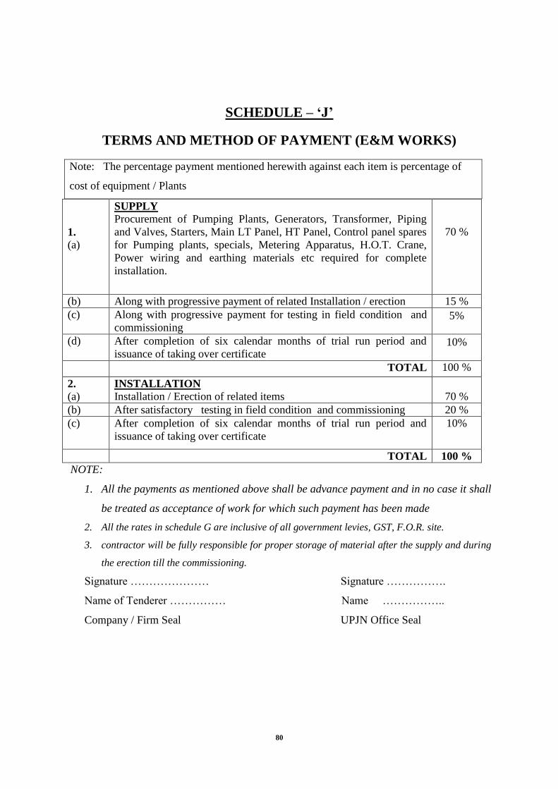
80
SCHEDULE – ‗J‘
TERMS AND METHOD OF PAYMENT (E&M WORKS)
1.
(a)
SUPPLY
Procurement of Pumping Plants, Generators, Transformer, Piping
and Valves, Starters, Main LT Panel, HT Panel, Control panel spares
for Pumping plants, specials, Metering Apparatus, H.O.T. Crane,
Power wiring and earthing materials etc required for complete
installation.
70 %
(b) Along with progressive payment of related Installation / erection 15 %
(c) Along with progressive payment for testing in field condition and
commissioning
5%
(d) After completion of six calendar months of trial run period and
issuance of taking over certificate
10%
TOTAL 100 %
2.
(a) INSTALLATION
Installation / Erection of related items
70 %
(b) After satisfactory testing in field condition and commissioning 20 %
(c) After completion of six calendar months of trial run period and
issuance of taking over certificate
10%
TOTAL 100 %
NOTE:
1. All the payments as mentioned above shall be advance payment and in no case it shall
be treated as acceptance of work for which such payment has been made
2. All the rates in schedule G are inclusive of all government levies, GST, F.O.R. site.
3. contractor will be fully responsible for proper storage of material after the supply and during
the erection till the commissioning.
Signature ………………… Signature …………….
Name of Tenderer …………… Name ……………..
Company / Firm Seal UPJN Office Seal
Note: The percentage payment mentioned herewith against each item is percentage of
cost of equipment / Plants

81
Technical Specifications

82
(A) SCOPE OF WORKS
1.1 General
Scope of work consists of “Survey, Investigation, collection of all type of field data, soil characteristics, underground utilities and accordingly preparation of Engineering design & drawing for Laying 25.804 Km sewer line (200 mm- 700 mm), construction of Patengra SPS (3 mld), Laying of rising mains Patengra SPS( 200 mm diameter, 335 m length), construction of 7 mld capacity STP based on SBR technology with disinfection system with all appurtenant works including testing and commissioning on Turn Key basis. STP will be constructed in the campus of existing STP. Total duration of the construction of work is 24 months including three (3) month for testing and commissioning. After three month of testing and commissioning a period of 12 months for defect liability period.The contractor shall carry out all the items of work required for the successful completion of the work, mentioned in the price schedule as a turnkey contract including replacement & repair of underground utilities such as for power cable and other obstacles. All tools, tackles, machinery, manpower and all consumables, materials, equipment, machineries, instruments, accessories, Electricity, Water skilled and unskilled manpower and all safety indication devices etc. are to be arranged by the contractor for full completion of work. Although Contractor shall be actively involved in getting the permissions for road cutting and power connection at Sewage Pumping Stations and Sewage Treatment Plant but power connection charges shall be paid by the owner to the concerned departments directly.
Scope of work shall include but not limited to the following: -
1. Detailed survey, Investigation & concise collection of all type of field data, soil
characteristics, underground utilities etc around site of work ie. In sewerage District D of Allahabad.
2. Preparation and submission of detailed engineering design and drawings of all the works
given in price schedule of the tender. 3. Execution of the following works:
A. Gravity Sewers
(i) Supply of RCC NP2/ NP3/ NP4 non pressure pipes and Laying of gravity sewers of the following sizes and length in different parts of sewerage district D.
Material of Pipe Size/ Diameter of Sewers
Total Length
DI K7 200 mm 21297 m DI K7 250 mm 1652 m
Sub Total 22949 m RCC NP3 300 mm 442 m RCC NP3 350 mm 514 m RCC NP3 400 mm 413 m RCC NP3 450 mm 648 m RCC NP3 500 mm 562 m RCC NP3 700 mm 86 m
Sub Total 2665 m G. Total 25614 m

83
(ii) Construction of manholes in accordance with the provisions laid down in the latest version of IS 4111(Part 1).
(iii) Laying of sewer of following sizes by micro tunneling method.
Size/ Diameter of Sewers
Total Length
200 mm 110 m 300 mm 25 m 400 mm 30 m 450 mm 25 m
Total 190 m
(iv) Permanent reinstatement of roads after sewer laying works as per PWD
specifications including sand filling in the trenches where depth of excavation is more than 3.0 m.
B.
C. Rising Mains:
(i) Laying & Jointing of Patengra IPS of 200 mm Dia folowing sizes DI/ CI/ PSC pipes rising mains with specials including fixing of sluice valves, scour valves, air valves at proper locations etc complete.The work also incluses dismentling of roads, excavation, timbering & shoring, dewatering, refilling of trenches and temporary reinstatement of roads.
E. Construction of New Sewage Pumping Stations
(i) Construction of Patengra SPS (3 mld)
(a) Civil Works:
Screen channel, for installation of two mechanical and three manual screens.
Construction of wet well and Valve Chamber.
Construction of platform for Diesel Generator
Construction of MEP Building
Construction of transformer yard
3.60 m wide Campus road, Boundary wall, fencing with 2 gates
Fire fighting arrangements, land scaping, site development etc.
(b) Electrical & Mechanical works:
Pumps of capacity 145 cum/hr at 15 m Head - 3 Nos.
Pumps of capacity 60 cum/hr at 15 m Head - 2 Nos. conveyor system Suction, Delivery lines, rising main with necessary valves and other
accessories 3 ton capacity HOT crane – 1 No. Panels HT vacuum circuit breakers One DG set of 250 kVA HT / LT cabling, bus trunk system, cable tray arrangement

84
LT panel with proper protection and metering arrangement Automatic power factor control (APFC) panel for power factor improvement
F. Construction of 7 mld STP based on SBR technique: Supply, erection,
installation, construction, testing & commissioning of 7 mld capacity Sewage Treatment Plant based on SBR technique. The STP will have following units and effluent of STP shall meet the standards given in this tender document
1. INLET CHAMBER 2. MANUAL SCREEN CHANNEL 3. MECHANICAL FINE SCREEN CHANNEL 4. GRIT CHAMBER DISTRIBUTION CHANNEL 5. MECHANICAL GRIT CHAMBER 6. GRIT CHAMBER OUTLET CHANNEL 7. PARSHALL FLUME 8. SPLITTER BOX 9. SEQUENTIAL BATCH REACTOR 9a. SELECTOR ZONE
10. SLUDGE SUMP 11. BLOWER BUILDING 12. UV DISINFECTION CHANNEL 13. RIO FOR SLUDGE TREATMENT AREA 14. SLUDGE THICKENER 15. THICKENED SLUDGE SUMP 16. CENTRIFUGE FEED PUMP HOUSE 17. CENTRIFUGE BUILDING (FIRST FLOOR) 18a. POLYMER DOSING TANK 18b. PAC/ FeCI3 DOSING TANK 18c. DOSING, CHEMICAL STORAGE AREA 19. FILTRATE SUMP 20. WORKSHOP/ STORE HOUSE 21. GRIT/ SCREEN STORAGE SPACE 22. ADMIN & LABORATORY (G+1) 23. SLUDGE DUYING STORAGE AREA 24. MCC ROOM-1 (GROUND FLOOR) 25. MEP ROOM (PMCC ROOM) 26. OPERATOR ROOM (FIRST FLOOR) 27. IIT PANELROOM 28. STP DG SET AREA
29. CONTROL ROOM
1.2 Design & Drawings The detailed design / working drawings shall be submitted in four copies by the successful contractor within 30 days from issue of Letter of Indent (LOI) to UPJN which will be approved by Engineer-in-Charge before the start of execution of work. Contractor is liable to provide 6 (six) sets of approved design and drawing sets to Engineer along with soft copies and tracings. If changes in the submitted design / drawings are required, Engineer may either himself do so prior to approval or may request the contractor to submit the design / drawings after making the required amendments. (i) On submission these designs and drawing will be reviewed by the Department/

85
Engineer or his representative and he may suggest modification, alteration, if any, which shall be promptly complied with by the contractor.
(ii) After satisfying himself the Engineer will accord approval to the designs, detailed drawings and detailed specifications. The contractor shall then submit three CD sets of final designs, calculations, detailed drawings and specification for all the works duly bound for incorporation in the contract which will be incorporated and form a part of the contract. Such approval shall however not relieve the contractor of his responsibilities of the connectness of the designs, drawings and specifications and he shall be fully responsible for that.
(iii) On completion of the contract he shall provide the Engineer with fully dimensioned drawing of the whole installation and construction in triplicate (3 sets) along with soft copy embodying and alterations and amendments that may have been agreed upon and executed. The contractor shall withdraw any worker or supervisor etc, only after the consent of the Engineer.
(A) General Requirements:
1.1.1. Design and Engineering
a. The Contractor shall execute the basic and detailed Design of STP, SPSs and
allied structures and its execution in compliance with the technical
specifications and requirements contained in the contract, codes of practices as
published by the Bureau of Indian Standard (BIS) or its equivalent standard as
well as the latest version of “Manual on Sewerage and Sewage Treatment” as
published by the Central Public Health Engineering Organization (CPHEEO)
of the Ministry of Urban Development, Government of India, New Delhi.
Wherever, the codes, standards and manual do not provide for the Design and
execution of some component i.e. required to be Designed and executed, the
contractor shall follow the standard engineering practices as approved by
Design-Build-Operations Engineer.
1.1.2. Proposed treatment scheme
The treatment scheme shall include facilities (complete in all respects)for
receiving sewage, screening, degritting, any proven treatment unit, flow
measurement, disinfection and sludge management. Provision of exact
components shall depend on the proposed technology. In addition the following
units shall be provided as applicable to the proposed technology:
i. Electrical substation
ii. Adequate lighting to all the units.
iii. Fire-fighting equipment as per state Government department of Fire services
iv. Health, Safety and Emergency (HSE) plan must be incorporated for the
management of all staff and activities undertaken in construction and O&M
of the STP. .
v. Provisions for power generation units (if found feasible), engine rooms with
gas engines and accessories.

86
1.1.3. The following general rules shall be followed in arranging the Plant:
i. Minimum clear distance of 6 m shall be allowed between adjacent units of
treatment or fixed structures to permit safe and convenient access for
operation and maintenance;
ii. Open area with necessary pavement, adjacent to all mechanical Plant shall
be provided as a maintenance lay down area;
iii. Fixed runways, lifting eyes or other means shall be provided to permit the
removal of Plant equipment that may logically be required to be removed
during the course of its normal operational life for maintenance or any other
purpose;
iv. Areas where leakage is likely to occur whether in normal use or during
maintenance, shall be provided with covered drainage channels which shall
direct the spillage either to a suitable drain or to a sump from where it can
be pumped;
v. Provided acoustic coverings where necessary to limit the noise produced
during normal operation to the limits detailed in these documents;
vi. Plant shall be arranged and the building designed to permit convenient
maintenance and removal of equipment;
vii. Environmental impacts during construction and installation/erection
works and O&M shall be identified and evaluated for geology,
seismology, soils, water resources and hydrology, physical environment
such as air quality, sound levels and noise, transportation; anticipated health
effects under normal conditions, health effects under accident conditions etc,
and relevant mitigation measures shall be implemented.
viii. Provide adequate supports and restraints for process piping, valves and
appurtenances.
ix. Connect pipework to equipment with flexible connections or make
other provisions to avoid transfer of pipe loads to devices.
x. All electro mechanical equipment, electronic instrumentation and Air
conditioning facilities shall be designed to withstand the corrosive
environment that will be prevailing in the STP.
xi. All sluice gates, valves, piping, Screens, degritting equipment, aerators and
air piping, sludge handling equipment, which will be submerged in or in
contact with sewage or sludge and stairs or ladders and hand railings for
access and platforms and walkways shall be designed with Corrosive
resistant material.
xii. Chemical piping for supply and feed of chlorine and polymer shall be of

87
corrosion resistant material and shall be secured to racks or trays to be fixed
to duct walls or walls of tanks and buildings as necessary. The method of
securing the pipes to the racks and / or trays shall be by clips or similar
devices and shall be of corrosion – resistant material facilitating ease of
xiii. removal in such a way that individual runs can be changed without
dismantling adjacent pipes.
xiv. All chemical piping shall be colour banded and suitably labeled to enable
individual lines to be identified throughout their run.
xv. Particular attention shall be paid to the layout of the chemical piping, which
shall be functional and neat in appearance. Generally, where pipework is
installed in ducts, it shall be supported not less than 150 mm clear of the
floor.
xvi. Where materials subject to UV degradation are employed, they shall
be shielded from direct sunlight.
xvii. Provide necessary platforms and walkways with proper flooring works at all
levels for operation of valves, gates and mechanical equipment with stairs or
ladders and hand railings for access.
xviii. Human contact with the sewage or sludge during O&M of STP shall be
strictly avoided
1.1.4. Provision of Modular Construction for Sewage Treatment Plants
All the treatment units shall be designed and constructed for their respective flows
/ capacities mentioned in these technical specifications and shall be constructed in
suitable modular or treatment train capacities. The minimum number of modules
or treatment trains and the minimum number of each unit process component
required shall be provided to facilitate O&M. Wherever no modular approach and stand by equipment is being proposed, the bidder will provide proper justification and certify that the proposed system will fulfill effluent design standards and other safeguards in all possible flow fluctuations.
1.1.5. Receiving of Sewage
Raw Sewage will be delivered through sewer network into a Receiving Chamber to be
constructed in this contract and from where it will be taken into downstream screens.
Receiving Chamber shall be of adequate size to meet the working space requirements.
The flow from the receiving chamber will lead to
further units such as screening/ grit chamber/ secondary treatment unit etc.
based on the technology and process flow being proposed by the bidder..
1.1.6. Flow Measurement:
All pumps shall be provided with flow meters and an ultrasonic flow transmitter shall also

88
be provided in the common header of the raw sewage Pumps.
1.1.7. Disinfection:
The Treated Sewage from the Secondary treatment units will be disinfected uing suitable
cost effective process/ technology. The treated and disinfected sewage shall be discharged
at near by nala (about 100 m from the plant) which ultimately falls in river Ganga.
1.1.8. Sludge Handling System – meet the relevant disposal standards:
Safe disposal of sludge meeting the required standards shallbe proposed by any required
processes namely thickening, digestion, aeration and de watering or their combination.
Efforts shall be made to reduce the sludge volume to the extent possible in a cost-
effective manner. Sludge should be stabilised before disposal. Human contact with sludge
shall be avoided.
1.1.9. Design criteria:
a. The Bidders are to adopt the same nomenclature as mentioned in the bid
document (to the extent possible) used for various treatment units in their
design report . Wherever new/ proprietary terms are being used, they shall be
explained in sufficient detail.
b. The STP shall be designed for 7 MLD capacity. The land provided is for
augmenting the capacity to the ultimate flow of 9 mld. The General
Arrangement Drawing (GAD) supported by hydraulic sizing calculation for
ultimate flow of 9 mld shall be provided. However the detailed design shall be
furnished for only 7 MLD.
c. To the extent possible, the plant must be designed in modules so as to augment
the capacity as and when the plant reaches its designed capacity. It is also
informed that the expected sewage flows cannot be generated immediately after
construction and that the sewage flows are likely to increase gradually and that
the STP should be able to perform at the designed levels even with these low
flows.
d. The process design of various units shall be done as per the norms prescribed in
the CPHEEO Sewerage Manual (Latest Edition) . If no guidelines are
mandated by CPHEEO for a certain component, the bidder shall demonstrate
that the guidelines being adopted are based on past successful experiences in
similar situtations and conform to best engineering practices.
e. The Designs and drawings as formulated by the contractor shall be subject to
approval by the owner or its authorized representative.
f. The Contractor shall be responsible for any discrepancies, errors or omissions

89
in the specifications, drawings and other technical documents, desired output /
performance of the STP, whether specifications, drawings and other
documents have been approved by the Owner or its representative or not,
provided that such discrepancies, errors or omissions are not because of
inaccurate information furnished in writing to the Contractor by or on behalf
of the Owner.
1.1.10. Codes and Standards
Wherever references are made in the Contract to codes and standards, in
accordance with which the Contract shall be executed, the edition or the revised
version of such codes and standards 30 days prior to the Submission Deadline
shall apply unless otherwise specified. During Contract execution, any changes in
such codes and standards shall be applied after approval by the Owner/Owner‟s
Representative and shall be treated in accordance with GC Section 10.1.
1.1.11. Design Responsibilities
a. The Contractor ‟s Design and Design-related services shall include, but not
limited to the following:
1. Site investigation and data collection including geotechnical assessment
and soil analysis for the Design and construction of the structures required
for the STP, SPSs and allied works;
2. Selection, adoption and detailed engineering Designs for the most
appropriate techno economically feasible cost effective treatment process
technology for the treatment of the sewage ensuring that the treated
sewage meets with the stringent of the disposal standards prescribed by the
MOEF / CPCB and in the contract as may be applicable. These standards
are prescribed below:
Sr. No.
Parameter
Effluent standards for discharge into Water bodies As per MoEF
Guidelines
i. PH value 5.5 – 9.0
ii. Temperature Shall not exceed 5degree
Celcius above the
receiving water
temperature
iii. BOD ( 3 days at 27°C), mg/L
≤ 10
iv. COD, mg/L ≤ 100
v. Total suspended solids, mg/L
≤ 10
vi. Residual Chlorine, mg/L ≤ 1
vii. Oil and grease, mg/L ≤ 10

90
viii. Total Nitrogen, mg/L ≤ 10
ix. Tot l Phosphate as P, mg/l ≤ 5
x. Fecal Coliforms MPN/100 ml
Desirable -100
Permissible – 230
xi. Bio-assay test 90% survival of fish after
96 hours in 100% Effluent
3. the acquisition of all data and information necessary to prepare the Design
and that are required to demonstrate that the 7 MLD STP meets or
exceeds the Technical Standards;
4. Preparation of Design development documents, based on the approved
HFD /schematic Design documents accepted by the Owner, consisting of
drawings and other documents appropriate to the size of the 7 MLD STP,
SPSs to describe the units and character of the entire proposed plant
including architectural, mechanical, civil works, and electrical systems,
materials, operations, landscaping, and such other elements as may be
appropriate; design shall be done to accommodate peak flow also.
5. the preparation of Design-Build Documents setting forth in detail the
requirements for construction based on the Design development
documents accepted by the Owner;
6. obtaining all approvals, permits, including building permits, and licenses
for the Design-Build Services, necessary compliances with occupational
health and safety requirements, environmental management plan as
specified in Appendix 1 of SCC, except for those approvals, permits or
licenses that the Owner is explicitly required to obtain itself under the
Applicable Law in which case the Contractor shall prepare all
documentation and provide assistance to the Owner in obtaining such
approval, permits or licenses;
7. the conducting of general reviews of the progress of the Design process, to
the extent necessary, in order to determine to the Contractor ‟s satisfaction
that the Design services are performed in compliance with the
requirements of the Contract and Applicable Laws.
1.1.12. Design-Build Documents
a. The Contractor shall prepare all the Design-Build Documents. The Design
Build Documents shall include the plans, Designs, drawings, as-built
documents, operations manuals, specifications, schematic Design documents,
Design development documents, and all modifications thereto required in
order to properly and fully test for, analyses for, plan, Design and build the
STP and all allied works as contemplated in the Technical Standards and the

91
remaining provisions of the Contract.
b. The Contractor shall prepare any other document, as may be requested by the
Design-Build-Operations Engineer, that the Owner considers necessary to
monitor the progress of the Design-Build Services and assess the Contractor ‟s
compliance with the Contract.
c. The Contractor shall provide the Owner with three sets of all of the Design-
Build Documents in reproducible form and shall modify them to keep them
up-to-date as requested by the Owner acting in a professionally reasonable
manner. The Design-Build Documents, with the exception of the as-built
documents, shall be subject to the review and approval of the Owner prior to
performing any of the services set out in DBSS in respect of any Design-Build
Document.
d. When the Contractor notifies the Owner in accordance with DBSS, the
Contractor shall provide to the Owner one copy of the “as built Designs,
Drawings/Documents” in reproducible form showing the exact as built
locations, sizes and details of the STP. The STP shall not be considered to
have reached Completion for the purposes of DBSS until such Design-Build
Documents have been provided. The Contractor shall update the as built
Designs, Build Drawings/Documents as necessary for the correction of defects
or deficiencies contemplated by DBSS.
1.1.13. Design Considerations
In preparing the Design for the STP and allied works and the Design-Build
Documents, the Contractor shall,
a. Protect public health and safety, including by the means set out in DBSS
b. maximize the protection of the environment and minimize any
adverse environmental impacts caused by the construction of STP throughout
the Service Area and Country, including as may be required,
recommended or advisable pursuant to any technical standard or
environmental assessments conducted on, at or near the STP site and by the
means set out in DBSS;
c. Consider the existing infrastructure and the Sewage Treatment Plant to be
connected with the Trunk infrastructure.
d. Ensure the STP and allied works has the capacity to accommodate the
anticipated sewage based upon the verifications prepared by the Contractor
pursuant to DBSS;
1.2. Design Responsibilities – On Site Issues
In preparing the Design for the STP and the Design-Build Documents, the
Contractor shall ensure that the Design,

92
a. makes adequate preparation and plans to ensure traffic movement and safety
during the laying of the network.
b. makes adequate preparation and plans and takes adequate measures for
controlling access to the STP site by animals and humans and vehicular traffic
at the perimeter of the site, including plans for plantings and vegetation,
fencing, lockable gates at vehicular access points, and the creation of an
internal (perimeter access corridor inside or, with appropriate local and other
approvals, surrounding the Site;
c. provides for allied works like control valves chambers, anchor /thrust /pedestal
blocks, internal access roads within the site and proposed units within the STP
site;
d. provides for ancillary works like new approach road that lead to or will be
used to access the Plant, culverts, compound wall with gates, fencing etc.;
e. provides for all utility services required for all of the Services
f. provides utilities services at the STP site such as electricity, telephone, potable
water, non- potable water and sewage collection and disposal.
1.2.1. Sewage Treatment Plant and SPS Layout and operation sequence
a. The Contractor shall be responsible for the planning and Designing of the
area of the Site for 7 MLD STP and SPSs, including,
b. Design and Construction of 7 MLD STP and SPSs and all allied /ancillary
works with an approach road to enter the facility and then carry out STP
Operation & Maintenance for 10 years by way of other services. Contractor
shall verify these details as per site condition.
c. The STP shall comprise treatment process, as may be techno economically
feasible and cost effective.
d. The Contractor shall have responsibility to dispose the treated sewage at the
designated location under the Contract. The Contractor shall have no right
over the use of treated wastewater and sludge except for generation of power
from sludge (if found feasible) for use in the STP.
e. On completion of the 10 years O & M period, the contractor shall have to
handover the STP to the Owner in full working condition, with necessary
replacements of the components towards the end of their economic life as
suggested by the manufacturers / operations manuals etc.
f. Also includes landscaping of plant area, internal roads with access to all units,
illumination of the entire STP site, pathways, storm water drainage, compound
wall all around & gates, administrative building including store house for tools
and spares, laboratory with water supply and waste water disposal

93
arrangements, access road of 7 m carriageway, O&M manual and as-built
drawings for all civil, electrical & mechanical works. All units shall be
provided with draining arrangements with suitable valves/gates with
chambers.
g. Supply and providing safety equipment namely gas mask, breathing apparatus,
Air hose respirator, portable lighting equipment, non-sparking lighting
equipment, portable air blowers, safety belts, inhalators and diver suit at the
commencement of O & M.
h. The contractor shall train the Owner‟s selected staff for on job training during
the specified 6 months of O & M period. A Maximum of Fifteen (15) staff of
Owner will be trained for a total period of 45 days during the last year of the
Operations Period.
i. Handing over of the Plant in good working condition with all relevant
documents such as as-built drawings, physical & operational condition of the
assets, rights on proprietary technologies, software, systems, O&M manual,
periodical reports along with soft copy to Owner.
j. Design shall be such that the plant requires minimum land foot print within the
total land made available under this contract and also lesser energy and less
manpower requirement with full automation for its sustainable and efficient
operation & maintenance.
i. For the disposal of Grit and screening materials, solid waste etc., the same
shall be disposed of by the contractor at his own cost at the site
Designated by the Owner
1.3. Design of 7 MLD STP, SPS (3.00 MLD) on Site Areas for Other Uses
a. In preparing the Design and layout for the STP, SPSs and allied structures, the
Contractor shall Designate areas of the site for use in,
i. SPSs
ii. Sewage Treatment Units including receiving well/ equalisation
chamber, pumping arrangement and other elctro-mechanical units/
equipment;;
iii. Sludge handling facilities;
iv. Ancillary works;
v. Site administration and Lab building;
vi. Perimeter buffer zones;
vii. Staff quarters etc.

94
1.4. Surface and Ground Water Management
In preparing the Design for the STP and all allied works and the Design-Build
Documents, the Contractor shall,
a. plan and Design the surface drainage at the Site of STP and SPSs with
adequate water drainage channels, pipes, sewers, structures and appurtenances,
including for higher, adequate to manage the highest seasonal levels and
volumes of storm water; and
b. plan and Design the STP and SPSssite with adequate protection from flooding
whether from rain, groundwater, high rivers, storms or any other source.
1.5. Site Administrative Facility
a. The Contractor shall be responsible for the administration of the STP, SPSs
and all allied works during the Design-Build Period and the Contractor shall
Design,
b. temporary office facilities for use by the Contractor and its Sub Contractor s
in the administration and execution of the Design-Build Services;
c. Project Facility for use in the administration of the Operations Services to
accommodate personnel, furniture, utility services, a lunch room, washrooms
and public toilets adequate or the Operations staff;
d. appropriate signage for the Site and the STP and SPSs , including signs that,
i. identify the STP, SPSs and its units;
ii. provide warning and hazard notification in Designated areas where
warranted; and
iii. identify areas of the STP and SPSs that are restricted to visitors and are
accessible to only Designated employees of the Contractor ;
e. the landscaping for the Facility as per the Design-Build Documents;
1.6. Other Design Responsibilities
The Contractor shall carry out the following Design or Design-related
responsibilities:
a. the Contractor shall prepare plans and Designs for all temporary works as
required by the Contractor ‟s Design and as required by the Contract
b. the Contractor s shall prepare plans and Designs for landscaping of the site;
c. the Contractor shall prepare plans and Designs for the acquisition of all data
and information necessary to prepare the Design, including, but not limited to,
any intrusive site investigations, off-site surveys and environmental baseline
monitoring required or contemplated under the Contract; and
d. the Contractor shall prepare detailed plans and methodologies for the testing
and inspection of the Plant and Equipment.

95
(B) GENERAL SPECIFICATIONS
Technical Specifications:
A. Sewage Treatment Plant of 7 MLD Capacity
1.0 Primary Treatment Units
Primary Treatment Units comprising Inlet Chamber, Fine Screen Channels and Grit
Chambers shall be designed for Peak Flow.
1.1 Inlet Chamber
Inlet Chamber of STP shall receive the flow from Raw Sewage Pumping Station, located in
STP area. Inlet Chamber shall be designed for Peak Flow. The entire construction shall be in
M30 grade reinforced cement concrete and as per IS 3370. RCC Platform/Walkway,
minimum 1.20 m wide with Hand Railing as per specifications shall be provided. RCC
Staircase, minimum 1.20 m wide with Hand Railing as per specifications shall be provided
for access from Finished Ground Level to the top of the Unit & to the Operating
Platform/Walkway.
Average Flow : 7 MLD
Peak Factor : 2.25
Peak Flow : 15.75 MLD
Number of Units : 1 No.
Hydraulic Retention
Time : 30 Sec at Peak Flow
Free Board : 0.50 m min.
All other accessories, whether specified or not, but required for completion of Contract
shall form the part of Bidder‟s Scope.
1.2 Mechanical & Manual Fine Screen Channels
Two Mechanical Fine Screens (Working) and one Manual Fine Screen (Standby) shall be
provided in Fine Screen Channels. Each Fine Screen Channel shall be designed for 50% of
Peak Flow. Mechanical screen shall be of Mat/perforated plate type.
The entire construction shall be in M30 grade reinforced cement concrete and as per IS
3370. RCC Platform/Walkway, minimum 1.20 m wide with Hand Railing as per
specifications shall be provided. RCC Staircase, minimum 1.20 m wide with Hand Railing
as per specifications shall be provided for access from Finished Ground Level to the top of
the Unit & to the Operating Platform/Walkway.
The clear opening shall be 6 mm for Mechanical Fine Screen and 10 mm for Manual Fine
Screen. The Mechanical and Manual Screens shall be made of SS 304 flats (3 mm for
Mechanical and 8 mm for Manual Screen). Bin and Chute arrangement shall be provided to
take the screenings. Screenings dropped from Chute shall be collected in a wheel Burrow.
Manually operated CI Sluice Gates shall be provided at the upstream and downstream ends
to regulate the flow.
Average Flow : 7 MLD
Peak Factor : 2.25
Peak Flow : 15.75 MLD
Number of Units : 1 Mechanical (Working) + 1 Manual
(Stand by) each of 50% of Peak Flow capacity.
Approach Velocity at Average Flow : 0.30 m/s

96
Velocity through Screen at Average Flow : 0.60 m/s max.
Velocity through Screen at Peak Flow : 1.20 m/s max.
Free Board : 0.30 m min.
Wheel Barrow : 1 No. min.
All other accessories, whether specified or not, but required for completion of Contract
shall form the part of Bidder‟s Scope.
1.3 Grit Chambers
Two Mechanical Grit Chamber (Working) along with one Manual Bypass Channel
(Standby) shall be provided after Fine Screen Channels. The Grit Chamber shall be designed
for 50% of Peak Flow and the Bypass Channel shall be designed for 50% of Peak Flow.
The entire construction shall be in M30 grade reinforced cement concrete and as per IS
3370. RCC Platform/Walkway, minimum 1.20 m wide with Hand Railing as per
specifications shall be provided. RCC Staircase, minimum 1.20 m wide with Hand Railing
as per specifications shall be provided for access from Finished Ground Level to the top of
the Unit & to the Operating Platform/Walkway.
Each Grit Chamber shall have the following features:
One tapered Inlet Channel running along one side with adjustable Influent Deflectors for
entry of sewage into the Grit Chamber.
One tapered Outlet Channel for collecting the de-gritted sewage, which overflow over a
adjustable Weir into the Outlet Channel. It shall be designed in such a way that no settling
takes place in it.
One sloping Grit Classifying Channel in to which the collected grit shall be classified.
The grit from Classifier shall be collected in a Wheeled Trolley.
A Grit Scraping Mechanism.
Screw Classifier or Reciprocating Rake Mechanism to remove the grit.
One Organic Matter Return Pump
Manually operated CI Sluice Gates shall be provided at entrance of the Inlet Channel of the
Grit Chambers as well as Byp ass Channel to regulate the flow.
Average Flow : 7 MLD
Peak Factor : 2.25
Peak Flow : 15.75 MLD
No. of Units : 1 Mechanical (Working) of 50% of Peak Flow capacity
Type : Mechanical
Size of grit particle : 0.15 mm
Specific gravity of grit : 2.65
Maximum Surface Overflow Rate : 960 m3/m2/day
Free Board : 0.30 m min.
Side Water Depth : 0.90 m min.
Wheel Barrow : 1 No. minimum
All other accessories, whether specified or not, but required for completion of Contract
shall form the part of Bidder‟s Scope.
Flow Measurement
Flow measurement shall be done online using an ultrasonic flow meter on the rising main.
2.0 Sequential Batch Reactor (SBR) Units
2.1 General
The Sequential Batch Reactor (SBR) Process shall be an advanced activated sludge process
with in-built nitrification, de-nitrification and biological phosphorous removal. The process

97
shall utilize a Fill-and-Draw Reactor with complete-mix regime and operating in true-batch
mode. The complete process shall be divided into Cycles with each Cycle is of duration of
2.5 – 4 hours. All the subsequent treatment Steps – Fill/Aeration, Settling and Decanting
must take place sequentially and independently without overlapping. During Fill/Aeration
phase, the sewage shall be filled into SBR Basins and part of the treated sewage along with
activated sludge shall be recycled with the help of Recycle Pumps. Air shall be supplied for
aeration with the help of Air Blowers. During settling phase, the Filling/Aeration shall be
stopped and the mixed content shall be allowed to settle under perfect settling conditions.
During Decanting phase, the supernatant shall be removed form top with the help of
Decanters and excess sludge shall be wasted with the help of Waste Pumps.
It shall be mandatory for the bidders to tie up with a SBR technology provider and submit a
tie up agreement duly signed and notarized on a Rs. 100 non judicial stamp paper. The
technology provider should have experience of providing SBR technology in India for at
least 3 numbers of STPs each of 7 MLD capacity and achieving the treated sewage quality
as BOD ≤ 10 mg/l, TSS ≤ 10 mg/l, NH4-N ≤ 2 mg/l, TN ≤ 10 mg/l and TP ≤ 2 mg/l and
each should be working satisfactorily for at least five years as on date.
2.2 Process Design
Sequential Batch Reactor (SBR) Units shall be installed and equipped for average flow of 7
MLD.
The SBR Process shall have following independent steps without overlapping each other:
Fill & Aeration
Settling (Sedimentation/Clarification)
Decanting (Draw)
Filling, during Settling or Decanting will not be acceptable.
The complete biological system shall be designed for handling peak flow.
Suitable Nos. of SBR Basins with adequate volume shall be provided. In addition, 0.50 m
Free Board shall be provided to each Basin.
The entire construction shall be in M30 grade reinforced cement concrete and as per IS
3370. RCC Platform/Walkway, minimum 1.20 m wide with Hand Railing as per
specifications shall be provided. RCC Staircase, minimum 1.20 m wide with Hand Railing
as per specifications shall be provided for access from Finished Ground Level to the top of
the Unit & to the Operating Platform/Walkway. Plinth protection along periphery shall be
provided as per technical specifications.
The system should work on a gravity influent condition. No influent / sewage Equalization
Tanks or flash filling is accepted.
The system should be designed for maximum F/M ratio of 0.18 Kg BOD/Kg MLSS day.
MLSS maintained in the Basin should range from 3500 to 5000 mg/l.
Cycle times shall be selected adequately by the Bidder considering min. 12 hrs/day Basin of
aeration and not exceeding decanting of 2.40 m liquid depth at any time with preferred
cycle times containing max. 50% not aerated portion.
The excess sludge produced shall be fully digested. Sludge production (including
percipients) rate shall be about 0.60 – 1.20 Kg / Kg of BOD removed.
A minimum total SRT of 10 days shall be maintained to ensure digested sludge.
2.3 Decanting Device
The Decanting Device shall be Moving Weir Arm Device of SS 304 with top mounted
Gear Box, Electric Drive, Scum Guard, Down comers, Collection Pipe, Bearings. The
maximum design travel rate shall be 60 mm/min with proven hydraulic discharge capacity
of the decanter proportional to the selected Basin area.
There should be maximum one (1) Decanter per Basin.
The hydraulic design based on design flow rate as given above shall not exceed flow speed
of 1.30 m/s.
Flexible rubber hose kind of decanter Sealing is not acceptable.
One or more decanters shall be provided in each basin which functions under a controlled
lowering rate to withdraw treated water out of SBR Basins.

98
The decanting mechanism shall be designed for a variable speed mode of operation.
Decanter shall be capable to travel at varying speeds. The rate of travel of the decanter shall
be adjustable during its travel in air and into the liquid surface, at which point the rate of
travel of the decanter shall be automatically adjusted to a calculated rate of operation. The
maximum design travel rate shall be restricted to 60 mm/min. Rope driven or Fixed
subsurface arrangements will not be acceptable.
The rate of operation shall be calculated for each cycle and shall be determined by
the volume of treated effluent to be discharged per cycle. The calculation of decanter travel
shall ensure that the volume of treated effluent shall be discharged throughout the
designated decant phase of the process cycle. The travel of the decanter shall be limited and
controlled by limit switches which shall communicate with the PLC. Upon reaching the
designated BWL, the decanter shall return to its parked position.
During non-decanting cycles, the decanter collection weir shall be parked above the top
water level of the basin during aeration and settling phases, thereby eliminating any
possibility of solids carryover during these phases. Therefore weirs or entry ports of the
Decanters shall not be submerged below the top water level of the basin during non-decant
phase. Each decanter shall be fitted with a scum retention mechanism to prevent surface
scums and floatables from exiting with the treated effluent.
In addition, at park position, the decanter shall also provide fail safe overflow protection in
the event of a power failure by allowing clear supernatant to flow via gravity, under the
scum guard, over the weir, and into the decanters and out of the basins.
If more than one decanter is provided per basin, operation of all decanters shall be
synchronized precisely using synchronization panel to achieve even distribution of flow
through each decanter.
Weir loading for each decanter shall not exceed 140 m3/hr/m of the inlet weir. During
Decanting Phase, decanter weir shall always be visible from the basin walkway to provide
the operator with a visual check of the effluent quality. Maximum velocity down comer
shall not exceed 1.0m/sec. at the designed decant flow.
All components of the decanter except seals and bearings shall be constructed of stainless
steel 304. The decanter seals and bearings shall be constructed of maintenance free,
synthetic materials for longest possible service life. All seals and bearings shall be shipped
factory assembled, simplifying installation. All fasteners shall be constructed of 304
stainless. Site fabrication of decanters shall not be allowed.
Drive mechanism or actuator shall be equipped with variable frequency drive connected to
PLC to facilitate its operation at varying flow rates to ensure controlled and seamless
operation at varying flow rates. Complete Drive Mechanism shall be mounted on the
walkway to provide easy access for maintenance and service purposes.
All critical decanter components that may require routine inspection or maintenance
shall be easily accessible from an access platform at basin coping level without
taking a basin out of service or draining or partially draining the basin. It shall be possible
to carry out decanter maintenance activities without interrupting normal operation of
the basin while the decanter is at its parked position during non-decant phases of the
process cycle.
The SBR blowers, Automatic Air supply Valves, RAS Pumps/Mixers, switching
mechanism shall be interlocked with the decanter controls so that aeration/mixing is
prevented in a basin which is settling or decanting.
2.4 Aeration System
The aeration facility shall be installed for 7 MLD average flow.
Only Fine Bubble Type, EPDM / PU Membrane Diffusers shall be acceptable with
minimum Membrane Diffusers to Floor Coverage Area of 5%. Combination of aeration
techniques using Aerators/Submersible Mixers etc. is not acceptable. Diffusers shall be
submerged, fine bubble / fine pore, high transfer efficiency, low maintenance and non-
buoyant type. Diffusers shall be panel / tubular type. In case tubular type Diffusers are used,
only top half surface area of the Diffuser shall be considered for supply of air. Material of

99
construction for entire under water system including accessories shall be of non-corrosive.
Complete Diffuser as a unit shall be assembled at the manufacturing factory level. The grid
supports shall of adjustable type made of SS 304.
The Air Blower Arrangement shall be capable of handling Total Water Level and Bottom
Water Level operation conditions controlled by process sensors such as DO, Temperature
and Level.
Each set of blower shall have at least one dedicated standby. Minimum One working air
blower in each set shall operate via VFD while others may be operating at a fixed constant
speed on soft starter configuration.
The blowers for air diffuser system shall be positive displacement (roots) type, and head for
blowers shall be decided on the basis of efficiency of diffusers and maximum liquid depth
in tank duly considering the losses governing point of delivery (diffusers) and the blowers.
Blowers shall be complete with motor and accessories like base frame, anti vibratory pad,
silencer, non return valve, air filter etc. as per requirements. Vibration due to operation of
blowers shall be to avoid damage to structures. Further, blowers shall have acoustics to
ensure that the noise level at 1.86 m from blowers is below 80-db. The blower room shall
have sufficient ventilation, lighting and working space. The room will be equipped with
sufficient capacity EOT (Min 2 T or 1.5 times the weight of blower, whichever is more) to
facilitate removal of blower/ motor etc. for repairs. The room will also have rolling shutter.
The blower and air diffuser system shall include PLC based control for diffuser operation.
The operation and speed of blowers shall be automatically adjusted using parameters like
Oxygen Uptake Rate, Dissolved Oxygen and Temperature, Incoming flow and liquid level
in the basin such that the DO is supplied as per demand and power utilisation for operation
of blowers is optimised. The main air header/ring main shall be in MS as per relevant IS
painted both outside and inside with corrosion resistant paint as per manufacture's
recommendations. The header / ring main shall be supported on saddles at suitable intervals
or will be protected against external corrosion in case they are laid below ground. The
header shall have auto valves to facilitate switch over aeration cycle from one basin to other
by PLC operation. The header shall supply air to fixed type diffuser grids at various
locations through air supply pipes. Air supply pipe above water level shall be in GI and
below water level it shall be in Imported PVC as per relevant standards. All under water
lateral pipes shall be of Imported PVC. Junction between air header and air supply pipe
shall be suitably protected against corrosion due to dissimilar materials. All other
accessories, whether specified or not, but required for completeness shall form part of
contractors scope. An Air cooler shall be provided, if required at the common discharge
blowers to ensure that the air temperature at the inlet of diffusers is less than 80 deg. C
All other accessories, whether specified or not, but required for completeness shall form
part of Contractors scope.
2.5 Return Sludge and Excess Sludge Pumps
Dedicated Return Sludge and Excess Sludge Pumps shall be provided in each SBR Basin.
The Pumps shall be of submersible / horizontal centrifugal type suitable for handling
biological sludge of 0.8 – 1% solids consistency. Capacity and Heads shall be decided
based on process requirements. Each Basin shall be provided with suitable lifting
arrangements to facilitate lifting of these Pumps if required for maintenance.
a. Return Sludge Pumps
Capacity and Head : As per requirements
Type : Submersible / Horizontal Centrifugal
Liquid : Biological Sludge of 0.8 – 1% solids consistency
Specific gravity : 1.05
Solid size : 40 mm (Maximum)
Temperature : Min. 25 C
Efficiency : more than 50%
Quantity : 1 No. per Basin + 1 No. Store Standby

100
b. Excess Sludge Pumps
Capacity and Head : As per requirements
Type : Submersible / Horizontal Centrifugal
Liquid : Biological Sludge of 0.8 – 1% solids consistency
Specific gravity : 1.05
Solid size : 40 mm (Maximum)
Temperature : Min. 25 C
Efficiency : more than 50%
Quantity : 1 No. per Basin + 1 No. Store Standby
2.6 Automation and Control
PLC based Automation System with application software based on Rockwell or equivalent
to control SBR System including all Gates, Air Blowers, Pumps, Valves and Decanters as
per Bidder‟s/Technology Provider‟s own design including I/Os with 20 % Spares and UPS.
HMI Panel shall comprise latest Personal Computer with 22” LCD Monitor, Multi Media
Kit, Printer, Internet Connection, RS-View, RS-Links (Gateway Version), Process and
Operator Software with dynamic Flow Charts, Pictures, Screens, Alarms, Historical Trends,
Reports etc. SCADA based Automation System to monitor the following parameters
continuously in each SBR Basins:
Fill Volume
Discharge Volume
Temperature
DO Level
Oxygen Uptake Rate
Air Blower Speed
Decanter Speed
3.0 Disinfection (Chlorination) Units
Disinfection (Chlorination) Units including Chlorination Tank and Chlorinator cum
Chlorine Tonner House shall be designed for Average Flow or Decant Flow whichever is
higher.
3.1 Chlorination Tank and Chlorinator cum Chlorine Tonner House
Treated sewage from SBR unit shall be taken to Chlorination Tank by RCC Channel/RCC
Pipe of Class NP3. Gas Chlorine shall be added for disinfection at suitable dosing rate.
Baffle walls shall be provided in the Tank to facilitate hydraulic mixing of treated sewage.
The entire construction shall be in M30 grade reinforced cement concrete and as per IS
3370.
Design Flow : Average Flow or Decant Flow whichever is more
Number of Units : 1 No.
Hydraulic Retention Time : 30 Minutes (excluding Outlet Channel after Weir)
Free Board : 0.50 m min.
A Chlorinator cum Chlorine Tonner House shall be provided above/near Chlorination Tank
to house Chlorination Systems. It shall be RCC (M25) Frame cum Brick Masonry Structure
with Rolling Shutter, Windows & Ventilators, Electrical Hoist with Electrical Travelling
Trolley of minimum 3 Ton capacity or 1.5 times the weight of the single Unit whichever is
more to lift the Pumps/Chlorine Tonners and Safety Equipment including Sand Buckets,
Fire Extinguishers and Fire Alarms etc. Also it shall be provided with IPS Flooring, Internal
& External Plaster and Internal & External Painting. Plinth Protection shall be provided
along the periphery as per specifications.

101
All other accessories, whether specified or not, but required for completion of Contract shall
form the part of Bidder‟s Scope.
3.2 Chlorination System
Gas Chlorination System comprising Vacuum Chlorinators (2 Nos.), Water Feed Pumps (2
Nos.), Interconnecting Piping and Appurtenances, Chlorine Gas Detector, Empty Chlorine
Tonners (Suitable for 30 days‟ Storage) with Trunions, Lifting Device and Suspended
Weighing Scale, Residual Chlorine Test Kit, Safety Equipment (e.g. Exhaust Fan, Canisters,
Gasmasks etc.), Mandatory Spares, Chlorine Leak Detection and Chlorine Leak Absorption
System including FRP Half Hoods, Caustic Solution Tank, Caustic Recirculation Pump,
Centrifugal Fan, Interconnecting Piping and Ducts complete and other required ancillary
shall be provided.
Design Flow : Average Flow or Decant Flow whichever is more
Type : Vacuum Type
Chlorine Dosing : 5 ppm min.
Quantity of Chlorinator : 2 Nos. (1Working + 1Standby)
All other accessories, whether specified or not, but required for completion of Contract
shall form the part of Bidder‟s Scope.
4.0 Sludge Dewatering Units
Sludge Dewatering Units comprising Sludge Sump and Pump House, Centrifuge House and
Dewatering Polymer Dosing System shall be designed for Average Flow.
4.1 Sludge Sump & Pump House
A Sludge Sump shall be provided to hold excess sludge from SBR Basins. It shall be
equipped with a submersible mixer to facilitate mixing of its contents on continuous basis. It
shall be constructed in M30 grade reinforced cement concrete and as per IS 3370.
Design Capacity : As required for 7 MLD Average Flow
Number of Units : 1 No.
Hydraulic Retention Time : 6 hrs. min. of Average Daily Sludge Production
Free Board : 0.50 m min.
A Pump House shall be provided near Sludge Sump to house Sludge Transfer Pumps
(Centrifuge Feed Pumps). It shall be RCC (M25) Frame cum Brick Masonry Structure with
Rolling Shutter, Windows & Ventilators and Electrical Hoist with Electrical Travelling
Trolley of minimum 1 Ton capacity or 1.5 times the weight of the single Unit whichever is
more to lift the Pump and Safety Equipment including Sand Buckets, Fire Extinguishers
etc. Also it shall be provided with IPS Flooring, Internal & External Plaster and Internal &
External Painting. Plinth Protection shall be provided along the periphery as per
specifications.
All other accessories, whether specified or not, but required for completion of Contract
shall form the part of Bidder‟s Scope.
4.2 Sludge Sump Mixers & Sludge Transfer (Centrifuge Feed) Pumps
Submersible mixer (<500 rpm) shall be provided inside the sludge sump to keep the sludge
in suspension. The material of construction of the mixer shall be SS304 along with lifting
device with SS 304 square tube.
All other accessories, whether specified or not, but required for completion of Contract
shall form the part of Bidder‟s Scope.

102
Sludge Transfer (Centrifuge Feed) Pumps shall be of positive displacement type Screw
Pumps suitable for handling biological sludge of 0.8 – 1% solids consistency.
Capacity and Head : As required for 7 MLD Average Flow
Type : Positive Displacement Type Screw Pump
Liquid : Biological Sludge of 0.8 – 1% Solids Consistency
Specific gravity : 1.05
Solid size : 40 mm (Maximum)
Temperature : Min. 25 C
Efficiency : more than 30%
Quantity : As per requirement + 1 Standby Min.
All other accessories, whether specified or not, but required for complete shall form part of
contractors scope.
4.3 Mechanical Sludge Dewatering Device (Centrifuge) and Centrifuge Platform
The Mechanical Sludge Dewatering Device shall be solid bowl type Centrifuges designed
for 100% trouble free operation at all times and provided as per the following guidelines.
The device shall be so located that the dewatered sludge can be loaded into Trucks/ Trolleys
/ Containers directly. Preferably the device shall be so located that the dewatered sludge
falls into the Trucks/ Trolleys / Containers without requirement of another Material
Handling Unit.
The dewatered sludge shall have a minimum solids concentration of 20% or more
(measured as dry solids w/w basis) so that it can disposed by open body Trucks/Trolleys.
The Centrifuge shall be solid bowl type of co-current/counter current design, as decided by
the Bidder. It shall have sufficient clarifying length so that separation of solids is effective.
The Centrifuge and its accessories shall be mounted on a common Base Frame so that the
entire assembly can be installed on an elevated structure. Suitable Drive with V-Belt
arrangement and Turbo Coupling shall be provided along with Overload Protection Device.
Differential speed and Bowl speed shall be adjusted by changing the Pulleys. Differential
speed may be adjustable by use of epicyclical gears. The Bowl shall be protected with
flexible connections so that vibrations are not transmitted to other Equipments. The Base
Frame shall be provided with anti-vibration Pads. The Drive Motor shall be of 1,450 RPM.
The noise level shall be 85 dB (A) measured at 2.00 m distance under dry run. The
vibration level shall be below 50 micron measured at Pillow Blocks under dry run
condition.
Capacity : As required for 7 MLD Average Flow
Operating Hours : 18 hrs per day maximum
Type : Solid Bowl Type
Liquid : Biological Sludge of 0.8 – 1% Solids Consistency
Specific gravity : 1.05
Quantity : As per requirement + 1 Standby Min.
All other accessories, whether specified or not, but required for complete shall form part of
contractors scope.
A Centrifuge Platform shall be provided near Centrifuge Feed Pump House to house
Centrifuges. It shall be a G(Stilt) + 1 type RCC (M25) Frame Structure. Centrifuges shall be
installed at First Floor whereas Trucks/Trolleys/Containers shall be parked at Ground Floor.
An Electrical Hoist with Electrical Travelling Trolley of minimum 3 Ton capacity or 1.5
times the weight of the single Unit whichever is more and Safety Equipment including Sand
Buckets, Fire Extinguishers etc. shall be provided. Also it shall be provided with Anti-Skid

103
Tile Flooring, Internal & External Plaster and Internal & External Painting. Plinth
Protection shall be provided along the periphery as per specifications.
4.4 Polyelectrolyte Dosing System
Polyelectrolyte shall be dosed online at the inlet of Centrifuge. Minimum dosage of
polyelectrolyte shall be 1.50 – 2.50 Kg/Ton of dry solids in sludge at 0.1% solution
strength. There shall one Solution Preparation Tank and one Solution Dosing Tank, each
suitable for minimum 8 hrs. of operation and quipped with slow speed Mixer (100 RPM).
The entire construction shall be in M30 grade reinforced cement concrete and as per IS
3370. RCC Platform/Walkway, minimum 1.00 m wide with Hand Railing as per
specifications shall be provided. RCC Staircase, minimum 1.00 m wide with Hand Railing
as per specifications shall be provided for access from Finished Ground Level to the top of
the Unit & to the Operating Platform/Walkway.
Design Capacity : As required for 7 MLD Average Flow
Number of Units : 2 Nos.
Hydraulic Retention Time : Suitable for min. 8 hours of Operation
Free Board : 0.50 m min.
The solution will be dosed using mechanically actuated diaphragm type Metering Pumps.
Dedicated Dosing Pumps shall be provided and shall be interlocked with Centrifuge in such
a way that they Start/Stop along with Centrifuge.
Capacity and Head : As required for 7 MLD Average Flow
Type : Mechanically Actuated Diaphragm Type Metering Pump
Liquid : Polyelectrolyte Solution of 0.1% Strength
Quantity : As per requirement + 1 Standby Min.
5.0 Plant Utilities
5.1 SBR Air Blower cum Administrative cum MCC & PLC/Control Building
The SBR Air Blower cum Administrative cum PLC/Control Building shall be G+1 type
RCC (M25) Frame and Brick Masonry Structure. SBR Air Blower House, Workshop &
Tool Room shall be constructed at ground floor whereas Administration Block (comprising
Office, Conference Hall and Laboratory), PLC/Control Room shall be placed at first floor.
PMCC, HT Substation shall be placed in separate Structure.
SBR Air Blower House shall house Air Blowers for SBR Basins. It shall be equipped with
Rolling Shutters, UPVC Windows/Ventilators, Exhaust Fans and a Manual forklift of
minimum 3 Ton capacity or 1.5 times the weight of Air Blower whichever is more.
Similarly, PLC/Control Room shall be designed.
Laboratory shall be fully equipped with all necessary Equipments, Instruments, Chemicals,
Reagents, Glassware and Furniture.
Adequate number of Toilets and Washbasins shall be provided separately for Men &
Women at each floor. A covered Overhead Tank of capacity 5 m3 shall be provided along
with an Underground Water Tank of capacity 10 m3 to cater to the water requirements of
the Building.
In addition, the Building shall be provided with Porch, Staircase, Passages,
Wooden/Aluminium/Glass Doors / Windows / Ventilators and Safety Equipments including
Sand Buckets, Fire Extinguishers and Fire Alarms etc. Adequate Flooring shall be provided
in various Rooms/Areas as per requirement or as per instructions of the Engineer-in-charge.
Internal & External Plaster with Painting shall be done as per instructions of the Engineer-
in-charge. Plinth Protection shall be provided along the periphery as per specifications.

104
The Building shall be provided with the following:
Sr.
No.
Item of work Work
1
Personal Computer
in PLC/Control
Room
2 Nos. of latest version & configuration
complete.
2
Printer in
PLC/Control Room
1 No. of A3 Size Laser Printer of latest
version & configuration complete.
3
Telecommunication
Facility
Min. 1 No Telephone Line with a Broad
Band facility. The chargers will be born by
the Contractor up to the O & M Period.
4
Plant Model
1 No. Wall Mounted Process Model
(Electronic Plant Display Model) with
Flow Diagram (Minimum size 3 m x 1.5
m)
1 No. 3D Model with display of flow
direction and lighting.
5 Air Conditioner Adequate nos. of Air conditioners shall be
provided as directed by Executive
Engineer.
5.2 Electrical HT Substation
The Electrical HT Substation shall be provided to house HT Components comprising
Metering Kiosk, HT Panel, Indoor Transformers and Power Control Centres. It shall be
RCC (M25) Frame and Brick Masonry Structure equipped with Rolling Shutters,
Windows/Ventilators, Exhaust Fans and Safety Equipments including Sand Buckets, Fire
Extinguishers and Fire Alarms etc. complete.
Also, it shall be provided with IPS Flooring, Internal and External Plaster with Painting and
Plinth Protection along the periphery as per specifications.
5.3 DG House
The DG house shall be provided to house DG Set of adequate rating capable of running the
entire STP and pumping station located in STP area at Peak Flow including AMF Panel,
Fuel Tank and other Accessories. It shall be RCC (M25) Frame and Brick Masonry
Structure equipped with Rolling Shutters, Windows/Ventilators, Exhaust Fans and Safety
Equipment including Sand Buckets, Fire Extinguishers and Fire Alarms etc. complete. Also
it shall be provided with IPS Flooring, Internal and External Plaster with Painting and
Plinth Protection along the periphery as per specifications.
5.4 Security Cabins
Security Cabin of size 3.00 m x 3.00 m shall be provided at each entry Gate of the Plant. It
shall be RCC (M25) Frame and Brick Masonry Structure equipped with Doors,
Windows/Ventilators, etc. complete. Also, it shall be provided with Flooring, Internal and
External Plaster with Painting and Plinth Protection along the periphery as per
specifications.
5.5 Schedule of Finishes
Sr.
N
o
.
Unit Flooring Doors Windows /
Ventilators
1 Administrative
Block, Laboratory,
Marbonite flooring
of approved make.
Solid Core Flush
Door with heavy
Aluminium of
approved make
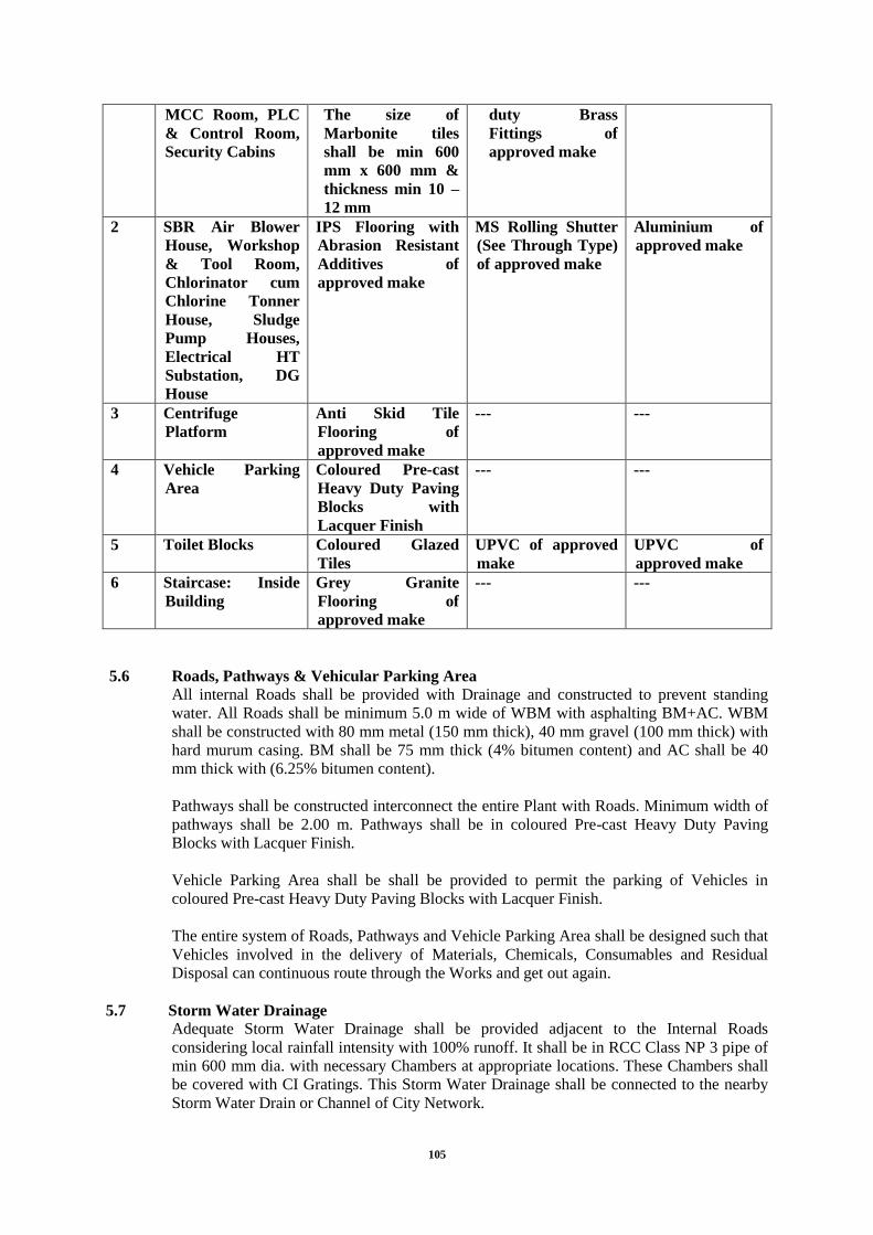
105
MCC Room, PLC
& Control Room,
Security Cabins
The size of
Marbonite tiles
shall be min 600
mm x 600 mm &
thickness min 10 –
12 mm
duty Brass
Fittings of
approved make
2 SBR Air Blower
House, Workshop
& Tool Room,
Chlorinator cum
Chlorine Tonner
House, Sludge
Pump Houses,
Electrical HT
Substation, DG
House
IPS Flooring with
Abrasion Resistant
Additives of
approved make
MS Rolling Shutter
(See Through Type)
of approved make
Aluminium of
approved make
3 Centrifuge
Platform
Anti Skid Tile
Flooring of
approved make
--- ---
4 Vehicle Parking
Area
Coloured Pre-cast
Heavy Duty Paving
Blocks with
Lacquer Finish
--- ---
5 Toilet Blocks Coloured Glazed
Tiles
UPVC of approved
make
UPVC of
approved make
6 Staircase: Inside
Building
Grey Granite
Flooring of
approved make
--- ---
5.6 Roads, Pathways & Vehicular Parking Area
All internal Roads shall be provided with Drainage and constructed to prevent standing
water. All Roads shall be minimum 5.0 m wide of WBM with asphalting BM+AC. WBM
shall be constructed with 80 mm metal (150 mm thick), 40 mm gravel (100 mm thick) with
hard murum casing. BM shall be 75 mm thick (4% bitumen content) and AC shall be 40
mm thick with (6.25% bitumen content).
Pathways shall be constructed interconnect the entire Plant with Roads. Minimum width of
pathways shall be 2.00 m. Pathways shall be in coloured Pre-cast Heavy Duty Paving
Blocks with Lacquer Finish.
Vehicle Parking Area shall be shall be provided to permit the parking of Vehicles in
coloured Pre-cast Heavy Duty Paving Blocks with Lacquer Finish.
The entire system of Roads, Pathways and Vehicle Parking Area shall be designed such that
Vehicles involved in the delivery of Materials, Chemicals, Consumables and Residual
Disposal can continuous route through the Works and get out again.
5.7 Storm Water Drainage
Adequate Storm Water Drainage shall be provided adjacent to the Internal Roads
considering local rainfall intensity with 100% runoff. It shall be in RCC Class NP 3 pipe of
min 600 mm dia. with necessary Chambers at appropriate locations. These Chambers shall
be covered with CI Gratings. This Storm Water Drainage shall be connected to the nearby
Storm Water Drain or Channel of City Network.

106
5.8 Boundary Wall with Gate
Boundary Wall shall be constructed all around the STP plot. Boundary Wall having
architectural and elegant view shall be provided along entire periphery of the Plot. Height
of boundary wall should not be less than 2.0 m from finished ground level. It should be able
to bear wind pressure up to 80 Km/hr. At least two Entry Gates, 3.60 m wide each shall be
provided. Each Entry Gate shall be provided with a Wicket Gate.
5.9 Internal Water Supply and Water Supply for Gardening
Proper water facility shall be provided at STP. Rate of water supply may be kept as 150 liter
per capita per day for a population of 20 people. Storage should not be less than 1000 litres.
Water supply for gardening purpose may be from treated final sewage in sufficient quantity.
5.10 Disposal of Plant Residuals & Treated Sewage
Plant Residuals (Screenings, Grit and Dewatered Sludge) and treated sewage shall be the
property of the Employer. However, the Contractor shall be responsible for disposal of
Plant Residuals within 12 Km from Site. Treated Sewage shall be discharged into nearby
Nallah. The Contractor may sell off the Dewatered Sludge but at the discretion of the
Employer.
5.11 Landscaping
Landscaping involves beautification of Sewage Treatment Plant site by cultivating lands,
plants and trees of environmental value and suitably modifying the appearance of STP site.
It shall add scenic value to the STP site to obtain maximum visual impact. Contractor has to
develop proper landscaping in the STP site from professional landscaper approved by
OWNER. Area for future expansion shall also be considered for landscaping.
6.0 Interconnecting Piping and Valves
All interconnecting Piping, Gates, Valves, Specials and other appurtenances, auxiliaries and
accessories required as per Process Design and Scope of Work. In case of Rising Mains,
thrust blocks shall be provided wherever required. In case of buried Pipes, warning tapes
shall be provided of the appropriate colours. The material of construction for major
interconnecting Piping shall be as follows:
Piping: Guide Line for Velocity
S
r
.
N
o
.
Service
Design
Velocity
m/s
Limitations
1 Gravity Lines for Sewage
& Water
0.60 – 1.2
Designed as pipe line
flowing full.
Min. Velocity shall not be
less than 0.6 m/sec. Max.
Velocity up to 1.2 m/sec is
allowable at Peak Flow.
2 Pressure Lines for
Sewage & Water
0.6 – 2.5 Min. Velocity shall not be
less than 0.6 m/sec. Max.
Velocity up to 2.5 m/sec is
allowable at Peak Flow.
3 Air (Pressurized Lines) 18 – 22 Max. Velocity shall not be
more than 25 m/sec in any
section.
4 Scum & Sludge Lines 0.6 – 1.5 Irrespective of flow,

107
S
r
.
N
o
.
Service
Design
Velocity
m/s
Limitations
Diameter shall not be less
than 150 mm for Gravity
Lines.
5 Chemical Feed Lines 0.6 – 1.5 Irrespective of flow,
Diameter shall not less than
20 mm.
Notwithstanding the above, the Bidder shall submit a Pipe Line Schedule with Tag No.,
Flow, Size, Type, Material of Construction etc. with detailed P & ID for approval of the
Engineer-in-charge prior to any further engineering or procurement/fabrication and
installation.
Generally, the Material of Construction shall be selected based on the following guide lines.
The Bidder can make suitable selection depending on Service, Type of Flow (i.e. Gravity or
Pressurized) and Diameter of Pipe.
Piping: Guide Lines for MOC
S
r
.
N
o
.
Service Type of
Flow MOC
1 Waste Water /
Sludge Gravity RCC NP-3 Class
2 Waste Water /
Sludge Pressurized
CI Class “LA” / DI
K-9
3 Service Water Gravity /
Pressurized GI “C” Class
4
Air Lines:
Headers, Vertical
Down-comers
Pressurized
Above Water: MS
Sand/Shot Blasted,
Epoxy Painted
Under Water: SS 304
5
a
Air Grid Piping:
Aeration Zone Pressurized UPVC Schedule 40
5
b
Air Grid Piping:
Selector Zone Pressurized SS 304
6 Chemicals Gravity /
Pressurized
SS 304 except
Chlorine & FeCl3
7 Chlorine &
FeCl3
Gravity /
Pressurized Schedule 40 UPVC
Valve: Guide Line

108
S
r
.
N
o
.
Service Type MOC
End
Conne
ction
A Sewage / Sludge
1
Gravity /
Pressurize
d
Knife
Gate
CI Body & SS
304 Gate &
SS 410
Spindle
Flange
d/Waf
er
2 Delivery of
Pump
Swing
Check
CS Body &
SS 304
Internals
Wafer
3
Suction &
Delivery of
Pump
Knife
Gate
CI Body & SS
304 Gate &
SS 410
Spindle
Flange
d/Waf
er
B Service Water
1
Gravity /
Pressurize
d
Ball
CS Body &
SS 304
Internals
Flange
d/
Screw
ed
2 Delivery of
Pump
Swing
Check
CS Body &
SS 304
Internals
Wafer
3
Suction &
Delivery of
Pump
Butter
fly
CI Body & SS
304 Internals Wafer
C Air
1 Pressurize
d Ball
CS Body &
SS 304
Internals
Flange
d/
Screw
ed
2 Delivery of
Blower
Swing
Check
CS Body &
SS 304
Internals
Wafer
3
Suction &
Delivery of
Blower
Butter
fly
CI Body & SS
304 Internals
Flange
d
D Chemicals
1
a
Gravity /
Pressurize
d
Ball
As per
Chemical
Compatibility
Chart
Flange
d
1
b
Gravity /
Pressurize
d
Diaph
ragm
As per
Chemical
Compatibility
Chart
Flange
d
1
c
Gravity /
Pressurize
d
Plug
As per
Chemical
Compatibility
Flange
d
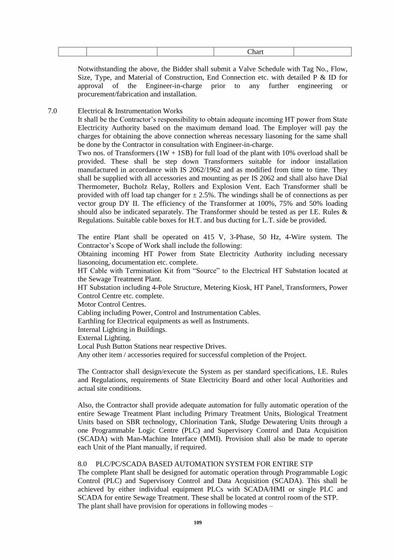
109
Chart
Notwithstanding the above, the Bidder shall submit a Valve Schedule with Tag No., Flow,
Size, Type, and Material of Construction, End Connection etc. with detailed P & ID for
approval of the Engineer-in-charge prior to any further engineering or
procurement/fabrication and installation.
7.0 Electrical & Instrumentation Works
It shall be the Contractor‟s responsibility to obtain adequate incoming HT power from State
Electricity Authority based on the maximum demand load. The Employer will pay the
charges for obtaining the above connection whereas necessary liasoning for the same shall
be done by the Contractor in consultation with Engineer-in-charge.
Two nos. of Transformers (1W + 1SB) for full load of the plant with 10% overload shall be
provided. These shall be step down Transformers suitable for indoor installation
manufactured in accordance with IS 2062/1962 and as modified from time to time. They
shall be supplied with all accessories and mounting as per IS 2062 and shall also have Dial
Thermometer, Bucholz Relay, Rollers and Explosion Vent. Each Transformer shall be
provided with off load tap changer for ± 2.5%. The windings shall be of connections as per
vector group DY II. The efficiency of the Transformer at 100%, 75% and 50% loading
should also be indicated separately. The Transformer should be tested as per I.E. Rules &
Regulations. Suitable cable boxes for H.T. and bus ducting for L.T. side be provided.
The entire Plant shall be operated on 415 V, 3-Phase, 50 Hz, 4-Wire system. The
Contractor‟s Scope of Work shall include the following:
Obtaining incoming HT Power from State Electricity Authority including necessary
liasonoing, documentation etc. complete.
HT Cable with Termination Kit from “Source” to the Electrical HT Substation located at
the Sewage Treatment Plant.
HT Substation including 4-Pole Structure, Metering Kiosk, HT Panel, Transformers, Power
Control Centre etc. complete.
Motor Control Centres.
Cabling including Power, Control and Instrumentation Cables.
Earthling for Electrical equipments as well as Instruments.
Internal Lighting in Buildings.
External Lighting.
Local Push Button Stations near respective Drives.
Any other item / accessories required for successful completion of the Project.
The Contractor shall design/execute the System as per standard specifications, I.E. Rules
and Regulations, requirements of State Electricity Board and other local Authorities and
actual site conditions.
Also, the Contractor shall provide adequate automation for fully automatic operation of the
entire Sewage Treatment Plant including Primary Treatment Units, Biological Treatment
Units based on SBR technology, Chlorination Tank, Sludge Dewatering Units through a
one Programmable Logic Centre (PLC) and Supervisory Control and Data Acquisition
(SCADA) with Man-Machine Interface (MMI). Provision shall also be made to operate
each Unit of the Plant manually, if required.
8.0 PLC/PC/SCADA BASED AUTOMATION SYSTEM FOR ENTIRE STP
The complete Plant shall be designed for automatic operation through Programmable Logic
Control (PLC) and Supervisory Control and Data Acquisition (SCADA). This shall be
achieved by either individual equipment PLCs with SCADA/HMI or single PLC and
SCADA for entire Sewage Treatment. These shall be located at control room of the STP.
The plant shall have provision for operations in following modes –

110
Automatic – Auto operation through PLC/digital controller.
Manual – Operator intervention through SCADA/HMI.
Local – Local operation through local control panel located near equipment.
Audio Visual Alarms –
Audio visual alarms shall be initiated under emergency or equipment trip conditions, other
than usual service alarms. Salient features of the proposed control system shall be as
follows:
Dynamic display of all Units, equipment and drives shall be available on SCADA screen.
It shall Acquire, process and manage the processed data.
It shall safeguard the process by means of interlocks and alarms.
Auto/Manual operation of each drive shall be made by selecting a soft switch on
SCADA/HMI screen.
In Auto mode, each drive shall operate based on pre-set sequence and interlock. Also
automatic change over from working to standby drive shall happen after a drive reaches
pre-set hours of operation.
In Manual mode, each drive shall be operated in Local/Remote mode by selecting a soft
switch on SCADA/HMI screen. In Local mode, each drive shall be operated from the Local
Push Button Station (LPBS) located nearby. In Remote mode, operation from LPBS shall
be disabled and each drive shall be operated manually from PLC. Also provision for
working/standby selection of drives by selecting a soft switch on SCADA screen shall be
provided.
Run/Trip indication of all drives shall be displayed on SCADA/HMI screen.
Open/Close indication of all Auto Sluice Gates and Auto Valves shall be displayed on
SCADA/HMI screen.
Annunciation & Alarm facility shall be available in PLC/HMI/SCADA. In the event of a
Fault, the symbol representing the equipment/drive shall continue flashing on SCADA/HMI
screen with equipment/drive description appearing at bottom of the SCADA/HMI screen
and electric Hooter shall continue blowing until the Fault Alarm is acknowledged.
Data logging of Running Hours of each drive, Alarms, Historical Trends of monitored
Parameters, etc. shall be envisaged in SCADA.
Report generation for plant performance.
The process system must have pre-configured software packages which can be adapted to
the process by parameterization.
The monitor images must be designed to be user-friendly by hierarchical breakdown with
the possibility of selective display and optimum selection possibilities.
Changing of parameters and other software units must be possible "online", i.e. with the
system running.
Different alarms colors provide information on their priorities.
For the system engineering offered, the Contractor must take measures, e.g. by the
installation of surge voltage arresters or surge voltage filters, to ensure that internal and
external surge voltages do not impair the function of his parts of the system.
The programs and data entered must be backed up in a non-volatile read-only memory.
A limit value and plausibility check must be provided in the software of the process station
for the measured values and messages. Exceeding of limit values or deviations detected by
the above checks must trigger an event and cause a message to be sent.
Further demanded features of the process system:
Integrated, detailed error message and fault detection concept with display on the
HMI/SCADA for quick localization of faults. The system operator must be able to identify
the fault from the error.
Essentially maintenance-free
Robust against external interferences of all kinds
Proven design and solder-free connection technique
Protection of the equipment against surge voltages

111
Automatic fault detection and quick troubleshooting in the PLC system by integrated,
hierarchically structured diagnostic devices
Power supply in wide admissible voltage range
Simple function-oriented operation
The process system (PLC, HMI/SCADA) shall be protected against power failure by an
uninterruptible power supply (UPS). When the critical charge state of the UPS is reached,
the process system is automatically shut down.
Mode selector switch
A mode selector switch is to be installed on the MCC or distribution board. It serves for
pre-selection between Automatic mode and Manual/Local mode.
The following switching functions must be provided:
Automatic – Manual/Local
Automatic: In this position, only automatic operation is possible; the local switches have no
function (Except emergency stop).
Local: Automatic mode cannot be started. The drives can be operated individually without
interlock with the local switches.
Local switches (LPBS)
Each drive must be equipped with a local switch positioned in such a location that the
corresponding machine or conveyor can be switched on in Manual/Local mode and can be
monitored visually at all times.
The local switch must have the following switching functions:
START – STOP (for drives with one direction of rotation) or
FORWARD – STOP - REVERSE (for reversible drives)
If a unit has several drives (e.g. conveyor belt drive and travel drive), the local switches
should be installed if possible in one switch box or at least installed next to one another.
Each local switch must be adequately labeled in plain text so that no operator errors can
occur.
PLC
The automatic start-up of the whole system, sequential operations and the automatic
shutdown, allowing for external control influences, e.g. EMERGENCY STOP, etc., is
performed by programmable logic controller (PLC).
This performs not only the control of the system, but also the display of the operating state
in the HMI/SCADA.
The interlocks of the individual process groups and their signaling must be performed by
the PLC.
A system must be selected which is sufficiently protected against external interference in
the supply, control and signaling lines. The aim is that the program can continue to run
without fault signals in the event of transient earth faults in the supply grid. In the event of
prolonged power failures, on the other hand, a controlled restart must be triggered (under-
voltage trip of the non-automatic circuit breaker).
PLC Specifications: Technical
The PLC shall be non-redundant.
PLC of individual equipment shall be selected to carry out necessary operations without
overloading the PLC memory.
The PLC shall have adequate I/O per card.
There shall be 15% spare I/O of each type.
The CPU shall not be loaded more than 60% of its capacity.

112
Retentively shall be 100% to save the recorded data and saving the programmed logic, other
attributes connected with system for power & system failure.
Change in programme / modifications to programme shall be possible by a portable laptop.
It is preferred to have all PLC‟s in the plant from same manufacturer.
HMI/SCADA system
The HMI system shall be designed as a minimum 6”, color, touch-screen on the panel.
Whereas SCADA system must be computer based.
All displays must be designed by the Contractor with graphic sophistication and all texts in
the visualization system must be displayed in English.
A sub-menu for each operating mode and further menus for editing the system parameters,
fault archive, etc., must be developed. It must be as simple as possible to switch between
the various menus and to edit the system parameters.
When designing the user interface or the assignment of the function keys, attention must be
paid that the function key assignment remains the same in all sub-menus so that it is
possible to jump to another menu without first having to jump back to the main menu.
It must be possible to edit the following parameters at the touch-panel and SCADA:
Operating mode
Changes in the speeds of frequency converter-controlled equipment
Start-up times
Shutdown times
Duration of the operation of warning devices
Limit values for sensors, etc.
Faults, level messages, pressed EMERGENCY STOP buttons, etc., must also be clearly
displayed at the bottom of the screen, irrespective of the selected screen page or sub-menu.
It must be possible to output all important menu items to the printer. The corresponding
interfaces must be provided.
The display of the function plans, images, etc. is affected in direct dialog with the system by
means of the mouse and keyboard.
The central SCADA shall generate various reports to analyze plant performance. The
process is documented via the laser printer.
Computer hardware and software
All programs required for operation of the system must be correspondingly compatible. The
corresponding licenses must be supplied for the standard programs. The operating systems
must be agreed upon with the Client. Minimum requirements shall meet:
CPU
Processo
r
Intel i5 or higher
Processo
r speed
2 GHz or higher
Configur
ation
Tower
Architect
ure
32 bit
System
memory
(RAM)
8 GB
Hard
disk
320 GB or higher
DVD
Drive
Combo (Read/Write)
Operatin
g system
Microsoft Windows 7 professional

113
Commun
ication
ports
USB – 4Nos., Ethernet – 1Nos.
Graphic
accelerat
or
1 GB
Power
supply
240V, 50Hz, 1Phase
Keyboar
d
Internet Keyboard (with USB interface)
Mouse Optical, 3 buttons (with USB interface)
Monitor
Type Full HD LED color monitor
Screen
size
22” or higher
Resolutio
n
1920 x 1080
Power
supply
240V, 50Hz, 1Phase
Complete Project shall operate in auto mode. As a minimum, following controls must be
considered in Bidder‟s Control Philosophy:
Inlet chamber
A clamp on type Ultrasonic or Electromagnetic flow transmitter shall be provided on inlet
pipe of inlet chamber for measurement of flow coming to Sewage Treatment Plant. PLC
shall calculate instantaneous flow as well as cumulative flow, both shall be displayed on
SCADA.
Fine screens
Each mechanical fine screen shall be installed with ultrasonic differential level transmitter /
level switch, across it; the same shall be operated on the basis of set level in SCADA. Also
if level is not reached for certain time period, the screen shall be operated on the basis set
time in SCADA.
The selection of Auto/Manual and Working/Stand-by shall be made available in SCADA.
In manual mode the screen operation will be done from SCADA screen. Physical switch
over of screens in plant will be done by operator using manual gates.
Necessary interlocks, controls, alarms, report generation, etc. shall be considered in PLC for
auto operation of fine screen.
Grit Chambers
Each grit chamber will consist of Detroiter (1No.), Organic Return Pump (1No.) and Screw
Conveyor for grit removal (1No.). As such Detroiter, Organic Return Pump and Screw
Conveyor will not have auto operation; these will be started and stopped from SCADA
screen as required.
Necessary interlocks, alarms, report generation, etc. shall be considered in PLC for
operation of Grit chamber equipment.
SBR Basin
Complete operation and control of SBR plant will be done through a separate PLC and
SCADA. However it shall have necessary inputs and generate required outputs to operate in
co-ordination upstream and downstream units of balance plant.
Alternatively contractor may provide single PLC and SCADA for entire Sewage Treatment
Plant.
Necessary interlocks, controls, alarms, report generation, etc. shall be considered in SBR
PLC for auto operation SBR basin.

114
Each SBR basins shall be equipped with Level Transmitter, DO Transmitter for monitoring
and recording of critical operation parameters through SCADA.
Sludge sump and pump
An ultrasonic type level transmitter shall be used for measurement of level in sludge sump.
Screw pumps will be used to feed sludge to Centrifuge. These will operate as per level in
sludge sump.
The selection of Auto/Manual and Working/Stand-by shall be made available in SCADA
for sludge pumps. In manual mode the Start/Stop of pump will be done from SCADA
screen.
Necessary interlocks, alarms, report generation, etc. shall be considered in PLC for
operation of chlorination system.
Chlorination tank
The selection of Auto/Manual and Working/Stand-by shall be made available in SCADA
for booster pumps. In manual mode the Start/Stop of pump will be done from SCADA
screen. Though chlorinator will have standalone operation, feedback for the equipment shall
be taken to PLC and displayed SCADA for monitoring purpose.
Necessary interlocks, alarms, report generation, etc. shall be considered in PLC for
operation of chlorination system.
Centrifuge
The drives and instruments of centrifuge shall be connected to PLC for its auto operation.
Starting of dewatering system will be a manual process.
Necessary interlocks, alarms, report generation, etc. shall be considered in PLC for auto
operation of centrifuges.
2.4 Technical Specifications – Civil Works
a) Survey Work
The Contractor shall carry out detailed survey work and submit both soft and hard copies of
contour drawings with spot levels with 10 m x 10 m grid to the Employer. Necessary
information such as reference to the location as proposed for the treatment plant by him
with respect to site boundary.
b) Geotechnical Investigation
The Contractor shall carry our Geotechnical Investigation work at the proposed location of
treatment plant. The no. of bore holes to be taken, depth of boring etc. shall be decided in
consultation with the Engineer In-charge. The Contractor has to provide the hard and soft
copies of the test reports. If the bearing capacity of the soil found lower than that is
mentioned in the soil report provided with the Tender document, the lower of the two
values shall be considered for design.
c) Process / Hydraulics Design
The Contractor shall provide his own design system and equipments based on Sequential
Batch Reaction process to treat the raw sewage up to the sewage quality as said in Clause
2.3.3 or even better.
Bidder shall design the plant in such a way that in case of non-availability of sufficient
sewage at the time of commissioning, plant can be commissioned with a minimum quantity
of sewage equal to 30% of the average capacity.

115
d) Treatment Objective
Considering the raw sewage quality and the required treated sewage quality, the Contractor
shall furnish a process train to achieve the following objectives –
To achieve guaranteed treated sewage quality or even better.
To ensure that the offered treatment process is the most appropriate and state of the
art in terms of both efficacy of treatment and cost (the Contractor shall have to produce the
performance records with the same treatment systems applied elsewhere.)
To ensure that the process is cost effective from both capital and running costs
consideration.
To ensure that the sludge produced is dewatered to a “spreadable” or “open body
transportable” consistency – so that it can be easily disposed off.
The process preferably should be free from utilization of chemical/any organic
chemicals except for sludge removal process. No toxic chemical shall be used by the
Contractor. He will submit the toxicity test report from any govt. recognized laboratory at
his own cost before using such chemical.
Oils/lubes/fuels/media/chemicals etc. to be used will be defined by Bidder.
The final treated sewage is to be disinfected through chlorination before its disposal.
e) Structural Design
The Contractor shall have to do the structural design considering the survey details and
geotechnical investigation details like safe bearing capacity, seismic forces, depth of water
table and hydraulic flow diagram. Rock anchoring shall be carried if required wherever
uplift is considered. The design of plant units and Buildings – if any, shall be submitted by
the Contractor in soft and hard copies, with General Arrangements and detail RCC
drawings. The design of units shall be finalized in consultation with the Engineer – in –
Charge. The design of units shall be as per relevant BIS or other Indian/international
standards in absence of BIS or sound engineering practice. The requirements to be fulfilled
by the Contractor are described in detail in the general civil specifications and particular
specifications for civil work for sewage treatment plant. Pressure releasing valve to release
sub soil water pressure shall be allowed at appropriate locations.
f) Construction Works
The Contractor shall construct the civil units of the plant (including intermediate process
pumping stations wherever required) to accommodate the mechanical units to fulfill the
requirement of process design. There shall be adequate working space, accessibility
considerations like RCC staircase or ladders, walkway with proper width, hand railing, etc
wherever needed. For Buildings, there shall be additional items like ventilation and lighting
requirements, flooring and finishing (hard flooring like granite for machine bearing floors)
etc. The civil units shall be constructed such that there is proper accessibility for repair or
replacement of mechanical equipments. Any concreting shall be done only after approval of
Engineer – in – charge. All construction work shall be carried out as per the provision of
CPWD specifications unless otherwise mentioned in the document.
g) Equivalency of Standards and Codes
Wherever reference is made in the Contract to specific standards and codes to be met by the
goods and materials to be furnished, and work performed or tested, the provisions of the
latest current edition or revision of the relevant standards and codes in effect shall apply,
unless otherwise stated in the Contract. Where such standards and codes are national or
related to a particular country or region, other authoritative standards which ensure an equal
or higher quality than the standards and codes specified will be acceptable subject to the
Engineer's prior review and written approval. Differences between standards specified and
the proposed alternative standards must be fully described in writing by the Contractor and
submitted to the Engineer at least 28 days prior to the date when the Contractor desires the
Engineer's approval. In fee event the Engineer determines that such proposed deviations do

116
not ensure equal or higher quality, the Contractor shall comply with the standards specified
in the Bid Documents.
h) Board
The Contractor at his own cost, shall provide sign boards at approved locations, in English
and Hindi at the site of the Works of approved size and design which provides
The name of the Project,
The name and addresses of the Employer, the Contractor and the Consultant;
The name and short description of the Project and
The starting and completion dates. Contractor shall take care of signboard and re-do it in
case of loss, damage, theft etc., as desired by the Engineer In-charge.
i) Assurance Programme/Sample Tests
Contractor shall be responsible to develop a quality control program and to all necessary
materials, apparatus, instruments, equipment, facilities and qualified staff for sampling,
testing and quality control of the materials and the under the Contractor. Without limiting
the generality of the foregoing, the actor shall either (i) establish a testing laboratory at the
site of Works which be adequately equipped and staffed to carry out all sampling and
testing in accordance with the requirement set out in the Tender document specifications
provide all field equipment and apparatus as necessary to conduct all in-situ tests and/or any
Tests on Completion, or (ii) arrange for routine sampling, testing and reporting, as required,
through a certified independent laboratory acceptable to the Engineer In-charge. The
Contractor shall obtain the approval of the Engineer In-charge for the quality control
programme developed by him and incorporate any modifications suggested by the Engineer
In-charge at no extra cost.
All costs of such sampling, testing and reporting of test results will be borne the Contractor,
and the Contractor shall include sufficient provisions in his; tendered rates to allow for
independent sampling and laboratory testing under the direction of the Engineer In-charge.
The Contractor shall furnish certified copies of all test reports to the Engineer In-charge
within 3 days of completion of the specified tests.
The Contractor shall, within 14 days after the date of the issue of Letter of Acceptance,
submit to the Engineer In-charge for his consent a detailed description of the arrangements
for conducting the quality control programme during execution of the Work, including
details of his testing laboratory, equipment, staff and general procedures. If following
submission, or at any time during the progress of Works, it appears to the Engineer In-
charge that the Contractor's quality control programme is not adequate to ensure the quality
of the Works, the Contractor shall produce a revised programme, as desired by the!
Engineer In-charge, which will be adequate to ensure satisfactory quality control, in case of
the Contractor will fail to ensure quality control program the action deem fit will be taken
against the Contractor. The Employer shall carry out supervision and quality control and
monitoring the progress of works.
j) Protection of Utilities
The Contractor is required to carefully examine the location of the Works and their
alignments and to make special enquiries with all authorities concerning utility lines such as
water supply, sewers, gas pipe, telephone (underground and/or overhead) lines, electric
cable (underground and/or overhead) etc., and determine and verify to his own satisfaction
the character, sizes, position and lengths of such utilities from authentic records. The
Contractor shall be wholly responsible for the protection and/or facilitating relocation of
such utilities as may be required and shall not make any claim for extra work or extra time
that may be required to protect or facilitate relocating such utilities. If any major shifting
realignment of water supply, sewers, gas pipes, electric and telephone lines is necessary due

117
to their interference with the proposed Works, the same may done by the Contractor. The
cost of such relocations will be borne by the Contractor.
k) Erection
Bidders have to note that various major items shall be procured / executed under this
Contract subject to inspection by the Employer or their authorized representatives at
manufacturer‟s premises. Cost of inspection shall be borne by Contractor
l) Testing of Concrete
Testing of Concrete shall be carried out as per IS4926: 1976. The contractors shall send
three flexural beams to the laboratory for every ten slabs, or part thereof, for testing flexural
strength. The admixture used shall conform to IS 9103-1979 reaffirmed on 1990 or AS1 C-
494 of 92.
All taxes/duties etc. will be borne by the contractors and not by the Employer. No extra
payment will be made for the use of admixtures.
2.5 Mechanical Equipments for STP
The Contractor shall have to design, supply, erect and commission the mechanical
equipments as proposed by him in the treatment train to achieve the required parameters.
The design, material of construction and type of various mechanical equipments shall
confirm to the standards laid in various sections of Tender document.
2.6 Electrical and Instrumentation / Automation System
The Contractor shall design, shop test, supply, transport, storing at site, erecting, testing and
commissioning all electrical equipments and instruments required for the plant as per
general specifications, specific specifications for electrical works, typical power distribution
scheme and typical control system architecture.
2.7 Disposal of Sludge/Screenings/Debris
The screenings/debris/dried sludge from the Sludge Handling Unit shall be disposed off by
the Contractor to a suitable location, which is away from the residential area. The place of
sludge disposal shall be as per the decision of the Engineer In-charge, within a radius of 12
kms from the plant. The responsibility of sludge withdrawal and disposing off lies with the
Contractor within the operation and maintenance period. The Contractor should explore the
possibility promoting it as manure.
2.8 Disposal of Excavated Stuff
It will be the responsibility of Contractor to dispose all the excavated stuff within the
Employer limits as directed by Engineer In-charge.
2.9 General Utilities
For the proper functioning of the proposed works of sewage treatment plant, connection for
rising mains, sewage channel, the other general utilities necessary for the proper functioning
of the proposed works which shall be included under this Contract are :
Internal & outdoor lighting, plant water supply and sanitation, waste disposal, etc.
Electric substations and distribution of power supply to all necessary points
Street and yard lighting and fire hydrant system for the STP.
2.10 Safety Equipment:
Safety Equipments should be provided at STP as per the recommendation of Inspector of
Industries. Contractor shall also take care of safety compliance as applicable from time to
time as per safety rules/Factory act/Indian Electricity regulations/manuals/manufacturer's
special instructions.

118
2.11 Model of the Project:
A 3D Model of the Plant shall also be submitted by the Contractor. The size of the Model
shall not be less than 1.5 m x 2.5 m. The Model shall be within a wooden Box having glass
on its top and kept over a Table fir display.
2.12 Scope of Work for Operation & Maintenance
The Bidder shall operate and maintain the Raw Sewage Pumping Stations, Sewage
Treatment Plant and all other allied works under this Contract for a period of 60 months,
including defect liability period of 12 months. For this period, the scope of work shall
include, but not be limited to the Operation and Maintenance of the following:
Raw Sewage Pumping Station and Sewage Treatment Plant for Raebareli Sewerage Scheme
including all the Civil Units and Electro-Mechanical Equipments as per the Bidder's
Proposal to ensure that all the output guarantees are met.
General Facilities and Utility Services.
PLC/SCADA based Automation system.
All other in-plant facilities listed in the detailed Scope of Work
The Bidder shall also dispose-off the sludge, screenings, grit and any other material, as per
specifications and to the satisfaction of the Engineer In-charge. It is to be noted that all
costs during the O&M period excluding cost of power and diesel for DG is to be borne by
the Contractor. Within his quoted cost, the Bidder is to ensure that the following guarantees
are maintained:
Guarantee for Quality of Treated Sewage.
Guarantee for Power Consumption.
Guarantee for Automation System.
The Bidder shall provide on job training to the Employer staff as per specifications.
The Bidder shall, at no extra cost to the Employer, repair and re-condition all the required
mechanical equipments in the concluding year of the O & M period and Hand over the
facility to the Employer in proper & fully working condition.
2.13 Operation and Maintenance Cost
All the cost for Operation and Maintenance of the Plant such as Chemicals and
Consumables, Disposal of Screenings, Grit and Dewatered Sludge, Manpower, Spares,
Repair and Maintenance of Civil, Mechanical, Electrical, Instrumentation Items including
all other major/minor repairs, breakdowns, replacements etc. excluding Cost of Electricity
and Diesel for DG shall be in the scope of the Bidder. No extra payment other than whatever
has been quoted in Price Schedule will be entertained by the Employer.
The Bidders are to quote O&M Cost and provide Functional Guarantee based on the
following data which shall be used for technical evaluation of qualifying Bids:
BOD : 250 mg/l
TSS : 375 mg/l
119
B. SPECIFICATION FOR MATERIALS:
1.1 IST
CLASS BRICKS: (M-100)
Bricks shall have a uniform deep cherry red or copper colour, shall be thoroughly burnt but not
over burnt, and regular in shape. Their edges must be Straight Square and the two bricks must
emit a clear ringing sound on being struck with each other. They must be free from cracks,
chips, flows and stones or lumps of any kind. The bricks shall comply with the I.S. – 1077.
1.2 STONE BALLAST
Stone ballast shall consist of crushed stone and shall be hard, strong, dense, durable, clean, of
proper gradation and free from weather effect. It shall be generally cubical in shape. As far as
possible, soft, thin, flaky or elongated or laminated pieces shall be avoided. For RCC work it
should not contain any materials which might affect the reinforcement. The grading and test
requirements should comply with the I.S. – 383.
1.3 TIMBER
Timber to be used in shuttering works shall be from the heart of a sound tree of natural growth,
the sapwood being entirely removed. It shall be uniform in substance, straight in fiber, free
from large, loose and dead knots, flaws, shakes, decay, rot, fungi and insect attacks and from
any other damages of harmful nature which will affect the strength, durability, appearance or its
usefulness for the purpose for which it is required. The color should be uniform as far as
possible. The other requirements of timber shall comply with the PWD specification No. 1.5
(material) part-I.

120
1.4 STEEL
The steel for RCC shall be high yield strength deformed bars of Grade Fe 500 conforming to IS
-1786 -1985 the placement of reinforcement shall be as per IS 456-2000.
1.5 PORTLAND CEMENT
The cement shall be Ordinary Portland shall be 43 grade cement conforming to I.S:8112 with
its latest amendments.
1.6 SAND
The sand shall consist of natural sand, crushed stone or crushed gravel or a combination of any
of these. it should be hard, durable, clean and free from adherent coating and organic matter and
shall not contain any clay. The fine sand which shall be used for plaster and brick work shall
have F.M. as 1.25 and the coarse sand for cement plaster/ brick work shall have F.M. as 2.0 and
for cement concrete 2.9 to 3.2. All materials which shall be brought and used at site shall
confirm to I.S. - 383.
1.7 SUNDRY MATERIALS
Certain other materials not particularly mentioned or described herein may be required for the
works and these if not specifically mentioned shall comply with the description set out in
standard specifications of PWD, LSGED (now U.P. Jal Nigam) or IS for the respective
materials and these specifications in so far as they are applicable shall be deemed to be
incorporated in this contact.
1.8 BRICKS
Bricks used for the construction of brick masonry shall be hard, rectangular in shape and size
and well burnt of uniform deep red, cherry or copper colour and shall confirm to IS: 1077-1986.
The bricks shall be brought from approved brick kilns. The bricks shall be free from cracks,
chippings, flaws, stones or lumps of any kind. The bricks shall not show any signs of
efflorescence and shall be homogeneous in texture.
They shall emit a clear metallic ringing sound on being struck and shall have a minimum
compressive strength of 10.5 N/mm2 equivalent to 105 kg/cm².
They shall not absorb more than 20% of its dry weight when soaked in cold water for 24 hours
or otherwise specified in the Indian Standard Specification.
1.9 MORTAR
The proportion of the cement mortar used for the masonry work shall be as specified on the
various drawings for different places/types of construction, specifications for each part of the
work.
For cement mortar fresh Portland cement of standard specifications shall be used. Sand shall be
sharp, clean and free from organic and foreign matters. For rich mortar coarse or medium sand
shall be used and for weak mortar local fine sand may be used. Materials of mortar shall be
measured to have the required proportion with measuring box and first mixed dry to have a
uniform colour in a clean masonry platform and then mixed by adding clean water slowly and
gradually to have workable consistency and mixed thoroughly by turning at least three times.
Fresh mixed mortar shall be used, old and stale mortar shall not be used and mortar for an hour
work only shall be mixed with water so that the mortar may be used before setting starts.

121
Coarse sand is mixed with the required quantity of cement for the preparation of the mortar.
Mortar shall be prepared in accordance with IS: 2250-1981. The sand used for the masonry
mortar shall meet the requirements as specified in IS: 2116-1980. For masonry mortars, sand
and cement of required proportions are mixed in small quantities in a dry state first and then
water is added to make the mortar of required consistency suitable for the type of work for
which it is required as directed by the Engineer-in-Charge. No left over mortar shall be used
and therefore only that much quantity of mortar that can be consumed within 30 minutes shall
be mixed in batches.
1.9.1 Sand for Brick Masonry
Table 1.9.1: Grading of sand for use in Masonry Mortar
IS Sieve Designation Percentage passing by mass
4.75 mm 100
2.36 mm 90 to 100
1.18 mm 70 to 100
600 micron 40 to 100
300 micron 5 to 70
150 micron 0 to 15
2.0 WATER SUPPLY FOR WORK AND DRINKING PURPOSE AND FACILITIES TO
LABOUR:
The contractor shall make his own arrangement in regard to water required for the execution
and tests of the works and shall also arrange for a supply of drinking water to his employees
and labour.
He shall bear all charges in this connection and include in his rates a sufficient amount to cover
such charges. All such facilities as are required to be provided for the labourers under the
labour welfare rules in force shall also be made available by the contractor at his own cost.
Minimum reasonable sanitary conditions are to be maintained in and around the labour camps
and at the site or work. As soon as one or more labour in trenches or at site get wounded or hurt
due to accident or carelessness immediate proper medical-aid shall be provided by the
contractor to them. However, if it is felt by the engineer that proper medical aid has not been
provided to them, it shall be incumbent upon the contractor to follow the instruction of the
engineer for proper medical-aid. A first-aid box should be maintained by the contractor during
execution period of the work. If proper medical facility is not provided by the contractor, same
shall be done by the department & cost shall be debited to the contractor‟s account.
3.0 NOTICE BOARD TO BE DISPLAYED:
Notice boards shall be supplied and fixed in suitable positions by the contractor where the roads
have been opened out for the construction of the culverts or sewers and the traffic has to be
diverted. Such boards shall display in big letter in BLACK AND WHITE or in RED AND
WHITE colours such warnings as ROAD CLOSED DRIVE SLOW, - WORK AHEAD MEN
ON WORK etc. Such caution boards be fixed at suitable points in the neighbor-hood of the
work or well before diversion where other roads join or cross the road opened out, so that
traffic may have sufficient warning to avoid the blocked road by taking any alternative routes or
by using the diversion provided by the contractor. No extra payment shall be made to the
contractor on this account. The caution boards shall be painted such that the warning or notices
glow in the night also to avoid accident or jamming of traffic.

122
4.0 BARRICADING:
The contractor shall provide necessary barricading in portion the excavation is done for laying
of sewer lines. The barricading shall consist of ballies and G.I. sheet duly painted red and white
in colour as per direction and approval of E/I. The contractor shall also make arrangement in
proper warnings like providing fencing, danger flags, night warning light and watch and ward
etc.. Safety code for excavation work I.S. 3764-1966 shall be rigidly followed.
5.0 SPECIFICATION FOR HDPE PIPES:
1. The HDPE Pipe must be as per specifications confirming to IS 14333 : 1996 suitable for
following maximum permissible working pressure.
Nominal Diameter (DN) Pressure Rating of Pipe Maximum Permissible
Working Pressure, MPa
110 PN 10 1.00
160 PN 10 1.00
2. Colour
The Colour of the pipe shall be black.
3. Material
High Density Polyethylene (HDPE) used for the manufacture of pipe shall confirm to
designation PEEWA-45-T-006 OF IS 7328:1992.
3.1 The M.R.S. (Minimum Required Strength) of material used shall not be lower than
6.3 MPa at 20°C at 50 years.
3.2 The specified base density between 940.00 kg/m3 and 958.40 kg/m
3 (both inclusive)
shall be determined at 27°C according to procedure prescribed in Annexure A of IS
7328: 1992. The value of density shall also not differ from the nominal value by more
than 3 kg/m3 as per 5.2.1.1 of IS 7328: 1992.
3.3 The MFR of the material shall be between 0.20g/10min and 1.10g/10min (both
inclusive) when tested at 190°C with nominal load of 5 kgf as determined by method
prescribed in 7 of IS 2530:1963. The MFR of the material shall also be within ±20
percent of the value declared by the manufacturer.
3.4 The resin shall be compounded with carbon black. The carbon black content in the
material shall be within 2.5 ± 0.5 percent and the dispersion of carbon black shall be
satisfactory when tested according to the procedure described in IS 2500 : 1963.
4. The percentage of anti-oxidant used shall not be more than 0.3 percent by mass of finished
resin.
5. Dimensions of pipes
The outside diameter of pipes, tolerance on the same and ovality of pipe shall be a given in
table below-
Nominal Diameter (DN) Tolerance (mm) Ovality (mm)
110 1.0 2.2
160 1.5 3.2
6. Wall thickness

123
The minimum and maximum wall thickness of pipes shall be as given in table below.
Nominal
Diameter (DN)
Pressure
Rating of Pipe
Minimum Permissible
Working Pressure, MPa
Maximum Permissible
Working Pressure, MPa
110 PN 10 10.0 11.2
160 PN 10 14.6 16.3
7. Visual appearance
The internal and external surface of the pipes shall be smooth clean and free from grooving
and other defects. The ends shall be cleanly out and shall be square with axis of the pipes.
Slight shallow longitudinal grooves or irregularities in the wall thickness shall be
permissible provided that the wall thickness remains within the permissible limits.
8. Performance requirements
8.1 Hydraulic Characteristics
When subjected to internal pressure creep rupture test in accordance with procedure
given in Annex-B, the pipes under test shall show no and shall not burst during the
prescribed test duration. The temperatures, duration of test and induced stresses or the
test shall conform to those specified in Table 3.
8.2 Reversion Test
When tested according to the procedure given at Annex C, the value of the
longitudinal reversion shall not be greater than 3 percent.
8.3 Density
When tested from a composite sample of minimum three pipes as per Annex A of IS
7328: 1992, it shall meet the requirement as given in 5.1.2.
9. Sampling, frequency of tests and criteria for conformity
9.1 Three samples of the same size and same pressure rating selected at random shall be
tested for compliance with the requirements of the type test, given in Table 3.
9.2 If all the samples pass the requirements of the type test, the type of the pipe under
consideration shall be considered eligible for type approval.
9.3 In case any of the samples fails in the type test, the testing authority, at its discretion,
may call for fresh samples not exceeding the original number and subject them to the
type test again. If in repeat test, no single failure occurs, the type of pipe under
consideration shall be considered eligible for type approval. If any of the samples fails
in the repeat tests, the type of pipe shall not be approved. The manufacturer or the
supplier may be asked to improve the design and resubmit the product for type
approval.
(C). DETAILED SPECIFICATIONS FOR CIVIL WORKS
1. EARTH WORK
1.1 GENERAL
The conditions/specifications laid down hereunder will hold good whether the excavation is to
be carried out over areas for leveling foundations of structures, trenches for pipes or cables or

124
any other type of work which involves earth work like the leveling of forming/embankments
etc. as per UP Jal Nigam / UP PWD specifications.
a. Earthwork in excavation includes site-cleaning activities like removal of shrubs, loose
stones, rubbish of all kinds, interfering with the works and with complete removal of
roots.
b. The products of the above clearing operations shall be removed from the site, dumped,
stacked at a place or places, burnt or otherwise disposed of as directed by the Engineer-
in-Charge within the compound.
c. A permanent base line and cross lines shall be established to serve as reference grid
using MS plates, pegs, pins set in concrete or brick masonry pillars where they will be
free from disturbances.
d. A permanent bench marks or marks as required necessary for the works connected to the
nearest GTS benchmark shall be established for reference.
e. Excavation shall be carried out in all types of soil like top soil, silt, sand, gravel, soft
moorrum, clay, kankar, hard materials like disintegrated rock shale which can be
removed by picks, crowbars and shovels. Soil/earth may contain boulders. Loosening of
rocks include the other methods of excavation other than blasting such as chiseling,
wedging line drilling to avoid shattering of rocks. The Engineer-in-Charge shall decide
what method shall be adopted for removal of the hard rock.
f. Excavation, whose sides are required to be maintained at a steeper slope than the stable
slopes, will be required to be properly shored and strutted failing which the contractor
will be required to execute the work by open cutting by the approval of Engineer-in-
Charge.
g. Negligence on account of this leading to any mishap will be entirely the responsibility of
the contractor.
1.2 DRAINAGE IN THE VICINITY OF EXCAVATION
i. The contractor shall control the drainage in the vicinity of the Excavation so that the
surface of the ground will be properly sloped to prevent surface water running into
excavated areas during construction. Arrangements shall be made for preventing rain and
other extraneous liquids entering the excavated parts. Seepage water shall be directed to
flow away from the trenches by gravity. If any pumping is required to keep the trench
and the exposed areas dry for further work the same shall be done by the contractor at his
own expenses.
ii. The rates quoted by the contractor shall be deemed to be inclusive of all the above costs
or charges for stipulations stated above.
iii. Excavated material shall not be deposited within 1.5 meters from the top edge of the
excavation.
iv. The contractor shall remove the excavated material to spoil heaps on the site or transport
the same to a place as directed by the Engineer-in-Charge.
v. If the bottom of the excavation is left exposed by the contractor and in the opinion of the
Engineer-in-Charge it has become deleteriously affected by atmospheric changes or
affected by water then the contractor shall remove at his own cost such portions of the

125
affected foundations and shall make good by filling with lean concrete or with
compacted sand as directed by the Engineer-in-Charge.
vi. Where Excavation is made in excess of the depths required as shown in the drawings or
as directed by the Engineer-in-Charge the contractor shall at his own expense fill up to
the required level with lean concrete or well compacted sand as decided by the Engineer-
in-Charge.
vii. Loose, soft or bad soil encountered in Excavation at the -required depth on Engineer-in-
Charge‟s directions shall be excavated to the firm bed and the difference of levels
between the required level and the firm bed shall be filled up or dealt with as directed by
the Engineer-in-Charge.
viii. Any obstacle encountered during excavation shall be reported immediately to the
Engineer-in-Charge and shall be dealt with as instructed by him. Same shall be
applicable for any antiques/treasure found during excavation.
ix. Any public utility services/facilities like water supply lines, gas supply line, sewers,
telephone/electric cables poles etc. met with during Excavation shall not be damaged and
no disruption is caused to the utility service on account of damages caused by the
contractor. Such facilities shall be properly supported in their original positions by giving
signs, suspension beams etc. as contractors own expenses.
x. The contractor shall not undertake any concreting or constructing work of any nature on
the excavated surfaces until approved for the same is given by the Engineer-in-Charge.
xi. The contractor shall be solely responsible for the protection of adjoining properties from
damages that may be on account of excavation close to the properties whether the
property belongs to government or to a private party.
xii. The contractor shall make all arrangements for proper warnings like providing. fences,
danger flags, barricading, night warning lights, watch and ward etc, to caution the public
as well as the labourers engaged by him about the dangers that may be involved by
excavation of trenches, pits, foundations etc. Safety code for excavation work IS: 3764-
1966 shall be rigidly followed unless instructed otherwise by the Engineer-in-Charge.
xiii. Any useful material obtained during Excavation shall be stacked as directed by the
Engineer-in-Charge and will be the property of the department. The decision of the
Engineer-in-Charge in this regard shall be final and binding on the contractor.
xiv. Any material used by the contractor out of the Excavated stuff in lieu of his own
materials shall be charged to the contractor at the market rates.
xv. The rates quoted shall include back filling of excavated material and disposal of surplus
earth as directed by the Engineer-In-Charge.
1.3 EXCAVATION IN TRENCHES AND CABLE DUCTS
i. Excavation as required in trenches, cable ducts, for manholes, other overflow structures,
cross drainage works, extra depths for joints of pipes shall be carried out as shown in the
drawings/directed by the Engineer-in-Charge.
ii. For deep foundations necessary shoring and strutting shall be executed as directed by the
Engineer-in-charge. If additional slopes are to be provided where vertical cuts „are not

126
possible the same shall be executed without any additional cost. The rates quoted shall be
deemed to be inclusive of all such extra work.
iii. The trench shall be kept perfectly dry by preventing the extraneous water entering the
pits and also wherever necessary by pumping at the cost of the contractor. No additional
cost of dewatering shall be payable.
iv. The trenches after laying, jointing and testing of pipes/cables are to be back filled. The
trenches shall be filled with the excavated material if found suitable as directed by the
Engineer-in-Charge.
v. All surplus soil/earth shall be transported and disposed of as directed by the Engineer-in-
Charge Boulders, sharp objects, brickbats, roots of trees, rubbish, rubble etc. shall not be
used for back filling. The back filling shall be done very carefully so as not to damage
the pipes/cables or disturb the alignment levels of the pipes/cables. The back filling shall
be done in layers on both sides of the pipes watered, consolidated by ramming to a dense
layer. The thickness of each layer shall not be more than 15 cms. Special care shall be
taken to avoid unequal pressures and not to disturb the pipe.
vi. In case the excavated material falls short of requirement the back fill soil/earth shall be
taken from borrow pits approved by the Engineer-in-Charge. The rates quoted by the
contractor shall be deemed to be inclusive of all such works.
vii. Sight rails and boning rods are to be used at regular intervals as directed by the Engineer-
in-Charge to excavate the trenches true to line and grade.
1.4 BACK FILLING /EARTH FILLING
a. Back filling of earth around liquid retaining structures and pipes shall be done only after
the water-tightness test is done to the satisfaction of the Engineer-in-Charge. Selected earth
from the excavated earth shall be used for back filling / embankment.
b. Care shall be taken to see that unsuitable soil/earth does not get mixed up with the material
proposed to be used for filling.
c. Regarding the soil/earth to be used for back filling the contractor shall have the prior
approval of the Engineer-in-Charge.
d. Backfill shall be placed in successive horizontal layers of loose material not more than 15
cm thick. The material shall be brought to within + or - 2% of the optimum moisture
content as described in IS:2720 (Part VIII) after adjusting the moisture content, the layers
shall be thoroughly compacted with such equipment . as may be required to obtain a
density equal to or greater than 95% of maximum laboratory dry density of the soil.
e. Successive layers of filling shall not be placed until the layer under construction has been
thoroughly compacted to satisfy the requirements laid down in the requirements.
1.5 FILLING AND EMBANKMENT
i. The area where filling or embankment is to be carried out shall be cleared from loose
material and the virgin soil shall be exposed. All shrubs and vegetation with roots are
cleared. All soft patches shall be removed and filled with selected soil/earth and
consolidated. Exposed soil/earth shall be consolidated properly to obtain 95% of maximum
laboratory dry density of the soil.

127
ii. Approved filling material shall be uniformly spread in layers not exceeding 20 cms in
loose depth. All clods, lumps, etc shall be broken before consolidation.
iii. Successive layers of filling shall not be placed until the layer under construction has been
thoroughly compacted to satisfy the requirements laid down in these specifications.
iv. The contractor shall give the samples of the earth he proposes to use for back filling for
testing, if required or directed by the Engineer-in-Charge along with the following
characteristics of the soil/earth.
v. Only earth having plasticity index less than 20 shall be used.
vi. Soil/earth having laboratory maximum dry density of less than 1500 kg per cubic meter
shall not be used.
vii. If the layer fails to meet the required density it shall be reworked or the materials shall be
replaced and method of compaction altered as directed by the Engineer-in-Charge to
obtain the required density.
viii. If any test indicates less than the specified degree of compaction the Engineer-in-Charge
may require all the fill placed; subsequent to the latest successfully tests to be removed and
compacted and compaction procedure to be done once again to obtain satisfactory density.
ix. The contractor shall perform all necessary tests to determine optimum moisture content
and the degree of compaction. He shall furnish the results to the Engineer-in-Charge.
x. Prior to rolling, the moisture content of the material shall be brought to within +2% of the
optimum moisture content as described in IS-2720 (part VIII). The moisture content shall
preferably be on the wet side for potentially expansive soil/earth. After adjusting the
moisture content as described in this clause, the layers shall be thoroughly compacted by
means of rollers till 95% of maximum laboratory dry density is obtained.
xiii. If the layer fails to meet the required density it shall be reworked or the materials shall be
replaced and method of compaction altered as directed by the Engineer-in-Charge to
obtain the required density.
xiv. The embankment shall be finished to the alignment levels and grades, cross sections,
dimensions shown in the drawings or as directed.
xv. If sand filling is specified in the tender for filling the trenches, plinth or foundations the
sand used shall be hard, free from inorganic materials and deleterious materials and
approved by the Engineer-in-Charge. Filling shall be carried out in layers not exceeding 15
cms in loose depth and flooded and tamped till it meets the approval of the Engineer-in-
Charge.
x. The contractor shall perform all necessary tests to determine optimum moisture content
and the degree of compaction. He shall furnish the results to the Engineer-in-Charge.
1.6 SHORING/STRUTTING/TIMBERING
i. When the depth of foundation or pipe trench is great and the soil/earth is soft and generally
for depths more than 1.5 m. Stepping, sloping and or paneling and strutting of sides shall
be done as directed by the Engineer-in-Charge. The decisions regarding the positions and
depths at which and what type of precautions are to be provided shall be decided by the
Engineer-in-Charge.

128
ii. It shall be the responsibility of the contractor to take all necessary precautions or steps to
prevent the sides of trenches from collapse. The contractor shall be responsible to make
good any losses or damages caused to execute works, life and property due to his
negligence.
iii. Deep excavation shall be inspected after every rain, storm, or other hazards and if
necessary the precautions required shall be augmented.
iv. Planking and strutting shall be either “Close” or “Open” type depending upon the nature of
the soil/earth and depth of excavation etc.
v. The timbering shall be of sufficient strength to resist earth pressure and ensure safety to the
adjoining property and to persons. Where the excavation is subjected to vibrations due to
machinery, vehicles, rail traffic, blasting and other sources, additional bracings shall be
provided.
vi. Generally the specifications and sizes and spacing of sheeting, wallers and struts used for
timbering of different depths shall be as given in the IS: 3764-1965 Safety code for
excavation work unless otherwise specified in the tender elsewhere. Shoring shall extend
30 cms, above the vertical sides.
vii. Withdrawal of timbering shall be done very carefully to prevent collapse of the sides of
excavation and any damage to the work executed.
viii. Open timbering shall be provided wherever the Engineer-in-Charge directs, where the
trenches are not close to any buildings/property/structures. In open timbering the trench
shall be protected by covering 1/3 the surface area by planks.
Important Note
1. The bottom of Excavation shall be trimmed to the required levels and when carried below such
levels, by error, shall be brought to level by filling with lean concrete of grade 1:4:8 or as
specified at the contractor‟s cost and nothing extra shall be paid to the contractor on this account.
2. The contractor shall be responsible for assumptions and conclusions that he may make regarding
the nature of materials to be excavated and the difficulty in making and maintaining the required
Excavation and performing the work required as shown on the drawing and in accordance with
these specifications. Cofferdams, sheeting, shoring, braking, draining, dewatering, etc. shall be
furnished and installed as required and the cost thereof shall be included in the rate quoted for the
item of excavation. The contractor shall be held responsible for any damage to any part of the
work and property caused by collapse of sides of Excavation. Materials may be salvaged if it can
be done with safety for the work and structures, as approved by the Engineer-in-Charge.
However, no extra claim shall be entertained for material not salvaged or any other damage to
contractor‟s property as a result of the collapse. He shall not be entitled to any claim for re-doing
the excavation as a result of the same.
3. The excavation for foundations shall be carried out carefully, creating least disturbance to the
founding stratum. The founding stratum should be blended by the concrete layer immediately
after exposure so that it does not loose its strength on exposure to air and water.
4. Where excavation requires bracing, sheeting, or shoring etc, the contractor shall submit to the
Engineer-in-Charge, drawings showing arrangement and details of proposed installation, and
shall not proceed until he has received approval from the Engineer-in-Charge.

129
5. The contractor shall have to constantly pump out the water collected in pits due to rainwater,
springs etc. and maintain dry working conditions.
6. For the purpose of excavation in earthwork, all types of soil including kankar, moorrum, single
and boulders without binding matrix are included.
7. All excavated material obtained as a result of over excavation for which payment shall not be
made, and that shall also be transported and disposed off as directed and at places shown by the
Engineer-in-Charge, at no extra cost to the department within plot boundary.
8. All excavated materials obtained from excavation shall remain in the department‟s property. The
useful portion as decided by the Engineer-in-Charge, shall be separated from the useless ones and
deposited in regular stacks at places indicated and as directed by the Engineer-in-Charge.
9. In no case the excavated soil shall be stacked upto a distance of 1.5 m from the edge of
excavation or one-half the depth of excavation whichever is more.
10. IS Codes
Some of the important relevant applicable codes for this section are
IS: 1200 (Part-I)-Method of measurement of building and civil engineering works and earthwork
IS: 3764 - Safety -code for excavation work
IS: 4701 - Code of practice for earthwork on canals
11. Cradle and Manholes for collection sewer line shall be as per CPHEEO Manual.
2. PLAIN CEMENT CONCRETE
General
Aggregate shall be of inert materials and shall be clean, dense, hard, sound durable, non-absorbent
and capable of developing good bond with mortar. Coarse aggregate shall be of hard broken stone or
granite or similar stone free from dust dirt and other foreign matters. The stone ballast shall conform
to UP Jal Nigam, UP PWD specifications.
Fine aggregate shall be of coarse sand consisting of hard, sharp and angular grains and shall‟ pass
through screen of 4.75 mm IS Sieve. Sand shall be of standard specifications, clean and free from
dust, dirt and organic matters. Fine aggregate may also be crushed stone.
Ordinary Portland cement of 43 grade as per IS: 8112 shall be used. It shall have the required tensile
and compressive stresses and fineness. Water shall be clean and free from alkaline and acid matters
and suitable for drinking purposes.
The proportion of concrete shall be 1:3:6 (Cement: Fine Aggregate: Coarse Aggregate) by unless
otherwise specified. Minimum compressive strength of concrete of 1:3:6 proportion shall be as per IS:
456 2000 or its latest revision.
Stone aggregate sand and cement shall be mixed as per UP Jal Nigam, UP PWD specifications. All
materials shall be dry. If damp sand is used, compensation shall be made by adding additional sand to
the extent required for the bulking of damp sand.
Appropriate quantity of water required for cement may be taken as spacified in IS 456-2000 or its
latest amendment. For concrete compacted by mechanical vibrations the quantity of water shall be
reduced by 20%.
Mixing shall be of machine mixing type. Hand mixing shall not be permitted.

130
Machinery Mixing: Stone ballast, sand and cement shall be put into the cement concrete mixer to
have the required proportion. For concrete of 1:2:4 proportion, first four boxes of stone ballast, then
two boxes of sand and then one bag of cement shall be put into the C.C. Mixer, the machine shall then
be revolved to mix materials dry and then water shall be added gradually to the required quantity, 25
to 30litres per bag of cement to have the required water cement ratio. The mixing shall be thorough to
have a plastic mix of uniform colour. It requires 1.5 to 2 minutes rotation for thorough mixing. Mixed
concrete shall be unloaded on a masonry platform or on a sheet iron. Output of concrete mixer is 15 to
20 mix per hour.
Regular slump test shall be carried out to control the addition of water and to maintain the required
consistency.
Formwork centering and shuttering shall be provided as required, as per standard specifications before
laying concrete to continue to support or to keep the concrete in position.
Concrete shall be laid gently (not thrown) in layers not exceeding 15 cm and with mechanical
vibrating machine until a dense concrete is obtained. (For important work mechanical vibrating shall
be used for thick or mass concrete immersion type vibrators and for thin concrete surface vibrators
shall be used for compacting concrete). Over vibration will separate coarse aggregate from concrete
and shall be avoided. After removal of the formwork in due time the concrete surface shall be free
from honey combing, air holes or any other defect.
Concrete shall be laid continuously, if laying is suspended for rest or for the following day the end
shall be shuttered and vibrated to achieve dense concrete and made rough after de-shuttering for
further jointing. When the work is resumed, the previous portion shall be roughened, cleaned and
watered and a grout of neat cement shall be applied and the fresh concrete shall be laid. For
successive layer the upper layer shall be laid before the lower has set.
After about 2 hours laying when concrete has begun to harden, it shall be kept damp by covering with
wet gunny bags or wet sand for 24 hours, and then cured by flooding with water, making mud walls
7.5 cm high or by covering with wet sand or earth and kept damp continuously for 15 days. If
specified, curing may be done by covering concrete with special type of waterproof paper as to
prevent water escaping or evaporating.
Plain cement concrete shall be provided for leveling courses, foundations, pipe bedding or at other
places wherever indicated in the drawings/directed by the Engineer-in-Charge. Grade and thickness of
all PCC works shall be as mentioned in the drawings.
The proportion of the concrete, size of the aggregate shall be as specified in the drawings and
technical specifications approved by Engineer-in-Charge.
While placing concrete directly on the soil for foundations etc. all the loose material shall be removed.
The surfaces shall be trimmed and well consolidated.
The material specifications, mixing, placing of concrete compaction, curing, removal of the form
work shall all be done as specified for reinforced cement concrete in the section of this tender
document. The clauses provided therein shall also equally apply for this item of work to the extent
relevant.
The rates quoted shall include supply of material, labour, tools and plant, water, mixing platforms,
curing, supplying, erecting and dismantling of all form works as required.
Testing and Acceptance Criteria of Concrete

131
The sampling of concrete making the test specimens, curing and testing procedures etc. shall be in
accordance with IS: 1199, IS: 3085 and IS: 516, the size of specimen being 15 cm cubes. Normally
only compression tests shall be performed in accordance with IS: 516.
For each grade of concrete and for each 8 hours of work or portion thereof the following samples shall
be taken.
At least six specimens shall be taken from the first 15.0 m3 or part thereof and three of these shall be
tested at 7 days and the remaining at 28 days. Four additional specimens shall be taken from each
additional 15.0 m of concrete or portion thereof of which 2 specimens shall be tested at 7 days and the
remaining at 28 days.
To control the consistency of concrete from every mixing plant slump tests, and/or compacting factor
tests in accordance with IS: 1199 shall be carried out by the contractor every two hours or as directed
by the Engineer-in-Charge. Slumps corresponding to the test specimens shall be recorded for
reference. The acceptance criteria of concrete shall be in accordance with IS: 456-2000.
Concrete work found unsuitable for acceptance shall have to be dismantled and replacement is to be
done as per specifications by the contractor. No payment for the dismantled concrete, the relevant
formwork and reinforcement embedded fixtures etc. shall be paid.
In the course of dismantling if any damage is done to, the embedded items or adjacent structures the
same shall be made good free of charge by the contractor to the satisfaction of the Engineer-in-
Charge.
3. BRICK MASONRY AND PLASTERING
3.1 Brick Masonry
General
All bricks shall be of class designation 10 or best locally available approved by Engineer-in-Charge
made of good brick earth thoroughly burnt, and shall be of deep cherry red or copper colour. Bricks
shall be regular in shape and their edges shall be sharp and shall emit clear ringing sound on being
struck and shall be free from cracks, chips, flaws and lumps of any kind. Bricks shall not absorb water
more than one sixth .of their weight after one hour of soaking by immersing the water. Bricks shall
have a minimum crushing strength of 105 kg/cm² (10.5 N/mm2).
Bricks shall be fully soaked in clean water by submerging in a tank for a period of 12 hours
immediately before use. Soaking shall be continued till air bubbling is ceased.
Bricks shall be well bonded and laid in English bond unless otherwise specified. Every course shall be
truly horizontal and wall shall be truly in plumb. Vertical joints of consecutive course shall not come
directly over one another, vertical joints in alternate course shall come directly over one another. No
damaged or broken bricks shall be used. Closers shall be of clean-cut bricks and shall be placed near
the ends of walls but not at the other edge. Selected best-shaped bricks shall be used for face work.
Mortar joints shall not exceed 6 mm in thickness and joints shall be fully filled with mortar. Bricks
shall be laid with frogs upwards except in the top course where frogs shall be placed downward.
Brickwork shall be carried out not more than 1.2m height at a time. When one part of the wall has to
be delayed, stepping shall be left at an angle of 45º. Corbelling or projections where made shall not be
more, than X brick projections in one course. All joints shall be raked and faces of wall cleaned at the
end of each day‟s work.
These specifications deal with all types of brickwork required for buildings, manholes, drains,
retaining walls or any construction made out of bricks.

132
3.1.1. Construction
The brick masonry shall be constructed as per the Indian Standard Code of Practice for Brick Work
IS: 2212-1962. The thickness of the joints shall not be thicker than those specified in para 5.4 of the
above Code of Practice.
The bricks shall be thoroughly soaked in water before using them on the work for at least twelve
hours and all the air bubbles shall come out during soaking process. The soaked bricks shall be
stacked on wooden planks/platforms so as to avoid sticking of the earth and other materials on to the
surfaces of bricks. Bricks required for construction in mud mortar or lime mortar shall not be soaked.
Brickwork shall be laid in English Bond unless otherwise specified. Half bricks shall not be used
except when needed to complete the bond. Each course shall be perfectly straight and horizontal. The
masonry shall be true to plumb in case of vertical walls and in case of battered construction the batter
or slope shall be truly maintained. The level of the courses completed shall be checked at every one
meter interval or less as required.
The bricks shall be laid frogs upwards. While laying the bricks they shall be thoroughly bedded and
flushed in mortar and well tapped into position with wooden mallets and superfluous mortar shall be
removed.
No part of the structure shall be raised more than one meter above than the rest of the work. In case it
is unavoidable the brickwork shall be raked back at an angle of not more than 45 degrees so as to
maintain a uniform and effectual bond, but raking shall not start within 60 cms from a corner.
In case of construction of buttresses, counter-forts, returns they are built course by course carefully
bound into the main walls.
At all junctions of walls the bricks at alternate courses, shall be carried into each of the respective
walls so as to thoroughly unite both the walls together. The brickwork shall not be raised more than
14 courses per day.
All the beds and joints shall be normal to the pressures applied upon them Le horizontal in vertical
walls, radial In arches and at right angles to the face in battered retaining walls.
Vertical joints in alternate courses shall come directly one over the other and shall be truly vertical.
Care shall be taken to ensure that all the joints are fully fitted up with mortar, well flushed up where
no pointing is proposed, nearly struck as the work proceeds. The joints in faces which are plastered or
painted shall be squarely raked out to a depth not less than 12 mm while the mortar is still green. The
raked joints shall be well brushed to remove the loose particles and the surfaces shall be cleaned with
a wire brush so as to remove any splashes of mortar sticking to the surfaces during the construction.
All iron fixtures, pipes, bolts, conduits, sleeves, holdfasts etc. which are required to built into the
walls shall be embedded in cement mortar or cement concrete as shown in the drawings/indicated in
the specifications/directed during the execution by the Engineer in-Charge as the work proceeds and
no holes be left for fixing them at a later date unless authorized by the Engineer-in-Charge.
3.1.2 Curing
Green work shall be protected from rain by covering the work suitably. Masonry work as it progresses
shall be thoroughly kept wet by watering on all the faces for at least 10 (Ten) days after completion of
the parts of the work. Proper watering cans, flexible pipes, nozzles shall be used for the purpose in
case of fat lime mortar curing shall start two days after construction of masonry and shall continue for

133
seven days. No additional payment is admissible for curing and the rates quoted are deemed to be
inclusive of the cost of curing.
3.1.3 Scaffolding
Double scaffolding sufficiently strong so as to withstand all loads that are likely to come upon it and
having two sets of vertical supports shall be provided. Where two sets of vertical supports are not
possible the inner end of the horizontal supporting pole shall rest in a hole provided in a header course
only. Only one header for each pole shall be left out. Such holes however shall not be permitted in
pillars less one meter in width or immediately near the skew backs of arches. Such holes shall be
filled up immediately after removal of the scaffoldings. Safety Code for Scaffolds and Ladders, IS:
3696-1987 (Parts I and II) shall be followed.
3.2 Plastering
Cement mortar used for plastering shall be of the mix proportions and thickness as specified on the
drawings or bill of quantities or particular specifications for the various different parts of the works.
The materials used i.e. cement, sand and water shall be of the same quality and of the same
specifications as indicated for plain and reinforced cement concrete works according to the
specifications and approved by the Engineer-in-Charge. Sand further shall meet the specifications as
laid down in IS: 1542-1977 Specification for sand for plaster.
The sand for preparation of mortar for plastering shall confirm to the following gradation, shown in
Table 3.2
TABLE 3.2: GRADING OF FINE AGGREGATES
Percentage by weight passing IS Sieve
IS Sieve Designation Class -A Class-B
4.75 mm 100 100
2.36 mm 90 to 100 90 to 100
1.18 mm 70 to 100 70 to 100
600 Microns 40 to 85 40 to 95
300 Microns 50 to 50 10 to 65
150 Microns 0 to 10 0 to 15
For the purpose of indicating the suitability for use, the sand is classified as Class A and Class B in
accordance with the limits of grading. Class A sand shall be used generally for plastering and when
they are not available, Class B sand may be used with the approval of Engineer-in-Charge.
The procurement of sand for Mortar for plastering and pointing shall confirm to be specifications
given in Table 3.2.
Surface that are to be applied with plaster shall be thoroughly cleaned to remove dust, dirt, loose
particle, oil, soil, salts etc, that may be sticking to the surfaces. The surfaces shall be washed, clean
and watered properly for 4 hours before applying plaster. Plaster shall not, in any case, be thinner than
specified. It shall have uniform specified thickness. When smooth finishing is required the cement
plastering shall be floated over with neat cement within 15 minutes after application of the last coat of
plastering. The plaster shall be protected from the sun and rain by such means as the Engineer-in-
Charge may approve.

134
The plastered surface shall be cured for 10 (ten) days. Construction joints in plastering shall be kept at
places approved by the Engineer-in-charge. When the thickness of the plaster specified is to be made
up in more than one layer the second layer shall be applied only when the lower coat is still green.
Wherever specified approved brands of additives like water proofing compounds shall be added in
specified quantities as recommended by the manufacturer of the compound or as directed by the
Engineer-in-Charge.
Wherever scaffolds are necessary for plastering they shall be provided as specified for scaffolds under
clause 3.2.2. Stage scaffolding shall be provided for ceiling plaster.
To ensure even thickness and true surface, patches of plaster about 15 cm x 15 cm shall be first
applied both horizontally and vertically 2.0 m apart. Plastering shall be done. from top of bottom and
care shall be taken to avoid joints on continuous surface.
In case any other finish like rough cast finish or dry dash finish is specified in the drawings the small
shall be provided as directed by the Engineer-in-Charge.
Surface which is to be plastered shall be roughened while they are still green or raked so as to give
proper bond between the surface and plaster.
All corners junctions shall be truly vertical or horizontal as the case may be and carefully finished.
Rounding or chamfering of corners shall be carried out with proper templates to the required size and
shapes.
The work shall be tested frequently with a straight edge and plumb bob. At the end of the day the
plaster shall be left cut clean to line. When the next days plastering is started the. day the plaster shall
be left cut clean to line. When the next days plastering is started the edge of the old work shall be
scrapped, cleaned and wetted with cement slurry. At the end of the day the plastering shall be closed
on the body of the wall and not nearer than 15 cm to any corner.
Curing shall be started as soon as the plaster has hardened sufficiently not to be damaged when
watered. The plaster shall be kept wet for at least 10 days. Any defective plaster shall be cut in
rectangular shape and replaced.
4. REINFORCED CEMENT CONCRETE AND ALLIED WORKS
GENERAL
In general RCC work is to be executed as per IS : 456-2000 or its latest revision. The water storage
tanks/reservoirs shall be followed by IS : 3370 Part I to IV & latest revision. Steel reinforcement bars
shall be of High Yield Strength Deformed (HYSD) steel bars as per IS: 1786 and shall be free from
corrosion, loose rust scales, oil, grease, paint, etc. Wire mesh or fabric shall be in accordance with IS:
1566. The steel bar shall be capable‟ of being bent without fracture. Bars shall be bent accurately and
placed in position as per design and drawing and bound together tight with 20 SWG annealed steel
wire @ 10 kg/ton of reinforcement at their point of intersection.
Formwork and shuttering shall be made with steel plate close and tight to prevent leakage of mortar,
with necessary props, bracings and wedges, sufficiently strong and stable and should not yield on
laying concrete and made in such a way that they can be slackened and removed gradually without
disturbing the concrete. For slab and beam small chamber should be given in centering, 1 cm per 2.5
m with a maximum of 4 cm. Centering should not be removed before 14 days in general (4 days for
RCC columns, 10 days for roof slab, and 14 days for beams).

135
The grade of concrete to be used shall be as mentioned in specifications/shown on drawings.
Table - 4.1 Minimum compressive strength of 15 cm cubes at 7 and 28 days after mixing,
conducted in accordance with IS: 516
Class Preliminary Test
N/mm2
Work Test
N/mm2
Maximum size of
Aggregate mm
Locations for Use
At 7
days
At 28
days
At 7
days
At 28
days
M40 33.50 50.00 27.00 40.00 20 As indicated in the
specifications or as
required
M35 30.00 44.00 23.50 35.00 20 -do-
M30 25.00 38.00 20.00 30.00 20 --do-
M25 22.00 32.00 17.00 25.00 20 --do-
M20 17.50 26.00 13.50 20.00 20 --do-
M15 13.50 20.00 10.00 15.00 20 --do-
The coarse aggregate shall usually be 20 mm to 6mm gauge unless otherwise specified. For heavily
reinforced concrete members as in the case of ribs of main beams the maximum size of aggregate
should usually be restricted to 5 mm less than the minimum clear distance between the main bars or 5
mm less than the minimum cover to the reinforcement whichever is smaller.
Mixing is done in the same manner as in PCC.
Before laying the concrete, the shuttering shall be clean, free from dust, dirt and other foreign matters.
The concrete shall be deposited (not dropped) in its final position. In case of columns and wall, it is
desirable to place concrete in full height if practical so as to avoid construction joints but the progress
of concreting in the vertical direction shall be restricted to 1.2 metre. Care should be taken that the
time between mixing and placing of concrete shall not exceed 20 minutes so that the initial setting
process is not interfered with. During the winters concreting shall not be done if the temperature falls
below 4ºC.
Concrete shall be compacted by mechanical vibrating machine until a dense concrete is obtained. The
vibration shall continue during the entire period of placing concrete. Compaction shall be completed
before the initial setting starts i.e. within 30 minutes of addition of water to the dry mixture. Over-
vibration which will separate coarse aggregate from concrete shall be avoided. After removal of the
form work in due time, the concrete surface shall be free from honey combing, air holes or any other
defect.
Concrete shall be laid continuously, if laying is suspended for rest or for the following day the end
shall be shuttered and vibrated to achieve dense concrete and made rough after de-shuttering for
further jointing. When the work is resumed, the pervious portion shall be roughened, cleaned and
watered and a grout of neat cement shall be applied and the fresh concrete shall be laid. For
successive layer the upper layer shall be laid before the lower has set.
Pre-cast concrete shall be provided with lifting device.
4.1.1 Standards
Following Indian Standards as revised most recently along with amendments will be followed for the
works included in the contract.
IS:8112 Ordinary, Portland cement
IS:383 Coarse and fine aggregates from natural sources for concrete

136
IS:445 Portland slag cement
IS:456-1978 Code of practice for plaint and reinforced concrete
IS:516 Method of test for strength of concrete
Methods of sampling and analysis of concrete
IS:2386 Methods of test for aggregates for concrete (Part I to VI)
IS:3414 Code of practice design and installation of expansion and contraction joints in
building.
IS:3713 Part- I to IV Code of practice for water storage Tanks
Standards on special subjects have been mentioned elsewhere in this para and also shall be followed.
4.2 Forms, false work or centering
4.2.1 Definitions
“Forms, formwork or shuttering” shall include all temporary moulds for forming the concrete to the
required shape, together with any special lining that may be required to produce the concrete finish
specified.
“False work or centering” shall consist of furnishing, placing and removal of all temporary
construction such as forming, props and struts required for the support of forms.
4.2.2 Materials
Steel shuttering shall be provided as directed by the Engineer-in-Charge.
4.2.3 Forms
All forms shall be of mild steel approved by the Engineer-in-Charge and shall be fabricated and
prepared water tight and of sufficient rigidly to prevent distortion due to the pressure of the concrete
and other incidental loads incident to the construction operations.
All form shall be set and maintained true to the line designated until the concrete is sufficiently
hardened. Forms shall remain in place for periods which shall be specified hereinafter. When forms
appear to be unsatisfactory in any way, either before or during the placing of concrete, the Engineer-
in-Charge shall order to stop the work until the defects have been corrected.
All formwork shall be approved by the engineer-in-charge before concrete is placed within it. The
contractor shall be required to submit copies of his calculations of the strength and stability of the
formwork or false work but not withstanding the Engineer-in-Charge‟s approval of these calculations,
nothing shall relieve the contractor of his responsibility for the safely or adequacy of the formwork.
Formwork shall be true to line and braced and strutted 10 prevent deformation under the weight and
pressure of the unset concrete, constructional load, wind and other forces. The deflection shall not
exceed 3 mm. Beam bottom shall be erected with an upward chamber of 2 mm per meter of the span.
The form work for a column may be erected.
One side shall. be left open and shall be built up in sections as placing of the concrete proceeds.
Before placing the concrete, bolts and fixtures shall be in .position, and cores and other devices, used
for forming openings, holes, chases, recesses and other cavities shall be filled to the formwork. No
holes shall be cut in any concrete unless approved. Approved mould oil or other material shall be
applied to faces of formwork in contact with unset concrete to prevent adherence of the non-staying
concrete. Such coating shall be insoluble in water, non-staying and non-detrimental to the concrete
and shall not be flaky or removed by wash water.
4.2.4 Tolerance in finished concrete

137
(As per IS code 456-2000, 0.1)
The form work shall be so made as to produce a finished concrete true to shape, lines, level, plumb
and dimensions as shown in the drawing subject to the following tolerances, unless otherwise
specified in drawings or directed by the Engineer-in-Charge.
For
Deviation from specified
Dimensions of cross-section of columns
And beams = -6mm
+12mm
b. Deviations of dimension of footings
(See Note)
Dimensions in plane = -12mm
+50mm
Eccentricity = 0.02 times the width of footing in the direction
of deviation but not more than 50 mm
Thickness = +/- 0.05 times the specified thickness
Note: Tolerances applied to concrete dimensions only, not to positioning of vertical reinforcing steel
or dowels.
4.2.5 False work and Centering
Detailed plans for false work or centering shall be supplied by the contractor if specifically asked for
by the Engineer-in-Charge at least 14 days in advance of the time the contractor begins construction
of the false work. Notwithstanding the approval by the Engineer-in-Charge of any designs for false
work submitted by the contractor, the contractor shall be solely responsible for the strength, safety and
adequacy of the false work or centering.
All false work shall be designed and constructed to provide the necessary rigidity and to support the
loads from the weight of green concrete and shuttering and incidental construction loads.
False work or catering shall be founded upon a solid footing safe against undermining and protected
from softening.
False work which cannot be founded on satisfactory footing shall be supported on piling which shall
be spaced, driven and removed in a manner approved by the Engineer-in-Charge. The Engineer-in-
Charge may require the contractor to employ screw jacks or hardwood wedges to make up any
settlement in the formwork either before or during the placing of concrete. Props of the upper storey
shall be placed directly over those in the storey immediately below.
False work shall be set to give the finished structure the required grade and camber specified on the
plans.
4.2.6 Formwork and Construction Joints
Where permanent or temporary joints are to be made in horizontal or inclined members, stout
stopping off boards shall be securely fixed across the mould to form a watertight joint. The form of
the permanent construction joint shall be as shown on the drawings. Temporary construction joints
shall have blocks of timber at least 75 mm thick, slightly tapered to facilitate withdrawal and securely
fixed to the face of the stopping off board. The area of the key or keys so formed shall be at least 30%
the area of the member. The blocks shall be kept back at least 50 mm from the exposed face of the
concrete.

138
Where reinforcement passes through the face of a construction joint the stopping off board shall be
drilled so that the bars can pass through, or the board shall be made in sections which a half round
indentation in the joint faces for each bar so that when laced, the board is a neat and accurate fit and
no grout leaks from the concrete through the bar holes or joints.
4.2.7 Removal of Forms and False work
In the determination of the time for the removal of forms, falsework and housing, consideration shall
be given to the location and character of the structure, the weather and other conditions influencing
the settings of the concrete and the materials used in the mix.
MS shuttering/formwork and scaffolding should be of standard reputed make to ensure better quality
of concrete finish.
Forms shall be removed in such a manner as not to injure the concrete and no formwork shall be
removed before the concrete has sufficiently set and hardened. The minimum periods which shall
elapse between the placing and compacting of normal Portland cement concrete for the various parts
of the structures are given in the following table, but compliance with these requirements shall not
relieve the contractor of the obligation to delay the removal of the forms if the concrete has not set
sufficiently hard.
Forms shall not be struck until the concrete has reached strength at least twice the stress to which the
concrete may be subject at the time of removal of formwork. In normal circumstance, generally where
the temperatures are above 20ºC and where ordinary Portland cement is used, form may generally be
removed after the expiry of the following periods, according to the Clause 10.3, IS: 456-2000.
Table 4.2 : Removal of the Forms
a. Walls columns and vertical faces of all
structural members
24 to 48 hours as may be decided by the
engineer-in-charge
b. Slabs (Props left under) 3 days
c. Beam soffit (props left under) 7 days
d. Removal of props under slabs
1. Spanning upto 4.5m
2. Spanning above 4.5 m
7 days
14 days
e. Removal of props under beams and arches
1. Spanning upto 4.5m
2. Spanning above 4.5 m
14 days
21 days
Where sulphate resistant cement is used, manufacturer‟s instructions are to be followed.
The Engineer-in-Charge may modify these requirements taking into account the type of cement and
method of compaction used, and contractor shall obtain the Engineer-in-Charge‟s written approval for
any decrease in time of stripping of the formwork given above. The contractor shall notify the
Engineer-in-Charge when he proposes to stripe of any formwork and no formwork shall be struck
except in the presence of the Engineer-in-Charge or his representative.
4.2.8 Reuse of Forms
Only mild steel formwork of best quality as per approved vendor list given by Engineer-in-Charge
shall be used for concreting purpose. These shuttering shall not be reused unless it is properly scraped
cleaned and repaired, so that it gives a plane, even, fair and dense concrete surface.
4.2.9 Cleaning and treatment of Forms

139
All forms shall be thoroughly cleaned of old concrete, wood shavings, sawdust, dirt and dust sticking
to them before these is fixed in position. All rubbish, loose concrete, chippings, shavings, saw dust
etc. should be scrupulously removed from the interior of the forms before concrete is poured. Wire
brushes, brooms, compressed air jet and/or water jet etc. shall be kept handy for cleaning, if directed
by the Engineer-In-Charge.
Before formwork is placed in position, the form surface that will be in contact with concrete shall be
treated with approved non-staining oil or composition, which is insoluble in water and not injurious to
concrete. Care shall be taken that the oil or composition does not come in contact with reinforcing
steel or stain the concrete surface. Burnt oil shall not be allowed to be used especially where the
concrete surface will require finishing and/or plaster.
4.3 Materials for Concrete
4.3.1 Water
Water used for cement concrete mortar, plaster, grout, curing or washing of sand shall be clear and
free from injurious amount of Oil, Acid, Alkali, Organic matter or other harmful substances in such
amounts that may impair the strength or durability of the structure.
Potable water shall generally be considered satisfactory for mixing and curing concrete. In case of
doubt regarding development of strength, the suitability of water for making concrete shall be
ascertained by compressive strength and initial setting time specified in the IS: 456 Code of Practice
for Plain and Reinforced concrete. The Engineer-in-Charge may require the contractor to get the water
tested from an approved laboratory at his own expense and in case the water contains any salts for an
excess of acid, alkali, any injurious substances etc., the Engineer-in-Charge may refuse its use. And
the contractor shall be required to arrange suitable water at his own cost.
4.3.2 Aggregate
General
Coarse and Fine Aggregates for concrete shall confirm in all respect to PWD Specifications / IS: 383
Specifications for Coarse and Fine Aggregates from Natural Sources for Concrete. Aggregates shall
be obtained from a source known to produce satisfactory material for concrete. Aggregates shall
consist of naturally occurring sand and gravel or stone, crushed or uncrushed or a combination
thereof. They shall be chemically inert, hard strong, dense, durable, clean and free from veins and
adherent coatings and of limited porosity. Flaky and elongated pieces shall not be used. Whenever
required by the Engineer-in-Charge the aggregates shall be washed by the Contractor before use in the
work.
The source of aggregates shall be approved by the Engineer-in-Charge and shall not be changed
during the course of the job without his approval. Rejected aggregates shall be promptly removed
from the work site by the contractor at his own expense.
4.3.2.1 Deleterious Materials
Aggregates shall not contain any harmful material, such as iron pyrites, coal, mica, shale or similar
laminated materials, clay, alkali, soft fragments, sea shells, organic impurities etc, in such quantities
as to affect the strength or durability of the concrete and in addition to the above, for reinforced
concrete, any material which might cause corrosion of the reinforcement. Aggregates which are
chemically reactive with the alkalis of cement shall not be used.

140
The maximum quantities of deleterious materials in the aggregate, shall be in accordance with IS:
2386 (Part II). Methods of Test for Aggregates for Concrete, shall not exceed the limit given in Table
I of IS: 383.
The sum of the percentages of all deleterious materials shall not exceed five. Deleterious materials
also include material passing 75 micron IS sieve.
4.3.2.2 Coarse Aggregates
Coarse aggregate is aggregate most of which is retained on 4.75 mm IS: sieve. Coarse aggregate for
concrete shall conform to IS: 383.
These may be obtained from crushed or uncrushed gravel or stone and shall be clean and free from
elongated, Flaky or laminated pieces, adhering coatings, clay lumps, coal residue, clinkers, slag,
alkali, mica, organic matter or other deleterious matter. Coarse aggregate shall be either in single size
or graded, in both cases the grading shall be within the following limits.
Table 4.3: Grading of Coarse Aggregates
IS Sieve
size (mm)
Percentage Passing For Single Sized Aggregate
of Normal Size
Percentage Passing for Graded
Aggregate of Normal Size
40mm 20mm 16mm 12.5mm 10mm 40mm 20mm 16mm 12.5mm
63 100 - - - - 100 - - -
40 85-100 100 - - - 95-100 100 - -
20 0-20 85-100 100 - - 30-70 95-100 100 -
16 - - 85-100 100 - - - 90-100 -
12.5 - - - 85-100 100 - - - 90-100
10 0-5 0-20 0-30 0-45 85-100 10-35 25-35 30-70 40-85
4.75 - 0-5 0-5 0-10 0-20 0-5 0-10 0-10 0-10
2-36 - - - - 0-5 - - - -
The Engineer-in-Charge may allow graded aggregates to be used provided they satisfy the
requirements and Table IV of IS: 383.
4.3.2.3 Fine Aggregates
Fine aggregates is aggregate most of which passes 4.75 mm IS sieve but not more than 10% passes
through 150 micron IS Sieve. These shall comply with the requirements of grading zones I, II and 1II
as given in Table III of 15:383. Fine aggregate conforming to grading zone IV shall not be normally
used in reinforced concrete unless tests have been made by the contractor to ascertain the suitability of
the proposed mix proportions and approved by the Engineer-in-Charge.
As per IS: 383 Table is given below:
Table 4.4: Grading of Aggregates
IS: Sieve Designation Grading
Zone-I
Grading
Zone-II
Grading
Zone-III
Grading
Zone-IV
10 mm 100 100 100 100
4.75 mm 90-100 90-100 90-100 95-100
2.36 mm 60-95 75-100 85-100 95-100
1.18 mm 30-70 5-90 75-100 90-100
600 microns 15-34 35-59 60-79 80-100
300 microns 5-20 8-30 12-40 15-50
150 microns 0-10 0-10 0-10 0-15
Note: To use the sand falling in Zone -IV, IS: 383 shall be followed.

141
Fine aggregates shall consist of natural sand resulting from natural disintegration of rock and which
has been deposited by streams or glacial agencies, or crushed stone sand or crushed gravel sand.
4.3.2.4 Sampling and Testing
Sampling and testing shall be carried out by the contractor, at the contractor‟s expense, in accordance
with:
IS: 516 METHOD OF TEST FOR STRENGTH OF CONCRETE
IS: 2386 Methods of Test for Aggregates for concrete
4.3.2.5 Storage of Aggregates
The contractor shall at all times maintain at the site of work such quantities of aggregates as are
considered by the Engineer-in-Charge to be sufficient to ensure continuity of work.
Each type and grade of aggregate shall be stored separately on hard firm ground having sufficient
slope to provide adequate drainage to rain water.
Any aggregate delivered to site in a wet condition or becoming wet at site due to rain shall be kept in
storage for at least 24 hours to obtain adequate drainage, before it is used for concreting, or the water
content of mix must be suitably adjusted as directed by Engineer-in-Charge.
4.3.3 Cement
4.3.3.1 General
The cement used shall be ordinary Portland cement conforming to IS: 8112 or as specified in the
particular specifications/drawings or as directed by the Engineer-in-charge.
4.3.3.2 Storage on the site
The cement shall be stored in a suitable weatherproof building and in such a manner as to permit easy
access for proper inspection and counting. The cement shall be stored in such a manner as to prevent
deterioration. Cement of different types and brands shall be kept in separate stacks and marked
accordingly. Cement older than two months shall not be used on site.
All cement stored on the site shall be arranged in batches, and used in the same order as received from
the manufacturer. A cement register shall be maintained at site in which all entries shall be completed
day to day, showing the quantities received date of receipt, source of receipt, type of cement etc, and
also the daily cement consumption on site. This register shall be accessible to the Engineer-in-charge
for his certification. The godown / room in which cement shall be kept, shall be locked double; one of
UPJN and another of contractor.
4.3.3.3 Rejection of Cement
The Engineer-in-charge may reject any cement as a result of any tests, thereof, not withstanding the
manufacturer‟s certificate. He may also reject cement, which has deteriorated owing to inadequate
protection during storage from moisture or due to intrusion of foreign matter or other causes. Any
such cement which is considered defective by the Engineer-in-Charge shall not be used, and shall be
promptly removed from the site of the work by the contractor at his own expense.
4.3.4 Other Materials
AI materials including admixtures, joint filters and joint sealants not fully specified herein and which
may be used in the work shall be of quality approved by the Engineer-in-Charge and he shall have the
right to determine whether all or any of the materials offered or delivered for use in the works are

142
suitable for the purpose. Contractor shall give the samples of materials to the Engineer-in-Charge and
shall get them approved before procurement and use.
4.3.5 Reinforcement
All reinforcement shall be clean and free from pitting, loose mill scales, dust and coats of paints. oil or
other coating which may destroy or reduce the bond.
4.3.5.1 Welded Joints
Welding of joints in reinforcement for bars of 28 mm dia and below shall not be allowed. However, in
case of using welded joints for bars 32 mm and above the approval of the Engineer-in-Charge shall be
obtained. The Engineer-in-Charge may require the Contractor, prior to the use of welded joints to
have tests carried out at he contractor‟s expense to prove that the joints are of the full strength of the
bars connected. The welding of the reinforcement shall be done in accordance with the
recommendation of IS: 2751 code of practice for welding of mild steel bars for reinforced concrete
construction. Special precautions are required in the welding of cold worked reinforcing bars. No
extra payment for welded joints shall be made to the contractor unless specifically mentioned in the
schedule of rates or bill of quantities and approved by the Engineer-in-Charge. Tack welding may be
permitted by the Engineer-in-Charge under certain conditions for fixing reinforcements.
4.3.5.2 Reinforcement Splices
Laps & anchorage length of reinforcing bars shall be in accordance with IS: 456, unless otherwise
specified. If the bars in a lap are not of the same diameter, the smaller dia will guide the lap lengths.
Laps shall be staggered as far as practicable and as directed by Engineer-in-Charge and not more than
50% of the bars shall be lapped at a particular section. Mechanical connections, for splicing
reinforcement bars in congested locations may be used by the contractor, only if approved by the
Engineer-in-Charge. Reinforcement bars shall not be lapped unless the length required exceeds the
maximum available lengths of the bars at site.
Unless otherwise specified the splices shall be wired contact lap splices as per the relevant standards.
No splicing of vertical bars shall be allowed except at specified or approved horizontal construction
joints. Splices in horizontal bars shall be lapped with atleast one continuous bar between adjacent
splices. The minimum spacing of splices in anyone run of bar shall be 6.0 m with splices in adjacent
bars offset at least 3.0 m where walls or slab contain two layers of reinforcement, splices in opposite
layer shall be offset by atleast 1.50m.
4.3.5.3 Fabrication and placement
Bars shall be pre fabricated accurately to dimensions, forms and shapes, Bending procedure shall be
approved by the Engineer-In-Charge. Placing and typing of reinforcement shall conform to IS: 2502-
1963 Code of practice for bending and fixing of bars for concrete reinforcement. Bar bending
schedules for the reinforced concrete works shown on the drawings shall be prepared by the
contractors and furnished to the Engineer-in-Charge at least two weeks before the commencement of
bending. Dimensions shown as furnished by the contractor‟s shall be his responsibility and approval
of the schedule shall not constitute the approval of the dimensions thereon.
4.3.5.4 Field Control
The contractor shall appoint a qualified Engineer experienced in reinforcement cutting, bending and
placing the same correctly, binding and cleaning before pouring the concrete. The reinforcement shall
be continuously kept in correct position during connections.
4.3.5.5 Steel Reinforcement

143
The reinforcement shall be High Yield Strength Deformed (HYSD) bars. Grade Fe-415 conforming to
IS: 1786-1985 shall be used unless otherwise specified.
Placement of reinforcement should be as per IS: 456 Clause 11.3.
Approved Manufacturers: TISCO, SAIL, Rashtriya Ispat Nigam, Tata
4.3.5.6 Structural Steel
Structural steel shall conform to IS: 226 and IS: 2062.
Electrodes for welding shall conform to IS: 814 or IS: 815 or equivalent.
All bolts and nuts shall conform to IS: 1367. Stainless steel nuts and bolts shall be of SS 307 type. All
materials shall be of new and unused stocks. Manufacturer‟s test certificate shall be made available to
the Engineer-in-charge when called for.
4.3.5.7 Storage
The steel reinforcement and structural steel shall be stored in steel yard in such a way as to prevent
deterioration and corrosion, preferably at least 150 mm above ground by supporting on wooden or
concrete sleepers at contractor‟s expenses.
4.4 Proportioning of Concrete
The determination of the water-cement ratio and proportions of the aggregates to obtain the required
strength shall be made from preliminary tests by designing the concrete mix as per provisions laid
down in IS: 456-2000 & IS: 10262 or its latest revision. Design mix shall be admissible only if
contractor is able to manage the quality control of design mix e.g. weighbridge, proper water
measuring device etc. and designing the concrete mix as and when source of any of the consistent of
concrete is changed. If contractor fails to comply with the requirements of design mix concrete, he
shall have to follow the nominal mix as tabulated below:
Table- 4.5 Recommended Water-Cement Ratio (As per IS: 456-2000)
Grade of Concrete Nominal Mix of
Concrete
Quantity of Water per 50 Kg. of cement
(Max)
M 5 1:5:10 60 litres
M 7.5 1:4:8 45 litres
M 10 1:3:6 34 litres
M 15 1:2:4 32 litres
M 20 1:1.5:3 30 litres
M-25 1:1:2 26 litres
Cube tests shall be carried out by the contractor on the trail mixes before the actual concreting
operation starts. Based on the strength of the concrete mix sanction for its use has to be obtained from
Engineer-in-charge.
If during the execution of the works it is found necessary to revise the mix because of the cube tests
lower strengths than the required one due to inconsistency of quality of material or otherwise, the
Engineer-in-charge shall ask for fresh trial mixes to be made by the contractor. No extra claim shall be
entertained due to such change in mix variations, as it is the contractor‟s responsibility to produce the
concrete of the required grade.

144
Great care shall be exercised when mixing the actual works concrete using the proportions of the
selected trial mix. The final concrete mix shall have the same proportions of cement, fine and coarse
aggregates and water as that of the approved selected mix.
Where the weight of cement is determined by accepting the manufacturer‟s weight per bag, a
reasonable number of bags should be weighed separately to check the next weight. Proper control of
mixing water is deemed to be of paramount importance. If mixers with automatic addition of water
are used water should be either measured by volume in calibrated buckets, tins or weighed. All
measuring equipment shall be maintained in a clean serviceable condition and their accuracy
periodically checked and certified and the Engineer-in-Charge‟s approval obtained.
The Engineer-in-Charge may require the contractor to carry out moisture content tests in both fine and
coarse aggregates. The amount of the added water shall then be adjusted to compensate for any
observed variations in the moisture contents. For the determination of moisture content IS: 2386 shall
be referred to.
No substitution in material, used on the work or alternation in the established proportions shall be
made without additional tests to show that the quality and strength of concrete are satisfactory. No
alternations shall be permitted .without the prior sanction of the Engineer-in-Charge.
4.5 Mixing of Concrete
The mixing of concrete shall be strictly carried out in an approved type of mechanical concrete mixer.
The mixing equipment shall be capable of combining the aggregates, cement and water within the
specified time into a thoroughly mixed and uniform mass, and of discharging the mixture without
segregation. The entire batch shall be discharged before recharging. Mixing periods shall be measured
from the time when all of the solid materials are in the mixing time has elapsed. The mixing time in
no case shall be less than two minutes. The mixer speed shall not be less than 14 and not more than 20
revolutions per minute.
Mixing shall be continued until there is a uniform distribution of the materials and the mass is uniform
in colour and consistency. Hand mixing of concrete shall not be permitted at all.
4.6 Grades of Concrete
The different grades of concrete shall conform to the strength as required by IS: 456-2000. Standard
deviation shall be calculated as stated in clause 14.5 of IS: 456-2000. The acceptable criteria for
concrete shall be as stated in clause 15 of IS: 456-2000.
The assumed standard deviations as given in table 6 of 18:456-2000 have to be followed. and are
given hereunder :
Table 4.6 : Assumed Standard Deviation
Grade of Concrete Assumed standard Deviation N/mm2
M 10 2.3
M 15 3.5
M 20 4.6
M 25 5.3
In order to get a quick idea of quality of concrete, the optional tests are conducted as stipulated in
14.1.1 of IS: 456-2000 and the results are analysed according to table 5 of IS: 456-2000.
4.6.1 Concrete

145
In general design mix concrete shall be used conforming to IS: 456-2000. Nominal Mix concrete
batching by volume can only be allowed if the contractor is not able to adhere to the quality control
provisions of the design mix with prior approval from Engineer on in writing request of the contractor
mentioning reasons, for which no extra payment shall be made.
The mix proportions for all grades of nominal mix concrete shall be provided corresponding to the
values specified in Table -4.7 below, for respective grades of concrete.
Table - 4.7 Characteristics Compressive strength of Concrete
Grade
Designation
Proportion of cement : fine
aggregate: coarse aggregate
Specified characteristic compressive
strength at 28 days (N/mm2)
M 15 1:2:4 15
M 20 1:1.5:3 20
M 25 1:1:2 25
The maximum water-cement ratio for all concrete works shall be as specified in IS: 456-2000 and
required by the Engineer-in-Charge.
To keep the water cement ratio to the designed value, allowance shall be made for the moisture
contents in both fine and coarse aggregates and determination of the same shall be made as frequently
as directed by the Engineer-in-charge. The determination of moisture contents shall be according to
IS: 2386 (Part III).
4.6.1.1 Controlled concrete-
Controlled concrete shall be used on all concreting works except where specified otherwise.
The mix proportions for all grades of concrete shall be designed to obtain strengths corresponding to
the values specified in Table 4.7.1 below for respective grades of concrete.
Table –4.7.1
Grade of Concrete Specified characteristic compressive strength at
28 days [N/mm2]
M 15 15
M20 20
M25 25
M30 30
The maximum water cement ration for all controlled concrete works shall be as specified in IS: 456-
2000 and preliminary tests as specified in the IS codes and required by the Engineer shall be carried
out, sufficiently ahead of the actual commencement of the work with different grades of concrete,
made from representative sample of aggregates and cement expected to be used on the job to ascertain
the ratios by weight of cement, of total quantity of fine and coarse aggregates and the water cement
ratio required to produce a concrete of specified strength and desired workability.
The minimum cement content for each grade of concrete shall be as per Table-4.7.2 below. If the
requirement of cement is found to be more than that specified below then such excess quantities of
cement shall be used and for which no extra payment shall be made.

146
Table –4.7.2 Minimum Cement Content In Concrete
Grade of Concrete Minimum cement content as per IS: 456 in kg./ cu. m of finished
Concrete
M 15 310
M20 360
M25 410
M30 500
At least 4 (four) trial batches are to be made and 7 (seven) test cubes taken for each batch noting the
slump on each mix. These cubes shall then be properly cured and two cubes for each mix shall be
tested in a testing laboratory approved by the Engineer at 7 (seven) days and others at 28 (twenty
eight) days for obtaining the ultimate compressive strength. The test reports shall be submitted to the
Engineer. The cost of mix design and testing shall be borne by the contractor.
On the basis of the preliminary test reports for trial mix, a proportion of mix by weight and water
cement ratio will be approved by the Engineer, which shall be expected to give the required strength,
consistency and workability and the proportions so decided for different grades of concrete shall be
adhered to, during all concreting operations. If however, at any time the Engineer feels that the quality
of material being used has been changed from those used for preliminary mix design, the contractor
shall have to run similar trial mixes to ascertain the mix proportions and consistency.
The mix once approved must not be varied without prior approval of the Engineer. However, should
the contractor anticipate any change in the quality of future supply of materials than that used for
preliminary mix design, he shall inform the same to Engineer and bring fresh samples sufficiently
ahead to carry out fresh trial mixes. The Engineer shall have access to all places and laboratory where
design mix is prepared. Design mix will indicate by means of graphs and curves etc. the extent of
variation in the grading of aggregates which can be allowed. In designing the mix proportions of
concrete, the quantity of both cement, and aggregate and water shall be determined by weight. All
measuring equipment shall be maintained in clean and serviceable condition and their accuracy
periodically checked.
To keep the water cement ratio to the designed value, allowance shall be made for the moisture
contents in both fine and coarse aggregates and determination of the same shall be made as frequently
as directed by the Engineer. The determination of moisture contents shall be according to IS: 2386
(Part III).
4.6.2 Strength Requirements
Where Ordinary Portland cement conforming to IS: 269 is used the compressive strength
requirements for various grades of concrete shall be as shown in Table -2 of IS: 456 -2000 where
rapid hardening Portland cement is used the 28 days compressive strength requirements specified in
Table-2 shall be met in 7 days. The strength requirements specified in Table-2 as previously given
shall apply to both controlled concrete and ordinary concrete.
Other requirements of concrete strength as may be desired by the Engineer-in-Charge shall be in
accordance with India Standard IS: 456-2000. The acceptance of strength of concrete shall be as per
clause 14 “Sampling and Strength Test of Concrete” and clause. 15 “Acceptance Criteria” of IS: 456-
2000 subject to stipulations and/or modifications stated elsewhere in this specification. if any.
Concrete work found unsuitable for acceptance shall have to be dismantled and replaced to the
satisfaction of the Engineer-in-charge by the contractor free of cost to the Department. No payment
for the dismantled concrete, the relevant formwork and reinforcement, embedded fixtures, etc. washed

147
in the dismantled portion shall be made. In the course of dismantling if any damage is done to the
embedded items or adjacent structures, the same shall also be made good free of charge by the
contractor to the satisfaction of the Engineer-in-charge. If the water quantity has to be increased in
special cases, cement also be increased proportionately to keep the ratio of water to cement same as
adopted in trial mix design for each grade of concrete. No extra payment for the additional cement
shall be made.
4.6.3 Workability
The workability of concrete shall be checked at frequent intervals by slump test. Where facilities exist
and if required by the Engineer-in-Charge, alternatively the Compacting Factor test in accordance
with IS: 1199 shall be carried out. The degree of workability necessary to allow the concrete to be
well consolidated and to be worked into the corners of formwork and round the reinforcement to give
the required surface finish shall depend on the type and nature of the structure and shall be based on
experience and tests. The limits of consistency for structures are as specified in Table 4.8 below:
Table 4.8: Limits of Consistency (as per IS : 456)
Placing Conditions Degree of
Workability
Values of Workability
Concreting of shallow sections with
vibration
Very low 20.1 0 seconds, vee-bee time or
0.75.- 0.60 compacting factor
Concreting of lightly reinforced
sections with vibration
Low 10-05 seconds, vee-bee time or
0.80 - 0.85 compacting factor
Concreting of lightly reinforced
sections without vibration or heavily
reinforced section with vibration
Medium 05-02 seconds, vee-bee time or
0.85 - 0.92 compacting factor or
25-75mm, slump for 20mm aggregate
Concreting of heavily reinforced
sections with vibration
High Above 0.92 compacting factor or
75 - 125 m, slump or 20 mm *aggregate
* For smaller aggregate the values shall be lower.
4.7 Workmanship
All workmanship shall be according to the latest relevant standards. Before starting a pour the
contractor shall obtain the approval of the Engineer-in-Charge or his representative in a “Pour Card”
maintained for this purpose. He shall obtain complete instructions about the material and proportion to
be used, slump, workability, quantity of water per unit of cement, number of test cubes to be taken,
finishing to be done, any admixture to be added, etc.
4.8 Transportation and Pouring
The concrete mixer shall be as close to the place of concreting as possible but not as close as to
produce vibration and disturbance to the shuttering and reinforcements. It shall be located at such a
position that time lapse for transportation of unloaded concrete mix from the mixer to the place of
deposition of concrete is minimum.
When there is a difference in level between the unloading platform of concrete from the mixer to the
actual place of deposition of concrete, the concrete shall be transported manually as by means of
builders‟ hoist/crane or concrete pump to the actual level of concreting, depending on requirement as
approved by Engineer-in-charge.
Chutes for transporting the concrete shall not normally be used. The Engineer-in-Charge‟s written
permission shall be taken for transporting by means of chutes. If use of chutes is permitted then the
concrete shall be again thoroughly mixed by using spades manually before placing the concrete in the

148
moulds/shuttering to avoid segregation of concrete. It shall be ensured that initial setting of the
concrete shall not take place and the mix of the concrete is as good as that of freshly poured concrete
delivered directly into the moulds/shuttering. It shall be ensured that the drop of concrete is not from
an excessive height and that the vibration and deposition of concrete are simultaneously carried out.
Before placing concrete, all equipment for mixing and transporting the concrete shall be cleaned and
all debris shall be removed from the place to be occupied by the concrete. All form and soil surface
shall be finished to desired levels and shall be thoroughly wetted immediately prior to placing of
concrete.
No concrete shall be placed until the Engineer-in-Charge has approved the excavation formwork and
the reinforcement. The competent formwork maker and steel fixer shall be in attendance during
concreting operation.
Concrete shall be handled from the place of mixing to the place of final deposit as rapidly as
practicable by methods, which shall prevent the segregation or loss of any of the ingredients. If
segregation does occur during transport, the concrete shall be remixed before being placed. The
concrete shall be place and compacted before setting commences and shall not be subsequently
disturbed.
To ensure bond and water tightness between old concrete surface and the concrete to be place PVC
water stops of approved make and size 150 mm wide, 10 mm thick should be used. The bonding of
old and new concrete shall be done by applying cement slurry after thoroughly watering the old
concrete surface and. removing all loose particles.
In specified cases, with approval of Engineer-in-charge the surface shall be cleaned and roughened by
initial green cut by wire brushes or chipping. The initial green cutting may be done after 6 hours of
placing concrete in order to facilitate the work. The old concrete walls/members shall be given a shear
of 50 x 65 mm deep. This key shall also be thoroughly cleaned with wire brush in green stage before
next lift pouring to avoid percolation of works.
4.7.1 Special methods of Concreting
Should be contractor propose to use the special methods of concreting not included in this
specification, such as pumping concrete or using vacuum moulds he shall obtain the Engineer‟s
approval before commencing work and comply with any subsequent specifications made by the
Engineer for this special methods of concreting. Contractor is advised to use modern techniques in
adapting methods of laying/finishing concrete in raft/wall etc., e.g. in raft, us of any other acceptable
and proven method will be welcomed. The contractor may elaborate same on while quoting the offer.
4.8.1 Placing of concrete in slabs and beams
Concrete in slabs shall be placed in one continuous operation for each span unless otherwise directed.
Longitudinal construction joints, if required by reason of the width to be placed shall be located as
shown on the drawings or as directed by the Engineer-in-Charge.
Concrete in the stem and slab of T -beam shall be placed in one continuous operation and shall be
deposited uniformly for the full length of the beam and brought up evenly in horizontal layers.
Where the size of the member is such that it cannot be made in one pour, transverse vertical
construction joints shall preferably be located within the area of contra flexure. For continuous spans,
where required by design considerations the concrete placing sequence shall be approved by the
Engineer-in-Charge.
4.8.2 Concreting floors

149
Concreting in floor shall be done in a chess board pattern, allowing sufficient time to elapse before the
adjacent band in cast. The panel size is restricted to 7.5m in reinforced concrete slab.
Concreting shall not be started unless the electrical conduits or any other piping Puddle Collars
wherever required or laid by the concerned agency. The civil contractor shall afford all the facilities
and maintain co-ordination of work with other agencies engaged in electrical and such other works as
directed by the Engineer-in-Charge.
Where concrete is placed on soil it shall be placed only on firm undisturbed ground. Any concrete that
is placed on a well compacted fill shall have the prior approval of the Engineer-in-Charge. Concrete
shall not be placed in standing water, on sub-grade or in foundation Excavation.
4.9 Compaction
Concrete during and immediately after depositing shall be thoroughly compacted. The compaction
shall be done by mechanical vibration subject to the following provisions:
a. The vibration shall be internal unless special authorization of other methods is given by the
Engineer-in-charge or as provided herein.
b. Vibrators shall be of type and design approved by the Engineer-in-charge. They shall be capable
of transmitting vibration to the concrete at frequencies of not less than 4,500 impulses per
minute.
c. The intensity of vibration shall be such as to visibly affect a mass of concrete of 25 mm slump
over a radius of at least 0.5m
d. The contractor shall provide a sufficiently number of vibrators to properly compact each batch
immediately after it is placed in the forms.
e. Vibrators shall be manipulated so as to the thoroughly work the concrete around the
reinforcement and embedded fixtures, and into the corners and angles of the forms.
Vibration shall be applied at the point of deposit and in the area of freshly deposited concrete.
The vibrators shall be inserted into and withdrawn out of the concrete slowly. The vibration shall
be of sufficient duration and intensity to thoroughly compact the concrete but shall not be
continued so as to cause segregation. Vibration shall not be continued at any one point to the
extent that localized areas of grout are formed.
Application of vibration shall be at points uniformly spaced and not further apart than twice the
radius over which the vibration is visibly effective.
f. Vibration shall not be applied directly or through the reinforcement to sections or layers of
concrete which have hardened to the degree that the concrete ceases to be plastic under vibration.
It shall not be used to make concrete flow in forms over distances so great as to cause segregation
and vibrators shall not be used to transport concrete in the forms.
g. Vibration shall be supplemented by such rodding/ spading as necessary to ensure smooth surface
and dense concrete along form surfaces and in corners and locations impossible to reach with the
vibrators.
The whole process starting from the mixing of concrete to the placing and compaction shall not
take more than 20 minutes and the process shall be completed before the initial setting takes
place.
4.10 Curing

150
Curing shall be accomplished in accordance with IS: 456-2000 by keeping the concrete covered with
a layer of sacking canvas, Hessian or similar absorbent materials and kept constantly wet for at least
seven days from the date of placing of concrete unless otherwise specified. The approval of the
Engineer-in-Charge shall be obtained for the method of curing the contractor proposes to use on the
work. In very hot weather precautions shall be taken to see that temperature of wet concrete does not
exceed 38ºC while placing.
Heavy loads shall not be placed on or moved across over the floor slabs until curing is complete. Care
shall be taken to prevent floor surface from being marred during curing period. Freshly laid concrete
form work shall not be jarred. Concrete placed in trenches or Excavation shall be protected from
falling earth during and after placing.
4.11 Consistency
The consistency of concrete shall be frequently checked by means of a slump test performed as per
the relevant Indian Standard by the Engineer-in-Charge. The maximum and minimum slump for each
class of concrete shall be as directed by the Engineer-in-Charge, and any concrete as represented by
the slump test which fails to comply with these directions shall be removed from the site and disposal
off at the contractors cost.
4.12 Finishing Concrete
On striking the formwork, all blowholes and honeycombing observed shall be brought to the notice of
Engineer-in-Charge. The Engineer-in-Charge may, at his discretion allow such honeycombing or
blowholes to be rectified by necessary chippings and packing or grouting with concrete or cement
mortar. If mortar is used, it shall be 1:2 mix or as specified by Engineer-in-Charge. However, if honey
combing or blowholes are of such extent as being undesirable, the Engineer-in-Charge may reject the
work totally and his decision shall be binding. No extra payment shall be made for rectifying these
defects. All burrs and uneven faces shall be rubbed smooth with the help of carborundum stone.
The surface of non-shuttered faces shall be smoothened with a wooden float to give a finish equal to
that of the rubbed down shuttered faces. Concealed concrete faces shall be Ieft as from the shuttering
except that honeycombed surface shall be made good as detailed above. The top faces of slabs not
intended to be surfaced shall be leveled and floated to a smooth finish at the levels or falls shown on
the drawings or elsewhere. The floating shall not be executed to the extent of bringing excess fine
material to the surface.
The top faces of slabs intended to be covered with screed, granolithic or similar faces shall be left
with a rough finish.
4.13 Work in Extreme Weather
During hot weather (atmospheric temperature above 40 degree centigrade) or cold weather
(atmospheric temperature at 5 degree centigrade and below) the concreting shall be done as per the
procedure and precautions set out in IS: 7861 (Part I and II).
Dependence shall not be placed on salt or other chemicals for the prevention of freezing. Calcium
chloride shall not be used as an accelerator except with the approval of the Engineer-in-Charge.
Recommendation given in relevant clauses of IS: 456 shall be strictly adhered to.
4.14 Loading of the Structures
No concrete structures shall be loaded until the concrete is at least 28 days old and only then with the
approval of the Engineer-in-Charge and subject to such conditions as he may lay down.

151
4.15 Testing and Acceptance Criteria of Concrete
The sampling of concrete making the test specimens, curing and testing procedures etc. shall be in
accordance with IS: 1199, IS: 3085 and IS: 516, the size of specimen being 15 cm cubes. Normally
only compression tests shall be performed in accordance with IS: 516.
For each grade of concrete and for each 8 hours of work or portion thereof the following samples shall
be taken.
At least six specimens shall be taken from the first 15.0 m3 or part thereof and three of these shall be
tested at 7 days and the remaining at 28 days. Four additional specimens shall be taken from each
additional 15.0 m3 of concrete or portion thereof of which 2 specimens shall be tested at 7 days and
the remaining at 28 days.
To control the consistency of concrete from every mixing plant slump tests, and/or compacting factor
tests in accordance with IS: 1199 shall be carried out by the contractor every two hours or as directed
by the Engineer-in-Charge. Slumps corresponding to the test specimens shall be recorded for
reference. The acceptance criteria of concrete shall be in accordance with IS: 456-2000.
Concrete work found unsuitable for acceptance shall have to be dismantled and replacement is to be
done as per specifications by the contractor. No payment for the dismantled concrete, the relevant
formwork and reinforcement embedded fixtures etc. shall be paid.
In the course of dismantling if any damage is done to, the embedded items or adjacent structures the
same shall be made good free of charge by the contractor to the satisfaction of the Engineer-in-
Charge.
4.16 Load Test of Structures
The Engineer-in-Charge may instruct for a load test to be carried out on any structure if in his opinion
such a test is deemed necessary for any of the following reasons.
The works site made concrete test-cube failing to attain the specified strength, as per the criteria laid
down in IS: 456-2000.
Suspected overloading during construction of the structure under review
Shuttering being prematurely removed and not as per the specification
The concrete is being improperly cured.
Visible deficiencies of the concrete
If the results of the load test be unsatisfactory, the Engineer-in-Charge may instruct the Contractor to
demolish and reconstruct the structure or part thereof at the contractor‟s cost. The load test of
structures shall be carried out as per the clause 16.5 of IS: 456-2000.
4.17 Special methods of concreting
The contractor should propose to use special methods of concreting not included in the specifications,
such as pumping concrete or using vacuum moulds, he shall obtain the Engineer-in-Charge‟s approval
before commencing work and comply with any subsequent specification made by the Engineer-in-
Charge for this special method of concreting. Contractor is advised to use modern techniques in
adopting methods of laying/finishing concrete in raft/walls etc. e.g. in raft use of any other acceptable
and proven method will be welcomed. The contractor may elaborate same on while quoting the offer.
4.18 CONCRETE FOR WATER RETAINING STRUCTURES

152
4.18.1 Materials for construction
Materials for concrete viz. Cement, sand aggregate, water etc. shall be as er the specifications of
reinforced concrete works described in section 4 and IS : 3320 Part I. However, super-sulphated
cement shall be used when ground water contains sulphates more than the permissible limit as
indicated in IS: 456-1978.
4.18.2 Design
The design of the structure shall be based as per IS: 3370 (part I to Part IV) code of practice for
concrete structures for storage of liquids.
4.18.3 Aggregates
Maximum size of the aggregate shall be 20 mm for thickness of the section upto 40 mm. above this
limit 40 mm size aggregate may be used in the quantities as approved by the Engineer.
4.18.4 Controlled concrete
Controlled concrete of grade not weaker than M 20 is to be used in the structures with minimum
quantity of cement in the concrete mix to be not less than 330 kg/cum, for the reinforced concrete
work, 360 kg/ cum in post-tensioned pre-stressed work and 380 kg/cum in pre-tensioned concrete
work. The maximum quantity of cement in the concrete mix shall preferably not exceed 530 kg/cum
of concrete. The design should be such that the resultant concrete is dense and impervious. The mix of
concrete should be fully compacted. The use of needle type of internal vibrators is recommended.
4.18.5 Cover
Cover to the reinforcement shall be as stated in the drawing and in conformation to IS: 3370 (part-I to
IV)
4.18.6 Admixtures
Admixtures such as plastic may be added to improve the workability only with the permission of the
Engineer.
4.18.7 Joints
The Maximum spacing between the partial contraction joints shall be not more than 7.5 m and
between the full contraction joint 15.0 m. Alternatively, temporary short gaps of width 0.5 m in walls
be left out to the filled in after the concrete has hardened on sides. Vertical joint shall be avoided by
casting a lift of approximately 1.0m deep in continuous operation for circular structures.
4.18.8 Shuttering
Scope
Form work shall be composed of steel and /or best quality shuttering wood of non-absorbent type.
Timber shall be free of knots and shall be of medium grain as far as possible. Hard woods shall be
used for caps and wedges under or over posts. Marine plywood shuttering or equivalent shall be used
where specified to obtain smooth surfaces for exposed concrete work. Struts shall generally be mild
steel tubes, and strong Sal bellies. Bamboos, small diameter bellies etc. shall not be used unless
approved by the Engineer in specific cases.
General Requirements

153
If, it is so desired by the Engineer the contractor shall design and prepare, before commencement of
actual work, the drawings for form work and centering and get them approved by the Engineer. The
form work shall conform to the shape, lines and dimensions as shown in the drawings.
The centering shall be true, rigid and thoroughly braced both horizontally and diagonally. The forms
shall be sufficiently strong to carry, without undue deformation, the dead weight of the concrete at the
time of casting as well as working load. Where the concrete is vibrated, the form work shall be strong
enough to withstand the effects of vibration without appreciable deflection, bugging distortion of
loosening of its components. The joints in the form work shall be sufficiently tight to prevent any
leakage of mortar. The form work shall be such as to ensure a smooth uniform surface free from
honeycombs, air bubbles, bulges, fins and other blemishes, Any blemish or defect found on the
surface of the concrete must be brought to the notice of the Engineer immediately by the contractor
and rectified, free of charge, as directed by him. To achieve the desired rigidity, tie bolts, spacer
blocks, tie wires and clamps as approved by the Engineer shall be used but they must in no way
impair the strength of concrete or leave stains or marks on the finished surface.
Where there are chances of these fixtures being embedded, only mild steel or concrete of adequate
strength shall be used. Bolts passing completely through liquid retaining walls/ slabs for the purpose
of securing and aligning the form work should not be used.
For exposed interior and exterior concrete surfaces or beams, columns and walls, plywood or other
approved forms, thoroughly cleaned and tied shall be used. Rigid care shall be exercised in ensuring
that all columns are in plumb and true and thoroughly cross braced to keep them so. All floor and
beam centering shall be crowned not less than 8 mm in all directions for every 5 m span. Temporary
openings for cleaning, inspection and for pouring concrete shall be provided at the base of vertical
forms and at other places where they are necessary and as may be directed by the Engineer. The
temporary openings shall be so formed that they can be conveniently closed when required and must
not leave any mark on the concrete.
Cleaning and Treatment of forms
All forms shall be thoroughly cleaned of old concrete, wood shavings, saw dust, dirt and dust sticking
to them before they are fixed in position. All rubbish, loose concrete, chipping, shavings, sawdust etc.
shall b scrupulously removed from the interior of the forms before the concrete is poured, along with
wire brushes, brooms etc. compressed air jet and / or water jet shall be kept handy for the cleaning, if
so directed by the Engineer.
Before shuttering is placed in position, the form surface in contact with concrete shall be treated with
approved form removing non-staining oil or composition. Care shall be taken that the oil or
composition does not come in contact with reinforcing steel or existing concrete surfaces. They shall
not be allowed to accumulate at the bottom of the shuttering.
The form work shall be so designed and erected that the forms for slabs and the sides of beams,
columns and walls may be removed first, leaving the shuttering to the soffits of beams and their
supports in position. Re-propping of beams shall not be done except with the approval of the Engineer
and props can be reinstated in anticipation of abnormal conditions, if form work for column is erected
to the full height of the columns, one side shall be left open and built up in sections, as placing of
concrete proceeds: Wedges, spacer, bolts, clamps or other suitable means shall be provided to allow
accurate adjustment of the form work and to allow, it to be removed gradually without jarring the
concrete.
Pipe inserts to be laid at the time of concreting

154
For pipes to be laid in the walls during concrete, relevant drawings shall be followed.
Openings shall be provided in the shuttering plates at suitable positions. It is to be noted here that
special shuttering plates for this purpose may have to be used, and the number of uses of shuttering
material, for working out the rate, shall be calculated accordingly.
Removal of forms
The contractor shall record on the drawings or in other approved manner, the date on which the
concrete is placed in each part of the work and the date on which the form work is removed there from
and have this record checked and counter signed by the Engineer. The contractor shall be responsible
for the safe removal of the form work but the Engineer may delay the time, if considers it necessary.
Any work showing sign of damage through premature removal of form work for loading shall be
entirely reconstructed by the contractor without any extra cost of the owner.
Forms for various types of structural components shall be removed before the minimum periods
specified below (table V) which shall also be subject to the approval of the Engineer. Engineer at his
discretion may extend this maximum period for removal of form work and contractor shall retain the
form work for a longer period as desired by the Engineer at no extra cost to the owner.
Table 5 Minimum period for Removal of Form work
Part of structure Temperature in degrees Celsius (0C)
Above
400
Days
400 to
200
Days
200
50
Days
to Below
50
Days
1 2 3 4 5
A. Ordinary Portland Cement
Concrete
1. Column and walls 2 1 1 Do not remove forms until site
2. Beams sides 3 2 3 cured test cylinder / cubes
3. Slabs 125 mm 10 7 8 develop 50%
thick or less of 28 days strength
4. Slabs over 125 mm 18 14 16
thick and soffit of
Minor beams.
5. Soffit of main beams 24 21 22
B. Rapid Hardening Portland Cement concrete
1. Columns and walls 1 1.5 1
2. Beams sides 2 1 1 Do not remove forms until site
3. Slab 125 mm thick or less 7 4 5 cured test cylinder / cubes
develop 50%
4. Slab over 125 12 8 9 of 28 days strength
mm thick and
soffit of minor Beams
5. Soffit of main 14 10 12
beams

155
Note : For Ordinary Portland Cement the removal time should be suitably increased over the time
giver for ordinary Portland Cement, as directed by the Engineer.
Reuse of forms
Before reuse, all forms shall be thoroughly scrapped, cleaned, joints examined etc. and when
necessary, repaired and inside surface treated as specified herein before. Form work shall not be used/
reused, if declared unfit or unserviceable by the Engineer.
Classification of form work
a. Ordinary
These shall be used in places where ordinary surface finish is required and shall be composed of steel
and / or approved good quality seasoned wood.
b. Plywood
These shall be used in exposed surfaces, where specially good finish is required and shall be made
mostly of approved brand of heavy quality shuttering/ marine plywood to produce a perfectly level,
uniform and smooth surface.
Ordinary form work shall be used for all underground structures and „plywood‟ form work shall be
used for all structure above ground.
Acceptance of form work and finished concrete shall be true to shape, lines, levels, plumb and
dimensions as shown on drawings. All embedded fixtures shall be correct type and in correct position
as shown in drawings. Finished concrete surface shall be free from blemishes like honeycombs, air
bubbles, fins, etc. Exposed decorative concrete surfaces shall be free from rust, stains, grease and
mould oil stains, etc. and shall have uniform pleasing appearance to satisfaction of the Engineer. If
desired, the finished concrete shall conform in all respects to the accepted sample.
Where exposed surface of concrete can be effectively sealed to prevent loss of water the periods
specified for temperature above 400 C can be reduced to those for the temperature range of 20
0 to 40
0
C subject to approval of the Engineer. Before removing any form work, the contractor must notify the
Engineer well in advance to enable him to inspect the concrete, if he so desires.
Tolerance in finished concrete
Tolerance in finished concrete shall be exactly same as for reinforced concrete structures in section
2.5.3.3.and 2.5.11.
4.18.9 Curing
Curing etc. of the structures shall be exactly same as for reinforced concrete structures in section 2.5.9
4.18.10 Vertical joints
All vertical joints shall extend full height of the wall in unbroken alignment.
4.18.11 Removal of Shuttering
Removal of the form work shall confirm of IS: 456-1978 and para 2.5.3.9 Bolts and fasteners passing
completely through liquid retaining slabs for the purpose of securing and aligning the form work
should not be used unless effective precautions are taken to ensure the water tightness after the
removal of pipes or other fittings. Puddle flange in concreting shall be placed at correct positions,
before concreting and verified by the Engineer.
4.18.12 Water Tightness

156
The test for water tightness of the structure shall be carried out as per clause 10 f IS 3370 part 3.
4.19 Epoxy coating and bituminous painting
EPOXY COATING
4.19.1 General
Epoxy coating is to be applied to the internal surface of MS pipes. The thickness of epoxy film shall
be 400 microns.
4.19.2 Materials
A solvent free epoxy coating like “Araldite GY 255 manufactured by Hindustan CIBA Geigy Ltd.
Bombay or equivalent is to be used for forming the film. In case of use of an equivalent it should be
got approved by the employer before placing supply orders.
Materials used and process of application on the concrete of other surface should be strictly according
ot the instructions of the supplier of the epoxy.
Araldite GY 25 one part by weight is to be mixed with 1 part by weight of Hardener HY 45.
4.19.3 Subsurface Preparation
The concrete surfaces should be cleaned thoroughly by sand blasting. The mild steel parts are also to
be cleaned to be free of grease and thoroughly sand blasted. The coverage should be move than 6 sq.
meters for concrete and 5 sq. meters for mild steel per kg. of epoxy respectively.
4.19.4 Curing
The curing should be done for 7 days at room temperature. If the temperature is less than 150 C the
space should be warmed up by incandescent lamps, heaters, blowers or infrared lamp.
The instructions of both the supplier/ manufacturer of the product, for use of materials and application
take priority over the above instructions and they should be followed very rightly.
4.19.5 Bituminous Painting
Two coats of bituminous paint of 80/100 grade, with 1.65 kg/sq. m spread will be provided on internal
and / or external surface of the pipes and on piers, in the reach, where MS/ GRP pipes are proposed,
and where concrete / structure is exposed to weathering or foul conditions.
4.19.6 Application
All corners and junctions shall be properly rounded off to present a uniform and smooth finish. After
complete curing of the paint, it shall be allowed to dry up. After drying, the moisture content shall be
brought to a value less than 4% by using a blow lamp. The surface should be well cleaned with
smooth brushed to make it dust free. The coating shall be allowed to dry and kept in dry condition till
final setting takes place. The sub-surface preparation and curing is to be done as specified is para
2.7.3 and 2.7.4 respectively above.
4.20 Codes and Standards
All applicable standards, specifications, etc. and codes of practice shall generally be the latest
editions, including all applicable official amendments and revisions. A complete set of all these
documents shall generally be available at site, with the contractor.
All work shall be carried out as per the stipulations contained in various sections of these
specifications and the latest Indian Standards, Acts, Codes and best practices.

157
In case of conflict between the stipulations contained in various‟ sections of these specifications and
stipulations of Indian Standard, Codes, etc. the requirements of stipulations contained in various
sections of these specifications, shall prevail over that of Indian Standards, Codes, etc.
Some of the applicable Indian Standard Codes, etc. are referred to here below:
IS:73 Specification for paving bitumen
IS:2060 Specification for structural steel
IS:8112 Specification for Ordinary Portland cement 43 grade.
IS:280 Specification for mild steel wire for general engineering purposes
IS:383 Specification for coarse and fine aggregates from natural sources for
concrete
IS:432 (Part I & II) Specification for mild steel and medium tensile steel bars and hard drawn
steel wire for concrete reinforcement
IS:455 Specification for Portland Slag Cement
IS:456 Code of practice for plain and reinforced concrete
IS:457 Code of Practice for general construction of plain & reinforced concrete for
dams and other massive structure.
IS:516 Method of test for strength of Concrete
IS:650 Specification for standard sand for testing of cement
IS:702 Specification for industrial bitumen
IS:816 Code of practice for use of metal as welding for general construction in mild
steel
IS:1199 Methods of sampling and analysis of concrete
IS:1200 (Part II, V,
VIII, XVIII, SVIII)
Method of measurement of building and civil engineering works, water
proofing and damp proofing
IS:1367 Technical supply conditions for threaded steel fasteners
IS:1489 Specification for Portland puzzolana cement (Part I) Fly ash based & (Part
II) Calcified clay based
IS:1566 Specification for Hard drawn steel wire fabric for concrete reinforcement
IS:1609 Code of practice for laying damp proof treatment. using bitumen felts.
IS:1786 Specification for high strength deformed steel bars and wires for concrete
reinforcement
IS:1791 General requirements for batch type concrete mixer.
IS: 1838 Specification for performed fillers for expansion joints in concrete
pavements and structures (non-extruding and resilient type)
IS:2204 Code of practice for construction of reinforced concrete shell roof
IS:2210 Criteria for the design of reinforced concrete shell structures and folded plate
IS:2386 (Part 1 to
VIII)
Methods for test of aggregates for concrete
IS:2438 Specification for roller pan mixer
IS:2502 Code of practice of bending and fixing of bars for concrete reinforcement
IS:2505 General requirements for concrete vibrators, immersion type
IS:2506 General requirements for concrete vibrators, screen board type
IS:2514 Specification for concrete vibrating tables
IS:2571 Code of practice for laying in situ cement concrete flooring
IS:2645 Specification for integral cement water proofing compounds
IS:2722 Specification for portable swing weigh batchers for concrete (single and
double bucket type)
IS:2750 Specification for steel scaffoldings
IS:2751 Code of practice for welding of mild steel plain and deformed bars for
reinforced concrete construction
IS:3025 Methods of sampling and test waste water
IS:3067 Code of practice for general design details and preparatory work for damp

158
proofing & water proofing of buildings
IS:3150 Specification for hexagonal wire netting for general purposes
IS:3366 Specification for pan vibrators
IS:3370 (Part I & II) Code of practice for concrete structures for the storage of liquids
IS:3384 Specification for bitumen primer for use in water proofing & damp proofing
IS:3414 Code of practice for design and installation of joints in buildings
IS:3550 Methods of test for routine control for water used in industry
IS:3558 Code of practice for use in immersion vibrators for consolidating concrete
IS:3696 (Part I & II) Safety code for scaffolds and ladders
IS:4014 (Part I & II) Code of practice for steel tubular scaffolding
IS:4031 Methods for physical tests for hydraulic cement
IS:4130 Safety code for demolition of buildings.
IS:4326 Code of practice for earthquake resistant design and construction of
buildings
IS:4461 Code of practice for joints in surface hydroelectric power stations
IS:4656 Specification for form vibrators for concrete
IS:4925 Specification for batching and mixing plant
IS:4990 Specification for plywood for concrete shuttering work
IS:4995 (Part I & II) Criteria for design of reinforced concrete bins for the storage of granular and
powdery materials
IS:5121 Safety code for piling and other deep foundations
IS:5256 Code of practice for sealing joints in concrete lining on canals
IS:5525 Recommendations for detailing of reinforcement in reinforced concrete work
IS:5624 Specification for foundation bolts
IS:6461 Glossary of terms relating to cement concrete
IS:6494 Code of practice for water proofing of underground water reservoirs and
swimming pools
IS:6509 Code of practice for installation of joints in concrete payments
IS:7193 Specification for glass fibre base coal tar pitch and bitumen felts
IS:7293 Safety code for working with construction machinery
IS:7861 (Part I & II) Code of practice for extreme weather concreting
IS:9012 Recommended practice for shuttering
IS:9103 Specification for admixtures for concrete
IS:9417 Recommendations for welding cold worked steel bars for reinforced
concrete construction.
IS:9595 Recommendations for metal-arc welding of carbon and carbon manganese
steels
IS:10262 Recommended guidelines for concrete mix design
IS:11384 Code of practice for composite construction in structural steel and concrete
IS:12118 Specification for two parts poly sulphide
IS:122000 Code of practice for provision of water slops at transverse contraction joints
in masonry and concrete dams
IS:12269 53 grade ordinary Portland cement
IS:12600 Portland cement, low heat
IS:23 Handbook of concrete mixes
IS:24 Explanatory Handbook on IS:456-1978
IS:34 Handbook on concrete reinforcement and detailing.
5. BITUMINOUS, CC, BOE & INTERLOCKING TILE ROAD
5.1 All work shall be carried out as per IRC detailed specifications where there are no IRC
specifications M.O.S.T. specifications/P.W.D. specifications will be followed unless otherwise
specified or directed by the Engineer in charge.

159
5.2 The contractor shall take all necessary measures for the safety of traffic during construction and
provide, erect and maintain such barricades, including signs, marking flags, lights and flagman,
as necessary at either end of work site and at such intermediate points as directed by the
Engineer in charge for the proper identification of the construction area. He shall be responsible
for all damages and accidents caused due to negligence on his part. The temporary warning
lamps or reflective barriers or sign boards shall be installed at all barricades during the hours of
darkness.
5.3 Stone ballast / Stone grit should be stacked at site for satisfaction regarding quantity of material
to Engineer in charge.
5.4 The material collected for use in the work shall satisfy all requirements for the particular work,
failing which the material will be rejected. The gauge of stone ballast shall be as per detailed
specification for the respective items and deduction will be made for the under gauge/ over
gauge material as per Engineer in charge.
5.5 During construction care shall be taken to ensure there is least disturbance to the traffic.
Adequate barriers, red flags in day time and light in night hours shall be provided to guide and
inform the traffic. All necessary precautions shall be taken to avoid any road accident at work-
site but if there happens any the responsibility will be of the contractor and he shall be
responsible for all consequences and damages/ claims etc.
5.6 The consolidation will be in specified layers. Proper and adequate camber or super elevation
etc. shall be provided as per directions of Engineer in charge.
5.7 Next coat of consolidation shall be allowed after checking of the crust and quality of previously
consolidated layer by the Engineer in charge and found satisfactory.
5.8 The material of the different layer will be spread in required loose thickness so as to achieve the
desired compacted thickness.
5.9 The binding material for consolidation shall be soil having plasticity index not more than 6
which is to be arranged by the contractor from a suitable place as directed by Engineer in
charge. The soil shall be got approved from the Engineer in charge before start of consolidation
and nothing extra shall be paid either for the cost of binding material or for its cartage.
5.10 Proper arrangement of water and its storage for consolidation shall have to be made by the
contractor at his own cost.
5.11 The stone ballast shall confirm to the following sieves.
Name of metal Percentage by weight passing
90 mm 63 mm 53 mm 45 mm 22.4 mm 1.2 mm
1. 63-45 mm gauge 10% 90-100% 25-75% 0-15% 0-5% -
2. 53-22.4 mm gauge - 100% 95-100% 65-90% 0-10% 0-5%
5.12 (a) 16-22.4 mm size grit shall pass 100% from 22.4 mm square mesh and all
retained on 16 mm square mesh sieve.
(b) 10-16 mm size shingle / grit shall pass 100% from 16 mm square Sieve and all retained
on 10 mm square mesh sieve.
5.13(A) Material for Ist coat painting shall be as follows:-
(i) Grit 16-22.4 mm size (crushed) 1.9 cum per% sqm

160
(ii) Bitumen
(a) For Pre coating 15 kg per cum of shingle/grit
(b) For tack coat 180 kg per% sqm.
(B) Material for IInd coat painting shall be as follows:-
(i) Grit /Shingle 10-16 mm size 1.20 cum per% sqm.
(ii) Bitumen
(a) For Pre coating 15 kg per cum of shingle/grit
(b) For tack coat 110 kg per% sqm.
(C) Material for open Graded Premix Carpet shall be as follows:-
(i) Aggregates for Carpet
(a) Stone chippings 13.2 mm size, passing 22.4mm sieve and retained on 11.2
mm sieve 1.8 cum per% sqm
(b) Stone chippings 11.2 mm size, passing 13.2 mm Sieve and retained on 5.6
mm sieve 0.9 cum per% sqm
(ii) Bitumen
(a) For tack coat 180 kg per% sqm
(b) For stone chipping of 13.2 mm size 52 kg per cum
(c) For stone chipping of 11.2 mm size 56 kg per cum
(D) Material for type „A‟ seal coat shall be as follows:-
(i) Stone chippings 6.7 mm size passing through 11.2 mm sieve and retained on 2.36
mm sieve - 0.9 cum per% sqm
(ii) Bitumen - 98 kg per % sqm
(E) Material for type „B‟ seal coat shall be as follows:-
(i) Chippings aggregates passing 2.36 mm sieve and be retained on 180 micron sieve
-0.6 cum per% sqm
(ii) Bitumen -68 kg per % sqm
5.14 Stone ballast/Grit/Shingle of approved quarry only, confirming to I.R.C. Specifications shall be
used. Before using stone ballast/Stone Grit/River shingle the quality & size has to be approved
by the Engineer in charge.
5.15 Contractor shall always cooperate in procurement of sample, conduction of tests as may be
directed and no extra payment shall be made for the same. Test samples shall be taken carefully
in accordance with the standard method of taking the test sample.
5.16 The contractor shall at all times keep the premises free from accumulated waste materials or
rubbish caused by his employee on the works and on completion of the work, he shall clear
away and remove from site all surplus materials, rubbish and temporary works of any kind and
fill up borrow pits dug by his. He shall leave whole of the site and work clean and in a
workman like condition to the entire satisfaction of the Engineer in charge.

161
5.17 The cement concrete road shall be constructed with concrete mix of M-20 grade as per IS code-
456.
5.18 The permanent reinstatement of all types of roads shall be executed as per UPPWD
specifications. Where UPPWD specifications are not available CPWD specifications shall be
followed. The material used shall be conforming to relevant IS codes with its latest revision.
5.19 C.C. Road will be prepared with 10 cm thick P.C.C. 1:2:4 Cement: Coarse Sand & 20 mm Stone
grit over base concrete 15 cm. P.C.C. 1:4:8 with cement coarse sand & 40 mm stone ballast
after compacting the earth surface properly. The C.C. surface must be compacted with surface
vibrator.
Interlocking Tile: Tiles must be of the thickness & grade of the disconnected tiles over base
concrete 75 mm thick 1:6:12 Cement: Local Sand: Brick Ballast Tiles must be fixed over 40
mm thick local sand layer with proper pointing.

162
(D). DETAILED SPECIFICATIONS OF SEWER WORKS:
1.0 EXCAVATION:
(i) The excavation in sewer trenches for the laying of sewers, manhole chamber, sumps, gully pits
in all types of soil i.e. loam, clay, sand mixed with mooram, shingle, boulders and all type of
rocks etc. shall be dug. Different rates for 1.5m intervals below ground level shall be applicable
for the purpose of measurement and payment according to the classification of soil under the
respective schedule or quantities. The sides of the excavated trenches shall be left plumb where
the nature of soil admits of it, but the sides must be sloped back or shored up carefully where
the soil appears likely to fall in or the depth exceeds 3.30 meters. The excavated materials be
placed 1.5 m away from the excavated earth or half the depth of trench whichever is more from
each edge the excavated trench or as directed by the Engineer-in-charge.
(ii) BOTTOM FINISHING OF TRENCHES :
The bottom of the trenches must be perfectly leveled both longitudinally and transversely
according to the level pillars given on the ground level in the alignment longitudinally. The
bottom of the trench shall be slightly watered (where necessary) and well rammed. If any soft
places come to light on inspection they will be dugout and dealt with as ordered by the
Engineer. The contractor shall sort out and remove boulders, or any other serviceable material
found during excavation as well as during preparation of bed, the bed of such places be again
leveled and hard dressed after consolidation or as per direction of Engineer.
If however, the contractor without the sanction of the Engineer makes the excavation deeper or
wider than the desired one, he shall fill the extra depth or width with cement concrete 1:4:8 (1
cement, 4 coarse sand & 8 approved stone ballast 40 mm) at his own cost. Roots of all trees and
plants encountered in digging trenches shall be removed completely, if possible, otherwise they
shall be cut upto a distance of 300 mm beyond side/ bottom of trench and shall then be burnt
and smeared with boiling coal/tar at the expense of the contractor. The hole thus occurring in
the trench shall be filled with cement concrete 1:4:8 (1 cement, 4 coarse sand & 8 approved
stone ballast 40 mm) to made it finished with the bottom or side of trench for which no
payment will be made to the contractor.
(iii) FINDS:
Any finds found on the site such as antique, relics, coins and fossils or any other valuable
article shall be immediately handed over to the care of Engineer for safe custody on behalf of
Govt.
(iv) WIDTH OF TRENCHES:
In case of pipe line, sewer, rising main etc. the width of trenches for depth up to 1.5 meter
below ground level shall be outer diameter of the pipe plus 30 cms rounded to nearest cm. For
depth greater than 1.5 meter below ground level, the trenches shall be excavated in telescopic
form in intervals from the ground level with off-sets of 250 mm at every 1.5 m depth on either
side of the trench and the width of lower most section will be governed by the above criteria.
The actual width or as described above whichever is less shall be measured for payment. The
depth of excavation shall be measured from the invert level to the ground level. Any extra
width excavated shall not he paid to contractor.

163
(v) This item of work also includes the work and expenses on laying out, making level pillars,
fixing of telltales, photographs of nearby building site clearance before taking up the work and
completion of the work.
(vi) The rates quoted by the contractor are inclusive of the filling back of trenches in 15 cm. layers
after laying and jointing of pipes, watering, ramming, dressing and disposal of surplus earth
with in the specified distance. The extra lead and lift shall be paid, as per item given separately.
The pumping of water from trenches which finds its way in to the trenches from drains or rains
or by any means (except sub-soil water) shall be done by the contractor at his own cost.
(vii) Cutting of road surfaces including sorting out of serviceable materials etc. will be paid extra
and the depth of excavation in such cases shall be measured from the bottom of the lower most
soling layer of the road.
(viii) Proper barricading and fencing shall be done along with the excavation. Red flags and caution
board during day and red lights during night shall be displayed so as to avoid any accident etc.
Contractor shall undertake all responsibility for slips or subsidence and shall make good all
damages to any adjoining property and pay compensation for loss of life and property at his
own cost and to the satisfaction of Engineer. The contractor shall be held liable to indemnify
the owner for any damage done to any adjoining property or to any of the works in progress or
partly completed by and settlement of ground which is in the opinion of the Engineer
attributable to any of the excavation, trenching work, timbering or refilling done by the
contractor.
2.0 TIMBERING (OPEN & CLOSED) :
Normally trenches upto 1.50 meter depth shall be excavated without timbering, but where the depth of
excavation exceed from 1.50 meter, timbering shall be provided, open or close, as the case may be.
Where the sides of the trenches covered shall be 33-1/3 percent it will be called open timbering and
where the sides of trenches covered shall be 100% by the timbering materials it will be called close
timbering. Open / close timbering shall be providing as per site and soil conditions. The thickness of
country wood planks shall be 40 mm up to 3.30 meter and 50 mm where the trenches depth exceeds
3.30 meter from the ground level. The sizes of Wallers and struts at various depths have been given in
the respective item of works.
The contractor will have to provide the timbering, open and close as per direction of Engineer. In case
there is sufficient space available for excavation of trenches at site, the contactor may be required to
excavate the trenches in requisite slopes in lieu of timbering as per direction of Engineer.
The contractor are advised to see the site and working conditions, specification and quote their rates
accordingly which should be including the cost of all timbering materials, labour for making the
timbering as and when required, and removal of timbering after completion of laying, jointing etc. in
any case no weakened polling board, wallers and strut will be used.
As already indicated under the item of bill of quantities both sides of timbering shall be measured as
one side for the purpose of measurement and payment. The removal of timbering shall be started as
per direction of the Engineer.
3.0 LAYING OF SEWER:
3.1 LAYING & JOINTING RCC NP-2 and NP- 3 S&S Pipe:
The laying and jointing of pipe shall be strictly as per 1.S. 783-1985 or its latest amendment. The
contractor will make the suitable arrangement of carting upto the site / alignment of work including

164
loading & unloading in such a way so as to avoid damage to any portion of the pipes and will then
place along the excavated trench for laying of these pipes in to the trenches in accordance detailed
specification laid in sewerage manual & U.P. Jal Nigam detailed specification (sewerage).
For laying of sewer, the center of each manhole shall be marked by a peg. Two wooden posts
100x100x1800 mm high shall be fixed on both side at nearly equal distance from the peg and
sufficiently clear of all excavation. The sight rail-when fixed on these posts shall cross the center of
manhole. The sight rails made from 250 mm wide x 40 mm thick wooden planks and screwed with
the top edge against the level marks shall be fixed at distances more than 30 m apart along the sewer
alignment. The center line of the sewer shall be marked on the sight rail. These vertical posts and the
sight rails shall be perfectly square and planed smooth on all sides. The sight rails shall be painted half
white and half black alternately on both the sides and the tee heads and cross pieces of the boning rods
shall be painted black. When the sewers converging to a manhole come in at various levels there shall
be a rail fixed for every different level.
The boning rods with section 75 mm x 50 mm of various lengths shall be prepared from wood. Each
length shall be certain number of meters and shall have a fixed tee head and fixed intermediate
crosspieces, each about 300 mm long. The top edge of the cross pieces shall be fixed at a distance
below the top edge to the top edge equal to, the outside dia of the pipe, the thickness of the concrete
bedding or the bottom of excavation, as the case may be. The boning staff shall be marked on both
sides to indicate its full length.
The contractor shall get checked the levels of bedding before and after laying of bedding and after
laying and jointing of pipes by Engineer in charge.
The posts and the sight rails, shall in no case be removed until the trench is excavated, the pipes are
laid, jointed and filling is started.
Pipes damaged during transit from store/site or during lowering shall be rejected/ removed from the
site and shall not be allowed to be laid. The contractor shall have to replace such pipes at his own cost
or the cost of such pipes shall be recovered from the contractor from his bills as per terms and
conditions mentioned in the tender document. Contractors are also advised in their own interest to
inspect each pipe before laying and jointing.
3.2 HDPE PIPE:
The laying and jointing of pipe shall be strictly as per relevant IS code or Manual of sewer manual &
treatment. The contractor will make the suitable arrangement of carting upto the site / alignment of
work including loading & unloading in such a way so as to avoid damage to any portion of the pipes
and will then place along the excavated trench for laying of these pipes in to the trenches in
accordance detailed specification laid in sewerage manual & U.P. Jal Nigam detailed specification
(sewerage).
staff shall be marked on both sides to indicate its full length.
Measurement & Payment :
The work of laying and jointing of RCC pipes shall be recorded from the inner surface of the first
M.H. wall to the inner face of the wall of the next M.H. in meters and paid as per rates marked/
quoted in bill of quantities for the respective depth (invert level) of work below ground level.

165
TESTING:
Each length of sewer line from manhole to manhole shall be tested by contractor at his own cost as
per relevant I.S. specification / sewerage manual by filling the water in to the sewer. The results of
testing shall be produced by the contractor properly signed by engineer in charge. The water required
for testing of sewers will have to be arranged by the contractor at his own cost.
As soon as a stretch of sewer is laid and tested a double disc or solid or closed cylinder of 75 mm less
in dimension than the internal dimensions of the sewer pipe shall be run though the stretch of the
sewer to ensure that it is free from any obstruction.
4 PIPE BEDDING:
As soon as the bed of trenches is ready according to the desired slope, depth and width, the bottom
shall be got leveled and rammed properly. After preparation of bed, P.C.C. or R.C.C. bedding of
specified mix or of any type of bedding shall be laid as per specification and as per direction of
Engineer in proper thickness, width and bed slope before laying of the pipe on it.
In case of concrete/RCC cradle beddings, pipes shall be allowed to be laid at least 10 hours after the
laying of base concrete bedding following type of bedding shall be provided.
Concrete Cradle: - It will consist of 1:2:4 (1 cement 2 coarse sand and 4 hard stone grit) cement
concrete with carefully compact back fill as mentioned in bill of quantities
After laying the first layer of bedding, laying of RCC pipes and jointing shall be done. As soon as the
jointing of pipes has been completed after proper leveling, the portion of concrete of bedding
(between pipe and trench face) on both the sides of pipe shall be done as per drawing and as directed
by Engineer.
4.1 RCC BEDDING:
1:1-1/2:3 RCC bedding shall be provided where sub soil condition exists during laying of sewer line.
In such case 0.8% steel in total (0.4% on each faces of bottom and top) shall have to be provided for
which no extra payment shall be admissible.
The measurement of the bedding shall be recorded and paid as per rates in bill of quantities on the
basis of volumetric quantity.
5 MANHOLES AND SEWER CONNECTING CHAMBERS :
All manholes and sewer connecting chambers shall be constructed in accordance with the dimensions
shown in the approved drawing, All the works related to construction of manhole should be carried
out in accordance with detailed specifications for the respective items of works. The inner surface of
the wall of M.H. /S.C.C. shall be plastered in mortar of mix as specified in Schedule –G. The plaster
below sub-soil water level must be finished with a floating coat of neat cement on both sides along
with the water proofing compound as per direction of Engineer. The manhole covers shall be precast
RCC heavy duty circular type conforming to I.S. 2592. However on highways and on important roads
extra heavy duty manhole covers shall be provided as desired by E/I. The footsteps shall be of
C.I./P.V.C. coated MS conforming to relevant I.S. code as per approval and direction of E/I. The
spacing of C.I. footsteps shall not exceed 25-cm. No separate measurement for manhole cover and
footsteps shall be made as they are part of manhole as per bill of quantities. If the manholes are
constructed in sub soil conditions, the PCC 1:2:4 shall be replaced by RCC 1:1½:3 with nominal
reinforcement on both faces of R.C.C. foundation. The plaster shall be 20mm thick on both sides in
sub soil conditions.

166
5.1 MANHOLE SHAFT:
The contractor shall quote rates per meter run of shaft for manholes. These rates shall be used for
regulating payments for variation of depth of manholes.
5.2 BRICK WORK :
The brick work in manholes and sewer connecting chambers shall consist of M-100 class bricks in
mortar of mix as specified in Schedule G. The bricks shall conform to the PWD detailed specification
and mortar to relevant I.S. specification according to the type of mortar specified. The work shall be
executed as per I.S. detailed specification.
6.0 DISMANTLING OF ROADS :
Dismantling of various road surfaces before the excavation in trenches shall be carried out in
following two parts:-
(i) Breaking and sorting out the top coat and stacking the dismantled materials properly so as to be
placed at the top of trench after re-filling with excavated earth in 20 cm. layers and its proper
compaction by watering and ramming.
(ii) Breaking and sorting out the serviceable materials from inter and soling coat of the road, carting
and stacking the same up to 50 m. from the trench, which shall also be used after re-filling and
compaction of trench as soon as the pipe laying is completed.
The payment for dismantling of road surfaces will be made per sq.m. as per rate quoted in bill of
quantities. The thickness of road cutting during dismantling of road surfaces will not be measured in
the item of excavation. The thickness of road may vary up to any extent as per site condition, so
contractor should make allowance for same while quoting rates for this item. No extra claim in this
item shall be entertained on any ground. As soon as the laying of pipe, refilling of trenches and
consolidation of the excavated earth is completed, the road materials of different coats which were
sorted out at the time of cutting of road will be placed on top in layers as they were in original
position to avoid inconvenience to the public/ traffic. No extra payment to the contractor will be made
on this account.
7 DRY BRICK BALLAST PADDING :
The work of dry brick ballast 65 mm gauge broken from the Ist class and over burnt bricks bats only
shall be spread over the entire area of trench before laying of R.C.C or P.C.C. of the specified mix and
after preparation of base of trench. The measurement shall be taken as per consolidated thickness of
the ballast padding in entire area of trench specified for the purpose. The payment shall be made as
per rates marked and quoted in schedule „G‟.
8 DISPOSAL OF SURPLUS EARTH:
The Contractor will dispose off the extra/surplus earth from the site of work to the place or places
specified by the Engineer. The Contractor is advised to quote his rates inclusive of loading carting,
unloading & spreading the surplus earth. The measurement shall be recorded on basis of earth
volume disposed off by the Contractor in any of the following methods-
(1) Where the disposal of earth is to be done in a large area the contour plan shall be prepared &
record measurements of levels shall be taken prior to start of the work and after completion of the
work and the volume of earth shall be worked out.
(2) Where the disposal is to done in a small area, volume of earth disposal shall be got measured in
respective vehicle or any other means of disposal.

167
In both the methods as mentioned above 20% reduction towards the bulk age of earth shall be done to
arrive at the quantity of earth to be actually paid for disposal.
9 OTHER WORKS:
Other works which have/have not been specified in schedule „G‟ and are essential to be executed shall
be carried out as per U.P. Jal Nigam, (LSGED) or PWD/CPWD specifications, along with the
procedure of measurements and payment.
For extra items of works the Contractor profit on the issue rate of materials shall not be added while
working out the extra rate in case the material is issued from the Deptt. For purpose of payment of
quantities of P.C.C. & R.C.C. cradle and brick padding in various lifts, the center line of the thickness
of particular quantity of the item shall be considered for measurement & payment of the same.
10 DEWATERING FOR REDUCTION OF SUB-SOIL WATER LEVEL DURING
CONSTRUCTION:
Dewatering is the removal of excess water from saturated soil mass, which is necessitated to make
working easier in wet conditions and possible below natural water level, during construction. The
Dewatering work is done as per the site conditions to enable for laying of sewer system and the
construction of RCC / brick structures in dry conditions and maintain factor of safety against uplifting
of structure. The subsoil water will be disposed off by the contractor as decided by Engineer-in-
Charge. The Dewatering shall be done as per IS: 9759-1981.
The choice of the dewatering system depends upon the type of the soil and its characteristics and
depth of water table to be lowered. The objective and main purpose of well point dewatering is to
drain out water only at the actual site of work. This avoids excessive dewatering over a large area and
provides dry working conditions to enhance the workability and manpower and machinery in a very
short time, and in most economical way. Accordingly dewatering whenever required shall be done by
well point equipment as per direction of E/I.
Extra payment shall be made for dewatering for excavation in sub soil condition during excavation,
laying of R.C.C, cradle, laying and jointing of pipes, construction of manholes, testing and back-
filling etc. shall be admissible for the sewer line under sub soil only and the contractor should quote
their price accordingly. No extra payment on this account shall be admissible for other sewer lines.

168
Mechanical Equipment General
and Particular Specifications

169
Mechanical Equipment General and Particular
Specifications
Schedule-II
Part-B
1.0 MECHANICAL WORKS DESIGN
1.1 Scope
The General Mechanical Works Specification covers the minimum requirements for
design, procurement, testing at manufacturer's works, supply, site testing and
commissioning of the Mechanical Works. Compliance with this specification shall not
relieve the Selected Bidder from any of his contractual obligations and responsibilities
towards fulfilling the performance requirements.
1.2 General Arrangement of the Works
The Selected Bidder shall provide and arrange the Works to comply with the
following general guidelines:
• Sufficient space shall be provided between items of Plant and adjacent Plant or fixed
structures to permit safe and convenient access for operation and maintenance.
• Layout of the site structures/equipment shall be cognisant of code distances required
between non-hazardous and hazardous structures/plant/equipment, etc.
• An area adjacent to all mechanical Plant shall be provided as a maintenance lay down
area.
• Electrically operated cranes, fixed runways, lifting eyes or other means shall be
provided to permit the removal of larger items of STP that may logically be required
to be removed during the course of its normal operational life for maintenance or
replacement purposes.
• Areas where leakage of water is likely to occur, whether in normal use or during
maintenance, shall be provided with covered drainage channels which shall direct
spillage either to a suitable drain or to a sump from where it can be pumped to an
appropriate place for safe disposal.
• Where necessary, the equipment shall be provided with removable acoustic coverings
to limit the noise produced during normal operation to the limits detailed elsewhere.
• Pipework shall be designed and installed to prevent blockages and to permit their
clearance without dismantling pipework or equipment.
• The Selected Bidder shall take due regard to the potential of hazardous mixing of
chemicals, particularly as a result of leaks and spillages, and their drainage and
containment.
• Chemical pipework shall be secured to racks or trays, to walls of tanks and walls of
buildings as necessary. It shall be arranged to facilitate maintenance and removal of
individual runs without dismantling adjacent pipes.
• All chemical pipes shall be colour banded and suitably labelled to enable individual
lines to be identified throughout their run.

170
• The Selected Bidder shall provide all signage necessary to inform of chemical and
operational hazards and to comply with statutory legislation.
1.3 Pumping systems
The Selected Bidder shall provide pumping systems with isolation valves, non-return
valves, gates with actuator and all necessary pipework and fittings.
The Selected Bidder shall provide pipe supports, hangers and anchors to support and
control movement of pipes and valves all in accordance with recognized international
piping standards.
Unless otherwise specified, the Selected Bidder shall provide all pumping systems
with standby pump sets of the same type and capacity as the duty pumps, providing a
standby capacity of not less than 50% of the total duty. All pumps shall operate at
high efficiency throughout their duty range and they shall be capable of continuous
operation throughout their required operational range. The minimum diameter of pipe
for sludge transfer shall be 150mm.
Lubrication arrangements shall be designed to avoid any contamination of pumped
fluid.
Dry well mounted pumps shall provide effective means for collecting gland/seal
leakage water which shall be piped to a floor drain or sump.
Design of pumps with suitable head and discharge should be done by selected bidder
as per CPHEEO manual considering (4 working + 50% standby) pumps .
1.4 Materials of construction
All materials of construction for tanks, vessels, pipelines, pumps, valves, etc. shall
be suitable for long term contact with the liquid or chemical concerned and at the
prevailing concentrations. Equipment shall be coated and protected in accordance
with Painting and Protective Coatings.
All pipework employed shall comply with the schedule below unless agreed with the
Independent Engineer. It is the responsibility of the Selected Bidder to ensure
compatibility of all pipelines with fluids or sludge carried and with external and
internal loadings and pressures.
Service Size range Pipe material
Potable and raw water
including supernatant
Up to and including DN 300 Ductile iron (DI)
Poly-ethylene (PE)
DN 300 – DN 600 Ductile iron (DI)
Steel
Poly-ethylene (PE)
Greater than DN 600 Ductile iron (DI)
Sewage (pumped below
ground)
Up to and including DN 300 Ductile iron (DI)
Greater than DN 300 Ductile iron (DI)
Above ground pipe-work
and within structures
Up to and including DN 300 Ductile iron (DI)
uPVC
Stainless steel (304L)

171
Service Size range Pipe material
Greater than DN 300 Ductile iron (DI)
Steel
All sewage pipework
underneath structures
Up to and including DN 300 Ductile iron (DI)
Greater than DN 300 Ductile iron (DI)
Steel
Stainless Steel (316L)
All pipes under roadways & structures to be
concrete encased.
Compressed air All diameters SS 304
Sampling All diameters (uPVC)
Instrumentation process
piping
All diameters Copper (plain/coated)
uPVC
Nylon
Stainless steel
Chemical dosing All diameters Sch. 80 PVC &According to manufact-
urer‟s recommendations
Natural Gas MDPE below ground
Stainless steel or steel above ground/inside
buildings
Sludge All diameters Ductile iron NP 16 rated below ground
Stainless steel (304L) above ground/inside
buildings
Biogas All diameters Stainless steel 316L (below ground,
inside/outside buildings)
Process Air piping Blower discharge and
common header– All
diameters
SS 304/316L (within building)
Transfer to and distribution
piping around aeration tanks
-All diameters
Stainless steel (316L)
1.5 Isolation and drain down
The Selected Bidder shall provide facilities for isolating and draining down all
pipework, chambers and storage tanks. Wherever duty/standby equipment is provided,
it shall be possible to isolate and drain-down each of the duty or standby items while
the other items are in service.
2.0 Particular Specifications
2.1. Medium and Fine Screens
2.1.1 Scope of Supply The scope of supply shall provide complete automatic mechanical screen systems
with all accessories and appurtenances, including, but not limited to:
Mechanically operated screen;
Screenings collection, washing and disposal system;
Automatic screen control system;
Electrical & Instrumentation for compliance of Automatic System (Electrical wiring between
all screen components, instruments, control devices and the local control panels and the
screen controls; )

172
2.1.2 Guaranteed Flow Rate and Head Loss The screen shall effectively screen all flows up to the design flow. The Selected
Bidder shall guarantee the following screen performance parameters:
Clean water flow rate capacity (l/s) at the maximum allowable water depth downstream of the
screen
Clean water head loss at the max flow rate and maximum allowable water depth downstream of
the screen
2.1.3 Screening Arrangements Selected Bidder shall provide automatic mechanical fine screen to remove particles
larger than 6mm size.
It is proposed to install sufficient number of appropriately sized automatically
operated mechanical fine screens (stainless steel grade – SS316) of opening size
6mm for screening out floating materials such as plastic pouches, bags, rags, floating
debris, weeds, paper wastes and other floating materials from the raw sewage coming
from the pumping station. Capacity of each channel shall be equal to of average flow.
Fully automatic mechanical screen along with the level sensing instrument for
automatic operation of screen mechanical and allied accessories, (local control panel
near screen,) shaft less screw conveyor with/cum compactor are to be provided.
The fixed as well as movable bars/ perforated band, mechanism, support frame,
fixings discharge chute shall be manufactured from stainless steel grade 304 for long
life in the aggressive sewage environment.
Automatic Screen Clearing and Screenings Removal
The screen shall be provided with the necessary controls and sensors to anticipate
blockage of the screen, and automatically clear the screen and remove the
accumulated screenings from the screen surface. The screen shall operate
automatically when the upstream water level increases beyond a pre-set limit and it
shall stop when the upstream level decreases to pre-set low level.
Screenings Conveyance, Compaction and Dewatering
The screening system shall be supplied with a duty and standby shaft less screw
conveyor that will be used to convey the screenings to the automatic screenings press
and discharge system that compacts, dewaters and discharges the screenings through
a chute to the screenings storage system.
The screenings dewatering and compaction system shall compress and dewater the
screenings such that the screenings from a consolidated mass with no free water
entering the screenings bag.
Screen Washing System
The Selected Bidder shall supply and install spray washing system that effectively
cleans the screen area and screening press. The Selected Bidder shall provide a high-
pressure clean water supply for the washing system.
Dewatered Screenings Discharge Chute

173
The screenings discharge chute shall terminate 1.5 meters above ground level. A
plastic screenings bag shall be secured around the chute, thereby creating a totally
enclosed screenings collection system.
Screen Covers
All screenings equipment shall be supplied with integral stainless steel covers that
prevent access to moving and wash water sprays. The covers need to be airtight to
ensure that no odours emanate from the screen.
Portable Screenings Container
Portable screenings containers made of galvanised steel duly epoxy painted shall be
provided to store the screenings until time of pick up. The container shall have
capacity of approximate 5 m3 and shall be of a convenient height to permit the
discharge of screenings directly into the container without having to transfer the
screenings manually. The containers shall have hinged covers and their design shall
permit them being lifted by an overhead hoist or packer truck. The container will
have four wheels each of about 20 cm diameter and two of which shall be swivel
castors. The maximum height of container including wheels shall be 0.6m. The sides
shall be constructed of minimum 12 gauge steel. The bottom of container shall be
made minimum of 6mm plate steel. The containers shall be reinforced with 50mm x
50mm x 5mm angle iron.
Electrical Motor
The motor shall be TEFC type with IP 55 protection & Class F insulation and shall be
suitable for operation on 3 phase, 415V + 10% and frequency of 50Hz + 5%. Motors
shall be squirrel cage type conforming to IS 325. The power rating of motor shall be
at least 125% of maximum power requirement.
Control Panel
The Control Panel shall have IP 65 protection, painted with Epoxy paint and shall be
comprise:
- Mushroom Head Emergency stop.
- Overload relays for motor protection.
- MCB‟s, HRC Fuses and Glass Fuses.
- Circuitry to operate the screen with level sensors.
- Selector Switch to operate the screen on JOG mode.
2.1.4 Access
Safe access shall be provided to all screen equipment and instruments to allow for
cleaning, inspection and maintenance activities.
2.1.5 Corrosion Resistance
All metal parts of the screen equipment that are in contact with the sewage shall be
constructed of a suitable grade of corrosion resistant stainless steel.

174
2.1.6 Installation, Testing, Commissioning and Training
It is the Selected Bidder‟s responsibility to install the screen system correctly and
achieve the required operation. The Selected Bidder shall provide a representative
who has knowledge and experience in the proper installation, start-up and operation
of the screen equipment to inspect the final installation and supervise the
commissioning tests.
2.2. Grit Removing Equipment
Grit chambers shall be of vortex type with centre drive and independent washer or
classifier. Grit Basin equipment, complete with all accessories including, but not
necessarily limited to, gear motor, turntable, propeller drive tube, axial flow
propeller shall be provided.
2.2.1. Vortex type with central drive grit removal system
The Vortex Grit Basin equipment shall be installed in concrete basins. The
equipment to be supplied shall be suitable for installation in these basins. The grit
chamber shall be designed to operate on the vortex principle. Drives, bearings, and
support equipment for grit mechanism shall be supported by and readily accessible
from a concrete walkway above the water surface.
2.2.2. Grit Separator:
The grit chambers shall conform to the following construction, operation guidelines
and have the accessories as indicated below:
Vortex Type Grit removal chamber with low head loss systems shall be proposed
for this project. Each grit chamber shall be complete with the minimum equipment
but not limited to gear motor, gear head, axial flow propeller and scrapper with
drive, grit removal pump and auxiliary equipment required for operation. The grit
removal unit shall have low head loss and shall be capable of removing grit from
raw waste or process water and depositing the grit in a storage hopper. An integral
grit transporting means shall be provided to transport the grit from the storage
hopper to the disposal means. To minimize the possibility of clogging, all internal
openings in the piping to the grit pumping device as well as the grit pumping device
shall be large enough to pass a 100 mm sphere. No bends or elbows will be allowed
in the piping on the suction side of the grit pump. All drives, lubrication and
bearings shall be readily accessible from walkways above the operating water level.
To minimize the possibility of organic capture, the floor of the grit separation
chamber shall be flat and there shall be no greater than a 80 mm opening for grit to
pass through to the storage hopper. Sloping floors in the upper chamber will not be
allowed due to reduced grit removal efficiency and extra construction costs. To
ensure the efficient transport of the grit and simultaneous lifting and discharge of
the organic material, the bottom of the upper chamber covering the storage hopper
shall be constructed suitable corrosion proof / or thick steel plate , free from
rotation, and shall be flat. The grit moving across the bottom of the chamber shall
be hydraulically scoured by an air lift pump or a propeller pump. The grit shall pass
from the removal chamber through an opening in the transition plate and drop into a
grit storage hopper. The flow in the removal chamber shall travel between the inlet
and the outlet a minimum (270°), providing maximum travel of the liquid for
effective grit removal. The Grit Chamber shall handle all flows equal to or less than

175
a hydraulic peak flow. The influent flume, transporting the liquid waste to the grit
chamber, shall be of the size and shape shown on the contract drawings to assure
that grit does not settle in the inlet flume and to provide for proper operation of the
grit chamber. A grit storage hopper with a 60° sloped bottom shall be provided with
effective grit storage for the designed flow. , grit pump will be either an air lift
educator pump or a turbo grit pump close-coupled, vacuum primed type with
curved multi vane impeller. Grit Classifier / Washer shall be rake or Shaft less
screw type. The material of construction of all wetted parts shall be in SS 316.
2.2.3. Operating Conditions The grit chamber shall operate on the vortex principle. To maximize grit removal
efficiency, the grit chamber hydraulics shall incorporate a toroidal flow path enhanced
by a slow vortex.
The grit removal device shall be capable of removing the following at the specified
hydraulic peak flow rate, and no decrease in efficiency will be allowed at flows less
than this design rate.
- 95% of the grit greater than 150 microns in size,
- 75-85% of the grit greater than 100 but less than 150 microns in size,
The displacement type blower shall have the capacity to provide sufficient quantities
of air at the required pressure to ensure efficient operation of the air wash/airlift
system.
Grit Trap
Item Description MOC
Air Lift Pump Stainless Steel
Geared Motor Assembly STD
3 Way Valve Stainless Steel
Screw Classifier Stainless Steel
2.3. Clarifier Mechanism
The Clarifier Mechanism shall be suitable for installation in RCC tank and circular
radial flow fixed bridge with scum collector, central turn table type clarifiers shall be
provided. Clarifier should be rugged and robust in design and should be provided with
high capacity drive head having high torque rating, centrally located with positive
sludge raking by means of two raking arms. Both the raking arms should have scraper
blades fitted at the bottom, so that the sludge from one scraper blade is pushed to the
other on every rotation. The centre drive head mechanism arrangements should consist
of a turn table base casting mounted on top of the centre pier and having an annular
ball bearing on which the internal gear that supports the underwater mechanism turns.
The pinion meshing with the internal gear should be driven through a worm gear
reduction unit mounted on top of the turn-table drive unit. The balls should ride on
hardened steel strips set into groves in the base and gear castings so that they can be
readily replaced whenever it is necessary. An overload alarm containing switches
controlling the alarm ball and motor in case of excessive load should be mounted on
the worm gear housing. An overload alarm device should be provided with mechanism
to indicate the overload conditions on the scrappers.

176
The mechanism shall comprise but not limited to the following main components:
- Bridge Superstructure spanning half the tank diameter with central maintenance platform
- Drive assembly complete with drive head, chain & sprocket, geared motor etc.
- Feed Well
- Center cage
- Cone scraper
- Rake arms
- Tie rods for rake arms
- Plow blades & squeegees
- Scum Blade & Skimmer assembly
- A-frame supports for the skimmer assembly
- Scum trough and ramp with support angle
- Scum baffle with supports
- Weir plate
Bridge Superstructure:
The bridge shall span half the diameter of the tank. The width of the walkway shall be
minimum 1.5 M. The bridge shall rest on the clarifier wall at the one end and the
drive at the center. The bridge shall be of truss type welded steel construction with
walkway of gratings supported by cross members. The truss bridge shall be provided
with one row of handrail in the middle. The bridge shall be provided with a drive
maintenance platform at the center.
Drive Assembly with Drive Head :
The central drive head shall rest on the RCC center pier and supports the bridge at the
center. The drive head shall be coupled to a geared motor through chain & sprocket
and shall support the center cage at the bottom for rotating the rake arms.
Feed Well:
A fixed feed well shall be hung from the bridge superstructure. The inlet feed pipe
shall connect to the central inlet column at the bottom.
Center Cage:
The center cage shall be of welded steel construction. The center cage shall be bolted
to the drive head at the top and shall support the rake arms at the bottom.
Cone Scraper:
A cone scraper shall be attached to the bottom of the center cage and shall serve to stir
the sludge in the bottom hopper.
Rake Arms & Tie Rods:
Two sets of rake arms shall be attached to the center cage in diametrically opposite
direction through a hinged connection. The rake arms shall be attached to the center
cage through tie rods with provision for adjustment of inclination of the rake arms.
Each rake arm shall be provided with plow blades at the bottom and adjustable
renewable squeegees for scraping of sludge.

177
Skimmer Assembly & Scum Blade:
One set of skimmer assembly with scum blade shall be attached to the rake arm and
shall serve to skim the floating material. The scum blade shall span from outside of
the feed well to scum baffle at the periphery of the clarifier.
Scum trough and ramp with support angle:
One no. scum box comprising of scum trough with ramp shall be provided at one
point along the periphery of the clarifier and shall serve to collect the scum discharged
by the scum blade into the trough. The scum box shall be supported from the side wall
by support angles. The scum box shall be provided with flange connection of
specified size for connection of scum pipe connecting the scum box to the scum
sump.
Scum baffle with supports:
The scum baffle shall be provided along the periphery of the tank to prevent floating
matter from reporting into the overflow. The scum baffle shall be supported by
support brackets from tank wall.
Weir Plate:
V-notch weirs shall be provided along the periphery of the overflow collection
launder for uniform draw-off of the overflow. The weir plate shall be fixed to the
launder by means of plate washers.
Material of Construction :
Feed Well SS 304, minimum 3 mm thick
Bridge MS with Hot dip Galvanized (galvanizing minimum thickness
shall be 80 micron) (welded/nut bolted/riveted truss in a
consolidated single component and no site welding shall be
allowed)
Rake Arm MSEP, minimum 5 mm thick
Center Cage MSEP, minimum 5 mm thick
Rake Blades MSEP, minimum 5 mm thick, 1500 m wide x 150 mm ht
V-notch weir SS 304, minimum 6 mm thick and 300 mm wide
Squeegees Neoprene rubber, 10 mm thick, adjustable type
Walkway Heavy duty MS epoxy coating grating, radial upto centre
minimum 10 mm thick
Handrail (both ways in
two layers minimum 1 m
high)
32 NB SS Pipe (radial upto centre)
Scum skimmer assembly MSEP, minimum 5 mm thick and 300 mm wide
Scum Box MSEP, minimum 3 mm thick
Scum Baffle MSEP, minimum 3 mm thick and 400 mm wide
Fasteners – Under Water SS-316
Fasteners – Above Water SS-316

178
All MS parts shall be provided with one coat of epoxy primer followed by one coat of
epoxy paint after sand blasting prior to dispatch to a total DFT of minimum 225
microns.
2.4. Diffuser
The aeration system may be provided to meet the aeration requirement as per the
process design requirement. Sufficient design calculations are to be provided along
with manufacturer standard having supplied diffuser during last five years to various
waste water treatment plants.
Fine Bubble Aeration System
Design: The membrane diffuser shall be developed specifically for Releases 1~3mm
fine bubble in the wastewater treatment plant. All materials have been selected for
their ability to withstand the effects of the chemical, bio-chemical agents and
0~100°C used in wastewater tank. The diffuser can be placed in an evenly distributed
grid system over the entire aeration tank bottom. Air can be easily through the air
orifice and integrated non-return valve into the wastewater. The air orifice design to
maintain the diffuser standard airflow input prevented the max. air enter to damage
diffuser membrane. The membrane shall be secured onto the support dish with a
constrict flex rim and retaining ring designed to increase the tension on the point of
engagement as the diffuser air rate increases.
Construction: The materials of construction for both support dish and membrane
diaphragm are non-corrosive and UV resistant.
The fine/coarse bubble aeration system will comprise:
Stainless steel (SS316) droplegs and Headers.
PVC manifolds and air distributors.
PVC diffuser holders and retainer rings.
Stainless steel supports and anchors
Bolts, nuts and gaskets for aeration system flange connections.
Air distributor purge systems.
Membrane disc diffusers with integral O-ring gaskets and subplates.
The following design features will be incorporated in the fine/coarse bubble aeration
system:
Fabricated manifold with fixed threaded union joints for connection to the air distributors.
Manifold sections connected with fixed threaded union or flanged joints to prevent rotation
or blow apart.
Manifold, distributor connections and supports designed to resist thrust generated by
expansion/contraction of the air distributors over a temperature range of 70°C
Air distributors perpendicular to the air manifold
Fabricated distributors with single diffuser holders solvent welded to the crown of the air
distributor for complete air seal and strength.
Air distributor sections joined with positive locking fixed threaded union or flange type joints
for all submerged header joints to prevent blow apart and rotation. Bell and spigot, slip on or
expansion type joints are not acceptable for submerged joints.

179
Threaded union joints designed with spigot section connected to one end of the distribution
header, a threaded socket section connected to the mating distribution header, an “O” ring
gasket and a threaded screw on retainer ring. Solvent welding shall be done in the factory.
All supports designed to allow for thermal expansion and contraction forces over a
temperature range of 70°C and to minimize stress build up in the piping system
Supports designed to be adjustable without removing the air distributor from the support.
Diffuser assembly comprising: diffuser membrane with integral „O‟ ring, sub-plate, holder,
retaining ring and air flow control orifice.
Integral check valve incorporated into the membrane diffuser assembly
PVC support plate incorporated to form an air plenum under the diffuser and support for the
membrane when the air is off
Retainer ring threads designed with minimum cross section of 3mm and to allow for one
complete turn to engage threads.
A liquid purge system to drain the entire submerged aeration piping system for each aeration
grid including airlift purge eductor line and manual control valve.
All PVC joints will be factory solvent welded. Field solvent welding will NOT be permitted.
Circular membrane diffuser discs with integral O-ring will be manufactured of EPDM
synthetic rubber compound with precision die formed slits. Thermoplastic materials (i.e.
plasticized PVC or polyurethane) are not acceptable.
Carbon black will be added to the EPDM material for resistance to ultraviolet light.
The maximum tensile stress on the diffuser will be limited to 10 psi (69 kPa) when operating
at 2.4 SCFM/sq. ft. (43.9 Sm 3 /h per m 2 ) of material. Proportionately thicker material is to
be furnished for larger diameter disc diffusers to limit the maximum tensile stress and to resist
stretching.
2.5. Aeration Tank
2.5.1. Submersible Mixers in Aeration Tank / Sludge Storage Tank Submersible mixers are used in the bio reactor for the following purposes
1) In Anoxic Tank to keep the Solids in Suspension
2) In Aeration Tank to keep solids in suspension and to improve the aeration capacity .
3) In Sludge Storage Tank
The mixer design guidelines are as follows
Mixer Duty
Application
Minimum
Pumping Rate
Mixer Min Power
Transmitted to
fluid
Anoxic Bio Reactor 1.5
times tank Volume
Tip Vel not
more than 16 m
/ sec
0.75 watt / m3
pumping capacity
Aeration tank for
improving aeration
efficiency
0.5 to 0.75
times tank Volume
Tip Vel not
more than 3 m /
sec
0.75 watt / m3
pumping capacity
Sludge Sump
( digested / undigested
)
More than 5
times tank Volume
Tip Vel not
more than 16 m
/ sec
8 watts per m3 of
tank volume
Non less than 2 mixers hall be provided per tank .

180
The mixers shall be of robust construction, designed for continuous operation under
the most difficult operating conditions installed in three aeration basins.
The mixers shall be energy efficient with submersible type mixer with motor housing
in CI IS 210 Gr FG 260 and 2 or 3 blades propeller in SS 316 construction with
suitable IE3 premium efficiency motor at 415 ± 10% V, 50 C/S.
The submersible mixer shall be complete with lifting device comprising of MS Hot
galvanized minimum 60 mm tube, MS winch and steel rope and handle with all
accessories.
2.5.2. Air Blowers
The term "blower" is commonly used to define a device with a functional need for
additional airflow using a direct mechanical link as its energy source. The term
blower is used to describe different types of devices 1) Positive displacement Roots type: rotary twin /tri lobe
2) screw type
3) centrifugal / Turbo Type
Blowers are defined essentially air / gas compressing machines compressing air / gas
to a pressure of 0.9 kg/cm2 ( 9000 mm Water Colum )
For pressures exceeding 9000 mm WC Screw Compressors or reciprocating
compressors shall be used
Air blower can be 1) Regenerative / Side Channel Blowers
2) Positive displacement type: rotary twin /tri lobe
3) Centrifugal blowers / Turbo
The preference for blowers will be
S No Type of
Blowers
Suitable for Capacity
m3/hr
Delivery
Head mm
WC
Drive HP
1 Regenerative
Side Channel
Blowers
High Volume Low
Pressure
applications
Up to 400-500
m3/hr
Up to 4000
mm WC
Up to 20
2 Positive
displacement
type: rotary
twin /tri lobe
Low / Medium
Volume and
medium to high
pressure
applications s
Up to 500-
6000 m3/hr
Up to 6000-
7000 mm
WC
Up to 150
HP
3 Centrifugal
Turbo
High Volume /
Medium to High
pressures
Volumes in
Excess of
5000 m3/hr
upwards
Pressure of
5000 mm
WC upwards
150 HP and
More

181
2.5.3. General Requirements for All Types of Blowers All type of Blowers blowers should have - suction air filter and silencer,
- outlet silencer,
- pressure retied valve,
- delivery pressure gauge and
- delivery isolating and no-return valve and
- acoustic enclosure of proper design shall be provided, so that decibel level shall be
maintained as specified elsewhere.
A metallic bellow joint is provided on the delivery side of each blower. Vibration
pads shall be provided at foundation level to keep vibration of the equipment within
limits as specified elsewhere in the specification.
Casing of the blower shall be robust construction and shall be machined to proper
tolerance. Rotor along with other un-machined rotating part shall be properly
balanced so as not to cause any vibration during operation. Rotor shall be made in one
piece and securely keyed to the shaft. Means shall be provided to prevent loosening
during operation including rotation in reverse direction
The bidders should propose energy efficient air blowers/compressors of proven design
working satisfactorily with documentary evidence. For large aeration capacities
considering high efficiency, low maintenance cost, minimal foot print, minimize
breakdown time and over all low life cycle cost energy air efficient compressors shall
be preferred as per the duty application. The minimum number of standby blowers
should be 50 % if numbers of installed blowers are 2 or more otherwise 100 % stand
by .
As far as practicable the bidder should review the possibility of using same model /
rating of blowers in case there are more than 3-4 blowers for a particular application
with slidhtly different duty points so as to make a minimum type of blowers
2.5.4. Roots Types Blowers
The following specifications are essentially for Roods Type (twin lobe / Tri lobe
blowers , in case the bidder offers side channel blower or a centrifugal blower the
descriptive requirements would change accordingly .
Roots blowers shall be driven by squired case valves through a matched Ve-belt drive.
Motors shall be mounted on slide rails mounted on a common bed plate, to facilitate
the tensioning of the belts.
The horsepower rating of the blower motor (including the service factor) shall not be
less than 115 % of blower design point BHP
In case of positive displacement roots blowers the blower operating speed RPM
should not be more than
1200 RPM in case of air cooled units
1800 RMP in case of Water Cooled units
Inlet to blowers shall be at the top and discharge at the bottom, the axes of both being
vertical.
Connecting pipe work shall be designed for a maximum velocity of 20 to 25 m/sec.
Delivery end of the blower shall be flanged connection of appropriate specification.

182
1) Special Requirements for Roots Type Blowers
i.) Though both air and water cooled units are acceptable, however the preference is for Air
Cooled unit, In case water cooled units are proposed the bidder shall provide details of
water quantity required and shall make the necessary arrangements for the same
ii.) Blower should be suitable for outdoor installation without any cover and be of suitable
construction and protection against rain
iii.) Power transmission : direct drive shall be preferred but alternative like V belt also
acceptable
iv.) The power rating of motor shall be at least 15 % above the maximum power requirement
by the blower
v.) Blower should be suitable for outdoor installation without any cover and be of suitable
construction and protection against rain
2) Material of construction
i.) Casing : C I conforming to IS: 210
Gr FG 260
ii.) Rotor : Alloy steel
iii.) Shaft : Carbon steel C40/EN
24/19
iv.) Timing gear : Cast alloy steel
v.) Pulley and gear side plates and cover : CI
conforming to IS 210 Gr FG 260
vi.) Manufacturing Code : BS 1571
3) Tests
i.) Hydrostatic tests Twice the maximum
working pressure
ii.) Strip test Clearances with tolerance limit
iii.) Performance test As per BS : 1571
iv.) Mechanical balancing ISO 1940 Gr. 6.3 or better
v.) Visual Inspection Before painting
2.5.5. Turbo Blower:
2.5.5.1. General Turbo Blower General Requirements / Specifications
i.) The high speed turbo blower should be gearless & direct driven with high frequency
permanent magnet motor. The PM motor should be high efficiency type with H class
insulation. Both, the PM motor & the blower should have lubrication-free air-foil bearing.
Super alloy material of construction of the shaft will be preferred.
ii.) The material of construction of the blower‟s impeller should be of stainless steel or
aluminium; however aerospace class high tensile strength (980 MPa) SUS630 stainless steel
17-4PH material will be preferred.
iii.) The PM motor should have perfectly matching integrated invertor (VFD) which should be
used for smooth start-up as well as capacity control from minimum of 40% to maximum of
100% output. VFD control shall be based upon constant motor current, not constant rpm.
iv.) The starting current should be less than 15% of full load current of the motor / blower.
v.) Both, the PM motor & Invertor (VFD) of air-cooled type will be preferred. All cooling shall
be accomplished with ambient air only. No provisions or requirements for water cooling of
any kind shall be required. Heated air from the motor & inverter shall not be mixed with
intake fresh air.
vi.) The blower package should be microprocessor controlled with graphical touch screen display
HMI. It should be able to control following parameters – constant pressure, constant flow,
constant power & dissolved oxygen control with direct connectivity to D.O. sensor.

183
vii.) The blower should have built-in flow meter which should continuously measure on-line flow
of air.
viii.) The blower should be equipped with pressure, differential pressure, vibration, speed, &
temperature monitoring devices.
ix.) Flow measurement should be an integral part of the blower and the flow measuring device
can be a orifice or a bell mouth the design with the flow being measured based on differential
pressure. Actual ambient & discharge temperatures should be measured using temperature
instrumentation. No assumptions or calculations regarding flow, pressure, temperatures or
relative humidity shall be made. All process & performance conditions shall be measured, not
calculated.
x.) The HMI should display set value, actual instantaneous value & on-line trend of discharge
pressure, flow, input power, rpm, suction temperature, performance curve / map with actual
instantaneous operating point. It should also have provision to send this data for logging
purpose.
xi.) Static pressure measurement should be carried out at exit of diffuser of the blower to ensure
that it is equivalent to the total discharge pressure.
xii.) The microprocessor controller should be able to accept external analogue input for remote
setting of the parameter to be controlled.
xiii.) The supplier should guarantee the total input power to the blower as per specified discharge
flow & pressure.
xiv.) Blower shall have built in automatic surge protection. Blower with high „rise to surge‟ will be
preferred.
xv.) Blower package shall be supplied with acoustic enclosure covering the entire blower package
to restrict the noise level up to 80 dBA at 1 mt distance. The enclosure shall be designed so as
to be able to install multiple blowers side-by-side with all maintenance done from the front or
back of the package.
xvi.) Each blower shall be factory tested by the standard methods based upon ASME PTC-10:1997
measuring kw input for Wire to Air power at the inlet of the package and/or applicable test
codes such as ISO 5389:2005, JIS B 8340. Acceptance criteria is 2% tolerance on power and
flow.
xvii.) All machines are Air Cooled. No additional cooling water circuit required either to cool the
VFD or the motor. This reduces the maintenance of water coolers which tend to get choked,
corroded, leakage in the long run depending upon the water quality being used for cooling. It
also ensures that the wire to air efficiency is complete since ppl do not add the cooling water
power consumption and cost while calculating the LCC and ROI
2.5.5.2. High Speed Tubro Motor
High Efficiency PM (Permanent Magnet) Motor .The permanent magnet will make it
possible to have very high efficiency (96-97%) over an entire operating range.
Due to high efficiency design and manufacturing, heat generation from the motor is
much smaller compared to other regular PM motors. Hence, air cooling was made
possible and is the standard for all the models up to 800 hp. Main benefits of an air
cooling system include higher safety and less maintenance.
PM motors will have low starting current to a maximum of 4 to 10 % of the Full Load
Current
Motor to be suitable for i.) Input Power: 3Ø, 415Vac, 50 Hz(± 5%)
ii.) Motor Power Range: 100 hp to 800 hp including 15 % 0verload of durty point FLC

184
iii.) Harmonics Frequency filters to be an integral part of the motors
iv.) Should have, optimized VFD needs very small starting current (< 5% Full load current) and
provides very High Efficiency (@96-97%), which helps to reduce electric facility costs.
Because our most advanced high efficiency motor design requires minimum cooling efforts,
the motor cooling air has a surplus capability allowing for cooling of the VFD before the air
is used for motor cooling
2.5.5.3. High Speed Tubro Blower Features i.) Oil-less Operation : due to air foil /permanent magnet bearings, ISO 8573-1
ii.) Flow Meter to be an integral part of blower showing flow rate with ±0.5% tolerance
iii.) Real High Rise-to-Surge : should have advanced current based control method enables an
active high rise-to-surge advantage. This is a critical feature required by Aeration
requirements .
iv.) Compactness of System :
The starting current is only 5% of FLC. This smooth starting enables to reduce the
starting load on electrical system.
v.) Semi-Permanent Life
These blowers can be used permanently with proper maintenance without
performance degradation.
vi.) Stainless steel impellers and packaging insure durability and allow for permanent life.
2.5.5.4. Material Of Construction
i.) Impeller :
Casted Stainless Impeller (17-4PH) or High Strength Aluminum allow for
impellers ii.) Shaft :
Stainless Steel or Tiatianum iii.) Permanent Magnet
Permanent Magnet to be used used in the rotor, which has very good high
temperature characteristics.
Even under very high temperature and high loading condition, Permanent
magnet are not demagnetized and very stable.. iv.) Bearing
Oil free Teflon-S Air foil or Permanent Magnet bearings made from corrosion
free material like nickel , titanium alloy steel . v.) Stainless steel Housing
Semi-permanent life time of the blower core require better package material. It
is recommended it should be stainless steel without painting.
VFD is mandatory for any of these blowers.
2.5.6. Single Stage Centrifugal Blower/compressors :
2.5.6.1. General The compressors shall be motor driven, single - stage centrifugal, integrally geared,
radially split type. Each compressor shall be provided with end-suction and side
discharge, with discharge adjustable radially increments. Each compressor shall be
equipped with an integral intake filter/silencer, modulating inlet guide e vanes and
discharge variable vane diffusers, integral speed-increasing gear, discharge cone -
silencer, direct coupled motor, coupling and guard, inlet and discharge flexible
connectors; discharge check valve, backflow barrier, motorized blow-off valve with
silencer, lube oil system, instrumentation and control system.

185
The compressor equipment shall include all the ancillaries with local control panels
for each compressor and the master sequence controller integrated in the local control
panels.
The compressor equipment specified herein is intended to pressurize ambient air for
the supply of oxygen to waste water treatment aeration tanks.
The compressors will receive filtered air and will discharge to the main header. The
capacity of each compressor shall be automatically controlled to provide the airflow
rate through the compressor as required by the process. The blow-off valve shall be
open during start-up and shutdown to allow unloaded start and stop, and to avoid
surge conditions All the piping system from the blowers shall be interconnected to
feed to all the basins.
Single Stage Centrifugal Blower should have variable frequency drive for variable
motor speed control and optimal efficiency for all operation points with soft start-up
function.
The capacity regulation shall be as per the process requirement of plant however not
less than from 120% to as low as 45% with best efficiency.
2.5.6.2. Impeller type The impeller shall be of the semi open radial flow type, induced S-shaped with strong
backward leaning blades, machined as one, not welded, casted or riveted.
The impeller shall be statically and dynamically balanced. The Supplier must demonstrate
that the impeller/shaft design is designed for operating at peripheral speeds up to 115% of the
rated operating speed. The axial gap between the impeller and compressor casing must be
adjustable by means of machined spacers in order to assure the prescribed gap. Gap
adjustments by means of machining of casings or shafts may not be accepted.
2.5.6.3. Shaft Seals The shaft seals shall be of double mechanical seal non-contact, multi-point, labyrinth
type with small clearances and sufficient touch points to minimize air leakage out of
or into the casing while the compressor is running in the specified operating range or
during start and shutdown and to ensure a 100% oil free air supply.
2.5.6.4. Gear Box
a) The gearbox shall be of ample size and rated to transmit the maximum torque and power input
requirements to the compressor under all operating conditions and continuous duty. The
service factor shall be minimum 1.4. All exposed machined surfaces shall be coated with a
corrosion-resistant compound prior to shipment.
b) The gear drive housing shall be of light weight aluminium di casted suitable for high
temperature and sufficiently rigid to maintain the shaft positions under maximum loads. The
gear housing shall be horizontally split in order to allow easy inspection and maintenance.
The gear housing assemblies shall be machined to close tolerances for bearing fit, gear
alignment and oil tightness.

186
2.5.6.5. Oil Lubrication System
a) A complete lube oil system shall be provided with each compressor. The system shall be
capable of supplying clean lube oil at suitable pressure and temperature to lubricate the speed
increasing gears and bearings. All components of the lubricating system shall be installed
integral with the compressor base plate and arranged to permit ease of accessibility for
operation, maintenance, inspection and cleaning.
b) The package shall include one gearbox drive shaft driven primary oil pump and one electric
motor driven pre-lubrication oil pump, each of adequate capacity to supply lubrication for the
air compressor/gearbox when operating under normal duty, during normal start/stop and
during run down in case of power loss. The electric motor driven oil pump will operate at
start/stop of compressor and at low oil pressure, activated by the control system located in the
local control panel.
c) The lube oil filter shall be duplex cartridge type suited for the oil pump capacity, with
replaceable cartridges which can be replaced without stopping the compressor. The filter
grade shall be capable of removing particles over 10 microns with a clean oil filter and a
pressure drop not exceeding 350 mbar at design temperature and flow. Filter cases shall be
suitable for operation at a pressure not less than the relief valve setting. A visual gauge or an
electric pressure switch shall indicate when the filters are contaminated and requires
replacement.
d) Strainers shall be manually cleaned and equipped with a magnetic trap. Design and
installation shall permit ready access for cleaning.
e) An oil cooler for each compressor shall be furnished and shall be of the air-to-oil type. The
cooler shall be capable of maintaining required cooling rate at all specified ambient
temperatures. Each cooler shall be rated to dissipate the total emitted heat from the
compressor gearbox. Air-to-oil cooler shall be furnished with an electric motor-driven air
blast fan.
2.5.6.6. Local Control Panel
a) Each compressor shall be furnished with an integrated and dedicated rack based PLC,
sequencing panel including in built variable frequency drive and soft starter. All controls shall
go into a safe condition by failure and not allow the machine to be operated with any
defective control.
b) The Local Control Panel set-up shall include the Load Sharing functionality with Master
Control Panel of adequate features.
c) The local control panel shall consist of the following:
d) Low voltage system -with main switch and motor overload relays for auxiliary equipment
such as blow-off valve, variable diffuser, and inlet guide vanes. Further, monitoring of the
drive motor's temperature sensors, and relay for control of drive motor's main switch, with
wiring to:

187
e) Control system - with automatic PLC, in built variable frequency drive and soft starter with
current overload circuit to limit power consumption of the compressor, and all necessary
control circuits for oil pressure, oil temperature, surge limit, and recirculation.
f) The front panel shall be equipped with Human Machine Interface with a screen of minimum
6" color touch panel with indication of process values Low voltage and control systems
mounted in a steel panel, IP55, and internally wired.
g) Terminal strip for external wiring.
2.5.6.7. Inlet filter / Silencer a) Each compressor shall be provided with an inlet filter / silencer designed for maximum air
flow at absolute minimum pressure drop and connected directly to the inlet of the compressor
via a flexible connection.
b) Filters shall be removable through easily accessible doors and have a removal efficiency of
99% on 10 micron. The filter has to have a minimum standard of EU3 in accordance to DIN
24185.
c) The compressor has to be installed with sand trap and pre-filter at the air intake.
2.5.6.8. Bearings The bearings could be
i.) Hydrodynamic type sleeve type bearings
ii.) Magnetic Bearings
iii.) Hydrofoil Bearings
The drive shaft radial and thrust bearings can be either Hydrodynamic type sleeve type
bearings or Duplex Roller bearings. The use of hydrodynamic thrust bearings on the high
speed shaft shall be avoided as to reduce the mechanical losses and instead the thrust load
from the high speed pinion shaft shall be transferred to the low speed shaft using high
precision thrust collars on the pinion shaft. Steel backed tilting pad radial bearings with white
metal on the bearing surfaces shall be used on the high speed pinion shaft. Radial and thrust
bearings shall be pressure lubricated with sufficient oil film thickness under all operating
conditions. All bearings shall be rated for a bearing life of minimum 150,000 hours.
Vibration levels (P≤ 300
kW) ≤
: In accordance to ISO 10816-1
Vibration levels (P>300 kW)
≤
: In accordance to ISO 10816-1
Noise level ≤ : In accordance to 85 dB at 1 m
Following has to be provided for each compressor by the supplier:
- Outlet pressure transmitters, inlet temperature transmitter and a thermal mass flow meter.
The unit should allow for communication to main SCADA control system.
- Inlet Air Filter Differential Pressure Switch
- Oil Temperature Transmitter
- Oil Pressure Transmitter
- Oil Filter Differential Pressure Switch - Variable Vane Diffuser Position Transmitter

188
- Inlet Guide Vane position transmitter
- Gear vibration accelerometer transmitter
- Blower reverse rotation detector
2.5.6.9. Material of Construction
Casing : Inner Volute Aluminium AlCu2MgNi,
Outer volute Aluminium AlCu2MgNi,
Impeller : Aluminium AlCu2MgNi, open radial flow type with
backward leaning blades.
Gearwheels : High tensile SS316
Shaft fast : High tensile SS316
Shaft slow : High tensile SS316
Coupling : Geared
Filter material : As required
Machine mounts : St. SIS 1312, for damping natural rubber hardness 60
Oil Cooling : Air cooled
Acoustic enclosure : Al-Zn coated steel, isolated with glass wool, IP55
enclosure
Motor : IE3 Premium efficiency motor, IP55, insulation class F
with temperature rise F and temperature measurement in
the winding as well as of anti-condensation heater.
Cone diffuser : Stainless Steel 316
Compensator : Stainless Steel 316
2.5.6.10. Performance Test run
One compressor in each type/model shall be fully inspected and functionally tested at the
factory for performance and proper operation by Engineer or Engineer‟s approval as per
approved QAP. Performance test and acceptance according to ISO 5389 should be performed
on manufacturer test stand to the satisfaction of the engineer. The design values of the
performance table according the contract must be within a manufacturing tolerance of ± 2%
and a measuring tolerance of ± 2%.
2.5.6.11. Electric Motor Driven Propeller Type Aerator with Blower Aspirator Aerators
General Description
The unit supplied must be able to operate both in mixing and in aeration mode controlled
completely independently of each other. Unit must have two distinct modes of operation;

189
simultaneous aeration and mixing mode, and mixing only mode. The aerator consists of an
electric motor and regenerative blower located above the water surface. The motor is
connected to a hollow shaft with a protective housing positioned at a 45° angle downward
into the water.
Aerators with submersible motors are not acceptable. No Gear Box mechanism should be
required. The hollow shaft drives a mixing propeller and Saturn Ring-type diffuser beneath
the water surface. Attached to the primary propeller is a Saturn ring diffuser, which disperses
the air as fine bubbles (2.0-2.5 mm diameter) into the stream of displaced water beneath the
water surface.
Aerator / Mixer Components:
Aerator Drive Motor
1) The motor shall deliver necessary horsepower as per process design requirement at
750 RPM nominal with no gear box mechanism and shall be rated for 415 volts,
50HZ/cycle, 3 phase service, IEC Motor.
2) Motor enclosure configuration shall be totally enclosed, fan cooled TEFC and meet
IP55/56 specifications.
3) Motor frame shall be made of cast iron end brackets and cast iron body. Fan material
shall be carbon steel, aluminium, or propylene with metal hub. Fan cover shall be
cast iron or carbon steel with epoxy polyester paint - 50 micrometres thick
minimum.
4) The noise level of the motor shall be less then 60DB and in accordance with IEC
specifications.
Blower
1) The equipment shall include a high efficiency regenerative blower sized to provide
sufficient airflow to yield the rated oxygen transfer capacity. Each blower includes
the following features:
a) Maintenance free and CE compliant - Declaration of Conformity on file
b) Aluminum alloy construction
c) Inlet and outlet sound attenuating silencers to minimize noise.
d) Inlet filters with epoxy-coated wire mesh media rated for 70 microns or better.
e) The blowers shall be tropicalized for corrosion resistance and deliver
necessary horsepower as per process design requirement maximum rated for
415 volts, 50 HZ cycle, 3 phase service. Blower motors shall be wired
separately.
Mounting Flange
1) The mounting flange shall be stainless steel and shall permit removal of the aerator
mechanism leaving the motor in place. The mounting flange will allow the aerator to
be rotated out of the water for inspection, maintenance or storage.
Shaft / Universal Joint Coupling

190
1) The shaft shall be stainless steel full-welded to a forged carbon steel universal joint
coupling. The shaft must be hollow to promote maximum air flow and oxygen
transfer. Units with solid shafts are not acceptable. The shaft shall be dynamically
balanced.
2) The universal joint coupling shall include standard grease fitting for maintenance
lubrication. Units which utilize flexible couplings to attach to the shaft of the motor
are not acceptable.
3) Units supplied with couplings that require alignment are not acceptable.
4) The shaft shall be stabilized by a replaceable water lubricated bearing located within
one inch from the propeller hub. The area of the shaft supported by the bearing shall
be fitted with a replaceable hardened non-metallic sleeve.
Housing
1) The housing shall be stainless steel and flanged for mounting to the aerator. The
housing shall form a guard around the hollow shaft and support a field replaceable,
water-lubricated bearing press-fitted into the housing lower end. Water lubrication
holes shall penetrate the housing in the area surrounding the bearing.
Bearing
1) The aerator shall be supplied with a field replaceable water lubricated lower support
bearing. The bearing shall be constructed of an appropriate material for the
application inside a fibre backing. The bearing shall be press-fitted into the housing
to allow ease of replacement.
2) Units utilizing a cantilever design without a lower support bearing or regreaseable
tapered roller bearings are not acceptable.
Sleeve
1) The replaceable hardened non-metallic sleeve shall be the only moving part in
contact with the electrometric bearing and shall spin with the shaft as one unit. The
sleeve shall be solid and homogeneous.
Propellers
1) The stainless steel mixing propeller shall be specifically designed to maximize
oxygen transfer and mixing characteristics. Propellers shall be self-tightening such
that the propeller threads tighten on the shaft threads during normal operation. The
entire flow of air shall pass through the propeller via the hollow drive shaft along the
axis of the propeller hub.
2) The propeller design shall be tested in clean water and shown to draw a minimum of
85% of the recommended full motor amperage load at nameplate voltage and power
factor. The propeller shall be designed to allow easy removal and replacement in the
field.

191
Saturn Ring / Diffuser
1) The Aerator shall be equipped with a stainless steel secondary Saturn Ring diffuser,
smaller than the mixing propeller, consisting of two concentric rings of differing
diameters fixed to the diffuser body. The rings shall be specially designed to
maximize oxygen transfer and to prevent self-aspiration when the regenerative
blower is turned off to accomplish anoxic mixing. The entire flow of forced air shall
exit through the propeller /atomizer opening.
Vortex Shield
1) A vortex shield shall be furnished with each mounting assembly to eliminate the
formation of vortices, maximize shaft airflow and prevent cavitations damage to the
propeller during operation. Units without vortex shields are not acceptable.
Bridge mount
1) The fixed bridge mount should be made of Galvanized steel, rails and mounting hardware.
The recommendation of fixed mount should be recommended by the Equipment supplier
according to the site conditions. Vortex shield cabled to the frame. The platform is fixed
type.
2.5.7. Gravity Sludge Thickener
Gravity Sludge thickener shall be Circular (radial), fixed bridge, central turn table type or
central drive. Selected Bidder may also provide alternatively the mechanical sludge
thickener.
(a) The circular reinforced concrete thickeners tapering at bottom shall be provided for
thickening process.
Design shall be such that the sludge after thickening can be extracted from the
bottom of the hopper portion. Interstitial liquid flows through peripheral weir at top.
Tanks shall be deep enough to allow the sludge to settle by gravity. At least 50 cm
freeboard shall be provided.
Provision shall be made for collection of thickened sludge and pumping it to the
dewatering units.
A full diameter bridge with central drive shall be provided with: central platform for
the installation of the scrapers and their drives and for the local control panel; a
radial scraper system with bottom scraper blades, suspended on the bridge.
(b) The thickener shall have a full diameter fixed bridge complete with walkway for
personnel access to the center, access stairs to ground level and hand railing, a motor
driven sludge scraper complete with all necessary controls, delivery pipe work, a
stilling well and overflow steel weir plates. Hand railing, walkways, access steps etc
shall be galvanized. Handrails shall be of tubular construction and made of
32NBpipes.
The scraping gear shall be supported from the tank base and from a fixed bridge
carrying the central electrical drive for the rotating gear. The equipment including

192
driving motor, gears, shafting and scrapers shall be designed for continuous
operation and sized for the most arduous operating condition including starting from
rest with an accumulation of sludge in the thickeners.
The electric motor, gearbox etc., shall be provided with a sunshade.
The fixed bridge, hand railing, access steps and the feed well shall be galvanized
steel. The main drive shall be cast Iron construction and shall be enclosed in a
dustproof enclosure with oil bath lubrication. All underwater hardware shall be of
SS304.
Suitable overload protection for the drive shall be provided to ensure that the sludge
shall not overload the equipment and emergency stop pushbutton shall be provided.
The scrapers shall be fitted with rotation monitors and over torque protection to
alarm in the event of a failure.
Structural design calculations shall be submitted for all structures including scraper
arm, bridge etc. and also the calculation for drive head selection including the
Torque Rating.
V-notch weir in Reinforced fiberglass construction of size minimum 5mm thick and
200 mm wide shall be provided along the launders for uniform draw-off of the
overflow. The weir plate shall be fixed to the launder by means SS304 grade
clamping plates and fasteners.
The hydraulic equipment will consists of the DI inlet pipe(runs along the bridge) to
the central feed well of the thickener; sludge draw-off pipe with an manual &
Motorized Knife Gate valve for intermittent operation according to an adjustable
timer; a drain pipe with manually operated gate valve for the complete emptying of
the unit; a discharge pipe/channel from the peripheral collecting channel to the main
channel leading to the Supernatant sump.
The sludge thickener mechanism shall be generally in MS galvanized construction,
suitable for installation in a circular RCC tank and shall include the following:
Mechanism support beam spanning the diameter of the tank.
Walkway and handrail from the edge to the centre of the tank.
Drive mechanism with internal gear type.
Reduction gear box.
Chain and sprocket with guard.
Central shaft with scrapper arm and picket fence.
Skimmer Scum Baffle and Scum trough.
Overflow weir:
Vertical pickets.
Torque Indicating Device.
Overload Alarm protection.
Auto lifting device.
The minimum thickness of all the underwater parts shall be minimum 6mm thick
excluding allowance for corrosion.

193
Material of Construction
Tank : Reinforced Cement Concrete
Feed Well : SS 304
Bridge : MS with Hot dip Galvanized (galvanizing minimum thickness
shall be 80 micron)
Center Cage : Mild Steel Epoxy Painted
V-notch weir : SS 304 or, minimum 6 mm thick and
Squeegees : Neoprene
Handrail : 32 NB MS Pipe with Hot Dip Galvanised (radial upto centre)
Anchor Bolt & fasternes : Stainless Steel -316
Walk way : Heavy duty MS epoxy coating up to center minimum thickness
10mm
2.5.8. Anaerobic Digesters
Digester shall be anaerobic, mesophillic, single stage and single phase type having fixed steel
cover. Bottom of the digester shall be conical.
2.5.8.1. Sludge Digestion and Gas Handling units
During all seasons, favourable temperature for the microorganisms shall be maintained.
Design basis temperature shall be maximum ambient temperature. Mixing of digester
contents shall be achieved by recycling of the bio gas through bio gas compressors at
adequate pressure. The minimum design pressure of the gas compressors shall be sufficient
even for de-clogging of the gas lancers (SS 304) after shut off period of digesters.
Rotary lobe PD with VFD or Single-stage centrifugal with dual-point (inlet guide vanes and
outlet valve) control type biogas mixing blowers shall be provided. All piping if used for gas
mixing system shall be SS304.(Lancer Tubes)
All electrical motors, local control units and associated instrumentation, etc. mounted in the
digester area shall be certified for use in a hazardous zone and having required protective
enclosure.
Mixing system shall be complete along with necessary accessories, spare parts and lowering/
hoisting arrangement required in the digestion units.
2.5.8.2. Gas Mixing System for Digesters
The gas mixing system shall be efficient in operation, simple in maintenance and suitable for
tropical climate. The gas re-circulation system shall provide complete and homogenous
mixing of the digester contents including intermixing of the raw and digesting solids and
breaking of scum blanket. For maximum intensity of mixing the full discharge of compressed
gas shall have upward action minimizing the scum formation.
Gas will be taken from the gas holder and conveyed by pipes to the gas compressors, from
where it will be fed to the digester. The pipe shall enter from top of digester dome / extracted
from roof , compressed and fed back at the bottom of digesters through diffuser such as to
mix the entire digester contents with practically no dead zones and to prevent sand build-up
on the floor. Gas flow indicator (sight glasses) to indicate flow of compressed gas through
each pipe and facility to clean individual pipe by water pressure or flexible rods in case of

194
chokage, without interrupting digester operation, shall also be provided. All connected piping
with necessary fittings and support and safety/protective devices shall be provided.
All electrical motors, local control units and associated instrumentation, etc. mounted in the
digester area shall be certified for use in a zone 1 hazardous area and have an IP 55 enclosure.
Gas mixing system shall be complete along with necessary accessories such as gas meter for
each digester at outfall of each digester, drip traps at suction and discharge pipes, electric
controls, spare parts and lowering / hoisting arrangement required in the digesters.
2.5.8.3. Gas Compressors
Design Requirement
The Gas Compressors shall be provided with 100% standby considering the operational
capacity and rating as required. It shall be positive rotary or reciprocating type,/ sliding vane
type air cooled/ water cooled, single stage oil free gas compressors. The cylinder shall be cast
such that gas and water passage shall be separated by metallic wall and shall not have any
gasket separating the two.
The compressors shall be complete with compressor unit, motor base plate, cooling system,
gas and water pipe work, valves, water separators, and all regulating and control equipment
as required to provide an adequate and efficient compressed high pressure gas supply. The
compressors shall have water seals.
The compressors shall be designed to compress wet and sludge gas comprising mainly
methane and CO2 with traces of H, N & H2S etc. The gas shall be assumed to be water
saturated. All metal parts in contact with gas shall be of stainless steel (type CF8M or SS
316).
A full set of performance curves, along with certificates of performance, for the package shall
be provided. The performance curves shall include gas flow and pressure, cooling water flow,
pressure and temperature rise and guaranteed power curves.
Gas Compressor Gearbox
Gas compressor gearbox shall be suitable for continuous running and intermittent starting
under maximum load with the resultant high torque and shock loads. The gearbox shall have
a service factor of 2.0 (Minimum).
Pressure Relief System
A pressure relief system shall be included to operate on shut off pressure of compressors.
This shall consist of actuated bypass and main gas valves which shall operate to dissipate the
high pressure in the delivery main to the low pressure digestion tank.
Temperature Sensor
A temperature sensor shall be installed to give a warning alarm and shut down facility in the
event of the pressure relief valve failing to operate.

195
Mode of Operation
Manual control via start/stop push buttons at the control panel with auto switch off in case of
temperature bypass or over pressure switch operating.
The compressors are to run on either a timed or continuous control selected by a two position
selector switch mounted on the control panel.
When „continuous‟ mode is selected, the compressor is to run continuously and when „timed‟
mode is selected the compressor is to run for fixed duration and to be off after fixed duration.
Compressor is to trip and lock out due to the following:
Electrical Overload
Earth fault
Motor over-temperature monitored by thermistors in each phase.
Over-temperature in the compressor gas delivery pipeline.
Cooling water over-temperature.
Rise in discharge pressure.
Vacuum in suction line.
Manual Reset of tripping shall be provided.
Mode of Operation
Motors shall be flame proof squirrel cage type conforming to IS 325. The power rating shall
be at least 125% of maximum power requirement. The other features of motors shall be as
follows:
Type of duty : Continuous (S1)
Method of starting : Start-Delta
Class of insulation : F (Temperature rise limited to Class B)
Type of enclosure : TEFC & Flame proof
Degree of protection : IP 55
2.5.9. Gas Holder
The gas holders shall be dual membrane type.The membrane cover(s) shall be stable under all
design load conditions, including localized static and dynamic loads. The external membrane
shall be designed to maintain a spherical shape that allows the cover(s) to support the
maximum possible applied loading taking into consideration dead load, Vacuum load, Wind
load and other static load.

196
Membrane gasholder shall consist of two membranes. The internal membrane shall store and
should be impermeable to digester gas, and inflate and deflate as the gas supply and usage
change the stored volume. The external membrane shall be constantly inflated by pressurized
air supplied by a blower or by the plant‟s Air Low Pressure (ALP) system and at least two
normally open air flow valves mounted on the side of the external membrane shall regulate
and maintain the external membrane at constant pressure. The internal membrane is protected
by a weighted relief valve that allows the evacuation of the biogas in case of over
pressurization.
Anchoring of both the external and internal membranes shall be by a pair of flanges and seals
bolted to the top of the tank periphery. The lower flange shall be sealed to the top of the tank
wall using gasket material. The upper flange and a gasket shall seal the membrane material
between the two flanges. The flange sections shall form a continuous ring to seal the
membrane to the top of the tank wall. The restraining flanges and anchors shall be fabricated
of 304 stainless steel.
All structural steel for fixing the membrane to the tank shall be Type 304 stainless steel. Steel
fabrication and welding shall be in accordance with latest edition of Structural Welding Code.
Sharp projections of cut or sheared edges of metals shall be ground and smooth to avoid
damaging membranes and to ensure satisfactory coating adherence.
All steel design shall be in accordance with the latest editions of the ISA Manual of Steel
Construction and Uniform Building Code (UBC).
Membrane shall be fabricated using High frequency welding with a 37mm minimum width.
The manufacturing process will include a peeling test on a specimen which enables the
validation of the welding parameters. All welds will be visually inspected. Additionally, all
welds and seams shall be tested mechanically through the use of pressure and tension to
ensure each weld is complete and has developed full strength.
Membranes
Internal Membrane:
The internal or gas membrane shall be fabricated of a polyester fabric coated with polyvinyl
chloride (PVC) and sized to accommodate the specified volume of biogas and shall be
resistant and impermeable to digester gas. The internal membrane fabric shall be designed
and fabricated to resist all design loadings without use of support cables superstructures or
other restraining devices and shall meet the prescribed standards.
The internal membrane shall be welded in such manner as to prevent the diffusion of biogas
through the yarn forming the internal structure of the membrane. The lack of this feature will
not be accepted for the membrane continuously exposed to biogas.
External Membrane:
The external membrane shall be fabricated of a polyester fabric coated with polyvinyl
chloride (PVC) designed for use on air-supported structures and high-stress applications and
shall be resistant to ultraviolet degradation, abrasion, and weathering in an outdoor
environment while meeting the prescribed parameter.

197
Membrane cover(s) accessories and appurtenances
The membrane cover(s) shall include the following appurtenances:
Two (2) low pressure centrifugal fans for the external membrane shall be provided with
adequate power and capacity with explosion proof motor at 415 ± V and 50 C/S.
The blower shall be complete with flexible collectors, air piping, check valve, inflation fan,
electro mechanical level sensor, air relief walls, air pressure transmitter, gas pressure
transmitter and gas detector.
2.5.10. Sludge Dewatering Units
Sludge dewatering shall be done by mechanical sludge dewatering units such as Solid Bowl
Centrifuge, Belt Filter Press. The dewatering units shall include but not limited to
the following equipments:
Powder or liquid Polymer storage tanks/ Bach tanks with mixers.
Polymer mertering pumps
Mixers and solution tanks.
Polymer service tanks.
Supply line & flush line.
Dry gravimetric or volumetric "atomizing" educator for polymer feeding
Plant Water supply pumps.
Sludge feeding pumps.
Dewatering unit
Belt conveyor.
Cake hopper.
Flow meters for feeding Sludge, and for feeding chemical solution.
Control valves on sludge feeding line, and on Chemical feeding line.
Drain system
Dewatered cake shall be conveyed by a belt conveyor to cake hopper for carrying out for
reuse.
The dewatering system should be so located that the dewatered sludge can be loaded into
trolleys/ drums/ bins directly – preferably the dewatering unit shall be so located that
the dewatered sludge falls into the containers/ bins without requirement of another
material handling unit.
The dewatered sludge should be truck-able & be suitable for disposal by open body truck and
should have a minimum solid concentration of 20% or more (measured as dry solids
w/w basis).
The dewatering unit should have a 95% solid recovery.
The centrifuge centrate should not contain more than 1000 mg/l solids.

198
The centrifuge should be capable of being operated at lower solid feed concentration in case
of maintenance.
Dewatering units shall be provided in a separate Sludge Dewatering Building. Feed pump
station shall be provided at lower level/floor and dewatering units shall be provided at upper
level/ floor. Solid Bowl Centrifuge
The centrifuge shall comprise a conical cylindrical bowl and scroll feed horizontally mounted
in bearings on a frame. The centrifuge bowl and scroll support frame shall be mounted on a
fabricated steel sub-frame.
The bowl and scroll shall be made from stainless steel SS316 material. The leading faces of
the scroll shall be protected against abrasive wear by the application of a suitable hard-coated
material.
The whole rotating assembly shall be enclosed by a carbon steel fabricated casing
incorporating a Centrate discharge hopper and outlet pipe, and a rectangular solids hopper
which shall discharge the dewatered sludge into the disposal system.
The rotor shall consist of a solid bowl which is conical-cylindrical in shape and which rotates
about a central shaft. An inner scroll shall be provided to convey separated sludge from the
periphery of the cylindrical bowl to the beach at the conical end of the rotor.
The main scroll bearings shall be arranged for lubrication by an external lubrication system.
Wherever practicable greasing nipples shall be arranged together as a battery. The complete
rotating assembly shall be dynamically balanced and test certificates provided.
Sludge shall be fed into one end of the rotor through a centrally positioned feed tube and
dispersed to the bowl through an inlet chamber.
The bowl shall be provided with an adjustable 360o peripheral weir at its cylindrical end to
control the depth of the Centrate in the rotor.
The fixed outlet castings of the rotor shall be designed to collect the centrate and dewatered
sludge from the rotor. Baffles within the casing shall direct the separate phases to the relevant
discharge points and prevent cross-contamination.
The centrifuge shall be mounted on heavy-duty vibration isolators, located between the
machine and the supporting steelwork or foundations, to damp vibrations and prevent
vibration transmission. Two axis vibration monitors shall be provided to stop the centrifuge
automatically when excessive vibration is detected.
Flexible connections shall be provided on the sludge fed system and the Centrate system at
the centrifuge. The dewatered sludge discharge system shall incorporate flexible chutes.
(i) Variable Speed Drive
A variable speed drive shall be provided to accelerate the rotor to operational speed and
maintain that speed during the centrifuge‟s duty period. The bowl drive shall be electric or
hydraulic and shall be coupled to the drive shaft by a multiple „V‟ notch belt drive.

199
(ii) Differential Scroll Drive
The scroll drive shall be provided with a separate drive mechanism to control its rotation in
the same direction but at a different speed to the outer bowl. The differential speed shall be
adjustable.
The drive shall be linked to the main bowl drive by an epicyclic gearbox. The differential
speed of the scroll shall be automatically and manually adjustable so that the moisture content
of the dewatered sludge can be controlled as required.
For safe operation, Selected Bidder shall provide control panel showing proper Sequence of
operation with interlocking.
Chutes and interconnecting piping shall be provided with flexible joint (minimum 10 mm
flexible in all direction) to avoid vibration.
2.5.11. Belt Filter Press/CENTRIFUGE The belt filter press shall dewater the sludge as gravity drainage and belt pressure system
without the need for vacuum dewatering.
Sludge is usually required to be conditioned using a polymer prior to dewatering on the belt
filter press. The optimum polymer dosage and type of for the specific sludge is determined
by testing. Typical polymer dosing rate ranges from 0 – 6 lbs/T of dry solids.
Each belt press is designed and sufficiently automated to require minimal operator attention.
The belt press shall incorporate the following components.
i. Main Structural Frame
The structural frame shall be of all welded construction and shall be fabricated from
channel designed to adequately support all components. The design permits roll
removal without requirement of disassembly of frame.
ii. Extended Gravity Drainage Section
To maximize gravity water removal, adequate gravity drainage area shall be provided.
A set of gravity dispersion device spaced on 6½” maximum centers shall be provided
to disperse sludge for effective removal of water. The devices shall be designed so
each one can be moved in either lateral direction and shall be a minimum of twelve
(12) inches long to turn the sludge over in the gravity section for maximum water
removal. Dispersion devices shall be constructed of ultra-high molecular weight
polyethylene. Each set of devices shall have the capability of being rotated out of the
flow by handles, for maintenance purposes or process flexibility. Sludge shall be
contained within the drainage section by a barrier equipped with replaceable rubber
seals on each side. The gravity drainage belt shall be supported by polyethylene grids
over the complete length and width of the gravity drainage section that are also used
for effective removal of gravity and capillary water.
iii. Adjustable Wedge

200
Following gravity dewatering, adjustable wedge section for process flexibility is
incorporated into the press design. Gradual increased pressure shall be applied as
belts pass through the adjustable wedge section.
iv. Pressure Section
A minimum diameter roll shall be used as the initial roll in contact with gravity
concentrated sludge. A S-shaped roll configuration shall be used to apply maximum
pressure and shear.
To ensure optimum cake dryness, a minimum number of rolls shall be used in the
pressure area.
v. Filtration Belts
Each belt shall be a continuous design woven from monofilament polyester strands.
Each belt shall incorporate a mechanical seam that does not interfere with press
operation and also allows simple, periodic belt replacement.
vi. Doctor Blade
For removal of dewatered cake, the press shall incorporate doctor blade for each
filtration belt. Blade pressure shall be field adjustable against the belt by means of
spring tensioning mechanism and shall be replaceable, reversible with two useable
edges and fully accessible to the operator.
vii. Rolls
All rolls, including guide and tracking, shall be of low deflection design.
viii. Roller Bearings
All bearings shall be pillow block type with split, cast iron, two bolt housings. All
bearings shall be capable of compensating for misalignment without seal distortion.
Each bearing shall be grease lubricated.
ix. Filtrate Collection
Drainage pans shall be located under all gravity and pressure section of the press.
Drain pans with standard NPT connections shall collect gravity filtrate and pressure
filtrate to common drainage points.
x. Belt Washing Device
Following cake discharge, each polyester belt shall be continuously washed using a
100 psi pressure, low volume steel shower assembly. A Y-strainer to be provided in
wash water line to remove any particles which may enter the shower assembly. Each
shower assembly shall have replaceable brass or steel nozzles. The shower assembly
shall be designed to completely contain the high velocity water spray and remove any
solids trapped in the belt. Pumps required for belt washing are not included in our

201
scope of supply.
xi. Belt Tracking
Belt positioning for each belt shall be continuously and automatically monitored by
suitable arrangement which shall be installed with guide devices. The guide device
shall ride the edge of the polyester cloth belt. The micro-torque unit shall sense belt
misalignment and shall automatically walk the belt back to the normal operating
position by means of a live hydraulic cylinder which shall be attached to tracking
rolls. The opposite end of the tracking roll shall incorporate self-aligning pillow block
bearings which allows the tracking rolls to pivot in a horizontal plane. Belt tracking
shall be automatically operated by the hydraulic power pack. A limit switch shall be
provided on each side of each belt to sense extreme belt travel and initiate a shut-
down signal and sound an alarm. The limit switches for the pressure section shall be
positioned to sense both belts simultaneously.
xii. Belt Tensioning
Each belt in the pressure section shall be equipped with a hydraulic cylinder belt
tension system operated by the hydraulic power pack to automatically ensure proper
preset belt tension while dewatering varying thickness of sludge. The belt tension
system shall assure parallel movement of the tension rolls by use of rack and pinion
system.
xiii. Belt Press Drive & Component Operation
The belt press drive comprises of an electric geared motor unit coupled to the drive
roll through a flexible coupling. A local electrical control panel complete with control
logic, variable frequency drive etc. is also supplied along with the belt filter press.
xiv. Painting All MS components shall be sand blasted and coaltar epoxy painted to a minimum
DFT of 120 Microns.
2.5.12. Bio Gas Scrubbing System
Bio Gas Scrubbing System
Hydrogen sulphide is a highly toxic and corrosive gas and is a major pollutant. At high
concentrations it will lead to almost instantaneous poisoning and death.
The system description consists of major equipment like Pre-Scrubber, Scrubber, Wash
Tower, Regenerator, Filter Press and Pumps. The system should be with zero liquid discharge
and no gases/ effluent emission in the process of scrubbing. Supplier/vendor supplied and
commissioned scrubbing would only be considered.
2.5.13. Gas Generating Set & Accessories
It is proposed to generate maximum possible power out of the available sewage gas by using
highly efficient gas generators. The power generated from Power Plant will be used for In-
house consumption of the Sewage treatment plant equipment.

202
The Generators have to be designed to operate at maximum gas generation to give the
optimum power output from in house captive consumption.
The CH4 (Methane) content in Gas shall be in the range of 60% to 65%. The gas will also
have concentration of H2S @ 1.5% to 2.0%. This H2S which is highly corrosive in nature has
to be removed from the sewage gas before feeding the gas to the gas gen-sets. This H2S has
to be removed from this sewage gas by using chemical gas cleaning scrubbers.
The gensets have to be designed to run on base load operation continuously during the peak
gas generation; The H2S content in the sewage gas generated shall be removed by a H2S
scrubbing system. The scrubber shall be capable to reduce the concentration below 200 ppm
level.
Gas Engines shall be designed for running on 100% Sewage Gas with a high level of fuel
efficiency with lean burn combustion technology. Bidder shall provide gas engine for power
generation from the gas produced by proposed plant.Gas engine should be designed as per the
actual load considering 100% standby. Capacity of all gas engines shall be same & the gas
gensets shall not be overloaded more than 100% since gas gensets are meant for base load
operation and cannot be overloaded. Also there should be provision for DG set to black start
the gas engine during breakdown period
Gas engine shall be hooked to the main LT panel. Gas engines shall be running on continuous
operation. It will be preferred that the gas gensets along with the H2S Scrubber shall be
provided as a package.
The gensets shall be designed for running on 100% Sewage Gas with a high level of fuel
efficiency / electrical efficiency. The electrical efficiency of the gensets at the alternator
terminal under site conditions and 100 % load shall not be less than 40 % (Standard
tolerances shall be applicable).The engine shall be 4 stroke Otto gas V engine type.
Main Components of Gas Engine
Genset Components
Base Frame, Coupling, Pre – Lube Pump, Air Filter, Zero Pressure Gas Control Line with
Connection Accessories, Crankcase, Driving gear, Cylinder head, Valve drive, Ignition,
Carburetion, Mixture charging, Starter, Lube oil system, Sensor technology/actuator
technology and cabling etc.
Rotary Current Internal Pole Synchronous Generator
Three-phase synchronous generator, brushless, self-induced, self-adjusting, with dampening
cage for 30% inclined load and parallel operation, artificial star point, protection type IP 23,
with tropical atmosphere and humidity protection insulation, degree of radio shielding "N",
voltage target value setting ± 5%, Insulation Class H.

203
Gen-Set Components
Base Frame Steel bend torsion-resistant construction
Coupling High stretch, axial plug in coupling for torsional elastic
connection of engine and generators
Pre – Lube Pump Electric pump
Air Filter Paper dry type air filter
Zero Pressure Gas Control Line with Connection Accessories
Crankcase Alloyed special cast iron
Driving gear Chrome molybdenum
Cylinder head Special cast Iron
Value drive Toothed-wheel driven camp shaft
Ignition Microprocessor control high voltage ignition system
Carburetion Drive type air filter
Lube oil system Pressure lubrication gear pump
Alternator
Brushless, Self-Excited, Self-Regulated, Double Bearing, Synchronous Alternator with
electronic AVR, 415 V, 1 Power Factor, 50 Hz, complete with standard accessories.
Flare System
A Comprehensive auto flare philosophy shall be submitted along with the GAS Engine
Power Generation Philosophy to complete the interlock of flaring with no power generation.
Gas Flow on the Gas flare line shall have interlock with the flame detector to conclude the
effective flaring.
The flare unit shall be designed for biogas flow generated during average flow conditions. It
shall be fabricated of suitable materials (carbon steel except for top portion which shall be in
SS 304). The design of flare unit will be such that it shall be conveniently mounted on the
steel supporting structure.
The velocity of biogas through the flare unit should be minimal considering 100-150 mm WC
pressure of biogas at flare inlet. Capacity of Gas flare system shall be provided for total gas
generated from the existing (Phase – I) and proposed plant (phase-II). Gas from existing
plant is not to be considered. Gas flare system shall be one working and one standby unit
alongwith all accessories.
A suitable spark ignition system should be provided at a convenient location. Biogas shall be
used as a pilot fuel. The pilot flame generated with the help of spark ignition systems shall
propagate through the flare unit to ignite main biogas. The control system involving control
panel, ignition transformer etc shall be provided for the said purpose.
H.T. Cable shall be provided from the secondary terminal of ignition transformer up to spark

204
ignition system. Necessary ignition electrode OR 1 number 25 KVA generator set shall be
provided. The 25 KVA generator set can also be used to start the gas engine.
Moisture Traps
The moisture trap shall be designed to effectively separate out moisture in the biogas such
that moisture free biogas is made available at the outlet of a trap. It shall be of suitable
materials of construction and be provided with suitable drain connection.
Flame Traps
The flame trap shall be of suitable size for biogas application. It shall be used primarily in
pipe lines to prevent flash back during explosions.
This device shall be installed in horizontal or vertical pipe line and hence it should be
bidirectional.
It shall be of suitable materials of construction.
The flame arresting element shall be designed such that it results in minimal pressure loss
under normal operating condition but to ensure maximum security in the event of explosion,
the end connection shall be flanged.
2.5.14. Pumps 2.5.14.1. Sump Pump
The pumps shall run smooth without undue noise and vibration.
The power rating of the pump motor shall not be less than the maximum power required
from zero discharge to zero head.
Pump should be vertical, centrifugal, single stage, non-clog type.
It should be suitable for handling sewage containing stringy materials.
Plate type strainer should be provided to prevent large size solids entering into pump
The pump shaft journal bearings shall preferably be grease lubricated. No external water
will be made available for the lubrication of the bearings.
Delivery piping with gun metal non-return valve should be supplied.
Delivery pipe should be as per IS: 1239, medium class.
Pump should be operated automatically by providing float operated level switch .
The base plate shall not be directly fixed to the floor. Channels should be grouted in the
floor and the base plate should be attached to the channel.
Materials of Construction
Impeller : Stainless Steel
Casing : Cast Iron
Shaft : Stainless Steel
Cover plate : Steel
2.5.14.2. Submersible Pumps
4. Design of pumps of MPSwith suitable head and discharge should be done by
selected bidder as per CPHEEO manual considering (4 working + 50% standby) pumps .

205
Design Requirements
Design consideration:
a. Submersible pumps shall be submersible, vertical shaped, centrifugal, non-clog type, suitable for
municipal sewage, design for continuous operation in submerged / partially submerged condition
and intermittent operation complete with motor control system, guide rail, anchoring brackets,
base elbow, power cable & pumping lifting cable/ SS chain with control panel and level switches
suitable for solid passage of 100mm diameter and above.
b. The efficiency / pump shall be high at duty point and remain reasonably high during the full duty
range at the pumping system.
c. The pump of MPS and STP shall be compatible with VFD and selected automation system.
d. The pump should be capable of developing the required total head at rated capacity. Pumps
should be suitable for single as well as parallel operation at any point.
e. The pump should deliver at least 125% of its rated capacity at 75% of the specified total head.
The H and Q curve should be continuously rising towards shut off head.
f. Operating range – system curve
g. The velocity of vibration should be less than 4.5mm/ sec. with noise level 85 dBA at resistance
of 1.85 meter.
h. The power rating of the pump motor should be the larger of the following:
i) The maximum power required by the pump from zero discharge to zero head.
ii) 115% of the power required at the duty point. Considering the combined efficiency
(motor & pump).
iii) System resistance curve shall be ap
i. The combined efficiency of the pump shall not be less than 70%. The motor efficiency shall not
be less than 92 % and pump efficiency shall not be less than 65-75%. The highest efficient pump
set shall be considered for selection.
j. For pumps that are run with variable frequency derive then System Curve shall be submitted
along with Motor Curve for the entire operative range of RPM for approval. Submission of pump
data sheet shall be tagged as variable frequency derive /Normal Operation.
k. The primary sludge pumps, dilution water pumps, treated effluent pumps, back wash pumps,
filter feed pump should have the efficiency of 60% and motor 87%. Only energy efficient motor
shall be accepted.
Material of Construction
Pumps Pump casing : Ductile iron
Discharge cover : Ductile iron
Impeller : stainless steel SS316
Shaft : stainless steel SS316
Bearing Bracket : Grey cast iron (CI IS: 210FG260/ Ductile iron)
Motor casing : Grey cast iron (CI IS: 210FG260/ Ductile iron)
Bolts, nuts : stainless steel SS316
Shaft protective sleeve : stainless steel SS316
Casing wear ring : Grey cast iron (CI IS: 210FG260/ Ductile iron)
O-ring : Nitrile rubber (NBR)

206
Efficiency : Min. 75%
Shaft seal
Type of seal : Double mechanical seal
Arrangement : Tandem
Seal on medium side : With elastomer bellows
Mechanical seal, pump side : Silicon carbide
Mechanical seal, bearing side : Carbon/ silicon carbide
Monitoring
Thermal winding protection : Thermistors PT-100 in all three phase winding
Explosion proof protection :
Motor housing monitoring : By conductive moisture sensor electrode
Mechanical seal leakage detection: By float switch
Bearing temp monitoring : Thermistors PT 100 in upper bearing
Installation
Type of installation : wet well installation design for automatic connection to
a permanently installed discharge elbow will neoprene seal to avoid metal to metal contact
Flange dimension to : EN 1092-2, PN 10
Claw : Bolted to the pump
Installation depth : As per data provided
Guide system : Stainless Steel
Lifting device : Stainless steel lifting chain
Length of lifting device : Suitable
Lifting loops : suitable
Installation accessories : Discharge elbow, fasteners, claw, bracket, lifting
chain, guide bars etc. complete
Motor
Min. motor efficiency : 92% and pump efficiency 65-75%
Degree of protection : IP 68
Insulation class : F0
Coolant temp : </= 40 C
Starting mode : Direct
Rated voltage : 3ph, 415 V
Rated freq : 50 Hz
Nominal speed : Less than 1500- rpm (Synchronise)
Voltage tolerance : ±10%
Motor casing : Grey cast iron
Main cable : complete with cable length as per requirement
2.5.14.1. Mixed Liquor Pumps
Type of Pump Vertical Propeller Tube Type
Column Length & Column & Shaft
Assembly
Required
Type of fabrication Self-Water
RPM 590

207
Pump Efficiency Min. 80%
Motor Efficiency Min. 92%
Pump housing Ductile cast iron
Impeller EN-GJS500-7, AISI 80-55-06
Pump Shaft Stainless Steel
Discharge Head MS Fabricated
Motor Cast iron, EN-JL1040, AISI A48 30
Voltage 415 ±10% 3 Phase
Frequency 50HZ
Note:
1. The Pumps will have VFD.
2. The primary and secondary scum pumps shall be submersible chopper pumps.
3. All above data are indicative and final design would be done after due
consideration of drawing/design as per site condition.
2.5.14.2. Horizontal Centrifugal Pumps
Design Requirements: a. The pump should be capable of developing the required total head at rated capacity. Pumps
should be suitable for single as well as parallel efficient operation at any point in between the
minimum and maximum system resistance indicated in the system resistance curves.
b. The total head capacity curve should be continuously rising towards the shut off. The pump
should deliver at least 125% of its rated capacity at 75% of the specified total head.
c. The required NPSH at duty point should be at least 1.0 M less than the available NPSH.
d. Pumps shall run smooth without undue noise and vibration. The velocity of vibration should
be within 4.5 mm/sec. The noise level should be limited to 85 dBA at a distance of 1.85 M.
e. Operating range - -system curve shall be submitted along with that of motor if the pump/s are
subjected to VFD application with the data sheet tagged as VFD application
f. The power rating of the pump motor should be the larger of the following:
i) The maximum power required by the pump from zero discharge to zero head.
ii) 115% of the power required at the duty point. Considering the combined efficiency of
pump and motor with zero negative tolerance.
g. The pump set should be suitable for starting with discharge valve open, as well as closed.
h. Design of pumps for MPS with suitable head and discharge should be done by
selected bidder as per CPHEEO manual considering (4 working + 50% standby)
pumps .
Features of Construction a. Pump should be suitable for applications in municipal sewage handling or sludge handling as
per process requirement, with back pull out design. It shall have end suction and side
discharge. It should be of self-venting type.
b. Pumps should be identical for particular application and suitable for parallel operation with
equal load division. Components of identical pumps should be interchangeable.
c. Pump casing should be of robust construction Liquid passages should be finished smooth and
designed so as to allow free passage of solids. The volute tongue should be straight across and
filed to a smooth rounded edge. Casing should be provided with hardened renewable wearing
ring.
d. Impeller should be suitable for application, enclosed type with smooth blunt edges and large
water ways so as to allow free passage of large size solids. It should be free from sharp
corners and projections likely to catch and hold rags and stringy materials. Impellers should
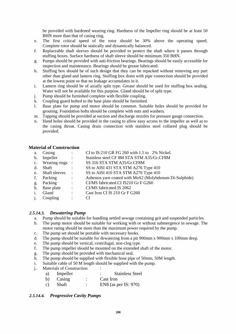
208
be provided with hardened wearing ring. Hardness of the Impeller ring should be at least 50
BHN more than that of casing ring.
e. The first critical speed of the rotor should be 30% above the operating speed.
Complete rotor should be statically and dynamically balanced.
f. Replaceable shaft sleeves should be provided to protect the shaft where it passes through
stuffing boxes. Surface hardness of shaft sleeve should be minimum 350 BHN.
g. Pumps should be provided with anti-friction bearings. Bearings should be easily accessible for
inspection and maintenance. Bearings should be grease lubricated.
h. Stuffing box should be of such design that they can be repacked without removing any part
other than gland and lantern ring. Stuffing box drain with pipe connection should be provided
at the lowest point so that no leakage accumulates in it.
i. Lantern ring should be of axially split type. Grease should be used for stuffing box sealing.
Water will not be available for this purpose. Gland should be of split type.
j. Pump should be furnished complete with flexible coupling.
k. Coupling guard bolted to the base plate should be furnished.
l. Base plate for pump and motor should be common. Suitable holes should be provided for
grouting. Foundation bolts should be complete with nuts and washers.
m. Tapping should be provided at suction and discharge nozzles for pressure gauge connection.
n. Hand holes should be provided in the casing to allow easy access to the impeller as well as to
the casing throat. Casing drain connection with stainless steel collared plug should be
provided.
Material of Construction a. Casing : CI to IS:210 GR FG 260 with 1.5 to 2% Nickel.
b. Impeller : Stainless steel CF 8M STA STM A35/Gr.CF8M
c. Wearing rings : SS 316 STA STM A35/Gr.CF8M
d. Shaft : SS to AISI 431 STA STM A276 Type 410
e. Shaft sleeves : SS to AISI 410 STA STM A276 Type 410
f. Packing : Asbestos yarn coated with MoS2 (Molybdenum Di-Sulphide)
g. Packing : CI/MS fabricated.CI IS210 Gr F G260
h. Base plate : CI/MS fabricated IS 2062
i. Gland : Cast Iron CI IS 210 Gr F G260
j. Coupling : CI
2.5.14.3. Dewatering Pump a. Pump should be suitable for handling settled sewage containing grit and suspended particles.
b. The pump motor should be suitable for working with or without submergence in sewage. The
motor rating should be more than the maximum power required by the pump.
c. The pump set should be portable with necessary hooks.
d. The pump should be suitable for dewatering from a pit 900mm x 900mm x 100mm deep.
e. The pump should be vertical, centrifugal, non-clog type.
f. The pump impeller should be mounted on the extended shaft of the motor.
g. The pump should be provided with mechanical seal.
h. The pump should be supplied with flexible hose pipe of 50mm, 50M length.
i. Suitable cable of 50 M length should be supplied with the pump.
j. Materials of Construction :
a) Impeller : Stainless Steel
b) Casing : Cast Iron
c) Shaft : EN8 (as per IS: 970)
2.5.14.4. Progressive Cavity Pumps

209
The progressive cavity pumps shall be self-priming and designed to handle abrasive, shear
sensitive and viscous materials, solids in suspension and liquid/solids mixtures.
Automatic Variable stroke frequency / stroke length arrangement shall be incorporated
wherever remote application with PLC/SCADA is envisaged and process demands these
changes through remote, Local Control Panel shall also be envisaged with each pump with
auto/manual selector switch and knob for these variations done manually.
The sludge will be a mixture of grit in the sludge that will be abrasive. The pump design shall
incorporate features that prevents ragging around pump connecting rod and rotor head and
include a shaft sleeve to protect the wear in these highly abrasive environments. These
conditions must be considered when selecting the pump. Pump should be screw type, slow
speed maximum 200 rpm having following construction features:
Casing : CI IS 210-FG 260
Rotor : SS316 Hard Chromed plated
Base Frame : ISMC Fabricated Epoxy coated
Bearing Housing : CI IS 210-FG 260
Shaft : SS 316
Foundation bolt : HTS GALVANIZED STEEL
Stator : Hypalon/Equivalent linning
Coupling : Flexible pin bush type
Coupling guard : MS Fabricated
The pumps must be sourced from a supplier that is ISO 9001:2000 certified to ensure that the
pump is manufactured to certified standards.
2.5.14.5. Polyelectrolyte solution preparation and Dosing System
Polyelectrolyte solution is needed to be prepared and dosed for aiding sludge thickening and
dewatering. The polyelectrolyte will be dosed online at the centrifuge inlet. Minimum dosage
of polyelectrolyte shall be worked out by the bidder. There shall be two poly-dosing tanks
each suitable for minimum 8 hrs. of operation. Each-tank shall be equipped with slow speed
mixer (100 RPM) to prepare polyelectrolyte solution. The solution will be fed using positive
displacement metering type dosing pumps. There shall be dedicated dosing pumps to each
centrifuge with one common standby. The pumps shall be interlocked with centrifuge so that
it can only be running in auto when centrifuge is on and should shut down when centrifuge
stops. The dosing system shall be housed in centrifuge house itself.
The polymer dosing required shall be as per peak requirement with 2 working and 2 standby.
Polymer dosing pumps hydraulically actuated diaphragm pumps simplex and duplex type
with maximum injection pressure of 5 kg/cm2 complete with PP head, PP / PVC fittings,
strainer, inbuilt PRV along with 415 V / 50 C / S suitable motor at 1000 RPM are required.
The system will also have storage bins, polymer batch tank and polymer batch tank mixers.
2.5.14.6. Dosing Pumps
Scope
The dosing pumps shall be selected to achieve optimum dosing technology and control safety
with safety relieve valve. The pump shall have a resistant plastic enclosure that can safely be

210
used for the selected application and shall provide soft and low-pulsation dosing.
The pump shall incorporate sensitive sensors that monitor the dosing flow and the diaphragm
and provide process stability. The pumps shall be designed to have separation of hydraulics
and electronics, to protected process from equipment failure.
Diaphram Valve, Gasket : PTTE
Liquid End : Stainless Steen 316
Foundation Bolt : Mild Sleet Epoxy Paint
Wetted Part : SS 316
Base Frame : Carbon Steel, epoxy Painted.
Flanges : Carbon steel
Plunger : Carbon Steel
Accuracy : ±3%
Voltage : 415 ±10%
RPM : 1440
Polyelectrolyte Dosing
Head PP
Check Valves PVC
Balls Glass
Diaphragm Teflon Faced Nitrile
Motor Details Explosion Proof Motor
2.5.14.7. Sludge Sump Pump House and Sludge Dewatering
Sludge Sumps shall be provided to collect sludge from PST & FST. The pump house shall be
constructed above the sludge sump. Sludge transfer pumps shall be provided to feed
the mechanical dewatering devices. The pump shall be screw type suitable to handle
sludge of 1 – 2% solid consistency.
2.5.15. Pipework
2.5.15.1. General
The term pipe work shall include all necessary supports, saddles, slings, fixing bolts and
foundation bolts required to support the pipes and associated equipment. The pipe work shall
be laid out and designed to facilitate the erection, painting in situ and dismantling of any
section for maintenance and to give a constant and uniform flow of working fluid with a
minimum of head loss. Where steel pipe work is used, the number of flanges shall be kept to
a minimum and the size of each length of pipe work shall be determined by the ease of
handling, installation and general appearance of the completed pipe system. Positions of
flanges shall take account of any concrete pipe supports or thrust blocks needed. Flexible
joints shall be provided where needed to facilitate removal of equipment or to allow for
differential settlement of the building. Wherever practical, flexible joints shall be provided
with tie-bolts or other approved means to transfer thrust or tension axially along the pipe
work.
Where steel and cast flanges are to be bolted together, the steel flange shall be machined over
its full face after welding to its pipe is completed. Flanges shall be finished truly square with

211
the pipe axis. Wherever possible, standard fittings shall be used in preference to special
fittings. Pipe work layout within pumping stations shall be prepared to meet the requirement
of the pump manufacturer. Valves, strainers and other devices mounted in the pipe work shall
be supported independently of the pipes to which they connect. Flanges shall be drilled in
accordance with the appropriate pressure rating. Where a pipe passes through a wall, a
retaining wall, or is subject to end thrust, it shall incorporate a puddle flange. Puddle flanges
shall be undrilled.
Material of Pipes, Sizing & Design Basis
Unless otherwise specified, the water velocity in the suction branches of a pump shall not
exceed 1.5m/s, delivery 1.8 m/s for horizontal pumps and in the discharge branch shall not
exceed 2.1 m/s for submersible pumps when the pump is operating within its specified
working range. There shall be no discernible noise due to hydraulic turbulence or cavitations
within the pump or its associated pipe work and valves.
Piping Sizing & Material
The piping and valves will be sized on the following basis for sizing.
Service / Flow Basis MOC
Gravity Lines for Sewage, Water
& Waste Water
Velocity between 0.6 to 1.2
m/s & designed as pipe line
flowing full
DI Class K 7
Pressure for Sewage, Water &
Waste Water
Velocity between 1.2 to 1.8
m/sec
DI Class K 9
Sludge line DI Suitable with
pressure rating
Air (Pressurized Lines)
[for Aeration Tank, Grit Chamber,
Gas Mixing System etc.,]
At velocities between 8 – 10
m/sec (desirable) with a
maximum of 15 m/sec in
small sections
Stainless Steel
Bio Gas At velocities between 3.5 to
4.5 m/sec (desirable)
Stainless Steel
Service Water Velocity between 1.4 to 2.0
m/sec
GI Class B
Chemical Feed Lines Velocity between 0.6 to 1.5
m/sec
PVC/ PP/ HDPE/ SS
2.5.15.2. Cast Iron Pipes
The cast iron pipes shall generally conform to IS:1537/IS:1536 and pipe fittings shall conform
to IS: 1538. All pipes and fittings above the ground level and inside pumping station shall be
flanged.
The material for cast iron pipes and fittings shall be of grey cast iron conforming to IS: 210,
Gr FG 200.

212
The pipes shall be of uniform bore and straight in axis. Length of the straight double flanged
pipes shall be within a tolerance of + 3 mm.
The flanges of the straight pipes shall be square to the axis of the pipe. The face of the flanges
shall be parallel. The bolt hole circle shall be concentric with the bore and bolt holes equally
spaced. In straight pipes the bolt holes in one flange shall be located in line with those in the
other flange.
The faces of the flanges of the fittings shall be square to the directional axes. The holes shall
be located symmetrically off the center line. The intersecting axes of the tees shall be
perpendicular to each other.
The bolt holes on flanged pipes and fittings shall be drilled with the help of drilling jig. The
blank flanges are to be machined and drilled.
2.5.15.3. Ductile Iron Pipes
The DI Pipes conform to IS 8329 /ISO 2531/BS EN 545 & Fitting conform to IS 9523/BS
EN:545. These pipes can also be offered with standard thickness for smooth flow and
corrosion resistance.
2.5.15.4. Stainless Steel Pipes
All gas pipes, fittings and other related components inside the digester shall be of stainless
steel SS-304.
2.5.15.5. Steel Pipes
All steel pipes shall conform to IS:3589.ERW steel pipes (200mm to 2000mm) for gas, water
and sewage and laying should conform to IS:5822.
2.5.15.6. Unplasticised Polyvinyl Chloride (uPVC) Pipes
The materials used in the manufacture of uPVC pipes and fittings shall comply with the
physical properties indicated in relevant specification. They shall not contain any matter
which could impart taste, odour, toxicity or be harmful to health or adversely affect the water
conveyed.
Unless specified otherwise joints shall be of the complying with BS 4346/IS4985 having an
elastometric sealing ring. Joints shall be made in accordance with the Manufacturer‟s
instructions.
Fittings shall be injection-moulded in uPVC to the requirements of BS 4346/IS4985.
Fabricated uPVC fittings or fittings manufactured in other materials will only be permitted
when the material and method of manufacture are approved by the Independent engineer
2.5.15.7. Dismantling Joints
Where dismantling joints, flexible couplings or flange adaptors are used these shall be of the
Viking-Johnson type except where otherwise specified or approved. Pressure ratings shall
match the pressure rating of the pipework in which they are installed, and materials used and
methods of protection shall not be inferior to those used for the pipework. Where needed,
joints and couplings shall be provided with tie bolts to restrain the maximum axial thrust
arising when in service.
The dismantling joints for cast iron pipes shall be of cast iron with EPDM seal ring.
2.5.16. Valves and Appurtenances
All sluice gates, isolation valves, air release valves, check valves shall be designed for the
medium carried in the respective pipeline, according to the diameter and the design working

213
pressure of the pipeline. Manual operation shall always be provided. Electrical drives shall be
provided as per requirement unless otherwise specified.
The valves shall be installed between flanges. The dismantling shall be possible by the use of
rigid or flexible dismantling pieces or flange adapters at one side. For this purpose, suitable
flange adapters may be provided. All valves shall be installed in the pipe work in such a
manner that they can easily be removed from the line for dismantling and maintenance.
The non-return valves on the pump delivery branches shall be spring loaded and have high
speed non slam closing characteristics.
Valves used in lines conveying chemical solutions and gases shall be manufactured of
material suitable for the purpose and to withstand the corrosive and aggressive action of the
medium. However for sludge pumps Knife gate valve can be accepted.
Valves used on sludge conveyance piping etc. shall be of straight through type and non-
logging. Butterfly/knife edge gate valves may also be used on sludge line.
The pressure rating of valves must at least be equal to the maximum expected pressure at the
point of installation.
The size of valves must not be less than the size of the respective main (suction, delivery)
pipes.
The material of construction of valve shall be as follows:
2.5.16.1. Sluice Valves
Sluice valves shall be generally conforming to IS: 14846:2000. Additionally they should
meet the specific requirement given below. The valves shall be double flanged machined and
drilled to IS-1538 Part IV & VI. The backside of the drill holes to be spot faced for proper
seating of bolts & nuts. Reasonable clearance behind the rear face of the flange on body and
bonnet to be kept to provide free access to use spanners for assembling and dismantling. No
tap hole is acceptable. The pressure rating of the Valves on the Suction side / discharge side
of the pump shall be as per design requirement. They should close with clockwise rotation of
hand wheel. The direction of closing shall cast on hand wheel. Nominal size, PN Rating and
Brand name should cast on the body. The valves shall be of Rising Spindle type. They shall
be with Back seat Bushing arrangement for replacement of packing without leakage. The
Valve of size 350 and above should be supplied with 2 nos. Single trust deep groove Ball
bearing on both end of spindle collar to reduce operating torque and vertical thrust on spindle.
The valves of sizes 450mm and above should be supplied with enclosed grease packed
bevel/worm gear box of suitable rating to ensure that the valve shall be operated with effort
not more than 7 KgM at the pinion shaft for manual valve only. The valves shall be provided
with position indicator for indication from full open to full close. They shall be provided with
cast iron cleaning door at the bottom of sluice valve body. The clearance between the wedge
nut housing lugs on the wedge and the inside surface of the valve body shall be adequate to
insert the wedge nut into the wedge lug recess either in the direction of water flow or in
perpendicular direction when the wedge is in closed position. The Valves shall be provided
with Air Release plug arrangement on the top of the bonnet. Sluice valves shall be electrically

214
operated with manual override facility. All valves in the pump house and on discharge
/header shall be actuator operating. The valves which are operated rarely i.e. not regularly
shall be manually operated.
SLUICE GATES FOR MPS
Provision of CI Thimble Mounted Sluice Gate with motor, actuator operated, Rising Spindle
type. Sluice gates are as per IS 13349 Including all taxes, Freight, loading, unloading, fitting
in position including Sluice gates are upward opening wall thimble mounted suitable for
isolating the flow of sewer into out of the opening in the wall. It consists Gate frame, wall
thimble, gate slide, shutter, seating/sealing faces .The gates will be provided with pads on
sides, top and bottom to mount the wedges. The gate shall be designed in such a manner, so
that it can be operated at 2 meter head. Gate frame & Shutter of CI Grade IS 210 FG 260,
Head Stock assembly bolts & SS ASTM A276 Type316, Stem, Operating Nut SS ASTM
A276 Type 316., Duly tested for tensile strength, Tested for over all dimensions as per
approved GA drawing complete in all respect as per specification and direction of Engineer,
For screen channels
Sewage Water Application
a. General
1. Sluice valve shall be conforming to IS: 14846: 2000 and with ISI marking. Additionally they
should meet the specific requirement given here under.
2. Sluice valve must be from ISO-9001 certified company towards Quality Management
System.
3. The valves shall be double flanged machined and drilled to IS- 1538 Part 4 & 6. The back
side of the drill holes to be spot faced for proper seating of bolts & nuts. Reasonable
clearance behind the rear face of the flange on body and bonnet to be kept to provide free
access to use spanners for assembling & dismantling. No tap hole is acceptable.
4. The valves should close with clockwise rotation of hand wheel. The direction of closing shall
be cast on hand wheel.
5. Nominal size, PN rating & Brand name should cast on the body.
b. Design Requirement
1. The valve should be of PN 1.0 rating/based on working pressure in the pipeline.
2. The valves shall be of Non-rising Spindle type.
3. The valves shall be with back seat bushing arrangement for replacement of packing
without leakage.

215
4. The valve size 350 mm & above shall be provided with renewable Shoe & Channel
arrangement to reduce the clearance between body and wedge lugs.
5. The valve size 350 mm & above should be supplied with 2 nos. Single trust deep
groove Ball bearing on both end of spindle collar to reduce operating torque and
vertical trust on spindle.
6. The valve size 450 mm & above should be supplied with enclosed grease packed
bevel/worm gear box of suitable rating to ensure that the valve shall be operated with
effort not more than 7 KgM at the pinion shaft.
7. The valves shall be provided with position indicator for indication from full open to full
close.
8. The valves shall be provided with cast iron cleaning door at the bottom of Sluice valve
body.
9. The clearance between wedge nut housing lugs on the wedge and the inside surface of
the valve body shall be adequate to insert the wedge nut into the wedge lug recess
either in the direction of water flow or in perpendicular direction when the wedge is in
closed position.
10. The valve shall be provided with air release plug arrangement on the top of the bonnet.
11. The valves should also be compatible with Actuator system.
c. Material of Construction
1. Body : Cast Iron to IS: 210 Gr. FG200
2. Wedge : Cast Iron to IS: 210 Gr. FG200
3. Spindle : St. Steel to IS: 6603 04Cr18Ni10
4. Seat Rings : SS to CF8
5. Spindle Nut : High Tensile Brass to IS – 320 HT2
6. Back Seat Bush : SS to CF8
7. Shoe & Channel Lining : SS to CF8
d. Shop Testing Witnessing
1. Seat Leakage Test (2 Minutes) : 10Kg/cm2
2. Body Leakage Test (5 Minutes) : 15Kg/cm2
3. Back Seat Leakage Test (2 Minutes) : 10Kg/cm2

216
SPECIFICATION OF CHECK VALVE
1. Checking valve shall be conforming to IS: 5312. Additionally they should meet the specific
requirement given below.
2. The valves shall be double flanged machined and drilled to IS- 1538 Part 4 & 6. The backside
of the drill holes to be spot faced for proper seating of bolts & nuts. Reasonable
clearance behind the rear face of the flange on body to be kept to provide free access to
use spanners for assembling & dismantling. No tap hole is acceptable.
3. The valve should be of PN 1.0 rating based on working pressure in the pipeline.
4. Nominal size, PN rating, Brand name & Direction of Flow should cast on the body.
5. The Valves shall be of Swing Check type.
6. The Valve sizes 50 to 600 mm should be of Single door design & above 600 mm should be
Multi door design.
7. The Check Valves shall be with Non Slam Characteristics. Non Slam Characteristics to be
achieved by combination of hydraulic passage and additional disposition of weight on
doors.
Material of Construction a. Body & Cover : Cast Iron IS: 210 Gr. FG 260
b. Door : Cast Iron IS: 210 Gr. FG 200
c. Hinge Pin : St. Steel to AISI – 316
d. Seat Rings : Gunmetal with 2% Nickel / IS: 318 Gr. LT B2
e. Bearing Bush : Teflon
f. Fastener : carbon steel
Shop Testing Witnessing 1. Seat Leakage Test (2 Minutes) : 10Kg/cm2
2. Body Leakage Test (5 Minutes) : 15Kg/cm2
SPECIFICATION OF KINETIC AIR VALVE
a. General
1. Kinetic Air valves shall be conforming to IS: 14845: 2000. Additionally they should meet
the specific requirement given her e under.
2. Kinetic Air valves should be from ISO – 9001 certified company towards Quality
Management System.

217
3. The Valves shall be flanged end machined and drilled to IS – 1538 Part 4 & 6
4. The valves should have an isolating Sluice Valve attached to it.
5. Nominal size, PN rating, Brand name should cast on the body.
b. Design Requirement
1. The valve should be of PN 1.0 rating /based on working pressure in the pipeline.
2. The Valves should double ball air valve consisting of large orifice (LP) & small orifice.
3. The large orifice chamber should have built-in Kinetic features to avoid blocking of the
large orifice during filling & emptying of pipeline. It should have a large timber ball
covered with rubber to be seated on a large orifice rubber ring.
4. The small orifice chamber should have a small timber ball covered with rubber to be
seated on gunmetal orifice plug.
c. Material of Construction
Body, Cover, Cowl : Grey Cast Iron. IS: 210 – 1993 Gr. – 260
Ball of small orifice : Seasoned timber ball covered with soft Vulcanite
Ball of large orifice : Seasoned timber ball covered with soft Vulcanite
Seat of large orifice : Neoprene Rubber
Nipple for small orifice : LTB. : IS 318 – 1980. LTB – 2./ AISI: 410
Isolating Gate valve : IS: 14846 (GM internals & AISI: 410 Spindle)
Bolt & Nut : M.S
d. Shop Testing Witnessing
Seat & Body Leakage Test (2 Minutes) : 10Kg/cm2
e. Painting & Coating
Pre – inspection
1st Step Surface Preparation
Blast cleaning to near white – SA 2 ½ Gr.
2nd
step Application of Primer Coating after blast cleaning
One coat of two component epoxy based primer
Post – inspection, if applicable
3rd
Step Application of Finish Coat
One coat of two component solvent free amine cured epoxy coating (Shade)
2.5.16.2. Butterfly Valves
Unless otherwise specified, valve body and disc shall be of close-grained gray cast iron.

218
Valves shall be mounted with shafts horizontal. Valves shall be fitted with indicators to show
the position of the disc, clearly marked with „open‟ and „closed‟ positions. Valves shall not
contain any brasses containing more than 5% zinc. Gunmetal conforming to BS 1400 Grade
LG2, aluminum bronze, or nickel components may be used for internal components.
Resilient-seated valves shall have nitrile rubber seals.
For valves of 900mm and above, retaining rings shall be provided to enable the sealing ring
to be replaced without the need to remove the valve body from the pipe work. Metal seated
valves of 900mm and above, shall have seat clearances adjustable to obtain as near a
watertight condition as possible, without the need to remove the valve body from the pipe
work.
Percentage Opening - Flow Curve shall be submitted along with data sheet mentioning area
where such valves are subjected for any controlling of the fluid flow.
Component Material 1 Body Cast Iron : IS:210 Gr FG260
2 Inner lining Stainless steel : BS:970 Gr 304
3 Plate /DLSC Stainless steel : IS 3444 1987
4 Stem Stainless steel : IS 6603:1972
5 Seat ring / Boss Stainless steel : IS 6603:1972
6 Gland housing Cast Iron : IS:210 Gr FG260
7 Gland packing Teflon Impregnated with asbestos+Rubber
2.5.16.3. Pressure-Relief Valves (PRV)
Pressure-relief valves shall be designed to prevent the pressure in the pipeline upstream of the
valve rising above a preset level. The valve shall remain closed at lower pressures. The
pressure at which the valve opens shall be adjustable. A pressure gauge shall be provided to
indicate upstream pressure over the operating range of the valve. Safety valves shall comply
with BS 6759: Part 1.
They shall be designed to open at the specified pressure and re-close and prevent further
release of fluid after normal pressure has been restored. The pressure / temperature rating
shall be in accordance with relevant standards. Flanged ends shall be Class 900, raised-face
type complying with ANSI B16.25 or relevant standards.
Component Material 1 Body Cast Iron : IS:210 Gr FG260
2 Inner lining Stainless steel : BS:970 Gr 304
3 Knife gate/ plate Stainless steel : BS:970 Gr 304
4 Stem Stainless steel : BS:970 Gr 304
5 Seat ring / Boss Stainless steel : BS:970 Gr 304
6 Gland housing Cast Iron : IS:210 Gr FG260
7 Gland packing Teflon Impregnated with asbestos+Rubber
2.5.16.4. Ball Valves
Ball valves shall conform where applicable to relevant standards. Multi-piece bodies shall be
used where work on the ball and seats when installed may be needed. If valves need removal

219
for servicing, one-piece bodies may be used. Seat materials shall be chosen for long life, with
erosion and corrosion resistance. Ball supports shall be of the floating ball or trunnion type. If
line pressure is too low to ensure a positive leak-free seal, built-in seat loading devices, or
specially shaped seatings shall be used to ensure sealing.
Component Material 1 Body Cast Iron : IS:210 Gr FG260
2 Inner lining Stainless steel : BS:970 Gr 304
3 Plate Stainless steel : BS:970 Gr 304
4 Stem Stainless steel : BS:970 Gr 304
5 Seat ring / Boss Stainless steel : BS:970 Gr 304
6 Gland housing Cast Iron : IS:210 Gr FG260
7 Gland packing Teflon Impregnated with asbestos+Rubber
2.5.16.5. Knife Gate Valves
The valve shall meet standards C105/A21.5-10, C520-10, C706-10, C707-10, C713-10 and
D106-10 and testing requirements of MSS SP 81.
Outer body may preferably be provided with inner liner in corrosion resistant stainless steel
which shall extend into the gland. The body shall be devoid of any wedge/ dead pockets to
avoid setting of suspended particles and solids in the service fluid.
The gate / plate shall be precision buffed and the edge contoured to a knife edge. The gate
shall move along / be guided by the seat ring to ensure that it scraps any deposit / scale
enabling smooth uninterrupted movement.
Seat shall be so designed that there is no recess / relieve groove to harbour deposition that
could build-up and swamp the valve. The design should also incorporate bosses that guide the
gate and avoid deflection ensuring positive shut-off. The stem shall have double start threads
cut in order to ensure smooth and speedy operation.
Gland packing shall offer minimal frictional resistance and precludes external lubrication. As
positive sealing elements, the packing shall also include a resilient rubber ring. The knife
edge and seat face in flow path shall be hard faced to a hardness of 400 to 450 BHN to
counter erosion. In such cases, provision shall also be made to ensure the fluid contact with
the seat ring is minimal.
Component Material 1 Body – Cast Iron : IS:210 Gr FG260
2 Knife gate/ plate – Stainless steel : BS:970 Gr 304
3 Stem – Stainless steel : BS:970 Gr 304
4 Seat ring / Boss – Stainless steel : BS:970 Gr 304
5 Gland housing – Cast Iron : IS:210 Gr FG260
6 Gland packing – Teflon Impregnated with asbestos + Rubber
2.5.16.6. Cast Iron Flap Valves (Circular Flap Valves)
The Flap Valves with circular aperture, single door and double flanges, shall be provided.
The flap valves upto 600mm dia shall have sealing faces in angular section and secured to the
frame and door by a force fit. For sizes above 700 to 2000mm dia the sealing faces are of

220
rectangular section and are secured to the frame and door using countersunk taper headed
screws in the same material as the sealing face. The flap valve shall be suitable for mounting
on a vertical wall or flange for static seating heads up to 6 meters.
Material of Specification
Frame
Constructed in BS EN 1561 min. 250 cast iron designed for wall, thimble or pipe mounting
applications.
Door
Constructed in BS EN 1561 min. 250 cast iron designed to withstand static seating heads up
to 6 meters.
Sealing Faces
Copper alloy sealing faces to BS EN 1982 : 1999 are supplied as the standard material for
ranges up to 600mm dia and for the ranges 700 to 2000mm dia phosphor bronze to BS EN
12167 : 1998. Sealing faces are set to 0.1mm feeler gauge non-acceptance to provide an
effective seal.
Hinge Links
Manufactured in Spheroidal Graphite cast iron
Fasteners
Standard fasteners are supplied in stainless steel to BS EN 10088 : 1995 grade 1.4401 (316).
Hinge Pins
Manufactured from stainless steel to BS EN 10088 : 1995 grade 1.4401 (316).
2.5.16.7. Sluice Gates
Sluice gate shall be preferably wall thimble type. However for controlling/isolation of flow in
channels, channel type gates may also be accepted by Jal Nigam as per application
requirement.
The construction of Sluice Gates shall be in accordance specification and generally to
IS:13349. The Sluice Gate shall be designed for Seating & Unseating Head without
sacrificing reasonable degree of leak tightness. The frame of Sluice gate shall be flanged back
type and shall be machined on the rear face to bolt directly to the machined face of the wall
thimble. The seating faces shall be made of solid section strip of Stainless steel. They shall be
secure firmly by means of counter sunk fixing in finished grooves in the frame and slide face
in such a way as to ensure that they will remain permanently in place, free from distortion
and loosening during the life of the Sluice Gate. Sluice Gates shall be equipped with
adjustable Side & Top wedging devices as required to provide contact between the slide and
frame facing when the gate is in closed position. The gates shall be of Rising Spindle Type.
They shall be operated through a suitable operating mechanism. The Lifting mechanism shall
incorporate gearing arrangement, if required to keep the torque requirement within 7 KgM
except electrically actuated gate. In case of gearing, those to be enclosed grease packed Bevel
or Worm Gear box type. Lifting mechanism shall be provided with suitable position indicator

221
to show the position of the gate from full open to full close. The indicator to be provided in
the head stock only. Stem Cover to be provided on the top of head stock for the rising
spindle. The cross section of the wall thimble shall have the shape of the English letter „F‟.
The Sluice gate shall be provided with Flush bottom seal. This is a solid square cornered
resilent rubber seal provided on the bottom facing of the slide. The seal may be secured
fastened to the bottom of the face of the slide by a retainer bar and fasteners. The top surface
of the bottom facing of frame shall be flush with invert of the gate opening. Bottom facing of
the slide shall be accurately machined to make contact with the seal when the slid is closed.
Gates shall be fixed for positive seating. Sluice gates shall be electrically operated with
manual override facility. The Sluice Gates shall be of Class – 2 i.e., suitable for maximum
unbalanced head needs as per calculation/design.
Material of Construction
The materials of construction of important components of gates will be as under: a. Frame & Shutter Cast Iron IS: 210 Gr. FG 200
b. Wall Thimble Cast Iron IS: 210 Gr. FG 200
c. Seating Faces & Counter Sunk Fixing Stainless Steel ASTM A276 type 316
d. Wedging Device Cast Iron IS: 210 Gr. FG 200
e. Wedge Linings Stainless Steel ASTM A276 type 316
f. Stem & Stem Coupling Stainless Steel ASTM A276 type 316
g. Stem Nut Stainless Steel ASTM A743 CF8M or SS316
h. Flush Bottom Rubber Seal EPDM ASTM D200
i. Seal retainer bar Stainless Steel ASTM A276 type 316
j. Fasteners, Studs Anchor Bolt & Nuts Stainless Steel ASTM A276 type 316
k. Lift Nut Bronze IS: 318 Type LTB-2
l. Headstock, Stem Guide Cast Iron IS: 210 Gr. FG 200
m. Hand wheel Mild Steel IS: 2062

222
n. Painting Ordinary Black Bituminous Paint
Standard Painting
Unless otherwise specified elsewhere provide following standard painting.
- Surface preparation: Blast clean or Ground to near white metal finish
- Priming: 1 coat of red oxide primer before and after shop testing. Total priming thickness 75
microns.
- Finish painting for gate assembly: 2 coats of black bitumen paint for gate assembly. Total
paint thickness inclusive of priming 200 microns.
- Finish painting for headstock: Grey enamel paint. Total paint thickness inclusive of priming
150 microns.
Shop Testing Parameters
- Leakage test at operating pressure for gate leakage performance.
- Movement test for checking interference free movement of complete assembly.
- Seat clearance check for checking clearance between mating sealing faces.
- Positive Material Identification test for all material other than cast iron.
2.5.17. Electrical Overhead Traveling (EOT) Crane
The capacities of various EOT‟s shall be decided as per recommendations of IS: 875.
The crane shall be of single / double girder type designed from lowest sump level and up to
under size of the bridge.
Suitable crane rails complete with fixing bolts, nuts, washers and anchor plates shall be
supplied for each crane.
The bridge structure shall be formed by a single/double cross girder with the hoist units
traveling along the lower flange of the bridge girder.
The end carriages shall be fabricated adequately stiffened throughout their length to produce
a section with high torsional resistance designed to eliminate and tendency for the bridge to
cross whip. The carriage wheel shall be adequate proportioned in relation to its span to give a
widely distributed load on the crane rails.
Proper selection of reduction gears shall be done to run drive motors. Wherever required the
motor enclosure shall afford protection to IP: 55 of IS: 4691 and have cooling facility to IC:
41 of IS: 6362. Each drive motor shall be fitted with an automatic electro-magnetic brake to
stop the crane on interruption of the power supply, whether intentional or accidental power
failure.
Suitable end stoppers/buffers shall be provided on the bridge girder and at each end of crane
rails.
The crane and hoist shall conform to IS: 3177, IS: 3832 and IS: 3938, class 2, medium duty
and meet specified operational requirements.

223
Power feed to the crane shall be form a shrouded conductor rail system and that to the hoist
shall be through close looped flexible suspension system with carriers sliding along a wire
across the full span of the crane.
Proper illumination of the area shall be done under the crane and on the crane.
All the crane and hoist functions and excluding the illumination lights shall be controlled
from a single pendant push button station. The pendant unit shall be suspended from a special
track spanning the bridge length using a non-metallic cord and not the control cables. The
pendant shall operate on a low voltage (typically 220 volts AC) source, incorporated with a
key operated switch to operate switch to prevent unauthorized operation and indicators to
indicate ail crane or hoist movements including start and stop.
EOT Operations and faults shall be interfaced with respective LCP about their operations.
Lifting speed Low 0.9 MPN
High 3 MPN
L.T. speed 10 – 15 MPN
C.T. speed 10 MPN (Max.)
However illumination lights to be operated by separate switch which will not be mounted on
pendant.
Other Common specification:
Brakes All brakes are electro-hydraulic thrusters/ECM brake
Operation Through pendent push button
Gear box Precise machine cut hardened material gear noiseless operation long
life
Cable All cables are insulated ISI Marked
Power supply All 415:440 4 phase 50 Hz. AC supply
Control voltage 220/230 volts-50 Hz
The hoist shall comply Class II with the performance requirement IS 3177/80, IS: 3938/IS:
3832 Class 2.
The electric hoist shall be fitted with right and left handed spiral grooved cast iron drum with
a rope hoist arrangement with spring loaded rope band and guards to ensure accurate rope
guidance and location.
Hoist rope shall be extra flexible, improved plog plough steel rope with well lubricated hemp
core and having 6 strands 37 wires per strand with an ultimate tensile strength of 160/180
kg/sq.mm. The braking load for the hoist rope shall be as per IS: 2266.
Electromagnetic brake shall be provided to hold suspended load instantly, securely and
automatically in the event of the electric current being cut off whether intentionally,
accidentally or due to power failure.
The lifting hooks shall be single „C‟ type complying with the requirement of IS: 15560 made
from grade C30/C20 carbon steel. The hook shall have a safety latch to prevent rope coming
off the hook.

224
2.5.18. Chlorination System
Chlorination system shall consist of chlorine contact tanks for disinfection of wastewater
from secondary clarifier, chlorine building housing equipment like chlorinators, chlorine ton
cylinders, chlorine ejector, chlorine leak detector, ventilation system, emergency chlorine
scrubber etc,
Chlorine solution diffusers shall be installed at the dosing point. Inlet chamber of the contact
tank shall have rapid mechanical mixers. The chlorine dosing shall be designed with
minimum chlorine dose of 8 PPM at peak flow. The residual chlorine should be not less than
0.2 PPM.
Vacuum type gas feed chlorinators comprising differential vacuum regulated flow meter,
regulating valve for vacuum & pressure, injector flow meter etc. shall be required. The
chlorinator should be floor mounted complying requirement of IS 10553 - 1983. The
chlorinator should be accompanied with booster pumps and the entire discharge line. The
moist chlorine or chlorine solution shall be conveyed through silver or platinum tubing. A pit
and alkali absorption system shall be provided to neutralize the chlorine in the event of leak.
Chlorine gas leak detector shall be provided in the chlorine storage room. Forced ventilation
system shall be provided with exhaust system industrial pattern. Chlorine residual monitoring
system shall be provided at the plant outlet.
Chlorine Gas Feed System
Minimum chlorine dose mg/l 5
Peak chlorine feed rate kg/day 275
Chlorine Ton Cylinders
Average chlorine feed rate kg/day 135
Min. storage period days 15
Capacity per cylinder kg 200
Min. no of manifold cylinders 10
Min. of cylinder to meet min. storage period
requirement
12
Min. no. of cylinders – Mani folded with
automatic switching.
10
Chlorinators
Type of Chlorinator Vacuum type-Gas Feed

225
Total No. of units 4
30 Kg/ hr. working 2
Min no of units – Standby 2 100%
Chlorine Ejector
Type Inline vacuum induction
Chlorine tonner can be provided by Jal Nigam as the chlorine gas is being purchased for
various plants.
Chlorine Contact Tank
Chlorine Contact Tanks
Min No of Units 1 with baffle wall
Material of Construction Reinforced Cement
Concrete
Chlorination System
Trunnuion Roller Support
Bed
Roller
Shaft
Bush
Steel as per IS 2062
Steel IS 2062 – Cadimum Plated
EN 8 BS 970 – Cadimum Plated
Gun Metal
Auxiliary Container Valve with Yoke
Valve Body
Spindle
Gland Packing
Yoke
Aluminium Silicon Bronze
Monel 400
PTFE
Forged Steel
Electrical Auto Change Over Device with
the Following
Ball Valve
Body
Ball
Seat
Forged Carbon Steel
Monel 400
PTFE
Pressure Switch Isol. Valve
Type
Diaphragm Sealed
By pass valve
Type
Body
Ball
Carbon Steel

226
Ball
Seat
Monel 400
PTFE
Gas Filter
Body
Filter Element
Seamless Carbon Steel 80 Sch,
Glass Wool
Pressure Reducing Valve
Body
Spindle
Spring
Diaphragm
Carbon Steel
Glass Filled PTFE
Hastelloy – C Silver Plated
PTFE
Isolation Valve
Type
Body
Ball
Seat
Ball
Carbon Steel
Monel 400
PTFE
Chlorinator with following accessories:
Pressure Gauge with ISO l. Valve Type Monel 400 bourdon tube
Vaccum Regulator
Body
Diaphragm & Seat
Spindle
Spring
HDPE
PTFE
Glass Filled PTFE
Hastelloy – C Silver Plated
Pressure Relief Valve
Body
Seat
Spindle
Spring
PVC
PTFE
PTEFE
Hastelloy – C Silver Plated
Rotameter
End Fittings
Glass
Float
PVC
Borosilicate Tapered
PTFE
Flow Control Valve
Body & Spindle
Type
PVC
V- Notch
Differential Regulator
Body
Diaphragm & Seat
Spring
HDPE
PTFE
Hastelloy – C Silver Plated
Vaccum Relief Valve
Body & Spindle
Seat
Spring
PVC
PTFE
Hastelloy – C Silver Plated

227
Vaccum Gauge
Type
Monel 400 Bourdon tube
Check Valve
Body
Spring
Diaphragm & Seat
Addl. Float
PVC
Hastelloy – C Silver Plated
PTFE
HDPE
Drain Valve
Body
Float
PVC
PTFE
Injector
Body
Nozzle & Throat
PVC
PVC
Pipe with fittings UPVC
2.5.19. Safety Equipment Severe exposure and potential health hazards exists due to chlorine atmosphere. The various
safety equipment like gas masks, oxygen breathing apparatus, portable air blower and
inhalator shall be provided keeping in mind the safety of staff operating chlorination system.
The Equipment shall include the following:
Canister type Gas masks with full face piece for short exposure.
Self-contained breathing apparatus with full face piece and a cylinder of air or oxygen carried on
the body.
Two sets of approved positive airline breathing apparatus, each comprising body harness, face
masks and valves and 30m of airline. One air trolley, comprising wheeled frame with two air
cylinders, control manifold, airline hose and hose winding drum. Two spare cylinders suitable for
changeover shall be provided.
Suitable quantity of air cylinders of capacity 1200ltr for recharging air cylinders, compete with
quick release air hose couplings.
Four sets of safety clothing in various sizes, each comprising PVC overall, wellington boots with
steel toe caps, goggles, gloves and helmets.
Gas leak detectors portable type -2 no.s
2.5.20. Emergency Equipment (General)
2.5.20.1. Fire Extinguishers
The Bidder shall provide required no. of dry powder type CO2 fire extinguishers (10 kg) for
the pumping station and switchyards at the following locations after consultation with the
Independent engineer:
Outdoor switchyard
Indoor electrical room
Pump rooms (maintenance bay)
Control room

228
GAS handling area
First Aid boxes and manual stretcher .
Besides above, Ionisation smoke, optical smoke & heat detectors shall be provided in control
room with fire alarm panel having appropriate battery back-up. Fire alarm detectors shall be
provided both below & above false ceiling, if any Fire alarm system and public address
system shall be provided at the
Plant.
All the smoke and heat sensors shall be wired up to nearest JB and interfaced to respective
PLC/DDC for alarm annunciations.
2.5.20.2. Spillage and Leakage
Chemical preparing, dosing and transfer equipment shall be designed and arranged so that
any leakage and spilling can be controlled and cannot enter ducts, channels, etc. and have a
corrosive impact on pipes, cables or other equipment of the plant.
At all lubrication or greasing points grease trays or pans shall be provided to collect excessive
lubricant or spillage onto the equipment or into sewage.
2.5.20.3. Installation Work:
Equipment shall be installed in a neat, workman like manner so that it is level, plumb, square
and properly aligned and oriented. Tolerance shall be as established in the manufactures
drawing or as stipulated by Jal Nigam . No equipment shall be permanently bolted down to
foundation of structure until the alignment has been checked and found acceptable by Jal
Nigam.
Manufacturer‟s drawings, instructions and recommendation shall be correctly followed in
handling, setting, testing and commissioning of equipment.
2.5.20.4. Leveling and Grouting of Machinery
The pumps, motors and other equipment shall be properly and accurately leveled and aligned
on the concrete plinth by means of tapered metal wedges and metal packing pieces before any
grout is poured. After correct alignment and leveling the foundation bolts shall be nipped up
to hold the machine firmly in position and it shall be the Selected Bidder's responsibility to
check that the position is maintained after the grout has been poured but before it sets. The
grout, which will contain an approved expanding agent, will be mixed and poured by the
Selected Bidder. Grouting material used for grouting should be as approved by Independent
engineer.
The horizontality of base plate top shall be within 0.05 mm/metre. The base plate top surface
and pump motor box are to be blue matched to get a contact area of at least 80%.
After the grouting mixture has set hard the foundation bolts shall be pulled up hard and the
alignment and level rechecked. The Engineer shall be informed at all times of the progress of
this work and when any checks on alignment and level are to be carried out so that he may
witness the checks if he so requires. The approval of the Engineer or his intimation that the
alignment or level of the machines is to his satisfaction shall in no way relieve the Selected
Bidder of his obligation under contract to properly install and align the machines and pipe-
work and shall in no way prejudice the Independent engineer's rights to order rectification of

229
any installation work later found to be improperly carried out.
2.5.20.5. Tests on Completion
(i). General
When the Contract Plant has been installed on site and is ready for energising, the Selected
Bidder shall notify the Independent Engineer in writing that Tests on Completion are about
to commence. At least three days notice shall be given. The Independent Engineer may
attend the tests at his discretion.
(ii). Commissioning Tests
The Selected Bidder‟s representative shall subject the screen to the following tests. The tests
shall include, but not be limited to:
Checking alignment of all components and adjust if necessary;
Checking that all equipment, safety devices and equipment protection devices function
properly;
Examining protective coatings and repair as necessary;
Running equipment for an appropriate time and check for correct operation;
Checking the operation of all equipment under field control;
Demonstrating access cover removal.
All necessary corrections and adjustments made shall be recorded. A written report shall be
provided by the Selected Bidder‟s representative at the completion of the tests, certifying that
the equipment has been properly installed and operates satisfactorily all test records are to be
appended.
(iii). Reliability Tests
Reliability testing will not be commenced until the Tests on Completion have been completed
and approved by the Independent engineer.
The Plant shall be required to operate under the normal operating conditions within the limits
of performance offered by the Selected Bidder, and their continuous or intermittent
performance as may be more convenient for the operation of the works. The Plant shall
operate without failure of any kind for period of one calendar month.
Should any failure (other than that of an entirely minor nature) occur in any portion of the
Plant, due to or arising from faulty design, materials or workmanship or staff training (but not
otherwise) sufficient to prevent commercial use of the plant, the test shall be deemed to have
failed. The test period of one month will recommence after the Selected Bidder has remedied
the cause of the failure. The onus of proving that any failure is not due to faulty design,
materials, workmanship or training will lie with the Selected Bidder.
In cases where the responsibility for failure cannot be determined initially, the Selected
Bidder is to attend to such failures as though they were his responsibility. When the
Reliability Test has been completed to the Independent Engineer written approval, the
Defects Liability Period shall commence.
2.5.20.6. Relevant Standards
The design, manufacture, supply, storage of all equipments shall comply with all Indian
Standards, (or in the absence of Indian Standards, the appropriate International Standards)
Acts and Regulations in their latest amendment, including local statutes covering:

230
Health and Safety
Dangerous Goods
Factories and Commercial Premises
Buildings
Electricity Regulations and Codes of Practice
The Standards referred shall form part of this Contract. Other Standards, Codes of Practice
and Regulations not referred to, but which would be applicable to the design, manufacture,
installation, testing or commissioning of the equipment under this contract shall be deemed
part of the Contract.
2.5.20.7. Working Stress and Design
The design of all parts shall ensure that under the most onerous of conditions they will not be
damaged or corroded.
Any joint that will need to be dismantled during maintenance shall be made by anti-corrosion
type fasteners.
All spare parts shall be fully interchangeable with the original part. If the spare part is
unavailable due to cease of production, the Selected Bidder shall give notice to the Employer
in writing, detailing the options available to the Selected Bidder.
All parts shall be designed to minimise the risk of fire and consequential damage. All parts
shall be designed to prevent the ingress of vermin, dust and dirt. All electrically live or
moving parts shall be adequately guarded to prevent accidental contact.
2.5.20.8. Name Plates
Each main and auxiliary item to the pumping station shall have permanently attached to it, in
a conspicuous position, a name plate and rating plate, each of weather-resistance and fire-
resistance material. Upon these shall be engraved or stamped the manufacturer's name, type
and serial number of equipment, details of the loading and duty at which designed to operate.

231
Mechanical Equipment General and Particular
Specifications
Schedule-II
Part-B
3.0 MECHANICAL WORKS DESIGN
1.6 Scope
The General Mechanical Works Specification covers the minimum requirements for
design, procurement, testing at manufacturer's works, supply, site testing and
commissioning of the Mechanical Works. Compliance with this specification shall
not relieve the Selected Bidder from any of his contractual obligations and
responsibilities towards fulfilling the performance requirements.
1.7 General Arrangement of the Works
The Selected Bidder shall provide and arrange the Works to comply with the
following general guidelines:
• Sufficient space shall be provided between items of Plant and adjacent Plant or fixed
structures to permit safe and convenient access for operation and maintenance.
• Layout of the site structures/equipment shall be cognisant of code distances required
between non-hazardous and hazardous structures/plant/equipment, etc.
• An area adjacent to all mechanical Plant shall be provided as a maintenance lay down
area.
• Electrically operated cranes, fixed runways, lifting eyes or other means shall be
provided to permit the removal of larger items of STP that may logically be required
to be removed during the course of its normal operational life for maintenance or
replacement purposes.
• Areas where leakage of water is likely to occur, whether in normal use or during
maintenance, shall be provided with covered drainage channels which shall direct
spillage either to a suitable drain or to a sump from where it can be pumped to an
appropriate place for safe disposal.
• Where necessary, the equipment shall be provided with removable acoustic coverings
to limit the noise produced during normal operation to the limits detailed elsewhere.
• Pipework shall be designed and installed to prevent blockages and to permit their
clearance without dismantling pipework or equipment.
• The Selected Bidder shall take due regard to the potential of hazardous mixing of
chemicals, particularly as a result of leaks and spillages, and their drainage and
containment.

232
• Chemical pipework shall be secured to racks or trays, to walls of tanks and walls of
buildings as necessary. It shall be arranged to facilitate maintenance and removal of
individual runs without dismantling adjacent pipes.
• All chemical pipes shall be colour banded and suitably labelled to enable individual
lines to be identified throughout their run.
• The Selected Bidder shall provide all signage necessary to inform of chemical and
operational hazards and to comply with statutory legislation.
1.8 Pumping systems
The Selected Bidder shall provide pumping systems with isolation valves, non-return
valves, gates with actuator and all necessary pipework and fittings.
The Selected Bidder shall provide pipe supports, hangers and anchors to support and
control movement of pipes and valves all in accordance with recognized international
piping standards.
Unless otherwise specified, the Selected Bidder shall provide all pumping systems
with standby pump sets of the same type and capacity as the duty pumps, providing a
standby capacity of not less than 50% of the total duty. All pumps shall operate at
high efficiency throughout their duty range and they shall be capable of continuous
operation throughout their required operational range. The minimum diameter of pipe
for sludge transfer shall be 150mm.
Lubrication arrangements shall be designed to avoid any contamination of pumped
fluid.
Dry well mounted pumps shall provide effective means for collecting gland/seal
leakage water which shall be piped to a floor drain or sump.
Design of pumps with suitable head and discharge should be done by selected bidder
as per CPHEEO manual considering (4 working + 50% standby) pumps .
1.9 Materials of construction
All materials of construction for tanks, vessels, pipelines, pumps, valves, etc. shall
be suitable for long term contact with the liquid or chemical concerned and at the
prevailing concentrations. Equipment shall be coated and protected in accordance
with Painting and Protective Coatings.
All pipework employed shall comply with the schedule below unless agreed with the
Independent Engineer. It is the responsibility of the Selected Bidder to ensure
compatibility of all pipelines with fluids or sludge carried and with external and
internal loadings and pressures.
Service Size range Pipe material
Potable and raw
water including
supernatant
Up to and including DN
300
Ductile iron (DI)
Poly-ethylene (PE)
DN 300 – DN 600 Ductile iron (DI)
Steel
Poly-ethylene (PE)
Greater than DN 600 Ductile iron (DI)

233
Service Size range Pipe material
Sewage (pumped
below ground)
Up to and including DN
300
Ductile iron (DI)
Greater than DN 300 Ductile iron (DI)
Above ground pipe-
work and within
structures
Up to and including DN
300
Ductile iron (DI)
uPVC
Stainless steel (304L)
Greater than DN 300 Ductile iron (DI)
Steel
All sewage pipework
underneath
structures
Up to and including DN
300
Ductile iron (DI)
Greater than DN 300 Ductile iron (DI)
Steel
Stainless Steel (316L)
All pipes under roadways &
structures to be concrete encased.
Compressed air All diameters SS 304
Sampling All diameters (uPVC)
Instrumentation
process piping
All diameters Copper (plain/coated)
uPVC
Nylon
Stainless steel
Chemical dosing All diameters Sch. 80 PVC &According to
manufact-urer‟s recommendations
Natural Gas MDPE below ground
Stainless steel or steel above
ground/inside buildings
Sludge All diameters Ductile iron NP 16 rated below
groundStainless steel (304L) above
ground/inside buildings
Biogas All diameters Stainless steel 316L (below ground,
inside/outside buildings)
Process Air piping Blower discharge and
common header– All
diameters
SS 304/316L (within building)
Transfer to and
distribution piping
around aeration tanks -
All diameters
Stainless steel (316L)
1.10 Isolation and drain down
The Selected Bidder shall provide facilities for isolating and draining down all
pipework, chambers and storage tanks. Wherever duty/standby equipment is provided,
it shall be possible to isolate and drain-down each of the duty or standby items while
the other items are in service.

234
4.0 Particular Specifications
2.6. Medium and Fine Screens
4.1.1 Scope of Supply The scope of supply shall provide complete automatic mechanical screen systems
with all accessories and appurtenances, including, but not limited to:
Mechanically operated screen;
Screenings collection, washing and disposal system;
Automatic screen control system;
Electrical & Instrumentation for compliance of Automatic System (Electrical wiring between
all screen components, instruments, control devices and the local control panels and the
screen controls;)
4.1.2 Guaranteed Flow Rate and Head Loss The screen shall effectively screen all flows up to the design flow. The Selected
Bidder shall guarantee the following screen performance parameters:
Clean water flow rate capacity (l/s) at the maximum allowable water depth downstream of the
screen
Clean water head loss at the max flow rate and maximum allowable water depth downstream of
the screen
4.1.3 Screening Arrangements Selected Bidder shall provide automatic mechanical fine screen to remove particles
larger than 6mm size.
It is proposed to install sufficient number of appropriately sized automatically
operated mechanical fine screens (stainless steel grade – SS316) of opening size
6mm for screening out floating materials such as plastic pouches, bags, rags, floating
debris, weeds, paper wastes and other floating materials from the raw sewage coming
from the pumping station. Capacity of each channel shall be equal to of average flow.
Fully automatic mechanical screen along with the level sensing instrument for
automatic operation of screen mechanical and allied accessories, (local control panel
near screen,) shaft less screw conveyor with/cum compactor are to be provided.
The fixed as well as movable bars/ perforated band, mechanism, support frame,
fixings discharge chute shall be manufactured from stainless steel grade 304 for long
life in the aggressive sewage environment.
Automatic Screen Clearing and Screenings Removal
The screen shall be provided with the necessary controls and sensors to anticipate
blockage of the screen, and automatically clear the screen and remove the
accumulated screenings from the screen surface. The screen shall operate
automatically when the upstream water level increases beyond a pre-set limit and it
shall stop when the upstream level decreases to pre-set low level.
Screenings Conveyance, Compaction and Dewatering
The screening system shall be supplied with a duty and standby shaft less screw
conveyor that will be used to convey the screenings to the automatic screenings press
and discharge system that compacts, dewaters and discharges the screenings through
a chute to the screenings storage system.

235
The screenings dewatering and compaction system shall compress and dewater the
screenings such that the screenings from a consolidated mass with no free water
entering the screenings bag.
Screen Washing System
The Selected Bidder shall supply and install spray washing system that effectively
cleans the screen area and screening press. The Selected Bidder shall provide a high-
pressure clean water supply for the washing system.
Dewatered Screenings Discharge Chute
The screenings discharge chute shall terminate 1.5 meters above ground level. A
plastic screenings bag shall be secured around the chute, thereby creating a totally
enclosed screenings collection system.
Screen Covers
All screenings equipment shall be supplied with integral stainless steel covers that
prevent access to moving and wash water sprays. The covers need to be airtight to
ensure that no odours emanate from the screen.
Portable Screenings Container
Portable screenings containers made of galvanised steel duly epoxy painted shall be
provided to store the screenings until time of pick up. The container shall have
capacity of approximate 5 m3 and shall be of a convenient height to permit the
discharge of screenings directly into the container without having to transfer the
screenings manually. The containers shall have hinged covers and their design shall
permit them being lifted by an overhead hoist or packer truck. The container will
have four wheels each of about 20 cm diameter and two of which shall be swivel
castors. The maximum height of container including wheels shall be 0.6m. The sides
shall be constructed of minimum 12 gauge steel. The bottom of container shall be
made minimum of 6mm plate steel. The containers shall be reinforced with 50mm x
50mm x 5mm angle iron.
Electrical Motor
The motor shall be TEFC type with IP 55 protection & Class F insulation and shall be
suitable for operation on 3 phase, 415V + 10% and frequency of 50Hz + 5%. Motors
shall be squirrel cage type conforming to IS 325. The power rating of motor shall be
at least 125% of maximum power requirement.
Control Panel
The Control Panel shall have IP 65 protection, painted with Epoxy paint and shall be
comprise:
- Mushroom Head Emergency stop.
- Overload relays for motor protection.

236
- MCB‟s, HRC Fuses and Glass Fuses.
- Circuitry to operate the screen with level sensors.
- Selector Switch to operate the screen on JOG mode.
4.1.4 Access
Safe access shall be provided to all screen equipment and instruments to allow for
cleaning, inspection and maintenance activities.
4.1.5 Corrosion Resistance
All metal parts of the screen equipment that are in contact with the sewage shall be
constructed of a suitable grade of corrosion resistant stainless steel.
4.1.6 Installation, Testing, Commissioning and Training
It is the Selected Bidder‟s responsibility to install the screen system correctly and
achieve the required operation. The Selected Bidder shall provide a representative
who has knowledge and experience in the proper installation, start-up and operation
of the screen equipment to inspect the final installation and supervise the
commissioning tests.
2.7. Grit Removing Equipment
Grit chambers shall be of vortex type with centre drive and independent washer or
classifier. Grit Basin equipment, complete with all accessories including, but not
necessarily limited to, gear motor, turntable, propeller drive tube, axial flow
propeller shall be provided.
2.2.4. Vortex type with central drive grit removal system
The Vortex Grit Basin equipment shall be installed in concrete basins. The
equipment to be supplied shall be suitable for installation in these basins. The grit
chamber shall be designed to operate on the vortex principle. Drives, bearings, and
support equipment for grit mechanism shall be supported by and readily accessible
from a concrete walkway above the water surface.
2.2.5. Grit Separator:
The grit chambers shall conform to the following construction, operation guidelines
and have the accessories as indicated below:
Vortex Type Grit removal chamber with low head loss systems shall be proposed
for this project. Each grit chamber shall be complete with the minimum equipment
but not limited to gear motor, gear head, axial flow propeller and scrapper with
drive, grit removal pump and auxiliary equipment required for operation. The grit
removal unit shall have low head loss and shall be capable of removing grit from
raw waste or process water and depositing the grit in a storage hopper. An integral
grit transporting means shall be provided to transport the grit from the storage
hopper to the disposal means. To minimize the possibility of clogging, all internal
openings in the piping to the grit pumping device as well as the grit pumping device
shall be large enough to pass a 100 mm sphere. No bends or elbows will be allowed
in the piping on the suction side of the grit pump. All drives, lubrication and
bearings shall be readily accessible from walkways above the operating water level.
To minimize the possibility of organic capture, the floor of the grit separation

237
chamber shall be flat and there shall be no greater than a 80 mm opening for grit to
pass through to the storage hopper. Sloping floors in the upper chamber will not be
allowed due to reduced grit removal efficiency and extra construction costs. To
ensure the efficient transport of the grit and simultaneous lifting and discharge of
the organic material, the bottom of the upper chamber covering the storage hopper
shall be constructed suitable corrosion proof / or thick steel plate , free from
rotation, and shall be flat. The grit moving across the bottom of the chamber shall
be hydraulically scoured by an air lift pump or a propeller pump. The grit shall pass
from the removal chamber through an opening in the transition plate and drop into a
grit storage hopper. The flow in the removal chamber shall travel between the inlet
and the outlet a minimum (270°), providing maximum travel of the liquid for
effective grit removal. The Grit Chamber shall handle all flows equal to or less than
a hydraulic peak flow. The influent flume, transporting the liquid waste to the grit
chamber, shall be of the size and shape shown on the contract drawings to assure
that grit does not settle in the inlet flume and to provide for proper operation of the
grit chamber. A grit storage hopper with a 60° sloped bottom shall be provided with
effective grit storage for the designed flow. , grit pump will be either an air lift
educator pump or a turbo grit pump close-coupled, vacuum primed type with
curved multi vane impeller. Grit Classifier / Washer shall be rake or Shaft less
screw type. The material of construction of all wetted parts shall be in SS 316.
2.2.6. Operating Conditions The grit chamber shall operate on the vortex principle. To maximize grit removal
efficiency, the grit chamber hydraulics shall incorporate a toroidal flow path enhanced
by a slow vortex.
The grit removal device shall be capable of removing the following at the specified
hydraulic peak flow rate, and no decrease in efficiency will be allowed at flows less
than this design rate.
- 95% of the grit greater than 150 microns in size,
- 75-85% of the grit greater than 100 but less than 150 microns in size,
The displacement type blower shall have the capacity to provide sufficient quantities
of air at the required pressure to ensure efficient operation of the air wash/airlift
system.
Grit Trap
Item Description MOC
Air Lift Pump Stainless Steel
Geared Motor Assembly STD
3 Way Valve Stainless Steel
Screw Classifier Stainless Steel
2.8. Clarifier Mechanism
The Clarifier Mechanism shall be suitable for installation in RCC tank and circular
radial flow fixed bridge with scum collector, central turn table type clarifiers shall be
provided. Clarifier should be rugged and robust in design and should be provided with
high capacity drive head having high torque rating, centrally located with positive

238
sludge raking by means of two raking arms. Both the raking arms should have scraper
blades fitted at the bottom, so that the sludge from one scraper blade is pushed to the
other on every rotation. The centre drive head mechanism arrangements should consist
of a turn table base casting mounted on top of the centre pier and having an annular
ball bearing on which the internal gear that supports the underwater mechanism turns.
The pinion meshing with the internal gear should be driven through a worm gear
reduction unit mounted on top of the turn-table drive unit. The balls should ride on
hardened steel strips set into groves in the base and gear castings so that they can be
readily replaced whenever it is necessary. An overload alarm containing switches
controlling the alarm ball and motor in case of excessive load should be mounted on
the worm gear housing. An overload alarm device should be provided with mechanism
to indicate the overload conditions on the scrappers.
The mechanism shall comprise but not limited to the following main components:
- Bridge Superstructure spanning half the tank diameter with central maintenance platform
- Drive assembly complete with drive head, chain & sprocket, geared motor etc.
- Feed Well
- Center cage
- Cone scraper
- Rake arms
- Tie rods for rake arms
- Plow blades & squeegees
- Scum Blade & Skimmer assembly
- A-frame supports for the skimmer assembly
- Scum trough and ramp with support angle
- Scum baffle with supports
- Weir plate
Bridge Superstructure:
The bridge shall span half the diameter of the tank. The width of the walkway shall be
minimum 1.5 M. The bridge shall rest on the clarifier wall at the one end and the
drive at the center. The bridge shall be of truss type welded steel construction with
walkway of gratings supported by cross members. The truss bridge shall be provided
with one row of handrail in the middle. The bridge shall be provided with a drive
maintenance platform at the center.
Drive Assembly with Drive Head :
The central drive head shall rest on the RCC center pier and supports the bridge at the
center. The drive head shall be coupled to a geared motor through chain & sprocket
and shall support the center cage at the bottom for rotating the rake arms.
Feed Well:
A fixed feed well shall be hung from the bridge superstructure. The inlet feed pipe
shall connect to the central inlet column at the bottom.
Center Cage:
The center cage shall be of welded steel construction. The center cage shall be bolted
to the drive head at the top and shall support the rake arms at the bottom.

239
Cone Scraper:
A cone scraper shall be attached to the bottom of the center cage and shall serve to stir
the sludge in the bottom hopper.
Rake Arms & Tie Rods:
Two sets of rake arms shall be attached to the center cage in diametrically opposite
direction through a hinged connection. The rake arms shall be attached to the center
cage through tie rods with provision for adjustment of inclination of the rake arms.
Each rake arm shall be provided with plow blades at the bottom and adjustable
renewable squeegees for scraping of sludge.
Skimmer Assembly & Scum Blade:
One set of skimmer assembly with scum blade shall be attached to the rake arm and
shall serve to skim the floating material. The scum blade shall span from outside of
the feed well to scum baffle at the periphery of the clarifier.
Scum trough and ramp with support angle:
One no. scum box comprising of scum trough with ramp shall be provided at one
point along the periphery of the clarifier and shall serve to collect the scum discharged
by the scum blade into the trough. The scum box shall be supported from the side wall
by support angles. The scum box shall be provided with flange connection of
specified size for connection of scum pipe connecting the scum box to the scum
sump.
Scum baffle with supports:
The scum baffle shall be provided along the periphery of the tank to prevent floating
matter from reporting into the overflow. The scum baffle shall be supported by
support brackets from tank wall.
Weir Plate:
V-notch weirs shall be provided along the periphery of the overflow collection
launder for uniform draw-off of the overflow. The weir plate shall be fixed to the
launder by means of plate washers.
Material of Construction :
Feed Well SS 304, minimum 3 mm thick
Bridge MS with Hot dip Galvanized (galvanizing minimum thickness
shall be 80 micron) (welded/nut bolted/riveted truss in a
consolidated single component and no site welding shall be
allowed)
Rake Arm MSEP, minimum 5 mm thick
Center Cage MSEP, minimum 5 mm thick
Rake Blades MSEP, minimum 5 mm thick, 1500 m wide x 150 mm ht
V-notch weir SS 304, minimum 6 mm thick and 300 mm wide
Squeegees Neoprene rubber, 10 mm thick, adjustable type
Walkway Heavy duty MS epoxy coating grating, radial upto centre

240
minimum 10 mm thick
Handrail (both ways in
two layers minimum 1 m
high)
32 NB SS Pipe (radial upto centre)
Scum skimmer assembly MSEP, minimum 5 mm thick and 300 mm wide
Scum Box MSEP, minimum 3 mm thick
Scum Baffle MSEP, minimum 3 mm thick and 400 mm wide
Fasteners – Under Water SS-316
Fasteners – Above Water SS-316
All MS parts shall be provided with one coat of epoxy primer followed by one coat of
epoxy paint after sand blasting prior to dispatch to a total DFT of minimum 225
microns.
2.9. Diffuser
The aeration system may be provided to meet the aeration requirement as per the
process design requirement. Sufficient design calculations are to be provided along
with manufacturer standard having supplied diffuser during last five years to various
waste water treatment plants.
Fine Bubble Aeration System
Design: The membrane diffuser shall be developed specifically for Releases 1~3mm
fine bubble in the wastewater treatment plant. All materials have been selected for
their ability to withstand the effects of the chemical, bio-chemical agents and
0~100°C used in wastewater tank. The diffuser can be placed in an evenly distributed
grid system over the entire aeration tank bottom. Air can be easily through the air
orifice and integrated non-return valve into the wastewater. The air orifice design to
maintain the diffuser standard airflow input prevented the max. air enter to damage
diffuser membrane. The membrane shall be secured onto the support dish with a
constrict flex rim and retaining ring designed to increase the tension on the point of
engagement as the diffuser air rate increases.
Construction: The materials of construction for both support dish and membrane
diaphragm are non-corrosive and UV resistant.
The fine/coarse bubble aeration system will comprise:
Stainless steel (SS316) droplegs and Headers.
PVC manifolds and air distributors.
PVC diffuser holders and retainer rings.
Stainless steel supports and anchors
Bolts, nuts and gaskets for aeration system flange connections.
Air distributor purge systems.
Membrane disc diffusers with integral O-ring gaskets and subplates.
The following design features will be incorporated in the fine/coarse bubble aeration
system:
Fabricated manifold with fixed threaded union joints for connection to the air distributors.

241
Manifold sections connected with fixed threaded union or flanged joints to prevent rotation
or blow apart.
Manifold, distributor connections and supports designed to resist thrust generated by
expansion/contraction of the air distributors over a temperature range of 70°C
Air distributors perpendicular to the air manifold
Fabricated distributors with single diffuser holders solvent welded to the crown of the air
distributor for complete air seal and strength.
Air distributor sections joined with positive locking fixed threaded union or flange type joints
for all submerged header joints to prevent blow apart and rotation. Bell and spigot, slip on or
expansion type joints are not acceptable for submerged joints.
Threaded union joints designed with spigot section connected to one end of the distribution
header, a threaded socket section connected to the mating distribution header, an “O” ring
gasket and a threaded screw on retainer ring. Solvent welding shall be done in the factory.
All supports designed to allow for thermal expansion and contraction forces over a
temperature range of 70°C and to minimize stress build up in the piping system
Supports designed to be adjustable without removing the air distributor from the support.
Diffuser assembly comprising: diffuser membrane with integral „O‟ ring, sub-plate, holder,
retaining ring and air flow control orifice.
Integral check valve incorporated into the membrane diffuser assembly
PVC support plate incorporated to form an air plenum under the diffuser and support for the
membrane when the air is off
Retainer ring threads designed with minimum cross section of 3mm and to allow for one
complete turn to engage threads.
A liquid purge system to drain the entire submerged aeration piping system for each aeration
grid including airlift purge eductor line and manual control valve.
All PVC joints will be factory solvent welded. Field solvent welding will NOT be permitted.
Circular membrane diffuser discs with integral O-ring will be manufactured of EPDM
synthetic rubber compound with precision die formed slits. Thermoplastic materials (i.e.
plasticized PVC or polyurethane) are not acceptable.
Carbon black will be added to the EPDM material for resistance to ultraviolet light.
The maximum tensile stress on the diffuser will be limited to 10 psi (69 kPa) when operating
at 2.4 SCFM/sq. ft. (43.9 Sm 3 /h per m 2 ) of material. Proportionately thicker material is to
be furnished for larger diameter disc diffusers to limit the maximum tensile stress and to resist
stretching.
2.10. Aeration Tank
2.5.21. Submersible Mixers in Aeration Tank / Sludge Storage Tank Submersible mixers are used in the bio reactor for the following purposes
4) In Anoxic Tank to keep the Solids in Suspension
5) In Aeration Tank to keep solids in suspension and to improve the aeration capacity .
6) In Sludge Storage Tank
The mixer design guidelines are as follows
Mixer Duty
Application
Minimum
Pumping Rate
Mixer Min Power
Transmitted to
fluid
Anoxic Bio Reactor 1.5
times tank Volume
Tip Vel not
more than 16 m
/ sec
0.75 watt / m3
pumping capacity
Aeration tank for 0.5 to 0.75 Tip Vel not 0.75 watt / m3

242
improving aeration
efficiency
times tank Volume more than 3 m /
sec
pumping capacity
Sludge Sump
( digested / undigested
)
More than 5
times tank Volume
Tip Vel not
more than 16 m
/ sec
8 watts per m3 of
tank volume
Non less than 2 mixers hall be provided per tank .
The mixers shall be of robust construction, designed for continuous operation under
the most difficult operating conditions installed in three aeration basins.
The mixers shall be energy efficient with submersible type mixer with motor housing
in CI IS 210 Gr FG 260 and 2 or 3 blades propeller in SS 316 construction with
suitable IE3 premium efficiency motor at 415 ± 10% V, 50 C/S.
The submersible mixer shall be complete with lifting device comprising of MS Hot
galvanized minimum 60 mm tube, MS winch and steel rope and handle with all
accessories.
2.5.22. Air Blowers
The term "blower" is commonly used to define a device with a functional need for
additional airflow using a direct mechanical link as its energy source. The term
blower is used to describe different types of devices 4) Positive displacement Roots type: rotary twin /tri lobe
5) screw type
6) centrifugal / Turbo Type
Blowers are defined essentially air / gas compressing machines compressing air / gas
to a pressure of 0.9 kg/cm2 ( 9000 mm Water Colum )
For pressures exceeding 9000 mm WC Screw Compressors or reciprocating
compressors shall be used
Air blower can be 4) Regenerative / Side Channel Blowers
5) Positive displacement type: rotary twin /tri lobe
6) Centrifugal blowers / Turbo
The preference for blowers will be
S No Type of
Blowers
Suitable for Capacity
m3/hr
Delivery
Head mm
WC
Drive HP
1 Regenerative
Side Channel
Blowers
High Volume Low
Pressure
applications
Up to 400-500
m3/hr
Up to 4000
mm WC
Up to 20
2 Positive
displacement
Low / Medium
Volume and
Up to 500-
6000 m3/hr
Up to 6000-
7000 mm
Up to 150
HP

243
type: rotary
twin /tri lobe
medium to high
pressure
applications s
WC
3 Centrifugal
Turbo
High Volume /
Medium to High
pressures
Volumes in
Excess of
5000 m3/hr
upwards
Pressure of
5000 mm
WC upwards
150 HP and
More
2.5.23. General Requirements for All Types of Blowers All type of Blowers blowers should have - suction air filter and silencer,
- outlet silencer,
- pressure retied valve,
- delivery pressure gauge and
- delivery isolating and no-return valve and
- acoustic enclosure of proper design shall be provided, so that decibel level shall be
maintained as specified elsewhere.
A metallic bellow joint is provided on the delivery side of each blower. Vibration
pads shall be provided at foundation level to keep vibration of the equipment within
limits as specified elsewhere in the specification.
Casing of the blower shall be robust construction and shall be machined to proper
tolerance. Rotor along with other un-machined rotating part shall be properly
balanced so as not to cause any vibration during operation. Rotor shall be made in one
piece and securely keyed to the shaft. Means shall be provided to prevent loosening
during operation including rotation in reverse direction
The bidders should propose energy efficient air blowers/compressors of proven design
working satisfactorily with documentary evidence. For large aeration capacities
considering high efficiency, low maintenance cost, minimal foot print, minimize
breakdown time and over all low life cycle cost energy air efficient compressors shall
be preferred as per the duty application. The minimum number of standby blowers
should be 50 % if numbers of installed blowers are 2 or more otherwise 100 % stand
by .
As far as practicable the bidder should review the possibility of using same model /
rating of blowers in case there are more than 3-4 blowers for a particular application
with slidhtly different duty points so as to make a minimum type of blowers
2.5.24. Roots Types Blowers
The following specifications are essentially for Roods Type (twin lobe / Tri lobe
blowers , in case the bidder offers side channel blower or a centrifugal blower the
descriptive requirements would change accordingly .
Roots blowers shall be driven by squired case valves through a matched Ve-belt drive.
Motors shall be mounted on slide rails mounted on a common bed plate, to facilitate
the tensioning of the belts.
The horsepower rating of the blower motor (including the service factor) shall not be
less than 115 % of blower design point BHP
In case of positive displacement roots blowers the blower operating speed RPM
should not be more than
1200 RPM in case of air cooled units

244
1800 RMP in case of Water Cooled units
Inlet to blowers shall be at the top and discharge at the bottom, the axes of both being
vertical.
Connecting pipe work shall be designed for a maximum velocity of 20 to 25 m/sec.
Delivery end of the blower shall be flanged connection of appropriate specification.
4) Special Requirements for Roots Type Blowers
vi.) Though both air and water cooled units are acceptable, however the preference is for Air
Cooled unit, In case water cooled units are proposed the bidder shall provide details of
water quantity required and shall make the necessary arrangements for the same
vii.) Blower should be suitable for outdoor installation without any cover and be of suitable
construction and protection against rain
viii.) Power transmission : direct drive shall be preferred but alternative like V belt also
acceptable
ix.) The power rating of motor shall be at least 15 % above the maximum power requirement
by the blower
x.) Blower should be suitable for outdoor installation without any cover and be of suitable
construction and protection against rain
5) Material of construction
vii.) Casing : C I conforming to IS: 210
Gr FG 260
viii.) Rotor : Alloy steel
ix.) Shaft : Carbon steel C40/EN
24/19
x.) Timing gear : Cast alloy steel
xi.) Pulley and gear side plates and cover : CI
conforming to IS 210 Gr FG 260
xii.) Manufacturing Code : BS 1571
6) Tests
vi.) Hydrostatic tests Twice the maximum
working pressure
vii.) Strip test Clearances with tolerance limit
viii.) Performance test As per BS : 1571
ix.) Mechanical balancing ISO 1940 Gr. 6.3 or better
x.) Visual Inspection Before painting
2.5.25. Turbo Blower:
2.5.5.5. General Turbo Blower General Requirements / Specifications
xviii.) The high speed turbo blower should be gearless & direct driven with high frequency
permanent magnet motor. The PM motor should be high efficiency type with H class
insulation. Both, the PM motor & the blower should have lubrication-free air-foil bearing.
Super alloy material of construction of the shaft will be preferred.
xix.) The material of construction of the blower‟s impeller should be of stainless steel or
aluminium; however aerospace class high tensile strength (980 MPa) SUS630 stainless steel
17-4PH material will be preferred.
xx.) The PM motor should have perfectly matching integrated invertor (VFD) which should be
used for smooth start-up as well as capacity control from minimum of 40% to maximum of
100% output. VFD control shall be based upon constant motor current, not constant rpm.
xxi.) The starting current should be less than 15% of full load current of the motor / blower.
xxii.) Both, the PM motor & Invertor (VFD) of air-cooled type will be preferred. All cooling shall
be accomplished with ambient air only. No provisions or requirements for water cooling of

245
any kind shall be required. Heated air from the motor & inverter shall not be mixed with
intake fresh air.
xxiii.) The blower package should be microprocessor controlled with graphical touch screen display
HMI. It should be able to control following parameters – constant pressure, constant flow,
constant power & dissolved oxygen control with direct connectivity to D.O. sensor.
xxiv.) The blower should have built-in flow meter which should continuously measure on-line flow
of air.
xxv.) The blower should be equipped with pressure, differential pressure, vibration, speed, &
temperature monitoring devices.
xxvi.) Flow measurement should be an integral part of the blower and the flow measuring device
can be a orifice or a bell mouth the design with the flow being measured based on differential
pressure. Actual ambient & discharge temperatures should be measured using temperature
instrumentation. No assumptions or calculations regarding flow, pressure, temperatures or
relative humidity shall be made. All process & performance conditions shall be measured, not
calculated.
xxvii.) The HMI should display set value, actual instantaneous value & on-line trend of discharge
pressure, flow, input power, rpm, suction temperature, performance curve / map with actual
instantaneous operating point. It should also have provision to send this data for logging
purpose.
xxviii.) Static pressure measurement should be carried out at exit of diffuser of the blower to ensure
that it is equivalent to the total discharge pressure.
xxix.) The microprocessor controller should be able to accept external analogue input for remote
setting of the parameter to be controlled.
xxx.) The supplier should guarantee the total input power to the blower as per specified discharge
flow & pressure.
xxxi.) Blower shall have built in automatic surge protection. Blower with high „rise to surge‟ will be
preferred.
xxxii.) Blower package shall be supplied with acoustic enclosure covering the entire blower package
to restrict the noise level up to 80 dBA at 1 mt distance. The enclosure shall be designed so as
to be able to install multiple blowers side-by-side with all maintenance done from the front or
back of the package.
xxxiii.) Each blower shall be factory tested by the standard methods based upon ASME PTC-10:1997
measuring kw input for Wire to Air power at the inlet of the package and/or applicable test
codes such as ISO 5389:2005, JIS B 8340. Acceptance criteria is 2% tolerance on power and
flow.
xxxiv.) All machines are Air Cooled. No additional cooling water circuit required either to cool the
VFD or the motor. This reduces the maintenance of water coolers which tend to get choked,
corroded, leakage in the long run depending upon the water quality being used for cooling. It
also ensures that the wire to air efficiency is complete since ppl do not add the cooling water
power consumption and cost while calculating the LCC and ROI
2.5.5.6. High Speed Tubro Motor
High Efficiency PM (Permanent Magnet) Motor .The permanent magnet will make it
possible to have very high efficiency (96-97%) over an entire operating range.
Due to high efficiency design and manufacturing, heat generation from the motor is
much smaller compared to other regular PM motors. Hence, air cooling was made
possible and is the standard for all the models up to 800 hp. Main benefits of an air
cooling system include higher safety and less maintenance.

246
PM motors will have low starting current to a maximum of 4 to 10 % of the Full Load
Current
Motor to be suitable for v.) Input Power: 3Ø, 415Vac, 50 Hz(± 5%)
vi.) Motor Power Range: 100 hp to 800 hp including 15 % 0verload of durty point FLC
vii.) Harmonics Frequency filters to be an integral part of the motors
viii.) Should have, optimized VFD needs very small starting current (< 5% Full load current) and
provides very High Efficiency (@96-97%), which helps to reduce electric facility costs.
Because our most advanced high efficiency motor design requires minimum cooling efforts,
the motor cooling air has a surplus capability allowing for cooling of the VFD before the air
is used for motor cooling
2.5.5.7. High Speed Tubro Blower Features vii.) Oil-less Operation : due to air foil /permanent magnet bearings, ISO 8573-1
viii.) Flow Meter to be an integral part of blower showing flow rate with ±0.5% tolerance
ix.) Real High Rise-to-Surge : should have advanced current based control method enables an
active high rise-to-surge advantage. This is a critical feature required by Aeration
requirements .
x.) Compactness of System :
The starting current is only 5% of FLC. This smooth starting enables to reduce the
starting load on electrical system.
xi.) Semi-Permanent Life
These blowers can be used permanently with proper maintenance without
performance degradation.
xii.) Stainless steel impellers and packaging insure durability and allow for permanent life.
2.5.5.8. Material Of Construction
vi.) Impeller :
Casted Stainless Impeller (17-4PH) or High Strength Aluminum allow for
impellers vii.) Shaft :
Stainless Steel or Tiatianum viii.) Permanent Magnet
Permanent Magnet to be used used in the rotor, which has very good high
temperature characteristics.
Even under very high temperature and high loading condition, Permanent
magnet are not demagnetized and very stable.. ix.) Bearing
Oil free Teflon-S Air foil or Permanent Magnet bearings made from corrosion
free material like nickel , titanium alloy steel . x.) Stainless steel Housing
Semi-permanent life time of the blower core require better package material. It
is recommended it should be stainless steel without painting.
VFD is mandatory for any of these blowers.
2.5.26. Single Stage Centrifugal Blower/compressors :
2.5.6.12. General The compressors shall be motor driven, single - stage centrifugal, integrally geared,
radially split type. Each compressor shall be provided with end-suction and side
discharge, with discharge adjustable radially increments. Each compressor shall be

247
equipped with an integral intake filter/silencer, modulating inlet guide e vanes and
discharge variable vane diffusers, integral speed-increasing gear, discharge cone -
silencer, direct coupled motor, coupling and guard, inlet and discharge flexible
connectors; discharge check valve, backflow barrier, motorized blow-off valve with
silencer, lube oil system, instrumentation and control system.
The compressor equipment shall include all the ancillaries with local control panels
for each compressor and the master sequence controller integrated in the local control
panels.
The compressor equipment specified herein is intended to pressurize ambient air for
the supply of oxygen to waste water treatment aeration tanks.
The compressors will receive filtered air and will discharge to the main header. The
capacity of each compressor shall be automatically controlled to provide the airflow
rate through the compressor as required by the process. The blow-off valve shall be
open during start-up and shutdown to allow unloaded start and stop, and to avoid
surge conditions All the piping system from the blowers shall be interconnected to
feed to all the basins.
Single Stage Centrifugal Blower should have variable frequency drive for variable
motor speed control and optimal efficiency for all operation points with soft start-up
function.
The capacity regulation shall be as per the process requirement of plant however not
less than from 120% to as low as 45% with best efficiency.
2.5.6.13. Impeller type The impeller shall be of the semi open radial flow type, induced S-shaped with strong
backward leaning blades, machined as one, not welded, casted or riveted.
The impeller shall be statically and dynamically balanced. The Supplier must demonstrate
that the impeller/shaft design is designed for operating at peripheral speeds up to 115% of the
rated operating speed. The axial gap between the impeller and compressor casing must be
adjustable by means of machined spacers in order to assure the prescribed gap. Gap
adjustments by means of machining of casings or shafts may not be accepted.
2.5.6.14. Shaft Seals The shaft seals shall be of double mechanical seal non-contact, multi-point, labyrinth
type with small clearances and sufficient touch points to minimize air leakage out of
or into the casing while the compressor is running in the specified operating range or
during start and shutdown and to ensure a 100% oil free air supply.
2.5.6.15. Gear Box
c) The gearbox shall be of ample size and rated to transmit the maximum torque and power input
requirements to the compressor under all operating conditions and continuous duty. The
service factor shall be minimum 1.4. All exposed machined surfaces shall be coated with a
corrosion-resistant compound prior to shipment.

248
d) The gear drive housing shall be of light weight aluminium di casted suitable for high
temperature and sufficiently rigid to maintain the shaft positions under maximum loads. The
gear housing shall be horizontally split in order to allow easy inspection and maintenance.
The gear housing assemblies shall be machined to close tolerances for bearing fit, gear
alignment and oil tightness.
2.5.6.16. Oil Lubrication System
f) A complete lube oil system shall be provided with each compressor. The system shall be
capable of supplying clean lube oil at suitable pressure and temperature to lubricate the speed
increasing gears and bearings. All components of the lubricating system shall be installed
integral with the compressor base plate and arranged to permit ease of accessibility for
operation, maintenance, inspection and cleaning.
g) The package shall include one gearbox drive shaft driven primary oil pump and one electric
motor driven pre-lubrication oil pump, each of adequate capacity to supply lubrication for the
air compressor/gearbox when operating under normal duty, during normal start/stop and
during run down in case of power loss. The electric motor driven oil pump will operate at
start/stop of compressor and at low oil pressure, activated by the control system located in the
local control panel.
h) The lube oil filter shall be duplex cartridge type suited for the oil pump capacity, with
replaceable cartridges which can be replaced without stopping the compressor. The filter
grade shall be capable of removing particles over 10 microns with a clean oil filter and a
pressure drop not exceeding 350 mbar at design temperature and flow. Filter cases shall be
suitable for operation at a pressure not less than the relief valve setting. A visual gauge or an
electric pressure switch shall indicate when the filters are contaminated and requires
replacement.
i) Strainers shall be manually cleaned and equipped with a magnetic trap. Design and
installation shall permit ready access for cleaning.
j) An oil cooler for each compressor shall be furnished and shall be of the air-to-oil type. The
cooler shall be capable of maintaining required cooling rate at all specified ambient
temperatures. Each cooler shall be rated to dissipate the total emitted heat from the
compressor gearbox. Air-to-oil cooler shall be furnished with an electric motor-driven air
blast fan.
2.5.6.17. Local Control Panel
h) Each compressor shall be furnished with an integrated and dedicated rack based PLC,
sequencing panel including in built variable frequency drive and soft starter. All controls shall
go into a safe condition by failure and not allow the machine to be operated with any
defective control.
i) The Local Control Panel set-up shall include the Load Sharing functionality with Master
Control Panel of adequate features.
j) The local control panel shall consist of the following:

249
k) Low voltage system -with main switch and motor overload relays for auxiliary equipment
such as blow-off valve, variable diffuser, and inlet guide vanes. Further, monitoring of the
drive motor's temperature sensors, and relay for control of drive motor's main switch, with
wiring to:
l) Control system - with automatic PLC, in built variable frequency drive and soft starter with
current overload circuit to limit power consumption of the compressor, and all necessary
control circuits for oil pressure, oil temperature, surge limit, and recirculation.
m) The front panel shall be equipped with Human Machine Interface with a screen of minimum
6" color touch panel with indication of process values Low voltage and control systems
mounted in a steel panel, IP55, and internally wired.
n) Terminal strip for external wiring.
2.5.6.18. Inlet filter / Silencer d) Each compressor shall be provided with an inlet filter / silencer designed for maximum air
flow at absolute minimum pressure drop and connected directly to the inlet of the compressor
via a flexible connection.
e) Filters shall be removable through easily accessible doors and have a removal efficiency of
99% on 10 micron. The filter has to have a minimum standard of EU3 in accordance to DIN
24185.
f) The compressor has to be installed with sand trap and pre-filter at the air intake.
2.5.6.19. Bearings The bearings could be
iv.) Hydrodynamic type sleeve type bearings
v.) Magnetic Bearings
vi.) Hydrofoil Bearings
The drive shaft radial and thrust bearings can be either Hydrodynamic type sleeve type
bearings or Duplex Roller bearings. The use of hydrodynamic thrust bearings on the high
speed shaft shall be avoided as to reduce the mechanical losses and instead the thrust load
from the high speed pinion shaft shall be transferred to the low speed shaft using high
precision thrust collars on the pinion shaft. Steel backed tilting pad radial bearings with white
metal on the bearing surfaces shall be used on the high speed pinion shaft. Radial and thrust
bearings shall be pressure lubricated with sufficient oil film thickness under all operating
conditions. All bearings shall be rated for a bearing life of minimum 150,000 hours.
Vibration levels (P≤ 300
kW) ≤
: In accordance to ISO 10816-1
Vibration levels (P>300 kW)
≤
: In accordance to ISO 10816-1
Noise level ≤ : In accordance to 85 dB at 1 m
Following has to be provided for each compressor by the supplier:
- Outlet pressure transmitters, inlet temperature transmitter and a thermal mass flow meter.
The unit should allow for communication to main SCADA control system.

250
- Inlet Air Filter Differential Pressure Switch
- Oil Temperature Transmitter
- Oil Pressure Transmitter
- Oil Filter Differential Pressure Switch - Variable Vane Diffuser Position Transmitter
- Inlet Guide Vane position transmitter
- Gear vibration accelerometer transmitter
- Blower reverse rotation detector
2.5.6.20. Material of Construction
Casing : Inner Volute Aluminium AlCu2MgNi,
Outer volute Aluminium AlCu2MgNi,
Impeller : Aluminium AlCu2MgNi, open radial flow type with
backward leaning blades.
Gearwheels : High tensile SS316
Shaft fast : High tensile SS316
Shaft slow : High tensile SS316
Coupling : Geared
Filter material : As required
Machine mounts : St. SIS 1312, for damping natural rubber hardness 60
Oil Cooling : Air cooled
Acoustic enclosure : Al-Zn coated steel, isolated with glass wool, IP55
enclosure
Motor : IE3 Premium efficiency motor, IP55, insulation class F
with temperature rise F and temperature measurement in
the winding as well as of anti-condensation heater.
Cone diffuser : Stainless Steel 316
Compensator : Stainless Steel 316
2.5.6.21. Performance Test run
One compressor in each type/model shall be fully inspected and functionally tested at the
factory for performance and proper operation by Engineer or Engineer‟s approval as per
approved QAP. Performance test and acceptance according to ISO 5389 should be performed
on manufacturer test stand to the satisfaction of the engineer. The design values of the
performance table according the contract must be within a manufacturing tolerance of ± 2%
and a measuring tolerance of ± 2%.

251
2.5.6.22. Electric Motor Driven Propeller Type Aerator with Blower Aspirator Aerators
General Description
The unit supplied must be able to operate both in mixing and in aeration mode controlled
completely independently of each other. Unit must have two distinct modes of operation;
simultaneous aeration and mixing mode, and mixing only mode. The aerator consists of an
electric motor and regenerative blower located above the water surface. The motor is
connected to a hollow shaft with a protective housing positioned at a 45° angle downward
into the water.
Aerators with submersible motors are not acceptable. No Gear Box mechanism should be
required. The hollow shaft drives a mixing propeller and Saturn Ring-type diffuser beneath
the water surface. Attached to the primary propeller is a Saturn ring diffuser, which disperses
the air as fine bubbles (2.0-2.5 mm diameter) into the stream of displaced water beneath the
water surface.
Aerator / Mixer Components:
Aerator Drive Motor
1) The motor shall deliver necessary horsepower as per process design requirement at
750 RPM nominal with no gear box mechanism and shall be rated for 415 volts,
50HZ/cycle, 3 phase service, IEC Motor.
2) Motor enclosure configuration shall be totally enclosed, fan cooled TEFC and meet
IP55/56 specifications.
3) Motor frame shall be made of cast iron end brackets and cast iron body. Fan material
shall be carbon steel, aluminium, or propylene with metal hub. Fan cover shall be
cast iron or carbon steel with epoxy polyester paint - 50 micrometres thick
minimum.
4) The noise level of the motor shall be less then 60DB and in accordance with IEC
specifications.
Blower
1) The equipment shall include a high efficiency regenerative blower sized to provide
sufficient airflow to yield the rated oxygen transfer capacity. Each blower includes
the following features:
a) Maintenance free and CE compliant - Declaration of Conformity on file
b) Aluminum alloy construction
c) Inlet and outlet sound attenuating silencers to minimize noise.
d) Inlet filters with epoxy-coated wire mesh media rated for 70 microns or better.
e) The blowers shall be tropicalized for corrosion resistance and deliver
necessary horsepower as per process design requirement maximum rated for
415 volts, 50 HZ cycle, 3 phase service. Blower motors shall be wired
separately.
Mounting Flange

252
1) The mounting flange shall be stainless steel and shall permit removal of the aerator
mechanism leaving the motor in place. The mounting flange will allow the aerator to
be rotated out of the water for inspection, maintenance or storage.
Shaft / Universal Joint Coupling
1) The shaft shall be stainless steel full-welded to a forged carbon steel universal joint
coupling. The shaft must be hollow to promote maximum air flow and oxygen
transfer. Units with solid shafts are not acceptable. The shaft shall be dynamically
balanced.
2) The universal joint coupling shall include standard grease fitting for maintenance
lubrication. Units which utilize flexible couplings to attach to the shaft of the motor
are not acceptable.
3) Units supplied with couplings that require alignment are not acceptable.
4) The shaft shall be stabilized by a replaceable water lubricated bearing located within
one inch from the propeller hub. The area of the shaft supported by the bearing shall
be fitted with a replaceable hardened non-metallic sleeve.
Housing
1) The housing shall be stainless steel and flanged for mounting to the aerator. The
housing shall form a guard around the hollow shaft and support a field replaceable,
water-lubricated bearing press-fitted into the housing lower end. Water lubrication
holes shall penetrate the housing in the area surrounding the bearing.
Bearing
1) The aerator shall be supplied with a field replaceable water lubricated lower support
bearing. The bearing shall be constructed of an appropriate material for the
application inside a fibre backing. The bearing shall be press-fitted into the housing
to allow ease of replacement.
2) Units utilizing a cantilever design without a lower support bearing or regreaseable
tapered roller bearings are not acceptable.
Sleeve
1) The replaceable hardened non-metallic sleeve shall be the only moving part in
contact with the electrometric bearing and shall spin with the shaft as one unit. The
sleeve shall be solid and homogeneous.
Propellers
1) The stainless steel mixing propeller shall be specifically designed to maximize
oxygen transfer and mixing characteristics. Propellers shall be self-tightening such
that the propeller threads tighten on the shaft threads during normal operation. The
entire flow of air shall pass through the propeller via the hollow drive shaft along the
axis of the propeller hub.

253
2) The propeller design shall be tested in clean water and shown to draw a minimum of
85% of the recommended full motor amperage load at nameplate voltage and power
factor. The propeller shall be designed to allow easy removal and replacement in the
field.
Saturn Ring / Diffuser
1) The Aerator shall be equipped with a stainless steel secondary Saturn Ring diffuser,
smaller than the mixing propeller, consisting of two concentric rings of differing
diameters fixed to the diffuser body. The rings shall be specially designed to
maximize oxygen transfer and to prevent self-aspiration when the regenerative
blower is turned off to accomplish anoxic mixing. The entire flow of forced air shall
exit through the propeller /atomizer opening.
Vortex Shield
1) A vortex shield shall be furnished with each mounting assembly to eliminate the
formation of vortices, maximize shaft airflow and prevent cavitations damage to the
propeller during operation. Units without vortex shields are not acceptable.
Bridge mount
2) The fixed bridge mount should be made of Galvanized steel, rails and mounting hardware.
The recommendation of fixed mount should be recommended by the Equipment supplier
according to the site conditions. Vortex shield cabled to the frame. The platform is fixed
type.
2.5.27. Gravity Sludge Thickener
Gravity Sludge thickener shall be Circular (radial), fixed bridge, central turn table type or
central drive. Selected Bidder may also provide alternatively the mechanical sludge
thickener.
(b) The circular reinforced concrete thickeners tapering at bottom shall be provided for
thickening process.
Design shall be such that the sludge after thickening can be extracted from the
bottom of the hopper portion. Interstitial liquid flows through peripheral weir at top.
Tanks shall be deep enough to allow the sludge to settle by gravity. At least 50 cm
freeboard shall be provided.
Provision shall be made for collection of thickened sludge and pumping it to the
dewatering units.
A full diameter bridge with central drive shall be provided with: central platform for
the installation of the scrapers and their drives and for the local control panel; a
radial scraper system with bottom scraper blades, suspended on the bridge.
(b) The thickener shall have a full diameter fixed bridge complete with walkway for
personnel access to the center, access stairs to ground level and hand railing, a motor
driven sludge scraper complete with all necessary controls, delivery pipe work, a
stilling well and overflow steel weir plates. Hand railing, walkways, access steps etc

254
shall be galvanized. Handrails shall be of tubular construction and made of
32NBpipes.
The scraping gear shall be supported from the tank base and from a fixed bridge
carrying the central electrical drive for the rotating gear. The equipment including
driving motor, gears, shafting and scrapers shall be designed for continuous
operation and sized for the most arduous operating condition including starting from
rest with an accumulation of sludge in the thickeners.
The electric motor, gearbox etc., shall be provided with a sunshade.
The fixed bridge, hand railing, access steps and the feed well shall be galvanized
steel. The main drive shall be cast Iron construction and shall be enclosed in a
dustproof enclosure with oil bath lubrication. All underwater hardware shall be of
SS304.
Suitable overload protection for the drive shall be provided to ensure that the sludge
shall not overload the equipment and emergency stop pushbutton shall be provided.
The scrapers shall be fitted with rotation monitors and over torque protection to
alarm in the event of a failure.
Structural design calculations shall be submitted for all structures including scraper
arm, bridge etc. and also the calculation for drive head selection including the
Torque Rating.
V-notch weir in Reinforced fiberglass construction of size minimum 5mm thick and
200 mm wide shall be provided along the launders for uniform draw-off of the
overflow. The weir plate shall be fixed to the launder by means SS304 grade
clamping plates and fasteners.
The hydraulic equipment will consists of the DI inlet pipe(runs along the bridge) to
the central feed well of the thickener; sludge draw-off pipe with an manual &
Motorized Knife Gate valve for intermittent operation according to an adjustable
timer; a drain pipe with manually operated gate valve for the complete emptying of
the unit; a discharge pipe/channel from the peripheral collecting channel to the main
channel leading to the Supernatant sump.
The sludge thickener mechanism shall be generally in MS galvanized construction,
suitable for installation in a circular RCC tank and shall include the following:
Mechanism support beam spanning the diameter of the tank.
Walkway and handrail from the edge to the centre of the tank.
Drive mechanism with internal gear type.
Reduction gear box.
Chain and sprocket with guard.
Central shaft with scrapper arm and picket fence.
Skimmer Scum Baffle and Scum trough.
Overflow weir:
Vertical pickets.

255
Torque Indicating Device.
Overload Alarm protection.
Auto lifting device.
The minimum thickness of all the underwater parts shall be minimum 6mm thick
excluding allowance for corrosion.
Material of Construction
Tank : Reinforced Cement Concrete
Feed Well : SS 304
Bridge : MS with Hot dip Galvanized (galvanizing minimum thickness
shall be 80 micron)
Center Cage : Mild Steel Epoxy Painted
V-notch weir : SS 304 or, minimum 6 mm thick and
Squeegees : Neoprene
Handrail : 32 NB MS Pipe with Hot Dip Galvanised (radial upto centre)
Anchor Bolt & fasternes : Stainless Steel -316
Walk way : Heavy duty MS epoxy coating up to center minimum thickness
10mm
2.5.28. Anaerobic Digesters
Digester shall be anaerobic, mesophillic, single stage and single phase type having fixed steel
cover. Bottom of the digester shall be conical.
2.5.8.4. Sludge Digestion and Gas Handling units
During all seasons, favourable temperature for the microorganisms shall be maintained.
Design basis temperature shall be maximum ambient temperature. Mixing of digester
contents shall be achieved by recycling of the bio gas through bio gas compressors at
adequate pressure. The minimum design pressure of the gas compressors shall be sufficient
even for de-clogging of the gas lancers (SS 304) after shut off period of digesters.
Rotary lobe PD with VFD or Single-stage centrifugal with dual-point (inlet guide vanes and
outlet valve) control type biogas mixing blowers shall be provided. All piping if used for gas
mixing system shall be SS304.(Lancer Tubes)
All electrical motors, local control units and associated instrumentation, etc. mounted in the
digester area shall be certified for use in a hazardous zone and having required protective
enclosure.
Mixing system shall be complete along with necessary accessories, spare parts and lowering/
hoisting arrangement required in the digestion units.
2.5.8.5. Gas Mixing System for Digesters
The gas mixing system shall be efficient in operation, simple in maintenance and suitable for
tropical climate. The gas re-circulation system shall provide complete and homogenous
mixing of the digester contents including intermixing of the raw and digesting solids and
breaking of scum blanket. For maximum intensity of mixing the full discharge of compressed
gas shall have upward action minimizing the scum formation.

256
Gas will be taken from the gas holder and conveyed by pipes to the gas compressors, from
where it will be fed to the digester. The pipe shall enter from top of digester dome / extracted
from roof , compressed and fed back at the bottom of digesters through diffuser such as to
mix the entire digester contents with practically no dead zones and to prevent sand build-up
on the floor. Gas flow indicator (sight glasses) to indicate flow of compressed gas through
each pipe and facility to clean individual pipe by water pressure or flexible rods in case of
chokage, without interrupting digester operation, shall also be provided. All connected piping
with necessary fittings and support and safety/protective devices shall be provided.
All electrical motors, local control units and associated instrumentation, etc. mounted in the
digester area shall be certified for use in a zone 1 hazardous area and have an IP 55 enclosure.
Gas mixing system shall be complete along with necessary accessories such as gas meter for
each digester at outfall of each digester, drip traps at suction and discharge pipes, electric
controls, spare parts and lowering / hoisting arrangement required in the digesters.
2.5.8.6. Gas Compressors
Design Requirement
The Gas Compressors shall be provided with 100% standby considering the operational
capacity and rating as required. It shall be positive rotary or reciprocating type,/ sliding vane
type air cooled/ water cooled, single stage oil free gas compressors. The cylinder shall be cast
such that gas and water passage shall be separated by metallic wall and shall not have any
gasket separating the two.
The compressors shall be complete with compressor unit, motor base plate, cooling system,
gas and water pipe work, valves, water separators, and all regulating and control equipment
as required to provide an adequate and efficient compressed high pressure gas supply. The
compressors shall have water seals.
The compressors shall be designed to compress wet and sludge gas comprising mainly
methane and CO2 with traces of H, N & H2S etc. The gas shall be assumed to be water
saturated. All metal parts in contact with gas shall be of stainless steel (type CF8M or SS
316).
A full set of performance curves, along with certificates of performance, for the package shall
be provided. The performance curves shall include gas flow and pressure, cooling water flow,
pressure and temperature rise and guaranteed power curves.
Gas Compressor Gearbox
Gas compressor gearbox shall be suitable for continuous running and intermittent starting
under maximum load with the resultant high torque and shock loads. The gearbox shall have
a service factor of 2.0 (Minimum).
Pressure Relief System

257
A pressure relief system shall be included to operate on shut off pressure of compressors.
This shall consist of actuated bypass and main gas valves which shall operate to dissipate the
high pressure in the delivery main to the low pressure digestion tank.
Temperature Sensor
A temperature sensor shall be installed to give a warning alarm and shut down facility in the
event of the pressure relief valve failing to operate.
Mode of Operation
Manual control via start/stop push buttons at the control panel with auto switch off in case of
temperature bypass or over pressure switch operating.
The compressors are to run on either a timed or continuous control selected by a two position
selector switch mounted on the control panel.
When „continuous‟ mode is selected, the compressor is to run continuously and when „timed‟
mode is selected the compressor is to run for fixed duration and to be off after fixed duration.
Compressor is to trip and lock out due to the following:
Electrical Overload
Earth fault
Motor over-temperature monitored by thermistors in each phase.
Over-temperature in the compressor gas delivery pipeline.
Cooling water over-temperature.
Rise in discharge pressure.
Vacuum in suction line.
Manual Reset of tripping shall be provided.
Mode of Operation
Motors shall be flame proof squirrel cage type conforming to IS 325. The power rating shall
be at least 125% of maximum power requirement. The other features of motors shall be as
follows:
Type of duty : Continuous (S1)
Method of starting : Start-Delta
Class of insulation : F (Temperature rise limited to Class B)
Type of enclosure : TEFC & Flame proof
Degree of protection : IP 55

258
2.5.29. Gas Holder
The gas holders shall be dual membrane type.The membrane cover(s) shall be stable under all
design load conditions, including localized static and dynamic loads. The external membrane
shall be designed to maintain a spherical shape that allows the cover(s) to support the
maximum possible applied loading taking into consideration dead load, Vacuum load, Wind
load and other static load.
Membrane gasholder shall consist of two membranes. The internal membrane shall store and
should be impermeable to digester gas, and inflate and deflate as the gas supply and usage
change the stored volume. The external membrane shall be constantly inflated by pressurized
air supplied by a blower or by the plant‟s Air Low Pressure (ALP) system and at least two
normally open air flow valves mounted on the side of the external membrane shall regulate
and maintain the external membrane at constant pressure. The internal membrane is protected
by a weighted relief valve that allows the evacuation of the biogas in case of over
pressurization.
Anchoring of both the external and internal membranes shall be by a pair of flanges and seals
bolted to the top of the tank periphery. The lower flange shall be sealed to the top of the tank
wall using gasket material. The upper flange and a gasket shall seal the membrane material
between the two flanges. The flange sections shall form a continuous ring to seal the
membrane to the top of the tank wall. The restraining flanges and anchors shall be fabricated
of 304 stainless steel.
All structural steel for fixing the membrane to the tank shall be Type 304 stainless steel. Steel
fabrication and welding shall be in accordance with latest edition of Structural Welding Code.
Sharp projections of cut or sheared edges of metals shall be ground and smooth to avoid
damaging membranes and to ensure satisfactory coating adherence.
All steel design shall be in accordance with the latest editions of the ISA Manual of Steel
Construction and Uniform Building Code (UBC).
Membrane shall be fabricated using High frequency welding with a 37mm minimum width.
The manufacturing process will include a peeling test on a specimen which enables the
validation of the welding parameters. All welds will be visually inspected. Additionally, all
welds and seams shall be tested mechanically through the use of pressure and tension to
ensure each weld is complete and has developed full strength.
Membranes
Internal Membrane:
The internal or gas membrane shall be fabricated of a polyester fabric coated with polyvinyl
chloride (PVC) and sized to accommodate the specified volume of biogas and shall be
resistant and impermeable to digester gas. The internal membrane fabric shall be designed
and fabricated to resist all design loadings without use of support cables superstructures or
other restraining devices and shall meet the prescribed standards.
The internal membrane shall be welded in such manner as to prevent the diffusion of biogas
through the yarn forming the internal structure of the membrane. The lack of this feature will

259
not be accepted for the membrane continuously exposed to biogas.
External Membrane:
The external membrane shall be fabricated of a polyester fabric coated with polyvinyl
chloride (PVC) designed for use on air-supported structures and high-stress applications and
shall be resistant to ultraviolet degradation, abrasion, and weathering in an outdoor
environment while meeting the prescribed parameter.
Membrane cover(s) accessories and appurtenances
The membrane cover(s) shall include the following appurtenances:
Two (2) low pressure centrifugal fans for the external membrane shall be provided with
adequate power and capacity with explosion proof motor at 415 ± V and 50 C/S.
The blower shall be complete with flexible collectors, air piping, check valve, inflation fan,
electro mechanical level sensor, air relief walls, air pressure transmitter, gas pressure
transmitter and gas detector.
2.5.30. Sludge Dewatering Units
Sludge dewatering shall be done by mechanical sludge dewatering units such as Solid Bowl
Centrifuge, Belt Filter Press. The dewatering units shall include but not limited to
the following equipments:
Powder or liquid Polymer storage tanks/ Bach tanks with mixers.
Polymer mertering pumps
Mixers and solution tanks.
Polymer service tanks.
Supply line & flush line.
Dry gravimetric or volumetric "atomizing" educator for polymer feeding
Plant Water supply pumps.
Sludge feeding pumps.
Dewatering unit
Belt conveyor.
Cake hopper.
Flow meters for feeding Sludge, and for feeding chemical solution.
Control valves on sludge feeding line, and on Chemical feeding line.
Drain system
Dewatered cake shall be conveyed by a belt conveyor to cake hopper for carrying out for
reuse.
The dewatering system should be so located that the dewatered sludge can be loaded into
trolleys/ drums/ bins directly – preferably the dewatering unit shall be so located that

260
the dewatered sludge falls into the containers/ bins without requirement of another
material handling unit.
The dewatered sludge should be truck-able & be suitable for disposal by open body truck and
should have a minimum solid concentration of 20% or more (measured as dry solids
w/w basis).
The dewatering unit should have a 95% solid recovery.
The centrifuge centrate should not contain more than 1000 mg/l solids.
The centrifuge should be capable of being operated at lower solid feed concentration in case
of maintenance.
Dewatering units shall be provided in a separate Sludge Dewatering Building. Feed pump
station shall be provided at lower level/floor and dewatering units shall be provided at upper
level/ floor. Solid Bowl Centrifuge
The centrifuge shall comprise a conical cylindrical bowl and scroll feed horizontally mounted
in bearings on a frame. The centrifuge bowl and scroll support frame shall be mounted on a
fabricated steel sub-frame.
The bowl and scroll shall be made from stainless steel SS316 material. The leading faces of
the scroll shall be protected against abrasive wear by the application of a suitable hard-coated
material.
The whole rotating assembly shall be enclosed by a carbon steel fabricated casing
incorporating a Centrate discharge hopper and outlet pipe, and a rectangular solids hopper
which shall discharge the dewatered sludge into the disposal system.
The rotor shall consist of a solid bowl which is conical-cylindrical in shape and which rotates
about a central shaft. An inner scroll shall be provided to convey separated sludge from the
periphery of the cylindrical bowl to the beach at the conical end of the rotor.
The main scroll bearings shall be arranged for lubrication by an external lubrication system.
Wherever practicable greasing nipples shall be arranged together as a battery. The complete
rotating assembly shall be dynamically balanced and test certificates provided.
Sludge shall be fed into one end of the rotor through a centrally positioned feed tube and
dispersed to the bowl through an inlet chamber.
The bowl shall be provided with an adjustable 360o peripheral weir at its cylindrical end to
control the depth of the Centrate in the rotor.
The fixed outlet castings of the rotor shall be designed to collect the centrate and dewatered
sludge from the rotor. Baffles within the casing shall direct the separate phases to the relevant
discharge points and prevent cross-contamination.
The centrifuge shall be mounted on heavy-duty vibration isolators, located between the
machine and the supporting steelwork or foundations, to damp vibrations and prevent
vibration transmission. Two axis vibration monitors shall be provided to stop the centrifuge
automatically when excessive vibration is detected.

261
Flexible connections shall be provided on the sludge fed system and the Centrate system at
the centrifuge. The dewatered sludge discharge system shall incorporate flexible chutes.
(i) Variable Speed Drive
A variable speed drive shall be provided to accelerate the rotor to operational speed and
maintain that speed during the centrifuge‟s duty period. The bowl drive shall be electric or
hydraulic and shall be coupled to the drive shaft by a multiple „V‟ notch belt drive.
(ii) Differential Scroll Drive
The scroll drive shall be provided with a separate drive mechanism to control its rotation in
the same direction but at a different speed to the outer bowl. The differential speed shall be
adjustable.
The drive shall be linked to the main bowl drive by an epicyclic gearbox. The differential
speed of the scroll shall be automatically and manually adjustable so that the moisture content
of the dewatered sludge can be controlled as required.
For safe operation, Selected Bidder shall provide control panel showing proper Sequence of
operation with interlocking.
Chutes and interconnecting piping shall be provided with flexible joint (minimum 10 mm
flexible in all direction) to avoid vibration.
2.5.31. Belt Filter Press/CENTRIFUGE The belt filter press shall dewater the sludge as gravity drainage and belt pressure system
without the need for vacuum dewatering.
Sludge is usually required to be conditioned using a polymer prior to dewatering on the belt
filter press. The optimum polymer dosage and type of for the specific sludge is determined
by testing. Typical polymer dosing rate ranges from 0 – 6 lbs/T of dry solids.
Each belt press is designed and sufficiently automated to require minimal operator attention.
The belt press shall incorporate the following components.
xv. Main Structural Frame
The structural frame shall be of all welded construction and shall be fabricated from
channel designed to adequately support all components. The design permits roll
removal without requirement of disassembly of frame.
xvi. Extended Gravity Drainage Section
To maximize gravity water removal, adequate gravity drainage area shall be provided.
A set of gravity dispersion device spaced on 6½” maximum centers shall be provided
to disperse sludge for effective removal of water. The devices shall be designed so
each one can be moved in either lateral direction and shall be a minimum of twelve
(12) inches long to turn the sludge over in the gravity section for maximum water
removal. Dispersion devices shall be constructed of ultra-high molecular weight
polyethylene. Each set of devices shall have the capability of being rotated out of the

262
flow by handles, for maintenance purposes or process flexibility. Sludge shall be
contained within the drainage section by a barrier equipped with replaceable rubber
seals on each side. The gravity drainage belt shall be supported by polyethylene grids
over the complete length and width of the gravity drainage section that are also used
for effective removal of gravity and capillary water.
xvii. Adjustable Wedge
Following gravity dewatering, adjustable wedge section for process flexibility is
incorporated into the press design. Gradual increased pressure shall be applied as
belts pass through the adjustable wedge section.
xviii. Pressure Section
A minimum diameter roll shall be used as the initial roll in contact with gravity
concentrated sludge. A S-shaped roll configuration shall be used to apply maximum
pressure and shear.
To ensure optimum cake dryness, a minimum number of rolls shall be used in the
pressure area.
xix. Filtration Belts
Each belt shall be a continuous design woven from monofilament polyester strands.
Each belt shall incorporate a mechanical seam that does not interfere with press
operation and also allows simple, periodic belt replacement.
xx. Doctor Blade
For removal of dewatered cake, the press shall incorporate doctor blade for each
filtration belt. Blade pressure shall be field adjustable against the belt by means of
spring tensioning mechanism and shall be replaceable, reversible with two useable
edges and fully accessible to the operator.
xxi. Rolls
All rolls, including guide and tracking, shall be of low deflection design.
xxii. Roller Bearings
All bearings shall be pillow block type with split, cast iron, two bolt housings. All
bearings shall be capable of compensating for misalignment without seal distortion.
Each bearing shall be grease lubricated.
xxiii. Filtrate Collection
Drainage pans shall be located under all gravity and pressure section of the press.
Drain pans with standard NPT connections shall collect gravity filtrate and pressure
filtrate to common drainage points.

263
xxiv. Belt Washing Device
Following cake discharge, each polyester belt shall be continuously washed using a
100 psi pressure, low volume steel shower assembly. A Y-strainer to be provided in
wash water line to remove any particles which may enter the shower assembly. Each
shower assembly shall have replaceable brass or steel nozzles. The shower assembly
shall be designed to completely contain the high velocity water spray and remove any
solids trapped in the belt. Pumps required for belt washing are not included in our
scope of supply.
xxv. Belt Tracking
Belt positioning for each belt shall be continuously and automatically monitored by
suitable arrangement which shall be installed with guide devices. The guide device
shall ride the edge of the polyester cloth belt. The micro-torque unit shall sense belt
misalignment and shall automatically walk the belt back to the normal operating
position by means of a live hydraulic cylinder which shall be attached to tracking
rolls. The opposite end of the tracking roll shall incorporate self-aligning pillow block
bearings which allows the tracking rolls to pivot in a horizontal plane. Belt tracking
shall be automatically operated by the hydraulic power pack. A limit switch shall be
provided on each side of each belt to sense extreme belt travel and initiate a shut-
down signal and sound an alarm. The limit switches for the pressure section shall be
positioned to sense both belts simultaneously.
xxvi. Belt Tensioning
Each belt in the pressure section shall be equipped with a hydraulic cylinder belt
tension system operated by the hydraulic power pack to automatically ensure proper
preset belt tension while dewatering varying thickness of sludge. The belt tension
system shall assure parallel movement of the tension rolls by use of rack and pinion
system.
xxvii. Belt Press Drive & Component Operation
The belt press drive comprises of an electric geared motor unit coupled to the drive
roll through a flexible coupling. A local electrical control panel complete with control
logic, variable frequency drive etc. is also supplied along with the belt filter press.
xxviii. Painting All MS components shall be sand blasted and coaltar epoxy painted to a minimum
DFT of 120 Microns.
2.5.32. Bio Gas Scrubbing System
Bio Gas Scrubbing System
Hydrogen sulphide is a highly toxic and corrosive gas and is a major pollutant. At high
concentrations it will lead to almost instantaneous poisoning and death.
The system description consists of major equipment like Pre-Scrubber, Scrubber, Wash
Tower, Regenerator, Filter Press and Pumps. The system should be with zero liquid discharge

264
and no gases/ effluent emission in the process of scrubbing. Supplier/vendor supplied and
commissioned scrubbing would only be considered.
2.5.33. Gas Generating Set & Accessories
It is proposed to generate maximum possible power out of the available sewage gas by using
highly efficient gas generators. The power generated from Power Plant will be used for In-
house consumption of the Sewage treatment plant equipment.
The Generators have to be designed to operate at maximum gas generation to give the
optimum power output from in house captive consumption.
The CH4 (Methane) content in Gas shall be in the range of 60% to 65%. The gas will also
have concentration of H2S @ 1.5% to 2.0%. This H2S which is highly corrosive in nature has
to be removed from the sewage gas before feeding the gas to the gas gen-sets. This H2S has
to be removed from this sewage gas by using chemical gas cleaning scrubbers.
The gensets have to be designed to run on base load operation continuously during the peak
gas generation; The H2S content in the sewage gas generated shall be removed by a H2S
scrubbing system. The scrubber shall be capable to reduce the concentration below 200 ppm
level.
Gas Engines shall be designed for running on 100% Sewage Gas with a high level of fuel
efficiency with lean burn combustion technology. Bidder shall provide gas engine for power
generation from the gas produced by proposed plant.Gas engine should be designed as per the
actual load considering 100% standby. Capacity of all gas engines shall be same & the gas
gensets shall not be overloaded more than 100% since gas gensets are meant for base load
operation and cannot be overloaded. Also there should be provision for DG set to black start
the gas engine during breakdown period
Gas engine shall be hooked to the main LT panel. Gas engines shall be running on continuous
operation. It will be preferred that the gas gensets along with the H2S Scrubber shall be
provided as a package.
The gensets shall be designed for running on 100% Sewage Gas with a high level of fuel
efficiency / electrical efficiency. The electrical efficiency of the gensets at the alternator
terminal under site conditions and 100 % load shall not be less than 40 % (Standard
tolerances shall be applicable).The engine shall be 4 stroke Otto gas V engine type.
Main Components of Gas Engine
Genset Components
Base Frame, Coupling, Pre – Lube Pump, Air Filter, Zero Pressure Gas Control Line with
Connection Accessories, Crankcase, Driving gear, Cylinder head, Valve drive, Ignition,
Carburetion, Mixture charging, Starter, Lube oil system, Sensor technology/actuator
technology and cabling etc.

265
Rotary Current Internal Pole Synchronous Generator
Three-phase synchronous generator, brushless, self-induced, self-adjusting, with dampening
cage for 30% inclined load and parallel operation, artificial star point, protection type IP 23,
with tropical atmosphere and humidity protection insulation, degree of radio shielding "N",
voltage target value setting ± 5%, Insulation Class H.
Gen-Set Components
Base Frame Steel bend torsion-resistant construction
Coupling High stretch, axial plug in coupling for torsional elastic
connection of engine and generators
Pre – Lube Pump Electric pump
Air Filter Paper dry type air filter
Zero Pressure Gas Control Line with Connection Accessories
Crankcase Alloyed special cast iron
Driving gear Chrome molybdenum
Cylinder head Special cast Iron
Value drive Toothed-wheel driven camp shaft
Ignition Microprocessor control high voltage ignition system
Carburetion Drive type air filter
Lube oil system Pressure lubrication gear pump
Alternator
Brushless, Self-Excited, Self-Regulated, Double Bearing, Synchronous Alternator with
electronic AVR, 415 V, 1 Power Factor, 50 Hz, complete with standard accessories.
Flare System
A Comprehensive auto flare philosophy shall be submitted along with the GAS Engine
Power Generation Philosophy to complete the interlock of flaring with no power generation.
Gas Flow on the Gas flare line shall have interlock with the flame detector to conclude the
effective flaring.
The flare unit shall be designed for biogas flow generated during average flow conditions. It
shall be fabricated of suitable materials (carbon steel except for top portion which shall be in
SS 304). The design of flare unit will be such that it shall be conveniently mounted on the
steel supporting structure.
The velocity of biogas through the flare unit should be minimal considering 100-150 mm WC
pressure of biogas at flare inlet. Capacity of Gas flare system shall be provided for total gas
generated from the existing (Phase – I) and proposed plant (phase-II). Gas from existing
plant is not to be considered. Gas flare system shall be one working and one standby unit

266
alongwith all accessories.
A suitable spark ignition system should be provided at a convenient location. Biogas shall be
used as a pilot fuel. The pilot flame generated with the help of spark ignition systems shall
propagate through the flare unit to ignite main biogas. The control system involving control
panel, ignition transformer etc shall be provided for the said purpose.
H.T. Cable shall be provided from the secondary terminal of ignition transformer up to spark
ignition system. Necessary ignition electrode OR 1 number 25 KVA generator set shall be
provided. The 25 KVA generator set can also be used to start the gas engine.
Moisture Traps
The moisture trap shall be designed to effectively separate out moisture in the biogas such
that moisture free biogas is made available at the outlet of a trap. It shall be of suitable
materials of construction and be provided with suitable drain connection.
Flame Traps
The flame trap shall be of suitable size for biogas application. It shall be used primarily in
pipe lines to prevent flash back during explosions.
This device shall be installed in horizontal or vertical pipe line and hence it should be
bidirectional.
It shall be of suitable materials of construction.
The flame arresting element shall be designed such that it results in minimal pressure loss
under normal operating condition but to ensure maximum security in the event of explosion,
the end connection shall be flanged.
2.5.34. Pumps 2.5.14.8. Sump Pump
The pumps shall run smooth without undue noise and vibration.
The power rating of the pump motor shall not be less than the maximum power required
from zero discharge to zero head.
Pump should be vertical, centrifugal, single stage, non-clog type.
It should be suitable for handling sewage containing stringy materials.
Plate type strainer should be provided to prevent large size solids entering into pump
The pump shaft journal bearings shall preferably be grease lubricated. No external water
will be made available for the lubrication of the bearings.
Delivery piping with gun metal non-return valve should be supplied.
Delivery pipe should be as per IS: 1239, medium class.
Pump should be operated automatically by providing float operated level switch .
The base plate shall not be directly fixed to the floor. Channels should be grouted in the
floor and the base plate should be attached to the channel.

267
Materials of Construction
Impeller : Stainless Steel
Casing : Cast Iron
Shaft : Stainless Steel
Cover plate : Steel
2.5.14.9. Submersible Pumps
5. Design of pumps of MPSwith suitable head and discharge should be done by
selected bidder as per CPHEEO manual considering (4 working + 50% standby) pumps .
Design Requirements
Design consideration:
l. Submersible pumps shall be submersible, vertical shaped, centrifugal, non-clog type, suitable for
municipal sewage, design for continuous operation in submerged / partially submerged condition
and intermittent operation complete with motor control system, guide rail, anchoring brackets,
base elbow, power cable & pumping lifting cable/ SS chain with control panel and level switches
suitable for solid passage of 100mm diameter and above.
m. The efficiency / pump shall be high at duty point and remain reasonably high during the full duty
range at the pumping system.
n. The pump of MPS and STP shall be compatible with VFD and selected automation system.
o. The pump should be capable of developing the required total head at rated capacity. Pumps
should be suitable for single as well as parallel operation at any point.
p. The pump should deliver at least 125% of its rated capacity at 75% of the specified total head.
The H and Q curve should be continuously rising towards shut off head.
q. Operating range – system curve
r. The velocity of vibration should be less than 4.5mm/ sec. with noise level 85 dBA at resistance
of 1.85 meter.
s. The power rating of the pump motor should be the larger of the following:
iv) The maximum power required by the pump from zero discharge to zero head.
v) 115% of the power required at the duty point. Considering the combined efficiency
(motor & pump).
vi)
t. The combined efficiency of the pump shall not be less than 70%. The motor efficiency shall not
be less than 92 % and pump efficiency shall not be less than 65-75%. The highest efficient pump
set shall be considered for selection.
u. For pumps that are run with variable frequency derive then System Curve shall be submitted
along with Motor Curve for the entire operative range of RPM for approval. Submission of pump
data sheet shall be tagged as variable frequency derive /Normal Operation.
v. The primary sludge pumps, dilution water pumps, treated effluent pumps, back wash pumps,
filter feed pump should have the efficiency of 60% and motor 87%. Only energy efficient motor
shall be accepted.
Material of Construction
Pumps

268
Pump casing : Ductile iron
Discharge cover : Ductile iron
Impeller : stainless steel SS316
Shaft : stainless steel SS316
Bearing Bracket : Grey cast iron (CI IS: 210FG260/ Ductile iron)
Motor casing : Grey cast iron (CI IS: 210FG260/ Ductile iron)
Bolts, nuts : stainless steel SS316
Shaft protective sleeve : stainless steel SS316
Casing wear ring : Grey cast iron (CI IS: 210FG260/ Ductile iron)
O-ring : Nitrile rubber (NBR)
Efficiency : Min. 75%
Shaft seal
Type of seal : Double mechanical seal
Arrangement : Tandem
Seal on medium side : With elastomer bellows
Mechanical seal, pump side : Silicon carbide
Mechanical seal, bearing side : Carbon/ silicon carbide
Monitoring
Thermal winding protection : Thermistors PT-100 in all three phase winding
Explosion proof protection :
Motor housing monitoring : By conductive moisture sensor electrode
Mechanical seal leakage detection: By float switch
Bearing temp monitoring : Thermistors PT 100 in upper bearing
Installation
Type of installation : wet well installation design for automatic connection to
a permanently installed discharge elbow will neoprene seal to avoid metal to metal contact
Flange dimension to : EN 1092-2, PN 10
Claw : Bolted to the pump
Installation depth : As per data provided
Guide system : Stainless Steel
Lifting device : Stainless steel lifting chain
Length of lifting device : Suitable
Lifting loops : suitable
Installation accessories : Discharge elbow, fasteners, claw, bracket, lifting
chain, guide bars etc. complete
Motor
Min. motor efficiency : 92% and pump efficiency 65-75%
Degree of protection : IP 68
Insulation class : F0
Coolant temp : </= 40 C
Starting mode : Direct
Rated voltage : 3ph, 415 V
Rated freq : 50 Hz
Nominal speed : Less than 1500- rpm (Synchronise)
Voltage tolerance : ±10%
Motor casing : Grey cast iron

269
Main cable : complete with cable length as per requirement
2.5.14.1. Mixed Liquor Pumps
Type of Pump Vertical Propeller Tube Type
Column Length & Column & Shaft
Assembly
Required
Type of fabrication Self-Water
RPM 590
Pump Efficiency Min. 80%
Motor Efficiency Min. 92%
Pump housing Ductile cast iron
Impeller EN-GJS500-7, AISI 80-55-06
Pump Shaft Stainless Steel
Discharge Head MS Fabricated
Motor Cast iron, EN-JL1040, AISI A48 30
Voltage 415 ±10% 3 Phase
Frequency 50HZ
Note:
3. The Pumps will have VFD.
4. The primary and secondary scum pumps shall be submersible chopper pumps.
3. All above data are indicative and final design would be done after due
consideration of drawing/design as per site condition.
2.5.14.2. Horizontal Centrifugal Pumps
Design Requirements: i. The pump should be capable of developing the required total head at rated capacity. Pumps
should be suitable for single as well as parallel efficient operation at any point in between the
minimum and maximum system resistance indicated in the system resistance curves.
j. The total head capacity curve should be continuously rising towards the shut off. The pump
should deliver at least 125% of its rated capacity at 75% of the specified total head.
k. The required NPSH at duty point should be at least 1.0 M less than the available NPSH.
l. Pumps shall run smooth without undue noise and vibration. The velocity of vibration should
be within 4.5 mm/sec. The noise level should be limited to 85 dBA at a distance of 1.85 M.
m. Operating range - -system curve shall be submitted along with that of motor if the pump/s are
subjected to VFD application with the data sheet tagged as VFD application
n. The power rating of the pump motor should be the larger of the following:
iii) The maximum power required by the pump from zero discharge to zero head.
iv) 115% of the power required at the duty point. Considering the combined efficiency of
pump and motor with zero negative tolerance.
o. The pump set should be suitable for starting with discharge valve open, as well as closed.
p. Design of pumps for MPS with suitable head and discharge should be done by
selected bidder as per CPHEEO manual considering (4 working + 50% standby)
pumps .
Features of Construction

270
o. Pump should be suitable for applications in municipal sewage handling or sludge handling as
per process requirement, with back pull out design. It shall have end suction and side
discharge. It should be of self-venting type.
p. Pumps should be identical for particular application and suitable for parallel operation with
equal load division. Components of identical pumps should be interchangeable.
q. Pump casing should be of robust construction Liquid passages should be finished smooth and
designed so as to allow free passage of solids. The volute tongue should be straight across and
filed to a smooth rounded edge. Casing should be provided with hardened renewable wearing
ring.
r. Impeller should be suitable for application, enclosed type with smooth blunt edges and large
water ways so as to allow free passage of large size solids. It should be free from sharp
corners and projections likely to catch and hold rags and stringy materials. Impellers should
be provided with hardened wearing ring. Hardness of the Impeller ring should be at least 50
BHN more than that of casing ring.
s. The first critical speed of the rotor should be 30% above the operating speed.
Complete rotor should be statically and dynamically balanced.
t. Replaceable shaft sleeves should be provided to protect the shaft where it passes through
stuffing boxes. Surface hardness of shaft sleeve should be minimum 350 BHN.
u. Pumps should be provided with anti-friction bearings. Bearings should be easily accessible for
inspection and maintenance. Bearings should be grease lubricated.
v. Stuffing box should be of such design that they can be repacked without removing any part
other than gland and lantern ring. Stuffing box drain with pipe connection should be provided
at the lowest point so that no leakage accumulates in it.
w. Lantern ring should be of axially split type. Grease should be used for stuffing box sealing.
Water will not be available for this purpose. Gland should be of split type.
x. Pump should be furnished complete with flexible coupling.
y. Coupling guard bolted to the base plate should be furnished.
z. Base plate for pump and motor should be common. Suitable holes should be provided for
grouting. Foundation bolts should be complete with nuts and washers.
aa. Tapping should be provided at suction and discharge nozzles for pressure gauge connection.
bb. Hand holes should be provided in the casing to allow easy access to the impeller as well as to
the casing throat. Casing drain connection with stainless steel collared plug should be
provided.
Material of Construction k. Casing : CI to IS:210 GR FG 260 with 1.5 to 2% Nickel.
l. Impeller : Stainless steel CF 8M STA STM A35/Gr.CF8M
m. Wearing rings : SS 316 STA STM A35/Gr.CF8M
n. Shaft : SS to AISI 431 STA STM A276 Type 410
o. Shaft sleeves : SS to AISI 410 STA STM A276 Type 410
p. Packing : Asbestos yarn coated with MoS2 (Molybdenum Di-Sulphide)
q. Packing : CI/MS fabricated.CI IS210 Gr F G260
r. Base plate : CI/MS fabricated IS 2062
s. Gland : Cast Iron CI IS 210 Gr F G260
t. Coupling : CI
2.5.14.3. Dewatering Pump k. Pump should be suitable for handling settled sewage containing grit and suspended particles.
l. The pump motor should be suitable for working with or without submergence in sewage. The
motor rating should be more than the maximum power required by the pump.
m. The pump set should be portable with necessary hooks.
n. The pump should be suitable for dewatering from a pit 900mm x 900mm x 100mm deep.

271
o. The pump should be vertical, centrifugal, non-clog type.
p. The pump impeller should be mounted on the extended shaft of the motor.
q. The pump should be provided with mechanical seal.
r. The pump should be supplied with flexible hose pipe of 50mm, 50M length.
s. Suitable cable of 50 M length should be supplied with the pump.
t. Materials of Construction :
a) Impeller : Stainless Steel
b) Casing : Cast Iron
c) Shaft : EN8 (as per IS: 970)
2.5.14.4. Progressive Cavity Pumps
The progressive cavity pumps shall be self-priming and designed to handle abrasive, shear
sensitive and viscous materials, solids in suspension and liquid/solids mixtures.
Automatic Variable stroke frequency / stroke length arrangement shall be incorporated
wherever remote application with PLC/SCADA is envisaged and process demands these
changes through remote, Local Control Panel shall also be envisaged with each pump with
auto/manual selector switch and knob for these variations done manually.
The sludge will be a mixture of grit in the sludge that will be abrasive. The pump design shall
incorporate features that prevents ragging around pump connecting rod and rotor head and
include a shaft sleeve to protect the wear in these highly abrasive environments. These
conditions must be considered when selecting the pump. Pump should be screw type, slow
speed maximum 200 rpm having following construction features:
Casing : CI IS 210-FG 260
Rotor : SS316 Hard Chromed plated
Base Frame : ISMC Fabricated Epoxy coated
Bearing Housing : CI IS 210-FG 260
Shaft : SS 316
Foundation bolt : HTS GALVANIZED STEEL
Stator : Hypalon/Equivalent linning
Coupling : Flexible pin bush type
Coupling guard : MS Fabricated
The pumps must be sourced from a supplier that is ISO 9001:2000 certified to ensure that the
pump is manufactured to certified standards.
2.5.14.5. Polyelectrolyte solution preparation and Dosing System
Polyelectrolyte solution is needed to be prepared and dosed for aiding sludge thickening and
dewatering. The polyelectrolyte will be dosed online at the centrifuge inlet. Minimum dosage
of polyelectrolyte shall be worked out by the bidder. There shall be two poly-dosing tanks
each suitable for minimum 8 hrs. of operation. Each-tank shall be equipped with slow speed
mixer (100 RPM) to prepare polyelectrolyte solution. The solution will be fed using positive
displacement metering type dosing pumps. There shall be dedicated dosing pumps to each
centrifuge with one common standby. The pumps shall be interlocked with centrifuge so that
it can only be running in auto when centrifuge is on and should shut down when centrifuge
stops. The dosing system shall be housed in centrifuge house itself.

272
The polymer dosing required shall be as per peak requirement with 2 working and 2 standby.
Polymer dosing pumps hydraulically actuated diaphragm pumps simplex and duplex type
with maximum injection pressure of 5 kg/cm2 complete with PP head, PP / PVC fittings,
strainer, inbuilt PRV along with 415 V / 50 C / S suitable motor at 1000 RPM are required.
The system will also have storage bins, polymer batch tank and polymer batch tank mixers.
2.5.14.6. Dosing Pumps
Scope
The dosing pumps shall be selected to achieve optimum dosing technology and control safety
with safety relieve valve. The pump shall have a resistant plastic enclosure that can safely be
used for the selected application and shall provide soft and low-pulsation dosing.
The pump shall incorporate sensitive sensors that monitor the dosing flow and the diaphragm
and provide process stability. The pumps shall be designed to have separation of hydraulics
and electronics, to protected process from equipment failure.
Diaphram Valve, Gasket : PTTE
Liquid End : Stainless Steen 316
Foundation Bolt : Mild Sleet Epoxy Paint
Wetted Part : SS 316
Base Frame : Carbon Steel, epoxy Painted.
Flanges : Carbon steel
Plunger : Carbon Steel
Accuracy : ±3%
Voltage : 415 ±10%
RPM : 1440
Polyelectrolyte Dosing
Head PP
Check Valves PVC
Balls Glass
Diaphragm Teflon Faced Nitrile
Motor Details Explosion Proof Motor
2.5.14.7. Sludge Sump Pump House and Sludge Dewatering
Sludge Sumps shall be provided to collect sludge from PST & FST. The pump house shall be
constructed above the sludge sump. Sludge transfer pumps shall be provided to feed
the mechanical dewatering devices. The pump shall be screw type suitable to handle
sludge of 1 – 2% solid consistency.
2.5.35. Pipework
2.5.15.8. General
The term pipe work shall include all necessary supports, saddles, slings, fixing bolts and
foundation bolts required to support the pipes and associated equipment. The pipe work shall
be laid out and designed to facilitate the erection, painting in situ and dismantling of any
section for maintenance and to give a constant and uniform flow of working fluid with a

273
minimum of head loss. Where steel pipe work is used, the number of flanges shall be kept to
a minimum and the size of each length of pipe work shall be determined by the ease of
handling, installation and general appearance of the completed pipe system. Positions of
flanges shall take account of any concrete pipe supports or thrust blocks needed. Flexible
joints shall be provided where needed to facilitate removal of equipment or to allow for
differential settlement of the building. Wherever practical, flexible joints shall be provided
with tie-bolts or other approved means to transfer thrust or tension axially along the pipe
work.
Where steel and cast flanges are to be bolted together, the steel flange shall be machined over
its full face after welding to its pipe is completed. Flanges shall be finished truly square with
the pipe axis. Wherever possible, standard fittings shall be used in preference to special
fittings. Pipe work layout within pumping stations shall be prepared to meet the requirement
of the pump manufacturer. Valves, strainers and other devices mounted in the pipe work shall
be supported independently of the pipes to which they connect. Flanges shall be drilled in
accordance with the appropriate pressure rating. Where a pipe passes through a wall, a
retaining wall, or is subject to end thrust, it shall incorporate a puddle flange. Puddle flanges
shall be undrilled.
Material of Pipes, Sizing & Design Basis
Unless otherwise specified, the water velocity in the suction branches of a pump shall not
exceed 1.5m/s, delivery 1.8 m/s for horizontal pumps and in the discharge branch shall not
exceed 2.1 m/s for submersible pumps when the pump is operating within its specified
working range. There shall be no discernible noise due to hydraulic turbulence or cavitations
within the pump or its associated pipe work and valves.
Piping Sizing & Material
The piping and valves will be sized on the following basis for sizing.
Service / Flow Basis MOC
Gravity Lines for Sewage, Water
& Waste Water
Velocity between 0.6 to 1.2
m/s & designed as pipe line
flowing full
DI Class K 7
Pressure for Sewage, Water &
Waste Water
Velocity between 1.2 to 1.8
m/sec
DI Class K 9
Sludge line DI Suitable with
pressure rating
Air (Pressurized Lines)
[for Aeration Tank, Grit Chamber,
Gas Mixing System etc.,]
At velocities between 8 – 10
m/sec (desirable) with a
maximum of 15 m/sec in
small sections
Stainless Steel
Bio Gas At velocities between 3.5 to
4.5 m/sec (desirable)
Stainless Steel
Service Water Velocity between 1.4 to 2.0
m/sec
GI Class B

274
Chemical Feed Lines Velocity between 0.6 to 1.5
m/sec
PVC/ PP/ HDPE/ SS
2.5.15.9. Cast Iron Pipes
The cast iron pipes shall generally conform to IS:1537/IS:1536 and pipe fittings shall conform
to IS: 1538. All pipes and fittings above the ground level and inside pumping station shall be
flanged.
The material for cast iron pipes and fittings shall be of grey cast iron conforming to IS: 210,
Gr FG 200.
The pipes shall be of uniform bore and straight in axis. Length of the straight double flanged
pipes shall be within a tolerance of + 3 mm.
The flanges of the straight pipes shall be square to the axis of the pipe. The face of the flanges
shall be parallel. The bolt hole circle shall be concentric with the bore and bolt holes equally
spaced. In straight pipes the bolt holes in one flange shall be located in line with those in the
other flange.
The faces of the flanges of the fittings shall be square to the directional axes. The holes shall
be located symmetrically off the center line. The intersecting axes of the tees shall be
perpendicular to each other.
The bolt holes on flanged pipes and fittings shall be drilled with the help of drilling jig. The
blank flanges are to be machined and drilled.
2.5.15.10. Ductile Iron Pipes
The DI Pipes conform to IS 8329 /ISO 2531/BS EN 545 & Fitting conform to IS 9523/BS
EN:545. These pipes can also be offered with standard thickness for smooth flow and
corrosion resistance.
2.5.15.11. Stainless Steel Pipes
All gas pipes, fittings and other related components inside the digester shall be of stainless
steel SS-304.
2.5.15.12. Steel Pipes
All steel pipes shall conform to IS:3589.ERW steel pipes (200mm to 2000mm) for gas, water
and sewage and laying should conform to IS:5822.
2.5.15.13. Unplasticised Polyvinyl Chloride (uPVC) Pipes
The materials used in the manufacture of uPVC pipes and fittings shall comply with the
physical properties indicated in relevant specification. They shall not contain any matter
which could impart taste, odour, toxicity or be harmful to health or adversely affect the water
conveyed.
Unless specified otherwise joints shall be of the complying with BS 4346/IS4985 having an
elastometric sealing ring. Joints shall be made in accordance with the Manufacturer‟s
instructions.
Fittings shall be injection-moulded in uPVC to the requirements of BS 4346/IS4985.
Fabricated uPVC fittings or fittings manufactured in other materials will only be permitted
when the material and method of manufacture are approved by the Independent engineer

275
2.5.15.14. Dismantling Joints
Where dismantling joints, flexible couplings or flange adaptors are used these shall be of the
Viking-Johnson type except where otherwise specified or approved. Pressure ratings shall
match the pressure rating of the pipework in which they are installed, and materials used and
methods of protection shall not be inferior to those used for the pipework. Where needed,
joints and couplings shall be provided with tie bolts to restrain the maximum axial thrust
arising when in service.
The dismantling joints for cast iron pipes shall be of cast iron with EPDM seal ring.
2.5.36. Valves and Appurtenances
All sluice gates, isolation valves, air release valves, check valves shall be designed for the
medium carried in the respective pipeline, according to the diameter and the design working
pressure of the pipeline. Manual operation shall always be provided. Electrical drives shall be
provided as per requirement unless otherwise specified.
The valves shall be installed between flanges. The dismantling shall be possible by the use of
rigid or flexible dismantling pieces or flange adapters at one side. For this purpose, suitable
flange adapters may be provided. All valves shall be installed in the pipe work in such a
manner that they can easily be removed from the line for dismantling and maintenance.
The non-return valves on the pump delivery branches shall be spring loaded and have high
speed non slam closing characteristics.
Valves used in lines conveying chemical solutions and gases shall be manufactured of
material suitable for the purpose and to withstand the corrosive and aggressive action of the
medium. However for sludge pumps Knife gate valve can be accepted.
Valves used on sludge conveyance piping etc. shall be of straight through type and non-
logging. Butterfly/knife edge gate valves may also be used on sludge line.
The pressure rating of valves must at least be equal to the maximum expected pressure at the
point of installation.
The size of valves must not be less than the size of the respective main (suction, delivery)
pipes.
The material of construction of valve shall be as follows:
2.5.16.8. Sluice Valves
Sluice valves shall be generally conforming to IS: 14846:2000. Additionally they should
meet the specific requirement given below. The valves shall be double flanged machined and
drilled to IS-1538 Part IV & VI. The backside of the drill holes to be spot faced for proper
seating of bolts & nuts. Reasonable clearance behind the rear face of the flange on body and
bonnet to be kept to provide free access to use spanners for assembling and dismantling. No
tap hole is acceptable. The pressure rating of the Valves on the Suction side / discharge side
of the pump shall be as per design requirement. They should close with clockwise rotation of
hand wheel. The direction of closing shall cast on hand wheel. Nominal size, PN Rating and
Brand name should cast on the body. The valves shall be of Rising Spindle type. They shall

276
be with Back seat Bushing arrangement for replacement of packing without leakage. The
Valve of size 350 and above should be supplied with 2 nos. Single trust deep groove Ball
bearing on both end of spindle collar to reduce operating torque and vertical thrust on spindle.
The valves of sizes 450mm and above should be supplied with enclosed grease packed
bevel/worm gear box of suitable rating to ensure that the valve shall be operated with effort
not more than 7 KgM at the pinion shaft for manual valve only. The valves shall be provided
with position indicator for indication from full open to full close. They shall be provided with
cast iron cleaning door at the bottom of sluice valve body. The clearance between the wedge
nut housing lugs on the wedge and the inside surface of the valve body shall be adequate to
insert the wedge nut into the wedge lug recess either in the direction of water flow or in
perpendicular direction when the wedge is in closed position. The Valves shall be provided
with Air Release plug arrangement on the top of the bonnet. Sluice valves shall be electrically
operated with manual override facility. All valves in the pump house and on discharge
/header shall be actuator operating. The valves which are operated rarely i.e. not regularly
shall be manually operated.
SLUICE GATES FOR MPS
Provision of CI Thimble Mounted Sluice Gate with motor, actuator operated, Rising Spindle
type. Sluice gates are as per IS 13349 Including all taxes, Freight, loading, unloading, fitting
in position including Sluice gates are upward opening wall thimble mounted suitable for
isolating the flow of sewer into out of the opening in the wall. It consists Gate frame, wall
thimble, gate slide, shutter, seating/sealing faces .The gates will be provided with pads on
sides, top and bottom to mount the wedges. The gate shall be designed in such a manner, so
that it can be operated at 2 meter head. Gate frame & Shutter of CI Grade IS 210 FG 260,
Head Stock assembly bolts & SS ASTM A276 Type316, Stem, Operating Nut SS ASTM
A276 Type 316., Duly tested for tensile strength, Tested for over all dimensions as per
approved GA drawing complete in all respect as per specification and direction of Engineer,
For screen channels
Sewage Water Application
e. General
6. Sluice valve shall be conforming to IS: 14846: 2000 and with ISI marking. Additionally they
should meet the specific requirement given here under.
7. Sluice valve must be from ISO-9001 certified company towards Quality Management
System.
8. The valves shall be double flanged machined and drilled to IS- 1538 Part 4 & 6. The back
side of the drill holes to be spot faced for proper seating of bolts & nuts. Reasonable
clearance behind the rear face of the flange on body and bonnet to be kept to provide free
access to use spanners for assembling & dismantling. No tap hole is acceptable.
9. The valves should close with clockwise rotation of hand wheel. The direction of closing shall
be cast on hand wheel.
10. Nominal size, PN rating & Brand name should cast on the body.

277
f. Design Requirement
12. The valve should be of PN 1.0 rating/based on working pressure in the pipeline.
13. The valves shall be of Non-rising Spindle type.
14. The valves shall be with back seat bushing arrangement for replacement of packing
without leakage.
15. The valve size 350 mm & above shall be provided with renewable Shoe & Channel
arrangement to reduce the clearance between body and wedge lugs.
16. The valve size 350 mm & above should be supplied with 2 nos. Single trust deep
groove Ball bearing on both end of spindle collar to reduce operating torque and
vertical trust on spindle.
17. The valve size 450 mm & above should be supplied with enclosed grease packed
bevel/worm gear box of suitable rating to ensure that the valve shall be operated with
effort not more than 7 KgM at the pinion shaft.
18. The valves shall be provided with position indicator for indication from full open to full
close.
19. The valves shall be provided with cast iron cleaning door at the bottom of Sluice valve
body.
20. The clearance between wedge nut housing lugs on the wedge and the inside surface of
the valve body shall be adequate to insert the wedge nut into the wedge lug recess
either in the direction of water flow or in perpendicular direction when the wedge is in
closed position.
21. The valve shall be provided with air release plug arrangement on the top of the bonnet.
22. The valves should also be compatible with Actuator system.
g. Material of Construction
8. Body : Cast Iron to IS: 210 Gr. FG200
9. Wedge : Cast Iron to IS: 210 Gr. FG200
10. Spindle : St. Steel to IS: 6603 04Cr18Ni10
11. Seat Rings : SS to CF8
12. Spindle Nut : High Tensile Brass to IS – 320 HT2
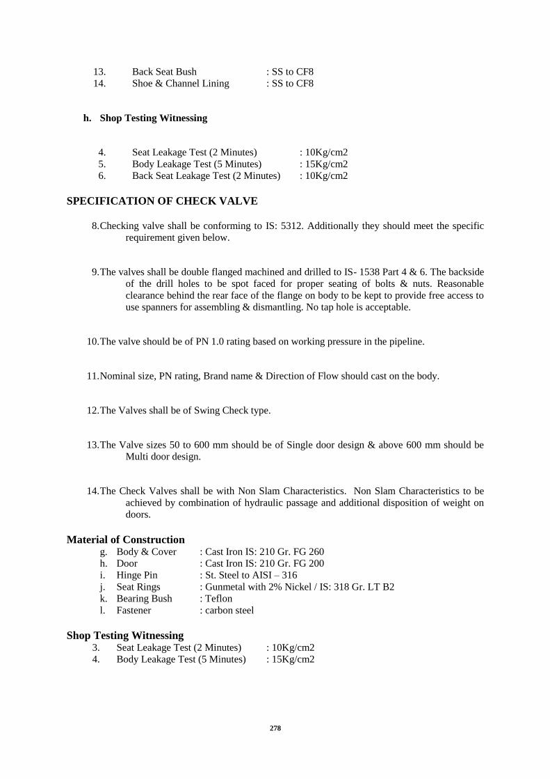
278
13. Back Seat Bush : SS to CF8
14. Shoe & Channel Lining : SS to CF8
h. Shop Testing Witnessing
4. Seat Leakage Test (2 Minutes) : 10Kg/cm2
5. Body Leakage Test (5 Minutes) : 15Kg/cm2
6. Back Seat Leakage Test (2 Minutes) : 10Kg/cm2
SPECIFICATION OF CHECK VALVE
8. Checking valve shall be conforming to IS: 5312. Additionally they should meet the specific
requirement given below.
9. The valves shall be double flanged machined and drilled to IS- 1538 Part 4 & 6. The backside
of the drill holes to be spot faced for proper seating of bolts & nuts. Reasonable
clearance behind the rear face of the flange on body to be kept to provide free access to
use spanners for assembling & dismantling. No tap hole is acceptable.
10. The valve should be of PN 1.0 rating based on working pressure in the pipeline.
11. Nominal size, PN rating, Brand name & Direction of Flow should cast on the body.
12. The Valves shall be of Swing Check type.
13. The Valve sizes 50 to 600 mm should be of Single door design & above 600 mm should be
Multi door design.
14. The Check Valves shall be with Non Slam Characteristics. Non Slam Characteristics to be
achieved by combination of hydraulic passage and additional disposition of weight on
doors.
Material of Construction g. Body & Cover : Cast Iron IS: 210 Gr. FG 260
h. Door : Cast Iron IS: 210 Gr. FG 200
i. Hinge Pin : St. Steel to AISI – 316
j. Seat Rings : Gunmetal with 2% Nickel / IS: 318 Gr. LT B2
k. Bearing Bush : Teflon
l. Fastener : carbon steel
Shop Testing Witnessing 3. Seat Leakage Test (2 Minutes) : 10Kg/cm2
4. Body Leakage Test (5 Minutes) : 15Kg/cm2

279
SPECIFICATION OF KINETIC AIR VALVE
f. General
6. Kinetic Air valves shall be conforming to IS: 14845: 2000. Additionally they should meet
the specific requirement given her e under.
7. Kinetic Air valves should be from ISO – 9001 certified company towards Quality
Management System.
8. The Valves shall be flanged end machined and drilled to IS – 1538 Part 4 & 6
9. The valves should have an isolating Sluice Valve attached to it.
10. Nominal size, PN rating, Brand name should cast on the body.
g. Design Requirement
5. The valve should be of PN 1.0 rating /based on working pressure in the pipeline.
6. The Valves should double ball air valve consisting of large orifice (LP) & small orifice.
7. The large orifice chamber should have built-in Kinetic features to avoid blocking of the
large orifice during filling & emptying of pipeline. It should have a large timber ball
covered with rubber to be seated on a large orifice rubber ring.
8. The small orifice chamber should have a small timber ball covered with rubber to be
seated on gunmetal orifice plug.
h. Material of Construction
Body, Cover, Cowl : Grey Cast Iron. IS: 210 – 1993 Gr. – 260
Ball of small orifice : Seasoned timber ball covered with soft Vulcanite
Ball of large orifice : Seasoned timber ball covered with soft Vulcanite
Seat of large orifice : Neoprene Rubber
Nipple for small orifice : LTB. : IS 318 – 1980. LTB – 2./ AISI: 410
Isolating Gate valve : IS: 14846 (GM internals & AISI: 410 Spindle)
Bolt & Nut : M.S
i. Shop Testing Witnessing
Seat & Body Leakage Test (2 Minutes) : 10Kg/cm2
j. Painting & Coating
Pre – inspection

280
1st Step Surface Preparation
Blast cleaning to near white – SA 2 ½ Gr.
2nd
step Application of Primer Coating after blast cleaning
One coat of two component epoxy based primer
Post – inspection, if applicable
3rd
Step Application of Finish Coat
One coat of two component solvent free amine cured epoxy coating (Shade)
2.5.16.9. Butterfly Valves
Unless otherwise specified, valve body and disc shall be of close-grained gray cast iron.
Valves shall be mounted with shafts horizontal. Valves shall be fitted with indicators to show
the position of the disc, clearly marked with „open‟ and „closed‟ positions. Valves shall not
contain any brasses containing more than 5% zinc. Gunmetal conforming to BS 1400 Grade
LG2, aluminum bronze, or nickel components may be used for internal components.
Resilient-seated valves shall have nitrile rubber seals.
For valves of 900mm and above, retaining rings shall be provided to enable the sealing ring
to be replaced without the need to remove the valve body from the pipe work. Metal seated
valves of 900mm and above, shall have seat clearances adjustable to obtain as near a
watertight condition as possible, without the need to remove the valve body from the pipe
work.
Percentage Opening - Flow Curve shall be submitted along with data sheet mentioning area
where such valves are subjected for any controlling of the fluid flow.
Component Material 1 Body Cast Iron : IS:210 Gr FG260
2 Inner lining Stainless steel : BS:970 Gr 304
3 Plate /DLSC Stainless steel : IS 3444 1987
4 Stem Stainless steel : IS 6603:1972
5 Seat ring / Boss Stainless steel : IS 6603:1972
6 Gland housing Cast Iron : IS:210 Gr FG260
7 Gland packing Teflon Impregnated with asbestos+Rubber
2.5.16.10. Pressure-Relief Valves (PRV)
Pressure-relief valves shall be designed to prevent the pressure in the pipeline upstream of the
valve rising above a preset level. The valve shall remain closed at lower pressures. The
pressure at which the valve opens shall be adjustable. A pressure gauge shall be provided to
indicate upstream pressure over the operating range of the valve. Safety valves shall comply
with BS 6759: Part 1.
They shall be designed to open at the specified pressure and re-close and prevent further
release of fluid after normal pressure has been restored. The pressure / temperature rating
shall be in accordance with relevant standards. Flanged ends shall be Class 900, raised-face
type complying with ANSI B16.25 or relevant standards.
Component Material

281
1 Body Cast Iron : IS:210 Gr FG260
2 Inner lining Stainless steel : BS:970 Gr 304
3 Knife gate/ plate Stainless steel : BS:970 Gr 304
4 Stem Stainless steel : BS:970 Gr 304
5 Seat ring / Boss Stainless steel : BS:970 Gr 304
6 Gland housing Cast Iron : IS:210 Gr FG260
7 Gland packing Teflon Impregnated with asbestos+Rubber
2.5.16.11. Ball Valves
Ball valves shall conform where applicable to relevant standards. Multi-piece bodies shall be
used where work on the ball and seats when installed may be needed. If valves need removal
for servicing, one-piece bodies may be used. Seat materials shall be chosen for long life, with
erosion and corrosion resistance. Ball supports shall be of the floating ball or trunnion type. If
line pressure is too low to ensure a positive leak-free seal, built-in seat loading devices, or
specially shaped seatings shall be used to ensure sealing.
Component Material 1 Body Cast Iron : IS:210 Gr FG260
2 Inner lining Stainless steel : BS:970 Gr 304
3 Plate Stainless steel : BS:970 Gr 304
4 Stem Stainless steel : BS:970 Gr 304
5 Seat ring / Boss Stainless steel : BS:970 Gr 304
6 Gland housing Cast Iron : IS:210 Gr FG260
7 Gland packing Teflon Impregnated with asbestos+Rubber
2.5.16.12. Knife Gate Valves
The valve shall meet standards C105/A21.5-10, C520-10, C706-10, C707-10, C713-10 and
D106-10 and testing requirements of MSS SP 81.
Outer body may preferably be provided with inner liner in corrosion resistant stainless steel
which shall extend into the gland. The body shall be devoid of any wedge/ dead pockets to
avoid setting of suspended particles and solids in the service fluid.
The gate / plate shall be precision buffed and the edge contoured to a knife edge. The gate
shall move along / be guided by the seat ring to ensure that it scraps any deposit / scale
enabling smooth uninterrupted movement.
Seat shall be so designed that there is no recess / relieve groove to harbour deposition that
could build-up and swamp the valve. The design should also incorporate bosses that guide the
gate and avoid deflection ensuring positive shut-off. The stem shall have double start threads
cut in order to ensure smooth and speedy operation.
Gland packing shall offer minimal frictional resistance and precludes external lubrication. As
positive sealing elements, the packing shall also include a resilient rubber ring. The knife
edge and seat face in flow path shall be hard faced to a hardness of 400 to 450 BHN to
counter erosion. In such cases, provision shall also be made to ensure the fluid contact with
the seat ring is minimal.
Component Material

282
1 Body – Cast Iron : IS:210 Gr FG260
2 Knife gate/ plate – Stainless steel : BS:970 Gr 304
3 Stem – Stainless steel : BS:970 Gr 304
4 Seat ring / Boss – Stainless steel : BS:970 Gr 304
5 Gland housing – Cast Iron : IS:210 Gr FG260
6 Gland packing – Teflon Impregnated with asbestos + Rubber
2.5.16.13. Cast Iron Flap Valves (Circular Flap Valves)
The Flap Valves with circular aperture, single door and double flanges, shall be provided.
The flap valves upto 600mm dia shall have sealing faces in angular section and secured to the
frame and door by a force fit. For sizes above 700 to 2000mm dia the sealing faces are of
rectangular section and are secured to the frame and door using countersunk taper headed
screws in the same material as the sealing face. The flap valve shall be suitable for mounting
on a vertical wall or flange for static seating heads up to 6 meters.
Material of Specification
Frame
Constructed in BS EN 1561 min. 250 cast iron designed for wall, thimble or pipe mounting
applications.
Door
Constructed in BS EN 1561 min. 250 cast iron designed to withstand static seating heads up
to 6 meters.
Sealing Faces
Copper alloy sealing faces to BS EN 1982 : 1999 are supplied as the standard material for
ranges up to 600mm dia and for the ranges 700 to 2000mm dia phosphor bronze to BS EN
12167 : 1998. Sealing faces are set to 0.1mm feeler gauge non-acceptance to provide an
effective seal.
Hinge Links
Manufactured in Spheroidal Graphite cast iron
Fasteners
Standard fasteners are supplied in stainless steel to BS EN 10088 : 1995 grade 1.4401 (316).
Hinge Pins
Manufactured from stainless steel to BS EN 10088 : 1995 grade 1.4401 (316).
2.5.16.14. Sluice Gates
Sluice gate shall be preferably wall thimble type. However for controlling/isolation of flow in
channels, channel type gates may also be accepted by Jal Nigam as per application
requirement.
The construction of Sluice Gates shall be in accordance specification and generally to
IS:13349. The Sluice Gate shall be designed for Seating & Unseating Head without

283
sacrificing reasonable degree of leak tightness. The frame of Sluice gate shall be flanged back
type and shall be machined on the rear face to bolt directly to the machined face of the wall
thimble. The seating faces shall be made of solid section strip of Stainless steel. They shall be
secure firmly by means of counter sunk fixing in finished grooves in the frame and slide face
in such a way as to ensure that they will remain permanently in place, free from distortion
and loosening during the life of the Sluice Gate. Sluice Gates shall be equipped with
adjustable Side & Top wedging devices as required to provide contact between the slide and
frame facing when the gate is in closed position. The gates shall be of Rising Spindle Type.
They shall be operated through a suitable operating mechanism. The Lifting mechanism shall
incorporate gearing arrangement, if required to keep the torque requirement within 7 KgM
except electrically actuated gate. In case of gearing, those to be enclosed grease packed Bevel
or Worm Gear box type. Lifting mechanism shall be provided with suitable position indicator
to show the position of the gate from full open to full close. The indicator to be provided in
the head stock only. Stem Cover to be provided on the top of head stock for the rising
spindle. The cross section of the wall thimble shall have the shape of the English letter „F‟.
The Sluice gate shall be provided with Flush bottom seal. This is a solid square cornered
resilent rubber seal provided on the bottom facing of the slide. The seal may be secured
fastened to the bottom of the face of the slide by a retainer bar and fasteners. The top surface
of the bottom facing of frame shall be flush with invert of the gate opening. Bottom facing of
the slide shall be accurately machined to make contact with the seal when the slid is closed.
Gates shall be fixed for positive seating. Sluice gates shall be electrically operated with
manual override facility. The Sluice Gates shall be of Class – 2 i.e., suitable for maximum
unbalanced head needs as per calculation/design.
Material of Construction
The materials of construction of important components of gates will be as under: o. Frame & Shutter Cast Iron IS: 210 Gr. FG 200
p. Wall Thimble Cast Iron IS: 210 Gr. FG 200
q. Seating Faces & Counter Sunk Fixing Stainless Steel ASTM A276 type 316
r. Wedging Device Cast Iron IS: 210 Gr. FG 200
s. Wedge Linings Stainless Steel ASTM A276 type 316
t. Stem & Stem Coupling Stainless Steel ASTM A276 type 316
u. Stem Nut Stainless Steel ASTM A743 CF8M or SS316
v. Flush Bottom Rubber Seal EPDM ASTM D200
w. Seal retainer bar Stainless Steel ASTM A276 type 316

284
x. Fasteners, Studs Anchor Bolt & Nuts Stainless Steel ASTM A276 type 316
y. Lift Nut Bronze IS: 318 Type LTB-2
z. Headstock, Stem Guide Cast Iron IS: 210 Gr. FG 200
aa. Hand wheel Mild Steel IS: 2062
bb. Painting Ordinary Black Bituminous Paint
Standard Painting
Unless otherwise specified elsewhere provide following standard painting.
- Surface preparation: Blast clean or Ground to near white metal finish
- Priming: 1 coat of red oxide primer before and after shop testing. Total priming thickness 75
microns.
- Finish painting for gate assembly: 2 coats of black bitumen paint for gate assembly. Total
paint thickness inclusive of priming 200 microns.
- Finish painting for headstock: Grey enamel paint. Total paint thickness inclusive of priming
150 microns.
Shop Testing Parameters
- Leakage test at operating pressure for gate leakage performance.
- Movement test for checking interference free movement of complete assembly.
- Seat clearance check for checking clearance between mating sealing faces.
- Positive Material Identification test for all material other than cast iron.
2.5.37. Electrical Overhead Traveling (EOT) Crane
The capacities of various EOT‟s shall be decided as per recommendations of IS: 875.
The crane shall be of single / double girder type designed from lowest sump level and up to
under size of the bridge.
Suitable crane rails complete with fixing bolts, nuts, washers and anchor plates shall be
supplied for each crane.
The bridge structure shall be formed by a single/double cross girder with the hoist units
traveling along the lower flange of the bridge girder.
The end carriages shall be fabricated adequately stiffened throughout their length to produce
a section with high torsional resistance designed to eliminate and tendency for the bridge to
cross whip. The carriage wheel shall be adequate proportioned in relation to its span to give a
widely distributed load on the crane rails.
Proper selection of reduction gears shall be done to run drive motors. Wherever required the

285
motor enclosure shall afford protection to IP: 55 of IS: 4691 and have cooling facility to IC:
41 of IS: 6362. Each drive motor shall be fitted with an automatic electro-magnetic brake to
stop the crane on interruption of the power supply, whether intentional or accidental power
failure.
Suitable end stoppers/buffers shall be provided on the bridge girder and at each end of crane
rails.
The crane and hoist shall conform to IS: 3177, IS: 3832 and IS: 3938, class 2, medium duty
and meet specified operational requirements.
Power feed to the crane shall be form a shrouded conductor rail system and that to the hoist
shall be through close looped flexible suspension system with carriers sliding along a wire
across the full span of the crane.
Proper illumination of the area shall be done under the crane and on the crane.
All the crane and hoist functions and excluding the illumination lights shall be controlled
from a single pendant push button station. The pendant unit shall be suspended from a special
track spanning the bridge length using a non-metallic cord and not the control cables. The
pendant shall operate on a low voltage (typically 220 volts AC) source, incorporated with a
key operated switch to operate switch to prevent unauthorized operation and indicators to
indicate ail crane or hoist movements including start and stop.
EOT Operations and faults shall be interfaced with respective LCP about their operations.
Lifting speed Low 0.9 MPN
High 3 MPN
L.T. speed 10 – 15 MPN
C.T. speed 10 MPN (Max.)
However illumination lights to be operated by separate switch which will not be mounted on
pendant.
Other Common specification:
Brakes All brakes are electro-hydraulic thrusters/ECM brake
Operation Through pendent push button
Gear box Precise machine cut hardened material gear noiseless operation long
life
Cable All cables are insulated ISI Marked
Power supply All 415:440 4 phase 50 Hz. AC supply
Control voltage 220/230 volts-50 Hz
The hoist shall comply Class II with the performance requirement IS 3177/80, IS: 3938/IS:
3832 Class 2.
The electric hoist shall be fitted with right and left handed spiral grooved cast iron drum with
a rope hoist arrangement with spring loaded rope band and guards to ensure accurate rope
guidance and location.

286
Hoist rope shall be extra flexible, improved plog plough steel rope with well lubricated hemp
core and having 6 strands 37 wires per strand with an ultimate tensile strength of 160/180
kg/sq.mm. The braking load for the hoist rope shall be as per IS: 2266.
Electromagnetic brake shall be provided to hold suspended load instantly, securely and
automatically in the event of the electric current being cut off whether intentionally,
accidentally or due to power failure.
The lifting hooks shall be single „C‟ type complying with the requirement of IS: 15560 made
from grade C30/C20 carbon steel. The hook shall have a safety latch to prevent rope coming
off the hook.
2.5.38. Chlorination System
Chlorination system shall consist of chlorine contact tanks for disinfection of wastewater
from secondary clarifier, chlorine building housing equipment like chlorinators, chlorine ton
cylinders, chlorine ejector, chlorine leak detector, ventilation system, emergency chlorine
scrubber etc,
Chlorine solution diffusers shall be installed at the dosing point. Inlet chamber of the contact
tank shall have rapid mechanical mixers. The chlorine dosing shall be designed with
minimum chlorine dose of 8 PPM at peak flow. The residual chlorine should be not less than
0.2 PPM.
Vacuum type gas feed chlorinators comprising differential vacuum regulated flow meter,
regulating valve for vacuum & pressure, injector flow meter etc. shall be required. The
chlorinator should be floor mounted complying requirement of IS 10553 - 1983. The
chlorinator should be accompanied with booster pumps and the entire discharge line. The
moist chlorine or chlorine solution shall be conveyed through silver or platinum tubing. A pit
and alkali absorption system shall be provided to neutralize the chlorine in the event of leak.
Chlorine gas leak detector shall be provided in the chlorine storage room. Forced ventilation
system shall be provided with exhaust system industrial pattern. Chlorine residual monitoring
system shall be provided at the plant outlet.
Chlorine Gas Feed System
Minimum chlorine dose mg/l 5
Peak chlorine feed rate kg/day 275
Chlorine Ton Cylinders
Average chlorine feed rate kg/day 135
Min. storage period days 15
Capacity per cylinder kg 200
Min. no of manifold cylinders 10

287
Min. of cylinder to meet min. storage period
requirement
12
Min. no. of cylinders – Mani folded with
automatic switching.
10
Chlorinators
Type of Chlorinator Vacuum type-Gas Feed
Total No. of units 4
30 Kg/ hr. working 2
Min no of units – Standby 2 100%
Chlorine Ejector
Type Inline vacuum induction
Chlorine tonner can be provided by Jal Nigam as the chlorine gas is being purchased for
various plants.
Chlorine Contact Tank
Chlorine Contact Tanks
Min No of Units 1 with baffle wall
Material of Construction Reinforced Cement
Concrete
Chlorination System
Trunnuion Roller Support
Bed
Roller
Shaft
Bush
Steel as per IS 2062
Steel IS 2062 – Cadimum Plated
EN 8 BS 970 – Cadimum Plated
Gun Metal
Auxiliary Container Valve with Yoke
Valve Body
Spindle
Gland Packing
Yoke
Aluminium Silicon Bronze
Monel 400
PTFE
Forged Steel

288
Electrical Auto Change Over Device with
the Following
Ball Valve
Body
Ball
Seat
Forged Carbon Steel
Monel 400
PTFE
Pressure Switch Isol. Valve
Type
Diaphragm Sealed
By pass valve
Type
Body
Ball
Seat
Ball
Carbon Steel
Monel 400
PTFE
Gas Filter
Body
Filter Element
Seamless Carbon Steel 80 Sch,
Glass Wool
Pressure Reducing Valve
Body
Spindle
Spring
Diaphragm
Carbon Steel
Glass Filled PTFE
Hastelloy – C Silver Plated
PTFE
Isolation Valve
Type
Body
Ball
Seat
Ball
Carbon Steel
Monel 400
PTFE
Chlorinator with following accessories:
Pressure Gauge with ISO l. Valve Type Monel 400 bourdon tube
Vaccum Regulator
Body
Diaphragm & Seat
Spindle
Spring
HDPE
PTFE
Glass Filled PTFE
Hastelloy – C Silver Plated
Pressure Relief Valve
Body
Seat
Spindle
Spring
PVC
PTFE
PTEFE
Hastelloy – C Silver Plated
Rotameter
End Fittings
Glass
Float
PVC
Borosilicate Tapered
PTFE
Flow Control Valve

289
Body & Spindle
Type
PVC
V- Notch
Differential Regulator
Body
Diaphragm & Seat
Spring
HDPE
PTFE
Hastelloy – C Silver Plated
Vaccum Relief Valve
Body & Spindle
Seat
Spring
PVC
PTFE
Hastelloy – C Silver Plated
Vaccum Gauge
Type
Monel 400 Bourdon tube
Check Valve
Body
Spring
Diaphragm & Seat
Addl. Float
PVC
Hastelloy – C Silver Plated
PTFE
HDPE
Drain Valve
Body
Float
PVC
PTFE
Injector
Body
Nozzle & Throat
PVC
PVC
Pipe with fittings UPVC
2.5.39. Safety Equipment Severe exposure and potential health hazards exists due to chlorine atmosphere. The various
safety equipment like gas masks, oxygen breathing apparatus, portable air blower and
inhalator shall be provided keeping in mind the safety of staff operating chlorination system.
The Equipment shall include the following:
Canister type Gas masks with full face piece for short exposure.
Self-contained breathing apparatus with full face piece and a cylinder of air or oxygen carried on
the body.
Two sets of approved positive airline breathing apparatus, each comprising body harness, face
masks and valves and 30m of airline. One air trolley, comprising wheeled frame with two air
cylinders, control manifold, airline hose and hose winding drum. Two spare cylinders suitable for
changeover shall be provided.
Suitable quantity of air cylinders of capacity 1200ltr for recharging air cylinders, compete with
quick release air hose couplings.
Four sets of safety clothing in various sizes, each comprising PVC overall, wellington boots with
steel toe caps, goggles, gloves and helmets.
Gas leak detectors portable type -2 Nos.

290
2.5.40. Emergency Equipment (General)
2.5.20.9. Fire Extinguishers
The Bidder shall provide required no. of dry powder type CO2 fire extinguishers (10 kg) for
the pumping station and switchyards at the following locations after consultation with the
Independent engineer:
Outdoor switchyard
Indoor electrical room
Pump rooms (maintenance bay)
Control room
GAS handling area
First Aid boxes and manual stretcher .
Besides above, Ionisation smoke, optical smoke & heat detectors shall be provided in control
room with fire alarm panel having appropriate battery back-up. Fire alarm detectors shall be
provided both below & above false ceiling, if any Fire alarm system and public address
system shall be provided at the
Plant.
All the smoke and heat sensors shall be wired up to nearest JB and interfaced to respective
PLC/DDC for alarm annunciations.
2.5.20.10. Spillage and Leakage
Chemical preparing, dosing and transfer equipment shall be designed and arranged so that
any leakage and spilling can be controlled and cannot enter ducts, channels, etc. and have a
corrosive impact on pipes, cables or other equipment of the plant.
At all lubrication or greasing points grease trays or pans shall be provided to collect excessive
lubricant or spillage onto the equipment or into sewage.
2.5.20.11. Installation Work:
Equipment shall be installed in a neat, workman like manner so that it is level, plumb, square
and properly aligned and oriented. Tolerance shall be as established in the manufactures
drawing or as stipulated by Jal Nigam . No equipment shall be permanently bolted down to
foundation of structure until the alignment has been checked and found acceptable by Jal
Nigam.
Manufacturer‟s drawings, instructions and recommendation shall be correctly followed in
handling, setting, testing and commissioning of equipment.
2.5.20.12. Leveling and Grouting of Machinery
The pumps, motors and other equipment shall be properly and accurately leveled and aligned
on the concrete plinth by means of tapered metal wedges and metal packing pieces before any
grout is poured. After correct alignment and leveling the foundation bolts shall be nipped up
to hold the machine firmly in position and it shall be the Selected Bidder's responsibility to
check that the position is maintained after the grout has been poured but before it sets. The
grout, which will contain an approved expanding agent, will be mixed and poured by the
Selected Bidder. Grouting material used for grouting should be as approved by Independent
engineer.

291
The horizontality of base plate top shall be within 0.05 mm/metre. The base plate top surface
and pump motor box are to be blue matched to get a contact area of at least 80%.
After the grouting mixture has set hard the foundation bolts shall be pulled up hard and the
alignment and level rechecked. The Engineer shall be informed at all times of the progress of
this work and when any checks on alignment and level are to be carried out so that he may
witness the checks if he so requires. The approval of the Engineer or his intimation that the
alignment or level of the machines is to his satisfaction shall in no way relieve the Selected
Bidder of his obligation under contract to properly install and align the machines and pipe-
work and shall in no way prejudice the Independent engineer's rights to order rectification of
any installation work later found to be improperly carried out.
2.5.20.13. Tests on Completion
(iv). General
When the Contract Plant has been installed on site and is ready for energising, the Selected
Bidder shall notify the Independent Engineer in writing that Tests on Completion are about
to commence. At least three days notice shall be given. The Independent Engineer may
attend the tests at his discretion.
(v). Commissioning Tests
The Selected Bidder‟s representative shall subject the screen to the following tests. The tests
shall include, but not be limited to:
Checking alignment of all components and adjust if necessary;
Checking that all equipment, safety devices and equipment protection devices function
properly;
Examining protective coatings and repair as necessary;
Running equipment for an appropriate time and check for correct operation;
Checking the operation of all equipment under field control;
Demonstrating access cover removal.
All necessary corrections and adjustments made shall be recorded. A written report shall be
provided by the Selected Bidder‟s representative at the completion of the tests, certifying that
the equipment has been properly installed and operates satisfactorily all test records are to be
appended.
(vi). Reliability Tests
Reliability testing will not be commenced until the Tests on Completion have been completed
and approved by the Independent engineer.
The Plant shall be required to operate under the normal operating conditions within the limits
of performance offered by the Selected Bidder, and their continuous or intermittent
performance as may be more convenient for the operation of the works. The Plant shall
operate without failure of any kind for period of one calendar month.
Should any failure (other than that of an entirely minor nature) occur in any portion of the
Plant, due to or arising from faulty design, materials or workmanship or staff training (but not
otherwise) sufficient to prevent commercial use of the plant, the test shall be deemed to have
failed. The test period of one month will recommence after the Selected Bidder has remedied

292
the cause of the failure. The onus of proving that any failure is not due to faulty design,
materials, workmanship or training will lie with the Selected Bidder.
In cases where the responsibility for failure cannot be determined initially, the Selected
Bidder is to attend to such failures as though they were his responsibility. When the
Reliability Test has been completed to the Independent Engineer written approval, the
Defects Liability Period shall commence.
2.5.20.14. Relevant Standards
The design, manufacture, supply, storage of all equipments shall comply with all Indian
Standards, (or in the absence of Indian Standards, the appropriate International Standards)
Acts and Regulations in their latest amendment, including local statutes covering:
Health and Safety
Dangerous Goods
Factories and Commercial Premises
Buildings
Electricity Regulations and Codes of Practice
The Standards referred shall form part of this Contract. Other Standards, Codes of Practice
and Regulations not referred to, but which would be applicable to the design, manufacture,
installation, testing or commissioning of the equipment under this contract shall be deemed
part of the Contract.
2.5.20.15. Working Stress and Design
The design of all parts shall ensure that under the most onerous of conditions they will not be
damaged or corroded.
Any joint that will need to be dismantled during maintenance shall be made by anti-corrosion
type fasteners.
All spare parts shall be fully interchangeable with the original part. If the spare part is
unavailable due to cease of production, the Selected Bidder shall give notice to the Employer
in writing, detailing the options available to the Selected Bidder.
All parts shall be designed to minimise the risk of fire and consequential damage. All parts
shall be designed to prevent the ingress of vermin, dust and dirt. All electrically live or
moving parts shall be adequately guarded to prevent accidental contact.
2.5.20.16. Name Plates
Each main and auxiliary item to the pumping station shall have permanently attached to it, in
a conspicuous position, a name plate and rating plate, each of weather-resistance and fire-
resistance material. Upon these shall be engraved or stamped the manufacturer's name, type
and serial number of equipment, details of the loading and duty at which designed to operate.

293
Schedule-II
Part-C
Electrical System General and Particular Specifications

294
1. Electrical System General and Particular Specifications
1.1 General
The scope of work includes design, equipment selection, manufacture, inspection at Bidder's
or his Sub-Bidder's works, supply, installation (including storing, unloading and transferring
the material / equipment to Bidder‟s storage area, maintaining equipment / material in safe
custody and assembling the elements of the equipment and installing at the place of work),
testing and commissioning of the plant equipment/ electrical system. After successful
commissioning and trial run of the plant, it should be handed over to the JAL NIGAM or
their representative. The Bidder shall submit their design calculations/ drawings based on
„Design criteria for electrical equipment/ system‟ for JAL NIGAM or their representative‟s
review and approval. These specification covers , 11kV switchboard, LV switchboards, LV
energy efficient motors, LV soft starters, LV capacitors, APFC,HV, and LV power cables and
control cables, DC supply system and other allied equipment, etc. along with the
specifications for workmanship, laying cables, lighting system, earthing systems, lightning
protection etc. It shall be the responsibility of the Bidder to design the electrical system based
on the selection of the mechanical equipment.
The Bidder shall make his own estimate of sizes, ratings and quantities for 11kV system,
equipment, all plant items and miscellaneous systems such as earthing, lightning protection,
lighting, However, facility for upgrade/ expansion of all equipment to cater any future
requirements load shall have to be considered during design-engineering stage. It should be
clearly understood that the Contract will be on „turnkey‟ basis and no variation will be
allowed for items of works not foreseen or omitted by the Bidder at the bidding stage, except
where specifically indicated in the bid documents.
All equipment offered shall comply with the requirements specified in the latest editions of
applicable Indian/ International Standards and shall also comply with the good engineering
practices.
The drawings enclosed with the specifications are for general guidance of the Bidder only.
Bidder shall design the electrical system on the basis of „Design Criteria‟ and to be submitted
for JAL NIGAM or their representative‟s approval. Bidder shall incorporate any changes/
suggestions in the drawings to suit site conditions and design criteria and standard
engineering practice and resubmit for approval to JAL NIGAM or their representative.
The Bidder shall possess the valid electrical Bidder‟s license of appropriate class from the
concerned statutory bodies governing the area of work place. The Bidder shall fully comply
with the relevant statutory rules and regulations.
All type (as applicable), routine and acceptance tests shall be conducted in the presence of
JAL NIGAM or their representative / Third Party Inspector on all the equipment as per latest
applicable IS/IEC at no extra cost. Typical type test reports for other equipment shall be
submitted by the Bidder for approval by JAL NIGAM or their representative.
All commissioning tests shall be carried out in the presence of JAL NIGAM or their
representative and approval for the same shall be obtained before commissioning and
installation. All test reports shall be properly maintained by the Bidder duly approved by the
statutory bodies and shall be handed over to the JAL NIGAM or their representative after
completion of the job. All instrument and accessories required for testing and commissioning

295
of the equipment specified herein shall be provided by the Bidder at no extra cost to the JAL
NIGAM or their representative.
Liaison with electricity board and other Government organization/ statutory bodies for
obtaining Power supply/ other clearance shall be Bidder‟s scope. After completion of
installation work, the Bidder shall arrange for inspection and obtain approval from the
concerned statutory bodies. Any fees that are to be paid to such statutory bodies for testing,
inspection or calibration shall be paid by the Bidder. Any modification / revision in the
equipment / installation of equipment as required by the statutory bodies shall be carried out
by the Bidder. All such costs / fees for revisions / modifications shall be deemed to be
included in the prices of supply, installation, testing and commissioning of equipment as
quoted by the Bidder.
1.1.1 Power Supply Information
The proposed power supplies are as follows:
(i) 11 kV AC System Voltage variation +10 to -
10% Freq. Variation +5 to
-5%
Three Phase, 50 Hz, effectively
earthed AC System SC. Rating of 350
MVA
(ii) 415V AC System Voltage variation +10 to -
10% Freq. Variation +5 to
-5%
Three Phase and neutral, 50 Hz,
effectively earthed system, SC. rating
of 20 MVA
(iii) 240V AC System Voltage variation+10% to
10%
Freq. Variation + 5% to -
5%
Single phase and neutral, 50 Hz,
effectively earthed system
(iv) 110V DC Supply Voltage variation +/- 15% Unearthed two wire system
All equipment shall have rated withstand capacity based on above criteria.
1.1.2 Design Criteria for Electrical Equipment/ System
The Design Criteria described below covers the electrical equipment/system;
General Power Distribution Scheme
Estimation of Load
The following assumptions have been be made to arrive at the estimated load of the different
sites.
a) Load Factor
i) Motor : 0.9
ii) Auxiliary load, valve motors, etc. : 0.9
iii) Lighting load : 1.0
b) Diversity Factor
i) Motor : 1.0
ii) Auxiliary load, valve motors, etc. : 1.5
iii) Lighting load : 1.2
c) Power factor of Motors : As per Manufacturer‟s Catalogue

296
d) Efficiency of Motors : As per Manufacturer‟s Catalogue
(Energy efficient eff1 or eff2)
(Energy efficient, high performance motors (minimum eff2 category) shall be
provided for optimum utilization of energy).
e) Protections
The following protections are proposed for various switchboards, transformers,
motors and other plant feeders.
1) 11 kV Switchboard
i) IDMT over current and earth fault protection for incomers
ii) IDMT and instantaneous over current and earth fault protection for
outgoing transformer feeders
2) LV switchboard
i) Over current, short circuit and earth fault protection on ACBs/ MCCBs
3) Motors
i) Overload protection by thermal (bimetal) relays in all the three phases
to trip with single phase preventer (SPP) and short circuit protection in
all the three phases through motor protection circuit breakers/ MCCBs
Alternatively, microprocessor based motor protection relay shall also
be used.
ii) Thermal, locked rotor, short circuit, negative sequence, under voltage,
over voltage and earth fault for each motor feeder of rating 90kW and
above.
f) Metering
The following metering shall be provided.
1) 11 kV Switchboard
Multifunction meter (for incomer) containing -
i) Ammeter
ii) Voltmeter
iii) kW meter
iv) Frequency meter
v) Power factor meter
vi) Kilowatthour meter
vii) kVAr meter
viii) kVA meter
For outgoing feeder
i) Ammeter with selector switch
2) LV Incomers

297
i) Ammeters with selector switch
ii) Voltmeter with selector switch
iii) kW meter
iv) Power factor meter
vi) Kilowatt-hour meter
vii) Frequency meter
3) LV Outgoing Feeders
i) Ammeter with ammeter selector switch
Multifunction meter shall be equipped with interfacing capability for RS-485
port.
g) Indicating Lamps
The following indication shall be provided:
1) 11kV Incomer, Bus Coupler and Outgoing feeders
i) Circuit breaker ON, OFF and TRIP, spring charged, control supply
healthy and trip circuit healthy (Mains ON (R,Y,B) indication for
incomer only)
2) LV Incomers
i) Mains ON (red, yellow and blue)
3) Motor Feeders
i) Motor ON, OFF and Trip indication (Red, green and Amber)
ii) Motor ON, OFF and Trip indication (Red, green and Amber), control
supply healthy and trip circuit healthy for breaker feeder.
All electrical equipment will be rated for 500 C design ambient temperatures.
All power cables shall be sized based on continuous current capacity, permissible voltage
drop and short circuit current rating. The voltage drop shall be limited to 2.5 % at rated
equipment current rating.
The other rating factors for variation in ground temperature, variation in ambient air
temperature, grouping of cables, depth of laying, etc. shall also be considered for cable
sizing.
The illumination levels proposed for various areas are as follows:
Area Illumination level (Lux)
Pump House 300
Office/Conference Room 500
Switchboard Room 300
All other indoor areas 150
Outdoor plant area and Road 10 – 20
Component of luminaries shall be „energy efficient low loss‟ type. LED type of luminaries
shall be used for office/ all indoor areas except pump house area. LED luminaries shall be
used for pump house area and other outdoor areas. Decorative fixtures/ receptacles shall be

298
used for office areas and industrial type fixtures/ receptacles shall be used for remaining
areas. Street/ area lighting shall be controlled by time switch/ photocell for automatic
switching of luminaries. Emergency light shall be provided for safe evacuation of the people
in case of fire or panic (blackout, total power failure, etc.) Emergency lighting shall be
automatically switched ON when mains power supply fails.
The values of fault level for designing the electrical system shall be based on transformer
capacity, its impedance and system fault level. Fault clearing time for sizing of earth
conductor will be taken as one second.
The material of earthing conductor shall be hot dip Galvanized Steel. All connections
between the earth conductors buried in earth/concrete and between earth conductor and earth
leads shall be of welded type. While sizing the buried earth conductor, a corrosion allowance
of at least 20% shall be taken. Plant earthing system shall be designed such that the overall
earthing grid resistance is maximum one ohm.
Main earthing conductors outside and inside the building shall be planned in such a manner
that various equipment is connected to earthing system by two connections in a reliable
manner.
1.1.3 System Description
11 kV power sub-station shall be constructed in plant, The 11 kV switchboard shall feed
11/0.433 kV transformer(s) with off load tap changer, which in turn will feed the 0.433 kV
indoor switchboard. 100% redundant transformer shall be available to feed the entire load of
the STP. The 11 kV indoor switchboard shall consist of incomer VCBs (with line VTs), a
bus coupler VCB and VTs on both the bus sections alongwith of outgoing VCB feeders.
A 415 V PCC shall receive power from 11KV/0.433 kV transformer(s) and to feed the
individual loads through different switchboards located at different locations and sufficient
space for installation of these switchboards should be made available at site.
LV capacitor banks with control panel consisting of automatic power factor correction
(APFC) relay are to be proposed across each LV bus section of the LV switchboards i.e.PCC.
Necessary metering, protection and indication/ annunciation are to be provided on all the
switchboards.
1.1.4 Units of Measurement
Metric units of measurement (System International) shall be used in all Contract
documentation. Angular measurement shall be in degrees with 90 degrees comprising one
right angle.
1.1.5 Reference Standards
All equipment / systems supplied under this Contract shall conform to the latest editions of
the International Electro-technical Commission (IEC) Standards or equivalent Indian
Standards or other International Standards, provided they promise to confirm equal or
superior performance. If standards other than IEC are referred, then the Bidder shall enclose
English Version of the standard with the bid.

299
1.1.6 Inspection and Testing at Manufacturer‘s Works and Dispatch
The Bidder will follow the approved QA/QC Plan for the Inspection and Testing of
Equipment at Manufacturer‟s Works which is to the satisfaction of ENGINEER/
ENGINEER‟S representative and after getting dispatch clearance from the engineer ,that
equipment would be dispatch.
Construction Power Supply
Bidder shall make his own arrangements for construction power supply from electricity board
authority.
All power and lighting circuits shall be constructed with due regard for personnel safety and
shall comply with recognized codes of practice and local regulations. All circuits shall be
fitted with earth leakage systems.
SUBSTATION FOR MPS
The selected bidder should propose for 11 KV indoor substation with provision of HT
PANEL ,TRANSFORMER (1W+1S) and other accessories for MPS whose design must be
according to MANUAL and IS.
For POWER BACKUP during unavailability of electric supply, the selected bidder should
supply DIESEL GENERATOR of capacity to run the MPS for peak flow with suitable design
considering the starter current.
1.2 Power Transformers
1.2.1 Standards
Transformers and its accessories shall comply with the following International Standards,
including those referred to therein.
IEC 60076, 60214, 60296 / IS 2026, IS 335 / BS 148, 171 and IS specification and latest IEC
standard.
The technical parameters of transformers shall be as below:
Description Unit Particulars
General
Quantity required 2 no.(1W+1S)
Installation (Indoor / Outdoor) Outdoor
Ratings
Rated power
(*) Selected Bidder shall
submit their design calculation
for rating of each equipment
for JAL NIGAM or their
representative for approval.
kVA
No load voltage Primary kV 11
Secondary kV 0.433
Number of phases 3
Rated frequency Hz 50
Impedance voltage % As per IEC/BIS

300
Description Unit Particulars
Vector group Dyn11
Winding material Electric Grade Copper
Type of cooling ONAN
System Voltage
Nominal system voltage
Primary
kV 11
Secondary kV 0.415
Highest system voltage -
Primary
kV 12
-
Secondary
kV
Transformer Secondary
Neutral Earthing
Effectively earthed
Insulation Withstand
Rated lightning impulse
withstand voltage
kV
(peak)
75
- Secondary kV (rms)
3.5
Temperature Rise
Reference design ambient 0C 50
Temperature rise over design
ambient temperature of 50 0
C
- Average winding
temperature rise (by resistance
measurement)
0C 55
- Top oil temperature rise (by
thermometer)
0C 50
Tap Changing Gear
Type of tap changer Off Circuit tap Changer
Tapping range % 10%
Tapping steps % 2.5
Bushings
Rated voltage – Primary kV 12
– Secondary kV 1.1
One minute power frequency
withstand voltage (dry and
wet) – Primary
kV (rms) 28
- Secondary (Line and
Neutral)
kV (rms) 2.5
Rated lightning impulse
withstand voltage
kV
(peak)
75
Nominal creepage distance mm/kV 31
Terminal Connections
Primary line end Cable box
Secondary line end Cable box/Bus Duct
Secondary neutral end One bushing each inside and outside cable box
Type of wheels Plain – Bi-directional

301
(*) Values to be ascertained by the Selected Bidder after Submitting design calculations
subject to approval.
1.2.2 Design Features Transformers will be located outdoor and shall also be rated for satisfactory operation at 50
0C
design ambient temperature.
1.2.3 Accessories and Fittings Each main power transformer shall have the following fittings and accessories including but
not limited to:
a) A conservator of sufficient volume with
i. oil level gauge with potential free contacts for initiating alarm for low oil level
ii. weather-proof dehydrating breathers for both compartments with activated
alumina or silica gel as the dehydrating breather
iii. shut off valves
iv. filling plug and drain valves
The conservator shall be designed to maintain an oil seal upto a temperature of 1000
C.
b) Gas and oil actuated Buchholz relay with
i. necessary shut off valves
ii. test cock with pipe connections for sampling
iii. potential free contacts for initiation of alarm in case of slow gas formation and
trip in case of fast oil and gas surges
c) Dial type thermometer with
i. maximum temperature indicator and its resetting device
ii. potential free contacts for initiating alarm on high temperature and trip on very
high temperature
d) Winding temperature indicator with
i. necessary sensing, compensating and calibrating devices
ii. potential free contacts for initiating alarm on high temperature and trip on very
high temperature
iii. WTI transmitter for remote indication on remote tap changing panel
f) Detachable type of radiators including but not limited to:
i. Shut-off valves and blanking plates on transformer tank at each point of
connection of inlet and outlet header
ii. Top and bottom shut-off valves and blanking plate on each radiator
iii. Lifting lugs
iv. Top oil filling plug, 19 mm size
v. Air release plug at top
vi. Oil drain plug at bottom, 19 mm size
vii. Earthing terminals
g) Pressure relief device for transformer tank
h) Weather - proof marshaling box mounted on transformer tank
i) Name plate, rating plate and Diagram plate
j) Valves and plugs as below:
i. Drain valve
ii. Filter valve
iii. Oil sampling valves at top and bottom
iv. Valves between radiators and tank (in case of detachable radiators)

302
v. Air release plug
vi. Twin outlets (with plug) for applying vacuum with attachments.
k) Earthing pads of copper or non-corrodible material for transformer tank (2 places) and
radiator banks
l) Inspection manholes as required
m) Lifting arrangement for
i. fully assembled transformer
ii. core and coil
iii. tank
n) Hauling eyes on each face of the transformer
o) Bi-directional flanged wheels
p) Anti-earthquake clamping devices
q) Jacking pads
Each auxiliary transformer shall have the following fittings and accessories including, but not
limited to:
a) Conservator with oil level gauge
b) Dehydrating silica gel breather
c) Oil temperature indicator
d) Thermometer pocket
e) Explosion vent diaphragm / pressure relief valve
f) Sampling and drainage valves
g) A plug or blank flange at the top for connecting valve for filtration
h) Two earthing terminals
i) Rating plate (Name plate and diagram plate)
j) Lifting lugs
k) Removable plain rollers
l) Adequate number of air vents for relieving trapped air during oil filling and during
maintenance.
m) Accessories for clamping the wheel to the foundation channel in order to withstand
earthquake forces.
1.2.4 Windings
The windings shall be of electrical grade copper.
Materials used in insulation and assembly shall be insoluble, non-catalytic and chemically
inactive in the hot transformer oil and shall not soften or otherwise be affected under
operating conditions. Windings and insulation shall be so arranged that free circulation of oil
is possible between coils, between windings, and between winding and core.
Leads from winding to the terminal board and bushings shall be rigidly supported to prevent
injury from vibration. Guide tubes shall be used where practicable.
Windings shall be subjected to shrinking and seasoning processes so that no further shrinkage
occurs during service. Adjustable devices shall be provided to take up possible shrinkage in
service. High voltage end - windings shall be suitably braced to withstand short circuit
stresses.
1.2.5 Core
The magnetic circuit shall be constructed from high grade, cold rolled, non-ageing, grain
oriented silicon steel laminations. Each sheet shall have an insulating coating resistant to the

303
action of hot oil. Each lamination shall be coated with insulation which is unaffected by the
temperature attained by the transformer during service.
The insulation structure for the core to bolts and core to clamp plates shall be such as to
withstand appropriate dielectric test. All steel sections used for supporting the core shall be
thoroughly shot or sand blasted after cutting, drilling and welding. Core laminations shall be
annealed and burrs removed after cutting. Cut edges shall be insulated. The framework and
clamping arrangements of core and coil shall be securely earthed inside the tank by a copper
strap connected to the tank. The core clamping structure shall be designed to minimize eddy
current loss. The core shall be provided with lugs suitable for lifting the complete core and
coil assembly. The framework and clamping arrangements shall be securely earthed.
The core and coil assembly shall be dried out and impregnated under vacuum.
1.2.6 Tank
The transformer tank shall be made from high-grade sheet steel, suitably reinforced by
stiffeners made of structural steel sections. All seams, flanges, lifting lugs, braces, and other
parts attached to the tank shall be welded. The interior of the tank shall be cleaned by shot
blasting and painted with two coats of heat resistant, oil insoluble paint. Adequately sized
manholes shall be provided for ease of inspection and maintenance. Steel bolts and nuts
exposed to atmosphere, shall be galvanized.
Tank together with radiators, conservator, bushings and other fittings shall be designed to
withstand without permanent distortion the following conditions:
a) Full vacuum of 760 mm of Hg for filling with oil under vacuum
b) Internal gas pressure of 0.35 kg/cm² with oil at operating level
Tank shall be provided with a pressure release device, which shall operate at a pressure below
the test pressure for the tank and radiators. The device shall be provided with a device visible
from ground to indicate operation. An equalizer pipe connecting the pressure relief device to
the conservator shall be supplied. The device shall be provided with potential free contacts
for alarm and tripping. Alternatively, a separate pressure relay shall be provided for this
purpose.
The tank cover shall be bolted type and not welded, sealed type. The tank cover shall be
removable and shall be suitably sloped so that it does not retain rainwater.
1.2.7 Radiators
Radiators shall be designed to withstand the vacuum pressure conditions specified for the
tank. They shall be so designed as to completely drain oil into the soak pit and to prevent
formation of gas pockets when the tank is being filled.
Transformers of rating above 1500 kVA shall be equipped with detachable or separately
mounted radiator banks. Radiators for the main transformers shall be with bolted and gasket
flange connections. Transformers of rating 1500 kVA and below shall be provided with fixed
type radiators. Fins of the radiators shall not have sharp edges and shall be rounded in shape.
When transformers are provided with separately mounted radiators, flexible joints shall be
provided on the main oil pipes connecting the transformer tank to the radiator banks, to
reduce vibration and facilitate erection and dismantling. The interconnecting pipes shall be
provided with drain plug and air release vents.
Off-circuit tap changer

304
Off circuit tap changer shall be provided for auxiliary transformers. It shall comprise
a) Operating handle or wheel accessible from ground level
b) Tap position indicator
c) Padlocking arrangement with padlock.
1.2.8 Marshalling Box
The marshalling box shall be tank mounted, weather proof, vermin proof, dust proof, sheet
steel (2 mm thick), enclosed and with hinged door having padlock. Door and gland plate shall
be fitted with neoprene gaskets. Bottom shall be at least 600 mm from grade level. Top
surface shall be sloped. The degree of protection shall be IP65.
Contacts / terminals of electrical devices / relays, etc. mounted on the transformer shall be
wired to the marshalling box. Interconnecting wires between the marshalling box and the
accessories / devices shall be either PVC insulated wires in GI conduits or PVC insulated,
armoured cables together with provision of double compression type, brass cable glands at
the marshalling box. The above mentioned cables as well as terminating the cables shall be
the Selected Bidder's responsibility.
All contacts for alarm, trip and indication circuits shall each be electrically free, designed for
the auxiliary DC supply of 110 V and brought out to separate terminals in the marshalling
box. Terminals shall be rated for 10 A. Disconnecting / shorting type terminal block shall be
used for CT circuits.
In case of main transformers, provision for remote annunciation shall be provided with two
changeover contacts for alarm condition and two changeover contacts for trip condition for
each of the following conditions including but not limited to:
a) Buchholz alarm
b) Buchholz Trip
c) Oil Temperature high
d) Oil Temperature very high
e) Oil level low
f) Pressure relief device operated
g) Winding temperature high
h) Winding temperature very high
i) Conservator oil level low
1.2.9 Cable Terminations
Cable boxes shall have sufficient space for segregating the cable cores and for adequate
clearance in air between bare conductors at the terminals. Cable boxes shall be complete with
necessary glands, lugs and armour grips.
Air filled cable boxes shall be of adequate dimensions and designed in such a manner that
they can be opened for inspection without disturbing the gland plate or incoming cable.
Disconnecting chamber shall be provided for disconnecting and moving away the main
transformer, without removing the cables or the cable box. Provision shall be made for
earthing the body of each cable box.

305
1.2.10 Tests
All tests required by the specification including repeated tests and inspection that may be
necessary owing to the failure to meet any tests specified, shall be carried out at the Selected
Bidder's expense.
The following tests shall be carried out on the assembled transformer during inspection at the
manufacturer‟s works.
a) Temperature rise test on one transformer
b) Measurement of resistance of windings at principal and extreme taps
c) Ratio at each tap, polarity and phase relationships
d) Measurement of impedance voltage at principal and extreme taps
e) Measurement of no load current and no load losses at rated frequency and at both the
rated voltage and 110 % rated voltage
f) Measurement of efficiency and regulation at ½, ¾ and full load
g) Measurement of insulation resistance
h) Induced over voltage withstand test
i) Separate source voltage withstand test
j) Magnetic balance test
k) Test on OLTC
Type test certificates shall be provided for verification. Whenever two nos. or more identical
transformers are being offered, type tests on one of them shall be carried out, including heat
run test.
All auxiliaries and accessories such as temperature indicators, Buchholz and pressure relays
shall be tested as per the applicable standards and test certificates shall be furnished to the
Employer‟s Representative for approval.
1.2.11 Rejection
The Employer may reject the transformer if anyone of the following conditions arises during
testing:
a) Any of the quantities / parameters of transformers subject to tolerances are outside the
tolerances given in the applicable standards or such tolerance as guaranteed in the
Selected Bidder's bid.
b) Winding and / or top oil temperature rise exceeds the specified / guaranteed value;
and
c) Transformer fails to withstand any of the dielectric tests.
Additional tests shall be conducted to locate the failure and after rectification, all tests shall
be repeated to prove that the rebuilt transformer meets the specification in all respects, all at
the Selected Bidder‟s expense.
JAL NIGAM reserves the right to have the transformer replaced or repaired by the Selected
Bidder within reasonable period to Employer's satisfaction at no extra cost to the Employer.
The Selected Bidder shall also bear the costs, including but not limited to, incurred by the
Employer in re-inspection / re-testing such as travel and incidental expense, etc. The Selected

306
Bidder shall note that any delay in completion time due to such repair / replacement shall be
subject to liquidated damages as specified in the Conditions of Contract.
1.3 MV Indoor Switchboard
MV indoor VCB switchboard shall comply with the following Standards, including those
referred to therein.
IEC 61869, 60265, 60282, 62271, 60529, 60694, 60787, 62271 IEC/TR2 61211 and IS 9046,
9920, 9921, 13118, 3427, 4237, 2156, 2705, 3156, 10118, 722, 13118.
There must be provision for LT panel and APFC PANEL FOR MOTOR OF MPS with
suitable BUS BAR and BREAKER along with proper rating of cables.
The technical parameters of HV switchboards shall be as below:
HV switchboard
Description Unit Particulars
General
Type Metal enclosed, compartmentalized,
draw-out type
Rated voltage, no. of phases and
rated frequency
kV / - / Hz 12 kV, 3 Phase, 50Hz
System neutral earthing Effectively Earthed
Rated Insulation Levels
- Rated short duration power
frequency withstand voltage
kV (rms) 70
- Rated lightning impulse withstand
voltage kV (peak) 170
Rated normal current of bus bars under
design ambient temperature of 500C and
material of busbar
A / - (*),Aluminium - suitable for 100% load
including future loads
Rated short-time withstand current and
time kA (rms) /
sec
16 kA for 1 sec
Dynamic rating kA (peak) 40
Constructional Requirements
Minimum thickness of sheet steel in
mm Cold rolled
(Frame/Enclosure/Covers)
mm Frame – 2
Doors/Covers – 2.0
Degree of protection of enclosure IP-5X
Color finish shade
- Interior Glossy White
- Exterior Light Grey Semi Glossy
Cable connection Bottom entry and exit
Circuit Breakers
Type Vacuum/ SF6
Rated current inside the cubicle
under design ambient temperature at
50C
A (*) – (Breakers shall be rated for final
ratings of motors in STP)
Rated operating sequence O–3 Min–CO-3 Min-CO
Rated short time breaking current kA (rms) 16

307
Description Unit Particulars
Rated short time making current kA (peak) 40
Rated short-time withstand current
and time
kA (rms) /
sec
16 kA for 1 sec
Rated peak withstand current kA (peak) 40
Min. no. of auxiliary contacts 6 NO + 6 NC after internal use by
manufacturer
Type of operating mechanism
- Normal Spring charging for closing and tripping
- Emergency Manual and Spring charged for closing
and tripping
Auxiliary control voltage
- Closing coil / Tripping coil V 110V DC
- Spring charging motor V 110V DC
- Space heater and lighting V 230V AC
Earthing switch Required
Current and Voltage Transformers
Details of ratio, taps, burden,
accuracy
As per Single Line Diagram (*)
Protective Relays
Type Numerical (Microprocessor based)
Auxiliary supply V 110V DC
Details of protective relays As per Single Line Diagram
Switch-Disconnector
Rated current under design ambient
temperature of 50C
A (*)
Rated making current kA (peak) 40
Rated peak withstand capacity kA (peak) 40
Rated short-time withstand current
and time
kA (rms) /
sec
16 kA for 1 sec
Insulation levels
Rated lightning impulse withstand
voltage
- Across the isolating distance kV (peak) 70
- Phase to phase, between phases
and across open switching devices
kV (peak) 60
Rated short duration power
frequency withstand voltage
- Across the isolating distance kV(rms) 23
- Phase to phase, between phases
and across open switching devices
kV(rms) 20
Operating mechanism
- Closing and opening Spring charged
- Control voltage V 110V DC
Earthing switch Required
HV Fuses
Application Indoor
Type HRC

308
Description Unit Particulars
Rated current A (*)
Rated voltage kV 36
Rated breaking capacity kA (rms) 16
(*) Value to be ascertained by the Bidder after submitting design calculations subject to
approval.
1.3.1 Circuit Breaker
Circuit breakers shall preferably vacuum type. Circuit breaker along with its operating
mechanism shall be mounted on a wheeled carriage moving on guides, designed to align
correctly and allow easy movement. Plugs and sockets for power circuits shall be silver faced
and shall be insulated with suitable insulating material shrouds. All corresponding
components of circuit breaker cubicles of same rating shall be interchangeable with one
another.
There shall be „Service‟, „Test‟ „Fully withdrawn‟ positions for the breakers. In the „Test‟
position the circuit breaker shall be capable of being tested for operation without energizing
the power circuits, i.e. the control circuits shall remain undisturbed while the power contacts
shall remain disconnected. Separate limit switches, each having a minimum of 2 „NO‟ + 2
„NC‟ contacts, shall be provided for both „Service‟ and „Test‟ positions of the circuit breakers
for future SCADA.
Electrical tripping shall be performed by shunt trip coils. “Local / Remote” selector switch
lockable in “Local” position shall be provided on the cubicle door. `Red‟ and `Green‟
indicating lamps shall be provided on cubicle door to indicate breaker close and open
positions. Breaker “Service” and “Test” positions shall be indicated by separate indicating
lamps on the cubicle door, in case mechanical indication of “Service” and “Test” positions
are not available on the cubicle door.
Connection of the control / interlocking circuits between the fixed portion of the cubicle and
the breaker carriage shall be preferably by means of plug socket arrangement.
Operating Mechanism Control
a) Circuit breakers shall be operated by a motor spring charging type of mechanism. The
mechanism shall be complete with motor, opening spring, closing spring and all
accessories to make the mechanism a complete operating unit
b) Operating mechanism shall normally be operated from the breaker cubicle itself.
c) The tripping spring shall be charged by the closing action, to enable quick tripping.
Closing of the circuit breaker shall automatically initiate recharging of the springs to
enable the mechanism to be ready for the next closing stroke. Charging time for the
springs shall not exceed 30 seconds. It shall be possible to manually charge the
springs in an emergency. Transfer from motor to manual charging shall automatically
disconnect the charging motor. All operating mechanisms shall be provided with
"ON" - "OFF" mechanical indication. The charging mechanism shall be provided with
mechanical indicators to show "charged" and "discharged" conditions of the spring.

309
Failure of any spring, vibration or mechanical shock shall not cause tripping or
closing of the circuit breaker.
d) Only one closing operation of the circuit breaker shall result from each closing
impulse (manual or electrical), even if the breaker trips while the control device
(manual or electrical) is being held in the "close" position.
e) The circuit breaker mechanism shall make one complete closing operation, once the
push button (PB) or control switch has been operated and the first device in the
control scheme has responded, even though the PB or control switch is released
before the closing operation is complete, subject to the condition that there is no
counter- impulse for tripping.
f) Means shall be provided to manually open and close the breakers slowly, when the
operating power is not available, for maintenance and adjustments. A local manual
trip device shall also be provided on the operating mechanism.
g) Circuit breaker control shall be on 110 V DC. Closing coils and other auxiliary
devices shall operate satisfactorily at all voltages between 85-110 % of the control
voltage. Trip coils shall operate satisfactorily between 70 -110 % the rated control
voltage.
h) Provision for remote control shall be provided for future SCADA.
1.3.1.1 Safety Interlocks and Features
a) Withdrawal or engagement of a circuit breaker / switch disconnector shall not be
possible unless it is in the open position.
b) Operation of a circuit breaker / switch disconnector shall not be possible unless it is in
service position, withdrawn to test position or fully drawn out. It shall not be possible
to close the circuit breaker electrically in the service position, without completing the
auxiliary circuit between the fixed and moving portions.
c) Circuit breaker / switch disconnector cubicles shall be provided with safety shutters
operated automatically by the movement of the circuit breaker / switch disconnector
carriage to cover the stationary isolated contacts when the breaker / switch
disconnector is withdrawn. Padlocking facilities shall be provided for locking the
shutters positively in the closed position. It shall, however, be possible to open the
shutters intentionally against spring pressure for testing purposes.
d) The circuit breaker / switch disconnector carriage shall be earthed before the circuit
breaker / switch disconnector reaches the test position from fully withdrawn position.
In case of breakers / switch disconnector with automatic disconnecting type of
auxiliary disconnects, the carriage shall be earthed before the auxiliary disconnects
are made and the carriage earthing shall break only after the auxiliary disconnects
break.
e) Caution nameplate, “Caution Live Terminals” shall be provided at all points where
the terminals are likely to remain live and isolation is possible only at remote end, i.e.
incomer to the switchboard. Suitable interlock shall be wired for the purpose.
1.3.2 Current and Voltage Transformers
CTs and VTs shall have polarity marks indelibly marked on each transformer and at the
associated terminal block. Facility shall be provided for short-circuiting and earthing the CT
secondary at the terminal blocks.

310
CT shall be able to withstand the thermal and mechanical stresses resulting from the
maximum short circuit current. Core laminations shall be of high grade silicon steel.
VTs shall be of the single phase type and mounted on a draw out trolley. VTs shall be
protected on their primary and secondary sides by current limiting fuses with interrupting
ratings corresponding to breaker rating. It shall be possible to replace the secondary fuses
safely when the switchboard is energized. Alternatively, MCB having auxiliary contact shall
be provided. Primary side fuses shall be replaceable only in the de-energized position.
Secondary winding of voltage transformer (VT) shall be rated for a three phase line to line
voltage of 110 V.
Identification labels giving type, ratio, output and serial numbers shall be provided for CTs
and VTs.
1.3.3 Relays
Protection relays shall be Numerical (microprocessor based) type. Relays shall have
interfacing facilities to communicate data to SCADA system.
All relays shall be enclosed in rectangular shaped, dustproof cases and shall be suitable for
flush mounting.
All relays shall be accessible from the front for setting and resetting. Access to setting
devices shall be possible only after the front covers of the relays are removed.
All protective relays shall be of the draw-out type and shall be provided with operation
indicators visible from the front.
1.3.3.1 Over Current / Earth Fault Protection
a) This relay shall be of the multi-characteristics type which has a flexible mode
selection facility so that it is possible to select one mode for the over current elements
and another for the earth fault element.
b) Phase current range shall cover at least 50-300% of „In‟ in steps of not more than 10%
while the earth current range shall cover at least 5-100% of „In‟ in steps of not more
than 5%.
c) The time setting range of the definite time mode shall not be less than 5 seconds in
steps of 0.1 second each.
d) The time multiplier setting for the inverse time-current characteristic modes shall
have a range not less than 0.05- 1.6 in steps of 0.05.
e) Over current and earth fault relays shall have separate timers and operation indicators.
f) The high set element shall have a range of 2 - 15 times the nominal current in steps of
„In‟ and shall be of low transient overreach, with a tripping time of less than 25 ms
and possible to be selected on "blocked" position. Reset time shall be not more than
50 ms for both elements.

311
g) The relays that are installed on the transformer neutral side shall be of single phase
version, but they shall have the same characteristics as the phase side relays.
1.3.3.2 Restricted Earth Fault Protection
a) The restricted earth fault relay shall be operated from a completely separate core of
line and neutral current transformers. The dedicated CTs shall be of class PS and have
the same magnetization characteristics with a knee „emf‟ value higher than the highest
possible setting of the relay. Intermediate CTs for ratio correction are not acceptable.
CT sizing shall be matched with the requirements of the relay.
b) For this protection, 1-phase high impedance relay shall be provided and all the aspects
regarding stability of the protection, dimensioning of current transformer, considering
the peak short circuit current, etc. and all the auxiliary equipment such as non-linear
VDR resistor for voltage limiting, filter for harmonics and DC component suppression
and variable shunt resistor for sensitivity adjustment, if required, shall be provided.
The total fault clearing time shall not exceed 20 m sec. at 3 x In.
c) The stability of this protection against out-zone faults shall be confirmed. A
calculation to show the proper selection of the relay up to the maximum short circuit
of the switchboard shall be submitted.
1.3.3.3 Under Voltage Relays
a) Suitable voltage operated relays for sensing loss of voltage shall be provided. The
relay shall have a drop off to pick up ratio of the order 90%. The relays shall be fast
operating type and shall be fitted with operation indication. The indication shall come
on drop off or loss of voltage.
b) Additional potential free contacts for all the relay outputs i.e. trip as well as alarm
signals shall be provided for connection to future SCADA.
1.3.3.4 Motor Protection Relay
a) It shall be designed to protect the motor against thermal overload, locked rotor, over
current and earth fault protection, under voltage, over voltage, phase reversal and
negative sequence.
b) Thermal setting range shall cover at least 50% to 200% of „In‟ in steps of not more
than 5 % of „In‟.
c) Phase current range shall cover at least 5-200% of „In‟ in steps of not more than 1%
while the earth current range shall cover at least 1-100% of „In‟ in steps of not more
than 5%.
1.3.3.5 Auxiliary Relays and Timers
a) Following auxiliary relays shall be provided on each breaker cubicle:
i. Trip circuit supervision relay
ii. Anti- pumping relay
b) Hand reset type lockout (tripping) relays and timers shall be provided as required in
addition to the protection relays given in the single line diagram.
c) Auxiliary relays and timers shall be rated to operate satisfactorily between 70 % and
110 % of the rated voltage.

312
d) Voltage operated relays with sufficient contacts to initiate tripping, alarm,
annunciation for various trip functions like Buchholz relay operation. Each relay shall
have four (4) pairs of self-reset contacts except for Buchholz and "PRD" trip which
shall have hand-reset contact. The relays shall have hand-reset operation indicators.
e) Voltage operated relays with sufficient contacts to initiate alarm and data logging for
various alarm functions for transformers, etc. shall be provided. Each relay shall have
four (4) normally open self reset contacts. The auxiliary relay for Buchholz alarm
shall be slugged to have delay on drop off at 100 ms. The relays shall have hand reset
operation indicator.
1.3.4 Switch Disconnectors and Fuses
.
Switch disconnectors when switched, shall be of the load break, fault make, grouping
operated type. For use on 3-phase systems, the switches shall be of the triple pole type with a
link for neutral connection.
Switch disconnectors shall be of the heavy duty, quick make and quick break type. It shall be
electrically and manually operated. Their contacts shall be silver plated, and contact springs
shall be of stainless steel. Their handles shall have provision for locking in both fully open
and fully closed positions. Mechanical „ON-OFF‟ indication shall be provided.
For combination units of switch disconnector and fuses, the following interlocks shall be
incorporated:
a) The fuses should not be accessible unless the switch disconnector is in fully open
condition.
b) It should not be possible to close the switch disconnector when the fuse cover is open,
but an authorized person may override the interlock and operate the switch
disconnector. After such an operation, the cover shall be prevented from closing if the
switch disconnector is left in the "ON" position.
All fuses shall be of the HRC cartridge type in accordance with IEC 60269 mounted on plug-
in type of fuse bases. Fuses shall be provided witM Visible indicators to show that they have
operated. Current vs. time characteristics of all types of fuses shall be furnished to the JAL
NIGAM or their representative.
Fuses and links functionally associated with the same circuit shall be mounted side by side.
An adequate number of spare fuse cartridges of each rating shall be supplied and fitted in
clips inside the panel.
1.3.5 Constructional Features of Switchboard
Switchboard design shall comprise metal enclosed, fully compartmental and draw out
execution having separate sections for each circuit. Compartments with doors for access to
operating mechanism shall be so arranged as not to expose high Voltage circuits.

313
Switchboard cubicle shall be provided with hinged door on the front with facility for locking
door handle.
Switchboard shall be dust and vermin-proof and shall have a degree of protection of
enclosure of IP 4X.
All removable covers shall be gasketed all around with neoprene or superior gaskets.
Instruments, relays and control devices shall be flush-mounted on hinged door of the
metering compartment located in the front portion of cubicle. The metering compartment
shall be properly shielded to prevent mal-operation of electronic equipment such as numerical
/ static relays due to electro-magnetic fields. Separate signal earth shall be provided for such
devices, if necessary.
Each switchboard cubicle shall be fitted with a label on the front and rear of the cubicle. Each
switchboard shall also be fitted with label indicating the switchboard designation, rating and
duty. Each relay, instrument, switch, fuse and other devices shall be provided with separate
label.
Sheet steel used for fabrication of switchboards, control cabinets, marshalling boxes, etc shall
be cold rolled.
All panels, cabinets, kiosks and boards shall comprise rigid welded structural frames made of
structural steel sections or of pressed and formed cold rolled sheet steel of thickness not less
than 2 mm. The frames shall be enclosed by sheet steel of at least 2 mm thickness. Stiffeners
shall be provided wherever necessary.
All doors, removable covers, gland plates, etc. shall be of at least 2 mm thickness and shall be
gasketed all round the perimeter.
All doors shall be supported by strong hinges of the disappearing or internal type and braced
in such a manner as to ensure freedom from sagging, bending and general distortion of panel
or hinged parts.
All floor mounted panels / boards shall be provided with a channel base frame.
It shall be possible to extend the switchboard on both sides.
The fully draw-out modules shall have all the circuit components mounted on withdrawable
type steel chassis. All power and control connections shall be of the draw out type. It shall be
possible to withdraw the chassis mounted circuit components without disconnecting any
connections. All draw-out contacts shall be of silver plated copper.

314
In case of circuit breaker compartments, suitable barriers shall be provided between breaker
and all control, protective and indication circuit equipment including instrument transformers
such that no live parts are accessible. External cable connections shall be through separate
cable compartments for power and control cables.
One metal sheet shall be provided between two adjacent vertical sections running to the full
height of the switchboard except for the horizontal busbar compartment. However, each
shipping section shall have metal sheets at both ends.
After isolation of the power and control connections of a circuit, it shall be possible to carry
out maintenance in a compartment safely, with the bus bars and adjacent circuits alive.
1.3.6 Earthing
A copper earthing bus shall be provided and extended throughout the length of the
switchboard. It shall be bolted to the framework of each unit and brazed to each breaker
earthing contact bar. It shall be located at the bottom of the board.
The earth bus shall have sufficient cross section to carry the momentary short circuit and
short time fault current for at least 1 second or higher as specified, without exceeding
maximum allowable temperature rise. The earth bus shall be properly supported to withstand
stresses induced by the momentary short circuit current.
Suitable clamp type terminals at each end of the earth bus shall be provided to suit the size of
the earthing conductors.
Bolted joints, slices, tap, etc. to the earth bus shall be made with at least two bolts.
Positive earthing of circuit breaker frame shall be maintained when it is in the connected
position and in all other positions whilst the auxiliary circuits are not totally disconnected.
Hinged doors shall be earthed through flexible earthing braid of adequate cross section.
All non-current carrying metal work of the switchboard shall be effectively bonded to the
earth bus.
Positive connection of the frames of all the equipment mounted in the switchboard to the
earth busbar shall be maintained through insulated conductors of size equal to the earth
busbar or the load current carrying conductor, whichever is smaller.
All instrument and relay cases shall be connected to earth busbar by means of 1100V grade,
green colored, PVC insulated, stranded, tinned copper, 2.5 sq. mm conductor looped through
each of the earth terminals.
1.3.7 Circuit / Busbar Earthing Facility
It shall be possible to connect each circuit or set of 3 phase bus bars of the switchboard to
earth through earthing switches.
Earthing switches / earthing devices shall be mechanically interlocked with the associated
breakers / switch disconnector to prevent accidental earthing of live circuit or bus bars.
In case the earthing facility comprises earthing trucks to be inserted in place of circuit
breakers, separate earthing trucks shall be supplied for each type / size of breaker.

315
The earthing facilities proposed to be provided by the Bidder shall be clearly detailed in the
Bid and shall be subject to JAL NIGAM or their representative 's approval.
Auxiliary contacts (min. 2 NO + 2 NC) shall be provided on each earth switch / earthing
device and shall be wired to the terminal block for interlocking purpose.
1.3.8 Annunciators
Annunciators shall be of facia type with translucent plastic window for each alarm point.
Annunciator facia plates shall be engraved in block lettering with respective alarm
inscriptions. The inscriptions shall be clearly readable and visible when the respective facia
light is lighted.
Each annunciation window shall be provided with two lamps to provide redundancy against
lamp failure. Lamps shall be replaceable from the front. Lamps shall be of clustered LED
type.
All facia annunciator points shall be suitable to accept external contacts of either „NO‟ or
„NC‟ self or hand reset type for initiating the annunciation sequence. Annunciators shall be
suitable for accepting fleeting faults of duration as less as 15 millisecond.
For static annunciator schemes, special precaution shall be taken by the Bidder to ensure that
spurious alarm conditions do not appear due to influence of external magnetic fields on the
annunciator wiring and switching disturbances from the neighboring circuits within the
panels / desks.
A “Lamp Test” push button shall be provided for each individual panel‟s group of
annunciators to limit the sudden drain on the battery.
Provision of testing facilities for flasher and audible alarm circuits of annunciators is
desirable. The Bidder shall give the details of the offered scheme.
Annunciators shall have following features:
a) Suitable for annunciating subsequent faults immediately after the sound cancel of the
previous fault.
b) During lamp test, if a fault occurs, the corresponding lamp circuit shall be
automatically disconnected from the “lamp test” circuit and shall start flashing.
c) Designed to prevent mal-operation of the scheme or sequence when the push buttons
are pressed incorrectly or in the wrong order.
d) "Alarm Supply Failure” Alarm scheme similar to the normal annunciation sequence,
but shall operate on a different DC supply or on AC auxiliary supply.
1.3.9 Instruments
All electrical instruments and meters shall comply with IEC 60051, 61010 and IS 722, 1248.
All indicating and recording instruments shall be flush mounted in dust proof cases
complying with IEC 60068 and dimensions to IEC 61554. All digital instruments shall have
interface facilities to communicate data to SCADA system.

316
1.3.9.1 Indicating Instruments
a) Electrical indicating instruments shall be 96 or 110 mm square with 2400 scale. Taut
band type of instruments is preferred. Taut band moving coil instruments for use on
AC systems shall incorporate built-in transducers.
b) Instrument dials shall be white with black numbers and lettering. A red line shall be
drawn on each scale to represent rated conditions.
c) Normal maximum meter reading shall be of the order of 60 % normal full scale
deflection. Ammeters for motor feeders shall have suppressed scale to show current
from full load up to six times the full load current.
d) Instruments shall have accuracy class of 1.0 or better. The design of the scales shall
be such that it can read to a resolution corresponding to 50% of the accuracy class
index.
e) Ammeters and current coils of Watt meters and Voltmeters shall continuously
withstand 120% of rated current and 10 times the rated current for 0.5 sec., without
loss of accuracy. Voltmeters and potential coils of Watt meters and Varmeters shall
withstand 120% of rated voltage continuously and twice the rated voltage for 0.5 sec.
without loss of accuracy.
f) Alternatively, instruments can be electronic / digital type with LCD display. These
instruments should have high performance ratio and can be equipped with digital
output (for alarms) or with interfacing facilities for communication and remote
reading of parameters.
1.3.9.2 Metering instruments
a) Watt-hour meters shall be of the induction type and shall be provided with reverse
running stops.
b) Watt-hour and Varhour meters shall be of the three phase two element type of
accuracy class 1.0, suitable for measurement of unbalanced loads in three phase three
wire circuits.
c) Watt-hour and Varhour meters shall be suitable for operation from the secondary of
CTs and VTs. They shall be provided with a separate 3 phase 4 wire type test
blocks for the testing of the meters without disturbing the CT and VT
secondary connections.
d) Meters shall have digital or cyclometer type of registers. They shall read kWh,
kVARh or MWh, MVARh as the case may be without the use of additional
multiplying factors. Multiplying factors if unavoidable shall be multiples of 10 (ten).
Number of digits provided shall be adequate to cover at least 1000 hrs. of operation.
g) Alternatively, instruments can be electronic / digital type with LCD display. These
instruments should have high performance ratio and can be equipped with digital
output (for alarms) or with interfacing facilities for communication and remote
reading of parameters.
1.3.10 Control and Selector Switches
Control and instrument switches shall be rotary type, provided with escutcheon plates clearly
marked to show operating position and suitable for semi-flush mounting with only the switch
front plate and operating handle projecting out. The connections shall be from the back. The
contact assembly at the back of the switch shall be enclosed in dust tight removable covers.

317
The control switches shall be 3 position, spring return to neutral type. They shall be provided
with contacts to close in „normal after close‟ and „normal after trip‟ position. Each switch
shall have external red and green indicating lamps, (except when discrepancy type switches
are called for). In addition, a semaphore indicator shall be provided for earthing switch.
Contacts of the switches shall be spring assisted and contact faces shall be of silver / silver
alloy. Springs shall not be used as current carrying parts. Contact rating and configurations of
the switches shall be adequate for the functions desired.
Instrument selector switches shall be of the maintained (stay-put) type. Ammeter selector
switches shall have make-before-break type contacts so as to prevent open circuiting of CT
secondary when changing the position of the switch.
Lockable type switches, which can be locked in a particular position, shall be provided, if
required.
Emergency stop buttons, if any, shall incorporate „stay-put‟ features with independent reset
facilities.
1.3.11 Indicating Lamps / Pilot Lights
Indicating lamp shall be of the double contact, bayonet cap type rated for operation at either
230 V AC or at the specified DC system voltage as applicable. Lamps shall be provided with
translucent lamp covers.
Clustered LED type lamps shall be provided Lenses shall be glass or plastic in standard
colors, red, green, blue, white and amber, in accordance with IEC 60073.
Bulbs and lenses shall be interchangeable and easily replaceable from the front of the panel.
Tools, if any, which are required for replacing the bulbs and lenses, shall also be included in
the scope of supply.
Miniature pilot lamps may be provided with plastic marking plate contained inside square (or
rectangular) front lens to provide indication of legend or symbols engraved on the marking
plate.
The basis of colors shall be as follows:
Red : Flow of energy.
Green : No flow of energy.
White : Supervision of power available, relay coil healthy, etc.
Amber : Disagreement with original condition, „abnormal‟ condition or
„sequence–on‟ condition.
1.3.12 Push Buttons
Push buttons shall be of momentary contact type with rear terminal connections. The color of
the push button actuator shall be red for „OPEN / STOP‟ and green for „CLOSE / START‟
and for other applications shall be as per specified requirements. The push button knob shall
be suitably shrouded to prevent inadvertent operation. The push buttons shall be provided
with integral inscription plates engraved with their designation.
All push buttons shall have independent, potential free, 2NO + 2NC contacts. The contact
faces shall be of silver / silver alloy. The contacts shall be rated 10A and capable of breaking
inductive load of 1A at 110V DC and 5A at 110V AC.

318
1.3.13 Space Heaters
Adequately rated anti-condensation space heaters shall be provided for each switchboard /
cubicle.
Space heater shall be of the industrial strip continuous duty type, rated for operation on a 230
V, 1 phase, 50 Hz, AC system.
Space heater shall be provided with a single pole MCB with overload and short circuit
release, a neutral link and a thermostat to cut off the heaters at 350 C.
1.3.14 Cubicle Lighting / Receptacle
Each cubicle shall be provided with interior lighting by means of 18 W fluorescent tube
lighting fixture. An MCB shall be provided for the lighting circuit. The lighting fixture shall
be suitable for operation from a 230 V, 1 ph, 50 Hz, AC supply.
A 230 V, 1 phase, AC receptacle (socket) plug point shall be provided in the interior of each
panel with an MCB.
1.3.15 Power and Control Cable Terminations
Terminals for power connections shall be complete with adequate phase segregating
insulating barriers, shrouds and suitable crimping type of lugs for terminating the cables.
Double compression type glands with armour and bonding clamps for the termination of all
solid dielectric multicore cables shall be provided. They shall be designed to secure the
armour wires to provide electrical continuity between the armour and the threaded fixing
component of the gland and to provide watertight seals between the cable outer sheath and
gland and between the inner sheath and threaded fixing component. The gland shall
preferably project above the gland plate to avoid entry of moisture.
Earthing connectors between cable armour and earth shall be routed outside the cable gland
in an approved manner. Gland insulation shall be capable of withstanding test for appropriate
higM Voltage for one minute.
Cable terminations for HV / MV cables shall be heat / cold shrinkable type. Adequately sized
shrouds/ bolts shall be provided at connections to completely cover the terminations.
Where core-balance type current transformers are provided on the feeder cables for earth fault
protection, glands for cables shall be insulated from earth in an approved manner.
1.3.16 Wiring for Control and Protective Circuits
All low voltage wiring for control, protection and indication circuits shall be carried out with
1100 V grade, PVC insulated cable with stranded, tinned copper conductor of minimum 1.5
sq. mm size. The size of conductor for CT circuits shall be minimum 2.5 sq. mm.

319
All wiring shall be run on the sides of panels and shall be neatly bunched and cleated without
affecting access to equipment mounted in the panel.
The wiring shall be bound and supported by clamping, roughing or lacing. Spiral wrapping
will not be accepted. Wireways shall not be more than 50% full. Adequate slack wire shall be
provided to allow for one restripping and reconnection at the end of each wire. When
screened cables or wires are necessary, an insulating sheath shall be included.
Wiring and supports shall be of fire resistant material.
Wiring shall only be jointed or teed at terminals. Terminals of the clamp type shall not have
more than two wires connected.
1.3.17 Terminations and Ferrules
Engraved core identification ferrules, marked to correspond with the wiring diagram, shall be
fitted to each wire and each core of multicore cables terminated on the panels.
Moisture and oil resisting insulating material shall be used. The ferrules shall be of the
interlocking type and shall grip the insulation firmly without falling off when the wire is
removed.
All wires forming part of a tripping circuit shall be distinctively marked.
Spare auxiliary contacts of electrical equipment shall be wired to terminal blocks.
1.3.18 Control Wiring Terminal Blocks
Terminal blocks shall be of 1000 V grade and stud type. Brass stud of at least 6 mm dia. with
fine threads shall be used and securely locked within the mounting base to prevent turning.
Each terminal shall comprise two threaded studs, with a link between them, washers, and
matching nuts and locknuts for each stud. Connections to the terminals shall be at the front.
Terminals shall be numbered for identification, grouped according to function. Engraved
„black on-white‟ labels shall be provided on the terminal blocks describing the function of the
circuit.
Terminals for circuits with Voltage exceeding 110 V shall be shrouded. Terminal blocks at
different voltages shall be segregated into groups and distinctively labeled.
Terminals used for connecting current transformer secondary leads shall be „disconnecting
and shorting‟ type with a facility for earthing the secondary.
Terminal blocks shall be arranged with 100 mm clearance, between any two sets.
Separate terminal stems shall be provided for internal and external wiring respectively.

320
All wiring shall be terminated on terminal blocks, using crimping type lugs or claw type of
terminations.
1.3.19 Electronic Equipment
Electronic equipment shall be capable of withstanding randomly phased transient over
voltages of either polarity on the power supply or interruptions of the power supply without
damage or impairment to the equipment's subsequent performance. In the case of controls, no
mal-operation shall occur.
Where manufacturers require that electronic equipment supplied under this Contract should
not be subjected to insulation resistance tests ('Meggering'), suitable warning notices shall be
provided and installed in appropriate locations. When specified by manufacturers, separate
shield / signal earthing shall be provided.
It shall be possible to remove / replace cards from / to electronic equipment without damage
and without interfering with the operation of the rest of the equipment or system. If
necessary, consideration should be given to switching off the supplies locally to a card to
prevent inadvertent interference to the equipment or system during removing / replacing a
card.
Electronic equipment shall not use local internal batteries unless the approval of the JAL
NIGAM or their representative ‟s Representative has been obtained. Where approval is given,
batteries used inside equipment shall be of the totally sealed, leak proof type.
1.3.19.1 Interference
a) Self-Generated Interference
Equipment shall not generate any type of interference at a level, which could be
detrimental to the performance of any other equipment / component or which could
cause annoyance or discomfort to personnel.
The earthing and cabling arrangements shall be such that detrimental interference is
not generated.
b) External Interference
In the presence of interference expected in substation environments, the design of the
equipment shall be such that no damage occurs and performance is maintained to the
requirements of the individual specifications.
c) Spark Quenching
Spark quenching devices shall be fitted wherever necessary to ensure continued
satisfactory operation of contacts and prevent mal-operation of electronic devices.
d) Noise and Vibration
The acoustical noise levels and / or vibration produced by the equipment in operation
shall be as low as is reasonably practicable for the type of equipment concerned and
shall be agreed with the JAL NIGAM or their representative ‟s Representative.

321
1.3.19.2 Setting-Up and Maintenance Facilities
All equipment shall be provided with sufficient easily accessible test points to facilitate
setting-up and fault location together with maintenance aids such as extension boards, jumper
leads and special maintenance tools.
Pin or terminal numbering of all cards in all crates shall be consistently uniform throughout.
Power supplies shall use the same pin positions on all cards in an equipment or system.
1.3.19.3 Loose Equipment
Special connecting leads, extension boards and any special item required for calibration or
maintenance purposes, together with the mating half of all necessary connectors shall be
supplied.
1.3.19.4 Printed Circuit Boards
Printed circuit boards shall be epoxy glass fabric boards to comply with IEC - 60321 suitable
for use in hot humid climates. Printed circuit boards may be single-sided, double-sided or
multi-layer.
Printed boards shall, in general, comply with IEC 60326. They shall not bow perceptibly
when they are mounted in their shelves or racks. Means shall be provided to prevent boards
being plugged into the wrong sockets and the plugging in / out action shall be arranged in a
positive manner.
An approved protective coat shall be applied to the printed circuit side of the board to protect
against tracking, tarnishing and general deterioration due to moisture and deposition of dust.
The coating shall not have any adverse reaction with any other material or components used
and shall be suitable for use under tropical conditions. When boards are repaired in the field it
shall be possible to apply (or 'touch up') such a finish by simple convenient means.
1.3.19.5 Component Identification
a) A component reference number shall be marked adjacent to each component. Where
this is impossible, components shall be identifiable from the layout drawings
provided.
b) The following shall be marked in all instances:
i. Fuses
The rating and the circuit identification of each fuse shall be marked adjacent
to the fuse base.
ii. Control, Protection and Indication Devices
The function of each control, protection and indication device shall be marked.
The caption and its arrangement shall be subject to the approval of the JAL
NIGAM or their representative ‟s Representative.
iii. Preset Controls

322
The circuit reference and if possible, the function shall be marked adjacent to
each preset control in a position where it will be clearly visible while the
adjustment is being made.
iv. Connectors
The diagram reference number shall be marked on or adjacent to each
connector.
c) Test points shall be individually marked with the diagram reference number.
d) The polarity of any polarized devices (e.g. diodes) shall be marked.
1.3.20 Test Terminal Blocks
Test terminal blocks, if any, shall be provided for secondary injection and testing of relays. A
suitable metering block shall be provided where specified for the connection of a portable
precision instrument to be operated when required for specific plant testing purposes.
1.3.21 Tests
The following routine tests shall be carried out on the assembled switchboard / panel during
inspection at the manufacturer‟s works in addition to other tests as per applicable standards.
(i) Primary injection tests to ensure correct ratios and polarity of current and voltage
transformers and of the current operated protection relays and direct acting coils, over
their full range of settings.
(ii) Balance earth fault stability test by primary current injection. Care must be taken to
reproduce accurately the burdens of interconnecting cables. A further test to ensure
correct polarity must be made after assembly.
(iii) Tests on auxiliary relays at normal operating voltages by operation of associated
remote relays.
(iv) Correct operation of sequencing and control circuits at normal operating voltages by
operation of local control switches, and simulation of operation from remote control
positions.
(v) Carry out functionality tests, check interfacing status contacts and instrumentation.
(vi) Checking of Differential protection relay.
(vii) One minute power-frequency voltage dry withstand tests on the main circuits
(viii) One minute power-frequency voltage dry withstand tests on auxiliary circuits
(ix) Insulation resistance tests
All circuit breakers shall be subject to the following tests:
(i) Routine tests including HV pressure test, millivolt drop tests and mechanical
tests.
(ii) To ensure the operation of the dc closing coil and satisfactory closing of the
circuit breaker with the voltage of the coil down to 80% of its rated voltage,
and that mal-operation does not occur with a voltage on the coil of 120% of its
rated voltage.
(iii) Interchangeability of withdraw able identically equipped circuit breakers, and
checking of all mechanical and electrical interlocks.

323
Type test figures for heat test runs performed on identical panel types shall be made
available.
All electrical equipment must be compatible with PLC and SCADA.
1.4 Motors
All motors shall comply with IEC 60034, 60072/ IS 325, 4691, 6362,4029,12065, 12075,
including standards referred to therein.
The technical parameters of main
The technical parameters of motors shall be as below :
Description Unit Particulars
Type Squirrel cage Induction motor (TEFC)
Rating kW (*)
Rated voltage kV 0.415
Type of mounting Vertical / Horizontal (As required)
Duty type Continuous (S1)
Method of starting By variable speed drive (For Blower/compressor
motors)
Direct on line- for motors upto 3.7kW
Star-Delta (Close transition type) – For motors above
3.7kW and upto 75kW
Soft Starter – For motors above 75kW
Type of system earthing Effectively earthed
Class of insulation F
Design ambient temperature C 50
Limits of temperature rise of
winding
- Determination by resistance
method C 70
- Determination by ETD
method C 80
Location Indoor
Degree of Protection IP55
Cooling designation IC411
External cable details 0.4 / 1 kV, 3C x (*) Aluminum, XLPE, armoured
Space heater for motor Required for rating 30kW and above
(*) Value to be ascertained by the Bidder after submitting design calculations subject to
approval.
The LV motors shall be of the totally enclosed fan cooled type, with degree of protection for
enclosure of IP 55 and shall be suitable for continuous operation and direct-on-line starting,
unless otherwise specified.
They shall be suitable in all respects for service in extreme climatic conditions. Main
conductor and slot insulation shall be non-hygroscopic and in accordance with Class F of IEC
60085.

324
Motors shall be capable of operating continuously at rated output at any frequency between
49 and 51 Hz and at any voltage within + 10% of the nominal value. Motors shall be
designed to be operated for a period of not less than five minutes at a voltage of 20% below
the nominal value and at normal frequency without injurious overheating.
The starting current at rated voltage when started direct-on-line shall not exceed 6 times the
rated full load current. When started with soft starter it should be 2.5 to 3 times the rated full
load current. The motor characteristics shall be co-ordinated with soft starter manufacturer.
All bearings shall be fitted with oil or grease lubricators. Vertical shaft motors shall have
thrust bearings.
All terminals shall be of the stud type of adequate size for the particular duty, marked in
accordance with an approved standard and enclosed in a weatherproof box.
All terminal boxes shall be fitted with an approved sealing chamber, conduit entry or adapter
plate, as required, together with the necessary fittings to suit the type of cable specified.
The power rating of the motors shall be larger of the following:
a) 115% of the power input to the pump at duty point at a speed corresponding to a
frequency of 50 Hz.
Motors shall be capable of starting and accelerating the load with the applicable method of
starting, without exceeding permissible winding temperatures, when the supply voltage is
80% of the rated voltage.
Motors shall be capable of satisfactory operation at a supply voltage of 80% of the rated
voltage for 5 minutes, commencing from hot condition.
The locked rotor withstand time under hot conditions at 110% rated voltage shall be more
than the starting time at minimum permissible voltage by at least two seconds or 15% of the
accelerating time, whichever is greater. The locked rotor current of motors shall not exceed
600% of full load current of motor, which is inclusive of 20% tolerance.
Motors when started with the drive imposing its full starting torque under the specified
supply voltage variations shall be capable of withstanding at least two successive starts from
cold conditions and one start from hot condition without injurious heating of windings. The
motors shall also be suitable for three equally spread starts per hour under the above referred
supply conditions.

325
In case of motors started by soft starters, the three phases shall be segregated by metal
barriers within both line and neutral side terminal boxes. The two terminal boxes shall be on
opposite sides.
The earthing pad shall be of non-corrodible metal, welded / brazed at two locations on
opposite sides. The pad size shall be 75x65x25 mm with two holes drilled at 40mm centers,
tapped and provided with suitable bolts and washers for connecting the earthing strip.
Motors shall have space heaters suitable for 230 V, single phase 50 Hz AC supply. These
shall be placed in easily accessible positions in the lower part of motor frame. Provision shall
be made to measure temperature of bearing by inserting hand held temperature measuring
device.
Motors shall have drain plugs so located that they will drain water, resulting from
condensation or other causes from all pockets in the motor casing.
Pockets shall be provided in the motor bearing housings for insertion of portable instrument
probes for measuring bearing temperature. One portable hand held instrument per pumping
station shall be provided for measuring motor bearing temperature. The same instrument shall
also be used to measure the pump bearing temperature.
1.4.1 Insulation
Any joints in the motor insulation such as at coil connections or between slot and winding
sections, shall have strength equivalent to that of slot sections of the coil. The insulation shall
be given tropical and fungicidal treatment for successful operation of the motor in extreme
climate. The motors shall be provided with class F insulation with temperature rise limited to
that of class B insulation.
1.4.2 Constructional Features
The motor construction shall be suitable for easy disassembly and re-assembly. The enclosure
shall be sturdy and shall permit easy removal of any part of the motor for inspection and
repair.
Motors weighing more than 25 kg shall be provided with eyebolts, lugs or other means to
facilitate safe lifting.
The rotor bars shall not be insulated in the slot portion between the inner core laminations for
squirrel cage motors.
1.4.3 Terminal Box
Terminal boxes shall be of weather proof construction designed for outdoor service. To
eliminate entry of dust and water, gaskets of neoprene or equivalent approved shall be
provided at cover joints and between box and motor frame. It shall be suitable for bottom
entry of cables. It shall be suitable of being turned through 3600 in steps of 900.

326
The terminals shall be of stud type with necessary plain washers, spring washers and check
nuts. They shall be designed for rated current carrying capacity and shall ensure ample phase
to phase and phase to earth clearances. Suitable cable glands and lugs shall be supplied to
match specified cables.
1.4.4 Accessories
Two independent earthing points shall be provided on opposite sides of the motor for bolted
connections. These earthing points shall be in addition to earthing stud provided in the
terminal box.
1.4.5 Tests
Motors shall be subject to routine tests which shall also include the following:
- insulation resistance
- Measurement of winding resistance
- high voltage test
- no load / full load tests to determine efficiency, power-factor and slip
- momentary overload test
- test for noise levels of motor
- test for vibration severity of motor
- overspeed test
- locked rotor reading of voltage, current and power input at a reduced voltage.
Type test certificates for test runs performed on identical motors (below 11 kW rating) shall
be made available. Whenever two nos. or more identical motors (above 11 kW rating) are
being offered, type tests on one of them shall be carried out, including heat run test.
1.5 Soft Starters for LV Motors
The soft starters shall comply with the requirements of IEC 60034, 60947 and IS 325
including those standards referred to therein.
1.5.1 Constructional and Performance Features
Motor soft starters shall be switched or electronic type.
Soft starter panel shall be indoor, metal clad with separate metal enclosed compartments for
a) control, metering and current transformers for differential protection, if specified
b) shorting (bypass) arrangement
c) bus bars
d) power cable terminations
e) push buttons with indicating lamps.

327
Soft starter shall achieve smooth starting by torque control for gradual acceleration of the
drive thus preventing jerks and extending the life of equipment.
Starting current shall be limited to 2.5 to 3 times the rated current of the motor. The soft
starter manufacturer shall co-ordinate with motor manufacturer for this purpose.
Separate removable gland plates shall be provided for power and control cables.
Each cubicle shall be fitted with a label in the front and rear of the cubicle, indicating the
panel designation, rating and duty. Each relay, instrument, switch, fuse and other devices
shall be provided with separate labels.
Necessary wiring diagram shall be provided considering starting interlock, trip circuit,
starting and running mode signal.
It shall be possible to manually start the motor locally from the starter panel or in Auto mode
through PLC.
1.5.2 Main Bus Bars
Bus bars shall be fully insulated by encapsulation in epoxy resin /shrinkable PVC Sleeve,
with moulded caps protecting all joints. Bus bars shall be supported on insulators capable of
withstanding dynamic stresses due to short circuit. Bus bars shall be of Aluminium
conductor (Copper is not recommended in sewage corrosive atmosphere as it us oxidized.)
1.5.3 Earthing
A copper earthing bus shall be provided at the bottom and extended throughout the length of
the panel. It shall be bolted / welded to the framework. All non-current carrying metal work
of the panel shall be effectively bonded to the earth bus. Hinged doors shall be earthed
through flexible earthing braid.
1.5.4 Panel Accessories and Wiring
Panel shall be supplied completely wired internally upto equipment and terminal blocks and
ready for the external cable connections at the terminal blocks. Inter panel wiring between
compartment of the same panel shall be provided.
All auxiliary wiring shall be carried out with 1100 volts grade, single core, stranded copper
conductor with PVC insulation. The sizes of wire shall be not less than 1.5 sq. mm.
Terminal blocks shall be of stud type, 10 A rated, complete with insulated barriers. Terminal
blocks for CTs shall be provided with test links and isolating facilities.

328
All spare contacts and terminals of cubicle mounted equipment and devices shall be wired to
terminal blocks.
Accuracy class for indicating instruments shall be 1.0 or better. Instruments shall be 110 mm
Push buttons shall be provided with inscription plates engraved with their functions.
Indicating lamps shall be of clustered LED type.
Space heaters of adequate capacity shall be provided inside each panel. They shall be suitable
for 230 V, 1 ph, 50 Hz supply. They shall be complete with MCB and thermostat.
Each panel shall be provided with 230 Volts, 1 phase, 50 Hz, 5 A, 3 pin receptacle with MCB
located in a convenient position. An interior illuminating lamp together with the operating
door switch and protective MCBs shall be provided.
The DC and AC auxiliary supply shall be distributed inside the panel with necessary isolating
arrangements at the point of entry and with sub-circuit MCBs as required.
1.5.5 Tests
Each unit of soft starter shall be tested at the manufacturer‟s work. Test result must satisfy all
the characteristics during starting and acceleration against their quoted values during bidding.
1.6 Capacitors and APFC Panel
Capacitors shall comply with IEC 60871 and IS 5553, 13925 including those standards
referred to therein.
The technical parameters of capacitors shall be as given below:
LV Capacitors and Control Panel
Description Unit Particulars
Capacitor Bank
Application Power factor improvement
Arrangement Automatic Power Factor Correction
(APFC)
Type of insulation Polypropylene (APP) / Mixed Dielectric
(MD)
Rated output kVAR (*)
Rated voltage V 415
Rated frequency and no. of phases Hz / - 50, 3 Phase
Capacitor bank connection Delta
Type of mounting and location Floor mounted and Indoor
Design ambient temperature C 50
Type of switching Automatic
Control supply 110V DC
No. of steps for control Nos. Minimum 8

329
Description Unit Particulars
Degree of protection of enclosure IP4X
Color finish shade Light Grey Semi Glossy
Type of APFC relay Microprocessor based automatic power-
factor correction relay (maximum setting
0.99 lag)
(*) Value to be ascertained by the Bidder after submitting design calculations subject to
approval.
MV capacitors shall be provided for connection across MV motor terminals while LV
capacitors with APFC relay and a panel shall be provided for connection to LV switchboard
bus, where specified.
1.6.1 Design Criteria
MV capacitors – Capacitor rating shall be such that capacitor current is less
than 90% of the magnetizing current of the motor or for improvement of
rated motor power factor to 0.98, whichever is lesser.
LV capacitors – Rated for improvement of power factor on LV side to 0.98
1.6.2 General
The capacitor bank shall be complete with all parts that are necessary or essential for efficient
operation. Such parts shall be deemed to be within the scope of supply whether specifically
mentioned or not. It shall be complete with the required capacitors along with the supporting
post insulators, steel rack assembly, aluminium bus bars, copper connecting strips,
foundation channels, fuses, fuse clips, etc. The steel rack assembly shall be hot dip
galvanized.
The capacitor bank shall comprise of suitable number of single phase units in series parallel
combination. However, the number of parallel units in each of the series racks shall be such
that failure of one unit shall not create an over voltage on the units in parallel with it, which
will result in the failure of the parallel units. The assembly of the banks shall be such that it
provides sufficient ventilation for each unit.
Each capacitor case and the cubicle shall be earthed to a separate earth bus.
Capacitors shall be of polypropylene type. Each unit shall satisfactorily operate at 135% of
rated kVAR including factors of over voltage, harmonic currents and manufacturing
tolerance. The units shall be capable of continuously withstanding satisfactorily any over
voltage up to a maximum of 10 % above the rated voltage, excluding transients.
Each capacitor unit / bank shall be fitted with a directly connected, continuously rated, low
loss discharge device, if required, to discharge the capacitors to reduce the voltage to 50 volts
within one minute upon disconnection.

330
1.6.3 Unit Protection
Each capacitor unit shall be individually protected by a HRC fuse suitably rated for load
current and interrupting capacity, so that only the faulty capacitor unit will be disconnected
without causing the bank to be disconnected. An operated fuse shall give visual indication so
that it may be detected during periodic inspection. The fuse breaking time shall co-ordinate
with the pressure built up within the unit to avoid explosion. Mounting of the individual fuse
should be internal to the capacitor case.
1.6.4 Capacitor (APFC) Control Panel for LV Application
APFC microprocessor based relay shall automatically switch ON / OFF the capacitor banks
to attain the value of „pf‟ close to the set value. Switching shall follow first in first out (FIFO)
method to ensure uniform use of all capacitor banks. At least eight steps shall be provided for
switching. Harmonic filter (inbuilt with APFC panel) shall be provided to restrict Total
Harmonic Distortion (THD) to 3% or less.
Capacitor and capacitor control shall be housed in a metal enclosed cubicle. Capacitor shall
be housed in the lower compartment and capacitor control unit at the top compartment, the
two compartments being segregated.
The cubicle shall be fabricated out of 2 mm thick cold rolled sheet steel and shall of a degree
of protection of IP 4X (for Capacitor Panel IP 4X ia applicable as cut out for fan for heat
dissipation.). The panel shall be of indoor type and shall consist of:
a) Isolating MCCB
b) Contactors with overload element
c) Relays responsive to current / voltage / kVAR / pf for automatic switching
d) Sequencing devices, timers and auxiliary relays for automatic sequential switching of
capacitor units in and out of circuit
e) Auto-manual selector switch
f) Microprocessor based Automatic Power Factor Correction (APFC) Relay
g) Push button for opening and closing the power circuit
h) Red and Green lamps for capacitors ON / OFF indication
i) Protective relays to protect the healthy capacitor units when one unit fails in a series
connection
j) Space heater and cubicle lighting
1.6.5 Tests and Test Reports
Capacitors shall be subjected to routine tests as per IS: 13925. Test for capacitor losses shall
also be carried out on one capacitor bank of each type ordered.
In addition to the above, the capacitor units shall be subjected to the following tests:
1. Load test at 110% rated voltage at an ambient of 45 to 50 C for a period of 8 hours
or more.

331
2. Leak proofness test-initially after impregnation and total sealing, each capacitor shall
be heated up to 80o C to 110
o C for a few minutes. After the load test each capacitor
unit shall be carefully inspected for leakage.
Type tests shall be carried out as per IS: 13925 on capacitors above 1000V rating of identical
design. Certificates of type tests carried out in the last three years for similar capacitor units
shall be furnished.
1.7 MV and LV Cables
MV / LV Cables shall comply with the following International Standards, including those
referred to therein.
IEC 60183, 60228, 60502, 60884 and IS 7098, 5831, 8130, 1554, 10810.
The technical parameters of cables shall be as given below:
Description Unit Particulars
MV XLPE Power Cables
Rated voltage U / Uo (Um) kV 6.35/11(12)kV & 3.6/7.2 kV
Material of conductor Aluminum (stranded)
Cross-sectional area (*)
Type of insulation XLPE
Inner sheath Extruded
Outer sheath Extruded
Conductor and insulation screening Required
Material of armour Galvanized Steel (Aluminum for single
core cable)
LV Power, Control and Lighting
Cables
Rated voltage U / Uo (Um) kV 0.6 / 1 (1.2)
Material of conductor Aluminum for Power and Tinned
Copper for Control cable (stranded)
Cross-sectional area (*)
Type of insulation XLPE for power and PVC for control
cables
Inner sheath Extruded
Outer sheath Extruded
Material of armour Galvanized Steel (Aluminum for single
core cable)
Cable Protection Compound of outer sheath of all
HV/MV/LV cables shall contain suitable
chemicals for preventing attack by
rodents.
(*) Value to be ascertained by the Bidder after submitting design calculations subject to
approval.

332
1.7.1 Installation
Cable installation shall be as per IS 1255/IEC standard
a) In air or buried in ground
b) Depth of laying in ground 1000 mm for directly buried HV / MV cables and 750 mm
for LV cables
c) In conduit: space factor not more than 40 % (ratio of total cable area to internal
conduit area)
d) In trays: single layer with spacing of one diameter for HV / MV and main LV cables
and touching for small LV cables
Control cables shall be 2C, 4C, 7C, 12C and 19C type. Minimum size of conductor for
control cables shall be 2.5 sq.mm. copper.
All power cables shall be sized based on continuous current capacity, maximum permissible
voltage drop of 2.5% and rated short circuit current withstand. In addition, rating factors for
variation in ground/air temperature, grouping of cables, depth of laying, number of racks, etc.
shall be considered for cable sizing.
1.7.2 Tests
All HV, and LV cables shall be subject to routine tests in accordance with the relevant Indian
Standard Specifications.
Test certificates shall be provided against each drum and/or cable length.
The tests carried out on every cable length and / or drum at manufacturer's premises shall
include following tests as applicable but not limited to:
- High Voltage dc insulation pressure test, between cores, each core to earth, metallic
sheath or armour as applicable;
- insulation resistance test;
- core continuity and identification;
- conductor resistance test
- Elongation test
- Smoke density test
- HCl gas generation test
- Anti rodent test (Presence of lead)
1.8 LV Indoor Switchboard
LV indoor switchboard and its components shall comply with the following International
Standards, including those referred to therein.
IEC 60269, 60947, 60529 and IS 4237, 8623, 1248, 722, 2705, 3156, 10118, 11353, 13947
The technical parameters of LV switchboard shall be as given below:

333
Description Unit Particulars
General
Rated voltage, no. of phases and rated
frequency
V / - / Hz 415V, 3, 50Hz
System neutral earthing Effectively Earthed
Rated short duration power frequency
withstand voltage
- Power circuit kV (rms) 3.5
- Control circuit kV (rms) 1.5
Rated normal current of bus bars under design
ambient temperature of 50C and material of
busbar
A / - (*), Aluminum
Rated short-time withstand current and
time
kA (rms) /
sec
25 kA for 1 sec
Constructional Requirements
Thickness of sheet steel in mm Cold
rolled (Frame/Enclosure/Covers)
mm Frame – 2.5
Doors/Covers – 2.0
Degree of protection of enclosure IP-5X, Form-4 enclosure
Color finish shade
- Interior Glossy White
- Exterior Light Grey
Cable connection Bottom entry and exit
Circuit Breakers
Type Air
Rated current inside the cubicle under
design ambient temperature at 50C
A (*)
Rated operating sequence O–3 Min–CO-3 Min-CO
Rated short-time withstand current and
time
kA (rms)/
sec
25(*)
Min. no. of auxiliary contacts 6 NO + 6 NC after internal use by
manufacturer
Type of operating mechanism
- Normal Spring charging for closing and
tripping
- Emergency Manual and Spring charged for
closing and tripping
Auxiliary control voltage
- Closing coil / Tripping coil V 110V DC
- Spring charging motor V 110V DC
- Space heater and lighting V 230V AC
Earthing switch Required
Current and Voltage Transformers
Details of ratio, taps, burden, accuracy As per Single Line Diagram (*)
Protective Relays
Type Numerical (Microprocessor based)
Auxiliary supply V 110V DC
Details of protective relays As per Single Line Diagram
Moulded Case Circuit Breakers

334
Description Unit Particulars
Type Moulded Case (microprocessor
based)
Rated current when installed within
cubicle under design ambient temperature
of 500C
A As required (*)
Rated short-time withstand current kA (rms) 25 kA
Miniature Circuit Breakers
Type Miniature
Rated current when installed within
cubicle under design ambient temperature
of 500C
A (*)
Rated short-time withstand current kA (rms) 10
Motor Starters and Contactors
Type Variable Frequency Drive/ Star-
Delta / Direct-on line
Rated current A (*)
Rated voltage of coil V 230V AC / 110V DC
Utilization category AC-3
(*) Value to be ascertained by the Bidder after submitting design calculations subject to
approval.
These cover the main switchboard and distribution boards. The distribution board shall be of
floor / wall mounting type. Entry for incoming and outgoing cables shall be from bottom. Bus
bars shall be of aluminiumr. Degree of protection of the panel shall be IP 5X.
The board shall be provided with circuits as required, ammeter with ammeter selector switch
and voltmeter with Voltmeter selector switch. Bidder shall furnish proposed single line
diagram of the board along with the Bid.
Incoming and outgoing circuit shall be protected by suitably rated ACBs/MCCBs.
The switchboard and its components shall be subjected to tests as per the applicable
standards.
The current rating of outgoing feeders of any switchboard shall not be less than 10% of that
of the incoming feeder. Deviation from this requirement shall be subject to the approval of
the JAL NIGAM or their representative ‟s Representative.
1.8.1 Bus Bars
The phase and neutral bus bars shall be of rating indicated in the corresponding single line
diagram. Bus bars shall be of aluminium and shall be provided with minimum clearances as
per standards.
All bus bars and bus taps shall be insulated with close fitting sleeve of hard, smooth, dust and
dirt free, heat shrunk PVC insulation of high dielectric strength, to provide a permanent non-
ageing and non-tracking protection, impervious to water, tropical conditions and fungi. The
insulation shall be non-inflammable and self-extinguishing type and in fast colors to indicate

335
phases. The dielectric strength and properties shall hold good for the temperature range of 0
to 95 degree centigrade. If the insulating sleeve is not colored, bus bars shall be color coded
with colored PVC tape at suitable intervals.
Busbar joints, if any, shall be of the bolted type with minimum 4 bolts. Spring washers shall
be provided to ensure good contact at the joints. Bus bars shall be thoroughly cleaned at the
joints and suitable contact grease shall be applied just before making a joint.
Direct access to, or accidental contact with bus bars and primary connections shall not be
possible. All apertures and slots shall be protected by baffles to prevent accidental shorting of
bus bars due to insertion of maintenance tools.
Sequence of red, yellow and blue phases and neutral for four-pole equipment shall be left to
right and top to bottom, for horizontal and vertical layouts respectively.
1.8.2 Moulded Case Circuit Breaker (MCCB)
MCCBs shall be of the air break, quick make, quick break and trip free type and shall be
totally enclosed in a heat resistant, moulded, insulating material housing.
MCCBs shall have an ultimate short circuit capacity not less than the prospective short circuit
current at the point of installation.
MCCBs shall have a service short circuit breaking capacity equal to the ultimate short-circuit
capacity.
Each pole of MCCB shall be fitted with microprocessor based protection for over current,
earth fault and short circuit (L-S-I-G). Such a protection system shall be fully self-contained,
needing no separate power supply. The elements shall be adjustable. Adjustments shall be
made simultaneously on all poles from a common facility. MCCB shall be suitable for remote
On-Off-Trip operation. Necessary spare auxiliary contacts (minimum 2NO+2NC) shall be
provided for future use.
Motor protection circuit breaker (MPCB) shall be used for motor feeder instead of MCCBs.
1.8.3 Miniature Circuit Breaker (MCB)
Miniature circuit breakers shall be of the thermal and magnetic tripping type, and comply
with IEC 60898 and IEC 60947-2.
MCB shall be hand operated, air break, quick make, quick break type.

336
Operating mechanisms shall be mechanically trip-free from the operating knob to prevent the
contacts being held closed under overload or short-circuit conditions.
Each pole shall be fitted with a bi-metallic element for overload protection and a magnetic
element for short-circuit protection. Multiple pole MCBs shall be mechanically linked such
that tripping of one pole simultaneously trips all the other poles. For motor feeders, MCB
shall have type C characteristics.
The short circuit rating shall be not less than that of the system to which they are connected
with a minimum of 10 kA.
1.8.4 Contactors and Starters
The power contactors used in the switchboard shall be of air break, single throw, triple pole,
and electromagnetic type. Contactors shall be suitable for uninterrupted duty and rated for
Class AC3 duty in accordance with IEC 60947-4.
Operating coils of all contactors shall be suitable for operation on 230 V, single phase, 50 Hz
supply.
Contactors shall be provided with at least two pairs of NO and NC auxiliary contacts.
Contactors shall not drop out at voltages down to 70 % of coil rated voltage. All motor
contactors and their associated apparatus must be designed to operate for a period of not less
than 5 minutes at a voltage of 20% below the nominal value and at normal frequency without
injurious overheating.
Contactors shall be provided with a three element, positive acting, ambient temperature
compensated, time lagged, hand reset type thermal overload relay with adjustable settings.
The hand reset button shall be flush with the front door of the control module, and shall be
suitable for resetting the overload relay with the module door closed. Relays shall be either
direct connected or CT operated. Overload relay and reset button shall be independent of the
"Start" and "Stop" push buttons. All contactors shall all be provided with single phasing
preventer (SPP).
Motor starters shall be complete with auxiliary relays, timers and necessary indications.
Starters shall be of the electrically held-in type with integral “start” and “stop” push buttons
mounted externally on the door, with integral interlocked isolators. Where required, auxiliary
switches shall be included for the operation of “red” and “green” indicating lights in remote
instrument panels.
For details of other equipment/ accessories of LV switchboard (e.g. circuit breaker, current
and voltage transformer, relay, constructional features of switchboard, earthing, annunciator,
indicating and measuring instrument, control and selector switch, indicating lamp, push
button, space heater, cubicle lighting/ receptacles, power and control cable termination,
wiring, terminal blocks, etc), refer specification of HV switchboard.
1.8.5 Tests
The following routine tests shall be carried out on the assembled switchboard / panel during
inspection at the manufacturer‟s works in addition to other tests as per applicable standards.

337
(i) Primary injection tests to ensure correct ratios and polarity of current and voltage
transformers and of the current operated protection relays and direct acting coils, over
their full range of settings.
(ii) Balance earth fault stability test by primary current injection. Care must be taken to
reproduce accurately the burdens of interconnecting cables. A further test to ensure
correct polarity must be made after assembly.
(iii) Tests on auxiliary relays at normal operating voltages by operation of associated
remote relays.
(iv) Correct operation of sequencing and control circuits at normal operating voltages by
operation of local control switches, and simulation of operation from remote control
positions.
(v) Carry out functionality tests, check interfacing status contacts and instrumentation.
(vi) Checking of Differential protection relay.
(vii) One minute power-frequency voltage dry withstand tests on the main circuits
(viii) One minute power-frequency voltage dry withstand tests on auxiliary circuits
(ix) Insulation resistance tests
All circuit breakers shall be subject to the following tests:
(i) Routine tests including HV pressure test, millivolt drop tests and mechanical tests.
(ii) To ensure the operation of the dc closing coil and satisfactory closing of the circuit
breaker with the voltage of the coil down to 80% of its rated voltage, and that mal-
operation does not occur with a voltage on the coil of 120% of its rated voltage.
(iii) Interchangeability of withdrawable identically equipped circuit breakers, and
checking of all mechanical and electrical interlocks.
Type test figures for heat test runs performed on identical panel types shall be made
available.
1.9 DC Equipment
DC equipment shall comply with IEC 60896 including those standards referred to therein.
1.9.1 Requirements
Following items shall be covered in the Contract:
a) One no. 110 V Nickel Cadmium type Battery (Minimum capacity of Battery –
200AH)
b) Two nos. Float-cum-boost chargers for 110 V battery
c) DC distribution board.
All connections between battery, battery chargers and DC distribution board shall be
designed for effective segregation between positive and negative leads.

338
1.9.2 110 V Battery
Battery offered shall be Nickel Cadmium (Ni-Cd) type. Nickel hydroxide and Cadmium
hydroxide shall be used for positive and negative electrode respectively. Aqueous solution of
Potassium hydroxide with small quantities of lithium hydroxide shall be used as electrolyte. It
shall be used only for ion transfer and shall not chemically changed during charging/
discharging.
The containers shall be transparent and preferably be made of toughened glass or plastic and
provided with acid level indicator.
The battery shall be rated on 5-hour basis and for the specified ambient temperature. The
battery shall have maximum recharge time of 8 hours. The batteries shall be sized for a
backup of 24 hours, incase of power failure. The ampere-hour capacity shall be selected to
cater to all the emergency loads, operation of control gear, indication lamps, annunciation
panels, emergency lighting, incoming breaker(s) spring charging currents, short time loads
etc. A margin of about 25% shall be taken to cater to the contingencies.
Terminal posts shall be designed to accommodate external bolted connection conveniently
and positively. Each terminal post shall have two bolt holes of the same diameter, preferably
at right angles to each other. The bottom hole shall be used to terminate the inter-cell
connection. The top hole shall be left for external terminal connections. Bolts, heads and nuts,
except seal nuts, shall be hexagonal and shall be lead covered. The junction between terminal
posts and cover, and between cover and container shall be so sealed as to prevent any seepage
of electrolyte.
Required quantity of electrolyte for first filling with 10% extra shall be supplied in non-
returnable containers.
Each battery shall be complete with following accessories, as applicable, that include, but are
not limited to:
a) Battery racks
b) Porcelain insulators, rubber pads, etc.
c) Set of inter-cell, inter-tier and inter-bank connectors as required for the complete
installation.
d) Electrolyte for first filling + 10% extra.
Accessories for testing and maintenance
i. One - -3, 0, +3 volts DC voltmeter with built-in discharging
resistor and suitable leads for measuring cell voltage.
ii. One - Filler hole thermometer fitted with plug and cap and having
specific gravity correction scale.
iii. Three - Pocket thermometers
iv Two - Cell lifting straps
v One set
Each of
- Terminals and cable boxes with glands for connecting
cable as required.
Spare connectors
Spare vent plugs
Spare nuts and bolts
Suitable set of spanners

339
Each battery shall be mounted in a manner that permits easy accessibility to any cell. The
racks shall be suitable for fixing on flat concrete floor. The complete racks shall be suitable
for bolting end to end.
It shall be the responsibility of the Bidder to provide batteries of adequate capacities to meet
specified requirements pertaining to control, indication, annunciation, etc. and emergency
lighting. For computing battery capacity, it shall be assumed that the battery is fully charged
at the beginning of loading cycle and is discharged to a voltage of 1.2 volts per cell at the end
of the loading cycle.
The battery shall have minimal difference (approx. 0.3 V per cell) between float and boost
charging voltages.
1.9.3 Battery Charger (110 V) .
The float-cum-boost type battery charger shall comprise silicon controlled rectifiers (SCRs)
connected in a full wave bridge circuit.
Each battery charger shall be suitable for float charging the battery under normal conditions
and boost charging the battery when it has discharged during service conditions. The
changeover from float to boost mode and vice versa shall be automatic.
The rectifier transformer shall be dry type and double wound with required number of taps.
The DC output voltage during float charging shall be stabilized within + 1% of the set DC
bus voltage for AC input voltage variation of +10%, frequency variation of + 5% and DC
load variation from 0 - 100%. The voltage regulation shall be achieved by a constant voltage
regulator having fast response SCR control. The ripple content shall be within 1% of DC
output nominal voltage with battery disconnected and shall be designed to have voltage
regulation of 1%. Also in any mode of operation, the maximum harmonics in the charger
output shall not exceed 5%.The setting of the output DC bus voltage shall be adjustable
between + 10% of nominal rated voltage. There shall be provision for manual control if
automode fails. Line surge suppressers shall be provided.
For boost charging the discharged battery after a mains failure, the rectifier shall charge the
battery at high rate limited to the maximum boost charging voltage. The boost charging shall
come on only when selected for boost mode manually. In auto control, the DC output current
shall be stabilized within +2% for AC input voltage and frequency variation of + 10% and +
5% respectively. There shall be provision for manual control if auto-mode fails. Boost
charging time for charging the battery to full capacity from fully discharged condition shall
not exceed 8 hours.
In the float charging mode, the charger shall be designed for supplying:
a) The DC loads of control, indication and annunciation circuits that remain energized
during normal operation and the momentary closing and trip coil loads of circuit
breakers, vacuum contactors; and
b) The float charging current of the battery.
c) 25% margin over the above load

340
Battery charging equipment complete with all accessories shall be housed in a free standing
sheet steel cubicle having degree of protection of IP 4X. Sheet steel used for construction
shall be 1.6 or 2 mm thick. The units shall be wired using 1100 V grade, PVC insulated,
stranded copper conductor cables.
Each battery charger shall be provided with accessories that include, but not limited to the
following:
a) Silicon controlled rectifiers connected in full wave bridge circuit with ripple control
devices and transient suppression network.
b) Double wound dry type transformer with taps
c) Automatic voltage regulator unit with manual / auto control switch
d) Coarse and fine control potentiometers for manual control
e) Selector switch for mode of charging i.e. float charging / boost charging
f) Off-load tap changing switch for changing the taps of the transformer
g) DC voltmeter with fuses and a three position selector switch
h) DC ammeter with shunt
i) AC ammeter with selector switch for incoming AC power
j) AC voltmeter with selector switch for incoming AC power
k) MCB for incoming AC supply along with surge suppressers
l) Switch-fuse / MCB on DC output side with kick fuses and alarm contacts
m) Voltage dropping diodes in load circuit during boost charging mode
n) DC under voltage relay and earth fault relay
o) AC / DC switching relays for alarm and indication circuits including buzzer
p) Cubicle space heater suitable for 230 V AC, 1 ph, 50 Hz supply, with MCB and
thermostat
q) 230 V AC compact fluorescent lamp fixture for internal lighting with MCB
Each battery charger shall be provided with the following alarms / indications:
a) AC and DC supply 'ON'
b) AC and DC supply fail
c) Modes of charging
d) Over voltage
e) Under voltage on DC side
f) Earth fault on DC side
g) AC / DC MCB trip
The Bidder shall include in the bid, detailed AC and DC scheme for battery charger offered.
1.9.4 110 V DC Distribution Board (DB) The distribution board shall be of floor mounting design. Entry for incoming and outgoing
cables shall be from the bottom. Bus bars shall be of aluminium or copper.
Incomers, bus coupler and outgoing circuits shall be controlled by suitably rated double pole
MCBs type suitable for DC application. Bidder shall furnish proposed single line diagram of
the board along with the Bid.
Constructional features, pre-treatment, painting and other aspects shall comply with the
specifications for LV switchboard.

341
Aluminium earth busbar of suitable size shall be provided along the length of the DB at the
bottom. Two nos. earthing terminals shall be provided on the external face of the board for
connection to the earthing grid.
1.9.5 Tests The batteries, chargers and distribution boards and their components shall be subjected to
routine/ acceptance tests as per the applicable standards. For battery, following tests are also
to be carried out:
- Capacity test
- Test for voltage charging and discharging
- Ampere-hour and watt-hour efficiency test
Certificates of type tests carried out on similar equipment shall be furnished.
1.10 Variable Frequency Drives (VFD)
1.10.1 General .
AC induction motor in clear water pumping station for rural distribution shall be coupled
with a Frequency drive of rating commensurate with the rated motor. The Frequency drives
shall be of Current Source Inverter Pulse Width Modulated (CSIPWM) with
GTO/IGBT/IGCT/SGCT/DTC technologies or later version, which performs precise speed
and torque control of standard squirrel cage motors with optimum efficiency. Each drive must
have a soft starting feature and a by pass arrangement for DOL starting of motors. All
frequency dives shall be suitable for data connectivity with PLC/SCADA system and shall
have suitable communication port and protocol. The drives must be easily programmable.
The drives shall be provided with surge protection, programmable lockable code. The
Frequency drive shall have following characteristics:
Accurate open loop torque control
Torque step rise time typically less than 5 ms
Speed control inaccuracy typically 0.1% to 0.5% of nominal speed
150% overload capacity for 60 second
Total Harmonic distortion shall comply with the provisions of IEEE 519. Necessary
metering, self-diagnostic arrangement (including display and alarm facilities) shall be
provided for local/ remote monitoring.
1.10.2 Technical Parameters Main connection
Voltage : 3 phase, 415 +/- 10 % permitted tolerance
Frequency : 45 to 65 Hz, maximum rate of change 17%/s
Imbalance : Max. +/- 3% of nominal phase to phase input voltage
Fundamental Power
factor
: 0.97 (at nominal load)
Motor connection
Voltage : 3 phase, from 0 to applied incoming supply voltage, 3-phase
symmetrical
Output Frequency : 0 to 250 Hz
Frequency Resolution : 0.01 Hz
Continuous Current : 1.0 * I2N(normal use)
Short Term Overload : I2max = 1.1 * I2N

342
Capacity (1min./10min)
Field Weakening point : 8 to 300 Hz
Acceleration Time : 0 to 1800 sec
Deceleration Time : 0 to 1800 sec
Efficiency : Min. 97% at nominal power level
Environment limits
Ambient temperature : 0 to 45 deg. Cent.
General Standard Control Connections or as per Process Requirement
3 programmable differential analogue inputs (1 voltage signal, 2 current signals)
7 programmable digital inputs
2 programmables analogues outputs (current signal)
3 programmable digital outputs ( from C relays)
Optional analogue and digital extension modules can be added as well as a wide range of
field bus adapters.
Protection
Over current
Short circuit at start-up
Input phase loss
Output phase loss
Motor overload
Earth fault
Overvoltage
Undervoltage
Over temperature
Motor stall
Application macros
The features a selection of built-in, pre-programmed application macros for configuration of
inputs, outputs, signal processing and other parameters. It shall have interfacing facilities to
communicate data to SCADA system. These include:
FACTORY SETTING for basic industrial applications
HAND/AUTO CONTROL for local and remote operation
PID CONTROL for closed loop processes
TORQUE CONTROL for process where torque control is required.
SEQUENTIAL CONTROL for processes where torque control is required.
USER MACRO 1 and 2 for user‟s own parameter setting
Comprehensive testing and diagnostic function
1.10.3 Tests Each unit of Variable frequency drive shall be tested at the manufacturer‟s work. Test result
must satisfy the efficiencies on various loads and at different frequency levels against their
quoted values during bidding.
1.11 Lighting System Equipment
Lighting system shall comply with the following International Standards, including those
referred to therein.

343
IEC 60083, 60598, 60669, 60884, 60906 and 60947
General Requirements
Lighting system equipment shall cover lighting panels, lighting fixtures, switches, receptacles
with switches, for outdoor lighting - lighting masts, street lighting poles, etc.
Normal and emergency lighting for indoor and outdoor areas shall be provided.
Supply for emergency lighting shall be derived from 110 V DC distribution board to be
provided under this Contract. The Bidder shall provide emergency lighting in the vital
installation including pump house, switchboard room, office building, administration areas,
etc. 10% of the total normal lighting shall be emergency type.
Galvanized conduits shall be used for all exposed wiring and black enameled MS conduit
shall be JAL NIGAM or their representative d for all concealed wiring. Minimum size of
conduit shall be 20 mm / 25mm for exposed / concealed conduits respectively. Wiring inside
the pump house, switchboard room and other areas shall be concealed type.
Wires used for conduit wiring of lighting fixtures / ceiling fans and receptacles shall be
250/440V grade, PVC insulated, single core, stranded copper conductor wires of sizes not
less than 2.5 sq. mm and 4 sq. mm respectively. Wires shall conform to IS standards. Three
individual wires with proper color coding (P-N-E) shall be used for wiring and no joint in
wires between conduit is allowed. 3 core x 2.5 sq. mm. copper cable shall be used for
circuiting of peripheral lighting.
1.11.1 Lighting Panels Lighting panels shall be of wall mounting type and fabricated out of 1.6 mm. thick cold rolled
sheet steel. lncomer circuit shall be controlled by a switch disconnector with a link in the
neutral circuit. Outgoing circuits shall be controlled by single pole MCBs of minimum 10A
rating and a link in the neutral circuit. TPN MCB shall be provided for street lighting/ area
lighting purposes. Breaking capacity of MCBs shall not be less than 10 kA. Residual circuit
breakers (RCCBs) shall be used on all lighting and receptacle circuits.
It shall be possible to terminate incoming and outgoing circuits from top and bottom. Knock-
out for cable / conduit entries for all the circuits shall be provided. Separate circuits shall be
provided for control of lighting fixtures and receptacles. Each phase shall have at least one
spare circuit.
The panel shall be provided with 3 phase and neutral copper busbar adequately rated to cater
to the requirement of all the outgoing circuits. Two earthing terminals shall be provided
external to the panels for terminating the external earthing conductor.
The panel shall be internally wired using color coded, stranded copper conductor, PVC
insulated wires of 1100 V grade.
The panels shall have hinged door, gasketed all round and provided with handle lock.
Operation of incomer switch or MCBs shall be possible without opening the door.
Detailed specification of lighting panel and its accessories (e.g. busbar, MCB, indicating
instrument, indicating lamp, etc.) are described at MV and LV switchboard.

344
1.11.2 Lighting Fixtures and its Accessories Lighting fixtures for illumination of outdoor and indoor areas shall be supplied. Fixtures for
outdoor installation shall be of weatherproof design with degree of protection of IP66. The
fixtures shall be suitable for operation on a nominal supply of 240 V, single phase, 50 Hz, AC
with a voltage variation of + 3 %.
Fixtures shall be complete with internal wiring, lamp, , holder, ballast, reflector, louvres /
perspex, etc. as required for their satisfactory operation. Fixtures shall be energy efficient and
ballast shall be electronic low loss type. All indoor lighting fixture for office and control
room shall be decorative type and for remaining areas it shall be industrial type.
The power factor of the luminaries shall be maintained at 0.95.
LED lamp shall be „Tri-band” color temperature of the luminaire shall be in the range of
5000 k – 6000k (CCT as per BIS).
Lighting fixture reflectors shall generally be manufactured from steel or aluminum sheet of
not less than 20 SWG thickness. Each fixture shall be complete with a four way terminal
block for connection and looping of incoming and outgoing cables. Each terminal shall be
able to accept two 2.5 mm2 copper stranded conductors. Each lighting fixture shall be
provided with an earthing terminal suitable for connecting 16 SWG copper stranded
conductor. All metal or metal enclosed parts of the housing shall be bonded and connected to
the earth terminal to ensure satisfactory earthing continuity throughout the fixture. All
reflectors and louvers shall be finished to the same standard as the fixture housing.
The enamel finish shall have a minimum thickness of 2 mils for outside surface and 1.5 mils
for inside surfaces. The finish shall be non-porous and free from blemishes, blisters, and
fading.
Size of wire chosen shall be such as to limit the voltage drop to within 3 %. Minimum area of
conductor shall be 1.5 sq mm stranded copper for lighting and 2.5 sq mm / 4 sq mm for 5A /
15A receptacle circuits respectively, and current density shall not exceed 2.5 A/sq mm.
Generally, not more than 8 to 10 lighting points shall be wired in one circuit. For calculating
connected loads of various circuits, a multiplying factor of 1.25 shall be assumed on the rated
lamp wattage for sodium vapour and fluorescent lamp fixtures to take into account the losses
in the ballast. A loading of 100 watts and 500 watts shall be assumed for each, single-phase 5
amps and 15 amps receptacles respectively. Wires belonging to different phases shall not be
run in the same conduit. However, more than one circuit on the same phase can be run in the
same conduit. For every phase wire, a separate neutral wire shall be run. Neutral wire for
different phases shall not be looped.
The following types of fixtures shall be considered for various areas. The construction
features are indicative. Equivalent or superior feature is acceptable.
General purpose flood lighting fixtures - Housing with integral control gear from die-cast
aluminum alloy, vitreous enameled, and with electrochemically brightened anodized
aluminum reflector, clear, heat resistant glass with rubber gasket secured to housing by a
ring, cast iron base and MS cradle for turning in horizontal and vertical planes and lockable
in desired position, suitable for max. 3000 W LED lamp. These fixtures shall be used for
illumination of outdoor area for providing general illumination.

345
Gate post lights - Top canopy spun from aluminum sheet and vitreous enameled. Spigot shall
be made of die-cast aluminum and vitreous enameled. Fixture shall be suitable for 70 W
HPSV/MH lamp.
Fluorescent tube fixtures - Housing made from mild steel sheet and stove enameled white.
Reflector assembly made from electrochemically brightened anodized aluminum sheets
secured to housing with spring loaded triggers and suitable for 2/3 nos. 36 watt triphosphor
coated tubes. These fixtures shall be used in switchboard room and other areas. Where false
ceiling is provided, fixtures shall be suitable for recessed mounting. For non-false ceiling
office areas, decorative type fixtures shall be used.
Street lighting fixtures for the approach road shall be weather-proof, suitable for 70 W / 150
W LED lamp and shall be cut-off type. The fixtures shall be of die-cast aluminum with
electrochemically brightened anodized aluminum reflector and with transparent
polycarbonate cover. The degree of protection shall be IP66. Street lighting control
(switching ON and OFF automatically) shall be done by photo-electric sensor or by timer.
Lighting fixture used for pump house and other areas with high ceiling shall be medium/high
bay type suitable for 150/250/400 W LED lamps. These shall have housing with integral
control gear of from die-cast aluminum alloy, electrochemically brightened anodized
aluminum reflector, etc.
1200mm sweep ceiling fans shall be provided in areas such as offices, etc. as per design
requirement. Adequate ventilation arrangements shall be made for enclosed areas where
ceiling fans are not proposed to be installed or cannot be provided. Power supply for the
ceiling fans shall be derived from lighting circuits. Ceiling fans shall be complete with all
accessories. Regulators shall be electronic (triac) type.
The work shall comprise wiring in heavy gauge (minimum 16 SWG) GI conduits, fixed and
supported at intervals of 300 mm on walls, ceiling etc.; installation of light control switches
and receptacles housed in GS boxes; earthing with 16 SWG copper wire run along the
conduit and clamped to it at every 300 mm; and termination of cables/wires at lighting
panels, light control switches, receptacles, lighting fixtures etc., as required. The minimum
size of conduit shall be 20 mm. Space factor (ratio of total wire area to internal conduit area)
shall be 40 %. Concealed conduiting shall be provided to all building / office areas. For pump
house area, the Bidder shall adopt surface conduiting also.
Receptacles and Switches – It shall be weather-proof for outdoor application. For Pump-
house area and Switchgear room, industrial type receptacles with switch shall be provided.
For Office areas, it shall be decorative type. 3 phase welding receptacles shall also be
provided as per requirement.
Types of fixtures proposed by the Bidder for various areas shall be subject to JAL NIGAM or
their representative ‟s Representative approval.
The lighting poles for streetlights shall be of tubular / swaged type steel poles, circular in
construction. The steel poles shall be coated with bituminous preservative paint on the inside
as well as embedded outside surface. Exposed outside surface of the steel poles shall be
painted with one coat of red lead oxide primer. After completion of installation, two coats of
aluminum paint shall be applied. The supply of poles shall be complete with fixing bracket,

346
necessary pipe reducer for fixing the fitting and also include the necessary associated pole
mounted junction boxes. 2 nos. studs shall be provided on the pole for earthing. The lighting
poles shall have an end cap with brackets for mounting HPSV/MH lamps (of suitable
wattage) in weatherproof fittings, cut-off type or semi- cut off type luminaries. The brackets
shall be welded to the pole and shall ensure an suitable overhang depending on height of the
pole.
Junction boxes with terminals shall be supplied for branching and terminating the lighting
cables, weatherproof and suitable for usage in outdoor areas. The junction boxes shall be dust
and vermin proof and shall be fabricated from 2 mm CRCA sheet steel and shall be complete
with removable cover plate with gaskets, two earthing terminals each with nut, bolt and
washer. The Bidder shall provide support arrangement (through 25 x 4 mm GI flat U clamp)
for proper fixing of the junction box to the pole.
The boxes shall be hot dipped galvanized / painted with on shop coat of red oxide zinc
chromate primer followed by a finishing coat of paint. Suitable rubber gaskets shall be
provided on the doors of the junction boxes. The junction boxes shall have a locking facility,
suitable to be opened by a common panel key for all the junction boxes. The boxes shall have
provision for mounting on the poles. Suitable knockouts for the entry for cable / conduit entry
shall be provided with terminal blocks, HRC fuses etc.
The terminal blocks shall be mounted securely on brackets welded to the back sheet of the
box. The terminals shall be 1.1kV grade, one piece construction complete with barriers,
galvanized nuts, bolts, washers and provided with identification strips of PVC. The terminals
shall be made of copper alloy and shall be of box clamp type. Double compression brass
glands shall be provided for entry / exit of the cables into the junction box.
1.11.3 Illumination Levels Lighting system shall be designed to achieve the average maintained levels of illumination as
indicated below. The Bidder shall be required to measure the actual levels and carry out
necessary modifications to accomplish specified levels. It is to be noted that the values
measured after installation will exceed those specified due to inclusion of light loss factor in
the calculation. Measurement shall be carried out after 100 burning hours.
The illumination system shall be so designed that the uniformity factor is of acceptable level
and that the glare is within limits. The ratio of maximum to minimum illumination levels
shall not exceed 20 in outdoor area.
The following values of „light loss factor‟ shall be considered for design:
a) Indoor air-conditioned area : 0.85
b) Other indoor areas : 0.85
c) Outdoor area : 0.85
The Bidder shall furnish detailed design calculations, uniformity factors, ratio of maximum to
minimum illumination levels, ratio of average to minimum illumination levels, glare values,
etc. for approval. Detailed characteristics of various types of fixtures including photometric
curves and tables shall also be furnished for review.
1.11.4 Receptacles with Switches

347
Adequate number of receptacles of 6A, 16A and 32A rating with MCBs suitable for
operation on 230 V AC, 1 phase, 50 Hz supply shall be provided as detailed below:
a) Decorative and industrial type shall be proposed in relevant areas.
b) Receptacles proposed for outdoor installation shall be of weatherproof design of
degree of protection IP65.
c) Single phase receptacle shall be provided with a switch / MCB of the same current
rating, housed in the same enclosure. Three phase receptacles shall be associated with
a MCB of the same rating, housed in the same enclosure. The number, type, rating
and location of receptacle shall be subject to approval of the JAL NIGAM or their
representative‟s Representative.
1.11.5 Switches
Decorative / industrial type switches of 6A / 16A rating shall be provided for all indoor areas.
Switches shall be provided to control a group of lighting fixtures in various areas. Switches
shall be housed in galvanized steel boxes.
1.11.6 Water Coolers
General
Water cooler shall conform to IS 1475/78 with latest amendment suitable for operation on
230 volts ±10%, 50 cycle‟s single phase AC supply. It shall be supplied with hermetically
sealed type suction cooled compressor with overload protection conforming to IS 10167. It
shall have cooling capacity of 40 liters per hour with storage capacity as 80 liters. The other
technical parameters are as under:
Specifications
Sr. No. Particulars Parameter
1 Overall Dimensions of
Unit
Width 590 mm
Depth 735 mm
Height 1555 mm
Tank
Width 485 mm
Depth 455 mm
Height 485 mm
2 Details of Cabinet
Material of Construction CRCA Sheet/Coated GI
Thickness 1 mm
Surface Treatment Powder Coated
Type of finish Structural
Dimensions of SS front panel below water outlets 410mm X 465 mm
3 Details of pedestal
Material of construction Stainless steel
SS conforming AISI 304
Thickness 2.65 mm
Method of securing to the cabinet SS bolts washer and nuts

348
Sr. No. Particulars Parameter
5 Rated voltage of water cooler 230 ±10 % volts
6 Details of compressor
Capacity of compressor 900 Kcal per hour
Max output of compressor motors 0.25 KW
Rated
Current 3.1 (nominal) Amps
Speed 2850 RPM
Voltage 230±10 % volts
Maximum full current of compressor 3.4 Amps
Warranty of compressor One year
Class of insulation B
Power consumption (max) during operation under
capacity rating test condition
575 watts
1.11.7 Tests Lighting panels, fixtures, receptacles and other accessories shall be subjected to routine and
acceptance tests as per the applicable standards.
1.12 Cabling System Installation
General
The scope shall cover, in addition to supply, complete installation of plant items and
accessories as indicated in various parts of the specification. Requirements / guidelines /
information / parameters / instructions, etc. specified in this section shall apply to all the
sections.
Installation work pertaining to plant items and systems such as cabling, lighting, earthing and
lightning protection systems, etc. shall comply with the applicable standards, safety codes,
etc.
Installation shall be carried out strictly in accordance with the approved drawings. Changes,
modifications, if any, required to suit site conditions, shall be carried out only with the prior
approval of the JAL NIGAM or their representative‟s Representative. All such changes shall
be incorporated in the "As built" drawings to be furnished by the Bidder.
All tools, brazing equipment, crane, scaffolding, rigging materials, ladders, consumables,
hardware, etc. required for installation shall be provided by the Bidder.
It shall be the responsibility of the Bidder to engage Specialist Engineers from his Sub-
Bidders / Manufacturers to supervise installation work for plant items such as switchboard,
motors, etc. where felt essential. Such services shall be arranged by the Bidder at no extra
cost to the JAL NIGAM or their representative.
It shall be the responsibility of the Bidder to obtain approval / clearance, if any, from local
statutory authorities, for conducting any work for completed installation.
The Bidder shall ensure that all plant under erection as well as the work area and the project
site are kept clean to the satisfaction of the JAL NIGAM or their representative. In case the
JAL NIGAM or their representative is not satisfied about the cleanliness, he will have the

349
right to carry out the cleaning operations. Expenditure incurred by him in this regard will be
to the Bidder's account. Packing cases and packing material, except for spares shall be cleared
from sites.
In order to avoid hazards to personnel moving around the equipment, which is kept charged
after installation before commissioning, such equipment shall be cordoned off by suitable
barriers to prevent accidental injury.
Switchboard shall be installed on finished surfaces. Proper aligning, joining of various
vertical shipping sections, busbar connections, inter panel wiring, etc. will be the
responsibility of the Bidder.
The Bidder shall take utmost care in handling instruments, relays and other delicate
mechanisms. Wherever the instruments and relays are supplied separately, they shall be
installed only after the erection of switchboards is complete.
1.12.1 Cabling System All apparatus, connections and cable work shall be designed and arranged to minimize risk of
fire and any damage, which might be caused in the event of a fire.
Cables shall be laid directly buried in earth, on cable trays in built-up trenches, in conduits /
pipes along walls / structures / foundations / ceilings, etc. The Bidder's scope of work
includes unloading, excavation, laying, backfilling, fixing, bending and terminating the
cables. The Bidder shall supply the necessary material and accessories required for
installation and termination of the cables which shall include but not be limited to items such
as glands, lugs, terminating accessories, hardware, consumables, saddles / spacers, GI
conduits / pipes, cable identification tags, protective bricks, civil materials, etc.
1.12.2 Buried Cables Cable installation in outdoor areas shall be carried out in directly burried cable trenches.
Stabilized thermal backfilling shall be used for directly buried cables. Cabling from trenches
up to junction box / equipment, etc. shall be carried out in GI conduit / pipes of class B.
Provision of GI pipe sleeves in trench wall shall be the Bidder's responsibility. Where cables
cross roads or water / sewage pipes, the Bidder shall provide rows of 150 mm diameter GI
pipes in a concrete block for passage of cables. Bidder shall also lay spare pipes for future
use. Alternatively, Bidder shall provide concrete cable duct for road crossing. LV cables shall
be buried at a depth of minimum 750 mm while HV and MV cables shall be buried at a depth
of minimum 1000 mm. For road crossings, the pipe for the cables shall be buried at not less
than one meter depth.
Directly buried cables shall be laid on a 75 mm thick riddled and compacted earth bed. The
cables shall then be covered on top and at their side with riddled earth to a depth of about
150mm. This shall then be gently pulled down to a depth of about 100 mm above the top of
uppermost cable to provide bedding for the protective concrete cable covers, which shall be
placed centrally over the cables. The protective cable covers shall be of reinforced concrete.
The RCC covers shall have one hole at each end to tie them to each other with GI wires to
prevent displacement. The trench should be then backfilled with the excavated soil and well
rammed in successive layers of not more than 300 mm thick, with the trenches being watered
to improve consolidation, wherever necessary. To allow for subsidence, a crown of earth not
less than 50 mm in the center and tapering towards the sides of the trench should be provided.
All cables to be routed along any particular route shall be laid at one time to avoid repeated
excavation, etc. Each cable shall be tagged with numbers. The tag shall be of aluminum with

350
the number punched on it and securely attached to the cable / conduits by not less than two
turns of 20 SWG GI wire. Cable tags shall be of rectangular shape for power cables and of
circular shape for control cables. Cables tags shall be provided on all cables at each end, on
both sides of wall / floor crossings, on each duct / conduit entry, at each bend/ corner and at
every thirty (30) meters in cables trench / tray racks on straight run.
Where groups of HV, LV and control cables are to be laid along the same route, suitable
metallic barriers to segregate them physically shall be JAL NIGAM or their representative.
When power cables are laid in the proximity of communication cables, minimum horizontal
and vertical separation of 300 mm shall be maintained. Power and communication cables
shall, as far as possible, cross at right angles to each other.
1.12.3 Cables in Trays Cables in trays shall be cleated individually or in a group using GI saddles. Interval for
cleating shall not exceed 1500 mm.
In case of laying on cable trays / racks, power and control cables shall be laid in separate
cable trays, the order of laying of various cables being as given below:
a) HV cables on top tiers
b) LV cables on subsequent tiers
c) Control, instrumentation and other service cables in bottom-most cable tier.
Ladder type GI cable trays and painted rack support shall be installed in cable trenches for
power cables. Perforated trays shall be used for control and instrumentation cables.
Embedded flats for fixing cable tray supports shall be provided in cable trenches to support
the cable trays during civil works. Where such flats cannot be used, the fixing of cable trays
shall be done using anchor fasteners. All cable trays shall be earthed at a regular interval.
The cable trays shall be complete with all necessary coupler plates, elbows, tees, bends,
reducers, stiffeners and other accessories and hardware. Cable trays and accessories such as
tees, elbows, reducer, etc. shall be fabricated out of minimum 2 mm thick sheet of hot dip
galvanized sheet except for trays of width 300 mm and lower for which 16 G GS sheet is
acceptable. Bends, tees, etc. shall be supplied or fabricated at site, as required. Cable tray
supports such as angles, channels, etc. shall be of galvanized steel. Galvanizing thickness
shall be not less than 85 micron.
1.12.4 Cable Pulling The cables shall be laid in built-up trenches, directly buried in ground, or on cable trays,
vertical raceways, clamped on structures / walls / ceiling, pulled through pipes and conduits,
etc. The scope of cable installation shall include excavation and backfilling (in case of buried
cable trench), laying, pulling of cables, proper dressing of cables on cable trays, racks,
vertical raceways and supply and installation of cable tags, saddles, spacers and nylon chord
for tying as required. The cost of supplying covers for cable route / joint markers, supply of
sand and cover plates are included in the scope of the Bidder.
Standard cable grips and reels shall be utilized for cable pulling. If unduly difficult pulling
occurs, the Bidder shall check the pull required and suspend pulling until further procedure
has been approved by the JAL NIGAM or their representative‟s Representative. The
maximum pull tension shall not exceed the recommended value for the cable measured by the
tension dynamometer. In general, any lubricant that does not injure the overall covering and

351
does not set up undesirable conditions of electrostatic stress or electrostatic charge may be
used to assist in the pulling of insulated cables in conduit / pipes and ducts.
After pulling the cable, the Bidder shall record cable identification with date pulled neatly
with waterproof ink in linen tags / aluminum tag and shall securely attach such identification
tags. Identification tags shall be attached to each end of each cable with non-corrosive wire.
The wire must be non-ferrous material on single conductor power cable. Tags would further
be required at intervals on long runs of cables on cable trays and in pull boxes. Cable and
joint markers and RCC warning covers shall be provided wherever required.
Each cable shall be pulled into the particular conduit / pipe and shall be taken from the
particular reel designated for the run. In hand holes, pull boxes or junction boxes having any
dimension over 1000 mm, all conductors shall be cabled and / or racked in an approved
manner. Care shall be taken to avoid sharp bending or kinking cables, damaging insulation or
stressing cable beyond manufacturer's recommendations in pulling. Cable shall be protected
at all times from mechanical injury and from absorption of moisture at unprotected ends. The
bending radii for various types of cables shall not be less than 12/15 times the overall
diameter of the cable for armoured cables and 15/20 times the overall diameter of the cable
for unarmoured cables.
Cables on cable racks and in conduits / pipes shall be formed to avoid bearing against edges
of trays, racks, conduit / pipes or their supports upon entering or leaving racks or conduit /
pipes.
Cables splices shall not be used except where permitted by the JAL NIGAM or their
representative's Representative. Splices shall be made by Bidder for each type of wire or
cable in accordance with the instructions issued by cable manufacturers and the JAL NIGAM
or their representative's Representative. Before splicing, insulated cables shall have conductor
insulation stepped and bound or penciled for recommended distance back from splices to
provide a long leakage path. After splicing, insulation equal to that on the spliced conductors
shall be applied at each splice.
At cable terminal points, where the conductor and cable insulation will be terminated,
terminations shall be made in a neat, skillful and approved manner by specially trained staff.
Terminations shall be made by the Bidder for each type of wire or cable in accordance with
instructions issued by cable manufacturers and / or the JAL NIGAM or their representative's
Representative.
Control cable termination shall be made in accordance with wiring diagrams, using proper
color codes for the various control circuit.
When control cables are to be fanned out and corded together with a cord, the Bidder shall
make connections to terminal blocks, and test the equipment for proper operation before
cables are corded together. If there is any doubt about correctness of connection, the Bidder
shall make a temporary connection with sufficient length of cable so that the cable can be
switched to another terminal without splicing. After correct connections are established,
cables shall be cut to their correct lengths, connected to terminals in the specified manner,
and corded together where necessary to hold them in place in a skillful manner. Jointing of
cables shall be in accordance with relevant Standards and manufacturer's instructions.
Materials and tools required for cable jointing work shall be supplied by the Bidder. Cables

352
shall be firmly clamped on either side of a „straight through joint‟ at a distance of not more
than 300 mm away from the joints. Identification tags shall be provided at each joint at all
cable terminations.
Where cables pass through floor or wall openings or other partitions, suitable bushes / pipe
sleeves of GI shall be provided by the Bidder. The Bidder shall seal the cables at the bushes /
pipe sleeves using fire resistant material.
Cable seals shall be examined to ascertain if they are intact and that cable ends are not
damaged. If the seals are found to be broken, the cable ends shall not be jointed until after
due examination and testing under supervision of the JAL NIGAM or their representative's
Representative. Before joining is commenced, insulation resistance of both sections of cables
to be jointed shall be checked by megger.
In case of motor cables, after installation and alignment of motors, the Bidder shall complete
the conduit / pipe installation, including a section of flexible conduit / pipe between motor
terminal box and trench / tray, if necessary. The Bidder shall install and connect the power,
control and heater supply cables as per equipment manufacturer‟s drawings / instructions.
The Bidder shall be responsible for correct phasing of the motor power connection and shall
interchange connections at the motor terminal box, if necessary, after each motor is test run.
Connections to recording instruments float switches, level electrodes, limit switches, pressure
switches, thermocouples, thermostats and other miscellaneous equipment shall be done as per
manufacturer's drawings and instructions.
In each cable run, some extra length shall be kept at a suitable point to enable one or two
straight-through joints to be made, should the cable develop fault at a later date.
1.12.5 Conduits / Pipes Where cable trench is not available, cables shall be laid in GI conduits / pipes routed along
walls / columns / beams / steel structures or buried in concrete slabs, etc. to suit site
conditions. GI conduits shall be Class C type. Supply and installation of GI conduits / pipes,
their accessories such as bends, tees, couplers, etc., saddles, spacers, junction / marshalling
boxes and GI hardware required for installation shall be included in the Bidder's scope.
Interval between supports shall not exceed 500mm. For multiple cables, maximum utilization
factor (ratio of total wire area to internal conduit area) shall be 50% of the conduit area.
Non-metallic conduits / pipes shall be used for single core cables of a 3 phase circuits.
1.12.6 Junction Boxes / Marshalling Boxes Junction boxes / marshalling boxes shall be hot-dip galvanized, weather proof with IP 55
degree of protection and shall be provided with cable glands for incoming and outgoing
cables. The boxes shall be fabricated from 1.6 mm thick sheet steel and galvanized. The
boxes shall be suitable for mounting on walls / columns / steel structures, etc. and shall be
supplied with mounting accessories. The front covers of the boxes shall be removable and
provided with gaskets. All the terminals shall be complete with insulated barriers, terminal
studs, washers, nuts, etc. The boxes shall be effectively earthed.
1.12.7 Fire Proof Sealing (FPS) System Fire proof sealing system shall be provided and shall consist of
a) Fire-stops / fire-seals for sealing of cable / cable tray and conduit / pipe penetrations,
both horizontal and vertical, through brick or RCC walls / floors, to prevent the spread
of fire from one area to other areas by fire-resistant barriers.

353
The FPS system shall also include all the necessary accessories and equipment required for
supporting, holding in position, fixing and installation of the fire-stop.
The FPS system shall comply in all respects with the requirements of the codes and standards
mentioned herein IEC-111 and IEC-112.
1.12.7.1 Fire Stop / Seal
The FPS system adopted for cables or cable trays penetrating through walls and floor
openings, or cables passing through embedded conduits / pipes / pipe-sleeves, constitutes a
`fire stop / seal', which is meant to prevent spreading of fire between areas separated by fire-
resistant barriers.
1.12.7.2 Performance Requirements
Requirement of fire stops
i. The material, design and construction of the fire stops shall be such as to provide a
fire-rating of 120 minutes for a fire on any side and meet all requirements listed in this
specification and the relevant codes and standards.
ii. The materials used in the fire stops shall be non-hygroscopic, compatible with the
type of cables.
iii. The fire stops shall be suitable for retrofitting of cables through the penetration seal
without disturbing the sealing of the cables already existing.
1.12.7.3 Application of Fire Proof Sealing System
a) Fire stops
Fire stops shall be provided for cable penetration openings listed below
i. The passage of cables / cable trays pipe sleeves / embedded conduits through
walls / floors.
ii. Vertical raceways, if any, which carry cables between successive floors,
through openings provided in the RCC floor slab, shall be sealed by fire stops
at each floor level.
iii. Cable entry through openings in floor slabs.
Bidder shall furnish the test certificates for the fire stops after award of Contract for JAL
NIGAM or their representative ‟s Representative eview. If the certificates are not satisfactory,
all the tests shall be conducted free of cost. The offered system i.e. fire stops and fire breaks
shall be identical (or better) with the system which is successfully type tested for the
specified rating i.e. the composition density of the material, thickness of coating in case of
fire breaks and any other properties of the material / system offered shall be identical or better
than the tested system and shall be subject to JAL NIGAM or their representative approval.
1.12.7.4 Performance Tests:
a) The fire stops shall be subjected to the following type tests:
i. Fire Rating Test
ii. Hose Stream Test
b) Type tests shall be conducted on different fire stop test specimens described above as
per IEEE-634. The sizes of the fire stop test specimens shall be similar to the largest
of the sizes being used in the plant.
c) Preconditioning of fire stop test specimens
Before conducting the Fire Rating and Hose Stream tests, each test specimen shall be
preconditioned for thermal ageing, water immersion and vibration.
d) Test on Fire Stops
During the Fire Rating test, the transmission of heat through the cable penetration fire
stop shall not raise the temperature on its unexposed surface above the self ignition

354
temperature of the outer cable covering, the cable penetration fire stop material, or
material in contact with the cable penetration fire stop, with a maximum temperature
limit on the unexposed surface of 2000C.
1.13 Earthing and Lightning Protection System
Earthing and lightning protection system shall comply with the following International
Standards, including those referred to therein.
ANSI / IEEE Std. 80 and 142, IEC 61024 and IS 2309, 3043.
The scope includes measurement of electrical soil resistivity (during dry season) at site,
supply of earthing conductors, earth electrode pits, lightning protection system and their
installation including associated civil work as per the specifications and approved drawings,
to the satisfaction of the JAL NIGAM or their representative ‟s Representative. The scope of
works shall also comprise designing the earthing and lightning protection systems as per the
applicable standards and specific design basis listed below:
a) Average value of soil resistivity as measured for different electrode spacing, at site.
(from 2 to 100 Meter or more in steps of 5, 10 Meter. At least 20 nos. readings shall
be taken over the plant area, each in two different directions)
b) Permissible values of step and touch potentials based on weight of human being as 70
kg and Earth fault current of 40 kA for 1 seconds
c) Gravel with surface resistivity of 3000 ohm-m
d) Depth of burial of earth conductors of 600 mm below ground level
e) Ground resistance with only electrodes of maximum 1 ohm.
f) Ground resistance of earthing grid of maximum 1 ohm
g) Corrosion allowance of at least 20 %
h) Earthing conductor material shall be minimum 20 mm diameter and 3 m long GI Pipe.
Earthing system design and calculations shall be subject to JAL NIGAM or their
representative‟s approval.
Earthing and lightning protection system shall be provided to ensure equipment safety,
personnel safety and to facilitate designed operation of protective devices during earth fault
conditions in the associated system.
The Bidder shall install bare earth conductors as required for the system and individual
equipment earthing. All the work such as cutting, bending, supporting, drilling, brazing /
soldering/welding, clamping, bolting and connections to structures, equipment frames,
terminals or other devices shall be in the Bidder‟s scope. All hardware and consumables such
as fixing cleats / clamps, anchor fasteners, lugs, bolts, nuts, washers, brazing electrodes, flux,
bituminous compound, anti-corrosive paint, etc. as required for the complete work shall be
included by the Bidder.
Tap connections (earthing leads) of more than 500 mm long, from main earthing grid to
equipment shall be embedded in the floor by the Bidder together with associated civil work
such as chipping / chasing, concreting and surfacing, etc. The concrete cover over the
conductor shall not be less than 50 mm.
The scope of installation of earth conductors in outdoor areas, buried in ground shall include
excavation in earth up to 600 mm depth and 400mm width, laying of conductor at 600 mm
depth, brazing as required of main grid conductor joints as well as riser‟s up to 500 mm

355
above ground at required locations and backfilling. Backfilling material to be placed over
buried conductor shall be free from stones and other mixtures. Backfill shall be placed in
layers of 150 mm, uniformly spread along the trench and compacted. If the excavated soil is
found unsuitable for backfilling, the Bidder shall arrange for suitable material from outside.
Earthing conductors in outdoor areas shall be laid 1500mm away from buildings. The scope
of installation of earth conductors in outdoor areas buried in ground, shall include excavation
of earth up to 600 mm depth, brazing / welding of main grid conductor, joints as well as risers
of length 500 mm above ground at required locations and then backfilling.
Wherever earthing conductor crosses underground service duct and pipes, it shall be laid 300
mm below them. If the distance is less than 300 mm, the earthing conductor shall be bonded
to such service ducts / pipes.
The scope of installation of electrodes shall include installation of electrodes in constructed
earth pits, and connecting to main buried earth grids. The scope of work shall include
excavation, construction of the earth pits including all materials required for treatment (salt,
charcoal, chemicals, etc.), placing the electrode and connecting to main earth grid conductors.
The work of embedment of earthing conductor in RCC floors / walls along with provision of
earth plate inserts / pads / earth risers shall be done by the Bidder preferably before the floors
/ columns / walls are cast. The embedded conductors shall be connected to reinforcing rods
wherever necessary.
The scope of installation of earthing leads to the equipment and risers on steel structures /
walls shall include laying the conductors, brazing / cleating at specified intervals, brazing to
the main earth grids, risers, bolting at equipment terminals and coating brazed joints by
bituminous paint.
Earthing and lightning protection system conductors along their run on walls / columns, etc.
shall be cleated at an interval of 750 mm.
Main earthing conductor shall be buried below the trench at crossing points.
Metallic frames of all electrical equipment shall be earthed by two separate and distinct leads
and then connected with earthing system.
Neutral of a transformer shall be earthed to two separate earth electrode pit by two separate
earth leads.
Crane rails shall be connected to the earthing system.
An earthing mat shall be provided under the operating handle of the disconnector. Operating
handle of the disconnector and the supporting structure shall be bonded together by a flexible
connection and connected to earth grid.
Metal pipes and cable conduits shall be effectively bonded and earthed by earthing clamps
efficiently fastened to the conduit at both ends.
Neutral connection shall never be used for equipment earthing.

356
A separate earth electrode shall be provided for each lightning arrester and for each lightning
conductor down comer.
Cable sheaths and screen shall be bonded to the earthing system.
Armour of multicore cables shall be bonded to earthing system at both ends, while that of
single core cables shall be earthed at source end only. The size of conductor for bonding shall
be appropriate with the system fault current.
Conduits, fixtures, junction boxes, etc. shall be bonded to the earthing system by 16 SWG
diameter copper wire looped from lighting panel earth bus onwards. Outdoor lighting poles,
junction boxes, etc. shall be earthed by 12 SWG copper wires.
Street light pole and junction box shall be earthed with 12 SWG tapped off from the 25x3
mm GI earthing conductor to be laid along the street lighting cable.
All metallic parts such as transformer, fence, gate, etc. shall be properly earthed.
Wherever earthing conductor passes through walls, galvanized steel pipe sleeves shall be
provided for the passage of earthing conductor. The pipe ends shall be sealed by the Bidder,
by suitable water-proof compound. Water stops shall be provided wherever earthing
conductor enters the building from outside below ground level.
All connections in the main earth conductors buried in earth / concrete shall be brazed type.
Connections between main earthing conductor and earth leads shall also be of brazed type.
Connection between earth leads and equipment shall be by two bolts.
Installation of lightning conductors on the roof of buildings shall include laying, anchoring,
fastening and cleating of horizontal conductors, grouting of vertical rods wherever necessary,
laying, fastening / cleating / brazing of the down comers on the walls / columns of the
building and connection to the test links to be provided above ground level.
Lightning protection system down-conductors shall not be connected to the conductors of
safety earthing system above ground level. The lightning protection system for the structures
shall be installed by forming a grid of exposed continuous earth conductors and taking down-
comers along the walls/supports of the structure and terminating the same at earth pits. A
separate earth electrode shall be provided for each lightning arrester and for each lightning
conductor downcomer. The lightning protection system earth pits shall be inter-connected to
form the safety earthing grid provided for the building / structure. The safety earthing grid
shall be connected to the mains grid of the switch yard.
The lightning protection air termination rods and / or horizontal air termination conductors
shall be fixed in a firm manner. The necessary accessories such as cleats, clamps, brazing
materials, bolts, nuts, shall be supplied by Bidder.
Air termination systems shall be connected to earthing system by down conductors. There
shall not be any sharp bends, turns and kinks in the down conductors.
All joints in the down conductors shall be of brazed type. All metallic structure within 1
meter of down conductors shall be bonded to lightning protection system.

357
Every down conductor shall be provided with a „test link‟ mounted on wall / column at about
1000 mm above ground level housed in a 16 SWG GS enclosure. The test joint shall be
directly connected to the earth electrode.
The lightning protection system shall not be in direct contact with underground metallic
service ducts, cables, cable conduits and metal enclosures of electrical equipment. However,
all metal projections, railings, vents, tanks, etc. above the roof shall be bonded together to
form a part of roof grid.
Lightning protection system down conductors shall not be connected to other earthing
conductors above ground level. In addition, no intermediate earthing connection shall be
made to lightning arresters and transformer, whose earthing leads shall be directly connected
to electrode pit.
1.13.1 Earth Electrodes and Pit Treated earth pits shall comprise of treatment material such as salt and charcoal or any other
conductivity enhancing compound. Treatment material placed around the electrode shall be
finely graded, free from stones and other harmful mixtures. Backfill shall be placed in 150
mm thick uniformly spread and compacted layers. If excavated soil is found unsuitable for
backfilling, the Bidder shall arrange for a suitable soil from outside.
Earth electrodes shall be fabricated from minimum 20 mm diameter, 3m long, copper rod or
40 mm diameter, 3m long GI pipe. The minimum spacing between adjacent electrodes shall
be 6 m. Design and constructional details of electrode pit shall be subject to the JAL NIGAM
or their representative‟s Representative approval.
Electrodes shall, as far as practicable, be embedded below permanent moisture level.
Test pits with concrete covers shall be provided for periodic testing of earth resistance.
Installation of electrodes in test pits shall be suitable for watering. The necessary materials
required for installation of test pits shall be supplied and installed by Bidder. The installation
work shall also include civil works such as excavation / drilling and connection to main earth
grid. Earth electrode pit marker shall be provided.
Treated earth pits shall be treated with suitable treatment material mentioned above, if
average electrical resistivity of soil is more than 20 ohm meter.
Conductor size for connections to various equipments shall be as per the table as follows:
Equipment Conductor Size
Motors Up to 11 kW
11 kW up to 22 kW
22 kW up to 37.5 kW
37.5 kW to 90 kW
90 kW to 200 kW
Above 200 kW
8 SWG GI wire
4 SWG GI wire
25 x 3 mm GI flat
25 x 6 mm GI flat
40 x 6 mm GI flat
50 x 10 mm GI flat
PCC 50 x 6 mm GI flat
PDB 50 x 6 mm GI flat
DG and other panel 50 x 6 mm GI flat
Local control station, street light pole
and its junction box
8 SWG GI wire

358
Equipment Conductor Size
All switchyard equipment 50 x 6 mm GI flat
Main earth grid 50 x 6 mm GI flat
Lighting Panel 25 x 3 mm GI flat
Indoor fixtures 14 SWG GI wire
All paint, scale etc. shall be removed before earthing connections are made.
Anchor bolts or fixing bolts shall not be used for earthing connections.

359
Schedule II – Part D
Instrumentation Works
Instrumentation Specifications
1.1 General
Jal Nigam (JN) requires to have latest technology with compatible automation system
having fully automatic process control, ON LINE to monitor and control the plant
from a single location. The plant data collected through online monitoring of water
quality and flow shall be made available via the internet to various statutory bodies.
The bidder shall provide, install, test and commission all instruments (online and
laboratory) and local panels required for proper operation of the works. Details of
instruments associated with the actual waste water treatment processes are in some
instance given in the relevant sections of the specification. The bidders are advised to
diligently go through the complete tender document and quote instruments
accordingly. The bidder shall include in their bid a list of instruments / devices
showing compliance to agencies such as ISO, BIS, EPA, etc. as applicable.
The instrument proposed for each application shall be of reputed make with latest.

360
1.2 Aim
Using the latest technology for online monitoring and control of various parameters
Jal Nigam hopes to achieve following aim:
Proper monitoring and correction
Generation of all faults and trends
Correct display of characteristics raw and output treated effluent
Long term historical storage of process data
Analysis and graphical plots of historical data
Prevention maintenance management
Inventory control
Maintain plant operation summaries
Improve plant efficiency and increase the plant life
Maintain records of pumping through flow meters
Maintain record of quantity of gas generated
1.3 Scope
This part covers the general requirements for the design, supply, installation,
inspection and testing of the instrumentation and automation solution proposed for
flow measurement, monitoring of water quality and control of plant.
1.3.1 Reference Standards
Unless otherwise approved, instrumentation shall comply with relevant quality
standards test procedures and codes of practice collectively referred to as Reference
Standards including those listed below in accordance with the requirements detailed
elsewhere in this specification. IEC 60381-1:1982 Analogue signals for process
control systems.
Specification for direct current signals:
IEC 60947-4-1:2000 Specification for low-voltage switchgear and Control Gear.
Contactors and motor-starters. Electromechanical contactors and motor-starters.
IEC 60947-4-2:1999 Specification for low-voltage switchgear and Control Gear.
Contactors and motor-starters. A.C. semiconductor motor controllers and starters.
IEC 60947-4-3:1999 Specification for low-voltage switchgear and Control Gear.
Contactors and motor-starters. Contactors and motor-starters. AC semiconductor
controllers and contactors for non-motor loads.
IEC 60770-1:1999 Transmitters for use in industrial-process control systems. Methods
for performance evaluation.
BS ISO 1217:1996 Displacement compressors. Acceptance tests.
ISO 2112:1990 Specification for aminoplastic moulding materials.
ISO 6817:1997 Measurement of conductive liquid flow in closed conduits. Method using
electromagnetic flow meters.
BS EN 837-1:1998 Pressure gauges. Bourdon tube pressure gauges. Dimensions,
metrology, requirements and testing.
BS EN 1057:1996 Copper and copper alloys. Seamless, round copper tubes for water and
gas in sanitary and heating applications.
BS EN 1092-1:2002 Flanges and their joints. Circular flanges for pipes, valves, fittings
and accessories, PN designated. Steel flanges.
BS EN 1563:1997 Founding. Spheroidal graphite cast iron.

361
BS EN 60529:1992 Specification for degrees of protection provided by enclosures (IP
code).
BS EN 60534-1:1993 Industrial-process control valves. Industrial-process control valves.
Control valve terminology and general considerations.
BS EN 60546-1:1993 Controllers with analogue signals for use in industrial-process
control systems. Controllers with analogue signals for use in industrial-process control
systems. Methods for evaluating performance.
BS EN 60584-2:1993 Thermocouples. Tolerances.
BS EN 60654:1998 Operating conditions for industrial-process measurement and control
equipment. All relevant parts.
BS EN 60751:1996 Industrial platinum resistance thermometer sensors.
BS EN 60873:1993 Methods of evaluating the performance of electrical and pneumatic
analogue chart recorders for use in industrial-process control systems.
BS EN 61000-6:2001 Electromagnetic compatibility (EMC). Generic standards.
Emission standard for industrial environments.
BS 89:1990 Direct acting indicating analogue electrical measuring instruments and their
accessories. All parts.
BS 90:1975 Specification for direct-acting electrical recording instruments and their
accessories.
BS 476 Fire tests on building materials and structures. All parts.
BS 1042-1.4:1992 Measurement of fluid flow in closed conduits. Pressure differential
devices. Guide to the use of devices specified in Sections 1.1 and 1.2.
BS 1041-2.1:1985 Code for temperature measurement. Expansion thermometers. Guide
to selection and use of liquid-in-glass thermometers.
BS 1041-2.2:1989 Code for temperature measurement. Expansion thermometers. Guide
to selection and use of dial-type expansion thermometers.
BS 1041-3:1989 Temperature measurement. Guide to selection and use of industrial
resistance thermometers.
BS 1041-4:1992 Temperature measurement. Guide to the selection and use of
thermocouples.
BS 1042-1.4:1992 Measurement of fluid flow in closed conduits. Pressure differential
devices. Guide to the use of devices specified in Sections 1.1 and 1.2.
BS 1123-1:1987 Safety valves, gauges and fusible plugs for compressed air or inert gas
installations. Code of practice for installation.
BS 1203:2001 Hot-setting phenolic and aminoplastic wood adhesives. Classification and
test method.
BS 1553-1:1977 Specification for graphical symbols for general engineering. Piping
systems and plant.
BS 1571-2:1975 Specification for testing of positive displacement compressors and
exhausters. Methods for simplified acceptance testing for air compressors and exhausters.
BS 1646-1:1979 Symbolic representation for process measurement control functions and
instrumentation. Basic requirements.
BS 1646-2:1983 Symbolic representation for process measurement control functions and
instrumentation. Specification for additional basic requirements.
BS 1646-3:1984 Symbolic representation for process measurement control functions and
instrumentation. Specification for detailed symbols for instrument interconnection
diagrams.
BS 1646-4:1984 Symbolic representation for process measurement control functions and
instrumentation. Specification for basic symbols for process computer, interface and
shared display/control functions.
BS 1794:1952 Specification for chart ranges for temperature recording instruments.
BS 2765:1969 Specification for dimensions of temperature detecting elements and
corresponding pockets.

362
BS 3680 Measurement of liquid flow in open channels. All relevant parts.
BS 3693:1992 Recommendations for design of scales and indexes on analogue indicating
instruments.
BS 4675-2:1978 Mechanical vibration in rotating machinery. Requirements for
instruments for measuring vibration severity.
BS 4999-142:1987 General requirements for rotating electrical machines. Specification
for mechanical performance: vibration.
BS 5169:1992 Specification for fusion welded steel air receivers.
BS 5728-3:1997 Measurement of flow of cold potable water in closed conduits. Methods
for determining principal characteristics of single mechanical water meters (including
test equipment).
BS 6004:2000 Electric cables. PVC insulated, non-armoured cables for voltages up to
and including 450/750 V, for electric power, lighting and internal wiring.
BS 6739:1986 Code of practice for instrumentation in process control systems:
installation design and practice.
BS 7671:2001 Requirements for electrical installations. IEE Wiring Regulations.
Sixteenth edition. Instrument Society of American Standards and Recommended
Practices:
S 5.1 Instrumentation symbols and identification
S 5.4 Instrument loop diagrams
S 7.3 Quality standard for instrument air
RP 16.1 Terminology, dimensions and safety practices for indicating variable 2, 3 area
meters
RP 16.4 Nomenclature and terminology for extension-type variable-area meters
(rotameters)
RP 16.5 Installation, operation, maintenance instructions for glass tube variable area
meters (rotameters)
RP 16.6 Methods and equipment for calibration of variable area meters (rotameters)
RP 18.1 Specifications and guides for the use of general purpose enunciators
S 26 Dynamic response testing of process control instrumentation
RP 31.1 Specification, installation and calibration of turbine flow meters
S 37.1 Electrical transducer nomenclature and terminology
S 37.3 Specifications and tests for strain gauge pressure transducers
S 50.1 Compatibility of analog signals for electronic industrial process instruments
S 51.1 Process instrumentation terminology
RP 60.08 Electrical Guide for Control Centers
1.3.2 Statement of Compliance
The Selected Bidder shall provide a list of the reference standards used and shall
provide a compliance/non-compliance statement for all the online and lab instruments
proposed.
All standards which the Selected Bidder intends to use but which are not referenced
herein shall be submitted to the Independent Engineer for consent before any design
against that standard proceeds. Installation works shall comply with all relevant local
Indian Regulations including the Code of Practice for Electrical Wiring Installations –
IS 732.
1.3.3 Submissions by Selected Bidder
General

363
The Selected Bidder shall make submissions to the Engineer of all design drawings
and schedules relating to instrumentation and control equipment and systems provided
under this Contract. These submissions shall include, where relevant, the following:
Functional Design Specification
The Selected Bidder shall submit a complete functional design specification (FDS) for
approval by the Engineer. This document shall serve as the primary mechanism by
which the Engineer may confirm that the Selected Bidder possesses an accurate
understanding of the system and its control requirements. The Selected Bidder is
encouraged to obtain clarifications and to suggest refinements to the control
descriptions contained in this Specification. The FDS shall comprise an overall
description of the plant, its functioning and control, and a detailed description of each
section of the control system covering modes of operation, manual overrides, set-point
and parameter selection and adjustment. The detailed description shall include a step-
by-step control description which defines the function of each piece of equipment and
each control action and interlock, including details of the program in each
programmable item. The format of the program details may be chosen by the Selected
Bidder, however it is suggested that this format be chosen to satisfy the requirements
of the software design documentation, if applicable, as described elsewhere.
The FDS shall describe the „fail-safe‟ features incorporated into the design for the
event of failure of a plant item or system, or loss of an input signal affecting a control
loop or process sequence.
The FDS shall describe control actions taken and monitoring functions which remain
available during a power failure, and any automatic controls or sequencing which take
place during system start-up and shut-down.
The FDS shall be presented in a clear and precise manner and shall include figures or
drawings where appropriate. The Selected Bidder shall submit and obtain approval of
the FDS from the Engineer before beginning the detailed control system design. The
Selected Bidder should take note of the importance of this obligation.
Drawings and Schedules
Process and instrumentation diagram which shall comply with BS 1646 (all parts) and
BS 1553-1:1977.
General arrangement drawings of field-mounted instruments showing installation
details.
General arrangement drawings of instrument and control panels, fully-dimensioned in
plan and elevation views, showing foundation and fixing details, access doors,
clearances, cable-entry positions, weight and lifting arrangement.
Layout drawings of panel fascias showing instruments, controls and details of all
labels.

364
Layout drawings of panel interior showing equipment, terminal blocks and cable
ways.
Annunciator arrangement and engraving details.
Internal circuit and wiring diagrams for instrument and control panels.
Schematic control diagrams.
Instrument loop diagrams.
Instrument wiring and piping diagrams.
Interconnection wiring diagrams.
Cable block diagrams, drawings and schedules.
Instrument system and panel power distribution diagrams.
Programmable-device functional design specifications which shall include hardware
details, logic flow charts, ladder diagrams and program listings.
Schedules of inputs to and outputs from programmable controllers and telemetry
outstations.
Labelling schedules.
Comprehensive testing schedules for all off-site, on-site, pre-commissioning and
commissioning tests and take-over tests.
All other drawings necessary for the provision of ducts, openings, trenches, fixing
holes for panels and the like and for the complete understanding of the operation,
maintenance and extension of the system including any required for the Purchaser to
dismantle, repair, maintain, modify or extend the Plant during the O&M period.
Data and Calculations
Manufacturer‟s catalogues and data sheets
Calculations to support control system design
Specification for protective coatings and painting
Certificates
Manufacturer‟s works tests
Pre-installation checks
Pressure-testing schedules
Instrument loop test check sheets
Installed instrument performance tests
System tests
Statutory certificates of compliance (such as hazardous area equipment)

365
Operation and Maintenance Instructions
Composite manual describing the functional and operation of each piece of
equipment.
Composite manual for testing and servicing every system and individual item.
1.4 Basic Features
Each instrumentation system shall be designed, manufactured and installed to achieve
the following basic requirements:
Basic Requirements
To maintain the highest standards of availability, reliability and accuracy and to give
clear warnings of any deterioration in performance
To suit the abilities of the staff who will:
(i) Use the systems
(ii) Service the systems
To measure, indicate, process, store and control the relevant parameters, as specified
To give clear warnings of dangerous and other abnormal conditions and to initiate plant
safety procedures, shutdowns and corrective measures as specified to assure the safety of
„operations and maintenance‟ personnel and that of the plant and to store and collate the
data, as required
To derive, present and utilize, as required, such additional data to facilitate:
(i) The most efficient operation of the plant
(ii) The routine maintenance of the plant
1.5 Design Requirements for Instrumentation And control Systems (I&C)
The instrumentation, control and automation installations shall fully comply with
design standards, regulations and the material and workmanship requirements of the
Specification. The instrumentation control and automation systems shall comply with
the relevant Indian Standards being practiced as per the industry norms. All
consumable items and spare parts shall be readily available within India.
All equipment and materials incorporated in the system shall be selected, designed
and rated to operate under the defined performance duties and specified site
conditions and to maintain a high level of operational reliability. The instrumentation
control and monitoring system equipment and materials shall have an operational life
of not less than 15 years, unless otherwise consented to by the Engineer.
Unless otherwise specified, all functions shall be transmitted electrically and all
analogue signal-transmission systems shall be in accordance with IEC 60381-1:1982
or equivalent and shall use a signal of 4mA to 20mA dc. Where possible, measuring
systems shall be designed so that any necessary power supply is taken from the
appropriate instrument panel. Transmitting devices shall have integral indicators to
monitor the output signal or connections suitable for use with a portable test meter,
and shall be capable of meeting the performance requirements specified in the
appropriate part of IEC 60770-1:1999 or equivalent. Equipment mounted in
enclosures shall be suitable for continuous operation at the maximum internal
temperature possible in service, due account being taken of internally-generated heat
and heat dissipated by other plant. All components shall be rated adequately and

366
circuits shall be designed so that change of component characteristics within the
manufacturers‟ tolerances shall not affect the performance of plant. All equipment
shall be designed to operate without forced (or fan) cooling.
All measuring instruments shall have zero and span adjustment. Instruments not
mounted in panels shall be supplied complete with all brackets, stands, supporting
steelwork and weatherproof enclosures (separate from the instrument cases) necessary
for securing them in their working positions and affording complete protection at all
times including periods of servicing, adjustment, calibration and maintenance. The
installation arrangements for meters measuring conductivity, pH, dissolved oxygen,
chlorine residual and ionic concentration shall include a sample bench and other
facilities for operating portable test meters. Each installation shall incorporate a valve
and pipework for obtaining a sample representative of the fluid at the position of the
permanent meter, tundish and drain. If the measuring and sampling points are remote
from each other, the test and sample facilities shall be provided at both points. Sample
transport times shall be minimized by provision of a bypass and drain with control and
isolating valves and a local flow meter to enable the correct sample flow to be
adjusted. An automatic portable sampler shall be provided for collecting and
transporting the samples from the sampling locations to the laboratory.
1.5.1 Instrument Design Criteria
The design criteria to be applied to instrumentation system shall be as follows:
Instrumentation & Control (I&C) systems shall be selected, designed,
manufactured, installed, tested and rated to operate under the defined
performance duties and specified site conditions and to maintain a high level of
operational reliability. Instruments mounted in field and on panels shall be
suitable for continuous real time operation. All electronic components shall be
adequately rated and circuits shall be designed so that change of component
characteristics shall not affect the plant operation.
All I&C equipment shall be new, of proven design, reputed make and have data
logging facility. Unless otherwise specified, all instruments shall be tropicalized.
The outdoor equipment shall be designed to withstand tropical rain and shall be
suitable for the worst environmental operating conditions. Wherever necessary
space heaters, heat dissipaters, dust and weather proof cabinets shall be provided.
Instruments offered shall be complete with all the necessary mounting accessories
& safety features.
No custom made hybrid type IC's [Integrated Circuits] shall be used in any
circuit in instrumentation and control equipment. Any hybrid circuits or sealed
modules or devices which do not have alternative manufacturer shall be
disclosed in the Bid by Selected Bidder, so that such devices can be included as
component spares in sufficient quantity in advance and shall be deemed to be
included in the bid price.
Instruments and loggers provided shall be able to carry out continuous real time
monitoring and logging of selected water quality parameters.
All instrumentation shall be suitable for continuous real time operation and be
powered through the UPS.
As far as possible and depending upon the location and availability of wireless
services, all transmitting instruments and data loggers shall be of wireless type

367
(GPRS / GSM based). In case of non-feasibility, the output of the transmitting
instruments shall be 4-20 mA / 0-10V DC linear having two wire system.
After a power failure, when power supply resumes, the instruments and
associated equipment shall start working automatically.
Unless otherwise specified, the normal working range of all indicating
instruments shall be between 25% and 80% of the full scale range.
The field instruments i.e. the instruments mounted outside the control panel shall
be mounted at a convenient height of approximately 1.2 m above grade
platform.
Unless otherwise stated, field mounted electrical and electronic instruments shall
be weatherproof to IP-65 or better.
The instruments shall be designed to work at the ambient conditions of
temperature, humidity, and contamination that may prevail at site. The
instruments shall be given enough protection against corrosion. All wetted parts
of instrument sensors shall be non – corrosive and suitable for use within
sewerage environment.
The performance of all instruments shall be unaffected for the ±10%
variation in supply voltage and ±5% variation in frequency simultaneously.
Unless otherwise specified, double compression glands shall be used for
glanding the cable in field instruments and instrument control panel.
All digital outputs shall be volt free.
All probe type analyzers should be IP68 rated.
All displays shall be of the digital type with no moving parts and should utilize
back lit liquid crystal diode LCD/ LED technology.
Instrumentation shall utilize solid state electronic technology and avoid the use
where practical of any moving parts.
Minimum maintenance requirements. The instruments selected shall be rugged
and not require any consumables / filling solutions. Systems should be able to
work with minimum power requirements.
Lockable enclosure shall be provided for all the field mounted instruments.
All the instruments and cabinets shall have tag plates / name plates permanently
attached to them.
All instruments to be used or installed within a corrosive sewerage environment
shall be Explosion Proof and Intrinsically Safe.
The data obtained from the online quality monitoring system shall be conveyed back via
suitable communications protocol, to web servers hosted by a service provider. The
service provider shall have the data storage capacity for next 15 years.
Unless otherwise specified, all continuous online monitoring instruments shall be plug
and play type.
Instrumentation system shall be provided to monitor the following parameters
Online Continuous Dissolved Oxygen Measuring System
Ultrasonic Level Measurement
Ultrasonic Differential Level Measurement
Ultrasonic Open Channel Flow Measurement at Parshall Flume
Gas Flowmeter (Thermal Mass Flow Measurement System)
Pressure Transmitter
Continuous Online Total Suspended Solids Analyzer

368
Continuous Online pH Measuring System
Online Residual Chlorine Measuring System
Conductivity Meter
Ammonia Analyzer
Alkalinity Analyzer
Total Nitrogen Analyzer
Indicative BOD Analyzer
Indicative COD Analyzer
Indicative TOC Analyzer
Measurement of CO2, CH4 and H2S Gas Concentration
Electro-Magnetic Flow Meter
Online Gas Calorific Value Measurement
Total Phosphorus Nitrate Analyzer
1.6 Instrumentation
1.6.1 Online Instruments
The online measurement would be done at various locations within the plant. The
location wise instruments list is as follows:
AT ASSI NALA AND PUMPING STATION:
- Ultrasonic Flow Measurement at weir at Assi Nala ( to measure any incidences of
flow over
- Electromagnetic flow meter at on the existing rising main
AT INLET:
- Ultrasonic Differential Level Measurement at Screens
- Ultrasonic Open Channel Flow Measurement
- Ammonia Analyzer
- Total Nitrogen Analyzer
- Conductivity Meter
- Continuous Online pH Measuring System
- Continuous Online Total Suspended Solids Analyzer
- Indicative BOD Analyzer
- Indicative COD Analyzer
- Indicative TOC Analyzer
- Alkalinity Analyzer
- Total Phosphorus Analyzer
AFTER PRIMARY CLARIFIER:
- Indicative BOD Analyzer
- Indicative COD Analyzer
- Indicative TOC Analyzer
- Continuous Online Total Suspended Solids Analyzer
AT PRIMARY SLUDGE PUMP HOUSE:
- Electro-Magnetic Flow Meter at the Header
- Pressure Transmitter on Header
- Ultrasonic Level Measurement at Sump

369
- Continuous Online Total Suspended Solids Analyzer
AT DIGESTORS AND GAS HOLDERS:
- Temperature Element and Temperature Transmitter
- Gas Flowmeter (Thermal Mass Flow Measurement System) for Measuring
Quantity of Gas
- Measurement of CO2, CH4 and H2S Gas Concentration
- Online Gas Calorific Value Measurement
AT AERATION UNIT:
- Online Continuous Dissolved Oxygen Measuring System
- Continuous Online pH Measuring System
- Continuous Online Total Suspended Solids Analyzer
- Nitrate Analyzer
- ORP instrument
AT RETURN SLUDGE PUMP HOUSE:
- Electro-Magnetic Flow Meter at inlet to Thickener
- Electro-Magnetic Flow Meter at inlet to Aeration Tank – Separate for each stream
- Ultrasonic Level Measurement at Sump
- Pressure Transmitter on Header
AT SECONDARY CLARIFIER / AFTER FILTER:
- Electro-Magnetic Flow Meter
- Ammonia Analyzer
- Alkalinity Analyzer
- Nitrate Analyzer
- Total Phosphorus Analyzer
- Conductivity Meter
- Continuous Online pH Measuring System
- Continuous Online Total Suspended Solids Analyzer
- Indicative BOD Analyzer
- Indicative COD Analyzer
- Indicative TOC Analyzer
- Online Residual Chlorine Measuring System
- Total Nitrogen Analyzer
- AT MPS
ELECTRO MAGNETIC FLOWMETER
LEVEL TRANSMITTER and SENSOR
The selected bidder must provide PLC/SCADA system at MPS which is integrated
through router from STP ,so that from SCADA room of STP,MPS could be supervise
and control.
Online instrument system shall have the ranges listed in “Table 1” and shall also be
in accordance with Guidelines for continuous monitoring for Effluents.
Table 1: Online Instrument Range
Sl.
No. Parameter Required Range(s)
1. Online Continuous Dissolved Oxygen Measuring 0 – 20 mg/l

370
Sl.
No. Parameter Required Range(s)
System
2. Ultrasonic Level Measurement As required at site
3. Ultrasonic Differential Level Measurement As required at site
4. Ultrasonic Open Channel Flow Measurement at
Parshall Flume 5 mtrs
5. Gas Flowmeter (Thermal Mass Flow
Measurement System)
0 – 1500 Normal
m3/hr
6. Pressure Transmitter As required at site
7. Continuous Online Total Suspended Solids
Analyzer
0 – 50 mg/l,
0 – 1000 mg/l,
0 – 5000 mg/l
8. Continuous Online pH Measuring System 0 – 12 pH
9. Online Residual Chlorine Measuring System 0 – 10 ppm
10. Conductivity Meter 0 – 1000 µS/cm
11. Ammonia Analyzer 0 – 5 mg/l,
0 – 50 mg/l
12. Alkalinity Analyzer 0 – 500 mg/l
13. Total Nitrogen Analyzer 0 – 30 mg/l,
0 – 80 mg/l
14. Indicative BOD Analyzer 0 – 50 mg/l,
0 – 500 mg/l
15. Indicative COD Analyzer 0 – 250 mg/l,
0 – 1000 mg/l
16. Indicative TOC Analyzer 0 – 1000 mg/l
17. Measurement of CO2, CH4 and H2S Gas
Concentration 0 – 100%
18. Electro-Magnetic Flow Meter As required at site
19. Online Gas Calorific Value Measurement 6000 Kcalorie/m3
20. Total Phosphorus 0 – 10 mg/l
21. Nitrate Analyzer 0 – 10 mg/l
1.7 Laboratory – Laboratory Instruments and Sampling System
The laboratory shall be housed within the administrative building and shall be
equipped with instruments, equipment, chemicals and other infrastructure that is
necessary to perform the routine analysis for the parameters as detailed in “Table 2”.
The equipment shall be supplied with all the accessories that are necessary to make
the equipment functional for analyzing parameters and generating daily reports. In
addition to these, Selected Bidder shall also provide necessary chemicals, glassware
and reagents required for sample testing in the laboratory along with calibration
standards / solutions for calibrating the instruments.
The quality of the sewage entering, passing and leaving the treatment plant shall be
monitored via online monitoring equipment as well as manual sampling systems and
tested daily, at least from the following parameters:
Table 2

371
Parameters
Sl. No. Parameter
1. BOD5 or BOD3
2. pH
3. SS
4. Temp.
5. COD
6. TOC
7. Ammonia
8. Total Phosphorous
9. Acidity, Alkalinity
10. Ammonical Nitrogen
11. Total Nitrogen
12. MLSS/MLVSS
13. Dissolved Oxygen
14. SVI
15. Total Hardness, Calcium Hardness
16. Gas Analysis
17. Calorific Value Monitoring
18. Volatile Suspended Solids
19. Total Solids
20. Specific Gravity
21. Moisture Content
22. Total Coliform
23. Faecal Coliform
24. Total Dissolved Solids
25. Bacteria, Escherichia Coli
Three nos. portable samplers shall be provided to collect composite samples for
monitoring from
Inlet chamber for raw sewage
At the outlet of clarifying units
At the outlet of STP
The laboratory shall have the equipment, storage space and chemicals for all the
chemical and bacteriological routine analyses. The area of laboratory shall be
sufficient with sufficient length of working platforms and adequate no. of sinks. Area
of laboratory shall be defined by bidder as per the requirement but not less than
specified in the bid document. At least the following equipment and all required
laboratory chemicals / reagents given in Table 3 are to be provided by the Selected
Bidder within the scope of work and have to be replenished by him till the end of the
O&M Period.
All lab based test instruments results shall be stored automatically and transferred to
the PLC as well as web servers on real time basis for control and report applications.
Table 3

372
Lab Instruments
Sl.
No. Description
1. Comparator test set for residual chlorine or chloroscope
2. Single / Multi parameter meter for pH, Conductivity, DO, Ammonia and
Phosphate
3. Mains operated pH meter completed with one calomel electrode and glass
electrode
4. Turbidity meter - Bench Model
5. Turbidity meter - Hand held (Portable)
6. UV / VIS Spectrophotometer
7. Water bath with 6 to 8 concentric holes and discs, electrically heated
8. Hot plates – 25cm
9. Ultrapure Water Plant
10. Conductivity with TDS meter
11. Refrigerator (280 litres capacity) double door / cooling cabinet for sample
preservation
12. Muffle furnace
13. Electronic Burettes and Dispensers
14. Magnetic stirrer
15. Analytical balance (Electronic) with weight box – Resolution up to 4 decimal
places
16. Jar-Test apparatus – 6 Stirrers
17. Centrifuge
18. Flame photometer with gas cylinder
19. Fume cupboard
20. Field Test kit for cations and anions
21. Depth Sampler
22. Total Organic Carbon Analyser
23. Sieve shaker with standard sieves and two pan balance weighing up to 200gm
samples
24. Hot Air Oven
25. Autoclave
26. Binocular microscope
27. Automatic Portable Sampler
28. Pipette Box (Stainless Steel)
20. Wooden Racks/Aluminium Racks
30. Wire Baskets
31. Cotton/ Aluminium Foils
32. Burners (Bunsen) With Pilot Lamp
33. Suction Flask (1 Litre Cap)
34. Suction Pump
35. Sampling Bottles
36. Measuring Cylinders (1000 Ml, 500 Ml, 200 Ml, 100 Ml, 50 Ml, 25 Ml)
37. Vacuum pump
38. Soxhlet extraction unit
39. Kjeldhal digestion unit
40. Weighing Balance (max 10kg)

373
Sl.
No. Description
41. Laminar Air Flow chamber
42. M. Endo Broth (dehydrated)
43. Lactose or Lauryl Tryptose broth
44. Mac Conkey broth
45. Brilliant Green Bile Lactose Broth
46. Total Plate Count Agar
47. Peptone / Triyptone Water
48. BOD Analysis: Incubator, Reagents, etc.
49. COD Analysis: COD Reactor – 15 Vials, Reagents, etc.
50. Filtration assembly for suspended solids
51. Incubator 44°C (Water/Air-Jacketed)
1.8 Online Instruments Specifications
1.8.1 Flow Measuring System
1.8.1.1 Ultrasonic Flowmeter – Open Channel
The open channel flow meter should employ ultrasonic principle to measure level and
level to flow conversion should be inbuilt in the unit. Ultrasonic flow measuring
system shall consist of flow sensor / transducer, flow computer and flow transmitter.
The flow transmitter shall be coupled with an ultrasonic level sensor for emitting and
receiving ultrasonic waves and signal conditioning & flow compounding unit. The
unit shall be suitable for installation in corrosive environment and shall be unaffected
by H2S laden atmosphere.
Flow transducers shall be rugged in construction and shall be suitable for continuous
operation. Flow transducers shall have waterproof construction and shall be suitable
for installation in underground/ above ground pipeline.
The design and application of ultrasonic level meter shall take into account the
channel construction, the material size, shape, environment, process fluid or material,
the presence of foam granules, size etc. To avoid the effects of disturbances in the
velocity profile, a straight and uninterrupted run, upstream as well as downstream
from the location of the flow sensor shall be provided in accordance with the
requirements of the flow meter manufacturer.
The flow transmitter shall be suitable for field mounting and shall accept an input
from the flow sensor. It shall process the input signal and provide isolated 4-20mA/0-
10VDC output proportional to flow rate. The flow range shall be adjustable.
Flow measurement shall not be affected by physical properties of waste water viz.,
temperature, pressure, viscosity, density etc., within given limits. The system should
have inbuilt temperature sensor for automatic compensation for changes in air
temperature to ensure measurement accuracy. Selected Bidder shall provide additional
compensating electronic circuits if required. The installation shall avoid any
degradation of performance from spurious reflections, absorption, sound velocity
variations, sensor detection area, temperature fluctuation, specific gravity changes and
condensation. For application where spurious reflections are unavoidable the control

374
unit shall be provided with facilities for spurious reflection rejection. The structure
required for supporting the level sensor, platform, railings etc. shall be in the Selected
Bidder‟s scope.
Technical Specifications
Measuring Principal : Ultrasonic
Application : H2S laden atmosphere and other poisonous
gases,
Corrosive Waste Water Environment
Safety : Explosion Proof or Intrinsically Safe
Range : 2 Meters
Accuracy : ± 0.5% of measured value or better
Mounting
a.) Sensor : Installation in open channel (above Parshall
Flume)
b.) Transmitter / Controller : Wall, Panel, Pole
Protection Category
a.) Sensor : IP-65
b.) Transmitter / Controller : IP-66 (NEMA 4X)
Transmitter / Controller Type : Microprocessor Based
Diagnostic : Inbuilt
Display : LCD with LED backlighting
Power Supply : 230 V AC ± 10%, 50 Hz
Analog Output : Isolated 4 – 20mA
Relay Contacts : Minimum of 3 SPDT contacts
Zero & Span : Field Adjustable
Operating Temperature : 0 to 50°C
Temperature Compensation : Inbuilt temperature sensors for automatic
compensation for changes in air temperature
Communication Protocol : Open Protocol like MODBUS, PROFIBUS, etc.
Sensor Cable : Integral to sensor
Cable Length : As per site requirement
1.8.1.2 Electromagnetic Flowmeter
Flow meters shall operate on the electromagnetic induction principle and shall consist
of a measuring sensor and measuring transmitter complying with ISO 6817:1997.
Measuring sensors shall have a full bore stainless steel metering tube and non-
conductive, abrasion-resistant lining to suit the fluid being metered. The lining of
material can be of polyurethane. No rubber lining will be allowed. The flow meter
shall have flanged connection. Measuring sensors shall have factory-sealed power and
signal cables. Unless otherwise specified, the cable lengths shall be sufficient to
permit termination external to the chamber, either at a junction box or at the
measuring transmitter. Remote flow indicator cum integrator shall be provided on the
control panel.
Measuring sensors installed within a chamber shall be suitable for indefinite
submersion under a head of water equal to the chamber depth or 3 meters whichever
is the greater. Measuring sensors shall be installed on a steel cradle or concrete plinth
with upstream and downstream straight pipe lengths not less than those recommended

375
by the manufacturer. When fitted in lined non-metallic or internally-coated pipe work,
measuring sensors shall have an earthing electrode or corrosion-resistant earthing
rings. To ensure full electromagnetic compatibility the flow tube flanges and
transmitter housing shall be connected earth.
Measuring sensors shall be bonded by tinned copper braid links at each end to the
adjacent pipe work to ensure a good connection between the body and the metered
liquid. Measuring sensors installed in a catholic protected pipeline shall have isolation
and bonding in accordance with the recommendations of the manufacturer. The
measuring transmitter shall provide a precise current input to the field winding of the
measuring sensor and shall convert the resultant signal from the electrodes to
analogue and pulse outputs in accordance with IEC 60381-1:1982. The signal
processing facilities of the converter shall ensure that the output signals are unaffected
by interfering voltages, stratified flow, changes in fluid electrical conductivity within
the limit stated, non-homogeneity of the fluid and the presence of ferrous particles.
The zero and output signals shall be unaffected by partly-fouled electrodes.
The following measuring transmitter features shall be provided as a minimum;
additional requirements may be stated elsewhere in the Specification:-
Measuring Transmitter Features:
Pulsed D.C. field excitation
Scaled pulse output for integration counter drive
Capability of bi-directional measurement with differing forward and reverse ranges and
with local and remote indication of flow reversal
Contact operation at a programmable measured value
Integral display of flow and integrated quantity
Galvanic isolation between each output circuit and between the electrode circuit and
output circuit
Output circuit isolation from earth within the instrument but suitable for earthing at any
point in the external circuit
Key entry for basic parameters
Commissioning and re-scaling to require no special programming knowledge
Adjustable low flow cut-off
Self-diagnosis
Continuously adjustable velocity and flow range settings
Terminals accommodated in a compartment separate from electronic components
Outputs including: analogue - 4-20mA
Pulse - two programmable outputs
Alarms - two outputs programmable for high/low
Flow, polarity, forward/reverse, instrument fault, liquid sensing fault condition including
partially empty pipe
Technical Specifications
Measuring Principal : Electromagnetic
Type : Pulsed DC

376
Application : H2S laden atmosphere and other poisonous
gases,
Corrosive Waste Water Environment
Safety : Explosion Proof or Intrinsically Safe
Metering Tube : SS 304
Sensor Housing : SS 304 fully welded
Connection / Junction Box : SS 304
Lining Material : PTFE/Polyurethane
Range : As per site requirement
Accuracy : ± 0.5% of flow rate at maximum mean velocity
of
1.5 to 3.0 m/sec
Electrode Type : Flush or bullet nose as recommended by
the
Manufacturer
Earthing Ring/Electrode Material: Type 316 stainless steel
Protection Category
a.) Sensor : IP-68
b.) Transmitter / Controller : IP-65
Transmitter / Controller Type : Microprocessor Based
Display : Indicating and totalizing
a.) Indicator : Digital 16-character display
b.) Totalizer : Digital 16-character display
Mounting : Pipe, wall, panel
Diagnostic : Inbuilt
Power Supply : 230 V AC ± 10%, 50 Hz
Analog Output : Isolated 4 – 20mA / 0-10VDC output based on
the
flow rate
Zero & Span : Field Adjustable
Turndown Ratio : Minimum of 10 to 1 when flow velocity
at minimum
flow is at least 0.3 metres per second
Zero Stability Feature : Required to eliminate the need to stop
flow to
check zero alignment
Pressure Loss : Very Low
Removable Electrodes : Required
Flange Material : Carbon steel, Epoxy Coated
Empty Pipe Detection : Inbuilt
Operating Temperature : 0 to 50°C
Temperature Compensation : Inbuilt temperature sensors for automatic
compensation for changes in air temperature
Communication Protocol : Open Protocol like MODBUS, PROFIBUS, etc.
1.8.2 Level Measuring System
1.8.2.1 Ultrasonic Level Meters
Ultrasonic level measuring devices applied for liquid level measurement shall
comprise of level sensor / transducer, level transmitter, digital level indicator / remote

377
indicator, control unit and any other items required to complete the level measuring
system.
The transducer shall be suitable for flange or bracket mounting as required. To reduce
the effect of sewage turbulence in wet wells / tanks, averaging facility should be
provided in the transmitter unit for providing steady readings.
The design and application of the ultrasonic level measuring system shall take into
account the vessel / sump / wet well / channel construction, the material, size, shape,
environment, process fluid or material, the presence of foam, granules, size etc.
In case of ultrasonic level sensor, the installation shall avoid any degradation of
instrument performance due to spurious reflections, absorption, sound velocity
variations, sensor detection area, temperature fluctuations, specific gravity changes
and condensation. For applications where spurious reflections are unavoidable the
control unit shall be provided with facilities for spurious reflection rejection. If
turbulence exists, shielding, stilling tubes or other measures shall be provided to avoid
effects on the measurement.
Technical Specifications
Measuring Principal : Ultrasonic
Application : H2S laden atmosphere and other poisonous
gases,
Corrosive Waste Water Environment
Safety : Explosion Proof or Intrinsically Safe
Range : As required at site
Accuracy : ± 0.25% of measured value or better
Resolution : 2mm or 0.2 percent of range, whichever is
greater
Blanking Distance : As short as 0.3 meters
Beam Angle : 12 degrees or less
Temperature compensation : Integral
Mounting
a.) Sensor : Flange or bracket
b.) Transmitter / Controller : Wall, Panel, Pole
Protection Category
a.) Sensor : IP-68
b.) Transmitter / Controller : IP-66 (NEMA 4X)
Transmitter / Controller Type : Microprocessor Based
Diagnostic : Inbuilt
Display : LCD with LED backlighting
Power Supply : 230 V AC ± 10%, 50 Hz
Analog Output : Isolated 4 – 20mA
Relay Contacts : Minimum of 3 SPDT contacts
Zero & Span : Field Adjustable
Operating Temperature : 0 to 50°C
Communication Protocol : Open Protocol like MODBUS, PROFIBUS, etc.
Sensor Cable : Integral to sensor
Cable Length : As per site requirement

378
1.8.3 Ultrasonic Differential Level Measurement
The ultrasonic type differential level measuring system shall consist of ultrasonic type
level sensors on upstream and downstream of screens, differential level computer /
transmitter and indicator. The flow computer / transmitter shall be microprocessor based
and shall have facility for programming (i.e. adjustment of set points) while the sensor
shall be capable of adjustable datum setting facilities.
The differential level control shall be done by two ultrasonic sensors, one before and one
after the screen to sense the differential level through the screen and give a signal to the
control to start the screens operation as soon as a preset differential level is reached. After
receiving the level signal the control shall start and operate the screen as long as the preset
level difference appears.
Technical Specifications
Measuring Principal : Ultrasonic
Application : H2S laden atmosphere and other poisonous
gases,
Corrosive Waste Water Environment
Safety : Explosion Proof or Intrinsically Safe
Range : As required at site
Accuracy : ± 0.25% of measured value or better
Resolution : 2mm or 0.2 percent of range, whichever is
greater
Blanking Distance : As short as 0.3 meters
Beam Angle : 12 degrees or less
Temperature compensation : Inbuilt
Mounting
a.) Sensor : Flange or bracket
b.) Transmitter / Controller : Wall, Panel, Pole
Protection Category
a.) Sensor : IP-68
b.) Transmitter / Controller : IP-66 (NEMA 4X)
Transmitter / Controller Type : Microprocessor Based
Diagnostic : Inbuilt
Display : LCD with LED backlighting
Power Supply : 230 V AC ± 10%, 50 Hz
Analog Output : Isolated 4 – 20mA
Relay Contacts : Minimum of 3 SPDT contacts
Zero & Span : Field Adjustable
Operating Temperature : 0 to 50°C
Communication Protocol : Open Protocol like MODBUS, PROFIBUS, etc.
Sensor Cable : Integral to sensor
Cable Length : As per site requirement
1.8.4 Pressure Measuring System – Pressure Transmitter
Pressure measuring system shall measure pressure and transmit signal proportional to
pressure. The system shall consist of a combined pressure transducer and transmitter,
digital panel indicator, connecting pipe work, diaphragm seal and valves. Pressure
measuring system shall be rugged in construction and shall be capable for with

379
standing surge pressures likely to occur in the monitored system. Pressure transmitters
shall have over range protection up to 1.5 times the maximum line pressure and shall
be capable of withstanding full line pressure on any side with the other side vented to
atmosphere without damage or effect on the calibration. No plastic material shall be
used in their construction. Internal parts shall be of stainless steel, bronze or approved
corrosion-resistant material. Where necessary, a special diaphragm shall be used to
segregate the corrosive fluid media. In ammonia applications, the diaphragm shall be
in stainless steel. In chlorine applications, the diaphragm shall be in silver or tantalum.
In Sulphur dioxide applications, the diaphragm shall be in tantalum.
The zero and span of a pressure transmitter shall not change by more than ±0.1% of
the span per °C change in ambient temperature. After application for 10 minutes of
pressure at 130% of maximum pressure, the change in zero and span shall not exceed
±0.1% of the span. Pressure transmitters shall be protected to BS EN 60529:1992, IP
65 standard or higher. For transmitters installed in locations liable to flooding or
underwater applications, they shall be to IP 68 standard and shall operate up to a
maximum submergence of 20 meters of water.
Technical Specifications
Parts : Transmitter and communicator
Type : Electronic variable capacitance; two-wire
transmitter
Application : H2S laden atmosphere and other poisonous
gases,
Corrosive Waste Water Environment
Safety : Explosion Proof or Intrinsically Safe
Range : As required at site
Accuracy : ± 0.25% of span or better
Humidity : 0 to 100% relative humidity
Damping : Fluid or electronic type with adjustment
Indicator : LCD with LED backlighting
Materials : Wetted parts including process flanges and drain
/
vent valves, Type 316 stainless steel otherwise
specified
Wetted O-Rings : Glass filled TFE, graphite filled PTFE,
or Viton, unless
otherwise specified
Fill Fluid : Silicone
Output : 4 – 20mA DC output proportional to the
pressure
range
Mounting : Pipe or wall as specified. Provide stainless steel
brackets with stainless steel bolts
Housing : Modular with separate compartments for
electronics and field wiring termination. Epoxy
coated aluminium, unless otherwise specified

380
Power Supply : 230 V AC ± 10%, 50 Hz
Operating Temperature : 0 to 50°C
Communication Protocol : Open Protocol like MODBUS, PROFIBUS, etc.
1.8.5 Dissolved Oxygen Measuring System - DO Analyzer
DO Analyzers shall be installed to continually record the dissolved oxygen level at
every grid within each aeration basin. The primary sensing device used for the
dissolved oxygen level measurement, shall be a sensing probe mounted within the
aeration basin and connected to a controller for displaying and transmitting the results
Technical Specifications
Measuring Principal : Optical
Application : H2S laden atmosphere and other poisonous
gases,
Corrosive Waste Water Environment
Safety : Explosion Proof or Intrinsically Safe
Range : 0 to 20.0 ppm, 0 to 20.0 mg/L
Accuracy : ± 0.5% or better
Repeatability : ±0.5% of span
Sensitivity : ±0.5% of span
Pressure Limit : 4 - 6 bar
Temperature Indication : Inbuilt
Calibration Method : Air Calibration: One point, 100% water
saturated air;
Sample Calibration: Comparison to standard
instrument, or comparison to Winkler Titration
method
Cleaning : Air Blast Unit. Probe should be able to function
with
cleaning unit attached to it
Mounting
a.) Sensor : Inside aeration basin at each grid
b.) Transmitter / Controller : Wall, Panel, Pole
Protection Category
a.) Sensor : IP-68 for Sensor
b.) Transmitter / Controller : IP-66 (NEMA 4X)
Transmitter / Controller Type : Microprocessor Based
Diagnostic : Inbuilt
Display : LCD with LED backlighting
Power Supply : 230 V AC ± 10%, 50 Hz
Analog Output : Isolated 4 – 20mA
Relay Contacts : Minimum of 2 SPDT contacts
Operating Temperature : 0 to 50°C
Communication Protocol : Open Protocol like MODBUS, PROFIBUS, etc.
Sensor Cable : Integral to sensor
Cable Length : As per site requirement

381
1.8.6 Total Suspended Solids Measuring System - TSS Analyzer
Technical Specifications
Measuring Principal : Optical
Application : H2S laden atmosphere and other poisonous
gases,
Corrosive Waste Water Environment
Safety : Explosion Proof or Intrinsically Safe
Range : 0 – 50 mg/l, 0 - 1000 mg/l, 0 – 5000 mg/l
Accuracy : <5% of reading or better
Pressure Limit : 6 bar
Flow Rate : Maximum 3m per second
Temperature Indication : Inbuilt
Calibration Method : Single point or two point
Cleaning : Inbuilt
Mounting
a.) Sensor : Inside pipe / channel / tank
b.) Transmitter / Controller : Wall, Panel, Pole
Protection Category
a.) Sensor : IP-68 for Sensor
b.) Transmitter / Controller : IP-66 (NEMA 4X)
Transmitter / Controller Type : Microprocessor Based
Diagnostic : Inbuilt
Display : LCD with LED backlighting
Power Supply : 230 V AC ± 10%, 50 Hz
Analog Output : Isolated 4 – 20mA
Relay Contacts : Minimum of 2 SPDT contacts
Operating Temperature : 0 to 50°C
Communication Protocol : Open Protocol like MODBUS, PROFIBUS, etc.
Sensor Cable : Integral to sensor
Cable Length : As per site requirement
1.8.7 pH Measuring System – pH Analyzer
Technical Specifications
Measuring Principal : Combination / Differential Electrode
Application : H2S laden atmosphere and other poisonous
gases,
Corrosive Waste Water Environment
Safety : Explosion Proof or Intrinsically Safe
Range : 0 - 12 pH
Accuracy : ±0.02 pH or better
Repeatability : ±0.05 pH
Sensitivity : ±0.01 pH
Pressure Limit : 4 - 6 bar
Flow Rate : Maximum 3m per second
Temperature Indication : Inbuilt
Temperature Compensation : Inbuilt automatic temperature compensation
Temperature Accuracy : ±0.5 °C
Calibration Method : Two point automatic, one point automatic, two

382
point manual, one point manual
Mounting
a.) Sensor : Inside pipe / channel / tank
b.) Transmitter / Controller : Wall, Panel, Pole
Protection Category
For Transmitter / Controller : IP-66 (NEMA 4X)
Transmitter / Controller Type : Microprocessor Based
Diagnostic : Inbuilt
Display : LCD with LED backlighting
Power Supply : 230 V AC ± 10%, 50 Hz
Analog Output : Isolated 4 – 20mA
Relay Contacts : Minimum of 2 SPDT contacts
Operating Temperature : 0 to 50°C
Communication Protocol : Open Protocol like MODBUS, PROFIBUS, etc.
Sensor Cable : Integral to sensor
Cable Length : As per site requirement
1.8.8 Residual Chlorine Measuring System – Residual Chlorine Analyzer
Technical Specifications
Measuring Principal : Amperometric or DPD Colorimetric
Application : H2S laden atmosphere and other poisonous
gases,
Corrosive Waste Water Environment
Safety : Explosion Proof or Intrinsically Safe
Range : 0 – 10 ppm
Accuracy : ±3% of the reference test or better
Resolution : 0.001 ppm
Repeatability : 30 ppb or 3%, whichever is greater
pH : Automatic
Temperature Compensation : Inbuilt temperature sensor
Temperature Indication : Inbuilt
Pressure Limit : 0.5 bar
Flow Rate : Maximum 50 L/hour
Calibration Method : 1-point or 2-point calibration
Mounting : Wall, Panel
Protection Category
a.) Sensor : IP-65
b.) Transmitter / Controller : IP-66 (NEMA 4X)
Transmitter / Controller Type : Microprocessor Based
Diagnostic : Inbuilt
Display : LCD with LED backlighting
Power Supply : 230 V AC ± 10%, 50 Hz
Analog Output : Isolated 4 – 20mA
Relay Contacts : Minimum of 2 SPDT contacts
Operating Temperature : 0 to 50°C
Communication Protocol : Open Protocol like MODBUS, PROFIBUS, etc.
Sensor Cable : Integral to sensor
Cable Length : As per site requirement

383
1.8.9 Conductivity Measurement – Conductivity Analyzer
Technical Specifications
Application : H2S laden atmosphere and other poisonous
gases,
Corrosive Waste Water Environment
Safety : Explosion Proof or Intrinsically Safe
Range : 0 - 1000 µS/cm
Accuracy : ±0.5% or better
Temperature Compensation : Inbuilt
Temperature Indication : Inbuilt
Pressure Limit : 6.9 bar
Flow Rate : Maximum 3m per second
Mounting
a.) Sensor : Inside pipe / channel / tank
b.) Transmitter / Controller : Wall, Panel, Pole
Protection Category
For Transmitter / Controller : IP-66 (NEMA 4X)
Transmitter / Controller Type : Microprocessor Based
Diagnostic : Inbuilt
Display : LCD with LED backlighting
Power Supply : 230 V AC ± 10%, 50 Hz
Analog Output : Isolated 4 – 20mA
Relay Contacts : Minimum of 2 SPDT contacts
Operating Temperature : 0 to 50°C
Communication Protocol : Open Protocol like MODBUS, PROFIBUS, etc.
Sensor Cable : Integral to sensor
Cable Length : As per site requirement
1.8.10 Ammonia Measurement – Ammonia Analyzer
Technical Specifications
Application : H2S laden atmosphere and other poisonous
gases,
Corrosive Waste Water Environment
Safety : Explosion Proof or Intrinsically Safe
Range : 0 – 5 mg/l, 0 - 50 mg/l
Accuracy : 3% ±1mg/l or better
Repeatability : 2% ±1mg/l or better
Flow Rate : Maximum 20 L/h
Cleaning : Automatic
Mounting
a.) Analyzer : Wall, Panel
b.) Transmitter / Controller : Wall, Panel, Pole
Protection Category
a.) Analyzer : IP-55 or better
b.) Transmitter / Controller : IP-66 or better
Transmitter / Controller Type : Microprocessor Based
Diagnostic : Inbuilt

384
Display : LCD with LED backlighting
Power Supply : 230 V AC ± 10%, 50 Hz
Analog Output : Isolated 4 – 20mA
Relay Contacts : Minimum of 2 SPDT contacts
Operating Temperature : 0 to 50°C
Communication Protocol : Open Protocol like MODBUS, PROFIBUS, etc.
Cable Length : As per site requirement
1.8.11 Alkalinity Measurement – Alkalinity Analyzer
Technical Specifications
Application : H2S laden atmosphere and other poisonous
gases,
Corrosive Waste Water Environment
Safety : Explosion Proof or Intrinsically Safe
Range : 0 – 500 mg/l
Accuracy : ±5% of reading or ±1.0 mg/L, whichever is
greater
Repeatability : ±3% of reading or ±0.6 mg/L, whichever is
greater
Pressure Limit : 2 bar
Flow Rate : Maximum 2 L/m
Mounting : Wall, Panel
Protection Category : IP-66 (NEMA 4X)
Power Supply : 230 V AC ± 10%, 50 Hz
Analog Output : Isolated 4 – 20mA
Relay Contacts : Minimum of 2 SPDT contacts
Operating Temperature : 0 to 50°C
Communication Protocol : Open Protocol like MODBUS, PROFIBUS, etc.
1.8.12 Total Nitrogen Measurement – Total Nitrogen Analyzer
Technical Specifications
Measuring Principle : UV Absorption
Application : H2S laden atmosphere and other poisonous
gases,
Corrosive Waste Water Environment
Safety : Explosion Proof or Intrinsically Safe
Range : 0 – 30 mg/l, 0 - 80 mg/l
Accuracy : ± 3% of mean + 0.5 mg/l
Resolution : 0.1 mg/L
Pressure Limit : 0.5 bar
Cleaning : Automatic
Mounting
a.) Sensor : Inside pipe / channel / tank

385
b.) Transmitter / Controller : Wall, Panel, Pole
Protection Category
a.) Sensor : IP-68
b.) Transmitter / Controller : IP-66 (NEMA 4X)
Transmitter / Controller Type : Microprocessor Based
Diagnostic : Inbuilt
Display : LCD with LED backlighting
Power Supply : 230 V AC ± 10%, 50 Hz
Analog Output : Isolated 4 – 20mA
Relay Contacts : Minimum of 2 SPDT contacts
Operating Temperature : 0 to 50°C
Communication Protocol : Open Protocol like MODBUS, PROFIBUS, etc.
Sensor Cable : Integral to sensor
Cable Length : As per site requirement
1.8.13 BOD Measurement – Indicative BOD Analyzer
Technical Specifications
Measuring Principle : UV Absorption
Application : H2S laden atmosphere and other poisonous
gases,
Corrosive Waste Water Environment
Safety : Explosion Proof or Intrinsically Safe
Range : 0 – 50 mg/l, 0 - 500 mg/l
Accuracy : ± 5% or better
Compensation : 550 nm
Sample pH : 4.5 to 9 pH
Pressure Limit : 0.5 bar
Cleaning : Automatic
Mounting
a.) Sensor : Inside pipe / channel / tank
b.) Transmitter / Controller : Wall, Panel, Pole
Protection Category
a.) Sensor : IP-68
b.) Transmitter / Controller : IP-66 (NEMA 4X)
Transmitter / Controller Type : Microprocessor Based
Diagnostic : Inbuilt
Display : LCD with LED backlighting
Power Supply : 230 V AC ± 10%, 50 Hz
Analog Output : Isolated 4 – 20mA
Relay Contacts : Minimum of 2 SPDT contacts
Operating Temperature : 0 to 50°C
Communication Protocol : Open Protocol like MODBUS, PROFIBUS, etc.
Sensor Cable : Integral to sensor
Cable Length : As per site requirement
1.8.14 COD Measurement – Indicative COD Analyzer
Technical Specifications
Measuring Principle : UV Absorption

386
Application : H2S laden atmosphere and other poisonous
gases,
Corrosive Waste Water Environment
Safety : Explosion Proof or Intrinsically Safe
Range : 0 – 250 mg/l, 0 - 1000 mg/l
Accuracy : ± 5% or better
Compensation : 550 nm
Sample pH : 4.5 to 9 pH
Pressure Limit : 0.5 bar
Cleaning : Automatic
Mounting
a.) Sensor : Inside pipe / channel / tank
b.) Transmitter / Controller : Wall, Panel, Pole
Protection Category
a.) Sensor : IP-55 or better
b.) Transmitter / Controller : IP-55 or better
Transmitter / Controller Type : Microprocessor Based
Diagnostic : Inbuilt
Display : LCD with LED backlighting
Power Supply : 230 V AC ± 10%, 50 Hz
Analog Output : Isolated 4 – 20mA
Relay Contacts : Minimum of 2 SPDT contacts
Operating Temperature : 0 to 50°C
Communication Protocol : Open Protocol like MODBUS, PROFIBUS, etc.
Sensor Cable : Integral to sensor
Cable Length : As per site requirement
1.8.15 TOC Measurement – Indicative TOC Analyzer
Technical Specifications
Measuring Principle : UV Absorption / UV Pursulphate
Application : H2S laden atmosphere and other poisonous
gases,
Corrosive Waste Water Environment
Safety : Explosion Proof or Intrinsically Safe
Range : 0 - 1000 mg/l
Accuracy : ± 5% or better
Compensation : 550 nm
Sample pH : 4.5 to 9 pH
Pressure Limit : 0.5 bar
Mounting
a.) Sensor : Inside pipe / channel / tank
b.) Transmitter / Controller : Wall, Panel, Pole
Protection Category
a.) Sensor : IP-55 or better
b.) Transmitter / Controller : IP-55 or better
Transmitter / Controller Type : Microprocessor Based
Diagnostic : Inbuilt
Display : LCD with LED backlighting
Power Supply : 230 V AC ± 10%, 50 Hz

387
Analog Output : Isolated 4 – 20mA
Relay Contacts : Minimum of 2 SPDT contacts
Operating Temperature : 0 to 50°C
Communication Protocol : Open Protocol like MODBUS, PROFIBUS, etc.
Sensor Cable : Integral to sensor
Cable Length : As per site requirement
1.8.16 Total Phosphorus Measurement – Phosphorus Analyzer
Technical Specifications
Measuring Principle : Photometric
Application : H2S laden atmosphere and other poisonous
gases,
Corrosive Waste Water Environment
Safety : Explosion Proof or Intrinsically Safe
Range : 0 - 10 mg/l
Accuracy : 2% of the measured value + 0.05 mg/L or better
Repeatability : 2% of the measured value + 0.05 mg/L
Flow Rate : Maximum 20 L/h
Sample pH : 5 to 9 pH
Pressure Limit : 0.05 bar
Mounting
a.) Analyzer : Wall, Panel
b.) Transmitter / Controller : Wall, Panel, Pole
Protection Category
a.) Analyzer : IP-55 or better
b.) Transmitter / Controller : IP-55 or better
Transmitter / Controller Type : Microprocessor Based
Diagnostic : Inbuilt
Display : LCD with LED backlighting
Power Supply : 230 V AC ± 10%, 50 Hz
Analog Output : Isolated 4 – 20mA
Relay Contacts : Minimum of 2 SPDT contacts
Operating Temperature : 0 to 50°C
Communication Protocol : Open Protocol like MODBUS, PROFIBUS, etc.
Cable Length : As per site requirement
1.8.17 Nitrate Measurement – Nitrate Analyzer
Technical Specifications
Measuring Principle : UV Absorption
Application : H2S laden atmosphere and other poisonous
gases,
Corrosive Waste Water Environment
Safety : Explosion Proof or Intrinsically Safe
Range : 0 – 30 mg/l, 0 - 80 mg/l
Accuracy : ± 5% or better
Resolution : 0.1 mg/L
Pressure Limit : 0.5 bar

388
Mounting
a.) Sensor : Inside pipe / channel / tank
b.) Transmitter / Controller : Wall, Panel, Pole
Protection Category
a.) Sensor : IP-68
b.) Transmitter / Controller : IP-66 (NEMA 4X)
Transmitter / Controller Type : Microprocessor Based
Diagnostic : Inbuilt
Display : LCD with LED backlighting
Power Supply : 230 V AC ± 10%, 50 Hz
Analog Output : Isolated 4 – 20mA
Relay Contacts : Minimum of 2 SPDT contacts
Operating Temperature : 0 to 50°C
Communication Protocol : Open Protocol like MODBUS, PROFIBUS, etc.
Sensor Cable : Integral to sensor
Cable Length : As per site requirement
1.9 Surge Protection Devices
Surge protection devices (SPDs) shall be suitable for withstanding the surge arising
out of high energy static discharge / lighting strikes and protect the instrument to
which it is connected against damage. SPDs shall provide protection through the use
of quick acting semiconductors like Tranzorb, zener diodes, varistors and an
automatic disconnect and reset circuit. SPDs shall be passive and shall require
negligible power for operation. During the occurrence of a surge it shall clamp on the
allowable voltage and pass the excess voltage to the ground. The SPD shall be self-
resetting to minimize the down time of the measurement loop.
SPDs shall be provided to protect devices transmitting and receiving analogue and
digital signals derived from field devices located outdoors.
The surge protection device shall be rated for surge rating of 10kA.
1.10 Cabinets for Field Instruments
Wall mounted cabinets shall be provided for enclosing transducer unit and associated
accessories which are mounted outside the main control panel. The cabinet shall be of
die-cast aluminium; field provided not less than IP-65 protection and shall be
lockable. The cabinet shall have facilities for earthing. A steel plate shall be provided
inside the cabinet for mounting instrument and accessories.
1.11 Panel Details
1.11.1 Cabinet / Enclosure for Instruments
Enclosures shall be any form of board, cabinet, panel, desk, box or case used to
protect, contain or group instrumentation, telemetry or control equipment. Cabinets
shall be fabricated from cold rolled steel with powder coating sheet of minimum 2
mm thick and shall be suitable for wall mounting or pedestal mounting as required. A
steel plate/pipe, as per the requirement, shall be provided in the cabinet for mounting
the instrument and accessories. The cabinet shall be properly painted from inside and
outside and shall have built in locking facility. The cabinet shall also be earthed
properly. All equipment in or on enclosures shall be arranged logically and, as far as

389
possible, symmetrically, with projections kept to a minimum. Each enclosure shall be
designed on ergonomic principles and shall permit in-situ and safe access for any
normal adjustment, maintenance and servicing. The tops of plant-mounted enclosures
shall be sloped downwards from front to rear.
The minimum degree of protection shall be IP 54 for indoor locations and enclosures
for use outside buildings or in places where splashing may occur shall have a
minimum rating of protection to BS EN 60529:1992, IP 65 and have tops which
project sufficiently to protect the vertical faces of the enclosure and any component
mounted thereon from splashing, inclement weather and direct sunlight. Also, when
enclosures for use outside buildings are located where exposure to direct sunlight will
give rise to high top-panel surface temperatures such that the internal temperature
rises above the manufacturer‟s recommendation (normally 40°C), the enclosure shall
include a sun shield fitted to the top of the enclosure and should have sufficient air
ventilation for heat dissipation.
Fixing arrangements for surface-mounting enclosures shall be external to the
enclosure and shall ensure that the rear face of the enclosure is not in contact with the
surface to which it is fixed. Enclosures shall have hinged access doors, fitted with
recessed lockable handles. Doors shall be of rigid construction and provided with
close-fitting flexible seals in recesses to prevent the ingress of liquids, moisture, dust
and vermin. Hinges shall be of the lift-off pattern and one hinge shall engage before
the other for ease of fitting. Wherever necessary, removable access covers secured by
quick-release fasteners shall be provided to ensure ease of maintenance for all
installed apparatus. Mounting plates, brackets and racks shall be provided for all other
internal equipment which shall be hinged or otherwise arranged with quick-release
fasteners or captive screws to give quick and easy access to equipment, securing
screws, terminals and wiring.
Enclosures for two or more devices with electrical circuits shall have gland plates and
terminal blocks as specified elsewhere. Each enclosure shall be designed for the safe
testing and servicing of equipment with the power on. Each part which may be live
under any circumstances shall be so covered or shielded as to prevent inadvertent
contact.
1.11.2 Panel Design and Construction
Unless otherwise specified, all instrument panels, instrument cubicles, control panels,
control consoles and desks, associated equipment and terminal racks, telemetry and
electronic equipment racks and the like shall be free-standing, floor-mounted units
and shall conform to the requirements of this part and will hereafter be referred to as
panels. The design and dimensions of control consoles and desks shall be determined
according to their intended function but shall be in accordance with the requirements
of the Specification drawings. The height shall not exceed 1400mm above the
finished floor level.
Unless otherwise specified or shown in the Specification drawings, the height of
panels shall be not greater than 2130mm overall (excluding lifting devices) above
finished floor level. Front-of-panel instruments and controls shall be mounted so that
the height of their centers above the floor shall be generally between 1800mm and
900mm for indicators, 1400mm and 900mm for recorders and process controllers,

390
2000mm and 750mm for alarm facias and signal lamps and 1500mm and 750mm for
manual controls. Controls, switches and push-buttons shall be positioned below or
adjacent to any associated reading instrument. Panels for use in locations such as
pumping stations and machinery rooms shall have anti-vibration mountings. The
clearance between the extremities of apparatus mounted on the internal walls shall
allow safe and unobstructed access to all terminals and to parts requiring
maintenance. Panel layout drawings shall normally include a list of all instruments,
accessories and components contained therein. If the drawings have insufficient space
for the list, a separate schedule of instruments, accessories and components shall be
provided and the panel drawing shall contain a cross reference to the contents list and
an indication of the panel location of each item on the list.
1.11.3 Panels - Major
Panels shall be constructed generally as specified in the preceding clause and as
shown in the Specification drawings. Panel material shall be prime-quality, cold-
rolled and annealed mild steel or zinc-coated mild steel sheet, suitably braced and
stiffened as necessary with flat bar or angle to form a rigid structure.
Panel fronts shall be flat and free from bow or ripple. Exterior corners and edges shall
be rounded or welded and ground to give a smooth overall appearance. Flanged edges
shall be straight and smooth. Materials shall be chosen with due regard to the panel
size, number of cut-outs, instrument weight and position of centre of gravity and
method of fabrication, with the following:
minimum thicknesses except where otherwise shown in the Specification
drawings
instrument bearing surfaces, gland plates and pneumatic distribution plates: 3mm
internal mounting plates: 3mm
doors, covers and filler panels: 2mm
No design involving the use of externally-visible assembly or fixing bolts and screws
nor any design resulting in dust or water-collecting crevices will be accepted.
Stiffeners and supporting frameworks shall be provided where necessary inside
panels. Framework shall be hinged or fixed, suitable for the installation of
instruments, components and internal equipment for which it is provided and located
to give easy access to adjacent equipment.
When a panel is constructed in sections, the sections shall be designed for ease of
assembly during installation and, in any case, shall not exceed 2m in length. All
necessary nuts, bolts, washers and the like shall be supplied and included in the same
shipment as the relevant sections. Sections exceeding 1m in length shall be provided
with double doors. Unless otherwise shown in the Specification drawings, each panel
shall be mounted on a self-draining base frame fabricated from 150mm deep, steel
channel section which shall be drilled or provided with clamps for bolting to the floor.
The base frame shall be set back from the panel front face to give a toe space of not
less than 25mm. The outside of the base frame shall be covered with an approved
kicking strip.
Ceiling and other filler panels shall be fabricated from sheet steel and adequately
stiffened. Each section shall have 50mm returned edges along all four sides and shall

391
be braced to the main steelwork of the panel. A chequer-plate floor shall be provided
inside and above the level of the base frame, having openings suitable for the bottom
entry of cables when applicable. Sufficient removable undrilled gland plates, in
sections convenient for handling, shall be fitted close to the appropriate terminal
blocks and not less than 230mm above the panel floor or not less than 230mm below
the panel top. The gland plates shall have removable side covers giving access to both
sides of the gland plate and ensuring vermin-proof and dust-proof construction. Gland
plates of a surface-mounted enclosure may form a part of the base or top. Panels
containing pneumatic or other instruments using a fluid as the transmission medium
shall have distribution plates with bulkhead unions for the termination of internal and
external pipework.
All doors shall open outwards and all doors in one panel assembly shall use the same
lock and key combination. Panel design shall ensure adequate ventilation and air
circulation without permitting the entry of vermin or dust. Panels installed in control
rooms or other clean condition areas shall have louvres to allow air circulation.
Temporary closures shall be provided to prevent the entry of dust and vermin during
transit and installation. After commissioning has been completed, all entries except
air-circulation louvres shall be sealed.
No equipment other than front-of-panel items shall be mounted on panel wall
surfaces. If electrical and non-electrical instruments are mounted in the same panel,
the panel shall be subdivided internally to separate the electrical and non-electrical
sections. All connections shall be arranged to ensure that no accidental damage to
cabling or electrical components can occur in the event of failure of any non-electrical
component or connection. Provision shall be made for safe and easy handling during
transit and installation. If lifting eyes are provided, they shall be reversible and panel
tops shall be reinforced where necessary.
Where equipment is specified to be installed at a future date, space shall be allocated,
and cutouts with removable masking plates, brackets, supports, wiring, terminals and
piping and the like shall be provided. Panels shall be finish-coated at the place of
manufacture before commencing the installation of apparatus and other fittings.
1.11.4 Panels - Minor
Panels for installation on the Plant which contain relatively few items of equipment,
or where so specified elsewhere, shall be classed as minor panels and shall be
constructed generally as specified in the preceding clause and comply with this
Clause. Panels shall be fabricated from sheet steel or other approved material less than
2.5mm thick suitably braced to form a robust and rigid structure. Exterior corners and
edges shall be rounded to give a smooth overall appearance and assembly bolts,
screws or rivets shall not be visible on the front face.
The design shall be such as to ensure adequate ventilation and air circulation where
required, without permitting the entry of vermin. Openings for cables shall be made
vermin-proof. Doors shall be hinged and shall be provided with close-fitting flexible
seals in recesses to prevent the ingress of liquids, moisture, dust and vermin. Unless
otherwise specified, panels shall be suitable for floor mounting and shall not exceed
2130mm in height. Where surface mounted panels are provided, the fixing shall

392
prevent the ingress of moisture and the rear of the enclosure shall be not less than
10mm from the wall.
Lifting eyebolts shall be removed, issued to the Purchaser and subsequently replaced
with bolts after installation. Panels shall be extensible, and symmetrically arranged as
far as possible with projections kept to a minimum. Where two or more panels are
fitted together, they shall form a flush-fronted continuous panel of uniform height.
Front door and top cover dimensions shall match. Instruments, relays, and control
devices shall be mounted at a height not more than 2000mm and not less than 300mm
from floor level.
The arrangement of equipment within each enclosure shall be such as to permit easy
access for installation and maintenance. No instruments, relays or other components
shall be mounted on rear access doors or removable covers.
1.11.5 Panels - Composite
In situations where space limitations preclude the use of separate instrumentation,
control and automation (ICA) and switchgear panels and, at the sole discretion of the
Engineer, ICA equipment may be combined within a single enclosure subject to the
following conditions:
Enclosure
The observance of all other clauses herein relating to enclosures, mounting boards and
minor panels.
The written assurance of each supplier of ICA equipment that the proximity of the
switchgear will have no detrimental effect on the life or performance of any ICA
component
The total segregation of ICA equipment and switchgear including the glanding and
termination facilities.
The absence of any voltage exceeding 250V ac or 50V dc from any compartment
containing ICA equipment.
The use of the full height of the panel (excluding the busbar chamber and cable space)
for any ICA equipment compartment.
1.11.6 Panels - Glass Reinforced Plastic (GRP)
Any panel required to be installed outside buildings shall, unless otherwise approved
by the Engineer, be manufactured from double-skin, resin-bonded fibreglass, with a
totally encapsulated infill of rigid weatherproof and „boil proof‟ plywood to BS
1203:2001 between the two skins to provide a rigid and vandal-proof enclosure. The
environmental rating shall be IP 65 or better.
For any application in a non-temperate climate or where so specified elsewhere, the
roof section shall be sloping and have a totally-encapsulated infill of end-grain balsa
instead of plywood. Box-section steel shall be encapsulated into door edges and door
frames. Door locks, handles and hinges shall be of a high tensile strength, non-
corroding alloy with stainless steel pins and through fixing bolts. Large plane surfaces
shall have adequate reinforcing to ensure rigidity.
The doors shall be complete with latching handles and locks. All door catches and
locks shall latch onto steel-reinforced surfaces. Threaded studs shall be incorporated

393
into the design of the panel for the mounting of sub frames within the panel. Any
panel drilled to provide fixings for internal equipment will not be accepted. Each
cubicle shall be provided with a floor or deck with a removable gland plate for cable
entry.
The laminate material shall have flame-retardant characteristics in compliance with
BS 476 Class 2, and shall retain „stability, integrity and insulation‟ for 30 minutes.
Colour-impregnated gel coats backed by coloured resin shall be used to ensure
maintenance free and „colour-fast‟ finishes. The external finish colour shall be
advised by the Engineer and the internal finish colour shall be white. The fronts of
externally-visible instruments and windows shall be of glass. An air-gap of 100mm
shall be provided between the top surface of the panel and its protective canopy. All
internal equipment shall be mounted on supports built into the fiberglass structure.
Fixing bolts through the skin will not be accepted.
1.11.7 Panel Protection
Adequate facilities for isolation and protection by miniature circuit breaker or fuse for
each instrumentation and control circuit and sub-circuit shall be provided and shall be
so arranged that any interruption causes minimum disruption of plant, operates the
appropriate alarm and cannot result in any unsafe operating condition. All fuses shall
be of the cartridge pattern and main fuses shall be of the high rupturing capacity type.
Fuse and solid-link carriers and bases shall be of plastic-moulded insulating material
as per best industry practices. Ceramic materials will not be accepted. Live
connections shall be efficiently shrouded and it shall be possible to change fuses with
power on without danger of contact with live metal. The fuses shall be rated to give
maximum protection to the equipment in circuit and the rating shall be permanently
inscribed on the fuse label and on the fuse carrier.
Unless necessary for the protection of particular equipment, miniature circuit breakers
used for individual circuits in a panel or control desk shall not trip on over-voltage or
under-voltage. Bases for solid links shall not be interchangeable with those for fuses.
Fuses and links in the same circuit shall be mounted opposite each other in separate
adjacent rows and shall not alternate in the same row. At least 10% and not less than
two unallocated miniature circuit breakers or fuses and links shall be provided in each
panel distribution board. Miniature circuit breakers and fuses of similar size and
rating shall be of the same make and type. At least 10%, and not less than two, spare
fuses and links of each rating shall be provided and fitted in clips inside the panel.
Each instrument requiring a power supply shall be individually wired and protected so
that, in the event of a failure in one circuit, the remainder is unaffected. Power supply
circuits shall be of sufficient rating that any protective device may operate without
reducing the voltage at the terminals of any other component to an unacceptable level.
Remote alarms shall be operated on failure of the electrical supply to a panel or to any
internal sub-circuit. Clearly identifiable, switched socket outlets of 15A minimum
rating to comply with IS 4615, supplied at the main cabinet operating voltages shall
be fitted within the panel at the rate of one for each operating voltage per meter of
panel length; for a panel whose length is less than one meter, one switched socket
outlet for each main operating voltage shall be provided. Suitable socket outlets for
portable tools and hand lamps shall be provided as specified elsewhere.

394
1.11.8 Panel Isolation
Clearly-labelled isolating circuit breakers shall be provided for each incoming power
supply. Switches shall be of the quick make-and-break type with spring-loaded
contacts that close fully without requiring full operation of the handle. The handle and
cover shall be interlocked so that the handle cannot be operated when the cover is
open and the cover cannot be opened unless the switch is in the „off‟ position. The
„on‟ and „off‟ positions of each switch shall be indicated clearly.
Circuit breakers for panel power supplies shall be mounted near an access point and in
positions where they may be operated easily from a standing position. Plug-in
isolating links or devices of an approved type shall be provided in any circuit that may
still be alive when the power supply isolators are in the „off‟ position, as, for example,
in circuits controlling equipment whose power supply is independent of the panel.
Such links or devices shall be properly screened and, if not incorporated in or adjacent
to their associated outgoing terminals, shall be labelled with suitable warning notices.
Any item of panel equipment to which panel internal wiring is connected with a plug
and socket instead of terminals shall be wired in flexible cable of adequate rating
between the „free‟ plug and a socket mounted adjacent to the device. The power
supply connector shall be a socket.
1.11.9 Panel Terminal Blocks
External wiring for panel power supplies shall be terminated on the appropriate
isolator. Signal cables from strain gauges, analyzers, resistance thermometers, re-
transmitting slide wires and thermocouples may be terminated at their appropriate
instruments. A terminal block shall be provided as the interface between the
corresponding conductors of each internal and external wire and each internal and
external connection except those listed above. The terminal blocks shall be mounted
vertically where possible and not nearer than 230mm to the floor or less than 230mm
from an incoming cable gland.
Terminal block rows shall be spaced apart by not less than 150mm and arranged to
permit convenient access to wires and terminals and to enable ferrule numbers to be
read without difficulty. Other circuits shall be grouped on the terminal blocks
according to the classification given in the clause for „Panel internal wiring‟ which
shall be clearly marked along the corresponding section of each terminal board.
Groups of different voltages on the same board shall be separated by insulated
barriers.
All connections shall be made from the front of terminal blocks and no live metal
shall be exposed at the back. All terminal blocks shall be of the type which clamps the
wire securely and without damage between two plates by means of a captive screw
and which permits removal of any terminal without disturbance to adjacent terminals.
Pinch-screw type terminal blocks will not be accepted. Terminal mouldings shall be
in melamine to ISO 2112:1990, polyamide or equivalent. Terminal rails shall be hot-
dip galvanized. Current bars between the two connection points of each terminal
block shall be of copper or brass with tin/lead alloy plating. All steel parts shall be
zinc-plated and passivated with a yellow chromate layer.
Terminal blocks for input and output analogue signals and for circuits containing volt-
free contacts internal or external to the cabinet shall be of the Klippon type SAKC or

395
equivalent which permit the connection of a test milliammeter or continuity meter
without disconnecting any wiring. Terminal blocks for power supplies for equipment
external to the panel shall permit the isolation of the item of external equipment
without affecting the operation of any other circuit within or outside the panel.
No more than one core of external cables or one internal wire shall be connected to
any terminal. If terminal blocks are used as common points for two or more circuits,
individual terminals with the appropriate number of permanent cross-connections
shall be provided. The lengths of exposed cable cores shall be sufficient to reach any
terminal in the appropriate row or rows. The cores shall be formed into a neat loom
and a separate loom shall be provided for each cable. Identification ferrules as
specified in the clause for „Panel wiring identification and termination‟ shall be fitted
on each core of all external cables and on each internal wire. The size of the terminals
shall be appropriate to the size and rating of the cable cores which will be connected
to them but shall not be smaller than Klippon type SAK2.5 or equivalent unless
otherwise agreed with the Engineer.
Each row of terminal blocks shall contain at least 25% spare terminals over the
number required for terminating all cores of external cables in that row. Unless
otherwise specified or shown in the Specification drawings, each external cable shall
contain at least 20% spare circuits, with a minimum of one spare circuit. Terminal
blocks shall be numbered consecutively in a sequence different from that used for
identifying wiring. The terminal numbers, voltage grouping and terminal board layout
shall correspond precisely with wiring diagrams so that quick and accurate
identification of wiring can be made. All the terminal boards shall be provided with
covers of transparent insulating material that does not sustain combustion and shall be
sectionalized where possible to give access to groups of terminals without uncovering
all boards. Terminals which may be live when the panel is isolated from its main
supplies shall be suitably labelled to minimize the risk of accidental contact.
1.11.10 Panel Internal Wiring
Panel circuits shall be segregated into the following categories:-
Group 1: Power control and very-high-level signal wiring (above 50V):
AC power supplies
DC power supplies
DC current signals above 50mA (such as CT circuits)
AC voltage and control signals above 50V (such as PT circuits)
Group 2: High-level signal wiring (6V to 50V dc):
Signals from conventional electronic transmitters and controllers (such as 4mA to 20mA)
Circuits to alarm enunciators and other solid-state devices (excluding those in categories
2.1, 2.5, 3.1, 3.2 and 3.3)
Digital signals
Emergency shut-down and tripping circuits
On / Off control circuits
Intrinsically safe circuits
Speech-frequency circuits
Group 3: Low-level signal wiring (5V dc and below):
Signals from thermocouples

396
Signals from resistance thermometers and re-transmitting slide-wires
Signals from analytical equipment and strain gauges
For Group 3 wiring, internal connections to the instruments shall be made by one of
the following methods:
The twisted, screened conductors of the external cable shall be led direct to their
appropriate instruments via ducting systems installed for this purpose during construction
of the panel.
The conductors of the external cables shall be terminated on terminals segregated from
all other categories and the connections to the appropriate instruments shall be made
using twisted pairs with individual screening installed for this purpose during
construction of the panel.
Internal wiring for all circuits in Group 2 except those sharing a common connection
shall be multi-stranded, twisted pair, 0.75mm² minimum copper conductors with
HPDE or PVC insulated cable of adequate grade and rating in accordance with BS
6004:2000. Wiring for circuits in other Groups or sharing a common connection shall
be run in stranded, 1.0mm² minimum copper conductors with 250V grade, PVC-
insulated cable of adequate grade and rating. Wiring sheath colours shall be black for
ac circuits, and grey for dc circuits (excluding thermocouple circuits) and blue for
Group 2.6 circuits. Circuits supplied at 240V, between 240V and 110V dc shall also
be physically segregated from each other and from other circuits. Access to wiring
and components of circuits having voltages exceeding 240V shall not be possible
unless and until the circuit has been isolated.
Separate ducts, trunking, cable looms, tray work and the like shall be provided within
the panel for each category with at least 150mm between parallel paths of Group 1
and those of any other Group. Intrinsically-safe circuits and their terminals shall be
segregated from other circuits and terminals. All wiring shall be neatly and securely
fixed by insulated cleats, bunched and secured by approved plastic strapping or run in
approved insulated wiring trunking or non-corrodible flexible tubing. Not more than
75% of the capacity of trunking, ducts, looming, or tubing shall be used. Insulated
earth wiring shall be so arranged that access to any equipment or connection point or
the removal of any item of equipment is unimpeded. Wiring for future equipment
shall be secured and terminated on terminal blocks. Lacing for wiring looms shall be
of rot-proof cord or plastic strips. Inter-section wiring in multi-section cabinets shall
be via a terminal block in each section.
1.11.11 Panel Wiring Identification And Termination
Identification ferrules shall be fitted at both ends of each wire. The numbers or letters
used shall correspond with the appropriate wiring diagram. The ferrules shall be of
plastic insulating material with permanent black characters on a colour-coded
background for numbers and on a white background for letters, unaffected by oil or
water. They shall be so arranged that they can be read logically from left to right
when viewed normally. The system of wire identification shall be such that wires in
the same circuit on opposite sides of a terminal shall have the same reference, and this

397
system shall be continued through all external cabling. Terminal ferrules (spade,
tongue, crimped connections) shall be provided on each conductor.
1.11.12 Panel Earthing
A continuous copper earth bar of not less than 25mm % 6mm cross section shall run
the full length of each panel and shall be securely fixed and bonded electrically to the
main frame. The cable gland-plates and the earth bar shall be provided with suitable
brass terminals of not less than 6mm diameter for connecting the metal cladding or
armouring of all incoming and outgoing cables to the station earthing system.
A second continuous copper earth bar of not less than 25mm % 6mm cross section,
electrically isolated from the steelwork of the panel and metal cladding and armouring
of cables, shall be provided for earthing the signal earth connection of each
instrumentation and control device and the screen(s) of each instrument cable not
earthed elsewhere to the station instrumentation earth plate. The earth bar shall have
sufficient brass terminals as specified above for each instrumentation and control
device and the screen of every shielded cable plus 25% spare terminals. In multi-
section panels, each earth bar shall be electrically bonded to the corresponding bars in
the adjacent section(s). Instrumentation and instrument cable screen earthing shall
comply with BS 6739: 1986, Section 10, unless otherwise stated in this clause.
1.11.13 Panel Heating
Each panel shall have one or more thermostatically-controlled tubular or ribbed panel
heaters to prevent condensation and assist ventilation and which shall be adequate for
ambient temperatures down to 5°C. The heater rating shall not exceed 0.2W/mm and
the surface temperature of any part which could be contacted accidentally shall not
exceed 60°C. Heaters shall be so situated that no deterioration can be caused to any
equipment or wiring in the panel. The heating circuits shall be switched and fused
independently of the instrumentation and control equipment and manually controlled
by an enclosed switch mounted in an accessible position within the panel.
Thermostats shall be mounted remote from the heaters and other sources of heat and
shall be fully adjustable over a range of not less than 0°C to 50°C.
Thermostats shall cut out each heater when the internal temperature of the panel
exceeds a preset value; differential thermostats shall be used to maintain the panel
internal temperature at a pre-set value above the external ambient temperature. If the
permanent power supply is not available at the time of installation of the panel and
condensation is detected, a temporary power supply shall be connected to the panel of
sufficient rating to operate the heaters.
1.11.14 Panel Lighting
Each panel shall be adequately illuminated internally, as evenly and as free from
dazzle as possible, by fixed fluorescent lighting controlled from totally-enclosed light
switches and by totally-enclosed door-operated switches positioned so as not to
interfere with access. There shall also be one installed inspection lamp per three
meters of panel length or part thereof with adequate flexible connection cable to reach
any point in the panel. The control switch for an inspection lamp shall form part of the
lamp assembly. Lighting circuits shall be fused independently of any instrumentation
and control circuit and designed to allow lamps to be replaced safely and shall be fed

398
from a distribution board and circuit breaker connected on the live side of the main
panel ac supply circuit breaker.
1.11.15 Panel Ventilation
Each panel shall be provided with ventilation fans as required to ensure that
equipment within the panel is maintained within manufacturer‟s recommendations,
with due regard to the environment in which the panel will be mounted. Fans shall be
controlled by a suitably labeled enclosed switch mounted internally in an accessible
position. Fans shall be mounted with their axes horizontal and shall be arranged to
draw clean air into the panel. Air entries shall have filters which can be renewed from
outside the panel and shall be designed to prevent the entry of rain, spray, injurious
fluids, sand or dust.
1.11.16 Panel Piping and Tubing
Panels containing equipment using a supply of compressed air shall have a common
air pressure-reducing station with duplicate pressure-reducing valves and filters. The
pressure reducing station shall also include isolating valves upstream and downstream
of each filter/reducing-valve set, pressure-relief valve, pressure indicator and low-
pressure alarm unit for the low-pressure header and a pressure indicator for the high-
pressure pipework. The pressure-reducing station components shall be mounted in a
clear space inside the panel, supported on a suitable framework between the lower
horizontal row of instruments and the main low-pressure header.
All piping, fittings and valves downstream of the pressure-reducing station shall be of
brass, copper or plastic. PTFE tape shall not be used downstream of the main filters.
The low-pressure header shall be brass and shall be near the panel floor with drain
valves and tundishes piped to a drain. Branch air headers shall be of brass (15mm
diameter minimum) and shall run vertically from the header to the instrument. The
low pressure header and each branch shall have a 6mm minimum, non-ferrous shut-
off valve for each instrument requiring an air supply and a compression coupling for
each air-purge connection. At least 10% spare connections for possible future
instruments shall be provided in each panel section. Any header dismantled before
shipment shall have brass unions or flanges at each panel-section junction.
Panel-mounted instruments shall be piped to bulkhead fittings on a gland plate during
assembly at the manufacturer‟s works. Piping shall be colour-coded in accordance
with Recommended Practice ISA−RP 7.2 issued by the Instrument Society of
America and shall be segregated from wiring so that any leakage is harmless. Each
panel-mounted pressure gauge shall have a stainless steel flush-mounted shut-off and
fine-regulating valve mounted vertically below. A drip tray shall be provided below
each row of gauges. Exhaust and de-pressurizing pipework shall be routed out of the
panel.
1.11.17 Panel Labels
Labels shall be provided for every panel to describe the duty or otherwise identify the
panel and its sections and every instrument, component and item of equipment
mounted internally and externally. Where applicable, front-of-panel labels shall be as
shown in the Specification drawings. Wording shall be clear, concise and
unambiguous and shall be subject to review by the Engineer before manufacture.
Each label shall be permanently secured to the surface near the item to which it refers.

399
Externally-fitted labels shall be of perspex or other approved transparent plastic, with
letters and numbers rear-engraved and filled with black. The rear surface of each
perspex label shall be finished with a coat of paint of the same colour as the panel
external finish. Instrument duty labels fitted externally shall be below the item to
which they refer. Embossed tape or similar adhesive labels will not be approved.
Laminated materials or rear-engraved and filled plastic shall be used for internally-
fitted labels, which shall be white with engraved black letters. Labels conforming to
the requirements of the preceding paragraphs or other approved means shall be
provided:
Labels
To describe or identify circuits or circuit components
To identify DC polarity
To warn or remind about dangerous or potentially-dangerous circumstances
Wherever elsewhere specified
Unless otherwise specified, all engraving shall be in plain block letters, 4mm high.
The minimum practicable number of different sizes shall be used. Manufacturers‟
nameplates shall not be fitted on panel external surfaces.
1.11.18 Panel Finish
For control and instrument panels, desks and cubicles a hard, smooth, durable finish,
free of blemishes, shall be provided. Before painting, all external welds and any rough
areas shall be smoothed, and all surfaces shall be thoroughly cleaned and free from
scale, contaminates, corrosion or grease. If rust-proof or Zintec steel has not been
used in the construction, the panel shall be treated with a passivating agent such as
phosphoric acid. All internal surfaces shall have a minimum of three coats of paint of
which the first shall be an approved antirusting priming coat and the final coat shall
be opaque gloss white enamel. All external surfaces shall have not less than five coats
of paint of which the first shall be an approved etchpriming coat, and the second and
third suitable undercoats, all of which shall be rubbed smooth when dry before
application of the next coat. The undercoats shall be easily distinguished in shade or
colour from the priming and finishing coats. The two final coats shall be of stove
enamel paint, gloss or semi-matt finish, to a colour and finish to be advised by the
Engineer. Stoving shall be carried out in accordance with the recommendation of the
paint manufacturer. The overall dry film thickness (DFT) shall be between 85 and 120
microns. Nuts, bolts, washers and other fixing devices which may have to be removed
for transit or maintenance purposes shall be galvanized or otherwise finished to an
approved standard. A 500ml tin of matching touch-up paint shall be provided and
packed with each panel. The colour of glass reinforced plastic panels shall be to the
approval of the Engineer.
1.12 Recording Equipment
1.12.1 Chart Recorders
Chart recorders shall be microprocessor-controlled or have auto-balancing
potentiometric movements and conform with BS 90:1975 where applicable and shall
be able to pass each test specified in BS EN 60873:1993 or equivalent standard.
Recording instruments shall have an accuracy of +/-0.5% full-scale deflection or
better. The operating temperature range shall be 0°C to 50°C. The recorder shall be

400
equipped with indicating scales and pointers for each measured variable. The pen and
a reasonable length of chart shall be visible without opening the case. Strip-chart
recorders shall be electrically driven and have monthly or fanfold charts of not less
than 100mm width which shall advance at a minimum of three selectable rates,
including 20mm per hour.
Recorder inks and inking systems shall be suitable for use both in highly-humid
conditions and in air-conditioning. Inks of differing colours shall be used for
recording two or more quantities on the same chart. Each recorder chassis shall be
easily withdrawable from its housing for chart changing without interrupting its
circuits. Recorder scales and charts shall be in accordance with BS 1794:1952 and BS
3693:1992 or equivalent as applicable. Single-pen recorders used for more than one
measurement shall have rotary-switch selectors with plates engraved to show the
density of the selected measurement.
1.12.2 Electrical Indicators and Integrators
Indicators for use with analogue signal-transmission systems shall comply with BS
89:1990 or equivalent and have an accuracy class index of 1.0. Indicator movements
shall be critically damped (dead-beat). Indicators for use on more than one circuit
shall have rotary switches to select the circuit, with engraved plates to show the
circuit selected. Indicators shall have circular scales or shall be of the vertical
edgewise type and shall be designed to avoid parallax error. Scales shall be clearly
marked in SI units and shall comply with BS 3693:1992 or equivalent. All
instruments mounted on one panel or board, or in adjacent groupings, shall have
similar styles of figures and letters. Dials shall be white with black scales and lettering
not subject to fading.
The material for scales shall be such that no peeling or discolouration will take place
with age under any environmental conditions. Major scale marks and numerals shall
be of the same size and thickness and shall be separated by not more than twenty-five
minor marks. Pointers shall taper to the width of the scale marks. Integrators shall be
of the multi-digit cyclometer type. Integrators operating in conjunction with an
electromagnetic or ultrasonic flow meter shall use the pulse output from the flow
transmitter. Any integrator operating from a device without a pulse output shall have
an integral or separate current-to-pulse converter with sufficient adjustment of the
pulse rate to avoid the use of any multiplying factor except in integer power of 10.
Each integrator shall incorporate an adjustable limiter whereby any input below a pre-
set value is inoperative. Unless otherwise specified, integrators shall have a minimum
of eight digits with a decimal point where applicable.
1.12.3 Alarm System
Alarms shall be initiated by the opening or closing of volt-free contacts which shall
remain unchanged throughout the periods in which the alarm conditions exit. Alarm
circuits shall be capable of conversion from open-healthy to open-alarm or vice versa
by a simple modification after installation requiring no additional parts or special
equipment.
Each alarm shall initiate the operation of both visual and audible devices. The sound
intensity of each audible device shall be suitable for the maximum sound level of its
environment.

401
Audible devices in the same room or area shall have distinguishable sounds and
adjustable sound levels.
1.12.4 Matrix Type Alarm Annunciators
The alarm annunciator shall be microprocessor based, modular, split type unit with
alarm windows mounted on the front door and electronic modules inside the panel.
The weather protection class for alarm annunciator shall be IP-54 of IS 13947, Part-I.
Each alarm shall initiate a visible and audible indication of the specified condition.
Unless otherwise specified, alarm indicators shall be grouped together in annunciator
units each having at least 20% spare ways. Alarm indicator lamps (Cluster LED type)
shall have transparent screens engraved with legends approved by the Project
Implementation Unit of JAL NIGAM (PIU). The legend area of each indication shall
not exceed 40mm high and 75mm wide.
When any alarm condition occurs, a condition device common to an alarm
annunciator system shall sound and the appropriate indicator shall flash on an off. The
flashing rate shall not be less than 2 Hz and shall not exceed 5 Hz. On pressing an
accept pushbutton, the audible device shall be silenced and the flashing light shall
become steady. The alarm indicator shall remain illuminated until the alarm condition
ceases and a reset pushbutton has been operated.
The operation or acceptance of one alarm shall not inhibit the operation of the audible
device or the flashing of the appropriate alarm indicator if a further alarm condition
occurs.
At unmanned locations alarms operated on two or more annunciators shall require
acceptance at each annuciator.
Alarms shall be accepted automatically and the appropriate audible device silenced
after an adjustable period of 1 to 5 minutes.
An integral „test‟ pushbutton shall be provided to illuminate each lamp in the
appropriate group and to operate the audible device but shall not cause a spurious
alarm condition on any other annunciator.
Alarm circuitry shall be arranged so that spurious or transient alarm states persisting
for less than 0.5 seconds do not initiate any action.
Alarm annunciator / indicator legends or labels shall be arranged with three lines of
text as follows:
Top Line: Location; example: Sludge Blanket Level
Middle line: parameter; LEVEL
Bottom line: status. HIGH
1.12.5 Push-Buttons and Indicator Lights
Push-buttons in control circuits shall have shrouds, guards or other suitable means for
preventing inadvertent operation. Status-indicator lights shall be of the high-intensity
LED type. Indicator lights shall be of a design which allows easy LED replacement
from the front. Indicator lights shall be easily visible above the ambient light level

402
when viewed from within an included angle of 120 degrees. LEDs shall be chosen to
ensure clear discrimination between the energized and de-energized states and to
ensure an average working life of not less than 3000 hours. A „lamp-test‟ push-button
shall be provided for each group of indicator lights. The colours of push-buttons and
indicator lights on instrument panels shall be as follows:
INDICATOR LIGHTS ON INSTRUMENT PANELS
Duty Push button - Signal lamp
Start or on (energize) - Green
Stop or off (de-energize) - Red
Open valve - Black*
Close valve - Black*
Accept - Black
Lamp test - Black
Reset - Black
Motor running (energized) - Red
Motor stopped (de-energized) - Green
Valve open - Red
Valve closed - Green
Urgent alarm - Red
Non-urgent alarm - Yellow
Plant healthy or ready for use - White
*Panel-mounted push-buttons for valve operation shall be
coloured black, unless otherwise agreed with the Engineer,
with the duty clearly defined by legend on an associated label.
1.12.6 Analogue Signal Transmission
Unless otherwise specified, analogue signal-transmission systems shall be in
accordance with BS EN 60546-1:1993 and shall use a signal of 4mA to 20mA DC.
Transmitting devices shall have integral indicators to monitor the output signal or
connections suitable for use with a portable test meter. Transmitters shall be capable
of meeting the performance requirements laid down in the appropriate part of IEC
60770-1:1999.
1.12.7 Analogue Process Controllers
Analogue controllers shall use solid-state components and shall have outputs
containing three terms with negligible interaction. The controller fascia shall have
measured value, set value and output indication, manual set-value and output controls,
auto/manual switch for control mode and remote-local transfer switch for set-value
control. Manual control stations shall have measured-value and set-value indication,
local/remote switch and control available lamp indicator. Each controller shall have
the means to restrict its output signal to a predetermined, fully adjustable band so that
the regulating device is not moved to unsafe positions. The adjustment of these safe
operating limits shall be by means of accessible, clearly marked, internal components.
A continuously adjustable proportional band of not less than 5 to 500% shall be

403
provided. Integral and derivative action times shall be adjustable over ranges which
shall not be narrower than 6 seconds to 25 minutes and 0-to 10 minutes respectively.
If the integral or derivative action times' adjustments are in steps, the ratio of
successive steps shall not exceed 2. The controls used to set the P, I and D values may
be at the front of the instrument or mounted internally in an accessible position.
Each controller shall be designed so that in the event of failure, it shall be possible to
plug a portable manual station into the controller case and to control the regulating
device manually. Controller design shall ensure automatic procedure-less, bump less
transfer whenever the instrument is switched from "auto" to "manual" or vice versa.
Controller action shall be adjustable from direct to reverse and vice versa by the
operation of an internal switch. Analogue process controllers shall be capable of
meeting the performance requirements laid down in the appropriate part of BS EN
60546-1:1993.
1.13 SCADA System
1.13.1 General
The purpose of this document is to briefly describe the proposed Automation system
(SCADA System) for UPJN. The SCADA shall monitor complete parameters of Plant
including Mechanical Equipment (Pumps, Motors, Valves, etc.) Process Instruments
and Power Network. The System should be such that it has feature as per generic
requirements to enable the system for seamless integration with other SCADA
System.
The SCADA System shall collect data of various Process instruments, Mechanical
Equipment, MFM and I/Os through Communication Network . The System
Architecture has been provided for reference purpose.
The System shall collect data through PLC under scope of supply. The field
instruments (continuous monitoring online analysers) can transfer data to Control
centre directly through GPRS (Mentioned in Annexure - 1A) other equipment (pumps,
motors, valves, etc.) data will report to remote PLC and PLC will report to Control
centre through Fibre cable.(Annexure - 1B). The fibre cable will be laid across all
location in Ring (Annexure - 1C) so that we can get redundant communication.
1.13.2 Basic Requirements for the Control System
This section summarizes the basic requirements for the control system, including the
system‟s components, its open communication capabilities, its combined DCS
functionality, and its scalable architecture.
1.13.3 System Components
The control system shall consist of a modular controller (including control, I/O, and
communications functions), a peer to peer architecture, comprehensive process
automation software (including configuration, documentation, operator interface,
historian, and simulation software) and software modules that facilitate open systems
connections.
The system shall include a full complement of modular supporting equipment
(including mounting racks, power supplies, termination strips, equipment enclosures,

404
prefabricated cables, furniture, etc.), all of which shall be designed to simplify
construction and the overall engineering effort.
1.13.4 Open Communications The control system shall be open to enable easy integration with OPC (OLE for Process
Control) [where OLE stands for Object Linking and Embedding (OLE)] server so as to collect
the data from the remote housing station.
The control system shall include features traditionally associated with both a
programmable logic controller (such as logic processing, modular rugged hardware,
and remote I/O architectures) and a distributed control system (such as continuous and
complex control, advanced operator interfaces, sophisticated redundancy). These
capabilities must seamlessly reside in one control system, without the use of special
gateways or interfaces.
1.13.5 Scope of Work
The solution should meet the functionality as per requirements for connectivity of
PLC, IP Camera (Optional) etc. with Control Centre. The scope of supplies for the
SCADA project shall be as detailed below and given in the System Architecture
attached herewith (Refer Annexure-1A).
1.13.5.1 Scope of Supply
Supply of Control Centre Hardware and Software for SCADA System
Networking Equipments (Router, Firewall etc.) for Control Centre.
Interface / Integration of PLC Units with SCADA System.
Integration of Field instruments Hardware with Control Centre.
Testing, Erection & Commissioning of supplied system.
Training as per detailed Offer.
1.13.6 Hardware Details
This chapter contains a detailed configuration description of Automation System.
The building sub-systems are:
SCADA cum Communication Server
User Interface subsystem like WS
Video Projection System (Optional)
IP Camera (Optional)
Local Area Network subsystem like LAN switch, Router, Firewall
12 C Single Mode Fibre cable
RTU/PLC,
Peripheral subsystem
Each subsystem is built from hardware common components. All subsystems and
hardware components are described below:

405
1.13.6.1 Subsystem Description
This section lists and describes the subsystems (associated hardware components) at
each location.
SCADA CUM COMMUNICATION SERVER, WEB SERVER, ISR SERVER
Qty Hardware Component Remarks
1 SCADA cum Communication
Server
The interfaces for each server are connected to
Ethernet networks to collect data from field.
1 WEB server Interface with Internet to remote client
1 ISR server Databases server with Oracle/SQL for Alarm and
MIS Report
USER INTERFACE SUBSYSTEM
Qty Hardware Component Remarks
2 Workstation Console
The console is provided with 2 TFT Monitor
The interface is connected to the Ethernet
networks.
1 Remote access terminal LAPTOP connected through a serial link and a
modem.
LOCAL AREA NETWORK SUBSYSTEM
Qty Hardware Component Remarks
1 LAN Switch Ethernet switch 14 ports (10/100 Base TX)+2
Fibre Port
6 Remote Location LAN switch Ethernet switch 14 ports (10/100 Base TX)+2
Fibre Port
1 Router 2 LAN+2 WAN, all are 10/100 with 2 V.35 Port
2 Firewall 4LAN+2 WAN, all Wan are 10/100Mbps and
LAN are 10/100/1000 Mbps
Lot 12C Single Mode Fibre
armored cable
For Connectivity
1.13.6.2 Peripheral Subsystem
PRINTERS Qty Hardware Component Remarks
1 Laser Printer(Colour) Each laser printer is connected to Ethernet
network.

406
UPS
Qty Hardware Component Remarks
1 10 KVA UPS for Control
room Hardware
The UPS is designed for 10 KVA with two hours
backup.
2 3 KVA UPS at all Remote
location
The UPS is designed for 2 KVA with two hours
backup.
IP Camera (Optional)
Qty Hardware Component Remarks
1 IP Camera Each Camera is connected to Ethernet network
for Remote location surveillance
Video Projection System (Optional)
Qty Hardware Component Remarks
1 Rear Projection one cube with
controller
Each VPS is connected to Ethernet network.
1.13.7 Hardware Components Description This section describes the common hardware components.
1.13.7.1 Communication cum SCADA Server, Web Server, ISR Server
Characteristics*
Intel® Xeon® Quad-Core Processor E5606 2.13 GHz, 8MB L3 Cache 1
Integrated Two Broadcom dual-port Gigabit Ethernet with TOE enabled 1
8GB Memory (4x2GB), 1333MHz, DDR3 RAM 1
2nd Intel® Xeon® Quad-Core Processor E5606 2.13 GHz, 8MB L3
Cache 1
300GB 15K RPM,6Gbps SAS 3.5 Hot Plug Hard Drive " With RAID5 3
DVD+/-RW ROM, SATA, Internal for Ms 2008 R2 1
High Output Power Supply, Redundant, 460W 1
Power Cord, GType, 230V (Nepal, Sri Lanka, India) 2
2U Cable Management Arm 1
2U Sliding Rail 1
Windows Server 2008 1
* The system (hardware, software, accessories, etc.) being provided during
installationwould be of latest configuration.
1.13.7.2 Workstation Console Dual Monitor
Characteristics*
Motherboard Intel® Xeon® Dual-Core Processor W3503 (2.40 GHz, 4 MB
cache, 1066 MHz memory)

407
Video Card ATI FirePro 2270 (512 MB )
RAM Memory 4GB (2x2GB) DDR3 SDRAM Memory, 1333MHz,ECC 1
HDD 500 GB SATA (7200 RPM) HDD
Input Power
Supply 220 to 240 VAC (+/- 10%), 50 Hz (+/- 2 Hz)
Power Cord Indian Style
CD Drive 16X DVD + /-RW Combo Drive
Keyboard USB Entry Keyboard
Mouse USB Optical Scroll Mouse (2 buttons) with Mouse Mat
LAN(Ethernet
port)
Dual Broadcom RJ45 10/100/1000 BASE on board Ethernet
NIC
I/O Cards One serial RS-232 port, 4 USB port and one parallel port
Indicator & Switch Power on/off x 1, HDD x 1. Power on/off x 1, System reset x 1
*The system (hardware, software, accessories, etc.) being provided during
installation would be of latest configuration.
1.13.7.3 Remote Access Terminal (1no.)
Characteristics*
LAPTOP*
Processor 2nd generation Intel® Core™ i3-2350M processor (2.30 GHz,
1333, 3M cache)
Operating System Genuine Windows® 7 Professional SP1 32bit (English) for
India
Display 14.0" HD WLED Anti-Glare (1366x768)
Memory2 2GB2 DDR3 SDRAM at 1333MHz
Hard Drive 320GB 5400RPM SATA Hard Drive
Video Card Intel® HD Graphics/ Intel® HD Graphics 3000( It depends on
processor selected)
*The system (hardware, software, accessories, etc.) being provided during
installation would be of latest configuration.
1.13.7.4 LAN Switch
Characteristics*
Specification Managed Industrial Ethernet switch
Ethernet Standards
IEEE 802.3 for 10BaseT
IEEE 802.3u for 100BaseT(X) and 100BaseFX
IEEE 802.3x for Flow Control
Design Standard
FCC Part 15, CISPR (EN55022) class A, Shock- IEC60068-2-
27, Vibration-IEC60068-2-6, EN61000-4-2 (ESD), EN61000-
4-3 (RS), EN61000-4-4 (EFT), EN61000-4-5 (Surge),
EN61000-4-6 (CS), EN61000-4-8, EN61000-4-11 standards
Input Voltage 9.6-60 VDC
Operating
Temperature: 0 to 60°C
Ambient Relative
Humidity: 5% to 95% Non-condensing

408
Overload Current
Protection Present
Mounting DIN Rail Mounting
No. of Ports 12 Nos. (10 CU + 2 FO)
Interface
Ethernet ports 10 no. RJ45 Ports with 10/100BaseT(X) auto negotiation speed,
Full/Half duplex mode, and auto MDI/MDI-X connection
Fiber Port Two 10/ 100BaseFX port SC Type Single-Mode, 1310 nm
Supports Ring, and Self Healing
* The system (hardware, software, accessories, etc.) being provided during
installation would be of latest configuration.
1.13.7.5 Color Laser Printer
Characteristics*
Print speed Up to 12 & 8 ppm
Print quality Up to 600x600 dpi with HP ImageREt 3600
(A4 Size, ready) 26/32 sec
Print speed footnote
Exact speed varies depending on the system
configuration, software application, driver and document
complexity.
Memory, standard 128 MB, expandable to 384 MB
Processor speed 600 MHz
Duty cycle (monthly, A4) Up to 30000 pages
Connectivity, standard Hi-Speed USB 2.0 port; built-in Fast Ethernet
10/100Base-TX
Print technology In-line colour laser printing technology
Print languages HP PCL 6, HP PCL 5c, HP Postscript level 3 emulation
Paper trays, standard 2
Paper handling input,
standard 150-sheet input tray
Paper handling output,
standard 150-sheet face-down output bin
Power
Input voltage 115 to 127 VAC (+/- 10%), 60 Hz (+/- 2
Hz), 12 A; 220 to 240 VAC (+/- 10%), 50 Hz (+/- 2 Hz),
6 A
Power consumption 445 watts maximum (active), 18 watts maximum (ready),
6.7 watts maximum (sleep), 0.48 watts maximum (off)
Media sizes supported
Tray 1: A4, A5, A6, B5 (JIS), 10 x 15 cm, 16K,
envelopes (ISO DL, ISO C5, ISO B5), post cards
(Standard #10, JIS Single, JIS Double); Tray 2 : A4, A5,
A6, B5 (JIS), 10 x 15 cm, 16K, envelopes (ISO DL, ISO
C5, ISO B5), post cards (JIS Single, JIS Double)
Media sizes, custom Tray 1: 76 x 127 to 216 x 356 mm; Tray 2 : 100 x 148 to
216 x 356 mm
Media weight, supported
Tray 1: 60 to 176 g/m² (up to 220 g/m² with HP laser
glossy photo papers); tray 2, optional tray 3: 60 to 163
g/m² (up to 176 g/m² with postcards, up to 220 g/m² with
HP laser glossy photo papers)

409
Recommended operating 15 to 27° C
Operating humidity
range 20 to 70% RH
* The system (hardware, software, accessories, etc.) being provided during
installation would be of latest configuration.
1.13.7.6 UPS (1 No.)
Characteristics
Technology Micro processor based IGBT, High Frequency Switching
Sinusoidal multiple PWM
Rating 10 KVA
Input 230 V AC, +10%, -15%
Output 230 V AC
Battery Sealed Maintenance Free Batteries, CSB / Panasonic /
Global & Yuasa or eqvt
Backup Hours 120 Minutes
1.13.7.7 UPS (6 NO.)
Characteristics
Technology Micro processor based IGBT, High Frequency Switching
Sinusoidal multiple PWM
Rating 3 KVA
Input 230 V AC, +10%, -15%
Output 230 V AC
Battery Sealed Maintenance Free Batteries, CSB / Panasonic /
Global & Yuasa or eqvt
Backup Hours 120 Minutes
1.13.7.8 Router (2 No.)
Characteristics*
Memory RISC @ 533 MHz
Flash Memory:256M Bytes
SDRAM: 256M Bytes
Interface 2 x 10/100/1000 Mbps Ethernet Port
2 Serial Ports (V.35)
2 X 10/100 Mbps WAN Interface
1 Console port
1 Auxiliary port
Performance
Throughput 300 Kpps (64-byte packets)
Routing table size 30000 entries
Network Management IMC - Intelligent Management Center; command-line
interface; Web browser; SNMP Manager; Telnet;
RMON1; FTP; IEEE 802.3 Ethernet MIB
Operating Temperature 0° to 40° C (32° to 104° F) (Relative Humidity: 5% to
90% non-condensing)
Non Operating
Temperature
-40° to 70° C (Relative Humidity: 5% to 90% non-
condensing)

410
Power 100-120/200-240 VAC
*The system (hardware, software, accessories, etc.) being provided during
installation would be of latest configuration.
1.13.7.9 IP Camera (6 No.) - Optional
Characteristics*
Camera
Sensor 1/2.7” HD progressive scan CMOS
Lens C/CS mount lens (lens not included)
Auto Iris Type DC drive
Illumination (low light
sensitvity)
• Color: 0.2 lux at F1.2
• B/W: 0.05 lux at F1.2
Synchronization Internal
White Balance ATW/AWB (range: 3200 to 10000°K)
Dynamic Range
• Color: 100 dB
• B/W: 110 dB
Auto Electronic Shutter 1/30 to 1/25000 sec.
Electronic Shutter Auto
S/N Ratio 50 dB (Gamma, Aperture, AGC OFF; DNR ON)
ICR Control Auto (light sensor control) or DI control
DNR Built-in DNR
WDR Level 1-8/Off
AGC control 2X, 4X, 8X, 16X, 32X, 64X
Flickerless Control Indoor/Outdoor mode
Black Level Control High/Medium/Low
Auto Exposure Level ±5
Image Rotation Flip, Mirror, and 180° rotation
Image Setting Manual tuning with saturation, sharpness, and contrast
• Video
Video Compression H.264 (ISO/IEC 14496-10) or MJPEG
Video Outputs Ethernet
Video Streams
Up to 3 video streams (2 x H.264 and 1 x MJPEG)
• Stream 1: H.264, 1280 x 800 resolution (max.)
• Stream 2: H.264, 720 x 480 resolution (max.)
• Stream 3: MJPEG, 720 x 480 resolution (max.)
Note Streams 2 and 3 must be at the same resolution
Video Resolution and FPS
(frames per second) Not less than 20 FPS in NTSC or PAL
• Network
Protocols
TCP, UDP, HTTP, SMTP, FTP, Telnet, NTP, DNS,
DHCP, UPnP, RTP, RTSP, ICMP, IGMPv3, QoS,
SNMPv1/v2c/v3, DDNS, Modbus/TCP, 802.1X,
SSH/SSL
Ethernet 1 10/100BaseT(X) Ethernet port, RJ45 connector
• Serial Interface

411
RS-485 1 half-duplex RS-485
• GPIO
Digital Input
1, max. 8 mA
• High: +13 V to +30 V
• Low: -30 V to +3 V
Relay Output 1, max. 24 VDC @ 1A
• LED Indicators
STAT Indicates if the system is booted properly or not
Network 10 Mbps or 100 Mbps
Power Power on/off
• Local Storage
SD Socket Standard SD socket (SDHC)
• Power Requirements
Input
• Redundant power inputs
• 12/24 VDC, 24 VAC, or Power-over-Ethernet (IEEE
802.3af)
• Physical Characteristics
Camera Body Housing Metal, IP30 protection
Installation Wall mounting, pole mounting, corner mounting
Note Optional external housing and mounting accessories
may be required.
• Security
Password User level password protection
Filtering By IP address
Authentication 802.1X
Encryption HTTPS, SSH
• Alarms
Intelligent Video Camera tamper, virtual fence, alert zone, missing object,
unattended object
Note IVA functions are optional except for camera tamper.
Video Motion Detection 3 independently configurable motion areas
Scheduling Daily repeat timing schedule
Imaging JPEG snapshots for pre/trigger/post alarm images
Video Recording Event recording and stored in the SD card
Email/FTP Messaging Automatic transfer of stored images via email or FTP as
event-triggered actions
Custom Alarms HTTP event servers for setting customized alarm
actions
Pre-alarm Buffer 24 MB video buffer for JPEG snapshot images
• Environmental Limits
Operating Temperature Standard Models: 0 to 60°C (32 to 140°F)
Wide Temp. Models: -40 to 75°C (-40 to 167°F)
Storage Temperature -40 to 85°C (-40 to 185°F)
Ambient Relative Humidity 5 to 95% (non-condensing)
• Standards and Certifications

412
Safety UL 60950-1
Hazardous Location UL/cUL Class I Division 2 Groups A/B/C/D (Pending),
ATEX Zone 2 Ex nCnAnL IIC T4 (Pending)
EMI FCC Part 15, CISPR (EN 55022) class A
EN 61000-4-2 (ESD), Level 3,
EN 61000-4-3 (RS), Level 3,
EN 61000-4-4 (EFT), Level 3,
EN 61000-4-5 (Surge), Level 3,
EN 61000-4-6 (CS), Level 3,
EN 61000-4-8,
EN 61000-4-11
Traffic Control NEMA TS2
Rail Traffic EN 50121-4
Shock IEC 60068-2-27
Freefall IEC 60068-2-32
Vibration IEC 60068-2-6
*The system (hardware, software, accessories, etc.) being provided during
installation would be of latest configuration.
1.13.7.10 Video Projection System (1 No.) – Optional Characteristics*
Resolution SXGA+
Individual Cube Size 67" Diagonal
Image Size (mm) 1361 x 1021
Display Technology DLP, single chip
Native Resolution 1400 x 1050 pixels
Aspect Ratio 4:03
Screen to screen gap Rear access:
Adjustable up to 0.2 mm
DMD 0.95” DMD 12 deg.
Light Source LED - 1R1G1B - 12 sq mm each
Brightness 650 Lumens
Luminance (Nits or cd/m2) Based on screen used, lamp mode and screen size
Brightness Uniformity Greater than 90%
Screen Type Fresnel/ Lenticular/Black Bead/Cross Prism (XPS)
Full Viewing Angle 180 degrees
Colors 16.7 million
Color Temperature Range 3200K to 9300K
Color Temperature Range 3200K to 9300K
LED Life (typical) > 60,000 Hours
Inputs RGBHV on BNC, Dsub -15,
DVI-DX2, Composite video, (NTSC/PAL/SECAM)
Component video HDTV, RS232C
Outputs Video/DVI
Control RS-232/IR, RS 422/IP
Voltage AC100-240V @ 50/60 Hz
Power Consumption ‹ 350 W
Operating Temperature 10-35°C
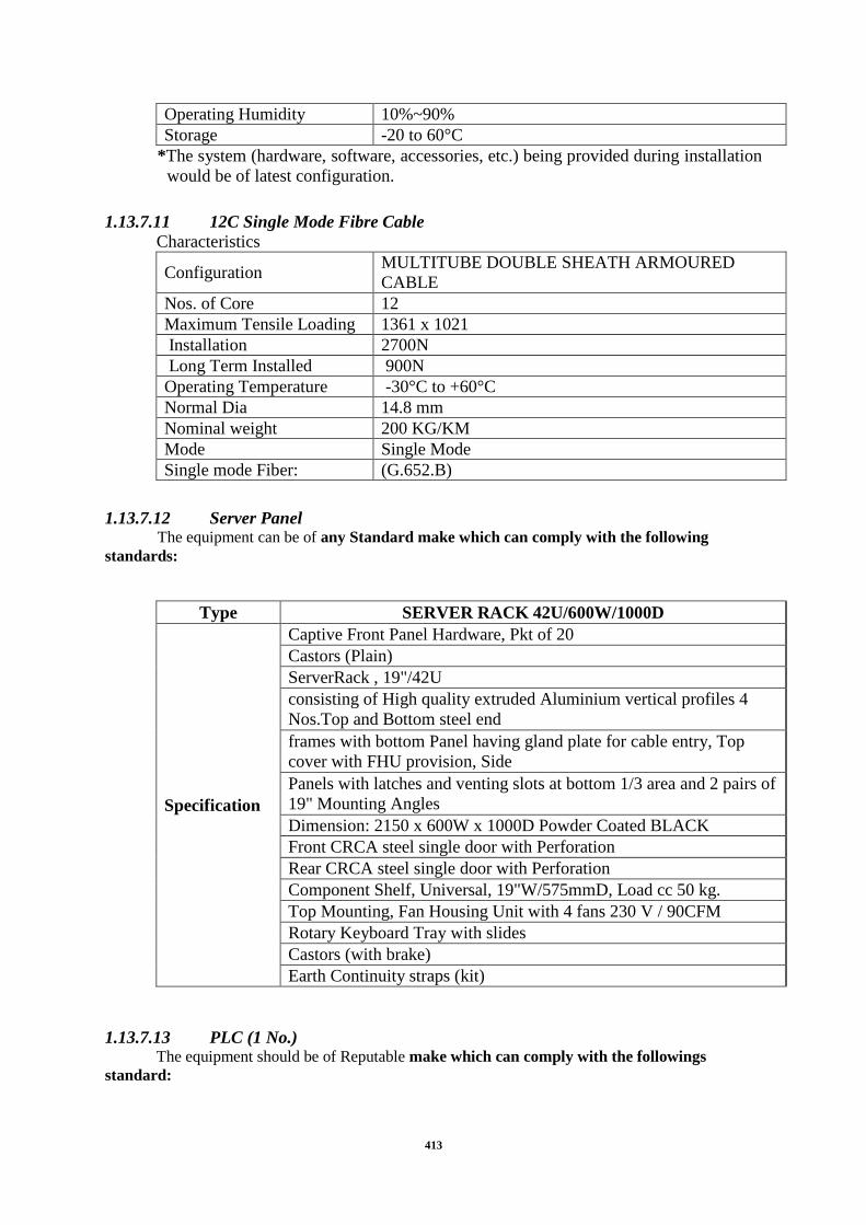
413
Operating Humidity 10%~90%
Storage -20 to 60°C
*The system (hardware, software, accessories, etc.) being provided during installation
would be of latest configuration.
1.13.7.11 12C Single Mode Fibre Cable
Characteristics
Configuration MULTITUBE DOUBLE SHEATH ARMOURED
CABLE
Nos. of Core 12
Maximum Tensile Loading 1361 x 1021
Installation 2700N
Long Term Installed 900N
Operating Temperature -30°C to +60°C
Normal Dia 14.8 mm
Nominal weight 200 KG/KM
Mode Single Mode
Single mode Fiber: (G.652.B)
1.13.7.12 Server Panel The equipment can be of any Standard make which can comply with the following
standards:
Type SERVER RACK 42U/600W/1000D
Specification
Captive Front Panel Hardware, Pkt of 20
Castors (Plain)
ServerRack , 19"/42U
consisting of High quality extruded Aluminium vertical profiles 4
Nos.Top and Bottom steel end
frames with bottom Panel having gland plate for cable entry, Top
cover with FHU provision, Side
Panels with latches and venting slots at bottom 1/3 area and 2 pairs of
19" Mounting Angles
Dimension: 2150 x 600W x 1000D Powder Coated BLACK
Front CRCA steel single door with Perforation
Rear CRCA steel single door with Perforation
Component Shelf, Universal, 19"W/575mmD, Load cc 50 kg.
Top Mounting, Fan Housing Unit with 4 fans 230 V / 90CFM
Rotary Keyboard Tray with slides
Castors (with brake)
Earth Continuity straps (kit)
1.13.7.13 PLC (1 No.) The equipment should be of Reputable make which can comply with the followings
standard:

414
1. Powerful Integrated Controller
The controller shall consist of a family of intelligent integrated modules, with each
performing a dedicated function. It shall have an integrated redundant interface for the I/O
modules as well as redundant interface for the Human machine interface.
Additionally the controller should be able to able to communicate to its redundant pair
directly preferably on a Passive backplane.
2. Modular Architecture
The modular approach shall enable a very small system to be installed with expansion to a
very large system without changing the basic hardware or disrupting the architecture. A
minimum of the following module types must be available: control modules, I/O modules,
communications modules, computer modules, and power supply modules.
3. Controller Packaging
For installation flexibility and high reliability, controller hardware must be designed to
withstand harsh conditions within industrial environments, such as heat, humidity, shock,
vibration, and electrical surge and discharge.
A. Module Hardware
Module hardware must meet the following requirements:
The modules shall be identical in appearance.
All the module shall be housed in a powder coated metal case rack to prevent physical
damage from handling or dust.
All control and I/O modules shall be rated for operation within the following ranges:
0-50 Deg C and 5-95% relative humidity, non-condensing.
I/O and power modules shall have circuitry to protect the system from electrical surge
and discharge.
The modules shall comply with the following specifications:

415
International Electro-technical Commission (IEC)
IEC 60751 (1983-01) Industrial platinum resistance thermometer sensors
IEC 61000-4-2 (2001-04) Electromagnetic compatibility (EMC)- Part 4-2
IEC 61000-4-3 (2002-03) Electromagnetic compatibility (EMC) - Part 4-3
IEC 61000-4-4 (1995-01) Electromagnetic compatibility (EMC) - Part 4
IEC 61158 (2000-08): Field-bus standard for use in industrial control systems - Part
2:
IEC 61131-3 (1993-03) for Programmable controllers - Part 3
The modules shall comply with the following shock and vibration standards:
Vibration: IEC 68-2-6, Fc: 10-50 Hz, 2g
B. Module Racks
The modules shall be grouped together in racks to form the control system. The racks
shall provide the communications mechanism to fully integrate the modules and
facilitate intercommunications between racks. A rack should hold approximately ten
individual modules, with each slot identical and able to accept any module. Modules
should be connected to the backplane using high quality, gold-plated, industry-grade
pin connectors.
It shall be possible to remove and reinsert the modules under power with no damage to
the rack or modules and without removing any external wiring or cables. The rack and
modules shall provide a physical keying mechanism to prevent incorrect module
insertion during system operation.
To simplify installation and maintenance, the module racks and modules shall
be designed for front access only. All user functions, including diagnostics,
field wiring, cable connections, switches and status indications, shall be
available from the front of the rack.
C. Power Supply
Redundant Power supplies shall be available for card rack mounting to form as
an integral part of the system. The module rack must provide two individual
power supply buses that to be driven by two independent power sources for high
availability placed in the rack in current sharing mode. Each module shall be
capable of using power from any of the two buses.
D. Enclosures

416
The racks shall be mounted in an industrial enclosure with a front & rear -access
design, with all frequently accessed items (such as modules, connectors, status
indicators, switches, and termination assemblies) located in the front of the
enclosure. For maximum flexibility, the enclosures shall be modular, with the
ability to be stacked, joined side to side, or joined back to back. To provide the
degree of environmental security required, enclosures shall be available in
sealed and vented versions. Enclosure shall be
i) for Indoor IP 44 and ii) for Outdoor IP 65
4. Control Module
A control module shall provide process control functions. The control module should
be used with dedicated I/O modules to read and control field signals. The module
shall also be capable of operation independent of I/O modules, “supervising”
operation of other control modules. In addition, the control module shall be capable of
executing on a 5 millisecond resolution input-to-output when required by the
application.
A. Hardware
The control module shall consist of a single-slot module with a dedicated
microprocessor. Memory should be battery-backed RAM so that the module
retains its configuration and state information to optionally and automatically
restart after a power failure without requiring its database to be downloaded.
The minimum memory required is 16MB.
During a hot start, all variables can be selected as retain or non retentive.
B. Software
The control system must support a full complement of process control functions.
It shall be possible to define these functions using a mix of function blocks,
ladder logic diagrams, sequential function charts, and textual programming.
Each of the four languages and their interaction within a configuration shall be
based on the IEC 61131-3 standard. The languages shall be completely
interchangeable and interactive, with a single control module‟s database capable
of including any combination of the four languages.
5. Input / Output Devices
Input/output Modules shall be intelligent I/O modules. Each module should be able to
communicate with the CPU in a dedicated fashion without requirement of any
additional interfacing hardware so as to reduce the common cause of the Failure. Each
module should have its own microprocessor to execute its input/output function,
maintain ownership of its configured data, and perform module diagnostics.
All process I/O shall be electrically isolated from both computer common and
communications common. Isolation shall meet be min 1500 VAC requirements.
Modules shall automatically determine their physical address and report this
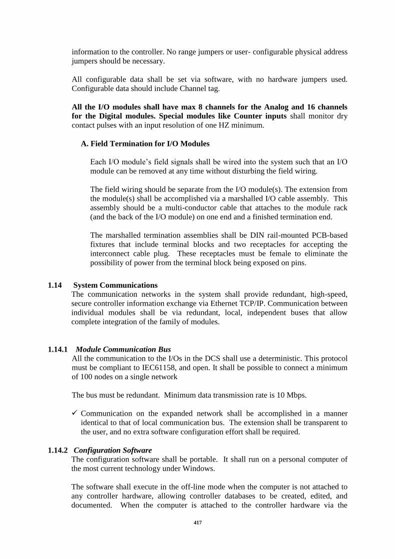
417
information to the controller. No range jumpers or user- configurable physical address
jumpers should be necessary.
All configurable data shall be set via software, with no hardware jumpers used.
Configurable data should include Channel tag.
All the I/O modules shall have max 8 channels for the Analog and 16 channels
for the Digital modules. Special modules like Counter inputs shall monitor dry
contact pulses with an input resolution of one HZ minimum.
A. Field Termination for I/O Modules
Each I/O module‟s field signals shall be wired into the system such that an I/O
module can be removed at any time without disturbing the field wiring.
The field wiring should be separate from the I/O module(s). The extension from
the module(s) shall be accomplished via a marshalled I/O cable assembly. This
assembly should be a multi-conductor cable that attaches to the module rack
(and the back of the I/O module) on one end and a finished termination end.
The marshalled termination assemblies shall be DIN rail-mounted PCB-based
fixtures that include terminal blocks and two receptacles for accepting the
interconnect cable plug. These receptacles must be female to eliminate the
possibility of power from the terminal block being exposed on pins.
1.14 System Communications
The communication networks in the system shall provide redundant, high-speed,
secure controller information exchange via Ethernet TCP/IP. Communication between
individual modules shall be via redundant, local, independent buses that allow
complete integration of the family of modules.
1.14.1 Module Communication Bus
All the communication to the I/Os in the DCS shall use a deterministic. This protocol
must be compliant to IEC61158, and open. It shall be possible to connect a minimum
of 100 nodes on a single network
The bus must be redundant. Minimum data transmission rate is 10 Mbps.
Communication on the expanded network shall be accomplished in a manner
identical to that of local communication bus. The extension shall be transparent to
the user, and no extra software configuration effort shall be required.
1.14.2 Configuration Software
The configuration software shall be portable. It shall run on a personal computer of
the most current technology under Windows.
The software shall execute in the off-line mode when the computer is not attached to
any controller hardware, allowing controller databases to be created, edited, and
documented. When the computer is attached to the controller hardware via the

418
networked or direct-connected PCs, the networked workstations, or by running in the
industrial computer module, an on-line mode of operation shall be available to allow
use of all off-line functions plus on-line troubleshooting tools. This software shall be
able to be used to configure continuous, batch, and safety protection control strategy
configurations from a single user console.
1.14.2.1 IEC 61131-3
The configuration software shall allow controller databases to be created using the
following standard languages defined by the specification IEC 61131-3: function
blocks, ladder logic, sequential function charts, and structured text.
1.14.3 Graphical Configuration and Documentation
Controller configuration should provide graphical configuration methods, with
functions entered into a database using a point and click object-oriented routine. The
resulting database should be its own documentation because of the graphical
appearance. Furthermore, the graphical database must be transferable directly to the
controller as it exists, including all graphical information, with no compile routine
necessary before transferring the database to the controller. The graphically
configured database shall be stored and executed in the controller, and the controller-
resident database shall be viewable graphically on-line and uploadable to a PC or
workstation without the need for storing the “source” database off-line.
A. On-Line Tools
The configuration software shall provide on-line tools that assist in troubleshooting
control schemes. These tools must include on-line display of variables, the ability to
force values and states, support for on-line database changes, and on-line real-time
trending.
It should be possible to display variables‟ values and the status of ladder logic and
SFC elements while viewing an on-line controller database. The ladder logic and
SFC element states shall be indicated using colors.
The configuration software shall provide the ability to write values, states, and modes
to independent variables and elements in the controller. It shall also provide the
ability to force non-independent variables and elements to a predetermined value,
state, or mode.
During troubleshooting, the user shall have the ability to stop the controller and
single-step its execution. This will provide a way to clearly understand complex
configuration schemes and highly interactive logic that might need to be examined.
B. Prebuilt Library of Functions
The configuration software shall include a predefined library of control schemes. The
library must include at least:
Single PID loop with alarm
Single PID loop with external setpoint and alarm
Ratio control loop with alarm

419
Cascade loop with alarm
Primary control loop with alarm etc.
Separate, optional libraries should be available for specialized applications.
The configuration software shall also allow commonly used functions created by the
user to be added to a library for future use.
C. On-Line Help
On-line help screens in the configuration software shall be available to assist while
creating a database. The help screens shall include descriptions of every
configuration element (e.g. each function block and ladder logic element).
D. System Architecture
A system architecture graphic depicting the hardware within the control system. This
graphic should give status information for the modules in the system by using colors
to indicate general health of the modules.
1.14.4 Windows Based Operator Software
The industrial-grade PC-based operator interface software shall be able to run on a
personal computer of the most current technology under Windows. The software
shall provide all standard operator functions, including process monitoring, alarm
management, real-time and historical trends, reports, plus provide process graphic
displays, an integrated historian, Internet enabler, batch manager and control
simulator.
1.14.5 Reliability
The system must be designed for maximum reliability and minimal downtime. This
should be achieved through a fault-tolerant design with minimal common cause
failures and state-of-the-art redundancy schemes.
1.14.5.1 Controller
The controller must have a fault-tolerant design, with redundancy in the same model
A. Standard Fault Tolerance
The module communication bus and each I/O communication bus must be redundant.
If one side of a redundant bus should fail, communications should continue,
uninterrupted, on the remaining side of the bus.
The module rack shall provide two separate power supply modules, with each module
capable of drawing power from any of the two.
B. Redundancy
Complete 1:1 redundancy needs to be quoted. The redundant control modules that
share a single set of I/O, identical, standard hardware must be used for all redundancy
schemes with option of duplication of control modules and I/O modules.

420
It must be possible to replace a failed component on-line, without removing power.
Process control shall continue to be executed in the non-failed unit.
When a module is replaced, the new module must automatically initialize, receive the
current database from the primary module, and pick up in synchronous execution as a
secondary module in the redundant relationship. This should take place without user
action for any of the steps.
1.14.6 Operator Interface
Window based operator interfaces need to be supplied such that the failure of one
component, card, or module does not cause the operator to lose any portion of the
process window.
1.14.7 System Architecture
The system should be capable of Remote I/O modules architecture at various remote
locations near to the major equipment sensors to reduce the commissioning. There
will be two remote I/O module stations. Please refer the Annexure 1 & 2 of the
system architecture.
1.14.8 Features Required in SCADA System
The system will be based on latest version of SCADA system. The main SCADA
system will be redundant. Based on application, servers are to be distributed with
redundancy. For Cyber Security it is proposed that Security Solutions Shall be
provided and separate DMZ zone be made so that outside intrusion can be minimised.
Network monitoring system shall also be provided for monitoring of Network devices.
SCADA system will have many extra features and the proposed system should
support multiple PLC/ RTU Protocol like Modbus, Profibus, DNP (Serial/TCPIP),
OPC etc.
1.15 Detailed Specification of SCADA System Components
1.15.1 Data Acquisition
The SCADA system shall perform data acquisition from PLC and field Equipments.
PLC is to be located at each location of the plant. PLC communications with
Control Centre shall utilize the Open protocol like Modbus, Profibus.
1.15.2 Data Exchange
The SCADA systems shall be able to exchange various types of data with the other
application software using ActiveX Data Objects (ADO) or Dynamic Data Exchange
(DDE).
1.15.3 Data Processing
a) Analog data
Analog data processing shall be performed according to the requirements listed
below.
- Conversion to Engineering Units
- Reasonability Limits Checking
- Limit Monitoring

421
b) Digital/Status Input Data
The following status input data types shall be accommodated as a minimum:
Two-state points: The following pairs of state names shall be provided:
(1) Open/Closed
(2) Tripped/Closed
(3) Alarm/Normal
(4) On/Off
(5) Auto/Manual
(6) Remote/Local
c) Calculated Data
It shall be possible to define the calculations on real-time data and historical data,
periodically and on request. The results shall be incorporated into the database as
calculated data available for display & report generation.
The user shall be able to define calculated analog values using database points as the
arguments and mathematical functions as the operations. Functions such as addition,
subtraction, multiplication, division, maximum value, minimum value, average,
count, square root, exponentiation, trigonometric functions, logarithms and other
statistical functions shall be provided.
The SCADA system shall be capable of analysing the open/closed status of
switching devices, such as Motor, PUMP etc. The configuration shall be updated
whenever a switching device status change is detected.
1.15.4 Quality Codes
Quality codes indicate the presence of one or more factors that affect the validity of a
data value. All quality codes that apply to a data value shall be maintained in the
database for that data value. At least following quality codes shall be supported:
- Telemetry failure
- Delete from scan
- Limit violated
- Manually replaced
- Alarm inhibit
- Abnormal data
1.15.5 Sequence-Of-Events Recording
The Sequence-of-events (SOE) data is listing of status change events with time
stamp. SOE data shall be collected by the SCADA system from PLCs. The
description of each event shall include the database description name, device state, the
date, and the time (to the nearest millisecond) of each event.

422
1.15.6 Supervisory Control
An authorized user of an SCADA system shall be able to control the operation of field
devices connected to PLCs. A control action shall require a confirmation of selection
prior to execution of control command.
The user shall be able to select and operate any controllable switching device.
Controllable switching devices will be of like, Pump, Motor.
1.15.7 Information Storage and Retrieval
Information Storage and Retrieval (ISR) system shall collect and store analog data
(telemetered and calculated) periodically at every 5 minute (configurable) and status
data by exception. Associated quality codes shall be included. It shall be possible to
perform calculations on the stored data, and the results of these calculations shall be
collected and stored. Other information such as alarms, events, SOE and reports shall
also be stored. The data shall be stored on hard disc with date tag on daily basis for
easy retrieval. Subsequently, the data shall be retrieved for analysis, display, trending,
and report generation.
1.15.8 Extensive Use of Standard
The SCADA Software should be such that it uses an extensive use of standards,
achieved by a corporate commitment to comply with all standards that are
recognized on the SCADA market, and in particular:
- Intel (or compatible) based hardware;
- Operating system options of WNT 4.0, Windows 2000 or Windows 2003;
- Uses Microsoft Foundation Class (MFC) Object Oriented Database;
- Developed with Microsoft Developer‟s Studio;
- Installed using Microsoft Install Shield utilities;
- Component Based Architecture;
- Interfaced using Active X controls (OCX);
- TCP/IP for Local and Wide Area Networks (LAN & WAN) ;
- Web-enabled Operator Consoles;
- Control Center Application Programming Interface (CCAPI) Initiatives
1.15.9 System Sizing & Extensibility
The hardware and software openness of SCADA allows the customer to smoothly
upgrade the proposed system with great facilities. Common upgrading needs include
(but not limited to) the following items:
- Additional measurement points (analog and digital);
- Additional protocol-compliant IEDs;
- Additional protocol-compliant PLCs;
- Additional operator consoles;
- Additional printers;
- Connection to other SCADA centers
1.15.10 SCADA Interfaces
User interface and gateway services communicate with SCADA over the following
interfaces:

423
- OLE Automation Control Interface - OLE Automation provides the easiest
programming interface to SCADA. OLE automation client services may be built
using Visual Basic or C++. The service may direct SCADA to add, delete, or
modify SCADA objects, may issue controls, and may retrieve measurement data.
The OLE Automation interface may be distributed across CPUs, such that a
service on one server uses SCADA running on another server;
- Publisher/Subscriber Control Interface - The publisher / subscriber interface
allows for high performance data update and automatic refresh. This interface is
based on TCP/IP sockets, and may run on the same server or between servers.
This may be used directly from C++ or using custom OLE controls in Visual
Basic;
- Custom ITelemetrySink Interface – The custom ITelemetrySink interface is
used by gateway services for high performance data transfer. This interface works
between two processes on the same server. This interface supports C++
programming.
1.16 Graphical User Interface (Gui)
The GUI shall operate within a window environment The system shall use displays
which mimic the existing control panels so that the operators working in conventional
control room environment are comfortable while working on the new system. Selected
Bidder shall develop control panel display generally similar to the one existing in
conventional control room.
The GUI shall allow the personnel to monitor and control the equipment through the
control panel displays and Tabular displays. The control panel displays shall be
dynamically updated for measurands, device positions, annunciations. To have better
visibility of control panels, it shall be possible to iconise each control panel separately.
Operator shall select that icon to zoom/view that panel display & carry out operations
such as alarm annunciation accept/reset, device close/open operations etc.
1.16.1 Trending
Trend displays shall enable the user to select real-time and historical data for trending on
graphical displays and for tabular displays. It shall be possible to take print of these trends.
1.16.2 Alarms
Alarms are conditions that require user notification when detected. Audio, visual alarm
shall be generated for all such conditions. It shall be possible to accept & reset all trip
& non-trip alarm annunciation appearing on control panel facia from control panel
display itself. Alarm annunciation on control panel shall have following characteristics:
Condition Facia Sound
Alarm initiation by
relay contact Flashing Glow On
Accept PB pressed Steady Glow Off
Reset
Off (if relay contact is reset)
Steady Glow (if relay contact is not
reset)
Off

424
Other alarm conditions shall be acknowledged from respective alarm list displays. Other
alarm conditions shall include, but not be limited to the following:
(a) Telemetered or calculated value limit violations
(b) Un-commanded changes of a power system device state
(c) Data source communication errors resulting in loss of data
(d) SCADA hardware and software element failures.
The standard products for advanced alarm management shall also be provided.
Regardless of the alarm management technique used, all alarm messages shall be
recorded with time & date tag on auxiliary memory for review and printing on demand
by the user.
Displays shall highlight alarm condition using a combination of colour, intensity,
inverse video and blinking. Alarm messages shall be a single line of text describing the
alarm that has occurred with date & time of occurrence.
1.16.3 Events
Events are conditions or actions that shall be recorded by the SCADA system but do not
require user action. Events shall be recorded in the form of an event message. The event
message format shall be similar to the alarm message format. Events shall include but
not limited to followings:
Values returning to normal from a limit violation state
Device status change on manual operation.
1.16.4 Hardcopy Printing of Display
A means shall be provided to produce a copy of a display. The display printout shall be
initiated from user friendly push buttons/pull down menus. The options for printing mode
shall include at least selection for orientation, background colour, page size, colour or black
& white print and print preview. It shall also be possible to print selected portions of display
and direct printing on any of the connected printer.
1.16.5 Report Generation
The user shall be able to schedule periodic reports generation, direct a report to a display,
print a report, and archive a report. Hardcopy report formats shall be handed over to
Selected Bidder for generation of report formats in the system. It shall also be possible to
define and generate the additional user configurable reports. The generation and printing of
any report shall not effect normal scanning of data from PLC. The report scheduling display
shall enable entry of the following parameters, with default values provided where
appropriate:
(a) Report name
(b) Report destination (printer or archiving device)
(c) Time the system should produce the report.
1.17 SCADA System Access Security
A mechanism for defining and controlling user access to the SCADA system shall be
provided.

425
1.17.1 Alarm Summary Displays
Displays that list or summarize all unacknowledged and acknowledged alarms shall
be provided. The user shall be able to select between viewing alarms in
chronological and reverse chronological order. The default shall be most recent
alarms. The summary shall separate acknowledged and unacknowledged alarms. To
facilitate identification of unacknowledged messages the time field shall blink or
entire row shall blink. It shall be possible to sort alarms by user defined text, date,
time.
1.17.2 Event Summary Displays
Event summary displays shall list the most recent events. The user shall be able to
select between viewing events in chronological and reverse chronological order.
The user shall be provided with a convenient and efficient means of selecting an
event summary display. It shall be possible to sort events by user defined text, date,
time.
1.17.3 Operating Information Summaries
The operating information summaries defined below shall be provided. Summary
items will be listed in reverse chronological order with the most recent item shown
on the first page. The user shall have the ability to sort summary items by device.
1.17.4 Abnormal Summary
The summary display shall list devices and values that are found to be abnormal,
i.e., are not in their normal state. Telemetered, calculated, and manually entered
status and data values shall be included.
1.17.5 Out-Of-Scan Summary
The out-of-scan summary display shall list device status and data values that are not
currently being processed by the system.
1.17.6 Alarm Inhibit Summary
This display shall list devices and data values for which the user has suspended
alarm processing.
1.17.7 Tag Summary
This display shall list and describe all active device tags.
1.17.8 Help Displays
Help displays shall be provided to aid the user in interpreting displayed information
and to guide the user through a data entry or control procedure.
1.17.9 Alarm Beeper Services
The Alarm Beeper service audibly notifies the operator of recent alarms by
playing a wave file. Wave files can be used to distinguish between Alarm
priorities. All the Windows‟ .wav files or customised .wav files can be used
1.17.10 Alarm Pager Services
The Alarm Pager service allows the user to configure the system to issue various
pages in response to specified alarms.

426
1.18 Quality Assurance Plan
To ensure total conformation of the application to the user requirement and to make
sure that S/W package development is of high quality, proper quality control activities
shall be performed and documented throughout the development. For this, the bidder
shall give a S/W quality assurance plan to establish system of controls and make the
S/W development activity less intangible and more manageable throughout life cycle of
S/W development viz. Review and acceptance of Requirement Analysis, Design,
Development, Testing, Implementation, User training, Maintenance, etc.
The Vendor shall be ISO 9001:2000 certified and shall ensure that all the activities
including documentation comply with the standards.
1.19 Time Schedule
Time is the essence of the work under this contract. The total turnkey work shall be
completed in 18 months and handed over, from the issue of award of contract, to the
owner.
The bidder shall workout a detailed bar chart for each activity separately indicating the
start & finish dates of each activity along with the resources that he plans to deploy in
each case and submit the same immediately after the award of contract.
1.20 Project Management
Progress of the project will be monitored by Project Management Team (PMT) which
will be steered by group of IT personnel, Site O&M persons.
1.20.1 Progress Review
The above team will monitor the progress on monthly basis and submit the
exceptional report to Owner‟s representative highlighting the achievements and
hurdles in achieving the targets with suggestions to solve these hurdles.
1.20.2 Warranty
The warranty shall be valid for a period of One (1) year from the date of installation /
Commissioning of the System.
Supplier shall ensure the warranty of supplied system for 1 Year after issuance of
Operational Acceptance by User and any defect/ repair shall be handled by
supplier‟s Engineer.
1.20.3 Preventive Maintenance
Time for regular preventive maintenance with a frequency of not less than once per
quarter will be required during the Warranty period. This should include general
checkup of various parameters, running diagnostics etc. to avoid any possible failure
or deterioration in response time.

427
1.20.4 Documentation
The following documents shall be required for smooth functioning of the system:
DOCUMENT NAME NO.OF COPIES IN ONE
SET
Installation Manual 2
System Administration and Maintenance Manual 2
User Manual 2
Technical Manual 2
Test Document(FAT &SAT) 1
1.20.5 Training Of Owners Engineers The Selected Bidder is required to provide in depth training to Owners engineers (10
Nos.) for 1 month at his facilities on all aspects of the system being supplied. Training
module shall be mutually discussed and finalized to cover Owner‟s personnel to
operate, append, modify and troubleshoot the System effectively. All the
documentation and write up material for trainees shall be provided by the Selected
Bidder.
The vendor should conduct this training at his premises, before testing of the
package start. The Bidder should devise an exhaustive training program.
1.20.6 Annual Maintenance Contract Supplier will support and provide services to ensure smooth functionality of the
supplied System for 15 Years under Annual Maintenance Contract. Any System
problems arising during AMC Period shall be handled and rectified by supplier‟s
engineer.
1.21 Project Schedule
The tentative Project schedule is 12 months from LOA.
1.22 Testing / Inspection
1.22.1 Test on Complete Control System
On completion, the functioning of the complete system shall be tested to
demonstrate its correct operation in accordance with the Specification.
For control system testing, the Selected Bidder may provide temporary means to
simulate operating conditions, but the system will not be finally accepted until
correct operation has been demonstrated to the satisfaction of the Engineer when all
the pumps are operating.
The system shall be shown to operate correctly whatever the selection of duty and
standby equipment may be.
Conditions to be tested shall include:
Normal automatic operation.
Normal manual operation
Emergency manual operation

428
1.22.2 Commissioning Tests Correct operation of controllers shall be verified by observing that the final control
element moves in the proper direction to correct the process variable as compared to
the set point.
All logic sequences shall be verified to operate in accordance with the
specifications.
All defects and malfunctions disclosed by test shall be corrected immediately. New
parts and materials shall be used as required and approved and tests shall be
repeated.
A report certifying completion of validation of each instrument system indicating
calibration values, verification that the system performs as per requirements and any
provisional settings made to devices shall be provided. A format for commissioning
checklist to be provided for approval before performing the commissioning tests.
1.22.3 Final Operational Testing and Acceptance
Upon completion of instrument calibration and system validation, all systems shall
be tested under process conditions.
The testing shall include, but not limited to all specified operational modes, taking
process variables to their limits (simulated or process) to verify all alarms, failures,
interlocks and operational interlocks between systems and/ or mechanical
equipment.
Any defects or malfunctions shall be immediately corrected using approved
methods and materials and the tests shall then be repeated.
Upon completion of final operational testing, a report shall be submitted, indicating
that the total control system provided meets all the functional requirements specified
herein. This report shall be made in the format approved by the Engineer. The
Engineer shall certify this report and it shall constitute final acceptance of the
control system.
1.23 Commissioning
After completion of installation works the Selected Bidder shall arrange to carry out
following checks/tests in the presence of JAL NIGAM representative / Engineer – in
– charge.
1.23.1 Test on Control Panels and Switchboards
1.23.1.1 Mechanical Completion Test
i) Check name plate details of every associated equipment according to
specification
ii) Check for physical damage
iii) Check for tightness of all bolts, clamps and connecting terminals
iv) Check earthing
v) Switch developments
vi) Each wire shall be traced by continuity tests and it should be made sure that
the wiring is as per relevant drawings. All interconnections between

429
panels/equipment shall be similarly checked.
vii) All the wires should be maggered to earth
1.23.1.2 Commissioning Tests
i) Checks on relays, functioning of relays, simulation of fault for testing
ii) Checks on motors
iii) Setting of relays, other alarm, tripping devices and interlocks as per scheme
iv) Phase angle checks, measurement of magnitude and phase angle of current
transformer secondary currents and potential transformer secondary voltage
v) Functional checking of all power and control circuits e.g. closing, tripping,
control, interlock, supervision and arm circuits including proper functioning of
the components equipment. If inter locks are provided with other equipment, it
shall be thoroughly tested.
1.23.2 Test of Relays
1.23.2.1 Mechanical Completion Checks
i) Check name plate details according to specification
ii) Check for any physical damage
iii) Check internal wiring
iv) Megger all terminals to body
v) Megger AC to DC terminals
1.23.2.2 Commissioning Checks
i) Check operating characteristics over the entire range by secondary injection
ii) Check minimum pick up voltage
iii) Check operation of electrical / Mechanical targets
iv) Relay settings to be checked by injecting different values of current
v) Setting of relays as per discrimination chart
1.23.2.3 Miscellaneous
Mechanical completion checks and commissioning tests on items not covered above,
shall be carried out by the Selected Bidder as per the instructions of JAL NIGAM
representative / Engineer - in – charge.

430
1.24 ANNEXURES ANNEXURE – 1A

431
ANNEXURE – 1B

432
ANNEXURE – 1C

433
Schedule II – Part E
General Painting and Protection Requirements

434
General Painting and Protection Requirements 1.1 General
The preparation, application and conditions for work shall comply with the
recommendations of BS 5493 and BS 6150 or if the protection is of a special nature,
in accordance with the manufacturer's directions.
Paints, primers and undercoats shall be obtained from the same manufacturer and
except where a definite time is specified between mixing and application, shall be
ready mixed for use. They shall be compatible with one another.
Paints shall be delivered in sealed containers bearing the manufacturer's name, batch
number, etc. and shall carry a label giving details of quality and instructions for use.
No site painting shall be carried out unless the surface to be painted is dry, the air
temperature above 4oC and the relative humidity less than 85% or as otherwise
specified by the paint manufacturer, whichever is minimum. The Employer‟s
Representative shall approve the methods for removing all dirt, oil, grease, etc, before
Site painting commences.
Test plates carrying finishes from the actual coating used may be required by the
Employer‟s Representative for inspection and test purposes.
To facilitate inspection, no consecutive coats of paint shall be of the same shade
except in the case of white.
Priming to two mating surfaces shall be applied prior to assembly.
All items of Plant shall be delivered to Site with the shop paint finish applied unless
specified otherwise. A further coat of final finish paint shall be applied at Site, of
sufficient thickness to produce a uniform colour and appearance. Such painting shall
be carried out within one month of successful acceptance trials for the Plant.
All paint thicknesses shall be checked using an Elkometer or equivalent instrument,
supplied by the Selected Bidder, for each layer of paint, to the reasonable satisfaction
of the Employer‟s Representative.
All coatings applied to any part of the plant in contact with water to be used for
drinking, washing or cooking shall be non-toxic, non-carcinogenic, shall not impart
taste, odour, colour or turbidity to the water or foster microbial growth. No
manufacturer‟s name-plate identification, vented filler plugs in gearboxes or grease
nipples shall be painted over. Lead based paints shall not be used.
The Selected Bidder shall liaise closely with the paint manufacturer who shall
provide full facilities for him to inspect and check the preparation and painting during
all stages. The Selected Bidder shall report on his inspections to the Engineer.
The Selected Bidder shall ensure that all coatings are free from defects and adequate
in all respects for the purpose intended.
1.1.1 Painting System Failure
The painting system shall be deemed to have failed if:-
After painting, damage has been caused by handling, impact, abrasion or welding;
Any portion of the paint film separates from any other or the parent metal;

435
After painting the total dry-film thickness is less than that specified.
Failure shall not include:-
Loss of gloss;
Variation of shade, not affecting the anti-corrosive properties of the system.
1.2 Colour Coding and Labelling of Pipes and Equipment
All pipes and equipment shall be colour coded to a schedule to be agreed with the
Employer‟s Representative before any site painting starts, or earlier if necessary to
suit manufacturing procedures.
Valves and fittings shall be painted in the same colour as of the pipe of which they
form a part. Where a pipe enters or leaves a piece of equipment the pipe colour shall
extend up to but not including the flange attached to the equipment.
All pipelines shall be identified by stick-on 90 micron thick vinyl film labels showing
the name of the material to be carried by the pipeline and an arrow indicating the
direction of flow. Letters of titles shall be pre-spaced on carrier tape and the complete
title protected by one piece removable liners. Titles shall be at intervals not less than 8
m, but shall in any case be provided in every space through which the pipe passes.
Locations of labels shall be subject to prior approval by the Employer‟s
Representative. Lettering sizes shall be between 16 mm and 75 mm in height
depending on the size of the pipe.
Pipes smaller than 22 mm outside diameter shall be labelled by the use of tags instead
of labels. Tags shall be made of brass no smaller than 65 mm x 16 mm by 1.5 mm
thick, with lettering etched and filled with black enamel.
Titles shall also be provided on all equipment in locations and in sizes to be approved
by the Employer‟s Representative.
1.3 Cleaning and Preparing at Place of Manufacture
The Selected Bidder shall be responsible for the cleaning and preparation for painting,
priming or otherwise protecting as specified of all parts of the Plant at the place of
manufacture prior to packing.
1.3.1 Cleaning
Parts shall be cleaned prior to testing at the manufacturer's works. Parts subject to
hydraulic test shall be tested before any surface treatment. After test all surfaces shall
be thoroughly cleaned and dried out if necessary by washing with an approved
dewatering fluid prior to surface treatment.
1.3.2 Preparation
Bright Parts: Bright parts and bearing surfaces shall be thoroughly polished and
protected from corrosion by the application of rust preventive lacquer or high melting-
point grease, as approved by the Employer‟s Representative, before the parts are
packed. A sufficient quantity of the correct solvent for removal of the protective
compounds shall be supplied and packed with each particular part.
Embedded Parts: Embedded parts or those parts of an assembly which will be
embedded in concrete shall be thoroughly de-scaled and cleaned to the satisfaction of
the Employer‟s Representative and before being packed shall be protected by a
cement wash or other approved method. No cast iron or steel work shall be bitumen or

436
tar coated where it is to be cast into the concrete and provision shall be made for
cleaning off any portions so coated.
Grit or Shot Blasted Parts: Grit or shot blasting shall be carried out in accordance with
B.S. 7079 to a standard between `First Quality' and `Second Quality' given in Table 1
after which the maximum amplitude of the surface shall not exceed 0.1 mm.
Cast Iron and Steel Pipework: All ungalvanised steel pipework including pump
suspension mains, bearing spiders and tunnel tubes shall be prepared internally and
externally by grit or shot blasting as specified above and the surfaces primed as
specified within four hours of blasting.
1.4 Painting and Finishing at Place of Manufacture
This Clause governs the methods for the protective coatings to be applied to structural
steel, metalwork and ironwork as corrosion protection systems. The systems designed
as specified here shall be applied as specified under Protective Coatings. Protective
coating specified elsewhere for particular works such as pipes and cladding shall
firstly be designed in accordance with particular requirements specified elsewhere and
secondly in accordance with any requirements herein which are not overridden
elsewhere. This specification makes reference to the following standard:
B.S.5493 "code of practice for the protective coating of iron and steel against
corrosion"
The Selected Bidder shall design each protective coating system and shall submit
details of each system to the Employer‟s Representative for approval. Submissions
shall where possible be in the format of which examples are given at the end of this
section with such additional information and samples as the Selected Bidder may
provide or the Employer‟s Representative may require to enable the system to be
assessed.
Protective coating shall be designed in accordance with B.S. 5493 to have a long life,
generally of at least 10 years to first maintenance. Protection systems shall be chosen
to be easily maintained in the future and to allow non-specialist on-site re-coating
where necessary using single part paints.
For the purposes of system design the general environment shall be as specified in
B.S. 5493 Table 3 Part 2 `Exterior exposed polluted inland'. Bulkhead gates and
stoplogs shall be assumed to be exposed to a Table 3 Part 8 `Non-saline water'
environment unless otherwise approved by the Employer‟s Representative.
Interior spaces shall be considered to be dry in administration areas open to
continuous access and damp or immersed in other spaces. The protective coating of
components or structures which are continuously or infrequently immersed shall be
designed for the more onerous of these two conditions relevant to the protection
system used.
All exterior exposed items to be coated shall have a final coat of good appearance of a
colour and type as approved by the Employer‟s Representative.
Protective coating systems shall generally fall into one of the following basic systems;
1.4.1 Protective Coatings
Galvanising;
Galvanising plus painting;

437
Multi-coat painting; Bitumen enamel;
Others as proposed by the Selected Bidder and approved by the employer‟s
representative.
The Selected Bidder shall submit to the Employer‟s Representative details of his
proposals for the corrosion protection of each of the items requiring such protection,
which will generally fall into the above categories, as follows:
Trash screens, flooring, ladders, access covers and frames, step irons and other
components which are inaccessible but subject to abrasion/damage;
Structural steelwork (including crane beams, monorails, crane structures and chassis),
bulkhead gates, stoplogs, grappling beams, steel tanks and other large items readily
accessible for maintenance;
Valves and other corrosion-susceptible items which may be buried and are not covered by
the provisions of other specifications :
Other components not covered by the above for which the Selected Bidder may propose a
system which he considers to be more suitable for the duty;
Electrical switchgear, transformers, control panels etc.
All painting material shall be applied in strict accordance with the paint manufacturer's
instructions.
Plant supplied to site with final coating applied:
Cubicles, cabinets etc. other than those specified in elsewhere in bid document.
Before any steel work is painted, the steel must be thoroughly cleaned and an
approved anti-rusting priming coat applied so that the possibility of rusting or
corrosion taking place is negligible. All surfaces should have not less than two stoved
undercoats and two top coats or air drying paint. The undercoats shall be easily
distinguishable in shade or colour from the priming and finishing coats. The two final
coats shall be in a colour and finish to be advised by the Employer‟s Representative.
The inside surfaces of any cubicles, cabinets etc. where condensation is liable to
occur, shall be coated with an approved anti-condensation composition. The Selected
Bidder shall ensure that all component sections of a switch board wherever
manufactured shall have a finish of uniform texture and an exact colour match.
Chromium Plated Parts: Where chromium plating is specified or offered by the
manufacturer it shall comply with the requirements of B.S. 1224 including the
following provisions. No blistering of any surfaces will be tolerated. The finished
appearance shall be bright. Where the base metal is steel, plating shall be applied in
accordance with Table 2. Other base metals shall be plated in accordance with Tables
3, 4, 5 as appropriate. For all base metals the service condition number 2 shall be
used.
Small bore pipes, valves and fittings etc., which are sited in architecturally finished
areas of the station and selected by the Employer‟s Representative shall be chromium
plated. Damage to chromium plating shall be made good before Taking Over.
Galvanized Parts: All materials to be galvanized shall be shown on the approved
drawings or specified. All punching, cutting, drilling, screw tapping and the removal
of burrs shall be completed before the galvanizing process begins. Parts to be

438
galvanized shall be shot blasted as specified above. Such parts shall be galvanized not
more than four hours after commencement of shot blasting.
All galvanizing shall be done by the hot dip-process. No alternative process may be
used without the approval of the Employer‟s Representative. No components shall be
galvanized which are likely to come into subsequent contact with oil.
The zinc coating shall be uniform, clean smooth and as free from spangle as possible.
In the case of component parts the zinc coating shall weigh not less than 610 g/sq.m
of area covered and shall not be less than 0.090 mm in thickness.
Where hot-dip galvanizing is not practicable bolts and nuts shall be sherardised,
which shall conform to BS: 4921. The Employer‟s Representative may select for test
as many components to be weighed after pickling, and before and after galvanizing as
he may think fit.
All galvanized parts shall be protected from injury to the zinc coating due to
differential serration and abrasion during the periods of transit, storage and erection.
Damaged areas of the coating shall be touched up with an approved zinc-dust paint or
other approved flake metallic compound.
Cast Iron and Steel Pipework: (Internal surfaces)
The internal surfaces shall have an approved coating.
Where a bitumen based coating is used, it shall be in accordance with Type 2 of B.S.
4147.
Prior to lining, the pipe shall be grit blasted and primed with an approved primer. The
lining shall be in accordance with B.S. 534. After installation, the internal lining shall
be made good and satisfactorily tested with required detector.
The coating shall be suitable for use in contact with drinking water. The type of
coating shall be entered in Schedule L provided and the Employer‟s Representative
reserves the right to call for test plates of the paint. The manufacturer shall at the time
of ordering carry out the `Taste and smell test' (Appendix E of B.S.4147) and `Effects
on water test' (Appendix C of B.S. 3416) and forward 3 copies of the test results to the
Employer‟s Representative for approval.
Where pipes are to be welded after the protective coatings have been applied, the pipe
surfaces shall be primed and all other coating stopped of the weld preparation. Collars
and fillings shall be primed but no other coating applied.
The manufacturer shall supply a sufficient quantity of suitable materials to repair
damage occurring during delivery to site and to provide a flush finished internal lining
at welded joints. He shall supply sufficient coating to fill in the recesses at internal
welds over the previously primed areas. The costs of these materials shall be included
in the unit rates for the supply of the pipes and specials.
The coating shall be applied in accordance with the manufacturer's instructions and
with Appendices J and K of B.S. 3416.
Machinery- (Internal surfaces) e.g. pumps, valves, strainers, rising and suspension
mains of wet well pumps:
As for cast iron and steel pipework (Internal surfaces).
Cast iron and steel parts (External surfaces) immersed in Water:

439
All ungalvanised metal parts which will be immersed in water shall be cleaned by grit
blasting and within four hours of blasting given a coating similar to that specified for
internal surfaces.
Cast iron and steel (External surfaces) in manholes and areas of high humidity:
Ungalvanised metal parts exposed in manholes or areas of high humidity shall be
cleaned by grit blasting and given two coats of a black bituminous solution.
Plant forwarded to site for final finishing.
Cast Iron and Steel Parts (External surfaces) outside buildings:
All ungalvanised metal parts which will be exposed to the outside atmosphere shall be
cleaned by grit blasting and provided with two coats of an approved primer.
Cast Iron and Steel Parts inside buildings:
All exposed metal surfaces which will not be immersed in water or exposed in areas
described above shall be rubbed down, cleaned by grit blasting and within four hours
of blasting given one coat of an approved primer before packing.
1.5 Painting at Site
Immediately on arrival at the site, all items of plant shall be examined for damage to
the paint coat applied at the manufacturer‟s works, and any damaged portions shall be
cleaned down to the bare metal, all rust removed, and the paint coat made good with
similar paint.
Steel and cast iron parts received at site shall be provided with adequate number of
further coats of coal tar epoxy polyamine coating to a total dry film thickness of 275
microns including the primer coats. All sharp edges, nuts, bolts and other items
difficult to be painted shall receive a brush coat of specified paint before application
of each coat of epoxy based coal tar paint giving a total dry film thickness of at least
275 microns. In the case of fabricated steelwork this work shall be done after
assembly.
Before painting is commenced the Selected Bidder shall submit for the approval of
the Employer‟s Representative, full details of the paints he proposes to use together
with colour charts for the gloss finishes.
After erection, such items which are not finish painted shall be finish painted, items
finish painted at the Manufacturer‟s works shall be touched up for any damaged paint
work.
1.5.1 Painting System Requirements
The painting work shall conform to the following requirements:
The surface preparation shall be carried out generally in accordance with IS: 1477 Part I
and IS: 6005.
After surface preparation, two coats of primer-red oxide zinc chromate with modified
phenolic alkyd base conforming to IS: 2074 shall be applied. Dry film thickness of each
coat shall be 25 microns.
For finish painting, after application of primer as in (b) above, two coats of synthetic
enamel conforming to IS: 2932 shall be applied. Dry film thickness of each coat shall be
25 microns.
Colours shall be selected as per IS: 5

440
No painting shall be carried out unless the item has been inspected and accepted by
Employer‟s representatives at the Manufacturer‟s works.
The dry paint film thickness shall be measured by Elcometer or other instruments
approved by the Employer. In order to obtain the dry film thickness (DFT) specified,
the Selected Bidder shall ensure that the coverage rate given by the paint
manufacturer will enable this thickness to be obtained. Strength of adhesion shall be
measured with an adhesion tester and this value shall not be less than 10 kg/cm2.
Painted fabricated steel Work which is to be stored prior to erection shall be kept clear
of the ground and shall be laid out or stacked in an orderly manner that will ensure
that no. poles of water or dirt can accumulate on the surface. Suitable packings shall
be laid between the stacked Materials. Where cover is provided, it shall be ventilated.
1.5.2 Painting System
The painting procedure shall be submitted in the following format:
Surface Preparation
Reference Standard
Conditions of Work
Type of Materials
Tests and inspection methods and sequence, thickness (DFT)
Colour in final coat
Total thickness of coats (DFT)
Other necessary data and information
The following items in the plant are required to be painted;
Outer surfaces of pumps, valves, pipes, fittings, motors etc., not exposed to treated water
Steelwork exposed to weather, such as outer surface of surge vessel, valves, pipes etc.
Internal Plant and pipework, cranes, exhaust fans, fire extinguishers and miscellaneous
steelwork not exposed to weather
Steelwork exposed to weather, such as platforms, ladders, hand railing, etc.
Steelwork exposed to humid weather and requiring hard maintenance and repairs
Buried steelwork
Buried pipes and fittings prior to application of wrapping
Other equipment, as per requirement of employer.
All buried steel pipes and fittings shall be coated and unwrapped with hot or cold
applied, self-adhesive, polyethylene in accordance with AWWA C214 or equivalent
Standard.
Cast iron or mild steel parts to be built into concrete shall remain unpainted.
Immediately before it is cast in-situ, it shall be made perfectly free from dirt, scale,
loose rust, paint, oil lime wash or any other coating.

441
No blast cleaning or painting shall be applied to corrosion resistant Materials such as
stainless steels. Ni-resist cast iron, bronze and other metals used for seals, bearings,
lighting fitting etc.
Machined surfaces such as gear teeth shall be coated with a thick layer of grease.
Other mechanical surfaces such as shaft ends or other bright parts shall be coated with
two coats of an anti-rust solution which can be removed easily when required.
Permanently bolted mechanical interfaces such as flanges shall be coated with a thin
coat of anti-rust compound before assembly.
All primers, under coats and finishes shall be applied by brush or airless spray, except
where otherwise specified.
Consecutive coats shall be in distinct but appropriate shades. All paints shall be
supplied from the store to the painters, ready for application, and addition of thinners
or any other Material shall be prohibited. Any instruction given by the paint
manufacturer shall be strictly followed.
All painting shall be carried out by the qualified, experienced & competent painters
under supervision. Paint shall be applied to the dry surface which has been prepared
in compliance with the approved procedure.
The Plant and equipment shall be inspected and reviewed at the various stages of the
coating application both at the manufacturer‟s Works and at the Site of the Works.
Samples may be taken from the paints as delivered and submitted to such tests as are
deemed necessary. The completed paint systems shall be tested by instruments to
ensure that the protection is of adequate thickness and is free from pinholes and the
direct measurement of adhesion shall be checked by the removal of a small section of
the coating. The Selected Bidder shall supply all instruments and apparatus required
for carrying out such tests required by the Employer.
1.6 Fusion-bonded Epoxy Powder Coatings
All fabricated steel pipework and other Plant where specified, shall have a lining and
coating, not less than 250 microns thick, of 100% solids, thermosetting fusion-
bonded, dry power epoxy coating. All grit and dust shall be removed and coating shall
be started before formation of visible oxidation of the surface. The metal shall be pre-
heated to a temperature recommended by the manufacturer and the epoxy powder
applied by immersion in a fluidized bed, after which excess powder shall be removed.
The powder shall be allowed to flow out completely before curing. The thickness of
the coating, including any repaired areas, shall be checked with a calibrated tester.
Spark testing, for pinholes, voids, contamination, cracks and damaged areas, shall use
a high-voltage spark generator. Repairs due to coating imperfections or damage shall
be done using a brush-applied compatible two-pack liquid epoxy compound. The area
to be repaired shall be cleaned to remove dirt, grease, scale and damaged coating,
which shall be feathered. Pinhole surface preparation is not required other than
removal of detrimental contaminants which could impair the adhesion of the repair
material. The surface coating shall be applied by an approved applicator. GRP covers
and guards shall be pigmented to give the finished colour without painting.
1.7 Waterworks Finish
A high standard of finish, defined as "Waterworks finish" is required for all Plant as
detailed below.

442
1.7.1 Welding and flame cutting
A smooth neat finish, by careful grinding if necessary is required on all exterior
welding and flame cutting. All plates and bars used in fabrication shall have smooth
surfaces with no pitting or deep slag inclusions.
1.7.2 Castings
Casting surfaces shall be smooth and free from surface blowholes. Stock castings
shall be specially selected with this in mind. All castings shall be shot blasted before
machining.
1.7.3 Covers
All covers shall be firmly fixed. Weld mesh shall sit square in its frame. Where panels
are placed next to each other the patterns shall line up.
1.7.4 Flanges and beadings
All bolt holes shall be spot faced parallel with the mating face for good seating of nuts
and bolt heads. Surplus jointing shall be removed from mating faces and peripheries.
1.7.5 Items to be chromium plated
Name plates, instruction plates, rotation arrows, indicators and pointers, small bore
pipework, oil level gauges and fittings, small valves (including air valves), plugs and
grease nipples, which are sited in architecturally finished areas of the station and as
selected by the Employer‟s Representative, shall be chromium plated. Damage to
chromium plating shall be made good. All pipes and fittings etc. shall be fitted in a
straight, neat symmetrical manner so as to present a pleasing appearance.
1.7.6 External screws, Bolt Heads, nuts and washers
These shall be chromium plated, sherardised or made in stainless steel.
1.7.7 Gauges
All indicating gauges fitted to any machine assembly shall be of similar appearance
and grouped together to present a pleasing aspect. They shall all have chromium
plated cases, bezels, cocks and fittings

443
Schedule III
Inspection, Testing And Commissioning Requirements

444
1.1 Inspection and Testing During Manufacture
1.1.1 General
(a) All inspection and testing shall be carried out in accordance with the Specification
and in absence of Specification relevant Indian Standard or internationally approved
equivalent standard. After award of contract, Selected Bidder shall furnish a QA plan
for approval by Engineer / Independent Engineer. QA plan shall include testing for
incoming supply of raw materials and bought out items, stage inspections and tests on
finished products at manufacturer‟s works / appropriate testing station. QA plan shall
clearly indicate tests which are intended to be witnessed by the Selected Bidder alone
and those by both Selected Bidder and Engineer / Independent Engineer.
(b) Inspection and tests schedule shall be as follows;
1) Manufacture tests
2) Acceptance inspection / Quantity checking
3) Install /site inspection
4) Site acceptance test
5) Tests on Completion
6) Process Wet Tests (by Raw Sewage & tertiary treated sewage )
7) Operation Test (Tests After Completion)
(c) The Selected Bidder shall carry out at the place of manufacture tests of the Plant
/Equipment at any part of the Works.
(d) The Engineer / Independent Engineer and/or duly authorised and designated
representative(s) shall be entitled to attend the aforesaid inspection and/or tests.
(e) Selected Bidder shall provide test procedure, pre-factory test results, and calculation
sheet and provide all of test result with necessary document including its data and
photo to show Engineer / Independent Engineer that test is carried out in proper
condition and the its test results.
(f) The procedure for the testing and inspection to be carried out during or following the
manufacture of the materials to ensure the quality and workmanship of the materials
and to further ensure that they conform to the Contract in whatever place they are
specified shall be as described below.
(i) The Selected Bidder shall give the Engineer at least 21 clear days notice in
writing of the date and the place at which any plant or equipment will be ready
for inspection/testing as provided in the Contract. The Engineer / Independent
Engineer or his duly authorised representative shall thereupon at his discretion
notify the Selected Bidder of his intention either to release such part of the plant
and equipment upon receipt of works tests certificates or of his intention to
inspect. The Engineer / Independent Engineer shall then give notice in writing
to the Selected Bidder, and attend at the place so named the said plant and
equipment which will be ready for inspection and/or testing. As and when any
plant shall have passed the tests referred to in this section, the Engineer /
Independent Engineer shall issue to the Selected Bidder a notification to that
effect.

445
(ii) The Selected Bidder shall forward to the Engineer / Independent Engineer 6
duly certified copies of the test certificates and characteristics performance
curves for all equipment.
(iii) If the Engineer(s) / Independent Engineer fails to attend the inspection and/or
test, or if it is agreed between the parties that the Engineer(s) / Independent
Engineer shall not do so, then the Selected Bidder may proceed with the
inspection and/or test in the absence of the Engineer / Independent Engineer and
provide the Owner with a certified report of the results thereof as per (ii) above.
(iv) If any materials or any part of the works fails to pass any inspection / test, the
Selected Bidder shall rectify or replace such materials or part of the works and
shall repeat the inspection and/or test upon giving a notice as per (i) above. Any
fault or shortcoming found during any inspection or test shall be rectified to the
satisfaction of the Engineer / Independent Engineer before proceeding with
further inspection of that item. Any circuit previously tested, which may have
been affected by the rectification work, shall be re-tested.
(v) Where the plant and equipment is a composite unit of several individual pieces
manufactured in different places, it shall be assembled and tested as one
complete working unit, at the maker‟s works.
(vi) Neither the execution of an inspection test of materials or any part of the works,
nor the attendance by the Engineer(s) / Independent Engineer, nor the issue of
any test certificate pursuant to (iii) above shall relieve the Selected Bidder from
his responsibilities under the Contract.
(vii) The test equipment, meters, instruments etc., used for testing shall be calibrated
at recognised test laboratories at regular intervals and valid certificates shall be
made available to the Engineer / Independent Engineer at the time of testing.
The calibrating instrument used as standards shall be traceable to
National/International standards. Calibration certificates or test instruments
shall be produced from a recognised/Laboratory for the Engineer‟s consent in
advance of testing and if necessary instruments shall be recalibrated or
substituted before the commencement of the test.
(viii) Tests shall also be carried out such that due consideration is given to the Site
conditions under which the equipment is required to function. The test
certificates shall give all details of such tests.
(ix) The Selected Bidder shall establish and submit a detailed procedure for the
inspection of materials or any part of the works to the Engineer / Engineer‟s
representative for approval within the date indicated in the Programme Details.
The detailed procedure shall indicate or specify, without limitation, the
following :
Applicable code, standard, and regulations.
Fabrication sequence flow chart indicating tests and inspection points.
Detailed tests and inspection method, indicating the measuring apparatus to
be used, items to be measured, calculation formula, etc.
Acceptance criteria.
Test report forms and required code certificates and data records.

446
Method of sampling, if any sampling test to be conducted.
Selected Bidder‟s or Engineer‟s / Independent Engineer‟s witness points.
(x) The Selected Bidder shall not pack for shipment any part of the Plant until he
has obtained from the Engineer / Independent Engineer or his authorised
representative his written approval to the release of such part for shipment after
any tests required by the Contract have been completed to the Engineer‟s /
Independent Engineer / Owners satisfaction.
(xi) The following Inspection and Testing procedures shall be carried out for the
equipment as applicable.
The detailed procedure shall indicate or specify, without limitation, the
following:
Visual Inspection.
Dimension Checking
Dynamic balancing for all rotating parts
Hydrostatic / Leak testing for all pressure parts, Pneumatic Leak Test
wherever applicable
Operation check
Liquid penetrant tests or magnetic particle tests for all machined surfaces of
pressure parts.
(g) The Selected Bidder shall maintain proper identification of all materials used, along
with reports for all internal / stage inspection work carried out, based on the specific
job requirement and or based on the datasheets / drawings / specifications.
(h) The expenses incurred during inspection shall include, but not be limited to all
travelling, boarding, lodging, local; travelling and out of pocket expenses.
(i) For inspections of major equipments such as pumps, blowers etc at manufacturer‟s
sites within India, the Selected Bidder shall incur all the expenses of the Engineer /
Independent Engineer. All the expenses with respect to the aforementioned
inspection(s) shall be for maximum Ten inspection trips comprising of two members
from the Employer per trip.
(j) However, cost of all the inspection shall be borne by the Selected Bidder and will not
be reimbursed when material or any part of the facilities is not ready at the time
specified by the Selected Bidder for inspection or when re-inspection is necessitated
by prior rejection.
(k) Witnessed testing will normally be waived on standard types of equipment such as
small motors, individual standardised instruments, small mass produced components
used in the manufacture of Plant items, small bore pipework and fittings, minor
installation materials and low voltage cable. In order to remove doubt this shall not
relieve the Selected Bidder of his obligation under the Contract to ensure that all Plant
is tested at the manufacturer's works prior to delivery to Site.
(l) As a guide to the Selected Bidder the Engineer / Engineer‟s representative reserves
the right to witness testing of the following but not limited to the following Plant
items:

447
a) Electrical:
(1) Transformers
(2) 33 LV & 11 kV Metal enclosed switchboards & Switchgears.
(3) 415 V Metal enclosed switchgears (PCC)/ MCC
(4) 415 V Power capacitor and control panel
(5) Battery, battery charger and DC Distribution Board
(6) Variable Frequency Drives
(7) Non Segregated Bus Duct
(8) Power & control cables
(9) Lighting System
b) Mechanical:
(1) SBR mechanism/Clarifier and thickener bridges, drives, and sludge/scum
mechanisms
(2) Chemical dosing systems complete
(3) Mixers, pumps and blowers including their motors rated at greater than 25
kW
(4) Valve and penstock actuators
(5) Valves and non return valves greater than 300 mm diameter
(6) Pipes more than 200 mm diameter
(7) Sluice Gates
(8) Weir Gates
(9) Coarse Screens and Fine Screens
(10) Dewatering Centrifuge / Belt Press Filter and associated plant
(11) Fine Bubble Diffuser systems
(12) Chlorination system and Gas Scrubbers
(13) Process Air Blowers
(14) Vertical turbine Pumps
(15) Horizontal & Submersible Pumps
(16) Membranes
(17) Gas safety devices/control valves
(18) Flame arrester and trap assembly

448
(19) Flares
(20) EOT Cranes and Hoists
c) Instrumentation and Control:
(1) Flow meter and Process Instruments
(2) Programmable Logic Controller
(3) SCADA / HMI System
(4) Uninterruptible Power Supply System
(5) Wireless GPRS gateway testing
(6) FAT & SAT for complete ICA system
(m) All destructively tested samples shall be replaced with new.
(n) The Engineer / Independent Engineer reserve the right to be present during the testing
and inspection of all Plant items.
Materials, Plant and Equipment
The Selected Bidder shall place orders for the material and the equipment only after
approval of the Engineer. The Selected Bidder shall submit the detailed drawings and
the procedure of submission, review and revision shall be as specified herein below.
The Selected Bidder shall inform the Engineer / Independent Engineer about the
likely dates of manufacturing, testing, and dispatching of any material and equipment
to be incorporated into the Permanent Works. The Selected Bidder shall notify the
Engineer / Independent Engineer for inspection and testing, at least twenty-eight (28)
days prior to packing and shipping and shall supply the manufacturer's test results and
quality control certificates. The Engineer / Independent Engineer will decide whether
he or his representative (Engineer) will inspect and test the material / equipment or
whether he will approve it on the basis of the manufacture‟s certificate.
The following inspection and test categories shall be applied prior to delivery of the
equipment, of various categories as indicated in the technical specifications for each
type of the equipment:
Category A: -The drawings have to be approved by the Engineer before manufacture
and testing. The material has to be inspected by the Engineer or a third party
inspecting agency approved by the Engineer / Independent Engineer at the
manufacturer‟s premise before packing and dispatching. The inspection charges of the
agency will be borne by the Engineer / Independent Engineer. The Selected Bidder

449
shall provide the necessary equipment and facilities for tests and the cost thereof shall
be borne by the Selected Bidder.
Category B: - The drawings of the equipment have to be submitted and approved by
the Engineer prior to manufacture. The material has to be tested by the manufacturer
and the manufacturer‟s test certificates are to be submitted and approved by the
Engineer before dispatching of the equipment. Notwithstanding the above, the
Engineer / Independent Engineer, after examination of the test certificates, reserves
the right to instruct the Selected Bidder for retesting, if required, in the presence of the
Selected Bidder‟s representative.
Category C: - Samples of the materials and/or equipment shall be submitted to the
Engineer for pre-construction review and approval in accordance with the provisions
of conditions of the contract. Following approval by the Engineer / Independent
Engineer, the material may be manufactured as per the approved standards and
delivered to the Site.
For material/equipment under Category “A” and “B”, the Engineer / Independent
Engineer will provide an authorization for packing and shipping after inspection.
The testing and approval for dispatching shall not absolve the Selected Bidder from
his obligations for satisfactory performance of the plant.
1.2 Factory Acceptance Test (FAT) Document
Fifty six (56) days prior to commencement of inspection of each Plant item /
equipment the Selected Bidder shall supply a Factory Acceptance Test (FAT)
Document for approval. This shall comprise four copies of the following:
- Unpriced copy of the Selected Bidders order for the Plant item / equipment
concerned:
- Details of the inspection and test procedures to be carried out.
- Pre-factory test results and its photos.
The FAT Plan shall provide comprehensive details of the tests to be carried out, the
purpose of each test, the equipment to be used in carrying out the test and the methods
to be adopted in carrying out the tests. The FAT shall provide space within the
documentation for results of the tests to be added and for each test and for the FAT as
a whole to be signed off by the Selected Bidder and the Engineer.
On completion of the tests the Selected Bidder shall provide four copies of all test
certificates, curves etc. for the inspected Plant item.

450
1.3 Inspection and Testing Programme
The Selected Bidder shall submit to the Engineer / Engineer representative not later
than 56 days prior to the commencement of the first inspection and test during
manufacture a programme detailing the inspection dates for all Plant. Usually 2-3
engineer from JAL NIGAM would go for the inspection . Those items of Plant that
the Engineer has specifically identified for witness testing test shall be highlighted in
the programme.
The Contractor shall make all necessary arrangements for to and fro travels of the Employer's
Engineers I Officers & Consultant for pre-delivery inspection of major equipment in India or
Abroad. The entire travelling cost including ticketing, boarding, lodging, local travel, visa
charges, insurances and other miscellaneous cost, of the members of the Employer's team
shall be borne by the Contractor as per RBI Guidelines (for overseas visit) and no claim,
whatsoever on this ground, shall be entertained by the Engineer-in-Charge. The Contractor
shall keep a provision in the program for 4 weeks' notice for inspection in India and 12
weeks' notice for testing/inspection overseas.
The Selected Bidder shall keep the Engineer / Engineer‟s representative informed of any
changes to the programme.
The Engineer / Engineer representative shall not be requested to inspect an item of
Plant until the Selected Bidder has satisfied himself that the equipment meets all
requirements of the Engineer / Independent Engineer‟s Requirements.
The Selected Bidder shall inform the Engineer / Independent Engineer in writing at
least 21 days in advance regarding readiness for carrying out inspection of
equipment/material etc. at manufacturer's works or at places of inspection. The
programme for inspection shall be finalised by the Engineer after the receipt of the
above. In case inspection cannot be carried out due to non-readiness of
equipment/material etc. a subsequent date shall be finalised for carrying out the
inspection in which event all expenses incurred by the Corporation for such visits
shall be recovered from the Selected Bidder. In case equipment/material etc. is found
not to comply with the specification, dates for re-inspection shall be finalised and
expenses incurred by the Corporation for such visits shall also be recovered from the
Selected Bidder. Selected Bidder's Representatives shall essentially be present during
all inspections. The following information shall be given in the inspection call letter
mentioned above:
(a) Name of manufacturer/supplier;
(b) Address of place where inspection is to be carried out;
(c) Proposed date/s and equipment to be inspected;
(d) Name/s of contact personnel at manufacturer's/ supplier/s works with
their telephone and fax numbers.
(e) Name of Selected Bidder's Representative who will be present during
the inspection.
(f) Confirmation that internal testing has been completed.

451
1.4 Tests at Manufacturer's Premises – Mechanical Equipment
1.4.1 Sewage / Sludge Pumps
Bidders shall complete the Schedule of Particulars and Guarantees and shall state
therein, inter alia, the guaranteed efficiencies of the pumps and motors offered, and
the overall guaranteed rates of energy consumption of the complete pump sets at the
duties specified.
The Selected Bidder‟s guarantees given when bidding in respect both of performance
and efficiency shall be binding and considered part of the contract.
1.4.2 Motors
(a) Routine TestsAll routine tests shall be carried out on all motors as per the latest
edition of IS 325.
1.4.3 Valve
(a) During testing there shall be no visible evidence of structural damage to any of the
valve component.
(b) Motorized valves shall be tested with their actuators, with a differential head
equivalent to their maximum working pressure, to prove that the actuators are capable
of opening and closing the valves under maximum unbalanced head condition within
the specified opening or closing period.
(c) Hydrostatically tested shall be as per relevant IS/BS standard for each type of valve.
1.4.4 Pipe-work
Testing of pipes and fitting shall be carried out in accordance with relevant Indian
Standard and internationally approved standard. Pipes, fittings and expansion bellows
shall be hydrostatically tested for 1.5 times the rated pressure.
The following test shall be carried out for pipelines:
(1) Pressure test
(2) Leakage test
(3) Colour check for welding pipeline
(4) Welding beat check
1.4.5 Compressors and Blowers
Tests shall be carried out in accordance with the relevant international standard. All
compressors and blowers shall be tested with their ancillaries to confirm design
performance particularly in respect of flow and pressure. The test shall demonstrate
that vibration and noise are within the specified limits and that the pressure relief
valve operates correctly.
Air receiver shall be tested in accordance with the relevant section of B.S. 5169.
All pressure vessels shall be inspected and hydro water tightness tested.

452
1.4.6 Process Plant Items
All process plant items shall be tested to ensure they meet the Engineer / Independent
Engineer‟s Requirements for quality of workmanship, construction, and performance.
1.4.7 Crane & Hoists
Hoists and lifting equipment shall be assembled and tested at the place of manufacture
in accordance with IS 3938.
Each and every rotating part/assembly/sub-assembly shall be dynamically balanced as
per grade G16 of ISO 1940/1 - 1986.
1.4.8 Sluice Gates
(a) Seat Clearance Check
With the gate fully closed, the clearance between seating faces when checked with the
thickness gauge, shall not exceed 0.1 mm.
(b) Movement Tests
Each gate shall be shop operated three times from the fully open position to the fully
closed position and return to fully open, under no flow conditions to demonstrate that
the assembly is workable.
(c) Leakage Tests
With the gate in closed position design pressure shall be applied for a period not lesser
than 5 minutes to the unseating side of the sluice gate and the leakage shall not exceed
the maximum leakage permissible as per IS 13349.
(d) Hydrostatic Tests.
Finally a differential of one and a half times the design pressure shall be applied to the
unseating side of the gate. Under these tests no part shall show any deflection of
deformation.
1.4.9 Medium Screens
(a) All screens shall be checked for overall dimensions, clearance between the bars /
aperture size and its material as well as painting works.
(b) Conveyor shall be checked for dimensions and physical conditions, belt joint portion,
travelling accuracy of belt, motors and its power consumption, performance of safety
device.
(c) At least one screen of each type shall be tested for efficiency and operation by
employing screenings. For the screen having depth of channel more than 3 metres,
testing with reduced depth is acceptable.
1.4.10 Fine Bubble Diffusers
(a) Clean water Standard Oxygen Transfer Efficiency (SOTE) tests shall be
performed for each different diffuser grid geometry/arrangement proposed in
the design. These tests shall be performed by the diffuser Manufacturer at the
Manufacturer‘s testing facility or an equivalent facility appropriately equipped
with an adequately sized testing tank and other required appurtenances. The
testing shall be performed in full compliance with the latest version of the

453
applicable standard testing protocol. These tests shall be witnessed by Engineer
per procedures set forth for witnessing elsewhere in this document.
(b) All diffusers including 5 % spares shall be thoroughly inspected by Selected
Bidder for physical damage to the membrane or any other part of the diffuser
and results of the inspection shall be reported to Engineer.
1.5 Miscellaneous Pump-sets (Drainage, Filtrate and Domestic Pump sets)
All the pump-sets other than sludge pumps shall be tested for performance as per IS
5120.
1.6 Manufacturer's Works Acceptance Tests on Electrical Equipment
The following equipment / items shall be subjected to inspection, routine
/acceptance tests as per latest edition of relevant Indian / International standards in
the presence of Engineer / Independent Engineer/ his Engineer
(a) Transformers
(b) 33 KV & 11 kV Metal enclosed switchboards & Switchgears.
(c) 415 V metal enclosed switchgears (PCC) /MCC
(d) 415 V Power capacitor and control panel
(e) Diesel Standby Generator with AMF Control Panel and Synchronizing panel
(f) Battery, battery charger and DC Distribution Board
(g) Variable Frequency Drives
(h) Non Segregated Bus Duct
(i) Power & control cables
(j) Cable carrier system
(k) Lighting system
(l) Earthing and lightning protection systems
Copies of test Certificates for the type tests and Special tests not later than 5 years
conducted as per relevant Indian / International Standards for all the equipment /items
of above shall be furnished for the perusal of Engineer / Independent Engineer / his
Engineer. If type tests and special tests have not been conducted on any of these
items, the same shall be carried out in the presence of owner/ Engineer at no extra
cost.
1.7 Manufacturer's Works Acceptance Tests on Instrumentation, PLC, SCADA and
Associated Equipment
A. Instrumentation:
(a) Inspection, Testing and Setting to Work:
(i) General

454
Each item of plant shall be subjected to the manufacturer‟s own tests which shall be
certified.
Each item of plant and its installation shall be subject to inspection and testing at the
place of manufacture.
The Selected Bidder shall be responsible for the provision of all necessary test
equipment. The Selected Bidder shall demonstrate to the Engineer, the correct
operation of any item of plant and the Engineer may witness any test. Tests which, in
the opinion of the Engineer, were failed or not performed correctly shall be repeated.
Calibration tests for field instruments and analytical instruments should be conducted
on site after installation and the same should be witnessed by the Engineer.
Before any test is made, the Selected Bidder shall submit to the Engineer a full list of
test equipment & test procedures (method statements) to be used. Each item of test
equipment shall have a standard of accuracy better than that stated by the
manufacturer of the item to be tested. The Selected Bidder shall provide evidence of
the condition and performance of any item of test equipment, in the form of test
certificates issued by an appropriate authority independent of the Selected Bidder and
manufacturer, or as otherwise directed by the Engineer. Test equipment shall be
checked frequently during the period of the tests.
The Selected Bidder‟s staff responsible for supervising and carrying out tests shall be
fully conversant with the various items of equipment of other manufacturers and if
necessary the Selected Bidder shall arrange for his personnel to attend suitable
training courses on his own expense.
Any fault or shortcoming found during any inspection or test shall be rectified to the
satisfaction of the Engineer before proceeding with further inspection or testing of
that item. Any circuit previously tested, which may have been affected by the
rectification work, shall be re-tested.
(b) Preliminary Inspection and Testing at the Place of Manufacture
(i) Field-mounted instruments
After the successful completion of the manufacturer‟s own inspection and testing of
instruments supplied under the Contract, similar tests shall be carried out in the
presence of the Engineer and the Selected Bidder. Such tests shall include a
demonstration that an increase or decrease of the measured value at several points
over the full range of the instrument produces a corresponding increase or decrease in
the instrument output signal. These tests shall include checks on the specified
accuracy of the instrument at all points.
(ii) Instrument panels, enclosures and mounting boards
The manufacturer shall not present instrument panels, enclosures and mounting
boards (assemblies) for inspection and testing until the manufacturer‟s own tests and
inspection has been completed. A preliminary inspection and test of these assemblies
may then be witnessed by the Engineer. The Selected Bidder shall give not less than 7
days‟ notice in writing that he has completed.

455
His tests and inspection and is ready for the witnessed tests and inspection. Where this
notice period is different in the Conditions of Contract this shall take precedent.
The witnessed inspection and testing shall include the following:
a. A visual inspection of the panel assembly to show that the design, construction and
finish are satisfactory and in accordance with the Specification;
b. A check that equipment is securely mounted, accessible for removal or calibration
without damage to or undue disturbance of other components, wiring or piping;
c. That all engraving and labels are correctly positioned, fixed and designated in
accordance with the Specification;
d. Panel power-distribution circuits have the correct breaker/fuse rating coordination and
designation;
e. Power-isolation facilities meet the Specification;
f. The main incoming supply voltage, frequency and/or pneumatic supply pressure is
within the required limits, these being checked at the beginning and end of the test
and the results recorded on test certificates;
g. The output of all power supply units again at the beginning and end of the testing with
results being recorded;
h. The power supply voltage or air pressure of all component instruments of the
assembly(s), these voltages/pressures being recorded on the test certificate;
i. The insulation resistance of all circuits except sensitive electronic equipment which is
liable to damage by application of the test voltage, such circuits being disconnected
before making the insulation resistance tests and these tests being carried out in
accordance with IEE Wiring Regulations;
j. That the clean earth bar is isolated from main frame of the panel.
Internal lighting and anti-condensation heaters and associated thermostats, isolators,
limit switches and wiring shall be checked for compliance with the Specification.
Spare capacity within the panel(s) shall be checked to see that it complies with the
Specification. This shall include future equipment space, spare terminals, space in
wiring trunkings and provision for additional cable entry.
(c) Functional Testing at the Place of Manufacture
(i) General requirements
Once the preliminary inspection and testing is complete to the satisfaction of the
Engineer, functional testing shall commence. The purpose of the functional tests are
to demonstrate that instrument panels enclosures and mounting boards (assemblies)
conform with requirements of the Specification.
Not less than 30 days before the commencement of functional tests, the Selected
Bidder shall submit to the Engineer, for approval, two copies of comprehensive test
procedural documents detailing each test to be carried out. The document shall
include results forms on which the results of each test will be entered. The forms shall
include spaces for numerical values, where necessary, and witness signatures.

456
All applicable drawings and data shall be provided at the place of inspection by the
Selected Bidder.
The Selected Bidder shall provide all test instruments and equipment necessary to test
the assemblies in their entirety.
The following is a typical list of the equipment required:
• Switch boxes;
• Indicator light boxes;
• Analogue signal sources;
• Dummy loads;
• Meters;
• Simulators;
• Desk-top computers;
• Programmers for DCS or outstations;
• Insulation test equipment
B. Programmable Logic Controller (PLC) and SCADA
The Selected Bidder shall carry out specified tests as follows in addition to any tests
stated or implied by the foregoing sections of this clause.
The tests shall be carried out on the fully assembled control panel containing the PLC
and associated equipment in order to demonstrate correct functional operation of the
hardware and software systems.
(ii) Factory Acceptance Test (FAT)
The Selected Bidder shall conduct a full programme of tests of the PLC & SCADA
system at the Selected Bidder‟s testing facility in the presence of the Engineer to
verify that all features of the system have been provided, are operating correctly and
are in full compliance with the Specification. Unless otherwise specified or agreed by
the Engineer, the entire PLC & SCADA system shall be assembled and tested
together as an integrated system, including all master station equipment, all operators‟
consoles, all outstations and telemetry equipment all instrumentation panels and
uninterruptible power supplies included in this Specification. The scheduled date for
the factory acceptance test shall be as agreed by the Selected Bidder and the Engineer
at least four weeks before the test.FAT shall be conducted with a hardwired
simulation panel connected to the PLC based SCADA system. Selected Bidder shall
note the importance of the requirement. No software based simulation testing shall be
accepted or allowed.
Not less than one month before the scheduled factory acceptance test, the Selected
Bidder shall submit to the Engineer for approval two copies of a comprehensive
manual detailing each test to be conducted. The manual shall include a results form on

457
which the results of each test will be entered, including spaces for numerical values
where appropriate and witness signatures.
Not less than 7 days before the scheduled factory acceptance test, the Selected Bidder
shall give written notification to the Engineer that a complete dry-run of the factory
acceptance test has been performed successfully and that, in the opinion of the
Selected Bidder, the system exhibits stable operation and is ready for the formal
factory acceptance test.
The factory acceptance test will be considered successfully completed only when the
system has successfully passed all factory tests. The system shall not be delivered to
Site until the successful completion of the factory acceptance test is certified by the
Engineer or unless otherwise approved by the Engineer. Delay in the delivery of the
system due to failure of the factory acceptance test shall not constitute an unavoidable
delay. If the system fails the factory acceptance test, the test shall be extended or
rescheduled at the discretion of the Engineer.
All hardware to be used in the testing of the system shall have passed an agreed
preliminary hardware performance test to ensure known hardware operability before
software testing begins.
After successful completion of the factory acceptance test, no software changes shall
be made to the system without written authorisation by the Engineer. Any changes to
the system which effect the system software documentation, such as input scale
modifications or changes to the control logic, shall be entered into the system
documentation before delivery of the system to Site.
(iii) FACTORY ACCEPTANCE TEST PROCEDURES
(d) General
The scope of the tests shall include the proving of every aspect of hardware and
software operation and functions as detailed below.
(e) Hardware tests
(a) Verify the correct inventory of hardware including cables and printed circuit
boards;
(b) Demonstrate that all spare-memory, disk-capacity and system-expansion
requirements have been met;
(c) Demonstrate all hardware and software diagnostics;
(d) Verify all power supply voltages are within tolerance;

458
(e) Verify proper earth connections and isolation of instrumentation earth for all
equipment;
(f) Demonstrate operation of test simulation and indication equipment and its
Suitability for adequate functional testing of all system functions.
(f) Software tests
(a) Demonstrate the editing of all system parameters including set-points, timers and
the like;
(b) Demonstrate system configuration capabilities including the addition and deletion
of input and output points, outstations, and all data base parameters;
(c) Demonstrate the addition, deletion and modification of mimic displays and report
formats;
(g) Functional tests
The functional tests shall verify proper operation of every specified system function
as an integrated system. These tests shall be conducted in conjunction with functional
tests of instrumentation and control panels as specified elsewhere. All failures or
discrepancies found shall be documented in the test manual.
Following a failure of any functional test, should software or hardware modifications
be required it shall be the decision of the Engineer whether the factory acceptance test
is to continue, re-start or be aborted. If testing is allowed to continue, any changes
which are required shall be described in a system modification document, signed by
both Selected Bidder and Engineer and be incorporated into the final factory
acceptance test documentation. The failed test shall be re-conducted and the Engineer
may require the retest of functions which may be affected by the modification.
The functional tests shall include, as a minimum, the following:
(a) Demonstration that the system meets the requirements of the Specification for
response time and speed of screen update
(b) Verification of the accuracy of all analogue input points in the system. The
procedure shall include applying the appropriate signal to each analogue input at
a minimum of three points within the range of the input, checking for expected
numerical results, and verifying appropriate update of related mimic displays.
Proper sensing and action by the system to high and low out-of-range inputs shall
also be verified
(c) Verification of the proper logic sense, pulse accumulation and rate computation
where appropriate, of all digital inputs and verifying appropriate update of related
mimic displays;
(e) Verification of all control and sequencing operations and proper operation of all
digital and analogue outputs. The procedure shall include simulation of all related
process variables for both normal and abnormal conditions, including instrument
and component failure, and demonstration of fail-safe response of the system.
System outputs shall be indicated with appropriate lamps and indicators;

459
(f) Simulation of outstation communications errors and failures and demonstration of
error detection and handling, failure detection and handling, and appropriate
changes to control actions as designed and specified;
(g) Verification of fault detection and diagnostics by inducing a sufficient variety of
fault conditions in the system to ensure that detection processes and fail-safe
operation are adequately tested;
(h) Demonstration of proper operation of all mimic displays, help pages, reports,
operator procedures and historical data accumulation;
(j) Demonstration of proper operation of all outstations following a simulated master
station central processor failure;
(k) Demonstration of proper operation of all equipment during both a system wide or
isolated power failure, and following power restoration. The procedure shall
include the demonstration of battery backup of both master station and outstation
for the full length of time specified, and proper operation of power fail, low
voltage warning and all associated alarms.
(h) Reliability test
After successful completion of the functional tests a 48-hour continuous run of the
system shall be performed. The test shall be passed if no system function is lost or no
hardware or software failure occurs. Hardware failure is defined for this test as the
loss of a major component such as the computer, an outstation, a VDU or a peripheral
device. Non-repetitive mechanical failures of loggers, push-buttons and the like are
excluded.
During this test, the system shall be exercised with simulated inputs and conditions in
a manner which approximates the on-site operational environment. Unstructured
testing by the Engineer shall be included during this test. Upon any system failure
during this period, it shall be the decision of the Engineer whether the reliability test is
to continue or be aborted. If testing is allowed to continue any changes to the system
which are required shall be described in a system-modification document, signed by
both Selected Bidder and Engineer and the document shall be incorporated into the
final factory acceptance test documentation.
(i) Factory acceptance test documentation
As a minimum, the following information shall be included in the factory Acceptance
test manual for each test:
• Test identification number;
• Test name and description;
• List of all equipment to be tested including any special test equipment required;
• Description of the test procedure broken down into logical steps;
• Description of the expected system response verifying the completion of each
logical step;
• Space for recording the results of the test and the time and date of the test;

460
• Space for signatures of the Selected Bidder and the Engineer.
In addition, the Selected Bidder shall provide a method for recording and tracing all
problems, discrepancies, queries and suggestions regarding the system and software,
and for formalised control of any modifications to the system.
(iii) Pre-commissioning tests
The Selected Bidder shall perform pre-commissioning, or preliminary, testing of the
SCADA system in accordance with that specified for instrumentation. The purpose of
pre-commissioning tests is to confirm readiness of the system for commissioning.
The scope of pre-commissioning tests shall be generally as specified for factory
acceptance tests but real field inputs and final control elements shall be used wherever
practical to provide inputs to the system and to confirm proper outputs.
Where this is impractical, simulation signals shall be injected as near as possible to
their ultimate sources so as to include in the tests as much of the cabling system as
possible.
Each process system shall be set to work under manual control and the system tested
to confirm proper operation. After proper operation of manual control mode has be
verified, tests of automatic controls of each process system shall be conducted
wherever practical.
(iv) Commissioning
(j) Site Acceptance Tests (SAT)
The Selected Bidder shall submit all relevant draft operating manuals for the PLC &
SCADA System to the Engineer for approval prior to commissioning tests.
Any faults or failures of the system detected during the previous tests shall be noted
and corrected to the satisfaction of the Engineer before commissioning is allowed to
commence.
As part of commissioning, the PLC & SCADA system shall be tested for availability
for a continuous period of 30 days. During this period, the system will perform the
normal functions according to the procedures described in the SAT documentation
approved by the Engineer.

461
The system shall have passed the SAT if all major components have been free from
fault or failure and exhibit full error-free functionality for 100 % of the total duration
of the test, unless otherwise agreed by the Engineer. Major components include all
master station equipment, outstations, communications facilities and instrument panel
components, excluding push-buttons, switches and lamps and any equipment not
supplied by the Selected Bidder.
During SAT, no modifications to the system shall be made by the Selected Bidder
without the written approval of the Engineer. Erroneous functioning which requires
software modifications or re-configuration to correct, other than set-point or
parameter changes, shall constitute a failure of the availability test. Any changes to
the system which are required and approved shall be described in a system-
modification document, signed by both Selected Bidder and Engineer and the
document shall be incorporated into the final test documentation. The test shall be
restarted after corrections have been made.
1.8 Manufacturer's Works Acceptance Tests on Uninterruptible Power Supplies
The Selected Bidder shall carry out further specified tests as follows in addition
to any tests stated or implied by the foregoing sections of this clause.
The tests shall be carried out on the fully assembled unit utilising the batteries
that are to be supplied with the unit.
The Selected Bidder shall demonstrate the following:
(1) Change-over from full load with mains present to full load on battery supply
(2) Carry out a discharge test on the system at full load and for the specified duty
bridging time period.
(3) Carry out recharge test after operation for the specified duty bridging time at full
load. The UPS shall supply the full load during the recharge cycle.
1.9 Inspection at Site
During erection of the Plant the Engineer will inspect the installation from time to
time in the presence of the Selected Bidder's Supervisor to establish conformity with
the requirements of the Specification. Any deviations found shall be corrected as
instructed by the Engineer.
1.10 Plant protection on Site
Factory finished plant shall be adequately protected both before and during
installation against damage to finished surfaces, fitted components, and the ingress of
dust. It may be necessary for structural finishing operations to be carried out in the
vicinity of installed plant before it is taken over and the Selected Bidder shall take this
into consideration in complying with the requirement of this clause.

462
1.11 Civil Inspection (Water Leakage Test)
1.11.1 Anaerobic Digester Tank
(a) Gas Leakage test of tanks
This test shall be conducted after water retention test before drain the water from the
digester.
The test procedure shall include but not necessarily be limited to the following;
a) Install blind flanges at all open pipes, and inject air at 700 mmAq into the
upper area of Anaerobic Digester tank.
b) Check and write down water level at Anaerobic Digester tank again before
starting the air leakage test.
c) Install differential pressure type level gauge and add air pressure up to
1,500mmAq and close the air feeding valve.
d) Observe the air pressure level gauge for 1.5 hrs,
e) If air pressure drop is observed, and then start air compressor at 700mmAq
again to find out air leakage location by soap.
f) Repair and retest until no air pressure drop checked by the Engineer.
(b) Operation test for safety valve
a) Set Gas safety valves for 520 mmAq and then inject air into the upper area of
sludge digestion tank.
b) Verify the action of safety valve open at 520 mmAq to control gas pressure in the
sludge digestion tank.
1.11.2 Digested Sludge and Biogas Storage Tank
The Digested Sludge and Biogas as Storage Tank shall consist of concrete Digested
sludge storage tank and M.S. Gas bell.
The Gas bell shall move up and down depending on generation of Biogas and
cogeneration operation.
The Digested Sludge and Biogas Storage Tank shall provide with a safety pressure
relief valves, flame arrester and trap assembly, vacuum contort valve.
(a) Water retention test of tanks (Refer to Part 7 – Particular Civil and Structural
Works Requirements of the Bid Document).

463
(b) Gas Leakage test of tanks
This test shall be conducted after water retention test before drain the water from the
digester.
The test procedure shall include but not necessarily be limited to the following;
a) Install blind flanges at all open pipes, and inject air at 700 mmAq into the
upper area of sludge digestion tank.
b) Check and writ down water level at sludge digestion tank Sludge and Gas
Storage tank again before starting the air leakage test.
c) Install differential pressure type level gauge and add air pressure up to
1,500mmAq and close the air feeding valve.
d) Observe the air pressure level gauge for 1.5 hrs,
e) If air pressure drop is observed, and then start air compressor at 700mmAq
again to find out air leakage location by soap.
f) Repair and retest until no air pressure drop checked by the Engineer.
(c) Operation test for safety valve
a) Set Gas safety valves for 520 mmAq and then inject air into the upper area of
Digested Sludge and Biogas Storage tank.
b) Verify the action of safety valve open at 520 mmAq to control gas pressure in
Digested Sludge and Biogas Storage tank.
1.11.3 Field Control Inspection
Selected Bidder shall be conduct periodic field control inspection to prevent any field
accident. The Engineer shall joint field inspect or conduct unannounced inspections.
1.11.4 Inspection after Erection
After the erection of any item of Plant and its associated equipment has been completed,
it shall be offered to the Engineer for inspection in its static state prior to
commissioning the item.
Completion of erection and procedure prior to setting to work.
The mechanical completion of plant under erection shall be deemed to occur if all the
units/systems of the Works are structurally and mechanically complete as noted below:
All rotary, static, structural equipment, piping, electrical/instrumentation and other
equipment under the scope of the Contract have been erected, installed and grouted and
are as per the specifications.
All systems have been washed/flushed/drained/boxed up where necessary.
All system testing including pressure, vacuum and nondestructive tests, no load tests
and such other tests are completed with safety valves/relief valves set to operating
conditions installed in position.

464
All panels, local control desks erected with power/control cable terminations with all
continuity checks, insulation checks and other installation checks are carried out.
Prior to pre-commissioning checks, the Selected Bidder shall erect the entire Plant and
ensure readiness of civil works to the satisfaction of Engineer / Independent Engineer,
so that the Works are physically ready to undergo pre-commissioning checks. Pre-
commissioning checks will include checks like no-load running of machinery, checks
on instruments and electrical including calibration and loop checks, functional checks,
inter-lock checks etc.
At the stage of mechanical completion of erection, the Selected Bidder shall ensure that
all the physical, aesthetic and workmanship aspects are totally complete and the Plant is
fit and sound to undergo pre-commissioning checks.
The following documentation shall be completed before the Selected Bidder notifies
Mechanical Completion of Erection to the Engineer / Independent Engineer
a) All shop inspection records compiled and bound in 4 (four) copies.
b) All erection and commissioning procedures duly approved.
c) All instruction manuals in draft form - with each sheet bearing a stamp to
indicate "DRAFT FOR REVIEW ONLY" submitted in 4 (four) copies.
Upon achieving mechanical completion, the Selected Bidder shall notify the
Engineer / Independent Engineer of such completion of section/units/systems and
readiness for inspection for acceptance of mechanical completion of erection. The
Engineer / Independent Engineer/ Engineer shall proceed with inspection of such
sections/units/systems within 10 days of such notice.
Consequent to inspection, the Engineer / Independent Engineer will inform the
Selected Bidder a list of deficiencies for rectification and the Selected Bidder shall
complete the rectification work within a jointly agreed period prior to start of pre-
commissioning tests. The erection period allowed by the Selected Bidder shall
include all activities of mechanical completion as noted above.
1.12 Site Acceptance Test Document
Fifty six (56) days prior to commencement of Tests on Completion the Selected
Bidder shall supply a Site Acceptance Test (SAT) Document for approval. This shall
comprise four copies of the details of the inspection and test procedures to be carried
out in testing the Works.
The SAT Plan shall provide comprehensive details of the tests to be carried out, the
purpose of each test, the equipment to be used in carrying out the test and the methods
to be adopted in carrying out the tests. The SAT shall provide space within the
documentation for results of the tests to be added and for each test and for the SAT as
a whole to be signed off by the Selected Bidder and the Engineer.
The SAT shall categorise tests as follows:
a) Dry tests

465
Dry tests are those tests carried out without process fluid being present.
b) Wet tests which can be further sub-divided into
(1) Hydraulic tests
Hydraulic wet tests are those tests carried out with potable water in
order to prove the hydraulic capability of the Works.
(2) Process tests /System tests
Process wet tests are those tests carried out with raw Sewage as the
feed stock to prove the process capability of the Works.
The Selected Bidder shall make his own arrangements for water supply, chemical,
electric power, fuel, instrument and labour during hydraulic wet tests.
1.13 Tests on Completion
14.30.1General
Prior to the commencement of Tests On Completion the Selected Bidder shall submit
for approval the following:
(1) Site Acceptance Test Documents
(2) As-Built Drawings
(3) Operation and Maintenance Manuals
(4) Site test results / data sheet and photo
Tests on Completion shall not be commenced until the aforementioned documents are
approved.
The initial charges of oil, grease, electrolyte, generator fuel / oil, chemical, disposal of
cake, etc. necessary for Tests on Completion shall be provided by the Selected Bidder.
Raw Sewage and electricity required for Tests on Completion will be provided by the
Engineer / Independent Engineer free of charge. If necessary, Selected Bidder shall
create design loading conditions for testing purposes by testing fewer than the total
number of installed units of process tanks or equipment at a time. In such cases,
multiple tests shall be conducted to ensure that all installed units are tested. In the event
that raw sewage/influent wastewater is not available at the plant, the Selected Bidder
shall defer testing until such time as sewage becomes available for treatment as
described elsewhere in these Bid Documents. The Selected Bidder shall provide
adequate notice (this notice period shall be determined by the normal lead time for
locally purchased chemicals plus at least 28 days) of his chemical requirements prior to
commencement of the Tests on Completion involving their use.
The cost of chemicals used for the Tests on Completion shall be met by the Selected
Bidder.

466
a) Manual Commissioning Tests
Manual Commissioning Tests shall be such preliminary trials, tests and retests on
individual items of Plant or complete systems as are required by the Engineer in
order to demonstrate that the Plant as a whole is ready to undergo the Manual
Operation Tests and that these will take place with a minimum of interruption.
The Manual Commissioning Tests shall demonstrate not only the items of Plant
under normal operation, but also their response to abnormal and emergency
conditions.
The Engineer will notify to the Selected Bidder which items of Plant will be tested
and the extent to which they will be tested in order to fulfill the requirements of
the Specification.
Leakage tests at 1.5 maximum working pressure shall be carried out on all erected
pipe work prior to the Manual Commissioning Tests.
Pump curves shall be available for the Manual Commissioning Tests and all
instruments essential for the tests shall have been calibrated.
b) Manual Operation Tests
When the Manual Commissioning Tests have been completed so that the items of
Plant have been demonstrated to the satisfaction of the Engineer / Independent
Engineer Representative, the Selected Bidder shall commence the Manual
Operation Tests.
These tests shall demonstrate the correct operation of the whole Plant whilst using
the minimum quantity of automatic control and monitoring equipment. Such
equipment shall be at least that required both for the maintenance of safety and for
the normal mode of operation of the Plant.
The Plant will be required to demonstrate satisfactory operation at all design flow
rates.
The tests shall be of seven consecutive days' duration; if the supply of water
should fail or other matters interfere outside the Selected Bidder's control, the tests
may be of such number of broken days as the Engineer considers is the equivalent.
The exact date of commencement shall be subject to the approval of the Engineer
and shall be dependent on the following conditions having been met
(1) All relevant items of Plant in approved working order
(2) All items of Plant correctly identified with labels
c) Automatic Commissioning Tests
The Automatic Commissioning Tests shall be such preliminary trials, tests and
retests on individual items of Plant or complete system as are required by the
Engineer in order to demonstrate that the Plant as a whole is ready to undergo the
Tests of Completion and that these will take place with a minimum of
interruption.

467
At least one week before the commencement of these tests, the Engineer will
notify the Selected Bidder which items of Plant will be tested and the extent to
which they will be tested in order to fulfill the requirements of the specification.
(1) All pipe work shall be hydrostatically tested at site to a pressure equal to 1.5
times the maximum working pressure likely to be encountered in the system.
(2) The Selected Bidder shall carry out all tests on the Plant and shall supply four
copies of all test results to the Engineer.
(3) All tests shall be to the approval of the Engineer who may require them to be
repeated, prolonged or modified as may be necessary to ensure that any or all
items of Plant conform to the Contract.
(4) The Engineer shall be permitted to inspect all Plant which is undergoing tests
and may himself conduct tests.
Where it is necessary for the Engineer to make arrangements for the supply of water,
chemicals, power, etc., for any testing, the Selected Bidder shall not commence the
tests until after these arrangements have been made on or after a date agreed by the
Engineer and the Selected Bidder shall make no claim for delay to such testing on this
account except as provided for under Clauses 44 of the General Conditions of contract.
If any item of plant fails during or after testing to achieve its intended duty or
otherwise proves defective, it shall be modified or altered as necessary and re-tested
and re-inspected as required by the Engineer.
Vibration/noise level tests shall be carried out at site which will form basis for
acceptance of the equipment. If the Selected Bidder is not in a position to meet the
requirements given below as per ISO 10816 – 1995, the equipment may either be
rejected or the Selected Bidder shall carry out all necessary modifications to keep
vibrations within the acceptable limits specified.
Equipment Noise Level
(dBA at 1.86 m from
equipment)
Velocity of
vibration
(mm/sec)
All rotating equipment not having
reciprocating parts with motor kW
less than or equal to 15 kW
85 1.12
All rotating equipment not having
reciprocating parts with motor kW
more than 15 kW and less than
or equal to 75 kW
85 1.8
All rotating equipment not having
reciprocating parts with motor kW
greater than 75 kW
85 2.8
All equipment having reciprocating
parts viz. compressors, dosing pumps
85 -

468
sampling pumps
The Selected Bidder shall have a minimum of two commissioning engineers, one for
process and plant and the other for electrical/instrumentation works on site during all
tests in order to both demonstrate the Plant and to correct any faults which may occur.
1.14 Dry Test Requirements
As a minimum requirement the following dry tests shall be carried out as a general
requirement:
(1) A general inspection to check for correct assembly and quality of
workmanship
(2) A check on the presence of lubricant, cooling medium, electrolyte, etc.
(3) A check on adequacy and security of Plant fixing arrangements.
(4) A general check to ensure that all covers, access ladders, water proofing,
guard railings etc are in place.
(5) A check on damp-proofing, rust-proofing and vermin-proofing and
particularly the sealing of apertures between building structures, chambers
etc and the outside.
a) Civil and Building Works
As a minimum requirement the following dry tests shall be carried out on the civil
engineering and building works:
- Check for the presence of foreign bodies in pipe work and structures.
b) Mechanical Works
As a minimum requirement the following dry tests shall be carried out on the
mechanical systems:
- Carry out preliminary running checks as far is permitted by circumstances in
order to ensure smooth operation of Plant.
c) Electrical Works
As a minimum requirement the following dry tests shall be carried out on the
electrical systems:
(1) Check phasing and polarity.
(2) Carry out point to point check on all cables.
(3) Check on security of cable terminations.
(4) Check on completeness and adequacy of earthing systems.
(5) Check setting on protection relays, sizes of fuses and motor overload
settings.

469
(6) Carry out checks on cabling systems in accordance with the requirements of
the relevant standards.
(7) Check operation of main circuit breakers by secondary injection methods.
(8) Check rotational direction of Plant.
(9) Check instrument loop integrity, functionality and calibration.
(10)Check operation of standby generator installation and mains / generator
changeover procedures; a 4 hour load test (using the normal load of the
Works) shall be carried out on the generator when the load is available.
(11) Check plant functionality.
(12) Check functionality of the central MMI and its power supply.
1.15 Process Plant Item / Equipment
All process plant items / equipment shall be tested to ensure they meet the Engineer /
Independent Engineer‟s Requirements for quality of workmanship, construction and
performance.
1.16 Hydraulic Wet Test Requirements
Hydraulic wet tests shall be carried out on completion of dry tests.
Clear Water shall be used for hydraulic wet tests. The purpose of the tests is to prove
the hydraulic performance of the Works. In order to demonstrate this, the Selected
Bidder shall ensure that each part of the Works is hydraulically loaded to its rated
throughput for a period of at least four hours.
In order to ensure a sufficient supply of water to carry out these tests the Selected
Bidder shall provide all required facilities, including but not limited to any temporary
facilities that may be required for storage and recycle of Clear Water or facilities for
the disposal of the water off Site in an approved manner.
The following tests inter alia shall be carried out:
(1) Pressure testing of all piped systems laid direct in ground in accordance
with the relevant standards.
(2) Fill all structures and check for leaks.
(3) Filling of all storage vessels to check for leaks and distortion.
(4) Running of all pumped systems in order to check for.
i) Correct functionality.
ii) Absence of leaks.
iii) Correct running temperatures.
iv) Smoothness of running and the absence of undue vibration or stress.
v) Check drive running currents.
(5) Carry out calibration of instruments where appropriate.
470
(6) Carry out valve operation, diversions etc. to fully hydraulically load each
process element (or where there is a requirement to withstand an over
load), overload each process element.
(7) Demonstrate correct functionality of electrical, control and
instrumentation systems.
The Selected Bidder shall simulate the conditions that will prevail when operating as
a process in order to demonstrate the correct functionality of process control loops
etc.
During these tests a check on the performance of Plant shall be made to compare its
site performance with the factory test data and to identify any constraints on
performance due to site conditions.
1.17 Safety Audit
After satisfactory completion of hydraulic wet tests and prior to introduction of
process fluid to the plant a safety audit shall be carried out to ensure compliance with
the necessary requirement for safety and for operation of Plant. The safety audit shall
be documented. The safety audit document shall be approved by the Engineer prior to
commencement of Plant commissioning.
1.18 Process Wet Tests (with Raw Sewage)
On approval by the Engineer / Independent Engineer the Selected Bidder shall carry
out process wet tests.
Raw Sewage shall be used as the main feed stock for process wet tests. These tests
shall be carried out to demonstrate the process performance of the Works. In order to
demonstrate this, the Selected Bidder shall ensure that each part of the Works is
loaded to its rated throughput (including a period of overload if required in order to
demonstrate compliance with the Engineer / Independent Engineer‟s / Owners‟s
Requirements) for a continuous stable operating period of not less than 48 hours. If
necessary, Selected Bidder shall create design loading conditions for testing purposes
by testing fewer than the total number of installed units of process tanks or equipment
at a time. In such cases, multiple tests shall be conducted to ensure that all installed
units are tested.
The Selected Bidder shall provide all required facilities for the disposal off Site in an
approved manner.
The following tests inter alia shall be carried out:
(1) Check for leaks on vessels, structures, pumps and pipe work.
(2) Running of all pumped systems in order to check for.
Correct functionality.
Absence of leaks.
Correct running temperatures.
Smoothness of running and the absence of undue vibration or stress.

471
Check drive running currents where the solution pumped is different from
that pumped during hydraulic wet tests.
(3) Carry out calibration of instruments.
(4) Carry out valve operation, diversions etc. to fully hydraulically load each process
element (or where there is a requirement to withstand an over load), overload each
process element.
(5) Demonstrate correct functionality of electrical, control and instrumentation
systems not checked during dry or hydraulic wet tests or which may have changed
as a result of the different operating conditions now prevailing.
On completion of the tests on the various parts of the works the Selected Bidder shall run
the plant as a whole in order to demonstrate the full functionality and preliminary
performance of the Works at various throughput rates for a continuous period of not less
than 15 days.
During the various process tests the Selected Bidder shall take samples and carry out
Sewage quality analysis at not greater than one-hour intervals in order to demonstrate to
the Engineer that the Works is functioning in accordance with the requirement of the
performance guaranteed. Each sample shall comprise two 1 litre (minimum) quantities
and shall be labelled to identify the contents, where taken and time and date. The flow
recorded at the time of sampling shall also be indicated in the log book or record. One
sample shall be used by the Selected Bidder for his analysis; the other shall be handed
over to the Engineer / Independent Engineer / Owner.
The Engineer reserves the right to take additional samples and to carry out his own tests
or to check the samples taken by the Selected Bidder.
The Engineer shall be given reasonable access to the premises where analysis is taking
place in order to check on working practices and the procedures being adopted.
1.19 Performance Guarantee (PG) Test (Tests after Completion)
(a) General
On successful completion of “Test on Completion” the Selected Bidder shall carry
out the Performance Guarantee out over a period of 30 days. Any failure to perform
during the 90 days period shall restart the „30 day clock‟. If any part of the Facilities
fails to pass the test in the 90 days period the test shall be deemed as a failure and the
Selected Bidder shall carry out any necessary remedial work to the satisfaction of the
owner before the owner restarts the test. All expenses shall be borne by the Selected
Bidder. These tests shall be used to prove the operation of the Works and the
performance guaranteed of the works at varying flows and with varying raw sewage
quality.
1) The capacity of the whole plant and the quality of treated sewage produced
2) Guaranteed Power Consumption.
3) Tests shall be conducted by accredited representatives of the Selected Bidder
and the owner and/or owner‟s representative. Selected Bidder‟s
representatives shall witness all phases of the test and record the data jointly
with the Owner‟s representatives.

472
4) The responsibility of conducting the test will be with the Selected Bidder
5) The timing of the tests shall be determined by the Independent Engineer who
shall give notice to the Selected Bidder.
6) All the instruments required for the PG test should have been calibrated by the
Selected Bidder prior to the start of the PG test, by the standard methods
acceptable to owner / owner‟s consultant. Wherever this is not possible, valid
calibration certificates by an independent agency shall be submitted by the
Selected Bidder.
7) All necessary tools and instruments required for PG test shall be arranged by
the Selected Bidder.
8) The Selected Bidder shall take samples in the presence of the owner and carry
out water quality analysis as specified in the contract in order to demonstrate
to the owner / consultant that the Plant is functioning in accordance with the
owner‟s requirements. Each sample shall comprise two 1 litre (minimum)
quantities and shall be labeled to identify the contents, where taken and time
and date. The flow recorded at the time of sampling shall also be indicated in
the log book or record. One sample shall be used by the Selected Bidder for
his analysis and the other shall be handed over to the Owner.
9) The owner reserves the right to take additional samples and to carry out his
own tests or to check the samples taken by the Selected Bidder.
10) If lab facility does not exist for any test, the same shall be arranged by the
Selected Bidder or the sample shall be tested for the same by a laboratory
approved by owner.
11) The owner shall be given reasonable access to the premises where analysis is
taking place in order to check on working practices and the procedures being
adopted.
12) Commissioning & PG test Record:
The Selected Bidder shall maintain two copies of Commissioning Record and
PG test Reports for documentation of following information on daily basis.
Print outs of data logs from SCADA system.
Water quality for samples collected (for parameters listed under
Functional Guarantee).
Electricity consumption.
Sludge Characteristics
13) Log sheets required for noting down readings / results of various tests shall be
prepared during formal approval of PG test procedure.
14) During PG test, the Selected Bidder shall run all the components of the plants
as a whole in order to demonstrate the full Functionality and performance of
the Facilities for a continuous period of not less than 30 days in accordance
with contract provision.

473
15) The Functional Guarantee Tests would be carried out over a period of 30 days.
Any failure to perform during the 30 days period shall restart the „30 day
clock‟. If any part of the Facilities fails to pass the test in the 90 days period
the test shall be deemed as a failure and the Selected Bidder shall carry out
any necessary remedial work to the satisfaction of the owner before the owner
restarts the test. All expenses shall be borne by the Selected Bidder.
16) During the performance test all equipments, instruments, materials, tools,
tackles, chemicals and all other consumable, utilities, manpower, sludge
disposal shall be provided by the Selected Bidder at his own cost except for
the power cost.
17) The Selected Bidder will not be held responsible for interruptions to the
sewage treatment process as a result of Grid power failures (unless as a result
of a Plant failure interruptions in the raw Sewage supply etc. which are out of
his control. However, the Selected Bidder shall be required to demonstrate
that the Works can cope with these inevitable interruptions in an orderly
fashion and recover to a normal operational state with the minimum of
manual intervention.\
18) All consumables except power needed for operation of the works shall be
provided by the Selected Bidder.
19) The Selected Bidder shall provide all facilities and equipment not supplied
under the contract and which are deemed necessary for the Selected Bidder to
carry out and monitor the Tests after Completion.
(b) Methodology of the Tests:
1) During PG test, the Selected Bidder shall run all the components of the plants
as a whole in order to demonstrate the full functionality and performance of
the facilities for a continuous period of not less than 30 days in accordance
with Selected Bidder agreement.
2) Any failure to perform during the 30 days period shall restart the „30 day
clock‟. If any part of the Facilities fails to pass the test in the 30 days period
the test shall be deemed as a failure and the Selected Bidder shall carry out
any necessary remedial work to the satisfaction of the owner before the owner
restarts the test. All expenses shall be borne by the Selected Bidder.
3) All the instruments and interlocks provided with requisite controls and alarms
shall be checked during the test periods.
4) The results of the Tests shall be compared and evaluated by the Engineer /
and Selected Bidder.
(c) Sampling and Analysis
Sampling and analysis shall be performed to measure the parameters indicated
technical specifications
All costs associated with the taking and analysis of samples shall be met by the
Selected Bidder. If lab facility does not exist for any test, the same shall be arranged by

474
the Selected Bidder or the sample shall be tested for the same by a laboratory approved
by owner and shall be performed in strict compliance with appropriate analytical
methods published in Indian Standards, or in “Standard Methods for the Examination of
Water and Wastewater” published by the American Public Health Association, or as
published by the US Environmental Protection Agency. The Selected Bidder shall
submit to the Engineer a comprehensive report of the above sampling and analysis,
including details of each analytical test as well as a summary of all the data and results
in a spreadsheet.

475
Environment Health & Safety

476
1.1 GENERAL
This Project should avoid, minimize, and control adverse impacts to human health,
safety, and the environment. The Selected Bidder shall follow all the related
Environmental Laws and Rules including the following:
a) Air (Prevention and Control of Pollution) Act, 1981 amended 1987
b) Water (Prevention and Control of Pollution) Act, 1974 amended 1988
c) Water (Prevention and Control of Pollution) Rules, 1975
d) The Environment (Protection) Act, 1986, amended 1991
e) Environmental (Protection) Rules, 1986 (Amendments in 1999, 2001, 2002, 2002,
2002, 2003, 2004)
f) Hazardous Waste (Management and Handling) Rules, 1989 amended 2000 and 2003
g) Manufacture Storage and Import of Hazardous Chemicals Rules, 1989 amended 2000
h) Chemical Accidents (Emergency Planning, Preparedness and Response) Rules, 1996
i) Batteries (Management and Handling) Rules, 2001.
j) Public Liability Insurance Act, 1991 amended 1992
k) Public Liability Insurance Rules, 1991 amended 1993
l) Factories Act, 1948
m) The Petroleum Act, 1934
n) The Petroleum Rules, 2002
o) The Motor Vehicle Act, 1988
p) The Central Motor Vehicle Rules, 1989
Selected Bidder shall obtain all the necessary permission from Central/ State Pollution
Control Boards and other regulatory agencies.
1.2 AIR EMISSIONS AND AMBIENT AIR QUALITY
Construction activities may generate emission of fugitive dust caused by a
combination of on-site excavation and movement of earth materials, contact of
construction machinery with bare soil, and exposure of bare soil and soil piles to
wind. A secondary source of emissions may include exhaust from diesel engines of
earth moving equipment etc. Techniques to consider for the reduction and control of
air emissions from construction sites may include:
• Minimizing dust from material handling sources, such as conveyors and bins, by
using covers and/or control equipment (water suppression, bag house, or cyclone)
• Minimizing dust from open area sources, including storage piles, by using control
measures such as installing enclosures and covers, and increasing the moisture content
• Dust suppression techniques should be implemented, such as applying water or non-
toxic chemicals to minimize dust from vehicle movements
During transportation, material should be covered by tauplin sheets to avoid fugitive
emission
• Managing emissions from mobile sources methods as given below:

477
Energy use efficiency
Application of emissions control techniques etc.
• Avoiding open burning of solid
Air emissions and potential for significant impacts to ambient air quality, should
prevent or minimize impacts by ensuring that Emissions do not result in pollutant
concentrations that reach or exceed relevant National Ambient Air Quality Standards.
1.3 NOISE AND VIBRATION
During construction activities, noise and vibration may be caused by the operation of
pile drivers, earth moving and excavation equipment, concrete mixers, cranes and the
transportation of equipment, materials and people. The Ambient Air Quality
Standards in respect of Noise is as following:
Area Code Category of Area / Zone Limits in dB(A) Leq*
Day Time Night Time
A Industrial area 75 70
B Commercial area 65 55
C Residential area 55 45
D Silence Zone 50 40
Note:- 1. Day time shall mean from 6.00 a.m. to 10.00 p.m.
2. Night time shall mean from 10.00 p.m. to 6.00 a.m.
3. Silence zone is an area comprising not less than 100 metres around
hospitals, educational institutions, courts, religious places or any other area
which is declared as such by the competent authority
4. Mixed categories of areas may be declared as one of the four above
mentioned categories by the competent authority.
* dB(A) Leq denotes the time weighted average of the level
Some recommended noise reduction and control strategies to be considered in areas
close to community areas include:
• Using noise control devices where necsseary, using sound proof enclosures for noise
generating equipment and machinery
• Avoiding or minimizing project transportation through community areas
• No employee should be exposed to a noise level greater than 85 dB(A) for a duration
of more than 8 hours per day without hearing protection. In addition, no unprotected
ear should be exposed to a peak sound pressure level (instantaneous) of more than 140
dB(C).
• The use of hearing protection should be enforced actively when the equivalent sound
level over 8 hours reaches 85 dB(A), the peak sound levels reach 140 dB(C), or the
average maximum sound level reaches 110dB(A). Hearing protective devices
provided should be capable of reducing sound levels at the ear to at least 85 dB(A).
• Although hearing protection is preferred for any period of noise exposure in excess of
85 dB(A), an equivalent level of protection can be obtained, but less easily managed,
by limiting the duration of noise exposure.
• For every 3 dB(A) increase in sound levels, the „allowed‟ exposure period or duration
should be reduced by 50 percent.

478
• Prior to the issuance of hearing protective devices as the final control mechanism, use
of acoustic insulating materials, isolation of the noise source, and other engineering
controls should be investigated and implemented, where feasible
• Periodic medical hearing checks should be performed on workers exposed to high
noise levels
1.4 SOIL EROSION
Soil erosion may be caused by exposure of soil surfaces to rain and wind during site
clearing, earth moving, and excavation activities. The mobilization and transport of
soil particles may, in turn, result in sedimentation of surface drainage networks, which
may result in impacts to the quality of natural water systems and ultimately the
biological systems that use these waters.
Recommended soil erosion and water system management approaches include:
Sediment mobilization and transport
• Reducing or preventing erosion by:
Scheduling to avoid heavy rainfall periods (i.e., during the dry season) to the
extent practical
Contouring and minimizing length and steepness of slopes
Mulching to stabilize exposed areas
Re-vegetating areas promptly
• Reducing or preventing off-site sediment transport through appropriate measures and
modifying or suspending activities during extreme rainfall and high winds to the
extent practical.
1.5 RUN OFF
• All necessary measures to be adopted to allow flow of run off from the site to nearby
by water body resulting in increased TDS of receiving water body. Such measures
may include silt fencing, provision proper storm water drains etc.
1.6 SOLID WASTE
Non-hazardous solid waste generated at construction sites includes excess fill
materials from grading and excavation activities, scrap wood and metals, and mall
concrete spills. Other non-hazardous solid wastes include office, kitchen, and
dormitory wastes when these types of operations are part of construction project
activities. Hazardous solid waste includes contaminated soils, which could potentially
be encountered on-site due to previous land use activities, or small amounts of
machinery maintenance materials, such as oily rags, used oil filters, and used oil, as
well as spill cleanup materials from oil and fuel spills. Techniques for preventing and
controlling non-hazardous and hazardous construction site solid waste can include the
following best work practices:

479
• Establishing waste management priorities at the outset of activities based on an
understanding of potential Environmental, Health, and Safety (EHS) risks and impacts
and considering waste generation and its consequences
• Establishing a waste management hierarchy that considers prevention, reduction,
reuse, recovery, recycling, removal and finally disposal of wastes.
• Avoiding or minimizing the generation waste materials, as far as practicable
• Where waste generation cannot be avoided but has been minimized, recovering and
reusing waste
1.7 WASTEWATER DISCHARGES
Construction activities may include the generation of sanitary wastewater discharges
in varying quantities depending on the number of workers involved. Adequate
portable or permanent sanitation facilities serving all workers should be provided at
all construction sites.
The quality of treated process wastewater, wastewater from utility operations or storm
water discharged should be established as set by Central Pollution Control Boards.
1.8 ENVIRONMENTAL MANAGEMENT PLAN
Selected Bidder shall prepare an Environmental Management Plan for pollution
abatement during, pre and post construction phase. This plan shall be approved by
Independent Engineer and shall be based on the standard practice and World Bank
guidelines. This Plan should identify the Potential Environmental Impacts at the
various project stages, Mitigation Measures and should also identify the agency
responsible for its implementation. This Plan should also include the environmental
monitoring plan.
1.9 Monitoring
To monitor the extent of environmental impact for proposed project, the periodic
monitoring of the ambient environmental quality will be done. The overall monitoring
requirement for the different environmental components is presented in table below:
Air Quality Monitoring
O&M Phase Operation & Maintenance period
Parameter SPM, SO2, NOx, CO and Pb
Sampling Method Use method specified by CPCB for analysis
Standards Air (Prevention and Control of Pollution) Rules, CPCB, 1994
Frequency Once before start of O&M phase
Duration As per rule / procedure
Location DG Sets.
Implementation Selected Bidder through approved monitoring agencies
Supervision Implementing agency

480
Water quality Monitoring
O&M phase Operation & Maintenance period
Parameter As agreed by client / as per applicable standards
Sampling Method Grab sample collected from source and analysis as per Standard
Methods for Examination of water and Waste water
Standards Indian standards for Inland Surface Water (IS; 2296, 1982) / for
Drinking water (IS; 10500,1991) or as per contract specifications.
Frequency Twice a year (pre monsoon and post monsoon seasons)
Duration Grab sampling
Location Treated water reservoir / raw water sump.
Implementation Selected Bidder through approved monitoring agencies
Supervision Implementing agency
Noise Operation & Maintenance period
Frequency Once in a year.
Duration Reading to be taken at 15 seconds interval for 15 minutes every
hour and then averaged
Location Blower, Centrifuge & pump houses
Measures
Incase of noise levels causing disturbance to the receptors,
management measures as suggested in the EMP shall be carried
out.
Implementation Selected Bidder through approved monitoring agencies
Supervision Implementing agency
Apart form the above mentioned monitoring requirements, any major accidents
/spillage during bulk transport of hazardous materials. Depending on the type of
spillages / accidents the parameters to be monitored will be decided as per applicable
rules.
Environmental Compliance Report: A progress report will be submitted as prescribed,
to know status of the implementation of the EMP for its compliance.

481
Health and Safety section
GENERAL
During installation, construction and maintenance the Selected Bidder shall follow all the
Safety Policy and Plant Safety rules of the country and World Bank including of the Uttar
Pradesh Factory Rules 1950 and Factories Act, 1948.
The drawings developed as part of detailed design during construction, operation and
maintenance shall be approved by the Independent Engineer. However, in any case
manufacturer / Selected Bidder will be wholly responsible for Safety, operation, performance
and all other related activity of the plant.
The Selected Bidder shall ensure at all times that his workers do not lie down or sleep under
or around any machine, equipment, vessel, vehicle or structures in his work area.
HEALTH AND SAFETY PLAN
A project specific health and safety plan shall be developed by the Selected Bidder and
submitted to Independent Engineer for approval. This health and safety plan shall be
reference document for implementation, control and monitoring of health and safety aspects
of the project by the main Selected Bidder, Independent Engineer and other parties
concerned.
Project health and safety plan shall describe how the project specific health and safety
objectives and targets shall be achieved. It shall define the road map for achieving the
standards that an organization lays down for itself so that efforts can be coordinated,
synergized and monitored.
Health and safety plan shall explain the means of establishing a positive health and safety
culture at the project site. Health and safety plan shall identify and enumerate the control
measures to mitigate the risks to the project completion arising out of health and safety issues
so that the project is allowed to proceed without interruption and executed as per schedule.
Salient aspects that may be covered in the project health and safety plan shall be:
a) Project specific health and safety objectives, targets and programmes in line with
health and safety policy
b) Hazard identification and risk assessment
c) Meeting legal and other requirements
d) Health and safety organization
e) Resources, roles, responsibility and authority
f) General health and safety rules
g) Health and safety requirements to be followed by sub-Selected Bidders
h) Operation control procedure
i) Activities requiring work permit system and its procedure
j) Management of traffic safety inside the project
k) Access control of employees

482
l) Safety of visitors
m) Management of critical activities such as work at height, material handling and
working with plant and machinery
n) Ensuring the competency and awareness of the workmen
o) Fire prevention and fire fighting plan
p) First Aid
q) Hand Tools, Electrical Safety, Welding
r) Confined Space, Scaffolding, Ladders, Formwork, Demolition, Dumping, Piling and
Stacking, Fabrication, Erection & Rigging, Excavation and other related works
s) Use of compressed gas cylinders
t) Plant equipment
u) Emergency preparedness and response plan
v) Traffic management plan
w) Training matrix, Health and safety performance monitoring measures such as
Inspection, Audit
x) Personal Protective Equipment Matrix
y) Incident reporting and investigation procedure
z) Checklist and formats
The risk control measures identified shall meet the provisions of Building and other
Construction Workers (Regulation of Employment and Conditions of Service) Act, 1996 and
other legislations. Provisions of various safety related standards shall also be referred to while
identifying the control measures for ensuring compliance of the same.
SAFETY ORGANISATION
Selected Bidder at site shall organize a Safety Group headed by a Safety Officer who shall be
responsible for providing, supervising and monitoring safe working conditions at all times for
their workers. The Safety Officer shall be experienced in maintaining safe conditions for
workers at site and shall be responsible for and shall have authority to enforce safe conditions
for the workers.
Selected Bidder shall have a declared Safety Policy in accordance with the Environmental,
Health, and Safety (EHS) Guidelines of the World Bank and shall get the same approved by
the Independent Engineer. The approved Safety Policy shall be displayed prominently in the
Selected Bidder‟s site office. Selected Bidder shall take active interest and participate in the
development and operation of safety programs at site. His responsibility does not cease with
establishment of Safety Group and approval of its various activities. He shall demonstrate his
involvement by regular participation in safety meetings, review of safety records and taking
corrective action where required, introduction of safety promoting bulletins, posters,
suggestions and awards and by setting example by strictly observing safety rules.
Selected Bidder shall remove all waste material and debris from and around the work area
and properly clean up the area at the end of each day before leaving the work site. Selected
Bidder shall take all necessary precautions not only for safe working of his own workmen but
also deploy all precautions to ensure safety of structures, equipment and workmen of other
agencies in and around his work site. The Selected Bidder shall ensure that his workmen do
not trespass into prohibited areas. Independent Engineer shall have the right to inspect at any
time, all items of machinery or equipment brought to site by the Selected Bidder, his agents

483
or workmen and to prohibit the use on the site of any item, which in the opinion of the
Independent Engineer is or may be detrimental to the safety of the site. The exercise of such
right or the omission to exercise it in any particular case shall not absolve the Selected Bidder
or his agents or workmen of their responsibility of adhering to the safe working practices.
Selected Bidder shall execute the work in a manner causing the least possible interference
with the business of the Independent Engineer, or with the work of any other Selected Bidder
who may be engaged on the premises and shall at all times co‐operate with the other Selected
Bidders working at site. Selected Bidder shall obtain work permit from the Independent
Engineer before starting any work at site. The work permits are issued to prevent the Selected
Bidder from working in un‐authorized areas and shall be valid for specific area for a
stipulated period.
Activities requiring permit to work shall be decided before starting the construction and shall
be suitably documented in the project health and safety plan. Some of the activities which
may require permit to work are:
a) Excavation
b) Entry into confined spaces
c) Electrical work
d) Opening manholes, covers and grills
e) Hot work
f) Work on plant, machinery and other power driven equipment.
g) Working at height
h) Working at night
The project team may establish a permit to work system for any other hazardous activity
which they feel need to be controlled administratively for safe execution.
RESPONSIBILITIES OF THE SELECTED BIDDER‘S SAFETY OFFICER
He is responsible and accountable for:
a) Preventing injury to personnel, damage to plant and equipment and fire.
b) Instituting ways to improve existing work methods from safety point of view.
c) Legal and contractual requirements affecting safety, health, and welfare of his
workmen
d) Provision and use of protective clothing and equipment and use of fire fighting
equipment
e) Suitability of new and hired equipment from a safety viewpoint
f) Identifying potential hazards.
g) Changes in safety requirements and fire precautions
h) Carrying out site surveys to see that only safe work methods are in operation, health
and safety requirements are being observed and welfare and first aid facilities are
adequate and properly maintained.
i) Determining the cause of an accident or dangerous occurrence and recommend means
of preventing recurrence.
j) Supervising the recording and analysis of information on injuries, damage and
production loss. Assess accident trends and review overall safety performance.

484
k) Assisting with training of employees at all levels. Organizing periodic demonstration
of practicing safe working conditions by experienced safety instructors.
l) Taking part in discussions on injury, damage and loss control.
m) Keeping up‐do‐date with recommended codes of practice and safety literature.
Circulating information applicable to each level of employees.
n) Fostering within the company an understanding that injury prevention and damage
control are an integral part of business and operational efficiency.
o) Attending job progress meetings where safety is an item on the agenda. Report on job
safety performance.
The Safety Officer shall inspect and ensure the following:
a) All electrical equipment‟s are securely earthed.
b) Standard access platforms and ladders are provided for inspection, operation and
maintenance of equipment.
c) The equipment are periodically inspected for their condition, maintained properly and
operated by trained personnel at design speeds and loads.
OVER-EXERTION
Over-exertion, and ergonomic injuries and illnesses, such as repetitive motion, over-exertion,
and manual handling, are among the most common causes of injuries in construction sites.
Recommendations for their prevention and control include:
• Training of workers in lifting and materials handling techniques in construction
projects, including the placement of weight limits above which mechanical assists or
two-person lifts are necessary
• Planning work site layout to minimize the need for manual transfer of heavy loads
• Selecting tools that reduce force requirements and holding times, and which promote
improved postures, including, where applicable, user adjustable work stations
• Implementing administrative controls into work processes, such as job rotations and
rest or stretch breaks
SLIPS AND FALLS
Slips and falls on the same elevation associated with poor housekeeping, such as excessive
waste debris, loose construction materials, liquid spills, and uncontrolled use of electrical
cords and ropes on the ground, are also among the most frequent cause of lost time accidents
at construction sites.
Recommended methods for the prevention of slips and falls from, or on, the same elevation
include:
• Implementing good house-keeping practices, such as the sorting and placing loose
construction materials or demolition debris in established areas away from foot paths
• Cleaning up excessive waste debris and liquid spills regularly
• Locating electrical cords and ropes in common areas and marked corridors
• Use of slip retardant footwear

485
WORKING AT HEIGHTS
Wherever possible, steel staging or platform shall be erected. Staging with toe guards shall be
provided with simple safety rails or ropes at waist height throughout its length on all open
sides. Staging supports shall be All Purpose Scaffolding (APS) steel tubes scaffolding, safety
secured and supported on firm level footings or slung from overhead beams. Wherever it is
not possible to put up staging and/or use of safety belts, safety nets shall be slung beneath the
place of work for safety.
When working over open process vessels or tanks, safety belts and safety nets shall always be
used whether or not staging and scaffolding is provided.
Safe access to all points of works shall be provided in the form of suitable ladders and
stairways etc. Area around the work place shall be barricaded suitably or fenced off to avoid
injuries to personnel passing by. Suitable warning boards and signs shall be put up.
Training and use of temporary fall prevention devices, such as rails or other barriers able to
support a weight of 90.7 Kgs, when working at heights equal or greater than two meters or at
any height if the risk includes falling into operating machinery, into water or other liquid, into
hazardous substances, or through an opening in a work
surface
Written permission of the Independent Engineer shall be obtained before undertaking work
on roofs.
Training and use of personal fall arrest systems, such as full body harnesses and energy
absorbing lanyards able to support 2268 Kgs (also described in this section in Working at
Heights above), as well as fall rescue procedures to deal with workers whose fall has been
successfully arrested. The tie in point of the fall arresting system should also be able to
support 2268 Kgs.
Use of control zones and safety monitoring systems to warn workers of their proximity to fall
hazard zones, as well as
SELECTED BIDDER‘S BARRICADES
Selected Bidder shall erect and maintain barricades required in connection with his operation
to guard or protect.
a) Excavations
b) Hoisting areas
c) Areas adjudged hazardous
d) Existing property subject to damage by Selected Bidder‟s operations
Selected Bidder‟s employees and these of his sub-Selected Bidders shall become acquainted
with Owner‟s barricading practice and shall respect the provisions thereof.
STUCK BY OBJECTS

486
Construction activities may pose significant hazards related to the potential fall of materials
or tools, as well as ejection of solid particles from abrasive or other types of tools which can
result in injury to the head, eyes, and extremities.
Techniques for the prevention and control of these hazards include:
• Conducting cutting, chipping or chiseling with proper guards and anchoring as
applicable
• Maintaining clear traffic ways to avoid driving of heavy equipment over loose scrap
• Use of temporary fall protection measures in scaffolds and out edges of elevated work
surfaces, such as hand rails and toe boards to prevent materials from being dislodged
• Wearing appropriate PPE, such as safety glasses with side shields, face shields, hard
hats, and safety shoes
MOVING MACHINERY
Vehicle traffic and use of lifting equipment in the movement of machinery and materials on a
construction site may pose temporary hazards, such as physical contact, spills, dust,
emissions, and noise. Heavy equipment operators have limited fields of view close to their
equipment and may not see pedestrians close to the vehicle. Center-articulated vehicles create
a significant impact or crush hazard zone on the outboard side of a turn while moving.
Techniques for the prevention and control of these impacts include:
• Planning and segregating the location of vehicle traffic, machine operation, and
walking areas, and controlling vehicle traffic through the use of one-way traffic
routes, establishment of speed limits, and on-site trained flag-people wearing high-
visibility vests or outer clothing covering to direct traffic
• Ensuring the visibility of personnel through their use of high visibility vests when
working in or walking through heavy equipment operating areas, and training of
workers to verify eye contact with equipment operators before approaching the
operating vehicle
• Ensuring moving equipment is outfitted with audible back-up alarms
• Using inspected and well-maintained lifting devices that are appropriate for the load,
such as cranes, and securing loads when lifting them to higher job-site elevations.
DUST
• Dust suppression techniques should be implemented, such as applying water or non-
toxic chemicals to minimize dust from vehicle movements
• PPE, such as dusk masks, should be used where dust levels are excessive
SCAFFOLDING
Suitable scaffolding should be provide for workmen for all works that safely be done from
the ground or from solid construction except such short period work as can be done safely
from ladders. When a ladder is used an extra worker shall engaged for holding the ladder and
if the ladder is used for carrying materials as well, suitable footholds and handholds shall be
provided on the ladder.

487
Scaffolding or staging more than 4 meters above the ground or floor, swing suspended from
an overhead support or erected with stationary support shall have a guard rail properly
attached, bolted, braced and otherwise rewarded at least 3 ft. high above the floor or platform
of such scaffolding or staging and extending along the entire length of the outside and ends
thereof with only such openings as may be necessary for the delivery of materials. Such
scaffolding or staging shall be so fastened as to prevent it from swaying from the building or
structure.
Safe – means of access shall be provided to all working platforms and other working places,
every ladder should be securely fixed. No portable single ladder shall be over 9 meters in
length while the width between side rails in rung ladder shall in no case be less than 30 cms
for ladder up to and including 3 meters in length. For longer ladder this width should be
increased at least 5 mm for each additional foot of length. Uniform steps spacing shall not
exceed 30 cms. Adequate precautions shall be taken to prevent danger from electrical
equipment. No materials on any of the site of work shall be so stacked or placed to cause
danger from electrical equipment. No materials on any of the site of work shall be so stacked
or placed to cause danger or inconvenience to any person or public. The Selected Bidder shall
also provide all necessary fencing and light to protect the defense of every suit, action or
other proceedings of law that may be brought by any person for injury sustained owing to
neglect to the above precautions and pay any damages and costs which may be awarded in
any such suit or action or proceedings to any such person or which may with the consent of
the Selected Bidder be paid to compromise any claim by any such person.
EXCAVATION AND TRENCHING
All trenches 1.2 meters or more in depth, shall at all times be supplied with at least one ladder
for each 50 meters length or fraction thereof. Ladder shall be extended from bottom of the
trench to at least 1 meter above the surface of the ground. The sides of the trenches which are
1.5 meters in depth shall be stepped back to give suitable slope or securely held by timber
bracing, so as to avoid the danger of sides to collapse. The excavated materials shall not be
placed within 1.5 meters of the edge of the trench or half of the trench width whichever is
more. Cutting shall be done from top to bottom. Under no circumstances undermining or
undercutting shall be done.
LIFTING GEAR
The Selected Bidder shall submit a valid Test Certificate to the Independent Engineer, from
approved certifying authorities for all of his lifting gear and hoists, slings, chains, wire ropes,
hooks, chainpulley blocks, winches, hoists and cranes etc. before commencing work.
These certificates shall be available at site in the Selected Bidder‟s office for inspection as
and when required.
PRESSURE AND LEAK TESTING
Pressure and leak testing of equipment shall be carried out hydraulically. However, in special
cases where pneumatic testing is specified, written approval shall be obtained from the
Independent Engineer before starting work. Under no circumstance gases other than nitrogen,
carbon dioxide, air or steam shall be used for testing.
488
In case nitrogen or carbon dioxide is used for testing, the equipment shall be adequately
ventilated and gas tested to ensure oxygen content of 21% before permitting a worker to enter
the equipment.
WORKS INSIDE AN EQUIPMENT OR DRAINAGE SYSTEM
All equipment and associated piping shall be isolated, completely drained, purged and well
ventilated before entry of a worker. The atmosphere inside the vessel or equipment shall be
tested to ensure absence of toxic and flammable gases.
Toxic and flammable liquids and gases in the equipment shall be safely disposed of as per the
Statutory requirements to the satisfaction of the Independent Engineer.
Workers carrying out drainage, purging and testing operations shall wear gas masks and other
Protective gear appropriate to the material being handled. While a worker has entered
equipment, treatment facility or a drainage system, another worker shall be present outside at
all times to assist the worker inside in the event of an emergency.
ELECTRICAL
All power supply and distribution boards shall have canopy for protection and all the
distribution boards shall be earthed securely.
All supply points shall have proper plug and socket.
The Selected Bidder shall check tightness of connection of cable terminations and joints
before starting the work.
WELDING
Only qualified welders shall be employed at the work site. The Selected Bidder shall organise
the qualifying test at site for his welders and the Independent Engineer shall approve the
welders. All welders shall have to undergo qualifying test and only on passing the test, they
shall be allowed to work at site. For all welding work at site, generator sets shall be used
instead of AC transformer sets. AC Transformer sets are banned for welding jobs inside
vessels (both open and closed top type).
The Selected Bidder shall get his welding sets certified by the SPM and/or DCPL before
starting work. These certificates shall have to be renewed every two months. A copy of the
certificates shall be displayed on respective welding sets.
Only cables in good condition and insulated holders shall be used. The length of supply cable
to welding site shall not exceed 8 metres and the welding set body shall be properly earthed.
A charged fire extinguisher of CO2 type shall be carried with each welding set. The Selected
Bidder shall keep Halon or equivalent type fire extinguishers near hot jobs like cutting oil
lines.

489
The welder shall not use a building structure, pipeline or railway track etc. as a return path of
the current. Adequately rated circuit breaker shall be provided in the power circuit for human
protection on all power supply points.
HOT WORK
Before starting any hot work like gas cutting, welding and grinding etc., the Selected Bidder
shall obtain hot work permit from the Independent Engineer. The permit shall be renewed on
day‐to‐day basis.
The Selected Bidder shall ensure purging of piping and equipment to make it totally safe
before carrying out any hot work.
Smoking is strictly prohibited in work areas inside the plant premises.
No combustible material shall be stored on or near any source of heat like hot pipes, welding
or gas. Before leaving the place of work or the Selected Bidder‟s sheds, the Selected Bidder‟s
workmen shall ensure that no material or item that could start a fire is left at site. Special
attention shall be paid to collection and disposal of oil soaked cotton waste or rags. On no
account are these to be dropped into corners, pushed below equipment or left hanging on
pipes.
Gas cylinders shall be used in a safe manner. These shall not be dropped from heights or
dragged on the floor. Trolley with rubber rimmed wheels shall be used for transporting gas
cylinders within the site. Acetylene cylinders shall be kept in upright position. Oxygen
cylinders shall not be kept near inflammable materials like oil etc.
Tarpaulins shall not be used in the vicinity of welding and gas cutting jobs.
The Selected Bidder‟s supervisor of the rank of a foreman or equivalent shall examine the
arrangements made for hot work before commencement of work and shall satisfy him that all
reasonable safety precautions have been taken.
The Selected Bidder shall return the hot work permit after completion of welding work.
ACCIDENTS
In case of injury or serious illness of a worker, Independent Engineer shall be notified
immediately. All accidents shall be recorded by filling in the „Accident Report‟ form, which
shall be kept in easy accessible location in the site office of the Selected Bidder. Any „Near
Miss‟ incident shall also be reported by the Selected Bidder and recorded.
TRAFFIC SAFETY
Adoption of best transport safety practices across all aspects of project operations with the
goal of preventing traffic accidents and minimizing injuries suffered by project personnel and
the public. Measures should include:
Emphasizing safety aspects among drivers

490
Improving driving skills and requiring licensing of drivers
Adopting limits for trip duration and arranging driver rosters to avoid overtiredness
Avoiding dangerous routes and times of day to reduce the risk of accidents
Regular maintenance of vehicles and use of manufacturer approved parts to minimize
potentially serious accidents caused by equipment malfunction or premature failure.
Minimizing pedestrian interaction with construction vehicles
Employing safe traffic control measures, including road signs and flag persons to warn of
dangerous conditions
DISEASE PREVENTION
Increased incidence of communicable and vector-borne diseases attributable to construction
activities represents a potentially serious health threat to project personnel and residents of
local communities. Recommendations for the prevention and control of communicable and
vector-borne diseases are as following:
• Undertaking health awareness and education initiatives, for example, by
implementing an information strategy to reinforce person-to-person counseling
addressing systemic factors that can influence individual behavior as well as
promoting individual protection, and protecting others from infection, by encouraging
condom use
• Training health workers in disease treatment
• Conducting immunization programs for workers in local communities to improve
health and guard against infection
• Providing health services
Vector-Borne Diseases
Reducing the impact of vector-borne disease on the long-term health of workers is
best accomplished through implementation of diverse interventions aimed at
eliminating the factors that lead to disease. Selected Bidder can implement an
integrated control strategy for mosquito and other arthropod-borne diseases that might
involve:
Prevention of larval and adult propagation through sanitary improvements and
elimination of breeding habitats close to human settlements
Elimination of unusable impounded water
Increase in water velocity in natural and artificial channels
Considering the application of residual insecticide to dormitory walls
Implementation of integrated vector control programs
Promoting use of repellents, clothing, netting, and other barriers to prevent
insect bites
Educating project personnel and area residents on risks, prevention, and
available treatment
Monitoring communities during high-risk seasons to detect and treat cases

491
ILLUMINATION
Work area light intensity should be adequate for the general purpose of the location as
following:
Minimum Limits For Workplace
Illumination Intensity
Location / Activity Light
Intensity
Outdoor non working areas 20 lux
Workspace with occasional visual tasks only (corridors, stairways,
lobby, elevator, auditorium, etc.)
100 lux
Medium precision work (simple assembly, rough machine works,
welding, packing, etc.)
200 lux
Precision work (reading, moderately difficult assembly, sorting,
checking, medium bench and machine works, etc.), offices.
500 lux
Simple orientation and temporary visits (machine storage, garage,
warehouse)
50 lux
FIRE PREVENTION
Fire prevention addresses the identification of fire risks and ignition sources, and
measures needed to limit fast fire and smoke development. Necessary measures to be
adopted to prevent fire.
PERSONAL PROTECTIVE EQUIPMENT
Personal Protective Equipment (PPE) provides additional protection to workers
exposed to workplace hazards in conjunction with other facility controls and safety
systems.

492
PPE is considered to be a last resort that is above and beyond the other facility
controls and provides the worker with an extra level of personal protection.
INSURANCE
All the Selected Bidder‟s workmen shall be covered under the Employees State
Insurance Scheme, Medi Claim Policy or any other scheme which may be specified
by the Statutory Authorities from time to time.
CONFINED SPACE
A confined space is defined as a wholly or partially enclosed space not designed or
intended for human occupancy and in which a hazardous atmosphere could develop as
a result of the contents, location or construction of the confined space or due to work
done in or around the confined space. A “permit-required” confined space is one that
also contains physical or atmospheric hazards that could trap or engulf the person.
Confined spaces can occur in enclosed or open structures or locations. Serious injury
or fatality can result from inadequate preparation to enter a confined space or in
attempting a rescue from a confined space. Recommended management approaches
include:
• Engineering measures should be implemented to eliminate, to the degree feasible, the
existence and adverse character of confined spaces.
• Permit-required confined spaces should be provided with permanent safety measures
for venting, monitoring, and rescue operations, to the extent possible. The area
adjoining an access to a confined space should provide ample room for emergency
and rescue operations.
• Access hatches should accommodate 90% of the worker population with adjustments
for tools and protective clothing.
• Prior to entry into a permit-required confined space:
o Process or feed lines into the space should be disconnected or drained, and
blanked and locked-out.
o Mechanical equipment in the space should be disconnected, de-energized,
locked-out, and braced, as appropriate.
o The atmosphere within the confined space should be tested to assure the
oxygen content is between 19.5 percent and 23 percent, and that the presence
of any flammable gas or vapor does not exceed 25 percent of its respective
Lower Explosive Limit (LEL).
o If the atmospheric conditions are not met, the confined space should be
ventilated until the target safe atmosphere is achieved, or entry is only to be
undertaken with appropriate and additional PPE.

493
• Safety precautions should include Self Contained Breathing Apparatus (SCBA), life
lines, and safety watch workers stationed outside the confined space, with rescue and
first aid equipment readily available.
REVIEW MEETING
The Independent Engineer shall conduct fortnightly Safety Review Meeting to review the
safety conditions practiced at work areas by the Selected Bidder.
WORK AFTER NORMAL WORKING HOURS
Extra care shall be taken for jobs to be carried out after normal working hours with due
revalidated work permit and supervised by the Selected Bidder‟s site in‐charge. The
site‐incharge shall make available his residential address and telephone number to the
Independent Engineer so that he can be contacted in case of an emergency.
Proper lighting shall be ensured at the workplace for any work carried out after the normal
working hours.
CONVEYANCE FOR EMERGENCY
The Selected Bidder shall ensure that conveyance and person with driving license is available
at site at all times of work execution so that in case of an accident, the victim can be rushed to
nearest medical Centre.
EMERGENCY PROCEDURES
The Selected Bidder shall familiarize himself with the emergency procedures, which apply to
plants and areas in which his men are working.
First Aid Box shall be kept in the Selected Bidder‟s site office. The Selected Bidder‟s
site‐in‐charge and his key supervisors shall be trained in administering first aid, preliminary
treatment for electrical shocks, fall from height and burns etc.
When an emergency condition exists or on hearing the „Stop Work Alarm‟ every supervisor
shall ensure:
a) All work is stopped at once.
b) All equipment is shutdown.
c) All men are evacuated to a pre‐determined assembly point.
d) A roll call is taken and every man is accounted for.
e) No one shall be permitted to return to work until notification has been received from a
responsible authorized agency that it is safe to do so.
OPERATION AND MAINTENANCE
The Selected Bidder should follow all procedures pertaining to safety and EMS in day to day
running of the plant. The Selected Bidder shall be responsible for safety of his staff during O

494
& M of the Plant and shall procure, provide and maintain all safety equipment necessary for
satisfactory O & M such as gasmasks, gloves, boots, mats etc.,
In addition to these the Selected Bidder shall also the below listed Indian Standards on safety
in construction:
IS 3696(Part 1):1987 Safety code of scaffolds and ladders: Part 1 Scaffolds
IS 3696(Part 2):1991 Safety code of scaffolds and ladders: Part 2 Ladders
IS 3764:1992 Code of safety for excavation work (first revision)
IS 4014(Part 2):1967 Code of practice for steel tubular scaffolding: Part 2 Safety
regulations for scaffolding
IS 4081:1986 Safety code for blasting and related drilling operations (First
Revision)
IS 4130:1991 Safety code for demolition of buildings (second revision)
IS 4138:1977 Safety code for working in compressed air (first revision)
IS 4756:1978 Safety code for tunneling work (first revision)
IS 4912:1978 Safety requirements for floor and wall openings, railings and
toe boards (first revision)
IS 5121:1969 Safety code for piling and other deep foundations
IS 5916:1970 Safety code for construction involving use of hot bituminous
materials
IS 7293:1974 Safety code for working with construction machinery
IS 7969:1975 Safety code for handling and storage of building materials
IS 8989:1978 Safety code for erection of concrete framed structures
IS 10067:1982 Material constants in building works
IS 10291:1982 Safety code for dress divers in civil engineering works
IS 13415:1992 Code of safety for protective barriers in and around
IS 13416(Part 1):1992 Recommendations for preventive measures against hazards
at workplaces: Part 1 Falling material hazards prevention
IS 13416(Part 2):1992 Recommendations for preventive measures against hazards
at workplaces: Part 2 Fall prevention
IS 13416(Part 3):1994 Recommendations for preventive measures against hazards
at workplaces: Part 3 Disposal of debris
IS 13416(Part 4):1994 Recommendations for preventive measures against hazards
at workplaces: Part 4 Timber structure
IS 13416(Part 5):1994 Recommendations for preventive measures against hazards
at workplaces: Part 5 Fire protection
IS 13430:1992 Code of practice for safety during additional construction and
alteration to existing buildings
IS 15883 (Part 5)] Construction Project Management - Guidelines:
Part 5 Health and Safety Management

495
Annexure-1
APPENDIX TO CONDITION OF CONTRACT
SALIENT FEATURES OF SOME MAJOR LABOUR LAWS APPLICABLE TO
ESTABLISHMENTS ENGAGED IN BUILDING AND OTHER CONSTRUCTION
WORK.
a) Workmen Compensation Act 1923: - The Act provides for compensation in case of injury
by accident arising out of and during the course of employment.
b) Payment of Gratuity Act 1972: - Gratuity is payable to an employee under the Act on
satisfaction of certain conditions on separation if an employee has completed the
prescribed minimum years (say, five years) of service or more or on death the rate of
prescribed minimum days‟(say, 15 days) wages for every completed year of service. The
Act is applicable to all establishments employing the prescribed minimum number (say,
10) or more employees.
c) Employees P.F. and Miscellaneous Provision Act 1952: The Act Provides for monthly
contributions by the Employer plus workers at the rate prescribed (say, 10% or 8.33%).
The benefits payable under the Act are:
i. Pension or family pension on retirement or death as the case may be.
ii. Deposit linked insurance on the death in harness of the worker.
iii. Payment of P.F. accumulation on retirement/death etc.
d) Maternity Benefit Act 1951: - The Act provides for leave and some other benefits to
women employees in case of confinement or miscarriage etc.
e) Contract Labour (Regulation & Abolition) Act 1970: - The Act provides for certain
welfare measures to be provided by the Contractor to contract labour and in case the
Contractor fails to provide, the same are required to be provided, by the Principal
Employer by Law. The principal Employer is required to take Certificate of Registration
and the Contractor is required to take license from the designated Officer. The Act is
applicable to the establishments or Contractor of Principal Employer if they employ
prescribed minimum (say 20) or more contract labour.
f) Minimum Wages Act 1948: - The Employer is to pay not less than the Minimum Wages
fixed by appropriate Government as per provisions of the Act if the employment is a
scheduled employment. Construction of buildings, roads, runways is scheduled
employment.
g) Payment of Wages Act 1936: - It lays down as to by what date the wages are to be paid,
when it will be paid and what deductions can be made from the wages of the workers.
h) Equal Remuneration Act 1979: - The Act provides for payment of equal wages for work of
equal nature to male and female workers and for not making discrimination against female
employees in the matters of transfers, training and promotions etc.
i) Payment of Bonus Act 1965: - The Act is applicable to all establishments employing
prescribed minimum (say, 20) or more workmen. The Act provides for payments of annual

496
bonus within the prescribed range of percentage of wages to employees drawing up to the
prescribed amount of wages, calculated in the prescribed manner. The Act does not apply
to certain establishments. The newly set-up establishments are exempted for five years in
certain circumstances. States may have different number of employment size.
j) Industrial Disputes Act 1947: - The Act lays down the machinery and procedure for
resolution of industrial disputes, in what situations a strike or lock-out becomes illegal and
what are the requirements for laying off or retrenching the employees or closing down the
establishment.
k) Industrial Employment (Standing Orders) Act 1946: - It is applicable to all establishments
employing prescribed minimum (say, 100, or 50). The Act provides for laying down rules
governing the conditions of employment by the Employer on matters provided in the Act
and get these certified by the designated Authority.
l) Trade Unions Act 1926: - The Act lays down the procedure for registration of trade unions
of workmen and Employers. The Trade Unions registered under the Act have been given
certain immunities from civil and criminal liabilities.
m) Child Labour (Prohibition & Regulation) Act 1986: - The Act prohibits employment of
children below 14 years of age in certain occupations and processes and provides for
regulations of employment of children in all other occupations and processes. Employment
of child labour is prohibited in building and construction industry.
n) Inter-State Migrant Workmen‟s (Regulation of Employment & Conditions of Service) Act
1979: - The Act is applicable to an establishment which employs prescribed minimum
(say, five) or more inter-state migrant workmen through an intermediary (who has
recruited workmen in one state for employment in the establishment situated in another
state). The Inter-State migrant workmen, in an establishment to which this Act becomes
applicable, are required to be provided certain facilities such as Housing, Medical-Aid,
Travelling expenses from home up to the establishment and back etc.
o) The Building and Other Construction workers (Regulation of Employment and Conditions
of Service) Act 1996 and the Cess Act of 1996: - All the establishments who carry on any
building or other construction work and employs the prescribed minimum (say, 10) or
more workers are covered under this Act. All such establishments are required to pay cess
at the rate not exceeding 2% of the cost of construction as may be modified by the
Government. The Employer of the establishment is required to provide safety measures at
the building or construction work and other welfare measures, such as canteens, first-aid
facilities, ambulance, housing accommodations for workers near the work place etc. The
Employer to whom the Act applies has to obtain a registration certificate from the
Registering Officer appointed by the Government.
p) Factories Act 1948: - The Act lays down the procedure for approval of plans before setting
up a factory, health and safety provisions, welfare provisions, working hours, annual
earned leave and rendering information regarding accidents or dangerous occurrences to
designated authorities. It is applicable to premises employing the prescribed minimum

497
(say, 10) persons or more with aid of power or another prescribed minimum (say, 20) or
more persons without the aid of power engaged in manufacturing process.
q) Arbitration and Conciliation Act, 1996: - The Act lays down the procedure for
appointment of Arbitrator, Arbitration and conciliation, Jurisdiction of Arbitral Tribunals,
Recourse against Arbitral award appeals.
General Manager Signature of contractor

498
Annexure-2
APPENDIX TO CONDITION OF CONTRACT
SAFETY CODE
1. Suitable scaffolds should be provided for workmen for all works that cannot safely be
done from the ground, or from solid construction except such short period work as can be
done safely from ladders. When a ladder is used, an extra mazdoor shall be engaged for
holding the ladder and if the ladder is used for carrying materials as well suitable
footholds and hand-hold shall be provided on the ladder and the ladder shall be given an
inclination not steeper than ¼ to 1(¼ horizontal and 1 vertical.)
2. Scaffolding of staging more than 3.6 m (12ft.) above the ground or floor, swung or
suspended from an overhead support or erected with stationary support shall have a
guard rail properly attached or bolted, braced and otherwise secured at least 90 cm. (3ft.)
high above the floor or platform of such scaffolding or staging and extending along the
entire length of the outside and ends there of with only such opening as may be necessary
for the delivery of materials. Such scaffolding or staging shall be so fastened as to
prevent it from swaying from the building or structure.
3. Working platforms, gangways and stairways should be so constructed that they should
not sag unduly or unequally, and if the height of the platform or the gangway or the
stairway is more than 3.6 m (12ft.) above ground level or floor level, they should be
closely boarded, should have adequate width and should be suitably fastened as
described in (2) above.
4. Every opening in the floor of a building or in a working platform shall be provided with
suitable means to prevent the fall of person or materials by providing suitable fencing or
railing whose minimum height shall be 90 cm. (3ft.)
5. Safe means of access shall be provided to all working platforms and other working
places. Every ladder shall be securely fixed. Uniform step spacing of not more than 30
cm shall be kept. Adequate precautions shall be taken to prevent danger from electrical
equipment. No materials on any of the sites or work shall be so stacked or placed as to
cause danger or inconvenience to any person or the public. The contractor shall provide
all necessary fencing and lights to protect the public from accident and shall be bound to
bear the expenses of defence of every suit, action or other proceedings at law that may be
brought by any person for injury sustained owing to neglect of the above precautions and
to pay any damages and cost which may be awarded in any such suit; action or
proceedings to any such person or which may, with the consent of the contractor, be paid
to compensate any claim by any such person.
6. (a) Excavation and Trenching - All trenches 1.2 m. (4ft.) or more in depth, shall at all
times be supplied with at least one ladder for each 30 m. (100 ft.) in length or fraction
thereof, Ladder shall extend from bottom of the trench to at least 90 cm. (3ft.) above the
surface of the ground. The side of the trenches which are 1.5 m. (5ft.) or more in depth

499
shall be stepped back to give suitable slope or securely held by timber bracing, so as to
avoid the danger of sides collapsing. The excavated materials shall not be placed within
1.5 m. (5ft.) of the edges of the trench or half of the depth of the trench whichever is
more. Cutting shall be done from top to bottom. Under no circumstances, undermining or
undercutting shall be done.
(b) Safety Measures for digging bore holes:-
(i). If the bore well is successful, it should be safely capped to avoid caving and
collapse of the bore well. The failed and the abandoned ones should be
completely refilled to avoid caving and collapse;
(ii). during drilling, Sign boards should be erected near the site with the address of the
drilling contractor and the Engineer in-charge of the work;
(iii). Suitable fencing should be erected around the well during the drilling and after
the installation of the rig on the point of drilling, flags shall be put 50m around
the point of drilling to avoid entry of people;
(iv). After drilling the bore well, a cement platform (0.50m x 0.50m x 1.20m) 0.60m
above ground level and 0.60m below ground level should be constructed around
the well casing;
(v). After the completion of the bore well, the contractor should cap the bore well
properly by welding steel plate, cover the bore well with the drilled wet soil and
fix thorny shrubs over the soil. This should be done even while repairing the
pump;
(vi). After the bore well is drilled the entire site should be brought to the ground level.
7. Demolition - Before any demolition work is commenced and also during the progress of
the work,
i. All roads and open areas adjacent to the work site shall either be closed or
suitably protected.
ii. No electric cable or apparatus which is liable to be a source of danger or a cable
or apparatus used by the operator shall remain electrically charged.
iii. All practical steps shall be taken to prevent danger to persons employed from risk
of fire or explosion or flooding. No floor, roof or other part of the building shall
be so overloaded with debris or materials as to render it unsafe.
8. All necessary personal safety equipment as considered adequate by the Engineer-in-
Charge should be kept available for the use of the person employed on the site and
maintained in a condition suitable for immediate use, and the contractor should take
adequate steps to ensure proper use of equipment by those concerned:- The following
safety equipment shall invariably be provided.

500
i. Workers employed on mixing asphaltic materials, cement and lime mortars shall
be provided with protective footwear and protective goggles.
ii. Those engaged in white washing and mixing or stacking of cement bags or any
material which is injurious to the eyes, shall be provided with protective goggles.
iii. Those engaged in welding works shall be provided with welder‟s protective eye
shields.
iv. Stone breaker shall be provided with protective goggles and protective clothing
and seated at sufficiently safe intervals.
v. When workers are employed in sewers and manholes, which are in active use, the
contractors shall ensure that the manhole covers are opened and ventilated at least
for an hour before the workers are allowed to get into the manholes, and the
manholes so opened shall be cordoned off with suitable railing and provided with
warning signals or boards to prevent accident to the public. In addition, the
contractor shall ensure that the following safety measure are adhered to :-
(a) Entry for workers into the line shall not be allowed except under supervision
of the JE or any other higher officer.
(b) At least 5 to 6 manholes upstream and downstream should be kept open for at
least 2 to 3 hours before any man is allowed to enter into the manhole for
working inside.
(c) Before entry, presence of Toxic gases should be tested by inserting wet lead
acetate paper which changes colour in the presence of such gases and gives
indication of their presence.
(d) Presence of Oxygen should be verified by lowering a detector lamp into the
manhole. In case, no Oxygen is found inside the sewer line, workers should be
sent only with Oxygen kit.
(e) Safety belt with rope should be provided to the workers. While working inside
the manholes, such rope should be handled by two men standing outside to
enable him to be pulled out during emergency.
(f) The area should be barricaded or cordoned of by suitable means to avoid
mishaps of any kind. Proper warning signs should be displayed for the safety
of the public whenever cleaning works are undertaken during night or day.
(g) No smoking or open flames shall be allowed near the blocked manhole being
cleaned.
(h) The malba obtained on account of cleaning of blocked manholes and sewer
lines should be immediately removed to avoid accidents on account of slippery
nature of the malba.

501
(i) Workers should not be allowed to work inside the manhole continuously. He
should be given rest intermittently. The Engineer-in-Charge may decide the
time up to which a worker may be allowed to work continuously inside the
manhole.
(j) Gas masks with Oxygen Cylinder should be kept at site for use in emergency.
(k) Air-blowers should be used for flow of fresh air through the manholes.
Whenever called for, portable air blowers are recommended for ventilating the
manholes. The Motors for these shall be vapour proof and of totally enclosed
type. Non sparking gas engines also could be used but they should be placed at
least 2 metres away from the opening and on the leeward side protected from
wind so that they will not be a source of friction on any inflammable gas that
might be present.
(l) The workers engaged for cleaning the manholes/sewers should be properly
trained before allowing to work in the manhole.
(m) The workers shall be provided with Gumboots or non sparking shoes bump
helmets and gloves non sparking tools safety lights and gas masks and portable
air blowers (when necessary). They must be supplied with barrier cream for
anointing the limbs before working inside the sewer lines.
(n) Workmen descending a manhole shall try each ladder stop or rung carefully
before putting his full weight on it to guard against insecure fastening due to
corrosion of the rung fixed to manhole well.
(o) If a man has received a physical injury, he should be brought out of the sewer
immediately and adequate medical aid should be provided to him.
(p) The extent to which these precautions are to be taken depend on individual
situation but the decision of the Engineer-in-Charge regarding the steps to be
taken in this regard in an individual case will be final.
vi. The Contractor shall not employ men and women below the age of 18 years on
the work of painting with products containing lead in any form. Wherever men
above the age of 18 are employed on the work of lead painting, the following
precaution should be taken:-
(a) No paint containing lead or lead products shall be used except in the form of
paste or readymade paint.
(b) Suitable face masks should be supplied for use by the workers when paint is
applied in the form of spray or a surface having lead paint is dry rubbed and
scrapped.
(c) Overalls shall be supplied by the contractors to the workmen and adequate
facilities shall be provided to enable the working painters to wash during and
on the cessation of work.

502
9. Safety Measures for laying of pipe lines and sewers:
9.1 Measures as provided in Manual on water supply and Manual on sewerage shall be
complied with strictly along with safety measures to be followed as per
Nigam/LSGED orders issued from time to time. Some important measures are given
below:
9.2 Proper barricading of trenches shall be done and caution boards and red flags shall be
displayed along with lighting arrangements and watchmen during night and
9.3 Watchmen shall be deployed during construction for diversion of traffic and necessary
permission shall be taken before excavation of trenches from local
administration/traffic police/Nagar Nigam/PWD/BSNL/POER CORPORATION etc.
9.4 Mouth of pipe or sewer shall be properly capped with end caps or steel plates to avoid
entry of soil/mud/water, before leaving the site at the end of days work and as for as
possible no trench shall be left open at the end of days work or shall be left
unguarded.
9.5 Open timbering should be done as per norms if the trench is more than 1.5 meter deep
and close timbering should be done when more than 3.0 meter deep.
9.6 Excavated earth should be kept at sufficiently safe distance from the sides of trench not
less than 60 cm away.
9.7 Special care should be taken during rains against collapse of trench or settlement of
soil which may take place and may pose danger to life and property.
9.8 If any trench which is more than 1.5 meter deep and within 3.0 meter adjacent to any
structure or building, then close timbering should be done.
9.9 Detailed safety measures issued by Chief Engineer (Ganga) vide letter no 463/Ganga-
06/2001 dated 31.5.2001 should be complied with.(annexed)
10. When the work is done near any place where there is risk of drowning, all necessary
equipments should be provided and kept ready for use and all necessary steps taken for
prompt rescue of any person in danger and adequate provision, should be made for
prompt first aid treatment of all injuries likely to be obtained during the course of the
work.
11. Use of hoisting machines and tackle including their attachments, anchorage and supports
shall conform to the following standards or conditions :-
(i) (a) These shall be of good mechanical construction, sound materials and adequate
strength and free from patent defects and shall be kept repaired and in good working
order.
(b) Every rope used in hoisting or lowering materials or as a means of suspension
shall be of durable quality and adequate strength, and free from patent defects.
(ii) Every crane driver or hoisting appliance operator, shall be properly qualified

503
(iii) In case of every hoisting machine and of every chain ring hook, shackle swivel and
pulley block used in hoisting or as means of suspension, the safe working load shall
be ascertained by adequate means. Every hoisting machine and all gear referred to
above shall be plainly marked with the safe working load. No part of any machine or
any gear referred to above in this paragraph shall be loaded beyond the safe working
load except for the purpose of testing.
12. Motors, gearing, transmission, electric wiring and other dangerous parts of hoisting
appliances should be provided with efficient safeguards. Hoisting appliances should be
provided with such means as will reduce to the minimum the risk of accidental descent
of the load. Adequate precautions should be taken to reduce to the minimum the risk of
any part of a suspended load becoming accidentally displaced. When workers are
employed on electrical installations which are already energized, insulating mats,
wearing apparel, such as gloves, sleeves and boots as may be necessary should be
provided. The worker should not wear any rings, watches and carry keys or other
materials which are good conductors of electricity.
13. All scaffolds, ladders and other safety devices mentioned or described herein shall be
maintained in safe condition and no scaffold, ladder or equipment shall be altered or
removed while it is in use. Adequate washing facilities should be provided at or near
places of work.
14. These safety provisions should be brought to the notice of all concerned and the person
responsible for compliance of the safety code shall be named therein by the contractor.
15. To ensure effective enforcement of the rules and regulations relating to safety precautions
the arrangements made by the contractor shall be open to inspection by the Labour
Officer or Engineer-in-Charge of the department or their representatives.
16. Notwithstanding the above clauses from (1) to (15), there is nothing in these to exempt
the contractor from the operations of any other Act or Rule in force in the Republic of
India.
General Manager
U.P.Jal Nigam
Certificate: I hereby certify that I have read/been explained contents of safety code above
and shall be abide by above rules fully and shall take all responsibility arising out of any
lapses on the part of my men and labour/workers and shall bear all costs and expenses, claims
what so ever etc. following any mishappening.
Signature
of contractor

504
Annexure-3
(DRAFT)
BANK GUARANTEE FOR ADVANCE MOBILISATION LOAN
The Project Manager,
Ganga Pollution Prevention Unit,
U.P. Jal Nigam,
Varanasi
Name of the work …………………………………………………………………..
WHEREAS M/s …………………………………………………..and having its registered
office at ………………………………………………………………….. (hereinafter called”
the Contractor / Bidder”) has undertaken, in pursuance of Work Order No.
……………………………………… to execute the work …………………………………
from …………………………………………………called “the Contract”).
AND WHEREAS it has been stipulated by you in the said contract that the contractor/
Bidder shall furnish you with a Bank Guarantee by a recognized Bank for the sum
specified therein as security for compliance with his obligations in accordance with the
contract for getting mobilization advance from you.
AND WHEREAS we have agreed to give the Contractor/bidder such a Bank Guarantee.
NOW THEREFORE, We , …………………………………………………………………
hereby affirm that we are the Guarantor and responsible to you on behalf of the
Contractor/bidder, up to a total of amount of Guarantee i.e ……………… (Rupees -
……………………………….)
We, ……………………………………………….. undertake to pay you upon your written
demand and without cavil and argument, any sum or sums within the limits of Rs.
…………………….. (Rupees
………………………………………………………………………. only) as aforesaid
without your heeding to prove or to show the grounds or reason for your demand for the sum
specified therein.
We hereby waive the necessity of your demanding the said debt from the Contractor/bidder
before presenting us with the demand.
We further agree that no change or addition to or other modifications of the terms of the
contract or of few works to be performed there under or any of the contract documents
which may be made between you and the Contractor/bidder shall in any way release us from
any ability under this guarantee, and we hereby waive notice of any such change, addition
or modification.
This guarantee is valid up to ---------------

505
The bank guarantee can be en-cashed by you at our branch ___________ (at our branch at the
city/place of work).
We--------------------------------------------- lastly undertake not to revoke
this guarantee during its currency except with the previous consent of the Authority in
writing.
Notwithstanding any contained hereinabove.
a) Our liability under this Bank Guarantee shall not exceed Rs---------------- (Rupees
Thirty --------------------------------------------------------------------------- only.)
b) This Bank Guarantee shall be valid up to --------------(60 days beyond date of
completion)
c) We are liable to pay the guaranteed amount or any part thereof under this Bank
Guarantee only and only if you serve upon us a written claim on or before ----------------
The -------------------------------------------- has here unto set his hand at ________ the
day of ---------------2016
SIGNATURE AND SEAL OF THE GUARANTOR

506
ANNEXURE—4
A FORM OF BANK GUARANTEE FOR SECURITY DEPOSIT
(SPECIMEN)
Name of Employer.__________________________________________________
Address of Employer:_________________________________________________
WHEREAS (Name & Address of Contractor/bidder ______________________dated
_______________________________________________Herein after called “the
contractor/bidder”) has undertaken, in pursuance of contract no._______________
dated ____________________ to execute (Name of Contract & Brief description of works
__________________________called “the contract”)
AND WHEREAS it has been stipulated by you in the said contract that the Contractor/
Bidder shall furnish you with a Bank Guarantee by a recognized bank for this sum specified
therein as security for compliance with his obligations in accordance with the contract.
AND WHEREAS we have agreed to give the Contractor/ bidder such a Bank
Guarantee__________________________________________________________
__________________________________we undertake to pay you upon your written
demand and without cavil or argument, any sum or sums within the limits of amount of
guarantee ___________________________as aforesaid without your heeding to prove or to
show the grounds or reason for your demand for the sum specified therein.
We hereby waive the necessity of your demanding the said debt from the Contractor/ bidder
before presenting us with the demand.
We further agree that no change or addition to or other modifications of the terms of the
contract or of few works to be performed there under or any of the contract documents which
may be made between you and the Contractor/ bidder shall in any way release us from any
ability under this guarantee, and we hereby waive notice of any such change, addition or
modification.
This guarantee is valid until the date --- months from the date_________________ month
after the issuing of the maintenance certificate.
(Guarantee period shall be minimum for ------------months.
The bank guarantee can be encashed by you at our local branch at----------------------- .
SIGNATURE & SEAL OF THE GUARANTOR____________________________
Name the Bank_____________________________________________________
Address __________________________________________________________
Date _________________

507
Engineer-in Charge Contractor