
DetailedNITGopiKrishanMVS.pdf - Madhya Pradesh Jal ...
250
MADHYA PRADESH JAL NIGAM (A GOVERNMENT OF MADHYA PRADESH UNDERTAKING) TENDER DOCUMENT ON FORM ‘F’ FOR LUMP– SUM CONTRACT FOR Engineering, Procurement, Construction, Testing, Commissioning, Trial Run and Operation & Maintenance of Various Components of Gopi Krishnan Multi-Village Scheme, District Guna in Single Package on ‘Turn-Key Job Basis’ including Trial Run and Operation & Maintenance of the Entire Scheme for 10 Years NIT No. 16/Proc./MPJNM/2020-21, Dated: 23.09.2020 Probable Amount of Contract: Rs. 392.24 Crore Earnest Money Deposit: Rs. 50.00 Lakh MANAGING DIRECTOR MADHYA PRADESH JAL NIGAM 2 ND FLOOR, D-WING, VINDHYACHAL BHAWAN BHOPAL - 462004
-
Upload
khangminh22 -
Category
Documents
-
view
0 -
download
0
Transcript of DetailedNITGopiKrishanMVS.pdf - Madhya Pradesh Jal ...

MADHYA PRADESH JAL NIGAM(A GOVERNMENT OF MADHYA PRADESH UNDERTAKING)
TENDER DOCUMENT ON FORM ‘F’FOR
LUMP– SUM CONTRACTFOR
Engineering, Procurement, Construction, Testing, Commissioning, Trial Runand Operation & Maintenance of Various Components of Gopi KrishnanMulti-Village Scheme, District Guna in Single Package on ‘Turn-Key Job
Basis’ including Trial Run and Operation & Maintenance of the EntireScheme for 10 Years
NIT No. 16/Proc./MPJNM/2020-21, Dated: 23.09.2020Probable Amount of Contract: Rs. 392.24 Crore
Earnest Money Deposit: Rs. 50.00 Lakh
MANAGING DIRECTORMADHYA PRADESH JAL NIGAM
2ND FLOOR, D-WING,VINDHYACHAL BHAWAN
BHOPAL - 462004

Page 2
MADHYA PRADESH JAL NIGAM(A GOVERNMENT OF MADHYA PRADESH UNDERTAKING)
OFFICE OF THE MANAGING DIRECTORMADHYA PRADESH JAL NIGAM, BHOPAL
TENDER DOCUMENT FOR LUMP-SUM CONTRACT FOR ENGINEERING,PROCUREMENT, CONSTRUCTION, TESTING, COMMISSIONING, TRIAL RUNAND OPERATION & MAINTENANCE OF VARIOUS COMPONENTS OF MULTI-VILLAGE SCHEME IN SINGLE PACKAGE ON ‘TURN-KEY JOB BASIS’INCLUDING TRIAL RUN AND OPERATION & MAINTENANCE OF THE ENTIRESCHEME FOR 10 YEARS
NIT No. 16/Proc./MPJNM/2020-21 Dated: 23.09.2020
S.No. Scheme No of
Villages
PAC(in Rs.Crore)
Cost ofTender
Document(Rs.)
EMD(Rs. Lakh)
Time forCompletion
1. Gopi Krishnan MVS 354 392.24 50,000 50.00 30 months
1. Detailed RFP can be seen and downloaded from the Madhya Pradesh Government E-Procurement Portal (https://mptenders.gov.in).
2. Cost of Tender Document and EMD of required amount is to be submitted online onMadhya Pradesh Government E-Procurement Portal.
3. The field pre-bid meeting will be held on the date and time specified in critical dates.4. The pre-bid meeting will be held on the date and time specified in addendum.5. Due date of tender: As per critical dates on MP Procurement E-government portal.6. The time for completion is including rainy season and will be reckoned from the date
of start of work, which is 21st day from the date of issue of LOA for engineering,procurement, construction, testing, commissioning and trial run.
7. MPJN will not be responsible for any delay in submission of bid due to any reason.8. MPJN reserves the right to accept or reject any bid, cancel the bidding process and
reject all bids, at any time prior to the award of contract, without incurring any noticeand answerability to the affected bidder or bidders or any obligation to inform theaffected bidder or bidders regarding the grounds for the discretion.
9. For any queries related to bid submission, please call M.P. Government E-ProcurementCell Help Desk Number 0120-4001002, 0120-4200462, 0120-4001005, 0120-6277787.
Managing DirectorMadhya Pradesh Jal Nigam
Bhopal

Page 3
MADHYA PRADESH JAL NIGAM(A GOVERNMENT OF MADHYA PRADESH UNDERTAKING)
INDEX
S. No. Particulars Page No.
1 Part I - Essential Instructions for the Bidders 4
2 Part II – Notice Inviting Tender 9
3 Part III – Detailed Notice Inviting Tender 15
4 Tender for Lump-sum Contract - Form F 56
5 Conditions of the Contract 57
6 Annexure 1 - Joint Venture 62
7Annexure A - Model rules relating to Labour, Water Supply and Sanitation inLabour Camps
64
8 Annexure B - Contractors labour regulations 66
9 Annexure E - General Specifications 67
10 Annexure F - Main Items of Work 212
11 Annexure H - Break up schedule for payment 217
12 Appendix I - List of villages 241
13
DrawingsNote: Softcopy of DPR would be available after online payment of tenderdocument fee for tentative idea only. The link for softcopy of DPR would bemade available to the prospective bidders after online payment of tenderdocument fee. DPR is not the part of the contract, it is only for guidelines andbetter understanding of the project.

Page 4
PART I - ESSENTIAL INSTRUCTIONS FOR THE BIDDERS
1. Conditional tender shall not be accepted under any circumstances whatsoever.
2. Price escalation shall be payable as per formula given in this Notice Inviting Tender(hereinafter, NIT).
3. The bidders shall ensure that their tenders are in conformity with the conditions andclauses of this NIT and the contract agreement form in general and with regard tosecurity deposit, mode of payment for extra work, if any, completion time, guaranteeabout mechanical and electrical equipment & water tightness, tests, structure stability,etc. for entire civil works in particular.
4. This tender is on turnkey job basis, hence no advance payment towards the mechanical& electrical equipment will be considered and no advance mobilization will be allowedfor any purpose.
5. Detailed Project Report (DPR) and Schedules have been prepared assuming that theproject is Green Field Project, however if there is existing infrastructure available insome of the villages, the Contractor shall prepare his design and drawing using allusable and compatible water supply assets available after confirmatory survey andsame shall be dealt with in accordance with provisions of contract for variation. Incase any of the existing infrastructure is not in the condition to be utilised further, thesame shall be pre-approved by the GM, PIU / Engineer-in-Charge with consultationof EE, PHE.
6. The contractor shall ensure that the proposal is strictly in line with the JJM Guidelines.
7. Return of security deposit furnished by way of unconditional and irrevocable bankguarantee shall be processed only in the manner and time prescribed in this NIT.
8. The bidder / contractor shall get the gradient/ reduced levels verified on his own at hisown expenditure and responsibility. The Madhya Pradesh Jal Nigam (hereinafter,MPJN) shall not be responsible for any variations in gradient/ reduced levels. Thebidder / contractor shall include all habitations / villages inside periphery of ProjectArea and shall include them in the design for coverage of water supply for allpopulation inside this periphery.
9. No payment shall be made on submission of drawing and design for civil work andgeneral arrangement drawing for mechanical and electrical equipment. All theprocesses, drawings and designs shall be duly checked and verified by any IndianInstitute of Technology (IIT)/ National Institute of Technology (NIT), the cost of thesame shall be borne by the contractor. Contractor shall start work only after dueapproval, of their designs and drawings, by the competent authority.

Page 5
10. Bidders shall keep their offer open for acceptance for a period as prescribed in thisNIT i.e. 180 days from the date of submission of bid. The validity of the bid can beextended by mutual consent in writing.
11. As a matter of abundant caution, the bidders are advised to carefully read the tenderdocument, review the DPR in the MPJN office or through softcopy and visit the sitebefore submitting the tender.
12. The bidder shall calculate and submit online in ‘Cover 2’ its Bid Capacity as given inSchedule – G of Pre-qualification documents. The financial bids shall be opened inthe descending order according to PAC of the bids due for opening on the scheduleddate. The financial offer of the bidder whose bid capacity is exhausted or is lower thanthe probable amount of contract given in the NIT shall not be opened.
13. The contractor shall be fully responsible and accountable to obtain all requiredpermissions from the concerned departments/authorities and shall be fully responsiblefor abiding by all the laws, rules, bye laws and regulations (for the time being in forcein India) relating to water, power, extracting of minerals, royalty, blasting,transportation, safety, traffic regulations related to the work.
14. Variations in length and size/ class of pipeline and electrical line will be dealt with asfollows:(i) Addition/ deduction in sizes and lengths of pipelines shall be made as per ISSRVolume 1 to 4 published by Urban Administrative and Development Department,Govt. of M.P. enforced from 10th May 2012 with amendments up to the date of bidsubmission.(ii) The additions/ deductions in capacity and lengths of electrical power lines shallbe made as per MPPKVVCL SOR 2016 with amendments up to the date of bidsubmission.(iii) The items of work not included in the above ISSR, shall be adjusted on the basisof proper rate analysis, supported with documents, submitted by the Contractor andapproved by the Managing Director.(iv) The decision of Managing Director in above cases shall be final.
15. Variation/ Extra work shall be finalized by the variation approval committee (VAC)formed within the MPJN. On the recommendation of variation approval committee,the variation up to 10% of total agreement cost shall be approved by ManagingDirector (MD), Madhya Pradesh Jal Nigam (MPJN) and above 10% variation shall beapproved by BETAC (Board Empowered Tender Approval Committee). Anyadditional work on account of distribution network expansion or any other reasonwhatsoever during the operation and maintenance period as approved by Engineer-in-Charge / MPJN, must be executed by the Contractor. The payment for the additionalwork will be done based on the applicable SORs at the time of execution.

Page 6
16. The MPJN’s estimation for consumption of energy is specified in Annexure F. Forreimbursement of energy charges calculation shall be done on pro rata basis from 1styear to end of design period. If energy consumption is more than as specified inAnnexure F, then excess energy charges shall be paid by the firm. If any change inscheme components or water demand increases due to any reason & approved byMPJN, then reimbursement of payment for energy consumption excluding penalties,shall be made accordingly.
17. Madhya Pradesh Jal Nigam may appoint Supervision and Quality Control Consultantand authorize the Consultant to act as representative of the Engineer-in-Charge.
18. Amendments to NIT, if any, shall be published on web site only and not in thenewspapers.
19. Site Visit and examination / knowledge of works
a) The bidders are advised to visit the sites of work, and assess its topographical,hydrological, geological conditions, etc. and obtain for itself on their own responsibilityall information that may be necessary for preparing the bid and entering into thecontract.
b) Any costs incurred by the bidders against these meetings, investigations and sitevisits shall be at their own cost and MPJN will not be liable to pay any such costs.
c) The bidders are advised to inspect the site of construction before submittingtheir offer to ascertain the quantum of such works. The bidders shall be deemed to havefull knowledge of all the relevant documents, proposed site of construction, soilsamples or strata at site. It is also to be noted that no claims on variation of above datashall be admissible & considered for payment.
20. Land Acquisition/Forest Permission
a) The contractor shall not be responsible for any acquisition of land, which shallbe done by Madhya Pradesh Jal Nigam. However, the responsibility of taking thepermission to lay pipeline along the road, railway lines etc., shall be that of thecontractor. Madhya Pradesh Jal Nigam shall assist the contractor on receipt of suchrequest, by issuing such letters, if so desired by the contractor.
b) The contractor shall be responsible for timely submission of requirement offorest land permission/ any acquisition of land, where so ever required. The timelysubmission of the application to the forest department and subsequent follow up shallbe under the scope of contractor. Madhya Pradesh Jal Nigam shall assist the contractoron receipt of such request, by issuing such letters, if so desired by the contractor. Thefee/ statutory charges and cost of land occupied, if any payable to the concerneddepartment/ authority for grant of permission will be paid/ reimbursed by MPJN.

Page 7
21. All railway crossings, canal crossings, national high way crossings and state highwaycrossings shall be done with trench less technology or as approved by the MPJN. Anybank guarantee/ security deposit, if required to be submitted to any authority/ agencyfor carrying out the works will have to be submitted by the Contractor. The fee/charges related to such financial instruments (BG/SD) if charged to the Contractor willbe reimbursed by MPJN.
22. All protection works like plinth protection, slope protection, etc. for stability ofstructure as per site condition must be done by the contractor.
23. Field Pre-Bid Meeting
A field pre-bid meeting with District Water & Sanitation Committee (DWSC) andGeneral Manager, Project Implementation Unit (GM, PIU) regarding in-villageinfrastructure to be covered under the scheme followed by a site visit will be held on12.10.2020 at 10.30 AM. Date and time of this field pre-bid meeting cum site visitappears as pre-bid meeting date in the critical dates on the Portal. All prospectivebidders are encouraged to attend the aforesaid meeting. Bidders desirous of attendingthe meeting are requested to connect with concerned General Manager, ProjectImplementation Unit (PIU Gwalior, General Manager - Name: Shri Anant Sharma,Mobile No.: 9425135101) of the respective scheme for information & logistics.
24. Pre-Bid Meeting
The pre-bid meeting shall be held on the date and time to be notified throughAddendum, at the MPJN head office, Bhopal.
(i) Any change in the schedule of pre-bid meeting will be communicated on theportal only, and no intimation to bidders will be given separately.
(ii) Any prospective bidder may raise his queries and/or seek clarifications inwriting before or during the pre-bid meeting. The purpose of such meeting is to clarifyissues and answer questions on any matter that may be raised at that stage. TheEmployer may, at his option, give such clarifications as are felt necessary.
(iii) Pursuant to the pre-bid meeting if the Employer deems it necessary to amendthe Bid Document, it shall be done by issuing amendment to the online NIT.
(iv) All bidders are requested to visit the site and understand the scheme prior topre-bid meeting.
25. Amendment of Bid Documents
i. Before the deadline for submission of bids, the Employer may amend or modifythe Bid Documents by publication of the same on the website.
ii. All amendments shall form part of the Bid Document.

Page 8
iii. The Employer may, at its discretion, extend the last date for submission of bids bypublication of the same on the website only.
26. Priority of Documents
26.1. This Contract, and all other contracts and documents forming part of or referred to inthis Contract are to be taken as mutually explanatory and, unless otherwise expresslyprovided elsewhere in this Contract, the priority of this Contract and other documentsand agreements forming part hereof or referred to herein shall, in the event of anyconflict between them, be in the following order:
(a) this Contract; and
(b) all other contracts and documents forming part hereof or referred to herein; i.e.this Contract at (a) above shall prevail over the agreements and documents at (b).
26.2. Subject to the provisions of Clause 26.1, in case of ambiguities or discrepancies withinthis Contract, the following shall apply:
(a) between two or more Clauses of this Contract, the provisions of a specific Clauserelevant to the issue under consideration shall prevail over those in other Clauses;
(b) between the Clauses of this Contract and the Schedules, the Clauses shall prevailand between Schedules and Annexes, the Schedules shall prevail;
(c) between any two Schedules, the Schedule relevant to the issue shall prevail;
(d) between the written description on the Drawings and the Specifications andStandards, the latter shall prevail;
(e) between the dimension scaled from the Drawing and its specific writtendimension, the latter shall prevail; and
(f) between any value written in numerals and that in words, the latter shall prevail.
27. Interpretations
In case of any issues with interpretation of bid document/ contract agreement/conditions of contract/ specifications/ scope of work, MD, MPJN shall be authorisedto take the final decision on interpretation.
Managing DirectorMadhya Pradesh Jal Nigam
Bhopal

Page 9
PART II (SUMMARY OF PART III)OFFICE OF THE MANAGING DIRECTOR
MADHYA PRADESH JAL NIGAM, BHOPAL
NOTICE INVITING TENDER
Online digitally sealed tenders are invited on behalf of Madhya Pradesh Jal Nigam for thefollowing work on "TURN KEY JOB BASIS” in Form- F for lump sum contract in the officeof undersigned within the time mentioned in the critical dates from eligible contractors, whofulfil the conditions mentioned in Para 3 ‘Eligibility Criteria’ herein below. All the conditionsmentioned herein below in this Part shall be read with all the conditions mentioned in Part IIIand vice-versa. The bidders intending to participate in this tender are required to get enrolled /registered on the M.P. Govt. E-Procurement Portal https://mptenders.gov.in.
NIT No. 16/Proc./MPJNM/2020-21 Dated: 23.09.2020
S.No. Scheme No of
Villages
PAC(winRs.
Crore)
Cost ofTender
Document(Rs.)
EMD(Rs. Lakh)
Time forCompletion
1. Gopi Krishnan MVS 354 392.24 50,000 50.00 30 months
1. Detailed RFP can be seen and downloaded from the Madhya Pradesh Government E-Procurement Portal (https://mptenders.gov.in).
2. Cost of Tender Document and EMD of required amount is to be submitted online onMadhya Pradesh Government E-Procurement Portal.
3. The field pre-bid meeting will be held on the date and time specified in critical dates.4. The pre-bid meeting will be held on the date and time specified in addendum.5. Due date of tender: As per critical dates on MP Procurement E-government portal.6. The time for completion is including rainy season and will be reckoned from the date
of start of work, which is 21st day from the date of issue of LOA for engineering,procurement, construction, testing, commissioning and trial run.
7. MPJN will not be responsible for any delay in submission of bid due to any reason.8. MPJN reserves the right to accept or reject any bid, cancel the bidding process and
reject all bids, at any time prior to the award of contract, without incurring any noticeand answerability to the affected bidder or bidders or any obligation to inform theaffected bidder or bidders regarding the grounds for the discretion.
9. For any queries related to bid submission, please call M.P. Government E-ProcurementCell Help Desk Number 0120-4001002, 0120-4200462, 0120-4001005, 0120-6277787.
Page 10
1. General
Tender must be submitted in online form for “Lump Sum Contract” duly filled and digitallysigned as per instruction contained in this tender notice and guideline which are attached withthis NIT.
1.1 Brief Scope of Work: The successful bidder has to carry out entire work of Planning,Survey, Soil investigation, Designing, Construction as per the Schedule program, testing,commissioning, three months trial run of completed scheme and 10 years operation &maintenance of entire water supply scheme after getting a confirmatory survey donewith the intention to serve the basic purpose of contract, that is to ensure the supply ofdrinking water in designated quantity to all villagers & to customers/ institutions/ officesidentified for bulk water usage located within the revenue boundary of villages as listedvide Appendix-I under this contract for the design period as specified in the manual.Scope of work detailed out in Annexure-F is tentative obtained from the DPR and it ismentioned as scope of work under billing break up schedule vide Annexure H for thepurpose of evaluating the bid price. Employer reserves the right to reduce/ modify thescope of work at any stage, and also to make any changes in payment schedule if required,without incurring any liability regarding the same towards the Contractor. Any variationin the scope of work, over that detailed out in Annexure F shall be evaluated as per thecondition of contract for variation and the lump sum bid price will be adjustedaccordingly.
1.2 The bidder is/ are required to do overall engineering of project area which shall includeoverall survey of villages/ habitations including household for connections and alsocheck the capacity of source, survey including preparation of contour plan & L sectionsas per requirement, collection of all data required for design from relevant authority, sitereconnaissance, soil investigation of all structures, bore logs as per standard norms &preservation of logs, alternate route if required to avoid hurdles by optimizing design &cost, overall design as per norms, timely submission & approvals of design as percontract.
1.3 The bidder is/ are required to carry out the survey including necessary data collectionfrom concerning division of PHED of old water supply schemes and if the existingcomponents i.e. pipe line, OHT/ GSR, etc. can be utilized from technical considerationlooking at the strength, etc. then it should be taken in account. The contractor shall checkthe efficacy & strength of existing system & use as per their status. Where new/ old watersupply schemes are in running condition then it shall be connected by the scheme as bulkwater consumer after taking consent of Sarpanch Gram Panchayat.
1.4 The proposed work is for all the villages falling within the Project Area including theirtola, majara / habitations.
1.5 Contractor shall ensure during confirmatory survey that all the villages coming in thePanchayats falling within the Project Area are covered by the Project. The Contractor

Page 11
shall submit documentary evidence regarding the same form the concerned Panchayats.
1.6 Lump Sum tender shall be inclusive of all the items of works.
1.7 The brief details are specified in Annexure F.
2. Issue of Tender Documents
2.1 Tender documents can be downloaded from https://mptenders.gov.in.
2.2 The bidders shall have to submit their bids online and upload the relevant documents asper time schedule (critical dates).
2.3 Other conditions including qualification and details of work can also be seen in the officeof the undersigned during office hours and can be downloaded online directly from theportal - https://mptenders.gov.in. This NIT shall form part of the agreement.
2.4 For details on tendering procedure through the electronic tendering system, please referto above web site.
2.5 The Bidders are advised to get in touch with the Service Provider of the e-ProcurementSystem, MPSEDC, Bhopal for confirming the time and date for their training session, iftraining is required. Provisions for training is not an obligation for Madhya Pradesh JalNigam / Service Provider of the e-procurement system. Training of more than onepotential bidder may be clubbed together.
2.6 Madhya Pradesh Jal Nigam will not be responsible for crashing or unexpected downtimeof its website and the related web portals from where the bidders will be downloadingthe documents and submitting the same for participation in the tender, whether or not itresults in failure by a bidder to submit the bid documents, and theft, loss or unintendeddisclosure of information/proposals of the bidders due to any act of commission oromission.
3. Eligibility Criteria
The bidders must fulfil the following eligibility criteria. The submission of tender must beaccompanied with the documents substantiating the fulfilment of eligibility critieria otherwisetender shall be rejected:
3.1. Average Annual Turnover: The bidder or JV should have Average Annual Turnoverof at least 50% of PAC in last 3 financial years preceding the tender submission date at currentprice level (2018-19). The turnover of the years prior to 2018-19 shall be escalated by 10% peryear to bring them to price level of 2018-19. The escalation factor shall be as under:
S. No. Year Escalation1 2018-19 1.002 2017-18 1.103 2016-17 1.21

Page 12
In case of Joint Venture, the combined strength of all the partners should meet the qualifyingcriteria for the average annual turnover. However, any individual partner should meet not lessthan 26% of qualifying amount.
Note: Only Audited Balance Sheet or CA certificate based on Audited Balance Sheet shall beconsidered. Provisional balance sheet will not be considered.
3.2. Working Capital: The bidder or JV shall demonstrate confirmed credit line from ascheduled commercial bank (other than a co-operative bank) recognized by the Reserve Bankof India (RBI) of not less than 15% of the PAC. In case of Joint Venture, the combined strengthof all the partners should meet the qualifying criteria for the working capital. However, anyindividual partner should meet not less than 26% of qualifying amount. A certificate fromofficer not below the rank of branch manager shall be submitted as part of the bid substantiatingthe above.
3.3. Net Worth: Net Worth of the Bidder (and each partner of JV in case of JV) of last 3financial years i.e. 2016-17, 2017-18 and 2018-19 should be positive and Net Worth of thebidder or JV of last Financial Year should not be less than 10% of the PAC as certified byChartered Accountant.
3.4. Not Suffer Loss: The bidder (and lead partner in case of JV) should not have sufferedloss in more than one financial year during last three financial years due to any reasonswhatsoever.
* For the purpose of substantiating net worth (paid up share capital + reserves & surplus) andNot Suffer Loss, certificates from a Chartered Accountant should be submitted. It is clarifiedthat the certificates shall be subject to verification at the discretion of the Employer.
3.5. Bid Capacity: Bid Capacity of the bidder or JV should be equal to or greater than PAC.
Evaluation of Bid Capacity:
Bid Capacity = (3.0 x A x B) – C. where:
A = Maximum escalated turnover in any one year during the last 3 years (2016-17to 2018-19) (10% escalation per year shall be given to bring the value of work executedto the price level of 2018-19).
B = Prescribed completion period in years for the subject contract
C = Balance amount of contract work in hand to be executed during the contractperiod.
The assessed value of Bid Capacity of bidder or JV should not be less than PAC.
Note:i. Only Audited Balance Sheet or CA certificate based on Audited Balance Sheet shall
Page 13
be considered. Provisional balance sheet will not be considered.
ii. The financial criteria (3.1 to 3.5) during the current financial year may be consideredsubject to the condition that Audited Balance Sheet or CA certificate based on AuditedBalance Sheet shall only be considered and number of financial years underconsideration shall not be more than 3 continuous financial years.
3.6. Experience of similar nature project: The Bidder / any partner of the Joint Ventureor all partners of JV jointly, must have completed within the last seven years from the date ofbid notification, either of the following works including engineering, procurement,construction, installation, testing and successful commissioning:
(a) Water Supply Project involving distribution pipe line
(b) Irrigation Project involving distribution pipe line
The eligibility shall be checked with following status:
One work costing not less than the amount equal to 30% of the PAC.
4. In case of JV, the JV members should nominate one of the member as Lead Partner of theJV.
5. Valid Registration certificate in case of registered contractors or previous year’s (2018-19)balance sheet in case of firm of repute/ all partners of Joint Venture.
6. Disqualification
Even though the bidder / joint venture satisfies the above requirements, they are liable to bedisqualified:
a. If the bid submitted by the bidder does not fulfil the criteria in general.b. If they have made untrue and false representation in the forms, statements and
attachments submitted in proof of the qualification requirement.c. If any department of Government Madhya Pradesh including but not limited to PWD,
WRD, NVDA / NVDD, PHED and Rural Development Department or undertaking orany Municipal Corporation or any other Corporation/ Board / Society under theadministrative control of these departments or state of Madhya Pradesh has:
i. Cancelled or suspended registration in last five years and not revoked up to thedate of bid submission.
ii. Black listed the Contractor.iii. Debarred the Contractor for participating in future tendering.
* Provided that the above said penal actions were in force on the last date ofsubmission of the bid.
** The bidder/all JV partners shall be required to submit an affidavit giving fullinformation of above facts.

Page 14
7. Rejection of Bids
The employer reserves the right to accept or reject of any bid, and to annul the bidding processand reject all the bids at any time prior to contract award, without incurring any liability, in allsuch cases reasons shall be recorded.
This tender notice can be viewed, downloaded, purchased and submitted online on MadhyaPradesh Government E-Procurement Portal (https://www.mptenders.gov.in).
Managing DirectorMadhya Pradesh Jal Nigam
Bhopal
Page 15
PART III - DETAILED NOTICE INVITING TENDER
MADHYA PRADESH JAL NIGAM(A GOVT. OF M.P. UNDERTAKING)
OFFICE OF THE MANAGING DIRECTORMADHYA PRADESH JAL NIGAM, BHOPAL
DETAILED NOTICE INVITING TENDER
Online digitally signed tenders are invited on behalf of Madhya Pradesh Jal Nigam for thefollowing work on "TURN KEY JOB BASIS” in Form – F for lump sum contract within thetime mentioned in the critical dates from the firms, who fulfil the conditions mentioned in Para1.3 ‘Eligibility Criteria' herein below. All the conditions mentioned in this Part shall be readwith all the conditions mentioned in Part II and vice-versa.
The bidders intending to participate in this tender are required to get enrolled / registered onM.P. Govt. E-Procurement Portal https://mptenders.gov.in.
The brief details of the works are specified in Annexure F.
ISSUE OF TENDER DOCUMENTS
(i) Tender documents can be purchased from https://mptenders.gov.in by making onlinepayment. The last date of purchase of tender document is as mentioned in critical dates.
(ii) The bidders shall have to submit their bids online and upload the relevant documentsas per time schedule (critical dates).
(iii) Other conditions including qualification and details of work can also be seen in theoffice of the undersigned during office hours and can be downloaded online directlyfrom the portal - https://mptenders.gov.in. This NIT shall form part of the agreement.
(iv) For details on tendering procedure through the electronic tendering system, please referto above web site.
(v) The Bidders, if training is needed, are advised to get in touch with the Service Providerof the e-Procurement System, MPSEDC, Bhopal for confirming the time and date fortheir training session.
(vi) Provision for training is not an obligation for Madhya Pradesh Jal Nigam / ServiceProvider of the e-procurement system. Training of more than one potential bidder maybe clubbed together.

Page 16
(vii) Madhya Pradesh Jal Nigam will not be responsible for crashing or unexpecteddowntime of its website and the related web portals from where the bidders will bedownloading the documents and submitting the same for participation in the tender,whether or not it results in failure by a bidder to submit the bid documents, and theft,loss or unintended disclosure of information/proposals of the bidders due to an act ofcommission or omissions.
Definitions
In this NIT, the following words shall mean–
i. ‘BIS’ means Bureau of Indian Standard.
ii. ‘Completion’ means completion of the work, as certified by the Engineer-in-Charge,in accordance with the provisions of the agreement.
iii. ‘Completion of work’ means completion of the entire contracted work including trial-run of the whole scheme for 3 months. Exhaustion of quantity of any particular itemmentioned in the bid document shall not imply completion of work or any componentthereof.
iv. ‘Contract’ means the Contract between the Employer and the Contractor to execute,complete and perform the work. The term agreement is synonym of Contract andcarries the same meaning wherever used.
v. ‘Contract Amount’ means the amount of contract worked out in Indian Rupees only(INR) on the basis of accepted bid.
vi. ‘Contract Data’ means all the documents and other information which forms part ofthe Contract or are annexed to the NIT and contract.
vii. ‘Contractor’ means a person or legal entity whose bid to carry out the work has beenaccepted by the Employer.
viii. ‘Contractor’s Bid’ means the complete bid document submitted by the Contractor tothe Employer.
ix. ‘Day’ means the calendar day.
x. ‘Defect’ means any part of the work not completed in accordance with thespecification included in the contract.
xi. ‘Deputy Manager’ means Deputy Manager of Madhya Pradesh Jal Nigam ofconcerned PIU.

Page 17
xii. ‘Drawings’ means duly approved drawings including calculation and otherinformation provided and approved by the Engineer-in-Charge.
xiii. ‘Employer’ means Madhya Pradesh Jal Nigam, who employs the Contractor to carryout the work. The Employer may delegate any or all functions to a person or bodynominated by him for specified function. The word Employer/ Government/Department wherever used denotes the Employer.
xiv. ‘Engineer-in-Charge’ means General Manager who is in-charge of the ProjectImplementation Unit (PIU) of Madhya Pradesh Jal Nigam under which the work is tobe executed.
xv. ‘Equipment’ means the Contractor’s machinery and vehicles brought temporarily tothe site for execution of work.
xvi. ‘GM’ means General Manager of Madhya Pradesh Jal Nigam of concerned PIU.
xvii. ‘Government’ means Government of Madhya Pradesh.
xviii. ‘In Writing’ means communicated in written form, signed by the authorized signatory,and delivered against receipt.
xix. ‘Manager’ means Manager of Madhya Pradesh Jal Nigam of concerned PIU.
xx. ‘Material’ means all supplies, including consumables, used by the Contractor forincorporation in the work.
xxi. ‘MD’ means Managing Director of Madhya Pradesh Jal Nigam.
xxii. ‘NIT’ means Notice Inviting Tender
xxiii. ‘PAC’ means probable amount of contract as specified in the NIT.
xxiv. ‘PIU’ means Project Implementation Unit of Madhya Pradesh Jal Nigam of the area,under whose jurisdiction the work falls.
xxv. ‘Project Area’ means all the villages inside the area covering the revenue boundary ofouter most villages listed in Appendix I.
xxvi. ‘Representative’ means Supervision and Quality Control Consultant appointed byMadhya Pradesh Jal Nigam and authorized to act as representative of the Engineer-in-Charge.

Page 18
xxvii. ‘Specification’ means the specification of the work included in the contract and anymodification or addition made or approved by the Engineer-in-Charge.
xxviii. ‘Start Date’ means the date specified in the Letter of Intent/Work Order after thesigning of agreement for the work.
xxix. ‘Stipulated date of completion’ means the date on which the contractor is required tocomplete the work as per the NIT.
xxx. ‘Sub-Contractor’ means a person or corporate body, who has a contract with thecontractor, duly authorized to carry out a part of the construction work under thecontract.
xxxi. ‘Substantial Completion’ means the completion of substantial works given in thescope of works and start of water supply in all the villages and only minor workssuch as painting, boundary wall, etc. are not fully complete.
xxxii. ‘Temporary Work’ means work designed, constructed, installed, and removed by thecontractor that are needed for construction of installation of the work.
xxxiii. ‘Tender/ Bid’ and ‘Tenderer/Bidder’ are the synonyms and carry the same meaningwherever used.
xxxiv. ‘Variation’ means any variation in the work as approved by the competent authorityunder this contract.
xxxv. ‘Work’ means the work by virtue of contract, contracted to be executed, whethertemporary or permanent and whether original, altered, substituted or additional.
1. Submission Requirements
1.1. Eligible Bidder: This Invitation of Tender is open to all firms meeting the eligibilitycriteria as specified in this NIT:
i) Individual Person / Proprietorii) Proprietary firmiii) Partnership firm / limited liability partnershipiv) Limited company or limited corporation or private limited companyv) Government Undertaking / Enterprisesvi) Joint venture or consortium of two or more (but not more than three including
Lead Member) firms / companies from (i) to (v) registered with registrar offirms / companies with appropriate authority under Companies Act / Firms /Society Registration Act or other applicable regulations. The JV membersshould nominate one of the member as Lead Partner of the JV.
Page 19
A Bidder (including all members of a Joint Venture and all sub-contractors of aBidder) should not be affiliated with a firm or entity which has providedconsulting services during the preparatory stages of the Works or of theProject of which the works form a part.
1.2. A Bidder shall not have a conflict of interest. Bidders found to be in conflict of interestshall be disqualified. A Bidder may be considered to have a conflict of interest with oneor more parties of the bidding parties in the bidding process, if they:
i. have controlling shareholders in common; orii. receive or have received any direct or indirect subsidy from any one of them, or
iii. have a relationship with each other, directly or through common third parties,that puts them in a position to have access to information about or influence onthe Bid of another Bidder that influence the decisions of the MP Jal Nigamregarding the bidding process.
* Government-owned/ undertaking enterprises in India shall be eligible if they arelegally and financially autonomous and operate in accordance with law.Bidders shall provide evidence of their continued eligibility up to the satisfaction ofthe MPJN.
1.3. Eligibility Criteria: The eligibility criteria is as specified in Clause 3 of Part II of theNIT document.
1.4. Copy of PAN Card and Income Tax Returns filed, for the financial years 2016-17,2017-18 and 2018-19.
1.5. Valid registration certificate in case of registered contractors or previous year’s (2018-19) balance sheet in case of firm of repute/ all partners of Joint Venture.
1.6. Disqualification – The disqualification provisions are as specified in Clause 6 of PartII of the NIT document.
1.7. The employer reserves the right to accept or reject of any bid, and to annul the biddingprocess and reject all the bids at any time prior to contract award, without incurring anyliability, in all such cases reasons shall be recorded.
1.8. Any other information or details in connection with work can be obtained from theoffice of the undersigned during office hours on any working day except on the day ofopening of tenders.
1.9. The tender must be in Form 'F' for lump-sum-contract duly filled in as per instructionscontained in detailed notice and said tender forms.

Page 20
1.10. No two or more concerns/ firms etc. in which an individual is interested/ engaged as aProprietor and/ or partner and/ or significant shareholder shall tender for the executionof the same work, if they do so all such tenders are liable to be rejected.
1.11. Not more than one tender shall be submitted by a contractor or by a firm of contractorseither individually or as part of JV.
2. Rates
2.1. Tenders must be in Form "F" for lump sum contract duly filled in as per instructionscontained in this tender notice and in the said tender form. The lump sum tenders shallbe inclusive of all charges regarding taxes, and duties including the Income Tax,royalties, octroi duties, cess, charge, fee, or any other taxes or duties levied on thecontractors' work by Government, Local bodies, etc. shall be payable by the contractorto the concerned authority.
All such charges and taxes except Goods and Services Tax, shall be deemed to beincluded in the contractor’s bid. The Goods and Services Tax, as applicable, shall bepaid separately to the contractor.
The rates quoted shall be inclusive of all taxes and duties except GST as mentionedabove) and shall be F.O.R. site of work; the contractor shall be fully responsible forstorage, watch and ward, insurance, etc. of all stores, inventories and assets, etc. duringthe construction and O&M period. The increase in taxes, levies, cesses, etc. except GSTin any form shall be payable by the contractor and the Employer shall not liable to makeany payment in this regard.
2.2. The lump-sum rates must be entered digitally both in the words and figures.
2.3. Bidders shall have to keep their offer open for acceptance for a period as prescribed inthe NIT i.e. 180 days from the last date of submission of bid.
2.4. The rates quoted by the contractor shall not be altered by the contractor during the termof contract.
2.5. Lead and lift for water - The contractor shall make his own arrangement for supply ofwater for construction, testing and other purposes. No lead and lift for water will bepaid.
2.6. Lead and lift of materials - No lead and lift for any material will be paid. The tenderedamount shall be inclusive of all lead and lift for the materials. The contractor shallhimself verify the lead of different materials before submitting his tender.
2.7. The contractor shall have to arrange for the temporary electric connection at site ofwork at his own cost for dewatering, curing, vibrator, testing and internal and outsideelectric fittings, etc.

Page 21
2.8. Dewatering - The lump-sum offer shall include dewatering, bailing out foundationwater, river water and rain water if any, which shall be required to be done by thecontractor at his own cost and his own risk and for which no payment will be admissibleunder any circumstances whatsoever.
The bidder shall assess the work of dewatering that may be required for execution ofwork and include the same in his lump-sum offer. No dewatering shall be payableseparately under any circumstances whether natural, artificial or man-made.
2.9. Escalation – Price escalation shall be payable as per the formula given in clause 8.5and under Force Majeure conditions as per formula given under clause 8.9.4 of DetailedNotice Inviting Tender.
3. Submission of tendersThe bidder shall fill/ upload the Bids online and the Bid shall be digitally signed andsubmitted online only in pdf format as per mentioned critical dates. Bidder should considerany corrigendum/ addendum published online on the tender document before submittingtheir bids.
Bidder should login on the site (https://mptenders.gov.in) well in advance for bidsubmission so that they can upload the bid in time i.e. on or before the bid submission time.Bidder will be responsible for any delay due to any issues. There shall be three separateOnline envelopes as under:
i. Cover 1 - In the 1st cover of online submission, Bidders are directed to submit thedetail of tender document fee and EMD.
ii. Cover 2 (Technical Bid) - In the 2nd cover of online submission, Bidders aredirected to submit Pre-qualification document, self- certified sheet duly supportedby documents to demonstrate fulfilment of pre-qualification conditions (Pleaserefer PQ document as attached Online). All the documents/ information enclosedwith the Technical Bid shall be self- attested and certified by the bidder.
The Bidder shall be liable for forfeiture of its earnest money deposit, if anydocument/ information is found false/ fake/ untrue after opening of the technicalbid. If it is found after acceptance of the bid, the bid sanctioning authority may athis discretion forfeit its performance security/ guarantee, security deposit,enlistment deposit and take any other suitable action.
The Cover 2 shall not contain any condition. Conditional Technical Bid shall besummarily rejected without assigning any reason.The following documents shall also be submitted in Cover 2:i. List of staff with the bidderii. List of Plants and Equipment owned and available for use with the bidder

Page 22
iii. List of works in progress as per Para 3.6 of Detailed NITiv. List of works executed by the bidder during last 5 years along with the due
date of completion and actual date of completion.v. History of litigation and criminal record.
Bidders should submit one hard copy of Pre-Qualification/ Technical detail (assubmitted online) in a sealed envelope in the office of MPJN. On the front side ofthe envelope it should be clearly mentioned as Cover 2 - "Technical Bid” alongwith NIT No., Bidder Name, Date and Time of opening of bid. The lump-sum offerin no case shall be put into this envelope. This envelope must reach after onlinesubmission but before due date and time of opening. This should includedocuments substantiating the fulfilment of eligibility requirements and otherconditions specified in bid documents. It should include the originals of anyaffidavits and certificates from the CA/ auditor. Complete technical evaluation willbe based on online submitted documents.
iii. Cover 3 (Financial Bid) - In the 3rd cover of online submission, bidders aredirected to submit Financial Proposal in portal (only online submission accepted).This cover shall contain only the lump-sum offer in INR only. The bidder shallhave to duly fill in their lump-sum offer in appropriate online form meant for it.This submission shall not contain any condition. Any condition stipulated in Cover3 shall render the Financial Bid non-responsive and will be rejected withoutassigning any reason. The bidder shall ensure that this tendered amount quoted inthe financial bid is not mentioned in any other document directly or indirectly. Ifany such mention is found, the tender will become invalid and shall not beconsidered.
Note: Only one bid will be submitted by a bidder, and a person who is a member of abidding JV consortium, can neither bid separately nor as a part of another biddingconsortium, whether directly or indirectly.
3.1. Earnest Money Deposit
i. Earnest Money Deposit (EMD) of amount specified in the NIT is to be submitted onlineaccording to the process specified on MP Govt. E-Procurement Portal.
ii. Bid not accompanied by EMD shall be liable for rejection as non-responsive.iii. Subject to the provisions of Clause 3, EMD of Bidders whose bids are not accepted will
be returned online.
3.2. Refund of Earnest Money Deposit
i. EMD of the successful Bidder will be discharged when the Bidder has signed the

Page 23
Agreement after furnishing the required Performance Security Deposit in the form ofan unconditional and irrevocable bank guarantee and additional performance security,if any, in the form of an unconditional and irrevocable bank guarantee.
ii. Failure to sign the contract by the selected bidder, within the specified period, forwhatsoever reason, shall result in forfeiture of the earnest money deposit.
3.3. Security Deposit
i. For Capital works
The security deposit in the form of performance security shall be submitted by thesuccessful bidder for due performance of the contract under the terms and conditionsmentioned in the bid which shall be equal to 10% (ten percent) of the sum of amount ofcontract in the form of the unconditional and irrevocable bank guarantee executed in favorof the Employer (MPJN) from a Scheduled Commercial Bank recognized by RBI (otherthan Co-Operative Banks) having an operational office in Bhopal prior to signing andexecution of the agreement. The contractor can either submit Bank Guarantee of 10%amount as described above or may submit Bank Guarantee for 5% contract amount at timeof agreement in the form as mentioned above and remaining 5% will be deducted fromRunning Bill to make the sum equal to 10% of contract amount. The amount deducted fromRA bills may also be replaceable by BG/ FDR of equal amount.
Additional performance security – In case the quote of the successful bidder is more than15% below the PAC amount, then additional performance security shall be required to besubmitted by the bidder. The amount of additional performance security shall be equal todifference between the quote submitted by the successful bidder and 85% of the PAC.
The security deposit shall be refunded after overall completion of capital work & one-yearsuccessful O&M work (certificate for such effect shall be issued by Engineer-in-Charge)i.e. fulfilling all the operation & maintenance conditions & achieving continuously all theservice level benchmark of O&M for one year but after deposit of security deposit forO&M mentioned below.
ii. For O&M works
After one year of successful O&M but before release of capital works performancesecurity, as mentioned above, a separate performance security for O&M which shall beequal to 2 years of operation & maintenance base cost in the form of the unconditional andirrevocable bank guarantee executed in favor of the employer (MPJN) from a scheduledcommercial bank recognized by RBI (other than Co-Operative Banks) having anoperational office in Bhopal, has to be submitted by the contractor. In case bank guaranteefor the entire duration is not provided, the bank guarantee should be kept valid throughoutthe term of the O&M period through replacing the bank guarantee due to expire one month

Page 24
before the expiry date of the bank guarantee. The above performance security deposit shallbe refunded after successful completion of O&M works of 10 years (certificate for sucheffect shall be issued by General Manager PIU). The employer (MPJN) shall be the solejudge to decide the time and manner of encashment of bank guarantee. The contractor shallsubmit a fresh/ renewed Bank Guarantee at least 30 days before the expiry of the existingBank Guarantee, otherwise the MPJN shall have the right to encash the existing BankGuarantee submitted as mentioned above.
3.4. Implication of Submission of Tender
Bidders are advised to visit the site sufficiently in advance of the date fixed for submissionof the tender. A bidder shall be deemed to have full knowledge of all relevant documentssoil samples of strata, bearing capacity to soil, hydrological, geological and topographicalsite condition, etc. whether he inspects them or not.
The submission of a tender by a contractor means that he has read and has fully,completely and particularly understood the notice inviting tender, conditions of tender andall the contract documents and has made himself aware of all the standards andspecifications in this respect, laid down in the National Building Code, relevant I.S. codeand IS Specification, IRC specification, Manual for Rural Water Supply Schemes,CPHEEO Manual on Water Supply and Treatment, Annexure 'E' giving the scope andspecification of the work to be done and the conditions of contract, the site of work andquarries with their approaches, etc. and has satisfied himself regarding the suitability andavailability of the materials at the quarries. The responsibility of opening new quarries andconstruction and maintenance of approaches shall lie wholly with the contractor.
3.5. Income Tax Returns
The Bidder has to submit copies of PAN and Income Tax Return filed, for the financialyears 2016-17, 2017-18, and 2018-19 in Cover 2. This condition shall be applicable foreach partner, in case the bidder is participating as Joint Venture.
3.6. List of works in progress
The tender must be accompanied by a list of all the ongoing contracts held by the bidder atthe time of submitting the tender in MPJN and elsewhere showing therein:(i) Amount of each contract(ii) Balance of work remaining to be done.

Page 25
3.7. Prohibited Relationship
A bidder shall not be permitted to submit its tender for works in the Project ImplementationUnit responsible for award and execution of this contract in which the near relatives of itsowners/ partners/ directors/ key managerial personal/ significant shareholders are posted.The bidder shall intimate names of his near relatives working in the Government ofMadhya Pradesh, Mantralaya, PHE Department and Madhya Pradesh Jal Nigam. Thebidder shall also intimate the names of persons working with him in any capacity oremployed by it and are near relatives of any gazetted officer in the M.P. Government,Mantralaya, Public Health Engineering Department or Madhya Pradesh Jal Nigam. Anybreach of this condition by the contractor shall render him liable to be removed from theapproved list of registered contractors.
NOTE: By the terms near relative is meant for wife, husband, parents, sons, daughters,grandsons, granddaughters, brothers, sisters, brother-in-law, sister-in-law, father-in-lawand mother-in-law.
3.8. The lump-sum rate in INR shall be entered digitally both in words and figures. For anydiscrepancy in amount mentioned in figures and words, the amount in words shall beconsidered.
3.9. The tender must be signed by the owner/ partner of the firm or their authorizedsignatory. Each bidder shall mention the full name, residence and place of business ofthe person signing the tender and this information shall be signed by the bidder with hisusual signature. Tender by partnership firms shall mention the full names and addressof all partners. An attested copy of the constitution of the firm and the registrationnumber of the firm shall be furnished by all bidders. In case of Joint venture, the Leadpartner having the authority to sign the Agreement shall place his/ her signature. Tenderby corporation / company shall be signed with the legal name of entity followed by thefull name and state of incorporation, and signature followed with designation of theperson authorized to sign it.
3.10. The tender of one contractor for works shall not be seen, witnessed, or examined byother contractor or contractors who himself/ themselves has/ have submitted the tenderfor the same work. Failure to observe this condition shall render the tender of thecontractor tendering as well as of those seeing, witnessing, or examining the tenderliable for rejection.
3.11. Tender of any contractor who proposes any additions, deletion, alternations, variation,or modification to any of the conditions laid down in any of the documents prescribedby MPJN in this regard is liable to be rejected.

Page 26
3.12. Pre-Bid Meeting
The bidder or his official representative, duly authorized by him by letter is advised toattend the pre-bid meeting at MPJN office Bhopal.
a. Any change in the schedule of pre-bid meeting would be communicated on theportal only, and no intimation to bidders in this regard shall be given separately.Any prospective bidder may raise his queries and/ or seek clarifications in writingbefore or during the pre-bid meeting. The purpose of such meeting is to clarifyissues and answer questions on any matter that may be raised at that stage. TheEmployer may, at his option, give such clarifications as are necessary.
b. Pursuant to the pre-bid meeting if the Employer deems it necessary to amend theBid Document, it shall be done by issuing amendment to the online NIT.
4. Opening & Acceptance of Tenders:
4.1. Place and time of opening
Date and time of opening as per Critical dates
Place of opening:
Office of The Managing Director, Madhya Pradesh Jal Nigam,D-Wing, 2nd Floor, Vindhyachal Bhawan, Bhopal (M.P.) PIN – 462004
4.1.1. Cover 1 shall be opened first, and its contents shall be checked. In cases where Cover1 does not contain all requisite documents, such bid shall be treated as non-responsive,and Cover 2 and/or 3 of such bid shall not be opened.
4.1.2. Cover 2 (Technical Bid) shall be opened online at the time and date notified in theCritical dates.
The bidders shall have the freedom to witness opening of the Cover 2. If any or all theconditions of Cover 2 are not fulfilled, Cover 3 (Financial Bid) of bidders shall not beopened.
4.1.3. Cover 3 (Financial Bid) of the Bidders who fulfil all the requirements of Cover 1 &Cover 2 shall be opened online at the time and date notified. The bidders shall havefreedom to witness opening of the Cover 3.
4.1.4. After opening Cover 3, all responsive bids shall be compared to determine the lowestevaluated bid.
4.1.5. The breaker among those bidders who submit the lowest evaluated & equally quotedbid will be in the following order:a) The Bidder with higher bid capacity.b) The Bidder with higher average annual turnover.

Page 27
c) The Bidder with higher Net Worth.d) Draw of lots
4.1.6. The Employer reserves the right to accept or reject any bid, and to annul the biddingprocess and reject all the bids at any time prior to the award of the contract, withoutincurring any liability whatsoever. In all such cases reasons shall be recorded.
4.1.7. Confidentiality
Information relating to examination, evaluation, comparison and recommendation ofcontract award shall not be disclosed to bidders or any other person not officiallyconcerned with such process until final decision on the bid is taken. Any attempt by abidder to influence the Employer in the evaluation of the bids or award of the contractdecisions may result in the rejection of the tender.
4.2. Conditional Tender
Any condition, additions, deletion, alternations, variation, or modification in Cover 1or Cover 2 or Cover 3 is liable to be rejected without assigning any reason whatsoever.
4.3. No Canvassing
Canvassing for support or opposition in any form for the acceptance/ rejection of anytender is strictly prohibited. Any bidder doing so will render himself liable to penaltieswhich may include removal of his name from the register of approved contractors orpenal action under Section-B of M.P. Vinirdishat Bhrashta Acharan NivaranVidheyak, 1982.
4.4. Unsealed Tenders
The unsealed tenders shall be rejected, if not properly digitally sealed.
4.5. Authority of Acceptance
The authority competent to accept the tender reserves the right for accepting tenders forthe whole work or part of it or distributing the work between one or more contractors/firms.
4.6. Validity of Offer
Tender shall remain valid initially up to 180 days from the last date of submission ofbid and in the event of the bidders withdrawing the offer before the aforesaid date forany reason what-so-ever, the Earnest Money deposited with the tender shall beforfeited by the Madhya Pradesh Jal Nigam. The validity of the bid can be extendedby mutual consent in writing for a reasonable period only. The decision of the MD asto the reasonable period shall be final.

Page 28
4.7. Legal address – Notices
Bidder shall mention in their tender, their place of residence and postal address clearly.The delivering of any communication at the above named place or posting in a post-box, or sending by registered post to the contractor shall be deemed to be sufficientservice thereof. Any change in address shall be intimated, in writing to the ManagingDirector, Madhya Pradesh Jal Nigam, 2nd Floor, D-Wing, Vindhyachal Bhawan,Bhopal - 462004.
Nothing contained in the agreement and its contract conditions shall be deemed topreclude or render inoperative the service of any notice, letter or other communicationupon the contractor or its representative personally.
4.8. History of litigation and criminal record
The bidder must provide accurate information on any litigation, criminal proceeding orarbitration resulting from contracts (or otherwise) completed or under execution by himover the last 10 years. A history of arbitration awards against the applicant or anypartner of the Joint Venture must be furnished.
In case the bidder has not provided such information and it comes to the notice of theauthority, the tender will be rejected at whatsoever stage. In such cases, all the lossesthat will arise out of this issue will be recovered from the bidder/contractor and he willnot have any defense.
Even though the bidder meets the criteria, it shall be disqualified, if it has mademisleading or false representation in the form, statements and attachments submittedand/ or record of poor performance such as abandoning the work, not properlycompleting the contract, inordinate delays in completion, or financial failures etc.
4.9. Contractor’s representative
The contractor shall, in his own absence, constantly and continuously keep on the worksa competent representative, and any direction, instruction or explanations given by theEngineer-in-Charge or his representative to such representative shall be deemed to thedirection, instruction or explanations given to the contractor in person. The contractorshall further provide all staff that is necessary for the supervision, execution andmeasurement of the work to ensure full compliance with the terms of contract.
5. Specifications
5.1. The general specifications for the work have been given in the Annexure E. Nothing inthis clause shall, however curtail the right of the Engineer-in-Charge to alter thespecification for any part or whole of the work if necessary in the interest of work.

Page 29
5.2. Materials of construction
All materials required for construction pertaining to this tender shall be in accordancewith specifications mentioned in Annexure-E, standard specification of CPWD (withall amendment issued up to last date of submission of tender), I.R.C. specifications andB.I.S. code of practice. The B.I.S. specification will be given preference in case thereis difference in CPWD specification and B.I.S. specification and the entire workpertaining to this tender shall be executed in accordance with the above specification.
5.3. Workmanship
The work shall be carried out according to the specification as mentioned in Annexure-E. The structure should have even and smooth finish. The decision of the Engineer-in-Charge in respect of workmanship shall be final.
All material used in the civil work should be of quality approved by the Engineer-in-Charge. The rejected material should be removed from the site immediately at the costof contractor. All component of civil work including electrical and mechanical workshould be of such workmanship and quality that they are liable to perform withmaximum efficiency in the normal working condition. Use of non-corrodible materialsfor conveying chemicals and to resist abrasive action of sand, and use of suitable paintsand coatings for under water fittings to prevent contamination of water are expected tobe provided by the Contractor.
5.4. Structural appearance
The structure should necessarily have acceptable architectural appearance. In thisrespect the opinion of the Madhya Pradesh Jal Nigam will be final and binding uponthe contractor. The contractor shall have to modify and improve the appearance of thestructure if desired by the Madhya Pradesh Jal Nigam without any extra payment.
5.5. Tests of Material & Structure
5.5.1. The structure as a whole and also its individual components will have to be tested forstability and water tightness, and necessary tests as required as per CPHEEO manualand BIS shall have to be carried out at Contractor’s own cost.
5.5.2. The contractor shall make arrangement for testing of construction materials andconcrete at site itself.
5.5.3. Testing of concrete, steel, cement, sand, metal and all other material will be carried outat a place/lab/ institution as decided by Engineer-in-Charge at the cost of contractor asand when Engineer-in-Charge considers necessary. The contractor shall have to makeall arrangements for sampling, transporting and other facilities for such testing.

Page 30
6. Supply of material
6.1. No material shall be supplied by the Madhya Pradesh Jal Nigam.
6.2. No lead will be paid for any material such as water, cement, sand, metal, pipes, etc. orwhatsoever.
7. Other Essential Conditions
7.1. Subcontracting
Subcontracting shall be permitted with the following conditions:a. The Contractor may subcontract up to 25 per cent of the contract value with the
prior approval of the Employer in writing, but the employer will not assign theContract. Subcontracting shall not alter the Contractor’s obligations.
b. The Contractor shall not sublet any specialized nature of work under thiscontract without specific prior approval from the Employer in writing.
c. Where such approval is granted, the Contractor shall not be relieved of anyobligation or duty or responsibility, which it undertakes under the Contract.
d. Following shall not form part of subcontracting:i. Hiring of labour through a labour contractor
ii. The purchase of Materials to be incorporated in the worksiii. Hiring of plant & machinery
e. The sub-contractor will have to be registered in the appropriate category in thecentralised registration system for contractors of the GoMP.
7.2. Taxes
All charges regarding taxes, and duties including the Income Tax, royalties, octroiduties, cess, charge, fee, or any other taxes or duties levied on the contractors' work byGovernment, Local bodies, etc. shall be payable by the contractor to the concernedauthority.
All such charges and taxes except Goods and Services Tax, shall be deemed to beincluded in the contractor’s bid. The Goods and Services Tax, as applicable, shall bepaid separately to the contractor. The contractor is required to submit the GSTINwithin 7 days of signing of agreement.
The rates quoted shall be inclusive of all taxes and duties except GST as mentionedabove) and shall be be F.O.R. site of work; the contractor shall be fully responsiblefor storage, watch and ward, insurance etc. of all stores, inventories and assets, etc.during the construction and O&M periods. The increase in taxes, levies, cesses, etc.except GST in any form shall be payable by the contractor and the Employer shall notliable to make any payment in this regard.

Page 31
7.3. The royalty charges for extracting mining minerals for Govt. work will be paid by thecontractor to the Collector or mining authorities as per rules. Employer shall not beliable to make any payment in this regard. However, the contractor has to produce ‘Noroyalty due’ Certificate from the Collector(s) of the concerned district(s) beforepreparation of the final bill. Statutory payments such as Worker’s Welfare Tax and TDSon payments, as applicable, shall be deducted from the payments due to the contractor.
7.4. Rules of Labor Camps
The contractor shall be bound to follow the Madhya Pradesh Model rule relating tolayout, water supply and sanitation on labor camps (vide Annexure - A) and theprovisions of the National Building code of India, with regard to constructions andsafety.
7.5. Fair Wages
The Contractor's shall pay not less than the fair wages to laborers engaged by him onthe work, as per rules enclosed at Annexure 'B'.
7.6. Work in the Vicinity
The Managing Director reserves the right to take up departmental work or to awardworks on contract in the vicinity without prejudice to the terms of contract.
7.7. Best Quality of Construction Materials
Material of the best quality shall be used as approved by the Engineer-in-Charge.
If any of the quarry material of more than one quality is found, the material approvedby the Engineer-in-Charge, will be used by the contractor. If the material of requiredspecification conforming to B.I.S. code is not available in the nearby area/ quarry, thecontractor shall arrange the same from the place where it is available.
7.8. Removal of Undesired Persons
The contractor shall on receipt of the requisition from the Engineer-in-Charge at onceremove any person employed by him on the work who in the opinion of the Engineer-in-Charge is unsuitable or undesirable.
7.9. Amount Due from Contractor
Any amount due to Madhya Pradesh Jal Nigam from the contractor on any account ofconcerning work may be recovered from him as arrears of land revenue.

Page 32
7.10. Tools and Plants
The contractor shall arrange all tools and plant to perform the contract. No tools andplants shall be provided by the Madhya Pradesh Jal Nigam.
7.11. Right to Increase or Decrease
The competent authority reserves the right to increase or decrease any item of workduring the currency of the contract and the contractor will be bound to comply with theorder of the competent authority without any claim for compensation, but payment willbe made as per the condition of contract for variation.
7.12. Time Schedule and Interim Progress
The work shall be done by the contractor according to the schedule fixed by theCompetent Authority for which a bar/ PERT/ CPM chart showing completion scheduleshall have to be submitted by the contractor along with the progress to be achievedfortnightly, along with schedule program, within 30 days of signing the agreement. TheEmployer reserves the right to direct for change in detailed construction program afterdiscussions with the Contractor to complete overall work within the time allowed underthe contract.
7.13. Time of Contract
Time is the essence of the contract. Delay in the completion of the work shall amountto breach of contract by the contractor and shall entitle the Employer to treat the contractas repudiated and to claim damages from the party at breach. The work shall be carriedout strictly within the time period allowed for the construction for the respectiveschemes (including rainy season from the date of start of work, which is 21st day fromthe date of issue of LOA) by the contractor. The completion time for the respectiveschemes shall be reckoned from the 21st day from the issue of Letter of Acceptance(LOA). Liquidated damages will be dealt with in accordance with Clause 13 of the formof lump-sum contract.
7.13.1. Milestones
Following shall be the milestones based on the execution time to be adhered to by theContractor for the respective schemes:
Milestone Task Completion
Mile Stone 1 1/8th of the whole work before 1/4th of the whole time allowed haselapsed
Mile Stone 2 3/8th of the whole work before 1/2nd of the whole time allowed haselapsed

Page 33
Milestone Task Completion
Mile Stone 3 3/4th of the whole work before 3/4th of the whole time allowed haselapsed
Mile Stone 4 Complete work with in the stipulated time
7.14. Compensation For Delay
Without prejudice to the provisions of clause 7.13, if the Contractor fails to achieve themilestones for the respective schemes as defined in clause 7.13.1, and the delay inexecution of work is attributable to the contractor, the Employer shall retain an amountfrom the sums payable and due to the contractor as per following scale:
i. Slippage up to 25% in financial target during the milestone under consideration -2.5% of the value of the work that remained unexecuted in the related time span.
ii. Slippage exceeding 25% but up to 50% in financial target during the milestoneunder consideration - 5% of the value of the work that remained unexecuted in therelated time span.
iii. Slippage exceeding 50 % but up to 75% in financial target during the milestoneunder consideration - 7.5% of the value of the work that remained unexecuted inthe related time span.
iv. Slippage exceeding 75% in financial target during the milestone underconsideration - 10% of the value of the work that remained unexecuted in therelated time span.
The decision of Managing Director, Madhya Pradesh Jal Nigam in this regard shall befinal and binding upon both the parties.
7.15. Payment
The payment of running account bills shall be made in INR only by RTGS/ ECSpreferably or by 'Payee's Account’ cheque drawn only on the Bank fixed by theManaging Director. No Bank commission charges for realizing such payments shall bepayable by MPJN.
7.16. Transport of Material
The contractor shall make his own arrangement for transport, handling and storage ofall materials. The Madhya Pradesh Jal Nigam shall not be responsible or liable in anymanner to arrange for priorities for getting wagons or any other materials. However, allpossible assistance only by way of recommendations will be given, if it is foundnecessary in opinion of the Engineer-in-Charge. If it is proved ineffective, theContractor shall have no claim for any compensation on this account.

Page 34
7.17. Compliance with Labour Regulations
During continuance of the Contract, the Contractor and his sub-Contractors shall abideat all times by all existing labour laws for the time being in force in India, including,enactments and rules made thereunder, regulations, notifications and bye laws of theState or Central Government or local authority and any other labour law (includingrules), regulations, bye laws that may be passed or notification that may be issued underany labour law in future either by the State or the Central Government or the localauthority. Salient features of some of the major labour laws that are applicable toconstruction industry are given in the Contract Data. The Contractor shall keep theEmployer indemnified in case any action is taken against the Employer by thecompetent authority on account of contravention of any of the provisions of any Act orrules made there under, regulations or notifications including amendments. If theEmployer is caused to pay or reimburse, such amounts as may be necessary to cause orobserve, or for non-observance of the provisions stipulated in the notifications/ byelaws/ Acts/ Rules/ regulations including amendments, if any, on the part of theContractor, the Employer shall have the right to deduct from any money due to theContractor. The Employer shall also have right to recover from the Contractor any sumrequired or estimated to be required for making good the loss or damage suffered bythe Employer. The employees of the Contractor and the Sub-Contractor in no case shallbe treated as the employees of the Employer at any point of time.
7.18. The Contractors shall make his own arrangement at his own cost for housing of his staffand stores for the work and M.P. Model Rules relating to layout, water supply andsanitation shall be followed.
7.19. Observance of Law
The contractor shall abide by all the laws for the time being in force in India includingthe regulations and by-laws of any local authority and/ or of any water or power(electricity) companies, with whose system the structure is proposed to be connected.
7.20. Accident - Hoardings - Lighting Observations
i. When there is any Likelihood of accidents, the contractor shall comply with alland any requirements of law on the subject, and shall provide suitable hoarding,lighting and watchman as necessary or directed by Engineer-in-Charge.
ii. It shall be the contractor's sole responsibility to protect the public and itsemployees against accident from any cause and it shall indemnify Madhya PradeshJal Nigam against any claims for damages for injury to any person or any property,resulting, from any such accidents; and shall, where the provision of theWorkmen's Compensation Act apply, take steps to properly insure against anyclaims thereunder.

Page 35
iii. On the occurrence of any accident which results in the death of any of the workmanor workmen employed by the contractor or which is so serious as to be likely toresult in the death of any such workman or workmen, the contractor shall, within24 hours of the happening of such accident, intimate in writing to the concernedPIU of the Madhya Pradesh Jal Nigam and Police about the facts of such accident.The contractor shall indemnity Madhya Pradesh Jal Nigam against all loses ordamage sustained by Madhya Pradesh Jal Nigam resulting directly or indirectlyfrom his failure to give intimation in the manner aforesaid including the penaltiesor fines if any payable by Madhya Pradesh Jal Nigam as consequence of failure togive notice under the Workmen's Compensation Act.
iv. In the event of an accident in respect of which compensation may become payableunder the Workman's Compensation Act VIII of 1923 whether by the contractoror by the Government as principal employer it shall be lawful for the Engineer-in-Charge to deduct out of monies due and payable to the contractor such sum orsums of money as in the opinion of the said Engineer-in-Charge may be sufficientto meet such liability. The opinion of Managing Director shall be final in regardto all matters under this clause.
7.21. Insurance
Copies of Work compensation policies of labour and insurance of whole site should begiven to engineer in charge before starting of the work. It shall be the duty of contractorto keep these policies in force during the existence of contract and get them renewed asand when required.
7.22. Site Order book
An order book, to be called as site order book shall be kept and maintained at the officeof Madhya Pradesh Jal Nigam at the site of work. All orders regarding the work are tobe entered in this book. All entries shall be signed and dated by Madhya Pradesh JalNigam officers in direct charge of the work or his authorized representatives and notedby the contractor or his duly authorized representative. The site order book shall not beremoved from work site, except with the written permission of the Engineer-in-Charge.
7.23. Blasting
If limited/ suppressed blasting is necessarily required to be resorted to by the contractorin excavation of foundation, it shall be the sole and exclusive responsibility of thecontractor to observe all rules and regulations regarding permission, licenseprocurement and storage of material thereof.

Page 36
8. Special Conditions
8.1. Details of Joint Venture
When the application is made by a joint venture/ consortium of two or more firms, itshall be signed by their duly authorized representatives and accompanied by a legaldocument signed by all the parties to the joint venture/ consortium confirming thereina clear and definite manner the proposed administrative arrangements for themanagement and execution of the contract, the delineation of duties, responsibilitiesand scope of work to be undertaken by each of the parties, the authorized representativeof the joint venture, and an undertaking that the parties are jointly and severally liableto the Madhya Pradesh Jal Nigam for the performance of the contract. One of the firmsshall act as the lead firm representing the joint venture/consortium and the duties,responsibilities and power of such lead firm shall be specifically indicated.
Experience and past performance of each of the parties of the joint venture/ consortiumon works of similar nature within the last three years, current works in hand and othercontractual commitments shall be as per Para 1 of Detailed NIT.
The joint venture must satisfy the criteria mentioned in Para 1 of Detailed NIT. Therelevant figures of each of the partner shall be added together to arrive at the jointventure's total capacity.
The formation of joint ventures after submission of tender, and any change in the jointventure, will be subject to the written approval of the Managing Director prior to theopening of price bids.
Also, that –
(a) Any change in composition of the JV, whether by way of transfer of shares byexisting members, or by issue of new shares to new members or in any othermanner, be subject to prior approval of the MP Jal Nigam, until completion of theOperation and Maintenance period.
(b) In no event, shall the lead member of JV consortium be allowed to exit the JVconsortium or dilute its membership below 51%, until completion of the Operationand Maintenance period.
(c) A check must be done for the JV consortium, as well as for its members and if itsmembers are corporate bodies, then for the members of such corporate bodies aswell. This is to ensure that any person otherwise disqualified/ banned fromparticipating in the NIT, is not able to do so indirectly by virtue of being a memberof the JV consortium or by being a member of any member(s) of the JV consortium.

Page 37
Breach of the above conditions entitles Madhya Pradesh Jal Nigam to rescind thecontract without any liability, but subject to its right to receive the prescribed liquidateddamages and other rights it may have under the contract, this NIT or under law.
Also, in case of breach of the above provisions, it shall attract disqualification/ ban fromparticipating in this NIT and future tenders, without prejudice to the rights of MadhyaPradesh Jal Nigam under this NIT and/or applicable laws.
8.1.1. Bid shall be signed so as to legally bind all partners, jointly and severally, and shall besubmitted with a copy of the joint venture agreement providing the joint and severalliabilities with respect to the contract, as given in Annexure-1.
8.1.2. All witnesses and sureties shall be person of status and probity and their full names,occupations and addresses shall be stated below their signatures.
8.2. Executive Authority of Works
All works to be executed under this contract shall be executed under the direction andsubject to the approval in all respects, of concerned Engineer-in-Charge of the MadhyaPradesh Jal Nigam under which the work is being executed, for time being who shallbe entitled to direct at what point or points and in what manner they are to becommenced and from time to time carried out.
8.2.1. Engineer-in-Charge
The Engineer-in-Charge wherever used in the contract means the General Manager whois in-charge of the Project Implementation Unit (PIU) of Madhya Pradesh Jal Nigamunder which the work is executed.
8.2.2. The Engineer-in-Charge shall have the power to direct his subordinate staff such asManager, Dy. Manager as his representative for management and execution of worksand any direction, explanation given by his representatives shall be held to have beengiven by the Engineer-in-Charge.
8.3. Agreement
The notes and specifications given in this detailed notice inviting tender and itsAnnexures are to be read in conjunction with instructions and conditions given in theshort notice inviting tenders and the conditions of contract. These have been intendedto supplement the provisions, in the NIT and the condition of contract. All, theseconditions shall be binding on the parties to the contract and shall form part of theagreement.

Page 38
8.3.1. Execution of Agreement
The Bidder whose tender has been accepted shall have to execute the agreement in theprescribed form within twenty days from the date of issue of information of its tenderacceptance by the Competent Authority (confirmation of fax message or e-mail at thecontractor’s address or fax number shall be deemed sufficient evidence for receipt ofinformation at bidder’s end) and shall execute the unconditional and irrevocable bankguarantee in favor of the Employer. Failure to do so will result in the Earnest Moneybeing forfeited by the Madhya Pradesh Jal Nigam and its tender being cancelled.
8.3.1.1. Contractor’s fax number and e-mail address
The contractor shall provide his fax number and e-mail address to Engineer-in- Chargeand any confirmation of message sending at this number or e-mail address shall bedeemed as if the message has been delivered to the contractor.
8.4. Technical Staff
The contractor shall employ technical staff to ensure that no work front / site of worksis ever without supervision from a qualified personnel. Lack of supervision staff is notacceptable and minimum staff as given below shall be deployed during the executionof works.
Technical Personnel
Position Minimum Qualification
Minimum NumberFor work
costing up toRs. 100 Crore
For workcosting aboveRs. 100 Crore
Project Engineer BE (Civil) 01 01
Graduate SiteEngineer
BE 03One per Rs. 40Crore or part
thereof
LaboratoryTechnician
Diploma / BE(Civil Engineer)
01 02
Diploma EngineerDiploma / BE
(Civil Engineer)One per Rs. 20
Crore workOne per Rs. 20
Crore work
Project Engineer – An overall in charge having a minimum of 10 years’ experienceshall be available at site office or local office to take the instructions of the Employerfor implementation.

Page 39
Graduate Site Engineer – A graduate engineer, having minimum 5 years’ experience inthe field of water supply works, shall be present at each work site where the executionof concreting work or other important civil, mechanical or electrical works are underexecution. However, one Graduate Engineer may get the work from maximum fourdiploma engineers employed under him, but presence of any one engineer is a must atthe time of execution of work at that site.
Diploma Engineer - A diploma engineer, having minimum 3 years’ experience/ BE(Civil) having minimum 1-year experience in the field of water supply works, shall bepresent at each work site where the execution of concreting work or other importantcivil, mechanical or electrical works are under progress.
Technical staff should be available at site, whenever required by the Engineer-in-Charge to take instructions.
In case the contractor fails to employ the technical staff as aforesaid; Engineer-in-Charge shall have the right to take suitable remedial measures. The Contractor shallgive the names and other details of the Graduate Engineer/ Diploma Engineer whom heintends to employ or who is under employment, at the time he commences the work.
The Contractor shall submit a certificate to the effect that the Graduate Engineer/Diploma Engineer is exclusively in his employment.
A retired Engineer/ Assistant Engineer who is holding Diploma may be treated at parwith the Graduate Engineer.
Experienced non-engineer employee of the contractor may be considered at par asdiploma engineer after approval of the Engineer-in-Charge.
In case the contractor fails to employ the technical staff as aforesaid, he shall be liableto pay to the Madhya Pradesh Jal Nigam, a sum of INR 30,000/- (INR Thirty Thousandonly) for each of defaults in case of Graduate Engineer and INR 20,000/- (INR TwentyThousand only) for each month in case of Diploma Engineer.
8.5. Price Adjustment
8.5.1. Applicability
1. The price adjustment clause shall apply only for the works executed from the date ofstart of work (21st day from LOA) until the end of the initial intended completion dateor extensions granted for reasons attributed to the Employer by the Engineer.
2. The Contractor shall not be entitled to any benefit arising from the price adjustmentclause for extension in the contract period for reasons attributed to the Contractor.

Page 40
3. In the Force Majeure event, the price escalation clause shall apply as given in the ForceMajeure clause.
8.5.2. Procedure
Price Adjustment
The formula for adjustment of prices are:
R = The value of work done during the quarter, it will include the amount of securedadvance granted, if any during the quarter, less the amount of secured advancerecovered, if any during the quarter, less value of material issued by department, ifany during the quarter.
i. Adjustment for Labour Component
Price adjustment for increase or decrease in the cost due to labour shall be paid inaccordance with the following formula.
VL = 0.85 X Pi/100 X R (Li – Lo ) / LoVL = increase or decrease in the cost of work during the month under consideration
due to changes in rates for local Labour.Lo = the consumer price index for industrial workers for the State on the day 28 days
prior to the last date of submission of Proposals as published by Labour Bureau,Ministry of Labour, Government of India.
Li = the consumer price index for industrial workers for the State for the month underconsideration as published by Labour Bureau, Ministry of Labour, componentof the work.
Pi = Percentage of Labour component of the work.
ii. Adjustment for Cement Component
Price adjustment for increase or decrease in the cost of cement procured by thecontractor shall be paid in accordance with the following formula:Vc= 0.85 X Pc/100 X R (C1-Co)/CoVc= increase or decrease in the cost of work during the month under Consideration
due to changes in rates for cement.Co= The all India wholesale price index for Pozzolana/OPC Cement on the day 28
days prior to the last date of submission of Proposals, as published by theEconomic Advisor, DIPP, Ministry of Commerce & Industry Government ofIndia, New Delhi.

Page 41
C1= The all India average wholesale price index for cement for the month underconsideration as published by the Economic Advisor, DIPP, Ministry ofCommerce & Industry Government of India, New Delhi.
Pc= Percentage of cement component of the work
iii. Adjustment of Steel Component
Price adjustment for increase or decrease in the cost of steel procured by the Contractorshall be paid in accordance with the following formula:
Vs= 0.85 X Ps /100 X R (Si-So)/SoVs= Increase or decrease in the cost of work during the month under consideration
due to changes in the rates for steel.So= The all India wholesale price index for mild steel long products / flats products
on the day 28 days prior to the last date of submission of Proposals, as publishedby the Economic Advisor, DIPP, Ministry of Commerce & IndustryGovernment of India, New Delhi.
Si = The all India average wholesale price index for mild steel long products / flatsproduct for the month under consideration as published by the EconomicAdvisor, DIPP, Ministry of Commerce & Industry Government of India, NewDelhi.
Ps= Percentage of steel component of the work.Note: For the application of this clause, index of mild steel long products / flats
product has been Chosen to represent steel group. In any work only one of theindices i.e. either for long products or for flats shall be used as decided by theEmployer/ Executing Agency.
iv. Adjustment of DI component
Price adjustment for increase or decrease in the cost of DI material procured by theContractor shall be paid in accordance with the following formula:
Vd= 0.85 X Pd /100 X R (D1-Do)/DoVd= Increase or decrease in the cost of work during the month under consideration
due to changes in the rates for steel.Do= The all India wholesale price index for pig iron on the day 28 days prior to the
last date of submission of Proposals, as published by the Economic Advisor,DIPP, Ministry of Commerce & Industry Government of India, New Delhi.
Di = The all India average wholesale price index for pig iron for the month underconsideration as published by the Economic Advisor, DIPP, Ministry ofCommerce & Industry Government of India, New Delhi.
Pd= Percentage of DI component of the work.

Page 42
Note: For the application of this clause, index of Pig Iron has been Chosen to representDI material group. In any work only one of the indices i.e. either for longproducts or for flats shall be used as decided by the Employer/ ExecutingAgency.
v. Adjustment of HDPE/Resin Component
Price Adjustment for increase or decrease is the cost of HDPE/Resin shall be paid inaccordance with the following formula:
Vr= 0.85 X Pr / 100X R (Ri – Ro) / RoVr= Increase or decrease in the cost of work during the month under
consideration due to changes in rates for HDPE/ ResinRo = The official retail price of HDPE resin/ Bitumen at the IOC depot nearest
to the work site on the day 28 days prior to the last date of submissionof Proposals.
Ri = The official retail price of HDPEresin/ Bitumen at the IOC depot nearestto the work site for the 15th day of the month under consideration.
Pr= Percentage of HDPE/ Resin component of the work.
vi. Adjustment of POL (Fuel and Lubricant) Component
Price adjustment for increase or decrease in cost of POL (Fuel and Lubricant) shall bepaid in accordance with the following formula:
Vf= 0.85 X Pf / 100 X R ( Fi– Fo) / FoVf= Increase or decrease in the cost of work during the month under
consideration due to changes in rates for fuel and lubricants.Fo= The official retail price of High Speed Diesel (HSD) at the existing
consumer pumps of IOC nearest to the work site on the day 28 dayspreceding the last date of submission of Proposals.
Fi = The official retail price of HSD at the existing consumer pumps of IOCnearest to the work site for the 15th day of month under consideration.
Pf = Percentage of fuel and lubricants component of the work.
Note : For the application of this clause, the price of High Speed Diesel oil has beenchosen to represent fuel and lubricants group.
vii. Adjustment for Plant and Machinery Spares component
Price adjustment for increase or decrease in the cost of plant and machinery sparesprocured by the Contractor shall be paid in accordance with the following formula:
Vp= 0.85X Pp /100X R (Pi – Po) / PoVp = Increase or decrease in the cost of work during the month under
consideration due to changes in rates for plant and machinery spares.

Page 43
Po= The all India wholesale price index for manufacturer of machines formining, quarrying and construction on the day 28 days prior to the lastdate of submission of Proposals, as published by the Economic Advisor,DIPP, Ministry of Commerce & Industry Government of India, NewDelhi.
Pi = The all India wholesale price index for manufacturer of machines formining, quarrying and construction for the month under considerationas published by the Economic Advisor, DIPP, Ministry of Commerce &Industry Government of India, New Delhi.
Pp = Percentage of plant and machinery spares component of the work.Note : For the application of this clause, index of manufacturer of machines for mining
/ quarrying and construction has been chosen to represent the Plant andMachinery Spares group.
viii. Adjustment of Other Materials Component
Price adjustment for increase or decrease in cost of local materials other than cement,Steel, Bitumen and POL procured by the contractor shall be paid in accordance withthe following formula:
Vm= 0.85X Pm /100X R(Mi – Mo) / MoVm = Increase or decrease in the cost of work during the month under
consideration due to changes in rates for local materials other thancement, Steel, Bitumen and POL.
Mo= The all India wholesale price index ( all commodities ) on the day 28days prior to the last date of submission of Proposals, as published bythe Economic Advisor, DIPP, Ministry of Commerce & IndustryGovernment of India, New Delhi.
Mi = The all India wholesale price index( all commodities) for the monthunder consideration as published by the Economic Advisor, DIPP,Ministry of Commerce & Industry Government of India, New Delhi.
Pm = Percentage of local material component (other than Cement, Steel,Bitumen and POL) of the work. Plant and Machinery spares componentof the work.
The following percentages will govern the price adjustment for the entire contract:
S. No. ComponentPercentage of
Component in the work
1 Labour component - Pi 102 Cement component - Pc 5

Page 44
S. No. ComponentPercentage of
Component in the work3 Steel component – Ps 5
4 Pig Iron - Pd (for DI Pipe) 355 HDPE / Resin component - Pr 25
6 POL component - Pf 57 Plant & Machinery Spares component - Pp 7.5
8 Other Materials component - Pm 7.5Total 100
Note: Ordinarily the 8 components shown above are components of the civil works.However for specific works in which some components not included in theaforementioned 8 components, form a substantial part of the works the samecan be provided using similar formula and related indices. In all cases the sumtotal of percentage of different components shall be 100%.
(Amended as per vide Govt. Order No. F-53-55-2018-19-Yo-1314 Bhopaldated 28-3-2018 )
8.5.3. To the extent that full compensation for any rise or fall in costs to the contractor is notcovered by the provisions of this or other clauses in the contract, the unit rates andprices included in the contract shall be deemed to include amounts to cover thecontingency of such other rise or fall in costs.
8.5.4. The index relevant to any quarter, for which such compensation is paid, shall be thearithmetical average of the indices relevant of the calendar month.
8.5.5. For the purpose of clarity it is pointed out that the price adjustment may be eitherpositive or negative, i.e. if the price adjustment is in favour of the Employer, the sameshall be recovered from the sums payable to the contractor.
8.6. Notice to be given before Work is covered up
The contractor shall give not less than five days' notice in writing to the Engineer- in-Charge or his subordinate in charge of the work before covering up or otherwise placingbeyond the reach of measurement any work in order that the same may be measuredand correct dimensions thereof be taken before the same is so covered up or placedbeyond the reach of measurement and shall not cover up or place beyond the reach ofmeasurement any work without the consent in writing of the Engineer-in- Charge orsubordinate-in-charge of the work, and if any work shall be covered or placed beyondthe reach of measurement without such notice having been given or consent obtainedthe same shall be uncovered at the contractor's expense or in default thereof no paymentor allowance shall be made for such work or materials with which the same was

Page 45
executed.
8.7. Dispute Resolution System
(i) No dispute can be raised any where else except before the Competent Authority i.e.Managing Director, Madhya Pradesh Jal Nigam in writing after giving fulldescription and grounds of dispute. It is clarified that merely recording protestwhile accepting measurement and/ or payment shall not be considered as raising adispute.
(ii) Limitation: No dispute can be raised after 45 days of its first occurrence. Anydispute raised after expiry of 45 days of its first occurrence shall not be entertainedand the Employer shall not be liable for claims arising out of such dispute.
(iii) After receiving the dispute, it shall be put up within the MPJN Technical committeefor discussion & recommendations to the Competent Authority i.e. ProjectDirector, who shall decide the matter within 45 days.
(iv) Appeal against the order of the Competent Authority i.e. Project Director must bepreferred within 30 days to the Appellate Authority i.e. Managing Director ofMPJN. The Appellate Authority i.e. Managing Director (MD) of MPJN shalldecide the dispute within 45 days.
(v) Appeal against the order of the Appellate Authority can be referred before theMadhya Pradesh Arbitration Tribunal constituted under Madhya PradeshMadhyastham Adhikaran Adhiniyam, 1983.
(vi) The contractor shall have to continue execution of the works with due diligencenotwithstanding pendency of a dispute before any authority or forum.
* Note: This clause shall supersede the dispute resolution related provisions inClause 17 of Form F.
8.8. Action and compensation payable in case of poor work
If at any time before the paper of unconditional and irrevocable bank guarantee isreturned to the Contractor, it shall appear to the Engineer-in-Charge or his subordinatesin charge of the work that any work has been executed with unsound, imperfect orunskilled workmanship or with materials of inferior quality or, that any materials orarticles provided for the execution of the work are unsound or of a quality inferior tothe contracted for, or otherwise not in accordance with contract, it shall be lawful forthe Engineer-in-Charge to intimate this fact in writing to the contractor and then notwithstanding of the fact that the work, materials or articles complained of may havebeen inadvertently passed, certified the work, and paid for, the contractor shall be boundforthwith to rectify or remove and reconstruct the works specified in whole or parts asthe case may require, or if so required shall remove the materials or articles so specifiedand provide other proper & suitable materials or articles at his own charge and cost andin the event of his failing to do so within a period to be specified by the Engineer-in-

Page 46
Charge in the written intimation aforesaid, the contractor shall be liable to paycompensation at the rate of one percent on the amount of the estimate of that part ofwork for every day not exceeding ten days during which the failure so continues and inthe case of any such failure, the Engineer-in-Charge may rectify or remove and re-execute the work or remove and replace the materials or articles complained of, as thecase may be at the risk and expense in all respects of the contractor. Should theEngineer-in-Charge consider that any such inferior work or materials as describedabove may be accepted or made use of, it shall be within his discretion to accept thesame at such reduced rates and as he may fix thereof. (Please refer Clause 13 under‘Conditions of Contract’ for the penalty due to delay in work).
8.9. Force Majeure:
8.9.1. The term “Force Majeure” means an exceptional event or circumstance:
(a) which is beyond a Party's control,(b) which such Party could not reasonably have provided against before entering
into the Contract,(c) which, having arisen, such Party could not reasonably have avoided or
overcome, and(d) Which is not substantially attributable to the other Party.
8.9.2. Force Majeure may include, but is not limited to, exceptional events or circumstancesof the kind listed below, so long as conditions (a) to (d) above are satisfied:
i. war, hostilities (whether war be declared or not), invasion, act of foreignenemies,
ii. rebellion, terrorism, sabotage by persons other than the Contractor's Personnel,revolution, insurrection, military or usurped power, or civil war,
iii. riot, commotion, disorder, strike or lockout by persons other than theContractor's Personnel,
iv. munitions of war, explosive materials, ionizing radiation or contamination byradio-activity, except as may be attributable to the Contractor's use of suchmunitions, explosives, radiation or radio-activity, and
v. natural catastrophes such as earthquake, hurricane, typhoon or volcanicactivity.
8.9.3. In the event of either party being rendered unable by force majeure to perform any dutyor discharge any responsibility arising out of the contract, the relative obligation of theparty affected by such force majeure shall upon notification to the other party besuspended for the period during which force majeure event lasts. The cost and losssustained by either party shall be borne by respective parties and the other party shallnot be liable in any manner whatsoever.

Page 47
8.9.4. For the period of extension granted to the Contractor due to Force Majeure, the price
adjustment clause shall apply, as per following formula -
Vfm = 0.75 x Pfm x (It – Io) / Io Where-Vfm = Adjustment of value of work affected as per Force Majeure clause for that partof work as per Price Break-up Schedule.Pfm = Value of part of work affected as per Force Majeure clause on the basis of PriceBreak- up ScheduleIo = Wholesale Price Index published by RBI for All Commodities applicable on thedate of opening of Financial Bid.It = Wholesale Price Index published by RBI for All Commodities at the time ofconsideration.
Note: However, if there is any delay in acquisition of land as per Para 18, Part – I ofNIT, the Employer shall give possession of the whole Site or such parts of theSite as are sufficient to enable the Contractor to commence and proceed withthe execution of the Works in accordance with the approved Work Program andpossession of such further portions of the Site as may be required to enableContractor to proceed with the execution of the Works with due diligence inaccordance with the agreed program or proposals, as the case may be shall beprovided to the Contractor. In the event of non-possession of site as perContractor’s program arises, the Contractor will reschedule his programaccording to availability of site. If the Employer fails to give possession of thewhole or part of the Site to the contractor in accordance with above provisions,the Employer is deemed to have delayed the start of the relevant activities andthis shall be considered for price escalation.
8.9.5. The time for performance of the relative obligation suspended by the force majeureshall stand extended by the period for which such cause lasts. Should the delay causedby force majeure exceed twelve months, the parties to the contract shall be at liberty toforeclose the contract after holding mutual discussions.
8.10. Extension of Time
If the contractor shall desire an extension of the time (“EOT”) for completion of thework on the grounds of his having been unavoidably hindered in its execution or anyother ground, it shall apply in writing to the Engineer-in-Charge of PIU and the Officerwith whom he has signed the agreement. The Engineer-in-Charge shall, if in hisopinion, (which shall be final) find reasonable grounds, may authorize such extensionfor the respective schemes for such period as is reasonably necessary under thecircumstances. Any further extension of time for the respective schemes shall besubjected to the previous sanction of the Managing Director (grounds to be shown

Page 48
therefore, for which a register will be maintained for the occurrence of the hindrancesand its resolution, which will be duly signed by the contractor and the Engineer-in-charge.
i) The contract is for completion of works and therefore non approval of EOT shallnot in any way invalidate the contract. The contractor will have to complete theworks.
ii) In the event of delays attributable to the contractor, the EOT shall not be given bythe Engineer-in-Charge and the Liquidated Damages shall be levied from thecontractor in accordance with the provisions of the contract.
iii) In the event, the delays are not attributable to the contractor, the EOT may be issuedby the Engineer-in-Charge without imposition of Liquidated Damages either suo-motto or on a written request of the contractor.
It is clarified that out of the total delays in completion of works, the EOT shall be issuedonly for the part, which is not attributable to the contractor.
(Amended as per Govt. Order No. F-53-55-2018-19-Yo-1154 Bhopal, dated 23-03-2018)
8.11. Defect Liability Period
The defect liability period in respect of the entire structure as a whole or in parts ofindividual components included in the contract shall be up to the end of one year afterthe successful testing and commissioning of the works.
8.12. Contractor liable for damage done and for imperfection for the period up to theend of Operation and Maintenance after completion certificate
If the contractor or its work people, or servants shall break, deface, injure or destroyany part of the building in which they may be working or any building, road, road kerbs,fences, enclosures, water pipe, cables, drains, electric or telephone posts or wires, trees,grass or grass land or cultivated ground contiguous to the premises on which the workor any part of it is being executed, or if any damage shall happen to the work while inprogress, from any cause whatsoever, or any imperfections become apparent in it,within the Operation and Maintenance period after a certificate, final or otherwise ofits completion shall have been given by the Engineer-in-Charge as aforesaid, thecontractor shall make the same good at his own expenses or in default the Engineer- in-Charge may cause the same to be made good by other workmen and deduct the expenses(of which the certificate of the Engineer-in-Charge shall be final) from any sums thatmay be then or any time thereafter may become due to the contractor or from hissecurity deposit or of sufficient portion thereof.

Page 49
9. Termination by Engineer-in-Charge/ MPJN
9.1. Termination for Employer’s Convenience
9.1.1. The Employer may at any time terminate the Contract for any reason by giving theContractor a notice of termination that refers to this Sub-Clause 9.1.
9.1.2. Upon receipt of the notice of termination under Sub-Clause 9.1.1, the Contractor shalleither immediately or upon the date specified in the notice of termination:
(a) cease all further work, except for such work as the Employer may specify in thenotice of termination for the sole purpose of protecting that part of the Facilitiesalready executed, or any work required to leave the Site in a clean and safecondition
(b) terminate all subcontracts, except those to be assigned to the Employer pursuant toparagraph (d) (ii) below
(c) remove all Contractors’ Equipment from the Site, repatriate the Contractors’ andits Subcontractors’ personnel from the Site, remove from the Site any wreckage,rubbish and debris of any kind, and leave the whole of the Site in a clean and safecondition
(d) In addition, the Contractor, subject to the payment specified in Sub-Clause 9.1.3,shall
(i) Deliver to the Employer the parts of the Facilities executed by theContractor up to the date of termination
(ii) To the extent legally possible, assign to the Employer all right, title andbenefit of the Contractor to the Facilities and to the Plant and Equipment asof the date of termination, and, as may be required by the Employer, in anysubcontracts concluded between the Contractor and its Subcontractors
(iii) Deliver to the Employer all non-proprietary drawings, specifications andother documents prepared by the Contractor or its Subcontractors as at thedate of termination in connection with the Facilities.
9.1.3. In the event of termination of the Contract under Sub-Clause 9.1.1, the Employer shallpay to the Contractor the following amounts:
(a) The Contract Price, properly attributable to the parts of the Facilities executedby the Contractor as of the date of termination
(b) The costs reasonably incurred by the Contractor in the removal of theContractor‘s Equipment from the Site and in the repatriation of the Contractor‘sand its Subcontractor’s personnel.

Page 50
(c) Any amounts to be paid by the Contractor to its Subcontractors in connectionwith the termination of any subcontracts, including any cancellation charges
(d) Costs incurred by the Contractor in protecting the Facilities and leaving the Sitein a clean and safe condition pursuant to paragraph (a) of Sub-Clause 9.1.2.
(e) The cost of satisfying all other obligations, commitments and claims that theContractor may in good faith have undertaken with third parties in connectionwith the Contract and that are not covered by paragraphs (a) through (d) above.
9.2. Termination for Contractor’s Default
9.2.1. The Employer, without prejudice to any other rights or remedies it may possess, mayterminate the Contract forthwith in the following circumstances by giving a notice oftermination and its reasons therefore to the Contractor-
a) If the Contractor becomes bankrupt or insolvent, has a receiving order issuedagainst it, compounds with its creditors, or, if the Contractor is a corporation, aresolution is passed or order is made for its winding up (other than a voluntaryliquidation for the purposes of amalgamation or reconstruction), a receiver isappointed over any part of its undertaking or assets, or if the Contractor takes orsuffers any other analogous action in consequence of debt.
b) If the Contractor assigns or transfers the Contract or any right or interest thereinin violation of the provision of the Contract.
c) If the Contractor, in the judgment of the Employer has engaged in corrupt orfraudulent practices in competing for or in executing the Contract.
d) If the contractor fails to achieve mutually agreed deadline (as set in mutuallyagreed Project Execution Plan/ CPM/ Bar chart/ PERT chart) for consecutive 3months, Employer shall issue contract termination notice giving suitable time tocontractors which may be up to time agreed between Employer and Contractor.In case, Contractor does not improve its performance as per contract terminationnotice, which shall be within overall plan under mutually agreed project executionplan, Employer will terminate the contract and encash performance securities.
For the purpose of this Sub-Clause:
a) corrupt practice is defined as offering, giving, receiving or soliciting, directlyor indirectly, anything of value to influence improperly the actions of anotherparty;
b) fraudulent practice is any act or omission, including a misrepresentation,that knowingly or recklessly misleads or attempts to mislead, a party to obtaina financial or other benefit or to avoid an obligation;

Page 51
c) collusive practice is an arrangement between two or more parties designed toachieve an improper purpose, including to influence improperly the actions ofanother party;
d) coercive practice is impairing or harming, or threatening to impair or harm,directly or indirectly, any party or the property of the party to influenceimproperly the actions of a party;
e) obstructive practice is
i. deliberately destroying, falsifying, altering or concealing of evidencematerial to the investigation or making false statements to investigators inorder to materially impede an Employer’s investigation into allegations ofa corrupt, fraudulent, coercive or collusive practice; and/ or threatening,harassing or intimidating any party to prevent it from disclosing itsknowledge of matters relevant to the investigation or from pursuing theinvestigation;
or
ii. acts intended to materially impede the exercise of the Employer’sinspection and audit rights.
In persuasions of its policy, the Employer will sanction a firm or individual,including declaring ineligible, either indefinitely or for a stated period oftime, to be awarded a contract if it at any time determines that the firm has,directly or through an agent, engaged in corrupt, fraudulent, collusive,coercive or obstructive practices in competing for, or in executing, acontract.
9.2.2. The Employer, without prejudice to any other rights or remedies it may possess, mayterminate the Contract forthwith by giving a notice of termination and its reasonstherefore to the Contractor, if the Contractor:
(a) has abandoned or repudiated the Contract
(b) has without valid reason failed to commence work on the Facilities promptly orhas suspended the progress of Contract performance for more than twenty-eight(28) days after receiving a written instruction from the Employer to proceed
(c) persistently fails to execute the Contract in accordance with the Contract orpersistently neglects to carry out its obligations under the Contract without anycause
(d) refuses or is unable to provide sufficient materials, services or labour to executeand complete the Facilities in the manner specified in the program furnished underthe Contract, at rates of progress that give reasonable assurance to the Employerthat the Contractor can attain Completion of the Facilities by the Time forCompletion as extended, then the Employer may, without prejudice to any other

Page 52
rights it may possess under the Contract, give a notice to the Contractor stating thenature of the default and requiring the Contractor to remedy the same. If theContractor fails to remedy or to take steps to remedy the same within fourteen (14)days of its receipt of such notice, then the Employer may terminate the Contractforthwith by giving a notice of termination to the Contractor that refers to this Sub-Clause 9.2.
9.2.3. Upon receipt of the notice of termination under Clauses 9.2.1 or 9.2.2, the Contractorshall, either immediately or upon such date as is specified in the notice of termination:
(a) cease all further work, except for such work as the Employer may specify in thenotice of termination for the sole purpose of protecting that part of the Facilitiesalready executed, or any work required to leave the Site in a clean and safecondition.
(b) terminate all subcontracts, except those to be assigned to the Employer pursuantto paragraph (d) below
(c) deliver to the Employer the parts of the Facilities executed by the Contractor upto the date of termination
(d) to the extent legally possible, assign to the Employer all right, title and benefitof the Contractor to the Facilities and to the Plant and Equipment as of the dateof termination, and, as may be required by the Employer, in any subcontractsconcluded between the Contractor and its Subcontractors
(e) deliver to the Employer all drawings, specifications and other documentsprepared by the Contractor or its Subcontractors as of the date of termination inconnection with the Facilities.
9.2.4. The Employer may enter upon the Site, expel the Contractor, and complete the Facilitiesitself or by employing any third party. The Employer may, to the exclusion of any rightof the Contractor over the same, take over and use with the payment of a fair rental rateto the Contractor, with all the maintenance costs to the account of the Employer andwith an indemnification by the Employer for all liability including damage or injury topersons arising out of the Employer‘s use of such equipment, any Contractor‘sEquipment owned by the Contractor and on the Site in connection with the Facilitiesfor such reasonable period as the Employer considers expedient for the supply andinstallation of the Facilities.
Upon completion of the Facilities or at such earlier date as the Employer thinksappropriate, the Employer shall give notice to the Contractor that such Contractor’sEquipment will be returned to the Contractor at or near the Site and shall return suchContractor’s Equipment to the Contractor in accordance with such notice. TheContractor shall thereafter without delay and at its cost remove or arrange removal ofthe same from the Site.

Page 53
9.2.5. Subject to Sub-Clause 9.2.6., the Contractor shall be entitled to be paid the ContractPrice attributable to the Facilities executed as of the date of termination, the value ofany unused or only used Plant and Equipment on the Site, and the costs, if any, incurredin protecting the Facilities and in leaving the Site in a clean and safe condition pursuantto paragraph (a) of Sub-Clause 9.2.3. Any sums due to the Employer from theContractor accruing prior to the date of termination shall be deducted from the amountto be paid to the Contractor under this Contract.
9.2.6. If the Employer completes the Facilities, the cost of completing the Facilities by theEmployer shall be determined.
If the sum that the Contractor is entitled to be paid, pursuant to Sub-Clause 9.2.5, plusthe reasonable costs incurred by the Employer in completing the Facilities, exceeds theContract Price of the entire Facilities if entire Facilities have been completed or theprice for part of the Facilities if part of the Facilities have been completed, theContractor shall be liable for such excess.
If such excess is greater than the sums due, the Contractor under Sub-Clause 9.2.5, theContractor shall pay the balance to the Employer, and if such excess is less than thesums due the Contractor under Sub-Clause 9.2.5, the Employer shall pay the balance tothe Contractor. For facilitating such payment, the Employer shall encash the BankGuarantees of the Contractor available with the Employer and retain such otherpayments due to the Contractor under the Contract in question or any other Contractthat the Employer may have with the Contractor.
The Employer and the Contractor shall agree, in writing, on the computation describedabove and the manner in which any sums shall be paid.
9.3. In the Clause 9.0, the expression ― Facilities executed shall include all workexecuted, Installation Services provided, and all Plant and Equipment acquired (orsubject to a legally binding obligation to purchase) by the Contractor and used orintended to be used for the purpose of the Facilities, up to and including the date oftermination.
9.4. In the Clause 9.0, in calculating any monies due from the Employer to the Contractor,account shall be taken of any sum previously paid by the Employer to the Contractorunder the Contract, including any advance payment paid pursuant to the correspondingAppendix (Terms and Procedures of Payment) to the Contract Agreement.
9.5. Assignment
Neither the Employer nor the Contractor shall, without the express prior written consentof the other party (which consent shall not be unreasonably withheld), assign to anythird party the Contract or any part thereof, or any right, benefit, obligation or interesttherein or thereunder, except that the Contractor shall be entitled to assign eitherabsolutely or by way of charge any monies due and payable to it or that may become
Page 54
due and payable to it under the Contract.
(It should be read in conjunction with clause 7.1 of NIT Part-III and clause 3 of Tenderfor Lump sum contract, condition of contract).
9.6. Termination due to non-performance during O&M period
The MPJN shall reserve the right to terminate the contract by giving one month noticefor non-fulfilment of all the requirement of operation & maintenance as per conditiondefined in relevant clauses of the Contract.
i. If the contractor/ operator is/ are not fulfilling all the requirement of operation &maintenance i.e. keeping the record of staff & regular attendance, insurance, PF, etc.as per rule, not maintaining the record of flow, electric consumption, chemicalconsumption, not fulfilling the service level standard consecutively for three months.
ii. not maintaining the structures consecutively for two yearsiii. not maintaining electric & mechanical equipment consecutively for six monthsiv. non-compliance of other relevant clauses as mention in GCC & bid then the contract
shall be terminated in any of the non-compliance/ non-maintaining the above points,at risk & cost of contractor/ operator and can be given to any contractor/ operator ofMPJN, preferably nearly working on same cost/rate of previous contractor till thattime the new operator shall be appointed.
In this situation contractor/ operator shall be required to hand over the overall assetsin proper condition within 7 days from the issue of such order without interruptionto the water supply.
The contract of the original contractor/ operator shall be determined after thecompletion of operation & maintenance period.
The payment or recovery shall be made as per relevant bid clauses.
(It should be read in conjunction with clause 14 of Tender for Lump Sum contractcondition of contract & other relevant clauses of NIT).
10. Payment upon Termination:
It shall be paid as defined in Clause 9 of the Contract.
11. Legal Jurisdiction
Arbitration shall always remain the primary method of resolution of dispute relating toor arising out of this contract. Judicial proceedings shall not be an alternative forarbitration.

Page 55
Subject to the provisions of the clause relating to Dispute Resolution, the CommercialCourt, Bhopal or the Commercial Division at the High Court of Madhya Pradesh,Jabalpur, as the case may be, constituted under the provisions of the CommercialCourts, Commercial Division and Commercial Appellate Division of High Courts Act,2015 shall have the exclusive jurisdiction relating to all the disputes relating to andregarding this contract. No other Courts in India or in any other legal system or countryshall have the original jurisdiction. The Commercial Court, Bhopal or the CommercialDivision at the High Court of Madhya Pradesh, Jabalpur shall apply only the laws fortime being in force in India. The law, whether substantive law or procedural law, of anyother legal system or country, other than those of India, shall have no application to thiscontract or to the dispute arising out of this contract.
12. Conditions applicable for contract
All the conditions of the tender notice shall be binding on the Contractor and theEmployer in addition to the conditions of the contract in the prescribed form.
13. The MPJN’s estimation for yearly consumption of energy for design period is specifiedin Annexure F. For reimbursement of energy charges calculation shall be done on prorata basis from 1st year to design period. If energy consumption is more than derived asabove, then excess energy charges shall be borne by the firm.
If any change in scheme components or water demand increases due to any reason &approved by MPJN, then reimbursement of payment for energy consumption excludingpenalties, shall be made accordingly.
14. Following documents annexed with this NIT shall form part of the Contract.
ANNEXURE – 1 : Joint VentureANNEXURE – A : Model rules, relating to labour, water supply, sanitation, etc.ANNEXURE – B : Contractor's labour regulationsANNEXURE – E : SpecificationsANNEXURE – F : Main items of work & leading detailsANNEXURE – H : Break-up schedule of paymentAPPENDIX –– I : List of Villages
Managing DirectorMadhya Pradesh Jal Nigam
Bhopal

Page 56
MADHYA PRADESH JAL NIGAM(A GOVT. OF M.P. UNDERTAKING)
TENDER FOR LUMP SUM CONTRACT FORM ‘F’I/ We do hereby tender to execute the whole of the work described in the drawingNos.………… and according to the annexed specification as signedby …………….. by………………….. and ………………….. dated ……………… for thesum of INR……………………. and should this tender be accepted I / we do hereby agreeand bind myself/ourselves to abide by and fulfil all the conditions annexed to the saidspecification or in default thereof to forfeit and pay to the Madhya Pradesh Jal Nigam thepenalties of sums of money mentioned in the said conditions.
Dated ………………….Bidder’s Signature………………………………….Address……………………………………………….Witness……………………….. Address………………………..
The above tender is hereby accepted by me on behalf of the Madhya Pradesh Jal Nigam.
The ………………….2020…………..
Signature of authority by which the tender is accepted
* To be expressed in words and figures.
SECURITIES
Name Address Occupation or Profession Remarks
Page 57
CONDITIONS OF CONTRACT
1. The person(s) whose tender may be accepted hereinafter called the Contractor(s) shallwithin twenty days of the receipt by him/ them of the notification of the acceptance of his/their tender execute an unconditional and irrevocable bank guarantee in favor of theEmployer (Managing Director, Madhya Pradesh Jal Nigam) for a sum equal to the percentof the sum specified in the clause 3.3 of Detailed Notice Inviting Tender, for a period on thebasis of condition for refund of Security Deposit (Para 3.3). All damages to be borne, orother sums of money payable by the contractor(s) to the Madhya Pradesh Jal Nigam underthe terms of this contract may be deducted from the running bill or from any sums whichmay be due or may become due to the contractors by the Madhya Pradesh Jal Nigam on anyaccount whatsoever. The Employer shall be entitled to get the bank guarantee encashed ifin his opinion the contractor has committed the breach of contract.
The Contractor(s) shall provide everything of every sort and kind (with the exception notedin the schedule attached) which may be necessary and requisite for the due and properexecution of the works included in the contract according to the true intent and meaning ofthe drawings and specification taken together, which are to be signed by General Managerof PIU, (hereinafter called the Engineer-in-Charge) and the contractor(s) whether the samemay or may not be particularly described in the specification or shown on the drawing;provided that the same are reasonably and obviously to be inferred therefrom and in case ofany discrepancy between the drawings and the specification the Engineer-in-Charge is todecide which shall be followed.
2. The contractor(s) shall set out the whole of the works in conjunction with an officer to bedeputed by the M.D. and during the progress of the works to amend on the requisition of theEngineer-in-Charge any errors which may arise therein and provide all the necessary laborand materials for so doing. The contractor(s) shall provide all plant, labour and materials(with the exception noted in the schedule attached) which may be necessary and requisitefor the works. All materials and workmanship are to be the best of their respective kindsand must meet the standard of the state of art. The contractor(s) shall handover all the workin all respects clean and perfect at the completion thereof.
3. Complete copies of the drawings and specification signed by the Engineer-in-Charge shallbe furnished by him to the contractor(s) for his/ their own use and the same or copies thereofare to be kept on buildings in-charge of the contractor's (s‟) agent who is to be constantlykept on the ground by the contractor(s) and to whom the instructions can be given by theEngineer-in-Charge. The contractor's shall not sublet the works or any part thereof withoutthe consent in writing of the Engineer-in-Charge.
4. The Engineer-in-Charge is to have at all times access to the works which are to be entirelyunder his control. He may require the contractor(s) to dismiss any person in the contractor(s)employ upon the works who may be incompetent or misconduct himself and thecontractor(s) shall forthwith comply with such requirements.

Page 58
5. The contractor(s) shall not alter, vary or deviate from the approved drawings orspecifications or execute any extra work of any kind, whatsoever. In case of daily labour,all vouchers for the same shall be delivered to the Engineer-in-Charge or the officer incharge at least during the week following that in which the work may have been done andonly such day work is to be allowed for as such as may have been authorized by theEngineer-in-Charge to be so done, unless the work cannot from its character be properlymeasured and valued.
6. Any authority given by the Engineer-in-Charge for any alternations or additions in or toworks is not to vitiate the contract, but all additions, omission or variations made in carryingout the work are to be measured and valued and certified by the Engineer-in-Charge andadded to or deducted from the amount of the contract as the case may be at rates in force inthe Latest Schedule of Rates of Urban Administration and Development Department (ISSRVolume 1 to 4) for all civil works in general and MPKVVCL SOR 2016 with amendmentsup to the date of bid submission for electrical works, as specified. In such cases in whichrates do not exist in the said ISSR/ SOR, the Managing Director will fix the rates to be paid,whose decision shall be final and binding.
7. All works and materials brought and left upon the ground by the contractor(s) or his/ theirorders for the purpose of forming part of the works shall be considered to be the property ofthe Madhya Pradesh Jal Nigam and the same shall not to be removed or taken away by theContractor(s) or any other person without the special license and consent in writing of theEngineer-in-Charge but Madhya Pradesh Jal Nigam shall not to be in any way answerablefor any loss or damage which may happen to or in respect of any such work or materialseither by the same being lost or stolen or injured by weather or otherwise.
8. The Engineer-in-Charge shall have the full power to require the removal from the premisesof all materials which in his opinion, are not in accordance with the specification and in caseof defaults the Engineer-in-Charge shall be at liberty to employ other persons to remove thesame without being answerable or accountable for any loss or damage that may happen orarise to such materials. The Engineer-in-Charge shall also have the full power to requireother proper materials to be substituted and in case of default the Engineer-in-Charge maycause the same to be supplied and all costs which may attend such removal and substitutionare to be borne by the contractor(s).
9. If in the opinion of the Engineer-in-Charge, any of the work is executed with impropermaterials or defective workmanship, the contractor(s) shall, when directed by the Engineer-in-Charge, forth with re-execute the same and substitute proper materials and workmanshipand in case of default of the contractor(s) in so doing within a week the Engineer-in-Chargeshall have the full power to employ other persons to re-execute the work and the cost thereofshall be borne by the contractor(s).

Page 59
10. Any defects, shrinkage or other faults which may appear within Defect Liability Periodfrom the completion of the project arising out of defective or improper materials orworkmanship shall upon the direction of the Engineer-in-Charge to be amended and madegood by the contractor(s) at his/ their own cost unless the Engineer-in-Charge shall decidethat he/ they ought to be paid for the same and in case of default, the Madhya Pradesh JalNigam may recover from the contractors the cost or making good the works.
11. From the commencement of the works to the completion of the same, they are to be underthe contractors(s) charge. The contractor(s) shall be held responsible for and to make goodall injuries, damage and repairs occasioned or rendered necessary to the same by fire orother causes and they are to hold the Madhya Pradesh Jal Nigam harmless from any claimsfor injuries to persons or for structure damage to property happening from any neglect,default, want of proper care or misconduct on the part of the contractor(s) or of any one inhis/their employ during the execution of the works.
12. The Engineer-in-Charge shall have the full power to send workmen upon the premises toexecute fittings and other works not included in the contract for whose operations thecontractor(s) shall afford every reasonable facility during ordinary working hours,provided that such operations shall be carried on in such a manner as not to impede theprogress of the work included in the contract but the contractor(s) shall not to beresponsible for any damage which may happen to or be occasioned by any such fittings orother works.
13. The works comprised in this tender are to be commenced immediately upon receipt of theorder of commencement given in writing by the Engineer-in-Charge when possession ofthe site can be had. The whole work including all such additions and variations as aforesaid(but excluding such, if any, as may have been postponed by an order from the Engineer-in-Charge) shall be completed in every respect including rainy season from the date of startof work, which is 21st day from the date of issue of LOA and if from any cause whateverother than wilful obstruction or default on the part of the Engineer-in-Charge or his staffand except as hereinafter provided the whole of such work shall not be finished to thesatisfaction of the Engineer-in-Charge within the said period, the contractor(s) shall forfeitto the Madhya Pradesh Jal Nigam from his/ their bills, and/ or encash the bank guarantee,and/or recover liquidated damages for each default @ 0.05 % per day.
The above liquidated damages shall be applicable for every completed day of such defaultprovided that the entire amount of damages to be forfeited under the provisions of theclause shall not exceed 10% on the quoted cost of the whole work as shown in the tender.
Nevertheless, and in case of any extension of time, the aforesaid provisions with amountfor damages in defaults of due completion shall apply in case of non- completion of theworks within the extended time. Provided that the contractors(s) shall not be entitled to anyextension of time in respect of the extra work involved in the extra depth of foundationmentioned in clause (5).

Page 60
14. If the Contractor(s) shall become bankrupt or compound with or make any assignment forthe benefit of his/ their creditors or shall suspend or delay the performance of his/ their partof the contract (except on account of causes mentioned in clause 13 or in consequence ofnot having proper instructions for which one contractor(s) shall have duly applied). TheEngineer-in-Charge may give to the contractor(s) or his/ their assignee or trustee, as thecase may be notice requiring the work to be proceeded with and in case of default on thepart of the contractor(s) or his/ their assignee or trustee for a period of seven days. It shallbe lawful for the Engineer-in-Charge to enter upon and take possession of the works andemploy any other persons to carry on and complete the same and to authorize him or themto use the plant, materials and property of the contractor(s) upon the works, and the costsand charges incurred in any way in carrying on and completion the said works are to bepaid to the Madhya Pradesh Jal Nigam by the Contractor(s). The Managing Director,Madhya Pradesh Jal Nigam shall be the final authority to determine the amount spent tocomplete the unfinished work. The certificate of Engineer-in-Charge and approved byManaging Director as the value of the balance work done shall be final and binding on thecontractor.
15. The contractor(s) shall be paid on the completion of each calendar month commencingfrom the date of work order, a sum equal to the total value of work done in accordancewith Annexure ''H'' (Price Break Up Schedule) since the last payment according to thecertificate of the Engineer-in-Charge. When the works shall be completed, the contractor(s)shall be entitled to receive one moiety of the amount remaining due according to the bestestimate of the same that can be made and the contractor(s) shall be entitled to receive thebalance of all moneys due or payable to him/ them under or by virtue of the contract withinsix months from the completion of the works provided always that no final or othercertificate is to cover or relieve the contractor(s) from his/ their liability under the provisionof clause 10 whether or not the same be notified by the Engineer-in-Charge at the time orsubsequently to the granting of any such certificate.
16. A certificate of the Engineer-in-Charge or an award of the referee hereinafter referred to,as the case may be, showing the final balance due or payable to the contractor(s) shall beconclusive evidence of the works having been duly completed and that the contractor(s)shall be entitled to receive payment of the final balance but without prejudice of the liabilityof the contractor(s) under provision of Clause 10.
17. Provided always that in case any question dispute or difference shall arise between theEngineer-in-Charge and the contractor(s) as to what additions, if any, ought in fairness tobe made to the amount of the contract by reason of the works being delayed through nofault of the contractor(s) or by reason or on account of any directions or requisitions of theEngineer-in-Charge involving increased cost to the contractor(s) beyond the cost ofproperly attending the carrying out of the contract according to the true intent and meaningof the signed drawings and specification, or as to the works having been duly completedor as to the construction of these presents or as to any other matter or thing arising underor out of this contract, except as to matters left during the progress of the works to the sole

Page 61
decision or requisition of the Engineer-in-Charge under clauses Nos. 1, 4, 8 and 9, or incase the contractor(s) shall be dissatisfied with any certificate of the Engineer-in-Chargeunder clause 6 or under the provision in clause 13 or in case he shall with-hold or not giveany certificate to which he/they may be entitled, or as to the right of the contractor(s) toreceive any compensation or as to the amount of such compensation payable to him/themunder clause 18, then such question, dispute or difference or such certificate or the valueor matter which should be certified, as the case may be, is to be from time to time resolvedas detailed in clause 8.7.
18. If at any time before or after the commencement of the work, Madhya Pradesh Jal Nigamshall, for any reason whatsoever:
i. Causes alterations, omissions or variation in the drawings and specification involvingany curtailment of the works as originally contemplated; or
ii. Does not require the whole of work as specified in the tender to be carried out,
The contractor(s) shall have no claim to any payment or compensation whatsoever on theaccount of any profit or advantage which he/ they may have derived from the execution ofthe work in full as specified in the tender but which he/ they did not derive in consequenceof the curtailment of the works by reason of alterations, omissions or variations or inconsequence of the full amount of the work not having being carried out.
But the contractor(s) shall be entitled to compensation for any loss sustained by him/ themby reason of his/ their having purchased or procured any materials or having entered intoany engagements or having made any advances to labour or having taken any otherpreliminary or incidental measures on account of or with a view to the execution of theworks or the performance of the contract.
Signature of the ContractorManaging Director
Madhya Pradesh Jal Nigam Bhopal
Dated……… Dated…………

Page 62
ANNEXURE 1 - INSTRUCTIONS REGARDING JOINTVENTURE (JV)
If a J.V. is the bidder, following conditions and requirements shall be required to be fulfilled:
1. Bids submitted by a joint venture of two or more firms (but not more than three) aspartners shall comply with the following essential conditions:
a. one of the partners shall be nominated as being the Lead Partner, and this authorizationshall be evidenced by submitting a power of attorney signed by all the partners or theirduly authorized signatories (of all the partners);
b. the bid and, in case of a successful bid, the Agreement, shall be signed so as to belegally binding on all partners;
c. the lead partner shall be authorized to incur liabilities and receive instructions for andon behalf of any and all partners of the joint venture and the entire execution of thecontract, including payment, shall be done exclusively with the lead partner;
d. all the partners of the joint venture shall be liable jointly and severally for theexecution of the contract in accordance with the contract terms, and a statement to thiseffect shall be included in the authorization mentioned under (c) above, as well as inthe bid and in the Agreement (in case of a successful bid);
e. The joint venture agreement shall clearly, unambiguously, unequivocally, andprecisely state the role of all members of JV in respect of planning, design,construction equipment, key personnel, work execution, and financing of the project.All members of JV shall have active participation in execution of the work during thecurrency of the contract. This condition shall not be varied/modified subsequentlywithout prior approval of the employer;
f. The joint venture agreement shall be on the non-judicial stamp paper of at least Rs.1000/- and notarized, so as to be legally valid and binding on all partners;
g. a copy of the Joint Venture Agreement entered into by the partners shall be submittedwith the bid.
h. The lead partner and the other partners shall have minimum 51% and 20% stakerespectively in the Joint Venture. Lead Partner shall not be allowed to exit at any stageprior to completion of the project.
i. The joint venture agreement should be made on Rs. 1000/- Non-Judicial stamp Paper,duly Notarized/ registered.
j. If the bidder have executed the works in the past as Lead Partner (or Partner) in a JointVenture then the bidders, experience and physical performance will be onlyconsidered to the extent of their shareholding in those joint venture, irrespective ofthe actual experiences and physical performance of the individual member of those

Page 63
joint venture and irrespective of any internal understanding among the members ofthose joint venture(s).
k. Provision that none of the parties of the JV shall be allowed to sign, pledge, sell orotherwise dispose all or part of its respective interests in JV to any party includingexisting partner(s) of the JV throughout the execution period. The Employer reservesright for any consequent action (including blacklisting) against any or all JV partnersin case of any breach in this regard.
2. The figures of qualifying amount for each of the partners of a joint venture shall be addedtogether to determine the joint venture’s compliance with the minimum qualifying criteriarequired for the bid. All the partners collectively and individually must meet the respectivecriteria specified in full. Failure to comply with this requirement shall result in rejection ofthe joint venture’s bid.
3. The performance security of a Joint Venture shall be executed and furnished in the nameof the Lead Partner.
4. The JV shall attach the power of attorney of the signatory(ies) of the bid authorizingsignature of the bid on behalf of the joint venture.
5. The JV shall attach the legally binding agreement among all partners of the joint venture,which shows the compliance with requirements as indicated in the ‘Instructions to Bidders’.
6. JV shall furnish details of participation proposed in the joint venture in the format specifiedin pre-qualification documents.

Page 64
ANNEXURE A - MODEL RULES RELATING TO LABOUR,WATER SUPPLY AND SANITATION IN LABOUR CAMPS
NOTE: These model rules are primarily meant for labor camps, which are not of a permanentnature. These rules lay down the minimum necessary standards which shall be adhered to.Standards in permanent, or semi-permanent labor camps shall not obviously be lower thanthose for temporary camps.
1. Location: The camp shall be located in elevated and well drained ground in the locality.
2. Layout: Labor huts shall be constructed for one family of 5 persons each. The layout to beshown in the prescribed sketch
3. Hutting: The Huts shall be built of local materials. Each hut shall provide at least 20 sq.meters of living space.
4. Sanitary facilities: Latrines and urinals shall be provided at least 16 meters away from thenearest quarters separately for men and women and specially so marked on the followingscale.
5. Latrines: Pit privies at the rate of 10 users or two families per seat. Separate urinals arenot required as the privy can also be used for this purpose.
6. Drinking Water: Adequate arrangements shall be made for the supply of drinking water.Filtered and chlorinated water supply shall be arranged. When supplies are fromintermittent sources, a covered storage tank shall be provided with a capacity for five litresper person per day. Where the supply is to be made from a well, it shall conform to thesanitary standard laid down in the report of the Rural Sanitation Committee. The well shallbe at least 30 meters away from any latrine or other source of pollution. If possible, handpump should be installed for drawing the water from well. The well shall be effectivelydisinfected once every month and the quality of the water shall be got tested at the PublicHealth Institution between each work of disinfection.
Washing and bathing shall be strictly prohibited at places where water supply is from ariver. The daily supply shall be disinfected in the storage reservoir and given at least 30minutes contact with the disinfectant before it is drawn for use.
7. Bathing and Washing: Separate bathing and washing place shall be provided for men andwomen for every 25 persons in the camp. There shall be one gap and space of 2 sq. metersfor washing and bathing. Proper drainage for the waste water shall be provided.
8. Waste Disposal: Dustbin shall be provided at suitable places in camp and the residentsshall be directed to throw all rubbish into those dustbins. The Dustbins shall be providedwith cover. The contents shall be removed every day and disposed of by trenching.
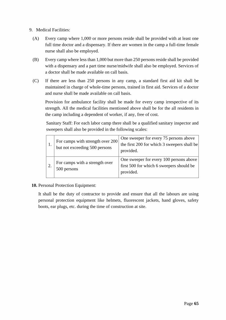
Page 65
9. Medical Facilities:
(A) Every camp where 1,000 or more persons reside shall be provided with at least onefull time doctor and a dispensary. If there are women in the camp a full-time femalenurse shall also be employed.
(B) Every camp where less than 1,000 but more than 250 persons reside shall be providedwith a dispensary and a part time nurse/midwife shall also be employed. Services ofa doctor shall be made available on call basis.
(C) If there are less than 250 persons in any camp, a standard first aid kit shall bemaintained in charge of whole-time persons, trained in first aid. Services of a doctorand nurse shall be made available on call basis.
Provision for ambulance facility shall be made for every camp irrespective of itsstrength. All the medical facilities mentioned above shall be for the all residents inthe camp including a dependent of worker, if any, free of cost.
Sanitary Staff: For each labor camp there shall be a qualified sanitary inspector andsweepers shall also be provided in the following scales:
1.For camps with strength over 200but not exceeding 500 persons
One sweeper for every 75 persons abovethe first 200 for which 3 sweepers shall beprovided.
2.For camps with a strength over500 persons
One sweeper for every 100 persons abovefirst 500 for which 6 sweepers should beprovided.
10. Personal Protection Equipment:
It shall be the duty of contractor to provide and ensure that all the labours are usingpersonal protection equipment like helmets, fluorescent jackets, hand gloves, safetyboots, ear plugs, etc. during the time of construction at site.

Page 66
ANNEXURE B - CONTRACTOR’S LABOUR REGULATIONS
The contractor shall pay not less than fair wages to laborers engaged by him in the work.
Explanation:
(a) “Fair Wages” means wages payable to the laborers on the date of payment whether fortime or piece work as notified from time to time and where such wages have not beenso notified the wages prescribed by the Labor Department for the division in whichthe work is done.
(b) The contractor shall, notwithstanding the provisions of any contract to the contrary,cause to be paid a fair wage to laborers indirectly engaged on the work including anylabor engaged by his sub-contractors in connection with the said work as if laborershad been immediately and directly employed by him.
(c) In respect of all laborers directly or indirectly employed on the works for theperformance of the contractor’s part of this agreement, the contractor shall complywith or cause to be complied with all the Labor Laws for the time being in force inIndia.
(d) The Engineer-in-Charge shall have the right to deduct from the money due tocontractor any sum required for making good the loss suffered by a worker or workersby reason of non-fulfilment of the conditions of the contract for the benefit of theworkers, non-payment of wages or of deduction made from his or their wages whichare not justified by their terms of the contract or non-observance of regulations.
(e) The contractor shall be primarily liable for all payments to be made under and for theobservance of the laws including regulations without prejudice to his right to claimindemnity from his sub-contractors.
(f) All the labor laws including regulations shall be deemed to be a part of this contractand any breach thereof shall be deemed to be a breach of this contract.
(g) The contractor shall obtain a valid license under the Contract (Regulation andAbolition) Act, in force and rules made thereunder by the competent authority fromtime to time before commencement of work and continue to have a valid license untilthe completion of the work.
Any failure to fulfil this requirement shall attract the penal provisions of the laws and thiscontract arising out of the resulted non-execution of the work assigned to the contractor.

Page 67
ANNEXURE E – GENERAL SPECIFICATIONS
Contents1. General Brief Specifications .........................................................................................75
1.1. Specifications.........................................................................................................751.2. Definitions .............................................................................................................751.3. Production, Submission and approval of engineering documents.........................76
1.3.1. Numbering and Titling ...............................................................................761.3.2. Submission Procedure ................................................................................761.3.3. Program of Submission ..............................................................................761.3.4. Design Report .............................................................................................771.3.5. Manufacturer's and Contractor's Certificate ...............................................771.3.6. Maintenance Instructions............................................................................781.3.7. Record Drawings ........................................................................................791.3.8. Program of Work ........................................................................................791.3.9. Progress ......................................................................................................80
2. General Specification....................................................................................................812.1. Design Period for Components..............................................................................812.2. SBC of soils for foundation of civil structures ......................................................822.3. Material For Construction .....................................................................................82
2.3.1. Bricks..........................................................................................................822.3.2. Sand ............................................................................................................822.3.3. Metal/ Aggregate ........................................................................................832.3.4. Steel For Reinforcement.............................................................................832.3.5. Cement........................................................................................................832.3.6. Concrete......................................................................................................84
2.4. Railing ...................................................................................................................852.5. Painting & Finishing..............................................................................................852.6. Designs For Seismic Forces ..................................................................................852.7. Electrical Works ....................................................................................................85
2.7.1. General........................................................................................................852.7.2. Earthing ......................................................................................................862.7.3. Colors..........................................................................................................872.7.4. Conductors..................................................................................................882.7.5. Cable Fixing ...............................................................................................882.7.6. Cable Identification ....................................................................................882.7.7. Marking Location of Underground Cables.................................................882.7.8. Lamp Test ...................................................................................................892.7.9. Telemetry Outstation ..................................................................................892.7.10. Emergency stop Circuitry ...........................................................................892.7.11. Lighting and Fixtures..................................................................................902.7.12. Motor Control Center/ Distribution Boards................................................912.7.13. Cables .........................................................................................................922.7.14. Starter/ Push Button....................................................................................922.7.15. Earthing For Motors ...................................................................................922.7.16. Lightening Conductor.................................................................................92
Page 68
2.7.17. Electric Connection Charges ......................................................................922.7.18. Length Of Electric Power Line...................................................................92
2.8. Valves & Specials..................................................................................................922.9. Units of Water Treatment Plant.............................................................................932.10. Minimum Diameter of D.I. pipelines.................................................................932.11. MS pipe of 800 mm and above diameter ...........................................................932.12. Boundary wall....................................................................................................932.13. Approach roads ..................................................................................................932.14. Road, Rail and River crossings..........................................................................94
3. Specifications for Intake Well ......................................................................................943.1. Scope of work........................................................................................................94
3.1.1. Intake Well cum Pump House ....................................................................943.1.2. Internal diameter.........................................................................................953.1.3. Inlet Port Arrangement ...............................................................................953.1.4. Approach bridge .........................................................................................953.1.5. Ancillary Works and Other General Considerations..................................95
3.2. Detailed investigation ............................................................................................963.3. Detail Designs and Drawings ................................................................................963.4. Foundation .............................................................................................................973.5. Trash Rack Structure .............................................................................................983.6. Staircase.................................................................................................................983.7. Inlet ports ...............................................................................................................993.8. Pipe floor or Discharge floor .................................................................................993.9. Motor floor and Pump house .................................................................................993.10. Arrangement of Gantry Girder.........................................................................1003.11. Approach bridge...............................................................................................100
4. Raw Water Pumping Mains ........................................................................................1014.1. Scope of Work .....................................................................................................1014.2. Layout Drawings .................................................................................................101
5. Clear Water Pumping Mains.......................................................................................1015.1. Scope of Work .....................................................................................................1015.2. Layout Drawings .................................................................................................102
6. Clear Water Gravity Mains.........................................................................................1026.1. Scope of Work .....................................................................................................1026.2. Layout Drawings Of Gravity Mains....................................................................1026.3. Allied Works........................................................................................................103
7. Water Supply Distribution Network ...........................................................................1037.1. Brief Scope of Work............................................................................................103
8. Electrically Welded Steel Pipes ..................................................................................1038.1. Scope ...................................................................................................................1038.2. Applicable Codes.................................................................................................1048.3. General Specifications.........................................................................................1048.4. Specification Requirements.................................................................................106
8.4.1. Material.....................................................................................................1068.4.2. Length.......................................................................................................1068.4.3. Joints and Ends .........................................................................................1068.4.4. Tolerances.................................................................................................107

Page 69
8.4.5. Manufacture..............................................................................................1078.4.6. Welding ....................................................................................................1078.4.7. Radiograph of welded joints.....................................................................1088.4.8. Radiographic Inspection of welded joints ................................................1098.4.9. Fabrication of specials ..............................................................................1098.4.10. Cement Concrete and Mortar Lining of Pipes and specials .....................1108.4.11. Workmanship............................................................................................1138.4.12. Handling of pipes and specials. ................................................................1138.4.13. Laying of pipes .........................................................................................1138.4.14. Field Jointing of Insides and outsides of Concrete lined pipes. ...............1138.4.15. Fixing of fixtures ......................................................................................1148.4.16. Testing of Pipe line...................................................................................1148.4.17. Measurements ...........................................................................................1158.4.18. Excavation and preparation of trenches for laying U/G pipeline .............1168.4.19. Trenching..................................................................................................1168.4.20. Preparation of bottom of trench................................................................1168.4.21. Recovery of other serviceable material ....................................................1168.4.22. Dewatering................................................................................................1178.4.23. Special foundation in poor soil .................................................................1178.4.24. Excavation in hard rock by blasting .........................................................1178.4.25. Braced and sheeted trenches.....................................................................1178.4.26. Stacking of excavated material.................................................................1178.4.27. Barricades, guards and safety provisions .................................................1178.4.28. Maintenance of traffic and closing of streets............................................1188.4.29. Structure Protection ..................................................................................1188.4.30. Protection of property and surface structures ...........................................1188.4.31. Avoidance of the Existing Service ...........................................................1188.4.32. Preparation of Formation for Sections of pipe line to be laid above Ground
1188.4.33. Disposal of surplus material .....................................................................1198.4.34. Allowable Removal of Pavement .............................................................1198.4.35. Replacement of Pavements and Structures...............................................1198.4.36. Cleaning-Up..............................................................................................1198.4.37. Extra material required for back filling ....................................................119
9. Ductile Iron Pipes & Specials .....................................................................................1199.1. General.................................................................................................................119
9.1.1. Specification Quality Standard.................................................................1209.1.2. Pipe Details...............................................................................................120
9.2. Standards .............................................................................................................1209.3. Specifications for Ductile Iron Pipes...................................................................121
9.3.1. Casting......................................................................................................1219.3.2. Surface coating .........................................................................................1219.3.3. Standard length .........................................................................................1219.3.4. Manufacture of Gaskets............................................................................1219.3.5. Flanged joints ...........................................................................................1219.3.6. Hydraulic test at works .............................................................................1219.3.7. Test for Gaskets ........................................................................................122
Page 70
9.3.8. Third party inspection...............................................................................1229.3.9. Retest ........................................................................................................1229.3.10. Marking ....................................................................................................1229.3.11. Packing and Transport ..............................................................................122
9.4. Specifications for Ductile Iron Fittings (Specials) ..............................................1239.4.1. General......................................................................................................1239.4.2. Types of specials ......................................................................................1239.4.3. Supply.......................................................................................................1239.4.4. Manufacture of Fittings/ Specials.............................................................123
9.5. Lubricant for Ductile Iron pipes and specials......................................................1249.5.1. General......................................................................................................1249.5.2. Specification .............................................................................................1249.5.3. Acceptance tests .......................................................................................1249.5.4. Packing for DI specials and Rubber Gaskets...........................................124
9.6. Laying and jointing of DI pipes and specials ......................................................1249.6.1. Use of tackle .............................................................................................1249.6.2. Cleaning....................................................................................................1259.6.3. Laying on steep slopes..............................................................................1259.6.4. Jointing .....................................................................................................1259.6.5. Deflection of the pipes..............................................................................1259.6.6. Anchoring of the pipeline .........................................................................125
9.7. Measurement and payment ..................................................................................1269.8. Excavation and preparation of trenches for laying underground pipeline...........1269.9. Recovery of other serviceable material ...............................................................1269.10. Dewatering.......................................................................................................1269.11. Trenching .........................................................................................................126
9.11.1. Preparation of bottom of trench................................................................1279.11.2. Special foundation in poor soil .................................................................1279.11.3. Excavation in hard rock by blasting .........................................................1279.11.4. Braced and sheeted trenches.....................................................................1279.11.5. Stacking of excavated material.................................................................1279.11.6. Barricades, guards and safety provisions .................................................1289.11.7. Maintenance of traffic and closing of streets............................................1289.11.8. Structure Protection ..................................................................................1289.11.9. Protection of property and surface structures ...........................................1289.11.10. Avoidance of the Existing Service ...........................................................1289.11.11. Restoration of sewerage system ...............................................................1299.11.12. Preparation of Formation for Sections of pipe line to be laid above Ground
1299.11.13. Disposal of surplus material .....................................................................1299.11.14. Extra material required for back filling ....................................................129
10. Water Treatment Plant ................................................................................................12910.1. Scope of Work .................................................................................................130
10.1.1. General......................................................................................................13010.1.2. Planning and Design.................................................................................130
10.2. Commissioning And Testing Of Plant.............................................................13310.2.1. Basic Information .....................................................................................133

Page 71
10.3. Detailed Specification Of Components Of Treatment Plant............................13410.3.1. Inlet Chamber ...........................................................................................13410.3.2. Inlet Channel.............................................................................................13410.3.3. Flow Measuring Arrangement..................................................................13410.3.4. By Pass Channel .......................................................................................13410.3.5. Rapid Mixing Unit....................................................................................13510.3.6. Flash Mixer...............................................................................................13510.3.7. Inflow Arrangement .................................................................................13510.3.8. Sedimentation and Clarifloculator............................................................13510.3.9. Flocculator ................................................................................................13610.3.10. Clarifier.....................................................................................................13610.3.11. Filtration ...................................................................................................13910.3.12. Appurtenances ..........................................................................................14110.3.13. Sludge Drying Beds..................................................................................15010.3.14. Safety Equipment .....................................................................................15010.3.15. Unloading Arrangement ...........................................................................15110.3.16. Clear Water Sump ....................................................................................15110.3.17. Clear Water Pump House .........................................................................15210.3.18. Laboratory Block, Office And Control Room..........................................15310.3.19. Site Roads .................................................................................................15610.3.20. Site Drainage ............................................................................................15610.3.21. Boundary Wall..........................................................................................15710.3.22. Telephone System.....................................................................................15710.3.23. Process Control.........................................................................................15710.3.24. Emergency Lighting .................................................................................15710.3.25. Landscaping..............................................................................................15810.3.26. External Lighting......................................................................................158
11. Reservoirs ...................................................................................................................15811.1. Design Criteria .................................................................................................15911.2. General specification .......................................................................................160
11.2.1. Depth of Excavation .................................................................................16011.2.2. RCC Stair Case.........................................................................................16011.2.3. Valve Chambers .......................................................................................16111.2.4. Pipeline Arrangement ...............................................................................16111.2.4.1. Pipes..........................................................................................................16111.2.4.2. Specials .....................................................................................................16111.2.4.3. Valves and Gates ......................................................................................16211.2.4.4. Flow Measurement ...................................................................................16211.2.4.5. Ancillary Works .......................................................................................16211.2.4.6. Protection works and Finishing ................................................................163
11.3. Inspection & testing of concrete structure .......................................................16311.3.1. Water Tightness Test ................................................................................163
11.4. Additional Requirements .................................................................................16411.5. Scope of Work ................................................................................................164
12. HDPE Pipes ................................................................................................................16512.1. Applicable Codes .............................................................................................16512.2. Colour ..............................................................................................................166

Page 72
12.3. Materials ..........................................................................................................16612.3.1. Raw Material ............................................................................................16612.3.2. Anti-oxidant..............................................................................................16712.3.3. Reworked Material ...................................................................................167
12.4. Maximum Ovality of Pipe ...............................................................................16712.5. Detectability.....................................................................................................16712.6. Length of Straight Pipe ....................................................................................16712.7. Coiling..............................................................................................................16712.8. Workmanship/ Appearance..............................................................................16812.9. Handling, Transportation, Storage and Lowering of pipes..............................16812.10. Lowering, Laying of Pipes...............................................................................16912.11. Measurement and payment ..............................................................................17012.12. Excavation and preparation of trenches for laying U/G pipeline ....................17012.13. Recovery of other serviceable material............................................................17112.14. Dewatering.......................................................................................................17112.15. Trenching .........................................................................................................17112.16. Jointing of Pipes...............................................................................................17112.17. Bedding, Backfilling and Compaction Bedding ..............................................17112.18. Back Filling......................................................................................................17112.19. Compaction......................................................................................................17212.20. Thrust Block.....................................................................................................17212.21. Fittings & Specials...........................................................................................17212.22. Bends................................................................................................................17212.23. Tees ..................................................................................................................17212.24. Reducers...........................................................................................................17212.25. Flanged HDPE Pipe Ends ................................................................................17212.26. Slip-On Flanges ...............................................................................................17312.27. Electro Fusion Tapping Saddle, Branch Saddle & Fittings .............................17312.28. Hydraulic Testing.............................................................................................17412.29. Manuals............................................................................................................17412.30. Flanges .............................................................................................................17412.31. Marking............................................................................................................17412.32. Packing & Transport ........................................................................................17512.33. Summary of quality Tests ................................................................................17512.34. Inspection & Testing........................................................................................17612.35. Field Hydraulic Testing ...................................................................................176
12.35.1. Sectional Tests..........................................................................................17612.35.2. Back filling ...............................................................................................17712.35.3. Flushing and disinfecting of pipelines......................................................177
12.36. House Service Connections on HDPE pipes ...................................................17712.36.1. Performance requirements........................................................................177
12.37. Sluice Valves on Branches/ Scour valves/ Air Valves ....................................17712.38. GM/ Brass Ferrules ..........................................................................................17812.39. Compression Fittings .......................................................................................178
12.39.1. Pressure Testing........................................................................................17812.39.2. Dimensions ...............................................................................................17812.39.3. Performance Requirements.......................................................................178

Page 73
12.39.4. Effects on Quality of Water......................................................................17812.40. House Service Connections on Metallic pipes.................................................179
12.40.1. Specifications for Clamp Saddle Service Connections for other pipes ....17912.40.2. Material and Design Specifications ..........................................................179
13. Pumps, Motors and Ancillaries...................................................................................18013.1. Scope of Work .................................................................................................180
13.1.1. Pumps .......................................................................................................18013.1.2. Motors.......................................................................................................18013.1.3. Capacitors .................................................................................................18013.1.4. Starters ......................................................................................................18013.1.5. Delivery pipes and specials for pumps:....................................................18013.1.6. Valves for delivery piping: .......................................................................18113.1.7. Flow Measuring Device: ..........................................................................18113.1.8. Electronic Pressure Transducers:..............................................................18113.1.9. Crane: 4 tonne capacity overhead gantry traveling crane.........................18113.1.10. H.T. and L.T. switchgear as per specifications. .......................................18113.1.11. Temperature scanner panels as per specifications. ...................................18113.1.12. Earthing of electrical equipment's inside pump house and electricalsubstation as per I.E. rules- as required. .....................................................................18113.1.13. Power and control cables..........................................................................18113.1.14. Civil Works...............................................................................................182
13.2. Specifications For Pumps ................................................................................18313.2.1. Raw Water Pumps ....................................................................................18313.2.2. Clear Water Pumps...................................................................................18313.2.3. Specifications............................................................................................18313.2.4. Material of construction............................................................................18613.2.5. Technical particulars.................................................................................18613.2.6. Energy Consumption ................................................................................18713.2.7. Excess Energy Consumption ....................................................................187
14. Electric Power Line.....................................................................................................18714.1. Item & specification of the work .....................................................................188
14.1.1. 33 KV Line Work .....................................................................................18814.1.2. 11 KV Electric power line (if required)....................................................19214.1.3. Specifications for 11 KV/ 0.4 KV outdoor substation on RSJ usingfollowing items including labour, transportation, etc. complete ...............................193
15. Internal and Approach Roads......................................................................................19415.1. WBM and overlaying Bituminous layer ..........................................................194
16. Cross Drainage Works ................................................................................................19517. Boundary/ Compound wall .........................................................................................19518. Office Buiding and Staff Quarters ..............................................................................196
18.1. General Specifications of Staff Quarters .........................................................19618.1.1. Foundation ................................................................................................19618.1.2. Plinth.........................................................................................................19618.1.3. Flooring ....................................................................................................19618.1.4. Walls.........................................................................................................19618.1.5. Doors ........................................................................................................19718.1.6. Windows...................................................................................................197

Page 74
18.1.7. Electrification ...........................................................................................19718.1.8. Water Supply ............................................................................................19718.1.9. Sanitary.....................................................................................................19718.1.10. General......................................................................................................197
19. Brief Scope of PLC SCADA ......................................................................................19819.1. General Specifications of PLC SCADA..........................................................19819.2. SCADA Components.......................................................................................199
20. Trial Run For 3 Months And Operation & Maintenance For 10 Years......................20121. O&M Period specification ..........................................................................................204
21.1. General.............................................................................................................20421.2. Service Level Standards...................................................................................204
21.2.1. Supply of safe & potable drinking water..................................................20421.2.2. Per capita supply of water- .......................................................................20421.2.3. Pressure at consumer end .........................................................................20521.2.4. Unaccounted for Water.............................................................................20521.2.5. Complaint redressal ..................................................................................20521.2.6. Increase in demand during O&M period..................................................20521.2.7. Road cutting and its restoration ................................................................20521.2.8. Additional Areas.......................................................................................20621.2.9. Extension of Distribution Network or Mains ...........................................20621.2.10. Additional Demands .................................................................................20621.2.11. Manpower Requirement: ..........................................................................20621.2.12. Facilities to Manpower .............................................................................206
22. Aproved list of manufactures......................................................................................20722.1. MPJN Empanelled Manufacturers............................................................207
23. House Service Connection Design..............................................................................211

Page 75
1. General Brief Specifications
1.1. Specifications
Specifications refer to
1) Operational Guidelines for the Implementation of Jal Jeevan Mission (JJM) (HarGhar Jal), Department of Drinking Water and Sanitation (DDWS), Ministry ofJal Shakti (MoJS), Government of India (GoI)
2) Manual for Preparation of Detailed Project Report for Rural Piped Water SupplySchemes published by Ministry of Drinking Water & Sanitation (MoDWS),Government of India (GoI)
3) Manual on Water Supply and Treatment by CPHEEO, Ministry of UrbanDevelopment, Government of India (GoI)
4) Specification of R.C.C. work and other civil works, pipes, gates, sluice valves,specials and all other materials shall be governed by relevant latest BIS codesand specifications.
5) National building code of India (latest edition)6) Code of practice for earthquake resistance designs IS-18937) Specification for civil engineering works shall be governed by "Standard
Specification Published" by CPWD Govt of India with up to date amendments.8) Government specification for electric works in Govt. Deptt. in Madhya Pradesh
in force from 1972 with up to date amendments.9) Any other specification not covered under the above said standard or/ and
required to be changed as per site conditions shall be fixed by the Engineer-In-Charge.
1.2. Definitions
The following definitions shall apply:
i. "Approved Drawings" means drawings which the Engineer-in-Charge has marked"Approved" and returned to the Contractor. Approval in this context means that thework described thereon may proceed.
ii. “Engineer-in-Charge” means head of Project Implementation Unit of Madhya PradeshJal Nigam normally General Manager.
iii. "Preliminary" and "Approved" as applied to designs and documents shall have thesame meanings as applied above to drawings. A drawing which forms part of anapproved design or document shall not be considered as approved drawing unless ithas been marked "Approved".

Page 76
iv. "Preliminary drawings" means drawings which the Contractor submits to the Engineerin charge for approval and any drawings returned by the Engineer in charge marked"Preliminary" or not marked "Approved".
v. ‘Representative’ means Supervision and Quality Control Consultant appointed byMadhya Pradesh Jal Nigam and authorized to act as representative of the Engineer-in-Charge.
1.3. Production, Submission and approval of engineering documents
The production, submission and approval procedure for design & drawings and documentsshall comply with the following requirements.
1.3.1. Numbering and Titling
The Contractor shall institute a reference numbering system for designs, drawings anddocuments so that each number used is unique. The numbering and title information on designs,drawings and documents shall be designed so that management, transmittal and communicationtherewith can be carried out expeditiously.
1.3.2. Submission Procedure
i. Every drawing submitted by the Contractor to the Engineer-in-Charge for checkingand approval shall be based on previously approved designs or documents.Interrelated drawings shall be submitted at the same time in a complete and threesets.
ii. In the case of first submissions by the Contractor to the Engineer-in-charge forapproval, each design, drawing and document shall reach the review office in timeto allow 30 working days (excluding weekends and national holidays) for checkingby the Engineer-in-Charge before return to the Contractor.
1.3.3. Program of Submission
i. The Contractor shall prepare a program for submitting drawings and documents tothe Engineer-in-Charge. The Program shall be submitted for approval. Theprogram shall also make reasonable provisions for re-submission of unapproveddesign, drawings and documents and for the time needed to transmit such designs,drawings and documents. No designs, drawings and documents will be acceptedfor review until the program for their submission has been approved by Engineer-in-Charge.
ii. Number of Copies: The contractor shall submit to the Engineer for approval threecopies of all submissions. Only one copy will be returned to the Contractor. After

Page 77
approval, the contractor shall submit to the Engineer 5 hard copies with onelaminated copy of all approved drawings with the date of approval marked alongwith CDs (duly prepared in Auto CAD Software and PDF). Five copies of allapproved design and documents shall also be submitted along with CDs.
iii. After acceptance to tender (date of issue of LOA), the contractor will have tosubmit structural details, designs and drawings at the earliest however, no laterthan following schedule:-
a. Head works (Intake well, WTP, Raw Water Rising Main) – within 60days
b. Distribution system (Village pipe network, ESRs, MBR, CWPM, etc.) –within 120 days
c. Other components (electric substation, all allied electrical & mechanicalworks of water supply scheme, other patty works) – within 150 days
1.3.4. Design Report
On completion of all working drawings, the Contractor shall submit a design report for theProject in the form of a comprehensive written description explaining the technical factors anddesign criteria for each Plant element and each structure and major building installation andshowing the hydraulic, structural, mechanical and electrical computations which governed thedesign of each.
1.3.5. Manufacturer's and Contractor's Certificate
i. Where certificates are required by the Specification or relevant ReferenceStandard, the original and one copy of each such certificate shall be provided bythe Contractor.
ii. Certificates shall be clearly identified by serial or reference number where everpossible to the material being certified and shall include information required bythe relevant Reference Standard or Specification Clause.
iii. The instruction manuals shall describe the installation as a whole and shall give astep-by-step procedure for any operation likely to be carried out during the life ofsuch item of Plant, including the erection, commissioning, testing, operation,maintenance, dismantling and repair.
Page 78
iv. Maintenance instructions shall include charts showing lubrication, checking,testing and replacement procedures to be carried out daily, weekly, monthly and atlonger intervals to ensure trouble-free operation. Where applicable, fault locationcharts shall be included to facilitate tracing the cause of malfunction or breakdown.
v. A section dealing with procedures for ordering spares shall also be included in theinstruction.
vi. Three draft copies of the manual shall be submitted to the Engineer'sRepresentative prior to commissioning the works. Five final copies of the amendedand corrected manuals and drawings shall be provided at the commencement of theperiod of Maintenance.
vii. All the electrical and mechanical equipment’s shall be subjected to approval bythird party inspection at place of manufacture, at contractor's cost.
viii. Transit insurance of all equipment's shall be the contractor's responsibility.
ix. Contractor shall have to take the certificate from the electrical inspector forregarding all electrical equipment's before commissioning of plant. Importantinstructions charts shall be framed and fixed at appropriate and prominent places.
1.3.6. Maintenance Instructions
A maintenance manual shall be provided as supporting documents to the equipmentmanufacturer's instructions. The manual shall have following at the minimum:
i. Checking, testing and replacement procedures to be carried out on all mechanicaland electrical plant items on a daily, weekly and monthly basis or at longer intervalsto ensure trouble free operations.
ii. Fault location and remedy charts to facilitate tracing the cause of malfunctions orbreakdown and correcting faults.
iii. Complete list of recommended lubricants, oils and their charts.
iv. Spares schedule that shall consist of a complete list of item wise spares for allelectrical and mechanical plant items with ordering references and part numbers.
v. Complete list of manufacturer's instructions for operation and maintenance of allbought-out equipment. The list shall be tabulated in alphabetical order giving thename of the Supplier/ Manufacturer, identification of the plant item giving themodel number and the literature provided including instruction leaflets anddrawing numbers.
vi. Preventive maintenance details.

Page 79
1.3.7. Record Drawings
The Contractor shall provide record drawings including those drawings submitted by theContractor to show the whole of the plant as installed and all civil works as built. These shallinclude all such drawings, diagrams and schedules as are necessary for a completeunderstanding of the works. Information given on record drawings shall include tolerance,clearances, loadings, finishes, materials and ratings of Plant and associated civil works.
The Contractor shall ensure that the approved and completion drawings are marked up, to showthe condition of plant as installed and associated Civil Works as built and two copies of suchmarked up prints shall be submitted to the Engineer-in-Charge for approval, prior to thepreparation of Record Drawings. Submission to and approval by the Engineer-in-Charge ofRecord Drawings shall be pre-requisite for the last taking over certificate. All the RecordDrawings shall be of minimum A2 size in five copies out of which 3 sets shall be plasticlaminated for long-life. In addition, one set of soft copies of all the Record Drawings shall alsobe furnished. The text of all the reports shall be prepared on a widely used MS Word/ MS Exceland all the Drawings shall be prepared using AutoCAD Software and in pdf form. Whenreports, drawings are furnished to Jal Nigam, 2 copies of the processor files together with 2copies of a descriptive memorandum linking these files to the text, drawings etc., shall also beprovided to the Jal Nigam on CD, portable hard drive, pen drive, data base preferable on MSoffice, AutoCAD latest versions and in pdf form.
1.3.8. Program of Work
i. The works to be carried out under this Contract form an essential part of the execution ofthis Water Supply Project. Satisfactory progress of the entire project as a whole dependsupon the timely completion of these works. For this reason, great importance needs to beattached for proper programming for the works with adequate provision for guardingagainst all the delays normally encountered in execution of various activities.
ii. Within four weeks from the date of issue of order of commencement for the works, theContractor shall submit to the Engineer-in-Charge for his approval a detailed program ofwork together with a description of his proposed methods of working.
iii. Particulars to be shown on the program shall include:
Submission of drawings; Placing of work orders; Stages of manufacture; Tests at place(s) of manufacture; Deliveries to Site; Construction of Civil works ready for erection of Plant; Mechanical completion of erection at site;
Page 80
Tests at site; Finishing and completion of civil and electrical woks.
iv. The contractor shall include with the program, a critical path network diagram whichcommences from the date of issue of Order of Commencement and includes inter alia thevarious activities as per the program of works, furnished as specified in Annexure F forrespective schemes.
activity duration in months and event times should be in months from the first eventon the network and event numbers:
a tabulation of months from the starting date of the network to enable earliest andlatest event dates to be read off; duration in months to be the last day of the month andthe monsoon months of 15th June to 15th October to be specially indicated in the Table
the timing of events shown in the program of work to be adhered to and shown in thenetwork
the erection program shall be shown in detail (with not more than 15 activities) withdurations in weeks shown in brackets behind the duration in months on the networkdiagram wherever considered necessary
the program for setting-up, treating, delivery, storage (if necessary) and placing offilter media (where appropriate) the placing being a part of the erection programreferred to above
program for submission of Instruction Manuals and Record Drawings.
v. Contractor shall submit the quarterly financial planning along with the work program. Thisfinancial planning shall be according to physical planning.
vi. The dates and times in the program shall allow for compliance and the completion date forthe whole of the works (except for tests on completion and except for Maintenance) shallcomply with the overall time for completion required in the tender.
vii. Any approval of or consent to the Contractor's program by the Engineer-in- Charge shallnot relieve the Contractor of his duties and responsibilities under the Contract.
1.3.9. Progress
i. The Contractor shall submit to the Engineer-in-Charge during the first week of each montha "Monthly Progress Report" with weighted activities all in an approved format so thatactual progress at the end of the preceding month may be compared with the Contractor'sprogram with photographs. Submission of monthly progress report shall be mandatory, ifthere is no progress at site, report shall be submitted with comment as no progress with thereasons.

Page 81
ii. The progress report shall also include status report on the following approved individualformats:
Drawings; Supplies of Plant Items; Construction program; Construction Progress; Overall Progress Curve;
iii. From time to time the Managing Director or Engineer-in-Charge may call meetings in theiroffice or at the Engineer's Site Office, as they deem necessary for the purpose of controlof the Contract, a responsible representative of the Contractor shall attend such meetings.
iv. The Contractor shall regularly review his program in the light of the progress actuallyachieved and shall submit for approval updated PERT/ CPM network and bar charts atintervals to be agreed with the Engineer-in-Charge. If progress falls behind that needed toensure timely completion of the various parts of the works, the Contractor shall submitproposals for improving his methods and pace of working to the satisfaction of theEngineer-in-Charge and shall take such measures as are needed to ensure that the worksare completed in time.
2. General Specification
2.1. Design Period for Components
Design period for various components should be according to the Manual for Preparation ofDetailed Project Report for Rural Piped Water Supply Schemes published by Ministry ofDrinking Water & Sanitation, Government of India as updated from time to time. Accordingly,project components should be designed to meet the requirements of the following designperiod:
S. No. Items Design Period (in years)1 Source – Surface Water 302 Intake works 303 Pumpingi. Pump house (Civil works) 20ii. Electric motor and pumps* 10
4 Water Treatment Units 20
5 Pipe connection to several treatment units and othersmall appurtenances 20
6 Raw water and clear water conveying mains 20

Page 82
7Clear water reservoirs at the head works, balancingtanks and service reservoirs (overhead or groundlevel)
20
8 Distribution system 20
* The stars rated (electric motors – energy efficient pumps) may be used.
2.2. SBC of soils for foundation of civil structures
The depth of excavation shall generally be guided by the underground strata and safe bearingcapacity of the soil. The foundation/ mat concrete shall be laid minimum 1.50m below GL oras specifically approved by MPJN. Safe bearing capacity & other soil test shall be conductedby the contractor at its own cost through any NIT/ Government Engineering College/ NABLLaboratory and any accrediting institution as per ISO/ IEC 17011 or laboratory accredited asper ISO/ IEC 17025. The result of SBC shall be submitted before start of work along with thedetailed structural design. The design of foundation shall not be permitted for SBC of morethan 15 tonne/ m2 in strata containing any type of soil, even if the reported SBC is more than15 tonne/ m2 however, in case of rocky strata it may be considered as maximum 25 tonne/ m2
or approved by the MPJN. No payment shall be made to the contractor for carrying out thesetests or on account of change in design due to strata. No dewatering in any condition shall bepayable.
It shall be the responsibility of the contractor to test and check the bearing capacity of soil andsubmit it with the design. This bearing capacity shall be tested by plate load bearing test methodat WTP and plate load test/ any other method applicable as per IS code at other structures likeIntake/ OHT/ MBR/ GLR/ Buildings etc., by any NIT/ Govt. Engg. College/ NABL Laboratoryand any accrediting institution as per ISO/ IEC 17011 or laboratory accredited as per ISO/ IEC17025. No dewatering in any condition shall be payable. The foundation shall be filled withminimum 150mm thick levelling course in cement concrete grade M-15 with 20mm metal.
2.3. Material For Construction
The material used for construction shall be governed by the provision of Part-IV of NationalBuilding Code of India and relevant IS Code of specification with up to date amendment.
2.3.1. Bricks
The brick shall be Common Burnt Clay Bricks of Class designation 5, as per IS: 1077. Crushingstrength and water absorption shall be tested as per IS: 3495 and others as given in Annex-A.Fly ash brick with same specifications as per applicable IS code may also be used.
2.3.2. Sand
The sand shall be as per IS: 383. The preferable sand shall be Narmada river sand. The sand

Page 83
for plaster shall be confirming IS: 1542.
2.3.3. Metal/ Aggregate
Metals/ Aggregate shall be confirming to IS: 383.
2.3.4. Steel For Reinforcement
All the iron and steel required for the work will be procured by the contractor at his own cost.The Madhya Pradesh Jal Nigam shall not supply any quantity of steel under any circumstances,whatsoever. The contractor shall be required to produce the test certificate of the manufacturersto the department before use of steel for the work. No untested steel will be allowed to be usedunder any circumstances. The Madhya Pradesh Jal Nigam however reserves the right to get thereceived/ supplied steel tested at the cost of the contractor.
Steel for reinforcement shall be confirming to latest BIS specification IS: 1786 for DeformedSteel Bars and wires. All the steel above 6mm dia shall be deformed bars with strength gradeof Fe-500 or Fe-415. If the steel being used is of 6mm diameter bars at any place, then it shallbe plain steel conforming to IS: 432. The contractor shall be required to produce the testcertificate from manufacturer to the Engineer-in-Charge, before use of steel for the work. Nountested steel shall be allowed to be used under any circumstance. The preferable makes ofsteel are TATA, RINL, SAIL or equivalent make of approved prime manufacturer.
2.3.5. Cement
In accordance to the instructions contained in Govt. of M.P. PHED, Bhopal, Memo No. F-16-28/34 2/87 dated 28-1-1991 cement required for the work will be procured by the contractor athis own cost from time to time as per requirement.
The cement to be used in the work shall be 43/ 53 grade Ordinary Portland Cement (OPC)conforming to IS: 8112 or IS: 12269 approved by the Engineer-in-Charge, for all importantand water retaining structures. Minor works e.g. PCC, thrust blocks, anchor blocks, etc. may,however, be constructed with OPC conforming to IS: 269 or PPC conforming to IS: 1489.Ordinary Portland cement shall be of ACC, Ultra Tech, Jaypee, Diamond, Prism, Birla orTATA or equivalent makes. It shall be tested for following test at contractor's cost. For underwater concreting rapid hardening cement shall be used.
S. No. Type of test Frequencya) Test for initial and final setting time
as per IS: 1199One test for 10 Tonnes or part thereof.
b) Test for determination ofCompressive strength of cement asper IS: 1199
One test for 50 tonnes or part thereof.

Page 84
S. No. Type of test Frequencyc) Specific Gravity As per Specificationd) Soundness As per Specification
2.3.6. Concrete
All concrete shall be mixed in concrete mixer and compacted by mechanical vibrators. Slumptests shall be carried out during concreting and sample test cubes prepared as per direction ofEngineer-in-Charge tested by the contractor at his own cost. The results of the tests shallconform with the required standards and if the test results are not found satisfactory orotherwise also if the Engineer-in-Charge considers that a structural test is necessary, the sameshall be carried out as instructed by the Engineer-in-Charge at contractor’s expenses and if theresults of this be unsatisfactory the contractor will be bound to dismantle and reconstruct theparticular portion of work which has given unsatisfactory test results. The contractor shall makearrangement for testing of construction material and concrete at site itself.
In general concrete shall be designed as per IS: 456 (latest edition) and concrete for water-retaining structures shall be designed as per IS: 3370-Part-II (latest edition). All thecomponents, which are in contact of water and its roof slabs or domes, shall be of minimumGrade M-30 e.g. jack well, intake well-approach bridge up to H.F.L. inlet chamber, raw waterchannel, flash mixer, flocculators, filters, module chambers, wash water tank, clear water sump,reservoirs, pure water channel etc. All other components not in contact with water shall be ofminimum M-25 Grade. The cement content per cubic meter of concrete shall not be less thanthe provisions of IS: 456 latest addition.
In general, the clear cover to reinforcement shall be as per IS: 456 (latest edition) but additionalcover, for corrosive water of 12mm shall be provided on all water retaining faces of thestructural members as per the provisions of IS: 3370 (Part II) (latest edition).
The concrete shall be prepared as per mix design. All ingredients of concrete shall be weighedand mixed as per the mix design. All concrete shall be mixed by concrete mixer and compactedwith concrete vibrator only.
The contractor shall setup a laboratory for testing of metal/ aggregate, concrete, cement etc. onthe site. Slump test shall be carried out by contractor at its own cost. During concreting, sampletest cube shall be prepared as per the frequency prescribed in IS: 456 and shall be tested bycontractor at his own cost. To assess the strength of cube immediately, accelerated curingtesting may also be conducted as required by the Engineer-in-Charge. If the result of the testshall not be in conformity with the required standard and if the Engineer-in-Charge considersthat the structural test is necessary, the same shall be carried out by the contractor at its owncost. If the result of this comes unsatisfactory again then the contractor shall be bound todismantle and reconstruct the particular portion of work.

Page 85
The formwork shall be of steel or fresh ply to get the smooth finish.
2.4. Railing
The railing, wherever provided shall consist of 1.2m high medium class G.I pipe posts at 1.5mc/c welded with reinforcement and embedded in cement concrete with 3 rows of 32mmdiameter at Intake well & WTP & 25mm diameter medium class G.I pipes railing, at ESRs/GLSRs, duly painted in two or three coats, so as to give smooth and even finish, with syntheticenamel paint over prime coat.
2.5. Painting & Finishing
Two coats of Weather Shield Apex painting on the entire civil works shall be done outsideabove ground level, interior with oil bound distemper, while 2 coats enamel oil painting shallbe done on doors, windows, ventilator and all steel fabrication work i.e., railing, gantry girderetc. over one coat of primer. The number of coats may be more than the above specified coatsto give smooth and even surface. All MS items of works in contact with water shall have epoxycoating.
2.6. Designs For Seismic Forces
All the structures shall be designed for seismic loads that may come on the structure during itslifetime and the design of structure shall be conforming to IS: 1893 'Criteria for earthquakeresistance design of structures'.
2.7. Electrical Works
2.7.1. General
The work shall be carried out as per drawing approved and directed by the Engineer-in-Charge.Electrification of structures both inside and outside shall be done in such a manner that standardlevel of illumination is obtained at all places. Proper earthing arrangements as per relevant ISspecifications shall be provided. The wiring shall be in concealed only. The total number oflight points shall be such that minimum 300 Lux illumination inside the structures is available,Sufficient Power points shall be provided.
The intake well below pipe floor, module pipe gallery shall be illuminated with the help ofsodium vapour lamps. On the outside also LED street lamps of suitable illumination to keepthe area well lighted shall be provided. On Approach Bridge decorative lighting shall beprovided on each side, suitably spaced in such a way that it provides prescribed LUXillumination.
Page 86
2.7.2. Earthing
(i) General
Protective conductors shall be provided for all electrical installations and associatedmechanical Plant and Equipment, exposed steel work and buildings.
Protective conductors shall be provided in accordance with the requirements of IS:3043 andthe latest edition of the I.E. Wiring Regulations/ Code of Practice for Electrical WiringInstallation IS:732.
(ii) Earthing Conductor
Earth electrodes where used shall be galvanized iron rods in accordance with IS: 3043 havingouter diameter not less than 38mm. The rod shall penetrate a minimum of three meters belowground level. Where multi-rods are used a distance of not less than the driven length shallseparate them.
Earth rods shall have hardened tips and caps and be extendable. Galvanized iron flats buried ata minimum depth of 600mm shall be used for interconnection of rods.
Where soil conditions make the use of rod type electrodes impracticable a grid configurationmay be used comprising horizontally buried bare galvanized iron strip of dimensions 50mm x5mm minimum. GI strip shall be buried at a minimum depth of 600 mm.
Each earth electrode rod if used shall be provided with an approved non-ferrous clamp for theconnection of the earthing conductor or tape as required. These connections shall each behoused in individual concrete inspection chamber set flush to the finished ground level andshall allow disconnection for testing of individual electrodes. The chamber shall bepermanently marked 'Electrical Earth'.
All materials used for the earth electrode installation shall be purpose made for the applicationand site conditions and shall be approved by the Engineer-in-Charge.
Unless otherwise stated in writing in this agreement, all excavation of trenches for theinstallation of the earth electrodes and the inspection pit shall be carried out by the Contractor.
After the earth installation has been completed the Contractor shall demonstrate to theEngineer-in-Charge that the resistance of the electrodes to earth and the continuity of the earthnetwork are within the limits specified. Any additional earth electrodes and test instrumentsrequired for the tests shall be provided by the Contractor.
Page 87
Marker posts and plates shall be provided to mark the route of buried tape electrodes. Themarkers shall be similar to those provided for cable routes.
(iii) Main Earthing Terminal
A main earth terminal shall be installed in an approved location adjacent to the incoming supplyto a building. This shall be labelled and comprise a 50mm x 6mm minimum cross sectioncopper strip as per IS: 3043. The bar shall be of sufficient length to accommodate bolted earthbonding connections from transformers, major items of Plant and Equipment and electricalswitchgear, building structural steel work, concrete reinforcement, the earth electrode systemand the lightning protection system. The earthing conductor shall be clearly marked as suchand shall be accessible for disconnection to facilitate testing of the earth electrode system. Forsmall installations an earthing terminal comprising a single brass stud of 12mm minimumdiameter shall be acceptable.
(iv) Instrument Earth
A separate instrumentation earth shall be established in each control panel. This shall compriseone or more copper earth bars not less than 25x6mm cross-section electrically isolated fromthe steel work of the panel and amounting of power cables. The instrument earth bar or barsshall be connected radially to the main earth bar of the control panel.
The instrument earth bar shall be provided for earthing the signal earth connection of eachinstrumentation and control device and the screen or screens of each instrument cable.
The earth bar shall have sufficient brass terminals to terminate all devices etc. as detailed plusnot less than 25% spare terminals.
The screens of instrumentation signal cables shall be earthed at one point only. This shallnormally be the nearest instrument earth bar at the control panel end.
Instrumentation signal screens shall be cut back and insulated at the field end. The overall earthresistance shall be brought down to less than one ohm.
2.7.3. Colors
All cables cores shall be colour coded throughout their length and shall be so connectedbetween switchboard, distribution board, plant and equipment and accessories, that the correctsequence or phase colours are preserved throughout the system.The colour coding should be as follows :
3 phases : red, yellow and blue single phase or dc : red and black

Page 88
earth : green / yellow control : blue (dc), red (ac)
2.7.4. Conductors
Copper conductors shall be used for power cables and copper conductors for control andinstrumentation throughout. Cores of cross-sectional area greater than 4 mm². Small power andcontrol cables shall be of a minimum cross section of 2.5 mm². Internal wiring of control panelsshall be of a minimum cross-section 1.5mm² flexible and standard.
Instrumentation and control cabling shall be of a minimum cross-section 1.5mm² for externaluse and 1.0mm² for internal use.
2.7.5. Cable Fixing
Ties and strapping shall be suitable for securing cable and cable groups to cable tray or ladder.They shall be resistance to chemicals. Plastic coated metal ties used in order to obtain corrosionresistance shall not be acceptable. Nylon ties shall be resistant to the effects of ultra-violet lightand shall be self-extinguishing.
Large single cables shall be secured with cable clamps or cable cleats.
2.7.6. Cable Identification
At each end of each cable, in a uniform and visible position a label shall be fixed on the cablein accordance with the cable schedule. Labels shall be made of PVC and shall be indeliblymarked to the approval of the Engineer-in-Charge. The label shall be retained using proprietarynylon strips passing through two fixing holes at either end of the label. If the cable gland is notnormally visible, then the label shall be fixed inside the panel by means of screws.
2.7.7. Marking Location of Underground Cables
The location of all underground cables shall be engraved on brass or other non-corrodible platesto be fixed to the exterior surface of all walls of buildings 300mm above ground level anddirectly above the point where cables pass through the wall.
In addition, concrete marker posts shall be installed at intervals of not more than 50m at alljunctions and changes of direction along the cable route. Such marker posts shall be not lessthan 200mm high and of substantial construction. A drawing or sample of a typical marker postshall be submitted for the approval.
The markers shall be marked 'electric cable' both in English and Hindi.

Page 89
2.7.8. Lamp Test
Facilities shall be provided to test all lamps on an assembly. This shall comprise a commonlamp test section. Operation of the lamp test circuit shall energies a relay in each section of theassembly in order to light each lamp and enunciator. The lamp test circuit shall pass throughauxiliary contracts on section isolators if fitted. A short time delay shall ensure that the lamptest supply is retained to allow visual checking of all lamps.
On small assemblies, less than ten starters, individual lamp test buttons on each section shallbe acceptable unless otherwise specified.
2.7.9. Telemetry Outstation
This section shall house the telemetry outstation and associated cable marshalling equipment.
The interior of the telemetry outstation section shall be accessible without isolation of any driveor circuit. Therefore, all voltages in excess of 24V shall be screened to prevent access.
Each circuit shall be protected by an MCB such that maintenance work can be carried out withthe minimum of interference to running plant.
Interconnection of inputs and outputs to the telemetry outstation shall be made via single edgeknife type terminals to allow easy disconnection.
Analogue signals for connection to any telemetry outstation shall be connected via a signalisolator which shall allow disconnection of the outstation signal without disturbance to theoperation of the works.
2.7.10. Emergency stop Circuitry
Each drive or group of drives shall be provided with an emergency stop facility which shallcomprise a red coloured, mushroom headed, stay-put-twist to release push button. The workshall be carried out strictly in accordance with latest Indian electrification rule, latestspecification of M.P.E.B. and relevant I.S. specification. Electrification of chemical room,module chamber room, chlorine room, chlorine storage room, clear water pump house, officeroom. store room, L.T. switchgear room, toilet blocks, laboratory block etc. shall be done bycontractor in such a manner that standard level of illumination is obtained. The wiring shall beconcealed only. Separate pipes shall be provided for ordinary, power wiring and circuit wiring.Circuits shall be decided as per rules. Power wiring shall only be done in rigid steel conduitpipes. All accessories and pipes shall be I.S.I. Mark. In wiring copper conductor shall be used.The electrification shall be done by experienced electrical worker, having valid license. Thecontractor shall provide MCC for the load of complete Treatment Plant except the clear waterpumps load.

Page 90
2.7.11. Lighting and Fixtures
The general requirements for lighting fixtures and wiring is given below. The contractor shallhowever work out details of illumination and arrangement and submit necessary drawings tothe departments. The drawing shall be approved by "Chief Electrical Inspector" or hissubordinate authorized officer.
Detailed Recommended Level Of Illumination
S. No. Units Recommended Level of Illumination1 Module Control Room 300 Lux2 Rooms and passages 200 Lux3 Office, pump houses 300 Lux4 Filter gallery 200 Lux5 Inspection boxes 300 Lux6 Stores 200 Lux7 Chlorine room and cylinder room 200 Lux8 Chemical House 200 Lux9 Laboratory 300 Lux10 Sanitary blocks 150 Lux11 Around clari-flocculator, ESRs, MBRs 150 Lux12 Around filters 200 Lux13 Around clear water sump and channel 150 Lux14 Intake well, pump house 200 Lux15 Approach Bridge 200 Lux
The switches and switch fuse unit shall be I.S.I. mark confirming to IS: 13947.
Approved make LED Batten lights of at least 2 x 20 watts subject to fulfilling of minimum luxrequirements, complete with all fittings shall be provided. Approved make and acceptedstandard LED street lighting luminaries, consisting of all required necessary accessories shallbe provided by the contractor. Approved make ceiling fans of 1200mm sweep and pedestal fanof 380mm size shall be provided by the contractor.
Approved make air circulatory fans mounted on motor floor in order to cool the motors shallbe provided by the contractor.
The cost of providing and laying the cables from I.T. switch gear room to different units, streetlight fitting (except from sub-station) fitting for wash water pump, air blower and additionalfitting for blowers is pump house, surge vessel, etc. shall be considered to be included in therelevant rates.

Page 91
Approved make means, Phillips, Crompton, G.E.C. or equivalent makes approved by thecompetent authority only,
The street light fitting shall be mounted on steel tubular poles swaged type as per I.S. 2713complete including fixing on ground with concrete block with base plate etc. of 7.00m heightfrom ground level.
All equipment's and material shall be suitably designed and guaranteed for normal life andsatisfactory operation under the climatic conditions prevalent at site. They should perform asper the characteristics without showing any sign of overload, overheating etc.
Detailed specification shall be given for all the mechanical and electrical equipment's dulyguaranteed for their satisfactory performance for at least 12 months from the date ofcommissioning of plant.
Before putting the plant in operation all electrical installations, wiring etc. shall be certified bythe contractor and clearance from Govt. Electrical Inspector shall be taken.
2.7.12. Motor Control Center/ Distribution Boards
There shall be fixed execution design in sheet metal housing and shall be suitable for powerand light requirement and equipment under the contract. A distribution board (D.B.) withM.C.B. shall be located in chemical house to provide power to alum and lime mixing agitator.Power supply to this distribution board shall be from main M.C.C. in pump house. This M.C.C.in form of L.T.O.C.B./ A.C.B. shall be provided and fixed by the contractor in pump house.The cooling etc. shall also be done by contractor.
The weather proof distribution board to energize flash mixer, clari-flocculator shall be locatedat suitable point.
For external and internal illumination in the module chamber room, a separated D.B. shall bemounted in this room. This D.B. shall consist of control for wash water pump air compressorand lighting, etc.
For external and internal lighting of chlorine room and storage room a separate D.B. shall bemounted. This will connect with L.T.O.C.B./ A.C.B. A separate D.B. shall be mounted tocontrol the external and internal lighting of pump house.
A Distribution Board for control of street light shall also be mounted in the pump house/ officereception area.

Page 92
2.7.13. Cables
All power and control cables should be of standard make and I.S.I. mark.
2.7.14. Starter/ Push Button
Motor starter shall be as mentioned below.a) Motors up to 5HP - DOL starterb) Motors above 5 HP up to 100 HP - Star-delta startersc) Motors above 100 HP - soft starter
2.7.15. Earthing For Motors
As per I.E. rule, 440 V motors shall be earthed to two independent earth station common to allmotor/ M.C.C. etc. using shortest routes, and by interconnecting earth wires/ strips lighteningArrestor shall be provided at two distant location of buildings.
The earthling shall be done after digging the pit of standard size and depth with 600mm x600mm x 3mm thick copper earth plate including accessories and providing masonry enclosurein C.M. with cover plate having locking arrangement and G.I. watering pipe of 20mm size2.7m long etc. with charcoal or coke and salt filling etc. complete.
2.7.16. Lightening Conductor
Lightening conductor of 25mm diameter and 300mm long copper tube having single prong attop with 85mm diameter, thick copper base plate including holes shall be provided. It shallhave 20 x 3mm thick copper strip with necessary support to connect the strip to surface up toearthing plate. It shall be provided at the highest point in the plant.
2.7.17. Electric Connection Charges
Power supply (excluding electric connection charges/ security deposit) at all points i.e. Intake,WTP, BPT, all OHT, staff quarters, office building, store etc. shall be in the scope of contractor.
2.7.18. Length Of Electric Power Line
Length of the electric power line 33 kV/ 11 kV shall be as per the scope of work, any changein the length will be considered as variation.
2.8. Valves & Specials
Specification for Valves, specials and other such materials shall be governed by latest relevantBIS specifications with their upto date amendments.

Page 93
The material of these valves and specials should be DI with ISI Mark, where DI pipeline andHDPE pipelines have been laid. The valves, which are not available conforming to BISspecification shall have face to face dimensions and flanges confirming to IS: 14846. The makeof valves and specials have been given here in these specifications. All Valves shall comply toIS/ BS standard and inspection and testing certificate shall be produced to Engineer- in-Charge.
All the pipes shall be fitted with sluice valve as per BIS/ BS standards and wherever necessaryprovided with inspection chambers.
2.9. Units of Water Treatment Plant
All units and components of Water Treatment Plant shall be designed as per recommendationsof ‘Manual for Preparation of Detailed Project Report for Rural Piped Water Supply Schemes’,published by Ministry of Drinking Water and Sanitation, Government of India for the plants inrural areas and as per ‘Manual on Water Supply and Treatment’, published by CPHEEO,Ministry of Urban Development, Government of India for the plants in urban areas.
2.10. Minimum Diameter of D.I. pipelines
The minimum diameter of D.I. K-7 or K-9 pipes shall be of 100 mm.
2.11. MS pipe of 800 mm and above diameter
Wherever the size of pipeline is designed as 800 mm dia. or above, it may be provided withMild Steel pipes also as per specifications of relevant latest B.I.S. Code of Practice, suitablylined and out coated with cement mortar or epoxy coating (not merely painting) to prevent itfrom corrosion.
2.12. Boundary wall
All the sites of structures e.g. intake well, pump houses, ESRs, MBRs and/ or B.P. Tanks, WTPetc. shall be provided with boundary wall of minimum 2.0m height from G.L. The Boundarywall shall be of minimum 20cm thick brick masonry suitably constructed on RCC beamsconnected with RCC columns with ‘Y’ shape angle iron with 2x3 rows of barbed wire fencingat top of boundary wall and having MS fabricated gate of minimum 3.0m width. Specificationsof individual works such as concreting, trenching, etc. has to be as specified in this Annexure-‘E’.
2.13. Approach roads
Wherever the specifications for approach roads are not given in NIT, it shall be WBM withoverlaying Bituminous layers as per MORTH specifications applicable for such roads. Thewidth of roads shall be minimum 3.0m. The specifications of BT road consist of Granular sub

Page 94
base with coarse graded material (Table 400-2), compacted WBM layers with Grading-II (a)and Grading- III (a). Primer coat with bitumen emulsion @0.60 kg/sqm, tack coat @0.30kg/sqm, Open Graded Premix surfacing (Case-II) and seal coat using Type-A and Type-B sealcoats.
2.14. Road, Rail and River crossings
The mode of laying the pipeline, crossing road, railway or river in the entire project shall bedetermined so as to satisfy the requirement of the authority concerned. Cost of execution of allsuch crossings is deemed to be included in the quoted bid rates and no extra payment shall bemade on that account of this. Laisoning with the concerned authorities will be under the scopeof the contractor, only the fee/statutory charges and cost of land occupied, if any payable to theconcerned department/authority for grant of permission will be paid/reimbursed by MPJN.
3. Specifications for Intake Well
3.1. Scope of work
The contractor is required to complete the following works including all planning, design,construction, testing, commissioning and O&M.
3.1.1. Intake Well cum Pump House
An intake well cum pump house is to be constructed at the location specified in Annexure-‘F’at the selected site to draw raw water from top most layers in different seasons and also fromthe lowest level of water. The various considerations to be kept in mind while designing andconstructing the intake well shall be as below:-
i. Floor area should be sufficient to have panels, switch gears and capacitors, etc. The floorarea shall be increased to the functional requirement for all these, if necessary.
ii. The size of the intake well should be such that it has adequate capacity to draw raw wateras per the requirement given in Annexure F for respective schemes.
iii. The size of the Intake well should have adequate capacity for installation & maintenanceof the pumps/motors with minimum internal diameter as specified in Annexure F forrespective schemes to house the pumping equipment, as per specifications capable todraw raw water as per the requirement given in Annexure F.
iv. Intake well should have a proper grit chamber for the retention of half minute or asrequired from the design consideration and should have a mechanical scraping belt orbucket for de-gritting the well.

Page 95
v. Suitable sluice valves/gates at the entrance of Intake well have to be provided to controlthe flow with manual as well electrical operated arrangement.
vi. Proper arrangement for fresh air circulation should be there so that suffocation does notoccur during the maintenance of the well.
vii. An RCC staircase to Intake well with proper railing up-to bottom, with landing atintermittent points has to be provided.
viii. A separate gantry of suitable capacity is to be provided for maintenance purposes.
ix. Proper ventilation/lighting arrangement as per the BIS requirements for the pumps andmotors are to be provided.
x. Proper lightening arrester arrangement as per BIS standards are to be made for Intakewell.
3.1.2. Internal diameter
Internal Diameter of the intake well shall be as per the design value obtained for the requiredinflow, however, it shall be minimum as specified in Annexure - ‘F’.
3.1.3. Inlet Port Arrangement
The intake well shall have inlet port arrangements at different levels with screens, racks, sluicevalve etc. with both manual and electrically operated arrangement.
3.1.4. Approach bridge
A suitable approach bridge as specified in Annexure-‘F’ with suitable return arrangement is toprovide to connect the Intake well with the nearest ground. The bridge should be sufficient tocarry IRC class B loading.
3.1.5. Ancillary Works and Other General Considerations
The scope of work includes all the necessary works required including ancillary works if any,to be executed to make available the desired quantity of water into the Intake and/or Jack well.No extra payment will be made on this account to the contractor and rates for such work shallbe deemed to be included in the quoted rates.
The job implies all works from detailed preliminary investigations to the final commissioningof the structure including all ancillary works such as construction of coffer dam for diversionof flow of river, dewatering, bailing out of water, etc. including testing during trial run periodand defects liability and O&M period of this contract.
Page 96
The contractor is required to arrange complete construction of civil works, supply andinstallations of all the pumping sets until the whole structure is handed over to the MadhyaPradesh Jal Nigam staff authorized by the Managing Director/ Engineer-in-Charge. Testingwill also have to be carried out at contractor’s cost and it will be the responsibility of thecontractor to ensure that respective standards are achieved.
The Intake well is required to house vertical turbine pumps and other accessories, thereforecoordination with the pump suppliers and hydraulic model studies will be essential for decidingarrangements of pump installations, the contractor will have to carry out any modification,addition and alteration to the design and structure to meet such requirement if needed withoutcausing any extra liabilities on the MP Jal Nigam. He will design the Intake well cum pumphouse in such a manner that it also meets the efficient vortex free hydraulic and structuralrequirements of pumps/ motors to be installed to meet such requirements.
The trash rack of the Intake well should be suitable for ultimate capacity of this project to drawraw water as specified in Annexure-‘F’ through different ports at same level. In the Intake wellcum pump house, pumps as specified in Annexure-‘F’ should be installed which may bereplaced in future after O&M period, for ultimate capacity. These pumps will operateindividually or in all possible combinations. The civil structure will have to be such that novortex is formed and there is no interference or pump starvation by operating these pumps inany combination or independently. However, for structural design suitable static loading foreach motor pump assembly may be considered at the points where they will be fixed. Inaddition to this a live load at motor and discharge pipe floor may also be considered. Theessential vibration effect factors will also be considered.
3.2. Detailed investigation
It will be necessary for the contractor to depute technical personnel to visit the site ofconstruction to get them acquainted with the prevailing site conditions and contact the officeof Engineer-in-Charge to collect all relevant information for planning and designing the entireconstruction work of said structure. A safe R.L. of HFL should be ascertained by the contractorfor planning water supply head works at the Intake well site on bank.
The contractor shall confirm any topographical and hydrological investigations done andsatisfy themselves as the details provided in this document are just for guidance. No claims onvariation because of any change in actual site conditions vis a vis conditions mentioned hereinshall be admissible & considered for payment.
3.3. Detail Designs and Drawings
Besides this a general layout drawing showing the arrangement of installations of verticalturbine pumping sets, piping arrangement at discharge floor, location of starters, control panels,main switch board, cable laying etc. should also be supplied by the contractor. Entire civil

Page 97
works related to these items viz. foundations for pump, motor, cable trenches ducts and openingin steining wall of Intake, opening in slabs for pumps, gantry cables and pipes etc. in all respectsare to be provided by the contractor and shall be a part of this contract.
The responsibility for design, construction, structural stability and water tightness shall restsolely with the contractor. The contractor shall have to submit four sets of as-built drawingsimmediately after completion of work.
Detailed design shall include all the required calculations for all the components including thefollowing:
i. Foundation depth and its design for trash rack structure, Intake well cum pumphouse Staining thickness and its design for various hydraulic conditions.
ii. Pipe floor and motor floor design for anticipated loading conditions.iii. Gantry support to be designed for ultimate loading capacity including weight of
gantry girder crane.iv. Design of shoring scaffolding.v. Protection work against flood and erosion of banks near Intake well.
vi. Design of inlet ports and/or approach conduit.vii. Design of Approach road/ramp with suitable approach
3.4. Foundation
The foundation of Intake well should be designed and constructed considering the strata at site,maximum scour depth, weight of superstructure, water force, wind force, live load of pumps,motors and pipes, dynamic forces due to vibrations of pumps, water thrust, seismic force, andother live loads, water thrust, uplift pressure, etc. Any other forces required to be taken for safedesign, which are not mentioned here, should also be taken into consideration for the design.
The drawings showing location of proposed work are enclosed for guidance only. The work offoundation also includes dewatering of water, shoring of sides of excavation, scaffoldings,desilting of foundation, construction of coffer dam, etc. for which no extra payment shall bemade to contractor. The concrete mix for RCC work in foundation should not be weaker thanM30 and the stresses in concrete shall be taken as per IS: 3370 and other relevant BIS codes/specifications.
Blasting in foundation shall be permitted only by the competent authority if the contractorguarantees that such operation shall not pose any threat of damages.
The foundation of Intake well shall be taken down to such depth that it is safe against scouring,settlement, overturning, floating logs and sliding. The depth of foundation below the scour lineshall not be less than 1.5m for adequate anchorage purpose. In case of foundation resting onrock, the minimum embedment in the rock shall be 1.5m. However, minimum depth below the

Page 98
scour line has to be ensured considering a sufficient factor of safety as per prevailing IS andIRC norms. The minimum bottom floor level of intake well should be such so that the watercan be drawn from the lowest supply level. The laying of foundation concrete under water shallbe done by skip boxes or termite pipes with prior permission of the Engineer-in-Charge.Pumping out of water shall not be permitted from the time of placing concrete upto 24 hoursthereafter.
Sufficient dowel/ Anchor bars should be provided in the foundation by drilling suitablediameter holes in the foundation rock and fixing for steel bars and grouting it with suitableepoxy compounds.
3.5. Trash Rack Structure
The R.C.C trash rack structure shall have minimum suitable floor area and three inlet portsshould be provided at suitable levels considering summer, fairweather and monsoon seasons.
Control sluices for lower most and monsoon level ports shall be above HFL at Intake floorlevel where as all upper sluices shall be provided in the steining of the trash rack and inletlower and operating gears from the approach floor at top manually and electrically. Theopening in the trash rack structure has to be provided in such a way that it is not obstructed dueto any floating logs/ big boulders or other floating bodies. And it should be able to drawdesigned flow from the river at each of the ports. The top level of trash rack structure has toconnect to Intake well with an approach. Rose pieces shall be designed for 50% clogging.
The RCC Intake well with RCC framed structure shall be having a diameter specified in scopeof work/ detailed specifications with a minimum discharge floor area for required number ofvertical turbine pump sets with all its appliances and appurtenances and minimum 6.00mheight. These shall be placed such as to have a clear space of 1.5m between the pumps/ motorsand the minimum distance of the pump/ motor from the wall should not be less than 1.5m andshould be designed to carry the static, dynamic and impact load excluding dead load of floor.The motor floor should have a minimum floor area to accommodate starters and capacitors formotor at floor level; motor floor slab has to be designed accordingly. The arrangement of beamsfor slab should be given in such a way that these do not obstruct motor foundation and columnassembly of pumps, valves and pipelines. The head room on discharge floor shall not be lessthan 3.0m below the bottom of the beams of motor floor. Sufficient sand filling in sunk wellsare to be made as per IRC clause 1207.
3.6. Staircase
An RCC staircase of minimum 1.0m width with railing for a suitable live load of dischargefloor level to bottom of the Intake well should be provided, on the inner circumference of thesteining. The stairs shall be provided in such a way that there is no obstruction to inlet ports oroperation rods, etc. The intermediate landings should be provided at about 4.0m vertical
Page 99
intervals. The stairs should be provided with railing as per specifications.
3.7. Inlet ports
The well staining shall be provided with 3 inlet ports with suitable thimble plates, gates,manual/ electrical operated operating rods and strainers at various levels and directions to drawwater from maximum draw down level to highest water level. Each inlet port shall be designedto allow a flow of raw water at the design rate of flow. The location and R.L. of these portsmay be altered if required during construction by the Engineer-in-Charge. These inlet ports/pipes shall be provided with sluices gates/valves with spindles, wheels and works gears so asto operate them from pipe floor level. The size of suction well and grit chamber shall besufficient so that no vortex eddies or cavitation's effects are experienced on pumps.
3.8. Pipe floor or Discharge floor
Pipe floor should be provided to house all discharge pipes, valves and manifold for all thevertical turbine pumping sets as per requirement. The floor slab should be designed for auniformly distributed expected live load and moving loads, suitably designed openings shouldbe provided for passing column pipes through the slab. The suitable provision for concretebedding and thrust blocks for all discharge pipes should also be provided. A door entranceopening with steel collapsible gate should be provided in the well steining above pumpdischarge floor level towards the approach road/ ramp. An opening towards the approach rampshould be provided at motor floor just above the entrance of discharge floor.
The arrangement should be such that easy handling of motors/ pumps is possible with the helpof gantry crane. A minimum 1.0m wide staircase from approach road/ ramp at discharge floorlevel to motor floor level shall be provided with G.I. pipe railing having specifications asmentioned. Discharge floor shall be of plain cement concrete with ironite flooring. An openingfor silt removal shall be provided with steel frame and cover on discharge floor. A suitablehoist of minimum 2.0 MT capacity and tilting bucket shall be provided for lifting silt from thebottom of Intake.
3.9. Motor floor and Pump house
A floor slab at motor floor with minimum 1.0m cantilever projection as balcony all around onthe outer side of wall steining should be provided with G.I pipe railing as per specifications.On this floor, the motors of turbine pumping sets, their starters, control panels, bus bar channelsetc. shall be installed. The floor slab shall be designed for expected live loads plus point loadsfor pumping sets etc. 50% impact and vibration factor be taken separately. All the civil workinvolved for installation of pumps and to lay electric cables of motor shall be provided by thecontractor. The motor floor shall be of mosaic with 1.50% ironite. An opening in floor withsteel frames and cover for unloading of motors, pipes and machineries directly from dischargepipe floor. The inner dimension of well at motor floor level shall be such that a sufficient floor

Page 100
area is available at this floor level. Suitable rubber mats as per BIS specifications are to beprovided in both the motor as well as discharge floors.
A cantilever chhajja at suitable height on the outer side of pump house should be provided allaround. Good architectural appearance should be provided to balcony and chhajja to thesatisfaction of department. A main entrance of 2.4m x 1.5m shall be provided facing towardsthe staircase. The staircase should be connected with the balcony to facilitate approach to themotor floor from discharge floor Approach road/ ramp. G.I pipe railing should be provided allaround the balcony. Sufficient doors, ventilator and windows of Z-section steel or aluminiumframes fully glazed shall be provided in such a way to provide at least 30% opening in floorarea for light and ventilation. All doors/ windows ventilators shall be provided with fine gradednetting for fly/ insect proofing. The height of pump house shall be such as to have a roof toplevel, so as to have a minimum of 6 m from motor floor level to inside roof level.
Note- If the contractor is using pumps with stool/ stand, in which no separate discharge andmotor floors are required, then he may submit the drawings accordingly for approval.
The roof of pump house shall be of RCC and the live load over the roof should not be less than150 Kg/Sqm.
Sufficient space for storage of spare parts and tools and plants should be provided in shape ofalmirah in the pump house. The total area or racks and almirah shall be wooden with sun-micafinish of good quality with looking arrangement.
3.10. Arrangement of Gantry Girder
Cantilever projection not less than 0.3m should be provided all around on the inner side of thewall at suitable height from motor floor level to support Gantry girder crane. Rails of suitablesize should be provided all around this projection over which the gantry girder will move alongthe circumference. The gantry girder should be provided with chain pulley with spur gear insuch a manner that it can move along the gantry girder. The length of chain pulley shall becapable of lifting the machines/pipes/other articles from the bottom of the Intake welldischarge floor, motor floor level or from any height between the bottoms of Intake to gantrygirder level. The job includes providing, installation and commissioning of de-gritting cranewith grab bucket, rope girder, hoist etc. complete. A suitable Air and water jet arrangementwith suitable compressor for scouring of Intake and trash rack arrangement is also to be made.
3.11. Approach bridge
An RCC approach bridge of suitable length from Intake well to nearest GL above HFL is to beconstructed. The width of the bridge shall be minimum 4 m excluding the raw water pipe, kerband cable duct and shall be designed to carry I.R.C class "B"/ Applicable loading. The returnon approach side is also included in this contract. The railing of bridge shall be of RCC. Full

Page 101
drainage arrangement from slab of the bridge is to be provided. The scope of this work includesthe detailed geo technical investigation, design drawing, construction, and load testing etc. forthis work.
4. Raw Water Pumping Mains
4.1. Scope of Work
The raw water pumping main shall be provided for conveying raw water in accordance withspecification in Annexure’F’. The raw water pumping main shall start from Raw Water Intakewell- cum- Pump House and terminate at the inlet of Water Treatment Plant (WTP) as per therequirements specified in Annexure F. This main shall be of either MS spirally welded pipesas per IS:3589, IS:5504 or ductile iron (DI K-9) pipes as per specifications mentionedelsewhere in this Annexure. The pipe material shall be as per the design diameter. PreferableDI pipe is to be used for diameters upto 800mm and MS pipe above 800mm diameter. The finaldecision on pipe material to be used shall be as per the directions of Engineer-in-Charge.
4.2. Layout Drawings
The contractor shall have to carry out confirmatory survey and submit the detailed layoutdrawing, sufficient to show the details as mentioned below:-
i. R.L. of ground, invert level of pipes and H.G.L. at every 30m interval.ii. Location of horizontal and vertical bends.
iii. Degree of bends, degree or radius of curves, tangent distance for curves.iv. Location and covering length of all valves and other appurtenances.v. Details and description of all specials.
vi. Location and size of supporting pillars, bridges and culverts to cross the waterways.vii. Location and sizes of thrust blocks and anchor blocks.
viii. Location and sizes of valve chambers.ix. Details, dimensions and plan including complete description of expansion joints
and flanges.The layout plan submitted by the contractor, can be altered or modified by the Engineer-in-Charge to suit the requirement depending upon the field conditions even during the course ofexecution of work and the contractor shall not claim for compensation in any way on thisaccount.
5. Clear Water Pumping Mains
5.1. Scope of Work
The Clear Water Pumping Main shall be provided for conveying water from Clear Water Sumpof Treatment Plant CW Sump cum pump houses to MBR / BPT / OHTs / GSRs, etc. as perrequirement specified in Annexure F.Providing, laying & jointing of Clear water Pumping main pipes as per relevant ISspecification with upto date amendments including Electro Magnetic Flow meters, valves,

Page 102
sluice valves, air valves, scour valves, chambers, thrust block, crossings, specials & accessoriesetc complete for a total length as per requirement specified in Annexure F.MS / DI class K-9 & K-7 pipe as per IS 8329 including valves, electromagnetic flow meters,sluice valves, air valves, scour valves, air valves, chambers, thrust block specials & accessories,etc. complete.
5.2. Layout Drawings
The contractor shall have to carry out confirmatory survey and submit the detailed layoutdrawing, sufficient to show the details as mentioned below-a) R.L. of ground, invert level of pipes and H.G.L. at every 30 m interval.b) Location of horizontal and vertical bends.c) Degree of bends, degree or radius of curves, tangent distance for curves.d) Location and covering length of all valves and other appurtenances.e) Details and description of all specials.f) Location and size of supporting pillars, bridges and culverts to cross the waterways.g) Location and sizes of thrust blocks and anchor blocks.h) Location and sizes of valve chambers.i) Details, dimensions and plan including complete description of expansion joints and
flanges.The layout plan submitted by the contractor, can be altered or modified by the Engineer-in-charge to suit the requirement depending upon the field conditions even during the course ofexecution of work and the contractor shall not claim for compensation in any way on thisaccount.
6. Clear Water Gravity Mains
6.1. Scope of Work
The Clear Water Gravity Main shall be provided for conveying water to OHTs / GSRs / MBRs.The diameter range of pipeline is 100mm to 1000mm of DI class K-9 & K-7 / MS for a lengthas specified in Annexure F.
Providing, laying & jointing of Clear water gravity main pipes as per relevant IS specificationwith upto date amendments including Electro Magnectic Flow meters, valves, sluice valves,air valves, scour valves, chambers, thrust block, crossings, specials & accessories etc completefor a total length as specified in Annexure F.
If MS pipe is used, then the specification for MS pipes mentioned in this annexure will beapplicable.
6.2. Layout Drawings Of Gravity Mains
The contractor shall have to carry out confirmatory survey and submit the detailed layoutdrawing, sufficient to show the details as mentioned below-
a) R.L. of ground, invert level of pipes and H.G.L. at every 30 m interval.

Page 103
b) Location of horizontal and vertical bends.c) Degree of bends, degree or radius of curves, tangent distance for curves.d) Location and covering length of all valves and other appurtenances.e) Details and description of all specials.f) Location and size of supporting pillars, bridges and culverts to cross the
waterways.g) Location and sizes of thrust blocks and anchor blocks.h) Location and sizes of valve chambers.i) Details, dimensions and plan including complete description of expansion joints
and flanges.The layout plan submitted by the contractor, can be altered or modified by the Engineer-in-charge to suit the requirement depending upon the field conditions even during the course ofexecution of work and the contractor shall not claim for compensation in any way on thisaccount.
6.3. Allied Works
All works necessary for providing, laying, jointing, testing, commissioning and O&M of abovegravity/pumping mains shall fall under the scope of works including surge protection works, ifany including fixing of Electro Magnetic Flow Meters at suitable places.
The main items of allied works are providing, fixing, jointing, testing, commissioning etc. ofbutterfly valves, reflux valve, air valves, scour valves, its chambers, manholes, cross drainageworks, thrust blocks, anchor blocks, expansion joints etc. complete.
7. Water Supply Distribution Network
7.1. Brief Scope of Work
The scope of work shall be as given in Annexure F. However, following specifications shall bekept in mind while executing the works.
i. House service connection should be provided just inside the boundary of theconsumer’s house with the suitable GI/ MDPE pipes and MS/Steel tap, the height ofstand post must be 60 cm over ground with a 15cm nipple.
ii. A platform of size 60cm x 60cm for each house service connection with suitablefoundation should be constructed by the contractor.
iii. Bulk water meter:- Suitable Mechanical Jet type Bulk Water Meters should be providedat the entry level of each village to ascertain the quantity of clear water supplied to thatparticular village.
8. Electrically Welded Steel Pipes
8.1. Scope
This Specification covers the requirements for manufacturing, supplying, laying, jointing and,

Page 104
testing at works, and site of Electrically Welded Steel pipes, internally lined with cementmortar and externally coated with cement concrete, used for water supply mains.
8.2. Applicable Codes
The laying of pipes and fittings/ specials shall comply with all currently applicable statutes,regulations, standards and Codes. In particular, the following standards, unless otherwisespecified herein, shall be referred. In all cases, the latest revision of the standards/ Codes shallbe referred to. If requirements of this Specification conflict with the requirements of thestandards/ Codes, this Specification shall govern.
IS: 3589Seamless/ Electrically Welded Steel Pipes for Water, Gas, Sewage-Specification
IS: 5822Code of Practice for Laying of Electrically Welded Steel Pipes for WaterSupply
IS: 7322 Specification for Specials for Steel Cylinder Reinforced Concrete PipesIS: 432 Part I Mild Steel and Medium Tensile Bars Reinforcement
IS: 432 Part IISpecifications for Mild Steel and Medium Tensile Bars and Hard DrawnSteel Wire
IS: 2328 Flattening Test for Seamless Pipes
IS: 269 Specification for Ordinary Portland Cement (OPC)IS: 6452 Specification for High Alumina Cement for Structural Use
IS: 8041 Specifications for Curing of Rapid Hardening Portland CementIS: 455 Specification for Portland Slag Cement
IS: 1489 Specification for Portland Pozzolana CementIS: 8043 Specification for Hydrophobic Portland Cement
IS: 4853Recommended Practice for Radiographic Inspection of Fusion Welded ButtJoints in Steel Pipes
IS: 4260 Recommended Practice for ultrasonic testing of butt welds in Ferritic Steel
IS: 3600(Part I)
Methods of Testing Fusion Welded Joints and Weld Metal in Steel: Part ICruciform Fillet Weld Tensile Test
Others I.S. Codes not specifically mentioned here but pertaining to the use of ElectricallyWelded Steel pipes shall form part of these Specifications.
8.3. General Specifications
M.S. Pipe - Above 800mm M.S. submerged arc (SAW) or ERW longitudinal pipes with 25mm thick in-lined & out-coated with grade 43 ordinary Portland cement conforming to IS 8112and design as per standard norms given below.
1. It shall be designed to satisfy the design requirements as given in Annex –B clause 16.1of IS 5822-1994 (Indian Standard Code of Practice for laying of welded steel pipe for

Page 105
water supply) with up to date amendments and other methods. It shall be designed byconsidering all forces i.e. internal pressure, dynamic effect, seismic forces, externalpressure, working temperature, weight effect, anticipated water hammer (surge) etc.
2. Nominal thickness:- The nominal thickness of the steel pipe shall be the designedthickness plus permitted manufacturing tolerances for reduction in thickness of steelplate plus 2 mm thickness for corrosion allowance (according to Para B-10 of IS : 5822-1994), however the plate thickness shall not be less than 6 mm.
3. The weld shall be continuous. The edges shall be prepared suitably prior to welding,wherever required, by the process of manufacturing. The pipes and specials should bemade in such a way that minimum possible wastage is taken place. No compensationshall be permissible on wastages. The specifications of ISI mark MS plate shall conformto IS: 2062-1999 and the grade designation shall be Fe 410 W B.
4. Process of manufacturing:- The electric resistance welding or submerged arc weldingas per IS: 3589-2001 shall be employed for the welding of pipes. Straightness, test atmanufacturer’s work, ovality, hydraulic testing etc. shall be as per IS 3589 & other codeof practice.
5. Length of pipes:- The steel pipes shall be manufactured in an average length of 6.0 mto 12.0 m.
6. Diameter of steel pipe shell:- The internal diameter of steel pipe shell shall be such thatafter providing 25 mm thick cement mortar inner lining, the finished clear diameter ofpipe shall be as per design.
7. Marking: Each pipe (steel plate) shall be ISI marked and legibly marked with followingdetails
i. Manufacturer’s name and trade mark
ii. Nominal size and specified wall thickness
iii. Pipe designation
8. Cement mortar lining & Out coating of Steel pipes & Specials:-
9. Thickness: The steel pipes and specials shall be in-lined and out-coated with 25mm.thick cement mortar with a maximum plus tolerance of 2 mm. The in-lining and out-coating may be applied to the pipe before the laying. As the in-lining and out- coatingof the pipes and specials has been done before the laying of the pipes. Reinforcing,strength, material, quality etc. shall be as per IS 3589.
Note :- Raw water & clear water delivery & manifold shall have the same specification exceptthickness which shall be min. 8 mm thick & as above except in-lining out-coating which shallbe liquid Epoxy coating interior & exterior of steel pipes & specials as per Annex B of IS 3589with upto date amendments.

Page 106
In case of raw water, clear water & gravity main, if contractor proposed more length for above800mm dia. Pipe as given in bid then he/they shall have to give the comparative statement ofcost for both type of pipes i.e. M.S. inclined & out-coated pipes as defined above and DI pipes.
If any other specifications mentioned in bid document anywhere for above narration & clashes,then above shall supersede.
8.4. Specification Requirements
The minimum requirement of MS pipes are given in this section; however, the bidder isrequired to design the pipe as per provisions of IS: 5822 and other applicable IS codes withupto date amendments.
8.4.1. Material
8.4.1.1. Steel
The steel used for manufacturing of the pipes and specials shall be Fe-410 and conforming toIS: 2062. The quality of steel, chemical composition and tensile strength of the steel shall beas specified in IS: 3589. The thickness of steel plates used for manufacturing pipes shallconform to IS: 3589 or as specified. The thickness of steel plates used shall in no case be lessthan that specified in IS: 3589.
8.4.1.2. Cement Mortar and Cement Concrete
The Cement Mortar and Cement Concrete used for lining of pipes and specials shall conform
to the Specifications mentioned here in this annexure. The maximum size of aggregate shall beone third the thickness of concrete cover inside the steel pipe or 10mm, whichever is less. Theconcrete mix shall have a minimum cement content of 450 kg/m3 and a characteristiccompressive strength of 25 N/mm2 at 28 days. The cement mortar shall have a minimumcement content of 600 kg/m3 and a characteristic compressive strength of 25 N/mm2 at 28 days.
8.4.1.3. Reinforcement
All cage reinforcement used in the pipes and specials shall conform to IS: 432 (Part- 1) orIS:432 (Part-2).
8.4.1.4. Welding Electrodes
All electrodes used for welding of steel plates shall conform to IS: 814.
8.4.2. Length
The pipes shall be manufactured in lengths of 10-12m, unless otherwise specified or as agreedbetween the MPJN and the manufacturer, for ease in handling.
8.4.3. Joints and Ends
Pipe sections shall be of swelled and plain ends suitable for swelled jointing. The dimensionsof sleeves shall be as specified in IS: 3589. Other relevant Specifications with respect to jointsand ends, as per IS: 3589 shall also be applicable.

Page 107
8.4.4. Tolerances
The tolerances over dimensions of pipes for different diameters of pipes shall be as specifiedin IS: 3589 and no negative tolerance in pipe thickness shall be accepted.
8.4.5. Manufacture
Pipes shall be made from steel plates by butt welding spirally. Pipes shall be of specifiednominal diameter after internal lining with 12 mm thick cement mortar as per Specifications.
Prior to welding, edges of plates shall be prepared suitably, and the plates shall be fitted closelyand during welding they shall be held firmly. Welding shall be done so that there shall bethorough fusion and complete penetration.
The ends of the steel pipes shall be perfectly vertical to its longitudinal axis.
8.4.6. Welding
For manufacturing of the steel pipes, any of the following types of welding shall be adopted asper IS: 3589.
i. Automatic submerged arc welding.
ii. Electric resistance welding.
The welding of pipes in the field and testing should comply with IS: 816.
Plates shall be held in the correct position. Abutting edges shall be properly squared. Eachdeposited layer of the welded metal in the fusion welding process shall be thoroughly cleanedbefore additional weld metal is supplied to coincide with the centre line of joint and the finishedjoint shall be free from all defects.
All welds shall have complete fusion with the base metal and shall be free from cracks, oxides,slag inclusion and gas pockets.
If welding is stopped for any reason, special care shall be taken when welding is resumed toobtain complete penetration between weld metal, plate and weld metal previously deposited.Three percent of all seams of pipes welded in the fabrication shop shall be Radiographed (asper IS: 4853) to render visible inspection of any internal defects such as blow holes, slaginclusion or cracks. If any defects are detected the metal at the location shall be chipped outand rewelded. In addition to Radiography of the joints, 100 percent testing by ultrasonicequipment (as per IS: 4260) shall also be included in welding tests. Any defects found out shallbe rectified free of cost. Welds found deficient in quality shall be removed by chipping ormelting and remade as per Specifications. Chipping or cutting the weld shall not extend to thebase metal.
Sample welds shall be submitted for testing. The weld joints shall be tested in accordance withthe procedure laid down in IS: 3600 (Part-I) and as specified in IS: 5822. Approval of suchtests shall be required prior to welding of the pipe.

Page 108
Manual welding of special sections and fittings will be permitted when it is impracticable touse an automatic welding machine.
Final welding of closure gaps for buried pipes shall be done after intermediate pipes have beenbackfilled.
8.4.7. Radiograph of welded joints
Soon after welding, each longitudinal / spiral and circumferential welded length, the minimumlength of the weld at random for each pipe shall be radiographed to detect welding defects, asper the requirements of IS 4853 and as directed by Engineer. This sampling will be at randomto ensure 100% coverage of junctions of longitudinal / spiral and circumferential joints. If theresults of such radiography fail to conform to the requirements, the Contractor shall carry outat his expense 100 % radiography test for the pertinent pipe as directed and fully satisfying theEngineer-in-Charge.
The percentage testing of radiography is as follows:
i. Pipes and Specials manufactured at Mill/ Factory - 10%
ii. Field joints welded at site - 5%
The weld ripples or weld surface irregularities and slag etc., on both inside and outside shallbe removed by any suitable mechanical process to a degree such that resulting radiographiccontact due to any remaining irregularities cannot mark or be confused with that ofobjectionable defect. The radiograph shall be made in strict accordance with the latestrequirements and as per the latest and most efficient technique either with X-ray or gamma rayequipment. The safety requirements during radiography shall be in accordance with IS: 2598.
The radiographs are to be marked in such a way that the corresponding portion of the weldedseam and the welder can be readily identified. All radiographs will be reviewed by the Engineerto identify the defects and determine those which requires rectification. Defects that are notacceptable shall be removed by chipping, grinding or flame gouging to sound metal and theresulting cavities shall be welded. After rectification, the joint is to be radiographed again toprove the quality of the repair. The radiographs will be judged as acceptable or unacceptableby the Engineer based on the latest standards prescribed by relevant Indian Standardspecification.
All X-rays shall be taken with equipment and by personnel of the Contractor. Films shall bedeveloped within 24 hours of exposure and be readily accessible at all times for inspection bythe Engineer. The Contractor shall provide for the use of the Engineer suitable X-ray viewingequipment. X-ray films shall be properly maintained by the Contractor. A complete set ofradiographs and records as described in IS: 2595, for each job shall be retained by theContractor and shall be handed over to the Engineer on completion of the Contract. All filmsshall be identified by the number and chart prepared indicating location of any work associatedwith the pipe erection and such inspection shall be performed by the Radiographer at thediscretion of the Engineer.

Page 109
8.4.8. Radiographic Inspection of welded joints
All welded joints to be radiographed shall be examined in accordance with:
(i) IS 2595 - Code of Practice for Radiographic Testing
(ii) IS 4853 - Recommended Practice for Radiographic Examination of FusionWelded Butt – Joints in Steel Pipes
(iii) IS 2598 - Safety Code for Industrial Radiographic Practice.
Radiographers performing radiograph shall be qualified in accordance with SNT-TC- 1A.Supplements and Appendices “Recommended Practice for Non-destructive Testing PersonnelQualification and Certification” published by the American Society for Non-destructiveTesting as applicable for the technique and methods will be used.
Final acceptance of radiographs shall be based on the ability to see the prescribed penetrometerimage and the specified hole.
Sections of welds that are shown by radiography to have any of the following types ofimperfections shall be judged unacceptable and shall be repaired.
Any type of crack or zone of incomplete fusion or penetration, any elongated slag inclusionwhich has length greater than 6mm any group of slag inclusion in line that have an aggregatelength greater than thickness in a length of 12 times thickness, except when the distancebetween the successive imperfections exceeds 6 L where L is the length of the longestimperfection in the group, rounded indications in excess of that specified by the acceptancestandards given earlier.
8.4.9. Fabrication of specials
Specials such as bends, tapers, tees shall conform to IS: 7322. Specials shall be fabricated bycutting plates of the specified thickness to the required shape obtained by developing the formof specials on ground. Stiffeners shall be provided wherever necessary. Abutting profiles shallbe obtained using templates which guide the cutting torches as to obtain a uniform cut. No handcutting shall be permitted. Specifications for the using and testing of the plates, electrodes,welding, cleaning etc., shall be the same as for the straight pipes.
8.4.9.1. Horizontal and vertical curves
Standard bends of deviations from 5 degree to 90 degrees shall be fabricated out of steel plates.The cut pieces shall as far as possible be placed at the end of pipes joined in the factory. Theangle of the cut pieces shall be made so as to obtain the necessary curvature. In case ofdeviations differing from the standards, cut pieces shall be made to suit the particular siteconditions. Length of the cut pieces shall be in line with standard specials. The vertical cutsshall be so adjusted as to conform to the proposed longitudinal section. Distance pieces maybe used to obtain the above conditions.
8.4.9.2. Tapers and Tees
Tapers and tees shall be fabricated with one or more stocks, each stock having a stiffening ring

Page 110
fixed circumferentially in the centre. The stiffener rings shall be made of M.S. Plate ofapproved thickness.
8.4.9.3. Provisions for valves
Provisions in the form of stubs of required diameter shall be fabricated by the Contractor andshall be fixed to the pipeline after cutting pipe with necessary pad plates.
8.4.10. Cement Concrete and Mortar Lining of Pipes and specials
8.4.10.1. Preparation of surface before lining or coating.
The surface of pipe to be lined or coated with cement mortar or cement concrete shall be clean.Any loose rust, loose millscale, dirt, debris, oil, grease and other detrimental materials presentshall be removed by mechanical means.
8.4.10.2. Cement Concrete lining for inside of steel pipes and specials and mortarcoating outside.
Cement Concrete shall be composed of cement, coarse and fine aggregates and water wellmixed and of proper consistency to obtain a dense, homogeneous lining that will adhere firmlyto the pipe surface. Thickness of cement concrete lining inside the pipe shell shall be of 12 mmand that of the mortar lining outside the pipe shell shall be 30 mm thick or as per relevant ISspecifications.
8.4.10.3. Mixing
The concrete for internal lining shall be mixed as per provisions of IS code
8.4.10.4. Cover
The clear cover to the reinforcement whether steel cylinder or cage shall not be less than 9mmfor lining and 12mm for coating.
8.4.10.5. Reinforcement
Wire fabric shall be used for external reinforcement. It shall be 50 x 50mm steel wire mesh, 13gauge each way, and conform to IS: 432 (Part-1) or IS: 432 (Part-2). The reinforcement cagefor the pipes shall extend throughout the pipe barrel and shall consist of spirals or rings andstraights. The spirals or rings shall be circular in shape and shall be either wound round thesteel pipe shell itself or wound round collapsible frame or drums and then slipped on the steelpipe shell. The fabric shall be wrapped on the shell by tack welding. The outer cagereinforcement for swelled end portions of the pipe shall be wound on them at the time of laying.Minimum reinforcement in the lining shall not be less than three percent of the quantity of steelpipe shell. Splices shall be made by welding or other suitable means. The fabric shall bewrapped on the shell by tack welding.
8.4.10.6. Equipment for lining of Pipes
Straight sections of pipe shall be lined by use of a spinning machine specifically designed tosuit for the purpose of rotating the section and centrifugally applying cement concrete lining to
Page 111
the interior of steel pipe. Mechanical feeding is preferable.
The Contractor shall plan for installation of sufficient number of spinning machines/ equipmentfor inside lining and outside coating of pipes and the proposed factories. If during the progressof works, it becomes necessary for transporting of plates/ pipes from one factory to the otherfor fabrication/ lining and or coating due to inadequate number of machines or breakdowns orto meet progress targets, the Contractor should arrange for such transportation of pipes fromone factory to the other at his own cost.
8.4.10.7. Concreting lining and mortar coating of pipes
This shall be done generally in two stages to give the required thickness of the barrel.
In the first stage concreting shall be done inside the pipe shell and in the second stage placingof the mortar is done outside the pipe shell. Placing of concrete inside the steel pipe shell shallalways be done at the manufacturer’s works and consolidated by spinning, vibrating, spinning
combined with vibrations or other appropriate mechanical means whilst the placing of mortaroutside the steel pipe shell shall be done later either at the manufacturer’s works or at site.
Mortar coating outside the steel pipe shell shall not commence before the expiry of three daysafter the completion of concreting inside, unless otherwise it is established that the concretelining inside has attained works cube strength of not less than 110 kg/cm2, earlier than thisperiod. During this entire period the concrete inside the steel pipe shell shall be under curing.The mortar outside the steel pipe shell shall be either vibrated or applied under pressure.
In the case of pipes with plain ends or slip-in type ends, the portions that should be left exposedwithout concreting or mortar lining shall be mutually agreed to between the purchaser and themanufacturer.
8.4.10.8. Lining of specials
Whenever practicable, specials shall be made form cut lengths of matured lined straight pipes.The lining shall be cut back from the end to ends to be bevelled and welded for a sufficientdistance to ensure that any of the concrete lining which is intended to remain as part of liningshall not suffer damage by the cutting or welding process. The concrete lining shall be madegood by rendering by hand.
Hand rendering of specials shall consist of freshly mixed concrete of a mixture equivalent tothat of the lining being repaired and shall be thoroughly compacted and finished to a smoothsurface of the correct form.
Cement concrete shall be used both for lining and coating of specials. The thickness of liningand coating shall be 25mm. Specials shall have the nominal dia as that of the connecting pipeafter lining. Specifications for lining and coating of specials shall be as that of the straightpipes.
The application of cement concrete lining to bends, or specials sections whose shapes precludeother process of lining shall be by mechanical placement, pneumatic placement or hand

Page 112
trowelling finished to produce a smooth dense surface. Debris shall be removed as necessary,permitting the application of the lining to a clear surface.
Thickness shall be as required for spun lining of straight sections except that it may be variedby feathering or filleting to affect system lining with adjoining sections of pipe and thicknessof lining.
8.4.10.9. Determination of thickness of lining
Lining thickness shall be determined on the freshly lined pipes, at intervals frequent enough toassure compliance. Thickness of lining may be determined by means of a steel pin not largerthan 1.5mm in diameter or on a hardened concrete or mortar by means of a non-destructivemeasurement process. The lining shall be measured at four equidistant points on two crosssections of the barrel at each end of the pipe or fittings. The first set shall be at least 200 mmfrom the respective ends of the pipe or fitting. The second set shall be made as far into theinterior of the pipe or fitting as can be readily reached without injuring the lining.
8.4.10.10. Curing
After completion of concreting or mortar lining, the concrete or mortar shall be kept wet byany suitable means such as immersion in water, covering by wet gunny bags, or by mechanicalsprinklers, for a period of not less than 14 days when cement conforming to IS: 269 or IS: 455or IS: 1489 or IS: 8043 or IS: 6909 is used; not less than 7 days when cement conforming toIS: 8041 or IS: 8112 is used; not less than 3 days when cement conforming to IS: 6452 or IS:12269 is used; and not less than 21 days when cement conforming to IS: 12330 is used.
Non-pressure steam curing may be permitted provided the requirements of non- pressure steamcuring are fulfilled. For non-pressure steam curing, the pipe shall be subjected to the action ofthoroughly saturated steam at a temperature of 38 to 54 degree C for a period of not less than24 hours or for such additional time as may be necessary to enable the pipe to meet the strengthrequirements.
8.4.10.11. Repair of defective or Damaged Areas of lining
Defective or damaged areas of linings may be patched by cutting out the defective or damagedlining to the metal so that the edges of lining not removed are perpendicular or slightlyundercut. A fresh mix of concrete or mortar equivalent to that of the lining being repaired shallbe prepared. The cut-out area and the adjoining lining shall be thoroughly wetted, and theconcrete or mortar applied to the inside or outside respectively and trowelled smooth with theadjoining lining. After any surface water has evaporated, but while the patch is still moist, itshall be cured as specified.
8.4.10.12. Protection of work
The lined pipe and fittings shall be protected from extreme heat due to direct sun rays, fromimpact of rainfall, and from freezing temperatures until the linings have cured sufficiently towithstand these conditions.
Page 113
8.4.11. Workmanship
All pipes shall be cleanly finished free of cracks, surface flaws, laminations and all otherdefects. They shall be cylindrical, concentric and straight in axis. The ends shall be accuratelycut and shaped for welds. The ends shall be square with the axis of the pipe. The repair of minordefects by welding or otherwise shall be permitted only after obtaining the prior permissionfrom the Engineer in writing. No heating shall be permitted.
8.4.12. Handling of pipes and specials.
During manufacturing and during the entire period of the application of concrete or mortarlining protection and the curing thereof, the section shall be carefully supported and handledso as to avoid injury to the fresh lining. If a pipe section must be rolled or otherwise moved,such operation shall be done slowly and with every reasonable precaution against damage. Anyportion of the lining, coating that may become damaged shall be cut and replaced.
During delivery, all sections shall be handled by such means and in such a manner that nodistortion or damage is done to the protection or to the section as a whole.
8.4.13. Laying of pipes
Pipes shall be laid in accordance with standard laying procedures.
All pipes shall be laid true to line and level and on pedestals wherever required, the jointsstrictly conforming to welding Specifications. Joints shall be finished in a workman likemanner and shall prove to be sound and water tight. The field welding shall be carefully carriedout so as to induce the minimum heat distortion and local hardness in steel.
In addition, the provisions of IS: 5822 shall also be applicable.
8.4.14. Field Jointing of Insides and outsides of Concrete lined pipes.
Cement mortar shall be used for lining of inside and outside of joints. It shall be of the sameSpecifications as those of outside mortar coating of pipes, cement mortar lining for inside andoutside of field joints shall be done only after testing the pipe line as per Clause 15.5.17.3.
8.4.14.1. Jointing Inside
For the inside lining of field joints, wire fabric of 50 x 50mm steel mesh, 13 gauge each way,shall be provided. Inside joints of mortar lined pipe shall be plastered with cement mortar andfinished off smooth with the inside surface of the pipe by trowelling or by other equipmentmeans. Before placing the joint mortar material against the surface of the lining, these surfacesshall be carefully cleaned and wetted to ensure good bond between the lining and joint mortar.The field joint shall be cured for a minimum of 14 days. In any case the pipe line shall not beput into serve until the mortar has cured for a minimum of 24 days. The joints shall be finishedoff smooth with the inside surface of the lining by trowelling.

Page 114
8.4.14.2. Jointing Outside
For this item, the joints have been classified into two groups:
Those coming under water logged area
Those coming in other area.
Joints under waterlogged areas: These joints shall be done with Cement Mortar 1:2 with twolayers of M.S. 50mm x 50mm x 13 gauge weld mesh and the thickness of mortar shall be 50mmthick and a suitable water proofing compound shall also be used.
Joints coming in other areas: These shall be done with Cement mortar 1:2, 25mm thick withone layer of 50mm x 50mm x 13 gauge wire fabric reinforcement.
Outside field joints shall be coated with cement mortar retained by suitable forms so as tobridge the joints. The mortar shall be compacted within the form to produce a dense coatingwithout voids. The joint coating shall be kept moist for a minimum or 14 days.
8.4.15. Fixing of fixtures
Contractor has to fix the required number of fixtures at proper locations as per the approvedDrawings and the instructions of Engineer. The fixtures shall be fixed to the flanges by bolts,
nuts and washers with necessary fireplay insertions etc. All types of fixtures and necessaryequipment required for fixing these fixtures shall be arranged by the Contractor at his own cost.
8.4.16. Testing of Pipe line
8.4.16.1. Mechanical Test (Tensile Test)
Tensile test shall be carried out as specified in IS: 1894. The tensile strength and percentageelongation of pipes shall not be less than the values specified in the table below. The percentageelongation shall be determined on a gauge length of 5.65 times of square root of original cross-sectional area of the specimen (So).
Steel grade Tensile strength MPa (min) Percentage elongation (min)Fe-330 330 20Fe-410 410 18Fe-450 450 12
8.4.16.2. Hydrostatic Testing at Works
Each straight pipe section whose ends are in plane at right angle to the pipe axis shall be testedhydrostatically before the pipe is coated, wrapped or lined, as per IS: 3589. The pipes shallwithstand the test pressure without showing any signs of weakness, leak or sweating. The testshall be carried out in the presence of the Engineer and as per Specifications. The requiredpressure should be maintained for at least 2 minutes for inspection purposes. The pipes shallbe fitted with an accurate pressure gauge approved by the Engineer.
The hydraulic test pressure shall be the pressure calculated from the formula P=2St/D except
Page 115
that the maximum test pressure shall not exceed 5 MPa.
Where:
P = Test pressure in MPa
S = Stress in MPa which shall be taken as 40 % of specified minimum tensile strength
t = Specified thickness in mm
D = Specified outside diameter in mm
In this test, no hammering shall be permitted. Any section showing more than one leak for each1.5 metres of welded seam or more than 2.5 percent of the total lengths of welded seam will berejected. Stopping leaks by means of caulking tools shall not be permitted. In sections showingless than one leak for each 1.5 meters of welded seam and not more than 2.5 percent of the totallengths of welded seam, the leaks shall be repaired by chipping the weld and rewelding, afterobtaining the permission of the Engineer in writing. All such sections shall be clearly indicatedin the logbook for reference. The repaired pipe should be retested hydrostatically for specifiedpressures. If on retest a pipe shows any leak in the welded seams it will be rejected. Acceptedpipe sections shall be marked with legible marks of identification. This test is compulsory onall straight pipes.
i. Testing at site: After completing the installation of pipe line, or a section of the line andwelding of joints, a hydrostatic pressure test of the line shall be made before giving thelining and coating to the exposed joints. The hydrostatic pressure shall be maintained asper Clause 11.2.1 of IS: 5822, during which time the pipe shall not show any sign ofsweating or oozing or spotting of water at the joints or any part. If a drop-in pressureoccurs the quality of water added in order to re-establish the test pressure, should becarefully measured. This should not exceed 0.1 litre per mm of pipe diameter per km ofpipe line per day for each 30m head of pressure applied.
If the pressure measurements are not made at the lowest section, an allowance should be madefor the static head between the lowest point and the point of measurement to ensure that themaximum pressure is not exceeded at the lowest point. Any defective joint or part shall berepaired and retested in the presence of the Engineer. The Contractor shall make his ownarrangements for water for field testing. Water if supplied by department will be charged atnon- domestic rates prevalent at the time of supply. The pipe line shall be tested in stretches ofnot exceeding 2 km in length. This field hydraulic test is mandatory. This clause is notnegotiable.
8.4.17. Measurements
The net length of pipes of specified thickness as laid or fixed shall be measured nearest to cm.The portion of the pipe at the joints shall not be included in the length of pipe work.
Excavation, refilling, shoring and timbering in trenches masonry or concrete pillars and thrustblocks wherever required is inclusive.
Page 116
8.4.18. Excavation and preparation of trenches for laying U/G pipeline
The trench shall be so dug that the pipe may be laid to the required alignment and at requireddepth. For road cutting and restoration of concrete/ BT roads, estimates are based onconventional method. However, as directed by the Engineer in Charge, the contactor is requiredto complete this work by either (i) using concrete cutter/ trenching machine, or (ii) usingtrenchless technology. Roads are required to be restored as per specifications of the concerneddepartment or as directed by the Engineer-in-Charge. When the pipeline is under a roadway, aminimum cover of 1.2m shall be provided, in other cases the minimum cover of 0.9m abovethe crown of the pipe shall be provided, if due to the any condition the pipe not laid at prescribeddepth deduction will be made as per UADD ISSR May 2012. The trench shall be shored,wherever necessary and kept dry so that the workman may work therein safely and efficiently.Under roadway and places where it is not possible to lay pipes up to required depth or laid openon ground should be encased all round with the 1:2:4 (M15) cement concrete.
8.4.19. Trenching
The trench shall be so dug that the pipe may be laid to the required alignment and at requireddepth. For road cutting and restoration of concrete/ BT roads, estimates are based onconventional method.
However, as directed by the Engineer-in-Charge, the contactor is required to complete thiswork either (i) with concrete cutter/ trenching machine, or (ii) using trenchless technology.When the pipeline is under a roadway, a minimum cover of 1.2m under major roads shall beprovided, in other cases the minimum cover of 0.9m above the crown of the pipe shall beprovided, if due to the any condition the pipe are not laid at prescribed depth, deduction willbe made as per UADD ISSR May 2012. The trench shall be shored, wherever necessary andkept dry so that the workman may work therein safely and efficiently. Under roadway andplaces where it is not possible to lay pipes up to required depth or laid open on ground shall beencased all round with the 1:1.5:3 (M15) cement concrete.
8.4.20. Preparation of bottom of trench
The bottom of the trench shall be properly trimmed to permit even bedding of the pipeline. Thecurvature of the bottom of the trench should match the curvature of the pipe as far as possible,subtending an angle of 120o at the centre of the pipe. Where rock or boulders are encountered,the trench shall be trimmed to a depth of at least 100 mm below the level at which the bottomof the pipe is to be laid and filled to a like depth with non-compressible material like sand orcrusher dust or moorum of adequate depth to give the curved seating.
8.4.21. Recovery of other serviceable material
All serviceable materials such as wood work, bricks, masonry etc. recovered during theoperation of cleaning or excavations, which, in the opinion of the Engineer-in-Charge aresuitable for reuse in restoring the surface, shall be separately stacked and disposed off asdirected by Engineer-in-Charge.

Page 117
8.4.22. Dewatering
Dewatering shall be carried out by the contractor, wherever necessary. The discharge of thetrench dewatering pumps shall be conveyed either to drainage channels or to natural drains andshall not be allowed to spread over in the vicinity of work place.
8.4.23. Special foundation in poor soil
Where the bottom of the trench at subgrade is found to consist of material, which is unstableto such a degree that in the opinion of Engineer-in-Charge it cannot be removed and replacedwith an approved material thoroughly compacted in place to support the pipe properly, asuitable foundation for the pipe, consisting of piling, timbers or other materials, in accordancewith the direction of the Engineer-in-Charge, shall be constructed.
8.4.24. Excavation in hard rock by blasting
Blasting for excavation shall be done only when the contractor obtains the license for the sameand only when proper precautions are taken for the protection of persons and property. Thehours of blasting shall be fixed by the Engineer-in-Charge. The procedure of blasting shallconform to the requirement of licensing authority. The excess excavation by blasting shall befilled up by 1:4:8 cement concrete. The contractor shall have to make his own arrangement forprocurement and storing of explosives required for blasting.
Rubble available from excavation of hard rock, shall be the property of the contractor, forwhich recovery of INR 65/- per cum of the quantity of hard rock excavated shall be made fromhis running account bills.
8.4.25. Braced and sheeted trenches
Open-cut trenches shall be sheeted and braced as required by Engineer-in-Charge and as maybe necessary to protect life and property or the work. When closed sheeting is required, it shallbe so driven as to prevent adjacent soil from entering the trench either below or through suchsheeting.
8.4.26. Stacking of excavated material
All excavated materials shall be stacked in such a manner that it does not endanger the workand avoids obstructing footpaths and roads, hydrants under pressure, surface boxes, fire, orother utility controls shall be left unobstructed and accessible until the work is completed.Gutters shall be kept clear or other satisfactory provisions made for street drainage and naturalwatercourses shall not be obstructed.
8.4.27. Barricades, guards and safety provisions
To protect persons from injury and to avoid damage to property, adequate barricades,construction signs, torches, red lanterns and guards, as required, shall be placed and maintainedduring the progress of the construction work and until it is safe for traffic to use the roadway.All materials, piles, equipments and pipes, which may obstruct traffic, shall be enclosed byfences or barricades and shall be protected by proper lights when visibility is poor. The rules

Page 118
and regulations of the local authorities regarding safety provisions shall be observed.
8.4.28. Maintenance of traffic and closing of streets
The work shall be carried out in such manner that it causes the least interruption to traffic, andthe road/ street may be closed in such a manner that it causes the least interruption to the traffic.Where it is necessary for traffic to cross open trenches, suitable bridges shall be provided.Suitable signs indicating that a streets is closed shall be placed and necessary detour signs forthe proper maintenance of traffic shall be provided.
8.4.29. Structure Protection
Temporary support, adequate protection and maintenance of all underground and surfacestructures, drains, sewers and other obstruction encountered in the progress of the work shallbe furnished under the direction of the Engineer-in-Charge. The structures, which may havebeen disturbed, shall be restored upon completion of the work.
8.4.30. Protection of property and surface structures
Trees, shrubbery fences, poles and all other property and surface structure shall be protectedunless their removal is shown on the drawings or authorized by the Engineer- in-Charge. Whenit is necessary to cut roots and tree branches such cutting shall be done under the supervisionand direction of the Engineer-in-Charge.
8.4.31. Avoidance of the Existing Service
As far as possible, the pipeline shall be laid below existing services, such as water and gaspipes, cables, cable ducts and drains but not below sewers, which are usually laid at great depth.If it is unavoidable, pipeline should be suitably protected. A minimum clearance of 150 mmshall be provided between the pipeline and such other services. Where thrust or auger boringis used for laying pipeline across road, railways or other utilities, larger clearance as requiredby the concerned authority shall be provided. Adequate arrangements shall be made to protectand support the other services during laying operations. The pipeline shall be so laid as not toobstruct access to the other services for inspection, repair and replacement. When such utilitiesare met with during excavation the authority concerned shall be intimated and arrangementsmade to support the utilities in consultation with them.
Restoration of sewerage system: If the sewer lines are coming in the way of pipeline alignment,it shall be properly restored either by constructing manholes on both sides and connecting itwith similar sewer line, so as not to disrupt the services of the sewerage system or by layingthe pipeline below or above the sewerage system as per the directions of Engineer-in-Charge.
8.4.32. Preparation of Formation for Sections of pipe line to be laid above Ground
Formation should be prepared by cutting high grounds and filling in low areas. Care has to betaken while fixing the alignment and gradient of the pipeline, to balance the cutting and fillingquantities, as far as possible, with minimum of lead. Care should also be taken to ensure thatpipe rests fully either on cutting or on bank.

Page 119
8.4.33. Disposal of surplus material
Excavated material in excess than required for backfilling the trenches, shall be disposed offas per the directions of Engineer-in-Charge. Surplus excavated stuff available at one sectionshall be used for back filling at other reaches, wherever required.
8.4.34. Allowable Removal of Pavement
Pavement and road surfaces may be removed as a part of the trench excavation, and the amountremoved shall depend upon the width of trench specified for the installation of the pipe and thewidth and length of the pavement area required to be removed for the installation of gate valves,specials, man-holes or other structures. The width of pavement removed along the normaltrench for the installation of the pipe shall not exceed the width of the trench specified by morethan 150 mm on each side of the trench. The width and lengths of the area of pavement removedfor the installation of gate valves, specials, man-holes or other structures shall not exceed themaximum linear dimensions of such structures by more than 150 mm on each side. Whereverin the opinion of the authority, existing conditions make it necessary or advisable to removeadditional pavement, it shall be removed as directed by the authority.
8.4.35. Replacement of Pavements and Structures
All pavements, paved footpaths, curbing, gutters, shrubbery, fences, poles, sods or otherproperty and surface structures removed or disturbed as a part of the work shall be restored to
a condition equal to that before the work began, furnishing all labour and materials incidentalthereto. In restoring the pavement, sound granite blocks, sound brick or asphalt paving blocksmay be re-used.
8.4.36. Cleaning-Up
All surplus water main materials and all tools and temporary structures shall be removed fromthe site as directed by the authority. All dirt, rubbish, and excess earth from the excavation shallbe hauled to a dump and the construction site left clean to the satisfaction of the authority.
8.4.37. Extra material required for back filling
If in any case, it is required to bring the soil for back filling from outside, it should be of goodquality and should not have chemicals e.g. sulphates, chlorides & conductivity etc., which maycause corrosion to pipes, specials and other structures, beyond the permissible limits.
9. Ductile Iron Pipes & Specials
The specifications are for DI pipes proposed to be used under this contract for any purpose.
9.1. General
Supply of Ductile Iron (DI) pipe with EPDM rubber gasket for Drinking water.

Page 120
9.1.1. Specification Quality Standard
i. Pipe: IS 8329/ ISO standardii. Jointing Material (EPDM rubber gasket): IS 5382
iii. Classification of Pipe: Class - K7 & K9iv. Joint: Push-on-Joint (as per IS: 8329/ ISO standard)v. Sampling: as per respective IS
vi. Test: as per respective IS.
9.1.2. Pipe Details
i. Length: Standard length of 4.00, 5.00, 5.50 and 6.00 meters (tolerance as per IS4984).
ii. Diameter: The nominal diameter (inside)iii. Wall Thickness: as per IS 8329iv. Coating: Metallic Zinc with finishing layer of bituminous paint as per IS: 8329v. Lining: Cement Mortar as per IS : 8329
vi. Type of Cement: Portland Cement or Sulphate Resisting Portland Cement (as PerIS: 8329)
vii. Quality Assurance: Quality Assurance Plan shall be got approved from theEngineer in Charge before production start.
9.2. Standards
Except as otherwise specified, the Indian/International Standards and Codes of Practice in theirlatest version shall be adhered to for the design, manufacturing, inspection, factory testing,packing, handling and transportation of product. Should any product be offered conforming toother standards, the equipment or products shall be equal to or superior to those specified andthe documentary confirmation shall be submitted for the prior approval of the Engineer inCharge. DI pipes of ISO standard shall also be accepted.
IS: 8329 centrifugally cast (spun) ductile iron pressure pipes for water, gas and sewage
IS: 5382 Rubber sealing rings for gas mains, water mains and sewers
IS: 638 Sheet rubber jointing and rubber insertion jointing
IS: 9523 Specification for DI fittings for pressure pipes for water, gas, and sewage
BS: 4772 Specification for DI fittings
IS: 11606 Methods of sampling of cast iron pipes and fittings
IS: 1608 Mechanical testing of metals – tensile testing
IS: 12288 Code of practice for use and laying of ductile iron pipes

Page 121
9.3. Specifications for Ductile Iron Pipes
9.3.1. Casting
The pipes will be centrifugally cast (spun) Ductile Iron pipes for Water, confirming to the IS8329. The pipes used will be with push on joints (Rubber Gasket Joints). The class of pipe tobe used shall be of K-9.
9.3.2. Surface coating
The pipes shall be coated with Metallic Zink coating as per appendix A, with a finishing layerof bituminous paint, and have factory provided cement mortar lining in the inside as per theprovisions of Appendix B of the IS: 8329.
9.3.3. Standard length
The pipes will be supplied in standard lengths of 5.50 and 6.00 meters with chamfered endssuitable for push-on jointing. Each pipe of the push on joint variety will also be supplied witha rubber EPDM gasket, confirming to the IS: 5382. Any change in the stipulated lengths willbe approved by the Engineer-in-charge.
9.3.4. Manufacture of Gaskets
The gaskets should also be supplied by the manufacturer of the pipes. They should preferablybe manufactured by the manufacturer of the pipes. In case they are not, it will be theresponsibility of the contractor to see that the manufacturer of the pipes get them manufacturedfrom a suitable manufacturer under its own supervision and have it tested at his/ sub-contractor’s premises as per the contract. The pipe manufacturer will however be responsiblefor the compatibility and quality of the products.
9.3.5. Flanged joints
The flanged joints will confirm to the Clause 6.2 of IS 8329. The pipe supply will also includeone rubber gaskets for each flange.
9.3.6. Hydraulic test at works
Each and every pipe shall be tested hydraulically by the manufacturer as specified under clause11 for the pressures specified in table 1 of IS: 8329. The test shall be carried out beforeapplication of surface coating and lining except Zinc coating which may be applied before thehydrostatic test.

Page 122
9.3.7. Test for Gaskets
The test reports for the rubber gaskets shall be as per acceptance tests of the IS 5832 and willbe in accordance to Clause 3.8 and contractor shall submit the test certificate issued by themanufacturer with the pipe supply, without which payment for pipe supply shall not bereleased.
9.3.8. Third party inspection
The inspection and testing of the pipes shall be carried out by the employer and/ or inspectingagency appointed by the employer, in the manufacture’s workshop. The pipes will be subjectedto following tests for acceptance:
(i) Visual and dimensional check as per Clause 13 and 15 of IS 8329 for length, internaland external diameter, wall thickness, deviation from straight length and ovality.
(ii) Mechanical Tests as per Clause 10 of IS 8329 for tensile strength and Brinell hardnesstest.
(iii) Hydrostatic Test as per Clause 11 of IS: 8329.The sampling for the above tests shall be as per the provisions under clause 9 of the IS:8329.All the tests shall be conducted in presence of the inspecting agency. The pipes shall bedispatched only after issue of the test certificate by the inspecting agency for satisfactory testresults as required. The inspection charges for such tests shall be paid by the contractor to theinspecting agency.
9.3.9. Retest
If a test piece representing a batch fails in the tensile or Brinell hardness test in the first instance,two additional tests shall be made on test pieces selected from two other pipes from the samebatch. If both the test results satisfy the specified requirements, the batch shall be accepted.Should either of these additional test pieces fail in the test, the batch shall be deemed as notcomplying the required standards and shall be rejected.
9.3.10. Marking
All pipes will be marked as per Clause 18 of IS 8329 and show as below:i. Manufacturer’s name/ stamp
ii. Nominal diameteriii. Class referenceiv. A white ring line showing length of insertion at spigot end
9.3.11. Packing and Transport
The pipes should be preferably transported by road from the factory and stored as per the
Page 123
manufacturer specifications to protect damage.
9.4. Specifications for Ductile Iron Fittings (Specials)
9.4.1. General
The Ductile Iron (DI) fittings shall be ISI marked as per IS: 9523-2000, suitable for Tytonjoints to be used with Ductile Iron pipes with flanged and Tyton jointing system.
9.4.2. Types of specials
The following types of DI fittings shall be manufactured and tested in accordance with IS: 9523or BS: 4772
i. flanged socketii. flanged spigot
iii. double socket bends (90°, 45°, 22½°, 11¼°)iv. double socket branch flanged teev. all socket tee
vi. double socket tapervii. All the fittings shall be of PN 16 pressure rating
9.4.3. Supply
All the DI fittings shall be supplied with one rubber ring for each socket. The rubber ring(EPDM) shall conform to IS: 12820 and IS: 5382. Flanged fittings shall be supplied with onerubber gasket per flange and the required number of nuts and bolts.
9.4.4. Manufacture of Fittings/ Specials
The metal used for manufacture of DI Fittings/ Specials shall conform to the appropriate gradeas specified in IS : 1865-2005.
Two side lugs shall be provided on each Socketed fitting, across all types and sizes along withLifting loops on fitting across all types and sizes from DN 400 & above.
D.I. Fittings shall also contain a Stub, minimum length -15mm x dia.- 10 mm., which can becut at random to carry out Metallographic test to ascertain minimum 80% Graphite Nodularityas per Clause – 9.1 of IS: 1865-2005, in the form - V or VI as per IS: 7754-2003. Fittingsmanufactured through Induction furnace route only shall be used.
The fittings/specials should preferably be manufacturer by a manufacturer of the pipes. In casethey are not, it will be the responsibility of the manufacturer of the fittings/specials to providefittings/specials, which commensurate manufacturer will however be responsible for thecompatibility and quality of the product.
Page 124
Note: ultimately the contractor who purchase the pipe/fittings/specials shall be responsible tooperate the scheme component as per design.
9.5. Lubricant for Ductile Iron pipes and specials
9.5.1. General
This section covers the requirements for lubricant for the assembly of Ductile Iron pipes andspecials suitable for Tyton push-in rubber ring joint.
9.5.2. Specification
The lubricant has to have the following characteristics:(i) must have a paste like consistency and be ready for use(ii) has to adhere to wet and dry surfaces of DI pipes and rubber rings(iii) to be applied in hot and cold weather; ambient temperature 0-50°C,
temperature of exposed pipes up to 70°C(iv) must be non-toxic(v) must be water soluble(vi) must not affect the properties of the drinking water carried in the pipes(vii) must not have an objectionable odor(viii) has to inhibit bacterial growth(ix) must not be harmful to the skin(x) must have a shelf live not less than 2 years
9.5.3. Acceptance tests
They shall be conducted in line with the provisions of the IS 9523.
9.5.4. Packing for DI specials and Rubber Gaskets
All the DI fittings shall be properly packed with jute cloth. Rubber rings shall be packed inpolyethylene bags. Rubber rings in PE bags and nuts, bolts etc. shall be supplied in separatejute bags.
9.6. Laying and jointing of DI pipes and specials
9.6.1. Use of tackle
Pipes should be lowered into the trench with tackle suitable for the weight of pipes. For smallersizes, up to 200 mm nominal bore, the pipe may be lowered by the use of ropes but for heavierpipes suitable mechanical equipment have to be used.
Page 125
9.6.2. Cleaning
All construction debris should be cleared from the inside of the pipe either before or just aftera joint is made. This is done by passing a pull-through in the pipe, or by hand, depending onthe size of the pipe. All persons should vacate any section of trench into which the pipe is beinglowered
9.6.3. Laying on steep slopes
On gradients of 1:15 or steeper, precautions should be taken to ensure that the spigot of thepipe being laid does not move into or out of the socket of the laid pipe during the jointingoperations. As soon as the joint assembly has been completed, the pipe should be held firmlyin position while the trench is back filled over the barrel of the pipe.
The designed anchorage shall be provided to resist the thrusts developed by internal pressureat bends, tees, etc.
The assembly of the pipes shall be made as recommended by the pipe manufacturer and usingthe suitable tools.
9.6.4. Jointing
The socket and spigot ends of the pipes shall be brushed and cleaned. The chamfered surfaceand the end of the spigot shall have to be coated with a suitable lubricant recommended by themanufacturer of the pipes. Oil, petroleum bound oils, grease or other material which maydamage the rubber gasket shall not be used as lubricant. The rubber gasket shall be insertedinto the cleaned groove of the socket. It has to be checked for correct positioning.
The two pipes shall be aligned properly in the pipe trench and the spigot end shall be pushedaxially into the socket either manually or with a suitable tool specially designed for theassembly of pipes and as recommended by the manufacturer. The spigot has to be inserted upto the insertion mark on the pipe spigot. After insertion, the correct position of the socket hasto be tested with a feeler blade
9.6.5. Deflection of the pipes
Deflection of the pipes, if any, shall be made only after they have fully been assembled. Thedeflection shall not exceed 75% of the values indicated by the pipe manufacturer.
9.6.6. Anchoring of the pipeline
Thrust blocks shall be provided at each bend, tee, taper, end piece to prevent undue movementsof the pipeline under pressure. They shall be constructed as per design approved by the

Page 126
Engineer according to the highest-pressure during operation or testing of the pipes, the safebearing pressure of the surrounding soil and the friction coefficient of the soil. This item shallbe payable as per the provision under BOQ.
9.7. Measurement and payment
The net length of pipes as laid or fixed shall be measured in running meters correct to a cm.Specials shall be included and measured in the total length. The portion of the pipe at the joints(inside the joints) shall not be included in the length of pipe work.
9.8. Excavation and preparation of trenches for laying underground pipeline
The trench shall be so dug that the pipe may be laid to the required alignment and at requireddepth. When the pipeline is under a roadway, a minimum cover of 1.2 m shall be provided, inother cases the minimum cover of 1 m above the crown of the pipe shall be provided. Thetrench shall be shored, wherever necessary and kept dry so that the workman may work thereinsafely and efficiently. Under roadway and places where it is not possible to lay pipes uptorequired depth or laid open on ground should be encased all round with the 1:2:4 (M15) cementconcrete.
9.9. Recovery of other serviceable material
All serviceable materials such as wood work, bricks, masonry etc. recovered during theoperation of cleaning or excavations, which, in the opinion of the Engineer-in- Charge aresuitable for reuse in restoring the surface, shall be separately stacked and disposed-of asdirected by Engineer-in-Charge.
9.10. Dewatering
Dewatering shall be carried out by the contractor, wherever necessary. The discharge of thetrench dewatering pumps shall be conveyed either to drainage channels or to natural drains andshall not be allowed to spread over in the vicinity of work place.
9.11. Trenching
The trench shall be so dug that the pipe may be laid to the required alignment and at requireddepth. For road cutting and restoration of concrete/ BT roads, estimates are based onconventional method. However, as directed by the Engineer-in-Charge, the contactor isrequired to complete trenching work in Concrete/ BT roads either (i) by using concrete cutter/trenching machine, or (ii) by using trenchless technology. Contractor shall make such concrete/BT roads same again in “as it is condition”. When the pipeline is under a roadway, a minimumcover of 1.2 m under major roads shall be provided, in other cases the minimum cover of 0.9m above the crown of the pipe shall be provided, if due to the any condition the pipe are notlaid at prescribed depth, deduction will be made as per UADD ISSR May 2012. The trenchshall be shored, wherever necessary and kept dry so that the workman may work therein safelyand efficiently. Under roadway and places where it is not possible to lay pipes up to required

Page 127
depth or laid open on ground shall be encased all round with the 1:2:4 ( M20) cement concrete.
9.11.1. Preparation of bottom of trench
The bottom of the trench shall be properly trimmed to permit even bedding of the pipeline. Thecurvature of the bottom of the trench should match the curvature of the pipe as far as possible,subtending an angle of 120° at the centre of the pipe. Where rock or boulders are encountered,the trench shall be trimmed to a depth of at least 100 mm below the level at which the bottomof the pipe is to be laid and filled to a like depth with non-compressible material like sand orcrusher dust or moorum of adequate depth to give the curved seating.
9.11.2. Special foundation in poor soil
Where the bottom of the trench at subgrade is found to consist of material, which is unstableto such a degree that in the opinion of Engineer-in-Charge it cannot be removed and replacedwith an approved material thoroughly compacted in place to support the pipe properly, asuitable foundation for the pipe, consisting of piling, timbers or other materials, in accordancewith the direction of the Engineer-in-Charge, shall be constructed.
9.11.3. Excavation in hard rock by blasting
Blasting for excavation shall be done only when the contractor obtains the license for the sameand only when proper precautions are taken for the protection of persons and property. Thehours of blasting shall be fixed by the Engineer-in-Charge. The procedure of blasting shallconform to the requirement of licensing authority. The excess excavation by blasting shall befilled up by 1:4:8 cement concrete. The contractor shall have to make his own arrangement forprocurement and storing of explosives required for blasting.
Rubble available from excavation of hard rock, shall be the property of the contractor, forwhich recovery of Rs. 65/- per cum of the quantity of hard rock excavated shall be made fromhis running account bills.
9.11.4. Braced and sheeted trenches
Open-cut trenches shall be sheeted and braced as required by Engineer-in-Charge and as maybe necessary to protect life and property or the work. When closed sheeting is required, it shallbe so driven as to prevent adjacent soil from entering the trench either below or through suchsheeting.
9.11.5. Stacking of excavated material
All excavated materials shall be stacked in such a manner that it does not endanger the workand avoids obstructing footpaths and roads, hydrants under pressure, surface boxes, fire, or
Page 128
other utility controls shall be left unobstructed and accessible until the work is completed.Gutters shall be kept clear or other satisfactory provisions made for street drainage and naturalwatercourses shall not be obstructed.
9.11.6. Barricades, guards and safety provisions
To protect persons from injury and to avoid damage to property, adequate barricades,construction signs, torches, red lanterns and guards, as required, shall be placed and maintainedduring the progress of the construction work and until it is safe for traffic to use the roadway.All materials, piles, equipments and pipes, which may obstruct traffic, shall be enclosed byfences or barricades and shall be protected by proper lights when visibility is poor. The rulesand regulations of the local authorities regarding safety provisions shall be observed.
9.11.7. Maintenance of traffic and closing of streets
The work shall be carried out in such manner that it causes the least interruption to traffic, andthe road/street may be closed in such a manner that it causes the least interruption to the traffic.
Where it is necessary for traffic to cross open trenches, suitable bridges shall be provided.Suitable signs indicating that a streets is closed shall be placed and necessary detour signs forthe proper maintenance of traffic shall be provided.
9.11.8. Structure Protection
Temporary support, adequate protection and maintenance of all underground and surfacestructures, drains, sewers and other obstruction encountered in the progress of the work shallbe furnished under the direction of the Engineer-in-Charge. The structures, which may havebeen disturbed, shall be restored upon completion of the work.
9.11.9. Protection of property and surface structures
Trees, shrubbery fences, poles and all other property and surface structure shall be protectedunless their removal is shown on the drawings or authorized by the Engineer- in-Charge. Whenit is necessary to cut roots and tree branches such cutting shall be done under the supervisionand direction of the Engineer-in-Charge.
9.11.10. Avoidance of the Existing Service
As far as possible, the pipeline shall be laid below existing services, such as water and gaspipes, cables, cable ducts and drains but not below sewers, which are usually laid at great depth.If it is unavoidable, pipeline should be suitably protected. A minimum clearance of 150 mmshall be provided between the pipeline and such other services. Where thrust or auger boringis used for laying pipeline across road, railways or other utilities, larger clearance as required

Page 129
by the concerned authority shall be provided. Adequate arrangements shall be made to protectand support the other services during laying operations. The pipeline shall be so laid as not toobstruct access to the other services for inspection, repair and replacement. When such utilitiesare met with during excavation the authority concerned shall be intimated and arrangementsmade to support the utilities in consultation with them.
9.11.11. Restoration of sewerage system
If the sewer lines are coming in the way of pipeline alignment, it shall be properly restoredeither by constructing manholes on both sides and connecting it with similar sewer line, so asnot to disrupt the services of the sewerage system or by laying the pipeline below or above thesewerage system as per the directions of Engineer-in-Charge.
9.11.12. Preparation of Formation for Sections of pipe line to be laid above Ground
Formation should be prepared by cutting high grounds and filling in low areas. Care has to betaken while fixing the alignment and gradient of the pipeline, to balance the cutting and filling
quantities, as far as possible, with minimum of lead. Care should also be taken to ensure thatpipe rests fully either on cutting or on bank.
9.11.13. Disposal of surplus material
Excavated material in excess than required for backfilling the trenches, shall be disposed offas per the directions of Engineer-in-Charge. Surplus excavated stuff available at one sectionshall be used for back filling at other reaches, wherever required.
9.11.14. Extra material required for back filling
If in any case, it is required to bring the soil for back filling from outside, it should be of goodquality and should not have chemicals e.g. sulphates, chlorides & conductivity etc., which maycause corrosion to pipes, specials and other structures, beyond the permissible limits.
10. Water Treatment Plant
All units and components of Water Treatment Plant shall be designed as per recommendationsof Manual for preparation of detailed project report for rural pipes water supply schemespublished by Ministry of Drinking Water and Sanitation, Govt. of India for plants in rural areasand Manual on Water Supply and Treatment, published by CPHEEO, Ministry of UrbanDevelopment, Govt. of India, for plants in urban areas.

Page 130
10.1. Scope of Work
The scope comprises all necessary site investigations, functional planning, supply of plant,general design, detailed design, manufacture, supply, delivery to site, installation, construction,testing and commissioning of all works required for the Water Treatment Plant of capacity asspecified in Annexure-‘F’ including all associated mechanical and electrical plants, equipmentsand services, civil and building works, pipe lines and appurtenances from the raw water inletup to clear water reservoir and pump house.
The principal requirement is a spacious and convenient layout. The structure should representa pleasing appearance with aesthetic features forming a balance between function and form.The interiors of the structure shall be eye appealing and in keeping with the objectives of theplant viz. production of potable and wholesome water. While designing and constructing, itshould be ensured that all materials, design, construction and fabrication details for differentunits including doors and windows conform to the IS specifications and codes of practicewherever available and in their absence to the established standards.
The scope of work includes but shall not be limited to the provision of the following:
10.1.1. General
Study of available data with department and if required collection of additional field data's andsite investigations.
10.1.2. Planning and Design
Planning and design of most economical type of treatment plant to generate filtered water asper requirement specified in Annexure-F with due consideration of future expansion.
The detailed design including hydraulic and structural design, development and preparation ofdetailed plant working drawings, diagrams and cable schedules and detailed structural steelfabrication drawings, preparation of design reports, manufacture and testing at places ofmanufacture, transport, delivery, erection, building-in, setting to work, commissioning, testingof all plant required for the Water Treatment Works.
The contract is including but not limited to, pipelines, pumping installations, blowers,compressors, machinery, apparatus, station pipe work, lifting, handling, ventilationequipments, electrical equipments, instrumentation, control, compatible PLC, interfacinglighting systems, earthing, fire safety and lightning protection systems, materials, articles,fittings and accessories, ancillary works of all kind and nature required for installations of thehighest possible operative standards and for compliance with the standards prescribed in theSpecification and with the particulars and guarantees entered by the Contractor in theschedules.
The contractor has to Design & Construct following components, if required, subject tofulfilment of the water quality parametrs as specified in this document.
(i) Cascade Aerator or any other suitable system, for removal of iron in incoming Rawwater if required. It shall be designed in circular shape with circular Gullet to collect
Page 131
water.
(ii) Sedimentation tank if required.
(iii) Dosing equipments of coagulants, including chemicals with facilities to store Alum andchemicals for 3 months.
(iv) Flash mixers.
(v) Distribution chamber for clarifiers/ flocculators.
(vi) Clarifiers and flocculators. It shall be designed with properly designed inlet and outletarrangement with due consideration to better efficiency of settling, mechanical sludgecleaning arrangement with sludge effluent pipe etc. complete. It shall be designed for25% overloading including inlet and outlet.
(vii) Rapid gravity sand filters, filter galleries, wash water tank, filter back wash system andfilter control block. Filter house shall be designed with rapid gravity sand filters in evennumbers. The minimum walk way near the filter should be 1.5m wide and pipe galleryshould be minimum 2.00m or more to accommodate all the pipes and valves and havea proper slope to drain out the wash water through wash water pipe.
(viii) Module Chamber Room: It shall be designed to accommodate module chambers of allfilters including weir, wash water tank pump and air blowers. The height should besufficient so that the wash water tank may be constructed above it.
(ix) Clear water sump to store treated water. It shall be designed for 1 hours detention periodcapacity and this capacity will be divided in 2 compartments capable for isolationprovided with scouring arrangement overflow arrangement, manholes, air ventilationcowels, ladders etc.
(x) Clear water Pump House to accommodate the clear water pumps, electrical panels,control room etc. It should have sufficient space to accommodate required number ofpumps and arrangement, to pump treated/ clear water to OHTs and IPS. Pumpingarrangement will, at least, have minimum numbers of centrifugal pumps as specifiedincluding cable ducts, surge protection (If so required), NRV, suction pipe etc.complete. It should have sufficient height to accommodate the gantry crane of suitablecapacity. It should have additional store room of minimum size 5.00x4.00x4.00m,Switch Board room of size 3.00x6.00m and office room of minimum 4.00x6.00m insize and toilet units of appropriate sizes.
(xi) Chlorination plant building, facilities for post and/ or pre-chlorination and storage ofchlorine cylinders for 90 days requirement. It should have sufficient space toaccommodate liquid or gaseous feed chlorinator with weighing machine of 2 tonnecapacity. The cylinder storing room should have sufficient capacity to accommodatecylinder/ toner for at least 90 days storage. It should be forced ventilated, easilyaccessible from at least two sides. It should have an arrangement near the ramp tounload the truck by providing chain pulley arrangement at a height of minimum 5.00m.

Page 132
(xii) Monitoring and instrumentation with their housing.
(xiii) Electrical works including incoming cable from substation to main control panel, motorcontrol centers, local control and panels, compatible PLC, interfacing, power andcontrol cabling, plant ventilation and lighting etc. It should be done as per details givenand as per ISS/ B.I.S./ I.E. Rules.
(xiv) Pipe lines, valve chambers, service water installation, sampling and water qualitymonitoring, instrumentation and other miscellaneous works associated with the plant.
(xv) Leveling the treatment plant site and landscaping.
(xvi) Storm water drain and sewers with appurtenances.
(xvii) Administrative building, laboratory, store, and for control arrangements housingbuilding, including services such as electrical, Lighting, water supply, sanitation andair conditioning facilities. (The air conditioning facilities shall be provided only forcontrol room having instrumentation).
Laboratory block shall be of minimum 60 sqm area or as per recommendation ofCPHEEO Manual on Water Supply and Treatment, whichever is more; provided withone Chemist room, one office room and remaining part for storing the chemicals andconducting the test and toilet. WC block should be attached with laboratory.
(xviii) Guard Room - with not less than 6.0 sqmt floor area with toilet facilities and Buildingservices.
(xix) Internal roads with storm water drains, landscaping and area lighting etc.
(xx) Training of PHE/ Jal Nigam personnel in operation and maintenance of the plant duringthe last three months of O&M period.
(xxi) By-Pass Channel: Following bypass channels shall be designed and constructed. Thechannels shall be designed as a one unit provided with sluice gates arrangement forisolation of channels. These channels shall be designed for capacity with 20% overload.
o From raw water channel to flocculator by-passing primary settling tank.
o From raw water channel to filters by-passing the flocculator and primary settling.
o From flocculator to sump by-passing filters.
(xxii) The sludge from plain sedimentation tank, clarifier and flocculators is to be collectedin sludge receiving tanks by gravity and disposed into sludge drying beds with drainagefacilities to reuse at flax mixer/ inlet channel. The back-wash water from filter is to becollected into settling tanks by gravity and to be recycled after settlement, by pumpingto raw water inlet channel. The overflow from various units shall be connected to thestorm water drains for safe disposal to the nearly water bodies with environmentalacceptance. Sludge drying beds shall be designed for 5 to 7 days cycle, the settledsludge from waste water sump will be taken to drying beds and filtrate will again be

Page 133
carried to flash mixer for reuse.
(xxiii) Storage Tank For Neutralization Of Chlorine - Solution storage tank of minimumdimension 3.00 x 3.00 x 2.00m size should be provided with fire resisting tiles cladding.It should be easily accessible from chlorine house or storage room.
(xxiv) Waste Water Collecting Sump- The waste water or sludge water from flocculator,clarifier and filter plant and other units shall be collected in waste water collecting tankof suitable detention time and depth according to the levels. It shall have such level thatthe waste water tank can be cleaned easily. The overflow of waste water from tank willbe directly discharged by gravity away from treatment plant to the natural Drain. Thechambers shall be provided at maximum 60.00m interval, at turning and where evernecessary.
(xxv) Waste Water Pipe From Flocculator, Filter, Clear Water Sump - The waste water linefrom all the units shall be of R.C.C. NP2 class and shall be provided upto the wastewater sump.
10.2. Commissioning And Testing Of Plant
10.2.1. Basic Information
10.2.1.1. The source of water will be as specified in Annexure F.
10.2.1.2. The contractor is required to assess the raw water quality parameters themselvesbefore designing the plant.
10.2.1.3. Location Of Treatment Plant - The location of the WTP is as specified inAnnexure F.
10.2.1.4. Bearing Capacity Of Soil - It is the responsibility of the contractor to test andcheck the bearing capacity of soil and submit it with the design. The bearing capacity shouldbe tested by plate load bearing test method by any NIT/ Govt. Engg. College/ NABLLaboratory or any accrediting institution as per ISO/ IEC: 17011 or laboratory accredited asper ISO/ IEC: 17025.
10.2.1.5. Treated Water Quality - The plant as a whole and the units individually shouldshow efficiency as per requirement given in BIS specification and manual on water supply &treatment by CPHEEO, New Delhi. In case of any confusion BIS specification shall get theprecedence to all manuals. The quality of treated water after filtration and chlorination shall beas per IS:10500 with up to date amendment.
10.2.1.6. Guarantees of Clarified Water and Final Treated Water - All works for theprocessing and treatment of raw water shall be designed to provide designed discharge. Theperformance tests on the treatment works shall be carried out at the flow inclusive of overloading of treated water as per CPHEEO Manual on Water Supply and Treatment.

Page 134
10.3. Detailed Specification Of Components Of Treatment Plant
All the units of Water Treatment Plant shall be designed on the basis of CPHEEO Manual onWater Supply and Treatment.
10.3.1. Inlet Chamber
It shall be provided to collect the raw water form cascade aerator. It shall be designed fordesigned Capacity. It shall be in R.C.C. of minimum grade M-30. The chamber shall serve thepurpose of dissipating the kinetic energy of incoming water and also provide necessary statichead for flow through treatment plant, during normal and emergency loading conditions. Theresidual head at the end of pumping main shall be 2 m, which may be kept, is considerationduring the design.
10.3.2. Inlet Channel
It shall be designed for designed capacity with flow measuring arrangement of parshall flumetype with dial type flow indicator. The raw water channel shall be constructed in R.C.C. ofminimum grade M-30, supported on columns at minimum 2.00m c/c in R.C.C. of minimumgrade M-25. A puddle collar shall be provided to receive water.
10.3.3. Flow Measuring Arrangement
The flume shall be designed for designed flow (with a provision of 50% over loading) and freeboard of not less that 30 cm. The measuring flume shall have a side chamber for float. Theflume shall be of open channel type. The entire construction shall be in R.C.C. and shall beperfectly water tight and suitably supported on R.C.C. columns. The walkway of 1.0m widthwith G.I. pipe railing as per specifications given shall be provided. The dial type flow indicatorshall be provided near the flume to indicate the flow. The flow indicator shall have a capacityof measuring the maximum flow as per the project requirement as specified in Annexure-Fincluding 50% overloading. The weir plate will have brass edges which shall be graduated toread in liters per hour. The weir shall operate with clear free fall condition. It shall be ensuredthat the weir plates do not get submerged due to afflux. The dial of indicator shall be properlylighted. Necessary arrangements for proper desalting of stilling chamber shall be provided.
10.3.4. By Pass Channel
In order to provide the flexibility in operation the bypass channels shall be provided. The by-pass channel shall be designed for designed capacity. It shall connect the following units :-
From raw water channel to flocculator by-passing primary settling tank.
From raw water channel to filters by-passing the flocculator and primary settling.
From flocculator to sump by-passing filters.
The necessary penstock with simple operating arrangement shall be provided as per IS: 3042or some alternative arrangement, that suits to the proposal. It shall be constructed in minimumM-30 grade concrete and columns shall be minimum M- 25 grade concrete.
Page 135
10.3.5. Rapid Mixing Unit
It shall be flash mixer designed for designed capacity, mixer with mechanical arrangement Asper provision in Manual on water supply & treatment third edition clause 7.4.2.
10.3.6. Flash Mixer
It shall be designed for detention period of 30 to 60 seconds. It shall be circular or square tankwith ratio of impeller diameter to tank diameter as 0.20 to 0.40 and the shaft speed of propellerto impart tangential velocity greater than 3m/s at the tip of the blade. The ratio of the tankheight to the diameter shall be 3:1. The power-mixing device shall be capable of creatingvelocity gradient of 300 per second.
The power requirement of flash mixer shall be as per recommendation given in IS: 7090.
The paddles made of structural steel confirming to IS: 226. The agitator shall be mechanicallydriven consist of electric motor with continuous duty operating through a reduction gear. Toachieve good results the chemical should be added just near the tip of blade. The design shouldbe such that there should be no possibility of short circuiting in the tank. It shall be designedfor a full flow of designed capacity.
A desludging pipe of RCC NP2 with sluice valve confirming to B.I.S. shall be provided. Thelength of pipe shall be as per requirement of layout plan and it shall be connected to wastewater sump. Hand railing along operating platform (1.0m diameter all around) of 0.75m heightshall be provided. The M.S. ladder of 0.75m wide shall also be provided. The specification ofladder and railing are given separately. It shall be constructed in RCC minimum M-25 gradeconcrete. Protective cover of G.I Sheet of 8 gauge shall be provided for motor.
10.3.7. Inflow Arrangement
Coagulated water from flash mixer will be conveyed to the inlet of clarifloculator throughprecast R.C.C. pressure pipe or CI or DI D/F of suitable diameter. It should be possible toregulate or stop flow, to individual unit. The pipes shall be laid over firm bedding and atuniform grade. The velocity of flow through this conduit shall preferably be between 0.25 to0.45m/s.
10.3.8. Sedimentation and Clarifloculator
It shall be designed for the detention time as per the provisions in CPHEEO Manual. It shallhave properly designed inlet and outlet arrangement with due consideration to better efficiencyof settling, mechanical sludge cleaning arrangement with sludge effluent pipe etc. complete.Combined units of flocculation and sedimentation shall be provided immediately after flashmixer but it should be designed on concept of tapering velocity gradient and settling velocitywith suitable motor operated mechanical cleaning device. Clarifloculator (s) shall be providedfor the total designed flow with provision for 25% overloading under emergency condition asper CPHEEO manual. The inlet and outlet arrangement will also be designed for 25%overloading.
Page 136
10.3.9. Flocculator
It shall be designed to provide a detention time of 30 minutes at design flow. Other designparameter viz depth of water, velocity of flow, paddle area, peripheral velocity of blade.Velocity gradient G and the factor GT shall be generally in accordance with CPHEEO manualPara 7.4.3.2. Mechanical Type Flocculator. Coagulated water will be admitted through thecentral hallow shaft near the water surface and then will flow radially outwards uniformly inall directions through slots. The velocity of flow through these slots should be about 0.2 to 0.3m/s. Flocculation paddles 2 or 4 in numbers depending upon design will be mounted on avertical shaft, which will be rotated by A.C. motor 3 phase 415 v. The partition wall and thefloor slab of flocculator shall be of RCC. Area of opening at the bottom of partition wall shouldbe large enough to maintain sufficiently low velocity of flocculated water.
10.3.10. Clarifier
The Clarifier shall be designed to provide a minimum detention period of 2.0 to 2.5 hours andsurface loading of 30 to 40 m3/ m2/ day at design flow. The outlet shall comprise of V-notchesand effluent launder or rectangular weir and outlet flume. A baffle may be provided in front ofthe weir to stop floating matter. A weir loading of 300 to 600 m3/day/m length may be provided.
The outer circular wall and the floor slab of the clarifier shall be of R.C.C. The floor slab shallhave a minimum slope of 1: 12. A peripheral walk way 1.2 m shall be provided with railing foreach floculator one set of 300mm dia telescopic bleed arrangement manually operated, sluicevalve extension rod and bend wheel ISI marked shall be provided.
10.3.10.1. Sludge Removal in Plain Sedimentation Tanks and Clarifiers/ Floculatorsand Clarifloculators
(i) The withdrawal of sludge from plain sedimentation tanks and clarifier/ flocculator/clariflocculators be carried out into a terminal sludge collection tank for disposal into thesludge drying beds by pumping. Suitable pump sets and pump house have to be providedat the sludge collection tank.
(ii) Each plain sedimentation tank and clarifiers/ flocculators/ clariflocculator shall beprovided with a scraper system to direct sludge to sludge pockets for piping to sludgecontrol chambers. Separate draw-off pipes and valves shall be provided for each sludgepocket.
(iii) Each plain sedimentation tank and clarifiers/ flocculators/ clariflocculator shall beprovided with a sludge control chamber. The chambers shall incorporate equipment forboth continuous and intermittent sludge draw-off. Hydrant connections shall be providedat each chamber for flushing / washing down purposes.
(iv) The sludge from the Plain sedimentation tanks and clarifiers/ flocculators/clariflocculators, shall be collected in the sludge receiving tanks. The pump house withsuitable pumping machinery shall be provided adjacent to the sludge receiving tank forpumping out the sludge from the tank into the sludge drying beds followed by effluentdisposal to the nearby water body with environmental acceptance and arrangement to
Page 137
pump this into inlet channel.
10.3.10.2. Desludging Control and Plant
Plant for the desludging system and control shall be located in the central control house asappropriate.
Control: The system shall be designed to carry out the following operations:
(i) intermittent desludging alone
(ii) continuous desludging alone
(iii) intermittent and continuous desludging simultaneously.
(iv) Pumping of sludge from sludge receiving tank into the sludge drying beds.
10.3.10.3. Clearing of Blockages
(i) Compressed air and pressure water shall be used to facilitate purging of sludge pipes andpockets in the event of blockages.
(ii) Control of each sludge valve shall originate from a manually pre-set electrical multi-range adjustable timer with means of independent adjustment of frequency (timebetween draw offs) and duration (length of draw-off) of desludging together with 'hand/off/ auto' switching, 'state' lights (indicating state viz. 'open/close') and associated sludgecontrol panels. Each plain sedimentation tank and clarifloculator shall be provided withits own independent sludge control system, with the associated panel located in thecentral control house.
(iii) Facilities for sequential sludge discharge shall be provided. Manual override facilitiesboth for initiation of a discharge sequence and for operation of individual valves shall beprovided. Valves controlled automatically on an intermittent basis shall be pneumaticallyoperated straight through type or eccentric plug type, and shall be arranged to be 'failsafe' (e.g. on power or pneumatic failure, discharge valves shall close) and initiate anaudible and visual alarm state at the Filter control Block. It shall be possible to open thevalve manually by using a lever or similar, under fail-safe conditions; alternativefacilities such as compressed air bottles (one for each sedimentation tank or clarifiers/floculators/ clarifloculator) or foot pumps (minimum two), shall be provided for manualoperation of valves. Each pneumatic valve shall be provided with a manually operatedguard valve and a manual bypass facility.
(iv) Continuous desludging of plain sedimentation tanks and clarifiers shall be by adjustablebell mouth devices with cast iron bodies and bronze guides. The devices shall be providedwith operating headstocks and suitably located position indication scales and arranged tooperate in parallel with the intermittent desludging valves.
(v) During the periods of temporary shutdown, it is required that sludge scraping and sludgeevacuation equipment shall continue to run until all heavy solids have been removedfrom the system which could otherwise compact during the shutdown period and cause
Page 138
difficulties on start up.
10.3.10.4. Hydraulic design
The total hydraulic design capacity of the sludge withdrawal and discharge system shall not beless than 10% by volume of the maximum Water Flow.
10.3.10.5. Sludge disposal pipework
The pipe work for the plain sedimentation tanks and clarifiers/ flocculators/ clariflocculatorssludge system (within structures) shall be of RCC NP3 and shall enable to empty tank into thesludge well by gravity. Valves shall be of cast iron-rubber lined type, epoxy painted outside.The valves shall be easily accessible for manual operation. The pipe work for sludge pumpingshall be in cast iron/ ductile iron.
10.3.10.6. Sedimentation Tank/ Clarifiers/ Flocculators/ Clariflocculator ScrapingMechanism
Sludge scrapers and mechanical flocculators Sludge scraper mechanism and dischargearrangements shall be designed for raw water suspended solids loadings up to 20000 mg/l forthe plain sedimentation tank and 1000 mg/l solids in clarifloccultors. The design shall allowfor starting up under a sludge sit down situations, and to accept without distortion any normaltorsional or bending loads which may occur during erection and operation, scraper mechanismshall extend to the entire diameter of the tank.
10.3.10.7. Plain Sedimentation Tank and Clarifier Sampling
a) Local sampling taps of approved design shall be installed to take sample from atleast three different points in each plain sedimentation tank and clariflocculators.
b) The three sampling taps for each tank shall be grouped together and shall dischargeinto a sink, which shall be connected to the main drainage system.
10.3.10.8. Drainage of Plain Sedimentation Tanks and Clarifier
Each tank shall be provided with facilities for complete gravity drainage of all water and sludgefrom both the main body of tank and from sludge concentrates. All valves, pipe work requiredfor discharge to and connection with the main drainage system shall be provided, so that a tankmay be emptied within 6 to 8 hours. These drains shall discharge into the main works drainageduct to be provided by the Contractor.
10.3.10.9. Rotating Bridge
The clarifier scraper bridge structure shall be made of welded and bolted structural M.S. It willbe a lattice girder bridge pivoted at the center and trolley fitted with pneumatic solid rubbertired wheel and resting on clarifier wall.
The bridge shall be 1.2m wide made of welded and bolted R.S. section of suitable size.
The scraper arm with scraper blade of suitable size fitted with rubber squeezer shall besuspended from the top of bridge having M.S. grill walkway 8mm thick M.S. chequered plate
Page 139
walk way ground flocculator drive gear. The scraper arm shall spread across the radius of theclarifier zone and to the dia. of flocculator zone. The bridge shall be so designed that it shouldalso act as a hand railing or otherwise additional double row 32mm G.I. pipe railing light dutyshall be provided. The driving mechanism for the bridge shall rotate over the steel fabricatedtrack located over peripheral wall or directly over wall by rubber tyre wheel and comprise ofGEC/ Kirloskar/ Crompton/ Jyoti make A.C. motor of suitable rating, 4 pole horizontal footmounted class 'B' insulation T.E.F.C. squirrel cage motor having degree of protection as IP 55suitable for 415 + 10 V-3 phase 50Hz having flexible coupling single speed worm reductiongear, duplex chain sprocket drive, plumber block with bearing M.S. ideal and driving shaft.The central bearing shall comprise of combined radial and thrust bearing housed in high gradeCI housing with G.M. bush for rigidity.
The bridge shall be designed to take its own dead weight with uniformly distributed loading of400kg/sqm. The bridge should be so braced that deflection at mid span is less than 80mm. Thecentral bearing assembly shall be adequately infraction in all respect catch trays shall beprovided to prevent slippage into water.
Five rings special current Collector shall be provided for each clariflocculator for transmissionof electric power through pipe laid under floor from outside to the sub distribution boardlocated over rotating board.
300 mm dia RCC NP2 pipe and specials as required shall be provided for each clarifier underthe floor slab between sludge out let channel around inlet well to sludge outlet chamber atperiphery.
300 mm dia D/F PN-1 manually operated C.I./ D.I. Non rising spindle sluice valve confirmingto B.I.S. standards and bearing ISI mark is to be provided for each clariflocculator.
One M.S. steel operating shaft with 25mm dia extension complete with C.I. head stock, 200mm dia hand wheel and brass indicator plate for operation of sluice valve for eachclarifloculator is to be provided.
For each clarifier bridge 2 No. 450mm wide rung ladder made out of M.S. black medium classpipe to IS 1239 painted with primer and paint, fixed to clarifier bridge structure for accessinside the clarifier zone/ flocculation zone be provided.
10.3.11. Filtration
Traces of suspended matter in the clarified water shall be removed by filtration. Filter designsshall be down-flow open rapid gravity units type or Single dual media filters of the divided bedtype and shall operate on declining rate principle.
Each filter shall be hydraulically designed for an overload of 20%. Filters shall be capable ofgiving a run time of at least 24 hours. The number of filters shall be in even numbers with standby units. All filters shall be of identical shape and size. Each filter shall have 2 halfs. In thecase of vertical flow rapid gravity sand filters; the average rate of filtration shall be 80 to 100lpm/sqm. The filters will be served by an adjacent filter control block where the air scour andmotive power plant for valve operation and other apparatus shall be housed. The main clarified
Page 140
water channel shall connect to the two filter inlet channels if necessary via a chamber. Allfilters shall be identical in internal dimensions and shall be designed for washing using filteredwater and air scour. The air scour may precede or be concurrent with the wash water. The filtersshall be designed so that when receiving clarified water of the standards given in clause 2.2 theminimum period between washes is not less than 24 hours.
10.3.11.1. Number of Filter
The filters should be in even numbers and designed for economy to provide treated water asper requirement specified in Annexure-F alongwith about 2.0 to 3.0 times of quantity of backwash water.
10.3.11.2. Rate Of Filtration
The rate of filtration shall be taken as 4.8 to 6m/hr (80 to 100 lpm/m2). The inlet and outletarrangements shall be designed to permit 100% overload for emergency conditions.
10.3.11.3. Capacity Of Filter Units
The capacity of filter should be such that the number of unit can take care of the total quantityof water to be filtered and with optimum efficiency to keep the filters working without undueoverloading at any time.
10.3.11.4. Size Of Filter Unit
Where the filters are located on both sides of pipe gallery the ratio of length to width of a filterbox shall be about 1.25 to 1.33. A minimum 2m depth of water shall be provided above filtermedia. The filters shall be constructed in R.C.C. of minimum grade M-30.
10.3.11.5. Filter Media
Filter media will consist of sand gravel. The Specification of media shall be as per CPHEEOmanual Para 7.6.3.6 to 7.6.3.10.
10.3.11.6. Under Drainage System
The design parameters in under drainage system shall be as given in Para 7.6.3.9 of CPHEEOmanual. The under drain system with central manifold or laterals either perforated in the bottomor having umbrella type strainers on top shall be provided. The central manifold and lateralsshall be of cast iron, concrete or other suitable materials.
10.3.11.7. Wash Water Gutter (Troughs)
It shall be of RCC with M-30 grade it shall be designed in such a way that the Horizontal travelof dirty water over surface of filter shall be kept in between 0.6 to 1.00 m before reaching theGutter. The upper edge of wash water gutter should be placed sufficiently near to the surfaceof sand so that large quantity of dirty water is not left in the filter after the completion ofwashing. At the same time the top of the wash water gutter should be placed at sufficient heightabove the surface of the sand so that the sand will not be washed into the gutter. The heightshould be considered by considering the expansion of sand.

Page 141
10.3.11.8. Filter Back Wash
The backwash shall be arranged at such a pressure that the sand should expand to about 130 to150% of its undisturbed volume. The backwash shall be of air water type. The air shall beintroduced at a rate of 36 to 45m/h and pressure of 0.35 kg/Sqcm for a duration of 5 minutesand then the wash water shall be introduced through the same under drains at a rate of 24 to 36to “cubic meter per hour” (cum/h) for 10 minutes. For introducing air and water the piping maybe same or separate. it shall be worked out by the firm with due consideration to the economy.
10.3.11.9. Wash Water Tank
It is advisable and economical also if wash water tank is constructed above the clear watercontrol chamber. Its capacity will depend on the total loss of head due to expansion of sand,loss in under drainage system, loss in incoming pipe and height of wash water gutter withrespect to under drainage system. The bottom of wash water tank shall be at a height of about9.00 m to 11.00 m, the capacity of wash water should be varied from 2 to 6% of filtered waterand should be sufficient for at least 10 minutes wash of one filter or 5 to 6 minutes wash of twofilters. The minimum capacity of tank should be designed for washing two filters at a time. Itshall be of RCC with minimum grade M-30. The most preferable shape is Rectangular. Thecorners of tank shall be rounded off. The top slab of tank shall be of RCC minimum grade M-30 with sufficient number of manholes and ventilators of 100mm diameter C.I. with cowls andaluminium ladder of 0.45m wide from top to bottom of tank.
A float operated mechanical gauge shall be provided. The arrangement should be fixed in sucha way that during excessive wind flow it should not be disturbed. It shall have meter scalepainted with enamel paint with black and red colour on white colour back ground. A RCCstaircase from ground to top of tank shall be provided by contractor. It shall have the railingeither on both sides or on one side as per site conditions.
10.3.12. Appurtenances
10.3.12.1. Rate Of Flow Controllers
Since it is proposed to provide declining rate filtration hence one rate of flow controller shallbe provided. In this case filter influent shall be entered below the low water level of filters sorelatively large influent header pipe or channel will serve all the filters. It shall be providedwith influent valve for each individual filter.
10.3.12.2. Filter Gauges
It shall be provided to measure accurately the rate or flow through each filter box and todetermine the loss of head occurring at any time during the filter run. It must be simple inoperation and easy in handling by the maintenance staff.
10.3.12.3. Walk Way
Walk way all-round the filters minimum 1.50m width shall be provided. it shall be fitted withrailing of 0.75m height.

Page 142
10.3.12.4. Pipe Gallery
Effluent wash and waste water pipes all together with the sluice valves are placed in the pipegallery should be well designed with minimum 2.00m width provided with a ladder or steelrungs to make it for the maintenance staff easily accessible to the bottom. It should be wellventilated. It should have a sufficient slope to drain out the wash water or other leakage water.The two pipe galleries shall be provided one gallery for effluent pipe Air and wash water pipesand other Gallery specially for draining out the wastewater of filters. It shall be designed bycontractor and preferably of RCC pipe. It shall be connected with wastewater sump. The systemwill avoid the unnecessary congestion of the pipes and avoid the hindrances in cleaning of pipegalleries.
One shall be towards the module chambers side and other towards the influent header pipe sideit should be constructed with minimum RCC grade M-30.
10.3.12.5. Effluent And Wash Water Pipe
The effluent pipe shall be designed for a velocity of 0.9 to 1.8m/s and wash water pipe for avelocity of 1.5m/s. These shall be C.I. double-flanged LA class pipes confirming to I.S.7181-1984 and C. I. specials shall be confirming to I.S.1538-1976. The sluice valve provided shallbe confirming to I.S. 14846-2000.
10.3.12.6. Module Chamber of Clear Water Control Chamber
It shall shave sufficient space to accommodate sluice valves of effluent pipes, effluentdischarge weir and clear water effluent pipe feeding to clear water sumps. It shall havesufficient circulation space minimum 2.00m of ground floor where the module chambers shallbe minimum ceiling height of floor shall be 4.00m. The ground floor shall be easily accessibleby providing aluminium ladders.
Arrangement for effluent sluice valves, air blowers piping, wash water tank etc. It shall beframed structure of minimum RCC M-30 grade concrete at a height of minimum 10.00m. Thewash water tank shall be provided for storing the water for washing the filters. The capacity ofwash water tank is given in Para 6.6. The panels of framed structure shall be constructed ofchimney brick masonry with cement mortar 1:5 and plastered with 1:5 mortar. The groundfloor as well as first floor shall have sufficient ventilation of about 30% of floor area. As far aspossible natural ventilation shall be provided and the window shall be of M.S. Z-sectionprovided with 4mm thick transparent glass. The gate shall be provided on all the four sides.The main gate shall be made of aluminium automatically closing type fitted with glass and theother gates one towards filter sides and other towards chlorine room side and open area sideshall be made of Z section angle iron of size 1.20 x 2.10m fitted with glass. The windows shallbe opened outside and fitted with mosquito net with all arrangements of opening and closingthe window stoppers etc. complete. These shall be primed and painted as approved by theEngineer-In-charge. The flooring in chamber shall be mosaic with good finish upto 30cmheight. The ground floor shall have drainage arrangement to easily drain out water in case ofcleaning the water from module chamber.

Page 143
10.3.12.7. Air Blower
The Air blowers shall be designed for a free flow of air at the rate of 36 to 45 Cum/hr at apressure of 0.35 kg/sqcm for a duration of 5 minutes. Two air blowers including100% standbyarrangements shall be provided. The material used for the pipe and specials should beanticorrosive, preferably DI class k-7 or C.I. Class LA double flanged and C.I. Sluice valvesconfirming to I.S. 14846. These shall be mounted in clear water control chambers at about1.00m depressed floor from operating floor of effluent sluice valves.
10.3.12.8. Back Wash Water Pump
It shall be designed for 2.00 Hr. i.e. pump shall be in position to fill wash water tank in 2 Hr.
There shall be two pumps where one will act as stand by unit. These pumps shall be providedon the air blower floor. The pump shall be of centrifugal type with a suitable motor to operateon 415+10% volt, 50 Hz. B class of insulation and degree of protection at IP-56 with suitableAuto Transformer Starter panel, Cable, suitable rating capacitors and Stabilizer. These pumpsshall be provided and fixed by the contractor. The pump shall be provided suitably with a NRVand sluice valve of PN 1.0. The size of the pipe to fill the wash water tank shall be designed bythe contractor. The pipe shall be C.I. double-flanged class A with bell mouth at the top. Thedelivery pipe in wash water tank connecting to different filter to sluice valve shall be designedby contractor and made of C.I. double-flanged class A confirming to I.S. code in practice. Thescour and over flow pipe also be designed and provided by the contractor. The overflow pipeshall be connected with the clear water sump pipeline or clear water sump whichever in nearer.Scour pipe shall be connected with the waste water line of filter going to waste water sump ofchamber with necessary C.I. sluice valves.
10.3.12.9. Modules
The module chamber shall be R.C.C. constructed for each filter bed separately. It shall havetwo compartments. In one compartment it shall have clear water effluent pipe with sluice valve.It shall be operated from the operating platform. The second compartment will be used forcollecting the clear water spill over the weir; the height of weir shall be kept in order to avoidthe negative head. It shall be line with tiles of standard make, preferably in sky blue colour.The top of the module chamber shall be covered with M.S. framed cover divided in two parts,fixed with glass of minimum 4mm thick the cover shall be so fixed that it should be easilyopened at the time of maintenance. The module chamber shall also have arrangement fordraining out the dirty water (at the time of maintenance). The minimum 600mm. R.C.C. ClassNP2 pipe with sluice valves should be provided. The entire module chamber shall be connectedwith the one waste water line & finally disposed of either in drain constructed in front of thisblock or in waste water collection sump Sufficient head room above the module chamber shallbe provided a M.S. ladder from floor to the top of the module chamber shall be provided.
10.3.12.10. Filter Control
Filters shall be of the declining rate type with filtration rates varying by +20% of the averageover a filter run length. At the start of the filter run, when the bed is clear the filtration rate shall

Page 144
be 20% above the average value whilst at the end of the filter run the filtration rate shall be of20% below the average value.
Clarified water shall be fed to each filter from the inlet channel through a submerged penstockopening.
At the outlet of each filter the filtered water shall flow through an adjustable valve or 'settingvalve', which shall limit the maximum flow to 20% above average flow. The valve setting shallbe adjusted during commissioning in order to achieve the required range of filtration ratesbetween clean bed and dirty bed conditions to within + 20% of the average flow though thefilters.
A separate valve drain shall be provided to drain the underflow chamber. Emergency access tothe underside of the filter floor shall be provided.
Filter valves and penstocks shall be fitted with electric actuators with facility for manualoperation.
Each filter shall be equipped with instruments for measurement of the differential head acrossthe filter bed. Measurement accuracy shall be +2% of the measured value. Each measurementinstrument shall be equipped with stainless steel needle isolating and drain valves.
A control console for each filter shall be installed in the gallery. These consoles shall beequipped such that the operator can initiate the backwashing operation manually.
The control consoles for each filter shall include the following facilities and indications as aminimum:
a) Start filter wash cycle -key operated push-button;b) Manual/automatic key operated selector switch;c) Filter water holding tank full-lamp;d) Open/close push buttons for each actuated valve and penstock;e) Open/close indication for each valve and penstock-lamp;f) Filter ready for wash-lamp;g) Filter washing - lamp;h) Filter in service - lamp;i) Filter out of servicej) Wash water pump tripped - lamp;k) Air scour blower tripped - lamp
Filters shall be washed in sequence automatically under the control of a preset timer, adjustablefrom 12 to 36 hours. Filter backwashing shall be inhibited to prevent two filters washingsimultaneously and also to prevent wash initiation when the filtered water holding tank hasinsufficient water in storage.
Programmable Logic Controllers (PLCs) may be used for filter washing controls, with eachfilter being controlled by a dedicated PLC with the initiation controlled by a central PLC. PLCsshall be arranged so that failure of one unit does not disable the automatic washing of morethan one filter.

Page 145
Lamps in the monitoring room shall indicate the state of each filter, i.e. filter in service, filterwashing and filter wash overdue.
Filter washing time cycles shall be manually adjusted to suit the monitored turbidity levels.
10.3.12.11. Filter Valves and Motive Power System
a) Butterfly valves shall be used for the filters in preference to penstocks or sluicevalves unless the proposed penstocks or sluice valves are of a size which can beoperated easily by one man.
b) Filter valves which require to be operated as part of the washing cycle shall beoperated by pneumatic power. The system shall be capable of operation in the eventof electric power failure and details shall be provided by contractor, as to how thiswill be done. The time taken to open or close any valve shall generally be between10-30 seconds.
c) Compressors for valve/ penstocks operation duties shall be in duplicate with duty/standby units including receivers, provided to serve only the filters. The standby unitshall be so arranged to automatically operate if the duty unit fails and also initiate analarm state on the filter block control room annunciator. The rating/ capacity of eachcompressor shall be designed to serve a total of 3 filters, and to enable valves on atleast three filters to be operated simultaneously.
d) The compressor installation shall be designed to satisfy conditions for maximum airdemand and shall ensure the duty compressor does not start more than six times inany hour and the running time of the duty compressor shall not exceed 35 minutesin any one hour. The standby compressor unit and receiver shall be identical in size.
e) To avoid overheating, an integral cooling system shall be provided for eachcompressor unit.
10.3.12.12. Piezometer Tapings
a) In two filters (to be selected by the Engineer-in-Charge's Representative), sixpiezometer tapings shall be provided for each filter to determine the head lossgradient across the media.
b) The Contractor shall provide and fix on the two filter front walls in an accessibleposition (with standing platform if necessary) all the necessary puddle pipes,strainers, manometers, tubes, calibrated scales, mounting boards and fixing brackets,interconnecting small bore tubing, cocks and fittings.
10.3.12.13. Paving
A paving in front of clear water control chamber 4.0m wide shall be provided by contractor.The paving shall be in grooved vetrified tiles good in appearance and color, laid over M-25cement concrete.

Page 146
10.3.12.14. Stair Case
The stairs made of brick masonry in cement mortar 1:4 with anti skid tiles shall be provided.The staircase shall be provided to connect ground level to the floor of control room and washwater pump or air blower floor to the operating plate from of control room.
10.3.12.15. Chemical House
The chemicals to be added to raw water for coagulation and flocculation will be filter alum,hydraulic lime and other coagulant aid if necessary. Looking to the characteristics of the wateronly filter alum shall be sufficient. But in certain conditions where the raw water becomes
acidic in nature then hydraulic lime shall be mixed.
The minimum storage shall be for 3 months for filter alum and 3 months for hydraulic lime andother chemicals. Store for the chemicals shall be provided below chemical dosing room. Theminimum ceiling height shall be 4m. In order to avoid moisture the minimum plinth heightshall be 0.90m. The floor should be made damp proof and it should be filled about 0.60m withsand and bituminous coating shall be provided over it in order to avoid the moisture. Theflooring shall be of concrete with acid resistance tiles cladding on the floor & in the sides upto2.0m height. The building shall be constructed in R.C.C. framed structure in M-25 gradeconcrete and panels shall be of second class brick masonry in cement mortar 1:6 and plaster incement mortar 1:4. The specification of brick shall be as given in the specifications. The roofof this storage room shall have an opening of 2x2m to facilitate lifting of chemicals. Thearrangement for lifting and weighting of chemicals shall be provided by contractor from firstfloor of chemical house. Adequate ventilation and lighting will be provided. It should be easilyaccessible to the trucks for unloading the chemicals. The main entrance shall be 3.00m wideand 3.50m height with rolling shutter. The height of alum stack should not be kept more than2.0m with 30% open space for passage.
10.3.12.16. Equipment For Handling Chemicals
The Platform type-weighting machine 'Avery make' or equivalent of capacity 2.00 tonne forweighing the chemicals shall be provided. For transportation of chemicals from storeroom tothe solution tank, an electric operated hoist of 2.00 tonne capacity of approved make shall beprovided. The chemical should be loaded in the steel tray attached to wire rope.
10.3.12.17. Solution Tank
A Platform for construction of solution tank at a height of about 2.00m from first floor levelshall be provided. The solution tank will be designed for the worst condition of turbidity foralum dosing to the designed flow. The minimum number of solution tank shall be two so thatone will be standby unit. The capacity of tank shall be designed for 8 Hrs. capacity with 0.30mfree board. The feeding arrangement shall be automatic based on flow. It shall be designed for10% strength of solution. The solution tank shall be constructed in R.C.C. minimum M-30grade and inside surface shall be lined with acid resistance material like F.R.P. or epoxy resin.The lime solution tank shall be designed for a dose of 5% strength of lime solution using 87%pure hydrated lime for the design flow for the period of 8 hrs. Each tank shall have platform at
Page 147
least 0.75m wide to allow the worker to stand for handling the chemicals and preparation ofsolution the platform shall have railing up to a minimum height of 0.75m. The height of thesolution tank shall not be more than 1.50m from the first floor to the platform. A M.S. ladder0.60m wide shall be provided and it shall be provided from solution tank platform to top ofsolution tank.
10.3.12.18. Dissolving Trays
The weighted chemical shall be placed into the tray. These trays shall be made up of cement
concrete with perforations both at sides and at the bottom. The weight of these trays shall besuch so as to handle easily by the workers.
10.3.12.19. Chemical Feed Devices
The solution feed device will depend upon the point of application. The pump type of feedershall be preferred, chemical feeder in which the solution from the chemical solution tank shallbe flown by pump through a strainer and through the float valve into the orifice box. It shallinclude the necessary piping arrangement with G.M. valve for drains, overflow, and deliverypipe as per I.S. standard. It shall also have necessary agitating arrangement coupled with motoras per standard. It shall also have the provision to return the excess flow to solution tank.
10.3.12.20. Chlorination
The chlorinator shall be designed for a dosing of 5mg/l. It shall be designed for designed waterflow. The chlorinator shall be vacuum type chlorinator with 100% standby. If any change inrequirement of chlorine comes the firm may suggest and quote the rate accordingly, the liquidchlorine shall be supplied in toners. The contractor shall have to make arrangement for Brandnew chlorine toners with a nominal capacity of holding one MT of liquid chlorine for minimumthree months requirement. The toners should be as per relevant IS standard specifications. Thecontractor should also submit the required test certificate and other certificate to enable thesecylinders to be put into the use. These toners shall be taken over by the department only afterthese have worked up to the satisfaction of the department after the O&M period. Thechlorinator shall be fixed up by the firm with all required accessories. Due to corrosive natureof chlorine it should be conveyed through either heavy wrought or steel pipe on flexibleannealed copper to be tested for 35kg/cm2 working pressure. The long pipeline shall beavoided. The chlorine gas lines shall be used. The gasket used shall be made of Antimony Lead(with 2 to 3% Antimony) or asbestos sheet. Screwed fitting shall be forged steel construction.Pressure indicators shall have Teflon diaphragms or silver foil protectors. Pressure reducingvalves shall be of bronze or metal with a Teflon diaphragm.
The dosing rate shall be manually set and each chlorinator shall be equipped with a 0 to 5mg/l scale and a manual dose setter over the complete range.
Mal-operation of the duty chlorination system shall be indicated in the chlorination roomand the monitoring room in order that manual changeover to the standby system can beinitiated.
Page 148
Chlorinator shall be fitted with a pressure switch to provide an alarm in the event of burstingdisc or pressure relief to atmosphere.
10.3.12.21. Chlorine House
It shall be situated in an isolated place and near to the chlorine feeding place in order to avoidthe long tpiping. It should have at least two doors. The ventilation shall be provided at thebottom of the floor. It shall be well lighted. In the proposed chlorinator an auxiliary watersystem shall be provided. The suitable capacity of tank and a pump shall be provided, capableof filling it with in 30 to 60 minutes. The structure shall be R.C.C. framed with masonry panelsin cement mortar 1:6 and plastered in cement mortar 1:4. The flooring of room shall have acidresistance tiles laid over cement concrete 1:2:4. An exhaust at sufficient height from bottom of300mm diameter shall also be provided. The ventilator shall be of aluminum Z section fixedwith 4 mm thick glass in order to avoid the corrosion; it shall be opened outside, a ramp on themain door of 2.0m wide to connect the G.L. to the plinth level of chlorine house shall beprovided.
10.3.12.22. Room To Store Chlorine Containers
The capacity of the room shall be to store the minimum chlorine toners for three months lookingto the requirement of 5mg/l average dose. The minimum space of room shall be provided withrails and trolley as per requirement. It shall be constructed at an isolated place near to thechlorine house for the chlorinator. It shall be constructed in R.C.C. M-25 concrete framedstructure and shall have same specification as for chlorine room. Suitable number of exhaustfans of 450mm dia of G.E.C. or Khaitan or equivalent standard make painted with anticorrosivepaint shall be provided.
10.3.12.23. Tank For Neutralisation Of Chlorine
A solution tank of minimum size 3.0 x 3.0 x 2.0m shall be provided. It shall be of R.C.C. withcladding of acid resistant tiles on all sidewalls and floor. It should be very near to the chlorineand storage room and shall have easy access without obstruction. It may be constructed belowG.L. so it shall have a drain pipe 150mm dia R.C.C. class NP2 or PE 100 pipeline with sluicevalve upto the nearest waste water line or upto sump.
10.3.12.24. Emergency Kit
It shall consist of various tools appliances like gasket, Yokes Studs. Tie rods, hoods, clamps,spanners, mild steel channel kits, screws pins etc. complete. It shall cover the totalprecautionary arrangement parts, which shall be required at the time of chlorine leakage. Allthe Gadgets shall be designed for using in controlling or stopping the leakages from valves,fusible plugs, and sidewalls of cylinder used for handling chlorine.
10.3.12.25. Residual Chlorine Monitoring
a) One residual chlorine sampling and transmitting unit for settled water shall be providedat outlet of clarifiers. Residual chlorine monitoring shall be arranged by collecting waterfrom the clear water reservoir.

Page 149
b) The residual chlorine monitoring system shall be designed to measure free availablechlorine. The signal from the measuring cell transmitter shall be indicated on the panelin the chlorine house with repeat indication and recording in the Control Blockmonitoring room.
c) A chlorine residual recorder shall be installed as a floor mounted unit in the chlorinationroom and actuated by a 4 to 20mA signal from a residual chlorination measurement cellmounted above ground level in the clear water reservoir outlet chamber.
d) This cell shall be fed with a continuous supply of treated water from the outlet main ofthe clear water reservoir. A suitable sampling pump shall be supplied to feed the water tothe measuring cell.
e) A signal shall be transmitted to the monitoring room and shall be used to activate achlorine residual indicator to be mounted in the monitoring room panel.
f) High and low chlorine residual level alarms shall be annunciated in themonitoring room and in the chlorination room.
g) All necessary sampling pumps, pipe work and isolation valves, for delivering clearwater to the cell shall be provided.
10.3.12.26. Fire Extinguishing - Arrangement
An automated fire fighting mechanism complete with piping arrangement, control and alarmsystem shall be provided to initiate fire fighting automatically as soon as fire is detected. Thisautomated system shall cover all buildings, pump houses, etc. Additionally suitable fireextinguishers in sufficient numbr shall be provided and placed at different position in pumphouse and chlorine storage room besides buckets filled with sand and placed at different placesin clear water control chamber, chlorine room pump house shall also be provided. Additionally
10.3.12.27. Water Sampling
Continuous comparison of water samples is required and the equipment provided shall includea suitable drained bench containing two clarity bowls complete with all interconnecting pipework, automatic sampling pumps and drainage facilities for samples drawn from:
a) Raw water at the inlet works;
b) Clear water reservoir outlet.
The bench shall be sited in the reception area of the administration building. In addition asuitable sampling arrangement shall be included in the laboratory to enable samples to beobtained as follows :
a) Raw water at the inlet works;
b) Clarifier inlet;
c) Rapid gravity filter inlet;
d) Clear water reservoir outlet;

Page 150
e) Supernatant
The sampling arrangement shall include all interconnecting pipe work, automatic samplingpumps and taps, adequate sink and drainage, all incorporated into a satisfactory sample bench.
In addition, convenient means shall be provided to obtain samples manually from each filterbed outlet and sample cocks shall be provided locally at the clear water reservoir outlet.
10.3.13. Sludge Drying Beds
Sludge from the waste water recovery tank shall be discharged by open impeller type sludgepumps to the drying beds. The sludge from clarifiers, flocculators and sedimentation tanks etc.,shall be pumped to the sludge drying beds directly through a suitable designed, pumping main.The sludge drying beds shall be with RCC M25 floor, supported by CC bed concrete of notless than 1:3:6 proportion, and with side walls of RCC M25 with proper granular material filledup over suitable drainage system designed and laid for collecting the filtrate and to dischargethe same to the inlet chamber and arrangement to discharge it into nearby natural drain shallalso be provided.
The drying beds shall be so sized that each can contain four times the average daily productionof sludge from the waste water recovery tanks as well as from the sludge produced from plainsedimentation tank, clarifiers/ floculators etc. The beds shall be designed for a cycle period of5 to 7 days.
Filtrate from the drying bed under drains shall be discharged in to the inlet chamber. Thedischarge shall meet the standards for discharge into inland surface waters. When a drying bedis full to a depth of 200mm with dried sludge, the sludge shall be dug out and used for landfillwherever required.
10.3.14. Safety Equipment
1) Self-contained air-breathing apparatus with gas mask 6 numbers.
2) Gas leakage detector orthotolodine impregnated paper type leak detection systemeight numbers.
Four chlorine gas leak detectors shall be supplied and installed, each with a single, detectorcell, two for the drum room, one for the evaporator room and one for the chlorination room toalarm in the event of a chlorine leak.
The chlorine leak detectors in the drum room shall be mounted at each end of the drum room.The chlorine leak detectors shall have two adjustable alarm levels sensitive to chlorineconcentrations above 1ml/m³, and the range of adjustment of alarms shall facilitate selectionof the following alarms:
low level - 2ml/m³
high level - 4ml/m³
Page 151
The low level alarm shall initiate local audible and visual alarms. The high level alarm shallinitiate local audible and visual alarms, audible and visual alarms outside the buildings, alarmsin the monitoring room, it shall shut down the chlorination systems, isolate chlorine drums andstop all the extract fans./ Warning signs shall be provided in English and Hindi.
3) Compressed air cylinder recharging facilities comprising of 40 liters capacitycylinder with recharging kit to refill service cylinder or breathing apparatus - 2No.
4) Protective Clothing - Rubber & P.V.C. clothing 2 No.
5) First Aid Facility - Emergency Oxygen Kit 5 No. complete for artificial respirationto neutralize Inhaled chlorine effect - 4 No. First Aid printed chart. It shall bemounted on a glass framed wooden board in chlorine room.
6) Weighing Machine - The weighing machine of standard make of two tonne capacityshall be provided to record the weight of cylinder.
7) Emergency safety showers & eye wash- the contractor shall provide two safetyshowers and eye bath units. These units shall be installed at location approved byEngineer-in-charge.
10.3.15. Unloading Arrangement
An arrangement with chain pulley block of 2 tonne capacity at a height of minimum 5.00msupported on M.S. beam section. It shall be provided at the entrance of chlorine storage roomto unload the toners.
10.3.16. Clear Water Sump
The clear water from the module chamber shall be conveyed to the clear water sumps eitherthrough pipe or channel designed for a velocity 0.9 to 1.8m/s. The selection of pipe or channelshall be made on the basis of economy. The pipe if openly laid according to level shall be D.I.class K-7 Tyton jonts and if covered then RCC. If the channel is provided, then it should be ofRCC M-30 grade and covered with the RCC cover slab and it shall be in horse shoe shape asfar as possible. The levels shall be so fixed up so that the tank up to water depth shall be totallyunderground. The tank shall be designed for a capacity for a minimum detention period of 60minutes. A minimum free board of 0.5m should be provided below the roof beam. The floor ofsump shall be designed in such way that it shall have a slope of 1:20 towards the inlet end. Theshape of tank may be circular or rectangular as per design and economy consideration,preferably sump should have two compartments connected with each other by sluice valves inorder to facilitate the cleaning of sump. It should be constructed in RCC with a minimum M-30 grade concrete and shall be provided with pressure release system to relieve the upliftpressure. The sump should be covered at top with RCC slab. The top slab shall have adequatenumber of manhole chambers of size 0.9 x 1.20m in each compartment fixed with M.S. coverand frame painted with primer & anticorrosive paint and locking arrangement. There shouldbe 100mm diameter C.I. or M.S. ventilators painted with primer and anticorrosive paint withC.I. cowls in each quadrant of beams on the roof shall be provided. The top of roof shall besloped out ward to drain rain water easily. An aluminum ladder 0.45m wide in one manhole of

Page 152
both chambers shall be provided by contractor. The inlet and outlet pipes shall be located atdiagonally opposite end in order to minimize the short-circuiting and turbulence effect. Anoverflow pipe designed to maintain level shall be provided. The scour pipe shall be laid frombottom of clear water sump to waste water sump.
All the pipes shall be fitted with sluice valve as per I.S. standard and wherever necessaryprovided with inspection chambers.
A locally mounted dial type float operated level indicator to indicate the water level shall beprovided along with automatic level indication in control room.
10.3.17. Clear Water Pump House
It shall have sufficient space to accommodate required numbers of pumps for conveying waterto OHTs and IPS. There shall be one pump house of suitable size and the minimum height shallbe provided in order to accommodate the function of Gantry. The elevation of building shouldbe such as to give an architectural view. It shall have one additional store room of size 6.00 x5.00m, L.T. switch gear room of size 3.00 x 6.00m and one office room of size 5.00 x 4.00mand attached toilet block. Additional space shall be provided for one pump set and also forgenerator set for use in emergency. Sufficient minimum space between the two pumps shall beprovided for circulation and the distance of pump from the sidewall should also be minimum2.00m. The distance of pumps from rear wall shall be decided to accommodate the suctionpipe, NRV, sluice valve to each pump individually. The level of pump floor may be depressedas compared to the general floor level in pump house to avoid the negative head or negativesuction. Space for LT/ HT ACB/ OCB, shall also be provided for generator set if used inemergency. The ducts for laying of electric cable from substation shall be provided. It shall beof R.C.C. covered with chequered M.S. Plate and will have minimum size 0.6 x 0.9m ofdesigned M-20 grade and chimney brick masonry in cement mortar 1:6 and plastered with C.M.1:4. The capacity of the gantry crane to be provided under this contract shall be electricallyhoisting and manually moving mounted on the rails or girders to move pumps & motors forlifting at the time of maintenance. The floor of pump house and all other units shall be mosaic/ironite laid over 1:2:4 cement concrete 40mm thick. The main gate shall be of size 3.00 x 3.50mrolling shutter. Office room, L.T. switch gear room and store room shall be with salwoodchaukhat and 40mm thick flush doors as per I.S. specification including door stoppers, towerbolts etc. complete. The door of the W.C. block shall be either M.S. Fabricated or flush doors.The window in pump house shall be about 20% of total area provided in each panel (exceptwhere doors are provided). The window shall also be the Z-Section fitted with 4mm thick glass,tower bolts and all other necessary arrangements as per I.S. specification. Minimum 12 numberof exhaust fan of 450mm diameter shall be provided. The exhaust fan may be G.E.C./Crompton/ Khaitan or equivalent make. A ramp shall be provided to connect the ground levelto the floor of pump house in main room only and in other doors and in depressed floor ofpump house wherever necessary steps shall be provided. The minimum plinth height of pumphouse shall be 0.60m. It shall provide easy loading and unloading of pumps / motors fromtrucks by gantry.
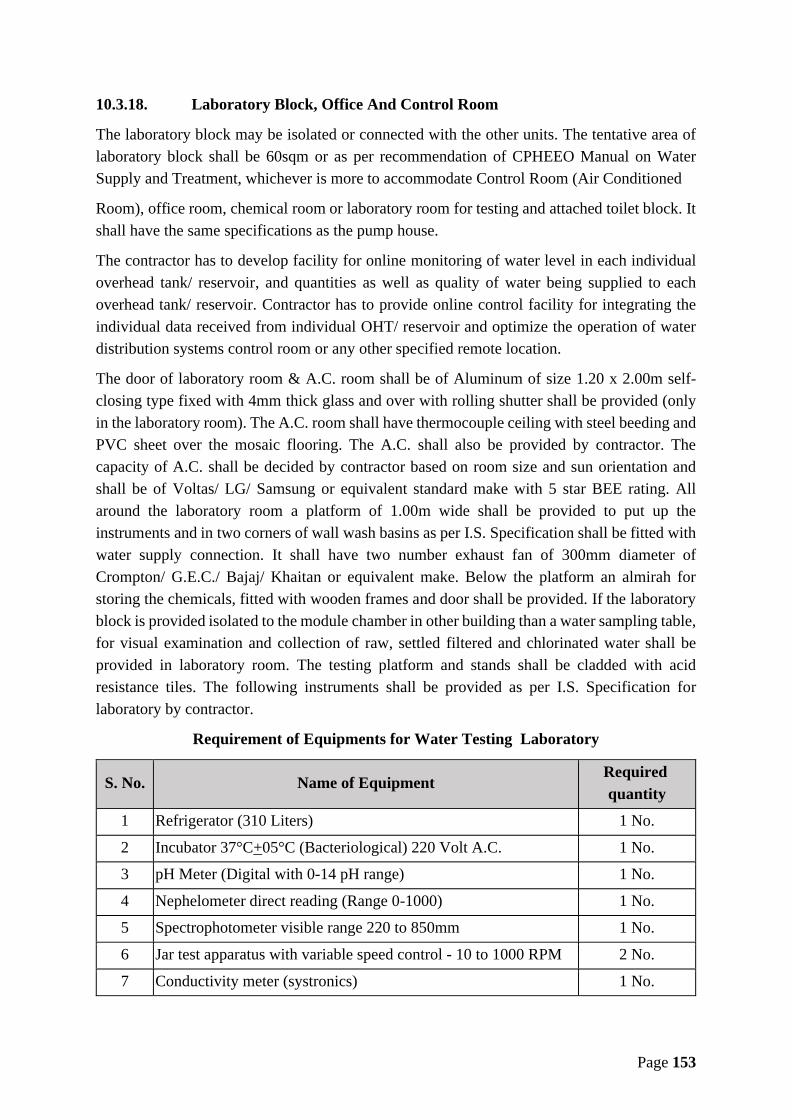
Page 153
10.3.18. Laboratory Block, Office And Control Room
The laboratory block may be isolated or connected with the other units. The tentative area oflaboratory block shall be 60sqm or as per recommendation of CPHEEO Manual on WaterSupply and Treatment, whichever is more to accommodate Control Room (Air Conditioned
Room), office room, chemical room or laboratory room for testing and attached toilet block. Itshall have the same specifications as the pump house.
The contractor has to develop facility for online monitoring of water level in each individualoverhead tank/ reservoir, and quantities as well as quality of water being supplied to eachoverhead tank/ reservoir. Contractor has to provide online control facility for integrating theindividual data received from individual OHT/ reservoir and optimize the operation of waterdistribution systems control room or any other specified remote location.
The door of laboratory room & A.C. room shall be of Aluminum of size 1.20 x 2.00m self-closing type fixed with 4mm thick glass and over with rolling shutter shall be provided (onlyin the laboratory room). The A.C. room shall have thermocouple ceiling with steel beeding andPVC sheet over the mosaic flooring. The A.C. shall also be provided by contractor. Thecapacity of A.C. shall be decided by contractor based on room size and sun orientation andshall be of Voltas/ LG/ Samsung or equivalent standard make with 5 star BEE rating. Allaround the laboratory room a platform of 1.00m wide shall be provided to put up theinstruments and in two corners of wall wash basins as per I.S. Specification shall be fitted withwater supply connection. It shall have two number exhaust fan of 300mm diameter ofCrompton/ G.E.C./ Bajaj/ Khaitan or equivalent make. Below the platform an almirah forstoring the chemicals, fitted with wooden frames and door shall be provided. If the laboratoryblock is provided isolated to the module chamber in other building than a water sampling table,for visual examination and collection of raw, settled filtered and chlorinated water shall beprovided in laboratory room. The testing platform and stands shall be cladded with acidresistance tiles. The following instruments shall be provided as per I.S. Specification forlaboratory by contractor.
Requirement of Equipments for Water Testing Laboratory
S. No. Name of EquipmentRequiredquantity
1 Refrigerator (310 Liters) 1 No.
2 Incubator 37°C+05°C (Bacteriological) 220 Volt A.C. 1 No.
3 pH Meter (Digital with 0-14 pH range) 1 No.
4 Nephelometer direct reading (Range 0-1000) 1 No.
5 Spectrophotometer visible range 220 to 850mm 1 No.
6 Jar test apparatus with variable speed control - 10 to 1000 RPM 2 No.
7 Conductivity meter (systronics) 1 No.
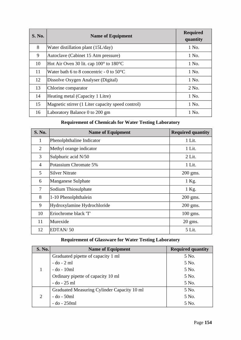
Page 154
S. No. Name of EquipmentRequiredquantity
8 Water distillation plant (15L/day) 1 No.
9 Autoclave (Cabinet 15 Atm pressure) 1 No.
10 Hot Air Oven 30 lit. cap 100° to 180°C 1 No.
11 Water bath 6 to 8 concentric - 0 to 50°C 1 No.
12 Dissolve Oxygen Analyser (Digital) 1 No.
13 Chlorine comparator 2 No.
14 Heating metal (Capacity 1 Litre) 1 No.
15 Magnetic stirrer (1 Liter capacity speed control) 1 No.
16 Laboratory Balance 0 to 200 gm 1 No.
Requirement of Chemicals for Water Testing Laboratory
S. No. Name of Equipment Required quantity
1 Phenolphthaline Indicator 1 Lit.
2 Methyl orange indicator 1 Lit.
3 Sulphuric acid N/50 2 Lit.
4 Potassium Chromate 5% 1 Lit.
5 Silver Nitrate 200 gms.
6 Manganese Sulphate 1 Kg.
7 Sodium Thiosulphate 1 Kg.
8 1-10 Phenolphthalein 200 gms.
9 Hydroxylamine Hydrochloride 200 gms.
10 Eriochrome black 'T' 100 gms.
11 Murexide 20 gms.
12 EDTAN/ 50 5 Lit.
Requirement of Glassware for Water Testing Laboratory
S. No. Name of Equipment Required quantity
1
Graduated pipette of capacity 1 ml- do - 2 ml- do - 10mlOrdinary pipette of capacity 10 ml- do - 25 ml
5 No.5 No.5 No.5 No.5 No.
2Graduated Measuring Cylinder Capacity 10 ml- do - 50ml- do - 250ml
5 No.5 No.5 No.

Page 155
S. No. Name of Equipment Required quantity- do - 1000 ml 5 No.
3Reagent Bottles of Capacity 250 ml.- do - 500ml
10 No.10 No.
4Nester's tube of capacity 50 ml- do - 100ml
5 No.5 No.
5
Conical flask of capacity 100ml- do - 250ml- do - 500ml- do - 1000ml
5 No.5 No.5 No.5 No.
6
Beakers of capacity 100ml- do - 250ml- do - 500ml- do - 1000ml
5 No.5 No.5 No.5 No.
7Test tube with rim of size 25 x 250- do - 15 x 150
100 No.100 No.
8 BOD Bottle 300 ml. 15 No.9 Funnel 4 15 No.
10Filter paper (Whatman's) No.1- do - No. 40- do - No. 42
4 Pkt.4 Pkt.4 Pkt.
12 Desiccator 1 No.
Requirement of Accessories & Material for Laboratory
S. No. Name of Equipment Required quantity
1Water Sampler (Steel) of capacity 2 Litre- do - 5 Litre
2 No.2 No.
2 Gas Cylinder 2 No.3 Burners (Bunsen Marks) ½" Pipe with tuner tone 4 No.4 Wire basket 5 x 5 x 5 2 No.5 Burette Clamps (Nickle plated) 4 No.6 Tongs stainless steel 13" 2 No.7 Spatula steel 8" 10 No.8 Test tube stand (Iron) 10 No.9 Rubber cork various sizes 50 No.10 ICE Box (thirmocal) 3 No.11 Iron Box with clamp 6 No.12 Blotting paper 10 Sheets13 Wire gage 6 x 6" 6 No.14 Stop Watch 1 No.15 Nesseler's tube stand 5 No.
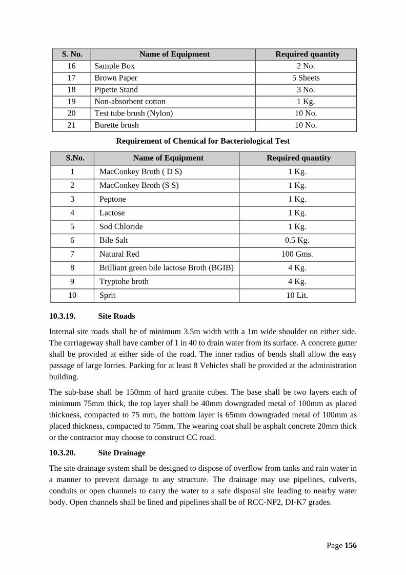
Page 156
S. No. Name of Equipment Required quantity16 Sample Box 2 No.17 Brown Paper 5 Sheets18 Pipette Stand 3 No.19 Non-absorbent cotton 1 Kg.20 Test tube brush (Nylon) 10 No.21 Burette brush 10 No.
Requirement of Chemical for Bacteriological Test
S.No. Name of Equipment Required quantity
1 MacConkey Broth ( D S) 1 Kg.
2 MacConkey Broth (S S) 1 Kg.
3 Peptone 1 Kg.
4 Lactose 1 Kg.
5 Sod Chloride 1 Kg.
6 Bile Salt 0.5 Kg.
7 Natural Red 100 Gms.
8 Brilliant green bile lactose Broth (BGIB) 4 Kg.
9 Tryptohe broth 4 Kg.
10 Sprit 10 Lit.
10.3.19. Site Roads
Internal site roads shall be of minimum 3.5m width with a 1m wide shoulder on either side.The carriageway shall have camber of 1 in 40 to drain water from its surface. A concrete guttershall be provided at either side of the road. The inner radius of bends shall allow the easypassage of large lorries. Parking for at least 8 Vehicles shall be provided at the administrationbuilding.
The sub-base shall be 150mm of hard granite cubes. The base shall be two layers each ofminimum 75mm thick, the top layer shall be 40mm downgraded metal of 100mm as placedthickness, compacted to 75 mm, the bottom layer is 65mm downgraded metal of 100mm asplaced thickness, compacted to 75mm. The wearing coat shall be asphalt concrete 20mm thickor the contractor may choose to construct CC road.
10.3.20. Site Drainage
The site drainage system shall be designed to dispose of overflow from tanks and rain water ina manner to prevent damage to any structure. The drainage may use pipelines, culverts,conduits or open channels to carry the water to a safe disposal site leading to nearby waterbody. Open channels shall be lined and pipelines shall be of RCC-NP2, DI-K7 grades.

Page 157
10.3.21. Boundary Wall
Water Treatment Plant will be protected by a 2m high boundary wall of brick work with RCCcolumns at suitable intervals and ‘Y’ shape angle iron with 2 x 3 rows of barbed wire fencingat top of boundary wall and will have a minimum 4m wide M.S. fabricated iron gate.
10.3.22. Telephone System
A telephone system shall be provided. The system shall originate in the administration buildingand shall be controlled by a receptionist. Telephone instruments shall be installed in the officesin the chemical building, the workshops, the filter monitoring room and the main offices of theadministration building. The connection of an outside line to the system will be provided byothers.
10.3.23. Process Control
The Contractor shall monitor summary status of all the treatment work as follows:• water level at raw water and clear water reservoirs• process flows and totalized quantities• water quality values• status of each process• reservoir high and low level alarms• power outage present• power consumed per day• individual power consumption• power factor• water treated in the last complete 24 hour period (midnight to midnight, time
selectable)• total power outage house per day
10.3.24. Emergency Lighting
Emergency luminaries shall be provided in all areas and so arranged to provide sufficientillumination to allow safe evacuation from all buildings under power failure conditions.Emergency luminaries shall be of the type utilizing fluorescent lamps and provided with self-contained rechargeable batteries of the sealed type to give a three-hour illumination period withthe batteries fully charged. A visual indication that the charger is operational shall be provided.
Where considered appropriate the emergency luminary can be incorporated as part of thenormal luminaries where they utilize the main lamp at a reduced output for three hours.
Emergency luminaries shall be so arranged that they are illuminated by the failure of the locallighting current. Key switches shall be provided as required to facilitate testing of theemergency luminaries.
As a minimum emergency luminaries shall be positioned at or near (within 2 metres) the

Page 158
following points:• each exit door• near each staircase so each flight of stairs receives direct light• near changes of direction• near firefighting equipment• at each change of floor• near each intersection• outside each final exit and close to it.
10.3.25. Landscaping
The campus of WTP shall be designed keeping a green belt on the periphery of the WTPpreferable with trees (of local species) planted inside the boundary/ compound wall. Other openareas within the WTP campus shall be maintained with green grass, shrubs and plantation ofplants (flowers, herbs, etc.) to maintain a pleasing appearance. The green area shall bemaintained in prime condition and failure to do so may invoke penalty as decided by Engineer-in-Charge.
10.3.26. External Lighting
External lighting shall be employed throughout the site to illuminate all site roads, turningareas, car parks, paths, tanks and building perimeters.
The following average levels of illumination are required :• Car Parking area: 5 lux• Access Roads, Pedestrian Walkways:10 lux• Lorry Loading and turning Areas: 20 lux• Top of Tanks: 50 lux• Building Perimeters: 50 lux
The access road lighting scheme shall be designed in accordance with the requirements of BS5489: Part 3: 1989 (group B5/6). Column heights shall be 5 meters and each lantern shallincorporate a photocell for control. At each position where a section of road lighting columnsis fed a selector switch shall be provided having the following functions:
• ON - Access road lighting permanently• ON/ OFF - Access road lighting permanently• OFF AUTO - Access road lighting under photocell control
Some flexibility in positioning of road lighting units is allowed but generally units shall bepositioned at intersections and junctions with spacing not exceeding 30 metres + 10%.
11. Reservoirs
This section is applicable to any type of reservoir such as Over Head Service reservoir (OHSR),Ground Level Service Reservoir (GLSR), Master Balancing Reservoir (MBR), ElevatedService Reservoir (ESR), Sumps, etc. that are to be executed under this contract.

Page 159
Construction of these RCC reservoirs that consists of central ventilation shall be of followingspecifications:-The reservoir shape should be circular with central dome and central ventilation lantern so asto incorporate architectural effect to give an impressive view. Any other shape which givesarchitectural impressive view better than the above may be considered as per the decision ofEngineer-in-Charge.Free board of minimum 50cm should be provided below lowest part of roof beam slabstructure. The minimum 50cm free board should be everywhere below bottom of straight beam,ring beam, and roof slab etc.The floor level of MBR shall be so fixed, so as to provide desired water by gravity throughgravity pipelines to proposed ESR/ SUMP.The contractor should assess the bearing capacity of strata at the proposed site by conductingthe required tests. It is responsibility of contractor to conduct bearing capacity test if requiredand bear financial charges towards it. MPJN will not make any payment towards it.
11.1. Design Criteria
(a) Foundation shall be designed as per ascertained S.B.C. of soil as given in next sectionand other soil parameter.
(b) The following load and forces should be considered:i. Dead Load
ii. Live Load – static and dynamic load due to flow and falling of wateriii. Load due to waterWind pressure as per IS: 875-1969iv. Pressure due to Earthquake i.e. seismic force
(c) The sump shall be designed as per IS: 456-2000 revised upto date and IS: 3370-1976(part I to IV) with upto date amendment and other standard code in practice besides thestipulations made in the code.
(d) Construction Joints: It should be as per clause No. 13.4 of IS 456.2000. Previously laidconcrete layer should be first cleaned by water jet and then 10mm thick layer of cementmortar of same proportion should be laid before casting of next layer of concrete.Formwork should be 100mm below the previously laid concrete layer.
(e) Steel: The minimum steel for design purpose shall be as per relevant code, but minimumsteel shall be as follows:-i. Exposed RCC surface:- If thickness is 150mm or more both face reinforcement
shall be providedii. Steel in container:- It shall be as per IS: 3370 but minimum shall be as per (i)
mentioned above.iii. Maximum spacing of reinforcement:- The maximum spacing of main
reinforcement in slab or wall should not be more than 150mm c/c. The spacing ofsecondary bars i.e. distribution steel shall not be more than 300mm c/c.

Page 160
(f) The contractor shall have to make the reservoirs chlorine resistant by painting surfacewith suitable Epoxy or any other material because heavy dose of chlorination is expectedto be given in water.
11.2. General specification
11.2.1. Depth of Excavation
The depth of excavation shall generally be guided by the underground strata and safe bearingcapacity of the soil. The foundation/ mat concrete shall be laid minimum 1.50m below G.L.Safe bearing capacity & other soil test shall be conducted by the contractor at his own costthrough any NIT/ Govt. Engineering College/ NABL Laboratory and any accreditinginstitution as per ISO/ IEC 17011 or laboratory accredited as per ISO/ IEC 17025. The resultof SBC shall be submitted before start of work along with the detailed structural design. Thedesign of foundation shall not be permitted for SBC more than 15 tonne/m2 in strata containingany type of soil, even if the reported SBC is more than 15 tonne/m2 however, in case of rockystrata it may be considered maximum 25 tonne/m2. No payment shall be made to the contractorfor carrying out these tests or on account of change in design due to strata. No dewatering inany condition shall be payable.
It shall be the responsibility of the contractor to test and check the bearing capacity of soil andsubmit it with the design. This bearing capacity shall be tested by plate load bearing test methodat WTP and plate load test/any other method applicable as per IS code at other structures likeIntake/ OHT/ MBR/ GLR/ Buildings etc., by any NIT/ Govt. Engg. College/ NABL Laboratoryand any accrediting institution as per ISO/ IEC: 17011 or laboratory accredited as per ISO/IEC: 17025. No dewatering in any condition shall be payable. The foundation shall be filledwith minimum 150mm thick leveling course in cement concrete grade M-15 with 20 mm metal.All other general & common specifications shall be as per Chapter -1.
11.2.2. RCC Stair Case
Suitable RCC Staircase of grade M-25 concrete from ground level to top of roof of theReservoir along circumference with G.I. railing as mentioned in the specification here. Theriser should be around 175±25 mm and tread should be around 275±25 mm. The width of stairshall not be less than 1000 mm. The landing of minimum 1000 mm wide should be providedafter 12 to 15 steps. The separate frame structure i.e. columns and beams should be providedfor staircase for the overhead tanks of capacity 500KL or more, there shall be staircase withsuitable gate shall be provided to prevent unauthorized entry to the tank. For RCC tank capacityless than 500KL staircase from ground to bottom of container tank and from bottom ofcontainer to top of the container MS ladder of angle 65x65x6 with 20mm double rods, widthof stair case 600mm, shall be provided shall be provided by contractor. It shall have the railingon both sides.
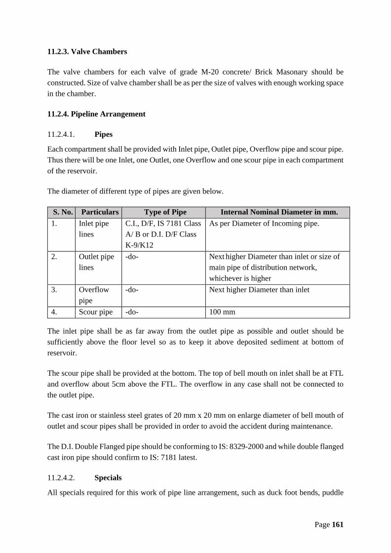
Page 161
11.2.3. Valve Chambers
The valve chambers for each valve of grade M-20 concrete/ Brick Masonary should beconstructed. Size of valve chamber shall be as per the size of valves with enough working spacein the chamber.
11.2.4. Pipeline Arrangement
11.2.4.1. Pipes
Each compartment shall be provided with Inlet pipe, Outlet pipe, Overflow pipe and scour pipe.Thus there will be one Inlet, one Outlet, one Overflow and one scour pipe in each compartmentof the reservoir.
The diameter of different type of pipes are given below.
S. No. Particulars Type of Pipe Internal Nominal Diameter in mm.1. Inlet pipe
linesC.I., D/F, IS 7181 ClassA/ B or D.I. D/F ClassK-9/K12
As per Diameter of Incoming pipe.
2. Outlet pipelines
-do- Next higher Diameter than inlet or size ofmain pipe of distribution network,whichever is higher
3. Overflowpipe
-do- Next higher Diameter than inlet
4. Scour pipe -do- 100 mm
The inlet pipe shall be as far away from the outlet pipe as possible and outlet should besufficiently above the floor level so as to keep it above deposited sediment at bottom ofreservoir.
The scour pipe shall be provided at the bottom. The top of bell mouth on inlet shall be at FTLand overflow about 5cm above the FTL. The overflow in any case shall not be connected tothe outlet pipe.
The cast iron or stainless steel grates of 20 mm x 20 mm on enlarge diameter of bell mouth ofoutlet and scour pipes shall be provided in order to avoid the accident during maintenance.
The D.I. Double Flanged pipe should be conforming to IS: 8329-2000 and while double flangedcast iron pipe should confirm to IS: 7181 latest.
11.2.4.2. Specials
All specials required for this work of pipe line arrangement, such as duck foot bends, puddle

Page 162
collars, bell mouths, bends, tees and end caps etc. shall be provided and fixed in position as perrelevant I.S.The bell mouth required to be embedded in the concrete should be specially manufactured withtheir collars as per requirement. The duck foot bend of all the pipe shall be grouted minimumsufficiently below ground level.
11.2.4.3. Valves and Gates
The contractor should provide and fix in desired position the CI/ DI valves and gates for easyand effective working.All valves should be I.S. mark and inspection and testing certificate should produce to engineerin charge.The double-faced sluice gate has been provided to pass water flow from one compartment toother compartment. In close position gate face should be capable of resisting water pressureforce. There should be no leakage in closed position when water pressure of full depth on oneside and other side being empty.For convenience in operation and maintenance of scheme, the flow controller i.e. valves shallbe of remote operation type to facilitate their operation from centralized control room at WTPor any other specified remote location.
11.2.4.4. Flow Measurement
The arrangement for measurement of water quantity reaching to the tanks by providing &installing in position electromagnetic flow meter of suitable diameter in inlet pipe should bemade by the contractor.Contractor should provide arrangement such that the flow meters be installed before each OHTand at other place as per design and shall give its reading on screen at central control room orany other specified remote location. In addition to the above, arrangements are also to be madefor measurement of Quality Parameter – only Residual Chlorine at the outlet of the OHT anddisplay the same at the control room or any other specified remote location.
11.2.4.5. Ancillary Works
a) Lightening conductor: The arrangement for lightening protective system for protectionof service reservoir should be made as per IS: 2309 revised up to date. The Lighteningprotective system should be designed, installed and tested as per this code and allcomponents of the system should also be provided as per specification mentioned inthis code.
b) Water Level Indicator: Each tank should be provided with water level indicator. Thussufficient water level indicators shall be provided in reservoir. Water level indicatorshall comprise of PVC float which should be 10cm more in diameter than outlet pipe.The plate shall have turned edged to accommodate and to make easy movement ofcounter weight made of iron pointer fixed with guide pulley provided with white enamelpaint write up with radium blue or black color letters. It shall be fixed on container wall.
Page 163
Contractor should provide arrangement such that the water level in OHT shall bedisplayed on screen at central control room and any other specified remote location.
c) Aluminium Ladder: The aluminium ladder from top of roof to the inside bottom ofcontainer shall be provided. It shall comprise of not less than 600 mm long double roundbar @ 250mm c/c. The ladder shall be rigidly fixed.
d) Railing: Railing should be provided up to manhole at top of roof and at balcony alongthe whole circumference and the sides of staircase as per specifications given in relevantchapter.
e) Manhole covers: Manholes of minimum size 60cm x 75cm shall be provided. Thecovers shall comprise of suitable angle iron frame and 10 gauge thick M.S. sheet,crossed by suitable flat inside, with locking arrangement.
f) Ventilators: The suitable air vent shall be provided as directed by Engineer-in-Charge.g) Electrification: The electrification inside and outside should be done in such a manner
that standard level of illumination is obtained inside the reservoir and in the campus.All electrical fixtures, wires etc. shall be ISI marked. The specifications shall be asgiven in relevant chapter.
11.2.4.6. Protection works and Finishing
a) Protection work around sump: Protection work all around the sump shall be provided. Itshall be circular in shape and minimum 2.0 m in width around the outer edge of wall. Itshall have 1:60 slope from center and a drain be constructed all around the tank. Theprotection work shall be with M-15 grade concrete.
b) Weather Shield Apex painting: Two and more coats suitable colour Weather Shield Apexas directed by Engineer-in- Charge shall be done after the testing of water tightness.
c) Colour enamel painting: All iron work, railing and pipes etc. shall be painted with twoor more coats of black Japan or suitable colour enamel paint over primer as directed byEngineer-in-Charge.
d) Finishing: Although concrete shall be off shutter finish means no plaster shall be appliedover concrete to make it smooth finish, but in unavoidable circumstances if plaster isdone, then no extra payment shall be made.
11.3. Inspection & testing of concrete structure
In order to ensure that the construction complies with the design and all the structuralrequirement, clause No. 17 of IS 456-2000 shall be followed. It should also be noticed thatduring construction the settlement of sump due to self-weight during construction should benoticed by proper procedure.
11.3.1. Water Tightness Test
a) After the completion of structure it shall be tested for water tightness. Initially the sumpshall be filled gradually to ensure uniform settlement all over the area. The full supply

Page 164
should reach in a period of not less than 72 hours. At the time of testing, verticality ofsump should be checked by theodolite as per IS: 3370 (part I general requirement) code ofpractice for concrete structures for the storage of liquids specifies water tightness test atfull supply level.
b) After seven days period for observation after filling with water the external face of sumpshould not show any sign of leakage and remain apparently dry.
c) The water for testing and pump for lifting water shall be arranged by the contractor at hisown cost.
d) The contractor shall give the test for water tightness to the entire satisfaction of thedepartment. The responsibility of structural stability shall solely be rest on the contractor.
11.4. Additional Requirements
a) All the tanks will have a room set of area 25 sqm with toilet, etc.b) All the tanks will have boundary wall of 2.00 m high and one iron gate.c) All the tank will have area lighting with electrification of room and for Electromagnetic
flow meter in campus.d) All the tanks & IPS will be provided with automation system as instructed by the engineer
incharge. Basic aim is to check the quantity and quality of water by automation.
For IPSs sumps, suitable pump houses will be designed over sumps or nearby these sumps toaccommodate required nos. of pumps with all other allied arrangements.
11.5. Scope of Work
The contractor is required to complete the following works.
a) Overhead service reservoirs at different villages of capacity and approximate stagingas specified in Annexure F.
b) Construction of MBR cum pump houses of capacity as specified in Annexure F.c) Construction of Sumps having capacity as specified in Annexure F, including all
works complete.
Note:- Minimum Height of Staging should be 12 m, Maximum height of staging shall be as peractual design and site condition to ensure the minimum required terminal pressure in thedistribution network.
1. Location, capacity & staging of ESR/GLR/Sump/pump house may change as per thedesign requirements.
2. If due to any reasons, whatsoever, it is desired to increase or reduce the number orcapacity of tanks/ reservoirs/ clear water sump, this will be done on per KL cost on

Page 165
prorata basis. Extra payment for staging will not be made.a. Construction of Ground level reservoir (sump), shall consist of two equal
compartment, all others may be with single compartment. All tanks will havecentral ventilation lantern.
b. R.C.C. Stair case and Valve chambersc. Pipe line arrangement including providing and laying pipes and specials of
required diameter, length as per Annexure "F".d. Providing and fixing required Valves and Sluice gates.e. Providing and fixing of Lightening Conductor, Water Level Indicator,
Aluminium Ladder, Railing, Manholes with locking arrangement andVentilation hole arrangements, internal lighting arrangement and externalcampus electrification etc.
f. Protection work all around the Reservoir, Weather Shield Apex painting,suitable colour enamel painting, cleaning, finishing and handing over finishedwork to the department.
The contractor will further be required to submit detailed design, drawing, approximatedquantities of cement, steel, pipes, valves, gates and specials, etc. and calculation in five copieswithin one month from the date of acceptance of their tender duly checked from any IIT / NIT,as directed by the General Manager for scrutiny and approval from competent authority. Theresponsibility for design construction/ structural stability and water tightness will however restsolely with the contractor.
12. HDPE Pipes
This specification covers the requirements for successfully designing, manufacturing,supplying, laying, jointing and testing at works and site of High Density Polyethylene Pipesused for water supply. The HDPE Pipes shall be of pressure class as per design requirementbut minimum class of pipe should be 6 kg/cm2 of PE 100.
12.1. Applicable Codes
The manufacturing, testing, supplying, laying, jointing and testing at work sites of HDPE pipesshall comply with IS: 4984 all currently applicable statutes, regulations, standards andamendments and others as follows:-
Code no. Title/ Specification
IS 4984 High Density Polyethylene Pipes for Water Supply
IS 2530Methods of test for polyethylene molding materials and polyethylenecompounds GRP Pipes, Joints and Fittings for use for Potable Water Supply
IS 5382 Rubber sealing rings for gas mains, water mains and sewers.
IS 4905 Methods for random sampling

Page 166
Code no. Title/ Specification
IS 7328 High density polyethylene materials for molding and extrusion
IS 7634 Laying & Jointing of Polyethylene (PE) Pipes
IS 9845Method of analysis for the determination of specific and/ or overallmigration of constituents of plastics material and articles intended to comeinto contact with foodstuffs
IS 10141Positive list of constituents of polyethylene in contact with food stuffs,pharmaceuticals and drinking water.
IS 10146Polyethylene for its safe use in contact with foodstuff, Pharmaceuticals anddrinking water.
12.2. Colour
The color of the pipe shall be black.
12.3. Materials
The material used for the manufacturer of pipes should not constitute toxicity hazard, shouldnot support microbial growth, should not give rise to unpleasant taste or odour, cloudiness ordiscoloration of water. Pipe manufacturers shall obtain a certificate to this effect from themanufacturers of raw material by any internationally reputed organization as per thesatisfaction of the Engineer-in-Charge in charge.
12.3.1. Raw Material
Resin used to manufacture the HDPE pipes shall be 100% virgin PE Black pre-compoundedconfirming to IS: 4984, IS: 7328 and ISO: 4427- 2007 (latest version). The resin proposed tobe used for manufacturing of the pipes should also comply with the following norms as perISO: 9080-2003 (latest version).
The resin should also have been certified by an independent laboratory of international reputelike Bodycote/ Slevan/ Advantica for having passed 10,000 hour long term hydrostatic strength(LTHS) test extrapolated to 50 years to show that the resin has a minimum MRS of over10MPa. There should not be any brittle knee at 80°C before 5000 hours. Internal certificate ofany resin manufacturer will not be acceptable.
Certificate from reputed organization OR Raw material supplier for having passed the full scalerapid crack propagation test as per ISO: 13478. High density Polyethylene (HDPE) used forthe manufacture of pipes shall conform to designation PEEWA-50-T-003 of IS: 7328. HDPEconforming to designation PEEWA-50-T-003 of IS:7328 may also be used with the exceptionthat melt flow rate (MFR) shall not exceed 1.10 g/10 min. In addition the material shall alsoconform to clause 5.6.2 of IS: 7328.
The specified base density shall be between 940 kg/m³ and 958 kg/m³ (both inclusive) when

Page 167
determined at 27°C according to procedure prescribed in IS: 7328. The value of the densityshall also not differ from the nominal value by more than 3 kg/m³ as per 5.2.1.1 of IS 7328.The MFR of the material shall be between 0.20 and 1.10 (both inclusive) when tested at 190°Cwith nominal load of 5 kgf as determined by method prescribed in IS: 2530. The MFR of thematerial shall also be within ± 20 percent of the value declared by the manufacturer.
The resin shall be compounded with carbon black. The carbon black content in the materialshall be within 2.5 ±0.5% and the dispersion of carbon black shall be satisfactory when testedas per IS:2530.
12.3.2. Anti-oxidant
The percentage of anti-oxidant used shall not be more than 0.3 percent by mass of finishedresin. The anti-oxidant used shall be physiologically harm less and shall be selected from thelist given in IS:10141.
12.3.3. Reworked Material
No addition of Reworked/ Recycled Material from the manufacturer’s own rework materialresulting from the manufacture of pipes is permissible and the vendor is required to use only100% virgin resin compound.
12.4. Maximum Ovality of Pipe
The outside diameter of pipes, tolerance on the same and ovality of pipe shall be as given intable 2 of IS: 4984. Ovality shall be measured as the difference between maximum outsidediameter and minimum outside diameter measured at the same cross section of the pipe at 300mm away from the cut end. For pipes to be coiled the ovality shall be measured prior to coiling.For coiled pipes, however, re- rounding of pipes shall be carried out prior to the measurementof ovality.
12.5. Detectability
HDPE Pipes shall be detectable when buried underground, by providing an insulated copperwire having minimum diameter of 1.20mm, firmly attached along the entire length of pipe.
To avoid theft or dislocation during handling/ laying or earth refilling in trench, the insulatedCopper wire shall be firmly fixed on the outer surface of HDPE pipe at Pipe manufacturer’sworks through external adhesion or co-extrusion or any other appropriate method. TheContractor shall supply 5 sets of Ultrasonic Metal detection instruments, suitable for on-sitedetection of under-ground buried HDPE pipelines, without any extra cost and will also arrangefor training of the department's personnel.
12.6. Length of Straight Pipe
The length of straight pipe used shall be more than 6 m or as agreed by Engineer-in-Charge.
12.7. Coiling
The pipes supplied in coils shall be coiled on drums of minimum diameter of 25 times thenominal diameter of the pipe ensuring that kinking of pipe is prevented. Pipe beyond 110mm
Page 168
dia shall be supplied in straight length not less than 6m.
12.8. Workmanship/ Appearance
Pipes shall be free from all defect including indentations, delaminating, bubbles, pinholes,cracks, pits, blisters, foreign inclusions that due to their nature degree or extent detrimentally
affect the strength and serviceability of the pipe. The pipe shall be as uniform as commerciallypracticable in colour opacity, density and other physical properties as per relevant IS Code orequivalent International Code. The inside surface of each pipe shall be free of scouring,cavities, bulges, dents, ridges and other defects that result in a variation of inside diameterfrom that obtained on adjacent unaffected portions of the surface. The pipe ends shall be cutclearly and square to the axis of the pipe. IS: 4984 will be followed for visual appearance.
12.9. Handling, Transportation, Storage and Lowering of pipes
During handling, transportation, storage and lowering, all sections shall be handled by suchmeans and in such a manner that no distortion or damage is done to the section or to the pipesas a whole.
The following procedures should be followed so as to eliminate potential damage to pipes andfittings and to maintain maximum safety during unloading, lifting and lowering.
1. Pipes must not be stored or transported where they are exposed to heat sources likely toexceed 60°C.
2. Pipes shall be stored such that they are not in contact with direct sunlight, lubricating orhydraulic oils, petrol, solvents and other aggressive materials.
3. Scores or scratches to a depth of greater than 10% or more of wall thickness are notpermissible; any pipes having such defects should be strictly rejected.
4. PE pipes should not be subjected to rough handling during loading and unloadingoperations. Rollers shall be used to move, drag the pipes across any surface.
5. Only polyester webbing slings should be used to lift heavy PE (>315mm) pipes by crane.Under no circumstances, chains, wire ropes and hooks be used on PE pipes.
6. Pipes shall not be dropped to avoid impact or bump. If any time during handling or duringinstallation, any damage, such as gouge, crack or fracture occurs, the pipe shall berepaired if so permitted by the competent authority before installation.
7. During coiling care should be taken to maintain the coil diameter at or above the specifiedminimum to prevent kinks. Coiling shall be done when the pipe attains the ambienttemperature from the extruder. In uncoiling or recoiling care should be taken that sharpobjects do not scour the pipe.
8. When releasing coils, it must be remembered that the coil is under tension and must bereleased in a controlled manner. The end of the coil should be retained at all times, thenthe straps released steadily, one at a time. If the coil has bands at different layers of thecoil, then they should be released sequentially starting from the outer layers. The amount
Page 169
of the energy locked up in the coil will depend on the size of the pipe, the SDR of the pipe,and the size of the coil.
9. Straight lengths should be stored on horizontal racks giving continuous support to preventthe pipe taking on a permanent setback
10. Bare coils shall be wrapped with hessian cloth for long distance (> 300Kms)transportation. The truck used for transportation of the PE pipes shall be exclusively usedfor PE pipes only with no other material loaded – especially metallic, glass and woodenitems. The truck shall not have sharp edges that can damage the Pipe.
11. Pipes manufactured at factory are to be carried to the site of work directly or stackedsuitably and neatly along the alignment/road side/elsewhere near by the work site or asdirected by the Engineer-in-Charge.
12. Damages during transit, handling, storage will be to the Contractor’s account andreplacement for such pipes has to be made by the Contractor without any extra cost asdirected by the Engineer-in-Charge.
12.10. Lowering, Laying of Pipes
1. Each pipe shall be thoroughly checked for any damages before laying and only the pipeswhich are approved by the Engineer-in-Charge shall be laid.
2. While installing the pipes in trenches, the bed of the trench should be level and free fromsharp edged stones. In most cases, the bedding is not required, as long as the sharp andprotruding stones are removed, by sieving the dug earth, before using the same a backfillmaterial. While laying in rocky areas suitable bed of sand or gravel should be provided.The fill to about 10 to 15 cm above the pipe should be fine sand or screened excavatedmaterial. Where hard rock is met with, bed concrete M15, 15 cm or 20cm thick sand bedas approved by the Engineer-in-Charge may be provided
3. As PE pipes are flexible, long lengths of fusion-jointed pipes having joints made aboveground can be rolled or snaked into narrow trenches. Such trenches can be excavated bynarrow buckets.
4. During the pipe laying of continuous fusion jointed systems, due care and allowance shouldbe made for the movements likely to occur due to the thermal expansion/ contraction of thematerial. This effect is most pronounced at end connections to fixed positions (such asvalves etc) and at branch connections. Care should be taken in fixing by finishing theconnections at a time the length of the pipe is minimal (lower temperature times of the day.)
5. For summer time installations with two fixed connection points, a slightly longer length ofPE pipe may be required to compensate for contraction of the pipe in the cooler trenchbottom.
6. The final tie-in connections should be deferred until the thermal stability of the pipeline isachieved.

Page 170
7. The flexibility of polyethylene pipes allows the pipe to be cold bend. The fusion jointed PEpipe is also flexible as the plain Pipe. Thus the total system enables directional changeswithin the trench without recourse to the provision of special bends or anchor blocks.However, the pipe should not be cold bend to a radius less than 25 times the OD of thepipe.
8. The Installation of flanged fittings such as connections to sluice/air/gate valves and hydranttees etc., requires the use of stub ends (collars/flange adaptors complete with backing ringsand gaskets. Care should be taken when tightening these flanges to provide even andbalance torque.
9. Provision should be made at all heavy fittings installation points for supports (such asanchoring of the flange in the soil) for the flange joint to avoid the transfer of valve wheelturning torque on to the PE flange joint.
10. PE pipe is lighter than water. Hence care should be taken for normal installations wherethere could be a possibility of flooding of the trench thus the trench shall be kept free ofwater till the jointing has been properly done
11. When flooded, some soils may lose cohesiveness, which may allow the PE pipe to float outof the ground. Several design checks are necessary to see if groundwater flotation may bea concern. Obviously, if the pipeline typically runs full or nearly full of liquid, or ifgroundwater is always below the pipe, flotation may not be a significant concern.
12. However, weights by way of concrete blocks (anchors) are to be provided so that the PEpipe does not float when suddenly the trench is flooded and the soil surrounding the pipeis washed away. Thus site conditions study is necessary to ensure the avoidance of flotation.
Pipe embedment backfill shall be stone-free excavated material placedand compacted to the 95% maximum dry density.
Anchoring of the pipeline
Thrust blocks shall be provided at each bend, tee, taper, end piece to prevent undue movementsof the pipeline under pressure. They shall be constructed as per design approved by theEngineer according to the highest pressure during operation or testing of the pipes, the safebearing pressure of the surrounding soil and the friction coefficient of the soil.
12.11. Measurement and payment
The net length of pipes as laid or fixed shall be measured in running meters correct to a cm.Specials shall be included and measured in the total length. The portion of the pipe at the joints(inside the joints) shall not be included in the length of pipe work.
12.12. Excavation and preparation of trenches for laying U/G pipeline
The trench shall be so dug that the pipe may be laid to the required alignment and at requireddepth. When the pipeline is under a roadway, a minimum cover of 1.2 m shall be provided, inother cases the minimum cover of 1 m above the top surface of the pipe shall be provided. The

Page 171
trench shall be shored, wherever necessary and kept dry so that the workman may work thereinsafely and efficiently. Under roadway and places where it is not possible to lay pipes up torequired depth or laid open on ground, pipes should be incased all-round with the 1:2:4 (M15)cement concrete.
12.13. Recovery of other serviceable material
All serviceable materials such as wood work, bricks, masonry etc. recovered during theoperation of cleaning or excavations, which, in the opinion of the Engineer-in- Charge aresuitable for reuse in restoring the surface, shall be separately stacked and disposed-of asdirected by Engineer-in-Charge.
12.14. Dewatering
Dewatering shall be carried out by the contractor, wherever necessary. The discharge of thetrench dewatering pumps shall be conveyed either to drainage channels or to natural drains andshall not be allowed to spread over in the vicinity of work place.
12.15. Trenching
The trench shall be so dug that the pipe may be laid to the required alignment and at requireddepth. For road cutting and restoration of concrete/ BT roads, estimates are based onconventional method. However, as directed by the Engineer-in-Charge, the contactor isrequired to complete this work either (i) with concrete cutter/ trenching machine, or (ii) usingtrenchless technology. When the pipeline is under a roadway, a minimum cover of 1.2m undermajor roads shall be provided, in other cases the minimum cover of 0.9m above the crown ofthe pipe shall be provided, if due to the any condition the pipe are not laid at prescribed depth,deduction will be made as per UADD ISSR May 2012. The trench shall be shored, wherevernecessary and kept dry so that the workman may work therein safely and efficiently. Underroadway and places where it is not possible to lay pipes up to required depth or laid open onground shall be encased all round with the 1:2:4 (M20) cement concrete.
12.16. Jointing of Pipes
The pipe shall have Electro-fusion with coupler jointing system that shall provide for fluidtightness for the intended service conditions.
12.17. Bedding, Backfilling and Compaction Bedding
In case of sandy strata no separate bedding is required. However the bottom face / trench bedwhere pipe shall be placed shall be compacted to provide a minimum compactioncorresponding to 95% of maximum dry density. The pipe bedding should be placed so as togive complete contact between the bottom of the trench and the pipe. The minimum cover overburied pipe should be 1m.
12.18. Back Filling
Backfilling should be placed in layers not exceeding 15cm thickness per layer, and should becompacted to a minimum of 95% maximum dry density. The refilling should be done on both

Page 172
sides of pipe together & height difference in earth fill on each side should not be more to causelateral movement of pipe.
Most coarse grained soil are acceptable. This may comprise of gravel or sand. However siltysand, clayey sand, silty and clayey gravel shall not be used unless proposed to be used inconjunction with gravel or clean sand.
It is very important that the pipe zone backfill material does not wash away or migrate in to thenative soil. Likewise, potential migration of the native soil in to the pipe zone backfill mustalso be prevented.
Heavy earth moving equipment used for backfilling should not be brought until the minimumcover over the pipe is 90cm in the case of wide tracked bulldozers or 120cm in the case ofwheeled roaders or roller compactors.
12.19. Compaction
Vibratory methods should be used for compaction. Compaction within distances of 15 cm to45 cm from the pipe should be usually done with hand tempers. The backfill material shouldbe compacted not less than 95% of maximum dry density.
12.20. Thrust Block
RCC thrust block should be suitably designed & provided at bends and at places of reductionin cross section to take care of thrust.
12.21. Fittings & Specials
All HDPE fittings/ specials shall be of minimum PN 10 or above Pressure class, fabricated inaccordance with IS: 8360 (Part I & III). PE Injection molded fittings shall be as per IS: 8008(Part I to IX). All fittings/ specials shall be fabricated or molded at factory only. No fabricationor molding will be allowed at site, unless specifically permitted by the Engineer-in-Charge.Fittings will be welded on to the pipes or other fittings by use of Electro- fusion process.
12.22. Bends
HDPE bends shall be plain square ended conforming to IS: 8360 Part I & III Specifications.Bends shall be molded.
12.23. Tees
HDPE Tees shall be plain square ended conforming to IS: 8360 Part I & II Specifications. Teesmay be equal tees or reduced take off tees. Tees shall be molded.
12.24. Reducers
HDPE Reducers shall be plain square ended conforming to IS: 8008 Part I & VIISpecifications. Reducer must be molded.
12.25. Flanged HDPE Pipe Ends
HDPE Stub ends shall be square ended conforming to IS: 8008 Part I & VI Specifications. Stubends will be welded on the pipe. Flange will be of slip on flange type as described below.

Page 173
12.26. Slip-On Flanges
Slip-on flanges shall be metallic flanges covered by epoxy coating or plastic powder coating.Slip-on-flanges shall be conforming to standard mating relevant flange of valves, pipes etc.Nominal pressure rating of flanges will be PN10.
12.27. Electro Fusion Tapping Saddle, Branch Saddle & Fittings
i. All the Electro fusion fittings should be manufactured with top quality virginpre-compounded PE 100 resin which should be compatible with the distributionmains.
ii. The products shall comply with the requirements of EN 12201-3, EN 1555- 3or ISO 8085-3.
iii. All the fittings shall be of SDR 11 rating.
iv. The fittings shall have the approval from any one of the three agencies likeKIWA, DVGW, WRC-NSF, U.K., CIPET etc.
v. All the products shall be manufactured by injection molding using virgincompounded PE 100 polymer having a melt flow rate between 0.2- 1.4 grams/10minutes and shall be compatible for fusing on PE 100 distribution mainsmanufactured according to the relevant national or international standards. Thepolymer used should comply with the requirements of EN 12201 -1.
vi. Process voltage of all saddles must not exceed a maximum of 40 volts.
vii. The heating elements should be designed for fusion at any ambient temperaturesbetween -5 to +40 degree centigrade.
viii. The heating coils contained in each individual saddle should be so designed thatonly one complete process cycle is necessary to fully electrofuse the fitting to theadjoining pipe or pipeline component as applicable. The heating coils shall beterminated at terminal pins of 4.0 or 4.7 millimeter diameter.
ix. No heating element shall be exposed and all coils are to be integral part of the bodyof the fitting.
x. The EF tapping/ branch saddles should be fixed by fixation device and shall beachieved by external or integral clamping device.
xi. The cutter should be designed in such a way that the cut coupon is not allowed tofall into the pipeline and is retained inside the body of the cutter.
xii. A limited path style fusion indicator acting for each fusion zone as visualrecognition of completed fusion cycle should be incorporated into the body of eachfitting near the terminals. The fusion indicators should not allow the escape of themolten polymer through them during or after the fusion process.

Page 174
xiii. All the sockets in the electro fusion fittings should include a method of tappingcontrolling the pipe penetration (pipe positioner /stopper).
xiv. All the electro fusion products should be individually packed in transparentprotective bags to allow easy identification without opening the bag and mustclearly indicate its contents
xv. The brand name, size, raw material grade, SDR rating and batch identification areto be embedded as part of the injection molding process. Each fitting should also besupplied with a Data Card or stickers with appropriate barcode as well as manualsetting information for data transfer purpose.
xvi. Installation and Fusion Jointing: The fusion jointing process is to be carried out isas per the procedure outlined in the DVS2202 standard, if not available equivalentstandards acceptable to employer.
A protocol for each fusion joint to be printed to ensure the joint process carried out is errorfree. The electro fusion machine shall have the facility to record & make print for each joint.
The precautions & measures as mentioned by electro fusion fittings/ machine manufacturershould be taken up rigorously while making the joints in the field.
The jointing procedures shall be performed with required accessories and tools asrecommended by the fittings manufacturer.
The related pipe jointing accessories such as rotary pipe cutter, Universal clamping tools, Pipecleaners, Pipe peelers supplied by the same electro fusion fitting/ machine supplier shall beused to ensure perfect jointing.
The usage of tapping tools such as taping keys, supplied by the same electro fusion fitting/machine supplier must be used to ensure perfect tapping of main lines.
The piping system will be tested as per the guidelines given by ISO standard. The guidelineshall be furnished by the supplier of electro fusion fittings, tools and machines.
12.28. Hydraulic Testing
Pipes shall be given different hydraulic tests for ensuring quality of manufacturing as perrelevant clauses of IS specifications or prevalent standards as decided by the engineer.
12.29. Manuals
Technical Manual on PE pipes including precautions to be taken during operation of thepipeline.
12.30. Flanges
All flanges employed in the project must be compatible whatever material used.
12.31. Marking
All pipes shall be marked as per Clause 10 of IS 4984-2016.

Page 175
12.32. Packing & Transport
The pipes should be preferably transported by road from the factory and stored as per themanufacturer specifications to protect damage.
12.33. Summary of quality Tests
i. Quality Mark : Pipe: IS 4984
ii. Material : As per IS 4984. However only virgin resin isallowed, reworked material is not allowed.
iii. Grade of Material : PE 100 as per IS 4984 (Certificate from raw materialmanufacturer is required).
iv. Pressure Rating : Minimum PN 6 or above as per requirement
v. Colour : as per IS 4984
vi. Dimensions of Pipe:
Diameter : The nominal diameter (outside)
Wall thickness : As per IS 4984
Length :
a) For diameter 90 mm and 110 mm : 100 meter (if pipes are supplied in lengthless than 100 m than the cost of extra joints will be borne by the contractor.)
b) For diameter more than 110 mm : minimum 6 meter (Tolerance as per IS4984)
vii. Visual Appearance : as per IS 4984
viii. Test and sampling : as per IS 4984
ix. Special Test : Notch hydraulic Test for the HDPE pipe made fromPE-100 grade raw material as per ASTM 1474 ORISO 13479 at manufacturer’s laboratory orindependent laboratory and should pass theHydraulic test as per IS:4984:2016 for a minimum165 Hours. The test reports shall not be more thanthree months old.
Pipe shall convey water under variable temperatureconditions ranging from 4°C to 45°C.
x. Jointing of pipes (pipe end):
All diameters : Electro-fusion Process
xi. Quality Assurance : Quality Assurance Plan shall be got approved fromthe employer before production start.

Page 176
Note: All remaining parameters/ specifications are as per respective BIS specifications.
12.34. Inspection & Testing
The inspection and testing of the sample pipes shall be carried out as per relevant IS and/ orISO standards (latest version) by the CEIL (Certification Engineers International Ltd.) orCIPET (Central Institute of Plastic engineering & Technology) or any other agency approvedby the MPJN, in the manufacture's works before dispatch and / or picking random samples ofpipe from the work site.
12.35. Field Hydraulic Testing
12.35.1. Sectional Tests
After laying and jointing the pipeline shall be tested for tightness of barrels and joints, andstability of thrust blocks in sections approved by the Engineer-in-Charge in Charge. The lengthof the sections depends on the topographical conditions. Preferably the pipeline stretches to betested shall be between two chambers (air valve, scour valve, bifurcation, other chamber). Atthe beginning, the Contractor shall test stretches not exceeding 1 km. After successfulorganization and execution of tests the length may be extended to more than 1 km after approvalof the Engineer-in-Charge in Charge. The hydraulic testing shall have to be commencedimmediately after laying and jointing of 1 km reach is completed.
The water required for testing shall be arranged by the contractor himself. The Contractor shallfill the pipe and compensate the leakage during testing. The Contractor shall provide andmaintain all requisite facilities, instruments, etc. for the field testing of the pipelines. Thetesting of the pipelines generally consists in three phases: preparation, pre-test/saturation andtest, immediately following the pre-test. Generally, the following steps are required which shallbe monitored and recorded in a test protocol.
a) Complete setting of the thrust blocks.
b) Partial backfilling and compaction to hold the pipes in position while leaving thejoints exposed for leakage control
c) Opening of all intermediate valves (if any)
d) Fixing the end pieces for tests and after temporarily anchoring them against the soil(not against the preceding pipe stretch) at the lower end with a precision pressuregauge and the connection to the reciprocating pump for establishing the test pressureat the higher end with a valve for air outlet
e) If the pressure gauge cannot be installed at the lowest point of the pipeline, anallowance in the test pressure to be read at the position of the gauge has to be madeaccordingly
f) Slowly filling the pipe from the lowest point(s). The water for this purpose shall bereasonably clear and free of solids and suspended matter
g) Complete removal of air through air valves along the line.

Page 177
h) Closing all air valves and scour valves.
i) Slowly raising the pressure to the test pressure while inspecting the thrust blocksand the temporary anchoring.
j) Keeping the pipeline under pressure for the duration of the pre-test / saturation ofthe lining by adding make-up water to maintain the pressure at the desired test level.Make up water to be arranged by Contractor himself at his own cost.
k) Start the test by maintaining the test pressure at the desired level by adding moremake-up water; record the water added carefully and the pressure in intervals of 15minutes at the beginning and 30 minutes at the end of the test period.
The pipeline stretch will pass the test if the water added during the test period is not exceedingthe admissible limits. No section of the pipe work shall be accepted by the Engineer-in-Chargeuntil all requirements of the test have been obtained. Water used for testing should not becarelessly disposed off on land which would ultimately find its way to trenches.
12.35.2. Back filling
On completion of a satisfactory test any temporary anchor blocks shall be broken out and stopends removed. Backfilling of the pipeline shall be completed.
12.35.3. Flushing and disinfecting of pipelines
After testing and commissioning the contractor shall flush the pipes with a velocity not lessthan 1 m/s or as approved by the Engineer-in-Charge. Disinfection of drinking water pipelinesshould be done by Contractor.
12.36. House Service Connections on HDPE pipes
These specifications are for MDPE Blue/ Black PE 80/100 Pipes for House ServiceConnections of Dia 20 mm to 32 mm OD. HDPE Pipes (PN12.5 for 25 to 50mm diameter andPN16 for 16 to 20 mm diameter as per ISO: 4427)
12.36.1. Performance requirements
The Pipe supplied should have passed the acceptance test as per ISO: 4427. The manufacturershould provide the test certificates for the following tests:
1. Melt Flow Rate2. Density,3. Oxidation and Induction test,4. Hydrostatic Test ,5. Pigment dispersion Test,6. Longitudinal Reversion Test.
12.37. Sluice Valves on Branches/ Scour valves/ Air Valves
Suitable numbers of CI/DI sluice valves shall be provided conforming to IS: 14846 at differentlocations to regulate or isolate the flow in the network with locking chambers. Scour Valves of

Page 178
CI/DI sluice valves shall be provided conforming to IS: 14846 at different locations foremptying the pipeline for cleaning purposes with locking chambers.
ISI marked Air valves of CI/DI shall be provided, wherever necessary with locking chambers.
12.38. GM/ Brass Ferrules
The ferrules for connection with HDPE shall generally conform to IS: 2692 (Reaffirmed 2005).It shall be of nonferrous materials with a CI bell mouth cover and shall be fitted with a screwand plug or valve capable of completely shutting off the water supply to the communicationpipe, if and when required.
The size of ferrule should not exceed a quarter of the nominal diameter of the main and also beless than the size of the service pipe/connection pipe.
12.39. Compression Fittings
Compression fittings used for House service connection should comply as per ISO: 14236 withThreaded metal inserts –SS 304 with BSP Threads.
12.39.1. Pressure Testing
The pressure rating of compression fittings should be as per clause 8 of ISO 14236 which shallbe PN16.
12.39.2. Dimensions
The Dimension of compression fittings shall be as per clause 7.1 of ISO: 14236
12.39.3. Performance Requirements
The compression fittings shall be tested as per ISO: 14236. Following Test methods shall beperformed.
a) Leak tightness under internal pressure.
b) Leak tightness under Internal Vacuum.
c) Long term Pressure Test for Leak tightness for assembled joint
d) MRS Value as per ISO 9080
e) Resistance to Internal pressure.
12.39.4. Effects on Quality of Water
The Compression fittings for intended for conveyance of Potable water for Humanconsumption to be tested to comply with BS 6920 specifications in any of the laboratories likeDVGW/ KIWA/ SPGN/ WRC –NSF and certificate of compliance to be produced for thefollowing parameters:
a. Odor & Flavor of Water.
b. Appearance of Water.
c. Growth of Micro Organism

Page 179
d. Extraction of substances that may be of concern to Public Health (CytoToxicity)
e. Extraction of Metals.
All fittings with threaded ends should be with BSP threads.
12.40. House Service Connections on Metallic pipes
12.40.1. Specifications for Clamp Saddle Service Connections for other pipes
Clamp saddles for service connection from water distribution mains shall be of wrap arounddesign, wide skirt and wide straps support, which shall reinforce the pipe while providingexcellent stability to the saddle. Clamp Saddles for service connections shall be of fastenedstrap type with threaded outlet for service connection. The service connection threading sizesshall be conforming to IS: 554 Clamp saddles shall be suitable for DI pipes of nominal size 3”(NB to 12” (NB 300) with nominal service connection size from ½” (NB 15), ¾” (NB 20), 1”(NB 25), 1¼” (NB 32), 1½” (NB 40) and 2”(NB 50). The straps shall be elastomer coated(insulated) type for firm grip on pipe as well as to protect the coating on the pipe and to insulatethe un-identical metals.
The saddles shall be single strap type up-to pipe sizes of NB 600 and service outlet of ½”, ¾”and 1”. The saddles shall be double strap type for pipe sizes above NB 600 or when the serviceoutlet is 1 ¼”, 1 ½” or 2”. Fasteners shall be of threaded nut-bolt-washer type. Nut-bolts of size½” (M12) shall be used for saddles of size up to 4” (NB 100) and Nut-bolts of size 5/8” (M16)shall be used for saddles of size 6” (NB 150) and above.
The sealing between the saddle and mains shall be obtained by using a profiled elastomer sealmatching to the curvature of the pipe. The seal shall be of elastomer type, suitable for all potablewater applications. The Material of construction of the body, straps, fasteners etc. shall be of anon-corrosive material such as engineering plastic (PE/PP) or stainless steel or a combinationof both or DI with epoxy coating. The design of the saddle body should be such that, the serviceconnection outlet metal insert shall project out towards pipe side and align with the hole drilledon the pipe to ensure positive locking against rocking or creeping on the pipe, as might becaused by vibration, pressure or excessive external loading. The clamp saddles shall be suitablefor maximum working pressures up-to 10 bars.
12.40.2. Material and Design Specifications
Saddle Body: Non corrosive Engineering Plastic body molded with Stainless steel/DI withepoxy coating threaded metal insert for tapping outlet. Also, the stirrup metal plate shall beduly embedded in the plastic body, except at the place of nut-bolt lugs. Threading size anddimensions shall conform to IS:554. The body shall have retaining cavity housing for internaland external retention of the elastomeric seal. Sealing shall be achieved by pressure exerted bythe body while fastening the saddle straps & body on the pipe.
Saddle Strap: Saddle straps shall be made of stainless steel 304 grade / plastic strap to preventcorrosion over the long service life.

Page 180
Strap Insulation: Elastomeric (rubber) insulation / lining shall be such that none of the StainlessSteel Strap is in direct contact with the pipe. It shall ensure a firm non slip grip mounting onthe pipe to prevent the saddle from rocking or creeping on the pipe, as might be caused byvibration, pressure or excessive external loading.
Saddle Seal: It shall be virgin rubber SBR Grade 30/ NBR (NSF 61 approved). It shall be oftype pressure activated hydro-mechanical design. It shall be contoured gasket to provide apositive initial seal which increases with increase in the line pressure. Gasket shall be griddedmat, with tapered ends, with the outlet section having O-ring contacting the saddle bodymultiple O-rings contacting the pipe, preferably with a Stainless steel reinforcing ring insertmolded to prevent expansion under pressure.
Nuts- Bolts- Washer: Stainless Steel Type 304, NC rolled thread, Tightening torque for ½”(M12) nut-bolt: 14-15 kg.m and for 5/8” (M 16) nut-bolt: 21-23 kg.m
13. Pumps, Motors and Ancillaries
13.1. Scope of Work
13.1.1. Pumps
Vertical turbine pumps and centrifugal pumps as per designed requirements complete with baseplate, sub floor discharge head, motor stool, Bowel assembly, pressure gauges, etc. as per thespecifications.
13.1.2. Motors
440 V, 3 phase, 50 cycle A.C. Solid shaft vertical motors to drive the above mentioned verticalturbine pumps with space heaters and all other accessories as per the specifications.
13.1.3. Capacitors
Capacitor banks for each of above motor to improve the power factor up to at least 0.95 withaccessories as per specifications attached- as per requirement
13.1.4. Starters
Motor starter shall be as mentioned below.
i. Motors up to 5 HP - DOL starterii. Motors above 5 HP up to 100 HP - Star-delta starters
iii. Motors above 100 HP - soft starter
13.1.5. Delivery pipes and specials for pumps:
i. Suitable diameter M.S. Pipe and specials, epoxy coated for delivery piping ofeach turbine pump in the required length as per specification attached.
ii. Suitable size M.S. epoxy coated pipe for common manifold of required length.iii. Dismantle joint as per diameter of delivery pipe.

Page 181
13.1.6. Valves for delivery piping:
i. Suitable diameter swing type reflux valve (non-return valve) as per thespecifications.
ii. Suitable dia. butterfly valves as per specificationsiii. Suitable dia. butterfly valve to be installed in the manifold as per the
specifications.iv. Suitable dia. Swing type reflux valve (non-return valve) for manifold.
13.1.7. Flow Measuring Device:
Electromagnetic full bore type flow measuring device to be installed at junction point ofpumping main and manifold outside the pump house with remote flow indication panel to befixed inside the pump house- one no.
13.1.8. Electronic Pressure Transducers:
For indication of delivery pressure of each pump electronic pressure transducers withindication panel.
13.1.9. Crane: 4 tonne capacity overhead gantry traveling crane
13.1.10. H.T. and L.T. switchgear as per specifications.
13.1.11. Temperature scanner panels as per specifications.
13.1.12. Earthing of electrical equipment's inside pump house and electrical substationas per I.E. rules- as required.
13.1.13. Power and control cables
Power and control cables of suitable rating including cable trays, conduits cable trenches,supporting materials etc. for inter connection of various electrical units in every pumps house-as required:
i) Street lighting M.S. tubular poles for yard and street lighting with completefitting suitable to carry three- phase line with necessary foundation,
ii) Suitable cable conductors of suitable size from lighting distribution panel ofpump house.
iii) Distribution board for indoor/outdoor lighting.
iv) Complete water tight 250 watt mercury vapour lamp fitting on each pole toprovide illumination as desired.
v) Lightening protection of pump house building complete with earthlingstations, earthing conductors and accessories as required,
vi) Hand gloves and shock treatment charts in English and Hindi,
vii) Rubber mats in suitable sections to be provided in front of all switch boardsfor their entire length,

Page 182
viii) Danger/caution notice boards in English and Hindi as per I.E. rules.
13.1.14. Civil Works
Necessary civil work required for erection with supply of building materials, all foundationbolts, washers, bolts of special design and special embedment as required for erection includingall other miscellaneous articles, e.g. lubricants and oils required for installation, testing,commissioning, trial run and O&M.
Contractors shall carryout the actual site survey for determination of electrical soil resistively.
All the equipment shall be designed for operation in tropical humid climate subject to heavyrainfall and frequent thunderstorms with ambient air temperature of 50°C a maximum and 45°Caverage over 24 hours. The design of indoor equipment shall be done for an ambienttemperature of 50°C. However, equipment and apparatus to be installed outdoor subject todirect incidence of sunrays shall be designed for operation at maximum ambient temperatureof 55°C. Maximum monthly mean relative humidity is 80% and shall be taken intoconsideration for design of equipment.
All the materials to be used in this work must be strictly in accordance with relevant B.I.S.
The work shall be carried out by a licentiate class A contractor authorized under I.E. rules 1956framed to in accordance with I.E. Rules of 1910. The contractor will have to obtain the licensefrom the M.P. inspector of electrical safety department permitting to carry out the work.
The work shall be carried out strictly in accordance with latest I.E. Rules in vogue and relevantIndian standards. (B.I.S.)
The pumping sets shall be installed over the properly designed foundation so as to satisfy truealignment and vibration free installation, dynamically and statically balanced. The installationshould conform to the modern technique and should be capable to give performances singly ofwith all units running in parallel in reference to system curve. The contractor shall test theinstallation of pumping sets for vibration and submit the vibration signature of pumping set forapproval of the engineer-in-charge of the work before commissioning of the plant.
The responsibility of commissioning and satisfactory working of all the equipments will bethat of contractor. Any defects due to faulty design, defective material of parts used inmanufacture, noticed during the entire O&M period shall be made good by the contractor freeof cost, without interruption of the plant. The replacement shall be done within a week of suchbreak down, free of all charges inclusive of all cost of transportation, handling and fixing thesame.
The contractor shall submit the technical particulars of the equipment.
The contractor shall submit the detailed description of each item provided for along withdimensioned drawing for the lay out and connections proposed.
The contractor shall also furnish an undertaking from the manufactures of equipment thatbefore going out of production of spare parts, for the equipment offered the manufacturer shall

Page 183
give at least 12 months advance notice to the Madhya Pradesh Jal Nigam.
The contractor shall furnish the system efficiency curve indicating the overall system efficiencyalong with the submission of design of pump after confirmatory survey, for followingsituations:-
i. Only one pump is operated.
ii. Two pumps are operated in parallel.
The combined discharge head curve shall also be furnished for all above conditions.
The contractor shall indicate the overall kilowatt input at duty point without any tolerance.
The overall efficiency of each pumping unit and KW input should be quoted without anytolerance on negative side. The efficiency and kilowatt input of motor once quoted should befirm and shall not be allowed to be altered.
On completion of work, contractor shall submit the completed drawing circuit diagrams,detailed mechanical drawings of equipments and the maintenance manual in form as desiredby the engineer-in-charge of work.
All the equipment shall be provided with rating plate and nameplate as per the specifications.
13.2. Specifications For Pumps
13.2.1. Raw Water Pumps
The pumps shall be Vertical Turbine wet pit type non-pull out design with multi stage bowlassembly, directly coupled through flexible pin coupling with vertical motor without speedreduction gear. These pumps are to be installed in the intake well cum pump house at rawwater pumping station to pump the turbid water. The rotating elements of pumps shall bedynamically balanced and over stressing shall not occur due to sudden failure of power.Reverse rotation shall not damage the pumps.
The design data for pumps is as given in Annexure F.
13.2.2. Clear Water Pumps
The number of centrifugal pumps to be supplied and installed are as mentioned in Annexure-F.For the pumps supplied and installed following specifications needs to be fulfilled:
i. Overall efficiency of each pump shall be 70% minimum for pumps of 50 KW ormore and 60% minimum for pumps of less than 50 KW.
ii. Pump speed - 1500 RPM (Max).iii. Characteristic of liquid to be handled - Clear wateriv. Method of lubrication - Auto lubrication with clear waterv. Pressure head - As per L- section including other losses of each case.
13.2.3. Specifications
i. Pumps shall be designed so as to have a maximum flow capacity of not less than

Page 184
110% of the rated flow capacity.
ii. Pumps shall be designed so as for continuous operation at any point headcapacity curve between 50% and 110% of pumps rates flow without unduevibration or overheating.
iii. The pumps shall be designed so as to have a stable non overloadingcharacteristic. Capacity head curve shall be continuously dropping from shut offpoint to operating point and shall be suitable for parallel operation of pumpswithout any haunting possibility. The shut off head should not exceed 360% ofduty point head.
iv. The impeller adjustment shall be designed in such a way that impellers run freein any installed condition in spite of the extension of line shaft caused byhydraulic down- thrust the weight of shafting and impellers.
The pumps shall be complete with bowel assembly, column pipe, line shaft, foundation plate,sole plate basket strainer, motor footstool and all other necessary accessories. The pumpsshould generally comply with the requirements of following standards.
i. I.S. 1710- Submersible pumps for clear, cold and fresh water.
ii. I.S. 5360- technical requirement of rot dynamic special purpose pumps.
iii. Any other relevant I.S. specifications.
Impeller shaft: The impeller shaft shall be of stainless steel with renewable stainless steelsleeves at bearing portion. The impeller shaft shall be guided by Bearings provided in eachbowel. The butting faces of the shaft shall be machined square to the axis and the shaft andshall be chamfered on the edges. The shaft shall have a surface finish of 0.75- micron Ra maxas per IS: 3073-1967.
Impellers: The impeller may be of closed type of semi open type made of S.S. CF8M, staticallyand dynamically balanced. The impeller shall be free of any carting defect and shall be properlymachined all the water passage shall be smooth finished. The impellers shall be fastened withshaft thrust collar and keys.
Bowels: The bowels shall be made of 1.5% to 2% Nickels cast iron I.S. 2010 Gr FG260smoothly finished and free from any casting defects. The bowels shall be capable ofwithstanding hydrostatic pressure equal to twice the pressure at rated capacity of 1.5 times ofthe shut off head whichever is greater. The bowels shall be equipped with replaceable seal ringson the suction side of impellers in case of closed impellers. The water passage in the bowelsshall be smooth and shall have the stainless steel bushes to serve as bearing for the impellershaft.
Line shafts: The line shaft shall be made of stainless steels the shafts shall be furnished withinter changeable sections having length of 1.5m, 2.5m of 3m. The butting faces of shafts shallbe machined square to shaft axis and the shaft ends shall be chamfered on the edges. To ensurethe correct alignments of shafts, they shall be straight within 0.365mm for 3m length total dial

Page 185
indicator reading.
The shaft shall not have the surface roughness more than 0.75 micron as per I.S. 3073-1967.The shaft coupling shall be designed with a minimum factor of safety for shafts and shall haveleft hand of right hand threads depending on the direction of rotation of pump to tighten duringthe pump operation. The outside diameter of the coupling shall be concentric with the bore andwith a small transverse hole in the middle. The shaft shall have the adequate strength to withstand all the forces at the (±10% of the critical speed of shaft). The minimum dia of line shaftshall not be less than 60mm.
Column Pipe: The columns pipe shall be manufactured from the heavy series of mild steel tubeconfirming to relevant India standard specifications. The column pipes shall be flanged andbolted and shall be complete with nuts and bolts the length of column section shall dependupon the design of intake well cum pump house and the installation however for the ease ofhandling. The length of each column pipe shall not exceed 3 meters.
Line Shaft Bearings: Lubrication from filtered water tapped from V.T. pump deliver line andthen passed through a small basket type filter unit. The filter unit shall have two sets of filterelements and booster pump to provide 100% standby system.
Thrust Bearing: The trust bearing shall be of angular contact spherical roller and shall belubricated by oil. The thrust bearing shall be designed on the basis of 30000 working hourminimum for the load corresponding to the duty point. The thrust bearing shall be capable oftaking entire pump thrust arising from all probable conditions of continuous operationthroughout its range of operation and also at shut off conditions.
Discharge Head: The discharge head should be sufficiently strong to support the weight of thepump. It shall be fitted with a tube tension plate to tighten up the shaft tubes for the purpose ofaligning the shafts. The discharge elbow shall be of fabricated mild steel.
Stuffing Box: A packing gland shall be provided at the top of stuffing box. Shaft sleeves shallbe provided on the top shaft. The stuffing box shall be of sufficient depth to permit adequatepacking. The space between the pump motor main coupling and the stuffing box shall besufficient to permit removal of packing glands and insertion of new packing withoutdismantling the pumps.
Motors Foot Stool: The motor footstool shall be of fabricated mild steel and shall be designedto take care of all the static and dynamic loads on it.
Sole Plate: Each pump shall be provided with a heavy structural steel sole plate. Sole plate shallbe provided and grouted with foundation. The sole plate shall be designed to permit removalof entire pump without disturbing sole plate.
Suction Bell and Basket Strainer: Each pump shall be provided with a suction bell and baskettype removable, strainer. The strainer shall be of galvanized mild steel. The open area ofstrainer should be such that there is a minimum head loss in the strainer.

Page 186
Pressure Gauges: Each pump shall be provided with a pressure gauge fibbing of best bell maketo give the indication of delivery pressure. The pressure gauges shall be of Bourdon type fittedwith glycerin outside the Burdon tube and connected to atmosphere for damping themechanical vibrations. The connection size shall be 36 mm BSP.
Bolts, Nuts and Washers: All bolts, nuts and washers shall be of superior quality conformingto relevant Indian standard specifications.
13.2.4. Material of construction
The material of construction of the pumps and columns and bowel assembly shall be such asto resist erosion and corrosion, the material of construction for various components shall be asunder:-
(i) Suction bell and bowels: 1.5-2%Nickel C.I. I.S.210 Gr FG260(ii) Impellers: S.S. CF8M(iii) Columns pipes: Fabricated Mild Steel conforming I.S. 2062(iv) Pumps shaft: Stainless steel AISI 410(v) Line shaft: Stainless steel AISI 410.(vi) Shaft sleeve: Stainless steel AISI 410.(vii) Line shaft bearing: Cut less rubber(viii) Sole plate: Mild steel as per IS 2062(ix) Pumps motor flexible coupling: Semi steel.(x) Gland: Bronze as per IS 318 Gr. 2.(xi) Packing for gland: Braided impregnated Teflon.(xii) Bowel wearing rings: Bronze.(xiii) Stuffing box: C.I to I.S. 2010 gr. 25.(xiv) Thrust bearing housing: C.I. to I.S. 2010gr 25.(xv) Motor foot stool: Fabricated mil steel to I.S. 2062(xvi) Nuts, bolts and washers: High tensile (Conforming to Relevant B.I.S.)
All the inspection, examination and testing shall be carried out in accordance with relevantIndian standard specifications. Details of test to be carried out are as follows:-
(i) Laboratory Test: Laboratory pump test shall be carried out as per I.S. 5360for each pump to access the pump discharge v/s head, horsepower & Efficiencyfigures. The pump bowel shall be subjected to a test pressure of 1.5 times ofthe shut off pressure of twice the working (Rated) pressure whichever ishigher.
(ii) Field test: The field test shall be carried out as per I.S. 1710 and 5360.
13.2.5. Technical particulars
The contractor shall submit the details of technical particulars along with the preliminary outline drawings indicating the principal dimensions and weight of pumping equipments, andcross section drawings indicating the assembly of pumps and major parts thereof with material

Page 187
of construction and special features, complete descriptive and illustrated literature on theequipment and accessories offered.
13.2.6. Energy Consumption
The MPJN’s estimation for yearly consumption of energy for design period is specified inAnnexure – ‘F’. For reimbursement of energy charges, calculation shall be done on proratabasis from 1st year to design period. The energy charges will be rebased according to thepopulation projections every financial year i.e. on 1st April of every year. The energy chargeswill be based on the projected population for the entire financial year. If energy consumptionis more than derived as above, then excess energy charges shall be paid by the firm.
If any change in scheme components or water demand increases due to any reason & approvedby MPJN, then reimbursement of payment for energy consumption excluding penalties, shallbe made accordingly.
13.2.7. Excess Energy Consumption
If energy consumption is more than the units as derived in the above clause, then excess energycharges shall be paid by the firm.
14. Electric Power Line
Design, Supply, erection and Construction of dedicated 33 KV/ 11KV power supply to Intakewell cum pump house and IPS including construction of suitable capacity substation andtransformers including standby and stretching of power. Campus lighting and allied internaland external electrical works for the entire project for all components including all allied civilworks, etc. complete.
Liaison with MPPKVVCL for new power supply agreement for getting Electricity connection,Necessary arrangement for getting MPPKVVCL/ Electrical inspectors clearance and approvalfor the same or with any agency/ department as required, shall be in Contractor’s scope. Thework shall be done with latest MPPKVVCL's specifications and IS specifications.
i. Supply, installation, testing and commissioning of two pole structure along withlightning arrestor, disconnector, AAAC conductor, clamp and connectors, insulators,hardware, CT- PT metering set, H.T. meter with enclosure, etc for taking tapping fromincoming overhead line.
ii. Supply, installation, testing and commissioning of suitable transformer with Off-circuit Tap Changer, necessary foundation and earthing.
iii. Supply, installation, testing and commissioning of the complete electrical distributionsystem with Main LV switchboards, process equipment panels etc.
iv. Supply, installation, testing and commissioning of the complete cabling system withterminations (scope includes supply of gland, lug, etc.) as per approved drawing.
v. Supply, installation, testing and commissioning of the illumination system including

Page 188
new lighting panels, lighting fixtures, cables, cable terminations, wires, GI conduits,switches, receptacles, street lighting poles with Junction box and overhang etc.including all the necessary accessories as per approved lighting layout drawings andtechnical specification.
vi. Supply, installation, testing and commissioning of earthing and lightning protectionsystem with earthing pits and connecting the pits to the earth grid and forming earthgrid and equipment connection to the grid including necessary clamps, nuts, bolts, etcall including welding, bolting and associated civil works for two pole structure,overhead line, for all equipments inside and outside plant as per approved layoutdiagram and technical specification.
vii. Civil works associated with the electrical works is also included in the Contractorsscope of works. Preparation of supports and structures for erection of transformers,switchgear, poles, cable trays and other accessories are included in the scope of worksof the contractor. The work also includes testing at the place of manufacture by a thirdparty as nominated by the Employer, as required at the contractor's cost.
14.1. Item & specification of the work
14.1.1. 33 KV Line Work
1. Supplying & drawing 100 mm sq. DOG, AAAC conductor, complete with binding atexisting insulator, jointing teeing of connection etc. As required and cleaning ofobstacle (if any) complete in all respect. As per latest BIS version (Make ISI make orEquivalent)
2. Supply and erection of angel/channel, flats iron fitting for over headlines such as crossarms, clams, V cross arms, brackets, back clamps, top clamps etc including nut bolts ofrequired size welding fabricating painting with two coat of red oxide paint and two coatof aluminum paint as required as per specification, complete in all respects. Make: ISIMarked/ Tested (Make: Tata, SAIL or Equivalent)
3. Supply erection testing, commissioning of 33/ 11 KV disc insulator/ Polymer insulatorand its hardware with galvanized insulator fitting, ball and socket type with galvanizedinsulator fitting wall and socket type with galvanized string camp, bolt, nut washer, etcsuitable for 100 sq mm (AAAC conductor as required) as per specification complete inall respect as per BIS version.
4. Supply, erection, testing, commissioning of 33/ 11 KV Pin insulator and with GI Pinclamp, bolt, nut washer. etc suitable for 100 sq mm (AAAC conductor as required asper specification complete in all respects. As per latest BIS version.
5. Carpet guarding of 33 KV/ 11KV lines with 8 Swg GI wires along with binding wiresetc complete in all respect including earthling of guarding as per BIS standard andspecifications.

Page 189
6. Supplying, installing, testing and commissioning of transformer, outdoor, oil filledcopper wound distribution transformer along with all accessories conforming to latestedition of IS: 1180 specification with Neutral Solidly earth, HV Bushing shall beprovided with home gaps, as per latest BIS version.
7. Supplying, Positioning, fixing & Erection at desired site of ISHB-beam/ Rail pole 11mlong (min: 37.10 Kg/m) for electrical lines/ sub stations including aligning and keepingit truly in vertical position including excavation of poles pits in hard rock, with concreteof Grade M15 with 20mm graded black metal. The job includes plastering the exposedconcreting with 1:4 (cement : sand) cement mortar including white cement painting. Italso including painting on MS pole with primer coat of red oxide, and two coat ofaluminum paint inclusive of painting materials, labor etc complete as required as perspecification. ISI Marked/ Tested (Make: Tata, SAIL or Equivalent)
8. Supply and erection of angel. Channel, flats iron fitting for over headlines such as crossarms, Clamps, V cross arms, brackets, black clamps, top clamps, stay clamps, stay setetc. including nut bolts of required size welding fabrication painting with two coat ifred oxide paint/ Zinc chromed and two coats of aluminum paint as required as perspecifications, complete in all respects. Make: ISI Marked/ Tested (Make: Tata, SAILof Equivalent)
9. Supply, Erection, Testing and Commissioning of 33 KV disk insulator and its hardwarewith galvanized insulator fitting, ball and socket type with galvanized insulator fittingball and socket type with galvanized string clamp, bolt, nut washer, etc suitable for 100Sq. mm. (AAAC conductor as required as per specification complete in all respects (setof 3 disk of 33 KV) As per latest BIS revision.
10. Supply Erection, Testing & commissioning of 33 KV double stage insulator channeltype drop out side complete as per specification duly installed on existing structure (Setof three complete in all respect). (DO Fuse) As per latest BIS version.
11. 33 KV Danger Boards as per MPPKVVCL specifications.
12. Providing and installing GI pipe earth electrode: earthling with GI pipe 40 mm dia.Including accessories and providing masonry enclosure with cover plate having lockingarrangement and GI watering pipe. Earthling strips to be traced on electrode andbrought out. Electrode to be covered by alternate layer of salt and charcoal powder.Complete in all respect, as per latest BIS revision.
13. Supplying /fixing of GI strips 25x5 mm size including riveting, welding clampingbrazing and connection from earth plate to transformer body LA, Do fuse, ABS, & earthgrid connection etc. complete in all respects, as per latest BIS version.
14. Winding of GI Barbed wire (Anti climbing device) up to height of 3m around of poleAs per MPPKVVCL standards.
Page 190
15. Supplying erection, testing of lighting arrester cap type single piece non linear resistertype (set of 3 nos.) suitable for three wire 33 KV line with galvanized clampingarrangement, G.I. Bolt, nuts washer etc and mounting on existing structure to completejob as per specification complete in all respect (LA) as per latest BIS version.
16. Transformer Distribution Box – Supplying, installation, testing and commissioning ofcubical type totally enclosed free standing type, dust, damp free and vermin proof,distribution board made of MS sheet 14G, complete with stove enamel paint, etc. withbus bar MV danger notice plate, ammeter and voltmeter with suitable aluminum leadsand connection of incoming and outgoing cable with thimble and cable clamps havingfollowing incoming and outgoing with HRC fuses.
17. Specification: A incoming : 1 nos. 400/200/100 Amp MCCB with over current, earthfault over voltage, under voltage protection B: Bus bar, a set of 600 mps aluminum busbar duly color coated, C: outgoing: 12 nos. 200 Amps HRC base with fuse. As per latestBIS version (make MCCB: Havels or ISI approved equivalent).
18. Supply, laying, placing, positioning, following PVC cables of 1.1 MN grade PVCinsulated aluminum conductor armored cables with inner and outer sheath mid layingvertically or horizontally including excavation in rock, trenching with cables coveredwith sand and brick protection etc. complete in all respects. (Offer should includetermination of cables covered with proper lugs and connection to the equipment'scomplete in all respects) As per latest BIS revision.
19. Supplying erection and commissioning of ging operated pin insulator type air breakswitch Outdoor type 33 kv, 3 phase 50 HZ 200 Amp normal current on existingstructure I including operating handle with guide and locking arrangement withearthling. 1 no. & 1 NC limit switch with its mounting etc as per specification (one setof three nos.) complete in all respect (AB switch as per latest BIS revision).
20. Providing & fixing fencing consisting of GI wire, MS angle iron post 40 x 40x 6 mm,(confirming to IS 225), 1.2 Mt. height above GL and 0.3 Mt. below GL. C/C spacingof each post shall not exceed 2.25 Mt. with diagonal strut to hold the fencing in line andlevel. Angle of size 40x40x6 mm length 1 Mt. at every forth post fixed with nuts boltsincluding applying a priming coat of steel printer and painting with black paint to postand struts etc, complete including screwing with GI tying wire, GI stipples, GI un-ailsor steel pins, etc. complete with cost of excavation and filling cement concrete M15grade for fixing posts and struts to the pit of size 0.3 x 0.3 x0.3 Mt for each post andstruts etc. complete for covering transformer & other electrical utility with welded mesh50x25 mm as per latest BIS version.
21. Supplying Positioning fixing & erection at desired site of ISHB –beam/ Rail pole 13mlong (min: 37.10 Kg/m) for electrical lines/ sub stations including aligning and keepingit truly in vertical position including excavation of pole pits in hard rock, with concreteof grade M15 with 20mm graded black metal. The job includes plastering the exposedconcreting with 1:4 (cement and sand) cement mortar including white cement

Page 191
plastering. It also including painting MS pole with primer coat of red oxide, and twocoat of aluminum paint inclusive of painting materials, labour etc. complete as requiredas per specification ISI marked/ tested (Make: Tata, SAIL or approved equivalent).
22. Supplying and fixing of earthling set coil made out of 8 swg GI wire complete asMPPKVVCL specification.
23. Supply and winding of GI Barbed wire (Anti climbing device) up to height of 3maround of pole as per MPEB standards.
24. Supply and installation of danger board 33 KV rating: The job includes concreting,suitable HBEAM pole of mm 11m height to house all mentioned fittings, includingexcavation, making pedestal, M20 concreting, reinforcement as per drawings & design.As per latest BIS version.
25. Supply and fixing of stay set 20 mm complete with stay rod, stay wire and base plate,excavation of pole pits in hard rock, with concrete of grade M15 with 20 mm gradedblack metal. The job includes plastering the exposed concreting with 1:6 (cement andsand) cement mortar including white cement painting. It also including paintingmaterials, labour etc complete as required as per specification.
26. Supply erection testing commissioning of 33 KV disk insulator and its hardware withgalvanized insulator fitting, ball and socket type with galvanized insulator fitting ballarid socket type with galvanized string clamp, bolt, nut washer, etc suitable for 100sq.mm (AAAC conductor as required as per specification complete in all respect) Asper latest BIS revision.
27. Supply and erection of Angel/ Channel, flats iron fittings for over headlines such ascross arms, clamps, V cross arms, brackets, back clamps. top clamps etc including nutsbolts of required size welding fabricating painting with two coat of red/ oxide paint/zinc chromed paint and two coats of aluminum paint as required as per specifications,complete in all respects. Make: ISI Marked/ Tested (Make: Tata, SAIL or approvedequivalent).
28. Supply erection testing commissioning of 33 KV Pin insulators and its hardware withInsulator and GI Pin as per latest BIS version.
29. Supply. Testing, Commissioning of 110 Volts/ 5 Amps KWH meter with TTB. Make:secure meters Ltd.
30. Supply, Testing and Installation of 33 KV oil immersed 3 phase CT PT unit of rating50/5 Amps as per design and specifications of MPEB.
31. Supply and Installation or HT meter box double door with glass window. Made of MSsheet duly painted with locking arrangements etc.
32. Supply and installation of cooper control cable 2.5 sq min 12 cores complete withglands connectors etc.

Page 192
33. Supplying laying placing positioning following PVC cables of 1.1 KV grade PVCinsulated aluminum conductor armored cables with inner and outer sheath and layingvertically or horizontally including excavation in rock, trenching and refilling andmaking it as original in GI pipe/Hume pipe/ GI cable trays/ earth/ RCC trenches withcables covered with sand and brick protection etc complete in all respects (offer shouldinclude termination of cables with proper tugs and connecting to the equipment'scomplete in all respects). As per latest BIS version (Make Havells, Finolex, Paragon orIS approved equivalent).
34. Supplying fixing and installation of RS JOIST 175x85 mm of 9 inch ht., its excavation,concreting M20, Primer & enamel painting etc junction box required in all respectswith accessories, The job includes supplying erection in positioning, RSJ pole of min 9mt height to house all mentioned fittings, including excavation, making pedestal, M20concreting, reinforcement as per drawing and design, as per latest BIS version includingjunction box, fixed with clamps with simple fuse fitted also providing street lightoperating as per MPPKVVCL norms (Make: Bajaj, Crompton, Philips or IS equivalentapproved)
35. The job included concreting in position, suitable MS tubular pole of min 9 Mt andsection feeder panels height to house all mentioned fittings, including excavation,making pedestal, M20 concreting, reinforcement as per drawings & design as per latestBIS version.
36. Supply and testing of sired light operating switch suitable for Street lights (Three phasesupply)
37. Supply and testing limit switch with copper armoured cables from AB switch to thebreaker.
14.1.2. 11 KV Electric power line (if required)
1. Scope of work includes supply, erection, testing and commissioning of 11 KV electricline using H-Beam as poles and using Raccoon Conductor having max span 70 Mtrswith following items using following items including labour, transportation etc.complete.
S. No. Particulars
1 H-Beams 152 X 152mm, 37.1 Kg/m, 11m Long
2 11 KV 'V' cross-arms angle type (65x65x6 mm angle)
3 Back clamps (65x6 mm flat) for 140kg PCC Pole
4 11 KV Top clamps angle type 65x65x6 mm
5Earthing Coil (coil of 115 turns of 50 mm.dia. and 2.5m lead of 4.0 mm.G.I wire)
6 11 KV (5 KN) polymer Pin insulator

Page 193
S. No. Particulars
7 AAAC Conductor Raccoon with 3% Sag
8 Jointing Sleeves suitable for 80 Sqmm Al. Eq. AAAC conductor
9Stay set 16 mm. complete with back clamps, stay wire 7/3.15 mm. (5.5kg.stay wire per stay set ) and turn buckles for H beam
10Concreting (1:2:4) of H-beam @0.65 cum per pole (Base pedding +Muffing)
11 Concreting (1:2:4) of stay @ 0.2 cum per stay
12 Painting with Red oxide paint
13 Final 2 coat of Aluminum paint
14 Fixing of Anti climbing devices
15 Fixing of Danger Boards Enamalled Type 11KV
14.1.3. Specifications for 11 KV/ 0.4 KV outdoor substation on RSJ using followingitems including labour, transportation, etc. complete
Transformer 11/ 0.4 KV 3 Star rated of designed capacity including standby
RS Joist 175x85, 19.6kg/m, 11m Long
D.C.cross-arm of 100 X50X 6 mm 8' centre with 2 pair of clamp suitable for RSJ
11 KV (45 KN) Polymer disc insulator
11KV Strain hard ware fitting
11 KV D.O. fuse & Lightening Arrestor mounting channel (75X 40 X 6 mm) with 2back clamp suitable for RSJ
11 KV D.O. fuse unit
9 KV Gapless type (5 KA) polymer lightning Arrestors for DTR
Transformer mounting DC cross-arm 100X50X6 mm channel
Transformer clamping set 50X50 X6 mm angle
Transformer belting with 50X50X6 mm angle with two cross fixing channels
Stay set 16 mm complete with back clamps, stay wire 7/3 15 mm (5.5 kg stay wireper stay set) and turn buckles
Concreting (1:2:4) of RS Joist @ 0.5 cum per pole
Concreting (1:2:4) of Stay @ 0.2 cum per stay
AAA Conductor Rabbit for Jumper
Danger Boards Enamalled Type 11KV
Earthing set
Anti climbing devices (Barbed wire 2.24 mm Dia (14 SWG) (3.5 Kg. wire per pole)
Red oxide paint
Page 194
Aluminum paint
M.S.Nuts and Bolts
Distribution Box mounting channel (75x40x6 mm.)
The work include supplying and fixing of all accessories complete whether included or not asper latest MPPKVVCL's specifications and charging the line including taking permission fromany other government department if necessary. All the transformer will have 100% standbyarrangement.
15. Internal and Approach Roads
15.1. WBM and overlaying Bituminous layer
Construction of Embankment/ Subgrade/ earth shoulders as per clause 305 of MoRTHSpecifications & its sub-clauses, where required but with approved materials/ soil like morrumand CBR value not less then 7% including all lead & lifts, excavation, cost of watering,compaction and maintenance of surface during construction to ensure shedding & preventponding of water (clause 305.3.6) shaping & dressing (clause 305.3.7) finishing etc. completebut excluding scarifying existing granular/ bituminous road surface vide clause 305.6.
Granular Sub-Base with Coarse Graded Material (Table:-400-2): Construction of granular sub-base by providing coarse graded material, spreading in uniform layers with motor grader onprepared surface, mixing by mix in place method with rotator at OMC, and compacting withvibratory roller to achieve the desired density, complete as per clause 401 of MoRTHSpecifications.
For grading-III Material: Providing, laying, spreading and compacting stone aggregates ofspecific sizes to water bound macadam specification including spreading in uniform thickness,hand packing, rolling with vibratory roller 8-10 tonnes in stages to proper grade and camber,applying and brooming requisite type of screening/ binding Materials to fill up the intersticesof coarse aggregate, watering and compacting to the required density.
By Manual Means Grading-I using screening of Type-A (13.2mm Agg.): Providing, laying,spreading and compacting stone aggregates of specific sizes to water bound macadamspecification including spreading in uniform thickness, hand packing, rolling with vibratoryroller 8-10 tonnes in stages to proper grade and camber, applying and brooming requisite typeof screening/ binding Materials to fill up the interstices of coarse aggregate, watering andcompacting to the required density.
By Manual Means Grading- II using screening Type-A (13.2mm Agg.): Providing, laying,spreading and compacting stone aggregates of specific sizes to water bound macadamspecification including spreading in uniform thickness, hand packing, rolling with vibratoryroller 8-10 tonnes in stages to proper grade and camber, applying and brooming requisite typeof screening/ binding Materials to fill up the interstices of coarse aggregate, watering andcompacting to the required density).

Page 195
By Manual Means Grading- III using screening Type-B (11.2mm Agg.): Providing andapplying primer coat with bitumen emulsion on prepared surface of granular Base includingclearing of road surface and spraying primer at the rate of 0.60 kg/sqm using mechanical means.
Providing and applying tack coat with bitumen emulsion using emulsion pressure distributoron the prepared bituminous/granular surface cleaned with mechanical broom and as perrelevant clauses of section-503 of MoRTH Specifications @ 0.30 kg per sqm (dry & hungrybituminous surfaces/granular surfaces treated with primer)
Open - Graded Premix Surfacing (Providing, laying and rolling of open - graded premixsurfacing of 20 mm thickness composed of 13.2 mm to 5.6 mm aggregates either usingpenetration grade bitumen or cut-back or emulsion to required line, grade and level to serve aswearing course on a previously prepared base, including mixing in a suitable plant, laying androlling with a smooth wheeled roller 8-10 tonne capacity, finished to required level and grades.)
Case - II: Open-Graded Premix: Surfacing using cationic Bitumen Emulsion Seal Coat(Providing and laying seal coat sealing the voids in a bituminous surface laid to the specifiedlevels, grade and cross fall using Type A and B seal coats)
Case - I : Type A: Construction of unlined surface drains of average cross sectional area 0.40sqm in soil to specified lines, grades, levels and dimensions to the requirement of clause 301and 309.
Excavated material to be used in embankment within a lead of 50 meters.
16. Cross Drainage Works
Providing and Laying Reinforced cement concrete pipe NP4/ prestressed concrete pipe 1000mm dia. for culverts on first class bedding of granular material (cost of bedding included) insingle row including fixing collar with cement mortar 1:2 but excluding excavation, protectionworks, backfilling, concrete and masonry works in head walls and parapets.
Notes:
1. Clauses and tables mentioned in specifications above refer to MORTHspecifications.
2. Excavation, disposal of surplus earth, construction of shoulders with approvedmaterial, Plain Cement Concrete for drains and other required works which willfacilitate full functionality shall also form part of the work.
3. Until and unless specified otherwise in this document the road width shall be 3.5 mwith 1 m shoulder on either side.
17. Boundary/ Compound wall
The boundary wall or compound wall as the case may be shall be constructed as perspecifications below:
Page 196
i. Type of foundation shall be as per approved design and drawing.
ii. Plain cement concrete used for foundation shall be minimum of M15 grade.
iii. RCC used for plinth beam foundation and columns shall be of M20 grade.
iv. Brick work with well burnt chimney bricks having crushing strength not less than 25kg/cm2 and water absorption not more than 20% using 1:4 cement mortar.
v. Internal and external plastering shall be 12 mm thick using 1:3 cement mortar.
vi. Finishing walls with Acrylic smooth exterior paint of required shade (two or more coatapplied @1.67 liters/ 10 sqm over and including base coat of water proofing cementpaint applied @2.0 kg/ 10sqm).
vii. Providing and fixing of gate built with structural steel as per approved drawing andspecifications at every location.
viii. The height of boundary wall above ground level shall be minimum 2m.
18. Office Buiding and Staff Quarters
Office building and staff quarters as specified in Annexure F are to be designed and constructedat WTP campus or as decided by Jal Nigam officials.
18.1. General Specifications of Staff Quarters
All the staff quarters/ Office shall be RCC framed brick masonry structures. The columns,Beams, Lintels, Chhajjas, Slabs shall be constructed in RCC M25 grade of concrete and wallsshall be constructed in brick masonry with 1:6 cement mortar duly plastered with 1:5 cementmortar. The specifications of all the materials have already given earlier, however briefdescription of different components of quarters are as under:
18.1.1. Foundation
The foundation shall be of RCC footing or raft as per safe bearing capacity of foundation strata.
18.1.2. Plinth
The minimum height of plinth shall be 0.60m above from highest nearby ground level. Theplinth shall be filled with hard moorum or stone crusher dust duly compacted. An RCC floorslab shall be laid at plinth level with minimum reinforcement. The minimum thickness of slabshall not be less than 0.15m.
18.1.3. Flooring
Kota stone flooring shall be done in I to H type of quarters and in G and F type of quartersflooring of Vitrified tiles shall be provided.
18.1.4. Walls
The brick masonry walls shall be constructed as per specifications given earlier. The minimumthickness of the outer walls shall be 0.20 m and partition wall may be of half brick wall.

Page 197
18.1.5. Doors
All the door frames shall be constructed by sal/malesia sal wood and panels shall be constructedby flush door panels except outer doors. The outer door shutters shall be constructed by teakwood panels. All the doors have one additional panel having mosquito net. The doors of washrooms may be constructed in aluminum frame with PVC shutters. All the doors shall also beprovided with interlock arrangement.
18.1.6. Windows
30% of floor area shall be provided for door and windows. All the windows shall be constructedof aluminum framed with 4 mm thick glass panes and mosquito net. MS grill shall also beprovided in each window.
18.1.7. Electrification
Concealed electric fitting shall be done as per standard IE rules. Each room shall be providedwith sufficient number of points for lights, fans, power points, sockets and etc. Separate linefor inverter shall also be laid. All fixtures like energy efficient tube lights, CFL, Night lamps,Fans, Exhaust Fans, Geyser etc as required of ISI mark and of standard make shall be provided.
18.1.8. Water Supply
Concealed water supply fitting shall be provided. GI class medium/ CPVC pipes can be used.A water storage tank of minimum 2000 lts capacity shall also be constructed over roof.Sufficient number of points for fresh as well as for stored water shall be provided for Kitchen,Dining room, Toilet, Court yard and etc. Provision for geyser connection, mixers shall also beprovided.
18.1.9. Sanitary
Provision of attached toilets for bed rooms shall be provided. A common toilet shall also beprovided. Glazed tiles shall be provided on inner walls of the toilet upto full height. Toiletblock should have Indian type WC with flushing arrangement, shower, fresh and stored wateroutlets, Geyser point, and wash basin. A septic tank of sufficient capacity shall be constructed.Internal drainage lines may be of UPVC and external line may be of UPVC/RCC and shouldbe laid upto local drain/ sewer. Roof water harvesting arrangement shall also be provided.
18.1.10. General
All the bed rooms will have the facility of wooden almirah, Dining room should be providedwith wash basin, Kitchen should have the facilities of Kitchen stand, Sink, sufficientalmirah/cupboard, exhaust fan and etc. All the fixtures shall be of standard make and shall beISI mark as approved by Jal Nigam Officials. H and I type quarter may be duplex type and G& H type may be constructed as row houses or separately. The office building should havesufficient number of rooms to accommodate all the staff. The flooring of the office buildingshall be of Vitrified tiles. Minimum two toilet blocks one for ladies and another for gents withall facilities as mentioned earlier shall be provided along with one attach toilet with main room.Roof water harvesting arrangement for office building/ quarters shall also be provided.

Page 198
19. Brief Scope of PLC SCADA
ComponentParameters to be Covered Under PLC SCADA Instruments to be
installed,monitored and
reportedMonitoring Regulation
Intake Well
Electricity parameter -Current, Voltage, PowerFactor, EnergyOther Parameters - Level,Flow & totalized flow,Discharge Pressure,Pressure at delivery end
On/ Off Operation ofPumps
ElectromagneticFlow Meter,Pressure Sensor,level sensor, &multi-function meter(MFM)
WTP
Raw Water Parameters -Flow of totalised value atinlet, pH, TurbidityClear Water Parameters -pH, Turbidity, ResidualChlorine
Complete Regulationof Filtration processincluding BackwashArrangement, ClarifierDrain with actuatorenabled
Level Sensor (FilterBed & Backwash),ROF (Raw & ClearWater), Turbidity,Chlorine & pHanalyser (Raw &Clear Water)
Clear WaterSump cumPump House& IPS
Electricity parameter -Current, Voltage, PowerFactor, EnergyOther Parameters -Flow,Pressure, ResidualChlorine
On/ Off Operation ofPumps
ElectromagneticFlow Meter,Pressure Sensor(individual pumps &common header),Level Sensor
OHT
Flow at inlet withTotalizer, Water Level atcontainer, residualchlorine
_
ElectromagneticFlow Meter, LevelSensor, Chlorineanalyser
Note: Remaining specification of PLC SCADA shall remain same as detailed in the biddocument
19.1. General Specifications of PLC SCADA
The automatic process control of the plant shall typically be based on the use of a number ofprogrammable logic controllers (PLCs). These shall be located within control panels.
Monitoring and Operative system of SCADA to be provided at Intake and WTP andMonitoring SCADA system to be provided at other Component like MBR, OHTs etc. andcontrol room to be constructed at WTP site.
The supervisory monitoring of the entire treatment plant shall be implemented by a site systemprovided in the administrative building control room by the contractor. The contractor shall

Page 199
also provide a static mimic panel of minimum 2m x 1m size within the administration buildingcontrol room with the main processes engraved on mosaic tales and with edgewise instrumentsdisplaying all main flows and levels (local raw water and clear water tank levels, residualvalues, number of filters in service etc.), together with indicator lamps for combined faults foreach process/area of the works. It is intended that the operator will investigate each local areafor the individual faults displayed.
The control system shall be provided and located in the administrative building at the watertreatment works.
19.2. SCADA Components
An industrial grade latest personnel computer (PC). This shall be provided to the latest industrystandard conducive to the efficient and effective operation of the selected SCADA softwarepackage. It shall be provided with latest drivers. The fixed drive shall be sized to permit theoperation of the system and the storage of the following:
i. In excess of 2000 historic alarms data;ii. Not less than 7 months archive data.
iii. Plus not less than 50% spare capacity.iv. One latest industry standard 20" colour monitor;
The PC hall also be supplied with important accessories and peripherals such as:i. Mouse
ii. 132 column alarm/ event latest dot matrix printer with fan fold paper attachment;iii. Colour inkjet screen duplex printer with multiple single sheet feeder (the printer
shall be suitable for use at the local SCADA system)A metal computer desk with vinyl work surface and one pedestal draw unit and one cupboardunit, the desk shall accommodate the PC and alarm/event printer and permit two operators tosit side by side. The desk shall be purpose built, attractive, durable and ergonomic and it shallbe sized to have not less than 50% spare work surface when accommodating the PC and printer.The desk shall incorporate an integral power distribution system to supply equipment mountedon desk;
i. full height two door metal storage cupboard with three shelves;ii. 2 Nos upholstered swivel chairs;
iii. Printer trolley/s to accommodate the report and screen dump printer.The Contractor shall provide proprietary SCADA software for the central SCADA systems.The SCADA software shall be windows compatible. It shall have a proven track record forsimilar applications in the water industry and shall be supported within India.
The SCADA system shall be the same as that used for the local SCADA systems. The softwarepackage selected shall provide facilities for the provision of the following :
i. Colour graphic screen representation of each plant area including systemoverviews;
ii. Alarm annunciation and historic logging of alarms;iii. Historic event logging;

Page 200
iv. Real time and historic trending of analogue variables;v. Preparation of simple reports;
vi. Archiving of system variables for retrieval on to third party machines operatingindustry standard spreadsheet and database software and onto machines usingthe SCADA software, which shall permit trend graphs of the archived data to berecreated.
The Contractor shall configure the SCADA system to provide facilities to: display status,
i. values and totals in a graphical and tabular format (see note 1)ii. annunciate alarms including details of the time the alarm occurred (see note 3)
iii. provide facilities for the operator to: acknowledge alarms view a journal of unacknowledged alarms; view a journal of the last 200 alarms acknowledged and unacknowledged; carry out real time (see note 4) and historic trending of analogue values (see note
3) carry out data archiving of all analogue values to optical disk (see note 5) prepare daily, weekly, monthly and annual reports (see note 6)
The SCADA system shall be configured by the Contractor to carry out any additionalrequirements needed to assist in the effective and efficient operation and monitoring of thewater transmission system.
Notes:
1. Graphic screens shall be provided to display:
overview of the treatment works;
active colour graphic flow diagrams for each process and section of the workssufficient to convey to the operations staff and management the status of theplant including the power supply and control system at all times;
2. A comprehensive screen navigation system shall be provided giving access to allscreens via a system of menus and short cuts (i.e. it shall be possible to follow from onescreen to another by clicking the mouse cursor on screen 'hotspots' to effect the movefrom one screen to another and back against).
3. The software chosen shall have a comprehensive alarm handling capability with theability to annunciate, acknowledge, sort and maintain a historic record of current andpast alarms including details of when the alarm occurred, when it was acknowledgedand when it returned to normal.
4. The system shall be capable of storing real time data for one day and historic data for 7months.
5. The sample rates for archiving shall be the same as for trending. The archives shall bestored in daily files. The system shall provide separate storage capacity to store archives

Page 201
for one year. A warning alarm shall be provided to the operator to advise that archivingto disk should take place or archived data will be overwritten. Additionally it shall bepossible to;
Reintroduced the data derived from archiving and view the archived datafacility;
Display the data using industry standard spread sheet or database software intabular format on a third party machine;
6. The SCADA system shall manipulate the data it receives in order to prepare reports inorder to provide the Employer with a schedule of throughput and power consumptionfor the period concerned. The reports shall be generated on demand and automaticallyas required.
The Contractor shall monitor summary status of all the treatment works as follows:a) water level in raw water and clear water reservoirs;b) process flows and totalized quantities;c) water quality valuesd) status of each process;e) reservoir high high and low low level alarms;f) power outage present;g) power consumed per day;h) individual power consumption;i) power factor;j) water treatended in the last complete 24 hour period (midnight to
midnight, time selectable);k) total power outage house per day.
The SCADA system and its ancillary equipment shall be powered via an uninterruptible powersupply with a hold up time at full output of the UPS for 30 minutes. The full output of the UPSshall correspond to the maximum imposed load plus 20%. All measuring instruments underSCADA shall be calibrated in the last month of Defect Liability Period and at least annuallythereafter.
20. Trial Run For 3 Months And Operation & Maintenance For 10 Years
General: The scope of work under this contract includes trial run and maintenance of thescheme as a whole and its parts as an individual component as well. Under this trial run periodof 3 months after the completion of works in all respects, the contractor has to run the schemecompletely and will have to prove performance of each component individually and of wholescheme as per the standards laid down in contract. After completion of three months trial runthe whole scheme shall be operated and maintained for 10 (ten) years and then shall be handedover to Madhya Pradesh Jal Nigam.

Page 202
During this period the contractor shall have to appoint necessary staff for running andmaintenance of scheme. The candidature of the staff being engaged by contractor shall have tobe approved by the Engineer In charge. During this period the staff engaged for running andmaintenance of scheme will be paid by the contractor as per the wages rules and all theresponsibilities of employees regarding safety/ insurance etc. will be of the contractor.
During the last three months period of O&M, Madhya Pradesh Jal Nigam will appoint staff toget hands on training to run and maintain the scheme. Contractor and his staff will arrangetraining for the staff to the satisfaction of Engineer In-charge.
The period of trial run shall be three calendar months from the date of actual commissioningof scheme as certified by the Engineer-In-charge. The period of 10 years O&M shall be fromthe date of actual completion of trial run of the scheme as certified by the Engineer-In-charge
Intake Well cum pump house: The contractor will provide the staff to run and maintain andkeep records of the machinery and equipments, installed in intake well. The electricity charges(excluding penalties) will be borne by MPJN, initial inventory of the consumables like oil,Grease, Gland packing; all type of fuses, T&P etc. will be provided by the contractor at hisown cost and expenses. The contractor shall have to maintain consumption and stock of theinventory so as not to interrupt the water supply. The contractor shall have to arrange forsecurity, watch and maintain the premises of intake well and approach bridge & road duringthis period.
Raw and Clear water pumping Mains: The contractor will have to arrange and provide forregular surveillance of pumping mains from Intake well cum pump house structure to treatmentplant and up to MBRs and OHTs, and will have to arrange for any repairs and maintenanceduring the trial run and O&M period. All necessary T&P, consumables, pipes etc. will beprovided by the contractor at his own cost and expenses.
Treatment Plant and Pump House: The contractor will provide necessary staff to run andmaintain the treatment plant the cost of chlorine, alum, lime and other chemicals used inlaboratory. The electricity charges (excluding penalties) consumed/used during the treatmentprocess will be borne by the MPJN.
The contractor will maintain the record of consumption of chemicals and inventory of stockand will apprise the Engineer in charge of shortcomings. The contractor will bring in the noticeof Engineer in charge all repairs and maintenance works done during the day and will generateand submit reports on each important parameter being monitored and an alarm enunciatedduring the day.
The contractor shall arrange for the training of the staff as nominated by the Engineer in chargeto run and maintain the plant and pump house three months prior to completion of 10 yearsO&M period- up to the satisfaction of Engineer in charge.
The contractor shall have to arrange and provide for watch and ward, security and upkeep ofpremises of the plant during trial run period and O&M period. He will maintain/replace thefurniture/ equipment etc. if damaged during this period.

Page 203
Master Balancing Reservoirs/ GLR/ ESR: The contractor will provide necessary staff forwatch and ward and maintenance of break pressure tanks and all over head tanks under thisproject and will upkeep the premises of the tanks to the satisfaction of Engineer in Charge. Thecontractor's staff will maintain the record of water level in tanks and stock of inventory if anyat these tanks.
Gravity Feeder Mains: The contractor will have to arrange and provide for regularsurveillance of gravity feeder mains from Break Pressure Tanks to all Overhead tanks of thevillages and will have to arrange for any repairs and maintenance during the trial run and O&Mperiod. All necessary T&P, consumables, pipes etc. will be provided by the contractor at hisown cost and expenses.
Electrical Substations and Electric Supply Line: The contractor will provide necessary staffand arrange for the maintenance/ repairs of electrical substations and systems developed/constructed under this contract at intake well, treatment plant and in the other premises. Allexpenses to operate and maintain shall be borne by the contractor, except the energy chargesexcluding penalties etc.
After successful completion of trial run and O&M period (to be certified by the Engineer inCharge) the scheme as a whole and its components individually will be handed over to MPJNfor further running and maintenance.
Operation & Maintenance of distribution system: The contractor is liable and responsiblefor all the works which have been executed under the contract. The O&M of ESRs of thevillages and distribution systems are also in the scope of contractor. Daily operation of valves,beyond the ESRs, within the village for distribution shall be done by Gram Panchayat. Pleasealso refer Chapter on ‘Service Level Benchmarks during Operation & Maintenance’.
All SCADA Instruments shall be calibrated Yearly.
Handing Over after O&M period: Before handing over the components to MPJN all thestructures shall be finished by painting as per specifications given in the agreement and all theElectrical & Mechanical equipments shall be finished by painting as per specifications andthese must be in good running conditions.
It will be the responsibility of the contractor to show that all stipulated Service Level Standardshave been fulfilled and are up to the mark on the date of handing over the works to MPJN.
The MPJN will not take any responsibility of the employees engaged by the contractor to runthe scheme during trial run and O&M period. The scheme and all its components individuallyshall be handed over to MPJN in a very good maintained condition. (Decision of Engineer-in-Charge will be final in this regard).

Page 204
21. O&M Period specification
21.1. General
The contractor shall be responsible to maintain service level standards during the 10 years ofoperation and maintenance period and these standards shall be effective till the date of handingover the project to Madhya Pradesh Jal Nigam. During O&M, the contractor shall paint allstructures (internally and externally) after completion of first three years of O&M, then afterSeven Year of O&M and before handing over the site to MPJNM in the 10th Year of O&M.
The contractor shall operate and maintain whole works for 10 years except distribution systemafter OHT and only Maintenance of distribution system is in the scope of this contract. TheScope of operation and maintenance of works executed under this Contract including Jackwell,Raw water Transmission mains, Water treatment plant, Pure water transmission mains,Pipelines, Pumping Stations and ESR (Source to OHT), including operation & maintenance ofSCADA system, metering, instrumentation, redressing complaints, for 120 months aftercompletion of all system components specified in the Contract.
21.2. Service Level Standards
The following standards shall be maintained by the contractor-
21.2.1. Supply of safe & potable drinking water
The safe and potable drinking water having characteristics of water as per IS: 10500 (latest)shall be supplied to each consumer. The testing of samples shall be done by contractor as perIS: 1622 (latest).
To achieve the above, the contractor shall submit the test results, including details of testresults of residual chlorine at the farthest consumer’s end, taken periodically as per the normsfor each village, during the submission of bills.
Penalty- If the contractor fails to perform as above, a sum of 15% of the amount payable onaccount of O&M for that village, for the period under default shall be deducted from the bill.
21.2.2. Per capita supply of water-
The contactor is liable to ensure supply of potable water for domestic use to each consumer atthe rate of 55 lpcd minimum at consumer end.
To achieve the above, the contractor shall submit the details of bulk water meter readinginstalled for each village, during the submission of bills.
Penalty - If the contractor fails to perform as above; a proportionate amount as mentionedbelow payable on account of supply of water for that village during the period underconsideration shall be deducted from the bill-
For 55 lpcd and above: No deduction
Between 55 to 40 lpcd supply: proportionately reduced payment.

Page 205
For 40 lpcd supply: 25% of payable amount
Between 40 to 10 lpcd supply: proportionately reduced payment.
Below 10 lpcd supply: 100% of payable amount
Note: If due to certain reasons such as shortage of storage in source or river flow theemployer orders reduction in supply above penalty will not be applicable up to thatmodified rate of supply.
21.2.3. Pressure at consumer end
The contactor is liable to ensure supply of potable water for domestic use at service point ofeach consumer not less than 7.0m.
Penalty- If the contractor fails to perform as above, an amount in proportion to the number ofconnections of that village not getting prescribed pressure shall be deducted from the bill, forthe period under consideration and/or until the contractor makes alternative arrangement.
21.2.4. Unaccounted for Water
The contactor is liable to ensure that the losses in the production of treated water and watersupplied to villages shall be within 5% of water produced (from Intake well to ESRs).
Penalty- If the wastages on account of UFW is more than 5%, then a proportionate amount ofwastages above 5% shall be deducted from the bill as follows-
Example: If UFW is 20% then excess wastage is 20-5=15%, so 15% of the total billed amountwill be deducted as penalty.
21.2.5. Complaint redressal
The contactor is responsible to attend the complaints of the consumers within 24 hours ofinformation received. In case of failure of system due to any technical breakdown, thecontractor has to supply water through alternative means, but the normal supply should berestored within 48 hours of its occurrence.
Penalty- If the contractor fails to perform as above, a sum of 5% of the amount payable onaccount of O&M for that village shall be deducted from the bill for that period for eachoccurrence of 48 hours as above or part thereof.
21.2.6. Increase in demand during O&M period
If due to any reason demand is increased then it will be made available by the contractor byadjustment of flow or by increasing the pumping hours and no extra payment shall be made onthat account.
21.2.7. Road cutting and its restoration
If required shall be the responsibility of the contractor during maintenance period but in caseof line shifting or repairing due to road widening, etc. the cost as per prevailing ISSR shall bepaid.
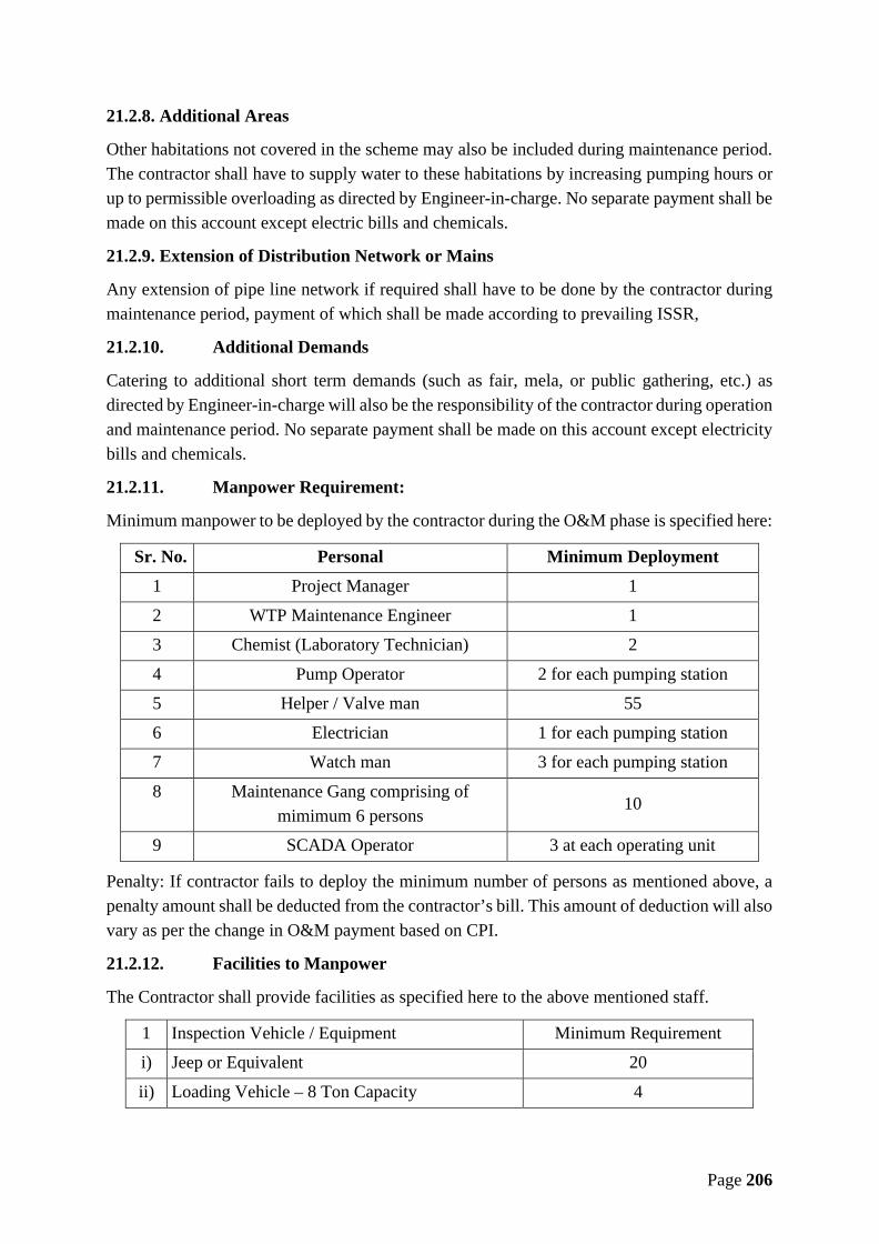
Page 206
21.2.8. Additional Areas
Other habitations not covered in the scheme may also be included during maintenance period.The contractor shall have to supply water to these habitations by increasing pumping hours orup to permissible overloading as directed by Engineer-in-charge. No separate payment shall bemade on this account except electric bills and chemicals.
21.2.9. Extension of Distribution Network or Mains
Any extension of pipe line network if required shall have to be done by the contractor duringmaintenance period, payment of which shall be made according to prevailing ISSR,
21.2.10. Additional Demands
Catering to additional short term demands (such as fair, mela, or public gathering, etc.) asdirected by Engineer-in-charge will also be the responsibility of the contractor during operationand maintenance period. No separate payment shall be made on this account except electricitybills and chemicals.
21.2.11. Manpower Requirement:
Minimum manpower to be deployed by the contractor during the O&M phase is specified here:
Sr. No. Personal Minimum Deployment1 Project Manager 1
2 WTP Maintenance Engineer 13 Chemist (Laboratory Technician) 2
4 Pump Operator 2 for each pumping station5 Helper / Valve man 55
6 Electrician 1 for each pumping station7 Watch man 3 for each pumping station
8 Maintenance Gang comprising ofmimimum 6 persons
10
9 SCADA Operator 3 at each operating unit
Penalty: If contractor fails to deploy the minimum number of persons as mentioned above, apenalty amount shall be deducted from the contractor’s bill. This amount of deduction will alsovary as per the change in O&M payment based on CPI.
21.2.12. Facilities to Manpower
The Contractor shall provide facilities as specified here to the above mentioned staff.
1 Inspection Vehicle / Equipment Minimum Requirementi) Jeep or Equivalent 20
ii) Loading Vehicle – 8 Ton Capacity 4

Page 207
iii) Small Canter or equivalent 4iv) JCB 4
v) Portable Welding Arrangements 22 Mobile Phones to all staff
3 Land Line Phone at each Pumping Station
21.2.12.1. Penalty: Deductions for not providing above facilities shall be as follows fromthe payments for Operations and Maintenance if O&M suffers and complaint rederessal is notdone in timely manner –
• Inspection Vehicle –o Jeep or Equivalent – INR 50,000/- per montho Loading Vehicle – 8 Ton Capacity – INR 60,000/- per montho Small Canter or equivalent – INR 40,000 per Month.o JCB – INR 50,000/- per month
• Mobile Phones – INR 1,000/- for each.• Land Line Phone - INR 1,000/- for each.
This amount of deduction shall also vary as per the change in O&M payment based on CPI.
22.Aproved list of manufactures
The following manufacturers are recommended for manufacturing of the major items givenbelow. Where more than one manufacturer is listed the Contractor is free to choose betweenthem. For additional items, the Contractor is free to submit proposals for other manufacturersfrom time to time and the same shall be effective after approval by the Employer.
The Contractor may substitute alternative brand names for the major items given belowprovided that it demonstrates to the employer’s satisfaction that substitution is inevitable in theinterest of project and the alternative makes proposed by the Contractor are substantiallyequivalent or superior to the one recommended hereunder.
Note: The manufacturers empaneled in MPJN at any later stage shall also be eligible besideslisted below.
22.1. MPJN Empanelled Manufacturers
No. Item / Component Recommended makes
1 VT and Centrifugal Pumps Kirloskar/ Jyoti/ Mather+Platt/ WPIL/ Becon Weir/Flowmore Ltd., Gudgaon
2 Electric motors Kirloskar/ Jyoti/ Crompton Greaves/ ABB/ Marathon/BHEL/ Siemens/ Bharat Bijlee
3 Power TransformersABB/ Crompton Greaves/ Emco/ Siemens/ Shri RamSwitchgears Ltd./ Vardhman Electro-mech Pvt. Limited/Star Delta Transformers Limited.

Page 208
No. Item / Component Recommended makes
4 DI PipesElectrosteel (original registered make)/ Jindal/ Tata/Electrotherm/ Jai Balaji Industries/ Rashmi Metaliks/Shrikalahasthi Pipe/ Electro Steel Limited.
5 HDPE Pipes & specials
Reliance/ Duraline/ Jain Irrigation/ Sangir/ TimeTechnoplast/ Signet Industries/ ORI-Plast/ KatariaPlastics/ Kirti Industries/ The Supreme Industries/Makknow Industries/ Texmo Pipes and Products/ KisanIrrigations and Infrastructure/ Tufropes Pvt. Ltd./Appollo Pipes/ Vishal Pipes/ Vectus Industries/ ParixitIrrigation/ Sagar Polytechnic/ Nimbus Pipes/ GodavariPolymers/ Shree TNB Polymers Ltd/ VEEKAY PLAST/Miraj Pipes and Fittings Pvt. Ltd./Delight EnterprisesPvt. Ltd./ Kothari Agritech Pvt. Ltd./ Tijariya PolypipesLtd./ Kisan Mouldings Ltd./ tirupati Structurals Limited.
6
Sluice Valves / ScourValves/ Butterfly Valve/Non Return Valves/Kinetic Air Valves
Kirloskar/ IVC/ VAG/ IVI/ Fouress/ Sachdeva MetalWorks/ Jupiter Engineering Co/ G. M. Engineering Pvt.Ltd./ G. M. DALUI & SONS Pvt. Ltd./ R&D Multiples(Metal Cast) Pvt. Ltd./ Kartar Valves Pvt. Ltd./ ShivaIndustries/ R S Valves & Products/ Durga Valves Pvt.Ltd./ AVK Valves India Private Limited/ McWane IndiaPrivate Limited/ Sigma Flow Control India Limited.
7 Valve Actuators Auma/ Rotork/ Limitork
8Hydraulically operatedFlow cum Pressure controlvalves
VAG/ Darling-Muesco/ Singer
9 Zero Velocity Valve Vardhman Electromech/ Flownix valves10 Single faced Sluice Gates JASH/ VAG/ Kirloskar
11 Water Hammer ControlDevices Sureseal or equivalent
12 Electro-magnetic Flowmeters
Emerson/ Krohne Marshall/ Yokogawa/ Siemens/Endress +Hauser (India)/ ITRON India/ Nivo Controls
13
Electro-magnetic Flowmeters, Water Meter, ItemsFor Instrumation/Automation
Endress +Hauser (India) /ITRON India / Nivo Controls
14 Woltman type Bulk watermeters Zenner/ Itron/ Elster/ Minol
15
WTP equipement : Flashmixers, Clariflocculators,Flocculators, Rotatingbridge, Blowlers etc.
Triveni/ Shivpad/ Dorr-Oliver/ Voltas/ AdroitAssociates/ Imac Engineering/ Reliable Equipments/Hindustan Water Engineering Company/ TMVTINDUSTRIES PVT. LTD. (Blowers only)/ KPTIndustries (Blowers only)/ Kay International (Blowersonly)
16Single Faced SluiceGate/WTP equipement(Flash mixers,
GEO Miller/ Kay International

Page 209
No. Item / Component Recommended makesClariflocculators,Floculators, Rotatingbridge & ChlorinationEquipement's)
17
Chlorination equipment :Chlorinator, Chlorine leakdetector, Residual Chlorineanalyzer, Scrubber etc.
Pennwalt/ W&T/ Alldos/ ZION TECHNOLOGIES
18 DI / CI Fittings & specialsKiswok/ Electrosteel/ Kejriwal/ R.G. Industries/ KartarValves Pvt. Ltd./ Jindal SAW Limited/ ChandranchalEnterprises Pvt. Ltd./ Truform Techno Products Ltd.
19 Dismantling / Expansionjoints Anup Engg./ LoneStar/ Vedanta/ Precise
20
HDPE Fittings:(Compression fittings,Tapping Saddles,Electrofusion Couplers)
Kimplas/ George fischer/ Glynwed/ Frialen/ Trustlene/GPS/ Durafuse/ AL-AZIZ Plastics/ AIVA EngineeringPvt. Ltd./ Lesso Buildtech Pvt. Ltd./ Bentlay FittingsPvt. Ltd./ TEGA MUHENDISLIK SANAYi VETiCARET A. S. Turkey
21Float Valves to controloverflow from ESR's/GSR's
Shiva Industries
22 D. I. Double Flange Pipe Sachdeva Metal Works/ SRIKALHASTHI PIPES
23 Steel For Reinforcement
TATA/ RINL/ SAIL/Shri Bajrang Power and IspatLimited or Equivalent make of approved as Prime
Manufacturer by ministry of steel authority of india asannual report
Items for Instrumentation/ Automation
No. Item / Component Recommended makes
1 Programmable LogicControllers (PLC) Rockwell (Allen Bradly) / Siemens / Honeywell
2 Moulded Case Circuit Breaker(MCCB) Siemens / Schneider M.G. / Jyoti / L&T
3 Relay and Contactors Siemens/ Alstom/ Jyoti/ ABB/ L&T
4 Cables Tropodur/ Finolex/ Asian/ Gloster/ Incab/Universal/ Polycab
5 Panel Enclosures andConsoles Rittal/ President/ Cutler Hammer
6 Switch fuse Disconnector L&T FN Type/ Siemens 3 KL Type/ GEPC
7 Multi-Function EnergyMeters Enercon/ L&T/ SOCOMEC
8 Capacitor bank Crompton Greaves/ Khatau Junker/ Malde/ L&T9 Cable Termination kit Raychem/ Denson/ M-Seal10 Battery HBL NIFE/ Exide/ Amco

Page 210
No. Item / Component Recommended makes11 Battery Charger Chaabi Electrical/ Masstech
12 Ultrasonic Type LevelMeasurement Device
Endress+Hauser/ Krohne Marshall/ Hycontrol UK/Electronet
13 Pressure switch Indfoss/ Switzer/ Tag Process Instruments
14 Pressure gauge WAREE/ WIKA/ AN Instruments/ Guru/ Hitek/Electronet
15 Flow switch Switzer/ General Instrument/ Forbes Marshall
16 Pressure Transmitter Emerson / Foxbro / Druck / Endress – Hauser/ ABB/Honeywell Automation/ Electronet
17 Engineering cum Operatorwork Station IBM/ Compaq/ Dell
18 Local Supervisory Station IBM/ Compaq/ Dell19 HMI Software Wincc/ Rs View/ Monitorpro/ Intellution/ Indusoft20 Alarm Annunciator Minilec/ Peacon/ ICA/ APLAB/ Electronet21 Uninterruptible Power Supply HI-Real/ Pulse/ Tata Libert/ APC/ APLAB
22 Lightening Protection Unit MH Inst/ Crompton Greaves/ MTL/ Pepper & fuchs/Rittmeyer/ Cirprotec
23 Instruments & Control Cables Delton/ Asian/ Servel/ TCL/ Thermopad
24 Receiver Indicator/ Digitalpanel meter
Masibus/ Yokogawa/ Lectrotek/ NISHKO/ SaiTech/MTL INSTS/ Electronet
25 Conductivity level switch Pune techtrol/ SBEM/ Krohne Marshall/ EndressHauser India/ NIVO/ Electronet
26 SCADA System Mitsubishi Electric/ Schneider Electric
27 Computer (Servers &Workstation) HP-Compaq/ IBM/ Dell
28 Laptop HP/ Dell/ Sony/ Toshiba29 Printer Samsung/ HP/ CANNON
30 Multifunction power monitor MASIBUS/ L&T/ ENERCON/ SOCOMECH/SECURE/ DAE
31 Temperature Scanner SaiTech/ Masibus/ Nishko/ Lectrotek32 Analog Signal Multiplier MASIBUS/ Sai Tech/ MTL INSTS/ NISHKO33 Air conditioning Voltas/ Samsung/ Carrier/ Hitachi34 Furniture Godrej/ Ergo/ Featherlite
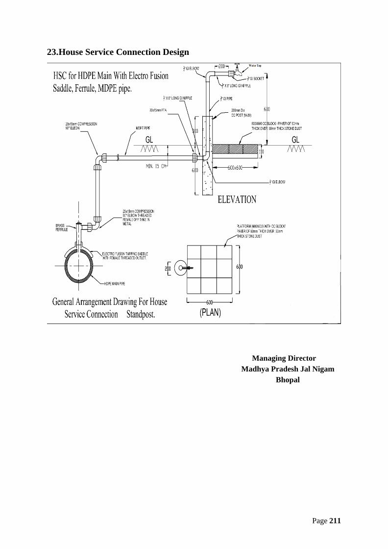
Page 211
23.House Service Connection Design
Managing DirectorMadhya Pradesh Jal Nigam
Bhopal
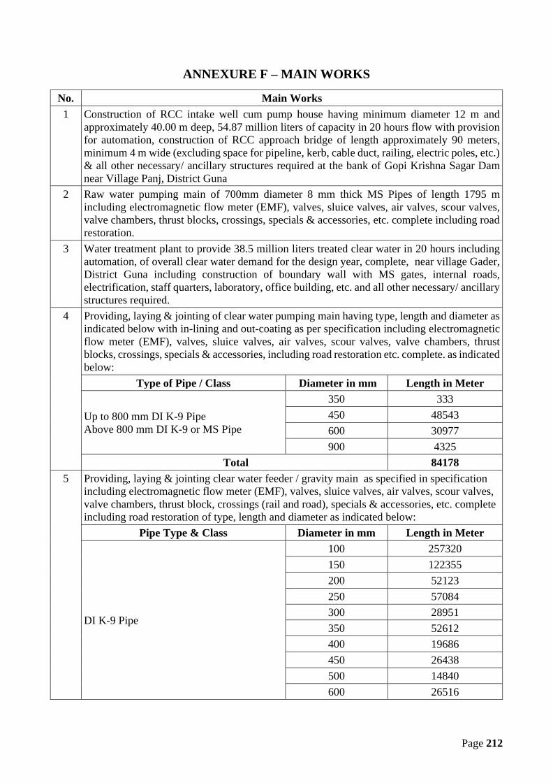
Page 212
ANNEXURE F – MAIN WORKS
No. Main Works1 Construction of RCC intake well cum pump house having minimum diameter 12 m and
approximately 40.00 m deep, 54.87 million liters of capacity in 20 hours flow with provisionfor automation, construction of RCC approach bridge of length approximately 90 meters,minimum 4 m wide (excluding space for pipeline, kerb, cable duct, railing, electric poles, etc.)& all other necessary/ ancillary structures required at the bank of Gopi Krishna Sagar Damnear Village Panj, District Guna
2 Raw water pumping main of 700mm diameter 8 mm thick MS Pipes of length 1795 mincluding electromagnetic flow meter (EMF), valves, sluice valves, air valves, scour valves,valve chambers, thrust blocks, crossings, specials & accessories, etc. complete including roadrestoration.
3 Water treatment plant to provide 38.5 million liters treated clear water in 20 hours includingautomation, of overall clear water demand for the design year, complete, near village Gader,District Guna including construction of boundary wall with MS gates, internal roads,electrification, staff quarters, laboratory, office building, etc. and all other necessary/ ancillarystructures required.
4 Providing, laying & jointing of clear water pumping main having type, length and diameter asindicated below with in-lining and out-coating as per specification including electromagneticflow meter (EMF), valves, sluice valves, air valves, scour valves, valve chambers, thrustblocks, crossings, specials & accessories, including road restoration etc. complete. as indicatedbelow:
Type of Pipe / Class Diameter in mm Length in Meter
Up to 800 mm DI K-9 PipeAbove 800 mm DI K-9 or MS Pipe
350 333450 48543600 30977900 4325
Total 841785 Providing, laying & jointing clear water feeder / gravity main as specified in specification
including electromagnetic flow meter (EMF), valves, sluice valves, air valves, scour valves,valve chambers, thrust block, crossings (rail and road), specials & accessories, etc. completeincluding road restoration of type, length and diameter as indicated below:
Pipe Type & Class Diameter in mm Length in Meter
DI K-9 Pipe
100 257320150 122355200 52123250 57084300 28951350 52612400 19686450 26438500 14840600 26516

Page 213
No. Main WorksTotal 657925
6 a) Construction of 160 numbers RCC overhead service reservoirs at different villages offollowing capacity and staging of minimum 12m or as per design to maintain the requiredminimum residual pressure of 7 m at consumer end including provision of Electromagneticflow (EMF) meters at each reservoir including compound wall with MS Gate & Approachroad, electrification etc. complete with 25 Sqm room.
S. No. Capacity in KL Quantity in Nos.1 100 782 110 113 120 124 130 115 140 56 150 57 160 128 170 49 180 310 190 311 200 212 210 113 230 214 250 215 270 316 280 117 340 118 360 119 440 120 470 121 500 1
Total 160
b) Construction of RCC Clear Water Sump cum pump houses having following capacity withtwin compartments including provision of electromagnetic flow (EMF) meters at eachreservoir including barbed wire fencing with MS gate & approach road, electrification etc.complete with 25 Sqm room.
i. Clear Water Sump at WTP Site – 1900 KLii. Clear Water Sump at PS -1at Bamhori – 1400 KL
c) Construction of 3 RCC OHMBR with following capacity and approx staging includingprovision of Electromagnetic flow (EMF) meters at each reservoir including Barbed wirefencing with MS Gate & Approach road, electrification etc. complete with 25 Sqm room.
i. Clear Water OHMBR at Bamhori– 340 KL, 26 M Stagingii. Clear Water OHMBR at Kahairar– 590 KL, 7 M Stagingiii. Clear Water OHMBR at Pachora– 940 KL, 7 M Staging
Note:

Page 214
No. Main WorksAll MBR/ BPT/ IPS/ WTP shall have boundary wall as defined in bid document but all ESRs/GSRs shall have G.I. chain link fabric fencing of mesh size 25x25mm made of G.I. wire of 3mm diameter including strengthening with welding or nuts, bolt & washers etc. complete. Itshall have ISA 50x50x5mm angle iron post at a spacing 2.5 m center to center of height 2mabove ground level embedded in M20 cement concrete 30x30 cm pillar minimum 75cm belowground level. Every 7th post & corners shall be strutted with similar specification angle iron& grouting. The top & bottom of chain link as well as on angle a 25x3mm flat secured witheither weld or rivets or bolts, to make fencing safer, shall be provided. It shall have angle irongate of size 3.0m x 1.8m having ISA 50x50x5mm angle iron & 16mm diameter plain M.S. barincluding AL drop, holdfast etc. and shall be fixed up in 45x45 cm wide R.C.C. pillars. Anadditional gate of size 0.6mx1.5m shall also be provided within the same gate, to avoidopening of bigger gate all the time & it shall be made of IS 40x40x5mm angle iron with ALdrop, etc.The CW sump cum pump houses and GLBR/ MBR/ BPT will have 2m high boundary wallwith ‘Y’ shape angle iron with 2*3 rows of wire bed, wire fencing at top of boundary wall andgate, one room set of area 25sqm size with W.C. & bathroom, automation system andelectrification with area lighting, etc. complete.The size of fencing or boundary wall shall be 20x20m including gate for these structures & ifit increases or decreases then accordingly variation shall be paid or deducted as per UADDISOR w.e.f. 1st May 2012 (with up to date amendments).One room set of minimum area 25 sqm size with W.C. & bathroom and housing of automationsystem and solar/ single phase electrification with area lighting, landscaping, plantation, etc.complete.The approach road for the MBR, OHSR, etc. shall be of approx. 30 m for each location. Anyalteration to the total length of approach roads considering all structures shall be paid ordeducted as per the MPPWD SOR w.e.f. 29th August 2017 (with up to date amendments).The length of the approach road shall be finalized by the Engineer-in-Charge.
7 Distribution network for length and diameter as indicated below comprising of HDPE, PE100PN6 (minimum) pipelines including Bulk water meters for every village, valves, specials,HSC and other allied works etc. complete.a. 90 mm dia. minimum 6 kg/cm2 pressure - 809159 meterb. 110 mm dia. minimum 6 kg/cm2 pressure - 107855 meterc. 140 mm dia. minimum 6 kg/cm2 pressure - 131547 meterd. 160 mm dia. minimum 6 kg/cm2 pressure - 45737 metere. 180 mm dia. minimum 6 kg/cm2 pressure - 43256 meterf. 200 mm dia. minimum 6 kg/cm2 pressure - 3814 meterg. 250 mm dia. minimum 6 kg/cm2 pressure - 9318 meterh. 280 mm dia. minimum 6 kg/cm2 pressure - 1554 meter
Sub Total - 11,52,240 meterHDPE & DI Pipe line including valves, sluice valves, air valves, scour valves, bulk watermeters for all villages, with protection chambers, thrust block, specials & accessories, etc.complete including road restoration.
8 (a) Pumping equipment including suitable motors, protection equipment for following-Providing and installation of suitable energy efficient deep well vertical turbine pumps for rawwater at intake well cum pump house including automation as under:(i) 4 No. pumps – 2 working of 216 lps discharge each and 2 standby of 108 lps dischargeeach and approx. 49 m headThe pumps given above are inclusive of standby pumps (50% standby)
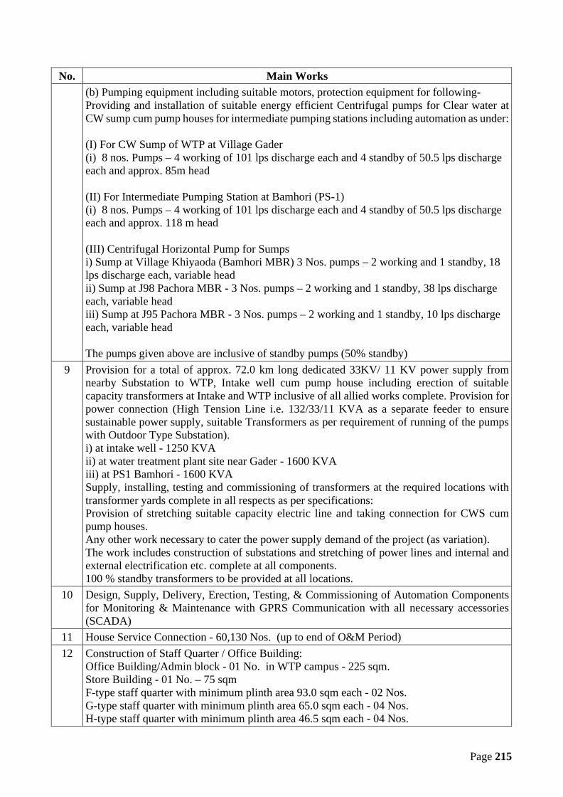
Page 215
No. Main Works(b) Pumping equipment including suitable motors, protection equipment for following-Providing and installation of suitable energy efficient Centrifugal pumps for Clear water atCW sump cum pump houses for intermediate pumping stations including automation as under:
(I) For CW Sump of WTP at Village Gader(i) 8 nos. Pumps – 4 working of 101 lps discharge each and 4 standby of 50.5 lps dischargeeach and approx. 85m head
(II) For Intermediate Pumping Station at Bamhori (PS-1)(i) 8 nos. Pumps – 4 working of 101 lps discharge each and 4 standby of 50.5 lps dischargeeach and approx. 118 m head
(III) Centrifugal Horizontal Pump for Sumpsi) Sump at Village Khiyaoda (Bamhori MBR) 3 Nos. pumps – 2 working and 1 standby, 18lps discharge each, variable headii) Sump at J98 Pachora MBR - 3 Nos. pumps – 2 working and 1 standby, 38 lps dischargeeach, variable headiii) Sump at J95 Pachora MBR - 3 Nos. pumps – 2 working and 1 standby, 10 lps dischargeeach, variable head
The pumps given above are inclusive of standby pumps (50% standby)9 Provision for a total of approx. 72.0 km long dedicated 33KV/ 11 KV power supply from
nearby Substation to WTP, Intake well cum pump house including erection of suitablecapacity transformers at Intake and WTP inclusive of all allied works complete. Provision forpower connection (High Tension Line i.e. 132/33/11 KVA as a separate feeder to ensuresustainable power supply, suitable Transformers as per requirement of running of the pumpswith Outdoor Type Substation).i) at intake well - 1250 KVAii) at water treatment plant site near Gader - 1600 KVAiii) at PS1 Bamhori - 1600 KVASupply, installing, testing and commissioning of transformers at the required locations withtransformer yards complete in all respects as per specifications:Provision of stretching suitable capacity electric line and taking connection for CWS cumpump houses.Any other work necessary to cater the power supply demand of the project (as variation).The work includes construction of substations and stretching of power lines and internal andexternal electrification etc. complete at all components.100 % standby transformers to be provided at all locations.
10 Design, Supply, Delivery, Erection, Testing, & Commissioning of Automation Componentsfor Monitoring & Maintenance with GPRS Communication with all necessary accessories(SCADA)
11 House Service Connection - 60,130 Nos. (up to end of O&M Period)12 Construction of Staff Quarter / Office Building:
Office Building/Admin block - 01 No. in WTP campus - 225 sqm.Store Building - 01 No. – 75 sqmF-type staff quarter with minimum plinth area 93.0 sqm each - 02 Nos.G-type staff quarter with minimum plinth area 65.0 sqm each - 04 Nos.H-type staff quarter with minimum plinth area 46.5 sqm each - 04 Nos.

Page 216
No. Main WorksI-type staff quarter with minimum plinth area 32.5 sqm each - 16 Nos.Office Building of 400 sqm at place directed by MPJN
13 Operation & Maintenance of the Whole Scheme for first yearThe Operation and Maintenance cost for the first year, in terms of percentage of contractAmount is given in Annexure H.For every subsequent year, the first-year percentage rates will be increased / decreasedaccording to the percentage change in consumer price index issued by Labour Bureau, GOI(All Industrial Worker) for that period. The index on the date of completion of trial run periodwill be treated as base for calculation of percentage point increase/decrease in O&M cost ofnext year. Payment of O&M will be made quarterly.Note:a. The operation & maintenance period is 10 years from the date of completion of three
months of trial run after successful commissioning of the project.b. The cost of energy charges (excluding penalties) shall be paid by MPJN on reimbursement
basis.c. Energy Requirement: The estimation for yearly consumption of energy is 1,71,06,488
kwH (Unit) for design period. The estimate will be finalized based on the equipmentinstalled as per the approved design. For intermediate years, payment will be made on prorata / calculation basis.
d. If due to any reasons, whatsoever it is desired to supply water in some of the villages beforefinal commissioning and trial run, then the pro-rata rates derived from the Annexure Hshall be applicable for the part payment on the basis of duration and quantity supplied, butthe date of commissioning of whole work shall be applicable from the dates as stipulatedin this contract.
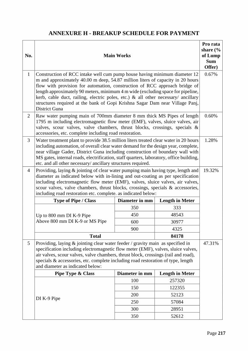
Page 217
ANNEXURE H - BREAKUP SCHEDULE FOR PAYMENT
No. Main Works
Pro ratashare (%of Lump
SumOffer)
1 Construction of RCC intake well cum pump house having minimum diameter 12m and approximately 40.00 m deep, 54.87 million liters of capacity in 20 hoursflow with provision for automation, construction of RCC approach bridge oflength approximately 90 meters, minimum 4 m wide (excluding space for pipeline,kerb, cable duct, railing, electric poles, etc.) & all other necessary/ ancillarystructures required at the bank of Gopi Krishna Sagar Dam near Village Panj,District Guna
0.67%
2 Raw water pumping main of 700mm diameter 8 mm thick MS Pipes of length1795 m including electromagnetic flow meter (EMF), valves, sluice valves, airvalves, scour valves, valve chambers, thrust blocks, crossings, specials &accessories, etc. complete including road restoration.
0.60%
3 Water treatment plant to provide 38.5 million liters treated clear water in 20 hoursincluding automation, of overall clear water demand for the design year, complete,near village Gader, District Guna including construction of boundary wall withMS gates, internal roads, electrification, staff quarters, laboratory, office building,etc. and all other necessary/ ancillary structures required.
1.28%
4 Providing, laying & jointing of clear water pumping main having type, length anddiameter as indicated below with in-lining and out-coating as per specificationincluding electromagnetic flow meter (EMF), valves, sluice valves, air valves,scour valves, valve chambers, thrust blocks, crossings, specials & accessories,including road restoration etc. complete. as indicated below:
19.32%
Type of Pipe / Class Diameter in mm Length in Meter
Up to 800 mm DI K-9 PipeAbove 800 mm DI K-9 or MS Pipe
350 333450 48543600 30977900 4325
Total 841785 Providing, laying & jointing clear water feeder / gravity main as specified in
specification including electromagnetic flow meter (EMF), valves, sluice valves,air valves, scour valves, valve chambers, thrust block, crossings (rail and road),specials & accessories, etc. complete including road restoration of type, lengthand diameter as indicated below:
47.31%
Pipe Type & Class Diameter in mm Length in Meter
DI K-9 Pipe
100 257320150 122355200 52123250 57084300 28951350 52612

Page 218
No. Main Works
Pro ratashare (%of Lump
SumOffer)
400 19686450 26438500 14840600 26516
Total 6579256 a) Construction of 160 numbers RCC overhead service reservoirs at different
villages of following capacity and staging of minimum 12m or as per design tomaintain the required minimum residual pressure of 7 m at consumer endincluding provision of Electromagnetic flow (EMF) meters at each reservoirincluding compound wall with MS Gate & Approach road, electrification etc.complete with 25 Sqm room.
7.89%
S. No. Capacity in KL Quantity in Nos.1 100 782 110 113 120 124 130 115 140 56 150 57 160 128 170 49 180 310 190 311 200 212 210 113 230 214 250 215 270 316 280 117 340 118 360 119 440 120 470 121 500 1
Total 160

Page 219
No. Main Works
Pro ratashare (%of Lump
SumOffer)
b) Construction of RCC Clear Water Sump cum pump houses having followingcapacity with twin compartments including provision of electromagnetic flow(EMF) meters at each reservoir including barbed wire fencing with MS gate &approach road, electrification etc. complete with 25 Sqm room.
i. Clear Water Sump at WTP Site – 1900 KLii. Clear Water Sump at PS -1at Bamhori – 1400 KL
1.14%
c) Construction of 3 RCC OHMBR with following capacity and approx stagingincluding provision of Electromagnetic flow (EMF) meters at each reservoirincluding Barbed wire fencing with MS Gate & Approach road, electrification etc.complete with 25 Sqm room.
i. Clear Water OHMBR at Bamhori– 340 KL, 26 M Stagingii. Clear Water OHMBR at Kahairar– 590 KL, 7 M Stagingiii. Clear Water OHMBR at Pachora– 940 KL, 7 M Staging
0.18%
Note:All MBR/ BPT/ IPS/ WTP shall have boundary wall as defined in bid documentbut all ESRs/ GSRs shall have G.I. chain link fabric fencing of mesh size25x25mm made of G.I. wire of 3 mm diameter including strengthening withwelding or nuts, bolt & washers etc. complete. It shall have ISA 50x50x5mm angleiron post at a spacing 2.5 m center to center of height 2m above ground levelembedded in M20 cement concrete 30x30 cm pillar minimum 75cm below groundlevel. Every 7th post & corners shall be strutted with similar specification angleiron & grouting. The top & bottom of chain link as well as on angle a 25x3mmflat secured with either weld or rivets or bolts, to make fencing safer, shall beprovided. It shall have angle iron gate of size 3.0m x 1.8m having ISA50x50x5mm angle iron & 16mm diameter plain M.S. bar including AL drop,holdfast etc. and shall be fixed up in 45x45 cm wide R.C.C. pillars. An additionalgate of size 0.6mx1.5m shall also be provided within the same gate, to avoidopening of bigger gate all the time & it shall be made of IS 40x40x5mm angle ironwith AL drop, etc.The CW sump cum pump houses and GLBR/ MBR/ BPT will have 2m highboundary wall with ‘Y’ shape angle iron with 2*3 rows of wire bed, wire fencingat top of boundary wall and gate, one room set of area 25sqm size with W.C. &bathroom, automation system and electrification with area lighting, etc. complete.The size of fencing or boundary wall shall be 20x20m including gate for thesestructures & if it increases or decreases then accordingly variation shall be paid ordeducted as per UADD ISOR w.e.f. 1st May 2012 (with up to date amendments).One room set of minimum area 25 sqm size with W.C. & bathroom and housingof automation system and solar/ single phase electrification with area lighting,landscaping, plantation, etc. complete.The approach road for the MBR, OHSR, etc. shall be of approx. 30 m for eachlocation. Any alteration to the total length of approach roads considering allstructures shall be paid or deducted as per the MPPWD SOR w.e.f. 29th August2017 (with up to date amendments). The length of the approach road shall befinalized by the Engineer-in-Charge.

Page 220
No. Main Works
Pro ratashare (%of Lump
SumOffer)
7 Distribution network for length and diameter as indicated below comprising ofHDPE, PE100 PN6 (minimum) pipelines including Bulk water meters for everyvillage, valves, specials, HSC and other allied works etc. complete.a. 90 mm dia. minimum 6 kg/cm2 pressure - 809159 meterb. 110 mm dia. minimum 6 kg/cm2 pressure - 107855 meterc. 140 mm dia. minimum 6 kg/cm2 pressure - 131547 meterd. 160 mm dia. minimum 6 kg/cm2 pressure - 45737 metere. 180 mm dia. minimum 6 kg/cm2 pressure - 43256 meterf. 200 mm dia. minimum 6 kg/cm2 pressure - 3814 meterg. 250 mm dia. minimum 6 kg/cm2 pressure - 9318 meterh. 280 mm dia. minimum 6 kg/cm2 pressure - 1554 meter
Sub Total - 11,52,240 meterHDPE & DI Pipe line including valves, sluice valves, air valves, scour valves,bulk water meters for all villages, with protection chambers, thrust block, specials& accessories, etc. complete including road restoration.
12.89%
8 (a) Pumping equipment including suitable motors, protection equipment forfollowing-Providing and installation of suitable energy efficient deep well vertical turbinepumps for raw water at intake well cum pump house including automation asunder:(i) 4 No. pumps – 2 working of 216 lps discharge each and 2 standby of 108 lpsdischarge each and approx. 49 m headThe pumps given above are inclusive of standby pumps (50% standby)
0.26%
(b) Pumping equipment including suitable motors, protection equipment forfollowing-Providing and installation of suitable energy efficient Centrifugal pumps for Clearwater at CW sump cum pump houses for intermediate pumping stations includingautomation as under:
(I) For CW Sump of WTP at Village Gader(i) 8 nos. Pumps – 4 working of 101 lps discharge each and 4 standby of 50.5lps discharge each and approx. 85m head
(II) For Intermediate Pumping Station at Bamhori (PS-1)(i) 8 nos. Pumps – 4 working of 101 lps discharge each and 4 standby of 50.5lps discharge each and approx. 118 m head
(III) Centrifugal Horizontal Pump for Sumpsi) Sump at Village Khiyaoda (Bamhori MBR) 3 Nos. pumps – 2 working and 1standby, 18 lps discharge each, variable headii) Sump at J98 Pachora MBR - 3 Nos. pumps – 2 working and 1 standby, 38 lpsdischarge each, variable headiii) Sump at J95 Pachora MBR - 3 Nos. pumps – 2 working and 1 standby, 10 lpsdischarge each, variable head
1.30%

Page 221
No. Main Works
Pro ratashare (%of Lump
SumOffer)
The pumps given above are inclusive of standby pumps (50% standby)9 Provision for a total of approx. 72.0 km long dedicated 33KV/ 11 KV power
supply from nearby Substation to WTP, Intake well cum pump house includingerection of suitable capacity transformers at Intake and WTP inclusive of all alliedworks complete. Provision for power connection (High Tension Line i.e.132/33/11 KVA as a separate feeder to ensure sustainable power supply, suitableTransformers as per requirement of running of the pumps with Outdoor TypeSubstation).i) at intake well - 1250 KVAii) at water treatment plant site near Gader - 1600 KVAiii) at PS1 Bamhori - 1600 KVASupply, installing, testing and commissioning of transformers at the requiredlocations with transformer yards complete in all respects as per specifications:Provision of stretching suitable capacity electric line and taking connection forCWS cum pump houses.Any other work necessary to cater the power supply demand of the project (asvariation).The work includes construction of substations and stretching of power lines andinternal and external electrification etc. complete at all components.100 % standby transformers to be provided at all locations.
1.42%
10 Design, Supply, Delivery, Erection, Testing, & Commissioning of AutomationComponents for Monitoring & Maintenance with GPRS Communication with allnecessary accessories (SCADA)
1.50%
11 House Service Connection - 60,130 Nos. (up to end of O&M Period) 3.79%12 Construction of Staff Quarter / Office Building:
Office Building/Admin block - 01 No. in WTP campus - 225 sqm.Store Building - 01 No. – 75 sqmF-type staff quarter with minimum plinth area 93.0 sqm each - 02 Nos.G-type staff quarter with minimum plinth area 65.0 sqm each - 04 Nos.H-type staff quarter with minimum plinth area 46.5 sqm each - 04 Nos.I-type staff quarter with minimum plinth area 32.5 sqm each - 16 Nos.Office Building of 400 sqm at place directed by MPJN
0.45%
13 Operation & Maintenance of the Whole Scheme for first yearThe Operation and Maintenance cost for the first year, in terms of percentage ofcontract Amount is given in Annexure H.For every subsequent year, the first-year percentage rates will be increased /decreased according to the percentage change in consumer price index issued byLabour Bureau, GOI (All Industrial Worker) for that period. The index on the dateof completion of trial run period will be treated as base for calculation ofpercentage point increase/decrease in O&M cost of next year. Payment of O&Mwill be made quarterly.Note:
1.50%

Page 222
No. Main Works
Pro ratashare (%of Lump
SumOffer)
a. The operation & maintenance period is 10 years from the date of completionof three months of trial run after successful commissioning of the project.
b. The cost of energy charges (excluding penalties) shall be paid by MPJN onreimbursement basis.
c. Energy Requirement: The estimation for yearly consumption of energy is1,71,06,488 kwH (Unit) for design period. The estimate will be finalized basedon the equipment installed as per the approved design. For intermediate years,payment will be made on pro rata / calculation basis.
d. If due to any reasons, whatsoever it is desired to supply water in some of thevillages before final commissioning and trial run, then the pro-rata ratesderived from the Annexure H shall be applicable for the part payment on thebasis of duration and quantity supplied, but the date of commissioning ofwhole work shall be applicable from the dates as stipulated in this contract.

Page 223
Notes regarding Break up of Payment Schedule
1. component wise cost for payment will be assessed based on the percentage in the abovetable, and the price quoted by Contractor in its Financial Proposal.
2. Maintenance expenditures of only first year (excluding energy charges) shall be calculatedby the percentage as given in Sr. No. 13 from the Lump-sum offer given by the contractor.Based on the first year O&M charges, the percentage increase of further years shall beworked out as given above in Sr. No. 13.
3. Up to the quantities of DI/HDPE (component wise i.e. Raw Water, Clear Water,Distribution pipe line) pipes mentioned in Annexure - F & H, for any change in pipedia/class/length, there shall be no additional payment for excavation, refilling, layingjointing and restoration of road, etc. Only cost of pipe shall be adjusted in the contract priceaccording to the approved variation.
4. If overall length of pipes of DI/HDPE (component wise i.e. Raw Water, Clear Water,Distribution pipe line) increases or decreases from the above mentioned quantities inAnnexure – F & H, then the cost of complete works of providing, laying, jointing of thepipeline including excavation, refilling, restoration of road, civil works, etc. will be payableor recovered as the case may be as per valuation of work based on actual detailed item wisemeasurements of work done according to the approved variation.
5. It will be the responsibility of the contractor to provide safe and potable water at 55 lpcd asspecified in the Appendix-I for each individual consumer of the village. However, it willbe responsibility of the contractor to ensure that all the villages in the scheme area arecovered, and the scheme is designed in accordance with the specifications after theconfirmatory survey.
6. Percentage rates for boundary wall, approach roads required to be constructed are includedin civil works of that respective sub head.
7. Component wise break-up is given in the following annexures.

Page 224
ANNEXURE – H1
Break up of schedule of payment for the
Intake well cum pump house and Approach Bridge
S. No. On completion of item of work Percentagepayable of H1
Cumulativepercentage
payable of H1
1 After construction of coffer dam, excavation offoundation and casting of bed concrete. 5% of H1 5% of H1
2 After completing foundation and well stainingup-to discharge floor level. 35% of H1 40% of H1
3 After construction of R.C.C. approach bridge,approach road and discharge floor. 15% of H1 55% of H1
4After completing pump house up to roof slabwith bridge connecting jack well with intake,R.C.C. Duct conduit etc.
20% of H1 75% of H1
5 After fixing of inlet ports, valves, specials,gantry girder. 15% of H1 90% of H1
6 After finishing, testing and successful trial runof work. 5% of H1 95% of H1
7 After Bank protection/land scaping as per sitecondition 5% of H1 100% of H1

Page 225
ANNEXURE – H2
Break up of schedule of payment for the Raw Water Pumping Main
S.No. On completion of item of work Percentage
payableCumulative
percentage payable
1
On testing and supply at site actualquantities of in-lined and out-coated K-7,K-9 & MS pipes of specified diameters andlengths on pro-rata basis
60% 60%
2
On transportation of pipes, excavation oftrenches and construction of supportingstructures, laying, jointing and testing atsite, backfilling of pipe trenches on pro-ratabasis
10% 70%
3After road restoration or making surfacegood as same before construction on pro-rata basis
20% 90%
4 After successful testing and disinfection ofpipelines on pro-rata basis 5% 95%
5 After successful commissioning of pipelineson pro-rata basis 5% 100%
Notes:
1. It is to be noted by the bidder that at no point more than 50% of pipe length claimedunder previous invoice shall remain unlaid (up to point 2) before new invoice forsupply of pipe can be claimed.
2. It is to be noted that the invoice shall be of minimum value equal to 1% of contractamount.
3. To bring the pipes of different sizes at equal level, equivalent length is calculated bylength x nominal diameter in mm.

Page 226
ANNEXURE – H3
Break up schedule for payment for Water Treatment Plant
I. Percentage wise break-up of cost of civil and mechanical/Electrical works. The costof C.I./DI Pipes, valves, laboratory equipment and chemical and furniture should be includedas E/M work.
II. Percentage wise break-up of cost of individual units of civil work and items of E/Mwork.
III. Percentage cost at various stages of construction of individual units of civil work.
Based upon the above, payment shall be regulated as given hereunder: -
For civil works - 0.8 H3
For E&M works - 0.2 H3
(The cost of wash water pumps, air blowers, alum agitators, pre-sedimentation (if it isthere) and clarifloculator motors/agitators, C.I. pipes, valves, laboratory equipment andchemical and furniture should be included as E/M works)
IV. Civil work:
Unit wise share of civil work shall be as under -
No Units of Civil Work Percentagepayable
Cumulativepercentage payable
1 Cascade aerator / Inlet chamber 0.5% of 0.8 H3 0.5%
2 Flash Mixer with inlet channel 0.5% of 0.8 H3 1.0%
3 Pre-Settling tank and/orClariflocculator 22% of 0.8 H3 23%
4 Filters 22% of 0.8 H3 45%
5 Wash Water Tank 10% of 0.8 H3 55%
6 Administrative Block 10% of 0.8 H3 65%
7 Lab Building 3% of 0.8 H3 68%
8 Store Building 4% of 0.8 H3 72%
9 Clear Water Sump 15% of 0.8 H3 87%
10 Recycling arrangement 2% of 0.8 H3 89%
11 Pump house 5% of 0.8 H3 94%
12 Boundary wall, roads 1% of 0.8 H3 95%
13 Site development (land scaping andplantation), etc. 5% of 0.8 H3 100%
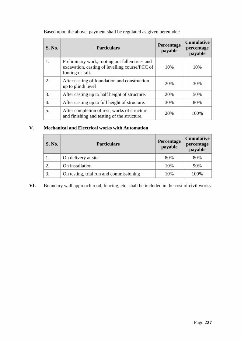
Page 227
Based upon the above, payment shall be regulated as given hereunder:
S. No. Particulars Percentagepayable
Cumulativepercentage
payable
1. Preliminary work, rooting out fallen trees andexcavation, casting of levelling course/PCC offooting or raft.
10% 10%
2. After casting of foundation and constructionup to plinth level 20% 30%
3. After casting up to half height of structure. 20% 50%
4. After casting up to full height of structure. 30% 80%
5. After completion of rest, works of structureand finishing and testing of the structure. 20% 100%
V. Mechanical and Electrical works with Automation
S. No. Particulars Percentagepayable
Cumulativepercentage
payable
1. On delivery at site 80% 80%
2. On installation 10% 90%
3. On testing, trial run and commissioning 10% 100%
VI. Boundary wall approach road, fencing, etc. shall be included in the cost of civil works.

Page 228
ANNEXURE – H4
Break up of schedule of payment for Clear Water Pumping Main
S.No. On completion of item of work Percentage
payable
Cumulativepercentage
payable
1
On testing and supply at site actual quantities ofin-lined and out-coated K-7, K-9 & MS pipesof specified diameters and lengths on pro-ratabasis
60% 60%
2
On transportation of pipes, excavation oftrenches and construction of supportingstructures, laying, jointing and testing at site,backfilling of pipe trenches on pro-rata basis
10% 70%
3 After road restoration or making surface goodas same before construction on pro-rata basis 20% 90%
4 After successful testing and disinfection ofpipelines on pro-rata basis 5% 95%
5 After successful commissioning of pipelines onpro-rata basis 5% 100%
Notes:
1. It is to be noted by the bidder that at no point more than 50% of pipe length claimedunder previous invoice shall remain unlaid (up to point 2) before new invoice forsupply of pipe can be claimed.
2. It is to be noted that the invoice shall be of minimum value equal to 1% of contractamount.
3. To bring the pipes of different sizes at equal level, equivalent length is calculated bylength x nominal diameter in mm.

Page 229
ANNEXURE – H5
Break up of schedule of payment for the Clear Water Trunk Mains
S.No. On completion of item of work Percentage
payableCumulative
percentage payable
1
On testing and supply at site actual quantitiesof in-lined and out-coated K-7, K-9 & MSpipes of specified diameters and lengths onpro-rata basis
60% 60%
2
On transportation of pipes, excavation oftrenches and construction of supportingstructures, laying, jointing and testing at site,backfilling of pipe trenches on pro-rata basis
10% 70%
3 After road restoration or making surface goodas same before construction on pro-rata basis 20% 90%
4 After successful testing and disinfection ofpipelines on pro-rata basis 5% 95%
5 After successful commissioning of pipelineson pro-rata basis 5% 100%
Notes:
1. It is to be noted by the bidder that at no point more than 50% of pipe length claimedunder previous invoice shall remain unlaid (up to point 2) before new invoice forsupply of pipe can be claimed.
2. It is to be noted that the invoice shall be of minimum value equal to 1% of contractamount.
3. To bring the pipes of different sizes at equal level, equivalent length is calculated bylength x nominal diameter in mm.

Page 230
ANNEXURE – H6a
CONSTRUCTION OF OVER HEAD TANKS (ESRs)
S.No. Particulars Percentage
payable
Cumulativepercentage
payable
1.Preliminary work, rooting out fallen trees andexcavation, casting of levelling course/PCC offooting or raft
10% 10% of H6a
2. After casting of foundation, columns up to andincluding ground bracing beams 10% 20% of H6a
3. After casting of full staging and columns up tobottom ring beam and staircase 10% 30% of H6a
4. After casting of bottom slab or dome includingwalkway slab or balcony 10% 40% of H6a
5. After casting of full vertical wall and top slab ordome 20% 60% of H6a
6.
After providing, fixing pipes and specials forinlet, over flow scour, outlet, bell mouths, grating,puddle collars, duck foot bends, sluice valves,Electromagnetic flow meter and their requiredchambers etc. complete.
10% 70% of H6a
7.
Providing arrangement for manhole covers, airvents & central ventilation, including railing forstaircase and roof top & After finishing andtesting of the structure, providing and fixing waterlevel indicator, lightening conductors, protectionwork, and all other works as given in tenderdocument. Painting as per specifications etc. allcomplete.
10% 80% of H6a
8. After commissioning of the overhead tank 10% 90% of H6a
9.Construction of 25 sqm. room set, electrificationwith area lighting, Automation and Boundary wallwith gate etc. complete.
10% 100% of H6a
NOTE: The value of pro rata share H6a is for all the tanks to be constructed as part of thescheme. For individual overhead tank, weighted share can be worked out.

Page 231
ANNEXURE – H6b
Clear Water sump cum pump house
S.No. Particulars Percentage
payable
Cumulativepercentage
payable
1. Preliminary work, rooting out fallen trees andexcavation, casting of levelling course/PCC offooting & casting of base slab.
10% 10% of H6b
2. After casting 50% tank wall and partition walls 15% 25% of H6b
3. After casting of full tank walls and partition walls 15% 40% of H6b
4. After casting top slab including arrangement formanhole covers, air vents & central ventilation,including casting of stair case, railing for staircaseand roof and complete construction of pump house(wherever applicable).
20% 60% of H6b
5. After providing, fixing pipes and specials for inlet,over flow scour, outlet, bell mouths, grating, puddlecollars, duck foot bends, sluice valves, sluice gates,Electromagnetic flow meter and their requiredchambers etc complete including installation ofpumps and making all internal electric connection(wherever applicable)
10% 70% of H6b
6. After finishing and testing of the structure,providing and fixing water level indicator,lightening conductors, air vent flow recorded,protection work, and all other works as given intender document. Painting as per specifications etc.all complete.
10% 80% of H6b
7. Construction of 25 sqm. room set, electrificationwith area lighting, Automation and Boundary wallwith gate etc. complete.
20% 100% of H6b
NOTE: The value of pro rata share H6b is for all the sump cum pump houses to be constructedas part of the scheme. For individual sump cum pump houses, weighted share can be workedout.

Page 232
ANNEXURE – H6c
CONSTRUCTION OF MBR
S.No. Particulars Percentage
payable
Cumulativepercentage
payable
1. Preliminary work, rooting out fallen trees andexcavation, casting of levelling course/PCC offooting or raft
10% 10% of H6c
2. After casting of foundation, columns up to andincluding ground bracing beams 10% 20% of H6c
3. After casting of full staging and columns up tobottom ring beam and staircase 10% 30% of H6c
4. After casting of bottom slab or dome includingwalkway slab or balcony 10% 40% of H6c
5. After casting of full vertical wall and top slab ordome 20% 60% of H6c
6. After providing, fixing pipes and specials forinlet, over flow scour, outlet, bell mouths, grating,puddle collars, duck foot bends, sluice valves,Electromagnetic flow meter and their requiredchambers etc. complete.
10% 70% of H6c
7. Providing arrangement for manhole covers, airvents & central ventilation, including railing forstaircase and roof top & After finishing andtesting of the structure, providing and fixing waterlevel indicator, lightening conductors, protectionwork, and all other works as given in tenderdocument. Painting as per specifications etc. allcomplete.
10% 80% of H6c
8. After commissioning of the overhead tank 10% 90% of H6c
9. Construction of 25 sqm. room set, electrificationwith area lighting, Automation and Boundary wallwith gate etc. complete.
10% 100% of H6c
NOTE: The value of pro rata share H6c is for all the MBRs to be constructed as part of thescheme. For individual MBRs, weighted share can be worked out.

Page 233
ANNEXURE – H7
DISTRIBUTION NETWORK
S. No. On completion of item of work Percentagepayable of H7
Cumulativepercentagepayable of H7
1
On testing and supply at site actual quantitiesof in-lined and out-coated K-7 & HDPEpipes of specified diameters and lengths onpro-rata basis
50% 50%
2
On transportation of pipes, excavation oftrenches and construction of supportingstructures, laying, jointing and testing at site,backfilling of pipe trenches on pro-rata basis
20% 70%
3After road restoration or making surfacegood as same before construction on pro-ratabasis
20% 90%
4 After successful testing and disinfection ofpipelines on pro-rata basis 5% 95%
5 After successful commissioning of pipelineson pro-rata basis 5% 100%
Notes:
1. It is to be noted by the bidder that at no point more than 50% of pipe length claimedunder previous invoice shall remain unlaid (up to point 2) before new invoice for supplyof pipe can be claimed.
2. It is to be noted that the invoice shall be of minimum value equal to 1% of contractamount
3. To bring the pipes of different sizes at equal level, equivalent length is calculated bylength x nominal diameter in mm.
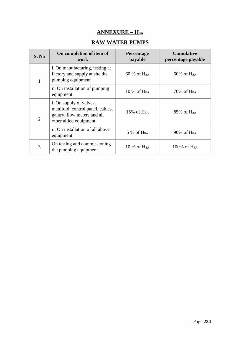
Page 234
ANNEXURE – H8A
RAW WATER PUMPS
S. No On completion of item ofwork
Percentagepayable
Cumulativepercentage payable
1
i. On manufacturing, testing atfactory and supply at site thepumping equipment
60 % of H8A 60% of H8A
ii. On installation of pumpingequipment 10 % of H8A 70% of H8A
2
i. On supply of valves,manifold, control panel, cables,gantry, flow meters and allother allied equipment
15% of H8A 85% of H8A
ii. On installation of all aboveequipment 5 % of H8A 90% of H8A
3 On testing and commissioningthe pumping equipment 10 % of H8A 100% of H8A

Page 235
ANNEXURE – H8B
CLEAR WATER PUMPS
S. No On completion of item ofwork
Percentagepayable
Cumulative percentagepayable
1i. On manufacturing, testing atfactory and supply at site thepumping equipment
60 % of H8B 60% of H8B
ii. On installation of pumpingequipment 10 % of H8B 70% of H8B
2
i. On supply of valves,manifold, control panel,cables, gantry, flow metersand all other allied equipment
15% of H8B 85% of H8B
ii. On installation of all aboveequipment 5 % of H8B 90% of H8B
3 On testing and commissioningthe pumping equipment 10 % of H8B 100% of H8B

Page 236
ANNEXURE – H9
33 KV/11 KV POWER LINE AND SUB STATION
S. No On completion of item of work Percentagepayable
Cumulativepercentage payable
1i. On manufacturing, testing and supplyat site the power cables, poles, wires,transformers, etc. all equipment
60 % of H9 60% of H9
ii. On installation of all above 20 % of H9 80% of H9
2 On getting approval as per I.E. rules fromElectrical Inspector 10% of H9 90% of H9
3 On testing and commissioning theelectric sub station 10 % of H9 100% of H9
Note:
1. The invoices for electrical line and transformers can be claimed on pro rata basis. Theweightage shall be worked out on basis of transformer capacity / electrical line length.
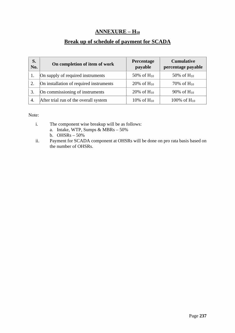
Page 237
ANNEXURE – H10
Break up of schedule of payment for SCADA
S.No. On completion of item of work Percentage
payableCumulative
percentage payable
1. On supply of required instruments 50% of H10 50% of H10
2. On installation of required instruments 20% of H10 70% of H10
3. On commissioning of instruments 20% of H10 90% of H10
4. After trial run of the overall system 10% of H10 100% of H10
Note:
i. The component wise breakup will be as follows:a. Intake, WTP, Sumps & MBRs – 50%b. OHSRs – 50%
ii. Payment for SCADA component at OHSRs will be done on pro rata basis based onthe number of OHSRs.
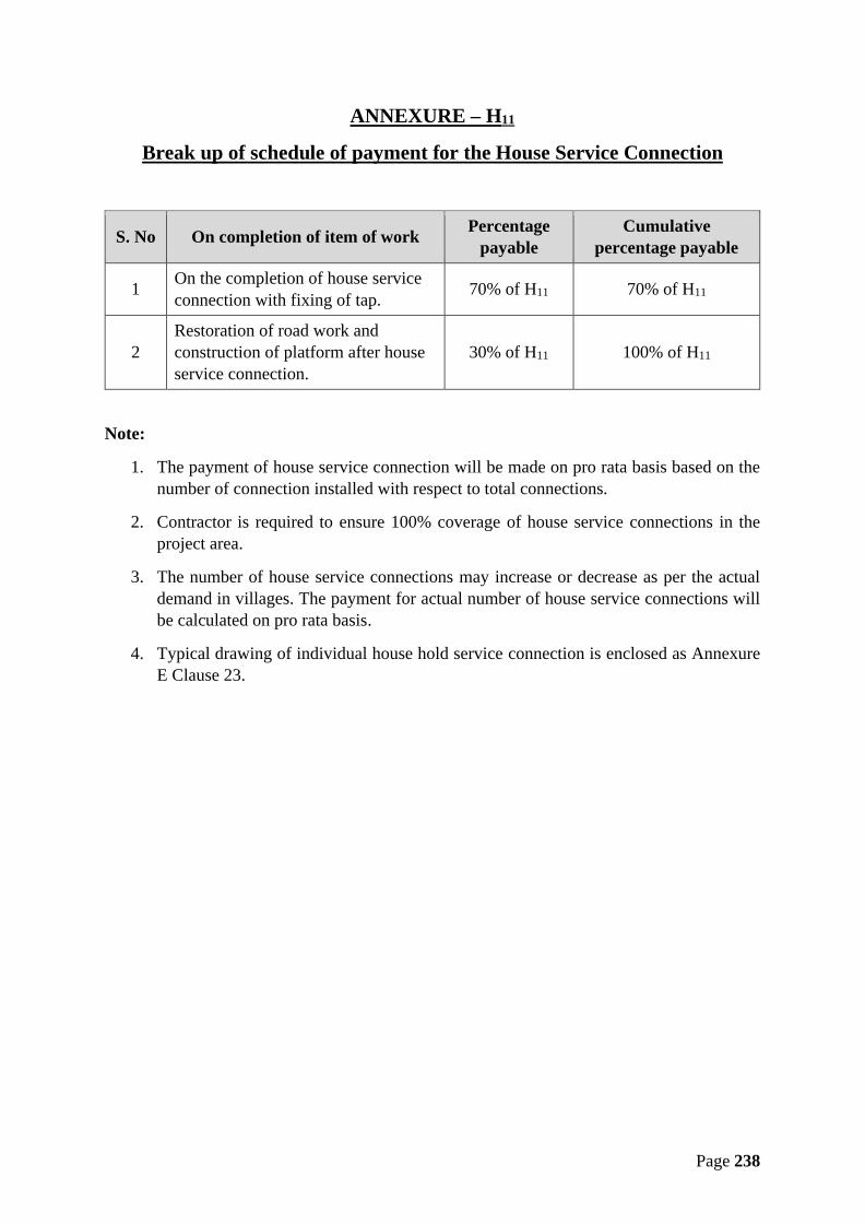
Page 238
ANNEXURE – H11
Break up of schedule of payment for the House Service Connection
S. No On completion of item of work Percentagepayable
Cumulativepercentage payable
1 On the completion of house serviceconnection with fixing of tap. 70% of H11 70% of H11
2Restoration of road work andconstruction of platform after houseservice connection.
30% of H11 100% of H11
Note:
1. The payment of house service connection will be made on pro rata basis based on thenumber of connection installed with respect to total connections.
2. Contractor is required to ensure 100% coverage of house service connections in theproject area.
3. The number of house service connections may increase or decrease as per the actualdemand in villages. The payment for actual number of house service connections willbe calculated on pro rata basis.
4. Typical drawing of individual house hold service connection is enclosed as AnnexureE Clause 23.
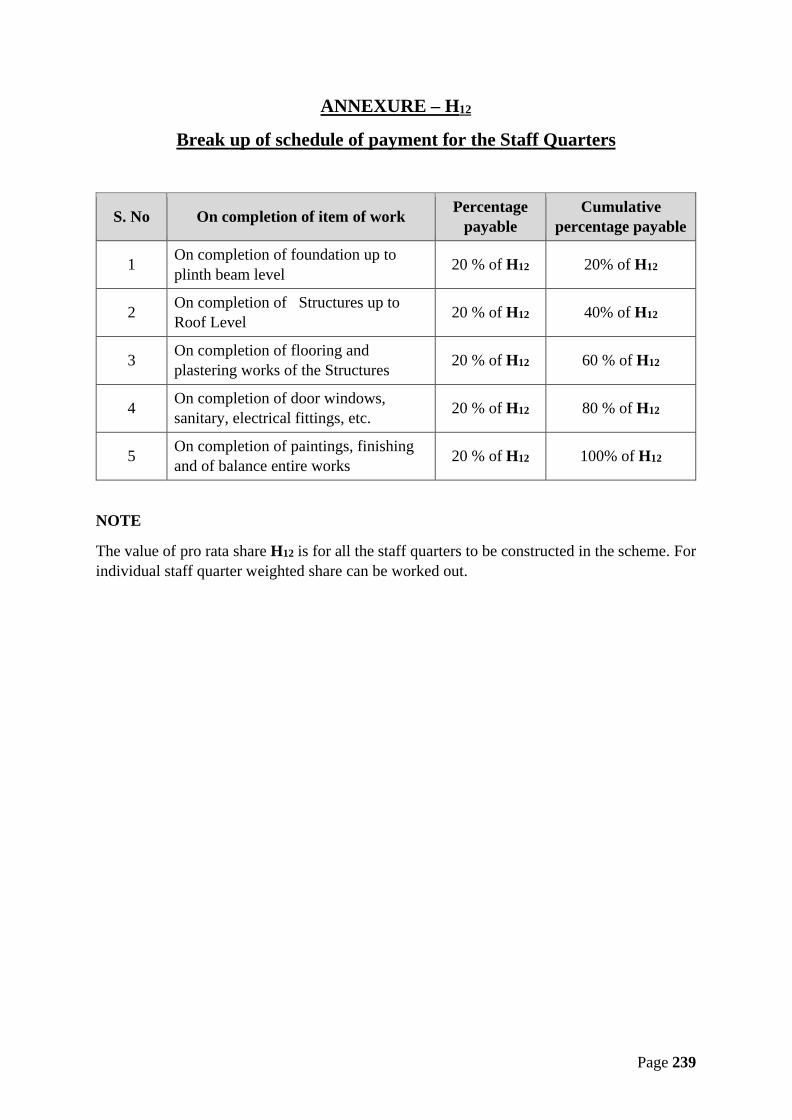
Page 239
ANNEXURE – H12
Break up of schedule of payment for the Staff Quarters
S. No On completion of item of work Percentagepayable
Cumulativepercentage payable
1 On completion of foundation up toplinth beam level 20 % of H12 20% of H12
2 On completion of Structures up toRoof Level 20 % of H12 40% of H12
3 On completion of flooring andplastering works of the Structures 20 % of H12 60 % of H12
4 On completion of door windows,sanitary, electrical fittings, etc. 20 % of H12 80 % of H12
5 On completion of paintings, finishingand of balance entire works 20 % of H12 100% of H12
NOTE
The value of pro rata share H12 is for all the staff quarters to be constructed in the scheme. Forindividual staff quarter weighted share can be worked out.

Page 240
ANNEXURE – H13
Break up of schedule of payment for the
OPERATION & MAINTENANCE
S. No. On completion of item of work Percentagepayable
Cumulativepercentage payable
1After three months of successful operationand maintenance of whole scheme aftercompletion of trial run
25% of H13 25% of H13
2After six months of successful operationand maintenance of whole scheme aftercompletion of trial run
25% of H13 50% of H13
3After nine months of successful operationand maintenance of whole scheme aftercompletion of trial run
25% of H13 75% of H13
4After one year of successful operation andmaintenance of whole scheme aftercompletion of trial run
25% of H13 100% of H13
NOTE:
a. The operation & maintenance period is 10 years from the date of completion of threemonths of trial run after successful commissioning of the project.
b. The cost of energy charges and consumable chemicals shall not be included in pro ratashare.
c. The value of H13 for subsequent years of O&M shall be assessed based on themethodology given in Annexure H.
d. If due to any reasons, whatsoever it is desired to supply water in some of the villagesbefore final commissioning and trial run, then the pro-rata rates derived from the abovetable shall be applicable for the part payment on the basis of duration and quantitysupplied, but the date of commissioning of whole work shall be applicable from thedates as stipulated in this contract.

Page 241
Appendix I
Population of Villages in the Scheme
No. Name of Village Block InitialPopulation
Population afterinitial 10 years
Population afternext 10 years i.e.
20 years1 Antar Soona Bamhori 1070 1340 16702 Chhapri Bamhori 260 420 7003 Bachhawada Bamhori 510 630 7704 Banskhedi Bamhori 650 820 10305 Endwara Bamhori 690 830 9906 Baksanpur Bamhori 400 510 6607 Suja Khedi Bamhori 940 1120 13508 Barru Khedi Bamhori 340 410 5009 Sekhapur Bamhori 670 810 98010 Berkhedi Bamhori 2100 2740 360011 Bhatodiya Bamhori 700 910 119012 Bilas Bamhori 390 480 60013 Kishangarh Bamhori 380 450 55014 Dudhai Bamhori 1050 1280 156015 Bisoniya Bamhori 1360 1680 207016 Vaneh Bamhori 1400 1710 209017 Chak Khurdon Bamhori 600 750 94018 Churela Bamhori 1030 1220 143019 Dumawan Bamhori 560 750 102020 Ukawad Kalan Bamhori 1180 1380 163021 Dongar Khedi Bamhori 440 520 62022 Gola Khedi Bamhori 1620 1970 240023 Rihana Bamhori 590 790 105024 Khadakpur Bamhori 1060 1420 191025 Goriya Bamhori 340 400 47026 Bhonra (Rampur) Bamhori 1270 1500 176027 Suhaya Bamhori 1420 1710 204028 Jhagar Bamhori 2290 2720 323029 Ukawad Khurd Bamhori 830 1010 123030 Silawati (Rampur) Bamhori 1370 1720 216031 Shyampur Bamhori 610 730 87032 Papawan Bamhori 190 230 29033 Sabra Pahad Bamhori 540 740 103034 Am Kheda Bamhori 600 720 880

Page 242
No. Name of Village Block InitialPopulation
Population afterinitial 10 years
Population afternext 10 years i.e.
20 years35 Khejra Baba Bamhori 1280 1490 174036 Chak Vishvanagar Bamhori 1120 1300 151037 Modka Bamhori 640 760 90038 Dhadhan Khedi Bamhori 1590 1890 225039 Moi Bamhori 890 1070 128040 Parwah Bamhori 2740 3160 363041 Chak Piplya Bamhori 30 40 5042 Brija Bamori Bamhori 80 110 15043 Piplya Bamhori 510 600 70044 Barodiya Kalan Bamhori 570 680 80045 Patna Bamhori 730 880 106046 Muradpur Bamhori 2950 3750 478047 Samar Singa Bamhori 1630 1970 240048 Sawaramodi Bamhori 1300 1630 205049 Poru Khedi Bamhori 820 1050 137050 Ratnagir Bamhori 1190 1470 181051 Mundra Hanuman Bamhori 1800 2160 260052 Kanari Bamhori 480 580 71053 Hirnoda Bamhori 100 120 16054 Kontar Bamhori 700 830 97055 Binda Khedi Bamhori 360 450 58056 Mali (Khiyaoda) Bamhori 220 280 34057 Khiyaoda Bamhori 430 510 60058 Borkheda Dang Bamhori 380 500 66059 Bamori Khurd Bamhori 330 390 47060 Pathriya Bamhori 300 360 430
61 Bhura Khedi(Churela) Bamhori 770 960 1190
62 Kanera Bamhori 170 200 25063 Imaliya Bamhori 950 1110 130064 Kanchanpura Bamhori 510 630 76065 Bilakhedi Bamhori 510 680 920
66 Dhanoriya(Dhanoriya) Bamhori 1280 1560 1910
67 Mahoogarha Guna 1170 1470 186068 Dholwaj Guna 700 850 105069 Garha Guna 3810 5720 895070 Madhopura Guna 110 150 220

Page 243
No. Name of Village Block InitialPopulation
Population afterinitial 10 years
Population afternext 10 years i.e.
20 years71 Haripur Guna 2390 2990 375072 Barodiya Khurd Guna 760 940 117073 Khas Kheda Guna 480 600 76074 Kisanpur Barkui Bamhori 250 360 52075 Salaiya Rai Bamhori 620 830 115076 Dehri (Bamori) Bamhori 970 1240 160077 Barkheda (Bamori) Bamhori 550 710 92078 Bishnwada Bamhori 2610 3030 352079 Dongri Bamhori 1270 1770 250080 Patan Bamhori 810 950 1120
81 Bans Khedi(Rampur) Bamhori 1410 1680 2000
82 Saretha Bamhori 150 180 21083 Gadlamar Bamhori 260 360 49084 Vithalpur Bamhori 760 920 112085 Gehun Kheda Bamhori 560 730 96086 Nagphani Saliya Bamhori 720 870 105087 Gopalpur Bamhori 550 760 107088 Bhotupura Bamhori 1020 1290 163089 Bagoniya Guna 1000 1470 223090 Rai Guna 1140 1450 185091 Tanda Guna 1110 1930 357092 Bandha Guna 690 920 122093 Chak Hanumatpura Guna 370 440 54094 Bheron Ghhati Guna 1370 1740 222095 Biloniya Guna 2050 2530 315096 Pura Posar Guna 2070 2520 306097 Sumer (Pura Posar) Guna 370 530 770
98 Marethiya AliasSala Kh Guna 70 90 130
99 Binkhyai Guna 720 840 980100 Bhidra Guna 720 1000 1420101 Banna Kheda Guna 1130 1490 1980102 Piprodi Guna 190 260 340103 Kotra Guna 250 370 540104 Porkho Guna 380 500 650105 Madai Guna 640 850 1130106 Chak Porkho Guna 170 240 360

Page 244
No. Name of Village Block InitialPopulation
Population afterinitial 10 years
Population afternext 10 years i.e.
20 years107 Chidrau Guna 240 300 380108 Jamdera Guna 390 540 790109 Tarapur Guna 810 1340 2330110 Chentbari Guna 380 530 740111 Dinola Guna 590 730 900112 Nakatpur Guna 490 640 850113 Chhinaira Guna 110 160 270114 Karili Guna 1020 1540 2430115 Mehra Guna 70 90 110116 Deogarh Guna 1050 1620 2600117 Fatehpur Guna 350 390 440118 Padura Guna 120 180 270119 Khargpur Guna 640 820 1040120 Dudhoniya Guna 50 60 90
121 Mamata-AliasGanesh Kheda Guna 300 360 450
122 Ganeshkheda Guna 350 460 620123 Badera Guna 790 1050 1410124 Akloun Guna 500 640 820
125 Hanumat Kheda(Sirsi) Guna 620 850 1200
126 Dhamkan Guna 140 180 220127 Tajpur (Bhidra) Guna 150 200 290128 Hathi Khudam Guna 590 880 1340129 Kilampur Guna 570 710 890130 Kalchheri Guna 770 1040 1420131 Hastnapur Guna 210 310 480132 Kheri Khata Guna 1800 2520 3590133 Mahodra Guna 2380 3090 4060134 Ratanpur Guna 560 730 940135 Makraudi Guna 360 590 1000136 Makrawada Guna 790 950 1150137 Marki Mahu Guna 3730 4760 6100138 Ladakheda Guna 510 610 740139 Barkheda (Sirsi) Guna 440 570 750140 Nagda Guna 750 930 1160141 Laldant Guna 10 10 20142 Nehgawan Guna 1310 1610 1970

Page 245
No. Name of Village Block InitialPopulation
Population afterinitial 10 years
Population afternext 10 years i.e.
20 years143 Biroli Guna 600 790 1040144 Biloda (Bhadora) Guna 580 810 1170145 Patana (Bhadora) Guna 420 530 680146 Chak Deopur Guna 680 810 940147 Kandhai Guna 260 400 650148 Deopur Guna 1060 1360 1760149 Pipal Khedi (Umri) Guna 330 480 700150 Barodiya (Sirsi) Guna 510 610 750151 Pipriya (Sirsi) Guna 1050 1410 1910152 Piproda Khurd Guna 6310 8750 12290153 Ajit Kheda Guna 250 340 450154 Rehpura Guna 940 1230 1610155 Sakatpur Guna 3100 4330 6120156 Sandkheda Guna 1080 1250 1440157 Sanwada Guna 1130 1360 1630158 Chandan Bhent Guna 280 390 540159 Mali (Umri) Guna 410 570 800160 Bawarauda Guna 1030 1370 1820
161 MiyanwalijhiriyaAlias Nayagaon Guna 210 250 310
162 Sartala Guna 480 710 1060
163 Nayagaon AliasParonda Guna 870 1300 2000
164 Sighhariya Guna 190 230 270165 Sirsi Guna 1710 2200 2850166 Suator Guna 1610 2170 2960167 Agara Guna 760 980 1270168 Jhiroli Guna 300 380 500169 Tajpur (Agara) Guna 230 370 640170 Karke Ki Mahu Guna 880 1290 1950171 Berkhedi (Sirsi) Guna 370 480 620172 Tilwara Guna 410 510 640173 Hanumatpura Guna 80 100 130174 Gopalpura (Umri) Guna 670 930 1290175 Umri Guna 3910 4730 5740176 Amrohi Guna 1180 1880 3100177 Jalampur Guna 1110 1540 2180178 Chilkheda Guna 70 100 150

Page 246
No. Name of Village Block InitialPopulation
Population afterinitial 10 years
Population afternext 10 years i.e.
20 years179 Bhawpur Guna 340 430 550180 Raniganj Guna 620 750 920181 Mangwar Guna 760 900 1060182 Sangai Guna 320 430 590183 Udaipri Guna 1020 1580 2520184 Ari Guna 860 1060 1320185 Mohanpur Kalan Guna 260 310 370186 Dastoli Ber Guna 620 770 960187 Dastoli Ghhat Guna 420 530 680188 Baheriya Guna 190 220 250189 Hansli Guna 420 650 1060190 Piproda Guna 200 260 330191 Khiriya (Sirsi) Guna 240 330 460192 Ikodiya Guna 760 920 1110193 Budera Guna 150 180 230194 Saloda Guna 310 410 560195 Barbatu Guna 220 290 380196 Atakhedi Guna 200 220 250197 Gadariya Kondar Guna 610 740 890198 Kherar Kheda Guna 290 380 500199 Musredi Guna 710 980 1370200 Sherpur Guna 230 300 410201 Naghera Guna 560 700 890202 Bharatpur Guna 160 220 310203 Karnawata Guna 480 670 960204 Badi Kanthi Guna 260 350 500205 Chhoti Kanthi Guna 450 580 750206 Chak Sakatpura Guna 670 880 1150207 Banskhedi (Sirsi) Guna 420 520 650208 Chandera Guna 260 340 460209 Ganeshpura Guna 700 880 1110210 Majhola Guna 560 690 840211 Ratanpura (Umri) Guna 470 600 760212 Rajela Guna 190 230 280213 Kusun Khoh Bamhori 580 790 1070214 Theuwa Bamhori 640 810 1050215 Amrod Bamhori 2180 2800 3620216 Semra Bamhori 410 580 840

Page 247
No. Name of Village Block InitialPopulation
Population afterinitial 10 years
Population afternext 10 years i.e.
20 years217 Bindarada Bamhori 120 170 220218 Pathi Bamhori 890 1060 1280219 Anapura Bamhori 360 450 560220 Dibiya Manpur Bamhori 910 1210 1620221 Kakarua Dang Bamhori 360 470 610222 Ata Khedi Bamhori 950 1340 1930223 Rahraun Bamhori 100 120 160224 Baghuriya Bamhori 1390 1840 2450225 Bagheri Bamhori 760 930 1150226 Prayagpur Bamhori 150 190 230227 Bamori Bamhori 6420 8120 10310228 Baniyani Bamhori 1070 1310 1600229 Kohan Bamhori 590 720 890230 Chaklonda Bamhori 1110 1360 1680231 Umrdha Bamhori 600 740 930232 Baniyani (Padon) Bamhori 640 790 970233 Doharda Bamhori 600 750 950234 Paranth Bamhori 2070 2550 3150235 Kharra Kheda Bamhori 930 1100 1290236 Baraudiya (Bamori) Bamhori 1210 1440 1730237 Barwan Bamhori 1470 1880 2400238 Simrod Bamhori 2670 3640 5030239 Bhaupura Bamhori 510 790 1270240 Fatehgarh Bamhori 5600 8090 11970241 Akoda Bamhori 1390 1770 2270242 Badanpur Bamhori 340 430 560243 Bhensatori Bamhori 390 540 770244 Bhidra Bamhori 1430 1880 2510245 Gadala Ujari Bamhori 2030 2490 3070246 Bhumra Khedi Bamhori 340 420 520247 Ajronda Bamhori 1220 1530 1920248 Gankar Kheda Bamhori 550 770 1120
249 Bhura Khedi (BhuraKhedi) Bamhori 1010 1240 1520
250 Magroda Bamhori 4010 5060 6420251 Semrakheda Bamhori 450 580 760252 Viroli (Padon) Bamhori 860 1300 2030253 Kishanpura Bamhori 900 1120 1400

Page 248
No. Name of Village Block InitialPopulation
Population afterinitial 10 years
Population afternext 10 years i.e.
20 years254 Chak Parsikheda Bamhori 630 820 1060255 Bilkheda Bamhori 1270 1810 2620256 Pakhar Bamhori 390 500 630257 Chitoda Bamhori 490 630 830258 Chitodi Bamhori 90 120 170259 Vardha Bamhori 420 650 1070260 Chak Kansal Bamhori 1530 2230 3320261 Kansal Bamhori 590 730 930262 Tuiya Kheda Bamhori 450 610 830263 Chhatarpur Bamhori 1010 1570 2540264 Majrania Bamhori 100 120 170265 Ratwara Bamhori 610 770 970266 Karra Kheda Bamhori 1300 1890 2800267 Chhikari Bamhori 850 1160 1610268 Rampur Bamhori 970 1230 1560269 Panchora Bamhori 1310 1590 1930270 Chim Bamhori 480 620 810271 Dumawan (Bamori) Bamhori 1450 1970 2710272 Kudka Bamhori 350 390 430
273 MahuwakhedaKhurd Bamhori 410 560 760
274 Tumada Bamhori 440 580 780275 Panehti Bamhori 1370 1780 2320276 Dehri (Fatehgarh) Bamhori 120 170 250277 Digdoli Bamhori 1410 2230 3700278 Dingdoli Bamhori 1410 1750 2180279 Sarkheda Bamhori 520 660 840280 Tili Bamhori 900 1250 1770281 Dobra Bamhori 550 660 790282 Bawadi Kheda Bamhori 840 1030 1260283 Mamla Bamhori 870 1100 1380284 Sonkhara Bamhori 1790 2140 2570285 Dongarpur Bamhori 1090 1300 1550286 Gandhotri Bamhori 40 40 50287 Hamirpur Bamhori 1800 2220 2750288 Gudha Bamhori 470 580 730289 Laloni Bamhori 2050 2600 3290290 Kusepur Bamhori 2180 2710 3380

Page 249
No. Name of Village Block InitialPopulation
Population afterinitial 10 years
Population afternext 10 years i.e.
20 years291 Karamda Bamhori 570 750 1000292 Gwarkheda Bamhori 990 1360 1900293 Jageswari Bamhori 760 1020 1390294 Jhiri Bamhori 1340 1840 2570295 Silawati (Podon) Bamhori 1240 1510 1850
296 Dhanoriya(Silawati) Bamhori 680 840 1030
297 Sileta Bamhori 320 400 510298 Jaitpura Bamhori 920 1130 1400299 Johri Bamhori 1060 1320 1670300 Dhimar Pura Bamhori 1210 1600 2140301 Kali Talaiya Bamhori 110 140 190302 Kalora Bamhori 1910 2380 2970303 Bongla Bamhori 180 240 320304 Kawar Bamori Bamhori 1350 1810 2460305 Anarad Bamhori 430 710 1230306 Rajpura Bamhori 270 340 440307 Kekdi Bamhori 230 300 390308 Khadela Bamhori 1680 2070 2550309 Hinotiya Bamhori 330 470 670310 Nonpura Bamhori 620 780 980311 Khairoda Bamhori 330 460 650312 Kherla Bamhori 1750 2120 2580313 Muhal Kaloni Bamhori 5390 6680 8290314 Kheroda Bamhori 510 730 1080315 Boodha Kheda Bamhori 650 870 1180316 Sanavani Bamhori 880 1170 1580317 Mana (Padon) Bamhori 540 720 970318 Padon Bamhori 370 440 510319 Kumhari Bamhori 1500 1950 2560320 Lakhana Khedi Bamhori 220 250 290321 Mirwada Bamhori 450 630 890322 Rampuriya Bamhori 390 490 620
323 Sakatpur(Fatehgarh) Bamhori 60 80 100
324 Londera Bamhori 1140 1390 1710325 Machhriya Bamhori 850 1110 1460326 Karamdi Bamhori 390 520 700

Page 250
No. Name of Village Block InitialPopulation
Population afterinitial 10 years
Population afternext 10 years i.e.
20 years327 Madhi Kheda Bamhori 620 910 1360328 Nani Pura Bamhori 830 1100 1480329 Mohanpur Khurd Bamhori 1600 2250 3250330 Dehra Bamhori 1340 1870 2650331 Morkhedi Bamhori 370 490 650332 Khohri Bamhori 310 410 540333 Laxmipura Bamhori 430 540 690334 Narwada Bamhori 650 840 1100335 Nibhera Bamhori 110 130 150336 Nibheri Bamhori 980 1380 1990337 Nonera Bamhori 1710 2240 2940338 Luhari (Vardha) Bamhori 310 440 650339 Chakari Bamhori 930 1180 1490340 Paronda Bamhori 280 350 430341 Ramnagar Bamhori 930 1070 1230342 Takodiya Bamhori 920 1130 1400343 Ganeshpura Bamhori 630 780 960344 Kapasi Bamhori 1780 2140 2570345 Bandha Bamhori 360 440 530346 Radhapura Bamhori 70 90 110347 Khutiyari Bamhori 760 920 1110348 Bilauda Bamhori 460 580 750349 Darawla Bamhori 800 990 1220350 Jhumka Bamhori 940 1250 1670351 Pipal Khedi Bamhori 100 120 140352 Sonda Bamhori 340 500 790
353 Luhari (Dehri(Bamori)) Bamhori 270 360 480
354 Pura Luhari Bamhori 330 390 460Total 300650 388840 511400
Note: Contractor should get the village wise present population and projected populationverified from General Manager, PIU before designing the OHT and distribution system.There may be some change in present population individually in villages. But theoverall capacity of following components of scheme should be kept constant i.e. asmentioned in NIT.
1. Intake Well2. Water Treatment Plant