
USER GUIDE
66
OPTIC Q™ USER GUIDE
-
Upload
khangminh22 -
Category
Documents
-
view
3 -
download
0
Transcript of USER GUIDE
OPTIC Q™
USER GUIDE
Contents2 Safety Information3 The Optic Q™ Controller3 Get Connected4 Quick Start5 Wake-up 6 Switching On and Off7 Adjusting the Temperature8 Adjusting the Flow9 Selecting your Outlet10 Adjustable Head
11 Fixed Head12 Settings14 Configuring your Outlets15 Connecting to the App17 Proximity Sensor18 Caring for your Shower19 Troubleshooting23 Have you Registered?23 Need Help?
Safety InformationThis appliance can be used by children aged from 3 years and above and persons with reduced physical, sensory or mental capabilities or lack of experience and knowledge if they have been given supervision or instruction concerning use of the appliance in a safe way and understand the hazards involved. Children shall not play with the appliance. Cleaning and user maintenance shall not be made by children without supervision. For further information regarding the installation of your product, refer to the Smart Installation Guide. Declaration of ConformityAqualisa Products Limited declares that the Aqualisa SmartValveTM and supplied controller, in conjunction with pairing remotes and diverter, complies with the essential requirements and other relevant provisions of the Low Voltage Directive (2014/35/EU), the EMC Directive (2014/30/EU) and the RED Directive (2014/53/EU).
2
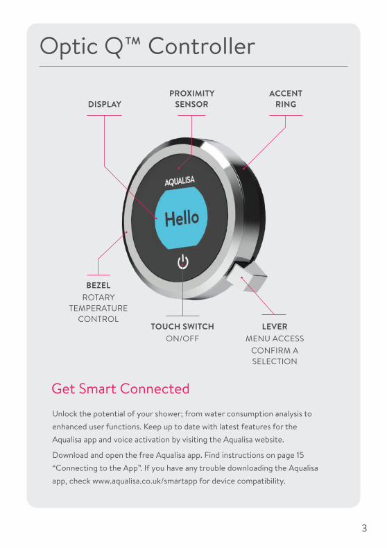
LEVER MENU ACCESS
CONFIRM A SELECTION
BEZELROTARY
TEMPERATURE CONTROL
TOUCH SWITCH ON/OFF
PROXIMITY SENSOR
ACCENT RINGDISPLAY
Optic Q™ Controller
Unlock the potential of your shower; from water consumption analysis to enhanced user functions. Keep up to date with latest features for the Aqualisa app and voice activation by visiting the Aqualisa website.
Download and open the free Aqualisa app. Find instructions on page 15 “Connecting to the App”. If you have any trouble downloading the Aqualisa app, check www.aqualisa.co.uk/smartapp for device compatibility.
Get Smart Connected
3

Quick Start
WAKE UP, (POWER ON) AND POWER OFF
SHOWER ON
TEMPERATURE FLOW SELECT OUTLET*Push and hold QTM lever for over
3 seconds then release when desired outlet icon appears.
Adjust during showering only.
Adjust before or during showering.
* Divert models only
You can prepare your temperature and outlet before you switch on the shower, or adjust with ease while showering.
4

The controller has a proximity sensor, so as you approach or move your hand towards the controller, the display wakes up and is ready to go.
(You can disable this feature in the Settings menu - see page 12).
Wake-up
The proximity sensor detects any object directly in front, at approximately 0.5m away from the controller. See page 17 for more information.
0.5 metres
5

39
HelloWarming39Get
Ready39Push Lever
Your shower was
9:20Goodbye
Push leverto power o�
water turns off
Switching On and Off
ENDING YOUR SHOWERTouch the power symbol for approximately 1 second, then push the lever when prompted, to confirm and end the shower.
STARTING YOUR SHOWERTo activate the controller, use the proximity sensor, or touch the power symbol until the screen wakes up, then push and release the lever to start the shower. The Get Ready screen will appear on the display. After a moment the target temperature will flash until it is reached. It will then display the thermostatically controlled temperature.
water turns on
As a safety feature, the Aqualisa SmartValveTM has a maximum run time of 20 minutes. The flow can be stopped and started at anytime by following the instruction on this page.
This can be enhanced by activating and using the free Aqualisa app. See pages 3 and 15 for details.
6

TIP: This is your Home screen.When in any of the Menu or Settings screens, you can easily return to the home screen by turning the temperature bezel.
42 3543Warming Cooling
34
TEMPERATURE FEEDBACK DISPLAY*
Adjusting the TemperatureFrom the Home screen you can adjust the temperature at any time, before or during showering, by turning the bezel.
Turn clockwise to increase the temperature. While the temperature is adjusting the screen will flash and the display will show Warming. When the desired temperature is reached, the display will stop flashing.
Turn anti-clockwise to decrease the temperature. While the temperature is adjusting the screen will flash and the display will show Cooling. When the desired temperature is reached, the display will stop flashing.
* Very small changes in temperature may not result in Warming or Cooling messages showing, only the temperature value will change.
7

Emergency Stop: When the flow setting is at ECO, joggle the QTM lever down 3 times in succession to turn the shower off.
Flow
MED MAX
Flow39
FLOW FEEDBACK DISPLAY
After adjusting the flow, the display will return to the temperature Home screen after a few seconds.
From the Home screen you can adjust the flow during showering, by moving the lever left or right.*
*Flow cannot be adjusted when in Settings mode, or when the shower is awake and not flowing.
Adjusting the Flow
8

DrenchShower
Push and hold for over 3 seconds
Release lever when desired outlet icon appears
Selecting your Outlet Divert models only
From the Home screen, you can alternate between outlets by pushing and holding the lever for over 3 seconds and releasing when the desired outlet icon appears. This can be done upon starting the shower, or during showering.
OUTLET ICONSBy default your controller will show the Shower icon as the primary outlet and the Drench icon as secondary. To change, go to Settings menu, Configure Outlets (page 14).
9

Single Outlet
To avoid water dripping from the shower head after use, we advise to tilt the head back to allow residual water to drain out.
The above recommendation applies to both adjustable and fixed shower heads.
Rotate the spray plate lever clockwise or anticlockwise to select the desired spray pattern.
To select the preferred height for the shower head, squeeze the side levers together to allow the handset holder to move up or down the rail.
Angular adjustment is made by carefully but firmly pulling forwards or pushing back the shower head against the ratchet in the holder.
Removing the shower head: With the hose still attached, disengage the pivot clip by pushing in the outer grey button located on the front of the shower head (near to the hose connection). Remove the threaded spigot from the bottom of the handset by using the hose to pull clear. To reattach: Ensure the hose washer is in the correct position, tighten the threaded spigot into the hose using a suitable spanner, taking care not to over-tighten. Reinsert the spigot into the handset and engage the pivot clip prior to placing the handset into the handset holder.
3. Outer
2. Middle
1. Inner
Vita™ Head
10
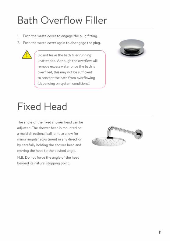
1. Push the waste cover to engage the plug fitting.
2. Push the waste cover again to disengage the plug.
Bath Overflow Filler
Do not leave the bath filler running unattended. Although the overflow will remove excess water once the bath is overfilled, this may not be sufficient to prevent the bath from overflowing (depending on system conditions).
The angle of the fixed shower head can be adjusted. The shower head is mounted on a multi directional ball joint to allow for minor angular adjustment in any direction by carefully holding the shower head and moving the head to the desired angle.
N.B. Do not force the angle of the head beyond its natural stopping point.
Fixed Head
11

SETTINGS
WifiAuto Wake up
Auto Wake up
EDITING A SETTING To change a setting, push the lever. Move the lever left or right to choose your preference, (the active setting is in darker type) and push the lever to confirm. A tick will briefly appear to confirm your choice.
SettingsOptic Q™ features optional settings to enhance your shower.
To enter Settings, from the Home Screen, move the lever left or right until the Settings screen appears. Push the lever to enter. Access to the settings menu is only available when water is not flowing.
BROWSING THE SETTINGS MENUWhen in the Settings menu, move the QTM lever left or right to browse.
Auto Wake up
ON OFFAuto Wake up
ON OFF
HOME
12

Settings
Confi gure outlets
CONFIGURE OUTLETSThis setting enables you to choose the icons that represent your outlets, and change the primary outlet. (See page 14 for details).
Pair a remote
PAIR A REMOTEIf you have purchased a remote control, please refer to the separate instructions supplied.
WI-FITo connect to the Aqualisa app and enable shower functionality using your personal smart devices.
Wifi
Auto Wake up
AUTO WAKE UPThis setting allows the Wake Up feature to be turned off. This may be required if you have a small shower enclosure, and the controller is permanently active. Factory default: ON.
Factory reset
Firmware update
About My Q
FACTORY RESETReset all settings to factory default.
FIRMWARE UPDATEThis setting should only be used under advice from Aqualisa Customer Service or by an Aqualisa Service Technician.
ABOUT MY QFor Aqualisa Service Technician use.
13

Configuring your Outlets
When you enter this setting you will first be asked to switch on the shower. You will then be prompted to confirm if the outlet running is the desired Primary Outlet.
Next, move the lever left or right to browse icons. Push the lever to select the icon that matches your installation.
When you have selected the icons, your choice will be confirmed with OK.
This setting enables you to choose the icons that represent your outlets. If you have multiple outlets, you can also select the most commonly used, this is known as the primary outlet. Water will divert to this outlet unless you select otherwise.
NB: Only available with divert models. You can not configure outlets whilst the shower is in use.
OK
Primary Outlet?
YES NO
OK
Choose an icon
Confi gure Outlets
YES NO
14
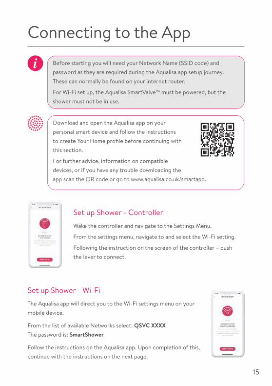
Connecting to the App
Set up Shower - Controller
Wake the controller and navigate to the Settings Menu.
From the settings menu, navigate to and select the Wi-Fi setting.
Following the instruction on the screen of the controller – push the lever to connect.
Set up Shower - Wi-FiThe Aqualisa app will direct you to the Wi-Fi settings menu on your mobile device.
From the list of available Networks select: QSVC XXXX The password is: SmartShower
Follow the instructions on the Aqualisa app. Upon completion of this, continue with the instructions on the next page.
Before starting you will need your Network Name (SSID code) and password as they are required during the Aqualisa app setup journey. These can normally be found on your internet router.
For Wi-Fi set up, the Aqualisa SmartValveTM must be powered, but the shower must not be in use.
Download and open the Aqualisa app on your personal smart device and follow the instructions to create Your Home profile before continuing with this section.
For further advice, information on compatible devices, or if you have any trouble downloading the app scan the QR code or go to www.aqualisa.co.uk/smartapp.
15

Connecting
The controller will display a Wi-Fi symbol and have the message “Connecting”. This indicates that the Aqualisa SmartValveTM is connecting to the Aqualisa app.
N.B. Depending on Wi-Fi signal strength, the connection may take a few minutes. Follow the instructions on the Aqualisa app. Upon completion of this, continue with the below.
A message will provide confirmation in the Aqualisa app journey and on the screen of the controller that connection is successful.
To exit the controller menu, either rotate the temperature bezel or allow the Settings menu to time out.
Wifi connected “Home SSID”
If the timer setting is adjusted within the Aqualisa app, then the shower will run for the newly set duration, overriding the default maximum run time. N.B. The water flow will stop at the end of the timer.
The Aqualisa app gives you the capability to operate your product remotely using your mobile device. It is the responsibility of the user to ensure that it is safe to remotely activate the water flow. Aqualisa recommend that baths and showers in operation are not left unattended.
16

Auto Wake up
The Proximity SensorAUTO WAKE-UP*The controller has a proximity sensor, so as you approach, or move your hand towards the controller, the display wakes up and is ready to go.
0.5 metres
*In some circumstances, in smaller shower enclosures, Auto Wake Up may cause the control to remain active. If this occurs, you should disable Auto Wake Up in Settings (see page 12).
17

Cleaning tip: To keep your shower effortlessly clean, we recommend drying all shower components with a soft cloth after use.
Caring for your ShowerOver time, your shower may be affected by hard water scaling. To keep your shower working effectively, we recommend that you clean your shower regularly.
Your product should be cleaned using only a soft cloth and washing up liquid. The bath system ‘click clack’ waste plug mechanism (if applicable) should be kept clear of debris to ensure the plug maintains a watertight seal. The plug can be unscrewed and removed to check and clean the mechanism.
Cleaning the shower head To reduce the need for chemical descaling in hard water areas, your shower head incorporates a ‘clear flow’ system, whereby any scale build up can be broken down by gently rubbing the flexible tips of the jets during use. This procedure should be completed regularly, as often as once a week in some hard water areas, as scale build up can affect the spray pattern and cause the shower to perform poorly. Failure to descale the shower head can affect the internal seals and may affect the warranty. Should descaling of the head using a cleaning agent become necessary, remove the shower head fully and immerse in a mild proprietary descaler (e.g. vegetable based or plain white vinegar). Cleaning and maintenance should not be undertaken by children without supervision by a person responsible for their safety.
DO NOT USE ABRASIVE CLEANERS. It is imperative that descaling is carried out in accordance with the manufacturer’s instructions, substances that are not suitable for plastics and electroplated surfaces must not be used.
Changing water system? If switching from a gravity-fed water system to a mains pressure system (e.g. Combination boiler) you will need to change your Aqualisa SmartValveTM. Contact a member of our Customer Service team for further information.
18

TroubleshootingSymptom Possible cause ActionController unresponsive - No Lights / Blank
Power supply turned off to Aqualisa SmartValveTM
Check power supply is turned on - Green power light should be illuminated on the Aqualisa SmartValveTM. Additionally check the following 2 action points.
Controller displaying “Preparing, please wait….” for longer than 2 minutes
Loss of communications
Check data cable connections are making good contact and are fully inserted and that there is no visible damage.Check that the wiring schematics are as per installation instructions in the Smart Installation Guide.
Pump noisy and low / no flow
Air lock (for Gravity fed systems only)
For models utilising a adjustable head kit; disconnect the handset from the hose, see Head section on page 10, lower the hose into the shower tray or bath, set the temperature to fully cold and then start the shower. As the water starts to flow and increase in volume gradually increase the temperature. If the flow starts to splutter, stop moving the temperature control until the flow again stabilises, then continue to move the dial towards the hottest setting.
Restriction in the waterway
Check for debris in the inlet filters of the Aqualisa SmartValveTM, diverter and Fixed Head connection washer. Must be conducted by a qualified person. NOTE: The water supplies MUST be isolated when checking the inlet filters.
Blocked or kinked hose liner
Where a flexible hose is fitted, unscrew the shower hose from the outlet connection and turn the shower on.
Auto wake up (proximity) not activating
Auto wake up turned off
Go to Settings menu and ensure Auto wake up is ON. See page 13 for instructions.
Flow does not change when adjusted with lever
Combination boiler output does not meet the flow demand
Check with boiler manufacturer for specification details.
Aqualisa SmartValveTM
is set to ECO modeRefer to Setting Water System Mode section in the Smart Installation Guide. Ensure mode is set to normal or ECO gravity setting.
Seasonal conditions During the cooler months the mains water temperature drops and this will reduce the performance of combination boilers. Check with your boiler manufacturer for details.
19

Low / no flow Seasonal conditions See previous point.
Incorrect Aqualisa SmartValveTM fitted
If water supplies are gravity fed, the PUMPED Aqualisa SmartValveTM must be used (unless a separate stand alone pump is being utilised). Refer to the Smart Installation Guide.
Water supply issue For the Standard Aqualisa SmartValveTM - Ensure water is turned fully on at the mains and at the servicing valve in the supply.
Ensure isolation valves are fully open.
Mixed water supplies For standard Aqualisa SmartValveTM - ensure hot and cold supplies are from the mains water supply.
Restriction in the waterway
See same cause in 'Pump noisy and low / no flow' symptom.
Blocked or kinked hose liner
Where a flexible hose is fitted, unscrew the shower hose from the outlet connection and turn the shower on.
Incoming mains water pressure or flow too low (Standard Aqualisa SmartValveTM only)
After confirming that the filters are clear, check with the local water authority.
Separate, stand alone pump not activating (Standard Aqualisa SmartValveTM only)
Ensure sufficient flow to activate the flow switches of the pump. Refer to IMPORTANT INFORMATION section in the Smart Installation Guide.
Aqualisa SmartValveTM pump not activating
Refer to Setting Water System Mode section in the Smart Installation Guide, ensure mode is set to Normal or ECO Gravity setting.
Aqualisa SmartValveTM
is set to ECO modeRefer to the above point.
Unable to adjust or control temperature
Reversed inlet water supplies (i.e. Hot supply feeding cold inlet and vice-versa)
Ensure correct water supply to specified inlet connection of the Aqualisa SmartValveTM.
Fluctuating water temperature
Incorrect setting on Logic Module of Aqualisa SmartValveTM
If hot water supply is from a combination boiler- the Logic module mode MUST be set to COMBI. Refer to Setting Water System Mode section in the Smart Installation Guide.
Airlock in water supplies (for gravity fed systems only)
See “Air lock” in Possible Cause section on page 19.
20

Fluctuating water temperature(continued)
Hot water temperature too high
Ensure hot water supply temperature is below 65ºC (minimum 55ºC for stored water and 50ºC for combination boilers).
Communications issue
Check data cable connections and that there is no visible damage.
Combination boiler unable to meet demand
Check if another outlet in the property is being used at the same time. Check that the hot water temperature is stable at another high flowing outlet (e.g. bath hot tap - run at maximum flow rate), additionally run a cold outlet at 1/3 of a maximum flow rate. If the same issue is evident on these outlets, contact your boiler manufacturer.
Temperature too low
Low hot water temperature
Check that domestic hot water temperature is a minimum of 55ºC for stored water and 50ºC for combination boilers.
Logic Module temperature setting too low
Maximum temperature is set to a factory default of 45ºC. To adjust refer to the important information section (Safety Information) and Controller Commission Instructions in the Smart Installation Guide.
Temperature too low - Controller temperature ready display does not stabilise
Hot water supply issue
Check another hot water outlet to ensure that hot water is available.
Mixed water supplies Water supplies MUST be from the same source: MUST NOT be gravity hot and mains cold.
Unbalanced water supplies
For mains fed systems the cold and hot feeds should be as evenly balanced as possible - especially for HP unvented systems.
Combination boiler unable to meet demand
See same cause in 'Fluctuating Water Temperature' symptom.
Temperature too hot
Seasonal conditions In the warmer months, the mains water temperature can rise to ambient level. The Aqualisa SmartValveTM always blends a mix of both hot and cold supplies therefore the output temperate at fully cold (controller setting) will always be higher than the incoming cold water supply.
Temperature too hot
Seasonal conditions (gravity fed systems only)
For installations which utilise a cold water storage supply (gravity fed system), the ambient temperature in the loft can rise to above 40ºC. In turn, this warms the stored water. Check by running a cold tap that is supplied from the water storage. N.B. Kitchen taps are normally fed from the mains water system.
Maximum temperature setting is not to your preference
Settings need adjusting
Refer to section 'Temperature too low', possible cause 'Logic module setting too low'.
21
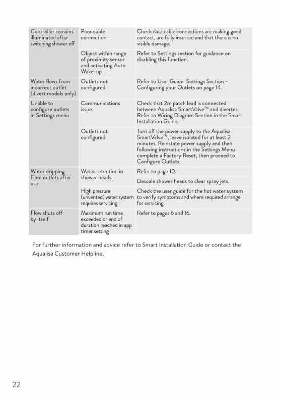
Controller remains illuminated after switching shower off
Poor cable connection
Check data cable connections are making good contact, are fully inserted and that there is no visible damage.
Object within range of proximity sensor and activating Auto Wake-up
Refer to Settings section for guidance on disabling this function.
Water flows from incorrect outlet (divert models only)
Outlets not configured
Refer to User Guide: Settings Section - Configuring your Outlets on page 14.
Unable to configure outlets in Settings menu
Communications issue
Check that 2m patch lead is connected between Aqualisa SmartValveTM and diverter. Refer to Wiring Diagram Section in the Smart Installation Guide.
Outlets not configured
Turn off the power supply to the Aqualisa SmartValveTM, leave isolated for at least 2 minutes. Reinstate power supply and then following instructions in the Settings Menu complete a Factory Reset, then proceed to Configure Outlets.
Water dripping from outlets after use
Water retention in shower heads
Refer to page 10.Descale shower heads to clear spray jets.
High pressure (unvented) water system requires servicing
Check the user guide for the hot water system to verify symptoms and where required arrange for servicing.
Flow shuts off by itself
Maximum run time exceeded or end of duration reached in app timer setting
Refer to pages 6 and 16.
For further information and advice refer to Smart Installation Guide or contact the Aqualisa Customer Helpline.
22

Need Help?
Have you Registered?
You can find Frequently Asked Questions at aqualisa.co.uk
Speak to our Customer Service team on 01959 560010
Use Live Chat at aqualisa.co.uk
Or email us [email protected]
All our products are manufactured to the highest standards. In the unlikely event that something goes wrong, we want all our customers to be protected, which is why we give you a totally free of charge 1 year parts and labour guarantee*. You can easily increase your FREE guarantee to 5 years simply by registering your product. Please keep your receipt to validate your guarantee. Please see our website for full terms and conditions.
Register your guarantee instantly at aqualisa.co.uk/guarantee
Register your guarantee 0800 408 4243
*Subject to terms and conditions
23

aqualisa.co.uk
Please note that calls may be recorded for training and quality purposes.The company reserves the right to alter, change or modify the product specifications without prior warning.
® Registered Trademark Aqualisa Products Limited.
Q5083 Part No 705145 Issue 01 May 20
THE FLYERS WAY, WESTERHAM, KENT TN16 1DECustomer Services: 01959 560010
REPUBLIC OF IRELANDSales enquiries: 01-864-3363, Service enquiries: 01-844-3212

SMARTINSTALLATION GUIDE

IMPORTANT INFORMATION
Safety informationThis appliance can be used by children aged from 3 years and above and persons with reduced physical, sensory or mental capabilities or lack of experience and knowledge if they have been given supervision or instruction concerning use of the appliance in a safe way and understand the hazards involved. Children shall not play with the appliance.
Cleaning and user maintenance shall not be made by children without supervision.
This product must be installed by a competent person in accordance with all relevant current local and national Water Supply Regulations.
ALL PRODUCTS REQUIRING AN ELECTRICAL CONNECTION MUST BE INSTALLED BY A QUALIFIED PERSON FOLLOWING THE LATEST REVISION OF THE ELECTRICAL WIRING REGULATIONS, BOTH NATIONAL AND LOCAL AND CERTIFIED TO CURRENT BUILDING REGULATIONS.
This system should be installed
so that other taps or appliances operated elsewhere within the premises do not significantly affect the flow. The Aqualisa SmartValve™ must not be used with a hot water supply temperature of over 65ºC. If the maximum hot water temperature is likely to rise above 65ºC then a Thermostatic Blending Valve must be used. The Aqualisa SmartValve™ is supplied factory pre-set at maximum temperature of 45ºC. The maximum temperature is fully adjustable to suit site conditions. If adjusted, we recommend the outlet temperature is set to a MAXIMUM of 46ºC.
The Aqualisa SmartValve™ must be installed in an accessible location for servicing and maintenance. The Aqualisa SmartValve™ must not be installed in situations where either the ambient temperature is likely to exceed 40ºC or where freezing may occur. The controller must not be installed in situations where the ambient temperature is likely to fall below 5ºC or rise above 40ºC.
We do not recommend the use of a controller in steam
therapy facilities. This appliance must be earthed. Cables must be protected by a suitably sized conduit or trunking to avoid risk of damage and to allow removal for service and maintenance purposes. Failure to install this way may invalidate the warranty.Ensure that the conduit is run to avoid the controller fixing holes.Surface mounted cables must also be protected by a suitable approved conduit, even in a loft, where there may be a risk of damage from vermin.The power lead must only be replaced by the manufacturer or their accredited agent. The controller is supplied from a safety low voltage source.This product is suitable for domestic use only.
Installation of the pumped Aqualisa SmartValve™ (for gravity stored systems)The pumped Aqualisa SmartValve™ shower system is designed to operate up to a maximum static pressure of 100kPa ((1 bar)(10 metres head)(14.5psi)). Under no circumstances must the pumped Aqualisa SmartValve™ be connected directly to the water main or in line with another booster pump. The minimum actual capacity of the cold water storage cistern
should be not less than 225 litres (50 gallons). The capacity of the hot water cylinder must be capable of meeting anticipated demand.
Installation of the standard (unpumped) Aqualisa SmartValve™ (for balanced high pressure and unvented systems, combination boiler systems and separately pumped gravity systems)Pressures: The standard (unpumped) Aqualisa SmartValve™ is designed to operate up to a maximum static pressure of 700kPa ((7 bar)(100psi)). Where pressures are likely to exceed 700kPa ((7 bar)(100psi)), a pressure reducing valve must be fitted to the incoming mains supply. A setting of 400kPa ((4 bar)(60psi)) is recommended. It should be noted that daytime pressures approaching 600kPa ((6 bar)(80psi)) can rise above the stated maximum overnight.
Special notes for combination boiler systemsThe appliance must have a minimum domestic hot water rating of 24kW and be of the type fitted with a fully modulating gas valve. If in any doubt, please contact the appliance

manufacturer before installation commences.
DUE TO PERFORMANCE CHARACTERISTICS OF COMBINATION BOILERS, SEASONAL INLET TEMPERATURE CHANGE WILL AFFECT THE AQUALISA SMARTVALVE™ OUTLET FLOW RATE RESULTING IN VARYING SHOWER FLOW RATE AND FLOW CONTROL RANGE. INLET TEMPERATURE CHANGE MAY ALSO CAUSE THE TEMPERATURE DISPLAY TO FLASH; THIS IS NOT NECESSARILY CHANGING THE OUTLET TEMPERATURE.DUE TO THE PERFORMANCE CHARACTERISTICS OF COMBINATION BOILERS, OPERATION OF THE BOOST BUTTON OR INCREASING THE FLOW RATE SETTING ON THE SHOWER CONTROLLER MAY NOT OFFER SIGNIFICANT CHANGE IN OUTPUT FLOW RATE.
Special notes for separately pumped gravity systems and universal/negative head pumps (for divert systems)We recommend a MINIMUM pump rating of 1.5 bar. For optimum performance a 2.5 bar pump should be used
for all separately pumped installations. A twin ended pump is required for use with single outlet products.
A universal/negative head type twin ended pump (works on both positive and negative head conditions) MUST be used with divert products.
The minimum actual capacity of the cold water storage cistern should be not less than 225 litres (50 gallons). The capacity of the hot water cylinder must be capable of meeting the anticipated demand.
THIS PRODUCT IS NOT SUITABLE FOR USE WITH A SINGLE ENDED PUMP.
Shower HeadsThe range of shower heads has been designed for use with Smart systems. Installation of any shower heads other than these may result in poor shower performance. If at any stage during installation you have any questions then please contact the Aqualisa Customer Service Department on 01959 560010 for advice.
ConnectionsThis product incorporates 15mm ‘push-fit’ type connections. Tube should be

cut using a rotary type cutter and lubricated using a silicone grease, petroleum jelly, or similar, prior to insertion into the fitting. 15mm pipework must be used to connect the product.
If plastic pipe is used, the tube insert must not increase the tube diameter or extend the cut-off length by more than 2mm.
THESE FITTINGS ARE NOT SUITABLE FOR STAINLESS STEEL TUBE. COMPRESSION FITTINGS MUST NOT BE USED.
Pipe sizingCHECK PIPE SIZE REQUIREMENTS FOR CONNECTIONS TO OUTLETS AND ACCESSORIES.
Long pipe runs, on both the inlet and outlet, will reduce the flow rate at the shower head, 22mm pipe work should be used on inlets and reduced down to 15mm as close to the valve as possible to reduce pressure loss and help maintain flow rate. If using 15mm pipe, copper pipe is preferred. To optimise performance minimise the number of elbows used. If long pipe runs are unavoidable on the outlet, and a diverter is used, use copper pipe rather
than plastic. If plastic pipe is used, minimise the number of elbows as the pipe inserts are very restrictive.
FlushingSome modern fluxes can be very corrosive and, if left in contact, will attack the working parts of this unit. All soldering must be completed and the pipe work thoroughly flushed out in accordance with current local and national Water Supply Regulations prior to connection of the product.
Declaration of ConformityAqualisa Products Limited declares that the Aqualisa SmartValveTM and supplied controller, in conjunction with pairing remotes and diverter, complies with the essential requirements and other relevant provisions of the Low Voltage Directive (2014/35/EU), the EMC Directive (2014/30/EU) and the RED Directive (2014/53/EU).
Applicable for some models

After installationFamiliarise the end user with the operation of this product and hand them all literature. Complete and post the guarantee card or register online at www.aqualisa.co.uk
GuaranteeAqualisa products are supplied complete with a 1 year parts and labour guarantee that can be upgraded by registering the product with Aqualisa. See www.aqualisa.co.uk/guarantee for details.

System Installation Dual Outlet (divert)
System layout diagrams
Supply
Pressurereducing valve
if required
10mmax
Controller
Supply
Hot water cylinder
Connect‘A’ or ‘B’
Cold feedto cylinder
B
A
10mmax
Controller
NB: THE BASE OF THE AQUALISASMARTVALVETM MUST BE SITED NO HIGHER THAN THE BASE LEVEL OF THE CISTERN
10mmax
Controller
Centralheatingboiler
Supply
Supply
Underside of cistern
Hot watercylinder
Cold feedto cylinder
Connect‘A’ or ‘B’
B
A
10mmax
Controller
NB: 1.5 bar MINIMUM universal pump rating
Underside of cistern
Diverter
Diverter
Diverter
Diverter
Diverter
Supply
Hot water cylinder
10mmax
Controller
Underside of cistern Underside of cistern
Undersideof cistern
Undersideof cistern
DualDual & Single Single
Supply
Pressurereducing valve
if required
10mmax
Controller
Supply
Hot water cylinder
Connect‘A’ or ‘B’
Cold feedto cylinder
B
A
10mmax
Controller
NB: THE BASE OF THE AQUALISASMARTVALVETM MUST BE SITED NO HIGHER THAN THE BASE LEVEL OF THE CISTERN
10mmax
Controller
Centralheatingboiler
Supply
Supply
Underside of cistern
Hot watercylinder
Cold feedto cylinder
Connect‘A’ or ‘B’
B
A
10mmax
Controller
NB: 1.5 bar MINIMUM universal pump rating
Underside of cistern
Diverter
Diverter
Diverter
Diverter
Diverter
Supply
Hot water cylinder
10mmax
Controller
Underside of cistern Underside of cistern
Undersideof cistern
Undersideof cistern
DualDual & Single SingleTypical gravity system installation(compatible with pumped Aqualisa SmartValve™)
Supply
Pressurereducing valve
if required
10mmax
Controller
Supply
Hot water cylinder
Connect‘A’ or ‘B’
Cold feedto cylinder
B
A
10mmax
Controller
NB: THE BASE OF THE AQUALISASMARTVALVETM MUST BE SITED NO HIGHER THAN THE BASE LEVEL OF THE CISTERN
10mmax
Controller
Centralheatingboiler
Supply
Supply
Underside of cistern
Hot watercylinder
Cold feedto cylinder
Connect‘A’ or ‘B’
B
A
10mmax
Controller
NB: 1.5 bar MINIMUM universal pump rating
Underside of cistern
Diverter
Diverter
Diverter
Diverter
Diverter
Supply
Hot water cylinder
10mmax
Controller
Underside of cistern Underside of cistern
Undersideof cistern
Undersideof cistern
DualDual & Single Single
Typical UHW system installation(compatible with standard Aqualisa SmartValve™)
Single Outlet

Supply
Pressurereducing valve
if required
10mmax
Controller
Supply
Hot water cylinder
Connect‘A’ or ‘B’
Cold feedto cylinder
B
A
10mmax
Controller
NB: THE BASE OF THE AQUALISASMARTVALVETM MUST BE SITED NO HIGHER THAN THE BASE LEVEL OF THE CISTERN
10mmax
Controller
Centralheatingboiler
Supply
Supply
Underside of cistern
Hot watercylinder
Cold feedto cylinder
Connect‘A’ or ‘B’
B
A
10mmax
Controller
NB: 1.5 bar MINIMUM universal pump rating
Underside of cistern
Diverter
Diverter
Diverter
Diverter
Diverter
Supply
Hot water cylinder
10mmax
Controller
Underside of cistern Underside of cistern
Undersideof cistern
Undersideof cistern
DualDual & Single Single
Supply
Pressurereducing valve
if required
10mmax
Controller
Supply
Hot water cylinder
Connect‘A’ or ‘B’
Cold feedto cylinder
B
A
10mmax
Controller
NB: THE BASE OF THE AQUALISASMARTVALVETM MUST BE SITED NO HIGHER THAN THE BASE LEVEL OF THE CISTERN
10mmax
Controller
Centralheatingboiler
Supply
Supply
Underside of cistern
Hot watercylinder
Cold feedto cylinder
Connect‘A’ or ‘B’
B
A
10mmax
Controller
NB: 1.5 bar MINIMUM universal pump rating
Underside of cistern
Diverter
Diverter
Diverter
Diverter
Diverter
Supply
Hot water cylinder
10mmax
Controller
Underside of cistern Underside of cistern
Undersideof cistern
Undersideof cistern
DualDual & Single Single
Typical thermal storage unit system installation(compatible with standard Aqualisa SmartValve™)
Supply
Pressurereducing valve
if required
10mmax
Controller
Supply
Hot water cylinder
Connect‘A’ or ‘B’
Cold feedto cylinder
B
A
10mmax
Controller
NB: THE BASE OF THE AQUALISASMARTVALVETM MUST BE SITED NO HIGHER THAN THE BASE LEVEL OF THE CISTERN
10mmax
Controller
Centralheatingboiler
Supply
Supply
Underside of cistern
Hot watercylinder
Cold feedto cylinder
Connect‘A’ or ‘B’
B
A
10mmax
Controller
NB: 1.5 bar MINIMUM universal pump rating
Underside of cistern
Diverter
Diverter
Diverter
Diverter
Diverter
Supply
Hot water cylinder
10mmax
Controller
Underside of cistern Underside of cistern
Undersideof cistern
Undersideof cistern
DualDual & Single Single
Supply
Pressurereducing valve
if required
10mmax
Controller
Supply
Hot water cylinder
Connect‘A’ or ‘B’
Cold feedto cylinder
B
A
10mmax
Controller
NB: THE BASE OF THE AQUALISASMARTVALVETM MUST BE SITED NO HIGHER THAN THE BASE LEVEL OF THE CISTERN
10mmax
Controller
Centralheatingboiler
Supply
Supply
Underside of cistern
Hot watercylinder
Cold feedto cylinder
Connect‘A’ or ‘B’
B
A
10mmax
Controller
NB: 1.5 bar MINIMUM universal pump rating
Underside of cistern
Diverter
Diverter
Diverter
Diverter
Diverter
Supply
Hot water cylinder
10mmax
Controller
Underside of cistern Underside of cistern
Undersideof cistern
Undersideof cistern
DualDual & Single Single
Typical combination system installation(compatible with standard Aqualisa SmartValve™)

Supply
Pressurereducing valve
if required
10mmax
Controller
Supply
Hot water cylinder
Connect‘A’ or ‘B’
Cold feedto cylinder
B
A
10mmax
Controller
NB: THE BASE OF THE AQUALISASMARTVALVETM MUST BE SITED NO HIGHER THAN THE BASE LEVEL OF THE CISTERN
10mmax
Controller
Centralheatingboiler
Supply
Supply
Underside of cistern
Hot watercylinder
Cold feedto cylinder
Connect‘A’ or ‘B’
B
A
10mmax
Controller
NB: 1.5 bar MINIMUM universal pump rating
Underside of cistern
Diverter
Diverter
Diverter
Diverter
Diverter
Supply
Hot water cylinder
10mmax
Controller
Underside of cistern Underside of cistern
Undersideof cistern
Undersideof cistern
DualDual & Single Single
Supply
Pressurereducing valve
if required
10mmax
Controller
Supply
Hot water cylinder
Connect‘A’ or ‘B’
Cold feedto cylinder
B
A
10mmax
Controller
NB: THE BASE OF THE AQUALISASMARTVALVETM MUST BE SITED NO HIGHER THAN THE BASE LEVEL OF THE CISTERN
10mmax
Controller
Centralheatingboiler
Supply
Supply
Underside of cistern
Hot watercylinder
Cold feedto cylinder
Connect‘A’ or ‘B’
B
A
10mmax
Controller
NB: 1.5 bar MINIMUM universal pump rating
Underside of cistern
Diverter
Diverter
Diverter
Diverter
Diverter
Supply
Hot water cylinder
10mmax
Controller
Underside of cistern Underside of cistern
Undersideof cistern
Undersideof cistern
DualDual & Single Single
Typical pumped system installation(compatible with standard Aqualisa SmartValve™)
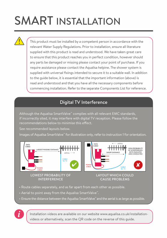
This product must be installed by a competent person in accordance with the relevant Water Supply Regulations. Prior to installation, ensure all literature supplied with this product is read and understood. We have taken great care to ensure that this product reaches you in perfect condition, however should any parts be damaged or missing please contact your point of purchase. If you require assistance please contact the Aqualisa helpine. The shower system is supplied with universal fixings intended to secure it to a suitable wall. In addition to the guide below, it is essential that the important information (above) is read and understood and that you have all the necessary components before commencing installation. Refer to the separate Components List for reference.
SMART INSTALLATION
Installation videos are available on our website www.aqualisa.co.uk/installation-videos or alternatively, scan the QR code on the reverse of this guide.
Although the Aqualisa SmartValve™ complies with all relevant EMC standards, if incorrectly sited, it may interfere with digital TV reception. Please follow the recommendations below to minimise this effect.
See recommended layouts below.
Images of Aqualisa SmartValve™ for illustration only, refer to instruction 1 for orientation.
• Route cables separately, and as far apart from each other as possible.
• Aerial to point away from the Aqualisa SmartValve™.
• Ensure the distance between the Aqualisa SmartValve™ and the aerial is as large as possible.
AERIAL
LARGEST POSSIBLE DISTANCE
DATA CABLE
POWER CABLE
CABLE TO TV
HIGH PROBABILITY OF INTERFERENCE,
BOTH RADIATED AND CONDUCTED
POWER CABLE CABLE
TO TV
DATA CABLE
AERIAL
SHORT DISTANCE
LAYOUT WHICH COULD CAUSE PROBLEMS
LOWEST PROBABILITY OF INTERFERENCE
Digital TV Interference

Isolation valves are supplied with the Aqualisa SmartValve™ and diverter (where supplied) and must be fitted on all inlet and outlet connections. All connections require 15mm pipe, and all pipe work should be supported.
For gravity fed installations, 22mm pipe work should be run as close to the Aqualisa SmartValve™ as possible before reducing down to 15mm.
To ensure safe operation and installation of this product, the Aqualisa SmartValve™ and diverter (where supplied) MUST be installed in one of the orientations shown.
To ensure optimum performance we recommend using copper pipe with a minimum number of elbows. To minimise post shower dripping outlet pipework should have a gentle gradient rise away from the Aqualisa SmartValve™ or the diverter (where supplied). Special notes for plastic pipework, refer to the Important Information (Connections) section.
300 mm
210 mm
70 mm
300 mm
210 mm
210 mm
450 mm
450 mm
210 mm
70 mm
1
2
AQUALISA SMARTVALVETM & DIVERTER
70 mm
240 mm
200 mm
240 mm 200 mm

Place the Aqualisa SmartValve™ and diverter (where supplied) on a solid mounting surface, and place the fixing feet into suitable positions. Mark, then drill and prepare suitable fixings securing to the mounting surface using the screws provided (if suitable).
Choose the position for your Aqualisa SmartValve™ and diverter (where supplied) as close to the controller as possible. These may be sited in the roof space above the proposed shower site, in the airing cupboard or behind a screwed bath panel if more convenient. For information regarding protecting the Aqualisa SmartValve™ and diverter (where supplied) from cold/frost, contact Aqualisa Customer Services or refer to the Aqualisa website. Insulation material must not be placed under or on top of the Aqualisa SmartValve™ and diverter (where supplied), the location should be where freezing cannot occur. Please refer to the system layout diagrams.
Exposed installation example shown
3
4
The Aqualisa SmartValve™ and diverter (where supplied) MUST be sited in a position that is safely accessible for servicing and commissioning purposes. When fitted in a loft space, the route to, and the area around the Aqualisa SmartValve™, and diverter (where fitted) must be boarded to ensure a safe working environment.
The optimum position for the Aqualisa SmartValve™ and diverter (where supplied) is in the roof space above the controller site to take full advantage of the ease and speed of installation.
The distance between the Aqualisa SmartValve™ and the controller must be within the range of the 10m data cable supplied. For dual-outlet models, the diverter must be within the range of the 2m low voltage data cable connecting it to the Aqualisa SmartValve™.
The inlet supply centres are 48mm.Please note arrow on isolation valve to indicate direction of flow.DO NOT use compression fittings on the inlet and outlet spigots as this will invalidate the warranty if fitted.
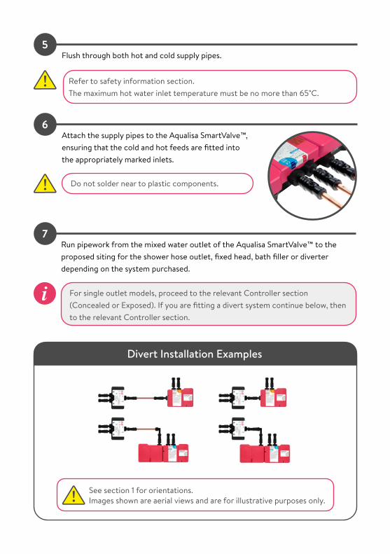
Refer to safety information section.The maximum hot water inlet temperature must be no more than 65˚C.
Run pipework from the mixed water outlet of the Aqualisa SmartValve™ to the proposed siting for the shower hose outlet, fixed head, bath filler or diverter depending on the system purchased.
7
Flush through both hot and cold supply pipes.
Attach the supply pipes to the Aqualisa SmartValve™, ensuring that the cold and hot feeds are fitted into the appropriately marked inlets.
5
6
Do not solder near to plastic components.
For single outlet models, proceed to the relevant Controller section (Concealed or Exposed). If you are fitting a divert system continue below, then to the relevant Controller section.
Divert Installation Examples
See section 1 for orientations.Images shown are aerial views and are for illustrative purposes only.

Ensure that the isolation valves are connected to the diverter spigots, with the arrows correctly aligned according to the direction of flow.
Run the pipes from the mixed water outlets of the diverter through to the proposed siting for the shower outlets, depending on the system chosen. For 2 buttoned shower divert controllers the outlets are assigned to the controller buttons as follows:
• Top button to outlet A of the diverter• Bottom button to outlet B of the diverter
See Diverter Outlet and Diverter Controller Matrix on the reverse page for reference.
8
Positioning the controllerThink about the location of the controller. Avoid grout lines where possible to ensure good surface contact with the silicone seal of the mounting plate. Choose a suitable height so all users can easily see and use the controller. Some controllers are activated by a proximity sensor. Refer to the user guide for details and further information.
CONTROLLERS - CONCEALED SHOWER
Supplied screws must be used as failure to do so will result in poor fitting of the controller, affecting its functions and may invalidate the warranty. If the supplied screws are not suitable for the mounting surface, use a screw of the same size and head design, the screws used must be non corrosive.
Power supply to the Aqualisa SmartValve™ must be switched off before connecting or removing the controller.
Ensure the data cable is the correct way round as both ends differ in type of connection used (transparent connector to the Aqualisa SmartValve™).
Data cables must be protected by suitable sheathing or conduit in the event of servicing and maintenance. Failure to install this way will invalidate the warranty.
Care should be taken to ensure that fixings do not pierce the data cable conduit.

Make note of the type of your mounting plate (A, B C or D) when proceeding with below instructions.
Fixing Specifications (refer to above)
Mounting plate type
A B C D
Data cable entry hole size
Ø16mm Ø16mm
Ø22mmdiamond dust hole saw must
be used
Ø16mm
Mounting plate screws and fixings
6mm drill bit for red fixings
5mm drill bit for yellow
fixings
6mm drill bit for red fixings
6mm drill bit, for red fixings or 5mm drill bit for yellow
fixings
6mm 5mm Data cable entry hole
A B C D
Diamond dust hole saw When using the diamond dust hole saw to cut a hole for the mounting plate, follow the manufacturers guidelines. This type of hole saw is suitable for ceramic tiles, glass, marble, slate and porcelain tiles. If cutting into showering panels or marine board a suitable Ø22mm hole saw should be used. For some brands of diamond dust hole saw it is recommended to wet the saw before cutting. Make an initial cut into the tile at an angle to avoid slippage of the drill bit.
1Place the mounting plate on the wall in the desired location for the controller and mark the central position for the data cable entry point as represented by in the above diagram. Remove the mounting plate and drill the data cable hole at the required size (see above table) at the appropriate position.

Referring to the above table, mark, drill and prepare the wall fixings for the mounting plate using the screw pack provided. The supplied screws MUST be used. If the supplied screws are not suitable for the mounting surface, use a screw of the same size and head design, the screws used must be non corrosive. For mounting plate C: Utilise the slotted fixing holes to align and to avoid hidden cables.
2
If fitting mounting plate B or D, for ease of installation, after positioning the cable (as per point 3), screw to the finished wall surface then utilise the silicone injection points to gently feed silicone into the channels.
The key way of the cable must be facing to the right.
Lining up the keyways of the data cable and the controller, push the data cable plug into the back of the controller. Ensure both rubber skirts are recessed into the connection (see diagram). To make a watertight fitting, ensure the rubber seal is no longer visible. If required, utilise a blunt flat bladed screwdriver or similar tool to push the connection fully home.
4
Ensure the data cable is correctly positioned as shown.
Feed the controller connection end of the data cable through the hole in the mounting plate, ensuring enough length to correctly connect into the back of the controller.
Run a bead of silicone sealant in the mastic groove on the back of the mounting plate. Ensuring the surface area is clear of debris press into position on the finished wall surface. N.B. For mounting plate C remove the paper liner on the foam gasket. To prevent the data cable from receding into the hole, secure the cable into the narrow middle slot of the mounting plate. Fix the mounting plate to the wall. The supplied screws MUST be used. If the supplied screws are not suitable for the mounting surface, use a screw of the same size and head design, the screws used must be non corrosive.
For mounting plate C: Use the spirit level to align.
3

For mounting plate A, B and D: To ensure a watertight seal, we recommend running a thin bead of silicone around the top half of the concealed controllers once it has been secured to the mounting plate.
Proceed overleaf to sections Aqualisa SmartValveTM Setup followed by Controller Comissioning Instructions.
Lock the controller onto the mounting plate with the fixing screw located at the base of the controller using a small Pozidrive screwdriver.
6
For mounting plate A, B and D: After correctly inserting the data cable, offer the controlleronto the mounting plate whilst feeding the cable back through the slot. Gently but firmly, push the controller down to secure and locate onto the mounting plate.
For mounting plate C: After correctly inserting the data cable, offer the controller up to the mounting plate whilst feeding the cable back through the slot. Position the controller into the mounting plate with the power symbol at the 7 o’clock position. Using the palm of your hand, gently apply pressure to the screen to locate the controller evenly into the mounting plate.With the other hand use the lever to rotate the controller counter clockwise until it stops and is seated in the mounting plate, and the power symbol is at the 6 o’clock position.
Visually check all the way around the two mating components to ensure there are no gaps and the controller is correctly fitted.
5

Positioning the controllerThink about the location of the controller.Choose a suitable height so all users can easily see and use the controller. Some controllers are activated by a proximity sensor. Refer to the user guide for details and further information. If the ceiling height is over 2.4m (8ft), a 550mm riser rail extension kit will be required. Contact our Customer Service Department to purchase a riser rail extension kit (part no: 910920).
201
CONTROLLERS - EXPOSED SHOWER
The centre of the riser rail stands 45mm from the wall. If this is not suitable, the spacers provided with the fixing brackets will increase the depth to 70mm from the wall.
Locate a suitable entry point into the ceiling for the riser rail, avoiding joists and services.
2Drill a hole through the ceiling, a minimum of Ø30mm, maximum Ø40mm.
The ceiling plate cannot be sited against an uneven surface. If there is coving or an alternative obstruction, please ensure the entry hole is neat and unobtrusive; otherwise the inner tube could be visible within the showering area. Remove ceiling plate if required.
3Feed the data cable through the hole in the ceiling followed by the riser rail assembly containing the supply pipe. Ensuring the controller is at the desired height, the rail is vertical, and that there is adequate working clearance above the top of the rail in the roof space.
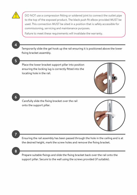
DO NOT use a compression fitting or soldered joint to connect the outlet pipe to the top of the exposed product. The black push fit elbow provided MUST be used. This connection MUST be sited in a position that is safely accessible for commissioning, servicing and maintenance purposes.
Failure to meet these requirements will invalidate the warranty.
4Temporarily slide the gel hook up the rail ensuring it is positioned above the lower fixing bracket assembly.
5Place the lower bracket support pillar into position ensuring the locking lug is correctly fitted into the locating hole in the rail.
6
7
8
Carefully slide the fixing bracket over the rail onto the support pillar.
Ensuring the rail assembly has been passed through the hole in the ceiling and is at the desired height, mark the screw holes and remove the fixing bracket.
Prepare suitable fixings and slide the fixing bracket back over the rail onto the support pillar. Secure to the wall using the screws provided (if suitable).

9Place the upper rail bracket support pillar into the desired location ensuring that both the hose restraint and the handset holder are below the upper rail wall bracket position.
10
11
12
Slide the fixing bracket over the rail onto the support pillar and repeat fixing procedures 7-8.
Carefully slide the rail end covers onto the fixing brackets flush with the finished wall surface and click the sides firmly into position.
Slide the ceiling plate up to the ceiling to cover the entry hole.
Proceed overleaf to sections Aqualisa SmartValveTM Setup followed by Controller Comissioning Instructions.

AQUALISA SMARTVALVETM SETUP
Connect the Aqualisa SmartValve™ power lead to a double pole 3 amp fused switched spur incorporated in the fixed wiring circuit, in accordance with current wiring rules (refer to safety information section). Ensure that this is located in an accessible, dry location and not in the bathroom.
Loosen the single fixing screw on the top of the Aqualisa SmartValve™ and diverter (where supplied) then carefully tilt the lid up and off the location lugs, and set the lid aside. Plug in the transparent connector of the low voltage, 10m data cable into the socket adjacent to the temperature adjuster as indicated on the label. Feed the cable out of the Aqualisa SmartValve™ ensuring it is correctly routed within the data cable channel.
1
2
Before any electrical adjustment is attempted, the electricity supply must be turned off at the mains switch.Electrical installation may only be carried out by a qualified person.All copper pipe work must be cross-bonded and connected to a reliable earthing point.
THIS APPLIANCE MUST BE EARTHEDWe recommend protecting surface mounted cables in suitable approved conduit to avoid the risk of damage from vermin.The power lead should also be clipped in place with ‘P’ clips or similar to avoid accidents.
Divert models have product specific diverters, and the supplied diverter must be used. If diverter is lost, damaged or separated from the main product contact Customer Services for the correct replacement.

A further data cable socket has been provided for use with a wired remote or diverter. This can be accessed by carefully snapping and removing the entry pillar and connecting the cable as described above. Please refer to the Wired Remote Installation Guide or the below wiring diagram. N.B. Wired Remotes
When making any adjustment to the Aqualisa SmartValve™ settings the power MUST be isolated. For water economy utilise the Eco mode. This is not to be used on Combination boiler installations, whereby only the Combi mode must be used.
To change the mode, use a flat bladed screwdriver.
Use the table below for water system settings.
3
Setting Water System Mode
Water System Valve Type SettingCombination Boiler - ensure setting is changed from factory default
Standard Aqualisa SmartValve™
Combi Factory default will be Normal HP, this setting must be changed to Combi for temperature stability and optimum performance
Balanced High Pressure Standard Aqualisa SmartValve™
Normal HP (factory default)orEco HP
Separately Pumped Gravity
Standard Aqualisa SmartValve™
Normal HP (factory default)orEco HP
Gravity Pumped Pumped Aqualisa SmartValve™
Normal Gravity (factory default)orEco Gravity
The ECO setting reduces the flow rate, therefore is not recommended when used in conjunction with combination boiler or bath filler applications.Site conditions can affect temperature settings, installer to adjust as required. See Controller Comissioning Instructions section.

Wiring Diagram - Divert Models Only
Cables must be run in conduit or trunking/sheathing
Diverter Outlet
BOUTLET
AOUTLET
1SWITCH
2
See reference notes in Diverter Controller Matrix for further information.
This switch sets the default outlet for the shower controllers.
CO
NN
ECT
ON
LY T
O P
ORT
1 (in
dica
ted
by si
ngle
dot
)
2m Patch Cable in Port 2
(indicated by 2 dots)
10m
Dat
a C
able
10m
Dat
a C
able
Controllers 1 & 3 only.
(Refer to Diverter controller matrix).
Controller 2 only.
(Refer to Diverter controller matrix).
Cable Entry Points
Port 1 Port 2

Diverter Controller Matrix
The controller will automatically assign the outlets as follows:• Top button to outlet A of the diverter• Bottom button to outlet B of the diverter
If using a wired remote
By default the remote button will assign outlet A as the primary. If required, this can be changeed from outlet A to outlet B, meaning when operated via the wired remote, the preferred outlet will always operate first.
Switch position 1 will allocate Outlet A as the primary. Switch position 2 will allocate Outlet B as the primary.
Changing the switch position will not override the main controller settings.
Switch position 1 will allocate Outlet A as the primary.
Switch position 2 will allocate Outlet B as the primary.
Controller 1
Controller 2
Refer to User Instructions, Configure Outlets section.
Controller 3

CONTROLLER COMISSIONING INSTRUCTIONS
Reinstate the electrical supply to the Aqualisa SmartValve™. Press the ‘Start/Stop’ button on the controller to turn the shower on.
4
Turn on the power supply to the Aqualisa SmartValveTM.1
Run the shower at maximum temperature (factory pre set to 45ºC). If required, the maximum temperature can be adjusted. (Refer to Safety Information for guidance).
2
To adjust the maximum temperate, isolate the power supply to the Aqualisa SmartValveTM.
Using a flat bladed screwdriver adjust the ‘MAX TEMP ADJUSTMENT’ control as indicated. When the temperature has been set to the desired position, carefully replace the Aqualisa SmartValve™ lid and secure the fixing screw, hand tight only.
3
When the power supply to the Aqualisa SmartValve™ is turned on the controller will automatically go into a set-up / configuration sequence.Whilst in the set-up sequence the controller will display flashing LED’s or a message on the display screen, this process can take up to 2 minutes to complete.The controller is ready to use once the configuration process has finished.

ADJUSTABLE HEIGHT HEADS
Ensure the finished wall surface is even, prepare pipework from the Aqualisa SmartValve™ or diverter (where supplied) to the required position for the hose outlet using a Ø15mm pipe. Slide the wall spacer down the projecting pipe until flush with the finished wall surface.
1
Trim the projecting pipe to a length of 15-22mm, measured from the face of the gripper ring, using a suitable cutter. If a hacksaw is used, the pipe end must be carefully de-burred and chamfered.
3
Clean and lubricate the pipe using a suitable (silicone based) lubricant.4
Remove the locking screw, rotate the chrome outlet assembly and remove the outlet from the wall mount-ing plate by carefully leavering with a flat bladed screwdriver.
5
Slide the 15mm gripper ring down the projecting pipe until flush with the wall spacer fitting.
2
Installation videos are available on our website www.aqualisa.co.uk/installation-videos or alternatively, scan the QR code on the reverse of this guide.

Secure the wall mounting plate to the wall using the screws provided (if suitable).
7
Ensuring the locking screw hole is positioned at the bottom, place the wall outlet mounting plate onto the pipe assembly and mark and prepare the fixing points, using the fixings provided (if suitable).
6
Place the ‘O’ ring on the recess of the spigot section on the mounting plate, offer the wall outlet onto the mounting plate in the 5 o’clock position and rotate clockwise until a stop is reached.
8
Refit the locking screw taking care not to overtighten. 9
To fit the rail, prepare two fixing holes up to a maximum of 657mm apart.N.B. The rail kit supplied utilises a floating bracket that can be positioned to suit existing screw holes on retrofit installations.
10

Dependant on the model purchased, depress the single release button or the side levers of the handset holder and slide onto the rail assembly.
11
Slide the bottom rail bracket onto the bottom of the rail.14
Secure the top rail bracket into position on the finished wall surface using the short wall screw.
13
Carefully slide the gel hook onto the rail under the handset holder.12
Slide the rail assembly up through the top rail bracket.15

Ensuring the hose washer is in the correct position; attach the hose to the wall outlet or the bottom of the exposed rail.
18
Place the rail end caps into both brackets and push firmly into position.
17
Align the fixing hole of the bottom bracket with the corresponding holes on the rail assembly, ensuring the smaller sized hole on the rail is closest to the wall. Secure the bottom rail bracket to the wall using the long wall screw.
16
Run the shower for a few seconds to clear any debris and to check for any leaks.
Pass the hose through the gel hook.19
Current Water Supply Regulations state that the handset should not be allowed to pass a point 25mm above the spill over level of the bath or shower tray. If this cannot be achieved, the hose must be passed through the gel hook which has been designed to be utilised as a hose restraint.
Make note of the type of
your shower head (A or B) when
proceeding with below instructions.
A B

For shower head A: Ensuring the hose washers are in the correct position, depress the anti-swivel locking button on the handset and secure the handset to the hose. Place the handset into the handset holder.
For shower head B: Disengage the pivot clip by pushing in the outer grey button on the front of the shower head, as shown. Remove the threaded spigot from the bottom of the handset by loosely attaching the hose to the thread and pulling clear. Ensure the hose washer is in the correct position, tighten the threaded spigot into the hose using a suitable spanner, taking care not to over-tighten. Reinsert the spigot into the handset and engage the pivot clip prior to placing the handset into the handset holder.
20
WALL MOUNTED HEAD
Run a 15mm outlet pipe from the Aqualisa SmartValve™ or diverter (where supplied) to the preferred position for the fixed head.
1
Cut the outlet pipe to the finished length (55mm-150mm measured from the finished wall surface) using a suitable cutter. If a hacksaw is used, the pipe end must be carefully de-burred and chamfered.
2
Installation videos are available on our website www.aqualisa.co.uk/installation-videos or alternatively, scan the QR code on the reverse of this guide.
Offer the fixed head arm over the projecting pipework and ensuring it is visibly straight, mark the four fixing points.
3
Ensuring the pipe is clean and free of dust, slide the wall spacer followed by the fixing bush onto the pipe flush with the finished wall surface.
5
Remove the fixed head arm and drill and prepare using the fixings provided (if suitable) taking care to avoid pipework hidden in the wall.
4

Run the shower for a few seconds to clear any debris and to check for any leaks.
Fit the 15mm ‘O’ ring against the end of the fixing bush. Lubricate the ‘O’ ring using a suitable silicone based lubricant.
6
Refit the shower arm and secure it to the wall using the screws provided (if suitable).
7
The ‘O’ ring must be positioned on the 15mm pipe flush to the fixing bush, not onto the fixing bush shaft.
Slide the cover plate into position flush with the finished wall surface.
8
Ensuring the rubber washer is in the correct posi-tion, attach the shower head to the fixed arm and carefully secure using a suitable spanner, or a tool with smooth jaws, sufficiently to lock the head into position.
9

CEILING MOUNTED HEAD
Run a 15mm outlet pipe from the Aqualisa SmartValve™ or diverter (where supplied) to the preferred position for the fixed head.
1
Drill a hole (minimum Ø28mm, maximum Ø40mm) through the ceiling and the noggin.
3
Remove the fixing bracket carefully from the fixed head arm.4
Locate the position for the fixed head in the bath-room and firstly drill a pilot hole to mark the position before checking that there is suitable space behind the ceiling for the fixing assembly.
2
Installation videos are available on our website www.aqualisa.co.uk/installation-videos or alternatively, scan the QR code on the reverse of this guide.
The minimum height required behind the ceiling is 50mm and the space must allow for an 80mm wide, 50mm deep noggin to be used to support the assembly.
The ceiling mounted fixed head is supplied with screws for fixing the product to a noggin. A NOGGIN MUST BE USED AS PART OF THIS INSTALLATION.

Cut off the excess pipe allowing for a suitable working length to allow for the required 22mm connection. If a push fit connector is to be used then the pipe must be abraded to remove all chrome plating.
7
Set the fixing bracket into position and mark the fixing points. Remove the bracket and drill and prepare suitable fixings. Refit the fixing bracket and secure it through the ceiling and into the noggin using the screws provided (if suitable).
5
Feed the arm through the fixing bracket to the correct depth. Tighten the nut using a 32mm spanner if necessary to facilitate.
6
Connect the pipe work from the Aqualisa SmartValve™ or diverter (where supplied) to the end of the fixed head pipe using a suitable coupling. Fully tighten the nut on the ceiling mounting bracket using a 32mm spanner if necessary to facilitate.
8
Lubricate the ‘O’ ring if necessary and carefully slide the cover plate back over the fixed head arm and into position against the ceiling.
9
Run the shower for a few seconds to clear any debris and to check for any leaks.

Secure the cover plate to the arm using the grub screw and 2.5mm hexagonal key provided.
10
Ensuring the rubber washer is in the correct position, attach the shower head to the fixed arm and carefully secure using a suitable spanner, or a tool with smooth jaws, sufficiently to lock the head into position.
11
BATH OVERFLOW FILLER
Carefully unscrew and remove the overflow filler outlet from the body assembly and set aside.
1
Installation videos are available on our website www.aqualisa.co.uk/installation-videos or alternatively, scan the QR code on the reverse of this guide.
The bath overflow filler is suitable for baths up to a maximum thickness of 24mm.

Carefully unscrew and remove the bath waste clicker assembly from the waste body and set aside.
2
Offer the bath waste into position ensuring the rubber washer is correctly aligned between the waste assembly and the bath base.
3
Ensuring the rubber washer is correctly aligned, pass the bath waste clicker through the bath and secure to the waste body assembly.
4
Connect the bath waste to a suitable trap (not supplied).5
Offer the outlet body assembly into position at the rear of the bath ensuring the rubber washer is correctly aligned between the outlet body assembly and bath wall.
6
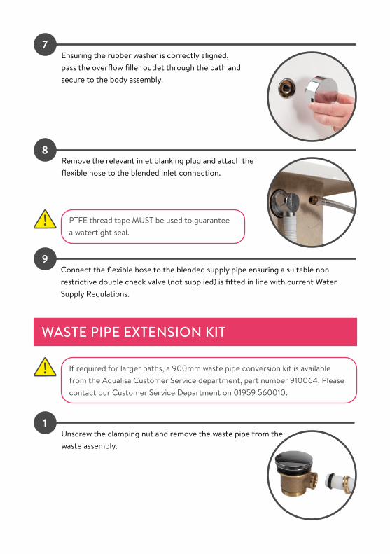
PTFE thread tape MUST be used to guarantee a watertight seal.
Ensuring the rubber washer is correctly aligned, pass the overflow filler outlet through the bath and secure to the body assembly.
7
Remove the relevant inlet blanking plug and attach the flexible hose to the blended inlet connection.
8
Connect the flexible hose to the blended supply pipe ensuring a suitable non restrictive double check valve (not supplied) is fitted in line with current Water Supply Regulations.
9
WASTE PIPE EXTENSION KIT
If required for larger baths, a 900mm waste pipe conversion kit is available from the Aqualisa Customer Service department, part number 910064. Please contact our Customer Service Department on 01959 560010.
Unscrew the clamping nut and remove the waste pipe from the waste assembly.
1

Carefully cut down the length of the waste pipe, and disconnect from the outlet assembly, ensuring not to damage the outlet.
3
Remove the clamping nut and sealing washer from the waste pipe and set aside.2
To reassemble, push the longer waste pipe into position over the outlet, and secure it in place using a jubilee clip (not supplied).
NOTE: The waste pipe may need to be softened by running it under hot water, to ensure it slides over the outlet.
4

TROUBLESHOOTING
Symptom Possible cause Action
Controller LED’s flashing and changing colour when power turned on to the Aqualisa SmartValveTM
Start up sequence and controller configuration in process (controller specific)
No action required - sequence and configuration can last up to 2 minutes. Wait until LED’s go out and then the controller is ready to use.
Controller unresponsive - No Lights / Blank
Power supply turned off to Aqualisa SmartValveTM
Check power supply is turned on - Green power light should be illuminated on the Aqualisa SmartValveTM.
Controller displaying “Preparing, please wait….” for longer than 2 minutes
Loss of communications
Check data cable connections are making good contact and are fully inserted.
Check that the wiring schematics are as per installation instructions.
Pump noisy and low / no flow
Air lock (for Gravity fed systems only)
For models utilising a adjustable head kit; disconnect the handset from the hose, lower the hose into the shower tray or bath, set the temperature to fully cold and then start the shower. As the water starts to flow and increase in volume gradually increase the temperature. If the flow starts to splutter, stop moving the temperature control until the flow again stabilises, then continue to move the dial towards the hottest setting.
Isolate hot and cold feeds to the Aqualisa SmartValveTM, disconnect from the inlet spigots and then using the isolation valve bleed through the hot and cold supplies.
Release the outlet pipe work from the outlet isolation valve of the Aqualisa SmartValveTM. Using an appropriate connection, flexi or length of pipe connect to the isolation valve so that water can be discharged into a bucket or suitable receptacle. Start the shower and bleed through until air is cleared.

Pump noisy and low / no flow
Air lock (for Gravity fed systems only) continued
It may be required to have the controller set at a cooler temperature setting until the hot water starts to bleed through, then gradually increase the temperature. NOTE: If the product fitted uses the Aqualisa diverter, then ensure that this is taken out of the plumbing configuration but remains connected to the Aqualisa SmartvalveTM via the 2m data cable.
Restriction in waterway
Check for debris in the inlet filters of the Aqualisa SmartValveTM.
Low / no flow Incorrect Aqualisa SmartValveTM fitted
If water supplies are gravity fed, the PUMPED Aqualisa SmartValveTM must be used (unless a separate stand alone pump is being utilised).
Water supply issue For Standard Aqualisa SmartValveTM - Ensure water is turned fully on at the mains and at the servicing valve in the supply.
Ensure isolation valves are fully open.Mixed water supplies For standard Aqualisa SmartValveTM - ensure hot and
cold supplies are from the mains water supply.
Check filters Check for debris in the inlet filters of the Aqualisa SmartValveTM, diverter and Fixed Head connection washer.
Incoming mains water pressure or flow too low
After confirming that the filters are clear, check with the local water authority.
Connectors and water supply feeds to the Aqualisa SmartValveTM are restrictive
Refer to IMPORTANT INFORMATION sections: Connections and Pipe sizing.
Separate, stand alone pump not activating (Standard Aqualisa SmartValveTM only)
Ensure sufficient flow to activate the flow switches of the pump.For Aqualisa divert products a twin ended universal (negative head) pump must be used. Refer to IMPORTANT INFORMATION section.
Aqualisa SmartValveTM pump not activating
Refer to Setting Water System Mode section, ensure mode is set to normal or ECO gravity setting.
Unable to adjust or control temperature
Reversed inlet water supplies (i.e. Hot supply feeding cold inlet and vice-versa)
Ensure correct water supply to specified inlet connection.

Fluctuating water temperature
Incorrect setting on Logic Module of Aqualisa SmartValveTM
If hot water supply is from a combination boiler - the Logic module mode MUST be set to COMBI.
Airlock in water supplies (for gravity fed systems only)
See “Air lock” in Possible Cause section.
Hot water temperature too high
Ensure hot water supply temperature is below 65ºC (minimum 55ºC for stored water and 50ºC for combination boilers).
Communications issue Check data cable connections.
Combination boiler unable to meet demand
Check that the hot water temperature is stable at another high flowing outlet (e.g. bath hot tap - run at maximum flow rate), additionally run a cold outlet at 1/3 of a maximum flow rate.
Temperature too low
Low hot water temperature
Check that domestic hot water temperature is a minimum of 55ºC for stored water and 50ºC for combination boilers.
Logic Module temperature setting too low
Refer to section: Controller Commissioning Instructions.
Temperature too low - Controller temperature ready display does not stabilise
Mixed water supplies Water supplies MUST be from the same source: MUST NOT be gravity hot and mains cold.
Unbalanced water supplies
For mains fed systems the cold and hot feeds should be as evenly balanced as possible - especially for HP unvented systems.
Combination boiler unable to meet demand
Check the hot water temperature is stable at another high flowing outlet (e.g. bath hot tap - run at maximum flow rate), additionally run a cold outlet at 1/3 of a maximum flow rate.
Controller remains illuminated after switching shower off
Poor cable connection Check data cable connections are making good contact and are fully inserted (this includes installations where a wired remote is fitted).
Object within range of proximity sensor and activating Auto Wake-up
Check user guide to see if the model in question has this feature - and if so go to settings menu for guidance on disabling this function.

Water flows from incorrect outlet (divert models only)
Pipe work configured incorrectly
Refer to section: Diverter Controller Matrix.
Primary outlet setting not configured
Refer to section: Diverter Controller Matrix.
Outlets not configured (For models with display screen only)
Refer to User Guide: Settings Section - Configuring your Outlets.
Flow will not switch between outlets
Communications issue Check that 2m patch lead is connected between Aqualisa SmartValveTM and diverter.
Ensure the correct 2m patch lead is connected - refer to separate Components List.
Outlets not configured (For models with display screen only)
Turn off the power supply to the Aqualisa SmartValveTM, leave isolated for at least 2 minutes. Reinstate power supply and then following instruction in the User Guide (Settings Menu) complete a factory reset, then proceed to Configure Outlets.
For further information and advice contact Aqualisa Customer Helpline.

Aqualisa Products LimitedThe Flyers WayWesterham Kent TN16 1DECustomer Helpline: 01959 560010Brochure Hotline: 0800 652 3669Website: www.aqualisa.co.ukEmail: [email protected] of IrelandSales enquiries: 01-864-3363Service enquiries: 01-844-3212
Please note that calls may be recorded for training and quality purposes.The company reserves the right to alter, change or modify the product specifications without prior warning.™ Trademark of Aqualisa Products Limited.
Scan for Installation Videos
Part No: 704711 Issue 01 Apr 20