User configuration manual - Stormshield Documentation
498
GUIDE STORMSHIELD NETWORK SECURITY USER CONFIGURATION MANUAL Version 4 Document last update: July 5, 2022 Reference: sns-en-user_configuration_manual-v4.5.1
-
Upload
khangminh22 -
Category
Documents
-
view
0 -
download
0
Transcript of User configuration manual - Stormshield Documentation

GUIDE
STORMSHIELD NETWORK SECURITY
USER CONFIGURATIONMANUALVersion 4
Document last update: July 5, 2022
Reference: sns-en-user_configuration_manual-v4.5.1

Page 2/498 sns-en-user_configuration_manual-v4.5.1 - 07/05/2022
SNS - USER CONFIGURATION MANUAL - V 4
4.3.7 Alarms view 334.3.8 System events view 33
4.4 Logs 33
5. ADMINISTRATORS 365.1 Administrators tab 36
5.1.1 Possible operations 365.1.2 Possible privileges 38
5.2 Administrator account tab 415.2.1 Authentication 415.2.2 Exports 41
5.3 Ticket management tab 425.3.1 The table 425.3.2 Possible operations 42
6. ANTISPAM 436.1 General tab 43
6.1.1 SMTP parameters 436.1.2 Advanced properties 44
6.2 Whitelisted domains tab 456.2.1 Interactive features 46
6.3 Blacklisted domains tab 466.3.1 Interactive features 46
7. ANTIVIRUS 477.1 Antivirus engine 477.2 Settings 47
7.2.1 ClamAV file analysis 477.2.2 Advanced antivirus file analysis 47
7.3 Sandboxing 48
8. APPLICATIONS AND PROTECTIONS 498.1 View by inspection profile 49
8.1.1 Selecting the encryption profile 498.1.2 The various columns 51
8.2 View by context 53
9. AUTHENTICATION 549.1 Available methods tab 54
9.1.1 Interactive features 549.1.2 Authentication methods 559.1.3 LDAP 559.1.4 SSL Certificate (SSL) 559.1.5 Radius 579.1.6 Kerberos 589.1.7 Transparent authentication (SPNEGO) 589.1.8 SSO Agent 599.1.9 Guest method 629.1.10 Temporary accounts 629.1.11 Sponsorship method 629.1.12 Time-based one-time password (2FA)63
9.2 Authentication policy tab 65
Table of contents1. WELCOME 12
1.1 Recommendations on theoperating environment 12
1.1.1 Recommendations 131.1.2 Configurations and usage modesubject to the evaluation of SNSfirewalls 15
1.2 User awareness 181.2.1 Administrator management 181.2.2 User password management 191.2.3 Work environment 201.2.4 User access management 20
2. ACCESS PRIVILEGES 212.1 Default options tab 21
2.1.1 VPN access 212.1.2 Sponsorship method 21
2.2 Detailed access tab 222.2.1 Possible operations 222.2.2 Detailed access grid 22
2.3 PPTP server tab 232.3.1 Interactive features 23
3. ACTIVE UPDATE 253.1 Automatic updates 253.2 Advanced properties 25
3.2.1 Update servers of the URLdatabase 253.2.2 Update servers of customizedcontext-based protection signatures 253.2.3 Update servers 25
4. LOGS - AUDIT LOGS 264.0.1 Private data 264.0.2 Collaborative security 264.0.3 Storage device: SD Card 26
4.1 Actions 274.1.1 Toolbar no. 1: period 274.1.2 Toolbar no. 2: simple or advancedsearch 274.1.3 Toolbar no. 3: actions 284.1.4 Information 29
4.2 Displaying details of a row of logs294.3 Interactive features 29
4.3.1 Simple search mode 294.3.2 Advanced search mode 304.3.3 IP addresses and host objects 304.3.4 URLs 314.3.5 Ports 324.3.6 Network packets 33

Page 3/498 sns-en-user_configuration_manual-v4.5.1 - 07/05/2022
SNS - USER CONFIGURATION MANUAL - V 4
authority or certificate11.3.1 Revoking an authority 8911.3.2 Revoking a sub-authority orcertificate 8911.3.3 Revoking a certificate 90
11.4 Creating, renewing or removing a CRL 9011.4.1 Creating a CRL 9011.4.2 Renewing a CRL 9111.4.3 Removing a CRL 91
11.5 Removing the private key of anidentity (while keeping the certificate) 9111.6 Defining a default authority or sub-authority 9211.7 Downloading a certificate 9211.8 Downloading an identity 9211.9 Downloading a CRL 92
12. CLI CONSOLE 9412.1 List of commands 9412.2 Data entry zone 95
13. CONFIGURATION 9613.1 General configuration tab 96
13.1.1 General configuration 9613.1.2 Cryptographic settings 9613.1.3 Password policy 9813.1.4 Date/Time settings 9813.1.5 Advanced configuration 9913.1.6 Industrial firewalls only (SNi20 andSNi40 models) 100
13.2 Firewall administration tab 10213.2.1 Access to the firewall’sadministration interface 10213.2.2 Remote SSH access 103
13.3 Network Settings tab 10413.3.1 IPv6 support 10413.3.2 Proxy server 10413.3.3 DNS resolution 105
14. CONFIGURING MONITORING 10614.1 Interval between refreshments 10614.2 Configuring interfaces, QoS queuesand web services to be monitored 106
14.2.1 "Interface configuration" tab 10614.2.2 "QoS configuration" tab 10614.2.3 "Web service configuration” tab 107
15. DASHBOARD 10815.1 Network 10815.2 Protections 10815.3 Properties 10915.4 Messages 110
9.2.1 Actions on the rules of theauthentication policy 659.2.2 Interactive features 669.2.3 New rule 669.2.4 Default method 679.2.5 Multi-user objects 67
9.3 Captive portal tab 689.3.1 Captive portal 689.3.2 SSL Server 689.3.3 Conditions of use for Internetaccess 699.3.4 Advanced properties 69
9.4 Captive portal profiles tab 709.4.1 Possible actions 709.4.2 Authentication 709.4.3 Conditions of use for Internetaccess 709.4.4 Authentication periods allowed 719.4.5 Advanced properties 71
9.5 Transparent or explicit HTTP proxyand multi-user objects 73
9.5.1 Multi-user objects 739.5.2 Transparent proxy (implicit) 749.5.3 Explicit proxy 74
10. BLOCK MESSAGES 7610.1 Antivirus tab 76
10.1.1 POP3 protocol 7610.1.2 SMTP protocol 7610.1.3 FTP protocol 76
10.2 Block page tab 7710.2.1 Block page tabs 7710.2.2 Editing block pages 77
11. CERTIFICATES AND PKI 7911.1 Possible operations 79
11.1.1 Search bar 7911.1.2 Filter 8011.1.3 Add 8011.1.4 Revoke 8011.1.5 Actions 8011.1.6 Download 8111.1.7 Check usage 81
11.2 Adding authorities andidentities 81
11.2.1 Adding a root authority 8111.2.2 Adding a sub-authority 8311.2.3 Adding a user identity 8411.2.4 Adding a smart card identity 8611.2.5 Adding a server identity 8711.2.6 Importing a file 88
11.3 Revoking an authority, sub- 89

Page 4/498 sns-en-user_configuration_manual-v4.5.1 - 07/05/2022
SNS - USER CONFIGURATION MANUAL - V 4
the DNS cache18.1.2 Advanced properties 136
19. DYNAMIC DNS 13819.1 List of dynamic DNS profiles 13819.2 Configuring a profile 138
19.2.1 DNS resolution 13819.2.2 Dynamic DNS service provider 13919.2.3 Advanced properties 139
20. E-MAIL ALERTS 14020.1 Configuration tab 140
20.1.1 SMTP Server 14020.1.2 E-mail sending frequency (inminutes) 14120.1.3 Intrusion prevention alarms 14120.1.4 System events 141
20.2 Recipients tab 14220.2.1 Creating a recipients group 14220.2.2 Adding a recipient to a group 14220.2.3 Deleting a group 14220.2.4 Checking whether a group is in use 143
20.3 Templates tab 14320.3.1 Modifying a template (HTML) 14320.3.2 Vulnerability management 14320.3.3 Certificate request 14320.3.4 User enrollment 14320.3.5 Sponsorship method 14420.3.6 SMTP configuration template 14420.3.7 List of variables 14420.3.8 Example of a report received by e-mail regarding alarms 144
21. ENROLLMENT 14521.1 The table 145
21.1.1 Possible operations 14521.1.2 Enrollment requests received 145
21.2 Information about the selectedenrollment request 14521.3 Advanced properties 146
21.3.1 User ID format 14621.3.2 Send an e-mail to the user 146
22. FILTERING AND NAT 14722.1 Evaluation of filtering and theimpact of NAT 147
22.1.1 “FastPath” mode 14722.2 Policies 147
22.2.1 Selecting the filter policy 14822.2.2 Possible operations 14922.2.3 Selecting multiple objects 14922.2.4 Drag & drop 149
15.5 Services 11015.6 Health indicators 11115.7 Pay As You Go 11215.8 Monitoring and configurationmodules 113
15.8.1 Favorite modules 11315.8.2 Access to modules 113
16. DHCP 11416.1 General 11416.2 “DHCP server” service 114
16.2.1 Default settings 11416.2.2 Address range 11516.2.3 Reservation 11516.2.4 Advanced properties 116
16.3 “DHCP relay” service 11716.3.1 Settings 11716.3.2 Listening interfaces on theDHCP relay service 118
17. DIRECTORIES CONFIGURATION 11917.1 Main window 120
17.1.1 "Add a directory" button 12017.1.2 "Action" list 120
17.2 Creating an internal LDAP 12017.2.1 Step 1: Selecting the directory 12017.2.2 Step 2: Accessing thedirectory 12017.2.3 Internal LDAP directory screen 121
17.3 Connecting to an externalLDAP directory 121
17.3.1 Step 1: Selecting the directory 12117.3.2 Step 2: Accessing thedirectory 12217.3.3 External LDAP directory screen123
17.4 Connecting to a PosixAccountexternal LDAP directory 126
17.4.1 Step 1: Selecting the directory 12617.4.2 Step 2: Accessing thedirectory 12617.4.3 External LDAP directory screen127
17.5 Connecting to a MicrosoftActive Directory 131
17.5.1 Step 1: Selecting the directory 13117.5.2 Step 2: Accessing thedirectory 13117.5.3 Microsoft Active Directoryscreen 132
18. DNS CACHE PROXY 13618.1 Enable DNS cache 136
18.1.1 List of clients allowed to used 136

Page 5/498 sns-en-user_configuration_manual-v4.5.1 - 07/05/2022
SNS - USER CONFIGURATION MANUAL - V 4
27. INSPECTION PROFILES 19127.1 Security inspection 191
27.1.1 Global configuration 19127.1.2 Configuring profiles 192
28. IPsec VPN 19328.1 Encryption policy – Tunnels tab 194
28.1.1 Site to site (Gateway-Gateway) 19428.1.2 The table 19728.1.3 Mobile users 19728.1.4 The table 200
28.2 Peers tab 20228.2.1 List of peers 20228.2.2 Gateway peer information 20228.2.3 Mobile peer information 204
28.3 Identification tab 20628.3.1 Approved certification authorities 20628.3.2 Mobile tunnels: pre-shared keys(PSK) 20728.3.3 Advanced properties 207
28.4 Encryption profiles tab 20828.4.1 Default encryption profiles 20828.4.2 Table of profiles 208
29. INTERFACES 21329.1 Interfaces 21329.2 Possible operations 21329.4 Bridge interface 214
29.4.1 Adding a bridge 21429.4.2 Bridge control panel 215
29.5 Ethernet interface 21929.5.1 Ethernet interface control panel 219
29.6 Wi-Fi interface (WLAN) 22329.6.1 Wi-Fi interface control panel 224
29.7 VLAN interface 22529.7.1 Adding a VLAN 22529.7.2 VLAN interface control panel 225
29.8 Aggregate 23029.8.1 Adding an aggregate 23029.8.2 Aggregate control panel 231
29.9 GRETAP interface 23329.9.1 Adding a GRETAP interface 23329.9.2 GRETAP interface control panel 233
29.10 PPPoE/PPTP modem interface 23629.10.1 Adding a modem 23629.10.2 PPPoE modem interface controlpanel 23629.10.3 PPTP modem interface controlpanel 237
29.11 USB/Ethernet interface (for USBkey/modem) 238
29.11.1 Modem profile control panel 238
22.3 Filtering tab 15022.3.1 Actions on filter policy rules 15022.3.2 Interactive features 15222.3.3 Filter table 153
22.4 NAT tab 16722.4.1 Actions on NAT policy rules 16722.4.2 Interactive features 16922.4.3 NAT table 170
23. HIGH AVAILABILITY 17623.1 Step 1: Creating or joining ahigh availability cluster 17623.2 Step 2: Configuring networkinterfaces 177
23.2.1 If you have chosen to create acluster 17723.2.2 If you have chosen to join acluster 178
23.3 Step 3: Cluster’s pre-sharedkey and data encryption 179
23.3.1 If a cluster is being created 17923.3.2 If a cluster exists 179
23.4 Step 4: Summary andfinalizing the cluster 180
23.4.1 If a cluster is being created 18023.4.2 If a cluster exists 180
23.5 High availability screen 18023.5.1 Communication betweenfirewalls in the high availabilitycluster 18023.5.2 Advanced properties 181
24. HOST REPUTATION 18324.1 Configuration tab 183
24.1.1 General 18324.2 Hosts tab 184
24.2.1 Included list 18424.2.2 Advanced properties 184
25. IDENTIFICATION PORTAL 18525.1 Connection 185
25.1.1 Presentation 18525.1.2 When TOTP authentication hasbeen enabled 186
25.2 The “admin” account, superadministrator 18725.3 Logging off 187
26. IMPLICIT RULES 18826.1 Implicit filter rules 188
26.1.1 Rule table 18826.1.2 Advanced configuration 190

Page 6/498 sns-en-user_configuration_manual-v4.5.1 - 07/05/2022
SNS - USER CONFIGURATION MANUAL - V 4
33.0.1 Private data 26033.0.2 The table 26033.0.3 Tooltips 261
33.1 Hardware / High Availability 26233.1.1 "Hardware" tab 26233.1.2 "Cluster details" tab 262
33.2 System 26533.2.1 "Real time" tab 26533.2.2 “History” tab 265
33.3 Interfaces 26633.3.1 "Real time" tab 26633.3.2 “History” tab 267
33.4 QoS 26833.4.1 "Real time" tab 26833.4.2 “History” tab 268
33.5 Hosts 26933.5.1 "Real time" tab 26933.5.2 “History” tab 276
33.6 Web Services 27633.6.1 "Connection per Web Services” tab 27633.6.2 "Incoming per web services” tab 27633.6.3 "Outgoing per web services” tab 277
33.7 Users 27733.7.1 "Real time" tab 27733.7.2 “History” tab 283
33.8 Connections 28433.8.1 "Real time" table 284
33.9 SD-WAN 28833.9.1 "Real time" tab 28833.9.2 History tab 291
33.10 DHCP 29133.10.1 "Real time" table 291
33.11 SSL VPN tunnels 29233.11.1 "Real time" table 29233.11.2 "Information" table 293
33.12 IPsec VPN tunnels 29333.12.1 Possible actions 29333.12.2 "Policies" table 29333.12.3 “IKE Security Associations (SA)”table 29533.12.4 “IPsec Security Associations (SA)”table 296
33.13 Black list / white list 29733.13.1 "Real time" table 297
33.14 Network captures 29833.14.1 Information in local storage 29833.14.2 Interactive features 29833.14.3 Captures in progress 29833.14.4 Completed captures 300
34. NETWORK OBJECTS 30234.1 Possible actions 302
29.11.2 USB/Ethernet interfacecontrol panel (for USBsticks/modems) 239
29.12 Network configuration modes 24029.12.1 Bridge mode 24029.12.2 Advanced mode (Router) 24129.12.3 Hybrid mode 241
30. LICENSE 24230.1 Firewalls with several modelson the same physical platform 24230.2 General tab 242
30.2.1 Buttons 24230.2.2 Dates 24230.2.3 Important information aboutthe license 24330.2.4 Installing from a file 24330.2.5 Advanced properties 243
30.3 License details tab 24430.3.1 Buttons 24430.3.2 The table 245
31. LOGS - SYSLOG - IPFIX 24931.1 Local storage tab 249
31.1.1 Storage device 24931.1.2 Configuring the spacereserved for logs 249
31.2 Syslog tab 25131.2.1 Syslog profiles 25131.2.2 Details 251
31.3 IPFIX tab 25231.3.1 Advanced properties 253
32. MAINTENANCE 25432.1 System update tab 254
32.1.1 Available updates: 25432.1.2 System update 25432.1.3 Advanced properties 255
32.2 Backup tab 25532.2.1 Configuration backup 25532.2.2 Configuration automaticbackup 256
32.3 Restore tab 25732.3.1 Restoring a configuration 25732.3.2 Restore automatic backup 258
32.4 Configuration tab 25832.4.1 System disk 25832.4.2 Maintenance 25932.4.3 High availability 25932.4.4 System report (sysinfo) 259
33. MONITORING 260

Page 7/498 sns-en-user_configuration_manual-v4.5.1 - 07/05/2022
SNS - USER CONFIGURATION MANUAL - V 4
37.8 ICMP 32437.8.1 “IPS” tab 324
37.9 IP 32437.9.1 “IPS” tab 324
37.10 SCTP 32537.10.1 “IPS” tab 325
37.11 TCP-UDP 32637.11.1 Profiles screen 326
37.12 IEC 61850 GOOSE (IPS) 32837.12.1 General Settings 32837.12.2 Support 328
37.13 MMS/IEC 61850 MMS 32837.13.1 MMS tab 32837.13.2 IEC 61850 MMS (IPS) tab 329
37.14 IEC 61850 SV (IPS) 33037.14.1 General Settings 33037.14.2 Support 330
37.15 BACnet/IP 33137.15.1 Service management 33137.15.2 Support 331
37.16 CIP 33237.16.1 Settings 33237.16.2 Service management 332
37.17 ETHERNET/IP 33237.17.1 EtherNet/IP settings 33237.17.2 EtherNet/IP commandmanagement 33337.17.3 Support 333
37.18 IEC 60870-5-104 (IEC 104) 33337.18.1 Settings 33337.18.2 Redundancy 33337.18.3 ASDU management 33437.18.4 Support 334
37.19 MODBUS (IPS) tab 33437.19.1 General settings 33437.19.2 Modbus settings 33437.19.3 Managing Modbus function codes 33537.19.4 Managing Modbus addresses 33537.19.5 Support 335
37.20 OPC AE (IPS) tab 33537.20.1 Managing OPC AE services 335
37.21 OPC DA (IPS) tab 33637.21.1 Grid of operations and operationgroups 33637.21.2 Possible operations 336
37.22 OPC HDA (IPS) tab 33637.22.1 Managing OPC HDA services 336
37.23 OPC UA 33737.23.1 OPC UA parameters 33737.23.2 Managing OPC UA services 33737.23.3 Support 337
37.24 PROFINET IO 337
34.1.1 Interactive features 30334.1.2 Filter 303
34.2 The various types of objects 30434.2.1 Host 30434.2.2 DNS name (FQDN) 30534.2.3 Network 30534.2.4 Address range 30534.2.5 Router 30634.2.6 Group 30934.2.7 Protocol 31034.2.8 Port – port range 31034.2.9 Port group 31134.2.10 Region group 31234.2.11 Time object 313
35. PPTP SERVER 31535.1 General configuration 315
35.1.1 Parameters sent to PPTPclients 315
35.2 Advanced configuration 31535.2.1 Traffic encryption 315
36. PREFERENCES 31636.1 Parameters tab 316
36.1.1 Connection settings 31636.1.2 Management interfacebehavior 316
36.2 Display tab 31736.2.1 Application settings 31736.2.2 Log settings 318
36.3 Links tab 31836.3.1 External links 318
37. PROTOCOLS 31937.1 Search 31937.2 List of protocols 31937.3 Profiles 319
37.3.1 Selecting a profile 31937.3.2 Buttons 320
37.4 Global protocol configuration 32037.4.1 Global configuration of theTCP/UDP protocol 32137.4.2 Global configuration of the SSLprotocol 32137.4.3 Global configuration of theICMP protocol 323
37.5 ICQ – AOL IM (OSCAR) 32337.5.1 Profiles screen 323
37.6 Live Messenger (MSN) 32337.6.1 Profiles screen 323
37.7 Yahoo Messenger (YMSG) 32437.7.1 Profiles screen 324

Page 8/498 sns-en-user_configuration_manual-v4.5.1 - 07/05/2022
SNS - USER CONFIGURATION MANUAL - V 4
37.38 SOFBUS/LACBUS (IPS) tab 35237.38.1 Managing Information units (IU)and SOFBUS or LACBUS blocks 352
37.39 DNS 35337.39.1 Profiles screen 353
37.40 FTP 35437.40.1 IPS tab 35437.40.2 Proxy tab 35537.40.3 Commands FTP tab 35537.40.4 FTP Users tab 35937.40.5 Analyzing files tab 36037.40.6 Sandboxing tab 360
37.41 HTTP 36137.41.1 IPS tab 36137.41.2 Proxy tab 36537.41.3 ICAP tab 36637.41.4 Analyzing files tab 36737.41.5 Sandboxing tab 368
37.42 NTP 36937.42.1 IPS tab 36937.42.2 IPS - NTP v1 tab 37037.42.3 IPS - NTP v2 tab 37137.42.4 IPS - NTP v3 tab 37137.42.5 IPS - NTP v4 tab 371
37.43 POP3 37237.43.1 IPS - PROXY tab 37237.43.2 POP3 Commands tab 37337.43.3 Analyzing files tab 37437.43.4 Sandboxing tab 374
37.44 SMTP 37537.44.1 IPS tab 37537.44.2 Proxy tab 37637.44.3 SMTP Commands tab 37737.44.4 Analyzing files tab 37837.44.5 Sandboxing tab 379
37.45 SNMP 37937.45.1 Allow version 37937.45.2 Allow Empty Field 37937.45.3 SNMP command management 38037.45.4 Community name 38037.45.5 Identifiers 38037.45.6 OID 38037.45.7 Support 381
37.46 SSL 38137.46.1 IPS tab 38137.46.2 Proxy tab 385
37.47 TFTP 38837.47.1 Profiles screen 388
37.48 Others 388
38. QUALITY OF SERVICE (QoS) 38938.1 Interfaces tab 389
37.24.1 Connection skeleton settings 33837.24.2 Managing UUIDs 33837.24.3 Managing operation numbers33837.24.4 Support 338
37.25 PROFINET RT 33837.25.1 Settings 33837.25.2 Support 339
37.26 S7 33937.26.1 Settings 33937.26.2 Managing function codes 33937.26.3 Support 339
37.27 S7 PLUS 34037.27.1 Protocol version 34037.27.2 Configuring operations 34037.27.3 Managing S7 Plus functions 34037.27.4 S7 Plus configuration 34137.27.5 Support 341
37.28 UMAS (IPS) tab 34137.28.1 UMAS Parameters 34137.28.2 UMAS function codesmanagement 34237.28.3 Support 342
37.29 MS-RPC protocol 34237.29.1 DCE/RPC (IPS) tab 34237.29.2 EPMAP protocol 34437.29.3 OPC AE (IPS) tab 34537.29.4 OPC DA (IPS) tab 34537.29.5 OPC HDA (IPS) tab 345
37.30 NetBios CIFS 34637.30.1 Profiles screen 346
37.31 EPMAP protocol 34637.32 NetBios SSN 34737.33 MGCP 347
37.33.1 Profiles screen 34737.34 RTCP 348
37.34.1 “IPS” tab 34837.35 RTP 348
37.35.1 “IPS” tab 34837.36 RTSP 348
37.36.1 RTSP commands 34837.36.2 Maximum size of elements(bytes) 34937.36.3 RTSP session settings 34937.36.4 RTSP features 34937.36.5 Support 349
37.37 SIP 34937.37.1 SIP commands 35037.37.2 Maximum size of elements(bytes) 35037.37.3 SIP session parameters 35037.37.4 SIP protocol extensions 35137.37.5 Support 352

Page 9/498 sns-en-user_configuration_manual-v4.5.1 - 07/05/2022
SNS - USER CONFIGURATION MANUAL - V 4
43.2.4 Errors found in the SMTP filter policy412
44. SNMP AGENT 41344.1 General tab 413
44.1.1 Configuration of MIB-II information 41344.1.2 Sending of SNMP alerts (traps) 413
44.2 SNMPv3 tab 41444.2.1 Connection to the SNMP agent 41444.2.2 Authentication 41444.2.3 Encryption (optional) 41444.2.4 Sending of SNMPv3 alerts (traps) 414
44.3 SNMPv1 - SNMPv2c tab 41644.3.1 Connection to the SNMP agent 41644.3.2 Sending of SNMPv2c alerts (traps) 41644.3.3 Sending of SNMPv1 alerts (traps) 416
44.4 MIBs and SNMP Traps 41644.4.1 Downloading MIBs 41744.4.2 Stormshield Network MIBs 417
45. SSL FILTERING 41845.1 Profiles 418
45.1.1 Selecting a profile 41845.1.2 Buttons 418
45.2 Rules 41945.2.1 Possible operations 41945.2.2 Interactive features 41945.2.3 The table 41945.2.4 Errors found in the SSL filter policy 420
46. SSL VPN 42146.1 Network settings 42146.2 DNS settings sent to client 42346.3 Advanced properties 42346.4 Used certificates 42446.5 Configuration 424
47. SSL VPN Portal 42547.1 General tab 425
47.1.1 Advanced properties 42647.2 Web servers tab 426
47.2.1 Adding a web server 42747.2.2 Adding an OWA web server 42847.2.3 Adding a Lotus Domino web server 429
47.3 Application servers tab 42947.3.1 Configuration with an applicationserver 42947.3.2 Configuration with a Citrix server 430
47.4 Deleting a server 43147.5 User profiles tab 431
47.5.1 Operating principle 43147.5.2 Configuring a profile 431
38.1.1 Interfaces with QoS 38938.2 Parameters tab 389
38.2.1 Network traffic 38938.2.2 Traffic shaper 39038.2.3 Queues 390
39. RECORDING CONFIGURATIONCOMMANDS 395
39.1 Recording a sequence ofconfiguration commands 395
40. ACTIVITY REPORTS 39640.1 Possible actions on reports 39740.2 Available reports 397
40.2.1 Web reports 39740.2.2 Security reports 39840.2.3 Virus reports 39940.2.4 Spam reports 40040.2.5 Vulnerability reports 40040.2.6 Network reports 40140.2.7 Industrial network reports 40140.2.8 Sandboxing reports 40240.2.9 SD-WAN reports 40240.2.10 Web service reports 403
41. REPORT CONFIGURATION 40441.1 General 40441.2 List of reports tab 404
41.2.1 Possible operations 40441.2.2 The table 404
41.3 List of history graphs tab 405
42. ROUTING 40642.1 IPv4/IPv6 static route tabs 406
42.1.1 General configuration 40642.1.2 Static routes 406
42.2 IPv4/IPv6 dynamic routingtabs 407
42.2.1 General configuration 40842.2.2 Advanced properties 40842.2.3 Sending the configuration 408
42.3 IPv4/IPv6 return routes tab 40842.3.1 Return routes 408
43. SMTP FILTERING 41043.1 Profiles 410
43.1.1 Selecting a profile 41043.1.2 Buttons 410
43.2 Rules 41043.2.1 Possible operations 41143.2.2 Interactive features 41143.2.3 The table 411

Page 10/498 sns-en-user_configuration_manual-v4.5.1 - 07/05/2022
SNS - USER CONFIGURATION MANUAL - V 4
54.1.2 Filter 45154.1.3 Add user 45154.1.4 Add group 45254.1.5 Delete 45254.1.6 Check usage 45254.1.7 Reset user’s TOTP enrollment 45354.1.8 Interactive features 453
54.2 List of users (CN) 45354.2.1 Account tab 45354.2.2 Certificate tab 45454.2.3 Member of these groups tab 454
55. VIRTUAL INTERFACES 45655.1 Creating or modifying an IPsecinterface (VTI) 456
55.1.1 Button bar 45655.1.2 Interactive features 45655.1.3 Presentation of the table 457
55.2 Creating or modifying a GREinterface 457
55.2.1 Button bar 45755.2.2 Interactive features 45855.2.3 Presentation of the table 458
55.3 Creating or modifying a loopbackinterface 458
55.3.1 Button bar 45955.3.2 Interactive features 45955.3.3 Presentation of the table 459
56. VULNERABILITY MANAGEMENT 46056.1 General configuration 460
56.1.1 List of monitored network objects 46156.2 Advanced configuration 462
56.2.1 Exclusion list (unmonitoredobjects) 462
57. WEB OBJECTS 46357.1 URL tab 463
57.1.1 Grid of custom URL categories 46357.1.2 Grid of URLs in a category 464
57.2 Certificate name (CN) tab 46557.2.1 Grid of custom certificate namecategories 46557.2.2 Grid of certificate names in acategory 465
57.3 Groups of categories tab 46657.3.1 Grid of category groups 46657.3.2 Details of a group 467
57.4 URL database tab 467
58. WEB SERVICES 46858.1 List of Web services tab 468
47.6 SSL VPN services on theStormshield Network web portal 432
47.6.1 Accessing your company’sweb sites via an SSL tunnel 43347.6.2 Accessing your company’sresources via an SSL tunnel 433
48. MULTICAST ROUTING 43448.1 STATIC ROUTING TAB 434
48.1.1 Possible operations on rules inthe static multicast routing policy 43448.1.2 Interactive features 43548.1.3 New rule 43548.1.4 Rule grid 435
48.2 DYNAMIC ROUTING TAB 43648.2.1 Definitions 43648.2.2 Configuring the interfaces 436
49. STORMSHIELD MANAGEMENTCENTER 440
49.1 Attaching the firewall to SMC 44049.1.1 Buttons 440
50. SYSTEM EVENTS 44150.1 Possible operations 441
50.1.1 Search 44150.1.2 Restore the defaultconfiguration 441
50.2 List of events 441
51. TEMPORARY ACCOUNTS 44351.1 Temporary accounts list 443
51.1.1 The table 44351.1.2 Possible operations 444
52. TRUSTED PLATFORM MODULE(TPM) 446
52.1 Initializing the TPM 446
53. URL FILTERING 44753.1 Profiles 447
53.1.1 Selecting a profile 44753.1.2 Buttons 447
53.2 Rules 44753.2.1 Possible operations 44853.2.2 Interactive features 44853.2.3 The table 44853.2.4 Errors found in the URL filterpolicy 449
54. USERS 45054.1 Possible operations 450
54.1.1 Search bar 450

Page 11/498 sns-en-user_configuration_manual-v4.5.1 - 07/05/2022
SNS - USER CONFIGURATION MANUAL - V 4
61.5 Interface names 49161.6 Objects 49261.7 DNS (FQDN) name objects 49261.8 Certificates 49261.9 Users 49261.10 IPsec VPN 49261.11 SSL VPN 49261.12 E-mail alerts 49361.13 Web services 493
62. Structure of an objects database inCSV format 494
62.1 Host 49462.2 IP address range 49462.3 DNS name (FQDN) 49462.4 Network 49562.5 Port 49562.6 Range port 49562.7 Protocol 49662.8 Host group, IP address group ornetwork group 49662.9 Service group 496
63. Structure of the file importingcustom web services (CSV format) 497
58.1.1 Web services grid 46858.2 Groups tab 469
58.2.1 List of groups grid 46958.2.2 Editing the contents of aservice group 470
58.3 Import custom services tab 47158.3.1 Import 47158.3.2 Information about the lastimport 471
59. Wi-Fi 47359.1 General configuration 47359.2 Channel configuration 473
60. IPv6 Support 47460.1 IPv6 Support 474
60.1.1 Details of supported features 47460.1.2 Unsupported features 47660.1.3 General points 476
60.2 Configuration 47760.2.1 Network Settings tab 477
60.3 Bridges and interfaces 47760.3.1 Bridges 47760.3.2 Ethernet interface in bridgemode 48060.3.3 Ethernet interface in advancedmode 48060.3.4 VLAN 481
60.4 Virtual interfaces 48160.4.1 “IPsec interfaces (VTI)” tab 48160.4.2 “Loopback” tab 481
60.5 Routing 48160.5.1 “IPv6 static routes” tab 48260.5.2 “IPv6 dynamic routing” tab 48360.5.3 “IPv6 return routes” tab 483
60.6 DHCP 48460.6.1 General 48460.6.2 “DHCP server” service 48560.6.3 “DHCP relay” service 487
60.7 Network objects 48860.7.1 Possible actions 48860.7.2 The different types of objects 489
60.8 Filtering 48960.8.1 “Filtering” tab 490
61. Allowed or prohibited names 49161.1 Firewall name 49161.2 Login and password 49161.3 Comments (prohibitedcharacters) 49161.4 Rules separators (prohibitedcharacters) 491

1. WELCOMEWelcome to the Stormshield Network v4.5.1 user configuration manual.
This guide explains the features of the web administration interface modules, and providesinformation on how to configure your Stormshield Network firewall for your network.
The Release Notes contain highly important information. Please refer to them before installingor updating your firewall.
For any questions, or if you wish to report errors, feel free to contact us [email protected].
Products concerned
SN160(W), SN210(W), SN310,
SN510, SN710, SN-M-Series-720, SN910, SN-M-Series-920, SN1100,
SN2000, SN2100, SN3000, SN3100, SN6000, SN6100,
SNi20, SNi40, SNxr1200,
EVA1, EVA2, EVA3, EVA4 and EVAU.
Copyright © Stormshield 2022. All rights reserved.
Unauthorized copying, adaptation or translation of this document prohibited.
The contents of this document relate to the developments in Stormshield’s technology at thetime of its writing. With the exception of the mandatory applicable laws, no guarantee shall bemade in any form whatsoever, expressly or implied, including but not limited to impliedwarranties as to the merchantability or fitness for a particular purpose, as to the accuracy,reliability or the contents of the document.
Stormshield reserves the right to revise this document, to remove sections or to remove thiswhole document at any moment without prior notice.
1.1 Recommendations on the operating environment
The installation of an SNS firewall and an SMC server is part of implementing a global securitypolicy. To ensure optimal protection of your assets, resources and information, installing anSNS firewall between your network and the Internet or installing an SMC server to help you toconfigure them correctly are only the first steps. This is mainly because most attacks comefrom the inside (accidents, disgruntled employees, dismissed employee having retainedinternal access, etc.).
The following is a list of security recommendations on how to use the SNS firewall and theSMC server.
IMPORTANT
l Check regularly for the Stormshield security advisories onhttps://advisories.stomshield.eu and for the latest security information regardingStormshield products on https://security.stormshield.eu/.
l Always apply updates if they fix security flaws on your Stormshield products. Updatesare available on https://mystormshield.eu.
SNS - USER CONFIGURATION MANUAL - V 41. WELCOME
Page 12/498 sns-en-user_configuration_manual-v4.5.1 - 07/05/2022

1.1.1 Recommendations
Physical security measures
SNS firewalls and the SMC server are must be installed and stored according to the state of theart regarding sensitive security devices: secured access to the premises, shielded cables withtwisted pairs, labeled cables, etc.
Organizational security measures
Super administrator
A particular administrator role, the super administrator, displays the following characteristics:
l The only administrator allowed to log on via the local console on SNS firewalls, and onlyduring the installation of the SNS firewall or for maintenance operations outside of normalproduction use,
l In charge of defining the profiles of other administrators,l All access to the premises where the SNS firewalls and the SMC server are stored must be
under the super administrator's supervision, regardless the purpose of the access is toconduct operations on the SNS firewall or on other equipment. All operations performed willbe this administrator’s responsibility.
IMPORTANTThe default password of the super administrator must be changed the very first time the SNSfirewall is used.
Password
User and administrator passwords must be chosen in such a way that it will take longer tosuccessfully crack them, by implementing a policy that regulates how they are created andverified (e.g., mix of alphanumeric characters, minimum length, inclusion of special characters,no dictionary words, etc.).
Administrators can change their password in the web administration interface of:
l SNS in Configuration > System > Administrators, Administrator account tab,l SMC in Maintenance > SMC Server > Administrators.
Administrators are aware of these best practices through their duties and are responsible formaking users aware of these practices (see the next section User Awareness).
Good information flow control policies
The information flow control policies to be implemented, for equipments on the trustednetworks to be protected, are defined as such:
l Complete: standard usage scenarios of how equipments are used have all beenconsidered when defining the rules and their authorized limits have been defined,
l Strict: only the necessary uses of equipments are authorized,l Correct: rules do not contradict each other,l Unambiguous: the list of rules provides all the relevant elements for direct configuration
of the SNS firewall by a qualified administrator.
SNS - USER CONFIGURATION MANUAL - V 41. WELCOME
Page 13/498 sns-en-user_configuration_manual-v4.5.1 - 07/05/2022

Cryptographic keys
Cryptographic keys that were generated outside the SNS firewall and injected into it must havebeen generated according to the general security guidelines defined by the French NationalCybersecurity Agency (ANSSI) in the Référentiel général de sécurité (RGS) document (inFrench).
Human agents
Administrators are non-hostile, competent persons with the necessary means foraccomplishing their tasks. They have been trained to perform operations for which they areresponsible. Their skills and organization mean that:
l Different administrators with the same privileges do not perform contradictoryadministrative actions (e.g., inconsistent modifications to the information flow controlpolicy),
l Logs are used and alarms are processed within the appropriate time frames.
IT security environment
SNS firewalls
SNS firewalls are installed in compliance with the current network interconnection policy andare the only passage points between the various networks on which the information flowcontrol policy has to be applied. They are sized according to the capacities of adjacent devicesor these devices limit the number of packets per second, set slightly below the maximumprocessing capacities of each SNS firewalls installed in the network architecture.
Besides the application of security functions, SNS firewalls do not provide any network serviceother than routing and address translation (e.g., no DHCP, DNS, PKI, application proxies, etc.).SNS firewalls are not configured to forward IPX, Netbios, AppleTalk, PPPoE or IPv6 informationflows.
SNS firewalls do not depend on external “online” services (DNS, DHCP, RADIUS, etc.) to applythe information flow control policy.
The IT environment provides:
l NTP reliable timestamps,l Up to date X.509 certificate revocation status, both for peers and administrators,l A reliable enrolment infrastructure.
SMC server
A traffic control policy must be applied to the SMC server to allow only its administrators andmanaged SNS firewalls to log in to it.
The virtual machine must be appropriately scaled (RAM, CPU, disk space) to enableadministration on SNS firewalls managed by the SMC server. The SMC operating system mustnever be modified, so that it can meet needs other than those it was designed to meet.
There must be sufficient and available bandwidth at all times between the SMC server and SNSfirewalls so that all administration operations can be performed. The administrator mustconfigure and even disable certain features to meet this requirement, otherwise restrict thenumber of packets per second to give priority to administration traffic.
The production and distribution of connecting packages, which allow the SMC server to manageSNS firewalls, must be managed and entrusted to individuals who are familiar with securityrequirements. Such packages must only be shared through secure channels (encrypted e-mails, secured USB keys, etc.) between the SMC server and SNS firewalls.
SNS - USER CONFIGURATION MANUAL - V 41. WELCOME
Page 14/498 sns-en-user_configuration_manual-v4.5.1 - 07/05/2022

Interconnectivity
Remote administration workstations are secured and kept up to date on all knownvulnerabilities affecting operating systems and hosted applications. They are installed inpremises with protected access and are dedicated exclusively to the administration of SNSfirewalls, the SMC server and the storage of backups.
Network appliances with which the SNS firewall sets up VPN tunnels are subject to restrictionsregarding physical access control, protection and control over their configuration, equivalent tothe restrictions placed on SNS firewalls.
Workstations on which the VPN clients of authorized users are launched are subject torestrictions regarding physical access control, protection and control over their configuration,equivalent to the restrictions placed on workstations in trusted networks. They are secured andkept up to date on all known vulnerabilities affecting operating systems and hostedapplications.
1.1.2 Configurations and usage mode subject to the evaluation of SNS firewalls
The usage mode subject to evaluation has the following characteristics.
l The evaluation covers the Stormshield UTM / NG-Firewall Software Suite installed on allversions of Stormshield firewalls, from the SN210 to SN6100 range, including industrialmodels SNi20 and SNi40. Certain models do not have large local log storage capacities andhave to send events via syslog,
l SNS firewalls have to be stored in a location with secured access. Such measures, as wellas organizational procedures for the operating environment, have to guarantee that the onlyphysical access to the SNS firewalls take place under the surveillance of the superadministrator,
l The local console is not used in production. Only the super administrator can log on to it,and hypothetically, such interventions are performed only when a decision has been madeto make an exception to the operating context – to conduct a maintenance operation or are-installation,
l Workstations on which the web administration interface will be used are secured, dedicatedto such use, and up to date on all patches concerning the respective operating systemsand the applications installed on them,
l Stormshield Network IPSec VPN Client and Stormshield Network VPN Client Exclusive are notpart of the evaluation. Users can use a VPN client of their choice, however, these clientworkstations have to be secured as rigorously as remote administration workstations,
l When external services are used by the SNS firewall, they are not part of the evaluation.However, these servers have to be dedicated to such use, and up to date on all patchesconcerning the respective operating systems and the applications installed on them.External services are:o The NTP time servers,o The LDAP administrator and IPSec user directory server,o The syslog server,o The CRL or OCSP server,o The SMC server,o The EST certificate enrolment server.
SNS - USER CONFIGURATION MANUAL - V 41. WELCOME
Page 15/498 sns-en-user_configuration_manual-v4.5.1 - 07/05/2022

l Those configuration parameters must remain in their factory (default) states:o CRLs: regularly downloaded from a CRL server,o Internal clock: regularly synchronized with NTP servers,o NSRPC administration services (port 1300/TCP): restricted to loopback,o IPv6 routing feature: even though it is supported, the IPv6 feature is disabled by default
and must remain so for the duration of the evaluation,o ESP Anti-replay windows, IKE re-authentication and IKE PFS (Perfect Forward Secrecy):
activated,o Maximum SA lifetimes: 24 hours for IKE SA and 4 hours for IPsec SA.
l Those application analysis functions are the only protocols covered by the certification:o FTP over TCP,o HTTP over TCP (including WebDAV extensions),o SIP over TCP or UDP,o SMTP over TCP,o DNS over TCP or UDP.
And industrial protocols:o OPC UA over TCP,o MODBUS over TCP.
Others must not be used in the running configuration.l The following parameters must not be used in filter policy to associate a filter rule with:
o An application inspection (HTTP, SMTP, POP3 and FTP proxies),o A schedule (Time object),o The "decrypt" action (SSL proxy),o A host reputation,o An FQDN object in source or destination (require external DNS services).
l The following features may be used, but are not considered security functions:o Address translation (network address translation or NAT),o Quality of Service,o High availability,o Embedded reports,o Filtering based on Geolocation and IP Reputation,o Filtering based on MAC address (Ethernet level),o Active Update.
SNS - USER CONFIGURATION MANUAL - V 41. WELCOME
Page 16/498 sns-en-user_configuration_manual-v4.5.1 - 07/05/2022

l The usage mode subject to evaluation excludes the fact that the SNS firewall relies onservices other than previously mentioned services. The optional modules provided byStormshield to manage these services are disabled by default and have to stay that way.Specifically, these are:o Modules that allow handling external servers (e.g., Kerberos, RADIUS, etc.),o The dynamic routing module,o The static multicast routing module,o The internal public key infrastructure (PKI),o The SSL VPN module (Portal and Tunnel),o DNS cache,o Antivirus engines,o SSH, DHCP, MPD and SNMPD servers,o The DHCP client,o The DHCP relay,o Wifi connection for equipped devices,o Host reputation,o For SNi40 and SNi20 models: the hardware bypass capabilities,o Any custom IPS patterns,o FQDN objects (require external DNS services),o IPFIX messages,o Telemetry,o Breathfighter (Sandboxing),o Network Vulnerability Manager (SNVM).
Administration and monitoring tools provide a way of checking at any moment duringoperation of these modules are disabled.
l The IKE & IPsec cryptographic algorithms implemented must be:
Standard IPsec IPsec DR
Identification Pre-shared key or Certificate withRSA or ECDSA key
Certificate with ECDSA or ECSDSAkey
Authentication/Integrity SHA-2 256 or 384 or 512 bit SHA-2 256 bit
Key negotiation Diffie-Hellman group 14 or upper Diffie-Hellman group 28
Encryption AES 128 or 192 or 256 bit in CBCor CTR or GCM mode
AES 256 bit in GCM or CTR mode
These cryptographic algorithms are needed for compliance with the general securityguidelines defined by the French National Cybersecurity Agency (ANSSI) in the Référentielgénéral de sécurité (RGS) document (in French)..
Do note that the recommendations on implementing the strengthened IPsec mode calledDiffusion Restreinte (DR) mode that complies with ANSSI's reference document for IPsec DRare given in the SNS Technical note "IPsec - Diffusion Restreinte mode".
SNS - USER CONFIGURATION MANUAL - V 41. WELCOME
Page 17/498 sns-en-user_configuration_manual-v4.5.1 - 07/05/2022

1.2 User awareness
1.2.1 Administrator management
The Firewall administrator is in charge of instructing users on network security, the equipmentwhich make up the network and the information which passes through it.
Most users in a network are computer novices and even more so in network security. It is thusincumbent upon the administrator or person in charge of network security to organize trainingsessions or at least programs to create user awareness of network security.
These sessions should be used to state the importance of managing user passwords and thework environment as well as the management of users’ access to the company’s resources, asindicated in the following section.
Initial connection to the appliance
A security procedure must be followed if the initial connection to the appliance takes placethrough an untrusted network. This operation is not necessary if the administration workstationis plugged in directly to the product.
Access to the administration portal is secured through the SSL/TLS protocol. This protectionallows authenticating the portal via a certificate, thereby assuring the administrator that he isindeed logged in to the desired appliance. This certificate can either be the appliance’s defaultcertificate or the certificate entered during the configuration of the appliance (Authentication >Captive portal). The name (CN) of the appliance’s default certificate is the appliance’s serialnumber and it is signed by two authorities called NETASQ - Secure Internet Connectivity ("O") /NETASQ Firewall Certification Authority ("OU") and Stormshield ("O") / Cloud Services ("OU").
To confirm a secure access, the browser must trust the certification authority that signed thecertificate used, which must belong to the browser’s list of trusted certificate authorities.Therefore to confirm the integrity of an appliance, the NETASQ and Stormshield certificateauthorities must be added to the browser’s list of trusted certificate authorities before the initialconnection. These authorities are available at http://pki.stormshieldcs.eu/netasq/root.crt andhttp://pki.stormshieldcs.eu/products/root.crt. If a certificate signed by another authority hasbeen configured on the appliance, this authority will need to be added instead of the NETASQand Stormshield authorities.
As a result, the initial connection to the appliance will no longer raise an alert in the browserregarding the trusted authority. However, a message will continue to warn the user that thecertificate is not valid. This is because the certificate defines the Firewall by its serial numberinstead of its IP address. To stop this warning from appearing, you will need to indicate to theDNS server that the serial number is associated with the IP address of the Firewall.
NOTEThe default password of the “admin” user (super administrator) must be changed the very firsttime the product is used in the web administration interface, in the Administrator module(System menu), under the Administrator account tab.
The definition of this password must observe the best practices described in the followingsection, under User password management.
This password must never be saved in the browser.
SNS - USER CONFIGURATION MANUAL - V 41. WELCOME
Page 18/498 sns-en-user_configuration_manual-v4.5.1 - 07/05/2022

1.2.2 User password management
Throughout the evolution of information technologies, numerous authentication mechanismshave been invented and implemented to guarantee that companies’ information systemspossess better security. The result of this multiplication of mechanisms is a complexity whichcontributes to the deterioration of company network security today.
Users (novices and untrained users) tend to choose “simplistic” passwords, in general drawnfrom their own lives and which often correspond to words found in a dictionary. This behavior,quite understandably, leads to a considerable deterioration of the information system’ssecurity.
Dictionary attacks being an exceedingly powerful tool is a fact that has to be reckoned with. Astudy conducted in 1993 has already proven this point. The following is a reference to thisstudy: (http://www.klein.com/dvk/publications/). The most disturbing revelation of this study issurely the table set out below (based on 8-character passwords):
Type of password Number ofcharacters
Number of passwords Cracking time
English vocabulary 8 char. and + Special 250000 < 1 second
Lowercase only 26 208827064576 9-hour graph
Lowercase + 1 uppercase 26/special 1670616516608 3 days
Upper- and lowercase 52 53459728531456 96 days
Letters + numbers 62 218340105584896 1 year
Printable characters 95 6634204312890620 30 years
Set of 7-bit ASCII characters 128 72057594037927900 350 years
Another tendency which has been curbed but which is still happening is worth mentioning:those now-famous post-its pasted under keyboards.
The administrator has to organize actions (training, creating user awareness, etc) in order tomodify or correct these “habits”.
EXAMPLE
l Encourage your users to choose passwords that exceed 7 characters,l Remind them to use numbers and uppercase characters,l Make them change their passwords on a regular basis,l And last but not least, never to note down the password they have just chosen.
One classic method of choosing a good password is to choose a sentence that you know byheart (a verse of poetry, lyrics from a song) and to take the first letter of each word. This set ofcharacters can then be used as a password.
EXAMPLE“Stormshield Network, Leading French manufacturer of FIREWALL and VPN appliances…”The password can then be the following: SNLFmoFaVa.
SNS - USER CONFIGURATION MANUAL - V 41. WELCOME
Page 19/498 sns-en-user_configuration_manual-v4.5.1 - 07/05/2022

The ANSSI (French National Cybersecurity Agency) offers a set of recommendations for thispurpose to assist in defining sufficiently robust passwords.
Users are authenticated via the captive portal by default, through an SSL/TLS access that usesa certificate signed by two authorities not recognized by the browsers. It is therefore necessaryto deploy these certificate authorities used by a GPO on users’ browsers. These authorities areby default the NETASQ CA and Stormshield CA, available from the following links:
l http://pki.stormshieldcs.eu/netasq/root.crt.l http://pki.stormshieldcs.eu/products/root.crt.
For further detail, please refer to the previous section Administrator management, under Initialconnection to the appliance.
1.2.3 Work environment
The office is often a place where many people pass through every day, be they from thecompany or visitors, therefore users have to be aware of the fact that certain persons(suppliers, customers, workers, etc) can access their workspace and by doing so, obtaininformation about the company.
It is important that the user realizes that he should never disclose his password either bytelephone or by e-mail (social engineering) and that he should type his password away fromprying eyes.
1.2.4 User access management
To round up this section on creating user awareness of network security, the administrator hasto tackle the management of user access. In fact, a Stormshield Network Firewall’sauthentication mechanism, like many other systems, is based on a login/password system anddoes not necessarily mean that when the application enabling this authentication is closed, theuser is logged off. This concept may not always be apparent to the uninitiated user. As such,despite having shut down the application in question, the user (who is under the impressionthat he is no longer connected) remains authenticated. If he leaves his workstation for just amoment, an ill-intentioned person can then usurp his identity and access informationcontained in the application.
Remind users to lock their sessions before they leave their workstations unattended. Thisseemingly tedious task can be made easier with the use of authentication mechanisms whichautomate session locking (for example, a USB token).
SNS - USER CONFIGURATION MANUAL - V 41. WELCOME
Page 20/498 sns-en-user_configuration_manual-v4.5.1 - 07/05/2022

2. ACCESS PRIVILEGESThis module consists of three tabs:
l Default access: allows you to define SSL VPN portal, IPsec VPN and SSL VPN accessparameters as well as the default sponsorship policy.
l Detailed access: grid of rules corresponding to SSL VPN portal, IPsec VPN and SSL VPNaccess and to users authorized to validate sponsorship requests.
l PPTP server: makes it possible to add and list users who have access to PPTP VPN via theirlogins, and create passwords to enable them to log in.
2.1 Default options tab
2.1.1 VPN access
SSL VPN portal profile SSL VPN Portal profiles represent the set of web and application servers that youwish to list in order to assign them to your users or user groups.
In this field, the default SSL VPN Portal profile can be defined for users. Prior to this,ensure that you have already restricted access to servers defined in theconfiguration of the SSL VPN in the menu VPN > VPN Portal > User profiles tab.
The drop-down list will display the following options:
l Block: users will not have access to the SSL VPN Portal.
l Allow: the user will have access to all SSL VPN Portal profiles created previously.
l <Name of user1 profile>: the user will have access only to this profile.
l <Name of user2 profile>: the user will have access only to this profile.
IPsec policy IPsec VPN makes it possible to set up secure tunnels (peer authentication, dataencryption and/or integrity checking) between two hosts, between a host and anetwork, or between two networks.
This field makes it possible to Block users from negotiating IPsec VPN tunnels bydefault or Allow them to do so.Depending on your selection, internal users and user groups will or will not be ableto communicate over your private protected IP networks, thereby allowing their datato be transmitted securely.
SSL VPN policy The SSL VPN makes it possible to set up secure tunnels (peer authentication, dataencryption and/or verification of data integrity) between two hosts, between a hostand a network, or between two networks.
This field makes it possible to Block or Allow users by default from negotiating SSLVPN tunnels in the absence of specific rules.Depending on your selection, internal users and user groups will or will not be ableto communicate over your private protected IP networks, thereby allowing their datato be transmitted securely.
2.1.2 Sponsorship method
Sponsorship allows an external user located within the organization to submit a request forlimited-duration Internet access from a captive portal.
SNS - USER CONFIGURATION MANUAL - V 42. ACCESS PRIVILEGES
Page 21/498 sns-en-user_configuration_manual-v4.5.1 - 07/05/2022

Sponsorship policy Sponsorship allows an external user located within the organization to submit arequest for limited-duration Internet access from a captive portal.
This field makes it possible to Block or Allow users from responding to sponsorshiprequests submitted from the captive portal by default.
2.2 Detailed access tab
2.2.1 Possible operations
Some operations can also be performed by right-clicking in the grid.
Search Enables searches by whole or partial keywords.
Add Adds a new detailed access rule. The procedure is explained in the section Add.
Delete Deletes the selected detailed access rule.
Move up Places the selected rule above the rule before it in the list.
Move down Places the selected rule below the following rule in the list.
Add
After clicking on Add, define the user or user group for which you want to create the detailedaccess rule.
User - Group found inthe LDAP directory
Makes it possible to add the rule to a user or user group found in the firewall's LDAPdirectory. Select from the drop-down list the user or user group in question.
User - Grouporiginating fromanother domain(directory)
Makes it possible to add the rule to a user or user group coming from anotherdomain. For this option, enter the following information:
l User - Group: choose whether the rule applies to a User or a Group.
l User - Group name: type the name of the user or group in question.
l Domain name: type the domain name in question.
Once the rule is added, it appears in the grid and the user or user group in question can be seenin the User-user group column. Added rules are disabled by default and all access is set toBlock (even if it was configured differently in the Default access tab).
2.2.2 Detailed access grid
Status Shows the configuration status of the detailed access rule for the user or user group.Double-click on it to change its status.
NOTEThe firewall will assess rules in their order of appearance on the screen: one byone from the top down. If Rule 1 applies to a user group, all users involved inthe rules that follow and which are part of this same group will receive theconfiguration in Rule 1.
SNS - USER CONFIGURATION MANUAL - V 42. ACCESS PRIVILEGES
Page 22/498 sns-en-user_configuration_manual-v4.5.1 - 07/05/2022

User-user group Shows the user or user group affected by the rule.
SSL VPN Portal Assigns to a user or user group an SSL VPN profile configured earlier in the VPNmodule > SSL VPN portal, User profiles tab.If you select Block, the user or user group will not have access to any SSL VPNprofiles, unlike the Allow option, which provides access to all web and applicationservers enabled in the user profiles. The Default option takes into account thedefault SSL VPN Portal profile entered in the Default access tab.
IPsec This field makes it possible to Block users from negotiating IPsec VPN tunnels orAllow them to do so. The Default option takes into account the default IPsec policyentered in the Default access tab.Depending on your selection, internal users and user groups will or will not be able tocommunicate over your private protected IP networks, thereby allowing their data tobe transmitted securely.
NOTEThe IPsec privilege only applies to tunnels:
l With pre-shared key authentication and e-mail address logins, or
l With certificate authentication.
SSL VPN This field makes it possible to Block users from negotiating SSL VPN tunnels or Allowthem to do so. The Default option takes into account the default SSL VPN policiesentered in the Default access tab.Depending on your selection, the internal users and user groups specified will or willnot be able to communicate over your private protected IP networks, therebyallowing their data to be transmitted securely.
Sponsorship method Depending on your selection, users or user groups will or will not be able to validatesponsorship requests submitted from the captive portal. The Default option takesinto account the default sponsorship policy entered in the Default access tab.
Description Comments describing the user, user group or the rule.
2.3 PPTP server tab
This tab allows listing users who have access to the PPTP VPN, providing them with a secureand encrypted connection for their login.
2.3.1 Interactive features
Some operations listed in the taskbar can be performed by right-clicking in the grid of PPTPaccounts:
l Add,l Delete,l Change password.
The following actions can be performed:
SNS - USER CONFIGURATION MANUAL - V 42. ACCESS PRIVILEGES
Page 23/498 sns-en-user_configuration_manual-v4.5.1 - 07/05/2022

Add When you click on this button, a new line will be added to the table and will displaythe drop-down list of users created earlier in the menu Users > Users module:
To ensure that the operation is valid, you will need to enter the user’s password inthe window that appears.
NOTEIt is possible to enter a user that does not exist in the firewall’s user database,as the PPTP is separate from the LDAP module.
Delete To delete a user, select the line containing the user to be removed from the list ofPPTP logins, then click on Delete.
Change password Select the line containing the user whose password you wish to modify, and enterthe new data in the window that appears.
NOTEA login consisting only of uppercase letter can be entered.
SNS - USER CONFIGURATION MANUAL - V 42. ACCESS PRIVILEGES
Page 24/498 sns-en-user_configuration_manual-v4.5.1 - 07/05/2022

3. ACTIVE UPDATEThe Active Update configuration window consists of a single screen. This screen is divided into2 sections:
l Automatic updates: allows activating an update module.l Advanced properties – Update servers: allows defining update servers.
3.1 Automatic updates
Status Enables or disables, with a double click, updates via Active Update for the type of updateselected.
Module Type of update (the list of modules varies according to the license purchased).
3.2 Advanced properties
3.2.1 Update servers of the URL database
If the Stormshield Network URL database has been selected as the URL database provider(menu Object > Web objects, URL database tab), servers other than Stormshield Networkservers can be entered. This allows you to update the Stormshield Network URL databasethrough internal mirror sites or import your own URL database.
URL Update files are retrieved on one of the servers defined by the user. 4 URLs are defined bydefault. To add a URL, click on Add; the following URL will be added by default:http://update.1.stormshield.eu/1. Replace this with your own URL and click on Apply. To deletea URL from the list, select it and click on Delete.
Updatefrequency
Indicates the frequency with which dynamic URL lists, ASQ contextual signatures and theantispam configuration are updated. The frequency is indicated as 3 hours, and can bemodified in console mode.
3.2.2 Update servers of customized context-based protection signatures
When you use customized context-based protection signatures hosted on one or severalinternal server(s), enter the URL(s) to access this or these server(s) in order for thesesignatures to benefit from automatic updates.
3.2.3 Update servers
Stormshield Network update servers are entered by default, but you can customize theseaddresses to set up internal mirror sites. For further information, refer to the article in theStormshield Knowledge base How to create my own autoupdate server for my StormshieldUTMs.
SNS - USER CONFIGURATION MANUAL - V 43. ACTIVE UPDATE
Page 25/498 sns-en-user_configuration_manual-v4.5.1 - 07/05/2022

4. LOGS - AUDIT LOGSThis menu is not available on firewalls that are not equipped with storage media.
The Logs - Audit logs module allows you to read logs generated by appliances and storedlocally. These logs are grouped by views, i.e., by alarm, connection, web log, etc. Advancedfilters make it possible to analyze logs even deeper.
4.0.1 Private data
For the purpose of compliance with the European GDPR (General Data Protection Regulation),personal data (user name, source IP address, source name, source MAC address) is no longerdisplayed in logs and reports and have been replaced with the term "Anonymized".
To view such data, the administrator must then enable the "Logs: full access" privilege byclicking on "Logs: limited access" (upper banner of the web administration interface), then byentering an authorization code obtained from the administrator's supervisor (see the sectionAdministrators > Ticket management). This code is valid for a limited period defined at themoment of its creation.
To release this privilege, the administrator must click on "Logs: full access" in the upper bannerof the web administration interface, then click on "Release" in the dialog box that appears.
After a privilege is obtained or released, data must be refreshed.
Please note that every time a "Logs: full access" privilege is obtained or released, it willgenerate an entry in logs.
4.0.2 Collaborative security
For more collaborative security, in just one click within a view, the level of protection on a hostcan now be increased. An interactive feature will allow you to add hosts to a pre-set group andassign a strengthened protection profile or specific filter rules to them (quarantine zones,restricted access, etc.).
For further information, please refer to the Technical Note Collaborative security.
4.0.3 Storage device: SD Card
The External log storage on SD card feature is available on SN160(W), SN210(W) and SN310models.
The type of SD card must be at least Class 10 (C10) UHS Class 1 (U1) or App Performance 1(A1), in SDHC or SDXC standard.
The memory card must be in a full-size physical SD format. Only adapters provided with thecard must be used.
Stormshield recommends the use of high-endurance/industrial cards or preferably, those thathave a built-in MLC flash chip developed by major brands (e.g., SanDisk, Western Digital,Innodisk, Transcend, etc.) and with at least 32 GB of memory. The maximum memory supportedis 2 TB.
SNS - USER CONFIGURATION MANUAL - V 44. LOGS - AUDIT LOGS
Page 26/498 sns-en-user_configuration_manual-v4.5.1 - 07/05/2022

NOTEStoring logs on an external medium can only be done on an SD card. This service is notcompatible with other storage media such as a USB key or an external hard disk.
For more information, refer to the Guide PRESENTATION AND INSTALLATION OF STORMSHIELDNETWORK PRODUCTS SN Range, available on Stormshield's Technical Documentation website.
4.1 Actions
4.1.1 Toolbar no. 1: period
Time scale This field allows choosing the period: Last hour, Today,past 7 days, past 30 days and customized duration.
l The past hour is calculated up to the minute before the current one.
l The Today view covers the current day, from midnight of the day before up to theminute before data is refreshed.
l The Yesterday view covers the previous day.
l The last 7 and 30 days refer to the period that has ended the day before atmidnight.
l The customized duration allows you to define a determined period, which coversthe whole day except for the current day in which data runs up to the previousminute.
The button is a shortcut allowing you to select a customized duration.
Refresh This button allows you to refresh the display of data.
4.1.2 Toolbar no. 2: simple or advanced search
Change search modes using the "Simple search" / "Advanced search" button.
Simple search mode
In this default search mode, the appliance will search for the value entered in all the fields ofthe log files displayed.
This search only covers field values, and not field names. For example, to filter blockedconnections, enter the value “block” in the search field, instead of “action=block”. For source ordestination countries, use the country code (e.g.: fr, en, us, etc.).
(field for entering thesearch value)
To create the search, enter text in the field or drag and drop the value from a resultfield. The name of an object can also be dragged and dropped directly into this fieldfrom the Network objects module.
Advanced search mode
In advanced mode, several search criteria can be combined. All of these criteria have to be metin order to be displayed, as the search criteria are cumulative.
SNS - USER CONFIGURATION MANUAL - V 44. LOGS - AUDIT LOGS
Page 27/498 sns-en-user_configuration_manual-v4.5.1 - 07/05/2022

This combination of search criteria can then be saved as a “filter”. Filters will then be saved inmemory and can be reset in the Preferences module of the administration interface.
(Filter drop-downmenu)
Select a filter to launch the corresponding search. The list will suggest filters thathave been saved previously and for certain Views, predefined filters. Selecting theentry (New filter) allows the filter to be reinitialized by deleting the selected criteria.
Save Save as a customized filter the criteria defined in the Filter panel described in thenext section. You can save a new filter using the button "Save as" based on anexisting filter or a predefined filter offered in certain Views. Once a filter has beensaved, it will be automatically offered in the list of filters.
Delete Delete a customized filter saved earlier.
FILTER panel
You can add a search criterion either by clicking on Add a criterion, or by dragging a value fromthe results field and dropping it in the panel.
The filter creation window allows you to either apply or add the defined criterion. The Add buttonkeeps the window open in order to define several criteria successively before launching thesearch.
Add a criterion To add a search criterion, click on this button in order to open a window to edit acriterion, for which you need to enter the 3 following elements:
l A Field in which the value will be searched. Selecting any will enable searches inall values contained in the logs.
l In this list, the translated name of the field is displayed as well as the originalname between brackets (token). The main fields are displayed in black andsecondary fields in gray, corresponding to the display of the button Expand all theelements / Collapse elements.
l A sort Criterion that will be associated with the value sought. These operators are:equal to, different from, contains, does not contain, starts with and ends with.
l A Value to look for according to the criteria selected earlier. For source ordestination countries, use the country code (e.g.: fr, en, us, etc.).
Once the criterion has been set up, it will be added to this Filter panel. The following actions canbe done to this criterion:
l Delete using the icon . Deleting a criterion automatically refreshes the search of themodified filter, without this criterion.
l Edit in a window similar to the one during its creation, using the icon . The editing windowonly allows you to apply the search.
4.1.3 Toolbar no. 3: actions
Expand all theelements / Collapseelements
Displays all fields or only main fields.
Export data The button allows downloading data in CSV format. The values are separated by
commas and saved in a text file. This makes it possible to reopen the file in aspreadsheet program such as Microsoft Excel.
SNS - USER CONFIGURATION MANUAL - V 44. LOGS - AUDIT LOGS
Page 28/498 sns-en-user_configuration_manual-v4.5.1 - 07/05/2022

Print The button enables access to the preview window in order to print logs. The Printbutton sends the file to the browser’s print module, which allows you to choosewhether to print the fie or generate a PDF file.
reset columns Shows only the columns offered by default the first time the log or view is looked up,or cancels changes to column width.
4.1.4 Information
Above the table displaying the logs, the queried period will be shown, according to the valueselected in the drop-down menu in the 1st toolbar. This period is displayed as:
SEARCH FROM - DD/MM/YYYY HH:MM:SS – TO - DD/MM/YYYY HH:MM:SS
Below the log table, the following information will be shown:
l Number of the page displayed,l Number of logs displayed in the page,l Period covered by the logs shown in the page,l The UTM’s date and time (information that will be useful if the administrator’s workstation
does not have the same settings).
4.2 Displaying details of a row of logs
Clicking on a row in a log automatically shows the details of the row in a window to the right ofthe table. Buttons now make it possible to hide ( ) or show ( ) this window.
In this window, click on Previous or Next to automatically display details of the previous or nextrow of logs.
The Copy button makes it possible to directly copy all fields/values from a row of logs to theclipboard.
4.3 Interactive features
Regardless of the display mode (line/grid), the values displayed in the log reading window offertwo categories of interactions: ACTION and CONFIGURATION. Right-clicking opens a menu thatoffers the following actions:
4.3.1 Simple search mode
ACTION:
l Add this value as a search criterion: shortcut for creating a criterion that searches for thevalue in the corresponding field and in the whole view. This search type is the same asdragging and dropping the value.
CONFIGURATION:
l Go to the corresponding security rule: shortcut to open the Filter and NAT module andhighlight the selected rule corresponding to the selected log line.
l Copy the selected line to the clipboard: shortcut to copy data from the selected row oflogs to the clipboard. The same action is performed when you click on Copy under thewindow displaying details of the selected row.
SNS - USER CONFIGURATION MANUAL - V 44. LOGS - AUDIT LOGS
Page 29/498 sns-en-user_configuration_manual-v4.5.1 - 07/05/2022

4.3.2 Advanced search mode
ACTION:
l Add a criterion for this field / value: shortcut for creating a criterion that searches for thevalue in the corresponding field and in the whole view. To avoid the repetition of the valuesought, the corresponding column will be automatically hidden in the grid view. This searchtype is the same as dragging and dropping the value.
l Add a difference criterion to this value: shortcut for creating a criterion that searches forany value that is different from the one selected in the corresponding field and in the wholeview.
CONFIGURATION:
l Go to the corresponding security rule: shortcut to open the Filter and NAT module andhighlight the selected rule corresponding to the selected log line.
4.3.3 IP addresses and host objects
ACTION:
l Search for this value in the \"All logs\" view : shortcut to open the "All logs" view filteredby the selected value.
l Check this host: shows the filter or NAT rules in which this host is used.l Show host details: opens a window showing additional information about the selected
host. The following information is given:
l Public IP address reputation,l Geolocation,l Host reputation,l Classification of the URL (to which the host has connected),l Vulnerabilities,l Applications (Internet browsers, mail clients, etc.),l Services,l Information (detected operating system, etc.),l Time taken to respond to the ping and network path (traceroute) to contact the host.
l Reset this object's reputation score: by clicking on this menu, the reputation score of theselected object will be reset to zero.
l Blacklist this object: makes it possible to place a host, IP address range or network in ablacklist (quarantine). The firewall will therefore reject such selected objects for a specificduration, which can be set in the sub-menu for this action:
l For 1 minute,l For 5 minutes,l For 30 minutes,l For 3 hours.
Once this duration has lapsed, the object in question will be allowed to go through thefirewall again as long as it complies with the active security policy.
CONFIGURATION:
SNS - USER CONFIGURATION MANUAL - V 44. LOGS - AUDIT LOGS
Page 30/498 sns-en-user_configuration_manual-v4.5.1 - 07/05/2022
l Add the host to the Object base and/or add it to a group: this option allows creating a hostand/or adding it to a group from a log file. As such, a host that has been identified asvulnerable can, for example, be added to a group with a strengthened protection profile. (cf.Technical Note Collaborative security).This option appears on fields that contain IP addresses (source, destination) or objectnames (source name, destination name). A window will appear, in which you can:
l Save the object in the database if it is an IP address,l Select the appropriate object if the IP address corresponds to several objects,l Add it to an existing group. This group may correspond to a quarantine of predefined
vulnerable objects.
In addition to the interactions listed above, scrolling over a source IP address or the name of asource host will display a tooltip that shows the following information (if the administrator hasobtained the privilege Logs: full access):
l Name of the host if it has been defined in the objects database,l IP address of the host,l Host’s operating system,l Number of vulnerabilities detected for the host.
4.3.4 URLs
ACTION:
l Search for this value in the \"All logs\" view : shortcut to open the "All logs" view filteredby the selected value.
l Show host details: opens a window showing additional information about the selectedhost. The following information is given:
l Public IP address reputation,l Geolocation,l Host reputation,l Classification of the URL (to which the host has connected),l Vulnerabilities,l Applications (Internet browsers, mail clients, etc.),l Services,l Information (detected operating system, etc.),l Time taken to respond to the ping and network path (traceroute) to contact the host.
l Reset this object's reputation score: by clicking on this menu, the reputation score of theselected object will be reset to zero.
l Blacklist this object: makes it possible to place a host, IP address range or network in ablacklist (quarantine). The firewall will therefore reject connections to and from suchselected objects for a specific duration, which can be set in the sub-menu for this action:
l For 1 minute,l For 5 minutes,l For 30 minutes,
SNS - USER CONFIGURATION MANUAL - V 44. LOGS - AUDIT LOGS
Page 31/498 sns-en-user_configuration_manual-v4.5.1 - 07/05/2022
l For 3 hours.
Once this duration has lapsed, the object in question will be allowed to initiate or acceptconnections as long as it complies with the active security policy.
CONFIGURATION:
l Add the host to the Object base and/or add it to a group: this option allows creating a hostand/or adding it to a group from a log file. As such, a host that has been identified asvulnerable can, for example, be added to a group with a strengthened protection profile. (cf.Technical Note Collaborative security).This option appears on fields that contain IP addresses (source, destination) or objectnames (source name, destination name). A window will appear, in which you can:
l Save the object in the database if it is an IP address,l Select the appropriate object if the IP address corresponds to several objects,l Add it to an existing group. This group may correspond to a quarantine of predefined
vulnerable objects.
l Add the URL to a group: this option allows adding a URL to a group from a log file. As such,URLs that have been identified as malicious or undesirable may, for example, be added to acustomized group that will be subject to URL filtering.This option appears on fields that contain URLs (destination name). A window will appear,enabling:
l URLs to be added to an existing group. This group may correspond to a category ofprohibited URLs, for example.
In addition to the interactions listed above, scrolling over a destination URL will display a tooltipthat shows the following information (if the administrator has obtained the privilege Logs: fullaccess):
l Domain name,l Corresponding IP address.
4.3.5 Ports
CONFIGURATION:
l Add the service to the objects base and/or add it to a group: this option allows creating aservice and/or adding it to a group from a log file. As such, services that have beenidentified as vulnerable or undesirable may, for example, be added to a group of prohibitedservices in filter rules.This option appears on fields that contain port numbers or service names (source port,destination port, , name of the source port, name of the destination port, etc). A window willappear, enabling:
l The object to be saved in the database if it is a port number,l Add it to an existing group. This group may correspond to a category of
prohibited services.
In addition to the interactions listed above, scrolling over a port name will display a tooltip thatshows the following information (if the administrator has obtained the privilege Logs: fullaccess):
l Port object name,l Port number or range of corresponding ports,
SNS - USER CONFIGURATION MANUAL - V 44. LOGS - AUDIT LOGS
Page 32/498 sns-en-user_configuration_manual-v4.5.1 - 07/05/2022

l Protocol,l Comments defined in the port object.
4.3.6 Network packets
ACTION
l Export the packet: this option makes it possible to export the captured packet in pcapformat in order to analyze it using tools such as Wireshark. To start capturing packets, thecheckbox Capture the packet that raised the alarm must be selected in the configuration ofthe alarm in question (Application protection > Applications and protections module >Advanced column > click on Configure).
4.3.7 Alarms view
CONFIGURATION
l Configure the alarm: shortcut to open the Applications and Protections - By inspectionprofile module with the relevant alarm selected automatically.
4.3.8 System events view
CONFIGURATION
l Configure the system event: shortcut to open the System events module with therelevant event selected automatically.
4.4 Logs
The following is the list of logs used in views to sort by themes, and the name of thecorresponding log file on the firewall:
Administration l_server
Alarms l_alarm
Authentication l_auth
Network connections l_connection
Filtering l_filter
FTP proxy l_ftp
IPsec VPN l_vpn
Application connections (plugin) l_plugin
POP3 proxy l_pop3
SMTP proxy l_smtp
SSL proxy l_ssl
System events l_system
SNS - USER CONFIGURATION MANUAL - V 44. LOGS - AUDIT LOGS
Page 33/498 sns-en-user_configuration_manual-v4.5.1 - 07/05/2022
Vulnerabilities l_pvm
HTTP proxy l_web
SSL VPN l_xvpn
Sandboxing l_sandboxing
The available views are:
l All logs
This view displays all logs: Administration, Alarms, Authentication, Network connections, Filter,FTP proxy, IPsec VPN, Application Connections, POP3 proxy, SMTP proxy, SSL proxy, Systemevents, Vulnerabilities, HTTP proxy and SSL VPN.
NOTE
If the user does not have admin privileges, the Administration log will not be taken intoaccount in this view.
l Network traffic
This view displays Network connections, Filter, FTP proxy, Application connections, POP3 proxy,SMTP proxy, SSL proxy, HTTP proxy and SSL VPN logs.
Two predefined filters searching for IPv4 traffic and IPv6 traffic are offered.
l Alarms
This view displays the Alarms log according to certain categories; this log only displays logsthat do not belong to the filter alarm category.
Three predefined filters that search for Application (classification=1), Malware(classification=2) or Protection (classification=0) vulnerabilities are offered.
l Web
This view displays Network connections, Application connections, and HTTP proxy logsaccording to certain categories:
l The Network connections logs only display logs whose standard service corresponding tothe destination port is HTTP, HTTPS or HTTP_PROXY.
l The Application connections log only displays logs with an associated plugin name that iseither HTTP or HTTPS.
A predefined filter that looks for detected viruses is offered.
l Vulnerabilities
This view displays the Vulnerabilities log.
Two predefined filters that search for Client (targetclient=1) and Server (targetserver=1)vulnerabilities are offered.
l E-mails
This view displays Network connections, Application connections, POP3 proxy and SMTP proxylogs according to certain categories:
l The Network connections logs only display logs whose standard service corresponding tothe destination port is SMTP, SMTPS, POP3, POP3S, IMAP or IMAPS.
SNS - USER CONFIGURATION MANUAL - V 44. LOGS - AUDIT LOGS
Page 34/498 sns-en-user_configuration_manual-v4.5.1 - 07/05/2022

l The Application connections log only displays logs with an associated plugin name that iseither SMTP, SMTPS, POP3, POP3S, IMAP or IMAPS.
Two predefined filters that search for detected viruses (virus=infected) and detected spam(spamlevel entered and different from 0) are offered.
l VPN
This view displays IPsec VPN, System events and SSL VPN logs according to certain categories;the System events log only displays logs for which the reference message is PPTP.
l System events
This view displays Alarms and System events logs according to certain categories; the Alarmslog only displays logs belonging to the system alarm category.
Two predefined filters that search for Minor (pri = 4) or Major (pri = 1) levels are offered.
l Filtering
This view displays Alarms and Filter logs according to certain categories; the Alarms logdisplays only logs belonging to the filter alarm category.
l Sandboxing
This view displays the Sandboxing log.
l Users
This view displays the Authentication log.
SNS - USER CONFIGURATION MANUAL - V 44. LOGS - AUDIT LOGS
Page 35/498 sns-en-user_configuration_manual-v4.5.1 - 07/05/2022

5. ADMINISTRATORSThis module consists of three tabs:
l Administrators: creates administrators by granting administration privileges to users usingone of the following authentication methods: LDAP RADIUS, KERBEROS or SSL.
l Administrator account: defines the authentication password of the administrator account byexporting the public or private key.
l Ticket management: administrators who manage access privileges to personal data cancreate temporary access tickets for full access to logs.
5.1 Administrators tab
This tab consists of a grid containing:
l A taskbar: it shows the various possible operations that can be applied to an administrator.l The list of users and user groups identified as administrators and their privileges.
NOTEThe Administrators tab can only be accessed by the user connected with the admin account.
5.1.1 Possible operations
Some other operations can also be performed by right-clicking in the grid of administrators.
Adding anadministrator
Adds a new administrator on the firewall. Several choices are offered depending onthe privileges to assign to the new administrator. The procedure is explained in thesection Adding an administrator.
Delete Deletes the selected administrator.
Move up Places the selected administrator above the previous administrator in the list.
Move down Places the selected administrator below the following administrator in the list.
Copy privileges Copies the privileges of the selected administrator.
Paste privileges Pastes the copied privileges to the selected administrator.
Grant all privileges Assigns all privileges to the selected administrator.
Switch toadvanced/simpleview
Changes how privileges are displayed in the grid according to two views:
l Simple view: default display containing several columns which represent thecategories of privileges that an administrator may or may not have.
l Advanced view: shows all available privileges.
Details of the privileges are provided in the section Possible privileges.
Adding an administrator
Several options are available when you click on Add:
SNS - USER CONFIGURATION MANUAL - V 45. ADMINISTRATORS
Page 36/498 sns-en-user_configuration_manual-v4.5.1 - 07/05/2022
Administrator withoutany privileges
This type of administrator has all the basic privileges such as access to theDashboard and to the following modules:
l Licenses,
l Maintenance,
l Active Update,
l High availability (and its wizard),
l CLI console,
l Network,
l Routing,
l Dynamic DNS,
l DHCP,
l DNS proxy cache,
l Objects,
l URL categories (and their groups),
l Certificates and PKI,
l Authentication (and its wizard),
l URL filtering,
l SSL filtering,
l SMTP filtering,
l Applications and protections,
l Inspection profile,
l Antivirus,
l Antispam,
l Block messages,
l Preferences.
The module Vulnerability management can only be accessed with write privileges.
Administrator withread-only access
This type of administrator has the same basic access privileges as the administrator“without privileges” with the following additional privileges: reading of SNMP logs, E-mail alerts, System events as well as reading privileges for Filtering and VPN.
Administrator with allprivileges
This type of administrator has access to all modules except those in which super-administrator access (admin account) is required.
NOTEThere can only be one super-administrator with the following characteristics:
l The only administrator authorized to log in via the local console onStormshield Network appliances, and only during the installation ofthe firewall or for maintenance operations outside of normalproduction use.
l In charge of defining the profiles of other administrators,
l Full access to the premises on which the firewall appliances arestored, and all operations are performed under this administrator'ssupervision,
SNS - USER CONFIGURATION MANUAL - V 45. ADMINISTRATORS
Page 37/498 sns-en-user_configuration_manual-v4.5.1 - 07/05/2022

Administrator fortemporary accounts
This type of administrator can only manage temporary accounts defined on thefirewall (creating, modifying and deleting).
Administrator withaccess to privatedata
This type of administrator can access all logs by clicking on Restricted access to logsin order to enable the Full access to logs (private data) privilege without having toenter an access code to view private data.
Administrator withoutaccess to privatedata
For the purpose of compliance with the European GDPR (General Data ProtectionRegulation), it is now possible to define an administrator with read and writeprivileges on the firewall but who cannot view private data stored in logs.Nonetheless, the administrator in question can still request and obtain accessprivileges to such data by entering an authorization code given by his supervisor.This code is valid for a limited period defined at the moment of its creation. To enableFull access to logs (private data), the administrator must click on the link Restrictedaccess to logs, then enter the code.Once the administrator's task is complete, he can release this privilege.
Next, define the user or user group to add as an administrator.
User - Group found inthe LDAP directory
Makes it possible to add as an administrator a user or user group found in thefirewall's LDAP directory. Select from the drop-down list the user or user group inquestion.
User - Grouporiginating fromanother domain(directory)
Makes it possible to add as an administrator a user or user group coming fromanother domain. For this option, enter the following information:
l User - Group: choose whether you wish to add a User or a Group.
l User - Group name: type the name of the user or group in question.
l Domain name: type the domain name in question.
Once added, the administrator will appear in the grid in the User-user group column.
5.1.2 Possible privileges
Privileges are displayed in the grid by two views:
l Simple view: default display containing several columns which represent the categories ofprivileges that an administrator may or may not have. Scroll over the title of a column to findout the exact privileges it holds.
l Advanced view: shows all available privileges.
Use the Switch to advanced/simple view button to change the display.
The icons in the table mean:
l : All privileges have been assigned.l : All privileges have not been assigned.l : Some of the privileges have been assigned.
Double-clicking on the represented icons changes the status of privileges (from “assigned” to“not assigned” for example). Double-clicking on the icon withdraws the assigned privileges.
NOTEAny changes made to an administrator's permissions will only be applied the next time thisadministrator logs on. If you wish to apply a modification immediately, you will need to force the
SNS - USER CONFIGURATION MANUAL - V 45. ADMINISTRATORS
Page 38/498 sns-en-user_configuration_manual-v4.5.1 - 07/05/2022

disconnection of the administrator in question (for example using the CLI command: monitorflush user).
Privileges in simple view
Name Description Privilegesassigned
System Permissions to perform maintenance operations (backups,restorations, updates, Firewall shutdown and reboot, antivirusupdate, modification of antivirus update frequency and RAID-related actions in Stormshield Network Real-Time Monitor).Permission to modify Object database
base, console,contentfilter,globalobject,maintenance,modify, object
Network Permission to modify filter policy configuration and routingconfiguration (default route, static routes and trusted networks)
base, modify,network, route
Users Permission to modify users and PKI base, modify, pki,user
Firewall Permission to modify VPN configuration, intrusion prevention(IPS) configuration and vulnerability management
modify, base,filter, vpn, asq,pvm, vpn, read,filter_read,globalfilter
Monitoring Permission to modify log logs and configuration from StormshieldNetwork Real-Time Monitor
modify, mon_write, base, log,log_read, report,report_read,privacy, privacy_read
Temporary accounts Permission to manage temporary accounts for the "Temporaryaccounts" authentication policy
base, guest_admin
Privileges in advanced view
Name Description Privilegesassigned
Logs (R) Reading logs base, log_read
Filter (R) Filter policy consultation base, filter_read
VPN (R) VPN configuration consultation base, vpn_read
Access to privatedata (L)
Permission to view logs containing private data base, privacy_read
Logs (W) Permission to modify log configuration modify, base,log
Filter (W) Permission to modify filter policy configuration modify, base,filter
SNS - USER CONFIGURATION MANUAL - V 45. ADMINISTRATORS
Page 39/498 sns-en-user_configuration_manual-v4.5.1 - 07/05/2022

VPN (W) Permission to modify VPN configuration modify, base,vpn
Management ofaccess to privatedata
Permission to create tickets for ad hoc requests for access toprivate data in logs.
base, privacy
PKI Permission to modify PKI base, modify,pki
Monitoring Permission to modify the configuration from Stormshield NetworkReal-Time Monitor
base, modify,mon_write
Content filtering Permission for URL filtering, Mail, SSL and antivirus management base, modify,contentfilter
Objects Permission to modify the object database base, modify,object
Users Permission to modify users base, modify,user
Network Permission to modify network configuration (interfaces, bridges,dialups, VLANs and dynamic DNS configuration)
base, modify,network
Routing Permission to modify routing (default route, static routes andtrusted networks)
base, modify,route
Maintenance Permission to perform maintenance operations (backups,restorations, updates, firewall shutdown and reboot, antivirusupdate, modification of antivirus update frequency, highavailability configuration and RAID-related operations in Real-TimeMonitor)
base, modify,maintenance
Temporary accounts Permission to manage temporary accounts (Users > Temporaryaccounts module)
base, guest_admin
Intrusion prevention Permission to modify Intrusion prevention (IPS) configuration base, modify,asq
Vulnerabilitymanagement
Permission to modify vulnerability management configuration(Stormshield Network Vulnerability Manager)
base, modify,pvm
Objects (global) Permission to access global objects base, modify,globalobject
Filter (global) Permission to access the global filter policy base, modify,globalfilter
Activity Reports (W) Permission to modify Stormshield Network Activity Reports base, report_read
Activity Reports (R) Permission to access Stormshield Network Activity Reports base, report_read
Access to TPM When the firewall is equipped with a TPM (Trusted PlatformModule), this permission makes it possible to initialize the TPMand perform operations on data protected by this TPM(certificates, keys, etc).
base, modify,tpm
SNS - USER CONFIGURATION MANUAL - V 45. ADMINISTRATORS
Page 40/498 sns-en-user_configuration_manual-v4.5.1 - 07/05/2022

Console (SSH) Permission to open a remote SSH connection on the firewall. base, modify,console
The base privilege is assigned to all users systematically. With this privilege, the administratorcan read the whole configuration except filtering, VPN, logs and content filtering.
The modify privilege is assigned to users who have write privileges.
The user logged in as admin will obtain the admin privilege. This is the only privilege that letsthe administrator add or remove administration privileges for other users.
5.2 Administrator account tab
In this screen, authentication data can be defined for the administrator account.
NOTES
l The default password of the “admin” user (super administrator) must be changed thevery first time the product is used.
l To define an ASCII pre-shared key that is sufficiently secure, you must follow the samerules for user passwords set out in the section Welcome, under the section Userawareness, sub-section User password management.
5.2.1 Authentication
Old password Enter the current password of the admin account so that you can change it.
New password Enter the new password for the admin account. For the list of allowed and prohibitedcharacters, refer to the section Allowed names.
Confirm password Confirm the password of the admin account that you have just entered in theprevious field
Password strength This progress bar indicates your password’s level of security: “Very Weak”, “Weak”,“Medium”, “Good” or “Excellent”.You are strongly advised to use uppercase letters and special characters.
NOTEStormshield Network uses asymmetric encryption, i.e., it uses a key pair consisting of a publickey to encrypt data, and a private key for decryption. The advantage of using this system is thatit removes the hassle of securing keys and allows electronic signatures.
5.2.2 Exports
Administrator'sprivate key
This button saves the private key associated with the admin account on yourworkstation.
Firewall's public key This button saves the public key associated with the firewall on your workstation.
SNS - USER CONFIGURATION MANUAL - V 45. ADMINISTRATORS
Page 41/498 sns-en-user_configuration_manual-v4.5.1 - 07/05/2022

5.3 Ticket management tab
In this table, administrators with permissions to manage access to personal data can createtickets for temporary access to such data.
5.3.1 The table
This table sets out all information relating to tickets for access to personal data. It contains thefollowing columns:
Ticket ID This is a randomly generated unique ID and corresponds to the first 4 characters ofthe code to access private data.
Valid from Date and time from which ticket and its associated access code become valid.
Valid until Date and time until which ticket and its associated access code remain valid.
Code for access toprivate data
Randomly generated code.After clicking on Restricted access to logs (upper banner of the web administrationinterface), the operator must enter this code in order to be able to view the personaldata found in logs and reports.
5.3.2 Possible operations
Adding a ticket
To create a temporary ticket for access to personal data found in logs and reports, enter thedates and times to and from which this ticket should be valid.
Valid from In the calendar, select the first day from which the code for access to private databecomes valid. The default value suggested is the current date.Next, select the time from which it becomes valid (granularity of 30 minutes).
Valid until In the calendar, select the last day on which the code for access to private datastops being valid. The default value suggested is the current date.Next, select the time after which it stops being valid (granularity of 30 minutes).
Delete
This button allows you to delete a ticket:
1. Select the ticket to delete.
2. Click on Remove.
SNS - USER CONFIGURATION MANUAL - V 45. ADMINISTRATORS
Page 42/498 sns-en-user_configuration_manual-v4.5.1 - 07/05/2022

6. ANTISPAMThe antispam configuration screen consists of 3 tabs:
l General: Basic configuration of the Antispam module (activation, SMTP parameters,Reputation-based analysis, etc).
l Whitelisted domains: contains the list of domains that must be systematically consideredlegitimate.
l Blacklisted domains: contains the list of domains that must be systematically consideredspam senders.
6.1 General tab
The antispam module can be enabled by determining the analyses to be enabled. Two optionsare available on the firewall:
Enable reputation-based analysis (DNSblacklists - RBL)
This option allows validating the sender by comparing against a public list of knownspam senders (DNSBL).
Activate heuristicanalysis
This option allows examining the contents of the e-mail to determine its impact.
6.1.1 SMTP parameters
The trusted server concerns the SMTP server. By filling in this field, which is optional, e-mailswill be analyzed more thoroughly by the Antispam module.
SMTP server domainname (FQDN)
This optional field allows defining a “trusted” domain.Mail relayed by a server belonging to the domain indicated will therefore be exemptfrom the domain scan. This value may be defined for mail relayed by internalservers, for example.SMTP allows mail relay servers to fill in a field indicating their identity. If mail passesthrough a server belonging to the trusted domain, the earlier servers will beconsidered legitimate and the scan will only apply to the following servers.
Action There are 4 possible actions that will allow the SMTP proxy to respond to the remoteSMTP server by indicating that the message has been rejected as it is spam :
l Tag as spam: e-mails will not be blocked but will be tagged as spam.
l Block all spam messages: the e-mail will be rejected regardless of the level oftrust.
l Block all spam messages at Level 2 or higher: this option allows defining thatbeyond the trust threshold of Level 2, an e-mail will be rejected. The thresholdsare: “1 – Low”, “2 – Medium”, “3 – High”.
l Block only Level 3 spam messages: this option allows defining that beyond thetrust threshold of Level 3 (High), the e-mail will be rejected.
For example, if you set a limit of 100 for the heuristic analysis, e-mails with a score higher than100 will be considered spam. From 100 to 200, the level of trust will be low, from 200 to 300 itwill be moderate and above 300, it will be high. If you have indicated a moderate level of trustfor this option, all e-mails of moderate and high level (above 200) will be rejected whereasthose from 100 to 200 will be kept.
SNS - USER CONFIGURATION MANUAL - V 46. ANTISPAM
Page 43/498 sns-en-user_configuration_manual-v4.5.1 - 07/05/2022

REMARKWhen several methods of analysis are used simultaneously, the highest score will be assigned.
6.1.2 Advanced properties
The Antispam module on Stormshield Network UTM appliances does not delete messages thatare identified as spam. However, it modifies messages detected as spam in such a way that thewebmail client can process it in the future, for example. There are two ways of taggingmessages:
Insert X-Spamheaders
When this option is selected, the Antispam module will add a header summarizingthe result of its analysis to messages identified as spam. The webmail client canthen use this antispam header, in “spam assassin” format, to perform the necessaryactions on the tagged message.
Reputation-based analysis
The DNS blacklist analysis or RBL (Real-time Blackhole List) enables identifying the messageas spam through RBL servers. The following menus allow configuring the list of RBL serverswhich will be used for this analysis as well as the level of trust assigned to each of the servers.
List of DNS blacklist severs (RBL)
A table displays the list of RBL servers which the Firewall queries to check that an e-mail is notspam. This list is updated by Active Update and cannot be modified, but certain servers can bedisabled by clicking on the checkbox at the start of each line (in the Enabled column).
The levels indicated in the columns of the table refer to the levels of trust assigned to theserver.
You can also configure the RBL servers to which you would like your Firewall to connect. To adda server, click on Add. A new line will appear. Up to 50 RBL servers can be defined.
Specify a name for this server (a unique name for the RBL server list), a DNS target (Field:Domain name only, which should be a valid domain name), a level of trust (Low, Medium andHigh) and comments (optional). Click on Apply.
To delete a configured server, select it in the list and click on Delete.
NOTERBL servers in Stormshield Network’s native configuration are differentiated from customizedservers by a padlock symbol ( ), which indicates RBL servers in Stormshield Network’s nativeconfiguration.
Reminder: Active Update only updates the list of these servers.
Interactive features
Some operations listed in the taskbar can be performed by right-clicking on the table ofblacklisted servers:
l Add,l Remove.
Heuristic analysis
The heuristic analysis is based on VadeRetro's antispam engine. Using a set of calculations,this antispam will derive a message’s degree of legitimacy.
SNS - USER CONFIGURATION MANUAL - V 46. ANTISPAM
Page 44/498 sns-en-user_configuration_manual-v4.5.1 - 07/05/2022

The antispam module will calculate and assign a score that defines a message’s“unwantedness”. E-mails that obtain a value exceeding or equal to the threshold set will beconsidered Advertisement or Spam.
The heuristic analysis will then suggest adding a prefix to the subject of these e-mails, makingit possible, for example, to isolate them in a dedicated folder in the Mail Client.
Advertisement
In order to detect advertising e-mails, enable the option Detect advertising e-mails.
Add advertisementtag to mail subjects(prefix)
The subjects of e-mails that have been identified as advertisements will be precededby a string of defined characters. This string is (ADS *) by default, where * representsthe assigned level of trust. This score ranges from 1 to 3, a higher number meaningthe higher the possibility of the e-mail being an advertisement. Regardless of thecharacter string used, it is necessary to provide for the insertion of the level of trustin this string by using “*”. This “*” will thereafter be replaced by the score. Themaximum length of the prefix can be 128 characters. E-mails identified asadvertisements will be transmitted without being deleted.Please note that double quote characters are not allowed.
Spam
Add spam tag tosubject fields (prefix)
The subject of messages identified as spam will be preceded by a string of definedcharacters. This string is (ADS *) by default, where * represents the assigned level oftrust. This score ranges from 1 to 3, a higher number meaning the higher thepossibility of the e-mail being spam. Regardless of the character string used, it isnecessary to provide for the insertion of the level of trust in this string by using “*”.This “*” will thereafter be replaced by the score. The maximum length of the prefixcan be 128 characters. E-mails identified as spam will be transmitted without beingdeleted.Please note that double quote characters are not allowed.
Minimum score forspam definition [1-5000] :
The heuristic analysis performed by the Antispam module calculates a value thatdefines a message’s “unwantedness”. E-mails that obtain a value exceeding or equalto the threshold set will be considered spam. Stormshield Network’s default value is200. This section enables the definition of a threshold to apply.By modifying the score, the minimum value of the 3 trust thresholds will bemodified.Furthermore, the higher the calculated value, the higher will be the level of trust thatthe antispam module assigns to the analysis. Thresholds for the levels of trustcannot be configured in the web administration interface.
6.2 Whitelisted domains tab
This section enables the definition of domains from which analyzed messages will besystematically treated as legitimate. The procedure for adding an authorized domain is asfollows:
Domain name(generic charactersaccepted: * and ?)
Specify the domain to be allowed.Click on Add.The added domain will then appear in the list of whitelisted domains. To delete adomain or the whole list of domains, click on Delete.
Please note that the antispam module will NEVER treat messages from whitelisted domains asspam.
SNS - USER CONFIGURATION MANUAL - V 46. ANTISPAM
Page 45/498 sns-en-user_configuration_manual-v4.5.1 - 07/05/2022

6.2.1 Interactive features
Some operations listed in the taskbar can be performed by right-clicking on the table ofwhitelisted domains:
l Add,l Remove.
6.3 Blacklisted domains tab
This section enables the definition of domains from which analyzed messages will besystematically treated as spam.
The procedure for adding a domain to be blocked is as follows:
Domain name(generic charactersaccepted: * and ?)
Specify the domain to be blocked.Click on Add.The added domain will then appear in the list of blacklisted domains. Messages thatare treated as spam because their domains are blacklisted will have the highest levelof trust (3). To delete a domain or the whole list of domains, click on Delete.
Please note that the antispam module will treat as spam all messages from blacklisteddomains.
6.3.1 Interactive features
Some operations listed in the taskbar can be performed by right-clicking on the table ofblacklisted domains:
l Add,l Remove.
Blacklisting and whitelisting prevail over DNS blacklist analyses and heuristic analyses. Thedomain name of the sender is compared against blacklisted and whitelisted domain insuccession.
For each of these lists, up to 256 domains can be defined. The same domain name cannotappear more than once in the same list. A domain name can appear in either the whitelist or theblacklist.
Domain names can contain alphanumeric characters, as well as "_", "-" and ".". Wildcardcharacters "*" and "?" are also allowed. The length of the domain name must not exceed 128characters.
SNS - USER CONFIGURATION MANUAL - V 46. ANTISPAM
Page 46/498 sns-en-user_configuration_manual-v4.5.1 - 07/05/2022

7. ANTIVIRUSThe configuration screen for the Antivirus service consists of 3 zones:
l Selection of the antivirus enginel Parametersl An area relating to sandboxing, available only for the advanced antivirus engine.
7.1 Antivirus engine
Using the drop-down list, you can migrate from one antivirus solution to another (ClamAV orAdvanced antivirus). When the antivirus is chosen, the following message will appear:
"The antivirus database has to be fully downloaded before the antivirus can be changed.During this interval, the antivirus scan will fail.” Click on Switch engines to confirm yourselection.
Once the database has been downloaded, the antivirus will be enabled.
7.2 Settings
7.2.1 ClamAV file analysis
The types of files that the Stormshield Network firewall antivirus service must analyze can beconfigured in this menu.
Analyze compressedexecutable files
This option enables the decompression engine (Diet, Pkite, Lzexe, Exepack, etc.).
Analyze archives This option enables the extraction engine and makes it possible to analyze archives(zip, arj, lha, rar, cab, etc.)
Block encrypted orpassword-protectedfiles
This option allows blocking files that are encrypted or protected by a password.
Block unsupportedfile formats
This option allows blocking file formats that the antivirus is unable to scan.
7.2.2 Advanced antivirus file analysis
Inspect archives This option enables the extraction engine and makes it possible to analyze archives(zip, arj, lha, rar, cab, etc.).
Block password-protected files
This option allows blocking password-protected files.
SNS - USER CONFIGURATION MANUAL - V 47. ANTIVIRUS
Page 47/498 sns-en-user_configuration_manual-v4.5.1 - 07/05/2022

Activate heuristicanalysis
Heuristic analysis is a method used to detect new viruses as well as new variants ofknown viruses, and is based on the assumed behavior of a program in order todetermine whether such a program is a virus. This method is not to be confused withstatistical analysis, which operates by looking up a repository of known viruses.Heuristic analysis therefore makes it possible to detect viruses that have not yetbeen referenced in an antivirus engine vendor's repository.This option is not supported on the following firewall models: SN160(W), SN210(W)and SN310.
7.3 Sandboxing
This menu is only available (not grayed out) when the advanced antivirus engine has beenselected. It also requires the prior subscription of the sandboxing (Breach fighter) option.
Do note that files can be manually submitted on https://breachfighter.stormshieldcs.eu/ foranalysis.
After being sandboxed, the file will be assigned a score (maliciousness threshold) evaluated ona scale of 1 to 100. Files with a score of 0 are considered not dangerous. Files with a score of100 are considered malicious.
Sandboxingthreshold abovewhich files will beblocked
From the drop-down list, select the level of maliciousness above which the firewallmust block such files.Four levels are available:
l Minor (score between 1 and 30)
l Suspicious (score between 31 and 70)
l Potentially malicious (score between 71 and 99)
l Malicious (score of 100)
SNS - USER CONFIGURATION MANUAL - V 47. ANTIVIRUS
Page 48/498 sns-en-user_configuration_manual-v4.5.1 - 07/05/2022

8. APPLICATIONS AND PROTECTIONSIn this module, you will be able to manage the configuration of your alarms generated by thefirewall’s applications and protection modules.
Note that titles of alarms are shown in the language of the firewall (Firewall language field in theGeneral configuration tab in the System > Configuration module) instead of the language usedduring the connection to the web administration interface.
An inspection profile (IPS_00) is a set of application profiles (default00 – See the moduleProtocols). An application profile contains the configuration of the alarms from a protocol scanthat can be modified in this module. Its other configuration elements can be accessed in thecorresponding “Protocols” menu.
To configure inspection profiles according to these application profiles, go to the moduleInspection profiles and click on Go to profiles.
The signatures of these alarms are regularly updated via Active Update for products undermaintenance (IPS: contextual protection signatures) and if this database is enabled in theActive Update configuration (module Configuration / System / Active Update).
Whether these alarms are raised therefore depends on the configuration of these protocolscans as well as the security policy applied.
In this module, the alarm configuration is divided into two views:
l “view by inspection profile” (also called “ view by configuration”)
l ”view by context” (also called “view by protocol”)
8.1 View by inspection profile
8.1.1 Selecting the encryption profile
You can configure up to 10 profiles, bearing by default the names “IPS_00”, “IPS_01” etc. Thesenames cannot be modified in the Alarms module but in the menu Application protection >Inspection profile (Go to profiles button):
1. Select a configuration from the drop-down list.
2. Click on Edit and select Rename.
3. Change the name of the profile in the field and add a comment if necessary.
4. Click on Update.
You will see your modified profile in the drop-down list of configurations in the Applications andProtections module.
Selecting multiple objects
A multiple selection allows assigning the same action to several alarms. Select severalsuccessive alarms using the Shiftñkey or individually by holding down the Ctrl key. You canalso remove an item from an existing selection with the Ctrl key.
SNS - USER CONFIGURATION MANUAL - V 48. APPLICATIONS AND PROTECTIONS
Page 49/498 sns-en-user_configuration_manual-v4.5.1 - 07/05/2022

Some column titles have the icon . When you click on it, a menu appears and suggestsassigning a setting to several selected alarms (Action, Level, New and Advanced).
Example: Several lines can be deleted at the same time, by selecting them with the Ctrl key andpressing on Delete.
You can perform several actions in the profile:
Applying a model
Several templates make it possible to configure the profile of alarms by defining their action(Allow or Block) and their level (Ignore, Minor or Major).
The templates LOW, MEDIUM and HIGH are distinguished essentially by the action of theProtections alarms, such as alarms relating to peer-to-peer networks or instant messaging. Bydefault, Applications alarms allow traffic and Malware alarms block it.
The INTERNET template disables alarms that may hinder the typical use of the internet, usuallydue to bad practices that are too common to be prohibited. An example of this is an alarmraised when there is a URL containing non-ASCII characters.
By default, the profile (1) IPS_ 01 is based on the INTERNET template, since it is intended fortraffic with a source address that is part of a protected network (see Inspection profiles). Otherprofiles are configured based on the MEDIUM template that ensures a standard level of security.
Internet This configuration is adapted to outgoing traffic. Most alarms are configured with theaction Allow when they do not pose a risk to the internal network.
Low The least critical alarms are configured with the action Allow.
Medium This template is a compromise between security and excessively strict blocking; it isapplied by default to incoming traffic.
High Most alarms are set to Block.
New alarms
Approve new alarms If this option is selected, all new alarms represented by the icon will be
accepted. This allows validating the action and alarm level set by default.
Selection
There are some buttons that allow you to sort the alarms of the inspection profile. These alarmsfall under 3 categories: Applications, Protections and Malware. They can be selected by clickingon either of the 3 buttons with the same name. The button All resets the selection.
Applications This type of alarm is raised when commonly used applications are used. Selectingthis makes it possible to prepare an application security policy.
Protections These alarms are raised by the IPS scan: they result from blocked known attacks andthe abnormal use of protocols as defined in the RFCs.
Malware These alarms are based on the known signatures of malicious programs, recognizedby suspicious types of activity. The examination of hosts at the source of this alarmcategory is recommended.
SNS - USER CONFIGURATION MANUAL - V 48. APPLICATIONS AND PROTECTIONS
Page 50/498 sns-en-user_configuration_manual-v4.5.1 - 07/05/2022

Search
This field allows displaying only the alarm(s) containing the letter or word entered. Searchresults appear instantaneously, in order to filter profiles and contexts more easily, without theneed to press “Enter”.
Filter
This list contains several protocols and services covered by the alarms. You can sort them anddisplay only the alarms that belong to the following categories:
None All categories of alarms will be displayed.
BYOD Traffic generated by mobile devices such as telephones or electronic tablets in bringyour own device programs.
Cloud Storage Applications that offer online data hosting.
E-mail address Online messaging applications.
Game Online gaming applications.
Communication Instant messaging, VoIP or videoconference (Skype, Google talk etc.) applications.
Multimedia Image, video or online music site.
Peer to peer Direct file sharing between users.
Remote access Remote PC control.
Social networks Online community sites.
Web Other applications.
This list may be modified by updating it via Active Update.
8.1.2 The various columns
To display the columns Signatures, Model and Application profile, click on the arrow thatappears when the mouse is rolled over the title of a column and click on the correspondingcheckboxes available in the Columns menu.
Patterns Number of variants of the attack or the traffic blocked by the signature that raisedthe alarm.
Model Model applied to the inspection profile that configures alarms by setting their actionand level. Please refer to the previous chapter Applying a model.
Message Text describing the alarm and its characteristics.When an alarm is selected, a Help button will appear. This link will open a helpwindow describing the alarm and summarizing its action and level.
Application profile Application profile containing the alarm configured in this inspection profile.
Action When an alarm is raised, the configured action will be applied to the packet that setoff the alarm. You can choose to Allow or Block traffic that causes this alarm.
Level There are three levels of alarms: "Ignore", "Minor" and "Major".
SNS - USER CONFIGURATION MANUAL - V 48. APPLICATIONS AND PROTECTIONS
Page 51/498 sns-en-user_configuration_manual-v4.5.1 - 07/05/2022

New Allows viewing new alarms, represented by the icon .
Context: id Alarm name.The icon represents alarms deemed sensitive.Refer to the paragraph below for further information.
Advanced Send an e-mail: an e-mail will be sent when this alarm is raised (cf. module E-mailalerts) with the following conditions:
l Number of alarms before sending: minimum number of alarms required before ane-mail is sent, during the period defined hereafter.
l During the period of (seconds): period in seconds during which alarms have beenraised, before an e-mail is sent.
l Place the machine under quarantine: the packet that caused the alarm will beblocked with the following parameters. To remove a packet from quarantine, useStormshield Network Realtime Monitor.
l for a period of (minutes): duration of the quarantine
l Qos applied to traffic: QoS queues can now be applied to any application trafficthat generates alarms. This option therefore makes it possible to assign abandwidth restriction or lower priority to traffic that caused the alarm to be raised.
l Capture the packet that raised the alarm: this capture can be viewed whenchecking alarms (Stormshield Network Realtime Manager or Unified Reporter),using a network sniffer such as Wireshark.
l ACK queue: QoS ACK queues can now be applied to any TCP ACK traffic thatgenerates alarms. This option therefore allows assigning a bandwidth restriction orlower priority to traffic that caused the alarm to be raised.
Next, click on Apply.
For each of the 10 profiles, you can configure them any way you wish by modifying theparameters described above.
Sensitive alarm
The action Allow on an alarm stops the protocol analysis on the traffic. You are thereforestrongly advised to dedicate a filter rule in Firewall mode (or IDS for logs) for traffic affected bythe alarm instead of setting to 'Allow' for this type of alarm.
Example of an HTTP 47 sensitive alarm
Microsoft IIS (Internet Information Server) allows managing the application server by usingMicrosoft technologies. The management of web servers offers the encoding of extendedcharacters using Microsoft’s proprietary "%uXXXX" format. Since this encoding is not a standard,intrusion detection systems cannot detect attacks that use this method.
When a user attempts to access a site with a URL containing this type of encoded character andnot corresponding to any valid character, the HTTP 47 alarm will be raised – Invalid %u encodingchar in URL. As this alarm is considered sensitive, access to the site will be blocked.
The Allow action applied to an alarm that blocks traffic stops the protocol analysis of thisconnection (including requests that follow).
In order to maintain protection from this type of attack and simultaneously allow access to thistype of server, it is recommended that you dedicate a filter rule in Firewall mode (or IDS forlogs) to the affected traffic instead of allowing traffic blocked by a sensitive alarm to Allow. As areminder, Firewall and IDS modes allow all types of traffic that raise alarms (with detection forIDS mode).
SNS - USER CONFIGURATION MANUAL - V 48. APPLICATIONS AND PROTECTIONS
Page 52/498 sns-en-user_configuration_manual-v4.5.1 - 07/05/2022

8.2 View by context
This view sets out alarms by protocol profiles. The first drop-down list, on the left, allowsselecting the protocol context.
For each protocol, you can configure up to 10 configuration profiles, which can be selected fromthe second drop-down list (which displays “default”)
You can change the name of the file by going to the menu Application protection > Protocols:
1. Select a configuration from the drop-down list.
2. Click on Edit and select Rename.
3. Change the name of the profile in the field and add a comment if necessary.
4. Click on Update.
You will see your modified profile in the drop-down list of configurations in the Applications andProtections module.
You can modify the policy within a profile according to 4 predefined templates: INTERNET, LOW,MEDIUM and HIGH, described in the section “View by inspection profile”.
The “new” status of alarms can be removed by clicking on Approve new alarms described in theprevious section. You can also Search in alarms by typing letters or words in the appropriatefield.
SNS - USER CONFIGURATION MANUAL - V 48. APPLICATIONS AND PROTECTIONS
Page 53/498 sns-en-user_configuration_manual-v4.5.1 - 07/05/2022

9. AUTHENTICATIONThe authentication feature allows the user to identify himself using a login and password orthrough a seamless process (SSO / certificate). To do so, the feature may use an LDAP(Lightweight Directory Access Protocol) database storing user profiles as well as the associatedx509 certificate.
Once the authentication is successful, the user’s login will be associated with the host fromwhich he has logged on – this information will be stored in the ASQ’s user table – and with all IPpackets that originate from it for the duration that the user or administrator has specifieddepending on the method used.
In order to be effective, the methods configured (1st tab) have to be made explicit in theauthentication policy rules (2nd tab).
The Authentication module contains 4 tabs:
l Available methods: this tab offers you the choice of one or several authentication methodsand their configuration on the firewall to allow the firewall to apply the security policy. Theadministrator may also require authentication for the purpose of entering the identity of thehost’s user in the logs. In this section, you will be able to configure several methods as theauthentication policy allows the use of several of these methods that will then be evaluatedin order when authentication is processed.
l Authentication policy: this tab allows specifying the methods according to the source of therequest and defining the order of the authentication methods to apply.
l Captive portal: Enables configuration of access to the captive portal from various interfaces,as well as the different information relating to it (SSL access, authentication, proxy). It alsoallows you to customize the display of the captive portal.
l Captive portal profiles: this tab makes it possible to manage several authentication profilesthat the captive portal can use. For example, these profiles enable the selection of the typeof account used (temporary accounts, users declared in the internal LDAP directory, etc) orallowed authentication durations.
NOTEThe captive portal has to be enabled for all authentication methods, except for SSO.
For issues relating to Multi-user networks and authentication by transparent or explicit proxies,please refer to the section Transparent or explicit HTTP proxy and multi-user objects.
9.1 Available methods tab
This screen offers the choice of one or several authentication methods and their configuration.
9.1.1 Interactive features
Some operations listed in the taskbar can be performed by right-clicking on the table ofavailable methods:
l Delete (the selected method).
SNS - USER CONFIGURATION MANUAL - V 49. AUTHENTICATION
Page 54/498 sns-en-user_configuration_manual-v4.5.1 - 07/05/2022

9.1.2 Authentication methods
The left column is dedicated to the list of authentication methods. The right column displays theoptions for setting the selected authentication method.
The button Add a method opens a drop-down list that offers a choice of eight authenticationmethods that you can Delete if necessary. These methods are:
l LDAP,l SSL certificate,l Radius,l Kerberos,l Transparent authentication (SPNEGO),l SSO agent,l Guest methodsl Temporary accounts,l Sponsorship method.l One-time password.
When temporary account management is enabled on the firewall, the Temporary accountsmethod will automatically appear in the column of authentication methods.
9.1.3 LDAP
Go to the menu Users > Directories configuration to access the configuration. The configurationof this method is automatic and requires the implementation of an LDAP database.
9.1.4 SSL Certificate (SSL)
After having selected your authentication method from the left column, you may enterinformation about it in the right column, which sets out the following elements:
List of trusted certificate authorities (CA)
The SSL authentication method accepts the use of certificates that have been signed by acertification authority outside the firewall. This certification authority has to be added in theconfiguration of the firewall so that it accepts all certificates that have been signed by thisauthority.
If the certification authority itself is signed by another certification authority, it can then beadded to the list of trusted CAs in order to create a “Trusted CA chain”.
If a trusted CA or trusted CA chain is specified in the configuration of SSL authentication, it willbe added to the firewall’s internal CA, which is implicitly checked as soon as there is a validinternal root authority on the Firewall.
SNS - USER CONFIGURATION MANUAL - V 49. AUTHENTICATION
Page 55/498 sns-en-user_configuration_manual-v4.5.1 - 07/05/2022
Add Adding a certification authority to a list of trusted certification authorities allows therecognition of this authority and the validation of all certificates signed by thiscertification authority.By clicking on
Add, then on the icon that appears on the selected line, you will
access the CA window (Cf. Certificates and PKI).
If the certification authority you wish to trust is not in the list of external certificates,click on Select in the external certificate window to add this certification authority tothe list.Firewalls support multi-level root authorities – the certificate of the user to beauthenticated is signed by a certification authority, which is itself signed by a higherauthority. You can insert the whole certification chain created by this multi-level rootauthority.
In order for the chain to be correctly applied, it is important that you insert every linkin the whole chain of authorities between the highest authority you have inserted tothe authority just above the user certificate.
Delete Deletes the selected certification authority.
Certification authority (C.A): This field displays the certificates you wish to trust and which youwill use.
It is possible to modify the subject field of the certificate that will be used for finding the user inthe LDAP. The LDAP field used for the search can also be modified. By default, the e-mailaddress is used in both cases. These settings can be configured in CLI.
Advanced properties
You can enable searches in several LDAP directories.
Various criteria can therefore be defined: for a given directory, you can indicate a characterstring to look for in a specific field in the certificate. This string needs to be defined in the formof a regular expression.
Enable searching inseveral LDAPdirectories (SSLauthentication)
Selecting this checkbox enables searches for users in several LDAP directories andprovides access to the search criteria grid.
List of search criteria
Each criterion is defined by a certificate field, a regular expression and an LDAP directory.
You can Add, Delete, or move a criterion Up or Down the list using the relevant buttons. Thesecriteria are assessed according to the order defined in the grid.
Field This drop-down list makes it possible to select the specific field in the certificate thatwill be queried with character strings.
Regular expression Enter the regular expression that defines the character strings to look for in thecertificate's field.
Domain or directory Select the LDAP directory to query in order to authenticate users if the field definedin their certificates contains a string corresponding to the regular expression.
SNS - USER CONFIGURATION MANUAL - V 49. AUTHENTICATION
Page 56/498 sns-en-user_configuration_manual-v4.5.1 - 07/05/2022

9.1.5 Radius
RADIUS is a standard authentication protocol running in client-server mode. It allows definingnetwork access for remote users. This protocol is equipped with a server linked to anidentification database (e.g. LDAP directory). The firewall can act as a RADIUS client and cantherefore send to an external RADIUS server the authentication requests of users wishing topass through the firewall. The user will only be authenticated on the Firewall if the RADIUSserver accepts the authentication request sent by the Firewall.
All RADIUS transactions (communications between the Firewall and the RADIUS server) arethemselves authenticated using a pre-shared secret, which is never transmitted over thenetwork. This same secret will be used to encrypt the user password, which will pass throughthe Firewall and RADIUS server.
After having selected your authentication method from the left column, you can enterinformation about it in the right column.
Access to the server
When the RADIUS method is selected, enter the information relating to your external RADIUSserver and a backup RADIUS server, if there is one.
Server Select from the drop-down list the object representing the RADIUS server. If thisobject does not yet exist, you can create it by clicking on the relevant icon.Since RADIUS authentication supports IPv6, the selected object can therefore havean IPv6 address if the firewall is configured to use this protocol.
Port Port used by the RADIUS server. By default, UDP port 1812 named RADIUS isselected. You can set another port by selecting it from the drop-down list or bycreating a new object.
Pre-shared key Key used for encrypting exchanges between the firewall and the RADIUS server.
Backup server
Server Select from the drop-down list the object representing the backup server. If thisobject does not yet exist, you can create it by clicking on the relevant icon.Since RADIUS authentication supports IPv6, the selected object can therefore havean IPv6 address if the firewall is configured to use this protocol.
Port Port used for the backup server. By default, UDP port 1812 named RADIUS isselected. You can set another port by selecting it from the drop-down list or bycreating a new object.
Pre-shared key Key used for encrypting exchanges between the firewall and the backup server.
NOTES
l The default timeout allowed to set up a connection to a RADIUS server is set to 3000milliseconds, i.e., 3 seconds, and the number of tries is set to 1.
l The idle timeout and number of tries to connect to the main and backup RADIUSservers can be configured by using the CLI/Serverd command CONFIG AUTH RADIUS.These commands are explained in detail in the CLI SERVERD Commands ReferenceGuide.
SNS - USER CONFIGURATION MANUAL - V 49. AUTHENTICATION
Page 57/498 sns-en-user_configuration_manual-v4.5.1 - 07/05/2022

9.1.6 Kerberos
Kerberos is different from other authentication methods. Instead of letting authentication takeplace between each client host and each server, Kerberos uses symmetrical encryption, thekey distribution center (KDC, Key Distribution Center) to authenticate users on a network.
During the authentication process, the Stormshield Network firewall acts as a client whichrequests authentication on behalf of the user. This means that even if the user has alreadyauthenticated with the KDC to open his Windows session, for example, it is still necessary to re-authenticate with this server even if connection information is the same, in order to passthrough the Firewall.
After having selected your authentication method from the left column, you may enterinformation about it in the right column, which sets out the following elements:
Domain name (FQDN) Domain name assigned to the Active Directory server for the Kerberos authenticationmethod. Defining this domain name allows masking the server’s IP address andsimplifying the search for it.Example: www.company.com: company.com represents the domain name, which ismore legible than its corresponding IP address: 91.212.116.100.
Access to the server
Server IP address of the server for the Kerberos authentication method (Active Directory forexample)
Port Port used by the server. By default, the port 88 / UDP named Kerberos_udp isselected.
Backup server
Server Backup IP address of the Active Directory server for the Kerberos authenticationmethod
Port Port used by the backup server if the main server is no longer available. By default,the port 88 / UDP named Kerberos_udp is selected.
9.1.7 Transparent authentication (SPNEGO)
The SPNEGO method enables Single Sign On to function in web authentication with an externalKerberos authentication server. This means that a user who connects to his domain via aKerberos-based solution would be automatically authenticated on a Stormshield Networkfirewall when he accesses the internet (requiring authentication in the filter policy on theFirewall) with a web browser (Internet Explorer, Firefox, Mozilla).
In order to implement this method, you must first execute the KEYTAB generation scriptspnego.bat on the domain controller. This script is available in your secure area, in theKnowledge Base (article "Where can I find the last version of the ''spnego.bat'' script?").
REMARKThe parameters requested when the script is executed are case-sensitive and must be strictlyfollowed as they cannot be modified later. In the event of an error, a backup of the domaincontroller has to be restored in order to continue with the installation.
SNS - USER CONFIGURATION MANUAL - V 49. AUTHENTICATION
Page 58/498 sns-en-user_configuration_manual-v4.5.1 - 07/05/2022

For firewalls that have not been configured in high availability, it is advisable to indicate theserial number of the firewall instead of its name to identify it (this name corresponds to thename indicated in the Stormshield Network script that comes with the installation hardware).The Service name will be the serial number preceded by “HTTP/”. Example:HTTP/U70XXAZ0000000
For firewalls in high availability, since the identifier has to be the same for both appliances, youare advised to use the name of the authentication portal’s certificate (CN) entered in theCaptive portal tab in the Authentication module.
SPNEGO can be configured on the firewall with the options explained in the table below:
Service name This field represents the name of the Kerberos service used by the firewall, obtainedafter the spnego.bat script has been executed.
Domain name Kerberos server’s domain name. This domain name corresponds to the full name ofthe Active Directory domain. It has to be entered in uppercase.
KEYTAB This field represents the shared secret, generated when the script is used on ActiveDirectory. This secret has to be provided to the firewall so that it can communicatewith Active Directory. It is also provided by the spnego.bat script
9.1.8 SSO Agent
With Single Sign-On (SSO), users need to authenticate only once to access several services.
The SSO agent method requires the installation of the Stormshield Network SSO Agentapplication, a Windows service that allows Stormshield Network firewalls to benefit fromtransparent authentication on Windows Active Directory. Refer to the technical note StormshieldNetwork SSO Agent - Installation and deployment for instructions on how to install thisapplication.
When users log in to the Windows domain by opening their sessions, they will automatically beauthenticated on the firewall. The SSO agent gathers information on the user’s identity on thedomain by connecting remotely to the event viewer on the domain controller. The SSO agentthen relays this information to the firewall through an SSL connection, which updates its tableof authenticated users.
From version 3 of the firmware onwards, up to 5 SSO agents can be declared, thereby making itpossible to manage authentication on 5 Windows Active Directory domains without approvalrelationships. These domains must be declared beforehand as external Microsoft ActiveDirectory types of LDAP directories (Users > Directory configuration module). Additional SSOagents will be named SSO Agent 1, SSO Agent 2, etc.
After having added this method, you can enter the information relating to its configuration.
SSO Agent
Domain name Select the Microsoft Active Directory corresponding to the domain on which users willbe authenticated. This directory must be configured beforehand through theDirectory configuration module.
SSO Agent
IP address IP address of the server for the machine hosting Stormshield Network SSO Agent.
SNS - USER CONFIGURATION MANUAL - V 49. AUTHENTICATION
Page 59/498 sns-en-user_configuration_manual-v4.5.1 - 07/05/2022

Port By default, the port "agent_ad" is selected, corresponding to port 1301. The protocolused is TCP.
Pre-shared key. This key is used for SSL encryption in exchanges between the SSO agent (machinehosting Stormshield Network SSO Agent) and the firewall.Enter the pre-shared key (password) defined during the installation of the SSO agent.
Confirm pre-sharedkey
Confirm the pre-shared key/password that was typed in the previous field.
Pre-shared keystrength
This field indicates your password’s level of security: “Very Weak”, “Weak”, “Medium”,“Good” or “Excellent”. The use of uppercase and special characters is stronglyadvised.
SSO backup agent
The fields for configuring the backup SSO agent are the same as those for the main agent.
Domain controller
You will need to add all the domain controllers that control the selected Active Directory domain.They must be saved in the firewall’s object database.
Add a domaincontroller
Click to select or create the corresponding object. You will need to add all the domaincontrollers that control the Active Directory domain. They must be saved beforehandin the firewall’s object database.
Advanced properties
Select this option if the SSO agent to be contacted is installed in Windows Active Directory mode(agent installed on a workstation or on a Windows server) or in Syslog server mode (agentinstalled on a Linux Ubuntu machine).
There are five additional fields to configure in Syslog server mode:
Listening IP address Enter the IP address of the syslog server.
Listening port Enter the listening port of the syslog server. The syslog network object is suggestedby default.
IP address search(reg. expr.)
Enter the regular expression that will be used to search for IP addresses in logshosted on the syslog server.Example: ([0-9]{1,3}\.[0-9]{1,3}\.[0-9]{1,3}\.[0-9]{1,3})\s\|
User search (reg.expr.)
Enter the regular expression that will be used to search for user names in logshosted on the syslog server.Example: JOHN\\([a-zA-Z0-9\.]*)\s will detect entries such as JOHN\john.doe
Message search (reg.expr.)
Enter the regular expression that will be used to search for connection messages inlogs hosted on the syslog server.Example: connect|ok will detect entries such as JOHN|connect|ok|sysvol
Backup syslog server configuration
You can specify a backup syslog server
Listening IP address Enter the IP address of the backup syslog server.
SNS - USER CONFIGURATION MANUAL - V 49. AUTHENTICATION
Page 60/498 sns-en-user_configuration_manual-v4.5.1 - 07/05/2022

The following fields appear in both Windows Active Directory mode and Syslog server mode:
Maximumauthenticationduration
Define the maximum duration for the session of an authenticated user. After thisperiod, the firewall will delete the user from its table of authenticated users, therebylogging out the user.This duration is to be defined in seconds or minutes. It is set by default to 36000seconds, or 10 hours.
Refresh user groupupdates
If the Active Directory has been configured on the firewall (Directory configurationmodule), the firewall will check for possible changes made to LDAP directory groups.The firewall will then update its directory configuration then send this information tothe SSO agent.This duration defined in seconds, minutes or hours, is set by default to 3600seconds, or 1 hour.
Disconnectiondetection
With this option, authenticated users can be deleted when an associated host logs offor when a session is shut down. This test to detect which hosts are connected to thefirewall is carried out either by pinging or by the registry database method.If this method is not enabled, the user will only be disconnected after the definedauthentication period, even if his session is shut down.
Detection method Select a log off method from PING or Registry database:
l PING : the SSO agent tests the accessibility of all hosts authenticated on thefirewall every 60 seconds by default.If it gets a host unreachable response or no response is received from an IPaddress after the defined period, the SSO agent will send a logout request to thefirewall. The firewall will then will delete the user associated with this IP addressfrom its table of authenticated users, logging the user out of the firewall.
l Registry : the Registry database (BDR) is a database used by the Windowsoperating system to store information about the system’s configuration andinstalled software. This method makes it possible to detect a closed session on ahost that is still running.If there is a positive response to the ping, the SSO agent will log in remotely to thehost and check in the Registry database the list of users with a session open onthe host. This makes it possible to update the firewall’s table of authenticatedusers.
Consider offline after If a host does not respond to the ping after this period, it will be considereddisconnected. The firewall will then delete the user associated with this hostfrom its table of authenticated users. This duration defined in seconds,minutes or hours, is set by default to 5 minutes.
Disconnectiondetection
With this option, authenticated users can be deleted when an associated host logs offor when a session is shut down. This test to detect which hosts are connected to thefirewall is carried out either by pinging or by the registry database method.If this method is not enabled, the user will only be disconnected after the definedauthentication period, even if his session is shut down.
Enable DNS hostlookup
With this option, you can manage changes to the IP addresses of user workstationsand authenticate users who have logged in to hosts that have several IP addresses.
SNS - USER CONFIGURATION MANUAL - V 49. AUTHENTICATION
Page 61/498 sns-en-user_configuration_manual-v4.5.1 - 07/05/2022

9.1.9 Guest method
This mode allows identification without authentication, for access to a public Wi-Fi network, forexample. This method automatically activates the display of the conditions of use for internetaccess. These conditions can be customized in the Captive portal tab. By default, the frequencyof this display confirming the authentication is 18 hours and can be modified in the settings forthis method (disclaimertime).
When these “guest” users log on, these events will be logged with the addition of source MACaddresses. This identification is checked every 4 hours, and this parameter can be set in thefollowing CLI command:
CONFIG AUTH GUEST (example: state=1 logontime=14400disclaimertime=64800)
NOTEIn the security policy, the User object to select to match the Guest method is “All”.
Display frequency ofthe Conditions of usefor internet access
With this method, the Conditions of use for internet access – commonly known asDisclaimer – are systematically shown to the user. A checkbox to indicate the user’sagreement has to be checked before the user can authenticate.These conditions can be customized in the “Captive portal” tab.If the feature has also been enabled in the profiles of the captive portal, this displayfrequency will be different from the one configured for the other methods.
9.1.10 Temporary accounts
This service enables the management of accounts with a limited validity duration. Theseaccounts are meant to provide temporary public Internet access to persons outside theorganization. Temporary accounts are not saved in the LDAP directory(ies) declared on thefirewall.
Default validityduration of a newuser account (days)
This field allows setting a validity duration (in days) that will be suggested by defaultwhen a new temporary account is created.
Go to the list oftemporary accounts
This shortcut will redirect you to the module Users > Temporary accounts to allowyou to manage (add, modify, delete) these accounts.
9.1.11 Sponsorship method
This mode enables identification without authentication through the captive portal. Thesponsored party will need to enter his/her first name and last name and his/her sponsor's emailaddress. The sponsor will then receive an email containing a link to confirm this request. Afterthe request has been validated, the sponsored party will automatically be redirected from thecaptive portal to the requested web page.
Minimumauthenticationduration
Define the minimum duration of a session for a sponsored user.This duration is to be defined in minutes, hours or days. It is set by default to 15minutes.
Maximumauthenticationduration
Define the maximum duration of a session for a sponsored user. After this durationhas lapsed, the firewall will log off the user.This duration is to be defined in minutes, hours or days. It is set by default to 240minutes, or 4 hours.
SNS - USER CONFIGURATION MANUAL - V 49. AUTHENTICATION
Page 62/498 sns-en-user_configuration_manual-v4.5.1 - 07/05/2022

9.1.12 Time-based one-time password (2FA)
The 2FA authentication method, which uses time-based one-time passwords (TOTP), increasesthe security of authentications that the firewall manages.This additional step to protect access is built into the firewall and does not require any third-party TOTP solution. Users who authenticate with an SNS TOTP only need to use an applicationon their smartphones or in their browsers to generate TOTPs.
The advantage of this method is that it can be enabled for all types of authentication: captiveportal, SSL VPN tunnel, web administration interface, console or SSH connections andIPsec/Xauth VPN tunnels.
NOTESince this 2FA method is built into each firewall, users must use as many TOTPs as the number offirewalls to which they must connect.
NOTEStormshield strongly recommends that you enable NTP time synchronization for the firewall byselecting Synchronize firewall time (NTP), and by specifying the NTP servers (System module> Configuration > General configuration tab ).
Time-based one-time password (TOTP)
Select the authentication methods that the firewall manages and which will use TOTP.The possible types of authentication are:
l Captive portal,l SSL VPN tunnels,l Web administration interface,l SSH/Console,l IPsec/Xauth.
TOTP code settings
Customize the various settings of TOTPs that will be generated for this authentication method.This information will be presented on the firewall’s captive portal during the user’s TOTPenrollment.
Issuer Specify the issuer of the TOTP (e.g., the name of your company).The default value is Stormshield Network Security.
Lifetime (s) Specify the validity period of a TOTP.The user’s application will automatically generate a new TOTP when this periodexpires.The default value is 30 seconds.
Code size Indicate the length (number of characters) of generated TOTPs.The default value suggested is 6.
Max. time to enter thecode (s)
Indicate the length of time allowed to enter the TOTP in the user’s authentication fieldfrom the moment the TOTP is generated.The default value is 1 second.
SNS - USER CONFIGURATION MANUAL - V 49. AUTHENTICATION
Page 63/498 sns-en-user_configuration_manual-v4.5.1 - 07/05/2022

Hash algorithm Select the hash algorithm used when generating TOTPs.The possible values are:
l SHA1,
l SHA256,
l SHA512.
The default value is SHA1.
Customize the TOTP user enrollment message
Message to display(max. 1024characters)
You can set the message (optional) that will be shown on the firewall’s captive portalduring the user’s TOTP enrollment.Enter this message in the text field within the limit of 1024 characters.
Advanced configuration
The two buttons found in this section allow you to perform operations on the database of userswho have completed TOTP enrollment.
Reset the TOTPdatabase
Clicking on this button will reset the entire database of users who have completedtheir TOTP enrollment.Users will then need to start the whole process of TOTP enrollment all over again thenext time they authenticate.
If you wish to reset the entire TOTP database:
1. Click on Reset TOTP database.A warning window will appear.
2. Confirm by clicking on Continue.
NOTEUsers with administration privileges cannot be deleted from the TOTP database.By clicking on this button, and if the TOTP database contains a user who holdsadministration privileges, a warning message will state that at least one usercould not be deleted.
Show TOTP orphans Orphan users are those found in the TOTP database but cannot be found in the LDAPdirectories configured on the firewall, and who last used a TOTP at least 3 monthsago.This button makes it possible to show orphan users and delete them from the TOTPdatabase (deletes all TOTP orphans).
If you wish to show the orphan users found in the TOTP database:
1. Click on Show TOTP orphans.A selection window appears.
2. In the calendar, select the date on which the orphan users you wish to show lastused a TOTP.The default date is 3 months before the current date.The relevant users will be shown.
To delete all the orphan users listed in this grid:
1. Click on Delete.
2. Confirm deleting all orphan users by clicking on OK.
To quit the grid without deleting orphan users, click on Cancel.
SNS - USER CONFIGURATION MANUAL - V 49. AUTHENTICATION
Page 64/498 sns-en-user_configuration_manual-v4.5.1 - 07/05/2022

9.2 Authentication policy tab
The filter table allows you to define the rules of the authentication policy to be applied throughthe firewall. High-priority rules are placed on top. The firewall executes rules in their order ofappearance in the list (rule no. 1, 2 and so on) and stops as soon as it reaches a rule thatmatches the traffic that it processes. It is therefore important to define rules from most specificto most general.
If no rules have been defined in the policy or if the traffic does not match any of the specifiedrules, the Default method will be applied. If this method has not been configured or the actionhas been set to Block, all authentication attempts will be denied.
9.2.1 Actions on the rules of the authentication policy
Search by user This field allows searching by user login. The rules assigned to this user appear inthe table.Example: If you enter “user1” in the field, all rules in the policy with “user1” as theirsource will appear in the table.
New rule Inserts a rule – predefined or to be defined – after the selected line. There are 5possible choices:
l Standard rule: an authentication wizard will appear when this option is selected.Please refer to the following section to see the options offered in each screen.
l Guest method rule: this wizard offers to create an authentication rule through theGuest method. This method cannot be combined with other methods within thesame rule as it does not require authentication.
NOTESelect “All” as the User object to match the Guest method.
NOTEThis method is incompatible with multi-user objects; all users connected inGuest mode must have different IP addresses.
l Temporary account rule: this wizard offers to create an authentication rule throughthe Temporary account method. This method cannot be combined with othermethods within the same rule.
l Sponsorship rule: this wizard offers to create an authentication rule through theSponsorship method. This method cannot be combined with other methods withinthe same rule as it does not require authentication.
l Separator – rule grouping: This option allows inserting a separator above theselected line and helps to improve the authentication policy’s readability andvisibility.
It may allow the administrator to prioritize rules, for example, or group those thatredirect traffic to different servers. You can collapse or expand the node of theseparator in order to show or hide the rule grouping. You can also copy/paste aseparator from one location to another.
SNS - USER CONFIGURATION MANUAL - V 49. AUTHENTICATION
Page 65/498 sns-en-user_configuration_manual-v4.5.1 - 07/05/2022

Delete Deletes the selected line.
Move up Places the selected line before the line just above it.
Move down Places the selected line after the line just below it.
Cut Allows you to cut an authentication rule in order to move it.
Copy Allows you to copy an authentication rule in order to duplicate it.
Paste Allows you to duplicate an authentication rule after having copied it.
9.2.2 Interactive features
Some operations listed in the taskbar can be performed by right-clicking on the table ofauthentication rules:
l New rule (Standard rule, Guest rule, Temporary accounts rule, Sponsorship rule, Separator -rule grouping),
l Delete,l Cut,l Copy,l Paste.
9.2.3 New rule
The authentication policy allows creating rules based on a user or a group of users. It is alsopossible to target certain traffic by specifying its source. Click on the "New rule" button andselect "Standard rule", "Guest rule", "Temporary account rule" or "Sponsorship rule" to launch thewizard.
Step 1: User authentication
Select the user, user group or leave the default value as “All”.This step is not offered for rules associated with the "Guest" or "Sponsorship" methods.
Step 2: Source
Click on Add an interface or Add an object in order to target the source of the traffic affected bythe rule. This may be the interface on which your internal network is connected (e.g.: ininterface) or the object corresponding to the internal networks (e.g.: Network_internals).
NOTEThe SSO agent authentication method cannot be applied with an interface as a criterion. Thismethod is based on authentication events collected by domain controllers, which do not indicatethe source of the traffic. A rule combining an interface as the source and the SSO agent method istherefore not allowed.
NOTEThe choice offered for the interface is the SSL VPN interface, indicating the interface on whichusers of an SSL VPN tunnel are connected.
SNS - USER CONFIGURATION MANUAL - V 49. AUTHENTICATION
Page 66/498 sns-en-user_configuration_manual-v4.5.1 - 07/05/2022

Step 3: Authentication methods
This step is not offered for rules associated with the "Guest", "Temporary account" or"Sponsorship" methods.
Click on Authorize a method and select from the drop-down list the desired authenticationmethods. The Default method selected corresponds to the method selected in the “Availablemethods” tab.
The “Block” entry can also be selected. It will then block authentication attempts on traffic thatmatches the rule.
One-time password If you want to add time-based one-time passwords (TOTP) to this authenticationmethod, place the cursor on ON:
The One-time password column will then be selected on the row in the correspondingauthentication rule in the authentication policy.
The authentication methods are evaluated in the order in which they appear on the list andfrom top to bottom. As the SSO agent method is transparent, it is by definition always appliedas a priority.
To enable the newly created rule, double-click on Disabled in the Status column in theauthentication rule grid.
Reorganizing rules
Every rule can be dragged and dropped so that the authentication policy can be reorganized
easily. The symbol as well as the "Drag and drop to reorganize" tool tip appear when youscroll over the beginning of the rule.
9.2.4 Default method
Method to apply if norules match
Select the method that will be applied when the Default method is selected in theauthentication policy. The methods offered are those added to the table of availablemethods.
9.2.5 Multi-user objects
This table allows selecting network objects that enable several authentications from the sameIP address. For example, applications and data can be accessed from a remote computer (TSEserver) by applying user-based filtering.
You can Add or Delete a multi-user object by clicking on the corresponding buttons.
NOTEThe SSO method does not allow “multi user” authentication.
Interactive features
Some operations listed in the taskbar can be performed by right-clicking on the table of multi-user objects:
l Add,l Remove.
SNS - USER CONFIGURATION MANUAL - V 49. AUTHENTICATION
Page 67/498 sns-en-user_configuration_manual-v4.5.1 - 07/05/2022

9.3 Captive portal tab
For the sake of strengthening security, the connection to the authentication portal and to theWeb administration interface is possible only by forcing certain options in the SSL protocol.Version SSLv3 is disabled and the TLS versions enabled, according to the recommendationsgiven by the French National Cybersecurity Agency (ANSSI).
As these options are not supported in Internet Explorer versions 6, 7 and 8, you are advised touse a higher version of this browser. Nonetheless, this mode may be disabled via commandline in the CLI (CONFIG AUTH HTTPS sslparanoiac=0 / CONFIG AUTH ACTIVATE).
The address of the captive or authentication portal is hosted on the firewall and accessible at:https://<ip_address>/auth
The captive portal has to be enabled for all authentication methods, except for the SSO agent.
9.3.1 Captive portal
Authentication profile and interface match
In this grid, a profile from the captive portal can be mapped to an interface on the firewall. It ispossible to Add or Delete a match rule by clicking on the corresponding buttons or by right-clicking in the grid.
Interface Select the network interface to which a profile from the captive portal will be mapped.This can be an Ethernet interface (in, out ...), a modem or an IPsec interface.
Profile Select the profile to be mapped to the interface. If a warning appears, indicating thatthe captive portal has been disabled, enable it in the Captive portal profiles tab.
Default method ordirectory
The authentication method or the directory associated with the selected profile willautomatically appear.
9.3.2 SSL Server
Certificate (privatekey)
To access the portal via SSL, the firewall’s authentication module uses its owncertification authority by default; the associated name of the CA is the firewall'sserial number. So when users contact the firewall other than by its serial number,they will receive a warning message indicating an inconsistency between what theusers are trying to contact and the certificate that the firewall receives.
You can choose to use another certificate from another CA imported earlier bychoosing it in the selection zone.
Users are authenticated via the captive portal by default, through an SSL/TLS accessthat uses a certificate signed by two authorities that the browsers do not recognize.These certification authorities used in a GPO must therefore be deployed on users’browsers. These authorities are the NETASQ CA and Stormshield CA, available at thefollowing links:
l http://pki.stormshieldcs.eu/netasq/root.crt.
l http://pki.stormshieldcs.eu/products/root.crt.
For further detail, refer to the chapter User awareness, under Initial connection to theappliance.
SNS - USER CONFIGURATION MANUAL - V 49. AUTHENTICATION
Page 68/498 sns-en-user_configuration_manual-v4.5.1 - 07/05/2022

9.3.3 Conditions of use for Internet access
Conditions of use can be shown whenever users access the Internet. These conditions can bedefined by importing them in HTML or PDF format. Users must then accept them by selectingthe checkbox before accessing the Internet.
Select the conditions of usefor Internet access in HTMLformat
Imports your version in HTML.
Select the conditions of usefor Internet access in PDFformat
Imports your version in PDF.
Reinitialize customization ofConditions of use for Internetaccess
This button allows you to reinitialize the customized Conditions of use forInternet access
TIPRemember to enable, in the Captive portal profiles tab, the display of the Conditions of use forInternet access in the relevant profile.
9.3.4 Advanced properties
Interrupt connectionsonce theauthentication periodexpires
As soon as the authentication duration expires, connections will be interrupted, evenif the user is in the middle of a download.
Proxy configurationfile (.pac)
This field allows sending to the firewall the .pac file, which represents the proxy’sautomatic configuration file (Proxy Auto-Config), to be distributed. Users can retrieve.pac files or check their contents by clicking on the button to the right of the field.Users can indicate in their web browsers the automatic configuration script locatedat https://if_firewall>/config/wpad.dat.
Captive portal
Port on the captiveportal
This option allows you to specify a listening port other than TCP/443 (HTTPS) definedby default for the captive portal.
Hide the header(logo)
With this option, the header that appears on the captive portal can be hidden. TheStormshield logo appears by default.
Select a logo todisplay (800x50 px)
You can customize the image that appears in the captive portal’s header. The formatof the image has to be 800 x 50 px by default.
Select a stylesheet toapply (CSS file)
Import a new style sheet in css, which will override the captive portal’s graphics.
Reset This button resets the custom settings on the captive portal.
SNS - USER CONFIGURATION MANUAL - V 49. AUTHENTICATION
Page 69/498 sns-en-user_configuration_manual-v4.5.1 - 07/05/2022

9.4 Captive portal profiles tab
This window allows you to select a predefined or customizable profile from the captive portaland modify its configuration.
9.4.1 Possible actions
Profile selection field Select from the drop-down menu the captive portal profile that you wish to configure.
Rename This button makes it possible to rename the selected profile.
Last modification Scroll over the icon to display the date and time of the last modification made to theprofile from the selected captive portal.
9.4.2 Authentication
Default method ordirectory
Select the authentication method or LDAP directory (for firewalls that have definedseveral directories) assigned by default to the authentication profile currently beingmodified. The methods offered are those defined in the Available methods tab.
IMPORTANTDepending on the authentication method or the default directory selected,some fields in this module cannot be modified.
Enable sponsorship This option enables the sponsorship method in addition to the authenticationmethod selected by default. This checkbox is automatically selected and grayed outwhenever the Sponsorship method is selected in the field above.
9.4.3 Conditions of use for Internet access
Enable the display ofthe conditions of usefor Internet access
This option shows the conditions of use when a user accesses the Internet. Theymust then accept them by selecting the checkbox in order to authenticate.Customize these conditions in the Captive portal tab.
NOTEThis option does not apply to the transparent SSO agent authentication method,as it does not require the activation of the authentication portal.
Display frequency ofthe Conditions
Set the display frequency of the conditions of use for Internet access. This frequencyapplies to all authentication methods except Guest method, which is configured inthe Available methods tab.
Customized fields on the captive portal (Guest method only)
When Guest mode is selected, three numbered fields become available. Up to three input zonescan be added to the captive portal when the conditions of use for Internet access are displayed.
The possible values for these fields are: Empty (disables the display of the field on the captiveportal), First name, Last name, Telephone number, Email address, Information and Company.
SNS - USER CONFIGURATION MANUAL - V 49. AUTHENTICATION
Page 70/498 sns-en-user_configuration_manual-v4.5.1 - 07/05/2022

9.4.4 Authentication periods allowed
Minimum duration Minimum duration for which the user can be authenticated.
Maximum duration Maximum duration for which the user can be authenticated.
For transparentauthentication
For SPNEGO and SSL certificates, set the period during which no transparentreauthentication requests (Kerberos tickets or certificates) will be sent between thecaptive portal and the client's browser.
9.4.5 Advanced properties
Enable the captiveportal
This option allows authentication via a web form from the network interfacesassociated with the captive portal profile. The map of the interfaces with the profilescan be consulted in the Captive portal tab.
Enable logoff page This option enables a separate logoff page from the captive portal's authenticationpage. When users who have not yet authenticated wish to access a website, theauthentication page will appear. Once they have authenticated, the requested webpage will then open in a new tab while the logoff page appears in the current tab.To log off, simply click on the Logout button which appears in the logoff page, orclose the tab of this page.
Allow access to theproxy's configurationfile (.pac) for thisprofile
This option allows the publication of the .pac file for users logging in from networkinterfaces associated with the authentication profile.
Prohibitsimultaneousauthentication of auser on multiplehosts
This option makes it possible to prevent a user from authenticating on severalcomputers at the same time. Multiple requests are automatically denied.
Expiry of the HTTPcookie
This option makes it possible to configure when the HTTP cookie expires:
l At the end of the authentication period: the cookie is negotiated only oncethroughout the whole duration of the authentication.
l At the end of the session: the cookie will be negotiated every time a request issent to your web browser.
l Do not use (not recommended - except sponsorship): the cookie never expires.This option is not recommended as it compromises authentication security.Configuring an expiry date makes it possible to protect the user from replayattacks, for example.
HTTP cookies are negotiated by the web browser, so authentication set up on onebrowser will not work on another browser.To allow several users to be authenticated from the same IP address, cookies mustbe used. The IP addresses in question must be entered in the list of Multi-userobjects in the Authentication policy tab, except for the SSO Agent method, whichdoes not support multi-user authentication.
SNS - USER CONFIGURATION MANUAL - V 49. AUTHENTICATION
Page 71/498 sns-en-user_configuration_manual-v4.5.1 - 07/05/2022

Authentication page
Select a customizedmessage (HTML file)
This option makes it possible to add a customized message containing text andimages under the title of the authentication page. This message must be an HTML fileso that the firewall can load it.
Reset customizationof authenticationpage
By clicking on this button, the customized message added earlier will be deletedfrom the authentication page.
User passwords
Users cannot changetheir passwords
This option does not allow users to change their passwords from the authenticationportal.
Users can changetheir passwords
This option allows users to change their passwords from the authentication portal, atany time with no restrictions on validity.
Users must changetheir passwords
This option requires users to change their passwords the first time they log in to theauthentication portal, and every time the password expires. The validity of apassword is specified in days without a specific time.
Lifetime (in days) This field can be modified if the Users must change their passwords option isselected. Indicate the number of days the password stays valid.When the password has reached the end of its lifetime, it expires at midnight.
EXAMPLEA user changes his password for the first time at 2:00 PM on Monday with alifetime of 1 day. The password must be changed by 12:00 AM the next dayinstead of 24 hours later.
User enrollment
The firewall offers web-based user enrollment. If users attempting to log in do not exist in theuser database, they may request the creation of their accounts via web enrollment on thecaptive portal.
Do not allow userenrollment
When this option is selected, users that are not in the user database cannot sendaccount creation requests.
Allow Web enrollmentfor users
When this option is selected, users that are not in the user database can request thecreation of an account by filling in a web form. An administrator must approve ordeny the request in the Configuration module > Users > Enrollment.
Allow web enrolmentfor users and createtheir certificates
When this checkbox is selected:
l Users that are not in the user database can request the creation of an accountand a certificate by filling in a web form. Two requests will then be sent - one forthe account, one for the certificate.
l Users who are in the user database but who do not have a certificate can requestthe creation of their certificate.
By submitting a request, users set the password for their certificate. An administratormust approve or deny requests in the Configuration module > Users > Enrollment.The certificate will be signed by the certification authority (CA) chosen by default inthe Configuration module > Objects > Certificates and PKI and created based on thesettings in the user certificate profile.
SNS - USER CONFIGURATION MANUAL - V 49. AUTHENTICATION
Page 72/498 sns-en-user_configuration_manual-v4.5.1 - 07/05/2022

Notification of a newenrollment
This option makes it possible to define a user group that will be notified when a newenrollment request is received. By default, the drop-down list will show that no e-mails will be sent. To select a user group, it must first be created in Configuration >Notifications > E-mail alerts > Recipients tab. Once it is created, it can be selectedfrom the drop-down list.
9.5 Transparent or explicit HTTP proxy and multi-user objects
9.5.1 Multi-user objects
The networks of options allows several authentications from the same IP address (see theoption Multi-user objects). For example, applications and data can be accessed from a remotecomputer (TSE server) by applying user-based filtering. This Multi-user application only appliesto HTTP and HTTPS traffic.
Below is a brief description of the mechanisms that allow multi-user authentication. The variousmodes are covered in the following sections.
Cookie mode
Cookie mode makes it possible to use Multi-user objects. During the initial connection to everynew website visited, the web browser captures authentication data in an authentication cookiethat has several attributes. This data is then forwarded in requests that follow, to be interceptedby the firewall, which can then apply its policy.
Only in unsecured HTTP connections, web browsers display an error message instead of thecontent of queried websites because authentication cookies cannot use the "Secure" attributetogether with the "SameSite” attribute.The web browser must be manually configured to enable browsing on websites queried in HTTP:
l In Google Chrome:o Go to chrome://flags/,o Set the attribute Cookies without SameSite must be secure to Disabled,o Restart the browser.
l In Firefox:o Go to about:config,o Set the attribut network.cookie.sameSite.noneRequiresSecure to false,o Restart the browser.
l In Microsoft Edge:o Go to edge://flags/,o Set the attribute Cookies without SameSite must be secure to Disabled,o Restart the browser.
Authentication offered by the browser (HTTP code 407)
The Proxy-Authorization - HTTP code 407 method can be used only for explicit proxies. The HTTPprotocol provides a field dedicated to authentication. The browser will prompt the user toauthenticate via a message window and the connection information will be relayed to thefirewall via the HTTP header. The security policy can then be applied.
The "Proxy-Authorization" (HTTP 407) authentication method via the browser does not allow theSSL (certificates) and SPNEGO methods as they do not involve the authentication portal, eventhough it needs to be enabled.
SNS - USER CONFIGURATION MANUAL - V 49. AUTHENTICATION
Page 73/498 sns-en-user_configuration_manual-v4.5.1 - 07/05/2022

NOTEIf an object is added to or deleted from the list of Multi-user objects, ensure that noauthentication process relating to this object has been saved. Using Stormshield NetworkRealtime Monitor, check the use of this object in the User module and delete the authenticationof any authenticated users by right-clicking on them – action "Delete user from ASQ".
9.5.2 Transparent proxy (implicit)
The transparent or implicit proxy filters user requests without any configuration on the clientworkstation (no proxy declaration in the browser). The firewall’s proxy will then intercept andfilter all requests in order to allow or deny access to a website, for example.
This mode is recommended as it meets all requirements: authentication of the user accordingto the selected method, SSL filtering (blocking of websites in HTTPS, for example), etc. Whilethis mode can use all features, it cannot use the transparent authentication SSO agent method.
Single user Multi-user objects (Cookie mode)
Methods Inspections Methods Inspections
All methods All inspections All methodsexcept SSO agent
All inspections
9.5.3 Explicit proxy
When a proxy is entered in the browser, two modes of authentication are possible:
l Standard or Cookie mode
This mode is easy to set up thanks to the Explicit HTTP proxy rule creation wizard, available inthe Filtering module. Two rules are generated – one redirects traffic to the explicit HTTP proxy,and the other applies the filter policy. Prescriptions with regard to user authentication have tobe stipulated in a rule to be inserted between the two rules that the creation wizard generates,after the redirection to the HTTP proxy and before authorizing traffic via the Explicit HTTP proxy.
l Authentication offered by the browser (HTTP code 407)
The feature Proxy-Authorization - HTTP code 407 can be enabled in the advanced properties ofthe HTTP protocol module (Proxy tab) accessible via the menu Application protection.
There are however certain restrictions to these modes, as shown in the table below:
Single user Multi-user objects
Standard mode "Proxy-Authorization" code407
Cookie mode "Proxy-Authorization" code407
Methods Inspections Methods Inspections Methods Inspections Methods Inspections
SNS - USER CONFIGURATION MANUAL - V 49. AUTHENTICATION
Page 74/498 sns-en-user_configuration_manual-v4.5.1 - 07/05/2022

Allmethods
Allinspectionsexcept onSSL trafficFiltering byuser
l LDAP
l RADIUS
l Kerberos
l SSOAgent
Δpasswordsin plaintext(encoded inbase 64)
Allinspectionsexcept onSSL trafficFiltering byuser
AllmethodsexceptSSOagent
Allinspectionsexcept onSSL trafficFiltering byuser (HTTPonly)
l LDAP
l RADIUS
l Kerberos
Δpasswordsin plaintext(encoded inbase 64)
Allinspectionsexcept onSSL trafficFiltering byuser
Content filtering can only be applied to HTTP traffic.Filtering by user can be applied to HTTP and HTTPS, except for multi-user networks in Cookiemode (HTTP only).
Explicit mode involves HTTP traffic via the CONNECT method. HTTPS traffic is then encapsulatedin HTTP and the method for sending requests makes it possible set up a relationship of trustbetween the client and the server.
SNS - USER CONFIGURATION MANUAL - V 49. AUTHENTICATION
Page 75/498 sns-en-user_configuration_manual-v4.5.1 - 07/05/2022

10. BLOCK MESSAGESThe configuration screen for the Block messages module comprises 2 sections:
l The Antivirus tab: detection of viruses attached to documents, which may arise whensending or receiving e-mails (POP3, SMTP) or through file transfers (FTP).
l The Block page tab: page that appears during an attempt to access an HTTP/HTTPS websitethat the URL and SSL filter rules do not allow.
10.1 Antivirus tab
10.1.1 POP3 protocol
Contents of the e-mail
This field allows modifying the text of the message received when a virus is detectedin an e-mail.
EXAMPLEYour Stormshield Network firewall has detected a virus in this e-mail - theembedded antivirus has cleaned it; infected attachments were removed.
10.1.2 SMTP protocol
SMTP error code Restricted to 3 digits, this field allows defining the error code that the SMTP serverwill receive when a virus is detected in a sent e-mail.
EXAMPLE554
Accompanyingmessage
This field contains the message that will be sent to the SMTP server when a virus isdetected.
EXAMPLE5.7.1 Virus detected.
10.1.3 FTP protocol
FTP error code Restricted to 3 digits, this field contains the error code that the user or the FTP serverwill receive when a virus is detected in a transferred file.
EXAMPLE425
SNS - USER CONFIGURATION MANUAL - V 410. BLOCK MESSAGES
Page 76/498 sns-en-user_configuration_manual-v4.5.1 - 07/05/2022

Accompanyingmessage
This spot is reserved for the message that will be sent with the error code when avirus is detected while sending / receiving a file to / from an FTP server.
EXAMPLEVirus detected. Transfer aborted.
10.2 Block page tab
This window shows by default the HTTP/HTTPS block page that appears whenever there is anattempt to access a site that URL or SSL filter rules have blocked. In a filter rule, there are 4versions of block pages to choose from.
By default, a block page consists of an icon and a message clearly explaining why the page hasbeen blocked, and showing for example, to which URL category the unauthorized websitebelongs.
EXAMPLEThe company’s policy does not allow access to this page. It falls under the category: “Games”.
The block page can be fully customized as it is in HTML/CSS format. You can choose to displayjust a logo, a sentence, or a combination of both. Each field on the page can be modified: thelogo, font, font size or even the font color.
Each of these 4 customizable HTML pages has multilingual support, meaning that the messagethat appears can be displayed in several languages. The version of the text displayed when apage is blocked is selected according to the browser’s default language.
An e-mail notification to the administrator can also be associated with the page to request theunblocking of access to a website.
10.2.1 Block page tabs
Each of the 4 block pages can be edited directly in the web administration interface. Thefollowing operations can also be performed on them:
Rename Customizes the name of the current block page.
Reset Resets data to the default block page.
Copy to Copies the settings of the current block page and applies this template to one of theother block pages.
10.2.2 Editing block pages
You can customize the page by replacing the image displayed on the page. The HTML page alsooffers multilingual support.
Depending on the language chosen, you can customize the message that appears when thewebsite is blocked, as well as a notification e-mail to the administrator, asking for access to theblocked website to be categorized or unblocked..
The page exists in several languages by default and offers the possibility of adding newlanguages.
SNS - USER CONFIGURATION MANUAL - V 410. BLOCK MESSAGES
Page 77/498 sns-en-user_configuration_manual-v4.5.1 - 07/05/2022

There are variables that can be used to make the information dynamic, such as the categoriesto which the blocked sites belong.
These variables are:
$host Queried domain name (e.g.: www.google.com)
$url Page of the queried domain
$protected_url Page of the queried domain – encoded in a format that can be processed by thebrowser or mail client
$user Name of the authenticated user (if known)
$src Name of the source or its IP address
$url_group Name of the category group
$protected_url_group Name of the category group - encoded in a format that can be processed by thebrowser or mail client
$cat_group Name of the URL category
$protected_cat_group Name of the category - encoded in a format that can be processed by the browser ormail client
$url_rule Number of the block rule in the URL filter policy
$url_policy Number of the URL filter policy
To display the full URL, both variables need to be concatenated as follows: $host$url
SNS - USER CONFIGURATION MANUAL - V 410. BLOCK MESSAGES
Page 78/498 sns-en-user_configuration_manual-v4.5.1 - 07/05/2022
11. CERTIFICATES AND PKIPKI or Public Key Infrastructure is a cryptographic system based on asymmetric cryptography.It uses signatures and certifies public keys which make it possible to encrypt and signmessages or traffic in order to ensure confidentiality, authentication, integrity and non-repudiation.
The Stormshield Network PKI allows you to generate or import digital identities of trustedauthorities (known as CAs or certification authorities), servers or users. With it, you can signcertificates, which contain a public key associated with information that may belong to a user, aserver, etc. The aim of Stormshield Network’s PKI is to authenticate these entities.
In the rest of this manual, the term "identity" refers to the concept of a digital identity.
When the SSL VPN feature is used, the certification authority “sslvpn-full-default-authority”includes a server identity “openvpnserver” and a user identity “openvpnclient”. This allows theclient and the Stormshield Network firewall’s SSL VPN service to identify each other withoutrelying on an external authority.
When the firewall has a TPM (Trusted Platform Module) that is used to securely storecertificates, keys, configuration backup files, etc., and the TPM has not been initialized (itsadministration password has not yet been created), a TPM initialization window will appearwhen the Certificates and PKI module is opened. For further information regarding the TPMmodule, refer to the section Trusted Platform Module (TPM).
The window of the Certificates and PKI module consists of three sections:
l At the top of the screen, the various possible operations in the form of a search bar andbuttons.
l On the left, the list of authorities, identities and certificates.l On the right, details regarding the authority, identity or certificate selected beforehand from
the list on the left, as well as information regarding the Certificate Revocation List (CRL) andthe configuration of the authority or sub-authority.
The firewall's health indicator (in the upper banner of the web administration interface whenthere is an issue) uses probes that track validity dates and the statuses of certificates andcertificate authorities used in the configuration. These probes report anomalies in the followingcases:
l Certificate expiring in fewer than 30 days,l Certificate with a validity period in the future,l Certificate expired,l Certificate revoked,l CRL of a CA that has exceeded half of its lifetime or which will be reaching it in fewer than 5
days,l CRL of an expired CA.
11.1 Possible operations
11.1.1 Search bar
Enter the name of a certificate, identity or authority in the search field to look for it.All certificates, identities and authorities that match the character string entered will appear.
SNS - USER CONFIGURATION MANUAL - V 411. CERTIFICATES AND PKI
Page 79/498 sns-en-user_configuration_manual-v4.5.1 - 07/05/2022

Example:
If you type “a” in the search bar, the list below it will show all certificates containing an “a”.
11.1.2 Filter
This button allows you to select the type of certificate to display and to view only items that arerelevant to you. A drop-down menu will offer you the following choices:
l "Filter: All": displays in the list on the left all existing authorities, identities and certificates,l "Filter: Certificate authorities": displays in the list on the left all authorities and sub-
authorities,l "Filter: User certificates": displays in the list on the left only user certificates and the
authorities on which they depend,l "Filter: Server certificates": displays in the list on the left only server certificates and the CAs
on which they depend,l "Filter: Smart card certificates": displays in the list on the left only smart card certificates
and the CAs on which they depend,
11.1.3 Add
Add various items to the PKI with this button:
l Root authority,l Sub-authority,l User identity,l Smart card identity,l Server identity.
And Import a file containing items from the above categories.
For further information on these operations, refer to the sections Adding a root authority, Addinga sub-authority, Adding a user identity, Adding a smart card identity, Adding a server identityand Importing a file.
Please refer to the section Allowed names to find out which characters are allowed andprohibited in various fields.
11.1.4 Revoke
Use this button to remove an authority, sub-authority, identity or certificate from the PKI.
For further information on these operations, refer to the section Revoking an authority, sub-authority or certificate.
11.1.5 Actions
The possible actions vary according to the type of object selected in the list on the left:
l Authority or sub-authority: Create CRL, Renew CRL, Remove CRL, Set as default.l User certificate: LDAP publication,l Any identity type (except imported identities): Remove private key.
SNS - USER CONFIGURATION MANUAL - V 411. CERTIFICATES AND PKI
Page 80/498 sns-en-user_configuration_manual-v4.5.1 - 07/05/2022
For further information on these operations, refer to Creating, renewing or removing a CRL,Removing the private key of an identity, Set as default and Publishing a certificate in the LDAPdirectory.
11.1.6 Download
With this button, you can download:
l Certificates of authorities and sub-authorities,l CRLs of authorities and sub-authorities,l User certificates, smart card certificates and server certificates,l User identities, smart card identities and server identities.
For further information on these operations, refer to Downloading a certificate, Downloading anidentity and Downloading a CRL.
11.1.7 Check usage
You can look for the features or modules that use the selected certificate, CA of sub-authorityselected.
11.2 Adding authorities and identities
The Add button opens up list of six actions to create certificate authorities, sub-authorities anddigital identities.
A digital identity (user, server or smart card identity) consists of:
l The bearer's certificate: identity information (name [FQDN for servers], e-mail address, etc.),bearer's public key, signature and public key of the issuing certification authority
l The bearer's private key.
11.2.1 Adding a root authority
A root authority or “root CA” is an entity that signs, sends and maintains certificates and CRLs(Certificate Revocation Lists).
NOTEOnce the certification authority has been entered, information entered can no longer be changed.
Creating a root authority
1. Click on Add.
2. Select Root authority.
3. Enter a CN (mandatory).This is a name that will help you identify your root authority, restricted to 64 characters. Itmay be the name of an organization, user, server, host, etc.
4. Enter an ID (optional).Here, you can add a shortcut to your CN, which will be useful for command lines.
5. Enter the attributes of the authority. All this information will appear in the authoritycertificate and the certificates that it issues.
SNS - USER CONFIGURATION MANUAL - V 411. CERTIFICATES AND PKI
Page 81/498 sns-en-user_configuration_manual-v4.5.1 - 07/05/2022

l Organization (O): Name of your company (e.g.: Stormshield).l Organizational unit (OU): "Branch" of your company (e.g.: Documentation).l Locality (L): City in which your company is located (e.g.: Boston).l State or province (ST): State or province in which your company is located (e.g.:
Massachusetts).l Country (C): Select from the list the country in which your company is located (e.g.:
USA).
4. Click on Next.
5. Enter the password that will protect the root authority, then confirm it.A progress bar indicates your password’s strength. Combine uppercase and lowercaseletters with numbers and special characters for best results.
6. You can enter your E-mail address in this field to receive a message confirming that yourauthority was created.
7. If necessary, change the Key size (in bits).Even though large keys are more effective, you are advised against using them with entry-level appliances as this will mean the key will take a long time to be generated.
8. You can also change your authority's Validity (in days).This field corresponds to the number of days for which your certification authority, andtherefore your PKI, will be valid. This date affects all aspects of your PKI, so once thiscertificate expires, all user certificates will expire as well. This value cannot be changedlater.The value of this field must not exceed 3650 days.
9. Click on Next.
10. Where necessary, specify distribution points for certificate revocation lists and click on Addto indicate the URL to the CRL.All this information will be embedded in the generated CAs and applications that use thecertificate will be able to automatically retrieve the CRL in order to check the certificate’svalidity.If there are several distribution points, they will be applied in their order of appearance onthe list.
11. Click on Next.You will be shown a summary of the information you entered.
12. Click on Finish.
The authority will automatically be added to the tree of authorities, identities and certificatesdefined on the firewall.
Displaying authority details
Click once on the authority to display its detailed information on the right side of the screen:
“Details” tab
Data about the authority is shown in four windows:
l The duration of its Validity: when it was issued and when it expires,l Its recipient (Issued for),l Its Issuer: the authority itself,l Its Fingerprints: serial number of the authority, encryption and signature algorithms used,
etc.
SNS - USER CONFIGURATION MANUAL - V 411. CERTIFICATES AND PKI
Page 82/498 sns-en-user_configuration_manual-v4.5.1 - 07/05/2022

"Revocation (CRL)" tab
Rounds up information regarding the CRL: its la validity including the last and next update, thetable of distribution points and the table of revoked certificates which should contain a serialnumber, a revocation date and a reason for the revocation (optional).
The maximum lifetime of certificates has been increased to ten years.
"Certificate profiles" tab
This tab shows the Key size (bits), Validity (days) and Encryption algorithm for the certificationauthority (including the authority's CRL validity (days), restricted to a maximum of 3650 days),user certificates, smart card certificates and server certificates.
These values can be changed later and are suggested by default when a sub-authority iscreated or when a certificate signed by the selected authority is added.
11.2.2 Adding a sub-authority
During the creation of a sub-CA, the windows are similar to those for the root CA. Theconfiguration wizard for a sub-CA requires a “parent” reference from which it will copyinformation.
1. Click on Add.
2. Select Sub-authority.
3. Enter a CN (mandatory).This is a name that will help you identify your root authority, restricted to 64 characters. Itmay be the name of an organization, user, server, host, etc.
4. Enter an ID (optional).Here, you can add a shortcut to your CN, which will be useful for command lines.
5. Select the parent authority: a sub-authority can only be used after the identification of itsparent authority.The authority suggested as the parent for the new sub-authority will be the default authorityor the last authority selected before clicking on “Add > Sub-authority”.
6. Enter the password of the parent authority.
The icon allows you to view the password in plaintext to check that it is correct.
7. Click on Next.
8. Enter the password that will protect the sub-authority, then confirm it.A progress bar indicates your password’s strength. Combine uppercase and lowercaseletters with numbers and special characters for best results.
9. You can enter your E-mail address in this field to receive a message confirming that yourauthority was created.
10. If necessary, change the Key size (in bits).Even though large keys are more effective, you are advised against using them with entry-level appliances as this will mean the key will take a long time to be generated.
11. You can also change your authority's Validity (in days).This field corresponds to the number of days for which your certification authority, andtherefore your PKI, will be valid. The date affects all aspects of your PKI as indeed, once thiscertificate expires, all user certificates will also expire. This value cannot be changed later.The value of this field must not exceed 3650 days.
12. Click on Next.
SNS - USER CONFIGURATION MANUAL - V 411. CERTIFICATES AND PKI
Page 83/498 sns-en-user_configuration_manual-v4.5.1 - 07/05/2022
13. Where necessary, specify distribution points for certificate revocation lists and click on Addto indicate the URL to the CRL.All this information will be embedded in the generated CAs and applications that use thecertificate will be able to automatically retrieve the CRL in order to check the certificate’svalidity.If there are several distribution points, they will be applied in their order of appearance onthe list.
14. Click on Next.You will be shown a summary of the information you entered.
15. Click on Finish.
The sub-authority will automatically be added to the tree of authorities and identities definedon the firewall.
Displaying sub-authority details
Click once on the sub-authority to display its detailed information on the right side of thescreen:
“Details” tab
Data about the sub-authority is shown in four windows:
l The duration of its Validity: when it was issued and when it expires,l Its recipient (Issued for): the sub-authority itself,l Its Issuer: its parent authority,l Its Fingerprints: serial number of the sub-authority, encryption and signature algorithms
used, etc.
"Revocation (CRL)" tab
Rounds up information regarding the CRL: its la validity including the last and next update, thetable of distribution points and the table of revoked certificates which should contain a serialnumber, a revocation date and a reason for the revocation (optional).
"Certificate profiles" tab
This tab shows the Key size (bits) and Encryption algorithm for the certification authority(including the authority's CRL validity (days), restricted to a maximum of 3650 days), usercertificates, smart card certificates and server certificates.
These values can be changed later and are suggested by default when a sub-authority iscreated or when a certificate signed by the selected sub-authority is added.
11.2.3 Adding a user identity
In the configuration wizard, enter the information relating to the user for whom you are creatingan identity.
Creating a user identity
1. Click on Add.
2. Select User identity.
3. Enter a CN (mandatory).This is a name that will help you identify the user, and is restricted to 64 characters.
SNS - USER CONFIGURATION MANUAL - V 411. CERTIFICATES AND PKI
Page 84/498 sns-en-user_configuration_manual-v4.5.1 - 07/05/2022

4. Enter an ID (optional).Here, you can add a shortcut to your CN, which will be useful for command lines (e.g., if theCN is a first name+last name pair, the identifier may correspond to the initials of the CN).
5. Enter the E-mail address (mandatory) of the user for whom you are creating an identity.
6. Click on Next.
7. Select the Parent authority that will sign the certificate for the identity.
8. Enter the Top CA passphrase.The attributes of the authority will be added automatically and can be found in the usercertificate.
9. Click on Next.
10. When the firewall has a TPM that has been initialized, select the checkbox Protect thisidentity with the TPM to register this identity on the TPM.
11. Where necessary, change the duration of the certificate's Validity (days).The recommended value is 365 days (suggested by default).
12. The Key size (bits) of the certificate can also be changed.Even though large keys are more effective, you are advised against using them with entry-level appliances as this will mean the key will take a long time to be generated.
13. If a user that was declared in the LDAP directory indicates the same e-mail address as theone given in step 4, this identity can be automatically associated with the user.However, this can only be done if the authority used to generate the certificate is thefirewall's default authority. In this case:l Select Publish this identity in the LDAP directory,l Enter the password that will protect the PKCS#12 container of the identity.
14. Click on Next.You will be shown a summary of the information you entered.
15. Click on Finish.
The identity will automatically be added to the tree of authorities, identities and certificatesdefined on the firewall, under its parent authority.
Displaying identity details
Click once on the identity to display its detailed information on the right side of the screen:
“Details” tab
Data about the identity is shown in six windows:
l The duration of its Validity: when its certificate was issued and when it expires,l Its recipient (Issued for),l Its Issuer: the parent authority,l Its Fingerprints: serial number of the certificate, encryption and signature algorithms used,
etc.
Revocation (CRL) tab
l The URLs of the parent authority's CRL distribution points,l The URLs of OCSP servers if OCSP is used in certificate renewal.
Publishing an identity in the LDAP directory
If a user that was declared in the LDAP directory indicates the same e-mail address as the onegiven for a user certificate, this identity can be associated with the user, if you did not alreadydo so while you were creating the identity.
SNS - USER CONFIGURATION MANUAL - V 411. CERTIFICATES AND PKI
Page 85/498 sns-en-user_configuration_manual-v4.5.1 - 07/05/2022

Do note that this can only be done if the authority used to generate this identity is the firewall'sdefault authority.
In this case:
1. Select the relevant identity by clicking once,
2. Click on the Actions menu.
3. Select LDAP publication,
4. In the pop-up window that appears, enter the password that will protect the PKCS#12container of the identity.
5. Click on Publish certificate.
11.2.4 Adding a smart card identity
Smart card identities are associated with Microsoft Windows accounts, and therefore associatedwith a unique user. This user's certificate is signed by a certification authority that providesaccess to CRLDPs to check the validity of the certificate, then published in an Active Directory(or an LDAP directory). Since the firewall is able to check the user's Windows account againstan authentication policy and confirm the information in the corresponding certificate, it canallow smart card-connected users to access your organization's network resources.
Creating a smart card identity
1. Click on Add.
2. Select Smart card identity.
3. Enter a CN (mandatory).This is a name that will help you identify the user, and is restricted to 64 characters.
4. Enter an ID (optional).Here, you can add a shortcut to your CN, which will be useful for command lines (e.g., if theCN is a first name+last name pair, the identifier may correspond to the initials of the CN).
5. Enter the E-mail address (mandatory) of the user for whom you are creating an identity.
6. In the Main user name (Windows) field, enter the name of the user's Active Directoryaccount.
7. Click on Next.
8. Select the Parent authority that will sign the certificate.
9. Enter the Top CA passphrase.The attributes of the authority will be added automatically and can be found in the smartcard certificate.
10. Click on Next.
11. When the firewall has a TPM that has been initialized, select the checkbox Protect thisidentity with the TPM to register this identity on the TPM.
12. Where necessary, change the duration of the certificate's Validity (days).The recommended value is 365 days (suggested by default).
13. The Key size (bits) of the certificate can also be changed.Even though large keys are more effective, you are advised against using them with entry-level appliances as this will mean the key will take a long time to be generated.
14. Click on Next.You will be shown a summary of the information you entered.
15. Click on Finish.
SNS - USER CONFIGURATION MANUAL - V 411. CERTIFICATES AND PKI
Page 86/498 sns-en-user_configuration_manual-v4.5.1 - 07/05/2022

Displaying certificate details
Click once on the identity to display its detailed information on the right side of the screen:
“Details” tab
Data about the identity is shown in six windows:
l The duration of its Validity: when its certificate was issued and when it expires,l Its recipient (Issued for),l Its Issuer: the parent authority,l Its Fingerprints: serial number of the certificate, encryption and signature algorithms used,
etc.
Revocation (CRL) tab
l The URLs of the parent authority's CRL distribution points,l The URLs of OCSP servers if OCSP is used in certificate renewal.
Publishing an identity in the LDAP directory
If a user that was declared in the LDAP directory indicates the same e-mail address as the onegiven for a user certificate, this identity can be associated with the user.
Do note that this can only be done if the authority used to generate the identity is the firewall'sdefault authority.
In this case:
1. Select the relevant identity by clicking once,
2. Click on the Actions menu.
3. Select LDAP publication,
4. In the pop-up window that appears, enter the password that will protect the PKCS#12container.
5. Click on Publish certificate.
11.2.5 Adding a server identity
Server identities are installed on web or application servers so that servers can thenauthenticate using certificates that match their identity.
In the case of websites, for example, certificates ensure that the URL and its domain namebelong to the right organization.
Creating a server identity
1. Click on Add.
2. Select Server identity.
3. Enter a Fully Qualified Domain Name (FQDN) (mandatory).The size limit of this field is 64 characters. E.g.: myserver.mycompany.com.
4. Enter an ID (optional).Here, you can add a shortcut to your CN, which will be useful for command lines.
5. Click on Next.
6. Select the Parent authority that will sign the certificate for the identity.
SNS - USER CONFIGURATION MANUAL - V 411. CERTIFICATES AND PKI
Page 87/498 sns-en-user_configuration_manual-v4.5.1 - 07/05/2022

7. Enter the Top CA passphrase.The attributes of the authority will be added automatically and can be found in the servercertificate.
8. Click on Next.
9. When the firewall has a TPM that has been initialized, select the checkbox Protect thisidentity with the TPM to register this identity on the TPM.
10. Where necessary, change the duration of the certificate's Validity (days).The recommended value is 365 days (suggested by default).
11. The Key size (bits) of the certificate can also be changed.Even though large keys are more effective, you are advised against using them with entry-level appliances as this will mean the key will take a long time to be generated.
12. Click on Next.
13. If needed, define FQDN aliases for the server.E.g.: alias1.mycompany.com
14. Click on Next.You will be shown a summary of the information you entered.
15. Click on Finish.
The identity will automatically be added to the tree of authorities, identities and certificatesdefined on the firewall, under its parent authority.
Displaying identity details
Click once on the identity to display its detailed information on the right side of the screen:
Details tab
Data about the identity is shown in six windows:
l The duration of its Validity: when its certificate was issued and when it expires,l Its recipient (Issued for),l Its Issuer: the parent authority,l Its Fingerprints: serial number of the certificate, encryption and signature algorithms used,
etc.l Its Aliases: FQDNs that may have been added when the identity was created.
Revocation (CRL) tab
l The URLs of the parent authority's CRL distribution points,l The URLs of OCSP servers if OCSP is used in certificate renewal.
11.2.6 Importing a file
Files that contain one or several of the following items can be imported:
l Certificate(s),l Private key(s),l CRL,l CA,l CSR (Certificate Signing Request).
SNS - USER CONFIGURATION MANUAL - V 411. CERTIFICATES AND PKI
Page 88/498 sns-en-user_configuration_manual-v4.5.1 - 07/05/2022

Importing a file
1. Click on Add.
2. Select Import a file.
3. In the File to import field, click on the icon to browse your computer and select the file.4. The firewall will automatically detect the File format. If this is not the case, select the
appropriate format (P12, DER or PEM).
5. If the file is a PKCS#12 (P12 extension), enter the Password that protects the file.
6. Indicate What to import from the file (if the file contains several items of different types, youcan select only one type).
7. If the items to be imported are already in your PKI, select Overwrite existing content in thePKI.
8. Click on Import.
If the items to be imported are authorities, identities or certificates, they will automaticallyadded to the tree.
When you scroll over these items, the Type field in the tool tip will indicate that these areimported items.
11.3 Revoking an authority, sub-authority or certificate
The Revoke button makes it possible to delete the PKI on authorities and sub-authorities, or addcertificates to the CRL of an authority to indicate that such certificates are no longer trusted.
Only the authority set as the default authority on the firewall cannot be revoked.
When a root authority is revoked, its CRL will also removed from the firewall.
When a parent authority or sub-authority is revoked, all these certificates will be revoked andremoved during the same operation.
11.3.1 Revoking an authority
1. Select the authority to be revoked from the list on the left.
2. Click on Revoke.
3. Enter the CA passphrase of the authority or sub-authority.
4. You can select a Reason for the revocation in the drop-down list.This reason will be shown in the CRL of the parent authority of the revoked entity.
5. Select the Format of the CRL export file:l Base64 format (PEM),l Binary format (DER).
6. Click on Apply.
7. Click on the link that appears to download and save the CRL on your workstation.
11.3.2 Revoking a sub-authority or certificate
1. Select the sub-authority to be revoked from the list on the left.
2. Click on Revoke.
3. Enter the CA passphrase (password of the sub-authority).
SNS - USER CONFIGURATION MANUAL - V 411. CERTIFICATES AND PKI
Page 89/498 sns-en-user_configuration_manual-v4.5.1 - 07/05/2022

4. Enter the Root CA passphrase of the parent sub-authority.
5. You can select a Reason for the revocation in the drop-down list.This reason will be shown in the CRL of the parent authority of the revoked sub-authority.
6. Select the File format of the CRL export:l Base64 format (PEM),l Binary format (DER).
6. Click on Apply.
7. Click on the link that appears to download and save the CRL of the sub-authority on yourworkstation.
11.3.3 Revoking a certificate
1. Select the certificate to be revoked from the list on the left.
2. Click on Revoke.
3. Enter the CA passphrase (password of the authority that issued the certificate).
4. You can select a Reason for the revocation in the drop-down list.This reason will be shown in the CRL of the parent authority of the revoked sub-authority.
5. Select the checkbox Export CRL after revocation if you wish to keep a copy of the CRL.
6. In this case, select the File format of the CRL export:l Base64 format (PEM),l Binary format (DER).
6. Click on Apply.
7. If you have chosen to export the CRL, a window will open with a link to download the CRLexport file.
11.4 Creating, renewing or removing a CRL
When an authority or sub-authority is added to the PKI, its Certificate Revocation List (CRL)must be created.
Likewise, even though a CRL automatically updates on a regular basis, it may be necessary torenew it manually after revoking certificates that were signed by the authority that owns theCRL.
11.4.1 Creating a CRL
1. In the list on the left, select the authority or sub-authority for which the CRL needs to becreated.
2. Click on Actions.
3. Select Create CRL.A dialog box opens.
4. Enter the password of the authority or sub-authority.
5. In the CRL export section, check or uncheck Export CRL after revocation depending on yourrequirements.If this checkbox is selected, choose the File format for the export:
SNS - USER CONFIGURATION MANUAL - V 411. CERTIFICATES AND PKI
Page 90/498 sns-en-user_configuration_manual-v4.5.1 - 07/05/2022

l Base64 format (PEM),l Binary format (DER).
6. Click on Apply.
7. If you have chosen to export the CRL, a window will open with a link to download the CRLexport file.
11.4.2 Renewing a CRL
1. In the list on the left, select the authority or sub-authority for which the CRL needs to berenewed.
2. Click on Actions.
3. Select Renew CRL.A dialog box opens.
4. Enter the password of the authority or sub-authority.
5. In the CRL export section, check or uncheck Export CRL after revocation depending on yourrequirements.If this checkbox is selected, choose the File format for the export:
l Base64 format (PEM),l Binary format (DER).
6. Click on Apply.
7. If you have chosen to export the CRL, a window will open with a link to download the CRLexport file.
11.4.3 Removing a CRL
1. In the list on the left, select the authority or sub-authority for which the CRL needs to beremoved.
2. Click on Actions.
3. Select Remove CRL.A dialog box opens.
4. Confirm by clicking on OK.
11.5 Removing the private key of an identity (while keeping the certificate)
After an identity - user, server or smart card - has been created on the firewall and issued to theend user (in general, in an encrypted PKCS#12 container), for security and confidentialityreasons, you may want to delete the private key of the identity to avoid keeping a copy on thefirewall.
To remove the private key of an identity:
1. Select the identity from the list on the left.
2. Click on Actions.
3. Select Remove private key.A message will appear confirming its removal.
SNS - USER CONFIGURATION MANUAL - V 411. CERTIFICATES AND PKI
Page 91/498 sns-en-user_configuration_manual-v4.5.1 - 07/05/2022

11.6 Defining a default authority or sub-authority
To define an authority or sub-authority as the default authority:
1. Select the authority or sub-authority from the list on the left.
2. Click on Actions.
3. Select Set as default.A dialog box opens.
4. Confirm by clicking on OK.
11.7 Downloading a certificate
The certificate of an authority, sub-authority or identity may be exported with this feature.
The generated file may be in these formats:
l PEM (ASCII format - Base64 encoding),l DER (binary).
To download a certificate:
1. Select the authority, sub-authority or identity from the list on the left.
2. Click on Download.
3. Select Certificate then the format of the file.
4. Click on the link to download the file containing the certificate.
11.8 Downloading an identity
User, server or smart card identities can be downloaded with this action.
The generated file may be in these formats:
l PEM (ASCII format - Base64 encoding),l DER (binary),l P12 (encrypted binary).
To download an identity:
1. Select the identity from the list on the left.
2. Click on Download.
3. Select Identity then select the format of the export file (PEM, DER or P12).
4. Set the password that will protect the private key included in the export file.
5. Confirm the password.A progress bar will indicate the strength of the password.
6. Click on Download certificate (format).
7. Click on the link to download the file containing the identity.
11.9 Downloading a CRL
The CRL of an authority or sub-authority may be downloaded with this action.
The generated file may be in these formats:
SNS - USER CONFIGURATION MANUAL - V 411. CERTIFICATES AND PKI
Page 92/498 sns-en-user_configuration_manual-v4.5.1 - 07/05/2022

l PEM (ASCII format - Base64 encoding),l DER (binary).
To download a CRL:
1. Select the authority or sub-authority from the list on the left.
2. Click on Download.
3. Select CRL then the format of the file.
4. Click on the link to download the file containing the CRL.
SNS - USER CONFIGURATION MANUAL - V 411. CERTIFICATES AND PKI
Page 93/498 sns-en-user_configuration_manual-v4.5.1 - 07/05/2022

12. CLI CONSOLEThis module will allow you to view executable commands on your appliance’s CLI (CommandLine Interface) console.
You can access it from the menu System > CLI.
This module consists of two sections:
l the list of commands in the upper part of the window, which is a text zonel a data entry zone at the bottom of the window
To obtain the full executable commands, refer to the guide CLI Serverd Commands referenceGuide available in your secure area, under the section Documentation.
Commands entered can be saved using the recording button located in the upper banner of theweb administration interface. This feature must be enabled beforehand in Preferences.
12.1 List of commands
The window displays by default the 16 main executable commands that are part of the “HELP”category.
NOTEBy entering the “HELP” command in the data entry zone that we will see later, the list thatsummarizes the main commands will appear again.
The following are the visible commands:
AUTH Used with the aim of avoiding spoofing, this command allows the user or theadministrator to authenticate in total security.
CHPWD Allows redefining the password if necessary.
CONFIG Allows accessing the firewall’s configuration features, which group 38 implicitcommands (ACTIVATE CONFIG, ANTISPAM CONFIG etc., cf “Data entry zone”).
GLOBALADMIN Allows obtaining information about the system and consists of two implicitcommands: GETINFOS and GETSTATUS.
HA: Allows accessing high availability features, grouping 8 commands.
HELP This command, as indicated earlier, allows displaying the list of main executablecommands.
LIST Displays the list of connected users, by showing user privileges (by level) andprivileges for the session in progress (SessionLevel).
LOG Allows viewing the Stormshield Network multifunction firewall’s activity logs, groups6 commands.
MODIFY This command is a specific privilege that allows the user to modify the configurationof a module, in addition to reading privileges.
MONITOR Allows accessing features relating to MONITOR, contains 20 commands.
NOP Does not perform any action and while preventing the server from logging off.
SNS - USER CONFIGURATION MANUAL - V 412. CLI CONSOLE
Page 94/498 sns-en-user_configuration_manual-v4.5.1 - 07/05/2022

PKI Allows displaying or downloading the PKI, groups 7 commands.
QUIT Allows logging off.
SYSTEM Groups 20 commands relating to the system.
USER Groups 12 commands relating to the user.
VERSION Allows displaying the version of the server.
12.2 Data entry zone
When you go to the CLI module, the area in which commands are entered is the main focus.
To the right of it, there are two buttons and a checkbox, which allow modifying certain actions:
Launch This button allows launching the command that was entered manually.The command will also be launched when the user presses “Enter”.
NOTEIn the field for editing commands, you can browse through the variouscommands that have already been launched, using the Up / Down buttons.Command history is stored and re-used each time the web application islaunched.
Clear display This button allows erasing the list of commands displayed above it (cf. “List ofcommands”). To view them again, enter the HELP command in the data entry zoneand click on “Launch”.
Multiline mode Select this checkbox to run a command block.This command block may, for example, be generated from a recorded sequence ofcommands (Record commands button).
Stop if error This checkbox becomes available only when multiline mode has been enabled.If this option is selected, the command sequence will be interrupted as soon as thefirst error is found.
NOTEMost commands displayed in the list at the top of the page involve others. To view all thesecommands, proceed as follows:
1. Enter the command of your choice in the text entry zone.
2. Click on “Launch”.
3. Depending on the command you have selected, the list will display the additionalcommands included in it.
EXAMPLEIf you enter the CONFIG command, all commands relating to it will appear on the screen.To use one of these commands, enter “CONFIG” in the data entry zone, followed by a space andthe desired command, such as: “CONFIG HA”.
SNS - USER CONFIGURATION MANUAL - V 412. CLI CONSOLE
Page 95/498 sns-en-user_configuration_manual-v4.5.1 - 07/05/2022

13. CONFIGURATIONThe configuration screen consists of three tabs:
l General configuration: defines the firewall’s characteristics (name, language, keyboard,etc.), cryptographic settings, date and time, password policy and NTP servers.
l Firewall administration: configures access to the firewall’s administration interface(listening port, protection from brute force attacks, etc.) and remote access via SSH.
l Network settings: enables or disables IPv6, and the configuration of the proxy server andDNS resolution.
13.1 General configuration tab
NOTERefer to the section Allowed names to find out which characters are allowed and prohibited invarious fields.
13.1.1 General configuration
Firewall name This name is displayed in the firewall’s main window and is used in alarm e-mailssent to the administrator. It can also be used as the DNS name of the captive portal ifit was enabled and the option Use firewall name was selected. The maximumsupported length of the firewall name is 127 characters.
Firewall language(logs)
Choice of language that the firewall uses for logs, syslog and the CLI configuration.The available languages are: French and English.
Keyboard (console) Type of keyboard that the firewall supports. The available languages are: English,French, Italian, Polish or Swiss.
13.1.2 Cryptographic settings
Enable regularretrieval of certificaterevocation lists (CRL)
If this option is selected, the firewall will regularly check the validity of each CRLdownloaded from the distribution points specified in the PKI. When a CRL is close toits expiry date or has expired, an alarm will then be generated.
SNS - USER CONFIGURATION MANUAL - V 413. CONFIGURATION
Page 96/498 sns-en-user_configuration_manual-v4.5.1 - 07/05/2022

Enable “ANSSIDiffusion Restreinte(DR)” mode
The Enable “ANSSI Diffusion Restreinte (DR)” mode option forces the firewall tocomply with the ANSSI’s (French national information security agency)recommendations on the use of coprocessors and cryptographic accelerators onproducts to be qualified. It is an imperative on networks that fall under the“Restricted” classification.This mode relies in particular on the use of software versions for asymmetric andsymmetric cryptographic algorithms and random key generation algorithms. As forsymmetric encryption algorithms, "AES-NI" instructions available on certain productsare exempt as they are made up only of “simple acceleration instructions” of certaincryptographic operations.
When “ANSSI Diffusion Restreinte (DR)" mode is enabled in SNS 4.5.1, the followingwill occur:
l IPsec: only certificate-based authentication is allowed.
l IPsec: the certificates used (from the end user certificate to the common trustedCA) must comply with the following specifications: ECDSA or ECSDSA signature onan SECP or Brainpool curve, and SHA256 as the hash algorithm.
l IPsec: the module will check whether the firewall is using version 2 of the IKEprotocol.
l IPsec: the module will check whether the Peer ID is entered.
l IPsec: the module will check whether the encryption algorithms used belong toDH19 and DH28 groups (SECP and Brainpool 256).
l IPsec: the module will check whether the encryption algorithm used is either AES_GCM_16 (AEAD: Authenticated Encryption with Associated Data; AES_GCM_16 istherefore not associated with any authentication algorithm), or AES_CTR, whichmust be associated with SHA256.
l IPsec: the verification of certificate revocation must be enabled.
l IPsec: the size of the anti-replay window must not be zero.
l IPsec: the Pseudo-Random Function (PRF) algorithm must be SHA256.
IMPORTANTIf any of the above conditions is not met, the non-compliant IPsecconfiguration will be disabled and the following message appears:“ANSSI ‘Diffusion Restreinte' mode disabled the non-compliant IPsec VPN
configuration”.The aim of this message is to prompt the administrator to modify the IPsecpolicy so that the configuration can be enabled.
l On firewalls equipped with Intel processors, the “ANSSI Diffusion Restreinte (DR)"mode will allow the use of the coprocessor's cryptographic hardware instructionsets. On firewalls equipped with other types of processors, the “ANSSI DiffusionRestreinte (DR)" mode will force such instruction sets to be disabled, causingperformance to slow down during encryption.
l The “ANSSI Diffusion Restreinte (DR)" mode restricts the encryption suites thatcan be used on the authentication portal and on SSL VPN: only AES, SHA256,SHA384 and GCM encryption suites are allowed.
NOTEEnabling the “ANSSI Diffusion Restreinte (DR)” mode requires rebooting thefirewall.
SNS - USER CONFIGURATION MANUAL - V 413. CONFIGURATION
Page 97/498 sns-en-user_configuration_manual-v4.5.1 - 07/05/2022

13.1.3 Password policy
The indicated parameters apply to all passwords and pre-shared keys defined on the firewall(PPTP VPN, IPsec VPN, internal LDAP directory, etc.).
Minimum passwordlength
Indicate the minimum number of characters required for each password defined onthe firewall.
NOTEThe value defined by default is 1 for the purpose of compatibility in the eventexisting configurations are migrated to version 2.
Mandatory charactertypes
Select the mandatory types of characters to be included in each password:
l None: the password is not required to contain any alphanumeric or specialcharacters,
l Alphanumeric: the password must contain at least an alphabetical character and anumber,
l Alphabetical and special: the password must contain at least an alphanumericcharacter and a special character (‘#’, ‘@’, etc…)
Minimum entropy Entropy is a parameter that makes it possible to define the required robustness of apassword. Higher entropy means that the password must be more robust.When it is defined, it will be factored into the calculation of randomly generatedpasswords, e.g., for temporary accounts, as well as manually defined passwords.Entropy takes into account the length of the password and the size of the characterset used.
The formula to calculate it is as follows:Entropy = (length of password)*(Log(Size of character set)/Log(2)).
The entropy value suggested by default is: 20.When its value is 0, entropy will be ignored when passwords are automaticallygenerated or manually defined.
13.1.4 Date/Time settings
Manual mode With this option, the firewall’s date and time can be manually set.
Synchronize withyour machine
This option makes it possible to set the firewall’s date and time according to yourcomputer’s settings.
Synchronize firewalltime (NTP)
This option makes it possible to synchronize the firewall's local clock through NTP(Network Time Protocol) servers. Complete this configuration by referring to List ofNTP servers and List of NTP keys.
Date This field appears only if the Manual mode option was selected. Select the desireddate from the calendar.
Time This field appears only if the Manual mode option was selected. Enter the desiredtime in HH:MM:SS format.
Time zone Time zone defined for the firewall (GMT by default). The firewall must be restarted ifthe time zone is changed.
SNS - USER CONFIGURATION MANUAL - V 413. CONFIGURATION
Page 98/498 sns-en-user_configuration_manual-v4.5.1 - 07/05/2022

NOTEThe date and time set on your Stormshield Network firewall are important: they allow you tolocate events in the log files. They are also useful in scheduling configurations.
List of NTP servers
This grid appears only if the option Synchronize firewall time (NTP) was selected.
NTP servers (host orgroup-address range)(max 15)
Shows the NTP servers used to synchronize the firewall's local clock.To add an NTP server, click on Add and select from the drop-down list the objectrepresenting the NTP server that you wish to add. If this object does not exist, clickon the object creation icon to create it.To delete an NTP server from the list, select it and click on Delete.
Authentication key(ID)
You can enter a key if access to an NTP server requires one for authentication. In thisfield, select an authentication key from the list of NTP keys already created. Each IDis associated with a value representing the NTP authentication key. To create a newkey ID, or to view the list of NTP keys already created, refer to List of NTP keys.
List of NTP keys
This grid appears only if the option Synchronize firewall time (NTP) was selected.
Authentication key(ID)
Shows the list of NTP authentication keys. These IDs can be selected in theAuthentication key (ID) column in the List of NTP servers.To add an NTP key ID, click on Add and give it a unique ID between 1 and 15inclusive. To delete an ID from the list, select it and click on Delete.
Value Shows the value of NTP keys. If you add a new NTP key ID, enter the value of its keyin this field (maximum 8 characters). Double-click on an existing value to change it.
Key type The key type is selected by default and cannot be changed. This column is hiddenby default.
13.1.5 Advanced configuration
Hardware
The Watchdog option, which monitors hardware activity, is available on all physical firewalls. Itis not available on virtual firewalls
Hardware monitoringtimeout (watchdog)
This device tests the activity of the firewall’s system. The frequency of tests isdefined by this timeout. When the system is idle, this watchdog will reboot thefirewall and raise a system event (24).To stop monitoring, select Disable.
SNS - USER CONFIGURATION MANUAL - V 413. CONFIGURATION
Page 99/498 sns-en-user_configuration_manual-v4.5.1 - 07/05/2022

Captive portal
Redirect to thecaptive portal
This option allows you to choose the name of the firewall used when generating URIsthat redirect to the captive portal. There are four possible values:
l Use firewall's IP address
l Use firewall's name.This refers to the name indicated in the Firewall name field in the Generalconfiguration section or the firewall's serial number if no name was specified inthis field.
l Use the captive portal's certificate.This refers to the name of the firewall specified in the portal's certificate.
l Specify a domain name (FQDN).
Domain name (FQDN) Enter a fully qualified DNS name for the firewall (e.g.: firewall.company.org). This fieldcan only be accessed when the Specify a domain name (FQDN) value was selectedin the previous field.
Telemetry
Allow usage data tobe sent toStormshield(anonymous)
When this checkbox is selected, your firewall will send usage data to Stormshield'scloud for statistics:
l CPU consumption,
l Memory use,
l Number of log lines generated,
l Size of log lines generated,
l Number of connections per protocol and number of concurrent connectionsthrough the proxy,
l Number of objects by type,
l Number of filter and NAT rules,
l Number of IPS alerts,
l Number of IPS signatures used.
By sending such data, which is completely anonymous, you will be helpingStormshield to refine the parameters of the proxy’s performance and the dimensionsand restrictions on future hardware platforms and SNS versions.
SSH command prompt
System node name In this field, you can set an additional name that will be concatenated with the nameof the firewall. The name of this system node is particularly useful in high availabilityconfigurations, as it easily identifies the member of the cluster on which you areconnected when you open a session in console mode, for example.When this system node name is configured, it appears in parentheses in the upperbanner of the web administration interface, after the serial number of the firewall.
13.1.6 Industrial firewalls only (SNi20 and SNi40 models)
To ensure service continuity in an industrial setting, SNi20 and SNi40 model firewalls areequipped with a hardware bypass function, which when enabled, allows network traffic to passthrough without being analyzed.
SNS - USER CONFIGURATION MANUAL - V 413. CONFIGURATION
Page 100/498 sns-en-user_configuration_manual-v4.5.1 - 07/05/2022
NOTES
l This mechanism cannot be enabled on firewalls in a high availability configuration.l This mechanism can only be enabled on the first two interfaces of the firewall.
Two of the firewall's operating modes are available:
l Security mode: this mode prioritizes network security and protection. The bypassmechanism cannot be enabled. This is the firewall's default operating mode.
l Safety mode: this mode prioritizes service continuity. The bypass mechanism will beenabled whenever the firewall breaks down or there is a power outage.
Whenever Safety mode is enabled, one of three types of bypass may be activated:
l SystemOff bypass: activated when the firewall experiences an electrical failure or whenthere is a power outage.
l JustOn bypass: it will be activated when the appliance is restarted and will then bedisabled.
l OnTimer bypass: when the product has to handle too many connections, this bypass will beactivated after a period defined in the configuration of Safety mode. Once the bypass isactivated, the firewall administrator can then reset Safety mode.
IMPORTANTThe proper operation of network traffic must be verified immediately after a manual reset. Thefirewall will not recognize connections initiated during the active bypass phase and willsystematically reject them.
When bypass is activated, the first two interfaces of the firewall will be represented as follows:
Enable safety mode When this option is selected, you will be enabling the firewall's bypass mechanism.All three activation modes will be automatically available.
Safety mode timeout Select the period after which the OnTimer bypass must be activated. The variouspossible values are:
l 1 min
l 1 min 30 sec
l 2 min
l 2 min 30 sec
l 3 min
l 3 min 30 sec
l 4 min
Reset safety mode When the OnTimer bypass is activated, you can click on this button in order todisable it and return the firewall to Safety mode.
SNS - USER CONFIGURATION MANUAL - V 413. CONFIGURATION
Page 101/498 sns-en-user_configuration_manual-v4.5.1 - 07/05/2022

13.2 Firewall administration tab
13.2.1 Access to the firewall’s administration interface
Allow the 'admin'account to log in
The admin account is the only account with all privileges and can connect withoutusing certificates. Unselect this checkbox to disable the admin account’s access tothe firewall’s administration interface. It will still have access to the firewall in SSH orin console mode.
IMPORTANTThis account must be considered “dangerous”, given the extent of itsconfiguration possibilities and the access privileges granted to it.
Listening port This field represents the port on which administrators can access the administrationinterface (https, tcp/443 by default). You can create an additional listening port byclicking on the relevant icon. The new port must use TCP.
Configure the SSLcertificate of theservice
Click on this link to modify the certificate presented by the firewall’s administrationinterface and authentication portal.
Maximum idletimeout (for alladministrators)
Set the longest idle timeout allowed for all administrator accounts on the firewallbefore they are logged out.Individual administrator accounts can set a different maximum idle timeout in theirpreferences as long as it is shorter than the maximum timeout configured.
Enable protectionfrom brute forceattacks
Brute force attacks are defined by the repeated attempts to connect to the firewall,by testing all password combinations possibleThis protection applies to all connections for the purpose of firewall administration -connections to the web administration interface as well as SSH connections.Select this option to enable this protection.
Number ofauthenticationattempts allowed
Maximum number of times an administrator can attempt to connect before beingblocked (login/password error or case sensitivity, for example). By default, thenumber of attempts allowed is limited to 3.This field can only be accessed if the Enable protection from brute force attacksoption is selected.
Freeze time(minutes)
Duration for which an administrator will not be able to log in the firewall after thenumber of failed attempts specified above. The duration cannot exceed 60 minutes.This field can only be accessed if the Enable protection from brute force attacksoption is selected.
Access to firewall administration pages
Add Select a network object from the drop-down list. It will be treated as an Authorizedadministration host that will be able to log on to the administration interface. Thisobject may be a host, host group, network or address range.
Delete Select the line to be removed from the list and click on Delete.
SNS - USER CONFIGURATION MANUAL - V 413. CONFIGURATION
Page 102/498 sns-en-user_configuration_manual-v4.5.1 - 07/05/2022

Disclaimer for access to the administration interface
Warning file A disclaimer (warning text) can be added to the login page of the firewall's webadministration interface, and will appear on the right of the authentication window.Click on Got it to enable this authentication window.The file containing the text of the disclaimer can be loaded onto the firewall using thefile selector .
For a better layout, the text can be in HTML but must not contain JavaScript. Once thefile has been saved on the firewall, its contents can be displayed using thebutton.
Deleting the warningfile
This button allows you to delete the warning file loaded earlier on the firewall.
13.2.2 Remote SSH access
NOTEThe user must be connected with the admin account to modify parameters for remote access viaSSH.
Enable SSH access SSH (Secure Shell) is a protocol that allows users to log in to a remote host via asecure link. Data is encrypted between hosts. SSH also allows commands to beexecuted on a remote server.
Selecting this option will enable access to the firewall via SSH from accountsdeclared as firewall administrators with the "Console (SSH)” permission and from theadmin account. When this checkbox is not selected, no accounts can connect to thefirewall via SSH.
All connection attempts, successful or unsuccessful, will be logged.
Enable passwordaccess
When this checkbox is selected, all accounts declared as firewall administrators withthe "Console (SSH)" permission and the admin account can connect to the firewallvia SSH by using their password. When it is unselected, administrators must thenuse a private/public key pair to authenticate. This field can only be accessed if the Enable SSH access option is selected.
SNS - USER CONFIGURATION MANUAL - V 413. CONFIGURATION
Page 103/498 sns-en-user_configuration_manual-v4.5.1 - 07/05/2022

Use the nsrpc shellfor administratorsother than the adminaccount
When this checkbox is selected, all accounts declared as firewall administrators withthe "Console (SSH)" permission use only the nsrpc shell interpreter when they openan SSH session on the firewall. Accessing the firewall in this way allows them to usethe CLI/Serverd commands according to the privileges that they hold.
When this checkbox is unselected, all accounts declared as firewall administratorswith the "Console (SSH)" permission use the nsrpc shell interpreter by default. Thisdoes not apply to the admin account and it still benefits from the shell interpreter bydefault.
IMPORTANTAccessing the shell interpreter firewall in this way grants unrestricted accessequivalent to super-administrator access. Commands used in this type ofaccess are not logged.
This field can only be accessed if the Enable SSH access option is selected.
Listening port This field represents the port on which administrators can access the firewall via SSH(ssh tcp/22 by default). You can create an additional listening port by clicking on therelevant icon. The new port must use TCP.This field can only be accessed if the Enable SSH access option is selected.
13.3 Network Settings tab
13.3.1 IPv6 support
ON / OFF Set the switch to ON to enable IPv6 support on the firewall.To find out about the scope of application of IPv6 support and changes to the variousmodules in the administration interface, refer to the chapter IPv6 support in thisguide.
IMPORTANTAs this action is irreversible, you are advised to back up your configurationbefore enabling support. To revert to IPv4 support only, you will need to resetyour configuration to its factory settings before you can restore the backup ofthis configuration. Reset your configuration by pressing the reset button if yourappliance has one, or by using the “defaultconfig” CLI command in consolemode.
13.3.2 Proxy server
ON / OFF Set the switch to ON to enable the use of a proxy when the firewall accesses theInternet for Active Update and License Update services.
Server This field makes it possible to specify the object corresponding to the server that thefirewall will use as a proxy.
Port This field allows specifying the port used by the firewall to contact the proxy.
SNS - USER CONFIGURATION MANUAL - V 413. CONFIGURATION
Page 104/498 sns-en-user_configuration_manual-v4.5.1 - 07/05/2022

ID This field allows defining an ID that the firewall will use to authenticate with a proxy.
Password Define a password that the firewall will need in order to access the proxy server.
13.3.3 DNS resolution
List of DNS servers used by the firewall
DNS servers allow the firewall to resolve (find out IP addresses based on a host name) objectsor hosts configured in “Automatic” DNS resolution.
Add When you click on Add, a new line will be added to the list of DNS servers. Choose anobject from the drop-down list or create a new one.
Delete Select the DNS server to be deleted and click on Delete.Do note that if you delete all the DNS servers defined in the table, the firewall willthen use Root DNS servers. These servers are found in the DNS configuration file(/usr/Firewall/Data/dns).
SNS - USER CONFIGURATION MANUAL - V 413. CONFIGURATION
Page 105/498 sns-en-user_configuration_manual-v4.5.1 - 07/05/2022

14. CONFIGURING MONITORINGMonitoring curves and data are compiled based on logs saved on the firewall. Such logs willthen be analyzed.
This screen is divided into 2 sections:
l Top: settings of the various refreshment timesl Bottom: a table listing throughout two tabs the network interfaces and QoS queues to be
monitored.
14.1 Interval between refreshments
Maximum perioddisplayed (inminutes)
This setting makes it possible to define the data period to be displayed for a curve.This period is expressed in minutes and may take on one of the following values: 15,30, 45 or 60.
Curve refreshmenttime (in seconds)
This parameter allows defining the refreshment time of monitoring curves. Thisperiod is expressed in seconds and may take on one of the following values: 5, 10,15 or 20.
Table refreshmenttime (in seconds)
This parameter allows defining the refreshment time of monitoring data set out onthe tables. This period is expressed in minutes and may take on one of the followingvalues: 1, 3, 5, 7 and 10.
14.2 Configuring interfaces, QoS queues and web services to be monitored
14.2.1 "Interface configuration" tab
It is possible to Add or Delete interfaces to be monitored by clicking on the correspondingbuttons.
The table contains the following columns:
Name Select the interface that needs to be monitored. The suggested interfaces are Ethernet,VLAN, Wi-Fi and modem interfaces (dialup).
Interactive features
Some operations listed in the taskbar can be performed by right-clicking on the table ofmonitored interfaces:
l Add,l Remove.
14.2.2 "QoS configuration" tab
It is possible to Add or Delete QoS queues to be monitored by clicking on the correspondingbuttons. These queues must be defined beforehand in the Security policy > Quality of servicemodule.
The table contains the following columns:
SNS - USER CONFIGURATION MANUAL - V 414. CONFIGURING MONITORING
Page 106/498 sns-en-user_configuration_manual-v4.5.1 - 07/05/2022

Name Select from the drop-down list the QoS queue that needs to be monitored.
Interactive features
Some operations listed in the taskbar can be performed by right-clicking on the table ofmonitored queues:
l Add,l Remove.
14.2.3 "Web service configuration” tab
It is possible to Add or Delete web services (standard or custom) to be monitored by clicking onthe corresponding buttons.
The table contains the following columns:
Name Select the web service that needs to be monitored from the drop-down list.
Interactive features
Some operations listed in the taskbar can be performed by right-clicking on the grid ofmonitored web services:
l Add,l Remove.
SNS - USER CONFIGURATION MANUAL - V 414. CONFIGURING MONITORING
Page 107/498 sns-en-user_configuration_manual-v4.5.1 - 07/05/2022

15. DASHBOARDThe dashboard provides an overview of the information relating to your firewall. It can beaccessed at any time during the configuration of the firewall by clicking on the Monitoring tab inthe upper banner, then on Dashboard in the menu on the left.
The dashboard consists of several widgets.
15.1 Network
This window shows the number of interfaces available on the firewall (maximum 32).
The interface(s) used appear(s) in green. When the bypass mechanism is enabled (industrialfirewalls only) and has been activated, the first two interfaces of the firewall will be representedas follows:
A tooltip containing information about each interface is available.
The following information is given:
Interface Name of the in, out or dmz interface used.
Address IP address(es) and subnet mask.
Network packets The number of Accepted, Blocked, Fragmented, TCP, UDP and ICMP packets.
Blocked The number of packets blocked coming from this interface.
Traffic received The total and individual breakdown of TCP, UDP and ICMP packets received.
Traffic sent The total and individual breakdown of TCP, UDP and ICMP packets sent.
Current incomingthroughput
Current incoming throughput
Current outgoingthroughput
Current outgoing throughput
Safety/Bypass modeactivated
This value is only available for industrial firewalls and is only shown when bypasshas been enabled and the "Safety" operating mode has been selected. The possiblevalues are "Safety mode enabled" (bypass not activated) or "Bypass mode enabled"(bypass activated).
15.2 Protections
This window contains the list of the latest alarms or system events raised by the firewall. Somecolumns can be hidden by default.
Date Date and time of the last alarms raised, arranged from the most recent to leastrecent.
SNS - USER CONFIGURATION MANUAL - V 415. DASHBOARD
Page 108/498 sns-en-user_configuration_manual-v4.5.1 - 07/05/2022

Message Comment associated with the selected alarm.Examples of possible messages“Invalid ICMP message (no TCP/UDP linked entry)” (minor priority).“IP address spoofing (type=1)” (major priority).
Action When an alarm is raised, the packet that set off the alarm will be subject tothe action configured. The actions are “Block” or “Pass”.
ID Unique alarm ID.
Class Class associated with the alarm.
Priority 3 levels of priority are possible and can be configured in the module ApplicationProtection > Applications and Protections.
Source interface Interface on which packets that set off the alarm arrived
Source port Source port of packets that set off the alarm
Source IP address that raised the alarm.For the purpose of compliance with the European GDPR (General Data ProtectionRegulation), IP addresses are now replaced with the term "Anonymized". To viewthem, you will need to obtain the "Full access to logs (private data)" privilege byclicking on Logs: restricted access and refreshing the data in the widget.
Destination Port Destination port of packets that set off the alarm
Destination Address of the destination host of the packet that set off the alarm.
Right-clicking on the line of an alarm or system event opens access to its configuration or helppage:
Go to alarmconfiguration
This button shows the alarms in the Applications and Protections module. TheAdvanced column in the selected includes the Advanced options button, whichmakes it possible to send an e-mail when an alarm is raised, quarantining the hostthat caused the alarm to be raised or capturing the blocked packet.
Go to system eventconfiguration
This button shows the system event in the Notifications > System events module.The Advanced column in the selected row includes the Configurebutton, whichmakes it possible to send an e-mail when an alarm is raised, quarantining the hostthat caused the alarm to be raised or capturing the blocked packet.
Open help to seedetails on this alarm
Select the desired alarm and click on this link, which will take you to a help pagerelating to the message (see above).
15.3 Properties
This window displays information relating to your firewall model and firmware version installedon your firewall or firewall cluster.
Name Name given to the firewall (Configuration > System > Configuration, Generalconfiguration tab). This name is the firewall's serial number by default.
Model Physical firewall model (e.g.: SN 210).
SNS - USER CONFIGURATION MANUAL - V 415. DASHBOARD
Page 109/498 sns-en-user_configuration_manual-v4.5.1 - 07/05/2022

EVA model This field appears only for virtual firewalls.It indicates the virtual firewall model corresponding to the physical resourcesallocated to the machine (EVA1, EVA2, EVA3, EVA4 or EVAU).
EVA memory capacity This field appears only for virtual firewalls.This entry specifies the amount of memory currently allocated to the virtualmachine.The minimum and maximum memory values that apply to this model are alsoindicated in brackets.
Number of CPUs onthe EVA
This field appears only for virtual firewalls.This entry specifies the number of virtual processors (vCPU) currently allocated tothe virtual machine.The minimum and maximum numbers of virtual processors that apply to this modelare also indicated in brackets.
Serial number Your Stormshield Network firewall’s reference.
Version Firmware version installed on the active partition of the firewall.
Version (passivefirewall)
This field appears only when HA is enabled.Firmware version installed on the passive partition of the firewall.
Uptime Duration for which the firewall has been running uninterrupted.
Date Firewall date and time in real time.
Maintenance expirydate
Date on which maintenance of the firewall ends.
Maintenance expirydate (passivefirewall)
This field appears only when HA is enabled.Date on which maintenance of the passive firewall ends.
15.4 Messages
This window lists system-related warnings and alerts.
15.5 Services
This window shows the status of some services on the firewall. The color of the icon indicatesthe status of the service:
l Gray: service not available or not enabled on the firewall,l Green: service running normally,l Orange: the status of the service requires your attention,l Red: the status of the service is critical,
The indicators taken into account for each health indicator are:
Management Center Status of the connection between the firewall and the Stormshield ManagementCenter server.
Active Update Date on which the Active Update module was updated.
SNS - USER CONFIGURATION MANUAL - V 415. DASHBOARD
Page 110/498 sns-en-user_configuration_manual-v4.5.1 - 07/05/2022

Sandboxing Status of the connection to sandboxing servers
Cloud backup Status of the connection to the Cloud Backup infrastructure when automatic backupsare enabled.
Antivirus Date on which antivirus definitions were updated.
Reports Activation status of reportsActivation status of history graphs
Syslog server Status of the connection to syslog servers configured on the firewall.If no syslog servers are configured, click on this service to go to the correspondingconfiguration module (Configuration > Notifications > Syslog tab).
SSO Agent Status of the connection to SSO agents configured on the firewall.If no SSO agents are configured, click on this service to go to the (configuration ofauthentication methods).
Radius Status of the connection to Radius servers configured on the firewall.If no Radius servers are configured, click on this service to go to the (configuration ofauthentication methods).
Telemetry Indicates whether telemetry is enabled.If it is not, clicking on this service will redirect you to the firewall’s generalconfiguration module.
15.6 Health indicators
This window shows the status of the firewall's hardware resources. These statuses are color-coded:
l Gray: the module is not available, installed or enabled on your firewall,l Green: the health indicators of the module are optimal,l Orange: the value(s) of one or several indicators in the module require(s) your attention,l Red: the value(s) of one or several health indicators in the module is/are critical.
Click on a health indicator to go directly to the corresponding monitoring or configurationmodule.
The indicators taken into account for each health indicator are:
HA link Status of the link dedicated to HA.
Power supply Status of the power supply modules if the firewall has any. The value of this fieldmay be one of the following: “Power on”, “Power off” or “Not detected” (missing ordefective module).
Fan Status of the fan if the firewall has one.
CPU Percentage of your processor’s use.
SNS - USER CONFIGURATION MANUAL - V 415. DASHBOARD
Page 111/498 sns-en-user_configuration_manual-v4.5.1 - 07/05/2022

Memory Status of memory used by the firewall. Various types of memory are analyzed:
l Host: percentage of memory allocated to processing a host.
l Fragmented: Percentage of memory allocated to processing fragmented packets.
l Connection: Percentage of memory allocated to processing connections.
l ICMP: percentage of memory allocated for ICMP.
l Logs: percentage of memory used for data tracking.
l Dynamic: percentage of dynamic memory on the intrusion prevention engine.
Disk Status of the firewall’s internal storage medium.
RAID Status of data redundancy between the firewall's physical disks.
Temperature Temperature of the firewallThis indicator is not available on virtual machines.
Certificate Validity of certificates and CRLs:
l Certificate expiring in fewer than 30 days,
l Certificate with a validity period in the future,
l Certificate expired,
l Certificate revoked,
l CRL of a CA that has exceeded half of its lifetime or which will be reaching it infewer than 5 days,
l CRL of an expired CA.
SD-WAN Status of all router objects and their gateways on the firewall.If none of the router objects monitor the status of their gateways, clicking on thisindicator will take you to the configuration of network objects.
15.7 Pay As You Go
This box appears only on Elastic Virtual Appliances (EVA) that run on a Pay As You Go licensemodel (billed according to usage).
This license model can be used:
l On a standalone basis if you are managing your virtual firewall within your Mystormshieldprivate-access area,
l Through an approved partner who then manages your virtual firewall in his ownMystormshield private-access area.
Virtual machineenrollment
This entry specifies whether the virtual firewall has logged on correctly to the Pay AsYou Go cloud service in order to retrieve its identity, certificate and license.
Expiry date Date on which the Pay As You Go license ends.
Web code Whenever the machine is managed in standalone mode, this web code allows you toregister it in your Mystormshield private-access area.
Client ID This entry may display an optional login chosen when the installation image wasimported, or when the partner created this image to identify the owner of the EVA.
SNS - USER CONFIGURATION MANUAL - V 415. DASHBOARD
Page 112/498 sns-en-user_configuration_manual-v4.5.1 - 07/05/2022

15.8 Monitoring and configuration modules
The Monitoring and Configuration tabs in the upper banner make it possible to access thefirewall’s monitoring and configuration modules respectively. When a tab is opened, the menuon the left enables access to the various modules.
The module menu is laid out in the form of a retractable column ( button) that containsseveral drop-down sections and a list of favorite modules.
15.8.1 Favorite modules
Favorite modules are listed in the drop-down menu under the icon .
To add a module to the list of favorites, click on the icon to the right of the title of themodule.
15.8.2 Access to modules
Click on a module to access it. The display at the center of the page will then be refreshed withthe contents of the open module.
If certain modules are grayed out in the menus, this may mean that:
l You have not subscribed to the required license and therefore cannot access them.l The connected user does not have the necessary privileges for accessing these modules.
SNS - USER CONFIGURATION MANUAL - V 415. DASHBOARD
Page 113/498 sns-en-user_configuration_manual-v4.5.1 - 07/05/2022

16. DHCPThe DHCP module is set out in a single screen, unless IPv6 support has been enabled. If this isthe case, the DHCP module will consist of two separate tabs and its settings will be located inthe DHCPv4 tab.
16.1 General
This button makes it possible to enable or disable the use of the DHCP protocol onthe firewall (server or relay).
DHCP server Sends various network parameters to DHCP clients.
DHCP Relay The DHCP relay mode is to be used when client requests are to be redirected to anexternal DHCP server.
16.2 “DHCP server” service
The “DHCP server” service presents 4 configuration zones:
l Default settings. This menu is reserved for the configuration of DNS parameters (domainname, primary and secondary DNS servers) and the default gateway sent to DHCP clients.
l Address range. For each range, specify a group of addresses to be allocated to users. Theaddress will be allocated for the duration determined in the advanced configuration.
l Reservation. The address allocated by the service stays the same for hosts listed in thecolumn Reservation.
l Advanced properties. This menu allows enabling or disabling the automatic sending of theproxy configuration files for client hosts (WPAD: Web Proxy Autodiscovery Protocol).Additional servers can also be defined (WINS, SMTP, POP3, etc.) and the duration of theassignment of IP addresses distributed by the DHCP service can be customized.
16.2.1 Default settings
If the DHCP server option has been selected, global parameters can be configured here, such asthe domain name, DNS servers, etc. that client hosts will use.
Domain name Domain name used by DHCP client hosts for DNS resolution.
Gateway The default gateway is the host that indicates the routes to use if the client does notknow the destination address.
Primary DNS Select the primary DNS server that will be sent to DHCP clients. This is a host object.If no objects are specified, the firewall’s primary DNS server will be sent to them.
Secondary DNS Select the secondary DNS server that will be sent to DHCP clients. This is a hostobject. If no objects are specified, the firewall’s secondary DNS server will be sent tothem.
SNS - USER CONFIGURATION MANUAL - V 416. DHCP
Page 114/498 sns-en-user_configuration_manual-v4.5.1 - 07/05/2022

16.2.2 Address range
In order for a DHCP server to provide IP addresses, an address pool from which the server canpick addresses has to be configured.
Action buttons
To add or delete address ranges, click on Add or Delete.
Add Allows adding an address range. Select or create an IPv4 address range (IP addressrange network object).
Delete Allows deleting one or several address ranges simultaneously.
The table shows the address ranges used by the DHCP server for distributing addresses toclients:
Address range Select an IP address range network object from the drop-down list. The server willpick from this pool to distribute addresses to clients.If none of the firewall’s protected interfaces has an IP address in the network hostingthis range, a warning message will appear: “No protected interfaces match thisaddress range”.
Gateway This field allows assigning a specific default gateway for DHCP clients.Select a host network object from the drop-down list. If no objects are selected, thevalue “default” will be displayed in this column. The host selected in the Defaultgateway field in the Settings section will then be used as the gateway for DHCPclients.
Primary DNS This field allows assigning a specific main DNS server to DHCP clients.Select a host network object from the drop-down list. If no objects are selected, thevalue “default” will be displayed in this column. The host selected in the Primary DNSfield in the Default settings section will then be used as the DNS server for the client.
Secondary DNS This field allows assigning a specific secondary DNS server to DHCP clients.Select a host network object from the drop-down list. If no objects are selected, thevalue “default” will be displayed in this column. The host selected in the SecondaryDNS field in the Default settings section will then be used as the DNS server for theclient.
Domain name This field allows indicating a specific domain name that will be used by the DHCPclient for its DNS resolution.If no name is specified, the value “Default domain” will be displayed in this column.The domain name indicated in the Domain name field in the Default settings sectionwill then be used for the client.
WARNINGAddress ranges must not overlap. An address range belongs to a single bridge / interface.
16.2.3 Reservation
Even when a server that dynamically distributes IP addresses to clients is used, a specific IPaddress can be reserved for certain hosts. This configuration resembles static addressing, butnothing is configured on client workstations, thereby simplifying their network configuration.
Action buttons
SNS - USER CONFIGURATION MANUAL - V 416. DHCP
Page 115/498 sns-en-user_configuration_manual-v4.5.1 - 07/05/2022
To add or delete reserved addresses, click on Add or Delete.
Add Allows adding a reserved IP address for a specific host network object.
Delete Allows deleting an IP address reservation. If a reservation is cancelled, the hostconcerned will be assigned a new random address when it is renewed.
The table displays the host objects for which addresses have been reserved: these objectsmust always be defined using an IPv4 address and their MAC address. Indeed, the MAC addresswill be used as the client’s unique ID for obtaining or renewing its reserved IP address.
Reservation This field contains the name of the network object (host) that has a reserved IPv4address.
Gateway This field allows assigning a specific default gateway for each DHCP client that hasreserved addresses.Select a host network object from the drop-down list. If no objects are selected, thevalue “default” will be displayed in this column. The host selected in the Defaultgateway field in the Settings section will then be used as the gateway for the client.
Primary DNS This field allows assigning a specific main DNS server to each DHCP client usingaddress reservation.Select a host network object from the drop-down list. If no objects are selected, thevalue “default” will be displayed in this column. The host selected in the Primary DNSfield in the Default settings section will then be used as the DNS server for the client.
Secondary DNS This field allows assigning a specific secondary DNS server to each DHCP client usingaddress reservation.Select a host network object from the drop-down list. If no objects are selected, thevalue “default” will be displayed in this column. The host selected in the SecondaryDNS field in the Default settings section will then be used as the DNS server for theclient.
Domain name This field allows indicating a specific domain name that will be used by the DHCPclient for its DNS resolution.If no name is specified, the value “Default domain” will be displayed in this column.The domain name indicated in the Domain name field in the Default settings sectionwill then be used for the client.
16.2.4 Advanced properties
Other types of servers to be used can be sent to client workstations through the DHCP service.
File name Name of the boot and configuration file that the client workstation can retrieve atstartup.
SMTP Server The SMTP server is used for sending e-mails. A drop-down list allows selecting thehost object that corresponds to this server.
POP3 server The POP3 server is used for receiving e-mails. A drop-down list allows selecting thehost object that corresponds to this server.
Next server Address of the server that hosts the boot and configuration file for the clientworkstations specified in the File name field.
SNS - USER CONFIGURATION MANUAL - V 416. DHCP
Page 116/498 sns-en-user_configuration_manual-v4.5.1 - 07/05/2022

News Server (NNTP) This field allows sending the news server’s address to DHCP clients. This serverprovides the NNTP service, which allows clients to read Usenet news.
TFTP Server The TFTP server is used for booting hosts remotely.This field (option 150: TFTP server address) can be used for starting up networkdevices such as routers, X-terminals or workstations without hard disks.
Distribute the Webproxy autodiscovery(WPAD) file
If this option has been selected, the DHCP server will distribute the Internet accessconfiguration to DHCP clients through a PAC file (Proxy Auto Configuration). This filemust be entered in the authentication settings (Captive portal tab in the menuConfiguration>Users>Authentication). It can be made accessible from internal and/oreternal interfaces (Internal interfaces and External interfaces tabs in the menuConfiguration>Users>Authentication).
Update DNS serverentries
If this option has been selected, DNS servers will be dynamically updated wheninformation contained in the DHCP server is modified.
Assigned lease time
Default (hour) For the purpose of optimizing network resources, IP addresses are assigned for alimited period. You therefore need to indicate here the default duration for whichhosts will keep the same IP address.
Minimum (hour) Minimum duration for which hosts will keep the same IP address.
Maximum (hour) Maximum duration for which hosts will keep the same IP address.
16.3 “DHCP relay” service
The “DHCP relay” service contains 2 configuration zones:
l Settings: this menu allows configuring the DHCP server(s) to which the firewall will relayDHCP requests from client hosts,
l Listening interfaces on the DHCP relay service: the network interfaces(s) on which thefirewall listens for DHCP client requests.
16.3.1 Settings
DHCP server(s) The drop-down list allows selecting a host object or group object containing hosts.The firewall will relay client requests to this or these DHCP server(s).
SNS - USER CONFIGURATION MANUAL - V 416. DHCP
Page 117/498 sns-en-user_configuration_manual-v4.5.1 - 07/05/2022

IP address used torelay DHCP queries
The IP address entered as the source in this field will be used for relayed queries.For example, this option would allow local users to benefit from the automaticconfiguration of the IP parameters of a remote DHCP server through an IPsec tunnel.This address has to belong to the local traffic endpoint in order to be recognized bythe tunnel. This option is only available for a DHCPv4 service and via a VPN tunnelwhose traffic endpoints have been configured in IPv4.
NOTEThis operating mode is only possible with an external DHCPv4 server; thefirewall’s DHCP service cannot be used.
NOTEThe tunnel’s traffic endpoints have to be configured in IPv4 and the tunnelendpoints can be defined in either IPv4 or IPv6.
If nothing is entered, the selection of the address will be automatic (selection of theIP address of the interface in front of the routing).
Relay DHCP queriesfor all interfaces
If this option has been selected, the firewall will listen for DHCP client requests on allits network interfaces. In this case, the table Listening interfaces on the DHCP relayservice will be grayed out.
16.3.2 Listening interfaces on the DHCP relay service
In this section, indicate:
l The network interfaces through which the firewall will receive DHCP client requests,l The network interfaces through which the firewall will contact the external DHCP server(s).
The DHCP relay service on the firewall can also listen on the interface used by the IPsec VPN inorder to relay DHCP queries through these tunnels.
Listening interfaces must include the interfaces for listening to the client-side query as well asthe interfaces for listening to the server-side response.
The DHCP server has to be configured in such a way that it can distribute IP addresses to clientsthat pass through the relay.
Action buttons
In order to add or delete listening interfaces, click on Add or Delete.
Add Adds a row to the table and opens a drop-down list of the firewall’s interfaces in orderto select an interface.
Delete Allows deleting one or several listening or outgoing interfaces.
SNS - USER CONFIGURATION MANUAL - V 416. DHCP
Page 118/498 sns-en-user_configuration_manual-v4.5.1 - 07/05/2022

17. DIRECTORIES CONFIGURATIONLDAP is a standard protocol that allows managing directories, i.e., accessing user databases ona network through the TCP/IP protocols.
Stormshield Network firewalls embed an internal LDAP database, which stores informationrelating to users who need to authenticate in order to use the firewall. In addition to this internaldirectory, the firewall can also be connected to up to four external LDAP bases located onremote hosts.
The Directory configuration module (accessible through the menu Users > Directoryconfiguration) contains a wizard in the first page, offering you the choice of a directory andinitializing it.
l Connecting to a Microsoft Active Directoryl Connecting to an external LDAP directoryl Connecting to a PosixAccount external LDAP directoryl Creating an internal LDAP
Depending on your selection, the next step will vary, as the configuration of the external LDAPrequires more information.
To find out which characters are allowed or prohibited in various fields, please refer to thesection Allowed names.
Depending on the model of your firewall, a maximum number will determine how many userscan be authenticated simultaneously. This restriction is explained in the section Users.
The configuration of each of these directories consists of 3 steps. Select the LDAP database youwish to create by clicking on the relevant option.
For a secure connection (LDAPS) to be set up between the firewall and the directory, the serverthat hosts the external directory must support and use one of the following cipher suites:
l TLS_AES_128_GCM_SHA256 (0x1301) (TLS1.3),l TLS_CHACHA20_POLY1305_SHA256 (0x1303) (TLS1.3),l TLS_AES_256_GCM_SHA384 (0x1302) (TLS1.3),l TLS_ECDHE_ECDSA_WITH_AES_128_GCM_SHA256 (0xc02b),l TLS_ECDHE_RSA_WITH_AES_128_GCM_SHA256 (0xc02f),l TLS_DHE_RSA_WITH_AES_128_GCM_SHA256 (0x009e),l TLS_ECDHE_ECDSA_WITH_CHACHA20_POLY1305_SHA256 (0xcca9),l TLS_ECDHE_RSA_WITH_CHACHA20_POLY1305_SHA256 (0xcca8),l TLS_DHE_RSA_WITH_CHACHA20_POLY1305_SHA256 (0xccaa),l TLS_ECDHE_ECDSA_WITH_AES_256_GCM_SHA384 (0xc02c),l TLS_ECDHE_RSA_WITH_AES_256_GCM_SHA384 (0xc030),l TLS_DHE_RSA_WITH_AES_256_GCM_SHA384 (0x009f),
ECDHE-based cipher suites must use elliptic curves that belong to one of the groups listedbelow:
l x25519 (0x001d),l secp256r1 (0x0017),l x448 (0x001e),
SNS - USER CONFIGURATION MANUAL - V 417. DIRECTORIES CONFIGURATION
Page 119/498 sns-en-user_configuration_manual-v4.5.1 - 07/05/2022

l secp521r1 (0x0019),l secp384r1 (0x0018).
17.1 Main window
This module contains the list of the various directories configured on the firewall.
It is divided into 2 distinct zones:
l The list of directories and action buttons (left column).l Tabs setting out the configuration and structure of the selected directory.
17.1.1 "Add a directory" button
Clicking on this button will launch the wizard to create a new LDAP directory.
17.1.2 "Action" list
When this list is expanded, it is possible to Delete a directory, Set as default, Check connectionto a directory or Check usage of a directory in the firewall's configuration.
17.2 Creating an internal LDAP
This type of directory is hosted by your Stormshield Network multi-function firewall, and yourinformation is stored in it once the LDAP directory is created.
17.2.1 Step 1: Selecting the directory
As indicated above, the LDAP database option has to be selected in order to confirm yourchoice. This is the first step in the configuration of a directory.
Select the option Connect to an internal LDAP directory and click on Next.
17.2.2 Step 2: Accessing the directory
In this second step, you will need to enter general information concerning the LDAP databasethat you wish to create. The information entered here will reappear in your firewall’s LDAPdirectory schema. The name of your directory will be automatically created based on the valueof the Organization and Domain fields.
Organization Name of your company (e.g.: mycompany).
Domain The extension of your domain name (e.g.: fr, eu, org, com, etc.).
Password Defines the password for LDAP administration.
Confirm Confirmation of the LDAP administration password that you have just entered in theprevious field.
SNS - USER CONFIGURATION MANUAL - V 417. DIRECTORIES CONFIGURATION
Page 120/498 sns-en-user_configuration_manual-v4.5.1 - 07/05/2022

Password strength This field indicates your password’s level of security: “Very Weak”, “Weak”, “Medium”,“Good” or “Excellent”.You are strongly advised to use uppercase letters and special characters.
NOTEOnly the password can be modified later, after you have configured your internal LDAP.
Click on Finish to display the internal LDAP directory screen.
17.2.3 Internal LDAP directory screen
Once the configuration of the LDAP directory is complete, you will arrive at the internal LDAPscreen which sets out the following items:
Configuration
Enable user directory This option allows starting the LDAP service.If this option is not selected, the module will be inactive.
Organization This field will contain the name of your company, entered earlier.
Domain This field will contain your company’s domain.
Username The login that will allow you to connect to the internal LDAP base.
Password The password allowing the firewall to connect to the directory.This password can be modified.
Confirm Confirmation of the LDAP administration password that you have just entered in theprevious field.
Password strength This field indicates your password’s level of security: “Very Weak”, “Weak”, “Medium”,“Good” or “Excellent”.You are strongly advised to use uppercase letters and special characters.
Access to the internal LDAP
Enable unencryptedaccess (PLAIN)
Data entered will not be encrypted, but displayed in plaintext.
Enable SSL access(SSL certificatepresented by theserver)
In order to set up SSL access, you will need to select a certificate server alreadygenerated by your root CA, or an imported certificate.
17.3 Connecting to an external LDAP directory
The external LDAP is a directory to which your Stormshield Network multi-function firewall willconnect.
17.3.1 Step 1: Selecting the directory
Select the LDAP base of your choice. This is the first step in the configuration of this directory.
Select the option Connect to an external LDAP directory and click on Next.
SNS - USER CONFIGURATION MANUAL - V 417. DIRECTORIES CONFIGURATION
Page 121/498 sns-en-user_configuration_manual-v4.5.1 - 07/05/2022

17.3.2 Step 2: Accessing the directory
Domain name Name that identifies the internal LDAP directory when several directories are definedon the firewall. In a configuration containing multiple directories, this name will beneeded in addition to the user's login for authentication (login@domain_name). Youare therefore strongly advised to enter a DNS domain name in this field.
EXAMPLEcompany.com
Server Select an object corresponding to your LDAP server from the drop-down list. Thisobject must be created prior to this step and must reference the IP address of yourLDAP server.
Port Enter the listening port of your LDAP server. The default port is: 389.
Root domain (BaseDN)
Enter the root domain (DN) of your directory. The DN represents the name of anentry, in the form of a path to it, from the top to the bottom of the tree structure. Thefield can be entered using the name of the Root Domain (DN).
EXAMPLEThe LDAP domain is “company.com” so my Root domain (Base DN) should be“dc=company,dc=com”
Read-only access If this option is selected, you will not be able to perform any actions in write mode onthe external LDAP directory.
Anonymousconnection
This option makes it possible to log on to the external LDAP directory withoutentering any username or password. The LDAP server must of course authorizeanonymous connections.If this option is selected, the fields Username and Password will become inactive(grayed out).
ID An administrator account allowing the firewall to connect to your LDAP server andmake changes (reading and writing privileges) to certain fields.We recommend that you create a specific account for the firewall and assignprivileges to it only in the necessary fields.
EXAMPLEcn=id
This field will be inactive when the Anonymous connection checkbox has beenselected.
Password The password associated with the ID for you to connect to the LDAP server.The key icon ( ) allows you to view the password in plaintext to check that it is
correct.This field will be inactive when the Anonymous connection checkbox has beenselected.
Click on Finish to display the external LDAP directory screen.
SNS - USER CONFIGURATION MANUAL - V 417. DIRECTORIES CONFIGURATION
Page 122/498 sns-en-user_configuration_manual-v4.5.1 - 07/05/2022

17.3.3 External LDAP directory screen
Once the configuration of the LDAP directory is complete, you will arrive at the external LDAPscreen which sets out the following items:
“Configuration” tab
The page that appears presents a window that summarizes the information entered for yourexternal LDAP and various services concerning access to your directory.
Remote directory
Enable user directory This option allows you to start the LDAP service.If this option is not selected, the module will be inactive.
Server This field contains the name of the server that you entered in the previous page.
Port This field contains the listening port that you selected in the previous page.
Root domain (BaseDN)
The root domain of your directory as it was defined when it was created.
EXAMPLEdc=company,dc=org
ID The login name allowing the firewall to connect to your LDAP server.
Password The password created in the firewall to connect to the LDAP server.
Secure connection (SSL)
For a secure connection (LDAPS) to be set up between the firewall and the directory, the serverthat hosts the external directory must support and use one of the following cipher suites:
l TLS_AES_128_GCM_SHA256 (0x1301) (TLS1.3),l TLS_CHACHA20_POLY1305_SHA256 (0x1303) (TLS1.3),l TLS_AES_256_GCM_SHA384 (0x1302) (TLS1.3),l TLS_ECDHE_ECDSA_WITH_AES_128_GCM_SHA256 (0xc02b),l TLS_ECDHE_RSA_WITH_AES_128_GCM_SHA256 (0xc02f),l TLS_DHE_RSA_WITH_AES_128_GCM_SHA256 (0x009e),l TLS_ECDHE_ECDSA_WITH_CHACHA20_POLY1305_SHA256 (0xcca9),l TLS_ECDHE_RSA_WITH_CHACHA20_POLY1305_SHA256 (0xcca8),l TLS_DHE_RSA_WITH_CHACHA20_POLY1305_SHA256 (0xccaa),l TLS_ECDHE_ECDSA_WITH_AES_256_GCM_SHA384 (0xc02c),l TLS_ECDHE_RSA_WITH_AES_256_GCM_SHA384 (0xc030),l TLS_DHE_RSA_WITH_AES_256_GCM_SHA384 (0x009f),
ECDHE-based cipher suites must use elliptic curves that belong to one of the groups listedbelow:
l x25519 (0x001d),l secp256r1 (0x0017),l x448 (0x001e),l secp521r1 (0x0019),l secp384r1 (0x0018).
SNS - USER CONFIGURATION MANUAL - V 417. DIRECTORIES CONFIGURATION
Page 123/498 sns-en-user_configuration_manual-v4.5.1 - 07/05/2022

Enable SSL access This option makes it possible to check your digital certificate generated by thefirewall’s root CA.Information is encrypted in SSL. This method uses port 636.Public access to the LDAP is protected by the SSL protocol.
NOTEIf this option is not selected, access will not be encrypted.
Check the certificatewith a rootcertification authority
During a connection to the LDAP database, the firewall will check that the certificatewas issued by the certification authority specified below.
Select a trustedCertification Authority
This field allows you to select the CA that will be used to verify the server certificateissued by the LDAP server, to guarantee the authenticity of the connection to thisserver.
NOTEThis option will be grayed out by default if the two options above were notselected.
Advanced configuration
Backup server This field makes it possible to define a replacement server if the main server cannotbe reached. You can select it from the list of objects suggested in the drop-down list.
Port Enter the listening port of your backup LDAP server,which may be different from the listening port on the main server.The default port is: 389 (ldap).
Use the firewallaccount to checkuser authenticationon the directory
When this option is selected, the firewall will use the identifier declared during thecreation of the directory to verify a user's privileges with the LDAP server when theuser authenticates.Otherwise, the firewall will use the user's account to conduct this check.
Click on Apply to confirm your configuration.
“Structure” tab
Read-only access
User selection filter When using the firewall in interaction with an external database, only users thatcorrespond to the filter will be used. By default this filter corresponds to ObjectClass= InetOrgPerson.
User group selectionfilter
When using the firewall in interaction with an external database, only user groupsthat correspond to the filter will be used. By default this filter corresponds toObjectClass = GroupOfNames.
You are accessing the directory in read-only mode. The creation of users and groups will not beallowed: If this option is selected, you will not be able to perform any actions in write mode.
SNS - USER CONFIGURATION MANUAL - V 417. DIRECTORIES CONFIGURATION
Page 124/498 sns-en-user_configuration_manual-v4.5.1 - 07/05/2022

Mapped attributes
Apply a model: This button offers to apply one of three LDAP servers to define your attributes:
l OpenLDAP: LDAP server.l Microsoft Active Directory (AD): LDAP directory services for Windows operating systems.l Open Directory: directory of websites under an Open Directory license
External directoryattributes
This column represents the value given to the attribute in the external directory.
EXAMPLESCn= COMPANYtelephoneNumber= +33 (0)3 61 96 30mail = [email protected]
Advanced configuration
Password hash: The password encryption method for new users.
Some authentication methods (such as LDAP) must store the user’s password in the form of ahash (result of a hash function applied to the password) which prevents the password frombeing stored in plaintext.
You must select your desired hash method from the following:
SHA “Secure Hash Algorithm”. This encryption method makes it possible to set up a 160-bit or 160-byte character string (called a “key”) which will be used as a reference foridentification.
MD5 “Message Digest”. This algorithm allows you to check the integrity of data entered, bygenerating a 128-bit MD5 key.
REMARKSAs this method uses fewer bytes and as such has a lower level of security, it isless robust against attacks.
SSHA “Salt Secure Hash Algorithm”. Based on the same principle as SHA, but contains apassword salting function in addition, which consists of adding a bit sequence to thedata entered in order to make them less legible.
NOTEThis variant of SHA uses a random value to diversify the password’s fingerprint.Two identical passwords will therefore have two different fingerprints.
The encryption method is the most secure and strongly recommended.
SMD5 “Salt Message Digest”. Based on the same principle as MD5, with the addition of thepassword salting function.
CRYPT The password is protected by the CRYPT algorithm, derived from the DES algorithmwhich allows block encryption using 56-bit keys.This method is not highly advised, as it has a relatively low level of security.
SNS - USER CONFIGURATION MANUAL - V 417. DIRECTORIES CONFIGURATION
Page 125/498 sns-en-user_configuration_manual-v4.5.1 - 07/05/2022

None No password encryption, meaning it is stored in plaintext.
WARNINGThis method is not recommended, as your data will not be protected.
User branch Enter the name of the LDAP branch for storing users.
EXAMPLEou=users
Group branch Enter the name of the LDAP branch for storing user groups.
EXAMPLEou=groups
Certification authoritybranch
This field defines the location of the CA on the external LDAP base. This location isused especially when searching for the CA used in SSL.
NOTEThis field does not necessarily need to be configured. In this case, to enableSSL authentication, specify the CA in the list of trusted CAs in the SSLconfiguration (see Users > Authentication module > Available methods tab: theauthentication method Certificate (SSL) must be added and the CA indicated inthe right column “Certification authorities (C.A)”).
Click on Apply to confirm your configuration.
17.4 Connecting to a PosixAccount external LDAP directory
17.4.1 Step 1: Selecting the directory
Select the LDAP base of your choice. This is the first step in the configuration of this directory.
Select the option Connect to a PosixAccount external LDAP directory and click on Next.
17.4.2 Step 2: Accessing the directory
Domain name Name that identifies the internal LDAP directory when several directories are definedon the firewall. In a configuration containing multiple directories, this name will beneeded in addition to the user's login for authentication (login@domain_name). Youare therefore strongly advised to enter a DNS domain name in this field.
SNS - USER CONFIGURATION MANUAL - V 417. DIRECTORIES CONFIGURATION
Page 126/498 sns-en-user_configuration_manual-v4.5.1 - 07/05/2022

Server Select an object corresponding to your LDAP server from the drop-down list. Thisobject must be created prior to this step and must reference the IP address of yourLDAP server.
Port Enter the listening port of your LDAP server. The default port is: TCP/389 (ldapobject).
Root domain (BaseDN)
Enter the root domain (DN) of your directory. The DN represents the name of anentry, in the form of a path to it, from the top to the bottom of the tree structure. Thefield can be entered using the name of the Root Domain (DN).
EXAMPLEAD domain is “company.com” so my Root domain (Base DN) should be“dc=company,dc=com”
Anonymousconnection
If this option is selected, the connection to the LDAP directory will not require the useof an identifier and its associated password. In this case, the identifier and passwordfields will be grayed out.
ID An administrator account allowing the firewall to connect to your LDAP server andmake changes (reading and writing privileges) to certain fields.We recommend that you create a specific account for the firewall and assignprivileges to it only in the necessary fields.
EXAMPLEcn=id
Password The password associated with the ID for you to connect to the LDAP server.The key icon ( ) allows you to view the password in plaintext to check that it is
correct.
REMARKSConnections to a PosixAccount external directory must be carried out in read-only mode. Users orgroups therefore cannot be created from the firewall's web administration interface.
Click on Finish to display the external LDAP directory screen.
17.4.3 External LDAP directory screen
Once the configuration of the LDAP directory is complete, you will arrive at the external LDAPscreen which sets out the following items:
“Configuration” tab
The page that appears presents a window that summarizes the information entered for yourexternal LDAP and various services concerning access to your directory.
Remote directory
Enable user directory This option allows you to start the LDAP service.If this option is not selected, the module will be inactive.
SNS - USER CONFIGURATION MANUAL - V 417. DIRECTORIES CONFIGURATION
Page 127/498 sns-en-user_configuration_manual-v4.5.1 - 07/05/2022

Server This field contains the name of the server that you entered in the previous page.
Port This field contains the listening port that you selected in the previous page.
Root domain (BaseDN)
The root domain of your directory as it was defined when it was created.
EXAMPLEdc=company,dc=org
ID The login name allowing the firewall to connect to your LDAP server.
Password The password created in the firewall to connect to the LDAP server.
Secure connection (SSL)
For a secure connection (LDAPS) to be set up between the firewall and the directory, the serverthat hosts the external directory must support and use one of the following cipher suites:
l TLS_AES_128_GCM_SHA256 (0x1301) (TLS1.3),l TLS_CHACHA20_POLY1305_SHA256 (0x1303) (TLS1.3),l TLS_AES_256_GCM_SHA384 (0x1302) (TLS1.3),l TLS_ECDHE_ECDSA_WITH_AES_128_GCM_SHA256 (0xc02b),l TLS_ECDHE_RSA_WITH_AES_128_GCM_SHA256 (0xc02f),l TLS_DHE_RSA_WITH_AES_128_GCM_SHA256 (0x009e),l TLS_ECDHE_ECDSA_WITH_CHACHA20_POLY1305_SHA256 (0xcca9),l TLS_ECDHE_RSA_WITH_CHACHA20_POLY1305_SHA256 (0xcca8),l TLS_DHE_RSA_WITH_CHACHA20_POLY1305_SHA256 (0xccaa),l TLS_ECDHE_ECDSA_WITH_AES_256_GCM_SHA384 (0xc02c),l TLS_ECDHE_RSA_WITH_AES_256_GCM_SHA384 (0xc030),l TLS_DHE_RSA_WITH_AES_256_GCM_SHA384 (0x009f),
ECDHE-based cipher suites must use elliptic curves that belong to one of the groups listedbelow:
l x25519 (0x001d),l secp256r1 (0x0017),l x448 (0x001e),l secp521r1 (0x0019),l secp384r1 (0x0018).
Enable SSL access This option makes it possible to check your digital certificate generated by thefirewall’s root CA.Information is encrypted in SSL. This method uses port 636.Public access to the LDAP is protected by the SSL protocol.
NOTEIf this option is not selected, access will not be encrypted.
SNS - USER CONFIGURATION MANUAL - V 417. DIRECTORIES CONFIGURATION
Page 128/498 sns-en-user_configuration_manual-v4.5.1 - 07/05/2022

Check the certificatewith a rootcertification authority
During a connection to the LDAP database, the firewall will check that the certificatewas issued by the certification authority specified below.
Select a trustedCertification Authority
This option allows you to select the CA that will be used to verify the servercertificate issued by the LDAP server, to guarantee the authenticity of the connectionto this server.
NOTEThis option will be grayed out by default if the two options above were notselected.
Advanced configuration
Backup server This field allows you to define a replacement server if the main server fails. You canselect it from the list of objects suggested in the drop-down list.By clicking on the button Test access to the directory below it, a window will informyou that your main server is functional.Click on OK.
Port Enter the listening port of your backup LDAP server,which may be different from the listening port on the main server.The default port is: 389 (ldap).
Use the firewallaccount to checkuser authenticationon the directory
When this option is selected, the firewall will use the identifier declared during thecreation of the directory to verify a user's privileges with the LDAP server when theuser authenticates.Otherwise, the firewall will use the user's account to conduct this check.
Click on Apply to confirm your configuration.
“Structure” tab
Read-only access
User selection filter When the firewall is used to interact with an external database, only users thatcorrespond to the filter will be used. By default this filter corresponds to ObjectClass= InetOrgPerson.
User group selectionfilter
When the firewall is used to interact with an external database, only user groups thatcorrespond to the filter will be used. By default this filter corresponds to ObjectClass= PosixGroup.
You are accessing the directory in read-only mode. The creation of users and groups will not beallowed: since connections to external POSIX LDAP directories must be in read-only, this optionwill be automatically selected and grayed out.
Mapped attributes
Apply a model: This button offers to apply one of three LDAP servers to define your attributes:
l OpenLDAP: LDAP server.l Microsoft Active Directory (AD): LDAP directory services for Windows operating systems.l Open Directory: directory of websites under an Open Directory license
SNS - USER CONFIGURATION MANUAL - V 417. DIRECTORIES CONFIGURATION
Page 129/498 sns-en-user_configuration_manual-v4.5.1 - 07/05/2022

External directoryattributes
This column represents the value given to the attribute in the external directory. ForPosixAccount LDAP directories, the attribute Stormshield member will have the valuememberUid.
Advanced configuration
Password hash: The password encryption method for new users.
Some authentication methods (such as LDAP) must store the user’s password in the form of ahash (result of a hash function applied to the password) which prevents the password frombeing stored in plaintext.
You must select your desired hash method from the following:
SHA “Secure Hash Algorithm”. This encryption method makes it possible to set up a 160-bit or 160-byte character string (called a “key”) which will be used as a reference foridentification.
MD5 “Message Digest”. This algorithm allows you to check the integrity of data entered, bygenerating a 128-bit MD5 key.
REMARKSAs this method uses fewer bytes and as such has a lower level of security, it isless robust against attacks.
SSHA “Salt Secure Hash Algorithm”. Based on the same principle as SHA, but contains apassword salting function in addition, which consists of adding a bit sequence to thedata entered in order to make them less legible.
NOTEThis variant of SHA uses a random value to diversify the password’s fingerprint.Two identical passwords will therefore have two different fingerprints.
The encryption method is the most secure and strongly recommended.
SMD5 “Salt Message Digest”. Based on the same principle as MD5, with the addition of thepassword salting function.
CRYPT The password is protected by the CRYPT algorithm, derived from the DES algorithmwhich allows block encryption using 56-bit keys.This method is not highly advised, as it has a relatively low level of security.
None No password encryption, meaning it is stored in plaintext.
WARNINGThis method is not recommended, as your data will not be protected.
User branch For PosixAccount external directories, this field is not available.
Group branch For PosixAccount external directories, this field is not available.
SNS - USER CONFIGURATION MANUAL - V 417. DIRECTORIES CONFIGURATION
Page 130/498 sns-en-user_configuration_manual-v4.5.1 - 07/05/2022

Certification authoritybranch
This field defines the location of the CA on the external LDAP base. This location isused especially when searching for the CA used in SSL.
NOTEThis field does not necessarily need to be configured but in this case, in orderfor the SSL authentication method to work, the CA must be specified in the listof trusted CAs in the configuration of the SSL method.
(See Users > Authentication module > Available methods tab: the authenticationmethod Certificate (SSL) must be added and the CA indicated in the right column“Certification authorities (C.A)”)
Click on Apply to confirm your configuration.
17.5 Connecting to a Microsoft Active Directory
Like internal and external directories, Active Directory offers the same user managementfeatures developed by Microsoft, using a Windows OS.
17.5.1 Step 1: Selecting the directory
Select the directory of your choice. This is the first step in the configuration of this directory.
Select the option Connect to a Microsoft Active Directory and click on Next.
17.5.2 Step 2: Accessing the directory
Domain name Name that identifies the internal LDAP directory when several directories are definedon the firewall. In a configuration containing multiple directories, this name will beneeded in addition to the user's login for authentication (login@domain_name). Youare therefore strongly advised to enter a DNS domain name in this field.
Server Select an object corresponding to your LDAP server from the drop-down list. Thisobject must be created prior to this step and must reference the IP address of yourLDAP server.
Port Enter the listening port of your LDAP server. The default port is: 389.
Root domain (BaseDN)
Enter the root domain (DN) of your directory. The DN represents the name of anentry, in the form of a path to it, from the top to the bottom of the tree structure.
EXAMPLEThe AD domain is “company.com”, so the Root domain (Base DN) is“o=company,dc=com”
SNS - USER CONFIGURATION MANUAL - V 417. DIRECTORIES CONFIGURATION
Page 131/498 sns-en-user_configuration_manual-v4.5.1 - 07/05/2022

ID An administrator account allowing the firewall to connect to your LDAP server andmake changes (read and write privileges) to certain fields. We recommend that youcreate a specific account for the firewall and assign privileges to it only in thenecessary fields.
EXAMPLEcn= Administrator,cn=users
Password The password associated with the ID for you to connect to the LDAP server.The key icon ( ) allows you to view the password in plaintext to check that it is
correct.
Click on Finish to display the Microsoft Active Directory screen.
17.5.3 Microsoft Active Directory screen
“Configuration” tab
Once you have completed the configuration of the directory, you will arrive at the ActiveDirectory which sets out the following items:
Enable user directory This option allows you to start the LDAP service.If this option is not selected, the module will be inactive.
Server This field contains the name of the server that you entered in the previous page.
Port This field contains the listening port that you selected in the previous page.
Root domain (BaseDN)
The root domain of your directory as it was defined when it was created.
EXAMPLEo=company,dc=org
ID The login name allowing the firewall to connect to your LDAP server.
EXAMPLEcn= Administrator,cn=users
Password The password created in the firewall to connect to the LDAP server.
Secure connection (SSL)
For a secure connection (LDAPS) to be set up between the firewall and the directory, the serverthat hosts the external directory must support and use one of the following cipher suites:
l TLS_AES_128_GCM_SHA256 (0x1301) (TLS1.3),l TLS_CHACHA20_POLY1305_SHA256 (0x1303) (TLS1.3),l TLS_AES_256_GCM_SHA384 (0x1302) (TLS1.3),l TLS_ECDHE_ECDSA_WITH_AES_128_GCM_SHA256 (0xc02b),l TLS_ECDHE_RSA_WITH_AES_128_GCM_SHA256 (0xc02f),l TLS_DHE_RSA_WITH_AES_128_GCM_SHA256 (0x009e),
SNS - USER CONFIGURATION MANUAL - V 417. DIRECTORIES CONFIGURATION
Page 132/498 sns-en-user_configuration_manual-v4.5.1 - 07/05/2022

l TLS_ECDHE_ECDSA_WITH_CHACHA20_POLY1305_SHA256 (0xcca9),l TLS_ECDHE_RSA_WITH_CHACHA20_POLY1305_SHA256 (0xcca8),l TLS_DHE_RSA_WITH_CHACHA20_POLY1305_SHA256 (0xccaa),l TLS_ECDHE_ECDSA_WITH_AES_256_GCM_SHA384 (0xc02c),l TLS_ECDHE_RSA_WITH_AES_256_GCM_SHA384 (0xc030),l TLS_DHE_RSA_WITH_AES_256_GCM_SHA384 (0x009f),
ECDHE-based cipher suites must use elliptic curves that belong to one of the groups listedbelow:
l x25519 (0x001d),l secp256r1 (0x0017),l x448 (0x001e),l secp521r1 (0x0019),l secp384r1 (0x0018).
Enable SSL access This option makes it possible to check your digital certificate generated by thefirewall’s root CA.Information is encrypted in SSL. This method uses port 636.Public access to the LDAP is protected by the SSL protocol.
NOTEIf this option is not selected, access will not be encrypted.
Check the certificatewith a rootcertification authority
During a connection to the LDAP database, the firewall will check that the certificatewas issued by the certification authority specified below.
Select a trustedCertification Authority
This option allows you to select the CA that will be used to verify the servercertificate issued by the LDAP server, to guarantee the authenticity of the connectionto this server.
NOTEThis option will be grayed out by default if the two options above were notselected.
Advanced configuration
Backup server This field makes it possible to define a replacement server if the main server cannotbe reached. You can select it from the list of objects suggested in the drop-down list.
Port Enter the listening port of your backup LDAP server,which may be different from the listening port on the main server.The default port is: 389 (ldap).
Use the firewallaccount to checkuser authenticationon the directory
When this option is selected, the firewall will use the identifier declared during thecreation of the directory to verify a user's privileges with the LDAP server when theuser authenticates.Otherwise, the firewall will use the user's account to conduct this check.
Click on Apply to confirm your configuration.
SNS - USER CONFIGURATION MANUAL - V 417. DIRECTORIES CONFIGURATION
Page 133/498 sns-en-user_configuration_manual-v4.5.1 - 07/05/2022

“Structure” tab
Read-only access
User selection filter When using the firewall in interaction with an external database, only users thatcorrespond to the filter will be used. By default this filter corresponds to ObjectClass= InetOrgPerson.
User group selectionfilter
When using the firewall in interaction with an external database, only user groupsthat correspond to the filter will be used. By default this filter corresponds toObjectClass = GroupOfNames.
You are accessing the directory in read-only mode. The creation of users and groups will not beallowed: If this option is selected, you will not be able to perform any actions in write mode.
Mapped attributes
Apply a model: This button offers to apply one of three LDAP servers to define your attributes:
l OpenLDAPl Microsoft Active Directory (AD)l Open Directory
External directoryattributes
This column represents the value given to the attribute in the external directory.
EXAMPLESCn= COMPANYtelephoneNumber= +33 (0)3 61 96 30mail = [email protected]
Advanced configuration
Password hash: The password encryption method for new users.
Some authentication methods (such as LDAP) must store the user’s password in the form of ahash (result of a hash function applied to the password) which prevents the password frombeing stored in plaintext.
You must select your desired hash method from the following:
SHA “Secure Hash Algorithm”. This encryption method makes it possible to set up a 160-bit or 160-byte character string (called a “key”) which will be used as a reference foridentification.
MD5 “Message Digest”. This algorithm allows you to check the integrity of data entered, bygenerating a 128-bit MD5 key.
REMARKSAs this method uses fewer bytes and as such has a lower level of security, it isless robust against attacks.
SNS - USER CONFIGURATION MANUAL - V 417. DIRECTORIES CONFIGURATION
Page 134/498 sns-en-user_configuration_manual-v4.5.1 - 07/05/2022

SSHA “Salt Secure Hash Algorithm”. Based on the same principle as SHA, but contains apassword salting function in addition, which consists of adding a bit sequence to thedata entered in order to make them less legible.
NOTEThis variant of SHA uses a random value to diversify the password’s fingerprint.Two identical passwords will therefore have two different fingerprints.
The encryption method is the most secure and strongly recommended.
SMD5 “Salt Message Digest”. Based on the same principle as MD5, with the addition of thepassword salting function.
CRYPT The password is protected by the CRYPT algorithm, derived from the DES algorithmwhich allows block encryption using 56-bit keys.This method is not highly advised, as it has a relatively low level of security.
None No password encryption, meaning it is stored in plaintext.
WARNINGThis method is not recommended, as your data will not be protected.
User branch Enter the name of the LDAP branch for storing users.
EXAMPLEou=users
Group branch Enter the name of the LDAP branch for storing user groups.
EXAMPLEou=groups
Certification authoritybranch
This field defines the location of the CA on the external LDAP base. This location isused especially when searching for the CA used in SSL.
NOTEThis field does not necessarily need to be configured but in this case, in orderfor the SSL authentication method to work, the CA must be specified in the listof trusted CAs in the configuration of the SSL method.
(See Users > Authentication module > Available methods tab: the authenticationmethod Certificate (SSL) must be added and the CA indicated in the right column“Certification authorities (C.A)” )
Click on Apply to confirm your configuration.
SNS - USER CONFIGURATION MANUAL - V 417. DIRECTORIES CONFIGURATION
Page 135/498 sns-en-user_configuration_manual-v4.5.1 - 07/05/2022

18. DNS CACHE PROXYWhen you send a DNS query to your browser or to an e-mail address, the DNS server willconvert the known domain name (e.g. www.company.com or smtp.company.com) into an IPaddress and communicate it to you.
The DNS cache proxy allows storing the response and IP address communicated earlier by theserver in the firewall’s memory. As such, whenever a similar query is sent, the firewall willrespond more quickly on behalf of the server and will provide the saved IP address.
The DNS cache proxy window consists of a single screen, divided into two sections:
l A table listing the DNS clients allowed to use the cache.l A drop-down menu allowing the definition of advanced properties.
18.1 Enable DNS cache
This option allows the DNS cache proxy to run: when a DNS query is sent to the firewall, it willbe processed by the DNS cache.
18.1.1 List of clients allowed to used the DNS cache
DNS client [host, network, range, group]:
The clients that appear in the list can send DNS queries through the firewall.
Add By clicking on this button, a new line will be added to the top of the table. The arrowto the right of the empty field allows adding a DNS client. You may select this clientfrom the object database that appears. This may be a host, network, address rangeor even a group.
Delete First, select the DNS client you wish to remove from the list. A window will appearwith the following message: “Remove selected DNS client?” " You can confirm thatyou wish to delete or Cancel the operation.
NOTEIn transparent mode, the selected clients will benefit from the DNS cache proxy, while otherrequests will be subject to filtering.
18.1.2 Advanced properties
Cache size (in bytes):
The maximum size allocated to the DNS cache depends on your firewall’s model.
SNS - USER CONFIGURATION MANUAL - V 418. DNS CACHE PROXY
Page 136/498 sns-en-user_configuration_manual-v4.5.1 - 07/05/2022

Transparent mode(intercepts all DNSqueries sent byauthorized clients)
As its name implies, the purpose of this option is to make the Stormshield NetworkFirewall’s DNS service transparent. As such, when this option is enabled, theredirection of DNS traffic to the DNS cache will be invisible to users who will get theimpression they are accessing their DNS servers.
In transparent mode, all queries will be intercepted, even if they are going to DNSservers others than the firewall. The responses will be saved in memory for a certainduration to avoid resending known requests.
Random querying ofdomain name servers
If this option is selected, the firewall will select the DNS server at random from thelist. (see menu System>Configuration module/Network settings tab/DNS Resolutionpanel).
SNS - USER CONFIGURATION MANUAL - V 418. DNS CACHE PROXY
Page 137/498 sns-en-user_configuration_manual-v4.5.1 - 07/05/2022

19. DYNAMIC DNSThe configuration screen for the Dynamic DNS client consists of 2 sections:
l On the left, the List of Dynamic DNS profiles.l On the right, DNS resolution, or the configuration of the profile selected earlier.
19.1 List of dynamic DNS profiles
The table that presents the profiles consists of 2 columns:
State Double-clicking on this allows enabling or disabling the profile.
Overview Indicates the domain name, interface and status of the resolution with regards to theprofile.
l The Add button allows adding a profile.l The Delete button allows deleting a selected profile.l The Reset button allows reinitializing the status of the Dynamic DNS profile.
19.2 Configuring a profile
19.2.1 DNS resolution
Domain name(mandatory)
Domain name assigned to the Dynamic DNS client. For example:myfirewall.dyndns.org.By using the option Resolve domain names for all sub-domains (wildcardmanagement), you will be able to cover all sub-domains.
EXAMPLEIf you specify company.dyndns.org in the Domain name field and the optionResolve domain names for all sub-domains (wildcard management) has beenselected, all sub-domains (commerce.company.dyndns.org,labo.company.dyndns.org, etc.) will be associated with the client.
Interface associatedwith the domainname
Name of the network interface whose IP address is associated with the domainname.Please note that :
l An interface can use only one profile.
l A profile can only be used by one interface.
l The profile cannot be active if an interface has not been indicated
Resolve domainnames for all sub-domains (wildcardmanagement)
Enables or disables the inclusion of sub-domains linked to the domain name.
NOTESubscribing to the Wildcard range is necessary in order to benefit from thisfeature.
SNS - USER CONFIGURATION MANUAL - V 419. DYNAMIC DNS
Page 138/498 sns-en-user_configuration_manual-v4.5.1 - 07/05/2022

19.2.2 Dynamic DNS service provider
This zone allows you to enter the access information for your Dynamic DNS service provider.
Dynamic DNSprovider (mandatory)
DNS service provider. Currently, two DNS service providers are supported: DynDNSand No-IP.
Login (mandatory) User indicated by the DNS service provider for the authentication of the DynamicDNS client.
Password (mandatory)
Password indicated by the DNS service provider for the authentication of theDynamic DNS client.
Dynamic DNS server(mandatory)
Server of the DNS service provider. The object to specify in this field must be named:"members.dyndns.org" or “members.dyndns.com” in order to run with DynDNS.
Dynamic DNS service(mandatory)
This option allows you to indicate the service you have subscribed with the DNSservice provider from among the following: "dynamic DNS", "custom", and "static DNS".
19.2.3 Advanced properties
Access the settings for advanced properties by clicking on the button Advanced properties.These allow in particular, renewing registrations and changing addresses.
Renewal frequency(days)
Renewal period of the Dynamic DNS service. Stormshield Network has set this periodto 28 days by default.
REMARKExcessively frequent renewals will be penalized (by a closure of the account,for example), therefore providers will not allow renewals made less than 26days (after the first renewal). Also, if an account is not renewed after 35 days, itwill be closed. However, the above information is subject to change as it is aprovider established operation.
Protocol used for theupdate
Protocol used during the dynamic DNS service renewal phase. Possible choices are:HTTPS and HTTP.
Notify the provider This service, which DynDNS charges at a fee, enables redirecting traffic headed foryour network to a specific page when your connection is inactive.
Support addresstranslation (NAT)
This option allows the firewall to use dynamic DNS services when it is located behinda device that performs address translation.
SNS - USER CONFIGURATION MANUAL - V 419. DYNAMIC DNS
Page 139/498 sns-en-user_configuration_manual-v4.5.1 - 07/05/2022

20. E-MAIL ALERTSThis screen consists of three tabs:
l Configuration: enables basic configuration of the module such as SMTP server settings, e-mail sending frequency (in minutes), intrusion prevention alarms and system events.
l Recipients: makes it possible to create groups that will be used in the mailing policies andin configuration modules in which e-mail sending can be configured.
l Templates: makes it possible to preview and modify e-mail templates used when sendingnotifications to users and administrators.
20.1 Configuration tab
This tab contains all the necessary parameters for configuring e-mail alerts.
Enable e-mailnotifications
This option enables the configuration of alerts. If it is disabled, none of theconfiguration items will be accessible as the firewall will not send ay e-mails. Thisoption is disabled by default.
The e-mail notification feature requires a mail server that can receive e-mails fromthe firewall.
20.1.1 SMTP Server
Server This field determines the host (SMTP server) to which the firewall will send e-mails,by selecting it from the object database. This field is empty by default.
Port Port on the SMTP server to which e-mails will be sent. A list allows selecting anobject, whose default value will be “SMTP”.
E-mail address Specifies the e-mail address of the sender and makes it possible to ensurecompatibility with external SMTP services such as Microsoft Office 365. The sender'se-mail address suggested by default starts as follows: '<firewall_name>@'.
Authentication A login and password can now be defined for sending e-mails via the firewall. Thischeckbox allows you to enable the authentication of the firewalls when sending e-mail alerts.
ID This entry is disabled if the Authentication option has not been selected. This fieldallows entering the SMTP username (this entry has to be provided if authenticationhas been enabled).
Password This entry is disabled if the Authentication option has not been selected. This fieldallows entering the SMTP username (this entry has to be provided if authenticationhas been enabled).
Testing the SMTPconfiguration
This button makes it possible to send a test e-mail to check the firewall's SMTPconfiguration. After having clicked on Test the SMTP configuration, enter the e-mailaddress of the recipient for the test e-mail, then click on Send.
SNS - USER CONFIGURATION MANUAL - V 420. E-MAIL ALERTS
Page 140/498 sns-en-user_configuration_manual-v4.5.1 - 07/05/2022

20.1.2 E-mail sending frequency (in minutes)
Sending frequency This option allows you to specify the frequency with which reports will be sent. Areport contains all the alarms detected from the previous report. As such, e-mails willbe received during certain time slots and not each time an alarm is raised. Thedefault value is 15.
EXAMPLEWith a frequency of 15 minutes, you will be informed by e-mail every 15minutes of alarms that were raised on the firewall during this period.
20.1.3 Intrusion prevention alarms
Here, you may select a group to notify of intrusion prevention alarms. The list of alarms will besent in the body of the e-mail to the specified group, and at the frequency defined in theSending frequency field.
Do not send any e-mails
No e-mails regarding alarms will be sent to a specific recipient.This option is selected by default, and used to enable e-mail notifications in order toapprove certificate requests, for example, without necessarily generating e-mails foralarms.
Send according toalarm and eventsettings
Only intrusion prevention and system event alarms for which the Send an e-mailcheckbox has been selected will activate the sending of an e-mail.
Send only majoralarms
If this option is selected, the group selected in the next field will receive majoralarms, which will act as a configured e-mail notification (Applications andProtections module / Advanced column).
Message recipient Selection of the group that will receive major intrusion prevention alarms.
Send major andminor alarms
If this option is selected, the group selected in the next field will receive major andminor intrusion prevention alarms, which will act as a configured e-mail notification(Applications and Protections module / Advanced column).
Message recipient Selection of the group that will receive intrusion prevention alarms.
20.1.4 System events
Here, you may select a group to notify of system events. The list of events will be sent in thebody of the e-mail to the specified group, and at the frequency defined in the Sendingfrequency field.
Do not send any e-mails
No e-mails regarding system events will be sent to a specific recipient.This option is selected by default, and used to enable e-mail notifications in order toapprove certificate requests, for example, without necessarily generating e-mails forsystem events.
Send only majoralarms
If this option is selected, the group selected in the next field will receive majorsystem events, which will act as a configured e-mail notification (Applications andProtections module / Advanced column).
SNS - USER CONFIGURATION MANUAL - V 420. E-MAIL ALERTS
Page 141/498 sns-en-user_configuration_manual-v4.5.1 - 07/05/2022

Message recipient Selection of the group that will receive major system events.
Send major andminor alarms
If this option is selected, the group selected in the next field will receive major andminor system events, which will act as a configured e-mail notification (Applicationsand Protections module / Advanced column).
Message recipient Selection of the group that will receive major system events.
NOTEThe status of system events can be viewed in the Notifications > System events module.
20.2 Recipients tab
In this tab, groups containing recipients can be created. Each recipient is represented by an e-mail address. There are no pre-configured groups. Up to 50 groups can be created. There is norestriction to the number of e-mail addresses in a group.
Once a group is created, it can be used in the mailing policies and in configuration modules inwhich e-mail sending can be configured.
This screen consists of two zones:
l A zone containing the recipient groups,l A zone containing the members of the selected recipient group.
NOTERefer to the section Allowed names to find out which characters are allowed and prohibited invarious fields.
20.2.1 Creating a recipients group
1. Click on New recipient group.
2. On the new line, enter the name that you wish to give to your group..
3. You can add comments regarding this group, by filling in the relevant field.
20.2.2 Adding a recipient to a group
1. Select the group in question beforehand from the zone on the left.
2. In the grid on the right, click on Add new recipient to group.
3. There are two ways to add the recipient:l E-mail address: enter the recipient’s e-mail address.l User/User group: if the user that you wish to add or the group to which the user belongs
is in the firewall’s list of users and groups, select it from the drop-down list.
20.2.3 Deleting a group
1. Select the group that you wish to delete from the zone on the left.
2. Click on Delete, then confirm. If the group in question is used in the firewall’s configuration,you can: force it to be deleted, check where it is being used, and cancel the operation.
SNS - USER CONFIGURATION MANUAL - V 420. E-MAIL ALERTS
Page 142/498 sns-en-user_configuration_manual-v4.5.1 - 07/05/2022

20.2.4 Checking whether a group is in use
The Check usage button allows you to check whether a recipient group is used in the variousmodules of the firewall’s configuration.
1. Select the group in question beforehand from the zone on the left.
2. Click on Check usage.
20.3 Templates tab
Several templates are available, each containing a body that differs according to the messagethat you wish to send out. This section allows you to use a customized message to send e-mails.
This screen consists of two zones:
l Templates on the left,l Editing window on the right.
20.3.1 Modifying a template (HTML)
Each template has some content called the “body” (like in an HTML page). This consists ofunformatted text that may contain simple HTML markers that may finalize the formatting.
These templates can be modified and may contain keywords which will later be replaced withvalues. For example, a keyword may automatically display the user’s name.
To view the contents of a template, click on Edit. The editing window consists of two zones:
l The preview of the template at the top,l The editing window at the bottom. There are two buttons in this window:
Insert a variable Allows you to select variables that will later be replaced with real values when themessage is sent.
Apply defaulttemplate
Allows resetting the template to its initial presentation.
20.3.2 Vulnerability management
l Vulnerability detection (detailed): detailed vulnerability report template, applied by default.l Vulnerability detection (summary): simple vulnerability report template, applied by default.
20.3.3 Certificate request
l Accept the certificate request: e-mail template specifying that the certificate request hasbeen approved by the administrator.
l Reject the certificate request: e-mail template specifying that the certificate request hasbeen rejected by the administrator.
20.3.4 User enrollment
l Accept the user request: e-mail template specifying that the enrollment request has beenapproved by the administrator.
SNS - USER CONFIGURATION MANUAL - V 420. E-MAIL ALERTS
Page 143/498 sns-en-user_configuration_manual-v4.5.1 - 07/05/2022

l Reject the user request: e-mail template specifying that the enrollment request has beenrejected by the administrator.
20.3.5 Sponsorship method
l Sponsorship request: e-mail template informing a designated user (sponsor) that anotheruser wishes to connect to the network with the sponsor’s approval. Clicking on the link inthe e-mail confirms this request.
20.3.6 SMTP configuration template
l SMTP configuration test: e-mail template sent during the SMTP configuration test, whichmakes it possible to inform the administrator that the firewall's SMTP configuration fornotifications is operational.
20.3.7 List of variables
E-mail templates dedicated to vulnerability detection:
l Mail subject ($Title)l Subtitle ($SubTitle)l Message summary ($MailSummary)l Vulnerability summary ($VulnsSummary)l Affected hosts ($HostsByVuln)l Vulnerable applications ($VulnsByProduct)l Message footer ($Footer)
E-mail templates used for certificate requests and user enrolment requests.
l User’s last name ($LastName)l User’s first name ($FirstName)l Date of the enrolment request ($Date)l User ID ($UID)l URL for downloading the certificate ($URL)
20.3.8 Example of a report received by e-mail regarding alarms
Type Minor
Action Block
Date 2010-10-11 15:08:32
Interface dmz2
Protocol tcp
Source 10.2.18.5:55987 (ed:ephemeral_fw_tcp)
Destination 66.249.92.104:80 (www.google.com)
Description SQL injection prevention: suspicious instruction OR in the URL
SNS - USER CONFIGURATION MANUAL - V 420. E-MAIL ALERTS
Page 144/498 sns-en-user_configuration_manual-v4.5.1 - 07/05/2022

21. ENROLLMENTThe web enrolment service allows “unknown” users in the user database to request the creationof their access accounts (internet, mail server, all services that require authentication) andtheir certificates.
This module requires at least the use of an LDAP database for user requests and a root CA(internal PKI) for user certificate requests.
NOTETo enable users to submit enrollment requests, the captive portal must be configured and allowweb enrollment for users. Enrollment can be enabled in Configuration > Users > Authentication,Captive portal profiles tab.
This screen consists of three zones:
l The grid containing user enrollment requests and certificate requests,l A zone containing information about the selected enrolment request,l An Advanced properties section.
21.1 The table
21.1.1 Possible operations
Search Searches in the enrollment requests received.
Refresh Refreshes the list of enrollment requests received.
Select all Selects all the enrollment requests received.
Approve Approves a user enrollment request or certificate request. Select the line(s) of therequests in question to approve them. When you approve a user enrollment requestwith a certificate request, you must enter the password of the CA (certificationauthority) to approve both requests in a single operation.
Reject Rejects a user enrollment request or certificate request. Select the line(s) of therequests in question to reject them. When you reject a user enrollment request witha certificate request, both requests will be rejected at the same time.
21.1.2 Enrollment requests received
Type Type of enrollment request received: User or Certificate.
Name Name that allows you to identify the user or certificate among the requests received.
21.2 Information about the selected enrollment request
This zone displays information about the selected user enrollment request or certificaterequest. For Certificate requests, only the E-mail address field appears.
SNS - USER CONFIGURATION MANUAL - V 421. ENROLLMENT
Page 145/498 sns-en-user_configuration_manual-v4.5.1 - 07/05/2022
ID Connection ID that will be created if the user is approved. You can change the formatused to generate IDs in the Advanced properties section.
Name User name.
First name User's first name.
E-mail address User’s e-mail address, If notifications have been configured when an enrollmentrequest is approved or rejected, e-mails will be sent to this address. Thesenotifications can be configured in the Advanced properties area.
Description Description of the user. This field can remain empty if the user did not fill it in duringthe enrollment request phase.
Telephone number User’s telephone number. This field can remain empty if the user did not fill it induring the enrollment request phase.
Password Specifies that the user entered a password during the request phase and that thepassword complies with the password policy set on the firewall.
Certificate request Specifies whether a certificate creation request was submitted at the same time asthe user enrollment request.
21.3 Advanced properties
21.3.1 User ID format
Identifier format Sets the format used to generate connection IDs when a user enrollment request isreceived:
l The format is written in the form: %F.%L.
l The variable %F corresponds to the first name and the variable %L to the last name.
l The variables %f and %l change the case of the variables to lowercase.
l Variables can contain a number to set a character limit.
EXAMPLES%F.%L results in FIRSTNAME.LASTNAME%f1.%l results in f.lastname
21.3.2 Send an e-mail to the user
whenapproving/rejectinguser's enrollmentrequest
This option makes it possible to send an e-mail to the user to inform him that hisuser enrollment request has been approved or rejected.
whenapproving/rejectinguser's certificaterequest
This option makes it possible to send an e-mail to the user to inform him that hiscertificate request has been approved or rejected.
SNS - USER CONFIGURATION MANUAL - V 421. ENROLLMENT
Page 146/498 sns-en-user_configuration_manual-v4.5.1 - 07/05/2022

22. FILTERING AND NATFiltering and NAT are condensed in a single module and are part of the Security policy menu.
22.1 Evaluation of filtering and the impact of NAT
The filter policy is assessed on IP addresses before their modification via NAT, meaning the IPaddresses of the network packet before it reaches the firewall. For example, in order to allowaccess to an internal server from a public network (e.g. the internet), the public address of thisserver (or the firewall’s public address, for example) has to be entered in the Destination fieldof the filter rule.
On rules with a "pass" action and the explicit HTTP service enabled, "decrypt" or "log" does notcancel the execution of he following rules. Rules continue to be evaluated. Filter rules cantherefore be added after such rules.
This module consists of 2 tabs, each containing an area reserved for filter policies and NATpolicies, and their configuration:
l Filtering: this is a set of rules that allow or block certain types of network traffic according tothe defined criteria.
l NAT: these allow rewriting (or translating) source and destination addresses and ports.
22.1.1 “FastPath” mode
For rules with an inspection in “Firewall” mode, traffic has been optimized and throughputmultiplied by a mechanism called FastPath. These rules in “Firewall” mode are recommendedfor simple access control requirements, for example, for specific internal traffic. This may betraffic dedicated to data backups or replication in a datacenter, or reserved for satellite VPNsites’ access to a main firewall if it already scans traffic.
This mechanism therefore allows lightening a heavy processing load that the intrusionprevention engine may have by saving connections that are eligible for FastPath, meaning thatonce they have been checked, they no longer need to go through the IPS engine. Thisoptimization is automatic for rules in firewall mode applied to IPv4 traffic, without networktranslation (NAT) and without scanning the protocol using dynamic connections (FTP, SIP, etc).Rules must also not have the following options or values:
l Quality of service (QoS),l A connection threshold: TCP with or without protection from synflood (synproxy), UDP,
ICMP and application requestsl Rewritten DSCP (DSCP value defined),l Rule with an unspecified destination port that does not comply with the protocol indicated
(onprobe).
This mechanism is compatible with PBR (policy-based routing) and load balancing options. Toensure a full and coherent overview of traffic, connection tracking will examine the table for loggeneration in particular.
22.2 Policies
This section allows you to select and handle Filter policies and NAT policies.
SNS - USER CONFIGURATION MANUAL - V 422. FILTERING AND NAT
Page 147/498 sns-en-user_configuration_manual-v4.5.1 - 07/05/2022

22.2.1 Selecting the filter policy
The drop-down menu offers 10 pre-configured filter policies, numbered from 1 to 10:
“Block all (1)” By default, this filter policy is enabled in factory settings.Only ports used for the management of the firewall will be open (1300/TCP and443/TCP). All the interfaces of the firewall can also be pinged. All other connectionswill then be blocked.
NOTEBy selecting this policy, you will only have access to the firewall’sadministration interface from internal networks (protected networks); thisrestriction depends on the list of workstations allowed to manage the firewall,defined in the System menu, Configuration module (Firewall administrationtab).
“High (2)” If you select this filter policy, only web, e-mail and FTP traffic and ping requests(echo request) will be allowed from internal interfaces to the outside.
“Medium (3)” By selecting this policy, intrusion prevention will be applied to outgoing connections,when the threat prevention engine is able to automatically detect the protocol:
For example, port 80 is generally used for HTTP traffic. The firewall will thereforeconsider all traffic on port 80 as HTTP traffic, as this port is defined as the default portfor the HTTP protocol (default ports for each protocol are defined in the menuApplication protection>Protocols). However, if another protocol is used (e.g. an SSHtunnel) for traffic going to port 80, the connection will be considered illegitimate andwill be blocked as the only protocol allowed is HTTP.
NOTEAll outgoing TCP connections that cannot be analyzed (for which no protocolcan be recognized) will be accepted.
“Low (4)” A protocol analysis will be forced for outgoing connections.
NOTEAll outgoing connections that cannot be analyzed will be allowed.
“Filter 05, 06, 07, 08,09”
Apart from the five pre-configured policies (Block all, High, Medium, Low, Pass all,which can be edited where necessary), there are five blank policies that you cancustomize.
“Pass all (10)” This policy allows all traffic to pass through, meaning connections on all protocolsand ports are allowed. Application analyses will however be applied. This policyshould only be used for testing.
NOTEYou can Rename these policies and modify their configuration whenever you wish (see below).
SNS - USER CONFIGURATION MANUAL - V 422. FILTERING AND NAT
Page 148/498 sns-en-user_configuration_manual-v4.5.1 - 07/05/2022

22.2.2 Possible operations
Activate thispolicy
Immediately activates the policy currently being edited. Parameters saved in this slot willoverwrite current parameters and the policy will be applied immediately on the firewall.
IMPORTANTAs Filter and NAT rules belong to the same policy, they will be enabledsimultaneously.
Edit Three operations can be performed on profiles with this function:
l Rename: by clicking on this option, a window comprising two fields will appear. It willallow you to modify the name of the filter policy and add comments. Once the operationhas been performed, click on “Update”. This operation can also be canceled.
l Reinitialize: Reinitialize: allows resetting the profile to its initial configuration, therebydeleting all changes made to the profile.
l Copy to: This option allows you to copy a profile to another, with all the information fromthe copied profile transferred to the receiving profile. It will also have the same name.
Lastmodification
Click on this icon to find out the exact date and time of the last modification. The timeshown is the time on the appliance instead of on the client workstation.
22.2.3 Selecting multiple objects
A multiple selection allows assigning the same action to several rules. Select severalsuccessive alarms using the Shiftñkey or individually by holding down the Ctrl key. You canalso remove an item from an existing selection with the Ctrl key.
Some column titles have the icon . When you click on it, a menu appears and suggestsassigning a setting to several selected rules (Status, Action and Inspection type for filtering).
EXAMPLESeveral lines can be deleted at the same time, by selecting them with the Ctrl key and pressingon Delete.
22.2.4 Drag & drop
Throughout the entire process of creating and editing rules, you will be able to drag and dropobjects, actions and even filter and NAT rules.
You can move any object to wherever you wish in the table, or insert objects from the browserbar on the left (Objects field), if they have been created earlier (you can also create themdirectly in the fields that accept objects).
This feature applies to the search field.
NOTETwo icons indicate whether the selected object or action can be moved within a particular cell:
l Means that the operation is possible,
l Means that the object cannot be added to the chosen cell.
SNS - USER CONFIGURATION MANUAL - V 422. FILTERING AND NAT
Page 149/498 sns-en-user_configuration_manual-v4.5.1 - 07/05/2022

22.3 Filtering tab
Stormshield Network’s intrusion prevention technology includes a dynamic packet filteringengine (“stateful inspection”) with rule treatment optimization that allows the application offilter policies safely and effectively.
The implementation of filter functions is based on the comparison of the attributes of each IPpacket received against the criteria of each rule in the active filter policy. Filtering applies to allpackets without any exceptions.
As for the user or user group authorized by the rule, from the moment a user identifies himselfand authenticates successfully from a given host, the firewall will take note of it and willattribute this user’s login name to all IP packets using this host’s address as its source IPaddress.
As a result, rules which specify user authentication, even without specifying the restrictionsplaced on authorized users, can only apply to IP packets transmitted from a host on which auser has already authenticated beforehand. A check action (see Action column) can bespecified in each filter rule.
Filtering consists of two parts. The strip at the top of the screen makes it possible to choose,enable or edit the filter policy, and view its last changes. The filter table is dedicated to thecreation and configuration of rules.
Checking the policy in real time
The firewall’s filter policy is one of the most important elements for the security of theresources that the firewall protects. Although this policy is constantly changing to adapt to newservices, new threats and new user demands, it has to remain perfectly coherent so thatloopholes do not appear in the protection provided by the firewall.
The art of creating an effective filter policy is in avoiding the creation of rules that inhibit otherrules. When a filter policy is voluminous, the administrator’s task becomes even more crucial asthe risk increases. Furthermore, during the advanced configuration of very specific translationrules, the multiplicity of options may give rise to the creation of a wrong rule that does not meetthe administrator’s needs.
To prevent this from happening, the filter rule edit window has a Check policy field (locatedunder the filter table), which warns the administrator whenever a rule inhibits another or anerror has been created on one of the rules.
EXAMPLE
[Rule 2] This rule will never be applied as it is covered by Rule 1.
22.3.1 Actions on filter policy rules
Search This field makes it possible to perform searches by occurrence, letter or word.
EXAMPLEIf you enter “Network_internal” in the field, all filter rules containing “Network_internal” will be displayed in the table.
SNS - USER CONFIGURATION MANUAL - V 422. FILTERING AND NAT
Page 150/498 sns-en-user_configuration_manual-v4.5.1 - 07/05/2022

New rule Inserts a predefined line or a blank line after the selected line.5 choices are available: authentication, SSL inspection and explicit HTTP proxy ruleswill be defined via a wizard in a separate window:
l Single rule: This option makes it possible to create a blank rule that will leave theadministrator the possibility of entering different fields in the filter table.
l Separator – rule grouping: This option makes it possible to insert a separatorabove the selected line.This separator makes it possible to group rules that apply to traffic going todifferent servers and helps to improve the filter policy’s readability and visibilityby indicating a comment.Separators indicate the number of grouped rules and the numbers of the first andlast rules in the form: “Rule name (contains the total number of rules, from first tolast)”.You can collapse or expand the node of the separator in order to show or hide therule grouping. You can also copy/paste a separator from one location to another.
l Authentication rule: The aim of this is to redirect unauthenticated users to thecaptive portal. By selecting it, an authentication wizard will appear.You need to select the Source (displays “Network_internal” by default) and theDestination (displays “Internet” by default) of your traffic from the drop-down listof objects, then click on Finish. As the port cannot be selected, the HTTP port ischosen automatically.You can specify as the Destination URL categories or groups that are exempt fromthe rule, and therefore accessible without authentication (the web objectauthentication_bypass contains by default Microsoft update sites). Access tothese sites without authentication can therefore also benefit from the firewall’ssecurity inspections.
l SSL inspection rule: The aim of this wizard is to create rules that inspect theencrypted SSL traffic. You are strongly advised to go through this wizard togenerate the two rules needed for the SSL proxy to run correctly.You will need to define the Profile of traffic to be encrypted by indicating theSource hosts (“Network_internal” by default), Incoming interface (“any” bydefault), the Destination (“Internet” by default) and the Destination port (“ssl _srv”by default) from the drop-down list of objects.In order to Inspect encrypted traffic through the second zone in the wizardwindow, you will need to define the configuration of the Inspection profile, byselecting one of those you have defined earlier, or leave it in “Auto” mode. Thisautomatic mode will apply the inspection relating to the source of the traffic (cfApplication protection>Inspection profile).You can also enable the Antivirus or Antispam and select the URL, SMTP, FTP orSSL filter policies (checks the CN field of the certificate presented).
l Explicit HTTP proxy rule: This option enables or disables the explicit HTTP proxyand defines who can access it. You will need to choose a Host object and anIncoming interface in the Source field. Next, define the Inspection of transmittedtraffic by indicating whether you wish to enable the Antivirus and select the URLfilter policies.
NOTETo allow a similar policy on a firewall hosted in the cloud and on a physicalfirewall, the listening port of an explicit HTTP proxy can be configured on aport other than the default port (8080/TCP).Click on Finish.
SNS - USER CONFIGURATION MANUAL - V 422. FILTERING AND NAT
Page 151/498 sns-en-user_configuration_manual-v4.5.1 - 07/05/2022
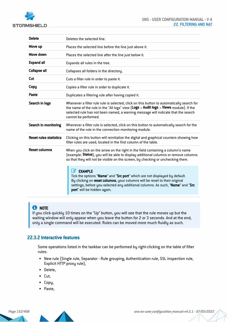
Delete Deletes the selected line.
Move up Places the selected line before the line just above it.
Move down Places the selected line after the line just below it.
Expand all Expands all rules in the tree.
Collapse all Collapses all folders in the directory.
Cut Cuts a filter rule in order to paste it.
Copy Copies a filter rule in order to duplicate it.
Paste Duplicates a filtering rule after having copied it.
Search in logs Whenever a filter rule rule is selected, click on this button to automatically search forthe name of the rule in the "All logs" view (Logs > Audit logs > Views module). If theselected rule has not been named, a warning message will indicate that the searchcannot be performed.
Search in monitoring Whenever a filter rule is selected, click on this button to automatically search for thename of the rule in the connection monitoring module.
Reset rules statistics Clicking on this button will reinitialize the digital and graphical counters showing howfilter rules are used, located in the first column of the table.
Reset columns When you click on the arrow on the right in the field containing a column’s name(example: Status), you will be able to display additional columns or remove columnsso that they will not be visible on the screen, by checking or unchecking them.
EXAMPLETick the options “Name” and “Src port” which are not displayed by default.By clicking on reset columns, your columns will be reset to their originalsettings, before you selected any additional columns. As such, “Name” and “Srcport” will be hidden again.
NOTEIf you click quickly 10 times on the “Up” button, you will see that the rule moves up but thewaiting window will only appear when you leave the button for 2 or 3 seconds. And at the end,only a single command will be executed. Rules can be moved more much fluidly as such.
22.3.2 Interactive features
Some operations listed in the taskbar can be performed by right-clicking on the table of filterrules:
l New rule (Single rule, Separator - Rule grouping, Authentication rule, SSL inspection rule,Explicit HTTP proxy rule),
l Delete,l Cut,l Copy,l Paste,
SNS - USER CONFIGURATION MANUAL - V 422. FILTERING AND NAT
Page 152/498 sns-en-user_configuration_manual-v4.5.1 - 07/05/2022

l Search in logs,l Search in monitoring.
Mathematical comparison
Whenever you come across a drop-down list of objects in the columns (except “Status” and
“Action”) a mathematical operator icon will appear ( ). It can only be used if an object otherthan “Any” has been selected.
You can therefore customize the parameters of your traffic using the following icon in 4different ways:
l “=" (or ): the value of the attribute corresponds to what is selected.
l “!=" (or ) the value of the attribute is different from what has been selected.
l "<" (or ; can only be used for source ports, destination ports and host reputationscores): the value of the attribute is lower than what has been selected.
l ">" (or ; can only be used for source ports, destination ports and host reputationscores): the value of the attribute is higher than what has been selected.
Adding/modifying objects
Some drop-down lists offer the button, which leads to a pop-up menu:l Create an object: new objects can be created directly from the Filter/NAT modulel Edit object: when an object is in a field, it can be edited directly to modify it (name, IP
address for a host, adding the object to a group, etc.), except for read-only objects ("Any","Internet", etc).
22.3.3 Filter table
This table allows you to define the filter rules to apply. The firewall will execute rules in theirorder of appearance on the screen (numbered 1, 2, etc) and will stop once it finds a a rule thatmatches the IP packet. Place them in the right order so that you obtain a coherent result.
It is therefore important to define rules from the most restrictive to the most general.
Reorganizing rules
In every security policy, every rule can be dragged and dropped so that the policy (filter or NAT)
can be reorganized easily. The symbol as well as the "Drag and drop to reorganize" tool tipappear when you scroll over the beginning of the rule.
Statistics on the use of rules
In the active security policy, each activated filter and NAT rule also displays a counter thatshows the number of times the rule has been used. When scrolling over the icon with a mouse,a tooltip will indicate the exact number of times the rule has been executed. The 4 levels of usecorrespond to the following values, according to the percentage on the counter of the rule mostfrequently used:
0%from 0 to 2%from 2 to 20% (from 2 to 100% if the counter is lower than 10 000)from 20 to 100 %, with a minimum of 10 000 times (otherwise the previouslevel will be displayed)
SNS - USER CONFIGURATION MANUAL - V 422. FILTERING AND NAT
Page 153/498 sns-en-user_configuration_manual-v4.5.1 - 07/05/2022

To obtain a new indicator, clicking on “Reset rule statistics” will start a new count. This counterwill be reinitialized if:
l One of the parameters in the rule has been modified (except for comments),l Another policy has been enabled,l The firewall has been restarted.
If no icons are displayed, this means that the information is unavailable.
Status
This column shows the status of the rule: On / Off . Double-click on it to change its status. Bydoing this once, you will enable the filter rule. Repeat the operation to disable it.
General tab
General section
Status Select On or Off to respectively enable or disable the rule being edited.
Comments You can enter comments in this area; they will be displayed at the end of the rulewhen the filter policy is displayed.
Advanced properties
Rule name You can assign a name to the filter rule; this name will be used in logs and facilitatesidentification of the filter rule during searches in logs or views (Logs - Audit logsmenu).
Action
This zone refers to the action applied to the packet that meets the selection criteria of the filterrule. To define the various parameters of the action, double-click in the column. A windowcontaining the following elements will appear:
SNS - USER CONFIGURATION MANUAL - V 422. FILTERING AND NAT
Page 154/498 sns-en-user_configuration_manual-v4.5.1 - 07/05/2022

General tab
General section
Action 5 different actions can be performed:
l Pass: The Stormshield Network firewall allows the packet corresponding to thisfilter rule to pass. The packet stops moving down the list of rules.
l Block: The Stormshield Network firewall silently blocks the packet correspondingto this filter rule: the packet is deleted without the sender being informed. Thepacket stops moving down the list of rules.
l Decrypt: This action decrypts encrypted traffic. Decrypted traffic will continue tomove down the list of rules. It will be encrypted again after the analysis (if it is notblocked by any rule).
l Reinit. TCP/UDP: This option mainly concerns TCP and UDP traffic:For TCP traffic, a “TCP reset” packet will be sent to its sender.For UDP traffic, a “port unreachable” ICMP packet will be sent to its sender.As for other IP protocols, the Stormshield Network firewall will simply block thepacket corresponding to this filter rule.
l If you are editing the global filter policy, a fifth option will appear: "Delegate".This option makes it possible to stop comparing the traffic against the rest of theglobal policy, but to compare it directly with the local policy.
If your policy contained rules with the action Log only, you will see log only(deprecated) whenever you edit these rules.
Log level The value is set to Standard (connection log) by default, so no logs are recorded.Several log levels are possible:
l Standard (connection log): No logs will be kept in filter logs if the packetcorresponds to this rule. However, ended connections can be logged (connectionlogs) depending on the connection of the protocol associated with the rule, whichis the case in a factory configuration.Do note that this option is not available if you have selected the “Log” action inthe previous field.
l Advanced (connection log and filtering log): In addition to logs in Standard mode,logs from all traffic that matches this rule will be captured. This option is notrecommended on "Deny All" filter rules (except for debugging) as it will thengenerate a large amount of logs.
l Minor alarm: As soon as this filter rule is applied to a connection, a minor alarmwill be generated. This alarm is recorded in the logs, and can be sent via Syslog(Logs – Syslog – IPFIX) or by e-mail (see module E-mail alerts).
l Major alarm: As soon as this filter rule is applied to a connection, a major alarmwill be generated. This alarm is recorded in the logs, and can be sent via Syslog(Logs – Syslog – IPFIX) or by e-mail (see module E-mail alerts).
To fully disable logs, you need to disable the Disk, Syslog server and IPFIX collectorcheckboxes in the Log destination for this rule field (Advanced properties tab in therule editing window).
Scheduling Select or create a time object.You will then be able to define the period/ day of the year / day of the week / time/recurrence when rules will be valid.
Objects can be created or modified directly from this field by clicking on
SNS - USER CONFIGURATION MANUAL - V 422. FILTERING AND NAT
Page 155/498 sns-en-user_configuration_manual-v4.5.1 - 07/05/2022

Routing section
Gateway – router This option is useful when specifying a particular router that will redirect trafficmatching the rule to the defined router. The selected gateway may be a host orrouter object.
Objects can be created or modified directly from this field by clicking on
IMPORTANTIf routers are specified in filter rules (Policy Based Routing), the availability of these routers willthen be tested systematically by sending ICMP echo request messages. When a router that hasbeen detected as unreachable is a host object, the default gateway entered in the Routingmodule will be selected automatically. If it is a router object, the action taken will depend on thevalue selected for the field If no gateways are available during the definition of this object (seethe section Network objects).For more technical information, refer to the technical support’s Knowledge Base (article "Howdoes the PBR hostcheck work?").
Click on Ok to confirm your configuration.
Quality of service tab
The QoS module, built into Stormshield Network’s intrusion prevention engine, is associatedwith the Filtering module in order to provide Quality of Service features.
When a packet arrives on an interface, it will first be treated by a filter rule, then the intrusionprevention engine will assign the packet to the right queue according to the configuration of thefilter rule’s QoS field.
QoS section
Queue This field offers you the choice of several queues that you have defined earlier in theSecurity policy module, in the Quality of Service menu.This operation does not apply (grayed out) to traffic going through the SSL proxy(Source menu > Advanced properties > Via field).
ACK queue This field offers you the choice of several queues that you have defined earlier forTCP ACK traffic in Security policy > Quality of Service.This operation does not apply (grayed out) to traffic going through the SSL proxy(Source menu > Advanced properties > Via field).
Fairness l No fairness: If you select this option, no particular amount of bandwidth will beassigned and each user/host/connection will use it according their needs.
l User fairness: bandwidth will be distributed evenly between users.
l Host fairness: bandwidth will be distributed evenly between hosts.
l Connection fairness: bandwidth will be distributed evenly between connections.
Connection threshold section
The Stormshield Network firewall may limit the maximum number of connections accepted persecond for a filter rule. The desired number can be defined for protocols corresponding to therule (TCP, UDP, ICMP and some application requests). This option also allows you to prevent adenial of service which hackers may attempt: you may limit the number of requests per secondaddressed to your servers.
Once this threshold has been exceeded, received packets will be blocked and ignored.
SNS - USER CONFIGURATION MANUAL - V 422. FILTERING AND NAT
Page 156/498 sns-en-user_configuration_manual-v4.5.1 - 07/05/2022

WARNINGThe restriction only applies to the corresponding rule.
EXAMPLEIf you create an FTP rule, only a TCP restriction will be taken into account.
REMARKSIf the option is assigned to a rule containing an object group, the restriction applies to the wholegroup (total number of connections).
If threshold isreached
l Do not do anything: no restrictions will be placed on the number of connections orrequests per second (c/s).
l Protect against SYN Flood: this option makes it possible to protect servers fromTCP SYN packet flooding (“SYN flooding”) attacks. The SYN proxy instead of theserver will respond and will assess the reliability of the TCP request beforetransmitting it.You can limit the number of TCP connections per second for this filter rule in thefield below.
l Raise associated alarm: Depending on the maximum number of connections persecond that you assign to the protocols below, the traffic will be blocked once thedefined number has been exceeded. The identifiers of these alarms are: 28 ICMP / 29 UDP / 30 TCP SYN / 253 TCP/UDP.
TCP (c/s) Maximum number of connections per second allowed for the TCP protocol.
UDP (c/s) Maximum number of connections per second allowed for the UDP protocol.
ICMP (c/s) Maximum number of connections per second allowed for the ICMP protocol.
SCTP (c/s) Maximum number of connections per second allowed for the SCTP protocol.
Application requests(r/s)
Maximum number of application requests per second allowed for the HTTP and DNSprotocol.
Click on Ok to confirm your configuration.
DSCP section
DSCP (Differentiated Services Code Point) is a field in the IP packet header. The purpose of thisfield is to allow services contained in a network architecture to be differentiated. It will specify amechanism for classifying and controlling traffic while providing quality of service (QoS).
Impose value By selecting this option, you will enable the field below and allow access to the DSCPservice.This option makes it possible to rewrite the packet with the given value, so that thenext router will know the priority to apply to this packet.
New DSCP value In this field, traffic differentiation can be defined. Through this field, it is possible todetermine which service a type of traffic belongs to, thanks to a pre-establishedcode. This DSCP service, used in the context of Quality of Service, allows theadministrator to apply QoS rules according to the service differentiation that he hasdefined.
Click on Ok to confirm your configuration.
SNS - USER CONFIGURATION MANUAL - V 422. FILTERING AND NAT
Page 157/498 sns-en-user_configuration_manual-v4.5.1 - 07/05/2022

Advanced properties tab
Redirection section
Service l None: This option means that none of the following services will be used: the userwill not go through the HTTP proxy and will not be redirected to the authenticationpage.
l HTTP proxy: If you select this option, the HTTP proxy will intercept userconnections and scan traffic.This service will be selected when rules are created by the explicit HTTP proxywizard.
l Authentication: If you select this option, unauthenticated users will be redirectedto the captive portal when they connect.This service will be selected when rules are created by the authentication wizard.
Redirect incoming SIPcalls (UDP)
This option allows the Stormshield Network firewall to manage incoming SIP-basedcommunications to internal hosts masked by address translation (NAT).
URLs withoutauthentication
This field becomes accessible if the previous option Service redirects traffic to theauthentication portal (authentication rule).It allows specifying URL categories or groups that are exempt from authentication;the listed sites therefore become accessible without authentication, which is usefulfor example in accessing update websites. The firewall’s security inspections cantherefore be applied to such access. There is by default in the web objects databasea URL group named authentication_bypass containing Microsoft update websites.
Logs section
Log destination forthis rule
This option makes it possible to define one or several methods for storing logsgenerated by the rule:
l Disk: local storage.
l Syslog server: the Syslog profile(s) including Filter policy logs must be defined inthe SYSLOG tab of the menu Notifications > Logs - Syslog - IPFIX.
l IPFIX collector: the IPFIX collector(s) must be defined in the IPFIX tab of the menuNotifications > Logs - Syslog - IPFIX.
Each log will contain details of connections evaluated through the rule.
Advanced properties section
Count If you select this option, the Stormshield Network firewall will count the number ofpackets that correspond to this filter rule and generate a report.Volume information on a desired traffic type can therefore be obtained.
Force source packetsin IPsec
When this option is selected, for this filter rule, you will force packets from thenetwork or source hosts to go through an active IPsec tunnel to reach theirdestination.
Force return packetsin IPsec
When this option is selected, for this filter rule, you will force return packets(responses) to go through an active IPsec tunnel in order to contact the host thatinitiated the traffic.
Synchronize thisconnection betweenfirewalls (HA)
When the firewall belongs to a cluster, this option enables or disables thesynchronization of the connection corresponding to the rule between two clustermembers.This option is enabled by default.
SNS - USER CONFIGURATION MANUAL - V 422. FILTERING AND NAT
Page 158/498 sns-en-user_configuration_manual-v4.5.1 - 07/05/2022
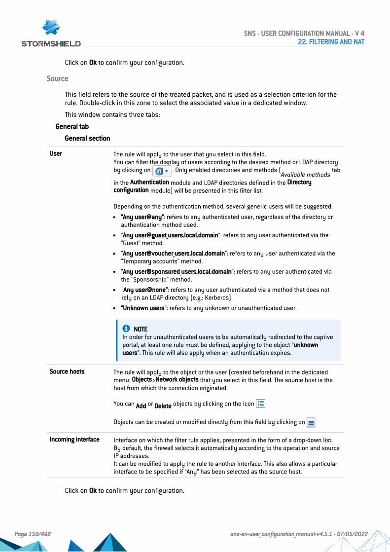
Click on Ok to confirm your configuration.
Source
This field refers to the source of the treated packet, and is used as a selection criterion for therule. Double-click in this zone to select the associated value in a dedicated window.
This window contains three tabs:
General tab
General section
User The rule will apply to the user that you select in this field.You can filter the display of users according to the desired method or LDAP directoryby clicking on . Only enabled directories and methods (
Available methodstab
in the Authentication module and LDAP directories defined in the Directoryconfiguration module) will be presented in this filter list.
Depending on the authentication method, several generic users will be suggested:
l "Any user@any": refers to any authenticated user, regardless of the directory orauthentication method used.
l "Any user@guest_users.local.domain": refers to any user authenticated via the"Guest" method.
l "Any user@voucher_users.local.domain": refers to any user authenticated via the"Temporary accounts" method.
l "Any user@sponsored_users.local.domain": refers to any user authenticated viathe "Sponsorship" method.
l "Any user@none": refers to any user authenticated via a method that does notrely on an LDAP directory (e.g.: Kerberos).
l “Unknown users”: refers to any unknown or unauthenticated user.
NOTEIn order for unauthenticated users to be automatically redirected to the captiveportal, at least one rule must be defined, applying to the object “unknownusers”. This rule will also apply when an authentication expires.
Source hosts The rule will apply to the object or the user (created beforehand in the dedicatedmenu: Objects>Network objects that you select in this field. The source host is thehost from which the connection originated.
You can Add or Delete objects by clicking on the icon
Objects can be created or modified directly from this field by clicking on
Incoming interface Interface on which the filter rule applies, presented in the form of a drop-down list.By default, the firewall selects it automatically according to the operation and sourceIP addresses.It can be modified to apply the rule to another interface. This also allows a particularinterface to be specified if “Any” has been selected as the source host.
Click on Ok to confirm your configuration.
SNS - USER CONFIGURATION MANUAL - V 422. FILTERING AND NAT
Page 159/498 sns-en-user_configuration_manual-v4.5.1 - 07/05/2022

NOTEFilter rules with a user@object source type (except any or unknown@object), and with a protocolother than HTTP, do not apply to Multi-user Objects (Authentication> Authentication policy). Thisbehavior is inherent in the packet treatment mechanism used by the intrusion preventionengine.
Geolocation/Reputation tab
Geolocation section
Select a region This field allows the filter rule to be applied to hosts with a public IP addressbelonging to a country, continent or group of regions (group of countries and/orcontinents) defined beforehand in the Objects > Network objects module.
SNS - USER CONFIGURATION MANUAL - V 422. FILTERING AND NAT
Page 160/498 sns-en-user_configuration_manual-v4.5.1 - 07/05/2022

Public IP address reputation section
Select a reputationcategory
This field makes it possible to apply the filter rule to hosts whose public IP addresseshave been classified in one of the predefined reputation categories:
l anonymizer: proxies, IPv4 to IPv6 converters.
l botnet: infected hosts running malicious programs.
l malware: hosts distributing malicious programs
l phishing: compromised mail servers.
l scanner: hosts that conduct port scanning or launch brute force attacks.
l spam: compromised mail servers.
l tor exit node: endpoint servers of the Tor network.
l exploit: IP addresses known for having been at the source of vulnerability exploits.
l bad: groups all of the above categories.
l suspicious: groups hosts and IP addresses that do not appear very trustworthy,and which are likely to cause false positives. This category is not included in badby default.
NOTESince the reputation of a public IP address may border on two categories(botnet and malware), and this field only allows one category to be selected,you are advised to use the "bad" group for optimum protection.
Other host categories are also available to facilitate the setup of filter rules forMicrosoft Online solutions:
l Exchange online: servers that host the corporate mail application.
l Microsoft Identity and authentication: authentication servers used for accessingMicrosoft Office 365.
l Office 365: servers that host the Microsoft Office 365 storage and office toolssolution.
l Office online: servers that host the free online office tools solution Microsoft Office365.
l Sharepoint online: servers that host the online collaborative solution MicrosoftSharepoint.
l Skype Enterprise Online: servers that host the professional version of the instantmessaging solution Skype.
l Microsoft: groups all categories of machines that host Microsoft services online.
Host reputation section
Enable filtering basedon reputation score
Select this checkbox in order to enable filtering based on the reputation score ofhosts on the internal network.To enable host reputation management and to define the hosts affected by thecalculation of a reputation score, go to the Application protection > Host reputationmodule.
Reputation score This field makes it possible to select the reputation score above which ( ) or belowwhich ( ) the filter rule will apply to the monitored hosts.
Click on Ok to confirm your configuration.
SNS - USER CONFIGURATION MANUAL - V 422. FILTERING AND NAT
Page 161/498 sns-en-user_configuration_manual-v4.5.1 - 07/05/2022

Advanced properties tab
Advanced properties section
Source port This field makes it possible to specify the port used by the source host, if it has aparticular value.By default, the "Stateful" module memorizes the source port used and only this portwill then be allowed for return packets.
Objects can be created or modified directly from this field by clicking on
Via l Any: This option implies that none of the following services will be used – theconnection will not go through the HTTP proxy, will not be redirected to theauthentication page and will not go through an IPsec VPN tunnel.
l Explicit HTTP proxy: Traffic originates from the HTTP proxy.
l SSL proxy: Traffic originates from the SSL proxy.
l IPsec VPN tunnel: Traffic comes from an IPsec VPN tunnel.
l SSL VPN tunnel: Traffic comes from an SSL VPN tunnel.
Source DSCP This field makes it possible to filter by the value of the DSCP field of the packetreceived.
Authentication section
Authenticationmethod
In this field, the application of the filter rule can be restricted to the selectedauthentication method.
Click on Ok to confirm your configuration.
Destination
Destination object used as a selection criterion for the rule. Double-click in this zone to selectthe associated value in a dedicated window. This window contains two tabs:
General tab
General section
Destination hosts Select the destination host of the traffic from the object database in the drop-downlist.You can Add or Delete objects by clicking on the icon .
Objects can be created or modified directly from this field by clicking on .
Click on Ok to confirm your configuration.
Geolocation/Reputation tab
Geolocation section
Select a region This field makes it possible to apply the filter rule to hosts with a public IP addressbelonging to a country, continent or group of regions (group of countries and/orcontinents) defined beforehand in the Objects > Network objects module.
SNS - USER CONFIGURATION MANUAL - V 422. FILTERING AND NAT
Page 162/498 sns-en-user_configuration_manual-v4.5.1 - 07/05/2022

Public IP address reputation section
Select a reputationcategory
This field allows applying the filter rule to destination hosts whose IP addresses havebeen classified in one of the predefined reputation categories:
l anonymizer: proxies, IPv4 to IPv6 converters.
l botnet: infected hosts running malicious programs.
l malware: hosts distributing malicious programs
l phishing: compromised mail servers.
l scanner: hosts that conduct port scanning or launch brute force attacks.
l spam: compromised mail servers.
l tor exit node: endpoint servers of the Tor network.
l Bad: groups all of the above categories.
NOTESince the reputation of a public IP address may border on two categories(botnet and malware), and this field only allows selecting one category, you areadvised to use the "Bad" group for optimum protection.
Host reputation section
Enable filtering basedon reputation score
Select this checkbox in order to enable filtering based on the reputation score ofhosts on the internal network.To enable host reputation management and to define the hosts affected by thecalculation of a reputation score, go to the Application protection > Host reputationmodule.
Reputation score This field allows selecting the reputation score above which ( ) or below which () the filter rule will apply to the monitored destination hosts.
Click on Ok to confirm your configuration.
Advanced properties tab
Advanced properties section
Outgoing interface This option allows choosing the packet’s outgoing interface, to which the filter ruleapplies.By default, the firewall selects it automatically according to the operation anddestination IP addresses. A packet’s outgoing interface can be used as a filteringcriterion.
SNS - USER CONFIGURATION MANUAL - V 422. FILTERING AND NAT
Page 163/498 sns-en-user_configuration_manual-v4.5.1 - 07/05/2022

NAT on the destination section
Destination If you wish to translate the traffic’s destination IP address, select one from theobjects in the drop-down list. Otherwise, leave the field empty, i.e. “None” by default.
NOTEAs this traffic has already been translated by this option, the other NAT rules inthe current policy will not be applied to this traffic.
Objects can be created or modified directly from this field by clicking on .
ARP publication onexternal destination(public)
This option has been added so that an ARP publication can be specified when a filterrule with a NAT operation is used on the destination. It must be enabled if thedestination public IP address (before applying NAT) is a virtual IP address and doesnot belong to the UTM.
NOTEAnother way to set up this publication would be to add the virtual IP address ofthe affected interface in the Interfaces module.
Click on Ok to confirm your configuration.
Port - Protocol
The destination port represents the port on which the “source” host opens a connection to the“destination” host. The protocol to which the filter rule applies can also be defined in thiswindow.
Port section
Destination Port Service or service group used as a selection criterion for this rule. Double-click onthis zone to select the associated object.
EXAMPLESPort 80: HTTP servicePort 25: SMTP service
You can Add or Delete objects by clicking on the icon
Objects can be created or modified directly from this field by clicking on .
Protocol section
Depending on the protocol type that you choose here, the following field that appears will vary:
SNS - USER CONFIGURATION MANUAL - V 422. FILTERING AND NAT
Page 164/498 sns-en-user_configuration_manual-v4.5.1 - 07/05/2022

Protocol type Select the desired protocol type. The value of the following fields varies according toyour choice.
l Automatic protocol detection (default),
l Application protocol,
l IP protocol.
l Ethernet protocol.
Application protocol The advantage of this choice is being able to apply application analysis on a portother that the default port. When this protocol type is selected:
l Application protocol: Select the desired protocol from the drop-down list.
l IP protocol: the IP protocols concerned will change according to the selectedapplication protocol.
IP protocol When this protocol type is selected:
l Application protocol: No application analysis.
l IP protocol: Select the desired protocol from the drop-down list. Additional fieldsmay appear depending on the protocol selected.
l Stateful tracking: Select the checkbox to track the status of IP connections. Thisoption is selected by default for TCP, UDP and ICMP protocols.
Ethernet protocol When this protocol type is selected, select the desired Ethernet protocol from thedrop-down list.
NOTEFor example, connection status tracking (stateful mode) can be enabled for the GRE protocol,which is used in PPTP tunnels. Thanks to this tracking tool, the source (map), destination(redirection) or both (bimap) can be translated.However, it will be impossible to differentiate 2 connections that share the same source anddestination addresses. In concrete terms, this means that when the firewall translates a source N-> 1 (map), only one simultaneous connection to a PPTP server can be made.
Translated port section
This section is available when NAT on the destination is selected.
Translateddestination port
Translated port to which packets are going. Network packets received will beredirected from a given port on a host or a network device to another host or networkdevice. If you wish to translate the traffic’s destination port, select one from theobjects in the drop-down list.Otherwise, leave the field empty, i.e. “None” by default. In this case, the Destinationport field remains unchanged.
Security inspection
General section
Inspection level field
IPS (Detect andblock)
If this option is selected, Stormshield Network’s IPS (Intrusion Prevention System)will detect and block intrusion attempts, from the Network level to the Applicationlevel in the OSI model.
SNS - USER CONFIGURATION MANUAL - V 422. FILTERING AND NAT
Page 165/498 sns-en-user_configuration_manual-v4.5.1 - 07/05/2022

IDS (Detect) If this option is selected, Stormshield Network’s IDS (Intrusion Detection System) willdetect intrusion attempts on your traffic, without blocking them.
Firewall (Do notinspect)
This option only provides access to basic security functions and will merely filteryour traffic without inspecting it.
Inspection profile
Depending on thedirection of thetraffic, IPS_ 00 to 09
You can customize the configuration of your security inspection by assigning apredefined policy to it, which will appear in the filter table.Numbered configurations can be renamed in the menu Application protection >Inspection profiles.The value suggested by default (Depending on the direction of the traffic) uses theIPS_00 profile for incoming traffic and the profile IPS_01 for outgoing traffic.
Application inspection section
Antivirus The On / Off buttons allow you to enable or disable the antivirus in your filterrule.
Antivirus analyses will only be run on HTTP, FTP, SMTP, POP3 protocols and on theirvariants in SSL. They can be configured for each of these protocols in the menuApplication protection > Protocols.
Sandboxing The On /Off buttons allow you to enable or disable sandboxing (malicious files)in your filter rule.Do note that Advanced antivirus must be used when this option is enabled.
Antivirus analyses will only be run on HTTP, FTP, SMTP, POP3 protocols and on theirvariants in SSL. They can be configured for each of these protocols in the menuApplication protection > Protocols.
Antispam The On / Off buttons allow you to enable or disable the antispam in your filterrule.
This analysis is only run on SMTP, POP3 protocols and on their variants in SSL. Theycan be configured for each of these protocols in the menu Application protection >Protocols.
URL filtering To enable this filtering method, select an URL filter profile from the suggestedprofiles.
SMTP filtering To enable this filtering method, select an SMTP filter profile from the suggestedprofiles.Selecting the SMTP filter policy also enables the POP3 proxy in the event the filterrule allows the POP3 protocol.
FTP filtering The On / Off buttons allow you to enable or disable FTP filtering in your filter rule,in line with the FTP commands defined in FTP plugin (Protocols module).
SSL filtering To enable this filtering method, select an SSL filter profile from the suggestedprofiles.
Comments
You can add a description that will allow distinguishing your filter rule and its characteristicsmore easily.
SNS - USER CONFIGURATION MANUAL - V 422. FILTERING AND NAT
Page 166/498 sns-en-user_configuration_manual-v4.5.1 - 07/05/2022

Comments on new rules indicate the date on which they were created and the user who createdthem, if the rules were not created by the "admin" account, in the form of "Created on {date} by{login} ({IP address)}". This automatic information may be disabled by unselecting the option"Comments about rules with creation date (Filtering and NAT)" found in the Preferences module.
22.4 NAT tab
The principle of NAT (Network Address Translation) is to convert an IP address to another whenpassing through the firewall, regardless of the source of the connection. It is also possible totranslate ports through NAT.
Checking the policy in real time
The firewall’s translation policy is one of the most important elements for the security of theresources that the firewall protects. Although this policy is constantly changing to adapt to newservices, new threats and new user demands, it has to remain perfectly coherent so thatloopholes do not appear in the protection provided by the firewall.
The art of creating an effective filter policy is in avoiding the creation of rules that inhibit otherrules. When a filter policy is voluminous, the administrator’s task becomes even more crucial asthe risk increases. Furthermore, during the advanced configuration of very specific translationrules, the multiplicity of options may give rise to the creation of a wrong rule that does not meetthe administrator’s needs.
To prevent this from happening, the filter rule edit window has a Check policy field (locatedunder the filter table), which warns the administrator whenever a rule inhibits another or anerror has been created on one of the rules.
EXAMPLE
[Rule 2] This rule will never be applied as it is covered by Rule 1.
22.4.1 Actions on NAT policy rules
Search This field makes it possible to perform searches by occurrence, letter or word.
EXAMPLEIf you enter “Any” in the field, all NAT rules containing “Any” will be displayed inthe table.
SNS - USER CONFIGURATION MANUAL - V 422. FILTERING AND NAT
Page 167/498 sns-en-user_configuration_manual-v4.5.1 - 07/05/2022

New rule Inserts a blank line after the selected line, 4 choices are available:
l Single rule: This option allows creating an inactive NAT rule which will need to beconfigured.
l Source address sharing rule (masquerading): This option allows creating a PAT(Port Address Translation) dynamic NAT rule. This type of rule allows convertingmultiple IP addresses into one or N IP addresses. The value selected by default isephemeral_fw (corresponding to a port range from 20000 to 59999 inclusive). Thesource port will also be rewritten.The wizard selects as the destination interface, the interface corresponding to thenetwork of this source after translation.
l Separator – rule grouping: This option allows inserting a separator above theselected line.This separator makes it possible to group rules that apply to traffic going to
different servers and helps to improve the NAT policy’s readability and visibility byindicating a comment.Separators indicate the number of grouped rules and the numbers of the first andlast rules in the form: “Rule name (contains the total number of rules, from first tolast)”.You can collapse or expand the node of the separator in order to show or hide therule grouping. You can also copy/paste a separator from one location to another.
l Static NAT rule (bimap): The principle of static address translation is to convert anIP address (or N public IP addresses) to another (or N private IP addresses) whengoing through Firewall, whatever the origin of the connection.A wizard window will allow you to map a private IP address to a public (virtual) IPaddress by defining their parameters. You must also choose from the drop-downlists the Private and virtual hosts for your IPs, as well as the interface on whichyou wish to apply them.The Advanced properties field makes it possible to restrict the application to a portor port group, and enable ARP publication, which may provision the IP via thefirewall’s MAC address.You are however advised to restrict access to a port or a port group through a filterrule corresponding to this traffic. This allows adding other criteria to it in order tomake this filter more accurate.
Click on Finish to confirm your configuration.
DO note that for an N-to-N bi-map rule, original and translated address ranges,networks or host groups must be of the same size.
Bi-directional translation is generally used to allow access to a server from theoutside with a public IP address that is not the same as the host’s real address
The “bi-map” action supports address ranges. Source and translated addresses areused in the following order: the “smallest” address in the source field is translated tothe “smallest” address in the translated field.
When a virtual IP address is selected, the corresponding interface will be selectedautomatically. This interface will be used as the source of the redirection rule and asthe destination for rules that rewrite the source.
Delete Deletes the selected line.
Move up Places the selected line before the line just above it.
SNS - USER CONFIGURATION MANUAL - V 422. FILTERING AND NAT
Page 168/498 sns-en-user_configuration_manual-v4.5.1 - 07/05/2022

Move down Places the selected line after the line just below it.
Expand all Expands all rules in the tree.
Collapse all Collapses all folders in the directory.
Cut Cuts a NAT filter rule in order to duplicate it.
Copy Copies a NAT rule in order to duplicate it.
Paste Duplicates a NAT rule after having copied it.
Search in logs Whenever a NAT rule is selected, click on this button to automatically search for thename of the rule in the "All logs" view (Logs > Audit logs > Views module). If theselected rule has not been named, a warning message will indicate that the searchcannot be performed.
Search in monitoring Whenever a NAT rule is selected, click on this button to automatically search for thename of the rule in the connection monitoring module.
Reset rules statistics Clicking on this button will reinitialize the digital and graphical counters showing howNAT rules are used, located in the first column of the table.
Reset columns When you click on the arrow on the right in the field containing a column’s name(example: Status), you will be able to display additional columns or remove columnsso that they will not be visible on the screen, by checking or unchecking them.
EXAMPLETick the options “Name” and “Src port” which are not displayed by default.By clicking on reset columns, your columns will be reset to their originalsettings, before you selected any additional columns. As such, “Name” and “Srcport” will be hidden again.
NOTEIf you click quickly 10 times on the “Up” button, you will see that the rule moves up but thewaiting window will only appear when you leave the button for 2 or 3 seconds. And at the end,only a single command will be executed. Rules can be moved more much fluidly as such.
22.4.2 Interactive features
Some operations listed in the taskbar can be performed by right-clicking on the table of NATrules:
l New rule (Single rule, Source address sharing rule [masquerading], Separator - Rulegrouping, Static NAT rule [bimap]),
l Delete,l Cut,l Copy,l Paste,l Search in logs,l Search in monitoring.
SNS - USER CONFIGURATION MANUAL - V 422. FILTERING AND NAT
Page 169/498 sns-en-user_configuration_manual-v4.5.1 - 07/05/2022

Mathematical comparison
Whenever you come across a drop-down list of objects in the columns (except Status and
Action) a mathematical operator icon will appear ( ). It can only be used if an object otherthan Any has been selected.
You can therefore customize the parameters of your traffic using the following icon in 4different ways:
l “=" (or ): the value of the attribute corresponds to what is selected.
l “!=" (or ) the value of the attribute is different from what has been selected.
l “<“ (or ; used for source and destination ports only): the port number of the traffic islower than what is selected.
l “>“ (or ; used for source and destination ports only): the port number of the traffic ishigher than what is selected.
Adding/modifying objects
Some drop-down lists offer the button, which leads to a pop-up menu:l Create an object: new objects can be created directly from the Filter/NAT modulel Edit object: when an object is in a field, it can be edited directly to modify it (name, IP
address for a host, adding the object to a group, etc.), except for read-only objects ("Any","Internet", etc).
22.4.3 NAT table
This table allows you to define the NAT rules to apply. The firewall will assess rules in their orderof appearance on the screen: one by one from the top down. Place them in the right order sothat you obtain a coherent result. Once it comes upon a rule that corresponds to the request,the will perform the specified action and stop there.
It is therefore important to define rules from the most restrictive to the most general.
The NAT table consists of two parts - Original traffic (before translation) and Translated traffic.
Reorganizing rules
Every rule can be dragged and dropped so that the policy (filter or NAT) can be reorganized
easily. The symbol as well as the "Drag and drop to reorganize" tool tip appear when youscroll over the beginning of the rule.
SNS - USER CONFIGURATION MANUAL - V 422. FILTERING AND NAT
Page 170/498 sns-en-user_configuration_manual-v4.5.1 - 07/05/2022

Status
This column shows the status of the rule: On /Off . Double-click on it to change its status. Bydoing this once, you will enable the NAT rule. Repeat the operation to disable it.
NOTESource address translation manages stateless IP protocols (GRE) but with the followingrestriction:if two clients go through the same firewall, they will not be able to connect to the same server atthe same time. Stormshield Network’s intrusion prevention engine will block packets received bythe second client.After 5 minutes, the intrusion prevention engine will deem the session too old and will allow thesecond client to take over.
General tab in the rule editing window
General section
Status Select On or Off to respectively enable or disable the rule being edited.
Comments You can enter comments in this area; they will be displayed at the end of the rulewhen the address translation policy is displayed.
Advanced properties section
Rule name You can assign a name to the NAT rule; this name will be used in logs and facilitatesidentification of the NAT rule during searches in logs or views (Logs - Audit logsmenu).
Original source before translation
General tab
General section
User The rule will apply to the user or the user group that you select in this field.There are three choices by default:
l “No user”: this option clears the user field and stops applying criteria to the rule.
l “Any user”: refers to any authenticated user.
l “Unknown users”: refers to any unknown or unauthenticated user.
Source hosts The rule will apply to the object that you select in this field. The source host is thehost from which the treated packet originated: it is the sender of the packet.
You can Add or Delete objects by clicking on and Create objects by clicking on
.
Incoming interface Interface on which the translation rule applies, presented in the form of a drop-downlist. By default, the firewall selects it automatically according to the operation andsource and destination IP addresses. It can be modified to apply the rule to anotherinterface.It can be modified to apply the rule to another interface. This also allows specifying aparticular interface if “Any” has been selected as the source host.
SNS - USER CONFIGURATION MANUAL - V 422. FILTERING AND NAT
Page 171/498 sns-en-user_configuration_manual-v4.5.1 - 07/05/2022

Click on Ok to confirm your configuration.
Advanced properties tab
Advanced properties section
Source port This field allows specifying the port used by the source host.By default, the "Stateful" module memorizes the source port used and only this portwill then be allowed for return packets.
Source DSCP This field refers to the DSCP code of the received packet.
Authentication section
Authenticationmethod
This field allows restricting the application of the filter rule to the selectedauthentication method.
Click on Ok to confirm your configuration.
Original destination before translation
General tab
General section
Destination hosts Select the destination host of the traffic from the object database in the drop-downlist.
Destination Port If you wish to translate the traffic’s destination port, select one from the objects inthe drop-down list. The object “Any” is selected by default.
You can Add or Delete objects by clicking on and Create objects by clicking on . Click onOk to confirm your configuration.
NOTELoad balancing types other than a connection hash can be selected with a destination portrange.
Advanced properties tab
Advanced properties section
Outgoing interface This option allows selecting the outgoing interface for the translated traffic.By default, the firewall selects it automatically according to the operation and sourceand destination IP addresses. It can be modified to restrict the rule to a particularinterface.
ARP publication This option makes the IP address to be published available via the firewall’s MACaddress.
NOTEThe ARP publication option is now assigned to the original destination (traffic before translation),whose IP address is indeed published, and not to the translated destination.
Source after translation
SNS - USER CONFIGURATION MANUAL - V 422. FILTERING AND NAT
Page 172/498 sns-en-user_configuration_manual-v4.5.1 - 07/05/2022

General tab
General section
Translated sourcehost
The rule will apply to the object that you select in this field. The translated sourcehost refers to the new IP address of the source host, after its translation by NAT.
Translated sourceport
This field allows specifying the source port used by the source host after translation.By default, the "Stateful" module memorizes the source port used and only this portwill then be allowed for return packets. The creation of a source address sharing rule(masquerading) assigns the value ephemeral_fw to this field.
Select a randomtranslated sourceport
By selecting this option, the firewall will randomly select the translated source portfrom the list (e.g.: ephemeral_fw). This makes it possible to avoid an anticipation ofthe following connections as the source ports are assigned consecutively , therebystrengthening security.
Click on Ok to confirm your configuration.
Advanced properties tab
Load balancing section
Load balancing type This option allows distributing IP addresses of sources that sent the packet aftertranslation. The load balancing method depends on the algorithm used.
Several load balancing algorithms are available:
l None: No load balancing will be carried out.
l Round-robin: This algorithm allows fairly distributing the load among the variousIPs of the selected address range. Each of these source IP addresses will berotated.
l Source IP hash: The source address will be hashed in order to choose the addressto use from the range. This method allows guaranteeing that a given sourceaddress will always be mapped to the same address range.
l Connection hash: Users can now choose the hash by connection (source IPaddress + source port + destination IP address + destination) as a load balancingmethod in their NAT rules. This allows connections from one source to the sameserver to be distributed according to the source port and source IP address.
l Random: The firewall randomly selects an address from the selected addressrange
ARP publication This option makes the IP address to be published available via the firewall’s MACaddress.
Click on Ok to confirm your configuration.
Destination after translation
General tab
General section
Translateddestination host
This field allows selecting the destination host of the translated packet from thedrop-down list of objects.
SNS - USER CONFIGURATION MANUAL - V 422. FILTERING AND NAT
Page 173/498 sns-en-user_configuration_manual-v4.5.1 - 07/05/2022

Translateddestination port
This field allows specifying the port used by the destination host.
Click on Ok to confirm your configuration.
Advanced properties tab
Load balancing types other than a connection hash can be selected with a destination portrange.
Load balancing section
Load balancing type This option allows distributing the transmission of packets among severaldestination IP addresses. The load balancing method depends on the algorithm used.
Several load balancing algorithms are available:
l None: No load balancing will be carried out.
l Round-robin: This algorithm allows fairly distributing the load among the variousIPs of the selected address range. Each of these source IP addresses will berotated.
l Source IP hash: The source address will be hashed in order to choose the addressto use from the range. This method allows guaranteeing that a given sourceaddress will always be mapped to the same address range.
l Connection hash: Users can now choose the hash by connection (source IPaddress + source port + destination IP address + destination) as a load balancingmethod in their NAT rules. This allows connections from one source to the sameserver to be distributed according to the source port and source IP address.
l Random: The firewall randomly selects an address from the selected addressrange
Between ports This option allows distributing the transmission of packets among severaldestination ports. The load balancing method depends on the algorithm used. Theload balancing algorithms are the same as the ones described earlier.
Click on Ok to confirm your configuration.
Protocol
Protocol section
Depending on the protocol type that you choose here, the following field that appears will vary:
Protocol type Select the desired protocol type. The value of the following fields varies according toyour choice.
l Automatic protocol detection (default),
l Application protocol,
l IP protocol.
l Ethernet protocol.
SNS - USER CONFIGURATION MANUAL - V 422. FILTERING AND NAT
Page 174/498 sns-en-user_configuration_manual-v4.5.1 - 07/05/2022

Application protocol The advantage of this choice is being able to apply application analysis on a portother that the default port. When this protocol type is selected:
l Application protocol: Select the desired protocol from the drop-down list.
l IP protocol: the IP protocols concerned will change according to the selectedapplication protocol.
IP protocol When this protocol type is selected:
l Application protocol: No application analysis.
l IP protocol: Select the desired protocol from the drop-down list. Additional fieldsmay appear depending on the protocol selected.
Ethernet protocol When this protocol type is selected, select the desired Ethernet protocol from thedrop-down list.
Options
Log level Logging traffic allows facilitating diagnosis and troubleshooting. The results will bestored in the filter log files.
NAT inside IPsectunnel (beforeencryption, afterdecryption)
If the option has been selected, the encryption policy will be applied to thetranslated traffic. The NAT operation is performed just before encryption by the IPsecmodule when packets are sent and after decryption when packets are received.
Comments
You can add a description that will allow distinguishing your NAT rule and its characteristicsmore easily.
Comments on new rules indicate the date on which they were created and the user who createdthem, if the rules were not created by the "admin" account, in the form of "Created on {date} by{login} ({IP address)}". This automatic information may be disabled by unselecting the option"Comments about rules with creation date (Filtering and NAT)" found in the Preferences module.
SNS - USER CONFIGURATION MANUAL - V 422. FILTERING AND NAT
Page 175/498 sns-en-user_configuration_manual-v4.5.1 - 07/05/2022

23. HIGH AVAILABILITYThis module will allow you to create first of all, a cluster or a group of firewalls. Once this isdone, another firewall can be added to join the cluster that you have just initialized.
Do note that only traffic relating to high availability must pass through HA links. The VLANcreation wizard, for example, does not allow selecting HA interfaces to support VLANs in theprocess of being created.
Stormshield Network’s high availability operates in “Active/passive” mode: Consider a clustercontaining 2 firewalls. If the firewall considered “active” fails, or if a cable has beendisconnected, the second firewall considered “passive” will seamlessly take over. As such, the“passive” firewall becomes “active”.
A video from Stormshield Network’s WebTV on YouTube will guide you step by step in theconfiguration of a group of Stormshield Network firewalls (cluster). Click on this link to accessthe video: Configuring a Stormshield Network firewall cluster.
The configuration of high availability takes place in 4 steps:
l Step 1: Creating a cluster / joining an existing clusterl Step 2: Configuring network interfaces: the main link and the secondary link (optional)l Step 3: Defining the cluster’s pre-shared keyl Step 4: Summary of the steps and application of configured settings
Once you are done with these 4 steps, a new screen will appear suggesting new configurationswithin the high availability module.
NOTEA communication link between members of a cluster has to be set up from a protected interface.The configuration can be changed in the Interfaces module.
23.1 Step 1: Creating or joining a high availability cluster
Create a cluster If this option is selected, the firewall will be prepared to receive other firewalls andwill add itself to the cluster.
SNS - USER CONFIGURATION MANUAL - V 423. HIGH AVAILABILITY
Page 176/498 sns-en-user_configuration_manual-v4.5.1 - 07/05/2022

Join a cluster If this option is selected, the appliance will attempt to connect to the firewall with theIP address defined during the creation of the cluster. As such, this second firewallwill retrieve information from the first and synchronize with it.
The cluster therefore comprises two firewalls: when the first firewall fails, the secondwill take over transparently.
NOTEAt the end of the wizard, the appliance will be rebooted. Once the reboot iscomplete, the appliance will be part of the cluster, and therefore no longerexists as an entity, but as a member of the cluster.
WARNINGIf you choose to “join” a cluster, it implies that you have already created onebeforehand, and have selected the option “Create a cluster” and haveperformed the necessary configuration to set it up on the first firewall.
WARNINGIt is important to avoid creating a cluster twice, as this would mean that you would be setting uptwo high availability clusters, each containing a firewall, and not a high availability clustercontaining 2 firewalls.
NOTEA member of a cluster can be forced to be the active firewall, even if members of the group havediffering firmware versions.
23.2 Step 2: Configuring network interfaces
23.2.1 If you have chosen to create a cluster
Configure the main link
Interface Main interface used for linking both firewalls that make up the cluster.Select it from the list of objects in the drop-down list.
Define name Define a customized name for the main link.
Define the IP addressand network mask
Enter the IP address and subnet mask dedicated to your main link. The format isexpressed in address / mask.
Secondary link (optional)
If the firewall does not receive responses on the main link, it will attempt to connect to thissecondary link. This will prevent both firewalls from switching to active / active mode if aproblem arises on the main link.
SNS - USER CONFIGURATION MANUAL - V 423. HIGH AVAILABILITY
Page 177/498 sns-en-user_configuration_manual-v4.5.1 - 07/05/2022

Use a secondcommunication link
Select this option in order to enable the fields below it and to define a secondary linkfor your cluster.
Interface Secondary interface used for linking both firewalls that make up the cluster.Select it from the list of objects in the drop-down list.
Define name Define a customized name for your secondary link.
Define the IP address Enter the IP address for your secondary link.
NOTEIn order for a link to work, both members of the cluster have to use the same interface.
23.2.2 If you have chosen to join a cluster
This option assumes that a cluster has already been created beforehand, in order for a firewallto be able to join it.As such, some of the information from the first firewall created will be copied.
Configure the main link
Interface Main interface used for linking both firewalls that make up the cluster.This has to be the same interface that you had selected during the creation of thecluster on the first firewall.
Define the IP addressand network mask
IP address and network mask dedicated to your main link. The format is expressed inaddress / mask.This address has to belong to the same sub-network as the one defined whencreating the cluster on the first firewall.
Secondary link (optional)
If the firewall does not receive responses on the main link, it will attempt to connect to thissecondary link. This will prevent both firewalls from switching to active / active mode if aproblem arises on the main link.
Use a secondcommunication link
Select this option in order to enable the fields below it and to define a secondary linkfor your cluster.
This option must only be selected if it was also selected during the creation of thecluster on the first firewall.
Interface Secondary interface used for linking both firewalls that make up the cluster.This has to be the same interface that you had selected during the creation of thecluster on the first firewall.
Define the IP address IP address for your secondary link.This address has to belong to the same sub-network as the one defined whencreating the cluster on the first firewall.
NOTEIn order for a link to work, both members of the cluster have to use the same interface.
SNS - USER CONFIGURATION MANUAL - V 423. HIGH AVAILABILITY
Page 178/498 sns-en-user_configuration_manual-v4.5.1 - 07/05/2022

23.3 Step 3: Cluster’s pre-shared key and data encryption
23.3.1 If a cluster is being created
To secure the connection between members of the cluster, you must define a pre-shared key.This key will only be used by firewalls that are joining the cluster for the first time.
Pre-shared key Define a password/pre-shared key for your cluster.
Confirm Confirm the password/pre-shared key that you have just entered in the previousfield.
Password strength This progress bar indicates your password’s level of security: “Very Weak”, “Weak”,“Medium”, “Good” or “Excellent”. You are strongly advised to use uppercase lettersand special characters.
Communication between firewalls in the high availability cluster
Encryptcommunicationbetween firewalls
By default, communications between the firewalls are not encrypted, since the linkused by high availability is a dedicated link.
In some architectures, the high availability link is not dedicated, but if you wish toprevent inter-cluster communications from being intercepted, they can be encryptedin AES, for example.
WARNING
1. Selecting this option can adversely affect the performance of your HAcluster.
2. Only connections, and not their contents, pass through the HA link.
Swap configuration
Enable linkaggregation when thefirewall is passive
When this option is enabled in a configuration that uses link aggregation (LACP),aggregates will be enabled even on the passive member of the cluster. This option isenabled by default.
Click on Next.
23.3.2 If a cluster exists
IP address of thefirewall to contact
Enter the IP address that you had defined in the wizard during the creation of thecluster (IP address of the main or secondary link).
Pre-shared key Enter the password/pre-shared key that you had defined in the wizard during thecreation of the cluster.This icon allows you to view the password in plaintext to check that it is correct.
SNS - USER CONFIGURATION MANUAL - V 423. HIGH AVAILABILITY
Page 179/498 sns-en-user_configuration_manual-v4.5.1 - 07/05/2022

23.4 Step 4: Summary and finalizing the cluster
23.4.1 If a cluster is being created
After having viewed the summary of your configurations, click on Finish. The following messagewill appear:This firewall is ready to run in high availability. You may now configure another firewall to add itto the cluster.
Now that your cluster has been created, a new screen will appear when you attempt to accessthis module.
23.4.2 If a cluster exists
After having viewed the summary of your configurations, click on Finish. The following messagewill appear:This firewall has to be rebooted in order to add a firewall to the cluster. Join the cluster?
To confirm the configuration, this firewall will join the cluster and synchronize the initialconfiguration. It will then restart in order to apply the configuration. To access this cluster, youneed to connect to the active firewall.
NOTEThis step may take a long time on entry-level models. Do not unplug the firewall.
23.5 High availability screen
23.5.1 Communication between firewalls in the high availability cluster
Main link Main interface used to link two firewalls that make up the cluster.Select it from the list of objects in the drop-down list.
Use a secondcommunication link
Select this option to enable the fields below it and to define a secondary link for yourcluster.
Secondary link Secondary interface used to link both firewalls that make up the cluster.Select it from the list of objects in the drop-down list.
WARNINGYou are advised to use a secondary link when you wish to change the interface used as the mainlink. Communications between members of the cluster may be disrupted when the link ischanged, which may cause the cluster to stop functioning.
SNS - USER CONFIGURATION MANUAL - V 423. HIGH AVAILABILITY
Page 180/498 sns-en-user_configuration_manual-v4.5.1 - 07/05/2022

23.5.2 Advanced properties
Changing the pre-shared key between firewalls in the high availability cluster
New pre-shared key In this field, the pre-shared key or the password defined during the creation of thecluster can be changed.
Confirm Confirm the password/pre-shared key that you have just entered in the previousfield.
Password strength This progress bar indicates your password’s level of security: “Very Weak”, “Weak”,“Medium”, “Good” or “Excellent”. You are strongly advised to use uppercase lettersand special characters.
Quality indicator
Active firewall if equal
This option designates one firewall as the active firewall in the event both firewalls have thesame quality.
The aim of designating an active firewall is to keep as many logs as possible on the samefirewall or give priority to the traffic on a specific firewall. If the active firewall fails, or if a cableis accidentally unplugged, the other firewall will take over as the active firewall.
Automatic If you select this option, no priority will be assigned.
This firewall (<itsserial number >)
By selecting this option, you will set this firewall as the active firewall; the secondfirewall will take over from it if it malfunctions or is unplugged.
The other firewall(remote) (<its serialnumber >)
By selecting this option, you will set the remote firewall as the active firewall; it willtake over if the first firewall malfunctions or is unplugged.
WARNINGSelecting this option will cause the firewalls to swap immediately, or make thisfirewall the active firewall, logging the user out of the administration interface.
Session synchronization
Enablesynchronizationbased on connectionduration
This option makes it possible to activate session synchronization depending on theduration of these sessions. Only connections with durations higher than or equal tothe value specified in the Minimum duration of connections to be synchronized(seconds) field will be synchronized.Sessions shorter than the specified value will be ignored during synchronization.This option therefore makes it possible to avoid synchronizing very shortconnections that may exist in large numbers, such as DNS requests, for example.
Minimum duration ofconnections to besynchronized(seconds)
Specify the minimum duration (in seconds) of connections that need to besynchronized.A value of 0 means this option has been disabled.
Swap configuration
When surrounding appliances change from a cluster to bridge mode, the change is appliedfaster with this option.
SNS - USER CONFIGURATION MANUAL - V 423. HIGH AVAILABILITY
Page 181/498 sns-en-user_configuration_manual-v4.5.1 - 07/05/2022

Reboot all interfacesduring switchover(except HAinterfaces)
If this option is enabled, interfaces on the bridge are reinitialized during the swap toforce switches connected to the firewall to renew their ARP tables.
Enable linkaggregation when thefirewall is passive
When this option is enabled in a configuration that uses link aggregation (LACP),aggregates will be enabled even on the passive member of the cluster.
Periodically sendgratuitous ARPrequests
If this option is selected, you will send ARP announcements at regular intervals sothat the different devices on the network (switches, routers, etc) can update theirown ARP tables.
NOTEEven during the passive stage, the firewall will still send an ARP announcement,regardless of this option.
Frequency (inseconds)
The frequency of ARP requests can be defined in this field, up to a maximum of 9999seconds.
Impact of the unavailability of an interface on a firewall's quality indicator
Interface This column lists all of your firewall’s Ethernet interfaces.
Weight [0-9999] The weight assigns a relative value to the interface. “100” has been set by default forthe listed interfaces. They all therefore have the same weighting.This criterion can be modified by selecting the relevant checkbox. E.g. specifying thatthe “in” interface is more important than the “out” interface and the other interfacesby assigning it a value of 150.
NOTESet all unused interfaces to 0 so that they will not affect the quality calculation.
NOTEDisabled network interfaces do not appear in the high availability quality calculations.
Next, click on Apply.
SNS - USER CONFIGURATION MANUAL - V 423. HIGH AVAILABILITY
Page 182/498 sns-en-user_configuration_manual-v4.5.1 - 07/05/2022

24. HOST REPUTATIONThis feature, which can be combined with geolocation, makes it possible to lower anorganization's attack risk.
Using his security policy, the administrator can block the connections of hosts with a badreputation.
Three criteria are taken into account when calculating a host's reputation:
l minor and major alarms generated by the host,l the results of the sandboxing analysis of files exchanged by the host,l the results of the antivirus analysis of files hosted and passing through the host,
24.1 Configuration tab
This tab makes it possible to enable host reputation management and define the respectiveweight of the various criteria involved in the calculation of a reputation.
24.1.1 General
This button makes it possible to enable or disable host reputation management.
Alarms
Major [0-20] Adjust the slider in order to define the weight of major alarms raised by a host in thecalculation of its reputation.
Minor [0-20] Adjust the slider in order to define the weight of minor alarms raised by a host in thecalculation of its reputation.
Antivirus
Infected [0-100] Adjust the slider in order to define the weight of infected files detected for a host inthe calculation of this host's reputation.
Unknown [0-20] Adjust the slider in order to define the weight of files that could not be scanned(encrypted files, password-protected files, etc).
Scan failed [0-20] Adjust the slider in order to define the weight of files for which the antivirus scanfailed during the calculation of a host's reputation (corrupted file, corrupted antivirusbase, etc.).
Sandboxing
Malicious [0-100] Adjust the slider in order to define the weight of malicious files detected for a host inthe calculation of this host's reputation.
Suspicious [0-100] Adjust the slider in order to define the weight of suspicious files detected for a hostin the calculation of this host's reputation.
SNS - USER CONFIGURATION MANUAL - V 424. HOST REPUTATION
Page 183/498 sns-en-user_configuration_manual-v4.5.1 - 07/05/2022

Scan failed [0-20] Adjust the slider in order to define the weight of files for which sandboxing failedduring the calculation of a host's reputation (e.g.: corrupted files).
Statistics
Reset scores for allhosts in the database
Clicking on this button will erase the reputation scores of all hosts contained in thereputation database. The scores of all these hosts will then be reset to zero, and willchange according to the settings selected in the Alarms, Antivirus and Sandboxingcategories.If "block" filter rules are applied based on reputation scores, hosts will only beblocked after their scores have increased.
24.2 Hosts tab
This tab enables the selection of hosts on the internal network for which a reputation needs tobe calculated.
24.2.1 Included list
This table enables the definition of hosts for which a reputation needs to be calculated. It ispossible to Add or Delete hosts, host groups, networks or IP address ranges using the relevantbuttons.
Interactive features
Some operations listed in the taskbar can be performed by right-clicking on the table ofmonitored hosts:
l Add,l Remove.
24.2.2 Advanced properties
Excluded list
This table allows defining the hosts to be excluded from the reputation calculation. It is possibleto Add or Delete hosts, host groups, networks or IP address ranges using the relevant buttons.
Interactive features
Some operations listed in the taskbar can be performed by right-clicking on the table ofexcluded hosts:
l Add,l Remove.
SNS - USER CONFIGURATION MANUAL - V 424. HOST REPUTATION
Page 184/498 sns-en-user_configuration_manual-v4.5.1 - 07/05/2022

25. IDENTIFICATION PORTALFor the sake of strengthening security, the connection to the authentication portal and to theWeb administration interface is possible only by forcing certain options in the SSL protocol. SSLversion v3 is disabled and the TLS versions enabled, in compliance with the recommendationsgiven by the French Network and Information Security Agency (ANSSI).
As these options are not supported in Internet Explorer versions 6, 7 and 8, you are advised touse a higher version of this browser. Nonetheless, this mode may be disabled via commandline in the CLI (CONFIG AUTH HTTPS sslparanoiac=0 / CONFIG AUTH ACTIVATE).
25.1 Connection
In order to configure your Stormshield Network firewall, you need to log onto the webadministration interface.
Configuration of a firewall is only accessible to administrators of the product.The “super admin” user or the administrator who holds all privileges can assign privileges tousers and/or user groups in the menu System > Administrators.
25.1.1 Presentation
The connection module consists of two sections:
l A static sectionl A collapsible section: Options
A third, optional panel appears when a Disclaimer for access to the administration interface hasbeen configured on the firewall (see Configuration > Firewall administration tab).
The information required depends on whether it is the administrator’s first connection to thefirewall.
ID This field is reserved for users who have at least basic privileges.
Password User’s password, which he will be asked to enter upon his initial connection.For a default configuration, no passwords need to be entered (empty field).
Authentication withSSL certificate
If this option is selected, the fields Username and Password will no longer benecessary, and therefore grayed out.The following message will appear: “Using a certificate will allow you to authenticateautomatically. Enable automatic authentication?”. ". Select Manual authentication orAutomatic authentication.
REMARKSThe automatic connection option can be enabled automatically in the sectionPreferences > Connection settings > Connect automatically with an SSLcertificate.
Log In Clicking on this button or pressing “Enter” will allow sending connection informationto the firewall.
SNS - USER CONFIGURATION MANUAL - V 425. IDENTIFICATION PORTAL
Page 185/498 sns-en-user_configuration_manual-v4.5.1 - 07/05/2022

WARNINGThe Stormshield Network Firewall is case-sensitive and distinguishes uppercase and lowercaseletters, both for the user name as well as for the password.
Options
Language Language of the web administration interface.When the user chooses a new language for the web interface, the authenticationpage will reload in the selected language.Available languages are English, French, Polish, Hungarian and German.
Read only Allows connecting in “read-only” mode.You will then be able to connect to the firewall without modify privileges using anaccount that ordinarily has such privileges. This allows the user to refrain from usingmodification privileges if they are not necessary.
REMARKS
l Options are contained in a cookie. Users therefore store their connectionpreferences on their browsers.
l If the “read only” option has been enabled in a cookie during the connection to theauthentication page, to avoid confusion, part of the options will be presented to theuser as deployed options.
Error notifications
When a field is empty
If a user attempts to authenticate without having entered the User or Password field,authentication will not begin and the message “This field should not be empty” will appear.
When “Caps lock” has been enabled
If this button has been enabled when the user enters his password, a warning icon will indicatethat “Caps Lock has been enabled”.
Authentication failure
When authentication fails, the message “Authentication has failed” will appear in red.
REMARKSProtection from brute force attacks:When too many requests are sent with the wrong password, the following message will appear:“Protection of authentication from brute force attacks has been enabled. The next authenticationattempt will be possible in <number of seconds>”.
25.1.2 When TOTP authentication has been enabled
When TOTP authentication is enabled for access to the web administration interface, once theright administrator login and password are entered, a second window will appear, containingeither one or two fields, depending on whether the administrator has already completed TOTPenrollment:
SNS - USER CONFIGURATION MANUAL - V 425. IDENTIFICATION PORTAL
Page 186/498 sns-en-user_configuration_manual-v4.5.1 - 07/05/2022

l If the administrator has not yet completed TOTP enrollment, a first section will appear. Thissection contains a message asking the administrator to enroll, and a link to TOTP enrollmentvia the captive portal.If the administrator has already completed TOTP enrollment, this section will not appear.
l A field in which the TOTP must be entered to fully validate the administrator's authenticationon the web administration interface via TOTP.
25.2 The “admin” account, super administrator
By default, only one user has administration privileges on Stormshield Network products – the“admin” account (whose login is “admin”). This administrator holds all privileges and canperform certain operations such as the modification of a user’s authentication method, forexample.
WARNINGThe administrator account has the value “admin” as login and password by default.
REMARKSGiven the privileges assigned to the “admin” account, Stormshield Network recommends that youuse this account only for tests or maintenance operations.Only the “admin: user can assign administration privileges to other users.
25.3 Logging off
The procedure for logging off the firewall is as follows:
1. In the drop-down menu with the name of the connected user (on the top right side of theinterface), select Log off.
2. Next, click on Quit to confirm.The administration interface will go back to the connection window.If you Cancel, the interface will return the user to the main screen, without any impact onhow the program runs.
SNS - USER CONFIGURATION MANUAL - V 425. IDENTIFICATION PORTAL
Page 187/498 sns-en-user_configuration_manual-v4.5.1 - 07/05/2022

26. IMPLICIT RULES
26.1 Implicit filter rules
This screen shows that it is possible to automatically generate various IP filter rules in order toallow the use of some of the firewall’s services. If a service is enabled, the firewall willautomatically create the necessary filter rules, without having to create “explicit” rules in thefilter policy.
To detect and block SYN Flood attacks against the firewall’s internal services, implicit rulesapplying to the firewall’s internal services must be disabled and replaced with equivalentexplicit rules. In this case, the firewall will generate specific logs that allow logging denial ofservice attempts by way of such attacks.
26.1.1 Rule table
The table contains the following columns:
Enabled Displays the status of the rule. Double-click to enable/disable the implicit rule.
Name Displays the name of the implicit rule. This name cannot be modified;
The following rules appear in the Name column:
l Allow access to the PPTP server: users can contact the firewall via PPTP to access the server,if it has been enabled.
l Allow mutual access to the administration server (port 1300) between the members of afirewall cluster (HA): this allows the different members of the HA cluster to communicatewith each other.
l Allow ISAKMP (UDP port 500) and the ESP protocol for IPsec VPN peers: IPsec VPN peers willbe able to contact the firewall through both of these protocols which make it possible tosecure data circulating over IP traffic.
l Allow protected interfaces to access the firewall's DNS service (port 53): users can contactthe DNS service and therefore use the DNS cache proxy if it has been enabled.
l Block and reinitialize ident requests (port 113) for modem interfaces (dialup).l Block and reinitialize ident requests (port 113) for ethernet interfaces.l Allow protected interfaces (serverd) to access the firewall's administration server (port
1300): administrators will be able to log in via their internal networks to port 1300 on thefirewall. This service is used especially by Stormshield Network Real-Time Monitor.
l Allow protected interfaces to access the firewall's SSH port: enables access to the firewallvia SSH in order to log in using command lines from a host located on the internal networks.
SNS - USER CONFIGURATION MANUAL - V 426. IMPLICIT RULES
Page 188/498 sns-en-user_configuration_manual-v4.5.1 - 07/05/2022
l Allow interfaces associated with authentication profiles (Authd) to access theauthentication portal and the SSL VPN: a rule allowing access to the https service (port 443)will be created for each interface associated with an authentication profile that has enabledthe captive portal. Users can then authenticate and access the SSL VPN from the networkscorresponding to these interfaces.
l Allow access to the firewall’s web administration server (WebAdmin): administrators will beable to log on to the web administration interface.
NOTEThis rule allows access to the captive portal, and therefore the web administrationinterface for all users connected from a protected interface. To restrict access to webadministration (/admin/ directory), define one or several hosts in the System module >Configuration > Firewall administration tab. A table will allow you to restrict access tothese pages at the web application level.
l Allow "Bootp" requests with an IP address specified for relaying DHCP requests: BOOTPservice (Bootstrap Protocol) requests to a DHCP server relayed by the firewall are allowedwhen they use an IP address specified in the configuration of the DHCP relay (option “IPaddress used to relay DHCP queries”). This option is used for relaying the DHCP queries ofremote users through an IPsec tunnel to an internal server.
l Allow clients to reach the firewall SSL VPN service on TCP and UDP ports: connectionsrelating to the setup of the SSL VPN tunnel are allowed on TCP and UDP ports.
l Allow router solicitations (RS) in multicast or directed to the firewall: if IPv6 support hasbeen enabled on the firewall, IPv6 nodes may send router solicitations (RS) in multicast orto the firewall.
l Allow requests to DHCPv6 server and DHCPv6 multicast solicitations: If IPv6 support hasbeen enabled on the firewall, DHCPv6 clients may send solicitation requests to the server orDHCPv6 relay on the firewall.
l Do not log IPFIX packets in IPFIX traffic: this rule makes it possible to not include thepackets that are needed for running the IPFIX protocol in logs sent to the IPFIX collector(s).
l Allow IGMP and PIM packets to be received for dynamic multicast routing to function: withthis rule, you do not need to reject IGMP and PIM packets going to the firewall when youconfigure dynamic multicast routing.
IMPORTANTThe following actions may be dangerous:
l Disabling the “Serverd” rule: in the absence of an explicit rule, may cause users to nolonger have access to tools using port 1300, namely Stormshield Network RealTimeMonitor, GlobalAdmin, Stormshield Network Centralized Management and StormshieldNetwork Event Analyzer.
l Disabling the “WebAdmin” rule: you will no longer have access to the webadministration interface, unless an explicit rule allows it.
SNS - USER CONFIGURATION MANUAL - V 426. IMPLICIT RULES
Page 189/498 sns-en-user_configuration_manual-v4.5.1 - 07/05/2022

26.1.2 Advanced configuration
Include outgoingimplicit rules forhosted services(indispensable)
This checkbox, selected by default, enables outgoing implicit rules for serviceshosted by the firewall.Previously, this feature, which was found in earlier versions of the firmware, couldonly be modified in CLI.
IMPORTANTThese rules are indispensable for the proper operaion of the firewall. They needto be explicitly defined in the filter policy if this checkbox has been unselected.
SNS - USER CONFIGURATION MANUAL - V 426. IMPLICIT RULES
Page 190/498 sns-en-user_configuration_manual-v4.5.1 - 07/05/2022
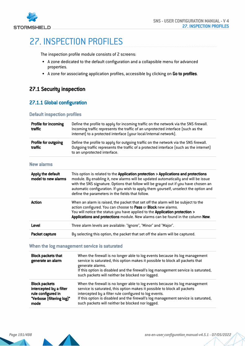
27. INSPECTION PROFILESThe inspection profile module consists of 2 screens:
l A zone dedicated to the default configuration and a collapsible menu for advancedproperties.
l A zone for associating application profiles, accessible by clicking on Go to profiles.
27.1 Security inspection
27.1.1 Global configuration
Default inspection profiles
Profile for incomingtraffic
Define the profile to apply for incoming traffic on the network via the SNS firewall.Incoming traffic represents the traffic of an unprotected interface (such as theinternet) to a protected interface (your local/internal network).
Profile for outgoingtraffic
Define the profile to apply for outgoing traffic on the network via the SNS firewall.Outgoing traffic represents the traffic of a protected interface (such as the internet)to an unprotected interface.
New alarms
Apply the defaultmodel to new alarms
This option is related to the Application protection > Applications and protectionsmodule. By enabling it, new alarms will be updated automatically and will be issuewith the SNS signature. Options that follow will be grayed out if you have chosen anautomatic configuration. If you wish to apply them yourself, unselect the option anddefine the parameters in the fields that follow.
Action When an alarm is raised, the packet that set off the alarm will be subject to theaction configured. You can choose to Pass or Block new alarms.You will notice the status you have applied to the Application protection >Applications and protections module. New alarms can be found in the column New.
Level Three alarm levels are available: "Ignore", "Minor" and "Major".
Packet capture By selecting this option, the packet that set off the alarm will be captured.
When the log management service is saturated
Block packets thatgenerate an alarm
When the firewall is no longer able to log events because its log managementservice is saturated, this option makes it possible to block all packets thatgenerate alarms.If this option is disabled and the firewall’s log management service is saturated,such packets will neither be blocked nor logged.
Block packetsintercepted by a filterrule configured in"Verbose (filtering log)”mode
When the firewall is no longer able to log events because its log managementservice is saturated, this option makes it possible to block all packetsintercepted by a filter rule configured to log events.If this option is disabled and the firewall’s log management service is saturated,such packets will neither be blocked nor logged.
SNS - USER CONFIGURATION MANUAL - V 427. INSPECTION PROFILES
Page 191/498 sns-en-user_configuration_manual-v4.5.1 - 07/05/2022

Advanced properties
Treat non-VTI IPsecinterfaces as internalinterfaces
If this option is selected, IPsec interfaces will become internal - and thereforeprotected - interfaces.All networks that are able to go through IPsec tunnels must therefore be legitimizedand static routes allowing them to be contacted must be declared. Otherwise, thefirewall will reject the IPsec traffic.
IMPORTANTWhen this checkbox is selected, the option will apply to all IPsec tunnelsdefined on the firewall.
27.1.2 Configuring profiles
Select the application profile associated with the protocol from the drop-down list by clicking onthe arrow to the right of the field.
To return to the previous menu, click on Go to global configuration.
SNS - USER CONFIGURATION MANUAL - V 427. INSPECTION PROFILES
Page 192/498 sns-en-user_configuration_manual-v4.5.1 - 07/05/2022
28. IPsec VPNA standard protocol, IPsec (IP Security) enables the creation of VPN tunnels between two hosts,between a host and a network, between two networks and any type of object that supports theprotocol.
The services that Stormshield Network’s IPsec offers provide access control, integrity in offlinemode, authentication of data source, protection against replay, confidentiality in encryptionand on traffic. You can for example, create a tunnel between two firewalls, or between thefirewall and mobile clients on which VPN clients would be installed.
The IPsec service has a mechanism to optimize the distribution of encryption and decryptionoperations. Its purpose is to significantly improve IPsec throughput, especially in configurationsthat contain a single IPsec tunnel.
It offers three configuration modes:
Automatic mode(auto)
This is the default mode, which allows the optimization mechanism to activateautomatically and transparently when both of the following conditions are met:
l The active IPsec policy has a single active VPN tunnel.
l The firewall model supports Automatic mode.
These models support Automatic mode: SN510, SN710, SN2000, SN2100, SN3000,SN3100, SN6000, SN6100 and SNi40. On other models, the optimizationmechanism can run only in Enabled mode.
Enabled mode (1) Makes it possible to run the optimization mechanism continuously without anyparticular conditions. It can be configured on all firewall models.
This mode is not recommended when an IPsec policy has many active VPN tunnels.Ensure that using this mode does not affect the general quality of your service.
Disabled mode (0) Makes it possible to disable the optimization mechanism continuously.
This mode can be configured only with the following CLI/serverd command:
CONFIG IPSEC UPDATE slot=<n> CryptoLoadBalance=<0|1|auto>
These commands are explained in detail in the CLI SERVERD Commands Reference Guide.
NOTES
l IPsec VPN policies now make it possible to edit their configurations in Global mode. Toenable the option, select “Display global policies” in the Preferences module.
l There is no specific privilege for "vpn_global".
The IPsec VPN module consists of 4 tabs:
l Encryption policy – Tunnels: create IPsec tunnels between two firewalls (Site to site –Gateway- Gateway) or between a Stormshield Network multi-function firewall and a mobileuser (Anonymous – Mobile users).10 blank encryption policies can be configured, activated and edited. The anonymouspolicy also makes it possible to configure tunnels with another firewall, but which does nothave a fixed IP address. It will therefore have the same problem as a “classic” mobileworkstation: an unpredictable IP address
SNS - USER CONFIGURATION MANUAL - V 428. IPSEC VPN
Page 193/498 sns-en-user_configuration_manual-v4.5.1 - 07/05/2022

l Peers: create new peers (remote site or anonymous mobile peer) by entering their IKEprofiles, their negotiation method, as well as the specific parameters for each negotiationmethod.
l Identification: list your approved certification authorities in the tunnels using PKI methodsas well as the pre-shared keys (PSK) of your mobile tunnels.
l Encryption profiles: define your IKE (phase 1) and IPsec (phase 2) encryption profiles, addnew ones or set their maximum lifetime (in seconds). You can also define negotiationproposals for authentication and encryption algorithms.
28.1 Encryption policy – Tunnels tab
IPsec policies can now group peers that use various versions of the IKE protocol withrestrictions on the use of the IKEv1 protocol (cf. section Explanations on usage in ReleaseNotes v4).
Profile bar The drop-down menu offers 10 IPsec profiles numbered from (1) to (10).To select a profile in order to configure it, click on the arrow to the right of the field.
Activate thispolicy
Immediately activates the selected IPsec policy: parameters saved in this policy willoverwrite current parameters in force.
Actions This function allows performing 3 operations on profiles:
l Rename: by clicking on this option, a window comprising two fields will appear. It willallow you to modify the name and add comments. Once the operation has beenperformed, click on “Update”. This operation can also be canceled.
l Reinitialize: Deletes all changes made to the profile. The configuration will therefore belost.
l Copy to: This option allows copying a profile to another, with all the information from thecopied profile transmitted to the receiving profile. It will also have the same name.
Lastmodification
This icon allows finding out the date and time of the last modification. The time displayedis the appliance’s time instead of your workstation’s time.
Disable policy This button allows immediately deactivating the selected IPsec policy.
28.1.1 Site to site (Gateway-Gateway)
This tab will allow a VPN tunnel to be created between two network devices that support IPsec.This procedure is also called: Gateway to Gateway VPN tunnel.
Several tutorials show you step by step how to configure a secure connection between yoursites. Click on one of the links to access a tutorial:
l IPsec VPN: Authentication by pre-shared key,l IPsec VPN: Authentication by certificate,l IPsec VPN: Hub and spoke configuration.
Search Searches will be performed on the name of the object and its various properties, unlessyou have specified in the preferences of the application that you would like to restrict thissearch to object names only.
Add The Add button will be covered in the following section.
SNS - USER CONFIGURATION MANUAL - V 428. IPSEC VPN
Page 194/498 sns-en-user_configuration_manual-v4.5.1 - 07/05/2022

Delete Select the IPsec VPN tunnel to be removed from the table and click on this button.
Move up Places the selected line before the line just above it.
Move down Places the selected line after the line just below it.
Cut Cuts the selected line to paste it.
Copy Copies the selected line to duplicate it.
Paste Duplicates the selected line after it is copied.
Show
details
To ease the configuration of the tunnel with a remote device (gateway or mobile client),click on this icon to view information on the IPsec policy:
l Summary: rule type, IKE version, peer, remote gateway, traffic endpoints (local network,remote network).
l Authentication: Mode/Type (Certificate/Pre-shared key)
l Encryption profiles (phase 1 & 2): algorithms, Diffie-Hellman group, lifetime
Search in logs When a name is assigned to the IPsec rule, clicking on this button will run a search by thename of the rule in the IPsec VPN log and show the results.
Search inmonitoring
Clicking on this button will open the screen to monitor IPsec tunnels (Monitoring tab >Monitoring module > IPsec VPN tunnels).
REMARKSRight-clicking anywhere in the grid will display a pop-up menu offering the following actions:
l Add,l Copy,l Cut,l Paste,l Show detailsl Delete,l Search in logs,l Search in monitoring.
Add
In order to configure the tunnel, select the VPN policy in which you wish to set it up. The IPsecVPN policy wizard will guide you through the configuration.
Standard site-to-site tunnel
Here, you will define each of the endpoints for your tunnel as well as for your peer.
Local resources Host, host group, network or network group that will be accessible via the IPsec VPNtunnel.
Peer selection This is the object that corresponds to the public IP address of the tunnel endpoint, or ofthe remote VPN peer. By default the drop-down list shows “None”. You can create peers inthe following option or select an existing peer from the list.
SNS - USER CONFIGURATION MANUAL - V 428. IPSEC VPN
Page 195/498 sns-en-user_configuration_manual-v4.5.1 - 07/05/2022
Create a peer Define the parameters for your peer. Several steps are necessary:
Step 1: Select the gateway.
1. Remote gateway: select the object corresponding to the IP address of the tunnelendpoint from the drop-down list.
You can also add gateways using the button .
2. Name: you can specify a name for your gateway or keep the peer’s original name,which will be prefixed with “Site_” (“Site_<name of object>“).Selecting None as a peer allows generating policies without encryption. The aim is tocreate an exception to the following rules of the encryption policy. Traffic matching thisrule will be managed by the routing policy.
3. IKE version: select IKEv1 or IKEv2, depending on the version of the IKE protocol that thepeer uses.
4. Click on Next.
Step 2: Identify the peer.Two choices are possible:
l Certificate
l Pre-shared Key (PSK):
1. Select the desired option.
2. If you have selected Certificate, you will need to select it from those you havepreviously created in the Certificates and PKI module.The certificate to enter here is the one presented by the firewall and not the onepresented by the remote site. A certification authority can also be added.
3. If you have selected Pre-shared key (PSK), you will need to define the secret that bothpeers of the IPsec VPN tunnel will share, in the form of a password to be confirmed in asecond field.You can Enter the key in ASCII characters (every character in ASCII text is stored in abyte whose 8th is 0) by selecting the relevant option.Unselect the option to view the key in hexadecimal characters (which is based on 16digits: the letters A to F and numbers 0 to 9).
NOTETo define an ASCII pre-shared key that is sufficiently secure, you must follow thesame rules for user passwords set out in the section Welcome, under the sectionUser awareness, sub-section User password management.
4. Click on Next.The screen will show you a window summarizing the configuration that was made, theParameters of the remote site and the Pre-shared key.You can also add a backup peer by clicking on the link provided. You will need to definea remote gateway.
5. Click on Finish.
Remotenetworks
Host, host group, network or network group accessible through the IPsec tunnel with thepeer.
Separator (rule grouping)
This option allows inserting a separator above the selected line. This allows the administrator tocreate a hierarchy for his tunnels according to his needs.
SNS - USER CONFIGURATION MANUAL - V 428. IPSEC VPN
Page 196/498 sns-en-user_configuration_manual-v4.5.1 - 07/05/2022

28.1.2 The table
Line This column indicates the number of the line processed in order of appearance on thescreen.
Status This column shows the status / of the tunnel.When a tunnel is created, it is enabled by default. Click twice to disable it.
Name A name can be given to this IPsec rule so that it will be easier to look for events thatinvolve this rule in logs.
Local network Select the host, host group, network or network group that will be accessible via theIPsec VPN tunnel, from the drop-down list of objects.
Peer Configuration of the peer, which can be viewed in the tab of the same name in theIPsec VPN module.
Remote network Select from the drop-down list of objects, the host, host group, network or networkgroup accessible through the IPsec tunnel with the peer.
Protocol This option makes it possible to restrict the setup of IPsec tunnels to traffic based onspecific protocols:
l TCP
l UDP
l ICMP
l GRE
l All
Encryption profile This option allows selecting the protection model associated with your VPN policy,from 3 preconfigured profiles: StrongEncryption, GoodEncryption and Mobile. Otherprofiles can be created or modified in the tab Encryption profiles.
Comments Description given of the VPN policy.
Keep alive The additional Keepalive option makes it possible to artificially maintain mountedtunnels. This mechanism sends packets that initialize the tunnel and force it to bemaintained. This option is disabled by default to avoid wasting resources, especiallyin the case of a configuration containing many tunnels set up at the same timewithout any real need for them.
To enable this option, assign a value other than 0, corresponding to the interval inseconds, between each UDP packet sent.
Checking the policy in real time
The window for editing IPsec policy rules has a “Check policy” field (located below the table),which warns the administrator whenever there are inconsistencies or errors in the rulescreated.
28.1.3 Mobile users
The IPsec VPN has two endpoints: the tunnel endpoint and the traffic endpoint. For anonymousor mobile users, the IP address of the tunnel’s endpoint is not known in advance.
As for the IP address of the traffic endpoint, it can either be chosen by the peer (“classic” case)or given by the gateway (“Config mode”).
SNS - USER CONFIGURATION MANUAL - V 428. IPSEC VPN
Page 197/498 sns-en-user_configuration_manual-v4.5.1 - 07/05/2022

Mobile IPsec policies containing several peers can be built as long as they use the same IKEencryption profile. In certificate-based authentication, the certificates of the various peers mustbe issued by the same CA,
Add
Select the VPN policy in which you wish to set up a tunnel. Policy creation wizards will guideyou in this configuration. If you wish to create the mobile peer through the wizard, please referto the section “Creating a mobile peer” below.
VPN client settings (Config mode) can be defined for mobile users through the Config modepolicy creation wizard.
New standard mobile policy
This policy makes local networks accessible to authorized users via an IPsec tunnel. In thisconfiguration, remote users log on with their own IP addresses.
Enter the details of the mobile peer to be used. Then add the accessible local resources to thelist.
New Config mode policy
This policy with Config mode makes a single local network accessible to authorized usersthrough an IPsec tunnel. With Config mode, remote users log on with an IP address assigned ina set defined as a “Mobile network”.
Once it is created, the cell corresponding to the Config mode column will contain an Edit Configmode (selection) button, allowing you to enter the parameters of the IPsec Config mode,described in the section The table.
You can enter a particular DNS server and specify the domains that this server uses. Theseindications are indispensable if an Apple® (iPhone, iPad) mobile client is used for example. Thisfeature is paired with Config mode, and is not used by all VPN clients on the market.
Creating a mobile peer
The procedure for creating a peer through these wizards is described below. You can also createit directly from the Peer tab.
1. Click on “Add” a “New policy” (VPN), then on “Create a mobile peer” via the mobile IPsec VPNpolicy wizard.
2. Name your mobile configuration.
3. Select the IKE version of the protocol that the peer uses.
4. Click on Next.
5. Select the authentication method of the peer.
Certificate If you select this authentication method, you will need to select the Certificate (server) to bepresented to the peer, from the list of those you have already created previously (Certificatesand PKI module).You can also enter details about the Certification authority (CA) that signed your peer’scertificate so that it is automatically added to the list of trusted authorities.
Hybrid If you select this hybrid method, you will need to provide the Certificate (server) to bepresented to the peer and probably its CA.The server is authenticated by certificate in Phase 1, and the client by XAuth immediatelyafter Phase 1.
SNS - USER CONFIGURATION MANUAL - V 428. IPSEC VPN
Page 198/498 sns-en-user_configuration_manual-v4.5.1 - 07/05/2022

Certificateand XAuth(iPhone)
This option allows mobile users (roadwarriors) to connect to your company’s VPN gateway viatheir mobile phones, using a certificate in Phase 1. The server is also authenticated bycertificate during this Phase 1. Additional authentication of the client is carried out by XAuthafter Phase 1.
NOTEThis is the only mode compatible with iPhones.
Pre-sharedkey (PSK)
If you have chosen this authentication method, you will need to edit your key in a table, byproviding its ID and its value to be confirmed. To do so, click on Add.
The ID may be in an IP address (X.Y.Z.W), FQDN (myserver.domain.com), or e-mail addressformat ([email protected]). It will then occupy the “Identity” column in thetable and the pre-shared key will occupy a column of the same name with its value displayedin hexadecimal.
NOTETo define an ASCII pre-shared key that is sufficiently secure, you must follow the samerules for user passwords set out in the section Welcome, under the section Userawareness, sub-section User password management.
6. Click on Next.
7. Check the summary of you mobile configuration and click on Finish.
8. Next, enter the local resource, or “local network" to which the mobile user will have access.
Other operations can also be performed:
Search Searches will be performed on the name of the object and its various properties, unless youhave specified in the preferences of the application that you would like to restrict this searchto object names only.
Delete Select the IPsec VPN tunnel to be removed from the table and click on this button.
Move up Places the selected line before the line just above it.
Move down Places the selected line after the line just below it.
Cut Cuts the selected line to paste it.
Copy Copies the selected line to duplicate it.
Paste Duplicates the selected line after it is copied.
Show
details
To ease the configuration of the tunnel with a remote device (gateway or mobile client), clickon this icon to view information on the IPsec policy:
l Summary: rule type, IKE version, peer, remote gateway, traffic endpoints (local network,remote network).
l Authentication: Mode/Type (Certificate/Pre-shared key)
l Encryption profiles (phase 1 & 2): algorithms, Diffie-Hellman group, lifetime
Search inlogs
When a name is assigned to the IPsec rule, clicking on this button will run a search by thename of the rule in the IPsec VPN log and show the results.
SNS - USER CONFIGURATION MANUAL - V 428. IPSEC VPN
Page 199/498 sns-en-user_configuration_manual-v4.5.1 - 07/05/2022

Search inmonitoring
Clicking on this button will open the screen to monitor IPsec tunnels (Monitoring tab >Monitoring module > IPsec VPN tunnels).
REMARKSRight-clicking anywhere in the grid will display a pop-up menu offering the following actions:
l Add,l Copy,l Cut,l Paste,l Show detailsl Delete,l Search in logs,l Search in monitoring.
28.1.4 The table
Line This column indicates the number of the line processed in order of appearance on thescreen.
Status This column shows the status / of the tunnel.When a tunnel is created, it is enabled by default. Click twice to disable it.
Name A name can be given to this IPsec rule so that it will be easier to look for events thatinvolve this rule in logs.
Local network Select the host, host group, address range, network or network group that will beaccessible via the IPsec VPN tunnel, from the drop-down list of objects.
Peer Configuration of the peer, which can be viewed in the tab of the same name in theIPsec VPN module.
Remote network Select from the drop-down list of objects, the host, host group, address range, networkor network group accessible through the IPsec tunnel with the peer.
NOTEWhen creating a new mobile IPsec VPN policy via the wizard, you will be asked toenter details about the local network, and not the remote network, since the IPaddress is unknown. The object “Any” will therefore be selected by default.
Domain name This option makes it possible to specify the domain (LDAP directory) on which themobile peer must be authenticated. The same user can therefore simultaneously setup several IPsec VPN tunnels and access separate resources by authenticating onseveral directories.
SNS - USER CONFIGURATION MANUAL - V 428. IPSEC VPN
Page 200/498 sns-en-user_configuration_manual-v4.5.1 - 07/05/2022

Group This option makes it possible to specify the user’s group on the authenticationdomain.The same user can therefore simultaneously set up several IPsec VPN tunnels byauthenticating on one or several directories, and accessing separate resources byobtaining the specific privileges for the group in question.The Domain name must be specified for this option.
Protocol This option makes it possible to restrict the setup of IPsec tunnels to traffic based onspecific protocols:
l TCP
l UDP
l ICMP
l GRE
l All
Encryptionprofile
This option makes it possible to select the protection model associated with your VPNpolicy, from three preconfigured profiles: StrongEncryption, GoodEncryption andMobile. Other profiles can be created or modified in the tab Encryption profiles.
Config mode This column makes it possible to enable “Config mode”, which is disabled by default.This allows the traffic endpoint IP address to be distributed to the peer.
NOTES
1. If you choose to enable this mode, you will need to select an object otherthan “Any” as the remote network.
2. With config mode, only one policy can be applied per profile.
The Edit Config mode button allows you to enter the parameters of the IPsec Configmode:
l DNS server used: this field determines the host (DNS server) that will be used bymobile clients, for DNS resolutions. You can select it or create it in the objectdatabase. This field is empty by default.
l Domains used in Config mode: the client will use the DNS server selected earlier,only for domains specified in this table. For other domains, the client will continueto use its DNS server(s). Therefore generally internal domain names are involved.
EXAMPLEIn the case of the domain "company.com", if an iPhone attempts to connect to"www.company.com" or "intranet.company.com" it will use the DNS serverspecified above. However, if it attempts to contact "www.google.fr", it willcontinue to use its older DNS servers.
Comments Description given of the VPN policy.
Keep alive The additional Keepalive option makes it possible to artificially maintain mountedtunnels. This mechanism sends packets that initialize the tunnel and force it to bemaintained. This option is disabled by default to avoid wasting resources, especiallyin the case of a configuration containing many tunnels set up at the same timewithout any real need for them.
To enable this option, assign a value other than 0, corresponding to the interval inseconds, between each UDP packet sent.
SNS - USER CONFIGURATION MANUAL - V 428. IPSEC VPN
Page 201/498 sns-en-user_configuration_manual-v4.5.1 - 07/05/2022
NOTEYou can only use and create a single mobile (roadwarrior) configuration per IPsec profile. Peerscan be applied to all profiles. As a result, only one authentication type can be used at a time forthe mobile configuration.
Checking the policy in real time
The window for editing IPsec policy rules has a “Check policy” field (located below the table),which warns the administrator whenever there are inconsistencies or errors in the rulescreated.
28.2 Peers tab
This tab consists of two sections:
l Left: the list of site-to-site IPsec VPN peers (Remote gateways) and mobile IPsec VPN peers(Mobile peers).
l Right: information about the selected peer.
28.2.1 List of peers
Enter a filter This field allows performing searches on the name of the object and its various properties,by occurrence, letter or word.
Add Peers can be added to this area.To do so, select the type of peer to create from the drop-down list:
l New remote gateway (for site-to-site tunnels),
l New mobile peer.
Action When you select a peer from the list, expand the Action menu to:
l Duplicate this peer,
l Rename this peer,
l Delete this peer,
l Check usage of this peer in the firewall configuration.
28.2.2 Gateway peer information
Select a peer from the list to display information about it.
Comments Description given of the local peer.
Remote gateway Object selected to represent the remote IP address during the creation of the peer viathe wizard.
Local address External interface presented to set up the tunnel with the peer shown.
IKE profile This option offers three preconfigured profiles as the protection model associatedwith Phase 1 of your VPN policy: StrongEncryption, GoodEncryption and Mobile. Otherprofiles can be created or modified in the tab Encryption profiles.
IKE version This option allows selecting the version of the IKE protocol (IKEv1 or IKEv2) that thepeer uses.
SNS - USER CONFIGURATION MANUAL - V 428. IPSEC VPN
Page 202/498 sns-en-user_configuration_manual-v4.5.1 - 07/05/2022
Identification
Authenticationmethod
This field will show the authentication method selected during the creation of yourpeer via the wizard.You may modify your choice by selecting another method from the drop-down list.
NOTEFor a “gateway” peer, you have the choice of Certificate or Pre-shared key(PSK).
Certificate If you have chosen certificate-based authentication, this field will display thecertificate to display to the peer to set up the IPsec tunnel.If you had opted for the pre-shared key method, this field will not appear.
Local ID (Optional) This field represents an IPsec VPN tunnel endpoint, sharing the “secret” or the PSKwith the “Peer ID”, the other endpoint. You are represented by the “Local ID”.Full Qualified Domain Name) or an e-mail address (user@fqdn). This identifier mustbe in the form of an IP address, a domain name (FQDN:
Peer ID (Optional) This field represents an IPsec VPN tunnel endpoint, sharing the “secret” or the PSKwith the “Local ID”, the other endpoint. The “Peer ID” represents your peer.The format is the same as the previous field.
Pre-shared key(ASCII)
In this field your PSK appears in the format you had selected earlier when creatingthe peer via the wizard: ASCII or hexadecimal characters (the format can be selectedin the checkboxes below the field if you wish to change formats).
Edit This button makes it possible to modify the pre-shared key that was used to set upthe IPsec tunnel with this peer.
Advanced properties
Do not initiate thetunnel (Responderonly)
If this option is selected, the IPsec server will be put on standby.It won't initiate tunnel negotiation. This option is used in the case where the peer is amobile host.
IKE fragmentation With this checkbox, IKE fragmentation can be enabled when IKE packets exceed thestandard packet size configured on the firewall.
SNS - USER CONFIGURATION MANUAL - V 428. IPSEC VPN
Page 203/498 sns-en-user_configuration_manual-v4.5.1 - 07/05/2022

DPD This field makes it possible to configure the DPD (Dead Peer Detection) feature onVPNs, which checks whether a peer is still operational.When DPD is enabled on a peer, requests (R U there) are sent to test the availabilityof the other peer , which will need to acknowledge the requests in order to confirm itsavailability (R U there ACK).
These exchanges are secured via ISAKMP (Internet Security Association and KeyManagement Protocol) SAs (Security Associations).If it is detected that a peer is no longer responding, the negotiated SAs will bedestroyed.
IMPORTANTThis feature provides stability to the VPN service on Stormshield NetworkFirewalls on the condition that the DPD has been correctly configured.
Four choices are available for configuring DPD:
l Inactive: DPD requests from the peer are ignored.
l Passive: DPD requests sent by the peer get a response from the firewall. However,the firewall does not send any.
l Low: the frequency of DPD packets being sent is low and the number of failurestolerated is higher (delay 600, retry 10, maxfail 5).
l High: the frequency of DPD packets being sent is high and the number of failuresrelatively low (delay 30, retry 5, maxfail 3).
The value delay defines the period after a response is received before the nextrequest is sent.The value retry defines the time to wait for a response before sending the requestagain.The value maxfail is the number of requests sent without receiving responses beforethe peer is considered absent.
DSCP In this field, you can specify the value of the DSCP field assigned to IKE networkpackets sent to this peer.Select one of the proposed values or specify a customized DSCP field (integerbetween 0 and 63 inclusive).
NOTE
For every field that contains “Gateway” and the icon , you can add an object to the existingdatabase by specifying its name, DNS resolution, IP address and then clicking on Apply.
28.2.3 Mobile peer information
Select a peer from the list to display information about it.
Comments Description given of the remote peer.
Remote gateway This field is grayed out for mobile peers.
Local address External interface presented to set up the tunnel with the peer shown.
SNS - USER CONFIGURATION MANUAL - V 428. IPSEC VPN
Page 204/498 sns-en-user_configuration_manual-v4.5.1 - 07/05/2022

IKE profile This option makes it possible to select the protection model associated with yourVPN policy, from three preconfigured profiles: StrongEncryption, GoodEncryption andMobile. Other profiles can be created or modified in the tab Encryption profiles.
IKE version This option allows selecting the version of the IKE protocol (IKEv1 or IKEv2) that thepeer uses.
Identification
Authenticationmethod
This field will show the authentication method selected during the creation of yourpeer via the wizard.You may modify your choice by selecting another method from the drop-down list.
NOTEFor “mobile” peers, you have a choice between Certificate, Pre-shared key(PSK), Hybrid, Certificate and XAuth (iPhone).
Certificate If you have chosen the Certificate, Hybrid or Certificate and XAuth authenticationmethod, this field displays the certificate that you present to set up the tunnel withthis peer, or suggests that you select it from the drop-down list.If you had opted for the pre-shared key method, this field will not appear.
Local ID (Optional) This field represents an IPsec VPN tunnel endpoint, sharing the “secret” or the PSKwith the “Peer ID”, the other endpoint. You are represented by the “Local ID”.Full Qualified Domain Name) or an e-mail address (user@fqdn). This identifier mustbe in the form of an IP address, a domain name (FQDN:
NOTEThis field can only be accessed if you have selected the Pre-shared keyauthentication method.
Peer ID (Optional) This field represents an IPsec VPN tunnel endpoint, sharing the “secret” or the PSKwith the “Local ID”, the other endpoint. The “Peer ID” represents your peer.The format is the same as the previous field.
Pre-shared key(ASCII)
In this field your PSK appears in the format you had selected earlier when creatingthe peer via the wizard: ASCII or hexadecimal characters (the format can be selectedin the checkboxes below the field if you wish to change formats).
Edit This button makes it possible to modify the pre-shared key that was used to set upthe IPsec tunnel with this peer.
Advanced properties
Do not initiate thetunnel (Responderonly)
This option is grayed out and validated, as a tunnel to a mobile client with anunknown IP address cannot be set up. In this configuration, the firewall is thereforein “responder only” mode.
SNS - USER CONFIGURATION MANUAL - V 428. IPSEC VPN
Page 205/498 sns-en-user_configuration_manual-v4.5.1 - 07/05/2022
DPD This field makes it possible to configure the DPD (Dead Peer Detection) feature onVPNs, This would allow checking whether a peer is still operational.When DPD is enabled on a peer, requests (R U there) are sent to test the availabilityof the other peer , which will need to acknowledge the requests in order to confirm itsavailability (R U there ACK).
These exchanges are secured via ISAKMP (Internet Security Association and KeyManagement Protocol) SAs (Security Associations).If it is detected that a peer is no longer responding, the negotiated SAs will bedestroyed.
IMPORTANTThis feature provides stability to the VPN service on Stormshield NetworkFirewalls on the condition that the DPD has been correctly configured.
Four choices are available for configuring DPD:
l Inactive: DPD requests from the peer are ignored.
l Passive: DPD requests sent by the peer get a response from the firewall. However,the firewall does not send any.
l Low: the frequency of DPD packets being sent is low and the number of failurestolerated is higher (delay 600, retry 10, maxfail 5).
l High: the frequency of DPD packets being sent is high and the number of failuresrelatively low (delay 30, retry 5, maxfail 3).
The value delay defines the period after a response is received before the nextrequest is sent.The value retry defines the time to wait for a response before sending the requestagain.The value maxfail is the number of requests sent without receiving responses beforethe peer is considered absent.
DSCP In this field, you can specify the value of the DSCP field assigned to IKE networkpackets sent to this peer.Select one of the proposed values or specify a customized DSCP field (integerbetween 0 and 63 inclusive).
28.3 Identification tab
28.3.1 Approved certification authorities
This table will allow you to list authorities to identify your peers within the IPsec VPN module.
Add When you click on this button, a window will open showing the CAs and sub-CAs that you havecreated earlier.Select the authorities that will enable you to check the identities of your peers, by clicking onSelect.The CA or sub-CA selected will be added to the table.
Delete Select the CA to be removed from the list and click on Delete.
CA
Below this field, the added and approved certification authorities will be displayed.
SNS - USER CONFIGURATION MANUAL - V 428. IPSEC VPN
Page 206/498 sns-en-user_configuration_manual-v4.5.1 - 07/05/2022

28.3.2 Mobile tunnels: pre-shared keys (PSK)
If you had created a mobile peer using the Pre-shared key (PSK) authentication method, thistable will be pre-entered.
You would have edited a key by assigning it an ID and a value (in hexadecimal or ASCIIcharacters).
Search Even though the table displays all the pre-shared keys of your mobile tunnels by default, youcan search by occurrence, letter or word, so that only the desired keys are displayed.
Add When you click on this button, a key editor window will appear: you need to provide it with anID, a value and confirm it.You can choose to edit characters in hexadecimal or ASCII.
Delete Select the key to be removed from the list and click on Delete.
Identity
This column displays the IDs of your pre-shared keys, which may be represented by a domainname (FQDN), an e-mail address (USER_FQDN) or an IP address.
Key
This column displays the values of your pre-shared keys in hexadecimal characters.
NOTES
l An unlimited number of pre-shared keys can be created.l Deleting a pre-shared key that belongs to an IPsec VPN tunnel will cause this tunnel to
malfunction.l To define an ASCII pre-shared key that is sufficiently secure, you must follow the same
rules for user passwords set out in the section Welcome, under the section Userawareness, sub-section User password management.
28.3.3 Advanced properties
Enable searching inseveral LDAPdirectories (pre-shared key orcertificate modes)
When several LDAP directories have been defined, selecting this checkbox will allowthe firewall to browse these directories sequentially to authenticate mobile peers. Thismethod is available regardless of the authentication type chosen (pre-shared key orcertificate).If this checkbox is not selected, the firewall will only query the directory defined bydefault.
List of directories
The various directories listed will be queried according to their order in the table.
Add Clicking on this button will add a line to the table in the form of a drop-down list that allowsselecting one of the directories defined on the firewall.This button is grayed out when all of the firewall's directories are selected.
Delete Select the key to be removed from the list and click on Delete.
SNS - USER CONFIGURATION MANUAL - V 428. IPSEC VPN
Page 207/498 sns-en-user_configuration_manual-v4.5.1 - 07/05/2022

Move up This button makes it possible to move the selected directory up the list to raise its prioritywhen the firewall queries the list of directories.
Move down This button makes it possible to move the selected directory up the list to lower its prioritywhen the firewall queries the list of directories.
28.4 Encryption profiles tab
28.4.1 Default encryption profiles
The values defined in Phase 1 and 2 will be preselected each time a new peer is created.
IKE
Phase 1 of the IKE protocol aims to set up an encrypted and authenticated communicationchannel between both VPN peers. This “channel” is called ISAKMP SA (different from the IPsecSA). Two negotiation modes are possible: main mode and aggressive mode.
The drop-down list allows choosing the protection model associated with your VPN policy, from4 pre-configured profiles: GoodEncryption, Mobile, DR andStrongEncryption. Others can also becreated by using the Add button.
IPsec
Phase 2 of the IKE protocol securely negotiates (through the ISAKMP SA communicationchannel negotiated in the first phase) the parameters of future IPsec SAs (one incoming, oneoutgoing).
The drop-down list allows choosing the protection model associated with your VPN policy, from4 pre-configured profiles: GoodEncryption, Mobile, DR andStrongEncryption. Others can also becreated by using the Add button.
28.4.2 Table of profiles
This table offers a series of predefined Phase 1 (IKE) and Phase 2 (IPsec) encryption profiles.
Possible operations
Add By clicking on this button, you will be able to add a New phase 1 profile (IKE) or New phase 2profile (IPsec), which will be displayed in the corresponding column.You can give it any “Name” you wish.Profiles and their characteristics can also be copied: to do so, select the desired profile andclick on the option Copy selection, and give it a name.
Actions In this drop-down menu, one of the following actions can be applied to the selected profile:
l Duplicate the profile,
l Define the default profile,
l Delete the profile,
l Check usage of the profile.
IKE profile
For the IKE profile added or selected, you will see its characteristics to the right of the screen(“General” and “Proposals” fields).
SNS - USER CONFIGURATION MANUAL - V 428. IPSEC VPN
Page 208/498 sns-en-user_configuration_manual-v4.5.1 - 07/05/2022

General
Comments Description given to your encryption profile.
Diffie-Hellman This field represents two types of key exchange: if you have selected an IKE encryptionprofile, the Diffie-Hellman option will appear.Diffie-Hellman allows 2 peers to generate a common secret on each side, without sendingsensitive information over the network.
In addition, if you have chosen an IPsec profile, PFS will be offered.Perfect Forward Secrecy allows guaranteeing that there are no links between the variouskeys of each session. Keys are recalculated by the selected Diffie-Hellman algorithm. Thehigher the number indicating the key size, the higher the level of security.
Regardless of what you choose, a drop-down list will suggest that you define the numberof bits that allow strengthening security during the transmission of the common secret orpassword from one peer to another. Encryption algorithms based on elliptic curves (ECDSAalgorithm: Elliptic Curve Digital Signature Algorithm) can also be selected.
NOTES
l To define an ASCII pre-shared key that is sufficiently secure, you must follow thesame rules for user passwords set out in the section Welcome, under the sectionUser awareness, sub-section User password management.
l The longer the password (or “key”), the higher the level of security, but at thesame time consumes more resources.
l The use of IPsec’s PFS function (ISAKMP) is recommended.
Maximumlifetime (inseconds)
Period after which keys will be renegotiated.The default duration of an IKE profile is 21600 seconds.
Proposals
This table allows you to modify or add combinations of encryption and authenticationalgorithms to the pre-entered list of the selected profile.
Add The default combination suggested is:
l des encryption algorithm with a "Strength" of 64 bits,
l sha1 authentication algorithm with a "Strength" of 160 bits,
Click on the arrow to the right of the respective “Algorithm” columns if you wish to modifythem.Each time you add a new line to the table, it will be of the priority level that follows.
Delete Select the line to be deleted from the list and click on Delete.
Move up Select the line to be moved up the table in order to raise the priority of the correspondingEncryption / Authentication combination.
Move down Select the line to be moved down the table in order to lower the priority of thecorresponding Encryption / Authentication combination.
Encryption
SNS - USER CONFIGURATION MANUAL - V 428. IPSEC VPN
Page 209/498 sns-en-user_configuration_manual-v4.5.1 - 07/05/2022

Algorithm 4 choices are offered:
l 3des (obsolete),
l aes,
l aes_gcm_16 (recommended),
l aes_ctr.
When a preset profile is selected, the recommended choices will automatically besuggested by default.
The advantage of the aes_gcm-16 algorithm is that it performs both authentication andencryption. You therefore do not need to choose an authentication algorithm in this case.
Strength Number of bits defined for the selected algorithm.
Authentication
Algorithm 4 choices are offered:
l sha1 (obsolete),
l sha2_256,
l sha2_384,
l sha2_512.
Strength Number of bits defined for the selected algorithm.
IPsec profile
For each IPsec profile added or selected, you will see its characteristics to the right of thescreen (“General”, “Authentication proposals” and “Encryption proposals” fields).
General
Comments Description given to your encryption profile.
SNS - USER CONFIGURATION MANUAL - V 428. IPSEC VPN
Page 210/498 sns-en-user_configuration_manual-v4.5.1 - 07/05/2022

Diffie-Hellman This field represents two types of key exchange: if you have selected an IKE encryptionprofile, the Diffie-Hellman option will appear.Diffie-Hellman allows 2 peers to generate a common secret on each side, without sendingsensitive information over the network.
In addition, if you have chosen an IPsec profile, PFS will be offered.Perfect Forward Secrecy allows guaranteeing that there are no links between the variouskeys of each session. Keys are recalculated by the selected Diffie-Hellman algorithm. Thehigher the number indicating the key size, the higher the level of security.
Regardless of what you choose, a drop-down list will suggest that you define the numberof bits that allow strengthening security during the transmission of the common secret orpassword from one peer to another. Encryption algorithms based on elliptic curves (ECDSAalgorithm: Elliptic Curve Digital Signature Algorithm) can also be selected.NOTESTo definean ASCII pre-shared key that is sufficiently secure, you must follow the same rules for userpasswords set out in the section Welcome, under the section User awareness, sub-sectionUser password management.The longer the password (or “key”), the higher the level ofsecurity, but at the same time consumes more resources.The use of IPsec’s PFS function(ISAKMP) is recommended.
NOTES
l To define an ASCII pre-shared key that is sufficiently secure, you must follow thesame rules for user passwords set out in the section Welcome, under the sectionUser awareness, sub-section User password management.
l The longer the password (or “key”), the higher the level of security, but at thesame time consumes more resources.
l The use of IPsec’s PFS function (ISAKMP) is recommended.
Lifetime (inseconds)
Period after which keys will be renegotiated.The default duration of an IPsec profile is 3600 seconds.
Authentication proposals
This table allows you to modify or add authentication algorithms to the pre-entered list of theselected profile.
Add The authentication algorithm that appears by default when you click on this button ishmac_sha256, with a strength of 256 bits.Click on the arrow to the right of the “Algorithm” column if you wish to modify it.Each time you add a new line to the table, it will be of the priority level that follows.
Delete Select the line to be deleted from the list and click on Delete.
Algorithm 4 choices are offered:
l hmac_sha1 (obsolete),
l hmac_sha256,
l hmac_sha384,
l hmac_sha512.
Strength Number of bits defined for the selected algorithm.
SNS - USER CONFIGURATION MANUAL - V 428. IPSEC VPN
Page 211/498 sns-en-user_configuration_manual-v4.5.1 - 07/05/2022

Encryption proposals
This table allows you to modify or add encryption algorithms to the pre-entered list of theselected profile.
Add The encryption algorithm that appears by default when you click on this button is aes_gcm_16 (recommended), with a strength of 256 bits.Click on the arrow to the right of the “Algorithm” column if you wish to modify it.Each time you add a new line to the table, it will be of the priority level that follows.
Delete Select the line to be deleted from the list and click on Delete.
Algorithm 4 choices are offered:
l 3des (obsolete),
l aes,
l aes_gcm_16 (recommended),
l aes_ctr.The advantage of the aes_gcm-16 algorithm is that it performs both authentication andencryption.
Strength Number of bits defined for the selected algorithm.
Click on Apply once you have completed the configuration.
SNS - USER CONFIGURATION MANUAL - V 428. IPSEC VPN
Page 212/498 sns-en-user_configuration_manual-v4.5.1 - 07/05/2022

29. INTERFACESThe Interfaces module makes it possible to manage, add or delete “network interface” networkitems. These represent physical or virtual communication devices between the variousnetworks that pass through the firewall.
The module window consists of a grid containing:
l The list of the firewall's interfaces and information about them.l A taskbar: it shows the various possible operations that can be applied to interfaces.l The control panel of each interface: appears when an interface is edited.
NOTERefer to the section Allowed names to find out which characters are allowed and prohibited invarious fields.
29.1 Interfaces
Interface Name of the interface (in, out, dmz1, etc.).A tool tip displays additional information when you scroll over the interface.The icon shows the interface from which the administrator logged in.The icon shows the interface being edited (open control panel).
Port Number of the interface’s physical port. For VLANs and modems, the port number ofthe parent interface appears.
Type Type of interface (Bridge, Ethernet, etc.). Additional information can be displayedwith the type (transfer rate, VLAN ID, etc.).
Status Special statuses of an interface (disabled, not connected, monitored, etc). When theinterface is enabled and connected, this column will be empty.
IPv4 address IPv4 address of the interface and its mask, or DHCP address if the interface usesdynamic addresses.
IPv6 address IPv6 address of the interface and its mask, or DHCP address if the interface usesdynamic addresses. This column is hidden by default if IPv6 is not enabled in thefirewall’s configuration.
MAC address Physical interface (MAC) of the interface. This column is hidden by default.
System name Name of the interface that the firewall operating system sees (em0, vlan0, etc.). Thiscolumn is hidden by default.
Comments Comments added during the configuration of the interface (open text field).
29.2 Possible operations
Some operations can also be performed by right-clicking in the grid of interfaces. Dragging anddropping on an interface modifies its configuration (its relationships and IP address). An iconindicates whether dragging and dropping is allowed.
Enter a filter Searches among the firewall's interfaces.
SNS - USER CONFIGURATION MANUAL - V 429. INTERFACES
Page 213/498 sns-en-user_configuration_manual-v4.5.1 - 07/05/2022

Collapse all Collapses all interfaces in the tree.
Expand all Expands all interfaces in the tree.
Refresh displayeddata
Refreshes information found in the grid of interfaces.
Edit Makes it possible to edit the selected network interface or one of the modemprofiles.
Add Adds a new interface. The following sections explain how to add new interfaces orchange the configuration of existing interfaces.
Delete Deletes the selected interface. Some interfaces cannot be deleted.
Monitor Enables or disables monitoring on the selected the interface. The correspondinggraphs are automatically created in Monitoring > Monitoring > Interfaces.
Go to monitoring Redirects to Monitoring > Monitoring > Interfaces.
Check usage In the menu on the left, shows the modules in which the interface is used.
29.3 Control panel of an interface
Interfaces can be configured in the control panel. Double-clicking on an interface displays it.The contents vary according to the type of interface selected.
l Bridge,l Ethernet interface,l Wi-Fi interface,l VLAN,l Aggregate,l GRETAP interface,l PPPoE/PPTP modem,l USB/Ethernet interface (USB key/modem).
29.4 Bridge interface
29.4.1 Adding a bridge
Adding a bridge without members
1. Click on Add.
2. Scroll over Bridge.
3. Click on No members.The new bridge will be added to the interfaces and its control panel appears.
Adding a bridge that contains selected interfaces
1. Select the interfaces to include in the new bridge beforehand.
2. Click on Add.
3. Scroll over Bridge.
SNS - USER CONFIGURATION MANUAL - V 429. INTERFACES
Page 214/498 sns-en-user_configuration_manual-v4.5.1 - 07/05/2022

4. Click on With interface_1, interface_2 ....The new bridge will be added to the interfaces and its control panel appears.
29.4.2 Bridge control panel
Double-click on the bridge interface control panel to open it. There are several tabs in thecontrol panel.
General configuration tab
General settings
Name Name of the interface. This name can be changed.
Comments Allows you to enter comments regarding the interface.
Address range
NOTEThe same options must be configured in the IPv4 and IPv6 address fields. The IPv6 address fieldappears only if IPv6 is enabled in the firewall’s configuration.
Dynamic IP (obtainedby DHCP)
When this option is selected, the IP address of the interface will be defined by DHCP.An Advanced DHCP properties zone appears with the following parameters:
l DNS name (optional): a fully qualified DHCP host name (FQDN) can be indicatedfor the DHCP request.If a value is entered in this field and the external DHCP server has the option ofautomatically updating the DNS server, the DHCP server automatically updatesthe DNS server with the name of the firewall, its assigned IP address andallocated lease time (field below).
l Requested lease time (seconds): in addition to the DNS name, enter the durationfor which the IP address is kept before renegotiation.
l Request domain name servers from the DHCP server and create host objects:select this parameter so that the firewall will retrieve DNS servers from the DHCPserver (access provider, for example) that provided its IP address. When thisoption is selected, two objects will be created: Firewall_<interface name>_dns1and Firewall_<interface name>_dns2. They can then be used in the configurationof the DHCP service. So if the firewall provides the users on its network with aDHCP service, the users will also benefit from the DNS servers given by theaccess provider.
Fixed IP (static) When this option is selected, the IP address of the interface will be static. A gridappears, in which you must add the IP address and its subnet mask. Several IPaddresses and associated masks can be added if aliases need to be created, forexample. These aliases allow you to use the firewall as a central routing point. Assuch, an interface can be connected to various sub-networks with a differentaddress range.If you add several IP addresses (aliases) to the same address range, theseaddresses must all have the same mask. Reloading the network configuration willapply this mask to the first address and a /32 mask to the addresses that follow.
Managing members
At least two interfaces must be selected to make up a bridge. To add or remove members fromthe bridge, move the interfaces from one section to another by using the arrows, dragging and
SNS - USER CONFIGURATION MANUAL - V 429. INTERFACES
Page 215/498 sns-en-user_configuration_manual-v4.5.1 - 07/05/2022

dropping, or double-clicking on the interface.
Routing configuration tab (IPv6 only)
NOTEThis tab appears only if IPv6 is enabled in the firewall’s configuration.
On each interface, bridge or aggregated interface, router advertisements (RA) can be sentperiodically to all IPv6 nodes (multicast) of the segment via the local link address or as aresponse to a router solicitation (RS) from a host on the network.
This advertisement allows an IPv6 node to obtain the following information:
l The address of the default router, in this case, the address of the firewall,l The prefix(es) used on the link (in 64 bits),l Indication of the use of SLAAC or DHCPv6 (Managed)l Indication of the retrieval of other parameters via DHCPv6 (OtherConfig),l DNS parameters, if any (RFC4862).
Automatic configuration, which is native in IPv6, is stateless (StateLess AddressAutoConfiguration - SLAAC), meaning that the server does not choose IP addresses for itsclients and does not need to remember them.
For example, a host has a local link address whose uniqueness has been confirmed via NPDDAD (Neighbor Discovery Protocol – Duplicated Address Detection). The host will then receivethe periodic or solicited RA. If SLAAC information has been specified, the host will then createone or several IPv6 addresses based on the prefix(es) advertised and its interface ID (randomor based on the MAC address). The router’s IP address (the firewall’s address) will then be usedas the default gateway.
By default, the routers advertise their presence by broadcasting the first prefix deduced fromthe interface. By default, DNS servers are those configured for the firewall in the Configurationmodule > System > Configuration, Network settings tab.
NOTEIf router advertisements have been enabled on a bridge, they will only be broadcast on protectedinterfaces.
Automatic configuration settings
Automatic detection If the DHCPv6 service is enabled on the firewall (Configuration module > Network>DHCP), the firewall will automatically send out router advertisements (RA) on thecorresponding interfaces, indicating to IPv6 nodes that they must be auto-configured in DHCPv6 (the options “Managed” and “Other config” will then beenabled by default).If the firewall is acting as a DHCPv6 server, the configured interface must belong toone of the address ranges entered in the DHCPv6 configuration. If the firewall is usedas a relay to a DHCPv6 server, the configured interface must belong to the list of theservice’s listening interfaces.If the DHCPv6 service is inactive, the sending of RAs will be disabled.
Send RA The firewall’s address is sent as the default router. The information relayed by thisadvertisement will be described further in this manual. This configuration isrecommended in order to allow hosts that are directly connected (local link) to useSLAAC.
SNS - USER CONFIGURATION MANUAL - V 429. INTERFACES
Page 216/498 sns-en-user_configuration_manual-v4.5.1 - 07/05/2022

Disable No router advertisement (RA) has been sent out. This configuration is recommendedin bridge mode if an IPv6 router is directly connected (local link).
Router advertisements (RA)
This zone can be accessed only if the Send RA option has been selected.
Announce the prefixextracted from theinterface address
The prefix advertised is the prefix configured in the interface’s IPv6 address range inthe General configuration tab. The size of the IPv6 address mask (prefix length –CIDR) must be 64 bits.
Configuration with DHCPv6 server
The DHCPv6 serverassigns addresses(Managed)
The advertisement indicates that the IPv6 addresses contacted will be distributed bythe DHCPv6 service enabled on the firewall (Configuration module > Network >DHCP). This service is implemented by the firewall or a relay that is directlyconnected (local link).
The DHCPv6 serverdelivers additionaloptions (Otherconfig)
The advertisement indicates that other auto-configuration parameters, such as theaddresses of DNS servers or other types of servers, will be issued by the DHCPv6server (firewall or relay) that is directly connected (local link).
Advanced properties
DNS Parameters
This section can be accessed if the option The DHCPv6 server delivers additional options (Otherconfig) is not enabled.
Domain name Default domain name to contact a queried server that does not have a domain.
Primary DNS server IP address of the primary DNS server. If this field is blank, the address sent will bethe address used by the firewall (Configuration module > System > Configuration,Network settings tab).
Secondary DNSserver
IP address of the secondary DNS server. If this field is blank, the address sent will bethe address used by the firewall (Configuration module > System > Configuration,Network settings tab).
Announced prefixes
This grid can be accessed if the option The DHCPv6 assigns addresses (Managed) is notenabled.
Prefixes Prefix to announce to hosts. We recommend using the interface’s prefix as theannounced prefix. If the interface specifies several prefixes, this field will indicatethe prefix to use.
Autonomous Instruction to use stateless address auto-configuration (SLAAC): if this option hasbeen selected, the host will then create one or several IPv6 addresses based on theprefix(es) advertised and its interface ID (random and/or based on the MAC address.
On link This option specifies to the host that all hosts with the same prefix may becontacted directly, without going through the router. In IPv4, such information wasdeduced from the network mask.
Comments Allows adding comments for the announced prefix.
Advanced properties tab
SNS - USER CONFIGURATION MANUAL - V 429. INTERFACES
Page 217/498 sns-en-user_configuration_manual-v4.5.1 - 07/05/2022

Other settings
MTU Maximum length of frames (in bytes) sent over the physical medium (Ethernet) sothat they are sent at one go without fragmentation. This option is not available forinterfaces contained in a bridge.
MAC address Makes it possible to specify a MAC address for a bridge.
Physical MAC address This option is not available for a bridge.
Loop detection (Spanning Tree)
This section makes it possible to enable a network loop detection protocol (Spanning Tree) onthe bridge. This feature is available only on SN510, SN710, SN910, SN2000, SN2100, SN3000,SN3100, SN6000, SN6100, SNi20 and SNi40 models.
Disable SpanningTree protocols
Disables the use of Spanning Tree protocols (RSTP and MSTP) in the bridge. Thisoption is enabled by default.
Enable RapidSpanning TreeProtocol (RSTP)
Enables Rapid Spanning Tree Protocol (RSTP) on the bridge.
Enable MultipleSpanning TreeProtocol (MSTP)
Enables Multiple Spanning Tree Protocol (MSTP) on the bridge. If this option isselected, the MSTP configuration zone appears.
MSTP configuration
This zone appears only if Enable Multiple Spanning Tree Protocol (MSTP) is selected. On SNSfirewalls, an MSTP configuration can only define one region.
Region name (MSTPregion)
Enter the name of the MSTP region in which the firewall is located. It must be thesame in the MSTP configuration on all network appliances belonging to this region.
Format selector This field specifies the information needed to define a region. Its default value is 0,indicating that a region’s properties are:
l Its name,
l Its revision number,
l A fingerprint derived from MST instance numbers and VLAN identifiersincluded in these instances.
The format selector must be the same in the MSTP configuration on all networkappliances belonging to this region.
Revision number Select a revision number for the region. The revision number must be the same inthe MSTP configuration on all network appliances belonging to this region.
NOTETo track changes more easily, the revision number may be incrementedmanually when the configuration of the region changes. In this case, thechanged revision number must be applied to all appliances in the affectedregion.
Common and InternalSpanning Tree (CIST)
Priority assigned to the firewall for traffic involving VLANs that were not declared inany MSTP instances (see grid of MSTP instances).
MSTP instances
SNS - USER CONFIGURATION MANUAL - V 429. INTERFACES
Page 218/498 sns-en-user_configuration_manual-v4.5.1 - 07/05/2022

List of VLAN IDs inthe instance
Indicate the various VLAN identifiers (list of identifiers separated by commas)included in the selected instance.
Priority Set the priority of an MSTP instance in relation to the root bridge. which has thelowest priority.
NOTEYou are advised against declaring the firewall as the root bridge of an MSTPinstance. This may create unnecessarily high network traffic on the firewall’sinterfaces.
29.5 Ethernet interface
The parameters of each Ethernet interface can be modified, but none can be added or deleted.When an Ethernet interface is a member of a(n):
l Bridge: some of the fields in the interface’s control panel cannot be modified (grayed out)because they are inherited from the bridge.
l Aggregate: only the Status, Name, Comments and Media fields appear. The other settingsare inherited from the configuration of the aggregate.
29.5.1 Ethernet interface control panel
Double-click on the Ethernet interface control panel to open it. There are several tabs in thecontrol panel.
General configuration tab
Status
ON / OFF Set the switch to ON/OFF to enable or disable the interface.Disabled interfaces cannot be used. An interface that has been disabled because itis not in use, or will be deployed later, is an additional security measure againstintrusions.
General settings
Name Name of the interface. This name can be changed.
Comments Allows you to enter comments regarding the interface.
This interface is An interface can be:
l Internal (protected): when this option is selected, this means that the interface isprotected (a shield appears). a protected interface only accepts packets comingfrom a known address range, such as a directly connected network or a networkdefined by a static route. This protection includes remembering machines thathave logged on to this interface, conventional traffic security mechanisms (TCP)and implicit rules for services offered by the firewall such as DHCP.
l External (public): choosing this option indicates that the interface does notbenefit from the protection of a protected interface and can therefore receivepackets coming from any address range (which are not assigned to internalinterfaces). This type of interface is used mainly to connect the firewall to theInternet.
SNS - USER CONFIGURATION MANUAL - V 429. INTERFACES
Page 219/498 sns-en-user_configuration_manual-v4.5.1 - 07/05/2022

Address range
Address rangeinherited from thebridge
When this option is selected, the interface becomes part of a bridge. Severalparameters, such as the address range, will then be inherited from the bridge. Thiswill unlock the Bridge field. Select the parent bridge of the interface in this field.
Dynamic / Static Selecting this option indicates that the IP address of the interface is dynamic(obtained via DHCP) or static. This will unlock the IPv4 address field and IPv6address field if IPv6 was enabled in the firewall’s configuration. The same optionsmust be configured in both fields.
Dynamic IP (obtainedby DHCP)
When this option is selected, the IP address of the interface will be defined by DHCP.An Advanced DHCP properties zone appears with the following parameters:
l DNS name (optional): a fully qualified DHCP host name (FQDN) can be indicatedfor the DHCP request.If a value is entered in this field and the external DHCP server has the option ofautomatically updating the DNS server, the DHCP server automatically updatesthe DNS server with the name of the firewall, its assigned IP address andallocated lease time (field below).
l Requested lease time (seconds): in addition to the DNS name, enter the durationfor which the IP address is kept before renegotiation.
l Request domain name servers from the DHCP server and create host objects:select this parameter so that the firewall will retrieve DNS servers from the DHCPserver (access provider, for example) that provided its IP address. When thisoption is selected, two objects will be created: Firewall_<interface name>_dns1and Firewall_<interface name>_dns2. They can then be used in the configurationof the DHCP service. So if the firewall provides the users on its network with aDHCP service, the users will also benefit from the DNS servers given by theaccess provider.
Fixed IP (static) When this option is selected, the IP address of the interface will be static. A gridappears, in which you must add the IP address and its subnet mask. Several IPaddresses and associated masks can be added if aliases need to be created, forexample. These aliases allow you to use the firewall as a central routing point. Assuch, an interface can be connected to various sub-networks with a differentaddress range.If you add several IP addresses (aliases) to the same address range, theseaddresses must all have the same mask. Reloading the network configuration willapply this mask to the first address and a /32 mask to the addresses that follow.
Routing configuration tab (IPv6 only)
NOTEThis tab appears only if IPv6 is enabled in the firewall’s configuration.
On each interface, bridge or aggregated interface, router advertisements (RA) can be sentperiodically to all IPv6 nodes (multicast) of the segment via the local link address or as aresponse to a router solicitation (RS) from a host on the network.
This advertisement allows an IPv6 node to obtain the following information:
l The address of the default router, in this case, the address of the firewall,l The prefix(es) used on the link (in 64 bits),l Indication of the use of SLAAC or DHCPv6 (Managed)
SNS - USER CONFIGURATION MANUAL - V 429. INTERFACES
Page 220/498 sns-en-user_configuration_manual-v4.5.1 - 07/05/2022

l Indication of the retrieval of other parameters via DHCPv6 (OtherConfig),l DNS parameters, if any (RFC4862).
Automatic configuration, which is native in IPv6, is stateless (StateLess AddressAutoConfiguration - SLAAC), meaning that the server does not choose IP addresses for itsclients and does not need to remember them.
For example, a host has a local link address whose uniqueness has been confirmed via NPDDAD (Neighbor Discovery Protocol – Duplicated Address Detection). The host will then receivethe periodic or solicited RA. If SLAAC information has been specified, the host will then createone or several IPv6 addresses based on the prefix(es) advertised and its interface ID (randomor based on the MAC address). The router’s IP address (the firewall’s address) will then be usedas the default gateway.
By default, the routers advertise their presence by broadcasting the first prefix deduced fromthe interface. By default, DNS servers are those configured for the firewall in the Configurationmodule > System > Configuration, Network settings tab.
NOTEIf router advertisements have been enabled on a bridge, they will only be broadcast on protectedinterfaces.
Automatic configuration settings
Automatic detection If the DHCPv6 service is enabled on the firewall (Configuration module > Network>DHCP), the firewall will automatically send out router advertisements (RA) on thecorresponding interfaces, indicating to IPv6 nodes that they must be auto-configured in DHCPv6 (the options “Managed” and “Other config” will then beenabled by default).If the firewall is acting as a DHCPv6 server, the configured interface must belong toone of the address ranges entered in the DHCPv6 configuration. If the firewall is usedas a relay to a DHCPv6 server, the configured interface must belong to the list of theservice’s listening interfaces.If the DHCPv6 service is inactive, the sending of RAs will be disabled.
Send RA The firewall’s address is sent as the default router. The information relayed by thisadvertisement will be described further in this manual. This configuration isrecommended in order to allow hosts that are directly connected (local link) to useSLAAC.
Disable No router advertisement (RA) has been sent out. This configuration is recommendedin bridge mode if an IPv6 router is directly connected (local link).
Router advertisements (RA)
This zone can be accessed only if the Send RA option has been selected.
Announce the prefixextracted from theinterface address
The prefix advertised is the prefix configured in the interface’s IPv6 address range inthe General configuration tab. The size of the IPv6 address mask (prefix length –CIDR) must be 64 bits.
Configuration with DHCPv6 server
The DHCPv6 serverassigns addresses(Managed)
The advertisement indicates that the IPv6 addresses contacted will be distributed bythe DHCPv6 service enabled on the firewall (Configuration module > Network >DHCP). This service is implemented by the firewall or a relay that is directlyconnected (local link).
SNS - USER CONFIGURATION MANUAL - V 429. INTERFACES
Page 221/498 sns-en-user_configuration_manual-v4.5.1 - 07/05/2022

The DHCPv6 serverdelivers additionaloptions (Otherconfig)
The advertisement indicates that other auto-configuration parameters, such as theaddresses of DNS servers or other types of servers, will be issued by the DHCPv6server (firewall or relay) that is directly connected (local link).
Advanced properties
DNS Parameters
This section can be accessed if the option The DHCPv6 server delivers additional options (Otherconfig) is not enabled.
Domain name Default domain name to contact a queried server that does not have a domain.
Primary DNS server IP address of the primary DNS server. If this field is blank, the address sent will bethe address used by the firewall (Configuration module > System > Configuration,Network settings tab).
Secondary DNSserver
IP address of the secondary DNS server. If this field is blank, the address sent will bethe address used by the firewall (Configuration module > System > Configuration,Network settings tab).
Announced prefixes
This grid can be accessed if the option The DHCPv6 assigns addresses (Managed) is notenabled.
Prefixes Prefix to announce to hosts. We recommend using the interface’s prefix as theannounced prefix. If the interface specifies several prefixes, this field will indicatethe prefix to use.
Autonomous Instruction to use stateless address auto-configuration (SLAAC): if this option hasbeen selected, the host will then create one or several IPv6 addresses based on theprefix(es) advertised and its interface ID (random and/or based on the MAC address.
On link This option specifies to the host that all hosts with the same prefix may becontacted directly, without going through the router. In IPv4, such information wasdeduced from the network mask.
Comments Allows adding comments for the announced prefix.
Advanced properties tab
Other settings
MTU Maximum length of frames (in bytes) sent over the physical medium (Ethernet) sothat they are sent at one go without fragmentation. This option is not available forinterfaces contained in a bridge.
MAC address Makes it possible to specify a MAC address for an interface instead of using theaddress assigned by the firewall.This option is not available for an interface contained in a bridge.
Physical (MAC)address
Hardware MAC address of the network card.
SNS - USER CONFIGURATION MANUAL - V 429. INTERFACES
Page 222/498 sns-en-user_configuration_manual-v4.5.1 - 07/05/2022

Media
Media Connection speed of the network. By default the firewall automatically detects themedia but you can impose the use of a particular mode by selecting it in the drop-down list.
IMPORTANTIf the firewall is directly connected to an ADSL modem, you are advised toenforce the medium that you wish to use on the interface concerned.
Routing without analysis
This zone appears only if the option Address range inherited from the bridge is selected in theAddress range field in the General configuration tab.
Authorize withoutanalyzing
Allows letting IPX (Novell network), Netbios (on NETBEUI), AppleTalk (for Macintosh),PPPoE or Ipv6 packets pass between the bridge’s interfaces. No high-level analysisor filtering will be applied to these protocols (the firewall will block or pass).
Routing by interface
This zone appears only if the option Address range inherited from the bridge is selected in theAddress range field in the General configuration tab.
Keep initial routing This option will ask the firewall to not modify the destination in the Ethernet layerwhen a packet goes through it. The packet will be resent to the same MAC addressfrom which it was received. The purpose of this option is to facilitate the integrationof firewalls transparently into an existing network, as this makes it possible to avoidthe need for modifying the default route of machines on the internal network.This option must be enabled to ensure that a DHCP server located on the interface inquestion, and which sends unicast responses to requests, runs properly
Known limitationsFeatures on a firewall that inserts or modifies packets in sessions may fail tofunction correctly. The affected features are:
l Connection reinitialization caused by an alarm,
l SYN proxy (enabled in filtering),
l Requests to resend packets that were dropped in order to speed upanalysis,
l Rewriting of packets by application analyses (SMTP, HTTP and web 2.0, FTPand NAT, SIP and NAT).
Keep VLAN IDs This option enables the transmission of tagged frames without the firewall having tobe the VLAN endpoint. The VLAN tag on these frames is kept so that the Firewall canbe placed in the path of a VLAN without the firewall interrupting this VLAN. TheFirewall runs seamlessly for this VLAN.To use this option, the previous option "Keep initial routing” must be enabled.
29.6 Wi-Fi interface (WLAN)
Some firewalls build in a Wi-Fi card that makes it possible to configure two WLAN access pointsto connect wireless equipment over 2.4 GHz or 5 GHz frequency ranges. The parameters of eachWiFi interface can be modified, but none can be added or deleted.
SNS - USER CONFIGURATION MANUAL - V 429. INTERFACES
Page 223/498 sns-en-user_configuration_manual-v4.5.1 - 07/05/2022

29.6.1 Wi-Fi interface control panel
Double-click on a Wi-Fi interface control panel to open it.
Status
ON / OFF Set the switch to ON/OFF to enable or disable the interface.Disabling a Wi-Fi interface makes it unusable even when the Wi-Fi network isenabled in the firewall’s configuration. Conversely, if the Wi-Fi interface is enabledbut the Wi-Fi network is disabled, the network will be unreachable.Ensure that the settings of Wi-Fi interface parameter coincide with those of the Wi-Finetwork parameter (Configuration module > Network > Wi-Fi).
General settings
Name Name of the interface. The name assigned by default can be changed. This name isnot the network name (SSID).
Comments Allows you to enter comments regarding the interface.
This interface is An interface can be:
l Internal (protected): when this option is selected, this means that the interface isprotected (a shield appears). a protected interface only accepts packets comingfrom a known address range, such as a directly connected network or a networkdefined by a static route. This protection includes remembering machines thathave logged on to this interface, conventional traffic security mechanisms (TCP)and implicit rules for services offered by the firewall such as DHCP.
l External (public): choosing this option indicates that the interface does notbenefit from the protection of a protected interface and can therefore receivepackets coming from any address range (which are not assigned to internalinterfaces). This type of interface is used mainly to connect the firewall to theInternet.
Wi-Fi
Network name Shows the name of the Wi-Fi network (SSID). This name can be changed ifnecessary.
Authentication Shows the type of security used for the authentication of the Wi-Fi network. Threechoices are possible:
l Open network: no authentication. When this option is selected, the Security keyfields will be hidden.
l WPA (Wi-Fi Protected Access).
l WPA 2: WPA 2 is an upgraded form of WPA offering a higher level of security.
Security key Allows the security key of the Wi-Fi network to be modified or displayed. Click on thebutton to the right of the field to display it. To modify the key, enter the new key inthis field, then confirm it in the Confirm security key field. A progress bar willindicate the strength of the security key chosen.
AP Isolation This feature makes it possible to prohibit devices connected to the Wi-Fi networkfrom communicating directly with one another without going through the firewall.This option is enabled by default in public Wi-Fi hotspot configurations.However, it must be disabled for private Wi-Fi networks that link up, for example,workstations to a network-based printer connected by Wi-Fi.
SNS - USER CONFIGURATION MANUAL - V 429. INTERFACES
Page 224/498 sns-en-user_configuration_manual-v4.5.1 - 07/05/2022

Address range
Address rangeinherited from thebridge
When this option is selected, the interface becomes part of a bridge. Severalparameters, such as the address range, will then be inherited from the bridge. Thiswill unlock the Bridge field. Select the parent bridge of the interface in this field.
Dynamic / Static Selecting this option indicates that the IP address of the interface is static. A gridappears, in which you must add the IP address and its subnet mask. Several IPaddresses and associated masks can be added if aliases need to be created, forexample. These aliases allow you to use the firewall as a central routing point. Assuch, an interface can be connected to various sub-networks with a differentaddress range.If you add several IP addresses (aliases) to the same address range, theseaddresses must all have the same mask. Reloading the network configuration willapply this mask to the first address and a /32 mask to the addresses that follow.
29.7 VLAN interface
29.7.1 Adding a VLAN
Adding a VLAN without members
1. Click on Add.
2. Scroll over VLAN.
3. Click on No members.The new VLAN will be added to the interfaces and its control panel appears.
Adding a VLAN that contains selected interfaces
1. Select the interfaces to include in the new VLAN beforehand.
2. Click on Add.
3. Scroll over VLAN.
4. Click on With interface_1, interface_2 ....The new VLAN will be added to the interfaces and its control panel appears.
29.7.2 VLAN interface control panel
Double-click on the VLAN interface control panel to open it. There are several tabs in the controlpanel.
General configuration tab
Status
ON / OFF Set the switch to ON/OFF to enable or disable the interface.Disabled interfaces cannot be used. An interface that has been disabled because itis not in use, or will be deployed later, is an additional security measure againstintrusions.
General settings
Name Name of the interface. The name assigned by default can be changed.
Comments Allows you to enter comments regarding the interface.
SNS - USER CONFIGURATION MANUAL - V 429. INTERFACES
Page 225/498 sns-en-user_configuration_manual-v4.5.1 - 07/05/2022

Parent interface Physical name of the interface to which the VLAN is attached.
ID Identifier for the VLAN, which must be any value between 1 and 4094 inclusive, andmust be unique (unless it is a VLAN associated with another bridge in a crossingVLAN).
Priority (CoS) This CoS (Class of Service field) priority will then be imposed for all packets sent bythe VLAN.
This interface is An interface can be:
l Internal (protected): when this option is selected, this means that the interface isprotected (a shield appears). a protected interface only accepts packets comingfrom a known address range, such as a directly connected network or a networkdefined by a static route. This protection includes remembering machines thathave logged on to this interface, conventional traffic security mechanisms (TCP)and implicit rules for services offered by the firewall such as DHCP.
l External (public): choosing this option indicates that the interface does notbenefit from the protection of a protected interface and can therefore receivepackets coming from any address range (which are not assigned to internalinterfaces). This type of interface is used mainly to connect the firewall to theInternet.
Address range
Address rangeinherited from thebridge
When this option is selected, the interface becomes part of a bridge. Severalparameters, such as the address range, will then be inherited from the bridge. Thiswill unlock the Bridge field. Select the parent bridge of the interface in this field.
Dynamic / Static Selecting this option indicates that the IP address of the interface is dynamic(obtained via DHCP) or static. This will unlock the IPv4 address field and IPv6address field if IPv6 was enabled in the firewall’s configuration. The same optionsmust be configured in both fields.
Dynamic IP (obtainedby DHCP)
When this option is selected, the IP address of the interface will be defined by DHCP.An Advanced DHCP properties zone appears with the following parameters:
l DNS name (optional): a fully qualified DHCP host name (FQDN) can be indicatedfor the DHCP request.If a value is entered in this field and the external DHCP server has the option ofautomatically updating the DNS server, the DHCP server automatically updatesthe DNS server with the name of the firewall, its assigned IP address andallocated lease time (field below).
l Requested lease time (seconds): in addition to the DNS name, enter the durationfor which the IP address is kept before renegotiation.
l Request domain name servers from the DHCP server and create host objects:select this parameter so that the firewall will retrieve DNS servers from the DHCPserver (access provider, for example) that provided its IP address. When thisoption is selected, two objects will be created: Firewall_<interface name>_dns1and Firewall_<interface name>_dns2. They can then be used in the configurationof the DHCP service. So if the firewall provides the users on its network with aDHCP service, the users will also benefit from the DNS servers given by theaccess provider.
SNS - USER CONFIGURATION MANUAL - V 429. INTERFACES
Page 226/498 sns-en-user_configuration_manual-v4.5.1 - 07/05/2022

Fixed IP (static) When this option is selected, the IP address of the interface will be static. A gridappears, in which you must add the IP address and its subnet mask. Several IPaddresses and associated masks can be added if aliases need to be created, forexample. These aliases allow you to use the firewall as a central routing point. Assuch, an interface can be connected to various sub-networks with a differentaddress range.If you add several IP addresses (aliases) to the same address range, theseaddresses must all have the same mask. Reloading the network configuration willapply this mask to the first address and a /32 mask to the addresses that follow.
Routing configuration tab (IPv6 only)
NOTEThis tab appears only if IPv6 is enabled in the firewall’s configuration.
On each interface, bridge or aggregated interface, router advertisements (RA) can be sentperiodically to all IPv6 nodes (multicast) of the segment via the local link address or as aresponse to a router solicitation (RS) from a host on the network.
This advertisement allows an IPv6 node to obtain the following information:
l The address of the default router, in this case, the address of the firewall,l The prefix(es) used on the link (in 64 bits),l Indication of the use of SLAAC or DHCPv6 (Managed)l Indication of the retrieval of other parameters via DHCPv6 (OtherConfig),l DNS parameters, if any (RFC4862).
Automatic configuration, which is native in IPv6, is stateless (StateLess AddressAutoConfiguration - SLAAC), meaning that the server does not choose IP addresses for itsclients and does not need to remember them.
For example, a host has a local link address whose uniqueness has been confirmed via NPDDAD (Neighbor Discovery Protocol – Duplicated Address Detection). The host will then receivethe periodic or solicited RA. If SLAAC information has been specified, the host will then createone or several IPv6 addresses based on the prefix(es) advertised and its interface ID (randomor based on the MAC address). The router’s IP address (the firewall’s address) will then be usedas the default gateway.
By default, the routers advertise their presence by broadcasting the first prefix deduced fromthe interface. By default, DNS servers are those configured for the firewall in the Configurationmodule > System > Configuration, Network settings tab.
NOTEIf router advertisements have been enabled on a bridge, they will only be broadcast on protectedinterfaces.
SNS - USER CONFIGURATION MANUAL - V 429. INTERFACES
Page 227/498 sns-en-user_configuration_manual-v4.5.1 - 07/05/2022

Automatic configuration settings
Automatic detection If the DHCPv6 service is enabled on the firewall (Configuration module > Network>DHCP), the firewall will automatically send out router advertisements (RA) on thecorresponding interfaces, indicating to IPv6 nodes that they must be auto-configured in DHCPv6 (the options “Managed” and “Other config” will then beenabled by default).If the firewall is acting as a DHCPv6 server, the configured interface must belong toone of the address ranges entered in the DHCPv6 configuration. If the firewall is usedas a relay to a DHCPv6 server, the configured interface must belong to the list of theservice’s listening interfaces.If the DHCPv6 service is inactive, the sending of RAs will be disabled.
Send RA The firewall’s address is sent as the default router. The information relayed by thisadvertisement will be described further in this manual. This configuration isrecommended in order to allow hosts that are directly connected (local link) to useSLAAC.
Disable No router advertisement (RA) has been sent out. This configuration is recommendedin bridge mode if an IPv6 router is directly connected (local link).
Router advertisements (RA)
This zone can be accessed only if the Send RA option has been selected.
Announce the prefixextracted from theinterface address
The prefix advertised is the prefix configured in the interface’s IPv6 address range inthe General configuration tab. The size of the IPv6 address mask (prefix length –CIDR) must be 64 bits.
Configuration with DHCPv6 server
The DHCPv6 serverassigns addresses(Managed)
The advertisement indicates that the IPv6 addresses contacted will be distributed bythe DHCPv6 service enabled on the firewall (Configuration module > Network >DHCP). This service is implemented by the firewall or a relay that is directlyconnected (local link).
The DHCPv6 serverdelivers additionaloptions (Otherconfig)
The advertisement indicates that other auto-configuration parameters, such as theaddresses of DNS servers or other types of servers, will be issued by the DHCPv6server (firewall or relay) that is directly connected (local link).
Advanced properties
DNS Parameters
This section can be accessed if the option The DHCPv6 server delivers additional options (Otherconfig) is not enabled.
Domain name Default domain name to contact a queried server that does not have a domain.
Primary DNS server IP address of the primary DNS server. If this field is blank, the address sent will bethe address used by the firewall (Configuration module > System > Configuration,Network settings tab).
Secondary DNSserver
IP address of the secondary DNS server. If this field is blank, the address sent will bethe address used by the firewall (Configuration module > System > Configuration,Network settings tab).
Announced prefixes
SNS - USER CONFIGURATION MANUAL - V 429. INTERFACES
Page 228/498 sns-en-user_configuration_manual-v4.5.1 - 07/05/2022

This grid can be accessed if the option The DHCPv6 assigns addresses (Managed) is notenabled.
Prefixes Prefix to announce to hosts. We recommend using the interface’s prefix as theannounced prefix. If the interface specifies several prefixes, this field will indicatethe prefix to use.
Autonomous Instruction to use stateless address auto-configuration (SLAAC): if this option hasbeen selected, the host will then create one or several IPv6 addresses based on theprefix(es) advertised and its interface ID (random and/or based on the MAC address.
On link This option specifies to the host that all hosts with the same prefix may becontacted directly, without going through the router. In IPv4, such information wasdeduced from the network mask.
Comments Allows adding comments for the announced prefix.
Advanced properties tab
Other settings
MTU Maximum length of frames (in bytes) sent over the physical medium (Ethernet) sothat they are sent at one go without fragmentation.
Physical MAC address MAC address of the network interface the VLAN belongs to.
Routing without analysis
This zone appears only if the option Address range inherited from the bridge is selected in theAddress range field in the General configuration tab.
Authorize withoutanalyzing
Allows letting IPX (Novell network), Netbios (on NETBEUI), AppleTalk (for Macintosh),PPPoE or Ipv6 packets pass between the bridge’s interfaces. No high-level analysisor filtering will be applied to these protocols (the firewall will block or pass).
Routing by interface
This zone appears only if the option Address range inherited from the bridge is selected in theAddress range field in the General configuration tab.
SNS - USER CONFIGURATION MANUAL - V 429. INTERFACES
Page 229/498 sns-en-user_configuration_manual-v4.5.1 - 07/05/2022

Keep initial routing This option will ask the firewall to not modify the destination in the Ethernet layerwhen a packet goes through it. The packet will be resent to the same MAC addressfrom which it was received. The purpose of this option is to facilitate the integrationof firewalls transparently into an existing network, as this makes it possible to avoidthe need for modifying the default route of machines on the internal network.This option must be enabled to ensure that a DHCP server located on the interface inquestion, and which sends unicast responses to requests, runs properly
Known limitationsFeatures on a firewall that inserts or modifies packets in sessions may fail tofunction correctly. The affected features are:
l Connection reinitialization caused by an alarm,
l SYN proxy (enabled in filtering),
l Requests to resend packets that were dropped in order to speed upanalysis,
l Rewriting of packets by application analyses (SMTP, HTTP and web 2.0, FTPand NAT, SIP and NAT).
Keep VLAN IDs This option enables the transmission of tagged frames without the firewall having tobe the VLAN endpoint. The VLAN tag on these frames is kept so that the Firewall canbe placed in the path of a VLAN without the firewall interrupting this VLAN. TheFirewall runs seamlessly for this VLAN.To use this option, the previous option "Keep initial routing” must be enabled.
29.8 Aggregate
This feature is available only on SN510, SN710, SN910, SN2000, SN2100, SN3000, SN3100,SN6000, SN6100, SNi20 and SNi40 models. There are two types of aggregates:
l LACP: the LACP feature helps improve the firewall’s bandwidth while maintaining a high levelof availability (link redundancy).
l Redundancy: with the redundancy feature, a backup link can be set up in case the mainlink (identified as Master in the aggregate) stops responding.
NOTEThe use of stackable switches is recommended as this would allow link redundancy betweenboth appliances.
29.8.1 Adding an aggregate
Adding an aggregate without members
1. Click on Add.
2. Scroll over Aggregate.
3. Click on No members.The new aggregate will be added to the interfaces and its control panel appears.
SNS - USER CONFIGURATION MANUAL - V 429. INTERFACES
Page 230/498 sns-en-user_configuration_manual-v4.5.1 - 07/05/2022

Adding an aggregate that contains selected interfaces
1. Select the interfaces to include in the new aggregate beforehand.
2. Click on Add.
3. Scroll over Aggregate.
4. Click on With interface_1, interface_2 ....The new aggregate will be added to the interfaces and its control panel appears.
29.8.2 Aggregate control panel
Double-click on an aggregate control panel to open it. There are several tabs in the controlpanel.
General configuration tab
Status
ON / OFF Set the switch to ON / OFF to enable or disable the aggregate.
General settings
Name Name of the aggregate. This name can be changed.
Comments Allows you to enter comments regarding the interface.
This interface is An interface can be:
l Internal (protected): when this option is selected, this means that the interface isprotected (a shield appears). a protected interface only accepts packets comingfrom a known address range, such as a directly connected network or a networkdefined by a static route. This protection includes remembering machines thathave logged on to this interface, conventional traffic security mechanisms (TCP)and implicit rules for services offered by the firewall such as DHCP.
l External (public): choosing this option indicates that the interface does notbenefit from the protection of a protected interface and can therefore receivepackets coming from any address range (which are not assigned to internalinterfaces). This type of interface is used mainly to connect the firewall to theInternet.
Address range
Address rangeinherited from thebridge
When this option is selected, the interface becomes part of a bridge. Severalparameters, such as the address range, will then be inherited from the bridge. Thiswill unlock the Bridge field. Select the parent bridge of the interface in this field.
Dynamic / Static Selecting this option indicates that the IP address of the interface is dynamic(obtained via DHCP) or static. This will unlock the IPv4 address field.
SNS - USER CONFIGURATION MANUAL - V 429. INTERFACES
Page 231/498 sns-en-user_configuration_manual-v4.5.1 - 07/05/2022

Dynamic IP (obtainedby DHCP)
When this option is selected, the IP address of the interface will be defined by DHCP.An Advanced DHCP properties zone appears with the following parameters:
l DNS name (optional): a fully qualified DHCP host name (FQDN) can be indicatedfor the DHCP request.If a value is entered in this field and the external DHCP server has the option ofautomatically updating the DNS server, the DHCP server automatically updatesthe DNS server with the name of the firewall, its assigned IP address andallocated lease time (field below).
l Requested lease time (seconds): in addition to the DNS name, enter the durationfor which the IP address is kept before renegotiation.
l Request domain name servers from the DHCP server and create host objects:select this parameter so that the firewall will retrieve DNS servers from the DHCPserver (access provider, for example) that provided its IP address. When thisoption is selected, two objects will be created: Firewall_<interface name>_dns1and Firewall_<interface name>_dns2. They can then be used in the configurationof the DHCP service. So if the firewall provides the users on its network with aDHCP service, the users will also benefit from the DNS servers given by theaccess provider.
Fixed IP (static) When this option is selected, the IP address of the interface will be static. A gridappears, in which you must add the IP address and its subnet mask. Several IPaddresses and associated masks can be added if aliases need to be created, forexample. These aliases allow you to use the firewall as a central routing point. Assuch, an interface can be connected to various sub-networks with a differentaddress range.If you add several IP addresses (aliases) to the same address range, theseaddresses must all have the same mask. Reloading the network configuration willapply this mask to the first address and a /32 mask to the addresses that follow.
Managing members
To add or remove members from the the aggregate, move the interfaces from one section toanother by using the arrows, dragging and dropping, or double-clicking on the interface. Aninterface that becomes a member of an aggregate loses its settings to inherit the configurationof the aggregate (except the name and Media settings).
The maximum number of members that an aggregate can contain varies based on its type:
l LACP: Maximum 8 members,l Redundancy: 2 members (includes 1 "Master" member that must be defined).
The type of aggregate and Master member are chosen in the Advanced properties tab.
Advanced properties tab
Other settings
MTU Maximum length of frames (in bytes) sent over the physical medium (Ethernet) sothat they are sent at one go without fragmentation. This option is not available forinterfaces contained in a bridge.
Physical (MAC)address
Makes it possible to specify a MAC address for an interface instead of using theaddress assigned by the firewall. If the interface is contained in a bridge, it will havethe same MAC address as the bridge.
SNS - USER CONFIGURATION MANUAL - V 429. INTERFACES
Page 232/498 sns-en-user_configuration_manual-v4.5.1 - 07/05/2022

Aggregate type
LACP When this option is selected, the aggregate is LACP-based. The LACP (IEEE 802.3ad -Link Aggregation Control Protocol) feature helps improve the firewall’s bandwidthwhile maintaining a high level of availability (link redundancy). Several physicalports on a firewall can be grouped together to be considered a single logicalinterface. Therefore, by aggregating x links, it is possible to set up a link of x times 1Gbps or 10 Gbps between two appliances.
NOTEEnsure that the remote appliances are using LACP.
Redundancy When this option is selected, the aggregate is redundancy-based. With theredundancy feature, a backup link can be set up in case the main link (Master )stops responding.
Main interface Select the main interface from the drop-down menu. It appears as the Master in thelist of aggregate members in the General configuration tab. This field can only beaccessed if it is a Redundancy aggregate.
29.9 GRETAP interface
Tunnels that use GRETAP interfaces allow encapsulating Level 2 traffic (Ethernet). They canthen be used to link sites sharing the same IP address range through a bridge or to transportnon-IP protocols over a bridge.
29.9.1 Adding a GRETAP interface
1. Click on Add.
2. Click on GRETAP interface.The GRETAP interface is added to the interfaces and its control panel appears.
29.9.2 GRETAP interface control panel
Double-click on the GRETAP interface control panel to open it. There are several tabs in thecontrol panel.
General configuration tab
Status
ON / OFF Set the switch to ON/OFF to enable or disable the interface.Disabled interfaces cannot be used. An interface that has been disabled because itis not in use, or will be deployed later, is an additional security measure againstintrusions.
General settings
Name Name of the interface. This name can be changed.
Comments Allows you to enter comments regarding the interface.
SNS - USER CONFIGURATION MANUAL - V 429. INTERFACES
Page 233/498 sns-en-user_configuration_manual-v4.5.1 - 07/05/2022

This interface is An interface can be:
l Internal (protected): when this option is selected, this means that the interface isprotected (a shield appears). a protected interface only accepts packets comingfrom a known address range, such as a directly connected network or a networkdefined by a static route. This protection includes remembering machines thathave logged on to this interface, conventional traffic security mechanisms (TCP)and implicit rules for services offered by the firewall such as DHCP.
l External (public): choosing this option indicates that the interface does notbenefit from the protection of a protected interface and can therefore receivepackets coming from any address range (which are not assigned to internalinterfaces). This type of interface is used mainly to connect the firewall to theInternet.
GRETAP tunnel address
Tunnel source Select the network object that corresponds to the bridge that supports the GRETAPinterface.
Tunnel destination Select (or create) the network object that corresponds to the public address of theappliance that hosts the remote GRETAP interface.
Address range
Address rangeinherited from thebridge
When this option is selected, the interface becomes part of a bridge. Severalparameters, such as the address range, will then be inherited from the bridge. Thiswill unlock the Bridge field. Select the parent bridge of the interface in this field.
Dynamic / Static Selecting this option indicates that the IP address of the interface is dynamic(obtained via DHCP) or static. This will unlock the IPv4 address field.
Dynamic IP (obtainedby DHCP)
When this option is selected, the IP address of the interface will be defined by DHCP.An Advanced DHCP properties zone appears with the following parameters:
l DNS name (optional): a fully qualified DHCP host name (FQDN) can be indicatedfor the DHCP request.If a value is entered in this field and the external DHCP server has the option ofautomatically updating the DNS server, the DHCP server automatically updatesthe DNS server with the name of the firewall, its assigned IP address andallocated lease time (field below).
l Requested lease time (seconds): in addition to the DNS name, enter the durationfor which the IP address is kept before renegotiation.
l Request domain name servers from the DHCP server and create host objects:select this parameter so that the firewall will retrieve DNS servers from the DHCPserver (access provider, for example) that provided its IP address. When thisoption is selected, two objects will be created: Firewall_<interface name>_dns1and Firewall_<interface name>_dns2. They can then be used in the configurationof the DHCP service. So if the firewall provides the users on its network with aDHCP service, the users will also benefit from the DNS servers given by theaccess provider.
SNS - USER CONFIGURATION MANUAL - V 429. INTERFACES
Page 234/498 sns-en-user_configuration_manual-v4.5.1 - 07/05/2022

Fixed IP (static) When this option is selected, the IP address of the interface will be static. A gridappears, in which you must add the IP address and its subnet mask. Several IPaddresses and associated masks can be added if aliases need to be created, forexample. These aliases allow you to use the firewall as a central routing point. Assuch, an interface can be connected to various sub-networks with a differentaddress range.If you add several IP addresses (aliases) to the same address range, theseaddresses must all have the same mask. Reloading the network configuration willapply this mask to the first address and a /32 mask to the addresses that follow.
Advanced properties tab
Other settings
MTU Maximum length of frames (in bytes) sent over the physical medium (Ethernet) sothat they are sent at one go without fragmentation. This option is not available forinterfaces contained in a bridge.
Physical (MAC)address
Makes it possible to specify a MAC address for an interface instead of using theaddress assigned by the firewall. If the interface is contained in a bridge, it will havethe same MAC address as the bridge.
Routing without analysis
This zone appears only if the option Address range inherited from the bridge is selected in theAddress range field in the General configuration tab.
Authorize withoutanalyzing
Allows letting IPX (Novell network), Netbios (on NETBEUI), AppleTalk (for Macintosh),PPPoE or Ipv6 packets pass between the bridge’s interfaces. No high-level analysisor filtering will be applied to these protocols (the firewall will block or pass).
Routing by interface
This zone appears only if the option Address range inherited from the bridge is selected in theAddress range field in the General configuration tab.
Keep initial routing This option will ask the firewall to not modify the destination in the Ethernet layerwhen a packet goes through it. The packet will be resent to the same MAC addressfrom which it was received. The purpose of this option is to facilitate the integrationof firewalls transparently into an existing network, as this makes it possible to avoidthe need for modifying the default route of machines on the internal network.
Known limitationsFeatures on a firewall that inserts or modifies packets in sessions may fail tofunction correctly. The affected features are:
l Connection reinitialization caused by an alarm,
l SYN proxy (enabled in filtering),
l Requests to resend packets that were dropped in order to speed upanalysis,
l Rewriting of packets by application analyses (SMTP, HTTP and web 2.0, FTPand NAT, SIP and NAT).
SNS - USER CONFIGURATION MANUAL - V 429. INTERFACES
Page 235/498 sns-en-user_configuration_manual-v4.5.1 - 07/05/2022

Keep VLAN IDs This option enables the transmission of tagged frames without the firewall having tobe the VLAN endpoint. The VLAN tag on these frames is kept so that the Firewall canbe placed in the path of a VLAN without the firewall interrupting this VLAN. TheFirewall runs seamlessly for this VLAN.To use this option, the previous option "Keep initial routing” must be enabled.
29.10 PPPoE/PPTP modem interface
Modem interfaces are used in remote connections when your modem is connected directly toyour firewall. There are two types of modem interfaces:
l PPPoE modem: when your modem is connected directly to an Ethernet port on the firewall,l PPTP modem: when your modem is connected directly to a serial port on the firewall.
NOTES
l The firewall automatically negotiates the opening of a line and reinitializes theconnection in the event of an interruption. When the connection cannot be set up (e.g.,issues with the line), the firewall will raise an alarm.
l If your modem needs to be connected to the firewall’s USB port, refer to USB/Ethernetinterface (for USB sticks /modems).
29.10.1 Adding a modem
1. Click on Add.
2. Scroll over Modem.
3. Click on PPPoE or PPTP depending on the interface you wish to create.The modem interface is added to the interfaces and its control panel appears.
29.10.2 PPPoE modem interface control panel
Double-click on the modem interface control panel to open it. There are several tabs in thecontrol panel.
General configuration tab
Status
ON / OFF Set the switch to ON/OFF to enable or disable the interface.
General settings
Name Name given to the modem. This name can be changed.
Comments Allows you to enter comments regarding the modem.
Modem type Reminder of the type of modem chosen when the modem was created.
Connectivity
Parent interface Select the network interface to which the PPPoE modem is connected.
SNS - USER CONFIGURATION MANUAL - V 429. INTERFACES
Page 236/498 sns-en-user_configuration_manual-v4.5.1 - 07/05/2022

Authentication
ID Enter the ID used for authentication.
Password In this field, enter the password used for authentication, then confirm it in theConfirm field. A progress bar will indicate the strength of the password entered.
Advanced properties tab
Other settings
Service Type of PPPoE service used. This option allows distinguishing between several ADSLmodems. Leave this field empty by default.
Connectivity Two choices are given:
l Permanent: keeps the connection to the Internet permanently active.
l If there is traffic (on demand): the Internet connection is set up only when aconnection request is received from the internal network. This mode is moreeconomical than a metered connection.
29.10.3 PPTP modem interface control panel
Double-click on the modem interface control panel to open it. There are several tabs in thecontrol panel.
General configuration tab
Status
ON / OFF Set the switch to ON/OFF to enable or disable the interface.
General settings
Name Name given to the modem. This name can be changed.
Comments Allows you to enter comments regarding the modem.
Modem type Reminder of the type of modem chosen when the modem was created.
Connectivity
PPTP address Enter the internal IP address of the modem.
Authentication
ID Enter the ID used for authentication.
Password In this field, enter the password used for authentication, then confirm it in theConfirm field. A progress bar will indicate the strength of the password entered.
Advanced properties tab
SNS - USER CONFIGURATION MANUAL - V 429. INTERFACES
Page 237/498 sns-en-user_configuration_manual-v4.5.1 - 07/05/2022
Other settings
Connectivity Two choices are given:
l Permanent: keeps the connection to the Internet permanently active.
l If there is traffic (on demand): the Internet connection is set up only when aconnection request is received from the internal network. This mode is moreeconomical than a metered connection.
29.11 USB/Ethernet interface (for USB key/modem)
USB/Ethernet interfaces are used in remote connections when your modem is directlyconnected to the firewall’s USB port. You can add only one USB/Modem interface on yourfirewall.
A USB/Ethernet interface is automatically created whenever a HUAWEI 4G USB modem thatsupports the HiLink feature is connected to the firewall and then configured. If you are usinganother USB modem, a modem profile must be configured before a USB/Ethernet interface canbe created.
NOTEIf your modem must be plugged into the firewall's Ethernet port or serial port (PPPoE/PPTPmodem), refer to PPPoE/PPTP modem interface.
29.11.1 Modem profile control panel
Click on Edit > Modem profiles to open the control panel of a modem profile. Two modemprofiles can be defined; select one of them.
Status
ON / OFF Set the switch to ON / OFF to enable/disable the modem profile.
General settings
Name Enter a name for the modem profile.
Model Enter the model of the modem for which the profile is being created (open text field).
Vendor ID ID specific to each modem vendor (Vendorid or VID). This is a hexadecimal string.
Initial product ID Product ID (Productidinit) after it has been recognized as a USB storage device. Thisparameter is specific to each modem model.
Target product ID ID representing the product when it is in modem mode (ProductId or PID). Thisparameter is specific to each modem model.
MessageContent formodem mode
This is a character string that allows the firewall to detect the USB device connectedas a modem (ModeSwitchString).
Advanced configuration
Configurationcommand port
This is the number of the dedicated serial port for sending configuration commands("AT" commands) to the modem. The most common value is 0.
SNS - USER CONFIGURATION MANUAL - V 429. INTERFACES
Page 238/498 sns-en-user_configuration_manual-v4.5.1 - 07/05/2022

Monitoring commandport
This is the number of the dedicated serial port for sending monitoring commands("AT" commands) to the modem. The most common value is 1.
Initialization stringno. 1, 2 and 3
These strings are optional and allow you to send "AT" configuration commands to themodem before it is used.
EXAMPLESATZ: command to reinitialize the modemAT^CURC=0: command that allows periodic messages to be disabled)
29.11.2 USB/Ethernet interface control panel (for USB sticks/modems)
Configuring profiles When no modem profiles are defined or active, a message will prompt you toconfigure a modem profile. For further information, refer to the section Modem profilecontrol panel
General settings
Name Name of the interface. Cannot be changed.
Comments Allows you to enter comments regarding the interface.
This interface is An interface can be:
l Internal (protected): when this option is selected, this means that the interface isprotected (a shield appears). a protected interface only accepts packets comingfrom a known address range, such as a directly connected network or a networkdefined by a static route. This protection includes remembering machines thathave logged on to this interface, conventional traffic security mechanisms (TCP)and implicit rules for services offered by the firewall such as DHCP.
l External (public): choosing this option indicates that the interface does notbenefit from the protection of a protected interface and can therefore receivepackets coming from any address range (which are not assigned to internalinterfaces). This type of interface is used mainly to connect the firewall to theInternet.
SNS - USER CONFIGURATION MANUAL - V 429. INTERFACES
Page 239/498 sns-en-user_configuration_manual-v4.5.1 - 07/05/2022

Address range
Dynamic IP (obtainedby DHCP)
When this option is selected, the IP address of the interface will be defined by DHCP.An Advanced DHCP properties zone appears with the following parameters:
l DNS name (optional): a fully qualified DHCP host name (FQDN) can be indicatedfor the DHCP request.If a value is entered in this field and the external DHCP server has the option ofautomatically updating the DNS server, the DHCP server automatically updatesthe DNS server with the name of the firewall, its assigned IP address andallocated lease time (field below).
l Requested lease time (seconds): in addition to the DNS name, enter the durationfor which the IP address is kept before renegotiation.
l Request domain name servers from the DHCP server and create host objects:select this parameter so that the firewall will retrieve DNS servers from the DHCPserver (access provider, for example) that provided its IP address. When thisoption is selected, two objects will be created: Firewall_<interface name>_dns1and Firewall_<interface name>_dns2. They can then be used in the configurationof the DHCP service. So if the firewall provides the users on its network with aDHCP service, the users will also benefit from the DNS servers given by theaccess provider.
Fixed IP (static) When this option is selected, the IP address of the interface will be static. A gridappears, in which you must add the IP address and its subnet mask. Several IPaddresses and associated masks can be added if aliases need to be created, forexample. These aliases allow you to use the firewall as a central routing point. Assuch, an interface can be connected to various sub-networks with a differentaddress range.If you add several IP addresses (aliases) to the same address range, theseaddresses must all have the same mask. Reloading the network configuration willapply this mask to the first address and a /32 mask to the addresses that follow.
29.12 Network configuration modes
There are several configuration modes that can be used on your firewall:
l Bridge mode,l Advanced mode (Router),l Hybrid mode.
These modes are not visually represented in the web administration interface, and there is noconfiguration wizard to set them up. There represent the types of configuration that you canapply to your firewall. Security-wise, all operating modes are equal.
29.12.1 Bridge mode
Interfaces are part of the address range declared on the bridge. This mode makes it possible tokeep the same address range between interfaces.
You can filter traffic later by using interface objects or address ranges depending on yourrequirements, and protect any part of your network.
The advantages of this mode are:
SNS - USER CONFIGURATION MANUAL - V 429. INTERFACES
Page 240/498 sns-en-user_configuration_manual-v4.5.1 - 07/05/2022

l Ease of integration of the product since there is no change in the configuration of clientworkstations (default router, static routes, etc.) and no change in IP address on yournetwork.
l Compatibility with IPX (Novell network), Netbios in Netbeui, Appletalk or IPv6.l No address translation, therefore time is saved when the firewall processes packets.
This mode is therefore recommended between the external zone and the DMZ. It allows keepinga public address range on the firewall’s external zone and on the DMZ’s public servers.
29.12.2 Advanced mode (Router)
The firewall operates like a router between its various interfaces. Every enabled interface hasan IP address from the network to which it is directly connected. This enables the configurationof translation rules for accessing other zones in the firewall.
This requires some IP addresses to be changed on routers or servers when you move them to adifferent network (behind a different interface of the firewall).
The advantages of this mode are:
l Address translation between the various networks.l Only traffic passing from one network to another passes through the firewall (internal
network to the Internet, for example). This considerably lightens the firewall’s load andreturns better response times.
l Item belonging to each zone are easier to differentiate (internal, external and DMZ). Thedistinction is made by the different IP addresses for each zone. This provides a clearer viewof the separations and the configuration to be applied to these items.
29.12.3 Hybrid mode
Some interfaces have the same IP address and others have a separate address. The hybridmode uses a combination of both modes mentioned earlier. This mode may only be used withStormshield Network products having more than two network interfaces. You may defineseveral interfaces in bridge mode.
EXAMPLEInternal zone and DMZ (or external zone and DMZ) and certain interfaces in a different addressrange. This provides greater flexibility when you integrate the product.
SNS - USER CONFIGURATION MANUAL - V 429. INTERFACES
Page 241/498 sns-en-user_configuration_manual-v4.5.1 - 07/05/2022
30. LICENSEThe License screen consists of several sections:
l The General tab: manual or automatic installation of a license and display of maininformation.
l The License details tab (or in high availability, a serial number such as Local LicenseSN210XX8E4545A5 to distinguish the active firewall from the passive firewall): details of alloptions in the license and their active value on the firewall.
l An additional tab is added for each passive appliance in high availability.
30.1 Firewalls with several models on the same physical platform
For firewalls that have several models on the same physical platform (e.g., SN-M-Series-720/SN-M-Series-920 firewalls), models can be upgraded by installing a license and restartingthe firewall.
30.2 General tab
This tab will allow you to automatically or manually install a license.
There are 2 ways to install a license manually:
l By inserting the License file in the relevant field. Automatic configuration possible.l By looking for a new license.
30.2.1 Buttons
l Search for a new license: This button is used for finding new licenses or for updating thedate of the last check for a license.By clicking on this button, a request to search for licenses will be sent to the appliance. If alicense is found, a notification will appear in the General tab and the user will then haveaccess to the button Install the new license. Licenses are searched for manually. If youprefer an automatic license search, you will need to change the settings in the advancedproperties section in this tab.
l Install the new license: If the firewall has found a license through the button Search for anew license, the button Install the new license will be enabled. By clicking on it, a downloadwill be launched. Confirm or cancel the download.
30.2.2 Dates
l Local firewall date: this date allows ensuring that the firewall’s date is correct. Expiry datesare calculated based on this date.
l Last check for license updates performed on: date of the last time a request was mademanually or automatically to search for licenses.
The Stormshield Network Firewall is sold by default with all features enabled. However, somefeatures (URL filtering, high availability, among others) are optional and not enabled. Certainoptions, such as updates, are valid for a limited period. If the expiry date has lapsed, someoptions will be disabled on the firewall.
SNS - USER CONFIGURATION MANUAL - V 430. LICENSE
Page 242/498 sns-en-user_configuration_manual-v4.5.1 - 07/05/2022

30.2.3 Important information about the license
The license configuration window shows you the version of your firewall, information on thehardware and the various options with their expiry dates, if any.
Icons and colors will indicate if an option is approaching its expiry date or has expired.
30.2.4 Installing from a file
You can install your first license here if you do not have internet access or if you wish tomanage licenses yourself.
If you choose to use new features or renew certain options, please contact your reseller. A newencrypted file will then be given to you through your private area on Stormshield Network’swebsite.
License file This field allows you to insert a license that you have retrieved earlier fromStormshield Network’s website and activate the configuration on your firewall. Thebutton Install the license file will validate the installation of the license file on theappliance. Information concerning your firewall will be modified and the new optionswill be enabled on the firewall.
REMARKThe options that require rebooting the firewall are changes to encryption strength and theaddition or removal of network interface cards.In order to be accessible, these modules, even if they are physically installed, require theinstallation of the appropriate license following a reboot.
30.2.5 Advanced properties
Here, you can define how frequently the firewall will look for updates as well as the type ofinstallation (manual or automatic).
Look for licenseupdates
Indicates how frequently searches will be conducted. If a license is found, anotification will appear in the information panel of the General tab, which may looklike this: “! A new license is available for U30XXA32100950”.
SNS - USER CONFIGURATION MANUAL - V 430. LICENSE
Page 243/498 sns-en-user_configuration_manual-v4.5.1 - 07/05/2022

Install license after ithas beendownloaded
l If you select always manual (using the button install a new license), the buttonInstall the new license will appear whenever a license is suggested. The newlicense can therefore be compared against the current license in the Licensedetails tab.If the license is suitable, click on Install the new license. A notification will appear,informing you that the current license is up to date.
l If you select automatic when possible (no reboot necessary), the appliance willinstall the license.Please note that there are several different notifications:
o "License Update: a new license is available” will appear when this is clearly thecase. Every message is associated with an alarm (68 in this case).
o The following can also be seen: 69= ”License Update: Temporary license,registration is necessary” or 71= ”License Update: A new license has beeninstalled”
These messages can be seen in SNMP and syslog.To enable the sending of these messages, go to the menu Notifications, Logs-Syslogor SNMP Agent.
30.3 License details tab
This tab displays the current valid license of the appliance to which you are connected.
30.3.1 Buttons
Search for a newlicense
This button is used for finding new licenses or for updating the date of the last checkfor a license.
NOTEIn this tab, the button allows searching for licenses for all firewalls in the highavailability cluster.
Install the newlicense
If the firewall has found a license through the button Search for a new license, thebutton Install the new license will be enabled. By clicking on it, a download will belaunched. Confirm or cancel the download.
NOTEIn this tab, the button allows installing the license for the firewall indicated.
Collapse all This button allows collapsing all the features in the license.
Expand all This button allows expanding all the features in the license.
SNS - USER CONFIGURATION MANUAL - V 430. LICENSE
Page 244/498 sns-en-user_configuration_manual-v4.5.1 - 07/05/2022

30.3.2 The table
Feature Indicates the features and options of each feature found on the firewall.The features are: “Administration”, “Date”, “Flags”, “Global”, “Hardware”, “Limit”,“Network”, “Proxy”, “Service” and “VPN”. The options relating to the features areexplained in detail in the next section.
In progress (currentlicense)
Indicates, for each license installed, which options have been enabled for eachfeature, or the expiry status. A symbol indicates whether a feature is enabled, andanother symbol shows that an option has been disabled. Symbols and colors showthe difference between an option that is close to expiry (less than 90 days to theexpiry date), an expired option and a valid option.
New license This column appears only if a new license is available but has not yet been installed,and that a reboot would be necessary (in other words, this column will never appearif you have selected in the advanced properties of the General tab the option Installlicense after it has been downloaded - automatic when possible (no rebootnecessary). When a new license is available, this column will set out the new valuesin comparison with the values of the current license indicated in the column “Inprogress (current license)”. Symbols and colors indicate improvements or declinesin value compared to the values of the current license. If the option has not changes,nothing will be indicated.
Administration
Manager Administration possible via the web interface. (Default value: 1).
Monitor Monitoring possible via Stormshield Network REAL-TIME MONITOR (Default value: 1).
Date
Antispam DNSblacklists (RBL)
Deadline for updating DNSRBL spam databases
ClamAV antivirus Deadline for updating ClamAV antivirus databases
Express Warranty Deadline for the Express Warranty.This makes it possible to shorten the client’s waiting time when the product is beingrepaired.
Industrial Deadline for the option that enables the analysis of industrial protocols.
License will be validuntil
Expiry date of the license.
Contextual protectionsignatures
Deadline for updating contextual protection signatures (intrusion prevention engine).
Antispam: heuristicengine
Deadline for updating the spam filter heuristic engine.
Sandboxing BreachFighter
Deadline for file analysis through sandboxing
Embedded URLdatabases
Deadline for updating Stormshield Network’s URL filter databases.
SNS - USER CONFIGURATION MANUAL - V 430. LICENSE
Page 245/498 sns-en-user_configuration_manual-v4.5.1 - 07/05/2022

Extended WebControl URLdatabases
Deadline for updating Stormshield Network Extended Web Control URL filterdatabases.
Update Deadline for updating the appliance.
Advanced antivirus Deadline for updating advanced antivirus databases.
Vulnerabilitymanagement
Deadline for updating SEISMO vulnerabilities.
Warranty Deadline for the warranty.
Options
Custom contextualprotection signatures
Creates customized signatures for the intrusion prevention engine.
Express Warranty Express warranty that allows limiting the client’s waiting time during the repair of hisproduct.
External directory(LDAP)
Enables or disables the use of an LDAP directory (Default value: 1*)
High availability Allows defining an active and passive appliance in a high availability cluster.(Master/Slave/None).
Industrial Enables or disables the analysis of industrial protocols.
PKI Enables or disables the internal PKI. (Default value: 1)
Vulnerabilitymanagement
Enables or disables SEISMO. (Default value: 0)
Global
Comments Comments.
ID Unique identifier
Temporary Temporary license (as long as the appliance has not been registered). Default value:1 (factory settings), 0 once the product has been registered.
Version Version of the license (checks the compatibility of the format for the license/versionof the Firmware). The default value is 9.
Hardware
Cryptographic card Presence of an optional cryptographic card. (Default value: depends on the model).
External storage Presence of an SD card for log storage
Network interfaces Maximum number of physical interfaces. (Default value: depends on the model).
RAID Allows channeling date from one hard disk to another when one of them fails.
SNS - USER CONFIGURATION MANUAL - V 430. LICENSE
Page 246/498 sns-en-user_configuration_manual-v4.5.1 - 07/05/2022

Limits
Connections Maximum number of connections passing through ASQ. (Default value: 0 (=unlimited)).
Network Maximum number of networks managed by ASQ. (Default value: 0 (= unlimited)).
Users Maximum number of users who can authenticate on the appliance. (Default value: 0(= unlimited)).
Network
Dialup HighAvailability
Enables or disables the possibility of using dialups to establish high availabilitylinks. (Default value: 1).
Interface routing Allows routing by interface. This option is enabled by default.See the Menu: Configuration > Network > Interfaces / Advanced properties tab/Bridge: routing by interface field (Default value: 1).
Dialup load balancing Enables or disables load-balancing on dialups. (Default value: 1).
QoS Enables or disables QoS. (Default value: 1).
Proxy
Antispam DNSblacklists (RBL)
Enables or disables spam filtering via DNSRBL in the proxy. (Default value: 1).
ClamAV antivirus Enables or disables the ClamAV antivirus in the proxy. (Default value: 1).
FTP proxy Enables or disables the FTP proxy. (Default value: 1**).
HTTP proxy Enables or disables the http proxy (Default value: 1).
ICAP (URL) Enables or disables the ICAP ReqMod. (Default value: 1).
ICAP (Virus) Enables or disables the ICAP RespMod. (Default value: 1).
POP3 proxy Enables or disables the POP3 proxy. (Default value: 1).
SMTP proxy Enables or disables the SMTP proxy. (Default value: 1).
Sandboxing BreachFighter
Enables or disables file analysis through proxy-based sandboxing.
Antispam: heuristicengine
Enables or disables the spam filter heuristic engine. (Default value: 0).
Embedded URLdatabases
Enables or disables URL filtering via Stormshield Network’s database in the proxy.(Default value: 1).
Extended WebControl URLdatabases
Enables or disables URL filtering via Stormshield Network Extended Web Controldatabase in the proxy. (Default value: 0).
Advanced antivirus Enables or disables the Advanced antivirus in the proxy. (Default value: 0).
SNS - USER CONFIGURATION MANUAL - V 430. LICENSE
Page 247/498 sns-en-user_configuration_manual-v4.5.1 - 07/05/2022

Services
Authentication Enables or disables the user authentication interface.
DHCP Enables or disables DHCP server/relay service (Default value: 1).
DNS Enables or disables DNS cache service. (Default value: 1).
Dynamic DNS Enables or disables the DynDNS client of the DNS update server.
Enrolment Enables or disables enrolment. (Default value: 1).
Internal LDAPdatabase
Enables or disables the internal LDAP database (Default value: 1).
NTP Enables or disables NTP synchronization (Default value: 1).
Public directory(LDAP)
Enables or disables public access to the internal LDAP (Default value: 1*).
SNMP Enables or disables the SNMP agent. (Default value: 1*).
VPN
Anonymous IPsecVPN tunnels
Enables or disables the possibility of setting up anonymous tunnels. (Default value:1*).
PPTP Enables or disables PPTP tunnels. (Default value: 1*).
SSL VPN Enables or disables SSL VPN.
Strong Encryption Enables or disables support for strong algorithms for the encryption of IPsec tunnels.(Default value: 1*).
Number of IPsec VPNtunnels
Maximum number of IPsec tunnels. (Default value: 0 (=unlimited)).
This tab works in the same way as the local license tab.
SNS - USER CONFIGURATION MANUAL - V 430. LICENSE
Page 248/498 sns-en-user_configuration_manual-v4.5.1 - 07/05/2022

31. LOGS - SYSLOG - IPFIXThe log configuration screen consists of 3 tabs:
l Local storage,l Syslog,l IPFIX.
31.1 Local storage tab
Log configuration makes it possible to allocate disk space for each type of log on the firewall. Inthis menu, logging on the firewall can be enabled or disabled.
Enables or disables logging on the firewall. Logging is disabled by default if thefirewall does not have a storage device.
31.1.1 Storage device
Storage device Select the storage device on which logs will be saved:
l Firewall’s internal storage medium,
l SD card for firewalls in equipped with an external storage device.
NOTEFor more information, refer to the SNS Presentation and installation guide,under Appendix B: log storage.
Refresh Refreshes the list of storage media
Format Formats the storage device.
NOTEIn a high availability configuration, actions relating to the SD card are only valid for the cardinserted into the active firewall. To use an SD card on the passive firewall, you must first switchfrom passive to active mode in the Maintenance module.
31.1.2 Configuring the space reserved for logs
There are several categories under which the firewall logs events detected by log functions,including data relating to capture features.
All categories share the same storage space. You can enable or disable logging for a particularcategory and modify its disk space quota by assigning a percentage to it.
The table
Enabled Shows that logging is enabled for a particular log category. Double-click to changethe status.
Family Specifies the name of the log category or family.
SNS - USER CONFIGURATION MANUAL - V 431. LOGS - SYSLOG - IPFIX
Page 249/498 sns-en-user_configuration_manual-v4.5.1 - 07/05/2022

Percentage Shows the percentage of disk space assigned to the log family. Double-click to edit.The total disk space reserved for all log families is shown at the bottom of the grid. Awarning message will appear if it exceeds 100%. However, changes are allowed. If astorage device is full, the most recent logs erase the oldest logs.
Disk space quota Shows the proportion of disk space that each log family occupies on the storagedevice. This value varies according to the percentage assigned.
The Enable all or Disable all buttons make it possible to enable or disable logging in a singleaction for all log families.
Confirm changes by clicking on Apply. You must save your changes if the total disk spacereserved exceeds 100%.
Log families
Administration(serverd)
Events relating to the firewall administration server (serverd).
Authentication Events relating to user authentication.
Network connections Events relating to connections through and to the firewall.
System events Events directly relating to the system: shutdown and startup of the firewall, systemerror, etc. Shutting down and starting log functions correspond to shutting down andstarting the daemons that generate logs.
Alarms Events relating to the application of intrusion prevention features.
HTTP proxy Events relating to HTTP traffic.
Applicationconnections (plugin)
Events relating to processes carried out by ASQ plugins.
SMTP proxy Events relating to SMTP traffic.
Filter policy Events relating to the application of filter functions.
IPsec VPN Events relating to the setup of SAs.
SSL VPN Events relating to setup of the SSL VPN.
POP3 proxy Events relating to message sending.
Statistics Events relating to real-time monitoring.
Vulnerabilitymanagement
Events relating to the application for consulting vulnerabilities on the StormshieldNetwork Vulnerability Manager network.
FTP proxy Events relating to FTP traffic.
SSL proxy Events relating to SSL traffic.
Sandboxing Events relating to the sandboxing of files if this option has been subscribed andenabled.
Network captures Data obtained from network captures activated on the firewall.
Router statistics Data obtained from statistics of routers and their gateways.
SNS - USER CONFIGURATION MANUAL - V 431. LOGS - SYSLOG - IPFIX
Page 250/498 sns-en-user_configuration_manual-v4.5.1 - 07/05/2022

31.2 Syslog tab
In the Syslog tab, up to four profiles can be configured to send logs to Syslog servers.
To increase the security of sent logs, Syslog servers must be configured with RGS-compliantalgorithms.
You can send logs to the Stormshield Visibility Center (SVC) server, Stormshield's monitoringsolution, in Syslog format. Refer to the SVC administration guide on the Stormshield's TechnicalDocumentation website.
Syslogs are text files in UTF-8 and follow the WELF standard. The WELF format is a sequence ofelements, written in the form of field=value and separated by spaces. Values may be framed bydouble quotes.
A log corresponds to a line ending with a return carriage (CRLF).
31.2.1 Syslog profiles
Status Enables or disables the syslog profile by double-clicking.
Name Displays the name of the syslog profile.
31.2.2 Details
The configuration of the syslog profile selected in the grid on the left can be viewed or modifiedin this zone.
Name Name assigned to the syslog profile.
Comments Comments can be entered in this field.
Syslog server Select or create a host object corresponding to the syslog server. Groups cannot beselected.
Protocol Select the protocol used for sending logs to the server:
l UDP (possible loss of messages - messages sent in plaintext),
l TCP (reliable - messages sent in plaintext),
l TLS (reliable - messages encrypted).
Port Port used by syslog server.
Certification authority This field will only be active when the protocol selected is TLS.Indicate the certification authority (CA) that signed the certificate that the firewalland server will present in order to authenticate mutually.
Server certificate This field will only be active when the protocol selected is TLS.Select the certificate that the Syslog server will need to present in order toauthenticate on the firewall.
Client certificate This field will only be active when the protocol selected is TLS.Select the certificate that the firewall will need to present in order to authenticate onthe Syslog server.
SNS - USER CONFIGURATION MANUAL - V 431. LOGS - SYSLOG - IPFIX
Page 251/498 sns-en-user_configuration_manual-v4.5.1 - 07/05/2022

Format Choose the Syslog format to use:
l LEGACY (format limited to 1024 character for each Syslog message),
l LEGACY-LONG (no limit on message length),
l RFC5424 (format compliant with RFC 5424).
Advanced properties
Backup server This field will only be active when the protocol selected is TLS or TCP.Select or create a host object corresponding to the backup syslog server. Groupscannot be selected.
Backup port This field will only be active when the protocol selected is TLS or TCP.Port used by the backup syslog server.
Category (facility) Associates an application system with the logs sent to the syslog server.
Logs enabled
In this table, the logs that need to be sent to the syslog server can be selected.
Status Enables or disables sending the selected log file. Double-click on it to change itsstatus.
Name Type of logs to be sent (Alarm, Connection, Web, Filter…).
31.3 IPFIX tab
The IPFIX (IP Flow Information Export) protocol, derived from Netflow, is a network monitoringprotocol that allows gathering information on IP traffic.
Such traffic consists of sending a template describing the type of information sent to thecollector. For TCP-based IPFIX traffic, this template will only be sent once the connection isestablished. When the IPFIX traffic is based on UDP, the template will be sent regularly.
This button makes it possible to enable or disable the sending of logs to an IPFIXcollector.
Four templates are defined by default:
l IPv4 connections without address translation (NAT),
l IPv4 connections with NAT,
l IPv6 connections,
l alarms.
These templates define whether information contained in alarm (l_alarm), connection(l_connection), intrusion prevention plugin (l_plugin), or packet filtering (l_filter) logfiles will be sent.
IPFIX collector Select or create a host object corresponding to the IPFIX collector. Groups cannot beselected.
Protocol Select the protocol on which IPFIX traffic will be based (TCP or UDP).
SNS - USER CONFIGURATION MANUAL - V 431. LOGS - SYSLOG - IPFIX
Page 252/498 sns-en-user_configuration_manual-v4.5.1 - 07/05/2022

31.3.1 Advanced properties
Port Choose an object corresponding to the communication port between the firewall andthe IPFIX collector. The default value suggested is ipfix (port 4739).
Backup IPFIXcollector
This field will only be active when the protocol selected is TCP.
In this case, a collector can be specified, to which IPFIX messages will be sent in theevent the nominal collector is unavailable. 10 minutes after having switched itstraffic to the backup collector, the firewall will attempt to contact the nominalcollector again. In the event of a failure, the firewall will continue to send its traffic tothe backup collector while regularly retrying to contact the nominal collector.
Backup port This field will only be active when the protocol selected is TCP.
This is the listening port of the backup IPFIX collector.
SNS - USER CONFIGURATION MANUAL - V 431. LOGS - SYSLOG - IPFIX
Page 253/498 sns-en-user_configuration_manual-v4.5.1 - 07/05/2022

32. MAINTENANCEIn the Maintenance module, you can change settings and conduct the necessary checks toensure that your appliance runs smoothly.
Through the interface, you can securely configure your firewall, and back up and update yoursystem, as shown in the four following tabs:
l System update,l Backup,l Restore,l Configuration.
32.1 System update tab
A Technical Note will give you a step by step guide on how to update a group of StormshieldNetwork firewalls (cluster). Click on this link to access the document: Updating a cluster.
32.1.1 Available updates:
Check for newupdates
The firewall will conduct a search for new system updates on update servers(Objects > Network objects) and will display them on the screen.
32.1.2 System update
Select the update: Select the firewall update to be installed and insert it in the field using the button.
The SHA1 fingerprint of the update file is displayed when you click on the link withits name. When a new firmware version is available, the Release Notes link willenable the user to download the version release notes applicable to the firmwareversion offered for download.
Updating the firmware Apply the selected update on your appliance by clicking on this button.
NOTEUpdates to an earlier are not supported and may cause instability, require theproduct to be reset.
NOTEIn high availability clusters, if you choose to enable updates on both firewalls, the upgrade willbe applied only to the remote firewall, to prevent your network from becoming inaccessible.Proceed as follows to enable this upgrade on your active firewall:
1. Ensure that the upgrade of the passive firewall on the Dashboard (Hardwarecomponent) screen is complete.
2. Go back to the Maintenance module, System upgrade tab and select "This firewall" asthe Firewall to be upgraded,
SNS - USER CONFIGURATION MANUAL - V 432. MAINTENANCE
Page 254/498 sns-en-user_configuration_manual-v4.5.1 - 07/05/2022

3. In advanced properties, select the option "Enable the firmware downloaded earlier"then click on Upgrade the firewall.
A switch will take place and your passive Firewall will become active.
32.1.3 Advanced properties
Action
Save the activepartition on thebackup partitionbefore updating thefirewall
If this option is selected, you will back up your system’s main partition on thebackup partition, in order to keep a record of it.The firewall will restart after the update is complete.
Upload the firmwareupdate and install it
This option allows you to send the update file (.maj) and activate it.
Upload the firmwareupdate only
This option allows you to send the update file (.maj) without activating it. The file canbe activated later using the option below Install the uploaded firmware.
Install the uploadedfirmware
If a file is located on the firewall, this option will allow you to activate it. The versionindicated can be found in the field Update present on the firewall.
Current version of the system
This field shows the current software version of your product.
Update uploaded on this firewall
This field displays the update that you had selected earlier at the top of this screen.
32.2 Backup tab
When the firewall has a TPM (Trusted Platform Module) that is used to securely storecertificates, keys, configuration backup files, etc., and the TPM has not been initialized (itsadministration password has not yet been created), a TPM initialization window will appearwhen the Backup tab is opened. For further information regarding the TPM module, refer to thesection Trusted Platform Module.
32.2.1 Configuration backup
Through this screen, you can create a comprehensive backup of your firewall’s configuration inthe form of files, and protect access to it.
Backup filename The suggested name of the backup is <firewall serial number>_day_month_year.na bydefault. This name can be changed.
Download theconfiguration backup
The file will be saved in .na format (Stormshield Network Archives).Click on this button to save it.
SNS - USER CONFIGURATION MANUAL - V 432. MAINTENANCE
Page 255/498 sns-en-user_configuration_manual-v4.5.1 - 07/05/2022
Advanced properties
You are advised to protect the backup file with a strong password. Keep it in a safe place, asrestorations will not be possible without this password, and the file can neither be modified norreinitialized. Our Technical Assistance Center will not be able to retrieve or reinitialize it for you.
Password Define a password to protect your backup.
Confirm Confirm the password of your backup, entered in the previous field.
Password strength This progress bar indicates your password’s level of security: “Very Weak”, “Weak”,“Medium”, “Good” or “Excellent”.You are strongly advised to use a combination of upper and lowercase letters,numbers as well as special characters.
TPM password When the firewall has a TPM that has been initialized, the password that protects theTPM must be entered in order to back up the configuration.
32.2.2 Configuration automatic backup
Regular backups of your configuration are now offered with the Cloud backup service. Thesebackups can be saved on a local or outsourced HTTP/HTTPS server or within the infrastructureoffered by the Cloud backup service.
These regular backups are saved in a secure environment. Information regarding the latestautomatic backup is also available in the firewall's Dashboard, in the Services widget.
NOTEThe firewall must be covered by a valid maintenance contract in order to be eligible for thisservice.
ON / OFF Set the switch to ON to allow a backup of your firewall’s configuration to be sentregularly.
Configuration l Cloud backup: these backups are stored in the cloud service infrastructure usingencrypted channels.
l Customized server: these backups are stored on a customized server, dependingon the criteria defined below.
Advanced properties
Backup frequency The automatic backup can be carried out every day, every week (7 days) or everymonth (30 days).
Password of thebackup file
You are advised to protect the backup file with a strong password. Keep it in a safeplace, as restorations will not be possible without this password, and the file canneither be modified nor reinitialized. Our Technical Assistance Center will not be ableto retrieve or reinitialize it for you.
Customized server
If you have selected a backup on a customized server, enter its configuration:
SNS - USER CONFIGURATION MANUAL - V 432. MAINTENANCE
Page 256/498 sns-en-user_configuration_manual-v4.5.1 - 07/05/2022
Server's URL Location used for storing backups.This URL is defined by the resolution of the Cloud server or customized serverselected below combined with the access path indicated hereafter.
Backup server Selects a customized server. Ensure that the resolution of the selected servercorresponds to the one expected.
Backup filename Enter the name assigned to the backup file.
Server port Server’s listening port for receiving backups.
Communicationprotocol
Protocol used for sending backups, which may be HTTP or HTTPS. For HTTPS, acertificate needs to be entered so that the firewall may confirm the identity of theserver.
Server certificate If HTTPS has been chosen, import then select the server certificate in this field, sothat the firewall can authenticate it. The aim of this is for the firewall to confirm theidentity of the server before sending it the backup.
Access path Depending on the sending method selected above, this access path for data on theserver may be a folder (/directory/) for WebDAV methods (auth) or a script(/upload.php) for the POST method.
Send method Basic and Digest modes (RFC 2617) allow the identification of the firewall on theserver with the help of a login and password:
l auth basic: this mode sends the encoded password but in plaintext. It is thereforerecommended for use with HTTPS communications.
l auth digest: this mode allows an identification but without sending the passwordin plaintext; this mode is more secure than the basic mode. It is recommended foruse in HTTP communications.
l POST: as identification via this method is not managed, you are advised to use itwith HTTPS communications.
ID If a sending method with identification is used (auth basic or auth digest), this username will allow the server to authenticate the firewall.
Backup password If a sending method with identification is used (auth basic or auth digest), thispassword will allow the server to authenticate the firewall.
POST - control name If the POST method is used, this field will indicate the control name in the header ofHTTP packets.
32.3 Restore tab
32.3.1 Restoring a configuration
This window allows you to restore a backup that was made earlier.
Select a backup torestore
Click on the button to the right of the field to insert the .na backup file to restore.
Restore theconfiguration fromthe backup file
Next, click on this button in order to proceed to the restoration of the firewall’sconfiguration, using the file selected above.You may be asked to reboot your firewall depending on the restored backup. If areboot is necessary, you will have the choice of rebooting immediately or later.
SNS - USER CONFIGURATION MANUAL - V 432. MAINTENANCE
Page 257/498 sns-en-user_configuration_manual-v4.5.1 - 07/05/2022

Advanced properties
Backup password If you have protected the selected backup with a password, enter it in this field.Backups cannot be restored without this password.
Modules to berestored
Your firewall’s configuration can be fully or partially restored. The Restore all modulesof the backup file checkbox is selected by default. All the modules contained in thebackup file can therefore be restored.If you wish to restore only some of the modules in the backup file, unselect Restoreall modules of the backup file, then individually select the modules you wish torestore.
32.3.2 Restore automatic backup
Date of the latestbackup
Date of the latest backup of your configuration, available on the local or externalserver.
Restore theconfiguration fromthe automatic backup
Click on this button to restore the firewall’s configuration, using the file selectedabove.You may be asked to reboot your firewall depending on the restored backup. If areboot is necessary, you will have the choice of rebooting immediately or later.
Advanced properties
Backup password If you have protected the selected backup with a password, enter it in this field.Backups cannot be restored without this password.
32.4 Configuration tab
32.4.1 System disk
You are currentlyusing this partition
Your firewall’s system disk is divided into two partitions, which allow you to back upyour data.This section indicates the partition on which the product started up.
Main partition Version of the firmware installed on the main partition.
Backup partition Version of the firmware installed on the backup partition.
Upon startup, use the Choose the partition on which you wish to start the appliance: the main or backuppartition.
l Main partition: if this option is selected, your firewall will use this partition atstartup.
l Backup partition: represents the last partition that you backed up. If this option isselected, your firewall will use this partition at startup.
Back up the activepartition
This button allows you to back up the active partition (the one indicated by You arecurrently using this partition) on the other partition.
SNS - USER CONFIGURATION MANUAL - V 432. MAINTENANCE
Page 258/498 sns-en-user_configuration_manual-v4.5.1 - 07/05/2022

32.4.2 Maintenance
Reboot the firewall Click on this button to restart your firewall directly.
Shut down the firewall Click on this button if you wish to shut down your firewall.
32.4.3 High availability
Make a firewall stayactive
In the event both firewalls in your HA cluster are in an active state or start up at thesame time, this option allows designating a member that will have priority in stayingactive.
NOTEBefore defining a remote firewall as the firewall with priority, check that yourfirewalls are synchronized. This is important as modifications made to thecurrent configuration on the firewall would be lost during the switch.
32.4.4 System report (sysinfo)
Download the systemreport
This button allows you to obtain various types of information about your firewall insysinfo format. Using this feature, you will be able to find out, for example, the modelof the firewall, its serial number, its current status and the status of its memory, etc.
SNS - USER CONFIGURATION MANUAL - V 432. MAINTENANCE
Page 259/498 sns-en-user_configuration_manual-v4.5.1 - 07/05/2022

33. MONITORINGThe Monitoring module offers data in real time and history graphs (if this option has beenenabled in the Report configuration module) regarding:
l Hardware and high availability status,l The use of the firewall's system resources,l The level of use of network interfaces,l The level of use of QoS queues,l Hosts that have gone through the firewall,l Users authenticated on the firewall,l Connections made through the firewall,l The status of routers, SD-WAN routers and network gateways defined on the firewall,l The DHCP service,l SSL VPN tunnels set up,l IPsec VPN tunnels set up,l The firewall's whitelist/blacklists.l Captures of network traffic going through the firewall.
Such data is presented in the form of curves or tables. History curves offer four time scales: lasthour, day, week or month. These time ranges are calculated in relation to the firewall’s date andtime settings.
33.0.1 Private data
For the purpose of compliance with the European GDPR (General Data Protection Regulation),personal data (user name, source IP address, source name, source MAC address) is no longerdisplayed in logs and reports and have been replaced with the term "Anonymized".
To view such data, the administrator must then enable the "Logs: full access" privilege byclicking on "Logs: limited access" (upper banner of the web administration interface), then byentering an authorization code obtained from the administrator's supervisor (see the sectionAdministrators > Ticket management). This code is valid for a limited period defined at themoment of its creation.
To release this privilege, the administrator must click on "Logs: full access" in the upper bannerof the web administration interface, then click on "Release" in the dialog box that appears.
After a privilege is obtained or released, data must be refreshed.
Please note that every time a "Logs: full access" privilege is obtained or released, it willgenerate an entry in logs.
NOTEFor SN160(W), SN210(W) and SN310 models, you can obtain the full feature by using anexternal storage medium such as an SD card (refer to the module Logs –Syslog). Only the SDformat is compatible: Micro SD or Nano SD cards fitted with an adapter are not supported.
33.0.2 The table
Search This field allows looking for monitoring graphs or tables using keywords.
SNS - USER CONFIGURATION MANUAL - V 433. MONITORING
Page 260/498 sns-en-user_configuration_manual-v4.5.1 - 07/05/2022

33.0.3 Tooltips
Scrolling the mouse over certain types of objects will display their properties in a tooltip. Theadvantage of this is that it reduces the number of columns to display in a table.
Whenever the administrator has full privileges to access all logs, the properties shown in thetooltip are the following:
Host or IP addressl Name of the host if it has been defined in the objects database,l IP address of the host,l Host’s operating system (only the internal host),l Number of vulnerabilities detected for the host,l Host’s reputation score (only the internal host),l Country in which the host is located (only the external host),l Number of packets sent,l Number of packets received,l Outgoing bandwidth used,l Incoming bandwidth used,l Firewall interface through which this host is seen,l Host’s MAC address (only the internal host),
Affected tables :
l Host monitoring: "Hosts" view, "Connections" view,l User monitoring: "Users" view, "Connections" view,l Connection monitoring.
Destination Portl Name of the object corresponding to the port,l Port number,l Protocol,l Comments defined in the port object.
Affected tables :
l Host monitoring: "Hosts" view, "Connections" view,l User monitoring: "Connections" view,l Connection monitoring.
Userl Description, if any,l Connection ID,l Domain (directory),l E-mail address,l Phone number,l IP address of the connecting host and name of the corresponding host object if it has been
defined in the objects database.l Firewall interface through which this host is seen,
SNS - USER CONFIGURATION MANUAL - V 433. MONITORING
Page 261/498 sns-en-user_configuration_manual-v4.5.1 - 07/05/2022

l Incoming bandwidth used,l Outgoing bandwidth used.
Affected tables :
l User monitoring: "Users" view,l Connection monitoring.
Interfacel Last name,l Whether the interface is protected,l Bridge to which the interface may be attached,l Incoming bandwidth used,l Outgoing bandwidth used.
Affected tables :
l Host monitoring: "Hosts" view,l User monitoring: "Connections" view,l Connection monitoring.
33.1 Hardware / High Availability
33.1.1 "Hardware" tab
This module presents various indicators on the operating status of the firewall or members ofthe cluster in the form of graphs or tables:
l CPU temperature curve,l S.M.A.R.T. information and tests on disks,l RAID status, if any,l Power supply status,l Fan status,l 3G/4G modems connected to the firewall.
Interactive features
For the curve:
l Left-clicking on an indicator listed in the legend allows hiding/showing the correspondingdata on the graph,
l Scrolling over a curve with a mouse will display the value of the indicator and correspondingtime in a tooltip.
For the table of S.M.A.R.T. information :
l By scrolling over the reference of a disk with a mouse, details of S.M.A.R.T. tests conductedand their results will appear in a tooltip.
33.1.2 "Cluster details" tab
This tab is accessible only when high availability has been configured and enabled. It groupsdata on the status of high availability for each member of the cluster.
SNS - USER CONFIGURATION MANUAL - V 433. MONITORING
Page 262/498 sns-en-user_configuration_manual-v4.5.1 - 07/05/2022
The Local firewall column sets out the value of an indicator for the firewall on which theadministrator is connected. The Remote firewall column sets out the value of this indicator forthe remote member of the cluster.
Indicators
Status This field indicates whether the firewall concerned is active or passive.
Firmware version Indicates the firmware version on each member of the cluster.
Forced status The Active status is imposed on one of the members of the cluster when you select"This firewall (serial number)" or "The other firewall (serial number)" for the Qualityindicator field (System > High availability > Advanced properties menu).
Quality indicator Specifies the quality indicator calculated for high availability. In particular, thisindicator takes into account the weight assigned to network interfaces when any ofthem accidentally become unavailable.A red or green LED will be seen next to the indicator.
Priority Indicates the priority assigned to the firewall on which the administrator isconnected.This priority may be defined in the menu:High availability > Quality indicator > Active firewall if equal.If one of the firewalls is selected, it will have a priority of 50 while the other memberof the cluster will be assigned a priority of 0.
Configurationsynchronization
Indicates whether the configurations of both members of the cluster are the same.Possible values: Synchronized or Desynchronized.A green or red LED accompanies this value.
HA link state Displays the status of the main physical link between members of the cluster:
l OK: the link is operational
l KO: the link is not functioning (e.g., unplugged cable).
l UNKNOWN: the status of the link could not be retrieved.
Backup HA link state Displays the status of the backup physical link (secondary) between members ofthe cluster:
l OK: a backup link has been defined and is operational.
l KO: a backup link has been defined but is not functioning (e.g., unplugged cable).
l UNKNOWN: the status of the link could not be retrieved.
l N/A: no backup link has been defined in the HA configuration.
Advanced indicators
Retrieving HA data Indicates, either with a green or red LED, whether the firewall has responded to therequest enabling the retrieval of data regarding high availability.
Firewall model Specifies the firewall model (SN200, SN6000, etc).
Supervisor In a cluster, one of the firewalls assumes the role of supervisor in order to decidewhen to synchronize files, for example.This field indicates which of the two firewalls assumes this role.
SNS - USER CONFIGURATION MANUAL - V 433. MONITORING
Page 263/498 sns-en-user_configuration_manual-v4.5.1 - 07/05/2022

Version number(data)
This version number is associated with data generated from the intrusion preventionengine and synchronized between both firewalls.It allows detecting incompatibilities when the cluster consists of firewalls in differentversions.
Version number(connections)
This version number is associated with the protocol (and not data) used for thesynchronization of data generated by the intrusion prevention engine.
Version number(status)
Version number of the algorithm used for determining the status (active/passive) ofmembers of the cluster.
License Specifies the type of license associated with HA (Master / Slave / None).
Currently connectedon
Indicates the cluster member on which the administrator is connected.
Boot partition Indicates which partition is used when the firewall starts up (main/backup).
Backup partitionversion
Specifies the firmware version installed on the backup partition.
Backup partition date Indicates the last time the backup partition was updated.
Firewall last startedon
Indicates the last time the firewall was started (format: YYYY-MM-DD HH:MM:SS).
Last synchronization Indicates the last time the cluster was synchronized (format: YYYY-MM-DDHH:MM:SS).
Last status change Indicates the last time the firewall's status (active/passive) was changed (format:YYYY-MM-DD HH:MM:SS).
HA service This refers to the internal status of the HA management service on members of thecluster. The value of this field may be one of the following:
l Starting: initial status of the service when the firewall has just restarted.
l Waiting_peer: during restart, the firewall goes into passive mode and attempts tocontact the other member of the cluster.
l Synchronizing: when a firewall has restarted and managed to contact the othermember of the cluster, the connection will start synchronizing.
l Running: the firewall is active.
l Ready: the firewall is passive and ready to switch to active if necessary.
l Reboot: before restarting, the firewall informs the other member about it beforeswitching to passive. The status of its service will then be shown as Reboot.
l Down: before being shut down, the firewall informs the other member of thecluster about it. The status of its service will then be shown as Down.
HA link IP address Firewall IP address presented by the interface dedicated to the main HA link.
HA link statuschanged
Indicates the last time the main HA link's status was changed (format: YYYY-MM-DDHH:MM:SS).
Backup HA link IPaddress
Firewall IP address presented by the interface dedicated to the backup HA link (N/A ifno backup links have been defined in the cluster).
Backup HA link statuschanged
Indicates the last time the backup HA link's status was changed (format: YYYY-MM-DDHH:MM:SS).
SNS - USER CONFIGURATION MANUAL - V 433. MONITORING
Page 264/498 sns-en-user_configuration_manual-v4.5.1 - 07/05/2022

No. of last SMCdeployment
Indicates the revision number of the last configuration deployed via StormshieldManagement Center (N/A if the firewalls are not managed by an SMC server).
33.2 System
33.2.1 "Real time" tab
In this module, various indicators show the firewall's operating status in the form of graphs ortables:
l CPU load,l Memory use,l CPU consumption of each service enabled on the firewall,l System information: system date and time, runtime since the last reboot, etc.,l Active Update: name, update status and date of the last time modules were updated,l SSO agents: name and status (enabled/disabled) of the main agent and backup agent for
each SSO Agent method configured (Configuration module > User > Authentication),l Syslog servers: name, status (enabled/disabled) and protocol used for each syslog server
configured (Configuration module module Logs - Syslog - IPFIX).l Radius: name, status, port of the main server and backup server (Configuration module >
Users > Authentication).
Possible operations
Collapse all Collapses all graphs on the page at once.
Expand all Expands all graphs on the page at once.
Add a column Increases the number of columns shown for curves and other information.
Remove a column Reduces the number of columns shown for curves and other information.
Go to monitoringconfiguration
Redirects to the monitoring configuration module (refreshment intervals).
Interactive featuresl Clicking on an indicator listed in the legend shows/hides the corresponding data on the
graph,l When you scroll over a curve, the value of the indicator and corresponding time appear in a
tooltip.l Buttons provide direct access to the configuration windows of certain modules.
33.2.2 “History” tab
This tab shows a history graph of the firewall's CPU consumption.
SNS - USER CONFIGURATION MANUAL - V 433. MONITORING
Page 265/498 sns-en-user_configuration_manual-v4.5.1 - 07/05/2022

Possible operations
Time scale In this field, the time scale can be selected: last hour, views by day,last 7 days and last 30 days.
l The last hour is calculated from the minute before the current minute.
l The view by day covers the whole day, except for the current day in which dataruns up to the previous minute.
l The last 7 and 30 days refer to the period that ended the day before at midnight.
The button allows the displayed data to be refreshed.
Display the In a view by day, this field offers a calendar allowing you to select the date.
Interactive featuresl Clicking on an indicator listed in the legend shows/hides the corresponding data on the
graph,l When you scroll over a curve, the value of the indicator and corresponding time appear in a
tooltip.l Clicking on the button to the right of each graph will prepare graph data for printing.
Comments can be added before you confirm printing (Print button).
33.3 Interfaces
33.3.1 "Real time" tab
This module presents two indicators in the form of graphs for each network interface selected inthe Configuration > Monitoring configuration module:
l Bandwidth use (incoming throughput, outgoing throughput),l Number of connections (TCP, UDP).
Possible operations
Collapse all The button allows all graphs on the page to be collapsed at once.
Expand all The button allows all graphs on the page to be expanded at once.
Add a column This button makes it possible to increase the number of columns to be displayed forcurves and other information. Therefore, information will be grouped in the samecolumn for each active interface.
Remove a column This button makes it possible to reduce the number of columns to be displayed forcurves and other information.
Configure networkinterfaces
This link makes it possible to go directly to the network interface configurationmodule (Configuration > Network > Interfaces).
Go to monitoringconfiguration
This link allows going directly to the configuration module of network interfaces to bemonitored.
SNS - USER CONFIGURATION MANUAL - V 433. MONITORING
Page 266/498 sns-en-user_configuration_manual-v4.5.1 - 07/05/2022

Interactive featuresl Left-clicking on an indicator listed in the legend allows hiding/showing the corresponding
data on the graph.l Scrolling over a curve with a mouse will display the value of the indicator and corresponding
time in a tooltip.
33.3.2 “History” tab
This tab sets out history graphs showing bandwidth use and the number of packetsaccepted/blocked for each monitored interface (except for VLANs).
Possible operations
Time scale This field allows selecting the time scale: last hour, views by day,last 7 days and last 30 days.
l The last hour is calculated from the minute before the current minute.
l The view by day covers the whole day, except for the current day in which datarun up to the previous minute.
l The last 7 and 30 days refer to the period that has ended the day before atmidnight.
The button allows the displayed data to be refreshed.
Display the In the case of a view by day, this field offers a calendar allowing you to select thedate.
Collapse The button allows all graphs on the page to be collapsed at once.
Expand The button allows all graphs on the page to be expanded at once.
Add a column This button makes it possible to increase the number of columns to be displayed forcurves and other information. Therefore, information will be grouped in the samecolumn for each active interface.
Remove a column This button makes it possible to reduce the number of columns to be displayed forcurves and other information.
Interactive featuresl Clicking on an indicator listed in the legend allows hiding/showing the corresponding data
on the graph,l Scrolling over a curve with a mouse will display the value of the indicator and corresponding
time in a tooltip.
l Clicking on the button to the right of each graph will prepare graph data for printing.Comments can be added before you confirm printing (Print button).
SNS - USER CONFIGURATION MANUAL - V 433. MONITORING
Page 267/498 sns-en-user_configuration_manual-v4.5.1 - 07/05/2022

33.4 QoS
33.4.1 "Real time" tab
For each QoS queue selected in the Configuration > Monitoring configuration module, thismodule shows bandwidth use (incoming, outgoing) in the form of graphs.
Possible operations
Collapse The button allows all graphs on the page to be collapsed at once.
Expand The button allows all graphs on the page to be expanded at once.
Add a column This button makes it possible to increase the number of columns to be displayed forcurves and other information. Therefore, information will be grouped in the samecolumn for each active queue.
Remove a column This button makes it possible to reduce the number of columns to be displayed forcurves and other information.
Go to QoSconfiguration
This link makes it possible to go directly to the QoS configuration module(Configuration > Security policy > Quality of Service).
Go to monitoringconfiguration
This link allows going directly to the configuration module of QoS queues to bemonitored.
Interactive featuresl Clicking on an indicator listed in the legend allows hiding/showing the corresponding data
on the graph,l Scrolling over a curve with a mouse will display the value of the indicator and corresponding
time in a tooltip.
33.4.2 “History” tab
This tab sets out history graphs showing bandwidth use for each monitored QoS queue.
Possible operations
Time scale This field allows selecting the time scale: last hour, views by day,last 7 days and last 30 days.
l The last hour is calculated from the minute before the current minute.
l The view by day covers the whole day, except for the current day in which datarun up to the previous minute.
l The last 7 and 30 days refer to the period that has ended the day before atmidnight.
The button allows the displayed data to be refreshed.
Display the In the case of a view by day, this field offers a calendar allowing you to select thedate.
Collapse The button allows all graphs on the page to be collapsed at once.
SNS - USER CONFIGURATION MANUAL - V 433. MONITORING
Page 268/498 sns-en-user_configuration_manual-v4.5.1 - 07/05/2022

Expand The button allows all graphs on the page to be expanded at once.
Add a column This button makes it possible to increase the number of columns to be displayed forcurves and other information. Therefore, information will be grouped in the samecolumn for each active queue.
Remove a column This button makes it possible to reduce the number of columns to be displayed forcurves and other information.
Interactive featuresl Clicking on an indicator listed in the legend allows hiding/showing the corresponding data
on the graph,l Scrolling over a curve with a mouse will display the value of the indicator and corresponding
time in a tooltip.
l Clicking on the button to the right of each graph will prepare graph data for printing.Comments can be added before you confirm printing (Print button).
33.5 Hosts
33.5.1 "Real time" tab
This screen consists of 2 views:
l A view listing the hostsl A view listing Connections, Vulnerabilities, Applications, Services, Information and
Reputation history relating to the selected host.
"Hosts" view
This view shows all hosts detected by the firewall. Every row represents a host.
The "Hosts" view displays the following data:
Name Name of the sending host (if declared in objects) or IP address of the host (if notdeclared).
IP address IP address of the host.
MAC Address MAC address of the host.
Interface Interface to which the user belongs.
Reputation Host's reputation score.This column will only contain data when host reputation management has beenenabled and the selected host is a monitored host.
Packets Number of packets exchanged by the selected host.
Bytes in Number of bytes that have passed through the firewall from the sending host eversince the firewall started running.
Bytes out Number of bytes that have passed through the firewall towards the sending hostever since the firewall started running.
SNS - USER CONFIGURATION MANUAL - V 433. MONITORING
Page 269/498 sns-en-user_configuration_manual-v4.5.1 - 07/05/2022

Incoming throughput Actual throughput of traffic sent by the source host and passing through the firewall.
Outgoing throughput Actual throughput of traffic sent to the destination host and passing through thefirewall.
Protected Indicates whether the interface on which the host was detected is a protectedinterface.
Continent if the See all hosts (show hosts behind unprotected interfaces) checkbox has beenselected in the filter, the source continent of the external host will be displayed.
Country if the See all hosts (show hosts behind unprotected interfaces) checkbox has beenselected in the filter, the source country of the external host will be displayed.
Reputation category Indicates the external host's reputation category if it has been classified.
EXAMPLESpam, phishing, etc.
Right-click menu
Right-clicking on the name or IP address of a host opens the following pop-up menus:
l Search for this value in logs,l Check usage of this host,l Show host details,l Reset this object's reputation score,l Blacklist this object (for 1 minute, 5 minutes, 30 minutes or 3 hours),l Add the host to the objects base and/or add it to a group.
Possible actions
Several search criteria can be combined. All of these criteria have to be met in order to bedisplayed, as the search criteria are cumulative.
This combination of search criteria can then be saved as a “filter”. Filters will then be saved inmemory and can be reset in the Preferences module of the administration interface.
(Filter drop-downmenu)
Select a filter to launch the corresponding search. The list will suggest filters thathave been saved previously and for certain Views, predefined filters. Selecting theentry (New filter) allows the filter to be reinitialized by selecting the criteria selection.
SNS - USER CONFIGURATION MANUAL - V 433. MONITORING
Page 270/498 sns-en-user_configuration_manual-v4.5.1 - 07/05/2022

Filter Click on this button to:
l Select filter criteria (Search criterion). For the "hosts" view, the criteria are thefollowing:
l By address range or by IP address
l By interface
l If the reputation score is higher than the value specified with the cursor.
l if the See all hosts (show hosts behind unprotected interfaces) checkboxhas been selected, all hosts detected will be displayed in the table.
l Save as a customized filter the criteria defined in the Filter panel described in thenext section (Save current filter). You can save a new filter using the button "Saveas" based on an existing filter or a predefined filter offered in certain Views. Once afilter has been saved, it will be automatically offered in the list of filters.
l Delete current filter.
Reset This button cancels the action of the filter currently in use. If it is a saved customizedfilter, this action will not delete the filter.
Refresh This button refreshes data shown on the screen.
Export results This button makes it possible to download a file in CSV containing information fromthe table. Once a filter is applied, all results matching this filter will be exported.
reset columns This button makes it possible to reinitialize column width and display only columnssuggested by default the first time the host monitoring window is opened.
"FILTER ON" panel
You can add a criterion by dragging and dropping the value from the results field into the panel.
"Connections" view
This view shows all connections detected by the firewall. Every row represents a connection.The "Connections" view displays the following data:
Date Indicates the date and time of the object's connection.
Connection Connection ID
Parent connection Certain protocols may generate "child" connections (e.g. FTP) and in this case, thiscolumn will list the parent connection ID.
Protocol Communication protocol used for the connection.
User User logged on to the host (if any).
Source IP address of the host at the source of the connection
Source name Name of the object (if any) corresponding to the source host.
Source MAC address MAC address of the object at the source of the connection
Source port Number of the source port used for the connection
Source Port Name Name of the object corresponding to the source port
Destination IP address of the host to which the connection was set up.
SNS - USER CONFIGURATION MANUAL - V 433. MONITORING
Page 271/498 sns-en-user_configuration_manual-v4.5.1 - 07/05/2022

Destination Name Name of the object (if any) to which the connection was set up.
Destination Port Number of the destination port used for the connection
Dest. Port Name Name of the object corresponding to the destination port
Source interf. Name of the interface on the firewall on which the connection was set up.
Dest. interf. Name of the destination interface used by the connection on the firewall.
Average throughput Average value of bandwidth used by the selected connection.
Sent Number of bytes sent during the connection.
Received Number of bytes received during the connection.
Duration Connection time.
Last used Time elapsed since the last packet exchange for this connection.
Router ID assigned by the firewall to the router used by the connection
Router name Name of the router saved in the objects database and used by the connection
Rule type Indicates whether it is a local, global or implicit rule.
Rule ID name of the rule that allowed the connection
Status This parameter indicates the status of the configuration corresponding, for example,to its initiation, establishment or closure.
Queue name Name of the QoS queue used by the connection.
Rule name If a name has been given to the filter rule through which the connection passes, thisname will appear in the column.
IPS profile Displays the number of the inspection profile called up by the rule that filtered theconnection.
Geolocation Displays the flag corresponding to the destination country.
Reputation category Indicates the external host's reputation category if it has been classified.
EXAMPLESpam, phishing, etc.
Argument Additional information for certain protocols (e.g.: HTTP).
Operation Additional information for certain protocols (e.g.: HTTP).
Right-click menu
Right-clicking on a line in this view will open the following pop-up menu:
l Go to the corresponding security rule
Possible actions
Several search criteria can be combined. All of these criteria have to be met in order to bedisplayed, as the search criteria are cumulative.
SNS - USER CONFIGURATION MANUAL - V 433. MONITORING
Page 272/498 sns-en-user_configuration_manual-v4.5.1 - 07/05/2022

This combination of search criteria can then be saved as a “filter”. Filters will then be saved inmemory and can be reset in the Preferences module of the administration interface.
(Filter drop-downmenu)
Select a filter to launch the corresponding search. The list will suggest filters thathave been saved previously and for certain Views, predefined filters. Selecting theentry (New filter) allows the filter to be reinitialized by selecting the criteria selection.
Filter Click on this button to:
l Select filter criteria (Search criterion). For the "connections" view, the criteria arethe following:
l By address range or IP address (grayed out if a host has been selected inthe "hosts" view).
l By interface
l By source interface
l By destination interface
l By destination port
l By protocol
l By user
l For a value of exchanged data higher than the value specified with thecursor.
l According to the last use of the connection (only saved connections with alast used value lower than the specified value will be displayed).
l By filter rule name
l By IPS profile.
l By geographic source or destination.
l If the See all connections (closed or reinitialized connections, etc.)checkbox has been selected, all connections will be displayed in the table,regardless of their status.
l Save as a customized filter the criteria defined in the Filter panel described in thenext section (Save current filter). You can save a new filter using the button "Saveas" based on an existing filter or a predefined filter offered in certain Views. Once afilter has been saved, it will be automatically offered in the list of filters.
l Delete current filter.
Reset This button cancels the action of the filter currently in use. If it is a saved customizedfilter, this action will not delete the filter.
Refresh This button refreshes data shown on the screen.
Export results This button makes it possible to download a file in CSV containing information fromthe table. Once a filter is applied, all results matching this filter will be exported.
Reset columns This button makes it possible to display only columns suggested by default whenthe host monitoring window is opened.
"FILTER ON" panel
You can add a criterion by dragging and dropping the value from the results field into the panel.
"Vulnerabilities" view
For a selected host, this tab will describe the vulnerabilities detected. Each vulnerability canthen later be viewed in detail. Scrolling over a vulnerability will display a link to a page providing
SNS - USER CONFIGURATION MANUAL - V 433. MONITORING
Page 273/498 sns-en-user_configuration_manual-v4.5.1 - 07/05/2022

a description of the vulnerability.
The "Vulnerabilities" view displays the following data:
Identifier Vulnerability ID
Name Indicates the name of the vulnerability.
Family Number of hosts affected.
Severity Indicates the severity level of the vulnerability. There are 4 levels of severity: "Low","Moderate", "High", "Critical".
Exploit Access may be local or remote (via the network). It allows exploiting thevulnerability.
Workaround Indicates whether a workaround exists.
Level The alarm level associated with the discovery of this vulnerability.
Port The network port on which the host is vulnerable (e.g. 80 for a vulnerable webserver).
Service Indicates the name of the vulnerable program (e.g.: lighthttpd_1.4.28)
Assigned Indicates the date on which the vulnerability was detected on the host
Details Additional information about the vulnerability.
Right-click menu
Right-clicking on the name of the vulnerability opens the following pop-up menus:
l Search for this value in logs,l Add the host to the objects base and/or add it to a group.
"Application" view
For a selected host, this tab will describe the applications detected.
The "Application" view displays the following data:
Product name Name of the application.
Family Application family (e.g. Web client).
Details Full name of the application including its version number.
Right-click menu
Right-clicking on the name of the product opens the following pop-up menus:
l Search for this value in logs,l Add the host to the objects base and/or add it to a group.
"Services" view
For a selected host, this tab will describe the services detected.
The "Services" view displays the following data:
SNS - USER CONFIGURATION MANUAL - V 433. MONITORING
Page 274/498 sns-en-user_configuration_manual-v4.5.1 - 07/05/2022

Port Indicates the port and protocol used by the service (e.g. 80/tcp).
Service name Indicates the name of the service (e.g.: lighthttpd)
Service Indicates the name of the service including its version number (e.g. lighthhtpd_1.4.28).
Details Additional information about the service detected.
Family Service family (e.g. Web server).
"Information" view
This tab provides information relating to a given host.
The "Information" view displays the following data:
ID Unique identifier of the software program or operating system detected.
Name Name of the software program or operating system detected.
Family Family to which the detected software belongs (e.g. Operating System).
Level The alarm level associated with the discovery of this program.
Assigned Date and time the program or operating system was detected.
Details Name and version of the software program or operating system detected (e.g.Microsoft_Windows_Seven_SP1).
Right-click menu
Right-clicking on the name opens the following pop-up menus:
l Search for this value in logs,l Add the host to the objects base and/or add it to a group.
"Reputation history" view
This view shows in the form of graphs how the reputation of the selected host has evolved andthe impact of the various criteria involved in the calculation of this score (alarms, sandboxingresults and antivirus analysis).
Possible operations
Time scale This field allows selecting the time scale: last hour, views by day,last 7 days and last 30 days.
l The last hour is calculated from the minute before the current minute.
l The view by day covers the whole day, except for the current day in which datarun up to the previous minute.
l The last 7 and 30 days refer to the period that has ended the day before atmidnight.
The button allows the displayed data to be refreshed.
Display the In the case of a view by day, this field offers a calendar allowing you to select thedate.
SNS - USER CONFIGURATION MANUAL - V 433. MONITORING
Page 275/498 sns-en-user_configuration_manual-v4.5.1 - 07/05/2022

Interactive features
Left-clicking on an indicator listed in the legend allows hiding/showing the corresponding dataon the graph.
Scrolling over a curve with a mouse will display the value of the indicator and correspondingtime in a tooltip.
33.5.2 “History” tab
This view shows in the form of graphs how the reputation of the selected host has evolved(average reputation and maximum reputation).
Possible operations
Time scale This field allows selecting the time scale: last hour, views by day,last 7 days and last 30 days.
l The last hour is calculated from the minute before the current minute.
l The view by day covers the whole day, except for the current day in which datarun up to the previous minute.
l The last 7 and 30 days refer to the period that has ended the day before atmidnight.
The button allows the displayed data to be refreshed.
Display the In the case of a view by day, this field offers a calendar allowing you to select thedate.
Print This button makes it possible to display the curve in fullscreen mode in order to printit (Print button).
Interactive features
Left-clicking on an indicator listed in the legend allows hiding/showing the corresponding dataon the graph.
Scrolling over a curve with a mouse will display the value of the indicator and correspondingtime in a tooltip.
33.6 Web Services
33.6.1 "Connection per Web Services” tab
This curve shows how the number of connections made has changed over the past 10 minutesfor each of the web services used in the firewall's configuration.
33.6.2 "Incoming per web services” tab
This curve shows how the incoming bandwidth consumed by each of the web services used inthe firewall's configuration has changed over the past 10 minutes.
SNS - USER CONFIGURATION MANUAL - V 433. MONITORING
Page 276/498 sns-en-user_configuration_manual-v4.5.1 - 07/05/2022

33.6.3 "Outgoing per web services” tab
This curve shows how the outgoing bandwidth consumed by each of the web services used inthe firewall's configuration has changed over the past 10 minutes.
33.7 Users
33.7.1 "Real time" tab
This screen consists of 2 views:
l A view listing the users authenticated on the firewall.l A view listing Connections, Vulnerabilities, Applications, Services and information
regarding the selected user.
"Users" view
This view shows all the users authenticated on the firewall. Every row represents a user.
The "Users" view displays the following data:
Name User name
IP address IP address of the host to which the user has logged on.
Directory Name of the LDAP directory used for authenticating the user.
Group List of groups to which the user belongs.
Expiry date Remaining authentication time for the user's session
Auth. method Method used for authenticating the user (e.g. SSL)
One-time password A green check means that the user used a TOTP.
Multi-user Indicates whether the host to which the user has logged on is a multi-user host (e.g.a TSE server).
Administrator Specifies whether the user has administration privileges on the firewall.
Sponsor Whenever the user logs on via the Sponsorship method, this column will indicate thename of the person who had validated the connection request.
SSL VPN Portal A green check in this checkbox means that the user is allowed to log on to the SSLVPN portal in order to access web servers.
SSL VPN Portal (Javaapplet)
A green check in this checkbox means that the user is allowed to log on to the SSLVPN portal in order to access application servers via a Java applet.
SSL VPN A green check in this checkbox means that the user is allowed to set up SSL VPNtunnels using the SN SSL VPN Client.
IPsec VPN A green check in this checkbox means that the user is allowed to set up one orseveral IPsec VPN tunnels.
Right-click menu
Right-clicking on the name of the user opens the following pop-up menus:
SNS - USER CONFIGURATION MANUAL - V 433. MONITORING
Page 277/498 sns-en-user_configuration_manual-v4.5.1 - 07/05/2022

l Search for this value in logs,l Log off this user,l Show host details
Possible actions
Several search criteria can be combined. All of these criteria have to be met in order to bedisplayed, as the search criteria are cumulative.
This combination of search criteria can then be saved as a “filter”. Filters will then be saved inmemory and can be reset in the Preferences module of the administration interface.
(Filter drop-downmenu)
Select a filter to launch the corresponding search. The list will suggest filters thathave been saved previously and predefined filters for certain views. Selecting theentry (New filter) allows the filter to be reinitialized by selecting the criteria selection.
Filter Click on this button to:
l Select filter criteria (Search criterion). For the "users" view, the criteria are thefollowing:
l By address range or IP address (grayed out if a user has been selected inthe "users" view).
l By directory (allows refining the filter when several LDAP directories havebeen defined on the firewall)
l By authentication method
l By one-time password by selecting TOTP code used or No TOTP code used.
l Save as a customized filter the criteria defined in the Filter panel described in thenext section (Save current filter). You can save a new filter using the button "Saveas" based on an existing filter or a predefined filter offered in certain Views. Once afilter has been saved, it will be automatically offered in the list of filters.
l Delete current filter.
Reset This button cancels the action of the filter currently in use. If it is a saved customizedfilter, this action will not delete the filter.
Refresh This button refreshes data shown on the screen.
Export results This button makes it possible to download a file in CSV containing information fromthe table. Once a filter is applied, all results matching this filter will be exported.
Configureauthentication
This link makes it possible to go directly to the authentication parameters(Configuration > Users > Authentication module).
Reset columns This button makes it possible to reinitialize column width and display only columnssuggested by default the first time the host monitoring window is opened.
"FILTER" panel
You can add a criterion by dragging and dropping the value from the results field into the panel.
"Connections" view
This view shows all connections detected by the firewall for a selected user. Every rowrepresents a connection. The "Connections" view displays the following data:
Date Indicates the date and time of the object's connection.
SNS - USER CONFIGURATION MANUAL - V 433. MONITORING
Page 278/498 sns-en-user_configuration_manual-v4.5.1 - 07/05/2022

Connection Connection ID
Parent connection Some protocols may generate "child" connections (e.g. FTP) and in this case, thiscolumn will list the parent connection ID.
Protocol Communication protocol used for the connection.
User User logged on to the host (if any).
Source IP address of the host at the source of the connection
Source name Name of the object (if any) corresponding to the source host.
Source MAC address MAC address of the object at the source of the connection
Source port Number of the source port used for the connection
Source Port Name Name of the object corresponding to the source port
Destination IP address of the host to which the connection was set up.
Destination Name Name of the object (if any) to which the connection was set up.
Destination Port Number of the destination port used for the connection.
Dest. Port Name Name of the object corresponding to the destination port
Source interf. Name of the interface on the firewall on which the connection was set up.
Dest. interf. Name of the destination interface used by the connection on the firewall.
Average throughput Average value of bandwidth used by the selected connection.
Sent Number of bytes sent during the connection.
Received Number of bytes received during the connection.
Duration Connection time.
Last used Time elapsed since the last packet exchange for this connection.
Router ID assigned by the firewall to the router used by the connection
Router name Name of the router saved in the objects database used by the connection
Rule type Indicates whether it is a local, global or implicit rule.
Rule ID name of the rule that allowed the connection
Status This parameter indicates the status of the configuration corresponding, for example,to its initiation, establishment or closure.
Queue name Name of the QoS queue used by the connection.
Rule name If a name has been given to the filter rule through which the connection passes, thisname will appear in the column.
IPS profile Displays the number of the inspection profile called up by the rule that filtered theconnection.
Geolocation Displays the flag corresponding to the destination country.
SNS - USER CONFIGURATION MANUAL - V 433. MONITORING
Page 279/498 sns-en-user_configuration_manual-v4.5.1 - 07/05/2022

Reputation category Indicates the external host's reputation category if it has been classified.
EXAMPLESpam, phishing, etc.
Argument Additional information for certain protocols (e.g.: HTTP).
Operation Additional information for certain protocols (e.g.: HTTP).
Right-click menu
Right-clicking on the name of the source or destination host opens the following pop-up menus:
l Go to the corresponding security rule
Possible actions
Several search criteria can be combined. All of these criteria have to be met in order to bedisplayed, as the search criteria are cumulative.
This combination of search criteria can then be saved as a “filter”. Filters will then be saved inmemory and can be reset in the Preferences module of the administration interface.
(Filter drop-downmenu)
Select a filter to launch the corresponding search. The list will suggest filters thathave been saved previously and predefined filters for certain views. Selecting theentry (New filter) allows the filter to be reinitialized by selecting the criteria selection.
SNS - USER CONFIGURATION MANUAL - V 433. MONITORING
Page 280/498 sns-en-user_configuration_manual-v4.5.1 - 07/05/2022

Filter Click on this button to:
l Select filter criteria (Search criterion). For the "connections" view, the criteria arethe following:
l By address range or by IP address
l By interface
l By source interface
l By destination interface
l By destination port
l By protocol
l By user (grayed out if a host has been selected in the "hosts" view).
l For a value of exchanged data higher than the value specified with thecursor.
l According to the last use of the connection (only saved connections with alast used value lower than the specified value will be displayed).
l By rule name
l By IPS profile.
l By geographic source or destination.
l If the See all connections (closed or reinitialized connections, etc.)checkbox has been selected, all connections will be displayed in the table,regardless of their status.
l Save as a customized filter the criteria defined in the Filter panel described in thenext section (Save current filter). You can save a new filter using the button "Saveas" based on an existing filter or a predefined filter offered in certain Views. Once afilter has been saved, it will be automatically offered in the list of filters.
l Delete current filter.
Reset This button cancels the action of the filter currently in use. If it is a saved customizedfilter, this action will not delete the filter.
Refresh This button refreshes data shown on the screen.
Export results This button makes it possible to download a file in CSV containing information fromthe table. Once a filter is applied, all results matching this filter will be exported.
Reset columns This button makes it possible to display only columns suggested by default whenthe host monitoring window is opened.
"FILTER ON" panel
You can add a criterion by dragging and dropping the value from the results field into the panel.
"Vulnerabilities" view
This tab describes the vulnerabilities detected on the host on which the selected user isconnected.
The "Vulnerabilities" view displays the following data:
ID Vulnerability ID
Name Indicates the name of the vulnerability.
SNS - USER CONFIGURATION MANUAL - V 433. MONITORING
Page 281/498 sns-en-user_configuration_manual-v4.5.1 - 07/05/2022

Family Number of hosts affected.
Severity Indicates the level of severity on the host(s) affected by the vulnerability. There are4 levels of severity: "Low", "Moderate", "High", "Critical".
Exploit Access may be local or remote (via the network). It allows exploiting thevulnerability.
Solution Indicates whether a workaround exists.
Level The alarm level associated with the discovery of this vulnerability.
Port The network port on which the host is vulnerable (e.g. 80 for a vulnerable webserver).
Service Indicates the name of the vulnerable program (e.g.: lighthttpd_1.4.28)
Assigned Indicates the date on which the vulnerability was detected on the host
Details Additional information about the vulnerability.
Right-click menu
Right-clicking on the name of the vulnerability opens the following pop-up menus:
l Search for this value in logs,l Add the host to the objects base and/or add it to a group.
"Application" view
This tab describes the applications detected on the host on which the selected user isconnected.
The "Application" view displays the following data:
Product name Name of the application.
Family Application family (e.g. Web client).
Details Full name of the application including its version number.
Right-click menu
Right-clicking on the name of the product opens the following pop-up menus:
l Search for this value in logs,l Add the host to the objects base and/or add it to a group.
"Services" view
This tab describes the services detected on the host on which the selected user is connected.
The "Services" view displays the following data:
Port Indicates the port and protocol used by the service (e.g. 80/tcp).
Service name Indicates the name of the service (e.g.: lighthttpd)
Service Indicates the name of the service including its version number (e.g. lighthhtpd_1.4.28).
SNS - USER CONFIGURATION MANUAL - V 433. MONITORING
Page 282/498 sns-en-user_configuration_manual-v4.5.1 - 07/05/2022

Details Additional information about the service detected.
Family Service family (e.g. Web server).
"Information" view
This tab describes the information relating to the host on which the selected user is connected.
The "Information" view displays the following data:
ID Unique identifier of the software program or operating system detected.
Name Name of the software program or operating system detected.
Family Family to which the detected software belongs (e.g. Operating System).
Level The alarm level associated with the discovery of this program.
Assigned Date and time the program or operating system was detected.
Details Name and version of the software program or operating system detected (e.g.Microsoft_Windows_Seven_SP1).
Right-click menu
Right-clicking on the name of the product opens the following pop-up menus:
l Search for this value in logs,l Add the host to the objects base and/or add it to a group.
33.7.2 “History” tab
In this tab, you will see history graphs showing the various authentication methods by type:
l Total,l Captive portal,l Console,l IPsec,l SSL VPN,l TOTP,l Web administration interface.
Possible operations
Time scale In this field, the time scale can be selected: last hour, views by day,last 7 days and last 30 days.
l The last hour is calculated from the minute before the current minute.
l The view by day covers the whole day, except for the current day in which dataruns up to the previous minute.
l The last 7 and 30 days refer to the period that ended the day before at midnight.
The button allows the displayed data to be refreshed.
Display the In a view by day, this field offers a calendar allowing you to select the date.
SNS - USER CONFIGURATION MANUAL - V 433. MONITORING
Page 283/498 sns-en-user_configuration_manual-v4.5.1 - 07/05/2022

Interactive featuresl Clicking on an indicator listed in the legend shows/hides the corresponding data on the
graph,l When you scroll over a curve, the value of the indicator and corresponding time appear in a
tooltip.
l Clicking on the button to the right of each graph will prepare graph data for printing.Comments can be added before you confirm printing (Print button).
33.8 Connections
33.8.1 "Real time" table
This view shows all connections detected by the firewall. Every row represents a connection.The "Connections" view displays the following data:
Date Indicates the date and time of the object's connection.
Connection Connection ID
Parent connection Some protocols may generate "child" connections (e.g. FTP) and in this case, thiscolumn will list the parent connection ID.
Protocol Communication protocol used for the connection.
Ethernet protocol When the communication protocol is part of the following list:
l PROFINET-RT,
l IEC61850-GOOSE,
l IEC61850-SV.
User User logged on to the host (if any).
Source IP address of the host at the source of the connection
Source name Name of the object (if any) corresponding to the source host.
Source IP address(multi-homing)
IP address presented by the host initiating an SCTP connection. Reminder: anappliance that communicates in SCTP may have several IP addresses (multi-homing).
Source MAC address MAC address of the object at the source of the connection
Source port Number of the source port used for the connection
Source Port Name Name of the object corresponding to the source port
Destination IP address of the host to which the connection was set up.
Destination Name Name of the object (if any) to which the connection was set up.
Destination MACaddress
MAC address of the host to which the connection was set up.
SNS - USER CONFIGURATION MANUAL - V 433. MONITORING
Page 284/498 sns-en-user_configuration_manual-v4.5.1 - 07/05/2022

Destination IPaddress (multi-homing)
IP address of the destination host of an SCTP connection. Reminder: an appliancethat communicates in SCTP may have several IP addresses (multi-homing).
Destination Port Number of the destination port used for the connection.
Dest. Port Name Name of the object corresponding to the destination port
Source interf. Name of the interface on the firewall on which the connection was set up.
Dest. interf. Name of the destination interface used by the connection on the firewall.
Average throughput Average value of bandwidth used by the selected connection.
Sent Number of bytes sent during the connection.
Received Number of bytes received during the connection.
Duration Connection time.
Last used Time elapsed since the last packet exchange for this connection.
Router ID ID assigned by the firewall to the router used in the connection.
Gateway name Name of the gateway (making up the router whose ID is specified in the previouscolumn) that the connection uses.
Status of the gateway Current status of the gateway used for the connection.
Rule type Indicates whether it is a local, global or implicit rule.
Rule ID name of the rule that allowed the connection.
Status This parameter indicates the status of the configuration corresponding, for example,to its initiation, establishment or closure.
Queue name Name of the QoS queue used by the connection.
Rule name If a name has been given to the filter rule through which the connection passes, thisname will appear in the column.
IPS profile Displays the number of the inspection profile called up by the rule that filtered theconnection.
Geolocation Displays the flag corresponding to the destination country.
Reputation category Indicates the external host's reputation category if it has been classified.
EXAMPLESpam, phishing, etc.
Argument Additional information for certain protocols (e.g., HTTP).
Operation Additional information for certain protocols (e.g., HTTP).
Right-click menu
Right-clicking on the name or IP address of a source or destination host opens the followingpop-up menus:
SNS - USER CONFIGURATION MANUAL - V 433. MONITORING
Page 285/498 sns-en-user_configuration_manual-v4.5.1 - 07/05/2022

l Search for this value in logs,l Show host details,l Reset the reputation score,l Add the host to the objects base and/or add it to a group.
Right-clicking on the name of the user opens the following pop-up menus:
l Search for this value in logs,l Log off this user,l Show host details
Right-clicking on the name of the source or destination opens the following pop-up menus:
l Search for this value in the "All logs" view,l Show host details,l Reset this object's reputation score,l Blacklist this object (for 1 minute, 5 minutes, 30 minutes or 3 hours),l Add the host to the objects base and/or add it to a group.l Go to the corresponding security rule
Right-clicking on the name of the source or destination opens the following pop-up menus:
l Go to the corresponding security rule,l Add the service to the objects base and/or add it to a group.
Right-clicking on the other columns will open the following pop-up menu:
l Go to the corresponding security rule
Possible actions
Several search criteria can be combined. All of these criteria have to be met in order to bedisplayed, as the search criteria are cumulative.
This combination of search criteria can then be saved as a “filter”. Filters will then be saved inmemory and can be reset in the Preferences module of the administration interface.
(Filter drop-downmenu)
Select a filter to launch the corresponding search. The list will suggest filters thathave been saved previously and predefined filters for certain views. Selecting theentry (New filter) allows the filter to be reinitialized by selecting the criteria selection.
SNS - USER CONFIGURATION MANUAL - V 433. MONITORING
Page 286/498 sns-en-user_configuration_manual-v4.5.1 - 07/05/2022

Filter Click on this button to:
l Select filter criteria (Search criterion). For the "connections" view, the criteria arethe following:
l By address range, by IP address or by source host.
l By interface
l By gateway name.
l By gateway status.
l By source interface
l By destination interface
l By destination port
l By protocol
l By user (grayed out if a host has been selected in the "hosts" view).
l For a value of exchanged data higher than the value specified with thecursor.
l According to the last use of the connection (only saved connections with alast used value lower than the specified value will be displayed).
l By rule name
l By IPS profile.
l By geographic source or destination.
l If only the Display all TCP/UDP connections (shut down, reset connections,etc.) checkbox is selected, the filter will display all connections regardlessof their state as well as the associations in use.
l If only the Display all SCTP associations (reset, currently in use, shuttingdown and shut down) checkbox is selected, the filter will display all SCTPassociations regardless of their state as well as the connections in use.
l Whenever both the Display all TCP/UDP connections (shut down, resetconnections, etc.) and Display all SCTP associations (reset, currently inuse, shutting down and shut down) checkboxes are selected, the filter willdisplay all of the firewall's known connections and associations regardlessof their state.
l If neither the Display all TCP/UDP connections (shut down, resetconnections, etc.) nor Display all SCTP associations (reset, currently in use,shutting down and shut down) checkbox is selected, the filter will displayonly connections and associations in use.
l Save as a customized filter the criteria defined in the Filter panel described in thenext section (Save current filter). You can save a new filter using the button "Saveas" based on an existing filter or a predefined filter offered in certain Views. Once afilter has been saved, it will be automatically offered in the list of filters.
l Delete current filter.
Reset This button cancels the action of the filter currently in use. If it is a saved customizedfilter, this action will not delete the filter.
Refresh This button refreshes data shown on the screen.
Export results This button makes it possible to download a file in CSV containing information fromthe table. Once a filter is applied, all results matching this filter will be exported.
Reset columns This button makes it possible to reinitialize column width and display only columnssuggested by default the first time the host monitoring window is opened.
SNS - USER CONFIGURATION MANUAL - V 433. MONITORING
Page 287/498 sns-en-user_configuration_manual-v4.5.1 - 07/05/2022

"FILTER ON" panel
You can add a criterion by dragging and dropping the value from the results field into the panel.
33.9 SD-WAN
33.9.1 "Real time" tab
This grid shows the list of routers used in the firewall's configuration: router objects, defaultgateway and routers configured in filter rules (PBR: Policy Based Routing) and return routes.
Possible actionsl The Search field makes it possible to filter the grid by the name of a router or a gateway.
When filtering is applied to the name of a gateway, the router that uses it will appear in thegrid.
l The Collapse button makes it possible to hide all the gateways that make up the routerobjects used in the configuration, and show only information regarding these routers.
lThe Expand button makes it possible to show all the gateways that make up the routerobjects and all the information relating to routers and gateways.
l The Refresh button allows refreshing the display of data in the table.l The Export results button allows downloading a file in CSV format containing all of this
information.l The Configure routing link makes it possible to go directly to routing configuration
(Configuration > Network > Routing module).l The Reset columns button makes it possible to reinitialize column width and display only
columns suggested by default the first time the host monitoring window is opened.
Grid
The Real time grid displays the following data:
Routers/Gateways Applies to all routers and gateways.Name of the router or a gateway that makes up a router.
Type Applies only to gateways.Indicates the type of route in which a gateway is used.
The possible values are:
l Policy-based routing,
l Default route.
SNS - USER CONFIGURATION MANUAL - V 433. MONITORING
Page 288/498 sns-en-user_configuration_manual-v4.5.1 - 07/05/2022

Status Applies to all routers and gateways.The status of a router is determined by the status of its gateways.
The possible values for a main gateway are:
l Active: gateway in optimal condition and in use,
l Active: main gateway in a degraded condition and in use,
l Unreachable: main gateway not responding to pings,
l Not monitored: no pings have yet been sent for this gateway.
The possible values for a backup gateway are:
l Standby: the backup gateway is in an optimal or a degraded condition,
l Unreachable: the backup gateway is not responding to pings,
l Not monitored: no pings have yet been sent for this gateway.
The possible values for a router are:
l Functional: all its gateways are in an Active state.
l Functional:o At least one of its gateways is in an Active state and all the others are on
Standby,o At least one of its gateways is in an Active state and all the others in any other
state,o All its gateways are in an Active state or on Standby,o At least one of its gateways is on Standby.
l Standby: all other combinations of statuses of gateways that make up therouter.
IP version Applies only to gateways.Version of the IP protocol used in the gateway. The possible values are:
l (IPv)4,
l (IPv)6.
IP address Applies only to gateways.IP address of the gateway (does not exist for a router).
SD-WAN SLA Applies only to routers.Indicates whether an SLA has been set for the router.The possible values are:
lEnabled,
lDisabled.
Detection method Applies only to routers.Shows the type of pinging to determine the status of a router.The possible values are:
l ICMP,
l TCP Probe (protocol used).
Main/backup Applies only to gateways.Indicates whether the gateway is defined as the main gateway or backup gateway inthe router.
SNS - USER CONFIGURATION MANUAL - V 433. MONITORING
Page 289/498 sns-en-user_configuration_manual-v4.5.1 - 07/05/2022

Last checked Applies only to gateways.Date and time the gateway was last pinged.
Latency (ms) Applies to all routers and gateways.For routers: indicates the threshold configured in the object.For gateways, indicates the latency measured during the last ping.
Jitter (ms) Applies to all routers and gateways.For routers: indicates the threshold configured in the object.For gateways, indicates the jitter measured over a moving period of 10 minutes.
Packet loss Applies to all routers and gateways.For routers: indicates the threshold configured in the object.For gateways, indicates the packet loss rate measured for a gateway over a movingperiod of 10 minutes.
Unavailability rate Applies to all routers and gateways.For routers: indicates the threshold configured in the object.For gateways, indicates the percentage of time spent in an inactive or unreachablestatus over a moving period of 10 minutes.
SLA status Applies to all routers and gateways.Indicates whether the router’s gateways complied with the defined SD-WAN SLA(when it is enabled in the router object definition).The SLA status of a router is determined by the SLA status of its gateways.
The possible values for a gateway are:
l Good: the gateway meets all the SLA thresholds defined,
l Degraded: the gateway does not meet at least one of the SLA thresholds defined,
l Unreachable: the gateway is not responding to pings (ICMP or TCP Probedepending on the detection method chosen).
l Not monitored: no pings have yet been sent for this gateway.
NOTEWhen you scroll over the SLA status of a gateway, a window will show thevalues of the various metrics measured and defined thresholds. These valuesare color-coded, making it possible to identify the metrics behind the status ofthe gateway.
The possible values for a router are:
l Good: all its gateways have a Good SLA status.
l Degraded: at least one of its gateways has a Degraded SLA status, regardless ofthe SLA status and its other gateways.
l Unreachable: all the gateways on the router have an Unreachable SLA status.
l Not monitored: no pings have yet been sent over the gateways of this router.
Last status change Applies only to gateways.Time of the last status change and time lapsed since the gateway's status was lastchanged.
Available since Applies to all routers and gateways.Time lapsed since the gateway's or router’s availability was last changed.
SNS - USER CONFIGURATION MANUAL - V 433. MONITORING
Page 290/498 sns-en-user_configuration_manual-v4.5.1 - 07/05/2022
Router ID Applies only to gateways.Unique gateway ID.
Fairness Applies only to gateways.Percentage of the gateway used in the router object when load balancing is set.
33.9.2 History tab
No curves are displayed by default the first time the History tab is accessed.
1. Select a router from the drop-down list.The first router (in alphabetical order) in this router will then be selected automatically andcurves relating to this gateway’s metrics will be displayed.
2. If you wish to display curves from another gateway, or display the curves from anothergateway in addition to the one selected by default, use the Select a gateway (max. 10)drop-down list.A maximum of 10 gateways can be selected at the same time.
Three graphs appear for each gateway selected:
l Jitter and latency,l Packet loss rate and unavailability rate,l Status balancing for the gateway: percentage of time spent in each possible status
(Functional, Degraded and Unreachable).
33.10 DHCP
33.10.1 "Real time" table
This table shows the list of all the hosts that have obtained an IP address through the firewall'sDHCP server. For each host, the "DHCP monitoring" view displays the following data:
IP address Indicates the IP address assigned to the host. This address comes from one of theaddress ranges declared in the Network > DHCP module.
Status Indicates that the IP address referenced in the table is used (active) or free in theDHCP range.
Lease begins Indicates the date and time at which the DHCP server assigned an address to thehost. This is displayed in YYYY-MM-DD HH:MM:SS.
Lease ends Indicates the date and time at which the IP address assigned by the firewall's DHCPserver will be available again if the host does not send any new requests to renewthe lease. The lease duration can be customized in the Network > DHCP > Advancedproperties > Assigned lease time module.This is displayed in YYYY-MM-DD HH:MM:SS.
MAC address Indicates the MAC address of the network card bearing the IP address assigned bythe firewall's DHCP server.
Host name Indicates the name of the host to which the IP address was assigned.
SNS - USER CONFIGURATION MANUAL - V 433. MONITORING
Page 291/498 sns-en-user_configuration_manual-v4.5.1 - 07/05/2022

Right-click menu
Right-clicking on the name or IP address of a source or destination host opens the followingpop-up menus:
l Search for this value in the "All logs" view,l Check this host,l Show host details,l Reset the reputation score,l Blacklist this object (for 1 minute, 5 minutes, 30 minutes or 3 hours),l Add the host to the objects base and/or add it to a group.
Possible actions
Refresh This button refreshes data shown on the screen.
Export results This button makes it possible to download a file in CSV containing information fromthe table.
Configure the DHCPservice
This link makes it possible to go directly to the configuration of the DHCP service(Configuration > Network > DHCP module).
Reset columns This button makes it possible to display only columns suggested by default whenthe host monitoring window is opened.
33.11 SSL VPN tunnels
33.11.1 "Real time" table
This table displays all the hosts connected to the firewall through an SSL VPN tunnel. For eachhost, the "SSL VPN tunnel monitoring" view displays the following data:
User Connection ID used in setting up the referenced SSL VPN tunnel.
Directory Directory in which the connected user is defined.
VPN client IP address IP address assigned to the client workstation to set up the SSL VPN tunnel (thisaddress belongs to the network defined in the VPN > SSL VPN module > Networkassigned to clients (TCP) or Network assigned to clients (UDP) field.
Real IP address IP address assigned to the local network of the connected client workstation.
Received Number of bytes received by the SSL VPN server (firewall) in the tunnel in question.
Sent Number of bytes sent by the SSL VPN server. (firewall) in the tunnel in question.
Duration Time lapsed since the tunnel was set up. This value is expressed in hh:mm:ss.
Port Port used by the client to set up the tunnel.
Right-click menu
Right-clicking on the name of the user opens the following pop-up menus:
l Search for this value in logs,l Log off this user.
SNS - USER CONFIGURATION MANUAL - V 433. MONITORING
Page 292/498 sns-en-user_configuration_manual-v4.5.1 - 07/05/2022

Right-clicking on the IP address of the VPN client or on the real IP address of a host opens thefollowing pop-up menus:
l Search for this value in the "All logs" view,l Show host details,l Reset this object's reputation score,l Blacklist this object (for 1 minute, 5 minutes, 30 minutes or 3 hours).
33.11.2 "Information" table
This table lists the number of tunnels that have been set up:
l Total number of tunnels (UDP + TCP)l Number of UDP tunnelsl Number of TCP tunnels
A warning message will appear whenever the number of tunnels set up starts to reach themaximum number of simultaneous tunnels allowed (information available in the SSL VPNmodule).
Possible actions
Reset this tunnel This button offers the possibility of forcing the renegotiation of the selected tunnel.The remote client will then be logged off and logged back on automatically.
Refresh This button refreshes data shown on the screen.
Export results This button makes it possible to download a file in CSV containing information fromthe table.
Configure the SSLVPN service
This link makes it possible to go directly to the configuration of the SSL VPN service(Configuration > VPN > SSL VPN module).
Reset columns This button makes it possible to display only columns suggested by default whenthe tunnel monitoring window is opened.
33.12 IPsec VPN tunnels
This module allows you to view tunnels in active IPsec policies on the firewall (tunnels thathave been defined using the native IPsec interface or virtual IPsec interfaces).
33.12.1 Possible actions
Refresh This button allows data displayed in the table to be refreshed.
Configure the IPsecVPN service
This link makes it possible to go directly to the configuration of the IPsec VPN service(Configuration > VPN > IPsec VPN module).
33.12.2 "Policies" table
Data shown in the “Policies" table is classified by policy type:
l Site-to-site tunnels,l Mobile tunnels,
SNS - USER CONFIGURATION MANUAL - V 433. MONITORING
Page 293/498 sns-en-user_configuration_manual-v4.5.1 - 07/05/2022

l Exception policies (bypass).
The following information is given:
Type This is the type of IPsec policy: site-to-site tunnels, mobile tunnels and exceptionpolicies (bypass).
Status A green LED with an “OK” caption, or red LED with a “KO” option, indicates the statusof the tunnels in the policy concerned.
Rule name Name given to the IPsec rule (rule editing window > General settings > Advancedproperties > Name).
Source Name of the object corresponding to the local network
Source address Host network that initiated the traffic going through the selected IPsec tunnel (trafficendpoint).
Mask Network mask associated with the source address.
Local gateway Name of the object corresponding to the local IPsec gateway (local tunnel endpoint).
Local gateway IPaddress
IP address that the local firewall presents to set up the tunnel.
Local ID Local ID (optional) specified when the peer was created. If nothing was specified,this refers to the IP address of the local gateway.
Remote gateway Name of the object corresponding to the remote IPsec gateway (remote tunnelendpoint).
Remote gateway IPaddress
IP address that the remote firewall presents to set up the tunnel with the localfirewall.
Peer Name of the peer that was used to set up the tunnel.
Peer ID ID (optional) assigned to the peer. If nothing was specified, this refers to the IPaddress of the remote gateway.
Remote trafficendpoint
Name of the object corresponding to network of the remote host with which traffic isexchanged in the tunnel.
Remote address Network of remote hosts that communicate through the selected tunnel (trafficendpoint).
Remote networkmask
Network mask associated with the remote address.
Policy Type of IPsec policy. This field contains two possible values::
l tunnel,
l pass.
Encapsulation Protocol used to encapsulate data in the tunnel.
IKE version Version (1 or 2) of the IKE protocol that was used to set up the tunnel.
Lifetime Maximum lifetime of the tunnel before keys are renegotiated.
Right-click menu
Right-clicking on the fields Type, Status, Rule name, Source network mask, Local ID, Peer, PeerID, Remote network mask, Policy type, Encapsulation, IKE version or Lifetime opens the
SNS - USER CONFIGURATION MANUAL - V 433. MONITORING
Page 294/498 sns-en-user_configuration_manual-v4.5.1 - 07/05/2022

following right-click menus:
l Go to the logs of this IPsec policy,l Copy the selected line to the clipboard,l Go to the configuration of this IPsec policy,l Go to this peer’s configuration.
Right-clicking on the fields Local gateway, IP address of the local gateway, Remote gateway orIP address of the remote gateway opens the following right-click menus:
l Search for this value in the "All logs" view,l Show host details,l Blacklist this object (for 1 minute, 5 minutes, 30 minutes or 3 hours),l Go to the logs of this IPsec policy,l Copy the selected line to the clipboard,l Go to the configuration of this IPsec policy,l Go to this peer’s configuration.
Right-clicking on the fields Source, Source address, Remote traffic endpoint or Remote addressopens the following right-click menus:
l Search for this value in the "All logs" view,l Show host details,l Blacklist this object (for 1 minute, 5 minutes, 30 minutes or 3 hours),l Go to the logs of this IPsec policy,l Copy the selected line to the clipboard,l Add the host to the objects base and/or add it to a group,l Go to the configuration of this IPsec policy,l Go to this peer’s configuration.
Additional information about a tunnel
Selecting the line of a tunnel displays additional details in the following tables:
l IKE Security Associations (SA),l IPsec Security Associations (SA).
33.12.3 “IKE Security Associations (SA)” table
Rule name Name (optional) given to the IPsec VPN rule that corresponds to the tunnel.Reminder: this name makes it possible to search for events relating to the tunnel inIPsec logs.
IKE Indicates the version of the IKE protocol for the tunnel in question.
Local gateway Name of the object corresponding to the local gateway (local tunnel endpoint).
Local gatewayaddress
IP address that the local gateway presents to set up the IPsec tunnel in question.
Remote gateway Name of the object corresponding to the remote gateway (remote tunnel endpoint).
SNS - USER CONFIGURATION MANUAL - V 433. MONITORING
Page 295/498 sns-en-user_configuration_manual-v4.5.1 - 07/05/2022

Remote gatewayaddress
IP address that the remote gateway presents to set up the IPsec tunnel in question.
Status Indicates the state of the IKE SA, e.g., established.
Role Role of the local gateway in setting up the tunnel (initiator or responder).
Initiator cookie Temporary identity marker of the initiator of the negotiation.Example: "0xae34785945ae3cbf".
Receptor cookie Temporary identity marker of the peer of the negotiation.Example: "0x56201508549a6526".
Local ID Local ID (optional) specified when the peer was created. If nothing was specified,this refers to the IP address of the local gateway.
Peer ID ID (optional) assigned to the peer. If nothing was specified, this refers to the IPaddress of the remote gateway.
NAT-T Indicates whether NAT-T (NAT Traversal - passing the IPsec protocol through anetwork that performs dynamic address translation) is enabled for this tunnel.
Authentication Authentication algorithm used for the IKE phase of the tunnel.
Encryption Encryption algorithm used for the IKE phase of the tunnel.
PRF PseudoRandom Function negotiated and used for key derivation.
DH Diffie-Hellman profile used for the tunnel.
Lifetime Lifetime of the IKE SA (Security Association) lapsed for the tunnel in question.
33.12.4 “IPsec Security Associations (SA)” table
Status Indicates the state of the IPsec SA, e.g., installed/rekeying.
Local gateway Name of the object corresponding to the local gateway (local tunnel endpoint).
Remote gateway Name of the object corresponding to the remote gateway (remote tunnel endpoint).
Bytes in Amount of data (in bytes) that passed through the tunnel to the local trafficendpoint.
Bytes out Amount of data (in bytes) that passed through the tunnel to the remote trafficendpoint.
Encryption Encryption algorithm used for the IPsec phase of the tunnel.
Authentication Authentication algorithm used for the IPsec phase of the tunnel.
Lifetime lapsed Lifetime of the IPsec SA lapsed for the tunnel in question.
ESN Indicates whether the ESN (Extended Sequence Number) option is enabled.This option is only available for IKEv2.
SNS - USER CONFIGURATION MANUAL - V 433. MONITORING
Page 296/498 sns-en-user_configuration_manual-v4.5.1 - 07/05/2022

UDP encapsulation Indicates whether UDP encapsulation of ESP packets is enabled.This encapsulation is automatically forced when DR mode is enabled(Configuration > System > Configuration > General configuration tab > Enable “ANSSIDiffusion Restreinte (DR)” mode).On firewalls that are not configured in DR mode, this option can be enabled with thetoken natt=<auto|force> in CLI/serverd commandsCONFIG.IPSEC.PEER.NEW and CONFIG.IPSEC.PEER.UPDATE.
For more details on these commands, refer to the CLI SERVERD CommandsReference Guide.
33.13 Black list / white list
33.13.1 "Real time" table
Black list
This view shows the list of quarantined hosts. Hosts can be quarantined from:
l The pop-up menu available in certain log and monitoring modules,l The alarm configuration module,l SN Real-Time Monitor.
Possible operations:
Delete black list This button makes it possible to delete the selected blacklist entry from the table.
The "Black list" view displays the following data:
Host / Address range References the blacklisted (quarantined) IP address, name (if the host has beendeclared in the objects base) or IP address range.
Destination blocked Indicates the destination (host, network, sub-network, address range) to whichtraffic from the quarantined host is blocked.
Expiry date Indicates the date on which the host or address range in question will be releasedfrom quarantine.
White list
This view shows the list of hosts allowed to pass through the firewall without any action on itspart (no filtering, no IPS analysis). Hosts can only be whitelisted from the command line andthe aim of this feature is to not block hosts in production as part of an in-depth analysis ofundesirable behavior on the firewall. The "White list" view displays the following data:
Host / Address range References the whitelisted IP address, name (if the host has been declared in theobjects base) or IP address range.
Destination blocked Indicates the destination (host, network, sub-network, address range) to whichtraffic from the whitelisted host is blocked.
Expiry date Indicates the date on which the host or address range in question will be releasedfrom the whitelist.
SNS - USER CONFIGURATION MANUAL - V 433. MONITORING
Page 297/498 sns-en-user_configuration_manual-v4.5.1 - 07/05/2022

33.14 Network captures
The network capture tool is based on the tcpdump command line packet analyzer. This moduleconsists of two grids:
l Captures in progress: makes it possible to launch network captures, list the ones inprogress, stop them and copy their TCPDump filters,
l Completed captures: makes it possible to list past captures, download their PCAP files andmetadata, delete them and copy their TCPDump filters,
NOTEThis module can be accessed only if the firewall is equipped with a storage medium on whichcaptures can be saved (e.g., internal storage or SD card). In addition, administrators must holdwrite permissions and the Full access to logs (private data) privilege or a temporary ticket toaccess personal data.
33.14.1 Information in local storage
Network captures are stored in the firewall's local storage within the quota of disk spaceallocated to network captures. If no quota has been allocated or enabled, the module cannot beused and a warning message will appear with two buttons:
l Configure the allocated disk space: opens the Logs - Syslog - IPFIX module in which a diskspace quota can be allocated to network captures,
l Reload module: reloads the module after allocating or enabling the disk space allocated tonetwork captures.
33.14.2 Interactive features
The operations listed in the taskbar of both grids can be performed by right-clicking in therelevant grid. For some actions, a line in the grid must be selected beforehand.
33.14.3 Captures in progress
Possible operations
Refresh list ofcaptures
Refreshes the list of captures in progress and information about them.
Creating a capture Creates a new capture. The procedure is explained in the following section.
Stop capture Stops a capture in progress. Select the relevant capture beforehand.
Restart capture Makes it possible to replay a capture by pre-entering its parameters in the windowto create a new capture. Select the relevant capture beforehand.
Copy filter Copy the capture’s TCPDump filter. Select the relevant capture beforehand. This filtercan later be used to create a new capture.
Creating a capture
You can launch up to five simultaneous captures but only one at a time per interface. Do notethat this may affect the firewall’s performance when network captures are in progress. If the
SNS - USER CONFIGURATION MANUAL - V 433. MONITORING
Page 298/498 sns-en-user_configuration_manual-v4.5.1 - 07/05/2022

disk space used by the captures reaches or exceeds 95%, new captures can no longer belaunched. When this threshold is reached, all captures in progress will automatically stop.
To start a capture, click Create a capture and choose from:
l TCPDump filter: makes it possible to create a capture by manually entering the filter. Youmust know the format of the TCPDump filters or already have the filter.
l Filter creation wizard: creates a capture via a wizard to build a TCPDump filter step by step.
Once the creation window is open, enter the following information:
Interface Select the interface on which network traffic will be captured.Do note that loopback interfaces cannot be selected for a network capture, to avoidcapturing decrypted SSL proxy traffic.
Max. duration (sec) Specify the maximum duration of the packet capture. This value cannot exceed172800 seconds, i.e., 48 hours. The capture will automatically stop once themaximum duration is reached, unless another parameter stops the capture beforethat.
Max. no. of packets Specify the maximum number of packets that can be captured. This value must notexceed 2147483647. The capture will automatically stop once this number isreached, unless another parameter stops the capture before that.
Packet size limit You can set a limit for the size of captured packets. Packets that exceed this size willbe truncated. A value of 0 makes it possible to capture full packets. This value mustnot exceed 262144.
TCPDump filter If you have selected TCPDump filter, only the TCPDump filter field appears. Enter thefilter in the field.
If you have selected Filter creation wizard, several fields will appear. Fill in only thefields needed for your capture.
l Transport protocols: enter the transport protocols (TCP, UDP, ICMP, etc.) involvedin the capture.
l Network protocols: enter the network protocols (IP, IP6, ARP, etc.) involved in thecapture.
l Bimap: this checkbox is selected by default and makes it possible to to apply thesame Host, MAC address and Port values in the source and destination. Unselectthis checkbox to access the Source and Destination tabs.o Hosts: enter the IP addresses of the hosts involved in the capture.o MAC addresses: enter the MAC addresses involved in the capture.o Ports: enter the ports involved in the capture.
NOTEUse the Equal to or Different from attribute according to what you wish tocapture. Click on the icon next to the text zone to change the attribute.
Once you have entered the information, click on Start to launch the capture. While it is running,you can quit the Network captures module and come back to it later.
NOTEIn high availability (HA) configurations, network captures can only be stopped from the firewallthat launched the captures. During the switch from the active firewall to the passive firewall,
SNS - USER CONFIGURATION MANUAL - V 433. MONITORING
Page 299/498 sns-en-user_configuration_manual-v4.5.1 - 07/05/2022

captures in progress will continue to run until they automatically stop when the Max. duration(sec) value is reached.
The table
Interface Interface on which the capture is currently running.
TCPDump filter Capture’s TCPDump filter.
Max. captureduration
Maximum duration of the packet capture.
Packet size limit Packet size limit set for the capture.
Number of packets Number of packets currently captured. The value of this column is not refreshed inreal time. Use the Refresh list of captures button to refresh the information in thegrid.
Max. no. of packets Maximum number of packets that can be captured.
33.14.4 Completed captures
Possible operations
Refresh list ofcaptures
Refreshes the list of completed captures.
Select all Selects all the captures in the grid.
Delete Deletes the selected captures.
Download the PCAPfile
Downloads the PCAP file of a capture. Select the relevant capture beforehand, thenclick on the link to download the file. Multiple PCAP files cannot be downloaded atonce in the interface.
PCAP files are named according to the format: serial_ifname_timestamp.pcap. Theyare saved on the firewall in the /log/capture folder.
Download capturemetadata
Downloads a capture’s metadata. Select the relevant capture beforehand, then clickon the link to download the file. The metadata of several captures cannot bedownloaded at once in the interface.
The files containing the metadata are named according to the format: serial_ifname_timestamp.txt. They are saved on the firewall in the /log/capture folder.
Replay capture Makes it possible to replay a capture by pre-entering its parameters in the windowto create a new capture. Select the relevant capture beforehand.
Copy filter Copy the capture’s TCPDump filter. Select the relevant capture beforehand. This filtercan later be used to create a new capture.
NOTEIn high availability (HA) configurations, files from a network capture can be downloaded ordeleted only from the firewall that launched the capture.
SNS - USER CONFIGURATION MANUAL - V 433. MONITORING
Page 300/498 sns-en-user_configuration_manual-v4.5.1 - 07/05/2022

The table
Name Name of the capture’s PCAP file.
Interface Interface on which the packets were captured.
TCPDump filter Capture’s TCPDump filter.
Packet size limit Packet size limit set for the capture. This column is hidden by default.
Capture size Size of the capture’s PCAP file.
Capture duration Duration of the packet capture.This duration can either be lower than the Max. capture duration if the Max. no. ofpackets is reached earlier, or if the capture was manually stopped.
Max. captureduration
Maximum duration set for the capture.
Start of capture Date and time the capture started. This column is hidden by default.
End of capture Date and time capture ended. This column is hidden by default.
Number of packets Number of packets captured.This number can either be lower than the Max. no. of packets if the Max. captureduration is reached earlier, or if the capture was manually stopped.
Packets rejected bythe kernel
Number of packets that the kernel rejected during the capture. The kernel rejectspackets when it is unable to capture all of them, for example when it receives toomany packets to process.
Packets rejected bythe interface
Number of packets that the interface or its driver rejected during the capture. Thiscolumn is hidden by default.
Max. no. of packets Maximum number of packets that could be captured.
SNS - USER CONFIGURATION MANUAL - V 433. MONITORING
Page 301/498 sns-en-user_configuration_manual-v4.5.1 - 07/05/2022

34. NETWORK OBJECTSThis module groups network objects and time objects. It is divided into two sections:
l The action bar at the top, allowing you to sort and handle objects.l Two columns dedicated to objects: one column listing them by category, the other
displaying their properties.
NOTEThe creation of objects does not allow declaring an object in Global mode, unless the option“Display global policies (Filter, NAT, IPsec VPN and Objects)" has been enabled in the Preferencesmodule.
To find out which characters are allowed or prohibited in various fields, please refer to thesection Allowed names.
34.1 Possible actions
Search If you are looking for a particular object, enter its name.The search field allows you to list all the network objects with properties that matchthe keyword(s) or letter(s) entered.
EXAMPLEIf you type the letter “a” in the search bar, the list below it will display allobjects containing an “a” in their names or descriptions.
You can also refine the search by using the “filter” that lists the various types ofobjects (see the section on the “Filter” button hereafter).
NOTEThe cross icon in the search field allows you to delete the entry and list allobjects by the current filter.
NOTEWhen you go to the Objects tab in the menu directory on the left, the focus willbe on the search field.
Add When you click on this button, a dialog box will appear, in which you can create anobject; indicate its type and other related information in the relevant fields.
REMARKThe object can be defined as a global object when it is created if you select theoption “This object is global” in the dialog box. It will then appear when youselect the “All objects” or “Network” filter (see below) and will be represented by
the following icon .
Delete Select the object to remove from the list and click on Delete.
SNS - USER CONFIGURATION MANUAL - V 434. NETWORK OBJECTS
Page 302/498 sns-en-user_configuration_manual-v4.5.1 - 07/05/2022

Check usage If you click on this button after having selected an event, the results will appear inthe module directory.
Export By clicking on this button (represented by the icon), a window will show the link
to download the objects database in CSV format. Click on this link to save theexportable file on your computer.
Import By clicking on this button (represented by the icon), a window will allow you to
select an objects database in the form of a CSV file so that you can import it into thefirewall.
The fields found in each row in a CSV file are described in the section Structure of anobjects database in CSV format.A gauge will show the progress of the database being transferred to the firewall.
NOTEObjects already found on the firewall will be replaced with the correspondingtransferred objects.
Collapse all This button collapses the object tree.
Expand all This button expands the object tree.
34.1.1 Interactive features
Some operations listed in the taskbar can be performed by right-clicking on the table of networkobjects:
l Remove (selected object),l Check usage (of the selected object).
34.1.2 Filter
This button allows you to select which object types to display. A drop-down menu offers thefollowing choices:
All objects Represented by the icon , this option makes it possible to display all types of
network objects in the list of objects on the left.
Host Represented by the icon , this option makes it possible to display only host
objects in the column on the left.
DNS name (FQDN) Represented by the icon , this option makes it possible to display only DNS
name (FQDN) objects in the column on the left.
Network Represented by the icon , this option makes it possible to display only network
objects.
Address range Represented by the icon , this option makes it possible to display only IP
address and MAC address ranges.
SNS - USER CONFIGURATION MANUAL - V 434. NETWORK OBJECTS
Page 303/498 sns-en-user_configuration_manual-v4.5.1 - 07/05/2022

Router Represented by the icon , this option makes it possible to display only router
objects.
Group Represented by the icon , this option makes it possible to display only network
groups.
IP protocol Represented by the icon , this option makes it possible to display only IP
protocols.
Port – port range Represented by the icon , this option makes it possible to display ports and port
ranges.
Port group Represented by the icon , this option makes it possible to display only port
groups.
Time object Represented by the icon , this option makes it possible to display only time
objects.
Region group Represented by the icon , this option makes it possible to display only
geographic groups.
34.2 The various types of objects
This section describes the various types of objects that can be defined on the firewall.
34.2.1 Host
Select a host to view or edit its properties. Each host has a name, an IP address and a DNSresolution (“Automatic” or “None (static IP)”) by default.
Name of the object Name given to the object during its creation. This field can be modified, and to savechanges, you need to click on Apply and Save.The icon to the right of the checkbox allows the object’s IP address to be
obtained, which can be seen in the “IP address” field.To obtain it, the object’s full URL must be entered.
IPv4 address IP address of the selected host.
DNS resolution The DNS (Domain Name System) resolution matches IP addresses with a domainname.
Two choices are possible:
l None (static IP): The selected object has a fixed IP address that will be used everytime.
l Automatic: If this option is selected, the firewall will submit DNS requests every 5minutes in order to determine the IP address of the selected object.
SNS - USER CONFIGURATION MANUAL - V 434. NETWORK OBJECTS
Page 304/498 sns-en-user_configuration_manual-v4.5.1 - 07/05/2022

MAC address Media Access Control address. This address corresponds to the physical address of anetwork interface or of a network card, allowing the identification of a host on a localnetwork.
EXAMPLE5E:FF:56:A2:AF:15.
Comments Description of the selected host.
34.2.2 DNS name (FQDN)
DNS name objects are dynamic objects that represent DNS (FQDN) names that can be resolvedon several IP addresses. These objects can either be defined in IPv4 or IPv6 and can only beused as the source or destination of a filter rule. They cannot be included in groups.
Select a DNS name to view or edit its properties.
Name of the object Name given to the object during its creation. This field can be modified, and to savechanges, you need to click on Apply and Save.
IP address IP address of the selected object.
Comments Description of the selected DNS name.
34.2.3 Network
Select a network to view or edit its properties. Each network has a name, IP address andnetwork mask.
Name of the object Name given to the object during its creation.This field can be modified, and to save changes, you need to click on Apply andSave.
Comments Description of the selected network.
IP address IP address of the selected network.The address is followed by a "/" and the associated network mask.
34.2.4 Address range
Select an address range to view or edit its properties.
IPv4 addresses
Object name Name given to the object when it was created. This field can be edited, and to savechanges, click on Apply and Save.
Start First IP address of the range.
End Last IP address of the range.
Comments Description of the selected IP address range.
SNS - USER CONFIGURATION MANUAL - V 434. NETWORK OBJECTS
Page 305/498 sns-en-user_configuration_manual-v4.5.1 - 07/05/2022

MAC addresses
Object name Name given to the object when it was created. This field can be edited, and to savechanges, click on Apply and Save.
Start First MAC address of the range.
End Last MAC address of the range.
Comments Description of the selected MAC address range.
34.2.5 Router
Router objects can be used:
l As the firewall’s default gateway,l As the gateway in static routes (except for router objects involved in load balancing),l For specifying the type of routing in filter rules (PBR: Policy Based Routing).
Router objects are defined by a name and at least a gateway used. They may contain one orseveral gateways used and backup gateways. A mechanism that tests the availability of thesegateways makes it possible to provide redundancy – if no responses are received from one orseveral main gateways, one or several backup gateways will then take over.
Select a router to view or edit its properties.
Properties
Object name Name given to the router object when it was created.
Comments Description associated with the router object.
Monitoring
The fields in the Monitoring section make it possible to define the method and parameters touse to verify the availability of the router object’s gateways.
Detection method There are two ways to detect the status of gateways:
l ICMP: ICMP requests (pings) are sent to gateways, and their statuses aredetected based on whether they respond to the pings.
l TCP Probe: gateway status is detected by connecting to a TCP service hostedby the gateways that make up the router object. When this method ischosen, an additional field will appear, corresponding to the TCP port of theservice to be tested (HTTPS by default).
Port This field appears only when the TCP Probe detection method is chosen.Select the TCP port to test on the gateways that make up the router object.The https port is suggested by default.
Timeout (s) Indicate the timeout (in seconds) after which a ping that has not received aresponse will be considered a failure.The default value when a router object is created is 1 second.
Interval (s) Indicate the interval (in seconds) between two pings.The default value when a router object is created is 5 seconds.
SNS - USER CONFIGURATION MANUAL - V 434. NETWORK OBJECTS
Page 306/498 sns-en-user_configuration_manual-v4.5.1 - 07/05/2022

Failures before degradation Indicate the number of failed pings before the gateway is declaredunreachable.The default value when a router object is created is 5 unsuccessful attempts.
SD-WAN SLA (thresholds)
IMPORTANT
This is an early access feature in SNS 4.
You must refer to the Known issues and Limitations and explanations on usage in the SNS 4release notes before enabling this feature.
Select this checkbox to show the restrictions on network metrics (latency, jitter, packet loss,etc.) that the router object’s gateway must comply with to guarantee the SLA relating to therouter.Compliance with these values determines the status of the router object’s gateways, thereforethe status of the router object itself. These statuses are shown in the dashboard, the SD-WANmonitoring module and the Connections monitoring module.
Latency (ms) This metric represents the amount of time that a data packet needs to go fromthe source to the destination through a network. Though the term is technicallyinaccurate, the ms that a ping takes to reach its destination is referred to as“latency”.Indicate the maximum accepted latency (in milliseconds) for the routerobject’s gateways.This value must be between 0 and 60000 milliseconds inclusive.
Jitter (ms) This metric represents how latency changes over time.Indicate the maximum accepted jitter (in milliseconds) for the router object’sgateways.This value must be between 0 and 30 milliseconds inclusive.
Packet loss rate (%) This metric represents the percentage of loss that a message can accept(sending without response).This value must be between 0 and 100 inclusive.
Unavailability rate (%) This metric represents the percentage of time that a gateway is unavailable orinactive over the period measured.This parameter exists mainly to show statistics regarding the availability ofgateways.
NOTEPrior to configuring a switch when any of the SLA thresholds are not met, we recommend thatyou check in advance whether these thresholds will not wrongly trigger a switch. To do so, createa router object with the desired SLA thresholds and add it to the end of your security policy in arule that will never be used. The object will then appear in the Monitoring module, which will allowyou to ensure that the right SLA thresholds are selected.We especially recommend this verification when jitter is the only SLA threshold used because itmeasures even the most minute changes when they occur.
SNS - USER CONFIGURATION MANUAL - V 434. NETWORK OBJECTS
Page 307/498 sns-en-user_configuration_manual-v4.5.1 - 07/05/2022

Tables of gateways used and backup gateways
Button bar
Add Adds a gateway.
Delete Deletes the selected gateway.
Move to the list ofbackups/Move to thelist of main gateways
Allows switching from one gateway in the main table to the backup table or viceversa.
Both grids contain the following columns:
Gateway(mandatory)
Clicking on a line in this column will open the objects database to select a host thatacts as the router.
Weight Allows a priority to be assigned between the various gateways for the load balancingmechanism. A gateway with a higher weight will therefore be used more often whenbalancing traffic load.
Test target(s) Host or host group to test in order to determine the connectivity of the gateway. Thevalue selected may be the gateway itself (Test the gateway directly), a host or agroup of third-party hosts. The availability test may be disabled for the selectedgateway by selecting the value No availability testing.
NOTEWe strongly recommend that you use a host group as the test target.
NOTEIf the value No availability testing has been selected for all gateways, thefunction that enables a switch to backup gateways will be disabled.
(Optional) Comments Any text.
NOTEParameters that define the interval between two availability tests (“frequency”), the maximumwaiting time for a response (“wait”) and the number of tests to perform before declaring thegateway uncontactable (“tries”) can only be configured via CLI command:CONFIG OBJECT ROUTER NEW name=<router name> [tries=<int>][wait=<seconds>] [frequency=<seconds>] update=1.The default values suggested are 15 seconds for the “frequency” parameter, 2 seconds for the“wait” parameter and 3 for the "tries" parameter.
SNS - USER CONFIGURATION MANUAL - V 434. NETWORK OBJECTS
Page 308/498 sns-en-user_configuration_manual-v4.5.1 - 07/05/2022

Advanced properties
Load balancing The firewall allows distributed routing between the various gateways used throughseveral methods:
l No load balancing: only the first gateway defined in the "Used gateways" and"Backup gateways" tables will be used for routing.
l By connection: all gateways defined in the "Used gateways" table will be used.The load balancing algorithm is based on the source (source IP address, sourceport) and the destination (destination IP address, destination port) of the traffic.The rate at which the various gateways are used will be related to their respectiveweights.
l By source IP address: all gateways defined in the "Used gateways" table will beused. An algorithm allows balancing routing based on the source of the routedtraffic. The rate at which the various gateways are used will be related to theirrespective weights.
Enable backupgateways
l When all gateways cannot be reached: the backup gateway(s) will only beenabled when all the gateways used cannot be contacted.
l When at least one gateway cannot be reached: the backup gateway(s) will beenabled as soon as a gateway used cannot be contacted. This option is grayedout when a single gateway is entered in the table of used gateways.
l When the number of gateways that can be reached is lower than: the backupgateway(s) will be enabled as soon as the number of contactable gateways usedfalls below the number indicated. This option is grayed out when a single gatewayis entered in the table of used gateways.
Enable all backupgateways whenunavailable
If this option is selected, all backup gateways will be enabled as soon as thecondition for enabling them has been met. If it is not selected, only the first backupgateway listed will be enabled.
If no gateways areavailable
Select the behavior that the firewall must adopt if all the gateways defined in therouter object cannot be contacted:
l Default route: the routes (static or dynamic) defined in the firewall’s routing tablewill be applied.
l Do not route: the firewall will not manage packets passing through.
Apply Confirms the router’s configuration.
Copy Allows creating a new router object by duplicating the same characteristics as theedited router.
Cancel Cancels the router’s configuration.
34.2.6 Group
In this screen, you will be able to aggregate your objects according to your network topology,for example.
Name of the object Name given to the object group during its creation.Objects in “read only” mode will be grayed out and cannot be modified.
Comments Description of the object group.
SNS - USER CONFIGURATION MANUAL - V 434. NETWORK OBJECTS
Page 309/498 sns-en-user_configuration_manual-v4.5.1 - 07/05/2022

Edit this group This button contains a dialog box for adding objects to the group.Two columns will appear:
l The left column contains the list of all the network objects that you may add toyour group.
l The right column contains the objects that are already in the group.
To add an object to the group, you need to move it from one column to the other:
1. Select the item(s) to add.
2. Click on this arrow .The object will move to the right column and become a part of your group (at thetop of the list).
To remove an object from the group:
1. Select it in the right column.
2. Click on this arrow .
NOTEBy clicking on the button “Edit this group”, you will be able to change the nameof the group and add comments to it and also search for objects and includenew objects in the group.
Objects in this group The network objects in your group will be shown in a table.To add or modify objects, refer to the previous field.
34.2.7 Protocol
Name of the object Name of the selected protocol. This field is grayed out and cannot be modified.
Protocol number Number associated with the selected protocol and provided by the IANA (InternetAssigned Numbers Authority).
Comments Description of the selected protocol.
34.2.8 Port – port range
Select a port or port range to view or edit its properties.
Name of the object Name of the service used.This field is grayed out and cannot be modified.
Port Number of the port associated with the selected service.
Port range By selecting this option, you will assign a port range to the selected service andenable the two checkboxes below it.
From If the Port range checkbox has been selected, this field will be enabled. Itcorresponds to the first port included in the selected port range.
Up to If the Port range checkbox has been selected, this field will be enabled. Itcorresponds to the last port included in the selected port range.
SNS - USER CONFIGURATION MANUAL - V 434. NETWORK OBJECTS
Page 310/498 sns-en-user_configuration_manual-v4.5.1 - 07/05/2022

Protocol Select the IP protocol that your service uses:
l TCP: Transmission Control Protocol. Transport protocol operating in connectedmode and made up of three phases: establishment of the connection, datatransfer, end of the connection.
l UDP: User Datagram Protocol. This protocol allows data to be transferred easilybetween two entities, each of them having been defined by an IP address and aport number.
l SCTP: Stream Control Transmission Protocol, is a protocol that is defined in RFC4960 (an introduction is provided in RFC 3286).As a transport protocol, SCTP is in a certain way equivalent to TCP or UDP.
l While TCP is traffic-oriented, (the sequence of bytes contained in a packet doesnot have a conceptual beginning or end, but belongs to the stream of traffic thatmakes up the connection), SCTP — like UDP — is message-oriented (it sendsmessages in a traffic stream with a beginning and an end, which can besegmented over several packets).
l Any protocol: The selected service can use any IP protocol.
Comments Description of the selected port or port range.
34.2.9 Port group
This screen will allow you to aggregate your ports by category.
Example
A “mail” group that groups “imap”, “pop3” and “smtp” ports.
Name of the object Name given to the port group during its creation.
Comments Description of the port group.
SNS - USER CONFIGURATION MANUAL - V 434. NETWORK OBJECTS
Page 311/498 sns-en-user_configuration_manual-v4.5.1 - 07/05/2022

Edit this group This button contains a dialog box for adding ports to the group.By clicking on it, you will be able to change the name of the group and addcomments to it and also search for ports and include new ports in the group.
Two columns will appear:
l The left column contains the list of all the ports that you may add to your group.
l The right column contains the ports that are already in the group.
To add a port to the group, you need to move it from one column to the other:
1. Select the item(s) to add.
2. Click on this arrow . The object will move to the right column and become a partof your group (at the top of the list).
To remove an object from the group:
1. Select it in the right column.
2. Click on this arrow .
NOTEBy clicking on the button “Edit this group”, you will be able to change the nameof the group and add comments to it and also search for objects and includenew objects in the group.
Objects in this group The ports in your group will be shown in a table.To add or modify objects, refer to the previous field.
34.2.10 Region group
In this screen, you will be able to aggregate countries or continents in a single group.
Name of the object Name given to the group of regions during its creation.
Comments Description of the region group.
SNS - USER CONFIGURATION MANUAL - V 434. NETWORK OBJECTS
Page 312/498 sns-en-user_configuration_manual-v4.5.1 - 07/05/2022

Edit this group This button contains a dialog box for adding countries or continents to the group.By clicking on it, you will be able to change the name of the group and addcomments to it and also search for ports and include new countries or continents inthe group.
Two columns will appear:
l The left column contains the list of all the countries or continents that you mayadd to your group,
l The right column contains the countries or continents that are already in thegroup.
To add a country or continent to the group, you need to move it from one column tothe other:
1. Select the item(s) to add.
2. Click on this arrow . The object will move to the right column and become a partof your group (at the top of the list).
To remove an object from the group:
1. Select it in the right column.
2. Click on this arrow .
NOTEBy clicking on the button “Edit this group”, you will be able to change the nameof the group and add comments to it and also search for objects and includenew objects in the group.
Objects in this group The countries or continents in your group will be shown in a table.To add or modify objects, refer to the previous field.
34.2.11 Time object
Name of the object Name given to the port group during its creation.
Comments Description of the port group.
Description This dynamic field will be entered automatically based on the parameters selectedfor the definition of the time object.
EXAMPLEFor an ad hoc event: from <date> at <time> to <date> at <time>
Fixed event
This field allows defining “From” when the event takes place and until when it will continue. Aday has to be defined from the calendar presented.
You will also need to define a time by entering the empty “to” field.
SNS - USER CONFIGURATION MANUAL - V 434. NETWORK OBJECTS
Page 313/498 sns-en-user_configuration_manual-v4.5.1 - 07/05/2022
Day of the year
By default, this field indicates the date 01: 01. You can click on Add a date range and entera start date and an end date for your event, by selecting the month and the day.
Day(s) of the week
The days affected by the event are marked with this icon . If you wish to remove a day, clickonce on it. If you wish to apply an additional day, such as a Saturday, for example, click onceon the checkbox “Sat”. It will then be marked by the same icon described above and your eventwill affect this day.
Time slots
You can define time slots using these buttons:
l Add a time slot, to add a time slot and to define the start and end time of your event.
l To delete it.
New information regarding the time slot(s) will appear in the field Description.
SNS - USER CONFIGURATION MANUAL - V 434. NETWORK OBJECTS
Page 314/498 sns-en-user_configuration_manual-v4.5.1 - 07/05/2022

35. PPTP SERVERThe screen for configuring the PPTP server consists of 2 zones:
l General configuration: Activation of the PPTP server, selection of the address pool.l Advanced properties: Traffic encryption.
Setting up the server is very quick and simple, and takes place in three steps:
l The IP addresses of PPTP clients (object).l Encryption parameters.l The DNS server and WINS server.
35.1 General configuration
Enable PPTP server Enables the configuration of the PPTP server on the firewall. This can be done byselecting the option Enable PPTP server.
IP addresses of PPTPclients (object)(mandatory)
Once the PPTP server has been enabled, a pool of private IP addresses must becreated. The firewall will then assign available IP addresses from the pool to clientswho connect in PPTP. A host group must be created, containing reserved addressesor an address range from the object database.
35.1.1 Parameters sent to PPTP clients
DNS Server The field DNS server allows sending the IP address of the DNS server to the client.
WINS server The field WINS server allows sending the IP address of the WINS server to the client.
REMARKThe characters “_”, “-”, and “.” are allowed for PPTP user names
35.2 Advanced configuration
35.2.1 Traffic encryption
The possible encryption parameters are:
Do not encrypt This will disable the field Accept only encrypted traffic and allow the followingalgorithms as well as the MPPE offered.
Accept onlyencrypted traffic andallow the followingalgorithms
Allows the connection only if the client encrypts data.
40-bit MPPE Allows the use of the 40-bit MPPE encryption protocol.
56-bit MPPE Allows the use of the 56-bit MPPE encryption protocol.
128-bit MPPE Allows the use of the 128-bit MPPE encryption protocol.
SNS - USER CONFIGURATION MANUAL - V 435. PPTP SERVER
Page 315/498 sns-en-user_configuration_manual-v4.5.1 - 07/05/2022

36. PREFERENCESIn the Preferences module, you can manage the firewall’s web administration interface settingsand improve your user experience.
You can access this module in the top right corner, from the drop-down menu with the ID of theconnected administrator.
To open this module:
1. Click on the name of the connected administrator (upper right side of the screen).
2. Click on .
Restore default parameters This button makes it possible to restore user preferences, which includethe settings in the Preferences module and display settings in theconfiguration modules, such as columns and their order.
Preferences are organized by 3 tabs:
l Parameters tab,l Display tab,l Links tab.
36.1 Parameters tab
36.1.1 Connection settings
Connect automatically with an SSLcertificate
If this option is selected, you will no longer need to identify yourself, asyou will be recognized directly thanks to your SSL certificate.
Log out when idle A duration can be set for the disconnection from your web interface:
l 5 minutes,
l 15 minutes,
l 30 minutes,
l 1 hour,
l Always remain connected.
NOTEIf the administrator has set a maximum timeout for alladministrator accounts, higher timeouts will not appear in thedrop-down menu.
36.1.2 Management interface behavior
Search every field of an object When you perform a search by letter or by word in the dedicated fields,the engine will check both the names and the comments, to findanything that matches the object of the search.
SNS - USER CONFIGURATION MANUAL - V 436. PREFERENCES
Page 316/498 sns-en-user_configuration_manual-v4.5.1 - 07/05/2022

Disable real-time diagnoses of thesecurity policy
When you create a rule in the security policy, the diagnosis engine willautomatically check if rules overlap and if errors have been detected. Ifthis option is selected, a manual search for these possible errors will beimplied.
Week starts on Sunday If this option is selected, Time objects that appear in the menu Objectswill begin their weeks on Sunday.
Confirm before applying changes This option makes it possible to cancel operations if you have made amistake or if you decide not to continue with your configuration.A confirmation window will appear, allowing you to confirm or cancelyour action.
36.2 Display tab
36.2.1 Application settings
Always display advancedproperties
Every item in advanced properties can be expanded in their respectivemodules, but are collapsed by default.By selecting this option, you will make them visible on the screenwithout having to expand them.
Display button to save commands By selecting this option, the command recording button will
appear in the upper banner of the web administration interface.It will therefore be available regardless of the configuration moduleselected.
Display users at startup of module If this option is selected, all users will be displayed in the directory onthe left.
Display network objects at startupof module
If this option is selected, all network objects will be displayed in thedirectory on the left.
Display global policies (Networkobjects, Certificates, Filter, NATand IPsec VPN)
If this option is selected, during connections to the Filter and NAT(Security policy), IPsec VPN (VPN) and Objects modules, the screen willdisplay a drop-down menu offering choices between the local andglobal policies.The current local security policy is displayed by default.
Apply a default comment to rules(filtering, NAT and IPsec)
If this option is selected, comments created for filter and NAT rules willautomatically include the date and time of creation.This option applies to the display of filter, NAT and IPsec policies.
Number of rules per page(filtering, NAT and IPsec)
Depending on the number of existing rules, you can choose to display:
l 100 rules per page
l 200 rules per page
l 500 rules per page
l 1000 rules per page
By selecting “Automatic”, the Stormshield Network engine will try todeduce the number of rules per page, according to your configuration.This option applies to the display of filter, NAT and IPsec policies.
SNS - USER CONFIGURATION MANUAL - V 436. PREFERENCES
Page 317/498 sns-en-user_configuration_manual-v4.5.1 - 07/05/2022

36.2.2 Log settings
Number of lines displayed perpage
Depending on the number of rows found in the log files, you can chooseto display:
l 200 rows per page
l 400 rows per page
l 600 rows per page
l 800 rows per page
l 1000 rows per page
Minimum number of characters tostart searching (0 to disable)
Indicate the number of characters that need to be entered in the searchfield in order to automatically filter data based on this value.
36.3 Links tab
36.3.1 External links
Online help URL This URL indicates the address to access Stormshield Network’s onlinehelp: you will find the directory of the modules in alphabetical order.Click on the module of your choice in order to view the correspondingpage.
Alarm online description URL This address allows you to access a help document that will help you tounderstand the Alarms module, which appears in the StormshieldNetwork knowledge base.
SNS - USER CONFIGURATION MANUAL - V 436. PREFERENCES
Page 318/498 sns-en-user_configuration_manual-v4.5.1 - 07/05/2022

37. PROTOCOLSThis module contains the list of the various protocols that can be configured from your webinterface.
It is divided into 2 distinct zones:
l The list of protocols (left column). Some protocols are grouped by theme:o IP protocols (ICMP, IP, SCTP and TCP-UDP),o Instant messaging,o Industrial protocols,o Microsoft protocols,o VoIP/Streaming.
l Profiles that can be assigned to the protocols and their parameters (right column). This areais enabled after a protocol has been selected in the left column.
37.1 Search
The search bar allows locating the protocol to be configured by entering the first few letters ofits name. Clicking on the desired protocol allows working directly with it.
37.2 List of protocols
Select the protocol that you wish to configure in the list displayed. Once the protocol has beenselected, you can start configuring it.
37.3 Profiles
37.3.1 Selecting a profile
These application profiles contain the configuration of the protocol scan, which is capable ofraising alarms. An inspection profile is made up of a set of application profiles per protocol. Bydefault, the inspection profile IPS_00 contains the application profiles protocole_00, and so on.These are the inspection profiles that will be applied in the filter policy.
For information, in factory configuration the inspection profile IPS_00 is intended for internalinterfaces, applied to incoming traffic. The profile meant for public interfaces applied tooutgoing traffic is the profile IPS_01.
The drop-down list offers 10 profiles, numbered from 00 to 09.
Each profile has by default the name of the protocol, accompanied by its number.
EXAMPLES
l http_00l (1) http_01…
SNS - USER CONFIGURATION MANUAL - V 437. PROTOCOLS
Page 319/498 sns-en-user_configuration_manual-v4.5.1 - 07/05/2022
37.3.2 Buttons
Edit This function allows performing 3 operations on profiles:
l Rename: by clicking on this option, a window comprising two fields will appear. Itwill allow you to modify the name and add comments. Once the operation hasbeen performed, click on “Update”. This operation can also be cancelled.
l Reinitialize: allows resetting the profile to its initial configuration, thereby deletingall changes made to the profile.
l Copy to: This option allows copying a profile to another, with all the informationfrom the copied profile transmitted to the receiving profile. It will also have thesame name.
Last modification This icon allows finding out the exact date and time of the last modification. If
the selected profile has comments, they will be displayed in the tooltip.
Go to globalconfiguration
This option contains the list of default TCP ports. This option is accessible in eachprotocol except: IP, ICMP, RTP, RTCP.You can Add or Delete ports by clicking on the respective buttons.Please refer to the following section to find out which settings are offered in theglobal configuration.
NOTEThe global configuration of SSL and TCP/UDP protocols is carried out differently.They are described in a sub-section under the section Global protocolconfiguration.
37.4 Global protocol configuration
The button “Go to global configuration” applies to all the profiles of the selected protocol.
This option is offered for every protocol except IP, RTP, RTCP and S7.
Protocol: list of default TCP or UDP ports
This option defines the list of ports (TCP or UDP) scanned by default by the plugin of theprotocol that is being configured. You can Add or Delete ports by clicking on the respectivebuttons.
Secure protocol: list of default TCP ports
The ports added to the list of secure protocols will first be analyzed by the SSL plugin, then bythe plugin of the configured protocol if the traffic is encrypted. You can Add or Delete ports byclicking on the respective buttons.
This selection is available for the protocols HTTPS, SMTPS, FTPS, POP3S, OSCAR over SSL, NetBiosCIFS over SSL, NetBios SSN over SSL and SIP over SSL.
EXAMPLEChoosing the HTTPS port in the list "HTTPS: list of default TCP ports" will activate two analyses:
l The HTTPS traffic will be scanned by the SSL plugin.l The traffic decrypted by the SSL proxy will be analyzed by the HTTP plugin.
SNS - USER CONFIGURATION MANUAL - V 437. PROTOCOLS
Page 320/498 sns-en-user_configuration_manual-v4.5.1 - 07/05/2022

Proxy
This option is enabled in the global configuration of the HTTP, SMTP, POP3 and SSL protocols. Itapplies to all the inspection profiles.
Apply the NAT rule onscanned traffic
By default, traffic scanned by an implicit proxy will be re-sent with the address of thefirewall’s outgoing interface.If this option is selected for a NAT policy, address translation will be applied to thetraffic leaving the proxy analysis. This option will not be applied on translations ofthe destination.
37.4.1 Global configuration of the TCP/UDP protocol
IPS tab
Denial of Service (DoS)
Max no. of ports persecond
In order to avoid port scans, this value is the limit to the number of the various ports(between 1 and 1024) accessible within 1 second for a given protected destination.This number has to be between 1 and 16 ports.
Purge session tableevery (seconds)
Once the connection/session table is full, the purge of inactive connections will bescheduled. Define the maximum time gap between two purges of the session tablebetween 10 and 172800 seconds to avoid overloading the appliance.
Connection
Allow half-openconnections (RFC793 section 3.4)
This option makes it possible to avoid denials of service that may take place withinso-called “normal” connections.
http://tools.ietf.org/html/rfc793#section-3.4
Support
Log every TCPconnection
Option for enabling log generation for TCP connections
Log every UDPpseudo-connection
Option for enabling log generation for UDP connections
37.4.2 Global configuration of the SSL protocol
Proxy tab
Generate certificates to emulate the SSL server
C.A (signs thecertificates)
Select the sub-authority used for signing the certificates generated by the SSL proxy.You must first import it in the Certificate module (Object menu).
Certification authoritypassword
Enter the password of the selected certification authority.
Certificate lifetime(days)
This field indicates the Validity (days) of the certificates generated by the proxy.
SNS - USER CONFIGURATION MANUAL - V 437. PROTOCOLS
Page 321/498 sns-en-user_configuration_manual-v4.5.1 - 07/05/2022

SSL: list of default TCP ports
This option is offered for the list of default TCP ports. The default ports of the added protocolswill be analyzed by the SSL plugin.
Proxy
This option applies to all the inspection profiles. It will not be applied on translations of thedestination.
Apply the NAT rule onscanned traffic
By default, traffic scanned by an implicit proxy will obtain the address of thefirewall’s outgoing interface on its way out.If this option is selected for a NAT policy, address translation will be applied to thetraffic leaving the proxy analysis. This option will not be applied on translations ofthe destination.
Customized certification authorities tab
Add the list ofcustomized CAs tothe list of trustedauthorities
This option enables the feature for importing certification authorities that are notpublic. These CAs will be considered trusted authorities. Certificates issued by suchcustomized CAs will therefore be considered trustworthy.
It is possible to Add or Delete certification authorities by clicking on the respective buttons.
Public certification authorities tab
A public certification authority can be disabled by double-clicking on the status icon, enabledby default. You may also choose to Enable all or Disable all these public CAs by clicking on therespective buttons.
In order to improve monitoring, these root certification authorities are kept up to date in thefirewall’s list via Active Update.
Trusted certificates tab
These are whitelisted certificates to which content inspection processes (self-signedcertificates, expired certificates, etc) defined in the Proxy tab in the SSL profile configurationwill not be applied.
In this window, you may Add or Delete trusted certificates by clicking on the relevant button.
IPS tab
Certificate analysis
Certificate cachetimeout (TTL)
To optimize the analysis of server certificates, a cache mechanism has beenimplemented to avoid retrieving a certificate when the intrusion prevention enginealready knows it.This mechanism therefore defines how long, in seconds, cache entries will be kept.When a cached certificate reaches the maximum duration, the corresponding entrywill be automatically deleted.
SNS - USER CONFIGURATION MANUAL - V 437. PROTOCOLS
Page 322/498 sns-en-user_configuration_manual-v4.5.1 - 07/05/2022

37.4.3 Global configuration of the ICMP protocol
IPS tab
IPS
Maximum global rateof ICMP error packets(packets per secondand per core)
Whenever the number of ICMP error packets exceeds this limit (25000 by default),the firewall will ignore additional packets before applying filter rules. This optionallows protecting the firewall from Blacknurse attacks.
37.5 ICQ – AOL IM (OSCAR)
37.5.1 Profiles screen
“IPS” tab
Automatically detectand inspect theprotocol
If this protocol has been enabled, it will automatically be used for discoveringcorresponding packets in filter rules.
Support
Disable intrusionprevention
When this option is selected, the scan of the protocol will be disabled and traffic willbe authorized if the filter policy allows it.
Log every OSCARquery
Enables or disables the generation of logs relating to OSCAR queries.
37.6 Live Messenger (MSN)
37.6.1 Profiles screen
“IPS” tab
Automatically detectand inspect theprotocol
If this protocol has been enabled, it will automatically be used for discoveringcorresponding packets in filter rules.
Support
Disable intrusionprevention
When this option is selected, the scan of the Live Messenger (MSN) protocol will bedisabled and traffic will be authorized if the filter policy allows it
Log every LiveMessenger query
Enables or disables the generation of logs relating to Live Messenger queries.
SNS - USER CONFIGURATION MANUAL - V 437. PROTOCOLS
Page 323/498 sns-en-user_configuration_manual-v4.5.1 - 07/05/2022

37.7 Yahoo Messenger (YMSG)
37.7.1 Profiles screen
“IPS” tab
Automatically detectand inspect theprotocol
If this protocol has been enabled, it will automatically be used for discoveringcorresponding packets in filter rules.
Support
Disable intrusionprevention
When this option is selected, the scan of the Yahoo Messenger protocol will bedisabled and traffic will be authorized if the filter policy allows it
Log every YahooMessenger (YMSG)query
Enables or disables the generation of logs relating to the Yahoo Messenger protocol.
37.8 ICMP
37.8.1 “IPS” tab
Session parameters (in seconds)
Session expiration This value has to be between 2 and 60 seconds.
Support
Ignore ICMPnotifications (statefulTCP/UDP)
If this option is selected, you will no longer take into account error messages thatcould arise in the protocols, such as the accessibility of a service or a host, forexample.
37.9 IP
37.9.1 “IPS” tab
MTU
Impose MTU limit(force fragmentation)
MTU (Maximum Transmission Unit) represents the maximum size of an IP packet.If this option is selected, the next field will be enabled and you can define your limit.
Maximum MTU value Define the maximum value of the IP datagram, between 140 and 65535 bytes.
Fragmentation
Minimum fragmentsize (bytes)
The fragment must be between 140 and 65535 bytes.
SNS - USER CONFIGURATION MANUAL - V 437. PROTOCOLS
Page 324/498 sns-en-user_configuration_manual-v4.5.1 - 07/05/2022

Session will expire in(seconds)
This period must be between 2 and 30 seconds.
Stealth mode
Enable stealth mode In stealth mode, the firewall does not respond to detection attempts - ICMP requestsin particular - so that it appears invisible.Stealth mode is enabled by default and can be disabled by unselecting thischeckbox.
NOTEDisabling stealth mode will affect packet processing performance.As the firewall must keep a log of each packet so that it can respond to ICMPerror messages, stealth mode allows the firewall to save resources that wouldhave been used on logging these packets.
NOTEThe IP protocol does not have a profile.
37.10 SCTP
SCTP, or Stream Control Transmission Protocol, is a protocol that is defined in RFC 4960 (anintroduction is provided in RFC 3286).
As a transport protocol, SCTP is in a certain way equivalent to TCP or UDP.
While TCP is traffic-oriented, (the sequence of bytes contained in a packet does not have aconceptual beginning or end, but belongs to the stream of traffic that makes up theconnection), SCTP — like UDP — is message-oriented (it sends messages in a traffic streamwith a beginning and an end, which can be segmented over several packets).
37.10.1 “IPS” tab
Specific configuration
Maximum no. of IPaddresses perendpoint [1-8]
This parameter defines the maximum number of IP addresses allowed for an SCTPassociation endpoint (multi-homing).
Timeout (seconds)
Associationnegotiation time [2-60]
Maximum duration allowed for an SCTP association to be fully set up (in seconds).This value has to be between 2 and 60 seconds (default value: 20 seconds).
Idle timeout [30-604800]
Maximum duration for which the state of an idle SCTP association will be kept (inseconds). This value has to be between 30 and 604800 seconds (default value:3600 seconds).
Associationshutdown time [2-60]
Maximum duration allowed for the shutdown phase of an SCTP association (inseconds). This value has to be between 2 and 60 seconds (default value: 20seconds).
SNS - USER CONFIGURATION MANUAL - V 437. PROTOCOLS
Page 325/498 sns-en-user_configuration_manual-v4.5.1 - 07/05/2022

Support
Disable intrusionprevention
When this option is selected, the analysis of the SCTP protocol will be disabled andtraffic will be allowed if the filter policy allows it
Log every SCTP query Enables or disables the logging of SCTP requests.
37.11 TCP-UDP
TCP ensures control of data during their transfer. Its role is to check that IP packets sent arereceived in good order, without any loss of changes integrity-wise.
UDP may replace TCP in the event of minor problems, as it ensures a more fluid transfer since itdoes not control each of the transmission stages. For example, it is suitable for streamingapplications (audio/video broadcast) for which packet loss is not vital. Indeed, during thesetransmissions, lost packets are ignored.
37.11.1 Profiles screen
“IPS-Connection”
Inspection
Impose MSS limit This option allows you to set an MSS (Maximum Segment Size) limit for theinspection of the profile.
NOTEMSS refers to the amount of data in bytes that a computer or any othercommunication device can contain in a single unfragmented packet.
If this option is selected, you will enable the following field, which would allow you toset your limit.
MSS limit (in bytes) Define your MSS limit, between 100 and 65535 bytes.
Rewrite TCPsequences withstrong random values(arc4)
If this option is selected, TCP sequence numbers generated by the client and serverwill be overwritten and replaced with the Stormshield Network intrusion preventionengine, which will produce random sequence numbers.
Enable protectionfrom repeatedsending of ACKpackets
If this option is selected, you are protecting yourself from session hijacking or “ACK”attacks.
Enable automaticadjustment ofmemory allocated todata tracking
If this option is selected, you will be allowing the firewall to dynamically adjust thememory allocated to data tracking. The maximum value of dynamically allocatedmemory is equal to the size of the TCP window divided by the MSS limit. When thischeckbox is unselected, the maximum value becomes 256.
SNS - USER CONFIGURATION MANUAL - V 437. PROTOCOLS
Page 326/498 sns-en-user_configuration_manual-v4.5.1 - 07/05/2022

Protection against denial of service attacks
Maximum number ofsimultaneousconnections for asource host (0disables protection)
This option allows restricting the number of simultaneous connections for a singlesource host. When the selected value is 0, no restrictions will be applied.
WARNINGChoosing a number that is too low may prevent certain applications fromrunning or web pages from displaying.
Maximum number ofnew connections fora source host in theinterval defined (0disables protection)
This option allows restricting the number of new connections initialed by a sourcehost within a defined interval. When the selected value is 0, no restrictions will beapplied.
WARNINGChoosing a number that is too low may prevent certain applications fromrunning or web pages from displaying.
Interval during whichnew connections arelimited
Define the reference interval to calculate the number of new connections allowed foreach source host. This value has to be between 1 and 3600 seconds.
Timeout (in seconds)
Connection openingtimeout (SYN)
Maximum time, in seconds, allowed to fully establish the TCP connection (SYN /SYN+ACK / ACK). It has to be between 10 and 60 (default value: 20 seconds).
TCP connection Maximum time, in seconds, the state of an idle connection is kept (default value:1800 seconds).
UDP connection Maximum time, in seconds, the state of an idle UDP pseudo-connection is kept. It hasto be between 30 and 3600 (default value: 120 seconds).
Connection closingtimeout (FIN)
Maximum time, in seconds, allowed for the TCP connection closing phase (FIN+ACK /ACK / FIN+ACK / ACK). This value has to be between 10 and 3600 seconds (defaultvalue: 480 seconds).
Closed connections Number of seconds a closed connection (closed state) is kept in the connectiontable. It has to be between 10 and 60 seconds (default value: 2 seconds).
Small TCP window To avoid Denial of Service attacks, the counter determine the lifetime of a connectionwith a small TCP window (lower than 100 byte). This counter is reset when the firstsmall window announcement is received.If no new message is received to increase the window size before this counterexpires, the TCP connection will be closed.
Support
Disable the SYNproxy
If this option is selected, you will no longer be protected from “SYN” attacks, as theproxy will no longer filter packets.We advise you to disable this option for debug purposes only.
SNS - USER CONFIGURATION MANUAL - V 437. PROTOCOLS
Page 327/498 sns-en-user_configuration_manual-v4.5.1 - 07/05/2022

37.12 IEC 61850 GOOSE (IPS)
IEC61850 is a communication standard that protection systems on substations use in theelectrical energy industry.
Specifically, IEC 61850 is used in communications between intelligent electronic deviceslocated on distribution substations in a power grid. Intelligent electronic devices, also known asIEDs, essentially include microprocessor-based protective relays, measuring devices,programmable logic controllers, and fault and event recorders. With these devices, power gridscan be monitored in real time, therefore making the substation “intelligent”.
37.12.1 General Settings
Max. duration of anEthernet connectionin seconds [2-604800]
This value is the period after which IEC 61850 GOOSE connections without responseswill be deleted, and must be between 2 and 604800 seconds.The default value is 60 days.
37.12.2 Support
Disable intrusionprevention
When this option is selected, the analysis of the IEC 61850 GOOSE protocol will bedisabled and traffic will be allowed if the filter policy allows it.
Log everyIEC 61850 GOOSErequest
Enables or disables logs that capture IEC 61850 GOOSE requests.
37.13 MMS/IEC 61850 MMS
37.13.1 MMS tab
Manage MMS services
Block reservedservices
When this option is selected, you will block a particular confirmed service - theservice labeled Reserved service and associated with ID 79 in the specifications ofthe IEC61850 protocol.
"Confirmed services" tab
This table lists the standard confirmed MMS services (services that require a reply) predefinedon the firewall, classified by service group:
l VMD Support,l Domain Management,l Program Invocation Management,l Variable Access,l Data Exchange,l Semaphore Management,l Operator Communication,l Event Management,
SNS - USER CONFIGURATION MANUAL - V 437. PROTOCOLS
Page 328/498 sns-en-user_configuration_manual-v4.5.1 - 07/05/2022
l Event Condition,l Event Action,l Event Enrollment,l Journal management,l File Management,l Scattered Accessl Access Control.
Predefined confirmed standard MMS services are allowed by default (Analyze action) and thisaction can be modified for each one of them. The buttons Block by service set, Analyze byservice set and Modify all services make it possible to edit the action (Analyze / Block) appliedto the selected service set or to all services listed in the table.
"Additional confirmed services" tab
This table lists the additional confirmed MMS services (services that require a reply) predefinedon the firewall, classified by service group:
l VMD Support,l Program Invocation Management,l Unit Control,l Event Condition.
Predefined additional MMS services are allowed by default (Analyze action) and this action canbe modified for each one of them. The Modify all services button makes it possible to edit theaction (Analyze / Block) applied to all services listed in the table.
Support
Disable intrusionprevention
When this option is selected, the scan of the MMS protocol will be disabled and trafficwill be authorized if the filter policy allows it
Automatically detectand inspect theprotocol
If the MMS protocol is enabled, the inspection function will automatically apply todiscover corresponding traffic that filter rules allow.
37.13.2 IEC 61850 MMS (IPS) tab
IEC61850 is a communication standard that protection systems on substations use in theelectrical energy industry.
Specifically, IEC 61850 is used in communications between intelligent electronic deviceslocated on distribution substations in a power grid. Intelligent electronic devices, also known asIEDs, essentially include microprocessor-based protective relays, measuring devices,programmable logic controllers, and fault and event recorders. With these devices, power gridscan be monitored in real time, therefore making the substation “intelligent”.
Manage IEC 61850 services
This table lists the IEC61850 MMS services that have been predefined on the firewall, classifiedby service group:
l Setting Group Control Block,l Server,l Report Control Block,
SNS - USER CONFIGURATION MANUAL - V 437. PROTOCOLS
Page 329/498 sns-en-user_configuration_manual-v4.5.1 - 07/05/2022

l Logical Node,l Logical Device,l Log Control Block,l GSSE,l GOOSE,l File transfer,l Data Set,l Data,l Control.
IEC61850 MMS services are allowed by default (Analyze action) and this action can be changedfor each one of them. The buttons Block by service set, Analyze by service set and Modify allservices make it possible to edit the action (Analyze / Block) applied to the selected service setor to all services listed in the table.
Whitelisted logical nodes
This grid lists the services that do not need the IEC61850 MMS protocol analysis.
Enable whitelist When this checkbox is selected, you will enable the whitelist so that MMS services tobe excluded from the analysis can be added to it.
It is possible to Add or Delete MMS services to be whitelisted by clicking on the correspondingbuttons.
The Select all button makes it possible to select all services found in the whitelist to Deletethem in a single operation.
37.14 IEC 61850 SV (IPS)
IEC61850 is a communication standard that protection systems on substations use in theelectrical energy industry.
Specifically, IEC 61850 is used in communications between intelligent electronic deviceslocated on distribution substations in a power grid. Intelligent electronic devices, also known asIEDs, essentially include microprocessor-based protective relays, measuring devices,programmable logic controllers, and fault and event recorders. With these devices, power gridscan be monitored in real time, therefore making the substation “intelligent”.
37.14.1 General Settings
Max. duration of anEthernet connectionin seconds [2-604800]
This value is the period after which IEC 61850 SV connections without responses willbe deleted, and must be between 2 and 604800 seconds.The default value is 60 days.
37.14.2 Support
Disable intrusionprevention
When this option is selected, the analysis of the IEC 61850 SV protocol will bedisabled and traffic will be allowed if the filter policy allows it.
SNS - USER CONFIGURATION MANUAL - V 437. PROTOCOLS
Page 330/498 sns-en-user_configuration_manual-v4.5.1 - 07/05/2022

Log everyIEC 61850 SV request
Enables or disables logs that capture IEC 61850 SV requests.
37.15 BACnet/IP
37.15.1 Service management
"Confirmed services" tab
This table lists the IDs and associated confirmed BACnet/IP services (services that require areply) that have been predefined on the firewall. These codes are classified by service set(Service choice): Alarm and Event, File Access, Object Access, Remote Device Management,Virtual Terminal et Security.
Predefined confirmed BACnet/IP services are allowed by default (Analyze action) and thisaction can be modified for each one of them. The buttons Block by service set, Analyze byservice set and Modify all services allow modifying the action (Analyze / Block) applied to theselected service set or to all BACnet/IP services listed in the table.
Other confirmed services
This list allows authorizing additional confirmed BACnet/IP service IDs blocked by default by thefirewall. It is possible to Add or Delete elements to or from this list by clicking on the relevantbuttons.
"Unconfirmed services" tab
This table lists the IDs and associated unconfirmed BACnet/IP services (services that do notrequire a reply) that have been predefined on the firewall.
Predefined unconfirmed BACnet/IP services are allowed by default (Analyze action) and thisaction can be modified for each one of them. The Modify all services button allows modifyingthe action (Analyze / Block) applied to all BACnet/IP types listed in the table.
Other unconfirmed services
This list allows authorizing additional unconfirmed BACnet/IP service IDs blocked by default bythe firewall. It is possible to Add or Delete elements to or from this list by clicking on therelevant buttons.
37.15.2 Support
Disable intrusionprevention
When this option is selected, the scan of the BACnet/IP protocol will be disabled andtraffic will be authorized if the filter policy allows it.
Log every BACnet/IPquery
Enables or disables the logging of BACnet/IP requests.
SNS - USER CONFIGURATION MANUAL - V 437. PROTOCOLS
Page 331/498 sns-en-user_configuration_manual-v4.5.1 - 07/05/2022

37.16 CIP
37.16.1 Settings
Maximum number ofCIP services in apacket
The CIP service code Multiple_Service_Packet makes it possible to encapsulateseveral CIP commands in the same network packet. This field allows defining thenumber of commands that can be grouped in a single packet.This value has to be between 1 and 65535 (default value: 65535).
37.16.2 Service management
Standard services tab
This list sets out the service IDs and associated standard CIP services that the firewallauthorizes by default. The action (Analyze / Block) applied to each service can be modified byclicking in the Action column. The Modify all services button allows modifying the action(Analyze / Block) applied to all services.
Specific services tab
This list sets out the service IDs, specific CIP services and associated class IDs that the firewallauthorizes by default. These services are allowed by default (Analyze action). These servicesare classified by service group: Acknowledge Handler Object, Assembly Object, ConnectionConfiguration Object, Connection Manager Object, Connection Object, File Object, MessageRouter Object, Motion Axis Object, Parameter Object, S-Analog Sensor Object, S-DeviceSupervisor Object, S-Gas Calibration Object, S-Partial Pressure Object, S-Sensor CalibrationObject, S-Single Stage Controller Object and Time Sync Object.
The buttons Block by service set, Analyze by service set and Modify all services allowmodifying the action (Analyze / Block) applied to the selected service set or to all CIP serviceslisted in the table.
Customized classes and services
This list makes it possible to filter, for the selected class IDs (between 0 and 65535 inclusive,separated by commas or by a dash to define a range), the CIP service IDs to be authorized(between 0 and 127 inclusive, separated by commas or by a dash to define a range). It ispossible to Add or Delete elements to or from this list by clicking on the relevant buttons.
37.17 ETHERNET/IP
37.17.1 EtherNet/IP settings
Max. number ofpending requests
Maximum number of requests without responses in a single EtherNet/IP session.This value has to be between 1 and 512 (default value: 10).
Maximum requestduration (seconds)
This value is the period after which EtherNet/IP requests without responses will bedeleted. This value has to be between 1 and 3600 seconds (default value: 10).
Maximum messagesize (bytes)
This value makes it possible to restrict the size allowed for an EtherNet/IP message.It has to be between 24 and 65535 (default value: 65535).
SNS - USER CONFIGURATION MANUAL - V 437. PROTOCOLS
Page 332/498 sns-en-user_configuration_manual-v4.5.1 - 07/05/2022

37.17.2 EtherNet/IP command management
Public commands
This list sets out the public EtherNet/IP functions allowed by default on the firewall. The action(Analyze / Block) applied to each command can be modified by clicking in the Action column.The Modify all commands button allows modifying the action (Analyze / Block) applied to allcommands.
Other commands allowed
This list makes it possible to allow additional EtherNet/IP commands blocked by default on thefirewall. It is possible to Add or Delete elements to or from this list by clicking on the relevantbuttons.
37.17.3 Support
Disable intrusionprevention
When this option is selected, the scan of the EtherNet/IP protocol will be disabledand traffic will be authorized if the filter policy allows it.
Log every EtherNet/IPquery
Enables or disables the logging of EtherNet/IP requests.
Automatically detectand inspect theprotocol
If this protocol has been enabled, it will automatically be used for discoveringcorresponding packets in filter rules.
37.18 IEC 60870-5-104 (IEC 104)
37.18.1 Settings
Maximum number ofpending requests
Maximum number of requests without responses in a single session. This value hasto be between 1 and 32768 (default value: 12).
Maximum requestduration (seconds)
This value is the period after which requests without responses will be deleted. Thisvalue has to be between 1 and 255 seconds (default value: 10).
Maximum messagesize (bytes)
This value makes it possible to restrict the size allowed for a message. It has to bebetween 12 and 255 (default value: 255).
37.18.2 Redundancy
The IEC 104 protocol adds the concept of redundancy: a client host sets up a certain number ofconnections with its server, with only one of these connections active at any given time. Thisset of connections is called a "redundancy group". Whenever the active connection is disrupted,one of the established connections will immediately take over.
Maximum number ofredundancy groups
This is the maximum number of redundancy groups allowed per server.
Maximum number ofredundantconnections
This is the maximum number of connections that can be set up in a redundancygroup.
SNS - USER CONFIGURATION MANUAL - V 437. PROTOCOLS
Page 333/498 sns-en-user_configuration_manual-v4.5.1 - 07/05/2022

37.18.3 ASDU management
Public IDs
This table shows the predefined ASDUs (Application Service Data Units) on the firewall. ASDUs,represented by their identifiers, are classified byType Id: System information, Settings andProcess information.
These public type identifiers are allowed by default (Analyze action). The buttons Block by TypeID set, Analyze by Type ID set and Modify all Type IDs allow modifying the action (Analyze /Block) applied to the selected ASDU set or to all ASDUs listed in the table.
Other authorized Type IDs
This list allows additional identifiers to be added. It is possible to Add or Delete elements to orfrom this list by clicking on the relevant buttons.
37.18.4 Support
Disable intrusionprevention
When this option is selected, the scan of the protocol will be disabled and traffic willbe authorized if the filter policy allows it.
Log each IEC 60870-5-104 request
Enables or disables the logging of requests.
Automatically detectand inspect theprotocol
If this protocol has been enabled, it will automatically be used for discoveringcorresponding packets in filter rules.
37.19 MODBUS (IPS) tab
37.19.1 General settings
Maximum number ofpending requests
Maximum number of requests without responses in a single session. This value hasto be between 1 and 512 seconds (default value: 10).
Maximum requestduration (in seconds)
This value is the period after which requests without responses will be deleted. Thisvalue must be between 1 and 3600 seconds inclusive (default value: 10).
Support serialgateways
If this option is selected, you will allow protocol scans for Modbus traffic heading tothe TCP Modbus gateway to the serial port (in this case, Modbus messages will havefields containing particular values).
Allowed Unit IDs
This list shows the Unit IDs allowed. It is possible to Add or Delete elements to or from this listby clicking on the relevant buttons.
37.19.2 Modbus settings
Maximum messagesize (bytes)
This value makes it possible to restrict the size allowed for a message. It has to bebetween 8 and 4096 (default value: 260).
SNS - USER CONFIGURATION MANUAL - V 437. PROTOCOLS
Page 334/498 sns-en-user_configuration_manual-v4.5.1 - 07/05/2022

Max. number of files This field allows defining the maximum number of fields allowed for "Read FileRecord" and "Write File Record" operations in order to protect certain vulnerableautomatons beyond a defined number of files.
37.19.3 Managing Modbus function codes
Public operations
This list sets out the public functions allowed by default on the firewall. The buttons Modifywrite operations and Modify all operations allows modifying the action (Scan/Block) applied tothe selected function or to all functions.
Other operations allowed
This list allows authorizing additional function codes blocked by default by the firewall. It ispossible to Add or Delete elements to or from this list by clicking on the relevant buttons.
37.19.4 Managing Modbus addresses
In this panel, the access privileges of Modbus function codes to memory addresses onautomatons can be filtered. By default, all Modbus function codes in read and write(1,2,3,4,5,6,15,16,22,23,24) are allowed to access all memory ranges on automatons (0-65535). It is possible to Add or Delete access rules to or from this list by clicking on therelevant buttons.
This added protection in the firewall makes it possible to define a Modbus profile that specifiesthe memory ranges on the PLC in which Modbus data can be written.
37.19.5 Support
Disable intrusionprevention
When this option is selected, the scan of the protocol will be disabled and traffic willbe authorized if the filter policy allows it.
Log each Modbusrequest
Enables or disables the logging of requests.
Automatically detectand inspect theprotocol
If this protocol is enabled, the inspection function will automatically apply todiscover corresponding traffic that filter rules allow.
37.20 OPC AE (IPS) tab
37.20.1 Managing OPC AE services
Predefined services
This table lists the OPC AE (OPC Alarms and Events) services that have been predefined on thefirewall. These services are classified by service set:
l Component Categories,l OPC Events,l OPC Type Library.
SNS - USER CONFIGURATION MANUAL - V 437. PROTOCOLS
Page 335/498 sns-en-user_configuration_manual-v4.5.1 - 07/05/2022

Predefined OPC AE services are allowed (analyzed) by default (Analyze action). The buttonsBlock by service set, Analyze by service set and Modify all services allow modifying the action(Analyze / Block) applied to the selected service set or to all OPC AE services listed in the table.
37.21 OPC DA (IPS) tab
37.21.1 Grid of operations and operation groups
This table lists the OPC DA operations that have been predefined on the firewall. The varioustypes of information for each operation/operation group are:
l Name: name of the operation or group of operations.l Operation no.: numerical identifier of the operation in its group.l Action: action applied to the network packet corresponding to the operation (Pass/Block)l Type: indicates whether it is a read or write operation.
37.21.2 Possible operations
Predefined OPC DA operations are allowed by default (Pass action). The buttons Block theselection, Pass the selection and Modify all write ops make it possible to change the action(Pass / Block) applied to the selected operation, selected operation set or to all DA OPC writeoperations listed in the grid.
37.22 OPC HDA (IPS) tab
37.22.1 Managing OPC HDA services
Predefined services
This table lists the OPC HDA (OPC Historical Data Access) services that have been predefined onthe firewall. These services are classified by service set:
l Component Categories,l OPC Browser,l OPC Client,l OPC Serverl OPC Type Library.
Predefined OPC HDA services are allowed (analyzed) by default (Analyze action). The buttonsBlock by service set, Analyze by service set and Modify all services allow modifying the action(Analyze / Block) applied to the selected service set or to all OPC HDA services listed in thetable.
SNS - USER CONFIGURATION MANUAL - V 437. PROTOCOLS
Page 336/498 sns-en-user_configuration_manual-v4.5.1 - 07/05/2022

37.23 OPC UA
37.23.1 OPC UA parameters
Maximum clientmessage size (bytes)
This value makes it possible to restrict the maximum size that an OPC UA client isallowed to send. It has to be between 8192 and 2147483647 (default value:65535).
Maximum servermessage size (bytes)
This value makes it possible to restrict the maximum size that an OPC UA server isallowed to send. It has to be between 8192 and 2147483647 (default value:65535).
Prohibit "None"security code
If this option is selected, you will prevent the circulation of unencrypted andunsigned OPC UA traffic.
37.23.2 Managing OPC UA services
Public services
This table lists the codes and associated OPC UA services that have been predefined on thefirewall. These codes are classified by operation set: Attribute, Discovery, Method, MonitoredItem, Node Management, Query, Secure Channel, Session, Subscription and View.
Predefined OPC UA services are allowed by default (Analyze action). The buttons Block byservice set, Analyze by service set and Modify all services allow modifying the action (Analyze/ Block) applied to the selected service set or to all OPC UA services listed in the table.
Other allowed services
This list allows authorizing additional OPC UA function codes blocked by default by the firewall.It is possible to Add or Delete elements to or from this list by clicking on the relevant buttons.
37.23.3 Support
Disable intrusionprevention
When this option is selected, the scan of the OPC UA protocol will be disabled andtraffic will be authorized if the filter policy allows it.
Log every OPC UAquery
Enables or disables the logging of OPC UA requests.
37.24 PROFINET IO
Like FTP, the PROFINET IO protocol may be used to set up several connections for the sametraffic stream: a parent connection from the client to the server over the port dedicated to theservice, followed by one or several child connections over random ports for data exchange.
When the PROFINET IO protocol is analyzed, the firewall extracts data from the parentconnection in order to create child connections (random ports allowed), so that you obtain aconnection skeleton that enables dialog.
SNS - USER CONFIGURATION MANUAL - V 437. PROTOCOLS
Page 337/498 sns-en-user_configuration_manual-v4.5.1 - 07/05/2022

37.24.1 Connection skeleton settings
Allow creation ofskeletons
When this option is selected, the PROFINET IO analyzer will allow parent and childconnections to be created.
Allow creation ofEPMAP skeletons
When this option is selected, the PROFINET IO analyzer will allow parent and childconnections to be created for EPMAP-based transactions.
Expiry date of askeleton
This parameter determines when a skeleton, which was created by a PROFINET IOconnection and has become idle, will be deleted.By default, it is set to 60 seconds.
37.24.2 Managing UUIDs
In this grid, you can manage the action (Analyze / Block) that will be applied to PROFINET IOservice categories defined earlier on the firewall.
This service category is identified by a 16-byte UUID (Universal Unique Identifier). Wheneverthe user scrolls over each category, a tool tip will display its UUID (Universal Unique Identifier).
An action can be applied to a whole service category, or to all service categories entered in thegrid (Modify all operations button).
37.24.3 Managing operation numbers
In this grid, you can manage the action (Analyze / Block) that will be applied to PROFINET IOoperations (in read or write mode) defined earlier on the firewall and identified by an operationnumber.
You can assign an action to an operation, to all operations (Modify all operations button) or toall read operations entered in the grid (Modify write operations button).
37.24.4 Support
Disable intrusionprevention
When this option is selected, the scan of the PROFINET IO protocol will be disabledand traffic will be authorized if the filter policy allows it.
Log every PROFINETIO query
Enables or disables the logging of PROFINET IO requests.
Automatically detectand inspect theprotocol
If this protocol has been enabled, it will automatically be used for discoveringcorresponding packets in filter rules.
37.25 PROFINET RT
37.25.1 Settings
Max. duration of anEthernet connectionin seconds [2-604800]
This duration is the period after which idle Ethernet connections will be deleted. Thisvalue has to be between 2 and 604800 seconds (default value: 60).
SNS - USER CONFIGURATION MANUAL - V 437. PROTOCOLS
Page 338/498 sns-en-user_configuration_manual-v4.5.1 - 07/05/2022

37.25.2 Support
Disable intrusionprevention
When this option is selected, the analysis of the PROFINET RT protocol will bedisabled and traffic will be allowed if the filter policy allows it.
Log every Ethernetquery
Enables or disables the logging of Ethernet requests.
37.26 S7
37.26.1 Settings
Maximum number ofpending requests
Maximum number of requests without responses in a single session. This value hasto be between 1 and 512 (default value: 10).
Maximum requestduration (seconds)
This value is the period after which requests without responses will be deleted. Thisvalue has to be between 1 and 3600 seconds (default value: 10).
Maximum messagesize (bytes)
This value makes it possible to restrict the size allowed for a message. It has to bebetween 11 and 3837 (default value: 960).
37.26.2 Managing function codes
Predefined operations
This table lists the codes and associated S7 operations that have been predefined on thefirewall. These codes are classified by operation set: JOB and USERDATA (from different groups).
Predefined S7 operations are allowed by default (Analyze action). The buttons Block byoperation set, Analyze by operation set and Modify all operations allow modifying the action(Analyze / Block) applied to the selected operation set or to all S7 operations listed in the table.
Other operations
Other blocked JOBS
This list allows prohibiting additional S7 function codes or code ranges belonging to the JOBoperation set. It is possible to Add or Delete elements to or from this list by clicking on therelevant buttons.
Other blocked USERDATA groups
This list allows prohibiting whole sets or ranges of whole sets of USERDATA operations. It ispossible to Add or Delete elements to or from this list by clicking on the relevant buttons.
37.26.3 Support
Disable intrusionprevention
When this option is selected, the scan of the S7 protocol will be disabled and trafficwill be authorized if the filter policy allows it.
Log each S7 request Enables or disables the logging of S7 requests.
SNS - USER CONFIGURATION MANUAL - V 437. PROTOCOLS
Page 339/498 sns-en-user_configuration_manual-v4.5.1 - 07/05/2022

37.27 S7 PLUS
37.27.1 Protocol version
Allow v2 protocol Selecting this option will allow S7 Plus v2 packets to be analyzed If this checkbox isnot selected, S7 Plus v2 packets will always be rejected.
Allow v3 protocol Selecting this option will allow S7 Plus v3 packets to be analyzed If this checkbox isnot selected, S7 Plus v3 packets will always be rejected.
37.27.2 Configuring operations
Start PLC When this checkbox is selected, the firewall will automatically accept any S7 Plusrequest to start a PLC.
Set date and time When this checkbox is selected, the firewall will automatically accept any S7 Plusrequest to set the date and time on a PLC.
Stop PLC When this checkbox is selected, the firewall will automatically accept any S7 Plusrequest to shut down a PLC.
Download a program When this checkbox is selected, the firewall will automatically accept any S7 Plusrequest to download programs for a PLC.
Send a program When this checkbox is selected, the firewall will automatically accept any S7 Plusrequest to send programs for a PLC.
37.27.3 Managing S7 Plus functions
Standard services tab
This grid lists the codes and corresponding S7 Plus functions that have been predefined on thefirewall.
Code S7 Plus code number according to the Siemens naming system.
Service name Service name assigned to the S7 Plus code according to the Siemens namingsystem.
Action Indicates the action applied to the S7 Plus code. This action can either be Pass orBlock.
Possible operations
Enter a filter Enter numerical characters to filter the list of codes, or alphabetical charactersto filter the list of standard services shown in the grid.
Select all Selects all the lines shown in the grid so that a single action can be assigned tothem (Pass/Block) by clicking on the relevant button.
Allow selection Assigns the Pass action to the selected line (or to all lines if Select all wasused).
Block Assigns the Block action to the selected line (or to all lines if Select all wasused).
SNS - USER CONFIGURATION MANUAL - V 437. PROTOCOLS
Page 340/498 sns-en-user_configuration_manual-v4.5.1 - 07/05/2022

Custom services tab
In this grid, you can manage the custom S7 Plus codes and functions that the firewall willautomatically accept.
Possible operations
Enter a filter Enter numerical characters to filter the list of custom service codesshown in the grid.
Select all Selects all the lines shown in the grid to Delete them in a singleaction by clicking on the relevant button.
Add Adds a custom S7 Plus service code in the grid.
Delete Deletes the selected custom S7 Plus service code or all codes ifSelect all was used.
37.27.4 S7 Plus configuration
Maximum number ofpending requests
Maximum number of requests without responses in a single session. This value hasto be between 1 and 512 seconds (default value: 50).
Max. duration ofrequest(s)
This value is the period after which requests without responses will be deleted. Thisvalue has to be between 1 and 3600 seconds (default value: 10).
37.27.5 Support
Disable intrusionprevention
When this option is selected, the analysis of the S7 Plus protocol will be disabledand traffic will be allowed if the filter policy allows it.
Log each S7 Plusrequest
Enables or disables the logging of S7 Plus requests.
37.28 UMAS (IPS) tab
The UMAS (Unified Messaging Application Services) protocol is the intellectual property ofSchneider Electric.
37.28.1 UMAS Parameters
Maximum messagesize (bytes)
This value makes it possible to restrict the size allowed for a message. It has to bebetween 10 and 4096 (default value: 1480).
SNS - USER CONFIGURATION MANUAL - V 437. PROTOCOLS
Page 341/498 sns-en-user_configuration_manual-v4.5.1 - 07/05/2022

Maximum reservationlife time (in seconds,0 for infinite time)
The reservation mechanism makes it possible to prevent certain behavior-modifyingrequests from being run at the same time. It is based on a reservation ID that theserver randomly defines and returns in the Umas_takePlcReservation response, thenuses in the 'Reservation ID' field of commands that the client sends as part of thisreservation.Whenever a client reserves a server, reservation requests from other clients will berejected.Depending on the specifications of the protocol, any unused reservations will bedisabled after 50 seconds. Once it has been allocated, a reservation can be used byUMAS requests originating from different TCP connections. Furthermore, thereservation remains valid even after a TCP connection that had been using is shutdown, up until its expiration (50 seconds).The value specified in this field therefore makes it possible to shorten the 50-secondlifetime set by specifications.
37.28.2 UMAS function codes management
Public operations
This table lists the codes and associated UMAS functions that have been predefined on thefirewall. These functions are classified by function group: Application Management, Applicationdownload to PLC, Application upload from PLC, Configuration Information requests, ConnectionInformation requests, Debugging, PLC Status commands, PLC Status requests, Read commands,Reservation requests and Write commands.
The Block by function group and Analyze by function group buttons make it possible to modifythe action (Analyze / Block) that had been applied to the selected function group.
Other operations allowed
This list allows authorizing additional function codes blocked by default by the firewall. It ispossible to Add or Delete elements to or from this list by clicking on the relevant buttons.
37.28.3 Support
Disable intrusionprevention
When this option is selected, the scan of the protocol will be disabled and traffic willbe authorized if the filter policy allows it.
37.29 MS-RPC protocol
In order to secure Microsoft RPC traffic based on the DCE/RPC standard, this module allowsauthorizing or blocking traffic using this protocol, set out in detail by the Microsoft service(Microsoft Exchange, for example).
37.29.1 DCE/RPC (IPS) tab
Like FTP, the DCE/RPC protocol may be used to set up several connections for the same trafficstream: a parent connection from the client to the server over the port dedicated to the service,followed by one or several child connections over random ports for data exchange.
When the DCE/RPC protocol is analyzed, the firewall extracts data from the parent connection inorder to create child connections (random ports allowed), so that you obtain a connectionskeleton that enables dialog.
SNS - USER CONFIGURATION MANUAL - V 437. PROTOCOLS
Page 342/498 sns-en-user_configuration_manual-v4.5.1 - 07/05/2022

Connection skeleton settings
Allow creation ofskeletons
When this option is selected, the DCE/RPC analyzer will allow parent and childconnections to be created.
Expiry date of askeleton
This parameter determines when a skeleton, which was created by a DCE/RPCconnection and has become idle, will be deleted.By default, it is set to 60 seconds.
Number of skeletonscreated per IPaddress
The number of DCE/RPC skeletons created by the same source IP address can berestricted.
Authentication
Verify user legitimacy If this option is selected, you will be enabling DCE/RPC user authentication. TheDCE/RPC analyzer will then be able to extract the user and compare it against thelist of users authenticated on the firewall.When no authenticated user matches the user submitted in the DCE/RPC query,the packet will be blocked.
Microsoft Remote Procedure Call (RPC)
"Predefined MS-RPC services" tab
The DCE/RPC protocol allows remotely hosted procedures to be launched. These services,known as MS-RPC, which have been predefined for the main Microsoft applications, are allowedby default.
These services, classified by category, can be allowed/blocked individually or in groups byselecting several categories using the Shift key together with the buttons available in the Actionmenu. The "Modify all operations" button makes it possible to assign the action to all servicecategories. The "Block by service group" and "Allow by service group" buttons allow modifyingthe action assigned to a full group of services. Prohibited services will raise the alarm “DCERPCforbidden service”.
Whenever the user scrolls over each service, a tooltip will display its UUID (Universal UniqueIdentifier).
The main Microsoft applications that have predefined MS-RPC services are:
l Distributed File System Replication.l Microsoft Active Directory.l Microsoft DCOM.l Microsoft Distributed Transaction Coordinator service.l Microsoft Exchange.l Microsoft File Replication service.l Microsoft IIS.l Microsoft Inter-site Messaging.l Microsoft Messenger.l Microsoft Netlogon.l Microsoft RPC services.l Microsoft Scheduler.
SNS - USER CONFIGURATION MANUAL - V 437. PROTOCOLS
Page 343/498 sns-en-user_configuration_manual-v4.5.1 - 07/05/2022
"Customized MS-RPC services" tab
This table allows you to enter the universal unique identifiers (UUID) of MS-RPC services thatwere not entered in the list of predefined MS-RPC services. Similarly to the first tab, you canassign an action to a service, to all services ("Block by service group" and "Allow by servicegroup" buttons) or to all services entered ("Modify all operations" button).
Support
Disable intrusionprevention
When this option is selected, the analysis of the MS-RPC protocol will be disabledand traffic will be authorized if the filter policy allows it.
Log every MS-RPCquery
Enables or disables the logging of MS-RPC requests.
Automatically detectand inspect theprotocol
If this protocol has been enabled, it will automatically be used for discoveringcorresponding packets in filter rules.
37.29.2 EPMAP protocol
This protocol allows launching procedures that are remotely hosted (bootstrap) through thedistribution of an MS-RPC service’s IP address and protocol. The options of this module mayrestrict the use of these relays. Dynamic connections can be opened on EPMAP (portmapper).
Automatically detectand inspect theprotocol
If this protocol has been enabled, it will automatically be used for discoveringcorresponding packets in filter rules.
Dynamic connections
As this protocol is used for relaying access to Microsoft services, the following options allowrestricting the services and options relayed by the EPMAP server.
Allow dynamicopening of MS RPCservices connections
This option allows MS RPC services to open connections without having to authorizethem explicitly with a filter rule.
Block servicesprovided by otherservers than theEPMAP server
If this option has been selected, only services relayed by the connection’s recipientEPMAP server will be authorized.
Only relay toMicrosoft Exchangeservices
If this option has been selected, only Microsoft Exchange services will be relayed bythe EPMAP server.
Support
Disable intrusionprevention
When this option is selected, the scan of the EPMAP protocol will be disabled andtraffic will be authorized if the filter policy allows it
SNS - USER CONFIGURATION MANUAL - V 437. PROTOCOLS
Page 344/498 sns-en-user_configuration_manual-v4.5.1 - 07/05/2022

37.29.3 OPC AE (IPS) tab
Managing OPC AE services
Predefined services
This table lists the OPC AE (OPC Alarms and Events) services that have been predefined on thefirewall. These services are classified by service set:
l Component Categories,l OPC Events,l OPC Type Library.
Predefined OPC AE services are allowed (analyzed) by default (Analyze action). The buttonsBlock by service set, Analyze by service set and Modify all services allow modifying the action(Analyze / Block) applied to the selected service set or to all OPC AE services listed in the table.
37.29.4 OPC DA (IPS) tab
Grid of operations and operation groups
This table lists the OPC DA operations that have been predefined on the firewall. The varioustypes of information for each operation/operation group are:
l Name: name of the operation or group of operations.l Operation no.: numerical identifier of the operation in its group.l Action: action applied to the network packet corresponding to the operation (Pass/Block)l Type: indicates whether it is a read or write operation.
Possible operations
Predefined OPC DA operations are allowed by default (Pass action). The buttons Block theselection, Pass the selection and Modify all write ops make it possible to change the action(Pass / Block) applied to the selected operation, selected operation set or to all DA OPC writeoperations listed in the grid.
37.29.5 OPC HDA (IPS) tab
Managing OPC HDA services
Predefined services
This table lists the OPC HDA (OPC Historical Data Access) services that have been predefined onthe firewall. These services are classified by service set:
l Component Categories,l OPC Browser,l OPC Client,l OPC Serverl OPC Type Library.
Predefined OPC HDA services are allowed (analyzed) by default (Analyze action). The buttonsBlock by service set, Analyze by service set and Modify all services allow modifying the action(Analyze / Block) applied to the selected service set or to all OPC HDA services listed in thetable.
SNS - USER CONFIGURATION MANUAL - V 437. PROTOCOLS
Page 345/498 sns-en-user_configuration_manual-v4.5.1 - 07/05/2022

37.30 NetBios CIFS
NetBios is a protocol that is used for sharing files/printers, generally by Microsoft systems.
37.30.1 Profiles screen
“IPS” tab
Automatically detectand inspect theprotocol
If this protocol has been enabled, it will automatically be used for discoveringcorresponding packets in filter rules.
Maximum size of elements (bytes)
Name of files (SMB2format)
This number has to be between 1 and 65536 bytes. This file name size (SMB2 - ioctlreferral request) is set by default to 61640 to protect the system from thevulnerability CVE 2009-2526.
Microsoft RPC (DCE/RPC)
Inspect Microsoft RPC(DCE/RPC) protocol
As the DCE/RPC protocol can be encapsulated in this protocol, this option allowsenabling or disabling its inspection.
Authentication
Verify user legitimacy If this option is selected, you will be enabling user authentication via the CIFSheader. The CIFS plugin will therefore be capable of extracting the user ID andcomparing it against the list of users authenticated on the firewall.When no authenticated users match, the packet will be blocked.
Support
Disable intrusionprevention
When this option is selected, the scan of the NetBios CIFS protocol will be disabledand traffic will be authorized if the filter policy allows it.
37.31 EPMAP protocol
This protocol allows launching procedures that are remotely hosted (bootstrap) through thedistribution of an MS-RPC service’s IP address and protocol. The options of this module mayrestrict the use of these relays. Dynamic connections can be opened on EPMAP (portmapper).
Automatically detectand inspect theprotocol
If this protocol has been enabled, it will automatically be used for discoveringcorresponding packets in filter rules.
Dynamic connections
As this protocol is used for relaying access to Microsoft services, the following options allowrestricting the services and options relayed by the EPMAP server.
SNS - USER CONFIGURATION MANUAL - V 437. PROTOCOLS
Page 346/498 sns-en-user_configuration_manual-v4.5.1 - 07/05/2022

Allow dynamicopening of MS RPCservices connections
This option allows MS RPC services to open connections without having to authorizethem explicitly with a filter rule.
Block servicesprovided by otherservers than theEPMAP server
If this option has been selected, only services relayed by the connection’s recipientEPMAP server will be authorized.
Only relay toMicrosoft Exchangeservices
If this option has been selected, only Microsoft Exchange services will be relayed bythe EPMAP server.
Support
Disable intrusionprevention
When this option is selected, the scan of the EPMAP protocol will be disabled andtraffic will be authorized if the filter policy allows it
37.32 NetBios SSN
The screens are the same as for the previous protocol, except that they allow configuring theNetBios SSN protocol, making it possible to exchange messages in connected mode.
37.33 MGCP
37.33.1 Profiles screen
“IPS” tab
Automatically detectand inspect theprotocol
If this protocol has been enabled, it will automatically be used for discoveringcorresponding packets in filter rules.
MGCP session parameters
Maximum commandsize (bytes)
A command can contain between 32 and 1024 bytes.
Max no. ofparameters percommand
The number of parameters that can appear in a command has to be between 32 and1024 bytes.
Maximum SDPparameter size(bytes)
The SDP parameter automatically validates the launch of applications in a sessionfrom the client’s www or by mail. Its size has to be between 32 and 1024 bytes.
Maximum idle time(seconds)
The maximum idle duration for a session has to be between 60 and 604800 bytes.
Support
Disable intrusionprevention
When this option is selected, the scan of the MGCP protocol will be disabled andtraffic will be authorized if the filter policy allows it
SNS - USER CONFIGURATION MANUAL - V 437. PROTOCOLS
Page 347/498 sns-en-user_configuration_manual-v4.5.1 - 07/05/2022

37.34 RTCP
37.34.1 “IPS” tab
Allowed RTCP commands
RTCP commands can be defined in the intrusion prevention module, by clicking on Add. Theyare limited to 115 characters and can be deleted when needed.
Prohibited RTCP commands
RTCP commands can be prohibited in the intrusion prevention module, limited to 115characters.
Support
Disable intrusionprevention
When this option is selected, the scan of the RTCP protocol will be disabled andtraffic will be authorized if the filter policy allows it
37.35 RTP
37.35.1 “IPS” tab
List of supported RTP codecs
This list contains the RTP codecs supported by default.
You can add codecs by clicking on the appropriate button or remove them from the list byselecting them and clicking on “Delete”.
Support
Disable intrusionprevention
When this option is selected, the scan of the RTP protocol will be disabled and trafficwill be authorized if the filter policy allows it
Log every RTP query Enables or disables the generation of logs relating to the RTP queries.
37.36 RTSP
RTSP is an application-level communication protocol for media streaming systems. It allowsmonitoring a media server remotely, offering typical audio/video player features such as “play”and “pause” and allows time-based access.
37.36.1 RTSP commands
Allowed RTSP commands
Add Inserts a command in the list of additional commands that require authorization.
Delete Select the command to remove from the list and click on Delete.
SNS - USER CONFIGURATION MANUAL - V 437. PROTOCOLS
Page 348/498 sns-en-user_configuration_manual-v4.5.1 - 07/05/2022
Prohibited RTSP commands
Add Inserts a command to the list of additional prohibited commands.
Delete Select the command to remove from the list and click on Delete.
37.36.2 Maximum size of elements (bytes)
RTSP requests Maximum size of the request and the response. Allows managing memory overflow.
RTSP header Maximum size of the header. Allows managing memory overflow.
SDP protocol Maximum size of an SDP line. Allows managing memory overflow.
Content-Type Maximum size of the « Content-Type » header.
37.36.3 RTSP session settings
Max. number ofpending requests
Maximum number of requests without responses in a single RTSP session.
Session timeout(seconds)
Duration of a RTSP session in seconds.
Request timeout(seconds)
Duration of a RTSP request in seconds.
37.36.4 RTSP features
Allow interleaving If this option is selected, RTSP will be allowed to encapsulate within its own TCPconnection RTP/RTCP protocols used for transporting media and usually based onUDP. This may be necessary when UDP traffic is denied.
Allow error messageswith content
This option allows accepting error messages containing additional content, in generalin HTML.
Allow renegotiation ofmedia transportsettings
If this option is selected , the firewall will allow the update of RTP/RTCP transportparameters during a session.
37.36.5 Support
Disable intrusionprevention
When this option is selected, the scan of the RTSP protocol will be disabled andtraffic will be authorized if the filter policy allows it
Log every RTSPrequest
Enables or disables the logging of SIP requests.
37.37 SIP
The SIP protocol performs protocol analyses and dynamically authorizes secondaryconnections. Connections are scanned line by line – the line has to be complete before the
SNS - USER CONFIGURATION MANUAL - V 437. PROTOCOLS
Page 349/498 sns-en-user_configuration_manual-v4.5.1 - 07/05/2022

scan can be launched. For each line containing a header, a check will be performed accordingto the status of the automaton.
l Verification of the SIP version and the operation, validation of the URI that must be encodedin UTF-8. For requests and responses:
Line-by-line analysis of the header: validation of the header fields and the extraction ofinformation (e.g. name of the caller and callee), protection from attacks (encoding, bufferoverflow, presence and order of mandatory fields, line format, etc).
Analysis and validation of data presented in the SDP (encoding, buffer overflow, RFCcompliance, presence and order of mandatory fields, line format, etc).
l For responses (in addition to the earlier checks): general coherence of the response inrelation to the request.The audit feature includes a session group identifier that will enable locating all theconnections by conversation, by name of caller and callee and by type of medium used(audio, video, application, data, control, etc).
Automatically detectand inspect theprotocol
If the protocol has been enabled, the inspection will be automatically applied to thediscovery of the corresponding traffic allowed by the filter.
37.37.1 SIP commands
Allowed SIP commands
Add Inserts a command in the list of additional commands that require authorization.
Delete Select the command to remove from the list and click on Delete.
Prohibited SIP commands
Add Inserts a command to the list of additional prohibited commands.
Delete Select the command to remove from the list and click on Delete.
37.37.2 Maximum size of elements (bytes)
SIP request [64-4096]
Maximum size of the request and the response. Allows managing memory overflow.
SIP header [64-4096]
Maximum size of the header. Allows managing memory overflow.
SDP protocol [64-604800]
Maximum size of an SDP line. Allows managing memory overflow.
37.37.3 SIP session parameters
Max no. of pendingrequests [1-512]
Maximum number of requests without responses in a single SIP session.
SNS - USER CONFIGURATION MANUAL - V 437. PROTOCOLS
Page 350/498 sns-en-user_configuration_manual-v4.5.1 - 07/05/2022

Session timeout(seconds) [60-604800]
Duration of a SIP session in seconds.
37.37.4 SIP protocol extensions
Enable extensionINFO (RFC2976)
The INFO extension allows exchanging information during a call in progress.
EXAMPLEThe strength of a peer’s Wi-Fi signal.
Select this option to enable the extension.
Enable extensionPRACK (RFC3262)
Two types of responses are defined by SIP: temporary and permanent.The PRACK extension allows providing a reliable recognition system andguaranteeing a sequenced delivery of temporary responses in SIP.Select this option to enable the extension.
Enable extensionsSUBSCRIBE, NOTIFY(RFC3265)
The SIP protocol includes a normalized mechanism to allow any client (a telephonein VoIP being an example of a SIP client) to monitor the status of another device.If Device A client wishes to be informed of changes to the status of Device B, it willsend a SUBSCRIBE request directly to Device B or to a server that is aware of DeviceB’s status. If the SUBSCRIBE request is successful, each time Device B’s statuschanges, Device A will receive a SIP NOTIFY, a message indicating the change instatus or presenting information about the event.When one device subscribes to another, it will be informed when an event occurs.
EXAMPLEOnlining of contacts that it is looking for.
Select this option to enable the extension.
Enable extensionUPDATE (RFC3311)
The UPDATE extension allows a client to update session parameters even before thesession has been set up, such as all media traffic and their codecs.Select this option to enable the extension.
Enable extensionMESSAGE (RFC3428)
The MESSAGE extension is an extension of the SIP protocol, allowing the transfer ofinstant messages.Since the MESSAGE request is an extension of SIP, it inherits all the security andprogress features included in this protocol. The contents of MESSAGE requests are inMIME format.Select this option to enable the extension.
Enable extensionREFER (RFC3515)
The REFER extension is used in particular for the transfer or redirection of calls. IfPeer A tries to contact Peer B who is not available, A will be redirected to Peer C, whowill act as B’s “referrer”.Select this option to enable the extension.
Enable extensionPUBLISH (RFC3903)
The PUBLISH extension allows publishing the status of events to a recipient.Select this option to enable the extension.
Enable support forPINT protocol
This extension allows SIP telephones to coexist with non-IP services (fax, etc.).Select this option to enable the extension.
SNS - USER CONFIGURATION MANUAL - V 437. PROTOCOLS
Page 351/498 sns-en-user_configuration_manual-v4.5.1 - 07/05/2022

Enable support forMicrosoft Messenger(MSN)
This option allows enabling support for Microsoft Windows Messenger.
37.37.5 Support
Disable intrusionprevention
When this option is selected, the scan of the SIP protocol will be disabled and trafficwill be authorized if the filter policy allows it
Log every SIP request Enables or disables the logging of SIP requests.
37.38 SOFBUS/LACBUS (IPS) tab
The SOFBUS/LACBUS protocols are the intellectual property of LACROIX Sofrel.
SOFBUS/LACBUS are industrial application protocols that are mainly used in water managementinfrastructures to conduct remote management, i.e., monitoring and controlling industrial sitesremotely.
These protocols are encapsulated in the MODBUS protocol, which is also an industrialapplication protocol that uses TCP as its transport protocol.
Enable SOFBUS/LACBUSanalysis in MODBUSpackets
Enables or disables the analysis of the SOFBUS/LACBUS protocol in MODBUSpackets. The default configuration of the SOFBUS/LACBUS analysis in the firewallcomplies with LACROIX Sofrel specifications.
37.38.1 Managing Information units (IU) and SOFBUS or LACBUS blocks
The grid lists the Information units (IU) and SOFBUS or LACBUS blocks. Each IU may containseveral blocks. Each item has a name, letter, action and type.
IUs and blocks are created by default in the configuration, and can be identified by their type:Default IU or Default block. These can be found in the technical characteristics provided byLACROIX Sofrel and therefore make up the default configuration. They cannot be renamed,moved or deleted, but the associated action can be changed for: Analyze or Block.
The default configuration can be customized when necessary. The Add an IU or a block buttonmakes it possible to add a Custom IU or Custom block to an existing IU. There are rulesregarding the use of letters:
l IU letter: must be in uppercase. No two IUs can have the same letter.l Block letter: can be uppercase or lowercase. No two blocks in the same IU can have the
same uppercase or lowercase letter (case sensitive).
Custom IUs and block can be renamed and moved as long as the rules on the use of letters arefollowed, but the associated action cannot be changed.
The Delete button makes it possible to delete a Custom IU or Custom block. Default IUs andDefault blocks cannot be deleted.
SNS - USER CONFIGURATION MANUAL - V 437. PROTOCOLS
Page 352/498 sns-en-user_configuration_manual-v4.5.1 - 07/05/2022

37.39 DNS
37.39.1 Profiles screen
“IPS” tab
Maximum size of DNS fields (in bytes)
DNS name (query) This field has to be between 10 and 2048 bytes.
Size of DNS messages
Enable detection oflarge messages
This checkbox makes it possible to enable (or disable) the option that checks thelength of DNS messages in order to generate alarms when messages exceed aspecified threshold.
Threshold before"DNS message toolarge" alarm is raised[0-65535] (in bytes)
Indicate the size above which a DNS message will be considered potentiallysuspicious and trigger the "DNS message too large" alarm.This size is expressed in bytes.
DNS request parameters (in seconds)
Maximum requestduration
This value is the period after which DNS requests without responses will be deleted.It can vary from 1 to 60 seconds, but has been set to 3 seconds by default.
Whitelist of DNS domains (DNS rebinding)
This list contains the allowed domain names (<www.ofdomain.fr>, for example) to be resolvedby a server located on an unprotected interface.
You can add codecs by clicking on the appropriate button or remove them from the list byselecting them and clicking on Delete.
To prevent false positives, this list contains the domain name of the Windows DNS service bydefault (msftncsi.com).
DNS registration types
Known types to be prohibited
This is a list of the known DNS types (A, A6, AAAA, CNAME, etc) and their associated codes. Thefirewall allows and analyzes these DNS types by default .
The action (Analyze/Block) applied to a DNS type can be changed by clicking on the Actioncolumn corresponding to this type.
The Modify all operations button makes it possible to change the action (Analyze/Block)applied to all DNS types.
Additional types to be prohibited
This list allows blocking additional DNS types (identified by their codes). It is possible to Add orDelete elements to or from this list by clicking on the relevant buttons.
Support
Disable intrusionprevention
When this option is selected, the scan of the DNS protocol will be disabled and trafficwill be authorized if the filter policy allows it
SNS - USER CONFIGURATION MANUAL - V 437. PROTOCOLS
Page 353/498 sns-en-user_configuration_manual-v4.5.1 - 07/05/2022

37.40 FTP
The FTP plugin supports the main RFC [RFC959] as well as many extensions.
Enabling this plugin allows the prevention of large families of FTP-based application attacks.This plugin performs various analyses such as the RFC compliance analysis, checks on FTPcommand parameter size or restrictions on the protocol (SITE EXEC for example). Theseanalyses therefore allow stopping attacks such as FTP Bounce, FTP PASV DoS, Buffer overflow,etc. This plugin is indispensable when allowing FTP traffic to pass through the firewall and todynamically manage FTP data connections.
37.40.1 IPS tab
Automatically detectand inspect theprotocol
If this protocol has been enabled, it will automatically be used for discoveringcorresponding packets in filter rules.
Authentication
Allow SSLauthentication
Enables SSL authentication for the protocol (FTP only). By selecting this option,personal data such as the login and password may be encrypted and therefore,protected.
Do not scan the FTPauthentication phase
No data scans will be performed
Size of elements (in bytes)
Imposing a maximum size for elements (in bytes) allows countering buffer overflow attacks.
Username Maximum number of characters that a user name can contain. This value must bebetween 10 and 2048 bytes.
User password Maximum number of characters for the FTP password. This value must be between10 and 2048 bytes.
Path (directory +filename)
Maximum number of characters of the path taken by the program execution, or thepath taken in the directory to reach the FTP file. This value must be between 10 and2048 bytes.
SITE command Maximum number of characters that the SITE command can contain (between 10and 2048 bytes).
Other commands Maximum number of characters that additional commands can contain (between 10and 2048 bytes)
Support
Disable intrusionprevention
When this option is selected, the scan of the FTP protocol will be disabled and trafficwill be authorized if the filter policy allows it
Log each FTP request Enables or disables the reporting of FTP logs.
SNS - USER CONFIGURATION MANUAL - V 437. PROTOCOLS
Page 354/498 sns-en-user_configuration_manual-v4.5.1 - 07/05/2022

37.40.2 Proxy tab
Filter the welcomebanner sent by theFTP server
If this option is selected, the server’s banner will no longer be sent during an FTPconnection.
Block FTP bounce Allows the prevention of IP address spoofing. By executing the PORT command andby specifying an internal IP address, an external host may access confidential databy exploiting vulnerabilities in an FTP server or a host that is vulnerable to bounces.
Connection
Keep original sourceIP address
When a request is made by a web client (browser) to the server, the firewall willintercept it and check that the request complies with URL filter rules and then relaysthe request.If this option is selected, the new request will use the original source IP address ofthe web client that sent the packet. Otherwise, the firewall’s address will be used.
Authorized transfer modes
Between the clientand the proxy
When the FTP client sends a request to the server, the proxy will first intercept therequest in order to analyze it. From the FTP “client”’s point of view, the proxycorresponds to the server. This option allows defining the authorized transfer mode:
l If Active only is specified, the FTP client will determine the connection port to usefor transferring data. The FTP server will then initialize the connection from its dataport (port 20) to the port specified by the client.
l If Passive only is specified, the FTP server will determine the connection port touse for transferring data (data connection) and will transmit it to the client.
l If Active and passive is specified, the FTP client will be able to choose betweenboth transfer modes when configuring the firewall.
Between the proxyand the server
When the proxy has finished scanning the client request, it will transfer it to the FTPserver, which will then interpret the proxy as the FTP client. Since the proxy has anintermediary role, it is transparent.The authorized transfer modes are the same as for the previous option.
37.40.3 Commands FTP tab
Proxy
Main commands
Modify write commands button: This button allows you to Pass without scanning, Block or Scanthe syntax and check that the command complies with the RFCs in force, for write commands.
Modify all commands button: This button allows you to Pass without scanning, Block or Scanthe syntax and check that the command complies with the RFCs in force, for generic commandsas well as modification commands.
Command Name of the command.
Action 3 authorizations possible from “Pass without scanning”, “Scan” and “Block”.
SNS - USER CONFIGURATION MANUAL - V 437. PROTOCOLS
Page 355/498 sns-en-user_configuration_manual-v4.5.1 - 07/05/2022

Command type Indicates the type of command. “Writing” FTP commands defined in the RFCs cancause changes in the server, such as the deletion of data or even the creation offolders. These commands operate in the same way as for “generic” commands – youcan authorize or prohibit a command or check that the command syntax complieswith the RFC in force.
Other commands allowed
Additional commands, limited to 21 characters, can be added and deleted when necessary.
IPS
Authorized FTP commands
RTCP commands can be defined in the intrusion prevention module, by clicking on Add. Theyare limited to 115 characters and can be deleted when needed.
Prohibited FTP commands
FTP commands, limited to 115 characters, can be prohibited in the intrusion prevention module.
List of generic FTP commands and details of filteringl ABOR: Command that interrupts the transfer in progress. This command does not accept
arguments. By default, a scan will be performed to check RFC compliance.l ACCT: Command that specifies the account to be used for connecting. This command
accepts only a single argument. By default, a scan will be performed to check RFCcompliance.
l ADAT: Command that sends security data for authentication. This command accepts only asingle argument. By default, a scan will be performed to check RFC compliance.
l AUTH: Command that selects the security mechanism for authentication. This commandaccepts only a single argument. By default, a scan will be performed to check RFCcompliance.
l CCC: Command that allows unprotected messages.l CDUP: Command that modifies the parent working folder. This command does not accept
arguments . By default, a scan will be performed to check RFC compliance.l CONF: Command that specifies the “confidential” message used for authentication.l CWD: This command modifies the working folder. This command accepts one or several
arguments. By default, a scan will be performed to check RFC compliance.l ENC: This command specifies the “private” message used for authentication. This command
accepts only a single argument. By default, a scan will be performed to check RFCcompliance.
l EPRT: This command enables the extended active transfer mode. This command acceptsonly a single argument. By default, a scan will be performed to check RFC compliance.
l EPSV: This command selects the extended passive transfer mode. This command has to beexecuted with at most one argument. This command is blocked by default.
l FEAT: This command displays the extensions supported by the server. It does not acceptarguments. The result of this command is filtered by the proxy if filtering has beenrequested on the FEAT command.
l HELP: This command returns the details for a given command. This command has to beexecuted with at most one argument. By default, a scan will be performed to check RFCcompliance.
l LIST: This command lists the contents of a data location in a friendly way.
SNS - USER CONFIGURATION MANUAL - V 437. PROTOCOLS
Page 356/498 sns-en-user_configuration_manual-v4.5.1 - 07/05/2022

l MDTM: This command displays the date of the last modification for a given file. Thiscommand accepts one or several arguments. By default, a scan will be performed to checkRFC compliance.
l MIC: This command specifies the “safe” message used for authentication. This commandaccepts only a single argument. By default, a scan will be performed to check RFCcompliance.
l MLSD: This command displays the contents of the normalized folder. By default, a scan willbe performed to check RFC compliance.
l MLST: This command displays the information of the normalized folder. By default, a scanwill be performed to check RFC compliance.
l MODE: This command specifies the transfer mode. By default, a scan will be performed tocheck RFC compliance. This command is the object of a greater filter. It is only allowed withthe arguments S, B, C and Z. If the antivirus analysis has been enabled, only argument S willbe allowed.
l NLST: This command lists the contents of a data location of the computer in a friendly way.By default, a scan will be performed to check RFC compliance.
l NOOP: This command does not do anything. It does not accept arguments. By default, ascan will be performed to check RFC compliance.
l OPTS: This command specifies the status options for the given command. This commandaccepts one or several arguments. By default, a scan will be performed to check RFCcompliance.
l PASS: This command specifies the password used for the connection. This commandaccepts only a single argument. By default, a scan will be performed to check RFCcompliance.
l PASV: This command selects the passive transfer mode. This command does not acceptarguments. By default, a scan will be performed to check RFC compliance.
l PBSZ: This command specifies the size of encoded blocks. This command accepts only asingle argument. By default, a scan will be performed to check RFC compliance.
l PORT: This command selects the active transfer mode. This command accepts only a singleargument. By default, a scan will be performed to check RFC compliance.
l PROT: This command specifies the level of protection. By default, a scan will be performedto check RFC compliance. This command is the object of a greater filter. It is allowed onlywith the arguments C, S E and P.
l PWD: This command displays the current working folder. This command does not acceptarguments. By default, a scan will be performed to check RFC compliance.
l QUIT: This command terminates the session in progress and the connection. By default, ascan will be performed to check RFC compliance.
l REIN: This command terminates the session in progress (initialized with the user). Bydefault, a scan will be performed to check RFC compliance.
l REST: This command specifies the offset with which the transfer has to catch up. By default,a scan will be performed to check RFC compliance. This command is the object of a greaterfilter. It is prohibited if the antivirus scan is running. Otherwise, the proxy will check that asingle argument is present.
l RETR: This command retrieves a given file. This command accepts one or several arguments.By default, a scan will be performed to check RFC compliance
l SITE: This command executes a command specific to the server. This command acceptsonly a single argument. By default, a scan will be performed to check RFC compliance.
SNS - USER CONFIGURATION MANUAL - V 437. PROTOCOLS
Page 357/498 sns-en-user_configuration_manual-v4.5.1 - 07/05/2022
l SIZE: This command displays the transfer size for a given file. This command accepts one orseveral arguments. By default, a scan will be performed to check RFC compliance.
l SMNT: This command modifies the data structure of the system in progress. This commandaccepts one or several arguments. By default, a scan will be performed to check RFCcompliance.
l STAT: This command displays the current status. By default, a scan will be performed tocheck RFC compliance.
l STRU: This command specifies the structure of transferred data. By default, a scan will beperformed to check RFC compliance. This command is the object of a greater filter. It isallowed only with the arguments F, R and P. If the antivirus scan has been enabled, onlythe argument F will be allowed.
l SYST: This command displays the information about the server’s operating system. Thiscommand does not accept arguments. By default, a scan will be performed to check RFCcompliance.
l TYPE: This command specifies the type of data transferred. By default, a scan will beperformed to check RFC compliance. This command is the object of a greater filter. It isallowed only with the arguments ASCII, EBCDIC, IMAGE, I, A, E and L. If the antivirus scan hasbeen enabled, only the arguments ASCII, IMAGE, I and A will be allowed. The option L may befollowed by a digital argument. The option L may be followed by a digital argument. Theoptions E, A, EBCDIC and ASCII accept the following arguments: N, C and T.
l USER: This command specifies the name of the user for connecting.l XCUP: This command modifies the parent working folder. This command does not accept
arguments. By default, a scan will be performed to check RFC compliance.l XCWD: This command modifies the working folder. This command accepts one or several
arguments. By default, a scan will be performed to check RFC compliance.l XPWD: This command displays the current working folder. This command does not accept
arguments. By default, a scan will be performed to check RFC compliance.
List of FTP modification commands and details of filteringl ALLO: This command allocates the storage space on this server. It accepts one or several
arguments. By default, a scan will be performed to check RFC compliance if the option“Enable modification commands” has been enabled. Otherwise, the command will beblocked.
l APPE: This command adds (or creates) to the data location. This command is the object of agreater filter. Indeed, this command is prohibited if the antivirus scan has been enabled(risk of bypass). Otherwise, the presence of at least one argument will be checked for.
l DELE: This command deletes a given file. It accepts one or several arguments. By default, ascan will be performed to check RFC compliance if the option “Enable modificationcommands” has been enabled. Otherwise, the command will be blocked.
l MKD: This command creates a new folder. It accepts one or several arguments. By default, ascan will be performed to check RFC compliance if the option “Enable modificationcommands” has been enabled. Otherwise, the command will be blocked.
l RMD: This command deletes the given folder. It accepts one or several arguments. Bydefault, a scan will be performed to check RFC compliance if the option “Enable modificationcommands” has been enabled. Otherwise, the command will be blocked.
l RNFR: This command selects a file that has to be renamed. It accepts one or severalarguments. By default, a scan will be performed to check RFC compliance if the option“Enable modification commands” has been enabled. Otherwise, the command will beblocked.
SNS - USER CONFIGURATION MANUAL - V 437. PROTOCOLS
Page 358/498 sns-en-user_configuration_manual-v4.5.1 - 07/05/2022

l RNTO: This command specifies the new name of the selected file. It accepts one or severalarguments. By default, a scan will be performed to check RFC compliance if the option“Enable modification commands” has been enabled. Otherwise, the command will beblocked.
l STOR: This command stores a given file. It accepts one or several arguments. By default, ascan will be performed to check RFC compliance if the option “Enable modificationcommands” has been enabled. Otherwise, the command will be blocked.
l STOU: This command stores a given file with a unique name. This command does not acceptarguments. By default, a scan will be performed to check RFC compliance if the option“Enable modification commands” has been enabled. Otherwise, the command will beblocked.
l XMKD: This command creates a new folder. It accepts one or several arguments. By default,a scan will be performed to check RFC compliance if the option “Enable modificationcommands” has been enabled. Otherwise, the command will be blocked.
l XRMD: This command deletes the given folder. It accepts one or several arguments. Bydefault, a scan will be performed to check RFC compliance if the option “Enable modificationcommands” has been enabled. Otherwise, the command will be blocked.
37.40.4 FTP Users tab
List of users
Allowed users
FTP users can be defined in the intrusion prevention module (limited to 127 characters) byclicking on Add. They are limited to 115 characters and can be deleted when needed.
Denied users
FTP users can be prohibited in the intrusion prevention module (limited to 127 characters) byclicking on Add. They are limited to 115 characters and can be deleted when needed.
SNS - USER CONFIGURATION MANUAL - V 437. PROTOCOLS
Page 359/498 sns-en-user_configuration_manual-v4.5.1 - 07/05/2022

37.40.5 Analyzing files tab
Maximum size forantivirus andsandboxing analysis(KB)
In this field, you can set the maximum size used to analyze files, and configure theaction to take if the file exceeds the allowed size.
WARNINGWhen a size limit is manually set for analyzed data, ensure that all values areconsistent, as the total memory space corresponds to the resources reservedfor all antivirus services. If you define the size limit for data analyzed over FTPas 100% of the total size, no other files can be analyzed at the same time.
This option corresponds to the maximum size of files that will be scanned.The default size depends on the firewall model:
l S model firewalls (SN160(W), SN210(W) and SN310): 4000 KB.
l M model firewalls (SN510, SN710, SNi20 and SNi40): 4000 KB.
l L model firewalls (SN910): 8000 KB.
l XL model firewalls (EVA1, EVA2, EVA3,EVA4, EVAU, SN2000, SN2100, SN3000,SN3100, SN6000 and SN6100): 16000 KB.
Analyzing files This option makes it possible to choose the type of file that needs to be analyzed:“downloaded and sent” files; “downloaded only” or “sent only” files.
Actions on files
When a virus isdetected
This field contains two options. "Pass" and "Block". By selecting “Block”, the analyzedfile will not be sent. By selecting “Pass”, the antivirus will send the file as is.
When the antivirusscan fails
This option defines the behavior of the antivirus module if the analysis of the file it isscanning fails.
EXAMPLEThe file could not be scanned as it is locked.If Block is specified, the file being scanned will not be sent.If Pass without analyzing is specified, the file being scanned will be sent.
When data collectionfails
This option defines the behavior of the antivirus module when certain events occur. Itis possible to Block traffic when information retrieval fails, or Pass without analyzing.
37.40.6 Sandboxing tab
Sandboxing
Status This column displays the status ( Enabled/ Disabled) of sandboxing for thecorresponding file type. Double-click on it to change its status.
SNS - USER CONFIGURATION MANUAL - V 437. PROTOCOLS
Page 360/498 sns-en-user_configuration_manual-v4.5.1 - 07/05/2022
File types The sandboxing option allows scanning four types of files:
l Archive: these include the main types of archives (zip, arj, lha, rar, cab, etc)
l Office document (Office software): all types of documents that can be openedwith the MS Office suite.
l Executable: files that can be run in Windows (files with the extension".exe",".bat",".cmd",".scr", etc).
l PDF: files in Portable Document Format (Adobe).
l Flash (files with the extension ".swf").
l Java (compiled java files. Example: files with a ".jar" extension).
Max size of scannedfiles (KB)
This field allows defining the maximum size of files that need to be sandboxed. Bydefault, this value is equal to the one in the Maximum size for antivirus andsandboxing scan (KB) field in the File analysis tab. This value cannot be exceeded.
Actions on files
When knownmalware has beenidentified
This field contains 2 options. By selecting “Block”, the analyzed file will not be sent.By selecting “Pass”, the file will be sent in its original form.
When sandboxingfails
This option defines the behavior of the sandboxing option if the file scan fails.
l If Block has been specified, the file being scanned will not be sent.
l If Pass without scanning has been specified, the file being scanned will be sent.
37.41 HTTP
This plugin allows preventing large families of HTTP-based application attacks. The variousanalyses that this plugin performs (in particular RFC compliance checks), validation ofencoding in URLs or checks on URL size or requests, allow you to block attacks such as CodeRED, Code Blue, NIMDA, HTR, WebDav, Buffer Overflow or even Directory Traversal…
Managing buffer overflows is fundamental at Stormshield Network, which is why defining themaximum sizes allowed for HTTP buffers is particularly detailed.
37.41.1 IPS tab
Automatically detectand inspect theprotocol
If this protocol has been enabled, it will automatically be used for discoveringcorresponding packets in filter rules.
Search engine options
Enable search enginefilter (Safesearch)
This mechanism allows excluding websites, documents or images that are explicitlyinappropriate or undesirable from the results of web searches conducted on themain search engines (Google, Bing, Yahoo)
SNS - USER CONFIGURATION MANUAL - V 437. PROTOCOLS
Page 361/498 sns-en-user_configuration_manual-v4.5.1 - 07/05/2022

YouTube contentrestriction
In this field, the type of restriction to be placed on results of video searches on theYouTube platform can be selected:
l "strict" means that inappropriate videos can be filtered,
l "moderate" will return the most relevant results and may therefore allow thedisplay of inappropriate videos.
Google services andaccounts allowed
This option allows restricting access to Google services and accounts by enteringonly authorized domains in this list.Enter the domain with which you have signed up to Google Apps, as well as anysecondary domains you might have added to it. Users accessing Google servicesfrom an unauthorized account will be redirected to a Google block page.
The way this option works is the firewall intercepts SSL traffic toward Google andadds the HTTP header “X-GoogApps-Allowed-Domains” to it, the value of which is thelist of authorized domain names, separated by commas. For more information,please refer to the following link:FR https://support.google.com/a/answer/1668854?hl=frEN https://support.google.com/a/answer/1668854?hl=en
NOTESSL inspection has to be enabled in the filter policy for this feature to work.
HTML/JavaScript analyses
Inspect HTML code Any page containing HTML content that is likely to be malicious will be blocked.
Max. length for aHTML attribute(Bytes)
Maximum number of bytes for an attribute of a HTML tag (Min : 128; Max: 65536).
Inspect JavaScriptcode
In order to prevent malicious content from damaging dynamic and interactive webpages that use JavaScript programming, a scan will be conducted in order to detectthem.
In the same way as for the option Inspect HTML code, if this option is selected, apage containing JavaScript content that is likely to be malicious will be blocked.
Automatically deletemalicious content
Instead of prohibiting the TCP connection, the scan will erase the malicious content(e.g. attribute, HTML marker) and allow the rest of the HTML page to pass through.
EXAMPLE OF MALICIOUS BEHAVIORRedirection without your knowledge, to a website other than the site you hadintended to visit.
NOTESelecting this checkbox will disable the Enable on-the-fly data decompressionoption.
SNS - USER CONFIGURATION MANUAL - V 437. PROTOCOLS
Page 362/498 sns-en-user_configuration_manual-v4.5.1 - 07/05/2022

Enable on-the-flydata decompression
When HTTP servers present compressed pages, enabling this option will allowdecompressing data and inspecting it as and when it passes through the firewall.Since no data will be rewritten, this operation will not cause any additional delay.
NOTESelecting this checkbox will disable the Automatically delete malicious contentoption.
List of exceptions to the automatic deletion of malicious code (User-Agent)
This list displays the browsers and their data, which will not be automatically deleted by theearlier option mentioned above. It is possible to Add or Delete elements to or from this list byclicking on the relevant buttons.
Authentication
Verify user legitimacy If this option is selected, you will be enabling user authentication via the HTTP"Authorization" header. The HTTP plugin will therefore be capable of extracting theuser and comparing it against the list of users authenticated on the firewall.When no authenticated users match, the packet will be blocked.
Advanced properties
URL: maximum size of elements (in bytes)
Imposing a maximum size for elements (in bytes) allows countering buffer overflow attacks.
URL (domain+path) Maximum size of a URL, domain name and path inclusive [128 – 4096 bytes]
Per parameter (afterthe '?' [argument])
Maximum size of a parameter in a URL [128 – 4096 (bytes)]
Full query (URL +parameters)
Maximum number of bytes for the full query:http://URLBuffer ?QueryBuffer [128 – 4096] (bytes)]
URL
Max. nb ofparameters (after '?')
Maximum number of parameters in a URL (Min: 0 ; Max: 512).
HTTP headers: maximum size of elements (in bytes)
Number of lines perclient request
Maximum number of lines (or headers) that a request can contain, from the client tothe server (Min:16; Max: 512).
Number of ranges perclient request
Maximum number of ranges that a response can contain, from the server to theclient (Min: 0; Max: 1024).
Number of lines perserver response
Maximum number of lines (or headers) that a response can contain, from the serverto the client (Min: 16; Max: 512).
SNS - USER CONFIGURATION MANUAL - V 437. PROTOCOLS
Page 363/498 sns-en-user_configuration_manual-v4.5.1 - 07/05/2022

Maximum size of HTTP headers (in bytes)
AUTHORIZATION field Maximum number of bytes for the AUTHORIZATION field, including formattingattributes. (Min: 128; Max: 4096).
CONTENTTYPE field Maximum number of bytes for the CONTENTTYPE field, including formatting attributes.(Min: 128; Max: 4096).
HOST field Maximum number of bytes for the HOST field, including formatting attributes. (Min:128; Max: 4096).
COOKIE field Maximum number of bytes for the COOKIE field, including formatting attributes. (Min:128; Max: 8192).
Other fields Maximum number of bytes for others field, including formatting attributes. (Min: 128;Max: 4096).
HTTP session parameters (in seconds)
Maximum request duration Set to 30 seconds by default (Max: 600 seconds).
HTTP protocol extensions
Allow Shoutcastsupport
This option allows transporting sound over HTTP.
EXAMPLESWebradio, webtv.
Allow WebDAVconnections (readingand writing)
This option allows adding writing and locking features to HTTP, and also allowssecuring HTTPS connections more easily.
Allowed HTTP commands
List of allowed HTTP commands (in CSV format). All commands included may not exceed 126characters. It is possible to Add or Delete commands using the respective buttons.
Prohibited HTTP commands
List of prohibited HTTP commands (in CSV format). All commands included may not exceed 126characters. It is possible to Add or Delete commands using the respective buttons.
Support
Disable intrusionprevention
When this option is selected, the scan of the HTTP protocol will be disabled and trafficwill be authorized if the filter policy allows it
Log each HTTPrequest
Enables or disables the logging of POP3 requests.
SNS - USER CONFIGURATION MANUAL - V 437. PROTOCOLS
Page 364/498 sns-en-user_configuration_manual-v4.5.1 - 07/05/2022

37.41.2 Proxy tab
Connection
Keep original sourceIP address
When a request is made by a web client (browser) to the server, the firewall willintercept it and check that the request complies with URL filter rules and then relaysthe request.If this option is selected, the new request will use the original source IP address ofthe web client that sent the packet. Otherwise, the firewall’s address will be used.
URL Filtering ( Extended Web Control base only)
Action whenclassification of URLfailed
The choice is either Pass or Block. If a URL has not been listed in a URL category, thisaction will determine whether access to the site will be authorized.
Allow IP addresses inURLs
An option allows authorizing or denying the use of IP addresses in the URL, meaningaccess to a website by its IP address instead of its domain name. Such a methodmay be an attempt to bypass URL filtering.
If the option has not been selected and the URL queried (containing an IP address)cannot be classified by the URL filtering system, its access will be blocked. However,this option has been designed to be applied after the evaluation of the filter.
As a result, internal servers that are contacted by their IP addresses will not beblocked if their access has been explicitly authorized in the filter policy (differentfrom the pass all policy). Such access can be authorized via the firewall’s basicNetwork objects (RFC5735) or the “Private IP” group in the EWC URL database.
NOTERegardless of whether the previous option has been selected, an IP address expresseddifferently from the format a.b.c.d will be systematically blocked.
HTTP protocol extensions
Allow WebDAVconnections (readingand writing)
WebDAV is a set of extensions to the HTTP protocol concerning the edition andcollaborative management of documents. If this option has been selected, theWebDav protocol will be authorized in the Stormshield Network Firewall.
Allow TCP tunnels(CONNECT method)
The CONNECT method allows building secure tunnels through proxy servers.If this option has been selected, the CONNECT method will be authorized in theStormshield Network Firewall.
TCP tunnels: List of allowed destination ports
In this zone, specify the types of service that can use the CONNECT method.
Destination port(service object)
The Add button allows you to add services objects database.To modify a service, select the line to be modified and make changes.Use the Delete button to delete the selected service.
SNS - USER CONFIGURATION MANUAL - V 437. PROTOCOLS
Page 365/498 sns-en-user_configuration_manual-v4.5.1 - 07/05/2022

Advanced properties
Protection quality
Check URL encoding By selecting this option, the filter policy cannot be bypassed.
Traffic sent to the server
Add authenticateduser to HTTP header
If the external HTTP proxy requires user authentication, the administrator can selectthis option to send data regarding the user (collected by the firewall’s authenticationmodule) to the external proxy.
Explicit proxy
The explicit proxy allows referencing the firewall’s proxy in a browser and sending HTTPrequests directly to it.
Enable "Proxy-Authorization" (HTTP407) 'authentication
The browser will prompt the user to authenticate through a message window and theconnection information will be relayed to the firewall via the HTTP header.
NOTEThe "Proxy-Authorization" (HTTP 407) authentication method via the browserdoes not allow the SSL (certificates) and SPNEGO methods as they do notinvolve the authentication portal, even though it needs to be enabled.
For further information, refer to the help for the Authentication module, in the section“Transparent or explicit HTTP proxy and Multi-user networks”
37.41.3 ICAP tab
HTTP response (reqmod)
The ICAP protocol targets mainly web and mail content. It provides HTTP proxies (for web) andSMTP relays (for mail) with an interface.
Send HTTP requeststo the ICAP server
Each client request to a website is sent to the ICAP server.
ICAP Server
Server Indicates the ICAP server.
ICAP Port Indicates the ICAP port.
Name of ICAP service Indicates the name of the service to set up. This information varies according to thesolution used, the ICAP server as well as the port used.
Authentication on the ICAP server
Information available on the firewall can be used for performing ICAP services.
Example
It is possible to define in an ICAP server that a certain site is intended for a certain user. In thiscase, you will be able to filter according to an LDAP ID or an IP address.
SNS - USER CONFIGURATION MANUAL - V 437. PROTOCOLS
Page 366/498 sns-en-user_configuration_manual-v4.5.1 - 07/05/2022

Send theusername/groupname
This option allows using information relating to the LDAP base (especially the loginsof authenticated users).
Send client’s IPaddress
This option allows using IP addresses of HTTP clients who send requests to Adapter(object used for translating between the ICAP format and the requested format).
Advanced properties
Whitelist (will not be sent to the ICAP server)
HTTP server (Host –Network – Addressrange)
Adds hosts, networks or address ranges whose details will not be sent to the ICAPserver. These items can be deleted from the list at any time.
37.41.4 Analyzing files tab
Transferring files
Partial download When a download is incomplete, for example, due to a connection failure during a filedownload via HTTP, the user can continue to download from where the error occurred,instead of having to download the whole file again. This is called a partial download –the download does not correspond to a whole file.
The option Partial download defines how the firewall’s HTTP proxy reacts to suchdownloads.
l Block: partial downloads are prohibited
l Block if antivirus has been enabled: partial downloads are allowed except if thetraffic matches traffic that is inspected by a rule with an antivirus scan.
l Pass: partial downloads are allowed but there will not be any antivirus scan.
File size limit [0-2147483647(KB)]
When files downloaded off the internet via HTTP get too huge, they can affect internetbandwidth for quite a long stretch of time.To avoid this situation, indicate the maximum size (in KB) that can be downloadedvia HTTP.
URLs excluded fromthe antivirus scan
A URL category or category group can be excluded from the antivirus scan. Bydefault, there is a URL group named antivirus_bypass in the object databasecontaining Microsoft update sites.
File filter (MIME type)
Status Indicates whether a file is active or inactive. Two statuses are available: “Enabled” or“Disabled”.
Action Indicates the action to be taken for the file in question, out of three possibilities:
l Detect and block viruses: The file will be scanned in order to detect viruses thatmay have infected the files. These viruses will be blocked.
l Pass without analyzing files: The file can be downloaded freely without anyantivirus scans.
l Block: The download is prohibited.
SNS - USER CONFIGURATION MANUAL - V 437. PROTOCOLS
Page 367/498 sns-en-user_configuration_manual-v4.5.1 - 07/05/2022

MIME type Indicates the file content type. This could be text, an image or a video, to be definedin this field.
EXAMPLES« text/plain* »« text/* »« application/* »
Maximum size forantivirus scan andsandboxing (KB)
This option corresponds to the maximum size of files that will be scanned.The default size depends on the firewall model:
l S model firewalls (SN160(W), SN210(W) and SN310): 4000 KB.
l M model firewalls (SN510, SN710, SNi20 and SNi40): 8000 KB.
l L model firewalls (SN910): 16000 KB.
l XL model firewalls (EVA1, EVA2, EVA3,EVA4, EVAU, SN2000, SN2100, SN3000,SN3100, SN6000 and SN6100): 32000 KB.
Actions on files
When a virus isdetected
This field contains two options. By selecting “Block”, the analyzed file will not besent. By selecting “Pass”, the antivirus will send the file in its original form.
When the antivirusscan fails
This option defines the behavior of the antivirus module if the analysis of the file it isscanning fails.
EXAMPLEThe file could not be scanned as it is locked.
If Block is specified, the file being scanned will not be sent.If Pass without analyzing has been specified, the file being scanned will be sent.
When data collectionfails
This option defines the behavior of the antivirus module when certain events occur. Itis possible to Block traffic when information retrieval fails, or Pass without analyzing.
EXAMPLEIf the hard disk has reached its capacity, information will not be downloaded.
37.41.5 Sandboxing tab
Sandboxing
Status This column displays the status ( Enabled/ Disabled) of sandboxing for thecorresponding file type. Double-click on it to change its status.
SNS - USER CONFIGURATION MANUAL - V 437. PROTOCOLS
Page 368/498 sns-en-user_configuration_manual-v4.5.1 - 07/05/2022

File types The sandboxing option allows scanning four types of files:
l Archive: these include the main types of archives (zip, arj, lha, rar, cab, etc)
l Office document (Office software): all types of documents that can be openedwith the MS Office suite.
l Executable: files that can be run in Windows (files with the extension".exe",".bat",".cmd",".scr", etc).
l PDF: files in Portable Document Format (Adobe).
l Flash (files with the extension ".swf").
l Java (compiled java files. Example: files with a ".jar" extension).
Max size of scannedfiles (KB)
This field allows defining the maximum size of files that need to be sandboxed. Bydefault, this value is equal to the one in the Maximum size for antivirus andsandboxing scan (KB) field in the File analysis tab. This value cannot be exceeded.
Actions on files
When knownmalware has beenidentified
This field contains 2 options:
l By selecting Block, the analyzed file will not be sent.
l By selecting Pass, the file will be sent in its original form.
When sandboxingfails
This option defines the behavior of the sandboxing option if the file scan fails.
l If Block has been specified, the file being scanned will not be sent.
l If Pass without scanning has been specified, the file being scanned will be sent.
37.42 NTP
Network Time Protocol or NTP is a protocol that allows synchronizing local computer clocks witha reference time, via the information network.
From the very beginning, this protocol was designed to offer synchronization precision of lessthan a second. Compared to the Time Protocol service, which offers a time service without anyinfrastructure, the NTP project offers a global and universal synchronization solution that can beused worldwide.
37.42.1 IPS tab
Allow version
Select the checkboxes corresponding to the versions of the NTP protocol that you wish toanalyze. The packets corresponding to the unselected versions will raise the alarm "NTP:version denied" and will be blocked by the firewall.
Version 1 By selecting this option, you will be enabling the intrusion prevention analysis forNTP version 1.
Version 2 By selecting this option, you will be enabling the intrusion prevention analysis forNTP version 2.
SNS - USER CONFIGURATION MANUAL - V 437. PROTOCOLS
Page 369/498 sns-en-user_configuration_manual-v4.5.1 - 07/05/2022

Version 3 By selecting this option, you will be enabling the intrusion prevention analysis forNTP version 3.
Version 4 By selecting this option, you will be enabling the intrusion prevention analysis forNTP version 4.
General Settings
Max. number ofpending requests
Maximum number of requests without responses in a single NTP session. This valuehas to be between 1 and 512 seconds (default value: 10).
Maximum requestduration (seconds)
This value is the period after which NTP requests without responses will be deleted.This value has to be between 1 and 3600 seconds (default value: 10).
Protection against Time Poisoning attacks
Clock skew thresholdallowed (minutes)
This parameter indicates the highest clock skew that an NTP server can send to anNTP client.Above the indicated value (default value: 20 minutes), the client host that sends NTPrequests will be considered the target of a Time Poisoning attack and will set off thealarm ntp:463 "NTP: possible poisoning attack" (block alarm by default) .
Support
Disable intrusionprevention
When this option is selected, the scan of the NTP protocol will be disabled and trafficwill be authorized if the filter policy allows it
Log each request inNTP client mode
Enables or disables the logging of NTP requests.
37.42.2 IPS - NTP v1 tab
Basic configuration
Maximum size ofpackets (bytes)
Enter the maximum size allowed for NTP v1 packets (default value: 72 bytes).
NTP modes
This list sets out the known NTP v1 modes (active symmetric, passive symmetric, client andserver) and the action applied to each one of them.
The action (Analyze / Block) applied to each mode can be changed by double-clicking in thecorresponding action column.
Advanced properties
Prohibited Reference IDs
This list makes it possible to block additional NTP Reference IDs (LOCL, LCL, etc.) by specifyingtheir names. It is possible to Add or Delete elements to or from this list by clicking on therelevant buttons.
SNS - USER CONFIGURATION MANUAL - V 437. PROTOCOLS
Page 370/498 sns-en-user_configuration_manual-v4.5.1 - 07/05/2022

37.42.3 IPS - NTP v2 tab
Basic configuration
Maximum size ofpackets (bytes)
Enter the maximum size allowed for NTP v2 packets (default value: 72 bytes).
NTP modes
This list sets out the known NTP v2 modes (reserved, active symmetric, passive symmetric,client, server, broadcast, NTP control messages and private use) and the action applied to eachone of them.
The action (Analyze / Block) applied to each mode can be changed by double-clicking in thecorresponding action column.
Advanced properties
Prohibited Reference IDs
This list makes it possible to block additional NTP Reference IDs (LOCL, LCL, etc.) by specifyingtheir names. It is possible to Add or Delete elements to or from this list by clicking on therelevant buttons.
37.42.4 IPS - NTP v3 tab
Basic configuration
Maximum size ofpackets (bytes)
Enter the maximum size allowed for NTP v3 packets (default value: 120 bytes).
NTP modes
This list sets out the known NTP v3 modes (reserved, active symmetric, passive symmetric,client, server, broadcast, NTP control messages and private use) and the action applied to eachone of them.
The action (Analyze / Block) applied to each mode can be changed by double-clicking in thecorresponding action column.
Advanced properties
Prohibited Reference IDs
This list makes it possible to block additional NTP Reference IDs (LOCL, LCL, etc.) by specifyingtheir names. It is possible to Add or Delete elements to or from this list by clicking on therelevant buttons.
37.42.5 IPS - NTP v4 tab
Basic configuration
Maximum size ofpackets (bytes)
Enter the maximum size allowed for NTP v4 packets (default value: 72 bytes).
SNS - USER CONFIGURATION MANUAL - V 437. PROTOCOLS
Page 371/498 sns-en-user_configuration_manual-v4.5.1 - 07/05/2022

NTP modes
This list sets out the known NTP v4 modes (reserved, active symmetric, passive symmetric,client, server, broadcast, NTP control messages and private use) and the action applied to eachone of them.
The action (Analyze / Block) applied to each mode can be changed by double-clicking in thecorresponding action column.
Advanced properties
Reference ID management
This table allows blacklisting or whitelisting additional NTP Reference IDs (LOCL, LCL, etc.).
Click on Block All to move all predefined NTP Reference IDs from the whitelist to the blacklist.
Reference IDs can also be added or deleted:
l Click on Add and specify the name of the Reference ID,l Select a Reference ID and click on Delete.
Kiss of death packets
This table allows blacklisting or whitelisting additional Reference IDs that may be involved inKiss of Death attacks (DENY, RSTR, RATELCL, etc.).
Click on Block All to move all predefined NTP Reference IDs from the whitelist to the blacklist.
Reference IDs can also be added or deleted:
l Click on Add and specify the name of the Reference ID,l Select a Reference ID and click on Delete.
37.43 POP3
The aim of the POP3 protocol is to detect connections between a client and e-mail server usingthe POP3 protocol.
37.43.1 IPS - PROXY tab
Both of these features have been condensed in a single tab for ease of use.
IPS
Automatically detectand inspect theprotocol
If this protocol has been enabled, it will automatically be used for discoveringcorresponding packets in filter rules.
Proxy
Mail traffic is based not only on SMTP but also on POP3. This protocol will enable a user toretrieve mail from distant servers onto his workstation using a mail software program. Since thismail server can be located outside the local network or on a separate interface, POP3 trafficpasses through and is analyzed by the firewall.
Filter the welcomebanner sent by theserver
When this option is selected, your mail server’s banner will no longer be sent duringa POP3 connection. This banner contains information that may be exploited byhackers (server type, software version, etc).
SNS - USER CONFIGURATION MANUAL - V 437. PROTOCOLS
Page 372/498 sns-en-user_configuration_manual-v4.5.1 - 07/05/2022

Connection
Keep original sourceIP address
When a request is made by a web client (browser) to the server, the firewall willintercept it and check that the request complies with URL filter rules and then relaysthe request.If this option is selected, the new request will use the original source IP address ofthe web client that sent the packet. Otherwise, the firewall’s address will be used.
Support
Disable intrusionprevention
When this option is selected, the scan of the POP3 protocol will be disabled andtraffic will be authorized if the filter policy allows it.
Log each POP3request
Enables or disables the logging of POP3 requests.
37.43.2 POP3 Commands tab
Proxy
Main commands
This menu allows you to authorize or reject POP3 commands defined in the RFCs. You can letcommands pass, block them or analyze the syntax and check that the command complies withthe current RFCs in force.
Modify all commands button: allows authorizing, rejecting or checking all commands.
Command Indicates the name of the command.
Action Allows defining the behavior of the command out of 3 possibilities. Click on thecommand’s action to modify it:
l Scan: data relating to the command will be scanned in compliance with the RFCsand blocked where necessary.
Example: If the name of the USER command does not comply with the RFCs, thepacket will not be sent to the server.
l Pass without scanning: the command will be authorized, without being checked.
l Block: the command will be blocked automatically, and an alarm will be raised toindicate it.
l Javascript (files with a ".js" extension).
Other commands allowed
Command This field allows adding additional personal commands.
SNS - USER CONFIGURATION MANUAL - V 437. PROTOCOLS
Page 373/498 sns-en-user_configuration_manual-v4.5.1 - 07/05/2022
37.43.3 Analyzing files tab
Maximum size forantivirus andsandboxing analysis(KB)
This option corresponds to the maximum size of files that will be scanned.The default size depends on the firewall model:
l S model firewalls (SN160(W), SN210(W) and SN310): 4000 KB.
l M model firewalls (SN510, SN710, SNi20 and SNi40): 4000 KB.
l L model firewalls (SN910): 8000 KB.
l XL model firewalls (EVA1, EVA2, EVA3,EVA4, EVAU, SN2000, SN2100, SN3000,SN3100, SN6000 and SN6100): 16000 KB.
WARNINGWhen a size limit is manually set for analyzed data, ensure that all values are consistent, as thetotal memory space corresponds to the resources reserved for all antivirus services. If you definethe size limit for analyzed data on POP3 as 100% of the total size, no other files can be analyzedat the same time.
Action on messages
This zone defines the behavior of the antivirus module when certain events occur.
When a virus isdetected
This field contains two options. By selecting “Block”, the analyzed file will not besent. By selecting “Pass”, the antivirus will send the file in its original form.
When the antivirusscan fails
This option defines the behavior of the antivirus module if the analysis of the file it isscanning fails.
ExampleThe file could not be scanned as it is locked.
If Block is specified, the file being scanned will not be sent.If Pass without analyzing has been specified, the file being scanned will be sentwithout being checked.
When data collectionfails
This option defines the behavior of the antivirus module when certain events occur. Itis possible to Block traffic when information retrieval fails, or Pass without analyzing.
37.43.4 Sandboxing tab
Sandboxing
Status This column displays the status ( Enabled/ Disabled) of sandboxing for thecorresponding file type. Double-click on it to change its status.
SNS - USER CONFIGURATION MANUAL - V 437. PROTOCOLS
Page 374/498 sns-en-user_configuration_manual-v4.5.1 - 07/05/2022

File types The sandboxing option allows scanning four types of attachments:
l Archive: these include the main types of archives (zip, arj, lha, rar, cab, etc)
l Office document (Office software): all types of documents that can be openedwith the MS Office suite.
l Executable: files that can be run in Windows (files with the extension".exe",".bat",".cmd",".scr", etc).
l PDF: files in Portable Document Format (Adobe).
l Flash (files with the extension ".swf").
l Java (compiled java files. Example: files with a ".jar" extension).
Max. size ofsandboxed e-mails(KB)
This field allows defining the maximum size of e-mails that need to be sandboxed.By default, this value is equal to the one in the Maximum size for antivirus andsandboxing scan (KB) field in the File analysis tab. This value cannot be exceeded.
Actions on files
When knownmalware has beenidentified
This field contains 2 options. By selecting Block, the analyzed file will not be sent. Byselecting Pass, the file will be sent in its original form.
When sandboxingfails
This option defines the behavior of the sandboxing option if the file scan fails:
l If Block has been specified, the file being scanned will not be sent.
l If Pass without scanning has been specified, the file being scanned will be sent.
37.44 SMTP
The aim of the SMTP protocol is to detect connection between a client and an e-mail server orbetween two e-mail servers using SMTP. It allows sending e-mails and is used by StormshieldVulnerability Manager to detect the version of the client and / or e-mail server in order to reportpossible vulnerabilities.
37.44.1 IPS tab
Automatically detectand inspect theprotocol
If this protocol has been enabled, it will automatically be used for discoveringcorresponding packets in filter rules.
SMTP protocol extensions
Filter the CHUNKINGextension
Allows filtering data transferred from one e-mail address to another.
EXAMPLEAttachments in e-mails.
Filter MicrosoftExchange Serverextensions
Allows filtering additional commands from the Microsoft Exchange Server.
SNS - USER CONFIGURATION MANUAL - V 437. PROTOCOLS
Page 375/498 sns-en-user_configuration_manual-v4.5.1 - 07/05/2022
Filter request tochange connectiondirection (ATRN,ETRN)
Allows filtering data contained in the request to change connection direction, fromthe client to the server, or from the server to the client.During an SMTP communication, the use of ATRN and ETRN commands allowsexchanging the client/server roles.
Maximum size of elements (bytes)
Imposing a maximum size for elements (in bytes) allows countering buffer overflow attacks.
Message header [64– 4096]
Maximum number of characters that an e-mail header can contain (e-mail address ofthe sender, date, type of encoding used, etc.)
Server response line[64 – 4096]
Maximum number of characters that the response line from the SMTP server cancontain.
Exchange data(XEXCH50)[102400– 1073741824]
Maximum volume of data when transferring files in MBDEF format (MessageDatabase Encoding Format).
BDAT extensionheader [102400 –10485760]
Maximum volume of data sent using the BDAT command.
Command line [64 –4096]
Maximum volume of data that a command line can contain (excluding the DATAcommand).
Support
Disable intrusionprevention
When this option is selected, the scan of the SMTP protocol will be disabled andtraffic will be authorized if the filter policy allows it
Log each SMTPrequest
Enables or disables the logging of SSL requests.
37.44.2 Proxy tab
Filter the welcomebanner
When this option is selected, the server’s banner will become anonymous during anSMTP connection.
HELO Command
Replace the client'sdomain name with itsIP address
During a basic identification, the client enters its domain name by executing theHELO command. By selecting this option, the domain name will be replaced by the IPaddress.
Filter domain name
Enable server’sdomain namefiltering
This option allows deleting the domain name of the SMTP server from its response toa HELO command coming from a client. This filter is enabled by default.
SNS - USER CONFIGURATION MANUAL - V 437. PROTOCOLS
Page 376/498 sns-en-user_configuration_manual-v4.5.1 - 07/05/2022

Connection
Keep original sourceIP address
When a request is made by a web client (browser) to the server, the firewall willintercept it and check that the request complies with URL filter rules and then relaysthe request.If this option is selected, the new request will use the original source IP address ofthe web client that sent the packet. Otherwise, the firewall’s address will be used.
Limits when sending an e-mail
By default, the data size limit for the outgoing mail message (text line) is enabled. Its maximumhas been set to 1000 according to the RFC 2821.
Restrict the size ofmessage lines
Sets a limit on the length of the lines in an outgoing message.
Message line [1000-2048 (KB)]
This field indicates the maximum length of a line when sending a message.
REMARKImposing a maximum size for elements (in bytes) allows countering bufferoverflow attacks.
Max. no. of recipients Indicates the maximum number of recipients that a message can contain. Thefirewall will refuse messages with too many recipients (the refusal will be indicatedby an SMTP error). This allows restricting spam.
Maximum size of themessage [0 –2147483647 (KB)]
Indicates the maximum size of messages passing through the Stormshield Networkfirewall. Messages exceeding the defined size will be refused by the firewall.
37.44.3 SMTP Commands tab
This menu allows you to authorize or reject SMTP commands defined in the RFCs. You can letcommands pass, block them or analyze the syntax and check that the command complies withthe current RFCs in force.
Proxy
Main commands
The button Modify all commands allows authorizing, rejecting or checking all commands.
Command Indicates the name of the command.
Action Indicates the action performed.
Other commands allowed
Command By default, all commands not defined in the RFCs are prohibited. However, some mailsystems use additional non-standard commands. You can therefore add thesecommands in order to let them pass through the firewall.
The buttons Add and Delete allow you to modify the list of commands.
SNS - USER CONFIGURATION MANUAL - V 437. PROTOCOLS
Page 377/498 sns-en-user_configuration_manual-v4.5.1 - 07/05/2022

IPS
Allowed SMTP commands
List of additional authorized SMTP commands. It is possible to Add or Delete commands.
Prohibited SMTP commands
List of prohibited SMTP commands. It is possible to Add or Delete commands.
37.44.4 Analyzing files tab
Maximum size forantivirus andsandboxing analysis(KB)
This option corresponds to the maximum size of files that will be scanned.The default size depends on the firewall model:
l S model firewalls (SN160(W), SN210(W) and SN310): 4000 KB.
l M model firewalls (SN510, SN710, SNi20 and SNi40): 4000 KB.
l L model firewalls (SN910): 8000 KB.
l XL model firewalls (EVA1, EVA2, EVA3,EVA4, EVAU, SN2000, SN2100, SN3000,SN3100, SN6000 and SN6100): 16000 KB.
WARNINGWhen a size limit is manually set for analyzed data, ensure that all values are consistent, as thetotal memory space corresponds to the resources reserved for all antivirus services. If you definethe size limit for analyzed data on SMTP as 100% of the total size, no other files can be analyzedat the same time.
Action on messages
This zone defines the behavior of the antivirus module when certain events occur.
When a virus isdetected
This field contains two options: "Pass" and "Block". By selecting “Block”, the analyzedfile will not be sent. By selecting Pass, the antivirus will send the file event it hasbeen found to be infected.
When the antivirusscan fails
The option Pass without analyzing defines the behavior of the antivirus module if theanalysis of the file it is scanning fails.
l If Block is specified, the file being scanned will not be sent.
l If Pass without analyzing is specified, the file being scanned will be sent.
When data collectionfails
This option defines the behavior of the antivirus module when certain events occur.
EXAMPLESIf the hard disk has reached its capacity, information will not be downloaded.The maximum size that the file can reach for the antivirus scan is restricted(1000KB).
SNS - USER CONFIGURATION MANUAL - V 437. PROTOCOLS
Page 378/498 sns-en-user_configuration_manual-v4.5.1 - 07/05/2022

37.44.5 Sandboxing tab
Sandboxing
Status This column displays the status ( Enabled/ Disabled) of sandboxing for thecorresponding file type. Double-click on it to change its status.
File types The sandboxing option allows scanning four types of attachments:
l Archive: these include the main types of archives (zip, arj, lha, rar, cab, etc)
l Office document (Office software): all types of documents that can be openedwith the MS Office suite.
l Executable: files that can be run in Windows (files with the extension".exe",".bat",".cmd",".scr", etc).
l PDF: files in Portable Document Format (Adobe).
l Flash (files with the extension ".swf").
l Java (compiled java files. Example: files with a ".jar" extension).
Max. size ofsandboxed e-mails(KB)
This field allows defining the maximum size of e-mails that need to be sandboxed.By default, this value is equal to the one in the Maximum size for antivirus andsandboxing scan (KB) field in the File analysis tab. This value cannot be exceeded.
Actions on files
When knownmalware has beenidentified
This field contains 2 options:
l By selecting Block, the analyzed file will not be sent.
l By selecting Pass, the file will be sent in its original form.
When sandboxingfails
This option defines the behavior of the sandboxing option if the file scan fails.
l If Block has been specified, the file being scanned will not be sent.
l If Pass without scanning has been specified, the file being scanned will be sent.
37.45 SNMP
37.45.1 Allow version
SNMPv1 If this option is selected, the firewall will allow packets corresponding to SNMPversion 1.
SNMPv2c If this option is selected, the firewall will allow packets corresponding to SNMPversion 2c.
SNMPv3 If this option is selected, the firewall will allow packets corresponding to SNMPversion 3.
37.45.2 Allow Empty Field
communityname If this option is selected, you will be allowing SNMP requests showing a blankcommunity (SNMPv1 - SNMPv2c).
SNS - USER CONFIGURATION MANUAL - V 437. PROTOCOLS
Page 379/498 sns-en-user_configuration_manual-v4.5.1 - 07/05/2022

Username If this option is selected, you will be allowing SNMP requests showing a blank ID(SNMPv3).
37.45.3 SNMP command management
SNMP commands
This list sets out the SNMP functions allowed by default on the firewall. The action (Analyze /Block) applied to each command can be modified by clicking in the Action column. The Modifyall commands button allows modifying the action applied to all commands.
37.45.4 Community name
Black list
This table allows listing communities for which SNMP packets will be systematically blocked.You can Add or Delete communities by clicking on the respective buttons.
White list
This table allows listing communities for which SNMP packets will not undergo contentinspection. You can Add or Delete communities by clicking on the respective buttons.
buttonsThese buttons make it possible to move a community from one table to another.
37.45.5 Identifiers
Black list
This table allows listing IDs for which SNMP packets will be systematically blocked. You can Addor Delete IDs by clicking on the respective buttons.
White list
This table allows listing IDs for which SNMP packets will not undergo content inspection. Youcan Add or Delete IDs by clicking on the respective buttons.
buttonsThese buttons make it possible to move an ID from one table to another.
37.45.6 OID
Black list
This table allows listing OIDs (Object identifiers) for which SNMP packets will be systematicallyblocked. You can Add or Delete OIDs by clicking on the respective buttons.
Whenever an OID is specified in this table, all OIDs originating from it will also be blocked.
Example: adding the OID 1.3.6.1.2.1 to the table will imply that OIDs 1.3.6.1.2.1.1, 1.3.6.1.2.1.2,etc... will also be blocked.
SNS - USER CONFIGURATION MANUAL - V 437. PROTOCOLS
Page 380/498 sns-en-user_configuration_manual-v4.5.1 - 07/05/2022

White list
This table allows listing OIDs for which SNMP packets will not undergo content inspection. Youcan Add or Delete OIDs by clicking on the respective buttons.
Whenever an OID is specified in this table, all OIDs originating from it will not undergo contentinspection.
Example: adding the OID 1.3.6.1.2.1 to the table will imply that OIDs 1.3.6.1.2.1.1, 1.3.6.1.2.1.2,etc... will also be whitelisted.
buttonsThese buttons make it possible to move an OID from one table to another.
37.45.7 Support
Disable intrusionprevention
When this option is selected, the scan of the SNMP protocol will be disabled andtraffic will be authorized if the filter policy allows it
Log each SNMPrequest
Enables or disables the logging of SNMP requests.
Automatically detectand inspect theprotocol
If this protocol has been enabled, it will automatically be used for discoveringcorresponding packets in filter rules.
37.46 SSL
The SSL (Secure Sockets Layer) protocol, which became Transport Layer Security (TLS) in2001, is supported in version 3 (1996). Sites that use an older version (which maypresent security flaws) or that do not support the start of a negotiation in TLS will beblocked.
Internet Explorer in version 7 or 8 does not enable by default, support for the protocol TLS1.0. For security reasons, you are advised to enable TLS 1.0 support via an ActiveDirectory object that defines host configurations (group policy object or GPO).
An ICAP server’s validation of HTTPS requests decrypted by the SSL proxy is notsupported.
37.46.1 IPS tab
This screen will allow you to confirm the activation of the SSL protocol through the firewall.
Certain options allow reinforcing this protocol’s security. For example, negotiations ofcryptographic algorithms that are deemed weak can be prohibited, or software applications thatuse SSL to bypass filter policies can be detected (SKYPE, HTTPS proxy, etc).
Automatically detectand inspect theprotocol
If this protocol is enabled, the inspection function will automatically apply todiscover corresponding traffic that filter rules allow.
SNS - USER CONFIGURATION MANUAL - V 437. PROTOCOLS
Page 381/498 sns-en-user_configuration_manual-v4.5.1 - 07/05/2022

TLS v1.3
Allow 0-RTT When this checkbox is selected, the IPS engine allows TLS requests that use 0-RTT(Zero Round Trip Time), which reduces the handshake to zero exchanges in order toimprove performance for TLS traffic.0-RTT allows the client to send application data from the first exchange when theclient and server share a pre-shared key, either imported manually or calculatedduring an earlier handshake.
Unknownvalues/extensions
Select the type of TLS values or extensions to allow:
l RFC TLS 1.3, GREASE (Generate Random Extensions And Sustain Extensibility) orunknown values/extensions,
l RFC TLS 1.3 and GREASE values/extensions,
l RFC TLS 1.3 and unknown values/extensions (except GREASE),
l Only RFC TLS 1.3 values/extensions.
Enable servercertificate analysis
When this option is selected, the intrusion prevention engine will attempt to retrievethe server certificate for every TLS v1 traffic stream that passes through the firewallso that any potential security flaws relating to this certificate can be analyzed.
NOTETo optimize the analysis of server certificates, a cache mechanism makes itpossible to avoid retrieving a certificate when the intrusion prevention enginealready knows it. This mechanism can be configured in the Global configurationof the SSL protocol, in the IPS tab.
When certificateretrieval fails
Select the action applied to analyzed TLS traffic when the firewall is unable toretrieve the server certificate:
l Continue analysis: the intrusion prevention engine allows the `ClientHello`message to pass through and continues protocol analyses on TLS 1.3 traffic.
l Block traffic: the firewall raises an alarm and blocks the TLS 1.3 traffic in questionby shutting down the connection.
When the certificatetype is wrong
Select the action applied to analyzed TLS traffic when the retrieved server certificatedisplays an anomaly:
l Continue analysis: the intrusion prevention engine continues to analyze thecertificate and the protocol analyses on the TLS 1.3 traffic in question.
l Block traffic: the certificate is rejected, the firewall raises an alarm and blocks theTLS 1.3 traffic in question by shutting down the connection.
When the SNI ismissing
Select the action applied to analyzed TLS traffic when the certificate does not havean SNI (Server Name Indication):
l Continue analysis: the intrusion prevention engine continues to analyze thecertificate and the protocol analyses on the TLS 1.3 traffic in question.
l Block traffic: the certificate is rejected, the firewall raises an alarm and blocks theTLS 1.3 traffic in question by shutting down the connection.
SNS - USER CONFIGURATION MANUAL - V 437. PROTOCOLS
Page 382/498 sns-en-user_configuration_manual-v4.5.1 - 07/05/2022

When the CA is nottrustworthy
Select the action applied to TLS traffic when the CA that signed the server certificateis not in the list of trusted CAs:
l Continue analysis: the intrusion prevention engine continues to analyze thecertificate and the protocol analyses on the TLS 1.3 traffic in question.
l Block traffic: the certificate is rejected, the firewall raises an alarm and blocks theTLS 1.3 traffic in question by shutting down the connection.
When the certificateis self-signed
These certificates are used internally and signed by your local server. They allowguaranteeing the security of your exchanges and authenticating users, among otherfunctions.
Select the action to perform when you encounter self-signed certificates:
l Continue analysis: the intrusion prevention engine continues to analyze thecertificate and the protocol analyses on the TLS 1.3 traffic in question.
l Block traffic: the firewall rejects these certificates and matching traffic is blocked.
When the validitydate is wrong
The certificates to which this field applies have a validity date before or after thecurrent date, and are therefore not “valid”.
Select the action to perform when you encounter certificates with validity dates thatare wrong:
l Continue analysis: the intrusion prevention engine continues to analyze thecertificate and the protocol analyses on the TLS 1.3 traffic in question.
l Block traffic: the firewall rejects these certificates and matching traffic is blocked.
When the CRLverification fails
Select the action to perform when the automatic verification of the CRL isunsuccessful.
l Continue analysis: the intrusion prevention engine continues to analyze thecertificate and the protocol analyses on the TLS 1.3 traffic in question.
l Block traffic: the firewall rejects these certificates and matching traffic is blocked.
When the CRL isinvalid
Select the action to perform when the CRL to verify has expired:
l Continue analysis: the intrusion prevention engine continues to analyze thecertificate and the protocol analyses on the TLS 1.3 traffic in question.
l Block traffic: the firewall rejects these certificates and matching traffic is blocked.
SSL negotiation
Allow unsupportedencryption methods
Select this option if the encryption algorithm that you wish to use is not supportedby the SSL protocol.
Allow unencrypteddata after an SSLnegotiation
This option allows sending data in plaintext after an SSL negotiation.
WARNINGAllowing data transmission in plaintext poses a security risk.
Authorize signalingcipher (SCSV)
TLS fallback attacks consist of intercepting communications and imposing theweakest cryptographic variant possible. By enabling this option, the firewall willannounce a cryptographic pseudo-algorithm that would allow reporting an attempt tolaunch a fallback attack (RFC 7507).
SNS - USER CONFIGURATION MANUAL - V 437. PROTOCOLS
Page 383/498 sns-en-user_configuration_manual-v4.5.1 - 07/05/2022

Encryption levelsallowed
The stronger the encryption algorithm used and the more complex the password, thehigher the level of security.
EXAMPLEThe AES encryption algorithm with a strength of 256 bits, associated with apassword of about ten characters made up of letters, numbers and specialcharacters.
Three choices of encryption levels can be authorized:
l Low, medium, high: for example, DES (64 bits), CAST128 (128 bits) and AES.Regardless of the password’s security level, the encryption level will be allowed.
l Medium and high: Only medium-security and high-security algorithms will betolerated.
l Only high: Only strong algorithms and passwords with a high level of security willbe tolerated.
Manage SSL extensions
Named extensions tab
This table makes it possible to allow/prohibit the named TLS v1.3 protocol extensions.All known named extensions (see the IANA’s list of TLS extensions) are listed by default: a linein the table therefore contains the ID (between 0 and 56 inclusive), the name of the extensionand the action applied to it.
You can:
l Allow or prohibit extensions individually by clicking on their associated action,l Allow or prohibit a selection of extensions (hold down the Shift key and select consecutive
lines or hold down the Ctrl key and select separated lines) and apply a common action tothem using Allow selection and Prohibit selection.
l Select all extensions with the Select all button and apply a common action to them usingAllow selection and Prohibit selection.
A search field also makes it possible to filter the display of extensions.
Blacklisted extension ranges tab
This table contains the known TLS v1.3 extensions to prohibit other than the ones defined in theNamed extensions tab. The ID of these extensions must be between 57 and 65535 inclusive.
Defined extensions can be added (Add button) or deleted (Delete button after selecting the lineconcerned) individually using their IDs (e.g. 59) or extension ranges (e.g. 59-62, 92-1001).
A search field also makes it possible to filter the display of blacklisted IDs.
Unencrypted data detection (plaintext traffic)
Detection method l Do not detect: unencrypted data will not be scanned.
l Inspect all traffic: all packets received will be scanned by the SSL protocol in orderto detect plaintext traffic.
l Sampling (7168 bytes): only the first 7168 bytes of the traffic will be analyzed inorder to detect plaintext traffic.
SNS - USER CONFIGURATION MANUAL - V 437. PROTOCOLS
Page 384/498 sns-en-user_configuration_manual-v4.5.1 - 07/05/2022

Support
Disable IPS When this option is selected, the scan of the SSL protocol will be disabled and trafficwill be authorized if the filter policy allows it
Log every SSL query Enables or disables the logging of SSL requests.
Application-Layer Protocol Negotiation (ALPN)
Application-Layer Protocol Negotiation (ALPN) is an extension of the Transport Layer Security(TLS) protocol, which negotiates the protocol of the application layer during the TLS handshake.
IANA ALPN tab
In this grid, protocols registered with the IANA and included in the ALPN extension as describedin RFC 7301 can be allowed/prohibited.
You can:
l Allow or prohibit protocols individually by clicking on their associated action,l Select all protocols with the Select all button and apply a common action to them using
Allow and Block.
A search field also makes it possible to filter the display of protocols.
ALPN EXCEPTIONS tab
In this grid, ALPN extension protocols that must be excluded from the SSL/TLS protocol analysiscan be defined.
You can:
l Add a protocol to be deleted by using the Add button.l Select all excluded protocols and delete them from the grid by using the Select all then
Remove buttons.
A search field also makes it possible to filter the display of protocols.
37.46.2 Proxy tab
Connection
Keep original sourceIP address
When a request is made by a web client (browser) to the server, the firewall willintercept it and check that the request complies with URL filter rules and then relaysthe request.If this option is selected, the new request will use the original source IP address ofthe web client that sent the packet. Otherwise, the firewall’s address will be used.
SNS - USER CONFIGURATION MANUAL - V 437. PROTOCOLS
Page 385/498 sns-en-user_configuration_manual-v4.5.1 - 07/05/2022

Content inspection
Self-signedcertificates
These certificates are used internally and signed by your local server. They allowguaranteeing the security of your exchanges and authenticating users, among otherfunctions.This option determines the action to perform when you encounter self-signedcertificates:
l Delegate to user: this action raises a security alert in the client's web browser. Theclient will then decide whether to continue the connection to the serverconcerned. An alarm will be generated and the client's action will be recorded inthe logs l_alarm file.
l Continue analysis: these certificates are accepted without generating any securityalerts in the client's web browser. Traffic goes through and is analyzed by theintrusion prevention engine.
l Block: the firewall rejects these certificates and matching traffic is blocked.
Expired certificates Expired certificates have validity dates that have lapsed and are therefore not valid.To fix this problem, they must be renewed by a certification authority
WARNINGExpired certificates may pose a security risk. After the expiry of a certificate, theCA that issued it will no longer be responsible for it if it is used maliciously.
This option determines the action to perform when you encounter expiredcertificates:
l Delegate to user: this action raises a security alert in the client's web browser. Theclient will then decide whether to continue the connection to the serverconcerned. An alarm will be generated and the client's action will be recorded inthe logs l_alarm file.
l Continue analysis: these certificates are accepted without generating any securityalerts in the client's web browser. Traffic goes through and is analyzed by theintrusion prevention engine.
l Block: the firewall rejects these certificates and matching traffic is blocked.
Unknown certificates This option will determine the action to perform when you encounter unknowncertificates:
l Delegate to user: this action raises a security alert in the client's web browser. Theclient will then decide whether to continue the connection to the serverconcerned. An alarm will be generated and the client's action will be recorded inthe logs l_alarm file.
l Do not decrypt: these certificates are accepted without generating any securityalerts in the client's web browser. Traffic goes through without being analyzed bythe intrusion prevention engine.
l Block: the firewall rejects these certificates and matching traffic is blocked.
SNS - USER CONFIGURATION MANUAL - V 437. PROTOCOLS
Page 386/498 sns-en-user_configuration_manual-v4.5.1 - 07/05/2022

Wrong certificatetype
This test validates the certificate’s type. A certificate is deemed compliant if it is usedin the context defined by its signature. Therefore, a user certificate used by a serverdoes not comply.
This option will determine the action to perform when you encounter non-compliantcertificates:
l Delegate to user: this action raises a security alert in the client's web browser. Theclient will then decide whether to continue the connection to the serverconcerned. An alarm will be generated and the client's action will be recorded inthe logs l_alarm file.
l Continue analysis: these certificates are accepted without generating any securityalerts in the client's web browser. Traffic goes through and is analyzed by theintrusion prevention engine.
l Block: the firewall rejects these certificates and matching traffic is blocked.
Certificate withincorrect FQDN
This option will determine the action to perform when certificates with an invaliddomain name are encountered:
l Delegate to user: this action raises a security alert in the client's web browser. Theclient will then decide whether to continue the connection to the serverconcerned. An alarm will be generated and the client's action will be recorded inthe logs l_alarm file.
l Continue analysis: these certificates are accepted without generating any securityalerts in the client's web browser. Traffic goes through and is analyzed by theintrusion prevention engine.
l Block: the firewall rejects these certificates and matching traffic is blocked.
When the FQDN of thecertificate is differentfrom the SSL domainname
This option will determine the action to perform when you encounter certificates withdomain names (FQDN) that are different from the expected SSL domain:
l Delegate to user: this action raises a security alert in the client's web browser. Theclient will then decide whether to continue the connection to the serverconcerned. An alarm will be generated and the client's action will be recorded inthe logs l_alarm file.
l Continue analysis: these certificates are accepted without generating any securityalerts in the client's web browser. Traffic goes through and is analyzed by theintrusion prevention engine.
l Block: the firewall rejects these certificates and matching traffic is blocked.
Allow IP addresses inSSL domain names
This option allows or denies access to a site based on its IP addresses instead of itsSSL domain name.
Support
If decryption fails This option will determine the action to perform when decryption fails: you canchoose to Block traffic or Pass without decrypting. Traffic will not be inspected if thesecond option is selected.
If classification ofcertificate fails
The choice is either Pass without decrypting or Block. If a certificate has not beenlisted in a certificate category, this action will determine whether the traffic will beauthorized.
SNS - USER CONFIGURATION MANUAL - V 437. PROTOCOLS
Page 387/498 sns-en-user_configuration_manual-v4.5.1 - 07/05/2022

37.47 TFTP
37.47.1 Profiles screen
“IPS” tab
Automatically detectand inspect theprotocol
If this protocol has been enabled, it will automatically be used for discoveringcorresponding packets in filter rules.
Maximum size of elements (bytes)
Filename This number has to be between 64 and 512 bytes.
Support
Disable intrusionprevention
When this option is selected, the scan of the TFTP protocol will be disabled and trafficwill be authorized if the filter policy allows it
Log every TFTP query Enables or disables the generation of logs relating to TFTP queries.
The scan of the option “utimeout” has been added to the TFTP protocol scan.
37.48 Others
This section is dedicated to the rest of the protocols that you may encounter but which havenot been covered above.
This screen is divided into five columns:
Protocol name Name given to the protocol
Default port The name of the port assigned by default.A new port can be created by clicking on to the right of the column.
Default SSL port Name of the port assigned to the default protocol.
Automatic detection You can choose to enable or disable automatic protocol detection.As all protocols are enabled by default, double-click on the column to disable theautomatic detection of the relevant protocol.
State You can choose to enable or disable the selected protocol.As all protocols are enabled by default, double-click on the column to disable theautomatic detection of the relevant protocol. Repeat the operation when you wish tore-enable it.
Click on Apply to save your changes.
SNS - USER CONFIGURATION MANUAL - V 437. PROTOCOLS
Page 388/498 sns-en-user_configuration_manual-v4.5.1 - 07/05/2022

38. QUALITY OF SERVICE (QoS)Since the QoS configuration has changed in SNS version 4.3.0, when a configuration that usesQoS is updated to SNS version 4.3.0 or higher, a warning message will appear, indicating that"The QoS configuration must be completed".
IMPORTANT
This is an early access feature in SNS 4.
You must refer to the Known issues and Limitations and explanations on usage of SNS 4 ReleaseNotes before enabling this feature or upgrading an existing QoS configuration to SNS 4.
QoS configurations defined in versions earlier than SNS 4 are not automatically valid. Trafficshapers must be set so that these QoS configurations can be enabled after an update to SNSversion 4.
QoS can be configured through two tabs:
l Interfaces tab: assigns traffic shapers and queues to the network interfaces in question.l Parameters tab: defines traffic shapers and queues.
38.1 Interfaces tab
38.1.1 Interfaces with QoS
In this grid, you can define the interfaces to which QoS is applied, as well as traffic shaping,queues or queues for TCP ACK traffic to use for each of these interfaces.
Possible operations
You can Add or Delete Interface/Traffic shaper/Queue/ACK queue associations.
Grid
Interface Select the interface to which you want to apply QoS.
Traffic shaper Select one of the traffic shapers defined on the firewall.
Default queue Select one of the queues defined on the firewall.If you do not wish to assign any particular queue, select Bypass.
Default ACK queue Select one of the queues defined on the firewall.If you do not wish to assign any particular ACK queue, select Bypass.
38.2 Parameters tab
38.2.1 Network traffic
An important aspect of Quality of Service is the resolution of a major issue – the high rate ofpacket loss over the Internet. When a packet is lost before it reaches its destination, the
SNS - USER CONFIGURATION MANUAL - V 438. QUALITY OF SERVICE (QOS)
Page 389/498 sns-en-user_configuration_manual-v4.5.1 - 07/05/2022

resources involved in its transmission will be wasted. In some cases, this can even lead tosevere congestion which may completely paralyze the systems.
The need for the stability and "real time" of videoconferencing applications is no longer the casetoday. The optimized control of congestion and the management of data queues has become amajor challenge in QoS.
Stormshield Network firewalls employ two algorithms for congestion management – TailDropand BLUE. However, Stormshield Network recommends using BLUE to manage congestion.
Treatment when full This option allows defining the congestion treatment algorithm, which aims toprevent slowdowns.
38.2.2 Traffic shaper
This grid lists the traffic shapers that may be assigned to network interfaces to which QoS hasbeen applied.
DEFINITIONTraffic shaping refers to how the volume of traffic is controlled on a computer network in order tooptimize or guarantee performance, lower latency or increase usable bandwidth by delayingpackets that meet certain criteria. More specifically, traffic shaping refers to any action onnetwork traffic that imposes an additional delay on these packets so that they comply with apredetermined constraint (contractual or related to a certain type of traffic).
Possible operations
You can Add or Delete traffic shapers. If you wish to delete a traffic shaper used on a networkinterface, a warning message will ask you to change the QoS configuration before deleting it.
The traffic shapers displayed can also be filtered by entering a character string in the filter field.
Grid
Name Name given to the traffic shaper.
Bandwidth Indicate the bandwidth reserved for the traffic shaper.When a traffic shaper is defined for the interface linked to the Internet access router,you are advised to set this value to 95% of the maximum bandwidth on the Internetlink.
Unit Select the bandwidth unit assigned to the traffic shaper:
l Kbit/s,
l Mbit/s,
l Gbit/s.
38.2.3 Queues
The QoS module, built into Stormshield Network’s intrusion prevention engine, is associatedwith the Filtering module in order to provide Quality of Service features.
When a packet arrives on an interface, it will first be processed by a filter rule, then theintrusion prevention engine will assign the packet to the right queue according to theconfiguration of the filter rule’s QoS field.
SNS - USER CONFIGURATION MANUAL - V 438. QUALITY OF SERVICE (QOS)
Page 390/498 sns-en-user_configuration_manual-v4.5.1 - 07/05/2022

There are three types of queues on the firewall: Two of them are directly associated with QoSalgorithms: PRIQ (Priority Queuing) and CBQ (Class-Based Queuing). The third enables trafficmonitoring.
Class-based queue (CBQ)
A scheduling class can be chosen for each filter rule and a bandwidth guarantee or restrictioncan be assigned to it.
For example, you can associate a scheduling class with HTTP traffic by associating a CBQ to thecorresponding filter rule.
Class-based queuing determines the way in which traffic assigned to QoS rules will be managedon the network. Bandwidth reservation mechanisms for this queue type guarantee a minimumservice while bandwidth restriction mechanisms enable the preservation of bandwidth whendealing with applications that consume a large amount of resources.
Adding a class-based queue
To add a class-based queue:
1. Click on Add.
2. Select Class Based Queuing (CBQ).A window appears, allowing you to configure the various properties of the queue: Name,Type, Comments, Bandwidth restrictions;
Details of the properties of a Class Based Queuing queue are described below.
Modifying a class-based queue
Name Name of the queue to be configured.
Type Bandwidth reservation/limitation queues are indicated as Class Based Queuing(CBQ).
Comments Related comments (optional).
Bandwidth restrictions
Guaranteedbandwidth
Acting as a service guarantee, this option allows guaranteeing a given throughputand a maximum transfer time. Configured in Kbits/s, Mbits/s, Gbit/s or as apercentage of the reference value, this value is shared between all traffic assigned tothis QoS rule. As such, if HTTP and FTP traffic is associated with a queue with aguaranteed minimum of 10Kbits/s, the HTTP+FTP bandwidth will be at a minimum of10Kbits/s. However, there is no restriction on the HTTP bandwidth being 9Kbits/s andthe FTP bandwidth being only 1Kbits/s.
REMARKSThis option is synchronized by default with the option Guaranteed rev. Bymodifying its value, the value will be replicated in Guaranteed rev. By modifyingthe value of Guaranteed rev., the values will be different and thereforedesynchronized.
SNS - USER CONFIGURATION MANUAL - V 438. QUALITY OF SERVICE (QOS)
Page 391/498 sns-en-user_configuration_manual-v4.5.1 - 07/05/2022

Max bandwidth Acting as a restriction, this option prohibits bandwidth for the traffic assigned tothese queues from being exceeded. Configured in Kbits/s, Mbits/s, Gbit/s or as apercentage of the reference value, this value is shared between all traffic assigned tothis QoS rule. As such, if HTTP and FTP traffic is associated with a queue with anauthorized maximum of 500Kbits/s the HTTP+FTP bandwidth must not exceed500Kbits/s.
REMARKSThis option is synchronized by default with the option Max rev. By modifying itsvalue, the value will be replicated in Max rev. By modifying the value of Max rev,the values will be different and therefore desynchronized.
Guaranteed rev. Acting as a service guarantee, this option makes it possible to guarantee a giventhroughput and a descending maximum transfer time. Configured in Kbits/s, Mbits/s,Gbit/s or as a percentage of the reference value, this value is shared between alltraffic assigned to this QoS rule. As such, if HTTP and FTP traffic is associated with aqueue with a guaranteed minimum of 10Kbits/s, the HTTP+FTP bandwidth will be at aminimum of 10Kbits/s. However, there is no restriction on the HTTP bandwidth being9Kbits/s and the FTP bandwidth being only 1Kbits/s.
REMARKSIf you enter a value higher than the Max rev., the following message will appear:“downward traffic: the minimum guaranteed bandwidth should be lower than orequal to the maximum bandwidth”.
Max rev. Acting as a restriction, this option prohibits bandwidth for the downward traffic,assigned to these queues, from being exceeded. Configured in Kbits/s, Mbits/s,Gbit/s or as a percentage of the reference value, this value is shared between alltraffic assigned to this QoS rule. As such, if HTTP and FTP traffic is associated with aqueue with an authorized maximum of 500Kbits/s the HTTP+FTP bandwidth must notexceed 500Kbits/s.
REMARKSIf you select “None” in the Guaranteed bandwidth column and “Unlimited” in the Max. bandwidthcolumn, no restrictions will be placed on the traffic. In this case, a message will appear,suggesting that you change your queue to a monitoring queue.
The grid of the Queues menu displays the various queues that have been configured. Clickingon Check usage allows you to display the list of filter rules in which the selected queue is beingused.
Deleting a class-based queue
Select the line of the class-based queue to be deleted and click on Delete. A message willappear asking you to confirm that you wish to delete the queue.
Monitoring queue
Monitoring queues do not affect how traffic associated with QoS rules is treated.
They enable the registration of throughput and bandwidth information that may be viewed inthe QoS monitoring module (after being selected in the QoS configuration tab in the Monitoringconfiguration module).
Configuration options for Monitoring queues are as follows:
SNS - USER CONFIGURATION MANUAL - V 438. QUALITY OF SERVICE (QOS)
Page 392/498 sns-en-user_configuration_manual-v4.5.1 - 07/05/2022

Adding a monitoring queue
To add monitoring queue:
1. Click on Add.
2. Select Monitoring Queuing (MONQ).A window appears, allowing you to configure the various properties of the queue: Name,Type, Comments.
Details of the properties of a Monitoring Queuing (MONQ) queue are described below.
Modifying a monitoring queue
Name Name of the queue to be configured.
Type Traffic monitoring queues are indicated as Monitoring Queuing (MONQ).
Comments Related comments (optional).
Deleting a monitoring queue
Select the line of the monitoring queue to be deleted and click on Delete. A message will appearasking you to confirm that you wish to delete the queue.
Priority queue
There are 7 levels of priority. Packets are treated according to the configured priorities.
High priority can be assigned to DNS queries by creating a filter rule and associating it with aPRIQ.
Priority queuing gives certain packets priority during their treatment. This means that packetsassociated with a PRIQ filter rule will be treated before other packets.
The scale of priorities ranges from 0 to 7. Priority 0 corresponds to traffic with the highestpriority among PRIQ queues. Priority 7 corresponds to traffic with the lowest priority amongPRIQ queues.
Traffic without QoS rules will be treated before any other PRIQ or CBQ queues.
Configuration options for PRIQ queues are as follows:
Adding a priority queue
To add a priority queue:
1. Click the Add button.
2. Select Priority Queuing (PRIQ).A window appears, allowing you to configure the various properties of the queue: Name,Type, Priority, Comments.
Details of the properties of a Priority Queuing (PRIQ) queue are described below.
Modifying a priority queue
The table displays the various queues that have been configured. Clicking on Check usageallows you to check whether these rules are being used in a filter rule. If this is the case, amenu will appear in the browser bar, showing the rules.
Name Name of the queue to be configured.
Type Priority-based queues are indicated as Priority Queuing (PRIQ).
SNS - USER CONFIGURATION MANUAL - V 438. QUALITY OF SERVICE (QOS)
Page 393/498 sns-en-user_configuration_manual-v4.5.1 - 07/05/2022

Priority Defines the priority level of the traffic assigned to the queue. The cells in this columncan only be edited for PRIQs. A value from 0 (highest priority) to 7 (lowest priority)can be selected.
Comments Related comments (optional).
Deleting a priority queue
Select the relevant line in the table of priority queues and click on Delete. A message willappear asking you to confirm that you wish to delete the queue.
Available queues
At the end of the queue table, the available number of queues will be indicated for a givenfirewall model. These values are as follows:
SN160(W), SN210(W),SN310
EVA1, EVA2, EVA3, EVA4, EVAU (16G),SN510, SN710, SN910, SNi20, SNi40
EVAU (32G), EVAU (64G), SN2000,SN2100, SN3000, SN3100, SN6000,SN6100
20 100 255
SNS - USER CONFIGURATION MANUAL - V 438. QUALITY OF SERVICE (QOS)
Page 394/498 sns-en-user_configuration_manual-v4.5.1 - 07/05/2022

39. RECORDING CONFIGURATION COMMANDSWhen it has been enabled in your preferences, the button allowing you to record configurationcommands will appear on the right side of the upper panel in the web administration interface.It allows you to save all commands sent to the firewall during a configuration sequence so thatthey can be reused later, for example, in scripts. This sequence may apply to severalconfiguration modules.
The status of this button may be one of the following:
l
: no recording in progress.
l: recording in progress.
39.1 Recording a sequence of configuration commands
1. Click on to start recording,
2. Perform all the configuration actions that you wish to record,
3. Stop recording by clicking on ,
The Recorded configuration commands window will then appear, containing the list of allcommands applied sequentially to the firewall. This list can be modified.
4. Select the action to apply to the list of commands:
l Copy to clipboard: all commands will be remembered in the workstation's clipboard so thatthey can be pasted in a text editor,
l Clear: all commands will be erased without being remembered,l Close: closes the Recorded configuration commands window.
SNS - USER CONFIGURATION MANUAL - V 439. RECORDING CONFIGURATION COMMANDS
Page 395/498 sns-en-user_configuration_manual-v4.5.1 - 07/05/2022

40. ACTIVITY REPORTSThe Reports module offers static reports based on logs saved on the firewall. These reportsbelong to several categories: Web, Security, Virus, Spam, Vulnerability, Network, Industrialnetwork, Sandboxing, SD-WAN and web services.
Most reports present the Top 10 most frequently occurring values (e.g., Top 10 most frequentlyblocked websites), while the remaining values are grouped under “Others”. SD-WAN reports arebased on metrics and operational statuses obtained when monitoring routers and theirgateways.
NOTEReports from each category are displayed only if they were enabled in the Configuration module> Logs - Syslog - IPFIX > Report configuration). If no reports are enabled in the configuration, theReports module will not appear.
40.0.1 Private data
For the purpose of compliance with the European GDPR (General Data Protection Regulation),personal data (user name, source IP address, source name, source MAC address) is no longerdisplayed in logs and reports and have been replaced with the term "Anonymized".
To view such data, the administrator must then enable the "Logs: full access" privilege byclicking on "Logs: limited access" (upper banner of the web administration interface), then byentering an authorization code obtained from the administrator's supervisor (see the sectionAdministrators > Ticket management). This code is valid for a limited period defined at themoment of its creation.
To release this privilege, the administrator must click on "Logs: full access" in the upper bannerof the web administration interface, then click on "Release" in the dialog box that appears.
After a privilege is obtained or released, data must be refreshed.
Please note that every time a "Logs: full access" privilege is obtained or released, it willgenerate an entry in logs.
NOTEFor SN160(W), SN210(W) and SN310 models, you can obtain the full feature by using anexternal storage medium such as an SD card (refer to the module Logs –Syslog). Only the SDformat is compatible: Micro SD or Nano SD cards fitted with an adapter are not supported.
40.0.2 Collaborative security
For more collaborative security, based on vulnerability reports generated by VulnerabilityManager, it is now possible in just one click to increase the level of protection on a host thathas been identified as vulnerable. Therefore, when critical vulnerabilities are detected, a newoption will allow you to add affected hosts to a pre-set group and assign a strengthenedprotection profile or specific filter rules to them (quarantine zones, restricted access, etc.).
For further information, please refer to the Technical Note Collaborative security.
SNS - USER CONFIGURATION MANUAL - V 440. ACTIVITY REPORTS
Page 396/498 sns-en-user_configuration_manual-v4.5.1 - 07/05/2022

40.1 Possible actions on reports
Time scale Changes the time scale in the report. Several choices are possible: last hour,views by day, last 7 days and last 30 days. Note:
l The last hour is calculated from the minute before the current minute.
l The view by day covers the whole day, except for the current day in whichdata runs up to the previous minute.
l The last 7 and 30 days refer to the period that ended the day before atmidnight.
Data refresh Refreshes displayed data.
Display the This field can only be accessed if the selected time scale is Views by day. Selectthe desired date from the calendar.
Print the report Opens the print preview window for the report. A comment field can be added tothe report that has been formatted for printing. The Print button sends the file tothe browser’s print module, which allows you to choose whether to print the fieor generate a PDF file.
Download the data inCSV format
Allows data to be downloaded in CSV format.
Display the horizontalhistogram
Displays data in the form of a horizontal bar graph.
Display the verticalhistogram
Displays data in the form of a vertical bar graph.
Display the pie chart Displays data in the form of a pie chart.
Show/hide legend Shows or hides the report’s legend. Le legend consists of:
l A color for each value in the report,
l Numbering that specifies the rank of the values in the report,
l The name of values,
l The amount of values,
l The percentage that the value represents in this report.
Depending on the report, additional information or interactive features can beadded to the legend (e.g., action of an alarm).
Left-clicking on a value in a report will open a menu offering several interactive features. Thesemay be for example, providing additional information on the value, modifying a parameter ofthe configuration profile or launching a search in the firewall's logs. Some interactive featurescan only be accessed in some values of some reports.
40.2 Available reports
40.2.1 Web reports
The activity analyzed in the Web category is the combined activity for all queried sites,meaning those belonging to the company’s internal networks or those hosted on the internet.These reports relate to HTTP and HTTPS traffic.
SNS - USER CONFIGURATION MANUAL - V 440. ACTIVITY REPORTS
Page 397/498 sns-en-user_configuration_manual-v4.5.1 - 07/05/2022

For reports relating to Sites, possible interactions with the elements and the legend are thequerying of a URL’s category and direct access to the URL. As for the Top Web searches, itallows relaunching the search via Google.
Visited Web sites Top most visited web sites.These values are evaluated by the number of hits sent to the HTTP server, for thedownload of files needed for displaying web pages.
Visited Web domains Top most visited web domains.Through a mechanism that aggregates the number of Websites queried, theprevious report is built according to web domains, which makes it possible to avoiddividing them.
Web categoryconsulted
Top most consulted web categories.For this report, the URL filtering module has to be enabled. Keep in mind that thesites queries include those belonging to the internal network (category Private IPAddresses).
Web sites volume Top web sites by exchanged volume.This report is based on the volumes of data exchanged, both sent and received.
Web domains volume Top web domains by exchanged volume.Through a mechanism that aggregates the number of Websites queried, theprevious report is built according to web domains, which makes it possible to avoiddividing them.
Web category volume Top web categories by exchanged volume.Traffic is scanned against rules on which a URL filter has been applied (Securityinspection). It relates to volumes of data exchanged, both sent and received.
Users volume Top users by volume exchanged.Authentication must be configured (refer to the section on Authentication in thisGuide). It relates to volumes of data exchanged, both sent and received.This report contains sensitive data and therefore the Full access to logs (sensitivedata) privilege is required in order to view it.
Blocked Web sites Top most blocked websites.This report relates to sites that have been blocked by the ASQ engine or by URLfiltering if it has been enabled (Security inspection).
Blocked Webdomains
Top most blocked web domains.Through a mechanism that aggregates the number of Websites queried, theprevious report is built according to web domains, which makes it possible to avoiddividing them.
Blocked Webcategories
Top most blocked web categories.The URL filtering inspection is required in order to obtain these categories. Thisreport relates to sites that have been blocked by the ASQ engine or by URL filtering ifit has been enabled (Security inspection).
Web searches Top web searches.These values relate to requests sent over the search engines Google, Bing andYahoo.This report contains sensitive data and therefore the Full access to logs (sensitivedata) privilege is required in order to view it.
40.2.2 Security reports
SNS - USER CONFIGURATION MANUAL - V 440. ACTIVITY REPORTS
Page 398/498 sns-en-user_configuration_manual-v4.5.1 - 07/05/2022

Alarm reports are based on the alarms in the Configuration module > Application protection >Applications and protections and system events in the Configuration module > Notifications >System events.
For reports relating to alarms, you can modify the action, change the alert level and access helpfor the selected alarm. These changes can be made to the profile concerned with the traffic thatgenerated the alarm.
Alarms Top most frequent alarms.This report displays the alarms that are most frequently raised when the firewallanalyzes traffic.
Alarms per host Top hosts generating alarms.Hosts that generate the most alarms are identified by their DNS names (fqdn) or IPaddresses if they do not have DNS names.This report contains sensitive data and therefore the Full access to logs (sensitivedata) privilege is required in order to view it.
Sessions ofAdministrators
This report lists the largest number of sessions on the firewall’s administrationinterface, regardless of privileges. This number of sessions is counted in relation tothe login of the Administrator account and in relation to the IP address of theconnected host. As such, the same IP address may be listed several times ifdifferent accounts have been used to log on to the firewall from the same host.
Alarms by country Top countries generating alarms.This report sets out the countries that generate the greatest number of alarms,regardless of whether they are the source or destination of network traffic.
Host reputation Top hosts showing highest reputation scores.This report sets out the hosts on the internal network that have the highestreputation scores, regardless of whether they are the source or destination ofnetwork traffic. This report requires the activation of host reputation management.It contains personal data, so the Full access to logs (sensitive data) privilege isrequired in order to view it.
Detection rate byanalytics engine(Sandboxing,Antivirus, AntiSpam)
This report shows the distribution of file analyses, between sandboxing, antivirusand antispam scans.
40.2.3 Virus reports
The Antivirus inspection is required for these analyses.
Web virus Top web viruses.This report lists the viruses detected on web traffic (HTTP and HTTPS if the SSLinspection has been enabled). An interactive feature on the graph makes it possibleto go to a description of the virus online (http://www.securelist.com).
Email virus Top mail viruses.This report lists the viruses detected on mail traffic (POP3, SMTP, POP3S and SMTPSif the SSL inspection has been enabled). An interactive feature makes it possible togo to a description of the virus online (http://www.securelist.com).
SNS - USER CONFIGURATION MANUAL - V 440. ACTIVITY REPORTS
Page 399/498 sns-en-user_configuration_manual-v4.5.1 - 07/05/2022

Senders of emailviruses
Top senders of e-mail viruses.Viruses via e-mail detected in the mail traffic of internal networks (SMTP and SMTPSif the SSL inspection has been enabled) are listed by sender. Senders are identifiedby their authenticated user logins. Authentication must therefore be configured(refer to the section on Authentication in this Guide).This report contains sensitive data and therefore the Full access to logs (sensitivedata) privilege is required in order to view it.
40.2.4 Spam reports
The Antispam module has to be enabled. This data is counted by recipient of spam received, byanalyzing SMTP, POP3, SMTPS and POP3S traffic if the SSL scan has been enabled.
Spammed users Top most spammed users.This report counts spam regardless of the level of trust (level 1-Low, 2-Medium and3-High). The user is identified by the user name of his e-mail address (without the“@” character and the domain name).It contains personal data, so the Full access to logs (sensitive data) privilege isrequired in order to view it.
Spam ratio Ratio of spam e-mails received.This report is a ratio. Of all e-mails received and analyzed by the Antispam module,three percentages are returned. The proportion of spam, regardless of the level oftrust (level 1-Low, 2-Medium and 3-High), the proportion of e-mails scanned butwith a failure and the proportion of e-mails that are not considered spam.
40.2.5 Vulnerability reports
Vulnerabilities can be listed by host. The Vulnerability management module has to be enabled.
By default, these reports concern vulnerabilities that have been detected on internal networksas the object network_internals is defined by default in the list of network elements beingmonitored. The analysis therefore covers hosts belonging to internal networks, identified by aDNS name (fqdn) or the IP address if there is no DNS name. Do note that a vulnerability thatmay have been reported at a given moment may have been resolved by the time it is read inthe report.
For more information on profiles and attack families, refer to Vulnerability management.
Vulnerable hosts Top most vulnerable hosts.This report shows the list of the most vulnerable hosts in the network with regard tothe number of vulnerabilities detected without taking into account their severity.This report contains sensitive data and therefore the Full access to logs (sensitivedata) privilege is required in order to view it.
Client vulnerabilities Top Client vulnerabilities.This report shows all vulnerabilities detected with a Client target, with a level ofseverity of either “3” (High) or “4” (Critical). These include vulnerabilities that haveboth Client and Server targets.
Server vulnerabilities Top Server vulnerabilities.This report shows all vulnerabilities detected with a Server target, with a level ofseverity of either “2” (Moderate), “3” (High) or “4” (Critical). These includevulnerabilities that have both Client and Server targets.
SNS - USER CONFIGURATION MANUAL - V 440. ACTIVITY REPORTS
Page 400/498 sns-en-user_configuration_manual-v4.5.1 - 07/05/2022

Vulnerableapplications
Top most vulnerable applications.This report shows the top 10 most detected vulnerabilities on the network byproduct regardless of severity.
40.2.6 Network reports
The activity analyzed in the Network category relates to all traffic passing through the firewall,meaning all protocols. Volumes are calculated on data exchanged, both sent and received.
Hosts per volume Top hosts by volume exchanged.This data volume concerns all hosts, whether they belong to internal or externalnetworks.This report contains sensitive data and therefore the Full access to logs (sensitivedata) privilege is required in order to view it.
Protocols per volume Top protocols by volume exchanged.This report sets out the protocols used most often on all data volumes exchanged byall hosts, whether they belong to internal or external networks.
Users volume Top users by volume exchanged.The data volume concerns authenticated users. Authentication must be configured(refer to the section on Authentication in this Guide).This report contains sensitive data and therefore the Full access to logs (sensitivedata) privilege is required in order to view it.
Protocols perconnection
Top most used protocols by connection.The protocols concern only the protocols from the Application layer of the OSI model.This report sets out the protocols used most often on all connections during thespecified period.
Source countries Top countries identified as network traffic source.This report sets out the countries most frequently identified as the source ofnetwork traffic going through the firewall.
Destination countries Top countries identified as network traffic destination.This report sets out the countries most frequently identified as the destination ofnetwork traffic going through the firewall.
Client applicationsdetected
Top most frequently detected client applications.This report sets out the applications on the client side most frequently detected bythe intrusion prevention engine during the specified period.
Server applicationsdetected
Top most frequently detected server applications.This report sets out the applications on the server side most frequently detected bythe intrusion prevention engine during the specified period.
Client applicationsper exchangedvolume
Top client applications by volume exchanged.This report sets out the client applications used most often on all volumesexchanged by all hosts during the specified period.
Server applicationsper exchangedvolume
Top server applications by volume exchanged.This report sets out the server applications used most often on all volumesexchanged by all hosts during the specified period.
40.2.7 Industrial network reports
SNS - USER CONFIGURATION MANUAL - V 440. ACTIVITY REPORTS
Page 401/498 sns-en-user_configuration_manual-v4.5.1 - 07/05/2022

Activity analyzed in the Industrial network category covers all traffic from industrial protocolspassing through the firewall. Volumes are calculated on data exchanged, both sent andreceived.
MODBUS servers pervolume
Top Modbus servers by exchanged volume.This report sets out the most frequently used servers over all volumes exchangedfor the industrial protocol MODBUS.
UMAS servers pervolume
Top UMAS servers by exchanged volume.This report sets out the most frequently used servers over all volumes exchangedfor the industrial protocol UMAS.
S7 servers pervolume
Top S7 servers by exchanged volume.This report sets out the most frequently used servers over all volumes exchangedfor the industrial protocol S7.
OPC UA servers pervolume
Top OPC UA servers by exchanged volume.This report sets out the most frequently used servers over all volumes exchangedfor the industrial protocol OPC UA.
EtherNet/IP serversper volume
Top EtherNet/IP servers per exchanged volume.This report sets out the most frequently used servers over all volumes exchangedfor the Ethernet/IP industrial protocol.
IEC 60870-5-104servers per volume
Top IEC 60870-5-104 servers per exchanged volume.This report sets out the most frequently used servers over all volumes exchangedfor the industrial protocol IEC 60870-5-104.
40.2.8 Sandboxing reports
The Sandboxing option must be enabled. Data will be taken into account by analyzing HTTP,SMTP, POP3, FTP and HTTPS, SMTPS and POP3S traffic if SSL analysis has been enabled.
Malicious filesdetected
Top malicious files detected after sandboxing.This report sets out the malicious files most frequently detected by sandboxing.
Malicious filesblocked
Top malicious files detected and blocked by sandboxing request.This report sets out the malicious files most frequently blocked by sandboxing.
Most frequentlyanalyzed file types
Top most frequently analyzed file types.This report sets out the types of files most frequently submitted for sandboxing.
Hosts that havesubmitted the mostfiles for sandboxing
Top hosts that have submitted files for sandboxing.This report shows the hosts on the network that have warranted the highest numberof sandboxing analyses. It contains personal data, so the Full access to logs(sensitive data) privilege is required in order to view it.
Protocols that usesandboxing the mostfrequently
Top protocols that use sandboxing.This report shows the network protocols (HTTP, SSL, SMTP, FTP) that have warrantedthe highest number of sandboxing analyses.
Users who havesubmitted the mostfiles for sandboxing
Top users who have submitted files for sandboxingThis report shows the users that have warranted the highest number of sandboxinganalyses. It contains personal data, so the Full access to logs (sensitive data)privilege is required in order to view it.
40.2.9 SD-WAN reports
SNS - USER CONFIGURATION MANUAL - V 440. ACTIVITY REPORTS
Page 402/498 sns-en-user_configuration_manual-v4.5.1 - 07/05/2022

Activity analyzed in the SD-WAN category includes metrics and operational statuses obtainedwhen monitoring routers and their gateways, regardless of whether they are used in theconfiguration of the firewall (router objects, default gateway, routers configured in filter rulesand return routes).
Latency Routers and gateways with the highest latency.This report shows the gateways of router objects with the highest latency (in ms).Unreachable routers and gateways do not appear in this report.
Jitter Routers and gateways with the highest jitter.This report shows the gateways of router objects with the highest jitter (in ms).Unreachable routers and gateways do not appear in this report.
Packet loss Routers and gateways with the highest packet loss rate.This refers shows the gateways of router objects with the highest packet loss rate.
Unavailability Routers and gateways with the highest unavailability rate.This report shows the gateways of router objects with the highest unavailability rate.
Functional status Routers and gateways with the highest functional status.This refers shows the gateways of router objects with the highest functional statusrate.
Unreachable status Routers and gateways with the highest unreachable status.This report shows the gateways of router objects with the highest unreachablestatus rate.
Degraded status Routers and gateways with the highest degraded status.This refers shows the gateways of router objects with the highest degraded statusrate.
40.2.10 Web service reports
The activity analyzed in the Web service category focuses on traffic relating to mainstream webservices defined in the configuration of the firewall as well as custom web services.
Web services byexchanged volume
Top web services by exchanged volume.This report presents the web services found in the firewall’s configuration and whichaccount for the highest traffic in terms of data volume.
Web services bynumber ofconnections
Top web services by number of connections.This report presents the web services found in the firewall’s configuration and whichaccount for the highest number of connections recorded.
SNS - USER CONFIGURATION MANUAL - V 440. ACTIVITY REPORTS
Page 403/498 sns-en-user_configuration_manual-v4.5.1 - 07/05/2022

41. REPORT CONFIGURATIONIn this module, the firewall's static reports and history curves can be enabled. These are basedon all traffic processed by the firewall, i.e., all connections passing through all interfaces,internal and external.
41.1 General
Static reports Enables the static reports shown in the Monitoring module > Reports.
Static reports are compiled based on logs saved on the firewall. In most reports, alist of the top 10 most frequently recurring values is compiled (the rest of the valuesare filed under “Other”). SD-WAN reports are based on metrics and operationalstatuses obtained when monitoring routers and their gateways.Data is refreshed every minute and includes a calculation of a new Top 50 over thelast few hours and days in order to better represent the recurring values and avoidoverloading the database. Data stored on SD cards can be read by other platformsequipped with an SQLite engine.
History curves Enables history curves shown in the Monitoring module > Monitoring.
History curves are compiled based on logs saved on the firewall. They offer four timescales: last hour, day, week or month. These time ranges are calculated in relation tothe firewall’s date and time settings.
41.2 List of reports tab
41.2.1 Possible operations
Search Filters the list of reports by what is entered in the search field.
Categories Filters the list of reports by the selected category.
Set status Enables or disables the report selected beforehand in the grid.
Reset the database Resets the database.
Enabled reports Shows the number of reports enabled.
Database size Indicates the disk space used by the SQLite database.
41.2.2 The table
Status Enables or disables the report in question. Some reports require the subscription ofa specific option in order to be enabled.
IMPORTANTEven though the generation of reports does not have priority over otherprocesses, the number of reports enabled or the type of traffic may have a realimpact on the performance of the firewall.
SNS - USER CONFIGURATION MANUAL - V 441. REPORT CONFIGURATION
Page 404/498 sns-en-user_configuration_manual-v4.5.1 - 07/05/2022

Category Indicates the data category to which the report belongs.The following categories are available:
l Web,
l Security,
l Virus,
l Spam,
l Vulnerability,
l Network,
l Industrial network,
l Sandboxing,
l SD-WAN,
l Web services,
l Custom.
Description Shows a description of the report and the data it contains.
Warning Displays a warning message if an option or a feature required to build a report hasnot been enabled.
Private data Specifies with a symbol that the report contains personal data (source IP address,host name, user name, etc.). Such data can only be viewed if the user holds the Fullaccess to logs (private data) privilege.
NOTESuch data may be sent via Syslog to the Virtual Log Appliance for Stormshield solution in order tobuild reports or archive them.
41.3 List of history graphs tab
Status Enables or disables the history graph in question.
Description Shows a description of history graph and the data it contains.
Warning Shows a warning message if, for example, an option needed for building a graph hasnot been enabled.
SNS - USER CONFIGURATION MANUAL - V 441. REPORT CONFIGURATION
Page 405/498 sns-en-user_configuration_manual-v4.5.1 - 07/05/2022

42. ROUTINGRouting can be configured in several tabs: IPv6 settings can only be accessed if IPv6 is enabledin the firewall’s configuration.
l IPv4/IPv6 static routes: enables the definition of static routes. Static routing represents aset of rules defined by the administrator as well as a default route.
l IPv4/IPv6 dynamic routing: makes it possible to configure dynamic routing protocols (RIP,OSPF, BGP) in the Bird engine, to allow the firewall to learn routes managed by otherdevices.
l IPv4/IPv6 return routes: when several gateways are used for load balancing, this tab makesit possible to define the gateway through which return packets will need to go in order toguarantee the consistency of connections.
These segments operate simultaneously, static routing having priority over all the rest duringthe transmission of a packet over the network.
42.1 IPv4/IPv6 static route tabs
These tabs correspond to the list of static routes, the maximum number of which variesaccording to the model of the appliance:
SN160(W)
SN210(W)
SN310 SN510 SN710,SNi20,SNi40
SN910 SN2000SN2100
SN3000SN3100
SN6000SN6100
512 512 512 2048 2048 5120 10240 10240 10240
The IPv6 Static routes tab can only be accessed if IPv6 is enabled in the firewall’s configuration.
42.1.1 General configuration
Default gateway(router)
The default router is generally the equipment which allows your network to accessthe Internet. This is the address to which the firewall sends packets that need to goon the public network. Often the default router is connected to the Internet. If you donot configure the default router, the firewall will not be able to let through packetswhich have a different destination address from those directly linked to the Firewall.You will therefore be able to communicate between hosts on the internal, external orDMZ networks, but not with any other network (including the Internet).
To set the default router, select the object that represents it (Host or Router) fromthe drop-down menu. If this object does not exist, click on the object creation buttonto create it.Once it has been selected, the hostname will appear on the screen. This option maybe grayed out in several main gateways have been defined.
42.1.2 Static routes
Possible operations
Some operations can also be performed by right-clicking in the grid.
Search Search that covers host, network and group objects.
SNS - USER CONFIGURATION MANUAL - V 442. ROUTING
Page 406/498 sns-en-user_configuration_manual-v4.5.1 - 07/05/2022

Add Adds a row to the grid. The route (sending of the command) is added once the newline is edited and the fields Destination network (host, network or group object) andInterface are entered.
Delete Deletes one or several selected routes.
Once the changes have been made:
Apply Sends the configuration of the static routes.
Cancel Cancels the configuration of the static routes.
Static routes
Status Specifies the status of the static routes. Double-click to enable or disable a route.
Destination network(host, network orgroup object)
Clicking in this column will open the objects database to select a host, network orgroup. If the object does not exist, click on the object creation button to create it.This field is mandatory.
Interface A drop-down list allows you to select an interface. This field is mandatory.
Address range This column shows the IP address or group of addresses linked to the items in thecolumn Destination network (host, network or group object).
Protected This column indicates whether the route is protected.A protected route will be added to the object Network internals. The behavior of thesecurity configuration will take this parameter into account. Hosts that can becontacted via this route will be remembered in the intrusion prevention engine.
Gateway Clicking in this column will open the objects database to select a host or routerobject that is not involved in load balancing.If the desired object does not exist, click on the object creation button to create it.This field is optional.
NOTELoad balancing is not compatible with static routes.If you select a router that participates in load balancing, a warning message willinform you that the route cannot be enabled.
Comments Optional field to enter any text.
42.2 IPv4/IPv6 dynamic routing tabs
Bird supports the following versions of dynamic routing protocols:
l Ripv2l OSPFv2 for IPv4 and OSPFv3 for IPv6l BGPv4 for IPv4 and IPv6
In this tab, the Bird dynamic routing engine can be enabled and configured. The IPv6 dynamicrouting tab can only be accessed if IPv6 is enabled in the firewall’s configuration.
SNS - USER CONFIGURATION MANUAL - V 442. ROUTING
Page 407/498 sns-en-user_configuration_manual-v4.5.1 - 07/05/2022

42.2.1 General configuration
ON/OFF Enables or disables the use of the Bird dynamic routing engine.
The window below this checkbox allows you to enter the configuration of the Bird dynamicrouting engine directly.
NOTEFor further information on how to configure dynamic routing or on migrating from ZebOS to BIRD,refer to the BIRD Dynamic routing technical note.
42.2.2 Advanced properties
Restart dynamicrouting when thefirewall becomesactive (highavailability)
In a cluster implementing the OSPF dynamic routing protocol, the active firewallwould have the role of OSPF DR (Designated Router). This option makes it possible toensure that during a switch the active firewall does not fail to detect that it hasinherited the role of OSPF Designated Router. It is enabled by default.This field can only be accessed in the IPv4 dynamic routing tab.
Add IPv4/IPv6networks distributedvia dynamic routingto the table ofprotected networks
In the table listing the intrusion prevention system's protected networks, this optionallows automatically injecting networks spread by the dynamic routing engine (IPv4/ IPv6).This field can only be accessed in the IPv4 and IPv6 dynamic routing tabs.
42.2.3 Sending the configuration
Changes made in this window can be confirmed using the Apply button.
IMPORTANTOnce the configuration has been sent to the firewall, and if there are syntax errors, a messageindicating the row numbers containing errors will inform the user of the need to correct theconfiguration.
42.3 IPv4/IPv6 return routes tab
When several gateways are used for load balancing, this tab will allow defining the gatewaythrough which return packets will need to go in order to guarantee the consistence ofconnections.
The IPv6 Return routes tab can only be accessed if IPv6 is enabled in the firewall’sconfiguration.
42.3.1 Return routes
Possible operations
Some operations can also be performed by right-clicking in the grid.
SNS - USER CONFIGURATION MANUAL - V 442. ROUTING
Page 408/498 sns-en-user_configuration_manual-v4.5.1 - 07/05/2022

Add Adds a row to the grid. An added route (sending of a command) is effective only if itsfields Gateway and Interface have been entered.
Delete Deletes one or several selected routes.
Once the changes have been made:
Apply Sends the configuration of the return routes.
Cancel Cancels the configuration of the return routes.
Return routes
Status Specifies the status of the return route configuration. Double-click to enable ordisable a route.
Gateway Clicking in this column will open the objects database to select a host or a virtualinterface (IPsec). If the object is a host object, it must specify a MAC address. Thisfield is optional.
Interface A drop-down list allows selecting the outgoing interface for the return route. Thisfield is mandatory.
Comments Optional field to enter any text.
SNS - USER CONFIGURATION MANUAL - V 442. ROUTING
Page 409/498 sns-en-user_configuration_manual-v4.5.1 - 07/05/2022
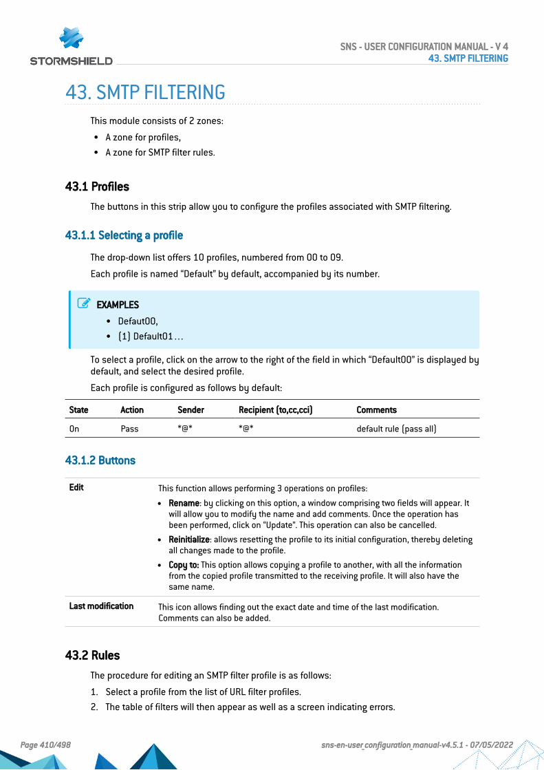
43. SMTP FILTERINGThis module consists of 2 zones:
l A zone for profiles,l A zone for SMTP filter rules.
43.1 Profiles
The buttons in this strip allow you to configure the profiles associated with SMTP filtering.
43.1.1 Selecting a profile
The drop-down list offers 10 profiles, numbered from 00 to 09.
Each profile is named “Default” by default, accompanied by its number.
EXAMPLES
l Defaut00,l (1) Default01…
To select a profile, click on the arrow to the right of the field in which “Default00” is displayed bydefault, and select the desired profile.
Each profile is configured as follows by default:
State Action Sender Recipient (to,cc,cci) Comments
On Pass *@* *@* default rule (pass all)
43.1.2 Buttons
Edit This function allows performing 3 operations on profiles:
l Rename: by clicking on this option, a window comprising two fields will appear. Itwill allow you to modify the name and add comments. Once the operation hasbeen performed, click on “Update”. This operation can also be cancelled.
l Reinitialize: allows resetting the profile to its initial configuration, thereby deletingall changes made to the profile.
l Copy to: This option allows copying a profile to another, with all the informationfrom the copied profile transmitted to the receiving profile. It will also have thesame name.
Last modification This icon allows finding out the exact date and time of the last modification.Comments can also be added.
43.2 Rules
The procedure for editing an SMTP filter profile is as follows:
1. Select a profile from the list of URL filter profiles.
2. The table of filters will then appear as well as a screen indicating errors.
SNS - USER CONFIGURATION MANUAL - V 443. SMTP FILTERING
Page 410/498 sns-en-user_configuration_manual-v4.5.1 - 07/05/2022

43.2.1 Possible operations
The available buttons are:
Add Inserts a line to be configured after the selected line.
Delete Deletes the selected line.
Move up Places the selected line before the line just above it.
Move down Places the selected line after the line just below it.
Cut Removes the selected line and moves it to the clipboard.
Copy Copies the selected line and moves it to the clipboard.
Paste Pastes the line from the clipboard above the selected line.
43.2.2 Interactive features
Some operations listed in the taskbar can be performed by right-clicking on the table of filterrules:
l Add,l Delete,l Cut,l Copy,l Paste.
43.2.3 The table
The table contains the following columns:
Status Status of the rule:
l If Enabled, the rule is used for filtering.
l If Disabled, the rule is not used for filtering. If this rule is disabled, the line willbe grayed out in order to reflect this.
REMARKThe firewall will assess rules in their order of appearance on the screen: oneby one from the top down. As soon as it comes across a rule that correspondsto the request, it will perform the specified action and stop there. This meansthat if the action specified in the rule corresponds to Block, all rules below itwill also be set to Block.
Action Allows specifying the result of the rule: Pass to allow sending and receiving e-mails,Block to prohibit them
Sender Defines the sender of the e-mail. The value “none” can be selected as a sender.
Recipient (to, cc, cci) Defines the intended recipient of the e-mail.
Comments Comments relating to the rule.
An e-mail mask may contain the following syntax:
SNS - USER CONFIGURATION MANUAL - V 443. SMTP FILTERING
Page 411/498 sns-en-user_configuration_manual-v4.5.1 - 07/05/2022

l *: replaces a character string.
EXAMPLE*@company.com allows defining all e-mails from the internet domain of the company calledCOMPANY.
The following can also be seen:
l ? Replaces a character.l <none>: This value can only be obtained when the Sender field is empty, and is used only
for mailer daemons. When an e-mail cannot locate its recipient on a remote mail server, theremote mail server will send back an error message, indicating that there is an errorregarding the recipient. In this case, the Sender field in this error message will be empty.
A rule with the action “Block” can be created to prevent the e-mail from being sent if the senderis unknown.
43.2.4 Errors found in the SMTP filter policy
The screen for editing SMTP filter rules on the firewall has a rule compliance and coherenceanalyzer which warns the administrator when a rule inhibits another rule or if there is an error ina rule.
This analyzer groups errors during the creation of rules or incoherent rules.
Errors are displayed in the form of a list. By clicking on an error, the rule concerned willautomatically be selected.
SNS - USER CONFIGURATION MANUAL - V 443. SMTP FILTERING
Page 412/498 sns-en-user_configuration_manual-v4.5.1 - 07/05/2022

44. SNMP AGENTThe screen for configuring the SNMP service consists of three tabs:
l General: tab that is displayed by default when users click on the SNMP menu in thedirectory on the left and which allows enabling the module and alarm and systemnotifications which will be integrated into the available(lookup and sending of traps).
l SNMPv3: Recommended version as it is equipped with more secure tools (security toolssuch as authentication, encryption, timing control, etc.).
l SNMPv1 – SNMPv2c: Version for which the SNMP request contains a name called“Community”, which is used as an ID and transmitted over the network in plaintext.
44.1 General tab
This tab allows configuring the system, meaning the host and its administrator. It containsnotifications (alarms and system events) which will be integrated into the available MIBs.
The option Enable the agent allows enabling the module. It is however possible to configure thedata for this screen even if the module has not been enabled.
SNMPv3(recommended)
Enables version 3 of SNMP, the recommended version as it is equipped with moresecure tools (security tools such as authentication, encryption, timing control, etc.)Since December 2002, a new standard has been introduced for SNMP, providing asignificant advance in security. The configuration requires the following parameters:SNMPv3 offers authentication and encryption methods and resolves certain securityissues from earlier versions.
SNMPv1/v2c Enables versions v1/v2c of SNMP. V1 is the first version of the protocol. The onlycheck made by this version concerns the “Community” character string. Version v2cis a version that improves the types of operations in SNMPv2p and uses“community” character string security from SNMPv1.
SNMPv1/v2c andSNMPv3
Enables all three versions of SNMP.
44.1.1 Configuration of MIB-II information
Location(sysLocation)
Alphanumeric information regarding the location of the monitored item. This locationcan be a country, city, server room, etc. Example: France.
Contact (sysContact) E-mail address, telephone number, etc of the contact person in case problems arise.Example: [email protected]
44.1.2 Sending of SNMP alerts (traps)
Intrusion preventionalarms
Do not send: by selecting this option, you will not receive ASQ alarms.By selecting send only major alarms, you will be able to receive major ASQ alarms.By selecting send major and minor alarms, major and minor ASQ alarms will be sent.
SNS - USER CONFIGURATION MANUAL - V 444. SNMP AGENT
Page 413/498 sns-en-user_configuration_manual-v4.5.1 - 07/05/2022
System events Do not send: by selecting this option, you will not receive system alarms.By selecting send only major alarms, you will be able to receive major systemalarms.By selecting send major and minor alarms, major and minor system alarms will besent.
NOTESNMP can now be configured so that the name of the firewall instead of its serial number is usedfor SysName.
44.2 SNMPv3 tab
The options Enable the agent SNMPv3 (recommended) or SNMPv1/v2c et SNMPv3 allowenabling the SNMP v3 module.
44.2.1 Connection to the SNMP agent
Username Username used for the connection and for looking up MIBs on the firewall.
44.2.2 Authentication
Password Password of the user who will look up MIBs.This password must comply with the firewall's general password policy defined inthe Password policy section in the Configuration module (General configuration tab),and contain at least 8 characters.
Algorithm Two authentication methods are available, MD5 (hash algorithm that calculates a128-bit digest) and SHA1 (hash algorithm that calculates a 160-bit digest). Bydefault MD5 will be used for authentication.
44.2.3 Encryption (optional)
Password SNMP packets are encrypted in DES or AES, and an encryption key can be defined.By default the authentication key will be used.
WARNINGYou are strongly advised to use a specific key.
Algorithm The two encryption methods possible are DES and AES. By default DES is used forencryption.
44.2.4 Sending of SNMPv3 alerts (traps)
Sending traps to hosts consists of 2 parts, with the list of hosts on the left and details of aselected host on the right.
SNS - USER CONFIGURATION MANUAL - V 444. SNMP AGENT
Page 414/498 sns-en-user_configuration_manual-v4.5.1 - 07/05/2022

List of SNMP servers
In this screen, you can configure the stations that need to contact the firewall when it needs tosend an SNMP Trap (event). If no stations (hosts) are specified, the firewall will not send anymessages.
A wizard will guide you through the configuration of the hosts.
By clicking to the right of a host name, the objects database will appear, allowing you to selecta host.
Server [Name of destination server (object)]
The parameters in the configuration of SNMP V3 events are as follows:
Port Port used for sending data to the host (snmptrap by default).
Username(securityName)
Name of the user allowed to send traps on the management station.Please note that when the server's ID below has not been entered (engineID), thisuser name (securityName) has to be the same as the name used for logging on tothe SNMP agent.
ID (engineID) Hexadecimal string created by the management station in order to give the user aunique identification such as 0x0011223344. The engine ID has to be made up of aminimum of 5 bytes and a maximum of 32 bytes.Please note that if this field is empty, the SNMP agent has to be configured to receivean identifier that changes as it will be automatically generated each time the servicestarts.
Security level Several levels of security are available for the version of the SNMP protocol:
l None: no security. The sections “Security Level: authentication” and “Securitylevel: Encryption” are grayed out.
l Authentication, no encryption: authentication of traps without encryption.
l Authentication and encryption: if the encryption password is not defined, theauthentication password will be used for encryption.
Authentication settings
Password User’s password
Algorithm Two authentication methods are available, MD5 (hash algorithm that calculates a128-bit digest) and SHA1 (hash algorithm that calculates a 160-bit digest). Bydefault MD5 will be used for authentication.
Encryption settings
Password SNMP packets are encrypted in DES or AES-128, and an encryption key can bedefined. By default the authentication key will be used.
WARNINGYou are strongly advised to use a specific key.
Algorithm The two encryption methods possible are DES and AES-128. By default AES-128 isused for encryption.
SNS - USER CONFIGURATION MANUAL - V 444. SNMP AGENT
Page 415/498 sns-en-user_configuration_manual-v4.5.1 - 07/05/2022

44.3 SNMPv1 - SNMPv2c tab
The option Enable SNMPv1/v2c or SNMPv1/v2c and SNMPv3 allows enabling the SNMP v1 andv2c modules.
44.3.1 Connection to the SNMP agent
Community The first versions of the SNMP protocol are not secured. The only field necessary isthe community name. By default VPN suggests the name "public".
WARNINGWe advise against using it for security reasons.
If you wish to indicate several communities, separate them with commas.
44.3.2 Sending of SNMPv2c alerts (traps)
List of SNMP servers
Destination server(object)
Host that receives traps, (“Host” object).
Port Port used for sending traps to this host (object type: service). By default, snmptrap.
Community Indicates the community.
44.3.3 Sending of SNMPv1 alerts (traps)
By default, the list of hosts that receive v1 traps will be minimized to point the user to versionv2c.
List of SNMP servers
Computer Host that receives traps, (“Host” object).
Port Port used for sending traps to this host (object type: service). By default, snmptrap.
Community Indicates the community.
44.4 MIBs and SNMP Traps
The Simple Network Management Protocol (SNMP) allows you to monitor all hosts installed onyour network. SNMP alerts (traps) and data listening (MIB) can be configured using the SNMPAgent module in the firewall’s web administration interface.
In it, you can configure the workstations to which the firewall must send alerts and SNMPevents (traps) or configure access to those that gather data. This manager allows you tocommunicate with the SNMP agent on a firewall and to obtain, manage and monitor data fromany firewall through the network. The SNMP agent authorizes read-only access to supervisorsthat comply with SNMP versions v1, v2c, and v3.
To configure data tracking and receive Stormshield traps, you must first download MIBs (textfiles that describe a list of SNMP objects that the supervisor uses). These MIBs therefore
SNS - USER CONFIGURATION MANUAL - V 444. SNMP AGENT
Page 416/498 sns-en-user_configuration_manual-v4.5.1 - 07/05/2022

provision data that the supervisor may need in order to interpret SNMP traps, events andrequest messages sent to the firewall.
44.4.1 Downloading MIBs
Download MIBs from your MyStormshield personal area (authentication required), inDownloads > Downloads > Stormshield Network Security > SNMP MIBs > MIBs corresponding toyour SNS version.
44.4.2 Stormshield Network MIBs
The following is the list of fields of Stormshield Network MIBs, the corresponding CLI/Serverdcommands and console commands.
STORMSHIELD-SMI-MIB is the top-level MIB of all MIBs.STORMSHIELD-VPN-MIB is the top-level MIB of VPNIKESA, VPNSA and VPNSP.
Stormshield Network MIB CLI/Serverd Console
STORMSHIELD-ALARM-MIB sfctl -s log
STORMSHIELD-ASQ-STATS-MIB sfctl –s stat
STORMSHIELD-AUTHUSERS-MIB MONITOR USER sfctl -s user
STORMSHIELD-AUTOUPDATE-MIB MONITOR AUTOUPDATE
STORMSHIELD-HA-MIB HA INFO hainfo
STORMSHIELD-HEALTH-MONITOR-MIB MONITOR HEALTH
STORMSHIELD-HOSTS-MIB MONITOR HOST sfctl -s host
STORMSHIELD-IF-MIB MONITOR INTERFACE sfctl -s global
STORMSHIELD-IPSEC-STATS-MIB ipsecinfo
STORMSHIELD-OVPNTABLE-MIB MONITOR OPENVPN LIST
STORMSHIELD-POLICY-MIB MONITOR POLICY slotinfo
STORMSHIELD-PROPERTY-MIB SYSTEM PROPERTYSYSTEM IDENTSYSTEM LANGUAGE
STORMSHIELD-QOS-MIB MONITOR QOS sfctl -s qos
STORMSHIELD-ROUTE-MIB MONITOR ROUTE sfctl -s route
STORMSHIELD-SERVICES-MIB MONITOR SERVICE dstat
STORMSHIELD-SYSTEM-MONITOR-MIB MONITOR STAT
STORMSHIELD-VPNIKESA-MIB MONITOR GETIKESA
STORMSHIELD-VPNSA-MIB MONITOR GETSA showSAD
STORMSHIELD-VPNSP-MIB MONITOR GETSPD showSPD
SNS - USER CONFIGURATION MANUAL - V 444. SNMP AGENT
Page 417/498 sns-en-user_configuration_manual-v4.5.1 - 07/05/2022

45. SSL FILTERINGSSL filtering is now integrated into the new security policy on Stormshield Network multi-function firewalls. This module allows filtering access to secure web sites. It also makes itpossible to allow or prohibit web sites or certificates that pose risks.
This module consists of 2 zones:
l A zone for profiles,l A zone for SSL filter rules.
45.1 Profiles
The buttons in this strip allow you to configure the profiles associated with SSL filtering.
45.1.1 Selecting a profile
The drop-down list offers 10 profiles, numbered from 00 to 09.
Each profile is named “Default” by default, accompanied by its number.
EXAMPLES
l Defaut00,l (1) Default01…
To select a profile, click on the arrow to the right of the field in which “Default00” is displayed bydefault, and select the desired profile.
Each profile is configured as follows by default:
State Action URL-CN Comments
On Pass without decrypting any default rule (decrypt all)
45.1.2 Buttons
Edit This function allows performing 3 operations on profiles:
l Rename: by clicking on this option, a window comprising two fields will appear. Itwill allow you to modify the name and add comments. Once the operation hasbeen performed, click on “Update”. This operation can also be cancelled.
l Reinitialize: allows resetting the profile to its initial configuration, thereby deletingall changes made to the profile.
l Copy to: This option allows copying a profile to another, with all the informationfrom the copied profile transmitted to the receiving profile. It will also have thesame name.
Last modification This icon allows finding out the exact date and time of the last modification.Comments can also be added.
URL databaseprovider
This link redirects to the module that allows configuring the URL database provider(Web Objects module / URL database tab).
SNS - USER CONFIGURATION MANUAL - V 445. SSL FILTERING
Page 418/498 sns-en-user_configuration_manual-v4.5.1 - 07/05/2022

45.2 Rules
The procedure for editing an SSL filter profile is as follows:
1. Select a profile from the list of SSL filter profiles.
2. The table of filters will then appear as well as a screen indicating errors.
45.2.1 Possible operations
A multiple selection allows assigning the same action to several rules. Select severalsuccessive alarms using the Shiftñkey or individually by holding down the Ctrl key. You canalso remove an item from an existing selection with the Ctrl key.
Some column titles have the icon . When you click on it, a menu appears and suggestsassigning a setting to several selected rules (Status and Action).
Example: Several lines can be deleted at the same time, by selecting them with the Ctrl key andpressing on Delete.
The available buttons are:
Add Inserts a line to be configured after the selected line.
Delete Deletes the selected line.
Move up Places the selected line before the line just above it.
Move down Places the selected line after the line just below it.
Cut Removes the selected line and moves it to the clipboard.
Copy Copies the selected line and moves it to the clipboard.
Paste Pastes the line from the clipboard above the selected line.
Add all predefinedcategories
This button makes it possible to create as many filter rules as the number of URLcategories in the selected URL base at once.All rules created in this way are enabled and the associated action by default isDecrypt.
45.2.2 Interactive features
Some operations listed in the taskbar can be performed by right-clicking on the table of filterrules:
l Add,l Delete,l Cut,l Copy,l Paste.
45.2.3 The table
The table contains the following columns:
SNS - USER CONFIGURATION MANUAL - V 445. SSL FILTERING
Page 419/498 sns-en-user_configuration_manual-v4.5.1 - 07/05/2022

Status Status of the rule:
l If Enabled, the rule is used for filtering.
l If Disabled, the rule is not used for filtering. If this rule is disabled, the line willbe grayed out in order to reflect this.
REMARKThe firewall will assess rules in their order of appearance on the screen: one byone from the top down. As soon as it comes across a rule that corresponds tothe request, it will perform the specified action and stop there. This means thatif the action specified in the rule corresponds to Block, all rules below it will alsobe set to Block.
Action Allows specifying the operation to perform:
l If Pass without decrypting is specified, access to the requested CN will be allowedwithout a prior SSL analysis.
l If Block without decrypting is specified, access to the requested CN will be denied,without any SSL analysis being applied. The connection will be shut down.
l If Decrypt is specified, the protocol analysis will be applied to the decryptedtraffic, as well as on the proxy, if a rule has been created for it.
URL-CN This action applies according to the value of this column. It may contain a group orURL category, as well as a group of certificate names.
Comments Comments relating to the rule.
45.2.4 Errors found in the SSL filter policy
The screen for editing SSL filter rules on the firewall has a rule compliance and coherenceanalyzer which warns the administrator when a rule inhibits another rule or if there is an error ina rule.
This analyzer groups errors during the creation of rules or incoherent rules.
Errors are displayed in the form of a list. By clicking on an error, the rule concerned willautomatically be selected.
SNS - USER CONFIGURATION MANUAL - V 445. SSL FILTERING
Page 420/498 sns-en-user_configuration_manual-v4.5.1 - 07/05/2022
46. SSL VPNSSL VPN enables remote users to safely access internal corporate resources usingcommunications encrypted in SSL. To use SSL VPN, an SSL VPN client must be installed on theworkstation or on any type of mobile terminal (Windows, IOS, Android, etc.).
SSL VPN tunnels may be based on UDP or TCP protocols. Whenever a UDP-based tunnel fails,the connection will switch to TCP.
If the provided VPN client is used, only the IP address of the firewall and its authenticationinformation (login/password) will be needed for the connection. If an OpenVPN client is used,the client must retrieve configuration details from the authentication portal (“Personal data”menu) before inserting them into the client
In addition to the settings in this module, the Authentication section must define the methodand allow the user in its policy. Filter rules must also specify ‘Via SSL VPN tunnel’ as the source(advanced properties) to allow traffic.
For further information, refer to the Technical note SSL VPN tunnels available in your secure-access area.
This module consists of a single configuration screen split up into four sections:
l Enable the service.l Network settings: this area contains the elements that can be used in the configuration of
the SSL VPN server, networks or contactable hosts, as well as the network assigned toclients.
l DNS settings sent to client: this area contains the DNS configuration elements that will besent to the client.
l Advanced properties: in this area, you can customize the lifetime before SSL renegotiation,define scripts to execute when the client is connected/disconnected, and select client andserver certificates to set up the SSL tunnel.
This button makes it possible to enable or disable the SSL VPN server on the firewall.
46.1 Network settings
UTM IP address (orFQDN) used
Indicate the public IP address of the IPS-Firewall (or an FQDN associated with thisaddress, e.g., sslserver.company.com) through which clients will be able to contactthe SSL VPN server.
SNS - USER CONFIGURATION MANUAL - V 446. SSL VPN
Page 421/498 sns-en-user_configuration_manual-v4.5.1 - 07/05/2022

Available networks orhosts
Indicate which network and hosts will be visible to clients. All packets from the clientgoing towards these networks will go through the SSL tunnel.This object can either be a network, machine or group object containing severalnetworks and/or hosts, and can be created directly from this window by clicking on
.The value of this field is Network_internals by default, which makes it possible toconnect with all networks protected by the firewall.
REMARKThis is only a network routing concept. Filter rules must be created to allow orblock traffic between the remote client network and internal resources.
Network assigned toclients (UDP)
Select a network object, except IP address range or Group objects, which are notaccepted. Each client that sets up a UDP-based tunnel will be assigned an IP addressbelonging to this network.This network must be different from the one assigned to the clients of TCP-basedtunnels.The object can be created directly from this window by clicking on .
IMPORTANTTo prevent routing conflicts on client workstations during the connection to theSSL VPN, select less commonly used sub-networks for your clients (e.g.,10.60.77.0/24, 192.168.38.0/24, etc.). Many filtered Internet access networks(public Wi-Fi, hotels, etc) or private local networks use the first few addressranges reserved for these uses (e.g., 10.0.0.0/24, 192.168.0.0/24).
Network assigned toclients
Select a network object, except IP address range or Group objects, which are notaccepted. Each client that sets up a TCP-based tunnel will be assigned an IP addressbelonging to this network.This network must be different from the one assigned to the clients of UDP-basedtunnels.The object can be created directly from this window by clicking on .
IMPORTANTTo prevent routing conflicts on client workstations during the connection to theSSL VPN, select less commonly used sub-networks for your clients (e.g.,10.60.77.0/24, 172.168.38.0/24, etc.). Many filtered Internet access networks(public Wi-Fi, hotels, etc) or private local networks use the first few addressranges reserved for these uses (e.g., 10.0.0.0/24, 192.168.0.0/24).
Maximum number ofsimultaneoustunnels allowed
Depending on the size of the network chosen for clients and the model of thefirewall, the number of tunnels that can be set up simultaneously will be indicated.This number corresponds to the lowest of the two following values:
l A quarter of the number of IP addresses included in the selected client network(e.g., 63 for a Class C network). Each SSL tunnel takes up four IP addresses.
l The maximum number of tunnels allowed on the IPS-Firewall used.
SNS - USER CONFIGURATION MANUAL - V 446. SSL VPN
Page 422/498 sns-en-user_configuration_manual-v4.5.1 - 07/05/2022
46.2 DNS settings sent to client
Domain name Domain name assigned to clients so that they can resolve the DNS.
Primary DNS server Primary DNS server assigned to the client.
Secondary DNSserver
Secondary DNS server assigned to the client.
46.3 Advanced properties
UTM IP address forthe SSL VPN (UDP)
You can specify the public IP address on the IPS-Firewall through which clients willbe able to contact the SSL VPN server over UDP.Fill in this field in the following cases:
l When the SSL VPN client uses an IP address without any link to the firewall'sdefault gateway in the “Firewall address” field,
l When the SSL VPN client uses an IP address assigned to the firewall as an alias(additional IP address on an interface) in the “Firewall address” field,
Port (UDP) Select or create the object corresponding to the UDP port that will be used to set uptunnels.
Port (TCP) Select or create the object corresponding to the TCP port that will be used to set uptunnels. This port will also be used as a backup mechanism if tunnels cannot be setup via UDP.
Interval before keyrenegotiation (inseconds)
Period after which keys will be renegotiated. The default value is 14400 seconds, or4 hours.
Use DNS serversprovided by thefirewall
If this option is selected, the SSL VPN client will include the DNS servers retrieved viathe SSL VPN in the workstation's network configuration. If DNS servers are alreadydefined on the workstation, they may be queried.
Prohibit use of third-party DNS servers
If this option is selected, the SSL VPN client will exclude DNS servers already definedin the workstation's configuration. Only DNS servers sent by the firewall can bequeried.These DNS servers must be contactable through an SSL VPN tunnel.
Script to run whenconnecting
Select a script that the client will execute locally when connecting to the SSL tunnel(e.g., connecting a disk to a remote shared network).
Script to run whendisconnecting
Select a script that the client will execute locally when it disconnects from the SSLtunnel (e.g., disconnecting a disk from a remote shared network).
NOTEOnly client hosts running under Windows and with the Stormshield Network client can use theexecutable script service. The format of files must be “.bat”.
NOTEAll Windows environment variables can be used in connection/disconnection scripts (e.g.,%USERDOMAIN%, %SystemRoot%, etc.).Two environment variables relating to the SSL VPN tunnel can also be used:
SNS - USER CONFIGURATION MANUAL - V 446. SSL VPN
Page 423/498 sns-en-user_configuration_manual-v4.5.1 - 07/05/2022

l %NS_USERNAME%: the user name used for authentication,l %NS_ADDRESS%: the IP address assigned to the client.
46.4 Used certificates
Server certificate Select the certificate submitted by the server to set up the SSL tunnel.By default, the server certificate suggested is the one created during the initializationof the firewall. It is issued by the CA dedicated to the default SSL VPN.
Client certificate Select the certificate submitted by the client to set up the SSL tunnel.By default, the client certificate suggested is the one created during the initializationof the firewall. It is issued by the CA dedicated to the default SSL VPN.This certificate is the same for all clients. They can be authenticated once the SSLconnection has been established.
IMPORTANTIf you choose to create your own CA, you must use two certificates signed by it. If this CA is not aroot authority, both certificates must use be issued by the same sub-authority.
46.5 Configuration
Download theconfiguration file
Click on this button to obtain an archive containing the SSL VPN server'sconfiguration file.
SNS - USER CONFIGURATION MANUAL - V 446. SSL VPN
Page 424/498 sns-en-user_configuration_manual-v4.5.1 - 07/05/2022

47. SSL VPN PortalStormshield Network’s SSL VPN portal allows your mobile or static users to connect to yourcompany’s resources securely.
Stormshield Network’s SSL VPN portal does not impose any client installations on your users’workstations and natively supports operating systems that have Java 8 or OpenWebStartinstalled (Windows, Linux, macOS, etc.).
The SSL VPN configuration screen consists of 4 tabs:
l General: Allows enabling the module, selecting the access type and configuring advancedproperties.
l Web servers: Stormshield Network’s SSL VPN allows securing access to your HTTP servers(Intranet, webmail,…) while avoiding the need to manage multiple HTTP servers.Furthermore, for mobile users, it allows masking information about your internal network,the only visible IP address being your firewall’s.Stormshield Network’s SSL VPN automatically rewrites HTTP links found in web pages thatyour users visit. This allows browsing between your various servers, if they have beenconfigured, or prohibiting access to certain servers. When a web link in a page points to anunconfigured server, the link will be redirected to the Stormshield Network SSL VPN startpage.
l Application servers: This section shows the servers that have been configured for access to resources other than web-based resources (telnet, mail, etc)Stormshield Network’s SSL VPN enables securing any protocol based on a single TCPconnection (POP3, SMTP, telnet, remote access, etc). For protocols other than HTTP, theclient that allows secure connections is a Java applet, which will open an encrypted tunnel.All packets exchanged between the client workstation and the firewall are encrypted.Stormshield Network’s SSL VPN does not impose any client installations on your users’workstations and natively supports operating systems that have Java 8 or OpenWebStartinstalled (Windows, Linux, macOS, etc.).You only need to configure the servers which you intend to allow your users to access.These servers will be added dynamically to the list of authorized servers the next time yourusers load the java applet.The Java applet opens listening ports on the client workstation, and client tools will need toconnect to these ports in order to pass through the secure tunnel set up between the appletand the firewall. It is necessary to ensure that the chosen port is accessible to the user(where privileges are concerned) and that there is no conflict with another port used byanother program. These servers will be added dynamically. These can be used for controlpurposes and/or transparent authentications on the source of requests.
l User profiles: If you wish to restrict access to servers defined in the SSL VPN configuration,you need to define profiles that contain the list of authorized servers, then assign them tousers.
47.1 General tab
Enable SSL VPN: Allows enabling SSL VPN and choosing from three options offers in the tablebelow.
Access only to webservers
Use of the SSL VPN module to access web-based resources. Enables the Web serverstab.
SNS - USER CONFIGURATION MANUAL - V 447. SSL VPN PORTAL
Page 425/498 sns-en-user_configuration_manual-v4.5.1 - 07/05/2022

Access only toapplication servers
Use of the SSL VPN module to access resources on a TCP connection. Enables theApplication servers tab.
Access to both weband applicationservers
Use of the SSL VPN module to access web-based and TCP-based resources. Enablesboth the Web servers and Application servers tabs.
47.1.1 Advanced properties
Access to servers via SSL VPN
Prefix for the URL rootdirectory
Stormshield Network’s SSL VPN technology enables masking the real addresses ofservers to which users are redirected, by rewriting all URLs contained in HTTP pagesvisited. These URLs will then be replaced by a prefixed followed by 4 digits. This fieldenables defining the prefix to be used.
HTTP header for userID
This field’s value will be sent to the web server in the HTTP header of outgoingqueries, along with the user’s login. This value can be used for checks and/ortransparent authentication on the source of the queries.
In the event the server to which HTTP traffic is redirected requests authentication, alogin can be defined in the header of the HTTP packet. This login may be useful inindicating, for example, that this traffic arriving on the server come from the firewalland can be accepted by the server without authentication.
Client workstation configuration
Command executedat startup
This command, which is executed when the applet is launched, allows theadministrator to define actions to perform before displaying the applet. For example,this command may launch a script (installed on a server) which will modify theparameters of the user’s mail account in such a way that when the applet islaunched, SMTP and POP traffic will be automatically redirected, all without the user’sintervention.
Command executedduring shutdown
This command, which is launched when the applet is shut down, allows theadministrator to define actions to perform before shutting down the applet. Forexample, this command may launch a script (installed on a server) which will modifythe parameters of the user’s mail account in such a way that when the applet is shutdown, SMTP and POP traffic will no longer be automatically redirected, all without theuser’s intervention.
47.2 Web servers tab
This section groups the servers configured for access to web resources.
The number of web servers that can be configured varies according to the appliance model:
Model Max. no. of HTTP servers Max. no. of other servers
SN160(W), SN210(W), SN310 64 64
SN510, SN710, SNi40, SNi20 128 128
SN910 256 256
SNS - USER CONFIGURATION MANUAL - V 447. SSL VPN PORTAL
Page 426/498 sns-en-user_configuration_manual-v4.5.1 - 07/05/2022

SN2000, SN2100, SN3000, SN3100,SN6000, SN6100
512 512
47.2.1 Adding a web server
To add a web access server, the procedure is as follows:
1. Click on Add.
2. Select one of the suggested servers.A screen containing server names will appear.
3. Enter a name for this server (he field can be left empty. Allowed characters: numbers,letters, spaces, -, _, and dots.).This server’s configuration then appears. The different parameters are explained below.
Destination server The object corresponding to the server accessible to the user can be specified in thisfield.
WARNINGMake sure that you use an object whose name is identical to the FQDN name ofthe server it refers to. If this is not the case, (e.g. object name: webmail, FQDNname: www.webmail.com), Firewall queries to this server may be refused.
Port The port on the server accessible to the user can be specified in this field. Port 80 isdefined for HTTP.
URL: access path This URL enables going directly to the specified page.
URL used by SSL VPN Link calculated based on 3 fields: Destination server, Port and URL: access path.(Example: http://destination server/URL: access path).
Name of the link onthe user portal
The defined link appears on the Stormshield Network web portal. When the userclicks on this link, he will be redirected to the corresponding server.
Advanced properties
Enable URL whitelist Only links that the SSL VPN module has rewritten can be accessed through SSL VPN.If, on an authorized site, there is a link to an external website whose server has notbeen defined in SSL VPN configuration, the authorized site will not be accessible viaSSL VPN.If the white list has been activated, it will enable access to URLs which have notbeen rewritten through the field Do not rewrite URLs in the category. For example, forwebmail SSL VPN access, if you wish to allow users to quit the SSL VPN by clickingon the links contained in their e-mails, you need to add a whitelist containing “*”.
WARNINGIf the user clicks on a link in the whitelist, it will no longer be protected by theStormshield Network SSL VPN module.
SNS - USER CONFIGURATION MANUAL - V 447. SSL VPN PORTAL
Page 427/498 sns-en-user_configuration_manual-v4.5.1 - 07/05/2022

Don't show thisserver on the userportal (access viaanother server only)
All servers configured in SSL VPN are listed on the Stormshield Networkauthentication portal by default. However, it may be necessary for servers to beaccessible only through another server, so in this case, the option Don't show thisserver on the user portal has to be selected. When this option is selected during theconfiguration of a server, this server can be accessed via SSL VPN, but will not be onthe direct-access list. A link to this server is needed in order to access it. Anapplication can use several servers but have only one entry point, so only one link inthe menu of the portal.
Deactivate NTLM Some web servers may request authentication before the transfer of data betweenthe server and the user. This method can be disabled for servers that do not supportthis authentication method for traffic passing through the firewall.
Rewrite \"User-Agent\" field (forceOWA compatibilitymode)
The “User-Agent” field in the header of an HTTP request contains the identifier for theweb browser used. For example, on Internet Explorer: Mozilla/4.0 (compatible; MSIE6.0 ...). Rewriting the “User-Agent” value therefore allows modifying the HTTP requestin such a way that it gives the impression of coming from a different browser type.
This option is particularly useful in basic mode of Outlook Web Access (OWA). In fact,OWA in premium mode (a very advanced mode), uses Webdav, an extension of HTTP.Since not all types of network equipment support these extensions (the SSL VPNmodule on firewalls supports OWA in premium mode), the transmission of suchtraffic may give rise to compatibility issues, especially on the internet. Instead of allusers (internal and external) having to use a more basic mode of OWA, the optionRewrite User-Agent enables using “premium” OWA internally (compatibility withpremium mode is easy to obtain) and using “basic” mode by passing through SSLVPN (for mobile users, via internet). Since “old” web browsers do not support theseextensions, OWA therefore automatically operates in basic mode when it encountersthe “User-Agent” on these browsers.
Rewrite OWAPremium modespecific code
If this option has been selected, you will enable the specific rewriting rules that allowsupporting Outlook Web Access in premium mode.
Lotus Domino Web Access version 7.0.4 runs through SSL VPN tunnels. There is therefore noneed to enable specific rewriting rules that would allow supporting Lotus Domino webapplications.
Alternative URLs for this server (alias)
Server alias Aliases allow indicating to the SSL VPN module that the server is known by severalnames and/or IP addresses. If a mail server is defined as the object“webmail.intranet.com” to which the alias “192.168.1.1” is assigned, the user will beredirected to the mail server whether he visits the link “http://webmail.intranet.com“ or “http://192.168.1.1”. Clicking on Add will display a line that will allow you to add anew alias.
47.2.2 Adding an OWA web server
The SSL VPN module on Stormshield Network Firewalls supports OWA (Outlook Web Access)Exchange 2003, 2007 and 2010 servers.
“Premium” mode can only be used in Windows with Internet Explorer 5 and higher. It is basedon web technologies such as html, css and javascript but also on Microsoft proprietarytechnologies such as htc, xml and activeX.
SNS - USER CONFIGURATION MANUAL - V 447. SSL VPN PORTAL
Page 428/498 sns-en-user_configuration_manual-v4.5.1 - 07/05/2022
In Exchange 2003, the links are absolute links, regardless of whether they are in HTML pages,javascripts, in XML data, or in XSL sheets, such as “http://www.company.com/index.htm”.
It is therefore possible to add HTTP servers (with specific preset options for perfectcompatibility with OWA) to the list of web-access servers.
To add an HTTP server-OWA, the procedure is as follows:
1. Click on Add then select OWA Web server 2003 (Premium mode) or OWA Web server 2007 –2010 (premium mode).The following screen appears:
2. Enter a name for this server (the field can be left empty. Allowed characters: numbers,letters, spaces, -, _, and dots.).
The preset options for an OWA 2003 premium server are:
l HTTP port,l The field URL: access path with "exchange" indicated,l The field Enable URL whitelist enabled,l The field Do not rewrite URLs in the category with the URL group “vpnssl_owa” indicated,l The field Deactivate NTLM,l The field Rewrite OWA Premium mode specific code.
For an OWA 2007-2010 server, the pre-entered fields are:
l HTTP port,l The field URL: access path with "owa" indicated,l The field Enable URL whitelist with the URL category “vpnssl_owa” indicated,l The field Rewrite OWA Premium mode specific code.
Other options that have not been entered have to be configured in the same way as for a“normal” web-access server.
47.2.3 Adding a Lotus Domino web server
The SSL VPN module on Stormshield Network Firewalls supports Lotus domino servers.
An HTTP server can be added to the list of web access servers with certain options specificallypre-entered for compatibility with Lotus Domino.
The procedure for adding an HTTP-Lotus Domino server is as follows:
1. Click on Add.
2. Select Lotus Domino web server.
3. Enter a name for this server (the field can be left empty. Allowed characters: numbers,letters, spaces, -, _, and dots.).
The following field is pre-entered option for Lotus domino servers: “http” port.
47.3 Application servers tab
47.3.1 Configuration with an application server
The procedure for adding a server to access resources other than web-based resources is asfollows:
SNS - USER CONFIGURATION MANUAL - V 447. SSL VPN PORTAL
Page 429/498 sns-en-user_configuration_manual-v4.5.1 - 07/05/2022

1. Click on Add then select Application server.
2. Enter a name for this server. (The field can be left empty. Allowed characters: numbers,letters, spaces, -, _, and dots.)
3. This server’s configuration then appears. The different parameters are explained below.
Destination server This field allows specifying the object corresponding to the server that the user willbe able to access.
Port The port on the server accessible to the user can be specified in this field.
User workstation settings
Listening IP address(local)
Local address of the client.
Port The JAVA applet uses this port, located on the remote workstation, to redirectencrypted traffic going to the Stormshield Network Firewall.The user must possess certain privileges on this port (to open it, for example),therefore make sure that the host’s local administration rights are modified as well.Also, the specified port must be free on all hosts wishing to connect to theassociated server via the portal.
Advanced properties
Enable Citrixcompatibility
Enables compatibility with the Citrix web authentication portal and access via theweb browser. This option is useless if the Citrix fat client is used.
Command executedat startup
This command, which is executed when the server is launched, allows theadministrator to define actions to perform before displaying the server. For example,this command may execute a script (installed on a server) that will check theactivity of the antivirus installed on the user’s host before granting him access to theserver.
47.3.2 Configuration with a Citrix server
Creating an object for the Citrix server
1. Go to the object database in order to create a host.
2. Select a host.
Configuring an application server
In the SSL VPN module:
1. Select the tab Application servers.
2. Click on Add
3. Select Citrix server.
4. Give your server a name.The Citrix configuration screen will then appear.
5. Select the Citrix server created earlier in the objects database. (Cf. Step1)
Configuring a web server
Select the tab Web servers:
SNS - USER CONFIGURATION MANUAL - V 447. SSL VPN PORTAL
Page 430/498 sns-en-user_configuration_manual-v4.5.1 - 07/05/2022

1. Click on Add.
2. Select Web server.
3. Give your server a nameThe web server configuration window will then appear:
4. As for the URL: access path, indicate CitrixAccess/auth/login.aspx (if it is the versionPresentation Server 4.0).
Sending the configuration
Click on Apply.
Accessing the web portal
1. Open the web browser.
2. Identify yourself (https://your firewall’s IP address or its name).
3. Go to Secure access.
4. Select Pop up secure-access window from the drop-down list.
WARNINGIt is important for the Stormshield Network SSL VPN applet to operate as a background task.
5. Select Portal access > Portal.
6. Enter your username, password and domain.
47.4 Deleting a server
To delete a server, the procedure is as follows:
1. Select the server to remove.
2. Click on the button Remove.
WARNINGWhen a server is removed from the list of configured SSL VPN servers, it will automatically beremoved from the profiles to which it belonged.
47.5 User profiles tab
47.5.1 Operating principle
All servers configured in the SSL VPN module are listed on the Stormshield Networkauthentication portal by default. As such, users who have the right to access SSL VPN featureson the firewall have access to all the servers configured by the administrator. The concept ofusing profiles enables determining which users will have access to which servers configured inSSL VPN.
47.5.2 Configuring a profile
Adding a profile
The procedure for adding a profile to the list of available SSL VPN profiles is as follows:
SNS - USER CONFIGURATION MANUAL - V 447. SSL VPN PORTAL
Page 431/498 sns-en-user_configuration_manual-v4.5.1 - 07/05/2022

1. Click on Add.
2. Specify the name of the profile.
3. From the list of “Accessible web servers” and “Accessible application servers”, select theservers that will be accessible to users that belong to this profile.
4. Click on Apply to activate the configuration.
WARNINGProfiles cannot be created if there is not at least 1 configured SSL VPN server.
Deleting a profile
The procedure for deleting a profile is as follows:
1. Select the profile you wish to delete.
2. Click on the button Remove.
Using a profile
Profiles can be used in 2 ways:
l Either as a default profile in SSL VPN configuration,l Or assigned to one or several users as the specific profile of these users.
Using a profile as a default profile
The procedure for using a profile as the default profile in SSL VPN configuration (users who donot have a specific profile will be assigned this default profile) is as follows:
Create a profile in SSL VPN > User profiles.
Define the profile to be used as the default profile (name of the profile and associated servers)in the configuration menu Users > VPN Access privileges > default access > SSL VPN.
Using a profile as the specific profile for one or several users
The procedure for using a profile as the specific profile for one or several users (regardless ofthe list of servers defined by the default profile, these users will possess a list of specificservers) is as follows:
1. Define the profile to be used as the specific profile (name of the profile and associatedservers) in User profiles in the SSL VPN module.
2. Click on Apply to apply the changes.
3. In the module Users > VPN Access privileges > VPN access, select the user from the “SSLVPN” column
4. Select the profile defined earlier.
5. Click on Apply.
47.6 SSL VPN services on the Stormshield Network web portal
When authentication is enabled on the firewall (module Users\Authentication\General, select“Enable the captive portal”), then you will be able to access Stormshield Network’s SSL VPNfeatures.
To access SSL VPN features, the procedure is as follows:
1. Open the web browser.
2. Indicate the URL ”https:// firewall_address” in the address bar.
SNS - USER CONFIGURATION MANUAL - V 447. SSL VPN PORTAL
Page 432/498 sns-en-user_configuration_manual-v4.5.1 - 07/05/2022

3. The firewall authentication page will appear.
4. Log in.
5. If the you have the privileges to use VPN features, the Secure access menu will appear,enabling access to SSL VPN features.
When the authentication duration expires or access to the SSL VPN is denied, the user will beredirected to the transparent authentication page (SSO) if this method is available.
47.6.1 Accessing your company’s web sites via an SSL tunnel
This menu displays the list of websites the administrator has configured and to which usershave access.
The other methods of secure access enable accessing other secure sites configured by theadministrator.
47.6.2 Accessing your company’s resources via an SSL tunnel
This menu displays the list of other servers the administrator has configured and to whichusers have access.
WARNINGNo links are available on this page. However, this window must be kept open throughout theduration of the connection (the window can be reduced), otherwise the connection will be lost.
To access resources the administrator has configured, it has to be indicated to the clientsoftware (e.g. a mail client) that the server to which he has to connect to retrieve mail is nolonger the usual mail server. An address like “127.0.0.1: Listening_port” where “Listening_port” isthe port specified on the server configuration, has to be indicated.
The listening port for each configured server will be displayed on the Stormshield Network webportal page.
SNS - USER CONFIGURATION MANUAL - V 447. SSL VPN PORTAL
Page 433/498 sns-en-user_configuration_manual-v4.5.1 - 07/05/2022

48. MULTICAST ROUTINGMulticast routing is a technology that aims to preserve bandwidth by delivering a singleinformation flow to several recipients, potentially in a very large number (several thousands).With IP multicast, simultaneous content can be delivered by using the least bandwidth possibleand without overloading either the sender or receivers.
This distribution method is an advantage for applications such as video-conferencing, e-learning, stock market quotes, or video on demand.
NOTEStatic or dynamic multicast routing has priority over all other types of routing (static routing,dynamic routing, routing in a bridge, policy-based routing, etc).
This button makes it possible to enable or disable multicast routing.
Static routing With this radio button, static multicast routing and its configuration tab can beenabled.
Dynamic routing With this radio button, dynamic multicast routing and its configuration tab can beenabled.
IMPORTANTStatic multicast routing and dynamic multicast routing cannot be enabled simultaneously.
48.1 STATIC ROUTING TAB
48.1.1 Possible operations on rules in the static multicast routing policy
In this grid, you can set the rules in the multicast routing policy that will be applied on thefirewall. High-priority rules are placed on top. The firewall executes rules in their order ofappearance in the list (rule no. 1, 2 and so on) and stops as soon as it reaches a rule thatmatches the traffic that it processes.
Add Inserts a line after a selected line; a routing rule creation wizard will then open automatically.
Delete Deletes the selected line.
Move up Places the selected rule before the rule just above it.
Move down Places the selected rule after the rule just below it.
Cut Cuts a routing rule in order to move it.
Copy Copies a routing rule in order to duplicate it.
Paste Duplicates a routing rule after having copied it.
SNS - USER CONFIGURATION MANUAL - V 448. MULTICAST ROUTING
Page 434/498 sns-en-user_configuration_manual-v4.5.1 - 07/05/2022

48.1.2 Interactive features
Some operations listed in the taskbar can be performed by right-clicking on the grid of multicaststatic routes:
l Add,l Delete,l Up,l Down,l Cut,l Copy,l Paste.
48.1.3 New rule
Step 1: selecting the multicast group and the source interface
Select the multicast object containing allowed multicast IP addresses as well as the multicasttraffic source (source interface) for this routing rule.
The multicast group must contain a host, network, IP address range or group containingexclusively multicast IP addresses (within the range 224.0.0.0 - 239.255.255.255 inclusive).
Step 2: selecting the destination interfaces
Click on Add to target the destination of the traffic affected by the multicast routing rule. Youcan add as many destination interfaces as necessary in the rule.
A multicast packet matching the rule (packet originating from an address contained in themulticast group and being presented by one of the declared source interfaces) will be sent toall destination interfaces.
48.1.4 Rule grid
The grid sets out the list of static multicast routing rules and their statuses:
Status Status of the static multicast route:
l on: the route is in operation.
l off: the route is not in operation. Double-click to enable the route.
Sourceinterface
Displays the multicast group and the associated source interface in the following form:multicast_group@source_interface.
Destinationinterfaces
Displays the list of destination interfaces of the multicast traffic specified in the routing rulecreation wizard.
Comments Displays any comments that may have been entered when the rule was added.
SNS - USER CONFIGURATION MANUAL - V 448. MULTICAST ROUTING
Page 435/498 sns-en-user_configuration_manual-v4.5.1 - 07/05/2022

48.2 DYNAMIC ROUTING TAB
IMPORTANT
Dynamic multicast routing is an early-access feature in SNS 4.
You must refer to the Known issues and Limitations and explanations on usage in the SNS 4release notes before enabling this feature.
48.2.1 Definitions
l Multicast source: source sender (e.g., video camera).l Multicast receiver: receiver of multicast traffic (subscribed to the multicast group).l Multicast group: multicast address (private, public, SSM).l (S,G) - multicast (Source, Group): source IP address and multicast group address pair.l IGMP (Internet Group Management Protocol): protocol used by a multicast receiver to
subscribe to or unsubscribe from a multicast group.l PIM (Protocol Independent Multicast): family of multicast IP routing protocolsl PIM-SM (PIM Sparse Mode): version of PIM that builds a distribution tree. This is a scalable
version of the protocol, making it possible to manage multiple sources. The distribution treecan be:o In shared mode, by going through a Rendez-vous Point (Shared Tree or RPT),o Set up by recalculating the shortest path tree (SPT), through unicast routing.
l PIM-SSM (PIM Source-Specific Multicast): version of PIM in which receivers know the source.When the receiver subscribes, the source IP address and multicast group address pair willbe formed directly. This protocol is easier to set up than PIM-SM (no RP involved), butrequires IGMPv3 and is meant for a more restricted application type.
l RP (Rendez-vous Point): role held by a PIM-SM router. The RP is contacted to discover andindicate the multicast source.The SNS firewall can play this role.
l BSR (BootStrap Router): role held by a PIM router. The BSR is elected from a list ofcandidates. Once it is elected, it will gather candidacies for the role of RP, then shares thetable of multicast group/RP associations with other routers.The SNS firewall can play this role.
48.2.2 Configuring the interfaces
This involves defining the source/destination interfaces that participate in dynamic multicastrouting (PIM protocol) and the IGMP protocol versions that these interfaces can accept. To allowpackets originating from these protocols and going to the firewall’s interfaces, the Allow IGMPand PIM packets to be received for dynamic multicast routing to function implicit filter rule mustbe enabled.
Possible operations
Select all Selects all the lines shown in the grid to delete them in a single action.
SNS - USER CONFIGURATION MANUAL - V 448. MULTICAST ROUTING
Page 436/498 sns-en-user_configuration_manual-v4.5.1 - 07/05/2022

Add Inserts a line after a selected line to add an interface.
Delete Deletes the selected line.
Adding an interface
NOTEBridges and bridged interfaces cannot be selected as multicast interfaces.
To add an interface to the list of interfaces participating in dynamic multicast routing:
1. Select the line in the grid under which you want to create a new entry.
2. Click on Add.
3. Select the interface.
4. Select the IGMP protocol version allowed for this interface: IGMP v2 only or IGMP v2 andIGMP v3.
NOTEIf you wish to use the PIM-SSM protocol, you must choose IGMP v2 and IGMP v3because only IGMP v3 is compatible with this protocol.
5. Specify the priority assigned to this interface.This concept of priority is important in an architecture with multiple access, in which severalSNS firewalls or routers manage dynamic multicast routing over the same local network. Asa matter of fact, priority makes it possible to elect the Designated Router (DR),which willthen send requests to the Rendez-vous Point (RP) via the interface with the highest priority.The interface with the lowest priority number will have the highest priority in routingmulticast traffic.If both interfaces have the same priority, the interface with the highest IP address will havepriority.
Possible interactions
Some operations listed in the taskbar can be performed by right-clicking on the grid ofinterfaces:
l Add,l Remove.
Being a BSR candidate
In the Rendez-vous Point election mechanism, the BootStrap Router (BSR) that centralizeselections must be defined. If a BSR is already configured on the network, the SNS firewallcannot be a candidate.However, if you want the SNS firewall to be eligible for election as a BSR, use this grid:
Address Select the network interface on the firewall that will be used as the firewall’s identifier in theelection mechanism.Stormshield recommends using a dedicated loopback interface for this purpose.Loopback interfaces can be defined in Network > Virtual interfaces > Loopback tab.
More information on creating loopback interfaces.
SNS - USER CONFIGURATION MANUAL - V 448. MULTICAST ROUTING
Page 437/498 sns-en-user_configuration_manual-v4.5.1 - 07/05/2022
Priority This concept of priority is important in an architecture for which several devices are BSRcandidates - the device that has the interface with the highest priority will be elected.
IMPORTANTThe interface with the highest number will have the highest priority.If both interfaces have the same priority, the interface with the highest IP address willhave priority.
Participating in Rendez-vous Point (RP) elections
NOTEMulticast groups must be very thoroughly managed (no address overlaps) so that the RPelection mechanism can be used while static RPs are being defined.
The RP plays an essential role in how PIM-SM runs. If a RP is already configured on the network,the SNS firewall cannot be a candidate.If you wish to register the firewall in the Rendez-vous Point election mechanism, use this grid.
Address Select the network interface on the firewall that will be used as the firewall’s identifier in theelection mechanism.Stormshield recommends using a dedicated loopback interface for this purpose.Loopback interfaces can be defined in Network > Virtual interfaces > Loopback tab.
More information on creating loopback interfaces.
Priority This concept of priority is important in an architecture for which several devices are RPcandidates - the device that has the interface with the highest priority will be elected.
IMPORTANTThe interface with the lowest number will have the highest priority.If both interfaces have the same priority, the interface with the highest IP address willhave priority.
Possible operations:
l To add a multicast group address belonging to the firewall that will be the potential RP, clickon Add, then select (or create directly from this grid) the network object corresponding tothis address.
l To delete a multicast group address belonging to the firewall that will be the potential RP,select the corresponding line, then click on Delete.
l To delete all multicast group addresses, click on Select all, then on Delete.
Static Rendez-vous Points (RP)
NOTEMulticast groups must be very thoroughly managed (no address overlaps) so that the RPelection mechanism can be used while static RPs are being defined.
If you wish to define static Rendez-vous Points (without going through an election mechanism),use this grid.
Possible operations:
SNS - USER CONFIGURATION MANUAL - V 448. MULTICAST ROUTING
Page 438/498 sns-en-user_configuration_manual-v4.5.1 - 07/05/2022

l To add a static RP definition, click on Add, then fill in the two fields below:
Range Multicast address range (multicast group) to which the RP is assigned.This range may either be an existing custom range defined in the firewall’s network objects, orcan be created directly from this grid.
Address IP address of the RP for this multicast group.
l To delete a static RP definition, select the corresponding line and click on Delete.l To delete all static RP definitions, click on Select all, then on Delete.
Advanced configuration
Intervalbetweentwo Hellomessages
Interval (in seconds) between two Hello packets sent to other devices that manage the PIMprotocol.The default value is 30 seconds.
Intervalbetweentwo IGMPrequests
Interval (in seconds) between two requests for the purpose of gathering subscription requestsfrom multicast receivers or detecting ended subscriptions.The default value is 5 seconds.
SNS - USER CONFIGURATION MANUAL - V 448. MULTICAST ROUTING
Page 439/498 sns-en-user_configuration_manual-v4.5.1 - 07/05/2022

49. STORMSHIELD MANAGEMENT CENTERIf you have installed the Stormshield Management Center centralized administration server, thispanel will allow you to install the attachment package in order to connect your firewall to theSMC server.
IMPORTANTIf you have logged on via the web administration interface to a firewall attached to an SMC server,"Managed by SMC" will be displayed in the upper panel. By default, the account used only hasread-only access privileges.You are strongly advised against directly modifying the configuration of a firewall administeredby an SMC server, except in an emergency (SMC server uncontactable, for example).This is because any changes made directly to the configuration via the web administrationinterface on a firewall attached to an SMC server may be overwritten when a new configuration issent from the SMC server.Fore more information about how to set up SMC, please refer to SMC installation guide and SMCadministration guide.
49.1 Attaching the firewall to SMC
Select theattachment package.
Choose the SMC attachment package from the centralized administration server.
49.1.1 Buttons
Install the package: When an attachment package has been selected, this button will downloadand install it on the firewall.
Once the package has been installed, information regarding the attachment to the server willthen be displayed (IPv4/IPv6 address of the server, connection validity, verification frequencyfor this connection, timeout before the server's response, timeout before reconnection).
NOTEFor more information on Stormshield Management Center centralized administration, please referto SMC installation guide and SMC administration guide.
SNS - USER CONFIGURATION MANUAL - V 449. STORMSHIELD MANAGEMENT CENTER
Page 440/498 sns-en-user_configuration_manual-v4.5.1 - 07/05/2022

50. SYSTEM EVENTSIn this module, you will be able to define in your configurations the alarm level of the varioussystem events that may occur (attacks, update failures, invalid CRLs, etc).
It consists of a single screen, listing events by number and in alphabetical order, with thepossibility of searching for a particular event.
50.1 Possible operations
There are two actions you can perform in this section.
50.1.1 Search
This field allows you to search by occurrence, letter or word. You can as such filter elements inthe list in order to view only those you need.
Example
If you enter “CRL” in the field, all messages containing this term will be displayed in the table.
50.1.2 Restore the default configuration
This button will allow you to cancel all changes you have made earlier in the system eventconfiguration.
When you click on this button, a confirmation message will appear, allowing you to confirm orcancel the action.
50.2 List of events
The screen consists of three columns, as well as a help page at the end of the line for eachevent type.
Username This field shows the number that identifies the event. It cannot be edited.
Level This column shows the default alarm levels assigned to events.
There are 4 levels, which you can modify by selecting the desired level from thedrop-down list. This list appears when you click on the downward arrow on the right:
l Ignore: No logs on the event will be kept.
l Minor: As soon as the event concerned is detected, a minor alarm will begenerated. This alarm is transferred to the logs, and can be sent by Syslog (Logs –Syslog) or by e-mail (see module E-mail alerts).
l Major: As soon as the event concerned is detected, a minor alarm will begenerated. This alarm is transferred to the logs, and can be sent by Syslog (Logs –Syslog) or by e-mail (see module E-mail alerts).
l Log: The Stormshield Network firewall does not do anything. This is useful whenyou wish to log only certain types of traffic without applying any particular action.
SNS - USER CONFIGURATION MANUAL - V 450. SYSTEM EVENTS
Page 441/498 sns-en-user_configuration_manual-v4.5.1 - 07/05/2022

Message (languagedepends on thefirewall language)
This field shows the name of the system event and its characteristics (cannot beedited).
NOTEBy clicking on the arrow on the right side of the column header, you can invertthe order in which events appear.
Open help When you select an event from the list by clicking on it, a “Show help” link appears.
Clicking on this link will take you to the Stormshield Network knowledge base,providing more details on theinformation relating to the event.
Configure Send an e-mail: an e-mail will be sent when this alarm is raised (cf. module E-mailalerts) with the following conditions:
l Number of alarms before sending: minimum number of alarms required before ane-mail is sent, during the period defined hereafter.
l During the period of (seconds): period in seconds during which alarms have beenraised, before an e-mail is sent.
l Quarantine host: the packet that caused the alarm will be blocked with thefollowing parameters. To remove a packet from quarantine, use StormshieldNetwork Realtime Monitor.
l for a period of (minutes): duration of the quarantine
GENERAL NOTEWhen you modify the alarm level of an event, don’t forget to click on Apply at the bottom of thepage, in order to confirm your action.
SNS - USER CONFIGURATION MANUAL - V 450. SYSTEM EVENTS
Page 442/498 sns-en-user_configuration_manual-v4.5.1 - 07/05/2022

51. TEMPORARY ACCOUNTSThis service enables the management of accounts with a limited validity duration. Theseaccounts are meant to provide temporary public Internet access to persons outside theorganization. Temporary accounts are not saved in the LDAP directory(ies) declared on thefirewall.
These accounts consist of the following information:
l First name (mandatory),l Last name (mandatory),l E-mail address (optional),l Company (optional),l Date from which the account will be valid (mandatory),l Date until which the account will be valid (mandatory),l Connection ID automatically made up of the first name and last name separated by a
period,l Automatically generated password.
To find out which characters are allowed or prohibited in various fields, please refer to thesection Allowed names.
The Temporary account is used to manage (creating / modifying / deleting) temporaryaccounts.
51.1 Temporary accounts list
Whenever the "Temporary accounts" authentication method is disabled, this module will askyou to go to the Authentication module to enable it.
Once it is enabled, this module will allow you to manage temporary accounts: add, delete,modify, print information, export the list of accounts.
51.1.1 The table
This table sets out all information relating to temporary accounts created on the firewall. Itcontains the following columns:
Username Connection ID of the temporary user. It will be automatically created byconcatenating the first name and last name separated by a period. Example:john.doe
First name First name associated with the account.
Last name Last name associated with the account.
E-mail address E-mail address associated with the account.
Company name: Company associated with the account.
From This is the date from which the temporary account will be valid.
Up to This is the date until which the temporary account will be valid.
Password The password associated with the temporary account. The firewall automaticallygenerates this password.
SNS - USER CONFIGURATION MANUAL - V 451. TEMPORARY ACCOUNTS
Page 443/498 sns-en-user_configuration_manual-v4.5.1 - 07/05/2022

51.1.2 Possible operations
Refresh
When several persons are authorized to create temporary accounts, clicking on this button willrefresh the list of accounts and allow viewing all entries.
Add user
To create a temporary account, enter at least the user's first name, last name and the start andend dates for the account's validity.
First name First name associated with the account.
Last name Last name associated with the account.
E-mail address E-mail address associated with the account.
Company name: Company associated with the account.
From In the calendar, select the first day of the temporary account's validity. The defaultvalue suggested is the current date.
Up to In the calendar, select the last day of the temporary account's validity. The defaultvalue suggested takes into account the start date and the default duration specifiedin the Configuration tab.
REMARKThe ID associated with the account will be automatically created using the first name and lastname separated by a period (example: john.doe). Once the account has been created, this ID canno longer be modified.
In order to confirm the creation of the account, click on Create account.
The following window will provide a summary of the account information as well as thegenerated password. This information can then be printed using the Print button in this window.
Remove
This button allows deleting a temporary account:
1. Select the user to remove.
2. Click on Remove.
Modify user
This button allows you to modify certain parameters of a temporary account:
l First name,l Last name,l E-mail address,l Company,l Valid from,l Valid until,
Only the account ID (permanent after the creation of the account) and password cannot bemodified here.
SNS - USER CONFIGURATION MANUAL - V 451. TEMPORARY ACCOUNTS
Page 444/498 sns-en-user_configuration_manual-v4.5.1 - 07/05/2022

1. Select the account that you wish to modify.
2. Click on Modify user.
3. After having modified the relevant parameters, click on Apply.The following window will provide a summary of the account information that can you canPrint unless the beneficiary of the temporary account has modified the initial password. Inthis case, the account settings can only be printed after the password has beenreinitialized;
Generate a new password
This button allows generating a new password associated with the selected temporary account.
1. Select the account for which you wish to generate a new password.
2. Click on Generate a new password.A window will provide a summary of the account information as well as the new associatedpassword, which you can Print.
Export
This button allows exporting the list of temporary accounts in CSV. You will then be able to openthis export file in a text editor in order to customize it.
Print selection
This button allows printing the information of a temporary account unless the beneficiary of thetemporary account has modified the initial password. In this case, the account settings canonly be printed after the password has been reinitialized;
SNS - USER CONFIGURATION MANUAL - V 451. TEMPORARY ACCOUNTS
Page 445/498 sns-en-user_configuration_manual-v4.5.1 - 07/05/2022

52. TRUSTED PLATFORM MODULE (TPM)The following firewall models are equipped with a TPM:
l SN1100,l SN3100,l SNi20.
The TPM (Trusted Platform Module) is a physical secure storage module that is used to protectcertificates, private keys, configuration backup files, etc.
The TPM must be initialized before it can be used, i.e., a TPM administration password must becreated.
You can initialize it the first time you log in to some configuration modules:
l Objects > Certificates and PKI,l Maintenance > Backup tab,l Maintenance > Restore tab,
52.1 Initializing the TPM
To initialize and use the TPM, the account of the connected administrator must hold the TPM (E)privilege. To assign this permission to administrators, go to Administrators > Administrators tab> Switch to advanced view.
When you open one of the above modules, the TPM initialization window will appear:
1. Enter the TPM administration password (at least 8 characters),
2. Confirm the passwordA progress bar will indicate the strength of the password.
3. If the firewall is part of a cluster (high availability enabled), select Derive the key from theTPM password so that both firewalls will obtain the exact same key and will not encounterissues when accessing the TPM during a HA switch.
4. Click on Apply.
SNS - USER CONFIGURATION MANUAL - V 452. TRUSTED PLATFORM MODULE (TPM)
Page 446/498 sns-en-user_configuration_manual-v4.5.1 - 07/05/2022

53. URL FILTERINGThis module consists of 2 zones:
l A zone for profiles,l A zone for URL filter rules.
53.1 Profiles
The buttons in this strip allow you to configure the profiles associated with URL filtering.
53.1.1 Selecting a profile
The drop-down list offers 10 profiles, numbered from 00 to 09. Each profile is named “Default”by default, accompanied by its number.
Examples:
l Defaut00l (1) Default01…
To select a profile, click on the arrow to the right of the field in which “Default00” is displayed bydefault, and select the desired profile. Each profile is configured as follows by default:
State Action URL category or group Comments
On Pass any default rule (pass all)
53.1.2 Buttons
Edit This function allows performing 3 operations on profiles:
l Rename: by clicking on this option, a window comprising two fields will appear. Itwill allow you to modify the name and add comments. Once the operation hasbeen performed, click on “Update”. This operation can also be cancelled.
l Reinitialize: allows resetting the profile to its initial configuration, thereby deletingall changes made to the profile. The profile becomes “active” again thanks to thePass action applied to all URL categories or their groups.
l Copy to: This option allows copying a profile to another, with all the informationfrom the copied profile transmitted to the receiving profile. It will also have thesame name.
Last modification This icon allows finding out the exact date and time of the last modification.Comments can also be added.
URL databaseprovider
This link redirects to the module that allows configuring the URL database provider(Web Objects module / URL database tab).
53.2 Rules
The procedure for editing a URL filter profile is as follows:
1. Select a profile from the list of URL filter profiles.
2. The filter table will then appear with a screen listing all errors found in the policy.
SNS - USER CONFIGURATION MANUAL - V 453. URL FILTERING
Page 447/498 sns-en-user_configuration_manual-v4.5.1 - 07/05/2022

53.2.1 Possible operations
A multiple selection allows assigning the same action to several rules. Select severalsuccessive alarms using the Shiftñ key or individually by holding down the Ctrl key. You canalso remove an item from an existing selection with the Ctrl key.
Some column titles have the icon . When you click on it, a menu appears and suggestsassigning a setting to several selected rules (Status and Action).
Example: Several lines can be deleted at the same time by selecting them with the Ctrl key helddown, then by clicking on Delete.
The available buttons are:
Add Inserts a line to be configured after the selected line.
Delete Deletes the selected line.
Move up Places the selected line before the line just above it.
Move down Places the selected line after the line just below it.
Cut Removes the selected line and moves it to the clipboard.
Copy Copies the selected line and moves it to the clipboard.
Paste Pastes the line from the clipboard above the selected line.
Add all predefinedcategories
This button makes it possible to create as many filter rules as the number of URLcategories in the selected URL base at once.All rules created in this way are enabled and the associated action by default is aredirection to the block page BlockPage_00.
53.2.2 Interactive features
Some operations listed in the taskbar can be performed by right-clicking on the table of filterrules:
l Add,l Delete,l Cut,l Copy,l Paste.
53.2.3 The table
The table contains the following columns:
SNS - USER CONFIGURATION MANUAL - V 453. URL FILTERING
Page 448/498 sns-en-user_configuration_manual-v4.5.1 - 07/05/2022

Status Status of the rule:
l Enabled, the rule will be active when this filter policy is selected.
l Disabled, the rule will not be operational. The line will be grayed out in order toreflect this.
REMARKThe firewall will assess rules in their order of appearance on the screen: one byone from the top down. As soon as it comes across a rule that corresponds tothe request, it will perform the specified action and stop there. This means thatif the action specified in the rule corresponds to Block, all rules below it will alsobe set to Block.
Action Allows specifying the result of the rule: Pass to allow the site, Block to prohibitaccess and directly shut down the connection without displaying a block message.
It is possible to Block and redirect to a block page in order to prohibit access anddisplay one of the 4 available HTML block pages. These pages can be customized inthe menu Notifications, Block messages module and HTTP block pages tab.
URL category orgroup
The name of a URL category or a group of category created earlier. By clicking on thisfield, a drop-down list will prompt you to select a URL category or a category group,taken from the objects database.
The group <Any> corresponds to any URL, even if it does not belong to any URLcategory or group.
Comments Comments relating to the rule.
REMARKThe characters “[ ]” and “{}” are no longer allowed in URLs (Internet Explorer 7 and 8).
53.2.4 Errors found in the URL filter policy
The screen for editing URL filter rules on the firewall has a rule compliance and coherenceanalyzer which warns the administrator when a rule inhibits another rule or if there is an error ina rule.
This analyzer groups errors during the creation of rules or incoherent rules.
Errors are displayed in the form of a list. By clicking on an error, the rule concerned willautomatically be selected.
SNS - USER CONFIGURATION MANUAL - V 453. URL FILTERING
Page 449/498 sns-en-user_configuration_manual-v4.5.1 - 07/05/2022

54. USERSThe user authentication service requires the creation of user accounts at the firewall level. Toaccess the features of this module, you must first create or configure your LDAP base (seedocument Directory configuration or module Users > Directory configuration).
The accounts contain all the information relating to these users:
l Connection ID,l Last name,l First name,l E-mail address (optional),l Phone number (optional),l Description (optional).
The Users screen consists of 3 parts:
l A banner showing the various possible operations,l The list of CNs (or users) in the first column on the left.
Each user authenticated with a TOTP (Time-based One Time Password) will see their namefollowed by a green check in the TOTP column.
l Information relating to users in the column on the right.
These are the tables indicating the maximum number of users that can be authenticatedsimultaneously according to the model of your firewall:
SN range SN160(W) SN210(W) SN310 SN510 SN710 SN910
Max. no. of users 15 30 50 100 200 500
SN range SN2000 SN2100 SN3000 SN3100 SN6000 SN6100
Max. no. of users 1000 2000 2500 4000 15000 15000
SN range SNi20 SNi40
Max. no. of users 100 100
EVA range EVA1 EVA2 EVA3 EVA4 EVAU
Max. no. of users 50 100 200 500 6000
Refer to the section Allowed names to find out which characters are allowed and prohibited invarious fields.
54.1 Possible operations
54.1.1 Search bar
Enter the name of the user or user group you are looking for.
The search field will list all users and/or user groups with first names, last names and/or loginsthat match the keywords entered.
SNS - USER CONFIGURATION MANUAL - V 454. USERS
Page 450/498 sns-en-user_configuration_manual-v4.5.1 - 07/05/2022
EXAMPLEIf you type “a” in the search bar, the list below it will show all users and/or user groups with first
names and/or last names containing an “a”.
54.1.2 Filter
This button allows you to select the type of CN to display. A drop-down menu offers thefollowing choices:
Groups and users This option is represented by the icon , which makes it possible to display all
users and user groups in the list of CNs on the left.
Users This option is represented by the icon , which makes it possible to display only
users in the left column.
Groups This option is represented by the icon , which makes it possible to display only
user groups in the left column.
54.1.3 Add user
To create a user, enter at least a login and a name. To associate a certificate with this user, youwill need to indicate a valid e-mail address.
ID (login) User’s login
Name User’s last name
First name User’s first name
Mail User’s e-mail address, This will be useful for creating certificates.
Phone number User’s telephone number
Description Description of the user
NOTEThe fields “ID”, “First name” and “Last name” cannot be modified after the user is created.
To confirm the creation of your user and to save changes made, click on Apply.
A window that allows creating a password for this user will then appear:
Password Enter the user’s password.
Confirm password Confirm password
Password strength A gauge indicating the robustness of the password will appear.
Click on Apply in this window to confirm the creation of the password.
SNS - USER CONFIGURATION MANUAL - V 454. USERS
Page 451/498 sns-en-user_configuration_manual-v4.5.1 - 07/05/2022
NOTEThe creation of the user’s password is not mandatory. Simply click on Cancel in the window toskip this step.
54.1.4 Add group
The Users module allows you to enter information about the group you wish to create in theright column.
Group name Give your group a name in order to identify it in the list of CNs.
NOTEYou will not be able to change the name of the group after you have created it.
Description You can provide a description of the group and modify the contents of thedescription whenever necessary.This field is optional but you are advised to fill it in.
CN
Filter (searchbar)
You can enter a character string in order to filter the list of members, or clear the field tosee the whole list.
Add Users can be added to a group in 2 ways:
l When you click on Add, a new line will appear at the top of the table. Expand the list ofexisting users with the help of the arrow on the right and select the user you wish toadd to the group.
l You can also drag and drop users by importing them from the list of CNs in the leftcolumn.
Delete To remove a member of the group, select it and click on Delete.When a user is deleted, the administrator will be prompted to revoke his certificate.
To confirm the creation of your group and to save changes made, click on Apply.
54.1.5 Delete
This button allows deleting a user or a group:
1. Select the user or group to be deleted.
2. Click on Remove.A window will appear with the message “Delete the user <name of user>?“.
3. Select Yes to proceed.
54.1.6 Check usage
Represented by the icon , this button will show you which groups users belong to, as well aswhere the user or group is used in the rest of the configuration.
SNS - USER CONFIGURATION MANUAL - V 454. USERS
Page 452/498 sns-en-user_configuration_manual-v4.5.1 - 07/05/2022

EXAMPLEFiltering:
1. Select the user or group for which you wish to check usage.
2. Click on Check usage.The menu directory on the left will show you the user/group (via its ID) in the tab Usersand groups, and displays the list of groups to which this user belongs, as well as itsuse in the configuration of the firewall.
54.1.7 Reset user’s TOTP enrollment
This button is enabled only when the selected user authenticated on the firewall with a TOTP.
When you click on this button, the user’s TOTP enrollment will be reset: the next time this userconnects to services on the firewall that use TOTP authentication, he or she will need to startthe whole process of TOTP enrollment all over again.
NOTEUsers with administration privileges cannot be deleted from the TOTP database.
54.1.8 Interactive features
Some operations listed in the taskbar can be performed by right-clicking on the table ofusers/groups (CN table):
l Adding users,l Adding groups,l Deleting (the user or the selected group),l Checking usage (of the user or the selected group),l Resetting the selected user’s TOTP enrollment.
54.2 List of users (CN)
If you wish to access a user’s data, select the user in the list of CNs on the left. The informationconcerning this user will appear in the right column.
54.2.1 Account tab
Create or updatepassword
By clicking on this link, you will be able to create the user’s authentication passwordin a specific window, which also displays the level of security.
NOTETo allow users to change their own passwords, go to the Users module >Authentication > Captive portal profiles tab > Advanced properties section >User passwords.
SNS - USER CONFIGURATION MANUAL - V 454. USERS
Page 453/498 sns-en-user_configuration_manual-v4.5.1 - 07/05/2022

Access privileges This shortcut makes it possible to display the user's access privileges directly in theUsers > Access privileges module.
ID (cannot bemodified)
Connection ID of the selected user.
Last name (cannotbe modified)
Last name of the selected user
First name (cannotbe modified)
First name of the selected user
Mail E-mail address of the selected user.
Phone number Telephone number of the selected user
Description Description of the selected user.
TOTP
This section appears only when the selected user authenticated on the firewall with a TOTP.
TOTP code to beverified
In this field, enter the TOTP used to connect to services on the firewall that use TOTPauthentication to verify its validity.
Reset enrollment When you click on this button, the user’s TOTP enrollment will be reset: the next timethis user connects to services on the firewall that use TOTP authentication, he or shewill need to start the whole process of TOTP enrollment all over again.
NOTEUsers with administration privileges cannot be deleted from the TOTP database.
54.2.2 Certificate tab
This tab will allow you to manage the user’s x509 certificate.
Since the PKI does not have a certification authority by default, you will need to create one inorder to manage user’s certificates: go to the Objects module > Certificates and PKI > Addbutton > Add a root authority.
This certificate will be useful in two cases: SSL authentication and VPN access to the firewallwith a mobile IPsec client. This certificate can also be used by other applications.
54.2.3 Member of these groups tab
This tab allows including the user in one or several groups:
1. Click the Add button.A new line will appear at the top of the table.
2. Select the arrow to the right of the field.A drop-down menu will display the list of existing groups.
3. Click on the group of your choice.It will be added to your table.
To remove a group, select it and click on Delete.
SNS - USER CONFIGURATION MANUAL - V 454. USERS
Page 454/498 sns-en-user_configuration_manual-v4.5.1 - 07/05/2022

A user attached to several departments, for example, may belong to many different groups. Themaximum number is 50 groups per user.
SNS - USER CONFIGURATION MANUAL - V 454. USERS
Page 455/498 sns-en-user_configuration_manual-v4.5.1 - 07/05/2022

55. VIRTUAL INTERFACESThe Virtual interfaces module allows managing, adding or deleting virtual network elements.Depending on their nature, these virtual interfaces can be used in a dynamic routingconfiguration (loopback interfaces), or to set up tunnels (GRE interfaces) or routed tunnels(IPsec interfaces).
The window for configuring virtual interfaces consists of 3 tabs:
l IPsec interfaces (VTI),l GRE interfaces,l Loopback.
NOTEPlease refer to the section Allowed names to find out which characters are allowed and prohibitedin various fields.
55.1 Creating or modifying an IPsec interface (VTI)
These interfaces make it possible to set up routed IPsec tunnels. The virtual IPsec interface actsas a traffic endpoint and all packets routed to this interface will then be encrypted. Suchconfigurations may allow, for example, making QoS traffic pass through a dedicated IPsectunnel: high-priority traffic will then take a specific tunnel while other traffic will go through asecond tunnel.
To create or modify a virtual IPsec interface, click on the “IPsec interfaces (VTI)” tab.
55.1.1 Button bar
Search Search that covers interfaces.
Add Adds an “empty” interface. An added interface (sending of a command) is effectiveonly if its fields Name, IP address and Network mask have been entered.
Delete Deletes one or several selected interfaces. Use the keys Ctrl/Shift + Delete to deleteseveral interfaces.
Check usage Represented by the icon , this button indicates whether the selected interface is
being used elsewhere in the configuration.
Apply Sends the configuration of the IPsec interfaces.
Cancel Cancels the configuration of the IPsec interfaces.
55.1.2 Interactive features
Some operations listed in the taskbar can be performed by right-clicking on the table of virtualIPsec interfaces:
l Add,l Delete,
SNS - USER CONFIGURATION MANUAL - V 455. VIRTUAL INTERFACES
Page 456/498 sns-en-user_configuration_manual-v4.5.1 - 07/05/2022

l Check usage.
55.1.3 Presentation of the table
The table sets out five fields of information:
Status Status of the interfaces:
l Enabled: Double-click to enable the created interface.
l Disabled: The interface is not in operation. The line will be grayed out in orderto reflect this.
Name(mandatory)
Give the IPsec interface a name.
NOTEPlease refer to the section Allowed names to find out which characters areallowed and prohibited in various fields.
IPv4 address(mandatory),
Enter the IP address assigned to the virtual interface created.
IPv4 mask(mandatory),
The default value suggested is 255.255.255.252. Since virtual IPsec interfaces aremeant for setting up point-to-point tunnels, a network that allows assigning twoaddresses is sufficient in theory. This value may however be customized.
Protected Double-click on this cell to modify the interface type:
l Protected
l Public
Comments(optional)
Any text.
55.2 Creating or modifying a GRE interface
The GRE protocol allows encapsulating IP traffic in a point-to-point IP tunnel. This allows, forexample, routing networks from one site to another through a GRE tunnel without having todeclare this routing method on all routers in between.
GRE tunnels are not encrypted natively: they merely encapsulate. GRE traffic can however bemade to go through an IPsec tunnel.
To create or modify a virtual GRE interface, click on the GRE interfaces tab.
55.2.1 Button bar
Search Search that covers interfaces.
Add Adds an “empty” interface. An added interface (sending of a command) is effectiveonly if its fields Name, IP address, Network mask, Tunnel source and Tunneldestination have been entered.
SNS - USER CONFIGURATION MANUAL - V 455. VIRTUAL INTERFACES
Page 457/498 sns-en-user_configuration_manual-v4.5.1 - 07/05/2022

Delete Deletes one or several selected interfaces. Use the keys Ctrl/Shift + Delete to deleteseveral interfaces.
Check usage Represented by the icon , this button indicates whether the selected interface is
being used elsewhere in the configuration.
Apply Sends the configuration of the IPsec interfaces.
Cancel Cancels the configuration of the IPsec interfaces.
55.2.2 Interactive features
Some operations listed in the taskbar can be performed by right-clicking on the table of GREinterfaces:
l Add,l Delete,l Check usage.
55.2.3 Presentation of the table
The table sets out seven fields of information:
Status Status of the interfaces:
l Enabled: Double-click to enable the created interface.
l Disabled: The interface is not in operation. The line will be grayed out in orderto reflect this.
Name(mandatory) Give the GRE interface a name.
IPv4 address(mandatory),
Enter the IP address assigned to the virtual interface created.
IPv4 mask(mandatory),
The default value suggested is 255.255.255.252. Since virtual GRE interfaces aremeant for setting up point-to-point tunnels, a network that allows assigning twoaddresses is sufficient in theory. This value may however be customized.
Tunnel source(mandatory)
Select the outgoing interface of traffic using the tunnel. In general, this would be thefirewall’s “out” interface or a bridge.
Tunnel destination(mandatory)
Select the object representing the tunnel’s remote endpoint. This is a host object thatpresents the public IP address of the remote firewall.
Comments(optional) Any text.
55.3 Creating or modifying a loopback interface
Loopback interfaces may be used, for example, in dynamic routing configurations.
To create or modify a loopback interface, click on the “Loopback” tab.
SNS - USER CONFIGURATION MANUAL - V 455. VIRTUAL INTERFACES
Page 458/498 sns-en-user_configuration_manual-v4.5.1 - 07/05/2022

55.3.1 Button bar
Search Search that covers interfaces.
Add Adds an “empty” interface. An added interface (sending of a command) is effectiveonly if its fields Name and IP address have been entered.
Delete Deletes one or several selected interfaces. Use the keys Ctrl/Shift + Delete to deleteseveral interfaces.
Check usage Represented by the icon , this button indicates whether the selected interface is
being used elsewhere in the configuration.
Apply Sends the configuration of the IPsec interfaces.
Cancel Cancels the configuration of the IPsec interfaces.
55.3.2 Interactive features
Some operations listed in the taskbar can be performed by right-clicking on the table ofloopback interfaces:
l Add,l Delete,l Check usage.
55.3.3 Presentation of the table
The table sets out four fields of information:
Status Status of the interfaces:
l Enabled: Double-click to enable the created interface.
l Disabled: The interface is not in operation. The line will be grayed out in orderto reflect this.
Name(mandatory) Give the loopback interface a name.
IPv4 address(mandatory),
Enter the IP address assigned to the loopback interface created.
Comments(optional) Any text.
SNS - USER CONFIGURATION MANUAL - V 455. VIRTUAL INTERFACES
Page 459/498 sns-en-user_configuration_manual-v4.5.1 - 07/05/2022

56. VULNERABILITY MANAGEMENTIn this menu, you will be able to configure your policy for managing vulnerabilities that mayappear on your network.
You can assign a detection profile to a host, network, group or address range. There are 12 pre-configured profiles by default.
The configuration of vulnerability management therefore simply consists of:
l Linking network objects to detection profiles andl Deciding which recipients will receive vulnerability reports.
The Vulnerability management configuration screen comprises 2 zones:
l A General configuration zone: it contains a checkbox for enabling the module and variousitems for the general configuration.
l Advanced properties: an area for determining data lifetime and excluded objects.
WARNINGThe index of applications is based on the IP address of the host initiating the traffic.A single IP address shared by several users can create a heavy load on the module. Thishappens for example, when an HTTP proxy, a TSE server or a router that performs dynamic NATfrom the source, is used. It is therefore recommended that these shared IP addresses be placedin the exclusion list.
56.1 General configuration
Enable applicationand vulnerabilitydetection
If this option is selected, vulnerability detection will be enabled and the relevantinformation will be visible in Monitoring > Monitoring > Hosts module.Note that during the update (if you have purchased the license), the Vulnerabilitymanagement module will be enabled by default. Alarms will be raised according tothe default configuration: monitor all vulnerabilities for all internal hosts.Remember to update the vulnerability database in System > Active Update. Without adatabase that is up to date, the service may not run correctly.Vulnerability detection relies on the analysis of network traffic. This allows detectingan application and / or a flaw, from the moment the user first uses the network.
Send simple reportsto
Group of e-mail addresses to which summary reports will be sent.These reports are brief and contain a summary of the vulnerabilities by product andthe hosts affected.
Send detailed reportsto
Group of e-mail addresses to which comprehensive reports will be sent.Detailed reports contain a summary of vulnerabilities, as well as their detaileddescriptions (family, client, possibility of remote exploitation) and a link to theirreferences in the Stormshield Network knowledge base, which generally includesinstructions regarding the bug fix to apply.
REMARKE-mail address groups can be configured in the menu: Notifications > E-mail alerts > Recipientstab.
SNS - USER CONFIGURATION MANUAL - V 456. VULNERABILITY MANAGEMENT
Page 460/498 sns-en-user_configuration_manual-v4.5.1 - 07/05/2022

56.1.1 List of monitored network objects
The list of monitored objects is displayed in the table together with the detection profilesassigned to them.
Network object (hostor group – network –address range)
Selects the network object to which monitoring applies.This object will be scanned by the Stormshield Network Vulnerability Manager enginewhich will rely on the rules contained in the associated detection profile.The type of object linked to the profile can only be a host, host group, network oraddress range.The list of monitored objects will be applied in order. This means that if a networkobject appears several times in this list, only the first detection profile will beapplied.Objects can be created within the column using the button on the far right of the fieldin a new line.
Detection profile Allows selecting a profile to restrict the applications to be monitored.The profile can be selected in the drop-down list of the column, which appears byclicking on the arrow on the right, when you add a new line to the table (See Addbutton below).
Several actions can be performed in this table:
Add This button allows you to add a network object and a profile associated with thisobject in the list of monitored objects.By clicking on this button, a blank line will appear in the table.
Delete Select the object-profile pair to be deleted, then click on this button.Warning : you will not be asked to confirm the deletion of the profile.
Move up Allows raising the priority of the association between a network object and a profile.
Move down Allows lowering the priority of the association between a network object and a profile.
Below is the list of profiles and vulnerability families that will be detected and reported:
SERVERS CLIENT APPLICATIONS ANDOPERATING SYSTEMS
CLIENTS TOOLS
Servers: SSH Servers –HTTP Servers / Web –Database Servers – FTPServer – Mail Servers andOperating Systems
Servers – critical flaws:SSH-Web-Apps-DB-DNS-Web Server-FTP Server-Misc-Mail Server-P2P-OS
Client applications andoperating systems (OS)
Client applications andoperating systems (OS) –critical flaws
Mail client: Client,Mail (Thunderbird,Outlook, e-mail …)
Security tools: Antivirus,Security tools andVulnerability scanner orNetwork scanner
FTP Servers Browsers and otherweb clients: Webclients, RSS feedreaders
Administration tools:Administration clientFTP, SSH etc.
Mail servers
SNS - USER CONFIGURATION MANUAL - V 456. VULNERABILITY MANAGEMENT
Page 461/498 sns-en-user_configuration_manual-v4.5.1 - 07/05/2022

Web servers: web/HTTPcontent servers
Database servers (SQL)
“All known applications” profile
This profile allows assigning to an object (host, group, network or address range), the detectionof all client / server and operating system vulnerabilities detected by the Stormshield NetworkVulnerability Manager.
56.2 Advanced configuration
Data lifetime (days) [1 – 30]: Duration for which data (application, vulnerability) will be keptwithout traffic or updates detected.
56.2.1 Exclusion list (unmonitored objects)
Network object (hostor group – network –address range)
Once objects have been associated with their profiles, one or several objects can beexcluded from the analysis.As such, regardless of the configuration of the monitored objects, the members ofthis exclusion list will not be monitored.Objects to be excluded can be selected in this table by clicking on Add.
WARNINGThe application inventory carried out by Stormshield Network Vulnerability Manager is based onthe IP address of the host that initiates traffic in order to index applications.For hosts that have an IP address shared by several users, for example an HTTP proxy, a TSEserver or even a router that performs dynamic NAT on the source may cause a significant load onthe module. You are therefore advised to place the addresses of these hosts in an exclusion list(unsupervised elements).
SNS - USER CONFIGURATION MANUAL - V 456. VULNERABILITY MANAGEMENT
Page 462/498 sns-en-user_configuration_manual-v4.5.1 - 07/05/2022

57. WEB OBJECTSIn this module, you can:
l Create custom URL and certificate categories,l Create groups that may contain custom and dynamic categories,l Set the URL database provider that provides dynamic URL categories.
For a specific category, e.g. “banks”, that groups the most frequently visited bank URLs, a rulecan be created in the Configuration > Security policy > URL filtering module to block access toit. Therefore, when a user attempts to connect to a website in this category, a block page willappear with an error message.Block pages can be customized in Configuration > Notifications > Block messages ⇒ HTTPBlock page tab.
NOTEIn filter policies, it is better to use dynamic categories provided by URL databases, as they arericher and perform better than custom URL lists.
This module consists of four tabs:
l URL: makes it possible to group URLs by category (e.g., shopping, pornography orvideogames). Each of these categories groups together a certain number of website URLs,which may be blocked or allowed, depending on the desired action.
l Certificate name (CN): makes it possible to create categories to recognize the certificatesassigned to secure websites, for use in SSL filtering.
l Category group: makes it possible to create URL or certificate category groups from customor dynamic categories in the URL database.
l URL database: defines the URL database provider used. The Embedded URL databaseprovider is selected by default.
Refer to the section Allowed names to find out which characters are allowed and prohibited invarious fields.
57.1 URL tab
This tab provides an overview of custom URL categories and their added URLs.
The screen is split into two parts - one for custom URL categories, and the other for URLs addedto a category.
57.1.1 Grid of custom URL categories
The following operations can be performed:
Add a customizedcategory
Creates a new category.Clicking on this button creates a new line, allowing you to name the category andadd comments if necessary.
Delete Deletes an existing category.Select the category in question, then click on the button. If the category is in use,a warning message will ask you to confirm the operation.
SNS - USER CONFIGURATION MANUAL - V 457. WEB OBJECTS
Page 463/498 sns-en-user_configuration_manual-v4.5.1 - 07/05/2022

Check usage Checks whether a category is being used in a configuration.Select the category in question, then click on the button. The results of the checkare shown in the module tree.
Check URLclassification
Checks whether a URL belongs to a category.Custom and dynamic categories will be searched. This will help to determinewhether a URL needs to be added to a category.Enter the desired URL in the text zone, then click on Classify. A panel thenappears, displaying the categories that contain this URL.
The grid includes the following:
URL category Name of the category.
Comments Description of the category.
NOTEThe number of characters for a URL category is restricted to 255.
57.1.2 Grid of URLs in a category
The contents of the grid of URLs (right) can be refreshed by selecting a custom URL categoryfrom the grid on the left.
The following actions can be performed in the grid:
Add a URL Adds a URL to a category.Clicking on this button creates a new line, allowing you to enter the URL and addcomments if necessary. The URL may contain the wildcards * and ?.
Delete Deletes a URL from a category.Select the URL in question, then click on the button.
The grid includes the following:
URL Name of the URL. It may contain the wildcards * and ?.
Comments You can add a comment in this field to describe each URL listed.
The list of Characters allowed and syntax restrictions apply only to URLs. The followingwildcards can be used:
* replaces a character string.
EXAMPLES*.company.com/ makes it possible to include all sub-domains of company.com (e.g.mail.company.com or www.company.com) as well as all elements that follow the slash “/”.*.exe makes it possible to include all URLs ending with ".exe".
? replaces a single character.
EXAMPLE???.company.com is equivalent to www.company.com or ftp.company.com but not towww1.company.com.
SNS - USER CONFIGURATION MANUAL - V 457. WEB OBJECTS
Page 464/498 sns-en-user_configuration_manual-v4.5.1 - 07/05/2022

57.2 Certificate name (CN) tab
In this screen, custom certificate name categories can be created, and may be useful in SSLfiltering (Configuration > Security policy > SSL filtering module).
The screen is split into two parts - one for custom certificate name categories, and the other forcertificate names added to a category.
57.2.1 Grid of custom certificate name categories
The following operations can be performed:
Add a customizedcategory
Creates a new category.Clicking on this button creates a new line, allowing you to name the category andadd comments if necessary.
Delete Deletes an existing category.Select the category in question, then click on the button. If the category is in use,a warning message will ask you to confirm the operation.
Check usage Checks whether a category is being used in a configuration.Select the category in question, then click on the button. The results of the checkare shown in the module tree.
The grid includes the following:
Certificate name category (CN) Name of the category.
Comments Description of the category.
NOTEThe number of characters for certificate name categories is restricted to 255.
57.2.2 Grid of certificate names in a category
The contents of the grid of certificate names (right) can be refreshed by selecting a customcertificate name category from the grid on the left.
The following actions can be performed in the grid:
Add a certificate name Adds a certificate name to a category.Clicking on this button creates a new line, allowing you to name the certificate andadd comments if necessary. The name can contain a wildcard (*) as long as it isplaced at the beginning of a URL and followed by a dot.
Delete Deletes a certificate name from a category.Select the name of the certificate in question, then click on the button.
The grid includes the following:
Certificate name (CN): Name of the certificate. It can contain a wildcard (*) as long as it is placed at thebeginning of a URL and followed by a dot.
Comments You can add a comment in this field to describe each name.
SNS - USER CONFIGURATION MANUAL - V 457. WEB OBJECTS
Page 465/498 sns-en-user_configuration_manual-v4.5.1 - 07/05/2022

The list of Characters allowed and syntax restrictions apply only to certificate names. Wildcards(*) can be used to replace any character sequence, but must be placed at the beginning of aURL followed by a dot.
EXAMPLE*.company.com makes it possible to include all sub-domains of company.com (e.g.mail.company.com or www.company.com).
57.3 Groups of categories tab
This screen allows creating groups of URL or certificate categories.
l URL category group: may contain custom or dynamic URL categories (URL database).l Certificate category group: may contain custom or dynamic certificate name categories
(URL database).
The screen is split into two parts - one for category groups, and the other for details of a group(content added to the group).
57.3.1 Grid of category groups
The following operations can be performed:
Search Makes it possible to search for one or several category groups.Enter a word or letter in the search zone. The list in the grid will then refresh,showing the results of the search.
Filter Makes it possible to select the category groups to display in the grid.Click on the button and select the filter of your choice from the drop-down menu.
Add Creates a new group.Click on the button and enter the requested information:
l Give the group a name.
l Give the group a description in the comments field (optional).
l Add the desired objects in the group by selecting them from the column on theleft, then moving them to the column on the right with the arrows.
Delete Deletes an existing group.Select the group in question, then click on the button. If the group is in use, awarning message will ask you to confirm the operation.
Check usage Checks whether a group is being used in a configuration.Select the group in question, then click on the button. The results of the check areshown in the module tree.
The grid includes the following:
Type Represents the type of category group.
Category group Name of the category group.
Comments Description of the category group.
Number of groups Indicates the number of objects in the category group.
SNS - USER CONFIGURATION MANUAL - V 457. WEB OBJECTS
Page 466/498 sns-en-user_configuration_manual-v4.5.1 - 07/05/2022

57.3.2 Details of a group
The details of a group (right) appear by select a category group from the grid on the left.
Object name Name of the category group. This name can be changed if necessary.
Comments Description of the category group. This description can be changed if necessary.
Objects in this group List of objects added to the category group.To modify them, click on Edit this group, then move the objects from one columnto another using the arrows.
57.4 URL database tab
In this tab, the URL database provider can be changed. Two providers are available:
l Embedded URL database: provider selected by default when a “standard” maintenanceservice is subscribed.
l Extended Web Control: this provider is available only if you have subscribed to the option,which offers a cloud-based URL database. The advantage of this URL filter is its higherquality compared to the embedded solution.
The following operation can be performed:
URL database provider Select the URL database provider that you wish to use. You can then choose itsURL categories in the URL filtering module.
If the provider has been changed, a warning message will appear, informing theuser that any URL filter policy using a category from the current provider will stopfunctioning.During the migration, you are advised to apply a URL filter policy that does notinvolve URL categories that are about to be deleted. This is due to differentcategory names according to the URL databases. For example, older URL filter policies with rules containing Extended Web Controlcategories must be rewritten with the categories from the embedded URLdatabase.
A box below the URL database provider options shows information about the provider's URLcategories that are currently in use (names of categories and their descriptions).
To download updates of URL databases:
l Embedded URL database: updates can be downloaded through the firewall's Active Updatemodule. This module also makes it possible to change the addresses of update servers if amirror site is used.
l Extended Web Control: since this URL database is cloud-based, updates are downloadeddynamically and transparently.
If the servers are temporarily inaccessible, a page will indicate that the query mechanism forthe classification of the site will be automatically relaunched.
SNS - USER CONFIGURATION MANUAL - V 457. WEB OBJECTS
Page 467/498 sns-en-user_configuration_manual-v4.5.1 - 07/05/2022

58. WEB SERVICESThis module shows the web service objects defined on the firewall and are to be used in thefilter policy. Web service objects can be:
l Objects representing official web services downloaded automatically via Active Update (Listof web services tab): these are mainstream web services (e.g., Google Drive, Logmein,Microsoft Azure).These services can also be grouped in predefined groups (Groups tab).
l Objects that represent custom web services (List of web services tab) defined by theadministrator and imported on the firewall through a CSV file (Import custom services tab).These services can also be added to custom service groups (Groups tab).
58.1 List of Web services tab
This tab provides an overview of the web service objects defined on the firewall.
58.1.1 Web services grid
This grid consists of two sections:
l The list of objects representing official web services (the most common online webservices) automatically imported via Active Update,
l The list of objects representing custom web services (optional services defined by theadministrator).
Official web services
These objects are the most common online services (e.g., Microsoft Office 365, Logmein,Sharepoint or Webex) and are automatically imported and updated via Auto Update.Each object is made up of public IP addresses and/or FQDNs corresponding to the web servicein question.
When you scroll over an object, a tooltip shows its properties:
l Name: name of the object, e.g., Microsoft Office 365,l Description: the contents of the service, e.g., IP addresses and domains to reach Microsoft
Office 365 online services,l Read only: indicates whether the service can be renamed or deleted. Official web service
objects are always in read-only mode.l Additional information:
o Revision number: this number is incremented every time Auto Update retrieves a newversion of information about the web service in question from the provider.
o Revised on: this is the date when Auto Update last retrieved an update on theinformation about the web service in question from the provider.
l URLs: specifies the addresses with which the service’s FQDN lists or public IP addressescan be looked up with the provider.
Custom web services
This section appears only when custom web services have been imported via a CSV file (Importcustom services tab).
SNS - USER CONFIGURATION MANUAL - V 458. WEB SERVICES
Page 468/498 sns-en-user_configuration_manual-v4.5.1 - 07/05/2022

The structure that this CSV file must follow is described in Structure of the file importing customweb services (CSV format).
When you scroll over an object, a tooltip shows its properties:
l Name: name of the object, e.g., MyCustomWebService,l Description: corresponds to the optional comments added for the service in the import file,l Read only: indicates whether the service can be renamed or deleted. Customized services
are always in read-only mode. Only the full database of custom web services can bedeleted.
l Additional information:o Revision number: this number is specified manually in the CSV import file.o Revised on: this date is specified manually in the CSV import file.o No. of IPv4 addresses: indicates the number of IPv4 addresses that define the web
service object.o No. of IPv6 addresses: indicates the number of IPv6 addresses that define the web
service object.o No. of FQDNs: indicates the number of FQDNs that define the web service object.
Possible operations
Enter a filter Enter a sequence of letters found in the name of the web services you are lookingfor, to restrict the display to these services.
Export customdatabase
By clicking on this button, all objects contained in the custom web service databaseare exported to a downloadable CSV file.
Delete customdatabase
Clicking on this button allows you to delete the whole custom web service database.
58.2 Groups tab
This tab consists of two separate parts:
l The list of web service groups on the left side of the screen,l The properties of the selected group on the right side of the screen.
58.2.1 List of groups grid
This grid contains:
l The predefined groups containing official web services (e.g., remote access, cloudcomputing, web conferencing),
l Custom groups, if any, meant to contain custom web services. Such groups are manuallycreated by the administrator.
Possible actions in the service group grid
Enter a filter Enter a sequence of letters found in the name of the web service groups you arelooking for, to restrict the display to these groups.
Select all By clicking on this button, all service groups found in the grid will be selected.
SNS - USER CONFIGURATION MANUAL - V 458. WEB SERVICES
Page 469/498 sns-en-user_configuration_manual-v4.5.1 - 07/05/2022

Add This button makes it possible to create a new blank custom group:
1. Click on Add.
2. Enter the Group name (no spaces allowed).
3. Add Comments if necessary.
4. Click on Apply.
Rename This action is allowed only for custom groups.
1. Select the custom group that you wish to rename.
2. Click on Rename.
3. Enter the new Group name.
4. Click on Apply.
Delete This action is allowed only for custom groups.
1. Enter the custom group(s) that you want to delete (select several by pressing[Ctrl]).
2. Click on Remove.
3. Confirm by clicking on OK.
Check usage This button allows you to check whether a web service group listed in the grid isused in the firewall's configuration:
1. Select the group.
2. Click on Check usage.The configuration modules that use this group are shown in the menu on the left.
Viewing the contents of a service group
When you scroll over a group, a tooltip shows its properties:
l Name: the name of the group, e.g., Microsoft,l Read only: indicates whether the group can be renamed or deleted. Official web service
groups are always in read-only mode.l Members of the group: lists the web services included in the group.
58.2.2 Editing the contents of a service group
Double-click on the group you want to edit.
NOTEOnly custom groups can be edited.
Details of the group are displayed in Properties:
Comments Enter comments for the group if necessary.These comments are immediately applied (they appear automatically in the servicegroup grid).
Select all By clicking on this button, all services found in the group will be selected so that acommon action can be applied to all of them (Delete).
SNS - USER CONFIGURATION MANUAL - V 458. WEB SERVICES
Page 470/498 sns-en-user_configuration_manual-v4.5.1 - 07/05/2022

Add This button makes it possible to add services or service groups to the custom groupbeing edited:
1. Click on Add.The list of web services (official and custom) and service groups defined on thefirewall appears.Services already in the group will be highlighted in yellow and the checkbox nextto their name is selected.
NOTEGroups containing a service already in the group being edited cannot be added.
2. Select the checkboxes next to the names of the services or groups that you wantto add to the group.Changes are applied immediately.
Delete This action is allowed only for custom groups.
1. Enter the services or service groups that you want to delete from the group beingedited (select several by pressing [Ctrl]).
2. Click on Remove.Changes are applied immediately.
58.3 Import custom services tab
In this tab, custom web services can be imported from a CSV file.The structure that this CSV file must follow is described in Structure of the file importing customweb services (CSV format).
58.3.1 Import
1. Use the Select database to import (.csv file) field to choose an import file saved on yourworkstation.
2. Next, click on Import database.Depending on the result of the import operation, additional information may be shown inthis section:
l If the operation is successful, the "Custom list of imported web services fullyoperational” message appears,
l In the event of failure:o The reason for the failure is given, e.g., “Failed to generate BitGraph files from
CSV import: invalid format of some data in the CSV file”,o The number of the line in question in the CSV file and the contents of this line,
e.g., "An error occurred on line1: MyWebService1,,2022/01/19,12.2,My first".
58.3.2 Information about the last import
After a successful import, this section shows a summary of the imported data:
SNS - USER CONFIGURATION MANUAL - V 458. WEB SERVICES
Page 471/498 sns-en-user_configuration_manual-v4.5.1 - 07/05/2022

Last custom web service import Date and time of the last successful import.
Number of custom web services Number of entries imported via the CSV file.
Total no. of IPv4 addresses Number of entries imported with an IPv4 address.
Total no. of IPv6 addresses Number of entries imported with an IPv6 address.
Total no. of FQDNs Number of entries imported with an FQDN.
SNS - USER CONFIGURATION MANUAL - V 458. WEB SERVICES
Page 472/498 sns-en-user_configuration_manual-v4.5.1 - 07/05/2022

59. Wi-FiThe WI-Fi Network module makes it possible to enable the Wi-Fi network. It also sets out someof this network's physical parameters.
NOTEThe parameters set out in this screen are the same for both access points available on thefirewall.
Enable Wi-Fi: enables or disables the use of the Wi-Fi network on the firewall
59.1 General configuration
Scheduling Select the time object that defines the Wi-Fi network's availability period.
Mode Select the Wi-Fi network standard that needs to be managed by the firewall:
l 802.11a (5 GHz frequency - shorter range),
l 802.11b (2.4 GHz frequency - wider range),
l 802.11g (2.4 GHz frequency - improved version of the "b" standard - wider range),
l 802.11a/n (high throughput [channel aggregation] based on the "a" standard - 5GHz frequency),
l 802.11g/n. (high throughput [channel aggregation] based on the "g" standard -2.4 GHz frequency),
59.2 Channel configuration
Country Select the country in which the firewall has been installed. This choice will determinethe available communication channels as well as the signal strength for thesechannels, depending on the country's local regulations.
Channel Select the channel used by the firewall's Wi-Fi network. The channels offereddepends on the selected country in the previous field.
Tx power This field makes it possible to set the Wi-Fi network's transmission strength for theselected channel. Depending on the country selected and the associated localregulations, the strength offered may differ.
Access point configuration: clicking on this link will redirect you to the Interface modules inorder to configure the necessary WLAN interfaces (network name, authentication type, etc);
SNS - USER CONFIGURATION MANUAL - V 459. WI-FI
Page 473/498 sns-en-user_configuration_manual-v4.5.1 - 07/05/2022

60. IPv6 SupportSupport for IPv6, offered in this version, allows firewalls to be integrated into IPv4 and/or IPv6infrastructures. Network (interfaces and routing), filter, VPN and administration features arecompatible with IPv6. This support is optional and can be enabled in the Configuration module.
The web administration interface will then be accessible regardless of whether it is in IPv6 orIPv4 as the firewall’s network interfaces may have a single static IPv6 address or as acomplement to an IPv4 address (double stack). Static routes and gateways can now be definedin IPv6; furthermore, the dynamic routing feature on NEXUS Firewalls (Bird6) is also compatible.
The SLAAC mechanism (StateLess Address AutoConfiguration) has been implemented onStormshield Network firewalls in order to generate Router Advertisements (RA), which allowautomatically configuring network hosts by distributing the IPv6 prefixes to be used. Theseadvertisements also allow transmitting DNS parameters (RDNSS support – RFC 6106) anddefining the firewall as the default gateway. The firewall’s DCHPv6 server or relay service can beused to complete this mechanism, in order to use IPv6 address reservation, for example.
Network objects (hosts, networks and IP address ranges) may have addresses in IPv6, or ahybrid address range. Filter policies can therefore be applied to IPv6 objects and can use thesecurity inspection feature (customizable inspection profiles). However, application inspectionfeatures (Antivirus, Antispam and URL, SMTP, FTP and SSL filtering) are not available in thisversion. Likewise, address translation (NAT) cannot be performed on IPv6 objects.
NOTEFor each interface defined in IPv6 and belonging to a bridge, the routing without analyzing optionin the IPv6 protocol must be disabled (advanced configuration tab in the Network>Interfacesmodule), in order to allow this traffic to be filtered.
IPsec tunnels are also compatible with IPv6; tunnels can therefore be set up between two IPv6endpoints and both IPv4 and IPv6 traffic may go through them. Conversely, IPv6 traffic mayalso go through IPv4 IPsec tunnels.
60.1 IPv6 Support
60.1.1 Details of supported features
System
ACL
An internal IPv6 network is automatically integrated into the “Network_internals” group.
Configuration: NTP
Firewalls can synchronize their clocks with a time server (NTP server) configured in IPv6.
IPv4/IPv6 administration server
Firewalls can be administered in the same way from a remote host, whether it has IPv4 or IPv6addresses (web administration and SSH connections). In order to do so, the server must listenon both protocols.
Active Update
The application protection features provided in Active Update (Antispam, Antivirus, etc.) canretrieve their updates from a mirror server that has an IPv6 address.
SNS - USER CONFIGURATION MANUAL - V 460. IPV6 SUPPORT
Page 474/498 sns-en-user_configuration_manual-v4.5.1 - 07/05/2022

High availability (HA)
Sessions set up in IPv4 or IPv6 can be transferred on HA links in IPv4.
CLI commands
IPv6 commands are accessible in the module Configuration > CLI Commands in the firewall’sweb administration interface.
Network
Interfaces: double stack
Interfaces on the firewall may have IPv4 and IPv6 addresses simultaneously (double stack).
Interfaces: IPv6 addresses only
It is possible to configure a firewall (or simply one of its interfaces) in IPv6 alone.
Interfaces: router advertisements (RA)
The firewall can send out router advertisements and prefixes (RA: Router Advertisement).
Static routing
IPv6 static routes can be defined on the firewall.
Dynamic routing
The dynamic routing engine handles IPv6 routes (RIP / BGP / OSPF protocols).
DHCPv6
The firewall can take on the role of a DHCPv6 server or relay.
Objects
Network objects
Network objects may have only IPv4 addresses, only IPv6 addresses or both (double stack).
Users
Authentication
Users can log on to the web authentication portal regardless of whether the remote host is inIPv4 or IPv6.
Security policy
Filtering
Filter rules may simultaneously contain IPv4 objects, IPv6 objects and IPv4 and IPv6 objects(double stack).
Filtering: rule coherence checker
The coherence checker also applies to rules that include IPv6 objects.
Filtering: IPS
Protocol scans apply to Level 7 protocols transported over IPv6 (example: HTTP, SMTP, etc.).
tab
Quality of service processing can be applied to IPv6 traffic.
IPv6 implicit rules
Implicit rules specific to IPv6 services (router advertisements, DHCPv6) have been added(these rules are listed in the paragraph General points > Implicit rules).
SNS - USER CONFIGURATION MANUAL - V 460. IPV6 SUPPORT
Page 475/498 sns-en-user_configuration_manual-v4.5.1 - 07/05/2022

Monitoring
Alarms / Logs
Events raised by IPv6 traffic (alarms, etc.) are saved in log files. They can also be looked up inthe SN Real-Time Monitor application.
VPN
IPsec IKEv1
IPv4 and/or IPv6 traffic can be transported through IPsec tunnels set up between:
l IPv6 tunnel endpoints,l IPv4 tunnel endpoints.
Notifications
Syslog
Logs can be sent to syslog servers in IPv6.
SNMP server
The SNMP server embeds the MIB-2 in IPv6. It can also generate traps in IPv6.
60.1.2 Unsupported features
In version 1.0, the following are features that will not be available for IPv6 traffic:
l IPv6 address translation (NATv6),l Application inspections (Antivirus, Antispam, URL filtering, SMTP filtering, FTP filtering and
SSL filtering),l Use of the explicit proxy,l DNS cache,l SSL VPN portal tunnels,l SSL VPN tunnels,l Radius or Kerberos authentication,l Vulnerability management.
60.1.3 General points
Active Update
The firewall’s Active Update service can now be used with update servers configured in IPv6. Inthis case, a mirror server needs to be installed for updates configured in double stack (IPv4 /IPv6): this server will be able to synchronize in IPv4 with Stormshield Active Update servers,and provision its updates to firewalls in IPv6.
High availability
In cases where the firewall is in high availability and IPv6 has been enabled on it, the MACaddresses of interfaces using IPv6 (other than those in the HA link) must be defined in theadvanced properties. Indeed, as local IPv6 link addresses are derived from the MAC address,these addresses will be different, causing routing problems during a switch.
Protocols
Enabling IPv6 support does not modify the IP configuration elements (Application protection >Protocols module).
SNS - USER CONFIGURATION MANUAL - V 460. IPV6 SUPPORT
Page 476/498 sns-en-user_configuration_manual-v4.5.1 - 07/05/2022

Implicit rules
Implicit rules specific to the use of IPv6 services have been added and can be enabled ordisabled. These rules are as follows:
l Allow router solicitations (RS) in multicast mode or to the firewall,l Allow requests to the DHCPv6 server and DHCPv6 multicast solicitations.
60.2 Configuration
IPv6 can be enabled globally on Stormshield Network Firewalls through the Network parameterstab in the Configuration module.
60.2.1 Network Settings tab
Enable IPv6 supporton this Firewall
Clicking on this button enables IPv6 network layers on the firewall, therefore makingIPv6 parameters accessible from the various configuration modules (Interfaces,DHCP, Routing, etc.). The firewall must be restarted in order to apply the activation ofIPv6.
WARNINGAs this action is irreversible, you are advised to back up your configurationbefore enabling IPv6 support. To return to support for IPv4 addressing only, youwill need to reset your firewall to its factory settings before you can restore thebackup of this configuration. Reset your configuration by pressing thededicated button if your appliance has one, or by using the “defaultconfig” CLIcommand in console mode.
NOTELikewise, for each interface with an IPv6 address and belonging to a bridge, the routing withoutanalyzing option in the IPv6 protocol must be disabled (advanced configuration tab in theNetwork>Interfaces module), in order to allow this traffic to be filtered.
60.3 Bridges and interfaces
60.3.1 Bridges
“General configuration” tab
Address range
IPv6 address
Fixed IP (static) When this option is selected, the bridge will have a static IPv6 address.
Address/ Mask IP address assigned to the bridge (all interfaces contained in a bridge have the sameIP address).Enter this address and its associated network mask in CIDR notation (example:2001:db8::70/32), in the field below the checkbox.
Comments Allows adding comments regarding the bridge’s address.
SNS - USER CONFIGURATION MANUAL - V 460. IPV6 SUPPORT
Page 477/498 sns-en-user_configuration_manual-v4.5.1 - 07/05/2022

Several IP addresses and associated masks can be defined for the same bridge (when aliasesneed to be created, for example). These aliases can allow you to use the Stormshield Networkfirewall as a central routing point. As such, a bridge can be connected to various sub-networkswith a different address range. To add or remove them, simply use the Add and Delete buttonslocated above the fields in the table.
Several IP addresses (aliases) can be added in the same address range on an interface. In thiscase, these addresses must all have the same mask.
“Routing configuration” tab
On each interface, bridge or aggregated interface, router advertisements (RA) can be sentperiodically to all IPv6 nodes (multicast) of the segment via the local link address or as aresponse to a router solicitation (RS) from a host on the network.
This advertisement allows an IPv6 node to obtain the following information:
l The address of the default router, in this case, the address of the firewall,l The prefix(es) used on the link (in 64 bits),l Indication of the use of SLAAC or DHCPv6 (Managed)l Indication of the retrieval of other parameters via DHCPv6 (OtherConfig),l DNS parameters, if any (RFC4862).
Automatic configuration, which is native in IPv6, is stateless (StateLess AddressAutoConfiguration - SLAAC), meaning that the server does not choose IP addresses for itsclients and does not need to remember them.
For example, a host has a local link address whose uniqueness has been confirmed via NPDDAD (Neighbor Discovery Protocol – Duplicated Address Detection). The host will then receivethe periodic or solicited RA. If SLAAC information has been specified, the host will then createone or several IPv6 addresses based on the prefix(es) advertised and its interface ID (randomor based on the MAC address). The router’s IP address (the firewall’s address) will then be usedas the default gateway.
By default, the routers advertise their presence by broadcasting the first prefix deduced fromthe interface. DNS servers are those configured for the firewall by default (System>Configuration module).
NOTEIf router advertisements have been enabled on a bridge, they will only be broadcast on protectedinterfaces.
Automatic configuration settings
Automatic detection If the DHCPv6 service has been enabled on the firewall (Network> DHCP), the firewallwill automatically send out router advertisements (RA) on the correspondinginterfaces, indicating to IPv6 nodes that they have to be auto-configured in DHCPv6(the options “Managed” and “Other config” will then be enabled by default).If the firewall is acting as a DHCPv6 server, the configured interface must belong toone of the address ranges entered in the DHCPv6 configuration. If the firewall is usedas a relay to a DHCPv6 server, the configured interface must belong to the list of theservice’s listening interfaces.If the DHCPv6 service is inactive, the sending of RAs will be disabled.
SNS - USER CONFIGURATION MANUAL - V 460. IPV6 SUPPORT
Page 478/498 sns-en-user_configuration_manual-v4.5.1 - 07/05/2022

Send RA The firewall’s address is sent as the default router. The information relayed by thisadvertisement will be described further in this manual.This configuration is recommended in order to allow hosts that are directlyconnected (local link) to use SLAAC.
Disable No router advertisement (RA) has been sent out.This configuration is recommended in bridge mode if an IPv6 router is directlyconnected (local link).
Router advertisements (RA)
Announce the prefixextracted from theinterface address
The prefix advertised is the prefix configured in the interface’s IPv6 address range(Configuration tab).The size of the IPv6 address mask (prefix length – CIDR) must be 64 bits.
Configuration with DHCPv6 server
The DHCPv6 serverassigns addresses(Managed)
The advertisement indicates that the IPv6 addresses solicited will be distributed bythe DHCPv6 service enabled on the firewall (Network > DHCP).This service is implemented by the firewall or a relay that is directly connected (locallink).
The DHCPv6 serverdelivers additionaloptions (Otherconfig)
The advertisement indicates that other auto-configuration parameters such as theaddresses of DNS servers or other types of servers, will be delivered by the DHCPv6server (firewall or relay) that is directly connected (local link).
Advanced properties
DNS settings
Domain name Default domain name to contact a queried server that does not have a domain.
Primary DNS server IP address of the primary DNS server. If this field is blank, the address sent will bethe address used by the firewall (System > Configuration)
Secondary DNSserver
IP address of the secondary DNS server. If this field is blank, the address sent will bethe address used by the firewall (System > Configuration)
Announced prefixes
Even though it is recommended that the announced prefix be the same as the interface’s prefix,in the event the interface specifies several, this field will indicate the prefix to use.
Prefixes Prefix to announce to hosts
Autonomous Instruction to use stateless address auto-configuration (SLAAC): if this option hasbeen selected, the host will then create one or several IPv6 addresses based on theprefix(es) advertised and its interface ID (random and/or based on the MAC address.
SNS - USER CONFIGURATION MANUAL - V 460. IPV6 SUPPORT
Page 479/498 sns-en-user_configuration_manual-v4.5.1 - 07/05/2022

On link This option specifies to the host that all hosts with the same prefix may be contacteddirectly, without going through the router.
NOTEIn IPv4, such information was deduced from the network mask.
Comments Allows adding comments for the announced prefix.
Optional parameters
Certain specific parameters for router advertisements can be configured in CLI, such as themaximum size of a packet sent (MTU) over the link, the validity duration of the prefix(es) usedover the link or the field Router Lifetime.
For more details and the possible values of these parameters, please refer to the guide “CLIserverd command reference – V1.0” available in your client area.
60.3.2 Ethernet interface in bridge mode
“Advanced properties” tab
Routing without analysis
Authorize withoutanalyzing
Allows IPv6 packets to move between the interfaces of the bridge. No higher analysisor filter will then be applied on this protocol.
IMPORTANTFor each of the interfaces included in a bridge, you must unselect the option Authorize withoutanalyzing for IPv6 in order for filtering to be applied on this traffic.
60.3.3 Ethernet interface in advanced mode
“General configuration” tab
To configure an interface in a network that does not belong to a bridge, simply remove it fromthe tree structure of the bridge by dragging it with the mouse.
During this detachment, the address range window will appear.
IPv4 address range When this option is selected, the bridge will have an IPv4 address. If this address isstatic, this has to be indicated (followed by it network mask) in the field below thecheckbox. By default, a dynamic address will be assigned to it via DHCP.
IPv6 address range When this option is selected, the bridge will have a static IPv6 address. Enter thisaddress and its associated network mask in CIDR notation (example:2001:db8::70/32), in the field below the checkbox.
Once the interface is outside the bridge, you will be able to access the parameters of theinterface described in the section Ethernet interface in bridge mode.
SNS - USER CONFIGURATION MANUAL - V 460. IPV6 SUPPORT
Page 480/498 sns-en-user_configuration_manual-v4.5.1 - 07/05/2022

60.3.4 VLAN
“General configuration” tab
Address range
IPv6 address
Fixed IP (static) When this option is selected, the VLAN will have a static IPv6 address.
Address/ Mask IP address assigned to the VLAN.Enter this address and its associated network mask in CIDR notation (example:2001:db8::70/32), in the field below the checkbox.
Comments Enables comments regarding the VLAN's address.
“Routing configuration” tab
For options regarding Automatic configuration settings and Router advertisements, refer to thesection “Router advertisement (RA)” tab in the Bridge menu.
60.4 Virtual interfaces
60.4.1 “IPsec interfaces (VTI)” tab
IPv6 address Indicate the IPv6 address assigned to the IPsec interface.
IPv6 prefix Indicate the IPv6 prefix associated with the IPsec interface
60.4.2 “Loopback” tab
IPv6 address Indicate the IPv6 address assigned to the loopback interface.
60.5 Routing
The configuration of IPv6 routing is separated into three segments:
l IPv6 static route: allows defining static routes for IPv6 packets. Static routing represents aset of rules defined by the administrator as well as a default route.
l IPv6 Bird dynamic routing: Allows configuring dynamic routing protocols (RIP, OSPF, BGP) inan IPv6 Bird engine, in order to allow the firewall to learn routes managed by otherappliances.
WARNING : IPv4 DYNAMIC ROUTINGThe BIRD6 dynamic routing engine is dedicated to IPv6 dynamic routing. This configuration has tobe performed in console mode in the files:/usr/Firewall/ConfigFiles/Bird/global ([bird6] section) /usr/Firewall/ConfigFiles/Bird/bird6.confFor more information on the configuration of dynamic routing, please refer to the Technical NoteBIRD Dynamic Routing, available on Stormshield's Technical Documentation website.
Static routing and dynamic routing run simultaneously; static routing however has priority fortransmitting packets over the network.
SNS - USER CONFIGURATION MANUAL - V 460. IPV6 SUPPORT
Page 481/498 sns-en-user_configuration_manual-v4.5.1 - 07/05/2022

60.5.1 “IPv6 static routes” tab
Default gateway(router)
The default router is generally the equipment which allows your network to accessthe Internet. This is the address to which the firewall sends packets that need to goon the public network. If you do not configure a default router, the firewall would notknow where to direct packets that have a destination address that differs from thenetworks directly linked to it. Hosts will therefore not be able to access any othernetwork apart from their own.Click on the button to access the object database and select a host. The “Defaultgateway” field will be grayed out if a list of gateways has been defined in theadvanced configuration zone.
Button bar
Search Search that covers host, network and group objects.
Add Adds an “empty” static route. The addition of the route (sending of the command) isapplied once the new line is edited and the fields Destination network (host, networkor group object) and Interface are entered.
Delete Deletes one or several selected routes. Use the keys Ctrl/Shift + Delete to deleteseveral routes.
Apply Sends the configuration of the static routes.
Cancel Cancels the configuration of the static routes.
Interactive features
Some operations listed in the taskbar can be performed by right-clicking on the table of IPv6static routes:
l Add,l Remove.
Presentation of the table
The table sets out six fields of information:
Status Status of the static routes:
l Enabled: Double-click to enable the route created.
l Disabled: The route is not functional. The line will be grayed out in order toreflect this.
Destination network(host, network orgroup object)(Mandatory)
Clicking on this column will open the object database to allow selecting a host,network or group.
Address range IP address or group of addresses linked to the selected items in the column“Destination network (host, network or group object)”. This field is enteredautomatically.
SNS - USER CONFIGURATION MANUAL - V 460. IPV6 SUPPORT
Page 482/498 sns-en-user_configuration_manual-v4.5.1 - 07/05/2022

Interface(Mandatory)
A drop-down list allows selecting the outgoing interface for contacting the destinationnetwork. This object may either be an Ethernet interface, VLAN or modem (dialup).
Protected This column indicates whether the route is protected.Protected routes are added to the object Network_internals. The behavior of thesecurity configuration will take this parameter into account. Hosts that can becontacted via this route will be remembered in the intrusion prevention engine.
Gateway (Optional) Clicking on this column will open the objects database in order to select a host(router).
Color (Optional) A window will appear, allowing the selection of an interface color (used inStormshield Network REAL-TIME MONITOR).
(Optional) Comments Any text.
60.5.2 “IPv6 dynamic routing” tab
This tab makes it possible to enable and configure the IPv6 Bird dynamic routing engine(Bird6).
Enable dynamicrouting (Bird)
This option activates the use of the routing Bird6 dynamic engine.
The window located under the Bird6 activation option makes it possible to directly enter theconfiguration of the Bird6 dynamic routing engine.
For further information on how to configure dynamic routing or on migrating from ZebOS to BIRD,please refer to the BIRD Dynamic routing technical note, available on Stormshield's TechnicalDocumentation website.
Advanced properties
Add IPv6 networksdistributed viadynamic routing to thetable of protectednetworks
In the table listing the intrusion prevention system's protected networks, this optionallows automatically injecting networks spread by the dynamic routing engine (IPv4/ IPv6).
Sending the configuration
Changes made in this window can be confirmed using the "Apply" button.
WARNINGSyntax checks will not be conducted when the configuration is sent to the dynamic routingengine.
60.5.3 “IPv6 return routes” tab
When several gateways are used for load balancing, this tab will allow defining the gatewaythrough which return packets will need to go in order to guarantee the consistence ofconnections.
SNS - USER CONFIGURATION MANUAL - V 460. IPV6 SUPPORT
Page 483/498 sns-en-user_configuration_manual-v4.5.1 - 07/05/2022
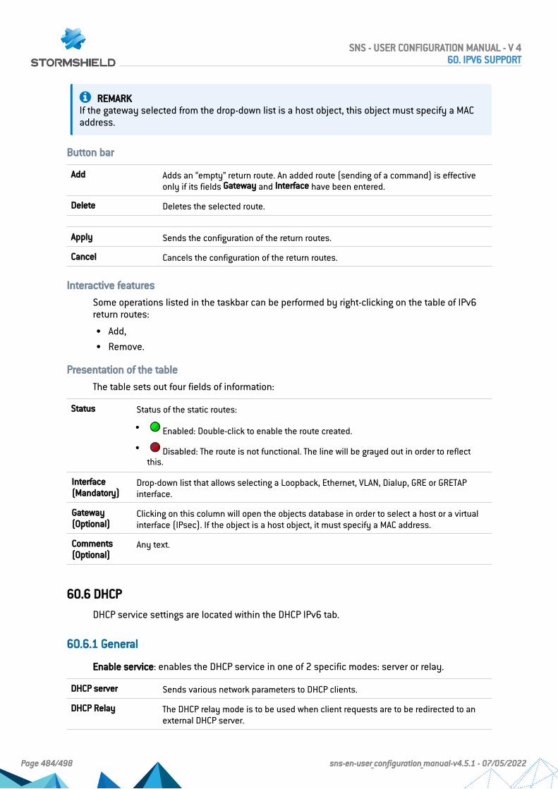
REMARKIf the gateway selected from the drop-down list is a host object, this object must specify a MACaddress.
Button bar
Add Adds an “empty” return route. An added route (sending of a command) is effectiveonly if its fields Gateway and Interface have been entered.
Delete Deletes the selected route.
Apply Sends the configuration of the return routes.
Cancel Cancels the configuration of the return routes.
Interactive features
Some operations listed in the taskbar can be performed by right-clicking on the table of IPv6return routes:
l Add,l Remove.
Presentation of the table
The table sets out four fields of information:
Status Status of the static routes:
l Enabled: Double-click to enable the route created.
l Disabled: The route is not functional. The line will be grayed out in order to reflectthis.
Interface(Mandatory)
Drop-down list that allows selecting a Loopback, Ethernet, VLAN, Dialup, GRE or GRETAPinterface.
Gateway(Optional)
Clicking on this column will open the objects database in order to select a host or a virtualinterface (IPsec). If the object is a host object, it must specify a MAC address.
Comments(Optional)
Any text.
60.6 DHCP
DHCP service settings are located within the DHCP IPv6 tab.
60.6.1 General
Enable service: enables the DHCP service in one of 2 specific modes: server or relay.
DHCP server Sends various network parameters to DHCP clients.
DHCP Relay The DHCP relay mode is to be used when client requests are to be redirected to anexternal DHCP server.
SNS - USER CONFIGURATION MANUAL - V 460. IPV6 SUPPORT
Page 484/498 sns-en-user_configuration_manual-v4.5.1 - 07/05/2022

60.6.2 “DHCP server” service
The “DHCP server” service presents 4 configuration zones:
l Default settings This menu is reserved for the configuration of the DNS parameters sent toDHCP clients (domain name, primary and secondary DNS servers)
l Address range For each range, specify a group of addresses to be allocated to users. Theallocated address will remain allocated for the duration determined in the advancedconfiguration.
l Reservation The address allocated by the service stays the same for hosts listed in thecolumn Reservation.
l Advanced properties This menu allows enabling or disabling the automatic sending of theproxy configuration files for client hosts (WPAD: Web Proxy Autodiscovery Protocol). It isalso possible to customize the duration of the allocation of IP addresses distributed by theDHCP service.
NOTEDHCPv6 can only function with the Router advertisements (RA) mechanism configured on aninterface or bridge in the module Network>Interfaces. These router advertisements indicate thatthe firewall is presented as the default router.
Default settings
If the DHCP server option has been selected, global parameters can be configured here, such asthe domain name, DNS servers, etc. that client hosts will use.
Domain name Domain name used by DHCP client hosts for DNS resolution.
Primary DNS server Select the primary DNS server that will be sent to DHCP clients. This is a host object.If no objects are specified, the firewall’s primary DNS server will be sent to them.
Secondary DNSserver
Select the secondary DNS server that will be sent to DHCP clients. This is a hostobject. If no objects are specified, the firewall’s secondary DNS server will be sent tothem.
Address range
In order for a DHCP server to provide IP addresses, an address pool from which the server canpick addresses has to be configured.
Action buttons
To add or delete address ranges, click on Add or Delete.
Add Allows adding an address range. Select or create an IPv6 address range (IP addressrange network object).
Delete Allows deleting one or several address ranges simultaneously.
The table shows the address ranges used by the DHCP server for distributing addresses toclients:
SNS - USER CONFIGURATION MANUAL - V 460. IPV6 SUPPORT
Page 485/498 sns-en-user_configuration_manual-v4.5.1 - 07/05/2022

Address range Select an IP address range network object from the drop-down list. The server willpick from this pool to distribute addresses to clients. If none of the firewall’sprotected interfaces has an IP address in the network hosting this range, a warningmessage will appear: “No protected interfaces match this address range”.
Primary DNS This field allows assigning a specific main DNS server to DHCP clients.Select a host network object from the drop-down list. If no objects are selected, thevalue “default” will be displayed in this column. The host selected in the Primary DNSfield in the Default settings section will then be used as the DNS server for the client.
Secondary DNS This field allows assigning a specific secondary DNS server to DHCP clients.Select a host network object from the drop-down list. If no objects are selected, thevalue “default” will be displayed in this column. The host selected in the SecondaryDNS field in the Default settings section will then be used as the DNS server for theclient.
Domain name This field allows indicating a specific domain name that will be used by the DHCPclient for its DNS resolution.If no name is specified, the value “Default domain” will be displayed in this column.The domain name indicated in the Domain name field in the Default settings sectionwill then be used for the client.
WARNINGRanges must not overlap. An address range belongs to a single bridge/interface.
Reservation
Even when a server that dynamically distributes IP addresses to clients is used, a specific IPaddress can be reserved for certain hosts. This configuration resembles static addressing, butnothing is configured on client workstations, thereby simplifying their network configuration.
Action buttons
To add or delete reserved addresses, click on Add or Delete.
Add Allows adding a reserved IP address for a specific host network object.
Delete Allows deleting an IP address reservation. If a reservation is cancelled, the hostconcerned will be assigned a new random address when it is renewed.
The table shows host objects for which addresses have been reserved (each object mustcontain the reserved IPv6 address), as well as their DUID (DHCP Unique Identifier). The DUID ismandatory as it allows identifying the client host during the assignment or renewal of IPaddresses so that it can be assigned the reserved address. It plays a role that is similar to thatof a MAC address in DHCP IPv4.
Reservation This field contains the name of the network object (host) that has a reserved IPv6address.
DHCP UniqueIdentifier (DUID)
This field contains the host’s unique ID. This ID allows the firewall to identify theclient and reassign the reserved IP address to it.
On a Windows client workstation, this DUID is entered in the following registry key:HKEY_LOCAL_MACHINE\SYSTEM\ControlSet001\services\TCPIP6\Parameters\Dhcpv6DUID
SNS - USER CONFIGURATION MANUAL - V 460. IPV6 SUPPORT
Page 486/498 sns-en-user_configuration_manual-v4.5.1 - 07/05/2022

Primary DNS This field allows assigning a specific main DNS server to each DHCP client usingaddress reservation.Select a host network object from the drop-down list. If no objects are selected, thevalue “default” will be displayed in this column. The host selected in the Primary DNSfield in the Default settings section will then be used as the DNS server for the client.
Secondary DNS This field allows assigning a specific secondary DNS server to each DHCP client usingaddress reservation.Select a host network object from the drop-down list. If no objects are selected, thevalue “default” will be displayed in this column. The host selected in the SecondaryDNS field in the Default settings section will then be used as the DNS server for theclient.
Domain name This field allows indicating a specific domain name that will be used by the DHCPclient for its DNS resolution.If no name is specified, the value “Default domain” will be displayed in this column.The domain name indicated in the Domain name field in the Default settings sectionwill then be used for the client.
Advanced properties
TFTP Server The TFTP server is used for booting hosts remotely.This field (option 150: TFTP server address) can be used for starting up networkdevices such as routers, X-terminals or workstations without hard disks. Only serversthat have an IPv6 interface will appear in the list.
Distribute the Webproxy autodiscovery(WPAD) file
If this option has been selected, the DHCP server will distribute the internet accessconfiguration to DHCP clients through a PAC Proxy Auto Configuration). This file,which has a “.pac” extension, has to be entered in the authentication settings(Captive portal tab in the menu Configuration>Users>Authentication). It can be madeaccessible from internal and/or external interfaces (Internal interfaces and Externalinterfaces tabs in the menu Configuration>Users>Authentication).
Assigned lease time
Default (hour) For the purpose of optimizing network resources, IP addresses are assigned for alimited period. You therefore need to indicate here the default duration for whichhosts will keep the same IP address.
Minimum (hour) Minimum duration for which hosts will keep the same IP address.
Maximum (hour) Maximum duration for which hosts will keep the same IP address.
60.6.3 “DHCP relay” service
The “DHCP relay” service contains 3 configuration zones:
l Settings This menu allows configuring the DHCP server(s) to which the firewall will relayDHCP requests from client hosts.
l Listening interfaces for DHCP requests Network interfaces on which the firewall listens forclient DHCP requests.
l Outgoing interfaces on the DHCP relay. Specify the interfaces through which the firewall willsend requests to the DHCP server(s) indicated earlier.
SNS - USER CONFIGURATION MANUAL - V 460. IPV6 SUPPORT
Page 487/498 sns-en-user_configuration_manual-v4.5.1 - 07/05/2022

Settings
DHCP server(s) The drop-down list allows selecting a host object or group object containing hosts.The firewall will relay client requests to this or these DHCP server(s).
Listening interfaces for DHCP requests
Indicate the network interfaces through which the firewall will receive DHCP client requests.
Action buttons
In order to add or delete listening interfaces, click on Add or Delete.
Add Adds a row to the table and opens a drop-down list of the firewall’s interfaces in orderto select an interface.
Delete Allows selecting one or several listening interfaces.
Outgoing interfaces on the DHCP relay
Indicate the network interfaces through which the firewall will be able to contact the DHCPserver(s) in order to send DHCP client requests.
Action buttons
In order to add or delete output interfaces, click on Add or Delete.
Add Adds a row to the table and opens a drop-down list of the firewall’s interfaces in orderto select an interface.
Delete Allows selecting one or several output interfaces.
60.7 Network objects
This module is divided into two sections:
l The action bar, at the top of the screen, allowing objects to be sorted and modified.l Two columns dedicated to objects: one column listing them, the other displaying their
properties.
NOTEThe creation of objects only allows declaring an object in Global mode if the option "Displayglobal policies (Filter, NAT, IPsec VPN and Objects)" has been enabled in the Preferences module.
To find out which characters are allowed or prohibited in various fields, please refer to thesection Allowed names.
60.7.1 Possible actions
IP version
This button completes the filtering feature and allows choosing the type of objects to displayaccording to the IP version that they use. A drop-down menu will offer you the followingchoices:
SNS - USER CONFIGURATION MANUAL - V 460. IPV6 SUPPORT
Page 488/498 sns-en-user_configuration_manual-v4.5.1 - 07/05/2022

IPv4 and IPv6 This option allows displaying all network objects of the chosen type (host, network,IP address range) in the list on the left, regardless of the IP version used for theiraddress.
IPv4 This option allows displaying all network objects of the chosen type (host, network,IP address range) in the list on the left with addresses exclusively in IPv4.
IPv6 This option allows displaying all network objects of the chosen type (host, network,IP address range) in the list on the left with addresses exclusively in IPv6.
60.7.2 The different types of objects
Computer
Select a host in order to view or edit its properties. Each object of this type must contain aname and DNS resolution method: “Automatic” if the host has been configured with a dynamicIP address; “None (static IP)” if the host has been configured with a static IP address).
IPv6 address IPv6 address of the selected host.
EXAMPLE2001:db8:11a::10
To make it easier to enter the IPv6 address, a drop-down list will suggest all theglobal prefixes entered on the firewall.
Network
Select a network in order to view or edit its properties. Each object of this type must contain aname, network address and its associated mask.
IPv6 address IPv6 address of the selected network and its associated mask, in CIDR notation.
EXAMPLE2001:db8::/32
To make it easier to enter the IPv6 address, a drop-down list will suggest all theglobal prefixes entered on the firewall.
60.8 Filtering
Network objects (hosts, networks and IP address ranges) may have addresses in IPv6, or in ahybrid mode (IPv4 and IPv6). Filter policies can therefore be applied to IPv6 objects and canuse the security inspection feature (customizable inspection profiles).
However, application inspection (Antivirus, Antispam and URL, SMTP, FTP and SSL filtering) andaddress translation (NAT) features are not available for IPv6 objects in this version (the NAT tabis renamed “NAT IPv4” when IPv6 is enabled).
SNS - USER CONFIGURATION MANUAL - V 460. IPV6 SUPPORT
Page 489/498 sns-en-user_configuration_manual-v4.5.1 - 07/05/2022

60.8.1 “Filtering” tab
Filtering consists of two parts. The strip at the top of the screen allows choosing the filter policy,activating it, editing it and seeing its last modification. The filter table is dedicated to thecreation and configuration of rules.
Actions on filter policy rules
The available actions are the same as those for rules including IPv4 or IPv6 objects.
REMARKNDP (Neighbour Discovery Protocol) traffic will never be blocked, even in the case of a “block all”filter policy. This concerns NS (Neighbour Solicitation) and NA (Neighbour Advertisement)messages.
In Stormshield Network 1.0, certain actions that can only apply to IPv4 traffic will generatewarnings ( icon) or errors ( icon) in the field “Checking the policy” if IPv6 objects areincluded in the filter rules.
Standard rule including objects withdifferent IP versions in the source anddestination
[Rule X] Source and Destination objects do not use the same IPaddressing version (IPv4/IPv6).
Authentication rule including IPv6objects
[Rule X] Redirection to services will only be performed on IPv4traffic.
Inspection SSL rule including IPv6objects
[Rule X] The action “decrypt” will only apply to IPv4 traffic.
Explicit HTTP proxy rule including IPv6objects
[Rule X] Cannot apply proxy or NAT on IPv6 traffic.
Rule with NAT on the destinationincluding IPv6 objects
[Rule X] NAT on destination will only apply to IPv4 traffic.
Rule including IPv6 objects and usingapplication inspections (Antivirus,Antispam, URL filtering, SMTP filtering,FTP filtering or SSL filtering)
[Rule X] Application inspections will only apply to IPv4 traffic.
SNS - USER CONFIGURATION MANUAL - V 460. IPV6 SUPPORT
Page 490/498 sns-en-user_configuration_manual-v4.5.1 - 07/05/2022

61. Allowed or prohibited namesThese are the characters allowed or prohibited on items saved on your firewall:
61.1 Firewall name
Firewall name must contain less than 127 characters. Allowed characters are:
<alphanum> - _ .
61.2 Login and passwordl Login (prohibited characters):
" <tab> & ~ | = * < > ! ( ) \ $ % ? ' ` <space>
l PPTP login (allowed characters):
<alphanum> - _ .
l Password (prohibited characters):
" <tab> <space>
61.3 Comments (prohibited characters)
" # @ < >
61.4 Rules separators (prohibited characters)
>
61.5 Interface namesl Names of interfaces may not contain the following words if they are immediately followed
by numbers (e.g.: ethernet0, dialup123):
loopback ethernet wifi dialup vlan bridge agg ipsec sslvpn gretun gretap
l Names must not begin with the following prefixes:
firewall network serial loopback
l Names must not be a reserved word:
Ipsec dynamic sslvpn any protected notprotected
l Names must not contain the following characters:
@ " # <tab> <space>
SNS - USER CONFIGURATION MANUAL - V 461. ALLOWED OR PROHIBITED NAMES
Page 491/498 sns-en-user_configuration_manual-v4.5.1 - 07/05/2022

61.6 Objectsl Prohibited characters:
<tab> <space> | ! " # , = @ [ \ ]
l Prohibited prefixes:
Firewall_ Network_ ephemeral_ Global_
l Prohibited names:
any internet none anonymous broadcast all
61.7 DNS (FQDN) name objects
Prohibited characters:
*
61.8 Certificates
Certification Authority name (prohibited characters):
` " : _ [ / ]
61.9 Usersl User name in the database (prohibited characters):
<tab> " , ; & ~ | = * < > ! ( ) \
l Name of the group in the User database (prohibited characters):
<tab> <space> & ~ | = * < > ! ( ) \ $ % ! ' " ‘
l LDAP database path: DN, CA Dn and consort (prohibited characters):
" & ~ | * < > ! ( )
61.10 IPsec VPN
Name of the IPsec peer (prohibited characters):
# = @ [ \ ]
61.11 SSL VPNl Web server login (allowed characters):
<alphanum> - _ . :
l Prefix of the URL’s root directory: (allowed characters):
<alphanum> - _
SNS - USER CONFIGURATION MANUAL - V 461. ALLOWED OR PROHIBITED NAMES
Page 492/498 sns-en-user_configuration_manual-v4.5.1 - 07/05/2022

61.12 E-mail alerts
Name of e-mail groups (prohibited characters):
<tab> <space> | ! " # , = @ [ \ ]
61.13 Web services
Web services names must contain less than 20 characters. Allowed characters are:
<alphanum>
SNS - USER CONFIGURATION MANUAL - V 461. ALLOWED OR PROHIBITED NAMES
Page 493/498 sns-en-user_configuration_manual-v4.5.1 - 07/05/2022

62. Structure of an objects database in CSV formatFor each type of object that can be imported or exported, this section defines the structure of arow that makes up the objects database in CSV format.
All fields are separated by commas. Optional empty fields will be included between twocommas.
62.1 Hostl Type of object (mandatory): host,l Name (mandatory): text string using only accepted characters (see section Allowed
names),l IPv4 address (mandatory),l IPv6 address (optional),l DNS resolution: static or dynamic,l MAC address (optional),l Comments (optional): text string between quotes.
EXAMPLEShost,dns1.google.com,8.8.8.8,2001:4860:4860::8888,,,"Google Public DNS Server"host,AD_Server,192.168.65.12,,static,,""
62.2 IP address rangel Type of object (mandatory): range,l Name (mandatory): text string using only accepted characters (see section Allowed
names),l First IPv4 address in the range (mandatory),l Last IPv4 address in the range (mandatory),l First IPv6 address in the range (optional),l Last IPv6 address in the range (optional),l Comments (optional): text string between quotes.
EXAMPLErange,dhcp_range,10.0.0.10,10.0.0.100,,,""
62.3 DNS name (FQDN)l Type of object (mandatory): fqdn,l Name (mandatory): text string using only accepted characters (see section Allowed
names),l IPv4 address (mandatory),
SNS - USER CONFIGURATION MANUAL - V 462. STRUCTURE OF AN OBJECTS DATABASE IN CSV FORMAT
Page 494/498 sns-en-user_configuration_manual-v4.5.1 - 07/05/2022

l IPv6 address (optional),l Comments (optional): text string between quotes.
EXAMPLEfqdn,www.free.fr,212.27.48.10,,""
62.4 Networkl Type of object (mandatory): network,l Name (mandatory): text string using only accepted characters (see section Allowed
names),l IPv4 address (mandatory),l Network mask (mandatory),l IPv6 address (optional),l Length of the IPv6 prefix (optional): indicated in number of bits,l Comments (optional): text string between quotes.
EXAMPLESnetwork,IANA_v6_doc,,,,2001:db8::,32,""network,rfc5735_private_2,172.16.0.0,255.240.0.0,12,,,""
62.5 Portl Type of object (mandatory): service,l Name (mandatory): text string using only accepted characters (see section Allowed
names),l Protocol (mandatory): TCP, UDP or Any,l Port (mandatory): port used by the service,l First port in the range: empty fieldl Last port in the range: empty fieldl Comments (optional): text string between quotes.
EXAMPLEservice,bgp,tcp,179,,"Border Gateway Protocol"
62.6 Range portl Type of object (mandatory): service,l Name (mandatory): text string using only accepted characters (see section Allowed
names),l Protocol (mandatory): TCP, UDP or Any,l Port: empty fieldl First port in the range (mandatory): number of the first port used by the port range,
SNS - USER CONFIGURATION MANUAL - V 462. STRUCTURE OF AN OBJECTS DATABASE IN CSV FORMAT
Page 495/498 sns-en-user_configuration_manual-v4.5.1 - 07/05/2022

l Last port in the range (mandatory): number of the last port used by the port range,l Comments (optional): text string between quotes.
EXAMPLEservice,MyPortRange,tcp,2000,2032,""
62.7 Protocoll Type of object (mandatory): protocol,l Name (mandatory): text string using only accepted characters (see section Allowed
names),l Protocol number (mandatory): standardized number available from the IANA (Internet
Assigned Numbers Authority),l Comments (optional): text string between quotes.
EXAMPLEprotocol,ospf,89,"Open Shortest Path First"
62.8 Host group, IP address group or network groupl Type of object (mandatory): group,l Name (mandatory): text string using only accepted characters (see section Allowed
names),l Group components (mandatory): list of elements included in the group (list between quotes
- components separated by commas),l Comments (optional): text string between quotes.
EXAMPLEgroup,IANA_v6_reserved,"IANA_v6_6to4,IANA_v6_doc,IANA_v6_linklocal_unicast,IANA_v6_teredo,IANA_v6_multicast,IANA_v6_uniquelocal",""
62.9 Service groupl Type of object (mandatory): servicegroup,l Name (mandatory): text string using only accepted characters (see section Allowed
names),l Group components (mandatory): list of elements included in the group (list between quotes
- components separated by commas),l Comments (optional): text string between quotes.
EXAMPLEservicegroup,ssl_srv,"https,pop3s,imaps,ftps,smtps,jabbers,ldaps","SSL Services"
SNS - USER CONFIGURATION MANUAL - V 462. STRUCTURE OF AN OBJECTS DATABASE IN CSV FORMAT
Page 496/498 sns-en-user_configuration_manual-v4.5.1 - 07/05/2022

63. Structure of the file importing custom webservices (CSV format)
For each custom web service that can be imported or exported, this section defines thestructure of a row that makes up the CSV file.
All fields are separated by commas. Optional empty fields will be included between twocommas:
l Name of the service (mandatory): text string using only accepted characters (see Allowednames),
l Public IPv4/IPv6 address or FQDN (mandatory),l Date of last revision (optional),l Revision number (optional),l Comments (optional): any text.
IMPORTANTThe CSV file must contain a blank line after the last entry.
EXAMPLESCustomWebService1,john.doe.org,2022/01/19,12.2,My first webservice with FQDNCustomWebService2,1.2.3.4,,,My second webservice with IP addressCustomWebService3,5.6.7.8,2022/01/19,15,My third webservice
Do note that for web services relying on several IP addresses or several FQDNs the line thatdescribes this web service must be duplicated as many times as the number of addresses orFQDNs that the service contains.
EXAMPLECustomWebService1,john.doe.org,2022/01/19,12.2,First FQDN for my first webserviceCustomWebService1,foo.bar.org,2022/01/19,12.2,Second FQDN for my first webserviceCustomWebService1,1.2.3.4,2022/01/19,12.2,IP address for my first webservice
SNS - USER CONFIGURATION MANUAL - V 463. STRUCTURE OF THE FILE IMPORTING CUSTOM WEB SERVICES (CSV FORMAT)
Page 497/498 sns-en-user_configuration_manual-v4.5.1 - 07/05/2022

Page 498/498 sns-en-user_configuration_manual-v4.5.1 - 07/05/2022
SNS - USER CONFIGURATION MANUAL - V 4
All images in this document are for representational purposes only, actual products may differ.
Copyright © Stormshield 2022. All rights reserved. All other company and product namescontained in this document are trademarks or registered trademarks of their respectivecompanies.