Use of Long-Term Warranties for the Colorado Department of ...
161
Applied Research and Innovation Branch - DTD Use of Long-Term Warranties for the Colorado Department of Transportation Pilot Projects Jay Goldbaum, P.E. CDOT Pavement Design Program Manager Report No. CDOT-2017-01 January 2017
-
Upload
khangminh22 -
Category
Documents
-
view
0 -
download
0
Transcript of Use of Long-Term Warranties for the Colorado Department of ...

Applied Research and Innovation Branch - DTD
Use of Long-Term Warranties for the Colorado Department of Transportation
Pilot Projects
Jay Goldbaum, P.E. CDOT Pavement Design Program Manager
Report No. CDOT-2017-01 January 2017

The contents of this report reflect the views of the author who is
responsible for the facts and the accuracy of the data presented
herein. The contents do not necessarily reflect the official views
of the Colorado Department of Transportation or the Federal
Highway Administration. This report does not constitute a
standard, specification, or regulation.

-i-
Technical Report Documentation Page
1. Report No.
CDOT-2017-01 2. Government Accession No.
3. Recipient’s Catalog No.
4. Title and Subtitle
Use of Long-Term Warranties for the Colorado Department of
Transportation Pilot Projects
5. Report Date
January 2017
6. Performing Organization Code
7. Author(s)
Jay Goldbaum 8. Performing Organization Report No.
CDOT-2017-01
9. Performing Organization Name and Address
Colorado Department of Transportation - Division of Project
Support, Materials and Geotechnical Branch
4670 Holly Street, Unit A
Denver, Colorado 80216
10. Work Unit No. (TRAIS)
11. Contract or Grant No.
12. Sponsoring Agency Name and Address
Colorado Department of Transportation
4201 E. Arkansas Ave.
Denver, Colorado 80022
13. Type of Report and Period Covered
Final
14. Sponsoring Agency Code
15. Supplementary Notes
16. Abstract
The Colorado construction communities, bonding insurance companies and the Colorado Department of Transportation
(CDOT) have a variety of concerns regarding the use of long-term warranties on CDOT projects. Many of these concerns
can only be answered by studying the two pilot projects constructed by CDOT containing long-term performance warranties.
This report provides a brief discussion of the European warranty practices and summarizes the use of long-term warranties
across the United States. In addition, the report reviews the relevant construction, specifications, selection guidelines, and
bonding of these pilot projects.
Implementation Based on the cost-benefit analysis and performance of the control projects versus the two warranty projects, long term
warranties are not a viable option for CDOT. However, echelon paving of hot mix asphalt significantly reduced longitudinal
cracking in the warranty project and may be a viable option for applicable CDOT projects.
17. Key Words Long-Term Warranty, Bonding, Hot Mix Asphalt,
Portland Cement Concrete Pavement, Performance.
18. Distribution Statement
No restrictions. This document is available to
the public through:
National Technical Information Service.
5825 Port Royal Road
Springfield, Virginia 22161
19. Security Classif. (of this report) Unclassified
20. Security Classif. (of this page)
Unclassified 21. No. of Pages
159 22. Price
Form DOT F 1700.7 (8-72) Reproduction of completed page authorized

-ii-
This page intentionally left blank

-iii-
ABSTRACT
The objective of this report is to summarize the information received concerning the two
10-year warranty pilot projects constructed by the Colorado Department of Transportation
(CDOT). In this warranty process, the contract specifications are expressed in terms of long-term
performance of the roadway after it was placed, rather than in terms of construction methods that
were used or final properties achieved in building the facility. Perceived benefits of the 10-year
warranty approach include the following:
The contractor using this method could be motivated to provide a facility that
meets the needs of the motoring public rather than simply meeting the prescribed
CDOT standards.
Due to the competitive market, the contractor could also be driven to create more
innovative and efficient ideas or processes. This approach to construction
contracting is significantly different than ones currently used by CDOT.
This report is divided into two phases. Phase I consists of reviewing the manner in which
long-term warranty contracts have been implemented across the United States, reviewing the
construction, specifications, project selection guidelines, and bonding of these projects. Also
included in Phase I is a comparison of the initial construction cost between pilot projects and
control projects of similar size. Phase II consists of monitoring long-term performance and doing
a cost-benefit analysis of these projects.
Phase I issues that are addressed include the aspects of the roadway behavior to be
warranted, duration of the warranty, payment terms, bid procedure, etc. As guides, CDOT used
examples of warranty projects from Europe, where the use of long-term warranties appears to be
commonplace, and from the United States, where several State Departments of Transportations
(DOTs) have recently researched and awarded demonstration projects. CDOT, the Colorado
construction community, and surety/bonding companies have a variety of concerns regarding the
use of long-term warranties on roadway construction projects. Many of these concerns can only
be definitively answered by studying our pilot warranty projects along with other warranty
projects constructed in the United States.
The first conclusion of Phase I is that the pilot projects should be reconstruction jobs on
moderately traveled highways. Second, the projects should be warranted with respect to ride,
rutting, and cracking for a period of 10 years. Third, the projects should include a weigh-in-
motion station (WIM), at or near the project, to measure the accumulated traffic loads. Fourth,

-iv-
the contract awards should be based on securing the best technical quality for the lowest cost.
Finally, a limited liability bond should always be required during the warranty period.
Phase II elements that are evaluated include the amount of preventive maintenance along
with annual reviews of the CDOT pavement management data and traffic data. The first
conclusion of Phase II is that the contractors on the warranty projects spent over 2.5 times as
much as CDOT forces in materials and labor to maintain the pavement. Second, the ride quality
was much better on the warranty pavement. Third, the accumulated traffic was significantly less
than CDOT anticipated for both projects. Finally, on a cost basis only, the 10-year warranties are
not beneficial.

- 1 -
TABLE OF CONTENTS
ABSTRACT ................................................................................................................................... iv
1.0 INTRODUCTION .................................................................................................................... 4
1.1 Background ................................................................................................................... 4
1.2 Objective and Scope ...................................................................................................... 5
2.0 HIGHWAY CONSTRUCTION PROCESS ............................................................................. 7
2.1 General Remarks ........................................................................................................... 7
2.2 Overview of the Construction Process .......................................................................... 7
2.2.1 Design-Bid-Build System ............................................................................ 7
2.2.2 Design-Build System .................................................................................... 8
2.2.3 Public Private Partnership System ................................................................ 9
2.2.4 Construction Management / General Contract System .............................. 10
2.2.5 Consideration for Long-Term Warranty Specifications ............................. 11
2.3 Technical Specifications .............................................................................................. 11
2.3.1 General Remarks ........................................................................................ 11
2.3.2 Current Contract Specifications .................................................................. 12
2.3.2.1 Incentive / Disincentive Program ............................................... 14
2.3.3 Consideration for Long-Term Warranty Specifications ............................. 14
2.4 Bid Process and Warranty Contract............................................................................. 19
2.4.1 Current System ........................................................................................... 19
2.4.2 Consideration for Long-Term Warranty Specifications ............................. 20
2.5 Bonding Practice.......................................................................................................... 21
2.5.1 Current Roadway Construction Bonding Practice ...................................... 21
2.5.2 Consideration for Long-Term Warranty Specifications ............................. 21
2.6 Payment Schedules ...................................................................................................... 22
3.0 SURVEY OF EXISTING LONG-TERM WARRANTY CONTRACT PRACTICES .......... 23
3.1 General Remarks ......................................................................................................... 23
3.2 Experiences in the United States with Long-Term Warranties ................................... 25
3.2.1 General Remarks ......................................................................................... 25
3.2.2 Current use of Warranties in the United States ........................................... 26
3.2.3 California ..................................................................................................... 27
3.2.4 Wisconsin .................................................................................................... 29
3.2.5 Indiana ......................................................................................................... 33
3.2.6 Michigan ...................................................................................................... 35
3.2.7 New Mexico ................................................................................................ 37
3.2.8 Initiatives of Private Companies .................................................................. 41
4.0 ESTABLISHMENT OF LONG-TERM WARRANTIES IN COLORADO .......................... 42
4.1 Initial Uses ................................................................................................................... 42
4.2 Task Force Panel ......................................................................................................... 43
4.3 Colorado Contracting Community .............................................................................. 44
5.0 COST – BENEFIT ANALYSIS ............................................................................................. 45
5.1 Principal Steps ............................................................................................................. 45

- 2 -
5.2 Estimating CDOT Cost and User Cost ........................................................................ 46
5.2.1 CDOT Initial Construction Cost ................................................................... 46
5.2.2 CDOT Maintenance Cost ............................................................................. 47
5.2.3 User Cost ...................................................................................................... 47
5.3 Estimating Effectiveness ............................................................................................. 48
5.3.1 Performance Effectiveness - IRI ................................................................... 48
5.3.2 Performance Effectiveness - Rutting ............................................................ 49
5.3.3 Performance Effectiveness – Fatigue Cracking ............................................ 50
5.3.4 Performance Effectiveness – Longitudinal Cracking ................................... 55
5.3.5 Performance Effectiveness – Transverse Cracking ...................................... 51
5.4 Extended Service Life ................................................................................................. 52
6.0 PILOT PROJECTS WITHIN COLORADO ........................................................................... 53
6.1 Project Selection Guidelines ........................................................................................ 53
6.2 Discussions with Contractor’s Representatives ........................................................... 53
6.3 Selection of Control Projects ....................................................................................... 54
6.4 PCCP Pilot Project....................................................................................................... 54
6.4.1 Cost Data ...................................................................................................... 54
6.4.2 Maintenance Cost and User Cost .................................................................. 56
6.4.3 Performance Data ......................................................................................... 56
6.4.4 Traffic Data ................................................................................................... 58
6.4.5 Project Specific Features .............................................................................. 58
6.4.6 Post Construction Interviews ........................................................................ 59
6.5 PCCP Cost Benefit Analysis ....................................................................................... 59
6.6 HMA Pilot Project ....................................................................................................... 59
6.6.1 Cost Data ...................................................................................................... 60
6.6.2 Maintenance Cost ......................................................................................... 61
6.6.3 Performance Data ......................................................................................... 62
6.6.4 Traffic Data ................................................................................................... 65
6.6.5 Project Specific Features .............................................................................. 66
6.6.6 Post Construction Interviews ........................................................................ 66
6.7 HMA Pavement Cost - Benefit Analysis ..................................................................... 67
7.0 SUMMARY AND CONCLUSIONS ...................................................................................... 68
7.1 Project Summary ......................................................................................................... 69
8.0 GLOSSARY OF TERMS ........................................................................................................ 70
9.0 REFERENCES ........................................................................................................................ 73
Appendix A............................................................................................................................... A 1-9
Appendix B ............................................................................................................................... B 1-3
Appendix C .................................................................................................................................. C 1
Appendix D............................................................................................................................. D 1-30
Appendix E ............................................................................................................................. E 1-39

- 3 -
List of Figures
Figure 1. Historical Performance of 32 HMA paving projects with 20-year design life .............. 16
Figure 2. Historical Performance of 42 HMA paving projects with 20-year design life .............. 17
Figure 3. IRI Performance Curves ................................................................................................. 49
Figure 4. Rut Depth Performance Curves ..................................................................................... 50
Figure 5. Longitudinal Cracking Performance Curves .................................................................. 51
Figure 6. Transverse Cracking Performance Curves ..................................................................... 51
Figure 7. Comparison of the Performance for IRI ......................................................................... 57
Figure 8. Comparison of the Performance for Transverse Cracking ............................................. 57
Figure 9. Comparison of the Performance for Longitudinal Cracking .......................................... 58
Figure 10. Accumulated Traffic Load on the I-70 PCCP Warranty Project ................................. 58
Figure 11. Comparison of the Performance for IRI ....................................................................... 63
Figure 12. Comparison of the Performance for Rut Depth ........................................................... 64
Figure 13. Comparison of the Performance for Fatigue Cracking ................................................ 64
Figure 13. Comparison of the Performance for Transverse Cracking ........................................... 65
Figure 14. Comparison of the Performance for Longitudinal Cracking ........................................ 65
Figure 15. Accumulated Traffic Load on the US 24 HMA Warranty Project .............................. 66
List of Tables
Table 3.1 European Warranty Practice .......................................................................................... 24
Table 3.2 Lead States Using Pavement Warranties ....................................................................... 26
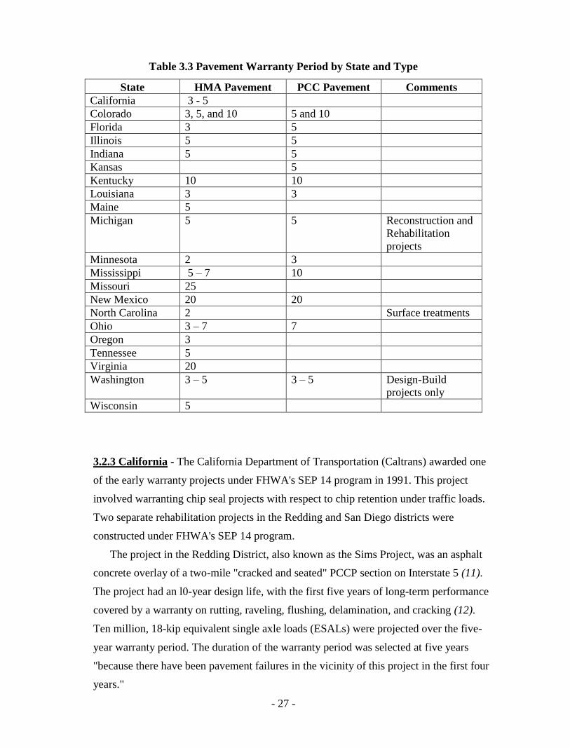
Table 3.3 Pavement Warranty Period by State and Type .............................................................. 27
Table 3.4 Wisconsin Warranty Provisions .................................................................................... 31
Table 3.5 Indiana Warranty Provisions ......................................................................................... 35
Table 3.6 Michigan Evaluation Criteria ........................................................................................ 37
Table 3.7 New Mexico Corridor 44 Project Evaluation Criteria ................................................... 40
Table 6.1 Summary of PCCP Project Information ........................................................................ 54
Table 6.2 Summary of PCCP Bidding Information ...................................................................... 55
Table 6.3 PCCP Maintenance Information.................................................................................... 56
Table 6.4 Summary of HMA Project Information ........................................................................ 60
Table 6.5 Summary of HMA Bidding Information ....................................................................... 61
Table 6.6 HMA Maintenance Data ................................................................................................ 62
Table 6.7 Traffic Volume in 2014 ................................................................................................. 63
Table 7.1 Summary of Cost Data (Dollars per Lane-Mile) ........................................................... 69

- 4 -
1.0 INTRODUCTION
1.1 BACKGROUND
As the world and our nation rapidly change, the future of highway construction may
evolve in entirely new, and hopefully, improved directions. Dynamic changes in highway
construction contracting are already underway in some states and other nations. One such
change is a move toward the use of contracts that include warranties on the long-term
performance of the roadway. Under this approach, the contract specifications are related to
the expectation that CDOT and the motoring public have for the performance of the
roadway once it is in use. At the very least, CDOT and the traveling public should expect
that a roadway provides a safe and comfortable ride at a reasonable cost during its design
life. Following the warranty specifications, the contractor is given the responsibility of
designing, constructing, and maintaining the roadway so that it meets CDOT’s prescribed
expectations.
The warranty approach to highway construction contrasts sharply with standard
Design-Bid-Build (DBB) highway contracting practices in Colorado and across the country.
DBB contracts typically specify construction processes and/or target material properties that
the facility must meet rather than specifying long-term roadway performance criteria. While
the majority of these specifications target processes and material properties that are known
to be related to long-term roadway performance, the actual performance of the roadway
over its design life is not considered in the contracting process. Following the long-term
warranty approach, these types of DBB contract requirements are eliminated. Instead, the
contractor is expected to provide a useable facility over a pre-determined warranty period
using the design and construction approach of his/her choice. The contractor is expected to
step in and repair the roadway if performance falls below some mutually agreed upon level
of service or distress during the warranty period.
The warranty approach to contracting highway construction services may result in
equal or better quality roadways than are presently being constructed and/or lower costs
than are currently being incurred. Regarding the benefits to the motorist, the contractor is
provided with direct incentives to produce a good useable roadway, rather than being
required to simply meet minimum standards in terms of construction materials and methods.
These incentives and the absence of required criteria should stimulate innovation in the
design and construction process as contractors seek efficient designs in an effort to

- 5 -
maximize their profits. Any cost savings that result from such innovations will eventually
be passed on to the traveling public.
Whether or not the above benefits will be realized by using warranty contracts (and
the specific level of any benefit to be realized), they are analyzed in this report. Much of the
risk associated with providing long-term serviceability in highways has historically been
assumed by CDOT and passed on to the public. This approach has been justified due to the
number of variables beyond the control of the contractor. Uncertainties are often associated
with pre-existing roadway conditions the contractor may be forced to accept and build upon,
conditions of future use the highway will experience (with regard to volume of traffic and
environmental conditions), and the level of maintenance the completed roadway will
receive. In response to the shifting consideration of these risks to the contractor, the initial
costs of facilities built under warranty contracts with long-term performance specifications
may exceed the cost of building the same facility using traditional contracting procedures.
The savings to be realized by using long-term warranties will likely be realized over the life
of the project or in the form of long-term savings associated with the development of
improved construction methods and materials.
In using a long-term warranty process, even on a pilot basis, a number of technical
and administrative issues were addressed. The manner in which these issues were addressed
may be critical to accurately assess the feasibility of a long-term warranty contracting
approach for roadway construction projects in Colorado. Issues of concern that were
addressed include:
1) Type of roadway projects appropriate for long-term warranty contracts;
2) Long-term performance parameters to be used in measuring contract
compliance;
3) Specific fiscal provisions of the contract agreement; and
4) Bonding requirements of such contracts.
1.2 OBJECTIVES AND SCOPE
The objective of this study has two phases. Phase I includes five tasks that are
preparatory to conducting pilot projects with long-term warranty provisions. These
undertakings consist of:
1) Identifying the manner in which long-term warranty contracts differ from
current contracts and determining the issues that need to be addressed upon

- 6 -
implementing these contracts;
2) Reviewing current practices with long-term warranty roadway contracts in
the United States;
3) Developing a formal contract instrument to be used on pilot projects;
4) Selecting specific pilot projects on which to try this contract instrument; and
5) Soliciting ideas and comments on long-term warranty contracts from those
parties that constructed the pilot projects.
Phase II of this investigation involved monitoring and analyzing the cost
effectiveness of the two long-term warranty roadway projects awarded by CDOT as a result
of the recommendations issued in Phase I. Specific tasks performed in this phase of the
study consist of:
1) Collecting cost data, long-term performance, and other information from the
start of construction through the warranty period for the pilot projects and
attendant control projects constructed with conventional contracts; and
2) Performing cost-benefit analyses for the pilot projects and formulating
recommendations for the future use of long-term roadway construction
warranty projects in Colorado.
The long-term warranty task force formulated specific recommendations in which
Colorado might implement long-term warranties on future roadway construction projects.
This information was collected in Tasks 1 and 2 of Phase I.
This report documents the work completed during Phase I and Phase II. The intent is
to provide the reader with adequate information to determine the direction for projects with
a long-term warranty.

- 7 -
2.0 HIGHWAY CONSTRUCTION PROCESS
2.1 GENERAL REMARKS
The potential benefits and problems associated with using long-term performance
warranties for roadway construction projects can be best understood when discussed in the
context of the current CDOT roadway construction process. Presented below is an overview
of this process, followed by discussions on how each aspect will be affected if long-term
warranties are used. Note that the current DBB process CDOT uses for most roadway
construction is similar to that used by many states and local agencies.
2.2 OVERVIEW OF THE CONSTRUCTION PROCESS
2.2.1 Design-Bid-Build System - The primary participants in a typical state highway
construction project are the contracting agency (CDOT), the contractor, and a
surety/bond company. A project typically is initiated by CDOT when a problem is
identified that requires some type of construction activity to resolve. CDOT reviews the
problem and develops an in-house design solution. A bid package is then assembled that
describes:
1) The facilities to be constructed;
2) Special requirements associated with the project;
3) Based upon historical knowledge and experience, CDOT will recommend
materials to be used; and
4) An incentive or disincentive will be applied to the percent within limits of the
specified target value.
Public notice is given regarding the intention to build the project, and the bid
package is made available to any interested party. Contractors interested in working on
the project prepare a detailed cost estimate for all work to be performed that includes a
bid item for warranted pavement. CDOT reviews these bid proposals and awards the
project to the lowest responsible bidder who complies with all of the requirements
prescribed (1). These requirements typically include bonding secured by the contractor
for the project in an amount equal to 100 percent of the construction costs. In the event
that the contractor is unable to complete the project, the bond is forfeited to the state,
and the proceeds are used to finish the project.
Once the project is awarded and work begins, monthly payment is made to the

- 8 -
contractor corresponding to the amount of the project completed at any given time.
Incentive or disincentive is assessed for the percent of materials within the specified
limits for elements such as smoothness, asphalt cement content, and in-place density for
hot mix asphalt (HMA) pavement or smoothness, thickness, and flexural strength for
portland cement concrete pavement (PCCP). Full payment is typically made shortly
after the project is completed and after CDOT agrees that it was completed in
conformance with the plans and specifications. In several states, the contractor is
subsequently liable for any defects discovered in the finished product related to
materials and workmanship for a period of one year after the project is completed.
Usually, CDOT assumes full responsibility for any subsequent maintenance and
rehabilitation required after the project is accepted and during the life of the roadway.
2.2.2 Design-Build System - Compared with the traditional DBB project delivery
method, the Design-Build (D-B) offers potential time and cost savings. D-B projects
combine design and construction phases of a project into a single contract that also
includes performance bonds secured by the contractor. This reduces costs without
reducing quality, since construction can begin while the plans are still being developed.
Since the Design-Builder is responsible for both design and construction activities, the
potential for cost increases due to design errors, and/or for discrepancies between design
plans and construction activities is reduced.
D-B contracts can be awarded by CDOT on the basis of being either "low-bid" or
"best-value" which is an important advantage. While “low-bid” basis is used for most
traditional contracts, “best-value” selection process permits the consideration of
additional factors such as; experience, qualifications, innovation, technical approach,
quality control methods, and project management. Often this can reduce costs as well as
increase process and/or product quality. With this system, CDOT does not have
incentive/disincentive specifications for material quality. However, quality processes are
monitored for conformance to the contract requirements. In the event that the contractor
is unable to complete the project, the bond is forfeited to the state, and the proceeds are
used to finish the project. Once the project is awarded and work begins, monthly
payments are made to the contractor based on a mutual understanding of how much of
the lump sum work was completed corresponding to the amount of the project
completed at any given time. Full payment is typically made shortly after the project is

- 9 -
completed and after CDOT agrees that it was completed in conformance with the plans
and specifications. Cost and schedule reduction along with decreased litigation
associated with D-B project delivery have been reported.
2.2.3 Public Private Partnership (PPP) - Public private partnerships are an integrated
partnership that combines the design and construction responsibilities of D-B
procurements with operations and maintenance. These project components are procured
from the private sector in a single contract with financing secured by the public sector.
With a PPP contract, a private entity is responsible for design and construction as well
as long-term operation and/or maintenance services. Types of PPPs currently used by
CDOT are as follows:
Design‐Build‐Maintain (DBM). This process is similar to Design‐Build
except the private sector also maintains the facility/system. The public
agency retains operation of the facility.
Design‐Build‐Operate (DBO). This process is similar to Design‐Build. Upon
completion, the title to the facility/system is transferred to the public agency
while the private sector operates the facility for a specified period of time.
Design‐Build‐Operate‐Maintain (DBOM). The public agency contracts with
the private sector to design, build, operate and maintain the facility/system
for a specific period of time. At the end of that period, the operation and
maintenance are transferred back to the public agency.
Design‐Build‐Finance‐Operate‐Maintain (DBFOM). The public agency
contracts with the private sector to design, build, finance, operate and
maintain a facility/system under a long‐term lease agreement. At the end of
that timeframe, operations and maintenance will be provided by the public
agency.
All PPPs include long‐term performance guarantees for a fixed price. The public
sector secures the project's financing and retains the operating revenue risk and any
surplus operating revenue. The advantage of the PPP system is that it combines
responsibility for usually disparate functions (design, construction, and maintenance)
under a single entity. This allows the private partners to take advantage of a number of
efficiencies. The project design can be tailored to the construction equipment and

- 10 -
materials that will be used. In addition, the PPP team is also required to establish a long-
term maintenance program up front, together with estimates of the associated costs. The
team's detailed knowledge of the project design and the materials utilized allows it to
develop a tailored maintenance plan that anticipates and addresses needs as they occur,
thereby reducing the risk that issues will go unnoticed or unattended and deteriorate into
much more costly problems. The potential exists to reap substantial rewards by utilizing
the integrated PPP system if CDOT takes great care to specify all standards to which
they want their facilities designed, constructed, and maintained.
With a PPP procurement, CDOT relinquishes much of the control they typically
possess with more traditional project delivery. Unless needs are identified up front as
overall project specifications, they will not generally be met. This is important, because
from design through operation, PPP contracts in CDOT extend for periods of up to 30
years or more. On US 36, Plenary Roads Denver is the PPP, or concessionaire. They
designed, built and financed Phase 2 of US 36 Express Lanes, and will operate and
maintain US 36 along with the I‐25 Express Lanes for 50 years. CDOT has specified
maximum thresholds for various distresses that CDOT will accept prior to taking back
responsibility at the end of their contract.
While some state and local authorities are considering PPPs for the operation and
maintenance of existing toll roads, many are turning to the private sector to develop,
design, construct, finance, operate, and maintain new transportation capacity and capital
improvements. Some states, such as Texas, Virginia, and Florida are farther along than
other states in developing programmatic approaches to using PPPs for these projects,
but the variety of states that are currently considering PPPs, and the variety of structures
that these states are considering, demonstrate that PPPs have become, in some places, a
preferred approach for funding and delivering new capacity and capital improvement
projects.
2.2.4 Construction Management / General Contract System (CMGC) - The
construction management/general contract project delivery method consists of a two
phase-design and construction.
Contractors interested in working on the CMGC project prepare a detailed cost
estimate for all design work to be performed. When CDOT considers the design
complete, the construction manager then has an opportunity to bid on the project based

- 11 -
on the design and schedule. If CDOT, the designer, and independent cost estimator
agree that the contractor has submitted a fair price, the owner issues a construction
contract and the construction manager becomes the general contractor.
The CMGC contractor acts as the consultant during the design process and can offer
constructability and pricing feedback on design options and identifies risks based on the
contractor's established means and methods. Once the CMGC project is awarded and
work begins, monthly payment is made to the contractor corresponding to the amount of
the project completed at any given time.
This process also allows CDOT to be an active participant during the design process
and make informed decisions on design options based on the contractor's expertise. In
this system, CDOT does not have incentive/disincentive specifications for material
quality. However, quality processes are monitored for conformance to the contract
requirements. Full payment is typically made shortly after the project is completed and
CDOT agrees that the project was completed in conformance with the plans and
specifications.
2.2.5 Considerations for Long-Term Warranty Specifications - Almost every step
followed in CDOT’s current approach to a majority of highway construction projects
will be altered to some extent if existing construction contracts are replaced with
contracts whose specifications are tied to long-term performance of the roadway. These
changes will not only be confined to the obvious areas of contract specifications and
warranty period, but changes may also be made in the manner in which the projects are
bid, reviewed, and awarded. Further, changes may also be required in the manner in
which these projects are bonded. Therefore, a review in more detail of how these
activities are currently performed is an important consideration when evaluating how
they may be changed. Such a review is presented below, followed by a discussion of
how these activities will be affected by using a long-term warranty approach.
2.3 TECHNICAL SPECIFICATIONS
2.3.1 General Remarks - Several types of technical specifications are used on highway
construction projects, and various aspects of a single project may be covered by
different types of specifications. On state projects in Colorado, independent of the type
of specifications used, the contractor is typically hired to execute a design prepared by

- 12 -
CDOT engineers or consultants hired by CDOT. The contract specifications are directly
related to the execution of the design, rather than to the use of the constructed facility.
The features of the project covered by the specifications are those that have been
identified from engineering principles and/or experience to correlate with a finished
roadway that will serve its intended purpose over the design life. These specifications
range from dictating the specific manner in which work is to be performed, to just the
physical characteristics of the final product. The form and content of these
specifications have developed over several decades and continue to evolve with regard
to advances in technology. Thus, the contracting agencies, contractors, and the bonding
companies are understandably comfortable with these specifications and contracts
because the technical and administrative requirements are known to work well.
2.3.2 Current Contract Specifications - The specifications currently used in
highway construction projects can be grouped into three broad categories:
1) Methods Based - The contract specifies the exact construction procedure to be
used in building the roadway. Contract compliance is judged based on properly
following those procedures.
2) Material Properties Based - The contract specifies various properties that the
finished product (and/or interim products) must possess. Contract compliance is
judged based upon achieving these properties, independent of the construction
approach used.
3) Methods and Material Properties Based - The contract specifies the methods to
be used and/or the material properties to be delivered to produce the best
possible final product.
Methods based specifications are used in situations where the scientific reason that a
particular product feature performs better than others is uncertain, but is known from
experience that if a specific procedure is followed, or that if a specific ingredient is
used, the finished product will probably perform as desired. An example of a methods
based specification is the specification used by CDOT for overlaying a pavement using
grading SX HMA (2). The fundamental intention of the specification is to provide an
overlay that will safely carry traffic over a long service life. The specification, however,
never mentions the requirement that the overlay needs to provide a long and useful

- 13 -
service life. The specification states the explicit procedure to be used by the contractor
in placing such overlays (temperature limitations). Based on experience, this procedure
is known to correlate with good overlay performance over the service life of the
pavement.
Method based specifications have both advantages and disadvantages. They are
attractive from an administrative perspective in that contract compliance is easily
determined and the contract term, limited to the time of construction, is relatively short
compared to the expected service life of the finished HMA product, generally 10 to 15
years. These specifications do require that CDOT observe construction operations to
insure specified procedures are being followed. The primary disadvantage of method
based specifications is that the contractor has no opportunity or motivation to improve
the construction process or the final constructed product. Contractually, the successful
completion of a project by a contractor is independent of the subsequent performance of
the roadway.
Once again, the underlying objective of these specifications are to obtain an overlay
that will satisfactorily carry traffic over its service life. Contract specifications, however,
are presented in terms of pavement density (and other parameters of this type) which are
known to be related to the subsequent long-term performance of the roadway.
Material property based specifications offer many of the same advantages as
methods based specifications. Contract compliance is easily determined and the duration
of the contract is limited to the time of construction. Material property based
specifications also offer some opportunities for contractors to be innovative with respect
to the construction processes used to meet the required material specifications. Note,
however, that while encouraging innovation, these specifications still provide no
opportunity or motivation to contractors regarding the outcome of the final product.
The effectiveness of material property based specifications can be compromised by
properties of the finished product that are most indicative of long-term performance
compared to which properties can reasonably be measured during construction. As the
understanding of pavement behavior increases, instrumentation and other technologies
expand, thus, the parameters change. These changes, however, tend to be gradual and
the fundamental basis for these types of specifications remains the same. Thus, the
historical justification and the level of risk associated with these specifications are
recognized by the various parties involved in the construction process.

- 14 -
Some construction activities are specified in terms of method as well as material
properties. This approach is used when certain aspects of the behavior are known to
correlate with measurable properties of the material, while other aspects of the behavior
are only known to be produced when specific construction procedures are followed.
Currently, several CDOT processes use a combination of method and material property
based specifications which may yield the best end results. For example, a CDOT
specifications describes the minimum surface and air temperature to be followed in
placing an HMA overlay using grading SX and the contractor’s requirements if the
overlay is placed below minimums.
2.3.2.1 Incentive/Disincentive Program. Since 1996, CDOT has incorporated
material property based specifications with an incentive for performing quality work
or a disincentive if the contractor provides substandard work. These specifications
are appropriate in situations where the long-term performance of the roadway is
known to be correlated with some property of the roadway as measured at the time
that it was constructed. Such correlations are generally established based on
engineering principles and/or experience. For example, on an overlay project,
CDOT specifies the required density of the completed overlay, without specifying
the particular compaction procedure to be used to achieve the density between a
lower and an upper satisfactory limit. The implementation of percent within limit
(PWL) specifications for HMA is being advocated by the Federal Highway
Administration (FHWA) as an improved method for assessing quality over other
more traditional methods utilizing mean values. PWL specifications date back to the
1950s, when they were used by the military, and they were first applied by the New
Jersey Department of Transportation in the 1970s. The advantage of the use of the
PWL is that it combines two important statistical measures, mean and standard
deviation, in one parameter. A synthesis published by the National Cooperative
Highway Research Program in 2005 shows that 27 out of 45 state agencies surveyed
now utilize a form of PWL specifications.
2.3.3 Considerations for Long-Term Warranty Specifications - Under an ideal long-
term warranty contract, the contract specifications are expressed directly in terms of the
performance the roadway is expected to provide once it is in service. Production

- 15 -
methods and intermediate performance requirements are not specified as part of the
contract. The specific design, construction procedures, and material properties of the
completed roadway are of nominal interest to the contracting agency. The basic
expectation of adequate service is that the roadway will provide a smooth, safe ride for
an agreed upon period of time for a certain volume of traffic. Historically, a 20-year life
has been targeted in HMA pavement design and a 30-year life in the design of PCCP. It
is generally accepted that the level of service provided by a roadway will decline with
use until a condition is reached at which major rehabilitation is necessary. Based on this
consideration, warranty specifications were defined to provide satisfactory long-term
performance with respect to ride quality and safety at various times throughout the
expected life of the roadway. Issues addressed in developing CDOT specifications
included:
1) What performance parameters will be used to quantify and measure ride quality
and distresses for determining warranty compliance;
2) How the acceptable values for these parameters at various ages of the roadway
will be measured; and
3) Suggested remedial action if the parameters are exceeded.
Considerable work has been done by others on developing the International
Roughness Index (IRI) as a measure of pavement smoothness. This index is calculated
by analytically running a standard "vehicle" over the measured longitudinal profile of a
roadway and assigning a numerical value to the calculated "ride." IRI values range from
0 to 400 for perfectly smooth to rough surfaces, where rough is compared to a gravel
road.
Independent of the specific distress indicators selected for evaluating warranty
compliance, the acceptable and achievable levels for these distresses as a function of
pavement age and volume of traffic were determined. Acceptable levels of distress were
determined by reviewing the historical performance of existing pavements. Despite our
best abilities to predict traffic and climate, designing a pavement that will meet specific
levels of performance through time is a challenge. The relationship between the 20-year
design life and actual performance life before the first rehabilitation of typical CDOT
HMA pavements constructed prior to1992 is illustrated in Figure l (3).

- 16 -
0
1
2
3
4
5
6
7
8
9
10
0 1 2 3 4 5 6 7 8 9 10 11 12 13 14 15 16 17 18 19 20
Years Before First Rehabilitation
Nu
mb
er o
f P
roje
cts
Average Performance
Figure 1. Historical Performance of 32 HMA Paving Projects with a 20-year Design Life.
Referring to Figure l, it was evident that when CDOT developed the warranty
specifications, there was some risk that a pavement designed using accepted engineering
procedures will not meet the level of performance over time without rehabilitation.
However, another study of the performance life of HMA pavements designed with a 20-
year life was conducted by CDOT in 2014 and shown in Figure 2. In the 2014 study, 42
HMA pavement projects constructed throughout the state between 2002 and 2009 were
analyzed and the average life before the first rehabilitation was determined to be 11.4
years (4).
This increase in performance life could be attributed to factors such as:
Improved awareness by the contractors for quality control;
Improved technologies in the design and production of HMA;
Requirement for all CDOT testers to be certified in sampling and testing;
Improved technologies in the laydown and placement of HMA; and
Implementation of the Incentive/Disincentive specifications.
Based on the 2014 study by CDOT, the performance risk may not exist in today’s
marketplace.

- 17 -
Figure 2. Performance of 42 HMA Paving Projects with 20-year Design Life.
The level of risk was determined in two ways:
1) Based on CDOT’s pavement management data, the required performance is such
that a reasonably designed pavement would have a minimal level of distress; and
2) A contractor could set his target level of design performance sufficiently high
that the risk of not meeting CDOT’s required level of performance would be
minimized.
Both of the above strategies have drawbacks. Under the first strategy, little incentive
may exist to develop new and innovative design solutions for roadway projects.
At the other extreme, efforts might be made to improve the reliability of the design
process so a lower performance level could be consistently obtained with a less
expensive facility. Use of the second strategy will insure that an excellent roadway is
constructed. However, initial cost, may be unacceptably high, as the roadway would be
overly conservative in its construction.
Despite the above concerns, long-term performance specifications potentially offer
several advantages over other types of roadway construction specifications. Perhaps the
greatest potential benefit is qualitative in nature and consists of a possible change in the
manner in which contractors approach project tasks. Under a long-term warranty
system, construction tasks will be accomplished with a view toward providing a good
and durable roadway, rather than to simply meet prescriptive standards on construction
methods and materials as given in the contract. For example, on a warranty overlay
project, the contractor should at least achieve the target compaction level of the surface

- 18 -
so the finished facility will perform adequately during the warranty period. The target
compaction level will be set by the contractor as part of their design of the overlay
project.
The long-term warranty approach allows contractors to have the opportunity and
motivation to employ efficient and innovative design solutions and construction
practices in addressing project requirements. Additionally, design procedures,
construction methodologies, and quality control activities that do not directly contribute
to creating quality roadways will be eliminated and/or replaced by more efficient
processes.
Under a long-term warranty system, the state will not have to engage in extensive
oversight/quality assurance activities during roadway construction. For example, density
requirements on the surface of an overlay will no longer be part of the contract
specifications. If the contractor believes as-built density is important to meeting
warranty performance requirements, it will be incumbent upon them to perform density
tests during construction. The state will have to monitor the performance of the roadway
during the warranty period to determine contract compliance. Such monitoring consists
of annual inspections during which quantitative data on longitudinal profile, rut depth,
extent of cracking, etc. is taken. CDOT already performs these types of tasks on an
annual basis as part of the pavement management program.
The intention of the long-term warranty approach is to hold the contractor
responsible for the occurrences of unacceptable conditions in which they have some
control over. If, for example, the volume of traffic or composition of the traffic stream
changes significantly over the warranty period with respect to design requirements
originally provided to the contractor, the contractor will not be held responsible for
repairing subsequent pavement damage. Thus, CDOT monitored traffic on warranty
projects using weigh-in-motion (WIM) stations so that necessary information on volume
and type of traffic was available. This way, both CDOT and the contractor can
determine if, and/or when, the warranty might expire.
In situations other than the types described above, establishing the degree to which
the contractor's performance is responsible for observed pavement damage may be
difficult. Consider a situation in which rutting problems develop on a warranted
reconstruction project. If the scope of the project did not include rehabilitation of the
subgrade, and problems with the subgrade were responsible for subsequent rutting

- 19 -
problems, the contractor might not be responsible for the damage. The distress in the
subgrade, however, could have resulted from an under-designed or poorly constructed
base and surface, which are features of the project within the contractor's control.
Establishing both the source(s) of the observed distress and the degree of Contractor’s
responsibility may require considerable investigatory effort. Mechanisms have been
developed to allow for the expedient and consensual resolution of differences of opinion
regarding warranty compliance between the contractor and the CDOT.
The consequence of failing to meet the conditions of the warranty are included as
part of the contract specifications. CDOT expects the contractor to be prompt and
effective in providing an acceptable level of service to a roadway that is in non-
compliance with warranty requirements; these expectations are fully stated in the
contract provisions.
A distinct disadvantage of long-term warranty specifications is the prolonged
contract agreement. CDOT’s overhead costs associated with contract administration will
be incurred over a relatively long period of time compared to the present system for
roadway construction. For the contractor who was awarded the contract, the possibility
of suffering a substantial financial loss will exist throughout the extended warranty
period. Outstanding warranty obligations may affect the ability of contractors to obtain
bonding for new projects (see Section 2.5.2 for more information).
2.4 BID PROCESS AND AWARD OF CONTRACT
2.4.1 Current System - In general, project announcements are made publicly, and any
contractor can bid on a project whose dollar value is commensurate with the
classification of their contractor's license. Note, that on federally-funded projects, the
contractor must have a license before starting work. Presuming various requirements
specific to the job are met, the project is subsequently awarded to the low bidder or to
the most qualified bidder on Design-Build projects. One such requirement is that the
contractor secures a performance bond in an amount equal to the cost of construction.
CDOT employs a formal pre-qualification process whereby bidders meet the
requirements of bonding (see Section 2.5.1 for more information).

- 20 -
2.4.2 Considerations for Long-Term Warranty Specifications - In evaluating bids
since the end product is the same, it is fairly simple to determine the recipient of a given
contract. Evaluation of the bids submitted under a warranty approach is not as simple.
The proposed physical product could vary significantly among bids, as contractors
pursue different strategies in providing a roadway that will meet long-term demands.
For example, on a simple HMA reconstruction project, contractor "A" may propose to
use a moderately thick base and a thin surface made with exotic asphalt concrete and
contractor "B" may propose a thick base and a thick asphalt concrete surface. In each
case, the contractors may or may not propose to do annual maintenance over the
warranty period.
The simple solution to this dilemma is to take the low bid. The contractor and
bonding company guarantees the design, and they are obligated to perform remedial
work if it becomes necessary. This approach may be somewhat irresponsible if the
design proposed by the low bidder is seriously flawed. However, the qualifying low
bidder's design is checked and awarded by CDOT prior to the contractor placing the bid,
CDOT is taking some level of responsibility for the contractor's design. A serious
dilemma is created by this approach, as it defeats one of the primary goals of long-term
contracting which is making the contractor responsible for the performance of the
roadway, at least for a portion of its life.
A second solution to this problem was to place constraints on the approach to be
followed by the contractor in meeting long-term performance requirements. For
example, the stipulation was made that the particular project must be constructed with
asphalt concrete. This approach, however, may seriously compromise one of the
benefits of the warranty approach. That is, the contractors will not be as free to bid a
project using the methodology they feel is the most appropriate and cost effective to
provide the required service of the roadway.
A third solution to this problem may be to use a different metric to determine the
lowest bid rather than using the lowest total project cost. For example, Florida let a
demonstration design-build project in 1990, in which the contract award was based on
the low bid per unit of quality offered (5). A technical panel reviewed the proposals
prepared by each contractor and assigned them a score between 0 and 100 based on
technical merit. The cost per unit of quality offered was calculated as the total bid cost
divided by the numerical technical score of the proposal. The job was awarded to the

- 21 -
contractor with the lowest cost per technical quality point. In this specific instance, the
low total dollar bid was not the successful bidder on the project.
2.5 BONDING PRACTICE
2.5.1 Current Roadway Construction Bonding Practices - Bonding is used on
roadway construction projects to protect the public interest in the event the contractor is
unable to complete a project according to specifications. Note, that this form of bonding
provides no protection to the public regarding the performance of the roadway over the
design life. The bond process simply insures the roadway will be completed according
to the design. Any flaws related to materials and workmanship revealed during
construction is repaired by the contractor. If the contractor is unable to complete the
project as specified in the contract, the bond will be forfeited and the proceeds used to
finish the project.
In entering into a bond agreement with a contractor, the bonding company implicitly
indicates that, in their opinion and within their acceptable level of risk, the contractor
will be able to successfully complete the project. Surety companies evaluate contractor's
equipment, experience, and outstanding level of bonds before entering into a bond
agreement. Thus, as bonds are required on all major CDOT contracts (in an amount
equal to the estimated project cost); the bonding requirement effectively insures only
"qualified" contractors bid on projects. Presuming CDOT concurs with the criteria used
by the bonding companies in their screening process, bond companies handle the
agency’s "pre-qualification process".
Bond companies have a reasonable idea of the risk associated with their job under
the present system of roadway construction contracting. The system has been in place
long enough that the type of work to be performed is well understood, the ability of
contractor to meet the contract specifications has been historically established, and the
administrative details of the contract process have been determined. The period of
exposure is limited to the physical completion of the project.
2.5.2 Considerations for Long-Term Warranty Specifications - Major issues
addressed since bonding has been used on long-term warranty roadway construction
projects include:
1) Limiting the risk of failure for the type of project given the historical

- 22 -
performance. Bond companies need to have some idea of the risk of the venture
they are underwriting.
2) Determining what remedial action will be required if the warranty specifications
are not met and who will determine what these remedial actions are. Bond
companies need to have an idea of the magnitude of financial obligations they
and the contractor could face.
3) Creating mandatory pre-bid meetings with contractors in Colorado to ensure an
understanding of the design and quality control efforts necessary for these
projects.
4) Allowing various bonding scenarios so that as time goes by, the ability of
contractors (and/or the bonding companies) to obtain bonding for new warranty
jobs will not be compromised by having multiple projects with active warranty
bonds.
These concerns were addressed on long-term warranty jobs to "protect" the public's
investment. Such protection has been provided by using some form of bonding system
similar to the current one used, or by withholding some of the payment for the project
pending its satisfactory performance during the warranty period.
CDOT’s current solution to the problem of using up the bonding capacity of
contractors under a long-term warranty system is for the contractor to increase the
bonding capacity. This action may result in an increase in bond costs since bonding
agents would be forced to increase their rates due to the reduced probability of
recovering their costs in the event of a default using a contractor’s assets. Other types of
solutions to the bonding capacity were not explored by CDOT’s long-term warranty task
force.
2.6 PAYMENT SCHEDULES
A variety of options were reviewed by the task force for the issuance of payments
for warranty projects. Consistent with current practice, funds for long-term warranty based
contracts are distributed to the contractors piecemeal as the work is completed and the
stipulations of the contract are met. A bond is posted to guarantee any remedial work
required during the warranty period is performed.

- 23 -
3.0 SURVEY OF EXISTING LONG-TERM WARRANTY CONTRACT
PRACTICES
3.1 GENERAL REMARKS
Warranting the long-term performance of roadway construction projects dates back
to 1889 (6) and is not a new idea in the United States. In contemporary times, transportation
agencies in various European countries have taken the lead in using long-term warranties.
European experience with these types of contracts dates back at least two decades, and their
use is now commonplace. Experimentation and adoption of this type of contract has
historically been less aggressive in the United States and Canada. Use of long-term
warranties has been increasing in the United States since the late 1980s, as innovative
contracting procedures have been implemented in an effort to provide the public with better,
more economical roads. As of 2006, six states have been identified as using warranty
contracts with a performance life greater than five years on pilot roadway construction
projects (7). Additionally, long-term warranties are offered by at least one major company
in the United States on roads that they construct.
Representatives of the highway construction industry in the United States toured
Europe in 1990, 1992 and again in 2002 (8)(9) to observe their roadway construction
procedures with respect to technical approaches and business practices for both flexible and
rigid pavements. A summary of their findings with respect to contracting practices from
these tours is found in Table 3.1. The countries visited by the tour included Austria,
Denmark, France, Germany, Norway, Sweden, and the United Kingdom. A number of
European practices, including warranties, were identified by the tours' participants as
potential practices that could improve the quality of roadways in the United States.

- 24 -
Table 3.1 European Warranty Practices
Country Structural QC/QA Warranty Warranty
Design Period Terms
Austria State Approved Contractor 2-5 years Warranty Bond
Denmark State Contractor 5 years min. 5% Retention
France Contractor Contractor 10 years Failures Paid by
Contractor
Germany
Contractor
(within state
established
limits )
QA - State
QC - Contractor 4-5 years 5% Retention
Norway State (usually) Contractor 3 years 15% Warranty
Bond
Sweden Joint Contractor 3-5 years Failures Paid by
Contractor
United Kingdom State State 2-5 years Failures Paid by
Contractor
The political, social, and economic climate in addition to the transportation network
is different in Europe than in the United States. Therefore, adoption of the European
warranty model was not appropriate for CDOT. However, the models were used by the
task force to assist in writing specifications. Differences in the construction situation in
the United States and Europe include:
1) In Europe, government and industry closely cooperate in the pursuit of quality,
and any increase in net construction costs associated with this collaboration is
accepted.
2) The construction industry in Europe is much more actively involved in research
and development than in the United States.
3) While contracts are awarded competitively in European countries, governments
are able to restrict these awards to well qualified contractors.
4) In many European countries, the government is able to negotiate the price and
scope of effort on construction work during the warranty period.
5) Contract disputes in Europe appear to be settled by negotiation rather than
litigation, as is usually the case in the United States.

- 25 -
All the European countries listed above, with the exception of the United Kingdom,
offer long-term warranties on roadway construction projects. Typical warranty periods
range from two years for an unbound base course without a wearing surface in Austria,
to 10 years for roadway projects in France.
3.2 EXPERIENCES IN THE UNITED STATES WITH LONG-TERM WARRANTIES
3.2.1 General Remarks - The use of long-term warranties on roadway construction
projects is much less prevalent in the United States than in Europe. The various
participants in the highway construction process (from the state DOTs, to contractors, to
bonding companies) have been reluctant to change the existing process for contracting
such projects, which is known from long experience to generally produce an adequate
product. The broadening of FHWA, Special Experimental Program Number 14 (SEP
14) in 1991 to cover long-term warranty projects resulted in an increased interest and
activity in the United States regarding the use of such contracts on roadway construction
projects. SEP 14 was initiated in 1988 with the intention of stimulating innovation and
experimentation with highway contracting practices in the United States (10). Contracts
that included long-term warranty provisions originally were ineligible for the program;
as such projects potentially would incorporate long-term maintenance activities, which
cannot be paid for using federal funds. The Intermodal Surface Transportation
Efficiency Act of 1991 allowed federal aid projects to be warranted for the first time,
with SEP 14 as the means of implementing contracts incorporating such warranties.
Presented in Table 3.2 are descriptions of some of the first warranty projects
initiated under SEP 14 in the United States. Items that have been subjected to warranties
include pavement markings, chip seals, micro-surfacing, asphalt concrete overlays, and
new asphalt concrete construction.

- 26 -
Table 3.2 Lead States Using Pavement Warranties
State Type of Project Year
Began
Warranted
Behavior
Warranty
Period
Warranty
Terms
California AC Overlay on a PCCP 1992
Rutting
Raveling
Flushing
Delamination
3-5 years
Monetary
Retainment +
Bond
Chip Seal 1991 Chip Loss 2 years Unknown
Wisconsin Partial Reconstruction
(AC Overlay on
Granular Base)
1995
Rutting
Friction
Longevity
(pavement
distress)
5 years Bond
Indiana AC Overlay on a PCC
Pavement 1995
Ride Quality
Rutting
Skid
Resistance
Cracking
5 years Bond
Michigan AC Overlay on a PCC
Pavement 1997
Ride Quality
Surface
Distress
Rutting
5 years
Monetary
Retainment
+ Bond
New
Mexico Partial Reconstruction
+ New Construction 1997
Rutting
Friction
Ride Quality
Distress
5-20 years Bond
3.2.2 Use of Warranties in the United States – Since the inclusion of long-term
warranties into SEP 14, several DOTs have sought to ensure the quality of design-build
projects through long-term warranties. The use of pavement warranties on various types
of construction projects has gained some interest in the United States. From the eight
states that originally piloted warranty specifications under SEP 14, long-term warranty
roadway construction projects have been piloted by at least 21 states since 1991 with a
summary presented in Table 3.3.
- 27 -
Table 3.3 Pavement Warranty Period by State and Type
State HMA Pavement PCC Pavement Comments
California 3 - 5
Colorado 3, 5, and 10 5 and 10
Florida 3 5
Illinois 5 5
Indiana 5 5
Kansas 5
Kentucky 10 10
Louisiana 3 3
Maine 5
Michigan 5 5 Reconstruction and
Rehabilitation
projects
Minnesota 2 3
Mississippi 5 – 7 10
Missouri 25
New Mexico 20 20
North Carolina 2 Surface treatments
Ohio 3 – 7 7
Oregon 3
Tennessee 5
Virginia 20
Washington 3 – 5 3 – 5 Design-Build
projects only
Wisconsin 5
3.2.3 California - The California Department of Transportation (Caltrans) awarded one
of the early warranty projects under FHWA's SEP 14 program in 1991. This project
involved warranting chip seal projects with respect to chip retention under traffic loads.
Two separate rehabilitation projects in the Redding and San Diego districts were
constructed under FHWA's SEP 14 program.
The project in the Redding District, also known as the Sims Project, was an asphalt
concrete overlay of a two-mile "cracked and seated" PCCP section on Interstate 5 (11).
The project had an l0-year design life, with the first five years of long-term performance
covered by a warranty on rutting, raveling, flushing, delamination, and cracking (12).
Ten million, 18-kip equivalent single axle loads (ESALs) were projected over the five-
year warranty period. The duration of the warranty period was selected at five years
"because there have been pavement failures in the vicinity of this project in the first four
years."

- 28 -
Two Redding California contractors (W. Jaxon Backer, Inc. and J. F. Shea Co.) bid
the project jointly. One contractor took responsibility for the northbound lanes; the other
took responsibility for the southbound lanes. The contractors were given considerable
latitude in the roadway design. Caltrans did specify the maximum aggregate size, the
number and thickness of HMA lifts (two 1.8-inch lifts), and the asphalt grades for each
lift. The first lift involved the use of a densely graded asphalt concrete Pacific Coast
User-Produced Performance Based Asphalt Grade 6 (PBA-6) with a maximum
aggregate size of one inch. The second lift was a gap graded rubberized asphalt concrete
with an 85:15 to an 80:20 blend of Asphalt Rubber (AR) 1000, AR 2000, or AR 4000
and a re-plasticized granular rubber from tires and a maximum aggregate size of one
inch. The two contractors selected different mix designs and separate aggregate and
asphalt sources. Contractors were required to verify the acceptability of the mix designs
using an independent party. Quality control testing during construction was the
responsibility of the contractors, but they were required, at a minimum, to follow
Caltrans quality control procedures.
Items included in the warranty contract were: rutting, raveling, flushing,
delamination, and cracking. Definitions of each of these distresses were written into the
contract, with threshold levels of acceptable performance established by Caltrans. For
example, during the five-year warranty period, rut depths were not to exceed 0.5 inches
under an expected loading of 10 million 18-kip ESALs (13). Unless otherwise stated in
the contract documents, the required repair for warranty problems was to remove the
affected material to a depth of 1.8 inches and replacement with rubberized asphalt
concrete. Warranty work was to occur annually, following surveys of the roadway by
Caltrans personnel. Conflict resolution was to be accomplished by the standard Caltrans
operating procedure. This procedure involves a grievance board comprised solely of
Caltrans personnel; if the findings of the board are disputed, arbitration or judicial action
is employed.
A five-year performance bond was required of the contractors performing the work,
and Caltrans retained 10 percent of the contract bid price to assure the commitment of
the contractors to meeting the warranty requirements. The retained funds were disbursed
to the contractors by Caltrans in the amounts of up to 10, 25, 45, and 70 percent of the
total amount retained after the first, second, third, and fourth years of the warranty
period, respectively. These distributions were only to be made if the contractor fulfilled
their obligations under the warranty specifications.

- 29 -
The other project performed by Caltrans under SEP 14 was the San Diego project.
This project incorporated a three-year warranty period, with special provisions that
closely mirrored those of the Sims Project.
3.2.4 Wisconsin - The Wisconsin Department of Transportation (WisDOT), in
conjunction with the Wisconsin Asphalt Paving Association (WAPA) and the FHWA,
began working on warranties for long-term performance in 1994 under SEP 14. In 1995,
WisDOT awarded three warranty projects to three different contractors. WisDOT
indicated that the groundwork for this action was laid over the previous ten years,
during which WisDOT moved away from the state specifying mix designs and
construction procedures on roadway construction projects to a system in which
contractors develop mixes and perform quality control testing under WisDOT
supervision. WisDOT was motivated to move in this direction in an effort to produce
better highways at a reduced cost while encouraging innovation in both design and
construction methodologies.
The basic warranty contract instrument, and the projects it was used on in
Wisconsin, represent a compromise between the ideal provisions for a warranty job (in
which the contractor is allowed total freedom in construction of the project, with
contract compliance based simply on long-term performance), used on the ideal type of
project (total reconstruction), and a contract that can be practically executed in the
existing construction and administrative environment. A brief description of the
Wisconsin projects is presented below.
The initial demonstration projects were chosen so as to have a high likelihood of
success. It was decided that the most suitable projects involved the use of asphalt
concrete reconstruction over a granular base on two-lane highways carrying medium
traffic (2500 to 4500 average daily traffic (ADT)). The projects involved milling off the
existing pavement, crushing the HMA to a maximum size of one-inch, placing this
material on an existing granular base to form a new base, and then applying a surface
material. To help minimize project variables, all the roadways had a good foundation
with existing distress levels similar at all points along their respective lengths. Thus,
while the jobs were not total reconstructions as might be preferred, initial conditions
were both uniform and good. While the contractors were allowed extensive freedom on
mix design and construction methods (in keeping with the philosophy of only being
concerned with long-term performance), the pavement thickness was from 3 to 5 inches

- 30 -
and type of base (granular) were specified in the contract documents (contrary to the
philosophy of allowing complete freedom in facility design) to simplify comparison of
bid proposals. Other items specified by WisDOT were the location of the projects and
the completion schedule for each project. In keeping with the principles of warranty
based contracting, quality assurance was left to the contractor's discretion.
The long-term warranty specifications for these projects were jointly established by
WisDOT, FHWA, and WAPA. A five-year warranty period was established because
five years was believed to be an acceptable evaluation period to assure a quality
product, without overburdening the contractors. The contractors were held liable for
attributes of long-term performance which WisDOT believed they had control over.
These attributes were chosen to be rutting, friction, and longevity, where longevity
encompasses 11 measures of pavement distress as defined by the Strategic Highway
Research Program (SHRP) (14). These measures of pavement distress, and the threshold
values that would trigger warranty repairs, are summarized in Table 3.3. Items
considered for inclusion in the specifications that were eliminated from the final
contract include roughness, appearance, noise, maintenance minimization, and
delineation (the use of different colored material for the mainline and shoulder sections).
Reasons for omitting these items ranged from the absence of proven standard techniques
for their measurement up to a lack of a sufficient historical data in order to confidently
establish performance expectations.
The expected levels of long-term performance of the roadway throughout the
warranty period was established by investigating the actual performance of
approximately 200 miles of HMA pavements placed over granular bases in 1987 and
1988. Threshold levels for friction resistance, rutting, and longevity were established so
that 90 percent of the pavements investigated would meet the criteria. As previously
mentioned, the contractors were not liable for factors beyond their control including, but
not limited to, settlement over culverts and ESALs 50 percent higher than predicted for
the five-year period.
Remedial actions were specified by WisDOT in the event that any threshold level of
performance was not met (see Table 3.4). Included in the specification was the
requirement that if 30 percent or more of the total project were requiring or had received
a remedial action, the entire project would receive the corrective action. All remedial
work in the primary service lanes was to also be performed on the shoulders.
With regard to execution of the contract, a bond was required to insure that any

- 31 -
remedial work necessary during the warranty period would be completed. The amount
of the bond was set at the highest reasonable expenditures expected during the warranty
period. In this case, repair by a thin overlay of 1.5 inches was expected to be the most
severe remedial action that would reasonably be undertaken, and the bond amount was
based on performing this "task." An Alfred M. (A.M.) Best rating of "A-" or better was
required of the bonding company and a Conflict Resolution Team was established to
mediate any disputes that might occur during the warranty period.
Table 3.4 Wisconsin Warranty Provisions
Distress Type Threshold Levels Remedial Action
Alligator Cracking 10% of the area in a segment Remove and replace distressed
layer(s)
Block Cracking 10% of the area in a segment Remove and replace distressed
layer(s)
Edge Raveling 10% of the segment length Remove and replace distressed
layer(s)
Flushing 20% of the segment length Remove and replace distressed
surface mixture full depth
Longitudinal
Cracking 1000 linear feet for crack
which average 0.5 in. or less
Rout and seal all cracks.
500 linear feet for cracks
which average greater than
0.5 inch
Rout and seal all cracks.
Longitudinal
Distortion
1 % of the segment length Remove and replace distressed
layer(s)
Rutting 0.25 inch Mill surface with fine-toothed
mill, overlay or micro-surface
Surface Raveling Slight rating Apply a chip seal

- 32 -
Table 3.4 Wisconsin Warranty Provisions (continued)
Distress Type Threshold Levels Remedial Action
Transverse
Cracking 25 cracks per segment Rout and seal all cracks
25 cracks per segment with
25% of the linear feet of
cracking having band
cracking or dislodgement
Remove and replace
distressed
layer(s) to a depth not to
exceed the warranted
pavement
Transverse
Distortion
1 % of the segment length Remove and replace
distressed
layer(s)
Patching 150 linear feet of patching
per segment.
Remove and replace the
surface layer or place a 1-1/4
inch overlay
Potholes, Slippage
Areas and Other
Disintegrated Areas
Existence Remove and replace
distressed
area(s)
The team consisted of two members each representing WisDOT and the contractors.
The fifth member was an individual mutually agreed upon by WisDOT and the
contractor.
A system of annual evaluations of pavement conditions was established as part of
the contract under the warranty system. This evaluation was conducted by WisDOT
between April 15 and May 15. The survey consisted of evaluating two one-tenth mile
sections within each mile of each project. One of the sections is chosen at random, and
one is to be the 0.3 - 0.4 mile section from the start of each mile. The contractor was
given the opportunity to contest the validity of any survey to the Conflict Resolution
Team. If the predetermined thresholds given in the contract were found to be exceeded,
warranty work would be done by the contractor, as coordinated with WisDOT.
The number of contractors that bid on these projects was judged by WisDOT to be
"limited." Bids were received, however, from competent contractors, who were awarded
the projects. Elective maintenance was included by some contractors in their bids.
Overall, WisDOT estimated that the contract costs were five to 10 percent higher than a
conventional contracting approach. Thus, these projects must offer a benefit of this
order of magnitude to be cost effective.
These projects reportedly have produced an increased awareness in the contracting
community on providing long-term roadway performance as opposed to meeting short
term construction requirements. While concerns have been raised regarding the potential

- 33 -
inability of small contractors to compete on these projects, it is generally held that they
will not be left out of the warranty process. Small contractors with innovative and
efficient ideas may have the opportunity to implement these ideas and thus better
compete with larger contractors than under the current system. To date, no major
problems have occurred with these projects (15).
Wisconsin developed long-term warranty specifications for PCCP. Wisconsin
awarded three demonstration projects that use these specifications early in 1998. An
industry representative indicated that a primary motivation for industry moving forward
with these demonstration projects is WisDOT's obvious interest in this approach (16).
3.2.5 Indiana - Indiana has also experimented with warranty roadway construction
projects under FHWA's SEP 14. Many similarities exist between Indiana's processes in
implementing warranties to that used by Wisconsin. The special provisions for the
Indiana contract were developed through a joint committee of the Asphalt Pavement
Association of Indiana (APAI), the Indiana Department of Transportation (InDOT), and
FHWA. Representatives from this group met with individuals from WisDOT and
WAPA to learn from their experiences. The following summary of Indiana's work was
prepared from information presented by InDOT.
InDOT’s first demonstration project, unlike the projects selected by WisDOT, is on
a heavily traveled (35,000 ADT) section of interstate highway. The project consisted of
rehabilitating four miles of pavement by milling off an existing overlay, cracking and
seating the underlying concrete pavement, and placing a new asphalt concrete overlay.
While the contractor was given the responsibility of specifying the overlay mix design,
InDOT did specify that at least a performance graded (PG) 64-28 asphalt cement be
used and the aggregate meet Superpave specifications (responsibility for transverse
cracking was retained by InDOT due to this stipulation). Bidders were free to use the
mix design procedure of their choice (Marshall, Hveem, Superpave, etc.). InDOT also
required the contractor to perform basic quality control testing on the project and submit
a quality control plan to InDOT for approval. Only the mainline pavement was subject
to the warranty requirements (shoulders, ramps, and acceleration/deceleration lanes
were not included).
InDOT's objective in using a long-term warranty is to insure the motoring public is
provided with a safe, smooth ride over the design life of the pavement. To accomplish
this objective, the contractor was required to warranty the performance of the roadway

- 34 -
for a five-year period with respect to ride quality (as quantified using the IRI), rut depth,
skid resistance, and the amount of longitudinal cracking. Note that Indiana is using
significantly fewer types of distress in evaluating pavement performance during the
warranty period than were used by WisDOT. InDOT believes that ride quality, as
measured by the IRI, reasonably reflects the effects on performance of several of the
distresses explicitly mentioned by WisDOT.
Acceptable levels of ride quality (IRI), rut depth, skid resistance, and the amount of
longitudinal cracking at any time during the five-year warranty period were established
after an extensive examination of numerous five-year old HMA pavements that were
judged to be delivering acceptable performance. Similar to WisDOT, InDOT took
contractors on a tour of several stretches of pavement so they could relate numerical
distresses to physical pavement condition. In general, the levels that trigger remedial
action were set two standard deviations below the observed mean performance for
existing pavements. Threshold values for the warranty parameters are given in Table
3.4.
Annual surveys of pavement condition were conducted by InDOT. The contractor
can dispute the results of these distress surveys. If excessive distress is identified during
the surveys, it must be remediated by the contractor in the year in which it is detected.
The threshold levels of performance, however, are to be waived if Class 5 truck traffic
exceed estimates by more than 50 percent (a weigh-in-motion device was installed in
the vicinity of the project), the base thickness is at least two inches less than the given
design thickness, or if the subgrade density is less than 90 percent of optimum.
Reflection cracking and stripping were specifically excluded as distresses covered under
the warranty.
The contract documents specify the minimum remedial actions that must be taken
based on the nature of the observed distress, as indicated in Table 3.5. The contractor
does not have to follow the remedial actions listed above. However, the contractor is
expected to develop a suitable remediation plan for the specific situation encountered
and to submit this plan to InDOT for approval.

- 35 -
Table 3.5 Indiana Warranty Provisions
Distress Type Threshold Levels* Remedial Action
International
Roughness
Index (IRI)**
133 inches/mile
Based on cause of failure
Alligator Cracks** Remove and replace the distressed surface
layer(s)
Block Cracks** Remove and replace the distressed surface
layer(s)
Transverse Cracks * * Rout and seal all cracks
Flushing** Remove and replace the distressed surface
layer, full lane width
Longitudinal
Distortion**
Remove and replace the distressed surface
layer, full lane width
Longitudinal Cracks 0 Rout and seal all cracks
Rutting 0.35 inches Mill surface with a fine-toothed mill to
remove rut and overlay
Friction Friction Number of
25 or less
Micro-surface distressed area for the full
lane width
Potholes, Slippage
Areas, Raveling,
Segregation, and Other
Disintegrated Areas
Any occurrence Remove and replace the distressed area(s)
* For each tenth-mile section ** Measured within IRI
Similar to the WisDOT approach, a bond was required to insure that any remedial
work necessary during the warranty period would be completed. The bond was set at
500,000 dollars, which is approximately 20 percent of the initial value of the warranted
work. This bond was believed to be on the order of magnitude of the cost to remove and
replace the surface. While this liability could exceed the value of the required
performance bond, no limit was placed on the liability the contractor may have to
assume. A Conflict Resolution Team was established with the same membership as
specified by WisDOT.
InDOT used an "A+B+C" bidding process for this demonstration warranty

- 36 -
project. Following this process, the bid is divided into three components:
Part A - Consideration of labor and materials to complete the project (appears to
include any warranty related costs).
Part B - Consideration of cost to consumers of disruption of traffic (in this case,
lane closures).
Part C - Consideration of long-term performance by warranting long-term
performance.
Part A of the bid most resembles the type of bid submitted on a traditional roadway
construction project; Parts B and C are both new types of contract provisions being
experimented with by InDOT. An incentive and disincentive clause was included with
the "B" portion of the bid to encourage timely completion of the project. Therefore, it
was the sum of A+B that was used to determine the low bidder for the project.
Consequently, under this system, a contractor that was not the low bidder under a
traditional contracting system may still win the contract by estimating fewer disruptions
to traffic while completing the required tasks.
3.2.6 Michigan - The Michigan Department of Transportation (MiDOT) began work on
a demonstration warranty roadway construction project in December of 1995 (17). The
project consisted of rehabilitating a 6.1 mile segment of PCCP rural freeway to provide
a 20-year design life with a five-year warranty on certain aspects of pavement
performance. A contract for the project was awarded in the summer of 1996, and the
roadway was opened to traffic in the fall of 1997. The project incorporated features of
both the California and Indiana approaches to long-term warranties with:
1. Fewer DOT imposed front-end constraints on the contractor's design solution;
and
2. A new approach to evaluating bid proposals.
In the MiDOT project, all aspects of the design and construction apparently were
left to the contractor's discretion (except for the 20-year design life and the 5-year
warranty). MiDOT did not specify the method of base preparation, materials,
pavement type, or pavement thickness to be used. Five contractors bid the project. As

- 37 -
part of the bid process, the contractors had to prepare a technical proposal outlining
their design, indicating the manner in which the required ride quality would be
achieved, and describing the quality control program they would use during
construction. A price proposal was subsequently submitted by each contractor. The
successful bidder was determined by dividing the score MiDOT assigned to each
technical proposal by the corresponding bid price. Thus, the basis for bid award was
the lowest cost per unit of technical quality, rather than simply the lowest lump sum
bid (see Section 2.4.2). The technical evaluation criteria used by MiDOT to score the
proposals is given in Table 3.6.
Performance during the warranty period was being measured using ride quality,
surface distress parameters (transverse, longitudinal, block, and alligator cracking), and
rutting. Similar to California, 10 percent of the contract price (in this case, $760,000)
was withheld, pending acceptable performance of the pavement during the warranty
period. This amount was returned to the contractor at annual intervals in a back-ended
manner in the amounts of none after the first year, one percent after the second year,
two percent after the third year, three percent after the fourth year, and four percent
after the fifth year.
Table 3.6 Michigan Evaluation Criteria
Item Potential Points
Technical Criteria 30 Maximum
Maintaining Traffic 10
Application of Design 10
Innovation of Design/Constructability 10
Management Criteria 25 Maximum
Team's Quality Control Plan 10
Applicable Experience of Design Team 5
Applicable Experience of Const. Eng and Inspection Team 10
Project Schedule 15 Maximum
Completed By 15
Open to Traffic By 10
Other 0
Proposed Pavement Fix 30 Maximum
Adequacy of 20-Year Maintenance Schedule 10
Best Optimal Design to Achieve Minimum 20-Year Design Life 20
Maximum Potential Score 100

- 38 -
3.2.7 New Mexico - One of the most ambitious attempts at the use of warranties in the
United States, thus far, is New Mexico's Corridor 44 Project. The project involved New
Mexico Highway 44, in northeast New Mexico, from Bernalillo (near Albuquerque) to
Bloomfield. This project stemmed from economic and safety concerns. The scope of
work consisted of widening approximately a 110-mile section, from two-lanes to four-
lanes. Based on requirements by the New Mexico State Highway and Transportation
Department (NMSHTD), the developer is responsible for:
1) Obtaining financing for the Corridor 44 Project;
2) Providing the final design of the improvements for the Project;
3) Providing construction management services in overseeing the construction
of the improvements to in the Project; and
4) Providing a warranty and preventive maintenance services for the Project
following its substantial completion and opening to traffic.
The Corridor 44 Project was managed on behalf of the NMSHTD by an Engineer in
Responsible Charge. The NMSHTD participated in the oversight in the design and
construction of the project consistent with the responsibilities of the Project
Development Contractor.
The bonding requirements for this project involve three phases. NMSHTD required
an A.M. Best rating of not less than "A" for the issuing bonding company. The initial
bonding phase was a 10 million dollar proposal guarantee. This amount was returned to
the bidders of proposals not selected within 30 days of the final execution of the
agreement. The state returned this bond to the selected bidder at the same time, provided
all required documentation and subsequent bonds had been submitted. The second
required bond was a performance and payment bond to cover the design and
construction management phases of the Corridor 44 Project. The amount of this bond
was equal to the amount negotiated between the chosen developer and the state for these
items. The third and final bond called for by NMSHTD was a performance warranty
bond. The amount of this bond was negotiated with the developer.
All aspects of design, except for the environmental and right-of-way design
(approximately 30 percent of the total design), were the responsibility of the developer.
The remaining items such as; funding, specification development, and design oversight,
were the responsibility of the state. Bidders were given considerable latitude in

- 39 -
developing their own designs, with NMSHTD setting only some minimum acceptable
standards. For example, the pavement design life was to be 20 years and consistent with
American Association of State Highway and Transportation Officials (AASHTO)
design standards. No limits were placed on the pavement type, aggregate, binder, etc.
Developers were required to incorporate into their proposal the submission of a QC/QA
and a preventive maintenance plan. These items were reviewed by NMSHTD and
weighted in the selection process.
The warranty components were as ambitious as the design freedom offered to
developers on the Corridor 44 Project. It was the opinion of NMSHTD that the market
would determine the overall length of the warranty period. The minimum required
warranty was to encompass an initial mandatory five-year period. Following this base
warranty, the state chose to extend the period an additional five years, and then further
for 10 consecutive one-year extensions. Therefore, the warranty extended throughout
the total 20-year design life. The previously mentioned warranty bond followed an
identical path, with the bond durations corresponding to the warranty lengths.
The warranty and maintenance activities, which were the developer's responsibility,
were divided into three categories. The first category of items covered by warranty
provisions are related to the pavement and its performance. Included in this are
pavement distresses as described in SHRP (18), the roughness and rutting reported in
IRI units and the surface friction based on the American Society of Testing Materials
(ASTM) E274-90 "Standard Test Method for Skid Resistance of Paved Surfaces Using
a Full-Scale Tire." The roughness and distress indices were combined into a Pavement
Serviceability Rating (PSR) based on the pavement management system of the
NMSHTD. Minimum threshold values were established by NMSHID for this item with
the value decreasing as the pavement ages. Individual distresses recognized by SHRP
(19) were given their own individual thresholds, with distinctions made for flexible and
rigid pavements. Along with the threshold levels, remedial actions were specified for the
individual distresses with lessening threshold levels as the pavement ages.
The second major category of warranted items were major structures such as bridges
and their associated components. Items the developer shall cover under the warranty
provisions include: settlement, design or material deficiencies, spalling, fatigue
cracking, ride ability, delaminations and patched areas, expansion joints, drainage, and
painting.
The third warranty category was erosion control for embankment and erosion

- 40 -
control structures. These structures were to be designed to provide protection from a 50-
year event with freeboard for a 100-year event. Therefore, a 500-year flood would be
considered an act-of-God.
Items covered by the warranty were evaluated jointly by NMSHTD and developer
personnel annually with equipment provided by the developer. Exceptions to the
warranty of the pavement and major structures were stipulated based on the level of
traffic carried by the facility once it was placed in service. If the number of Class 4 or
greater commercial vehicles exceeded the projections provided by NMSHTD, the
developer would not be responsible for the distressed associated with the excessive
loadings. To obtain accurate traffic data, NMSHTD was contractually obligated to
install weigh-in-motion devices along the route.
In the event a dispute(s) arose between the state and the developer, a two-step
process was provided to resolve the dispute(s). The first step consisted of negotiations
between the state and the developer. If these negotiations did not work, the
disagreement is heard by a dispute resolution board consisting of one member each from
the NMSHTD and the developer, and a third person, mutually agreed upon by both
parties. The powers of this board are similar to those of Wisconsin and Indiana.
The method used to evaluate, select, and award the contract for the Corridor 44
Project were clearly defined in the Request for Proposal (RFP). A summary of the
evaluation criteria is presented in Table 3.7, with a total of 520 available points.
Table 3.7 New Mexico Corridor 44 Project Evaluation Criteria
Item Potential Points
Design 160 Maximum
Roadway 50
Bridge Structures 30
Maintenance of Traffic 30
Project Development Design Qualifications 50
Construction Management 160 Maximum
Management/Organizational Capabilities 40
Quality Management Program 40
Work Plan/Schedule 20
Coordination with Agencies Utilities 20
Community Relations/Public Information 20
Safety Maintenance During Construction 20

- 41 -
Table 3.7 New Mexico Corridor 44 Project Evaluation Criteria (continued)
Warranty 100 Maximum
Basic Warranty Service Plan and Optional Warranty Plans 10
Duration of Optional Warranty Extensions 10
Preventative Maintenance 10
Cost 50
Approach to Securing a Performance Guarantee for the Warranty 10
Experience and Capabilities with Warranties 10
Financing 100 Maximum
Bidder’s Financing Method(s) or Techniques(s) for the Entire Project 25
Method and Cost of Financing of Construction 25
Bidder’s Financial Capability to Finance the Project 20
Bidder’s Proposed Method(s) for Securing its Performance of all Financial 15
Aspects of the Project
Bidder’s Proposed Duration for Repayment of all Financing of the Project 10
NMSHTD Involvement in the Achievement of Financing 5
Maximum Potential Score 520
3.2.8 Initiatives of Private Companies - Warranties on the long-term performance of
roadway construction projects have been offered by Koch Materials (Wichita, Kansas).
These warranties have been offered on roads constructed by the company for private
entities and local governments on private sector projects. Koch Materials offers design,
build, and maintenance services as requested by the client through their "Performance
Roads" program. The warranties offered on these roadways are tailored to the needs of
the client and cover a number of distresses. Major warranty projects Koch Performance
Roads is currently involved in include a 15-year warranty on the Miguel Mountain
Parkway in California, a 20-year warranty on the Corridor 44 Project in New Mexico
(see Section 3.3.7), and a 15-year warranty for the streets in Aspen, Colorado. The
Performance Roads Division of Koch Materials was not acquired when SemMaterialsSM
purchased the company. The Koch Materials Performance Roads Division recently
limited their involvement with long-term performance of roadway projects they
construct.

- 42 -
4.0 ESTABLISHMENT OF LONG -TERM WARRANTIES IN COLORADO
4.1 INITIAL USES
The first use of long-term warranties began in Colorado in 1999 on Interstate 70
extending from State Highway 26 to Floyd Hill. This project (STA 0061-067) was designed
to last 10 years and included a five-year warranty on the two inch HMA overlay. During the
advertisement of this project, contractors reviewing it were reluctant about the warranty on
this project. When the bids were opened, only one contractor submitted a bid for this
project. Their bid to perform the work and warranty it for five years was 27 percent over the
Engineer’s estimate. Since there were less than three bidders and their bid was over 10
percent above the Engineer’s estimate, this project was not awarded according to Colorado
statutes. After removing the warranty provision and re-advertising, the same project
received multiple bidders and the lowest bidder was nine percent under the Engineer’s
estimate.
The second attempt to utilize long-term warranties was also in 1999 on State Highway
14 near Briggsdale, Colorado. This project (STA C030-018) was a reconstruction project
with a 20-year design life and included a 10-year warranty. After the bids were opened,
three contractors had bid on this project. The lowest bid to perform the work and warranty
the project for 10 years was 41 percent over the Engineer’s estimate. Since there were three
bidders and the lowest bid was 10 percent over the Engineer’s estimate, the Region
Transportation Director had the option of adding funds to the project or rejecting the bids.
After considering the options, supplemental funds were not added to the project and it was
not awarded. After removing the warranty provision and re-advertising, the same project
received multiple bidders and the lowest bidder was six percent over the Engineer’s
estimate.
After these unsuccessful attempts to use long-term warranties, a task force to develop a
Pavement Warranty Position Paper was initiated. The task force met with important
stakeholders from CDOT and industry representative from asphalt and concrete paving to
discuss the path CDOT should pursue with regard to pavement warranties. In general, while
all three groups voiced concern regarding the use of long-term warranty contracts, they all
indicated a willingness to develop a strategic direction for pavement warranties in Colorado.
This group developed a document outlining the strategic direction which was then signed by

- 43 -
the Chief Engineer of CDOT in 1999. A copy of the strategic direction can be found in
Appendix A.
As a result of CDOT’s previous work to pursue long-term warranties, a new task force
was created in order to determine if long-term warranties could be applied on appropriate
projects. The task force consisted of representatives from the asphalt and concrete paving
industries, bonding companies, and CDOT. In 2000, the task force concluded that long-
term warranties would be feasible and the resulting specifications would only be used on a
very limited number of projects. A signed letter of support from 14 members of the Asphalt
Paving Association in Colorado for long-term warranties can be found in Appendix B.
4.2 TASK FORCE PANEL
Several discussions have occurred with the CDOT task force panel on the general
features of long-term warranty projects, the advantages and disadvantages this type of
contract may offer for roadway construction projects, the project selection guidelines, and
the manner in which pilot projects should be implemented. Membership on the task force
panel is given in Appendix C. The substance of the general discussions of the committee on
the concept of using long-term warranties for roadway construction projects has been
included in this report. With respect to the types of projects that may be appropriate for
long-term warranties, the committee's attention focused on reconstruction projects. Reasons
for considering this type of project for pilot purposes included:
1) These projects will be controlled by the prime contractor from the subgrade to
the final surface. Thus, the thickness, mix design, workmanship, and
performance would be shifted to the prime contractor.
2) These projects would allow the contractor some grounds for innovation with any
innovative changes approved by CDOT. Thus, the long-term performance would
be monitored.
During task force discussion, significant concerns were raised regarding:
1) The degree to which the contractor could be realistically held responsible for
the performance of the roadway, independent of the condition of the
underlying material.
2) High costs anticipated for repairing the roadway if the warranty
requirements were not met. The cost of the remedial measures envisioned
for most excessive distress scenarios were limited to the present cost.

- 44 -
The task force recommended full reconstruction projects for pilot purposes, as such
projects would give the contractor complete control over all aspects of the finished facility
from the subgrade to the finished surface. In this situation, the contractor could reasonably
be held responsible for the long-term performance of the entire facility. The primary
disadvantages voiced for total reconstruction were that such projects are very complex and
expensive compared to other roadway construction activities.
Many of the design and construction functions presently performed by CDOT personnel
will still need to occur on warranty projects; responsibility for these functions will simply
shift from CDOT to the contractor. Thus, while not explicitly stated in this report, as state
personnel requirements diminish, private sector employment opportunities should increase.
4.3 COLORADO CONTRACTING COMMUNITY
Obviously, the Colorado construction industry will be affected by changes in
contracting practices for roadway construction projects. As the entity that actually performs
the work on such projects, the industry’s opinions and ideas on the following statements
were deemed to be important:
1) The overall concept of using warranty contracts for roadway construction
projects; and
2) The manner in which the concept is being investigated in this report.
Furthermore, the cooperation of the construction industry was judged to be
essential to the ultimate success of long-term warranties.

- 45 -
5.0 COST – BENEFIT ANALYSIS
5.1 PRINCIPAL STEPS
The cost-benefit analysis (CBA) estimates and totals the equivalent monetary value of
the benefits and costs of the warranty and control projects to establish if the warranty
projects are worthwhile. The projects in this study have a wide range of widths and lengths
making a simple comparison difficult. In order to evaluate projects on an equal basis, all the
benefits and costs are expressed in terms of dollars per lane-mile. For this report, a lane-
mile is 12 feet wide by 5,280 feet long or 7,040 square yards and the total square yards of
the pavement surface is used to calculate the lane-miles of a project. The assessment of the
CBA for warranty projects are comprised of the following steps:
1) Pavement selections using warranty specifications and control bidding processes
are established to form comparison sets;
2) The costs for initial construction, incentive payments, and maintenance are
calculated for each warranty and control project in the comparison set;
3) The benefit of reduced CDOT forces is estimated on a warranty project;
4) The benefit is estimated in terms of extended service life based on average
pavement performance for each warranty project; and
5) A ratio using both the net cost minus the net benefit (savings) of the warranty
project is the compared to the net cost of the control project. A ratio greater than
1.0 means that the cost of a warranty project exceeds the cost associated with the
control project and is not worthwhile. Detailed calculations with each step are
provided in Chapter 6 for the pilot projects.
Example: Initial construction for the warranty was $75,000 per lane-mile while the control
was $65,000 per lane-mile.
Incentive payment on the control project was $900 per lane-mile.
Control maintenance costs was $700 per lane-mile.
Reduced CDOT Staff on the warranty project was $2,000 per lane-mile.
No difference in service life could be determined therefore, no additional benefit
was given to the warranty project.
Ratio is 1.1 defined as ($75,000 - $2,000)/($65,000 + $900 + 700)
Since the ratio is greater than 1.0, the warranty project was not beneficial.

- 46 -
5.2 ESTIMATING CDOT COST and USER COST
In calculating the costs for each project, the real cost at the time of construction and
maintenance work was added to the user cost component when CDOT maintenance forces
performed work on the comparison sets of projects. The costs were totaled from initial
construction to the end of the warranty period.
5.2.1 CDOT Initial Construction Cost - The first item we reviewed for the initial
construction cost was the unit cost of HMA and PCCP. To avoid any analytical bias about
the relative unit cost of warranty and control projects, pavements in each set had as much in
common as possible in terms of quantities of material. Data on cost of each warranty and
control project were obtained from CDOT’s Cost Estimating Unit on the lowest responsible
bidder for the projects. In most cases, the quantities of HMA and PCCP were comparable
and we did not need to develop equations to account for the economy of scale.
The second item was for the cost of a warranty on the HMA and PCCP over the ten-year
period. This was an added cost to CDOT during the initial construction, paid to the
contractor as a cost per square yard of material placed, and accepted. To develop the
engineer’s estimate for bidding purposes on the warranty project, an estimate of the cost for
the limited liability was based on engineering judgment and intended to cover the
contractor’s costs, such as potential risks to perform warranty work, potential lane rental
fees because of warranty work, and cost of warranty bond from bond insurance companies.
The third item was for the cost to construct a WIM station to monitor traffic. The WIM
station monitored the traffic load on the warranty project.
The fourth item we reviewed was the cost for quality control testing. Since quality
control during construction was shifted to the contractor, a CDOT tester was not specified
on warranty projects. Based on a conservative daily production rate of 1,000 tons of HMA
or 5,000 square yards of PCCP, the number of tester days was estimated. To establish the
CDOT cost savings on warranty projects due to reduced staffing, an average salary
(including overhead) of a CDOT Engineer/Physical Science Technician Level II of $350.00
per day was used. A loading factor of 1.35 was used to calculate the CDOT hourly rate.
These items were totaled. Since the project length of the warranty and control projects
varied, the initial cost to construct the project was determined on the basis of dollars per
lane-mile.

- 47 -
5.2.2 CDOT Maintenance Cost - Maintenance costs may be routine or periodic, preventive
or corrective, or done by the CDOT workforce or contractors. In the case of the control
projects, the maintenance responsibility of the contractor is terminated after CDOT accepts
the project. For warranty projects, the contractor bears the cost to maintain the roadway for
the warranty period. In computing CDOT maintenance costs, only the post-warranty
maintenance period costs were considered. However, the maintenance costs associated with
the control projects were determined starting from the CDOT acceptance date. These costs
were taken from CDOT’s maintenance management system (MMS) and included such
items as; crack sealing, crack filling, hand patching, machine patching, and chip seal
coating. Since the project length of the warranty and control projects varied, the
maintenance cost was determined on the basis of dollars per lane-mile.
5.2.3 User Cost - These costs are considered to be indirect “soft” costs borne by the
facility’s user in the work zone as they relate to roadway condition, maintenance activity,
and rehabilitation work. These costs include user travel time and increased vehicle
operating costs (VOC). Though these “soft” costs are not part of the actual spending for
CDOT, the costs are inherent in the cost of road repair and are included in maintenance
fees. By specification, the contractors were not assessed a user cost if they did not use more
than three days per year or up to a maximum of 12 days to perform maintenance or remedial
actions. For the value of travel time, CDOT used $18.50 per hour for passenger cars, $43.50
per hour for single unit trucks, and $49.50 per hour for combination trucks. To determine
the user cost, we used software developed for CDOT called CDOT WorkZone - User Cost
Program. The duration of user costs was determined based on a daily single lane closure
from 10:00 pm to 5:00 am in urban areas and 9:00 a.m. to 3:00 p.m. in rural areas. The
average annual daily traffic at the time of construction was used for the traffic volume.
Speed reduction was considered to be from the posted speed limit down to 45 mph in the
work-zone. We estimated about $3,000 of work by CDOT maintenance forces or
contractors could be accomplished in a day. The cost of work was divided by $3,000 to
determine the number of days. Since the length of the warranty and control projects varied,
the user cost was determined on the basis of dollars per lane-mile.

- 48 -
5.3 ESTIMATING EFFECTIVENESS
For this report, the time scope for evaluating the CBA is based on performance from the
initial construction to the end of the warranty period. CDOT’s pavement management
system (PMS) data for the international roughness index (IRI), rutting depth, fatigue
cracking, longitudinal cracking, and transverse cracking was used in this report to estimate
the performance and extended life. When comparing the extended lives from these
performance measures, the smallest value from the five distresses was used as the basis for
calculating the benefit. The PMS condition data was collected annually and summarized in
528 foot (0.1 mi.) sections. The condition data was recorded even when preventive
maintenance work had been performed. Based on the contractors records of when and
where preventive maintenance work was performed, future distresses in the tenth mile
segment were reduced by the amount of distress at the time work was accomplished. When
the typical section was a divided highway, annual PMS data was reported in the driving lane
for both directions. When the typical section was an undivided highway, annual PMS data
was collected in one direction one year and the opposite direction the next year. Since 2009,
PMS data was collected only in the primary direction (increasing mileposts) on undivided
highways.
For warranty projects, the contractual threshold of performance indicators was
established by CDOT to reflect minimum acceptable distresses over the warranty period.
The contractor was obligated to perform remedial work if the thresholds are exceeded at any
time during that period. Such distress thresholds on warranty projects are not the same
minimums for rehabilitation or replacement. Given the minimum rehabilitation threshold
and the performance curve, the service life can be estimated.
5.3.1 Performance Effectiveness – The International Roughness Index - International
Roughness Index (IRI) is a statistic used to determine the amount of roughness in a
measured longitudinal profile. IRI was used because it is a common indicator of pavement
condition and is computed from a single longitudinal profile using a quarter-car simulation
(quarter-car calculates the response similar to a passenger car). The simulated suspension
motion is accumulated and divided by the distance traveled to give an index with units of
slope in inches per mile.
For this study, the performance curve for the warranty project was compared to the
control project and the time interval at which the IRI between the two are the same is the

- 49 -
extended service life. For example, a comparison of IRI in Figure 3 shows that the extended
service life is over two years. However, CDOT rounds down to the whole year. Resulting in
an extended service life of two years.
Figure 3. IRI Performance Curves
5.3.2 Performance Effectiveness – Rutting - The depth of a rut in the wheel path was used
because it is a common indicator for rehabilitation. Rutting of the pavement could be
caused by low air voids in the HMA or an underestimate of the truck traffic over the design
life. Remedial action by the contractor will not be required if the accumulated truck traffic
exceeds the design. WIM stations were installed on or near the warranty projects to monitor
the truck traffic. In this research the performance curve for the warranty project was
compared to the control project and the time interval between them is the extended service
life. For example, a comparison of rutting in Figure 4 shows the extended service life of a
warranty project to be one year. This extended service life is probably conservative since it
assumes the rut depth for the warranty pavement will increase at the same rate as the control
project.

- 50 -
Figure 4. Rut Depth Performance Curves
5.3.3 Performance Effectiveness – Fatigue Cracking - Fatigue cracking is a series of
small, jagged, interconnected cracks caused by fatigue failure of the HMA surface (or
stabilized base) caused by repeated traffic loadings usually in the wheel paths (also called
alligator cracking). This distress is a measured distress under warranty. It was evaluated
because it is a typical distress CDOT repairs.
5.3.4 Performance Effectiveness – Longitudinal Cracking - Longitudinal cracking was
evaluated because it is a good indicator for the performance of the contractor’s construction
of the longitudinal joint for HMA and the effectiveness of the vibrators in PCCP. This study
compared the performance curve for the warranty project to the control project and the time
interval between them is the extended service life. For example, a comparison of
longitudinal cracking in Figure 5 indicates that no extended service life was found because
the control project had a lesser amount of longitudinal cracking.

- 51 -
Figure 5. Longitudinal Cracking Performance Curves
5.3.5 Performance Effectiveness – Transverse Cracking - Transverse cracking was
evaluated because it is a good indicator for the performance of the asphalt cement binder’s
resistance to thermal cracking. This study compared the performance curves between the
two projects and the time interval between them is the extended service life. For example, a
comparison of transverse cracking in Figure 6 indicates the extended service life of a
warranty project to be one year.
Figure 6. Transverse Cracking Performance Curves

- 52 -
5.4 EXTENDED SERVICE LIFE
To maintain and manage CDOT’s highway network requires capital investments to
rehabilitate pavements as they approach the end of their service lives. Longer life translates
into cost savings to maintain CDOT’s network. In fiscal year 2015, CDOT spent
approximately $250 million to rehabilitate about 1,100 lane-miles of the network.
Therefore, to rehabilitate a lane-mile of roadway is about $227,273 for the estimated 10
years of design life. For this report, every year of extension in service life past the design
life would save CDOT about $22,727 per lane-mile.

- 53 -
6.0 PILOT PROJECTS WITHIN COLORADO
6.1 PROJECT SELECTION GUIDELINES
These guidelines were developed by the task force to be referenced by CDOT designers
in the selection of good candidate projects for long-term warranties. With properly selected
projects, the maximum possible amount of information needed to assist the CDOT task
force in the strategic direction of long-term warranties will be produced. The criteria used
to select long-term warranty projects are as follows:
1) The primary scope of the project should be paving.
2) The length of the project should be a minimum of 3 miles. (A length greater than 5
miles would be preferred)
3) The design ESALs should be 20 years for HMA and 30 years for PCCP projects.
4) The project should be new construction or reconstruction.
5) The project should be a design/bid/build.
6) A Weigh-In-Motion station should be installed on or near the project unless a
current station exists in the vicinity.
7) A mandatory pre-bid meeting should be held with all the prime contractors bidding
on the project.
8) If detours are allowed, the plans and specifications should address the design and
phasing of the detours.
9) The designer should reference the applicable sections of each chapter from the
fourth edition of the “AASHTO Policy on Geometric Design of Highways and
Streets.”
6.2 DISCUSSIONS WITH CONTRACTORS’ REPRESENTATIVES
In order to give all interested parties an equal opportunity to bid, pre-bidding meetings
were required with representatives from the prime contractor. An understanding of the
specifications and project lay-out were given by CDOT representatives, the Resident
Engineer, and Project Engineer. The contractor’s representative had the opportunity to ask
questions regarding the specifications or the project. Any clarifications needed by CDOT
were included in revisions to the specifications prior to opening the bids.

- 54 -
6.3 SELECTION OF CONTROL PROJECTS
To perform the cost-benefit analysis, control projects were selected. The control
projects used the traditional CDOT specifications (non-warranty) and were comparable to
the warranty projects in terms of year of construction, constructed pavement thickness,
traffic, and original pavement condition. It was not possible to obtain perfect matches
between the warranty and control projects but, reasonable matches were found.
6.4 PCCP PILOT PROJECT
The pilot 10-year warranty project is located on I-70 near the town of Stratton in Kit
Carson County. The project began at Milepost 418.3 and extended east 9.1 miles to
Milepost 427.4 for a total of 58.6 lane-miles (412,870 / 7,040). The CDOT project number
is IM 0705-070 (Project Code 12635). A copy of the applicable long-term warranty
specifications can be found in Appendix D. Based on an average production rate of 5,000
square yards per day, it was estimated that a CDOT field tester would have been needed on
the warranty project for about 90 days. Therefore, CDOT saved a total of $31,500 ($538 per
lane-mile) in salaries for a field tester.
The control project is on State Highway 287 south of the town of Eads in Kiowa
County. The project began at Milepost 95.2 and extended north 13.0 miles to Milepost
108.2 for a total of 48.8 lane-miles (343,524 / 7,040). The CDOT project number is NH
2872-014 (Project Code 13552).
A comparison of the information from the pilot and control project is summarized in
Table 6.1.
Table 6.1 Summary of PCCP Project Information
Pilot Project Control Project
Design PCCP Thickness 9.75 inches 10.5 inches
Date of Bid Opening August 23, 2001 May 3, 2001
Begin Construction Date January 3, 2002 August 1, 2001
Project Acceptance Date November 23, 2002 June 28, 2002
Facility Type 4-lane Interstate 2-lane Principal Arterial
30-year Design 18 kip ESALs 34,500,000 16,500,000
6.4.1 Cost Data - The successful contractor’s bid on the warranty project was 0.35 percent
above the engineer’s estimate. The two bids ranged from 0.35 to 6.16 percent above the
engineer’s estimate. The contractor’s cost per square yard of Warranted PCCP System

- 55 -
(WPCCPS) was $22.67 ($159,723 per lane-mile), which was 9.3 percent below the
engineer’s estimate of $25.00. The contractor’s cost per square yard for the maximum
liability of $1,000,000 on the long-term warranty was $2.42 ($17,050 per lane-mile), which
was 142 percent above the engineer’s estimate.
For the control project, the successful contractor’s bid was 4.82 percent below the
engineer’s estimate. The three bids ranged from 4.82 percent below to 11.71 percent above
the engineer’s estimate. The contractor’s cost per square yard of PCCP was $22.40
($157,958 per lane-mile), which was 0.04 percent below the engineer’s estimate at $22.50.
Table 6.2 has more comparison information between the two projects. At the end of the
construction, the contractor on the control project was awarded an incentive of $374,940.26
($7,683 per lane-mile) for quality of work.
Table 6.2 Summary of PCCP Bidding Information
Pilot Project Control Project
Prime Contractor Interstate Highway Construction Castle Rock Construction
Project Low Bid $16,588,329 $11,993,047
Engineer’s Estimate $16,530,678 $12,600,190
Quantity of PCCP
(square yards)
412,870 344,122
Bid Prices
($/square yard)
$22.67 and $26.18 $22.40, $22.85, and
$27.40
Engineer’s Estimate
($/square yard)
$25.00 $22.50
Bid Prices for Warranty
($/square yard)
$2.42 and $3.31 N/A
Engineer’s Estimate for
Warranty ($/square
yard)
$1.00 N/A
Number of Bidders 2 3
To develop the engineer’s estimate for the $1,000,000 liability for the warranty
project, $1.00 per square yard was estimated. The estimate was developed based on
engineering judgment and was intended to cover the contractor’s costs, such as potential
risks to perform warranty work, potential lane rental fees because of warranty work, and
cost of warranty bond from the surety company.
Although, there is an obvious difference between the unit cost of the engineer’s
estimate and the contractor’s low bid in the pilot project, it can be assumed with a high
level of confidence that the engineer’s estimate of warranty cost of $1.00 per square

- 56 -
yard was reasonable. However, after awarding the project, the contractor mentioned
that their $1,000,000 warranty liability was developed with funds generated through the
bid item for the warranty ($2.42 * 412,870 = $999,145).
6.4.2 Maintenance and User Costs - The Maintenance Management System (MMS)
was used to track all of CDOT’s maintenance activities on a particular segment of
highway. Those include a variety of activities, but of particular interest for this report
were those related to the roadway surface (cross stitching, joint and crack sealing,
partial and full depth repair, slab replacement, diamond grinding, shoulder restoration,
and base stabilization). Based on a pilot car operation and the number of days that
maintenance forces had worked on the project, the user cost was determined to be
$10,486 per day. The costs of CDOT roadway surface maintenance activities were
summarized in Table 6.3 for the pilot warranty project and control project as gathered
from MMS.
Table 6.3 PCCP Maintenance Information
Year Pilot Project
(Contractor)
Control Project
(CDOT)
Time and Materials User Cost
2003 $15,342 $1,161 $4,060
2004 $26,438 $1,671 $5,842
2005 $11,588 $8,073 $28,220
2006 $13,630 $98 0
2007 $30,026 $319 0
2008 $12,252 $131 0
2009 $22,700 $3,110 $10,872
2010 $9,200 $5,572 $19,477
2011 $14,960 $16,457 $57,526
2012 $15,864 $3,524 $12,318
Total $172,000 $40,116 $138,315
Cost Per
Lane-Mile
$2,935 $822 $2,834
6.4.3 Performance Data - The performance of the pilot and control project was
measured annually by the pavement management system’s automated data collection
van.
The database that CDOT receives reports the pavement condition on 1/10-mile
intervals. Ride is reported as the project average in inches/mile. Corner breaks,

- 57 -
transverse cracking, D-cracking, and spalling are reported as a count. The maximum
count for each distress was used in this report. Longitudinal cracking is reported as total
linear feet and scaling is reported as square feet. Figure 7 represents the comparison of
the ride information from the control and warranty projects. Figure 8 represents the
transverse cracking comparison from the control project and warranty project. Figure 9
represents the comparison of the longitudinal crack information. After 10 years of
service, no corner breaks, D-cracking or spalling was found on either the control project
or the warranty project.
Figure 7. Comparison of the Performance for International Roughness Index.
Figure 8. Comparison of the Performance for Transverse Cracking.

- 58 -
Figure 9. Comparison of the Performance for Longitudinal Cracking.
6.4.4 Traffic Data – Since traffic data is critical to the design of the pavement
thickness and CDOT supplied the contractor with this information, the contractor would
be released from the warranty if the accumulated 18 kip ESALs on the rigid pavement
exceeded 50 percent of the 30-year design 18 kip ESALs. The accumulated ESALs from
a nearby weigh-in-motion station are shown in Figure 10.
Figure 10. Accumulated Traffic Load on the Warranty Project.
6.4.5 Project Specific Features - On this project the contractor elected to modify their
concrete mix from the “standard mix” prescribed by CDOT. This modification increased
the flexural strength from CDOT’s standard value of 650 psi to a target value of 750 psi.
Since the pavement thickness design is related to flexural strength, the 100 psi increase

- 59 -
in flexural strength allowed the contractor to reduce the pavement thickness 1.25 inches.
To ensure good quality and uniformity, the contractor added two people to provide
increased Quality Control throughout the construction process.
6.4.6 Post Construction Interviews - This meeting was set up to exchange experiences
by CDOT and the contractor on the 10-year warranty project. In general, everyone
thought the project was very successful with no major problems or issues. There were a
few minor issues that could be addressed by the long-term warranty task force and
considered on future projects.
6.5 PCCP COST – BENEFIT ANALYSIS
As of January 2015, the net cost on the warranty project was $176,235 per lane-mile
(159,723 + 17,050 - 538) while the net cost on the control project was $169,297 per lane-
mile (157,958 + 7,683 + 822 + 2,834) per lane-mile. Since the extended life for rut depth
and longitudinal cracking was less than the IRI and transverse cracking, no net benefit in
extended life is expected for this warranty project. Since the ratio is 1.04 (176,235/169,297)
the cost of a warranty project exceeds the cost of the control project and is not worthwhile.
6.6 HMA PILOT PROJECT
The pilot project was located on State Highway 24 near the city of Colorado Springs in
El Paso County. The project began at the intersection of Constitution Avenue (Milepost
314.2) and extended east 4.7 miles at the intersection of Garrett Road (Milepost 317.9) for a
total of 15.6 lane-miles. Since the eastbound direction was new construction, it was
selected as the warranty section for this project. The CDOT project number is NH 0243-068
(Project Code 14822). A copy of the applicable long-term warranty specifications can be
found in Appendix E.
The control project is adjacent to the warranty project and similarly located on State
Highway 24. The project began near the intersection of State Highway 94 (Milepost 312.2)
and extended east 2.0 miles at the intersection of Constitution Avenue (Milepost 314.2).
Based on the plan sheets and quantities, 15.3 lane-miles were constructed. The CDOT
project number is NH 0243-067 (subaccount number 14274).
A comparison of the information from the pilot and control (non-warranty) project is
summarized in Table 6.4.

- 60 -
Table 6.4 Summary of HMA Project Information
Pilot Project Control Project
Design HMA Thickness 8 inches 9.5 inches
HMA Used in the Top Layer 2 inches SX(100) PG 64-28 2 inches S(100) PG 64-28
HMA Used in the Middle
Layer
2 inches S(100) PG 64-22 2.5 (2) inches S(100) PG 64-28
HMA Used in the Bottom
Layer
4 inches SG(100) PG 64-22 2.5 inches S(100) PG 64-28
Aggregate Base Course
Thickness
6 inches 6 inches
Minimum R-Value of the Soil 60 36
Date of Bid Opening August12, 2004 March 6, 2003
Begin Construction Date October 18, 2004 June 1, 2003
Project Acceptance Date November 1, 2005 September 1, 2004
Facility Type 4-lane Principal Arterial 4-lane Principal Arterial
20-year Design 18 kip ESALs 9,080,780 9,243,362
6.6.1 Cost Data - The successful contractor’s bid on the warranty project was 11.06
percent below the engineer’s estimate. The three bids ranged from 11.06 percent below
to 8.69 percent above the engineer’s estimate. The contractor’s cost per square yard of
Warranted Hot Bituminous Pavement System (WHBPS) was $14.62 ($22.36 per ton)
($103,225 per lane-mile), which was 23.05 percent below the engineer’s estimate of
$19.00 ($29.06 per ton). The contractor’s cost per square yard for the maximum liability
of $750,000 on the long-term warranty was $6.81 ($48,082 per lane-mile), which was
the same as the engineer’s estimate. A WIM station was needed for this project at a cost
of $63,000 ($4,038 per lane-mile). Based on the average production rate, it was
estimated that CDOT saved a total of about $26,250 ($1,683 per lane-mile) for the field
tester to be on-site for 75 working days.
For the control project, the successful contractor’s bid was 3.67 percent below the
engineer’s estimate. The six bids ranged from 3.67 percent below to 10.71 percent
above the engineer’s estimate. The contractor’s cost per ton of HMA was $33.70
($123,681 per lane-mile), which was 8.7 percent above the engineer’s estimate of
$31.00. Table 6.5 has more comparison information between the two projects. At the
end of construction, the contractor was awarded a quality incentive of $100,853 ($6,592
per lane-mile).

- 61 -
Table 6.5 Summary of HMA Bidding Information
Pilot Project Control Project
Prime Contractor Rocky Mountain Materials &
Asphalt
Rocky Mountain Materials &
Asphalt
Project Low Bid $5,181,045.10 $3,978,971.81
Engineer’s Estimate $5,825,137.69 $4,130,497.00
Quantity of HMA (tons) 72,000 (110,144 square yards) 56,152 (107,500 square yards)
Bid Prices ($/ton) $22.36, 31.83, and $36.71 $33.70, $36.50, $36.00, $39.00,
$35.47, and $37.85
Engineer’s Estimate
($/ton)
$19.00 $31.00
Bid Prices for Warranty
($/square yard)
$6.81, 2.87, and 4.00 N/A
Engineer’s Estimate for
Warranty ($/square
yard)
$6.81 N/A
Number of Bidders 3 6
To develop the engineer’s estimate for the $750,000 liability for the warranty
project, $6.81 per square yard was estimated based on engineering judgment along with
previous information from the pilot PCCP project. The bid item was intended to cover
contractor’s costs such as potential risks to perform warranty work, potential lane rental
fees because of warranty work, and cost of warranty bond from the surety company.
Similar to the warranty liability for the PCCP project, the contractor mentioned their
$750,000 warranty liability was developed with funds generated through the bid item
for the warranty ($ 6.81* 110,144 = $750,080.64).
6.6.2 Maintenance Costs - The Maintenance Management System (MMS) is being
used to track all of CDOT’s maintenance activities on a particular segment of highway.
Those included a variety of activities, but of particular interest for this report were those
related to the roadway surface (minor patching, machine patching, crack sealing, chip
sealing, fog coating, shoulder restoration, and base stabilization). Based on a single lane
closure and the number of days that maintenance forces had worked on the project, the
user cost was determined to be $23,849 per day. The costs of CDOT roadway surface
maintenance activities were summarized in Table 6.6 for the pilot warranty project and
control project as gathered in MMS.

- 62 -
Table 6.6 HMA Maintenance Data
Year Pilot Project
(Contractor)
Control Project
(CDOT)
Time and Materials User Cost
2006 0 0 0
2007 0 0 0
2008 0 $142 $1,128
2009 $2,754 $231 $1,840
2010 $4,647 $533 $4,239
2011 $4,647 0 0
2012 0 $10,639 $84,580
2013 0 $615 $4,887
2014 $10,052 $783 $6,223
2015 $2,625 $734 $5,839
Total $24,725 $13,677 $108,736
Cost per
Lane-Mile
$1,585 $894 $7,107
6.6.3 Performance Data - The performance of the pilot and control projects was
measured annually by the pavement management system’s automated data collection
van.
CDOT subcontracts all data collection. The vendor drives an automated data
collection van over all of the required highway miles and reports the data on tenth-mile
increments. For rut data, the van is equipped with a five-sensor rut bar that measures rut
to the hundredth of an inch. Ride data is collected with an inertia profiler consisting of
laser sensors, accelerometer, and distance transducer. The van is equipped with digital
cameras, one windshield view and four pavement views (one over each wheel). All data
is recorded and sent to the vendor’s data reduction office where the data are viewed and
rated. This raw data is what the vendor delivers to CDOT.
The database CDOT receives reports the pavement condition on tenth-mile intervals.
Ride is reported as an average inch/mile over the tenth-mile. Rutting is reported as an
average hundredth of an inch over the tenth mile. Load associated longitudinal cracking
is reported as total square feet. Longitudinal cracking is reported as total linear feet and
the transverse cracks are counted.
Based on the 2014 traffic data from the Division of Transportation Development
shown in Table 6.7, the volume of traffic drops significantly at a milepost 313.178 in the

- 63 -
control project. A reasonable comparison of the performance control project was taken
from the data starting from milepost 313.3 and ending at milepost 314.2.
Table 6.7 Traffic Volume in 2014
Beginning
Milepost
Ending
Milepost
Average
Annual
Daily
Traffic
Average Annual
Daily Traffic of
Single Unit
Trucks
Average Annual
Daily Traffic of
Combination
Trucks
310.878 311.070 41,000 1,600 1,200
311.070 311.746 33,000 1,400 1,100
311.746 312.430 29,000 1,500 960
312.430 313.178 20,000 1,000 700
313.178 314.592 16,000 900 540
314.592 319.640 17,000 610 270
319.640 320.292 14,000 550 340
Figure 11 represents the comparison of the average IRI information from the control
and warranty projects. The rut data shown in Figure 12 indicates that the warranty
project had about the same rut depth as the control. Based on this information, no
expected benefit in extended life for the warranty project is recommended.
Figure 11. Comparison of the Performance for International Roughness Index.

- 64 -
Figure 12. Comparison of the Performance for Rut Depth.
The fatigue cracking shown in Figure 13 indicates a significant improvement in the
performance of the warranty project when compared to the control project. This life
extension is estimated to be about five years. The improved life may be due to a higher
level of quality control performed by the contractor when placing the subgrade and
aggregate base course material along with reduced truck traffic.
Figure 13. Comparison of the Performance for Fatigue Cracking.
Approximately two years of extended life, as shown in Figure 14, was estimated for
the comparison of transverse cracking between the warranty and control projects. This
improvement may be affected by using a ½ inch nominal maximum aggregate size in
the top lift of the warranty project. It is estimated that this smaller size aggregate

- 65 -
increased the optimum binder content by about 0.2 percent over the ¾ inch nominal
maximum aggregate size used in the top lift for the control project.
Figure 14. Comparison of the Performance for Transverse Cracking.
The comparison of the longitudinal cracking shown in Figure 15 indicates a
significant improvement to the life of the warranty project. This increase in life is most
likely due to the use of echelon paving on the warranty project which eliminated the
longitudinal joint between the lanes.
Figure 15. Comparison of the Performance for Longitudinal Cracking.
6.6.4 Traffic Data – Since traffic data is critical to the design of flexible pavements and
CDOT supplied the contractor with this information, the contractor would be released
from the warranty for rutting if the accumulated 18 kip ESALs on the flexible pavement
exceed a prescribed limit of the 20-year design 18 kip ESALs. The accumulated ESALs
from the weigh-in-motion station installed on the project are shown in Figure 16.

- 66 -
Figure 16. Accumulated Traffic Load on the US 24 Warranty Project.
6.6.5 Project Specific Features - The contractor elected to use a CDOT Grading
SG(100) PG 64-22 HMA in the bottom lift topped by a lift of Grading S(100) PG 64-22
and a surface course of Grading SX(100) PG 64-28. Higher quality aggregates were
used in the top lift. To reduce the number of longitudinal joints, where possible, paving
was done in echelon. The latest paving equipment was used and well maintained. To
ensure a smooth ride, cross traffic was limited. The contractor also used a Quality
Control plan that included a very high level of testing to ensure good quality and
uniformity.
6.6.6 Post Construction Interviews - This meeting was set up to exchange experiences
by CDOT and the contractor on the 10-year warranty project. In general, everyone
thought that the project was very successful with no major problems or issues. There
were a few minor issues that could be addressed by the long-term warranty task force
and considered on future projects are as follows:
1) Coring for QA thickness measurements of the HMA could be detrimental to the
performance.
2) Drainage and compaction of the subgrade is a major concern.
3) Additional QC testing was done by the contractor.
4) Lowest bidder with the warranty specifications could be a problem; the best
value method to awarding these projects should be explored.

- 67 -
6.7 HMA PAVEMENT COST – BENEFIT ANALYSIS
As of January 2015, the net cost on the warranty project was $153,662 per lane-mile
(103,225 + 48,082 + 4,038 – 1,683) while the net cost on the control project was
$138,274 (123,681 + 6,592 + 894 + 7,107) per lane-mile. Since both projects had about
the same amount of rutting, no extended life was given for the warranty project.
Therefore, the ratio is 1.11 (153,662/138,274) the cost of this warranty project exceeds
the cost of the control project and was not worthwhile.

- 68 -
7.0 SUMMARY AND CONCLUSIONS
The objective of this investigation was to determine the cost effectiveness of using
warranties for long-term performance on roadway construction projects in Colorado. Phase
I consisted of identifying the issues that must be addressed in implementing long-term
warranties, reviewing current practice with this type of contract in other countries and
across the United States, finalizing a contract instrument to be used on the pilot projects,
determining current perceptions in Colorado regarding the pilot project, and finally,
formulating recommendations for future warranty projects for Colorado. Phase II of the
research consisted of monitoring the performance of the pilot projects, tracking maintenance
cost, and performing a cost-benefit analysis.
If the choice is made to go forward, further decisions need to be made regarding the
revisions to the current project selection guidelines and specifications to be used for future
long-term warranty projects. The information and recommendations presented in this report
should facilitate this process. Philosophically, this approach to roadway construction
projects is expected to improve quality and reduce costs because a) the contractor is directly
motivated to provide a facility that offers a safe and smooth ride, b) market forces will force
the contractor to focus on activities that directly contribute to a smooth and safe ride, and c)
the contractor will have the opportunity to explore new and innovative design solutions and
construction procedures. Recall that under an ideal long-term warranty approach, contract
requirements are simply expressed in terms of the performance to be provided by the
roadway once it is placed into service. The nature of the facility required to provide this
service and the manner in which it is constructed are completely at the contractor’s
discretion. This approach to roadway construction projects contrasts sharply with current
practice. The intent of current contract specifications is to insure that at the time of its
completion, the roadway has been physically constructed according to CDOT
specifications.
In Colorado, the opinion of the contracting community is that there may be potential
improvement in the quality of roadway projects if long-term warranty contracts are used.
Some firms are more optimistic than others regarding possible improvements in quality.
Opinion on the costs of these projects is that these projects will be more expensive than
traditional projects. The comment was also made by Colorado contractors that many
contractors are already doing a good job using the available materials and construction
methods. An additional business related concern, shared by CDOT, the contracting

- 69 -
community, and the bonding companies in Colorado, is the ability of small and medium
sized contractors to obtain bonding and compete in a long-term warranty environment.
While the smoothness of the PCCP warranty project was much better than the
control, the distresses monitored on the PCCP warranty project did not show any difference
in performance. The contractor had some remedial action to perform and spent about three
times as much as CDOT forces in materials and labor to maintain the roadway.
The HMA pavement projects were difficult to analyze due to the different truck
volumes. Smaller nominal maximum aggregate size may have reduced the propagation of
transverse cracks. As a best practice, echelon paving should be used. The contractor was
diligent in performing preventive maintenance and no remedial action was required. The
contractor spent about twice as much as CDOT forces in materials and labor to maintain the
roadway.
7.1 PROJECT SUMMARY
Each project was individually evaluated to determine if there was an overall cost
saving that resulted from the warranty. The summary of the cost data is shown in Table 7.1.
Based on the current data from this report, warranty projects were not worthwhile to CDOT.
However, the greatest benefit of using long-term warranties could be realized on projects
that require innovative design and construction solutions and/or outstanding workmanship
to provide good long-term performance. The significant life extension for longitudinal
cracking in the HMA pavement warranty project indicates that CDOT could benefit from
specifying echelon paving on appropriate projects.
Table 7.1 Summary of Cost Data (Dollars per Lane-Mile)
Location Initial
Construction
Cost
Warranty
Line Item
Weigh-in-
Motion
Station
Incentive
Payment
QC
Testing
(Savings)
Total
Maintenance
And User
Cost
Total
Cost
I-70, Stratton
(PCCP) $159,723 $17,050 N/A N/A ($538) N/A $176,235
Control Project $157,958 N/A N/A 7,683 N/A 3,656 $169,297
US 24, Constitution
to Garrett (HMA) $103,225 $48,082 $4,038 N/A ($1,683) N/A $153,662
Control Project $123,681 N/A N/A $6,592 N/A 8,001 $138,274

- 70 -
8.0 GLOSSARY OF TERMS
Average Daily Traffic (ADT): The average two-way daily traffic, in the total number of
vehicles, for the 24-hour measuring period.
Best Value: The overall maximum value of the proposal to a sponsor after considering all
of the evaluation factors described in the specifications for the project including but not
limited to the time needed for performance of the contract, innovative design approaches,
the scope and quality of the work, work management, aesthetics, project control, and total
project cost.
Conflict Resolution Team: A committed group engaged in collective negotiations
attempting to resolve conflicts by actively communicating information about conflicting test
results.
Corrective Action: Improvements to an organization's processes taken to eliminate causes
of non-conformities or other undesirable situations
Cost Benefit Analysis: An approach to estimating the strengths and weaknesses of
alternatives that satisfy transactions, activities or functional requirements.
Crack and Seat: A fractured slab technique used in the rehabilitation of PCCP that
minimizes slab action in a jointed concrete pavement by fracturing the PCCP layer into
smaller segments. This reduction in slab length minimizes reflective cracking in new
asphalt overlays.
Design–Bid–Build (DBB): A project delivery system in which the design is completed
either by in-house professional engineering staff or a design consultant before the
construction contract is advertised. This method is sometimes referred to as the traditional
method.
Design–Build (DB): A project delivery system in which both the design and the
construction of the project are simultaneously awarded to a single entity.
Design-Build-Finance-Operate-Maintain (DBFOM): The private sector delivers the
design and construction (build) of a project to the public sector. It also obtains project
financing and assumes operations and maintenance of an asset upon its completion.
Design–Build–Maintain (DBM): A project delivery system in which the design,
construction, and maintenance of the project are awarded to a single entity.
Design-Build-Operate (DBO): A single contract is awarded for the design, construction,
and operation of a capital improvement. Title to the facility remains with the public sector.
Combining all three phases into this approach maintains the continuity of private sector

- 71 -
involvement and can facilitate private-sector financing of public projects supported by user
fees generated during the operations phase.
Echelon Paving: Paving multiple lanes side-by-side (with adjacent pavers slightly offset).
Rollers behind the echelon pavers can pass directly over the longitudinal joint while both
sides are hot, which results in better compaction.
Hot Mix Asphalt (HMA): A plant-produced, high-quality hot mixture of asphalt cement
and well-graded, high-quality aggregate thoroughly compacted into a uniform dense mass.
International Roughness Index (IRI): A measurement of the roughness of a pavement,
expressed as the ratio of the accumulated suspension motion to the distance traveled
obtained from a mathematical model of a standard quarter car traversing a measured profile
at a speed of 50 mi/hr.
Limited Liability: Amount owed (i.e., payable) by an individual or entity for construction
performed capped by a specific dollar amount.
Long–Term Warranty: A sufficient period of time, usually greater than 5 years, that the
contractor guarantees or promises within the contract to provide assurance from premature
failure to the owner for a specific element or elements.
Method Specifications: Specifications that require the Contractor to produce and place a
product using specified materials in definite proportions and specific types of equipment
and methods under the direction of the Agency.
Percent Within Limits: A procedure using the arithmetic Mean and Standard Deviation of
the Acceptance Field Sample test results for a given Lot of material that estimates the
percent of a Lot that is within the Specification Limits.
Portland Cement Concrete Pavement. A composite paving material consisting of
portland cement, coarse aggregate, fine aggregate, water, air, and possibly other additives
that, when mixed together, hardens through a chemical reaction to form a hard solid mass.
Preventive Maintenance: Proactive approach that applies maintenance treatments while
the asset is still in good condition; extends asset life by preventing the onset or growth
(propagation) of distress.
Quality Assurance (QA): Planned and systematic actions by an owner or his representative
to provide confidence that a product or facility meet applicable standards of good practice.
This involves continued evaluation of design, plan and specification development, contract
advertisement and award, construction, and maintenance, and the interactions of these
activities.
- 72 -
Quality Control (QC): Actions taken by a producer or contractor to provide control over
what is being done and what is being provided so that the applicable standards of good
practice for the work are followed.
Reconstruction: Roadways that are rebuilt primarily along existing alignment normally
involving full-depth pavement replacement. Other work that would fall into the category of
reconstruction would be adding lanes adjacent to an existing alignment, changing the
fundamental character of the roadway (e.g., converting a two-lane highway to a multi-lane
divided arterial) or reconfiguring intersections and interchanges.
Remedial Action: A change made to a nonconforming product or service to address the
deficiency. This also can refer to restoration of a landscape from industrial activity.
Serviceable Life: The service life is the number of years a pavement is expected to last
from completion of construction until pavement failure.
User Costs: Costs incurred by highway users traveling on the facility and the excess costs
incurred by those who cannot use the facility because of either agency or self-imposed
detour requirements. User costs typically are comprised of vehicle operating costs (VOC),
crash costs, and user delay costs.
Weigh-in-Motion (WIM): The process of measuring the dynamic tire forces of a moving
vehicle and estimating the corresponding tire loads of the static vehicle.

- 73 -
9.0 REFERENCES
(1) Colorado Department of Transportation, (2005), Standard Specifications for Road
and Bridge Construction. pp 16.
(2) Colorado Department of Transportation, (2005), Standard Specifications for Road
and Bridge Construction. pp 231 – 246.
(3) Goldbaum, J. (2000), Report Number CDOT- R1 – R – 00 – 3, “Life Cycle Cost
Analysis: State-of-the-Practice”, Colorado Department of Transportation.
(4) Perkins, M. (2014), Report Number CDOT-2014-10, “Years to First Rehabilitation of
Superpave Hot Mix Asphalt”, Colorado Department of Transportation.
(5) Merwin, D.P. (1990), “Design/Build Public Projects: Has Their Time Come?”,
Highway and Heavy Construction, October, 1990. pp 20-21.
(6) Hancher, D. (1994), “Use of Warranties in Road Construction,” National Cooperative
Highway Research Program, Synthesis of Highway Practice 195, TRB, National
Research Council, Washington, D.C.
(7) Scott, S (2006), “Long-Term Warranty Survey Results”, National Cooperative
Highway Research Program, Project 10-68 and 20-07, Guideline for the Use of
Highway Pavement Warranties and Warranty Use in Highway Construction, TRB,
National Research Council, Washington, D.C.
(8) American Association of State Highway Transportation Officials, (1991), “1990
European Asphalt Study Tour,” American Association of State Highway
Transportation Officials, Washington, D.C.
(9) Federal Highway Administration, (2003), Asphalt Pavement Warranties: Technology
and Practice in Europe, Federal Highway Administration, Washington, D.C.
(10) Federal Highway Administration, (1995), Rebuilding America: Partnership for
Investment, Innovative Contracting Practices, Federal Highway Administration,
Washington, D.C.
(11) Vallerga, B.A. (1995), “Warranted Pavement on an Interstate Highway in California,”
Conference Proceedings 7: Third International Conference on Managing Pavements,
Transportation Research Board, Washington, D.C.
(12) California Department of Transportation, (1993), Notice to Contractors and Special
Provisions for Construction on State Highway, Sacramento, California.
(13) Harvey, J., Vallerga, B.A., and Monismith, C.L. (1995), Transportation Research
Record 1492, Transportation Research Board, Washington, D.C.

- 74 -
(14) Strategic Highway Research Program, National Research Council, (1993), Distress
Identification Manual for Long-Term Pavement Performance Project, SHRP-P-338,
Federal Highway Administration, Washington, D.C.
(15) Shober, S.F., Whited, G.C., and McMullen, K.W., (1996) “Wisconsin Grabs The
Warranty Rung.” Asphalt Contractor, November, 1996. pp. 36-43.
(16) McMullen, K. (1998), “Development and Implementation of PCCP Pavement
Warranty Specifications in Wisconsin”, 77th Annual Meeting, Transportation
Research Board, Washington, D.C.
(17) Scherocman, J.A., and Van Deusen, C.H. (1997), “Thinking Outside the Windrow.”
Asphalt Contractor, October, 1997. pp 50-58.
(18) Strategic Highway Research Program, National Research Council, (1993), Distress
Identification Manual for Long-Term Pavement Performance Project, SHRP-P-338,
Federal Highway Administration, Washington, D.C.
(19) Strategic Highway Research Program, National Research Council, (1993), Distress
Identification Manual for Long-Term Pavement Performance Project, SHRP-P-338,
Federal Highway Administration, Washington, D.C.

A - 1
APPENDIX A
STRATEGIC DIRECTION

A - 2

A - 3
PAVEMENT WARRANTIES
ISSUE:
The Colorado Department of Transportation has made several attempts to implement
various pavement warranty specifications, with limited success. In order to satisfy
political and public demand for better performing pavements and encourage
Contractors to adopt effective quality control measures, the Department is committed to
pursuing pavement warranty specifications for future projects. The purpose of this
paper is to outline the strategic direction for implementation of pavement warranty
specifications in Colorado.
BACKGROUND:
CDOT began an effort to implement pavement warranties approximately three years
ago. The original effort began as a five-year asphalt pavement warranty. State
legislation was passed on May 21, 1997 requiring the Department to develop a pilot
three-year asphalt pavement warranty for use on three front-range projects. As a
result of the legislation the five year effort was converted to a three-year specification.
The pilot projects were bid during 1997 and 1998, and constructed during the 1998
construction season.
Additionally, Region 1 advertised a five-year asphalt pavement warranty project in
January, 1999. Unfortunately there was only one bidder on the project, and the bid
was substantially over the Engineer's estimate. The warranty provision was removed
and the project re-advertised. It has been expressed by industry that the project, as
advertised, was not the most appropriate project for a five-year warranty provision
because of the method selected for rehabilitation. Additionally, there were complaints
about the lack of communication between CDOT and industry prior to attempting this
effort.
During the spring of 1999, Region 4, in conjunction with Staff, developed a ten year
asphalt warranty specification for use on Design/Build portions of a project on SH
14. There was also extensive contractor involvement during the development
process. The project was advertised in June and opened in July. Three bids were
received. Low bid on the warranted project was $8,996,047 which was 40% over the
engineer's estimate of
$6,373,882. The project was re-advertised as a non-warranted project and the low bid was $4,858,483 which was over the engineer's estimate of $4,584,728 by 6%.
In order to satisfy public demand for better performing pavements and encourage
Contractors to adopt effective quality control measures, the Department is committed
to pursuing future pavement warranties. Because of past problems with awarding
projects with various warranty provisions, the Department formed a task force to
develop a strategic direction for pavement warranties in Colorado and document the
strategic direction in the form of a position paper signed by the Chief Engineer.

A - 4
FUTURE STRATEGIC DIRECTION OF PAVEMENT WARRANTIES:
Development Methodology:
Members of the task force to develop the Pavement Warranty Position Paper were as follows:
Steve Horton
Tim Aschenbrener
Bernard Paiz
John Ward
Robert Laforce
Gary DeWitt
Rick Chapman
George Rowe
Bernie Kuta
Richard Zamora
Design and Construction Engineer
Materials and Geotechnical Section
Design and Construction Section
Contract Services Section
Region 1 Materials
Region 4 Materials
Region 4 Materials
Region 4 Evans Residency
FHWA
Materials and Geotechnical Section
The task force identified important stakeholders including the CDOT's executive
management, the asphalt paving industry and the concrete paving industry. Meetings
were held with each stakeholder to discuss their views on perceived problems with
previous CDOT warranty efforts, as well as opinions regarding the direction CDOT
should pursue with regard to pavement warranties. During meetings with both
industry groups, some common concerns were presented. Many of the issues were
financial in nature and related more to long term performance warranties. The issues
included , but were not limited to, limiting contractor risk for hyper-inflation,
availability of and impact on contractor bonding capacity, tax liability issues and
ensuring contractors would not be held liable for items outside their control. Proper
project scoping, regardless of warranty term, was also raised as a major concern.
Additionally there were some concerns with the performance criteria specified.
Another common theme discussed was that the cost effectiveness of pavement
warranties needs to be evaluated.
Recommendations for Strategic Direction:
Considering the input of the identified stakeholders, the two tiered approach listed in
Table 1 is recommended. Table 1 depicts an approach for asphalt pavement
warranties, but a similar table can be developed for use on Portland Cement Concrete
Pavement (PCCP) projects. Under the conceptual approach, COOT will quickly
pursue development of short-term materials and workmanship pavement warranty
specifications for both Hot Bituminous Pavement (HBP) and PCCP.

Table 1. Summary of Two-Tiered Asphalt Pavement Warranty Approach **
**Table may change based upon further input from industry
A - 5
Short-term Warranty
Materials and
Workmanship
Long-term Warranty
Performance Based
Warranty Life 3 years for 10 year Design Life
5 years for 20 year Design Life
15 years for 20 year Design Life
(or greater)
Application All Projects :Total ESAL's > 3 x 10⁶
(including 2" overlays)
New/Major
Rehabilitation/Reconstruction (may
include D/B or Alternate Bid)
Warranty Cost $ $$$$$
Specification Availability
November 5, 1999 October l, 2000 (±)
Specification Implementation
1 project per Region,
2000 Construction Season
1 pilot project in 2001 Construction
Season
Typical Projects Available
(% Asphalt Program)
2"Overla
y (No
Design)
Rehab. 10 year
Designs
Rehab. 20
year Designs
Minimal (1-3 per year)
25 % 45% 24% 6%
Risk Allocation
CDOT Contractor CDOT Contractor Rehab. Strategy Workmanship
(segregation,
joints)
ESAL's –
Growth
Hyper-
inflation
Workmanship
Structural Design Materials mix design
and production (Must
pass Hamburg)
Performance
ESAL's - Growth Performance during
Warranty (Ravel and
rut if in new
pavement.)
Rehab Strategy
Performance
(crack, rut due
to existing
condition)
Structural
Thickness
Min.
Binde
r
Requir
ement
s
Materials Mix
Design and
production. Pavement Type Pavement Type

A - 6
Short-term Materials and Workmanship Warranties: As a part of the short-term
specification development effort for both pavement types, the following key items need to
be addressed:
• Risk Allocation
• Performance Criteria
• Project Selection Guidelines
• Project Scoping Recommendations
• Evaluation of Cost Effectiveness
• Warranty Term
• Implementation Plan
• Plan for Communicating with the Regions and Industry
Long-term Pavement Performance Warranties: Long-term pavement performance
warranties should be pursued, but viewed as a longer-term goal than the materials
and workmanship specifications. It is recommended to perform an investigation to
determine the feasibility of implementing a cost-effective specification. As part of
this investigation, the following items need to be addressed and documented:
• What is the objective?
• Can this be done?
• How can this be funded?
• What will it cost?
• Will it be cost-effective?
• Considerations for taxes, inflation, etc.
• How do we ensure competition from both contractors and warranty providers?
If long-term performance warranties are determined to be feasible, the bullets
outlined under the short-term warranty heading above need to be addressed during
the long-term warranty specification development.
Impl ementation Schedule:
Short-term Materials and Workmanship Warranties: Task forces, consisting of
CDOT and industry members, should be formed immediately to develop short term
materials and workmanship warranties for both HBP and PCCP warranty specifications.
Performance criteria, project selection guidelines and project scoping
recommendations for both the HBP and PCCP specifications should be fully
developed by November 5, 1999. The HBP and PCCP task forces should also
develop an evaluation plan to determine cost-effectiveness of the short-term
pavement warranty provisions.
For HBP, the resulting specification and guidelines should be used on at least one
project per Region to be constructed during the 2000 construction season.
The PCCP specification and guidelines should be used on at least one pilot project
statewide to be advertised during 2000.

A - 7
Long-term Pavement Performance Warranties: A task force consisting of CDOT, both
the HBP and PCCP industries, and the surety/insurance industry should be formed to
determine the feasibility of implementing a long-term pavement performance warranty
provision. CDOT membership should include engineers and at least one financial
specialist. The feasibility study should be completed and the findings documented by
February 28, 2000. If long-term warranties are determined to be feasible, task forces
should be formed to develop specifications. Specifications should be developed by
October 1, 2000 and implemented on at least one pilot project to be advertised for the
2001 construction season. A plan to evaluate cost-effectiveness should also be
developed. These specifications should be compatible with both the Design/Build and
Alternate Bid scenarios.

A - 8

B - 1
APPENDIX B
LETTER OF SUPPORT FROM THE COLORADO ASPHALT PAVING ASSOCIATION

B - 2

B - 3

C - 1
APPENDIX C
LONG-TERM WARRANTY TASK FORCE MEMBERS
Don Appleby Linden Company
Tim Aschenbrener CDOT, Materials and Geotechnical Branch Manager
Bob Bisgard Asphalt Paving Company, President
Rick Chapman CDOT, Region 4 Materials
Roberto de Dios CDOT, Research Engineer
Gary DeWitt CDOT, Region 4 Materials Engineer
John Edwards Interstate Highway Construction
Kim Gilbert CDOT, Flexible Pavement Engineer
Jay Goldbaum CDOT, Pavement Design Program Manager
Lee Hill AIG
Stan Ihlanfeldt Kiewit Construction Company
Erik Jensen Castle Rock Construction, President
Bernie Kuta FHWA, Resource Center
Mark Mueller CDOT, Region 1 Resident Engineer
Pat Nolan Interstate Highway Construction
Tom Peterson Colorado Asphalt Pavement Association, President
Doug Rothey HRH Insurance
Scott Schuler Colorado State University
Bruce Walters SemMaterialsSM
Ron Youngman American Concrete Paving Association, CO/WY Chapter President
Richard Zamora CDOT, Region 2 Materials Engineer

D - 1
APPENDIX D
PORTLAND CEMENT CONCRETE PAVEMENT WARRANTY SPECIFICATIONS

D - 2
REVISION OF SECTION 105
ACCEPTANCE
Section 105 of the Standard Specifications is hereby revised for this project as follows:
Subsection 105.16(b), first paragraph shall include the following:
Final acceptance will occur upon the completion of the warranty period and all warranty work.
Subsection 105.16 shall include the following:
(c) Pavement acceptance will occur upon completion of all warranted Portland cement concrete pavement, pavement markings, signing, shouldering, and features necessary for opening the pavement to traffic. The warranty period shall start from the date when the pavement surfaces are completely constructed, accepted for traffic, or determined by the Engineer to be in compliance with the Contract plans and specifications. Pavement acceptance may occur on different dates for different parts of the pavement depending on varying acceptance for traffic or stage construction sequences.
(d) Job acceptance will occur upon the satisfactory completion of all work in the original bid
schedule.
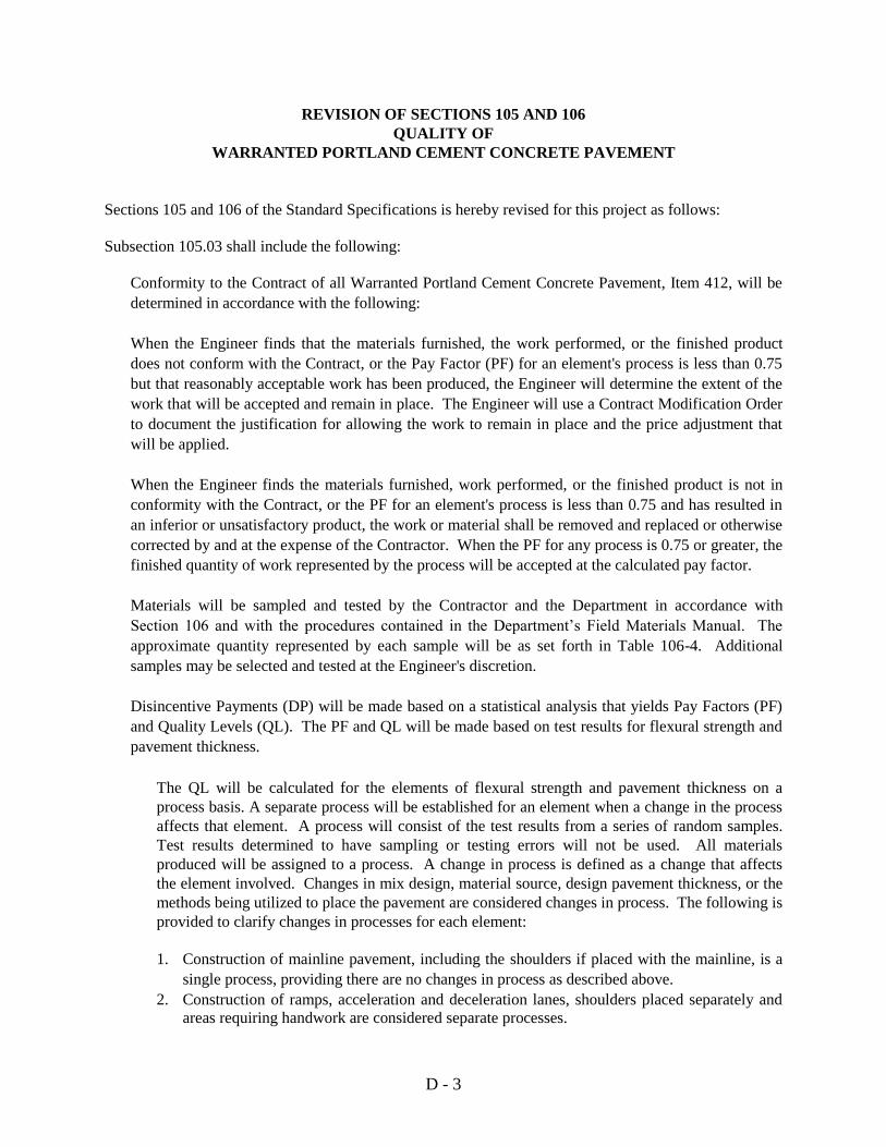
D - 3
REVISION OF SECTIONS 105 AND 106
QUALITY OF
WARRANTED PORTLAND CEMENT CONCRETE PAVEMENT
Sections 105 and 106 of the Standard Specifications is hereby revised for this project as follows:
Subsection 105.03 shall include the following:
Conformity to the Contract of all Warranted Portland Cement Concrete Pavement, Item 412, will be
determined in accordance with the following:
When the Engineer finds that the materials furnished, the work performed, or the finished product
does not conform with the Contract, or the Pay Factor (PF) for an element's process is less than 0.75
but that reasonably acceptable work has been produced, the Engineer will determine the extent of the
work that will be accepted and remain in place. The Engineer will use a Contract Modification Order
to document the justification for allowing the work to remain in place and the price adjustment that
will be applied.
When the Engineer finds the materials furnished, work performed, or the finished product is not in
conformity with the Contract, or the PF for an element's process is less than 0.75 and has resulted in
an inferior or unsatisfactory product, the work or material shall be removed and replaced or otherwise
corrected by and at the expense of the Contractor. When the PF for any process is 0.75 or greater, the
finished quantity of work represented by the process will be accepted at the calculated pay factor.
Materials will be sampled and tested by the Contractor and the Department in accordance with
Section 106 and with the procedures contained in the Department’s Field Materials Manual. The
approximate quantity represented by each sample will be as set forth in Table 106-4. Additional
samples may be selected and tested at the Engineer's discretion.
Disincentive Payments (DP) will be made based on a statistical analysis that yields Pay Factors (PF)
and Quality Levels (QL). The PF and QL will be made based on test results for flexural strength and
pavement thickness.
The QL will be calculated for the elements of flexural strength and pavement thickness on a
process basis. A separate process will be established for an element when a change in the process
affects that element. A process will consist of the test results from a series of random samples.
Test results determined to have sampling or testing errors will not be used. All materials
produced will be assigned to a process. A change in process is defined as a change that affects
the element involved. Changes in mix design, material source, design pavement thickness, or the
methods being utilized to place the pavement are considered changes in process. The following is
provided to clarify changes in processes for each element:
1. Construction of mainline pavement, including the shoulders if placed with the mainline, is a
single process, providing there are no changes in process as described above.
2. Construction of ramps, acceleration and deceleration lanes, shoulders placed separately and
areas requiring handwork are considered separate processes.

D - 4
-2-
REVISION OF SECTIONS 105 AND 106
QUALITY OF
WARRANTED PORTLAND CEMENT CONCRETE PAVEMENT
3. A change in the mix design is a process change for the flexural strength element, but is not a
process change for the pavement thickness element.
Pavement thickness tests will be evaluated in accordance with the following.
The lower tolerance limit (TL) for pavement thickness shall be the Contractor’s Plan Thickness (CPT)
minus 0.4 inches. This TL shall be used for determining any Disincentive Payments (DP), Quality
Levels (QL) and Pay Factor (PF). Any pavement thickness test value that exceeds the CPT by more
than 1.0 inch shall be assigned a value of CPT + 1.0 inch for the purpose of calculating the QL, PF
and DP.
Coring frequency shall be in accordance with subsection 106-3. Core locations shall be determined
by a random procedure in the longitudinal direction so that each area has a randomly selected coring
location at the point of minimum required thickness in the lateral direction. One core will be taken at
each location.
When it is necessary to represent material by one or two tests, each individual test shall have a PF
computed in accordance with the following:
If the value of the test is at or above the lower tolerance limit, then PF = 1.000.
If the value of the test is below the lower tolerance limit, then:
PF = 1.00 – [0.25(TL –T0)/0.4]
Where: PF = pay factor.
T0 = the individual test value.
TL = lower tolerance limit.
The following procedures will be used to compute Disincentive Payments (DP), quality levels (QL), and
pay factors (PF) for processes represented by three or more tests:
1. Quality Level (QL) will be calculated according to CP-71.
2. Compute the PF for the process. When the process has been completed, the number of tests
(Pn) it includes shall determine the formula to be used to compute the final pay factor in
accordance with the following:
When 3 ≤ Pn ≤ 5
If QL ≥ 85, then PF = 1.00
If QL < 85, then PF = 1.00 + (QL – 85)0.005208
When 6 ≤ Pn ≤ 9
If QL ≥ 90, then PF = 1.00
If QL < 90, then PF = 1.00 + (QL – 90)0.005682

D - 5
-3-
REVISION OF SECTIONS 105 AND 106
QUALITY OF
WARRANTED PORTLAND CEMENT CONCRETE PAVEMENT
When 10 ≤ Pn ≤ 25
If QL ≥ 93, then PF = 1.00
If QL < 93, then PF = 1.00 + (QL – 93)0.006098
When Pn ≥ 26
If QL ≥ 95, then PF = 1.00
If QL < 95, then PF = 1.00 + (QL – 95)0.006757
Additional cores will be taken at the direction of the Engineer as follows:
(1) One additional core at the location of each test that is less than TL but greater than CPT minus 1.0
inch. If the length of the additional core is greater than TL, no additional actions will be taken and
the original randomly selected acceptance test core will be used to compute DP for the process
that includes this material.
(2) If the additional core or any randomly selected core is less than TL but greater than CPT minus
1.0 inch, the area represented by this core shall become a separate process and this core will not
be used to compute a DP. Four additional randomly selected cores will be taken within the area
represented by this core. The four additional cores will be used to compute a DP. Cores taken at
locations not randomly determined, such as process control cores will not be used to compute DP.
(3) When the measurement of any core is less than CPT minus 1.0 inch, whether randomly located or
not, the area represented by this core shall become a separate process and this core will not be
used to compute a DP. The actual thickness of the pavement in this area will be determined by
taking exploratory cores. Cores shall be taken at intervals of 15 feet or less, parallel to the
centerline in each direction from the affected location until two consecutive cores are found in
each direction which are not less than CPT minus 1.0 inch.
Pavement areas found to be less than CPT minus 1.0 inch shall be removed and replaced at the
Contractor's expense. Exploratory cores taken at the Contractor's expense will be used to
determine the extent of deficient pavement for pavement removal or other corrective actions as
approved by the Engineer.
When the removal and replacement have been completed, four additional randomly selected cores
will be taken within the area represented by this core. The four additional cores will be used to
compute a DP. Exploratory cores will not be used to compute DP.
The Contractor shall repair all core holes by filling them with an approved non-shrink high
strength grout.

D - 6
-4-
REVISION OF SECTIONS 105 AND 106
QUALITY OF
WARRANTED PORTLAND CEMENT CONCRETE PAVEMENT
Flexural Strength tests will be evaluated in accordance with the following.
The lower tolerance limit (TL) for flexural strength shall be the Contractor’s design value for the
Modulus of Rupture minus 80 psi. This TL shall be used for determining any Disincentive Payments
(DP), Quality Levels (QL) and Pay Factor (PF).
Flexural strength testing frequency shall be in accordance with subsection 106-3. Locations shall be
determined by a stratified random procedure so that each area has a randomly selected location at the
point of sampling.
When it is necessary to represent material by one or two tests, each individual test shall have a PF
computed in accordance with the following:
If the value of the test is at or above the lower tolerance limit, then PF = 1.000.
If the value of the test is below the lower tolerance limit, then:
PF = 1.00 - [0.25(TL -T0)/50]
Where: PF = pay factor.
T0 = the individual test value.
TL = lower tolerance limit.
The following procedures will be used to compute Disincentive Payments (DP), quality levels (QL), and
pay factors (PF) for processes represented by three or more tests:
1. Quality Level (QL) will be calculated according to CP-71.
2. Compute the PF for the process. When the process has been completed, the number of tests
(Pn) it includes shall determine the formula to be used to compute the final pay factor in
accordance with the following:
When 3 ≤ Pn ≤ 5
If QL ≥ 85, then PF = 1.00
If QL < 85, then PF = 1.00 + (QL - 85)0.005208
When 6 ≤ Pn ≤ 9
If QL ≥ 90, then PF = 1.00
If QL < 90, then PF = 1.00 + (QL - 90)0.005682
When 10 ≤ Pn ≤ 25
If QL ≥ 93, then PF = 1.00
If QL < 93, then PF = 1.00 + (QL - 93)0.006098
When Pn ≥ 26
If QL ≥ 95, then PF = 1.00
If QL < 95, then PF = 1.00 + (QL - 95)0.006757

D - 7
-5-
REVISION OF SECTIONS 105 AND 106
QUALITY OF
WARRANTED PORTLAND CEMENT CONCRETE PAVEMENT
When any flexural strength test is less than Contractor’s design value for the Modulus of Rupture minus
100 PSI, whether randomly located or not, the area represented by this test shall become a separate
process and will not be used to compute a DP. The actual flexural strength of the pavement in this area
will be determined by averaging the results of two sets of sawed beams taken from the pavement. Each
set shall consist of at least two sawed beams and shall be taken at intervals of 100 feet or less in each
direction from the affected location until two consecutive sets are found that are not less than Contractor’s
design value for the Modulus of Rupture minus 100 PSI. The Contractor shall obtained the sawed beam
samples in accordance with AASHTO T- 24 within 72 hours after the Engineers written notice of
deficient strength. The sawed beams shall be tested in accordance with AASHTO T-97 within 48 hours
after removal from the pavement. Other corrective actions may be approved by the Engineer.
(1) If the average flexural strength of the two sets of sawed beams is found to be less than
Contractor’s design value for the Modulus of Rupture minus 100 PSI, the area shall be removed
and replaced at the Contractor's expense.
When the removal and has been completed and while replacing the area, one randomly selected
flexural strength test will be taken. The flexural strength test will be used to compute a DP.
(2) If the average flexural strength of the two sets of sawed beams is found to be greater than or equal
to the Contractor’s design value for the Modulus of Rupture minus 100 PSI, the average flexural
strength of the two sets of sawed beams shall be used to compute a DP.
The DP will be computed for the process in accordance with the following:
DP = (PF – 1)(QR)(UP)
Where: QR = Quantity Represented by the process.
UP = Unit Price bid for the item.
The total DP for an element shall be computed by accumulating the individual DP for each process of that
element.
As test results become available, they will be used to calculate accumulated QL and Disincentive
Payments (DP) for each element and for the item. The Contractor’s test results and the accumulated
calculations shall be made available to the Engineer upon request. The Engineer’s test results and the
calculations will be made available to the Contractor as early as reasonably practical. Numbers from the
calculations shall be carried to significant figures and rounded according to AASHTO Standard
Recommended Practice R-11, Rounding Method.
DP will be made to the Contractor in accordance with the revision to section 412. During production,
interim DP will be computed for information only. The Pn will change as production continues and test
results accumulate. The Pn at the time a DP is computed shall determine the formula to be used.

D - 8
-6-
REVISION OF SECTIONS 105 AND 106
QUALITY OF
WARRANTED PORTLAND CEMENT CONCRETE PAVEMENT
After all Warranted Portland Cement Concrete Pavements have been placed according to the contract, the
final DP will be computed.
The Contractor will not have the option of accepting a price reduction or disincentive in lieu of producing
specification material. Continued production of non-specification material will not be permitted.
Material that is obviously defective may be isolated and rejected without regard to sampling sequence or
location within a process.
Subsection 106.03 shall include the following:
All Warranted Portland Cement Concrete Pavement, Item 412, shall be tested in accordance with the
following process control and acceptance testing procedures:
(a) Process Control Testing. The Contractor shall be responsible for process control testing of all
elements listed in Table 106-4. Process control testing for flexural strength shall be performed at
the expense of the Contractor. The Contractor shall develop a quality control plan (QCP) in
accordance with the following:
1. Quality Control Plan. For each element listed in Table 106-4, the QCP must provide
adequate details to ensure that the Contractor will perform process control. The Contractor
shall submit the QCP to the Engineer at least two weeks prior to the preconstruction
conference. The Contractor shall not start any work on the project until the Engineer has
approved the QCP in writing.
A. Frequency of Tests or Measurements. The QCP shall indicate a random sampling
frequency, which shall not be less than that shown in Table 106-4. The process control
tests shall be independent of acceptance tests.
B. Test Result Chart. Each process control test result, the appropriate area, volume and the
tolerance limits shall be plotted. The chart shall be posted daily at a location convenient
for viewing by the Engineer.
C. Quality Level Chart. The QL for each element in Table 106-4 shall be plotted. The QL
will be calculated in accordance with the procedure in CP 71 for Determining Quality
Level. The QL will be calculated on tests 1 through 3, then tests 1 through 4, then tests 1
through 5, then thereafter the last five consecutive test results. The area of material
represented by the last test result shall correspond to the QL.
D. F-test and t-test Charts. The results of F-test and t-test analysis between the
Department’s verification tests of flexural strength and the Contractor’s quality control
tests of flexural strength shall be shown on charts. The F-test and t-test will be calculated
in accordance with standard statistical procedures using all verification tests and quality
control tests completed to date. When a verification test is completed, the F-test and t-
test calculations will be redone. The area of material represented by the last test result
shall correspond to the F-test and t-test. A warning value of 5% and an alert value of 1%

D - 9
-7-
REVISION OF SECTIONS 105 AND 106
QUALITY OF
WARRANTED PORTLAND CEMENT CONCRETE PAVEMENT
shall be shown on each chart. The chart shall be posted daily at a location convenient for
viewing by the Engineer.
2. Point of Sampling. The material for process control testing shall be sampled by the
Contractor using approved procedures. Acceptable procedures are Colorado Procedures,
AASHTO and ASTM. The order of precedence is Colorado Procedures, AASHTO
procedures and then ASTM procedures. The location where material samples will be taken
shall be indicated in the QCP.
3. Testing Standards. The QCP shall indicate which testing standards will be followed.
Acceptable standards are Colorado Procedures, AASHTO and ASTM. The order of
precedence is Colorado Procedures, AASHTO procedures and then ASTM procedures.
The compressive strength test for process control will be the average strength of two test
cylinders cast in plastic molds from a single sample of concrete, cured under standard
laboratory conditions, and tested three to seven days after molding. The trial mix proposed
and conducted by the Contractor for mix design approval shall include compressive strength
data including the curing time for compressive strength process control tests. CDOT may
participate in the process control testing for compressive strength at a frequency determined
by the Engineer.
4. Testing Supervisor Qualifications. The person in charge of and responsible for the process
control testing shall be identified in the QCP. This person shall be present on the project and
possess one or more of the following qualifications:
A. Registration as a Professional Engineer in the State of Colorado.
B. Registration as an Engineer in Training in the State of Colorado with two years of paving
experience.
C. A Bachelor of Science in Civil Engineering or Civil Engineering Technology with three
years of paving experience.
D. National Institute for Certification in Engineering (NICET) certification at level III or
higher in the sub fields of Transportation Engineering Technology, Highway Materials or
Construction Materials Testing Engineering Technology, Concrete and four years of
paving experience.
5. Technician Qualifications. Technicians performing tests, if other than the person in
responsible charge, must have a minimum of two years concrete testing experience and
possess an American Concrete Institute (ACI) Laboratory Testing Technician Grade 1
certification.
6. Testing Equipment. All of the testing equipment used to conduct process control testing shall
conform to the standards specified in the test procedures and be in good working order. The
following equipment and supplies will not be paid for separately but shall be included in the
work:

D - 10
-8-
REVISION OF SECTIONS 105 AND 106
QUALITY OF
WARRANTED PORTLAND CEMENT CONCRETE PAVEMENT
A. A separate, temperature controlled facility of at least 300 square feet usable space. This
facility shall be used exclusively for the molding, storage and testing of concrete test
specimens as required. This facility shall be provided in addition to other facilities
required in Section 620. The storage facility shall have sufficient water storage capacity
for curing all required test specimens. The storage facility shall provide separate storage
tanks for each type of required testing. Each storage tank shall have a continuously
recording thermometer and sufficient blank charts for the project. Temperatures of each
storage tank shall be recorded for the duration of the project.
B. A machine for testing flexural strength of concrete specimens. The machine shall be
used only for flexural strength tests. The machine shall be model number F-250F
manufactured by Forney with a DFM/IV digital monitor or an approved equal. Both the
Contractor and the Engineer will use this machine for testing concrete specimens. The
machine and the flexural strength assembly shall be of a rigid construction. The applied
vertical load shall be uniformly distributed to the third points and uniformly across the
width of the beam (transverse distribution). Uniform distribution of the load is defined as
less than a 3 percent variation in the load between each of the nine strain gages placed in
the middle third section of the tension face for loads from 1,000 to 10,000 pounds. One
firm that can evaluate and assess the ability of the machine to distribute the load evenly is
Construction Technology Laboratories, Skokie Illinois (847) 965-7500 (Paul Okamoto);
other firms may be capable of evaluating and assessing the load distribution of the
machine. The Engineer must approve the firm prior to assessing the machine. The
machine shall be ready for use and calibration two days before paving begins. After the
machine has been calibrated and accepted by the Engineer it shall not be moved until all
Warranted Portland Cement Concrete Paving and flexural strength acceptance tests have
been completed.
C. Beam molds for molding all test specimens required. This shall include all testing
described in subsection 106.03.
7. Reporting and Record Keeping. The Contractor shall report the results of the tests to the
Engineer in writing at least once per day. The Contractor shall make provisions such that the
Engineer can inspect quality control work in progress, including sampling, testing, plants,
documentation and the Contractor's testing facilities at any time.
(b) Acceptance Testing. Acceptance testing frequencies shall be in accordance with Table 106-4.
Acceptance tests will be conducted by and at the expense of the Department. Acceptance
sampling and
testing procedures will be in accordance with the Department's Field Materials Manual with the
following exceptions and inclusions:
A split sample from an acceptance test shall not be used for a process quality control test. The
Engineer shall designate the location where samples are to be taken. Samples shall be taken by
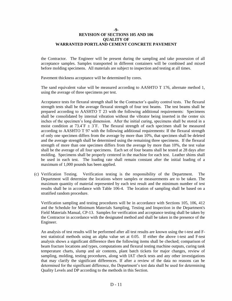
D - 11
-9-
REVISION OF SECTIONS 105 AND 106
QUALITY OF
WARRANTED PORTLAND CEMENT CONCRETE PAVEMENT
the Contractor. The Engineer will be present during the sampling and take possession of all
acceptance samples. Samples transported in different containers will be combined and mixed
before molding specimens. All materials are subject to inspection and testing at all times.
Pavement thickness acceptance will be determined by cores.
The sand equivalent value will be measured according to AASHTO T 176, alternate method 1,
using the average of three specimens per test.
Acceptance tests for flexural strength shall be the Contractor’s quality control tests. The flexural
strength tests shall be the average flexural strength of four test beams. The test beams shall be
prepared according to AASHTO T 23 with the following additional requirements: Specimens
shall be consolidated by internal vibration without the vibrator being inserted in the center six
inches of the specimen’s long dimension. After the initial curing, specimens shall be stored in a
moist condition at 73.4˚F ± 3˚F. The flexural strength of each specimen shall be measured
according to AASHTO T 97 with the following additional requirements: If the flexural strength
of only one specimen differs from the average by more than 10%, that specimen shall be deleted
and the average strength shall be determined using the remaining three specimens. If the flexural
strength of more than one specimen differs from the average by more than 10%, the test value
shall be the average of all four specimens. Each set of four beams shall be tested at 28 days after
molding. Specimens shall be properly centered in the machine for each test. Leather shims shall
be used in each test. The loading rate shall remain constant after the initial loading of a
maximum of 1,000 pounds has been applied.
(c) Verification Testing. Verification testing is the responsibility of the Department. The
Department will determine the locations where samples or measurements are to be taken. The
maximum quantity of material represented by each test result and the minimum number of test
results shall be in accordance with Table 106-4. The location of sampling shall be based on a
stratified random procedure.
Verification sampling and testing procedures will be in accordance with Sections 105, 106, 412
and the Schedule for Minimum Materials Sampling, Testing and Inspection in the Department's
Field Materials Manual, CP-13. Samples for verification and acceptance testing shall be taken by
the Contractor in accordance with the designated method and shall be taken in the presence of the
Engineer.
An analysis of test results will be performed after all test results are known using the t-test and F-
test statistical methods using an alpha value set at 0.05. If either the above t-test and F-test
analysis shows a significant difference then the following items shall be checked; comparison of
beam fracture locations and types, computations and flexural testing machine outputs, curing tank
temperature charts, slump and air contents, plant batch tickets for major changes, review of
sampling, molding, testing procedures, along with IAT check tests and any other investigations
that may clarify the significant differences. If after a review of the data no reasons can be
determined for the significant difference, the Department’s test data shall be used for determining
Quality Levels and DP according to the methods in this Section.

D - 12
-10-
REVISION OF SECTIONS 105 AND 106
QUALITY OF
WARRANTED PORTLAND CEMENT CONCRETE PAVEMENT
(d) Check Testing. The Contractor and the Engineer shall conduct a check testing program (CTP)
prior to the placement of any concrete pavement. The check testing program will include a
conference directed by the Region Materials Engineer of the Contractor’s testers and the
Department’s testers concerning methods, procedures and equipment for compressive or flexural
strength testing. Check testing shall be completed before any Warranted Portland Cement
Concrete Pavement is placed. A set four beams will be molded by both the Contractor and the
Department’s project testers from a split sample. The specimens will be sampled, molded and
cured for seven days and tested for flexural strength according to the procedures of Section 106.
The Department’s Independent Assurance Tester will also mold, cure and test a set of four beams,
but the Independent Assurance Test results will not be entered in the check testing analysis. If the
results of the check tests do not meet the following criteria, then the check testing will be repeated
until the following criteria are met:
1. The average of the Contractor’s test results and the average of the Department’s test results
shall be within 10% of the average of all test results.
2. Each specimen test result shall be within 15% of the average of all test results.
If production has been suspended and then resumed, the Engineer may order a CTP between
process control and acceptance testing persons to assure the test results are within the permissible
ranges. Check test results shall not be included in process control testing. The Region Materials
Engineer shall be called upon to resolve differences if a CTP shows unresolved differences
beyond the allowable range.
(e) Independent Assurance Tests (IAT) for flexural strength will be performed at a frequency of
1/50,000 sq. yds. The sample for the IAT will be a split sample of the Contractor’s quality
control test. The Department’s representative performing verification tests shall also use a split
sample of the Contractor’s quality control test and participate in the IAT. The IAT for flexural
strength will be the average flexural strength of four test beams prepared according to the
requirements of Section 106 and cured for seven days.
(f) Testing Schedule. All samples used to determine DP by quality level formulas in accordance
with Section 105, will be selected by a stratified random process.

D - 13
-11-
REVISION OF SECTIONS 105 AND 106
QUALITY OF
WARRANTED PORTLAND CEMENT CONCRETE PAVEMENT
TABLE 106-4
TESTING SCHEDULE - ITEM 412 PORTLAND CEMENT CONCRETE
PAVEMENT, FLEXURAL STRENGTH CRITERIA
Element Minimum Testing Frequency
Contractor's Process Control
Minimum Testing Frequency
CDOT Acceptance Testing
Aggregate Gradation
and Sand Equivalent
For the first five days, 1/10,000 sq. yds.
or one/day if less than 10,000 sq. yds.
placed in a day. After 5 days, 1/40,000
sq. yds.
None
Slump First three loads each day, then as
needed for control. Witness by the Engineer.
Water Cement Ratio First three loads each day, then 1/500
cu. yds.
First three loads each day, then 1/2,000 cu.
yds.
Air Content and
*Yield
1/2,500 sq. yds. or one/day if less than
2,500 sq. yds. placed in a day.
Minimum of 1/day. If the project total
<50,000 sq. yds. then a minimum of ten
tests. If the project total ≥ 50,000 sq. yds.
then 1/5,000 sq. yds.
Flexural Strength 1/2,500 sq. yds. Or one/day if less than
2,500 sq. yds. placed in a day.
One verification test per four quality
control tests performed by the Contractor.
(Approximately 1/10,000 sq. yds.).
Compressive Strength 1/10,000 sq. yds. None
Pavement Thickness In accordance with subsection 412.21.
Minimum of 1/day. If the project total <
50,000 sq. yds. then a minimum of ten
tests. If the project total ≥ 50,000 sq. yds.
then 1/5000 sq. yds.
Pull Test Joints
Minimum of six transverse and six
longitudinal joint locations in each
2,500 linear feet.
Witness by the Engineer.
Load Transfer Dowel
Bar Placement
Minimum of six transverse joint
locations in each 2,500 linear feet. Witness by the Engineer.
Tining Depth 1 per 1 per 528 linear feet in each lane
and shoulder wider than 8 feet. Witness by the Engineer.
*Yield is for information only.

D - 14
REVISION OF SECTION 109
PARTIAL PAYMENTS
Section 109 of the Standard Special Provisions is hereby revised for this project as follows:
In subsection 109.06(a) delete the last sentence and replace with the following:
The amount retained will be in effect until such time as final payment is made, with the
following exceptions which require the Contractor's written request and consent of the Surety:
Upon completion and acceptance of the project, after the project quantities are finalized, and the
Contractor has submitted the necessary forms, the Engineer may make reduction in the amount
retained, or upon job acceptance a partial payment will be made that will include release of all
retainage or securities.

D - 15
SECTION 110
DESIGN REQUIREMENTS
Section 110 is hereby added to the Standard Specifications for this project as follows:
110.01 General. The Contractor shall perform the design work as described herein. The Engineer as
required will provide clarification.
The Contractor shall provide design services for pavement structure, including any proposed base and
subbase layers, in accordance with subsection 110.04. The Contractor’s design shall be warranted as
required in the Revision of Section 412 Warranted Portland Cement Concrete Pavement System.
All designs provided by the Contractor shall be completed under the responsible charge of a Professional
Engineer registered in the State of Colorado. The responsible engineer in charge shall seal the designs
and plans in accordance with the bylaws and rules of procedure of the Colorado State Board of
Registration for Professional Engineers and Professional Land Surveyors.
Bidders will not be compensated by CDOT for any design required to prepare the bid for the work.
Bidders who will have performed design work before award, but who do not get the award, for any
reason, will have performed that work solely at their own cost and that design work will not be
reimbursed by CDOT.
The Contractor shall ensure that the design meets all applicable design criteria including but not limited to
the strength, safety and serviceability, as described herein and as shown on the Plans. The Contractor
shall use the plans, references and guidelines indicated herein for the design criteria. The work shall be
performed in every case using a desirable range design criteria. Where conflicts exist between these plans
and specifications and any desirable range design criteria described herein then the Plans and
Specifications for this Contract shall take precedence.
Designs predicated on any errors or omissions in the Contract will be rejected. If any such error,
omission or discrepancy is discovered, the Contractor shall notify the Engineer immediately. Failure to
notify the Engineer will constitute a waiver of all claims for misunderstandings, ambiguities, or other
situations resulting from error, omission, or discrepancy.
110.02 Project Development. Design development shall be managed by the Contractor to occur along
with the communication, project team reviews, data gathering, construction and documentation required
to accomplish the work. The various project elements shall occur in parallel paths where possible and as
determined appropriate by the Engineer. Conceptual layouts shall be developed that show satisfaction of
the minimum horizontal and vertical clearances criteria. Designs shall include general profile and cross
section information, critical areas sufficient to analyze the general cut and fill limits, right-of-way and
easement requirements, and earthwork and structural requirements. The design for the roadway
alignments and detours shall be completed sufficiently so that satisfaction of pertinent design criteria can
be demonstrated. The Contractor shall ensure the recommended alternative complies with applicable
standards and criteria.
110.03 Roadway Design Requirements. (a) Roadway Engineering. The Contractor shall provide final profile data to the Department for
inclusion in the as built drawings.

D - 16
-2-
SECTION 110
DESIGN REQUIREMENTS
The vertical alignment shall approximate the existing to the extent possible except where the design
speed of the vertical curve is below 75 mph, in which case that portion of the alignment shall be
modified to meet 75 mph design criteria. When making determinations regarding replacement of
existing alignment features, the minimum criteria for the design speed stated shall control. Vertical
alignment corrections are not required for existing vertical curves meeting design criteria for 75 mph
or greater. Where the existing roadway profile meets 75 mph design criteria or greater, the
Contractor may establish the vertical control line using the existing surface as a guide and adjusting
slightly to provide a smooth finished roadway. The Contractor shall provide a design vertical
alignment to the Engineer for acceptance that clearly demonstrates the ability to provide the
minimum thickness of pavement at the locations shown on the typical sections.
Vertical alignment adjustments may be required at bridges and overpasses. All new and significantly
modified vertical curves shall be designed to meet 75 mph design requirements.
The Contractor shall prepare roadway design plans and details for acceptance by the Engineer. The
roadway design plans shall include, as a minimum, the following:
Plan and profile sheets including all current horizontal and vertical alignment information (CDOT
Supplied)
Interchange layout and lighting details (CDOT Supplied)
Quantity tabulations and summary (CDOT Supplied)
Detour layout details (CDOT Supplied)
Existing Roadway cross sections including earthwork information (CDOT Supplied)
Typical section alternatives and locations selected (Contractor Supplied)
Vertical clearances for existing structures shall be in accordance with the Bridge Design Manual,
CDOT policy, or as shown on the plans, and shall meet necessary roadway and hydraulic design
requirements.
110.04 Pavement Design Requirements.
The Contractor shall be responsible for selecting a combination of materials and layer thicknesses for the
pavement structure using the 2000 CDOT Pavement Design Manual, and the following criteria. The
Contractor shall have discretion for determining a design flexural strength. Additionally, all Portland
Cement Concrete Pavement (PCCP) shall conform with Standard Plan M-412-1. CDOT will provide
boring logs every 1000 feet for information only.
Pavement Design Input Values:
30 year Design 18 kip ESAL’s = 34,500,000
Reliability (R) = 95%
Standard Normal Deviate (ZR) = -1.645
Overall Deviation (So) = 0.34
Initial Serviceability = 4.5
Terminal Serviceability = 2.5
∆ PSI= 2.0
Drainage Coefficient (Cd) = 1.0

D - 17
-3-
SECTION 110
DESIGN REQUIREMENTS
Loss of Support Factor (LS) = 0.81
Modulus of Subgrade Reaction k value (Reconstructed Sections) = 200 pci
Modulus of Subgrade Reaction k value (Overlay sections) = 125 pci
Effective thickness of existing pavement (Deff) = 6.5 inches
The Contractor shall provide the proposed typical pavement sections, including material property
assumptions, a minimum of two weeks prior to the pre-construction conference. As a minimum, the
submitted information shall include the assumed Modulus of Rupture (S’c), Modulus of Elasticity (Ec),
and anticipated physical properties for the base and subbase layers, if any.
Any submittals not containing the above information, and/or not conforming to the requirements of the
CDOT Pavement Design Manual or the Standard Plans, will be rejected and shall be resubmitted.
Any modifications to the pavement sections and design material properties shall be submitted to the
Engineer a minimum of four weeks prior to commencing construction of the modified sections.

D - 18
REVISION OF SECTION 412
WARRANTED PORTLAND CEMENT CONCRETE PAVEMENT SYSTEM
Section 412 of the Standard Specifications is hereby revised for this project as follows:
Delete Section 412, except subsections 412.02, 412.12(d), 412.13, 412.17, and 412.18, and replace with
the following:
DESCRIPTION
This work consists of the construction and warranty of a Warranted Portland Cement Concrete Pavement
System in accordance with these specifications, and in conformity with the lines and grades shown on the
plans or established. Warranted Portland Cement Concrete Pavement System (10 Year) shall consist of
the pavement structure, defined in subsection 101.39.
Definitions:
Acceptance- Methodology and/or Plan. Cursory review for the purpose of recognizing that
reasonable efforts have been made to determine an appropriate result.
Approval- Methodology and/or Plan. Review for the purpose of ratifying input and result
determinations. Generally includes sanctioning of procedures utilized and
comparison of developed values to historic values.
Emergency Work- Immediate pavement maintenance activities necessary to prevent accidents,
damage or injury to the public
Remedial Action- An action defined and performed by the Contractor on or in the Warranted
Portland Cement Concrete Pavement System for segments requiring warranty
work. The purpose of such action is to bring the Warranted Portland Cement
Concrete Pavement System back in conformance with the performance criteria.
WPCCPS- Warranted Portland Cement Concrete Pavement System
MMD- Contractor developed materials mix design for WPCCPS
Count- Single occurrence of a distress type, regardless of length or severity
Slab- The area of WPCCPS bounded by transverse contraction joints on two sides with
the other two sides bounded by longitudinal contraction and/or construction
joints and/or the edge of pavement.

D - 19
-2-
REVISION OF SECTION 412
WARRANTED PORTLAND CEMENT CONCRETE PAVEMENT SYSTEM
MATERIALS AND CONSTRUCTION REQUIREMENTS
The Contractor shall be responsible for WPCCPS design, materials compliance, workmanship, and
warranty work that shall be required under this specification for a period of ten years from pavement
acceptance, as defined in the Revision of Section 105, Acceptance.
The minimum thickness structural design shall be determined by the Contractor, including any
intermediate processes, base course, or subgrade preparation, in accordance with the Revision of Section
110. The contractor shall provide the Engineer the proposed structural design two weeks prior to the
preconstruction conference for review and acceptance. Acceptance of the structural design by the
Engineer does not relieve the Contractor from any of the warranty requirements.
The Contractor shall establish a mixture design for the WPCCP. The mixture shall consist of Portland
Cement, fine aggregate, coarse aggregate, water and Class F flyash. Portland Cement shall be 80 percent
and Class F flyash shall be 20 percent of the total mass (weight) of the cement plus flyash. The concrete
used for WPCCPS shall be designated as Class WP. The materials used in Class WP shall conform to the
requirements in subsection 412.02.
A minimum of two weeks before starting paving, the Contractor shall provide the Engineer the proposed
mix design proportions, laboratory trial mix information, all aggregate data as required in subsection
601.05, and all thickness testing methods, for review and acceptance. The test data shall show the mix
design proportions of all ingredients including cement, fly ash, aggregate and additives. The laboratory
trial mix shall follow AASHTO T 126-97 Making and Curing Concrete Test Specimens in the
Laboratory. The test data shall include the following trial mix data: slump measured by AASHTO T 119-
99, air content measured by AASHTO T 152-97, unit weight and yield measured by AASHTO T 121,
water/cement ratio, 7 day and 28 day compressive strengths measured by AASHTO T 22-97, 28 day
flexural strength measured by AASHTO T 97-97 and ASTM C 1260-94 Potential Alkali Reactivity of
Aggregates (Mortar-Bar Method). Aggregate test data shall include results of AASHTO T 27-99 Sieve
Analysis of Fine and Coarse Aggregates, AASHTO T 11-91 Materials Finer Than 75 um (No. 200) Sieve
in Mineral Aggregates by Washing, AASHTO T 176-00 Plastic Fines in Graded Aggregates and Soils by
Use of the Sand Equivalent Test, AASHTO T 21-00 Organic Impurities in Fine Aggregate for Concrete,
AASHTO T 84-00 Specific Gravity and Absorption of Fine Aggregate, AASHTO T 85-91 Specific
Gravity and Absorption of Coarse Aggregate, AASHTO T 96-99 Resistance to Degradation of Small-Size
Coarse Aggregate by Abrasion and Impact in the Los Angeles Machine, ASTM C535-96 Resistance to
Degradation of Large-Size Coarse Aggregate by Abrasion and Impact in the Los Angeles Machine,
AASHTO T 104-99 Soundness of Aggregate by Use of Sodium Sulfate or Magnesium Sulfate, and
fineness modulus.
The 28-day flexural strength of the laboratory trial mix shall be at least 50psi greater than the Contractor’s
target value for flexural strength.
The Contractor shall submit the required test data in a report with discussion relating the test results to
other design assumptions used in the design and production of Warranted Portland Cement Concrete
Pavement System.

D - 20
-3-
REVISION OF SECTION 412
WARRANTED PORTLAND CEMENT CONCRETE PAVEMENT SYSTEM
Class WP concrete shall not be placed on the project before the design mix proportions and data have
been reviewed and accepted by the Engineer. Acceptance of the mixture design by the Engineer does not
relieve the Contractor from any of the warranty requirements.
Process control testing shall be in accordance with the Revision of Sections 105 and 106.
WARRANTY
The WPCCPS shall be warranted for ten years against the types of distress listed in Table 412-1 and
Table 412-2 below.
(a) Warranty and Warranty Bond. By submission of its bid in response to this specification, the
Contractor warrants that all of the WPCCPS placed on the project will perform such that the
measured distress values (Performance Criteria) will be at or below the distress threshold values
(Performance Criteria), as described in Table 412-1 for a period of ten years from the date of
pavement acceptance.
The Contractor further warrants that all distresses, as described in Table 412-2, shall be repaired in a
manner acceptable to the Engineer prior to expiration of the ten year warranty period, except as
described below, and if that warranty work is required or needed on that WPCCPS, then the
Contractor will ensure proper and prompt performance and completion of that warranty work,
including payments for all labor performed and for all equipment and materials used, in accordance
with this specification.
The Contractor understands and further warrants that if so required by the Department the Contractor
shall perform and complete that warranty work after that ten year period has ended if the Department
needs the warranty work performed at that later date due to timing of the final survey, weather delays
that do not reasonably allow that work to be performed during the ten year period, or both provided
that the start of any such performance shall not be required later than nine months after that ten year
period has ended. All necessary warranty work will be identified prior to expiration of the ten-year
warranty term.
The Contractor agrees to perform that warranty work within that additional nine months if so
required by the Department.
All warranty work, subject to the exceptions, exclusions and limitations outlined below, shall be
performed solely at the Contractor’s cost and expense.
The Contractor shall provide a warranty performance bond, hereinafter referred to as "warranty
bond", to guarantee the full performance of the warranty work described in this specification in the
amount of $ 1,000,000. In lieu of providing a warranty bond, the Contractor may elect to provide
CDOT with an alternate form of security equal to the amount of the warranty bond.

D - 21
-4-
REVISION OF SECTION 412
WARRANTED PORTLAND CEMENT CONCRETE PAVEMENT SYSTEM
Acceptable alternate forms of security are a letter of credit, certificate of deposit, warranty
insurance, or United States currency. Should other alternative forms of security be developed during
the ten year warranty period, the Department in its sole discretion may determine such alternative
security to be acceptable in meeting the warranty security requirements of this specification.
If Contractor provides a surety bond as its security to cover warranty work, such warranty bond shall
be either continuous or definite-term and subject to the following requirements:
1. Bond duration(s) shall be no less than one year definite terms
2. Continuation certificates used to extend a definite-term bond shall extend the bond for no less
than one year definite terms
3. The initial warranty bond shall be in effect upon pavement acceptance, and it shall remain in
effect for a minimum of one year from that date. The Contractor shall provide the initial
warranty bond, which fully complies with this specification, to the Department at the time of
execution of the Contract.
4. Throughout the 10-year warranty period, subsequent bond(s) or acceptable alternative security
shall be presented to the Department a minimum of 90 calendar days prior to term expiration of
the previously posted security.
5. If a subsequent bond or acceptable alternate security is not presented to the Department a
minimum of 90 calendar days prior to the expiration of the bond, then the existing bond shall
remain in full force and effect until the warranty term is complete, the $1,000,000 limitation for
warranty work is achieved and agreed to by the Department, or adequate substitute security is
provided by Contractor.
6. Should Contractor fail to complete warranty work as prescribed in these specifications, the
Department shall make claim upon the warranty bond to complete the work according to the
terms and conditions of this specification.
7. The required warranty security amount may be reduced by the dollar amounts of warranty work
performed by the Contractor. If the Contractor desires to provide a bond or alternate form of
security less than $1,000,000, the Contractor shall provide supporting documentation showing
the actual cost of warranty work performed for audit by the Department. To minimize
administration the bond shall only be adjusted at its face value upon issuance of a subsequent
definite term bond or continuation certificate. At such time(s), the Department will audit the
warranty work documentation from the Contractor in relation to the $1,000,000 limitation of this
warranty.
8. Regardless of the number of periods a warranty bond(s) remain(s) in force, in no event shall the
liability of the Contractor and their surety(ies) on a cumulative and combined basis exceed
$1,000,000
Should Contractor’s warranty security provided hereunder contain an expiration date, then
Contractor shall submit the above described documentation showing actual costs of warranty work
performed to date along with the replacement or continuing security at least 90 days prior to such
expiration date. Any disputes between Contractor and Department as to amount of warranty work
performed and the remaining security amount reduced by warranty work already performed shall be
decided by the Dispute Resolution Team (DRT) as outlined in (e) below.
D - 22
-5-
REVISION OF SECTION 412
WARRANTED PORTLAND CEMENT CONCRETE PAVEMENT SYSTEM
Should the DRT determine warranty security to be inadequate as to its amount, Contractor shall
increase its warranty security within 60 days to comply with the amount stipulated by the DRT.
The need for warranty work, and the performance of that warranty work, shall be determined in
accordance with (d) below. At the end of the warranty period, the Contractor will be released from
further warranty work or responsibility, provided all required warranty work has been satisfactorily
completed.
(b) Early Termination of Warranty. The warranty term of this provision will end effective the next
calendar year for any year in which the accumulated 18 kip Rigid Equivalent Single Axle Loads
(ESAL’S) exceed 50 percent of the 30 year Design 18 kip Rigid ESAL’s given in the Revision of
Section 110. The Department will provide the Contractor accumulated ESAL’s on an annual basis.
This termination provision is specific to each site within the project. The Contractor shall be
responsible for performing any warranty work required before termination as given in this section (b).
(c) Exceptions, Exclusions and Limitations. The Contractor will not be held responsible for failure of the WPCCPS to meet the Performance
Criteria for factors beyond the control of the Contractor, including the following occurring after
pavement acceptance:
1. Destruction. When the pavement is damaged due to spills of any kind (including chemical,
petroleum, solvent and the like), releases (including any contaminants or pollutants), vandalism,
maintenance equipment damage, or earth movement not related to work performed by the
Contractor.
2. Natural Disasters. When the pavement is damaged due to flooding, earthquakes, landslides,
lightning, falling rocks, explosions, fires, tornadoes, hurricanes, and all occurrences considered as
acts of God.
3. Acts of War. When the pavement is damaged due to an act of war or because of heavy military
activity, including tank movement, terrorist attacks, accidental weapon discharges and sabotage.
4. Accidents. When the pavement is damaged by vehicular accidents or as a consequence thereof.
5. Other’s Work. The Contractor is not responsible for damages that are a result of coring, milling,
repaving, or other destructive procedures conducted by the Department, utility companies or other
entities not under the control of the Contractor, with the exception of Emergency Work ordered
by the Engineer. The Contractor will be notified when any coring, milling or other destructive
activities are to occur on the project pavement.
The Contractor shall further not be responsible for any warranty not expressly provided for herein,
including any implied warranties of merchantability and any implied warranties of fitness for a
particular purpose, or any other implied warranties of any kind.

D - 23
-6-
REVISION OF SECTION 412
WARRANTED PORTLAND CEMENT CONCRETE PAVEMENT SYSTEM
The Contractor shall not be liable for incidental or consequential damages of any kind including
without limitation those that may be associated with pavement failures, defects or any other
inadequacy claimed or proved. This limitation shall remain effective regardless of whether the
remedies provided for herein are deemed to fail of their essential purpose.
This warranty does not extend to users of the pavement, who are not intended to be third party
beneficiaries of the provisions set forth herein.
The Contractor’s total cumulative financial commitment for warranty work shall be limited to
$1,000,000. This cumulative financial commitment shall be based upon actual costs incurred by the
Contractor for personnel, equipment and materials, without any profit for the prime contractor.
Equipment rental rates shall be in accordance with the Dataquest Blue Book of Rental Rates for
Construction Equipment in effect at the time the work is completed. Lane rental fees paid by the
Contractor shall be excluded when determining the Contractor’s total financial commitment for
warranty work. The Contractor shall provide documentation of warranty repair costs at the time of
repair.
Any defects requiring repair within 60 days after pavement acceptance will not be included as part of
the Contractor’s total cumulative financial commitment for warranty work.
If the Contractor reaches the total financial commitment limit for warranty work, then the Contractor
shall make available its records for audit by the Department. If upon review by the Department, the
Contractor is found to have reached the total financial commitment, the Contractor will be relieved of
all further warranty requirements.
(d) Maintenance/Warranty Work. During the warranty period, the warranty work shall be performed
at no cost to the Department. All elective and preventive maintenance work that the Contractor
performs during the warranty period shall be at no cost to the Department. The cost of performing
maintenance will be included as part of the Contractor’s cumulative financial commitment under this
warranty. The Contractor may assess, using nondestructive procedures, the WPCCPS’s condition. If
the pavement requires maintenance/warranty work the Contractor shall develop a Pavement
Maintenance/Warranty Plan, hereinafter referred to as “Plan” Destructive procedures used for
WPCCPS assessment shall have the prior written approval of the Engineer. The assessment will
establish the current condition of the WPCCPS with respect to the Performance Criteria given in (f)
below. The Pavement Maintenance/Warranty Plan will describe an assessment of the warranty site’s
condition and will describe the proposed maintenance and warranty work that will be performed. If
warranty work is required a detailed description of the remedial action will be given. The Plan shall
also include a Quality Control Plan if the methods and materials differ from the original Quality
Control Plan. The Pavement Maintenance/Warranty Plan will establish the scheduled dates for the
maintenance and warranty work. The Pavement Maintenance/Warranty Plan will be transmitted to the
Engineer for review and written acceptance. Acceptance of the Plan by the Engineer does not relieve
the Contractor from warranty responsibilities.

D - 24
-7-
REVISION OF SECTION 412
WARRANTED PORTLAND CEMENT CONCRETE PAVEMENT SYSTEM
At least 60 days before the expiration of the warranty or at any time deemed necessary, the Engineer
will conduct a pavement distress survey to determine the need for warranty work as described in (f)
below. The Contractor may participate in the final distress survey if they so desire. If warranty work
is required, the Engineer will notify the Contractor in writing. Within 45 working days of receiving
notice, the Contractor shall submit a plan for completing the work and/or provide written objection if
the need for such warranty work is contested. Disagreement between the Contractor and the Engineer
shall be resolved in accordance with the dispute resolution provisions given in (e) below. If the
Contractor or the Surety fails to submit a plan within 45 days after receiving written notice from the
Engineer or fails to complete the work described in the plan within nine months of receiving written
notice, the CDOT will complete the warranty work or contract to have it completed and the
Contractor and Surety shall be responsible for the total cost of the warranty work including the lane
rental fees. All warranty work shall be completed no later than 9 months following the end of the
warranty period.
The Engineer may choose to delay the Maintenance or Warranty work due to unfavorable seasonal
restrictions or other reasons deemed to be in the public interest.
The warranty provisions for the remainder of the warranty term shall cover all repair, maintenance,
and warranty work performed as part of this warranty provision, except as excluded elsewhere in this
provision.
If remedial action necessitates a corrective action to the pavement markings, adjacent lanes or
roadway shoulders, then such corrective action to the pavement markings, adjacent lanes and
shoulders shall be performed at the expense of the Contractor.
When remedial action requires the removal of pavement, the pavement shall be replaced with a mix
that meets the Contractor’s original design flexural strength and is approved by the Engineer. The
mix shall be placed according to the Contractor's Quality Control Plan (QCP). Pavement shall be
removed by cutting neat lines vertically for the full depth of the pavement unless otherwise specified
or approved.
Removal area shall be a rectangular shape. Deformed tie bars or smooth dowel bars shall be set by
drilling holes at mid-depth of the exposed face of the existing slab. An approved epoxy or grout
anchoring material shall be used in the blown out drill holes prior to placing the new pavement. Joint
sealing shall be in accordance with M-412-1 of the CDOT Standard Plans included in the contract.
The Contractor shall be allowed a total of five days per calendar year for any type of work without a
lane rental fee. If the Contractor uses less than five days in a calendar year, the remaining days may
be accumulated up to a maximum of 15 days. If the allowable accumulated days in any given
calendar year are exceeded, the Contractor shall be charged a lane rental fee as described below. Days
counted toward this total shall be as follows. The Contractor shall be assessed a day for the closure of
any lane. This day will be assessed for each calendar day or portion thereof, whether work is
performed or not, that the traffic is limited to less than the number of lanes in the final configuration
as shown in the construction plans. The Contractor shall maintain traffic at all times as detailed in the

D - 25
-8-
REVISION OF SECTION 412
WARRANTED PORTLAND CEMENT CONCRETE PAVEMENT SYSTEM
Traffic Control Plan. Work, except Emergency work, shall be performed during the times of day and
days of week specified for the original contract work.
The Contractor and Surety shall be responsible for the lane rental fee. The fee will be based on the
applicable rates for any and all closures whether work is performed or not. This fee is not a penalty,
but is a rental fee based upon road user cost to occupy lanes.
The lane rental fee for this project after pavement acceptance shall be $1400 per occurrence if a lane
is closed between the hours of 7:00 a.m. and 7:00 p.m. and $500 per occurrence if a lane is closed
between the hours of 7:00 p.m. and 7:00 a.m.
(e) Dispute Resolution.
Dispute Resolution Team (DRT). The purposes of the DRT is to fairly and impartially consider
disputes that arise under the warranty provisions and provide expertise in the resolution of disputes at
the project level. The decisions of the DRT will be final and binding.
The DRT shall consist of three subject matter experts not affiliated with the project. The Department
will select and pay for one of the DRT members. The Contractor shall select and pay for one of the
DRT members. The Department and the Contractor shall jointly select the third DRT member and
each shall pay fifty percent of the costs associated with the third DRT member. Each member of the
team shall have at least ten years of experience in one or a combination of the following disciplines:
pavement management, PCCP design or construction, maintenance management, or PCCP
maintenance. The team shall be selected prior to the start of the warranty period. If it is necessary to
replace a member of the DRT for any reason, the new member shall meet the experience requirements
identified above.
All other costs associated with forensic work required by the DRT will be borne by the Department.
Disagreement between the Contractor and the Engineer shall be resolved as follows: within 30
working days of receipt of the Contractor’s Plan the Engineer shall provide written acceptance, or
notify the Contractor of objection describing in full contractual and factual basis for objecting to the
plan. If the Engineer and the Contractor are unable to reach agreement within 15 working days after
the Contractor receives written notice of objection, the Contractor shall submit written notification of
the dispute to the DRT, with a copy to the Engineer, describing the contractual and legal basis for the
disagreement with the decision of the Engineer. The DRT will render a decision and notify both
parties in writing within 30 working days of the Contractor’s submission. The DRT’s decision will be
final and binding.
(f) Performance Criteria - Pavement Distress Indicators and Thresholds. The annual condition data
collected by the Department as part of the pavement management program will be used as an initial
indicator of performance.

D - 26
-9-
REVISION OF SECTION 412
WARRANTED PORTLAND CEMENT CONCRETE PAVEMENT SYSTEM
Table 412-1. WPCCPS Distress Thresholds per tenth mile
Distress Type Threshold (per tenth mile)
Corner Breaks 5 counts
Longitudinal Cracking 100 feet
Transverse Cracking 5 counts
Scaling 250 square feet
D-cracking 1 count
Spalling 5 counts
If the pavement management condition data indicates any of the thresholds in Table 412 – 1 have
been exceeded, the Engineer will be notified. The Engineer may then perform a detailed manual
distress survey. The Engineer will notify the Contractor prior to any manual surveys. The Contractor
may participate in the distress survey if they so desire. The pavement distress survey will be
conducted by dividing the roadway into nominal one-tenth mile segments for the entire length of the
WPCCPS.
The Engineer will notify the Contractor in writing of the manual survey results within 15 calendar
days of completion of the survey.
Pavement distress will be measured in general accordance with Publication No. SHRP-P338, ISBN 0-
309-05271-9, Titled: Distress Identification Manual for the Long-Term Pavement Performance
Project, Strategic Highway Research Program.
Prior to expiration of the warranty the Contractor shall repair all distresses, as defined in Table 412-2.
Potential remedial actions are identified, but the actual repair method shall be approved by the
Engineer.

D - 27
-10-
REVISION OF SECTION 412
WARRANTED PORTLAND CEMENT CONCRETE PAVEMENT SYSTEM
Table 412-2. Distresses to be Corrected Prior to Expiration of Warranty
DISTRESS TYPE THRESHOLD LEVELS
PREFERRED REMEDIAL ACTION
(Actual action will be approved by the
Engineer)
Corner Breaks Spalling 2 in.; faulting of the
crack or joint 0.25 in, width of
crack 0.125 in.; or the corner
piece is not broken into two or
more pieces.
Spalling >2 in. to 6 in); faulting
of the crack or joint >0.25 in. to
0.5 in.; width of crack >0.125 in.
to 0.5 in); or the corner piece is
not broken into two or more
pieces.
Spalling >6 in.; faulting of the
crack or joint 0.5 in.; width of
crack 13 0.5 in.; or the corner
piece is broken into more than two
pieces.
No action required if less than 50% of the
surveyed slabs within each one-tenth mile
segment are at or below the indicated
threshold level.
Route and seal the crack and concrete patch
the spalled area.
Remove and replace the affected area.
Longitudinal or
Transverse Cracking
Spalling 2 in.; faulting of the
crack 0.25 in., width of crack
0.125 in.; or the 15 ft. slab is not
broken into more than two pieces.
Spalling >2 in. to 6 in.; faulting
of the crack >0.25 in. to 0.5 in.;
width of crack >0.125 in. to 0.5
in.; or the 15 ft. slab is not broken
into more than two pieces.
Spalling >6 in.; faulting of the
crack 0.5 in.; width of crack 0.5
in.; or the 15 ft. slab is broken into
more than two pieces.
No action required if less than 50% of the
surveyed slabs within each one-tenth mile
segment are at or below the indicated
threshold level.
Concrete patch the spalled location then
route and seal the crack. If the crack has
faulted 0.4 in., then cross-stitch or retrofit
tie bars in the crack.
Remove and replace the slab or the affected
area whichever is less.

D - 28
-11-
REVISION OF SECTION 412
WARRANTED PORTLAND CEMENT CONCRETE PAVEMENT SYSTEM
Table 412-2. Distresses to be Corrected Prior to Expiration of Warranty (continued)
DISTRESS TYPE THRESHOLD LEVELS PREFERRED REMEDIAL ACTION
(Actual action will be approved by the
Engineer)
Longitudinal or
Transverse Joint Seal
Damage
Total length longitudinally or
transversely in a 15 ft. slab 2 ft..
Total length longitudinally or
transversely in a 15 ft. slab >2 ft.
and 6 ft..
Total length in longitudinally or
transversely in a 15 ft. slab >6 ft.
No action required if less than 50% of the
surveyed slabs within each one-tenth mile
segment are at or below the indicated
threshold level.
Clean the joint and replace the backer rod and
sealant material.
Remove and replace all the joint material in
the slab.
Scaling Scaling 2.0 ft² per 15 ft. slab.
Scaling > 2.0 ft² per 4.5 meter 15
ft. slab.
No action required if less than 50% of the
surveyed slabs within each one-tenth mile
segment are at or below the indicated
threshold level.
Remove partial depth and replace the affected
area.
Popouts Popouts 2 per square yd. or 2
in deep.
Popouts > 2 per square yd. or > 2
in deep.
No action required if less than 50% of the
surveyed slabs within each one-tenth mile
segment are at or below the indicated
threshold level.
Clean and patch all the locations in the slab.
Blowups (Due to
transverse joint seal
deterioration)
Any blowup Remove a minimum of 0.6 meters (2 ft.) in
the longitudinal direction past the affected
area on each side, reset the dowel bars and
replace PCCP.
Faulting of Dowelled
Pavement. (If dowels are
missing or misplaced)
Faulting 0.25 in.
Faulting >0.25 in. and 0.5 in.
Faulting >0.5 in.
No action required if less than 50% of the
surveyed slabs within each one-tenth mile
segment are at or below the indicated
threshold level.
Retro fit dowel bars. Grinding may be
included.
Remove and replace the slab with the required
dowels and tie bars.

D - 29
-12-
REVISION OF SECTION 412
WARRANTED PORTLAND CEMENT CONCRETE PAVEMENT SYSTEM
Table 412-2. Distresses to be Corrected Prior to Expiration of Warranty (continued)
DISTRESS TYPE THRESHOLD LEVELS PREFERRED REMEDIAL ACTION
(Actual action will be approved by the
Engineer)
Lane-To-Shoulder or
Lane–To-Lane Dropoff or
Separation
Dropoff or Separation 0.5 in.
Dropoff or Separation >0.5 in.
No action required if less than 50% of the
surveyed slabs within each one-tenth mile
segment are at or below the indicated
threshold level.
Clean the joint, cross stitch or retro fit tie bars,
and then reset the backer rod and joint sealant.
Patch/Patch in pavement
Deterioration
Same as PCCP pavement not
patched
See previous preferred remedial actions
(g) Emergency Work. The Engineer may request, in writing, immediate action of the Contractor
and Surety for the safety of the traveling public. The Contractor or Surety shall have the first
option to perform the emergency work. If the Contractor or Surety cannot perform the emergency
work within 24 hours, the Engineer may have the emergency work done by other forces and seek
reimbursement from the Contractor or Surety accordingly. Emergency work performed by other
forces shall not alter the requirements, responsibilities, or obligations of the warranty.
(h) Traffic Control. Construction Traffic control for warranty work shall be performed in
accordance with Section 630 at the Contractor’s expense and will be included in the total cost for
completing warranty work.
(i) Process Control Testing for Warranty Work: The Contractor shall perform process control
testing in accordance with the Revision of Section 105 and 106, Quality of Portland Cement
Concrete Pavement and will be included in the total cost for completing warranty work
METHOD OF MEASUREMENT
Warranted Portland Cement Concrete Pavement System will be measured for payment by the square yard
based on the actual quantity placed, completed and accepted.
The Portland Cement Concrete Pavement 10 Year Warranty will be measured for payment by the square
yard based on the actual quantity of Warranted Portland Cement Concrete Pavement System placed,
completed and accepted.

D - 30
13-
REVISION OF SECTION 412
WARRANTED PORTLAND CEMENT CONCRETE PAVEMENT SYSTEM
BASIS OF PAYMENT
Warranted Portland Cement Concrete Pavement System, measured as provided above, will be paid for at
the contract unit price per square yard. The unit price will be full compensation for furnishing, preparing,
hauling, and placing all materials, concrete mix design, Quality Control Plan, testing, record keeping,
sampling, and for all labor, tools, and equipment during construction and during the warranty period,
along with any incidentals necessary to complete the work.
The Portland Cement Concrete Pavement 10 Year Warranty will be paid at the contract unit price,
which will be full compensation for the warranty and warranty bond, for performing warranty work,
and for all materials, labor, tools and equipment used during performance of the warranty work, and
incidentals necessary to complete the warranty work.
Payment will be made under:
Pay Item Pay Unit
Warranted Portland Cement Concrete Pavement System Square Yard
Portland Cement Concrete Pavement 10 Year Warranty Square Yard
Facilities for testing the PCCP will not be paid for separately, but shall be included in the work.

E - 1
APPENDIX E
HOT MIX ASPHALT WARRANTY SPECIFICATIONS

E - 2
REVISION OF SECTION 105
ACCEPTANCE
Section 105 of the Standard Specifications is hereby revised for this project as follows:
Delete subsection 105.16(b) and replace with the following:
(b) Job Acceptance. Job acceptance will occur upon the satisfactory completion of all work in
the original bid schedule. Upon notice from the Contractor of presumptive completion of the
entire project, the Engineer will make an inspection. If the work provided for by the Contract
has been satisfactorily completed, that inspection shall constitute the final inspection and the
Engineer will notify the Contractor in writing of job acceptance indicating the date on which
the project was inspected and accepted.
If the inspection discloses any unsatisfactory work, the Engineer will give the Contractor a
written list of the work needing correction. Upon correction of the work another
inspection will be made. If the work has been satisfactorily completed, the
Engineer will notify the Contractor in writing of the date of final inspection and
job acceptance. Job acceptance under this subsection does not waive any legal
rights contained in subsection 107.21
(c) Pavement Acceptance. Pavement acceptance will occur upon completion of all Warranted
Hot Bituminous Pavement System (10 Year), pavement markings, signing, signalization and
features necessary for opening the pavement to traffic. The warranty period shall start on the
first day in January of the year following the date when the pavement surfaces are completely
constructed in each direction, accepted for traffic, or determined by the Engineer to be in
compliance with the Contract plans and specifications. Pavement acceptance may occur in
different years for different parts of the pavement depending on varying acceptance for
traffic or stage construction sequences.
(d) Final Acceptance. Final acceptance will occur upon the completion of the warranty period
and all warranty work.

E - 3
REVISION OF SECTION 109
PARTIAL PAYMENTS
Section 109 of the Supplemental specifications is hereby revised for this project as follows: In subsection 109.06(a) delete the last sentence and replace with the following: The amount retained will be in effect until such time as final payment is made, with the following exceptions which require the Contractor’s written request and consent of the Surety: Upon completion and job acceptance of the project, after the project quantities are finalized, and the Contractor has submitted all required documentation, the Engineer will make a reduction in the amount retained

E - 4
REVISION OF SECTIONS 105 AND 106
QUALITY OF
WARRANTED HOT BITUMINOUS PAVEMENT SYSTEM
Sections 105 and 106 of the Standard Specifications are hereby revised for this project as
follows:
Subsection 105.03 shall include the following:
Conformity to the Contract of all Warranted Hot Bituminous Pavement System, Item 403,
will be determined in accordance with the following:
The final pavement thickness tests will be evaluated in accordance with the following.
The lower tolerance limit (TL) for pavement thickness shall be the Contractor’s Plan
Thickness (CPT) minus 0.4 inches. This TL shall be used for determining any Disincentive
Payments (DP), Quality Levels (QL) and Pay Factor (PF). Any pavement thickness test value
that exceeds the CPT shall be assigned a value equal to the CPT for the purpose of
calculating the QL, PF and DP.
Coring frequency shall be in accordance with subsection 106.03. Core locations shall be
determined by a random procedure in the longitudinal and transverse direction so that each
area has a randomly selected coring location. One core will be taken at each location.
When it is necessary to represent material by one or two tests, each individual test shall have a
PF computed in accordance with the following:
If the value of the test is at or above the lower tolerance limit, then PF = 1.000.
If the value of the test is below the lower tolerance limit, then:
PF = 1.00 – [0.25(TL –T0)/0.4]
Where: PF = pay factor.
T0 = the individual test value.
TL = lower tolerance limit.
Additional cores will be taken at the direction of the Engineer as follows:
(1) One additional core at the location of each test that is less than TL. If the length of the
additional core is greater than TL, no additional actions will be taken and the original
randomly selected acceptance test core will be used to compute DP for the process that
includes this material.

E - 5
-2-
REVISION OF SECTIONS 105 AND 106
QUALITY OF
WARRANTED HOT BITUMINOUS PAVEMENT SYSTEM
(2) If the additional core or any randomly selected core is less than TL, the area represented
by this core shall become a separate process and this core will not be used to compute a
DP. The limits of the affected area shall be defined the area within the 375 feet of this
core times the width of the pass. Four additional randomly selected cores shall be taken
within this area. The average thickness of the four additional cores will be used to
compute a DP. Cores taken at locations not randomly determined, such as process control
cores will not be used to compute DP.
(3) When the measurement of any core is less than CPT minus 0.75 inches, whether
randomly located or not, the area represented by this core shall become a separate process
and this core will not be used to compute a DP. The actual thickness of the pavement in
this area will be determined by taking exploratory cores. Cores shall be taken at intervals
of 15 feet or less, parallel to the centerline in each direction from the affected location.
The limits of the affected area shall be defined as the length where two consecutive cores
are found in each direction which are not less than CPT minus 0.75 inches times the
width of the pass.
Pavement areas found to be less than CPT minus 0.75 inch shall be removed and replaced
unless approved by the Engineer. All corrective action shall be at the Contractor's
expense. Exploratory cores taken at the Contractor's expense will be used to determine
the extent of affected area for pavement removal or other corrective actions as approved
by the Engineer.
When the removal and replacement have been completed, four additional randomly
selected cores will be taken within the affected area. The four additional cores will be
used to compute a DP. Exploratory cores will not be used to compute DP.
The Contractor shall repair all core holes by filling and compacting them with an
approved mix.
In-Place density tests as determined in accordance with CP 81 and CP 82 will be evaluated in
accordance with the following.
The lower tolerance limit (TL) for in-place density shall be 92.0 percent and the upper
tolerance limit (TU) shall be 96.0 percent of the maximum specific gravity as determined in
accordance with CP 51. This TL and TU shall be used for determining any Disincentive
Payments (DP), Quality Levels (QL) and Pay Factor (PF).

E - 6
-3-
REVISION OF SECTIONS 105 AND 106
QUALITY OF
WARRANTED HOT BITUMINOUS PAVEMENT SYSTEM
The testing frequency for in-place density shall be in accordance with subsection 106-3.
Locations shall be determined by a stratified random procedure so that each area has a
randomly selected location at the point of sampling.
When it is necessary to represent material by one or two tests, each individual test shall have a
PF computed in accordance with the following:
If the value of the test is within the lower and upper tolerance limits, then PF = 1.000.
If the value of the test is below the lower tolerance limit, then:
PF = 1.00 - [0.25(TL -T0)/1.10]
If the value of the test is above the upper tolerance limit, then:
PF = 1.00 - [0.25(T0 –TU)/1.10]
Where: PF = pay factor.
T0 = the individual test value.
TL = lower tolerance limit.
TU = upper tolerance limit.
When any in-place density test is less than 90.0 percent or greater than 98.0 percent of the
maximum specific gravity as determined in accordance with CP 81, whether randomly located or
not, the area represented by this test shall become a separate process and will not be used to
compute a DP. The actual in-place density of the pavement in this area will be determined by
averaging the results of two sets of cores taken from the pavement. Each set shall consist of two
6-inch diameter cores and shall be taken at intervals of 100 feet or less in each direction from the
affected location. The limits of the affected area shall be defined as the length until two
consecutive sets of cores are found that are within the lower and upper tolerance limits times the
width of the pass. The Contractor shall obtain the core samples immediately after the Engineers
written notice of deficient or excessive in-place density. The cores shall be tested in accordance
with CP 44 within 48 hours after removal from the pavement. The Engineer may approve other
corrective actions.

E - 7
(1) If the average in-place density of the two sets of cores is found to be less than 90.0
percent or greater than 98.0 percent, the pavement in the area shall be removed and
replaced at the Contractor's expense.
-4-
REVISION OF SECTIONS 105 AND 106
QUALITY OF
WARRANTED HOT BITUMINOUS PAVEMENT SYSTEM
When the removal has been completed and while replacing the pavement in the area, one
randomly selected in-place density test will be taken. The in-place density test will be
used to compute a DP.
(2) If the average in-place density of the two sets of cores is found to be greater than or equal
to 90.0 and less than or equal to 98.0 percent, the average in-place density of the two sets
of cores shall be used to compute a DP.
The following procedures will be used to compute Disincentive Payments (DP), quality levels
(QL), and pay factors (PF) for pavement thickness and in-place density represented by three or
more tests:
1. Quality Level (QL) will be calculated according to CP-71.
2. Compute the PF for the process. When the process has been completed, the number
of tests (Pn) it includes shall determine the formula to be used to compute the final
pay factor in accordance with the following:
When 3 ≤ Pn ≤ 5
If QL ≥ 85, then PF = 1.00
If QL < 85, then PF = 1.00 + (QL - 85)0.005208
When 6 ≤ Pn ≤ 9
If QL ≥ 90, then PF = 1.00
If QL < 90, then PF = 1.00 + (QL - 90)0.005682
When 10 ≤ Pn ≤ 25
If QL ≥ 93, then PF = 1.00
If QL < 93, then PF = 1.00 + (QL - 93)0.006098
When Pn ≥ 26
If QL ≥ 95, then PF = 1.00
If QL < 95, then PF = 1.00 + (QL - 95)0.006757

E - 8
-5-
REVISION OF SECTIONS 105 AND 106
QUALITY OF
WARRANTED HOT BITUMINOUS PAVEMENT SYSTEM
The DP will be computed for thickness and in-place density in accordance with the following:
DP = (PF – 1)(QR)(UP)
Where: QR = Quantity Represented by the process.
UP = Unit Price bid for the item.
The total DP for an element shall be computed by accumulating the individual DP for each
process of that element.
As test results become available, they will be used to calculate accumulated QL and Disincentive
Payments (DP) for each element and for the item.
DP will be made to the Contractor in accordance with the revision to section 403. During
production, interim DP will be computed for information only. The Pn will change as production
continues and test results accumulate. The Pn at the time a DP is computed shall determine the
formula to be used. After all Warranted Hot Bituminous Pavement Systems have been placed
according to the contract, the final DP will be computed.
The Contractor will not have the option of accepting a price reduction or disincentive in lieu of
producing specification material. Continued production of non-specification material will not be
permitted. Material that is obviously defective may be isolated and rejected without regard to
sampling sequence or location within a process.
Subsection 106.03 shall include the following:
All Warranted Hot Bituminous Pavement System, Item 403, shall be tested in accordance
with the following process control and acceptance testing procedures:
(a) Process Control. The Contractor shall be responsible for the process control of all
elements listed in Table 106-4. Process control testing shall be performed at the expense
of the Contractor. The Contractor shall develop a quality control plan (QCP) in
accordance with the following:
1. Quality Control Plan. For each element listed in Table 106-4, the QCP must provide
adequate details to ensure that the Contractor will perform the process control. The
Contractor shall submit the QCP to the Engineer at least three weeks prior to the
preconstruction conference. The Contractor shall not start any work on the project
until the Engineer has approved the QCP in writing.

E - 9
-6-
REVISION OF SECTIONS 105 AND 106
QUALITY OF
WARRANTED HOT BITUMINOUS PAVEMENT SYSTEM
A. Target Values. The QCP shall include the proposed target values from the
Materials Mix Design (MMD) along with a tolerance band for each target
element. The QCP shall include a description of the remedial action the
Contractor will take when results indicate a deviation from the target values.
B. Frequency of Tests or Measurements. The QCP shall indicate a random sampling
frequency, which shall not be less than that shown in Table 106-4. The process
control tests shall be independent of acceptance tests.
C. Test Result Chart. Each process control test result, the appropriate area, volume
and the tolerance limits shall be plotted. The Contractor shall post the charts daily
at a location convenient for viewing by the Engineer.
D. Quality Level Chart. The QL for each element in Table 106-4 shall be plotted.
The QL will be calculated in accordance with the procedure in CP 71 for
Determining Quality Level. The QL will be calculated on tests 1 through 3, then
tests 1 through 4, then tests 1 through 5, then thereafter the last five consecutive
test results. The area of material represented by the last test result shall correspond
to the QL.
E. F-test and t-test Charts. The results of F-test and t-test analysis between the
Department’s verification tests of in-place density and the Contractor’s quality
control tests of in-place density shall be shown on charts. The F-test and t-test will
be calculated in accordance with Colorado Procedure CP 14-01 using all
verification tests and quality control tests completed to date. When a verification
or quality control test is completed, the F-test and t-test calculations will be
redone. The area of material represented by the last test result shall correspond to
the F-test and t-test. A warning value of 5% and an alert value of 1% shall be
shown on each chart. The Contractor shall post the charts daily at a location
convenient for viewing by the Engineer.
2. Quality Assurance Plan. The Contractor shall provide a quality assurance plan to the
Engineer outlining the steps to be taken by the Contractor to assure the quality control
processes are followed.
3. Point of Sampling. The material for process control testing shall be sampled by the
Contractor using approved procedures. Acceptable procedures are Colorado
Procedures, AASHTO and ASTM. The order of precedence is Colorado Procedures,
AASHTO procedures and then ASTM procedures. The location where material
samples will be taken shall be indicated in the QCP.

E - 10
-7-
REVISION OF SECTIONS 105 AND 106
QUALITY OF
WARRANTED HOT BITUMINOUS PAVEMENT SYSTEM
4. Testing Procedures. The QCP shall indicate which testing procedures will be
followed. Acceptable procedures are Colorado Procedures, AASHTO and ASTM or
other procedures approved by the Engineer.
5. Testing Supervisor Qualifications. The testing supervisor shall meet or exceed the
qualifications shown in the section for Technician Qualifications. The person in
charge of and responsible for the process control testing shall be identified as the
QCP manager and shall be on the project while process control sampling and testing
work is performed.
6. Technician Qualifications. Technicians performing tests, if other than the person in
responsible charge, must meet the following qualifications:
A. Technicians taking samples and conducting compaction tests must have Level A
certification from the Laboratory Certification for Asphalt Technicians
(LABCAT).
B. Technicians conducting process control tests must have Level B certification
from the Laboratory Certification for Asphalt Technicians (LABCAT).
C. Technicians determining asphalt mixture volumetrics and strength
characteristics must have Level C certification from the Laboratory Certification
for Asphalt Technicians (LABCAT).
D. Technicians conducting process control tests on materials other than hot
bituminous pavement must have at least 2 years of documented practical
experience performing the necessary sampling and testing procedures for that
material or equivalent NICET Level II.
7. Testing Equipment. All of the testing equipment used to conduct process control
testing shall conform to the standards specified in the test procedures and be in good
working order. The equipment and supplies will not be paid for separately but shall
be included in the work.
8. Reporting and Record Keeping. The Contractor shall report the results of the tests
and the accumulated calculations for QL and DP for each element and for each item
to the Engineer in writing within 24 hours after performing the test. Numbers from
the calculations shall be carried to significant figures and rounded according to
AASHTO Standard Recommended Practice R-11, Rounding Method. The Engineer
may suspend the work if the Contractor’s test results are not submitted to the
Engineer within 24 hours after performing the test. All costs incidental to work

E - 11
-8-
REVISION OF SECTIONS 105 AND 106
QUALITY OF
WARRANTED HOT BITUMINOUS PAVEMENT SYSTEM
suspension due to the results not being presented within 24 hours will not be paid for
by the Department. The Contractor shall make provisions such that the Engineer can
inspect quality control work in progress, including sampling, testing, plants,
documentation and the Contractor's testing facilities at any time.
(b) Acceptance Testing. Acceptance of the final pavement thickness will be determined by
6-inch diameter cores. The Department will determine the locations where samples are to
be taken based on a stratified random process. The Contractor at the Contractor’s expense
shall do all coring and filling of core holes. Coring shall be done under CDOT
observation and the cores shall be immediately turned over to the Engineer.
(c) Verification Testing. Verification testing is the responsibility of the Department. The
Department will determine the locations where samples or measurements are to be taken.
The maximum quantity of material represented by each test result and the minimum
number of test results shall be in accordance with Table 106-4. The location of sampling
shall be based on a stratified random procedure. Testing procedures will be in accordance
with the Department's Field Materials Manual. The Engineer’s test results and the
calculations will be made available to the Contractor as early as reasonably practical.
Numbers from the calculations shall be carried to significant figures and rounded
according to AASHTO Standard Recommended Practice R-11, Rounding Method.
Verification sampling and testing procedures will be in accordance with this section and the Schedule for Minimum Materials Sampling, Testing and Inspection in the Department's Field Materials Manual, CP-13. Samples for verification testing shall be taken by the Contractor in accordance with the designated method and shall be taken in the presence of the Engineer. All materials are subject to inspection and testing at all times.
(d) Evaluation of Test Results for Pay. An analysis of the in-place density test results will
be performed after each test result is known using the F-test and t-test statistical methods. The Contractor’s in-place density test results will be accepted for pay once all the test results have been entered for the process and the required comparisons of data sets indicates a Fcalc less than Fcrit and tcalc less than tcrit when using an α = 5%.
(e) Check Testing Program (CTP). The Contractor and the Engineer shall conduct a
check-testing program (CTP) prior to the placement of any Warranted Hot Bituminous
Pavement System. The check-testing program will include a conference directed by the
Region Materials Engineer of the Contractor’s testers and the Department’s testers
concerning methods, procedures and equipment for testing. The CTP for maximum

E - 12
-9-
REVISION OF SECTIONS 105 AND 106
QUALITY OF
WARRANTED HOT BITUMINOUS PAVEMENT SYSTEM
specific gravity and in-place density shall be completed before any Warranted Hot
Bituminous Pavement is placed. If the results of the in-place density check tests do not
meet the criteria set forth in CP-13, then the check testing will be repeated until the
criteria are met. If the results of five maximum specific gravity check tests exceed the
limits shown in Table 2 of CP 51, then the check testing will be repeated until the criteria
are met.
If production has been suspended and then resumed, the Engineer may order a CTP
between process control and acceptance-testing persons to assure the test results are
within the permissible ranges. Check test results shall not be included in process control
testing. The Region Materials Engineer shall be called upon to resolve differences if a
CTP shows unresolved differences beyond the allowable range.
(f) Resolution of Disputes. The following procedure will be used to resolve disputes when
analysis shows that the in-place density from Contractor's process control test results and CDOT's verification test results are not from the same population:
1. At any time during production, if there is a dispute concerning in-place density test
results, an analysis of the accumulated process control and verification tests shall be performed. The analysis shall be a comparison of all test obtained from the process control and
verification testing using the F-test and paired t-test statistical methods. If the
analysis results indicates a Fcalc greater than Fcrit or tcalc greater than tcrit when using
an α = 5%, then a minimum of one 6-inch diameter core samples from each of the
last five locations tested by the Contractor and CDOT will be tested for bulk and
maximum specific gravities by an independent lab chosen by the Engineer and
agreed upon by the Contractor. NOTE: This laboratory will be determined and
documented at the Pre-paving conference. The Regional Materials Laboratory
may be selected as the independent lab. The Contractor shall repair all core holes by
filling and compacting them with an approved mix. All costs associated with the
coring, filling and compacting with an approved mix shall be at the Contractor's
expense
2. The Department’s Region Materials Engineer (RME) will review the test results. If the RME determines that one lab’s test results (either CDOT’s or Contractor’s) are closer to the independent lab results than the other, then the results of that lab will be used for pay factor calculations for the disputed quantity. If the RME cannot

E - 13
-10-
REVISION OF SECTIONS 105 AND 106
QUALITY OF
WARRANTED HOT BITUMINOUS PAVEMENT SYSTEM
determine that either lab is closer to the independent lab results, then the disincentive payment (DP) shall be based on the Department’s verification test results for in-place density.
(g) Testing Schedule. All samples used to determine a DP by the quality level formulas in
subsection 105.03 will be selected by a stratified random process.
TABLE 106-4
TESTING SCHEDULE - ITEM 403 WARRANTED HOT BITUMINOUS PAVEMENT
SYSTEM
Element Minimum Testing Frequency
Contractor's Process Control
Minimum Testing Frequency
CDOT Verification Testing
Asphalt Cement
Content
1/2,500 sq. yds. or one/day if less
than 2,500 sq. yds. placed in a day.
None
Gradation 1/2,500 sq. yds. or one/day if less
than 2,500 sq. yds. placed in a day. None
Maximum Specific
Gravity
1 per day. When 4 consecutive tests
are within tolerances as set forth by
CP 51 and CP 56, the frequency may
be reduced to 1 per 4 days of
production.
Minimum of one test per day for the
first four days then a minimum of one
test per week.
In-Place Density 1/2,500 sq. yds. Or one/day if less
than 2,500 sq. yds. placed in a day.
One test per four process control tests
performed by the Contractor.
(Approximately 1/10,000 sq. yds.).
% Air Voids, Stability,
Lottman, VMA, VFA
One per day for the first 3 days then
1/10,000 sq. yds. None
Pavement Thickness As per QCP
Minimum of one test per day. If the
project total < 50,000 sq. yds. then a
minimum of ten verification tests. If
the project total ≥ 50,000 sq. yds. then
1 verification test per 5,000 sq. yds.
Pavement Smoothness
As per subsection 401.20 in the
Revision of Sections
105,202,401,405, 406, and 412 –
Roadway Smoothness
None

E - 14
SECTION 110
DESIGN REQUIREMENTS
Section 110 is hereby added to the Standard Specifications for this project as follows:
110.01 General. The Contractor shall perform the design work as described herein. The
Engineer as required will provide clarification.
The Contractor shall provide design services for pavement structure, including any proposed
base and subbase layers, in accordance with subsection 110.04
All designs provided by the Contractor shall be completed under the responsible charge of a
Professional Engineer registered in the State of Colorado. The responsible engineer in charge
shall seal the designs and plans in accordance with the bylaws and rules of procedure of the
Colorado State Board of Registration for Professional Engineers and Professional Land
Surveyors.
Bidders will not be compensated by CDOT for any design required to prepare the bid for the
work. Bidders who will have performed design work before award, but who do not get the
award, for any reason, will have performed that work solely at their own cost and that design
work will not be reimbursed by CDOT.
The Contractor shall ensure that the design meets all applicable design criteria including but not
limited to the strength, safety and serviceability, as described herein and as shown on the Plans.
The Contractor shall use the plans, references and guidelines indicated herein for the design
criteria. The work shall be performed using a desirable range design criteria. Where conflicts
exist, the Plans and Specifications for this Contract shall take precedence.
Designs predicated on any errors or omissions in the Contract will be rejected. If any such error,
omission or discrepancy is discovered, the Contractor shall notify the Engineer immediately.
Failure to notify the Engineer will constitute a waiver of all claims for misunderstandings,
ambiguities, or other situations resulting from error, omission, or discrepancy.
110.02 Project Development. Design development shall be managed by the Contractor to occur
along with the communication, project team reviews, data gathering, construction and
documentation required to accomplish the work. The various project elements shall occur in
parallel paths where possible and as determined appropriate by the Engineer. Conceptual layouts
shall be developed that show satisfaction of the minimum horizontal and vertical clearances
criteria. Designs shall include general profile and cross section information, critical areas
sufficient to analyze the general cut and fill limits, right-of-way and easement requirements, and
earthwork and structural requirements. The design for the roadway alignments and detours shall
be completed sufficiently so that satisfaction of pertinent design criteria can be demonstrated.
The Contractor shall ensure the recommended alternative complies with applicable standards and
criteria.

E - 15
-2-
SECTION 110
DESIGN REQUIREMENTS
110.03 Roadway Design Requirements.
(a) Roadway Engineering. The Contractor shall provide, in electronic format, final plan and
profile sheets to the Department for inclusion in the as built drawings.
CDOT will provide final profile elevations. The Contractor shall provide a design vertical
alignment to the Engineer for acceptance that clearly demonstrates the ability to provide the
minimum thickness of pavement at the locations shown on the typical sections. The design
vertical alignment provided shall conform to the final profile elevations.
The Contractor shall prepare roadway design plans and details for acceptance by the
Engineer. The roadway design plans shall include, as a minimum, the following:
Plan and profile sheets including all current horizontal and vertical alignment information
(CDOT Supplied)
Interchange layout and lighting details (CDOT Supplied)
Quantity tabulations and summary (CDOT Supplied)
Detour layout details (CDOT Supplied)
Existing Roadway cross sections including earthwork information (CDOT Supplied)
Typical section alternatives and locations selected (Contractor Supplied)
Vertical clearances for existing structures shall be in accordance with the Bridge Design
Manual, CDOT policy, or as shown on the plans, and shall meet the design requirements
from the AASHTO fourth edition of “A Policy on Geometric Design of Highways and
Streets”.
110.04 Pavement Design Requirements.
The Contractor shall be responsible for selecting a combination of materials and layer thickness
for the pavement structure using the 2004 CDOT Pavement Design Manual, and the following
criteria. CDOT will provide boring logs every 1000 linear feet, or fraction thereof, for the
existing top two feet of roadway in anticipated fill sections. In anticipated cut sections, CDOT
will provide a boring log every 1000 linear feet, or fraction thereof, to a depth of approximately
two feet below the roadway alignment. The boring logs are based upon data obtained from the
borings performed at the indicated locations and are for preliminary design information only.
The boring logs do not reflect variations, which may occur between borings or across the project.
The Contractor shall verify the soil properties at least three weeks prior to placing any Warranted

E - 16
-3-
SECTION 110
DESIGN REQUIREMENTS
Hot Bituminous Pavement System. The Contractor’s boring logs shall include the R-Value,
AASHTO soil classification with a Group Index, Liquid Limit, Plastic Index, and percent
passing the #200 sieve.
Pavement Design Input Values: 20 year Design 18 kip ESAL’s = 9,080,780 Reliability (R) = 95 % Standard Normal Deviate (ZR) = -1.645 Overall Deviation (So) = 0.44 Initial Serviceability = 4.5 Terminal Serviceability = 2.5 PSI= 2.0 Drainage Coefficient (Cd) = 1.0
Maximum Structural Layer Coefficient for Warranted Hot Bituminous Pavement = 0.44
Minimum acceptable R-Value = 60 The Contractor shall provide the proposed typical pavement sections, including material property assumptions, a maximum of four weeks after the pre-construction conference. As a minimum, the submitted information shall include the assumed Structural Layer Coefficient of the hot bituminous pavement and anticipated physical properties and Structural Layer Coefficients and drainage coefficients for the base and subbase layers, if any. Any submittals not containing the above information, and/or not conforming to the requirements of the CDOT Pavement Design Manual or the Standard Plans, will be rejected and shall be resubmitted. Any modifications to the pavement sections and design material properties shall be submitted to the Engineer a minimum of four weeks prior to commencing construction of the modified sections.

E - 17
REVISION OF SECTION 203
EMBANKMENT MATERIAL
Section 203 of the Standard Specifications is hereby revised for this project as follows:
In Subsection 203.03(a), first paragraph, delete the second sentence and replace with the
following:
The top two feet of embankment material placed under the roadway shall be soil with a
minimum R-Value of 60 when tested in accordance with Colorado Procedure L-3101.
In Subsection 203.12, add the following:
No additional payment will be made to the Contractor’s change in pavement thickness.
General Note: The Contractor shall be responsible for ensuring that the shouldering material is
flush with the pavement (as shown on the typical section). If additional shoulder grading has
to take place at the end of the project to insure this, it shall be done by the Contractor at no
additional cost to the project.

E - 18
REVISION OF SECTION 403
WARRANTED HOT BITUMINOUS PAVEMENT SYSTEM
Section 403 of the Standard Specifications is hereby revised for this project to include the
following:
DESCRIPTION
This work consists of the design, construction and warranty of a Warranted Hot Bituminous
Pavement System in accordance with Section 110.04 and these specifications, and in conformity
with the lines and grades shown on the plans or established. Warranted Hot Bituminous
Pavement System shall consist of the pavement structure, defined in subsection 101.39.
Definitions:
Acceptance - Methodology and/or Plan. Cursory review for the purpose of recognizing
that reasonable efforts have been made to determine an appropriate result
Approval - Methodology and/or Plan. Review for the purpose of ratifying input and
result determinations. Generally includes sanctioning of procedures
utilized and comparison of developed values to historic values.
Emergency Work – Immediate pavement maintenance activities necessary to prevent
accidents, damage or injury to the public.
Lane Rental Fee - A fee rate based on road user delay cost while a lane is closed to traffic.
Lane Rental Day - A unit of time, beginning and ending at midnight, assessed to the
Contractor during the warranty period for working on a lane closed to
traffic.
Remedial Action - An action defined and performed by the contractor on or in the Warranted
Hot Bituminous Pavement System for segments requiring warranty work.
The purpose of such action is to bring the Warranted Hot Bituminous
Pavement System back in conformance with the performance criteria.
WHBPS - Warranted Hot Bituminous Pavement System
MMD - Contractor developed Materials Mix Design for the hot bituminous
pavement.
COUNT - Single occurrence of a distress type, regardless of length or severity.
MATERIALS AND CONSTRUCTION REQUIREMENTS
The provisions of Section 401 do not apply to the hot bituminous pavement portion of the
WHBPS project except subsection 401.20 in the Revision of Sections 105, 202, 401, 405, 406,
and 412-Roadway Smoothness.
The Contractor shall be responsible for the Warranted Hot Bituminous Pavement System.

E - 19
-2-
REVISION OF SECTION 403
WARRANTED HOT BITUMINOUS PAVEMENT SYSTEM
The minimum structural thickness design shall be determined by the Contractor, including any
intermediate processes, base course, or subgrade preparation in accordance with Section 110.
The Contractor shall provide the Engineer the proposed structural design a maximum of four
weeks after the preconstruction conference for review and acceptance. Acceptance of the
structural design by the Engineer does not relieve the Contractor from any of the warranty
requirements. The Contractor shall submit the required test data in a report with discussion
relating the test results to other design assumptions used in the design and production of
WHBPS.
The hot bituminous pavement portion of the WHBPS shall be a mixture of aggregate, filler or
additives if used, and bituminous material.
The Contractor shall establish the MMD with target values and tolerances for the hot bituminous
pavement. As a minimum, the MMD shall include all information shown in Colorado Procedure
52 Section 3 and a temperature for the mixture at discharge from the mixing plant. The
Contractor shall select all materials to be used in the mixture including the asphalt cement. The
MMD shall be transmitted to the Engineer in writing at least two weeks prior to the prepaving
conference.
Process control testing shall be in accordance with the Revision of Sections 105 and 106.
WARRANTY
The WHBPS shall be warranted for ten years against the types of distresses (Performance
Criteria) listed in (d) below, subject to the exceptions, exclusions and limitations provided below.
(a) Warranty and Warranty Bond. By submission of its bid in response to this specification,
the Contractor warrants that all of the WHBPS placed on the project will perform such that
the measured distress values (Performance Criteria) will be at or below the distress threshold
values (Performance Criteria) given in (d) below for a period of ten years from the date of
pavement acceptance.
The Contractor further warrants that all distresses, as described in (d) below, shall be repaired
in a manner acceptable to the Engineer prior to the expiration of the ten year warranty period,
except as described below, and if that warranty work is required or needed on that WHBPS,
then the Contractor will ensure proper and prompt performance and completion of that
warranty work,

E - 20
-3-
REVISION OF SECTION 403
WARRANTED HOT BITUMINOUS PAVEMENT SYSTEM
including payments for all labor performed and for all equipment and materials used, in
accordance with this specification.
The Contractor understands and further warrants that if so required by the Department the
Contractor shall perform and complete that warranty work after that ten year period has
ended if the Department needs the warranty work performed at that later date due to the
timing of the final survey, weather delays that do not reasonably allow that work to be
performed during the ten year period, or both provided that the start of any such work shall
not be required later than nine months after that ten year period has ended. All necessary
warranty work will be identified prior to the expiration of the ten-year warranty term.
The Contractor agrees that the ten-year warranty period described in the specification shall
be deemed to be extended by this additional nine months for the purposes described above,
and Contractor warrants to perform that warranty work within that additional nine months if
so required by the Department.
All such warranty work, subject to the exceptions, exclusions and limitations outlined below,
shall be performed solely at the Contractor’s cost and expense.
The Contractor shall provide a warranty performance bond or bonds, hereinafter referred to
as "warranty bond" to guarantee the full performance of the warranty work described in this
specification in the amount of $ 750,000. In lieu of providing a warranty bond, the
Contractor may elect to provide CDOT with an alternate form of security equal to the amount
of the warranty bond. Acceptable alternate forms of security are a letter of credit, certificate
of deposit, warranty insurance, or United States currency. Should other alternative forms of
security be developed during the ten-year warranty period, the Department in its sole
discretion may determine such alternative security to be acceptable in meeting the warranty
security requirements of this specification.
If Contractor provides a surety bond as its security to cover warranty work, such warranty
bond shall be either continuous or definite-term and subject to the following requirements:
1. Bond duration(s) shall be no less than one-year definite terms
2. Continuation certificates used to extend a definite-term bond shall extend the bond for no
less than one-year definite terms
3. The initial warranty bond shall be in effect upon pavement acceptance, and it shall remain
in effect for a minimum of one year from that date. The Contractor shall provide the
initial warranty bond, which fully complies with this specification, to the Department at
the time of execution of the Contract.

E - 21
-4-
REVISION OF SECTION 403
WARRANTED HOT BITUMINOUS PAVEMENT SYSTEM
4. Throughout the ten-year warranty period, subsequent bond(s) or acceptable alternative
security shall be presented to the Department a minimum of 90 calendar days prior to
term expiration of the previously posted security.
5. If a subsequent bond or acceptable alternate security is not presented to the Department a
minimum of 90 calendar days prior to the expiration of the bond, then the existing bond
shall remain in full force and effect until the warranty term is complete, the $ 750,000
limitation for warranty work is achieved and agreed to by the Department, or adequate
substitute security is provided by Contractor.
6. Should Contractor fail to complete warranty work as prescribed in these specifications,
the Department shall make claim upon the warranty bond to complete the work according
to the terms and conditions of this specification.
7. The required warranty security amount may be reduced by the dollar amounts of
warranty work performed by the Contractor. If the Contractor desires to provide a bond
or alternate form of security less than $750000, the Contractor shall provide supporting
documentation showing the actual cost of warranty work performed for audit by the
Department. To minimize administration the bond shall only be adjusted at its face value
upon issuance of a subsequent definite term bond or continuation certificate. At such
time(s), the Department will audit the warranty work documentation from the Contractor
in relation to the $ 750,000 limitation of this warranty.
8. Regardless of the number of periods a warranty bond(s) remain(s) in force, in no event
shall the liability of the Contractor and their surety(ies) on a cumulative and combined
basis exceed $750,000.
Should the Contractor’s warranty security contain an expiration date, then Contractor shall
submit the above described documentation showing actual costs of warranty work performed
to date along with the replacement or continuing security at least 90 days prior to such
expiration date. Any disputes between Contractor and Department as to amount of warranty
work performed and the remaining security amount reduced by warranty work already
performed shall be decided by the Dispute Resolution Team (DRT) as outlined in (b) below.
Should the DRT determine warranty security to be inadequate as to its amount, Contractor
shall increase its warranty security within 60 days to comply with the amount stipulated by
the DRT.
The need for warranty work, and the performance of that warranty work, shall be determined
in accordance with (c) below. At the end of the warranty period, the Contractor will be
released from further warranty work or responsibility, provided all required warranty work
has been satisfactorily completed.

E - 22
-5-
REVISION OF SECTION 403
WARRANTED HOT BITUMINOUS PAVEMENT SYSTEM
(b) Dispute Resolution Team (“DRT”). The purpose of the DRT is to fairly and impartially
consider disputes that arise under the warranty provisions and provide expertise in the
resolution of disputes at the project level. The decisions of the DRT will be final and
binding.
The DRT shall consist of three subject matter experts not affiliated with the project. The
Department will select and pay for one of the DRT members. The Contractor shall select and
pay for one of the DRT members. The Department and the Contractor shall jointly select the
third DRT member and each shall pay fifty percent of the costs associated with the third DRT
member. Each member of the team shall have at least ten years of experience in one or a
combination of the following disciplines: pavement management, HBP design or
construction, maintenance management, or HBP maintenance. The team shall be selected
prior to the start of the warranty period. If it is necessary to replace a member of the DRT for
any reason, the new member shall meet the experience requirements identified above.
All other costs associated with forensic work required by the DRT will be borne by the
Department.
Disagreement between the Contractor and the Engineer shall be resolved as follows: Within
10 working days, the Contractor and the Engineer shall meet with the DRT to review the
Contractor’s proposed warranty work. Within 10 working days of receipt of the Contractor’s
Plan the Engineer shall provide written acceptance, or notify the Contractor of objection
describing the full contractual and factual basis for objecting to the plan. If the Engineer and
the Contractor are unable to reach agreement within 10 working days after the Contractor
receives written notice of objection, the Contractor shall submit written notification of the
dispute to the DRT, with a copy to the Engineer, describing the contractual and legal basis for
the disagreement with the decision of the Engineer. Before making a final decision, the DRT
will meet with the Contractor and the Engineer to hear the merits to their case. The DRT will
render a decision and notify both parties in writing within 30 working days of the
Contractor’s submission. The DRT’s decision will be final and binding.
Maintenance/Warranty Work. During the warranty period, the warranty work shall be
performed at no cost to the Department. All elective and preventive maintenance work that
the Contractor performs during the warranty period shall be at no cost to the Department.
The cost of performing maintenance will be included as part of the Contractor’s cumulative
financial commitment under this warranty. The Contractor may assess, using nondestructive
procedures, the WHBPS’s condition. If the pavement requires maintenance/warranty work
the Contractor shall develop a Pavement Maintenance/Warranty Plan, hereinafter referred to
as “Plan”. Destructive procedures used for WHBPS assessment shall have the prior written
approval of the Engineer. The assessment will establish the current condition of the WHBPS
with respect to the Performance Criteria given in (d) below. The Pavement
Maintenance/Warranty Plan will describe an assessment of the warranty site’s condition and
will describe the proposed maintenance and warranty work that will be performed.

E - 23
-6-
REVISION OF SECTION 403
WARRANTED HOT BITUMINOUS PAVEMENT SYSTEM
If warranty work is required a detailed description of the remedial action will be given. The
Plan shall also include a Quality Control Plan if the methods and materials differ from the
original Quality Control Plan. The Pavement Maintenance/Warranty Plan will establish the
scheduled dates for the maintenance and warranty work. The Pavement
Maintenance/Warranty Plan will be transmitted to the Engineer for review and written
acceptance. Acceptance of the Plan by the Engineer does not relieve the Contractor from
warranty responsibilities.
At least 60 days before the expiration of the warranty and at any time deemed necessary, the
Engineer will conduct a pavement distress survey to determine the need for warranty work as
described in (d) below. The Contractor may participate in the final distress survey if they so
desire. If warranty work is required, the Engineer will notify the Contractor in writing.
Within 45 working days of receiving notice, the Contractor shall submit a plan for
completing the work and/or providing written objection if the need for such warranty work is
contested. Disagreement between the Contractor and the Engineer shall be resolved in
accordance with the dispute resolution provisions given in (b) above. If the Contractor or the
Surety fails to submit a plan within 45 days after receiving written notice from the Engineer
or fails to complete the work described in the plan within nine months of receiving written
notice, the CDOT will complete the warranty work or contract to have it completed and the
Contractor and Surety shall be responsible for the total cost of the warranty work including
the lane rental fees. All warranty work performed by the Contractor shall be completed no
later than nine months following the end of the warranty period.
The Engineer may choose to delay the Maintenance or Warranty work due to unfavorable
seasonal restrictions or other reasons deemed to be in the public interest.
The warranty provisions for the remainder of the warranty term shall cover all repair,
maintenance, and warranty work performed as part of this warranty provision, except as
excluded elsewhere in this provision.
If remedial action necessitates a corrective action to the pavement markings, adjacent lanes
or roadway shoulders, then such corrective action to the pavement markings, adjacent lanes
and shoulders shall be performed at the expense of the Contractor.
When remedial action requires the removal of pavement, the pavement shall be replaced with
a mix that meets the Contractor’s original design or an approved equal. The Contractor’s mix
design shall be submitted to the Engineer at least two weeks prior to any remedial action.
The mix shall be placed according to the Contractor's Quality Control Plan (QCP). Pavement
shall be removed by cutting neat lines vertically for the full depth of the pavement unless
otherwise specified or approved. Removal area shall be a rectangular shape.

E - 24
-7-
REVISION OF SECTION 403
WARRANTED HOT BITUMINOUS PAVEMENT SYSTEM
The Contractor shall be allowed a total of five lane rental days per calendar year for any type
of work without a daily lane rental fee. If the Contractor uses less than five days in a
calendar year, the remaining days may be accumulated up to a maximum of 15 days. If the
allowable accumulated days in any given calendar year are exceeded, the Contractor shall be
charged a lane rental fee as described below. Days counted toward this total shall be as
follows. The Contractor shall be assessed a day for the closure of any lane. This day will be
assessed for each calendar day or portion thereof, whether work is performed or not, that the
traffic is limited to less than the number of lanes in the final configuration as shown in the
construction plans. The Contractor shall maintain traffic at all times as detailed in the Traffic
Control Plan. Work, except Emergency work, shall be performed during the times of day and
days of week specified for the original contract work.
The lane rental fee will be based on the applicable rates for any and all closures whether
work is performed or not. This fee is not a penalty, but is a rental fee based upon delays to
the road user.
The lane rental fee for this project, after pavement acceptance shall be $2,000.00 per
occurrence if a lane is closed between the hours of 7:00 a.m. and 7:00 p.m. and $1,000.00 per
occurrence if a lane is closed between the hours of 7:00 p.m. and 7:00 a.m.
(d) Performance Criteria - Pavement Distress Indicators and Thresholds. The annual
condition data collected by the Department as part of the pavement management program
will be used as an initial indicator of performance. If the pavement management condition
data indicates any thresholds in Table 403-3 have been exceeded, the Engineer will be
notified. The Engineer may then perform a detailed manual distress survey. The Engineer
will notify the Contractor prior to any manual surveys. The Contractor may participate in the
manual distress survey if they so desire. The Engineer will notify the Contractor in writing of
the manual survey results within 15 calendar days of completion of the survey.
Table 403-3
WHBPS Distress Thresholds Per Tenth Mile
Distress Type Threshold (per tenth mile)
Permanent Deformation 0.50 inches in any wheel path
Longitudinal Cracking 30 feet
Transverse Cracking 5 counts
Load Associated Longitudinal Cracking 50 square feet
Bleeding 50 square feet
Raveling 50 square feet

E - 25
-8-
REVISION OF SECTION 403
WARRANTED HOT BITUMINOUS PAVEMENT SYSTEM
Manual distress surveys will measure the pavement distress in accordance with Publication
No. SHRP-P-338, ISBN 0-309-05271-9, Titled: Distress Identification Manual for the Long-
Term Pavement Performance Project, Strategic Highway Research Program. Rutting and
shoving will be measured with a 4-foot straight edge. Any warranted pavement distress
exceeding the thresholds described below shall be repaired. The Engineer shall approve the
repair method
1. Permanent Deformation - Rutting and Shoving. Rutting is longitudinal surface depression
in the wheel path. Shoving is longitudinal displacement of a localized area of the
pavement surface caused by traffic pushing against the pavement. If the rut depth at the
maximum depth point is greater than or equal to 0.50 inches for a longitudinal length
greater than 50 feet then remedial action is required. If the vertical displacement, at any
point, in a shoved area (centerline to edge stripe) is greater than or equal to 0.50 inches
and the shoved area extends for more than 50 square feet then remedial action is required.
Measurement of Rutting:
Record Maximum rut depth in inches, to the nearest 0.1 inches at 50-foot intervals for
each wheel path, as measured with a 4-foot straight edge. Record number of linear feet
(parallel to centerline) of rut in which the maximum rut depth is greater than or equal to
0.5 inches.
Measurement of Shoving:
Record vertical displacement to the nearest 0.1 inch for each occurrence at its maximum
height or depth. Record number of occurrences and square feet of affected area from the
centerline to edge stripe. The area (square feet) of affected area shall be measured in
square or rectangular sections and will include the area to be 12 inches beyond the point
where deformation of the pavement surface begins.

E - 26
-9-
REVISION OF SECTION 403
WARRANTED HOT BITUMINOUS PAVEMENT SYSTEM
The Permanent Deformation – Warranty work for rutting and shoving will not be required
when the accumulated Equivalent Single Axle Loads (ESAL's) exceed "w" at time
intervals shown below, for each site:
Time after Pavement Acceptance
(sampling intervals)
Maximum Accumulated ESAL's
(Where D = 20 year projection in ESAL's) “w”
6 months 0.11 x D
12 months 0.18 x D
18 months 0.24 x D
30 months 0.35 x D
36 months 0.41 x D
48 months 0.50 x D
60 months 0.59 x D
72 months 0.68 x D
84 months 0.77 x D
96 months 0.85 x D
108 months 0.92 x D
120 months 1.0 x D
Note the 20-year projection in ESAL’s is the 20-year Design 18 kip Flexible ESAL’s
given in Revision of Section 110.
2. Potholes. Potholes are bowl shaped depressions of various sizes in the pavement surface
caused by loss of pavement mix. If the area is greater than or equal to 0.20 square feet
and greater than or equal to 1.0 inch in depth, remedial action is required.
3. Longitudinal Construction Joint Degradation. Longitudinal Joint Degradation is loss of
the pavement surface or depressions near a longitudinal joint. If Longitudinal Joint
Degradation is greater than 0.50 inches deep and 0.25 inches wide including any spalling
and extends for more than 3 feet longitudinally, remedial action is required.

E - 27
-10-
REVISION OF SECTION 403
WARRANTED HOT BITUMINOUS PAVEMENT SYSTEM
4. Raveling and Weathering. Raveling and weathering are the wearing away of the
pavement surface caused by the dislodging of aggregate particles (raveling) and the loss
of asphalt binder (weathering). If the Raveling or Weathering is moderate (SHRP-P-338)
and extends for more than 50 square feet, remedial action is required.
5. Bleeding. Bleeding is a film of bituminous material on the pavement surface, which
creates a shiny, glass-like, reflective surface. If the asphalt cement is free on the surface,
moderate (SHRP-P-338) and extends for more than 50 square feet, the area shall receive
remedial action.
6. Delamination of Pavement Layers. Delamination of pavement is the separation of one
layer from the layer below it and during early stages typically is associated with crescent
or half-moon cracks. If delamination is greater than 0.20 square feet, remedial action is
required.
7. Transverse and Longitudinal Cracking. Transverse cracks are cracks relatively
perpendicular to the pavement centerline. Longitudinal cracks are predominantly parallel
the pavement centerline. Wheel path longitudinal cracking will be noted separately from
that outside the wheel path. Random cracks with transverse cracks are cracks that occur
randomly and are within 2.0 feet of the transverse crack. The highest severity level
present for at least 10% of the total length of the crack shall be assigned. Spalling with
transverse cracks is the cracking, breaking or chipping of the pavement surface within 2.0
feet of the transverse crack. If cracking of any type is greater than 0.25 inches in width
including spalling and there is more than 30 feet (includes all longitudinal and transverse
cracking) in length in any tenth mile segment, remedial action is required.
8. Load Associated Longitudinal Cracking. Can be a series of interconnected cracks in
early stages of development, in a wheel path. Develops into many-sided, sharp angled
pieces, usually less than 1 foot on the longest side, characteristically with a chicken
wire/alligator pattern, in later stages, in a wheel path. If the sharp angled pieces are less
than 1 foot on any side, with any crack width and extend for more than 50 square feet,
remedial action is required.
(e) Early Termination of Warranty. The warranty term of this provision will end effective the
next calendar year for any year in which the accumulated 18 kip Flexible Equivalent Single
Axle Loads (ESAL’S) exceed the 20 year Design 18 kip Flexible ESAL’s given in the
Revision of Section 110. The Department will provide the Contractor accumulated ESAL’s
on an annual basis. This termination provision is specific to each site within the project. The
Contractor shall be responsible for performing any warranty work required before
termination as given in this section (e).

E - 28
-11-
REVISION OF SECTION 403
WARRANTED HOT BITUMINOUS PAVEMENT SYSTEM
(f) Exceptions, Exclusions and Limitations. The Contractor will not be held responsible for
failure of the WHBPS to meet the Performance Criteria for factors beyond the control of the
Contractor, including the following occurring after pavement acceptance:
1. Destruction. When the pavement is damaged due to spills of any kind (including chemical,
petroleum, solvent and the like), releases (including any contaminants or pollutants),
vandalism, maintenance equipment damage, or earth movement related to the undisturbed
subgrade.
2. Natural Disasters. When the pavement is damaged due to flooding, earthquakes,
landslides, lightning, falling rocks, explosions, fires, tornadoes, hurricanes, and all
occurrences considered as acts of God.
3. Acts of War. When the pavement is damaged due to an act of war or because of heavy
military activity, including tank movement, terrorist attacks, accidental weapon discharges
and sabotage.
4. Accidents. When the pavement is damaged by vehicular accidents or as a consequence
thereof.
5. Other’s Work. The Contractor is not responsible for damages that are a result of coring,
milling, repaving, or other destructive procedures conducted by the Department, utility
companies or other entities not under the control of the Contractor, with the exception of
Emergency Work ordered by the Engineer. The Contractor will be notified when any
coring, milling or other destructive activities are to occur on the project pavement.
The Contractor shall further not be responsible for any warranty not expressly provided for
herein, including any implied warranties of merchantability and any implied warranties of
fitness for a particular purpose, or any other implied warranties of any kind.
The Contractor shall not be liable for incidental or consequential damages of any kind
including without limitation those that may be associated with pavement failures, defects or
any other inadequacy claimed or proved. This limitation shall remain effective regardless of
whether the remedies provided for herein are deemed to fail of their essential purpose.
This warranty does not extend to users of the pavement, who are not intended to be third
party beneficiaries of the provisions set forth herein.
The Contractor’s total cumulative financial commitment under this warranty shall be limited
to $750,000 this cumulative financial commitment shall be based upon actual costs incurred
by the Contractor for personnel, equipment and materials, without any profit for the Prime
Contractor.

E - 29
-12-
REVISION OF SECTION 403
WARRANTED HOT BITUMINOUS PAVEMENT SYSTEM
Equipment rental rates shall be in accordance with the Dataquest Blue Book of Rental Rates
for Construction Equipment in effect at the time the work is completed. Lane rental fees paid
by the
Contractor shall be excluded when determining the Contractor’s total financial commitment
for warranty work. The Contractor shall provide documentation of warranty repair costs at
the time of repair.
Any defects requiring repair within 60 days after pavement acceptance will not be included
as part of the Contractor’s total cumulative financial commitment for warranty work.
If the Contractor reaches the total financial commitment limit for warranty work, then the
Contractor shall make available its records for audit by the Department. If upon review by
the Department, the Contractor is found to have reached the total financial commitment, the
Contractor will be relieved of all further warranty requirements.
(g) Emergency Work. The Engineer may request, in writing, immediate repair of the
WHBPS from the Contractor and Surety for the safety of the traveling public. The Contractor
or Surety shall perform the emergency work within a 24-hour period from notification. If the
Contractor or Surety cannot perform the emergency work within 24 hours, the Engineer will
have the emergency work done by other forces and shall be entitled to reimbursement from
the Contractor or Surety accordingly. Emergency work performed by other forces shall not
alter the requirements, responsibilities, or obligations of the warranty.
(h) Traffic Control. Construction Traffic control for warranty work, emergency work and
maintenance work shall be performed in accordance with Section 630 at the Contractor’s
expense and will be included in the total cost for completing warranty work.
(i) Process Control Testing: The Contractor shall perform process control testing in
accordance with the Revision of Sections 105 and 106, Quality of Warranted Hot Bituminous
Pavement System and will be included in the total cost for completing warranty work.
E - 30
-13-
REVISION OF SECTION 403
WARRANTED HOT BITUMINOUS PAVEMENT SYSTEM
METHOD OF MEASUREMENT
Warranted Hot Bituminous Pavement System will be measured for payment by the square yard
based on the actual quantity placed, completed and accepted. The Contractor shall present
asphalt scale tickets to the Engineer on a daily basis for the quantities placed under this special
provision.
The Hot Bituminous Pavement 10 year Warranty will be measured for payment by the square
yard based on the actual quantity of Warranted Hot Bituminous Pavement System placed,
completed and accepted.
BASIS OF PAYMENT
Warranted Hot Bituminous Pavement System, measured as provided above, will be paid for at
the contract unit price per square yard. The unit price will be full compensation for furnishing,
preparing, hauling, mixing and placing all materials, including asphaltic materials, for
compacting mixtures, subgrade preparation as determined by the Contractor and all work
associated with the Contractor’s subgrade preparation, rehabilitative processes as determined by
the Contractor and all work associated with the Contractor’s rehabilitative processes for the
materials mix design, for design of the WHBPS, for the Quality Control Plan, for testing, record
keeping, sampling, and for all labor, tools, materials, and equipment during construction and
during the warranty period, and incidentals necessary to complete the work.
Disincentive Payments (DP) will not be made on interim estimates. DP will be made when the
Warranted Hot Bituminous Pavement System or a major phase of the pavement has been
completed and all the data for computing the DP is available.
The Hot Bituminous Pavement 10 year Warranty will be paid at the contract unit price, which
will be full compensation for the warranty and warranty bond, for performing warranty work,
and for all materials, labor, tools and equipment used during the performance of the warranty
work, and incidentals necessary to complete the warranty work.
Payment will be made under:
Pay Item
Pay Unit Warranted Hot Bituminous Pavement System (10 year) Square Yard
Hot Bituminous Pavement 10 Year Warranty Square Yard

E - 31
REVISION OF SECTION 614
WEIGH-IN-MOTION STATION
Section 614 of the Standard Specifications is hereby revised for this project as follows:
Subsection 614.01 shall include the following:
This work includes the construction and installation of a 4-lane Weigh-In-Motion (WIM) station.
This work shall be done in accordance with these specifications, manufacturers’
recommendations, and in conformity with the details shown on the plans or established. The
Contractor shall warrant the WIM station for a period of three years from the date of pavement
acceptance. The warranty shall cover all equipment and software including all on-site labor and
professional services required to keep the system complete and fully functional in accordance
with the Contract. All such warranty work shall be at the Contractor’s sole cost and expense. If
remedial action is performed, as defined in the Revision of Section 403, Warranted Hot
Bituminous Pavement System, on the warranted hot bituminous pavement at the WIM station the
Contractor shall also restore the eastbound portion of the WIM station to working order and
provide calibration services if the remedial action affects the operation of the eastbound WIM
station. All calibration activities shall be under the supervision of the Engineer.
Add Subsection 614.06 as follows
614.06 Weigh In Motion (WIM) Station. The WIM station electronics shall be supplied by
Electronic Control Measurement (ECM), with the following specifications. Each WIM station
shall be a completely functioning data collection unit. The accuracy of the WIM station shall be
in conformance with the following requirements:
Axle Load ± 30%
Axle-Group Load ± 20%
Gross-vehicle Weight ± 15%
Speed ± 1 mph
Axle-Spacing ± 0.5 ft.
The operation of the station supplied under these specifications shall be compatible with the data
format requirements from the latest edition of FHWA’s Traffic Monitoring Guide (TMG).
(a) Each WIM station shall consist of the following components:
(1) Class 1 piezoelectric axle sensors (two per lane).
(2) A data storage device with all cables and wiring needed to make all connections
including battery chargers, communications (modems) and printer cabling.
(3) Modems that will transmit data at a minimum rate of 56 K.
(4) Traffic detection loops with lightning arrestors (two per lane).

E - 32
-2-
REVISION OF SECTION 614
WEIGH-IN-MOTION STATION
(b) Materials for the WIM station components shall conform to the following:
(1) Sensors:
Loops – 6-foot by 6-foot (2 m x 2 m) square (2 per lane)
Cables - Class I piezoelectric
(2) Piezoelectric Interface:
2 piezoelectric sensors per lane
2 inductive loops per lane
Unit shall collect WIM traffic data in 4 lanes expandable to 12 lanes.
(3) Surge and lightning protection: Each system shall be adequately protected against surges
and lighting. The electronics must be conductive for proper earth grounding.
(4) Data Collection Computer: The WIM computer shall be a permanent rack mounted
system designed where circuit boards are easily accessible and changeable from the unit.
The unit will contain all necessary boards to interface axle sensors, loops, and power
sources to the CPU. The unit must be able to provide protection against extremes in
temperature. The computer shall be capable of storing data for at least two weeks and for
a minimum of 60,000 five-axle vehicles. The stored data shall include time, date of
vehicle passage, weight, axle spacing, GVW, length, classification, validation, and speed.
(c) The Contractor shall supply the following number of manuals and software with each WIM
station:
(1) Three sets of operators’ manuals for each piece of equipment.
(2) One maintenance manual. The maintenance manual shall include a plan view of the as-
constructed layout of the station with dimensions, schematics, circuit diagrams, parts list,
a current price list for parts, parts list with cross-reference of all components by
manufacturers, and instructions suitable for CDOT technicians to perform programming,
data analysis, services and repairs.
(3) Software. All software used with the station must be clearly documented and provided at
no additional cost. Enough software shall be supplied to run on three separate computers.
Two software manuals, including documentation shall be provided at no additional cost
for each permanent unit delivered. Polling, data retrieval, processing and reporting
software shall be in a readily usable form along with supporting documentation,
specifications, training and application support. All software must operate on an IBM
compatible computer running under Windows NT or Windows 2000 operating system.
The manufacturer shall certify, in writing, that all software and hardware is Windows NT
or 2000 compliant.

E - 33
-3-
REVISION OF SECTION 614
WEIGH-IN-MOTION STATION
Add subsection 614.101 as follows:
614.101 WIM Station Installation.
The WIM station shall be installed at locations close to what is shown on the plans. A minimum
of 10 days prior to the start of the installation, the Contractor shall meet with the Engineer and
David Price (303) 757-9976 of the Traffic Data Collection Unit of CDOT’s Division of
Transportation Development (DTD) to determine exact site location and configuration. David
Price or another DTD representative will be on site throughout the installation of the WIM
station to ensure that the installation and operation is in accordance with CDOT requirements.
The layout of the WIM station shall be in accordance with manufacturer’s recommendations and
as directed by the Engineer. Figure 614-1 is provided for information only, but may be utilized
by the Contractor as an example of a typical layout.
Prior to start of work, the Contractor shall provide a detailed schedule of installation activities
including alternative scheduling to the Engineer for information only.
The Contractor shall arrange for a representative of the manufacturer or supplier to be present to
oversee the installation of the WIM station.
Upon completion of the WIM Installation, the Contractor shall meet with the Engineer and the
DTD representative for inspection and acceptance of the WIM station. Acceptance of each site
will be based on the results of this inspection. All additional labor, materials, and equipment
necessary to bring the WIM to a fully functional level in order to meet acceptance requirements
shall be at the Contractor’s expense.
(a) Piezoelectric Axle Sensors or Equivalent. In this multi-lane system the piezo cables shall be
located directly adjacent in the adjoining lanes. Software shall be provided to prevent double
counting of straddling vehicles.
The piezo sensors shall operate within specification in both asphalt and Portland cement
concrete pavements, constructed on all commonly encountered sub-base materials and soil
types.
The piezo sensors shall function within specification at temperatures from -20° to 160°
Fahrenheit and be able to withstand temperatures from -40 to +160 degrees Fahrenheit and
up to 95 percent relative humidity without suffering permanent damage or significant
deterioration.

E - 34
-4-
REVISION OF SECTION 614
WEIGH-IN-MOTION STATION
The piezo sensors shall achieve a minimum operating life of three years so long as the
pavement integrity is maintained.
Minimum piezo lengths shall be 11'- 6" for use in each of the lanes.
Feeder lengths shall reach the roadside electronics without joints in the feeders. PVC sleeves
shall protect feeder cables where they crossover joints in or adjacent to the pavement.
Piezo cables, electronics and sensor resin components shall be permanently installed under
the supervision of the manufacturer’s or supplier’s representative. The sensor output shall be
compatible with the station’s electronics without modification. The installation grout must
be set and ready for traffic within 60 minutes after mixing at an ambient temperature of 32
degrees Fahrenheit or higher.
(b) Data Collection and Storage Device. The data collection device shall be capable of
monitoring signals from two piezo sensors and at least one traffic loop per lane up to a four-
lane facility (8 piezo sensors and 8 traffic loops).
Provisions shall be made for input of all the station's operating parameters on-site or by
telephone.
User programmable factors shall include parameters required for setting up the station such
as site identification, mode of operation, parameters for data processing, time and date,
sensor configuration, etc.
Diagnostic checks of the station's operation and performance shall include, as a minimum:
monitoring storage remaining in the station's memory; checking for low battery power, axle
sensor failure, and telemetry errors; loop diagnostics; and condition of module data.
All data output shall be ASCII and RS232-C compatible. External data transmission rates
shall include at a minimum 56K baud. Protocols and handshaking shall be provided for
communication to modems, terminals and IBM compatible microcomputers.
In the continuous mode of operation, individual vehicle data for all vehicles shall be stored in
memory and output to a remote computer or printer, including vehicle number, time, lane,
speed, class, and axle spacing.
In the selection mode, individual vehicle data as above shall be output or stored in memory
for all trucks and buses, or for any selected vehicle class.

E - 35
-5-
REVISION OF SECTION 614
WEIGH-IN-MOTION STATION
Provisions shall be made for portable data retrieval from the site by means of take away
memory, portable memory modules, downloading to a portable microcomputer, or a similar
system to be clearly defined and demonstrated by the manufacturer’s representative.
Whatever data retrieval system is utilized, the external data output format shall be as
specified in the TMG.
The station's electronics shall be designed for continuous operation. It shall be capable of
operating on 110-120 VAC, and backup batteries, or both. Battery backup shall be provided
for 10 hours of continuous operation during power supply failures, brownouts, or other
supply fluctuations.
All of the data input parameters shall be capable of being monitored and reset via a telephone
system.
All electric components shall be solid-state design with high noise immunity. Logic and data
storage components shall be mounted on replaceable plug-in circuit boards. All components
shall be firmly mounted and housed so that they will not be damaged by jolts and vibrations
encountered in transportation and use. Electronic components shall be fully protected against
overloads, power surges and transients. All components shall be capable of operating within
a temperature range of -25° to 70° Fahrenheit.
The equipment shall contain standard manufactured products, so that prompt and continuing
service and delivery of spare parts may be assured.
(c) Communications (Modems). Modems shall be capable of transmitting data at a minimum of
56 K baud.
All modems shall have an auto-answer feature.
Modems shall be capable of operating on 110-120 VAC, or batteries.
Modems shall be capable of operating within a temperature range of 40° to 100° Fahrenheit.
Modems shall be accessible by all IBM compatible microcomputer communications
software.
(d) Traffic Detector Loops. All traffic detector loops shall have 4 wraps of 14 gauge XLP/RHH
or RHW strand wire. Lightning arrestors and surge protectors shall be attached to all traffic
detector loops.

E - 36
-6-
REVISION OF SECTION 614
WEIGH-IN-MOTION STATION
(e) All Weather Control Cabinets and Pull Boxes. Data collection devices shall be housed in a
sealed and lockable roadside cabinet containing power mains, telephone connections, and
modems. The cabinet model shall be in accordance with the manufacturer’s
recommendations.
Pull boxes shall conform to the requirements of Standard Plan S-614-40, unless otherwise
directed by the Engineer. Pull boxes shall be placed off the shoulder or as shown in the
plans, and shall contain all loops and piezo cable lead wire connections.
(f) Power Source. The power supply shall be 110-120 VAC to the cabinet from a nearby source.
All electrical devices shall be protected from lightning and power surges.
(g) Telephone Service. Regular landline telephone service shall be provided. The regular
telephone line to the control cabinet shall be fully protected against overloads, power surges
and transients.
(h) Approaches to WIM Station. The Contractor shall construct the finished roadway surface
165 feet in advance of and beyond the WIM sensors. Each lane of the finished roadway
surface shall not have a high spot or a low spot greater than 1/8", extending greater than 6
inches in width. Measurements to confirm that this roadway surface finish has been achieved
shall be taken at locations selected by the Engineer within the 165 feet, using an approved
straightedge furnished by the Contractor. All work required to complete this finishing will
not be measured and paid for separately but shall be included in the work. All subsequent
corrective work required to achieve this finished surface shall be as directed by the Engineer,
and shall be at the Contractor’s expense.
(i) Initial Station On-site Calibration and Acceptance. After final inspection and acceptance,
the station shall be calibrated using a vehicle supplied by the Contractor and in the presence
of the Engineer and the DTD representative. The vehicle shall be a 5-axle tractor-trailer
loaded to at least 65,000 pounds GVW, unless otherwise directed by the Engineer. The
vehicle shall make a sufficient number of runs over each lane of the station at various speeds
for a proper calibration of the station, in accordance with ASTM E 1318 section 7.5.
(j) Performance Requirements. Following successful completion of the on-site calibration, the
5-axle truck shall make subsequent runs over each lane to verify the repeatability of the
station in accordance with ASTM E 1318 section 7.5. After verification of the station
calibration, the Contractor shall ensure that the station is able to operate accurately for
continuous period of 30 days under normal operating conditions. All labor, materials and
equipment required to maintain proper station performance during this period will not be
measured and paid for separately, but shall be included in the work.

E - 37
-7-
REVISION OF SECTION 614
WEIGH-IN-MOTION STATION
Subsection 614.13 shall include the following:
WIM stations will be measured by the actual number of stations installed and accepted.
Subsection 614.14 shall include the following:
Pay Item Pay Unit
Weigh-In-Motion Station (Type II) Each
All labor, materials and equipment required to complete the work, including, excavation,
backfill, trenching, conduits, pull boxes, sensors, wiring, 5-axle tractor trailer, and straightedge,
will not be measured and paid for separately, but shall be included in the work.
Electrical and telephone service from the source to the control cabinet will be paid by force
account in accordance with subsection 109.04.

E - 38
-8-
REVISION OF SECTION 614
WEIGH-IN-MOTION STATION
Figure 614-1: Weigh-in-Motion Station typical four-lane layout
(For Information Only)
Equipment Requirement (each site)
8– Class 1 Piezo Cables
1 – Control Cabinet
4 – Pull Boxes
8 – Inductive Loops 6-ft. x 6-ft.
Notes:
1. WIM sites will be as indicated in the plans or located as directed. Sites should be located on
a tangent section of roadway. Control cabinets should be placed in an accessible location,
protected where possible by placing behind existing guardrail, or locating as far from the
travel lanes as possible outside the clear zone, near the ROW fence.

E - 39
-9-
REVISION OF SECTION 614
WEIGH-IN-MOTION STATION
2. Cables from the median pull box shall be run in 1.5 inch conduit to the Control Cabinet,
installed under new pavemnet or bored under the exisiting roadway. Open cutting of the
roadway will not be permitted.
3. All cabling runs from the loops to the pull boxes, and from the pull boxes to the Control
Cabinet shall be placed in 1.5 inch conduit.
Dimensions shown between piezos and loops are symmetric for each direction of travel.