USE OF BIOMASS GASIFICATION FOR TRANSPORT
72
LAPPEENRANTA UNIVERSITY OF TECHNOLOGY Faculty of Technology Master’s degree programme in Bioenergy technology Inna Rudakova_____________________________________ USE OF BIOMASS GASIFICATION FOR TRANSPORT Examiners and supervisors: Professor D. Sc. Esa Vakkilainen Professor D.Sc. Timo Hyppanen
-
Upload
khangminh22 -
Category
Documents
-
view
1 -
download
0
Transcript of USE OF BIOMASS GASIFICATION FOR TRANSPORT

LAPPEENRANTA UNIVERSITY OF TECHNOLOGY
Faculty of Technology
Master’s degree programme in Bioenergy technology
Inna Rudakova_____________________________________
USE OF BIOMASS GASIFICATION FOR TRANSPORT
Examiners and supervisors: Professor D. Sc. Esa Vakkilainen
Professor D.Sc. Timo Hyppanen

ABSTRACT Lappeenranta University of Technology
Faculty of Technology
Master’s degree programme in Bioenergy technology
Inna Rudakova
Use of Biomass Gasification for Transport
Master’s thesis
2009
71 pages, 12 figures, 12 tables
Examiners and supervisors: Professor D. Sc. Esa Vakkilainen
Professor D.Sc. Timo Hyppanen
Keywords: biomass gasification, wood gas, producer gas, transport
This thesis represents an overview of biomass gasification technology together with
some practical aspects of this technology application for transport in Finland.
The main aim of this work is an assessment whether this technology is perspective in
the nearest future for the wide use on transport or not.
The first part of the thesis is a kind of survey of the previous works and materials con-
cerning the usage of biomass gasification for transport. The second part concentrates
more on the practical moments of its use for mobile applications in Finland (taxation,
emissions, etc.).
2

TABLE OF CONTENTS
1. INTRODUCTION…………………………………………………………………….5
2. BIOMASS GASIFICATION – WHAT IS IT?.............................................................8
2.1 Principles of Biomass Gasification…………………………………………………..8
2.2 Fuel…………………………………………………………………………………..9
2.3 Gas Composition…………………………………………………………………...16
2.4 Types of Gasifiers.………………………………………………………………….17
2.5 Benefits and Drawbacks of Using the Producer Gas for Transport………………..23
2.6 Several Present Examples…………………………………………………………..25
3. THE DOWNDRAUGHT GASIFIER DESIGN……………………………………..29
3.1 Processes Occurring in the Downdraught Gasifier…………………………………29
3.2 Design Guidelines for the Downdraught Gasifier………………………………….31
4. GAS CLEANING AND COOLING…………………………………………...........36
4.1 Gas Cleaning………………………………………………………………………..37
4.2 Gas Cooling………………………………………………………………………...43
5. FUELLING OF ENGINES BY PRODUCER GAS………………………………....45
5.1 Engine Modifications for the Producer Gas Operation…………………………….45
5.2 Engine Power Output and Its Maximizing in the Producer Gas Operation………...48
6. HEALTH AND ENVIRONMENTAL HAZARDS ASSOSIATED WITH THE USE
OF PRODUCER GAS………………………………………………………………….52
6.1 Toxic Hazards………………………………………………………………………52
6.2 Fire Hazards………………………………………………………………………...54
6.3 Explosion Hazards………………………………………………………………….55
6.4 Environmental Hazards…………………………………………………………….55
7. REQUIREMENTS FOR WOOD GAS POWERED CARS………………………...57
7.1 Taxes………………………………………………………………………………..58
7.2 Emissions…………………………………………………………………………...60
8. EVALUATION OF POSSIBILITY OF USING WOOD GAS FOR TRANSPORT –
SECURITY OF SUPPLY.……………………………………………………………....62
3

9. SUMMARY AND CONCLUSIONS……………………………………………......66
REFERENCES………………………………………………………………………....68
4

1. INTRODUCTION
The global warming, climate change threat and green house gas (GHG) emissions as a
major source of this problem are the subjects of great and strong concern of the world
community.
The EU is working to reduce GHG emissions in order to mitigate global warming, im-
prove air quality and establish a common energy policy. As part of this policy,
European Heads of State or Government agreed in March 2007 on binding targets to in-
crease the share of renewable energy. By 2020 renewable energy should account for
20% of the EU's final energy consumption (Finnish target is 38%). To meet this com-
mon target, each Member State needs to increase its production and use of renewable
energy in electricity, heating and cooling and transport. (Finland – Renewable Energy
Fact Sheet. 2008)
Finland has commitment to maintain its greenhouse gas emissions at the 1990 level, at
the highest, during the period 2008–2012. The Finnish energy policy aims to achieve
the target, and a variety of measures are taken to promote the use of renewable energy
sources and especially wood fuels. In 2007, the government started to prepare a new
long-term (up to the year 2050) climate and energy strategy that will meet EU’s new
targets for the reduction of green house gas emissions and the promotion of renewable
energy sources. (Heinimö 2008)
At the present moment, biomass is the most important renewable energy source in Fin-
land, representing 21% of the total energy consumption in 2006. A new law on the pro-
motion of biofuels entered into force on 1 January 2008. The aim of this law is to pro-
mote an increase in share of renewables on the transport market (at least 5.75% by the
year 2010).
But still, the share of renewable energy sources (RES) in the Finnish transport sector is
negligible, accounting for only 1.3% owing to gas and electricity use. (Finland – Re-
newable Energy Fact Sheet. 2008)
And at present, transport is still a major source of air pollution. In Finland, inland trans-
port generates about 20% of the total CO2 emissions, of which road traffic alone ac-
counts for 85%. (Energy Visions 2030 for Finland. 2003)
5

A number of alternative solutions for reducing CO2 emissions in the transportation sec-
tor, based on renewable energy sources utilization are being employed all over the
world, e.g. use of natural gas and biofuels (methanol, ethanol) for petrol substitution.
But there can be another route for reducing the net carbon emissions and providing re-
newable energy supply in the transportation sector – use of biomass gasification.
Coal, wood and charcoal gasifiers have been used for operation of internal combustion
engines in various applications since the beginning of this century. The utilization peak
was during the Second World War, when almost a million gasifiers were used all over
the world, mainly vehicles operating on domestic solid fuels instead of gasoline. But
then these vehicles fell into disuse, because of their economic and technical disadvant-
ages comparing with relatively inexpensive imported fuels. (Wood Gas as Engine Fuel
86, 1)
At the present moment, biomass gasification technology is used for the power genera-
tion, but its application for transport is not widely spread. Although, this technology can
provide use of renewable energy sources and is carbon neutral, thus decreasing the CO2
emissions level.
Moreover, an important motivation for supporting the development and increasing the
consumption of bioenergy is the improvement of energy supply security, which is defin-
itely under threat – Finland is highly reliant on imported fossil fuels and particularly on
oil, which is the most important source of primary energy and most of it is used in the
road transport. (Energy Visions 2030 for Finland. 2003)
Thus, biomass gasification technology application for transport can contribute not only
to the CO2 emissions level reduction, but can also help to increase energy security and
self-sufficiency.
In this work is presented an overview of biomass gasification technology together with
some practical aspects of this technology application for transport and an attempt to as-
sess the real possibility of its use in the nearest future in Finland.
The theory of biomass gasification (gasifiers and fuel types, gas composition, etc.) is
described in the Chapter 2. The downdraught gasifier design and gas cleaning and cool-
ing equipment are examined in a more detailed way in Chapters 3 and 4. Health and en-
6

vironmental hazards associated with the use of producer gas are outlined in Chapter 6.
Some practical moment concerning the vehicles running on the producer gas (taxation,
emissions) are discussed in Chapter 7.
And finally, in Chapter 8 the problem of the security of supply is discussed, specifically
– if there is enough biomass for producing wood gas for transport and what percentage
of Finnish road vehicle fleet can be converted for running on wood gas.
The main aim of this work is an assessment whether biomass gasification technology is
perspective in the nearest future for the wide use on transport or not.
7

2. BIOMASS GASIFICATION – WHAT IS IT?
2.1. Principles of biomass gasification
Gasification is a chemical process during which biomass converts into carbon monoxide
and hydrogen by reacting the raw material with a controlled amount of oxygen and/or
hot steam. The substance of a solid fuel is usually composed of the elements carbon, hy-
drogen and oxygen. In addition there may be nitrogen and sulfur. The occurring gasific-
ation reactions need high operating temperatures (800 – 1300 0 C) and pressures. The re-
actor is called a gasifier and the resulting gas mixture is called syngas or producer gas
and is itself a fuel. (Boyle (ed.) 2004, 131; Niessen 2002, 479; Yogi Goswami 86, 83–
102)
When the complete combustion takes place, carbon dioxide is obtained from the carbon
and water from the hydrogen. Oxygen from the fuel is also incorporated in the combus-
tion products and decreases the amount of combustion air needed. (Wood Gas as Engine
Fuel 86, 16) Combustion is described by the following chemical reaction formulae:
C + O2 => CO2 – 401.9 kJ/mol
H2 + 1/2O2 => H2O – 241.1 kJ/mol
This means that burning 1 gram atom, i.e. 12.00 g of carbon, to dioxide, a heat quantity
of 401.9 kJ is released, and that a heat quantity of 241.1 kJ is released during the oxida-
tion of 1 gram molecule, i.e. 2.016 g of hydrogen to water vapour.
In all types of gasifiers, the carbon dioxide (CO2) and water vapour (H2O) are reduced
(as much as possible) to carbon monoxide (CO), hydrogen (H2) and methane (CH4),
which are the main combustible components of producer gas. (Wood Gas as Engine
Fuel 86, 16)
The most important reactions of the gasification process (they are taking place in the re-
duction zone of a gasifier between the gaseous and solid reactants) are given below:
a. C + CO2 => 2CO
b. C + H2O => CO + H2
c. CO2 + H2 => CO + H2O (known as water-gas equilibrium)
d. C + 2H2 => CH4
8

e. CO + 3H2 => CH4 + H2O
So, the steps of the gasification process are the following:
1. Biomass heating and converting volatile compounds to gas (when heated, bio-
mass releases volatile matter leaving fixed carbon – app. 20 – 25 %);
2. Combustion of the volatile compounds with air (volatile compounds react with
air, provide energy for the heating of biomass and rise the temperature of gases
to 1200 – 1300 0 C);
3. Reduction of combustion products CO2 and H2O to CO, H2 and CH4 (the hot
gases, contained carbon dioxide and water vapour, react with the fixed carbon) –
these reactions are endothermic – the reduction requires heat and so, the gas
temperature decreases (app. 600 – 700 0 C);
4. The rate of reactions decreases with falling temperature. In the case of the wa-
ter-gas equilibrium, the reaction rate becomes very low below 700°C (reaches
equilibrium very fast). The gas composition (the concentrations of carbon
monoxide, steam, carbon dioxide and hydrogen are now balanced) then remains
unchanged. (Wood Gas as Engine Fuel 86, 17; Anon. Principles of Biomass
Gasification, conference paper)
So, the essence of the gasification process is a sub-stoichiometric combustion of the
fuel: limited amount of oxygen or air is supplied to the gasifier to allow some of the or-
ganic material to be "burned", thus producing carbon monoxide and energy, which
drives the next reaction that further converts organic material to hydrogen (H2) and ad-
ditional carbon dioxide (CO2).
2.2 Fuel
There is a vast amount of biomass fuels available for the gasification process (“almost
any biomass fuel can be gasified under experimental and laboratory conditions”) (Yogi
Goswami 86, 83–102):
- charcoal
- wood
- wood waste (roots, branches, twigs, bark, sawdust, wood shavings)
- agricultural residues (coconut shells and husks, rice husks, straw, etc.)
- peat
9

Those kinds of fuel differ greatly in their properties (physical, chemical, morphological)
and, as a consequence, demand different gasification methods, technologies and gasifier
constructions. (Wood Gas as Engine Fuel 86, 26)
So, although, some gasifier manufacturers claim that there exist gasifier which can gasi-
fy almost any fuel or fuel type – “universal” gasifier, this can’t be possible and realized
in practice. Gasifier is very fuel specific and is closely connected with the certain fuel or
range of fuels.
Thus a gasifier fuel can be classified according to the following parameters:
- energy content
- moisture content
- volatile matter
- ash content and chemical composition
- bulk density
- reactivity
“Before choosing a gasifier for any individual fuel it is important to ensure that the fuel
meets the requirements of the gasifier or that it can be treated to meet these require-
ments. Practical tests are needed if the fuel has not previously been successfully gasi-
fied.”(Wood Gas as Engine Fuel 86, 27)
Energy content
The choice of a fuel for gasification will be partly based on its heating value – the high-
er is the heating value (energy content) of the fuel, the higher is the efficiency of the
gasifier – “for one charge one can get power for longer time”. (Yogi Goswami 86, 83–
102)
The method of determination of the fuel energy content will influence greatly on the ef-
ficiency estimation of the gasification system:
- fuel higher heating value determined experimentally using an adiabatic bomb calori-
meter (overrated);
- fuel higher heating value on a moisture-free basis (overrated);
- fuel higher heating value on a moisture and ash free basis (overrated).
10

Thus, the only realistic and most reliable way of presenting fuel heating value for gasi-
fication purposes is to adduce lower heating value (excluding the latent heat of water
evaporation). (Wood Gas as Engine Fuel 86, 27) Average lower heating values are giv-
en in Table 2.2.1.
Table 2.2.1 Average lower heating values (Wood Gas as Engine Fuel 86, 27; Yogi Goswami 86; Nemestothy; Trossero et al. 2001]
FuelMoisture content,
%-dry basis
Lower heating value,
MJ/kg
Wood 20–25 13–15
Charcoal 2–7 29–30
Peat 35–50 12–14
Coconut husks 5–10 16–17
Rice hulls 9–11 13–15
Wheat straw 15 18–19
Moisture content
The moisture content of the fuel affects greatly the energy available from it – the heat-
ing value of the produced gas is highly dependent on the amount of water in the feed-
stock.
It is desirable to use fuel with low moisture content for several reasons: first of all, high
moisture content reduces the thermal efficiency of the process, because the heat is
wasted for the water evaporation and thus is not available for the reduction reactions
and conversion of the energy. As a result we will have low gas heating values. (Wood
Gas as Engine Fuel 86, 28)
Secondly, in the case with downdraught gasifiers (the most suitable type for the wood
gas producing for engine applications – see below) high moisture content result in not
only low gas heating values, but also low temperatures in the gasifier oxidation zone.
The latter can lead to the tar entrainment problems.
11

And the last reason is that high moisture content also creates difficulties during cooling
and filtering gas processes: increasing the pressure drop across the equipment as a result
of condensing liquid. (Yogi Goswami 86, 83–102)
So, desirable moisture content for fuel should be less than 20 – 25%-dry basis.
Volatile matter
The volatile matter content of the fuel result in the tar formation (the higher the volatile
matter content the higher amount of tar produced), which in turn causes the problems to
the internal combustion engine operation.
Thus, the amount of volatiles in the biomass fuel determines the design of the gasifier
and gas cleaning equipment.
In practice the only biomass fuel that does not need this special attention is good-quality
charcoal. The volatile matter content in charcoal varies from 3 up to the 30% and even
more. For the comparison, volatile matter content for other biomass materials is for crop
residue – 63–80%, for wood – 72–78% and for peat – up to 70%. (Wood Gas as Engine
Fuel 86, 28; Turare, conference paper 2002)
Ash content and chemical composition
Ash is the mineral content of the fuel that remains in oxidized form after complete com-
bustion. The ash content and chemical composition affects greatly the gasifier operation
process:
- ash melting and agglomeration result in slagging and clinker formation, which, if
no measures are taken, can cause excessive tar formation and complete blocking
of the reactor;
- possibility of “air-channeling”, which can lead to the explosion. (Yogi Goswami
86, 83–102; Wood Gas as Engine Fuel 86, 29)
The slagging formation depends on the ash content of the fuel, the melting characterist-
ics of the ash, and the temperature mode of the gasifier.
Charcoal and raw wood have the lowest ash content – approximately 0.75–2.5%. “In
general, no slagging is observed with fuels having ash contents below 5–6%. Severe
slagging can be expected for fuels having ash contents of 12% and above. For fuels with 12

ash contents between 6 and 12%, the slagging behaviour depends to a large extent on
the ash melting temperature”. (Wood Gas as Engine Fuel 86, 29) The ash content of the
different biomass fuels is given in Table 2.2.2.
Table 2.2.2 Fuels ash content (Wood Gas as Engine Fuel 86, 29; Turare, conference paper 2002)
FuelAsh content,
% - weight
Barley straw 10.3
Charcoal 2–5
Coffee hulls 1.3
Peanut husks 0.9
Rice hulls 16–23
Wood chips 0.1
RDF1 pellets 10.4
1RDF – refuse derived fuel
Bulk density
Bulk density is the weight per unit volume of loosely tipped fuel. Fuels with high bulk
density are more preferable as they represent a high “energy-for-volume value”. As a
consequence these fuels need less storage space. (Wood Gas as Engine Fuel 86, 31)
Average bulk densities are given in Table 2.2.3. Insufficient bulk densities can be im-
proved by briquetting and pelletizing.
13

Table 2.2.3 Average bulk densities (Wood Gas as Engine Fuel 86, 31; Turare, conference paper 2002)
FuelBulk density,
kg/m3
Wood 110
Charcoal 223
Peat 197
Saw dust loose 134
Corn-cobs 202
Reactivity
Reactivity of the fuel is a very important factor as it determines the rate of reduction re-
actions in the gasifier (from carbon dioxide to carbon monoxide). Reactivity depends on
the type of the fuel (morphological characteristics, geological age) and can be improved
through the stream treatment with activated carbon or with lime and sodium carbonate.
Also the small quantities of potassium, sodium and zinc can act as catalysts and affect
the rate of gasification. (Wood Gas as Engine Fuel 86, 30)
Suitability of several types of biomass as a fuel for gasifier
Charcoal
Good-quality charcoal has low moisture, volatile matter and ash contents that is why it
is suitable and feasible for almost all gasifier types.
But there are two main disadvantages of charcoal:
- relatively high cost, which reduces competitiveness of charcoal comparing with
liquid fuels;
- energy losses, which occur during conversion of wood to charcoal (up to 70% of
the original energy presented in wood may be lost). (Wood Gas as Engine Fuel
86, 31)
14

Wood
Wood has low ash content, but relatively high moisture and volatile matter contents.
The latter result in high tar content in gas produced by the updraught gasifier system.
Cleaning of the gas before using in internal combustion engines is very expensive and
labour consuming process. But the downdraught systems can be designed to produce re-
latively tar-free gas (“in a certain capacity range when fuelled by wood blocks or wood
chips of low moisture content”). And after passing through the quiet simple cleaning
system this gas can be used in internal combustion engines. (Wood Gas as Engine Fuel
86, 32; Turare, conference paper 2002)
Sawdust
The downdraught gasifier systems are not suitable for unpelletized sawdust. The arisen
problems in this case are:
- excessive tar production;
- inadmissible pressure drop;
- lack of the bunker flow.
All these problems can be alleviated by using of pelletized sawdust. For the application
of produced gas in internal combustion engines gas cleaning system is necessary.
Peat
The main problems in peat gasification are its high moisture and ash content. So, it can’t
be utilized unless dried (reducing moisture content to 30% or even less).
“During the Second World War a lot of transport vehicles were converted to wood or
peat gas operation, both in Finland and Sweden”. (Wood Gas as Engine Fuel 86, 32)
Agricultural residues
It is possible to gasify most types of agricultural residues in pre-war design updraught
gasifiers. But the capital, maintenance and labour costs, and the environmental con-
sequences of the gas cleaning process in this case prevent engine applications.
Downdraught equipment is cheaper in installation and operation. It also creates less en-
vironmental difficulties, but at the present level technology is not appropriate for the ag-
15
ricultural residues handling without expensive additional equipment installation. (Wood
Gas as Engine Fuel 86, 33)
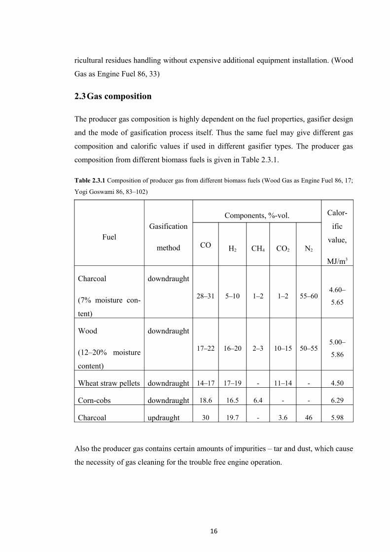
2.3Gas composition
The producer gas composition is highly dependent on the fuel properties, gasifier design
and the mode of gasification process itself. Thus the same fuel may give different gas
composition and calorific values if used in different gasifier types. The producer gas
composition from different biomass fuels is given in Table 2.3.1.
Table 2.3.1 Composition of producer gas from different biomass fuels (Wood Gas as Engine Fuel 86, 17;
Yogi Goswami 86, 83–102)
FuelGasification
method
Components, %-vol. Calor-
ific
value,
MJ/m3
CO H2 CH4 CO2 N2
Charcoal
(7% moisture con-
tent)
downdraught
28–31 5–10 1–2 1–2 55–604.60–
5.65
Wood
(12–20% moisture
content)
downdraught
17–22 16–20 2–3 10–15 50–555.00–
5.86
Wheat straw pellets downdraught 14–17 17–19 - 11–14 - 4.50
Corn-cobs downdraught 18.6 16.5 6.4 - - 6.29
Charcoal updraught 30 19.7 - 3.6 46 5.98
Also the producer gas contains certain amounts of impurities – tar and dust, which cause
the necessity of gas cleaning for the trouble free engine operation.
16

Tar content
Tar is an unconverted volatile matter and one of the most unpleasant components of the
producer gas as it tends to condense and deposit in the various engine passages causing
sticking and operational problems. The process resulting in tar formation takes place in
the pyrolysis zone of the gasifier. (Yogi Goswami 86, 83–102)
So far, very little research work has been done in the area of removing or burning tar in
the gasifier for the relatively tar-free gas to come out – the major effort has been de-
voted to cleaning the tar by filters and coolers. A well-designed gasifier should put out
less than 1 g/m3 of tar. Usually it is assumed that a downdraught gasifier produces less
tar than other gasifier types. (Remulla, 82)
Dust content
All types of the gasifier fuels produce dust. The dust has to be removed from the produ-
cer gas as it can clog the internal combustion engine. The concentration of dust in the
gas depends on the fuel and gasifier type, and intensity of load (with the load increase,
dust concentration in producer gas also increases). “The gasifier design should be such
that it should not produce more than 2–6 g/m3 of dust”. (Kaupp, 82)
On the average the temperature of gas leaving the gasifier is about 300–400 0 C. If the
temperature is higher than these values it means that partial combustion of gas is taking
place - this might happens when the air flow rate through the gasifier is higher than the
design value. (Yogi Goswami 86, 83–102)
2.4 Types of gasifiers
The choice of the one particular gasifier depends on type of fuel used (its final available
form, size, moisture and ash content) and on the application – portable or stationary.
Gasifiers are classified according to the way in which air is introduced in the fuel
column. Thus, there exist three main gasifier types:
- updraught;
- downdraught;
- crossdraught.
17

Updrau ght or counter-current gasifier
The counter current or updraught gasifier is the oldest and the most simple gasifier type.
Figure 2.1 shows the scheme of this gasifier.
Figure 2.1 Updraught or counter-current gasifier (Skov and Papworth 74)
An updraft gasifier has clearly defined partial combustion, reduction, and pyrolysis
zones. The air intake takes place at the bottom and the gas leaves from the top of the
gasifier (so, the air flow is countercurrent to the fuel flow). The combustion reactions
occur near the grate at the bottom. Then the reduction reactions take place a little bit
higher up in the gasifier, followed by heating and pyrolysis of the fuel in the upper part
(as a result of “heat transfer by forced convection and radiation from the lower zones”).
The updraft gasifier allows achieving the highest efficiency level as the hot gas passes
through the fuel bed and leaves the gasifier at low temperature. But in this case the tar,
produced during the gasification process is carried out with the gas stream (ash is re-
moved from the bottom of the gasifier). (Wood Gas as Engine Fuel 86, 22)
18

Advantages of updraught gasifier:
- simplicity;
- high charcoal burn-out;
- internal heat exchange, which leads to low gas exit temperatures and high equip-
ment efficiency;
- possibility of operation with many biomass fuel properties (contaminated, un-
sized, various shapes) and types (sawdust, cereal hulls, etc.) – in this case the ap-
plications can be only thermal.
Drawbacks of updraught gasifier:
- possibility of the equipment "channeling", which in turn can lead to oxygen
break-through and risk of explosions;
- problems connected with disposal of the tarry condensates (result from the gas
cleaning operations). (Wood Gas as Engine Fuel 86, 22)
Downdraught or co-current gasifiers
In the case with the updraft gasifier producer gas has very high tar content which can
cause serious problems during the internal combustion engine operation.
The tar entrainment problem in the gas stream is minimized in co-current or
downdraught gasifiers, in which primary gasification air is introduced at or above the
gasifier oxidation zone and the producer gas leaves from the bottom of the gasifier (so,
the air and fuel flow move in the same direction – co-current). (Wood Gas as Engine
Fuel 86, 23)
Figure 2.2 shows the scheme of the downdraught gasifier.
19

Figure 2.2 Downdraught or co-current gasifier (Skov and Papworth74)
Tarry distillation products from the fuel in this gasifier type have to pass through the
burning bed of charcoal and by means of this they are converted into gases: hydrogen,
carbon dioxide, carbon monoxide and methane. (Wood Gas as Engine Fuel 86, 23)
The tar decomposition degree depends on the gasifier hot zone temperature and on the
residence time of tarry vapours there.
Advantages of downdraught gasifier:
- possibility of producing the relatively tar-free gas suitable for engine applica-
tions (“in practice, however, a tar-free gas is seldom if ever achieved over the
whole operating range of the equipment”);
- downdraught gasifiers are more environmentally safe, because of the lower level
of organic components in the condensate (comparing with the updraught gasifi-
er).
20

Drawbacks of downdraught gasifier:
- the lower overall efficiency (comparing with the updraught gasifier);
- the lower heating value of the gas;
- inability to operate on a number of unprocessed fuels – fluffy, low density ma-
terials result in flow problems and excessive pressure drop, and the solid fuel
must be pelletized before use;
- downdraught gasifiers also has difficulties in handling high ash and moisture
content fuels (slagging). (Wood Gas as Engine Fuel 86, 24)
Cross-draught gasifier
Cross-draught gas producers were adapted for the use of charcoal as a fuel. They have
certain advantages over the updraught and downdraught gasifiers and unlike these
types, the ash bin, fire and reduction zone in cross-draught gasifiers are separated. (Tur-
are, conference paper 2002) Figure 2.3 shows the scheme of the cross-draught gasifier.
Figure 2.3 Cross-draught gasifier (Skov and Papworth 74)
21

Charcoal gasification results in very high temperatures (1500 0 C and even higher) in the
oxidation zone which can lead to material problems and affect the producer gas com-
position – high carbon monoxide content, and low hydrogen and methane content.
(Wood Gas as Engine Fuel 86, 24; Turare, conference paper 2002)
Advantages of cross-draught gasifier:
- it takes less time to start the gasifier up (comparing with the downdraught and
updraught gasifiers);
- very small operational scale can be possible - installations below 10 kW (shaft
power) can, under certain conditions, be economically feasible (the reason is
very simple gas-cleaning equipment – cyclone and hot filter – which can be em-
ployed when using cross-draught gasifier in combination with small engines).
Drawbacks of cross-draught gasifier:
- high exit gas temperature;
- poor CO2 reduction;
- high gas velocity;
- minimal tar-converting capability and, as a consequence, limiting of the fuel
type for operation – the high quality (low volatile matter content) charcoal;
- operates well only with dry air and fuel flows. (Wood Gas as Engine Fuel 86,
24; Turare, conference paper 2002)
Other gasifier types
There exist various other biomass gasifier types (twin-fired, fluidized bed, etc.), which
are partly spin-outs of the coal gasification technology. Some of these types are built to
combine the advantages of cross-draught with downdraught or updraught gasifiers, but
in most cases these systems have unnecessary complications or their equipment is too
large and sophisticated for the near-term application.
Thus, we can conclude, that if we need the internal combustion engine conjunction with
gasifier (for transportation) – the downdraught will be the most suitable gasifier type for
this kind of application.
22

2.5Benefits and drawbacks of using the producer gas for transport
Compared to the conventional internal combustion engine systems biomass gasification
technology for mobile applications is not so convenient. Operation of diesel or gasoline
engine is quite simple – engine starts immediately, has no trouble within the running
process, handling of the traditional fuel (diesel or gasoline) is also very easy.
And in the case with the biomass gasification system the start-up time takes at least half
an hour, fuel is bulky and for the continuous system running frequent refueling is
needed. Moreover, handling residues (ash, soot and tarry condensates) is time consum-
ing and dirty work. (Wood Gas as Engine Fuel 86, 5)
Although, wood gas producing process is not difficult itself, the quality of the obtained
gas varies a lot (physical and chemical properties, such as energy content, gas composi-
tion and impurities) – and gasoline/diesel have quite homogenous properties.
It is a widespread delusion to assume that any biomass fuel type can be used to produce
wood gas in an any gasifier. As it was already mentioned above, different gasifier types
have quite strict requirements for the fuel properties – sizing, moisture, volatile matter
and ash content. Use of unsuitable fuel or improper fuel preparation can cause various
technical problems and operational difficulties during the biomass gasification and
vehicle running processes:
- bridging in the fuel bunker;
- reduced power output because of large pressure losses;
- "weak" gas;
- slag cakes;
- tar in the engine;
- damage to the gasifier caused by overheating.
In order to avoid all these problems it is necessary to choose very carefully fuel type
with certain properties for each particular gasifier type and kind of application. But
these limitations are not more serious than “the need to use gasoline of super grade for
high compression spark ignition engines rather than regular gasoline or diesel fuel”. The
main difference in this latter case between biomass and gasoline/diesel fuel is that bio-
mass fuel quality control is the responsibility of the operator.
23

Operation of wood gas engines can also be dangerous if the operator neglects the safety
rules or maintenance of the system (poisoning accidents, explosions and fires, caused by
unsafe design or careless handling of the equipment). Although, the modern systems are
designed according to the all safety standards, it is still necessary to handle the equip-
ment in a responsible manner. (Wood Gas as Engine Fuel 86, 5)
Use of producer gas in internal combustion engines also affects their performance. Cold
gas efficiency of producer gas in favorable condition can be as high as 70%. The actual
efficiency of engine varies with design, size and running condition (the geographical
situation – flat or hilly terrain, the skills of the driver, etc.).
Theoretically, gasoline and diesel engine operated on producer gas undergo a power
loss of 30 (for gasoline engine) and 20 (for diesel engine) per cents. (Turare, conference
paper 2002) Figure 2.4 illustrates theoretical efficiency and power losses in different
units of the gasifier-engine system.
0%
10%
20%
30%
40%
50%
60%
70%
Gasifier Diesel eng. Gasolineeng.
efficiency
power loss
Figure 2.4 Theoretical efficiency and power loss in different units of gasifier-engine system (Turare, con-
ference paper 2002)
Benefits of using the producer gas for transport:
- economic advantages (if biomass is already available at reasonable low prices);
- biomass gasification technology is environmentally friendly (reduction in CO2
emissions);
- provides energy security;
24

- independence of fossil fuel prices and supply.
Drawbacks of using the producer gas for transport:
- biomass gasification is very sensitive process (fuel type and properties);
- not very simple operation process;
- risk of toxic gaseous emissions (i.e., carbon monoxide), fire and explosion haz-
ards.
Whether these drawbacks will be balanced by the better economy of producer gas
fuelled transport vehicles depends entirely on the local situation, especially on the cost
and availability of petrol and diesel oil.
Additional difficulties as compared with stationary units:
- mobile gasifier system must be compact and lightweight (fuelled manually, com-
pact ash pits and filters design result in frequent cleaning necessity);
- minimum use of material, which enables the lightweight construction leads to
the shorter lifetime for parts exposed to corrosion;
- mobile applications are operated within the wide range of engine and gasifier
loads, this circumstance can lead to tar formation and clogging of cooling and
cleaning equipment and engines.
Nevertheless, these latter difficulties can be minimized if the gasifier-engine system is
used on trains or boats, as in these cases the weight and load constraints are not so strict,
and system gives better results. (Wood Gas as Engine Fuel 86, 44)
Thus, we can conclude that driving the producer gas fueled vehicles requires more at-
tention than gasoline or diesel fueled ones, but is more environmentally safe and gives
the possibility of traditional fuel supply and prices independence.
2.6 Several present examples
Here in this section I would like to give some present examples of vehicles running on
the wood (producer) gas.
25

Picture 1. Yugo 45 runs on wood gas (Zastava Yugo Page)
Mr. Anton Peterka from Belgrade, Serbia along with his team, made his '85 Yugo 45,
using wood and coal as a fuel (see Picture 1). The whole mechanism is made of steel
plate and it weighs 60 kg. The highest speed that can be achieved with this engine type
is about 85 km/h, because of the power losses and increased weight and air resistance
(the aerodynamic properties of the vehicle is worse because of the external firebox). Ca-
pacity of the firebox is 35 kg of wood or coal, which is enough to run approximately
150 km. On the roof you can see filters for gas cleaning and cooling.
Picture 2. Lincoln Continental runs on wood gas (Renewable Energy for Housing and Transporta-
tion 2008)
Mr. Vesa Mikkonen from Finland has converted his Lincoln Mark V 1979 to run on
wood gas (see Picture 2).
Technical characteristics:
26

- engine 6.6 litres;
- top speed 110 km/h;
- fuel demand 50 kg/100 km;
- operation distance 250 km (peat);
- possibility to use both peat and wood as a fuel;
- fuel expense 4€/100 km (peat);
- service: cleaning of the filter every 1000 km;
- carbon dioxide emissions 0 g/km.
Picture 3. Ford F-250 powered by wood gas (Woodgas.net 2009)
27

Mr. Jonathan Spreadborough from the USA has built wood gas generator to power his
1990 Ford F-250 (fuel injected, 5.0 litres) (see Picture 3). This generator was construc-
ted from the scrap parts, including metal barrels of various sizes and lots of pipes. Fil-
tration equipment to remove soot was mounted on the front bumper. The fuel injected
truck was modified so it can burn either gasoline or wood gas (dual fuel), but it needs
gas when the engine is started. Driving solely on wood gas costs a vehicle 30% of its
acceleration. Mr. Spreadborough said that “he doesn’t have to pay tax on his fuel be-
cause there’s no tax on wood”. (Woodgas. net 2009)
Picture 4. Volvo 142 powered by wood gas (Wood car - A car that runs on wood 2008)
Mr. Johan Linell from Sweden along with his friends made '68 Volvo 142, using wood
as a fuel (see Picture 4). The gasifier is double hulled and it was manufactured in 1942
by Bolinder’s AB for Ford Motorcompany AB. The gas cleaning system consists of a
cyclone and a fibreglass filter made from stainless steel. The fuel mixing system allows
switching between producer gas and gasoline with a throttle switch while the car is run-
ning.
Technical characteristics:
- top speed 90 km/h;
- wood consumption 1m3/ 1000 km;
- operation distance on one load 70 km;
28

- producer-gas systems weight 260 kg.
3. THE DOWNDRAUGHT GASIFIER DESIGN
As it was already discussed in the previous part, the downdraught gasifier makes it pos-
sible (using biomass as a fuel) to produce wood gas with relatively low tar content
which can be applied for the internal combustion engine operation.
Moreover, the down-draught gasifier is comparatively easy in construction, operation
and maintenance processes, so it is the most appropriate gas producer type for the mo-
bile applications.
It is for this reason the process of conversion of solid fuel into gas in a downdraught
gasifier and the design basis for such gasifier type will be examined here more detailed.
3.1 Processes occurring in the downdraught gasifier
It is possible to distinguish four separate zones in the gasifier:
- drying zone;
- pyrolysis zone;
- oxidation (combustion) zone;
- redaction zone.
Each zone is characterized by one certain process of the biomass fuel convertion into
the producer gas. Although these processes are, to the some extent, overlapped, each
can be assumed to occupy a separate gasifier zone where fundamentally different chem-
ical and thermal reactions take place. (Yogi Goswami 86, 83–102) These zones and pro-
cesses are described below.
Drying zone
Solid fuel is introduced into the gasifier at the top. There is no need in using of the com-
plicated fuel-feeding equipment as a small amount of air leakage is tolerable at this spot.
Biomass fuel entering the gasifier has variable moisture content – of about 5–30% (de-
pending on the fuel type) and in this gasifier zone drying of the fuel takes place (as a
result of heat transfer from the lower parts of the gasifier).
29

Then the water vapour flows downwards and is added to the water vapour formed in the
oxidation (combustion) zone. Part of this vapour may be reduced to hydrogen while the
rest will end up as a moisture content of the producer gas. (Wood Gas as Engine Fuel
86, 33)
Some organic acids that can result in gasifier corrosion are also released during the dry-
ing process.
Pyrolysis Zone
At the temperature range between 280 and 500 0 C pyrolysis of the biomass fuel occurs.
The details of the pyrolysis reactions are not yet well known, but it can be assumed that
the large molecules (e.g., cellulose, hemi-cellulose and lignin) break down into the me-
dium size molecules and carbon (char) during the fuel heating. Then the products of the
pyrolysis process flow downwards into the hotter zones of the gasifier. Some of them
will be burned in the combustion zone, and the rest (depending on the residence time in
the hot gasifier zone) will break down to even smaller molecules of hydrogen, methane,
carbon monoxide, ethane, ethylene, etc. If the residence time will be too short or the
temperature too low, then medium sized molecules can escape and condense as tars and
oils, in the low temperature parts of the system. (Wood Gas as Engine Fuel 86, 34; Yogi
Goswami 86, 83–102)
Oxidation (Combustion) Zone
The oxidation zone is formed at the air intake level of the gasifier. Reactions that take
place in this zone (reactions with oxygen) are highly exothermic and raise the temperat-
ure up to 1200–1500 0 C.
Oxidation zone has two important functions:
- heat generation;
- convertion and oxidation of condensable products from the pyrolysis zone.
To help gasifier establish its functions well, cold spots in the oxidation zone must be
avoided. It is for this reason, two parameters – air inlet velocities and the reactor geo-
metry – must be carefully chosen.
30

There are two widely used methods to obtain an even temperature distribution:
- reducing the cross-sectional area at a certain height of the reactor ("throat"
concept);
- spreading the air inlet nozzles over the circumference of the reduced cross-sec-
tional area, or using a central air inlet with a suitable spraying device. (Wood
Gas as Engine Fuel 86, 34)
Reduction zone
The products of partial combustion move downwards through the red-hot charcoal bed,
where reduction reactions take place. These reactions are endothermic – the reduction
requires heat and so, the gas temperature decreases (app. 600 – 700 0 C). “In this zone
the sensible heat of the gases and charcoal is converted as much as possible into the
chemical energy of the producer gas”.
The end product of the chemical reactions that take place in the gasifier reduction zone
is a producer (wood) gas which can be used (after dust and tar removal and cooling) as a
fuel for internal combustion engines.
The moveable grate at the bottom of the gasifier is necessary for the ash removal – it
makes possible the stirring of the charcoal bed in the reduction zone and, thus, helps to
prevent blockages, which may result in the gas flow obstruction. (Wood Gas as Engine
Fuel 86, 34; Yogi Goswami 86, 83–102)
3.2 Design guidelines for the downdraught gasifier
The downdraught (co-current) gasifiers can be of two types (see Figure 3.1):
- throat type design (including “single” and “double” throat designs);
- open core design.
Throat type gasifiers are usually used for biomass fuels with low ash content and uni-
form size – “single” throat gasifiers are mainly used for stationary applications while
“double” throat are more suitable for varying loads and for the transport applications.
The small throat diameter gives rise to the higher gas velocities at the oxidation (com-
bustion) and reduction zones. This result in tar formation reduction, but increases dust
31

loading. Large throat diameter causes an increase of tar in the gas stream because of the
hot zone by-passing. (Sivakumar et al.)
Open core gasifiers are more tolerant to the various fuel properties (moisture and ash
content, size). Fuels with high ash content create problems by ash clogging and slogging
at the combustion zone in downdraught gasifiers. The open core and throat type com-
bustion regions used in downdraught gasifiers “work well with lower coking tendency
fuels (e.g. wood), but when high coking fuels (e.g. cotton stalk) are used they cause
bridging in and above the pyrolysis zone”. (Reed and Markson 83; Dasappa et al. 2000)
Figure 3.1 The downdraught gasifier classification (Wood Gas as Engine Fuel 86, 39)
Design of the gasifier implies obtaining the dimensions of the various gasifier
components. This process is, to the certain extent, empirical – it is carried out through
32

computations and using empirical relations and some experimental data. (Sivakumar et
al.)
The principal design parameters are the following:
- specific gasification rate (SGR);
- gas reduction time (GRT);
- area of air nozzles.
The derived parameters are:
- diameter of hearth and throat;
- total length of combustion and reduction zone;
- air velocity;
- diameter of nozzles;
- number of nozzles.
Equivalence ratio (ER)
ER fixes the amount of air supplied for gasification and is defined as the ratio of oxygen
supplied per kilogram of wood to the stoichiometric requirement. A value of 0.3 ER is
the theoretical optimum. (Zainal et al. 2002)
Specific gasification rate (SGR)
SGR is the volumetric flow rate of gas per unit area based on throat diameter (the gas
volume is measured at the standard conditions). The recommended SGR is in the range
between 0.3 and 1.0.
Specific solid flow rate (SSR)
SSR is the fuel mass flow measured at the throat and it is a derived parameter which can
be obtained from SGR. As one kilogram of wood gives approximately 2.5 m3 of the pro-
ducer gas, SSR can be related to SGR as SGR/2.5.
Gas reduction time (GRT)
GRT is defined as the average time spent by the gas phase in the reduction zone.
GRT = (Vε/G) * (273/T) * 360 sec (3.1)
33

V = total volume of reactor
ε = void fraction (volume of voids in the bed/total volume of reactor)
G = gas flow rate
T = average temperature inside the reactor
Recommended value of GRT is 0.5 sec. (Reed and Das, 88)
Air blast velocity (Vb)
This is the linear velocity of air in the nozzle at the standard conditions. The recommen-
ded Vb range is 15–30 m/s. There is an opinion that the high air blast velocity helps in
higher air penetration into the bed and also helps to prevent hot spots formation. (Sivak-
umar et al.)
Design of hearth and nozzle
In this case the controlling parameters are air inlet velocity and number of nozzles.
Both, high and low air inlet velocities are not suitable – the former will produce narrow
jets and the latter will not allow the air to reach the central area. These, in turn, lead to
the central cold (dark) zone formation which means poor non-uniform combustion zone
and inefficient tar-cracking process. (Reed and Das, 88; Bridgwater 95)
Thus, the general range for air inlet velocity is 6 m/s up to 10 m/s, and the number of
nozzles used – from 1 up to 10. The aim of the nozzle design is avoiding of cold (dark)
zones in the oxidation (combustion) zone. (Sivakumar et al.)
Sizing of the hopper
Figure 3.2 Close up view of the combustion and reduction zones (Sivakumar et al.)
34

Main parameters here are the diameter and the height of the hopper. The main consider-
ations that have to be taken into account when designing the hopper diameter are the
following:
- storage requirements;
- the hearth size (D hearth);
- size of the biomass particle.
Figure 3.2 illustrates the close up view of the combustion and reduction gasifier zones.
(Sivakumar et al.)
35

4. GAS CLEANING AND COOLING
For the trouble-free operation internal combustion engine must be supplied with fairly
clean producer gas – sufficiently free from tars, dust and acids. If these contaminants
are not removed properly they can cause engine wear and tear, which in turn may result
in maintenance, repair and reliability problems. “In fact, it is likely that more gasifier
engine systems have failed because of improper cleanup systems than for any other
cause.” (Wood Gas as Engine Fuel 86, 40; Reed and Das 88; Turare, conference paper
2002)
The first step in the clean gas producing is to choose such a gasifier design, which al-
lows minimizing tar formation – for example, downdraught gasifier type and to make
sure, that it is operated properly. The next step is to remove tars, dust and water in the
proper order and at the right temperature – this will simplify the handling of the cap-
tured contaminants. For example, if the producer gas is immediately cooled and
quenched in one operation, then dust, tars and water will be removed altogether and
form sticky, tarry mess, which is difficult to handle.
Thus, the optimal sequence of the contaminants removal is the following:
- dust removal at the temperature above the tar dew point (app. 300 0 C);
- tars removal at the intermediate temperatures (above 100 0 C);
- water removal (30–60 0 C).
This order makes the handling of each separated contaminant easier. (Reed and Das 88)
As it was already mentioned above, well designed downdraught gasifier makes it pos-
sible to produce the relatively tar-free gas suitable for engine applications (“in practice,
however, a tar-free gas is seldom if ever achieved over the whole operating range of the
equipment”). Updraught gasifier, in case of the conjunction with internal combustion
engine, has to be equipped with bulky and expensive tar separating equipment.
Thus, we can conclude, that when the gasifier and the cleaning system are carefully
chosen, well designed and properly operated (with the suitable fuel type used), tar
contamination of the producer gas does not present a major problem. (Wood Gas as
Engine Fuel 86, 40)
36

4.1 Gas cleaning
The main problem in producing wood gas for the engine applications is the removal of
dust. The amount of dust contained in the producer gas at the gasifier outlet depends on
several factors:
1. Equipment design – “in most gasifiers the direction of the gas stream is already
reversed over 1800 inside the apparatus, and this simple measure removes the coarse
dust”. (Wood Gas as Engine Fuel 86, 40)
2. The load of the gasifier – the amount of dust per m3 of the producer gas generally
increases with the gasifier load: high loads result in higher gas velocities and dust
entrainment.
3. The type of fuel used – smaller fuel particles generally cause higher dust
concentrations in the gas than the larger fuel blocks. Moreover, hardwoods usually
generate less dust than softwoods.
Table 4.1 shows the results of the producer gas dust size and size distribution
investigations carried out by the Nordstrom. It is possible to separate approximately 60–
70% of this dust from the gas by means of a well designed cyclone. (Wood Gas as
Engine Fuel 86, 40)
Table 4.1 Size distribution of producer gas dust (Nordstrom 63)
Particle size of dust, m.10-6
Percentage in the gas, %
over 1000 1.7
1000–250 24.7
250–102 23.7
102–75 7.1
75–60 8.3
under 60 30.3
Losses 4.2
So, after passing through cyclone the producer gas still contains fine dust, particles and
37

tar. These contaminants have to be removed by other means.
The best cleaning effect can be obtained by employing cloth filters. But they are
normally very sensitive to the gas temperature. In the case of wood or agricultural waste
gasification, the dew point of the gas will be around 70 0 C. Below this temperature
water will condense in the filters and this condensation will stop the gas flow, because
of the increased pressure drop over the filter section of the gas cleaning system.
That is why, in almost all gasification systems the hot gas first passes through the cloth
filter and only after this it is headed to the cooler. (BECE 82) In this latter case, as the
gas is still above the dew point, no condensation takes place in the filter. (Yogi Gos-
wami 86, 83–102)
The gas cleaning system for the typical wood gasifier used during the Second World
War consisted of the cyclone, the gas cooler with some scrubbing action and the packed
bed filter. Figure 4.1 illustrates such kind of a system.
Figure 4.1 Gas cleaning system for vehicles – traditional wet cleaning system (Nordstrom 63)
38

Systematic tests with this type of gas cleaning system have been conducted by Nord-
strom. According to these tests such kind of a system is not very efficient and may
cause different operational problems. “The engine wear and the contamination of the
lubrication oil in this case exceeded considerably those observed on diesel fuel opera-
tion”. (Nordstrom 63)
After considering several possibilities for gas cleaning system improving such as fabric
filters, electrostatic filters (although they have very good particle separating properties,
they are very expensive, and their use is not feasible for the mobile applications) and
wet scrubbers, fabric filters using a glassfibre cloth as filtering material were selected as
most suitable for vehicle applications. (Wood Gas as Engine Fuel 86, 60; Nordstrom 63)
Figure 4.2 illustrates improved gas cleaning system.
Figure 4.2 Gas cleaning system for vehicles – fabric filter cleaning system with cyclone (Nordstrom 63)
Hot gas cyclone separator, fitted into this system, is simple, inexpensive, and is widely
used as a prefilter for the solid particles elimination before the fine particles removal
and gas cooling. “A cyclone separator is essentially a gravitational separator that has
been enhanced by a centrifugal force component.” The cyclone performance is usually
evaluated in the terms of particle cut diameter or cut size (dp50) – particle size, which is
captured with the 50% efficiency. (Reed and Das 88) Figures 4.3 and 4.4 show schemes
of the cyclone separator.
39

Figure 4.3 Cyclone proportions (Perry and Chilton 73)
Figure 4.4 Scheme of the cyclone separator (de Nevers 2000, 257)
40

Glassfibre cloth, which is used as a filtering material in the fabric filters can be used at a
maximum temperature of about 300 0 C, which means that “it is possible to operate the
filter at a temperature giving a large margin over the dew point of the gas”.
To study engine wear and contamination of the lubricant oil Nordstrom has carried out a
number of comparative tests between the wood gas operation system with a fabric filter
cleaning train and diesel fuel operation system (Nordstrom 63). It was found, that the
cylinder wear is considerably less comparing with the old type of cleaning system and,
in some cases, even less than during the operation on diesel fuel. The similar results
were found for the lubricant oil contamination. Dust concentration after cleaning was
0.3 mg/m³ with the fabric filter system and 200–400 mg/m³ with the old type wet clean-
ing system. According to the Tiedema et al. (83) dust concentration less than 50 mg/m³
is acceptable, and less than 5 mg/m³ is preferred.
After a series of tests for the filter configuration determination, a standard filter box
with eight filter bags giving a total filter surface of 3.0 m has been designed. The box is
insulated with 10 mm thick layer of mineral wool and its complete weight is 65.5 kg.
(Wood Gas as Engine Fuel 86, 61) Figure 4.5 illustrates the standard fabric filter type.
41

Figure 4.5 Sketches of the standard type fabric filter (Wood Gas as Engine Fuel 86, 64)
The maximum recommended gas flow through the one filter box shall be less than 65
m/h, “giving an equivalent velocity through the filter fabric of 0.01 m/s at the operating
temperature of 200 0 C”.
“The pressure loss over the filter depends on the load and the amount of dust in the
filter. If condensation occurs in the filter, and the fabric gets wet, the pressure loss will
increase considerably”.
The filter cleaning interval on practice depends on the power loss, resulting from the
filter pressure drop, which the driver can accept. Normal cleaning intervals vary
between 1500 and 3000 km. (Wood Gas as Engine Fuel 86, 61)
42

4.2 Gas cooling
The producer gas has to be cooled to increase its energy density. The latter will allow
maximizing the amount of the combustible gas entering the engine cylinder at each
stroke: the reduction of the gas temperature on 10% increases the maximum output of
the engine by almost 2%. The cooling also contributes to gas cleaning process, making
it possible to avoid the moisture condensation of producer gas after it is mixed with air
before the engine intake. (Wood Gas as Engine Fuel 86, 40)
According to the Swedish Academy of Engineering Sciences (79), major factors that
have to be taken into the consideration in the gas cooling process are the following:
- the sensible heat of the gas;
- the water vapour content of the gas and its heat of condensation;
- the effects of cooler fouling.
Various types of the equipment are used to achieve the gas cooling purpose. Producer
gas coolers can be divided into three following categories:
- natural convection coolers;
- forced convection coolers;
- water coolers.
Natural convection coolers are represented as a simple combination of pipes. They are
easy to use and clean and require no additional energy input. Although the construction
can be rather cumbersome, this problem can be partly neutralized by using fined pipes
to increase the conductive surface.
“Forced convection coolers are equipped with a fan which forces the cooling air to flow
around the gas pipes”. This cooler type is usually smaller than the natural convection
coolers, but they require the extra energy input for the fan. Another disadvantage of the
forced convection coolers is the necessity to use gas cooling pipes of small diameters,
which can result in fouling problems.
Water coolers can be of two types: the scrubber and the heat exchanger. When the
scrubber is used, the objective is usually to clean and to cool the gas simultaneously
during the one operation process.
43

There are many different scrubber types, but the principle is always the same: the gas is
brought in direct contact with a liquid medium (e.g., water) which is sprayed into the
gas stream through the nozzles. The main advantage of this system is its small size. But
there are too many disadvantages: the fresh water need, increased complexity of
maintenance, increased power consumption, as a result of the water pump usage and the
waste water treatment necessity. (Wood Gas as Engine Fuel 86, 42)
44

5. FUELLING OF ENGINES BY PRODUCER GAS
5.1 Engine modifications for the producer gas operation
The producer gas has relatively low energy content and the certain combustion charac-
teristics that differ greatly from these of the gasoline and diesel fuel. (Yogi Goswami
86, 83–102)
Moreover, there is a significant difference between diesel and spark ignition (gasoline)
engine systems in their suitability for running on producer gas. In the diesel engine,
diesel fuel is injected at the end of the compression stroke and gets ignited without any
spark ignition. But this will not work with the producer gas – it cannot be ignited under
the prevailing pressure. Thus, a certain amount of diesel fuel has to be injected into the
engine combustion chamber. (Turare, conference paper 2002; Yogi Goswami 86, 83–
102)
In the gasoline engine, air-fuel mixture is sucked during the suction stroke and mixture
is ignited with a spark at the end of the compression stroke. Thus, gasoline engine can
operate on producer gas alone without any gasoline injection, which is certainly very
convenient and economically beneficial. But this will work only in the case with the
constant engine loads. This approach is not practically workable for any automobile ap-
plication, as in this latter case the engine has to work under different loading conditions.
Thus, for the transport application we have only one possibility left – diesel engine. As
it was already mentioned above, diesel engines are compression ignition engines (com-
pression ratio of about 16–24, depending on whether they are direct combustion cham-
ber, pre-combustion chamber, four strokes or two strokes), where fuel is ignited by high
air temperature. And so, diesel engine cannot be operated on producer gas alone. (Tur-
are, conference paper 2002)
For the using producer gas as a fuel, diesel engines can be either converted completely
into the spark ignition systems (full producer gas operation mode) or the normal uncon-
verted diesel engine can be operated in the “dual-fuel” mode, where the diesel fuel is
necessary for the combustible gas-air mixture ignition. (Turare, conference paper 2002,
Wood Gas as Engine Fuel 86, Yogi Goswami 86, 83–102)
However, not all the types of diesel engines can be converted to the “dual-fuel”
45

operation mode. Compression ratios of ante-chamber and turbulence chamber diesel
engines are too high for satisfactory “dual-fuel” operation and use of the producer gas in
those engines leads to knocking, as a result of too high pressures combined with delayed
ignition. (Kaupp and Goss 81) Direct injection diesel engines have lower compression
ratios and can generally be successfully converted. (Wood Gas as Engine Fuel 86, 9)
Diesel engine conversion to spark ignition system
Nordstrom in 1957–1963 has conducted detailed studies of conversion of two diesel
engines, produced by Swedish manufacturers – Volvo and Bolinder-Munktell, to spark
ignition system for operation on straight producer gas. (Nordstrom 63)
The conversion included the following modifications:
- replacement of the cylinder head for the spark plugs fitting;
- replacement of the injection pump by a distributor;
- use of special producer gas pistons giving a lower compression ratio.
Moreover, different shapes of the combustion chamber were tested on one of the
engines. (Wood Gas as Engine Fuel 86, 62)
Although, the power loss in diesel engine converted to spark ignition system is not as
severe as in gasoline engine running on producer gas, conversion of the diesel engine to
the spark ignition system is complicated, expensive and time consuming affair, the ad-
vantages of which are nullified by the cost. (Yogi Goswami 86, 83–102; Turare, confer-
ence paper 2002)
Thus, most of the diesel engines running on producer gas are of the “dual-fuel” type. As
a rule, the diesel engine can run on 15–20% (of the original consumption) of the diesel
fuel and rest on the producer gas. Generally, “the engine is started on diesel fuel and as
the gas generation builds up the diesel consumption is then kept at the idling level”.
(Yogi Goswami 86, 83–102) In this case the engine efficiency is about 25%. So, one
can conclude, that running in the “dual-fuel” engine mode for producing 1 kWh requires
1 kg of biomass and consumes 0.07 liters of diesel fuel. (Johansson 80)
46

Dual fuelling of ante-chamber and turbulence chamber diesel engines
Nordstrom has carried out a number of tests with “dual-fuel” operation of ante-chamber
and turbulence chamber diesel engines. (Nordstrom 63) During the tests it was found
that these engines are not suitable for the “dual-fuel” operation mode, as too early igni-
tion of the gas-air mixture, result in engine knocking, will occur if the load is fairly high
or the gas-air mixture is dirty. This will lead to the poor diesel oil substitution.
Dual fuelling of direct injection engines
According to the studies of the performance of direct injection diesel engines operated
in a “dual-fuel” mode with a minimum diesel fuel injection, which have been carried
out at the National Swedish Testing Institute for Agricultural Machinery, the required
modifications are generally simple and limited to:
“- installation of a control lever for obtaining low injection quantities and maintaining
the possibility for normal injection by straight diesel operation;
- modification of the injection pump to provide suitable injection characteristics
(constant injection per stroke at varying engine speed);
- advancing the injection timing”.
The injection timing is not very important for engine speeds below 1200 rpm, but its
advancing becomes more important as the engine speed increases. The injection timing
setting for the “dual-fuel” operation mode should be determined through the bench tests
for each engine type.
In the case with the direct injection engines operated in the “dual-fuel” mode, the full
power efficiency is about 35%, the diesel fuel substitution is between 80 and 90%, and
the power loss is about 10–38%.
The main advantage of this latter system (direct injection diesel engine operated in a
“dual-fuel” mode) lies in its flexibility: in case of malfunctioning of the gasifier or lack
of biomass fuel, an immediate change to full diesel fuel operation is generally possible.
(Wood Gas as Engine Fuel 86, 8)
Apart from the above mentioned required engine modifications, there is one more
necessary condition for the successful engine operation on the producer gas – it is
airtightness of the gasifier unit-engine connection. The producer gas is unable to burn
47

without being mixed with certain amount of oxygen. If an air leakage occurs below the
grate area, the hot gas will burn, consuming the available oxygen and creating heat. This
latter process will almost certainly destroy the gasifier unit (if it is not detected). If an
air leakage occurs in the filter unit or in the connecting pipes, the producer gas will
become saturated with improper amounts of oxygen and, thus, will become unsuitable
for the engine running. Therefore airtightness of the gasifier unit-engine connection is
very essential. (La Fontaine and Zimmerman 89)
5.2 Engine power output and its maximizing in the producer gas oper-
ation
The power output of the engine operating on the producer gas is determined by the same
factors as of the engine operating on traditional liquid fuel:
“- the heating value of the combustible mixture of fuel and air which enters the engine
during each combustion stroke;
- the amount of combustible mixture which enters the engine during each combustion
stroke;
- the efficiency with which the engine converts the thermal energy of the combustible
mixture into mechanical energy (shaft power);
- the number of combustion strokes in a given time (number of revolutions per minute –
rpm).” (Wood Gas as Engine Fuel 86, 9)
The engine conversion to the “dual-fuel” operation mode will, in most cases, lead to the
reduced power output. The reasons for the power losses and the possibilities to
minimize them are the following:
Heating value of the combustible mixture
The producer gas heating value depends on its content, to be more precise, on the
relative amounts of the main combustible components – carbon monoxide, hydrogen
and methane.
As it was already mentioned above, for the combustion, the producer gas has to be
48

mixed with a suitable amount of air. And the combustible mixture will have a lower
heating value per unit of volume than the producer gas alone.
It is, thus, evident that the highest heating value for the combustible mixture is achieved
at the highest heating value of the producer gas itself. And the latter one depends on the
design of the gasifier and on the gasifying fuel characteristics. In the case with the
gasifier design, it is very important to minimize heat losses, and for the fuel, it is very
important to consider carefully such characteristics as the moisture content and the size
distribution.
During the practical tests with wood chips gasifiers, developed at the National Swedish
Testing Institute for Agricultural Machinery, it was found that the upper limit for the
fuel moisture content for acceptable gas quality is 30% (wet basis). If the moisture
content of the fuel exceeds 40%, the gas will not be combustible.
Concerning the size distribution characteristic, it is recommended that, e.g., the wood
chips be screened to remove fines and coarse pieces. (Wood Gas as Engine Fuel 86, 66)
Table 5.1 presents the typical size distribution of the suitable for vehicle gasifiers wood
chips.
Table 5.1 Typical size distribution for wood chips suitable for the vehicle gasifiers (Wood Gas as Engine Fuel 86, 68)
Size range % -weight
below 5 x 5 mm 2–3
5 x 5–10 x 10 6–11
10 x 10–15 x 15 12–19
15 x 15–20 x 20 20–24
20 x 20–25 x 25 25–30
25 x 25–30 x 30 9–20
30 x 30–35 x 35 about 5
35 x 35 and above about 3
To study the effect of the size distribution on the engine maximum power output the
number of tests was carried out with the mounted on the tractor gasifier type F5. Table
5.2 shows the results of these tests.
49

Table 5.2 Improvement of the maximum power output by wood chips screening (Wood Gas as Engine Fuel 86, 68)
Size rangeUnsieved
chips5–10 mm 10–15 mm
15–40 mm
Sieving loss, % - 3 14 34
Pressure drop across gasifier, bar
0.18 0.13 0.09 0.08
Power output at 1800 rpm, kW 16.8 18.1 21.1 21.0
Power increase by sieving, % 0 7.7 25.5 25.5
The power increase can be explained both, by reduced pressure losses in the gasifier and
the producer gas quality improvement after fines removing (since less than 50% of the
power increase can be explained by reduced pressure losses).
Also, according to these tests, “removal of the fines gives a substantial power increase
at a fairly small expense, i.e. about 3% increase of the feedstock cost. Screening for
removal of material in the range of 10–15 mm may also be considered worthwhile,
whereas further screening does not appear to give any power increase”.
Moreover, the engine power output can be improved by at least 10%, if instead of the
wood chips, wood blocks are used. And this will also be the result of the gasifier
pressure losses reduction.
As it was already mentioned above, another reason for the power loss is in the mixing
the producer gas with the combustion air, which result in the gas composition changes
and in variations in pressure drop across the gasifier.
Both, excess and deficiency of air will lead to the power output decrease, as both of
them result in the decrease of the heating value of the combustible mixture (per unit of
volume). In practice, however, it is normally better to operate the engine with a slight
air excess – to prevent backfiring in the engine exhaust gas system. (Wood Gas as
Engine Fuel 86, 13)
Engine speed and ignition advance
As the engine power output is defined per unit of time, the engine power output
50

depends on the engine speed. For diesel engines the power output is nearly linear with
the rpm. (Wood Gas as Engine Fuel 86, 14)
If a diesel engine is operated in the “dual-fuel” mode, it is also necessary to advance the
timing of the diesel fuel injection. And this advance depends on the engine speed, as it
was shown by Nordstrom. (Nordstrom 63)
Moreover, in the process of “dual-fuelled” engine operation, one can sometimes
encounter with the problem of detonation. “Apart from the engines with too high
compression ratios (above 1:16), this phenomenon mostly occurs when an attempt is
made to remedy low power output of the engine by introducing increased amounts of
diesel fuel”. Depending on the producer gas composition, an excess of pilot fuel can
lead to the detonation. That is why, the amount of pilot diesel fuel in “dual-fuel”
operation mode must be limited – in most cases “a limitation at around 30% of the
maximum engine power output will prevent detonation”. (Wood Gas as Engine Fuel 86,
15)
The certain minimum amount of diesel fuel, injected per cycle to ensure the ignition,
also depends on the engine speed. According to the Middleton and Bruce (46) this
minimum amount varies from 3 up to 5 mm3 per cycle.
In practical operation, however, a somewhat higher amount of diesel fuel has to be
injected per cycle “to stay on the safe side”. Diesel fuel injection of 8–9 mm³ per cycle
and cylinder is recommended. (Wood Gas as Engine Fuel 86, 15)
51

6. HEALTH AND ENVIRONMENTAL HAZARDS ASSOSIATED
WITH THE USE OF PRODUCER GAS
During the gasifier operation process one can encounter with various dangers, namely
toxic, fire and explosion hazards. Moreover, this process and men’s activities connected
with it can affect the environment. Thus, we also should consider the environmental
hazards of the gasifier operation. A review of the different types of hazards and
environmental impacts of producer gas operation was published by Kjellstrom (84).
6.1 Toxic hazards
An important component of the producer gas is carbon monoxide (CO) – an extremely
toxic and dangerous gas as it tends to combine with the hemoglobin of the blood and,
thus, prevents oxygen absorption and distribution. The carbon monoxide is also
extremely dangerous, because it is odorless and tasteless. Table 6.1 shows the effects
caused by different concentrations of carbon monoxide in the air.
52

Table 6.1 Toxic effects caused by different concentrations of carbon monoxide in the air (Wood Gas as Engine Fuel 86, 45)
CO concentration in the air, %
ppm effects
0.005 50 no significant effects
0.02 200 possible mild frontal headache after two to three hours
0.04 400 frontal headache and nausea after one to two hours; occipital head-ache after 2.5 to 3.5 hours
0.08 800 headache, dizziness, and nausea in 45 min; collapse and possibly un-consciousness in two hours
0.16 1600 headache, dizziness, and nausea in 20 min; collapse and possibly death in two hours
0.32 3200 headache and dizziness in 5 to 10 min; unconsciousness and danger of death in 30 min
0.64 6400 headache and dizziness in 1 to 2 min; unconsciousness and danger of death in 10 to 15 min
1.28 12800 immediate effect; unconsciousness and danger of death in 1 to 3 min
Generally, producer gas system works under suction, so that even if a minor leakage
occurs, no dangerous gases will escape from the equipment during actual operation, thus
the risk of poisoning through leakage is minimal. The situation is, however, different
during starting-up and shutting-down of the gasification installation. (Wood Gas as
Engine Fuel 86, 45; La Fontaine and Zimmerman 89)
When the engine is shut down, formation of the producer gas still continues, resulting in
pressure increasing inside the gasifier. This pressure increase lasts for approximately 20
minutes after the engine shutdown. Thus, it is not advisable to stay in the vehicle during
this period. Moreover, the gasification system should be allowed to cool for at least 20
minutes before the vehicle is placed in the closed garage, especially, connected with the
living premises. The gas formed during the shutdown period has a carbon monoxide
53

content of 23 up to 27% and is, thus, very toxic. (La Fontaine and Zimmerman 89)
It is still arguing, whether chronic poisoning can occur as a result of prolonged
inhalation of relatively small amounts of carbon monoxide. But, to the present moment
the majority of researchers tends to opinion that no chronic symptoms can occur
through carbon monoxide poisoning. (Wood Gas as Engine Fuel 86, 45)
However this does not mean that the symptoms mentioned in the literature (tiredness,
irritability and touchiness, difficulty in sleeping) did not result from prolonged exposure
to the producer gas. There exist a possibility that some other gas compounds can be
responsible for these symptoms. (Reed and Das 88; Wood Gas as Engine Fuel 86, 46)
The latter facts again emphasizes the importance of carrying out starting-up and
shutting-down processes of the gasifier unit in an open environment, as well as of taking
care to avoid close contact with the gases during these phases. (Wood Gas as Engine
Fuel 86, 46)
6.2 Fire hazardsFire hazards can result from the following causes:
- high surface temperature of equipment;
- risks of sparks during refueling;
- flames through gasifier air inlet on refueling lid (may ignite nearby flammable
materials).
However, fire risks can be considerably decreased by taking certain precautions. First of
all, hot parts of the system must be carefully insulated. Secondly, installation of the
double-sluice type filling device and back-firing valve at the gasifier inlet should be
considered. (Wood Gas as Engine Fuel 86, 46)
Moreover, size of the clearance between the gasifier unit and the vehicle should be
carefully chosen. Also the ash disposal should be carried out only after the unit cool
down (this residue must be placed away from any combustible material). (La Fontaine
and Zimmerman 89)
54

6.3 Explosion hazards
Risk of explosion can arise from the producer gas-air explosive mixture formation. This
mixture can be formed under the following circumstances:
- air leakage into the gas system;
- air penetration during refueling process;
- air leakage into the cold gasifier still containing residual producer gas, which can
ignite;
- back-firing from the fan exhaust burner when the system is filled with a combustible
mixture of air and gas during the starting-up process. (Wood Gas as Engine Fuel 86, 46;
Reed and Das 88)
Air leakage into the gas system does not generally give rise to explosions. If a leakage
occurs in the lower part of the gasifier, this will result in partial combustion of the gas,
which in turn will lead to higher gas outlet temperatures and a lower gas quality. (Wood
Gas as Engine Fuel 86, 46)
Air leakage into the cold gasifier and residual producer gas-air mixture ignition will
lead to an explosion. That is why, the cold system should always be carefully ventilated
before igniting to ensure that it contains only fresh air. (Wood Gas as Engine Fuel 86,
46; Reed and Das 88)
6.4 Environmental hazards
During the gasification process of wood or agricultural residues, besides the producer
gas itself, certain amounts of ash (from the gasifier unit and the gas cleaning system)
and condensate, polluted by phenol and tar, are produced.
The ash disposal creates no problem, but with the tarry condensate the situation is quite
different – disposal of this condensate from a large number of the gasifiers can have
undesirable environmental effects. Thus, this problem (the tarry condensate disposal)
needs careful investigation.
“The properties of exhaust emissions from engines running on the producer gas are 55

generally considered to be acceptable, comparable to those of diesel engines”. (Wood
Gas as Engine Fuel 86, 47)
There is one more question to consider, when talking about the wide use of the biomass
gasification for transport – the increased demand for wood and agricultural residues
fuels. The effect of this increased demand on the environment can be either positive or
negative – depending on the approach to the problem. “Selective wood cutting and use
of some residues can improve the forests and fields. Indiscriminate cutting and use of
residues can lead to poor wood lot stands, erosion and soil depletion”. (Reed and Das
88)
“It is essential that a careful survey of available sources of biomass fuel, and analysis of
alternative uses and existing competing markets of these fuels, be carried out” before
the wide introduction of the biomass gasification for transport. (Kjellstrom et al. 83)
56
7. REQUIREMENTS FOR WOOD GAS POWERED CARS
So, one has decided to converse the car to enable wood gas fuelling. In this case, apart
from the technical questions, there are certain considerations from the part of the
Finnish laws and taxes that have to be taken into account before the vehicle conversion
and in the process of its operation.
At the present moment, only vehicles, produced before the 1.7.1987, can be conversed
for the wood gas utilization, as for the newer vehicles there exist certain Euro-norms for
transport fuels – Euro Emission Standards – where for wood gas there are no defined
limits. The first standard – Euro 0 – defined the acceptable limits for vehicles exhaust
emissions for the 1988–1992 years.
Emission measurements and their results, submitted to the vehicle inspection
authorities, cannot help in this case, even if the emissions are lower than allowed for
this car type/model.
In Finland one cannot easily find fairly good old vehicles, so the car, in most cases, has
to be purchased abroad.
After the car is purchased and conversed, all the changes must be approved in the
corresponding authority (Vehicle Administration AKE) after the alteration inspection
procedure. Only after this one can use modified vehicle on the road:
- “a power-driven vehicle and a vehicle coupled to the power-driven vehicle or to
its trailer shall be approved in a modification inspection prior to entry into ser-
vice, if essential modifications are made to the construction or use of the vehicle
or if components or equipment are added to or removed from the vehicle, thus
changing its characteristics or use considerably. A vehicle shall also be submit-
ted to a modification inspection if the prerequisites for a tax or a fee for the
vehicle change or if the data on the classification or subclassification of the
vehicle is no longer valid”. (Vehicles Act, 402/2005)
The special attention, when the conjunction of the gasification unit and the vehicle takes
place should be paid to the dimensioning of the whole construction – the maximum
weight and the main vehicle dimensions should not exceed permissible norms.
57

If the gasification unit is mounted on the towed device (e.g., trailer), one should
remember that the maximum allowable speed in this case is 80 km/h. (Ministry of
Transport and Communications Finland. Driving in Finland. 2004)
7.1 Taxes
According to the Ministry of Finance Finland, motor vehicles and fuel used for road
traffic are subject to the following taxes:
- “car tax on passenger cars, delivery vans and motorcycles – Car Tax Act of 29
December 1994;
- vehicle tax on diesel driven vehicles – tax on the propelling force; Act on
Vehicle Tax of 30 December 2003;
- vehicle tax on passenger cars and vans – basic tax; Act on Vehicle Tax of 30
December 2003;
- fuel fee – Act on Fuel Fee of 30 December 2003”. (Ministry of Finance.
Taxation in Finland 2005)
Car tax
“The car tax is a purchase tax, which must be paid before the first registration or use of
the vehicle in Finland”. (Ministry of Finance. Taxation in Finland 2005) So, this tax can
be applicable only in case, when one purchases the vehicle for the modification abroad
– and it is obvious, that future car conversion doesn’t influence on this tax value.
Vehicle tax
Vehicle tax is divided into two following parts:
- basic tax (“owners of passenger cars, vans and special-purpose cars that have a
maximum unladen weight 3,500 kg are liable to pay vehicle tax if the vehicle
has been or should have been registered in Finland. The tax is 26 cents per day
on vehicles in use before 1 January 1994, otherwise 35 cents per day. The tax is
assessed for 12-month tax periods” (Ministry of Finance. Taxation in Finland
2005)).
- tax on the propelling force (“the tax on the propelling force is levied annually on
all vehicles using, entirely or partly, fuel other than petrol, i.e. diesel oil, ker-
58

osene, liquefied petroleum gas or electricity. The tax is assessed for 12-month
tax periods” (Ministry of Finance. Taxation in Finland 2005)).
The rates per day are the following – “for passenger cars and dual-purpose cars, 6.7
cents/100 kg of the total weight or a fraction thereof and for motor caravans and deliv-
ery vans 0.9 cents /100 kg.” (Ministry of Finance. Taxation in Finland 2005)
Thus, the vehicle tax on the propelling force can be applicable to our case of the wood
gas powered vehicle. But there are certain exceptions from the vehicle tax – vehicles us-
ing wood-based or peat-based fuels. However, if the vehicle is operated in the “dual-
fuel” mode (starting on diesel and then switching to the wood gas) it cannot wholly be
excised from the vehicle tax (on the propelling force).
Fuel fee
“Fuel fee is payable if certain more lightly taxed fuels are substituted for highly taxed
fuels. The purpose is to prevent the use of such fuels in vehicles (e.g. heating oil in dies-
el-driven vehicles). The amount of the fee is 100–1.000 euros a day according to the
vehicle group. Passenger cars, vans, buses and lorries using liquid gas, natural gas or
biogas are exempt if they fulfill certain criteria of exhaust emissions (EURO 4)”. (Min-
istry of Finance. Taxation in Finland 2005)
At the present moment, vehicles using wood-based or peat-based fuels are also exemp-
ted from the fuel fee. (Parkkinen 2008)
Moreover, according to the Ministry of the Environment, there exist also “the
environmental tax component (i.e. carbon surtax), based on the carbon content of fuels
used for heating and transportation. Its value since January 2008 is €20 per tonne of
CO2 (€75 per tonne of carbon)”. (Ministry of the Environment. Environmentally Related
Energy Taxation in Finland. 2008) Table 7.1 shows the excise duty and strategic
stockpile fee rates in Finland (January 2008).
59

Table 7.1 Excise duty and strategic stockpile fee rates in Finland (January 2008) (Ministry of the Envir-
onment. Environmentally Related Energy Taxation in Finland. 2008)
Fuel Basic taxSurtax (*=car-
bon comp., €20/tonne CO2)
Strategic stock-pile fee
Diesel oil, euro cents/litre
- sulphur free 30.67 *5.38 0.35
- other grades 33.32 *5.38 0.35
Light fuel oil, euro cents/litre
2.94 *5.41 0.35
Peat - - -
The table above is not all-inclusive; substitutes for liquid fuels may face the same rate. Fuels for com-mercial aviation and commercial yachting exempted; also other exemptions exist. Strategic stockpile fee = precautionary stock fee.
7.2 Emissions
Against general belief, exhaust gas emission level of internal combustion engine is
significantly lower on wood gas than on petrol. Especially low are HC emissions. A
normal catalytic converter works well with wood gas but even without it, emission level
less than 20 ppm HC and 0.2% CO can easily be achieved by most automobile engines.
Combustion of wood gas generates no particulates and the gas thus renders very little
carbon black amongst motor oil. (Renewable Energy for Housing and Transportation
2008)
Table 7.2 shows the emission measurements of the modified cars using only wood gas
as a fuel (not “dual-fuel” mode). For the case of Chevrolet ElKamina both the emissions
when running on wood gas and gasoline are presented. This allows making some kind
of a comparison of the emissions level.
60

Table 7.2 Emission measurements (Suomen Ekoautoilijat Ry 2009)
Component Chevrolet ElKam-ina,
wood gas/gasoline
Saab 99,
wood gas
Chevrolet Fleet-side,
wood gas
Lambda 1.163/1.096 1.407 1.266
CO 0.18%/2.45% 0.32% 0.23%
CO2 16.38%/10.94% 12.66% 15.70%
HC 48 ppm/519 ppm 29 ppm 10 ppm
O2 4.01%/4.05% 7.92% 6.20%
CO2 calculated 0.18%/2.74% 0.36% 0.20%
As it can be perfectly seen from the table above, the emissions of CO and HC when
running on wood gas are much lower than that when running on gasoline. Thus, these
data confirm the given above statement.
Moreover, in the work of Sridhar et al. (2005) the overall performance and emission of
reciprocating internal combustion engines in “dual-fuel” mode and gas alone mode of
operation using biomass derived producer gas were considered.
The emissions in gas alone and “dual-fuel” mode were compared with existing emission
standards of various countries (EU, USA, India). The data given in this work indicates
that emission levels with gas alone operation are lower than emission norms of EU and
USA. However, in the case of “dual-fuel” operation mode, the CO levels are higher than
these norms (as a result of the combustion inefficiency) thus requiring improved gasifier
construction or exhaust gas treatment. (Sridhar et. al 2005)
61

8. EVALUATION OF POSSIBILITY OF USING WOOD GAS FOR
TRANSPORT – SECURITY OF SUPPLY
From the previous chapters one can perfectly see that using wood gas as a fuel for trans-
port has a number of economical and environmental advantages.
Although, biomass gasification technology has also some disadvantages, its application
for transportation needs, especially in the agricultural sector (driving of farm machinery
like tractors, harvesters etc.), seems feasible and promising in the nearest future. (Yogi
Goswami 86, 83–102)
But, if we are discussing the possibility of using this technology, we must consider one
very important moment – if there is enough biomass for producing wood gas for trans-
port and what percentage of, e.g. Finnish road vehicle fleet can be converted for running
on wood gas.
At the present moment, traffic energy consumption in Finland is about 230 PJ and ap-
proximately 74% of this is the road traffic consumption, which is 170 PJ. Figure 8.1 il-
lustrates these data.
Figure 8.1 Primary energy consumption of traffic in Finland (LIPASTO. Traffic Emissions. 2007)
62

Thus, we have to assess the present utilization of biomass resources in various sectors
(industrial and non-industrial).
Nowadays, wood and peat covers over 90% of the biofuels use in Finland. Table 8.1
summarizes the energy use of wood and peat in different sectors in Finland in the year
2006. (Heinimö 2008, 16)
Table 8.1 End use of wood and peat by end user groups in 2006, PJ (Heinimö 2008, 16)
Fuel/End use sectorForest
industry
District
heating
Small-scale
use(c
Other in-dustry &
usersTotal
Forest fuels(a 7.8 9.0 2.8 5.0 24.6
Firewood 0 0 45.3 0 45.3
Solid wood processing in-dustryby-products andresidues(b
43.6 17.2 1.0(d 21.7 83.5
Total wood(e 51.4 26.2 49.1 26.7 153.4
Fuel peat 18.6 39.4 1.1 34.5 93.6
(a Excludes firewood.(b Includes bark, sawdust, industrial chips, pellets, briquettes, recovered wood and all other wood fuels excluded from the other columns. The share of pellets and briquettes was estimated at 1.5 PJ.(c Includes the use of forest chips by farms and detached house properties.(d In addition includes wood pellets.(e Excludes black liquor.
So, the total amount of biomass (wood and peat), which is currently in use is about 250
PJ.
Now, we have to estimate the production potential and future use of the biofuels in Fin-
land:
- solid forestry industry by-products consist of pulp chips, bark, sawdust and in-
dustrial chips and they are utilized both as raw material and in energy produc-
tion. Their total volume available for energy purposes would not change sub-
stantially from the current level by the year 2010 (Ranta et al. 2005);
- forest chips (forest fuels) from logging residues, stump and root wood and small-
diameter energy wood constitute a large and underutilized biofuel potential, and
63

they will consist the largest share of the future growth of biofuels production;
(Heinimö 2008, 18)
- peat has a significant role in the Finnish energy system. The Geological Survey
of Finland has estimated the employable energy reserve of peat at 48 EJ (Virtan-
en 2003).
Table 8.2 compares the current use, production potentials and estimated use of major
biofuels.
Table 8.2 The current use, production potential and prospective use of the biofuels in Finland (Heinimö
2008, 19)
Fuel
Use in 2006, PJ
Production po-tential,
PJ/a
Estimated use in 2010-2015,
PJ/a
Solid wood processing in-dustryby-products andresidues
81.5 - 65–85(a
Forest fuels (forest chips) 24.6 80–140(b 40–73
Firewood 45.3 - 55–63
Wood pellets 1.5 9–25(c 1–25
Peat 93.6 - 61–97
Total 246.5 - 222–343
(a The lower value results from the increased use of sawdust in pellet production. (b The theoretical maximum production potential was evaluated at 45 million solid-m3 (324 PJ). (c This equals 0.55-1.5 Mt/a pellet production. The lower limit is a production target of the Finnish pellet energy association for the year 2010.
Analyzing these two tables, we can make a conclusion that, e.g. solid wood processing
industry by-products and residues can’t be utilized for wood gas production for trans-
portation needs, because in this case forest industry is the major user of wood fuels. Al-
most two thirds of wood fuels use takes place in the forest industry. Wood is the most
important fuel at forest industry mills, accounting for about 75% of their fuel consump-
tion. (Peltola (ed.) 2007)
Moreover, as it was already mentioned above, the total volume of the forest industry by-
products available for energy purposes would not change substantially in the nearest fu-
ture (production potential is not much higher than current and estimated use).
64

Thus, we can conclude that only forest fuels (forest chips) and peat can be utilized as
raw materials for the wood gas production, as their production potential is considerably
higher than their use (both, current and estimated).
But, we also have to take into account the strategy aims to secure and promote biomass
utilization in the Finnish energy sector, so use of wood and peat fuels can increase in the
nearest future. This would again decrease the available amount of resources for wood
gas production.
So, we can roughly estimate that if the road traffic energy consumption is at the present
moment about 170 PJ and will increase in future and the production potential of forest
fuels is 140 PJ/a (maximum estimated level) minus 73 PJ/a (maximum estimated de-
mand), about 40% of Finnish vehicle road fleet can be converted for running on wood
gas as a fuel. But this can be realized only if the whole 67 PJ (140 PJ/a–73 PJ/a=67 PJ)
of available biomass resources would be directed to the wood gas production. The latter
is very unlikely, so the number of road vehicles that can be converted for the wood gas
utilization is up to 20%.
65

9. SUMMARY AND CONCLUSIONS
In the first part of this thesis a kind of survey of the previous works and materials con-
cerning the usage of biomass gasification for transport was made.
First of all, the principles of biomass gasification process along with possible fuel and
gasifier types, and gas composition were considered. Also the benefits and drawbacks
of using the resulting producer (wood) gas for transport were outlined.
From this part, it was concluded that the most appropriate biomass fuels for gasification
are wood and peat, and the most suitable gasifier type is downdraught (if we are speak-
ing about transportation needs), as it makes possible to produce wood gas with relat-
ively low tar content which can be applied for the internal combustion engine operation.
It is for this reason the process of conversion of solid fuel into gas in a downdraught
gasifier and the design basis for such gasifier type was examined in this work in a more
detailed way.
In this study, also the gas cleaning and cooling equipment was discussed, as for the
trouble-free operation internal combustion engine must be supplied with fairly clean
producer gas – sufficiently free from tars, dust and acids.
Then, such an essential process as fuelling of engines by producer gas was considered
with respect to such moments as necessary engine modifications and engine power out-
put and ways of its maximizing.
Moreover, different hazards (health and environmental) associated with use of the pro-
ducer (wood) gas were also mentioned here.
And, finally, the last chapters concentrated more on the practical aspects of the wood
gas application for vehicles fuelling, specifically on the taxation of such vehicles in Fin-
land, their emissions and the security of biomass and, as a consequence, wood gas sup-
ply.
It was roughly estimated that with the present level of the road traffic energy consump-
tion and the production potential of forest fuels and current level of their use, up to 20%
of Finnish vehicle road fleet can be converted for running on wood gas as a fuel.
66

The main aim of this work was an assessment whether biomass gasification technology
is perspective in the nearest future for the wide use on transport or not.
As it can be perfectly seen from the above estimation there is a possibility (from the part
of the resources availability) to convert some percentage of the Finnish vehicle fleet for
the running on wood gas.
Of course, driving the producer gas fueled vehicles requires more attention than gasol-
ine or diesel fueled ones, but it is more environmentally safe and gives the possibility of
traditional (fossil) fuel supply and prices independence. The latter is very important for
Finland, as it is highly reliant on imported fossil fuels and particularly on oil, most of
which is used in the road transport.
If we also take into account the low cost of wood gas, comparing with the costs of avail-
able green alternatives, the extra work (that is certainly needed for the biomass gasifica-
tion technology development and promotion in the transport sector) seems acceptable.
67

REFERENCES
Anonymous. Principles of Biomass Gasification. Combustion, Gasification and Propul-
sion Laboratory. Indian Institute of Science. Bangalore.
Biomass Energy Consultants and Engineers (BECE), unpublished data, 1982.
Boyle, G. (ed.) 2004. Renewable Energy: Power for Sustainable Future. Second edition.
New York: Oxford University Press Inc. 452 p. ISBN 0-19-926178-4
Bridgwater, A. V. 1995. The Technical and Economic Feasibility of Biomass Gasifica-
tion for Power Generation. Fuel, 1995. Vol. 74, pp. 631-653
Dasappa, S., Paul, P. J., and Mukunda, H. S. 2000. Gasification Theory and Design- Re-
newable Energy for Rural Areas. Indian Institute of Science, Bangalore.
De Nevers, N. 2000. Air Pollution Control Engineering. Second Edition. The McGraw-
Hill Companies, Inc. 586 p. ISBN 0-07-039367-2
Energy Visions 2030 for Finland. 2003. Third Edition. VTT Energy. Edita Prima Ltd.
Helsinki. 237 p. ISBN 951-37-3596-6
Finland – Renewable Energy Fact Sheet. 2008. European Comission. Directorate Gen-
eral for Energy and Transport.
Heinimö, J. 2008. IEA Bioenergy Task 40 “Sustainable International Bioenergy Trade:
Securing supply and demand” Country report of Finland 2008. Lappeenranta University
of Technology. Department of Energy and Environmental Technology Research. Report
EN A-57. 33 p. ISBN 978-952-214-613-7. This publication is available in PDF format
on the Internet at www.doria.fi/lutpub
Johansson, E.1980. Swedish Tests of Otto and Diesel Engines Operated on Producer
Gas. Report of National Machinery Testing Institute. Sweden.
Kaupp, A. 1982. Myths and Facts about Gas Producer Engine Systems. Paper presented
at First International Producer Gas Conference, Colombo, Sri Lanka, 8–12 November
1982.
68

Kaupp, A. and Goss, J.R. 1981. State-of-the-art for Small-scale (to 50 kW) Gas Produ-
cer Engine Systems. Contract No. 53-319R0-141. Bioresources for Energy Timber
Management Research, USDA, Forest Service.
Kjellstrom, B. 1984. Hazards of Producer Gas Operation: The Beijer Institute, Stock-
holm, Sweden.
Kjellstrom, B., Stassen, H., and Beenackers, A.A.C.M. 1983. Producer Gas 1982: A
Collection of Papers on Producer Gas with Emphasis on Applications in Developing
Countries. Producer Gas Conference. Sri Lanka. Beijer Institute, Stockholm, Sweden.
ISBN 91-86618-00-8
La Fontaine and Zimmerman. 1989. Construction of a Simplified Wood Gas Generator
for Fueling Internal Combustion Engines in a Petroleum Emergency. Final Report for
Federal Emergency Management Agency. Washington, D.C. 20472. 68 p.
LIPASTO. Traffic Emissions. 2007. Figures of Trends in Emissions 1980–2027. [On-
line] Available at: http://lipasto.vtt.fi/lipastoe/figures.htm [Accessed 11 May 2009]
Middleton, F.A. and Bruce, C.S. 1946. Engine Tests with Producer Gas, Journal of Re-
search of the National Bureau of Standards, U.S.A.
Ministry of Finance. Taxation in Finland. 2005. Ministry of Finance/Media and Com-
munication Unit. Edita Prima Ltd. Helsinki. 196 p. ISBN 951-804-541-0
Ministry of the Environment. Environmentally Related Energy Taxation in Finland.
2008. [Online] (Updated 8 July 2008) Available at: http://www.environment.fi/de-
fault.asp?contentid=147208&lan=en [Accessed 21 April 2009]
Ministry of Transport and Communications Finland. Driving in Finland. 2004. [Online]
Available at: http://www.lvm.fi/c/document_library/get_file?
folderId=24398&name=DLFE-1102.pdf [Accessed 21 April 2009]
Nemestothy, K.P. Wood Fuels: Characteristics, Standards, Production Technology.
E.V.A. – the Austrian Energy Agency.
Niessen, W.R., 2002. Combustion and Incineration Processes. Third Edition, Revised
and Expanded. New York: Marcel Dekker, Inc. 698 p. ISBN 0-8247-0629-3
69

Nordstrom, O. 1963. Account of Research and Ttesting Activities in the Producer Gas
Field at the National Swedish Testing Institute for Agricultural Machinery During 1951-
1962, carried out for the Swedish Board for Economic Defence (in Swedish). Statens
Maskinprovningar, Uppsala, Sweden.
Parkkinen, T. 2008. Detailed Information on Environment-related Taxes and Charges in
Finland.
Peltola, A. (ed.) 2007. Metsätilastollinen vuosikirja 2007 (The Finnish Statistical Year-
book of Forestry). Finnish Forest Research Institute. 436 p. ISBN 978-951-40-2065-0
Perry, R.H., and Chilton, C.H., 1973. Eds. Chemical Engineers’ Handbook, 5th Edition.
McGraw-Hill, New York.
Ranta, T., Lahtinen, P., Elo, J. and Laitila, J. 2005. The regional balance of wood fuel
demand and supply in Finland. FINBIO - The Bioenergy Association of Finland.
Bioenergy 2005. International Bioenergy in Wood Industry Conference and Exhibition.
12-15 September 2005. Jyväskylä. pp. 39-45
Reed, T., and Markson, M. 1983. A Predictive Model for Stratified Downdraft Gasifica-
tion of Biomass. In Proc. Of the Fifteenth Biomass Thermo-chemical Conversion Con-
tactors Meeting, Atlanta, GA, pp. 217-254
Reed, T.B., and Das, A. 1988. Handbook of Biomass Downdraft Gasifier Engine Sys-
tem. Golden, CO: SERI.
Remulla, J. A. 1982. Gasifier Manufacture in the Philippines: Status and Prospects.
Presented at Technical Consultation Meeting between People’s Republic of China and
Philippines, Manila. June 23-30, 1982.
Renewable Energy for Housing and Transportation. 2008. [Online] Available at: http://
www.ekomobiili.fi/Tekstit/english_etusivu.htm [Accessed 15 April 2009]
Sivakumar, S., Pitchandi, K., and Natarajan E. Design and Analysis Of Down Draft
Biomass Gasifier Using Computational Fluid Dynamics. Department of Mechanical
Engineering. College of Engineering. Guindy, Anna University, Chennai-25. India.
Skov, N.A., and Papworth, M.L., 1974. The Pegasus Unit: The Lost Art of Driving
without Gasoline. Pegasus.70

Sridhar, G., Dasappa, S., Sridhar, H.V., Paul, P.J., and Rajan, N.K.S. 2005. Gaseous
Emissions Using Producer Gas as Fuel in Reciprocating Engines. Combustion Gasifica-
tion and Propulsion Laboratory. Department of Aerospace Engineering. Indian Institute
of Science Bangalore, India.
Suomen Ekoautoilijat Ry. 2009. The Measured Emissions. [Online] (Updated 10 May
2009) Available at: http://www.ekoautoilijat.fi/tekstit/Pakokaasupaastojen_mittaustu-
loksia.htm [Accessed 1 May 2009]
The Swedish Academy of Engineering Sciences. 1979. Generator Gas - The Swedish
Experience from 1939-1945. Translated by the Solar Energy Research Institute, U.S.A.
SERI/SP-33-140
Tiedema, P., van der Weide, J. and Dekker, H.J. 1983. Converting Diesel Engines to the
Use of Gaseous Fuels. Producer Gas 1982. pp. 393-414. The Beijer Institute, Stock-
holm, Sweden.
Trossero, M.A., Nogueira, L.H., Etherington, T., and Flood, R. 2001. UWET - Unified
Wood Energy Terminology. Food and Agriculture Organization of the United Nations
(FAO), Forestry Department.
Turare, C. 2002. Biomass Gasification – Technology and Utilization. ARTES Institute.
University of Flensburg. Bahnhofstr. 6, Glucksburg, Germany.
Vehicles Act, 20 June 2005/402
Virtanen, K., Hänninen, P., Kallinen, R.-L., Vartiainen, S., Herranen, T. and Jokisaari,
R. 2003. Suomen turvevarat 2000 (The peat reserves of Finland in 2000). Geological
Survey of Finland. Geological Survey of Finland, Report of Investigation 156. Espoo.
101 p.
Wood Car – A Car That Runs on Wood. 2008. Around Sweden with Wood in the Tank.
[Online] Available at: http://www.vedbil.se/AUA236e.shtml [Accessed 15 April 2009]
Wood Gas as Engine Fuel. 1986. Food and Agriculture Organization of the United
Nations (FAO), Via delle Terme di Caracalla, 00100 Rome, Italy. 133 p. ISBN 92-5-
102436-7
71

Woodgas. net. 2009. My 1990 Ford F-250 fuel injected 5.0L. [Online] (Updated 2
March 2009) Available at: http://www.woodgas.net/ [Accessed 15 April 2009]
Yogi Goswami (ed.) 1986. Alternative Energy in Agriculture. Vol. II. CRC Press. pp.
83–102
Zainal, Z.A., AliRifau, Quadir, G.A., and Seetharamu, K.N. 2002. Experimental Invest-
igation of a Downdraft Biomass Gasifier. Biomass and Bioenergy 23. pp. 283-289
Zastava Yugo Page. Yugo Runs by Wood Gas. [Online] Available at:
http://freeweb.deltha.hu/zastava.in.hu/wood-gas.htm [Accessed 15 April 2009]
72