
A comprehensive mathematical model for biomass gasification in a bubbling fluidized bed reactor
Upload
ciitlahoreCategory
view
4download
0
Mf
TD
a
ARAA
KHBGMHC
C
a
1d
Renewable and Sustainable Energy Reviews 16 (2012) 2304– 2315
Contents lists available at SciVerse ScienceDirect
Renewable and Sustainable Energy Reviews
j ourna l ho me pa ge: www.elsev ier .com/ locate / rse r
athematical and computational approaches for design of biomass gasificationor hydrogen production: A review
igabwa Y. Ahmed1, Murni M. Ahmad ∗, Suzana Yusup2, Abrar Inayat3, Zakir Khan4
epartment of Chemical Engineering, Universiti Teknologi PETRONAS, Bandar Seri Iskandar, Tronoh 31750, Malaysia
r t i c l e i n f o
rticle history:eceived 30 May 2011ccepted 9 January 2012vailable online 21 February 2012
eywords:ydrogen
a b s t r a c t
The ever growing environmental concern caused by excessive use of fossil fuels in energy and trans-portation systems triggered considerable investigations on alternative energy sources such as biomass.Furthermore, the availability and security of fossil fuels to meet future global energy need are also sub-jected to uncertainty. For these reasons, the world’s current focus is shifted towards hydrogen-basedfuture economy. Gasification is a proven technology to produce satisfactory yield of hydrogen. Manystudies have been performed to increase the production yield. Due to the extensive range of investiga-
iomassasificationodelingeat integrationogeneration
tions, mathematical and computational approaches have been applied to conduct these studies. Thus,this paper aims to update and broaden the review coverage by incorporating works done to materializethe investigations on the potential of producing hydrogen from biomass via gasification encompassingmathematical modeling, simulation, optimization, process heat integration and cogeneration. Each ofthese subjects is reviewed and analyzed which helped to identify their respective strength and areaswhich require further research effort.
© 2012 Elsevier Ltd. All rights reserved.
ontents
1. Introduction . . . . . . . . . . . . . . . . . . . . . . . . . . . . . . . . . . . . . . . . . . . . . . . . . . . . . . . . . . . . . . . . . . . . . . . . . . . . . . . . . . . . . . . . . . . . . . . . . . . . . . . . . . . . . . . . . . . . . . . . . . . . . . . . . . . . . . . . . . 23052. Biomass conversion into hydrogen . . . . . . . . . . . . . . . . . . . . . . . . . . . . . . . . . . . . . . . . . . . . . . . . . . . . . . . . . . . . . . . . . . . . . . . . . . . . . . . . . . . . . . . . . . . . . . . . . . . . . . . . . . . . . . . . . . 2305
2.1. Gasification of biomass into hydrogen . . . . . . . . . . . . . . . . . . . . . . . . . . . . . . . . . . . . . . . . . . . . . . . . . . . . . . . . . . . . . . . . . . . . . . . . . . . . . . . . . . . . . . . . . . . . . . . . . . . . . . . 23052.2. Gasifying agents . . . . . . . . . . . . . . . . . . . . . . . . . . . . . . . . . . . . . . . . . . . . . . . . . . . . . . . . . . . . . . . . . . . . . . . . . . . . . . . . . . . . . . . . . . . . . . . . . . . . . . . . . . . . . . . . . . . . . . . . . . . . . . 23052.3. Types of biomass gasifier . . . . . . . . . . . . . . . . . . . . . . . . . . . . . . . . . . . . . . . . . . . . . . . . . . . . . . . . . . . . . . . . . . . . . . . . . . . . . . . . . . . . . . . . . . . . . . . . . . . . . . . . . . . . . . . . . . . . . 2306
3. Development of mathematical models . . . . . . . . . . . . . . . . . . . . . . . . . . . . . . . . . . . . . . . . . . . . . . . . . . . . . . . . . . . . . . . . . . . . . . . . . . . . . . . . . . . . . . . . . . . . . . . . . . . . . . . . . . . . . . 23063.1. Equilibrium models . . . . . . . . . . . . . . . . . . . . . . . . . . . . . . . . . . . . . . . . . . . . . . . . . . . . . . . . . . . . . . . . . . . . . . . . . . . . . . . . . . . . . . . . . . . . . . . . . . . . . . . . . . . . . . . . . . . . . . . . . . 23063.2. Kinetics models . . . . . . . . . . . . . . . . . . . . . . . . . . . . . . . . . . . . . . . . . . . . . . . . . . . . . . . . . . . . . . . . . . . . . . . . . . . . . . . . . . . . . . . . . . . . . . . . . . . . . . . . . . . . . . . . . . . . . . . . . . . . . . . 2307
3.2.1. Fluidized bed gasifiers . . . . . . . . . . . . . . . . . . . . . . . . . . . . . . . . . . . . . . . . . . . . . . . . . . . . . . . . . . . . . . . . . . . . . . . . . . . . . . . . . . . . . . . . . . . . . . . . . . . . . . . . . . . . . . 23083.2.2. Fixed bed gasifiers . . . . . . . . . . . . . . . . . . . . . . . . . . . . . . . . . . . . . . . . . . . . . . . . . . . . . . . . . . . . . . . . . . . . . . . . . . . . . . . . . . . . . . . . . . . . . . . . . . . . . . . . . . . . . . . . . . 23083.2.3. Entrained flow gasifiers . . . . . . . . . . . . . . . . . . . . . . . . . . . . . . . . . . . . . . . . . . . . . . . . . . . . . . . . . . . . . . . . . . . . . . . . . . . . . . . . . . . . . . . . . . . . . . . . . . . . . . . . . . . . 2308
3.3. Artificial neural networks models . . . . . . . . . . . . . . . . . . . . . . . . . . . . . . . . . .
4. Development of simulation models . . . . . . . . . . . . . . . . . . . . . . . . . . . . . . . . . . . . . . .
4.1. Process simulation models . . . . . . . . . . . . . . . . . . . . . . . . . . . . . . . . . . . . . . . . .
4.2. Computational fluid dynamics simulation models . . . . . . . . . . . . . . . .
5. Process optimization . . . . . . . . . . . . . . . . . . . . . . . . . . . . . . . . . . . . . . . . . . . . . . . . . . . . . . .
6. Heat integration . . . . . . . . . . . . . . . . . . . . . . . . . . . . . . . . . . . . . . . . . . . . . . . . . . . . . . . . . . . .
Abbreviations: BFBG, bubbling fluidized bed gasifier; CFBG, circulating fluidized bed
∗ Corresponding author. Tel.: +6053688215; fax: +6053688204.E-mail addresses: [email protected] (T.Y. Ahmed), [email protected] (M.M
brar [email protected] (A. Inayat), zakirkhan [email protected] (Z. Khan).1 Tel.: +6053688208; fax: +6053688204.2 Tel.: + 6053687642; fax: +6053688204.3 Tel.: +6053688208; fax: +6053688204.4 Tel.: +6053688208; fax: +6053688204.
364-0321/$ – see front matter © 2012 Elsevier Ltd. All rights reserved.oi:10.1016/j.rser.2012.01.035
. . . . . . . . . . . . . . . . . . . . . . . . . . . . . . . . . . . . . . . . . . . . . . . . . . . . . . . . . . . . . . . . . . . . . . . . . . 2308. . . . . . . . . . . . . . . . . . . . . . . . . . . . . . . . . . . . . . . . . . . . . . . . . . . . . . . . . . . . . . . . . . . . . . . . . . 2309. . . . . . . . . . . . . . . . . . . . . . . . . . . . . . . . . . . . . . . . . . . . . . . . . . . . . . . . . . . . . . . . . . . . . . . . . . 2310. . . . . . . . . . . . . . . . . . . . . . . . . . . . . . . . . . . . . . . . . . . . . . . . . . . . . . . . . . . . . . . . . . . . . . . . . . 2311. . . . . . . . . . . . . . . . . . . . . . . . . . . . . . . . . . . . . . . . . . . . . . . . . . . . . . . . . . . . . . . . . . . . . . . . . . 2311. . . . . . . . . . . . . . . . . . . . . . . . . . . . . . . . . . . . . . . . . . . . . . . . . . . . . . . . . . . . . . . . . . . . . . . . . . 2312
gasifier; TBFBG, twin-bed fluidized bed gasifier; D, dimension.
. Ahmad), drsuzana [email protected] (S. Yusup),

T.Y. Ahmed et al. / Renewable and Sustainable Energy Reviews 16 (2012) 2304– 2315 2305
7. Cogeneration potential . . . . . . . . . . . . . . . . . . . . . . . . . . . . . . . . . . . . . . . . . . . . . . . . . . . . . . . . . . . . . . . . . . . . . . . . . . . . . . . . . . . . . . . . . . . . . . . . . . . . . . . . . . . . . . . . . . . . . . . . . . . . . . . 23128. Conclusion. . . . . . . . . . . . . . . . . . . . . . . . . . . . . . . . . . . . . . . . . . . . . . . . . . . . . . . . . . . . . . . . . . . . . . . . . . . . . . . . . . . . . . . . . . . . . . . . . . . . . . . . . . . . . . . . . . . . . . . . . . . . . . . . . . . . . . . . . . . . 2313
. . . . . .
1
mimaoaeft∼fardfiep
dhthts
itibuattawstf
2
ihavcehvtt(ftt
References . . . . . . . . . . . . . . . . . . . . . . . . . . . . . . . . . . . . . . . . . . . . . . . . . . . . . . . . . . . .
. Introduction
In recent years, renewable types of energy have receiveduch attention worldwide. Due to its advantageous character-
stics, hydrogen is expected to satisfy a considerable, if not aajor, portion of world’s future energy need as enlightened by
number of researchers [1–6]. Once produced—water being itsnly combustion product—hydrogen has started to gain grounds an eco-friendly fuel [7,8]. Moreover, it has by far the highestnergy content, i.e. 141.8 MJ/kg, in comparison to other commonuels [9]. Although fossil fuels i.e. natural gas, heavy oil, naph-ha and coal make up the largest current source of hydrogen (i.e.97% [10,11]), their depletion concerns along with high carbon
ootprint [11–14] leads to the immense investigation on renew-ble alternative source of hydrogen [15]. Water electrolysis is alsoeported to be energy intensive resulting in high hydrogen pro-uction cost, e.g. 4.36–7.36 $/kg [16]. In contrast, some exclusiveeatures of biomass including local availability, large commercial-zation potential, carbon-neutral nature and being a renewablenergy resource, make the route feasible for sustainable hydrogenroduction [17–20].
Hydrogen fuel has a wider range of applications includingomestic, industrial and space uses [21,22]. In this paper, the use ofydrogen in combined heat and power (CHP) generation is of par-icular discussion interest (Section 6) since the technology ensuresigh system efficiency and supports the integration of the sus-ainable biomass-based hydrogen into the existing large energyystems [23].
Biomass gasification is a proven technology to produce sat-sfactory yield of hydrogen. Many studies have been performedo increase the production yield. Due to the extensive range ofnvestigations, mathematical and computational approaches haveeen applied to conduct these studies. This paper aims to presentpdated review on mathematical and computational works thatre closely contributing to the development of hydrogen produc-ion technology via gasification of biomass. The overview of theechnology is given in Section 2. The mathematical modeling worksnalyzed are categorized into equilibrium, kinetic and neural net-orks modeling approaches. Review on existing software based
imulation models, optimization, heat integration and cogenera-ion works is also included (Sections 3–7). The areas which needurther research and development effort are also mentioned.
. Biomass conversion into hydrogen
As biomass is characterized by a low energy density, convertingts energy content into more practical and clean gaseous fuel, i.e.ydrogen represents a successful option [24]. Based on the typend physical state of biomass, thermo-chemical conversion (con-entional combustion, pyrolysis and gasification), bio-chemicalonversion (fermentation and anaerobic digestion) and mechanicalxtraction are technologies applied for converting biomass intoydrogen [25]. Kalinci et al. [26] reviewed the literatures on thearious methods exploited for biomass based hydrogen produc-ion. Biagini et al. [24] conducted experimental study to evaluatehe performance of the different thermo-chemical configurations
i.e. combustion, gasification, electrolysis and syngas separation)or hydrogen production from biomass. The authors reportedhat the hydrogen production was maximized for the gasifica-ion/separation process followed by the gasification/electrolysis. . . . . . . . . . . . . . . . . . . . . . . . . . . . . . . . . . . . . . . . . . . . . . . . . . . . . . . . . . . . . . . . . . . . . . . . . 2313
and the least being the combustion/electrolysis. With respect torelated researches in Malaysia, Ahmad et al. [27] has recentlyreported the potential development of producing hydrogen frombiomass.
2.1. Gasification of biomass into hydrogen
On the whole, among the aforementioned technology options,gasification of biomass is identified as the most efficient and eco-nomical route for hydrogen production [4,28]. Gasification is ahigh-temperature partial oxidation process in which a solid car-bonaceous feedstocks such as biomass is converted into a gaseousmixture (H2, CO, CO2, CH4, light hydrocarbons, tar, char, ash andminor contaminates) using gasifying agents [29,30]. The primaryemphasis in biomass gasification is to maximize the yield of theproduct gas which in turn ensures high hydrogen yield. The perfor-mance of biomass gasification processes is influenced by at least 20operation parameters concerning the gasifier and feedstock suchas flow rate, composition and moisture content of the feedstock,geometrical configuration of the gasifier, reaction/residence time,type of gasifying agent, gasification temperature and pressure, thegasifying agent/biomass ratios, etc. [31,32].
Nevertheless, the development of hydrogen production frombiomass gasification is still facing several challenges [33]. Forinstance the presence of tar which is an undesirable condensableorganic compound in gasification product gas restricts the quickand widespread use of hydrogen. Unless the tar content in theproduct gas is controlled it imposes various problems includingfouling and plugging in end-use devices such as exit pipes, heatexchangers, particulate filters and gas turbines and difficulties inhandling tar–water mixtures and contamination of waste streams[34]. Moreover, since hydrogen has low energy content by volumeits storage mechanism also requires additional research effort forits effective and efficient implementation in areas where size andweight constraints are dominant.
2.2. Gasifying agents
Air, pure oxygen, steam, carbon dioxide [35], nitrogen [36] ormixtures are the known gasifying agents used in biomass gasi-fication [30]. The different gasifying agents produce gas withdifferent calorific value. Even though air gasification offers oper-ation simplicity and lack of dependence on complex industrialinfrastructures and utilities [37], the technology produces low heat-ing value gas, i.e. 4–7 MJ/Nm3 [38]. Conversely, oxygen and steamgasification produce medium heating value gas, i.e. 10–18 MJ/Nm3
[38,39]. Pure oxygen production, however, incurs high cost whichmakes it less competitive. Steam gasification is comparatively eco-nomical and brings high hydrogen yield [32] which is attributedto the utilization of the hydrogen content of steam in the reform-ing and shift reactions [40]. The thermal efficiency of conventionalgasification i.e., moisture content less than 10–15% [41] decreasesconsiderably as the biomass moisture content increases [42].Therefore, for biomass with high moisture content of as high as90–95%, supercritical water gasification is found to be a promisingtechnology for hydrogen production [43–45]. Gil et al. [32] con-
ducted experimental study to evaluate effect of different gasifyingagents i.e. air, pure steam and steam–O2 mixtures, on product gasgasification. Results from the study showed that steam gasificationenhances the concentration of hydrogen in the product gas.
2306 T.Y. Ahmed et al. / Renewable and Sustainable
S
2
ibigrfiaoWbbd(
fflotvpp
taou(tda
srath[d
Fig. 1. Typical schematic drawing of a dual fluidized bed gasification reactor.ource: Adapted from [149].
.3. Types of biomass gasifier
Three types of gasifier are used for biomass gasification purposes.e., fluidized bed-, fixed bed- and entrained flow gasifiers. Fluidizeded gasifiers have some advantages over fixed bed gasifiers includ-
ng the uniform and controllable temperature distribution in theasification zone and their ability to accommodate flexible feedate and composition [46]. Such features make fluidized bed gasi-ers attractive for large scale biomass gasification [47]. The depthnalysis of the advantages and disadvantages of the three typesf gasifier is reviewed by McKendry [41], and in a separate studyarnecke [48] reviewed the pros and cons of fixed and fluidized
ed gasifiers. Nevertheless, regardless of gasifiers’ configuration,iomass gasification is believed to occur in sequential steps ofrying (100–200 ◦C), devolatilization (200–500 ◦C) and gasification500–900 ◦C) [29].
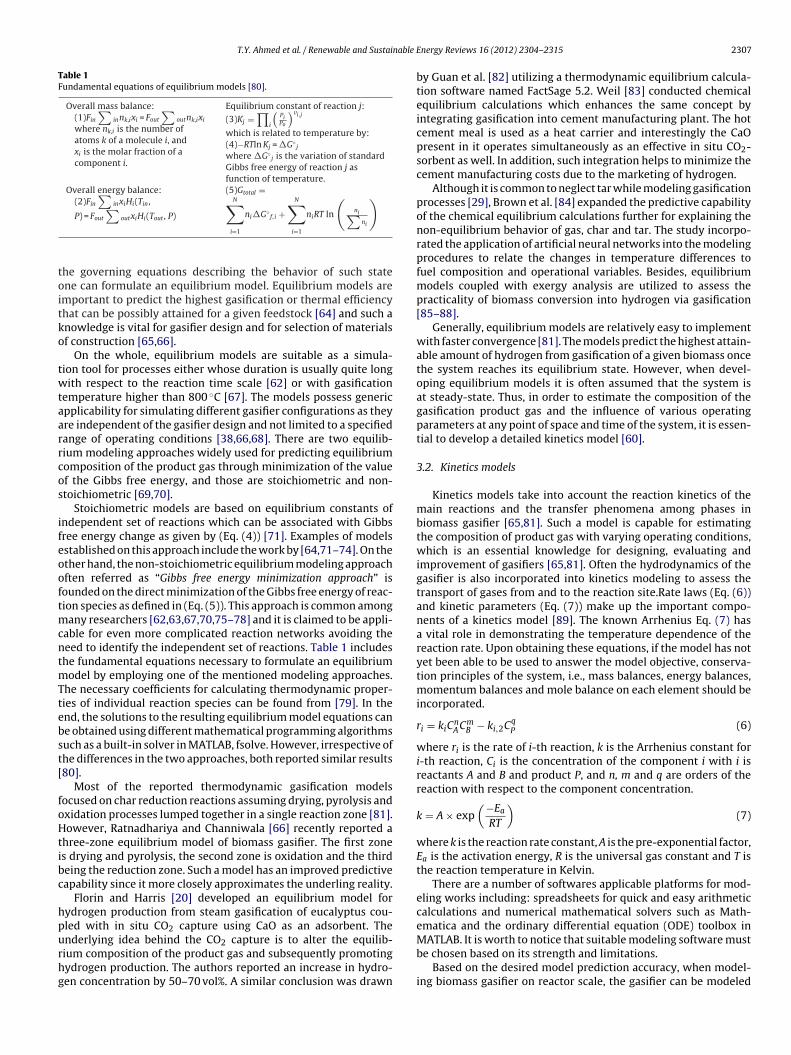
Bubbling-, circulating- and twin-bed gasifiers are the three dif-erent types of fluidized bed gasifier. They differ in respect ofuidizing velocity and gas path [41]. Twin-bed gasifiers (Fig. 1) aref recent development in which the gasifier vessel is divided intowo distinct fluidization chambers operated at two different gaselocities [37]. The design aimed to avoid mixing of gasificationroducts with those from the combustion in order to obtain highurity hydrogen [49].
The type of transport of fluid inside gasifier differentiates oneype of fixed bed gasifier from another. While biomass is oftendded from the top of the gasifier and flows downwards, dependingn the flow direction of gasifying agents fixed bed gasifier can bepdraft (counter-current), downdraft (co-current) and crossdraftcross-current) [50]. In entrained flow gasifier the biomass andhe gasifying agent move co-currently and the reactions occur in aense cloud of very fine particles at high pressures (19.7–69.1 atm)nd very high temperatures (i.e. >1000 ◦C) [51].
Due to the endothermic nature of biomass gasification, it neces-itates external energy input. According to the ways to provide theequired energy, gasifiers can further be grouped into autothermalnd allothermal types. For autothermal gasifiers, partial oxida-
ion of the biomass in the gasifier itself provides the necessaryeat; air and oxygen gasification often employ such an approach52]. Unfortunately, the oxidation generates exhaust gas whichilutes the product gas and reduces its heating value [49,52]. InEnergy Reviews 16 (2012) 2304– 2315
contrast, allothermal gasifiers get the energy from external sourcesoften in a form of bed materials carrying heat [53]; steam andCO2 gasification are examples of this type. The combustion of theresidual char outside the gasifier is also another method in whichallothermal gasifiers can acquire the required energy [54]. To date,various research efforts have continued to integrate other forms ofrenewable energy with biomass gasification for the same purposeincluding direct sun energy [55,56], geothermal energy [57] andnuclear heat [49]. The main advantage of allothermal gasificationsystems is their ability to produce significantly higher H2/CO ratios.
Needless to say, a desired target quantity and quality of gasifica-tion product gas should not compromise on energy consumptionfor production. Hence, the engineering-based techniques includ-ing modeling, simulation and heat integration are invaluable toolswhich can be used to optimize the trade-off taking into account theprocess, energy, economic and environmental constraints.
3. Development of mathematical models
Particularly with regards to biomass conversion into hydrogenvia gasification, there exists a wide range of investigation relatingto technologies and operating conditions, type of reactor and sepa-ration and purification equipment, type of biomass, and even typeof fuels. Due to the inherent complexity of biomass gasification pro-cesses, modeling for simulation and prediction of performance ofthe processes is still an incipient activity [58].
In order to optimize the design and operation of biomass gasi-fier, an extensive investigation of the plant behavior dependingon various operating parameter is required [59]. Often conduct-ing experiments at large scales is problematic, undesirable in somecases for safety reasons and expensive as well [60]. Instead, asmathematical modeling gives a good representation of the chemi-cal and physical phenomena occurring in the gasifier the resultingmodels can be used to study the plant behavior for use in optimiz-ing the gasifier design and its operation (start up, shutdown, etc.)with minimal temporal and financial costs [29,59,60].
Warnatz et al. [61] stated that when considering a chemicallyreacting flow a system at each point in space and time is char-acterized by the specification of properties including pressure,temperature, velocity of flow, density and concentration of eachspecies. Any change in the properties is the result of chemicalreaction, fluid flow, molecular transport and radiation [61]. Hence,when modeling biomass gasifier depending on the required levelof understanding on the system, one may take into account theinfluence of all or some of the above mentioned mechanisms i.e.chemical reaction, fluid flow, molecular transport and radiation.Upon completion of model development, the accuracy of the modelneeds to be verified and validated against the reality of the system,other than compared to other model’s performance.The overall sys-tem efficiency and practicality of produced hydrogen for end-usealso depends highly on efficiency of processes downstream thegasifier. However, to date—to our knowledge—modeling efforts inliteratures have focused mainly on biomass gasifier alone. Hence,the reported mathematical models for biomass gasifier which arespecifically used for hydrogen production can be classified intothermodynamic equilibrium models, kinetics models and neuralnetwork models [62]. Each type of models has their own strengthsand limitations as discussed in the following sections.
3.1. Equilibrium models
The concept of chemical reaction equilibrium is based on thesecond law of thermodynamics as applied to reacting systems [63].It is a state where species of a reaction system will no longer experi-ence net change in concentrations over time. Hence, by employing
T.Y. Ahmed et al. / Renewable and Sustainable E
Table 1Fundamental equations of equilibrium models [80].
Overall mass balance:(1)Fin
∑innk,ixi = Fout
∑outnk,ixi
where nk,i is the number ofatoms k of a molecule i, andxi is the molar fraction of acomponent i.
Equilibrium constant of reaction j:
(3)Kj =∏
i
(PiPo
)vi,j
which is related to temperature by:(4)−RTln Kj = �G◦
j
where �G◦j is the variation of standard
Gibbs free energy of reaction j asfunction of temperature.
Overall energy balance:(2)Fin
∑inxiHi(Tin ,∑ (5)Gtotal =
N∑◦
N∑ (ni∑ )
toitko
twtaarrcos
ifeooftmcntmTtebst[
foHtibc
hpurhg
P) = Fout outxiHi(Tout , P)
i=1
ni�G f,i +i=1
niRT lnni
he governing equations describing the behavior of such statene can formulate an equilibrium model. Equilibrium models aremportant to predict the highest gasification or thermal efficiencyhat can be possibly attained for a given feedstock [64] and such anowledge is vital for gasifier design and for selection of materialsf construction [65,66].
On the whole, equilibrium models are suitable as a simula-ion tool for processes either whose duration is usually quite longith respect to the reaction time scale [62] or with gasification
emperature higher than 800 ◦C [67]. The models possess genericpplicability for simulating different gasifier configurations as theyre independent of the gasifier design and not limited to a specifiedange of operating conditions [38,66,68]. There are two equilib-ium modeling approaches widely used for predicting equilibriumomposition of the product gas through minimization of the valuef the Gibbs free energy, and those are stoichiometric and non-toichiometric [69,70].
Stoichiometric models are based on equilibrium constants ofndependent set of reactions which can be associated with Gibbsree energy change as given by (Eq. (4)) [71]. Examples of modelsstablished on this approach include the work by [64,71–74]. On thether hand, the non-stoichiometric equilibrium modeling approachften referred as “Gibbs free energy minimization approach” isounded on the direct minimization of the Gibbs free energy of reac-ion species as defined in (Eq. (5)). This approach is common among
any researchers [62,63,67,70,75–78] and it is claimed to be appli-able for even more complicated reaction networks avoiding theeed to identify the independent set of reactions. Table 1 includeshe fundamental equations necessary to formulate an equilibrium
odel by employing one of the mentioned modeling approaches.he necessary coefficients for calculating thermodynamic proper-ies of individual reaction species can be found from [79]. In thend, the solutions to the resulting equilibrium model equations cane obtained using different mathematical programming algorithmsuch as a built-in solver in MATLAB, fsolve. However, irrespective ofhe differences in the two approaches, both reported similar results80].
Most of the reported thermodynamic gasification modelsocused on char reduction reactions assuming drying, pyrolysis andxidation processes lumped together in a single reaction zone [81].owever, Ratnadhariya and Channiwala [66] recently reported a
hree-zone equilibrium model of biomass gasifier. The first zones drying and pyrolysis, the second zone is oxidation and the thirdeing the reduction zone. Such a model has an improved predictiveapability since it more closely approximates the underling reality.
Florin and Harris [20] developed an equilibrium model forydrogen production from steam gasification of eucalyptus cou-led with in situ CO2 capture using CaO as an adsorbent. The
nderlying idea behind the CO2 capture is to alter the equilib-ium composition of the product gas and subsequently promotingydrogen production. The authors reported an increase in hydro-en concentration by 50–70 vol%. A similar conclusion was drawnnergy Reviews 16 (2012) 2304– 2315 2307
by Guan et al. [82] utilizing a thermodynamic equilibrium calcula-tion software named FactSage 5.2. Weil [83] conducted chemicalequilibrium calculations which enhances the same concept byintegrating gasification into cement manufacturing plant. The hotcement meal is used as a heat carrier and interestingly the CaOpresent in it operates simultaneously as an effective in situ CO2-sorbent as well. In addition, such integration helps to minimize thecement manufacturing costs due to the marketing of hydrogen.
Although it is common to neglect tar while modeling gasificationprocesses [29], Brown et al. [84] expanded the predictive capabilityof the chemical equilibrium calculations further for explaining thenon-equilibrium behavior of gas, char and tar. The study incorpo-rated the application of artificial neural networks into the modelingprocedures to relate the changes in temperature differences tofuel composition and operational variables. Besides, equilibriummodels coupled with exergy analysis are utilized to assess thepracticality of biomass conversion into hydrogen via gasification[85–88].
Generally, equilibrium models are relatively easy to implementwith faster convergence [81]. The models predict the highest attain-able amount of hydrogen from gasification of a given biomass oncethe system reaches its equilibrium state. However, when devel-oping equilibrium models it is often assumed that the system isat steady-state. Thus, in order to estimate the composition of thegasification product gas and the influence of various operatingparameters at any point of space and time of the system, it is essen-tial to develop a detailed kinetics model [60].
3.2. Kinetics models
Kinetics models take into account the reaction kinetics of themain reactions and the transfer phenomena among phases inbiomass gasifier [65,81]. Such a model is capable for estimatingthe composition of product gas with varying operating conditions,which is an essential knowledge for designing, evaluating andimprovement of gasifiers [65,81]. Often the hydrodynamics of thegasifier is also incorporated into kinetics modeling to assess thetransport of gases from and to the reaction site.Rate laws (Eq. (6))and kinetic parameters (Eq. (7)) make up the important compo-nents of a kinetics model [89]. The known Arrhenius Eq. (7) hasa vital role in demonstrating the temperature dependence of thereaction rate. Upon obtaining these equations, if the model has notyet been able to be used to answer the model objective, conserva-tion principles of the system, i.e., mass balances, energy balances,momentum balances and mole balance on each element should beincorporated.
ri = kiCnACm
B − ki,2CqP (6)
where ri is the rate of i-th reaction, k is the Arrhenius constant fori-th reaction, Ci is the concentration of the component i with i isreactants A and B and product P, and n, m and q are orders of thereaction with respect to the component concentration.
k = A × exp(−Ea
RT
)(7)
where k is the reaction rate constant, A is the pre-exponential factor,Ea is the activation energy, R is the universal gas constant and T isthe reaction temperature in Kelvin.
There are a number of softwares applicable platforms for mod-eling works including: spreadsheets for quick and easy arithmeticcalculations and numerical mathematical solvers such as Math-ematica and the ordinary differential equation (ODE) toolbox in
MATLAB. It is worth to notice that suitable modeling software mustbe chosen based on its strength and limitations.Based on the desired model prediction accuracy, when model-ing biomass gasifier on reactor scale, the gasifier can be modeled
2308 T.Y. Ahmed et al. / Renewable and Sustainable
S
a[hficaaiphdrmt
3
pmgrtzf
aowosncase
cba
Fig. 2. Fluidized bed gasifier zones.ource: Adapted from [92].
s plug flow reactor, stirred tank reactor and so on. Inayat et al.90] constructed a kinetic model for biomass steam gasification forydrogen production with in situ CO2 capture considering the gasi-er as a batch reactor. The work reported profiles on product gasomposition that matches empirical results to some extent. Over-ll, in this paper the kinetics models for biomass gasifiers whichre reported in literatures are reviewed being classified accord-ng to the gasifier types considered in the respective studies andresented as follows.On the whole, several mathematical modelsave been proposed for biomass gasification kinetics with differentegrees of compliance, accuracy and adaptability to the differenteactor configuration [91]. Nevertheless, one limitation of kineticsodels stand out i.e., the models contain parameters that restricts
heir applicability to different process plants [38].
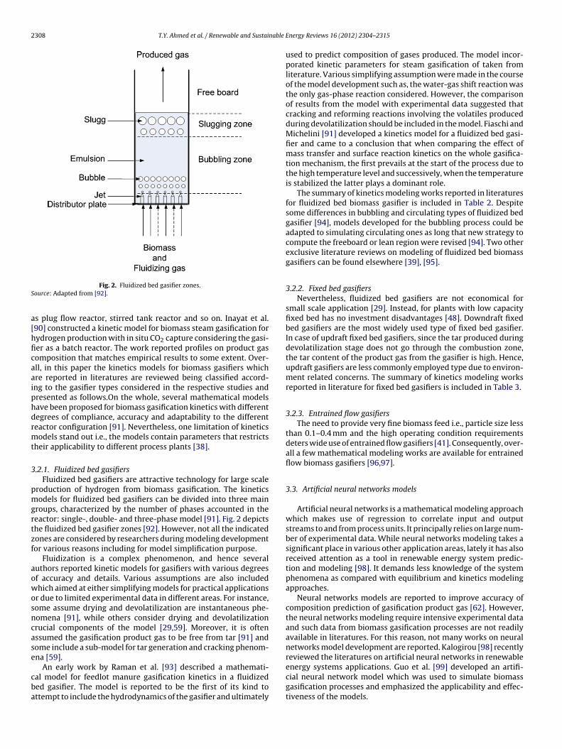
.2.1. Fluidized bed gasifiersFluidized bed gasifiers are attractive technology for large scale
roduction of hydrogen from biomass gasification. The kineticsodels for fluidized bed gasifiers can be divided into three main
roups, characterized by the number of phases accounted in theeactor: single-, double- and three-phase model [91]. Fig. 2 depictshe fluidized bed gasifier zones [92]. However, not all the indicatedones are considered by researchers during modeling developmentor various reasons including for model simplification purpose.
Fluidization is a complex phenomenon, and hence severaluthors reported kinetic models for gasifiers with various degreesf accuracy and details. Various assumptions are also includedhich aimed at either simplifying models for practical applications
r due to limited experimental data in different areas. For instance,ome assume drying and devolatilization are instantaneous phe-omena [91], while others consider drying and devolatilizationrucial components of the model [29,59]. Moreover, it is oftenssumed the gasification product gas to be free from tar [91] andome include a sub-model for tar generation and cracking phenom-na [59].
An early work by Raman et al. [93] described a mathemati-al model for feedlot manure gasification kinetics in a fluidizeded gasifier. The model is reported to be the first of its kind tottempt to include the hydrodynamics of the gasifier and ultimately
Energy Reviews 16 (2012) 2304– 2315
used to predict composition of gases produced. The model incor-porated kinetic parameters for steam gasification of taken fromliterature. Various simplifying assumption were made in the courseof the model development such as, the water-gas shift reaction wasthe only gas-phase reaction considered. However, the comparisonof results from the model with experimental data suggested thatcracking and reforming reactions involving the volatiles producedduring devolatilization should be included in the model. Fiaschi andMichelini [91] developed a kinetics model for a fluidized bed gasi-fier and came to a conclusion that when comparing the effect ofmass transfer and surface reaction kinetics on the whole gasifica-tion mechanism, the first prevails at the start of the process due tothe high temperature level and successively, when the temperatureis stabilized the latter plays a dominant role.
The summary of kinetics modeling works reported in literaturesfor fluidized bed biomass gasifier is included in Table 2. Despitesome differences in bubbling and circulating types of fluidized bedgasifier [94], models developed for the bubbling process could beadapted to simulating circulating ones as long that new strategy tocompute the freeboard or lean region were revised [94]. Two otherexclusive literature reviews on modeling of fluidized bed biomassgasifiers can be found elsewhere [39], [95].
3.2.2. Fixed bed gasifiersNevertheless, fluidized bed gasifiers are not economical for
small scale application [29]. Instead, for plants with low capacityfixed bed has no investment disadvantages [48]. Downdraft fixedbed gasifiers are the most widely used type of fixed bed gasifier.In case of updraft fixed bed gasifiers, since the tar produced duringdevolatilization stage does not go through the combustion zone,the tar content of the product gas from the gasifier is high. Hence,updraft gasifiers are less commonly employed type due to environ-ment related concerns. The summary of kinetics modeling worksreported in literature for fixed bed gasifiers is included in Table 3.
3.2.3. Entrained flow gasifiersThe need to provide very fine biomass feed i.e., particle size less
than 0.1–0.4 mm and the high operating condition requirementsdeters wide use of entrained flow gasifiers [41]. Consequently, over-all a few mathematical modeling works are available for entrainedflow biomass gasifiers [96,97].
3.3. Artificial neural networks models
Artificial neural networks is a mathematical modeling approachwhich makes use of regression to correlate input and outputstreams to and from process units. It principally relies on large num-ber of experimental data. While neural networks modeling takes asignificant place in various other application areas, lately it has alsoreceived attention as a tool in renewable energy system predic-tion and modeling [98]. It demands less knowledge of the systemphenomena as compared with equilibrium and kinetics modelingapproaches.
Neural networks models are reported to improve accuracy ofcomposition prediction of gasification product gas [62]. However,the neural networks modeling require intensive experimental dataand such data from biomass gasification processes are not readilyavailable in literatures. For this reason, not many works on neuralnetworks model development are reported. Kalogirou [98] recentlyreviewed the literatures on artificial neural networks in renewable
energy systems applications. Guo et al. [99] developed an artifi-cial neural network model which was used to simulate biomassgasification processes and emphasized the applicability and effec-tiveness of the models.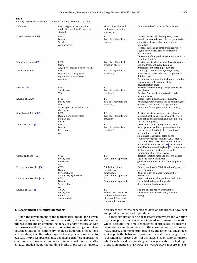
T.Y. Ahmed et al. / Renewable and Sustainable Energy Reviews 16 (2012) 2304– 2315 2309
Table 2Summary of the kinetics modeling studies on fluidized bed biomass gasifiers.
Reference Reactor type and its operationmode, biomass & gasifying agentstudied
Model dimension andmultiphase modelingapproaches
Fundamentals of the model formulation
Fiaschi and Michelini [91] BFBGDynamicSawdustAir and oxygen
1 DTwo phase (bubble anddense)
Reaction kinetics (in dense phase), masstransfer between the two phases, quantitativeestimation of local bubble and particlepropertiesFreeboard area considered chemically inertDrying and devolatilization consideredinstantaneousTar content of the product gas is assumed to beassimilated in CH4
Hamel and Krumm [59] BFBGStrawAir, air-stream and oxygen- steam
Two phase (bubble &emulsion phase)
Reaction kinetics (drying and devolatilization),bed and freeboard hydrodynamicsPredict amount of tar in product gas
Sadaka et al. [92] BFBGDynamic and steady stateAgricultural waste- StrawAir-steam
Two phase (bubble &emulsion)
Kinetics parameters and hydrodynamics,transport and thermodynamic properties offluidized bedFree energy minimization technique is used tocalculate gas mole fractions at thedevolatilization stage
Lu et al. [150] BFBGSteady stateWood
1 DTwo phase (bubble andemulsion)
Reaction kinetics, axial gas dispersion in thetwo phasesPyrolysis (devolatilization) is taken to beinstantaneous
Kaushal et al. [29] BFBGSteady stateWoodAir, oxygen, steam and mix ofthese gases
1 DTwo phase (bubble andemulsion)
Global reaction kinetics, mass & energybalances, hydrodynamics (for bubbling regimeof fluidization), material properties andsub-model for tar generation and cracking
Gordillo and Belghit [49] BFBGDynamic and steady stateBiomass charSteam
1 DTwo phase (bubble andemulsion)
Reaction kinetics, mass and energy balancesMass and heat transfer occurs only betweenthe bubbles and emulsion and the emulsionand the solid phases
Radmanesh et al. [151] BFBGDynamicBeech woodAir
1 DTwo phase (bubble andemulsion)
Takes into account pyrolysis and variousheterogeneous and homogeneous reactionkinetics as well as the hydrodynamics of thebed and the freeboard.Solid phase (char) is modeled by thecountercurrent back-mixing (CCBM) model.The study used a first-order kinetic modelproposed by Borosan et al. [98] and a kineticmodel by Bryden and Ragland [99] to representthe homogenous cracking of tar andcombustion of tar respectively.
Corella and Sanz [152] CFBGSteady statePine woodAir
1 DCore-annulus approach
Reaction kinetics, mass and energy balancesand a sub-model for the targeneration-elimination and some empiricalaspects
Petersen and Werther [36] CFBGDynamicSewage sludgeAir and CO2/N2-mixture
A 1.5-dimensional(pseudo twodimensional)Core-annulus approach
Fluid dynamics of a CFBG, kinetics of pyrolysisand gasification stepsBenzene taken as model component forbiomass tar
Petersen and Werther [153] CFBGDynamicSewage sludgeAir
3 DCore-annulus approach
Uses continuous radial profiles of velocitiesand solids hold-up with regard to thedescription of fluid mechanics
Kaushal et al. [154] TBFBGSteady state
1 DBottom bed: two phase
Sub-models for bed hydrodynamics,conversion and conservation (mass and
4
bupflaece
Biomass charSteam and air
. Development of simulation models
Upon the development of the mathematical model for a giveniomass processing system and its validation, the model can betilized to predict or simulate the behavior and/or criteria and/orerformance of the system. When it comes to simulating a completeowsheet, due to its complexity involving hundreds of equations
nd variables, it is often advantageous to use process simulators tovaluate the process performance depending on different operatingonditions in reasonable time with minimal effort. Built-in math-matical models being the building-blocks of process simulators,(bubble and emulsionphase) and Freeboard:core-annulus approach
energy)
here users are instead expected to develop the process flowsheetand provide the required input data.
Process simulation can be of at steady state where the variationof process properties over time is ignored and dynamic simulationwhich accounts the time dependence of processes by incorpo-rating the accumulation terms in the conservation equations i.e.,mass, energy and momentum balances. The latter has advantages
as it depicts the behavior of processes in real time change whichis essential for process control activities. Steady state simulatorswhich can be used in simulating biomass gasification for hydrogenproduction include ASPEN PLUS, PETRONAS iCON, IPSEpro, HYSYS,
2310 T.Y. Ahmed et al. / Renewable and Sustainable Energy Reviews 16 (2012) 2304– 2315
Table 3Kinetic models for fixed bed biomass gasifiers.
Reference Reactor type, mode of operation, biomassstudied and gasifying agent
Fundamentals of the modelformulation
Parameter studied
Chen and Gunkel [155] DowndraftWoodAir
Non isothermal particle modelapplying principles ofthermodynamics, transportprocesses, hydrodynamics ofsolid and gas flows, and themass and energy balances.One dimensional
Feedstock moisture contents,particle sizes, reactorinsulation, input airtemperatures and gasifierloads, dimension of gasificationzone
Blasi [156] DowndraftDynamicAir
Heat and mass transfer acrossthe bed, reaction kinetics(drying, pyrolysis, charcombustion and gasification,gas phase combustion andthermal tar cracking).
Predictions of the gascomposition and the axialtemperature profile
Giltrap et al. [157] DowndraftSteady stateAir
Reaction kinetics (reductionzone)
Output gas composition
Babu and Sheth [158] DowndraftSteady stateBiomass charAir
Reaction kinetics (reductionzone)
Char reactivity factorComposition and temperatureprofiles for the reduction zone
Gobel et al. [159] DowndraftDynamicWoodAir and steam
Mass and energy balances insimply one dimensional flowreaction kinetics in the gasphase andLangmuir–Hinshelwoodcorrelation describing reactionkinetics in the charThe char consisted pure carbonConsiders no tar in thegasification zone
Char reactivity, bed heighttemperature profile, gascomposition and its heatingvalue
Tinaut et al. [160] DowndraftSteady stateAny type of biomassAir
Mass and energy conservationequationsOne dimensional
Biomass particle meandiameter, air flow velocity,gasifier geometry, compositionand inlet temperature of thegasifying agent and biomasstype
Sommariva et al. [161] UpdraftSteady state
Heat and mass transportresistances and chemical
Particle sizeTemperature
SMs
4
cSlaagsee
cpeiasifAfi
Refuse derived fuels (RDF) and wastesAir
uperPro Designer, Pro/II, ChemCad, etc. For dynamic simulation,ATLAB, ANSYS Fluent, ANSYS CFX, CFD2000 are good examples of
oftware.
.1. Process simulation models
ASPEN is a standard process flowsheet simulation tool whichan be used to simulate the biomass gasification process [100,101].everal ASPEN PLUS simulation models have been reported in theiteratures which investigates the effect of different operating vari-bles on the performance of the process. Shen et al. [54] simulatedir-steam gasification of biomass in interconnected fluidized bedasifier. A steady state simulation model for the process is con-tructed in the ASPEN PLUS simulator. The model assumed chemicalquilibrium is reached for the reactions and it was used to studyffect of temperature and S/B ratio on hydrogen yield.
Doherty et al. [102] reported an equilibrium simulation modelonstructed in ASPEN PLUS simulator. The model allowed forredicting syngas composition, heating values and conversionfficiencies while evaluating the influence of different variablesncluding gasification temperature, equivalence ratio and level ofir preheating on gas composition. The results from the studyhowed that air preheating enhanced H2 and CO production and it
s more effective at low equivalence ratios and should not be usedor ERs greater than 0.35. Nikoo and Mahinpey [103] presented anSPEN PLUS simulation model which is based on kinetics of a gasi-cation process in an atmospheric fluidized bed gasifier. The modelkinetics (both at the reactorand particle scale)
Feed flow rate
takes into account both the hydrodynamic parameters and reactionkinetics of the process. The model is used to observe the effect ofreaction temperature, equivalence ratio, S/B ratio and particle sizeon hydrogen production.
Tan and Zhong [104] reported an equilibrium simulation modelfor steam gasification of sawdust which is implemented in ASPENPLUS simulator. The model is used to investigate effect of processparameters including gasification temperature, pressure and steamto biomass ratios (S/B). The results showed hydrogen content ofup to 60 vol%. Moreover, it was observed that higher S/B ratiosfavored hydrogen yield while increasing temperature above 700 ◦Cis observed to have adverse effect on hydrogen yield.
Pröll et al. [105] simulated gasification of biomass in dualfluidized bed gasifier for enriched H2 gas production in equation-oriented steady state simulation software named IPSEpro. Themodel was used to investigate a case where CaO was used for selec-tive transport of CO2. This work observed that the CO2 transportconcept not only enhances the hydrogen content in the productgas but also makes the process more energy efficient. Schusteret al. [38] also reported a simulation model of a decentralized com-bined heat and power station based on a dual fluidized bed steamgasifier using IPSEpro process simulator. The net electric efficiencyof the system is reported to be about 20%. Among many parame-
ters evaluated, the results of the sensitivity analysis showed thatgasification temperature and fuel oxygen content are the most sig-nificant parameters which determine the chemical efficiency of thegasification.
nable E
Ctsgtaasgheyig
aMgetbmwpamgstaafadde9
4
ipiiocatsda
ttecscaltRu[
T.Y. Ahmed et al. / Renewable and Sustai
Detournay et al. [106] developed a simulation model using HSChemistry 5.1 software which is based on Gibbs Energy MINImiza-ion (GEMINI code). Ahmad et al. [107] reported an equilibriumimulation model for hydrogen production via oxygen assistedasification of empty oil palm fruit bunch (EFB) with in situ adsorp-ion of CO2. The simulation model is constructed in PETRONAS iCONnd used to evaluate the influence of temperature (600–1000 ◦C)nd S/B ratio (0.1–1) on hydrogen yield and product gas compo-ition. Ahmad et al. [108] also simulated flowsheet of pressurizedasification process of biomass coupled with CO2 adsorption forydrogen production using a PETRONAS iCON. The effect of param-ters such as pressure, temperature and S/B ratio on the hydrogenield was investigated. Hydrogen yield was predicted to be increas-ng with pressure, temperature and S/B ratio in this high pressureasification system.
Inayat et al. [109] analyzed the influence of the temperature, S/Bnd sorbent/biomass ratios on steam gasification flowsheet usingATLAB. They observed that the thermodynamic efficiency of the
asifier increased with temperature and S/B ratio. The maximumfficiency obtained about 84% at S/B ratio of 2.0. They predictedhat by using CaO as a sorbent in the gasifier, the efficiency cane increased by 10% compared to the conventional gasificationethod. Inayat et al. [110] also developed process simulation modelhich was used as a platform to investigate the effects of processarameters on the production of hydrogen rich gas from EFB using
single-pass fluidized bed gasifier. Based on the results, the maxi-um hydrogen purity predicted is 71 mol% at 1150 K at outlet of the
asifier unit with the yield of 107.3 g/kg of EFB. The mass conver-ion efficiency increases with increasing temperature and is foundo be at the maximum at 84.7% at 1100 K. Ahmad et al. [111] used
simulation approach to study the influence of temperature, S/Bnd sorbent/biomass ratios against the thermodynamic efficiencyor hydrogen production from steam gasification taking biomasss pure char. The results show that the thermodynamic efficiencyepends on feed stock quality and vary with the operating con-itions. The model predicts an increment in the thermodynamicfficiency from 66.5% to 83.3% within the temperature range of00–1100 K.
.2. Computational fluid dynamics simulation models
Computational fluid dynamics (CFD) is the science of predict-ng fluid flow, heat transfer, chemical reaction and other relatedhenomena by solving numerical set of the governing mathemat-
cal equations which are mostly based on conservation equations.e., mass, heat and momentum. However, due to the complexityf the gasification process i.e., involving many phases and varioushemical and physical interactions among them not much worksre available concerning development of mathematical CFD modelo be used for simulation purposes. Generally, results of CFD analy-is are relevant for conceptual studies of new design, detail productevelopment, troubleshooting and redesign. Besides, CFD modelinglso is cost saving, timely, safe and easy to scale-up [112].
Various numerical techniques have been employed in the solu-ion of the CFD model equation and the most widely use numericalechnique is discretization method including finite difference, finitelement and finite volumes method. Finite volume is now the mostommonly used approach in CFD code for its ease in the under-tanding, programming and versatility. The most routinely usedommercial codes include ANSYS Fluent, ANSYS CFX, CFD2000nd many others [112]. Most reported CFD simulation models initeratures are either for coal gasification or for biomass combus-
ion/gasification in entrained flow gasifiers [113–115]. Recently,ashidi [116] has discussed CFD simulation of biomass gasificationsing detailed chemistry. Papadikis et al. [117,118] and Xue et al.119] used CFD modeling approach for simulating fast pyrolysis ofnergy Reviews 16 (2012) 2304– 2315 2311
biomass in fluidized bed gasifiers. In addition, Pepiot et al. [120]reported a CFD model for both biomass gasification and pyrolysis.Generally, for better result comparisons and to improve the model-ing and simulation of biomass gasification in CFD, it is necessary todevelop more CFD models. Thus, the development of CFD modelsneeds further research and development effort.
5. Process optimization
In order cope with the current energy and environment cri-sis, industries need to convert operations of a plant/system intoan efficient system in terms of utilization of energy, resourcesand materials. Generally, there are two systematic mathematicalapproaches to make a system efficient: one is to perform heat inte-gration studies to maximize heat recovery in the system and hencereducing the utility requirement; and two is to find optimal oper-ating conditions to minimize the cost of the production/operation.The heat integration approach will be discussed in Section 6 of thispaper.
Optimization can be applied to search for the optimal conditionsand/or geometric parameters that give extremes of selected objec-tive functions in the frame of previously defined constraints [121].For instance, a mathematical optimization model can be developedto find the minimum production cost of a product subject to theperformance and constraints of a selected processing system. Theobjective of an optimization problem can also be the maximumproduct yield or purity, maximum profit, minimum productiontime, best combination of raw materials that generate maximumprofit, best process configuration that yields the maximum oper-ating efficiency, the lowest carbon emission while fulfilling thedemand, etc. An optimization problem must have the degreesof freedom of more than zero, i.e., there must at least one freeindependent variable in the calculation that can be changed bythe optimizer/solver to achieve minimum or maximum objectivefunction making it different from simulation where the degree offreedom is zero.
Among the tools available for optimization are General Alge-braic Modeling System (GAMS), MATLAB Optimization Toolbox,Solver in Microsoft Excel, LINDO, SolvOpt and many more. Takriffet al. [122] conducted literature review on integrating optimizationmodules into chemical process simulation softwares. The authorsidentified the use of readily available process simulation softwareas an interface to structural and continuous optimization as possi-ble and promising strategy.
Kamarudin et al. [123] conducted mathematical optimization toinvestigate hydrogen demand and determine the optimum hydro-gen delivery network employing truck transportation in Malaysia.The overall objective function the authors used to minimize thetotal investment of production plant is given by (Eq. (8)). Theobjective function is optimized while being subjected to a combi-nation of various constraints. Hugo et al. [124] presented a genericoptimization-based model for the strategic long-range investmentplanning and design of future hydrogen supply chains using MixedInteger Linear Programming (MILP) techniques.
Min(x)
⎡⎣⎡⎣∑
gi
⎛⎝∑
pi
1.3FC
⎞⎠⎤⎦
+∑
gn
(∑Tm
[CC + NV(VC)] +∑
So
SC
)]˛ (8)
As the number of literatures directly dealing with optimizationof biomass gasification for hydrogen production is limited, it is ourbelief that reviews on biomass processing evolving gasification will
2 nable
btipncfAtpft(mp
6
eceikupTaoaU
eaftaicawtcHdii[fih
pgwetuaAspgct1
312 T.Y. Ahmed et al. / Renewable and Sustai
e beneficial for future development of optimization models onhe area. Gasification is one route which can be used for produc-ng ethanol from biomass. Employing an optimization algorithmreviously developed for the design of integrated process wateretwork [125], Cucek et al. [126] reported an optimization workonducted on integrating energy, water and process technologiesor simultaneous production of ethanol and food from corn plant.hmetovic et al. [127] also reported energy optimization model for
he design of corn-based ethanol plants. Verda and Nicolin [128]erformed a thermo-economic optimization of a molten carbonateuel cell (MCFC) stack integrated with a micro gas turbine for elec-ricity generation coupled with a pressure swing absorption systemPSA) for hydrogen production. Muis et al. [129] developed opti-
ization model used for analysis of biomass usage for electricityroduction with the main aim of reducing CO2 in Malaysia.
. Heat integration
Heat integration maximizes savings by making processes energyfficient and self sustainable through utilizing recovered pro-ess heat which significantly reduces the process dependency onxternal energy supply [130]. Process to process integration andntegration of heat engines and heat pumps into processes are thenown methods for heat integration. Heat integration approachsing pinch analysis [131] has been accepted by many major com-anies to revamp their plants to reduce their energy consumption.his way, less fuel (hence operating cost) is required to gener-te energy in the form of steam and electricity to support theirperations. Tools available for heat integration studies are suchs Microsoft Excel and SPRINT by Centre for Process Integration,niversity of Manchester.
Pavlas et al. [132] used heat integration methodology andffectively integrated heat pump with biomass gasification. Theuthors reported the availability of large amount of waste heatrom biomass gasification and proved the feasibility of the integra-ion to allow efficient utilization of the available heat for heatingnd cooling requirements. Sadhukhan et al. [100] performed heatntegration analysis on biomass integrated gasification combinedycle processes. They modeled a combined heat and power gener-tion plant from gasification of low-cost, fourth generation biomassaste feedstocks in ASPEN simulator and performed a heat integra-
ion study to demonstrate the potential via an energy productionost analysis that included detailed discounted cash flow profile.eyne et al. [133] reported a study on synthetic natural gas pro-uction from biomass gasification using integrated process design
n ASPEN PLUS. The authors applied pinch analysis for the optimalnternal heat recovery calculation within the process. Smejkal et al.134] presented a model for energy production from biomass gasi-cation using process integration approach. The model predictedigh efficiency and low operating cost of process.
Inayat et al. [135] performed heat integration analysis for arocess flowsheet developed for hydrogen production from steamasification of EFB with in situ CO2 capture using the SPRINT soft-are. The authors employed pinch analysis to obtain an energy
fficient and self-sustained system. Their result analysis showedhat considerable saving can be obtained for steam productionsing heat integration application as there is a large amount ofvailable waste heat from the gas cleaning and cooling units.hmad et al. [136] developed a process simulation model of aelected flowsheet for a biomass gasification plant for hydrogenroduction using ASPEN PLUS software. They performed heat inte-
ration study on the plant flowsheet using pinch analysis and wasarried out in SPRINT, University of Manchester Process Integra-ion Software. The minimum temperature difference was set to be0 K. The results reported possible energy savings of approximatelyEnergy Reviews 16 (2012) 2304– 2315
72% in hot utilities and 88% in cold utilities via the heat integrationanalysis.
7. Cogeneration potential
Cogeneration also known as CHP is a power generation systemwhich leads to an improvement in the overall system efficiency.While the different benefits of the cogeneration technology such asenergy, economic and environmental benefits, are well acknowl-edged due to tight emission regulations direct combustion ofbiomass or fossil fuels for cogeneration applications are notattractive. Hence, the environment-friendly and biomass-derivedhydrogen is expected to play a major role in substituting fossil fuelsin CHP generation applications. Biomass fuelled cogeneration sys-tem is one of the key energy technologies of the future since itcombines the merits of renewable energy sources and hydrogenenergy systems [137]. Moreover, it is reported that the share ofbiomass in combined heat and power production is expected toincrease in the future and decentralized combined heat and powerplants are of interest to avoid the cost associated with biomasstransportation [23]. Generally, cogeneration supports sustainablebiomass-based hydrogen integration into existing large energy sys-tem [23] and promising work is being done on the area.
Available options for biomass based CHP systems in the outputrange of 1MWe include internal combustion engines, microgas tur-bines and fuel cells [21]. The integrated gasification combined cycle(IGCC) is an early application [138]. However, recently this trendhas changed. In literatures biomass gasification for hydrogen pro-duction has been studied while integrated with power producingtechnologies such as evaporative gas turbines [139], micro-turbines[23,139,140], fuel cells [21,23,40,52,128,140–142] and gas engines[143].
Improved gas turbines are under development for use with H2and H2-rich gases [144–146]. Fuel cells are emerging as an impor-tant component of a renewable energy future for many utilityand mobile applications. A very promising technique is to obtainthe required hydrogen from gasification of biomass. In a separatestudy, Rosen and Scott [147] investigated the cogeneration poten-tial of several types of fuel cell system (phosphoric acid, alkaline,solid polymer electrolyte, molten carbonate and solid oxide) usingenergy and exergy analysis. Recently Colpan et al. [137] concludedthat among the different types of fuel cells, MCFC and solid oxidefuel cells (SOFC) are considered as the most promising ones forhydrogen fuelled fuel cells due to their high operating temper-ature level, flexibility to different fuel and greater tolerance tocontaminants. Biomass gasification processes are more commonlyintegrated to gas turbine based combined heat and power genera-tion systems. However, efficiency can be greatly enhanced throughthe use of more advanced power generation technology such asSOFC [138].
Bang-Møller and Rokni [23] conducted a modeling study onthree combined heat and power systems based on biomass gasifi-cation. In this system, the product gas from biomass gasification isconverted in a micro gas turbine (MGT) in the first system, in a solidoxide fuel cell in the second system and in a combined SOFC–MGTarrangement in the third system. The authors reported that by com-bining the SOFC and MGT, the unconverted syngas from the SOFCis used in the MGT to produce more power and the SOFC is pres-surized, which improves the efficiency to as much as �el = 50.3%.The optimal operating pressure ratio for the SOFC–MGT combi-nation is also reported to be 2.5. Similarly, Abuadala and Dincer
[40] studied an integrated process of steam biomass gasificationand a SOFC and concluded that such an integration brings positivevalue to the overall system efficiency. For the integration of fuelcells into biomass gasification, cogeneration relevant performance
nable E
firr
8
rmcFd
•
•
•
•
•
•
A
P
R
T.Y. Ahmed et al. / Renewable and Sustai
gures which could be investigated for different system configu-ations and cell parameters may include fuel utilization, fuel flowate, operation voltage and extent of internal fuel reforming [148].
. Conclusion
The purpose of this paper has been to review the variousesearch works encompassing mathematical models, simulationodels, heat integration, cogeneration and optimization which are
ontributing to the development of hydrogen as an energy carrier.rom this review of literatures the following conclusions can berawn:
Biomass gasification is a sustainable and economical technologyfor producing hydrogen.Practicality and availability of hydrogen for end uses is highlydependent on several factors including technological, economicand social. Hence, to bring the future hydrogen-based economyinto reality, issues on the respective areas should be addressedappropriately.From this review of literatures, it is learned that there existslimited data from large-scale biomass gasifiers for uses in math-ematical model development and for model validation purposes.Hence, for wider and more reliable application of mathematicalmodels for process optimization it is necessary to obtain datafrom large-scale operations of gasifiers.Each modeling approaches discussed has their own strengths andlimitations. Mathematical models are essential for process opti-mization purposes to find optimal operating conditions whichleads better process performance. However, the model develop-ment process could be tiresome. On the other hand, simulationmodels are easy for simulating a complete flowsheet avoidingthe need to deal with large number of equations and variable.Nevertheless, simulation models could not be used for processoptimization purposes. modeling effort employing the computa-tional fluid dynamic modeling approach requires further researchand development to enhance the understanding of biomass gasi-fication processes.Integrating biomass gasification into power producing devicessuch as fuel cell and micro-turbines is an emerging and promis-ing technology which allows the sustainable integration of thebiomass-based hydrogen into the existing large energy systems.Evaluating the overall system performance in terms of energyusage, economic benefit and product distribution strategyusing mathematical optimization strategies still require furtherresearch and development to assess effective implementation ofhydrogen in energy and transportation systems.
cknowledgementsThe authors acknowledge Universiti Teknologi PETRONAS and
ETRONAS Research Fund for the financial support.
eferences
[1] Marbán G, Valdés-Solís T. Towards the hydrogen economy? Int J HydrogenEnergy 2007;32:1625–37.
[2] Johnston B, Mayo MC, Khare A. Hydrogen: the energy source for the 21stcentury. Technovation 2005;25:569–85.
[3] Valverde SMF. Hydrogen as energy source to avoid envirnmental pollution.Geofisica Int 2002;11:223–8.
[4] Balat H, Kirtay E. Hydrogen from biomass – present scenario and futureprospects. Int J Hydrogen Energy 2010;35:7416–26.
[5] Holladay JD, Hu J, King DL, Wang Y. An overview of hydrogen productiontechnologies. Catal Today 2009;139:244–60.
[6] Winter C-J. Hydrogen energy – abundant, efficient, clean: a debate over theenergy-system-of-change. Int J Hydrogen Energy 2009;34:S1–52.
[7] Fujimoto S, Yoshida T, Hanaoka T, Matsumura Y, Lin S-Y, Minowa T, SasakiY. A kinetic study of in situ CO2 removal gasification of woody biomass forhydrogen production. Biomass Bioenergy 2007;31:556–62.
nergy Reviews 16 (2012) 2304– 2315 2313
[8] Roychowdhury S. Process for production of hydrogen from anaerobicallydecomposed organic materials in: U.S.; 2000.
[9] Lide DR. CRC handbook of chemistry and physics. CRC Press; 2010.[10] Koroneos C, Dompros A, Roumbas G. Hydrogen production via biomass gasifi-
cation – a life cycle assessment approach. Chem Eng Process 2008;47:1261–8.[11] Tous M, Pavlas M, Stehlík P, Popela P. Effective biomass integration into exist-
ing combustion plant. Chem Eng Trans 2010;21.[12] Caputo AC, Palumbo M, Pelagagge PM, Scacchia F. Economics of biomass
energy utilization in combustion and gasification plants: effects of logisticvariables. Biomass Bioenergy 2005;28:35–51.
[13] Withagen C. Pollution and exhaustibility of fossil fuels. Resour Energy Econ1994;16:235–42.
[14] Hoel M, Kverndokk S. Depletion of fossil fuels and the impacts of global warm-ing. Resour Energy Econ 1996;18:115–36.
[15] Muradov NZ, Veziroglu TN. Green path from fossil-based to hydrogen econ-omy: an overview of carbon-neutral technologies. Int J Hydrogen Energy2008;33:6804–39.
[16] Bartels JR, Pate MB, Olson NK. An economic survey of hydrogen productionfrom conventional and alternative energy sources. Int J Hydrogen Energy2010;35:8371–84.
[17] Demirbas A. Biomass resource facilities and biomass conversion processingfor fuels and chemicals. Energy Convers Manage 2001;42:1357–78.
[18] Anghel M, Niculescu V-C, Stefanescu I, Tamaian R. Biomass – an environmen-tal friendly production source for hydrogen. Int J Energy Environ 2010;4.
[19] Ni M, Leung DYC, Leung MKH, Sumathy K. An overview of hydrogen produc-tion from biomass. Fuel Process Technol 2006;87:461–72.
[20] Florin N, Harris A. Hydrogen production from biomass. Environmentalist2007;27:207–15.
[21] Panopoulos KD, Fryda LE, Karl J, Poulou S, Kakaras E. High temperature solidoxide fuel cell integrated with novel allothermal biomass gasification: part I:modelling and feasibility study. J Power Sources 2006;159:570–85.
[22] Jain IP. Hydrogen the fuel for 21st century. Int J Hydrogen Energy2009;34:7368–78.
[23] Bang-Møller C, Rokni M. Thermodynamic performance study of biomass gasi-fication, solid oxide fuel cell and micro gas turbine hybrid systems. EnergyConvers Manage 2010;51:2330–9.
[24] Biagini E, Masoni L, Tognotti L. Comparative study of thermochemical pro-cesses for hydrogen production from biomass fuels. Bioresour Technol2010;101:6381–8.
[25] Saxena RC, Seal D, Kumar S, Goyal HB. Thermo-chemical routes for hydrogenrich gas from biomass: a review. Renew Sustain Energy Rev 2008;12:1909–27.
[26] Kalinci Y, Hepbasli A, Dincer I. Biomass-based hydrogen production: a reviewand analysis. Int J Hydrogen Energy 2009;34:8799–817.
[27] Ahmad MM, Ali RMM, Inayat A, Yusup S. Potential developement of hydrogenproduction from biomass in Malaysia. Int J Chem Environ Eng 2011;2:45–50.
[28] Bridgwater AV. The technical and economic feasibility of biomass gasificationfor power generation. Fuel 1995;74:631–53.
[29] Kaushal P, Abedi J, Mahinpey N. A comprehensive mathematical modelfor biomass gasification in a bubbling fluidized bed reactor. Fuel2010;89:3650–61.
[30] Kumar A, Jones DD, Hanna MA. Thermochemical biomass gasification: areview of the current status of the technology. Energies 2009;2:556–81.
[31] Chen G, Andries J, Luo Z, Spliethoff H. Biomass pyrolysis/gasification for prod-uct gas production: the overall investigation of parametric effects. EnergyConvers Manage 2003;44:1875–84.
[32] Gil J, Corella J, Aznar MP, Caballero MA. Biomass gasification in atmosphericand bubbling fluidized bed: effect of the type of gasifying agent on the productdistribution. Biomass Bioenergy 1999;17:389–403.
[33] Levin DB, Chahine R. Challenges for renewable hydrogen production frombiomass. Int J Hydrogen Energy 2010;35:4962–9.
[34] Paasen SVBV, Kiel JHA. Tar formation in a fluidised-bed gasifier: impactof fuel properties and operating conditions. Energy Research Centre of theNetherlands (ECN): ECN-C-04-013; Petten, The Netherlands, 2004.
[35] Khalil R, Varhegyi G, Jaschke S, Grønli MG, Hustad J. CO2 gasification ofbiomass chars: a kinetic study. Energy Fuels 2009;23:94–100.
[36] Petersen I, Werther J. Experimental investigation and modeling of gasifica-tion of sewage sludge in the circulating fluidized bed. Chem Eng Process2005;44:717–36.
[37] Foscolo PU, Germana A, Jand N, Rapagna S. Design and cold model testingof a biomass gasifier consisting of two interconnected fludized beds. PowderTechnol 2007;173:179–88.
[38] Schuster G, Löffler G, Weigl K, Hofbauer H. Biomass steam gasification – anextensive parametric modeling study. Bioresour Technol 2001;77:71–9.
[39] Gomez-Barea A, Leckner B. Modeling of biomass gasification in fluidized bed.Prog Energy Combust Sci 2010;36:444–509.
[40] Abuadala A, Dincer I. Investigation of a multi-generation system using ahybrid steam biomass gasification for hydrogen, power and heat. Int J Hydro-gen Energy 2010;35:13146–57.
[41] McKendry P. Energy production from biomass (part 3): conversion technolo-gies. Bioresour Technol 2002;83:47–54.
[42] Yoshida Y, Dowaki K, Matsumura Y, Matsuhashi R, Li D, Ishitani H, Komiyama
H. Comprehensive comparison of efficiency and CO2 emissions betweenbiomass energy conversion technologies–position of supercritical water gasi-fication in biomass technologies. Biomass Bioenergy 2003;25:257–72.[43] Yanik J, Ebale S, Kruse A, Saglam M, Yüksel M. Biomass gasification in super-critical water: part 1. Effect of the nature of biomass. Fuel 2007;86:2410–5.

2 nable
314 T.Y. Ahmed et al. / Renewable and Sustai[44] Lu YJ, Jin H, Guo LJ, Zhang XM, Cao CQ, Guo X. Hydrogen production by biomassgasification in supercritical water with a fluidized bed reactor. Int J HydrogenEnergy 2008;33:6066–75.
[45] Guo LJ, Lu YJ, Zhang XM, Ji CM, Guan Y, Pei AX. Hydrogen production bybiomass gasification in supercritical water: a systematic experimental andanalytical study. Catal Today 2007;129:275–86.
[46] Cui H, Grace JR. Fluidization of biomass particles: a review of experimentalmultiphase flow aspects. Chem Eng Sci 2007;62:45–55.
[47] Alauddin ZABZ, Lahijani P, Mohammadi M, Mohamed AR. Gasification of lig-nocellulosic biomass in fluidized beds for renewable energy development: areview. Renew Sustain Energy Rev 2010;14:2852–62.
[48] Warnecke R. Gasification of biomass: comparison of fixed bed and fluidizedbed gasifier. Biomass Bioenergy 2000;18:489–97.
[49] Gordillo ED, Belghit A. A two phase model of high temperature steam-onlygasification of biomass char in bubbling fluidized bed reactors using nuclearheat. Int J Hydrogen Energy 2011;36:374–81.
[50] Rajvanshi AK. Biomass gasification. In: Goswami, editor. Alternative energyin agriculture. CRC Press; 1986. p. 83–102.
[51] Zhang L, Xu C, Champagne P. Overview of recent advances in thermo-chemicalconversion of biomass. Energy Convers Manage 2010;51:969–82.
[52] Karl J, Frank N, Karellas S, Saule M, Hohenwarter U. Conversion of syngas frombiomass in solid oxide fuel cells. J Fuel Cell Sci Technol 2009;6:1–5.
[53] Karellas S, Kakaras E, Papadopoulos T, Schäfer C, Karl J. Hydrogen productionfrom allothermal biomass gasification by means of palladium membranes.Fuel Process Technol 2008;89:582–8.
[54] Shen L, Gao Y, Xiao J. Simulation of hydrogen production from biomass gasi-fication in interconnected fluidized beds. Biomass Bioenergy 2008;32:120–7.
[55] Z’Graggen A, Steinfeld A. Hydrogen production by steam-gasification of car-bonaceous materials using concentrated solar energy – V. Reactor modelling,optimization, and scale-up. Int J Hydrogen Energy 2008;33:5484–92.
[56] Chen J, Lu Y, Guo L, Zhang X, Xiao P. Hydrogen production by biomassgasification in supercritical water using concentrated solar energy: sys-tem development and proof of concept. Int J Hydrogen Energy 2010;35:7134–41.
[57] Kanoglu M, Bolatturk A, Yilmaz C. Thermodynamic analysis of modelsused in hydrogen production by geothermal energy. Int J Hydrogen Energy2010;35:8783–91.
[58] De Souza Jr MB, Barreto Jr AG, Nemer LC, Soares PO, Quitete CPB. A studyon modeling and operational optimization of biomass gasification processesusing neural networks. AlChE J 2010.
[59] Hamel S, Krumm W. Mathematical modelling and simulation of bubblingfluidised bed gasifiers. Powder Technol 2001;120:105–12.
[60] Li XT, Grace JR, Lim CJ, Watkinson AP, Chen HP, Kim JR. Biomass gasificationin a circulating fluidized bed. Biomass Bioenergy 2004;26:171–93.
[61] Warnatz J, Mass U, Dibble RW. Combustion: physical and chemical funda-mentals, modeling and simulation experiments, pollutant formation. BerlinHeidelberg, New York: Springer; 2006.
[62] Baratieri M, Baggio P, Fiori L, Grigiante M. Biomass as an energy source:thermodynamic constraints on the performance of the conversion process.Bioresour Technol 2008;99:7063–73.
[63] Mahishi MR, Goswami DY. Thermodynamic optimization of biomass gasifierfor hydrogen production. Int J Hydrogen Energy 2007;32:3831–40.
[64] Sharma AK. Equilibrium modeling of global reduction reactions for a down-draft (biomass) gasifier. Energy Convers Manage 2008;49:832–42.
[65] Karmakar MK, Datta AB. Generation of hydrogen rich gas through fluidizedbed gasification of biomass. Bioresour Technol 2011;102:1907–13.
[66] Ratnadhariya JK, Channiwala SA. Three zone equilibrium and kineticfree modeling of biomass gasifier – a novel approach. Renew Energy2009;34:1050–8.
[67] Altafini CR, Wander PR, Barreto RM. Prediction of the working parameters of awood waste gasifier through an equilibrium model. Energy Convers Manage2003;44:2763–77.
[68] Salaices E. Catalytic steam gasification of biomass surrogates: a thermody-namic and kinetic approach. Chem Biochem Eng. London, Ontario, Canada:University of Western Ontario; 2010, p. 266.
[69] Haryanto A, Fernando SD, Pordesimo LO, Adhikari S. Upgrading of syngasderived from biomass gasification: a thermodynamic analysis. Biomass Bioen-ergy 2009;33:882–9.
[70] Li X, Grace JR, Watkinson AP, Lim CJ, Ergüdenler A. Equilibrium modeling ofgasification: a free energy minimization approach and its application to acirculating fluidized bed coal gasifier. Fuel 2001;80:195–207.
[71] Jarungthammachote S, Dutta A. Equilibrium modeling of gasification: Gibbsfree energy minimization approach and its application to spouted bed andspout-fluid bed gasifiers. Energy Convers Manage 2008;49:1345–56.
[72] Khadse A, Parulekar P, Aghalayam P, Ganesh A. Equilibrium model for biomassgasification. Adv Energy Res 2006;16:6–12.
[73] Loha C, Chatterjee PK, Chattopadhyay H. Performance of fluidized bed steamgasification of biomass – modeling and experiment. Energy Convers Manage2010;52:1583–8.
[74] Deydier A, Marias F, Bernada P, Couture F, Michon U. Equilibrium model fora travelling bed gasifier. Biomass Bioenergy 2011;35:133–45.
[75] Melgar A, Pérez JF, Laget H, Horillo A. Thermochemical equilibrium modellingof a gasifying process. Energy Convers Manage 2007;48:59–67.
[76] Yan Q, Guo L, Lu Y. Thermodynamic analysis of hydrogen productionfrom biomass gasification in supercritical water. Energy Convers Manage2006;47:1515–28.
Energy Reviews 16 (2012) 2304– 2315
[77] Lu Y, Guo L, Zhang X, Yan Q. Thermodynamic modeling and analysis ofbiomass gasification for hydrogen production in supercritical water. ChemEng J 2007;131:233–44.
[78] Ruggiero M, Manfrida G. An equilibrium model for biomass gasification pro-cesses. Renew Energy 1999;16:1106–9.
[79] McBride BJ, Gordon MJZ. NASA Glenn coefficients for calculating thermody-namic properties of individual species. Ohio: Glenn Research Center; 2002.
[80] Rodrigues R, Secchi AR, Marcílio NR, Godinho M. Modeling of biomass gasifi-cation applied to a combined gasifier-combustor unit: equilibrium and kineticapproaches. Comput Aid Chem Eng 2009;27:657–62.
[81] Sharma AK. Equilibrium and kinetic modeling of char reduction reactions ina downdraft biomass gasifier: a comparison. Sol Energy 2008;82:918–28.
[82] Guan J, Wang Q, Li X, Luo Z, Cen K. Thermodynamic analysis of a biomassanaerobic gasification process for hydrogen production with sufficient CaO.Renew Energy 2007;32:2502–15.
[83] Weil S, Hamel S, Krumm W. Hydrogen energy from coupled waste gasificationand cement production – a thermochemical concept study. Int J HydrogenEnergy 2006;31:1674–89.
[84] Brown D, Fuchino T, Maréchal F. Solid fuel decomposition modelling for thedesign of biomass gasification systems. In: 16th European symposium oncomputer aided process engineering and 9th international symposium onprocess systems engineering. Elsevier B.V.; 2006. p. 1661–6.
[85] Pellegrini LF, de Oliveira JS. Exergy analysis of sugarcane bagasse gasification.Energy 2007;32:314–27.
[86] Abuadala A, Dincer I, Naterer GF. Exergy analysis of hydrogen production frombiomass gasification. Int J Hydrogen Energy 2010;35:4981–90.
[87] Karamarkovic R, Karamarkovic V. Energy and exergy analysis of biomass gasi-fication at different temperatures. Energy 2010;35:537–49.
[88] Srinivas T, Gupta AVSSKS, Reddy BV. Thermodynamic equilibrium model andexergy analysis of the biomass gasifier. Energy Resour Technol 2009;131:1–7.
[89] Resende FLP, Savage PE. Kinetic model for noncatalytic supercritical watergasification of cellulose and lignin. AlChE J 2010;56:2412–20.
[90] Inayat A, Ahmad MM, Yusup S, Mutalib MIA. Biomass steam gasification within situ CO2 capture for enriched hydrogen gas production: a reaction kineticsmodelling approach. Energies 2010;3:1472–84.
[91] Fiaschi D, Michelini M. A two-phase one-dimensional biomass gasificationkinetics model. Biomass Bioenergy 2001;21:121–32.
[92] Sadaka SS, Ghaly AE, Sabbah MA. Two phase biomass air-steam gasificationmodel for fluidized bed reactors: part I – model development. Biomass Bioen-ergy 2002;22:439–62.
[93] Raman P, Walawender WP, Fan LT, Chang CC. Mathematical model for thefluid-bed gasitication of biomass materials: application to feedlot manure.Ind Eng Chem Process Des Dev 1981;20:686–92.
[94] Souza-Santos MLd. Comprehensive simulator (CSFMB) applied to circulatingfluidized bed boiler and gasifiers. Open Chem Eng J 2008;2:106–18.
[95] Basu P, Kaushal P. Modeling of pyrolysis and gasification of biomass in flu-idized beds: a review. Chem Prod Process Model 2009;4:1–45.
[96] Fletcher DF, Haynes BS, Chen J, Joseph SD. Computational fluid dynam-ics modelling of an entrained flow biomass gasifier. Appl Math Modell1998;22:747–57.
[97] Henrich E, Weirich F. Pressurized entrained flow gasifiers for biomass. EnvironEng Sci 2004;21:53–64.
[98] Kalogirou SA. Artificial neural networks in renewable energy systems appli-cations: a review. Renew Sustain Energy Rev 2001;5:373–401.
[99] Guo B, Li D, Cheng C, Lü Z-a, Shen Y. Simulation of biomass gasification witha hybrid neural network model. Bioresour Technol 2001;76:77–83.
[100] Sadhukhan J, Ng KS, Shah N, Simons HJ. Heat integration strategy for economicproduction of combined heat and power from biomass waste. Energy Fuels2009;23:5106–20.
[101] Ramzan N, Ashraf A, Naveed S, Malik A. Simulation of hybrid biomass gasi-fication using Aspen plus: a comparative performance analysis for food,municipal solid and poultry waste. Biomass Bioenergy 2011;35:3962–9.
[102] Doherty W, Reynolds A, Kennedy D. Simulation of a circulating fluidisedbed biomass gasifier using ASPEN Plus – a performance analysis. In: 21stinternational conference on efficiency, cost, optimization, simulation andenvironmental impact of energy systems. 2008. p. 1241–8.
[103] Nikoo MB, Mahinpey N. Simulation of biomass gasification in fluidized bedreactor using ASPEN PLUS. Biomass Bioenergy 2008;32:1245–54.
[104] Tan W, Zhong Q. Simulation of hydrogen production in biomass gasifier byASPEN PLUS. IEEE 2010;10:1–4.
[105] Pröll T, Hofbauer H. H2 rich syngas by selective CO2 removal from biomassgasification in a dual fluidized bed system – process modelling approach. FuelProcess Technol 2008;89:1207–17.
[106] Detournay M, Hemati M, Andreux R. Biomass steam gasification influidized bed of inert or catalytic particles: Comparison between experi-mental results and thermodynamic equilibrium predictions. Powder Technol2011;208:558–67.
[107] Ahmad MM, Inayat A, Yusup S, Sabil KM. Simulation of oxygen-steam gasifi-cation with CO2 adsorption for hydrogen production from empty fruit bunch.J Appl Sci 2011;11:2171–8.
[108] Ahmad MM, Chiew CK, Inayat A, Yusup S. Simulation of integrated pressurized
steam gasification of biomass for hydrogen production using Icon. J Appl Sci2011;11:3593–9.[109] Inayat A, Ahmad MM, Mutalib MIA, Yusup S. Flowsheet development andmodeling of hydrogen production from Empty Fruit Bunch via steam gasifi-cation. Chem Eng Trans 2010;21:427–32.

nable E
[
[
[
[
[
[
[
[
[
[
[
[
[
[
[
[
[
[
[
[
[
[
[
[
[
[
T.Y. Ahmed et al. / Renewable and Sustai
110] Inayat A, Ahmad MM, Mutalib MIA, Yusup S. Process design of enriched hydro-gen gas production from empty fruit bunch via steam gasification with in situCO2 capture. In: AIChE annual meeting. 2010.
111] Ahmad MM, Inayat A, Yusup S, Uemura Y. Thermodynamic efficiency forbiomass steam gasification with in situ CO2 capture for hydrogen production.In: BIT’s 1st annual world congress of bioenergy (WCBE 2011). 2011.
112] Wang Y, Yan L. CFD studies on biomass thermochemical conversion. Int J MolSci 2008;9:1108–30.
113] Fletcher DF, Haynes BS, Christo FC, Joseph SD. Combustion modelling foran entrained flow biomass gasifier. In: International conference on CFD inmineral and metal processing and power generation. 1997.
114] Fletcher DF, Haynes BS, Christo FC, Joseph SD. A CFD based combustionmodel of an entrained flow biomass gasifier. Appl Math Modell 2000;24:165–82.
115] Marklund M, Tegman R, Gebart R. CFD modelling of black liquor gasification:identification of important model parameters. Fuel 2007;86:1918–26.
116] Rashidi A. CFD simulation of biomass gasification using detailed chemistry.Heidelberg: Ruprecht-Karls-Universit; 2011.
117] Papadikis K, Gu S, Bridgwater AV, Gerhauser H. Application of CFD to modelfast pyrolysis of biomass. Fuel Process Technol 2009;90:504–12.
118] Papadikis K, Gu S, Bridgwater AV. CFD modelling of the fast pyrolysis ofbiomass in fluidised bed reactors. Part B: heat, momentum and mass transportin bubbling fluidised beds. Chem Eng Sci 2009;64:1036–45.
119] Xue Q, Heindel TJ, Fox RO. A CFD model for biomass fast pyrolysis in fluidized-bed reactors. Chem Eng Sci 2011;66:2440–52.
120] Pepiot P, Dibble CJ, Foust TD. Computational fluid dynamics modeling ofbiomass gasification and pyrolysis. In: Nimlos MR, Crowley MF, editors. Com-putational modeling in lignocellulosic biofuel production. Golden: AmericanChemical Society; 2010. p. 273–98.
121] Rodrigues AE, Minceva M. Modelling and simulation in chemical engineering:tools for process innovation. Comput Chem Eng 2005;29:1167–83.
122] Takriff MS, Mansor NH, Kamarudin SK. Review: integrating optimizationmodule into chemical process simulation. J Appl Sci 2010;10:2493–8.
123] Kamarudin SK, Daud WRW, Yaakub Z, Misron Z, Anuar W, Yusuf NNAN. Syn-thesis and optimization of future hydrogen energy infrastructure planning inPeninsular Malaysia. Int J Hydrogen Energy 2009;34:2077–88.
124] Hugo A, Rutter P, Pistikopoulos S, Amorelli A, Zoia G. Hydrogen infrastructurestrategic planning using multi-objective optimization. Int J Hydrogen Energy2005;30:1523–34.
125] Ahmetovic E, grossmann IE. General superstructure and global optimizationfor the design of integrated process water networks. AlChE J 2011;57:434–57.
126] Cucek L, Martín M, Grossmann IE, Kravanja Z. Energy, water and process tech-nologies integration for the simultaneous production of ethanol and foodfrom the entire corn plant. Comput Chem Eng 2011;35:1547–57.
127] Ahmetovic E, Martın M, Grossmann IE. Optimization of energy and water con-sumption in corn-based ethanol plants. Ind Eng Chem Res 2010;49:7972–82.
128] Verda V, Nicolin F. Thermodynamic and economic optimization of a MCFC-based hybrid system for the combined production of electricity and hydrogen.Int J Hydrogen Energy 2010;35:794–806.
129] Muis ZA, Hashim H, Manan ZA, Taha FM. Optimization of biomass usage forelectricity generation with carbon dioxide reduction in malaysia. J Appl Sci2010;10:2613–7.
130] Klemes JJ, Lam HL. Heat integration, energy efficiency, saving and security.Energy 2009;34:1669–73.
131] Linnhoff B, Flower JR. Synthesis of heat exchanger networks: II. Evolu-tionary generation of networks with various criteria of optimality. AlChE J1978;24:642–54.
132] Pavlas M, Stehlík P, Oral J, Klemes J, Kim J-K, Firth B. Heat integrated heatpumping for biomass gasification processing. Appl Therm Eng 2010;30:30–5.
133] Heyne S, Seemann MC, Harvey S. Integration study for alternative methana-tion technologies for the production of synthetic natural gas from gasifiedbiomass. Chem Eng Trans 2010;21:409–14.
134] Smejkal Q, Sarlej M, Stehlik P. New unit for clean energy production from
contaminated biomass (1 to 3 MWt) – example of process design. Chem EngTrans 2009;18:57–62.135] Inayat A, Ahmad MM, Mutalib MIA, Yusup S. Heat integration analysis of gasi-fication process for hydrogen production from oil palm empty fruit bunch.Chem Eng Trans 2011;25:971–6.
nergy Reviews 16 (2012) 2304– 2315 2315
[136] Ahmad MM, Aziz MF, Inayat A, Yusup S. Heat integration study on biomassgasification plant for hydrogen production. J Appl Sci 2011;11:3600–6.
[137] Colpan CO, Hamdullahpur F, Dincer I, Yoo Y. Effect of gasification agent onthe performance of solid oxide fuel cell and biomass gasification systems. IntJ Hydrogen Energy 2010;35:5001–9.
[138] Sadhukhan J, Zhao Y, Shah N, Brandon NP. Performance analysis of integratedbiomass gasification fuel cell (BGFC) and biomass gasification combined cycle(BGCC) systems. Chem Eng Sci 2010;65:1942–54.
[139] Steinwall PH. Integration of biomass gasification and evaporative gas turbinecycles. Energy Convers Manage 1997;38:1665–70.
[140] Karellas S, Karl J, Kakaras E. An innovative biomass gasification process and itscoupling with microturbine and fuel cell systems. Energy 2008;33:284–91.
[141] Nagel FP, Schildhauer TJ, McCaughey N, Biollaz SMA. Biomass-integrated gasi-fication fuel cell systems – part 2: economic analysis. Int J Hydrogen Energy2009;34:6826–44.
[142] Omosun AO, Bauen A, Brandon NP, Adjiman CS, Hart D. Modelling systemefficiencies and costs of two biomass-fuelled SOFC systems. J Power Sources2004;131:96–106.
[143] Pratola F, Pellizza ML, Repetto F, Maggio E, Amorino C. Integration of biomassgasification in a gas-engine cogeneration system. In: International conferenceon clean coal technologies for our future. 2002.
[144] Jin H, Ishida M. A novel gas turbine cycle with hydrogen-fueled chemical-looping combustion. Int J Hydrogen Energy 2000;25:1209–15.
[145] Gobbato P, Masi M, Toffolo A, Lazzaretto A. Numerical simulation of ahydrogen fuelled gas turbine combustor. Int J Hydrogen Energy 2011;36:1–10.
[146] Ogden J. Hydrogen applications: industrial uses and stationary power. Hydro-gen pathway class. San Francisco, Davis: University of California; 2004.
[147] Rosen MA, Scott DS. A thermodynamic investigation of the potential forcogeneration for fuel cells. Int J Hydrogen Energy 1988;13:775–82.
[148] Kazempoor P, Dorer V, Ommi F. Evaluation of hydrogen and methane-fuelledsolid oxide fuel cell systems for residential applications: system design alter-native and parameter study. Int J Hydrogen Energy 2009;34:8630–44.
[149] Pfeifer C, Puchner B, Hofbauer H. Comparison of dual fluidized bed steamgasification of biomass with and without selective transport of CO2. ChemEng Sci 2009;64:5073–83.
[150] Lü P, Kong X, Wu C, Yuan Z, Ma L, Chang J. Modeling and simulation of biomassair-steam gasification in a fluidized bed. Front Chem Eng Chin 2008;2:209–13.
[151] Radmanesh R, Chaouki J, Guy C. Biomass gasification in a bubbling fluidizedbed reactor: experiments and modeling. AlChE J 2006;52:4258–72.
[152] Corella J, Sanz A. Modeling circulating fluidized bed biomass gasi-fiers. A pseudo-rigorous model for stationary state. Fuel Process Technol2005;86:1021–53.
[153] Petersen I, Werther J. Three-dimensional modeling of a circulating fluidizedbed gasifier for sewage sludge. Chem Eng Sci 2005;60:4469–84.
[154] Kaushal P, Pröll T, Hofbauer H. Model for biomass char combustion in theriser of a dual fluidized bed gasification unit: part 1 – model developmentand sensitivity analysis. Fuel Process Technol 2008;89:651–9.
[155] Chen J-S, Gunkel WW. Modeling and simulation of co-current movingbed gasification reactors – part II. A detailed gasifier model. Biomass1987;14:75–98.
[156] Blasi CD. Dynamic behaviour of stratified downdraft gasifiers. Chem Eng Sci2000;55:2931–44.
[157] Giltrap DL, McKibbin R, Barnes GRG. A steady state model of gas-char reactionsin a downdraft biomass gasifier. Sol Energy 2003;74:85–91.
[158] Babu BV, Sheth PN. Modeling and simulation of reduction zone of down-draft biomass gasifier: effect of char reactivity factor. Energy Convers Manage2006;47:2602–11.
[159] Gøbel B, Henriksen U, Jensen TK, Qvale B, Houbak N. The development ofa computer model for a fixed bed gasifier and its use for optimization andcontrol. Bioresour Technol 2007;98:2043–52.
[160] Tinaut FV, Melgar A, Pérez JF, Horrillo A. Effect of biomass particle sizeand air superficial velocity on the gasification process in a downdraft fixed
bed gasifier. An experimental and modelling study. Fuel Process Technol2008;89:1076–89.[161] Sommariva S, Grana R, Maffei T, Pierucci S, Ranzi E. A kinetic approachto the mathematical model of fixed bed gasifiers. Comput Chem Eng2011;35:928–35.
Copyright © 2022 FDOKUMEN