Thermal plasma-sprayed nickel catalysts in the clean-up of biomass gasification gas
14
Thermal plasma-sprayed nickel catalysts in the clean-up of biomass gasification gas Rönkkönen Hanne a,⇑ , Klemkaite ˙ Kristina b,1 , Khinsky Alexander b,1 , Baltušnikas Ar unas b,1 , Simell Pekka c,2 , Reinikainen Matti c,2 , Krause Outi a , Niemelä Marita a a Aalto University, School of Science and Technology, Department of Biotechnology and Chemical Technology, P.O. Box 16100, FI-00076 Aalto, Finland b Department of General and Inorganic Chemistry, Vilnius University, Naugarduko str. 24, LT-03225 Vilnius, Lithuania c Technical Research Centre of Finland (VTT), P.O.Box 1 000, FI-02044 VTT, Finland article info Article history: Received 17 February 2010 Received in revised form 11 November 2010 Accepted 11 November 2010 Available online 23 November 2010 Keywords: Nickel catalyst Thermal plasma spraying Gasification Gas clean-up abstract Plasma spraying is a potential catalyst preparation method for hot gas clean-up which requires very dura- ble catalytic coatings. In this work, the multi-layer composite coating powders consisted of a gibbsite or boehmite core together with a hydrotalcite coating. We used the coating powders in the preparation of the powder form Ni catalysts, which were characterized by XRD, BET, XPS, and XRF. The coating powders were also used in the preparation of plasma sprayed metal substrate supported Ni catalysts. Selected plasma-sprayed nickel containing catalysts were characterized by XRD and SEM. In addition, for compar- ative purposes we prepared and used a ceramic monolithic Ni catalyst on modified ZrO 2 . The perfor- mance of all catalysts were studied in the clean-up of synthetic gasification gas, i.e. the decomposition of tar, ammonia, and methane, at 700 and 900 °C, without and with the addition of H 2 S. Catalysts with a gibbsite-core showed higher activity and better sulfur resistance than those with a boehmite-core. The high activity of the gibbsite-core Ni catalyst with a sulfur-containing gas together with the promising mechanical and thermal strength makes the plasma spraying method an interesting alternative for gas clean-up catalysts in biomass gasification processes. Ó 2010 Elsevier Ltd. All rights reserved. 1. Introduction Biomass gasification is an efficient and environmentally friendly way of producing energy. In biomass gasification, the feedstock is converted through reactions with steam, air, or oxygen at high temperatures to product gas. Depending on the gas composition, it can be burned to produce heat, conducted into gas turbines or fuel cells to produce electricity, or upgraded to hydrogen or syn- thesis gas. The gasification gas consists mainly of CO, H 2 , CO 2 , CH 4 ,H 2 O, and N 2 , but it also contains impurities, such as tar and ammonia. These impurities must be removed to prevent fouling and blockage of the downstream equipment, as well as NO x emis- sions during the gas combustion [1,2]. A promising option for both tar and ammonia decomposition is the use of a separate catalytic hot gas clean-up unit [3]. Hot gas clean-up catalysts are typically made from dolomite (e.g. [3,4]), alkali metals (reviewed in [5]), zirconia [6,7], and nickel (reviewed in [2,8–27]). At lower temperatures Ni catalysts suffer from sulfur poisoning and deactivation, but at temperatures above 900 °C nickel is very active in decomposition of both ammonia and tar [2,11,12]. The catalysts have mainly been used in the form of pellets or ceramic monoliths with the active compounds washcoated on the surface (e.g. [6,7,11]). In hot gas clean-up, a metal support is advan- tageous over ceramic monolithic supports, providing good mechan- ical strength together with good heat and electrical conductivity. Hence, plasma spraying (see Fig. 1) could offer unique advantages for preparing catalyst coatings on metal supports when manufac- turing thin surfaces which are durable and flexible at high temper- atures [28]. Not surprisingly, plasma spraying has already gained attention in catalyst synthesis (e.g. [29–31]) and application in e.g. methane steam reforming [32], but not in hot gas clean-up yet. In plasma spraying, the porous structure of the coatings, neces- sary for catalytic applications, depends significantly on the jet out- flow regime (laminar, transient, or turbulent), the components and the flow rate of the plasma-forming gas, the applied power or the average bulk temperature, and the spraying distance [33,35–36]. By changing the particle size of the sprayed powder, the physico- chemical characteristics such as porosity, specific surface area, and thermal conductivity of the layer can be regulated [33,34]. Two different plasma spraying approaches are used for catalyst coating synthesis: (1) a preliminary spraying of a gradient layer with various additives, followed by the deposition of the catalytically active components and (2) a direct spraying 0016-2361/$ - see front matter Ó 2010 Elsevier Ltd. All rights reserved. doi:10.1016/j.fuel.2010.11.019 ⇑ Corresponding author. Tel.: +358 50 534 5579. E-mail address: [email protected].fi (H. Rönkkönen). 1 Fax: +370 37 49 00 97. 2 Fax: +358 20 722 7048. Fuel 90 (2011) 1076–1089 Contents lists available at ScienceDirect Fuel journal homepage: www.elsevier.com/locate/fuel
-
Upload
independent -
Category
Documents
-
view
2 -
download
0
Transcript of Thermal plasma-sprayed nickel catalysts in the clean-up of biomass gasification gas

Fuel 90 (2011) 1076–1089
Contents lists available at ScienceDirect
Fuel
journal homepage: www.elsevier .com/locate / fuel
Thermal plasma-sprayed nickel catalysts in the clean-up of biomass gasification gas
Rönkkönen Hanne a,⇑, Klemkaite Kristina b,1, Khinsky Alexander b,1, Baltušnikas Ar�unas b,1, Simell Pekka c,2,Reinikainen Matti c,2, Krause Outi a, Niemelä Marita a
a Aalto University, School of Science and Technology, Department of Biotechnology and Chemical Technology, P.O. Box 16100, FI-00076 Aalto, Finlandb Department of General and Inorganic Chemistry, Vilnius University, Naugarduko str. 24, LT-03225 Vilnius, Lithuaniac Technical Research Centre of Finland (VTT), P.O.Box 1 000, FI-02044 VTT, Finland
a r t i c l e i n f o
Article history:Received 17 February 2010Received in revised form 11 November 2010Accepted 11 November 2010Available online 23 November 2010
Keywords:Nickel catalystThermal plasma sprayingGasificationGas clean-up
0016-2361/$ - see front matter � 2010 Elsevier Ltd. Adoi:10.1016/j.fuel.2010.11.019
⇑ Corresponding author. Tel.: +358 50 534 5579.E-mail address: [email protected] (H. Rönkkönen
1 Fax: +370 37 49 00 97.2 Fax: +358 20 722 7048.
a b s t r a c t
Plasma spraying is a potential catalyst preparation method for hot gas clean-up which requires very dura-ble catalytic coatings. In this work, the multi-layer composite coating powders consisted of a gibbsite orboehmite core together with a hydrotalcite coating. We used the coating powders in the preparation ofthe powder form Ni catalysts, which were characterized by XRD, BET, XPS, and XRF. The coating powderswere also used in the preparation of plasma sprayed metal substrate supported Ni catalysts. Selectedplasma-sprayed nickel containing catalysts were characterized by XRD and SEM. In addition, for compar-ative purposes we prepared and used a ceramic monolithic Ni catalyst on modified ZrO2. The perfor-mance of all catalysts were studied in the clean-up of synthetic gasification gas, i.e. the decompositionof tar, ammonia, and methane, at 700 and 900 �C, without and with the addition of H2S. Catalysts witha gibbsite-core showed higher activity and better sulfur resistance than those with a boehmite-core.The high activity of the gibbsite-core Ni catalyst with a sulfur-containing gas together with the promisingmechanical and thermal strength makes the plasma spraying method an interesting alternative for gasclean-up catalysts in biomass gasification processes.
� 2010 Elsevier Ltd. All rights reserved.
1. Introduction
Biomass gasification is an efficient and environmentally friendlyway of producing energy. In biomass gasification, the feedstock isconverted through reactions with steam, air, or oxygen at hightemperatures to product gas. Depending on the gas composition,it can be burned to produce heat, conducted into gas turbines orfuel cells to produce electricity, or upgraded to hydrogen or syn-thesis gas. The gasification gas consists mainly of CO, H2, CO2,CH4, H2O, and N2, but it also contains impurities, such as tar andammonia. These impurities must be removed to prevent foulingand blockage of the downstream equipment, as well as NOx emis-sions during the gas combustion [1,2].
A promising option for both tar and ammonia decomposition isthe use of a separate catalytic hot gas clean-up unit [3]. Hot gasclean-up catalysts are typically made from dolomite (e.g. [3,4]),alkali metals (reviewed in [5]), zirconia [6,7], and nickel (reviewedin [2,8–27]). At lower temperatures Ni catalysts suffer from sulfurpoisoning and deactivation, but at temperatures above 900 �C
ll rights reserved.
).
nickel is very active in decomposition of both ammonia and tar[2,11,12].
The catalysts have mainly been used in the form of pellets orceramic monoliths with the active compounds washcoated on thesurface (e.g. [6,7,11]). In hot gas clean-up, a metal support is advan-tageous over ceramic monolithic supports, providing good mechan-ical strength together with good heat and electrical conductivity.Hence, plasma spraying (see Fig. 1) could offer unique advantagesfor preparing catalyst coatings on metal supports when manufac-turing thin surfaces which are durable and flexible at high temper-atures [28]. Not surprisingly, plasma spraying has already gainedattention in catalyst synthesis (e.g. [29–31]) and application in e.g.methane steam reforming [32], but not in hot gas clean-up yet.
In plasma spraying, the porous structure of the coatings, neces-sary for catalytic applications, depends significantly on the jet out-flow regime (laminar, transient, or turbulent), the components andthe flow rate of the plasma-forming gas, the applied power or theaverage bulk temperature, and the spraying distance [33,35–36].By changing the particle size of the sprayed powder, the physico-chemical characteristics such as porosity, specific surface area,and thermal conductivity of the layer can be regulated [33,34].
Two different plasma spraying approaches are used for catalystcoating synthesis: (1) a preliminary spraying of a gradientlayer with various additives, followed by the deposition ofthe catalytically active components and (2) a direct spraying

Plasma torch
Powderinjector
SubstrateCoating
Plasma jet
Plasma torch
Powderinjector
SubstrateCoating
Plasma jet
Fig. 1. Schematic diagram of the plasma spraying process.
H. Rönkkönen et al. / Fuel 90 (2011) 1076–1089 1077
of the catalytically active components onto the support surface[33,37–39]. In the first approach, the support is first prepared fol-lowed by deposition (e.g. impregnation) of the active compounds.This approach requires a support with a sufficiently high specificsurface area, at least 80–100 m2/g. The second approach involvesa one-step process to obtain a catalytic coating. We chose the firstapproach, because of the desire to attain a successful spaying of thedeveloped composite powder without the active element. Further-more, during the thermal plasma spraying, loss of the powder mayoccur and therefore enough of the cheap powder (without Ni) hasto be sprayed to obtain good adhesion.
The plasma spraying of hydroxide or hydrotalcite materials re-quires heating of the particles for better penetration into the metalsupport, but at the same time decomposition of the particles in theplasma stream should be prevented. Therefore, the mass of theparticle and its velocity in the plasma stream should be increased,leading to the development of a new type of composite powder[40]. This new composite powder consists of a hydroxide core(20–60 lm) with a thin hydrotalcite coating.
Hydrotalcite type materials have attracted a lot of attention ascatalyst precursors and are also well suited for plasma spraying.After calcination, hydrotalcites produce mixed oxides, usually witha small crystallite size, high thermal stability, and a large specificsurface area [41–48]. The hydrotalcite structure is partly convertedto oxide during the plasma spraying and partly during calcination.Depending on the hydroxide type, the hydroxide core may also beconverted into oxide. On the other hand, partial decomposition ofthe composite powder might occur e.g. due to introduction of thepowder into plasma stream cold zones and intensive cooling ofthe support. Thus, the structure of the coating powder (porosity,the ratio of micro-, meso-, and macropores) changes and a newporous structure is created during the spraying and formation ofthe final structure of the sprayed layer [40].
The goal in hot gas clean-up is production of gas clean enoughfor advanced heat and electricity generation and eventually ultraclean gas for liquid fuel processing applications. Active, sulfur tol-erant, and durable hot gas clean-up catalysts are of utmost impor-tance for industrial scale operation. Therefore, we investigated thecoating powders and the corresponding metal block catalystsprepared by plasma spraying as potential new supports for nickelcatalysts in the hot gas clean-up of synthetic gasification gas, i.e.,the decomposition of tar, ammonia, and methane. Our workinghypothesis accordingly was to obtain excellent adhesion of thepowder materials to the metal support via the use of plasma spray-ing and thereby to improve the durability of the catalysts in thehot-gas cleaning. We also evaluated the sulfur resistance of thecatalysts and compared the overall performance to that of a cera-mic monolithic nickel catalyst. As a whole, our aim is to developreliable hot gas clean-up catalysts for elongated industrialoperation.
2. Experimental
2.1. Catalyst preparation
2.1.1. Coating powdersFour multi-layer composite coating powders (CP) were pre-
pared as follows: two powders with monoclinic gibbsite (Al(OH)3)(Pikalevsky Glinozem Joint-Stock Company) cores and two pow-ders with orthorhombic boehmite (AlO(OH)) (Sasol GermanyGmbH) cores. After a chemical treatment in alkaline solution(2 M NaOH) to increase adhesion, aluminum hydroxide powderas gibbsite (20–60 lm) or boehmite (20–90 lm) was depositedby a thin layer of classic hydrotalcite Mg6Al2(OH)16(CO3)�4H2O.
The classic hydrotalcite type materials were prepared by copre-cipitation from 1 M solutions of magnesium and aluminium ni-trates (Lach – Ner, s.r.o.) with a molar ratio of Mg(II):Al(III) equalto 3:1 and a solution of NaHCO3:NaOH (Lach – Ner, s.r.o.) with a1:2 M ratio. Deposition of the hydrotalcite on the gibbsite core(OG) was carried out by a low super saturation method, and onthe boehmite core (BG) by a high super saturation method [41]since these methods have been found most appropriate for gibbsitecore and boehmite core, respectively. The multi-layer compositepowders were then filtered and dried at 100 �C.
The powders were subsequently heated at a rate of 1.67 �C/minto 650 or 850 �C and calcined for five hours to yield four powders:two powders calcined at 650 �C with gibbsite or boehmite cores;OG-65-CP and BG-65-CP, and two powders calcined at 850 �C withgibbsite or boehmite cores, OG-85-CP and BG-85-CP. Two differentintermediate calcination temperatures were chosen in order tostudy the effect of temperature on the final catalyst activity. Thelower calcination temperature of 650 �C was selected based on re-ports of it being an optimal temperature for the creation of mixedoxide structures [45]. The higher temperature of 850 �C was se-lected because it is the typical temperature needed for tar decom-position with Ni based catalysts [12].
2.1.2. Powder form catalystsIn general, hydrotalcite is an anionic clay with layered mixed
hydroxides containing exchangeable anions. When exposed toheating, it yields a mixed oxide with a property called a ‘‘memoryeffect’’, allowing it to reconstitute the hydrotalcite like structureunder mild conditions when the hydrotalcite structure obtainedin the thermal treatment is brought into contact with aqueoussolutions containing various anions. For example, Mg-Al hydrotal-cite can be reconstituted on the surface of the particles, and someof the Mg2+ sites can be replaced with Ni2+ [46]. Accordingly, thecalcined coating powders were dipped into an aqueous 1 Msolution of nickel (II) nitrate (Lach – Ner, s.r.o.) for 45 min, andthereafter washed with distilled water and dried at 100 �C (6 h).

1078 H. Rönkkönen et al. / Fuel 90 (2011) 1076–1089
Finally, the powders were heated at a rate of 5 �C/min to 850 �C forfive hours calcination to obtain four powder form catalysts: OG-65,BG-65, OG-85, and BG-85. The desired Ni content was 15–20 w-%.
2.1.3. Plasma-sprayed catalystsTwo sets of metal block catalysts were produced by thermal
plasma spraying using metal strips (Sandvik OC404) as a support.First, the strips were cleaned in series with benzene, acetone,and alcohol to remove wetness, fat, and dust. The 100 mm heightand 1000 mm length strips were split in two parts and one wascorrugated with 3 mm spacing and then both were foiled to blockswith dimensions of 25 � 100 mm. The strips were coated on bothsides. The first set was produced by spraying the strip with a coat-ing powder consisting of a gibbsite core (OG), and the second set byspraying the strip with a coating powder consisting of a boehmitecore (BG). The details of the catalyst preparation are proprietaryinformation.
The sprayed metal foils were calcined at 650 and 850 �C. Thetwo lower-temperature catalyst supports, namely G-65 and B-65,were calcined at 650 �C as described above. The two higher-tem-perature catalyst supports, namely G-85 and B-85, were calcinedat 850 �C. The resulting layers were then treated with nickel (II)nitrate as described above for powder form catalysts. Finally, thecatalysts were calcined at 850 �C to obtain four catalysts. Thetemperature of 850 �C was selected here as the final calcinationtemperature, since it is the typical temperature needed for tardecomposition with Ni based catalysts [12].
2.1.4. Reference catalystNickel nitrate-6-hydrate (Aldrich Chem. Co.) was chosen as a
precursor and a modified zirconia (Mel Chemicals) was used asthe support for synthesis of the reference catalyst. The nickel cata-lyst was prepared by incipient wetness impregnation under a vac-uum, aged overnight, dried under a vacuum for two hours, andcalcined in the air at 800 �C for one hour. The targeted metal load-ing was 8 w-%. The reference catalyst has been selected based onstudies on Ni catalyst in literature. In addition, we wanted to usethe same reference catalyst throughout our comparative work.
It was assumed that the 50 �C difference in calcination temper-ature has no discernible effect on the comparison of the activitiesbetween the plasma-sprayed catalyst and the reference catalyst.After calcination, a water-based slurry was prepared from the pow-der for the dip coating of cordierite monoliths. The monoliths (celldensity 64 cpsi, cross sectional area 20 � 20 mm2, and length100 mm) were dip coated and dried repeatedly until the desiredamount of coating was attained. Finally, the catalysts were recalc-ined. The details of the catalyst preparation are proprietaryinformation.
2.2. Characterization
2.2.1. Powder form catalystsSpecific BET surface areas of the calcined powder form catalysts
were measured with a Tristar 3000 gas adsorption instrumentusing volumetric adsorption and desorption methods with N2 asan adsorption gas. The measurements were done for evacuatedsamples (0, 5 g) in a liquid nitrogen bath at �196 �C. The adsorp-tion isotherm was measured by dosing N2 to the sample and mea-suring the adsorbed amount as a function of nitrogen pressure.
The metal loadings of the calcined powder form catalysts wereanalyzed semi-quantitatively by X-ray fluorescence (XRF) with aPhilips 1480 WDS spectrometer.
The XRD patterns of the powder form catalysts before, after cal-cination, after Ni addition, and after final calcination were collectedusing conventional Bragg–Brentano geometry (h – 2h scans) on aDRON-6 automated diffractometer equipped with a secondary
graphite monochromator. Cu–Ka radiation was used as the primarybeam. A pattern was recorded from 2 to 70� 2h in steps of 0.02� 2h,with a measuring time of 0.5 s per step.
X-ray photoelectron spectroscopy (XPS) was used to determinethe chemical composition of the calcined OG-65 and BG-65 powderform catalyst surfaces. For the XPS measurements, a SSX-100 ESCAspectrometer (Surface Science Instruments) with monochromaticAl–Ka radiation and a flood gun for charge neutralization was used.The atomic ratios of surface species were calculated from back-ground subtracted peak areas. The binding energy scale was refer-enced to as the Al2p peak corresponding to aluminum oxide at74.0 eV [49].
2.2.2. Plasma-sprayed catalystsA special challenge to characterization is posed by the metal
support used for the plasma-sprayed catalyst blocks. For example,it is questionable that scrapping of the catalyst material, and anal-ysis of the powders collected, would represent the surface of theblock Therefore, only XRD and SEM were used in this work.
The XRD patterns of gibbsite based thermal plasma sprayedcoatings were measured after plasma spraying and calcination,and after Ni addition and final calcination abiding the experimentalmethod already described for powder form catalysts.
Small cut samples were placed onto a sample holder and cov-ered with a thin gold film to obtain scanning electron microscopeSEM images (EVO 50, LEO company, Cambridge UK) with a resolu-tion of 3 nm and working distance of 10 mm for the gibbsite basedthermal plasma sprayed coating powder before Ni addition, G-65,and B-65 after Ni addition and final calcination. Because of the lackof standard tests for evaluation of adhesion of catalytic coating tometal substrate (ASTM and ISO standards), the adhesion (in thiscase) was evaluated as depletion or peeling of the sprayed layerduring the manufacturing operation, such as corrugation ofsprayed strip.
2.3. Activity studies
2.3.1. Reactor set-upsThe activity tests of the catalysts in the decomposition of tar,
ammonia, and methane from the synthetic gasification gas wereperformed at atmospheric pressure in quartz reactors. The reactorwas packed with a powder form catalyst, metal block, or theceramic monolith catalyst and placed inside a three-zone furnace.
In the activity tests of the powder form catalysts, 0.1 g of225–300 lm particle size powder was packed onto the quartz gridof the tubular quartz reactor (inner diameter 10 mm). In the firstexperimental set, powder form catalyst samples were pre-reducedunder a gas flow of 20 vol-% of H2/N2 by increasing the tempera-ture at a rate of 5 �C/min from ambient temperature to 800 �C,and keeping it there for 1 h. In the second set, the four powdersamples were tested without pre-reduction.
The activity tests of the metal blocks and reference Ni catalystwere executed in a two-piece quartz reactor designed for testingof 100 mm monoliths. The reactor was packed with the monolithcatalyst (100 � 22 mm) or with the metal block (100 � 25 mm),closed and placed in a three-zone furnace. The reactor wasequipped with a thermocouple pocket, designed to fit in the centerof the monolith, to measure the temperature profile. In the case ofthe reference Ni catalyst, the K-type thermal element was drawndownwards at 10 mm intervals inside the thermocouple pocketto record the temperature gradient. Only the temperature belowthe catalyst bed was measured for the metal block catalysts,because of the block shape. A K-type thermo element with an outerdiameter of 1 mm was inserted into a thermocouple pocket placedbelow the catalyst bed. The metal blocks and reference Ni catalystwere tested without pre-reduction.

H. Rönkkönen et al. / Fuel 90 (2011) 1076–1089 1079
2.3.2. Reaction conditions and product analysisThe powders, metallic block, and reference Ni catalyst were
studied in the clean-up of a synthetic gasification gas at 700 and900 �C with and without sulfur addition. The powder catalystswere tested in order to study the activity of the catalytic materialswithout the effect of the thermal plasma spraying.
In the used experimental set-up, an adequate gas flow is re-quired to ensure that the gas analysers used for measuring theproduct gases function properly. In addition, a high volume of thepowder form catalyst bed would increase the pressure drop acrossthe bed, make the experiments unfeasible and impair safety ofoperation. Therefore, it unfortunately was not possible to havethe same space velocity for the small volume powder catalyst bedand for the much higher volume monolith catalyst beds.Thus, thegas feed rate was adjusted to 1 dm3 min�1 (NTP) for the powderform catalyst tests, giving a space velocity of 27,000 1/h and forthe monoliths and metal blocks tests, the feed rate was adjustedto 2 dm3 min�1 (NTP), giving the space velocity of 3500 1/h. The dif-ference in the experimental conditions facilitates only a qualitative/semiquantitative comparative analysis of the results.
All the gas lines were heated to 200 �C to avoid condensa-tion.The gases were introduced by mass flow controllers (Bronk-horst) and the gases (>99% purity) were supplied by AGA Ltd. Amixture of 90 w-% toluene (>99.5% purity, VWR International)and 10 w-% naphthalene (>99% purity, VWR International) wasused as the model compound for tar and it was fed by HPLC pumps(Agilent Technologies) directly into the heated gas line to mix itinto the gas stream. Before mixing it into the gas stream, waterwas fed with HPLC pumps and vaporized in a separate vaporizerat 450 �C. Oxygen was added to enable the oxidation reactions[6,7,50]. The mixed feed comprised 12.5 vol-% CO, 15.0 vol-% CO2,11.0 vol-% H2, 6.0 vol-% CH4, 1.0 vol-% C2H4, 0.5 vol-% NH3 (inN2), 3.4 vol-% O2, 50.6 vol-% N2, 15 g m�3
N tar model compound,and 110:0 g m�3
N �H2O. The catalysts were first studied withoutsulfur addition. Hydrogen sulfide (in N2), 100 ppm, was then addedto the feed stream to mimic the sulfur impurities of the gasificationgas.
The inlet and outlet gases were analyzed with a Gasmet FTIRgas analyzer. The condensable compounds were removed fromthe product gas by a cold trap consisting of isopropanol and waterin series in an ice bath. The flow rate and temperature of the thusdried product gas were measured with a dry gas flow meter and itwas directed into a Sick Maihak type S710 on-line gas analyzer,wherein the volumetric composition of the dry gas (CO, CO2, CH4,O2 and H2) was measured.
All activity measurements were conducted at a steady state. Thetime on stream to reach a steady state varied between 30 min toseveral hours depending on the measuring point.
2.3.3. Extended sulfur tolerance testsThe best performing plasma-sprayed catalyst and the reference
catalyst were exposed to sulfur in additional experimental runs.These experiments were carried out by measuring the activity ofthe catalysts at 800 �C for ten hours with gas containing 100 ppmH2S. It should also be noted that the experiments investigatingthe stability of the catalysts in the presence of H2S were performedon the catalysts, which were already aged through prior use in theactivity measurement at 700 and 900 �C.
The effect of H2S concentration on the catalyst performance wasfurther studied at 900 �C. In these tests, H2S was switched off atcertain intervals (and the gas matrix was kept the same withexception of H2S which was replaced with N2) to study regenera-tion after exposure to various H2S concentrations in the followingorder: 0, 100, 0, 150, 0, 1000, 0, 500, 0 ppm of H2S. All the measure-ments were conducted at a steady state and thus, the time on
stream varied from 0.5 to 2 h depending on the measuring pointand the time needed to stabilize the catalyst performance.
Accordingly, the overall testing scheme including extended sul-fur tolerance tests was as follows: Activity tests with sulfur at 700and 900 �C, activity tests without sulfur at 700 and 900 �C, stabilitytests for 10 h at 800 �C, and impact of H2S concentration at 900 �C.
2.3.4. Performance evaluation criteriaSeveral parallel and consecutive reactions, both exothermic and
endothermic, can take place as a result of the complex feed gascomposition [2,12]. For example, toluene decomposition on Ni onalumina is proposed to readily proceed in steam and CO2 reformingreactions. Oxidation, dealkylation, hydrocracking, thermal crack-ing, and carbon formation may also occur. Simultaneously, severalequilibrium reactions of the main gas components take place. Also,ammonia decomposition on Ni on alumina occurs, most likely viareverse ammonia synthesis [11].
In this study, the performance of the catalysts were comparedbased on conversions of the tar model compound (toluene + naph-thalene), total aromatic hydrocarbon, ammonia, and methane. Theconcentrations of these compounds are very important in deter-mining gas quality and its applicability for further use. The gascomposition and possible reactions are only discussed shortly forthe best performing plasma-sprayed catalyst and for the referenceNi/modified zirconia catalyst.
The mass balances were calculated using the data for variousgas components from FTIR and dry gas analyzers, the measureddry gas flow. Then the molar flows were calculated to wet gas ba-sis, wherefrom the elemental balances could be calculated. Conver-sions were then calculated from the reactor mass balances basedon mole fractions at a steady state according to Eq. (1)
Xi ¼Fi;in � Fi;out
Fi;in� 100% ð1Þ
Xi is the conversion of compound i and Fi is the molar flow of com-pound i in inlet and outlet, Fi,in and Fi,out. Generally, a successfulexperiment required a mass balance of 95% or above. The conver-sion of the tar model compound is the combined conversion ofnaphthalene and toluene to compounds having molar masses lessthan toluene. Furthermore, the total aromatic hydrocarbon refersto conversion to compounds having molar masses lower thanbenzene.
3. Results and discussion
3.1. Characterization of the powder catalysts
3.1.1. Specific surface area and elemental analysesFor powder catalysts, the specific surface areas measured by BET
analysis as well as the Ni/Mg/Al contents after the final calcinationsmeasured by XRF are shown in Table 1. The specific surface areaswere quite high for both (90–120 m2/g). The higher specific areaof the powder form catalysts on the boehmite cores (BG-65 andBG-85) than those of gibbsite cores (OG-65 and OG-85) was a nat-ural consequence of the higher specific surface area of boehmite(about 300 m2/g) than gibbsite (150 m2/g). The Ni contents of thegibbsite core based OG samples were nevertheless higher thanthose of the BG samples. The nickel content and specific surfacearea of the Ni/modified zirconia were lower than those of thehydrotalcite based powders, 7.9 % and 35 m2/g.
3.1.2. XRD and XPS analysesThe XRD patterns of the composite powders, with gibbsite or
boehmite cores and a hydrotalcite coating, are presented in Figs.2 and 3. Before calcination, the data for all the powders revealed

Table 1The Ni/Mg/Al contents and BET surface areas of the powder catalysts.
Catalyst Ni content(w-%)
Mg content(w-%)
Al content(w-%)
BET(m2/g)
OG-65 29.7 2.7 30.4 98OG-85 29.4 4.6 28.5 89BG-65 15.1 4.0 38.9 126BG-85 21.1 3.8 35.0 113Ni/modified ZrO2 7.9 – – 35
1080 H. Rönkkönen et al. / Fuel 90 (2011) 1076–1089
the presence of gibbsite (ICDD 33–18) and hydrotalcite (#) (ICDD14-191) and boehmite (ICDD 21–1307) and hydrotalcite (#) (ICDD70–2151; 14–191), as shown in Figs. 2a–3a. The asymmetric andbroad character of the hydrotalcite peaks, especially at higherangular values, is considered typical for all the hydrotalcite mate-rials and is partly due to the poor crystallization of these materials[41]. The broad peaks of boehmite might result from small particlesizes and/or poor crystallization.
The XRD patterns of the composite powders after calcination at650 �C are presented in Figs. 2b–3b. During calcination, interlayerwater elimination, dehydroxylation of brucite-type (Mg(OH)2) lay-ers, and interlayer carbonate ion elimination took place. Similarly,gibbsite and boehmite decomposed to form nanocrystalline alumi-num oxide (Y) (ICDD 75–921). Moreover, spinel (MgAl2O4) (S)(ICDD 48–528) was observed on both samples. After calcination,more periclase-like oxide, MgO (X) (ICDD 74–1225), formed ongibbsite core powders (Fig. 2b) than on boehmite core powders(Fig. 3b), where no peak detection occurred. No fundamental dif-ferences between calcination occurred at 650 and 850 �C, althoughat 850 �C more crystalline structure was observed (not shown).
The amount of Ni and the depth of the layer can be influenced bychanging heating conditions of the hydrotalcite and the dippingconditions for the Mg-Al mixed oxide [46]. As shown in Fig. 2c, afterthe Ni addition, the OG samples showed aluminum oxide (Y), mag-nesium and aluminum mixed oxide (S), MgO (ICDD 75–1525), andhydrotalcite type material with Ni ions in the structure (#). Asshown in the XRD patterns of BG-65 (Fig. 3c) and BG-85, however,a similar layer of hydrotalcite was not observed after calcinationand treatment in nickel nitrate solution. Calcination temperature
5 15 25 35
2 x Theta
Rel
ativ
e in
ten
sity
## #
SS
SS
SX
##
#
G
SX
Fig. 2. The XRD patterns of powder sample OG-65. (a) before calcination, (b) after calcina– aluminum oxide; S – spinel, MgAl2O4 ; # – hydrotalcite; G – gibbsite.
is very important to the successful regeneration of the hydrotal-cite-like layered structure in the reconstitution method. In the cal-cination of hydrotalcite type materials, the temperature should behigher than that of layer collapse, but also lower than that of thespinel phase formation. This solid phase is stable and thus it is chal-lenging to convert the formed oxides into hydrotalcite like materi-als [46,47]. Hence, one reason the hydrotalcite like phase was notdetected in BG-65 and BG-85 is the formation of the spinel struc-ture or a hydrotalcite like layer in the BG-65 and BG-85 catalystsbeing very thin and not detectable in the XRD measurements.
The last stage of the preparation was the final calcination at850 �C for 5 h with a low rate of heating to obtain the final struc-ture of mixed Mg–Al–Ni oxides. The XRD data from samples afterthe final calcination of OG-65 and BG-65, see Figs. 2d–3d, revealsaluminum oxide (Y) and magnesium and aluminum mixed oxide(S) in both types of samples. Results resembling those from thefirst calcinations were obtained (Figs. 2b–3b), as nickel oxide wasnot separately detected and thus, it is possible that part of the nick-el oxide was mixed with magnesium oxide or was absorbed in thespinel structure (MgAl2O4) [48].
In the XPS analysis, detailed photoelectron spectra of the cal-cined samples were acquired for the Al and Mg region, and forthe Ni region. The normalized spectra are shown in Figs. 4 and 5.The peaks used for extracting the atomic ratios were Al 2s, Mg2s, and Ni 2p3/2, shown using grey shading in the figures. Thesmall shoulder found in the Al 2s peak is due to the Ni 3s core levelpeak and was excluded in the area calculation. The calculated rel-ative concentrations of Ni, Al, and Mg (at.%) with an estimated er-ror of ±2%-units were 17%, 59%, and 24% on OG-65 and 9%, 73%, and18% on BG-65. Thus, also the Ni content on the surface of the OG-65 was higher than on the BG-65 in addition to the higher Ni con-tent measured by XRF (Table 1). The nickel Ni 2p3/2 peaks, shownin Fig. 5, were found for both samples at approximately 856.3 eV.This binding energy, together with the shape of the spectrum, indi-cates that the nickel was in an oxidized state e.g., as NiAl2O4.
The differences in the structure of the gibbsite and boehmite-based catalysts, after calcinations, can be partly explained by thedifferent decomposition of the powder core. In the gibbsite core,the hydroxide decomposition goes through boehmite, delayingthe decomposition. The result of this stepwise decomposition of
45 55 65
(degree)
#
X
Y
XXY
Y
XSY
SS X
SY
a
b
c
d
Y X YS
Y
G GG
tion (c) after Ni addition, and (d) after final calcination.Crystalline phases: X – MgO Y

5 15 25 35 45 55 65
2 Theta (degree)
Rel
ativ
e in
ten
sity
#
##
S S
S
Y
SY
S
SY
SS
S
Y
SY
S
SY
a
b
c
d
SY
SY
B
B B
B
B
# #
S S
S SY
B BB
B
Fig. 3. The XRD patterns of powder sample BG-65. (a) Before calcination, (b) after calcination (c) after Ni addition and (d) after final calcination. Crystalline phases:Y – aluminum oxide; S – spinel, MgAl2O4; # – hydrotalcite; B – boehmite.
Fig. 4. Photoelectron spectra of aluminum and magnesium regions of samples OG-65 and BG-65. The peak areas used in the concentration analysis are shown withgrey shading.
Fig. 5. Photoelectron spectra of the nickel 2p region of samples OG-65 and BG-65.The peak areas used in the concentration analysis are shown with grey shading.
H. Rönkkönen et al. / Fuel 90 (2011) 1076–1089 1081
gibbsite might be that only part of the magnesium oxide forms aspinel structure with aluminum oxide. Indeed, after calcinationmore MgO was formed on gibbsite core powders (Fig. 2b) thanon boehmite core powders, which showed only Mg–Al mixed oxideand aluminum oxide structures. This difference can affect thereconstitution process of the hydrotalcite during nickel deposition.The Ni content on the surface of the OG-65 powder was higherthan that of the BG-65 sample, indicative of more active Ni avail-ability when gibbsite is used as a starting material. The XRD ofOG-65 indicated a more successful reconstitution effect with newhydrotalcite like material formation with Ni addition compared
to BG-65, over which this effect was not clearly observed. Thiscould be one reason OG-65 showed higher Ni content thanBG-65. Not only the impregnation of nickel on top occurred, butformation of a layered structure with nickel also took place.Further investigations are needed to verify these findings.
3.2. Characterization of the plasma-sprayed catalysts
3.2.1. XRD analysisThe G-65 catalyst was selected for the XRD analysis to investi-
gate the plasma sprayed surface structure. A typical result of the

5 15 25 35 45 55 65
2 x Theta (degree)
Rel
ativ
e in
ten
sity
#
##
##
#
SSY
Y
SX
X
X
SY
SY
SY
a
b
Y
A A
A
Fig. 6. XRD patterns (a) of sprayed and reconstituted coating powder from Mg-Al hydrotalcite precipitated on gibbsite, (b) G-65 after final calcination at 850 �C. Crystallinephases: X – NiO; Y – aluminum oxide; S – spinel; # – hydrotalcite; A-aluminum, and metal support.
Fig. 7. SEM images of plasma-sprayed gibbsite-based composite powders on metal substrate (upper left and right) and on the surfaces of the G-65 (lower left) and the B-65(lower right) cores.
1082 H. Rönkkönen et al. / Fuel 90 (2011) 1076–1089
XRD analysis of a sprayed and reconstituted coating is shown inFig. 6a. The hydrotalcite coating on the metal substrate was treatedin the same way as the coating powders. Before activity testing, thecatalytic foils were calcined at 850 �C. The final structure of the cal-cined catalyst showed a similar formation of mixed Mg–Al–Ni oxi-des on the sprayed coating of G-65 (Fig. 6b) as observed with thepowder samples.
3.2.2. SEM imagesThe SEM images of a plasma sprayed gibbsite based composite
powder on a metal support are shown in Fig. 7. Full coverage of themetal substrate was obtained. Only a few agglomerates existed,which implied a high specific surface area and high adhesion tothe metal substrate. For comparison, the SEM images of the sur-faces of the G-65 and B-65 catalysts after the Ni addition and final
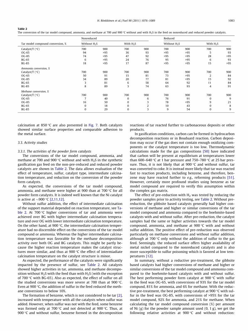
Table 2The conversion of the tar model compound, ammonia, and methane at 700 and 900 �C without and with H2S in the feed on nonreduced and reduced powder catalysts.
Nonreduced Reduced
Tar model compound conversion, % Without H2S With H2S Without H2S With H2S
Catalyst/T (�C) 700 900 700 900 700 900 700 900OG-65 94 >95 36 93 >95 >95 5 93OG-85 74 >95 47 92 >95 >95 28 >95BG-65 6 >95 24 76 95 >95 6 93BG-85 18 >95 17 87 >95 >95 15 >95
Ammonia conversion, %Catalyst/T (�C) 700 900 700 900 700 900 700 900OG-65 50 91 15 81 73 >95 2 84OG-85 34 89 20 77 81 >95 15 92BG-65 3 81 6 58 64 92 11 84BG-85 8 89 3 74 63 93 4 91
Methane conversion, %Catalyst/T (�C) 700 900 700 900 700 900 700 900OG-65 7 40 0 6 76 91 0 9OG-85 16 50 0 3 78 >95 9 21BG-65 0 18 0 2 10 43 0 8BG-85 0 29 0 3 9 54 0 9
H. Rönkkönen et al. / Fuel 90 (2011) 1076–1089 1083
calcination at 850 �C are also presented in Fig. 7. Both catalystsshowed similar surface properties and comparable adhesion tothe metal surface.
3.3. Activity studies
3.3.1. The activities of the powder form catalystsThe conversions of the tar model compound, ammonia, and
methane at 700 and 900 �C without and with H2S in the syntheticgasification gas feed on the non-pre-reduced and reduced powdercatalysts are shown in Table 2. The data allows evaluation of theeffect of temperature, sulfur, catalyst type, intermediate calcina-tion temperature, and reduction on the conversion of the powderform catalysts.
As expected, the conversions of the tar model compound,ammonia, and methane were higher at 900 than at 700 �C for allpowder form catalysts. It is indeed well known that the Ni catalystis active at �900 �C [2,11,12].
Without sulfur addition, the effect of intermediate calcinationof the support material depended on reaction temperature, see Ta-ble 2. At 700 �C higher conversions of tar and ammonia wereachieved over BG with higher intermediate calcination tempera-ture and over OG with lower intermediate calcination temperature.On the other hand, at 900 �C, the intermediate calcination temper-ature had no discernible effect on the conversions of the tar modelcompound or ammonia. Whereas the higher intermediate calcina-tion temperature was favorable for the methane decompositionactivity over both OG and BG catalysts. This might be partly be-cause the higher reaction temperature makes the catalyst struc-tures more similar, and thus at 900 �C the effect of intermiadiatecalcination temperature on the catalyst structure is minor.
As expected, the performance of the catalysts were significantlyimpacted by the presence of sulfur, see Table 2. All catalystsshowed higher activities in tar, ammonia, and methane decompo-sition without H2S with the feed than with H2S (with the exceptionof 700 �C with BG-65). Also as expected, the effect of sulfur on allthe studied conversions was more severe at 700 than at 900 �C.Even at 900 �C, the addition of sulfur in the feed reduced the meth-ane conversions to below 10%.
The formation of benzene, which is not considered to be tar [2],increased with temperature with all the catalysts when sulfur wasadded. However, when sulfur was not with the feed, some benzenewas formed only at 700 �C and not detected at 900 �C. Thus, at900 �C and without sulfur, benzene formed in the decomposition
reactions of tar reacted further to carbonaceous deposits or otherproducts.
In gasification conditions, carbon can be formed in hydrocarbondecomposition reactions or in Bouduard reaction. Carbon deposi-tion may occur if the gas does not contain enough oxidizing com-ponents or the catalyst temperature is too low. Thermodynamiccalculations made for the gas compositions [50] have indicatedthat carbon will be present at equilibrium at temperatures lowerthan 600–640 �C at 1 bar pressure and 750–780 �C at 25 bar pres-sure. Thus, it is not likely that at 900 �C and without sulfur, tarwas converted to coke. It is instead more likely that tar was reactedfast to reaction products, including benzene, and therefore, ben-zene may have reacted further to e.g., reforming products [51].However, certainly more profound studies using benzene as tarmodel compound are required to verify this assumption withinthe complex gas matrix.
The effect of pre-reduction with H2 was tested by reducing thepowder samples prior to activity testing, see Table 2. Without pre-reduction, the gibbsite based catalysts generally had higher con-versions of methane and higher or similar conversions of the tarmodel compound and ammonia compared to the boehmite-basedcatalysts with and without sulfur. After pre-reduction, the catalystsamples had the same or higher activities towards the tar modelcompound, ammonia, and methane at 900 �C with and withoutsulfur addition. The positive effect of pre-reduction was observedparticularly on methane conversions and without sulfur addition,although at 700 �C only without the addition of sulfur to the gasfeed. Seemingly, the reduced surface offers higher availability ofmetal nickel compared to the nonreduced catalysts and is alsomore susceptible to sulfur poisoning which is favored at low tem-peratures [12].
In summary, without a reductive pre-treatment, the gibbsitebased catalysts had higher conversions of methane and higher orsimilar conversions of the tar model compound and ammonia com-pared to the boehmite-based catalysts with and without sulfur.The best performing powder form catalyst at 900 �C with sulfurin the feed was OG-65, with conversions of 93% for the tar modelcompund, 81% for ammonia, and 6% for methane. With the reduc-tive pre-treatment, the best performing catalyst at 900 �C with sul-fur in the feed was OG-85, with conversions of >95% for the tarmodel compund, 92% for ammonia, and 21% for methane. Whencalculating the tar model compound conversion (%) per amountof Ni (g) for the powder sample amount used (0, 1 g), we get thefollowing relative activities at 900 �C and without reduction:

1084 H. Rönkkönen et al. / Fuel 90 (2011) 1076–1089
3100 for OG-65 and OG-85 3.1, 5000 for BG-65 and 4100 for BG-85at 900 �C. This comparison thus rather suggests that BG catalystsare slightly more active based on the amount of Ni in the catalyst.However, looking at the respective data representing 700 �C, thesuperior performance of the OG materials – also per amount ofnickel – is selfevident.
3.3.2. The activities of the plasma sprayed and reference catalystsFigs. 8 and 9 compare the conversion of the tar model com-
pound, ammonia, and methane at 700 and 900 �C without and withH2S in the feed on the plasma-sprayed catalysts and the referencemonolith catalyst. Several indicators are compared such as: con-versions of the tar model compound, ammonia, and methane at700 and 900 �C with and without sulfur, the effect of catalyst typeon activity, and the effect of the intermediate calcination temper-ature on the activity. The catalysts were tested without pre-reduc-tion to simulate the situation at a gasification plant wherepre-reduction is not possible.
The conversions of the tar model compound, ammonia, andmethane were higher at 900 �C than at 700 �C when sulfur wasnot added (Figs. 8 and 9). In general, at 900 �C, all the catalystsshowed high activities in tar (over 90%) and ammonia (over 80%)decomposition without H2S in the feed. Moreover, the conversionof total aromatic hydrocarbons (not shown) were also over 90%at 900 �C without sulfur addition.
0
10
20
30
40
50
60
70
80
90
100
700°C 900°C
Without H2S
Tar
mod
el c
ompo
und
conv
ersi
on (
%)
0
10
20
30
40
50
60
70
80
90
100
700°C 900°C
Without H2S addition
Am
mon
ia c
onve
rsio
n (%
)
Fig. 8. The conversion of the tar model compound (upper graph) and ammonia (lowercatalysts: G-65 (black), G-85 (white), B-65 (diagonal lines from left), B-85 (squares), an
At 700 �C, higher conversions of tar were achieved over gibbsitebased catalysts with lower (650 �C) intermediate calcination tem-peratures and over boehmite-based catalysts with higher(850 �C) intermediate calcination temperatures, in qualitativeagreement with the data observed with powder form catalysts(see Section 3.3.1). Over gibbsite and boehmite-based catalysts,however, the lower intermediate calcination temperature favoredammonia and methane decomposition at 700 �C. The intermediatecalcination temperature had no discernible effect on the conver-sions of the tar model compound, ammonia, and methane at900 �C. The gibbsite based catalysts had higher tar and methaneconversions at 900 �C, however, compared to boehmite-based cat-alysts when sulfur was not with the feed.
The effect of sulfur poisoning depended on the temperature: at900 �C the poisoning was much less severe than at 700 �C. WithH2S addition, the activities of the gibbsite based foils towards thetar model compound were higher than those of the boehmitebased foils. The highest conversions at 900 �C with H2S in the feedwere obtained with the G-65 foil, being over 90% in the tar modelcompound, over 80% for ammonia, and around 15% for methane.The activity of the G-65 foil at 900 �C was comparable to a mono-lithic Ni catalyst on modified zirconia with respect to decomposi-tion of the tar model compound. But for ammonia removal,higher levels of conversion were achieved. It should also be notedthat the formation of benzene increased with temperature with all
700°C 900°C
With H2S
700°C 900°C
With H2S addition
graph) at 700 and 900 �C without and with 100 ppm H2S in the feed on differentd Ni/modified ZrO2 (horizontal lines).

0102030405060708090
100
700°C 900°C 700°C 900°C
Without H2S addition With H2S addition
Met
hane
con
vers
ion
(%)
Fig. 9. The conversion of methane at 700 and 900 �C without and with 100 ppm H2S in the feed on different catalysts: G-65 (black), G-85 (white), B-65 (diagonal lines fromleft), B-85 (squares), and Ni/modified ZrO2 (horizontal lines).
H. Rönkkönen et al. / Fuel 90 (2011) 1076–1089 1085
the catalysts when sulfur was added to the gas feed. The interme-diate calcination temperature had no discernible effect on the sul-fur tolerance of the catalysts.
The effect of the plasma spraying and experimental set-up(powders versus plasma catalysts) on the performance dependedon the temperature. At 900 �C the plasma-sprayed catalystsshowed activities similar to those of the powder form catalystsin the tar model compound and ammonia conversion, both withand without sulfur addition. This is notweworthy since the gasflow, the amount of catalyst, the length of the catalyst bed, andthe space velocity varied significantly, being 27 000 1/h in powdercatalyst testing and 3500 1/h at the foil catalysts testing. Hepola[12] has previously noted that at sulfur free conditions the conver-sions of toluene, ammonia, and methane were not significantly af-fected by space velocity between 7500–30,000 1/h at 900 �C,20 bar over Ni catalysts with gasification gas feed. Whereas withsulfur addition the conversions decreased as the space velocityincreased.
Hence, the preparation of the catalyst support by plasma spray-ing had no significant effect on the conversions of the tar modelcompound and ammonia at 900 �C for the studied catalysts. Fur-thermore, this was observed with and without sulfur in the gasfeed. On the other hand, the methane conversions were higherfor all the plasma-sprayed catalysts compared to the powders at900 �C with and without sulfur addition for gibbsite based foils.This is perhaps partly due to the difference in the space velocity.
The sprayed coatings are affected by the process features suchas the high temperature of the plasma stream, high velocity ofthe sprayed particles, etc. The final thermal treatment at 850 �C isperhaps not yet high enough to stabilize the structure of the coat-ing. In support of this view, an additional improvement of thesprayed samples activity was observed during the activity testingat 900 �C, but not at 700 �C.
Interestingly, and contrary to powder catalysts, the ammoniaconversions at 700 �C were higher with than without sulfur addi-tion over both gibbsite and boehmite based as well as Ni monolithcatalysts. This difference is probably partly due to the differentspace hourly velocities.
The conversion levels for the tar model compound and totalaromatic hydrocarbon obtained in this work are in line with thosereported earlier, although the experimental conditions vary anddifferent Ni loadings have been used on several different supports[2,8–27]. For example, complete tar conversion over a Ni monolithcatalyst at 900 �C and 5 bar pressure in a fixed bed reactor has beenachieved [12], and at above 800 �C complete conversion of meth-
ane, naphthalene, and benzene to H2O, CO, and H2 has been ob-served [16]. In addition, almost complete tar decomposition hasbeen obtained above 850 �C over a nickel-based monolith type ofcatalyst in slip-stream testing from an 8 MW dual fluidized-bedsteam gasifier plant in Güssing [20].
The levels of conversion of ammonia over G-65 and Ni/modifiedZrO2 were more than 90% at 900 �C without sulfur and around 80%with sulfur addition. These results are in agreement with e.g. Hepo-la [12], who obtained around 70–80% ammonia conversion on a Nimonolith catalyst at 900 �C and 5 bar pressure in a fixed bed reac-tor since based on our experience, the pressure difference of 5 barhas only a minor effect at reaction temperatures of approx. 900 �C.Our data is also in line with Wang et al. [53], where the NH3 con-centration in a flue gas from biomass gasification decreased by 90%at 900 �C.
In our work, the conversion of methane for the studied catalystsincreased with temperature, but was never higher than �70%(Fig. 9). With sulfur addition, the conversion of methane was loweven at 900 �C. The highest conversion of methane in the presenceof H2S at 900 �C was obtained with a G-65 foil, around 15%. The ob-served decrease in methane conversions over Ni catalysts with sul-fur addition is in agreemeent with e.g. Albertazzi et al. [25], whichreported a drop in methane conversion over Ni catalysts after50 ppm H2S exposure. It should be born in mind, however, that ifthe product gas is directed to e.g., FT-liquid production, methaneis undesirable, but if the product gas is utilized in energy produc-tion, the light hydrocarbons in the gas are acceptable.
3.3.3. Stability and sulfur resistance of G-65 and Ni/modified zirconiacatalysts
The stabilities of the G-65 and the Ni/modified zirconia cata-lysts were studied in ten hour experiments at 800 �C with syn-thetic gasification gas containing 100 ppm H2S (space velocity3500 1/h). This temperature was chosen in order to more clearlyobserve changes in the activity than could be seen at 900 �C be-cause it is well documented that at higher temperature of 900 �Cthe sulfur poisoning of Ni based catalysts in this application is re-duced. Thus, at 800 �C sulfur clearly poisons the catalysts; the low-er the temperature the more severe the sulfur poisoning of the Nicatalyst (see e.g. [12]). Therefore, at 800 �C we better can observethe changes in activity while having a high enough temperatureto allow Ni to still to perform.
The levels of conversion of the tar model compound and ammo-nia remained higher at 800 �C with the G-65 catalyst than the cor-responding levels of conversion with the Ni/modified zirconia

0
10
20
30
40
50
60
70
80
90
100
0 2 4 6 8 10
Time (h)
Con
vers
ion
(%)
Ammonia G-65Tar model compound G-65
Ammonia Ni/modified ZrO2Tar model compound Ni/modified ZrO2
Nitrogen flush overnight
Fig. 10. Conversion levels of the tar model compound and ammonia at 800 �C with G-65 and Ni/modified ZrO2 catalysts.
0
10
20
30
40
50
60
70
80
90
100
0 100 0 150 0 1000 0 500 0
H2S content (ppm)
Co
nve
rsio
n (%
)
Total aromatics G-65 Total aromaticsNi/modified ZrO2
Ammonia G-65 Ammonia Ni/modified ZrO2
Methane G-65 Methane Ni/modified ZrO2
Fig. 11. The effect of H2S feed concentration on the conversion of total aromatic hydrocarbon, ammonia, and methane over G-65-Ni and Ni/modified zirconia catalysts at900 �C.
1086 H. Rönkkönen et al. / Fuel 90 (2011) 1076–1089
(Fig. 10). A decrease in the conversion of ammonia over G-65, how-ever, was observed as a function of time on stream.
The activity of the Ni/modified zirconia catalyst towards the tarmodel compound was higher after the overnight N2 flush (due tothe safety practice of the laboratory), whereas for the G-65 catalystit remained at similar levels before and after the N2 flush. This im-proved activity of the Ni/modified zirconia might be due to desorp-tion of sulfur compounds during the nitrogen flush, which freesactive nickel sites. This re-activation phenomenon is seen clearlyon Ni/modified zirconia, but not on G-65 probably because of thelower specific surface area and lower Ni content of the Ni/modifiedzirconia compared to the G-65 catalyst.
Interestingly, for both catalysts the ammonia conversion waslower after the overnight N2 flush. The conversion of methane
was negligible with both catalysts. The conversion of total aro-matic hydrocarbons (not shown) remained around 35% over G-65and at 20–30% over Ni/modified zirconia.
In biomass gasification gas, the content of H2S is normally be-low 100 ppm. If peat is used as a feedstock, however, the H2S con-tent can be as high as 500 ppm and in coal gasification it can evenbe much higher [12]. Therefore, the effect of H2S feed concentra-tion on the activities of G-65 and Ni/modified zirconia catalystswere studied.
In general, both of the studied catalysts behaved similarly withvarious levels of H2S (Fig. 11). The higher the H2S content, the low-er the levels of conversion of the total aromatic hydrocarbons. Theconversion of total aromatic hydrocarbon was used here as a com-parative basis instead of the tar model compound because of the
-1.2
-1
-0.8
-0.6
-0.4
-0.2
0
0.2
0.4
0.6
0.8
1
CO CO2 H2 H2O CH4 C2H4
Out
/In r
atio
G-65 700°C
Ni/mod. ZrO2700°C
G-65 700°Cwith sulfur
Ni/mod. ZrO2700°C withsulfurG-65 900°C
Ni/mod. ZrO2900°C
G-65 900°Cwith sulfur
Ni/mod. ZrO2900°C withsulfur
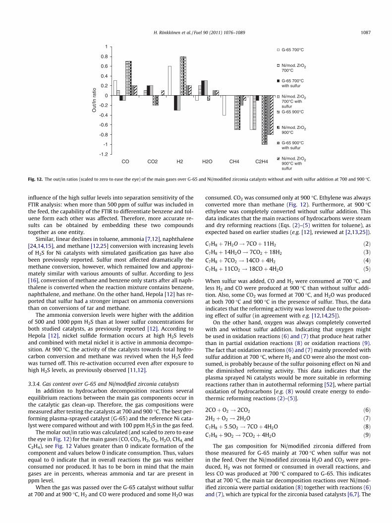
Fig. 12. The out/in ratios (scaled to zero to ease the eye) of the main gases over G-65 and Ni/modified zirconia catalysts without and with sulfur addition at 700 and 900 �C.
H. Rönkkönen et al. / Fuel 90 (2011) 1076–1089 1087
influence of the high sulfur levels into separation sensitivity of theFTIR analysis: when more than 500 ppm of sulfur was included inthe feed, the capability of the FTIR to differentiate benzene and tol-uene form each other was affected. Therefore, more accurate re-sults can be obtained by embedding these two compoundstogether as one entity.
Similar, linear declines in toluene, ammonia [7,12], naphthalene[24,14,15], and methane [12,25] conversion with increasing levelsof H2S for Ni catalysts with simulated gasification gas have alsobeen previously reported. Sulfur most affected dramatically themethane conversion, however, which remained low and approxi-mately similar with various amounts of sulfur. According to Jess[16], conversion of methane and benzene only starts after all naph-thalene is converted when the reaction mixture contains benzene,naphthalene, and methane. On the other hand, Hepola [12] has re-ported that sulfur had a stronger impact on ammonia conversionsthan on conversions of tar and methane.
The ammonia conversion levels were higher with the additionof 500 and 1000 ppm H2S than at lower sulfur concentrations forboth studied catalysts, as previously reported [12]. According toHepola [12], nickel sulfide formation occurs at high H2S levelsand combined with metal nickel it is active in ammonia decompo-sition. At 900 �C, the activity of the catalysts towards total hydro-carbon conversion and methane was revived when the H2S feedwas turned off. This re-activation occurred even after exposure tohigh H2S levels, as previously observed [11,12].
3.3.4. Gas content over G-65 and Ni/modified zirconia catalystsIn addition to hydrocarbon decomposition reactions several
equilibrium reactions between the main gas components occur inthe catalytic gas clean-up. Therefore, the gas compositions weremeasured after testing the catalysts at 700 and 900 �C. The best per-forming plasma-sprayed catalyst (G-65) and the reference Ni cata-lyst were compared without and with 100 ppm H2S in the gas feed.
The molar out/in ratio was calculated (and scaled to zero to easethe eye in Fig. 12) for the main gases (CO, CO2, H2, O2, H2O, CH4, andC2H4), see Fig. 12 Values greater than 0 indicate formation of thecomponent and values below 0 indicate consumption. Thus, valuesequal to 0 indicate that in overall reactions the gas was neitherconsumed nor produced. It has to be born in mind that the maingases are in percents, whereas ammonia and tar are present inppm level.
When the gas was passed over the G-65 catalyst without sulfurat 700 and at 900 �C, H2 and CO were produced and some H2O was
consumed. CO2 was consumed only at 900 �C. Ethylene was alwaysconverted more than methane (Fig. 12). Furthermore, at 900 �Cethylene was completely converted without sulfur addition. Thisdata indicates that the main reactions of hydrocarbons were steamand dry reforming reactions (Eqs. (2)–(5) written for toluene), asexpected based on earlier studies (e.g. [12], reviewed at [2,13,25]).
C7H8 þ 7H2O! 7COþ 11H2 ð2ÞC7H8 þ 14H2O! 7CO2 þ 18H2 ð3ÞC7H8 þ 7CO2 ! 14COþ 4H2 ð4ÞC7H8 þ 11CO2 ! 18COþ 4H2O ð5Þ
When sulfur was added, CO and H2 were consumed at 700 �C, andless H2 and CO were produced at 900 �C than without sulfur addi-tion. Also, some CO2 was formed at 700 �C, and H2O was producedat both 700 �C and 900 �C in the presence of sulfur. Thus, the dataindicates that the reforming activity was lowered due to the poison-ing effect of sulfur (in agreement with e.g. [12,14,25]).
On the other hand, oxygen was always completely convertedwith and without sulfur addition. Indicating that oxygen mightbe used in oxidation reactions (6) and (7) that produce heat ratherthan in partial oxidation reactions (8) or oxidation reactions (9).The fact that oxidation reactions (6) and (7) mainly proceeded withsulfur addition at 700 �C, where H2 and CO were also the most con-sumed, is probably because of the sulfur poisoning effect on Ni andthe diminished reforming activity. This data indicates that theplasma sprayed Ni catalysts would be more suitable in reformingreactions rather than in autothermal reforming [52], where partialoxidation of hydrocarbons [e.g. (8) would create energy to endo-thermic reforming reactions (2)–(5)].
2COþ O2 ! 2CO2 ð6Þ2H2 þ O2 ! 2H2O ð7ÞC7H8 þ 5:5O2 ! 7COþ 4H2O ð8ÞC7H8 þ 9O2 ! 7CO2 þ 4H2O ð9Þ
The gas composition for Ni/modified zirconia differed fromthose measured for G-65 mainly at 700 �C when sulfur was notin the feed. Over the Ni/modified zirconia H2O and CO2 were pro-duced, H2 was not formed or consumed in overall reactions, andless CO was produced at 700 �C compared to G-65. This indicatesthat at 700 �C, the main tar decomposition reactions over Ni/mod-ified zirconia were partial oxidation (8) together with reactions (6)and (7), which are typical for the zirconia based catalysts [6,7]. The
1088 H. Rönkkönen et al. / Fuel 90 (2011) 1076–1089
similarity of the product gases over Ni/modified zirconia to thoseobserved for G-65 at 900 �C indicate that the reforming reactionsbecome dominating at 900 �C and oxygen might be used in sidereactions (6) and (7).
Ammonia decomposition is suggested to occur mainly via re-verse ammonia synthesis reaction (10) over Ni catalysts ([12], re-viewed in [2]), and therefore the reaction (10) is likely to alsooccur over the presently studied catalyst. Also, several equilibriumreactions between the gas components may occur, such as metha-nation, water gas, and Bouduard and water gas shift reactions,which can affect the product distribution [2,12]. Further experi-ments are needed to verify and study the occurring reactions inmore detailed.
N2 þ 3H2 $ 2NH3 ð10Þ
3.3.5. The relationship between catalyst properties and activityWhen addressing the interrelation of catalysts properties and
performance, it is important to keep in mind that the metal con-tents varied significantly. Partly due to the highest metal content,the gibbsite based catalysts with the nickel hydrotalcite coatingwere more active than the boehmite-based catalysts at 900 �C inthe tar model compound, ammonia, and methane decomposition,in both powder and plasma sprayed forms. Moreover, the mea-sured activity levels were comparable to or higher than that ofmonolithic 8 w-% Ni/modified zirconia.
In addition, the gibbsite based catalysts were also more resis-tant to sulfur poisoning at 900 �C and the best performing catalyst(G-65) was very stable for ten hours at 800 �C with a sulfur con-taining feed. Since the surface areas of the gibbsite based powderswere lower than those of the boehmite-based catalysts, the BETseem not to be the determining factor for catalyst activity and sul-fur resistance. Furthermore, the intermediate calcination tempera-ture only had a small effect on the activity.
In the gibbsite based powder catalysts the surface was more en-riched with Ni and the metal content was generally higher thusresulting in higher activity. It has previously been concluded thateggshell-type Ni loading of Mg-Al hydrotalcite catalysts is highlyactive and stable in methane reforming [46]. Since the same activ-ity levels were measured for both tar and ammonia for the plasma-sprayed catalysts as with the powders at 900 �C with and withoutsulfur, it seems that the preparation of the catalyst support by plas-ma spraying had no significant effect on the performance of thestudied catalysts at 900 �C.
4. Conclusions
The following conclusions can be drawn based on the resultspresented here:
1. Plasma spraying of the gibbsite and boehmite based compositepowders with a surface hydrotalcite layer produced coatings onmetal substrates with high adhesion. These coatings were suc-cessfully used for deposition of Ni as an active metal.
2. When sulfur was present in the gas, the gibbsite based catalystswere more active towards tar, ammonia, and methane decom-position from synthetic gasification gas than the boehmite-based catalysts. One reason for the higher activity of the gibb-site based catalysts is surface enrichment of active Ni, whereasin boehmite-based catalysts, more uniform Ni distribution isachieved due to the different decompositions of the powdercores.
3. The gasification gas clean-up results were comparable to that of8 w-% Ni on modified zirconia. The activity and stability of thehigh Ni containing gibbsite based plasma sprayed Ni catalyst
during a ten hour experiment at 800 �C were better than thoseof Ni on modified zirconia.
4. Thermal plasma-sprayed nickel catalysts were successfullyused in gasification gas clean-up in which high mechanicalstrength and good thermal stability of the catalysts are needed.Further activity and stability tests of the catalysts in long-termexperiments are required to prove the performance with elon-gated times on stream. Long lifetime and superior performancewill be necessary to justify the use of the complex and costlyplasma spraying method for commercial applications.
Acknowledgements
The authors acknowledge the financial support of the EuropeanUnion, Project no. 019761: Advanced Biomass Gasification for HighEfficiency. The authors thank Tiia Viinikainen, Laura Vilkko, PäiviJokimies, and Mari-Leena Koskinen-Soivi for assistance with theexperiments. Jouko Lahtinen and Jani Sainio are thanked for theXPS analysis.
References
[1] Bridgwater A. The technical and economic feasibility of biomass gasificationfor power generation. Fuel 1995;74:631–53.
[2] Torres W, Pansare S, Goodwin J. Hot gas removal of tars, ammonia andhydrogen sulfide from biomass gasification gas. J Catal Rev Sci Eng2007;49(4):407–56.
[3] Simell PA, Leppälahti JK, Kurkela EA. Tar-decomposing activity of carbonaterocks under high CO2 partial pressure. Fuel 1995;74:938–45.
[4] Orío A, Corella J, Narváez I. Performance of different dolomites on hot raw gasclean-up from biomass gasification with air. Ind Eng Chem Res1997;36(9):3800–8.
[5] Sutton D, Kelleher B, Ross JRH. Review of literature on catalysts for biomassgasification. Fuel Process Technol 2001;73:155–73.
[6] Juutilainen SJ, Simell PA, Krause OI. Zirconia: Selective oxidation catalyst forremoval of tar and ammonia from biomass gasification gas. Appl Catal B2006;62:86–92.
[7] Viinikainen T; Rönkkönen, H.; Bradshaw H.; Stephenson H.; Airaksinen S.;Reinikainen M.; Simell P.; Krause Outi, Acidic and basic surface sites ofzirconia-based biomass gasification gas clean-up catalysts, Appl Catal A:General, 362: 69-177.
[8] Corella J, Toledo JM, Padilla R. Olivine or dolomite as in-bed additive inbiomass gasification with air in a fluidized bed: which is better? Energy Fuels2004;18(3):713–20.
[9] Zhang R, Wang Y, Brown RC. Steam reforming of tar compounds over Ni/olivinecatalysts doped with CeO2. Energy Conv Manag 2007;48(1):68–77.
[10] Mojtahedi W, Abbasian J. Catalytic decomposition of ammonia in a fuel gas athigh temperature and pressure. Fuel 1995;74(11):1698–703.
[11] Hepola J, Simell PA. Sulfur poisoning of nickel-based hot gas clean-up catalystsin synthetic gasification gas: I. Effect of different process parameters. ApplCatal B 1997;14(3–4):287–321.
[12] Hepola J. Sulfur transformations in catalytic hot-gas clean-up of gasificationgas [PhD Thesis]. Helsinki (Finland): Helsinki University of Technology; 2000.
[13] Coll R, Salvadó J, Farriol X, Montané D. Steam reforming model compounds ofbiomass gasification tars: conversion at different operating conditions andtendency towards coke formation. Fuel Process Technol 2001;74(1):19–31.
[14] Srinakruang J, Sato K, Vitidsant T, Fujimoto K. Highly efficient sulfur and cokingresistance catalysts for tar gasification with steam. Fuel 2006;85(17–18):2419–26.
[15] Sato K, Fujimoto K. Development of new nickel based catalyst for tar reformingwith superior resistance to sulfur poisoning and coking in biomassgasification. Catal Commun 2007;8(11):1697–701.
[16] Jess A. Catalytic upgrading of tarry fuel gases: a kinetic study with modelcomponents. Chem Eng Proc 1996;35(6):487–94.
[17] Swierczynski D, Libs S, Curson S, Kiennemann A. Steam reforming of tar from abiomass gasification process over Ni/olivine catalyst using toluene as a modelcompound. Appl Catal B 2007;74(3–4):211–22.
[18] Swierczynski D, Curson S, Kiennemann A. Study of steam reforming of tolueneused as model compound of tar produced by biomass gasification. Chem EngProc 2008;47(3):508–13.
[19] Wang TJ, Chang J, Wu CZ, Fu Y, Chen Y. The steam reforming of naphthaleneover a nickel–dolomite cracking catalyst. Biomass Bioenergy2005;28(5):508–14.
[20] Pfeifer C, Hofbauer H. Development of catalytic tar decompositiondownstream from a dual fluidized bed biomass steam gasifier. PowderTechnol 2008;180(1–2):9–16.
[21] Tomishige K, Miyazawa T, Kimura T, Kunimori K, Koizumi N, Yamada M.Resistance to sulfur poisoning of hot gas clean-up catalysts for the removal oftar from the pyrolysis of cedar wood. Appl Catal B 2005;60(3–4):299–307.

H. Rönkkönen et al. / Fuel 90 (2011) 1076–1089 1089
[22] Kimura T, Miyazawa T, Nishikawa J, Kado S, Okumura K, Miyao T, et al.Development of Ni catalysts for tar removal by steam gasification of biomass.Appl Catal B 2006;68(3–4):160–70.
[23] Tomishige K, Kimura T, Nishikawa J, Miyazawa T, Kunimori K. Promoting effectof the interaction between Ni and CeO2 on steam gasification of biomass. CatalCommun 2007;8(7):1074–9.
[24] Ma L, Baron G. Mixed zirconia–alumina supports for Ni/MgO based catalyticfilters for biomass fuel gas clean-up. Powder Technol 2008;180(1–2):21–9.
[25] Albertazzi S, Basile F, Brandin J, Einvall J, Fornasari G, Hulteberg C, et al. Effectof fly ash and H2S on a Ni-based catalyst for the upgrading of a biomass-generated gas. Biomass Bioenergy 2008;32(4):345–53.
[26] Bona S, Guillen J, Alcalde GJ, Garcia L, Bilbao R. Toluene steam reforming usingcoprecipitated Ni/Al catalysts modified with lanthanum or cobalt. Chem Eng J2008;137(3):587–97.
[27] Taralas G, Kontominas MG. Kinetic modelling of VOC catalytic steam pyrolysisfor tar abatement phenomena in gasification/pyrolysis technologies. Fuel2004;83(9):1235–45.
[28] Shohet J. Plasma-aided manufacturing. Plasma Sci 1991;19(5):725–33.[29] Liu C, Vissokov G, Jang B. Catalyst preparation using plasma technologies. Catal
Today 2002;72(3–4):173–84.[30] Ismagilov Z, Podyacheva O, Solonenko O, Pushkarev V, Kuz’min V, Ushakov V,
et al. Application of plasma spraying in the preparation of metal-supportedcatalysts. Catal Today 1999;51(3–4):411–7.
[31] Pranevicius L, Pranevicius L, Valatkevicius P, Valincius V. Plasma spraydeposition of Al–Al2O3 coatings doped with metal oxides: catalyticapplications. Surf Coat Technol 2000;123(2–3):122–8.
[32] Oukacine L, Gitzhofer F, Abatzoglou N, Gravelle D. Application of the inductionplasma to the synthesis of two dimensional steam methane reforming Ni/Al2O3 catalyst. Surf Coat Technol 2006;201(5):2046–53.
[33] Tsibulev P, Parhomenko B. Proc Plasmachem 1979;79:60.[34] Shi K, Qian Z, Zhuang M. Microstructure and properties of sprayed ceramic
coating. J Am Ceram Soc 1988;71(11):924–9.[35] Yoshida T. The future of thermal plasma processing for coating. Pure Appl
Chem 1994;66(6):1223–30.[36] Ilavsky J, Forman J, Chraska P. Plasma-sprayed aluminium coating. J Mater Sci
Lett 1992;11(9):573–4.[37] Gorynin IV, Farmakovsky BV, Khinsky AP, Kalogina KV, Szekely J, Saluje NS;
Technalum Research, Inc. Catalyst composition and a method for itspreparation. United States patent US 5204302. 1993 April 20.
[38] Khan H, Frey H. R.f. plasma spray deposition of LaMOx (M Co, Mn, Ni) films andthe investigations of structure, morphology and the catalytic oxidation of COand C3H8. J Alloys Comp 1993;190(2):209–17.
[39] Dozmorov SV, Pestryakov AN, Kolesnikov VN, Reznik BL; OMSKIJ G PED I.Method of producing promoted metal catalyst. SU Patent, SU1695978 (A1).1989.
[40] Khinsky AP, Pakamanis R; UAB Norta. Method for producing a multifunctionalcatalytic element. WO Patent WO2006041273 (A1).2006 April 20.
[41] Cavani F, Trifiro F, Vaccari A. Hydrotalcite-type anionic clays: preparation,properties and applications. Catal Today 1991;11(2):173–301.
[42] Trifirò F, Vaccari A. Hydrotalcite-like anionic clays (layered doublehydroxides). In: Albert G, Bein T, editors. Comprehensive SupramolecularChemistry. Oxford: Pergamon; 1996. p. 251–91.
[43] Vaccari A. Preparation and catalytic properties of cationic and anionic clays.Catal Today 1998;41:53–71.
[44] Rives V, Ulibarri MA. Layered double hydroxides (LDH) intercalated with metalcoordination compounds and oxometalates. Coord Chem Rev 1999;181(1):61–120.
[45] Clause O, Rebours B, Merlen E, Trifiro F, Vaccari A. Preparation andcharacterization of nickel-aluminum mixed oxides obtained by thermaldecomposition of hydrotalcite-type precursors. J Catal 1992;133:231–46.
[46] Takehira K, Kawabata T, Shishido T, Murakami K, Ohi T, Shoro D, et al.Mechanism of reconstitution of hydrotalcite leading to eggshell-type Niloading on Mg–Al mixed oxide. J Catal 2005;231:92–104.
[47] Kanezaki E. Preparation of layered double hydroxides. In: Wypych F,Satyanarayana KG, editors. Clay surfaces: fundamentals andapplications. New York: Elsevier; 2004. p. 345–73.
[48] Albertazzi S, Basile F, Benito P, Del Gallo P, Fornasari G, Gary D, et al. Effect ofsilicates on the structure of Ni-containing catalysts obtained fromhydrotalcite-type precursors. Catal Today 2007;128(3–4):258–63.
[49] Wagner C, Riggs W, Davis L, Moulder J, Muilenberg G, editors. Handbook of X-Ray photoelectron spectroscopy. USA: Perkin–Elmer Corporation PhysicalElecctronic Division; 1979.
[50] Simell, P., Ståhlberg, P., Solantausta Y., Hepola, J, Kurkela, E., Gasification GasCleaning with Nickel Monolith. In Bridgwater, A.V and Boocock, D. G. B (eds.)Development in thermochemical biomass conversion vol. 2 Blackie Academicand Professional, pp. 1103-1116.
[51] Park H, Park S, Sohn J, Park J, Jeon J-K, Kim S-S, et al. Steam reforming ofbiomass gasification tar using benzene as a model compound over various Nisupported metal oxide catalysts. Bioresour Technol 2010;101(1):S101–3.
[52] Kaila, R., Autothermal reforming of simulated and commercial fuels onzirconia-supported mono-and bimetallic noble metal catalysts, TKKDissertation 141, Helsinki University of Technology, 2008.
[53] Wang W, Padban N, Ye Z, Andersson A, Bjerle I. Kinetics of ammoniadecomposition in hot gas clean-up. Ind Eng Chem Res 1999;38:4175–82.