Use of an amorphous silicon electronic portal imaging device for relative dosimetry and quality...
17
Use of an amorphous silicon electronic portal imaging device for multileaf collimator quality control and calibration This article has been downloaded from IOPscience. Please scroll down to see the full text article. 2005 Phys. Med. Biol. 50 1377 (http://iopscience.iop.org/0031-9155/50/7/003) Download details: IP Address: 152.92.171.92 The article was downloaded on 08/10/2010 at 20:20 Please note that terms and conditions apply. View the table of contents for this issue, or go to the journal homepage for more Home Search Collections Journals About Contact us My IOPscience
-
Upload
independent -
Category
Documents
-
view
1 -
download
0
Transcript of Use of an amorphous silicon electronic portal imaging device for relative dosimetry and quality...

Use of an amorphous silicon electronic portal imaging device for multileaf collimator quality
control and calibration
This article has been downloaded from IOPscience. Please scroll down to see the full text article.
2005 Phys. Med. Biol. 50 1377
(http://iopscience.iop.org/0031-9155/50/7/003)
Download details:
IP Address: 152.92.171.92
The article was downloaded on 08/10/2010 at 20:20
Please note that terms and conditions apply.
View the table of contents for this issue, or go to the journal homepage for more
Home Search Collections Journals About Contact us My IOPscience

INSTITUTE OF PHYSICS PUBLISHING PHYSICS IN MEDICINE AND BIOLOGY
Phys. Med. Biol. 50 (2005) 1377–1392 doi:10.1088/0031-9155/50/7/003
Use of an amorphous silicon electronic portal imagingdevice for multileaf collimator quality control andcalibration
S J K Baker, G J Budgell and R I MacKay
North Western Medical Physics, Christie Hospital NHS Trust, Manchester M20 4BX, UK
E-mail: [email protected]
Received 19 October 2004, in final form 6 January 2005Published 16 March 2005Online at stacks.iop.org/PMB/50/1377
AbstractMultileaf collimator (MLC) calibration and quality control is a time-consumingprocedure typically involving the processing, scanning and analysis of filmsto measure leaf and collimator positions. Faster and more reliable calibrationprocedures are required for these tasks, especially with the introduction ofintensity modulated radiotherapy which requires more frequent checking andfiner positional leaf tolerances than previously. A routine quality control (QC)technique to measure MLC leaf bank gain and offset, as well as minor offsets(individual leaf position relative to a reference leaf), using an amorphous siliconelectronic portal imaging device (EPID) has been developed. The techniquealso tests the calibration of the primary and back-up collimators. A detailedcomparison between film and EPID measurements has been performed for sixlinear accelerators (linacs) equipped with MLC and amorphous silicon EPIDs.Measurements of field size from 4 to 24 cm with the EPID were systematicallysmaller than film measurements over all field sizes by 0.4 mm for leaves/back-up collimators and by 0.2 mm for conventional collimators. This effect is due tothe gain calibration correction applied by the EPID, resulting in a ‘flattening’ ofprimary beam profiles. Linac dependent systematic differences of up to 0.5 mmin individual leaf/collimator positions were also found between EPID and filmmeasurements due to the difference between the mechanical and radiation axesof rotation. When corrections for these systematic differences were applied,the residual random differences between EPID and film were 0.23 mm and0.26 mm (1 standard deviation) for field size and individual leaf/back-upcollimator position, respectively. Measured gains (over a distance of 220 mm)always agreed within 0.4 mm with a standard deviation of 0.17 mm. Minoroffset measurements gave a mean agreement between EPID and film of0.01 ± 0.10 mm (1 standard deviation) after correction for the tilt of theEPID and small rotational misalignments between leaf banks and the back-up collimators used as a reference straight edge. Reproducibility of EPIDmeasurements was found to be very high, with a standard deviation of
0031-9155/05/071377+16$30.00 © 2005 IOP Publishing Ltd Printed in the UK 1377

1378 S J K Baker et al
<0.05 mm for field size and <0.1 mm for individual leaf/collimator positionsfor a 10 × 10 cm2 field. A standard set of QC images (three field sizes definedboth by leaves only and collimators only) can be acquired in less than 20 minand analysed in 5 min.
1. Introduction
The potential of electronic portal imaging devices (EPIDs) as tools for analysing radiationfield size has been recognized by a number of authors (Kirby 1995, Luchka et al 1996,Dunscombe et al 1999, Samant et al 2002, Prisciandaro et al 2003). EPIDs provide digitalimages which can be analysed automatically compared with films which require processing andscanning before analysis, or with plotting tank measurements which are very time-consumingto set up. The use of an EPID can thus save valuable time, enabling the checks to beperformed more frequently. The use of an EPID is particularly beneficial when changes to thefield-size calibration are required; the measurements can be re-acquired immediately to verifythe changes made. The use of an EPID also has the potential to be more reproducible due tothe removal of uncertainties in positioning and marking of films. Another benefit is that thecost of the film is removed.
The introduction of multileaf collimators (MLCs) into clinical use added a new dimensionto the complexity of the calibration and quality control (QC) checks required for x-rayfield-size definition, requiring check films to make measurements of field size for both leafbanks and primary/secondary collimators (Jordan and Williams 1994). Hounsell and Jordan(1997) describe such a preventative maintenance and quality control (QC) programme for onemanufacturer’s MLC (Elekta Oncology Systems, Crawley, UK): in order to ensure that theMLCs are positioned accurately, several sets of measurements must be performed as part ofQC checks. Measurements are made to evaluate the following:
1. Minor offsets—the relative position of every individual leaf in the MLC relative to areference leaf.
2. Major offsets—the position of each leaf bank relative to its prescribed position.3. Leaf bank gain—ensuring that the major offset does not change over its whole range of
travel, tested by measuring offset over a range of field sizes.4. Primary and secondary (back-up) collimators offset and gain.
These measurements are normally carried out using radiographic film and individual leafbank/collimator positions are measured relative to the mechanical axis of rotation, as definedby the optical cross-wire. The normal practice for establishing the true centre of the field isto observe any deviation in the cross-wire position with collimator rotation, and to transferthe average position to the film as a reference. The measurement and analysis of films forMLC QC and calibration is time-consuming, and set-up errors, particularly in marking thebeam axis centre onto the film packet, lead to a significant level of uncertainty in the resultscompared with the 2 mm tolerance on overall field size (IEC 1989).
With the introduction of intensity modulated radiotherapy (IMRT), the accuracy andprecision of the positioning of MLCs across the range of travel becomes more important(Budgell et al 2000). The consequences of inaccurate leaf positioning may be more significant,hence the tolerances on positioning may need to be tightened, and the checks performed morefrequently. Methods for using EPIDs to measure all the required components of the leafpositions would be highly beneficial as the checks could be carried out more often and a

MLC QC with an amorphous silicon EPID 1379
higher precision on the measurements should be obtainable. EPIDs have been used as a toolfor verifying the position of individual MLC leaf positions, both for QC and verification ofclinical MLC fields (Eilertsen 1997, James et al 2000, Samant et al 2002).
The commercial introduction of amorphous silicon EPIDs provides a tool ideally suitedto QC applications. This new design of EPID provides a geometrically stable, undistorted,high-resolution image, which ought to allow more accurate measurements of x-ray field sizethan ever before. In this paper, the use of an amorphous silicon EPID to obtain QC andcalibration measurements for minor offsets of individual MLC leaves, major offsets and gainof leaf banks, and offset and gain measurements for primary and secondary collimators isdescribed. Comparisons between the results obtained with the EPID and with film are madein order to assess inherent differences and accuracy. The reproducibility and precision of theresults obtained using the EPID are measured. The implementation of the software for routineQC in a department with six EPIDs and MLCs of this type is discussed.
2. Methods
A series of prescriptions were created in order to cover all aspects of calibration of the MLCand the primary/secondary collimators. In each case, the prescriptions were delivered both tothe EPID and to films. Images were exported from the EPID acquisition software and analysedoffline using software developed for the purpose. The films were scanned and analysed, thenthe results compared with those from the EPID. Each aspect of this methodology is discussedin detail below.
2.1. Description of MLC and EPID
This work was carried out using six Elekta Precise linear accelerators (Elekta OncologySystems, Crawley, UK) at this institution, each equipped with an MLC and iViewGT EPID.A full description of the MLCs can be found in Jordan and Williams (1994). The EPIDsare amorphous silicon (a-Si) flat-panel detectors. The a-Si array is 41 × 41 cm2 (1024 ×1024 pixels). Each pixel corresponds to close to 0.25 mm square at isocentre, thus enablinga comparatively high image resolution. The EPIDs are geometrically stable, with a highpositional reproducibility centred relative to the treatment head and are mounted at about160 cm FSD. The dosimetric response has been shown (McCurdy et al 2001) to be near-linear, enabling relative dosimetry within each image. The images are 16-bit grey-leveldepth, giving high contrast information, particularly important when imaging profiles andbeam penumbra. The default image processing software performed is a bad pixel correction,offset (dark current) correction, gain (flat-field) correction, pixel value renormalization, pulseartefact removal, optional greyscale inversion and rotation through 90◦.
2.2. Characterization of EPID
In order to use EPID images as a substitute for films, it was necessary to establish certainproperties of the EPID images, namely dosimetric linearity and pixel size. The greyscale doselinearity needs to be known in order to correctly detect the field edge, which is defined as 50%of the central axis dose. This property was investigated in two ways. Firstly, by acquiringimages of a 10 × 10 cm2 field for differing numbers of monitor units (MU), correcting for theeffects of image normalization and greyscale, and plotting dose versus greyscale. Secondly,to check the dose linearity within a single image (which is the actual situation for detectingfield edges), an ionization chamber was moved incrementally across a wedged field, and thereadings were compared with the grey level on the image at the corresponding positions.

1380 S J K Baker et al
The pixel size needs to be known accurately in order to convert number of pixels intoabsolute distance. The pixel size at isocentre was measured for each EPID using a gridphantom placed at isocentre, consisting of thin lead wires laid out to define 4 cm squares,mounted on backing material (Kirby 1995). Measurements were made to the nearest tenthof a millimetre between specific points on the phantom using the longest distances possible(around 24 cm) to maximize accuracy. Images of the phantom were used to obtain numbersof pixels corresponding to measured distances. The measurements were made for multiplelines, both in-plane and cross-plane, and averaged to determine the pixel size to an accuracyof four decimal places. The measurements were repeated after an interval of two years to testthe stability of the pixel size calibration.
2.3. Prescriptions
The detector on the EPID projects to only 26 × 26 cm2 at isocentre. Thus all 40 1-cm-thickleaves in each leaf bank cannot be imaged simultaneously. A series of prescriptions were thuscreated to fit inside the EPID field of view, with the EPID in the central rest position wheneverpossible. An exposure of 40 monitor units was used for each prescription since this is knownto give suitable optical density on film for our processor.
For minor offset measurements, it was necessary to divide the field into two overlappinghalves; leaves 1–24 and leaves 17–40. The field width was chosen to be 10 cm, with the leafbank at 10 cm and the opposing back-up collimator on the central axis forming an opposingstraight edge to the leaf bank relative to which the individual leaf positions can be measured(figure 1). The EPID had to be offset in order to encompass these prescriptions. Figure 1 alsoillustrates the IEC601 collimator labelling convention used throughout this paper.
The major offsets for both leaf banks and collimators are measured using a set of squarefields of varying size. The fields can be defined in the direction of leaf travel by leaves orback-up collimators, enabling calibration of either. In the orthogonal direction, the field isdefined by the primary X collimators. The leaf square fields were defined as 4 × 4 cm2, 10 ×10 cm2 and 24 × 24 cm2, with the back-up collimators pulled back 2 cm behind the leaf bankto avoid interference with the leaf edge. The collimators-only square fields were defined as4 × 4 cm2, 10 × 10 cm2 and 22 × 22 cm2, with the leaf banks pulled back 2 cm behind theleaf bank to avoid interference with the back-up collimator edge; the reason for the smallerlarge field (22 × 22 cm2) being that we wished to maintain a 2 cm gap between leaf bank andcollimator but did not want the sensitive electronics around the detector edge to be shielded byback-ups only (with 10% transmission), hence the 24 × 24 cm2 leaf dimension was maintainedand the back-up collimator dimension reduced.
Prescriptions were created for measuring gain for both Y1 and Y2 leaf banks and back-upcollimators. The central 24 leaves were used for analysis. The prescriptions consist of twosegments (figure 2); the first segment sets the leaf bank/back-up collimators to define Y2 to12 cm and Y1 to 10 cm to the left of the central axis, defining a field which is 2 cm wide and24 cm long. The second segment has Y1 positioned at 12 cm and Y2 at 10 cm to the right ofthe central axis. Gain can be measured from the difference between the measured position ofeach leaf bank/collimator at the two positions: a perfectly calibrated MLC/collimator wouldmeasure a difference of 22 cm.
2.4. Acquisition
The EPID was positioned so that the field was totally within the detector region of the plate.The angle of the treatment head was adjusted so that the exposed region on the images appeared

MLC QC with an amorphous silicon EPID 1381
Y2
X2
X1
Y1 Y2
X2
X1
Y1
Primary X collimators
Back-up Y collimators
MLC leaves
Figure 1. Positions of individual leaves and collimators in the prescriptions used for measuringminor offsets of the Y1 leaf bank. The prescriptions for the Y2 leaf bank are the mirror images ofthese two. The IEC601 collimator labelling convention used throughout this paper is also shownby this diagram. The Y collimator positions in the prescriptions shown are Y2 leaf bank: −10.0 cm,Y2 back-up collimator: 0.0 cm, Y1 leaf bank: +10.0 cm, Y1 back-up collimator: +12.0 cm.
Y2
X2
X1
Y1Y2
X2
X1
Y1
Figure 2. Positions of individual leaves and collimators in the prescriptions used for measuringthe leaf bank gains. For measuring back-up collimator gain, the leaf and back-up collimatorpositions are reversed. The leaf bank positions in the two prescriptions are Y2: −12.0 cm, Y1:−10.0 cm (left-hand diagram) and Y2: +10.0 cm, Y1: +12.0 cm (right-hand diagram). The back-upcollimators are pulled back 2 cm from the leaves.
parallel to the edges of the image. This was quite a sensitive requirement, as deviations fromparallel could be seen, on the image displayed on the iViewGT computer, at head angles of

1382 S J K Baker et al
±0.1◦. Exposures were made with 40 monitor units for each prescription, which dose gives asensible optical dose to the films used for comparison. All prescriptions were delivered with6 MV, the lowest energy on each linac except for one machine which had a lowest energy of8 MV.
Radiographic films (Kodak X-Omat V) were also taken for each of the calibrationprescriptions. The films were positioned at the isocentre, under 15 mm or 20 mm of Perspexfor build-up depending on whether the energy was 6 MV or 8 MV. For the minor offsetimages, it was imperative that the leaf positioning was the same on the image as the film inorder for comparisons to be valid so the films and EPIs were acquired without the leaves beingreset. For the other prescriptions, the films were acquired on the same day as the images,but not simultaneously, so a small error was introduced corresponding to the reproducibilityin positioning of the leaf banks/back-up collimators. The leaf bank reproducibility has beenreported as 0.23 mm (1 standard deviation) by Jordan and Williams (1994); however, theactual error introduced will be smaller than this since the leaf positions are measured from theaverage of the central four leaves.
2.5. Image analysis
The programming language used for image analysis throughout this project was the InteractiveData Language (IDL) (Research Systems Inc., Boulder, CO) programming environment asrecommended by Eilertsen (1997).
The approximate edges of the field are identified by thresholding with a greyscale knownto be near the field edge in all images. The centre of each leaf can then be estimated bydividing the length of the field by the number of leaves in the field, and incrementing alongthe length. Profiles are then extracted from the central portion of each leaf; this is done toavoid interleaf leakage regions. Fifteen adjacent profiles across the leaf centre are averaged toimprove the measurement precision, equating to 3.75 mm of the leaf width at isocentre. Allfurther analysis uses these averaged profiles.
The position of an individual leaf edge within a bank of leaves can be found at thepoint of 50% of the intensity in the centre of the field, found from the average of the central21 pixels (5.25 mm). The intensity along the central axes varies across the image in both xand y axes, due to the inherent profile of the radiation beam, therefore a central intensity valuewas identified for each incremental leaf profile. The approximate edge values found usingthe thresholding method are then used as a starting point for the location of the field edge. Thesoftware loops through 15 pixels (3.75 mm) either side of these to find the pixels which haveintensity values closest to either 50% of the 100% intensity value in the central region for aleaf bank or the X collimators, or 55% for a Y back-up collimator (Jordan and Williams 1994).Linear interpolation between adjacent pixels allows the absolute edge point to be located tosub-pixel accuracy. The straight-line interpolation is a suitable and accurate approximation,as the portion of the profile corresponding to 50% dose has a very steep, near-linear gradient.
The minor offset measurements are made relative to the opposing back-up collimator. Todetermine major offsets, the absolute position of the field edges relative to the centre of theradiation field must be measured. To achieve this, the prescriptions are imaged twice, onceat a treatment head angle of 0◦ and once at 180◦. The absolute position of each collimatorrelative to the radiation axis of rotation can then be found as the average distance of eachspecific collimator from the image centre. Major offset leaf bank or collimator positions aredefined as the mean of the positions measured for the central four profiles, i.e. −15, −5, +5,+15 mm.

MLC QC with an amorphous silicon EPID 1383
2.6. Film analysis
The films were processed and analysed using a Vidar VX12 scanner (Vidar SystemsCorporation) and Poseidon software version 4.1A (MDS Nordion), in the same manner aswould normally be performed for x-ray field-size checks. The films are scanned at a resolutionof 150 dots per inch, and digitized at a 12-bit greyscale. The field centre is identified as markedusing a cross on the film, the image is then normalized and the background subtracted. Profilesare then extracted at 0.2 mm resolution and the positions on the profile corresponding to theoptical density measured for that batch of film for 50% dose (or 55% for back-up collimators)are identified as the edge points. Again, the central four leaf profiles are used to identify themajor offset for a leaf bank. The minor offset films were also run through a version of thesoftware described above adapted to read in film images and which used calibrated opticaldensity values for 50% and 55%. By using exactly the same software, any differences seenmust be due only to inherent differences between film and EPID acquisition, not the analysistechnique.
2.7. Reproducibility and precision
A 24 × 24 cm2 field defined by leaves and X collimators was imaged five times in succession,without resetting the leaf bank positions and without moving the EPID position. The field wasthen imaged a further five times, driving the EPID in and out again in between each exposureto determine the reproducibility of EPID centring. The images were analysed using a modifiedform of the software which analyses only one image using an arbitrary field centre: this gavefive sets of individual leaf bank positions and five sets of overall field sizes for each of the twoexperiments. This experiment was repeated on a second linac, this time using a 10 × 10 cm2
field and repeating each measurement ten times in succession. On the second linac, ten fieldswith the leaves and collimators re-positioned in between fields, but with the EPID stationary,were also imaged and analysed.
3. Results
3.1. Characterization of EPID
The grey-level value to dose relationship proved to be near-linear through the y = 0 intercept,as found by Munro and Bouius (1998) and McCurdy et al (2001). This result was foundboth for varying numbers of MU in different images and for studying dose linearity within animage. The non-linearities at low dose levels due to image lag and ghosting as reported byMcDermott et al (2004), although observed in our results, will not affect the 50% dose pointfor the doses used in this study. Moreover, since they are frame-by-frame effects, whereas weare studying dose linearity within an image, they would not affect the 50% field edge.
The pixel size was measured to be between 0.2503 and 0.2510 mm/pixel. The pixel sizesof five EPIDs were re-measured two years later and all five pixel size measurements werefound to be within 0.0002 mm/pixel of their previous value; even for a panel which had beenreplaced. This is to be expected in that the pixel size is mainly dependent upon the height atwhich the EPID is initially set when commissioned, which varies slightly from linac to linac.When a panel is replaced no change is made to the mounting, the replacement panel is simplyslid into place, resulting in no change in panel height or pixel dimension.
3.2. Comparisons of EPID against film
3.2.1. Minor offsets. The results of the comparisons between minor offsets measured withfilm and EPID are shown in figures 3 and 4. Figure 3(a) shows an example set of results from

1384 S J K Baker et al
(a) (b)
-1
-0.5
0
0.5
1
1.5
2
Leaf number Leaf number
Dev
iati
on
fro
m le
af 2
0 (m
m)
Dev
iati
on
fro
m le
af 2
0 (m
m)
EPID
Film
-1
-0.5
0
0.5
1
0 10 20 30 400 10 20 30 40
EPIDFilm
Figure 3. Minor offset values as found using film and EPID for an example linac: (a) raw data,(b) after correction for the rotational misalignment of MLC and back-up collimator.
Y2 leaves
-1.0
-0.5
0.0
0.5
1.0
0 5 10 15 20 25 30 35 40
Leaf number Leaf number
Leaf number Leaf number
EP
ID -
film
(m
m)
EP
ID -
film
(m
m)
EP
ID -
film
(m
m)
EP
ID -
film
(m
m)
Y1 leaves
-1.0
-0.5
0.0
0.5
1.0
0 5 10 15 20 25 30 35 40
Y1 leaves
-1.0
-0.5
0.0
0.5
1.0
0 5 10 15 20 25 30 35 40
Y1 leaves
-1.0
-0.5
0.0
0.5
1.0
0 5 10 15 20 25 30 35 40
(a) (b)
(c) (d)
Figure 4. Difference between individual relative leaf positions (minor offsets) as measured withEPID and film for six linacs for (a) the Y2 leaf banks, and (b) the Y1 leaf banks, (c) and (d) showthe same results after correction for EPID tilts.
one leaf bank for one linac. The film and EPID results can be seen to clearly follow the sameoverall pattern. Unexpectedly, the results do not fluctuate randomly around zero but show amarked gradient versus leaf position. This result was found to differing extents for all sixMLCs. The reason for the gradient is that the back-up collimator used as the reference straightedge is not perfectly rotationally aligned with the MLC. Analysis of the different gradientsmeasured showed rotational misalignments of between 0.0◦ and 0.6◦; all but one of whichwere within the manufacturer’s 0.5◦ tolerance for this alignment. A correction can be made

MLC QC with an amorphous silicon EPID 1385
Table 1. Mean and standard deviation of the EPID/film differences for major offset measurementsboth before and after correction for field flattening and mechanical/radiation centre of rotationdifferences.
Individual leaf banks/collimator Overall field size
Film/EPID differences (mm) Leaf banks Y collimators X collimators Leaf banks Y collimators X collimators
Before correctionMean −0.17 −0.19 −0.08 −0.35 −0.40 −0.17Standard deviation 0.41 0.36 0.47 0.17 0.27 0.25
After correctionMean 0.03 0.01 0.02 0.05 0.00 0.03Standard deviation 0.26 0.28 0.26 0.17 0.27 0.25
for this effect by subtracting the best-fit straight line to the data thus leaving only the residualminor offsets. The result of this operation can be seen in figure 3(b). Clearly, if there is a realgradient in the minor offsets it would be disguised by this operation. In practice, however, thisis unlikely and could be easily checked for by viewing a film or the light field for a long thinMLC only field.
Since both film and EPID measurements include this rotation effect, a clearer way tocompare the two data sets is to subtract the film measurements from the EPID measurements asshown in figures 4(a) and (b) for all six linacs. These diagrams show reasonable correspondencebetween film and EPID with mean differences (±1 SD) of −0.03 ± 0.14 mm for the Y2 leafbanks and −0.02 ± 0.17 mm for the Y1 leaf banks. However, there are systematic discrepanciesof up to 0.5 mm for leaves 1–10 for several of the linacs, which all display similar patterns. Thecause of these discrepancies was further investigated: a likely explanation is that the EPIDsare not perfectly flat with respect to the front face of the linac head. Physical measurementsshowed systematic tilts of up to 0.7◦ in the in-plane axis for all the EPIDs. Moreover, significantcurvature was found of the front metal plate of the EPID. If such tilts exist, the profiles fromwhich the minor offsets are extracted will project systematically larger or smaller (dependingon the tilt direction) onto the flat panel with increasing distance from the reference leaf due tothe divergent ray paths intersecting the panel too low or too high. Similar effects are likely tobe seen on different EPIDs since they share the same construction and geometry; for instancethe measured in-plane tilts were all in the same direction.
The effect of such a tilt would be to introduce an apparent angular discrepancy betweenthe projected leaf bank and back-up collimator. Hence, the correction described above forthe back-up collimator rotational misalignment will also correct for this tilt effect. The datapresented in figures 4(a) and (b) were corrected in the way described and the results are shownin figures 4(c) and (d). There is a noticeable improvement in the agreement between film andEPID, with the mean differences (±1 SD) now 0.01 ± 0.10 mm for the Y2 leaf banks and0.01 ± 0.09 mm for the Y1 leaf banks. This extremely high level of agreement demonstratesthat the EPID is sufficiently accurate for re-calibration of minor offsets.
3.2.2. Major offsets. The differences between measurements obtained using the EPID andfilm were obtained by subtracting the film measurement relative to the optical cross-wiresmarked onto the film with biro from the EPID measurement obtained from the softwarerelative to the radiation centre of rotation by analysing the pair of images at 0◦ and 180◦
head angles. The spread of differences between the film and EPID measurements can be seen
1386 S J K Baker et al
0
2
4
6
8
10
12
14
16
18
20
-1.0 -0.8 -0.6 -0.4 -0.2 0.0 0.2 0.4 0.6 0.8 1.0
EPID - film (mm) EPID - film (mm)
EPID - film (mm) EPID - film (mm)
Fre
qu
ency
Fre
qu
ency
Fre
qu
ency
Fre
qu
ency
0
2
4
6
8
10
12
14
16
18
20
-1.0 -0.8 -0.6 -0.4 -0.2 0.0 0.2 0.4 0.6 0.8 1.0
0
5
10
15
20
25
30
35
40
-1.0 -0.8 -0.6 -0.4 -0.2 0.0 0.2 0.4 0.6 0.8 1.00
5
10
15
20
25
30
-1.0 -0.8 -0.6 -0.4 -0.2 0.0 0.2 0.4 0.6 0.8 1.0
(a) (b)
(c) (d)
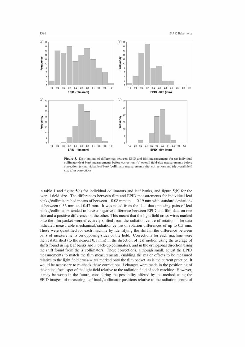
Figure 5. Distributions of differences between EPID and film measurements for (a) individualcollimator/leaf bank measurements before correction, (b) overall field-size measurements beforecorrection, (c) individual leaf bank/collimator measurements after corrections and (d) overall fieldsize after corrections.
in table 1 and figure 5(a) for individual collimators and leaf banks, and figure 5(b) for theoverall field size. The differences between film and EPID measurements for individual leafbanks/collimators had means of between −0.08 mm and −0.19 mm with standard deviationsof between 0.36 mm and 0.47 mm. It was noted from the data that opposing pairs of leafbanks/collimators tended to have a negative difference between EPID and film data on oneside and a positive difference on the other. This meant that the light field cross-wires markedonto the film packet were effectively shifted from the radiation centre of rotation. The dataindicated measurable mechanical/radiation centre of rotation differences of up to 0.5 mm.These were quantified for each machine by identifying the shift in the difference betweenpairs of measurements on opposing sides of the field. Corrections for each machine werethen established (to the nearest 0.1 mm) in the direction of leaf motion using the average ofshifts found using leaf banks and Y back-up collimators, and in the orthogonal direction usingthe shift found from the X collimators. These corrections, although small, adjust the EPIDmeasurements to match the film measurements, enabling the major offsets to be measuredrelative to the light field cross-wires marked onto the film packet, as is the current practice. Itwould be necessary to re-check these corrections if changes were made in the positioning ofthe optical focal spot of the light field relative to the radiation field of each machine. However,it may be worth in the future, considering the possibility offered by the method using theEPID images, of measuring leaf bank/collimator positions relative to the radiation centre of

MLC QC with an amorphous silicon EPID 1387
0%
20%
40%
60%
80%
100%
120%
-200 -150 -100 -50 0 50 100 150 200
Distance (mm)
% o
f ce
ntr
al in
ten
sity
Imager
Film
Figure 6. The difference in profile between EPID and film due to the flood-field calibration of theEPID, which explains the inherent small EPID/film difference (EPID field size slightly smallerthan film).
rotation as a relevant measurement, and not including this correction, as is done by somecentres (Sastre-Padro et al 2004).
The measurements of the overall field size are not affected by the shift inmechanical/radiation centre of rotation. The differences between the film and EPIDmeasurements have an average of –0.23 ± 0.24 mm (1 standard deviation) for the leavesand Y back-up collimators, and an average of –0.40 ± 0.27 mm (1 standard deviation) for theX collimators. This indicates that the EPID results are systematically small, by 0.4 mm onthe leaf banks and Y back-ups, and by 0.2 mm on the X collimators, to the nearest 0.1 mm.This is due to the fact that the EPID has been calibrated using the radiation beam such that theEPID response is flat when the entire detector plate is exposed. However, the radiation beamis not flat at the detector plate, and exhibits a profile such as can be seen in figure 6 from filmmeasurements. This off-axis variation results in a shift in the location of defined field edge(50% of the central intensity of the beam) in towards the central axis. Although theoreticallyone would expect this effect to be field-size dependent due to the variation in beam profileoff-axis, no field-size dependence was observed in the results, possibly due to this effect beingmuch smaller than the measurement uncertainties. This effect can therefore be correctedfor by adding a correction (away from field centre) to each detected field edge position of0.1 mm for the X collimators, and 0.2 mm for the leaf banks and Y back-up collimators. Thiscorrection is the same for each machine and should not require further checks. It is possible,however, if implemented at higher energies, for which the beam profiles are steeper, a field-sizedependence would be observed in this correction.
Following these corrections for radiation/light field centre shifts and off-axis field edgemovements, the differences between the film and EPID measurements are minimized, asshown in table 1 and figures 5(c) and (d). The individual measurements and overall field-size measurements no longer show systematic differences, but show approximately normaldistributions giving an indication of the random error between measurements made usingdigitized film and with the EPID images. After applying systematic corrections, the meandifference between film and EPID measurements of the overall field size is less than 0.05 mm

1388 S J K Baker et al
0
2
4
6
8
10
12
-1.0 -0.8 -0.6 -0.4 -0.2 0.0 0.2 0.4 0.6 0.8 1.0
EPID - film (mm)
Fre
qu
ency
Figure 7. Distribution of the differences between EPID and film measurements of the gain ofback-up collimators and leaf banks.
(average for each machine in range −0.08 mm to 0.15 mm), with 1 SD = 0.23 mm. Individualleaf/collimator agreement has a mean difference <0.03 mm (average for each machine inrange −0.04 mm to 0.09 mm), 1 SD = 0.27 mm.
3.2.3. Leaf bank and back-up collimator gains. The gain measurements are obtained fromthe difference in position of each collimator or leaf bank when it is moved from +12 cm to−10 cm across the field. Because the measurements are relative, it is not necessary to includecorrections for the radiation centre/light field centre offset, or any off-axis corrections. Themean difference between film and EPID measurements is –0.06 mm. The standard deviationof 0.17 mm is lower than for the major offset measurements, and shows that the measurementaccuracy is sufficient for gain calibration. A histogram of the differences between EPID andfilm measurements is shown in figure 7.
3.3. Reproducibility and precision
The results of the reproducibility and precision measurements described in section 2.7 are givenin table 2. The results shown are counterintuitive in that it appears that better reproducibilityis gained when the EPID is re-positioned than when all components remain stationary.However, it should be observed that the variations are extremely small in all cases. Hence,it can be concluded that the reproducibility of repeated measurements, EPID centring andleaf/collimator repositioning is excellent and will not be a limiting factor in the accuracy ofthe technique.
3.4. Implementation
The techniques described in this paper have been clinically implemented for over a year onsix linacs equipped with iViewGT EPIDs and quickly have become our method of choice,both for routine QC measurements and re-calibrations. The software is directly accessed fromthe computer controlling the EPID and can be opened from within the iViewGT software.A routine complete field-size check (normally performed every 2 months) consists of thethree leaf bank prescriptions (4 × 4 cm2, 10 × 10 cm2 and 24 × 24 cm2) and three back-upcollimator prescriptions (4 × 4 cm2, 10 × 10 cm2 and 22 × 22 cm2) described in section 2.3.

MLC QC with an amorphous silicon EPID 1389
Table 2. Standard deviation and range for repeated measurements of fields defined with MLC leavesand X collimators. Linac 1 measurements were repeated five times each, linac 2 measurements tentimes each.
Linac 1 Linac 2
Individual leaves/ Overall Individual leaves/ Overallcollimators field size collimators field size
Collimators and EPID stationaryStandard deviation 0.11 0.02 0.10 0.03Range 0.4 0.1 0.3 0.1
Collimators stationary, EPID re-positionedStandard deviation 0.06 0.00 0.03 0.00Range 0.2 0.0 0.2 0.0
Collimators re-positioned, EPID stationaryStandard deviation – – 0.08 0.05Range – – 0.2 0.1
Initially, the diaphragm angle is set to zero and the first 10 × 10 cm2 field acquired—a visualcheck is made of the image rotation since the tolerance on the diaphragm rotation setting is0.5◦. If rotation is observed, the diaphragm angle is adjusted and the 10 × 10 cm2 imagere-acquired. All six images are taken with diaphragm angle zero and then the head is rotatedthrough 180◦ and the procedure repeated. The analysis is then performed and the results savedto file. This procedure takes 20–25 min and is all completed at the linac. The equivalenttime at our hospital using film would be 20 min to acquire the films, 10 min to physicallyprocess the film and 20 min to scan and analyse the six different field sizes. Since using threefield sizes effectively tests the MLC and collimator gain, the gain prescription described is notroutinely used, only when a gain adjustment is required.
Minor offsets are normally tested annually at our centre since they are known to beextremely stable with time. The minor offsets prescriptions described in section 2.3 are usedfor this check. For each leaf bank, the two overlapping prescriptions described are delivered,and the best-fit straight-line correction described in section 3.2.1 is separately applied to eachprescription since the EPID tilt may be different in the two offset positions used. The resultsfor the whole leaf bank are then displayed, both with and without the correction so that anygenuine gradient in the minor offset pattern is not hidden from the user. An average is takenof the eight leaves contained in both prescriptions. A file is saved and printed out showingthe corrections required in the exact format required by the calibration procedure, allowingthe numbers to be directly typed in with the danger of data input error considerably reduced.If corrections to the minor offsets are indicated, at least two further sets of prescriptions areacquired and adjustments are made on the average minor offset from the three images; this isnecessary because a leaf position in a single image may be a statistical outlier. The time-savingfor acquiring and analysing three sets of minor offsets measurements is considerable comparedto the use of film.
4. Discussion
Other authors have described methods of obtaining high-precision leaf position measurementsusing both EPID and film techniques. Samant et al (2002) used very careful image distortion

1390 S J K Baker et al
corrections with a video-based EPID to measure absolute individual leaf positions with astandard deviation of 0.6 mm. Yang and Xing (2004), using an a-Si EPID, measured individualleaf positions relative to an initial independent calibration with a long-term reproducibilityof 0.3 mm when EPID repositioning errors are included, or 0.1 mm without. Bayouth et al(2003) obtained film measurements of MLC minor offsets using a standard test pattern andobtained measurements with 0.3 mm precision. Sastre-Padro et al (2004) describe a dose-basedmeasurement using matched adjacent segments to create a flat profile in the abutting regions.The method presented here yields an accuracy of 0.1 mm (1 SD) for relative measurements(minor offsets) and around 0.25 mm (1 SD) for absolute measurements compared with film,and a precision of 0.1 mm (1 SD). This is as good, or better, than the methods described above.Given the uncertainties in the two techniques being compared (EPID and film), it would bedifficult to improve on an agreement of 0.25 mm in absolute positioning. Film measurementsinclude uncertainties due to digitizer instabilities and non-linearities, scan resolution, dailyprocessor variations resulting in differing values of optical density corresponding to 50% doseand set-up accuracy. In addition, a significant problem is that the marking of the beam axiscentre onto the film (carried out using pinpricks or marks scribed onto the film packet) is crucialto determine the independent collimator/leaf bank positions. This method cannot be moreaccurate than 0.5 mm at best. Hence, we conclude that there is no scope in trying to improve theagreement any further. This raises the question of whether a true ‘gold standard’ for absolutemeasurement of leaf position actually exists, against which new methods can be compared.MLCs are capable of 0.1–0.2 mm reproducibility (1 standard deviation), more accurate thanthe measurement techniques traditionally used to calibrate them. Hence, although relative leafpositions can be measured with a precision of 0.1 mm, it is difficult to derive corrections andassess the true-accuracy of any new method for absolute measurements.
Several of the authors above have used the radiation centre of rotation as their referencepoint, by averaging the position of the collimators within the EPID images at 0◦ and 180◦
diaphragm angles. Although this improves the precision of defining the field centre, it canlead to differences of up to 0.5 mm with the mechanical centre of rotation, at which thecross-wires are set and to which lasers are often set. Therefore, adopting this reference pointcan lead to small systematic differences in definition of collimator positions. There mayalso be differences in radiation centre of rotation for different energies on dual energy linacs.However, these differences should not be overemphasized given that a measurement accuracyof 0.5 mm is normally the limit of accuracy for these measurements. The fact that systematicdifferences of less than this value have been quantified is due to the accuracy and carewith which measurements were carried out, and because the differences have been identifiedfrom the average of multiple measurements which has the effect of suppressing the randomerrors.
The frequency at which tests of radiation field size should be performed is now beingre-visited with higher levels of accuracy being required for some IMRT techniques. Publishedrecommendations usually suggest monthly checks (e.g. see Mayles et al (1998)), althoughexperience in this centre has led to a 2-monthly check frequency (Hounsell and Jordan1997). The tests described in this paper are intended to be used at this kind of frequencyand when re-calibration is required. A common procedure being followed in centres usingIMRT is to maintain the previous frequencies of standard field-size checks but to introduce,in addition, much more frequent (daily or weekly) checks of all MLC leaves. These arenormally quick to carry out, but very sensitive, relative checks—either visual checks ofgeometric patterns (Chui et al 1996) or dosimetric checks which readily detect changes froma reference dosimetric values (Viera et al 2002). These types of test are equally applicable tofilm or EPID. This combination of frequent, high sensitivity, relative measurements and less
MLC QC with an amorphous silicon EPID 1391
frequent absolute measurements is a sensible approach to increasing MLC check frequencywith minimum time implications.
Although the method described here has been applied to the equipment for one particularmanufacturer, the method should be generally applicable to any a-Si EPID. The accuracy ofthe measurements will be dependent on the pixel resolution of the a-Si and for systems whichallow variable height, the variation in pixel size with height should be taken into account andthe accuracy of height positioning tested. The effects of any processing must be checked toensure that it does not affect edge positioning. However, corrections for flood-field (if used),mechanical/radiation centre coincidence and EPID tilt will still be needed. The stability ofpixel size will also need verifying for each manufacturer. It should also be noted that the MLCcalibration methods described in this paper are manufacturer specific and the technique willneed adapting for use with other MLCs. In addition, for MLCs without a primary/secondarycollimator in the direction of leaf motion (e.g., Siemens), a different reference straight linewould be required for minor offsets checks; for example, a normal to the orthogonal primarycollimator defining the other field edge.
The use of the EPID and software for calibration can be fast and accurate but there areseveral important measurements that are required for successful implementation:
• It is important that the pixel size for each machine is calibrated correctly and checked forstability.
• It is necessary to determine the correction required due to the flood-field calibration. Thevalues given here for a 6 MV/8 MV energy will not necessarily apply for a higher andlower energy beams.
• It is necessary to obtain and evaluate the radiation field/light field centre offset correctionfor each machine. This will require adjustment following any movement of the opticalset-up.
• As the minor offsets program subtracts a best-fit line to account for the leaf bank andback-up collimator not being parallel, it is important to frequently check the leaf banksvisually, using the light field, to ensure that this subtracted best-fit line does not disguisea true trend in deviation of the leaf bank from the centre along the length of the field.
5. Conclusion
The method presented in this paper is ideal for routine QC as the measurements and analysisare fast. It maintains the IEC field-size definition (50% of central axis dose) and can beused to evaluate individually every aspect of MLC and collimator calibration major offsetsfor back-up collimators or leaf banks, minor offsets and gains. The method can be carried outquickly requiring no additional film processing, analysis is automatic and can be carried outat the linac. The results obtained using the a-Si EPIDs show good agreement with film, whilegiving better consistency and reproducibility than film. The accuracy is good enough to usefor re-calibration of the leaf banks and back-up collimators, as well as for routine QC checks.The method has now been in routine use for QC for over a year and is our method of choicefor QC on six Elekta Desktop linacs. We expect a-Si EPID based methods to increasinglyreplace film in the next few years.
References
Bayouth J E, Wendt D and Morrill S M 2003 MLC quality assurance techniques for IMRT applications Med. Phys.30 743–50
1392 S J K Baker et al
Budgell G J, Mott J, Williams P C and Brown K 2000 Requirements for leaf position accuracy for dynamic multileafcollimation Phys. Med. Biol. 45 1211–27
Chui C S, Spirou S and LoSasso T 1996 Testing of dynamic multileaf collimation Med. Phys. 23 635–41Dunscombe P, Humphreys S and Leszczynski K 1999 A test tool for the visual verification of light and radiation
fields using film or an electronic portal imaging device Med. Phys. 26 239–43Eilertsen K 1997 Automatic detection of single MLC leaf positions with corrections for penumbral effects and portal
imager dose rate characteristics Phys. Med. Biol. 42 313–34Hounsell A R and Jordan T J 1997 Quality control aspects of the Philips multileaf collimator Radiother. Oncol. 45
225–33International Electrochemical Commission (IEC) 1989 Medical electrical equipment—medical electron accelerators
in the range 1 MeV to 50 MeV—guildeline for functional performance characteristics (IEC 977), IEC, GenevaJames H V, Atherton S, Budgell G J, Kirby M C and Williams P C 2000 Verification of dynamic multileaf collimation
using an electronic portal imaging device Phys. Med. Biol. 45 495–509Jordan T J and Williams P C 1994 The design and performance characteristics of a multileaf collimator Phys. Med.
Biol. 39 231–51Kirby M C 1995 A multipurpose phantom for use with electronic portal imaging devices Phys. Med. Biol. 40 323–34Luchka K, Chen D, Shalev S, Gluhchev G and Rajapakshe R 1996 Assessing radiation and light field congruence
with a video based electronic portal imaging device Med. Phys. 23 1245–52Mayles W P M, Lake R A, McKenzie A L, Macaulay E M, Morgan H M and Powley S K 1998 Report 81: Physics
Aspects of Quality Control in Radiotherapy (York: Institute of Physics and Engineering in Medicine (IPEM))McCurdy B M, Luchka K and Pistorius S 2001 Dosimetric investigation and portal dose image prediction using an
amorphous silicon electronic portal imaging device Med. Phys. 28 911–24McDermott L N, Louwe R J W, Sonke J-J, van Herk M B and Mijnheer B J 2004 Dose–response and ghosting effects
of an amorphous silicon electronic portal imaging device Med. Phys. 31 285–95Munro P and Bouius D C 1998 X-ray quantum limited portal imaging using amorphous silicon flat-panel arrays Med.
Phys. 25 689–702Prisciandaro J I, Herman M G and Kruse J J 2003 Utilizing an electronic portal imaging device to monitor light and
radiation field congruence J. Appl. Clin. Med. Phys. 4 315–20Samant S S, Zheng W, Parra N A, Chandler J, Gopal A, Wu J, Jain J, Zhu Y and Sontag M 2002 Verification of
multileaf collimator leaf positions using an electronic portal imaging device Med. Phys. 29 2900–12Sastre -Padro M, van der Heide U A and Welleweerd H 2004 An accurate calibration method of the multileaf collimator
valid for conformal and intensity modulated radiation treatments Phys. Med. Biol. 49 2631–43Viera S C, Dirkx M L P, Pasma K L and Heijmen B J M 2002 Fast and accurate leaf verification for dynamic multileaf
collimation using an electronic portal imaging device Med. Phys. 29 2034–40Yang Y and Xing L 2004 Quantitative measurement of MLC leaf displacements using an electronic portal image
device Phys. Med. Biol. 49 1521–33