
UQ-SDAAP | Notional injection well design
25
The University of Queensland Surat Deep Aquifer Appraisal Project (UQ-SDAAP) Scoping study for material carbon abatement via carbon capture and storage Supplementary Detailed Report Notional injection well design 30 April 2019
-
Upload
khangminh22 -
Category
Documents
-
view
4 -
download
0
Transcript of UQ-SDAAP | Notional injection well design
The University of Queensland Surat Deep Aquifer
Appraisal Project (UQ-SDAAP)
Scoping study for material carbon abatement via
carbon capture and storage
Supplementary Detailed Report
Notional injection well design
30 April 2019
UQ-SDAAP | Notional injection well design 2
Authors
Mr Iain Rodger, The University of Queensland
Prof Andrew Garnett, The University of Queensland Prof Jim Underschultz, The University of Queensland
Acknowledgements
This working document was prepared for The University of Queensland Surat Deep Aquifer Appraisal Project (UQ-SDAAP),
a 3-year, $5.5 million project funded by the Australian Government through the Carbon Capture and Storage Research Development
and Demonstration (CCS RD&D) programme, by Coal 21, and The University of Queensland. UQ-SDAAP would like to acknowledge
Schlumberger for providing its PIPESIM software for use by the project.
Citation
Rodger I, Garnett A & Underschultz J (2019), Notional injection well design, The University of Queensland Surat Deep Aquifer Appraisal
Project – Supplementary Detailed Report, The University of Queensland.
Referenced throughout the UQ-SDAAP reports as Rodger et al. 2019d.
Publication details
Published by The University of Queensland © 2019 all rights reserved. This work is copyright. Apart from any use as permitted under
the Copyright Act 1968, no part may be reproduced by any process without prior written permission from The University of Queensland.
ISBN: 978-1-74272-266-5
Disclaimer
The information, opinions and views expressed in this document do not necessarily represent those of The University of Queensland, the Australian Government or Coal 21. Researchers within or working with the UQ-SDAAP are bound by the same policies and procedures as other researchers within The University of Queensland, which are designed to ensure the integrity of research. The Australian Code for the Responsible Conduct of Research outlines expectations and responsibilities of researchers to further ensure independent and rigorous investigations.
UQ-SDAAP | Notional injection well design 3
Contents
1. Executive summary........................................................................................................................... 5
2. Introduction ....................................................................................................................................... 6
3. Well design considerations .............................................................................................................. 6
3.1 Injection (Including pressure and temperature conditions) ................................................................. 6
3.2 Containment (well integrity) ................................................................................................................. 8
3.3 Operational .......................................................................................................................................... 9
4. Design options .................................................................................................................................. 9
4.1 Well trajectory ...................................................................................................................................... 9
4.2 Tubing size ........................................................................................................................................ 14
4.3 Casing sizing and depths .................................................................................................................. 16
4.4 Cementing ......................................................................................................................................... 19
4.5 Metallurgy/materials .......................................................................................................................... 20
4.6 Downhole equipment......................................................................................................................... 21
5. Conclusions ..................................................................................................................................... 21
6. References ....................................................................................................................................... 22
Tables
Table 1 Parameters used as the reference case for notional well design. ................................................ 8
Table 2 Advantages (black) and disadvantages (red) associated with vertical and horizontal wells. ..... 11
Table 3 Maximum CO2 velocity determined for each tubing size (as shown in Figure 6) using Pipesim. 16
Table 4 Anticipated stratigraphy in notional injection areas. Key formations shown in bold. Grey colour indicates formations generally considered to be aquitards. ........................................................ 18
Figures
Figure 1 Key formations in the target notional injection areas. Diagram is approximately to scale (apart from “overlying formations”, which are cropped). Of particular relevance to UQ-SDAAP is the Hutton Sandstone, which overlies the Ultimate Seal. ................................................................... 7
Figure 2 Illustrative vertical and horizontal well design. Horizontal well length could be several km, and could kick off (i.e. become deviated) at shallower depth, depending on achievable build-up rates, extended reach requirements, and wellbore stability. ....................................................... 10
Figure 3 Results of nodal analysis based on reference case properties shown in Table 1. The pressure at nodal analysis point is equivalent to bottomhole pressure in this case. The black dashed line is inflow performance for 6⅝″ tubing with a wellhead pressure of 15,000 kPa (150 bar). Coloured lines show outflow performance for various (completed) lengths of horizontal well, and a vertical well open to flow across the whole reservoir thickness. The points where these outflow lines cross the inflow line indicate the operating points for these wells when the reservoir is at initial pressure. Note that the horizontal wells achieve higher rates at lower bottomhole pressure. As the reservoir pressure increases, the outflow lines would move upwards in the plot, causing the operating points to move to higher pressures (increasing bottomhole pressures) and lower mass flow rates. .......................................................................................................... 12
UQ-SDAAP | Notional injection well design 4
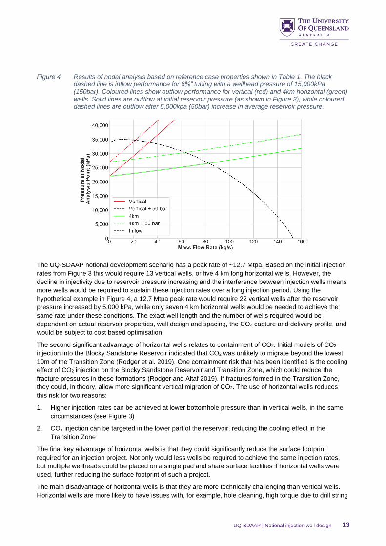
Figure 4 Results of nodal analysis based on reference case properties shown in Table 1. The black dashed line is inflow performance for 6⅝″ tubing with a wellhead pressure of 15,000kPa (150bar). Coloured lines show outflow performance for vertical (red) and 4km horizontal (green) wells. Solid lines are outflow at initial reservoir pressure (as shown in Figure 3), while coloured dashed lines are outflow after 5,000kpa (50bar) increase in average reservoir pressure. ......... 13
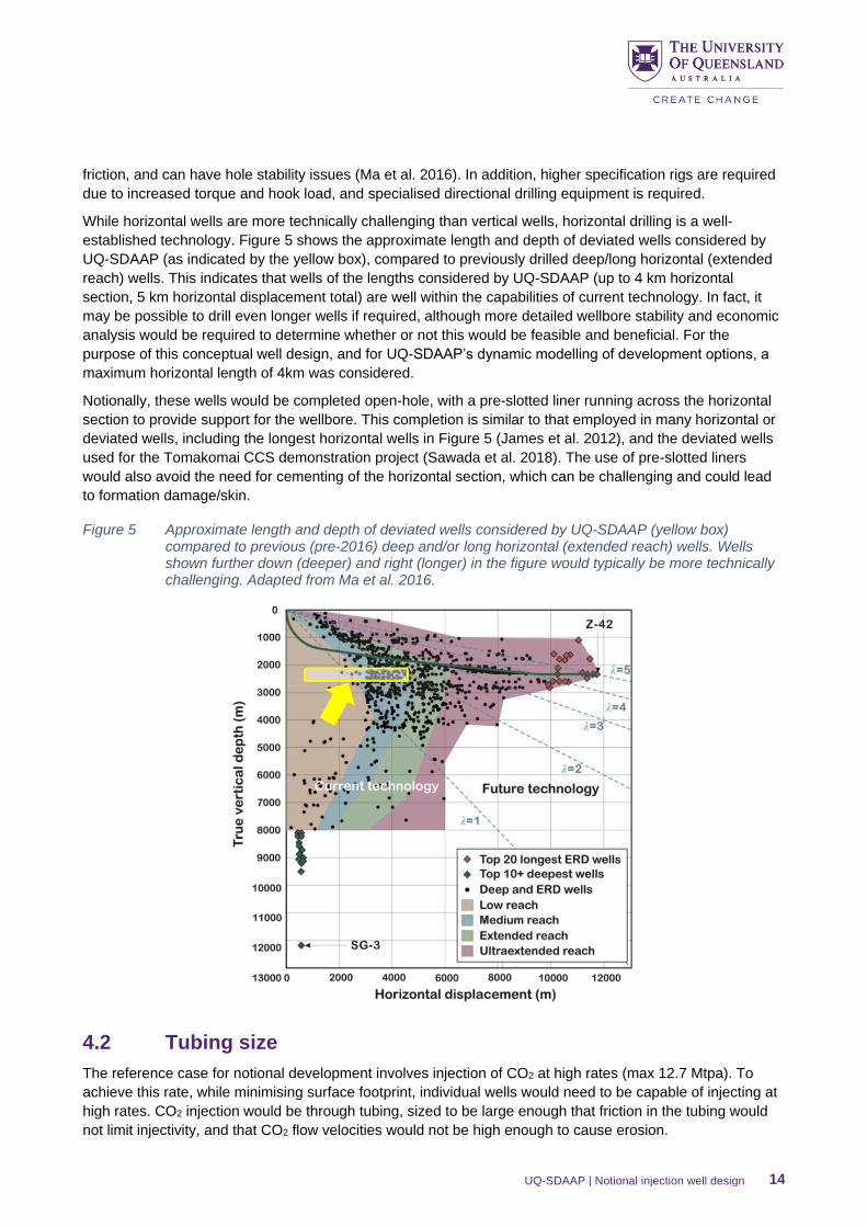
Figure 5 Approximate length and depth of deviated wells considered by UQ-SDAAP (yellow box) compared to previous (pre-2016) deep and/or long horizontal (extended reach) wells. Wells shown further down (deeper) and right (longer) in the figure would typically be more technically challenging. Adapted from Ma et al. 2016. ................................................................................. 14
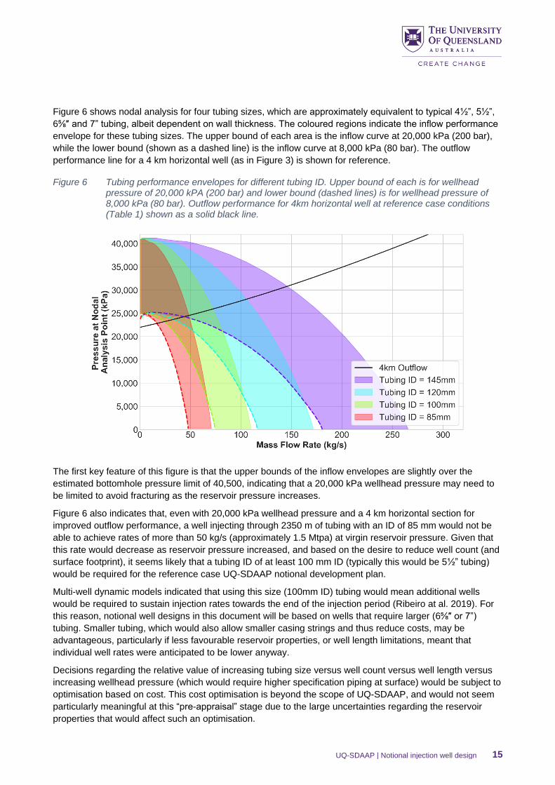
Figure 6 Tubing performance envelopes for different tubing ID. Upper bound of each is for wellhead pressure of 20,000 kPA (200 bar) and lower bound (dashed lines) is for wellhead pressure of 8,000 kPa (80 bar). Outflow performance for 4km horizontal well at reference case conditions (Table 1) shown as a solid black line. ......................................................................................... 15
Figure 7 Comparison of well trajectories for wells with kick off points (red dots) in the Transition Zone or Walloon Coal Measures. This figure is not to scale, but illustrates the need for higher build up rates (tighter bends) if wells kick off below the ultimate seal. Also note the higher angle of the wellbore through the Ultimate Seal, which may make cementing across this zone more challenging. ................................................................................................................................. 17
Figure 8 Notional casing plan for horizontal CO2 injection wells. All casing strings (apart from 7” pre-slotted liner) would be cemented to surface per U.S. EPA guidelines, although this would need to be assessed post appraisal. ................................................................................................... 20
UQ-SDAAP | Notional injection well design 5
1. Executive summary
The University of Queensland Surat Deep Aquifer Appraisal Project (UQ-SDAAP) is a climate mitigation
project. Within this, The University of Queensland (UQ) is investigating whether or not there may be potential
for industrial scale carbon dioxide (CO2) injection in the Surat Basin, Australia. High rates of sustained
injection need to be achieved and these volumes of CO2 must be securely contained indefinitely. This
document finds no technical “show stoppers”.
Injection well designs are considered within an overall development philosophy discussed in more detail in
Ribeiro et al. 2019b. Notional injection sites have been screened following a process aimed at minimising
containment risk. Within this, field development options have been further constrained to minimise surface
footprint. Well designs are then created which further minimise containment risk. Given this, the well designs
in this document have been engineered to accommodate large injection rates with minimal pressure build up.
A notional well design is presented for injection of CO2 into the lower most parts of the Blocky Sandstone
Reservoir. Designs are based on the current best estimates of reservoir properties and a peak CO2 injection
rate of approximately 13 million tonnes per annum. A total of just nine wells would be needed for this on
three well pads.
The notional design selected is a horizontal well targeted along the base of the Blocky Sandstone Reservoir.
This reduces the containment risk by allowing high-rate injection at a relatively low bottomhole pressure. The
use of horizontal wells reduces the required well count and surface footprint required for the given injection
volume. The design also significantly reduces the risk of any thermally induced fractures in the overlying
Transition Zone or Ultimate Seal.
The main disadvantages of horizontal wells is the cost per well and the additional technical challenges of
drilling compared to vertical wells. However, the well profiles in the notional designs are well within the limits
of established technology.
Injection in the notional wells would be through 7” tubing to allow high rates through individual wells. This
tubing (and any components that would be exposed to wet CO2) would be chrome steel (13Cr or Super
13Cr) to avoid corrosion.
Shallower casing strings would use common combinations of casing (9⅝″, 13⅜” and 20”) and hole (12¼”
17½” and 26”) diameters. In this notional well design the casing strings would be cemented to surface, based
on the United States Environmental Protection Agency (U.S. EPA) Class VI Well Construction Guidelines.
Many of the selections in these notional designs were based on the U.S. EPA guidelines. It should be noted
that these guidelines are considered to be conservative. Alternative designs are possible that might achieve
or improve the objective of protecting overlying aquifers.
There is little or no technology risk in achieving a well design with minimal to zero well integrity risk This can
minimise pressures and temperature effects in the sub-surface and can achieve a sustainable, high rate
injection of 1.3 to 2.6 million tonnes per annum per well for more than two decades.
Wells would be designed for minimum intervention, nevertheless, there is always a chance that a work-over
would be required in the life of a well. A redundancy philosophy of N+1 per well pad is a reasonable
assumption and has been applied in scoping economics (Garnett, 2019).
UQ-SDAAP | Notional injection well design 6
2. Introduction
UQ-SDAAP has identified the Blocky Sandstone Reservoir in the Surat Basin as a notional target formation
for injection (Garnett et al. 2019d).
As part of this work, notional development plans have been created. These are intended to represent
technically feasible options for a large-scale CO2 injection project. These plans are based on the current
understanding of the geology and flow characteristics of the Blocky Sandstone Reservoir, as well as the
overlying Transition Zone and Ultimate Seal (La Croix et al. 2019a, 2019b; Gonzalez et al. 2019a, 2019b;
Harfoush et al. 2019a). They remain subject to key uncertainties, which require further appraisal of the
subsurface at the notional injection sites should this scoping study progress to an appraisal project.
Any of these notional plans would require a number of injection wells. In keeping with a minimal risk (rather
than minimum cos approach), this document presents a notional and conservative well design, which is
considered a credible option for industrial-scale CO2 injection in the Blocky Sandstone Reservoir. The
decisions leading to this design are based on the current best estimates of the reservoir properties and
behaviour, which are subject to significant uncertainty.
A more detailed study, including an economic assessment of each of the available options, would be
required post-appraisal, when these uncertainties (particularly those regarding injectivity and geomechanics)
will have been reduced.
3. Well design considerations
CO2 injection wells for any carbon capture and storage (CCS) project must fulfil a number of safety and
economic-related criteria. Overall, the UQ-SDAAP notional well design work was based on two key
principles:
1. In accordance with the overall development philosophy, the surface footprint of the wells and associated
infrastructure should be minimised, within this:
2. Well placement, design and construction should minimise containment risk and within this constraint,
maximise injectivity.
3.1 Injection (Including pressure and temperature conditions)
UQ-SDAAP is not a CCS deployment project, thus does not have a pre-defined capture and storage
program scope. Instead, credible commercial scale scenarios for capture and storage have been
constructed.
These scenarios involve capture of CO2 from (up to) three, modern coal fired power stations – Milmerran,
Kogan Creek, and Tarong North. In these hypothetical scenarios, the captured CO2 would be transported by
pipeline to any or all (notional) injection sites, then injected into the Blocky Sandstone Reservoir in the
deepest parts of the Surat Basin.
For the purpose of notional well design, a scenario which involved capture and storage of CO2 from all three
power stations over a 42-year period was considered. This would require the injection of approximately
380Mt of CO2 in total, with a peak rate of 12.7 Mtpa (total across all sites/wells) for around 18 years.
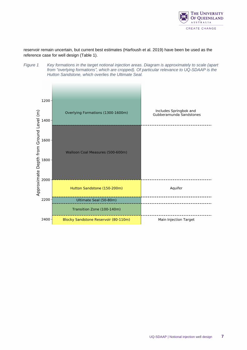
The target formation for CO2 injection is the Blocky Sandstone Reservoir in the Surat Basin (Figure 1). By
adopting a risk-minimisation, screening approach, three notional injection sites have been identified
(Wolhuter et al. 2019a) in the deepest part of the basin, where the Blocky Sandstone Reservoir is
approximately 80-110m thick. In this location, the top of the reservoir lies at depths between approximately
2300m and 2500m (below ground level) and the structural dip is close to zero. Many of the properties of the
UQ-SDAAP | Notional injection well design 7
reservoir remain uncertain, but current best estimates (Harfoush et al. 2019) have been be used as the
reference case for well design (Table 1).
Figure 1 Key formations in the target notional injection areas. Diagram is approximately to scale (apart from “overlying formations”, which are cropped). Of particular relevance to UQ-SDAAP is the Hutton Sandstone, which overlies the Ultimate Seal.
UQ-SDAAP | Notional injection well design 8
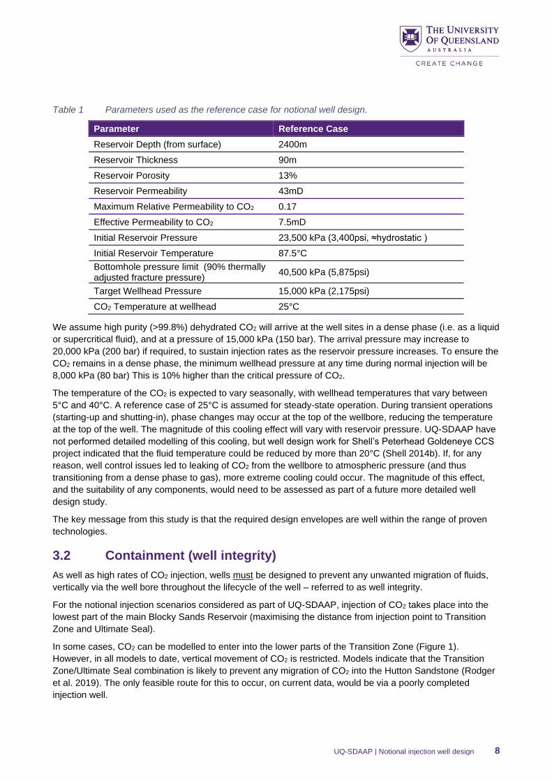
Table 1 Parameters used as the reference case for notional well design.
Parameter Reference Case
Reservoir Depth (from surface) 2400m
Reservoir Thickness 90m
Reservoir Porosity 13%
Reservoir Permeability 43mD
Maximum Relative Permeability to CO2 0.17
Effective Permeability to CO2 7.5mD
Initial Reservoir Pressure 23,500 kPa (3,400psi, ≈hydrostatic )
Initial Reservoir Temperature 87.5°C
Bottomhole pressure limit (90% thermally adjusted fracture pressure)
40,500 kPa (5,875psi)
Target Wellhead Pressure 15,000 kPa (2,175psi)
CO2 Temperature at wellhead 25°C
We assume high purity (>99.8%) dehydrated CO2 will arrive at the well sites in a dense phase (i.e. as a liquid
or supercritical fluid), and at a pressure of 15,000 kPa (150 bar). The arrival pressure may increase to
20,000 kPa (200 bar) if required, to sustain injection rates as the reservoir pressure increases. To ensure the
CO2 remains in a dense phase, the minimum wellhead pressure at any time during normal injection will be
8,000 kPa (80 bar) This is 10% higher than the critical pressure of CO2.
The temperature of the CO2 is expected to vary seasonally, with wellhead temperatures that vary between
5°C and 40°C. A reference case of 25°C is assumed for steady-state operation. During transient operations
(starting-up and shutting-in), phase changes may occur at the top of the wellbore, reducing the temperature
at the top of the well. The magnitude of this cooling effect will vary with reservoir pressure. UQ-SDAAP have
not performed detailed modelling of this cooling, but well design work for Shell’s Peterhead Goldeneye CCS
project indicated that the fluid temperature could be reduced by more than 20°C (Shell 2014b). If, for any
reason, well control issues led to leaking of CO2 from the wellbore to atmospheric pressure (and thus
transitioning from a dense phase to gas), more extreme cooling could occur. The magnitude of this effect,
and the suitability of any components, would need to be assessed as part of a future more detailed well
design study.
The key message from this study is that the required design envelopes are well within the range of proven
technologies.
3.2 Containment (well integrity)
As well as high rates of CO2 injection, wells must be designed to prevent any unwanted migration of fluids,
vertically via the well bore throughout the lifecycle of the well – referred to as well integrity.
For the notional injection scenarios considered as part of UQ-SDAAP, injection of CO2 takes place into the
lowest part of the main Blocky Sands Reservoir (maximising the distance from injection point to Transition
Zone and Ultimate Seal).
In some cases, CO2 can be modelled to enter into the lower parts of the Transition Zone (Figure 1).
However, in all models to date, vertical movement of CO2 is restricted. Models indicate that the Transition
Zone/Ultimate Seal combination is likely to prevent any migration of CO2 into the Hutton Sandstone (Rodger
et al. 2019). The only feasible route for this to occur, on current data, would be via a poorly completed
injection well.
UQ-SDAAP | Notional injection well design 9
Protection of aquifers (or “Underground Sources of Drinking Water”) is one of the main aims of the U.S. EPA
Class VI1 Well Construction Guidelines (U.S. EPA 2012). Notional injection well design for UQ-SDAAP will
follow that guidance. However, it must be noted that the U.S. EPA Guidelines are very conservative
(requiring, for example, a blanket rule to cement all casing strings to surface). It is possible that alternate
designs are able adequately to protect any aquifers within the Hutton Sandstone or other shallower aquifers
without this “blanket rule”. In fact, by reducing the need for staged cementing or significant stop-start drilling
operations, better hole quality and easier to emplace cement recipes might be achievable. This might even
provide improved protection over a “cement to surface” requirement.
The key message is that well design for minimising well integrity risk should be on a case by case basis and
should include issues relating to drilling quality in-gauge hole and enabling cement recipes most likely to
form complete and in-tact cement sheaths.
In all cases, wells have to be designed to minimise the risk of unwanted CO2 migration (e.g. into the Hutton
Sandstone) through any natural or induced pathway, not just along the wellbore. For example, well site
selection already aims to minimise leakage risk from natural faults and fractures. Similarly, injection well
design and operations must minimise the chances of inducing fractures through the Ultimate Seal.
This is of particular relevance when considering the fracture pressure of the Blocky Sandstone Reservoir and
Transition Zone, and how this fracture pressure would be reduced by the cooling effects of CO2 injection
(Rodger et al. 2019a). If fracture pressures are reduced such that fractures form in the Transition Zone
during injection, CO2 may be able to migrate more easily thought the Transition Zone. Reducing this risk is
possible through appropriate well design and choice trajectory, discussed in more detail in section 4.1.
3.3 Operational
Wells are designed to allow monitoring of injection rates, as well as temperature and pressure in the tubing
and annuli (including downhole temperature and pressure). Well sites would likely be unmanned, and this
data would be transmitted live to a control room.
Wells designs have been scoped to require “minimum intervention”. This requires simplicity of down-hole
equipment. No hydraulic workovers (e.g. to alter the size of the tubing) are planned. However, given the
uncertainties in long-term injection, remedial/unplanned workovers may become necessary. Therefore, UQ-
SDAAP’s notional development plans employ an N+1 redundancy scheme (a backup injection well) at each
wellsite or pad to allow for workovers and avoid the need for operational venting.
The UQ-SDAAP notional development plan involves 40+ years of injection. After injection, it is possible that
the injection wells would be used for monitoring for a few years before final abandonment.
4. Design options
The following sections outline the selection of a feasible rather than an optimal well design. Several
conservative assumptions have been made. These should be revisited once additional, site specific data is
available.
4.1 Well trajectory
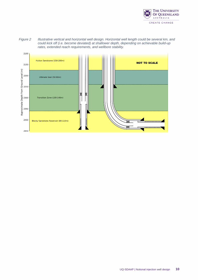
UQ-SDAAP considered both vertical and horizontal wells for CO2 injection (Figure 2). Some of the key
advantages and disadvantages of these well types are summarised in Table 2.
1 Class VI refers toCO2 injection wells for CCS projects
UQ-SDAAP | Notional injection well design 10
Figure 2 Illustrative vertical and horizontal well design. Horizontal well length could be several km, and could kick off (i.e. become deviated) at shallower depth, depending on achievable build-up rates, extended reach requirements, and wellbore stability.
UQ-SDAAP | Notional injection well design 11
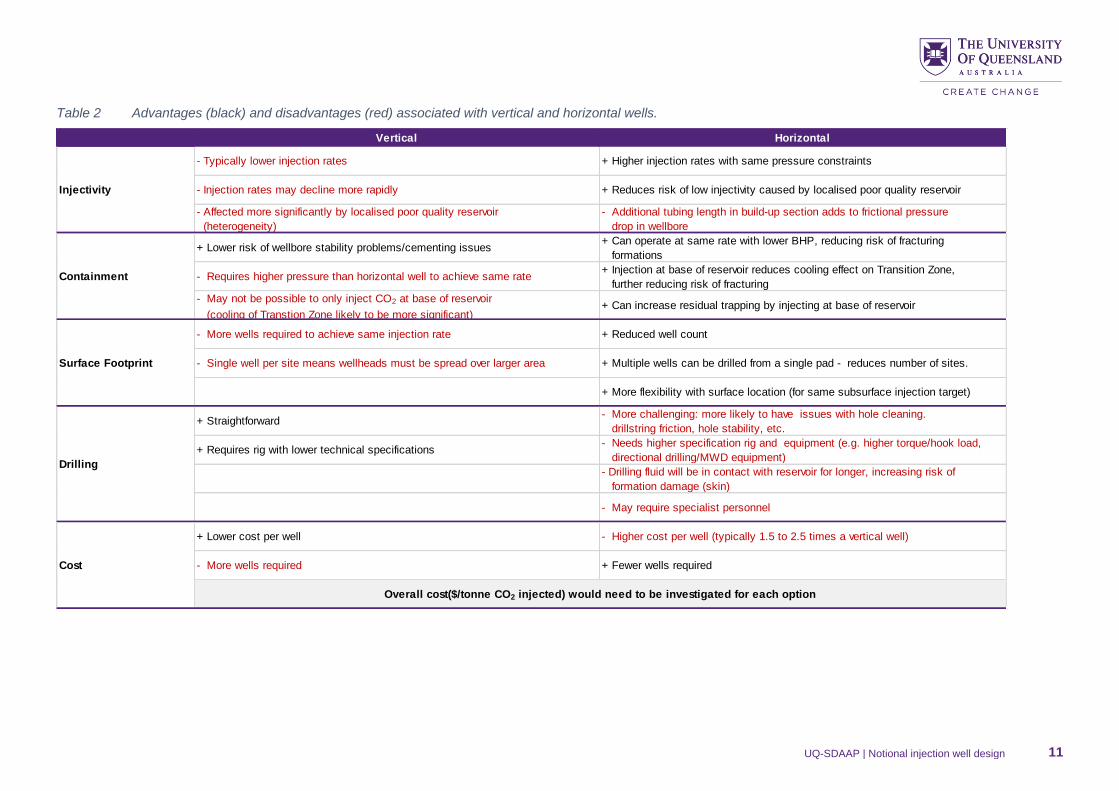
Table 2 Advantages (black) and disadvantages (red) associated with vertical and horizontal wells.
Vertical Horizontal
- Typically lower injection rates + Higher injection rates with same pressure constraints
- Injection rates may decline more rapidly + Reduces risk of low injectivity caused by localised poor quality reservoir
- Affected more significantly by localised poor quality reservoir
(heterogeneity)
- Additional tubing length in build-up section adds to frictional pressure
drop in wellbore
+ Lower risk of wellbore stability problems/cementing issues+ Can operate at same rate with lower BHP, reducing risk of fracturing
formations
- Requires higher pressure than horizontal well to achieve same rate+ Injection at base of reservoir reduces cooling effect on Transition Zone,
further reducing risk of fracturing
- May not be possible to only inject CO2 at base of reservoir
(cooling of Transtion Zone likely to be more significant)+ Can increase residual trapping by injecting at base of reservoir
- More wells required to achieve same injection rate + Reduced well count
- Single well per site means wellheads must be spread over larger area + Multiple wells can be drilled from a single pad - reduces number of sites.
+ More flexibility with surface location (for same subsurface injection target)
+ Straightforward- More challenging: more likely to have issues with hole cleaning.
drillstring friction, hole stability, etc.
+ Requires rig with lower technical specifications - Needs higher specification rig and equipment (e.g. higher torque/hook load,
directional drilling/MWD equipment)
- Drilling fluid will be in contact with reservoir for longer, increasing risk of
formation damage (skin)
- May require specialist personnel
+ Lower cost per well - Higher cost per well (typically 1.5 to 2.5 times a vertical well)
- More wells required + Fewer wells required
Injectivity
Containment
Drilling
Surface Footprint
Cost
Overall cost($/tonne CO2 injected) would need to be investigated for each option
UQ-SDAAP | Notional injection well design 12
Three particular benefits of horizontal wells made them more favourable, when considering UQ-SDAAP’s key
design criteria.
First, horizontal wells would be capable of higher injection rates than vertical wells. Furthermore, directionally
drilled wells form a single surface location or pad can minimise long term pressure interference. This is in line
with a minimum surface footprint philosophy.
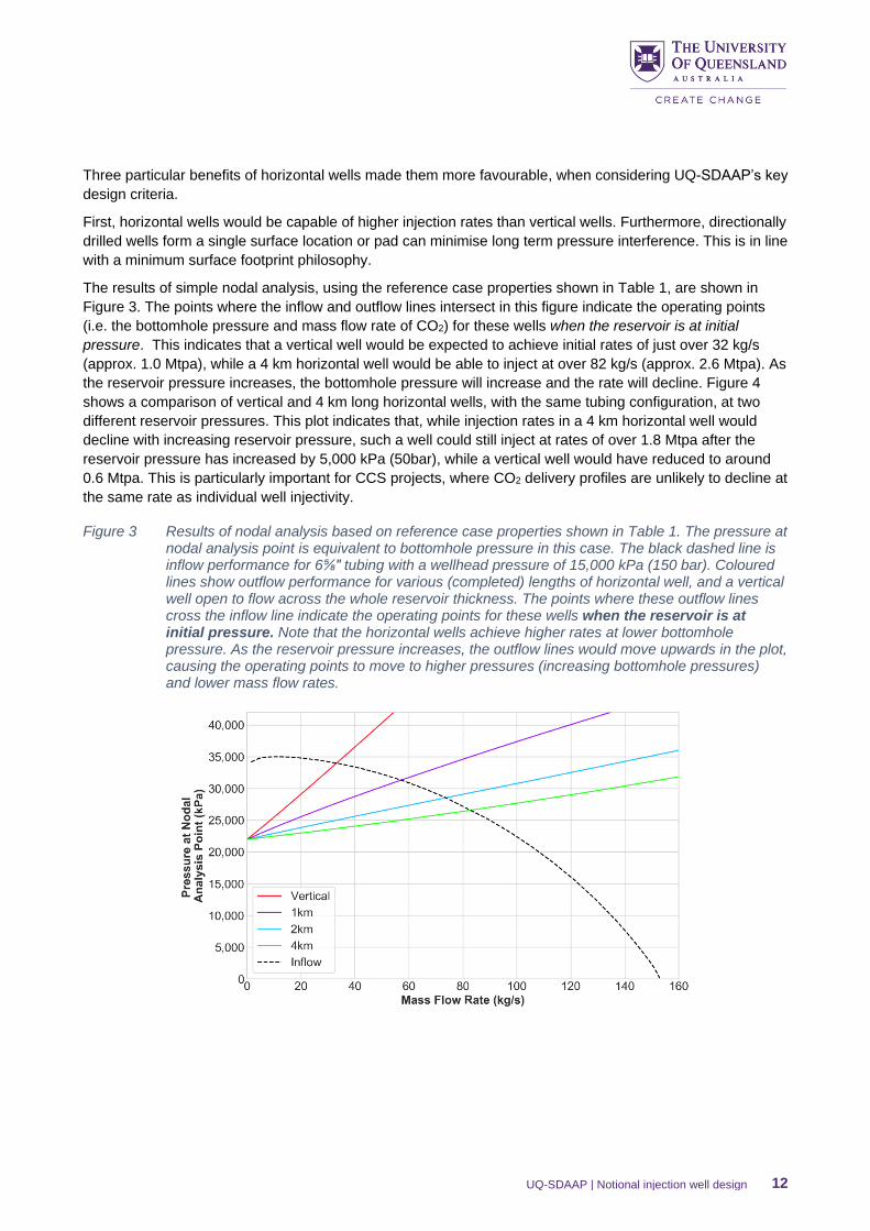
The results of simple nodal analysis, using the reference case properties shown in Table 1, are shown in
Figure 3. The points where the inflow and outflow lines intersect in this figure indicate the operating points
(i.e. the bottomhole pressure and mass flow rate of CO2) for these wells when the reservoir is at initial
pressure. This indicates that a vertical well would be expected to achieve initial rates of just over 32 kg/s
(approx. 1.0 Mtpa), while a 4 km horizontal well would be able to inject at over 82 kg/s (approx. 2.6 Mtpa). As
the reservoir pressure increases, the bottomhole pressure will increase and the rate will decline. Figure 4
shows a comparison of vertical and 4 km long horizontal wells, with the same tubing configuration, at two
different reservoir pressures. This plot indicates that, while injection rates in a 4 km horizontal well would
decline with increasing reservoir pressure, such a well could still inject at rates of over 1.8 Mtpa after the
reservoir pressure has increased by 5,000 kPa (50bar), while a vertical well would have reduced to around
0.6 Mtpa. This is particularly important for CCS projects, where CO2 delivery profiles are unlikely to decline at
the same rate as individual well injectivity.
Figure 3 Results of nodal analysis based on reference case properties shown in Table 1. The pressure at nodal analysis point is equivalent to bottomhole pressure in this case. The black dashed line is inflow performance for 6⅝″ tubing with a wellhead pressure of 15,000 kPa (150 bar). Coloured lines show outflow performance for various (completed) lengths of horizontal well, and a vertical well open to flow across the whole reservoir thickness. The points where these outflow lines cross the inflow line indicate the operating points for these wells when the reservoir is at initial pressure. Note that the horizontal wells achieve higher rates at lower bottomhole pressure. As the reservoir pressure increases, the outflow lines would move upwards in the plot, causing the operating points to move to higher pressures (increasing bottomhole pressures) and lower mass flow rates.
UQ-SDAAP | Notional injection well design 13
Figure 4 Results of nodal analysis based on reference case properties shown in Table 1. The black dashed line is inflow performance for 6⅝″ tubing with a wellhead pressure of 15,000kPa (150bar). Coloured lines show outflow performance for vertical (red) and 4km horizontal (green) wells. Solid lines are outflow at initial reservoir pressure (as shown in Figure 3), while coloured dashed lines are outflow after 5,000kpa (50bar) increase in average reservoir pressure.
The UQ-SDAAP notional development scenario has a peak rate of ~12.7 Mtpa. Based on the initial injection
rates from Figure 3 this would require 13 vertical wells, or five 4 km long horizontal wells. However, the
decline in injectivity due to reservoir pressure increasing and the interference between injection wells means
more wells would be required to sustain these injection rates over a long injection period. Using the
hypothetical example in Figure 4, a 12.7 Mtpa peak rate would require 22 vertical wells after the reservoir
pressure increased by 5,000 kPa, while only seven 4 km horizontal wells would be needed to achieve the
same rate under these conditions. The exact well length and the number of wells required would be
dependent on actual reservoir properties, well design and spacing, the CO2 capture and delivery profile, and
would be subject to cost based optimisation.
The second significant advantage of horizontal wells relates to containment of CO2. Initial models of CO2
injection into the Blocky Sandstone Reservoir indicated that CO2 was unlikely to migrate beyond the lowest
10m of the Transition Zone (Rodger et al. 2019). One containment risk that has been identified is the cooling
effect of CO2 injection on the Blocky Sandstone Reservoir and Transition Zone, which could reduce the
fracture pressures in these formations (Rodger and Altaf 2019). If fractures formed in the Transition Zone,
they could, in theory, allow more significant vertical migration of CO2. The use of horizontal wells reduces
this risk for two reasons:
1. Higher injection rates can be achieved at lower bottomhole pressure than in vertical wells, in the same
circumstances (see Figure 3)
2. CO2 injection can be targeted in the lower part of the reservoir, reducing the cooling effect in the
Transition Zone
The final key advantage of horizontal wells is that they could significantly reduce the surface footprint
required for an injection project. Not only would less wells be required to achieve the same injection rates,
but multiple wellheads could be placed on a single pad and share surface facilities if horizontal wells were
used, further reducing the surface footprint of such a project.
The main disadvantage of horizontal wells is that they are more technically challenging than vertical wells.
Horizontal wells are more likely to have issues with, for example, hole cleaning, high torque due to drill string
UQ-SDAAP | Notional injection well design 14
friction, and can have hole stability issues (Ma et al. 2016). In addition, higher specification rigs are required
due to increased torque and hook load, and specialised directional drilling equipment is required.
While horizontal wells are more technically challenging than vertical wells, horizontal drilling is a well-
established technology. Figure 5 shows the approximate length and depth of deviated wells considered by
UQ-SDAAP (as indicated by the yellow box), compared to previously drilled deep/long horizontal (extended
reach) wells. This indicates that wells of the lengths considered by UQ-SDAAP (up to 4 km horizontal
section, 5 km horizontal displacement total) are well within the capabilities of current technology. In fact, it
may be possible to drill even longer wells if required, although more detailed wellbore stability and economic
analysis would be required to determine whether or not this would be feasible and beneficial. For the
purpose of this conceptual well design, and for UQ-SDAAP’s dynamic modelling of development options, a
maximum horizontal length of 4km was considered.
Notionally, these wells would be completed open-hole, with a pre-slotted liner running across the horizontal
section to provide support for the wellbore. This completion is similar to that employed in many horizontal or
deviated wells, including the longest horizontal wells in Figure 5 (James et al. 2012), and the deviated wells
used for the Tomakomai CCS demonstration project (Sawada et al. 2018). The use of pre-slotted liners
would also avoid the need for cementing of the horizontal section, which can be challenging and could lead
to formation damage/skin.
Figure 5 Approximate length and depth of deviated wells considered by UQ-SDAAP (yellow box) compared to previous (pre-2016) deep and/or long horizontal (extended reach) wells. Wells shown further down (deeper) and right (longer) in the figure would typically be more technically challenging. Adapted from Ma et al. 2016.
4.2 Tubing size
The reference case for notional development involves injection of CO2 at high rates (max 12.7 Mtpa). To
achieve this rate, while minimising surface footprint, individual wells would need to be capable of injecting at
high rates. CO2 injection would be through tubing, sized to be large enough that friction in the tubing would
not limit injectivity, and that CO2 flow velocities would not be high enough to cause erosion.
UQ-SDAAP | Notional injection well design 15
Figure 6 shows nodal analysis for four tubing sizes, which are approximately equivalent to typical 4½”, 5½”,
6⅝″ and 7” tubing, albeit dependent on wall thickness. The coloured regions indicate the inflow performance
envelope for these tubing sizes. The upper bound of each area is the inflow curve at 20,000 kPa (200 bar),
while the lower bound (shown as a dashed line) is the inflow curve at 8,000 kPa (80 bar). The outflow
performance line for a 4 km horizontal well (as in Figure 3) is shown for reference.
Figure 6 Tubing performance envelopes for different tubing ID. Upper bound of each is for wellhead pressure of 20,000 kPA (200 bar) and lower bound (dashed lines) is for wellhead pressure of 8,000 kPa (80 bar). Outflow performance for 4km horizontal well at reference case conditions (Table 1) shown as a solid black line.
The first key feature of this figure is that the upper bounds of the inflow envelopes are slightly over the
estimated bottomhole pressure limit of 40,500, indicating that a 20,000 kPa wellhead pressure may need to
be limited to avoid fracturing as the reservoir pressure increases.
Figure 6 also indicates that, even with 20,000 kPa wellhead pressure and a 4 km horizontal section for
improved outflow performance, a well injecting through 2350 m of tubing with an ID of 85 mm would not be
able to achieve rates of more than 50 kg/s (approximately 1.5 Mtpa) at virgin reservoir pressure. Given that
this rate would decrease as reservoir pressure increased, and based on the desire to reduce well count (and
surface footprint), it seems likely that a tubing ID of at least 100 mm ID (typically this would be 5½” tubing)
would be required for the reference case UQ-SDAAP notional development plan.
Multi-well dynamic models indicated that using this size (100mm ID) tubing would mean additional wells
would be required to sustain injection rates towards the end of the injection period (Ribeiro at al. 2019). For
this reason, notional well designs in this document will be based on wells that require larger (6⅝″ or 7”)
tubing. Smaller tubing, which would also allow smaller casing strings and thus reduce costs, may be
advantageous, particularly if less favourable reservoir properties, or well length limitations, meant that
individual well rates were anticipated to be lower anyway.
Decisions regarding the relative value of increasing tubing size versus well count versus well length versus
increasing wellhead pressure (which would require higher specification piping at surface) would be subject to
optimisation based on cost. This cost optimisation is beyond the scope of UQ-SDAAP, and would not seem
particularly meaningful at this “pre-appraisal” stage due to the large uncertainties regarding the reservoir
properties that would affect such an optimisation.
UQ-SDAAP | Notional injection well design 16
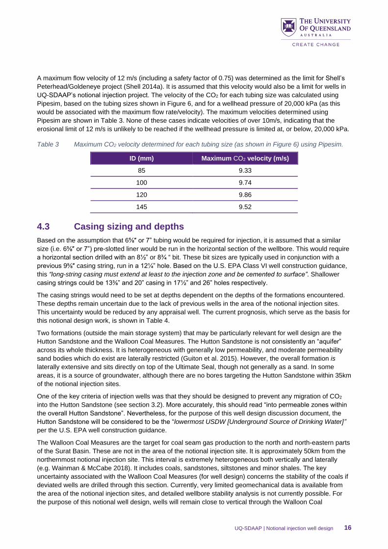
A maximum flow velocity of 12 m/s (including a safety factor of 0.75) was determined as the limit for Shell’s
Peterhead/Goldeneye project (Shell 2014a). It is assumed that this velocity would also be a limit for wells in
UQ-SDAAP’s notional injection project. The velocity of the CO2 for each tubing size was calculated using
Pipesim, based on the tubing sizes shown in Figure 6, and for a wellhead pressure of 20,000 kPa (as this
would be associated with the maximum flow rate/velocity). The maximum velocities determined using
Pipesim are shown in Table 3. None of these cases indicate velocities of over 10m/s, indicating that the
erosional limit of 12 m/s is unlikely to be reached if the wellhead pressure is limited at, or below, 20,000 kPa.
Table 3 Maximum CO2 velocity determined for each tubing size (as shown in Figure 6) using Pipesim.
ID (mm) Maximum CO2 velocity (m/s)
85 9.33
100 9.74
120 9.86
145 9.52
4.3 Casing sizing and depths
Based on the assumption that 6⅝″ or 7” tubing would be required for injection, it is assumed that a similar
size (i.e. 6⅝″ or 7”) pre-slotted liner would be run in the horizontal section of the wellbore. This would require
a horizontal section drilled with an 8½” or 8¾ “ bit. These bit sizes are typically used in conjunction with a
previous 9⅝″ casing string, run in a 12¼” hole. Based on the U.S. EPA Class VI well construction guidance,
this “long-string casing must extend at least to the injection zone and be cemented to surface”. Shallower
casing strings could be 13⅜” and 20” casing in 17½” and 26” holes respectively.
The casing strings would need to be set at depths dependent on the depths of the formations encountered.
These depths remain uncertain due to the lack of previous wells in the area of the notional injection sites.
This uncertainty would be reduced by any appraisal well. The current prognosis, which serve as the basis for
this notional design work, is shown in Table 4.
Two formations (outside the main storage system) that may be particularly relevant for well design are the
Hutton Sandstone and the Walloon Coal Measures. The Hutton Sandstone is not consistently an “aquifer”
across its whole thickness. It is heterogeneous with generally low permeability, and moderate permeability
sand bodies which do exist are laterally restricted (Guiton et al. 2015). However, the overall formation is
laterally extensive and sits directly on top of the Ultimate Seal, though not generally as a sand. In some
areas, it is a source of groundwater, although there are no bores targeting the Hutton Sandstone within 35km
of the notional injection sites.
One of the key criteria of injection wells was that they should be designed to prevent any migration of CO2
into the Hutton Sandstone (see section 3.2). More accurately, this should read “into permeable zones within
the overall Hutton Sandstone”. Nevertheless, for the purpose of this well design discussion document, the
Hutton Sandstone will be considered to be the “lowermost USDW [Underground Source of Drinking Water]”
per the U.S. EPA well construction guidance.
The Walloon Coal Measures are the target for coal seam gas production to the north and north-eastern parts
of the Surat Basin. These are not in the area of the notional injection site. It is approximately 50km from the
northernmost notional injection site. This interval is extremely heterogeneous both vertically and laterally
(e.g. Wainman & McCabe 2018). It includes coals, sandstones, siltstones and minor shales. The key
uncertainty associated with the Walloon Coal Measures (for well design) concerns the stability of the coals if
deviated wells are drilled through this section. Currently, very limited geomechanical data is available from
the area of the notional injection sites, and detailed wellbore stability analysis is not currently possible. For
the purpose of this notional well design, wells will remain close to vertical through the Walloon Coal
UQ-SDAAP | Notional injection well design 17
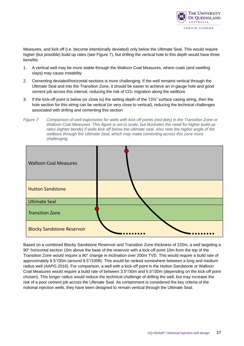
Measures, and kick off (i.e. become intentionally deviated) only below the Ultimate Seal. This would require
higher (but possible) build up rates (see Figure 7), but drilling the vertical hole to this depth would have three
benefits:
1. A vertical well may be more stable through the Walloon Coal Measures, where coals (and swelling
clays) may cause instability
2. Cementing deviated/horizontal sections is more challenging. If the well remains vertical through the
Ultimate Seal and into the Transition Zone, it should be easier to achieve an in-gauge hole and good
cement job across this interval, reducing the risk of CO2 migration along the wellbore
3. If the kick-off point is below (or close to) the setting depth of the 13⅜” surface casing string, then the
hole section for this string can be vertical (or very close to vertical), reducing the technical challenges
associated with drilling and cementing this section
Figure 7 Comparison of well trajectories for wells with kick off points (red dots) in the Transition Zone or Walloon Coal Measures. This figure is not to scale, but illustrates the need for higher build up rates (tighter bends) if wells kick off below the ultimate seal. Also note the higher angle of the wellbore through the Ultimate Seal, which may make cementing across this zone more challenging.
Based on a combined Blocky Sandstone Reservoir and Transition Zone thickness of 220m, a well targeting a
90° horizontal section 10m above the base of the reservoir with a kick-off point 10m from the top of the
Transition Zone would require a 90° change in inclination over 200m TVD. This would require a build rate of
approximately 8.5°/30m (around 8.5°/100ft). This would be ranked somewhere between a long and medium
radius well (AAPG 2016). For comparison, a well with a kick-off point in the Hutton Sandstone or Walloon
Coal Measures would require a build rate of between 3.5°/30m and 5.5°/30m (depending on the kick-off point
chosen). This longer radius would reduce the technical challenge of drilling the well, but may increase the
risk of a poor cement job across the Ultimate Seal. As containment is considered the key criteria of the
notional injection wells, they have been designed to remain vertical through the Ultimate Seal.
Blocky Sandstone Reservoir
Transition Zone
Ultimate Seal
Hutton Sandstone
Walloon Coal Measures
UQ-SDAAP | Notional injection well design 18
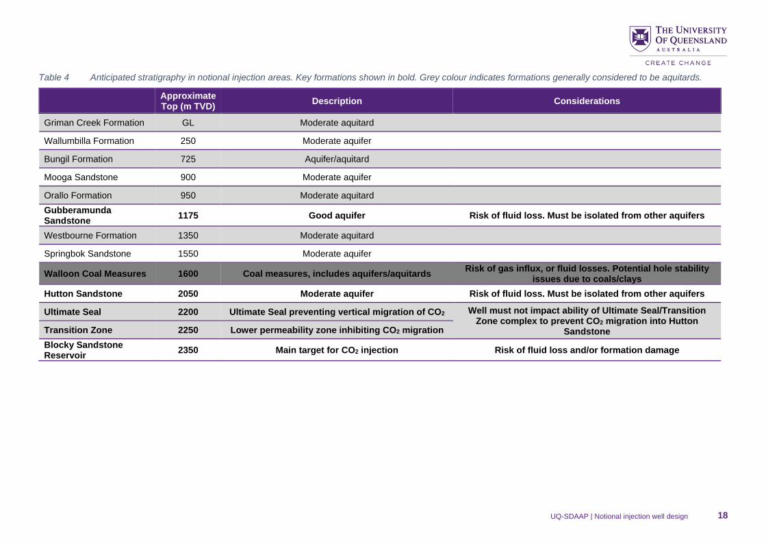
Table 4 Anticipated stratigraphy in notional injection areas. Key formations shown in bold. Grey colour indicates formations generally considered to be aquitards.
Approximate Top (m TVD)
Description Considerations
Griman Creek Formation GL Moderate aquitard
Wallumbilla Formation 250 Moderate aquifer
Bungil Formation 725 Aquifer/aquitard
Mooga Sandstone 900 Moderate aquifer
Orallo Formation 950 Moderate aquitard
Gubberamunda Sandstone
1175 Good aquifer Risk of fluid loss. Must be isolated from other aquifers
Westbourne Formation 1350 Moderate aquitard
Springbok Sandstone 1550 Moderate aquifer
Walloon Coal Measures 1600 Coal measures, includes aquifers/aquitards Risk of gas influx, or fluid losses. Potential hole stability
issues due to coals/clays
Hutton Sandstone 2050 Moderate aquifer Risk of fluid loss. Must be isolated from other aquifers
Ultimate Seal 2200 Ultimate Seal preventing vertical migration of CO2 Well must not impact ability of Ultimate Seal/Transition Zone complex to prevent CO2 migration into Hutton
Sandstone Transition Zone 2250 Lower permeability zone inhibiting CO2 migration
Blocky Sandstone Reservoir
2350 Main target for CO2 injection Risk of fluid loss and/or formation damage
UQ-SDAAP | Notional injection well design 19
The U.S. EPA CO2 injection well construction guidance dictates that surface casing “must extend from the
ground surface through the base of the lowermost USDW [Underground Source of Drinking Water]” (U.S.
EPA, 2012). On the basis that similar principles should be applied to wells in Queensland, and that the
Hutton Sandstone would be considered as the “lowermost USDW”, notional well designs will feature a 13⅜”
casing extending into the Ultimate Seal, and cemented to surface (again per the U.S. EPA guidance). It may
be that alternate strategies, e.g. those which avoid the need for staged cement jobs (see section 4.4), would
be suitable (and potentially better) options for protecting the Hutton Sandstone and other overlying
formations.
Assuming a conductor (or structural) casing string was set to around 50 m depth to support shallow
formations, 13⅜” casing extending into the Ultimate Seal would require an approximately 1,900 m section to
be drilled, which would pass through the Walloon Coal Measures, and several aquifers. It may be that mud
window limitations while drilling and cementing (due to low fracture pressures or high pore pressures)
necessitate a shallower 20” casing string (which would be run in a 26” hole). The setting depth of this 20”
string would need to be determined as part of a more detailed well engineering study post-appraisal, but for
the purpose of this notional design is assumed that it would be set in a low permeability interval of the Bungil
Formation, somewhere between 350 m and 700 m True Vertical Depth (TVD), which would also serve to
isolate moderate aquifers in the Wallumbilla formation. Alternatively, this string could be set in the
Westbourne Formation (approx. 1400 m TVD) to isolate the Gubberamunda Sandstone (aquifer) prior to
drilling ahead.
A notional casing scheme for horizontal CO2 injectors targeting the Blocky Sandstone Reservoir is shown in
Figure 8. In addition, the need to follow the U.S. EPA Guidelines when constructing wells would need to be
reviewed, as alternate casing schemes may be possible if cement returns to surface are not required.
4.4 Cementing
The most important function of the cement in any CO2 injection well is to prevent unwanted movement of
fluids outside the casing, acting as a barrier to isolate relevant formations (e.g. injection reservoirs or
aquifers).
In this notional well design, the intermediate (9⅝″), surface (13⅜”), conductor (20”) and structural (30”)
casing strings would be cemented to surface. This assumes that CO2 injection wells for a CCS project in
Queensland would follow guidelines similar to the U.S. EPA guidance for CO2 injection well construction. The
U.S. EPA guidance does acknowledge that it may not always be possible to achieve cement to surface, and
has provisions that allow alterative cement schemes, as long as they will prevent fluid migration along the
outside of the casing. However, it may be that cement returns to surface are possible but are still not the best
way of preventing fluid migration. For example, multi-staged cement jobs would likely be required to achieve
cement to surface for the longer casing strings in this notional well design.
In a two-staged cement job, the lower part of the casing string is cemented in place, then a cement collar is
opened to allow cementing of the upper part of the string. This is a slightly more complex operation than a
single stage cement job, and may make it harder to achieve a good cement bond throughout the whole
cemented interval.
It may be preferable to perform a single stage cement job that does not achieve cement to surface, but
rather to a specified distance back into the preceding casing string. The primary focus of such a single-phase
cement job would be on achieving good cement coverage and bond throughout the key interval across the
Ultimate Seal (rather than focussing on returns to surface, potentially at the cost of a lower quality cement
bond through the Ultimate Seal). The decisions regarding which of these strategies is most suitable would
need to be made post-appraisal, when additional data on the subsurface (in particular relating to fracture
pressures, which may limit cementing) would be available.
The interaction of CO2 with portland cement, the most common type of cement in general use around the
world, has been studied extensively (for example: Condor and Asghari 2009; Brandvoll et al. 2009; Sauki
UQ-SDAAP | Notional injection well design 20
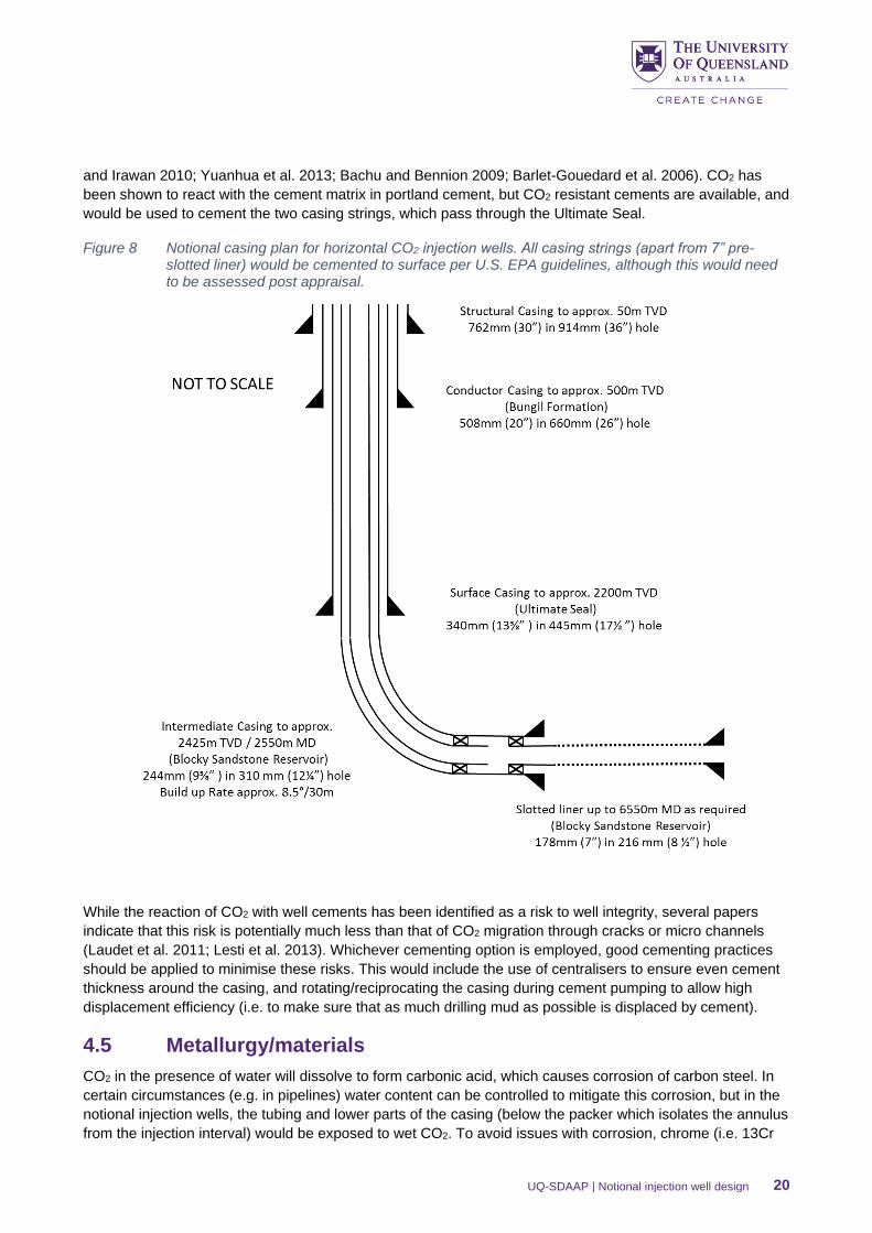
and Irawan 2010; Yuanhua et al. 2013; Bachu and Bennion 2009; Barlet-Gouedard et al. 2006). CO2 has
been shown to react with the cement matrix in portland cement, but CO2 resistant cements are available, and
would be used to cement the two casing strings, which pass through the Ultimate Seal.
Figure 8 Notional casing plan for horizontal CO2 injection wells. All casing strings (apart from 7” pre-slotted liner) would be cemented to surface per U.S. EPA guidelines, although this would need to be assessed post appraisal.
While the reaction of CO2 with well cements has been identified as a risk to well integrity, several papers
indicate that this risk is potentially much less than that of CO2 migration through cracks or micro channels
(Laudet et al. 2011; Lesti et al. 2013). Whichever cementing option is employed, good cementing practices
should be applied to minimise these risks. This would include the use of centralisers to ensure even cement
thickness around the casing, and rotating/reciprocating the casing during cement pumping to allow high
displacement efficiency (i.e. to make sure that as much drilling mud as possible is displaced by cement).
4.5 Metallurgy/materials
CO2 in the presence of water will dissolve to form carbonic acid, which causes corrosion of carbon steel. In
certain circumstances (e.g. in pipelines) water content can be controlled to mitigate this corrosion, but in the
notional injection wells, the tubing and lower parts of the casing (below the packer which isolates the annulus
from the injection interval) would be exposed to wet CO2. To avoid issues with corrosion, chrome (i.e. 13Cr
UQ-SDAAP | Notional injection well design 21
or super 13Cr steel, 18Cr, 25Cr or other corrosion-resistant alloy (CRA) should be used for these
components. The final choice of metallurgy will depend on the detailed gas composition being supplied, in
particular whether it contained sulphur (in the form of hydrogen sulphide - H2S) on the detailed composition
of the formation fluid, and on the final operating pressures. While the presence of H2S would require more
corrosion resistant (higher chrome) steel, such as 25Cr, to avoid issue with sulphide stress cracking (SSC),
this has been dealt with in other projects (e.g. Shell 2011), and is therefore not considered a technical
showstopper. For the purpose of this document it has been assumed the fluid will contain no H2S, and
therefore SSC is not an issue, and 13Cr or super 13Cr would be suitable.
As well as being exposed to the corrosive effects of wet CO2, the tubing and wellhead will also need to be
able to withstand low temperatures during transient conditions (see section 3.1). The low temperature limits
of 13Cr steel are between -10°C and -30°C, while Super13Cr can be used down to -50°C (Shell 2015), which
could be suitable options for this application.
Carbon steel would be suitable for the 9⅝″ casing above the packer, and for the other casing strings, which
should not be exposed to CO2.
Any other materials (e.g. elastomers for seals/packers etc.) which would come into contact with CO2 would
need to be compatible with CO2, and should be stable across the ranges of pressure and temperature that
could occur in the well.
4.6 Downhole equipment
Subject to a detailed operational risk assessment, it is likely that injection wells require a subsurface safety
valve (SSSV) on the tubing to isolate the wellbore in the case of failure of the surface well control facilities.
This tubing retrievable SSSV would need to be compatible with CO2 and water at the range of temperatures
which could occur during the well lifecycle.
As well as the SSSV, wells would require permanent downhole gauges (PDGs) to monitor the bottomhole
pressure and temperature. This data would be continuously transmitted to the surface, and onto the project
control room.
Other CCS projects have investigated the use of distributed temperature sensors (DTS) and distributed
acoustic sensors (DAS) to monitor the movement of CO2, both inside and outside the wellbore. This would
require permanent fibre optic cables to be run in the well on the outside of the tubing, and/or on the outside
of the casing. It may be that the risks associated with running the fibre optic lines on the outside of the casing
e.g. the possible formation of micro-annuli around the fibres, are considered to outweigh the benefits of
being able to monitor the movement of CO2.
The decision regarding whether or not to run fibre optic lines on the outside of the casing would need to be
made post appraisal, when the characteristics of the Transition Zone in the notional injection areas, is better
understood.
5. Conclusions
A notional design for a CO2 injection well suitable for injection in the Blocky Sandstone Reservoir has been
developed, based on the current best estimates regarding the reservoir properties and development options.
The notional design involves a horizontal well, with a 3 km to 4 km long horizontal section. The use of a
horizontal well allows CO2 injection at a lower bottomhole pressure, and targeted at the base of the Blocky
Sandstone Reservoir, reducing containment risk.
Horizontal wells would also reduce the well count, and surface footprint. The main disadvantage of horizontal
wells is that they would be more technically challenging to drill, and may require expertise and equipment
UQ-SDAAP | Notional injection well design 22
which is not widely available in Australia. However, the notional design discussed as part of this study is well
within the limits of current technology.
The notional wells would be completed with a pre-slotted 7” liner, with injection through 7” tubing to allow for
high rates. Chrome steel (13Cr or Super 13Cr) could be used for the tubing, and other well components that
would be exposed to wet CO2, with carbon steel a suitable material for other parts of the well.
Based on the U.S. EPA guidelines for Class VI wells (U.S. EPA 2012), the notional well design features a
9⅝″ casing run across the Ultimate Seal to provide an additional barrier protecting the Hutton Sandstone,
with shallower 13⅜” and 20” casing strings as required. Adhering to the EPA guidance, the notional designs
have all strings cemented to surface. This conservative approach may not be required, or even be beneficial,
for wells in the Blocky Sandstone Reservoir. A more detailed study into the most effective means of
minimising the risk of CO2 migration along the wellbore (and protecting overlying aquifers) would be required.
This study could be completed post-appraisal, when more information regarding the likely behaviour of the
Transition Zone and Ultimate Seal in the notional injection areas would be available.
The design discussed herein is feasible and conservative rather than optimal. It intended to represent a
feasible option for injection of CO2 into the Blocky Sandstone Reservoir, based on the current best estimates
of the reservoir properties, and an assumed CO2 delivery schedule. If different reservoir properties are
encountered, or if an alternate delivery profile is required, the design would be changed to be fit for purpose.
For example, a lower quality reservoir might require more/longer wells, but perhaps with slimmer tubing (due
to the reduced injection rate per well). If the reservoir quality was determined to be better than the current
estimates, then fewer wells might be required, and vertical wells may become a feasible option.
This study shows that it is possible to design CO2 injection wells that fulfil the criteria of achieving high CO2
injection rates while minimising containment risk, and which are well within the limits of current technology.
6. References
AAPG (2016), Wellbore Trajectory, Available at: https://wiki.aapg.org/Wellbore_trajectory.
Bachu S & Bennion DB (2009), Experimental assessment of brine and/or CO2 leakage through well cements
at reservoir conditions, International Journal of Greenhouse Gas Control, vol 3, pp 494-501.
Barlet-Gouedard V, Rimmele G, Goffe B et al. (2006), Mitigation strategies for the risk of CO2 migration
through wellbores, IADC/SPE Drilling Conference, Miami, Florida, USA: Society of Petroleum Engineers
Brandvoll Ø, Regnault O, Munz I et al. (2009), Fluid–solid interactions related to subsurface storage of CO2
Experimental tests of well cement, Energy Procedia, vol 1, pp 3367-3374.
Condor J & Asghari K (2009), Experimental study of stability and integrity of cement in wellbores used for
CO2 storage.
Garnett A (2019), Estimates of unit costs and discussion of the value of investment in appraisal, The
University of Queensland Surat Deep Aquifer Appraisal Project – Supplementary Detailed Report, The
University of Queensland.
Gonzalez S, He J, Underschultz J & Garnett A (2019), Seismic interpretation - geophysics, The University of
Queensland Surat Deep Aquifer Appraisal Project – Supplementary Detailed Report, The University of
Queensland.
Gonzalez S, Harfoush A, La Croix A, Underschultz J & Garnett A (2019), Regional static model, The
University of Queensland Surat Deep Aquifer Appraisal Project – Supplementary Detailed Report, The
University of Queensland.
UQ-SDAAP | Notional injection well design 23
Guiton S, Kieft R, Churchill J & Sheerin C (2015), Characterising the Hutton Sandstone in the Northeastern
Surat Basin, In AAPG Asia Pacific Region, Geoscience Technology Workshop, Opportunities in Coal Bed
Methane in the Asia Pacific, Brisbane.
Harfoush A, Hayes P, La Croix A, Gonzalez S & Wolhuter A (2019), Integrating petrophysics into modelling,
The University of Queensland Surat Deep Aquifer Appraisal Project – Supplementary Detailed Report, The
University of Queensland.
La Croix A, Wang J, Gonzalez S, He J, Underschultz J & Garnett A (2019), Sequence stratigraphy of the
Precipice Sandstone and Evergreen Formation in the Surat Basin, The University of Queensland Surat Deep
Aquifer Appraisal Project – Supplementary Detailed Report, The University of Queensland.
La Croix A, Harfoush A, Rodger I & Underschultz J (2019), Sector-scale static reservoir modelling of the
basin-centre in the Surat Basin, The University of Queensland Surat Deep Aquifer Appraisal Project –
Supplementary Detailed Report, The University of Queensland.
Laudet J-B, Garnier A, Neuville N et al. (2011), The behavior of oil well cement at downhole CO2 storage
conditions: Static and dynamic laboratory experiments, Energy Procedia, vol 4, pp 5251-5258.
Lesti M, Tiemeyer C & Plank J (2013), CO2 stability of Portland cement based well cementing systems for
use on carbon capture & storage (CCS) wells, Cement and Concrete Research, vol 45, pp 45-54.
Ribeiro A, Rodger I, Underschultz J & Garnett A (2019), Notional injection sites – injection scenarios, The
University of Queensland Surat Deep Aquifer Appraisal Project – Supplementary Detailed Report, The
University of Queensland.
Rodger I, La Croix A, Underschultz J & Garnett A (2019), Transition Zone behaviour test models, The
University of Queensland Surat Deep Aquifer Appraisal Project – Supplementary Detailed Report, The
University of Queensland.
Rodger I, Altaf I, Underschultz J & Garnett A (2019), Pressure constraints on injection, The University of
Queensland Surat Deep Aquifer Appraisal Project – Supplementary Detailed Report, The University of
Queensland.
Sauki A & Irawan S (2010), Effects of pressure and temperature on well cement degradation by supercritical
CO2, International Journal of Engineering & Technology, IJET-IJENS, vol 1, pp 53-61.
Shell (2011), Quest CCS Project – Well Technical Specifications – Quest SCL Radway 7-11-59- 20, Thorhild
5-35-59-21, Available at:
https://www.energy.alberta.ca/AU/Publications/KnowledgeSP/Documents/2014/Storage_Well_Technical_Sp
ecifications_2014.pdf
Shell (2014a), Peterhead CCS Project – Well Completion Concept Select Report, Available at:
https://assets.publishing.service.gov.uk/government/uploads/system/uploads/attachment_data/file/531051/P
eterhead_-_11.097_Well_Completion_Concept_Select_Report.pdf
Shell (2014b), Peterhead CCS Project – Well Functional Specification (WFS) Document), Available at:
https://assets.publishing.service.gov.uk/government/uploads/system/uploads/attachment_data/file/433494/W
ell_Functional_Specification.pdf
Shell (2015), Peterhead CCS Project – Well Technical Specification, Available at:
https://assets.publishing.service.gov.uk/government/uploads/system/uploads/attachment_data/file/433496/W
ell_Technical_Specification.pdf
Garnett AJ, Underschultz JR & Ashworth P (2019), Project Report: Scoping study for material carbon
abatement via carbon capture and storage, The University of Queensland Surat Deep Aquifer Appraisal
Project, The University of Queensland.

UQ-SDAAP | Notional injection well design 24
U.S. EPA (2012), Geologic Sequestration of Carbon Dioxide: Underground Injection Control (UIC) Program
Class VI Well Construction Guidance, United States Environmental Protection Agency, Available at:
https://www.epa.gov/sites/production/files/2015-07/documents/epa816r11020.pdf.
Wainman CC & McCabe PJ (2019), Evolution of the depositional environments of the Jurassic Walloon Coal
Measures, Surat Basin, Queensland, Australia. Sedimentology, doi:10.1111/sed.12548
Yuanhua L, Dajiang Z, Dezhi Z et al. (2013), Experimental studies on corrosion of cement in CO2 injection
wells under supercritical conditions, Corrosion Science, vol 74, pp 13-21.
UQ-SDAAP | Notional injection well design 25
CRICOS Provider Number 00025B