
Untitled - Digital Library of the Silesian University of Technology
244
-
Upload
khangminh22 -
Category
Documents
-
view
0 -
download
0
Transcript of Untitled - Digital Library of the Silesian University of Technology

. . . a guide to maximum production and operating economy
The relative flowrates and capacities of standard grades
of Dicalite filteraids are charted above. They afford
desired clarity with a wide range of flowrates. Liquors
that are difficult to filter, temporary shortage of filter
capacity, liquors containing an unusual percentage of
suspended solids from colloidal to coarse in size—these
and other conditions may be corrected by selection of
the most suitable Dicalite filteraid grade. You thus have
at hand a "balancing" factor to insure maximum pro
duction at lower cost.
D I C A L I T E F I L T E R A I D S. . . what they are, . . what they do
O R IG IN —D icalite filteraids are produced
from diatomaceous silica, a material depos
ited several million years ago on the bottoms
of oceans and lakes. It is composed of the
"skeletons" of aquatic plants called diatoms.
STRUCTURE—Particles of the materials are
microscopic in size and "elongated" or
"needle-like" in shape, a structure found to
make most efficient filtering materials.
USE—The finished Dicalite materials are in
powder form and are used in conjunction
with filter presses or other equipment in filtra
tion of liquids of all kinds, being added to
the liquid before filtering.
ACTION—As the liquid is pumped through
the filter, the particles of Dicalite filteraid
collect on the cloths or screens together with
the suspended solids being removed. As the
filter cake builds up, the filteraid particles
interlace and overlay in the fashion of a pile
of straws. Thus, millions of extremely fine
openings, continually forming, keep the filter
cake porous for liquid flow.
RESULTS—These openings are so small that
even the finest solids are trapped and held,
to give the liquids brilliant clarity. The open
ings being so numerous, free flow through
the cake gives high flowrates and long filter
cycles.
THE D ICALITE COMPANY C H I C A G O 1 1 • N E W Y O R K 5 • L O S A N G E L E S 1 4
v'. K v w iM x a

INDUSTRIAL and ENGINEERINGV O L U M E 3 9 N U M B E R 1
ISSUED J A N U A R Y 14, 1947
43,100 CO PIES O F TH IS ISSUE PRINTED JANUARY 1947
EDITOR: W ALTER J. MURPHY
Assistant to Editor: N . A . PARKINSON
Executive Editor:- JAMES M . CROWE
Managing Editor: D. O . M y ATT
Associate EditorsWashington: ROBERT F. G O U L D
A U L E G G IN
Chicago: RICH A RD L , K EN Y O N
Houston: W IL L H . S H E A R O N , JR .
N ew York: H A R R Y STENERSO N
R ic h a r d l . De m m e r l e
San Francisco: FREDERICK G . SAW YER» M e r r it t l . Ka s t e n s
Assistant EditorsMake-up: BERTH A REYN O LDS
Manuscript Editing:H e l e n K . N e w t o n
Manuscript Reviewing:St e l l a A n d e r s o n
Editorial Assistant: C O R A G . RYERSON
* In the armed services.
Contributing Editors
CH A RLES O W EN BROW N M ARS G . F O N T A N A RALPH H . M U N C H
W ALTER V O N PEC H M A N N
Advisory Board
W . L . BADGER ELMER K. B O LTO N W . H . D O W G A S T O N DUBOIS G U STA V U S J . ESSELEN PER K. FRO LIC H C . F. KETTERING O . E. M A Y C . S. M INER
H . R. M URDOCK C . F. PRUTTON A . S. R ICHARD SO N W . A . SCHM IDT R. N . SHREVE L . V . STECK E. C . S U LL IV A N E. R. W EIDLEIN J O H N M. WEISS
Industrial Edition, l&EC Consecutive Number 1
Copyrisht 1947 by American Chemical Society
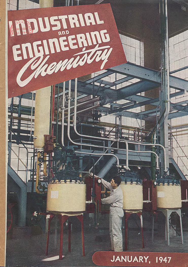
Shown on the cover is Monsanto's distillation pilot plant In St. Louis.It calls attention to the second an* nual unit operations review, appearing in this issue. Photo courtesy Mor.S2nto Chemical Company.
U N IT O P E R A T IO N S R E V IE W
Introduction........................................................................... 3Filtration
Shelby A . M i l l e r ......................................................... 5Materials Handling
Robert E. W r ig h t ............................ 8Crushing and Grinding
Lincoln T. W o r k ................................................................11Adsorption
Arthur B. R a y ......................................................................12Absorption and Humidification
Harrison C . C a r ls o n ..........................................................14Centrifugation
James O . M a lo n e y .......................................................... 16High Temperature Distillation
T. J . W a l s h ...........................................................................17
Langbeinite. M ining and ProcessingG . T . Harley and G . E. Atwood .
Molecular DistillationK. C . D. H ickm an ................................................................ 19
DryingSamuel J . F r ie d m a n ..........................................................20
EvaporationW . L . Badger and R. A . Lindsay . . . . . . 22
Solvent ExtractionJoseph C . E lg in .....................................................................23
FlotationFred D. D e V a n e y ...............................................................26
Heat TransferGeorge T. Skaperdas..........................................................28
MixingJ . Henry R u sh to n ................................................................30
H igh Pressure Gasification of Coal in Germ anyHorace M . W e i r ...............................................................
Sodium Reduction of Fatty A c id EstersV . L . H a n s le y .............................................
H eat Transfer Coefficients for Condensing Hydrocarbon VaporsDaniel A . D ono hue.......................................................................................................
43
48
55
62
Vulcanization of G R -S with Halogen CompoundsB. M . Sturgis, A . A . Baum, and J . H . Trepagn ier................................................................................................. 64
A c tiv e MagnesiaA . C . Zettlemoyer and W . C . W a lk e r ........................................................................................................................ 69
Solubilities of Am m onium and Potassium A lu m s in W aterDavid Schlain, John D. Prater, and S. F. R a v itz ....................................................................................................... 74
Phase Equilibria in Hydrocarbon SystemsH . H . Reamer, B. H . Sage, and W . N . L a c e y ....................................................................................................... 77
Recovery of Lactic A c id from Dilute SolutionsAlbert A . Dietz with Ed. F. Degering, and H . H . Schopmeyer.........................................................
Extending Phenolic Resin P lyw ood G lu es with Proteinaceous M aterialsGlen E. Babcock and A llan K. S m it h .............................................................................................................
82
. . . . 85
Depolym erization of Butadiene DimerThomas F. Doumani, Ronald F. Deering, and A rt C . M c K in n is ..................................................................... 89
Formation of Static Electric Charges on Agitating Petroleum Products with A irC . M . K la e r n e r ..........................................................................................................................................................
Plasticizing G R -S and Natural RubberArnold R. D a v i s ........................................
92
94
Comparative O xid ation of Linseed and Sardine O ilsG . A . O ’Hare and W . J . W ith ro w ....................................................................................................................................101
Superfractionation StudiesC . C . Ward, R. M . Gooding, and B. H . E c c le s to n .................................................................................................. 105
Continuous Preparation of Butadiene-Styrene Copolym erJ . J . O w en , C . T . Steele, P. T. Parker, and E. W . C a r r i e r ................................................................................. 110
Calorimetric Measurements of H eats of Hydration of StarchesW . G . Schrenk, A . C %Andrews, and H . H . K i n g ........................................ , .................................................... 113
EDITORIAL
H ead lines......................................................................... 117I. & E . C . Reports......................................................... 5 AA s W e See I t .................................................................... 71 ASidelights and T r e n d s .................................................122 A
Equipment and Design. Charles O . Brown . 77 AInstrumentation. Ralph H . M u n c h ........................... 83 ACorrosion. Mars G . Fo n tana .......................................89 APlant Management. W . von Pechmann . . . 93 A
Published by the American Chemical Society at Easton, Pa. Editorial Headquarters: 1155 16th St., N .W ., Washington 6 , D. C . ; telephone, Republic 5301; cable, Jiechem (Washington). Chicago Editorial Branch, 25 East Jackson Blvd., Chicago 4, HI.; telephone, Wabash 7376. Houston Editorial branch. 413 West Bldg., Houston 2, Tex.; telephone. Capital 6516. N ew York Editorial Branch, 60 East 42nd St., N ew York 17, N . Y . ; telephone, Murray H ill 2-4662. San Francisco Editorial Branch, 24 California St., San Francisco 11, C a lif.; telephone, Exbrook 2895. Business O ffice : American Chemical Society, 1155 16th St., N . W., Washington 6 , D. C . Advertising O ffice : 332 West 42nd St., N ew York 18, N . Y . ; telephone, Bryant 9-4430.
Entered as second-class matter at the Post O ffice at Easton, Pa., under the A c t of March 3 , 1879, as 24 times a year— Industrial and Engineering Chemistry monthly on the 1st, Analytical Chemistry monthly on the 15th. Acceptance for mailing at special rate of postage provided for in Section 1103, A ct of October 3 , 1917, authorized Ju ly 13 ,1918 .
The American Chemical Society assumes no responsibility for the statements and opinions advanced by contributors to its publications. V iew s expressed in the editorials and reports are those of the editors and do not necessarily represent the official position ofthe American Chemical Society.
Remittances and orders for subscriptions and for single copies, notices of changes of address and new professional connections, and claims for missing numbers should be sent to the American Chemical Society, 1155 16th St., N . W ., Washington ó , D. C- Changes of address for Industrial and Engineering Chemistry must be received on or before the 18th ofthe preceding month and for Analytical Chemistry hot later than the 30th ofthe preceding month. Claims for missing numbers w ill not be allowed (1 ) if received more than 60 days from date of issue (owing to delivery hazards, no claims can be honored from subscribers in Continental Europe, Asia , or the Pacific Islands other than H aw aii), (2 ) if loss was due to failure of notice of change of address to be received^before the dates specified in the preceding sentence, or (3 ) If the reason for claim is "missing from files".
Annual subscriptions— Industrial and Engineering Chemistry and Analytical Chemistry (Industrial and Analytical Editions of Industrial and Engineering Chemistry) sold only as a unit, members $3.00 , nonmembers $4.00. Postage to countries not in the Pan-American Union $3.00. Canadian postage $1 .00 . Single copies— current issues. I&EC $0.75, Analytical Chemistry $0 .50 ; back numbers, l&EC $0.80 , Analytical Chemistry prices on request; special rates to members.
The American Chemical Society also publishes Chemical and Engineering News, Chemical Abstracts, Journal o fthe American Chemical Society. Rates on request.

Celite Filter A id s assure the clearest filtrates atthe fastest flow products as :
rates in the clarification of such
A N IM A L O ILS , FA TS GLUE RESIN SO LUTIO N S
BEER G R A P E JU IC E SH ELLA C
C H EM ICA LS GUM S S O A P , L IQ U ID
C ID ER H O N EY S U G A R R EFIN IN G
C O R N O IL LA R D TA LLO W
C O TTO N SEED O IL LIN SEED O IL TU N G O IL
C U TTIN G FLU ID S M A PLE SYR U P V A R N IS H
D YESTU FFS M IN ER A L O ILS V EG ET A B L E O ILS
FRU IT JU IC ES M O LA SSES V IN E G A R
G ELA T IN E PECTIN W A TER
G LU C O SE P H A R M A C EU T IC A LS W IN E
I N D U S T R I A L A N D E N G I N E E R I N G C H E M I S T R Y Vol. 39, No. I
Johns-Manville
*R ® ir . U . S . P a t . O f f .
Is slow filtration a "bottleneck” in your production? Does lack o f clarity handicap the sales appeal o f your product?
You can have both brilliantly clear filtrates and maximum flow rates by using Celite* Filter Aids!
These modern filter aids are milled from nature’s largest and purest source o f diatomaceous silica—the Johns-Manville deposit at Lompoc, California. They are furnished in nine grades o f fineness, each designed for a specific type o f filtration problem. If the suspended impurities are small, one o f the finer grades o f Celite will provide the right combination o f clarity and flow; if large, one o f the coarser grades will do the job.
All nine grades o f Celite Filter Aids are available now to help you get the clearest filtrates at the fastest flow rates. For full information, write Johns-Manville, Box 290, New York 16 , N. Y.

INDUSTRIAL and ENGINEERING CHEMISTRY....
K e p o r t s
O N T H E C H E M I C A L W O R L D T O D A Y
S P I C Y S T O R YWith the memory of the holiday season and its attendant
taste-tempting tidbits fresh in our minds, it is appropriate to pause and reflect a moment on the cause of all this gustatory delight—spices. Visions spring forth immediately of turkey dressing containing sage, bay leaves, pepper, and the socially taboo but oh-so-savory onions. Mounds of cookies flavored with cinnamon, nutmeg, or cloves also appear before the mind's eye, as well as spicy pumpkin and mince pies.
Until recently the means used by either food companies or home cooks for bringing all this paradise to the palate consisted of adding a shovelful or pinch of the desired spice to the culinary concoction. Essential oil companies, however, viewed this as inefficient for many reasons. A large bulk had to be handled to get the flavorful oil constituent out of the plant particle and into the food in the right concentration. Freightage had to be paid on thousands of pounds of tannins, cellulose, and the other constituents of the whole spice that did nothing, savorly speaking, but go along for the ride. Mold formation, the bane of spice men, was an ever-present threat to destruction of the spices as they lay in expensive storage space awaiting distribution.
Today a small room lined with bottles of “ chemically pure” flavors is the equivalent of the sprawling spice storehouse of yesteryear, whose wonderful fragrance was enjoyed by the neighborhood but lamented by the spice man as lost dollars. This change has come about because of an increasingly common practice of the essential oil industry to steam-distill the spices at the point at which they are grown to remove the essential oils, the real flavoring materials.
The essential oil content of spices varies from year to year according to crop conditions; consequently, food packers received the advent of spice oils as the solution to the problem of keeping the flavor of products constant in spite of Mother Nature’s whims. Housewives stand to gain by the new development too, for, although it is doubtful that they will handle the concentrated flavors used in commerce, a host of spice-flavored salts will be available to them soon to augment those of onion, celery, and garlic now on their shelves.
The equivalent values between the whole spice and its corresponding spice oil are amazing. According to the spice equivalent table of the War Food Administration, 100 pounds of whole spice are equivalent to the following number of pounds of spice oil:
Bay leaves Black pepper Cinnamon, Ceylon Clove Dill seed
2IV*1173Vj
MaceNutmegSageThyme
12»/«121/a22
A spokesman for Magnus, Mabee, and Reynard, Inc., an essential-oil firm, revealed that his company has succeeded in isolating the flavor oil of onions, an ounce of which is equivalent to 5000 ounces of whole onion. A similar accomplishment was made with garlic, in which one ounce of the oil is equivalent to 3200 ounces of the parent material. Considering the strength of the original, that’s carrying a good thing far enough!
The final step for the spice maker would be the synthesis of flavor by chemical means. Synthetic vanillin has been a familiar sight on grocers’ shelves for many years. War shortages inspired similar work on cinnamon, the results of which were reported by Carl Bordenca of the Southern Research Institute at the recent ACS meeting in Chicago. From his researches the chemical requirements for a cinnamonlike product are blueprinted as “ a properly aromatic ring structure, not modified excessively by organoleptically active groups, and an acrolein nucleus (Continued on page 5A)
An interpretative monthly digest for chemists, chemical engineers, and executives in the chemical producing and chemical consuming industries
5 A

6 A I N D U S T R I A L A N D E N G I N E E R I N G C H E M I S T R Y Vol. 39, No. 1
FERGUSON FILTER LEAVEST u b u la r S l i t ted S c re e n
18-8 Stainless Steel
B ring you r S w cellan d F ilter Presses u p to d ate w ith ou r S tain less Steel 18-8
F ilter Leaves (A ll w elded co n stru ctio n ) co m p le te w ith Stainless Steel 18-8 N ip
ples and Cast Iro n N uts for the price o f Brass Leaves. T hese Leaves w ill give
greater flow w ith less pressure th an any le a f m a d e . S h ip m en t o f any n u m b er
from stock .♦
FERGUSON PERFORATING & WIRE CO.134 Ernest Street PROVIDENCE 5, R. I., U. S. A.

January 1947 I N D U S T R I A L A N D E N G I N E E R I N G C H E M I S T R Y
L fJifK ^ B £ L T JC R £ W CO N VFyO RCOLLARS - COUPLINGS • HANGER S * T ROUGHS • B O X ENOS • FLANGES • T H R U S T S * DRIVES
EXA CTLY what you need?tudinal conveyors, or for inclines up to 20 degrees, with most materials. Pitch o f flight is approximately the conveyor diameter.
When you have consulted a capable materials handling engineer and decided that a screw conveyor is best suited to use on your particular conveying problem, be sure that it is properly designed and fabricated.
At right are shown just a few of the many available styles of Link-Belt conveyor flights. Mountings and assemblies are widely varied to meet different conditions. Shafts and flights may be made of steel, cast iron, aluminum, or many other metals. Shown below is a section of conveyor made of stainless steel, with seamless tube shaft, parts welded together and highly polished.
Long Pitch Conveyor, occasionally em ployed on Vertical Screw Agitators for fluid materials, or for high capacity conveying of very free-flowing materials.
Double Flight Short Pitch Screw. Used to obtain smooth, slow movement o f materials. Also to prevent highly fluid products from flushing or “ spiraling” around screw flights on feeders under bins, hoppers, etc.
Double Flight Standard Pitch Conveyor, “ stepped- up” in diameter, and mounted on a com m on shaft or pipe. Successfully used on feeders for many products.
MAIN FACTORS TO CONSIDERAmong the many technical factors to be given careful study and consideration in planning a screw conveyor installation are the following: Cut Flight Conveyor with Paddles, which tend to
reverse flow and mix materials. Used mostly for light products.Weight—
a. Pounds per cubic foo t
Feed—a. M anuallyb. Uniformc. Surges
Operating Cyde-a. Hours per dayb. Days per year
Layout of Installation—
Kind of Material Handled—
a. Hard g. Stickyb. Soft h. Packsc. M edium i. D ryd. Lum py ¡. W ete. Free-flowing k. Abrasivef. Sluggish I. Corrosive D ouble Flight R ibbon Conveyor, Standard Pitch. Has
somewhat larger capacity than Single R ibbon Con- veyor of same diameter.Quantity—
a. Cubic feet per hourb. Tons per hour
To be sure on all points, why not consult a Link-Belt Materials Handling Engineer? He knows all kinds of equipment. He can give you unbiased advice, as Link-Belt makes almost every type of conveyor.
Double R ibbon M ixing Conveyor, consisting of two ribbons o f opposite hand, one large and one small, both o f the same pitch.Chicago 8, Indianapolis 6, Philadelphia 40, Atlanta, Dallas 1, M inneapolis 5,
San Francisco 24, Los Angeles 33, Seattle 4, Toronto 8. Offices,Factory Branch Stores and Distributors in Principal Cities. tc
IF IT'S
SCREW CONVEYORWHY NOT GET
FLIGHTS • MOUNTINGS • ASSEMBLY
Standard Pitch Conveyor, used on ordinary longi-

in which the aldehyde group is free or easily regenerated and in which no large side chains exist.” We do not, however, advise the housewife to try this mouthful on her corner grocer tomorrow. Many years and many headaches for the chemist will come and go before the labyrinthine magic of Mother Nature will be completely outmoded in flavor creation by a chemical reaction unit. R.L.D.
m a x i m u m
c o r r o s i o n
%S,STANCESERVICE
Faced with a flood of supercolossal predictions ■ A « that atomic energy is the “ open sesame” to allt ® » postwar technical problems, the professional
and lay observer alike are prone to forget that radioactive materials worked for the scientist many years before the advent of the Manhattan Project. The petroleum industry is one that has utilized radioactivity for many years. In 1936 oilmen began to learn that natural radioactivity might give an indication of the nature of subsurface formation. By 1940 “ dry holes” which had been drilled in the ’20s and earlier, and later resurveyed by the use of radioactive well logs, were producing oil, and producing wells were tapping reservoirs which had been by-passed in the original drilling.
The techniques utilized in this type of survey involve lowering an ionization chamber connected to a high-speed recording instrument into the well casing. The recorder register's the impact on the chamber of gamma radiation from radioactive materials in the surrounding formations. Emitting materials occur primarily in broken-down igneous rock formations. Shales and phosphatic limestone have relatively high activity. Most other limestones and sand formations in which oil may be present have low activity. This technique gives no indication of the presence of liquids as such.
It takes a specialist to transform stainless steel sheet into processing equipment that gives you the best out of the alloy. We work with stainless steel alloys exclusively. That means we're equipped to protect your investment in stainless steel processing equipment —know all the fabricating safeguards th a t g ive you the maximum benefits of the original alloy in your finished vessel. Consult with us on your requirements.
CiBANlNO
Itery maintaining' voltoqt
~Go*Ihombir'
"—Cosinç — ---O p era tion o f G a m m a -R a y E le ctro s co p e (A rrow s S h ow
P atli o f G a m m a R a y s )S . B lIC K M A N , IN C . *1201 G R E G O R Y A V E . • W EEH A W K EN , N . J .
In 1941 a new procedure was developed involving secondary emission initiated by neutron bombardment. In making a so- called neutron curve, 300 mg. of a radium-beryllium mixture are suspended from the bottom of the ionization chamber, with heavy shielding introduced between the two units. The neutrons emitted by the radiation source enter the surrounding mineral formations, where they initiate a secondary gam- ma-ray emission which varies with (Continued on pope 10 A)

C H A N G E - C A N A N D P O N Y M IXERS for mechanical dispersion of l i q u id s , p a s t e s , o r
pow ders.
THE "REFIN ER” precision-built m ixer fo r liquids o f low viscosity.
D O U B L E - C O N E B L E N D E R S f o r r a p i d m i x i n g o f d ry pow ders, c rys
ta ls , etc.
PO RTEREDUCER a sub- stantially-built unit fo r h e a v y - d u ty s e r v ic e . Speeds as low as / j r.p .m . in a com plete size range from Vi
h .p . up.
THE "G E N E R A L ' a liquid m ixer de signed fo r g enera l m ixing operations
DOUBLE-RIBBO N MIX ERS h eavy-du ty ma chines fo r speed y mix ing o f h e avy m ateria ls
PAINT AN D PASTE M IXERS substantia lly constructed fo r h e a vy duty m ixing o f viscous
liquids.
H. K. PORTER COMPANY, Inc.
. •; r-
January 1947 I N D U S T R I A L A N D E N G I N E E R I N G C H E M I S T R Y 9 A
T T ttX & l fr v t / é fifiC c c a tio K
T O P - E N T E R I N G M iX E R S — p ortab le and flange-mounted
types.

Keep those viscous fluids MOVING with
G a m m a -R a y L og nntl N eu tron L og
After the neutron emitters and ionization chambers became familiar equipment in the oil fields, many minor uses were found for them. By adding half a pound of radioactive carno- tite to each bag of cement used in the wells, it is possible to determine whether the cement completely filled the formation outside of the casing. Any gaps not filled with the activated cement appear on the gamma-ray curve as local areas of decreased radioactivity. Gamma-ray emission curves give an indication of varying porosities in large sand beds; they show just what part of the bed is producing the oil. Neutron curves are used to determine the exact location of casing shoes with respect to the sand bed.
Radioactive well logs possess the advantages of flexibility, economy, and simplicity of interpretation. They now constitute the only method of making a geological survey in a well, once it has been completely drilled and cased. The neutron log does have the disadvantage of being affected by oil Surrounding the instrument when it is used in a producing well, which introduces uncertainties because the diameter of the pipe changes with depth. Experts say that the radioactivity log will produce nearly everything that the geologist desires if a method can be developed which will identify the fluid content, after the presence of the fluid has been determined.
One more instrument of great utility in the oil field is the Penetron, developed for the purpose of measuring pipe thickness and the effects of corrosion where both inside and outside surfaces are not readily accessible. The Penetron has as a source of radiation a needle containing 1 mg. of radium in the form of a commercially available salt, surrounded with a shield containing a window which (Continued on page 14-A)
VISUAl DISCPOSITIONINDICATOR
DISCS ARE NOT AFFECTED BY EXPANSION OR CONTRACTION OF THE VALVE BODY
JACKETINLET
QUARTER-TURNOPERATION
DEEP STUFFING BOX
the hydrogen content of the materials in the formation. Thus when any liquid containing hydrogen, such as fresh water, salt water, petroleum, or natural gas, is present in a porous stratum adjacent to the emitter, it greatly retards the velocity of emitted neutrons and reduces the resultant secondary radiation. By utilizing the two methods successively, a significant picture of the subsurface strata can be constructed. Oilmen believe that this process represents the first practical application of neutron emission.
REED6H-I
JACKET
JACKET CHAMBER
JACKET DRAIN
Reed Jacketed Steel or Jacketed Semi-Steel valves will keep your viscous materials m oving at all times. They require no lubrication and maintenance costs are negligible.
The jacketing design provides correct operating temperature over the entire valve body, keeping the material fluid from flange to flange.
Reed V a lves a re in terchangeab le w ith wedge steel va lves and a re supp lied w ith A . S . A . standard fo r O . S . & Y . w edge gate va lves .
2200
R A D IO A C T IV IT Y IN C R E A S E S

January 1947 I N D U S T R I A L A N D E N G I N E E R I N G C H E M I S T R Y 1 1 A
We could almost say that the drastic steps taken by our friend here are necessary. Because, today drums are the lifeline of chem icals. Prompt return of drums is vital in maintaining deliveries of essential chemicals to your own plant. Steel is short— w e can’t purchase the new drums w e need. We must re-use all containers in serviceable condition. That’s w h y w e are relying on you.
T H E D O W C H E M IC A L C O M P A N YM I D L A N D • M I C H I G A N
New York • Boston • Ph iladelphia • Washington • Cleveland • Detroit • Chicago • $ f. Louis • Houston San Francisco • Los Angeles • Seattle

OVERFLOWS h7Z OVER THE PLANT
11* HG. VAC. ttS*F VAPOR
V A P O R 18 IS O / M R V E L . 1 7 0 F p / s e c .
S E P H A T f* R O SE CONN. FOR W ASR/NG .
z * » E F F E C T
20 * t/6. v n c l i l ’ F VAPOZ
-■v
i
SW ENSON DARES TO BE
Swenson dares to be first in working out difficult processes because o f its tremendous background of research, experience, and engi
neering skill. The development o f equipment and techniques for producing ammonium thiocyanate is another "first” that illustrates how industries secure important benefits by using Swenson Process Engineering to work out unusual problems.
5 W E N 5 D NE V A P O R A T O R S • F I L T E R S • C R Y S T A L L I Z E R S
S P R A Y D R Y E R S ' i i
- VALVE NORM,- VALVE, ron. s r-vAAVfc' NON K
atmo/pmekic
■> A C I P A T O P .
LitECK t/ALVt
fONNEL OP.Vlf/ALE OVERFLOW
<•!» S T - (S ' S T E E L P IP E
I / I * • L Ht ctf a pi PS
IEVEL IN THIS T.NORM A LEV LOU TO NAVE STORA AVAILABLE U/U, ORATORS NAVE DOWN FOR OLE REPAID
L E G E N P
Swenson is not just another builder of chemical equipment. . . it is an organization capable o f analyzing new, unusual, and difficult processes, and developing the evaporators, filters, and crystallizers required to achieve the desired results. Call in Swenson engineers while your plans are still in the formative stage.

January 1947 I N D U S T R I A L A N D E N G I N E E R I N G C H E M I S T R Y 13 A
is'sTet*. 29,7«s'/**S Ą L T WASH Vat. FILTER
IS: EFFECT
w e *
SWENSON EVAPORATOR COH A R V E Y , I L L . , U . S . A .
Title- f l o w S H E E T 4M A T F R / A L B A C A A / C E
Capacity
AMMONIUM THIOCYAN ATE-W AR-SHORT CHEMICAL
Analysis o f Design and Layout
Manufacture o f Equipment
TestOperation
n » h i a *
ChU F M
Scale ' / z " = o« ft-
Sw enson -W alker Crystallizer
Am erica’s entrance into W orld W ar II found this country with no consequential source o f ammonium thiocyanate— urgently needed for the production o f insecticides, anti-corrosives, matches, adhesives, and photographic chemicals; for textile printing and dyeing processes; and for use in synthesis and laboratory tests.
The governm ent assigned high priorities for plants to manufacture ammonium thiocyanate . . . but m ore than priorities were needed to secure quick production. There were special problem s in evaporating the original solution o f sodium thiocyanate due to its high boiling point rise, its tendency to foam , and its highly corrosive properties. There was no time to experiment or set up pilot plants.
In the emergency, Swenson engineers were entrusted with the design and fabrication o f full scale production equipment. They em ployed Long Tube Vertical Evaporators built with nickel and stainless steel; and solids were crystallized out o f the concentrate with Swenson-W alker Crystallizers.
Thus under stress o f wartime conditions, w orking in a new field without the benefit o f an experimental installation, Swenson was able to develop urgently needed equipment that w orked successfully. It is still in use and perform ing satisfactorily.
F/LT/tAre 68.304 *SO¿W
S W E N S O N15671 Lathrop Ave.
E V A P O R A T O R C O M P A N YDivision of Whiting Corporation H arvey, I llin o is
* Requirements
U n li/ S W E N S O N P R O V I D E S T H I S
PeriodicC heck-U ps
F I V E - W A Y S E R V I C E
2
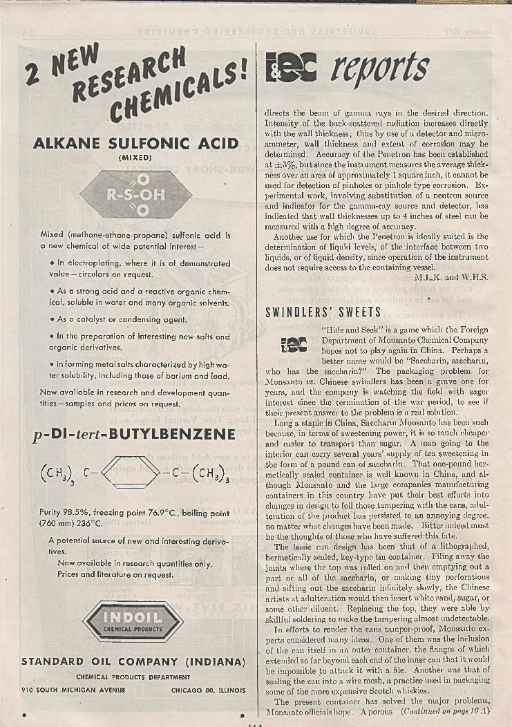
ALKANE SULFONIC ACID(M IX E D )
Mixed (methane-ethane-propane) sujfonic acid is a new chemical of wide potential interest—
• In electroplating, where it is of demonstrated
value — circulars on request.
• A s a strong acid and a reactive organ ic chem
ical, soluble in water and m any organ ic solvents.
• A s a catalyst or condensing agent.
• In the preparation of interesting new salts and
o rgan ic derivatives.
• In form ing metal salts characterized by high w a
ter solubility, including those of barium and lead.
N ow ava ilab le in research and development quan
tities— samples and prices on request.
p-DI-ieri-BUTYLBENZENE
( C H3) r C ~ \ / - C - ( c H 3)3
Purity 9 8 .5 % , freezing point 76.9°C., boiling point
(760 mm) 236°C.
A potential source of new and interesting deriva
tives.
N ow available in research quantities only.
Prices and literature on request.
STANDARD OIL COM PANY (INDIANA)C H EM IC A L PROD UCTS DEPARTM ENT
910 SO UTH M IC H IG A N A V E N U E C H IC A G O 8 0 , ILL IN O IS
i Kdirects the beam of gamma rays in the desired direction. Intensity of the back-scattered radiation increases directly with the wall thickness; thus by use of a detector and microammeter, wall thickness and extent of corrosion may be determined. Accuracy of the Penetron has been established at ± 3 % , but since the instrument measures the average thickness over an area of approximately 1 square inch, it cannot be used for detection of pinholes or pinhole type corrosion. Experimental work, involving substitution of a neutron source and indicator for the gamma-ray source and detector, has indicated that wall thicknesses up to 4 inches of steel can be measured with a high degree of accuracy.
Another use for which the Penetron is ideally suited is the determination of liquid levels, of the interface between two liquids, or of liquid density, since operation of the instrument does not require access to the containing vessel.
M.L.K. and W.H.S.
S W I N D L E R S ’ S W E E T S“ Hide and Seek” is a game which the Foreign
5 jW F Department of Monsanto Chemical CompanyI ® * hopes not to play again in China. Perhaps a
better name would be “ Saccharin, saccharin,who has the saccharin?” The packaging problem forMonsanto vs. Chinese swindlers has been a grave one for years, and the company is watching the field with eager interest since the termination of the war period, to see if their present answer to the problem is a real solution.
Long a staple in China, Saccharin Monsanto has been such because, in terms of sweetening power, it is so much cheaper and easier to transport than sugar. A man going to the interior can carry several years’ supply of tea sweetening in the form of a pound can of saccharin. That one-pound hermetically sealed container is well known in China, and although Monsanto and the large companies manufacturing containers in this country have put their best efforts into changes in design to foil those tampering with the cans, adulteration of the product has persisted to an annoying degree, no matter what changes have been made. Bitter indeed must be the thoughts of those who have suffered this fate.
The basic can design has been that of a lithographed, hermetically sealed, key-type tin container. Filing away the joints where the top was rolled on and then emptying out a part or all of the saccharin, or making tiny perforations and sifting out the saccharin infinitely slowly, the Chinese artists at adulteration would then insert white sand, sugar, or some other diluent. Replacing the top, they were able by skillful soldering to make the tampering almost undetectable.
In efforts to render the cans tamper-proof, Monsanto experts considered many ideas. One of them was the inclusion of the can itself in an outer container, the flanges of which extended so far beyond each end of the inner can that it would be impossible to attack it with a file. Another was that of sealing the can into a wire mesh, a practice used in packaging some of the more expensive Scotch whiskies.
The present container has solved the major problems, Monsanto officials hope. A porous (Continued on page 16 A)

ENGINEERS • CONSTRUCTORS • M ANUFACTURERS
for the CHEMICAL, PETROLEUM, GAS & POWER Industries
See Sw eet’ s Industrial F iles, Chem ical E n g ineering Catalog, R e fin ery Catalog, A S H & V E Guide, A S R E Databook, or w rite fo r sp ec ific inform ation .
• Chicago • Los A ngeles • Detroit • Pittsburgh • St. Louis • Houston • Tulsa O m ah a • D enver • D allas • A tlan ta • Sa lt Lake C ity *-• El Paso • M exico. C ity
The best from past practice, coupled wit the proven from among current development
. . . this combination of broad experience plus forward-looking ingenuity enable
Pritchard engineers to provide sound counse and service in the design , engineering am
construction of modern chemical procès projects . . . any facility involving th
handling of fluids and solids, distillation evaporation, crystallization, filtratior
heat transfer, gas manufacture, th treating or handling of natural gas, go
absorption and fractionation, dehydration a gases or liquids, recovery of oxygen, nitrogei
and argon from liquid a ir, am many other operation'
P R I T C H A R D p la n ts a n d p ro c e sse s are designed to produce maximum profitsFrom draw ing board to fu ll plant production , superior services are available, separately or in com bination :• E con om ic studies, investigations and com parisons o f alternative processes • D esign and engineer processes either independently or in con ju n ction w ith clien t’s ow n organization a n d /o r their consultants• R efin e and perfect process design from flo w diagram * Purchase equipm ent, construct plant or units and set in operation , either from P ritchard-developed plans or from furnished plans • E ff ic ie n c y analyses.
CHEMICAL DIVISION • FIDELITY BLDG. • KANSAS CITY 6, MO.

K I N N E YHIGH VACUUM PUMPS
MAINTAIN LOW ABSOLUTE PRESSURES FOR MODERN PROCESSING
This group of Kinney Compound Vacuum Pumps can exhaust
electronic tubes faster than operators can load the machine.
The view shows only 5 of the more than 700 Kinney High
Vacuum Pumps serving Sylvania Products, Inc. The reliability,
compactness and high pumping speed of Kinney High Vac
uum Pumps make them the choice — not only for producing
electronic tubes — but for countless applications in other
fields, including sintering metals, coating lenses, vacuum dry
ing, producing drugs, cyclotron evacuation, etc. Kinney Single
Stage Vacuum Pumps produce and maintain low absolute pres
sures to 10 microns; Compound Vacuum Pumps to 0.5 micron.
Write for Bulletin V45.
K IN N EY M AN UFACTU RIN G CO M PAN Y3 5 4 9 W A S H IN G T O N ST ., B O ST O N 3 0 , M A SS .
N EW YORK CH ICAG O PHILADELPHIA LOS AN GELES SAN FRANCISCO
F O R E IG N R EP R ESEN TA T IV ES
G e n e ra l Eng ineering C o , (R adcliffe ) L td ., S tatio n W o rks , Bury Road , R adcliffe , Lancash ire , Eng land
H orrocks, Roxburgh Pty, L td ., M elbourne , C . I . A u stra lia
W . S . Thom as & T ay lo r P ty , Ltd ., Jo hannesburg , Union of South A fr ica
W e a fso m a n u fa c tu re L iq u id P u m p s , C lu tch es a n d B itu m in o u s D is t r ib u to r s .
e S £ re p o r ts
cotton bag is packed inside the can so that the saccharin cannot be sifted out even if tiny holes are drilled in the tin. A fairly large rent must be made in the bag before it will permit leakage of the crystals. In the end of the can bearing the metal flap which slips into the key, they have inserted a metal •“ buffer” , so that if the swindler's lift the flap, bore a sizable hole, and attempt to reach any of the contents, they merely reach an empty space. The only device against which they have found no adequate protection is the actual counterfeiting of the can itself. Some remarkable reproductions have been made, and only the omission or misplacing of a punctuation mark or the misspelling of a word has revealed the imitation.
In probably no* place but the Orient could one find skill, patience, and time so cheap that they could be expended with so little, relatively, to gain. W.H.S.
P O T E N T P R O P E L L A N TBy V-E day Germany had been producing
g&ggn steady volumes of heavy, jet-propelledmissiles for over a year. At that time noother nation was prepared to make- such *a
projectile in the determinable future. The primary reason for this pre-eminence was the mastery in German chemical industries of the production and handling of high-potency hydrogen peroxide solutions.
German scientists, notably at the Elektrochemische Werke in Munich, studied high-concentration peroxide solutions as a propellant oxygen source during the 1914-18 war. Production of such solutions was not possible then because of the lack of sufficiently corrosion-resistant processing equipment. However, between wars Krupp perfected the V-2A, V-4À, and V-14A stainless steels which, when polished, would carry solutions of 90% peroxide concentration if sodium pyrophosphate and/or phosphoric acid were present as stabilizing elements. During the same period Koroseal and polyvinyl chloride resins were developed and proved suitable for use as gaskets and tubing materials in peroxide concentrating equipment. The production of peroxide solutions of more than 75% concentration immediately became feasible.
The basic peroxide solutions up to 30% strength are made by six different processes in Germany. The old barium peroxide method (still in use) and the persulfuric acid process, in which sulfuric acid is electrolyzed to persulfuric acid and the hydrogen peroxide distilled off, antecede the first World War. The interwar years contributed the Pietsch and Adolph process and the Kufstein process to this field. In the first, ammonium bisulfate is electrolyzed to ammonium persulfate, and potassium persulfate is then precipitated by the addition of potassium bisulfate. The precipitate is treated with sulfuric acid and steam-distilled to give hydrogen peroxide vapor, which may be fractionated to 35% strength. The second method is a modification of the first in which hydrogen peroxide is distilled directly from the ammoniumA}jdrsrjT àte solution.
As World War II progressed, the shortage of platinum in Germany became acute, and the repeated bombings of the Krupp works made stainless steel (Continued on page 22 A)
16 A

January" 1947 I N D U S T R I A L A N D E N G I N E E R I N G C H E M I S T R Y
Y O U G E To M P A C TN ESS
N A T I O N A L C A R S O N €*¡ ■ I — i
F o r pickling, etching, plating, and cleaning processes, the "Karbate” Plate-Type Heat Exchanger is ideal. It alone combines the most desirable properties required of a tank- type heater—compactness, shock resistance, high heat transfer, and corrosion resistance.
In form, it is a compact plate with interior tubular channels. It extends only a few inches from the tank wall. Individual units may be joined in multiple to provide the desired capacity.
Made of "Karbate” impervious graphite, it is resistant to- mechanical and thermal shock and has an unmatched heat- transfer rate. Moreover, it is unaffected by hydrochloric, dilute sulphuric, mixtures o f nitric and hydrofluoric acids, or other corrosive solutions.
For your copy of detailed folder, ask for Catalog Section M-8804. Write Dept. IE.
Photos show com pactness and flexibility o f installation o f the plate heater. Cut-away shows how tubular channels pass heating or cooling liquid within corrugated block. Unit is light in weight, easily installed.
Union Carbide and Carbon Corporation ords "National” and "Karbate” are registered
e-marks of National Carbon Company, Inc.
30 East 42nd Street, New York 17, N . Y . Division Sales Offices: Atlanta, Chicago, Dallas, Kansas City, New York, Pittsburgh, San Francisco

J Is Activated Carbon the answer
to your Adsorbent Problems?
The technology o f m odern manufacturing embraces, in ever increasing degree, application o f the science o£ chemistry as well as the mechanical forces o f physics. Likewise the accom plishment o f a physical act through a chemical medium becom es more and more com m on practice. Solving problem s o f adsorption is a typical sample o f this method.
O f the various adsorptive materials, Activated -Carbon has proved to be exceptionally adaptable and versatile. It has high adsorptive capacity, is chemically stable, readily regenerated and can be made in a variety o f forms and sizes to meet specific needs. M oreover it can be produced relatively econom ically on a tonnage basis for large scale applications.
If your manufacturing process requires the use o f an adsorbent you should investigate the merits o f Activated Carbon. Pittsburgh Coke & Chemical Company has the technical "k n ow -h ow ” and the production facilities to help you.-Ask us to!
Air Conditioning
Solvent Recovery
Gas Purification
Deodorization
Decolorization
Fractionation
Isolation of Organic Chemicals or Drugs
Catalysis orCatalyst Carriers
a c t i v a t e d c a r b o n
t y p e
l °T N O ._
PITTSBURGHHBViue C o * e $ C H EM IC A L C O M W „y
■'SŁANO, PENNSYLVANIA
Pittsburgh Coke & C|Grant Building
icat CompanyPittsburgh, Pennsylvania
1 8 A I N D U S T R I A L A N D E N G I N E E R I N G C H E M I S T R Y Vol. 3'9, No. 1

ADVERTISERS E X T —This entire page is a paid advertisement Prepared Monthly by U. S. Industrial Chemicals, Inc.
USJ. CHEMICAL NEWSJanuary + A Monthly Series for Chemists and Executives of the Solvents and Chemical Consuming Industries ★ 1947
Modern Farming Makes Diverse Use of Many Types of ChemicalsWide Range of Compounds Are Vital In The Manufacture of
Feedstuffs. Insecticides, Insectifuges, and Other ProductsChemicals of every type, many of which have their origin in farm products, are
helping America’s post-war farmer meet today’s urgent demands for increasing quantities of high quality products. These chemicals are used in the manufacture
THE MONTH IN PLASTICSA n e w p la s tic sa id to be stro nger than a ll others an d lig h te r than the lig h test m etal is d eve lo p ed . . . The adoption of a phenolic m olded housing fo r a n e w ly -d e s ig n e d g u ita r m arks the entry of p lastics into a fie ld fo rm e rly se rved a lm o st e xc lu s iv e ly by w ood and m etal . . . A n e w a p p a ra tus is p atented for s im u ltan e o u s ly subjecting th erm o p lastic or therm osetting resin s to p ressure an d h ig h-frequency heatin g . . . A process is reported to be perfected by w h ich m irro rized p lastic s and m eta l co atings can be produced on p lastics b y m eta l deposits in h igh vacuum e va p o ration cham bers . . . F ine d e ta il in the production o f p ho to graphs a n d d ra w in g s by use of pho to sensitive p o ly v in y l acetate la cq u e r is a ch ie ved . . . A c id etching on p la stic s is perfected . . . The n e w “ Scotch” v in y l p la stic e lectric tape is c la im ed to possess increased stre tch , th in n e ss , res is tan ce , an d f le x ib il ity . . . A n “ e xp a n d e d ” p o ly s ty re n e , a lle g e d to sh o w res is tan ce to m old an d ro t, is perfected for low -tem - p eratu re in su la tio n . . . A n e w p la stic fab ric fo r period fu rn itu re is announced . . . A paten t le a th e r p la s tic , su ita b le fo r uppers an d so les o f shoes, is p laced on the m arket . . . A n e w p la stic -b ase g lu e , w h ich sets hot or co ld , is suggested for use on a ll k inds of w o o d .
44Smokeless Coal” Now Receiving Final Tests
The bane of industrial cities, “ smog,” may soon he a thing of the past if a new process
v for making new types of smokeless fuel from western soft coal is successful. The process, developed experimentally over a period of seven years, is now undergoing its final tests.
In the process, finely divided coal is passed continuously through a heated horizontal retort which is vibrated at a controlled intensity, according to the inventor. At high temperatures the coal is then pressed into “ logs” about 2 inches in diameter. The complete process of converting the coal into smokeless logs is reported to take only three minutes.
Research Data on Powder Metallurgy Now AvailableSix research reports on the strides made in
powder metallurgy research during the war are now available to the chemical and related industries. Among the Highlights in these reports is the discovery that nonilowing, finely divided metal powders can be made to flow by waterproofing the individual particles with a vapor of the wartime-developed methyl chlorosilanes. This discovery now makes possible the use of many metallic powders hitherto considered unsuitable for powder metallurgy, according to the authors.
Clear Liquid SoapThe cloudiness which results when liquid
soaps are stored in glass containers may be avoided, according to the claims made in a patent issued recently. To preserve the clarity of the soap, the inventor suggests the addition of small quantities of commercial sodium silicate and a prescribed treatment.
Bactericidal Powers of Alcohols Are DeterminedSwedish workers have classified the bacteri
cidal powers of alcohol in vitro, in the following order of increasing effectiveness: ethyl alcohol, propylene glycol, amyl alcohol, propyl alcohol, and butyl alcohol. In the form of aerosols as vehicles for phenol, the effectiveness increased in the order: propyl alcohol, butyl alcohol, amyl alcohol, and propylene glycol. Since the latter is in the order of increasing boiling points, the authors conclude that the bactericidal effectiveness is dependent upon the stability of the aerosol.
Invents Flameproof Coating for Fabrics
A new-type flameproof coating for fabrics is claimed in a patent issued recently. The coating is described as consisting of coutna- rone indene resins and an antimony oxide or sulfide in proportion of about 8 to 5 by weight. It is said to improve resistance to water, weather, mold, fungus, and mildew as well as making the fabric flameproof. According to the patent, the coating is applied at temperatures of 225 deg. to 260 deg. F.
New Cinnamon SubstituteA substitute for cinnamon may be obtained
from waste oat hulls, it was announced recently. The comoound designated as furana- crolein, is said to he derived in two simple steps from the waste hulls.
of animal feeds and in the preparation of compounds that protect livestock, grains, tobacco, and dried fruits from insects and vermin. They are also employed to kill weeds, to aid in the preservation of food, to hasten the ripening of fruits and vegetables, and for numerous other purposes.
M odern A nim al FeedsToday, farm animals are fed with carefully
processed feeds which include all o f the essential nutrients known to be necessary for good health and general well being. In this planned program of animal husbandry, five valuable U.S.I. products are in wide use: Curbay B-G, Special Liquid Curbay, Vacatonc 40, U.S.I. Brand Riboflavin Mixture No. 1. and U.S.I. Brand Riboflavin Concentrate No. 85. These products, representing more than ten years of service to the feed industry, contain essential parts of the vitamin B-G complex. Feed manufacturers are substituting increasing amounts of vegetable protein to replace scarce animal protein, and nutritionists recommend the use of vitamin B-G products to bring the vegetable proteins to a high level of performance.
Curbay B-G (dried fermentation solubles), a by-product of alcohol fermentation, contains vitamins of the B-G complex essential for maximum feed efficiency. Special Liquid Curbay (condensed molasses distiller’s solubles), a special concentrate derived from a yeast fermentation of black-strap molasses, does an outstanding job as a feedstuff ingredient for hog and dairy rations. The addition of Vaca- tone 40 (dried molasses distillers’ solubles), which is richer than dried skim milk in the essential B complex vitamins, is one of the
(Continued on next page)
T o d a y 's fa rm s produce m ore an d better foods, th an ks to a w id e v a r ie ty o f chem ica ls w h ich go into the m an u factu re of products ran g in g from feed stu ff in g red ien ts to insectic id es .

U . S . I N D U S T R I A L C H E M I C A L S , I N C60 EAST 42ND ST., NEW YORK 17, N. Y. ■ RANCHES IN ALL PRINCIPAL CITIES
T E C H N IC A L D E V E L O P M E N T S
ADVERTISEM ENT—This entire pape is a paid advertisement
U.S.I. CHEMICAL NEWS
ACETIC ESTERSAmyl Acetate Butyl Acetate Ethyl Acetate
OXALIC ESTERS Dibutyl Oxalate Diethyl Oxalate
PHTHALIC ESTERS Dtamyl Phthalate Dibutyl Phthalate Diethyl Phthalate
OTHER ESTERS•DialolDiethyl Carbonate Ethyl Chloroformate Ethyl Formate
INTERMEDIATESAcetoacetanilide Acetoacet-ortho-anisidide Acetoacet-ortho-chlorqnilide Acetoacet-ortho-toluidide Acetoacet-para-chloranilide Alpha-acetylbutyrolactone 5-Chloro-2*pentanone 5-Diethylomino-2-pentanone EthyLAcetoacetote Ethyl Benzoylacetate Ethyl Alpha-Oxalpropionate Ethyl Sodium Oxalacetate Methyl Cyclopropyl Ketone
ETHERS Ethyl EtherEthyl Ether Absolute—A.C.S.
FEED CONCENTRATESRiboflavin Concentrates
•Vacatone 40*Curbay B-G 'Curbay Special Liquid
ACETONEChemically Pure
RESINSEster Gums—all types Congo Gums—raw, fused A esterified
•Aroplaz—alkyds and allied materials •Arofene—pure phenolic*•Arochem—modified types
Natural Resins—all standard grades OTHER PRODUCTS
Collodions EthyleneEthylene Glycol UrethanNitrocellulose Solutions d/-Methionine
Printed in U.S.A.
Further information on these items may be obtained by writing to U.S.I.
A new fast paint brush cleaner is said to clean hardened paint, lacquer, varnish, shellac or enam el w hile being non-injurious to hog bristle, nylon, setting com pound or painter's hands.
USI (No. 149)
To w aterproof exterior w alls and to reduce dam pness and seepage in dam p basem ents, a new com pound is offered w hich, the manufacturer states, can be applied like a paint. (No. 150)
USIA new cold-setting w aterproof adhesive, d e scribed as a thermoplastic synthetic elastic com position that does not require vulcanization, is said to be unaffected betw een the temperature range — 40 deg . F. to - f l6 0 deg . F., and to be more resistant to oxidation than sim ilar natural rubber com pounds. (No. 151)
USIA liquid w indshield defroster, said to soften grease , ice or frozen rain, is cla im ed to be harmless to auto finishes and to contain no corrosive chem icals. (No. 152)
USINew-type paints, described as intermediates b e tween ordinary paints and ceram ic coatings, are now offered for uses w here high heat- and w ear- resistance are required. They are said to give hard, tough films that w ill neither fade nor chalk.
USI (No. 153)-
To revitalize dried-out hardened leathers, is thepurpose of a new com pound designed to give the maximum of waterproofing without clogging the leather "p o re s ." (No. 154)
USIA quick-acting paint rem over w ill stay moist and deep-cutting as long as 24 hours, reducing hard finish coats to a quickly-y ield ing sludge, a ccord ing to the m anufacturer. It is claim ed to leave w ood grain and bristles unaffected. (No. 155)
USITo prevent rot of w ood , rope, canvas, and cloth products, a new product has been announced w hich is described as a liquid w hich penetrates the fibers, waterproofing and m ildew- proofing the articles. (No. 156)
USIA synthetic asbestos, w hich m ay a lso b e used as a mica substitute, is said to have properties similar to polystyrene. It is recom m ended foruse in electrical equipm ent. (No. 157)
USIBristles from casein are now being m ade com m ercially for the first time, it w as announced recently. Of m any possib le uses, the bristle is said to be particularly adapted to the construction of paint brushes since it is resistant to oils and organ ic solvents. (No. 158)
PAINT SHOW BREAKS ATTENDANCE RECORDSTh e f i r s t p o s t - w a r coatings convention b r o k e a i l a t t e n d ance records at A tlan tic C ity . H ere , at th e U . S . I . b o o th , seated le ft to r ig h t:E . G . D e la n e y of U . S . I . a n d H. W .C a n t w e l l o f t h e C r o w n C o rk a n d Seal Co . S tand ing le ft to righ t G rant Sch le icher o f W ilson Prin ting In k , Dr.C . W . M e incke of L a s t in g P ro d u c ts C o . , a n d M . M .G rub er o f U .S .I .
ALCOHOLSAmyl AlcoholButanol (Normal Butyl Alcohol) Fusel O il—Refined
Ethanol (Ethyl Alcohol)Specially Denatured—oil regular
and anhydrous formulas Completely Denatured—all regular
and anhydrous formulas Pure-190 proof, C.P. 96%
Absolute —•Super Pyro Anti-freeze •Solox proprietory Solvent
«ANSOLSAnsol M Ansol PR ¿
•Registered Trade Mark
Organic Chemicals on the Farm( Continued from page one)
more economical ways of forming a proper ration for poultry, hogs, and other livestock.
Made available recently are two riboflavin concentrates. One of these, U.S.I. Brand Riboflavin Mixture No. 1. a natural riboflavin concentrate obtained from vegetative fermentation reaction, contains one gram of active riboflavin per ounce of material, along with carriers and important vitamins of the B complex. The other, U.S.I. Brand Riboflavin Concentrate No. 85. also obtained from a vegetative fermentation, consists of 85 parts per hundred of active riboflavin, along with a natural carrier and a new vitamin of the B complex. It is expected that methionine will be used in the near future to enrich feedstufis.
Insecticides and In scctifu g csThe protection of farm animals and workers
against insects is now obtained by many low-cost sprays containing organic chemicals. One of the newest of these sprays is produced by combining pyrethrum with a new D&O- developed chemical, piperonyl butoxidc. Liquid insecticide and aerosols made in this way are superior to straight pyrethrum insecticides in range of effectiveness, stability, and residual killing power. They are completely free from toxicological hazards, irritation, odor, and other undesirable properties. Other insecticides and insectifuges are constantly being developed by the Entomological Division of Dodge ami Olcott, Inc., located in U.S.I.’s newly-opened laboratory in Baltimore.
Other Uses Ethylene is used to hasten the ripening of
fruits and vegetables. Plant hormones, employed to stimulate growth, and to kill weeds, are synthesized from organic chemicals. Ethyl alcohol, amyl alcohol, ethyl acetate, and amyl acetate are among the chemicals used to prepare flavorings, extracts, and essences.
Courtesy U. of Mo.
Ch icks fed w ith feedstu ffs enriched w ith rib o fla v in concentrates a v o id curled-toe p a ra ly s is (sh o w n h e re ) . . . g ro w into top egg producers.


/lutMuitic pH CONTROL BMwith Constant Main Line Rate of Flow
a u t o m a t i c » h c o n t r o l w rrr t c o n s t a t m a in l in e r a « or > l o w
pH CORRCCTINC CHEM ICA L
ADDITION
Milton Roy Pumps are controlled volume metering units, designed to meter and pump practically any liquid in volumes as low as 1 pint per hour to as high as 23 gallons per minute per pump side and against pressures as high as 20,000 lbs. per square inch. Because o f the high degree o f accuracy o f volumetric measure made possible by the Milton Roy step valve design, these pumps have found many applications as components o f automatic chemical feed systems.
Automatic pH control systems use Milton Roy controlled volume pumps both to measure the quantity o f material required to maintain a desired pH value, and to transfer the chemical, injecting against pressure where desired.
On these systems, the pH meter and controller may function to either change motor speed, or to automatically change the length o f the stroke o f the pump. Control o f stroke length is normally preferred for this type o f system. Proper design o f such a system is essential. Milton Roy chemical engineers are fully qualified to assist and recommend designs for such installations and to furnish the complete pH control system including pH meter, controller, and controlled volume pump.
For further information . . . on automatic pH control with varying main line rate o f flow . . . on automatic proportioning and ratio control systems . . . and on pumps and other equipment for other automatic chemical feed systems ask for new Bulletin 468, also Technical Paper N o. 54 "A n Application o f Electronics in Automatic Chemical Feed Systems.”
production difficult. German scientists therefore began to cast about for a peroxide process which did not involve electrolysis. They came up with two interesting solutions. The first process involved the reduction by hydrogen of 2-ethyl- anthraquinone in the presence of a nickel catalyst to give 2- ethylanthranol. Reoxidation of the anthranol to the quinone with 40% oxygen yielded peroxide. The process was conducted in a 50-50 benzene-hexanol mixture from which the peroxide was later extracted by water. The process had only one disadvantage. Organic impurities in the peroxide solution caused it to explode periodically and kill everyone who happened to be in the vicinity of the plant.
The second new method is of particular theoretical interest. In it a mixture of 95% hydrogen gas and 5% oxygen is saturated with water vapor and passed between parallel quartz plates coated with aluminum on the outer side. A high voltage, high frequency electric discharge is applied to the plates, and the hydrogen and oxygen combine to give hydrogen peroxide. This process did not reach production status because of the collapse of Germany. However, it is estimated that, while its consumption of electrical power would be higher than that in the conventional methods, the labor cost attendant to the operation would be very small. All of the various plants used a reduced-pressure distillation system for concentrating the dilute peroxide solutions to the requisite 80-90% for use in propellants.
In the use of high-concentration peroxide solutions, the first development was simply the decomposition of the solution by a catalyst to form superheated steam and oxygen, which were used to run a turbine. The catalysts usually contained manganese dioxide, although sodium and potassium permanganates were sometimes used. Later the oxygen was employed with a liquid fuel. In the military rockets a mixture of hydrazine hydrate, methanol, and water, known as “ C-stuff” , was used. The principal difficulty encountered in this adaptation was to obtain complete decomposition of the peroxide before it came into contact with the fuel, since failure to attain this decomposition resulted in an explosion. This hazard was reduced by maintaining high standards of purity in the peroxide, which ensured that the catalyst remained unpoisoned and operative. The principal special qualification of the fuel was that it be sulfur-free.
The peroxide-fuel combination was used to provide jet propulsion for rockets and ultimately for auxiliary starting derices for airplanes. Eventually 5000-horsepower turbine engines were developed which would have been capable of propelling a submarine for 30 miles under water without discharging air bubbles. However, the ships containing these engines were never put into service because of the bombing of Kiel. A 500-horsepower torpedo was also developed which had a speed of 50 miles per hour and a range of 15 miles, and traveled without producing air bubbles.
Recent experiments in this country have confirmed the German scientists’ conclusion that hydrogen peroxide solutions are a practicable source of energy for rocket propulsion. If fate condemns us to another war, look for H20 2 on the critical materials lists and for a coincident decrease in the number of the Nation’s “ suicide” blondes. ' M.L.K.
miLTOn oy COmPffflY1365 E. MERMAID AVE., CHESTNUT HILL, PHILA. 18, PA.
22 A

January 1947 I N D U S T R I A L A N D E N G I N E E R I N G C H E M I S T R Y 23 A
Stainless Steel assures freedom from contamination and protects product quality in this sanitary evaporator, made entirely of Republic EN- DURO Stainless Steel.
AI«o Carbon Steel M echanical Tubing
1» It’s true that the original cost o f ELECTRUNITE«¡> Stainless Steel tubing is higher than that o f ordinary
carbon steel tubing. But it’s also true that, where the use o f stainless steel is indicated, its cost per year o f service is less. Actually, you are money ahead when you use ELECTRUNITE Stainless Steel Tubing.This modem tubing gives you all o f the many cost-saving advantages o f Republic ENDURO Stainless Steel—PLUS the consistently uniform wall thickness, diameter, roundness and ease o f fabrication which result from the ELECTRUNITE Process o f tube manufacture.If severe corrosion is causing premature failure o f ordinary tubing . . . i f sanitation or non-contamination is important to safeguard quality o f your products . . . it will pay you to write for complete information about ELECTRUNITE Stainless Steel Tubing.
R E P U B L I C S T E E L C O R P O R A T I O NS T E E L A N D T U B E S D I V I S I O N • C L E V E L A N D 8, O H I OE xp ort D e p a rtm e n t: C h ry sler B u ild in g , N e w Y o rk 1 7 , N e w Y ork

Spectroscopic Analysis o f Carbon Twelve reveals minute amounts o f the elements listed at right.
Content in per centMaximum Minimum
M A G N E S IU M .... 0 .01S I L I C O N ................ 0 .01B O R O N ............... 0 .001C A L C IU M ............... 0 .001I R O N ...................... .......... 0.1 0 .001C H R O M I U M ____ T raceP O T A S S I U M ____ T raceM A N G A N E S E ____ T raceS O D I U M ................. T raceT I N ............................ T raceS T R O N T IU M ......... T raceT IT A N IU M ............. Trace

R carbon available in carload lo£s which/approaches the quality o f a fine C. P. chemical It is carbon in its pures/form, and it is available now, in carload lots. Carbon Twelve is ready for new consumers and new applications, and at a much lower cost than most industrial carbons.
These are some/bf the manY qualities of Carbon TwelveIts ability to prevent caking recommends it to those industries using hygroscopic materials.
Its chemical purity recommends it as a reagent to the carbon disulphide and electrode industries.
Its fine particle size and/large surface area recommend it as a catalyst carrier in both liquid and gaseous systems.
Its low thermal conductivity, low er than that o f the most widely used insulators, including ground cork, recommends/lt as a low temperature insulating material.
Conve/sely, it cyn be used in inert atmosphere at high temperatures which w ould melt other insulators.
Itynuidity provides easy application, especially in closed, cylindrical form s.
Carbon Twelve is 99% pure carbon. It is available now, at a great,economy, in iarload or L.C.L. lots. Unequaled production facilities assure a constant supply. The Research and Development Department of Godfrey L. Cabot, Inc., is ready to explore with you the many possibilities of Carbon Twelve.
GODFREY L. CABOT, INC. 7 7 FRANKLIN S T R E E T B O S T O N 1 0 , M A S S .

26 A I N D U S T R I A L A N D E N G I N E E R I N G C H E M I S T R Y Vol. 39, No. 1
W E K N O W T H E
B R O W N ■ B U T
A N
O r A n y Step
In Design,
Engineering,
Fabrication
O r Erection
of
Process Plants
for the
O il, Gas
and Chemical
Industries
P. O. BOX 2634 HOUSTON 1, TEXAS
Q u i t C o & i t
H E G U L F C O A S T , from the toe of
Texas to the Florida Keys, is one of the
world’s greatest treasurehouses.
Vast resources in oil, gas, sulphur
and other minerals have made this region
the capital of the petroleum, chemical
and petro-chemical industries.
Brown & Root, Inc., have rich and
varied operating experience in every state
on the Gulf Coast.
W e k now, through many jobs over
many years, the right answers in plant
location, design, engineering, fabrication
and erection of process plants for the
petroleum, chemical and petro-chemical
industries.
Brown & Root, Inc., /7can do7/
guarantees your success in locating on the.
Gulf Coast.
BROWN & ROOT, Inc

FULL W A L L TH ICKN ESS
HERE
REINFORCEDHERE
January 1947
j:-
s e l e c t i v e
l e l n i o t c e m e m. „ stresses in a ue greatest
The bursting sur£ ^ calcu-
£ j“ ' S J b e U ^ 0u * e S o « .
a ^ hv experiments. -on in forming
inner arc to evidenc engineering
The,,e “ r * “ ” ' ®oov Bi“extra lengths strength thro S extra^eldB TLS f m b i U other e v u l g ^ rs only
your p ip e '' ® p i P E ” w- n e O R G E * ,a5_ Chicago
W e ld E L L S a lo n e c o m b in e th e se fe a tu re s :
• Seam less— greater strength and uniformity.• Tangents— keep weld away from zone o f highest
stress— simplify lining up.• Precision quarter-m arked ends— sim plify layout and
help insure accuracy.• S e le c t iv e re in fo r c e m e n t — p ro v id e s u n ifo rm
strength,• Permanent and com plete identification m arking—
saves time and eliminates errors in shop and field.• W a ll thickness never less than specification mini
mum— assures full strength and long life.• Machine tool beveled ends— provides best welding
surface and accurate bevel and land.• The most com plete line o f W elding Fittings and
Forged Stee l Flanges in the W o rld — insures com plete service and undivided responsibility.
v: h: •" h f • - - : - : - i ‘ : Ti iifV - tf=£P . ; , f
H =i • ; • tor- ^ - -
i « -

28 A
A N
I N D U S T R I A L A N D E N G I N E E R I N G C H E M I S T R Y Vol. 39, No. 1
Davison Silica Gel
D S E L E C T I V E A D S O R P T I O N
The basic principles involved:D efinite relationships exist between adsorbents and materials adsorbed.
2 Under any particular set o f conditions, each adsorbent-exhibits a definite capacity and tenacity toward each respective adsórbate (the material adsorbed).
o When a mixture o f adsorbates contacts an adsorbent surface S E L E C T IV E ADSORPTION occurs.
No one adsorbent will function in an ideal manner in all operations, BUT the specific nature o f Davison silica gel adsorbents can be controlled over wide ranges and thereby will find applications where constant quality is required.
Silica gel is structurally complex and the specific SURFACE and PHYSICAL properties depend on each phase o f its manufacture.
Davison, through years o f experience and research, has developed definite controls for every step in the manufacture of
Davison Silica GelThe Davison Chemical Corporation welcomes inquiries relating to specific gels for selective adsorption work.
T H E D A V I S O N CH L C O R P O R A T I O NB A L T I M O R E 3 , M A R Y L A N D

F O R P R O C E S S I N G S Y S T E M S
January 1947 I N D U S T R I A L A N D E N G I N E E R I N G C H E M I S T R Y ___________ ____________________
ADE L A V A L Centrifugal Separator or Clari- fier provides a means for effecting cleaner,
faster continuous separation of two liquids (with a removal o f solid impurities) or the continuous removal of solids from a single liquid. In the case
of the De Laval “ Nozzle-M atic” Separator, the removed solids are likewise continuously discharged through nozzles or valves in the bowl shell.
But a De Laval Separator does more than speed up operations and remove troublesome solids. It usually produces a more com plete separation — and therefore actually improves the product. Because it operates as part o f a continuous system, a De Laval centrifugal saves money by avoiding waste of the product itself.
There are types and sizes of De Laval machines for eliminating “ slow-spots” in every branch of the Process Industries. In writing, specify whether you are most interested in separation, clarification or concentration.
THE DE L A V A L SEPARATO R CO M P A N Y165 Broadway, N ew York 6 42 7 Randolph St., Chicago 6
^ L A V A L P A C IF IC C O . , 61 Beale St., San Francisco 19
T H E D E L A V A L C O M P A N Y , Limited PETER BO RO U G H
Q U EBEC M O N T R E A L W IN N IP EG V A N C O U V E R
/ Ask for Bulletin No. 225

I N D U S T R I A L A N ;D E N G I N E E R I N G C H E M I S T R Y
YO U ’LL SAVE ON INSTALLATION, OPERATION, M A IN TEN AN CE
W ITH STACEY -KLO N N E TYPE DRY SEAL GAS H O L D E R S . . .
Vol. 39, No. 1
\ %ü » ; M
This 32-pagc book tells the complete construction and operation story o f dry seal gas holders, including four pages o f valuable engineering data and tables. From detailed drawings and close-up illustrations you’ ll find why operators are turning to Stacey-Klonne D ry Seal Holders for economical, trouble-free storage capacity.
During the 14 years since we first introduced Stacey-Klonne Holders in this country, we’ve built them as small as 30,000 cu. ft.— and as large as 10,000,000 cu. ft. You can benefit by
this pioneering experience. Whether you operate holders now— or plan building them in the future, you ’ ll want this book. Write us on your company letterhead for your copy. Ask for Bulletin D-46.
T H E S T A C E Y B R O S . GAS C O N S T R U C T IO N CO.
One of the Dresser Industries ,5535 VINE STREET • CINCINNATI 16 OHIO
ALL-WELDED GAS HOLDERS

January 1947 I N D U S T R I A L A N D E N G I N E E R I N G C H E M I S T R Y 31 A
G O O
T R A P S
m
No one will quarrel, with that! Plant operators know that air and
condensation must be removed from steam coils and lines rapidly
and completely, if the steatn is to do its work efficiently.
A good steam trap will do this, day after day, for years, and with
a minimum of maintenance or interruption.
The Sarco Inverted Bucket Trap illustrated is such a good steam
trap, as testified by hundreds of users who employ them through
out their plants.
The advanced design includes straight-through conections for easy
installation; a strainer built into every trap; stainless steel mechan
ism attached to the trap cover for easy inspection and cleaning.
Standard types, V2 " to 2" up to 250 lbs.; forged steel types to
900 lbs. pressure. Ask for Catalog No. 350 .
SARCO COMPANY, INC.Representad ¡n Principal CU ¡es
475 FIFTH AVE., NEW YORK 17, N. Y.SARCO CA N A D A , LTD ., TO RO N TO 1, O N TA R IOyí"*'SÉfts MSSai ■ .. - . , - ■ . ■ •

32 A I N D U S T R I A L A N D E N G I N E E R I N G C H E M I S T R Y Vol. 39, No. 1
... first step toward
petroleum-chemical profits
★
Q As a low-cost source material, petroleum
offers excellent opportunities for profits from
the production of ethylene, solvents, styrene,
butadiene, phenol, alcohols, ketones, esters,
resins, and other intermediates. Already large,
the markets for these chemicals are still ex
panding rapidly.
With wide experience in designing and
building all types of petroleum and chemical
plants, Lummus is wefl prepared to help
chemical producers and petroleum refiners to
capitalize the demand for chemicals which can
be produced cheaply from petroleum-.
Throughout the world are hundreds of
Lummus-built plants. Lummus engineers will
welcom e an opportun ity to present the
performance records of those which are of
significant interest to you—and to discuss the
design and construction of facilities for the
production of chemicals from petroleum.
T H E L U M M U S C O M P A N Y420 L ex in g ton A ven u e , N ew Y ork 17 , N .Y .
C H I C A G O — 600 South Michigan Avenue, Chicago St H L
H O U S T O N — M «IIi« Esperson Bldg., Houston 2, Texas L O N D O N — 78 M ount Street, London, W . l , England

January 1947 I N D U S T R I A L A N D E N G I N E E R I N G C H E M I S T R Y 33 A
ed g e m oor fa b r ic a to rs of p ro cess eq u ip m ent
a c h i e v e m e n t
e q u i p m e n t f a b r i c a t i o n
This 62-foot fractionating column, completely X-rayed and stress-relieved and built to API-ASME code, is another Edge Moor achievement in process equipment fabrication . . . a direct result of Edge Moor experience, facilities and proficiency.
Edge Moor is equipped to furnish any type of heavy-wall welded fabrication to your individual designs, specifications or requirements. Materials include:
CA RBO N STEELS N ICKEL STEELS H IG H CH RO M E IN CO N ELSTA IN LESS 'STEELS M O N EL 1 8 - 8 A LLO YS N ICHRO M ECLAD STEELS H ERCU LO Y N ICKEL EVERDUR
Edge Moor Shops have complete facilities for stress-relieving, annealing qnd X-ray . . . and are approved by leading insurance companies for fusion welding to meet all codes and tests. W e shall be pleased to place our experience and facilities at your disposal when you are considering additional plant equipment. Write for literature today.
Ed g e M o o r I r o n W o r k s , IN C. • M ain O ffice and W o rks : Edge Moor, D e law are
Branch O ffices and Agents:A tlan ta • Boston • Ch icago • Detroit • Hoboken • S t. Paul • San Antonio • San Francisco

34 A I N D U S T R I A L A N D E N G I N E E R I N G C H E M I S T R Y Vol. 39, No. 1
another 10 per reducf,on m 1945, » ^ ^
the heels of, a ^ d from . naturaith a t newZirmet .00b sue q , 4 i t is t&ereiui « throughper square inch sm c^W 1‘ ^ ppmg
L e s tor v e r s a ‘" o U fieon ly reason, industry. P Z I R M E T
M O R ERefinements m P ;, e Zirmet, av
S i M E *■ The high - ¡ ¡ S i ? ”" *
ricating, and u at0Ty appaia u , equipmentsuitable spinneret - ^ ^ * ” roany develop-
industry*. .J u s try * *t v t o fu rn is h y o u
a p p lic a t io n s o f Z ir m e t .
. T . M . R e g . U . S . P a t -O f f i c e
Chemicals • Ores • M eta ls • Alloys
P H I L A D E L P H I A • A S B E S T O S • E X T O N , P E N N S Y L V A N I AHome O ffice : 51<5 G ERM AN TO W N TRUST CO M PAN Y B LD G ., P H IIA . 4 4 , PA.
W est Coast Representative: G riffin Chemical C o ., San Francisco, C a l.
January 1947 I N D U S T R I A L A N D E N G I N E E R I N G C H E M I S T R Y 35 A
co m m e r c i a l S o l v e n t s
Cor/iom/ion
ERIEZ MANUFACTURING COThe obove ore but a few of the m any hundreds of indush io l com panies w h o h a v e E r i e * M a g n e t ic Protection.
116 EAST 12th ST. ERIE, PENNA
. . i S J l l
C h e m ic a l s -Pu s t ic sMIKM Ilnik ItHm
ouse
C A N N O N
TRADE MARK
American Cyanamid Company
BAKELITEA M E R IC A N V IS C O S E C O R P O R A T IO N
T ire stowe <§
ERIEZ N O N -ELECTR IC PERMANENT MAGNETS REMCOTE TRAMP IRON FROM CHEMICALS IN PROCESS
Installed in chemical processing lines and on chemical machinery, Eriez Non-Electric Permanent Magnets remove wires, nails, nuts, bolts and minute ferrous particles from all types of chemicals such as asbestos, alumina, bromine, chloride, cyanimide, phosphate, etc., as well as from clays, glass, paints, oils, copper & brass,' rock products, insulation materials, acids, and the like. Eriez Magnetic Equipment is your best protection against costly machinery damage, production shut-downs and contamination of product. Stainless
k Steel Eriez Permanent Magnets installed in chutes, feeder aprons X and conveyor lines assure purity and sanitation.
h r CLIP AND M A IL TO DAY “ “' W e are in teres ted in re m o v in g tr a m p iro n o r ferrou s p a rtic les
fro m th e fo llo w in g m a t e r ia ls :____________________ ________ ________________W e w o u ld lik e to k n ow m o re a b o u t in s ta lla t io n o f E R I E Z o n : IEC-1
□ G ra v ity C on veyors Q M e ch a n ica l C on veyors Q P n e u m a tic C on veyors□ L iq u id P ip e lin es M a g n e tic T rap Q E q u ip m e n t o r P rocess in g M a ch in es
N a m e __________________________________________________________________________________.S ta te _________
P A T . PEN D IN GA dd ress
• T itien *)t'& ’TfCzqnetcc P rotection . . .S e e S rce j. '?in o t

% p .uret bard, uniform , bauxite granules — low in iron and silica content. Nickel uniformly put on up to 25%.
0- W ur work is the making o f inexpensive supported catalysts. We do the
job by first helping you solve reaction problems and then producing the
catalyst that meets the specific need. Such cooperative effort will often solve
tricky catalytic problems.
Take nickel. For petro-chemical users we developed a nickel catalyst on Our
Porocel* carrier. It gives high-activity performance in the conversion o f
methane and steam to carbon monoxide and hydrogen which, by means o f the
Fischer-Tropsch process, later become synthetic hydro-carbons. In the same
field, we produced a nickel catalyst for the hydrogenation o f unsaturated hydro
carbons—of codimers—both o f which presented entirely different factors.
So, if a supported catalyst — be it Ni, Mo, Cr, A1C13, ZnCl2, etc.— is on your
mind, call on us. Our research staff, together with our plant facilities, have
turned out efficient, inexpensive catalysts for others. Why not for you?
Outline the details to: Attapulgus Clay Company (Exclusive Sales Agent), Dept. C,
260 South Broad Street, Philadelphia 1, Pa.
A C T I V A T E D B A U X I T E S • S U P P O R T E D C A T A L Y S T S • C A T A L Y S T C A R R I E R S • A D S O R B E N T S A N D D E S I C C A N T S

D O U B LE CH ECK ED ^ f ro m R E S E A R C H to IN D U S T R Y
E T Y L A M I N E S
-find application as reactants and solvents in many fields, including:PETROLEUM RUBBER PHOTOGRAPHICTEXTILE PLASTICS EMULSION
are available in commercial quantities
are of uniformly high quality and conform to the following specifications:
Specifications Monoethylamine(7 0 % aqueous sol'n )
Waler-whife
Diethylamine
Waler-while
Triethylamine
Waler-while
Specific Gravify @ 2 0 / 2 0 ° C. 0 .778-0.802
Wafer Insolubles
Minimum Amine Content 7 0 .0 % as Monoefhylamine 9 8 .0 % as Diethylamine 9 8 .5 % as Triethylamine
Distillation:Initial boiling pt. Final boiling pt.
5 3 .0 ° C. minimum 5 9 .5 ° C. maximum
8 5 ° - 9 1 ° C.
Samples and further information sent promptly on request.
9 5 % Between
‘ sv ■
• ' 1 » ^ -■ tm êsÊÊiê&g& m Êfâfa• ■'-‘''fil-“-'' ’,v '•
S i
SH fiRPLfST R A D E
M A R K
CHEMICftlS,

S H A R P L E S S Y N T H E T I C O R G A N I C C H E M I C A L S
■ /U N O D IM E T H Y L D IT P iR B A M A T E W ' D I B U T Y L D 7 T - (• - A R B A M A T E& I - : M D I E T F ' t H IO C A R B A M A T E
A M Y L C H L O R ID o - te i~ - f L P H E N O L o -s e c -A M Y L P H E N O LD IC H L O R O P E N T A E DT - • v iY L P H E N O L A M Y L S U L F ID E
-iE N O X Y E T H A N O L* Trademark Registered
E X E C U T IV E O FF IC ES : P H IL A D E L P H IA , P A .
P L A N T : W Y A N D o n E , M IC H .
Sales Offices N EW Y O R K C H IC A G O
West Coast: M A R T IN , H O Y T & M IL N E , IN C ., Los Angeles . . San Francisco . . Seattle M ining Representative: A N D R EW C L A U S E N , 1826 Herbert A v e ,,S a lt Lake C ity 5, Utah
Canada: S H A W 1 N IG A N C H E M IC A LS LT D ., Montreal, Quebec Export: A1RCO EXP O R T C O R P ., New York City
P E N T A S O L * (A M Y L A L C O H O L S )O R T H O P H E N *
P E N T -A C E T A T E * (A M Y L A C E T A T E ) P E N T A L A R M * (A M Y L M E R C A P T A N )
B U R A M IN E 1 (B U T Y L U R E A , T ec (o -A M Y L P H E N O L )
P E N T A P H E N « (p - te r t -A M Y L F H E N O L ) V U L T A C S * (A L K Y L P H E N C , - JL F ID E S )
P E N T A L E N E S * (A M Y L N A P H T H A L E N E S )A M Y L A M IN E E T H Y L A M IN E B U T Y I A M I
- • V v - t - V '
D IA M Y L A M tN E D IE T H Y L A M IN E D IB U T Y L A M IN ET R I A M j ! .A r._ IN E T R IE T H Y L A M IN E T P ï S U T Y L A M IN E
D IE T H Y L A M • tA N O L /T E T R A E T H Y L T P i U R A M D IS U L F ID EE T H Y L E T H A N t.’L A *v NES 161 T E T R A E T H Y 1 T n i g R A M M O N O S U L F ID E
Ö L T E T R A M F • Y u T H IU R A M D IS U L F ID Ei c D I E T H Y L D I T H I O P A K - a M A T E
D I-s e c -A M Y
FOUR FORMS
January 1947
A /'E S , M arblehead is alw ays on its toes.H ere ’ s a high quality, h igh ca lcium
ch em ica l lim e that perform s superbly tim e after tim e because its inherent characteristics never vary. In any ch em ica l process, M arblehead consistently affords u n iform results, thus perm itting fixed proportions to speed p rodu ction and low er costs.
M arb lehead ’s high ca lcium content (over 9 8 % ), plus its neglig ib le percentage o f im purities, m ean h igh w ork in g efficiency. D aily laboratory tests keep M arblehead quality up to par, assuring positive results every tim e you put its boundless energy to w ork .
Free from grit and foreign matter, M arblehead provides q u ick slaking w here n eeded and a ch o ice o f fast or slow-settling properties. O n e o f our four con ven ien t form s w ill solve you r ch em ica l lim e prob lem s for all tim e . . in the factory or laboratory . . . in m u n icipa l or railroad water treatment plants.

40 A I N D U S T R I A L A N D E N G I N E E R I N G C H E M I S T R Y Vol. 39, No. 1
TAYLOR TRANSETGives More Precise Control. . .
What It Is. A new Pneumatic Transmission System particularly adapted to applications involving long lead lines between transmitter and control panel and where compactness of control panel is a consideration.It is applicable to the control o f temperature, pressure, rate of flow, and liquid level.
How It W orks. The Transet Controller is in reality a Fulscope Pneumatic-Set Recording Controller-Transmitter (see interior view opposite). Left hand control mechanism regulates the control valve while other side transmits air pressure, proportional to pen movement, to the indicating receiver remotely located on panel board.
The left gauge of the receiver unit (shown on opposite page) is calibrated' in same units of measurement as the controller chart and thus provides an indication of the controlled variable. The right gauge, connected in the pneumatic-set line and calibrated in same units as controller chart, gives an indication of set pointer position. Thus, when both pointers of receiver unit coincide, the pen and set pointer of Transet will be together and process will be at desired control point.
The controller set pointer is pneumatically adjusted by manipulating reducing valve on right end of receiver panel until pointer of pneumatic- set gauge is at desired value.
A typical "TR A N SE T" application. Also demonstrating how seven Transet receiver units can he installed in panel space normally occupied hv only two conventional controller receivers
G A U G E IN D IC A T E S S E T P O IN T E R
PO SIT IO N
FR A C T IO N A T IN G C O L U M N -------
O IAPHRAGM VALVC
G A U G E IN D IC A TES C O N T R O L PEN
PO S IT IO N
S E T P O IN T E R A D JU S T IN G
K N O B
nsqgs==ayt
(0 Q O J - 1— tiR I A U TO M A TIC TO M AN U AL
C O N T R O L U N ITREM O TELY LO C A TE D IN S T R U M E N T P A N EL

January 1947 I N D U S T R I A L Ä N D E N G I N E E R I N G C H E M I S T R Y 41 A
CONTROLLERCuts Panel Board
ALL THESE A D V A N T A G E S1. M ore Precise Control: Eliminates, or reduces to a negligible minimum, the time lag in the control circuit (point o f measurement to controller and back to control valve) because Transet Controller can be at or very near the point o f measurement.This permits most favorable controller sensitivity and reset rate for process. For example, on one large installation the substitution o f "Transet” permitted con troller sensitivity to be raised from 5 to 50, and con sequently much closer control resulted. Whereas with conventional remote pneumatic transmission system when controller-receiver is 300 to 1000 feet from transmitter, sufficient time lag in the control circuit [600 to 2000 feet] is introduced to require substantially unfavorable sensitivity and reset rate settings.
2. Pneum atic Control At Its Best: T he simplicity, econom y and dependability o f Taylor Fulscope air- operated controllers are universally recognized. Taylor "Transet” Control now extends all o f these advantages to remote pneumatic transmission systems;
3. Field Tested and Time Proven: N ot an experiment; simply new com binations o f various standard Taylor Fulscope control features designed to better serve the needs o f the process industries.
4. Standard Case Construction: N ot only conveniently contains controller, transmitter and pneumatic- set mechanisms, but also allows ample space for either spring-driven or exp losion -proof electric chart clock .
5. Less Exp ensive Panels and Control Rooms: Youcan put seven o f the Transet receiver units in same space required by two conventional recording receiver- controllers (see sketch opposite). This can be a real econom y on large installations.
6. M ore Convenient for Process Eng ineers: T h e •easy-to-read dials on the com pact panels enable the process engineer to easily and quickly check all related process variables without having to move all over a large control room .
V T ▼
You will want the fu ll story. Call in your local Taylor Field Engineer, or'write to Taylor Instrument Companies Rochester, N. Y., or Toronto, Canada.
Size to ]/3
"TR A N SE T” Recording Controller-Transmitter.
Indicating Receiver (left). Set Pointer (center). Set Point Adjustment (right).
T a if io r I n s t r u m e n t s
-------------------MEAN'---------------------
ACCURACY FIRST

A M E R IC A N T O O L & M A C H IN E C O M P A N Y ,1421 H yde Park Ave., Boston 36, Mass.
Please send in form ation on centrifuging applied to the fo llow in g p rocesses :
□ Extraction □ Filtration □ Dehydration □ C oating
□ Precipitation □ Sedimentation □ Im pregnation
W rite here any other p rocess ......................... ...............................................
N a m e .
Com pany .
A ddress...
Centrifugal force, developed by high-speed rotation, builds up the solids on the baffled sides o f the basket while the liquor is decanted over the top by the ski rn ier.
Then the cake , with most o f its liquid rem oved, is p lowed out and conveyed to the drier w here drying time is g rea tly reduced.
T TJL . _JL_ ow to speed up dehydration
of a macerated material without expanding his drying facilities teas a
problem that perplexed a food processor. .
A G A I N .. . the answer is centrifugingThis case study is just one of the many applications in which centrifugal force as developed by AT&M Centrifugals has saved time, space and costs in the process industries. N ow — while you ’re exploring new ways to lower unit production costs — investigate what centrifuging can do for you. A confidential study and recommendation by A T& M ’s experienced engineering service costs you nothing and does not obligate you in any way. The coupon will bring you evidence that AT&M Centrifugals can improve products at lower cost. AMERICAN TOOL & MACHINE COMPANY, 1421 Hyde Park Ave., Boston 36, Mass., 30C Church St., New York 7, N. Y.
S A V E T I M E , S P A C E A N D C O S T S W I T H
A . T . a m i M *
AT&M specified a centrifugal with an im perforate basket and a built-in skimmer.

January 1947 I N D U S T R I A L A N D E N G I N E E R I N G C H E M I S T R Y 43 A
U niversal-jo int-type action of linkag e in Foxboro's new M-40 Controller
assures straight line motion.
space, or sticking. It is rugged, and simple to install . . . snapped in or out of place easily, with positive assurance that it will line up properly.
This new exclusive link is one of the outstanding features of the Foxboro M-40 Controller. It helps to make possible the unique Perm- aligned construction which assures outstanding perform an ce from every angle.
To appreciate fully the radical advance in controller construction represented by this new instrument, send for Bulletin 381. It contains a complete but concise description of each M-40 improvement. Write The Foxboro Company, 40 Neponset Avenue, Foxboro, Mass., U. S. A. Branches in all principal cities.
iTlere's an entirely new conception of mechanical links and pivots. It offers several important advantages — all of which contribute to the greater accuracy, stability, respons iven ess and a cce ss ib ility of Foxboro's M-40 Controller.
The new, high precision ball link operates essentially like a universal joint, requiring no critical alignment of levers to insure free action without binding. Tubular construction gives it unusual rigidity, strength and lightness. New pinch-clip permits instant removal.
Furthermore, this new type of link is made to the extremely close tolerance of ±.0002 . . . another contributing factor towards smoother operation; free from lost motion, dead
CONTROLLER

I N D U S T R I A L A N D E N G I N E E R I N G C H E M I S T R Y Vol. 39, No. 1
RECORDER
GAS PLANT EFFICIENCYIs Helped By MICROMAX
Micromax instruments for C 0 2 and S 0 2 are described in these catalogs; applications to other gases will be described on request. When writing, please be as specific as possible.
“ M y plant,” says the foreman shown above, “ needs lots of S 0 2. And th e gas m ust be uniform in strength, to give proper yield of acid. I don’t care what else the sulphur-burner operator does, but he simply must keep th a t gas up to strength. If it starts to go off, he’s got to hop out of this shanty, and locate the trouble, and fix it.
“Naturally, there are various ways for the operator to find out when the gas is weak, but the one we prefer is to use a Micromax Recorder. We like this instrument because i t ’s direct — it shows S 0 2 in per cent, and the operator doesn’t have to hesitate when he’s in trouble. One glance at the Recorder, and he’s on his way.
“Then, too, the automatic record ends arguments and alibis. The operator does a good job, and the chart proves it. But the saving of time and improvement of uniformity are the big advantages.”
This Recorder is applicable not only to S 0 2 but to N H 3, C 0 2, H 2, 0 2, acetone and other gases. I t can operate horns, lights or automatic controls if you wish.
L E E D S 4 NORTH R U P COM PANY, 4920 STENTON A V E ., PH I LA .. PA.
MEASURING INSTRUM ENTS • TELE M E T E R S • AUTOMATIC CONTROLS • H EAT-TREATING FURNACCSJrt. Ad N -91-708(1)

Stainless steel is unaffected by corrosive media
This cen trifu g al m achine, constructed e n
t ire ly o f sta inless stee l, reco vers chem icals for
re -u se during the process o f m aking A ra la c
p ro te in -b a se textile fib e r. S ta in less steel is
u sed here b e ca u se if is not co rro d ed b y the
actio n o f the chem icals. T extile mills use sta in
less stee l fo r much o f their equipm ent b e ca u se
it is e a s ily c le a n e d , is d u ra b le and rust-resis
tan t, and b e ca u se its smooth su rfa ce w ill not
sn ag d e lic a te fab rics . These sam e q ualities
m a k e sta inless steel h ighly d e s ira b le fo r e q u ip
m ent in m any other industries a s w ell.
If you a re interested in the m any uses o f
sta in less and other a llo y stee ls, a sk to re ce ive
th e monthly publication , ELECTROMET REVIEW.
If you need inform ation on the production,
p ro p e rties, o r fab rica tio n o f these steels, w rite
our Technical S e rv ice D epartm ent. W e d o not
m ake stee l, but w e do p rod uce the fe rro -a llo y s
which a re used in its m anufacture, and our
en g ineers h a v e accum ulated a fund o f in for
m ation on the use o f stainless steel in m any
industries. ,
ELECTRO M ETA LLU RG ICA L C O M P A N Y
Unit o f Union C a rb id e and Carbon Corporation
rrm3 0 East 42nd Street, N ew York 17, N. Y.
In C anad a : Electro M etallurgical Com pany
o f C anad a , Limited, W e lland, O ntario
R E S I S T S C H E M I C A L S
ReauiifulEnduringStrong JoUGIt '• I
January 1947

46 A I N D U S T R I A L A N D E N G I N E E R I N G C H E M I S T R Y Vol. 39, No. 1
. . . BUT, M O ST IM P O R T A N T T O Y O U , each "BCF” cooler is individually assembled from standard parts. Through this Ross feature you have the com bined benefits o f meeting your requirements EXACTLY, as well as saving through mass production.
ROSS HEATER & MFG. CO ., INC.Division ot A merican R ad ia tor & S ta n d a rd ^ a n ita r g c o r p o r a t i o n
1423 W EST A V E . B U FFA LO 13 , N . Y .
R O S S E Q U I P M E N T I S M A N U F A C T U R E D A N D S O L D I N C A N A D A
B Y H O R T O N S T E E L W O R K S L T D . , F O R T E R I E , O N T A R I O
^ • „ „ have® DO YOU
BO11« * - " 4 ’ : , , ,
a
W here space is at a premium, and heat removal must be accom plished with a small, lightweight cooler, you’ll find the Ross Type "BCF” design ideal in every respect.
For instance, consider Diesel, hydraulic press, reduction gear, thrust bearing or turbine installations. The "BCF” has proved itself so perfectly suited and so outstanding in perform ance that machinery builders everywhere are including it as original equipment. In their judgment, no other cooler measures up in compactness, high heat transfer rate» sturdy non-ferrous construction, low maintenance, easy inspection or cleaning, flexible mounting provisions.

CHEMICO plants are profitable investments
January 1947 I N D U S T R I A L A N D E N G I N E E R I N G C H E M I S T R Y 4 7 A
Hallmark of Performance
on aCHEMICAL
More than GOO installations all over the world attest to CHEMICO's leadership in chemical plant design — and to the profitable performance of CHEMICO plants. When you consult CHEMICO for recommendations on any problem involving production, concentration or recovery of heavy chemicals, you benefit by thirty-two years of specialization in this field.
CHEMICO's plant design and construction service is com plete in every detail. One contract will provide
, you with an entire plant . . . in operation . . . with your personnel trained to operate it . . . all covered by an overall guarantee of performance.
CHEMICAL CONSTRUCTION CORP.fi EMPIRE STATE BLDG., 350 FIFTH AVE.. NEW YORK 1, N. Y.
^ European Technical Representative: Cyanam id Product# Ltd.# Berkhamsted, Herts.# England
C ables: Chemiconst# New York
PLANT

48 A I N D U S T R I A L A N D E N G I N E E R I N G C H E M I S T R Y Vol. 39, No. 1
HAGANHALL
BUROM INCALGON
iJl Titanium oxide(15%)
— after standing 23 hours. Calgon (8/10 of 1% ) has been added to the one at the right.
Clay slurry ■>-(60% )
Calgon (3/10 of 1 % ) h as b e e n added to the one at the right.
•T.M . Reg. U.S. Pat. Off.
TH ESE P ICTU RES TELL THE STO RY O F THE
A SUBSIDIARY OF HAGAN CORPORATION
H AGAN BUILDING PITTSBURGH 30, PA.
-*r Iron oxide slurry( 20% )
— after standing 23 hours. Calgon ( 1 % ) has been added to the one at the right.
^ Clay slurry (15%)
— after standing 5 hours. Calgon (3/10 o f 1% ) has been added to the one at the right.

January 1947 I N D U S T R I A L A N D E N G I N E E R I N G C H E M I S T R Y _______________________________ 49 A ‘
' 1
Contributing to Precision Measurement T H E F L O A T
The extra large forged steel float has a vertical travel o f 1.2" and weighs 1.93. lbs., providing positive m otion through the stainless steel lever and connecting shaft to the pen linkage for
S'eatest accuracy o f measurement. M oves with e slightest change in pressure differential.
Contributing to Positive ControlT H R O T T L IN G R A N G E A N D A U T O M A T IC RESET DIALS
The Throttling Range D ia l is calibrated from 1 % to 1.50%— sufficient to provide the flexibility required to meet any con trol problem .The Automatic Reset D ia l is graduated in units from 1 to 10— ample to meet the load change requirements o f any process.
A CONTROL unit may be the utmost in responsive- ^ ness— but it cannot achieve positive process control unless it is built on a foundation o f precision measurement.
In every Brown Air-o-Line Flow Controller, design refinements, precision manufacture to minimum tolerances, and extreme care in assembly all contribute to an optimum measurement accuracy. This accuracy o f measurement, plus the ease with which the throttling and automatic reset elements o f the Brown Air-o-Line unit are "tuned in” to the specific requirements o f the process, add up to positive flow control.
Look twice . . . at the features o f Brown Flow Controllers contributing to precision measurement and control . . . remember positive control begins with precision measurement.
For complete descriptions o f Brown Flow Controllers, write for Catalogs Nos. 2204-2 and 8904. THE BROW N INSTRUMENT COM PANY, a division of Minneapolis-Honeywell Regulator Company, 4480 Wayne Avenue, Philadelphia 4 4 , Pa. Offices in all principal cities.
T O R O N T O , C A N A D A L O N D O N . ENG LAN DST O C K H O L M . SWEDEN A M STERD AM , H O LLA N D
A ir-o-L in e — T H E C O M M O N D E N O M IN A T O R OF PROCESS C O N T R O L
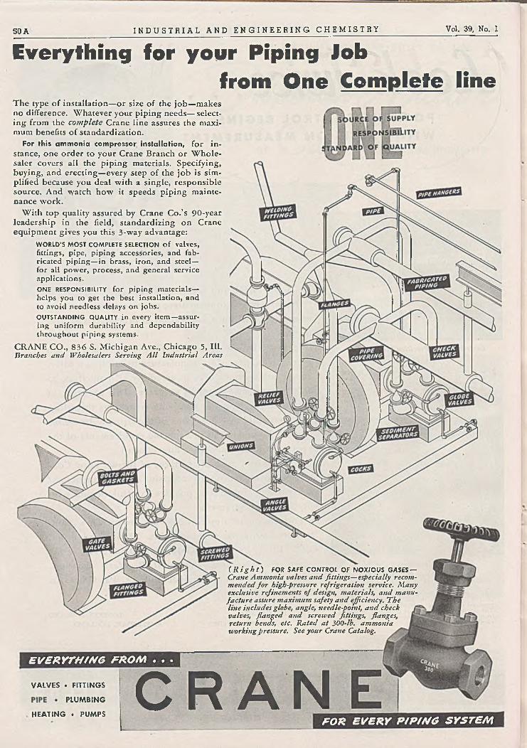
50 A I N D U S T R I A L A N D E N G I N E E R I N G C H E M I S T R Y Vol. 39, No. 1
EVERYTHING FROM . . .
VALVES . FITTINGS
PLUMBING
HEATING • PUMPSC R A N
FOR EVERY PIPING SYSTEM
Everything for your Piping lob from One Complete line
The type o f installation—or size o f the job —makes no difference. Whatever your piping needs— selecting from the complete Crane line assures the maximum benefits o f standardization.
For this am m onia compressor installation, for instance, one order to your Crane Branch or W holesaler covers all the piping materials. Specifying, buying, and erecting—every step o f the job is simplified because you deal with a single, responsible source. And watch how it speeds piping maintenance work.
With top quality assured by Crane Co.’s 90-year leadership in the field, standardizing on Crane equipment gives you this 3-way advantage:
WORLD'S MOST COMPLETE SELECTION o f valves, fittin gs, p ip e , p ip in g a c c e s s o r ie s , an d fa b r ica ted p ip in g — in brass , ir o n , an d s tee l— fo r all p o w e r , p r o c e s s , an d g en era l serv ice a p p lica t io n s .ONE RESPONSIBILITY fo r p ip in g m ateria ls— h e lp s y o u to g e t the best in sta lla tion , an d to a v o id n eed less delays o n jo b s .OUTSTANDING QUALITY in every item — assurin g u n ifo rm d u rab ility an d d e p e n d a b ility th r o u g h o u t p ip in g system s.
CRANE CO., 836 S. Michigan Ave., Chicago 5, III. Branches and Wholesalers Serving A ll Industrial Areas
( R i g h t ) FOR SAFE CONTROL OF NOXIOUS GASES —Crane Ammonia valves and fittings—especially recommended fo r high-pressure refrigeration service. Many exclusive refinements of design, materials, and manufacture assure maximum safety and efficiency. "The line includes globe, angle, needle-point, and check valves, flanged and screwed fittings, flanges, return bends, etc. Rated at 300-lb. ammonia working pressure. See your Crane Catalog.

charges leavf lipid in conimeniial operaSocony-Vacuum 's Paulsboro, N. J., T C C unit has been converted to concurrent flow of catalyst and oil — with provisions for processing high boiling liquid charging stocks. \
*
On the first run follow ing its conversion, charging at a rate of 10,000 barrels per d ay of combined vapor and liquid stocks, the yield of 10 pound motor gasoline w as 4 5 .5 % . The portion of the charge that w a s unvaporized had a mid-boiling point\of 850°F. with an end point w ell in excess of 1000°F. No difficulties were encountered in conducting the run. The carbonacequs material on the catalyst leaving the reactor w as entirely free of oily matter. O f noteworthy importance w as the dry gas yield ofXonly 3.9 wt. % C3 and lighter, a coke yield of only 3 .0 wt. % , an^j a liquid recovery of 102.1 volum e % C3-free.
Even though unvaporized liquid oil w as charged to the reactor, it w as not necessary to increase the rate of stripping steam formerly used on vapor phase operation.
For about 1 % of original capital cost, other existing T C C units can be sim ilarly modified to charge non-vaporizable stocks.
H O U D R Y P R O C E S S C O R P O R A T I O N
25 Broad Street, N ew York 4, N. Y.
H O U D R YCATALYTIC
WOCESSES
January 1947 I N D U S T R I A L A N D E N G I N E E R I N G C H E M I S T R Y 5 1 Ä

W a r A s s e t s A d m i n i s t r a t i o nO F F I C E O F R E A L P R O P E R T Y D I S P O S A LOffices located at: A T L A N T A • B IR M IN G H A M • BO STO N • C H A R LO TT E • C H IC A G O • C IN C IN N A T I ■ C LEV ELA N D . D A LL A S
D EN V ER • D ETR O IT ■ FO R T D O U G L A S , U TA H • H ELEN A • H O U STO N • JA C K S O N V IL L E • K A N S A S C IT Y , M O . • LITTLE R O C K
LO S A N G E LES • LO U ISV ILLE • M IN N EA P O LIS • N A S H V ILL E • N EW O R LEA N S • N EW Y O R K • O M A H A • P H ILA D E L P H IA
P O R T LA N D , O R E . • R IC H M O N D . ST. LO U IS • S A N A N T O N IO ■ S A N F R A N C IS C O • S EA T T LE • S P O K A N E • T U LS A 181-1
Vol. 39, No. 1
YOU CAN W ORK OUT YOUR PLANT
PROBLEM S IN FRACTIONSD on’t let the mere size o f your plant needs keep you from going ahead with plans for starting a new business, or for improving or expanding your present production.
The Government offers you the opportunity to purchase or lease the facilities yrou may require . . . to move immediately into the business home you want—whether it be an entire plant or a mere fraction o f the space.
Perhaps you may want to expand your production, or modernize your facilities, or add a new process, or relocate your business, or start a new enterprise. Whatever your plans, make your needs for plant and equipment known to the War Assets Administration office nearest you.
You have wide flexibility o f choice from the hundreds o f Government-owned surplus plants now
being offered—for example: (1) Entire plants (both large and small—with or without equipment); (2) Separate buildings, where the facility is economically or operationally divisible; and (3) Leases o f a portion o f a single building under a multiple- lenancy arrangement.
Further, if you can qualify as a "small business” , there is a possibility for you to purchase the plant you want under high priority through the Reconstruction Finance Corporation—a preference which our field offices will advise you how to obtain.
, Get in touch with the nearest War Assets Administration office—see list below.
W rite, phone or call for the PLA N T-FIN D E R , a fully indexed, descriptive catalog o f Government-owned plants.
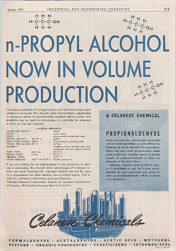
January 1947 I N D U S T R I A L A N D E N G I N E E R I N G C H E M I S T R Y 53 A
H H HH -C -C -C -O H
I I IH H HH N
Ii > - s rv* a ; ? ' o h
n-PROPYL ALCOHOLNOW IN VOLUME PRODUCTION -G *
Celanese production of n-propyl alcohol can now meet large-scale continuous demands. This straight chain hydrocarbon— applicable to processes where its characteristic excellent solvent action and miscibility can be used to advantage— is available for shipment in drum or tank car amounts.
PH Y S IC A L PR O P ER T IESM O LECULAR W E IG H T 6 0 .0 6CO LO R w a te r whiteOD O R characteristic alcohol-like odorSPECIFIC G R A V IT Y 2 0 ° /4 ° C 0 .8 0 4DISTILLATION R A N G E ASTM 2 ° including true boiling pointW EIG H T PER G A LLO N 2 0 ° C 6 .7 lbs.SOLUBILITY soluble in w a te r , a lcohol, ether and
p ra c tic a lly a ll other o rgan ic solventsFLASH PO INT open cup 3 2 .2 ° CBO ILING PO IN T 1 atm. 9 7 .2 ° CFREEZING PO IN T -127° CVAPO R PRESSURE 1 00 ° F o r 3 7 .8 ° C 0 .9 lbs. p e r sq . in.
If you are looking for an improvement in your products, or short cuts in processing, the straight chain advantages of n-propyl a lcohol are worth investigation, n-propyl alcohol also can be used as a replacement for other alcohols now in critical supply. Call or write for additional information and specifications.Celanese Chemical Corporation, division of Celanese Corporation of America, 1&0 Madison Avenue, New York 16, N.Y.
A CELANESE CHEMICAL
P R O P I O N A L D E H Y D EP ro p io n a ld é h y d e , p re v io u s ly a v a ila b le only in sm all quantities, is now offered by Ce lan ese in drum am ounts for experim entation and pilot plant developm ent. Large sca le production facilities assure a steady supp ly of p rop ionaldéhyde in tank car am ounts in the near future.
C e lan ese research and technica l service is a v a ila b le to you for further d eve lopm ent of yo ur p rocesses and products utilizing p rop ionaldéhyde. Write us about your problem s.
F O R M A L D E H Y D E • A C E T A L D E H Y D E • A C E T I C A C I D • M E T H A N O L A C E T O N E • O R G A N I C P H O S P H A T E S • P L A S T I C I Z E R S • I N T E R M E D I A T E S
♦ R e jf . U .S .P u t .O f f .

• Long experience, and a searching, technical, mathematically exact approach to problems of surface evaporation or d iffu s ion , corrosion , abrasion, dust condition and possible galvanic action,— has enabled Bartlett-Snow Heat Engineers to make noteworthy contributions to the art o f catalyst preparation.
Typical o f many, are a stainless steel equipment—jacketed—that separates distilled water from an impregnated cata lytic support, d ischarges the dried material through an enclosed plug gate without any dust loss whatever . . . Cylinders o f special design and construction that withstand the high temperatures o f producing
oxides . . . Equipment for processing in a reducing atmosphere, at 2000°F., that exhausts the hot gases safely, and discharges the processed material, first cooled to norm al tem peratures, con tin u ou sly , at the desired rate per hour.
W hether yours is a problem o f crystallization, oxidation, or reduction . . . or merely a simple drying, calcination, or heat treatment, call the Bartlett-Snow Heat Engineers,—It’s your assurance that the equipm ent recommended‘ w ill prove thoroughly suited to all phases o f your requirement. .Our Bulletin N o. 89—more than 50 pages—and profusely illustrated—contains much technical data on heat processing o f interest to development and operating men. Send for a copy.
the C O . BARTLETT & S N O W ca6 2 0 7 H A R V A R D A V E N U E • C L E V E L A N D , O H I OE n g i n e e r i n g a n d S a l e s R e p r e s e n t a t i v e s in P r i n c i p a l C i t i e s
D R Y E R S • C A L C I N E R S • K I L N S • P R E S S U R E V E S S E L S
Vol. 39, No. 1
FOR P R E P A R A T I O N
CO M PLETE M ATERIAL H A N D LIN G FA CILITIES TO MEET AN Y REQ U IREM EN T
O N E CO N TRACT • ON E GUARANTEE OF SATISFACTORY PERFO RM AN CE • UN IT R ESPO N SIB IL ITY

January 1947 I N D U S T R I A L A N D E N G I N E E R I N G C H E M I S T R Y 55 A
O I L I T E
H A M M E L - D A H L C O M P A N Y243 R IC H M O N D S T R E E T P R O V ID E N C E , R. I.HOUSTON CLEVELAND DETROIT SEATTLE SAN FRANCISCOST. LOUIS, MO. KANSAS CU Y LOS ANGELES PITTSBURGH W ILMINGTON. DEL,NEW ŸÔRK C H JC A G p NEW HAVEN TULSA KINGSPORT. TENN.
A U T O M A T I C C O N T R O LE N G I N E E R E D D E S I G N BY I
U I P M E N T

© ©
©
Vol. 39, No. 1
• Select your instrument from Wheelco standard scale range: f r o m — 1 0 0 ° F t o 4-3600° F, or centigrade eq u iv a len ts .
W H EE L C OIN S T R U M E N T S
C O M P A N Y851 W . H arrison S t.
C h icago 7 , II I .

THE YOUNGSTOWN MILLER CO.SUBSIDIARY O F W A ITER KIDDE S CO M PAN Y, INC.
B ellev ille , N ew Je rse y.a \\Kidde/f p rod u ct
January 1947 I N D U S T R I A L A N D E N G I N E E R I N G C H E M I S T R Y 5 7 A
A NEW DESIGN IN
FILTER PRESS CON STRUCTION /
Filtering area —31 sq. ft.
Available cake space 2 cu. ft.
THE YO U N G STO W N MILLER V ERTICA L STA CK
FILTER PRESS represents a rad ically new design
in filter press construction, wherein the plate and
frame are combined in one casting and placed
in a vertical stack.
Cleaning and removal of the cakes is accom
plished quickly and easily simply by starting
with the top member and latching it in an
elevated position. This permits the filter paper
and cake to be pulled forward out of the
press. Succeeding members are similarly
until the entire press is clean.
O f cast iron construction, the YM Filter
Press is suitable for the filtration of many
liquids, only a few of which are alkfd
resins, solvents, paint, varnish, molasses,
honey, fruit syrups, soaps, liquid sham
poos, shaving lotions; fish, linseed ,
castor and essential oils; cutting oils
and coolants.

W E ’ R E G L A D T H A T BIRCH T R E E S SWAY
The telephone wire which runs from the pole in the street to your house is your vital link with the Bell System. More than 17 ,000,000 such wires are in use.
The wire becomes coated with ice; it is ripped by gales, baked by sun, tugged at by small boys’ kite strings. Yet Bell Laboratories research on every material that goes into a drop-wire—metals, rubbers, cottons, chemicals—keeps it strong, cheap, and ready to face all weathers.
Now a new drop-wire has been developed by the Laboratories which lasts even longer and will give even better service.
It has met many tests, over 6 or 7 years, in the laboratory and in field experiments. It has been strung through birch thickets —rubbed, winters and summers, against trees, and blown to and fro by winds. In such tests its tough cover lasts twice as long as that of previous wires.
House by house, country-wide, the new wire is going into use. Wire is only one of millions of parts in the Bell System. All are constantly under study by Bell Telephone Laboratories, the largest industrial laboratory in the world, to improve your telephone service.
Drop-wire undergoing abrasion tests in birch th icket " la b o ra to ry ." Below, the new drop-wire, now being insta lled .
I N D U S T R I A L A N D E N G I N E E R I N G C H E M I S T R Y Vol. 39, No. 1
E X P L O R IN G , IN V E N T IN G , D E V IS IN G A N D P E R P E C T IN G F O R C O N T IN U E D IM P R O V E M E N T S A N D E C O N O M IE S IN T E L E P H O N E S E R V IC E

January 1947 I N D U S T R I A L A N D E N G I N E E R I N G C H E M I S T R Y 59 A
STAINLESS STEEL W ELDING FITTINGSAvailable in a complete line, in sizes from
I" O .D . through 18" O .D ., fabricated from stainless steel type 304, 316 or 347.
No mitred joints— sweep ell design— no internal threads or pockets— joints are flush.
Flanged Type NICAL END
aeUifittsMe fo <z uusvUettp ¿ittie u f. U ffied
The installation o f new light weight corrosion-resistant conveying lines is now greatly simplified, through the use o f the new Tri-Clover stainless steel conical end fittings, together with light gauge stainless steel tubing. Existing corrosion-resistant fittings and valves need not be discarded . . . for, by means o f simple adapters, all Tri-Clover conical end fittings are readily adaptable to a wide variety o f other fitting and valve types, including IPS fittings (screwed or flanged type), conical glass tubing, welding fittings and Victaulic joints.
These new fittings are fabricated from type 316 stainless steel, in a complete line, including ells, tees, crosses, return bends, " Y ’s” , laterals and ferrules, for use with commercial tolerance stainless steel tubing having outside diameters o f 1, 2 ,2 ^ , 3 and 4 inches.
Write for details about the advantages offered through Tri-Clover Industrial Fittings and light gauge tubing.
O lllu stra tio n s demonstrate the ad ap tab ility of Tri-C lover conical end fHtings to both flanged ond screwed type iron pipe size fittings and va lve s . The aluminum flanged coupling, shown in the "exploded '' v ie w , above, is the key to easy , fa st insta llation of these new fittings. It provides a sim ple, leak-tight union, for working pressures up to 250 lb s. per sq. in .
TR IALLO Y AND STAIN LESS STEEL SAN ITARY FITTIN GS, V A LV ES , PUMPS, TUBIN G , SPECIALTIES
FABRICATED STAIN LESS STEEL INDUSTRIAL FITTIN GS AND
INDUSTRIAL PUMPSTHE Complete LIN E
60 A I N D U S T R I A L A N D E N G I N E E R I N G C H E M I S T R Y Vol. 39, No. 1
D O Y O U N E E D
A BETTER R E F R A C T O R Y ?
£ Corhart Electrocast Refractories are high-duty products which have proved considerably more effective than conventional refractories in certain severe services. If your processes contain spots where a better refractory is needed to provide a balanced unit and to reduce frequent repairs, Corhart Electrocast Refractories may possibly be the answer. The brief outline below gives some of the basic facts about our products. Further information will be gladly sent you on request.
Corhart Refractories Company, Incorporated, Sixteenth and Lee Streets, Louisville 10, Kentucky.
'•Corhart” is a trade-mark, registered U . S. Patent Office.
PRODUCTST he Corhart Refractories Company manufactures Electrocast refractory products exclusively. Corhart Electrocast Refractories are made by melting selected and controlled refractory batches in electric furnaces and casting the molten material into molds of any desired reasonable shape and size. After careful annealing, the castings are ready for shipment and use.Three Electrocast refractory compositions are commercially available:C ORH ART STAN D A R D ELECTROCAST — a high-duty corundum-mullite refractory', with density o f approximately 183 lbs. per cu. ft. CO R H AR T ZED ELECTROCAST— a high-duty zirconia-bearing aluminous refractory, with density o f approximately 205 lbs. per cu. ft. CO R H AR T ZA C ELECTROCAST— a high-duty zirconia-bearing refractory, with density o f approximately 220 lbs. per cu. ft.Other Corhart products are:CO R H AR T STAN D A R D M O RTAR— a high- temperature, high-quality, hot-setting cement for laying up Electrocast, or any aluminous refractory.CO R H AR T ACID-PROOF M ORTARS — rapid cold-setting, vitrifiable mortars o f minimum porosities.C O R H AR T ELECTROPLAST— a high-tempera- ture, hot-getting ‘ plastic refractory, designed for ramming and made from crushed Standard Electrocast.
C ORH ART ELECTROCAST GRAINS— Standard Electrocast crushed to desired screen size for use in many commercial applications.
PROPERTIESD ue to the unique method o f manufacture, the Electrocast refractory line possesses a combination o f characteristics found in no other type of refractory. Data on properties will be sent on request.P O R O S IT Y : Apparent porosity o f Corhart Electrocast refractories is practically nil— therefore virtually no absorption.H ARD N ESS: 8-9 on Mineralogist’s scale. • THERM AL E X P A N SIO N : Less than that of conventional fire clay bodies.THERM AL C O N D U C T IV IT Y : Approximately one and one-half times that o f conventional fire clay bodies.REFRACTORINESS: Many industrial furnaces continuously operated up to approximately 30000 F. are built o f Corhart Electrocast. C O R R O SIO N : Because o f exceedingly low porosity and inherent chemical compositions, Corhart Electrocast refractories are resistant to corrosive action o f slag, ashes, glasses, and most non-ferrous metals as well as to disintegrating effects o f molten electrolyte salt mixtures.
APPLICATION SMost heat and metallurgical processes present spots where better refractory materials are
ENDURANCE
needed, in order to provide a balanced unit and reduce the expense o f repeated repairs. It is for such places o f severe service that we invite inquiries regarding Corhart’ Products as the fortifying agents to provide the balance desired. A partial list o f applications in which Corhart Electrocast products have proved economical fo llo w s :GLASS TANKS— entire installation of sidewalls and bottoms, breastwalls, ports, tuckstones, throats, forehearths, bushings, bowls, recuperators, etc., for lime, lead, opal and borosilicate glasses.ELECTROLYTIC CELLS— for production o f magnesium and other light metals.SODIU M SILICATE FURNACES — sidewalls, bottoms, and breastwalls.PIGM EN T FRIT FURNACES— complete tank furnaces for melting metallic oxides and salts for pigment manufacture.ALKALI AND. B O R A X M ELTING FURNACES — fast-eroding portions.BOILERS— clinker line.RECUPERATORS— tile, headers, separators, etc. ENAMEL FRIT FURNACES— flux walls and bottoms.BRASS FURNACES— metal contact linings.ELECTRIC FURNACES— linings for rockinp type and rammed linings o f Electroplast for this and other types.N ON-FERROUS SMELTERS— complete hearths, sidewalls, and tapping hole portions.
REFRACTOR!

January 1947 I N D U S T R I A L A N D E N G I N E E R I N G C H E M I S T R Y 61 A

FOR YOUR INFORJ M —
ATION
S Y N T H ETIC C H E M IC A L S
C L E A N S IN G FO R
A G EN T S P EN IC ILL IN
W O O D
P R E S E R V A C H LO R IN E
TIV ES
Plant Expansion Under W ayThe C iv ilian Production Administration re cently a p p ro ve d a $ 4 ,0 0 0 ,0 0 0 M onsanto expansion p rogram which involves four sep a ra te projects— a d d e d capac ity fo r the production o f chemicals fo r penicillin, syn thetic c lean ing agents, San tophen 2 0 * (M onsanto 's pentachlorophenol, technical) and chlorine . . . It is expected that this new capac ity will b e re a d y fo r operation during the latter part o f 1947 .
One Less V ariab le in Tanning with the Ex an s*—
M onsanto’s Synthetic Vegetable Tans
The control o f quality m ad e possible in the manufacture o f synthetic products a s sures the tanner that he will p roduce a uniform product with the Exans.
In add ition to uniformity, the Exans produce leather with exceptionally fine, tight grain, light color and a g o o d "b re a k .” They a re com patib le with other extracts and processes — they spe ed production through faster penetration — they work well a s retans on chrom e-tanned leathers. The Exans a re m ade from a va ila b le dom estic ra w materials.
sihbSS®*™»« itf3®*SSSa «m m m
Revised Phosphoric A cid Bulletin N ow A va ilab le
Latest information on M onsanto’s phosphoric acid is included in Bulletin P-2Ô. C o p y will b e mailed on request— add re ss Phosphates Division, M onsanto Chem ical Com pany, St. Louis, o r a n y M onsanto District Office.
• • • •
THE AROCL ORS( C h l o r i n a t e d Biphenyls )
Unusually versatile series of Monsanto Chemical CompoundsThe A ro d o rs * a re well established in the field o f synthetics because their unique properties meet requirements not filled b y m aterials heretofore ava ilab le . They range in form and ap p ea ran ce from m obile oily liquids to fine white crystals and transparent resins. They a re nonox id izing, permanently thermoplastic, o f low volatility and non-corrosive to metals. They a re not hyd ro lyzed b y w ater o r a lkalies— viscous liquids and resins will not support combustion when heated alone.
The Aroclors a re heavie r than w ater — possess great adhesiveness, especial ly on smooth surfaces— have rem arkable penetrating pow er— are w ater repellent and flame resistant. Their ab ility to withstand extreme pressure is unusual.
In addition to the applications illustrated, the A rod o rs a re useful for:
Pow er T ran sm ission . . .A ro d o rs furnish unusually high torque pow er transmission in fluid drives fo r trucks, buses and ships.
H igh-Tem peraturo Lubrication . . •Nonfiam m ability o f Aroclors is idea l fo r governor systems and heavy-duty a ir compressors.
Extrem e-Pressure Lubrication .. . Use o f A rod o rs in rolling stainless steel and chrome iron, prevents surface seizure and scoring.
Subm erged Lubrication . . . Heavier than water, Aroclors a re stab le lubricants fo r b r id ge rollers and underw ater equipment.
M o istu re P roofing . . . Aroclors combine read ily with w axes, oils, resins, to produce moisture-resisting im pregnating compounds.
V in y l R e s in s . . . Com patib le with all the vinyl resins, Aroclors a re used to a d d m any desired properties to finished products.
R ubber . . . R ubber Substitutes . . . M illed into rubber, Aroclors im part permanent tackiness and adhesion; a lso reduce brittleness.
Chlorinated R ubber F in ish e s ... Used a s plasticizers fo r chlorinated rubber, Aroclors a d d both toughness and flexibility; resist acid.
Plastic M o ld Lubricant . . . Use o f Aroclors produces g rea t improvement in ease o f m old ing; a lso in ap p ea ran ce o f finished products.
Paints . . . V a rn is h e s .. . Aroclors contribute excellent durab ility and va ry ing degrees o f flexibility o r hardness in quick-drying paints.
A d h e sive Coatings . . . Aroclors give unusual smooth-surface adhesiveness to pressure-sensitive industrial and masking tapes.
Heat Transfe r M edium . . . Aroclors do not generate extreme pressures a t high temperatures in liquid heat transfer equipment.
Ethyl C e llu lose . . . Nitro Cellulose. . . Aroclors impart weather resistance, luster, adhesion, flexibility and decrease in burning rate .
Send fo r bulletin No. P-115, describing physical properties and suggested applications of the Aroclors. Address Phosphates Division,Monsanto Chemical Company, St. Louis, or any Monsanto District O ffice .

M O N S A N T O I N T E R M E D I A T E
W h ile som e M onsanto Intermediates are
still in critical supply, experimental sam ples
o f m any o f them a re a va ila b le together
with prices. If you are interested in a n y o f
the intermediates listed below, w e suggest
you contact the O rg a n ic Chem icals Division,
M onsanto Chemical Com pany, 1 7 0 0 South
Second Street, St. Louis 4 , M issouri— or any
M onsanto District Office.
ortho-Am inobicydohexyl, Refined ortho-Nitrobiphenyl, Technical
ortho-Aminobiphenyl, Technical meta-Nitrochlorobenzene
ortho-Anisidine ortho-Nitrochlorobenzene
para-Anisidine para-N itrochlorobenzene
Benzenesulfonic Acid, Technical para-N itrophenol
Benzoic Acid, Technical ortho-Phenetidino
Benzotrichloride para-Phenetidine
Benzyl Chloride Phenol, U.S.P.
meta-Chloroaniline Phenolsulfonic Acid, 6 5 % and 7 0 %
ortho-Chloroaniline Phosphorus O xych loride
para-Chloroaniline Phosphorus Trichloride
ortho-Chlorophenol Phthaloyl Chloride
para-Chlorophenol Salicylic Acid, Technical
Cyclohexylam ine,
Sodium Benzoate, Technical
2,5-Dichloroaniline Thiourea
2,5-DichIoronitrobenzene para-Toluenesulfonam ide
2,4-Dichlorophenol Toluenesulfonic Acid, 9 4 %
Dicyclohexylam ine para-ToIuenesulfonyl Chloride
2,4-Dinitroanilineortho-Vanillin
(2 -H ydroxy-3-m ethoxybenza lde- hyde, Technical)
2,4-Dinitrochlorobenzeneortho-Veratra ldehyde
(2,3-D im ethoxybenzaldehyde,Technical)
ortho-Nitroaniline
First in United States HEXAETHYL TETRAPHOSPHATE
Garden and Orchard Insecticide
W ith M onsanto ’s introduction o f H exaethyl Tetraphosphate to the United States, a g r iculture has a powerful new w eapon fo r the control o f aphids, " re d sp id e r " and citrus mites — one that show s g re a t prom ise aga inst a number o f other d am ag in g insect pests in field tests now being conducted.
Particularly va luab le in the treatment o f fruits and vegetables, this new ly introduced insecticide will decom pose within a matter o f d a y s afte r application, and thus m ay not h a ve to be w ashed o ff fo od products before marketing. This offers a distinct a d van ta ge ove r m any insecticides since the decomposition products are thought to b e non-toxic.
1947 Lusfron* ProductionBoosted to 80,000 ,000 Pounds!
The recent purchase fo r $ 9 ,5 5 0 ,0 0 0 , o f the T exa s C ity Styrene Plant is on ly one phase o f M onsanto 's greatly e xpan d ed fa cilities fo r production o f Lustron polystyrene plastic. Estimated capac ity fo r 1 9 4 7 will be 8 0 ,0 0 0 ,0 0 0 pounds — 3 0 0 % greater than M onsanto’s 1 9 4 6 styrene production and la rge r than the entire production of thermoplastics b y all m aterials m anufacturers in 1941. It is interesting to note that the present ba se price o f 2 5 j* p e r pound fo r the crystal m olding polym er (in ca rload quantities) com pares with a price o f 7 2 per pound, effective in 19 3 9 when M onsanto commenced production o f styrene plastic. In addition, M onsan to 's new C a n a d ia n f a cilities which will serve C a n a d a and the United Kingdom , a re now in production.
Monsanto Chemical Company, 1700 South Second Street, St. Louis 4 , Missouri . . . District O ffices: New York, Chicago, Boston, Detroit, C leveland, Cincinnati, Charlotte, Birmingham, Los Angeles, San Francisco, Seattle , Montreal, Toronto.
*Reg. U. S. Pat. O ff.

64 A I N D U S T R I A L A N D E N G I N E E R I N G C H E M I S T R Y Vol. 39, No. 1
AIR CONDITIONING
REFRIGERATION
INDUSTRIAL HEATING
’-A*«*,
The Greatest
Forward Step in
Carrier History ★
6 6 0 ,0 0 0 sq. ft. m ore to build Carrier
Air Conditioning and R efrigeration
Today, more than ever before, Carrier leads in air conditioning and refrigeration. For the acquisition of a huge, new 66o,ooo-sq.-ft. plant in East Syracuse gives Carrier Corporation facilities that are among the largest, most modern in the world for the manufacture of air conditioning and refrigeration equipment!
This additional plant—part of Carrier’s great expansion program— is necessary to meet the ever-mounting demand for Carrier products. Together with the large plant in Syracuse, it will in a matter of months produce the greatest volume of air conditioning and refrigeration in Carrier history.
Flere, in these vast new facilities, is impressive evidence of Carrier’s position in the air-conditioning field . . . a dramatic re-statement of the Carrier leadership which began with the creation of air conditioning 44 years ago.

January 1947 I N D U S T R I A L A N D E N G I N E E R I N G C H E M I S T R Y 65 A
Chlorine, Sul fur or Thionyl Croup—, ______ all from Chloride
f y o u are interested in introducing chlorine, sulfur alone or sulfur in combination with oxygen, into organic or inorganic com pounds, you should investigate the use of H ooker Thionyl Chloride.
In this one inorganic chemical-, these three groups are readily available. Sulfur dioxide and hydrogen chloride, the gaseous byproducts o f its reaction, are easily removed. Excess thionyl chloride may be recovered by distillation.
High purity o f H ooker Thionyl Chloride has stimulated use o f this chemical in organic synthesis. Freedom from side reactions and good yields o f a purer product are concomitants o f this high purity.
Thionyl Chloride is a clear, pale yellow to red liquid with a sharp irritating odor. It fumes when exposed to moist air and requires some special care in handling and storage. It is available in technical and refined grades. Principal properties are given below:
F orm u la ......................................................SO CCMolecular Weight .................................. 119.0Specific Gravity, 15.5°/15.5°C.................1.644Boiling Range
Tech ...................................... 72° to 79°C.Refined ................................. 7 5 °to7 8 °C .
Pour Point ............................... Below —75°C.Flash Point ............................................... NoneFire Point ............... i ................................ None
Technical Data Sheet No. 718 gives more complete physical and chemical data and analysis as well as suggestions for handling. Bulletin No. 328A, “ Hooker Chlorinating Agents,” is also available to those interested. Your name and the bulletin numbers on your letterhead trill bring you this descriptive literature.
“ Artists in Lead Burning” design and fashion the lead equipment required for processing and handling many of the Hooker Chemicals.
H O O K E RE L E C T R O C H E M I C A L
C O M P A N Y9 Forty-Seventh St., Niagara Falls, N. Y.
New York, N. Y. • Wilmington, Calif. • Tacoma, Wash.
HOOKERc h e m i c a l s
Caustic Soda Paradiehlorbenzene Muriatic Acid Chlorine Sodium Sulfide Sodium Sulfhydrate

S6Ä I N D U S T R I A L A N D E N G I N E E R I N G C H E M I S T R Y Vol. 39, No. 1
K E Y S TO A N IN D U ST R IA L P A R A D O X
friction lubricates
Metallic soaps possess properties more v. surprising and paradoxical than any other class o f chemical compounds. Some are excellent lubricants; some enormously increase friction between surfaces spread with them.
Although metallic soaps generally will burn, they are valuable flame retardants.
A metallic soap may be the key which will open the way to solving your most troublesome industrial problem. Write the Mallinckrodt Chemical Works for a free copy of “ METALLIC SOAPS,” a booklet which outlines yesterday’s, today’s and perhaps tomorrow’s uses of this entire class of compounds.
This book describes the individual soaps and notes their physical and chemical properties. It reviews their most important applications and suggests methods for their more effective use. A three-fold index affords quick reference according to applications, properties, and individual compounds. It should be part o f your technical library. Write for your copy today.
MALLINCKRODT8 0 ^ e a ’iA c j? F P e fa v ic e
M a l l i n c k r o d t S t . , S t . L o u i s 7 , M o
C H IC A G O * PHILADELPHIA
CHEMICAL WORKSC o S ß / ie tn ic a / ty / ô ek à
7 2 G o l d S t . , N e w Y o r k 8 , N . Y .
LOS A N G ELE S » MONTREALU N I F O R M '• D E P E N D A B L E • P U R I T Y

January 1947 I N D U S T R I A L A N D E N G I N E E R I N G C H E M I S T R Y 67 A
These tests safeguard your investm ent in
Bufiovak Equipment by show ing unmistakably-,
at the start, w hat w ill be obtained from a g iven
process. It is your assurance of the most efficient
type of equipment!
Bufiovak m akes Chem ical Plant and Food
Processing Equipment, Dryers, Evaporators,
Solvent Recovery and Distillation Equipm ent.
Write to us. There’s no obligation to you in
having us m ake tests, and you w ill qu ick ly
know the value of a new process. Bufiovak
offers m any savings.
■ T e r e at Bufiovak you w ill find modern
equipment to study and test your new process,
at sav ing s to you!
Here practical research is em ployed in the
solution of processing problem s involving
c h e m ic a l an d d ry in g , food p ro ce ss in g ,
evaporation, extraction, im pregnation, solvent
recovery, and crystallization. Modern testing
units w ill quickly show you the com m ercial
possibilities of a contemplated process, with
data on production costs, capacity, and the
characteristics of the finished product.
1549 FILLM O RE A V E ,

68 A I N D U S T R I A L A N D E N G I N E E R I N G C H E M I S T R Y Vol. 39, No. 1
Workers like A -O Ful-Vue
Safety Goggles for their comfort
and good appearance. Shaped to
conform to the orbit o f the eye,
lenses are brought closer to the face,
leaving no unprotected area around the
bridge o f the nose. Made in three eye and three
bridge sizes, with 6-curve Super Armorplate Clear
or Calobar lenses—with or without side shields.
The nearest A-O Safety
Representative can
supply you.
American ^ Optical Safety Division
S O U T H B R ID G E , M A S SA C H U S E T T S . OFFICES IN P R IN C IP A L CITIES
Ful-Vue
Safety G oggles
for Good Looking
Eye Protection

’* a fllT-R STIL Demineralizer woiks . . . Units consist of four "beds" of IONAC* Resins ''Ch. by principle of ion exchange, successively remove the dissolved minerals from water. !,er is fed through a conductivity cell which indicates quality of water being produced.
WaterDemineralizing
Unit
• Improve Product Quality
• Lower Processing Costs
• Simplify Operations
Now, thanks to Cyanamid’s FILT-R-STIL Demineralizing units, you can have quality-controlled water day-in and day-out. . . water which is chemically equal or superior to distilled. FILT-R-STIL Demineralizers are economic, too. The IONAC* Resins used make the process comparable to a simple cold filtration. The added expense of heat, cooling water and periodic dismantling have all been eliminated.
All standard units (capacity from 5 to 1200 or more gallons per hour) are compact and completely self-contained. And the ease with which they’re installed, operated and maintained further assures long, efficient service and reliable results. For complete data on FILT-R-STIL Demineralizers «**5
and assistance in solving your water problems—mail coupon today. i|]y
/O N E X C H A N G E P R O D U C T S DEPARTMENT '
3 0 r o c k e f e l l e r p l a z a
N EW Y O R K 2 0 , N . Y .
American Cyanamid Company,Ion Exchange Products Dept. 10 30 Rockefeller Plaza, New York 20, N. Y .
Send me your free booklet on FILT^R-STIL. Briefly, my water problem is of the following nature:
Name____
Company.
Address_

70 A I N D U S T R I A L A N D E N G I N E E R I N G C H E M I S T R Y Vol. 39, No. 1
WHAT YOU FACE IN BUYING STEEL VALVES IN 1947
A n A n n u a l R e p o r t t o S t e e l V a l u e U s e r s
I1[TS BEEN FIVE YEARS s in c e m o s t t y p e s of
S tee l v a lv e s h a v e b e e n r e a d i ly o b t a in a b le o n
s h o r t d e l iv e r ie s . W h a t is th e o u t l o o k n o w ?
In general, the situation is much better on small valves, and just about as tight, or perhaps even tighter, on large valves.
WHY SHOULD THAT BE?
The principal reason is that throughout the war the Navy and Maritime Commission were just about the biggest users of steel valves. Marine power plants usually run to smaller sizes than land power plants. Therefore, the smaller sizes of steel valves were in very short supply.
Since the end of the war, construction of land facilities has increased substantially. With that has come a great demand for the larger sizes of valves.
LA1
M O R E L E A D T I M E[ARGE VALVES require more lead time in
the procurement cycle. For the higher pressures and temperatures particularly, they are not usually stocked and production runs are necessarily shorter.
Of course, even in the smaller sizes, "specials” take time. Standard valves are in regular production, and v while requirements are still so heavy that a few large orders may all but wipe out available stocks, they come through regularly with normally little delay. Special flange facings, materials or design changes greatly retard deliveries, however.
SO, WE SUGGEST THAT SO FAR AS POSSIBLE, YOU. . .
1. Place orders, particularly for large valves, w ell in advance o f requirements.
2. A void specials.
N E W O P E R A T I N G C O N D I T I O N S-'HERE IS A DISTINCT TREND in nearly
every service for which steel valves are used, toward higher pressures, higher temperatures, or a combination of the two.
Many new valve designs have been introduced to meet these new requirements. Edward, a pioneer in steel valve development, has done a great deal of research and design work on welded bonnet valves, pressure sealed bonnet valves, re-contouring of bodies for lower pressure losses, high alloys for temperature extremes and welded lines, and many construction details.
To take full advantage of these advancements, some of which are not yet fully covered in catalogs and
T 1
sales promotion material, we suggest that you give us an opportunity to work with you in the early stages of any expansion program you plan.
COMBINED RESEARCH FACILIT IES
There has been great progress in steel valve research during the past few years. Much specific data on valve installation and operation, never before available, is now in our files.
Furthermore, as a unit in the Rockwell Manufacturing Company, Edward has access to the research and engineering departments o f a number of other plants, most o f them serving related fields.
Often, we can help you with problems which you face. Don’t hesitate to call upon us. Our laboratories and engineering research departments are operated not for development alone, but for customer service as well.
LESS P R E S S U R E O N RAW M A T E R IA L S
'O N G RANGE PREDICTIONS are at thistime very difficult, particularly in view of
the uncertain labor outlook. Barring extensive plant closings in key industries, however, we feel that steel valveraw material shortages will be only spotty and not of longduration. Labor supply, though, particularly in the skilled categories, keeps us from approaching maximum output.
It appears that the demand for steel valves will be quite extensive for most of 1947 at least. A sufficiently large number of major projects are under way or definitely projected to assure that. As a matter of fact, shortage of consulting engineering time seems to be all that is holding up many more projects.
You will therefore, we feel, be the gainer to anticipate your steel valve requirements as far into the future as possible. Whether it be for boiler room, petroleum, industrial, technological or marine service, if steel valves are required, Edward can help you. In size range we build valves from Vs in. to 14 in., and in pressures, we build valves for services from 150 psi up.
L0)
\ President
^ ^ y iL x x H i/ v d { / ( J U y e A , ( J n c .SUBSIDIARY OF
R O C K W E L L M A N U F A C T U R IN G C O M P A N Y E A S T CH ICA G O , IN D IAN A

As We See It.Revi ew Number Two . The second link inwhat, we hope, will" prove an increasingly valuable chain is presented in the second annual review of unit operations, appearing on the forty pages at the beginning of this issue. Fourteen subjects are covered this year, one more than the total for the first review.However, four unit operations are reviewed that did not appear last year. They are filtration, materials handling, crushing and grinding, and adsorption. Three were not repeated this year (fluid dynamics, crystallization, and sedimentation and hydraulic classification) but will be back in subsequent years. The ten _reviews that appear for the second time are by the same authors who wrote in 1946. Accordingly, they should take up where the previous review ended to give, in combination, an integrated perspective on significant developments in those fields since the beginning of the war.
Always Gas s i ng . The reader interested in comparing the technological status of German industrial development with that in America can find statements in our daily press to support almost any position. Some depreciate the accomplishments of the erstwhile “master race” ; others seem to forget our own well- nigh fantastic achievements while viewing with awe the strange and wonderful (and sometimes terrible) inventions that had been created behind the walls of Festung Europa. Our opinion lies between these two extremes. We give the Germans due credit for a high degree of technical competency. As was inevitable when the normal channels of intercourse for technical information were wiped out during the Hitler régime, technical progress in Germany and America did not progress in parallel directions. With the Nazi surrender, a once-in-a-lifetime opportunity came to obtain complete data on German technical developments unknown in America. Much information of great significance has been secured by industrial and federal representatives, whose activities have been coordinated and encouraged by the Office of Technical Services of the United States Department of Commerce.
The results of one such investigation are reported by H. M. Weir, page 48. He describes a full-scale commercial plant for producing a gas of good heating value from coal through a continuous high-pressure process utilizing oxygen as a source for combustion. This continuous method shows advantages over the intermittent method of present American practice and should prove of great interest to our engineers. Several characteristics of the high-pressure process are worth particular mention: At thedesigned pressure of 20 atmospheres, methane formation is facilitated, so that the final product of the gasification of German brown coal contains 20% of this constituent and has a heating value of 475 B.t.u. per cubic foot. Equipment can be considerably smaller with respect to present American designs, per unit of gas output, and removal of carbon dioxide and most of the hydrogen sulfide becomes a simple matter of passing the gas through water scrubbers while it is still at the design pressure.
All technical investigations of German industry áre written up as formal reports to the Office of Technical Services. The vast majority are promptly declassified and made available to anyone interested enough to pay the fifty cents to a few dollars required to produce a microfilm or photostatic copy. Weir’s article represents one of the few exceptions where any substantial fraction of the technical information obtained in such an investigation appears in print elsewhere. A complete“ Bibliography of Scientific and Industrial Reports” , containing titles and brief abstracts of newly declassified reports, is issued weekly by the Office of Technical Services.
Mi ni ng for Mor o Crops . Our lcadoff technical article this month, by Harley and Atwood, links together a desert and the fertile soil, and affords a refreshing glance at a well-set-up mining operation. But best of all is the main subject matter of the article, which applies chemical engineering knowledge with simplicity to an industrial process. The article describes the production of agricultural grade potassium sulfate containing 90 to 95% potassium sulfate. The raw material is langbeinite (K:SOt-- 2 Mg SO 4) obtained from the only known commercial deposit of this mineral, near Carlsbad, N. Mex. The interesting aspect of the purifying steps resides in the timing involved. Potassium sulfate is more soluble than the sodium chloride impurity of the crude ore, but because the former dissolves more slowly, a preferential leaching can be carried out effectively. Then, in a two- step base-exchange operation, the magnesium in the langbeinite is replaced with additional potassium from a potassium chloride solution, and the resultant magnesium chloride liquor is discarded. Efficiency of the over-all operation is about 90% of that theoretically possible in view of the respective solubilities at the temperature of operation.
I nf l at i on is mirrored with quantitative effect in the figures the cost estimator must produce in forecasting the price of new plant construction. Brown discusses in his column the disheartening situation facing anyone in today’s economic turmoil who tries to gain a fair estimate of the dollars needed to erect a plant requiring more than a few months to complete.
An 6 l 6Ctri cal h y g r o me t e r and some recent manufacturers’ literature are taken up by Munch. A humidity sensing element is the operating heart of the hygrometer described.
CorrOSIOn joins the group of subjects that are discussed monthly in our pages by specialists. Mars G. Fontana, professor of metallurgical engineering and of metallurgical research at Ohio State University, is the author. His first offering is a perspective view of the important part played by corrosion in the chemical industry.
COSt OStimSting, according to von Pechmann, should be an important part of the production executive’s duties, in order to indicate conditions prevailing in the plant when a new product is introduced.
71 A

COMPATIBILITY OF "FLEXOl" PLASTICIZERS (20% OF COMPOSITION) WITH VARIOUS RESINS
S — -S lightly
L — P lasticizer sw e a ts outC — C om patib le I —Incom patible
C a r b id e a n d C a r b o n C h e m ic a l s C o r p o r a t io nUnit o f Union Carbide and Carbon Corporation
u ra i3 0 East 42nd Street, New York 17, N. Y . Offices in Principal Cities
Distributed in Canada by Carbide and Carbon Chemicals, Limited, Toronto
K* TfCMMCALFl e x o rnisTiciis*
■ s ^ B - 4 0 0 ^
Trade-Mark
"F l e x o l ” P l a s t i c i z e r s arc designed to meet industry’s expanding needs for products with good general characteristics such as compatibility and low volatility. In addition, each " F l e x o l ” P l a s t i c i z e r is outstanding in producing one or more special properties such as low-temperature flexibility, resilience, or Itigh impact strength.
" F l e x o l ” P l a s t i c i z e u s are successfully
serving industry in lacquers, artificial leathers, vinyl films and sheetings, vinyl butyral safety glass, and molded and ex truded products based on the vinyl resins and cellulose derivatives.
The " F l e x o l ” P l a s t i c i z e r s shown are in commercial production. Several more are available in research or development quantities. Consult us on availability.
Our laboratories have prepared extensive data on the performance o f the " F l e x o l ”
P l a s t i c i z e r s for many uses. This information will assist you in selecting the right " F l e x o l ” P l a s t i c i z e r or mixture of plasticizers for your needs.
B-400
Vinyl Acetate Vinyl Butyral Vinyl Chloride Vinyl Chloride-Acetate Cellulose Acetate Cellulose Acetate-Butyrate Cellulose Nitrate Ethyl Cellulose Synthetic Rubbers
Flexol” is a registered trade-mark o f Carbide and Carbon Chemicals Corporation.
72 A I N D U S T R I A L A N D E N G I N E E R I N G C H E M I S T R Y Vol. 39, No. 1

INDUSTRIAL and ENGINEERINGßkemistry
Your Journal
I n d u s t r i a l a n d E n g i n e e r i n g C h e m i s t r y is a partnership. The editors are trustees cognizant always
of a great responsibility of serving members of the chemical profession and industry to the best of their abilities and to the fullest extent possible commensurate with the resources available" to them.
Occasionally it is wise to ignore briefly the onrushing current of the day’s demands to note where we have come and to fix anew our goals. Such a pause for reflection and analysis is especially appropriate as we enter the new year, and particularly is it necessary in the postwar era following the most devastating upheaval in man’s history. Chemistry and chemical engineering were employed in that cataclysmic holocaust: they not only must and will aid materially in restoring the world’s goods and services to prewar levels, but in time will provide a higher standard of living for all the peoples of the earth and thereby remove many of the causes of war. But chemists and chemical engineers will not be content to provide merely a steady stream of material advances. They will contribute beneficial effects of a spiritual nature as well, recognizing that science can be either a destructive or a constructive force according to how man uses it. Scientists in all fields today understand that they have a grave moral obligation to see that the world utilizes properly the torrent of new knowledge made available by their labors. I n d u s t r i a l a n d E n g i n e e r i n g C h e m i s t r y is, and will continue to be, both a vehicle for the dissemination of chemical information and a factor in formulating opinion on how man can best employ science in improving human relations.
Thirty-eight years ago the founding fathers of this publication declared'its purpose to be:
The necessity for a journal published in the interests o f the American Technical Chemist and Chemical Engineer must be apparent . . .Let it not be said o f the Technical Chemist that he loves his science any less than his brother, who devotes his time to research or teaching. The S o c i e t y . . .believes that a certain liberality in publishing broader information on subjects o f manufacturing interest will be b en eficia l.. .The chemical engineer should have at hand the most recent developments o f the science which pertain to the installation or improvement o f existing processes.
In the intervening years the plan and policies of this publication have been broadened to meet the requirements of a rapidly advancing field of science, yet the basic precept of providing every member of the chemical profession interested in applied chemistry with the best technical tools available remains unaltered.
Those who created I n d u s t r i a l a n d E n g i n e e r i n g C h e m i s t r y understood fully the close relations which should exist between the industrial research chemist,
W A L T E R J. M U R P H Y , Editor
the chemical engineer, and the chemical executive. Forty years ago the teaching profession was engaged mostly in fundamental or pure science. World War I and the decade that followed saw great changes, including the entrance of a large number of teachers into the field of applied chemistry, and today they are an integral part of a highly efficient and effective quadru- inanous group which has provided the world with new products in profusion.
The greatest strength of t his publication has been and will continue to be the contributors, the men and women of the laboratory and the plant who report for the world’s benefit the scientific results of their work and I he reviewers who make possible the continuation of the high standards that have characterized the journal from its inception. These reports of original chemical research must be factually accurate and should provide sufficient data so that a person familiar with the general field of study can duplicate the results; the work reported should be of permanent scientific usefulness; conclusions drawn either should be concordant with the knowledge of other qualified workers in the field, or if a difference of opinion exists that fact should be carefully pointed out; lastly, the method of reporting should be in accord with the generally accepted principles of terminology, phraseology, and nomenclature so that the literature will not tend to become a Tower of Babel.
The editors believe it desirable to supplement the pages of the journal with additional features, exemplified in this issue by the second annual review of new developments in unit operations, the columns on Equipment and Design, Instrumentation, Corrosion, and Plant Management, and the increasingly popular section, “ I & E C Beports on the Chemical World Today” . Throughout the year every effort will be made to supply not only the information that industrial research chemists, chemical engineers, and plant and chemical executives need in order to function efficiently but also the insight into what their fellow laborers in other parts of the chemical vineyard arc doing. It is the editors’ firm intention not to create unnecessary artificial walls or barriers designed to separate the various members of the profession, but to provide information of value to each member of the chemical team and of over-all value to the group as an entity.
There is a special need in the years ahead for articles for the chemical plant production man. These should contain adequately detailed descriptions of new equipment, instrumentation, ingenious arrangements of floor- plan layout, and novel solutions to the particular problems of the process. Any special features concerning the organization of the operating crew, safety and health problems, necessary medical facilities, and
1

2 I N D U S T R I A L A N D E N G I N E E R I N G C H E M I S T R Y Vol. 39, No. 1
similar plant operation and management aspects should be described. Of special value are discussions of cooperation effected between research, design, and operating groups. Far too little has been said in the past about the principles of organizing and operating manufacturing facilities, proper relation of the research budget to the other major financial elements of a successful enterprise, effect of personnel policies on productiveness of the technical staff, and economies and relative costs. Frequently such information is of a confidential nature, but there are times when it can be divulged.
The wellspring that is our greatest resource is the contributed article. The editors are encouraging potential contributors to the broadest interpretation of the subject range appropriate as contributions. Applied chemistry and chemical engineering will prosper in direct proportion to the extent to which a wide variety of knowledge is shared by research chemists, chemical engineers, and operating and top-flight management.
Before accepting an article for I n d u s t r i a l a n d E n g i n e e r i n g C h e m i s t r y , the editors wish to be convinced that it meets three basic requirements: (1)originality, (2) immediate or imminent usefulness of data, (3) reasonable likelihood of permanent value in the literature. Authors who understand these essentials are better able to present their contributions in an acceptable fashion. They should also understand the critical review system for manuscripts which has been in operation over a long period.
Because the range of subjects is.so broad and articles are usually of such a highly technical nature, it has been customary to submit all contributed manuscripts to special critics for prepublication evaluation. Each reviewer is selected for his knowledge and interest ill the topic discussed, and has usually made some worthwhile contribution to the field. His purpose in reviewing is not to find fault, but to appraise what has been done and assist the authors in presenting data to best advantage.
Although reviewers naturally have a direct influence on editorial decisions, authors are never required to adopt their recommendations. The editors expect that authors will accept only what they regard as constructive in a review. If there are significant differences of opinion between author and reviewer, the former is expected to defend his position. This is a courtesy to the reviewer who has given advice and opinions gratuitously, and a necessary aid to the editors who must have all pertinent facts to reach an equitable decision,
Reviewers chosen initially are not necessarily the only ones involved when a manuscript is being considered. Should there be sharp differences of opinion between reviewers, as is sometimes the case, it is the rule to choose a “referee” . He has an opportunity to consider the reviews as well as the manuscript before commenting.
Success for such a system depends upon understanding and cooperation among authors, reviewers, and editors. Authors should prepare their manuscripts with the requirements of the journal in mind. Reviewers should offer their frank opinions and recommendations in a constructive spirit. The editors will consider the viewpoints of each, and take action consistent with the high standards of publication for which they are responsible. With mutual good will and appreciation for the efforts of each, I n d u s t r i a l a n d E n g i n e e r i n g C h e m i s t r y cannot do less than achieve its fundamental purposes.
The editors again wish to stress accurate, clear, and especially concise presentation of data which has been the one goal of the technical literature and particularly
of this journal. Certain simple, self-evident standards are involved which cannot be emphasized too much or too often. In order that there may be no chance for misunderstanding, either by reviewer, editor, or printer, manuscripts should be typewritten, with double- or triple-spaced lines, on letter-size paper; generous margins should be left on every page to enable the manuscript editor to mark printer’s instructions without difficulty. It is important for us to have the original (ribbon) copy of the article and at least one carbon copy, complete with reproductions of all illustrations and tables for examination by reviewers. The size of illustrations should be such that they can be easily mailed with the manuscript for examination by the reviewers.
The title of a paper should be explicit, but concise and crisp. If it seems advisable to limit the scope of the subject, a subtitle may be included; again, we emphasize the short, snappy title.
Headings should be included to divide coordinate parts or natural divisions of the article, and the author is most competent to supply such headings. Formulas and equations should be checked and balanced by the author. An error in copying a complicated equation is easily overlooked unless careful comparison is made back to the original. Complicated structural formulas should be submitted as India ink drawings with large, clear lettering from which cuts can be made.
Flow sheets, diagrams, graphs, and photographs are a valuable part of technical articles, particularly in this “ picture-minded” era. Each illustration should be placed on a separate sheet, not numbered with the text pages. Each should have its caption and number, and should be referred to in numerical order in the text. The captions should be typed underneath and not be made a part of the graph or diagram. Although blueprints or photostatic copies are acceptable as reproductions to accompany the carbon copy of a'manuscript for the reviewer’s examination, the drawings from which cuts are made must be originals with clear lettering in black ink, preferably all capitals. White paper, tracing cloth, or strong tracing paper is a good medium; if coordinate paper is used for graphs, the cross-section lines should be light blue— never orange, green, or red, which do not “ screen out” when the cut is made. These points are stressed so that authors need not remake or reletter drawings at cost of time and money. Lettering, numbering, and symbols on graphs and diagrams should be large enough to reproduce clearly upon reduction.
Literature citations cause the manuscript editor more trouble than any other one item. Here again, the ‘author is requested to compare the list of references back to a carefully prepared check list or to the original source where possible. The editorial office cannot verify every reference, but often obvious errors are found in volume, page, or year numbers which make it necessary to check with Chemical Abstracts. This is a tedious and time-consuming task, and it is the author’s responsibility to see that his bibliographical material is without error. Authors may refer to any recent copy of I n d u s t r i a l a n d E n g i n e e r i n g C h e m i s t r y to see the alphabetical arrangement which is our style; references are made to the particular citation by number in the text, and a check should be made by the author to see that every reference is really “ cited” in the text.
Since papers printed in I n d u s t r i a l a n d E n g i n e e r i n g C h e m i s t r y are an important part of the permanent technical and scientific literature, the editors cannot emphasize too strongly the desirability of maintaining physical form as well as content at the highest level.

UNIT OPERATIONS REVIEWThis month we present the second annual review of unit operations. Four new subjects have been added— filtration, materials handling, crushing and grinding, and adsorption— and like all of the reviews of last year, the author of each new subject has surveyed developments in his field back through the war period. Subjects appearing for the second time are brought up to date from the period covered in the previous
review. With its interpretative character and generous bibliography, we hope the
feature continues to be a source of substantial help in keeping you currently informed in this important phase of chemical engineering technology. T H E E D IT O R S
ÎM iteK h u U M X f, Ô u h M e u t R e u i z w e f i l
F IL T R A T IO N 5 M A T E R IA L S H A N D L IN G . . . . 8
SH E L B Y A. M IL L E R was born in Louisville, K y., in 1914. H e received the degrees of B.S. in Ch.E. from Speed Scientific School, University o f Louisville, in 1935, and of Ph.D . from the University o f Minnesota in 1944. He worked in the analytical laboratory of Corhart Refractories Com pany in 1935 and 1936, and was a teaching assistant in chemical engineering at the University o f Minnesota from 1936 to 1940. In 1940 he joined the staff o f E. I. du Pont de Nemours & Com pany, Inc., becom ing a member o f its Engineering Research Laboratory. Here he was
engaged in research and design efforts in the fields o f agitation and filtration until 1946, when he assumed his present position as associate professor o f chemical engineering at the University of Kansas. M iller is a member o f the A m e r ic a n C h e m ic a l S o c i e t y , American Institute of Chemical Engineers, and American Association for Engineering Education, and is a licensed professional engineer.
R O B E R T E. W R IG H T was born in Oconto, W is., in 1917. H e obtained his B.S. in mechanical engineering from the University o f Wisconsin in 1940.Since then he has been employed by M onsanto Chemical Com pany in the General Engineering Department, where he has served in various capacities in the field o f design and construction of chemical plants. He has participated in such projects as M onsanto’s phosphoric acid and phosphates plant at Trenton, M ich., the styrene plant at Texas City, Tex., and numerous other developments. He was plant engineerat Texas City and is now a project engineer in the Design Section o f the General Engineering Departm ent in St. Louis, M o. H e is a member o f the American Society o f M echanical Engineers and is a registered professional engineer in the state o f Texas.
C R U S H IN G A N D G R IN D IN G . . . . 11
L IN C O L N T . W O R K was born in Hartford, Conn., in 1898. His training culminated in scientific study at Colum bia University where he received the degrees o f bachelor o f arts, chemical engineering, and doctor o f philosophy. W hile studying for his advanced degrees, he was instructor at the university, later becom ing assistant, and, finally, associate professor in chemical engineering. His research in the field o f particle size has been extensive. He has developed a broad knowledge in the application o f this work to Portland cement, fuels, soils, paints,
and pigments, and he has been a consultant for these industries. Since 1940 W ork has been director o f research and developm ent at the M etal & Therm it Corporation. He is a member o f the A m e r ica m C h e m ic a l S o c i e t y , American Institute o f Chemical Engineers, Society o f Chemical Industry, Electrochemical Society, Society for Testing Materials, American Institute o f M ining and Metallurgical Engineers, American Association for Engineering Education, and American Society for Metals, and has held both local and national posts in several o f them. He is author o f many patents and publications having to do with particle size, educational, and research management subjects.
A D S O R P T I O N 12
A R T H U R B. R A Y was born in Leaks- ville, N . C., in 1889. He received B .A . and M .A . degrees from W ake Forest College in 1910 and 1911, and the Ph.D . degree from Cornell University in 1916.H e was associate professor o f industrial chemistry at A. & M . College o f Texas during 1916-17. H e was with the Bureau o f Mines until he went into the Arm y as captain, Chemical Warfare Service, in 1917-19. Since then he has been on the staff o f Union Carbide and Carbon Corporation (National Carbon Com pany, Inc., Union Carbide and Carbon Research Laboratories, Inc., and now Carbide and Carbon Chemicals Corporation). A t present R ay is in charge o f activated carbon developm ent and sales for Carbide and Carbon, while with Union Carbide he has been responsible for the developm ent o f special activated carbons and various industrial applications o f vapor and gas adsorption carbons. He has published a number o f technical papers and patents in this field. He is a member o f the A m e r i c a n C h e m ic a l S o c i e t y and American Institute o f Chemical Engineers, and is consultant to the Chemical Warfare Service and representative o f the American Institute o f Chemical Engineers on the National Technological Advisory Committee.
3

p tv e A e rtiin a A < j,cU n . • •
A B S O R P T IO N A N D H U M ID IF IC A T IO N . . . 14
Harrison C. CarlsonEngineering Research Laboratory, E. I.
du Pont de Nemours 8c Company, Inc.
C E N T R IF U G A T IO N . . . 16
James 0 . MaloneyHead of the Department of Chemical Engineering and Director of the Research
Foundation, University of Kansas
D IS T IL L A T IO N , H IG H T E M P E R A T U R E . . . 17
T. J . WalshSenior Engineer, Design Group, Service Division, The Standard O il
(Ohio)
TechnicalCompany
During 1946 Walsh was promoted from design engineer to senior engineer in his company. He has also become a registered professional engineer (Ohio), chemical engineering branch, and is now a special lecturer in Petroleum Refinery Engineering at Case School of Applied Science.
E V A P O R A T IO N . . . 22
W. L. BadgerConsulting Chemical Engineer,
Ann Arbor, Mich.
R. A. LindsayChemical Engineer, The Dow
Chemical Company
In July 1946 Lindsay was transferred from the Ann Arbor laboratory to the main office of Dow Chemical at Midland, Mich., where he will continue to work on heat transfer and evaporation.
E X T R A C T IO N , S O L V E N T . . . 23
Joseph C. ElginProfessor of Chemical Engineering and Chairman of the Department, Princeton
University
Elgin has been elected a director of the American Institute of Chemical Engineers for 1947.
F L O T A T IO N . . . 26
Fred D. DeVaneyResearch Metallurgist, Pickands Mather &
Company
D IS T IL L A T IO N , M O L E C U L A R . . . 19H E A T T R A N S F E R 28
K. C. D. HickmanVice President and Director of Research,
Distillation Products, Inc.
George T. SkaperdasChemical Engineer, The M . W. Kellogg Company
M IX IN G . . . 30
D R Y IN G . . . 20
Samuel J . FriedmanEngineering Research Laboratory, E.
du Pont de Nemours 8; Company, Inc.
J . Henry Rush tonProfessor of Chemical Engineering and Director of the Department, Illinois Institute of
Technology
During the past year Rushton resigned as professor of chemical engineering at the University of Virginia to accept the post at Illinois Tech.
4

FILTRATIONS h e lb y A . M iller , u n iv e r s it y o f Ka n s a s , l a w r e n c e , k a n s .
D U R IN G the war years efforts in the field o f filtration have been directed principally toward keeping abreast with the accelerated production rates demanded o f the entire chemi
cal industry. Developments, therefore, have comprised chiefly improvements to existing designs and methods, adaptation o f available equipment to war-born processes, and application of substitute materials, old or new, as filter media and filter aids. Because no com plete review of filtration has been published for some time, and because foreign contributions withheld from American readers by the war have recently becom e available, this report covers the past five years and includes an extensive bibliography.
The scope o f the subject matter considered is delineated by the definition o f filtration as the separation o f a liquid from insoluble solids suspended in it b y retention of the solids on a septum through which the liquid is induced to flow by vacuum, by gravity, or by positive pressure applied b y a pump. I t excludes, on the one hand, separations by sedimentation, b y elutriation, or by centrifuging, and, on the other, separations of dust and mist from gas streams. Brevity has prohibited the consideration o f such accessories as feed tanks, pumps, and condensers.
T h e o r y a n d D e s i g n M e t h o d s . T he accepted filtration theory, which predicts a parabolic function relating volum e and time of filtrate discharge, was reviewed by D ickey and Bryden(3). Sperry (<?) modified the form of the equation for constant- pressure filtration and evaluated the constants for twenty industrial slurries. H e also presented an extensive bibliography of filtration theory. Porter (6) suggested a rapid m ethod of com puting the constant-pressure constants by means of a chart which he developed. D eW itt (2) criticized existing equations for filtration as not being truly representative and proposed the Gompertz probability function as a more accurate, if more complicated, correlation.
The m ost recent theoretical work has been directed toward relating cake permeability to specific cake resistance. In an investigation o f liquid flow through a sintered-glass filter, Grunberg and Nissan (4) found that the rate of flow at a given pressure depended not only on the viscosity o f the liquid, but on the surface tension as well. Deryagin and K ry lov ( I ) , in a similar study, ob served that Poiseuille’s law was obeyed only at relatively high pressures when the pore diameters were below a critical magnitude, and that addition agents in small concentration caused sharp increases or decreases in flow rates. R uth (6) had noted a similar phenomenon during filter-cake washing; he further reported that the specific resistance of many cakes is greater than is predicted by the size and shape o f the cake particles. He proposed the concept o f “ unavailable void volum e” , postulated an explanation in terms of electro-osmosis, and developed a method of measuring it by permeability-compression tests. Such tests, he stated, might becom e a basis of industrial control o f filtering properties. W alas (3) suggested that cake perm eability and cake particle size might be used to predict filtration performance, and, hence, to design filters, and be developed techniques for determining these quantities in the laboratory. Instruments for measuring the permeability o f a filter bed were described by Sack- man and Hughes (7).
E q u ip m e n t . D ickey and Bryden ( 13) presented brief, up-to- date descriptions o f American industrial filters in a new text book. Filters used in Europe were described by Chateauneuf (12) and by Waeser (SB); the latter appended a comprehensive list of references to equipment developm ents for the period 1939-41.
In addition, reproductions of two foreign text books (IB, 18) that summarize filtration equipment and methods have been made available through the Alien Property Custodian.
Ramsey (21) discussed a continuous rotary vacuum filter, the Synchro-drum, recently introduced to American industry. Consisting o f tw o cylindrical drums rotating so that their tops retreat from each other at the pinch where the top feed is introduced, it is said to be particularly useful for slurries containing large particles of widely distributed size. Other new filters which have appeared are essentially modifications o f old designs. Am ong them are a continuous vacuum -drum filter with high drainage capacity, suitable for dewatering paper pulp (SO), a basket strainer incorporating a magnet for more com plete rem oval of small magnetic particles (10), and a conical-shaped sieve for continuously separating pellets from a liquid in which they are suspended (22). M cB erty (19) developed a radially vibrating puddler to assist in dewatering thixotropic and pseudoplastic cakes on vacuum -drum filters; Stanley (24) patented a similar device which vibrates transversely. A new continuous-pressure- thickener (17) resembles a plate-and-frame press, and has spiral- grooved chambers through which the slurry circulates under pressure and loses some of its liquid as it circulates.
Several authors have published detailed descriptions o f certain standard industrial filters. Hillier (16) offered an excellent nontechnical exposition of typical vacuum -drum and -disk filters and pressure leaf filters. W right (26) advocated for sugar clarification the use of the continuous cord filter. Barnebl (11) cataloged vacuum filters suitable for granular materials (defined in terms o f cake permeability) but failed to mention the band filter, which recently has found new uses in the chemical field. Schm itt, Kolachov, and W illkie (23) discussed pressure filters used in whisky clarification and wrote of horizontal-plate filters, porous stones, pulp-pad strainers, and cotton-spool cartridges. Field(14) described clarifying filters o f both the mechanical strainer and micronic (paper or cotton cartridge) types, and recommended them for hydraulic systems.
F i l t e r M e d i a . N o new types of filter media have appeared since Van Antwerpen’s review (69) o f 1940. Outstanding new applications o f materials have been made, however, both to woven media and to rigid porous bodies. Possibly the m ost significant developm ent in the field of filtration in m any years is the adaptation of polymeric fibers to filter fabrics, a developm ent accelerated by the wartime dem and for cotton substitutes and longer-lived filter media. Several excellent reviews (27, 29, 32) o f synthetic fibers and the textiles fabricated from them summarize the properties of these materials, and provide a check list o f new actual or potential filter fabrics. There is reason to believe that the list will be extended, in view o f the demand for less expensive, more durable filter media and o f the activity in the field of high polymers. Polyethylene, for example, now producible in fiber form (SO) , may becom e a filter-fabric material.
Users of filter media have becom e interested in methods of characterizing the performance of a given sample prior to its use in an actual filtration. One such possible m ethod o f characterization is b y the porosity or the permeability o f the medium. Sie- minski and H otte (60) emphasized the distinction between these terms (porosity refers only to void volum e, whereas permeability refers to the arrangement of voids to form continuous channels through the material). These authors and K ocatopcu (51) outlined methods o f measuring porosity. Bogaty and Carson (37)
5

42
reported a simple method of determining the water permeability o f filter paper.
General reviews o f filter media were given b y Daumas (41) and by D ickey and Bryden (43).
Textiles. C otton is still the most widely used material for filter fabrics because it is durable in neutral media and is relatively inexpensive. Bogtstra (33) tested a number of cotton cloths for use in sugar-sirup filtration. Sandera (61) discussed both cotton and linen for this application. O f the other natural fibers, ramie offers some promise as a filter medium material because of its strength (60). Efforts to increase the chemical resistance of natural fibers by impregnation with synthetic materials have not proved generally successful; Herfurth (48), for example, reported failure in attempts to increase the life o f staple-rayon filter fabric b y impregnation.
Of the artificial fibers, glass was the first to be used in filter cloths (S3). Although it has pronounced chemical resistance to all aqueous solutions except alkalies, alkaline salt solutions, hydrofluoric acid, and phosphoric acid, its mechanical properties and cost have prevented wide use in this field. The most recent advances include the application of impregnating plastics to reduce failures caused by flexing, crushing, or raveling, and the developm ent o f exceedingly fine filaments which are not abrasive to human skin (67).
Acid- and alkali-resistant filter fabrics have been made successfully from polyvinyl chloride in Germany (as Pe-Ce fiber, 46) and in Am erica (as Vinyon, 64). Better mechanical properties have been obtained with Vinyon by m odifying somewhat its chemical structure (60). In spite o f its excellent chemical resistance and strength, Vinyon has had lim ited application because it shrinks and stiffens seriously above 65° C. (64). Recently fabrics have been woven from Saran (modified polyvinylidine chloride, 31), a material with a considerably higher temperature threshold and with good chemical resistance. T he high price o f this fabric, however, has restricted its use. Loasby (68) suggested that nylon’s alkali resistance and thermal stability make it attractive as a filter m edium ; as a matter of fact, experimental filter cloths of this material had appeared just before the war restricted its further use. N ylon is more resistant to solvents than is Vinyon, but is degraded by acids.
Metal Screens. T he chemical, thermal, and mechanical stability of metal has long commended its use in screens or perforated plates as a filter medium in the chemical industry (49, 69). Such media are susceptible to bleeding, however, and certain weaves tend to plug badly. Gardner (46) found that screens will handle sewage successfully, provided the solids which fill the slots are not removed frequently; these accumulated solids prevent excessive bleeding. He described several constructions o f screens. Reck(66) reported that a stainless steel screen eliminated the plugging difficulties encountered when canvas was used in the vacuum filtration o f slimy fluorspar flotation concentrates. B y precoating the screen with cake and allowing about 0.5 inch of the cake to remain on the filter at all times, bleeding is eliminated. Black (36) described a screen (70 X 80 twill) used successfully on pres- sure-leaf and vacuum-drum filters for sugar refining. Dittm ar and Harvey (44) recommended treatment successively with acid and alkali to unplug a screen in such service when it blinded.
Paper. Scribner and W ilson (63) described a series o f mechanical tests for evaluating filter paper. T A P P I (67) has proposed a series of standard tests for determining the retentiveness, filtration speed, ash content, and physical properties o f filter paper.
Bulk Media. In the field of bulk filter media, Cruickshank (40) invented a cotton wadding bonded with polyvinyl alcohol for use in milk filters. Bray (39) discovered that w ood pulp and cotton are superior to fuller’s earth for oil filtration in that they adsorb less addition agent from the oil than does fuller’s earth. Anthracite has gained in popularity for granular bed filters. Turner (68) described the properties o f this material, and Behan
6 I N D U S T R I A L A N D E N (
(34) reported an instance in which it was superior to sand and gravel for water filtration.
Rigid Porous Septa. The various grades and forms of porous ceramics used as filters were reviewed b y Desmond (49), by R obitschek (68), and by Bentley (36). Tavasci (66) found that the structure and pore size of such materials can be determined b y metallographic examination. Garriga (47) reported the composition o f a porous concrete which will successfully filter natural rubber latex.
A new developm ent in the field o f rigid porous filters is the use o f sintered metal members. Schwarzkopf (62) gave the properties and pore sizes for typical sintered metals, reporting that the permeability can be controlled accurately. According to Koehr- ing (69), the pore size m ay be graded from one surface of the mass to the other to reduce plugging of the medium. Recently sintered stainless steel has been made available in thin, flexible sheets which may be welded together to form a filter septum (65).
In addition to ceramics and metals, plastics m ay be used for the construction o f porous filters. Rudolph (59) described such filters formed from polyvinyl chloride, polystyrene, methyl methacrylate, aniline-formaldehyde condensation products, and nylon. Alfthan (28) patented the production o f porous poly- tetrafiuoroethylene, which promises to be of interest because of its extreme chemical inertness.
F i l t e r A id s . An inert, free-filtering material added to a slurry to increase its filterability is called a filter aid. The type and quantity of aid to be used in a given case must be determined by experience or b y specific laboratory test. Several papers (72, 73, 76) describe apparatus and procedures for such test filtrations. Brieghel-Mttller (71) found that indirect evaluation (e.g., o f particle size and of surface) was not a reliable index to filter aid performance.
Diatomaceous Earth. Diatom aceous silica continues to be the m ost widely used filter aid. Cummins (76) and Elsenbast and Morris (80) have described typical diatomaceous aids, the latter authors specifying methods for their use. Skinner and coworkers (90) investigated diatomites found in the Pacific N orthwest and found that they were inferior to the fastest commercial aids; some of them, however, m ay be used. Ddribdrd (78) discussed the advantages and properties o f kieselguhr aids, and Ferenyi, in a monograph on the subject (82), described many industrial applications.
A number of specific uses have been reported. Black and Spaulding (70) divulged the use of diatomaceous silica in portable water filters for field troops during the war. Ham ilton and Jones(83) developed a precoating technique for the filtration of viscous liquids containing tarry solids. Kieselguhr is used also in the clarification o f sugar solutions (86), lard (77), and beer (79).
If the solids being filtered are organic, the filter aid m ay be recovered by burning. M artindale (89) and Cotter (74) discussed the reconditioning of diatomaceous silica used in sugar clarification. T he recovered material m ay have a higher filtering capacity than it had originally because o f the loss of fines and because of the addition o f charred residue from the burned solids.
Other Materials. Cellulosic pulp frequently is used as a filter aid. Knowles (87) recommended the use o f paper pulp for the filtration o f phosphate-defecated sirup. Erm ilov (31) described the successful application o f paper pulp to titanium dioxide filtration, 14 kg. being required per ton o f pigment. Cellulose acetate spinning solution is filtered more readily after the addition of 0 .01-0 .2% o f cotton linters (84). Liu (88) reported that asbestos is a satisfactory filter aid for sugar refining (it m ay be recovered and re-used), and Harris (85) found that activated carbon employed to decolorize sugar sirup may be selected to act as a filter aid as well as an adsorbent.
G e n e r a l I n d u s t r i a l A p p l i c a t i o n s . T he im portance o f the physical condition o f solids prior to their filtration can hardly be overemphasized. T he ultimate size of most precipitated crystals, for example, is usually exceedingly small; unless these tiny
I N E E R I N G C H E M I S T R Y Vol. 39, No. 1

January 1947 I N D U S T R I A L A N D E N G I N E E R I N G C H E M I S T R Y 7
particles can be enlarged by flocculation or by crystal growth, they present a difficult filtration problem. Increasing attention is being devoted to the pretreatment o f slurries, particularly in sugar refining (117) and sewage sludge (105,114) filtrations, where the addition of flocculating agents and provision o f digestion periods are standard prefiltration practice. Centrifugal pumps should be avoided for slurry feeding, since they m ay deflocculate the solids mechanically, as pointed out by D iago and Leon (¡01) and by Halvorsen and Boilaert (107).
Because of the multiplicity o f factors which influence filtration, because of the difficulty in evaluating certain o f these factors, and because o f the wide variation in the degree of filtration required in various applications, there is an unfortunate tendency to consider each installation a distinct problem and the filtration steps occurring in any process as different from those for all other processes. As a result, many of the published reports on filtration performance are phrased in terminology peculiar to a specific industry, with insufficient quantitative information given to make them useful to any other industry. Space limitations permit an indication o f only such articles on filter operation as include generalized statements o f the problem and its solution or give actual, quantitative performance data.
Chemical Industries. Arend (93) described the vacuum filtration of pigments. Cellin (98) discussed filtration applications to superphosphate and potash processing. The correct m ethod of operating varnish filters was outlined by Kracklauer (110), and specific operating data for varnish pressure filters were reported by Gibson and Braithwaite (108). Kufferath described the industrial clarification of liquid soap (111) and of oils and fats(113); Thomssen (134) reviewed filtration difficulties said to be peculiar to the pharmaceutical and chemical specialty plant. Careful investigations o f the filtering characteristics of viscose spinning solutions were made by Marschall (116) and by Samuel- son (132) ; the former developed a laboratory m ethod of evaluating filterability, and the latter presented an extensive bibliography on viscose filteration. Arend (94) reported the successful use of rotary vacuum filters in rayon production.
Food and Beverages. Cummins (100), Knowles (87), and Wright (26) reviewed filtration practice in sugar refining, and Exley(103) described the m ethod of sugar recovery from filter cakes. Bassermann-Jordan (96) gave a brief history o f wine filtration- Considerable work on the clarification of beer b y filtration has been reported (97, 109, 113,118, 120, 125). Filtering details in the processing of apple juice (119) and of yeast bouillon (96) have been published.
Pidp and Paper. The recovery of waste liquors from sulfite pulp and the washing o f the pulp with continuous vacuum filters have been discussed by M cGregor (115) and by Richter (121). When extremely clean pulp is desired, the sulfite acid is given a preliminary filtration (102) ; in one such installation gravity sand filters are used (92).
Sewage and Waler Treatment. Although both o f these fields are outside the chemical process industries, they are o f interest in that they em ploy chemical engineering equipment. Furthermore they report more quantitative operating data than do most chemical industries. Careful cost and filtration capacity data for rotary vacuum filters handling sewage sludge in four different plants have been reported by Fuhrman (105), Schroepfcr (123), and Lynch and M ann (114)- The American Society o f Civil Engineers published a bibliography on sewage sludge handling(91). The present trends in water filtration were summarized by Chase (99). Fugate (104) described the operation o f a selfcleaning sand strainer, and gave its operating cost. Hardin (108) prepared a summary o f design and operation data for a number of large rapid-sand water filtration units in this country.
L a b o r a t o r y E q u ip m e n t a n d M e t h o d s . Because filtration is such an im portant and frequently time-consuming operation in the analytical or research chemistry laboratory, a number of papers have been devoted to laboratory practice. Clark, Porges,
and Aronovsky (131) developed a pressure-leaf filter which, it appears, might provide preliminary engineering data for plant design. Several small, glass, clarifying filters have been described (ISO, 135, 136), one of which (134) was designed for use with Ostwald viscosity pipets. Quackenbush and Steenbock(137) designed a low temperature laboratory filter by enclosing a Büchner funnel in an insulated chamber. Tarara (138) suggested an automatic feed device for a Gooch crucible. Burton(129) reviewed comprehensively the accepted methods of microfiltration employed in qualitative analysis.
Heisig (133) reported Pyrex glass wool to be a chemically resistant filter medium only after it has been extracted several times with hot hydrochloric acid. Gibson (132) recommended bulk cotton to replace filter paper for the filtration of viscous solutions. Benne (126) found that Selas fritted-glass crucibles could be used to replace unavailable asbestos fibers. Paper pulp (127) and asbestos fibers (139) have been discussed as filter aids. Burnett and Merrifield (128) adapted the principle of continuous-precoat filtration to the laboratory by developing a scraper for removing a thin layer from the surface of the filter cake in a Büchner funnel.
C o n c l u s i o n . The most outstanding recent advance in filtration has been the production of filter media from artificial fibers and plastics. New filtration equipment and methods are essentially modifications of existing ones. Theoretical developments give promise of simplified design and improved control techniques based on permeability and particle size measurements. There is still a regrettable lack of published data from corresponding laboratory and plant filtrations and of quantitative performance information from typical production installations, data which can originate only in the industry. Until they become available, design methods will remain unprecise, and complete integration of filtration theory and practice will be impossible.
LITERATURE CITED
T h e o r y a n d D e s ig n M e t h o d s(1) Deryagin, B. V., and Krylov, N. A., Akad. Nauk S.S.S.R.,
Otdel. Tekh. Nauk, Inst. Maschinovedeniya, Soceshchanie po Vyazkosti Zhidkostei i Kolloid. Raslvorov, 2, 52-3 (1944).
(2) DoWitt, C. C., I n d . E n g . Chem., 35, 695-700 (1943).(3) Dickey, G. D., and Bryden, C. L., “ Theory and Practice of
Filtration” , Chap. 2, New York, Rcinhold Pub. Corp., 1946.(4) Grunberg, L., and Nissan, A. H., J. Inst. Petroleum, 29, 193-
225 (1943).(5) Porter, D. J., Ind. Eno. C hem., A n a l . Ed ., 15, 269 (1943).(6) Ruth, B. F., In d . E n g . C hem., 38. 564-71 (1946).(7) Sackman, L. A., and Hughes, L., J. phys. radium, 6, 131—14
(1945).(8) Sperry, D. R „ I n d . E n g . Chem., 36, 323-8 (1944).(9) Walas, S. M ., Trans. Am. Inst. Chem. Engrs., 42, 783-93
(1946).
E q u ip m e n t(10) Anonymous, Product Eng., 16, 804 (1945).(11) Barnebl, A. J., Chem. & Met. Eng., 48, No. 7, 80-4, 92.(1941);
Trans. Am. Inst. Chem. Engrs., 37, 707-26 (1941).(12) Chateauneuf, M., Chimic & industrie, 52, 5-9 (1944).(13) Dickey, G. D., and Bryden, C. L., “ Theory and Practice of
Filtration” , Chap. 6-S, 10-13, 17-19 (1946).(14) Field, H., Jr., Product Eng., 16, 409-11 (1945).(15) Genin, G., “ La filtration industrielle", Paris, Dunod, 1934;
Ann Arbor, Mich., J. W . Edwards, 1944.(16) Hillicr, G. O., “ The A B C of Oliver Filtration” , New York,
Oliver United Filters, Inc., 1943.(17) Jahrei3, C. A., U. S. Patent 2,364,366 (Dec. 4, 1944).(18) Kufferath, A., "Filtration und Filter” , Berlin, Bodenbonder,
1942; Ann Arbor, Mich., J. W . Edwards, 1944.(19) MeBerty, F. H., U. S. Patent 2,374,114 (Apr. 17, 1945).(20) Pitkin, W . H „ Paper MiU, 68, No. 23, 14, 21 (1945).(21) Ramsey, R. II., Chem. Age (London), 51, 321-2 (1944); Chem.
& Met. Eng., 51, No. 7, 109-11 (1944); Eng. Mining J., 145, No. 7, 78-80 (1944).
(22) Richardson, H. O., U. S. Patent 2,385,162 (Sept. IS, 1945).(23) Schmitt, R. O., Kolachov, P. J., and Willkie, H . F., I n d . E n g .
Chem., 34, 1134-8 (1942).(24) Stanley, C. M., U. S. Patent 2,377,189 (M ay 29, 1945).(25) Waeser, B „ Chem. Tech., 16, 157-62 (1943).(26) Wright, A., I n d . E n o . Chem., 34, 425-9 (1942).
(Continued on page 81)

MATERIALS HANDLINGRobert E. Wright, M o n s a n t o c h e m i c a l c o m p a n y , s t . l o u i s 4, m o .
A G E N E R A L review o f liquid and gas handling equipment, such as pumps, compressors, and vacuum pumps, reveals that equipment has been developed during the war to cover
wider ranges o f temperature, pressure, and flow, to m eet severely corrosive or abrasive conditions, and to handle liquids and gases more efficiently. Solids handling equipment, such as conveyers and trucks, has been developed to save or eliminate labor and to m ove materials more efficiently. T he sum o f these developments gives the engineer new tools for designing better and more efficient process plants. Sometimes the new equipment makes it possible to perform entirely new operations. Because of the breadth o f the field it is possible to mention only a few typical advances made during the war years in materials handling equipment.
L iq u id a n d G a s H a n d l i n g . Pumps.W artim e expansion o f chemical plants and the huge programs o f manufacturing high octane gasoline, synthetic rubber, and the atom ic bom b required entirely new designs for and radical improvements in pumps.M any of the pump developments were dictated b y special requirements. For example, the catalytic cracking process for production o f high octane gasoline requires a pump which will handle molten salt at a temperature o f 850° F . and with a specific gravity o f 1.75.N ot on ly is this an unusual type o f material to be pumped, but the quantity being handled is very large, and, under some conditions, the salt is pumped under vacuum .T he pum p discharges 17,000 gallons of m olten salt per minute against a head o f 45 feet. For that purpose a propeller-type pum p is used with the pum ping element immersed in the molten salt. Special materials o f construction, particularly for the bearings operating in the molten salt, and attention to proper submergence to avoid cavitation make it possible for pumps such as this to operate satisfactorily in continuous operation.
In recent years m ost pump users have appreciated the necessity for providing sufficient net positive suction head on pumps. Where liquids are handled at or near their boiling points, failure to provide sufficient net positive suction head m ay result in vapor locking because o f flasliing o f the liquid at the impeller, and, in addition, serious cavitation m ay be caused. M any o f the pump manufacturers now state the net positive suction head requirements o f their pumps, which is a great help toward ensuring a successful installation. Several manufacturers have developed a type o f pum p specially suited to handling liquids near their boiling point.This new type o f pump is a vertical multistage unit mounted in a barrel, from which the pum p takes suction (Figure 1). The base o f the pum p is at ground level, whereas
the barrel is below the ground and is o f sufficient length to obtain the desired net positive suction head. This eliminates the necessity o f lowering the pump into a p it or elevating the suction tank above the pump in order to get sufficient head.
T he use o f special materials o f construction should be mentioned. F or example, a pump for the handling o f corrosive fluids has been developed which is made o f impregnated electric- furnace graphite. This material gives a pump which is mechanically strong, highly resistant to thermal shock, and resistant to
practically all acids, alkalies, and solvents. The pump is provided with a specially designed rotary seal which eliminates the use o f a stuffing box. Another manufacturer has developed a new solids handling centrifugal pump constructed o f a tough abrasive- resistant alloy, which increases pump life two to four times that o f pumps constructed of ordinary materials. These are but two examples o f the m any special materials developed and used during the war.
During the past few years m uch use has been made o f process pumps. Such pumps were used for years b y the petroleum industry, but their use is now being extended to chemical plants where costly process liquids must not be wasted or contaminated. Process pumps have been developed b y several manufacturers to meet the requirements o f difficult pumping problems involving hot liquids well above their flash points. Pumps are now available to handle fluids at 1000° F.
T o meet the need for a high efficiency pump for small capacities at high heads, several companies have developed such equipment as vertical multistage pumps, usually o f double case construction. A 54-stage pump o f this type delivers 18 gallons per minute against 1100 pounds per square inch, operates at 3500 revolutions per minute and has an efficiency above 50% .
One o f the unusual pumps developed during the past few years is an axial-flow pump with variable-pitch blades (2). T he pitch o f the blades can be changed while the pump is in operation; this adjusts head and capacity without throttling or speed reduction, yet maintains high efficiency over the whole range o f operation. Pumps o f this type have been built with 1400-horsepower m otors to deliver 0 to 112,000 gallons per minute at heads from 0 to 50 feet.
On the opposite extreme an interesting new pump o f very small capacity has recently been announced which should prove useful in chemical laboratories. This new device (Figure 2) is not in itself a pump, but, when a resilient piece o f tubing is connected through it, the presser bars m oving in sequence create a positive unidirectional flow in the low flow range o f 1.5 to 34 gallons per hour. Since it
Figure 1. Pump for Handling Liquids at Temperatures near
Their Boiling Points
8

January 1947 I N D U S T R I A L A N D E N G I N E E R I N G C H E M I S T R Y
is a positive displacement device, it can produce and maintain a vacuum of 27 inches of mercury.It will develop discharge pressure up to 15 or 25 pounds per square inch.
One manufacturer has developed a small motor- driven pump which is flanged at both ends. It is installed in the line just like a pipe fitting and looks like a piece of pipe, since its diameter is about the same as that of the pipe line. Such a pump saves foundations and piping.
Much of the recent pump progress centers around improvements to the stuffing box. This may seem of minor importance, but the successful performance of a pump under difficult conditions depends on the stuffing box. To minimize packing difficulties most manufacturers have developed special design details and have tried to keep the stuffing box pressures as low as possible.More radical departures in pump designs have completely eliminated the stuffing box. One manufacturer has developed a very advanced pump without a stuffing box, which makes use of an oil-filled motor built integrally with the vertical pump. The design can be adapted to high pressures and corrosive liquids. Another manufacturer has announced a new vertical pump which not only eliminates the stuffing box but, in addition, is self-priming. The principle of this pump seal is ingenious and effective without close tolerances. Still another method of eliminating stuffing boxes is the use of mechanical seals. In general, all mechanical seals close the space between the pump case and the pump shaft by a spring-loaded, hardened wearing surface. An example of such a seal is one in which the stationary portion is carbon and the rotating portion is stainless steel faced with stellite. Such seals make it possible to handle costly, difficult, or dangerous liquids without a stuffing box and without leakage. The increased use of the mechanical seal is
Figure 3. Elliott-Lysholm Compressor
Figure 2. Sigmamotor, a Small Capacity Pump
perhaps one of the most significant trends to record in wartime pump progress.
For security reasons it is not yet possible to describe some of the special pumps developed on the atomic bomb project. Some idea of the nature of these developments can be learned from the Smyth report (5), which states that thousands of pumps were needed; also, “ It must be remembered that these pumps are to be operated under reduced pressure, must not leak, must not corrode, and must have as small a volume as possible. Many different types of centrifugal blower pumps and reciprocating pumps were tried. In one of the pumps for the larger stages, the impeller is driven through a coupling containing a very novel and ingenious type of seal. Another type of pump Is completely enclosed, its centrifugal impeller and rotor
being run from outside, by induction.” Possibly these developments can be reported at a later date.
Compressors. One of the wartime developments in compressors was the wide application of the gas turbine- axial flow compressor in Houdry units to produce large quantities of compressed air used in the process. The gas turbine is driven by the hot high-pressure flue gases from the process. In this application the gas turbine not only produces all the power needed to drive the compressor, but in many instances could even generate additional electric power. The gas turbine- compressor set will probably be applied to other processes, because such units require no cooling water, they have a higher thermal efficiency than most present equipment, they cost less to install, and they are exceptionally useful in cases where there is surplus heat available from proc-
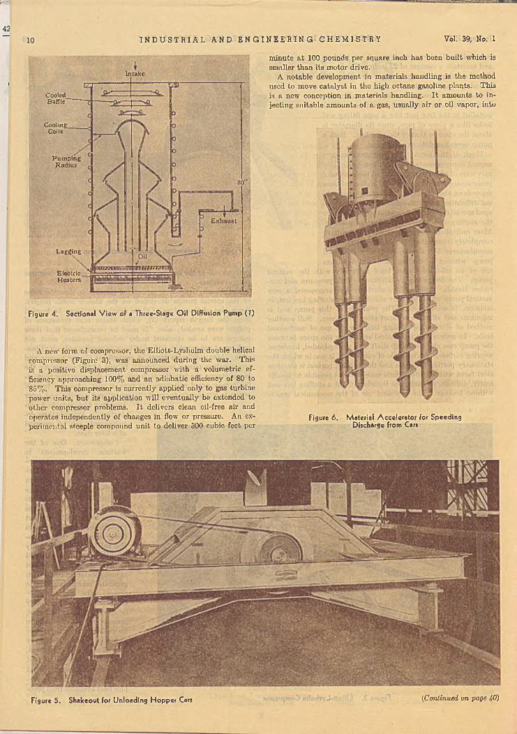
Intake
CooledBaffle'
CoolingCoils
PumpingRadius
Exhaust
Lagging
rjiiiwnai;aronsElectricHeaters
I N D U S T R I A L A N D E N G I N E E R I N G C H E M I S T R Y Vol. 39, No. 1
minute at 100 pounds per square inch has been built which is smaller than its motor drive.
A notable development in materials handling is the method used to move catalyst in the high octane gasoline plants. This is a new conception in materials handling. It amounts to injecting suitable amounts of a gas, usually air or oil vapor, into
Figure 4. Sectional V iew of a Three-Stage O il Diffusion Pump (J)
A new form of compressor, the Elliott-Lysholm double helical compressor (Figure 3), was announced during the war. This is a positive displacement compressor with a volumetric efficiency approaching 100% and an adiabatic efficiency of 80 to S5%: This compressor is currently applied only to gas turbinepower units, but its application will eventually be extended to other compressor problems. It delivers clean oil-free air and operates independently of changes in flow or pressure. An experimental steeple compound unit to deliver 300 cubic feet per
Figure 6. Material Accelerator for Speeding Discharge from Cars
(Continued on page Ą0)Figure 5. Shakeout for Unloading Hopper Cars
CRUSHING AND GRINDINGLincoln T. Work, m e t a l a n d t h e r m it c o r p o r a t i o n , r a h w a y , n . j.
S IN C E particle size measurement is essential to fundamental and practical developm ents in this field, particularly in finer sizes, the tremendous extension o f such measurement during
the thirties has tended toward more exact work in crushing and grinding. Old methods were perfected and made more economical to use, while new principles were being tested. T he war period has seen a continuation o f this trend in the special applications to war industries. There has thus developed a more extensive “ knowhow” , and simple, well established methods o f particle size measurement are available for use. The potentialities are still only partially realized, but good progress has been made. The prewar period was marked b y the successful application o f a fluid-jet mill and b y a sudden general interest in the new aspects o f this principle which show today in developments in varying stages o f completeness and effectiveness. Fluid energy grinding is an old idea which apparently had little application until m odern knowledge o f je t performance and unique com bination o f grinding and classifying elements made possible the practical production o f fine particle size.
W hile these developm ents were in progress before the forties, the war period created an entirely new set o f problems. The mining field was faced with the need for efficiency because on ly thus could the needed volumes o f production be attained, and this had to be done with mill types then available. There was little manpower or time for research on the current problems or on the uses o f these operations in the chemical industries. Some specific and exacting requirements for the armed services demanded closely controlled ranges o f particle size, and manufacturers were faced with studies of procedure to meet these needs with an econom ic utilization o f materials. These problem s also necessitated consideration o f alternatives, as when spraying replaced grinding.
Throughout this period there were those who thought about the trends. Some contributed to the immediate problems, while others looked into the future, so that now the field stands to profit from its war experience, and new developm ents are beginning to take their form.
M e a s u r e m e n t . In order that product control may be effectively carried out or that the fundamental principles in size reduction may be established, rapid and econom ical methods o f size measurement, particularly in the subsieve range, are essential. Considerable progress has been made in recent years, and the Twelfth Annual Chemical Engineering Sym posium o f the D ivision o f Industrial and Engineering Chemistry, A m e r ic a n C h e m ic a l S o c i e t y , gives evidence o f this. (This symposium, Measurement and Creation o f Particle Size, was held in D ecem ber 1945.) A brief review o f developm ents follows.
Just before the war, standardization o f sieves was effected in the American Standards Association through a com m ittee sponsored by the American Society for Testing Materials and the National Bureau o f Standards (1). These two organizations have adopted this standard. Procedures for sieving and the performance testing o f sieves are not yet fully standardized. In the subsieve range the electron m icroscope has opened new vistas for photographic examination, with the result that magnifications with good resolution are now m any fold greater than with the light microscope. Sedimentation methods have been checked with others {22), and the usefulness o f the hydrometer, Andreasen pipet, and Wagner turbidimeter has been defined. Centrifugal sedimentation has been developed {15), and indications are that
there will be further progress. The air analyzer, one form o f which was defined b y R oller {19), is finding a place in the range 5 to 40 microns for those materials which are not altered b y the vigor o f the operation. Spectral transmission studies using a range o f wave lengths finds a place from 0.2 up to 2 or 3 microns (4). Gas permeability methods for surface have been developed and are being extended to fine sizes b y the use o f higher gas pressures and compression o f pellets {10). Gas adsorption for total surface, both internal and external, is finding m ore extended use {11). M ethods o f dispersion appear solved for many materials, but there is no standard and the problem still requires, study b y new procedures.
M any o f the methods o f measurement use different criteria— - for example, the sieve aperture, Stokes law diameter, or surface- evaluation b y gas adsorption. There have been m any serious, problems o f correlation, but the literature is now beginning to show the relation o f these methods to one another; the exception is that the gas adsorption method measures total surface, whereas- the other methods depend largely on the external surface characteristics o f the material. There is extensive literature on the correlation of shape factors {21).
P r o d u c t s o f S iz e R e d u c t i o n . Recent work on the laws of grinding as they affect the product has given a more fundamental approach through action even on individual particles. Bond {7) com pared compression tests on. cores with im pact tests, the latter more closely resembling the grinding action. Gaudin and associates {12) studied surface developed in relation to size, using controlled fracture o f quartz, glass, galena, and other materials. T h ey found that size distribution o f broken fragments made by a single fracture is such that the new surface on each grade is the same, and that this generalization m ay be carried into multiple fractures. Such information m ay ultimately lead to scientific design o f equipm ent for a predictable product.
E n e r g y ' . Theoretical calculations are based on the energy necessary to create new surface w ithout unusual distortion o f the particle, whereas the actual behavior represents distortion o f the particle to the point o f rupture, and the restoration o f its form m ay return energy as heat to the system. It appears, therefore, that there is opportunity to develop grinding methods where the energy would be applied in such a way as to produce fracture w ithout too serious a distortion o f the total particle.
G r i n d a b i l i t y . The old hardness scale was never more than a rough criterion o f the ease or difficulty o f grinding a material, although it would serve to give some measure o f wear on the grinding media. Furthermore, many materials contained a variety o f particles o f widely differing hardness— for example, coal containing silica— and the hardness m ethod would have no applicability in giving a measure in such a case. Grindability methods were developed through m any experimental phases during the thirties, and some information reached the literature at that time. M ore recently methods have been standardized, at least tentatively, as the ball mill m ethod {2) and the Ilardgrove machine m ethod (3). H ardgrove grindability depended on sieve determinations, and there the m ethod has been im proved by using the air permeability test for measuring surface {20). Grindability studies have been further extended to the mesh sizes to which an ore is to be ground in practice so that the capacity o f a mill can be calculated directly (3). W ilcoxson {25) reported, relative to Hardgrove grindability, “ there are indications that the higher the grindability, the higher the specific {Continued on page 31)

ADSORPTIONArthur B. Ray, c a r b id e a c a r b o n c h e m i c a l s c o r p o r a t i o n , n e w y o r k 17, n . y.
T H E processes covered b y this review are (a) adsorption of gases and vapors (other than water vapor), (6) adsorption of substances from liquids, and (c) drying o f gases and liquids. Ion
exchange and use of adsorbents as catalysts and catalyst carriers will not be discussed because space is lim ited and a great deal o f recent work in these fields has not yet been published.
Detailed background inform ation is summarized in a number o f fairly recent books and articles. D ietz (37) gave “ an annota- tive bibliographical survey o f the scientific literature on bone char, activated carbons, and other technical solid adsorbents for the years 1900 to 1942 inclusive” . M antell’s book (74) is "an attem pt to correlate the practical, commercial, and the engineering aspects o f adsorption” b y various adsorbents in various fields. Hassler (43) gave a bibliography and discussion primarily o f liquid purification b y activated carbon. Applications of silica gel and activated alumina were discussed b y Dehler (36) and Simpson (98), respectively.
N o n a q u e o u s G a s e s a n d V a p o r s . The developm ent of adsorbents for military gas masks during W orld W ar I gave special impetus to the developm ent of industrial gas and vapor adsorbents. During the past thirty years activated carbons have continued to be the only im portant industrial adsorbents for gases and vapors other than water vapor. These carbons are in the form of hard, relatively dense granules or pellets. Manufacturers supply various grades and particle sizes of carbon to m eet industrial requirements, but little has been published regarding modern manufacturing processes (13, 76). Gas and vapor adsorbent carbons now most widely used for industrial processes in the United States are manufactured from coconut shells. Carbons for use in military masks were also made from various nut shells, coal, and w ood sawdust. European carbons (51) are made from peat, coal, wood charcoal, and nut shells.
Gas Masks. The granular carbon of small particle size used in all military' gas masks is generally treated with agents which cause it to decom pose certain toxic agents catalytically. Great advances in the preparation o f this adsorbent-catalyst were made during W orld W ar II, but this work h.as not yet been published. Granular carbon o f high adsorptive capacity is used in all industrial masks for the adsorption o f organic vapors and certain other gases. Industrial masks contain additional materials to stop such gases as carbon monoxide, ammonia, and others which are not effectively rem oved by carbon alone.
Solvent Recovery. The use o f activated carbon for the recovery o f solvents vaporized in manufacturing operations originated in Germany (S3) about thirty years ago. M any im provem ents in carbons, processes, and equipment have been made until now the various activated carbon processes are used the world over to recover billions o f pounds of solvents per year. In North America alone, carbon recovery plants installed or being built have a recovery capacity o f over one billion pounds o f solvents per year. T he leading European (31, 94) and American (19) processes differ in types of carbons and equipment used and in operating procedure but, in general, they all have the ability to recover solvent vapors present in low concentration in air or other gases. Improvements in carbon, in adsorber design (66), and in operating procedure (89) have increased recovery efficiency and reduced recovery expense. M ost o f the recovery plants installed in N orth America during recent years are automatically operated (70), which makes possible the safe and efficient operation o f very large plants.
W hile low-boiling solvents are recovered b y the carbon process in practically all industries where vaporized solvents can be collected, the largest am ount o f solvent recovered in N orth America is in the acetate rayon industry. Because o f the difficulty of efficient collection of the solvent vapors, the recovery of solvents by automatically operated equipment from rotogravure printing(75) is noteworthy. During the war large quantities o f ether and alcohol vaporized in the manufacture o f smokeless powder were recovered by the carbon process. Bodm an (11) reported that in 1943, 50,000,000 gallons o f alcohol, worth §41,000,000, were saved in the United States. This saving was due almost entirely to the twenty-six automatically operated recovery plants which contained ninety-five adsorbers and had a capacity to handle vapor-laden air at the rate of 1,600,000 cubic feet per minute and to recover solvent at the rate of 50,000 pounds per hour, with an efficiency of over 95% .
Engle and Coull (31) described adsorption studies o f vapors in carbon-packed towers. Othmer and Sawyer (83) correlated equilibrium vapor pressures o f gas or vapor adsorbed on activated carbon with the temperatures o f adsorption and the concentration of gas or vapor b y a graphical method. T hey (93) also determined adsorption equilibria of pressures, temperatures, and concentrations for a number of vapors on a com mercial activated carbon and described a simple apparatus and procedure. E m m ett (SO) reported gas adsorption methods for measuring surface area o f adsorbents. Various studies in connection with the recovery of volatile solvents by means of solid sorbents were discussed b y Alekseevskil and associates (1).
Recovery of Benzene from Fuel Gas. Activated carbon is used extensively in Europe to recover benzene from manufactured fuel gas but not in the United States, where the o il absorption process is preferred. The advantages o f the activated carbon system are reported as follows: H igh recovery, practically independent o f concentration, is possible with low steam consum ption; no “ wash oil” constituents are introduced into the gas stream ; cleaner gas is obtained (free of naphthalene and with lower content o f organic sulfur, hydrocyanic acid, and gum-form ing hydrocarbons); and carbon com pletely stops any hydrogen sulfide which m ay pass the normal purification system provided for its removal. Also, an advantage in Europe is that no imported “ wash oil” is required. One o f the largest activated carbon recovery plants, in Beckton, England (50), has the capacity to extract 20,000 gallons o f benzene per 24 hours from 75,000,000 cubic feet o f coal gas. Operating data on this and a smaller plant in Manchester, England (111), indicate 90 to 9 5 % benzene recovery, which is substantially the same as that o f oil scrubbing units in the United States. Under existing conditions, the costs of operation o f the two systems, including carbon replacement, are reported to be about the same. Incidentally, carbon reactivation and replacement is one o f the large items of operating cost. I t is reported that one pound o f carbon will recover approxim ately 175 pounds o f benzene before reactivation or replacement is required.
Recovery of Hydrocarbons from Fuel Gas. T he recovery of gasoline from lean natural gas was originated in the United States in 1918, and a large number of gasoline recovery plants were installed in the ensuing years. M ost of them, however, have been discontinued, and at present in the United States gasoline is recovered from natural gas alm ost exclusively by com pression and oil absorption. In Europe, however, gasoline is
12

January 1947 I N D U S T R I A L A N D E N G I N E E R I N G C H E M I S T R Y 13
recovered extensively from natural gas by means of activated carbon (69). It was reported (94) that in 1938, 630,000 tons of naphtha and gasoline were recovered in Germany and elsewhere by the Supersorbon process. In addition to gasoline, propane and butane are recovered by proper operation of the adsorbers so that these lighter hydrocarbons are retained in the carbon at the end of the adsorbing period. The lighter and heavier hydrocarbons are steamed out of the carbon, and the lighter hydrocarbons are liquefied under pressure and separated in the usual manner. This same principle is employed in Germany for the recovery of hydrocarbons from gases in the Fischer-Tropsch method (67) of fuel production.
Processes have recently been described for the separation of light hydrocarbon gases by activated carbon. A method for adsorbing hydrocarbons such as ethylene takes advantage of the higher adsorptive capacity of carbon obtainable at elevated pressures and reduced temperatures (64). Adsorption on activated carbon under high pressures is claimed to offer considerable advantages in the recovery of liquefiable hydrocarbons from gas distillate reservoirs (88).
A recent means of separating light gases is reported to permit processing and recovery of hydrocarbons from gases that cannot be handled economically by conventional processes. So-called Hypersorption (8) employs a moving bed of activated carbon to adsorb hydrocarbons from lean gas streams. Its applications are reported to include the recovery of ethylene from gases produced in thermal and catalytic cracking operations, the recovery of propane and heavier components from natural gas, the separation of methane from hydrogen, and many other separations. The essential operation of Hypersorption involves the contacting of the feed gas stream with a moving bed of activated carbon which has been previously stripped and cooled to the desired temperature. Separation of the components of the feed takes place in the contacting bed by controlled selective adsorption of the heavier constituents. These are subsequently stripped from the carbon at an elevated temperature by steam. The stripped carbon is returned to the top of the unit where it is dried and cooled, and the cycle of operation repeated.
Purification of Gases. Activated carbon can also remove traces of impurities and is efficiently used for the purification (67, 110) of many industrial gases such as hydrogen, carbon dioxide, inert gas, ammonia, hydrogen chloride, acetylene, and others. The carbon, in the form of hard granules or pellets, is usually placed in vessels which permit the gas to be passed through a deep bed. The equipment is arranged so that one adsorber may be in service while the other is beingnrevivified and prepared for re-use. Hydrogen from cracking operations, intended for synthesis or for hydrogenation of oils, is effectively purified by passage through a bed of activated carbon. Carbon dioxide (87) is deodorized for the manufacture of dry ice or for liquid carbonation. Acetylene to be used in synthesis is freed of objectionable organic sulfur and some vinyl compounds. Pyridine and other compounds are removed from ammonia, which is to be used as such or for oxidation to nitric acid. Traces of nitrogen oxides and other impurities are adsorbed from inert gas generated in combustion machines. Organic sulfur compounds (39, 103, 105) may be removed from manufactured gas by activated carbon.
Odor Removal. In recent years the widespread use of air conditioning and other factors have made people odor conscious; many installations have been made of equipment employing activated carbon for the removal of odors and impurities from both inside and outside air. Hard, granular dust-free activated carbon with high retentive power for odors has been developed. Two general types of equipment are in use for the removal of odors by adsorption. In one (23, 88) the air is passed through thin beds of granular activated carbon at velocities which permit substantially complete removal of odors by one passage. The other type (24, 101) is designed so that the air is passed in contact
with the carbon but not necessarily through a carbon bed. This so-called panel type of equipment is used where very low pressure drop is an economical necessity and where air can be recirculated through the odor-removing equipment. Partial removal of odors is effected by each pass through the panel but contmued recirculation permits the odor load to be kept below the threshold value.
A large number of installations have been made for taking objectionable odors and impurities from air exhausted from restaurants and manufacturing operations which must be conducted in congested areas. In many cases (79) activated carbon is used to remove impurities (such as sulfur compounds) from intake air in order to protect equipment such as automatic telephone exchanges and valuable books and manuscripts, and to protect operations such as the manufacture of photographic film.
Smock at Cornell University found that, as apples ripen in storage, they give off ethylene and other gases which, if allowed to accumulate in the storage chambers, may shorten the storage life of the fruit and give a “scalded” brown appearance. During storage apples also readily adsorb odors (41) given off by certain types of building materials (such as pine wood) and by certain other stored products (such as onions, etc.). Smock showed that proper circulation of storage air through thin beds of activated carbon will remove ethylene, gases which cause scalding, and objectionable odors which would otherwise be picked up by the apples (102). It is reported that best results are obtained wben special activated coconut charcoal is used in canisters through which the air may be circulated by a blower.
Removal of odors from conditioned air permits “recovery” and re-use of this air, and thus materially reduces the initial cost of the conditioning system and the operating expense (114). The air which has been deodorized by passage through activated carbon is the equivalent of fresh air and in many cases is actually purer than intake air. For example, the Criminals Court Building in New York (78) has thirty separate air conditioning units to serve court rooms. Installation of activated carbon equipment to deodorize recirculated air reduced the necessary outside air intake by approximately 100,000 cubic feet per minute and the necessary refrigeration equipment by 275 tons. The radiation and boiler capacity was reduced by 10,000,000 B.t.u. per hour. Operating savings in fuel and electrical power amounted to a yearly saving of approximately 90,000 gallons of oil and122,000 kilowatt-hours of electricity.
In addition to the many installations in restaurants, theaters, offices, clubs, and elsewhere, air deodorization equipment is being rapidly installed in conditioned railway passenger cars(80). Such installations permit an increased recirculation of air, in effect increase the amount of “ fresh” air per passenger, and thus minimize the serious odor problem. In a 64-passenger coach, for example, each person receives nearly three times as much fresh air as formerly. It is reported that the cost of activated carbon air purification in railway cars is only about 2% of the entire air conditioning cost.
Another deodorization application of activated carbon was of particular interest during World War II and will continue to be of service in hospitals. Odors from wounds, which caused an almost unbearable condition in planes transporting wounded, were effectively controlled by withdrawing air from beneath the blanket covering the patient and passing it through a canister of activated carbon (81). The same result is accomplished in some cases by mixing activated carbon with plaster when molds are to be applied (91) or by using bandages or wrappings of cloth impregnated with activated carbon (95).
A d s o r p t i o n f r o m L iq u id s . Activated carbon (44) for the removal of color or other substances from solution (43,47) is usually in the form of a low density powder, but granular carbon is sometimes used. The powdered carbon is mixed with the liquid to be purified, and after contact for 15 to 60 (Continued on page 32)

ABSORPTION AND HUMIDIFICATION
Harrison C. Carlson, 1413 V A N BUREN STREET, W ILM IN GTO N , DEL,
THE theory and practice of absorption and humidification have advanced slowly during the past year. Marshall (12) discussed the selection of finned coils cooled by a boiling refrig
erant for dehumidifying and cooling air. His presentation of the equivalent by-pass theory considers that part of the air is cooled to the surface temperature and part unchanged in temperature. The same conclusions could be reached if the ratio of the heat transfer coefficient to the mass transfer coefficient were taken equal to the humid heat and if the transfer units for heat and mass transfer are equal in number.
When cooling water is limited, the refrigeration industry uses evaporative condensers for condensing vapors inside tubes with water recirculated over the outside, but cooled only by the air btown countercurrent to the descending water films. Goodman(7) had analyzed the rate of heat transfer to the air by sensible and latent heat effects, and showed that the enthalpy driving force between the water and th? inlet air could be used to calculate the rate of heat transfer. Thomsen (10) substituted an approximate expression for the enthalpy as a function of the wet- bulb temperature, obtaining an over-all coefficient to be used with the temperature difference between the condensing vapor and the average wet-bulb temperature of the air. He analyzes the operation on a graph of temperature plotted against resistance to heat flow between the vapor and cooling air.
Ferencz (5) reformulated the heat and material balance equations and rates of heat and material transfer in the countercurrent contact of a liquid and gas in a packed tower for dehumidification and water cooling. He suggested a method of solving the differential equations by successive approximations. The concept of the enthalpy driving force, however, gives quicker solutions to some cases than does the general equations based on over-all transfer coefficients presented by Ferencz.
Estignard-Bluard (4) applied the Ponchon diagram to calculations of the separation of two gases by a solvent (extractive distillation). He shows how the minimum reflux and the number of theoretical plates at infinite or finite reflux ratios can be calculated for an isothermal and isopiestic column, using a nonvolatile solvent in which the gases are only slightly soluble. An example calculated for separating a 20% mixture of propylene in propane using water at atmospheric temperature and pressure indicated twenty-five theoretical plates and a circulation of 7 cubic meters of water per cubic meter of propylene recovered, when the top and bottom products contained less than 0.5% impurity.
Geddes (6) developed a method of predicting local Murphree plate efficiencies in bubble-cap absorption and distillation columns. Although Geddes points out that some of the assumptions are inexact, the predicted plate efficiencies agree with the measured values over a wide range of conditions. The gas film resistance is based on the theoretical equation for unsteady-state diffusion from a spherical gas bubble to a constant interface composition. The time of contact is calculated from an empirical correlation of the velocities of rise of single gas bubbles and the head of unaerated liquid over the slot. The paper is characteristic of the theoretical attack on absorption and distillation problems which designers of commercial equipment are forced to make because of the lack of experimental data.
O'Connell gave an empirical correlation of the over-all plate efficiency of bubble-cap absorbers (14), using the ratio of the gas solubility to the liquid viscosity. O'Connell terminated his correlation at a plate efficiency of 70%; this probably indicates that, for higher plate efficiencies, the resistance in the liquid film becomes less important and other variables would have to be included to correlate the gas film resistance.
The design of absorbers for natural gasoline to operate at 1000 to 2000 lb./sq. in., when the dry gas is to be reinjected into the petroleum reservoir, was discussed by Wade (SO). At 1800 lb./sq. in. mothane is almost immediately dissolved in the lean oil at the top of the absorber, so that the amount of liquid is nearly doubled and the oil temperature raised. With cool entering gas the oil temperature may actually decrease as it flows through the high pressure absorber. At low pressure the major absorption is of butanes and higher hydrocarbons; this occurs at the bottom of the absorber, so that the oil temperature rises as it flows, through the absorber. As the solubility of methane increases and that of butane decreases with increasing pressure, the lean oil rate is nearly constant for pressures between 1000 and 2000 lb./sq. in. Wade discussed the choice of absorption pressure and the method of separating the large amount of methane from the desired components in the rich oil.
H u m id it y M e a s u r e m e n t . The familiar Carrier psychrometrie chart of humidity vs. dry-bulb temperature was redecorated by Palmatier and Wile (15) with an auxiliary scale for the enthalpy of saturated air in the range of 20° to 110° F. As unsaturated air has nearly the same enthalpy as saturated air of the same thermodynamic wet-bulb (adiabatic saturation) temperature, deviations in the two enthalpies are shown by contour lines on the chart. A table of corrections to the saturated humidities and enthalpies in the range of 20° to 84° F. is given for total pressures between 24 afid 31 inches of mercury.
For calculating the humidity from wet- and dry-bulb temperature measurements with air in the range of 50-200° F. and 5-100 lb./sq. in., Rohsenow (17) presented two graphs based on the hope that the adiabatic saturation temperature is the same as the wet-bulb temperature. He made the minor correction for gas law deviations, which are less than the uncertainty in reading from the small charts. The amount of labor expended in calculating charts of adiabatic saturation compared to the actual measurement of humidity as a function of reliable wet- and dry- bulb temperatures is really amazing in view of the lack of definitive data.
Williams and Schmitt (21) solved the problem of humidity measurement by wet-bulb psychrometry in rotary dryers of water-soluble salts, where the wet-bulb thermometer can be contaminated with salt. The wet-bulb reading can be used to calculate the humidity by using a saturated solution of the salt being dried on the wick of the wet-bulb thermometer. Williams and Schmitt developed the psychrometrie equation for this case, which required that the vapor pressure of the saturated salt solution and the heat of crystallization be known. Humidity measurements in an uncontaminatcd air stream with the wet bulbs moistened with water as well as with saturated solutions of sodium nitrate, ammonium nitrate, or magnesium chloride liexa-
14

January 1947 I N D U S T R I A L A N D E N G I N E E R I N G C H E M I S T R Y IS
hydrate gave the same calculated humidity; this indicated that their extension of the psychrometric equation was correct. Humidity-temperature charts showing wet-bulb lines for these three salt solutions were published.
E q u ip m e n t . Since 1940 glass and ceramic equipment for hydrogen chloride absorption has been largely replaced by Karbate. Hatfield and Ford (9) recounted the improvements in the resin used to make the carbon or graphite base impervious, which extended its temperature and corrosion resistance. They also reviewed the mechanical improvements in Karbate pumps, valves, coolers, towers, and heat exchangers. The ease of fabricating this material of high thermal conductivity and corrosion resistance into shell and tube exchangers means that the acid and hydrogen chloride gas can be contacted directly on the water- cooled surface. These cooler absorbers, which may be constructed with either horizontal or vertical tube bundles, are preferred with concentrated hydrogen chloride gas to the old system of a number of towers in series, each with its external cooler for the acid circulated over the tower. Cooler-absorbers are characterized by compactness and low pressure drop.
E q u ip m e n t P e r f o r m a n c e D a t a . The flooding velocities of various sizes and types of tower packing have previously been correlated with a packing constant, the ratio of the surface area per unit volume to the cube of the percentage of voids. For small packings this ratio is a function of the method of packing the tower as well as the diameter of the tower and the source of the packing. Lobo, Friend, Hashmall, and Zenz (11) found that if '/finch Raschig rings were poured into a water-filled tower, the packing constant was 360, but if the packing were then shaken, the ratio increased to 725. The ratio for '/«-inch rings may vary from 593 to 1664, depending on the manufacturer. These authors recorrelated the existing data on flooding velocities of dumped packings, using the most probable values for the packing constant, but the points are still scattered in a band of ± 100% around the mean curve.
Boelter, Gordon, and Griffin (2) measured the rate of evaporation of water from a 1-foot diameter horizontal surface into quiet air at 65° to 80° F. and 54 to 98% relative humidity when the water temperature was varied from 63° to 200° F. Evaporation coefficients for free convection were correlated with the Grashof and Schmidt groups and compared with similar data on heat transfer.
During the war about 250,000 tons a year of butadiene were purified from the associated Ci hydrocarbons by absorption or extraction with an aqueous cuprous ammonium acetate solution. Morrell, Paltz, Packie, Asbury, and Brown {18) give the physicochemical data underlying the process, which depends on the formation of a loose chemical compound. This chemical absorbent has the advantage of higher selectivity over the usual extractive distillation agents. The diolefins are much more soluble than the olefins or saturated paraffins, particularly at low temperatures. For absorption on 1-inch Raschig rings, a height equivalent to a theoretical plate was between 10 and 12 feet. The greater selectivity at low temperatures and the boiling points of the hydrocarbons indicated the liquid-liquid extraction would be better than absorption.
Pigulevskil and Ilyina {16) measured the rate of absorption of ethylene in sulfuric acid in a flask rotated to keep the walls wet. In fresh 95.5% sulfuric acid at 70° C., K, was 0.9 X 10"' lb. mole/(hr.)(sq. ft.)(atm.). The absorption coefficient increased twenty-five fold as the acid concentration was increased from 86.5 to 99.4%. The absorption coefficient increased 1.33 times for a 10° C. rise in temperature. The absorption rate decreased the initial value to 0.1 when a mole of sulfuric acid had absorbed a mole of ethylene.
Bosworth (3) absorbed carbon dioxide in a 56% sugar solution wade alkaline with 0.078 Ar calcium oxide, using a 1-foot spray tower. The effective tower height was varied from 5 to 96 inches, and the amount of carbon dioxide absorbed was found
proportional to the 1/i power of the tower height. The resistance is mainly in the liquid film, as Johnstone and Williams {10) found 1 N sodium hydroxide necessary to eliminate the liquid film resistance. Equations for the unsteady-state diffusion through a stagnant drop indicate that the amount absorbed should be proportional to the square root of the time. As the liquid velocity from the spray was less than 1 ft./sec., the time of fall was proportional to the square root of the tower height; this explains the observed variation of the amount absorbed with the '/< power of the tower height. It is interesting to note that Guyer, Tobler, and Farmer (8), desorbing carbon dioxide from single water drops, found no appreciable change in the desorption coefficient on changing the tower height.
Using a 10-mm. tube packed with 5-mm. balls, Amelin (1) found that the percentage of sulfur trioxide absorbed in 75-95% sulfuric acid passed through a minimum at about 120° C. as the acid temperature was varied from 20-200° C. He gave a quantitative explanation of this in terms of the relative rates of absorption of water and sulfur trioxide and the equilibrium partial pressures from the solution.
Abstracts of the following articles from Russia are all that are available to the reviewer at present. Zhavoronkov and Furmer (22) measured heat transfer coefficients for cooling air with water in towers packed with Raschig rings, coke, and wooden grids. Air velocities up to 2 ft./sec. and liquid rates up to 5000 lb./(hr.) (sq. ft.) were employed. Shabalin and Blyakher (18) measured the plate efficiency of a bubble-cap column absorbing sulfur trioxide in sulfuric acid. Varying the gas rate and liquid depth from 1.2 to 2.5 inches gave Murphree efficiencies between 81 and 97% at pressure drops of 4 to 7.5 inches of water. Cooling coils on the plates had over-all heat transfer coefficients of 200 B.t.u./(hr.)(sq. ft.)(° F.).
LITERATURE CITED
(1) Amelin, A. G „ J. Applied Chem., 17, 319-25 (1944); 18, 509-17(1945). .
(2) Boelter, L. M. K., Gordon, H. S., and Griffin, J. It., I n d . E n o .C hem., 38, 596-000 (1940).
(3) Bosworth, R. C. L., Australian Chem. Inst. J. & Proc., 13,53-9 (1946).
(4) Estignard-Bluard, J., Chimie & Industrie, 52, 25-9 (1944).(5) Ferencz, P., Can. Chem. Process Inds., 30, 47-9 (1946).(6) Geddes, R. L „ Trans. Am. Inst. Chem. Engrs., 42, 79-105
(1940).(7) Goodman, TV., Healing, Piping Air Conditioning, 10, 165-8,
255-8, 327-8 (193S).(8) Guyer, A., Tobler, B., and Farmer, H., Chem. Fabrik, 9, 5-7
(1936).(9) Hatfield, M . R., and Ford, C. E., Trans. Am. Inst. Chem.
Engrs., 42, 121-47 (1946).(10) Johnstone, H. F. and Williams, G. C., In d . E n o . C hem., 31,
993-1001 (1939).(11) Lobo, W. E., Friend, L., Hashmall, F., and Zenz, F., Trans. Am.
Inst. Chem. Engrs., 41, 693-710 (1945).(12) Marshall, G. K., Heating & Ventilating, 42, 82-7 (1945).(13) Morrell, C. E., Paltz, W . J., Packie, J. W., Asbury, W. C.
and Brown, C. L., Trans. Am. Inst. Chem. Engrs., 42, 473-94(1940).
(14) O'Connell, H. E „ Ibid., 42, 741-55 (1946).(15) Palraatier, E. P., and Wile, E. E., Refrig. Eng., 52, 31-6, 74
(1946).(16) Pigulevskil, V. V., and Ilyina, S. I., Compt. rend. acad. sci.
U.R.S.S., 45, 331-3 (1944).(17) Rohsenow, W. M „ Re frig. Eng., 51, 423-4, 464, 460 (1946).(18) Shabalin, K. N., and Blyakher, 1. G., Khimicheskaya Prom.,
1945, No. 11, 14-16.(19) Thomsen, E. G., Refrig. Eng., 51, 425-31 (1946).(20) Wade, H. N., Oil Gas J., 44 (50), 120, 122-4, 126 (1946);
Petroleum Refiner, 25, 206-10 (1946).(21) Williams, G, C., and Schmitt, R . O., In d . E n o . C hem., 38,
967-74 (1946).(22) Zhavoronkov, N, M., and Furmer, I. E., Khimicheskaya Prom.,
1944, No. 12, 7-9.

CENTRIFUGATIONJames O . M a lo n e y , u n iv e r s it y o f Ka n s a s , l a w r e n c e , k a n s .
NO QUANTITATIVE information on the effect of the major variables influencing centrifugal operation has appeared in the literature during the year. Although the qualitative
effects are fairly well known, chemical engineers still need a considerable amount of data in order to make a preliminary selection of equipment.
G e n e r a l A p p l i c a t i o n s o p E q u ip m e n t . T w o papers appeared during the past year, describing in some detail the fields of application of certain types of centrifuges. Bryden (5) points out that new developments resulting in improved lubricating oils have, in turn, required that equipment be better protected from dust and water in the oils. Now improved turbine oils in which the oxidation rate has been greatly reduced require a minimum of water washing under normal conditions to remove oxidation products. Water washing, however, has been found desirable if the oil is in an atmosphere of corrosive vapors which condense in the oil and attack the metal parts in contact with the oil. It has been found that many oxidation-inhibited oils are more easily purified centrifugally than are the straight mineral oils. Bryden states that operators of turbine equipment are using their centrifugal purifiers continuously in order to decrease maintenance costs on the turbine. Filtration of the oil through certain types of activated earth has been found to remove both oxidation and rust inhibitors. The desire for a visibly clean Diesel lubricating oil has resulted in the combination of a paper disk filter and an oil-water separating centrifuge. Bryden reports that the centrifuge needs cleaning only about one third as often and that the filter does not plug up with water. A centrifuge separating wax continuously from crude oil, used as a fuel for Diesel engines, has improved the operation of Diesel engines pumping crude oil.
Jacobs et al. (11) describe pilot plant comparisons of a Shriver filter, an Oliver precoat filter, a Bird solid bowl centrifuge, and a Lurgi band filter for the separation of solids from a manganese sulfate solution. Essentially complete operating data on all of these units are presented. Because of limitations in the performance of all except the Shriver filter, an economic analysis was not required.
Experiments on the extraction of tannins are reported by Beebe et al. (4). It was observed that if the pieces of tannin- containing material were too large, it was difficult to extract the tannin. On the other hand, when the material was ground too fine, it either could not be wet thoroughly or it packed into a solid. By grinding the material or crushing it, mixing it with water and grinding, and finally centrifuging the entire mixture in a basket-type centrifuge, the recovery of tannins was good.
There is an increasing use of high speed centrifuges in the biological sciences. Ogston {17, 18, 19) employed an air-driven centrifugal operating at two speeds—24,000 and 40,000 revolutions per minute—to separate tobacco mosaic virus. Chargaff {6) studied the distribution of thromboplastic activity in representative cellular fractions of beef lungs. The fractions were obtained by centrifugation at 1900 times gravity, followed by centrifugation at 31,000 times gravity. All of the activity was found to be confined to the sediment from the 31,000 X gravity operation. Stanley {22) and Taylor el al. {25) employed the high speed centrifuge in the sedimentation of influenza virus and vaccines. Taylor {23, 24) also employed a Sharpies supercentrifuge for preliminary concentration of rabbit papilloma. This was followed by further concentration in an ultracentrifuge to
produce this virus in satisfactory purity and yield. An unsuccessful attempt was made by Baker el al. {1,2) to determine the distribution of water in bread doughs with a Sharpies centrifuge.
Mitham and Yardley {16) describe in considerable detail a dynamic brake for a laboratory high speed centrifuge. Dynamical braking is a method of stopping or slowing down moving equipment in which the stored mechanical energy of the body is converted into electricity and the electricity reconverted into work in an external circuit. The rate at which this energy is removed determines the time required to bring unit to rest. This method of stopping rapidly moving mechanisms saves wear and tear.
A clever process for continuously obtaining the specific gravity of a gas by means of centrifugal force was devised by Dowling (7). It is based on the principle that, if a tube filled with gas is revolved about one end, a pressure difference proportional to the average density of the gas develops. By having two tubes, one containing a standard gas and the other the gas whose gravity is to be determined, it is possible to measure the pressure differences and determine the gravity of the unknown gas.
Irving (10) describes the ter Meer continuous centrifugal and points out that it is limited to the separation of relatively coarse, free-draining solids from a liquid. The considerations in the design of the discharge mechanism are reported in considerable detail.
F u n d a m e n t a l D e v e l o p m e n t s . Bryden (5) lists a number of important considerations in the design of centrifugal purifier bowls. Included in this list are: efficiency of separation, stability of operation with varying feed composition, feed distribution and flow, mechanical stability, and ease of cleaning.
P a t e n t s . A number of patents have appeared during the year on centrifugal separations (3, 8, 9, 12-15, 20, 21, 26). Lindgren and Thylefors (15) patented a device for discharging sludge from the periphery of the bowl. In Schutte’s centrifugal filter for removing wax (21), a temperature gradient exists from the top to the bottom of the unit. A method for refining crude waxes in a centrifuge was patented by Gilmore (8). Lars (13) designed a vertical, pear-shaped, centrifugal separator bowl containing a number of flat disk-shaped separator elements, in each of which a hole is drilled. Jones (12) patented a unit for separating three phases by first separating the mixture into a light and heavy phase, the heavy phase containing essentially all of the intermediate phase. Hertrich (9) describes a device for driving centrifugal equipment employing a turbine.
LITERATURE CITED
(1) Baker, J. C., Parker, H. K ., and Mize, M . D ., Cereal Chem., 23»16-30 (1946).
(2) Ibid., 23, 30-8 (1946).(3) Bath, W . H „ U. S. Patent 2,380,014 (July 10, 1945).(4) Beebe, C. W ., Cordon, T . C., and Rogers, J. S., J. Am. Leather
Chan. Assoc., 41, 161-71 (1946).(5) Bryden, C. W ., Natl. Conf. on Petroleum, Am. Soc. M ech„
Engrs., Tulsa, Okla., Oct. 7, 1946.(6) Chargaff, E., J. Biol. Chem., 160, 351-9 (1945).(7) Dowling, J. J., J. Sci. Instruments, 22, No. 8, 145-8 (1945).(8) Gilmore, F. H., Australian Patent 118,047 (Feb. 3, 1944).(9) Hertrich, J., U. S. Patent 2,402,496 (June 18, 1946).
(10) Irving, H. F., Meek. Eng., 68, 330-2 (1946).(11) Jacobs, J. H., Hunter, J. W., Yarroll, W . H „ Churchward, P..
E., and Knickerbocker, R . G., U. S. Bur. Mines, Bull. 463: (1946).
(Continued on page 35)
16

HIGH TEMPERATURE DISTILLATION
T. J. W alsh, STANDARD O IL CO M PAN Y (O H IO ), C LEV ELA N D , O H IO
THE year 1946 was favorable for the study of distillation. Many advances were made from 1941 to 1945 that were not made public because of wartime restrictions. After the end of
hostilities in the Pacific theater of operations it became possible to release previously restricted information. By 1946 publication of data on wartime-developed projects was quite general. Distillation shared in this broad increase of knowledge. The articles on distillation may be grouped conveniently according to the direction in which they have extended the limits of past information.
L a b o r a t o r y D i s t i l l a t i o n . Progress in this field has continued the previous trend of improving laboratory equipment so that better control of distillations may be maintained. This permits a more exact analysis of results and a greater confidence in the use of these results for designing or operating commercial equipment.
One of the difficulties connected with many laboratory distillations is related to the problem of reflux control. Most laboratory distillations are conducted batchwise. If the distillation curve is to be studied, it is desirable to have a constant reflux ratio throughout the operation, regardless of variations in the boil-up rate. As the still temperature is increased, heat losses from the column and still pot increase. This reduces the quantity of vapor reaching the condenser section. With still heads of either constant reflux or constant take-off the reflux ratio is changing continuously.
Most constant reflux ratio heads operate on a time cycle basis— that is, take-off is made for 3 seconds every 30 seconds to give a 9 to 1 ratio of reflux to take-off. An improved head of this type described by Hepp and Smith (Id) has the advantage of constant reflux ratio but the disadvantage of intermittent take-off and reflux operation. At high reflux ratios this is less serious than at intermediate or low ratios, but it is never completely satisfactory.
A new modification of the constant reflux ratio head by vapor- stream splitting is proposed by Berg (2). These heads operate on the principle that a constant reflux ratio can be maintained by dividing the condensing surface into sections, one of which feeds the take-off system, the rest providing reflux. This modification is simpler in design than previous heads based on vapor-stream splitting. It has the advantages of steady reflux flow, constant reflux ratio, and no moving parts. Its disadvantages are a stepwise variation in the obtainable reflux ratios and the difficulties connected with obtaining accurate control of high (100 to 1) reflux ratios.
A third style of reflux head is described by Zimmerman (SI). The condensed vapor is divided into two streams, reflux and product. The rate of each is controlled by setting a stopcock to give a predetermined number of drops from a calibrated dropping tip. Operation is supposed to be steady after the rates have been set. The head gives a continuous reflux that is continuously variable over a wide range of settings. The reflux ratio will be influenced by the rate of column throughput.
A laboratory stripping column described by Langdon (16) is designed to overcome the difficulties associated with vaporizing small quantities of liquid. Usually local overheating will occur; this results in a cracked column or a spoiled bottoms product.
The design proposed involves use of an intermediate heating medium between the source of heat and the column vaporizer. Columns of this nature are most useful when a small percentage of a high boiling impurity is to be removed from a large amount of lower boiling material.
An all-glass perforated plate column described by Langdon and Tobin (17) has an efficiency and throughput similar to most packed laboratory columns. The plate type of construction might be useful in demonstration columns, and the all-glass feature is useful in distilling corrosive materials.
E q u i l i b r i u m D a t a . Distillation calculations can never be more accurate than the data upon which they are based. In many cases these data involve the equilibrium established between a liquid and a vapor under particular conditions of temperature and pressure.
An improved still for determining this equilibrium is described by Gillespie (8). In addition to using the usual vapor cycle system, this still utilizes a liquid cycle system to ensure homogeneity of the sample and a novel method of measuring the temperature at which the equilibrium is established.
The azeotropic forming behavior of benzene with all paraffins boiling between 68° and 100° C. has been definitely established, and a method of predicting the azeotrope composition and boiling point is presented by Marschner and Cropper (20). A somewhat smaller range of benzene-naphthene azeotropes is indicated by these same authors.
Data on specific binary blends of benzene, paraffins, and naph- thenes are given by Harrison and Berg (12). These data confirm the aromatic-paraffin or aromatic-naphthene azeotropes and show deviation in behavior of paraffin-naphthene systems.
Ternary systems have become more important since the recent developments in extractive and azeotropic distillation techniques. The thermodynamics of ternary system equations are considered by Wohl (30). Unsuccessful attempts to correlate the improvement in relative volatility when a third component is added to a binary mixture, with the dielectric constant, dipole moment, or internal pressure, are reported by Updike, Langdon, and Keyes (29). However, a definite rearrangement of relative volatility when furfural is added to a mixture of C( hydrocarbons is indicated by Happel el al. (10), who also present a theoretical study of activities for hydrocarbons over an extractive solvent.
F r a c t i o n a t i n g C o lu m n C a l c u l a t i o n s . The need for better methods of designing fractionators has become evident. The conventional methods of design guided by experience are entirely satisfactory when applied within the range of previous experience; they are, however, only a guide to guessing in the design of such items as superfractionators with 100 or more plates and extractive distillation columns in which the normal relations between components are deliberately distorted. The efforts to satisfy this need have followed two parallel courses: (a) to improve the correlations between theoretical considerations and plant experience so that behavior under new conditions may be predicted more accurately, and (b) to simplify the calculations necessary in the study of a fractionation problem.
Most methods of calculating the amount of fractioning tower necessary to achieve a separation will result in a number of theo

18 I N D U S T R I A L A N D E N G I N E E R I N G C H E M I S T R Y Vol. 39, No. 1
retical plates. To convert this to an actual tower, an over-ali plate efficiency is used. The over-all plate efficiency may be defined as the number of theoretical plates necessary to make a separation, divided by the number of actual plates which produce the same separation. It is usually expressed as a percentage.
The over-all plate efficiency of petroleum columns had been related to the viscosity of the tower feed by Drickamer and Bradford (5). The range of application of this type of correlation is extended by O’Connell (22), who shows that, if the viscosity of the feed is multiplied by the relative volatility of the key components, dissimilar fractionators all fit the same curve with an average deviation of 10%.
For absorbers a better correlation is obtained by relating the over-all plate efficiency to the function IIP/p, where H = constant for Henry’s law, P = absolute pressure, and p = viscosity. In this case the average deviation is 9%.
A theoretical empirical approach to local efficiency of bubble plate fractionators is proposed by Geddes (7). The local efficiency is related to the over-all plate efficiency through various factors of the plate design. These factors have been recognized since Peters’ theoretical study in 1934 (25). Geddes considers that the local efficiency is a function of several factors, including slot submergence, bubble size, gas and liquid transfer coefficient, and the interface transfer coefficient. The concept is presented for evaluation and revision. In view of the approximations necessary in using this approach, the agreement between observed and calculated values of efficiency is remarkable.
The gas film resistance is also considered by Peck and Wagner(25), who conclude that the effect of this film varies between 50% in plate towers and 100% in wetted wall towers.
The capacity of packed towers is correlated with the physical properties of packing and flowing fluids within an accuracy of 5% by Lobo el al. (19). This permits the selection of tower sizes with as great an accuracy as the economic availability of shell material will permit (6 inches up to 10 feet in diameter, etc.).
Most distillation problems concern the separation of multi- component mixtures into fractions, each of which also contains several components. A rigorous solution of these problems involves a tedious plate-to-plate calculation. Several empirical calculation techniques previously proposed required many hours of mathematical work to approximate the rigorous solution.
The solution of binary distillation problems has been well developed. Several attempts have been made to handle the multicomponent distillation problems as binary separations of the key components. In these attempts various schemes are proposed to adjust the key component relations for the effect of other substances.
Scheibel (26) proposes the use of a pseudo reflux ratio, which he defines as “ that reflux ratio which will give the same separation of key components in the binary mixture as the reflux ratio used gives with the multicomponent mixture” . Using a similar concept, Scheibel and Montross (27) are able to develop an equation for the theoretical minimum reflux ratio necessary to achieve a given separation. Accurate to 1%, this equation is equivalent to determining the minimum reflux ratio for a binary mixture of the key components and then applying a correction for the lighter and heavier substances present.
Mayfield and May (21) approach this latter problem somewhat differently by postulating: “ If two (or more) binary systems having the same required minimum reflux ratio are mixed, the same minimum reflux ratio should produce the same degree of separation." Sample calculations, made by using this assumption for systems in which the key components lie at either extreme of the volatility range, indicate that the postulate should be considered further for a final decision. The authors do not present an example in which the keys lie between other compounds.
The use of effective absorption and stripping factors is recommended by Edmister (6). These effective factors are theoreti
cally exact for two trays and may be used whenever the molal overflow is constant or the temperature gradient is not great.
The 'standard McCabe-Thiele diagram is modified slightly by Stone (28) for use in studying a butane splitter. The author comments that it is generally economical to install the largest number of plates that may be considered practical and thus reduce the required reflux as far as possible.
This approach is carried one step farther by Hengstebeck (14), who proposes that any multicomponent system be treated as a binary distillation of effective quantities of the key components. The effective quantities are determined by using an empirical relation between the logarithm of the enrichment ratio and the relative volatility.
Townn H y d r a u l i c s . The information on liquid flow inside fractionator towers has been extended by the description of internal tower hydraulics in a paper by Harrington, Bragg, and Rhys (11). Large towers, such as crude towers 16.5 feet in diameter, did not meet design capacity. Pump-around reflux streams wore not getting sufficient liquid, and tray efficiencies were low. A half tray was set up in a wooden box and studied for liquid gradient difficulties.
Later glass observation ports were inserted in a de-isobutanizer tower, and actual flow within the tower was studied. Vapor cross flow was found to occur at high liquid rates. This caused an additional build-up of liquid on the seal-pot side of the tray. Eventually a point was reached at which the tray liquid flowed down through the bubble cap vapor risers (dumped). Thus, the liquid by-passed two tra3rs. After the dumping of the tray, flow was re-established and the cycle repeated.
C o n t r o l a n d I n s t r u m e n t a t i o n . Previous experience has been reviewed in the light of newer theories. Three schemes for controlling columns—stripping section temperature control, rectification section temperature control, and material balance control—are listed by Boyd (3). This author also points out that multiple thermocouples at various points throughout a batch column may be used to watch the approach of a cut point.
A theoretical analysis of the control variables is made by Perry(24). Attention is directed to the common practice of leaving some variables to manual control for greater flexibility in operating the column.
The actual instrumentation used on a fluid cracking unit fractionator has been described (1). Particularly interesting is the control of reflux by a flow controller reset by the tower top temperature. This system is used to reduce “hunting” of the instruments due to minor changes in process conditions.
E x t r a c t i v e a n d A z e o t r o p i c D i s t i l l a t i o n . Solvent distillation techniques were described in several articles. Methyl ethyl ketone is a satisfactory azeotrope former in the separation of toluene from a heart-cut stream. Azeotropic distillation is more economical than extractive distillation when the charge contains 40% aromatics. Flow diagrams and distillation curves for this process are presented by Hartley (13).
On the other hand, the use of aniline to break the aromatic- naphthene azeotropes of cyclohexane-benzene and methylcyclo- hexane-toluene is described by Dicks and Carlson (4). The same solvent is also useful in improving the separation of methylcyclo- hexane-n-heptane.
Plant experiences in the extractive distillation of Ct hydrocarbons using furfural are described by Happel et al. (10). The average tray efficiency was found to be 25%. Water in the solvent (4-6% by weight) was found to increase the selectivity of the distillation. The solvent columns operate most efficiently just before phase separation occurs; however, if the phases separate, flooding occurs immediately. This introduces a particular problem in column control.
Laboratory experiences with extractive distillation (the Distex process) are given by Griswold ef al. (9). Almost any polar solvent can be used to spread the relative volatilities of close-boiling hydrocarbons; Chlorex (2,2'-dichloro- (Continued on page 36)

MOLECULAR DISTILLATIONK. C. D. Hickma n, D IST IL LA T IO N PRODUCTS, INC., RO CH ESTER 13, N, y.
THE account of this subject last year (January, pp. 28-
29) would serve excellently to present the over-all picture for the year 1940. Molecular distillation is making industrial progress, accelerated by improved understanding of the potential i t ies and slowed down by adverse manufacturing conditions. Nearly the whole of the development is concentrated in Rochester,N. Y., at least as far as we are aware or from published reports.Several articles and patents have appeared during the year (2-6, S-10).
1946 has been an important year for have been installed in Rochester and applied in three fields—distillation of marine vegetable oils, and distillation of plasticizers. stills were equipped with fabricated iron rotors, maintained by a miscellaneous collection of pumps of the KB oil-vapor ejector type, which had been evolved previously for other purposes. These pumps have since been redesigned to fit them especially for the purpose in hand. The illustration shows the 5-foot still and pumps, just ready to leave production line. The vacuum capacity is now sufficient to handle throughputs which were considered impracticable two years ago. Early in the year cast aluminum rotors, precision-turned in a turbine factory, were substituted for fabricated steel rotors. The improvement in performance was outstanding and unexpected. Vibration, channeling of distilland, charring, and splashing were reduced to negligible proportions; the degree of separation of constituents was improved, and part of this gain could be taken in increased throughput. Table I presents comparative data for
Rotor of the Five-Foot Molecular Still
New units have been
stripping of first 5-foot
vacuum was
T a b l e I .
Purpose of Distn.Stripping and partial
distn. of glyceride oil or waxes
Plasticizers or heavy mineral oils
Stripping and deodoriza- tion of glyceride oils
D a t a f o r V a r i o u s T y p e s o f D is t il l a n dRelative
Distillate No. of
Capacity o f Single
Still, L b ./H r .
Total Kw.*H r.a R equired/
Lb. ofInput, Output,
L b ./H r .Stills of M ain Main
L b ./H r . Required Product Product700-1000b 100-250 2 350-500 0 .6 -0 .4700-1000 100-250 & 2 50-125 1 .0 -4 .0
800 400-550 1 400-550 0 .1 8 -0 .2 51200 800 i> 2 400 0 .25
1300-1900 16-80 1 1300-1900 0 .0 6 -0 .1 0
: Including current for operating vacuum and transfer pumps.6 The main product under discussion.
, e Where com plete distillation is required, the residue or 95 -99% of it is recirculated with the incoming distilland, the input quantity being reduced accordingly.
various typos of distilland with the new pumps and rotors.
Recent measurements indicate that the time of travel of distilland over the 5-foot rotor is Ï.8- 2.0 seconds at 200° C. for a typical glyceride oil fed at 1600 pounds per hour. The time of travel at distilling temperature is a little less. The thickness of the oil layer varies from about 0.08 mm. at the smaller or feed end of the cone to about 0.04 mm. at the top or discharge end. Turbulenco is high, so that the separation of volatile constituents
from the heavier oil under operating conditions is 90-93% of that obtained under ideal or infinitely slow distillation. An operating efficiency of 0.9 theoretical molecular plate may bo assigned to the aluminum rotor.
Nothing new has been learned about the thermal gradient in the oil on the rotor, but important advances have been made concerning the specific thermal radiation towards the condenser(7). Except under laboratory conditions, there appears to be no known means of conserving the heat radiated by the distilland, contrary to our beliefs expressed earlier.
Progress in the design of small stills has lagged. Various laboratory falling film stills continue to be described without radical new designs. The precision centrifugal still with a 6-8 inch rotor is nearing perfection and should be ready for demonstration in 1947. Not until the temperature of the front face of the rotor and the actual distilling surface of the oil are both known accurately can further quantitative advances be achieved, either in the science of free-path distillation or the better characterization of distillates.
In the academic field the most notable use of the small molecular still was in the discovery and isolation of 5-
----------- tocopherol from soybean oil by Baxter et al. (I).
LITERATURE CITED
(1) Baxter, J. G., et al., D iv. of Biol. Chem., A.C.S., Chicago, 1946.
(2) Hickman, IC., Chem. Products, 9, 25-30 (Feb. 1946).
(3) Hickman, IC., Nature, 156, 635 (1945).(4) Hickman, K., U. S. Patent 2,379,151 (June 26,
1945).(5) Ibid., 2,396,374 (Mar. 12, 1946).(6) Ibid., 2,408,639 (Oct. 1, 1946).(7) KapfT, S. F., Science, 104, 274 (1946).(8) Seymour, S., Ind. Chemist, 22, 265 (1946).(9) Taylor, J. IC., J. Research Natl. Bur. Standards,
37, 173 (Sept. 1946).(10) Wollner, H. J., et al., U. S. Patent 2,406,421
(Aug. 27, 1946).C o m m u n i c a t i o n N o. 107 from the laboratories of Distillation Products, Inc.
19

4:
DRYINGSamuel J. Friedman, 1811 g il p in a v e n u e , w i l m i n g t o n , d e l .
THE literature of the past year on the unit operation of drying emphasized primarily the newer types of drying techniques. However, much of this literature was evaluative in na
ture, relegating such techniques as drying by sublimation, by infrared, and by dielectric heating to their proper, narrow fields of application. Food drying, which has been greatly overemphasized in the past few years, received little attention, except for a few limited materials such as milk and eggs. The drying and moisture relations of textiles were the subject of many papers. Reviews of methods of drying were prevalent in the literature, and a few unique developments in technique were reported. Fundamental studies of drying were few in number but indicate an increased interest in the underlying theory of this unit operation. It is hoped that, with the war over, more effort will be devoted to this phase.
D r y i n g b y S u b lim a t io n '. The dehydration of materials in the frozen state received much less attention in the past year than in the previous two years, presumably because it is an expensive drying method and applicable only to a few high-cost, heat-sensitive products which cannot be dried satisfactorily by other methods. Flosdorf (48) reviewed the progress in this field and stated that the cost of removing one pound of water by this method is about 3 cents.
Descriptions of sublimation drying units for penicillin (S, 86) and streptomycin (71) were available. Brown, Bierwirth, and Hoyler (86) described radio-frequency dehydration of penicillin solution in a pioneering article on combined dielectric and sublimation drying. Less technical articles (3, 8) on this process are also available. Dehydrofreezing of foods, which consists of moderate drying by conventional means followed by frozen storage, was reported by Howard and Campbell (67)', the process was claimed to combine many of the merits of both drying and freezing as a method of food storage without many of the disadvantages.
Practically no data are available for predicting drying rates with, sublimation drying. Some of the theoretical aspects were considered by Flosdorf (48). However, several of his statements were misleading—namely, that the heat transfer rate through solid ice is independent of the ice thickness, and that the pressure differential between the frozen material and the condenser surface is limited to 55% of the absolute vapor pressure of water at the temperature of the frozen material. A common basis for comparing drying and freezing was presented by Hirsh (56). He proposed that the molar ratio of solvent (water) to solute (material being dried or frozen) be plotted against the ratio of the vapor pressure of water over the material being frozen or dried to the vapor pressure of pure water at the same temperature. Such a plot is claimed to represent, within engineering accuracy, equilibrium conditions for both freezing and water absorption, independent of temperature.
I n f r a r e d D r y i n g . Radiant energy of the infrared region is used to supply heat for this method of drying. Although this method of drying is still the subject of much discussion, there were few new developments in the past year. Whether convection ovens or infrared ovens are better suited for drying paints is still a controversial issue. Silman and Hall (83) concluded that the convection oven is the cheapest. Others believe that paints which dry by evaporation or oxidation are suited to convection drying, whereas polymerizing paints are suited to infrared dryiDg (10). The principles underlying the correct applica
tion of infrared radiation to paint drying have been emphasized (81, 77, 78, 98). Roberts and Long (78) discussed the wave length of the radiation from electrical, gas, and dull-emitter sources and related this to probable applications. The wave length is of little significance in paint drying. In the heating of plastics the long wave length of gas and dull-emitter sources is probably to be preferred. Barber (19) discussed maintenance of electrical infrared equipment.
D6rib5r6 (34-40) presented comprehensive discussions of the application of infrared to the drying of chemicals and related products, such as sand (36), sugar-beet pulp (36), foods (37), explosives (38), infusorial earth (39), and rubber (40). Data on the transmission of infrared rays by a number of different materials were presented along with drying rates and determinations of optimum bed thicknesses. Connell (31) discussed its application to rubber processing, and drying of ink by gasrfired radiant burners was described by Herr (64).
A number of new and old uses for infrared drying were reported in the textile field (43, 60, 78). The method is still being used primarily as a booster for other types of dryers. French(43) described complete gas- and oil-fired infrared units for textile drying but emphasized the necessity of using the convection heat from the combustion gases. The mechanism and rate of drying of textiles both by infrared and convection was experimentally investigated by Wilhelm (91), who found that the rate and the internal mechanism were the same for the two methods if the rate of heat input was the same. The effect of air flow on the rate of drying under infrared radiation was evaluated.
The ceramic industry continued to report successful application of radiant heat dryers. Ratcliffe and Webb (73) studied electrical, gas-fired, and dull-emitter radiant heating of pottery and concluded that the gas-fired unit was cheapest to maintain and easiest to control. Plates and cups were dried without warping in 45 and 2 minutes, respectively. A decrease in the drying time of bathtubs from 14 days to 12 hours by application of infrared drying was described (68). Roberts (76) concluded that radiation methods of drying are practical for small clayware and refractory articles. Cracking of larger articles during drying can sometimes be avoided by exposing only one side of the ware to radiant heat.
D i e l e c t r i c D r y i n g . This method, which consists of subjecting the material to a high-frequency electrical field, is the only means whereby heat can be applied to the inside of a material without having to diffuse through it. For this reason it might be expected that dielectric drying would be most applicable to large bulky materials. Heating by this method was reviewed by Venable (89), Hartshorn (51), and Bosomworth (33).
The most extensive commercial use of dielectric heating has been in conjunction with concentration and sublimation drying of penicillin (3, 8, 86). High-frequency drying has been found useful for drying sugar samples in sirups for moisture determinations, and it was suggested that large-scale evaporation by this method appears feasible (84). Smith (86) described dielectric drying tests on leather and reported that, although the process is expensive, it has the advantages of savings in time (drying time, 1 minute), close control of conditions, and no fading of the dyestuff in the leather. Preliminary studies of the drying of cotton textiles were reported by Rusca (81), who analyzed this method for possible textile applications. He stated that much progress must be made before dielectric heating can be applied
20

January 1947 I N D U S T R I A L A N D E N G I N E E R I N G C H E M I S T R Y 21
economically to textile drying. Dielectric drying of paint films is considered impractical {.32).
Preheating bulky objects by dielectric heating and subsequent drying in a convection oven is one of the newer drying techniques. Bosomworth (S3) reported that dielectrically preheating foamed rubber cushions for 1 minute and then drying by convection for 1 hour dries material which formerly required 6 hours in a convection oven. Similar results were obtained with crepe rubber.
Heating rates of dry granular alumina and silica in a dielectric field of 10 to 30 megacycles were studied by Schütz and McMahon(S3). They found that the heating rate increased with increasing size of the granules. This is true for alumina 0.103 to 2.04 mm. in diameter and for silica 0.65 to 3.00 mm. in diameter. For silica above 3.5 mm. in diameter no further increase in heating rate was obtained. Increasing the dielectric constant of the medium surrounding the particles also increased the heating rate of the particles.
T e x t i l e D r t i n o . Textile manufacturers are becoming more aware of the importance of drying in their processes. The use of infrared for drying in this field was previously discussed (43, 60) and the fundamental studies of Wilhelm {91) were described. Rabold {72) reviewed recent developments in textile drying, and the discussion following the paper contains many new thoughts on textile drying. An excellent cross section of the types of textile dryers used in England is available {15). Pagerie {68) discussed in general terms the progress in drying and curing of resin-treated fabrics. An important consideration was the removal of noxious fumes. A continuous-screen dryer for wool was described by Wilson {94).
In the drying of textiles the equilibrium moisture content of the material affects both the rate and extent of drying. It is therefore important to know the moisture relations of textiles. Considerable work in this field was reported in the last year. Carlene {28) gave a comprehensive review of the literature on the moisture regain of textiles. The moisture adsorption of wool, cotton, cellulose acetate, and viscose rayon yams was measured at low temperatures (S3); it was found that for all of these materials a maximum equilibrium moisture content exists at any constant relative humidity of the air surrounding them. This maximum value occurs in the temperature range 0-30° F. The moisture relations of jute were determined {65) and the heats of wetting calculated from these data. A complete study of the cellulose-water system was reported by Hermans {53).
Whitwell and Toner {90) proposed the first generalized plot of equilibrium moisture data for textiles. They found that both absorption and desorption data can be represented by straight lines of constant moisture regain on an Othmer chart, in which the logarithm of the vapor pressure of water over the yarn is plotted against that of the vapor pressure of water at the same temperature. Common points of intersection of these lines for a given material were predicted and found. A definite relation between sorption and desorption was established for all of the materials for which data were available. Heat effects were calculated. It was found that sorption data for silica gel can also be represented in this manner. The mathematics of calculating the intersection point of the lines of constant equilibrium moisture was the subject of another paper (64).
Diffusion of moisture within the yarn itself may control drying rates at low moisture contents. Baxter (30) measured heat and mass transfer from dry and wet cylinders when bare and when covered with layers of fabric. Diffusion coefficients of water through the fabric were calculated from these data and were found to agree with values obtained from membranes. Cassie {29) and King {58) measured the diffusion coefficient of water in wool and found it to be a function of the moisture content of the fiber. Similar measurements were made on nylon and polyethylene by Rouse {80).
M i s c e l l a n e o u s D r t e r s a n d M a t e r i a l s . Paper drying received 6ome attention in the past year {11). Montgomery {67)
presented an elementary discussion of the heat transfer occurring on cylinder dryers and discussed individual resistances to heat transfer. Data on cylinder dryers indicate that the contact coefficient between the paper and the cylinder controls the drying rate, except for the case of Yankee dryers, where the cylinder shell conductance may limit the rate. A method of manipulating the nip pressure in the press section of a newsprint machine to correct for defective dryer operation was described by Garrett(44)-
One of the best fundamental studies of paper drying in several years was presented by Burstcin (27). He constructed a machine to duplicate cylinder dryer operation on hand sheets and measured the drying rates of a number of different papers at different cylinder temperatures. Hand sheets of the same paper were also dried in a convection oven. It was found that the paper dried in the oven had a constant rate followed by one or two falling rate periods. With duplication of cylinder drying, however, the paper dried in two constant-rate periods, one much less than the other. In cylinder drying the drying rate (expressed as pounds per hour per square foot) varies linearly with the cylinder temperature in the range 160° to 280° F. The rate does not change appreciably with different pulps; porosity affects the rate more than does the weight of the sheets.
In addition to reported dielectric drying {85), leather drying was discussed from a general standpoint by Pittard (70), who recommends continuous drying only when large numbers of the same types of hides are handled. Green (49) reported experiments indicating that the increased equilibrium moisture content of chrome-tanned hides over untanned hides is attributable to the equilibrium moisture regain of the tanning agent.
Little information was reported on food drying in the past year. Andrews (1) described the operation of a tunnel dryer for dehydrating meat. The status of the milk drying industry in France was outlined by Ray (74), who described the types of dryers (drum and spray) that are used. Electrical heating units for dryers handling milk and agricultural products were described (5, 6, 7).
Other than milk drying (7, 74), little information in the field of spray drying was presented in the past year. An installation of a spray dryer for concentrated distillery by-product was reported (14). Kunkel (61) described the operation of a spray dryer producing hydrated magnesium chloride. A high-speed disk was used to obtain atomization. More basic information and performance data are needed in the field of spray drying, particularly since it is a method which is being increasingly employed in the chemical industry.
Another type of dryer that is widely used and yet suffers from lack of basic knowledge is the rotary kiln. A few articles were published in the past year, but they contained only empirical equations and generalized statements on lime kilns (17, 45-48) and cement kilns (12, 13). Reliable and complete operating data in this field are completely lacking; until these are obtained, few advances can be made in the study of kilns.
Sewage sludge was reported as having been dried in a superheated steam atmosphere (59). Linton and Wood (63) reported extensive drying tests on salted codfish, along with optimum air velocities and temperatures. The drying of coal was summarized by Dress (41). Combined drying and grinding of gypsum in a roller mill was also described (9).
G e n e r a l D r y i n g . Dryers are classified logically and completely, on the basis of heat transfer, by Marshall (66) as direct and indirect, with subclassifications of batch and continuous. Characteristics of the two subclasses in each category are discussed. European dryers for agricultural products were reviewed by Guillet and Gattefoss<5 (50); a number of types which are not commercially available in the United States are described. Clegg (SO) presented an inexactly conceived and somewhat erroneous review of the theory and practice of drying with hot air.
(Continued on page 38)

EVAPORATIONW . L. Badger and R. A . Lindsay, 309 s . s t a t e street , a n n a r b o r , m i c h .
NO IMPORTANT review articles covering this subject have appeared during the past year. Coutanceau (8) presents a partial history of evaporation in the sugar industry. How
ever this account is of dubious accuracy; it is reported, for example, that Rillieux was of French birth, when actually he was bom in Louisiana. Many evaporators were installed during the year but, since they were principally units that were deferred during the war years, they show no definite trend other than the increasing number of multiple effect units, whose installation is dictated by increasing fuel costs. The trend continues toward the use of the submerged-heating-element, forced-circulation evaporators for salting operations. It is notable that the war-caused destruction and subsequent need for reconstruction throughout the world, coupled with the submergence of the Germans, has greatly advanced the position of this country as the source of both evaporation knowledge and equipment.
Bonilla (4) presents a complete summary of the determination of the area required in multiple-effect evaporators. He points out that, despite the general practice of making identical bodies to decrease manufacturing costs, it is sometimes desirable to vary the area from effect to effect. An equation is presented for the determination of the minimum total area, and several examples are given. Varying areas are often needed where the process requires a specific temperature at one of the effects, so that salting occurs in the proper region of the phase diagram. The outside-heating-element forced-circulation evaporator is particularly suited for this work, as it is often possible to add area, in the form of one or more heaters (extra passes), to any of the effects. In some instances it is possible to make all the heaters identical and merely use a varying number at each effect. This latter scheme is often favored because of the general difficulty encountered in building multiple-pass heaters in a single body.
Coutanccau’s publications (8) represent a detailed analysis of the problem of proportioning the heating surface in multiple- effect sugar evaporators. This work is based on experience in refineries at Mauritius. The results enabled operation of one of these of considerably increased capacity. The statement is made that the areas should be inversely proportional to the square root of the heat transfer coefficients. It is indicated that in a tripleeffect evaporator (for sugar) continental European manufacturers have adopted an area ratio of 1 to 1.2 to 2, whereas British and American manufacturers make them equal. It is further recommended that steam be bled off the first effect to heat the juices and assist in the pans. In existing units it is suggested that additional area to accomplish the vapor bleed be secured by increasing tube length rather than increasing the number and, thereby, body size.
There arc many references in patents and literature to new evaporator designs; unfortunately, many of these were not available to the reviewers, and as a result only a sketchy summary can be presented. Wiegand (29) shows a unit designed for handling foaming liquids. Rcavell (24) describes a unit for the concentration of liquids through the use of infrared with a wave length from 10,000 to 100,000 A. Patrick and Elder (23) describe an unusual unit in which the evolved vapor is absorbed in a desiccant. The heat of absorption is used to preheat the feed. McMillan(21) has patented a unit which has more than one effect in a single body. Ladd (20) discloses a system for the concentration of caustic without impurity pickup. The solution is cascaded down trays countercurrent to steam superheated to 260-425° F. A
complete drying system has been patented by Hall (17). The system consists of a dryer and evaporator and is noteworthy because vapor from the dryer is used as part of the steam to the evaporator.
A system for the concentration of sulfuric acid is described (1). This unit uses Dowtherm vapor at a temperature of 550-600 ° F. Because of the much higher temperature available with this system as compared to steam, the amount of an expensive heat surface required could be decreased to a point where the Dowtherm system is the more economical, despite its generally higher cost for the boiler and auxiliaries. Firing (12) presents an apparatus for evaporating liquids, particularly waste lyes from the manufacture of cellulose. Engisch (11) has patented a special feed water evaporator. Spiral heat exchange surfaces are a feature peculiar to the unit described by Blomen (3). A laboratory unit with a capacity of 10-12 liters of aqueous solution suitable for operation at low vacua is described by Kemmerer (19). With an auxiliary condenser this unit will handle evaporation at a rate of 35 to 40 liters per hour of acetone and 30 to 40 liters of 70% alcohol.
The operation of a quadruple-effect black-liquor evaporator is presented by Henderson (18). This unit handles the liquor from a pulp production of 175 tons per day. It has capacity for the evaporation of 85,200 pounds of water per hour and requires27,000 pounds of steam at 30 pounds per square inch. A complete heat and material balance is given. The starting and stopping procedure for the unit is shown and discussed. A list of operating troubles and their remedies is also given.
There has been considerable interest in the use of pressure evaporators in the past several years. Gromus (IB) discusses such units in sugar refining. A diagrammatic relation is presented between the concentration of the raw and thick juice and the steam consumption. Dalton (9) gives a summary of the generation and use of steam in a sugar refinery; particular emphasis is given to determining the cost of steam per unit of sugar. Some means are discussed to decrease the losses often encountered, the use of multiple-effect evaporation being the principal one. Gon- záles Matz (14) suggests that considerable improvement in the coefficient in an ordinary calandria evaporator can be achieved by the injection of steam at the bottom of each tube. He found the best results when the steam injected equals 5% of the evaporation. This scheme also decreased the rate of scale formation.
The effect of vacuum pan design on the quality of sugar produced is discussed by Webre (28). Chapman (6) suggests that vacuum pan and evaporator vapor can be advantageously used in a sugar melting tank. The vapor should pass through the tank and then to the main condenser. A slurry of crude liquor containing string and grain is sprayed into the melting unit. Steam savings as high as 6% have been realized, and the long run average was. 4%. A new boiling process for the sugar industry is described by Bourgault du Coudray (5). Evaporated sirup is boiled to grain, the pan being filled to maximum capacity. Massecuite is drained out of the body into an equalized receiver and drained to a centrifuge, the sugar is removed, and the mother liquor is returned to the pan. This process is continued until the volume remaining is too small for further withdrawals, and the balance is sent to crystallizers. After three to four days the material is centrifuged; molasses of higher than average purity is obtained with better sugar quality and higher sugar purity. (Continued on -page 37)
22

SOLVENT EXTRACTIONJoseph C. Elgin, p r i n c e t o n u n iv e r s it y , p r i n c e t o n , n . j .
LAST year's review (11) pointed out that the scientific background and chemical engineering principles of the solvent extraction unit operation have now been sufficiently well estab
lished to place it on a basis comparable to its companion operations, distillation and absorption. Consequently, the immediate future is most likely to see steady progress toward the acquisition of much needed scientific and design data and the improvement and amplification of practical applications, rather than the development of basically new principles or types of use. This has been largely the case for the past year.
Our knowledge of the phase behavior of complex extraction systems and of the factors determining mass transfer and operation of equipment for contacting liquids with liquids and with solids needs to be broadened. In particular, the acquisition, correlation, and generalization of phase equilibrium data in condensed systems, together with improved methods of predicting such data, will be especially important to continued progress. The same is true for such factors as mass transfer, limiting flow (flooding), agitation, and settling in contacting equipment, and their correlation with physical properties, apparatus geometry, and flow dynamics. Much remains to be done in determining and clarifying extraction mechanism and flow characteristics in countercurrent extraction columns and in obtaining basic systematic mass transfer data for such equipment. Reported studies on such factors have been fewer during the year than could be desired. They may, however, be expected to be forthcoming. Continued progress in industrial application has been made.
P h a s e E q u i l i b r i u m a n d P r o c e s s D a t a . Interest has continued in the measurement, correlation, and prediction of solubility and tie line data for condensed systems as a basis for generalizing such data, and in their use for testing equipment and for particular industrial applications. Among the ternary liquid-liquid and liquid-solid systems, for which data have recently become available, ate the following:
Û(14)(14)(40)(24)(SO)US)(SO)(SO)(SO)
(S9)(SB )(27)
(14)
For several of these systems (24, 40) satisfactory correlations were made of the tie line data by previously suggested methods. Densities, 'viscosities, and refractive indices for the two liquid phases in the acetone-water-trichloroethane system were also determined (40). Treybal, Weber, and Daley (40) showed a convenient method for determining the plait point in systems of this type and point out the suitability of trichloroethane for extracting acetone from water solutions.
Palit and McBain (30) demonstrated the effect of potassium and sodium fatty acid soaps in enhancing the mutual solubility
System TemperatureIsobutànol-water with
Tetrachloroethane 25° C.Acetone 25° C.Ethyl ether NaCl
25° C. 25° C.
NaOH 25° C.Tetrachloroethane-acetone-water 25° C.A cetone-w ater-1 ,1,2-trichloroethane 25° C.Acetic acid-ethyl ether-water 20. 25° C.Cyclopentane-neohexane-aniline 15. 25° C.ieri-Butyl alcohol-benzene-watcr 25° C.M ethyl isobutyl ketone-propionic acid-water M ethyl isobutyl ketone-benzoic acid-water
80. 85° F.80° F.
Benzene-propylene glycol-sodium oleate 20° C.Isopropanol-water with
Ammonium nitrate 25-75° C.Potassium nitrate 25-75° C.
W ater-sodium acetate-sodium hydroxide 0.5. 10. 20° C.Isobutanol-tetrachloroethane-acetone-water
(quaternary) 25° C.
and rendering completely miscible many mutually insoluble organic liquids. For example, in the presence of soaps, glycols become completely miscible with such solvents as carbon tetrachloride and hydrocarbons. Twelve per cent sodium oleate solution is sufficient to make propylene glycol and benzene completely miscible in all proportions at room temperature. Solubility and critical solution temperature data for a number of such systems were given by these authors, and the theoretical principles and mechanisms of solvent blending by soaps were developed. Studies of this character not only have theoretical interest but may well be of practical importance in dealing with phase behavior in some types .of extraction systems.
Mutual solubilities of low-molecular-weight hydrocarbons (isobutane, «-butane, propane) and of hydrogen fluoride in two liquid-phase systems analogous to ones encountered in petroleum alkylation processes' were determined by Butler, Miles, and Kuhn (6). The data include measurements from 0° to 50° C. without water and with water contents of the acid phase up to 10% by weight and alkylate contents up to 30 weight % in the hydrocarbon phase. The objective of this work was to supply data useful for the design and operation of the recovery and separation steps for hydrogen fluoride in the alkylation process and to provide further clues to the chemical behavior of hydrogen fluoride. In processing high-sulfur petroleum crudes by solvent extraction with liquid anhydrous hydrogen fluoride for the removal of sulfur, Scafe (35) reported that a 70% sulfur reduction with a yield of 85 volume % of 0.5% sulfur-containing product could be obtained. This solvent is, however, restricted to use with virgin oils because of its alkylating activity.
Morrell and co-workers (28) presented vapor-liquid absorption data in aqueous cuprous ammonium acetate solutions for butadiene and other C< unsaturated hydrocarbons associated with it in its recovery and purification. The effects of temperature and copper ion concentration and the physical properties of such cuprous solutions were also given. Although the data are for the hydrocarbon in the gaseous state, they also have utility for estimating equilibrium relations for liquid-liquid extractive operation. Qualitative data are also reported for pilot-plant separation of butadiene from associated hydrocarbons with copper acetate solutions by liquid-liquid extraction, in both packed and sieve plate types of towers and individual mixer-settler stages, and the results of full scale plant operation are described. Studies of the separations in the methyl cyclohexane-toluene, n-heptane-methylcyclohexane, and n-heptane-benzene systems by extractive distillation with aniline reported by Dicks and Carlson (10) should be useful in considering liquid-liquid extraction in such systems. Liquid-liquid extraction with aniline to separate neohexane from cyclopentane was recently suggested and the phase equilibria were measured (36).
Rowley, Steiner, and Zimkin (33) provided important information and data regarding the liquid-liquid extraction process for recovering, concentrating, and purifying penicillin. These authors reviewed the principles of this operation and analyzed its theoretical basis. Basic quantitative phase distribution data, including the effect of pH on solvent selectivity, are presented for a number of solvents in addition to the widely used amyl acetate. A relatively simple mathematical distribution equation was developed which well represented the data quantitatively. Most of the solvents tested showed better solvent power for penicillin than does amyl acetate; outstanding among them were the cyclic
23

24 I N D U S T R I A L A N D E N G I N E E R I N G C H E M I S T R Y Vol. 39, No. 1
ketones, such as methyl cyclohexanone and dimethyl cyclohexa- none. With these solvents efficient extraction was found possible at pH 4; this avoids contact of penicillin with solutions of greater acidity where it becomes unstable. Solvent selectivity increased with the pH of extraction. Further process data and technical information on the liquid-liquid extraction of penicillin with amyl acetate were contributed by Whitmore and co-workers (43). Procedures and the results of large laboratory scale penicillin extractions were described.
The use of organic solvents to facilitate the separation of components of mixtures and solutions, under temperature conditions such that one component separates as a solid phase, has already received considerable study and application, and is due for wider attention. Operations of this type can be regarded either as solvent or “extractive” crystallization or “precipitative” solvent extraction, depending upon the point of view and details of the operating method. Commercial solvent dewaxing of lubricating oils and separation of fatty acids, such as oleic and stearic, by crystallization from solvents are examples of those being widely exploited. Hilditch and co-workers (18,19) recently contributed additional quantitative data on the separation of mixed fatty acids—for example, eleostearic, linoleic, and oleic—from one another and from other impurities present in tung and other seed oils by extractive crystallization from acetone and from light petroleum at temperatures of —60° to 0° C. They employ this method to analyze such mixtures.
In an investigation of the commercial possibilities of applying extractive crystallization with organic solvent précipitants to the recovery of inorganic salts from aqueous solution, Thompson and Molstad (59) determined ternary phase equilibria for ammonium and potassium nitrates with isopropanol and water. From these measurements they concluded that solvent crystallization could be used commercially for these salts and also suggested a method of preparing anhydrous isopropanol through the use of ammonium nitrate. Application of the same principle to the preparation of iron-free aluminum sulfate using ethanol was recently indicated by Gee (16). An interesting possibility is that of facilitating and enhancing the separation between substances which form a eutectic mixture on crystallizing from their binary mixture, by crystallization in the presence of suitable solvents; this procedure is analogous to extractive or azeotropic distillation. Recent results of Chen (7) in separating para- from ortho-dichlorobenzene in the presence of certain solvents need further confirmation, but they indicate that the eutectic mixture can be thus altered and destroyed.
D a t a P r e d i c t i o n a n d C o r r e l a t i o n . Estimation and prediction of mutual solubility, solvent selectivity, and distribution between condensed phases from readily available or obtainable data continue to be subjects of great importance to the continued advancement of solvent extraction. Some additional work in this field was carried out during the year. Testing the qualitative prediction of solvent selectivity for glycerol-water systems with organic solvents, based on relative critical solution temperatures as employed by Francis (IS) for hydrocarbons, McCune(22) concluded that binary critical solution temperatures are a reliable indication of selectivity only for ideal or “ regular” liquid mixtures. New critical solution temperature data for several glycerol-solvent mixtures were measured, and the results of these with corresponding binary mixtures of the solvent with water were compared with the ternary phase data of Plumb (31).
Thermodynamic equations such as those of Van Laar and of Margulcs offer a potentially invaluable tool for treating and predicting phase relations in binary and multicomponent nonideal systems. The thermodynamic evaluation of binary and ternary liquid systems published by Wohl (44), in which the applicable mathematical relations and activity coefficient equations for vapor-liquid and liquid-liquid equilibria are collected, systematized, and surveyed for range of validity, should be helpful in their practical application.
Kaliehevsky (21) contributed to the generalization of solvent extraction equilibria involving petroleum oils. He presented a series of mathematical relations for expressing and calculating the solubility of petroleum oils in various solvents—for example, chlorex, furfural, phenol, nitrobenzene—applicable over relatively wide ranges of solvent concentrations and temperatures. The method finds use in comparing relative solvent efficiencies on a quantitative basis and permits construction of the complete miscibility diagram from four solubility experiments.
S o l v e n t s . T o the steadily increasing variety of organic liquids potentially useful as extracting solvents and already available on commercial scale, a number were added during the year. Still others can and will be made available. Such development will undoubtedly be a potent catalyst to the continued expansion of solvent separation processes. The new sulfolane solvents recently announced (37) are reported to have important characteristics as selective solvents for liquid-liquid as well as for vapor-liquid extractions (extractive distillation). They are said to be effective solvents for liquid-liquid extractive separation of mixtures of components having different degrees of unsaturation or polarity—naphtheDes from paraffins, aromatics from Diesel oils, and the components of noncellulosic wood products, such as black liquors, brown oil, and pyroligneous acid. The introduction of petroleum naphthas having the lowest possible solvent power, which have application in effecting separations dependent upon solubility differences, was reported by Crawford (9) as being among the important new developments in the naphtha field. McKee (23) described the use of hydrotropic solutions (concentrated aqueous solutions of high-molecular-weight neutral salts of organic acids), such as calcium cymene sulfonates for the solubilizing of many organic substances; he discussed also the extraction of aniline from dimethylaniline and of tar acids from tars, the general purification of organic substances insoluble in water, and the purification of such substances as sulfanilic, salicylic, and benzoic acids and slightly soluble amines by extractive crystallization from the hydrotropic solution.
M a s s T r a n s f e r a n d E q u ip m e n t P e r f o r m a n c e . Comparatively few studies of these subjects for solvent extraction operations have been published in the past year. A comprehensive investigation of the spray-type column as a device for liquid- liquid extraction by Johnson and Bliss (20) has, however, provided an important expansion of knowledge in this direction. These authors studied over-all transfer coefficients, performance, means of improving distribution of the discontinuous phase, and flooding velocities in the spray column. The relatively high throughput possible with such equipment when properly designed, previously reported by Blanding and Elgin (6), was confirmed. Extensive mass transfer, height of transfer unit, and holdup data for four different extraction systems were given, and a correlation method was suggested for approximating overall coefficients for one system in a specific spray tower, from data taken with another system. Comparisons among spray, packed, and perforated plate towers were also made, and conditions under which spray towers would be advantageous were deduced.
In pilot plant studies of the recovery and purification of butadiene from refrigerated C, hydrocarbon streams, by liquid-liquid extraction with cuprous ammonium acetate solutions, Morrell and co-workers (28) reported satisfactory operation with packed towers. More efficient operation was achieved with the copper solution as the dispersed phase. In a tower 8 inches in diameter the height of 1-inch Raschig ring packing equivalent to one theoretical absorption stage was found to be about 12 inches. Sieve plate and other types of tower construction were reported to be generally inferior to Raschig ring packing. Further studies were made with a series of individual mixer-settler stages equipped with a turbine-type mixer and settling drums of various sizes. The pertinent variables were studied; it was found that, under entirely practical conditions of agitation over the entire range of butadiene concentrations and temperatures anticipated in com

January 1947 I N D U S T R I A L A N D E N G I N E E R I N G C H E M I S T R Y 25
mercial plant installations, an approach to equilibrium which was 75 to 100% of a theoretical stage could be obtained. No difficulty was experienced in obtaining essentially complete phase separation with a reasonable holdup time in the settlers.
A nomograph presented by Nord (29) should facilitate the rapid calculation of equilibrium stages required in simple multi-contact extraction operations in ideally behaving systems of essentially immiscible solvents. In a further contribution to design data for mixing operations, Rushton, Mack, and Everett (34) reported data on the displacement capacities of mixing impellers.
A p p l i c a t i o n s . Several recent applications of solvent e x traction have already been referred to in this review. Large- scale industrial applications mentioned last year have continued in operation, with expansion and improvements in many cases. Solvent separation methods have been found useful in several new processes and have been proposed and studied for a variety of applications. In addition, engineering data have been reported for several commercial-scale operations (6, 17, 21, 28, S3, 43).
In the petroleum field a large program for construction of new solvent refining and dewaxing plants for lubricating oil production is under way in refineries on the Eastern Seaboard, Gulf Coast, Mid-continent and Great Lakes areas (38). A large number of additional projects are under active consideration. Otder methods of refining waxes are gradually being replaced by modern solvent methods, particularly in the field of microcrystalline waxes (38). Among the newest developments in solvent dewaxing have been the simultaneous production by solvent methods of marketable waxes along with low-pour lubricating oils. Commercial operation of the so-called reverse sequence solvent dewaxing will be under way shortly. Apparently chilling wax out of a rich oil-lean solvent solution results in the production of harder, iPore satisfactory crystals, which contain less oil and yield a more highly refined product with lower solvent requirements.
Commercial application of solvent treating methods for separating the components of vegetable and animal oils, glyceride esters, and fatty acids and for separating and refining the free fatty acids derived from them, has further developed and expanded (17). Extractive solvent crystallization of cottonseed fatty acids has achieved practical separation of the liquid and solid acids. Pilot plant study and commercial plant design have continued for the solvent-extraction treatment of tall oil with solvents such as liquid propane. Commercial solvent extraction of butadiene from its C< homologs continues in large-scale use.
Major new commercial developments of magnitude comparable with those mentioned previously appear to have been relatively few during the year; however, a variety of applications of solvent extraction to the separation and recovery of products from various types of chemical processing have been reported. Important among these is the production of the new pharmaceutical agent, streptomycin (32). This substance is recovered from adsorption on carbon by a two-stage, countercurrent leaching with an acidified solvent, such as hydrochloric acid and alcohol. After concentration by evaporation and dehydration to about 25% solids, streptomycin is precipitated by organic solvent treatment.
Goos and Reiter (16) employed solvent extraction in the separation and recovery of products from wood carbonization. Butyric acid was, for example, recovered from a wood oil fraction by extraction with ethyl acetate. Morgan and Fink (26) described the use of various solvent treating methods (leaching) to remove extraneous matter or to effect activation in the manufacture of activated carbons. In producing organic acids by the direct oxidation of coal with gaseous oxygen, Franke and Kiebler (IS) separated polycarboxylic aromatic acids from the crude product by extracting an acidified aqueous solution of the water-soluble acids with organic solvents. A two-stage counter
current process in glass-lined kettles was used and gave 95% recovery. Solvents employed are not stated. As a step in the process of producing lactic acid from sulfite waste liquor, the acid is extracted from a 6% fermented liquor with suitable solvents, such as amyl alcohols. The plant-scale use of extractive lumber drying (2), in which recovered resins are said to pay the operating costs, may well be a significant application.
Another interesting industrial application of extraction was reported by Cooley (8) in describing the process for producing hydrogen peroxide with 2-ethylanthraquinone as developed by the Germans. After the final reaction step, hydrogen peroxide was recovered as a 20% aqueous solution by liquid-liquid extraction from the solution of peroxide in anthraquinone with iron-free water.
A particularly significant recent commercial application is the newly developed ammonia extraction purification process for caustic soda (1). The process employs liquid-liquid extraction with countercurrent contact between 70-90% liquid ammonia and 50-70% caustic soda solutions. The sodium chlorate content of the caustic is thus reduced to zero and the chlorides to less than 0.2%; this gives the rayon-grade caustic. Distillation recovers the ammonia from extracted impurities, while the small amount of ammonia carried by the purified caustic raffinate is removed by air blowing or by evaporation of a small amount of water. New techniques were also developed for separating soluble silicic acid from acidified solutions of sodium silicates by organic solvents (25). Such processes undoubtedly foreshadow expanding development of solvent extraction applications in the inorganic field.
Solvent recovery of vegetable oils and extracts from oil-bearing seeds and other agricultural materials, already an established commercial practice mentioned last year, has continued to receive study and development and has grown in importance. A new one-step solvent-extraction process recently announced(3) claims to increase the oil yield from cottonseed, linseed, castor, and most other seeds, beans, and nuts to more than 98% of the available oil, a yield about 6% greater than was possible with hitherto known processes. This process has plant and equipment of new design, can bo used interchangeably for treating almost any bean, seed, or nut, and reduces the time for oil extraction from about 3 hours to 1 hour. Another development in this field reported that extracting soybean oil with 95% ethanol mixed with 10% of trichloroethylene increased the oil yield from 12 to 50%. It was also reported that replacement of hydraulic presses with the newer solvent methods should enable commercial plants to reduce the residual oil in cottonseed meal from about 6% to between 1 and 1.5%, which would increase the oil yield about 45 pounds per ton of seed with added saving in labor costs. Additional studies providing further basic data and design information for oil solvent-extracting processes were reported by Vix, Pollard, Spadaro, and Gastrock (41). Further work in this direction would be valuable. Improved solvent extraction processes for obtaining rutin—employed as a pharmaceutical agent and formerly derived from tobacco—from buckwheat were recently developed (4). One process employs hot water, the other 'alcohol as the leaching solvent. Three 20- minute, simple multiple-contact batch extractions with hot water remove 97% of the rutin; three 12-hour extractions are required with alcohol. In the latter process a final extraction with benzene is required to remove fats.
Although solvent extraction advancements during the past year have not been so numerous or significant as for the war years, they show continued progress for this operation. Published studies of engineering and technical data have been scarcer than could be hoped for, and basic studies of extraction rates, mechanisms, equipment performance, and phase equilibria continue to be badly needed.
(Continued on page 37)

FLOTATIONFred D. D e V a n e y , p i c k a n d s m a t h e r & co„ h ib b in g , m i n n .
THE first full year of peace has changed, to a considerable degree, developments in the field of flotation. The feverish activity of the war years to increase production of old plants
and to develop new processes for the recovery of scarce minerals is now over. In its place has come a Bomewhat quieter phase, that of finding cheaper and more efficient means of separation to meet increased competition. The tendency of companies, which expanded considerably during the war, to go into new fields has been noted in the increased number of those investigating the production of reagents for the flotation industry.
A number of excellent papers on flotation theory were published during the year. These include a study made by Gaudin and Preller (15) on the surface areas of flotation concentrates and the thickness of collector coatings. They found that the usual collector coating is an incomplete mono-ionic layer and also that the denser the packing in the mono-layer, the higher the recovery. Taggart and Hassialis (36) studied solubility product and bubble attachment in flotation, and postulate that all conditioning and collecting reactions involving ions are predictable on the basis of the solubility product of the least soluble compound involved in the reaction. Undissolved frother was shown to accelerate bubble attachment greatly, and the lower reagent consumption found in mill work was attributed partly to the presence in the ore of small amounts of lubricants. Rogers and associates (34) in Australia investigated the use of long-chain paraffin salts as collectors by the use of contact bubble tests, cylinder tests, and flotation cell tests; they found that substituted amines are of most value in floating acidic minerals, and the anionic agents—for example, soaps—are of greatest value for basic minerals. Gaudin and Sun (17) correlated behavior in cataphoresis or electrophoresis and in flotation through the use of a new criterion called the “ zeta” coefficient. Zeta potential represents difference in potential between immovable and movable liquid layers.
Two papers dealing with the composition of flotation frothers were published in 1946. Bishop (5) described the properties of the various components of pine oil and discussed their relation to flotation. The technical application of cresylic acids to flotation was described by Bates and Miller (4). Since cresylic acid is now being produced from petroleum as well as from coal tar, some differences in the properties of the acids exist, and the properties of these complex materials must be known in order to allow selection of the material best suited for a particular separation.
Although the newer and rapidly developing field of nonmetallic flotation has attracted most of the spotlight in the last few years, developments have not been neglected in the old established field of sulfide flotation. The big producers of nonferrous metals are constantly improving flotation practices.' Many of these developments are not spectacular because the industry has already arrived at a high stage of efficiency; they are, nevertheless, important. Molybdenite is one of the most floatable of minerals; to secure the optimum recovery and grade with a minimum amount of grinding, a rather complex flowsheet has been developed at Climax Molybdenum Company (10). Flotation reagents used in the primary circuit consist of pine oil, a saturated petroleum fraction, and a sulfated monoglyceride. The flotation feed in the roughing circuits is rather coarse, approximately —35 mesh. Climax-Weincg subaeration machines of the hog trough type are used. The value of flotation research at this plant is shown by a steady increase in the recovery of molybdenite from approximately 80% in 1936 to 93% in 1945.
The separation of chalcopyrite concentrate is being accomplished by a novel method at the San Francisco Mines of Mexico, Ltd. (8). Here the bulk lead concentrate is treated by sulfur dioxide and zinc hydrosulfite, which tend to clean the chalcopyrite surfaces. The pulp is dispersed with common cornstarch, and amyl alcohol is used as a frother. Copper carbonate minerals are being recovered from 2% ore by flotation at Ohio Coppers Company’s Big Indian Mine, Utah (2). Flotation concentration of lead-zinc ore from the Grandview Mine, Wash., was described(1), and treatment of lead-zinc-iron sulfide ore at a custom mill in the Platteville district of Wisconsin was discussed by Pett (22).
Graphite is one of the most floatable of minerals, but frequently particular conditions make special treatment necessary. In the Soo Fidelis district mine in Brazil it -was necessary to dry, grind, and classify the ore before flotation to prevent an undue amount of fines (27). The procedure used in floating graphite ore from the rather large deposit in Burnet County, Texas, was described by Needham (21). The large scale flotation separations of copper nickel ore at the Sudbury, Ont., plant of the International Nickel Company was also reported (6).
In the field of nonmetallics there have been many new developments. Probably the most authoritative series of articles on the practical treatment of the nonmetallic or industrial minerals by flotation are those by Barr (8). He described in considerable detail the minerals which may be separated, the machines used, flow sheets employed, and type of reagents used. Articles by Gisler and Wright (19) give an excellent survey of separations in both the metallic and nonmetallic field. Gaudin (14) presented a thought-provoking paper on how to improve flotation of nonsulfide minerals; he discussed the relation of crystal structure to flotation and the effects of mineral lattice structure and particle size, and suggested avenues of research.
In the nonmetallic field the phosphate district of Florida is relying more and more on this method to recover mineral that would be unrecoverable by older methods. Several large plants are under construction in Florida. One being built by International Minerals and Chemical Corporation at Noralyn Mine will have an annual capacity of 1,000,000 tons. The trend in phosphate flotation is toward production of higher grade concentrate, by floating silica with amines from the rougher concentrates floated with fatty acids. Recently Le Baron (20) described the effect of various flowsheets on efficiency of phosphate recovery at the Peace Valley plant. He found that stage addition of reagents was definitely beneficial and that, by the use of scavenger cells, the plant was able to recover 90% of the phosphate when the feed was 32% B.P.L. (bone phosphate of lime).
Practice at the Coronet Phosphate Company was reported by Gisler (18). A novel form of agglomerate tabling is carried out on the coarser portion of the feed on continuously moving belts. This plant is being expanded, and cationic flotation by amines of silica from the fatty acid circuit will be utilized. Gisler also described the wet storage tanks used to store the deslimed mill feed.
There has been little decrease in the demand for high grade fluorspar as a result of the cessation of war, since the use of fluorine chemicals seems to be definitely on the increase. The greatly increased demand for acid-grade fluorspar during the war years was supplied almost entirely by production from flotation plants. The largest domestic producer was the Mahoning Mining Company of Rosiclaire, 111., and the operation at this plant was recently the subject of a detailed paper by Duncan (11). At this
26

January 1947 I N D U S T R I A L A N D E N G I N E E R I N G C H E M I S T R Y 27
plant four separate flotation concentrates are made: lead concentrates, zinc concentrates, acid-grade fluorspar concentrates, and metallurgical-grade fluorspar concentrates. In making these separations, precise control is necessary, and continuous pH indicating and recording equipment has been installed. All of the water used in the flotation circuit is softened by the zeolite process. In the fluorspar flotation section the pulp is thickened to 38% solids and heated in steam-jacketed conditioners to 80- 90 °F. The reagents usually employed are soda ash, quebracho extract, and oleic acid. The quebracho serves as a depressant for calcite and the small amounts of remaining sulfides. Siuce fatty acid flotation concentrates tend to clog duck filter cloths rapidly, this plant filters its acid-grade fluorspar concentrates on a Swenson drum filter covered by 60 X 60 mesh, twill-weave, stainless- steel screen, which is backed by a 4-mesh, stainless-steel screen. The filtrate is returned to the original thickener to recover the solids in the filtrate. The use of stainless-steel screens for filtering flotation concentrates was also described by Reck (53). Such filters operate in much the same manner as precoat filters and, in addition to high capacity, have a long life. As a war measure Fine and O’Meara (18) investigated the possibility of treating metallurgical-grade fluorspar by flotation and converting a portion into acid-grade fluorspar. Their tests indicated that a certain recovery of such a product could be made by several methods.
In the cement industry the use of froth flotation is coming into increased use in adjusting the SiOj-CaO-AljOj-FiO, ratio. In discussing the use of cationic flotation in the treatment of cement rock by the Valley Forge Cement Company at Conshohocken, Pa., Williams described the operation in detail (28). At this plant the main objective of the concentrating process is to produce a kiln feed lower in mica than the average rock. When this is done, the result is to give a product-lower in alumina, alkalies, and magnesia and higher in lime. A two-stage processes used in which the high lime fraction is floated with anionic reagents. A deslimed portion of the tailing from this first treatment is then treated with a cationic collector, DP-243 (the hydrochloride of technical laurylamine), which floats the mica. This mica is marketed after drying, grinding, and air classification. Reagent consumption in the cationic circuit is about 0.243 pound of DP- 243 and 0.05 pound of B-23 frother per ton of cell feed. It was found true at this plant as in many other plants using cationic reagents that a well deslimed feed is essential for a fast-float low- reagent consumption and a good-quality froth.
Much of the potash now obtained in this country is from the flotation of sylvite-halite ores in saturated brines. Either mineral may be floated away from the other by suitable reagents. The practices at the Booneville, Utah, deposit were recently described(7) and are of peculiar interest because the deposit occurs as a dried lake bed. The brines from the salt bed are evaporated by solar heat in a series of nine evaporating ponds. The crystallized salt mixture containing about 67% sodium chloride and 33% potassium chloride is harvested by scrapers. The mineral sylvite is collected in a froth by the use of an Armour aliphatic amine (Armeen T.D.). These concentrates contain from 85 to 90% potassium chloride and are further improved by a short freshwater wash which brings the grade up to 95%.
Use of flotation for recovering fine coal from coal washery sludge product is attracting interest. At one plant 60 to 90 tons per hour of —28 mesh coal sludge are treated in two four-cell banks of No. 30 flotation cells, which reduce ash content from 30 to 13%.
Flotation of iron ores has not yet progressed beyond the pilot plant stage. Extensive test work was carried out on washing plant tailings from mills on the Mesabi Range of Minnesota. The Mineral Separation Company did test work at the Canisteo mill. Pilot plant tests were also being made at Pickands Mather’s Danube mill. Some of the details of American Cyanamid’s process for floating iron ores -were described by Falconer (12). Thoroughly deslimed ore is conditioned with an anionic reagent at high solids content. All reagents are added in the conditioner.
The flotation operation described by Falconer was tried in a 10- ton-per-hour plant at Butler Brothers Patrick mill during 1945. The actual flotation operation was carried on in four No. 20 Stef- fensen air flotation machines. The results of these and later tests indicate that excellent separations can be made on wTell deslimed ores. If the ore is inadequately deslimed, or if it contains soft iron minerals that break down to form slimes during the conditioning or flotation treatment, the separation suffers.
The results of a laboratory investigation on the flotation of finely disseminated tin ore high in iron oxides were described by Gaudin and associates (16). In their suggested process the ore is given an acid leach followed by flotation of the cassiterite, using oleic acid as a collector and sodium silicate and tartaric acids as conditioning agents.
American Cyanamid Company has introduced two series of flotation reagents that are being rather widely tested. Series 600 are gangue depressants and are being tried, among other places, on southwestern copper ores for increasing the grade of concentrates and for cleaning sphalerite concentrates in the Rosiclaire district. Reagent series 800 are of the anionic type and are being tried as promoters for iron oxides and for the flotation of such nonmetallic minerals as fluorspar, barite, garnet, feldspar, scheelite, and wolframite (12). Oronite Chemical Company is marketing chemicals derived from petroleum for the flotation industry. These include ercsylic, naphthenic, and aliphatic acids. The latter are used chiefly as collectors for nonmetallic minerals.
Rose of International Nickel stirred up controversy in his discussion (85) of how big flotation machines can be built for efficient operation. He concludes that there is an optimum size beyond which the efficiency of the cell decreases; by inference one concludes that cells much larger than 100 cubic feet are not practical.
The Dow Chemical Company published its annual “ Flotation Index” which contains a bibliography of articles written on flotation as well as a list of patents granted (9).
(1(2(3
(4
(5(6(7(8
(9(10(11
(12(13
(14(15
(16
(17(IS
(19(20
(21(22(23(24
(25(26
(27(2S
L ITERATURE CITED
Anonymous, Minina Congr. J., Jan., 1946, 26-31.Anonymous, Mining World, Jan., 1946, 11-14.Barr, J. A., Jr., Rock Products, 1946, July, 65-7, Aug., 128-32;
Sept., 71-5.Bates, W. A., and Miller, R . J „ Am. Inst. Mining M et, Engrs.,
Tech. Pub. 2015 (July 1946).Bishop, W .T.Jbid., 2011 (March 1946).Con. Mining J., M ay, 1946,423-30.Denver Equipment Co., Deco Trefoil Bull. M4-B39 (1946). Deshler, G. O., and Herndon, T . R., Eng. Mining J., May,
1946,67-9.Dow Chemical C o .,‘ ‘Flotation Index” , June 15, 1946.Duggan, E , J., Mining and Met., June, 1946, 322-7.Duncan TV. E., Am. Inst. Mining Met. Engrs., Tech. Pub. 2040
(Sept. 1946).Falconer, S. A., Eng. Mining J., Feb., 1946, 104-7.Fine M . M., and O'Meara, R. G., Am. Inst. Mining Met.
Engrs., Tech Pub. 2055 (Sept. 1946).Gaudin, A. M., Eng. Mining J., Dec., 1945, 91-5.Gaudin, A. M ., and Preller, G. S., Am. Inst. Mining Met.
Engrs., Tech. Pub. 2002 (M ay 1946).Gaudin, A. M ., Schuhraann, R., Jr., and Brown, E. G., Eng.
Mining J., Oct., 1946, 54-9.Gaudin, A. M., and Sun, S. C., Ibid., 2005 (M ay 1946).Gisler, H. J., Denver Equipment Co., Deco Trefoil Bull. M4-B40
(1946).Gisler, H. J., and Wright, H. M., Ibid., F10-B22 (1946).Le Baron, I. M ., Am. Inst. Mining M et. Engrs., Tech. Pub.
2079 (Sept., 1946).Needham, A. B., U. S. Bur. Mines, Inf. Circ. 7339 (Jan., 1946). Pett, G. H ., Mining Congr. J., Nov., 1945, 22-7.Reck, W. H., Deco Trefoil, Nov.-Dee., 1945, 4.Rogers, J., Jr., Sutherland, K . L „ Wark, E, E., and Wark,
I. W „ Am. Inst. Mining Met. Engrs., Tech. Pub. 2022 (July1946).
Rose, E. H., Eng. Mining J., June, 1946, S2-3.Taggart, A. F., and Hassialis, M . D., Ami Inst. Mining Met.
Engrs., Tech. Pub. 2078 (Sept. 1946).Von der Weid, F. C., Ibid., 2012 (Sept. 1946).Williams, J. C „ Ibid., 1901 (Jan. 1946).

HEAT TRANSFERG e o r g e T. Skaperdas, t h e m . w . k e l l o g g c o m p a n y , jersey city 3, n . j .
IN CONTINUATION of the program initiated last year, the salient parts of the heat transfer literature for 19-16 are reviewed. The literature of last year up to November has been
classified under the following headings: convection, boiling and condensing, conduction, miscellaneous methods of heating, design methods, and equipment.
C o n v e c t i o n . Heat transfer rates and pressure drops for water heated in a vortical annular space were determined by Carpenter el al. (4). When the Reynolds number was based on the hydraulic diameter (equal to the difference between outer and inner diameters of the annulus) and on properties at the bulk fluid temperature, it was found to correlate the pressure drop data so that the break between viscous and turbulent flow occurred properly at a Reynolds number of 2100. Furthermore, the friction data correlated in this manner fitted the theoretical equation for annuli in the viscous region and the simple Fanning equation for flow inside commercial pipes in the turbulent region. It was therefore concluded that these simple equations are to be preferred to the more complicated equations recently proposed by Davis. The heat transfer data in the turbulent region, correlated with the Reynolds number as described, were a little lower than the relation recommended by Sieder and Tate for flow inside tubes; but in the viscous region it was found that the data approached the correlation for tubes when the L/D term was based on the sum of the inner and outer diameters of the annulus instead of on the difference as used in the Reynolds number. Since, however, only one annulus was studied in this work, this definition of the L/D term could not be clearly established. Heat transfer in annular spaces was the subject of another paper by Chen el al. (7) who heated and cooled water in the viscous region in four different annuli, in which the difference between outer and inner diameters varied from s/a to l ‘/< inches. These investigators found that their data on the four annuli could be correlated by using the hydraulic diameter (equal to the difference between annulus diameters) in the Nusselt, Reynolds, and Grashof numbers and in the L/D ratio, if they included a term equal to the ratio of annulus diameters. The exponent on the Reynolds number differed from the more usual value of 0.25 used by Carpenter el al. (4), and the Grashof number was used as a multiplier rather than in the manner adopted in previous works.
Further work on the effect of conduit shape on heat transfer was reported by Green and King (17), who determined air-to-air heat exchange in round, partially flattened and dimpled tubes. In common with the two works on annuli, the hydraulic diameter was used in the Reynolds number, and in the case of the flattened and dimpled tubes the minimum cross sectional area was employed in evaluating mass velocity. The transition between viscous and turbulent flow extended over a range of Reynolds numbers from 2000 to 8000 for round tubes and 2000 to 3500 for flattened tubes but became sharp at 2000 for dimpled tubes. For a given pressure drop, dimpled tubes gave higher coefficients than did flattened tubes, but the coefficients for round tubes varied from the values for flattened tubes at low flows to the values for dimpled tubes at high flows. Further work on the effect of induced turbulence was reported by Seigel (58), who measured heat transfer but not pressure drop for water heated in a horizontal tube fitted either with a spiral spring, a twisted strip, or a sealed end tube as turbulence promoters.
Very little work was reported last year on extended surface exchangers, but Katz el al. (86) reported coefficients for transfer
from freon liquid inside a cross-finned tube to freon vapors on the outside. Pressure drop data were reported, but end effects were stated to have been large for both heat transfer and pressure drop data.
Thiele (60) presented an analytical paper which reviewed the available work on unsteady state transfer of heat and material between a granular solid and a flowing fluid. Other work on fluid-solid exchange was reported by Moore (36), who studied packed-tube air heaters, and by Kramers (89), who studied heat transfer from spheres to flowing media.
Forced convection along a flat surface was investigated by Parmelee and Huebscher (41), who reported preliminary data on heat transfer and pressure drop for this system. The heat transfer coefficient was found to decrease to a large extent as the length of the flat surface increased; the significance of these findings, however, must be evaluated in light of the fact that the coefficients were calculated using a temperature difference based on the inlet air temperature only. Forced convection along the outer surface of a cylinder, heated electrically in a stream of air flowing along the axis of the cylinder, was the subject of work by Jakob and Dow (85); these authors were concerned particularly with the effect of starting length. It was found that the heat transfer coefficient increased as the length of the unheated starting section increased relative to the length of the heated section. The maximum increase noted was about 10%, but the effect was opposite to that observed with unheated calming sections in experiments for flow inside tubes. A novel definition of Reynolds number was used, inasmuch as the length of the tube in the direction of flow was substituted for the length term of the Reynolds number.
Free convection for enclosed plane gas layers was reviewed by Jakob (84), who generalized and simplified the representation of earlier data, and Storrow (58) determined outside coefficients for an immersed coil.
Not included in last year’s review was a paper by McAdams et al. (30) who measured heat transfer coefficients and recovery factors for air flowing at high subsonic velocities inside a tube. The inadequacy of the usual definition of heat transfer coefficient at these Mach numbers was pointed out, as was the advantage of the “effective coefficient” in correlating data in this range.
B o i l i n g a n d C o n d e n s in g . Cichelli and Bonilla (8) determined boiling rates for six pure liquids and three binary liquids using a horizontal, electrically heated, chromium-plated surface under pressures up to the critical. The maximum boiling rate before vapor binding at any pressure increased up to about one third of the critical pressure and then decreased to zero at the critical pressure. A single curve served to correlate pressure and maximum heat flux for both pure and binary liquids as well as previously reported data at lower pressures, but binary mixtures were found to require a larger temperature difference to boil at the same rate as pure materials. When the boiling surface became fouled, the transfer rate was found to increase by about 15%. Boiling and condensing coefficients for water and normal hexane, obtained by students in a laboratory program, were reported by Katz el al. (87). Though the data are not assumed to be precise, the data on condensing hexane, which are the first reported for this material, agree well with the Nusselt equation. Temperature measurements were made about the periphery of the horizontal tube used in these tests, and it was found that the maximum temperature occurred at the top and the minimum at the bottom.
28

January 1947 I N D U S T R I A L A N D E N G I N E E R I N G C H E M I S T R Y 29
An interesting paper on condensation at high vacua was presented by Silver (65). As a result of the postulate that only a few per cent of the incident molecules condense on a surface, Silver concluded that there exists an interface resistance even in the condensation of pure materials. This resistance was shown to be negligible at pressures close to atmospheric, but increased as the pressure decreased so that, at an absolute pressure of one inch of mercury, this interface resistance may be about the same as the resistance of the condensate film. Silver emphasized that this entire theory was based on the postulate that the fraction of incident molecules which condense on a surface is small. Thomsen (61) examined the performance of an evaporative condenser and indicated methods for evaluating performance data.
C o n d u c t i o n . Data on the properties of seven types of low temperature insulation materials, including a reflective insulation, were presented by Wilkes (65). The properties reported were thermal conductivity, thermal expansion, and specific heat over a temperature range between 170° F. and —300° F. Variation of the conductivity of the reflective insulation with the direction of heat flow was of particular interest, and it was observed that when the heat flowed vertically upward the conductivity was as much as six times the value for downward flow of heat. Furthermore, the conductivity for downward flow varied with the mean temperature, whereas for upward heat flow it varied with the temperature difference and was independent of the mean temperature, except for very small temperature differences. This behavior was explained by the fact that convection was of major importance in upflow, whereas radiation was the important mechanism for downflow of heat. For the latter, reflective insulation was comparable with the best of the other insulations tested, giving a value of 0.1 B.t.u/(hr.)(sq. ft.)(° F./in.) at —85 ° F. Another investigation of thermal conductivity for insulation materials in the temperature range from 90° to — 60° F. was reported by Rowley et al. (48). There was good agreement between the two investigations on those materials tested in common, and Rowley et al. found that the more loosely packed materials gave the biggest drop in coefficient with decreasing temperature. The proper evaluation of mean temperature to be used in the analysis and correlation of conductivity data was analyzed by Phillips (48), and the effect of insulation on the efficiency of petroleum refinery operation was studied by Hanson (80).
The two electrical analogy systems for solving unwieldy conduction problems were exploited further. Heisler (88) extended and enlarged the methods of using the resistor-capacitor grid, and Paschkis and Heisler (42) established the proper relation between resistors and capacitors and examined the accuracy of lumping, in using this system for duplicating heat flow in cylinders and spheres. Kayan (28), using the resistance concept Analogger, determined temperature patterns and heat transfer for a wall containing a submerged beam, by probing constant temperature contours on an electrically scaled model.
MacLean (82) reported on the rate of change of temperature in short round timbers, and Rohsenow el al. (46) investigated unsteady-state heat transfer and amplified the lower end of the Gurnie-Lurie plots for flat plates, infinite cylinders, and spheres. They also presented curves for rectangular bars. An analytical method for finding the equivalent homogeneous wall for the case of periodic heat flow through a composite wall was presented by Mackey and Wright (81). Fowler (14) analyzed numerical solutions of transient heat flow problems.
M i s c e l l a n e o u s M e t h o d s o r H e a t i n q . Dielectric heating in the range between 10 and 30 megacycles was studied experimentally by Schütz and McMahon (52) , who heated alumina and silica of particle size from 0.103 to 9.00 mm. in air, mineral oil, and castor oil. They found that the heating rate of alumina increased with size up to 2.04 mm., and also with the dielectric constant of the surrounding medium. A similar rise of heating rate with size was observed for silica up to 3.53 mm., but a further increase in size had no effect on heating rate. The increase in heating rate of
the particles when surrounded by a medium of higher dielectric constant was in excess of the increased energy picked up by the dielectric, because of the higher electrical losses within it. A theoretical interpretation of the data was included in the paper. A general article on heating by immersion and submerged combustion, which included some material and heat balance considerations, was presented by Eeles (12), and essential engineering design data on gas-fired immersion heating were reported by Buck(2). Hutchison and Chapman (28) and Parmelce (40) analyzed solar heating problems, whereas Roberts and Long (44) investigated the effect of wave length in radiant heating as applied to gas-fired radiation furnaces, paint drying, and plastics. Carne(8) and Connell (9) also studied radiant heat transfer, and Stan- sel (66) discussed frequencies, power densities, and efficiencies in induction heating. Use of tetracresylsilicate as a heat transfer medium, particularly for domestic use, was described by Oaks (39).
D e s i g n M e t h o d s . The effect of heat flow to or from an exchanger may usually be neglected in design, but in exchangers in which the temperature difference may be only a small fraction of the temperature change caused by the exchanger, the effect of heat leak may be of major importance. Trumpler (64) considered exchangers in which the passage walls were bonded to each other so that the metal temperature was substantially uniform at any cross section normal to the direction of flow of fluid, and presented solutions for the differential equations for this case. An example, based on gas turbine recuperator conditions, illustrated the results and showed that a unit designed with due allowance for heat loss required only half as much surface as was needed by a design in which heat loss had been neglected. It was indicated that a check on the effect of heat loss should be made if the heat loss is sufficient to cause an appreciable change in terminal temperature differences.
In operation of single shell pass-multitube pass coolers and condensers, Meisler (35) analyzed the optimum water rate to be employed. He concluded that, from considerations of cooler design and performance, enough water should be used so that the water outlet temperature can be colder than the outlet temperature of the warm stream. Should cooling water supply be limited, the water rate may be reduced so that the two fluids have equal outlet temperatures, but water rates less than 75% of this latter rate must be avoided.
Calculation of over-all coefficients from individual film coefficients was performed graphically by Garber and Licht (16), who also showed that their chart could be used to allow for the fouling factor in the over-all coefficient. The use of a logograph to solve a standard heat transfer coefficient equation was described by Tour (62). The combination of heat transfer and catalytic reaction was considered by Grossman (18); this author applied stepwise graphical approximations, which are rapid and easily adapted to changes of boundary conditions and of fluid and solid properties, to the calculation of temperature distribution in catalytic converters. The simplified systems considered included an adiabatic batch operation in which internal conduction by the granular catalyst or the gas was negligible, and a steady-state system in which heat conduction in the solid, perpendicular to the direction of fluid flow, was taken into account.
H e a t E x c h a n g e E q u ip m e n t . Materials of construction for exchangers were discussed by Mears (84), who considered the use of aluminum alloys for condenser tubes, and by Hatfield and Ford (21). The latter authors outlined the development of Kar- bate materials, illustrating their use in plate-type or basket immersion heaters, cascade coolers, shell and tube exchangers, and other services. Mechanical design in exchangers was discussed by Sandland (50) in connection with construction of a longitudinal baffle in shell and tube units, and by Sarjant'(5f), who reviewed improvements in industrial furnace design and reported a trend to mechanization and use of fuels capable of improved control. In connection with a study of heated (Continued on page 85)

MIXINGJ. H enry Rushton, Il l i n o i s institute o f t e c h n o l g y , Ch i c a g o , il l .
A FEW articles 011 mixers or mixing appearing in the journals up to November, 1946, had to do with small scale chemical laboratory equipment and have not been included for this
review. Further, the references are limited to operations in which liquid is at least one phase.
Mixing is a difficult operation to define in physically measurable quantities; because this is so, it is to be expected that much of the published material on mixing is qualitative and general, and articles of a quantitative nature are in the minority. Several articles, however, have given new experimental data on the performance of mixing equipment (3, 7, IS, 16), and several other papers have summarized mixing principles along quantitative lines (1, 13).
E q u ip m e n t P e r f o r m a n c e D a t a . Rushton, Mack, and Everett (15) give data on the displacement capacities of mixing impellers. A method is described for determining the volumetric flow of water produced by a propeller or a turbine operation in a mixing tank. The method, applied to propellers, gives results which are believed to be very close to the true discharged capacity under conditions of normal mixing operations. Quantitative data on discharge capacities of impellers operating without casings and based upon direct experimental evidence do not appear in the literature. There is sufficient difference between the capacities of impellers operating in the free space conditions present in a mixing tank, and impellers running in pump casings, to raise the question as to how accurately pump impeller data can be applied to mixing impeller performance. The technique described is designed for obtaining flow data under conditions which approximate as closely as possible those existing during actual mixing operations.
Results of flow measurements on marine-type, square-pitched propellers from 4 to 12 inches in diameter are given. Adaptation of the measurement technique to the flow from a flat-bladed turbine impeller is also described. Results are given for one diameter of turbine of a type used in industrial mixing operations.
An article by Keon (7) describes development of and research on propellers for use in both rectangular pulp chests and large cylindrical tanks. Performance data are given for two-, three-, and four-bladed propellers at several different pitch-diameter ratios and of different size3 up to 24 inches in diameter. Flow displaced by the propellers was measured by means of a rectangular weir installed in the chest. Power was measured, and plots are given for correlation of propeller size, power consumed, and flow at various discharge heads, for water and pulpwood stocks of 2 to 5.5% consistency. Relations are also expressed for variation of propeller pitch with speed and discharge head. All of these measurements are for side-entering or horizontal shaft propellers. Optimum relations of propeller size and speed for pulp chest operations were determined.
In addition to that on rectangular chests, considerable work is described for cylindrical tanks and chests. Several types of side- entering and top-entering impellers were tried, and experiments were carried out with tubes (or draft tubes) in both horizontal and vertical position. Performance is described for operations in tanks up to 65 feet in diameter and 35 feet deep.
Atwood (2) describes an impeller mixing device for large charge stock tanks. Although the method described does not involve the use of a rotating impeller, it is interesting in connection with the use of ordinary mixing impellers in large mixing tanks. The device consists of a liquid operated eductor using a relatively large
quantity of educted liquid to jet liquid. The jet liquid is introduced from an outside pump and either uses tank liquid or feed liquid to cause high velocity flow. The eductor suction is connected to a standpipe extending from the bottom to the top of the tank. The standpipe contains ports of varying opening sizes, which increase from bottom to top of standpipe. The eductor is located near the bottom of the tank. It is reported that an 80,000-barrel tank can blend light petroleum hydrocarbons in approximately 1.5 hours. No data are given as to the power required, and there is no way of comparing its performance with conventional impeller equipment. From the theoretical point of view the apparatus is interesting in that considerable emphasis is placed upon the quantity of material which must be recirculated to produce the necessary mixing. Impeller designers have considered that it is necessary to supply not only power for a given mixing operation but also adequate flow or discharge from the impeller. It would seem that the eductor type of mixer was applied successfully in this case, since a large circulating capacity is provided. The author states that this eductor operating in an 80,000- barrel tank draws 50,000 barrels per hour through the suction mixing tube. The other figures just mentioned show that successful blending operation with motor and aviation gasolines can thus be accomplished when a volume equivalent to the total tank contents has passed through the mixing device. The stated figures show that 80,000 barrels were blended in 96 minutes and, during that time, 80,000 barrels had passed through the eductor. It was considered essential that eductor feed be taken from all vertical areas of the tank apportioned by the openings of various sizes in the suction standpipe.
M i x i n g P r i n c i p l e s . Two articles by Asquith (1) are general reviews of the present practice and theory of mixing. The author emphasized the lack of standardization in defining mixing and agitation. Present ideas concerning correlation between power consumption and Reynolds number were reviewed {13A).
An article by Rushton (13) on the technology of mixing reviews the art and surveys the experimentally verified relations between power and flow performance and the impeller dimensions and fluid properties encountered in mixing operations. It is emphasized that there are few data available to date for measuring degree of agitation and mixing. In lieu of such data various methods arc available for scaling up operations, such as liquid- liquid, solid-liquid, gas-liquid, and heat transfer, when pilot plant data can be determined to give the optimum power or other criterion—e.g., Reynolds number—required for the mixing.
Brumagin (4) summarizes the principal characteristics of propellers, turbines (both open and shrouded), and the so-called radial propeller. The article is general and contains diagrams for a supposed flow of fluid through propellers and turbines. The diagrams are all of the type usually proposed for such conditions. No data or other evidence are given in support of the flow lines pictured for the various conditions shown. However, data now in the literature (16) applying specifically to the flow patterns immediately adjacent to impellers indicate that it is somewhat misleading to visualize flow from impellers along the lines so commonly pictured in the past. The author discusses the advantages of various impeller tank combinations as well as the effect of viscosity on applying various mixing devices. It is emphasized that there are two primary factors on which decision should be based in selecting a type of agitator: “ adequate circulation and the most economical means of providing (Continued on page 43)
30

January 1947 I N D U S T R I A L A N D E N G I N E E R I N G C H E M I S T R Y 31
CRUSHING AND GRINDINGC O N TIN U E D THOM FAO E 11
surface produced at a given mesh screen analysis” . The progressive development of data on grindability is p r o lo n g to be of material help in choosing the size of mill for a grinding operation and in estimating capacity for different feed materials under given mill conditions (7<S).
E q u ip m e n t . In 1941 Taggart (24) presented a one-page "vignette of the future” with an accompanying set of notations “ in retrospect” . The latter revealed the comparatively slow progress which has taken place in the field of grinding. It showed the beginnings of the gravity stamp in the sixteenth century, and the development of roils, jaw, and gyratory crusher and of the ball mill during the nineteenth century. He evaluated the future in terms of the early war problems, and found these problems were essentially mechanical, structural, and operational. Pressure of wartime efficiency demanded a greater consideration of production on all equipment. These questions involved such matters as larger size bins in order to enable steady and uniform feeding of the crushing device, better and more economical structural design of mill in order to minimize weight without impairing strength in the operating structure, careful attention to lubrication schedules and the location of bearings in unexposed positions, and the removal of tramp material which might cause breakdown.
Lack of availability of pebbles and liners for ball mills led to many interesting results. Hatch (18) reported a liner made of steel rails embedded in concrete. Howes (14) described a double-step liner to improve ball mill operation. Berry (5) reported on replacements for Belgian silex as pebble mill linings, and found quartzite and granite satisfactory. Ball size and grading and ball mill control by the "electric ear” have been of help in improving operations.
Major developments of the recent period include high-speed mills and classifiers, jet-energy mills and classifiers, and grinding aids. Berry (5) reported in considerable detail on the first two. Furthermore, hammer mill progress has been made by increased speeds and by improved design. This has usually involved an improvement in classification so that finer oversize is returned, and the resulting product is more closely cut as to “ top size” . The development of jet-energy mills, of which the Micronizer was first to become fully established, has led to further effort in this field. The Micronizer embodies an interesting combination of the application of high fluid energy and fine classification controlled by the jets and without mechanical parts. Other work in process of development includes fracture in the expansion zone of the jet as Yellott and Singh (26) are doing with coal and the use of the older principle of the jet and anvil type (17).
With respect to grinding aids, some progress has been made in improving performance of the dry grinding operation. This is a comparatively old art for wet grinding, but the use of sulfonated compounds or ethanolamine salts or even of coal and graphite in improving production and the degree of grinding which may be obtained have been the subject of considerable study (8, 16, 23).
L ITERATURE CITED
(1) Am. Soc. for Testing Materials, Standards, Pt. I l l , pp. 1048-54,E - l l -3 9 (1944).
(2) Ibid., Pt. I l l , pp. 1170-3, D —408-37T (1944).(3) Ibid., Pt. I l l , pp. 1174-7, D -409-37T (1944).(4) Bailey, E. D „ Ind. Eng. Chem., A nal. E d., 18, 305-70 (1946).(5) Berry, C. E., Ind. E ng. Chem., 38, 672-8 (1946).(6) Berry, C. E., Mining Tech., 10, Tech. Pub. 1948 (1946).(7) Bond, F. C „ Ibid., 10, Tech. Pub. 1895 (1946).(8) Bond and Agthe, Ibid., 4, Tech. Pub. 1160 (1940).(9) Bond and Maxson, Ibid., 7, Tech. Pub. 1579 (1943).
(10) Carman, P. C., Trans. Inst. Chem. Engrs. (London), 15, 150-66(1937); Lea and Nurse, J. Soc. Chem. Ind., 58, 277-83 (1939);
Gooden and Smith, In d . E n g . Chem., A n a l . E d ., 12, 479-S2(1940); Pechukas and Gage, Ibid., 18, 370-3 (1946); Keyes, W . F „ Ibid., 18, 33-4 (1946).
(11) Emmett and Brunauer, J. Am. Chem. Soc., 59, 1553-64 (1937).(12) Gaudin and Hukki, Mining Tech., 8, Tech. Pub. 1779 (1944);
Gaudin and Yavasca, Ibid., 9, Tech. Pub. 1819 (1945).(13) Hatch, R ., Mining Congr. J., 67 (Feb. 1942).(14) Howes, W. L., Eng. Mining J., 143, No. 6, 57 (1942).(15) Jacobsen and Sullivan, In d . E n q . Chem ., A n a l . E d ., 18, 360-4
(1946).(16) Kennedy and Mardulier, Rock Products, 44, 78-9 (1941).(17) Kiseihof, M . L., Eng. Digest, 3, 394-6 (1946).(18) Michaelson, S. D., Mining Tech., 9, Tech. Pub. 1844 (1945).(19) Roller, P. S., U. S. Bur, Mines, Tech. Pub. 490 (1931).(20) Romer, J. B., Proc. Am. Soc. Testing Materials, 41, 1152-72
(1941).(21) Schweyer, H. E „ Chem. Revs., 31, 295-317 (1942).(22) Schweyer, H. E., In d . E n g , Chem., A n a l . E d ., 14, 622-32
(1942).(23) Sweitzer and Craig, I n d . E n g . Chem., 32, 751-6 (1940).(24) Taggart, A. F., Eng. Mining J., 142, No. 8, 116 (1941).(25) Wilcoxson, L. S., Iron Steel Engr., 21, No. 6, 74-85, 88 (1944).(26) Yellott and Singh, Power Plant Eng., 49, S2-G (1945).
FILTRATIONC O N TIN U E D FRO M PA G E 7
F il t e r M e d ia
(27) Akin, R. B „ Chem. Industries, 52, 456-60, 599-603 (1943).(28) Alfthan, J „ U. S. Patent 2,400,091 (M ay 14, 1946).(29) Anonymous, Modern Plastics, 22, No. 1, 91-7, 184-92 (1944).(30) Anonymous, Plastics News Letter, 4, No. 36, 4 (1944).(31) Anonymous, Rayon Textile Monthly, 25, 78 (1944).(32) Anonymous, Textile World, 93, No. 9, 10811 (Sept. 1943).(33) Bateson, S., Chemistry & Industry, 1941, 341..(34) Behan, F. D „ Public Works, 76, No. 5, 26-9 (1945).(35) Bentley, W . B., J. Junior Insts. Engrs. (London), 56, 25-32
(1945).(36) Black, R. F., Intern. Sugar J., 48, 207-8 (1946).(37) Bogaty, H., and Carson, F. T ., J. Research Natl. Bur. Stand
ards, 33, 353-62 (1944).(38) Bogtstra, J. F., Arch. Suikerind. Nederland en Ned. Indii, 2,
178-81 (1941).(39) Bray, U. B., Gas Oil Power, 37, 219-20 (1942).(40) Cruickshank, G. A., U. S. Patent 2,327,250 (Aug. 17, 1943).(41) Daumas, M., Chimie & Industrie, 52, 10-15 (1944).(42) Desmond, J., Mfg. Chemist, 13, 216-17 (1942).(43) Dickey, G. D., and Bryden, C. L „ “ Theory and Practice of
Filtration", Chap. 5 (1946).(44) Dittmar, J. H „ and Harvey, F. L., Chem. <k Met. Eng., 50, No.
9, 117-18 (1943).(45) Foulon, A., Wochbl. Papicrfabr., 73, 362-3 (1942).(46) Gardner, G. M., Water & Sewage Works, 93, 31-4 (1946).(47) Garriga, J. M ., U. S. Patent 2,387,726 (Oct. 30, 1945).(48) Herfurth, O. R., Deut. Wollen-Gcwerbe, 74, 461-6 (1942).(49) Herfurth, O. R., Zellwolle, Kunstseide, Seide, 47, 2-8 (1942).(50) Jones, C. S., Indian Textile J ., 56, 741-6 (1946).(51) Kocatopcu, S. S., Bull. Am. Ceram. Soc., 25, 53-5 (1946).(52) Koehring, R. P., U. S. Patent 2,300,048 (Oct. 27, 1942).(53) Loasby, G., Textile M/r., 69, 230 (1943).(54) Luttge, W. G., Chem. & Mel. Eng., 48, No. 6, 98 (1941).(55) Micro Metallic Co., “ Announcing a New Filter Medium” ,
Forest Hills, N . Y ., 1946.(56) Reck, W. H ., Deco Trefoil, 9, No. 9, 4 (1945).(57) Robertson, A. M., Chemistry A Industry, 1946, 138-9, 146-7.(58) Robitschek, J. M., Ceram. Age, 42, 8-11 (1943).(59) Rudolph, H., Kolloid-Z., 103, 164-6 (1943).(60) Rugeley, E. W ., U. S. Patent 2,355,822 (Aug. 15, 1944).(61) Sandera, K ., Z. Zuckerind. Böhmen-Mähren, 67, 1-6 (1943).(62) Schwarzkopf, P., Product Eng., 17, 268-72 (1946).(63) Scribner, R . W ., and Wilson, W . K ., J. Research Natt. Bur.
Standards, 34, 453-8 (1945).(64) Shearer, H. E., Rayon Textile Monthly, 25, 431-2 (1944).(65) Sieminski, M . A., and Hotte, G . H., Ibid., 25, 608-10 (1944).(66) Tavasci, B., Chimica e industria (Italy), 24, 119-22 (1942).(67) Tech. Assoe. of Pulp & Paper Ind., Paper Trade J., 122, No.
12, 57-8 (1946).(68) Turner, H. G., In d . E n g . C h em ., 35, 145-7 (1943).(69) Van Antwerpen, F. J., Ibid., 32, 1580-4 (1940).

32 I N D U S T R I A L A N D E N G I N E E R I N G C H E M I S T R Y Vol. 39, No. 1
F i l t e r A id s
(70) Black, H. H., and Spaulding, C. H., J. Am. Water WorksAssoc., 36, 1208-21 (1944).
(71) Brieghcl-MüHer, A., Kolloid-Z., 99, 293-301 (1942).(72) Coalatad, S. E., J. Soc. Chem. Ind., 65, 175-80 (1946).(73) Cogger, R . N., and Merker, H. M., I n d . E n g . C h em ., 33, 1233-
7 (1941).(74) Cotter, S. E., Intern. Sugar J., 48, 178-9 (1946).(75) Cummins, A. B., In d . E n g . Chem., 34, 403-11 (1942).(76) Cummins, A. B „ and Weymouth, L. E., Ibid., 34, 392-8 (1942).(77) Cummins, A. B., Weymouth, L. E., and Johnson, L. L., Oü &
Soap, 21, 215-23 (1944).(78) D6rib6r6, M ., Chimie & industme, 52, 16-18 (1944).(79) Dietz, C., Brewer's J. (Chicago), 92, No. 5, 22-3, 52 (1945).(80) Elsenbast, A. S., and Morris, D . C., I n d . E n g . Chem., 34, 412-
18 (1942).(81) Ermilov, P., Khimicheskava Prom., 1944, No. 6, 20.(82) Ferenyi, J., "D io Filtration mit aktivierten Kieselguren” ,
Stuttgart, Enke, 1941; Ann Arbor, Mich., J. W . Edwards,1945.
(83) Hamilton, J. P., and Jones, C. F., U. S. Patent 2,404,061(July 16, 1946).
(84) Haney, C. I., Ibid., 2,330,211 (Sept. 28, 1943).(85) Harris, E. W ., In d . E n g . C hem., 34, 1057-60 (1942).(86) Kent, R . W ., Sugar, 36, No. 5, 26-9 (1941).(87) Knowles, H. I., I n d . E n g . C hem., 34, 422-4 (1942).(88) Liu, T ., J. Chinese Chem. Soc., 11, 142-54 (1944); In d . E n g .
Chem., 38, 521^1 (1946).(89) Martindale, C., Intern. Sugar J ., 45, 126-7 (1943).(90) Skinner, K. G., Dammann, A. A., Swift, R . E., Eyerly, G. B.,
and Shuck, G. R ., Jr., U. S. Bur. Mines, Bull. 470 (1944).
G e n e r a l I n d u s t r ia l A p p l ic a t io n s
(91) Anonymous, Proc. Am. Soc. Civil Engrs., 69, 103-4 (1943).(92) Anonymous, Pulp Paper Ind., 19, No. 2, 32 (1945).(93) Arend, A. G., Paint Manuf., 12, 200-1 (1942).(94) Arend, A. G., Silk J. Rayon World, 20, No. 233, 22-3, 41 (1943).(95) Bassermann-Jordan, F., Wein u. Rebe, 24, 16-22 (1942).(96) Benesch, R ., Bull, assoc. chim., 59, 624-8 (1942).(97) Burns, J. A., J. Inst. Brewing, 50, 119-23 (1944).(98) Cellin, F., Düngermarkt, 3, 213, 216 (1941).(99) Chase, E . S., J. New Engl. Water Works Assoc., 58, 344-7
(1944).(100) Cummins, A. B., I n d . E n g . Chem., 34, 398-402 (1942).(101) Diago, R. E., and Leon, R., Mem. conf. anual Aaoe. técnicos
azúcar. Cuba, 19, 231-3 (1945).(102) Erickson, A. E., Paper Ind. and Paper World, 26, 729 (1944).(103) Exley, F. M ., Sugar, 41, N o. 7, 39 (1946).(104) Fugate, G. L., Water Work3 & Sewerage, 89, 161-4 (1942).(105) Fuhrman, R. E., Proc. Am. Soc. Civil Engrs., 69, 50-5 (1943).(106) Gibson, D . L., and Braithwaite, C. H., Chem. Industries, 55,
70-2 (1944).(107) Halvorsen, G. G., and Bollaert, A . R ., I n d . E n g . Chem., 38,
3S5-9 (1946).(108) Hardin, E. A., J. Am. Water Works Assoc., 34, 1847-79 (1942).(109) Horine, F. L., Wallerstein Labs. Commun., 5, 171-80 (1942).(110) Kracklauer, A . C., Am. Paint J., 26, 71-4 (March 16, 1942).(111) Kufferath, A., Fette u. Seifen, 50, 292-4 (1943).(112) Ibid., 50, 370-2 (1943).(113) Kuhn, H. M., Modern Brewery Age, 27, No. 5, 53-5 (1942).(114) Lynch, J. T ., and Mann, U. T ., Sewage Works J., 15, 807-16
(1943).(115) McGregor, G. H., Paper Trade J „ 122, No. 20, 49-53 (1946).(116) Marschall, A., Jentgen’s Kunstseide u. Zellwolle, 24, 188-99
(1942).(117) Naugle, J. J., La. State Univ., Eng. Expt. Sta. News, 1, N o. 3,
17-1S (1945).(118) Nissen, B. H ., et al., Brewers Digest, 21, No. 1, 43-5 (1946);
Brewer’s J. (Chicago), 94, No. 1, 31, 34 (1946).(119) Ohlhues, D . N „ Food Industries, 17, 1292-3 (1945).(120) Pozen, M . A., Modern Brewery Age, 27, No. 1, 52-7 (1942).(121) Richter, J., Svensk Papperstidn., 47, 81-3 (1944).(122) Samuelson, O., Ibid., 48, 517-27 (1945).(123) Schroepfcr, G. J., Proc. Am. Soc. Civil Engrs., 69, 56-69 (1943).(124) Thomssen, E. G., Drug Cosmetic Ind., 56, 438-9, 526-7 (1945).(125) Ulrich, E. A., Brewers Digest, 20, No. 10, 41-4; No. 11, 49-51
(1945).
L a b o r a t o r y E q u ip m e n t a n d M e t h o d s
(126) Benne, E . J., I n d . E n g . C h em ., A n a l . E d ., 16, 277-8 (1944).(127) Bradley, H. F., Chemisl-Analyst, 34, 69 (1945).(128) Burnett, R . S., and Merrifield, A . L., I n d . E n g . C h em ., A n a l .
E d ., 16, 365 (1944).
(129) Burton, F., Metallurgia, 32, 285-8 (1945).(130) Bush, M . T ., I n d . E n g . C h em ., A n a l . E d ., 18, 584-5 (1946).(131) Clark, T . F., Porges, N., and Aronovsky, S. I., Ibid., 12, 755-7
(1940).(132) Gibson, A. J., Bull. Am. Soc. Hosp. Pharmacists, 2, 68, 98
(1945).(133) Heisig, G. B., I nd. E ng. C h em ., A nal. E d., 14, 766 (1942).(134) Hetzel, S. J., Ibid., 14, 288 (1942).(135) Lloyd, J. B „ Pharm. J., 154, 169 (1945).(136) Neal, M . H „ Ibid., 154, 15 (1945).(137) Quackenbush, F . W ., and Steenbock, H., In d . E n g . C h em .,
A n a l . Ed., 14, 736-7 (1942).(138) Tarara, R. W ., Chemist-Analyst, 35, 18, 20 (1946).(139) Walker, L. S., J. Assoc. Official Agr. Chem., 28, 771-2(1945).
ADSORPTIONCO N TIN U E D FIIOM P A G E 13
minutes at a temperature suitable to the product being treated, the carbon with adsorbed impurities is removed from the liquid by filtration. The countercurrent application of powdered activated carbon, proposed by Sanders in 1928 (92), is being more and more widely employed. After one use, the carbon is re-used to secure partial purification of a fresh batch of liquid and thereby reduces the amount of new carbon needed for complete purification. Helbig reports that in a number of corn sugar refineries a continuous two-stage process is employed.
Activated carbon is used for refining cane sugar, although it has not replaced granular bone char in this field, beet sugar (42, 71), and corn sugar. Other uses include purification of industrial chemicals, pharmaceuticals, vegetable and animal oils and fats, alcoholic beverages (106, 113), and numerous food products. Originally color removal was the prime reason for treating liquids with active carbon; today emphasis is often placed on its ability to remove colorless impurities which can cause numerous difficulties such as foaming, slow filtration, poor crystal growth (33), and inhibition of chemical reactions.
In the removal of tastes and odors (46, 62) from water for industrial applications, common practice is to percolate the water through granular activated carbon in beds 2 to 3 feet deep at a slow rate of about 2 gallons per square foot of cross section area per minute. Because the load of impurities is usually small, the carbon filters can be maintained in uninterrupted service for a year or more before carbon is regenerated or replaced.
Municipal water supplies are treated by activated carbons ground to extreme fineness to obtain satisfactory quiescent dispersion in the water, usually in basins designed for sedimentation of coagulant floe. Within the past fifteen years more than a thousand communities (97) in the United States have utilized powdered carbon for odor and taste removal as a standard step in water treatment. This phenomenal growth is mainly due to the effectiveness of odor removal and to the moderate cost, approximately 2 cents per capita year. During World War II the threat of contamination of water supplies by war poisons resulted in a technique for using a special carbon for this purpose(10, 14)-
Activated carbon maintains the purity of cyclically used liquids such as those of the dry cleaning and electroplating industries. The general procedure is to deposit the carbon as a precoat on a filter and to circulate continuously or periodically the liquid through this precoat.
Activated carbon has been used on a commercial scale to concentrate and recover substances of value—e.g., gold from a cyanide solution (9, 20) and iodine from petroleum waste brines. Recently the basic principle has been extensively studied for the preparation of biological products (25, 37, 67). A method (47) has been used to recover and concentrate penicillin from a nutrient medium; the adsorbed penicillin is removed from the

January 1947 I N D U S T R I A L A N D E N G I N E E R I N G C H E M I S T R Y 33
carbon by elution with a suitable solution such as a saturated solution of amyl acetate in water (.108) or 80% acetone (6, 90). This process results in an increase of concentration from three to six fold, but has now largely been supplanted by solvent extraction directly from the original nutrient medium. The adsorption and elution process has again found large scale use in the production of streptomycin (63, 86).
Phenols are extracted and recovered from crude ammonia liquor (96) and waste water (72) by an activated carbon which differs materially from the usual liquid purification type. A hard granular carbon is used in beds through which the liquid is passed until phenol removal ceases to be complete. The phenol is then removed from the carbon by treatment with benzene, alkali, or other means. The carbon is then freed of the extraction medium and is again ready for phenol adsorption. The type of carbon used is also suitable for removing and recovering other materials from liquids. Traces of solvents in water may be concentrated by adsorbing with carbon and then removing from the carbon by steam. A concentration from less than 1% to approximately 25% may be accomplished by this method.
Papps (84) described the separation of stearic and abietic acids by selective adsorption after hydrogenation and suggested a flow sheet for operating this process as applied to hydrogenated tall oil. Mair (73) described the separation and recovery of aromatic hydrocarbons from paraffins and naphthcnes with a number of adsorbents, including silica gel and activated carbon, and gave the results of experimental determinations in the form of adsorption isotherms.
Bone Char. This material continues to be utilized in the refining of sugar because of its ability to remove color and ash and to keep low the formation of invert sugar. Important recent developments have been in the improvement of the revivification treatment. Dietz and Gleysteen (28) described recent work with bone char; and Dietz reports that particular attention has been given to revivification equipment used in sugar refining. This work includes a plant scale study of reactivating equipment such as standard vertical retorts, the rotary kiln, the Nickles char kiln, and a modification of the Herresehoff furnace. Barrett reports that research on the use of bone char by sugar refineries during the past twenty years has resulted in decreasing requirements from about 1.0 to about 0.5 pound of char per pound of raw sugar melted. The general picture of bone char is that of a material which is static or on the decline. In the field of petroleum refining, bone char has been practically replaced by activated bauxite (Porocel). Glucose and dextrose refineries use some bone char where ash removal is important. Barrett et al. (6) described a synthetic bone char which has satisfactory hardness and other desirable properties for sugar refining.
Fuller’s Earth. The Georgia-Florida type of fuller’s earth continues to be an important adsorbent for decolorizing, deodorizing, dehydrating, and neutralizing petroleum products and vegetable oils, either by percolation or contacting. The major use of this material is still for the percolation refining of petroleum oils, particularly in Pennsylvania and other eastern areas. A test method for evaluating adsorbents for this use (36) checks plant results closely (63). Fuller’s earth is expected to continue as a preferred adsorbent in oil refining because of low cost, ready availability, and improved regenerative equipment.
Fuller’s earth is employed for reclaiming used lubricating turbine and transformer oils, for dewatering and neutralizing kerosene, for refining and decolorizing white oils to U.S.P. specification and for removing dirt, grease, and color from dry cleaning solvents (36). Its use as a desulfurization catalyst for gasoline and naphtha is increasing (7, 22, 82). Percolation through thermally activated fuller’s earth raises the pH of sugar liquor but has little effect on the ash and invert contents of the solution (60). Miscellaneous analytical uses of fuller’s earth have been developed in recent years, particularly as an adsorbent >n vitamin determinations (4) and in the chromatographic
adsorption of carbohydrates (66) and oil-soap mixtures (IS, 66). During recent years the sorptive properties of fuller’s earth have made it valuable for cleaning floors soaked with oil or water and as a poultry litter and animal bedding. The fine-mesh grades are finding applications as adsorptive fillers in insecticidal mixtures employing DDT and liquid organic pesticides. Specially processed earth (34) is used as a drilling mud component for oil wells.
Now information regarding the structure of attapulgite, the mineral constituent of Florida-Georgia fuller’s earth, has been obtained recently (16, 40). Processing of fuller’s earth for adsorbent uses has not advanced since the introduction of high pressure extrusion which exposes fresh adsorptive surfaces. Extrusion increases the oil-decolorizing capacity by 10 to 25% (3) and is now standard practice. The most notable technical advance expected in the near future is the more widespread use of the Thermofor kiln (99) for reactivation of used fuller’s earth. This kiln provides better control of temperature and materially extends the life of the adsorbent.
Activated, Bauxite. Thermally activated bauxite is extensively used for filtering lubricating oil stocks and is said to have largely replaced fuller's earth for the purification of petrolatum and special waxes because of the larger yields and better quality of products (66). La Lande (68) gives laboratory data which indicate that activated bauxite (Porocel) is a highly efficient adsorbent for the refining of sirups and liquors. Bauxite is reported to be superior to bone char in ash and invert adsorption, to produce filtrates of higher purity than char, and to equal char in color removal efficiency. Barrett reports, however, that activated bauxite may have the disadvantage of being softer and deteriorating more rapidly than bone char and of giving hazy filtrates.
Activated Clays. The acid-activated clays (bentonites) are finding increasing applications in the refining of petroleum and vegetable oil refining and the purifying of dry cleaning solvents. Considerable unpublished information concerning the physical and chemical properties of the activated clays has been gathered during the war. The expiration of patents and the discovery of large deposits of crude acid-activatable bentonite in South America materially affect the economics of the industry. Langston and Rich (61) prepared nomographs for rapidly evaluating contact adsorbents, and Hinners et al. (48) described methods of evaluating bleaching clays.
D r y i n g Am a n d O t h e b G a s e s . The most important industrial adsorbents are silica gel, activated alumina, and activated bauxite (46). Silica gel is a prepared porous form of silicon dioxide (26) and activated alumina (98) is a prepared form of porous aluminum hydrate. Activated bauxite (Florite) is made by thermal treatment of selected natural bauxite (17, 69). Each of these adsorbents has special unique properties, but all are characterized by preferential adsorptive power for water vapor, inertness to most agents, and stability of form under service conditions. The wartime need for drying agents and special catalysts resulted in tremendous increase in their production.
Dehler states that probably the outstanding application of silica gel in recent years has been as a desiccant in packaging to prevent moisture damage during shipping and storage (49, 77). The equipment or material to be protected is sealed together with the desiccant in a barrier or container impervious to water vapor. Damage, such as rusting, mildew-, and rot, does not occur if air is maintained at a relative humidity of 30% or less. Many types of equipment, such as precision instruments, electrical apparatus, typewriters, airplane engines, machine tools, and perishable goods (100) are packed in this way. The silica gel or other adsorbent used for this purpose is generally held in cloth bags (49, 112) or metal containers made of wire screen or perforated plate (107). Gel impregnated with cobalt chloride shows a decided color change at about 30% relative

34 I N D U S T R I A L A N D E N G I N E E R I N G C H E M I S T R Y Vol. 39, No. 1
humidity and so acts as a simple humidity indicator {77, 100). Other treated gels indicate relative humidities from 2 up to 40%.
The Navy Department is making use of the low-humidity preservation principle in laying up its inactive fleet of some 2700 vessels {107). To obtain the desired relative humidity inside a ship, static and dynamic dehumidification methods are employed; both silica gel and activated alumina are used, and thousands of adsorption dehumidifiers have been built for the Navy. Improvements in the design of such equipment have resulted in more effective use of adsorbents and lower operating expense. Specially designed, fully automatic dehumidifiers using activated alumina were developed for the Navy, in addition to the standardized line of dehumidifiers for industrial use.
Dynamic dehumidification equipment is employed for protection of cargo and ships (62). Dehumidifiers of different designs are used to control the relative humidity at any desired level in a room or a building where many types of industrial operations are carried out or where perishable materials are stored.
Simpson reports that during the past few years millions of pounds of activated alumina have been used for drying large volumes of air to extremely low dew points in supersonic wind- tunnel investigations, and even larger installations are anticipated. One dryer now delivers 3 tons per minute of air having the low moisture content of stratosphere. Other units supply still drier air required in development work in supersonics.
To prevent contamination of the product and excessive corrosion of processing equipment, dried air is provided for the oxidation of elemental phosphorus to PiOj. Dried air is also provided for the production of sodium monoxide, for annealing operations, for packaging penicillin and streptomycin, for manufacture of hermetically sealed refrigerator units, etc. Large scale adsorption equipment can deliver air having a dew point as low as —100 ° F.
Solids, such as hygroscopic chemicals and pharmaceutical products that are affected by moisture, are frequently mixed with Bmall quantities of impalpable silica gel which preserves them and prevents caking. Telephone cable splices are effectively dried by silica gel {104).
La Lande el al. {59) discussed the activation of trihydrate bauxites to produce a highly efficient adsorbent which is used for drying feeds to catalytic isomerization and alkylation plants, drying natural gas {29, 85, 109) to prevent hydrate formation, and other drying applications. Activated bauxite {64, 68) is reported to be durable, relatively inexpensive, and comparable with other older drying adsorbents. Drying units containing 20 tons or more of bauxite, handling 100 million standard cubic feet of natural gas per day and more at pressures of 1000 pounds and above, are in operation {18). Investigations of the physical properties of bauxite {46) have resulted in improved methods of preparation and utilization.
When the first high pressure units were operated, data then available were inadequate for predicting pressure drops. Relations developed by Chilton and Colburn gave higher values than were found in operation. Allen {2) presented data which are useful for predicting pressure drop over a -wide range of Reynolds numbers. A convenient method was also devised by Deschner (IS) for estimating reactivation heat requirements based on a complete reactivation cycle, which takes into account the temperature required for reactivation and the sensible heat requirements of the heavy equipment required for high pressure.
D r y i n g o f L iq u id s . Some use is made of granular adsorbents to dry compounds in the liquid phase—for example, refrigerants of the Freon-12 type, electric insulating oils, benzene, toluene, and a variety of other organic compounds {16). Absolute alcohols may be produced from aqueous solutions by percolation through bauxite.
A c k n o w l e d g m e n t , Summaries of information regarding various adsorbents and their applications were prepared for the author by the following: R. C. Amero, Floridin Company;
E. P. Barrett and R. G. Capell, Mellon Institute; F. G. Dehler, The Davison Chemical Corporation; Victor R. Dietz, National Bureau of Standards; John W. Hassler, West Virginia Pulp and Paper Company; H. Heinemann, Attapulgus Clay Company; W. A. Helbig, Darco Corporation; J. E. Orr, W. B. Connor Engineering Corporation; and G. L. Simpson, Pittsburgh Lectrodryer Corporation. To these men and to the author’s associates, E. G. Doying, D. F. Morgan, L. D. Polderman, and P. R. Rector, gratitude is expressed for their fine cooperation and assistance.
L ITERATU RE CITED
(1) Alekseevskil, E. V., et al., J. Applied Chem. (U.S.S.R.), 12,719 (1939); 13, 1571 (1940); 17, 289, 394, 487 (1944); 18, 193, 377 (1945).
(2) Allen, H. V., Petroleum Refiner, 23, No. 7, 93 (1944).(3) Amero, R. C., and Capell, R. G.,Ibid., 22, No. 1, 82 (1943).(4) Andrews, J. S., Boyd, H ., and Terry D ., I n d . E n o . Chem.,
A n a l . E d., 14, 271 (1942).(5) Anonymous, Ind. Chemist, 22, 329 (June 7, 1946)./ 6) Barrett, E. P., and West, J. R., U. S. Patent 2,352,932 (1944).(7) Bent, R. D., and Pines, C. A., Ibid., 2,340,922 (1944).(8) Berg, C., Trans. Am. Inst. Chem. Engrs., 42, 665 (1946).(9) Bernewitz, M . W . von, Eng. Mining J., 141, 43 (1940).
(10) Black, H. H „ Am. J. Pub. Health, 34, 697 (1944).(11) Bodman, H. T ., Army Ordnance, Rept. 44 (March 15, 1944).(12) Boyk, S., and Haas, H. B., In d . E n o . Chem., 38, 745 (1946).(13) Brooks, F., Peters, E. D., and Lykken, L., I n d . E n g . Chem .,
A n a l . Ed., 18, 544 (1946).(14) Buswell, A. M ., Gare, R . C., Hudson, A. E., Wiesor, A. C.,
and Larson, T . E., J. Am. Water Works Assoc., 35, 1303 (1943).
(15) Caldwell, O. G., and Marshall, C. E., Univ. Missouri, Research Bull. 354 (Oct. 1942).
(16) Capell, R . G., and Amero, R. C., OH Gas J., 41, No. 6, 37(1942).
(17) Capell, R. G., Amero, R . C., and Moore, J. W ., Chem. & Met.Eng., 50, No. 7, 107 (1943).
(18) Capell, R . G., Hammerschmidt, E. G., and Deschner, W . W .,Ind. Eno. C hem., 36, 779 (1944).
(19) Carbide and Carbon Chemicals Corp., Publication 4410(1943).
(20) Chapman, T . G., Am. Inst. Mining M et. Engrs., Tech. Pub.1070 (1939).
(21) Chapui, A., Chimie el Industrie, 52, 52 (1944).(22) Cobb, A. W ., and Carlson, L ., Oil Gas J., 41, No. 28, 33
(1942).(23) Dauphine, G. S., U. S. Patent 2,214,737 (1940).(24) Ibid., 2,303,332-3 (1942).(25) Dale, J. F „ U. S. Patent 2,343,254 (1944).(26) Dehler, F. C., Chem. & Met. Eng., 47, 307 (1940).(27) Dietz, V . R ., “ Bibliography of Solid Adsorbents” , U. S. Cane
Sugar Refiners and Bone Char Mfrs. and Natl. Bur.Standards, 1944.
(28) Dietz, V . R., and Gleysteen, L. F., Natl. Bur. Standards,Supplementary Rept. of Bono Char Research Project and Tech. Rept. of Bone Char Investigation, 1944.
(29) Dowe, H. F., Petroleum Engr., 17, 119 (1946).(30) Emmett, P. H., I n d . E n o . Chem., 37, 639 (1945).(31) Engle, H. C., and Coull, J., Trans. Am. Inst. Chem. Engrs.,
38, 947 (1942).(32) Englehardt, A., U. S. Patent 1,815,554 (1931).(33) Faye, M ., and Hagberg, R. A ., Chem. Industries, 50, 358
(1942).(34) Fitz Simons, 0 ., U. S. Patent 2,231,328 (1941).(35) Fitz Simons, O., Amero, R . C., and Capell, R . G., Natl.
Petroleum News, 33, No. 44, R339 (1941).(36) Fitz Simons, O., and Capell, R . G., U. S. Patent 2,315,410
(1943).(37) Frieden, E. H „ Mitchell, H. K ., and Williams, R . J., J. Am.
Chem. Soc., 66, 269 (1944).(38) Garrison, A. D „ U. S. Patent 2,374,091 (1945).(39) Geller, F., and Winkler, F., German Patents 701,758 (1940)
and 702,605 (1941).(40) Grim, R. E., and Rowland, R. A., Am. Mineral., 27, 746 (1942).(41) Gross, C. R., and Smock, R. M ., Refrig. Eng., 5, 535 (1945).(42) Harris, E. W „ In d . E n o . Ciiem., 34, 1057 (1942).(43) Hassler, J. W ., “ Active Carbon—The Modern Purifier” ,
Githens-Sohl Co., 1941.(44) Hassler, J. W ., and McMinn, W . E., I n d . E n o . C hem., 37,
645 (1945).(45) Hassler, W . W., Jr., J. Am. Water Works Assoc., 33, 2124
(1941).

January 1947 I N D U S T R I A L A N D E N G I N E E R I N G C H E M I S T R Y 35
(46) Heinemann, H., Krieger, K . A., and McCarter, W . S. W .,I n d . E n g . C h em ., 38, 839 (1946).
(47) Helbig, W. A., in Alexander’s “ Colloid Chemistry” , Yol. 6,Chap. 36 and Appendix 2, New York, Reinhold Pub. Corp., 1946.
(48) Hinnors, H. F., McCarthy, J. J „ and Bass, R. E., Oil & Soap,33, 22 (1946).
(49) Hockley, R . L., Chem. Eng. News, 21, 2132 (1943).(50) Hollings, H., and Hay, S., Chemistry & Industry, Feb. 16,
1934, 143.(51) Hormatz, S., Chem. & Met. Eng., June, 1946, 112.(52) Howard, F., and Sporrer, E. C. R ., Chemistry & Industry,
M ay 11, 1946, 186.(53) Jones, G . C., Nall. Petroleum News, 34, No. 7, R57 (1942).(54) Kiesskalt, S., U. S. Patents 2,349,098 and 2,354,383 (1944).(55) King, H. L., Jr., Laughlin, C. D., and Gwyn, H. M ., Jr.,
Oil Oas J., 42, No. 49, Sec. 1, 236; No. 50, 71 (1944).(56) Koch, J. M., In d . E n g . C h em ., A n a l . E d ., 16, 25 (1944).(57) Kuhn, A., and Gerhard, II., Kolloid-Z., 103, 130 (1943).(58) La Lande, W . A., Jr., In d . E n g . C h em ., 33, 108 (1941).(59) La Lande, W . A., Jr., McCarter, W . S. W ., and Sanborn,
J. B „ Ibid., 36, 99 (1944).(60) La Lande, W. A., Jr., Sanborn, J. B., Aepli, O. T-, and Mc
Carter, W . S. W ., Ibid., 34, 988 (1942).(61) Langston, R. B., and Rich, A. D., Oil & Soap, 33, No. 6,
182 (1946).(62) Leeming, Jos., "M odern Ship Storage” , p. 193, Washington,
U. S. Govt. Printing Office, 1942.(63) LcPage, G. A., and Kampbell, E., J. Biol. Chem., 162, 163
(1946).(64) Levin, H., Uhrig, K ., and Roberts, F. M., I n d . E n g . C h em .,
A n a l . Ed., 17, 212 (1945).(65) Lew, B. W., Wolfram, M . L., and Goepp, R. M ., Jr., J. Am.
Chem. Soc., 68, 1449 (1946).(66) Logan, L. A., U. S. Patents 2,111,218 (1938); 2,174,666 and
2,180,712 (1939).(67) Lohmann, B „ Oel u. Kohle, 40, 183 (1944).(68) Love, F. H., Petroleum Engr., 17, No. 5, 151 (1946).(69) Luaces, E. L., in Alexander's "Colloid Chemistry” , Chap. 6,
p. 840 (1946).(70) McBride, R. S., Chem. & Met. Eng., 42, No. 10, 532 (1935).(71) MacDonald, J. C., Intern. Sugar J., 46, 294, 318 (1944).(72) Mackert, Anton, U. S. Patent 1,866,417 (1928).(73) Mair, B. J., and Forziata, A. F., J. Research Natl. Bur.
Standards, 32, 151, 165 (1944); 34, 435 (1945).(74) Mantell, C. L., “ Adsorption” , Now York, McGraw-Hill
Book Co., 1945.(75) Moffett, T . F. J., Heating & Ventilating, April, 1943, 33.(76) Morgan, J. J., and Fink, C. E „ I n d . E n g . C h em ., 38, 219
(1946).(77) Mueller, M. F., Chem. Eng. News, 23,1628 (1945).(78) Munkelt, F. H., Air Conditioning & Refrig. News, June 10,
17, and 24, 1946.(79) Munkelt, F. H „ Refrig. Eng., 47, 21 (1944).(80) Munkelt, F. H., Ry. Age, 121, 97 (1946).(81) Naval Med. Research Inst., Natl. Naval Med. Center,
Bethesda, Md., Report, June 25, 1946.(82) Nobeck, H. J., ü . S. Patent 2,329,930 (1943).(83) Othmer, D . F., and Sawyer, F. G., I n d . E n g . C h em ., 35,
1269 (1943).(84) Papps, George, and Othmer, D . F., Ibid., 36, 430 (1944).(85) Parker, R . W ., Petroleum Engr., 14, No. 4, 110 (1943).(86) Porter, R . W ., Chem. Eng., 53, No. 4, 94 (1946).(87) Ramat, A., Chimie & Industrie, 52, 64 (1944).(88) Ray, A. B „ U. S. Patent 2,055,774 (1936).(89) Ray, A. B „ and Logan, L. A „Ibid., 2,211,162 (1940).(90) Regna, P. P., Trans. Am. Inst. Chem. Engrs., 40, 759 (1944).(91) Ryan, J. F., U. S. Patent 2,402,779 (1946).(92) Sanders, M. T ., I n d . E n g . C h em ., 20, 791 (1928).(93) Sawyer, F. G., and Othmer, D. F., Ibid., 36, 894 (1944).(94) Schindel, E., Chem. App., 27, 257, 273 (1940).(95) Seddon, H. J., and Florey, H. W ., Lancet, 1942, 6200.(96) Sierp, F., Gas- u. Wasserfach, 76, 105 (1933).(97) Sigworth, E. A., J. Am. Water Works Assoc., 35, 1587 (1943).(98) Simpson, G. L., Chem. & Met. Eng., 47, 310 (1940).(99) Simpson, T . P., Nicholls, E . S., and Payne, J. W ., Trans. Am.
Inst. Chem. Engrs., 36, 841 (1940).(100) Skerrett, R . G., Compressed Air Mag., 50, 2S0 (1945).(101) Sleik, Henry, Modern Power and Eng,, 40, 59 (1946).(102) Smock, R. M., and Southwick, F. W ., Cornell Univ., Pub
lication of Dept, of Pomology, 1946.(103) Stanisavlievici, L., Gas- u. Wasserfach., 85, 353 (1942).(104) Telephony, "Signal Corps Cable Splicing” , Dec. 11, 1943.(105) Thau, A., Oel u. Kohle, 40, 208 (1944).(106) Tolbert, N . E „ and Amerine, M . A., In d . E n g . C h em ., 35,
1078 (1943).
(107) Urdahl, T . H., and Queer, E . R ., Heating, Piping Air Conditioning, 71 (March 1946).
(108) Wachtel, J. L., U. S. Patent 2,399,840 (1946).(109) Wade, H . W ., Petroleum Eng., 14, 100, 184 (1943).(110) Waeser, B., Z. kompr. flüss. Gase, 38, 1 (1943).(111) Walker, R., Applebee, H. C., and Howell, A, K ., Gas J.,
March 8, 1944, 310.(112) Wilkinson, H. H., Chem. Eng. News, 21, No. 13, 1054 (1943).(113) Williams, G. C., and Fallin, E. A., I n d . E n g . C h em ., 35, 241
(1943).(114) Ziel, H. E., and Sleik, Henry, Heating, Piping Air Condition
ing. 15, No. 7, 367 (1943).
CENTRIFUGATIONCO N TIN U E D f b o m p a g e 16
(12) Jones, L. D., U. S. Patent 2,407,834 (Sept. 17, 1946).(13) Lars, E., Ibid., 2,403,089 (July 2, 1946).(14) Lindgren, H. O., Swedish Patent 100,822 (Feb. 4, 1941).(15) Lindgren, H. O., and Thylefors, H., U. S. Patent 2,378,778
(June 19, 1945).(16) Mitham, D . J., and Yardley, V . A., Chemistry <fc Industry, 1945,
307-8.(17) Ogston, A. G., Brit. J. Exptl. Path., 26, 286-7 (1945).(18) Ibid., 26, 294-312 (1945).(19) Ibid., 26, 313-15 (1945).(20) Schneible, C. B., and Herman, C. C., U. S. Patent 2,374,238
(April 24, 1945).(21) Schutte, A . A., Ibid., 2,379,993 (July 10, 1945).(22) Stanley, W . M „ J. Exptl. Med., 79, 255 (1944).(23) Taylor, A . R., J. Biol. Chem., 163, 283-7 (1946).(24) Ibid., 163, 289-99(1946).(25) Taylor, A. R ., Sharp, D . G., McLean, I. W ., Jr., Beard, D ., and
Beard, J. W „ J. Immunol., 50, 291 (1945).(26) Tholl, J. F., U. S. Patent 2,384,784, (Sept. 11, 1945).
HEAT TRANSFERC O N TIN U E D FRO M P A G E 2 9
aircraft wings, Tribus (68) illustrated four exchangers designed primarily for lightness in weight; and with respect to refrigeration equipment Swart (69) described the capillary heat exchanger, which, by virtue of an intentional extremely high pressure drop, is used to replace the expansion valve normally used in vapor compression refrigeration systems. Contributions to the patent literature were made by Sewell (54) for a heat exchanger fin, Ryder (49) for a support for finned tubes, and Stewart (67) for temperature control for heat exchange units.
The pebble heater was described by Norton (38) as a new heat transfer unit for industry used for extremely high temperatures. Heat is transferred from combustion gases to a descending body of pebbles which then enter a chamber through a lock feeder; there they give up the absorbed heat to the desired stream. The cooled pebbles are then elevated so they can enter the first chamber through another lock feeder to continue the cycle. Application of air cooling to petroleum refining, of advantage where cooling water is not readily available, was described by Demarest (10). A tabulation of recently announced heat transfer equipment was compiled in connection with a review article (6) on process equipment developments.
The art of exchanger cleaning was discussed by Feller and Williams (13) in connection with chemical cleaning, and by Williams(67), who described portable pumping equipment for chemical cleaning. Water lancing, which is used to reduce superheater fouling by alternate heating and chilling of bonded deposits, was
36 I N D U S T R I A L A N D E N G I N E E R I N G C H E M I S T R Y Vol. 39, No. 1
described by Carr (6), who reported the results of five tests and recommended a definite program of operation.
M i s c e l l a n e o u s . Work on heat transfer combined with diffusion was reported by Nord (37) on the temperature efficiency in distillation, by Willey (66) on heat losses through wetted walls, and by Hafsten (19) on air humidification with extended surface. Among the papers on boiler studies were those of Ross and Wilkins(47), who compared forced with natural circulation boilers, and of Fry (15), who studied a locomotive boiler. Temperature corrections to be applied to an unshielded thermocouple were described by Rohsenow (45) by means of a graphical method; another measurement method was studied by Martinelli and Randall(S3), who observed the behavior of a hot wire anemometer subjected to periodic velocities. Ashley (1) indicated a method of analyzing finned coil exchangers, and Denbigh (11) outlined a method of estimating the Prandtl number when data are not available.
L ITERATU RE CITED
(1) Ashley, C. M „ Refrig. Eng., 51, 529 (1940).(2) Buck, R .M ., Iron Age, 158, No. 2 ,46 (1940).(3) Carne, J .B ., Gas World, 123, 296 (1945).(4) Carpenter, F. G., Colburn, A. P., Schoenborn, E. M „ and
Wurster, A., Trans. Am. Inst. Chem. Engrs., 42, 105 (1946).(5) Carr, T. H., Boiler House Ree., 60, No. 2, 39 (1946).(6) Chemical Industries, 59, No. 2,279 (1946).(7) Chen, C. Y ., Hawkins, G. A., and Solberg, H. L., Trans. Am.
Soc. Mech. Engrs., 68,99 (1946).(8) Ciehelli, M . T ., and Bonilla, C. F., Trans. Am.Inst. Chem. Engrs.,
41,755 (1946).(9) Connell, L. J. C., Trans. Inst. Rubber Ind., 21, 285 (1946).
(10) Demarcst, K. D., Petroleum Engr., 17, 145 (1946).(.11) Denbigh, K . G., J. Soo. Chem. hid., 65, 61 (1946).(12) Eeles, C. C., Am. Gas.J., 165, No. 3,14 (1946).(13) Fellor, E. W., and Williams, G. F., Power, 90, 587 (1946).(14) Fowler, C. M ., Quart. Apjilied Math., 3, 361 (1946).(15) Fry, L, H., Trans. Am, Soc. Mech. Engrs., 68, 107 (1946).(16) Garber, II. J., and Licht, W ., In d . E n o . C h em ., 38, 757 (1946).(17) Green, F. H., and King, L. S., Trans. Am. Soc. Mech. Engrs., 68,
115(1946).(18) Grossman, L. M ., Trans. Am. Inst. Chem. Engrs., 42, 535 (1946).(19) Hafsten, T., Refrig. Eng., 50,431 (1945).(20) Hanson, L., California Oil World, 38, No. 24,7 (1945).(21) Hatfield, M . R ., and Ford, C. E., Trans. Am. Inst. Chem. Engrs.,
42,121(1946).(22) Hoislor, M. P., Trans. Am. Soc. Mech. Engrs., 68, 493 (1946).(23) Hutchison, F. W ., and Chapman, W. P., Heating, Piping Air
Conditioning, 18, No. 6, 109 (1946).(24) Jakob, M., Trans. Am. Soc. Mech. Engrs., 68, 189 (1946).(25) Jakob, M., and Dow, W . M., Ibid., 68,123 (1946).(26) Katz, D. L., Hanson, G. II., Kemp, II. S., and Opdyke, E. G.,
Petroleum Refiner, 25,419 (1946).(27) Katz, D . L., Hope, R . E;, and Datako, S. C., Refrig. Eng., 51,
335(1946).(28) Kayan, C. F .,Ibid., 51, 533 (1946).(29) Kramers, H., Physica, 122, 61 (1946).(30) McAdam3, W . II., Nicolai, L. A., and Keenan, J. H., Natl.
Advisory Comm, Aeronaut., Tech. Note 985, June 1945.(31) Mackey, C. O., and Wright, L. T ., Heating, Piping Air Condi
tioning, 18, No. 6,107 (1946).(32) MacLean, J. D., Trans. Am. Soc. Mech. Engrs., 68, 1 (1946).(33) Martinelli, R, C., and Randall, R. D ..Ibid., 68, 75 (1946).(34) Mears, R . B., Corrosion, 11, 165 (194G).(35) Meisler, J., Trans. Am. Inst. Chem. Engrs., 42, 553 (1946).(36) Moore, P. II., Petroleum (London), 9, 2 (1946).(37) Nord, M., In d . E n o . C h em ., 38, 657 (1946).(38) Norton, C. L ., Chem. Engineering, 53, No. 7, 116 (19-16).(39) Oaks, O. O., Am. Soc. Heating Ventilating Engrs., 18, N o. 1,
119(1946).(40) Parmelee, G, V., Heating, Piping Air Conditioning, 17, 562
(1945).(41) Parmelee, G , V., and Huebacher, R . G., Ibid., 18, No. 5, 112
(1946).(42) Paschkis, V., and Heisler, M . P., J. Applied Phys., 17, 246
(1946).(43) Phillips, L. W ., and Robinson, H. A., Refrig. Eng., 51, N o. 1.
43(1946).(44) Roberts, A. L., and Long, R „ Gas World, 123, 618 (1945).(45) Rohsenow, W . M ., Trans. Am. Soc. Mech. Engrs., 68, 195
(1946).
(46) Rohsenow, W . M ., Aronstein, M. J „ and Frank, H. C., Ibid.,68,135(1946).
(47) Ross, G. F. and Wilkins, L., Ibid., 68, 399 (1946).(48) Rowley, F. B., Jordan, R. C., and Landen, R. M.. Refrig. Eng.,
50,541 (1945).(49) Ryder, A. J., U. S. Patent 2,402,209 (June 18,1946).(50) Sandland, C. M., California Oil World, 39, No. 9, 11 (1946).(51) Sarjant, R. J., Gas World, 123,10S (1945).(52) Schütz, P. W ., and McMahon, E. K., Ind. Eng. C h em ., 38, 179
(1946).(53) Seigel, L, G., Heating, Piping Air Conditioning, 18, No. 6,111
(1946).(54) Sewell, C. A., U. S. Patent 2,402,262 (Juno 18, 1946).(55). Silver, R . S., Engineering, 161, 505 (1946).(50) Stansel, N. R ., Iron Steel Engr., 23, No. 1, 102 (1946).(57) Stewart, R . J., U. S. Patent 2,393,941 (Jan. 29, 1946).(58) Storrow, J. A., J. Soc. Chem. Ind., 64, 322 (1945).(59) Swart, R . H „ Refrig. Eng., 52, 221 (1946).(60) Thiele, E. W ., Ind. Eno. C h em ., 38, 040 (1946).(61) Thomsen, E. G,, J. Am. Soc. Refrig. Engrs., 51, No. 5, 425
(1946).(62) Tour, R, S., Trans. Am. Soc. Meek. Engrs., 68, 143 (1946).(03) Tribus, M., S.A.E. Journal, 54, 261 (1946).(64) Trumpler, P. R ., Trans. Am. Soc. Mech. Engrs., 68, 487 (1946).(05) Wilkes, G. B „ Refrig. Eng., 52, 68 (1946).(66) Willey, E. C., Heating, Piping Air Conditioning, 18, No. 6, 103
(1946).(67) Williams, G. P.. Ibid., 18, No. 8,108 (1946).
HIGH TEMPERATURE DISTILLATION
CO N TIN U E D PROM PA G E 1 8
ethylether), furfural, phenol, and nitrobenzene are recommended. These authors make the following observations: (a) There is no advantage to either high pressure or vacuum operations over normal atmospheric pressure for separating hoxane-heptaue fractions. (b) The use of high solvent concentrations reduces the number of theoretical trays necessary to make a given separation, (c) The effectiveness of the solvent increases as the solvent concentration in the liquid phase increases, (d) The relative volatilities of the hydrocarbons are independent of hydrocarbon concentration at a given solvent concentration.
C o m p r e s s io n D i s t i l l a t i o n . A novel combination of distillation and compression is presented by Latham (18). Vapors are compressed mechanically and used as a hot medium in an exchanger-boiler. The unit was used to prepare distilled water from sea water during the war. Greater efficiency is claimed than for straight distillation.
LITERATU RE CITED
(1) Anonymous, Petroleum Processing, 1, 52 (1946).(2) Berg, L., In d . E n o . Chem., A n a l . E d ., 18, 54 (1946).(3) Boyd, D . M „ Jr., Petroleum Refiner, 25, 187 (1946).(4) Dicks, R . S., and Carlson, C. S., Trans. Am. Inst. Chem. Engrs.,
41,789 (1945).(5) Drickamer, H. G., and Bradford, J. R ., Ibid., 39, 319 (1943).(6) Edmister, W . C „ Ibid., 42, 15 (1946).(7) Geddes, R . L., Ibid., 42, 79 (1946).(8) Gillespie, D . T . C., In d . E n o . C h e m ., A n a l . E d ., 18, 575 (1946).(9) Griswold, J., Andres, D., Van Berg, C. F., and Kasch, J. E.,
I n d . E n o . C hem., 38, 65 (1946).(10) Happel, J., Cornell, P. W ., Eastman, Du B., Fowle, M . J.,
Porter, C. A., and Schutte, A . H ., Trans. Am. Inst. Chem. Engrs., 42, 189 (1946).
(11) Harrington, P. J., Bragg, B. L., I l l , and Rhys, C. O., Jr., Petroleum Refiner, 24, 502 (1945).
(12) Harrison, J. M ., and Berg, L., In d . E n o . Chem., 38, 117 (1946).(13) Hartley, J. L., Petroleum Refiner, 24, 519 (1945).(14) Hengstebeck, R . J., Trans. Am. Inst. Chem. Engrs., 42, 309
(1946).(15) Hepp. H. J., and Smith, D . E., In d . E n o . Chem ., A n a l . E d ., 17,
579 (1945).

January 1947 I N D U S T R I A L A N D E N G I N E E R I N G C H E M I S T R Y 37
(16) Langdon, W . M ., Ibid., 17, 590 (1945).(17) Langdon, W . M., and Tobin, D. G., Ibid., 17, 801 (1945).(18) Latham, A., Jr., Petroleum Refiner, 24, 515 (1945).(19) Lobo, W . E., Friend, L., Hashmall, F., and Zenz, F., Trans.
Am. Inst. Chem. Engrs., 41, 693 (1945).(20) Marschner, 11. F., and Cropper, W . P., In d . E n g . C h em ., 38, 262
(1946).(21) Mayfield, F. D ., and May, J. A., Petroleum Refiner, 25, 141
(1946).(22) O'Connell, H. E., Trans. Am. Inst. Chem. Engrs., 42, 741
(1946).(23) Pock, R. E „ and Wagner, E. F., Ibid., 41, 737 (1945).(24) Perry, C. W., Chcrn. & Met. Eng., 52, No. 9, 108 (1945).(25) Peters, W . A., Jr., Symposium on Distillation, Div. of Ind.
Eng. Chem., A.C.S., Dec. 1934.(26) Seheibel, E. G „ Ind. Eng. Chem ., 38, 397 (1946).(27) Scheibel, E. G., and Montross, C. F., Ibid.. 38, 268 (1946).(28) Stone, F. H., Petroleum Refiner, 25, 1G4 (1946).(29) Updike, O. L., Jr., Langdon, W . M., and Keyes, D. B., Trans.
Am. Inst. Chem. Engrs., 41, 717 (1945).(30) Wohl, K., Ibid., 42, 215 (1946).(31) Zimmerman, B . G., In d , E n g . Chem., A n a l E d ., 17, 815 (1945).
EVAPORATIONCO N TIN U ED FROM TA G E 2 2
Dutilloy (10) explains that a sugar vacuum pan should be operated not as an evaporator but as a crystallizer. The finished inasseeuite should be the maximum possible quantity of sugar as hard white crystals. It is shown that clarification of the feed and careful laboratory control are very important in vacuum pan operation. Several mathematical formulas for the control of the boiling house in a sugar refinery are presented by Gundurao (16) .
Antifoam agents for glue solutions, paper pulp suspensions, fermentation masses, and starch pastes have been formulated by Fritz (IS). These consist of an aqueous emulsion containing an ester of glycol (or polymerized glycol) and a fatty acid, a hydro phobic extender or insoluble metal soap, and, if necessary, an emulsifying agent. Verma (SB) indicates that the scale encountered in sugar evaporators is more efficiently removed by spraying with 50% caustic than with 15-20%. Furthermore, less caustic is lost in the operation. Wasco and Alquist (26) verify the greater efficiency of more concentrated caustic for the removal of calcium sulfate scale. They describe the removal of 100,000 pounds of scale from an evaporator with a liquid capacity of 50>- 000 gallons. This unit was used for brine concentration and contained scale as much as one half inch thick. It is recommended that 30 to 50% caustic be used at a temperature of 175° F. In the unit treated the caustic was kept in the body for two periods totaling five days. At the end of this time the unit was adjudged 90% clean and, when placed in operation, showed an increase of 40-45% in capacity.
Balakrishna and Dase (S) recommend that sugar evaporators be descaled by the circulation of raw juice for 24 hours. This treatment was particularly effective in the third effect of a triple- effect evaporator. In the first and second effects the thin hard scale which was not affected by the usual acid-alkali treatment was reduced to a slimy paste that, could be removed by a hard brush. After the descaling operation the raw juice can be returned to the process with no loss.
As fuel costs rise, steam becomes more expensive. Considerable interest has been shown in the use of vapor bled off multiple- effect evaporators for other heating jobs., Watson (27) discusses this problem in the sugar industry. He recommends that steam be bled off the first effect in existing units and that body pressure be kept constant by increasing the steam pressure. When this bleed-off was used to preheat the raw juice, he found a 4.5% steam saving. Meinecke (22) has patented an evaporator layout that amounts to a combination of a multiple-effeet and a double
effect unit. The double effect serves as the first and last effects (liquor side), whereas the multiple effect is used for the intervening units.
There has been little theoretical work in the past year, but Cichelii and Bonilla (7) present a study of the effect of pressure on heat transfer to liquids boiling under pressure. This work indicates that, as the pressure approaches the critical, the boiling coefficient increases considerably. They show further that, as the pressure changes, the Ai at which nucleate boiling changes to film boiling is different, and that the maximum heat flux is dependent on pressure.
L ITERATU RE CITED
(1) Anonymous, Heat Engineering, 20, 147 (1945).(2) Balakrishna, P. R., and Dose, B. G., Proc. Sugar Tech. Assoc.
India, 12, I, 135-6 (1943).(3) Blomen, T. A. J „ Swedish Patent 100,870 (Feb. 18, 1941).(4) Bonilla, C. F., Trans. Am. Inst. Chem. Engrs., 41, 529 (1945).(5) Bourgault du Coudray, L., Rev. agr. Maurice, 24, 198-202
(1945).(6) Chapman, F. M., Intern. Sugar J., 47, 262 (1945).(7) Cichelii, M . T ., and Bonilla, C. F., Trans. -Am. Inst. Chem.
Engrs., 41, 755 (1945).(8) Coutanceau, L. J., “ Heaters and Evaporators” ; “ Diagrams,
Curves and Nomograms for the Design of Heaters and Evaporators” ; "Practical Examples of Heaters and Evaporators” , published by author at 31, Route Nicolay, Port Louis, Mauritius, 1945.
(9) Dalton, H. H „ Intern. Sugar J., 47, 327 (1945).(10) Dutilloy, R., Bull, assoc, chim., 61, 169 (1944).(11) Engisch, O., German Patent 737,454 (Juno 3, 1943).(12) Firing, W ., Norwegian Patent 69,764 (Nov. 18, 1945).(13) Fritz, J. H., U. S. Patent 2,390,212 (Dec. 4, 1945).(14) Gonzdles Maiz, J. C,, Mem. asoc. tec. azucareros Cuba, 18, 69
(1944).(15) Gromus, R „ Zuckerind., 2, 49 (1944).(16) Gundurao, S. N., Proc. Sugar Tech. Assoc, India, 1 3 ,1, 43 (1944).(17) Hall, J. M „ U. S. Patent 2,367,770 (Jan. 23, 1945).(18) Henderson, W. W., Paper Ind. and Paper World, 27, 217 (1945).(19) Kemmerer, K. S., In d . E n g . C h em ., A n a l . E d ., 17, 466 (1945).(20) Ladd, E. T., U. S. Patent 2,396,664 (March 19, 1946).(21) McMillan, W . A., Ibid., 2,374,519 (April 24, 1945).(22) Meinecke, E., German Patent 745,809 (Dec. 16, 1943).(23) Patrick, W. A., Jr., and Elder, J. D., U. S. Patent 2,390,167
(Dec. 4, 1945).(24) Roavell, J. A., Brit. Patent 561,110 (M ay 5, 1944).(25) Verma, S. P., Proc. Sugar Tech. Assoc. India, 13, I, 53 (1944).(26) Wasco, J. L., and Alquist, F. N „ In d . E n g . C h e m .,38,394 (1946).(27) Watson, H. C., Intern. Sugar J., 48, 13 (1946).(28) Webre, A. L,, S. African Sugar J., 29, 321 (1945).(29) Wiegand, W ., German Patent 742,896 (Oct. 28, 1943).
SOLVENT EXTRACTIONCO N TIN U E D FROM PAO E 2 5
L ITERATU RE CITED
(1) Anonymous, Chem. & Met. Eng., 53, No. 2, 125 (1946) ; Muskat, I. E., U. S. Patent 2,325,339 (1943).
(2) Anonymous, Chem. & Met. Eng., 53, N o. 2, 144 (1946).(3) Ibid., 53, No. 9, 149 (1946).(4) Anonymous, Chem. Industries, 59, 74 (1946).(5) Blanding, F. II., and Elgin, J. C., Trans. Am. Inst. Chem.
Engrs., 38, 305 (1942).(6 ) Butier, E. B „ Miles, C. B., and Kuhn, C. S., Jr., I n d . E n g .
Chem., 38, 147 (1946).(7) Chen, W., Chem. Eng. Thesis, Princeton Univ., 1946.(8) Cootoy, R. A., Chem. Industries, 58, 961 (1946).(9) Crawford, C. C., Ibid., 59, 4G9 (1940).
(10) Dicks, R. S., and Carlson, C. S., Trans. Am. Inst. Chem.Engrs., 41, 789 (1945).
(11) Elgin, J. C „ In d . E n g . Chem ., 38, 26 (1946).(12) Francis, A. W ., Ibid., 36, 764, 1096 (1944).(13) Franke, N. W ., and Iiiebler, M . W ., Chem. Industries, 58, 580
(1946).(14) Fritzsche, R. H., and Stockton, D . L., In d . E n g . Chem., 38,
737 (1946).

38 I N D U S T R I A L A N D E N G I N E E R I N G C H E M I S T R Y Vol. 39, No. 1
(15) Gee, E. A., Am. Chem. Soc., 67, 179 (1945).(16) Goos, A. W ., and Reiter, A. A., In d . E n g . Chem., 38, 1
(1946).(17) Gould, R . F., Chem. Eng. News, 23, 2199 (1945).(18) Gunstone, F. D., and Hilditch, T . P., Soc. Chem. Ind., 65, S
(1946).(19) Hilditch, T . P., and Riley, J. P., Ibid., 65, 74 (1946).(20) Johnson, H. F., Jr., and Bliss, H., Trans. Am. Inst. Chem.
Engrs., 42, 331 (1946).(21) Kalichevsky, V . A., In d . E n g . Chem., 38, 1009 (1946).(22) McCune, L. IC, Princeton Ch.E. thesis, 1946.(23) McKee, 11. H., In d . E n g . Chem., 38, 382 (1946),■(24) Major, C. J „ and Swenson, O. J „ Ibid., 38, 834 (1946).(25) Marshall, M . D., U. S. Patent 2,377,841-2 (1945); Kirk,
J. S., Ibid., 2,383,653 (1945); and Robinson, J. W ., Jr., Ibid., 2,392,767 (1946).
(26) Morgan, J. J., and Fink, C. E „ In d . E n q . Chem., 38, 219 (1946).(27) Morgen, R. A., and Walker, R . D „ Ibid., 37, 11S6 (1945).(28) Morrell, C . E., Paltz, W . J., Packie, J. W ., Asbury, W . C.,
and Brown, C. L „ Trans. Am. Inst. Chem. Enors., 42, 473(1946).
(29) Nord, Melvin, I n d . E n g . Chem., 38, 560 (1946).(30) Palit, S. R., and McBain, J. \V„ Ibid., 38, 741 (1946).(31) Plumb, D. S., Princeton Ch. E. thesis, 1939.(32) Porter, R . W ., Chem. Engineering, 53, No. 8, 94 (1946).(33) Rowley, D., Steiner, II., and Zimkin, E., J. Soc. Chem. Ind.,
65, 237 (1946).(34) Rushton, J. H., Mack, D . E., and Everett, II. J „ Trans. Am.
Inst. Chem. Engrs., 42, 441 (1946).(35) Scale, E . J., Petroleum Refiner, 25, 413 (1946).(36) Serijan, K. TV, Spurr, R . A., and Gibbons, L. C., J. Am.
Chem. Soc., 68, 1763 (1946).(37) Shell Development Co., Repl. S-9868 (Jan. 1946).(38) Smoley, E. R., and Bowles, E. O., Petroleum Refiner, April
1946.(39) Thompson, A. R ., and Molstad, M . C., Ind . Eng. Chem., 37,
1244 (1945).(40) Treybal, R. E., Weber, L. D ., Daley, J. F., Ibid., 38, 817
(1946).(41) Vix, L. E., Pollard, E. F., Spadaro, J. J., and Gastrock, E . A.,
I n d . Enq . Chem., 38, 635 (1946).(42) Washburn, E. R „ and Simonsen, D . R ., J. Am. Chem. Soc.,
68, 235 (1946).(43) Whitmore, F. C., et ed., In d . E n o . Chem., 38, 942 (1946).(44) Wohl, K., Trans. Am. Inst. Chem. Engrs., 42, 415 (1946).
DRYINGC O N TIN U E D FRO M P A G E 21
The prediction of the critical moisture content of clays dried by forced convection was discussed by Broughton. (26). On the assumption of a parabolic moisture gradient in the material during drying in the constant rate period, an equation was derived relating the average critical moisture content to the surface critical moisture, the thickness and density of the material, the constant drying rate, and the diffusion coefficient of water in the solid. The usefulness of the relations developed, however, is limited.
An equation was developed by Banks and Barkas (18) expressing the minimum initial radius of capillaries that can exist in a material without collapsing during complete drying. This minimum radius is expressed as a function of the rigidity of the material, the surface tension of the liquid evaporating, and the contact angle between the liquid and the solid. It is directly related to the minimum relative humidity which can be employed without collapsing the capillaries smaller than the minimum size. Below this humidity no capillary moisture is present in the solid, since capillaries smaller than the minimum will have collapsed and capillaries larger than the minimum will be dry. For materials such as rubber, which have low rigidity, this minimum relative humidity may be as high as 98%; this may explain why some solids show abnormal external shrinkage at high moisture contents.
The calculation of the size of continuous dryers for adsorbent materials and the moisture relations within them were subjects treated by Ledoux (68). He used a plot similar to that employed for absorption calculations, in which an equilibrium line and operating line are established on a plot of moisture content of the air against moisture content of the solid being dried. In isothermal operation the equilibrium line is merely a plot of the equilibrium moisture content of the material being dried at the temperature considered. Adiabatic operation requires knowledge of the temperature increase of the material during drying. Ledoux presented a method whereby this temperature increase can be evaluated graphically on a plot of total heat against absolute humidity, which contains lines of constant moisture content of the material. By means of this plot the equilibrium line for adiabatic operation can be established.
R e l a t e d S t u d i e s . Mention should be made of a few papers which do not directly involve drying. Boelter, Gordon, and Griffin (88) investigated the free evaporation into air of water from a free horizontal quiet surface and correlated the data in terms of dimensionless moduli. The rate of evaporation of droplets was studied by Bradley, Evans, and Whytlaw-Gray (86). Evaporation and diffusion coefficients under vacuum for drops of dibutyl phthalate and butyl stearate about 5 mm. in diameter were determined and correlated.
Thiele (88) reviewed the field of mass and heat transfer between granular solids and flowing fluids. The flow of gases through very fine porous media was investigated by Hodgins (56) who found that permanent gases flow according to the equations of Knudsen and Poiseuille, whereas the flow of condensable gases (ether) deviates considerably; this indicates condensation and surface transfer. Rose (79) studied experimentally the flow of gases and liquids through porous media. His data and those of previous investigators were correlated by a friction factor- Reynolds number plot similar in shape to that of a sphere moving in an infinite fluid. Corrections for wall effect and porosity of the bed were included.
A method of determining the size of droplets dispersed in a gas was presented by Stoker (87) and should assist in spray- drying investigations. The droplets are allowed to strike a suitably coated surface without wetting it; in this way they form a track of the contact area. The ratio of track width to drop diameter was found to obey Weber’s law.
Williams and Schmitt (98) presented a theory for the observed rise in the wet-bulb temperature when salt solutions are present as the bulb-wetting liquid and derived an equation for determining the humidity of the air under these conditions. Humidity charts of saturated sodium nitrate, ammonium nitrate, and magnesium chloride hexahydrate were presented. Experimentally obtained data checked with the proposed equation.
N e w D e v e l o p m e n t s . Roichard (75) described a method of increasing the capacity of a single-drum, dip-feed drum dryer by spraying wet solution on the drum at a point where the material applied by the dip tank begins to thicken. Payne and Lechthaler (69) described a new, continuous, through-circulation dryer for drying pellets of Thermofor cracking catalysts. In this dryer the pellets flow downward by gravity between two long vertical screens. Heated air is blown into the material through the screen on one side and is removed from the other side. Pilot plant data were compared with operation of the large dryer, which employs several vertical passages operating in parallel.
Continuous vacuum drying of pigments was accomplished in a unit described by Arend (16). The pigment slurry is fed continuously to a vacuum double-drum dryer from which the product, not yet completely dried, falls into one end of a modified vacuum rotary dryer, called a “scoop dryer” . The material is dried to the desired final moisture content in this last unit as it passes from one end to the other; there it is discharged into one of two vacuum receivers. A drying unit employing radiation, convection, and conduction for heat transfer in drying foods was described

January 1947 I N D U S T R I A L A N D E N G I N E E R I N G C H E M I S T R Y 39
by Stateler (86). A continuous belt conveyor passes the material to be dried under Dowtherm-heated coils and over a Dowtherm- heated shelf while hot air is blown over the surface of the material at the rate of 1500 feet per minute. Five such units as these are stacked one above the other with material dropping from the upper belt to the one beneath. The air flows upward through the dryer and parallel to the flow of material on each belt. Finish drying is accomplished on a sixth, slow-moving, perforated belt, where heated air is blown through the material. Over-all drying rates greater than 1 pound of water per hour per square foot were obtained, compared to less than 0.5 pound for conventional truck dryers.
A process was described (S) for drying wood by exposure to inert organic vapors at high temperatures (280-330° F.) in a closed vessel. Removal of the organic vapors from the wood was accomplished by vacuum drying. This method of drying is claimed to be much more rapid than kiln drying.
C o m m e r c ia l D e v e l o p m e n t s . Few if any significant developments have occurred in commercial drying equipment. A few new laboratory spray dryers were placed on the market. Laboratory Turbo dryers (4) and screw conveyor dryers were announced, and gas-fired ovens engineered to utilize both convection and infrared for drying are appearing. Many mechanical details of existing dryers were improved.
C o n c l u s i o n s . There is still a grave need for accurate operating data on plant equipment and for renewed research on the fundamentals of drying. Some fields, such as tray drying, have received attention in the past decade; but in the field of continuous drying equipment, such as spray, pneumatic conveying, cylinder, rotary, and drum drying, there is little or no information available by means of which a competent engineer unskilled in the art can estimate equipment sizes or predict drying times.
L ITERATU RE CITED
(1) Andrews, J, C., Food Industries, 18, 32-3, 154, 156 (1946).(2) Anonymous, Business Week, 1946, 53-4 (April 13).(3) Anonymous, Chem. & Met. Ena., 52, N o. 9, 130 (1945).(4) Ibid., 53, No. 7,141 (1948).(5) Anonymous, Electrician, 134, No. 3481, 139-40 (1945).(6) Anonymous, Electrical Review (London), 136, No. 3503, 61-2
(1945).(7) Anonymous, Electrical West, 95, No. 6, 89 (1945).(8) Anonymous, Ind. Chemist, 21, 589-90 (1945).(9) Anonymous, Ind. Power & Production, 21, N o. 237, 282-5
(1945).(10) Anonymous, Paint Tech., 11, 258 (1946).(11) Anonymous, Paper Ind. and Paper World, 27, 1566-8 (1946).(12) Anonymous, Pit and Quarry, 38, No. 3, 83-6, 93 (1945).(13) Ibid., 38, N o. 4, 76-8 (1945).(14) Anonymous, Power Plant Ena-, 50, No. 3, 58-63 (1946).(15) Anonymous, Silk J. Rayon World, 20, No. 246, 39-41; No. 247,
40-1, (1944); 21, No. 248, 34-7 (1945).(16) Arend, A. G., Paint Tech., 11, No. 122, 47-9 (1946).(17) Azbe, V. J., Rock Products, 48, No. 8, 92-4, 154-5; No. 9, 81-2,
84, 86; No. 10, 102, 104, 106, 120, 122, 124; No. 11, 95-6, 9 8 ,108 ,110 (1945); 49, No. 1, 113-14; No. 2, 90-1, 110, 112, 114, 116, 122-3 (1946).
(18) Banks, W . H „ and Barkas, W . W „ Nature, 158, 341-2 (1946).(19) Barber, I. J., Ind. Finishing, 22, No. 6, 40, 42, 44, 46 (1946).(20) Baxter, S., J. Textile Inst., 37, No. 3, T39-57 (1946).(21) Birdsall, G. W „ Steel, 117, No. 6, 116-19, 148, 150, 152, 156
(1945).(22) Boelter, L. M . K ., Gordon, H. S., and Griffin, J. It., In d . E n g .
Chem., 38, 596-600 (1946).(23) Bosomworth, G. P., Can. Chem. Process Inds., 30, No. 7, 28-
34, 47 (1946).(24) Bradley, R. S., Evans, M . G., and Whytlaw-Gray, it. W „ Proc.
Roy. Soc. (London), 186, 368-90 (1946).(25) Broughton, D . B., I n d . E n g . C h em ., 37, 1184-5 (1945).(26) Brown, G. H., Bierwirth, R . A., and Hoyler, C. N., Proc. Inst.
Radio Engrs., 34, No. 2, 5S-65W (1946).(27) Burstein, V. S., Paper Trade J., 122, No. 10, 35-42 (1946).(28) Carlene, P. W ., Am. Dyestuff Replr., 34, 322-7, 334 (1945).(29) Cassie, A. B. D „ Trans. Faraday Soc., 41, 450-8, 45S-64 (1945)(30) Clegg, R ., J. Inst. Heating Ventilating Engrs. (London), 13,
184-223 (1945).(31) Connell, L. J. C., Trans. Inst. Rubber Ind., 21. 285-97 (1946).
(32) Connell, L. J. C., Humphreys, O. W ., and Rycroft, J. L., ./.Inst. Elec. Engrs. (London), 92, II, 385-402 (1945).
(33) Darling, R. C., and Bolding, H. S., I n d . E n g . Chem., 33, 524-9(1946).
(34) D6rib6r6, M ., Ann. chim. anal.. 25, 34-6 (1943).(35) Ibid., 27, 25-7 (1945).(36) Deribtre, M., Bull, assoc, chim., 61, 88-93 (1944).(37) D6rib6r6, M ., Chimie & Industrie, 52, 30-4 (1944).(38) Ibid., 52, 30-4 (1944).(39) D6ribtr6, M., Industrie chimigue, 32, 259-60 (1945).(40) D6rib6r6, M., Rev. gin. caoutchouc, 21, 148-9 (1944).(41) Dress, L., Mining Congr. J., 32, No. 6, 34-5 (1946).(42) Flosdorb E. W ., J. Chem. Education, 22, 470-80 (1945).(43) French, C. A., Am. Dyestuff Replr., 34, No. 13, 252 (1945).(44) Garrett, F. A., Paper Trade J., 122, No. 16, 53-9 (1940).(45) Gibbs, Ralph, Chem. & Met. Eng., 53, No. 4, 99-101 (1946).(46) Ibid., 53, No. 5, 139-141 (1946).(47) Gibbs, Ralph, Paper Trade J., 121, No. 10, 25-S (1945).(48) Ibid., 122, No. 18, 37-40 (1946).(49) Green, R. W ., .7. Am. Leather Chem. Assoc., 40, 378-95 (1945).(50) Guillot, Robert, and Gattefoss6, Marcel, Chimie Industrie,
52, 75-80 (1944).(51) Hartshorn, L., Nature, 157, 607-10 (1946).(52) Hepner, L. H., Bull. Am. Ceram. Soc., 24, 415-17 (1945).(53) Hermans, P. H., et al., J. makromol. Chem., 1, 247-90 (1944).(54) Herr, F. A., Heating & Ventilating, 42, No. 6, 67-8 (1945).(55) Hirsh, M., Refrig. Eng., 51, 331-4 (1940).(56) Hodgins, J. W ., et al., Can. J. Research, 24B, 167-77 (1946).(57) Howard, L. B., and Campbell, H., Food Industries, 18, 674-6
(1946).(58) King, G., Trans. Faraday Soc., 41, 325-32, 479-87 (1945).(59) Knapp, H. M ., Jr., Sewage TForfcs Eng. and Munic. Sanil., 17
254-5 (1946).(60) Krupp, P. H., Textile Recorder, 63, No. 752, 45-8 (1945).(61) Kunkel, K . E., Chem. & Met. Eng., 53, No. 2, 254 (1946).(62) Ledoux, Edward, Ibid., 53, No. 9, 109-10 (1946).(63) Linton, E. P., and W ood, A. I/., J. Fisheries Research Board
Can., 6, 380-91 (1945).(64) McCarthy, P. J., Toner, R. K ., and Whitwell, J. C., 'Textile
Research, 16, 307-17 (1946).(65) MacMillan, W . G., Mukhorjes, R . R ., and Sen, M . K., J.
Textile Inst., 37, T13-24 (1946).(66) Marshall, W . R., Jr., Heating, Piping Air Conditioning, 18,
No. 5, 71-6 (1946).(67) Montgomery, A. E., Paper Trade J., 123, No. 14, 29-32 (1946).(68) Pagerie, M. J., Rayon Textile Monthly, 27, 477-8 (1946).(69) Payne, J. W ., and Lechthalcr, C. H., Chem. & Met. Eng., 52,
No. 12, 105-7 (1945).(70) Pittard, C. J., J. Intern. Soc. Leather Trades' Chem., 29, 199-
204 (1945).(71) Porter, R . W., Chem. Industries, 53, No. 10, 98 (1946).(72) Rabold, C. N.,' Am. Dyestuff Reptr., 34, 108—17 (1945).(73) Ratcliffe, S. W ., and W ebb, H. W ., Trans. Brit. Ceram. Soc., 44,
119-32 (1945).(74) Ray, Georges, Chimie & iruiustrie, 52, 81-4 (1944).(75) Relchard, H. F „ Chem. & Met. Eng., 52, No. 12, 118-19 (1945).(76) Roberts, A. L., Refractories J., 21, 301, 302, 305-8 (1945).(77) Roberts, A. L „ Steel Processing, 31, N o. 10, 649-51 (1945).(78) Roberts, A. L., and Long, R., Inst. Gas Engrs., Commun. G .R.B.
No. 15 (1945).(79) Rose, H. E., Proc. Inst. Mech. Engrs. (London), 153, War Emer
gency Issue No. 5, 141-61 (1945).(80) Rouse, P. E., D iv. o f Phys. and Inorg. Chem., A.C.S., Chicago,
1946.(81) Rusca, R. A., Textile World, 96, No. 5, 118-21, 212, 217, 220,
230 (1946).(82) Schütz, R . W ., and McMahon, E . K., In d . E n g . C h em ., 38,
179-84 (1946).(83) Silman, H., and Nelson, J. H., “ Application of Radiant Heat
to Metal Finishing", 2nd ed., London, Chapman & Hall, Ltd., 1945.
(84) Smart, S. G., Intern. Sugar J., 48, 10 (1946).(85) Smith, P. I., Hide and Leather and Shoes, 109, No. 7, 30 37
(1945).(86) Stateler, E .S ., Food Industries, 17,1450,1590,1594,1596 (1945).(87) Stoker, R. L „ J. Applied Phys., 17, 243-5 (1946).(88) Thiele, E. W „ I n d . E n g . Chem ., 38, 646-50 (1946).(89) Yenable, D., Electronics, 18, No. 11, 120-4 (1945).(90) Whitwell, J. C., and Toner, R . K., Textile Research, 16, 255-67
(1946).(91) Wilhelm, R . H „ Am. Dyestuff Replr., 34. 525-6, 539-40 (1945) .(92) Williams, A. E „ Mech. World, 120, No. 3112, 199-205, No. 3113,
233-8 (1946).(93) Williams, G. C., and Schmitt, R . O., In d . E n g . Chem ., 38, 967-
74 (1946).(94) Wilson, Donald, Textile Recorder, 62, No. 747, 41-2. 51 (1945).

40 I N D U S T R I A L A N D E N G I N E E R I N G C H E M I S T R Y Vol. 39, No. I
MATERIALS HANDLINGCONTI NTJED FRO M PA O E 1 0
Figure 8. Swiveloader (or Boxcars
powdered catalyst, which thus becomes aerated and takes on the properties of a fluid. Within limits the fluid density is controlled by varying the amount of gas added and by changing the rate of flow of the fluid mixture. The process operations of oil reaction, catalyst transfer, and catalyst regeneration are all accomplished by moving the catalyst in a fluid state. The compressed air or oil vapor used for aeration is obtained from a centrifugal blower which is notable because of its size (2100 horsepower and delivering 30,000 cubic feet per minute at 26 pounds per square inch).
Vacuum Pumps. In connection with the atomic bomb project, in both the electromagnetic and gaseous diffusion methods of isotope separation, problems of vacuum technique arose on a scale previously unheard of. The world’s largest diffusion pumps were used on the atomic bomb project. All-metal vacuum systems were devised which operate at pressures' as low as 0.000001 mm. of mercury; this has never been accomplished previously except on a laboratory scale (1).
The principle of diffusion as applied to vacuum pumps is not; new, but the glass construction of the earlier pumps limited their size and capacity. The all-metal diffusion pump is simple and continuous, and requires no moving parts (Figure 4). The operation of these pumps depends upon the rapid evaporation of oil from an electrically
heated boiler in the base of the pump. The oil vapor from the boiler travels up through central chimneys to the various jets. The oil vapor molecules, directed downward by the jets, collide with the gas molecules that have diffused into the region. The gas molecules in the oil-vapor stream are compressed by additional
jets to permit their removal by mechanical pumps. The oil vapors are condensed and return to the boilers for re- evaporation. In the opinion of Westing- house engineers, no limit has been reached as to size and capacity of vacuum pumps and systems, and the prospective' further improvements in vacuum pumps and high vacuum technique promise an ever-increasing use of this tool in industry.
S o l i d s H a n d l i n g . Palletized Materials. There is a marked trend toward the handling of materials on pallets from the point of origin, to boxcars, and finally to the point of use. This trend was greatly accelerated during the war by the request of the Army and Navy that suppliers make shipments to the armed forces on standardized pallets. The pallets are handled throughout by industrial fork-lift trucks. Fork-lift trucks and pallets greatly reduce manual labor; for example, hi one case the time required to unload freight cars has been reduced from 56 to 2 man-hours, though typical savings are usually less. In addition to facilitating the handling of loaded pallets, fork-lift trucks make it possible to store materials in tiers in warehouses; this leads to better utilization of ware
house space. There were no specially notable developments in fork-lift trucks during the war, although there were numerous refinements in design.
Within a warehouse pallets are often handled with hand trucks equipped with jacks, which lift the pallets enough so that they can be moved. During the past few years warehouse lift trucks have been developed that arc equipped

January 1947 I N D U S T R I A L A N D E N G I N E E R I N G C H E M I S T R Y
with electric motors driven from batteries. These are designed in such a manner that the operator is relieved of all physical effort of pulling or pushing, and even women operators can lift and move 2- and 3-ton loads with comparative ease.
One disadvantage of the fork-lift truck and pallet system when used for shipments outside the plant of origin is the extra cost of shipping the pallets themselves, plus the expense of returning the pallets to the point of origin. To eliminate this disadvantage, one firm has recently developed light-weight aluminum pallets which greatly reduce shipping cost. Another company is planning to introduce an expendable
so cheap that it will not have to be returned.
This trend toward palletized handling of materials was given great impetus during the war. The trend will probably continue, since the economical handling of materials generally lias not received as much attention as other phases of operation. Plants faced with increased production costs may be able to offset such increases by improving their handling of materials.
Convey era. A retractable conveyer has been announced recently which permits exceptionally rapid loading or unloading of boxes and cartons into or out of boxcars and trucks. This conveyer has a continuous belt which can be extended or retracted by one man. The entire machine is portable and can be moved to different warehouse doors if necessary. Material being loaded or unloaded is always within reach of the man in the car or truck, and no conveyer sections have to be carried into or out of the truck. This conveyer fills the need for a device to handle boxes and cartons between a warehouse and a boxcar and is an example of one of the new labor-saving devices which can be applied to materials handling operations.

42 I N D U S T R I A L A N D E N G I N E E R I N G C H E M I S T R Y Vol. 39, No. 1
Bulk Handling. A new car unloader (Figure 5) lias been developed which can empty hopper-bottom railroad cars containing coal, ore, minerals, and other free-flowing materials in as little as 90 seconds. The device is placed on top of the hopper-bottom car. by a hoist and produces a rhythmical seismic action throughout the car with a frequency of 1000 cycles per minute. Under the influence of this vibration even tightly packed granular materials flow out of the hopper doors in a steady stream. The action is so fast that entire trainloads can be emptied without uncoupling the locomotive.
Figure 6 shows another newly developed device to assist in rapid unloading of hopper-bottom cars. This device loosens and accelerates the discharge of frozen coal and other materials. The power diggers first screw into the packed or frozen cars, then the direction of rotation is reversed, and the action of the screws pushes the loosened material through the bottom gates.
A new device has been developed to unload bulk materials from boxcars. Known as the Carscoop (Figure 7), it is a small, highly maneuverable scoop on wheels. It is so fast that an average operator can unload materials from a 56-ton car in as little as an hour and a quarter. Not only can the Carscoop easily move around inside the car, but can, if desired, leave the car and drive into the warehouse before dumping. The machine is available with either electric motor or gasoline drive. Power for the electric motor is supplied through a cable which automatically reels or unreels from a drum; tension is maintained on the latter by a hydraulic coupling driven from the main motor.
Another recent development is the Swiveloader, which will fill the largest boxcars without hand trimming at the rate of 40 to 80 tons of material per hour (Figure 8).
The bulk handling of materials has many natural advantages. The new devices described here, and other machines, greatly reduce the labor required and simplify the problems of bulk shipments.
W a r e h o u s e D r u m - H a n d l i n g S y s te m . A plant is currently being designed which requires the use of thousands of 55-gallon steel drums each day. A method has been devised to minimize the handling of these drums, the general arrangement of which is shown in Figure 9. The principal feature of the system is a gravity roller conveyer in the form of an elongated spiral, which permits the “ live” storage of hundreds of drums. The live storage section is filled by an automatic hoist, and the system is devised so that the drums pass through all storage and filling operations without being handled manually. This system shows the trend toward highly mechanized handling of materials.
W e i g h i n g D e v i c e s . Most of the weighing devices now used were available just before the war, but some are relatively new and were widely applied during the war. For example, two scale manufacturers have applied photoelectric eyes on dial scales to control weighing and batching operations and thus reduce the operations to an automatic basis.
Another company has perfected a machine which will automatically eject from a package conveyer line any underweight or overweight packages. The machine has a green light to indicate weights within tolerance, a red light for underweight, and an amber light for overweights. The accuracy is extremely close, and, depending upon the speed desired, the packages can be culled to an accuracy of 'As ounce.
An electronic weigher has been devised to weigh penicillin in the amount of 40 mg. to an accuracy of =*=2%.
L ITERATU RE CITED
(1) Colaiaco, A. P., and Hopper, D. L., Westinghouse Engr., 6,103-7 (1946).
(2) Reeve, L. N., and Scoville, J. D., Combustion, 14, 32-8 (1943).(3) Smyth, H. D., “Atomic Energy for Military Purposes” , 1st
ed., Chap. X, p. 182, Princeton, N. J., Princeton Univ.Press, 1945.
MIXINGCO N TIN U ED FRO M PA G E 30
the physical changes necessary to the processes” . The author states that a satisfactory basis of liquid agitation design can be obtained from data now existing on hydraulics and mechanics in chemical handbooks and equipment manufacturers’ publications, but no illustrations or data are presented, and no specific information is given as to how the formulas of hydraulics and mechanics can be applied.
A general discussion of problems encountered in mixing of liquids in shallow tanks is the subject of an article by Bissell, Everett, and Rushton (S). An analysis is made of the design factors necessary to achieve satisfactory agitation under conditions of shallow liquid depth and when liquid depth is diminishing during the runoff in some mixing operations. Methods of avoiding difficulties are enumerated, and data are given on recommended limit ratios of tank diameter to minimum liquid depth.
A p p l i c a t i o n s t o P a r t i c u l a r P r o c e s s e s . Two articles appeared recently which deal specifically with mixer applications to the handling of pulp stock; the one by Keon (7) has been reviewed above. The article by Couture (6) discusses the use of propeller and paddle agitators for wood pulp circulating and blending operations. Several setups are shown for the use of outside pumps to produce circulation and blending. Propeller design is said to be subject to computation by theoretical equations given in the article. No efficiencies are given, however, and no reference is made to experimental verification of the several mathematical examples worked out.
Kugel (8) discusses mixing and mixing equipment, as applied especially in the pulp and paper industry. Sterrett {18) gives several methods suitable for agitation of pickling solutions. Lo Presti and Bandos {10) describe a method for shaking cathodes in small plating tanks and thereby causing sufficient agitation and mixing.
H e a t T r a n s f e r . An article (and later discussion) by Chad- dock and Sanders {6) about the unsteady state heat transfer to liquids in tanks was inadvertently omitted from last year’s review. The authors developed equations for batch heating and cooling of liquids in mixing tanks for use of both internal coils and external heat exchangers.
E q u ip m e n t . Porter {IS) and Lee (8) give information on how to design and construct a spiral ribbon suitable for attachment to a shaft for use as an impeller in mixing operations. Stein {17) describes an agitator made of Saran sized for use in a 65-gallon vessel. Three of the articles {11,14,18) are reviews of recent developments up to 1946 in the field of mixing.
L ITERATU RE CITED
(1) Asquith, J. P., Ind. Chemist., 21, 203 (1945); 21, 262 (1945).(2) Atwood, E. H., Petroleum Reliner, 25, 125 (March 1946).(3) Bissell, E. S., Everett, H. J., and Rushton, J. H., Chem. & Met.
Eng., 53, 118 (Jan. 1946).(4) Brumagin, I. S., Ibid., 53, 110 (April 1946).(5) Chaddock, R. E., and Sanders, M . T., Trans. Am. Inst. Chem.
Engrs., 40, 203 (1944); 40, 505 (1944).(6) Couture, J. W., Pulp Paper Mag. Can., 46, 765 (1945).(7) Keon, J.J., Ibid., 47,188 (1946).(8) Kugel, F., Papier Fabr. Wochbl. Papier/abr., 1944, 340.(9) Lee, C. A., Chem. & Met. Eng., 53, 166 (Feb. 1946).
(10) Lo Presti, P. J., and Bandos, H., Metal Finishing, 43, 406 (1945).(11) Lyons, E. J., Chem. Industries, 57, 856 (1945).(12) Porter, A. B., Chem. & Met. Eng., 52, 123 (Sept. 1945).(12A) Riley, D. F., Manufacturing Chemists, 17, 27A (July 1946).(13) Rushton, J. H., Can. Chem. Process Inds., 30, 55 (M ay 1946).(14) Rushton, J. H „ In d . E ng. C h em ., 38, 12 (1946).(15) Rushton, J. H., Mack, D. E., and Everett, H. J., Trans. Am.
Inst. Chem. Engrs., 42, 441 (1946).(16) Staff Review, Chem. & Met. Eng., 53, 144 (Feb. 1946).(17) Stein, A., Ibid., 53, 147 (M ay 1946).(18) Sterrett, E .,Ind. Finishing, 21, 110 (Sept. 1945).

G. T . H arley and G. E. Atw ood International M in erais & Chem ical Corporation, C arlsbad, N . M e x .
The Delaware Basin is a pear-shaped area occupying approximately15,000 square miles. It covers portions of Eddy and Lea Counties in southeastern New Mexico and extends as far south as the Glass Mountains in Brewster County, Tex. It is at the northernmost edge of the basin in a relatively small area approximately 25 miles east of Carlsbad, N. Mex., that potash salts are being mined. This region is the only portion of the Delaware Basin in which commercial deposits of potash salts have been found.
The potassium minerals are the products of the last stages of evaporation; consequently the horizons at which they occur are found in the upper salt strata. The top of the salt is found at an average depth of 400 feet below the surface, or an elevation of approximately 2800 feet above sea level. The bittern salts are interbedded with halite and occur at vertical intervals of approximately 50 feet. The uppermost bed is found about 750 feet below the surface and contains camallite (KCl.MgCl2.6H2O). At depths of 800 and 850 feet beds of langbeinite occur, the lower being associated with considerable sylvite. At 900 feet a stratum of sylvite is found. The stratographic sequence of these beds indicates that the cycle of deposition was periodically interrupted
SIX years ago langbeinite was practically unknown in the fertilizer industry. Today it
takes a prominent place among the potash and magnesium base fertilizers. Production of langbeinite in the 1941-42 fiscal year was 28,672 tons, compared with 85,701 tons during 1945-46.
Langbeinite is a double sulfate of potash and magnesia, with the formula K2SCh.2MgSOt, and is composed of 22.7% K20, 19.4% MgO, and 57.9% SOj. It has a specific gravity of 2.825 and a hardness of 4.2. It crystallizes in the isometric system, usually as simple tetrahedrons, which show a triangular outline on the surface of the hand specimen or on the walls of the mine workings. It is more slowly soluble in cold water than either sylvite or halite, and much of the langbeinite present in samples can be recovered by quickly dissolving out the chloride minerals. It is the hardest of the saline minerals, and has a conchoidal or irregular fracture with no cleavage.
The geology of the region in which langbeinite occurs is complex and not fully understood. Langbeinite is one of numerous salts deposited during the latter stages of evaporation of a large Permian sea. In the early part of the Permian period a shallow sea extended across New Mexico and western Texas, northward through Oklahoma and Kansas, and into southeastern Nebraska. The indications are that the shore lines of this sea fluctuated over considerable areas. The sea was originally in open communication with the ocean by way of a channel extending through Mexico into the gulf. One theory is that, late in Permian time, the connections to the sea became restricted because of the deposition of limestone reefs. The further growth of these barrier reefs, coupled with the subsidence of certain areas, led to the formation of large evaporating pans. The area defining one such pan is generally known as the Delaware Basin, and it is in the series of evaporites found in this basin that commercial deposits of potash salts occur.
...M iningand
Processing
43
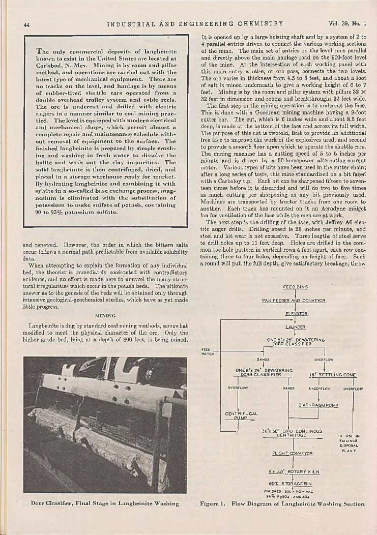
44 I N D U S T R I A L A N D E N G I N E E R I N G C H E M I S T R Y Vol. 39, No. 1
T h e only commercial deposits o f langbcinitc known to exist in the United States are located at Carlsbad, N. Mcx. Mining is by room and pillar method, and operations are carried out with the latest type o f mechanical equipment. There arc no tracks on the level, and haulage is by means o f rubber-tired shuttle cars operated from a double overhead trolley system and cable reels. The ore is undercut and drilled with electric augers in a manner similar to coal mining practice. The level is equipped with modern electrical and mechanical shops, which permit almost a complete repair and maintenance schedule without removal o f equipment to the surface. The finished langbcinitc is prepared by simple crushing and washing in fresh water to dissolve the halite and wash out the clay impurities. The solid langbeinite is then centrifuged, dried, and placed in a storage warehouse ready for market. By hydrating langbcinitc and combining it with sylvite in a so-called base exchange process, magnesium is eliminated with the substitution of potassium to make sulfate of potash, containing 90 to 95% potassium sulfate.
and renewed. However, the order in which the bittern salts occur follows a normal path predictable from available solubility data.
When attempting to explain the formation of any individual bed, the theorist' is immediately confronted with contradictory evidence, and no effort is made here to unravel the many structural irregularities which occur in the potash beds. The ultimate answer as to the genesis of the beds will be obtained only through intensive geological-geochemical studies, which have as yet made little progress.
M IN IN G
Langbeinite is dug by standard coal mining methods, somewhat modified to meet the physical character of the ore. Only the higher grade bed, lying at a depth of 800 feet, is being mined.
It is opened up by a large hoisting shaft and by a system of 2 to 4 parallel entries driven to connect the various working sections of the mine. The main set of entries on the level runs parallel and directly above the main haulage road on the 900-foot level of the mine. At the intersection of each working panel with this main entry a raise, or ore pass, connects the two levels. The ore varies in thickness from 4.5 to 6 feet, and about a foot of salt is mined underneath to give a working height of 6 to 7 feet. Mining is by the room and pillar system with pillars 32 X 32 feet in dimension and rooms and breakthroughs 32 feet wide.
The first step in the mining operation is to undercut the face. This is done with a Goodman mining machine having a 9-foot cutter bar. The cut, which is 6 inches wide and about 8.5 feet deep, is made at the bottom of the face and across its full width. The purpose of this cut is twofold, first to provide an additional free face to improve the work of the explosives used, and second to provide a smooth floor upon which to operate the shuttle cars. The mining machine has a cutting speed of 5 to 6 inches per minute and is driven by a 50-horsepower alternating-current motor. Various types of bits have been used in the cutter chain; after a long series of tests, this mine standardized on a bit faced with a Carboloy tip. Each bit can be sharpened fifteen to seventeen times before it is discarded and will do two to five times as much cutting per sharpening as any bit previously used. Machines are transported by tractor trucks from one room to another. Each truck has mounted on it an Aerodyne midget fan for ventilation of the face while the men are at work.
The next step is the drilling of the face, with Jeffrey A6 electric auger drills. Drilling speed is 28 inches per minute, and steel and bit wear is not excessive. Three lengths of steel serve to drill holes up to 11 feet deep. Holes are drilled in the common toe-hole pattern in vertical rows 4 feet apart, each row containing three to four holes, depending on height of face. Such a round will pull the full depth, give satisfactory breakage, throw
F E E D B IN S
n r ~PAN FEEDER AND CONVEYOR
IELEVATOR
LAUNDER
~ r ~O N E 8 * x 2 5 ' DEW ATERING
DORR C L A S S IF IE R
SANDS
IO N E 8 'x 2 5 ' DEWATERING
DORR C L A S S IF IE R 1 8 ' S E T T L IN G CONE
C E N T R IF U G A L PUMP
UNDERFLOW
D IAPHRAGM PUMP
3 6 x 5 0 BIRD CO NT IN O U S C EN TR IFU G E
FLIGHT CONVEYOR
TO USE IN TAILIN GS DISPOSAL
P L A N T
Dorr Classifier, Final Stage in Langbeinite Washing
5fx 4 0 * RO TARY K IL Nj60T. ST O R A G E BIN
FINISHED S U L - PO - MAC » 6 % K2 S0 4 . 2 M CS0 4
Figure 1. Flow Diagram of Langbeinite Washing Section

January 1947 I N D U S T R I A L A N D E N G I N E E R I N G C H E M I S T R Y 45
Raymond Pulverizer Preparing Langbein ite for Base Exchange
They are electrically driven through a trailing cable connected with a junction box, which is kept within a short distance of the working faces. The current is 220 volts, alternating current. The Joy machine can load out boulders that weigh as much as 1500 pounds; with a good face of broken ore and a plentiful supply of cars to serve it, a mucking rate of 150 tons per hour can be maintained.
Haulage on this level is entirely by rubber-tired shuttle cars, which operate on a double overhead trolley. This is the first installation of its kind in a nonmetallic mine. The first cars used were the 42D, holding 7 tons of broken ore. Later the 60D- type cars holding 10 tons were introduced. The cars are loaded by a Joy loader and haul the ore to one of the raises; there the ore is discharged by a conveyor in the bottom of the car. Hauls as long as 3000 feet have been made by these cars with remarkably high efficiencies, but best practice is to keep the haul length down so that the loader can operate continuously. Under these circumstances the material handled on the level will average 30 tons per man-shift.
In mining langbeinite, 15 to 20% of the material is classed as waste and left in the mine. This material is loaded onto shuttle cars by Joy loaders and transported to an abandoned part of the mine, where it is dumped in front of a second loader which stacks it in the face over the tail conveyer.
The ore is drawn from a 800-foot level through raises into mine cars on the 900-foot level, and is hauled to the shaft station where it is crushed in a Jeffrey 56-inch single-roll crusher to a maximum of 5 inches in size. It is then passed through storage bins to an automatic skip loader into the hoisting skips for transfer to surface and the treatment plant.
the ore away from the rib, and leave little or no overhang in the face. Langbeinite is so hard that it was drilled with wet jack- hammer-type drills at first. This was unsatisfactory because of solution of salt in the water used and the attendant danger of short circuits. Experimental work was done on alloy-tipped bits used with the Jeffrey auger drill; after nearly a year of work Carboloy-tipped bits were adopted for all drilling at a substantial saving in cost.
Much care has to be exercised in spacing and pointing holes, but after some practice the drillers become proficient. General practice is for the face boss or shift boss to locate each one of the holes and the position of the post by actual measurement.
Blasting is done at the end of each shift with primers which are assembled underground. The shot firer hauls powder and primer from the underground magazines to the faces in insulated boxes. Holes are fired electrically, and each round is connected in series. The shooting circuit is 220 volts of alternating current; it is taken off the transformer serving the section with power, but through a separate blasting line having locked switch boxes. Both Du Pont and Hercules powders are used; the Du Pont is extra D, 40% volume strength, and the Hercules powder is Hercomite 4X, 40% volume strength. Primers are made up with unperforated sticks of powder, all other powder being perforated for better tamping in the hole. Blasting caps are No. 6, and delays through No. 4 are used on this level of the mine. Powder consumption is 0.6 pound per ton of langbeinite ore.
The ore and waste are loaded by Joy 11-BU caterpillar- mounted conveyor-type machines. These machines have universal application, and can load in narrow' or wide headings.

46 I N D U S T R I A L A N D E N G I N E E R I N G C H E M I S T R Y Vol. 39, No. I
WASH T I M E - Ml NUTES
Figure 2. Analysis o f Solid Phase during Travel through Wash Section
R E F IN IN G
The beneficiation of langbeinite ore does not present a serious problem. This mine has been successful in the development of an efficient fresh-water washing process in which the chloride gangue salts are dissolved away and leave residual langbeinite. Although langbeinite is the most soluble salt in the system under discussion, the rate at which it dissolves is very slow. This slow rate, coupled with the relatively fast rate for the gangue salts, furnishes the basis for the wash process.
Since langbeinite is a soluble salt, the extraction efficiency in any fresh-water washing process is a function of the rapidity with which the wash is accomplished. The salt content of the rejected wash water is also a function of processing time, and, therefore, optimum performance is obtained only after a delicate balance is reached between water consumption, equipment capacity, and extraction efficiency.
This mine utilizes a continuous countercurrent washer, which gives maximum solution of the gangue salts in minimum contact time. Briefly this process consists of the following steps: Mine- run ore is dry ground by Jeffrey hammer mills operating in closed circuit with vibrating screens. The crushed product has the following average screen analysis:
Cumulative CumulativeMesh % Retained Mesh % Reta
4 0 20 556 2 28 678 12 80 90
10 25 200 9714 40 - 2 0 0 3
The crushed ore is then introduced into the wash section proper, which consists of 140 feet of open launder discharging into the first of two Dorr dewatering classifiers operating in series. The feed water is added to the second classifier with the sands from the first unit. The overflow from the second classifier is pumped to the feed launder, where it travels to the first classifier with the new feed. The overflow from this classifier is the spent liquor and is rejected as waste after a settling operation for removal of suspended fines. The liquor rejected
from the washer runs consistently above 20% in sodium chloride, whereas the residual solid phase analyzes 96 to 98% Iang- beinite. The solids are centrifuged and kiln-dried to become finished products. The washing section as outlined is shown on the flow diagram (Figure 1).
The results being obtained with the countercurrent washer are illustrated graphically in Figures 2 and 3. Figure 2 shows the grade of the solid phase in its travel through the wash section; Figure 3, the loss in recovery due to the dissolution of langbeinite. The data for these curves were taken during treatment of an ore analyzing 40% langbeinite and rejection of a liquor containing 22% sodium chloride.
Langbeinite production has risen from approximately 200 tons per day in 1941 to a current daily tonnage of 500. Of this amount, approximately 225 tons are consumed in the manufacture of potassium sulfate, and 275 tons are sold under the name Sul-Po-Mag.
P O T A SSIU M SU L F A T E SECTION
In the potassium sulfate or base exchange section langbeinite is reacted with sylvite and water to produce potassium sulfate, of a minimum grade of 90% KjSCL, and a waste liquor rich in magnesium chloride. The process involves the reaction of liquid and solid phases in the reciprocal salt pair system magnesium chloride-potassium sulfate-water. The phase reactions are complicated and can be thoroughly understood ojily in the light of certain solubility data. Solubility data on this system have been obtained independently by d’Ans (1), van’t Hoff (2), and others, and check within reasonable limits.
TRAVEL THROUGHo u S E C O N D C L A S S I -— Id 6.0 TRAVEL THROUGH FI ERDCId
u_2 LAU N D E R AND F IRST
CL C LA SS I Fl ERo o _Id Id> z
<o h 4.0 _ y /¡0 oÛ o
u)u >- 'HZ 2u03
uCO 2.0---- /O o y
z z< <-J -Ju. u.o o / i l l I ItOIO 0.0 1 I 1 1 12 2< <oc 0.0 2 . 0 4 .0 6.05 o W A S H T I M E - M IN U T E S
Figure 3. Processing Loss Resulting from Dissolution o f Langbeinite
The base exchange process is a two-step batch operation. In the first, referred to as the hydration step, the finely ground langbeinite is agitated with potassium sulfate mother liquor to produce schoenite (K2S0(.MgS0<.6H-0) or leonite (KiSO,.- MgS04.4II20), depending upon temperature, and a waste liquor of high magnesium chloride content. In the second step, filtered schoenite or leonite is agitated with sylvite and water to produce potassium sulfate as a solid and a mother liquor for use in the preceding step.
The essential reactions, although possible in one step, are purposely split so as to yield a higher potassium recovery. In the two-step process the principal reactions are believed to progress as follows:2(KjSO,.2MgSOO + 2ICC1 + 13ILO — >
3(K*S04.MgS0<.6H20) + MgCl, (1)3(K2S0(.MgS0,.6H20) + 6KC1 — >
6KjSO( + 3MgCl2 + 18H20 (2)

January 1947
SYLV ITE
TJEFFREYVIBRATOR
t
WATER LANGBEINITEK ;> S < V 2 M G S0 4
M EA SU REO
STORAGE BIN JS Ç A L £
C EN TR IFUG ALPUMP
eO% MURIATE TO STO RA G E
RAYMOND PU LVER IZER-------------f
SCALE
—F * ----------4 HYDRATION T A N K S W ITH TURBO AG ITATORS--------- j
f.FN T R IFU G A L PU M P
BIRD CONTINUOUS CEN TR IFU G ALS
U L R E J E C T LIQUOR
L E O N IT E C A K E K j S 0 4 - MG S 0 4 - 4 H j O
n .IG H T CONVEYOR
3 R EA C T IO N T A N K S W ITH TURBO AG ITATORS ?
C.FNTRIFUGAL PUMP
T H IC KEN ER1 I
U N D ER FLO W O V ERFLO W
OLIVER F IL T E R CENTRIFUGA!.. PUMP
A R C A N IT E C A K E k 2 s o 4
ROTARY K ILN
M O TH ER LIQ U O R
F IN IS H E D P O T A S S IU M S U L P H A T E
9 0 % K 2 S ° *
Figure 4. Base Exchange Flow Diagram
Reaction 1 (hydration step) will proceed to much higher magnesium chloride and lower potassium chloride concentrations than will the second (reaction step). In this system potassium sulfate is stable only at relatively low concentrations of magnesium chloride accompanied by high concentrations of potassium chloride. Reaction 2 therefore furnishes an ideal liquor for the hydration of langbeinite.
The extent to which each of the reactions progresses in a sodium-free system is illustrated in a comparison of typical mother and waste liquors at 25° C.:
ceases in favor of the double salt, glaserite [KsNa(SO<)i]. The following analysis of the mother liquor reflects the maximum tolerance of sodium in production of potassium sulfate at 25° C. The stable solid phases are glaserite, sylvite, schoenite, and potassium sulfate.
M oles/1000 Moles W ater
M gCl.MgSO.KiCliNaiCltHiO
15.75 10.023.75
9 .25 1000
Per Cent
5.924 .75
13.974.27
71.09
The most outstanding of the variables influencing yields in the base exchange is temperature. The solubility of potassium rises rapidly with any increase in operating temperature, and, consequently, yields suffer. 1 he extent to which temperature influences recovery is seen in the fact that an increase in operating temperature of 25° C., or a change from 25° to 50° C-, results in a decrease in yieldof approximately 10%.
The optimum operating temperature in the base exchange is' believed to be 25 C. Operation below this temperature would not only introduce cooling costs but would also impair reaction rates. The best results thus far obtained in the base exchange process show a yield of potassium sulfate, equivalent to 73% of the total input. Available
solubility data indicate these results to be approximately 90% of the possible yields in operation at 25° C.
L IT E R A T U R E C ITED
(1) d ’Ans, J., “ Dio Losungsgleichgcwichte der Systeme der Salzeozeanischer Salzablagcrungen", Berlin, 1933.
(2) Hoff, J. H. van’t, “ Zur Bildung der ozeanischen Salzablager-ungon” , Berlin, 1905.
P r e s e n t e d before the Division of Fertilizer Chemistry at tho 110th Meeting of the A m e r i c a n C h e m i c a l S o c i e t y , Chicago, 111.
Stable Solid Phases
MgCli, % KC1, % MgSO., % HzO, %
M other Liquor Schoenite, KiSO., KC1
7.9S14.87
5 .2871.87
In the base exchange flow (Figure 4) the reactions progress so slowly that careful selection of equipment is necessary to keep processing time within practical limits. Raymond mills are used for the reduction of langbeinite. When the langbeinite is introduced into the hydration step, it analyzes 98% -200 mesh. All slurry tanks are equipped with Turbo agitators for maximum intensity of agitation. Although the sylvite ia more rapidly dissolved than langbeinite, it must also be kept within certain definite size limits to prevent interference with the rapidity of reaction.
The presence of sodium in the base exchange system quickly impairs results; beyond certain definite concentrations of sodium in the reaction step the precipitation of potassium sulfate Dryer for Langbeinite
Waste Liquor Schoenite
14.82 9 .84 5.26
70.08
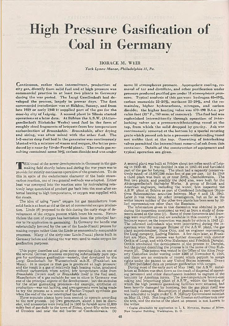
H igh P ressu re Gasification of Coal in G erm any
HORACE M. WEIRYork Lynne Manor, Philadelphia 31, Pa.
Continuous, rather than intermittent, production of city gas, directly from solid fuel and at high pressure was commercial practice in at least two plants in Germany ■during the war period. The Lurgi Gesellschaft had developed the process, largely in prewar days. The first commercial installation was at Bohlen, Saxony, and from late 1939 or early 1940 it supplied part o f the gas for the near-by city o f Leipzig. A second plant in Silesia started operations at a later date. At Bohlen the A .S .W . (Akticn- gcscllschaft Sachsiche Werke) used fuel in the form of roughly sized fragments of briquets from low temperature carbonization of Braunkohle. Braunkohle, after drying and sizing, was often mixed with the other fuel. The1—2-meter deep fuel bed in the generator was continuously blasted with a mixture o f steam and oxygen, the latter produced by a near-by Linde-Frankl plant. The crude gas resulting contained some 30% carbon dioxide and was under
some 115 atmospheres pressure. Appropriate cooling, removal of tar and distillate, and other purification under pressure produced purified gas under 18 atmospheres pressure. Typical analysis of this gas was: hydrogen 48-49% , carbon monoxide 22-24% , methane 23-29% , and the remainder, higher hydrocarbons, nitrogen, and carbon dioxide; the higher heating value was 470-490 B .t.u . per cubic foot (32 ° F., 760 m m . of mercury). The fuel bed was replenished intermittently through operation of interlocking valves on a pressure-withstanding vessel at the top, from which the solid dropped by gravity. Ash was continuously removed at the bottom by a special rotating grate which passed ash into a pressure-withstanding vessel not unlike that at the top. Operating of interlocking valves permitted the intermittent removal of ash from this container. Details of the construction of equipment and typical operation are given.
THE trend of the newer developments in Germany in the gas- making field shortly before and during the war years was to
provide for strictly continuous operation of the generators. To do this in spite of the endothermic character of the basic steam- carbon reaction, one of two general methods was adopted. Either heat was conveyed into the reaction zone by recirculating relatively large quantities of product gas back into the zone after external heating to high temperatures, or oxygen was supplied with the steam.
The idea of using "pure” oxygen for gas manufacture from solid fuels is at least as old as the art of commercial oxygen production. Linde ([6) proposed to do this during the early stage of development of the oxygen process which bears his name. Nevertheless the cost of oxygen has heretofore been the principal barrier to its application in gasmaking. In Germany the hurdle was substantially lowered by the use of the Linde-Frankl process for making oxygen rather than the Linde or economically comparable processes. Many of the sixty-nine Linde-Frankl plants built in Germany before and during the war were used to make oxygen for gasification purposes.
This paper describes and gives some operating data on one of the several German processes employing substantially pure oxy-
£en for continuous gasification—namely, that developed by the iurgi Gesellschaft für Wärmetechnik m.b.H. (Frankfurt am Main). It is unique in that gas is generated at high pressure:
and the result is a gas of relatively high heating value, produced without carburetion when active, low temperature coke from Braunkohle (brown coal) or Braunkohle itself is the fuel used. Manufacture of a gas suitable for use in cities in Germany was one of the principal objects of the development; but the stimulus for the other gasmaking processes—for example, synthetic oil production—was not lacking, and arrangements were being made to try the process as a source of Fischer-Tropsch synthesis gas when the end of the war interrupted the effort.
Three separate plants have been erected to operate according to the new process, (a) Two generators, about 4 feet in diameter, and accessories were installed in 1936 to furnish some 35,000 cubic feet of gas daily to the town of Zittau, about fifty miles west of Dresden and near the old border of Czechoslovakia. (6)
A second plant was built at Bohlen about ten miles south of Leipzig in 1939-40. It was doubled in size in 1943-44 and furnished part of the gas for Leipzig. The plant had a capacity (conservatively rated) of 15,000,000 cubic feet of gas per day. (c) In 1944 a third plant was built at or near Brüx, Czechoslovakia. The first two plants, and possibly the third also, were built for the Aktiengesellschaft Sächsiche Werke. A group of British and American engineers, including the writer, first inspected the A.S.W. plant at Böhlen as part of Combined Intelligence Objectives Subcommittee activities between May 4 and 13, 1945. Later it was visited by other investigators, but as far as the writer knows neither of the other two plants has been seen by Allied representatives other than the Russians.
The information given in this discussion was obtained in part during the inspection mentioned as well as from a study of documents siezed at the time (1). Some of these documents and drawings were microfilmed and are available in this country1. A preliminary report on the inspection was made by others in 1945 (4)- The informed individuals who were interviewed during the inspection were the manager Böhme of the A.S.W. plant, the gas plant superintendent, Hans Otto, and an engineer representing the Lurgi company, Ludwig Rückes. A few days later, at Frankfurt am Main, the process was further discussed with director Oetkin of Lurgi, and with Otto Hubmann and Friedrich Danulat. Oetkin attributed the development of the process to Danulat, but the patent describing the process is in the name of Otto Hubmann (5). This patent was vested in the Office of the Alien Property Custodian under vesting order 4269 of November 6, 1944, and there are no contracts of record which purport to assign rights under the patent to any United States interests. Drawe(S) first published data on pressure gasification with oxygen.
During most of the early part of May 1945, the A.S.W. installation at Böhlen was shut down as the result of dispersal of operating personnel and other disturbances incident to capture of the territory by American forces. The low-tornperature brown-coal coking and briquetting plant of A.S.W., within the borders of which the high pressure gasmaking facilities were situated, had been heavily damaged by bombing, but the gas plant itself was not badly damaged. Resumption of gasmaking at part capacity was scheduled to begin under U. S. Military Government sanction on May 13,1945. Not long after, the Russian authorities took over the area, and the status of the plant at present is not known to the writer.
1 Copies obtainable b y application to L . L. Newman, Bureau of Mines, New Interior Building, W ashington, D . C.

January 1947 I N D U S T R I A L A N D E N G I N E E R I N G C H E M I S T R Y 49
D E SCR IPTIO N O F PL A N T AND PR O C E SS
The heart of the gasmaking plant at Bohlen was the generator house; this building was about 100 feet in height, including overhead fuel bunkers, and enclosed ten generator units, each of approximately 8.25 feet i.d. These units produced gas at a nominal pressure of 20 atmospheres absolute. Five of the generators were installed in 1940, the other five in 1944. The newer generators were not fundamentally different from the older ones but did have improvements in charging hoppers, grate drive, and scrapers.
When operating on the normal fuel, a mixture of 3-10 mm. brown-coal coke and local brown coal itself, the plant had a rated annual capacity equivalent to 15 million cubic feet of gas at normal temperature and pressure (N.T.P.) per day. Each generator could produce as much as 105,000 cubic feet of gas per hour but was normally run to make about 85,000 cubic feet per hour (N.T.P.) of gas having a higher heating value of 470 B.t.u. per cubic foot (N.T.P.).
Essentially the high pressure gasification process involves continuously blowing a bed of hot fuel with steam, superheated to 950-1000° F., and 95% purity oxygen; the latter is introduced cold and thoroughly admixed 'with the steam to give about 10% by volume of oxygen before passing upward through the bed. The temperature of the bed is regulated by the proportion of oxygen used and is maintained at 1900-2000 ° F. or higher, if the softening point of the ash permits it.The desired high pressure—at Bohlen about 20 atmospheres absolute—is heldby pressure regulation on the gas after it cooled and completely purified.
Figure 1 reproduces one of the drawings obtained at the Bohlen plant and shows generator B together with immediate accessories. Each generator is about 16 feet high in the cylindrical section and is provided with hemispherical ends, top and bottom. The internal diameter in the fuel bed zone is about 8.25 feet. Fuel hopper A and ash hopper C are above and below the generator itself. These cylindrical vessels are about 10 feet high and 5.2 and 4.2 feet in diameter, respectively, in the newer design. These devices serve to replenish fuel and remove asl without interrupting the gasmaking operation and disturbing the pressure.
The operating procedure is as follows: The mixed fuel, sized 3-10 mm., flows by gravity through the open valve at the top of pressure vessel or hopper A. The foot valve at the bottom is closed during charging and holds the pressure of the generator body. When A is full enough, the top valve is closed and crude gas is bled in slowly until the pressure in A equals that in the generator body below. The foot valve is then opened, and the fuel descends through the central delivery pipe or skirt at a rate corresponding to the tendency of the level of the fuel bed to subside. When the level of fuel from hopper A is below the foot valve, this valve is closed, the gas in A is bled to a relief holder, and the vessel is scavenged with nitrogen.' The vessel is then opened for more fuel by operation of the top valve. Vessel A is sized in
CRUDE C A S PRODUCT
TO C O O L IN G TOWER
C O O L IN CWATER
Figure 1. Flow Diagram of Gas Producer
respect to the newer generators, so that refilling with fuel must be done about every 40 minutes at normal production rates.
In operation the bottom of the intense reaction zone is somewhat above the lower limit of the refractory-lined portion of generator B. Below that limit, fine sandlike ash collects to form a layer some 18-24 inches deep. This ash layer is supported on a grate made of 25% chrome steel plate, formed in three segments and bolted together to make a conical element, which is rotated by a shaft from below. The drive consists of a motor, reduction gear, and adjustable ratchet, and the shaft passes through a pressure-tight stuffing box' to the grate element. The grate and shaft bear an even closer resemblance to a giant mushroom and stem than is evident from Figure 1. The slow rotation of the grate moves ash to the periphery of the mushroom head, and three re- .placcable plow blades underneath the bottom side of the mushroom head move the ash toward and into the ash pipe opening underneath the grate and to one side of the central axis. The shaft which rotates the grate and plows is hollow and serves to lead the stcam-oxygen mixture to orifices under the canopylike protection of the grate. The gasifying mixture passes through the ash bed and into the fuel bed in excellent distribution because of the movement of the ash and its finely divided form.
The ash falls through the ash pipe and into the pressure vessel or hopper, C, beneath and to one side of the axis of the generator body. When this vessel is nearly full, the top valve is closed, the

50 I N D U S T R I A L A N D E N G I N E E R I N G C H E M I S T R Y Vol. 39, No. 1
pressure of steam and oxygen is relieved to atmosphere, and the discharge of the ash to sluiceway II is effected by opening the bottom valve. In order to return the ash receiver to its function, an obvious sequence of operations is then followed-—namely, closing the bottom valve, repressuring the chamber writh steam, and opening the top valve.
The crude product gas leaves the top of the generator and passes into pipe I? at a temperature substantially reduced from that of the active fuel bed, which latter is in the neighborhood of 2000 0 F. The exact temperature of the exit gas depends on the amount of water and oil distilled from the upper layer of fresh fuel as the gases pass through it. With the fuel used at Bohlen, the exit gas temperature was about 575° F. Since some precipitation of hydrocarbons occurs on the top courses of the refractory lining and the steel shell above, a scraping mechanism was provided to eliminate the accumulation of residue and coke from these surfaces. The device consisted of steel scraper blades which could be made to sweep close to the walls where coke might accumulate. The scrapers were attached to a horizontal ring gear carried by crude bearings, which were supported by the central fresh fuel delivery cylinder. Shaft K was carried through a stuffing box into the generator body and it was provided with a pinion gear which engaged the ring gear so that the scrapers could be moved at will. Actually, hand operation of the scraper blades for a period of a few minutes every two to three hours was all that was required to keep the walls satisfactorily free of coke.
Important from the structural standpoint is the fact that the entire generator body, including top and bottom hemispherical heads, is provided with a water jacket. Pipes at top and bottom of this jacket connect suitably into steam-separating drum D,
from which the steam generated is led directly into the product gas stream near its discharge from the generator. Only a small amount of steam is made because of the poor heat transfer through the refractory lining of the reaction zone, but that steam suffices to keep the pressure on the two sides of the inner steel wall almost exactly balanced and, at the same time, keeps this wall substantially at the temperature of saturated steam under that pressure.
G E N ER A TO R AND A CC E SSO R IES
The gas leaving the generator at E is contacted with a spray of recirculated water. Separation of the gas and water is effected in F, which has been tested in several designs for the best removal of tar and dust. The separated water containing phenols is pumped by centrifugal pump J through heat exchanger G (which preheats boiler feeds water) and back to the spray nozzles. Appropriate withdrawal of liquid and addition of fresh water prevents build-up in the circulating system.
The flow' diagram of Figure 2 shows the generator 6 together wdth auxiliaries, including mainly the purification system used for the crude gas. Although the legend on the diagram makes it substantially self-explanatory, the more or less conventional solution of the purification problem may be described briefly. The wrater spray device and circulation heat exchanger are not showm in Figure 2, but these should be considered as inserted between the gas exit from generator b and the first of the tw'O tubular gas coolers c. The two latter coolers bring the temperature of the gas down to a reasonable approach to the cooling water temperature, and thus precipitate tar and light oils w-hich are separated before
а . S team superheaterб . G en erator c . C oolerd O il w asher fo r gas
Figure 2. Flow Diagram for Pressure Gasification of Fuels (5)
e . W ater w asher for gasf . P u m p turb ineg. A eration towerh. F inal su lfu r rem oval
1. S team2. Oxygen3. Fuel 4. Ash 5. C rude gas
6. T a r an d oils7. “ F a t” o il8. C ircu la tin g water9. Purified gas

January 1947 I N D U S T R I A L A N D E N G I N E E R I N G C H E M I S T R Y
the cooled gas passes to countercurrent oil scrubbing in tower d. The stripping of light vapors dissolved in the wash oil is conventional and not indicated in Figure 2. Stripped gas from tower d passes to countercurrent water washing in e, which, at Bohlen, consisted of four Raschig-ring- packed towers operated in parallel. Most of the 30% or so of carbon dioxide in the gas is removed in this step together with almost all of the hydrogen sulfide. A recirculation system is used for the water in this water-washing step. Accordingly the foul water from the base of e is led through turbine /, which is directly connected with the charge pump and driving motor so that the latter is required to supply only the difference between the recovered power and that necessary to pump the water against the tower pressure (approximately 20 atmospheres). The fuel constituents in the gas released by pressure drop through the turbine give it a fuel value of the order of producer gas though the gas is largely carbon dioxide and hydrogen sulfide. Consequently it is recovered by Bohlen and used as part of the fuel for process steam superheater a.
To complete the conditioning of the water for re-use as purification agent, it is aerated by downward flow through four slat-filled towers in parallel, indicated by single tower g. Fans supply the air required, and the air and gas stream passing from the top of the towers is led to near-by boilerhouse stacks in order to avoid hydrogen sulfide nuisance.
Returning to a consideration of the main stream of gas leaving the top of water washer e, it is necessary to mention the final purification step carried out in iron oxide beds h. At Bohlen the gas entering the step had a hydrogen sulfide content of the order of 300 parts per million and that leaving, less than 1 part per million. Four towers, each 5 feet in diameter and 25 feet high, and each holding ten layers of Luxmasse (active iron oxide) were provided for purification. In normal operation one of these towers was being recharged while three were in series on the gas stream. Internal arrangements in each tower were such that the gas flow was equally divided between the ten layers, each of which was about 18 inches deep.
T a b le I. E f f e c t o f F u e l U s e d o n G a s (a n d T a r ) P r o d u c t i o n in P r e s s u r e G a s i f i c a t i o n
(Pressure 20-30 atmosphere gage; basis, 1 long ton “ pure” carbon)Fuel Gas“ , Cu. Ft. Tar, %
58,500
TheCoal
Lean coal Brown coal
Rheinland LausitzCentral Germany
“ Calculated to 32° F., 760 mm. Hg.
48,10040.00034.000
T a b l e II. O x y g e n R e q u i r e m e n t s in G a s i f i c a t i o nCu. F t./M illion B.t.u.Process
Producer gas (Oi in air) Water gas (Oj in air blow) Oxygen gasification
Atm. pressure Bituminous coal
20 atm.30 atm.
Brown coal, 20 atm.
1070770
640
435375305
Upper Picture Shows the Top of the Pressure Hopper for the Lower, the Top o f the Pressure Gas Generators
Gas leaving the oxide purification step of the process is ready for distribution and passes into delivery lines through a pressure controller which holds the desired back pressure on all of the equipment described. The pressure drop from generator to control valve at normal production rates is of the order of 1 atmosphere.
To make the discussion of the high-pressure gas-producing process complete, it would be necessary to describe the Linde-Frankl oxygen-producing equipment as well. This is a method which has been used to date to supply all of the plants with necessary oxygen, and the investment required, operating costs, and personnel required are important considerations in the over-all picture of the gasmaking process. A detailed description has already been published (7).
Briefly stated, the Linde-Frankl process involves the conventional distillation separation between liquid oxygen and nitrogen in which two fractionating columns are used in heat- and material- exchange relationship, although one is at 4-5 atmospheres pressure, the other at substantially atmospheric pressure. The Frankl modification of the Linde process makes use of recuperators in place of tubular heat exchange equipment to attain the low temperature for liquid-phase separation. The savings in pressure drop through the system effected by this substitution, together with savings in removal of impurities from air, are reflected in substantial reduction in cost of oxygen for those applications,

52 I N D U S T R I A L A N D E N G I N E E R I N G C H E M I S T R Y Vol. 39, No. 1
Gasification Pressure, AtmospheresFigure 3. Composition o f Crude Gas as a F unction
o f Pressure
like gasification, in which minor percentage impurities are not important.
The oxygen-producing plant at Bohlen had a capacity more than double the normal requirement and consisted of four separate units with a total producing capacity of about 210,000 cubic feet of free oxygen per hour at atmospheric pressure. Compressors to raise the oxygen pressure to 23 atmospheres were situated in the separate building which housed the oxygen-producing equipment. Oxygen at this pressure, having 95% or higher purity, was introduced directly into the superheated steam stream at the gashouse generators.
The equipment installed at Bohlen required the expenditure of 32-35 kilowatt-hours per 1000 cubic feet of oxygen (N.T.P.) compressed to 23 atmospheres, which was definitely higher than normal because of inefficient rotors in the turbo compressors handling all of the process air used. New rotors were to have been installed, and it was hoped to reduce the power consumption to about 28.5 kilowatt-hours. This is, however, also higher than can be attained and 25 kilowatt-hours per 1000 cubic feet of oxygen (N.T.P.) compressed to 23 atmospheres may be more typical for large-scale Linde-Frankl installations.
The stream of about 95% nitrogen also made in the plant was used to good advantage in the scavenging operations at the gas plant and in the fuel bunkers to provide an inert atmosphere and lower fire hazard. The nitrogen was also used at various other points in the adjacent A.S.W. carbonization plant. It was understood, however, that the oxygen bore all the costs of manufacture.
I I IG n PR E SSU R E G A SIF IC A T IO N PR O C E SS
The statements made and figures given here have their source either in Lurgi claims for the process or in records obtained at the Bohlen plant. They are believed to represent accurately the true attributes of the process, but the author has had no opportunity to examine the detailed data.
F u e l R e q u i r e m e n t s . It is claimed that all noncoking fuels are physically suitable raw materials, and low grade, finely divided coal is economically the best. The gas which may be obtainable by simple heat decomposition is not important and has little influence on the gas yield or quality, except possibly in slightly increasing the B.t.u. value of the gas. Gas yield is a function of the amount of carbon reacted, and anything which reduces this, such as the distillation of tar from tar-rich fuels, correspondingly reduces the gas yield.
If the reactivity of the fuel is high, it favors the formation of
high B.t.u. gas at lower oxygen consumption. For any given fuel, raising the pressure of the operation increases the B.t.u. content of the product and reduces oxygen consumption. To date it is considered that the practical maximum pressure, on economic and structural grounds, is about 30 atmospheres. Table I shows gas yield as a function of fuel used. Table II shows oxygen required as influenced by both fuel used and pressure of the operation.
-The properties of the fuel which can be handled by the process are indicated by the following details on size characteristics and water, ash, and sulfur content:
Fragments up to 25 mm. can bo handled, but the optimum is2-10 mm. Granules less than 2 mm. cannot be satisfactorily . handled because of low throughput and excessive dust carry-over.
Up to 25% water content can be handled without predrying. Predrying is necessary for higher water contents since the sensible heat in the gas is insufficient to vaporize amounts of water above 25%.
Material with as much as 30% ash by weight can be handled satisfactorily. Ash of low softening point is disadvantageous since the operating temperature must be held below the ash softening point to avoid clinker formation, and temperature reduction involves more steam and oxygen use for the same gas output.
The sulfur content may be quite high without involving excessive purification costs or, indeed, even any substantial increase. This follows because the water washing under pressure, necessary to reduce the carbon dioxide content of the crude gas is sufficient to bring the hydrogen sulfide content to a low figure before the gas passes to the oxide purification step. Naturally the corrosion problem increases with sulfur content and may necessitate higher initial investment than otherwise or, alternately, greater maintenance costs.
N a t u r e o f R e a c t i o n . The usual reactions in gasmaking which lead to the formation of carbon monoxide and hydrogen proceed
T a b l e III. E f f e c t o f F u e l U s e d o n G a s P r o d u c t i o n
Fuel dataLb. gasified/sq. ft ./h r .Size, mm.Composition, % b y wt.
Combustible Water Ash
Tar content, % by wt.H eat value (higher), B .t.u ./lb .
Gas produced (purified)Cu. ft ./sq . ft. generator area/hr. Composition, % by vol.
Methane Hydrogen Carbon monoxide C n H «
NitrogenOxygenCarbon dioxide
DensityHeat value (higher), B .t .u ./cu . ft.
YieldsGas, cu. ft ./lon g ton (combustible) Tar, % of that from analysis
Oxygen used, cu. ft./1000 cu. ft. gas Steam used, lb ./1000 cu. ft. gas
it 32° F. and 760 mm. Hg.) Brown Coal
Middle Bituminous,Lausitz Germany Ruhr
153 + 182 . 63 +2-10 2-10 3-10
67.5 72.5 88.42 7.4 16.9 6 .6
5 .1 10.6 5 .010.2 14.8
10,400 11,700 16,700
1950 2040 1665
22.6 22.9 16.948.7 50.4 52.422.8 2 1.9 27 .8
0 .5 0 .8 0 .3
2 .3 2 .1 1 .50 .13 .0
0 .21.7
0 .11.0
0.448 0.426 0.432480 506 460
40,000 33,000 63,00072.0 84.3
150 147 19868 .5 S1.0 87.0
T a b l e IV. H e a t B a l a n c e f o r P r o c e s s ( f )I n p u t H e a t O u t p u t H e a t
FuelSteam (satd.)
8 9 .9 % Product gas 6 2 .2 %10.1 Product tar 14.3
100.0Losses in process
Gas, sensible heat Steam, superheat, and
16.2
water blowing 5 .4Steam (water jacket) 0 .6Phenols in water 0 .9Combustibles in ash 0 .4
7 6 .5 %
23.5
100.0

January 1947 I N D U S T R I A L A N D E N G I N E E R I N G C H E M I S T R Y 53
under pressure operation, but the minor reaction of methane formation is substantially increased; this accounts for the relatively high B.t.u. value of the gas. Furthermore, the reduction in oxygen requirements shown in Table II is probably due to this cause, since the exothermic heat of methane formation tends to offset the endothermic formation of hydrogen and carbon monoxide from the action of steam on hot carbon.
Figures 3 and 4 show the typical composition of crude gas and purified gas as a function of pressure.' The curves (3) are somewhat idealized and indicate only the major constituents of the gases.
Figure 4 shows the increase of methane formation with pressure, as well as the gradual change in the ratio of hydrogen to carbon monoxide, from about 1.85 at atmospheric pressure to over 2.6 at 20 atmospheres absolute. The right-hand ordinate scale refers to higher heating values; the increase in the heating value of the purified gas with the pressure under which it was formed is entirely due to the increase in methane content, since hydrogen and carbon monoxide have substantially the same higher heat value. Nevertheless, the change in the ratio of hydrogen to carbon monoxide with pressure has some interest where these gases are to be used as reagents, provided the methane content is not specifically harmful to the reaction in question. This feature of the adj ustability of the ratio by pressure change was one of the incentives to the projected use of this pressure gasmaking process for Fischer-Tropscli synthesis of hydrocarbons.
The tar and oil by-products from the process tend to be paraffinic, especially when brown coal from central Germany is the fuel gasified. There is some production of phenols and aromatic hydrocarbons, but the removal of liquids from the fuel seems to be in the nature of a mild cracking distillation. Of the total liquid from brown coal, about 18% is naphtha boiling under 356° F.. There is no evidence that any hydrogenation of the liquids has taken place, and the conditions are not such as to lead us to expect this.
E N G IN EERIN G AND E CO N O M IC A SPE C TS
Gasification under pressure carries with it the possibility of decreasing the dimensions of the equipment roughly in proportion to the volume of the gas handled, as compared to atmospheric pres-
c6
a6
P4
E-j£ ' —s
’fi6
PQ
>top
«
»■aw
T a b l e V. P r o d u c t i o n D a t a ( F e b r u a r y 1944), A.S.W., B o h l e n “
ProductsC ity gas, 1000 cu. ft. 381,000Tar, long tons 1 1 8 5 -Naphtha, long tons 503 +Gas
M ax. day’s product, 1000 cu. ft. 15,100Mean day product, 1000 cu. ft. 13,150Mean product/generator day, 1000 cu. ft ./h r . 85
Fuel and utilities usedLow-temp. coke briquet pieces and Braunkohle long tons as
delivered 17,332Tons, calcd. as “ pure” carbon 11,642Pure oxygen, v o l./vo l. product gas 0 .156Steam, lb./lOOO cu. ft. product gas 85 .3Electricity, kw.-hr./lOOO cu. ft. product gas 9 .3 8W ater, gal./lQOO cu. ft. product gas (exclusive of recircula
tion) 173Yields
Purified gasCu. ft. long ton dry fuel 22,300Cu. ft ./ion g ton pure carbon 32,800
TarGal. total/1000 cu. ft. product gas 1 .68% of Fischer analysis on fuel (% naphtha in tar — 29.8) 72 .7
ProductCrude
gasExpanded
gas
CH< 20.6 14.9(washer «)
5 .3Ha 62.2 35.7 7 .6CO 18.3 12.9 3 .4CnHm 0 .7 0 .8 0 .8HaS 2 .0 3 .8C 0 2 • ¿:8 32.1 7 7 .2Oa 0 .2 0 .2 0 .2Na 1.2 1 .5 1 .8
100.0 100.0 • 100.0H eat units (higher)
B .t.u ./cu . ft. 475 3426 1096Density 0 .463 . . .
a All gas volumes calculated as 32° F. and 760 mm. Hg.6 Calculated from analysis.
Gasification Pressure, Atmospheres Figure 4. Composition and Heating Value of Purified
Gas as a Function of Pressure in the Generator
sure operation. Thus the diameter of the gas-handling elements can be reduced to a value proportional to the square root of the ratio of operating pressure to atmospheric pressure, or, in the case of 26-atmosphere operation, to about 22% of that for atmospheric pressure. The observation applies more exactly to the auxiliaries than it does to the generators themselves, because the reaction per unit volume must be moderated to hold temperatures within the limits dictated by ash softening point, etc.
As a practical matter the fuel-handling capacity of the pressure generator is markedly affected by the nature of the fuel. Danulat (3) gave comparative figures for three different types of fuel; they are shown in Table III as part of rather complete performance data. With the least active fuel (column 3), in comparison to the brown coal, the specific fuel consumption and gas production are lower, as is the heating value of the gas, whereas the oxygen and steam consumption are higher.
Table IV gives what is claimed to be a typical heat balance for the process when central German brown coal and coke is the fuel used. The chief source of heat loss is that of the sensible heat in the gas, including the latent heat of condensation of the water in the gas. The heat balance is taken around the equipment indicated in Figure 2; it does not include the fuel necessary to generate power for the oxygen plant or for the motor drives at the gas plant and purification units.
The data in Table V are taken from a seized document purporting to be the official record of production for the A.S.W. plant at Bohlen during February 1944. The data are similar in all respects to those shown by a record for January 1945, but the earlier figures are given here because there were fewer air raid interruptions at that time. The data are self-explanatory, but attention is redirected to the remarks made earlier in respect to the known inefficiency of compressors at the oxygen plant. If 25 rather than about 35 kilowatt-hours 1000 per cubic feet of oxygen is more nearly a typical figure for power consumed to make oxygen*

54 I N D U S T R I A L A N D E N G I N E E R I N G C H E M I S T R Y Vol. 39, No. 1
T a b l e VI. C o s t o f G a s M a n u f a c t u r e d a t A.S.W., B ö h l e n ( in M a r k s )
Element of costFuel per long ton 6 .50Oxygen per 1000 cu. ft. 0 .78Steam per long ton 2 .25Electricity per kw.-hr. 0.011W ater per long ton 0 .006Labor (operating av.), per hr. 0 .9 5
Cost of gas (at 18.5 atm. abs.) per 1000 cu. ft.Labor“ 0 .145Maintenance 0 .145Fuel, utilities and capital charge 1.05
Gross total 1 .34B y-product tar credit 0 .50
Net cost 0 .84° This is a crude estimate from data of Table V and does not differentiate
between foreign (“ slave’ ') labor and German workers.
then the figure of 9.38 kilowatt-hours total (Table V) should be reduced to 7.9 to have a value more characteristic of the process itself.
The total operating personnel, including those in the oxygen plant but excluding steam and electric production, was thirteen salaried and 188 hourly workers. To operate the gas plant generator house alone at Bohlen, three men and a superintendent or foreman were used in the control room on each shift. The instruments provided there for each generator were carbon dioxide recorder, steam and oxygen flowmeters, pressure recorder, and five-point temperature indicator. At the generators four men were used on each shift to operate the pressure hoppers for fuel and ash, and one man per shift was used for bunkering the fuel.
* The writer did not learn how many workers were employed at the steam superheater and in the purification operations, or in the oxygen plant alone.
C O ST O F G A SM A K IN G
The figures obtained with respect to the cost of gas by the pressure process are of questionable value, since they refer to the particular brown coal available at the Bohlen plant and to the special labor conditions obtaining in Germany during the war; also, discrepancies might exist as a result of the formidable difficulty in translating marks into dollars.
At some plants in Germany foreign labor (or “slave” labor) was paid the same as German labor, but there were deductions which lowered the net amount actually received. At other plants this practice did not obtain; it is not known by the writer what the practice was at Bohlen. To emphasize that the figures refer to such conditions and that they have not been carefully analyzed, the items are expressed in marks, although the units employed are in tons and feet. Table VI gives the fragmentary figures.
CON CLU SION S
All of the evidence, including statements of management and operators at the A.S.W. installation at Bohlen, Saxony, leads to the conclusion that the Lurgi oxygen-pressure gasmaking process is a dependable and economic means for producing relatively highB.t.u. gas from the active brown coal available in central Germany. There is sufficient evidence to substantiate the claims that the process is also applicable to many, if not all, other noncoking coal. From the economic standpoint, however, it seems certain that fuel of the brown coal type ranks high, if not highest, in suitability.
Obviously any application of the process to gasmaking in this country would have to be prefaced by a critical study of the fuels available in regions where a market for gas exists. The author is reliably informed that at least one forward-looking group has underwritten a program of this nature and that work on a small scale has recently been initiated.
The gas produced at Bohlen, and apparently that producible from any other fuel without carburetion, is lower in B.t.u. value than the gas now marketed in any large city in the United States. Either carburetion, or blending with relatively large quantities of coke-oven gas or lesser amounts of natural gas, propane, or butane, would presumably be necessary to market the gas for household consumption. There is no record available to the writer of any results of carburetion, but this would seem to be physically feasible by injection of heavy oil into the reaction zone. Feasibility from the economic standpoint would depend on the portion of the oil lost by oxidation and, accordingly, the point of introduction of the oil might be quite critical.
In view of the points discussed, it is not possible now to do more than generalize as to possible applications of the process in this country. Although the cost of oxygen is a factor, the major raw material cost is that of coal. The fact that the gas becomes available from the process under a pressure of about 18-20 atmospheres enlarges the area about any point of gas utilization within which a cheap source of fuel can be sought. The most nearly ideal circumstance would probably be the installation of the generators at the coal mines, where their proximity to the point of consumption would allow piping the gas without any pressure boosting. Elimination of coal transport by water or rail carriers and the use of small size fuel (possibly with high ash and sulfur content) could all contribute to realization of a low price for fuel, without substantial increase of any other item making up the total cost of the gas manufactured.
When the transportation of manufactured gas over considerable distances is under consideration, it would seem that the pressure gas-generation process has particular appeal. To compress manufactured gas to 20 atmospheres pressure, for example, requires about 50% more power than is demanded in the necessary Linde-Frankl oxygen production and subsequent .compression, in order to produce the same volume of gas at 20-atmosphere pressure by the new process. This applies to cases where about 150 cubic feet of oxygen are required for each thousand cubic feet of gas produced, a typical figure for active fuel. The total free volume of air plus oxygen to be handled does not greatly differ from that of the gas, but the major portion of air plus oxygen need only be compressed to about 5.5 atmospheres. Taking this into consideration together with the relatively high density of the air, it is obvious that investment for the compressors and accessories in the oxygen plant would be materially lower than the costs of gas compression units.
A self-contained process for making relatively high B.t.u. gas from low grade fuels without by-products other than some oil poses a set of economic problems entirely different from those met in gasmaking processes now commonly used in this country. Specific and novel rather than general routine considerations will be required to determine the true value of the process for any particular set of conditions. Whatever the ultimate result of such considerations, it will probably be agreed now that the process does present an interesting and stimulating innovation in gasmaking, with substantial promise for future application in present or possibly somewhat modified form.
L IT E R A T U R E C ITE D
(1) Danulat, F., Gas- u. Wasserfach, 76, 541 (1933); 80, 806 (1937);84, 549(1941).
(2) Danulat, F., Mitteilungen aus dem Arbeitsbereich der Metall-gesellschaft, Frankfurt Am Main, Issue 13.
(3) Drawe, R ., Gas- u. Wasserfach, 69, 541 (1926); 76,1013 (1933).(4) Hollings, H., Hopton, G. V., Newman, L. L., Horne, W . A., and
Spivey, E., U. S. Bur. of Mines, C.I.O.S. Rept. XXX-13,Item 30 (Aug. 17, 1945).
(5) Hubmann, Otto, U. S. Patent 2,094,946 (Oct. 5, 1937).(6 ) Linde, German Patent 108,158 (M ay 21, 1898).(7) Weir, H. M., U. S. Dept, of Commerce, O.T.S. Rept. PB-368.
P r e s e n t e d before the Division of Gas and Fuel Chemistry at the 109th Meeting of the A m e r ic a n C h e m ic a l S o c ie t y , Atlantic C ity, N. J ,

Sodium Reduction ofFatty Acid Esters
V. L. HANS LEYE. I. du Pont de Nemours & Co., Inc., Niagara Falls, N. Y.
A.n improved general method has been developed for reducing esters by means o f metallic sodium. Practically quantitative yjelds o f alcohols, based on both sodium and ester, are obtained, especially from fatty acid esters of higher molecular weight. In the classical sodium reduction procedure an excess o f sodium is ordinarily added to a solution o f the ester in ethyl alcohol, which functions both as solvent and as reducing alcohol. The improved method described in this paper uses theoretical amounts o f both sodium and reducing alcohol, and the reaction is carried out in an inert solvent, such as xylene or toluene. The method is especially applicable to the preparation o f unsaturated alcohols not easily made by catalytic hydrogenation. It compares favorably with catalytic hydrogenation o f saturated, higher fatty acid esters because of the simplicity o f operation and equipment. The process can be carried out at ordinary pressure.
SINCE its discovery in 1903 by Bouveault and Blanc {17), the sodium reduction of esters has been a classical method for the preparation of alcohols (1,2,13,15,22,24,25, SO, 41,46,41,45,50).
Little improvement in Bouveault and Blanc’s procedure for carrying out this reduction has been reported in the literature. Therefore, the sodium reduction of an ester is taken to mean, almost without exception, treatment of the ester in absolute ethyl alcohol solution with an excess of sodium added in increments to the boiling alcohol. Recently published procedures for the reduction of ethyl laurate and diethyl sebacate (13,15) include the substitution of n-butyl for absolute ethyl alcohol. Large excesses of both sodium and alcohol have always been necessary. This made the handling of the reaction products difficult, caused low yields on sodium, and tended to increase hazards. Chablay and Haller (23) carried out the sodium reduction of esters in liquid ammonia. Prins (55) employed an ether solution of the ester with acetic acid present. An attempt was made in Germany around 1930 (16) to overcome some of these difficulties by carrying out the reduction in n-butyl alcohol in an autoclave against the back pressure of hydrogen, which formed by direct reaction of sodium with n- butyl alcohol. Although somewhat improved yields were reported, it is doubtful whether the moderate pressures of hydrogen developed had any direct influence on yield.
The method of Bouveault and Blanc has proved very convenient in synthetic organic research; however, it does not lend itself readily to the commercial preparation of alcohols, particularly of higher molecular weight, for several reasons: (a) There is considerable direct reaction of sodium with alcohol to give by-product hydrogen, which results in low sodium reduction efficiency; (b) condensation by-products are formed with resultant low yields based on the ester; (c) ethyl alcohol is required in a large amount and is not easily recovered as absolute alcohol; and (cl) the temperature of boiling ethyl alcohol is somewhat low for rapid and efficient reduction, particularly for esters of higher molecular weight.
During the last ten years more efficient methods of utilizing the reducing power of sodium have been developed in this laboratory. Certain phases of the work have been the subjects of various patents (32, 61, 62). The reduction of sperm oil and coconut oil
was carried to large scale production. The purpose of this article is to describe what this laboratory considers to be the best practice for sodium reduction of carboxylic esters.
M E C H A N ISM O F SODIU M E ST E R R ED U CTIO N
Hydrogen formed by the direct reaction of alcohols with sodium plays no role in this type of reduction (19, 20). Once molecular hydrogen is formed, it bubbles out and is lost. Chemical reduction by sodium proceeds through a series of reactions. Soluble sodium ester kctals are first formed in dilute solution and immediately decomposed by reaction with an alcohol. In the process to be described, the concentration of the alcoholytic or reducing alcohol is kept at a minimum by adding it only as fast as it is used up in the reduction reaction. Furthermore, careful selection of the reducing alcohol enables one to maintain conditions such that sodium ester intermediates are rapidly decomposed with essentially no direct reaction of the reducing alcohol with sodium. Ethyl alcohol, used in the equations now given, will furnish hydrogen atoms as needed, but other less reactive alcohols—for example, secondary, tertiary or even aliphatic primary alcohols of higher molecular weight (56)—will allow greater sodium reduction efficiencies—that is, permit less w'aste of sodium in hydrogen- forming reactions or cause fewer condensation reactions.
The over-all ester reduction reaction can be expressed simply, using ethyl palmitate as an example ester:
0Ethyl
C.sHj.OOCJL + 4Na alcohol ? C,5H31CH2OH + 4C2II6ONa solution Cetyl alcohol Sodium
ethoxide
laJlC Ethyl palmitate
The reaction is quite complex, and may be explained as follows:
0 ONaCiHLi^OCJ-L + 2Na — Ci5H31i —OC2Ii6 (1)
Ethyl palmitateN a
Sodium ester ketal
The existence of sodium ketals has been postulated for a long time (8, 9, 12, 18, 27, 43, 51, 62, 68). When ethyl alcohol or other reducing alcohol is present in solution, the decomposition of the sodium ketal proceeds immediately:
ONa
11C—Cc 15h3,c —o c j l + C2H6OH • An
ONa
C13H31¿ —0
NaSodium ketal
C 2H 6 4- C ; I í5ONa
Sodium derivative of hemiacetal
The sodium derivative of the hemiacetal loses sodium ethoxideand forms cetyl aldehyde:
ONa
C.sHa.b—OC2Hs -I
H
0
C 1SH 31 H + C iH iO N a Cetyl
aldehyde
(3)
55

56 I N D U S T R I A L A N D E N G I N E E R I N G C H E M I S T R Y Vol. 39, No. 1
T a b l e I . S o d iu m R e d u c t io n o f S a t u r a t e d E s t e r s
Saponifi Acid, Am t. R e Calcd. H ydrolytic Agent Analysis of Product, Based on Ester, % Solvent, ReactionEster Reduced cation Value % duced, G. Yield, G. (Alcohol) A lcohol Acid Ester Residue Loss Liters Tim e, Hr.
M ethyl palmitate 207 Nil 225 194 ieri-Butyl 94.6 0 .54 2 .5 1 .4 Xylene, 1 .5 2 .0Bayberry tallow 223 6.87 225 203 Isobutyl 8 9.0 7 .4 0Í65 2 .9 Xylene, 3 .0 2 .0Bayberry tallow 223 6.87 225 203 ieri-Butyl SO.9 8 .9 0 .37 8 .4 Ü 5 Xylene, 1 .5 2 .0Bayberry tallow 223 6 .87 225 203 Hexalin 8 1.2 11.2 0 .1 3 .2 4 .3 Xylene, 1 .5 1 .6Sperraacetti 123 Nil 200 204 feri-Butyl 96.2 3 .8 Xylene, 1 .5 2 .0M ethyl laurate 262 Nil 535 467 icri-Butyl 8 8.0 4 .7 8 0. Í9 7 .03 Xylene, 3 .0 1 .0M ethyl stearate 188 0 .3 547 496 teri-B utyl 91.5 0 .90 2 .6 5.06 Xylene, 3 .0 2 .5
Cocoa butter 132 119 Abs. ethyl 84.9 5 .0 1.2 9 .5 X ylene, 1 .5 2 .0Isobutyl palmitate Í73 0*.Í2 145.8 113 Isobutyl 93.0 1.3 2 .2 3 .1 Ô.4 X ylene, 1 .7 2 .0Bayberry tallow 223 6.87 256 230 n-Butyl 7 4.7 14.6 2 .6 6 .7 3 .2 X ylene, 1 .5 2 .0Coconut oil 254 Nil 400 351 ierf-Amyl 88.4 7 .9 3 .7 Toluene, 1 .0 1 .5Coconut oil 254 Nil 400 351 M ethyl amyl 94.6 4 .1 1.3 Toluene, 1 .0 1 .5Coconut oil 262 535 470 ter t-Am yl 91.2 6 .7 2 .1 X ylene, 2 .0 2 .0Spermacctti 123 Nii 228 232 Cetyl 9 1.8 3 .2 5.’ 0 Xylene, 3 .0 1 .1
T a b l e I I . S o d iu m R e d u c t io n o f U n s a t u r a t e d E s t e r s
H ydrolytic
Ester ReducedSaponifi
cation ValueAcid,
%Am t. Reduced, G.
Calcd. Y ield, G.
Agent(Alcohol)
Cottonseed oil 206 Nil 450 374 ieri-ButylCottonseed oil 206 Nil 450 374 «-B u ty l
Linseed oil 187 Nil 450 404 ter/-ButylLinseed oil 185 Nil 400 365 M ethyl amylTung oil 193 Nil 307 278 ieri-ButylTung oil 193 Nil 407 367 ieri-ButylTung oil 193 Nil 400 363 M ethyl amylMenhaden oil 190 2 .72 200 182 feri-ButylE thyl oleate 3 .8 155 135 tert- Butyl
C odlivcr oil 189 0 .5 6 200 182 ieri-ButylSperm oil 137.7 2 .4 600 606 teri-AmylSperm oil 134 Nil 418 422 M ethyl amylRapeseed oil 177 0 .2 8 250 206 ieri-ButylBeef tallow 203 0 .2 666 600 sec-ButylM ethyl abietate 178 Nil 474 432 feri-ButylM ethyl abietate 178 Nil 500 456 «ec-ButylM ethyl abietate 159 2 .8 352 324 tert-ButylHerculoin 117 Nil 317 289 M ethyl amyl
° Acetyl value: found, 160; calculated, 170. b A cetyl value: found, 163; calculated, 170.
Analysis of Product, Based on Ester, __________________ %J_________________A lco Resi Iodine No. Solvent, Reaction
hol Acid Ester due Loss Before After Liters Tim e, Hr.90.5 2 .1 110 123 Xylene, 3 .0 3 .0(T oo viscous to stir when ester 4 9% added; H2 effici- Xylene, 4 .0 2 .0
ency 99% up to this point)76 .8 1 .9 0 .7 8 14.8 4 .2 178 195 Xylene, 3 .0 2 .080.5 1.1 12.6 Xylene, 1 .0 1 .591.4 4. S 1 .8 241 166* Xylene, 3 .0
Xylene, 3 .02 .5
87.8 3 .9 0 .93 241 170 2 .59 2 .8 0 .6 ¿ ’.6 Xylene, 1 .1 1 .585.2 5 .6 O'. 72 180 Xylene, 1 .5 2 .080.4 3 .4 8 .14 83.2 99 .*8 Xylene, 3 .0 2 .5
88.5 3 .4 1.7 6 .0 0 .9 165 178 Xylene, 1 .5 2 .090 .0 3 .3 3 .0 6 .8 79 7 9 .2 Xylene, 2 .0 2 .093 .6 0 .7 5*7 Xylene, 0 .5 0 .587.6 1.1 0 .49 10'. 4 Ö. 6 99'. 3 108*. 3 Xylene, 1 .5 2 .090.6 0 .4 0 1.67 4 .7 2 .6 38.5 41.5 Xylene, 1 .7 3 .68 2 .6 ° 3 .2 14.1 Xylene, 1 .5 4 .2574.2 4 .1 19.1 2 .7 Xylene, 1 .5 2 .2582.2b 3 .9 9 .6 4 .3 X ylene, 1 .5 2 .070.0 12.1 Xylene, 0 .8 2 .1
Ketones and aldehydes reduce with extreme ease by the method o f Bouveault and Blane (14, 66). The aldehyde is instantaneously attacked b y more sodium and yields a second sodium ketal similar to the sodium ester derivative in Equation 1:
0
á jt j :!H + 2Na ■
ONa
- > C rH „ ¿ H
N a
(4 )
W ith a reducing alcohol present in solution, this sodium ketal also is im mediately decom posed and yields the sodium alkoxide of the higher alcohol:
ONa
C uH mC H + C2H sOH ■IN a
- > CisHuCíLiONa + C JR O N a (5) Sodium cetoxide
Hydrolysis o f the sodium alkoxide mixture with water generates the free alcohols:
C u H s iC H jO N a + H 20
C iH jO N a + H îO ■ Sodium
ethoxide
C ,6H 3,C H 2OH + NaOH C etyl alcohol
- > C iH t O H + N a O I I Ethyl
alcohol
(6)
A ny direct reaction o f sodium with the reducing alcohol,
C ,H ,O H + N a — > CsH6ONa + * /,H ,
is a waste reaction; hydrogen once liberated in the molecular state takes no further part in the reaction, as can be shown by
bubbling hydrogen through the reaction mixture while a sodium reduction is under way. N o detectable absorption o f hydrogen takes place.
These equations show that the am ount o f alcohol needed is 2 moles per m ole o f ester, and, if no sodium is wasted b y direct reaction o f sodium with alcohol, on ly 4 atom s o f sodium per molecule o f ester are necessary. T he theoretical ratio o f raw materials, therefore, is 1 mole o f ester to 2 moles o f reducing alcohol to 4 atom s o f sodium. When one attem pts to run the reaction in this ratio, using ethyl alcohol as the reducing alcohol, there is sufficient direct reaction with the sodium to upset this ratio. I t is evident that a reducing alcohol should be used that will react with the soluble sodium intermediate but not appreciably with sodium under these conditions.
Figure I shows relative reaction rates o f a few possible reducing alcohols w ith sodium. The curves were obtained by measuring the rate o f hydrogen evolution after adding 0.2 mole o f the alcohol in question to a stirred suspension o f 23 grams o f sodium in 400 cc. o f boiling toluene. Primary alcohols o f lower molecular weights react several times as fast as the corresponding secondary alcohols, and secondary alcohols react somewhat faster than the corresponding tertiary alcohols. The half-life periods under these experimental conditions are 2 to 4 minutes for primary alcohols, 10 to 15 minutes for secondary alcohols, and over 20 minutes for tertiary alcohols. Experience has shown that, rvhore- as primary alcohols react directly with sodium to a considerable extent when used as reducing alcohols, tertiary alcohols tend to decompose the intermediate sodium ketals too slowly. Secondary alcohols have about the proper reactivity. The choice o f a particular secondary alcohol is determined b y other considerations, such as the ease o f recovery for re-use in a sufficiently anhydrous condition, the solubility o f the sodium alkoxide under actual reduction conditions, and cost and availability. M ethyl hexalin

January 1947 I N D U S T R I A L A N D E N G I N E E R I N G C H E M I S T R Y 57
(85), the isomeric mixture of o-, m-, and p- hexahydrocresols, and methyl amyl alcohol (methyl isobutyl carbinol) (81, 63) are examples of generally satisfactory reducing alcohols. (Some commercial samples of these reducing alcohols contain significant amounts of the corresponding ketones which are reduced during -the reaction with sodium; therefore, in computing reaction mixture and 3rields, allowances should be made for their presence.)
Alcohols too low in reactivity fail to alco- holyze the sodium intermediates with sufficient speed; this gives the organometallic intermediates an opportunity to condense with unreacted ester, and yields bimolecular reduction products. The effect, at least to the extent of the bimolecular reduction rcac tion, is the same as if all of the reducing alcohol were omitted. These are the conditions for acyloin formation (38). The acyloin reaction, however, requires only half the quantity of sodium needed to produce a higher alcohol. Therefore, where a reducing alcohol is used which acts too slowly, unchanged sodium will be found together with the bimolecular reduction by-products in the reaction mixture.
The acyloin reaction is pictured as starting with the formation of a sodium ester ketal (Equation 1). In the absence of a reducing alcohol the ketal enters into a Grignard type of reaction with a second ester molecule:
TIME - MINUTES
ONa 0c ,sh 31¿ —o c2h 6 + c 16h j1(Ü:o c ,h 6 •
lia
C15II31CONa
/
Sodium ketal of ethyl palmitate
(7)
C ÄONa
/ C16H31C
c 2h
This intermediate loses two sodium ethoxide molecules to become a'diketone, which reacts further with sodium to give the sodium derivative of the enol-acyloin (10,38):
ONA
C.sH^d^OCjHn
C,6H31C—ONa
c 16h 31c = o
C15H3iC = 0
Ci5H31C = 0
,iC = Cc ,6h 31c = oDiketone
+ 2C2H„ONa
+ 2NaCI6H31C—ONaC16H31¿ —ONa
Disodium derivative of enol-acyloin
Hydrolysis with water yields the acyloin (S) upon rearrangement:
Ci6H3iC—ONa CisH31C = 0II + 2H50 — ^ I
ChH3vC—ONa CuH31CHOHAcyloin
The reduction reaction takes place with ease in both hydrocarbon and ether solvents. Toluene or xylene is preferred except in a few special cases. It is convenient to choose a solvent such that the heat of reaction can be removed by allowing the solvent to reflux.
Figure 1. Relative Reaction Rates o f Reducing Alcohols with Sodium
In practice sodium with little or no solvent is placed in the reaction flask. Ester to be reduced is mixed with the reducing alcohol and with enough solvent to keep the reaction mixture fluid during the reduction. The ester mixture is run as rapidly as possible into the reaction flask containing the stirred molten sodium. A few trials will determine the minimum amount of solvent necessary in any specific instance.
The rate of the reduction reaction (Equations 1 to 6) is fast for reactions of this type. One pound of beef tallow can be reduced in a 3-liter flask in 60-90 minutes. Since the ester reacts as rapidly as it is admitted, the effective concentrations of ester and reducing alcohol are low at all times. Such experimental conditions are not favorable for condensations of the acetoacetic type which, for the higher fatty acid esters, require an excess of ester and a considerably longer reaction time (35).
The reaction mixture must be kept fluid during the reduction. If gelling of the reaction mixture occurs, adequate agitation cannot be maintained to contact the ester and intermediates with the sodium. A gel isolates the sodium globules and interferes with ready access of new ester and intermediates to the sodium surface. Gelling, therefore, will result in unchanged sodium, condensation products, and unconverted ester. When the latter is “drowned” in water, it is saponified to the fatty acid soap. The reaction mixture can be kept fluid in several ways—for instance, by proper selection of solvent medium, greater dilution with solvent medium, proper selection of reducing alcohol, proper selection of the ester of the fatty acid being reduced, or use of a higher temperature.
Glycerides give more fluid reaction mixtures than do methyl esters, other factors being equal. It can be shown that the glycerol is present in the finished reduction mixture as the trisodium alkoxide by alkylating the reaction mixture with methyl chloride and isolating the trimethyl ether of glycerol. Methyl amyl alcohol (methyl isobutyl carbinol) (81, 63), feri-butyl, and ieri-amyl alcohols, for example, give more fluid reaction mixtures than do ethyl alcohol, hexalin, methyl hexalin, or sec-butyl alcohol. Temperature influences fluidity. At 140° C. reductions can be run where the total sodium alkoxide concentration exceeds 70% in xylene. Mixtures containing xylene that are insufficiently fluid for efficient reduction at 100° C. will be quite fluid at the boiling point of xylene. Methyl hexalin reduction mixtures that are fluid at 140° C. will become a semisolid mass at 100° C. and completely solidify at room temperature. Comparable reduction mixtures made using methyl amyl alcohol remain fluid even when
(8)
+ 2NaOH

58 I N D U S T R I A L A N D E N G I N E E R I N G C H E M I S T R Y Vol. 39, No. 1
Figure 2. Sodium Requirement for Reduction of Fatty Acid Glycerides and Methyl Esters
cooled to room temperature. The substitution of n-hexyl alcohol for methyl amyl alcohol, besides giving poor reduction efficiency, gives a reduction mixture that will not stir adequately even at 140° C.
ECO NO M ICS O F SODIU M R ED U CTIO N AND C A T A L Y T IC H YD RO G E N ATIO N
Saturated alcohols and, to a limited extent, unsaturated alcohols can also be prepared by the catalytic hydrogenation of the corresponding esters. Pressures of the order of 200-300 atmospheres and temperatures between 300° and 400° C. are required (2, 3). Under these conditions for catalytic hydrogenation glycerol is reduced to propylene glycol (44); this destroys its glycerol value. The percentage of glycerol in a natural fat runs around 10-15%. Glycerol can readily be recovered as a byproduct of the sodium reduction, along with the by-product sodium hydroxide, from the aqueous liquid formed in the hydrolysis operation.
The selective catalytic hydrogenation of an olefinic ester such as ethyl oleate gives only 65% yields of oleyl alcohol {56). An exceedingly large amount of catalyst must be used, nearly half the weight of the ester being hydrogenated.
Most ethylenic unsaturation is not susceptible to reduction by sodium under the conditions to be described. Hence, the iodine numbers of alcohols made by sodium reduction rise slightly because of the slight lowering of molecular weight in the alcohol from that of the parent ester. Certain conjugated systems are reduced by sodium to the extent of destroying the conjugation only (23, 61). One of the three conjugated double bonds in eleostearic acid (tung oil) esters is reduced. However, the conjugation in abietates (rosin esters) is not attacked (62), since it is part of a hydroaromatic system.
Where it is desired to preserve ethylenic unsaturation, sodium reduction presents a distinct advantage and in most cases provides the only practical route. This advantage increases with the degree of unsaturation. The highly unsaturated constituent of menhaden oil (Table IV), with an average of five ethylenic bonds (not conjugated), can be reduced with little effect on the degree of unsaturation.
Reduction by means of sodium becomes more attractive as the molecular weight of the parent ester increases (Figure 2). The sodium requirement is constant per functional ester group regardless of molecular weight. Thus the theoretical requirement of sodium per pound of a Ci8 fatty acid ester is 0.34 pound compared with 0.71 pound for a C8 ester.
SODIU M R ED U CTIO N O F F A T T Y A CID E ST E R S
In practice the time of reaction is determined more by the capacity of the reflux condenser (through which the reaction heat is removed) than by reaction rates of the series of reactions involved. The laboratory equipment described here permits reduction of about one pound of C12 to Cis glyceride in 60 to 90 minutes. The heat of reaction amounts to approximately 125 kg.- cal. per ester equivalent. It is not practical even on a laboratory scale to remove this much heat through the sides of the reaction flask into the oil bath. A reflux condenser of high capacity is provided, and the reaction heat is removed by allowing the solvent to reflux.
Care must be exercised to avoid spiffing or accidentally blowing into the air reaction mixture containing finely divided sodium at 110-140° C., since the sodium will ignite spontaneously. The various special parts of the equipment were incorporated to minimize the fire hazard involved. The main factor in this respect is the reduction to a minimum of the amount of flammable solvent required.
The reduction equipment consists of two parts or units, one for carrying out the reduction proper (Figure 3) and another for the
T a b l e III. S o d iu m R e d u c t i o n o f M i s c e l l a n e o u s E s t e r s a n d N i t r i l e s
Amt.Saponifi- Re
cation Acid, duced,Ester Reduced Value % G.
M ethyl ricinoleate 187 Nil 314
M ethyl ricinoleate 187 Nil 301
M ethyl ester napli- thenic acids
D im ethyl sebacate
212 Nil 147
115
Ethyl phenyl acetate Ethyl phenyl acetate
246217
Laurie nitrile 90.
Laurie nitrile 90.
a Product is lauryl amine, CuHmNHj.
Analysis of Product, BasedCalcd. H ydrolytic
Agent(Alcohol)
Ester, %Yield,
G.A lco
hol Acid EsterResidue
286 feri-Amyl 87.2 2 .8 6 .0
273 ieri-Amyl 90.1 0 .22 4 .8
119 M ethyl amyl 95.1 4 .9
87 /eri-Butyl 74
183161
/cri-Butyl Abs. ethyl
80.75 6 .8
0.31 10.9
93 feri-Amyl 89°
93 Abs. ethyl 9 0 .5 °
on R eaction
Time,Loss Remarks Solvent, Liters Hr.
5 atoms Na used Solvesso No. 2 (b.p. 130- 190° C .), 1 .5
0 .7 5
5 .1 Iodine No. acetyl deriv. = 7 0 .5 : acetyl No. = 281
Dim ethyl glycol ether
Xylene, 0 .65 2 .0
Diethyl glycol ether
8 .1 Toluene, 1 .0 1 .0Abs. ethyl alco
hol, 0 .51.0
5 .8 % C N split off
Xylene, 1 .0 1 .0
0 .7 % CN split off
Xylene, 1 .0 1.0

January 1947 I N D U S T R I A L A N D E N G I N E E R I N G C H E M I S T R Y 59
C. Lowlag flexible immersion electric heater (G) connected in serieswith temperature controller.
D. Thormoswitch temperature controller (25).E. Air motors, approximately */< horsepower (25). Air motor is recommended, but sparkproof electric motor or other source of
power is satisfactory.F. Stirrer, Vs-inch drill-rod shaft with 1.5 X 4 inch paddle, or just
small enough to enter center neck of 3-liter flask.G. 3-liter round-bottom Pyrex flask with bottom outlet and stopcock to serve as reservoir for solvent-reducing alcohol-ester
mixtures.H. Rotameter (22), covering the range 5-100 cc. per minute, to indicate and control rate of addition of ester-reducing alcohol- solvent mixture. Rotameter is attached by spherical joints which
allow greater ease of assembly.I. All-metal (copper or stainless steel satisfactory) high-capacity water condenser. For greater safety water connections to condenser should be Vs-inch standard copper tubing with rigid fittings. Condenser tube dimensions are: internal diameter 3/< inch, effective length 18 inches. Condenser is attached to reduction flask through a short adapter made from a stock 34/45 standard-taper male joint fastened to condenser by small rubber ring cut from oil- resistant pressure tubing or rubber stopper. This adapter brings end of condenser into view so that operator can observe rate of
reflux from end of condenser.J. Oil-resistant rubber tubing seal. This may be omitted if close- fitting metal sleeve bearing is provided for stirrer shaft. An occasional drop of glycerol on stirrer shaft effectively seals flask at
this point and lubricates rubber seal against stirrer shaft.K. Trap cooled with dry ice-methyl alcohol mixture (500-cc. suction flask) to free by-product hydrogen of volatile solvent before it
enters gas meter.L. Meter for measuring by-product hydrogen. (Items K and L may be omitted if the reduction is being run for preparative purposes only. In studying a particular reaction with the object of improving the yield, much information can be gained by observing the points in the course of reaction where hydrogen is wasted.)
Figure 3. Sodium Reduction Unit for Fatly Acid Esters
A. 3-]iter three-neck Pyrex flask with one of the side arms fittedwith 34/45 standard-taper female glass joint.
B. Insulated oil bath (cottonseed oil recommended), 14 inches indiameter, 8 inches deep.
hydrolysis (Figure 4). With the recommended concentrations the reaction products must be added to water for hydrolysis, since the reverse procedure would cause the whole reaction mass to set up to a solid gel. The hydrolysis step is a combination of hydrolysis and steam distillation to remove the solvent and regenerated reducing alcohol from the product. The hydrolysis unit (Figure 4) is constructed to handle foaming, which is sometimes encountered at this stage of the process. Washing and neutralization of the product are also carried out in this unit. Two Pyrex round-bottom flasks, one 3-liter and one 1-liter in capacity, are connected by means of a wide 15-mm. vapor line and a return 12-mm. liquid line.
C ALC U LA TIO N O F R ED U C TIO N C H A R G E
Following the chemical equations given, the data needed to calculate the charge for a sodium ester reduction are saponification value of the ester (in milligrams of potassium hydroxide per gram) and the hydroxyl value (31) (also in terms of milligrams of potassium hydroxide per gram) of the reducing alcohol solvent mixture. In practice it is advisable to dilute the reducing alcohol with solvent to a hydroxyl value in the range of 140 to 180. It is also advisable to use about 5% over the theoretical of both sodium and reducing alcohol. It is assumed that raw materials are dry. Azeotropic distillation with either toluene or xylene will provide sufficiently dry esters and reducing alcohol. Azeotropic drying lowers the water content to 0.05% in the case of xylene and methyl amyl alcohol mixtures.
Assume that a 400-gram sample of glyceride having a saponification value of 196 is to be reduced, and that the hydrox3rl value of the reducing alcohol-xylene mixture is 140. Equation 10 gives the reducing alcohol mixtures required:wt. of ester X sap, value X (2 X 1.05) _ hydroxyl value of reducing ale. mixt.
400 X 196 X 2 X 1.05-------------^ -------------= 1180 grams (10)
The factor 2 is from the reducing theoretical ratio where 2 moles of reducing alcohol are required for 1 mole of ester. The factor 1.05 indicates 5% excess of sodium and reducing alcohol, respectively.
The sodium requirement is calculated similarly:wt. ester X sap, value X at. wt. Na X (4 X 1.05)
mol. wt. KOH, mg.400 X 196 X 23 X 4 X 1.05 10.------------------------ = 135 grams sodium required (11)
The factor 4 is also from the theoretical ratio where 4 atoms of sodium are required for 1 mole of ester.
P R O C ED U R E
Mix ester and reducing alcohol-xylene mixture and charge into feed flask G (Figure 3).
Charge sodium and 25-50 grams of xylene into reduction flask A and heat to refluxing point of xylene with agitator turning. An extremely high stirrer speed is not necessary, but agitation should be sufficient to disperse the sodium into particles of approximately 1-mm. diameter. As the reduction proceeds, it is extremely important that the whole reduction mass be kept actively stirred at all times and in a fluid condition.
Set gas meter to zero and start the reduction with the rotameter set to deliver around 18 grams of the ester-xylene-reducing alcohol mixture per minute. This will complete the addition of this reagent in 80-90 minutes. The heat of reaction at this reaction rate can usually be handled in the water condenser I by the refluxing xylene; if not, a somewhat lower rate must be used.
Allow reaction mixture to stir for 15 minutes after the last of the ester has been added. Read the gas meter, barometric pressure, and temperature at which the by-product hydrogen was measured.
Charge 800 cc. of water into hydrolysis flask A (Figure 4) and heat to boiling with steam to purge air from the flask. Adjust steam so that a small amount of water continuously drops from condenser II. Connect adapter J to the gas meter through a dry ice-methyl alcohol trap.
Remove reduction flask from oil bath and transfer the reaction mixture while still hot through adapter C into the hydrolysis flask. For safety, transfer small portions at a time from the reaction flask to adapter by means of a 600-ce. beaker; 300-400 cc. of the reduction mixture at a time can be transferred. Keep-

60 I N D U S T R I A L A N D E N G I N E E R I N G C H E M I S T R Y Vol. 39, No. 1
Figure 4. Hydrolysis Unit for Sodium-Ester Reduction Reaction Mixtures
A. 3-liter hydrolysis and steam distillation vessel.B. Foam trap, capacity about X liter, fitted with return outlet and 34/45 standard-taper female joint to provide greater vapor capacity
than is possible with rubber stopper.
adapter filled with the reduction mixture to provide sufficient head to keep water from backing up the tail tube into the adapter. Admit small amounts of reduction mixture at a time into the hydrolysis zone by raising the flared-out stirring rod, D. The heat generated will cause vigorous boiling, and the rate of addition must be governed by the ability of condenser H to handle reflux- ing solvent vapors. Ten to fifteen minutes are required for the hydrolysis of the reaction mixture formed by the specified amounts of materials. Care must be taken to avoid fires, and provision must be made for quickly extinguishing a fire if a small piece of unchanged sodium should happen to ignite some of the xylene. However, the amounts of materials involved are not large, and, if adequate safety precautions are taken, this apparently hazardous operation can be performed quite safely. A shield of some sort should be provided between the operator and the hydrolysis vessel. Small particles of sodium remaining in the reduction mixture will become incandescent as they come in contact with water, but decompose smoothly without trouble. It should be stressed again that the water should be at the boiling point, and the hydrolysis vessel completely filled with steam, before this operation is started.
The reduction flask and other equipment can best be cleaned of traces of unchanged sodium by steaming. A rapid stream of live steam blowing into a flask will immediately displace the air; then particles of sodium (not larger than 1 mm. in diameter) will decompose harmlessly. Larger pieces of sodium should be removed mechanically and not added to the hydrolysis vessel. Destroy larger sodium residues as sodium scrap by burning in an outside area.
Much of the xylene and reducing alcohol will be distilled over during the hydrolysis operation. Use some of the recovered xylene-reducing alcohol mixture for rinsing reduction flask A after it has been freed of unchanged sodium by steaming. After decomposition is complete, read the gas meter again and disconnect.
At this point shut off steam, keeping separatory funnel stopcock A open, A sharp separation generally occurs between the organic and aqueous alkali layers. Blow air from separatory funnel with steam. Close both the steam valve and separatory funnel stopcock simultaneously so that the aqueous alkali layer can be decanted over into the separatory funnel, together with a little xylene solution. Separate and, return the latter, and continue the steam distillation until all of the xylene and reducing alcohol have been removed.
Add a slight excess of 50% sulfuric acid and agitate with steam until all traces of alkali soaps have been neutralized. This may take 10-15 minutes. Wash with water by the same decantation procedure until neutral to methyl orange.
Remove crude higher alcohols with as little water as possible.
C. Adapter for introducing reduction mixture (containing traces of free sodium) beneath surface of water at its boiling point. Capacity of top part of adapter is about 1 liter. Internal diameter of tail piece, which dips below surface of water in hydrolysis vessel, should be about V s-lA inch, depending on viscosity of reaction mixture being
hydrolyzed.D. Stirring rod with flared end to serve as valve to regulate rate at which reduction mixture enters hydrolysis zone. Flared end may be
ground in place, but this is not necessary.E. 1-liter separatory funnel, used alternately as water trap for steam line and as separatory funnel for aqueous and organic phases from A. B y closing stopcock of separatory funnel and steam valve simultaneously, liquid from A can be decanted rapidly into separatory funnel by suction caused by condensation of steam trapped in funnel.F. Line from steam source.G. Vigreux-type still head, 8 inches long, bearing thermometer and
34/45 standard-taper male joint.II. High-capacity water condenser with metal condensing tube (internal diameter Vs inch, length 3 feet). Rate at which solvent and reducing alcohol can be removed is considerably slower if glass con
denser is used here.I. Adapter for separating steam distillate condensate from hydrogen
formed from traces of unreacted sodium.J. Line to dry ice-methyl alcohol trap and meter. Both I and J
may be omitted if measurement of unused sodium is not desired. K. Receiving flask in which leg of adapter dips below surface of water, making a liquid seal sufficiently high to force gaseous by
products through dry ice trap and gas meter.L. Sheet-iron catch pan, 20 X 20 X .4 inches deep.M . 2-liter beaker.
Then vacuum distill quickly at a pressure of 10-15 mm. mercury through a short wide column (6 X 1.5 inches) to eliminate unchanged ester, acyloin, and other by-products. The entrained water, residual xylene, and reducing alcohol are removed as a heads fraction. The distillation should be conducted as rapidly as possible to avoid esterification of higher alcohols with traces of free fatty acids present.
After xylene, reducing alcohol, and traces of water have been removed, collect the complete fraction distilling over as crude higher alcohols. Analyze a sample of the crude distillate for free fatty acid and apply as a correction to determine the yield of higher alcohols.
For 400 grams of beef tallow, saponification value 196, the theoretical yield is 362 grams.
„ . . . (g. crude distilled higher alcohols — g. free acid) _ . _n% yield = —--------------------------gg 2------------------------------X100
A saponification number on the alcohol sometimes will show the presence of esters, particularly if a methyl or ethyl ester has been reduced; if an ester is found to be present, a corresponding correction in yield of higher alcohols must be made. However, if the reduction has proceeded normally, the amount of ester present will be negligible.
The data on hydrogen formed in side reactions, when corrected for excess sodium used, furnishes a check on this yield.
PR E P A R A T IO N O F A L C O H O L S O F H IG H M O L E C U L A R W E IG H T
Data on the sodium reduction of various saturated esters are given in Table I, of unsaturated esters in Table II, and of miscellaneous other esters with interfering or reactive substituent groups in Table III. The average fatty acid compositions of the more common naturally occurring oils arc shown in Table IV.
Yields on both sodium and esters can be nearly quantitative. However, each reduction presents a special problem in finding proper reducing alcohol, solvent, reaction temperature, etc., for highest yields. The general method described will give 85-90% yields with almost any ester.
Glycerides are more easily reduced than, for instance, methyl esters. It seems that much more hydrocarbon solvent is needed

January 1947 I N D U S T R I A L A N D E N G I N E E R I N G C H E M I S T R Y 61
to hold sodium methoxide in solution, than is required for trisodium glycerate. On the other hand, castor oil, although a glyceride, does not reduce well by tliis method. The methyl ester mixture (over 85% methyl ricinoleate) derived from castor oil by alcoholysis (89) does reduce, however, under the rather special conditions shown in Table III.
Any saturated fatty acid ester will yield the corresponding saturated alcohol. For example, cottonseed oil or corn oil, saturated by catalytic hydrogena- tion (low pressure, low temperature “hardening” which does not affect the carbonyl group), will yield, respectively, 76.5% and 88.3% of octadecyl alcohol, CII3(CH2)16CH2OH; the remainder consists mainly, in both cases, of eetyl alcohol, CH3(CII2)i<CH2OH. Palm oil furnishes a better source, 42% (after hardening), of cetyl alcohol. Coconut oil (68), even without preliminary hardening, is an excellent starting material for lauryl alcohol, CH3(CII2)ioCH2OII, and myristyl alcohol, CHj(CHj) i2CII 2OII.
Olive oil, which contains over 85% oleic acid as the glyceride, is a good raw material for sodium reduction to oleyl alcohol, which is A8:I° octadecenyl alcohol:
CH3(CIT2)jCH=CH(CH2)vCH2OH
The doubly and triply unsaturated linoleyl and linolenyl alcohols can be obtained in about a 50-50 mixture of the two, with only minor amounts of other alcohols, by the sodium reduction of linseed oil. Linoleyl alcohol is A9:li, A12:I3 octadecadienyl alcohol:
CH3(CH2)4CH=CHCH2CH=CH(CH2),CH2OH
Linolenyl alcohol is A3:1°, A ls:13, A1S:I3 octadecatrienyl alcohol:
CH3CH2CH=CHCH2CH=CHCH2CH=CH(CH2),CPI2OH •
Tung oil is a glyceride of eleostearic acid, which makes up over 85% of the fatty acid component. The acid contains three conjugated double bonds; one of these bonds becomes saturated during the sodium reduction of the carbonyl group. Eleostearic acid is A,:i°, Au:u, At3:u octadecatrienoic acid. The structure has not been determined for the alcohol derived from it by sodium reduction. The alcohol contains only two double bonds that are not conjugated, but it is presumably an isomer of linoleyl alcohol.
Interesting, highly unsaturated alcohols can be prepared by the sodium reduction of marine oils—for example, menhaden oil. A principal constituent is clupanodonic acid, which contains 22 carbon atoms in a straight chain and six nonconjugated ethylenic bonds. Part of the unsaturation is separated by — CH2— groups and part by —CH2CH2— linkages. From the published literature (88) one formula for the clupanodonyl alcohol obtained by sodium reduction would be:
CH,CH=CII(CH2)2CH(=CIICri2CH).=CH(CH2)2CH2OH
Castor oil, composed almost entirely of the glyceride of ricin- oleic acid, yields ricinoleyl alcohol by sodium reduction. Ricin- oleyl alcohol is 12-hydroxy, A9:1° octadecenolyl alcohol:
CH3(CH2)5CH(OH)CH2CH=CH(CH2),CH2OH
Rapeseed oil contains 40-50% erucic acid glyceride, which yields, upon reduction, erucyl alcohol, A ls:i4 docosenyl alcohol:
T a b l e IV. A v e r a g e P e r c e n t a g e F a t t y A c i d C o m p o s i t i o n o f F a t s a n d O i l s
ChemicalFormula
C oconut0
PalmK ernel*»
BeefTallow« Palm
C ottonseed Corn
Linseed
Castor Tung
M enhaden**
R apeseed*
Saturated acidsLaurie C ijHu Oj 48 .0 52.0Myristio 17.5 15.0 3 .0 0 .6 6 .0 Ü 5 .Palmitic CieHijOj 8 .8 7 .5 29 .2 4 3 .8 20.2 7 .8 5 .4 16.0Stearic CuHieOj 2 .0 2 .5 21.0 2 .9 2 .0 3 .5 Ó .3 4 .6 1 .5 i ’.6
Unsaturated acidsOleic C isHm O* 6 .0 16.0 41.1 43.1 3 5 .2 46.3 9 .6 7 .2 0 .8 20.2Linoleic C iiHmOi 2 .5 1.0 2 .0 9 .5 4 1 .7 41 .8 42.6 3 .6 30* 14.5Linolenic CisHaiOj 38.1 2 .1Eleostearic CisHjoOa 94 i 6Rioinoleic CisHnOa 87 .'8° Cooonut oil also contains 0 .2% caproic acid, 8 .0% caprylic acid, and 7 .0% caprio acid.*» Palm kernel also contains 3 .0% caprylic acid and 3 .0% capric aoid.c Beef tallow contains minor amounts of Cn and Cie unsaturated acids and other constituents. f Menhaden oil also contains 15.5% Cia unsaturated acids, 19% Cm unsaturated acids, and 12% Cm unsaturated
acids.* Rapeseed oil has 57.2% Cm unsaturated acids as main constituent.
Esters of rosin abietyl alcohol:
acid reduce readily (Table III) and yield
II3C c ii2oh
X
Abietyl alcohol shows distinct drying properties. The conjugated double bonds are not attacked by sodium. However, the sodium reduction of methyl dihydroabietate (87) yields nondrying di- hydroabietyl alcohol:
CH3
X■c h 2oh
/ X
A Q /C H 3-CHX cH ,
Another series of alcohols may be derived from naphthenic acid esters by sodium reduction. Naphthenic acids are cyclopentane derivatives of the following general structure:
(Rk (Rk
R 0ft(CHXCOH
(Rk
<B)iwhere R may be either alkyl or hydrogen. The naphthenic esters described in Table III were made by esterifying Oronite (54) with methanol and fractionating out the cut 70-150° C. (15 mm.) for sodium reduction.
R ED U CTIO N O F N IT R IL E S O F H IG H M O L E C U L A R W E IG H T
Nitriles are also reduced by the foregoing method. Laurie nitrile (Table IV) yields lauryl amine. It is important to note that 3 moles of reducing alcohol are needed, according to the following equation:
CnHaCN + 4Na + 3ROH ■ CnHaCHlNHNa + 3RONa
CHs(CH2)7CH=CH(CH1)I1CH2OH Hydrolysis with water then yields the free amine.

62 I N D U S T R I A L A N D E N G I N E E R I N G C H E M I S T R Y Vol. 39, No. 1
B IB L IO G R A P H Y
(1) Adam, N . K ., and Dyer, J. IV. W ., J. Chem. Soc., 127, 70-3(1925).
(2) Adams, R. I., and Marvel, C. S., Univ. III. Bull. 20, (8) 54 (1922).(3) Adkins, H., and Folkers, K., J. Am. Chem. Soc., 53, 1095-7
(1931).(4) Ibid., 54, 1145-54(1932).(5) Mien, C. F. H „ Org. Synthesis, 20, 67-70 (1940).(6) American Instrument Co., Catalogue 41, 59 (1941).(7) Arnold, H. R ., and Lazier, W . A., U. S. Patent 2,116,552 (May
10, 1938).(8) Bachmann, W. E., J. Am. Chem. Soc., 55, 1179-88 (1933).(9) Ibid., 55, 2827-30 (1933).
U0) I bin., 56, 963-5 (1934).(11) Baur, F. J., Jr., and Brown, J. B., Ibid., 67, 1899-1900 (1945).(12) Bent, H. E „ and Keevil, N. B „ Ibid., 58, 1367-71 (1936).(13) Blatt, A. H., "Organic Syntheses” , Vol. II, p. 154, New York,
John Wiley & Sons, Inc., 1943.(14) Ibid., Vol. II, p. 317.(15) Ibid., Vol. II. p. 372.(16) Böhme, H. T ., A.-G., Brit. Patents 346,237 (Sept. 23, 1929),
358,721 (Nov. 27, 1929), and 359,188 (Dec. 9, 1929); French Patent 703,844 (Oct. 18, 1930); German Patents 568,62S (M ay 8, 1929), 577,037 (M ay 31, 1933), and 591,057 (Jan. 16,1934).
(17) Bouveault, L., and Blanc, G., Compt. rend., 136, 1676-8 (1903),137, 60-2, 328-9 (1903); Bull. soc. chim., [3] 31, 666-72, 1203-6 (1904); French Patent 338,895 (Jan. 27, 1903); German Patent 164,294 (July 5, 1903); U. S. Patent 868,252 (Oct. 15, 1907).
(18) Bowden, S. T ., and John, T ., J. Chem. Soc., 1940, 213-16.(19) Burton, H., and Ingold, C. K., Ibid., 1929, 2022-37.(20) Campbell, K . N ., and Campbell, B . K ., Chem. Revs., 31, 77-175
(1942).(21) Carbide and Carbon Chemicals Corp., “ Synthetic Organic
Chemicals” , 12th ed., p. 10 (1945).(22) Carothers, W. H., Hill, J. W ., Kirby, J. E., and Jacobson, R . A.,
J. Am. Chem. Soc., 52, 5279-88 (1930).(23) Chablay, M . E., and Haller, M. A., Compt. rend., 156, 1020-2
(1913).(24) Chuit, P., Helv. Chim. Acta, 9, 264-78 (1926).(25) Chuit, P., Boelsing, F., Hausser, J., and Malet, G., Ibid., 10,
113-32 (1927).(26) Eclipse Air Brush Co., Inc., “ Pneumix Air Motored Stirrers” ,
p. 22 (1943).(27) Favorsky, A. E., and Nazarov, I. N., Bull. soc. chim., [5] 1, 46-
65 (1934).(28) Fenwal, Inc., “ Thermoswitchcs” , p. 22 (1944).(29) Fischer and Porter Co., “ Special Service Rotameters” , Section
32E, p. 3207 (1946).
(30) Franke. A., and Kienberger, O., Monatsh., 33, 1189-1203 (1912).(31) Hafner, P. G., Swinney, R. H., and West, E. S., J. Biol. Chem.,
116, 691-7 (1936).(32) Hansley, V . L., J. Am. Chem. Soc., 57, 2303-5 (1935).(33) Hansley, V. L., U. S. Patent 2,096,936 (Oct. 19, 1937).(34) Ibid., 2,158,071 (M ay 16, 1939).(35) Henke, C. O., and Benner, R. G., Ibid., 2,070,597 (Feb. 16,
1937).(36) Henke, C. O., and Prahl, M . A., Ibid., 2,021,100 (Nov. 12, 1935).(37) Hercules Powder Co., “ Hercolyn and Abalyn” , pp. 2-6 (1943).(38) Hilditch, T . P., “ Chemical Constitution of Natural Fats” ,
, New York, John Wiley & Sons, Inc., 1940.(39) Karrer, P., “ Organic Chemistry” , p. 241, New York, Nordeman
Pub. Co., Inc., 1938.(40) Ibid., p. 606.(41) Kawai, Shin-ichi, J. Chem. Soc. Japan, 49, 227-34 (1928).(42) Kharasch, M . S., Sternfeld, E., and Mayo, F. R ., J. Am. Chem.
Soc., 61, 215 (1939).(43) Kharasch, M . S., Sternfeld, E., and Mayo, F. R., J. Org. Chem.,
5, 362-78 (1940).(44) Larcher, A. W ., U. S. Patent 1,963,997 (June 26, 1934).(45) Lazier, W. A., Ibid., 1,839,974 (Jan. 5, 1932).(46) Levene, P. A., and Allen, C. H., J. Biol. Chem., 27,433-62 (1916).(47) Levene, P. A., and Cretcher, L. H., Jr., Ibid., 33, 505-12 (1918).(48) McElvain, S. M., J. Am. Chem. Soc., 51, 3124-30 (1929).(49) Marvel, C. S., and Tanenbaum, A. L., Ibid., 44, 2645-50 (1922).(50) Meyer, J. D., and Reid, E. E., Ibid., 55, 1574-84 (1933).(51) Nazarov, I. N., Compt. rend. acad. sei. U.R.S.S., 1, 325-8 (1934).(52) Ibid., 4, 288-91 (1934).(53) Normann, W ., U. S. Patent 2,242,017 (M ay 13,1941).(54) Oronite Chemical Co., “ Naphthenic Acids” , p. 4 (1945).(55) Prins, H. J., Rcc. trav. chim., 42, 1050-2 (1923).(56) Rosser, R . J., and Swann, H., U. S. Patent 2,070,318 (Feb. 9,
1937).(57) Ruzicka, L., and Meyer, J., Helv. Chim. Acta, 5, 581-93 (1922).(58) Sauer, J., and Adkins, H., J. Am. Chem. Soc., 59, 1-3 (1937).(59) Schrauth, W ., German Patent 636,681 (Oct. 15, 1936).(60) Schrauth, W ., Schenck, O., and Stickdorn, K., Ber., 64, 1314-18
(1931).(61) Scott, N. D., and Hansley, V . L., U. S. Patent 2,019,022 (Oct. 29,
1935).(62) Ibid., 2,113,243 (Apr. 5. 1938).(63) Shell Chemical Co., “ Organic Chemicals” , 2nd ed., p. 8 (1942).(64) Shell, J. M., and McElvain, S. M., J. Am. Chem. Soc., 53, 750—60
(1931).(65) Taylor, E. R „ and Clarke, H. T „ Ibid., 49, 2829-31 (1927).(66) Wiemann, J., Compt. rend., 212, 764-5 (1941).(67) Wooster, C. B., and Ryan, J. F., J. Am. Chem. Soc., 56, 1133-6
(1934).(68) Zuffanti, S., J. Chem. Education, 22, 230-4 (1945).
Heat Transfer Coefficients for Condensing Hydrocarbon Vapors
DANIEL A. DONOHUEThe Lummus Company, Neio York, A7. Y.
THE theoretically derived Nusselt relations (6) for calculating the heat transfer coefficient of condensation on horizontal
tubes are used for designing commercial condensers. The relations are in two forms; the first is in terms of temperature dif- ference At,
K = 0.725 (V P/W iV w AfD)>'‘ (1)and the second is in terms of condensate loading w/L:
hm = 0.955 (iyV /W w ^)1/s (2)where D = outside tube diameter, feet
g = acceleration of gravity = 4.17 X 108 ft./hr.2hm = mean value of the coefficient of heat transfer for the
entire tube bundle, B.t.u./(hr.)(sq. ft.)(° F.) kt = thermal conductivity of condensate at average
film temperature, B.t.u./(hr.)(sq. ft.)(° F.)/ft.
L = horizontal tube length, feetN — number of tube rows in a vertical condensing streamIf = average film temp. = [condensing vapor temp. +
(tube wall temp.)/2], ° F.w — rate of flow of condensate from lowest point on
condensing surface, lb./hr.Ai = temperature difference between the dew point of
the condensing vapor and the outer tube wall temperature, ° F.
X = latent heat of condensation at saturation temperature, B.t.u./lb.
Pr = viscosity of condensate at average film temperature, lb./(hr.) (ft.)
Pf = density of condensate at average film temperature, lb./cu. ft.

January 1947 I N D U S T R I A L A N D E N G I N E E R I N G C H E M Ï S T R Y 63
Several charts {1, 2, 7) essaying rapid solution of the above equations have been presented. However, it should be pointed out that charts devised to solve Equation 1, which require substitution of the value of temperature difference Ai, are not desirable for design use, because At is not readily known and must be determined by trial and error, and this necessitates more than one solution of the problem. On the other hand, Equation 2 requires substitution of the value for condensate loading w/L and, since this value is known at the outset, only one solution is necessary. Therefore Equation 2 is the relation suitable for condenser design.
Constant values for the term 0.955 (iyV/Ww)1 /3 were observed for hydrocarbons and for petroleum fractions over the usual condensing temperature range. For this commercially important case the heat transfer coefficient may be expressed as
A simplified form o f the Nusselt equation hm — C(L/te)1/> is presented for calculating heat transfer coefficients for hydrocarbon vapors condensing on horizontal tubes. This simplification results from the observation that the term 0.955(kfpfg/pf)x,t in the Nusselt equation is approximately constant over the usual condensing temperature range for the hydrocarbons considered. Since solution requires that only the condensate loading w/L be known, the necessity for looking up values o f the physical properties kf, pj, and pf at the pertinent film temperature is obviated; this results in an easy, direct, time-saving method. Application o f this equation to commercial design is illustrated.
K = C(L/w)x'* (3 )
wherein the constant C, which equals 0.955 (lv V }/f f )1 n, is characteristic of the compound. Equation 3 is the simplest and most facile means of solution of the condensation .equation yet developed, since the only required quantity is condensate loading w/L, which is immediately available, and search to obtain the values of the physical properties kf, p/, and pt at the appropriate film temperature is unnecessary. The superiority of Equation 3 as a ready means of calculating heat transfer coefficients for condensing hydrocarbons becomes apparent by comparison with the references listed (1, 2,7).
C O N STA N C Y O F P H Y S IC A L P R O P E R T IE S
It was noted for pure hydrocarbons and for petroleum fractions that, as the result of the fortuitous combination of physical properties, the value of the term 0.955 (fcf’p/Ww)1 ,z remained constant wdthin >*=10% throughout the temperature range for each individual compound.
Table I lists calculated values of this term for the paraffin hydrocarbons shown throughout the indicated temperature range. Viscosity values from Drickamer and Bradford (S), density values from Nelson (4), and thermal conductivity values from Smith (<?) were used; since measurements of thermal conductivities are available only over the range 68° to 212° F., values at other temperatures were obtained by extrapolation.
Table II lists calculated values of 0.955 (fc/3p/2ff/w)1/3 for three typical petroleum fractions throughout the indicated temperature range. Viscosity values from Nelson (5), density values from Nelson (4), and thermal conductivity values from Smith (8) were used.
Figure 1. Condensation o f Hydrocarbon Vapors on Horizontal
Tube Banksh = co e ffic ien t o f h eat transfer = B .t .u . /
(h r .)(sq . f t .) (° F .)L « tu be len g th , feetW =* m a x im u m con d en sa te flow in a
vertical stream , lb . / (h r .) (tu b e)
Ll-i
h W
-700—-20
2- —ÔÛ0—-30
3-CAft_ -50
5 --70
7 - —400——100
10= - -— _ -200
20--3 0 0 - -300
30- _ -500
50-
70--2 0 0 -
-700
= 1,000
100= -
— 150—-2,000
200- - -3,000
300- -5,000
500- — 100—-7,000
700- - 9 0 - -10,000
1.000—- 8 0 - -
S IM P L IF IE D CON DEN SATION EQU ATIO N
Referring to Equation 3, C represents the average value of0.955 (k/3pf2g/pf) 1 n for each compound listed in Tables I and II. The value of C for pentane and for the 76.5° A.P.I. natural gasoline is 775. For these compounds Equation 3 becomes
hm = 775{L/wy* (4 )
A chart which may be used for solving this equation is given in Figure 1; to use it, w/L must be known, or, if L is 16 feet, only w need be known. Using Equation 4 or Figure 1 as a basis, heat transfer coefficients for the other compounds can be obtained by multiplying by the following factors:
Vapor Compn.CiCeCeCioCuCh
Light gasoline Gasoline Kerosene
Chart Multiplier1.00 .950.930 .870 .860 .831.00 .90.88
A D A PTATIO N T O DE SIG N
An experimental investigation of a small tube bank (9) indicates the suitability of the Nusselt relation for design use. This relation is applicable only to streamline flow of condensate on the tubes, Reynolds number less than 2100; but on horizontal tubes condensate flow rarely exceeds this value. The Reynolds number for horizontal tubes is
Nr. = D.G/p./ — 2w/pfLwhere D, = equivalent diameter of flow area, feet
G = mass velocity, .lb./(hr,)(sq. ft.)Nr. — Reynolds number
(5)
To determine w the total flow of condensate is divided by the number of vertical condensing streams. For the case of a tube bundle having a rectangular cross section, the number of vertical condensing streams would be equal to the number of tubes in a
T a b l e I. V a l u e s o f C i n E q u a t i o n 3
1/ Ci C. C, Cio Cu Cm
50 780 728 608100 780 746 698 625150 780 755 713 662 609200 764 763 733 679 650 607250 748 741 728 695 667 625300 738 728 713 687 672 652350 713 678 662 675 655400 681 643 678 654450 641 645 649500 625 636

64 I N D U S T R I A L A N D E N G I N E E R I N G C H E M I S T R Y Vol. 39, No. 1
T a b l e II. V a l u e s o p C i n E q u a t i o n 376.5° A .P .I. 57° A .P .I. 42° A .P .I.
'/ Natural Gasoline Gasoline Kerosene50 727
100 ' 7G2 667150 785 696 62 i200 806 699 664250 704 676300 702 684350 675400 . . . 665450 652500 628
horizontal row if an “ in lino" tube spacing were used; if a staggered arrangement were used, it would be twice this number. In practice tube bundles of circular cross section are used; to resolve into a square bundle, the number of tubes at the horizontal diameter is multiplied by 0.S86 when the pitch is in line and by 1.77 when staggered pitch is used.
For example, a shell-and-tubo condenser was used to condense43,000 pounds per hour of pentane vapor at 140° F. under an operating pressure of 15 pounds per square inch gage. The unit used was a shell of 2S-inch outside diameter having 580 3/«-inch
OD tubes on I S / i s - i n c h triangular pitch, 16 feet long. The number of tubes at the horizontal diameter was 27, and the average number of vertical condensing streams was 1.77 X 27 = 48.
w = 43,000/48 = 896 and a value of hm = 203 is read from Figure 1. The Reynolds number may be calculated from Equation 5
N r. = 2 w/m,L = 2 X S96/0.436 X 16 = 258
which shows that the condensate was in streamline flow.
L IT E R A T U R E C IT E D
(1) Benenati, R . F., and Othmer, D . F., Chem. & Met. Eng., 51, No.5, 1Q7-8 (1944).
(2) Chilton, T . H., Colburn, A. P., Genereaux, R . P., and Vernon,H . C .t Trans. Am. Soc. Mech. Engrs., 55, 7-14 (1933).
(3) Drickamer, H. G., and Bradford, J. R., Trails. Am. Inst. Chem.Engrs., 39, 325 (1943).
(4) Nelson, W. L., Oil Gas J., 36, No. 37, 1S4 (1938).(5) Nelson, W . L., “ Petroleum Refinery Engineering” , 2nd ed., p.
125, (1941).(6) Nusselt, W ., Z. Ver. deut. I n g . , 60, 541, 569 (1916).(7) Pock, R. F ., and Bromley, L. A., In d . E n g . C h em ., 36, 312-16
(1944)..(8) Smith, J. F. D., Trans. Am. Soc. Mech. Engrs., 58, 719-25 (1936).(9) Young, F. L., and Wohlcnbcrg, W . J., Ibid., 64, 787-94 (1942).
Vulcanization of GR-S with Halogen Compounds
B. M . STU R G IS, A . A . BAUM , AND J. II. TREPAG N IERE. I. du P on t de N em ou rs and C om pany, In c ., W ilm in gton , D el.
A. nc>»’ class o f nonsulfur vulcanizing agents for butn- dicne-styrcnc copolymer rubbers consists o f lialogenatcd compounds which may be divided into three types: (a) lialogenatcd aliphatic hydrocarbons containing at least one —CXj group, where X represents chlorine, bromine, or iodine; (b) halogcnated aryl methyl compounds containing at least one halogen in the methyl group; and (c) aliphatic compounds containing a —CX3 group and another reactive group, such as ethyl trichloroacetatc. Each type behaves somewhat differently with respect to activation by metal oxides and other substances, but all give vulcani- zates with high moduli and good physical properties. These vulcanizing agents are o f particular interest since they produce vulcanizatcs having unusually good aging properties at elevated temperatures. The mechanism of vulcanization with these lialogenatcd vulcanizing agents is discussed.
Ij^OR more than a hundred years sulfur has been used almost . exclusively to vulcanize rubber into articles of commerce. With the advent of the butadiene copolymer rubbers, com
pounders naturally turned to the time-tested combinations of sulfur, metal oxide, and accelerator to provide a means of vulcanizing these new elastomers. In general, these combinations have worked out quite well, although certain of, the properties of the synthetic rubber vulcanizatcs have never been made to equal those of natural rubber. Profound changes in physical properties during aging at elevated temperatures, for example, have always characterized GR-S vulcanizatcs and have impaired their suitability for many uses.
At various times investigators have sought to vulcanize rubber by other means, both for the purpose of obtaining new and superior vulcanízate properties and in an attempt to shed some light on the process of vulcanization. As a result a variety of
chemical compounds, such as benzoyl peroxide (11), diazoamino- benzenes (5, 9), dichloroazodicarbonamidine (8), quinones (S, j), 18), quinone oximes and imines (6), polynitrobenzenes (10), and mixtures of aromatic amines or phenols with oxidizing agents, have been found to vulcanize rubber. These compounds can be classified as (a) compounds which decompose thermally at vulcanizing temperatures to yield free radicals, (6) oxidants of appropriate resonance structure, and (c) agents which yield free radicals on oxidation (1). None of these agents, however, has produced rubber vulcanizates with properties equal to those obtained with sulfur.
These nonsulfur vulcanizing agents have all been tried, with more or less success, as vulcanizing agents for GR-S. Some of them, such as benzoyl peroxide, vulcanize only feebly (I); others, such as the polynitrobenzenes, give quite good vulcanizates (13). As in the case of rubber, however, none has proved of sufficient merit to be used commercially.
In the search for new types of compounds which might vulcanize GR-S to give superior properties, especially resistance to heat aging, a large new class of vulcanizing agents has been discovered of a type which was not readily predicted from the various vulcanization theories. This class is composed of certain types of halogenated organic compounds and is unique in that its members null not vulcanize natural rubber. These vulcanizing agents may be divided into three subclasses as follows:
1. Chlorinated aryl methyl compounds containing at least one chlorine substituted in the methyl group—for example, benzal chloride and o-chlorobenzotrichloride.
2. Halogenated aliphatic hydrocarbons containing at least one —CXj group, in which X represents chlorine, bromine, or iodine—for example, hexachloroethane and 1,1,1,3-tetrachloro- propane.
3. Aliphatic compounds containing a trichloromethyl group attached to a strong polar group—for example, trichloroacetic acid and trichloromethane sulfochloride.

January 1947 I N D U S T R I A L A N D E N G I N E E R I N G C H E M I S T R Y 65
T a b l e I. P r o p e r t i e s o f V u l c a n i z a t e s w i t h C h l o r i n a t e d A r y l M e t h y l C o m p o u n d s
Stress
Vulcanizing Agent Parts
PartsLitharge
at 300% Elongation, L b ./S q . In.
Tensile at Break,
L b ./S q . In.
Elongation at Break,
%Benzyl chloride 10 10 570 1740 5602,4-Dichlorobenzyl
chloride2,4,6-TrichIoroben-
10 10 1990 2600 360
10 10 1990 2350 330zyl chloride
Benzal chloride 10 10 740 2160 5602,6-Dichlorobenzal 10 10 2280 2450 320
chlorideBenzotrichloride 2 20 600 1310 500
8 20 1150 2500 460o-Chlorobenzotri- 10 770 1690 • 500
chlorido 1 20 710 1540 4702 .5 10 1710 3140 4302 10 1580 2820 4202 20 2200 2490 320
2,4-Dichlorobenzo- 10 10 2280 280trichloride
1-Trichloromethyl- 10 10 470 1400 640naphthalene
These compounds are all primary vulcanizing agents capable of vulcanizing GR-S in the absence of sulfur to give good vulcanizates. Members of each subclass differ from those of the other subclasses in several important respects. Each subclass will therefore be discussed separately, and the general properties of the class as a whole will be summarized.
C H L O R IN A T E D a r y l m e t h y l c o m p o u n d s
The chlorinated aryl methyl compounds are perhaps the most active of the group. They vulcanize GR-S at ordinary temperatures in the absence of any other vulcanizing agent, accelerator, or activator. They are strongly activated by a number of metal oxides, however, and litharge is probably the most effective. Such combinations of vulcanizing agent and metal oxide produce vulcanizates having stress-strain properties remarkably similar to those of sulfur vulcanizates.
Table I illustrates the vulcanízate properties obtainable by the use of chlorinated aryl methyl vulcanizing agents. The indicated quantities of vulcanizing agents and litharge were mixed into a master batch of 100 parts of GR-S and 50 parts of MPC black on a rubber mill, and the mixes were vulcanized for 30 minutes at 307° F. These compounds are active vulcanizing agents and in some cases give a state of cure comparable to that obtained with sulfur and metal oxide under similar conditions. o-Chlorobenzotrichloride is one of the most promising of these compounds; only 2.5 parts are necessary to obtain a vulcanízate of high modulus and high tensile strength.
The chlorinated methyl group attached to the aromatic ring appears to be necessary, since a large number of other halogenated aromatic compounds gave no vulcanization under similar conditions. Compounds tried include hexachlorobenzene, benzene hexachloride, 9,10-dichloroanthracene, and 2,4,6-trichloromesity- lene. Analogous fluorinated compounds tested, such as benzo- trifluoride and 2,4,6-trichlorobenzotrifluoride, were ineffective.
T a b l e II. E f f e c t o f M e t a l O x i d e s
A ctivatorNoneCerium dioxide Copper oxide, black Copper oxide, red R ed lead oxide Lead peroxide LithargeMagnesium oxide Magnesium peroxide Manganese dioxide Tellurium oxide Zinc oxide Zinc peroxide
Stress at 300% Elongation, L b ./S q . In.
770 .1000 1490 1170 2190
134011501170142010201640
Tensile at Break,
L b ./S q . In.1690204022602790269014202260239017702010154025002220
Elongation at Break,
%500450370500330200240420400400320510350
In nonsulfur vulcanization certain metal oxides arc often specific with a certain type of vulcanizing agent, such as litharge- with dinitrobenzene (11). Although litharge and lead peroxide are superior with the chlorinated aryl methyl compounds, a number of other metal oxides are quite effective activators. Table II gives test results on vulcanizates prepared by heating for 30 minutes at 307° F. a mix comprising 100 parts GR-S, 50 parts MPC black, 10 parts o-chlorobenzotrichloride, and 10 parts of metal oxide. It is evident that the compounds containing litharge and lead peroxide are badly overcured. Magnesium carbonate, calcium carbonate, and lithopone are also effective activators for o-chlorobenzotrichloride.
These chlorinated aryl methyl vulcanizing agents possess the advantage of giving a very flat cure at the reasonable concentration of vulcanizing agent, as shown by the following figures for stocks containing 1.5 (A) and 2.5 parts (B) of o-chlorobenzotrichloride, an.d vulcanized at 307° F.:
Minutes at 307° F.306090
Stress at 300% Elongation, L b ./S q . In. Stock A Stock B
100011401280
177519252125
Other vulcanizate properties besides stress-strain are similar to those of sulfur vulcanizates and further indicate that GR-S can be as fully vulcanized with these chloro compounds as with sulfur. Shore hardness, tear resistance, and 70° C. tensile properties closely approximate those of sulfur vulcanizates. The similarity of kerosene swell and heat build-up, as measured on the Goodrich Flexometer, is illustrated in Table III. The sulfur- vulcanized stock was cured 60 minutes at 287° F.; the stock vulcanized with o-chlorobenzotrichloride was cured 60 minutes at 307° F. The states of cure were similar.
T a b l e III. K e r o s e n e S w e l l a n d H e a t B u i l d - u p
Formula, parts GR-SM P C black Zinc oxide SulfurZinc 2-bcnzothiazyl mercaptideDiphenylguanidineLithargeo-Chlorobenzotrichloride
V ol. increase in kerosene, after 2 days at 82° F., %
Heat build-up O/e-in. stroke), ° C.5 minutes
10 minutes 20 minutes
As judged by the tests commonly applied to determine the quality of GR-S vulcanizates, those prepared with the more active chlorinated aryl methyl compounds show little difference from sulfur vulcanizates except in aging properties, which vail be discussed later.
H A L O G E N A T E D A L IP H A T IC COM PO UN D S
The halogenated aliphatic compounds which are effective as vulcanizing agents for GR-S are those containing at least one —CX3 group, where X represents chlorine, bromine, or iodine. It appears that, no matter how many halogen substituents a compound may have, unless three are attached to the same carbon atom the compound is ineffective as a vulcanizing agent. Fluorine differs from the other halogens in that compounds containing —CF, groups are inactive.
These aliphatic vulcanizing agents differ from the aromatics in several respects. When used by themselves in the absence of a metal oxide, they do not vulcanize to any appreciable extent. Further, litharge appears to be quite specific as an activator. While in a few cases zinc oxide and magnesium oxide show some
Stock C Stock D
100 10050 50
520 .650 .6 5
20*2 .5
136.5 146.2
33 3348 4856 56

66 I N D U S T R I A L A N D E N G I N E E R I N G C H E M I S T R Y Vol. 39, No. 1
■ T a b le IV. P r o p e r t i e s o f V u l c a n i z a t e s w i t h H a l o g e n a t e d A l i p h a t i c C o m p o u n d s
Stressat
300% Tensile E lonVulcani E lon at gation
Parts zation gation, Break, atLith Time, L b ./S q . L b ./S q . Break,
Vulcanizing Agent Parts arge Min. In. In. %1 ,1,1,3-Tetrachloro- 2 20 30 1150 2360 460
propane 4 20 30 1610 2560 40010 10 60 1510 2320 390
1,1, 1-Trichloropen- 10 10 60 1620 2110 350tane
1,1, 1-Trichlorohep- 10 10 60 1510 1720 320tane
1,1,1,9-Tetrachloro- 10 10 60 940 2080 480nonane
1,1,1,5-Tetrachloro- 10 10 60 1010 1990 450pentane
1,1,1,5-Tetrachloro- 10 10 60 370 1420 6302-pentene
Octachloro-1,3- 10 10 60 1550 2050 350pentadiene
1440 590Hexachloroethane 4 10 60 53010 - 10 60 900 1960 500
Hexachloropropanc 5 10 30 1000 1920 430Heptachloropropane 10 10 60 1150 16S0 370Pentachloropropane 10 10 60 480 1380 600Pentachloroetbane 10 10 60 270 970 730Brom oform 10 10 30 540 1140 500Iodoform 10 10 30 360 710 670Carbon tetra- 10 10 30 1080 1850 420
bromideTelom er mixture0 1 20 * 60 1140 2230 470
° A mixture of com pounds of the formula Cl— (CxH<)i eists mostly of com pounds where x is 2 and 3.
-C C I, which con-
activation, they are considerably inferior to litharge. Other metal oxides, carbonates, and the like appear ineffective.
By using litharge as an activator, however, fairly rapid cures of GR-S are obtained to produce good vulcanizates. The tensile strengths of the vulcanizates are usually lower than those obtained with the chlorinated aryl methyl vulcanizing agents. The stress-strain properties obtained with a number of vulcanizing agents of this type are presented in Table IV. The mix in each case consisted of 100 parts of GR-S, 50 parts of MPC black and the indicated amounts of litharge and vulcanizing agent. The mixes were vulcanized at 307° F. for the time indicated.
Under the same test conditions the following halogenated aliphatic compounds either did not vulcanize at all, or gave a very weak cure: 1,2,3-tribromobutane, 1,2,3,4-tctrabromobutane,1.2.3-tribromo-2-methylpropane, 1,2,3,4-tetrachlorobutane, 1,2,-3.3-tetrachlorobutane, 1,2,2,3-tetrachlorobutane, 2,2,3-tribromo- butane, l,4-dibromo-2-butene, 1,2-dibromo-I-chloroethane, 3,4- dibromohexane, 1,1,2,2-tetrabromoethane, hexachlorobutadiene, n-butyl iodide, 1,1,7-trichloroheptenc, 1,3,3,4,5,6-hcxachloro- hexane, and methylene iodide.
If sulfur is added to a stock containing an aliphatic halogenated vulcanizing agent, it neither activates the cure nor gives an additive effect, but instead acts as a strong retarder. It appears that
the two methods of vulcanization are incompatible, and that the halogenated hydrocarbon cure takes precedence over the sulfur cure at low sulfur concentrations. This phenomenon is illustrated in the following table. The stocks used contained 100 parts of GR-S, 50 parts of MPC black, 20 parts of litharge, 4 parts of 1,1,1,3-tctrachloropropane, and the indicated amount of sulfur, and were vulcanized for 30 minutes at 307° F.:
Stress at 300% Tensile atParts Elongation, Break, ElongationSulfur L b ./S q . In. L b ./S q . In. at Break, %
0 1610 2560 4000 .2 1210 2490 4600 .4 1050 2050 * 4500 .8 650 1760 5401.6 370 1320 700
' T a b l e V . P r o p e r t i e s o f V u l c a n iz a t e s w i t h T r ic h l o r o A c id C o m p o u n d s
Vulcanizing Agent PartsPartsZnO
PartsSulfur
Tem p, of Cure, ° F.
Stress at 300% Elon
gation, L b ./S q . In.
Tensile at Break,
L b ./S q . In.
Elongation
atBreak, %
Am yl trichloroacetate 10 0 .5 0 .5 298 1010 2950 55010 1 2 298 1340 3500 540
5 5 3 298 850 3040 590Hexamethylene bis (tri 5 5 3 298 910 3050 560
chloroacetate)Ethyl trichloroacetate 5 .85 3 3 307 1500 3475 510Trichloroacetic acid 5 3 3 307 1725 2925 420Zinc trichloroacetate 6 3 307 900 2200 650Lead trichloroacetate 8 .32 3 3 307 1000 2500 560iV-Trichloroacetylurea 6.84 3 3 307 1825 2840 390Sodium trichloroacetate 5 3 3 307 1050 2000 450Trichloromethane 5 3 3 298 1425 3700 520
sulfochloride 5 0 .5 3 298 1700 3425 440
In contrast to the very flat cures obtained with the chlorinated aryl methyl compounds, the aliphatic halogenated vulcanizing agents give moduli which continue to increase rapidly as the time of cure is lengthened.
T R IC H L O R O A CID D E R IV A T IV E S
This class of vulcanizing agents consists of aliphatic compounds containing a —CC13 group attached to a carboxyl, substituted carboxyl, or sulfochloride group. Thus, trichloroacetic acid, its salts, esters, and amides are effective, as well as trichloromethane sulfochloride. These compounds differ from those of the preceding two classes in several respects; zinc oxide is the most effective metal oxide activator, and sulfur activates rather than retards the cure. When activated by both zinc oxide and sulfur, these vulcanizing agents give quite good vulcanizates, with high tensile strengths in many cases.
Vulcanizing agents of this class are effective when used in the absence of any activator, although the tcnsiles are somewhat low. Results of tests follow on vulcanizates prepared by vulcanizing for 30 minutes at 307° F., a mix consisting of 100 parts GR-S, 50 parts MPC black, and the indicated amount of vulcanizing agent:
Vulcanizing AgentTrichloroacetic acid Ethyl trichloroacetate Zinc trichloroacetate Lead trichloroacetate Ar-Trichloroacetylurea Trichloromethane
sulfochloride
These compounds are all stronger vulcanizing agents than sulfur which, under the same conditions, does not produce a cure. Certain metal oxides, particularly zinc oxide, speed up the rate of cure. The amount necessary is quite small, since 1 part of zinc oxide often doubles the modulus and is as effective as larger quantities.
Sulfur also activates the cure obtainable with these trichloro- acid vulcanizing agents. Here again only small amounts are re
quired; 0.5 part for every 100 parts of ________________ the elastomer and 3 to 10 parts of vul
canizing agent are often sufficient. In fact, 3 parts of sulfur show no advantage over 1 part. This would strongly indicate that the trichloro acid compound rather than the sulfur is the primary vulcanizing agent. The effects do not in any way appear to be additive, and the sulfur exerts a greater effect on the tensile strength than on the modulus.
By using a combination of the two types of activators, good cures are obtained which are comparable to highly accelerated sulfur cures. A base stock consisting of 100 parts of , GR-S and
Parts
Stress at 300% Elongation, L b ./S q . In.
Tensile at Break,
L b ./S q . In.
Elongation at
Break, %.5 1270 2090 4605 .85 90 1700 4506 850 1575 4808 .32 1150 2000 4306 .84 575 950 4705 775 1650 460

January 1947 I N D U S T R I A L A N D E N G I N E E R I N G C H E M I S T R Y 67
SO parts of MPC black was mixed with the indicated amounts of vulcanizing agent, zinc oxide, and sulfur, and vulcanized for 30 minutes at the indicated temperature. Stress-strain results are given in Table V.
Although several other metal oxides, including litharge, magnesium oxide, red lead oxide, molybdenum trioxide, and zinc peroxide, show some activation, they are less effective than zinc oxide. Additional evidence that, in stocks containing both tri- chloro acid compounds and sulfur, the former is the primary vulcanizing agent is found in the response of such stocks to amines such as tetraethylene pentamine. Such an amine is a strong accelerator for sulfur vulcanization and gives a considerably increased rate of cure. When used in combination with both ethyl trichloroacetate and sulfur, however, the rate of cure is decreased markedly.
Vulcanizates with trichloro acid agents compare favorably with sulfur vulcanizates in other properties such as Shore hardness, tear resistance, retention of properties at elevated temperatures, and kerosene swell. They sometimes show superior resiliency, as measured by the heat build-up on the Goodrich Flexom- eter. A comparison follows of the vulcanization characteristics of the three types of halogenated organic vulcanizing agents:
T ype of Vulcanizing AgentChlorinated aryl
methyl
Halogenated / aliphatic
Trichloro acid
VulcanizeAlone
Yes
Very weak
Yes
M etal Oxide Activation
Activated by many metal oxides
Litharge specific
Zinc oxide the beat
Effect of Sulfur
Curve of Stress vs.
Tim e of Cure
Retards Very flat
Retards
Activates
Quite steep
Fairly steep
The properties of the vulcanizates, however, are similar in each case and are much like those of sulfur vulcanizates, except in heat resistance.
H E A T A G IN G O F V U L C A N IZA T E S
Although resembling sulfur vulcanizates in many properties vulcanizates prepared by the use of halogenated organic compounds are unique in their resistance to change during aging at elevated temperatures. Exposure of sulfur vulcanizates of GR-S to temperatures such as 100° C. causes the vulcanizates to become brittle rapidly and to lose their usefulness. The deterioration is marked by a rapid rise in modulus and hardness and a decrease in elongation. It had been believed that this change was a fundamental property of the polymer itself; even the use of low amounts of sulfur has not led to great improvement in heat resistance. It now appears that the poor heat-aging properties of GR-S vulcanizates is more a function of the type of vulcanization than an inherent property of the polymer, since halogenated organic vulcanizing agents give GR-S vulcanizates which show little deterioration of properties when aged for several days at 100° C. This is illustrated by tests on the following vulcanizates:
GR-SStock E 100
Stock F 100
M P C black 50 50Zinc oxide 5Sulfur 2Zinc 2-benzothiazyl mercaptide 0 .65DiphenylguanidineLithargeo-Chlorobenzotrichloride*
0 .6520'
2 .5
Stock E was vulcanize^ at 287° F. and stock F at 307° F. to obtain comparable original moduli. Portions of each vulcanízate, in the form of test pieces, were aged for 1 day at 100° C. in a circulating air oven. Table VI shows the stress-strain properties of both aged and unaged samples.
Not only did the halogenated hydrocarbon vulcanízate retain its original properties remarkably well but the 90 minute cure actually showed some evidence of reversion on aging. A more
1800
1600
1400
§ 1 0 0 0ÜJ
O 8 0 0CO
<co 6 0 0
4 0 0
200
//
</
//
/
///GR-SMPC BLACK
ZINC OXIDE SULFURZINC 2-BENZOTHIAZYL
MERCAPTIDE OPGLITHARGETETRACHLOROPENTANE
G10050
52
H1005 0
0.650.65
1010
0 1 2 3 4DAYS ATJOO °C.
Figure 1. Heat Aging o f Tetrachloropentane Vulcanízate
severe test was made on a vulcanízate cured with 1,1,1,5-tetra- chloropentane. This was prepared by vulcanizing for GO minutes at 307° F. a mix comprised of 100 parts of GR-S, 50 parts MPC black, 10 parts litharge, and 10 parts tetrachloropentane. For comparison an accelerated sulfur vulcanízate with a composition similar to that of stock E was used, the cure being 30 minutes at 287° F. Test pieces of each vulcanízate were aged for 1, 2, 3, and 4 days in a 100° C. air oven. Test results are given in Table VII and Figure 1.
The excellent resistance to heat aging of these vulcanizates should prove useful for certain applications. The chief disadvantage to their use is the fact that the results appear to be influenced to a greater extent by the lot of GR-S used than is the case with sulfur.
V U L C A N IZA T IO N R E A C T IO N
In the light of present knowledge it appears probable that most of the known nonsulfur vulcanizing agents for rubbers act through a free radical mechanism. These agents are able to form free radicals under conditions of vulcanization, either through thermal decomposition or oxidation. These free radicals then react with the rubber molecule to form a rubber free radical and initiate a sequence of cross-linking reactions. This mechanism has been illustrated by Alfrey, Hendricks, Hershey, and Mark (I) for the vulcanization of rubber with benzoyl peroxide, and appears to fit the known facts concerning such vulcanization.
The known facts about vulcanization with halogenated compounds do not appear to fit any of the theories completely. However, it is possible that vulcanization with halogenated organic compounds proceeds in a similar fashion to that with benzoyl peroxide. It has been observed that certain highly halogenated compounds will dissociate under certain conditions to yield free radical fragments in solution. Kharasch and Dannley (5) found that in the presence of di-a- and di-/3-naphthoyl peroxides carbon tetrachloride will dissociate to Cl. + CC13., and Gregg and Mayo (6) described chain termination during polymerization by means of carbon tetrachloride. There is evidence in other reactions that CClj. free radicals can be formed from trichloroacetic acid, chlorinated hydrocarbons, and the like (7).

68 I N D U S T R I A L A N D E N G I N E E R I N G C H E M I S T R Y Vol. 39, No. 1
T a b l e V I . H e a t A g in g o f V u l c a n iz a t e s
Stress at 300% Elongation, L b ./S q . In. Elongation at Break, %
Tim e of A fter 1 day% o forig Orig A fter 1 day
% o forig
Cure, Min. Original at 100° C. inal inal at 100° C. inal
30 1450Stock
2275E160 495 320 64
60 1675 2350 140 460 310 6790 1850 2325 125 410 315 77
30 1125Stock
1150'F102 365 375 103
60 1600 1525 95 375 325 8790 1850 1550 S3 320 330 103
T a b l e V I L H e a t A g in g o f T e t r a c ii l o r o p e n t a n e V u l c a n iz a t e s
Sulfur vulcanízateStress at 200% elongation,
lb ./sq . in.% oí original
Elongation at break, %% o f original
Tetrachloropentane vulcanízate Stress at 200% elongation,
lb ./sq . in.% of original
Elongation at break, %% of original
1 D ay 2 Days 3 Days 4 Days
575 1125 1600 1700 1700100 196 278 300 300460 340 260 230 200100 74 56 50 44
400 425 475 500 500100 106 119 125 125530. 540 520 480 480100 102 9S 91 91
Drawing an analogy, then, with the benzoyl peroxide-catalyzed reaction described by Alfrcy et al. (I), the reaction mechanism may be as follows:
1. Decomposition of the vulcanizing agent into free radicals:
a + c c i .
or perhaps
— CCI3 + ci-
2. The reaction of the free radicals with the elastomer molecule to remove an a-methylenic hydrogen atom and leave an odd electron:
H H H H¿ = ¿ —¿ — HR-
1 ¿I-I
II H H H
¿==¿— +RH
À3. Reaction of the elastomer free radical with an elastomer
molecule, probably with one of the electrons of a double bond, to give cross linking:
II H II II
- U - U -kri
ll II 11 II! I I I
—C—C = € —C-I I
II II
H H II H
- U - U -
II H
H
II
-C—C—C—C—J i l lII . H H
4. Continuation of the process either by a sequence of cross linking through the double bonds of additional chains or by chain transfer, until a termination reaction occurs.
Probably initiation of the reaction may be caused by the presence of elastomer peroxides or hydroperoxides, or even traces of residual polymerization catalyst. It is doubtful if the thermal conditions of vulcanization alone are sufficient to cause dissociation of the halogen compounds into free radicals.
The amount of halogen combined with the elastomer during vulcanization is small. To reach a given modulus level, less combined halogen is required than the sulfur required in corresponding sulfur vulcanizates. Sulfur may, of course, undergo other addition or substitution reactions with the elastomer molecule which are incidental to the ones responsible for vulcanization. Vulcanizates prepared by curing stocks I, J, and K at 307° F. were crumbled, acetone-extracted for 4 days, then analyzed for chlorine. For comparison a sulfur vulcanizate containing 5 parts sulfur and 10 parts zinc oxide was treated similarly.
The sulfur vulcanizate gave combined sulfur values of 0.82, 1.32, and 1.69% for 120-, 180-, and 240-minute cures at 287° F. The modulus of the 240-minute sulfur cure was similar to the 30- minute cure of stocks I and J and the 60-minute cure of stock K. The increase in combined chlorine with time of vulcanization was not very great, particularly in the case of o-chlorobenzotri- chloride. This may correlate with the flat curing curve obtained with this agent.
The increase in modulus and hardness of most GR-S vulcanizates which takes place during aging at elevated temperatures is probably due to a cross-linking or cyclization reaction. This may proceed through a free radical mechanism somewhat analogous to polymerization. If this is so, then the beneficial effects of the halogenated compounds on heat aging may be ascribed to the functioning as chain terminators for this reaction of the residual vulcanizing agent. This would parallel the use of carbon tetrachloride as a chain terminator in polymerizations.
T a b l e VIII. C h l o r i n e A n a l y s e s o f S t o c k s I, J, a n d KStock I Stock J Stock K
FormulaGR-S 100 100 100M P C black 50 50 50Litharge 20 10o-Chlorobenzotrichloride 2Zinc oxide Z ’Sulfur 3E thyl trichloroacetate 61,1,1,5-Tetrachloropentane 10’ *
% chlorine after cure for15 minutes 0 .40 0 .11 0.2230 minutes 0 .4 8 0 .16 0 .2 860 minutes 0 .44 0.17 0.2990 minutes 0 .49 0 .25 0 .34
L IT E R A T U R E C IT E D
( 1 ) Alfrey, T ., Hendricks, J. C., Hershey, R. M., and Mark, H. F.,India Rubber World, 112, 577 (1945).
(2 ) Fisher, H., I n d . E n o . C h e m ., 31, 1381 (1939).(3) Fisher, II. (to Naugatuck Chem. Co.), U. S. Patent 1,918,328
(July 18, 1933).(4) Fisher, II. (to U. S. Rubber Co.), Ibid., 2,170,191 (Aug. 22,
1939).(5) Fisher, H „ and Gray, A., I n d . E n g . C h e m ., 20, 294 (1928).(6) Gregg, R. A., and Mayo, F. R., D iv. of Paint, Varnish, and
Plastics Chem., A.C.S., Atlantic City, 1946.(7) Hanford (to Du Pont Co.), U. S. Patent 2,396,786 (March 19,
1946).(8) Kharasch, M. S., and Dannley, R. L., J. Org. Chem., 10, 406
(1945).(9) Leri, T . G., Rubber Chem. Tech., 10, 471 (1937).
(10) Ostromislensky, J. Russ. Phys. Chem. Soc., 44, 204 (1912).(11) Ibid., 47, 1467 (1915).(12 ) Spence, D . (to B. F. Goodrich Co.), U. S. Patent 2,234,202
(March 11, 1941).(13) Sturgis, B. M., Baum, A. A., and Vincent, J. R., I n d . E n o .
C h e m ., 3 6 , 3 4 8 (1 9 4 4 ) .
P r e s e n t e d before the D ivision of R ubber Chemistry at the 110th Meeting of the A m e r ic a n C h e m ic a l So c ie t y at Chicago, 111. Contribution No. 52 from Jackson Laboratory, D u Pont Company.

A. C. ZETTLEMOYER
AND W. C. WALKER
L ehigh University,
B eth leh em , Pa.
Low-temperature nitrogen adsorption isotherms were measured on a series o f commercial active magnesias. The isotherms are mixtures o f types II and IV. The isotherm shape is explained by hypothesizing a structure consisting o f plates of clieckerwork o f cubic holes and crystallites. The surface areas of the magnesias are shown to range from less than 1 to more than200squaremcters per gram. Some difficulty was encountered in the use o f the usual methods for calculating areas from adsorption data. The B-point areas are shown to l>e directly proportional to the amount of iodine adsorbed from solution, or the iodine number. Photograph shows commercial kilns for producing active magnesia.
t
Surface Areas and Pore Structures from Nitrogen Adsorption
R ECENT investigations have shown that active magnesium oxide has a place of its own in the fields of adsorption
and catalysis. It is unique in being the only commercial product possessing high surface area and mechanical strength combined with a high degree of basicity and an ionic crystal lattice. These attributes give it unusual adsorptive and catalytic properties, only a few of which have been investigated.
The commercial active magnesias have been found to be excellent adsorbents for the removal of fluoride from drinking water {10), silica from boiler water (1), fatty acids from petroleum ether (S), and impurities from petroleum lubricants, dry cleaning solvents, and other nonaqueous and unreactive fluids {19). They have proved useful also in the chromatographic separation of the carotenes {36).
Catalytically, active magnesia has been used extensively in the manufacture of synthetic rubber {16) and studied thoroughly in the dehydration of ethyl alcohol {9, 34).
Most of the active commercial grades have been prepared by the light burning of magnesium hydroxide obtained from sea water bitterns. Activity is measured industrially by the adsorption of iodine from solution. The work reported here on the
low temperature nitrogen adsorption isotherms was initiated to correlate iodine adsorption with specific surface areas and to obtain information about pore structures of these grades.
C O M M E R C IA L PRODU CTION M E TH O D S
The essential operations for the production of the active magnesias investigated here involve first the production of lime by the calcination of oyster shells. Bitterns remaining after sodium chloride has been separated from sea water by solar evaporation are treated with this lime to precipitate the more insoluble magnesium hydroxide. Since the bitterns contain sulfate, a portion of calcium chloride obtained by the reaction of the lime with the magnesium chloride in the bitterns is recycled; this precipitates the sulfate as calcium sulfate before the reaction with the lime. The magnesium hydroxide, which is precipitated in as granular a form as possible at about 60° C. with mild mechanical agitation, is -washed countercurrently in Dorr thickeners. The washed sludge is filtered in a rotary vacuum filter and fed into the stack end of a rotary kiln. The details of these operations have been adequately described by Seaton {36).
69

70 I N D U S T R I A L A N D E N G I N E E R I N G C H E M I S T R Y Vol. 39, No. 1
Figure 1. Isotherms o f Nitrogen Adsorption on Active Magnesias at —195° C.
The rotary kiln is fired countercurrent with gas or fuel oil. By trial the temperature of a thermocouple located at a point between the feed and discharge end of the kiln is correlated to the activity of the magnesia discharged from the kiln. Subsequent production is then carried out by maintaining the temperature of this intermediate couple at the desired level. The two factors which are correlated to the activity and ignition loss of the final product are temperature and time of retention in the kiln. Pertinent data for the commercial grades of active magnesia are given in Table I, and analyses in Table II. • »
Magnesias 2641 and 2642 are straight run products made by the procedure described. Magnesia 2652 is a granular variety, —8 to +28 mesh, obtained by burning magnesite ore, hydrating, and reburning; it was included in these studies' for comparison with the sea water varieties. Magnesia 2652-S is a comparable granular grade from sea water. Magnesia 2661 had been strongly burned to remove chlorides, which are highly detrimental to the production of a magnesia of high activity. It is a chemical rather than an active grade but is included for purposes of comparison. Magnesia 266 l'A is an experimental grade. Magnesia 2665 is a straight run grade which was, in this instance, air-separated to obtain a more uniformly fine particle size.
The XP magnesia is one of a series of experimental grades and was made only in small batches. Production data for the series will be presented elsewhere.
IOD IN E N U M B ER T E S T FO R A C T IV IT Y
In commercial practice, activity is tested by the adsorption of iodine from carbon tetrachloride solution and reported as an empirical iodine number. These iodine numbers were determined by the following procedure, which is a slight modification of the usual industrial method. As a result our iodine numbers are higher than those reported commercially, but the two are linearly related. This change was made to obtain a larger spread in iodine number. The procedure for iodine number determinations is as follows:
1. Weigh a 2-gram sample of material to the nearest milligram.
2. Transfer to a clean, dry, 200-ml., glass-stoppered bottle.
3. Add 100 ± 0.5 ml. of 0.1000 N iodine in carbon tetrachloride. The carbon tetrachloride must be free from traces of sulfur or carbon disulfide.
4. Stopper the bottle and shake vigorously in a suitable shaking device for exactly 30 minutes. (The test is relatively insensitive to temperature so that no temperature controls are employed.)
5. Allow to settle 5 minutes and pipet 20 ml. of the clear solution into a 250-ml. Erlenmeyer flask containing 50 ml. of 0.03 N potassium iodide in 75% ethanol.
6. Titrate with standard 0.05 N sodium thiosulfate. A sharp end point can be obtained without the use of starch indicator.
7. Calculate the iodine number by subtracting the milliliters of thiosulfate used from the milliliters of thiosulfate required for 20 ml. of the original iodine solution, and multiply the results by 250 times the normality of the sodium thiosulfate.
Iodine No. =250 X Nthio X (ml. thio for blank — ml. thio for titration)
This value is reported to the nearest unit only.
The isotherms of this adsorption are of the Langmuir type (type I) in which adsorption does not proceed past the formation of the first unimolecular layer (19). The point determined for the iodine number is always on the horizontal portion of the isotherm and is thus indicative of the amount of iodine in the monolayer. This test has been extensively used for rapid determination of the activity of magnesia.
A PPAR A TU S AND PROCED U RE
The apparatus and procedure were essentially the same as described by Emmett and Brunauer (11, 12) and others (23). Nitrogen was adsorbed at liquid nitrogen temperatures in a constant volume apparatus. Known volumes of nitrogen were added and the resulting pressures noted. The nitrogen added was either adsorbed on the chilled sample (0.1 to 0.3 gram) or occupied the dead space above it. The dead space volumes were measured at liquid nitrogen temperatures with helium. Since the accuracy of the adsorption measurements depends on the precision with which the dead space is kept constant throughout the experiment, the end of the dead space at the pressure manometer was equipped with a tungsten contact. When the mercury was raised to the proper level in the dead space arm of the manometer, a circuit was completed so that, through a relay, a one- watt neon bulb flashed on. Corrections to the dead space volumes for the deviation of nitrogen from the ideal gas laws were determined experimentally.
The temperature of the bath surrounding the sample tube was measured with a nitrogen vapor pressure thermometer. The vapor pressure-temperature relations were taken from the measurements of Giauque and Clayton (14).
A vacuum pump evacuating the space above the liquid nitrogen bath made possible the use of temperatures below the normal boiling point of nitrogen. The pump was controlled through a relay by contacts in the nitrogen thermometer arranged as described by Orr (21).

January 1947 I N D U S T R I A L A N D E N G I N E E R I N G C H E M I S T R Y 71
Selection of optimum degassing conditions for active magnesia presented a serious problem. The temperature could not be so high as that generally used for other adsorbents, since active magnesia sinters readily. The conditions finally chosen were a temperature of 250° C. and a pressure of 10“ * mm. mercury for 1 hour. Maintenance of these conditions for longer periods led to a decrease in the surface area, 1.6% after 4 hours and 3.2% after 20 hours. At higher temperatures the area increased initially, but the loss due to sintering was more pronounced. Under the selected conditions the samples lost from 0.4 to 2.5% by weight during the degassing period. Thus it is believed that these degassing conditions produce the maximum cleaning of the adsorbent surface without destroying the structure of the sample.
A gas microanalysis was performed on the gases removed from the XP sample under the standard degassing conditions. Before the sample was subjected to the oven temperature (250° C.), it was evacuated for 10 minutes at 22° C. This gas was entirely carbon dioxide and water; consequently it may be concluded that these compounds, rather than adsorbed air, contaminate the surface of active magnesia. The mole ratio of carbon dioxide to water was approximately 5:3.
ADSORPTION ISOTHERMS
The nitrogen adsorption isotherm s'at —195.8° C. for three active grades, 2642, 2652-S, and 2652, are given in Figure 1, and for 2642 and XP, in Figure 2. Careful study was made of the high pressure points., For the powdered grade, equilibrium was usually attained in 30 minutes, but the pressure readings were taken after 1 hour. The nitrogen was introduced slowly and removed slowly (coming down the hysteresis loop) over a period of at least 15 minutes. For the granular grades somewhat longer periods of time were required for equilibrium readings. The isotherms in Figures 1
Grade
T a b l e I . P r o d u c t io n C o n d it io n s
Intermediate Couple,% of Kiln Length Tem p.,
from Discharge End ° C.
RetentionTim e,
Hr.2641 50 750 0 .52642 50 700 0 .52652 .50 625 0 .52652-S 50 625 0 .52661 53 800-900 5 -62661>/i 45 600-700 22665 31 300-400 4
T a b l e II. A n a l y s e s o f S a m p le sGrade Iodine No.Ignition loss, %Typical chem.
analysis, ignited basis, %
Chloride as NaCl SiOi Fe,0,AUOj CaO MgO
Approx. particle size, microns
bulk density, lb . / cu. ft.® Same grade as 2641. * Same grade as 2661.
264176
8 .7
0 .3 0.8 0 .3 0 .4 1.5
9 6 .S 227
2642 2652 2652-S 2661 2661»/* 2665 XP150 130 146 4 44 25 2106. S 7 .0 7 .2 1.4 0.1 6 .5 4 .9
a a 0 .02 b 0 .3 0 .07a ó.’ á a 0 .7 b 0 .6 0 .9a 0 .4 a 0 .2 b 0 .2 0 .3a 0 .3 a 0 .3 6 0 .2 0 .8a 2 .6 a 1.3 6 1.2 1.5a 9 5.9 a 97.4 b 9 7.2 96.4
5 (8 to 28 mesh) 2 3 2 3
30 46 42 22 52.5 14.5 6
Figure 2. Isotherms for Nitrogen Adsorption on XP Magnesia and Magnesia 2642 Compared with Corresponding Brunnucr-Emmett-
Teller Isotherms for re = »
and 2 distinctly show a second plateau in the neighborhood of 0.8 relative pressure. The isotherms appear to be mixtures of the sigmoid type II and the much rarer type IV isotherms, according to the widely used classification of Brunauer (5). Type IV isotherms possess second plateaus generally attributed to the filling of pores of uniform radius. From the shape of the isotherms, then, one would suspect a large number of pores of uniform size as well as a considerable number with random size distribution.
The adsorption isotherms possess definite hysteresis loops (Figures 1 and 2). Hysteresis is usually attributed to a narrowing of the pores at the openings—bottle-neck picture (17, 18)— or to the presence of pores with two open ends (IS).
AREA DETERMINATION
The first method for area determination to be applied to the adsorption of nitrogen on active magnesia was the method of Brunauer, Emmett, and Teller (6). According to their theory the volume of nitrogen required to complete a unimolecular layer Vm can usually be obtained from the slope and intercept of the linear plot of p/v(p0 — p).
+ c — 1( 1 )v(p0 - p) Vmc ' vmc
where p — measured pressurep¡¡ = condensation pressure of the adsórbate v = measured volume of gas adsorbed c = constant related to heat of adsorption
(1)

72 I N D U S T R I A L A N D E N G I N E E R I N G C H E M I S T R Y Vol. 39, No. 1
In order to obtain the surface area of the adsorbent from vm, it is necessary to assign an area to the adsorbed nitrogen molecule. A wide variety of values for this area have been recommended by
, various authors (15) and a choice is difficult. In this work the value selected by Harkins and Jura for porous solids (15.25 square A.) was used. In an attempt to find a method for calculating the surface area of active magnesia which was more adaptable to the data, the recent method of Harkins and Jura (15) was applied. Their approach makes use of the following equation:
log p/pa = B - (A/v1) (2)
where the slope of this equation gives the area according to the equation
area = 4.06 A 1/“ (3)The plot of Equation 2 for magnesia 2642 is shown in Figure 4. This method also appears not to be completely applicable for area determination of active magnesia, because the linear portion of the plot extends, at best, from 0.2 to 0.5 relative pressure. Harkins and Jura recommend that their method be applied only if the linear region extends from 0.1 to 0.7 relative pressure. These authors suggested that a better fit for their equation is frequently obtained at lower temperatures. In order to check this possibility, a nitrogen adsorption run was made on magnesia 2642 at —201.0° C. The Harldns-Jura plot made with these data showed the same curvature as had been found at higher temperatures.
Because of the difficulties found in evaluating area by Equations 1 and 2, vm values were estimated by the B-point method suggested in the earlier work of Emmett and
Brunauer (12). These values are the volumes corresponding to lower extremities of the central linear portions of the isotherms. If the area of tl?e nitrogen molecule is taken as 15.25 square A., the value recommended by Harkins and Jura (15) for porous solids, these B-point vm values give the areas tabulated in Table III. These B-point areas are in good agreement
i o d i n e : n u m b e r 'vith the Brunauer-Emmett-Teller areas and, except
Figure 5. Relation be- for the granular magnesias,tween Surface Area and ... ,, , , , , .
Iodine Number wlth those determined bythe Harkins and Jura plots (Table III).
The first column of area values listed in Table III was calculated from the iodine numbers. This was done by assuming close packing of solid iodine on the surface and using the area of the iodine molecule (21.2 square A.) as calculated from the gram molecular volume (4). The areas calculated from iodine numbers are lower than those obtained from nitrogen adsorption by about 35%. The relative order obtained for the commercial active magnesias is, however, correct.
Even though the areas calculated from iodine adsorption do not agree with those determined by nitrogen adsorption, the iodine number itself is, fortuitously, a close approximation to the surface area (Table III). This relation is shown graphically in Figure 5, w’here the best straight line may be expressed by the following equation:
area = 0.95 X iodine number (4)
PO R E STRU C TU RE
The isotherms of the adsorption of nitrogen on active magnesia show' both type II and type IV characteristics. Furthermore,
0.1 0.2 0.3RELAT IV E PRESSU RE
Figure 3. Brunauer-Emmctt-Tellcr Plots for XP Magnesia and Magnesia 2642
The Brunauer-Emmett-Teller plots for XP magnesia and for magnesia 2642 are presented in Figure 3; they are typical of those for the other magnesias. In the 0.05 to 0.35 relative pressure regions recommended for area determinations, the curves for all the samples are slightly but definitely concave to the relative pressure axis, rather than linear.
The curvature is in such a direction that it indicates too much adsorption in the second layer. Figure 2 shows that, at a relative pressure of about 0.5, the isotherms are above the Brunauer- Emmett-Teller n = od plots. The suggestion has been made (3) that this type of deviation from the Brunauer-Emmett-Teller equation may be attributed to the fact that the heat of adsorption in the second layer is greater than, rather than equal to, the heat of liquefaction, as is assumed in the derivation of the Brunauer- Emmett-Teller equation.
In most cases this curvature introduces an uncertainty in the position of the best straight line which allows the vm to be obtained with
^ swi i 1--------\ —|------------ ------ a precision of only\ ±5% (Figure 3).
The value determined in this manner is not necessarily the correct one, since it disagrees with those obtained by the following methods applied.
yV x io'
Figure 4. Ilarkins-Jura plot for Magnesia 2642
9
8
7
6
5p
vk- fo
4
3
I01FK
4 4
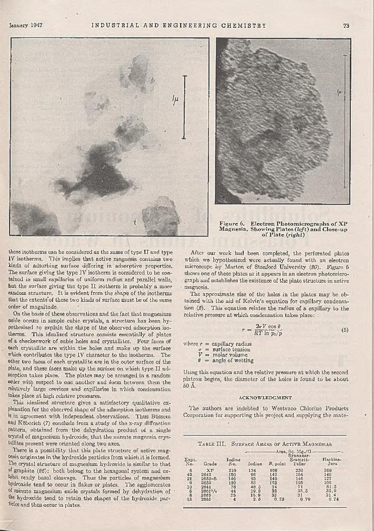
January 1947 I N D U S T R I A L A N D E N G I N E E R I N G C H E M I S T R Y 73
Figure 6. Electron Photomicrographs o f XP Magnesia, Showing Plates ( l e f t ) and Close-up
o f Plate (right)
these isotherms can be considered as the sums of type II and type IV isotherms. This implies that active magnesia contains two kinds of adsorbing surface differing in adsorptive properties. The surface giving the type IV isotherm is considered to be contained in small capillaries of uniform radius and parallel walls, but the surface giving the type II isotherm is probably a more random structure. It is evident from the shape of the isotherms that the extents”of these two kinds of surface must be of the same order of magnitude.
On the basis of these observations and the fact that magnesium oxide occurs in simple cubic crystals, a structure has been hypothesized to explain the shape of the observed adsorption isotherms. This idealized structure consists essentially of plates of a checkerwork of cubic holes and crystallites. Four faces of each crystallite are within the holes and make up the surface which contributes the type IV character to the isotherms. The other two faces of each crystallite are in the outer surface of the plate, and these faces make up the surface on w'hich type II adsorption takes place. The plates may be arranged in a random order with respect to one another and form between them the relatively large crevices and capillaries in which condensation takes place at high relative pressures.
This idealized structure gives a satisfactory qualitative explanation for the observed shape of the adsorption isotherms and is in agreement with independent observations. Thus Biissem and Kobcrich (7) conclude from a study of the x-ray diffraction pattern, obtained from the dehydration product of a single crystal of magnesium hydroxide, that the minute magnesia crystallites present wrere oriented along two axes.
There is a possibility that this plate structure of active magnesia originates in the hydroxide particles from which it is formed. The crystal structure of magnesium hydroxide is similar to that of graphite (22): both belong to the hexagonal system and exhibit ready basal cleavage. Thus the particles of magnesium hydroxide tend to occur in flakes or plates. The agglomerates °f minute magnesium oxide crystals formed by dehydration of ' the hydroxide tend to retain the shapes of the hydroxide particles and thus occur in plates.
After our work had been completed, the perforated plates which we hypothesized were actually found with an electron microscope by Marton of Stanford University (20). Figure 6 shows one of these plates as it appears in an electron photomicrograph and establishes the existence of the plate structure in active magnesia.
The approximate size of the holes in the plates may be obtained with the aid of Kelvin’s equation for capillary condensation (2). This equation relates the radius of a capillary to the relative pressure at which condensation takes place:
2<rF cos 0 ...T ~ RT In Po/p (5)
where r = capillary radius a = surface tension V = molar volume $ = angle of wetting
Using this equation and the relative pressure at which the second plateau begins, the diameter of the holes is found to be about 50 A.
A C K N O W L E D G M E N T
The authors are indebted to Westvaco Chlorine Products Corporation for supporting this project and supplying the mate-
T a b l f . III. S u r f a c e A r e a s o f A c t i v e M a g n e s i a s,----------------------Area, Sq. M g ./G .---------------
Expt.N o. Grade
IodineNo. Iodine B , point
Brunauer-Eramett-
TeLlerHarkins-
Jura6 X P 210 134 198 230 209
42 2642 150 96 142 154 14021 2652-S 146 93 140 146 127
9 2652 130 83 123 125 10910 2641 76 48 .5 74 71 81.55 26611/s 44 19.8 33 33 .5 32 .98 2665 25 15.9 33 31 3 1.4
13 2661 4 2 .5 0 .73 0 .7 9 0 .74

74 I N D U S T R I A L A N D E N G I N E E R I N G C H E M I S T R Y Vol. 39, No. 1
rials. A. G. Aitchison and W. J. Riley of that company entered into many constructive discussions and supplied the production data. E. F. Schweitzer made some of the measurements and calculations. The authors are greatly indebted to E. J. Serfass for carrying out the gas microanalysis.
LIT E R A T U R E C ITE D
(1) Betz, L. D ., Noll, C. A., and Maguire, J. J., In d . E n g . C h em .,32, 1323 (1940).
(2) Brunauer, S., “ The Adsorption of Gases and Vapors” , Vol. I,p. 120, Princeton Univ. Press, 1943.
(3) Ibid., p. 160.(4) Ibid., p. 2S7.(5) Brunauer, S., Deming, L. S., Deming, W . E., and Teller, E.,
J. Am. Chem. Soc., 62, 1723 (1940).(6) Brunauer, S., Emmett, P. H., and Teller, E., Ibid., 60, 309
(1938).(7) Biissem, W ., and Kobcrich, F., Z. physik. Chem. 17B, 310
(1932).(8) Cassidy, H. G., J. Am. Chem. Soc., 62, 3075 (1940).(9) Castonguay, T . T ., Ph.D. thesis, Iowa State College, 1941.
(10) Elvolve, E „ Pub. Health Repts., 52, 1308 (1937).(11) Emmett, P. H., Proc. Am. Soc. Testing Materials, 41, 95 (1941).(12) Emmett, P. H ., and Brunauer, S., J. Am. Chem. Soc., 56, 35
(1934); 59,310 (1937).
(13) Foster, A . G., Trans. Faraday Soc., 28, 645 (1932).(14) Giauque, W . F., and Clayton, J. 0 ., J. Am, Chem. Soc., 55,
4875 (1933).(15) Harkins, W . D „ and Jura, G., Ibid., 6 6 , 1360-72 (1944).(16) Harness, C. L., and Jensen, Nan C., V. S. Bur. Mines, Circ.
7269, 14 (1943).(17) Kraemer, E. O., in Taylor’s "Treatise on Physical Chemistry” ,
p. 1661, New York, D . Van Nostrand Co., Inc., 1931.(18) McBain, J. W „ J. Am. Chem. Soc., 57, 699 (1935).(19) Mantell, C. L., “ Adsorption” , New York, McGraw-Hill Book
Co., Inc., 1945.(20) Marton, L., J. Applied Phys., 16, 137 (1945).(21) Orr, W . J. C., Proc. Roy. Soc. (London), 173A, 349 (1939).(22) Pauling, L., “ The Nature of the Chemical Bond” , 2nd ed., p.
393, Ithaca, Cornell University Press, 1940.(23) Ries, H. E., Jr., Van Nordstrand, R. A., and Teter, J. W ., In d .
E n g . C h em ., 37, 310 (1945).(24) Rubinshtein, A. M ., Bull. acad. sci. U.R.S.S., Classe sci. chim.,
1943, 427-34.(25) Seaton, M . Y ., Am. Inst. Mining Met. Engrs., 148, 22 (1942);
U. S. Patents 2,219,725-6 (1940).(26) Strain, H. H „ “ Chromatographic Adsorption Analysis” , New
York, Interscience Publishers, Inc., 1942.P r e s e n t e d before the D ivision of Colloid Chemistry at the 110th Meeting of the A m e r ic a n C h e m ic a l S o c i e t y , Chicago, 111. Based on thesis presented by W illiam C.W alker to Lehigh University in partial fulfillment of the requirements for degree of doctor o f philosophy, 1946.
Solubilities of Ammonium and Potassium Alums in Water
DENSITIES OF THE SATURATED SOLUTIONS
David Sclilain, John D. Prater, and S. F. Ravitz V. S. Bureau o f M ines, Salt Ixikc City, Utah
1 he solubilities of ammonium and potassium alums in water at 0° to 85° C. and the densities o f the saturated solutions at the saturation temperatures have been determined. The results indicate that many o f the previously published solubility data, especially on ammonium alum, are incorrect.
THE crystallization of an alum is an important step'in two of the processes being investigated by the Bureau of Mines for the production of alumina from sources other than bauxite.
Ammonium alum is formed in the ammonium sulfate process for recovering alumina from clay (12), and potassium alum is formed in the recovery of alumina from alunite (I). During a recent study of the distribution of impurities in the crystallization of these alums, data were obtained that were inconsistent with solubilities reported in Seidell (13) and in the International Critical Tables (7, 8). Moreover, adequate data could not be found on the densities of saturated alum solutions. It was therefore decided to determine the solubilities and densities at 25° to 85° C., the temperature range of importance in connection with the processes1.
1 After this article had been submitted for publication, it became necessary to make solubility and density determinations at lower temperatures. The smoothed values derived from the additional measurements are as follows:
Tem p.,°C.
01020
(N H iIjSOi.- Densitv AU(S04),.24Hi0 ¿ f SaJd
Soly./lOOO G. Soln. So?n ,* Grams M ole G ./M l.
EjSOi.® DpnsitvAls(S 0 .),.2 4 H ,0 o fS a td
Soly ./1000 G . Soln. S o l“ Grams M ole G ./M l.
53 .6 0.059273 .4 0.0810
102 0 .113
1.02581.03471.0464
54 .5 0.05757 6 .0 0.0802
103 0 .109
1.02831.03921.0519
A diagram of the apparatus used is shown in Figure 1. Most of the solubility determinations were made from the oversaturation side. Sufficient recrystallized c.p. alum was dissolved in hot distilled water to give a solution containing about 200 grams of alum per liter in excess of the quantity required for saturation at the temperature being studied.- The solution was then cooled with agitation to about 1 ° C. above that temperature and placed in the covered crystallizing vessel in the thermostat, where it was cooled to the temperature and aged for 2 hours with constant agitation. With the aid of compressed air, the resulting slurry was filtered through the fritted glass disk in the bottom of the vessel, and the filtrate was transferred to the receiver; the compressed air was first heated to the temperature of the thermostat and saturated with water vapor. A sample of the saturated solution was removed from the receiver by means of a calibrated 100-ml. pipet and allowed to cool to room temperature with agitation. Two hours were allowed for equilibrium to be reached, after which the crystals were filtered off, dried at approximately 42° C., and weighed. The total volume of mother liquor was measured, and its alum content was determined by evaporating an aliquot portion to dryness at 42 ° C. and weighing the resulting crystals; this direct determination wrns checked by analyzing the mother liquor for alumina. The weight of alum in the mother liquor was added to the weight of crystals obtained in cooling the original saturated solution to room temperature, to obtain the total weight of alum in the saturated solution.
As a check on the attainment of equilibrium, a number of determinations were made from the undersaturation side by placing distilled water and an excess of alum directly in the crystallizing

January 1947 I N D U S T R I A L A N D E N G I N E E R I N G C H E M I S T R Y 75
THERM0-REGUL4T0R
SATURATED AIR RETURN
THERMOMETER
HEATER TERMINALS-^"
RUBBER STOPPER
CRYSTALLIZING VESSEL
WATER LEVEL
FRITTED GLASS FILTER
WATER BOTTLE
GLASS JAR
Figure 1. Therm ostat
as those from oversaturation; this indicates that, in general, equilibrium had been attained. Data taken from the curves at regular temperature intervals are summarized in Table III, in which the solubility data are expressed as grams and moles of hydrate per 1000 grams of solution1.
The values obtained for the solubility of ammonium alum are much lower than those given in Seidell (IS) and in the International Critical Tables (7), the difference ranging from 30% at 30° to 2.5% at 80° C. The data in both references are based largely upon the work of Poggiale (11), who conducted his tests more than 100 years ago and did not use a thermostat. A recent determination at 25° C. by Hill and Kaplan (5) is only 1% lower than the corresponding value in Table III.
For potassium alum the solubility data in Seidell (13) and in the International Critical Tables (8) for the range 25° to 60° C. are based chiefly upon Berkeley’s work (3) and agree rather well with the results obtained in the present investigation. Above 60° C., however, the data in Seidell, which appear to be based on Mulder’s work published in 1864 (10), differ greatly from those in the International Critical
vessel, agitating the mixture for 2 hours, and then proceeding as described. The results agreed well with those obtained from oversaturation.
Careful ammonia analyses of various samples of ammonium alum crystals dried at 42 ° C. indicated that drying had been complete and that no dehydration of the crystals had occurred, since the analyses agreed within 0.1% with the theoretical value for {NH4)2S0<.AI2(S0<)j.24H20.
The hot, saturated solutions of alum frequently became slightly cloudy because of hydrolysis. To determine whether the extent of hydrolysis was sufficient to affect the solubility determinations, samples of saturated solutions were agitated for 2 hours at various temperatures from 25 ° to 85° C. and filtered, and the residues were washed, ignited, and weighed. The weights showed that only 0.01 to 0.1% of the ammonium or potassium alum in the saturated solutions had hydrolyzed.
Temperatures were measured to 0.1 ° C. with a calibrated thermometer, crystals were weighed to the nearest 0.01 gram, and pipets were calibrated with distilled water at the temperatures at which they were to be used. The precision of the various measurements was such that, aside from the attainment of equilibrium, the probable errors in the solubility determinations ranged from 0.2% at 25° to 0.4% at 85° C. for ammonium alum, and from 0.2 % at 25 ° to 0.8 % at 85 ° C. for potassium alum.
The densities of the saturated solutions used for the solubility determinations were measured at the saturation temperatures with 10-ml. pycnometers calibrated with distilled water at the temperatures at which they were to be used. Weighings were made to 0.1 mg. and were corrected to vacuo when necessary. The probable errors in the measurements involved in the density determinations range from 0.0005 at 25° to 0.0056 at 85° C. for ammonium alum, and from 0.0005 at 25° to 0.012 at 85° C. for potassium alum, the greatest source of error being variation of solubility with the temperature, which was measured to 0.1 ° C.
R E S U L T S
The results of solubility and density determinations, expressed as grams per liter and grams per milliliter, respectively, are given in Tables I and II and in Figures 2, 3, and 4, the unit of volume in each instance being measured at the saturation temperature. Points obtained from undersaturation fit the curves about as well
T a b l e I. E x p e r i m e n t a l S o l u b i l i t y a n d D e n s i t y R e s u l t s f o r A m m o n iu m A l u m
Density ofTem p., (N H O îSO* . A li(SO «)i. 24HiO Satd. Soln.,
° C. Soly., G ./L . G ./M l.25 .0 126.2 1.05213 4 .7 ° 1.070435.2 167‘.3 1.070640.1 199.3 1.083040.3 204.0 1.083040.5* 200.74 0 .7 « 204.0 l!0 8 4 544.6 236.1 1.0954 4 .7 “ 234 .0 1.09745.3 1.09750.5 289! 6 1.11254.5 331.8 1.12859.9 390.2 1.1506 0 .2 ° 410.2 1.15861.2 415.1 1.15564.5 438.5 1.1786 4 .6 “ 462.4 1.17669.5 532 1.20774 .3 644 1.2367 9 .0 723 1.2698 0 .0 “ 749 1.28384.5 899 1.329
From below saturation.
Figure 2. Solubility o f Ammonium Alum

76 I N D U S T R I A L A N D E N G I N E E R I N G C H E M I S T R Y Vol. 39, No. 1
O FROM O V ER-SATU RATIO N
X FROM UNDER-SATURATION
Figure 3. Solubility o f Potassium Alum
Figure 4. Densities o f Saturated Solutions of Ammonium and Potassium Alums at Saturation
Temperatures '
TE M P ER A T U R E ,
X POTASSIUM ALUM FROM UN DER-SATURATION
+ AMMONIUM ALUM FROM UNDER-SATURATION
© FROM O V ER-SATU RATIO N
T E M P E R A T U R E , °C .
1000
2 5 0 0 <
J 1.35 2 orUJQLtn 2 <<x o
T a b l e II, E x p e r i m e n t a l S o l u b i l i t y a n d D e n s i t y R e s u l t s f o r P o t a s s iu m A l u m
Density ofTem p., K ,SO ..A1,(SO .) j . 2411,0 Satd. Soln.,
Soly., G ./L . G ./M l.25 .2 128.0 1.059234.6 171.5 1.07943 4 .7 “ 172.2 1 .0S0235 .0 1.080840.3 208.9 1.094040 .5 20S.8 1.09524 0 .7 “ 210.5 1.09724 2 .0 “ 220.4 1.10044 .8 250.4 1.11150.0 304.9 1.13155.4 358.6 1.15759.9 420.4 1.1826 0 .7 “ 411.3 1.17764.4 401.7 1.20969.7 577 1.25275 .0 720 1.29S79.4 810 1.3458 0 .1 “ 833 1.3558 5 .0 1065
“ From below saturation.
1.444
T a b l e III.
Tem p.,
S m o o t h e d S o l u b i l i t y a n d D e n s i t y V a l u e s f o r A m m o n iu m a n d P o t a s s iu m A l u m s
S o ly ./1000 G . Soln. Densitv of Hydrate, H ydrate, Satd. Soln.,
g. moles G ./M l.
(N H «)iS0< .A h(S0«)i.24H ,0
25 120 0.132 1.052135 156 0.172 1.070545 216 0 .238 1.095855 296 0.327 1.13065 391 0.432 1.17975 514 0.567 1.24185 692 0 .764 1.331
KjSO<.Alj(SOOi.24HtO
25 120 0.127 1.058635 161 0 .170 1.080845 224 0.236 1.11155 309 0.326 1.15565 408 0 .430 1.21575 541 0.571 1.29785 738 0 .778 1.444
Tables, which are based on Marino’s work published in 1905(9). The data in Table III for temperatures above 60° C. agree fairly well with those in International Critical Tables but are much lower than those in Seidell, the difference amounting to 20% at 80 "C.
The International Critical Tables (6) summarize density measurements made by Berkeley (2) on saturated solutions of potassium alum at saturation temperatures up to 60 0 C., and by Bindel (S), Gerlach (4), and others on supersaturated solutions of ammonium and potassium alums at 15° or 20° C. The density data in Table III agree within 0.1% with Berkeley’s values and are in accord with the values for the supersaturated solutions, if it is assumed that the solutions have the same temperature coefficient of expansion as water.
ACKNOW LEDGM ENT
The paper is one of many reporting on various aspects of the Bureau of Mines program directed toward the more effective utilization of our mineral resources. Investigations of our mineral resources are carried out by the Mining Branch, under L. B. Moon, and the Metallurgical Branch, under R. G. Knickerbocker. Both branches are under the supervision of R. S. Dean. The scope of this paper falls in the province of the Metallurgical Branch whose activities embrace the separation of difficultly beneficiated ores, the production of pure metals from domestic deposits, the exploitation of marginal ore reserves, the recovery of secondary metals, and the improvement of present industrial metallurgical practice. This paper is published by permission of the Director, Bureau of Mines, Department of the Interior.
L IT E R A T U R E C ITED/
(1) Baroch, C. T., Hackwood, A. W., and Knickerbocker, R . G.,Bureau of Mines Report of Investigations 3845 (February 1946).
(2) Berkeley, Earl of, Trans. Roy. Soc. (London), 203, 189-216(1904).
(3) Bindel, Karl, Ann. Physik, (3) 40,370-98 (1890).(4) Gerlach, G. Th., Z. anal. Chem., 28, 466-524 (1869).(5) Hill, Arthur E., and Kaplan, Nathan, J. Am. Chem. Soc., 60,
550-4(1938).(6) International Critical Tables, Vol. I l l , pp. 71, 92, 106, New
York, McGraw-Hill Book Co., Inc., 1928.(7) Ibid., Vol. IV, p. 226.(8) Ibid., Vol. IV, p. 242.(9) Marino, L., Gazz. chim. ital., 35, 341-64 (1905).
(10) Mulder, G. J., “ Scheikundige Verhandellingen en Onderzockin-gen” , Vol. 3, pt. 2, Bijdragen tot de Geschiedenis Van Het Scherkungig Gebonden Water, Rotterdam, 1864.
(11) Poggiale, M ., Ann. chim. phys., 8, 463-78 (1843).(12) St. Clair, H. W ., Ravitz, S. F., Sweet, A. T ., and Plummer, C. E.,
Trans. Am.Inst. Mining Met. Engrs., 159, 255-66 (1944).(13) Seidell, A ., "Solubilities of Inorganic and Metal Organic Com
pounds", 3rd ed., Vol. I, p. 101, New York, D . Van Nostrand Co., Inc., 1940.

Phase Equilibria in HydrocarbonSystems
Methane—n-Butane—Decane SystemH. II. REAMER, B. H. SAGE, AND W. N. LACEY
California Institute o f Technology, Pasadena, Calif.
Five mixtures o f the ternary system consisting o f m eth ane, n -butan e, and dccane were studied volumetrically at seven tem peratures from 100° to 460° F. and at pressures up to 10,000 pounds per square inch absolute. The m ixtures were chosen so as to have a fixed m olal ratio o f n- butane to decane o f about 2 to 1, whereas the m ole fraction o f m ethane varied from 0.3785 to 0.9775. T he experim ental results establish the volum etric properties o f these mixtures in the single-phase region at pressures above that o f the bubble point and, in the two-phase region, near the bubblc-point boundary.
THE volumetric and phase behavior of single-component and binary systems involving the lighter aliphatic hydrocarbons have been studied by many investigators and much information
concerning these systems has been published. To a lesser extent the equilibrium distribution of components between coexisting fluid phases of ternary hydrocarbon systems has been studied. However, little information is available concerning the pressure- volume-temperature properties of ternary systems. Such information would provide an opportunity to compare the partial volumetric behavior of each of the components in the ternary system with that found in the related binary systems (10, IS). Such a comparison would aid greatly in attempts to predict quantitatively the volumetric and thermodynamic properties of multi- component hydrocarbon systems. For these reasons an experimental investigation was undertaken to establish the volumetric and phase behavior of the methane-n-butane-decane system at pressures up to 10,000 pounds per square inch absolute and at temperatures between 100° and 460° F.
A number of investigations have established the properties of methane and n-butane in the pure state, and good agreement between investigators (6, 7) was attained. The specific volume of liquid n-decane and its boiling point at atmospheric pressure were determined by Shepard, Hennc, and Midgley (IS), and the vapor pressure at two temperatures was reported by Young (16). Sage, Lavender, and Lacey (14) measured the specific volume of liquid decane at pressures up to 3500 pounds per square inch for temperatures between 70° and 250° F. The authors have extended these measurements to 10,000 pounds per square inch and 460 ° F. (8).
The properties of coexisting phases in the methane-rc-butane system, at temperatures from 70° to 305.6° F., the critical temperature of n-butane, were reported by Sage, Hicks, and Lacey (U), and the volumetric and partial volumetric properties of this system throughout the single-phase region at pressures up to 3000 pounds per square inch absolute for temperatures between 70° and 250° F. were described by Sage, Budenholzer, and Lacey (9). Beattie, Stockmayer, and Ingersoll (1) reported single-phase volumetric studies of three mixtures of methane and n-butane at pressures up to 5000 pounds per square inch for temperatures from 167° to 572° F. The studies of this system at the authors’ laboratory have recently been extended to 10,000 pounds per
square inch for temperatures between 100° and 460° F., but the data are not yet published.
The composition of the dew-point gas in the methane-decane system was determined at 100 °, 160 °, and 220 ° F. for pressures below 2500 pounds per square inch absolute by Lavender, Sage, and Lacey (4). They also published results from a volumetric study of this system at pressures below 4500 pounds per square inch for temperatures between 70° and 250° F. (14). The authors’ laboratory has reported an extension of the data for this system to 10,000 pounds per square inch and 460° F. (8).
As a part of the present investigation the volumetric behavior of the liquid phase of the n-butane-decane system was determined at pressures from bubble point to 10,000 pounds per square inch absolute for temperatures from 100° to 460° F. The results have not yet been published.
These various investigations served to establish the volumetric behavior of the binary systems bounding the ternary methane- n-butane-decane system throughout wide ranges of pressure and temperature, including the single-component apices of the ternary composition diagram shown in Figure 1. This paper is the first of a series which will undertake to describe the volumetric and phase behavior of three-component mixtures whoso compositions may be represented by points distributed systematically over the interior of the ternary diagram. The group of mixtures considered in this paper lies along a straight line cutting across the ternary composition diagram from the methane apex to a point on the n-butane-dccane boundary corresponding to 0.66 mole fraction n-butane (Figure 1). The compositions of the mixtures experimentally studied are indicated along the line.
M A T E R IA L S
Gas from the Bowerbank Field in the San Joaquin Valley, Calif., was used as the source of methane. The gas consisted primarily of methane and water vapor with traces of carbon dioxide. Before being introduced into the pressure-volume-temper- ature apparatus the gas, at a pressure above 1000 pounds per square inch absolute, was passed through a chamber packed with successive layers of granular calcium chloride, activated charcoal, potassium hydroxide, and anhydrous calcium sulfate. The purity of a sample of gas treated in this manner wa itested by methods involving partial condensation at liquid air temperatures, gas density determination at atmospheric pressure, and Orsat analysis of reaction products resulting from combustion with pure oxygen. These tests indicated that the quantity of hydrocarbons less volatile than methane was less than 0.02 mole % and the amount of noncondensable gases was less than 0.1 mole %.
Butane was obtained from the Phillips Petroleum Company, the accompanying analysis indicating the presence of less than 0.3 mole % isobutane and negligible amounts of other impurities. This material was distilled with a reflux ratio of about 50 to 1 in a fractionating column four feet long packed with broken glass helices. The initial tenth and the final fifth of the charge in the distillation column were discarded, and the middle fraction was
77

78 I N D U S T R I A L A N D E N G I N E E R I N G C H E M I S T R Y Vol. 39, No. 1
M E TH O D
No important modifications in the equipment and procedures already described (IS) were necessary for the present investigation. The volumetric apparatus consisted of a stainless steel chamber, called the equilibrium cell, whose elective volume could be varied by the injection or withdrawal of mercury. The volume occupied by the hydrocarbon sample was known in terms of measurements of the position of the mercury surface in an adjoining interconnected pressure vessel, which served as a reservoir for mercury injected into or withdrawn from the equilibrium cell; suitable corrections were made for the effects of pressure and temperature upon the volumes of the equilibrium cell and of the mercury.
The temperature of the oil bath surrounding this cell was controlled by an electrical thermostat and was determined by use of a platinum resistance thermometer whose resistance was measured with a Mueller bridge. Over a period of a number of years, the resistance thermometer had been checked several times by comparison with a similar instrument manufactured by Leeds and Northrup and certified by the National Bureau of Standards, and no appreciable change in its calibration was noted.
The pressure in the cell was transmitted hydraulically through the mercury injection system to a piston-and-cylinder fluid pressure balance. The pressure balance was calibrated at approximately semiannual intervals by comparison with the vapor pressure of pure carbon dioxide at 0° C., using Bridgeman’s value of 505.56 pounds per square inch absolute as a standard (2). Over a period of two years the calibration of the pressure balance changed only 0.2%.
The mixtures of the three components were prepared in the cell. The decane was measured volumetrically in the liquid state with a calibrated glass buret. Next n-butane was added in slight excess from a small steel sample bomb, the amount being determined from the difference in weighings on an analytical balance. A small, accurately measured volume of the gas phase of the n-butane-decane mixture was withdrawn from the cell under known conditions in order to adjust the ratio of n-butane to decane of the cell contents more closely to the desired value. After this adjustment, methane was added from an isothermal, iso- choric reservoir in which the gas was stored at somewhat higher
PRESSU RE L B ./ S Q . IN. 2 0 0 0 4 0 0 0 6000 8 000P R ES S U R E L B ./ S Q . IN.
Figure 2 . Relation between Compressibility Factorand Pressure for ¡Mixture Containing 0.5763 ¡Mole Figure 3. Effect o f Pressure on M olal Volum e for
Fraction M ethane Mixture Containing 0.5763 M ole Fraction M ethane
M E T H A N E
condensed at liquid air temperature with continuous removal of any noncondensable gases which may have been present by means of a mercury vapor diffusion pump. A sample obtained by this process showed a difference of less than 0.25% in its vapor pressure at 280° F. when 5% and when 50% of the sample was in the gas phase.
The decane used in this study was obtained from the Eastman Kodak Company and was distilled at reduced pressure to remove dissolved gas and possibly to improve its purity. The resulting material had a specific volume of 0.022316 cubic foot per pound at 100° F. and atmospheric pressure (1.3931 ml. per gram at 37.8° C.) and a refractive index of 1.4100 at 77° F. measured for the D line of the sodium spectrum. These data, compared with available information concerning the properties of n-decane (15) and of several decane isomers (S, 5), indicate that the material used in this work was composed primarily of paraffin hydrocarbons consisting of ten carbon atoms per molecule but that it probably was not entirely ?t-decane.
Figure 1. Ternary Com position Diagram Showing Series o f Mixtures Studied
D E C A N E 0 .2 0 .4 0 .6 0 .8M O L E F R A C T IO N n - B U T A N E
n - B U T A N E
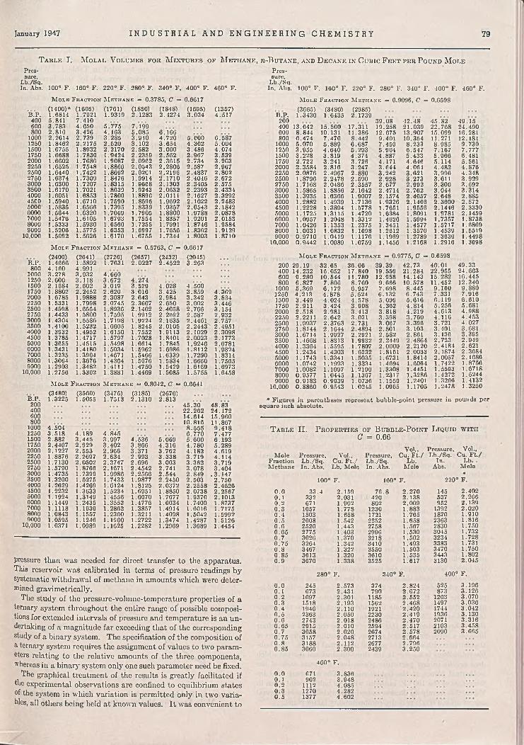
January 1947 I N D U S T R I A L A N D E N G I N E E R I N G C H E M I S T R Y 79
T a b l e I. M o l a l V o lu m e s f o r M i x t u r e s o f M e t h a n e , m -B u t a n e , a n d D e c a n e i n C u b i c F e e t p e r P o u n d M o l ePres-sure.
Lb./Sq. In. Abs. 100° F. 160° F. 220° F. 280° F. 340° F. 400° F. 460° F.
M o l e F r a c t io n M e t h a n e = 0.3785, C = (1400)a (1605) (1761) (1850) (1848)
0.6617(1695) (1357)
B.P. 1.6814 1.7921 1.9319 2.1283 2.4274 3 .034 4.517400 5.841 7.410600 3.783 4.650 5.775 7.199800 2.816 3.426 4 .163 5.085 6 .166
1000 2.2614 2.739 3.285 3.910 4 .720 5 .600 6.5871250 1.8462 2.2175 2 .620 3.102 3.654 4 .302 5 .0041500 1.6755 1.8932 2.2170 2.582 3.000 3.486 4 .0741750 1.6688 1.7830 1.9424 2.2359 2.562 2.967 3.5392000 1.6602 1.7686 1.9087 2.0962 2.3615 2.734 3.2032250 1.6525 1.7548 1.8866 2.0543 2.2806 2.587 2.9672500 1.6440 1.7422 1.8662 2.0201 2.2196 2.4837 2 .8022750 1.6374 1.7309 1.8476 1.9914 2.1710 2.4046 2 .6723000 1.6300 1.7207 1.8315 1.9608 2.1303 2.3405 2.5753500 1.6170 1.7021 1.8039 1.9243 2.0632 2.2393 2.43344000 1.6051 1.6853 1.7800 1.8896 2.0111 2.1627 2.32924500 1.5940 1.6710 1.7590 1.8596 1.9092 2.1022 2.24835000 1.5835 1.6566 1.7395 1.8339 1.9357 2.0543 2.18426000 1.5644 1.6320 1.7069 1.7905 1.8800 1.9788 2.08787000 1.5476 1.6105 1.6793 1.7554 1.8357 1.9201 2.01538000 1.5333 1.5930 1.6560 1.7255 1.7991 1.8746 1.95849000 1.5206 1.5775 1.6353 1.6997 1.7656 1.8362 1.9129
10,000 1.5092 1.5626 1.6170 1.6755 1.7344 1.8003 1.8710
B.P.
M o l e F r a c t io n M e t h a n e = 0.5763, C = (2400) (2641) (2726) (2657) (2432)
0.6617(2045)
1.4666 1.5892 1.7631 2.0227 2.4522 3.203800 4.160 4.991
1000 3.278 3.932 4 .6601250 2.600 3 .118 3.672 4 .2741500 2.1684 2.602 3.019 3 .529 4 .028 4.5001750 1.8802 2.2452 2.620 3.016 3.425 3.859 4.3692000 1.6785 1.9888 2.3087 2.643 2 .984 3 .342 3 .8342250 1.5331 1.7998 2.0745 2.3607 2 .650 3.002 3 .4462500 1.4598 1.6554 1.8936 2.1402 2.4058 2.766 3.1542750 1.4433 1.5800 1.7595 1.9912 2.2692 2.587 2.9323000 1.4304 1.5586 1.7198 1.9224 2.1635 2.4461 2.7573500 1.4100 1.5232 1.6605 1.8245 2.0105 2.2443 2.49514000 1.3932 1.4952 1.6150 1.7552 1.9113 2.1029 2.30984500 1.3785 1.4717 1.5797 1.7028 1.8401 2.0023 2.17735000 1.3655 1.4515 1.5498 1.6614 1.7845 1.9246 2.07816000 1.3431 1.4180 1.5034 1.5962 1.6986 1.8112 1.93247000 1.3235 1.3904 1.4671 1.5466 1.6339 1.7290 1.83148000 1.3064 1.3676 1.4364 1.5076 1.5834 1.6660 1.75659000 1.2903 1.3482 1.4111 1.4750 1.5429 1.6169 1.6973
10,000 1.2756 1.3302 1.3881 1.4469 1.5085 1.5755 1.6458
B.P.
M o l e F r a c t io n M e th a n (3480) (3560) (3475)
e « 0.8042, C = (3185) (2670)
0.6641
1.3225 1.5055 1.7513 2.1310 2.813200 45.30 48.83400 22.262 24.172600 14.614 15.960800 10.816 11.867
1000 4 .504 8 .555 9 .4181250 3 .518 4 .189 4.845 6.770 7.4771500 2.882 3 .445 3.997 4.536 5.069 5 .600 6 .1931750 2.4407 2.929 3.402 3 .866 4.316 4 .780 5 .2892000 2.1227 2 .553 2.966 3.371 3.762 4 .182 4 .6192250 1.8876 2.2697 2.634 2.993 3 .338 3 .719 4 .1142500 1.7130 2.0502 2.3747 2.696 3.003 3.362 3 .7192750 1.5790 1.8766 2.1671 2.4542 2.741 3 .078 3.4043000 1.4735 1.7399 1.9986 2.2566 2.544 2.849 .3 .1 4 73500 1.3200 1.5275 1.7433 1.9877 2.2450 2 .503 2 .7504000 1.2629 1.4269 1.6124 1.8125 2.0372 2.2558 2.46264500 1.2232 1.3633 1.5234 1.6951 1.8850 2.0738 2.25675000 1.1924 1.3149 1.4556 1.6070 1.7077 1.9370 2.10136000 1.1449 1.2435 1.3552 1.4776 1.6034 1.7400 1.87377000 1.1118 1.1939 1.2862 1.3857 1.4914 1.6016 1.71758000 1.0843 1.1557 1.2360 1.3211 1.4098 1.5042 1.59929000 1.0595 1.1246 1.1960 1.2722 1.3474 1.4287 1.5126
10,000 1.0371 1.0989 1.1625 1.2282 1.2969 1.3689 1.4454
pressure than was needed for direct transfer to the apparatus. This reservoir was calibrated in terms of pressure readings by systematic withdrawal of methane in amounts which were determined gravimetrically.
The study of the pressure-volume-tempcrature properties of a ternary system throughout the entire range of possible compositions for extended intervals of pressure and temperature is an undertaking of a magnitude far exceeding that of the corresponding study of a binary system. The specification of the composition of a ternary system requires the assignment of values to two parameters relating to the relative amounts of the three components, "'hereas in a binary system only one such parameter need be fixed.
The graphical treatment of the results is greatly facilitated if the experimental observations are confined to equilibrium states of the system in which variation is permitted only in two variables, all others being held at known values. It was convenient to
Pressure,
L b ./S q .In. Abs. 100° F. 160° F . 220° F. 280° F. 340° F. 400° F. 400° F.
M o l e F raction ' M e t h a n e = 0 .9096, C = 0 .6598(3665) (3480) (2985)
B.P. 1.3430 1.6435 2.1739200 39.08 42.48 45.82 49.15400 13.642 15.500 17.311 19.258 21.039 22.768 24.490600 8.844 10.131 11.386 12.675 13.907 15.099 16.281800 6.474 7.470 8.442 9.401 10.354 11.271 12.181
1000 5.070 5.889 6.687 7.450 8.233 8.985 9.7301250 3.955 4.640 5.293 5.904 6.547 7.167 7.7771500 3.228 3.819 4.374 4.887 5.433 5 .966 6.4811750 2.722 3.241 3.726 4.171 4.646 5.114 5.5612000 2.3584 2.816 3.247 3.644 4.064 4.482 4.8762250 2.0876 2.4967 2.880 3.242 3.621 3.996 4.3482500 1.8796 2.2478 2.590 2.928 3.273 3.611 3.9292750 1.7168 2.0486 2.3557 2.677 2.992 3.300 3 .5923000 1.5865 1.8856 2.1642 2.4714 2.762 3.044 3 .3143500 1.3935 1.6366 1.9007 2.1574 2.4057 2.648 2.8854000 1.2882 1.4939 1.7136 1.9326 2.1466 2.3600 2.5724500 1.2228 1.3894 1.5778 1.7651 1.9556 2.1416 2.33305000 1.1725 1.3115 1.4720 1.6384 1.8091 1.9781 2.14596000 1.0957 1.2048 1.3312 1.4626 1.5994 1.7357 1.87387000 1.0426 1.1353 1.2375 1.3451 1.4577 1.5717 1.68698000 1.0031 1.0832 1.1698 1.2612 1.3570 1.4539 1.55199000 0.9710 1.0419 1.1176 1.1969 1.2789 1.3636 1.4498
10,000 0.9442 1.0089 1.0759 1.1456 1.2168 1.2916 1.3698
M o l e F r a c t io n M e t h a n e = 0.9775, C = 0.6598200 29.19 32.65 36.06 39.39 42.73 46.01 49.33400 14.232 16.052 17.840 19.556 21.284 22.955 24.663600 9 .280 10.544 11.780 12.958 14.143 15.282 16.445800 6.827 7.806 8 .760 9.666 10.578 11.452 12.340
1000 5 .369 6.172 6 .957 7.698 8.445 9.160 9.8801250 4.213 4 .878 5.524 6.132 6.743 7.331 7.9161500 3.449 4.024 4 .578 5.096 5.616 6.119 6.6101750 2.911 3.424 3 .908 4.362 4.814 5.256 5.6812000 2 .518 2.981 3.413 3 .818 4.219 4.613 4 .9882250 2.2211 2.642 3.031 3 .398 3 .760 4.116 4.4532500 1.9937 2.3763 2.731 3.067 3.396 3.721 4.0272750 1.8144 2.1644 2.4894 2.801 3.103 3.401 3.6813000 1.6714 1.9927 2.2921 2.582 2.861 3.136 3.3953500 1.4668 1.8313 1.9932 2.2449 2.4864 2.723 2.9494000 1.3364 1.5595 .1.7807 2.0000 2.2120 2.4184 2.6214500 1.2434 1.4303 1.6232 1.8161 2.0033 2.1874 2.36845000 1.1743 1.3341 1.5035 1.6731 1.8414 2.0057 2.16866000 1.0742 1.1993 1.3334 1.4694 1.6064 1.7422 1.87567000 1.0082 1.1097 1.2190 1.3308 1.4451 1.5593 1.67188000 0.9577 1.0445 1.1367 1.2317 1.3286 1.4272 1.52449000 0.9183 0.9939 1.0736 1.1559 1.2401 1.3266 1.4132
10,000 0.8860 0.9543 1.0245 1.0965 1.1705 1.2478 1.3250
a Figures in parentheses represent bubble-point pressure in pounds per square inch absolute.
T a b l e II. P r o p e r t i e s o f B u b b l e - P o i n t L i q u i d w i t h C = 0.66
Vol., Pressure, Vol.,M ole Pressure, Vol., Pressure, Cu. F t . / L b ./S q . Cu. F t ./
Fraction L b ./S q . Cu. F t . / L b ./S q . Lb. In. Lb. .Methane In. Abs. Lb. M ole In. Abs. M ole Abs. M olo
100° F. 160° F. 220° F.
0 .0 33.4 2.159 76.8 2 .270 145 2.4020.1 332 2.031 420 2.138 537 2.2660 .2 671 1.902 802 2.009 952 2.1390 .3 1057 1.778 1230 1.883 1392 2.0200 .4 1503 1.658 1721 1.765 1870 1.9100 .5 2008 1.542 2252 1.658 2363 1.8160 .6 2520 1.443 2758 1.567 2830 1.7500 .65 2775 1.403 2996 1.530 3045 1.7320 .7 3026 1.370 3218 1.502 3234 1.7280 .75 3264 1.342 3410 1.493 3383 1.7310 .8 3467 1.322 3550 1.503 3470 1.7500 .85 3613 1.320 3610 1.535 3443 1.8020 .9 3670 1.338 3525 1.617 3130 2.045
280° F. 340° F. 400° F.
0 .0 245 2.573 374 2.824 525 3.1960.1 673 2.431 790 2.672 873 3.1260 .2 1097 2.301 1185 2.552 1203 3.0700 .3 1518 2.193 1562 2.468 1497 3.0360 .4 1946 2.110 1921 '2 .4 2 0 1744 3.0420 .5 2363 2.050 2230 2.419 1936 3.1300 .6 2743 2.018 2486 2 .470 2071 3.3160 .65 2915 2.010 2594 2.517 2103 3 .4580 .7 3058 2.020 2674 2.578 2090 3 .6650 .75 3157 2.048 2713 2.6640 .8 3188 2.112 2677 2.7960.85 3060 2.300 2439 3.250
460° F.
0 .0 671 3.8360.1 902 3.9480 .2 1112 4.0850 .3 1270 4.2820 .5 1377 4 .602

80 I N D U S T R I A L A N D E N G I N E E R I N G C H E M I S T R Y Vol. 39, No. 1
c = - * ± - M« + tl,0
0 .4 0.6M O LE FRACTION METHANE
Figure 4. Relation between Bubble-Point Pressure and M ole Fraction W hcn C — 0.66
choose, as primary variables, pressure, volume, temperature, weight, and two parameters specifying the composition of the system. The procedure in the present study consisted in determining the pressure-volume relation for a mixture having constant weight and composition at a constant temperature. This procedure was repeated at seven temperatures for five mixtures.
Letting Ni, Nt, and Ario represent, respectively, the mole fractions of methane, n-butane, and decane in the ternary mixture, the two parameters chosen in this work to specify the compositions of the mixtures are Ni and C, where
The smoothed experimental results for all five mixtures, graphically interpolated to oven values of pressure, are recorded in Table I. Within the temperature range covered by this investigation these data establish the volumetric properties of the mixtures throughout the region of pressures between bubble point and 10,000 pounds per square inch absolute, and throughout a fairly large portion of the two-phase region adjacent to the bubble-point boundary. None of the mixtures was expanded to a sufficiently low pressure as to permit observation of the dew point. For mixtures rich in methane and a t ' temperatures high enough to avoid the two-phase region, it was possible to extrapolate graphically the compressibility factor isotherm to zero pressure, making use of the fact that the compressibility factor of any gas approaches unity as the system is expanded without limit. In this way some reliable information was obtained concerning the volumetric behavior of the system in portions of the single-phase region at pressures less than those experimentally observed.
The mixture having 0.9775 mole fraction methane exhibited no detectable two-phase region. It is assumed that the proportion of methane in this
mixture was so great as to place the cricondentherm below the lowest temperature studied.
Figure 4 shows isothermal relationships between the bubble- point pressure and the mole fraction of methane when C = 0.66. It is of interest to note that at pressures above 1000 pounds per square inch the solubility of methane passes through a minimum with respect to isobaric variations in the temperature. For example, at 2000 pounds per square inch absolute the mole fraction of methane in the bubble-point liquid has a minimum value of about 0.41 at approximately 280° F., whereas for temperatures above and below 280 ° F. the concentration of methane is greater than 0.41.
The quantity C represents the mole fraction of n-butane in the n-butane-decane portion of the mixture. For the five mixtures 6oooherein reported, C had a value of approximately 0.66, and Ni was varied from 0.3785 to 0.9775 (Figure 1). By holding C constant, the variation of jYi may be treated graphically in a manner analogous to that employed for binary systems, the n-butane-decane mixture being regarded as one constituent and methane as the other.
R E S U L T S
The distribution of the experimentally observed equilibrium states for a typical mixture is indicated by circled points in Figures 2 and 3. The boundary of the two-phase region, designated as the bubble-point locus in these figures, is determined by discontinuities in the slopes of the isotherms. The discontinuities are more definite in Figure 3 at the lower temperatures, whereas at the higher temperatures the compressibility isotherms of Figure 2 more clearly locate the boundary of the two-phase region.
It may be noted in Figure 2 that at pressures above the bubble- point, the 100 ° F. isotherm cuts 'across the two-phase region and apparently again intersects the bubble-point locus in the neighborhood of the 220 ° F. bubble point. It should be realized that the isotherms shown in this figure may be regarded as contour lines on a three dimensional surface, representing intersections of that surface with a series of parallel isothermal planes. The bubble-point locus is a curve in the three-dimensional surface which docs not lie in any particular plane, but intersects each of the isothermal planes at the bubble point. The apparent dual intersection of the 100 ° F. isotherm with the bubble-point locus in Figure 2 is merely an illusion caused by projecting the isothermal curves upon a single pressure-compressibility factor plane.
d 4 0 0 0
cCD-J
OCL 2 0 0 0
UJ_iCDœo©
0 .2 0 .4 0 .6 0 .6
M OLE F R A C T IO N M ETH AN E
Figure 5. Bubble-Point Pressure at 100° F. as Related to M ole Fraction M ethane for Three Values o f C

January 1947 I N D U S T R I A L A N D E N G I N E E R I N G C H E M I S T R Y 81
ED 4 .0
B U B B L E -P O IN T
0 .4 0 .6M O LE FRAC TIO N METHANE
Figure 6. Relation between M olal V olum e at 340° Fraction M ethane with C = 0.66
F . and M ole
The volumetric behavior of the system at the bubble point is recorded in Table II. The bubblc-point pressure at 100° F. is shown in Figure 5 in relation to the mole fraction of methane for values of C equal to 0, 0.66, and 1.0. The curves corresponding to C = 0 and 1.0 were constructed from data given in earlier publications (S, 11). The curve corresponding to C = 0.66 lies, for the most part, more nearly midway between the other curves rather than at two thirds of the distance from the curve C — 0 to the curve C = 1.0, as would be the case if these materials behaved as ideal solutions.
The isobaric-isothermal relation between the molal volume and the mole fraction of methane is shown in Figure 6 for a series of pressures at 340° F. with C = 0.66. Although this diagram superficially resembles similar ones which may be drawn for binary systems, there are some important differences which should be noted.
In accordance with the phase rule the intensive properties of two coexisting phases of a binary system are fixed if the pressure and temperature of the system are specified. A consequence of this fact is that the isothermal-isobaric curves for molal volume plotted against molal composition in the two-phase region of a binary system are straight lines. The isothermal isobars crossing the two phase region are not straight lines in Figure 6.
In a binary system the intersections of an isothermal isobar with the boundary of the two-phase region on a volume versus composition diagram correspond to the gas and liquid phases which coexist in equilibrium with each other at that temperature and pressure; however, this is not true in the case of a ternary system. Points on the two-phase boundary in Figure 6 represent saturated single-phase states in which the proportions of n- butane and decane correspond to a value of C = 0.66. In general the coexisting equilibrium phases of this system will not both contain n-butane and decane in these proportions. The greater complexity in the behavior of the ternary system over that of a binary system is a result of the additional degree of freedom introduced by a third component, which permits the intensive properties of the coexisting equilibrium phases of the ternary system to vary throughout the two-phase region even though the pressure end temperature are fixed.
Figure 7 is presented to aid in visualizing the relation of this investigation to the more extensive problem of determining the
volumetric behavior of the entire ternary system. The figure is an oblique view of a prism whose triangular base corresponds to the conventional triangular diagram for three-component mixtures. The distance along the vertical elements of the prism measured from the base corresponds to the molal volume of the system. The isothermal- isobaric relation between the molal volume of the system and its composition may be represented as a surface whose intersections with the three sides of the prism describe the isothermal-isobaric volumetric behavior of the three binary systems corresponding to those sides. These intersections are shown in the figure for the surface corre- ponding to 340° F. and 2000 pounds per square inch absolute pressure. The dotted curve indicates the estimated locus of bubble-point and dew-point states on this surface.
The nature of the surface within the prism may be indicated either by contours generated by the intersections of constant volume (horizontal) planes with the surface in question, or by profiles generated by the intersections with the surface of vertical planes. Figure 7 shows the profile corresponding to the intersection of the plane for C = 0.66, in which lie all the data from the five mixtures of this investigation, with the 340° F., 2000 pounds per square inch, isotherm al- isobaric molal volume surface of the ternary
M O LC F R A C T IO N n - B U T A N E
Figure 7. Oblique Viev/ o f Ternary Diagram Showing Relation between M olal Volum e and Com position at
340° F. and 2000 Pounds per Square Inch Absolute

82 I N D U S T R I A L A N D E N G I N E E R I N G C H E M I S T R Y Vol. 39, No.- 1
system. This profile corresponds to the 2000 pounds per square inch absolute curve of Figure 6.
It is apparent that a large amount of information is necessary in order to describe in reasonable detail the volumetric properties of a ternary system throughout extended ranges of pressure and temperature. Data for a number of other profiles suitably spaced across the figuro are needed. Later papers of this scries will present such information.
E X P E R IM E N T A L A CC U RA C Y
The sensitivity and precision of the measuring instruments which wore mentioned earlier in this paper do not necessarily indicate the accuracy of the experimental results. Uncertainties related to the skill of the experimenter, the reliability of the calibrations, the density and distribution of the observations, and the validity of the graphical methods employed in the interpolation and correlation of the data render the exact estimation of over-all experimental accuracy very difficult. Probably the most reliable estimates of accuracy may be derived from comparisons of results from similar studies by several investiga- . tors. Wherever such comparisons are not possible, as in the present case, statements of experimental accuracy necessarily represent merely estimates based upon extended experience with the apparatus and techniques during their development and improvement, and upon those comparisons which have been possible in similar cases. The following estimates of the uncertainties in the accuracy of measurements reported here are believed to bo valid:
PressureVolumeTemperatureComposition
*0.1%* 0 .2 5 %* 0 .0 5 F.* 0 .0 0 2 mole fraction
A C K N O W L E D G M E N T
This work was carried out as a part of the activities of Research Project 37 of the American Petroleum Institute. Assistance from R. H. Olds and J. A. Irwin in calculations, graphical treatment of the data, and their preparation in final form is gratefully acknowledged. H. A. Taylor gave valuable aid in the operation of the laboratory equipment and in graphical smoothing operations.
L IT E R A T U R E CITED
(1) Beattie, Stockmayer, and Ingersoll, J. Chem. Phys., 9, S71 (1941).(2) Bridgeman, J. Am. Chem. Soc., 49, 1174 (1927).(3) Calingaert and Soroos, Ibid., 58, 635 (1936).(4) Lavender, Sage, and Lacey, Oil Gas J., 39, No. 9,48 (1940).(5) Marker and Oakwood, J. Am. Chem. Soc., 60, 2598 (1938).(6) Olds, Reamer, Sage, and Lacey, In d . E n o . C h em ., 35, 922 (1943).(7) Ibid., 36, 282 (1944).(8) Reamer, Olds, Sage, and Lacey, Ibid., 34, 1526 (1942).(9) Sage, Budonholzer, and Lacey, Ibid., 32, 1262 (1940).
(10) Sage, Hicks, and Lacey, “ Drilling and Production Practice,1938” , p. 402, New York, Am. Petroleum Inst., 1939.
(11) Sage, Hicks, and Lacey, In d . E n g . C h em ., 32, 1085 (1940).(12) Sage and Lacey, “ Drilling and Production Practice, 1939” , p.
641, New York, Am. Petroleum Inst., 1940.(13) Sage and Lacoy, Trans. Am. Inst. Minina Met. Engrs., 136, 136
(1940).(14) Sage, Lavender, and Lacey, I n d . E n g . C h em ., 32, 743 (1940).(15) Shepard, Henne, and M idgley,./. Am. Chem. Soc., 53,1948 (1931).(16) Young, Proc. Roy.Irish Acad., B38, 65 (1928).P a p e r 47 in tho series “ Phase Equilibria in Hydrocarbon Systems” . Previous articles have appeared during 1934-40 and 1942-46.
Recovery of Lactic Acid from Dilute Solutions
ALBERT A. DIETZ1 WITH ED. F. DEGERINGP urdue U niversity, L a fayette , In d .
H. H. SCHOPMEYERA m erican M a ise-P rod u cts C om pan y, R oby , Ind.
IN TIIE manufacture of lactic acid by the fermentation of glucose, lactose, or other carbohydrates, the acid is obtfdned in
dilute solution. Difficulties due to the properties of lactic acid are encountered in its purification. Because of the relative high solubility of its salts, lactic acid cannot be precipitated quantitatively, and it cannot be rectified without decomposition because it undergoes autoesterification on heating. The difficulties involved in the manufacture of pure lactic acid are indicated by the fact that, until 1930, only commercial grades of lactic acid were manufactured in the United States (S). Smith and Claborn(9) described the preparation of a pure lactic acid by the hydrolysis of an ester. The commercial manufacture of lactic acid and the difficulties encountered in its purification were reviewed by Peckham (5) and Smith and Claborn (5).
Several methods are used at present for the removal of lactic acid directly from dilute fermentation liquors. Small amounts of lactic acid volatilize with steam at atmospheric pressure, but the distillation is not complete unless superheated steam (7) or high vacuum is used. Methods involving the extraction of the acid with isopropyl ether are used, but, because of the impurities that are extracted at the same time, it is necessary to start with a pure
4 Present address, Toledo Hospital Institute of M edical Research, T oledo 6, Ohio.
fermentation mash (5). Extraction methods using an alcohol to extract the lactic acid (10) have also been tried. If the alcohol is soluble in water, a solvent immiscible with water can be used to extract the lactic acid, which is then esterified in the extraction mixture. In the present investigation a method was sought whereby it would be possible to recover the lactic acid as an alkyl lactate after its estérification in dilute solutions. Two methods were tried. '
First a study was made of the distillation of the binary and ternary mixtures of the estérification ingredients. The esters and the corresponding alcohols do not distill azeotropically. The esters and water distill azeotropically to give a distillate containing 20 to 30% ester. This distillation has since been studied fully (2, 6), and several patents for the purification of lactic acid are based on it (5, 11, 12). In the reported methods an alcohol is passed through a tower containing partly concentrated Lactic acid, and the vapors are collected without reflux. Since no reflux is used, impurities are also carried into the distillate, and considerable hydrolysis of the ester may take place before the ester can be obtained free of water.
In the second method tried by the present authors, the dilute lactic acid solution (5 to 6%) is esterified and the ester extracted with a solvent in which it is preferentially soluble. The chlori-

January 1947 I N D U S T R I A ! A N D E N G I N E E R I N G C H E M I S T R Y 83
A t present there appears to be 110 best m ethod for the isolation o f pure lactic acid from ferm entation liquors. Acid o f varying degrees o f purity is obtained by solvent extraction, steam distillation, and crystallization o f its salts. T h e recovery o f lactic acid by passing vapors o f an alcohol through a partly concentrated lactic acid solution has been reported. A pure grade o f acid m ay be prepared by the hydrolysis o f an alkyl lactate. In the present investigation a study was m ade o f the recovery o f lactic acid as an ester directly from dilute solutions. In the m ethod evolved the acid is converted to an ester and is extracted w ith a solvent in which it is preferentially soluble. Certain chlorinated hydrocarbons were found to be selective solvents. Using 1,2-dicliloroethane as the solvent, the preparation o f ethyl and propyl lactates is described. T h e esters can he purified to any desired degree by distillation.
nated hydrocarbons act as selective solvents for the esters in the presence of the other ingredients constituting the estérification mixtures. Using 1,2-dichloroethane, the esters are extracted at such a rate that only a small amount of impurities are removed. The esters can be recovered from the solvents and purified to any desired degree by rectification. A correspondingly pure grade of lactic acid could then be prepared by the method of Smith and Claborn (9). The estérification mixture need not be cooled to separate the chlorinated hydrocarbon solvent, since the latter is immiscible at the boiling point of the former. This property makes it possible to operate a continuous, countercurrent esterification- extraction, but working out the process is beyond the scope of this investigation. The method studied is one of continuous estérification at the boiling point and intermittent extraction. The use of chlorinated hydrocarbons as solvents has a further advantage in that only a little water is removed with the ester. The extracted water is removed during the recovery of the first portion of the solvent, so that hydrolysis, of the ester is prevented.
In order that a method of estérification and extraction be feasible, it is necessary that the equilibrium constant be favorable and that the ester be preferentially soluble in the solvent. A study was therefore made of the equilibrium constant of the estérification mixture under the experimental conditions and of the preferential solubility of the ingredients.
D IL U T E E T H Y L L A C T A T E E ST E R IF IC A T IO N
E q u i l i b r i u m C o n s t a n t . Several results are recorded in the literature for the equilibrium constant of the estérification but none for the conditions of these experiments. In the following discussion the equilibrium constant will always be given for the equation written as follows: acid + alcohol ester + water. Williams, Gabriel, and Andrews (IS) found the equilibrium constant of the ethyl lactate system to be 2.64 at 100° C. They established the equilibrium in sealed tubes without the aid of additional catalysts and indicated that the above equation does not represent the true equilibrium conditions because of the presence of lactic acid polymers which analyze as esters. The concentration of these polymers is very small in the 5 to 7% lactic acid used in the present investigation (5). Berger (1) found the equilibrium constant of the same system at 40.5° C. to be 1.61. Palo- maa (4) gives the constants for the rate of hydrolysis of methyl and ethyl lactates in 0.1 and 0.2 N hydrochloric acid at 25 ° C.
In view of the above differences the equilibrium constant for the ethyl lactate estérification was determined for the conditions of these experiments. It was determined both by hydrolysis of ethyl lactate and by the estérification of lactic acid. The ethyl lactate was carefully rectified at reduced pressure, the lactic acid was c.p. grade, and the alcohol was obtained by distilling absolute alcohol over sodium. The lactic acid from which the final dilu
tions were made had a concentration of 9.78% as lactic acid and contained 0.6% polymers. The ingredients used in these experiments were weighed separately into iodine flasks, mixed, and rapidly heated to boiling. As catalyst, 0.1823 gram of hydrogen chloride was used per 250 grams of estérification mixture. Samples were withdrawn at intervals, rapidly cooled, weighed, and diluted with carbon dioxide-free water, and the acid and ester contents determined. The lactic acid concentration was determined by direct titration (with corrections for the hydrochloric acid present), and the esters by back titration after hydrolysis had occurred in the presence of excess alkali. The analysis of the known mixtures at zero time showed that this method gave accurate values. The results of the determination of the equilibrium conditions are shown in Table I and Figure 1, and the rate of estérification in Table II and Figure 2. The boiling points given are only approximate, since they vary slightly with changes in concentrations of the ingredients and with barometric pressure. Neglecting the three low values in Table I, the average value for i f is 2.71 — 0.06.
E x t r a c t i o n o f E t h y l L a c t a t e . In order to be useful in an esterification-extraction procedure, the solvent should preferentially dissolve the ester in the presence of the other ingredients. It should have a density significantly different from that of the estérification mixture and be but slightly miscible with it.
Figure 1. Ethyl Lactate in Equilibrium Mixtures
The selective solvent action was determined by adding 5 ml. of the estérification ingredients (ethyl lactate, absolute ethyl alcohol, and 102% lactic acid) to 40 ml. of water. This mixture was then heated to boiling under reflux and poured into 50-ml. graduated cylinders. The volumes of the solvent layers at two temperatures and the indices of refraction of both layers at 25° C. were used as criteria for the preferential solvent action. The results are summarized in Table III. In the absence of water all other ingredients were completely miscible.
The ethyl lactate was more soluble in the solvent layer than was the alcohol or acid. Table III indicates that 1,1,2,2-tetra- chloroethane is a better solvent for ethyl lactate than is 1,2-

84 I N D U S T R I A L A N D E N G I N E E R I N G . C H E M I S T R Y Vol. 39, No. 1
T a b l e I . E t h y l L a c t a t e P r e s e n t in E q u il ib r iu m M i x t u r e s
M ole Ratio BoilingTem p.,
as Determined by: Kof A cid : Ale. : H ydroly Esteri- ' H ydroly Estéri
Expt. Water ° C. sis fication sis ficationA 1:1 :9 8 100.0 2 .5 2 .7 2 .6 0 2 .80B 1:2 :9 7 95.5 4 .0 2 .12C 1 :4 :9 5 94.3 9 .9 10.* 1 2.64 2.‘ 74D 1:8 :91 89.0 19.1 2 .78E 1:16 :83 86.3 33.5 33! 6 2 .70 2'.70F 1:32 :67 84 .0 50.4 52.0 2 .18 2 .32“ Per cent of total possible ester.
T a b l e II.Tim e,
I ir .0 .5 1 .0 5 .0
24.030.048.0
“ Per cent of total possible ester.
R a t e o r E t h y l L a c t a t e E s t é r if ic a t io n
% Estérification0_____________A C E . F
1.7 5 .3 13.4 17.02 .8 9 .6 22.8 26.63 .0 10.5 33.4 49.23 .0 10.0 33.6 52.02 .6 10.4 33.6 51.82 .6 10.0 33.6 52.2
dichloroethane, but the former also dissolves more alcohol and acid. Furthermore, the boiling point of the former is too high and too close to that of ethyl lactate to be used most effectively. 1,1'2-Trichloroethane could perhaps be used to advantage. Isopropyl ether and o- and p-dichlorobenzenes were also tried, but their selective solvent action was insufficient.
E ST E R IF IC A T IO N AND E X T R A C T IO N PROCED U RES
A 1-liter distilling flask was connected through a condenser to a 2- or 5-liter three-necked flask. Reflux condensers were used in the latter, and a glass tube ran from the bottom of it to the top of the distilling flask. The estérification was carried out in the threenecked flask with 1,2-dichloroethane as the solvent. The solvent was transferred to the distilling flask at intervals by the use of suction, and the solvent, alcohol, and water distilled back into the estérification flask. The ester is thus obtained in anhydrous form. The estérification mixture was allowed to run overnight before the first extraction was made, and the following day the extractions were carried out at 30- to 60-minutc intervals. A long period of heating at the start was used to obtain an initial equilibrium mixture. Since all the ester was not extracted, subsequent maximum ester concentrations were reached in shorter periods, especially as the lactic acid concentration decreased (Figure 2). The 30- to 60-minute interval was estimated to give sufficient estérification to make extraction profitable. A more detailed investigation of the optimum intervals for extraction is desirable. When a number of extractions had been made, the anhydrous extract was transferred to the distilling flask of a Podbielniak column, from which the ester was distilled under reduced pressure.
Figure 2. Rate o f Ethyl Lactate Estérification
A typical experiment is as follows: 345 grams of 11.24% lactic acid, 317.4 grams of absolute ethyl alcohol, and 337.6 grams of water (mole ratio 1:16:83) were used as the estérification mixture. This corresponds to starting with a 5.7% lactic acid solution. Two ml. of hydrochloric acid were added as the catalyst, and 250 ml. of dichloroethane as the solvent. The reflux temperature of the mixture is 69° C., which is the boiling point of the ternary constant boiling mixture, ethyl alcohol-dichloroethane-water. AJter twelve extractions, 15.6 grams of ethyl lactate were recovered following distillation (30.6% yield).
In another experiment using only 200 ml. of dichloroethane, twelve extractions gave a 24.4% recovery of ethyl lactate. An additional twelve extractions brought the yield to 45.2%, and the third set of twelve extractions increased the yield to 59.6%. A more concentrated solution of lactic acid can perhaps be used to advantage.
P r o p y l L a c t a t e . An experiment was run using crude fermentation lactic acid, with a mole ratio of lactic acid to propyl alcohol to water of 1:10:89. This is equivalent to starting with a 5.3% solution of lactic acid by weight. For this 81.0 grams of 48.4% crude lactic acid, 262 grams of propyl alcohol, 657 grams of water, and 5 ml. of concentrated hydrochloric acid were used.
T a b l e I I I . E x t r a c t i o n o f E s t é r if ic a t io n I n g r e d ie n t s
5 M l. C H Cla.C H Cli (1.-1911)° + 40 M l. 11,0 5 M l. C H jC l. CH jC l (1.4425)“ + 40 M l. H ,0Solvent layer Aqueous layer Solvent layer Aqueous layer
« d before Addn. of
Chlorinated Solvent
Volume At
75° C.
, ml.At
25° C. „25n D
«D,difference from pure
solvent,X 10* «25n D
«D,difference from value in column 2, X 10*
Volume, ml. A t At
65° C. 25° C. n î?
nD,difference from pure
solvent, X 10* n ’D5
nD, difference
from value in column 2, X 10«
1.3329 4 .5 4 .2 1.4913 + 2 1.3329 0 4 .3 4 .0 1.4421 - 4 1.3330 + 11.3381 5.1 4 .8 1.4897 - 1 4 1.3373 - 8 4 .8 4 .1 1.4413 - 1 2 1.3380 - 1
1.3438 7 .0 6 .8 1.4649 - 2 6 2 1.3395 - 4 3 6 .6 6 .0 1.4300 - 1 2 5 1.3404 - 3 4
1.3452 5.3 5 .0 1.4855 - 5 6 1.3449 - 3 4 .2 4 .0 1.4413 - 1 2 1.3453 + 1
1.3570 8 .0 7 .4 1.4591 - 3 2 0 1.3424 -1 4 6 6 .2 5.9 1.4287 - 1 3 8 1.3550 - 2 0
Additional Ingredients,
5 M l.NoneEthyl alcohol
(1.3595)“Ethyl lactate
(1.4107)“Lactic acid
(1.4368)“Ethyl alcohol,
ethyl lactate, lactic acid
* Values in parentheses are for n ^ of the pure ingredients.

January 1947 I N D U S T R I A L A N D E N G I N E E R I N G C H E M I S T R Y 85
1,2-Diohloroethane (250 ml.) was added as the solvent and the mixture refluxed at 74° C. A total of thirty-six extractions at 30- to 60-minute intervals were made and a yield of 70.5% obtained after two rectifications (boiling point, 164.2° C.; n2D6, 1.4147).
SU M M A R Y
The equilibrium constant for ethyl lactate estérification mixtures was found to be 2.71 =*= 0.06 at the boiling point.
Ethyl lactate may be preferentially dissolved from estérification mixtures by the use of chlorinated hydrocarbon solvents. Symmetrical di- and tetrachloroethanes were found to serve this purpose, but the latter cannot be used satisfactorily because its boiling point is too near that of ethyl lactate.
By a method of continuous estérification and intermittent extraction with 1,2-dichloroethane, it was found that the lactic acid may be recovered as ethyl or propyl lactate from solutions containing as little as 5.3% lactic acid.
L IT E R A T U R E C ITED
(1) Berger, G., Rec. trav. chim., 43, 1G3 (1924).(2) Filachione, E . M ., and Fisher, C. H., I n » . E n g . C h em ., 38, 228
(1946).
(3) Garrett, J. F., Ibid., 22, 1153 (1930).(4) Palomaa, M . H., Ann. Acad. Sei. Fennicae (A ), 4, 1-104 (1913);
Chem. Zentr., 1913, II, 1956.(5) Peckham, G. T ., Jr., Chem. Eng. News, 22, 440 (1944).(6) Rehberg, C. E., Faucette, W . A., and Fisher, C. H., In d . E n g .
Chem., 36, 469 (1944).(7) Rozhdestvenskii, A. A., Trans. VI Mendeleev Congr. Theoret.
Applied Chem., 1932, 2, Pt. 2, 166 (1935).(8) Schopmeyer, H. H., and Arnold, C. R. (to American Maizo-
Products Co.), U. S. Patent 2,350,370 (June 6, 1944).(9) Smith, L. T ., and Claborn, H. Y . , I n d . E n g . Chem ., N e w s E d .,
17, 641 (1939).(10) Soc. anon des distilleries des Deux-Sèvres, French Patent 711,-
175 (M ay 16, 1930).(11) Weisberg, S. M ., and Stimpson, E. G. (to Sealtest, Inc.), U.S.
Patent 2,290,926 (July 28, 1942).(12) Wenker, H. (to Apex Chemical Co., Inc.), Ibid., 2,334,524 (Nov.
16, 1943).(13) Williams, R. S., Gabriel, A., and Andrews, R . C., J. Am. Chem.
Soc., 50, 1267 (1928).
A b s t r a c t e d from a portion of a thesis submitted by A . A. Dietz to the faoulty of Purdue University in partial fulfillment of the requirements for the degree of doctor of philosophy. This work was sponsored by the American M aize-Products Company.
Extending Phenolic Resin Plywood Glues with Proteinaceous Materials
GLEN E. BABCOCK AN D ALLAN K. SMITHN orthern R egional R esearch Laboratory, U. S. D ep a rtm en t o f A gricu lture, Peoria, III.
Tor the first tim e data are presented showing that vegetable proteinaceous m aterials, such as corn gluten and soybean m eal, can be used in substantial am ounts as extenders for phenolic resin plywood glues. To attain the best results in this com bination, it is necessary to use a resin o f low m olecular weight and proteinaceous m aterials low in water-soluble constituents. Form ulas containing resin and protein materials in the ratio o f 6 :4 give rapid- curing glue lines which m eet the established standards for exterior-grade plywood w ith a considerable saving in glue cost.
\
PREVIOUS investigations on modifying phenolicplastics with soybean meal performed at this laboratory {!) led to the suggestion that soybean meal or other proteinaceous materials
could be used to extend phenolic resin plywood glues.The addition of substantial amounts of inexpensive proteina
ceous materials to phenolic resin would materially lower the glue cost and broaden the field of usefulness of plywood, provided no substantial loss resulted in glue quality and handling properties. The proteinaceous materials are a combination primarily of proteins and insoluble carbohydrates. The proteins are excellent glue materials in themselves, and the carbohydrates can function as a filler material to substitute for the commonly used 'valnut-shelV flour. Earlier work with plastics (I) demonstrate«! that the incorporation of 30 to 40% resin in a molding powder was sufficient to give excellent water resistance to the resulting plastic product; this suggested that an extension of the plywood resin could be effected without serious loss in plywood quality.
Preliminary experiments in which glued joints were prepared, nsing mechanical mixtures of commercial phenolic resin plywood glues and soybean meal, gave very poor bonding properties. An examination of the results indicated that the failure was due to sufficient plastic flow of the glue, which resulted in poor contact
between the glue and the veneer. These preliminary results
showed that the preparation of a successful combination of proteinaceous material and resin appeared to depend primarily on securing high plastic flow properties in the glue without, at the same time, producing starved joints.
Several methods are available for improving the flow properties of a combination of resin and protein mixtures: (a) addition of a plasticizer, (6) modification of the protein by hydrolytic treatment, (c) use of a resin of low molecular weight, and {<!) a combination of the suggested methods. Although some work was done toward increasing the flow of soybean meal by hydrolytic treatment, it was found that the third method, the use of low molecular weight resin, was essential to the process and was the best method of attaining the desired flow properties.
In addition to describing the proper type of resins for use in combination with protein materials for making plywood glues, the present paper presents information on the characteristics of corn gluten, soybean meal, and linseed meal which are important in their glue formulation, the proper conditions for using the glue, and test results for both hard and soft woods.
PR EPA R ATIO N O F R ESIN
Since the preliminary studies had indicated that the available commercial plywood resins would be unsuitable for combination with proteinaceous materials, the problem resolved itself into the preparation of the correct type of phenolic resin. The studies on resin preparation which followed eventually led to two general formulations of low molecular weight products which may be further characterized by their phenol and formaldehyde ratios.
Resin 1 contains phenol and formaldehyde in the mole ratios 1:1.5, with 6 grams of sodium hydroxide per mole of phenol as catalyst. Resin 2 contains phenol and formaldehyde in the ratio 1:2.5, with 9 grams of sodium hydroxide per mole of phenol as catalyst. Resin 2 is the more rapid-curing resin, and its curing rate is further increased by the use of ammonia a3 an acceler-

86 I N D U S T R I A L A N D E N G I N E E R I N G C H E M I S T R Y Vol. 39, No. 1
T a b l e I . G lu e S p re a d s a n d S h e a r V a lu e s a f t e r 3 -H o u r B o i l in g in . W a t e r f o r C o r n G lu t e n - E x t e n d e d P h e n o l i c
G lu e s o n D i f f e r e n t T y p e s o f H a r d W o o dResin:GlutenRatio Spread0
T ype of W ood
Shear&, L b ./S q . In.
W ood Failure, %
2 :1 9 .7 Birch 515 1002:1 9 .8 Birch 491 1002:1 13.2 Mahogany 293 1002:1 11.8 Mahogany 317 1002:1 11.7 Poplar 203 1002:1 13.2 Poplar 220 100
3 :2 12.3 Birch 412 483 :2 13.6 Birch 463 963 :2 12.5 Mahogany 225 983 :2 12.7 Mahogany 238 100
1:1 11.2 Birch 403 511:1 15.7 Birch 393 701:1 10.0 Mahogany 383 1001:1 12.9 Mahogany 307 991:1 10.0 Poplar 215 100
° Spread, pounds of dry glue per 1000 square feet of single glue line. The glue was dried 1 hour in open assembly.
*> Each recorded shear value is the average of 5 breaks. Three-ply, Vie* inch veneer, pressed at 300° F. for 5 minutes. Pressure on birch, 200 pounds per square inch, and poplar and mahogany, 175 pounds per square inch.
T a b l e I I . G l u e S p r e a d s a n d S h e a r V a lu e s a f t e r 3 -H o u r B o i l in g in W a t e r f o r S o y b b a n .E x t e n d e d P h e n o l i c G lu e s
o n D i f f e r e n t T y p e s o f H a r d w o o dResin: ShearMeal Type of Strength*», W oodR atio Spread" W ood L b./S q . In. Failure,2:1 8 .3 Birch 460 982 :1 10.5 Birch 509 1002:1 11.6 Birch 516 1002:1 10.1 M ahogany 284 952:1 10.8 Mahogany 380 932 :1 13.3 Poplar 235 100
3 :2 9 .7 Birch 403 983 :2 10.0 Birch 517 973 :2 13.4 Birch 446 963 :2 8 .0 Mahogany 293 973 :2 10.0 Mahogany 333 983 :2 11.9 Mahog: ny 345 99
1:1 8 .0 Birch 409 881:1 1 1 .S Birch 397 851:1 11.8 M ahogany 317 1001:1 9 .2 Mahogauv 313 831:1 11.8 Poplar 258 100
° Spread, pounds o f dry glue per 1000 square feet of single glue line. The glue was dried 1 hour in open assembly.
b Each recorded shear value is the average of 5 breaks. Three-ply, Vi«- inch veneer. Pressed at 300° F. for 5 minutes. Pressure on birch, 200 pounds per square inch and poplar and mahogany, 175 pounds per square inch.
ator. The principal advantages of resin 1 are longer storage life and any benefits which may accrue from the lower alkali content.
For the preparation of small quantities of resin—about 1 liter— the reaction can be carried out in a three-necked, round-bottom flask heated on a steam bath. For preparation of large quantities, the reaction vessel should be jacketed for steam heating and for water cooling. The reaction is exothermic and proceeds rapidly after reaching a temperature of about 700 C., and it is dangerous without a cooling system for its control.
The same procedure is followed in the preparation of the two resins. The phenol, formaldehyde, and catalyst are mixed together and warmed carefully until the temperature reaches 95° to 100 ° C. Then the reaction product is cooled slowly to room temperature. The total time for reacting and cooling should not exceed 60 minutes. The resins thereafter should be kept in a cool place, preferably under refrigeration, to retard further reaction.
The storage life of resin 1 at 25° C. was tested for a period of 60 days, and little change was found in its behavior during this time. The small change in viscosity for the 60-day period indicated that its life would be useful for a substantially longer time. The gluing behavior of resin 2 was examined with respect to its change in viscosity with time and its useful gluing life. It was
usable in the given formula for 33 days, or until its viscosity had increased beyond Y on the Gardner-IIoldt viscosity scale. Lower temperatures would extend the storage life of these resins.-
PR O TE IN A C EO U S M A T E R IA L S
The vegetable proteinaceous materials which are readily available in large quantities are corn gluten, and soybean, linseed, cottonseed, and peanut meals. These materials contain 35 to 70% protein and are usually sold as components of stock feed within the range of 2 to 5 cents per pound. However, it is hardly to be expected that all of them will be equal in value as phenolic resin extenders, since they are different in composition and in the properties which are important to this use. The first three products listed were tested as extenders for phenolic resin glue and will be described further.
The properties of proteinaceous materials which have the most influence on the quality of the final glue product are protein value, content of water-soluble constituents, water-absorbing or -holding capacity, and plastic flow characteristics. The relative influence of these several factors cannot be precisely determined in plywood testing because of inherent weaknesses which occur in the testing methods—for instance, the high variability in the strength of the wood. However, past experience (I) in using proteinaceous materials in modifying phenolic plastics gave a criterion for their use in extending plywood glue. Proteinaceous materials high in protein content and low in water-soluble constituents are best suited for phenolic resin extenders. Proteinaceous materials with high water-absorbing capacity are undesirable, as they effect a lowering in the solids content of the glue beyond practical limits. Linseed meal in its usual commercial form can be used as an extender only in small amounts, because it has a high water- holding capacity and contains substantial amounts of water- soluble constituents. Nevertheless, because of the mucilagenous carbohydrate which it contains, a small amount of Unseed meal is desirable in the glue formula, for it improves the spreading characteristics of the glue. The usual solvent-extracted soybean meal contains 25 to 30% water-soluble constituents, such as sugars and nonprotein nitrogen, and is therefore not suitable in this form as an extender. However, forms of soybean meal from which the water-soluble fraction has been removed are available and satisfactory for this purpose.
Several grades of corn gluten separated from starch in the wet milling of com are nearly free of water-soluble components because of the processing methods used in their separation. The grade used in the present work is known as Merco gluten, since it is a product of the Merco or similar type of centrifuge and contains 55 to 70% protein.
The protein fraction of the meal plays the most important part in extending the resin, since it takes part in the flow and adhesive
T a b l e I I I . C u r in g T im e o n C lo s e d A s s e m b ly f o r T h r e e - P l y V io -In c h D o u g la s F ir , U s in g F o r m u la 2B w i t h 4 0 % C o r n
G l u t e n 3
PanelNo. Spread"
ClosedAssembly
Tim e,Min.
PressTem p.,
Press b Tim e, M in.
W oodFailure",
%1 12.5 17 280 3 952 13.5 15 280 4 % 97
* 3 16.6 12 280 5 964 13.3 9 280 6 955 14.3 58 300 2 846 11.9 19 300 2 .5 1007 10.9 6 300 3 1008 10.5 18 300 4 999 10.3 8 300 5 100
10 15.0 59 300 5 10011 13.1 60 300 5 100
a Spread, pounds of dry solids per 1000 square feet o f single glue line. Moisture content of the veneer was about 2 % at the time of spreading.
b Panels were stacked to simulate commercial practice. c Shear values were taken after the 3 l/ j wet and dry cycle.

January 1947 I N D U S T R I A L A N D E N G I N E E R I N G C H E M I S T R Y 87
properties of the glue. It was found that meal products containing 45 to 60% protein gave good results as extenders. Higher protein values gave measurably better results, but the improvements were not great enough to merit the premium prices usually charged for the higher protein values. The proteins are thermoplastic materials, and they differ in flow properties, depending on their source and past physical and chemical treatment. Water is a good plasticizer for proteins as well as for the resin, and it plays an important part in the gluing operation. The moisture content of the veneer assembly should be in the same range as that of an unextended phenolic resin glue.
Walnut-shell flour was omitted from the formulas used in this investigation, since the insoluble part of the proteinaceous material serves the same purpose, as far as can be determined. At the same time, the protein contributes to the flow and adhesive properties of the glue. In all “glue spreads” , the proteinaceous materials are included in the weight of glue used.
P R EPA R ATIO N O F T H E G LU E
Many formulations are possible using materials of different protein content and varying meal:resin ratios. Only a few formulas are described and used here to serve as illustrations of the process.
The following formula using resin 1 is for a ratio of two parts of resin to one part of corn gluten, and it may be used as a guide for other formulations with lower ratios of resin to meal:
Liquid resin (53% solids) Corn gluten (57% protein) Linseed meal W ater
500 grams 110
23 150
The glues are made up with a solids concentration of 40 to 53% depending on the resin content of the glue, the spreading equipment available, and kind and thickness of the veneer to be spread. To prepare the glue, the resin is mixed with the corn gluten and linseed meal in a conventional glue mixer. After the mix begins to thicken, the remaining solvent is added, and stirring is continued until the glue becomes smooth.
The above glue formula contains 51% solids. For lower ratios of resin to meal it is necessary to lower the solids content several per cent, as the added meal increases the water-holding capacity of the glue. Linseed meal improves the spreadability of the glue and its stability on the glue spreader. However, it should not be in excess of 25% of the corn gluten or soybean meal, for it is high in water-soluble components. One plywood mill operates satisfactorily without it. Alcohol may be added to the glue formula if desired; this will give the glue a smoother texture, but the trend in glue formulation is to leave out the alcohol.
Resin 2 may be used in the given formula after proper adjustment for its lower solids content. To increase the rate of cure, ammonia is added to the glue preparation at the rate of 90 grams of 28% ammonia per 1000 grams of liquid resin.
These glue preparations have a working life of several days, but they will thicken if they are allowed to stand, and more water must be added to attain a satisfactory spreading consistency.
E X P E R IM E N T A L R E S U L T S
The given formula, with a number of variations in the ratio of resin to proteinaceous materials, was tested on both hard and soft wood veneers in this laboratory. The birch veneer was the best quality obtainable and was furnished through the courtesy of the Forest Products Laboratory of Madison, Wis. The other veneers were selected from stocks purchased from various dealers. The glue was spread with a conventional glue spreader having rubber-covered, corrugated rolls, and the tensile tests were made on three-ply test pieces and on a standard Richie Automatic Plywood Tester. An open assembly of 1 hour was used for the samples listed in Tables I and II with resin 1, although a 24-hour open assembly was equally satisfactory.
T a b l e IV.PLY VlO-lNC
Spread010.313.211.3 9 .8
10.010.013.212. 1
C u r in g T im e o n C l o s e d A s s e m b l y f o r T h r e e -
C o r n G l u t e n
ClosedAssembly Press Press b Shear W ood
Time, Tem p., Time, Strength®, L b ./S q . In.
Failure,Min. ° F. Min. %
15 280 3 212 9412 280 4 202 96
6 280 5 201 8812 2S0 6 214 10012 300 2 .5 178 8012 300 3 244 947 300 4 224 945 300 5 214 99
° Spread, pounds of dry solids per 100 square feet of single glue line. Moisture content of veneer was about 2 % at time of spreading.
b Panels were stacked to simulate commercial practice. c Shear values were taken after alternate boiling and drying.
T a b l e V. T e s t R e s u l t s f o r T h r e e M o d if i c a t io n s o f a H ig h F o r m a l d e h y d e R e s in
(Formulas 2 and 2B used phenol containing 18% m-cresol, and formula 2A used U.S.P. phenol. Ammonia was the accelerator for formulas 2A and 2B.
All three glues contained 40% corn gluten.)
Moisture AssemblyTim e
Shear Strength^, L b ./S q . In. W ood Failure1», %
Content®, % 2 2 A C 2B«i 2 2 A C 2B®6 6 min. 383 430 471 72 91 64
2 hr. 414 445 483 97 100 7124 hr. 429 395 439 100 100 100
12 5 min. 265 459 404 0 80 712 hr. 298 460 470 70 96 98
24 hr. 400 468 407 86 100 100° Moisture in veneer at time o f spreading.b On three-ply, 1/i*-inch birch plywood pressed at 300° F. for 8 minutes.
Results of tests on shear strength and wood failure are the average of 10 breaks and were mado after 3-hour boiling in water.
c Gardner-Holdt viscosity =» II. d Gardner-Holdt viscosity = Y .
Tables I and II show the laboratory results for com gluten- and soybean meal-extended phenolic resins on several varieties of hard wood. The 3-hour boiling test referred to in the experimental work is part of the Army-Navy Aeronautical Specifications for Aircraft Flat Panel No. AN-P-69, and requires, when tested wet, a minimum average shear value of 290 pounds per square inch for birch, 210 pounds per square inch for mahogany, and 130 pounds per square inch for poplar, for constructions closely similar to those used in these tests. The wet and dry cycle test used in Table III is part of the specification used for Douglas fir exterior-grade plywood and consists of 48-hour soaking at 70° F., 8-hour drying at 145° F., 16-hour soaking, and 8- hour drying at the same temperatures; a third cycle like the second; another soaking for 16 hours; and breaking while wet. The alternate boiling and drying test used in Table FV consists of 4-hour boiling, 20-hour drying, 4-hour boiling, and breaking while wet. Under these conditions the break must show a minimum average of 60% wood failure.
The results for the corn gluten-extended glues prepared with resin 1 (Table I) show that all of the combinations, up to and including 1 part of gluten to 1 part of resin, passed the aeronautical specifications. Table II shows the results for soybean meal-extended glues. Here also the lowest ratio of resin to meal which can be used to meet the given specifications is 1 part of resin to 1 of meal. Glue spreads of 10 to 14 pounds on the basis of dry solids per 1000 square feet of single glue line give satisfactory results.
The limitations in the amount of extender which may be used in meeting waterproof specifications happen to apply also to the spreadability of the glue. With increasing amounts of proteinaceous materials it is necessary to lower the solids content of the glue to obtain the proper consistency for good spreading. With this increased dilution the spreadability of the glue on rubber- covered rolls becomes difficult at ratios higher than 1:2 for the resin-gluten product and 3:2 for the resin-soybean product as described here.

88 I N D U S T R I A L A N D E N G I N E E R I N G C H E M I S T R Y Vol. 39, No. 1
T a b l e VI. C u r in g T im e f o r E x t e n d e d P h e n o l ic R e sinG l u e s '1 a t 3 0 0 ° F. o i i T h r e e - P l y V is -In c h B i r c h 6
Shear S trengths L b ./S q . In.PressTime, Resin; Gluteni => 2 :1 Resin: Gluten = 1:1Min. Dry W et Dry W et3 335 148 374 2064 609 470 459 3265 652 487 493 3416 588 440 536 5187 653 475 485 4038 619 480 462 427
Resin: Soybean - 2 :1 Resin: Soybean - 1:12 3222 .5 383 2403 434 421 2903 .5 450 360 286 2084 479 322 346 2844 .5 484 406 384 2955 392 347
- juesm x.b The spread glue was dried by open assembly for about 1 hour. e A fter soaking in water for 48 hours.
T a b l e VII. C u b in g T im e f o r F o r m u la 2B o n T h r e e - P l y V if -In c h B ir c h , U s in g 4 0 % C o r n G l u t e n E x t e n d e r
Press Tem p., 280° F. Press Tem p., 300° F.Press Shear W ood Shear W oodTime, strength, failure, strength“ , failure,M in. lb ./sq . in. % lb ./sq . in. %2 .5 461 723 350 *0 50S 213 .5 400 2 466 1004 434 55 405 944 .5 471 90
“ Shear tests were made after soaking in water for 48 hours; moisture content of veneer was 6 % .
Table V shows test results for the glues prepared with resin 2 and corn gluten in the ratio 60:40. The resin in formulas 2A and 2B was prepared from a coal tar phenol containing about 18% m-cresol, whereas the 2A formula was made with U.S.P. phenol. Ammonia w'as used in formulas 2A and 2B as an accelerator. These tests were made with a closed assembly and at veneer moisture levels of 6 and 12%. The results show good glue properties, as well as the advantage of using the ammonia as an accelerator, especially at the 5-minute assembly time and at the higher moisture level.
C U R IN G t i m e
Tables VI and VII demonstrate the curing rate with birch veneers for glues prepared with resins 1 and 2, respectively. In carrying out the tests described in Table VI, the spread glue was allowed to dry in open assembly, and in Table VII, a closed assembly time of 1 hour was used with a veneer moisture content of !\%. The press delay for these tests was approximately 15 seconds. Although the data are not shown here, the resin 1 formulas can be used satisfactorily in a closed assembly of 2 hours or longer and at veneer moisture content up to 8%.
When the panels were removed from the press, they were allowed to cool in the open and without any attempt to duplicate the “stack curing” practiced in many plywood mills. There appears to be no standard laboratory method for determining the curing time of a plywood-resin bond. A practical definition which is often used for pressing time is that time at which the bond is approaching its average maximum value. Using this definition and keeping in mind the previously mentioned Army- Navy Aeronautical Specifications for Aircraft Flat Panel No. AN-P-69, it is concluded from the data of Table VI that, for the formulas containing resin 1 and corn gluten, the curing time is 4 minutes. For the formula containing 2 parts resin and 1 part soybean meal the curing time is 3.5 minutes; and for equal parts of resin and soybean meal the curing time is somewhat longer. However, in the latter series of tests the bond was weakened by the high proportion of soybean meal; a 50% extension with either soy meal or corn gluten is not recommended as a practical com
Figure 1. Shear Values and W ood Failures for Birch Test Pieces Inoculated with P enicilliuni brevicaule and
Stored at 100% Relative H um idity for 17 M onths
position. From these results it is concluded that, in practical formulations, resin 1 cures at a time and temperature equal to the high temperature-curing resins (2) now in use, and that the resin 2 formula corresponds in curing behavior to the so-called medium- curing resins.
Tables III and IV give curing results for Douglas fir plywood at various closed assembly periods up to 1 hour, and at temperatures of 280 ° and 300 ° F. for a glue made with resin 2B and corn gluten. The panels for this series of tests were “hot-stacked” to assist in curing the resin. The results show that resin 2B extended with corn gluten has a rapid rate of cure and appears to be comparable in this respect to recently developed rapid-curing plywood resin glues. .
W EA TH E RIN G P R O P E R T IE S
Another property of glues which is of the greatest importance is resistance to the action of molds and exterior weathering conditions. Preliminary testing was carried out to evaluate partially the mold and weather resistance of the extended glues, and the results are favorable. For the mold-resisting experiments a number of test pieces were placed in a container in which the atmosphere was maintained in equilibrium with water, and the test specimens were thoroughly inoculated with Penicilliuni brevicaule. Resin 1 was used in preparing the glue with corn gluten at a ratio 2:1. Test specimens were withdrawn at regular intervals for tensile tests (see Figure 1). Each test is the average of six breaks. The tests have covered a period of 17 months so far, and there is no indication of mold growth on the glue line. The increase in wood failure and lowering of shear strength after 6 months indicate a weakening of the wood through microbial action. At the end of 17 months the wood had become so weakened through mircobial action that the tests were discontinued.
In another experiment several birch panels were exposed to the action of an accelerated weathering unit which sprays water on the test pieces for 5 minutes during each 2-hour period. For the remainder of the time the test pieces are exposed to a strong carbon arc light at a temperature between 50° and 60° C. At the end of 2460 hours about half of the upper part of the exposed veneers had decomposed and washed away, but there was no evidence of delamination of the panels.
In another set of outside exposure tests using three-ply, Vie- inch unprotected birch on a standard test fence, where the specimens have southern exposure at a 45° angle, there is no loss in shear value at the end of 12 months.
L IT E R A T U R E C ITED
(1) McKinney, L. L., Deanin, Rudolph, Babcock, G. E., and Smith,A. K., I n d . E nq. C h e m ., 3 5 , 905 (1943).
(2) Resinous Products & Chemical Co., Inc., “ Resin Adhesives forPlywood” , 7th ed., p. 23 (1942).
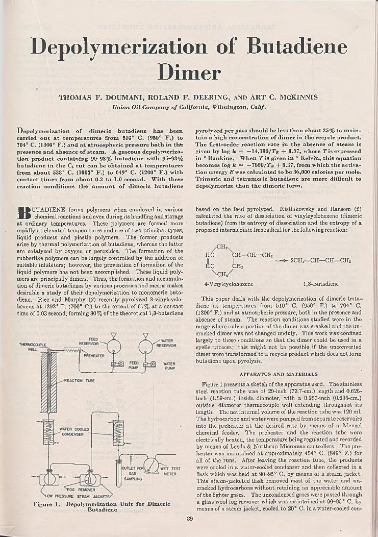
Depolymerization of Butadiene Dimer
TH O M AS F. DOUM ANI, ROLAND F. D EERIN G, AND A R T C. M cK IN N ISUnion Oil C om pany o f California, W ilm in gton , Calif.
D epolym erization o f dim eric butadiene has been carried out at temperatures from 510° C . (950° F .) to 704° C. (1300° F .) and at atm ospheric pressure both in thte presence and absence o f steam . A gaseous depolym erization product containing 90 -9 3 % butadiene with 95 -9 8% butadiene in the C< cut can be obtained at temperatures from about 538° C . (1000° F .) to 649° C . (1200° F .) with contact tim es from about 0.2 to 1.0 second. W ith these reaction conditions the am ou nt o f dim eric butadiene
pyrolyzed per pass should be less than about 2 5 % to m ain tain a high concentration o f dim er in the recycle product. T h e lirst-order reaction rate in the absence o f steam is given by log k = —14,180/7’b + 8.37, where T is expressed in ° Rankine. W hen T is given in ° Kelvin, this equation becom es log k = — 7880/Tb + 8.37, from which the activation energy E was calculated to be 36,000 calories per m ole. Trim eric and tetram eric butadiene are m ore difficult to depolymerize than the dimeric form .
BUTADIENE forms polymers when employed in various chemical reactions and even during its handling and storage
at ordinary temperatures. These polymers are formed more rapidly at elevated temperatures and are of two principal types, liquid products and plastic polymers. The former products arise by thermal polymerization of butadiene, whereas the latter are catalyzed by oxygen or peroxides. The formation of the rubberlike polymers can be largely controlled by the addition of suitable inhibiters; however, the prevention of formation of the liquid polymers has not been accomplished. These liquid polymers are principally dimers. Thus, the formation and accumulation of dimeric butadienes by various processes and means makes desirable a study of their depolymerization to monomeric butadiene. Rice and Murphy (S) recently pyrolyzed 3-vinylcyclo- hexene at 1292° F. (700° C.) to the extent of 61% at a contact time of 0.03 second, forming 80% of the theoretical 1,3-butadiene
Figure 1. Depolym erization U nit for Dimeric Butadiene
based on the feed pyrolyzed. Kistiakowsky and Ransom (2) calculated the rate of dissociation of vinylcyclohexene (dimeric butadiene) from its entropy of dissociation and the entropy of a proposed intermediate free radical for the following reaction:
HC CH—CH=CITs
1 c c h 2x c h /
4-Vinylcyclohexene
This paper deals with the depolymerization of dimeric butadiene at temperatures from 510° C. (950° F.) to 704° C. (1300° F.) and at atmospheric pressure, both in the presence and absence of steam. The reaction conditions studied were in the range where only a portion of the dimer was cracked and the uncracked dimer was not changed unduly. This work was confined largely to these conditions so that the dimer could be used in a cyclic process; this might not be possible if the unconverted dimer were transformed to a recycle product which does not form butadiene upon pyrolysis.
A PPAR A TU S AND M A T E R IA L S
Figure 1 presents a sketch of the apparatus used. The stainless steel reaction tube was of 29-inch (73.7-cm.) length and 0.626- inch (1.59-cm.) inside diameter, with a 0.250-inch (0.635-cm.) outside diameter thermocouple well extending throughout its length. The net internal volume of the reaction tube was 120 ml. The hydrocarbon and water were pumped from separate reservoirs into the preheater at the desired rate by means of a Manzel chemical feeder. The preheater and the reaction tube were electrically heated, the temperature being regulated and recorded by means of Leeds & Northrup Micromax controllers. The preheater was maintained at approximately 454° C. (849° F.) for all of the runs. After leaving the reaction tube, the products were cooled in a water-cooled condenser and then collected in a flask which was held at 90-95° C. by means of a steam jacket. This' steam-jacketed flask removed most of the water and uncracked hydrocarbons without retaining an appreciable amount of the lighter gases. The uncondensed gases were passed through a glass wool fog remover which was maintained at 90-95° C. by means of a steam jacket, cooled to 20° C. in a water-cooled con-
— > 2CHr=CH—CH=CHj
1,3-Butadiene
89

90 I N D U S T R I A L A N D E N G I N E E R I N G C H E M I S T R Y Vol. 39, No. 1
DISTAN CE FROM REA CTO R BOTTOM (IN C H ES)
Figure 2 . Reaction Tube Temperatures and Corresponding Relative Reaction Rate
Constants
denser, and finally passed through a wet test meter saturated with the gas to determine the volume of gases produced.
Experiments on the dimerization of butadiene indicated that the constitution of the compounds formed depend on the dimerization conditions. A dimer of practically constant boiling point and refractive index was obtained when butadiene was heated in closed vessels in the liquid phase at temperatures from 110° C. (230° F.) to 150° C. (302° F.). Data on the kinetics of this dimerization have been published (4). When higher dimerization temperatures—such as 399° C. (750° F.) to 482° C. (900° F .)—were employed, the product consisted apparently of a mixture of isomers, as indicated by the variation in refractive index with boiling point. The |ow temperature dimer was used to obtain the kinetic data. The high temperature dimer, the crude dimer-polymer mixture obtained by various polymerization conditions, as well as the trimer and tetramer of butadiene were studied to determine whether they could be depolymerized to butadiene. The trimer and tetramer were accumulated from crude dimerization products.
The gases formed by cracking the dimer were analyzed by a mass spectrometer. Analyses for butadiene were by the method of Cuneo and Switzer (1). The dimeric butadiene was analyzed by fractionation and determination of the refractive index and by density of the fractionated product.
REA C TIO N T E M P E R A T U R E S AND R A T E CO N STA N TS
To determine the true or effective temperature in the reaction tube, the reaction rates were plotted throughout the reaction tube
( l / T ) ( I 0 4 ) ,* R A N K IN E
Figure 3. Depolyxuerization o f Dim eric Butadiene in Absence o f Steam
as shown in Figure 2, and the average reaction rate was determined from this plot. The average rate selected is such that the area of the shaded portion above the average rate line is equal to the area of the shaded portion below the line. The temperature corresponding to this rate is the true average temperature and in all cases was nearly 11° F. lower than the arithmetical average temperature. In Figure 3 the k values were plotted using the true average temperature determined in the manner described; the first-order reaction rate equation is expressed as follows :
, 2 .303 , r a 1* = — log|_— J «
where k — reaction constant in reciprocal seconds t = contact time in secondsa = initial concentration of dimeric butadiene under the
reaction conditions in moles per liter x = amount of dimer depolymerized at any time t
The equation in Figure 3 is
log k = - 1 4 ,1 8 0 / ^ + 8.37
where T r is expressed in ° Rankine. When T is given in ° Kelvin this equation becomes
log k = -7 8 8 0 /7 ' + 8.37
from which the activation energy E was calculated to be 36,000 calories per mole.
E F F E C T O F D E P O L Y M E R IZ A T IO N C O N DITION S
When s’team was employed with the dimer, a reaction rate was obtained which was greater than that obtained in the absence of steam (Figure 4). These data were not sufficiently good to determine the order of the reaction but were plotted as first order for comparison with the results in the absence of steam (the straight line of Figure 4). The use of steam tended to suppress the deposition of carbonaceous materials on the tube walls.
Increasing the contact time for the depolymerization of dimeric butadiene at temperatures of 532° C. (990° F.) and 560° C. (1040° F.) in the absence of steam (Figure 5) caused the production of a less pure butadiene, less dimer in the liquid products, and a larger conversion to gas. The per cent dimer in the liquid product was an indication of the quality of the hydrocarbon for recycle. The average molecular weight of the gas found was a criterion of the per cent butadiene in the gas.
( l / T ) ( I 0 4 ),* R A N K IN E
Figure 4. Depolym erization o f Dim eric Butadiene in Presence o f Steam

January 1947 I N D U S T R I A L A N D E N G I N E E R I N G C H E M I S T R Y 91
CON TACT T IM E ,S E C O N D S
Figure 5. Effect o f Contact T im e on Depolym erization o f Dim eric Butadiene
T E M P E R A T U R E , *E
Figure 6. Effect o f Tem perature on Depolym crization o f Dim eric Butadiene
C on tact t im e , 0.40 se co n d ; d im e r purtial pressure, 130 m m .; d ilu en t, steam
The effect of temperature on the depolymerization of dimeric butadiene is given for contact times of 0.40 second (Figure 6) and 0.70 second (Figure 7) at dimer partial pressures of 130 mm. and 110 mm., respectively. The contact times used in this work were limited by the capacities of the feed pumps and the heating capacity of the cracking furnace. With these contact times, temperatures above 649° C. (1200° F.) did not appear feasible, since a good recycle product could not be obtained with conversions of more than about 25%. The possibility of obtaining improved results by employing higher temperatures and shorter contact times appears to be of interest. A gas containing a high percentage of butadiene (90 to 95%) was obtained for all conditions where the uncracked hydrocarbon was substantially the same as the feed.
Table I lists a number of gas analyses for various feeds. Column 2 shows the results of a run made with mixed butadiene trimer and tetramer feed. The conditions used for this run do not afford a good comparison with the other runs; however, the results indicate that trimer and tetramer were definitely inferior feeds compared with butadiene dimer. It can be seen that a
mixed feed of butadiene dimer and higher polymers was cracked to yield a CL fraction (hydrocarbons consisting of 4 carbon atoms) containing 90-98% butadiene, but the best feed was the pure butadiene dimer which yielded a gas containing 90-93% butadiene with 95-98% butadiene in the C4 cut. Dimeric butadiene formed at high temperatures (750-900° F.) was equivalent to the low temperature (about 300° F.) dimer for depolymerization to monomeric butadiene, even though it apparently consisted of dimer isomers.
Table II shows the results of three runs made using the condensed hydrocarbon from one run as the feed for the next. The results show that conversions of less than about 25% would have to be used to obtain a satisfactory recycle product.
DISCUSSION OF RESULTS
The results obtained in this work indicate the possibility of obtaining practically pure butadiene by depolymerizing dimeric butadiene. It was found that the temperature
T a b l e I. A n a l y s e s o f G a s f e o m D e p o l y m e r i z a t i o n o f B u t a d i e n e P o l y m e r sFeed
Temp., ° F.Temp., ° C.Contact time, sec. Conversion to gas,„ WV %Partial pressure of
hydrocarbon, mm. Boiling range of liquid
product, ° C.
Ana!., wt. % of gas H,CH,CjH«C iH iC,H,CiHjC.H,cat,CiHio
80% dimer + 20% higher polymers
Trimer + tetramer, impure
24 .0 58.7
73.6 35.30 .3 5 .62.1 0 .4
100.0 100.0
Dim er (b.p., 05% dimer Dimor (b.p., Dim er (b .p ., 70% dimer Dim er (b .p ., Dim er (b.p.,128-132° C.) (b .p., 125- 129-131° C.) 129-131° C.) + 30% 125-131* C.) 125-135* C.)
135° C .) higherpolymers
1306 1309 1178708 710 637
0.37 0 .62 0
48 ■ 51 45
51 150 109
< 65 (4 .1 % ); 65-125 (29 .8% ); 125-135 (24 .9% ); >135 (30 .1% ); loss (11.1% )
0 .34 .66 .52 .43 .2
1099593
0.72
23.4
122125-135
(9 0 % );>135(10%)
' 72 .9 7 .13 .0
100.0
2.02.20 .72.20 .5
92.4
100.0
1043562
1.70
13.7
760
997536
3 .2
14.6
760
1049565
0.94
15.7
115
< 1 2 5 (6 .3 % ); <126 (6 .3 % ); < 1 2 6 (1 9 .2 % ); 125-133125-135(8 7% );>135(6 .7% )
1.3 2.1 2.8 1.92 .3 0.2
82.93 .53 .0
100.0
126-132(7 1 % );>132(22.7% )
0.11.01.70.61.00.2
9 2 .82.00.6100.0
126-133(4 2% );>133(47.8% )
0.23 .57 .4 2.04 .4 0.0
71.211.3
100.0
1044 1065563 575
0 .96 0 .77
21.2 17.37
129 110
125-133(91 .1% );>133(8 .9% )
0 .2 0 .21 .0 2 .12 .2 2 .30 .8 1.31.4 1.70 .2
89.9 90 .84.1 1.10 .2 0 .5
100.0 100.0

92 I N D U S T R I A L A N D E N G I N E E R I N G C H E M I S T R Y Vol. 39, No. 1
T a b l e II. E f f e c t o f R e c y c l e o n D e p o l y m e r i z a t i o n o fD i m e r
Figure
C on tact
7. Effect o f Tem perature on Depolym cri- zution o f Dim eric Butadiene
tim e , 0.70 secon d ; d im or partia l pressure, 110 m m .; d ilu en t, steam
gradient in the reaction tube was quite sensitive to changes in feed rate. The partial pressure of the hydrocarbon gases varies as the cracking takes place. The partial pressures reported are the arithmetic averages of the partial pressures at the entrance and at the exit end of the reaction tube.
In general, low temperatures and relatively small conversions produced butadiene in the highest over-all yields, with a high percentage of dimer in the recycle product. The required tempera-
Run No. Feed type
T em p., ° F.T em p., ° C.Contact time, sec.Partial pressure of hydro
carbon, mm.Conversion to gas, wt. % Ay. mol. wt, of gas Dimer in condensed hydro
carbon, wt. %C< hydrocarbons in gas,
wt. %C«H« in C< cut, wt. %
C-33 C-34 C-35Dim er (b.p.,
129-131 C.)Condensed Condensed
hydrocarbons from C-33
hydrocarbon from C-34
1078 1076 1078582 581 582
0 .48 0 .4 8 0 .49
109 110 11319.8 17.3 15.052.0 50.6 48.7
95 90 68
95 93 8999 98
ture should be as close to the initial depolymerization (decomposition) temperatures as possible and still provide for a practical conversion per pass. In practice this makes necessary the employment of temperatures' somewhat higher than the initial decomposition temperature.
L IT E R A T U R E C ITED
(1) Cuneo, J. F., and Switzer, R . L., I n d . Eng». Chem., A n a l . E d ., 15,508 (1943).
(2) Kistiakowsky; G. B., and Ransom, W . W ., J . Chem. Phys., 7,.734 (1939).
(3) Rice, F. O., and Murphy, M . T., J. Am. Chem. Soc., 66, 765(1944).
(4) Robey, R. F., Wiese, H. K ., and Morrell, C. E., I n d . E n o .Chem., 36. 3 (1944).
P r e s e n t e d before the D ivision of Petroleum Chemistry at the 109th Meeting of the A m e r ic a n C h e m ic a l S o c ie t y , Atlantic C ity , N. J.
Formation of Static Electric Charges on Agitating Petroleum Products with Air
Ex p lo s io n s caused byelectric sparks require not
only the existence of high voltages but also a certain current density and the presence of an explosive mixture. Formation of an explosive mixture in air agitation depends on the vapor pressure of the liquid. If the vapor pressure is low, the concentration of the vapors in the air may be less than that corresponding to the low explosibility limit, whereas if the vapor pressure is very high, the concentration of vapors may be above the high explosibility limit and, in either case, no explosion occurs. Explosive mixtures of hydrocarbons of known composition can be calculated with a fair degree of accuracy (2), but these calculations are not applicable to commercial petroleum products which contain small quantities of volatile components. For these reasons the flash point remains the most reliable guide for such estimates.
Since the flash point determination is affected by the type of procedure selected, experiments were made for determining the relation between the Pensky-Martens closed-cup flash point (A.S.T.M. D93-36) and the explosibility of oil-air vapors obtained on agitating petroleum solvent and kerosenes of 92° to 110°F. flash points with air at various temperatures. The John- son-Williams explosibility indicator was used to measure the explosibility of the oil-air vapors obtained during the experiments. The work showed a close correlation between the flash points and the temperature of explosibility of oil-air vapors in commerical
C. M. KLAERNERM agnolia P etro leu m C om pany, B eau m on t, Texas
Solvent Temperature,o R889296
° Explosive limit *» 1.00.
agitators, as demonstrated by the following typical results secured with a petroleum distillate of 96° F. flash point:
Relative Explosibility of Vapors in Commercial Agitators0
0 .620 .851.00
It is believed, therefore, that the explosive temperature is within less than 1 ° F. of the flash point of the petroleum distillates.
The rate of air blowing should not have an appreciable effect on the explosibility limits, provided sufficient time is allowed to reach the equilibrium conditions. In plant practice the depth of the liquid in agitators is sufficient to allow the attainment ofequilibrium conditions during the passage of air-bubbles. Thismay be shown by the following typical data obtained by varying the air rate to a large commercial agitator of approximately 30- foot diameter with a liquid depth of 20 feet:
Agitation, Relative Explosibility of VaporsRelative Degree E volved from Commercial Agitator
None 0 .140 .1 0 0.610 .2 5 0 .640 .5 0 0 .591.00 0.6C

January 1947 I N D U S T R I A L A N D E N G I N E E R I N G C H E M I S T R Y 93
Air blowing is widely used in treating kerosenes with sulfuric acid and alkalies. Although water-washing is desirable between applications of acid and sodium hydroxide solution, this is not always done in actual plant practice and was omitted in the present experiments. These experiments were conducted with a large cylindrical tank agitator of the type mentioned with approximately the same liquid depth. A distribution pipe which supplied the air for agitation was located at the bottom of the agitator. Static charges developed in the agitator during treating were measured by means of an electrostatic voltmeter. No attempt was made to determine the current density; this was considered to be of secondary importance because of the necessity of first obtaining a spark in order to cause an explosion. This is determined by the voltage generated and the gradient between the charge and tank wall.
The observed voltages varied widely with the conditions of the atmosphere, as might be expected. The following results, however, were obtained in dry weather with air of about 50% relative humidity. In determining voltages generated, measurements were made at various intervals between the center of disturbance and the tank walls. The highest voltages were observed at points between the tank walls and the center of greatest disturbance; these were the voltages that were recorded. The following observations were made with apparatus which required a finite operating current, the effect of which was not specified. The potential readings, therefore, are relative and do not indicate undisturbed values, which might be hundreds of times those indicated by experimental measurement.
In the course of the experiments the following observations were made:
No charges were observed on blowing dry kerosene with air. This may possibly be ascribed to the insufficient sensitivity of the instrument used but served as an indication that the current density was not great.
During the acid-treating, voltages close to 1000 were detected. Apparently the acid globules surrounded with oil favored accumulation of fairly large quantities of electricity.
After the acid sludge was settled and withdrawn, the sodium hydroxide solution was added in small steps. Upon addition of a small amount of caustic the charges disappeared, notwithstanding the presence of certain quantities of water and vigorous air agitation. No satisfactory explanation of this phenomenon was developed.
Upon further additions of sodium hydroxide solution electric potentials well in excess of 1000 volts were observed. In some instances potentials as high as 2500-3000 volts were recorded.
Prevention of fire hazard involved in agitating light petroleum distillates may be secured either by eliminating the conditions leading towards formation of explosive mixtures, or by using devices favoring dissipation of electric charges within the agitators. The first can be accomplished by calculating the maximum temperature rise that would occur on treating. This can be done as follows:
In treating straight-run products such as kerosene or petroleum solvents in commercial equipment with reasonable quantities of surfuric acid, the temperature rise is not over 0.5 0 F. per pound of acid per barrel. It varies somewhat with the strength and quantity of acid used (S) and with the nature of charge stock used. Similar data can be established easily for other types of petroleum products. On neutralizing with caustic, the heat developed depends on the extent of sludge separation, but it seldom results in a temperature rise over 8°F. This information, as well as the knowledge of the flash point of the stock treated, permits an easy estimation of the maximum safe temperature for the charge stock in the agitators’.
The problem of dissipating electric charges is more complex horn the practical viewpoint. Maintenance of a highly humid atmosphere at the top of the agitators for creating conditions favorable to dissipation of electric charges is difficult, particularly because of the tendency of the acid to pick up moisture. Another method involves the use of metal screens. However,
Jr orm ation o f static electric charges in petroleum products flowing through pipe lines or subjected to air agitation is a well known phenom enon which has been investigated at various tim es because o f its practical im portance in preventing fire hazards. A m in im u m 300-volt potential m ay be considered as representing the dangerous sparking lim it (4) under the conditions th at m ay at tim es be encountered in plant practice around petroleum refineries, although potentials well in excess o f this m ay frequently be generated w ithout causing sparking. Potentials o f several thousand volts are easily generated by friction produced by petroleum distillates flowing through pipe lines at a velocity o f a few feet per second. T he term inal velocity o f air hubbies rising through light petroleum products depends on viscosity and gravity o f the liquid m edium but is o f the sam e m agnitude (5). The size o f plant agitators does not afford m eans for a quick dissipation o f electric charges by contact with m etal walls; this facilitates accum ulation o f high voltages in excess o f those that can be expected in pipe flow experiments.
this requires that the screen be kept close to the surface of the liquid, because otherwise new charges will be formed while the air bubbles rise from the screen to the surface. The distance at which such screens are capable of protection depends also on their mesh size, as demonstrated by the following data obtained by immersing screens of various mesh sizes at different depths below the petroleum liquid level in the agitator:
________Maximum Voltage, Approx. % ________Screen Mesh, 2-in. screen -1-in. screen 8-in. screen
In. immersion immersion immersionN o screen 100 100 100
5 75 85 1002 50 70 901 35 50 750 .5 25 35 650 .2 5 ‘ 15 25 45
Another method of achieving protection from sparking is the hanging of wires at close intervals between the top and bottom of the tank so that they penetrate the oil surface.
In connection with these discussions it may be of interest to mention that observations are reported (1) claiming that gasoline, after passing over copper or brass filings, completely loses its ability to acquire electric charges when it flows over a metal surface; zinc powder, on the other hand, has temporary effect only, and magnesium and iron filings have no influence whatever.
A C K N O W L E D G M E N T
The writer would like to express his appreciation to J. W. Newton, W. W. Leach, and P. L. Smith for permission to publish this manuscript, and to V. A. Kalichevsky for valuable suggestions in carrying out the experimental work and in the preparation of this paper. He also acknowledges the helpful assistance of Morris Muskrat, S. S. Mackeown, and G. M. Pearson, who reviewed the manuscript.
L IT E R A T U R E C IT E D
(1) Bruninghaus, L., Recherches inventions, 7, 735-7 (1936).(2) Jones, G. W ., Bureau of Mines, Report of Investigations, 3787
(1944); Mack, E., Boord, C. E., and Barham, H. N., In d . E n g . C hem., 15, 9 6 3 - 5 (1 9 2 3 ) .
(3) Kalichevsky, V. A., and Stagner, B. A., “ Chemical Refining ofPetroleum” , 2nd ed., New York, Reinhold Pub. Corp., 82,1942.
(4) Mackeown, S. S., and Wouk, V., I n d . E n g . Chem., 34, 659-64(1942).
(5 ) Miyagi, O., Phil. Mag., 5 0 , 112-40 (1925).
P r e s e n t e d before the Texas Regional M eeting o f the A m e r ic a n C h e m ic a l S o c ie t y at Austin, Texas, 1945.

Plasticizing GR-S and Natural RubberARNOLD R. DAVIS
A m erica n C yanam id C om pan y, S tam ford , C onn.
A n o th e r class o f chem icals, the o,o'-diacyIam inodipIienyI disulfides, arc shown to prom ote the plasticization o f G R -S with h ot m astication . o,o '-D ibcnzam idodiphenyl disulfide has been shown to he a catalytic plasticizer for G R -S and natural rubber with hot m astication . T h e data point out the possibility o f decreasing the tim e and thereby the power required to obtain a desired plasticity, or the possibility o f producing softer rubber in a given tim e. The control o f additional gel form ation and also actual reduction o f gel with hot processing o f G R -S in the presence o f o,o'-d ibcnzam idodiphenyl disulfide is show n. Th is indicates possible im provem ent in quality, and, with lower viscosities, possible im provem ent in processing characteristics. Physical properties obtained w ith cold m asticated G R -S and natural rubber m ay be obtained with the sam e elastom ers plasticized by use o f o ,o '-d i- benzam idodiphenyl disulfide w ith h ot m astication . The sim ilarity in the chem ical nature o f the plasticization o f G R -S and natural rubber is shown.
BUTADIENE-STYRENE copolymers have been plasticized by mastication and thermal processes similar to those used
for natural rubber. It is generally known that the copolymer GR-S does not yield to plasticization processes as well as or to the same extent as does rubber. Several explanations for this difference have been advanced (16). The tendency for GR-S (17). to eyclize or form gel in hot processing and the presence of an antioxidant undoubtedly have counter effects on the plasticization.
The mastication of rubber and a crude use of the thermal process of softening rubber date back over 125 years to the days of Thomas Hancock (14). However, it was only during the last 25
0,0 -Qdd. o.o’-Od.d. o.o'-D.Ad.
Figure 1. Cold and H ot Banbury M illing Compared with H ot Banbury M illing w ith o,o'-D ibenzam idodiphenyl Disul
fide in G R -ST o ta l m illin g tim e , 6 m in u te s ; b a tch , 230 gram s; co ld B an bu ry in it ia l tem p eratu re , 30° C . (co ld w ater o n ) ; h o t B an bu ry ja c k e t , 153° C -; ro tors ,
100° C.
years that the nature of the plasticization process became known. The first indication that atmospheric oxygen might play a part in plasticizing rubber is said (16) to be a conclusion to a report of the Research Association of British Rubber Manufacturers in 1921 stating: “The effect produced by milling can be imitated by heating rubber in the presence of oxygen or air.” The work supporting this conclusion was also published (9) by Fry and Porritt in 1927. A few years later Grenquist (19) showed that a breakdown analogous to that brought about by milling could be obtained by heating rubber in air.
In a study of the loss of unsaturation in rubber during milling, Fisher and Gray (8) suggested that the breakdown or plasticization during milling is chemical in nature and is caused by oxygen. Schack- lock (15) showed that a new compound was formed from rubber by milling it in air. He assumed this c o m p o u n d was formed by oxidation. Cotton (5), and a little later Busse (1), showed conclusively that oxygen is necessary for the plasticization of rubber during mastication or
milling. Comes (4) showed that rubber could be plasticized by niastication in an internal mixer at high temperatures (up to 400° F.). Busse and Cunningham (8) showed that oxygen is required for the plasticization of rubber with mastication in an internal mixer at temperatures of 160° to 325° F. After a long study of thermal plasticization of rubber, Farberov and Margo- lina (6) concluded that, for a given set of thermal conditions, oxygen is , the fundamental factor in thermal plasticization. Hagen (13) stated that oxygen is required for the thermal plasticization of the butadiene-styrene copolymer, Buna S.
Since it is now evident that the plasticization of rubber and butadiene-styrene copolymers involves a chemical reaction, one would expect to find a number of catalysts for the reaction. These chemicals would be used in relatively small amounts to decrease the time or to reduce the temperature required to give a desired plasticity, as well as to give increased plasticity in a given time. The plasticization catalysts might avoid the use of large amounts of commonly used softeners which function largely through dilution, swelling, and lubrication of the elastomer. Ac-
Figurc 2. H ot Banbury Plasticizing o f G R -S w ith o ,o '-D iben zam ido-
diphcnyl DisulfideB an bu ry ja c k e t , 153° C .; ro tors , 100° C .; b a tch , 250 g ra m s ; to ta l t im e in B an bu ry ,
6 m in u tes
94

January 1947 I N D U S T R I A L A N D E N G I N E E R I N G C H E M I S T R Y 95
TOTAL TIME IN BANBURY, MINUTES
Figure 3. H ot Banbury Plasticizing o f G R -S with o ,o '-D iben z-
am idodipbenyl DisulfideB a n b u ry ja c k e t , 153° C .; ro to rs , 100° C .;
b a tch , 250 gram s
tually, a number of such catalysts have been found, and several have had considerable practical application during the past ten years.
Zimmerman and Cooper (24) stated in 1928 that diphenyl- guanidine as well as some antioxidants were known to be softeners for rubber. To date many rubber technologists have undoubtedly observed that the commonly used guanidine accelerators are effective plasticizers for rubber, particularly with hot milling. Piperidinium pentamcthylene dithiocarbamate has been shown to plasticize lightly vulcanized rubber on milling (SO). Mer- captobenzothiazole (5) and some of its derivatives are known to promote the plasticizing of rubber with hot mastication. The hydrazines (S, SI), particularly phenylhydrazine and its salts, thiophenols (aromatic mercaptans) (3, SS), and various nitroso compounds, including nitroso-/3-naphthol (7, S3) have been used
T a b l e I. H o t B a n b u r y 0 P l a s t i c i z i n g o f GR-S w i t h T y p i c a l o , o ' - D i a c y l a m i n o d i p i i e n y l D i s u l f i d e s
C h e m i c a l F o r m u l a : N H O C R R C O H N -
Control G R -S (blend of 4 polymers)■o.o'-Diacetamidodiphenyl disulfide ■o.o'-Dibutyramido diphenyl disulfide ■o.o'-Di-isobutyramidodiphonyl disul
fide >•o.o'-Dicrotonamidodiphenyl disulfide o.o'-Dipalm itam idodiphenyl disulfide o.o'-Dibenzam idodiphenyl disulfide o»o'-Dibenzamidodiphenyl disulfide
a Banbury jacket, 162° C ., rotors, 100° C .; batch , 200 grams G R -S ; •total time in Banbury, 6 minutes.
b Lower Y values and recovery figures indicate softer G R -S .
T a b l e II. H o t B a n b u r y “ P l a s t i c i z i n g
— s -------- q
% . Williams 1-Minuteasticizer 3-M in. Yb R ecovery
on at 100° C., at 100° C.GR-S Mils Mils0 103 491 .5 85 331.5 93 45
1.5 86 411 .5 94 472 .4 97 461 .5 81 351 .0 86 38
’Control G R -S (blend of 4 polymers)•PiP -Diacetamidodiphenyl disulfide
(a form).P.p'-Diacetamidodiphenyl disulfide
(0 form).P>p'-Dibutyramidodi phenyl disulfide P*P/"Dibenzamidodipnenyl disulfide o.o -Dibenzamidodiphenyl disulfide'^O^trol G R -S (blend of 3 polymers)0,0 ~PiP.en2ab1idodiphenyl disulfide m,m -D ibenzam idoaiphenyl disulfide
“ Banbury jacket at 162° C .; rotors at 100° C.; total time in Banbury, 6 minutes.
% . Williams 1-Min.Plasticizer 3-M in. Y R ecover
on at 100° C ., at 100° CG R-S Mils M ils0 103 49
1 .5 101 51
1 .5 100 441 .5 102 512 .0 106 531 .5 81 350 119, 401 .5 93 241 .5 144 91
MILS
12011010090
80
70
60
50
4 0
30
20100
IW LUAM S yW IN .Vot 100'C. S3l-MIŃ. RECOVERY ol 100'C.
00 ,0 '-D . d .d .
40*C .
1.5% * o,o*-D.d.d.
4 0*C .
1.5% o .o-.D .d-d .
II 5*C.
1.5% o,o'-D.d.d.
162 *C.
batch , 200 grams G R -S ;
Figure 4. Plasticities o f G R -S Containing Ojo'-Dibenzamiclodiphcnyl Disulfide at D if
ferent Banbury Tem peraturesB a tch , 250 g ram s ; to ta l t im e in B an bu ry , 6 m in u tes
to plasticize rubber. Certain aromatic mercaptans (10), the zinc (18) salts of aromatic mercaptans, and nitroso-/3-nnphthol have found some application in plasticizing GR-S with hot mastication.
The fact that several of these chemicals, although in different ratios, aid in plasticizing GR-S and natural rubber under like conditions again indicates similarity in the nature of the plasticization process for the two elastomers.
Bussc and Cunningham (8) called the hydrazine compounds and thiophenols true mastication accelerators or oxidation catalysts. Since these materials do not affect the aging qualities of the cured rubber stocks, it might be better to call them plasticization catalysts or catalytic plasticizers.
As a result of research work on the problems of plasticizing GR-S, a number of o,o'-diacylaminodiphenyl disulfides or bis(o- acylaminophenyl) disulfides were found to be effective plasticizers for GR-S with hot mastication. Several of this class of chemicals were also found to be very active in plasticizing natural rubber during hot mastication. Table I shows the results obtained with a number of typical o,o'-diacylaminodiphcnyl disulfides in GR-S with hot Banbury milling.
EXPERIMENTAL METHODS
A small laboratory Banbury mixer (approximately 310-320 grams of polymer capacity) was used for most of the work. The jacket of the Banbury could be heated to 162° C. (80 pounds steam pressure) and the rotors to 100 0 C. The chemical plasti- cizer was added 0.5 minute after the elastomer was loaded into the Banbury.
A 6 X 12 inch laboratory mill at 50-60 ° C. was used to crepe out the batches from the Banbury and to facilitate cooling. Some experiments in open mill plasticizing were run with the 6 X 12 inch mill at 115 0 to 120 ° C. In these experiments the plas- ticizer was added 1 minute after the polymer was put on the mill.
Banbury and mill temperatures were checked with a surface pyrometer. The temperature of the rubber on dumping from the Banbury was determined with a needle pyrometer. With Banbury temperatures of 153° C. (jacket) and 100°C. (rotors), GR-S showed a temperature of 149 ° C. on dumping. When temperatures of 162° C. (Banbury jacket) and 100 °C. (Banbury rotors) were used, the GR-S showed a temperature of 157° C. In the case of natural rubber, temperatures somewhat higher than the Banbury jacket temperature were observed (Figure 9).
GR-S from one source was used for some of the work, whereas a blend of GR-S polymers from several sources was used for other parts of the work.
In the Banbury, batches of 200 to 310 grams of GR-S were used, whereas on the 6 X 1 2 inch mill batches of 320 grams were used. Separate batches of 250 grams were milled for the indicated time in determining the change of plasticity with time of milling, instead of individual samples being removed from a single

96 I N D U S T R I A L A N D E N G I N E E R I N G C H E M I S T R Y Vol. 39, No. 1
0 1.0 1.5 2.0PERCENT 0,6" DIBENZ AMIDODIPHENYLOISULFIDE ON GR-S
Figure 5. Effect o f o,o '-D ibenzam idodiphcnyl Disulfide on Gel in H ot Processing o f G R -S
B an bu ry ja c k e t , 162° C .; ro tors , 100° C .; b a tch , 250 gram B; tota l t im e in B an bu ry , 6 m in u tes
120110
4 60
INITIAL TEMR >35*0. WATER ON
INITIAL TEMR MU'C.-HELD AT I20*C.DURING MILLING
I WILLIAMS 3-MIN. Y o t 100’ C.I'MINUTE RECOVERY ot 100*0.
UNMILLEDAVERAGE
COLD MILL JO MIN.
HOT MIU 10 MIN.
HOT MILL 10 MIN. *
1.0% o,o'D.d.d.
Figure 6. Comparison o f Cold and Ilot M ill Plasticizing o f G R -S with o,o'-D ibenzam idodiphenyl Disulfide
batch at the end of the time period. Plasticity measurements were made after the milled batches had been cooled to room temperature.
Both the Williams plastometer and Mooney viscometer at 100° C. were used. The Williams plasticity values are shown as the Williams 3-minute Y at 100° C. in mils (0.001 inch) and represent the thickness of a 2-cc. pellet after 3-minute compression at 100 ° C. under a load of 5000 grams. The 1-minute recovery at 100° C. is the increase in thickness of the pellet one minute after removal of the 5000-gram load. The Y values and recovery figures are the averages of at least two determinations.
The character of the GR-S before and after milling rvas determined by procedures for the determination of gel, swelling index, and dilute solution viscosity of Mullen and Baker (19).
For the mastication in nitrogen the gas was led into the Banbury through a hole in the ram, and a continuous flow and a positive pressure of 2 to 3 inches of water was maintained during the milling. The nitrogen was passed through a washing tower containing pyrogallol and then through a calcium chloride drying tower before admission to the Banbury. After the Banbury was flushed with nitrogen, the plasticizer and rubber were added simultaneously. No attempt was made to eliminate any air that might be contained in the GR-S or rubber.
Cut growth tests were run on the DeMattia flexing machine at 375 flexes per minute. In the case of GR-S the angle of bend was 135°. With natural rubber the angle of bend was 180°.
' <n 9 0; -JI 2
Table I shows that the o,o'-diacylaminodiphenyl disulfides, or bis(o-acylaminophenyl) disulfides, promote the plasticization of GR-S with hot milling. The activity varies with the hydrocarbon of the acyl group, the o,o'-dibenzamidodiphenyl disulfide being the most active.
T a b l e III. E f f e c t o f o , o ' - D i b e n z a m i d o d i p k e n y l D i s u l f i d e o n G e l in H o t P r o c e s s i n g o f GR-S°
Expt. N o. Unmilled G - l G-2 G-3 G-4G R -S (polym er A) 100 100 100 100 100Plasticizer at 0.5 min. s . . . 0 1 .0 1 .5 2 .0
Total milling time, min. 0 6 6 6 6
N ot Creped twice through 6 Xcreped 12 in. mill at 50 -55° C .
Plasticity testsWilliams 3-min. Y at 100° C ., mils 1-min. recovery at 100° C ., mils
Character of GR-S % gelSwelling index Dilute soln. viscosity
Plasticity tests after 18 hr.Williams 3-min. Y at 100° C ., mils 1-min. recovery at 100° C ., mils
Character of G R -S in ball after 18 hr. % gelSwelling index Dilute soln. viscosity
139 131 109 100 9180 62 37 28 23
19.6 25 .7 15.1 8 .3 2 .9135 91 160 208 1781.38 1.19 1.23 1.42 1.46
I Cloth (Slow Cooling)
137 118 103 9096 54 •10 24
29.5580 .9 8
21.6801.03
16.91021.08
13.61571.11
a Banbury jacket at 162° C .; rotors at 100° C .; batch, 250 grams,
The property of accelerating the plasticization process is specific for the o,o'-diacylaminodiphenyl disulfides. In other words, when the amido group is in any other position on the phenyl ring relative to the sulfur atom, the resulting chemical shows no plasticizing action. The results obtained with a number of other diacylaminodiphenyl disulfides in GR-S are shown in Table II.
'the m.m'-dibenzamidodiphenyl disulfide and the p,p'-dibenz- amidodiphenyl disulfide were tested in natural rubber, as compared with the o,o'-dibenzamidodiphenyl disulfide; at the concentration used (0.25% on the rubber), only the o,o'-dibenzamido- diphenyl disulfide showed plasticizing effect with hot mastication.
o,o'-Dibenzamidodiphenyl disulfide, or bis(o-benzoylamino- phenyl) disulfide, is a light yellow crystalline material with a melting point range of 136° to 143° C. and a specific gravity of approximately 1.35. It has practically no odor and shows no internal or external toxic effects on animals. Months of preparing and testing o,o'-dibenzamidodiphenyl disulfide showed no evidences of toxic effects from handling the material or the plasticized rubbers.
o.o'-DIBENZAMIDODIPHENYL DISULFIDE IN GR-S
A comparison of cold and hot Banbury milling with no plas- ticizcr and hot Banbury milling with 1.5% of o,o'-dibenzamido- diphenyl disulfide was made in order to demonstrate further its plasticizing action. This comparison and the resulting effects on the Mooney viscosity are shown in Figure 1. Cold Banbury milling gave only a small change in the Mooney viscosity in 6 minutes. Hot Banbury milling gave a slightly lower viscosity than the cold milling. However, these reductions in the viscosity are small compared to that obtained by using 1.5% o,o'-dibenz- amidodiphenyl disulfide with hot mastication. Lower Mooney viscosity values indicate softer or more plastic GR-S (Figure 1).
G R - S - X - 5 5 + 1 .5% . o .o '- D .d .d — B A N . J A C K E T A T 1 5 V C . ---------------------
8 L E N 0 O F 4 P O L Y M E R S + 2 . 0 % o .o '-R d .d .~ B A N . J A C K E T A T I 2 7 * C . _
BLEN 0 OF 3 POLYM ERS + L5% o ,o '-D .d .d .-BAN . JA C K ET AT 16 2 *0 .
_L _L _L I10 , 15 2 0 25 3 0 35
DAYS AT ROOM TEM PERATU RE
Figure 7. Effect o f Storage T im e on Plasticity o f G R -S with o,o'-Dibenzam idodiphenyI Disulfide afler H ot Banbury M illing
R otors , 100° C .; tota l t im e in B an bu ry , 6 m in u tes
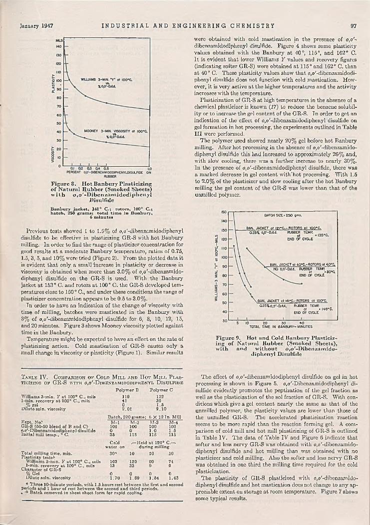
January 1947 I N D U S T R I A L A N D E N G I N E E R I N G C H E M I S T R Y 97
Figure 8. H ot Banbury Plasticizing o f Natural Rubber (Sm oked Sheets) ■with o ,o '-D ib e n za m id o d ip h e n y l
Disulfide
B an bu ry ja c k e t , J41° C .; rotora , 100° C .; b a tch , 250 g ram s ; to ta l t im e in B an bu ry ,
6 m in u tes
Previous tests showed 1 to 1.5% of o,o'-dibenzumidodiphcnyl disulfide to be effective in plasticizing GR-S with hot Banbury milling. In order to find the range of plasticizer concentration for good results at a moderate Banbury temperature, ratios of 0.75, 1.5, 3, 5, and 10% were tried (Figure 2). From the plotted data it is evident that only a small increase in plasticity or decrease in viscosity is obtained when more than 3.0% of o,o'-dibenzamido- diphenyl disulfide on the GR-S is used. With the Banbury jacket at 153° C. and rotors at 100° C. the GR-S developed temperatures close to 150° C., and under these conditions the range of plasticizer concentration appears to be 0.5 to 3.0%.
In order to have an indication of the change of viscosity with time of milling, batches were masticated in the Banbury with 3% of o,o'-dibenzamidodiphenyl disulfide for 6, 8, 10, 12, 15, and 20 minutes. Figure 3 shows Mooney viscosity plotted against time in the Banbury.
Temperature might be expected to have an effect on the rate of plasticizing action. Cold mastication of GR-S causes only a small change in viscosity or plasticity (Figure 1). Similar results
were obtained with cold mastication in the presence of o,o'~ dibenzamidodiphenyl disulfide. Figure 4 shows some plasticity values obtained with the Banbury at 40°, 115°, and 162° C. It is evident that lower Williams Y values and recovery figures (indicating softer GR-S) were obtained at 115° and 162° C. than at 40° C. These plasticity values show that o,o'-dibonzamidodi- phenyl disulfide does not function with cold mastication. However, it is very active at the higher temperatures and the activity increases with the temperature.
Plasticization of GR-S at high temperatures in the absence of a chemical plasticizer is known (17) to reduce the benzene solubility or to increase the gel content of the GR-S. In order to get an indication of the effect of o,o'-dibenzamidodiphenyl disulfide on gel formation in hot processing, the experiments outlined in Table III were performed.
The polymer used showed nearly 20% gel before hot Banbury milling. After hot processing in the absence of o,o'-dibenzamido- diphenyl disulfide this had increased to approximately 26% and, with slow cooling, there was a further increase to nearly 30%. In the presence of o,o'-dibenzamidodiphcnyl disulfide, there was a marked decrease in gel content with'hot processing. With 1.5 to 2.0% of the plasticizer and slow cooling after the hot Banbury milling the gel content of the GR-S was lower than that of the unmilled polymer.
BATCH S IZ E .250 ,m s .
BAN. JACKET ot !2 rC .~ ROTORS ot tOO*C.0.25% 0,0'-D.d.d. RUBBER TEMP,
atEND OF CYCLE
BAN. JACKET ot 40*C.-RQ T0RS ot 40*0 . NO O.O'-adjd. RUBBER TEMR
at *80*0 .ENO OF CYCLE
BAN. JACKET at WI*C.-ROTORS at IOO*C. Q 25X 0 ,0 '-nd .d . RUBBER TEMR
at « 146* C. ENO OF CYCLE
10 20 30 40TOTAL TIME IN BANBURY-MINUTES
Figure 9. H ot and Cold Banbury Plasticizing o f Natural Rubber (Sm oked Sheets),with a n d w ith o u t o .rt^ -T jih e n ^a m id o -without o,o '-D ibenzam ido-
diphenvl Disulfide
T a b l e IV. C o m p a r i s o n o f C o l d M i l l a n d H o t M i l l P l a s t i c i z i n g o f GR-S w i t h o ,o '- D i b e n z a m i d o d i p h e n y l D i s u l f i d e
Williams 3-min. Y at 100° C ., mils 1-min. recovery at 100° C ., mils
BelDilute soln. viscosity
Expt. N o!GR-S (50-50 blend o f B and C) o,o'-Dibenzaraidodiplienyl disulfide Initial mill temp., ° C.
Total milling time, min.Plasticity testst
Williams 3-min. Y at 100° C ., mils 1-min. recovery at 100° C-, mils
Character of GR-S % GelDilute soln. viscosity
Polym er B Polym er C119 12241 390 1 .52. 01 2 .1 0
Batch, 320 grams; 6 X 12 In. M illM -l M -2 M -3 M -4100 100 100 1000 0 1 .0 1 .535 115 115 115
Cold ,—Held at 120® C .- -water on during milling
30* 10 10 10
103 120 90 7413 33 9 9
0 0 0 01.70 1.89 1.54 1 .43
“ Three 10-minute periods, with 1.5 hours rest between the first and second periods and 1 hour of rest between the second and third periods.* '° Batch rem oved in sheet sheet form for rapid cooling.
The effect of o,o'-dibenzamidodiphenyl disulfide on gel in hot processing is shown in Figure 5. o,o'-Dibenzamidodiphenyl disulfide evidently promotes the peptization of the gel fraction as well as the plasticization of the sol fraction of GR-S. With conditions which give a gel content nearly the same as that of the unmilled polymer, the plasticity values are lower than those of the unmilled GR-S. The accelerated plasticization reaction seems to be more rapid than the reaction forming gel. A comparison of cold mill and hot mill plasticizing of GR-S is outlined in Table IV. The data of Table IV and Figure 6 indicate that softer and less nervy GR-S was obtained with o,o'-dibenzamido- diphenyl disulfide and hot milling than was obtained with no plasticizer and cold milling. Also the softer and less nervy GR-S was obtained in one third the milling time required for the cold plasticization.
The plasticity of GR-S plasticized with o,o'-dibenzamido- diphenyl disulfide and hot mastication does not change to any appreciable extent on storage at room temperature. Figure 7 shows some typical results.

98 I N D U S T R I A L A N D E N G I N E E R I N G C H E M I S T R Y Vol. 39, No. 1
T a b l e V . E f f e c t o f o , o ' - D i b e n z a m i d o d i p h e n y l D i s u l f i d e o n M a s t i c a t i o n in Am a n d N i t r o g e n
(Tim e in Banbury, 6 minutes; Banbury rotors, 100° C .; batch, 250 grams)
T a b l e VI. P h y s i c a l P r o p e r t i e s o f V a r i o u s C o m p o u n d s a f t e r P l a s t i c i z a t i o n a n d H o t M a s t i c a t i o n
Air NitrogenV o
o.o '-D iben-zamido-diphenylDisulfide
Williams 3-min. Y
at 100° C .,
mils
1-min. recovery
at 100° C .,
mils
W illiams 1-min.3-min. Y recovery
at at100° C ., 100° C.,
mils mils
Banbury jacket at 153° C.GR-SGR-S
Smoked sheets Smoked sheets
01.5
11893
4732
Banbury jacket at 141° C.00 .25
14384
2210
129109
180128
6038
6122
BANBURY JACKET 01 50*C. ROTORS at 50*C.
2 «5
Oy o '-D IB E N Z A M ID O D IP IIE N Y L D IS U L F ID E IN N A T U R A L RU BBER
It was stated earlier that o,o'-dibenzamidodiphenyl disulfide had been found to be a plasticizer for natural rubber with hot mastication. The preliminary tests indicated that much lower concentrations of plasticizer were effective in natural rubber than were required for GR-S. Concentrations of 0.0625, 0.125, 0.25, 0.5, and 1.0% on the rubber were tried with the Ban
bury jacket at 141° C. and the rotors at 100° C. (Figure 8). The curves for the 'Williams Y values and Mooney viscosity figures show that there is only a small gain in plasticizing effect when more than 0.5% of plasticizer is used. The actual effective range of concentration appears to be 0.05 to 0.5 % of o,o'-dibenz- amidodiphcnyl disulfide on the rubber.
As with GR-S, temperature has its effect on the plasticizing action in rubber. The plasticizer activity increases with the temperature. This effect is illustrated in Figure 9 along with a comparison of hot Banbury plasticizing with o,o'-dibenzamido- diphenyl disulfide and cold Banbury mastication with no plasticizer. A desired plasticity can be
BAN8URY JACKET ol 153'C. ROTORSol IOO* C.
HOT
10U2SXo.o’-D.la.
oxO.O'-D.dA
Figure 10. I lo t and Cold Banbury M illing o f N atural Rubber (Sm oked Sheets) with and w ithout o ,o '-D ibenzam ido-
diphcnyl DisulfideM illin g to sam e p la stic ity ; W illiam s 3 -m in u te Y at 100° C .,
94 m ils ; b a tch , 250 gram s
obtained in a much shorter time with hot milling and the plasticizer than can be obtained with cold mastication and no plasticizer. This fact is more clearly shown in Figure 10 where, under the conditions used, 0.125% of the plasticizer gave the desired plasticity in one fourth of the time required for cold mastication.
N A T U R E O F P L A S T IC IZ IN G ACTIO N
Hagen (13) stated that oxygen is required for the thermal softening of butadiene-styrene copolymers, and it was shown (5) that oxygen is essential for the best results with some catalytic plas- ticizers in the hot mastication of natural rubber. Probably oxygen plays a part in the plasticizing action of o,o'-dibenzamido- diphenyl disulfide during hot mastication of GR-S and natural rubber. In order to get some clue regarding the nature of this plasticizing action, a few experiments were performed comparing mas-
G R -S (blend of 4 polymers)G R -S hot Banbury-plasticized
fo o.o'-dibenzaniidodiphenyl disulfide on GR-S ulfur
EPC black Zinc oxideBenzothiazyldisulfide Di-o-tolylguanidine Unsatd. petroleum softener Plasticity test after remilling, Williams 3-min.
Y at 100° C., mils
Plasticity tests after 2.5 hr. in boiling HiO Williams 3-min. Y at 100° C ., mils Change on heating, %
Shore hardness (0.5-30-sec. dwell) after cure at 141° C .fo r
30 min.60 min.90 min.
Shore hardness o f cut-growth strips (30-sec. dwell, cured 60 min.)
UnagedAged 24 hr. at 100° C.
Cut growth rate, m ils/1000 flexes (60-min. cure)
UnagedAged 24 hr. at 100° C.
Bashore rebound (60-min. cure), %Torsional hysteresis K at 138° C. after cure
for 30 min.60 min.90 min. •
Tear resistance0, lb ./O .l in., after 60-min. cure at
25° C.100° C.
° Angle tear test o f Graves (11).
C om pd. Gom pd. Com pd. 1 2 3100
100 101.50 0 1 .52 2 250 50 505 5 50 .495 0.495 0 .4950.705 0.705 0 .7055 5 5
135 128 111
171 170 161+ 2 7 + 33 + 4 5
65-58 66-57 67-5869-60 69-60 69-6170-61 70-62 70-62
59 58 5862 63 63
22 21 2043 52 4435 36 35
0.150 0 .152 0 .1060.143 0.140 0.1540 .145 0.142 0 .158
23 .4 23 .0 22 .918.4 16.9 16.9
tication in air and mastication in an atmosphere of nitrogen. As in all of the previous work, unmilled GR-S and unmilled natural rubber were used. No attempt was made to eliminate any dissolved oxygen the polymers may have contained. The Banbury, of course, is not gastight; even though the nitrogen was washed and a positive pressure maintained in the Banbury during mastication, traces of oxygen may have been present in addition to those carried in with the rubber. However, the results in Table V show that there is a marked difference in the plasticity values obtained by hot mastication in ordinary air and in an atmosphere of nitrogen. The Williams Y values and the recovery figures are much higher (indicating harder rubber) with'hot mastication in nitrogen, both for GR-S and natural rubber with and without the plasticizer, than with hot Banbury milling in the regular atmosphere. These results indicate that oxygen is essential for the best results with o,o'-dibenzamidodiphenyl disulfide in plasticizing GR-S and natural rubber during hot mastication.
The process of plasticizing GR-S and natural rubber with hot mastication is chemical in nature and involves an oxidation reaction. All of the data presented show that o,o'-dibenzamido- diphenyl disulfide is a catalyst for the plasticization of GR-S and natural rubber with hot mastication.
In all of this work the plasticizer was added to the GR-S or natural rubber shortly after the Banbury or mill had been loaded. Recent work indicated the possibility of adding the o,o'-dibenz- amidodiphenyl disulfide to the GR-S latex or natural rubber latex prior to coagulation. The coagulated polymer may be wrashed and dried as usual. The dried GR-S or natural rubber containing the desired amount of plasticizer can then be plasticized by the usual hot mastication methods.
E F F E C T O F C OM PO U N D IN G IN G R E D IE N T S
Sulfur has a strong retarding effect on the plasticizing action. Channel black retards to a lesser extent than sulfur, whereas materials such as zinc oxide, clay, and calcium carbonate have little

January 1947 I N D U S T R I A L A N D E N G I N E E R I N G C H E M I S T R Y 99
2«o
raAGED24!»s.B>I0CTC lUNAGEO
COLOMILL
HOT BANBURY
15%0,0U d d.
L5%no'-Ct4d.
Figure 11. C ut-G row th R ate and Tensile Strength o f Tire Tread Type G R -S C om pound with o,o'-D ibenzam idodiphenyI
Disulfide (60-M inute Cure at 141° C .)
or no effect on the plasticizing action in GR-S and natural rubber. Certain accelerators and antioxidants retard the action of o,o'~ dibenzamidodiphenyl disulfide to some extent. For maximum plasticizing effect it is best to add the plasticizer to the GR-S or rubber alone and complete the desired plasticization before adding the other compounding ingredients.
However, direct mixing or simultaneous plasticizing and mixing in the Banbury appears possible. In this case it is desirable to start with a hot Banbury (120° to 135° C.) and allow the o,o’-
2 4d
B unaged * 5{§3 48 hr*, at IOO°C.
30 MiN. CURE ot I4I*C.
8
AVERAGE OF 30,45, and 60 nin. CURES at I4I*C.
I I
0 0.25%O.O'-O.d.d. O.O'-D.d.d.
COLD HOTBANBURY BANBURY
0 Q25%0,0‘ -D.d.d. 0,0‘ -D.d.d.
COLD ' HOTBANBURY BANBURY
Figure 12. Tensile Strength o f Cold and Ilo t Banbury M illed Natural Rubber Tire Tread Com pound w ith o ,o '-D ibenzam ido-
diplienyl Disulfide
dibenzamidodiphenyl disulfide several minutes for incorporation and start of the plasticizing action, before adding the other compounding ingredients. The materials with the retarding effect should be added as late in the cycle as possible.
o .o '-D IB E N Z A M ID O D IP H E N Y L D IS U L F ID E IN F IN A L COM PO U N D S
GR-S and natural rubber plasticized with o,o'-dibenzamido- diphenyl disulfide and hot mastication were tested in several types of compounds. In the ratios used (0.0625 to 3%), o,o'-dibenz- amidodiphenyl disulfide showed no tendency to bloom from the cured stocks. White rubber compounds were not discolored. Typical results for GR-S compounds are shown in Tables VI and VII and in Figure 11.
The GR-S for compounds 2 and 3 was masticated for 6 minutes in the laboratory Banbury with the jacket at 162° C. and the rotors at 100° C. The GR-S for compound 3 contained 1.5% of o,o'-dibenzamidodiphenyl disulfide. The compounds were mixed on a cold (35 ° C.) 6 X 12 inch mill in batches three times the formula in grams. For compound 1 the sulfur was added after 2 minutes of milling, and the EPC black addition was started after 7 minutes. The black addition required 12 minutes and was followed by the zinc oxide, accelerators, and finally the softener. With compounds 2 and 3 containing the hot Banbury-plasticized GR-S, the sulfur was added after 1 minute of milling and the EPC black addition was started after 2 minutes. The balance of the mixing was the same as for compound 1. The batches were
T a b l e VII. T e n s i l e T e s t s b e f o r e a n d a f t e r 4 8 - H o u r A g i n g a t 100° C.
Compd.No.
Cold milled H ot Banbury-plasti
cized H ot Banbury +
1.5% , o,o'-dibenz- amidodi phenyl disulfide
Cold milled H ot Banbury-plasti
cized H ot Banbury -f-
1.5% o.o'-dibenz- amidodiphenyl disulfide
30 M in. at 141° C.M odu-
lusa at
200%
500
525
525
1400
1450
1475
M odulus“at
300%
950
1050
Tensile®
3400
3150
1050 2925
2900
3000
2940
670
615
625
350
345
345
60 M in. at 141° C.
E longation,
%Set&,
%
M odu- M odulus lusat at
200% 300%
U n a o e d C o m p o u n d s
32 700 1400
28 700 1450
30 715 1390
A g e d C o m p o u n d s
1325
1425
1350
T ensile
3250
3150
.3325
2825
3050
3000
Elongation,%
525
510
560
345
350
360
90 M in. at 141° C.M odu- M odu-
Set,%
19
20
27
lusat
200%
775
750
765
1325
1350
1325
lusat
300%
1525
1550
Elonga- Ten- tion.sile
2850
3500
%
465
530
1500 3350 520
3050
2975
3190
370
355
390
Set,%
13
18
21
“ Modulus and tensile in pounds per square inch. 6 Set at break 2 minutes after break.
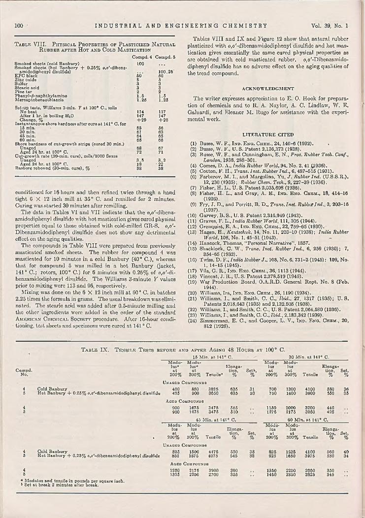
100 I N D U S T R I A L A N D E N G I N E E R I N G C H E M I S T R Y Vol. 39, No. 1
100
100.25s o 505 53 33 32 21 .5 1 .51.25 1.25
114 117147 147+ 2 9 + 26
55 5661 6364 6565 66
68 6772 71
3 .5 3 .218 ■ 2238 38
T a b l e VIII. P h y s i c a l P r o p e r t i e s o f P l a s t i c i z e d N a t u r a l R u b b e r a f t e r H o t a n d C o l d M a s t i c a t i o n
Com pd. 4 Com pd. 5Smoked sheets (cold Banbury)Smoked sheets (hot Banbury + 0.25% o,o '-d ibcnz-
amidodiphenyl disulfide)E PC black Zinc oxide Sulfur Stearic acid Pine tarPhenyl-/S-naphthylamine Mercaptobenzothiazole
Set-up tests, W illiams 3-min. Y at 100° C ., mils No heatAfter I hr. in boiling HiO Change, %
Instantaneous shore hardness after cure at 141° C. for 15 min.30 min.45 min.60 min.
Shore hardness of cut-growth strips (cured 30 min.)UnagedAged 24 hr. at 100° C.
Cut-growth rate (30-min. cure), m ils/1000 flexes UnagedAged 24 hr. at 100° C.
Bashore rebound (30-min. cure), %
conditioned for 16 hours and then refined twice through a hand tight 6 X 12 inch mill at 35° C. and rcmillcd for 2 minutes. Curing was started 30 minutes after remilling.
The data in Tables VI and VII indicate that the o,o'-dibenz- amidodiphenyl disulfide with hot mastication gives cured physical properties equal to those obtained with cold-millcd GR-S. o,o'- Dibenzamidodiphenyl disulfide does not show any detrimental effect on the aging qualities.
The compounds in Table VIII were prepared from previously masticated smoked sheets. The rubber for compound 4 was masticated for 10 minutes in a cold Banbury (40° C.), whereas that for compound 5 was milled in a hot Banbury (jacket, 141° C.; rotors, 100° C.) for 6 minutes with 0.25% of o,o'-di- benzamidodiphenyl disulfide. The Williams 3-minute Y values prior to mixing were 113 and 96, respectively.
Mixing was done on the 6 X 12 inch mill at 60° C. in batches 2.25 times the formula in grams. The usual breakdown was eliminated. The stearic acid was added after 0.5-minute milling and the other ingredients were added in the order of the standard A m e r ic a n C h e m ic a l S o c i e t y procedure. After 16-hour conditioning, test sheets and specimens were cured at 141 ° C.
Tables VIII and IX and Figure 12 show that natural rubber plasticized with o.o'-dibenzamidodiphenyl disulfide and hot mastication gives essentially the same cured physical properties as are obtained with cold masticated rubber. o,o'-Dibenzamido- diphenyl disulfide has no adverse effect on the aging qualities of the tread compound.
ACKNOWLEDGMENT
The writer expresses appreciation to E. O. Hook for preparation of chemicals and to R. A. Naylor, A. C. Lindlaw, W. E. Galuardi, and Eleanor M. Rugo for assistance with the experimental work.
LITERATURE CITED
(1) Busse, W . F., I n d . E n g . Chem., 24, 140-6 (1932). .(2) Busse, W. F., U. S. Patent 2,136,373 (1938).(3) Busse, W . F., and Cunningham, E. N., Proc. Rubber Tech. Conf.,
London, 1938, 288-301.(4) Comes, D . A., India Rubber World, 94, No. 2, 41,0.936).(5) Cotton, F. H., Trans. Inst. Rubber Ind., 6, 487-515 (1931).(6) Farberov, M . I., and Margolina, Yu, J. Rubber Ind. (U.S.S.R.),
12, 230 (1935); Rubber Chem. Tech., 9, 227-39 (1936).(7) Fisher, H. L., U. S. Patent 2,035,698 (1936).(8) Fisher, H. L., and Gray, A. E., In d . E n g . Chem., 18, 414-16
(1926).(9) Fry, J. D ., and Porritt, B. D., Trans. Inst. Rubber Ind., 3, 203-16
(1927).(10) Garvey, B. S., U. S. Patent 2,316,949 (1943).(11) Graves, F. L., India Rubber World, 111, 305 (1944).(12) Grenquist, E. A., I n d . E n g . C hem., 22, 759-65 (1930).(13) Hagen, H., Kautschuk, 14, No. 11, 203-10 (1938); India Rubber
World, 108, No. 1, 45-51 (1943).(14) Hancock, Thomas, “ Personal Narrative” , 1857.(15) Shaddock, C. W ., Trans. Inst. Rubber Ind., 6, 259 (1930); 7,
354-65 (1932).(16) Twiss, D . F., India Rubber J., 108, N o. 6, 731-2 (1945); 109, No.
1, 1 4 -1 5 (1 9 4 5 ) .(17) Vila, G. R., In d . E n g . Chem ., 36, 1113 (1944).(18) Vincent, J. R „ U. S. Patent 2,378,519 (1945).(19) War Production Board, O .A .R .D . General Rept. No. 8 (Feb.
1 9 4 4 ).(20) Williams, Ira, In d . E n g . Chem., 26, 1190 (1934).(21) Williams, I., and Smith, C. C., Ibid., 27, 1317 (1935); U .S .
Patents 2,018,643 (1935) and 2,132,505 (1938).(22) Williams, I., and Smith, C. C., U. S. Patent 2,064,580 (1936).(23) Williams, I., and Smith, C. C „ Ibid., 2,183,342 (1939).(24) Zimmerman, E. C., and Cooper, L. V., I n d . E n g . Chem., 20,
8 1 2 (1 9 2 8 ) .
T a b l e IX. T e n s i l e T e s t s b e f o r e a n d a f t e r A g i n g 48 H o u r s a t 100° C .15 M in. at 141° C. 30 M in. at 141° C.
Com pd.N o.
M odulus“at
2 0 0 %
M odulus“at
3 0 0 % Tensile“
Elongation,
%Set»,
%
M odulusat
2 0 0 %
M odulusat
3 0 0 % Tensile
E longation,
%Set,
%U n a g e d C o m po u n d s
45
Cold BanburyH ot Banbury + 0 .2 5 % o.o'-dibcnzam idodiphenyl disulfide
400425
850 3625 900 3650
635635
3130
700750
13001400
41003900
580550
3635
A g ed C om po u n d s
45
900900
1675 3475 1675 3475
515510
11501275
20002175
32003250
440425
45 M in. at 141° C. 60 M in. at 141° C.
•
M odulusat
2 0 0 %
M odulusat
3 0 0 % Tensile
Elongation,
%Set,%
M odulusat
2 0 0 %
M odulusat
3 0 0 % Tensile
Elongation,
%Set,
%U n a g e d C o m po u n d s
45
Cold BanburyH ot Banbury + 0 .2 5 % o,o'-dibenzamidodiphenyl,disulfide
825850
1500 4175 1575 4075
550545
3838
825925
15251650
41003975
560530
4034
A ged C o m po u n d s
45
12501325
2175 2900 2250 2700
390355
13501460
22502350
26502825
350345
a Modulus and tensile in pounds per square inch, t Set at break 2 minutes after break.

Comparative Oxidation of Linseed and Sardine Oils
G. A. O’lIARE AND W. J. WITHROW1C on goleu m -N airn , In c ., K earn y, New Jersey
Linseed and sardine oils "were oxidized by air blowing at 220° F . w ith improved blowing techniques which m in im ize polym erization. T he conventional drying oil constants were used to follow the course o f oxidation; dielectric constant and ultraviolet absorption m easurem ents were also applied. R esults indicate th at these latter properties show characteristic and reproducible changes as oxidation progresses. The oxygen content o f sardine oil was found to fluctuate as blowing proceeds. This is contrary to the linseed, which shows a steady rise in oxygen content w ith increasing blowing lim e. Sardine oil goes through highly reactive stages near the beginning o f the blow ; these are found at peaks in the fluctuating oxygen content curve o f the oil. Com parative curves are given to illustrate the chem ical and physical changes which take place during linseed and sardine oil oxidation.
DR Y IN G oil oxidation has been the subject of many investigations during the past years. Several approaches to this
subject have been made, but as yet no well defined picture of the mechanism of the oxidation of a drying oil has been presented. One of the reasons for this is the complexity and nonuniformity of the starting raw oil. The distribution of the acid radicals in the triglyceride molecule varies depending on the history of the oil, and this greatly influences the course of the oxygen addition to the molecule.
Polymerization, which usually accompanies oxidation, also complicates the oxygen addition. Since oxidation promotes polymerization, the complication becomes greater as oxidation proceeds. The usual chemical and physical constants used to define a processed oil, such as iodine number, acid number, viscosity, etc., are affected by both polymerization and oxidation. For this reason, the use of these constants for following the course of oxidation is unsatisfactory.
Hazelhurst (S) described in detail the use of the dielectric constant as a measurement of linseed oil oxidation. Since that time additional work was done in this laboratory using dielectric constant as a means of following drying oil processing, and some of this work is covered in the present paper.
The physical and chemical changes which take place during the oxidation of linseed oil were studied extensively in this laboratory. As a result of that work more efficient methods of oil oxidation were found so that linseed oil can now be oxidized to about 17-18% oxygen in a few hours with minimum polymerization. This is evidenced by the relatively low viscosity and refractive index obtained at high oxygen content. In the older methods of blowing it was difficult to put so much oxygen into the molecule before polymerization caused high viscosity and gelation. Patent applications are now pending on these improved oxidation methods. As soon as these are allowed, the details of the methods will be available in the patent literature.
Some previous work was done on the oxidation of marine oils. Brockelsby and Denstedt (I, 3) and others studied rate of oxygen pickup, etc., during oxidation. Unfortunately, however, the high temperature (250° F.) and long blowing times (30 to 60 hours) in most of their work make it inevitable that a large amount of polymerization complicates the oxidation reaction. This results in nonuniform oxidation products, and uniform reproducible results are exceedingly difficult to obtain. Consequently, it is useless to compare results of different investigations,
1 Present address, College of the C ity of New York , New York , N . Y .
since the amount of polymerization always varies with the conditions involved.
The improved oxidation technique of this laboratory was applied to sardine oil and the results were correlated with data on linseed oil obtained under the same conditions. In each case it is felt that a minimum of polymerization was involved, and hence a much more accurate and representative picture of oil oxidative changes was obtained.
The random triglyceride distribution of the higher polyeth- ylenic acids found in sardine oil makes the problem of oxidation mechanism much more complex than that of linseed oil. The composition of marine oils has long been under study. During the past few years the methyl ester fractionation of their component acids has clarified the situation considerably.
For the present work a west coast sardine oil was used. The approximate constants for this oil at 77° F. follow:
Refractive index 1.4S05Specific gravity 0.9250W ijs iodine number 195Acid number 4 .5Viscosity, centipoises 45
The oil was subjected to oxidation by air blowing at 220° F No driers were used, and an air rate of 6 cubic feet per minute per 100 pounds of oil was maintained throughout the blow. Samples were withdrawn every 20 minutes during the oxidation.
D E T E R M IN A T IO N O F P R O P E R T IE S
V isco s ity . A direct-reading Brookfield electroviscom eter was used and values reported directly in centipoises at 77 0 F.
S p e c ific G ra v ity . This property was measured at 77 ° F. with a set of precision hydrometers.
A cid N um ber. A conventional acid num ber determination was used with a 50-50 mixture of benzene-ethyl alcohol as the solvent.
Io d in e N um ber. The Wijs method was used in this determination.
M o le c u la r W e ig h t . The freezing point method with benzene as the solvent was used to determine the average molecular weight.
O x y g en C o n te n t . Conventional combustion analysis for carbon and hydrogen was used to obtain oxygen content of the oils.
D ie le c t r i c C o n sta n t. The bridge method for dielectric constant measurement was used. A special test cell designed for liquid samples, a Schering type bridge, alternating current voltage source, and detector made up the apparatus. The values were measured at 200 kilocycles and 77° F.
R e f r a c t iv e In d ex . The Abbe refractometer was used at 77° F.

102 I N D U S T R I A L A N D E N G I N E E R I N G C H E M I S T R Y Vol. 39, No. 1
T a b l e I. D a t a o n O x i d i z e d S a r d i n e O i lViscos
ity, Tim e, Centi-
Refractive
Dielectric
Con Iodine Acid Sp. Oxygen, M ol.Sample M in. poises Index stant No. No. Gr. % W t.
0 0 45 1.4805 3 .23 195.0 4 .5 0 .925 14.87 7671 30 84 1.4820 3 .5 7 173.5 5 .5 0 .940 16.38 8172 53 113 1.4824 3 .72 107.5 5 .9 0.946 10.80 8623 75 174 1.4830 3.91 158.5 0 .5 0.952 16.27 9104 95 250 1.4835 4 .0 8 152.0 7 .2 0 .960 17.71 9425 115 342 1.4840 4 .17 142.5 7 .6 0.906 18.33 9920 135 400 1.4842 4 .2 5 136.5 8 .0 0 .970 17.35 10107 155 070 1.4847 4 .33 132.0 8 .2 0.976 17.93 10408 175 880 1.4850 4.41 122.5 8 .3 0.980 I S .40 10609 195 1170 1.4852 4 .45 123.0 8.6 0.983 19.81 1070
10 215 1490 1.4857 4 .4 8 120.5 8 .7 0.9S5 I S .25 109011 235 1950 1.4858 4 .50 119.5 8 .8 0.9S8 19.75 110012 255 2290 1.4859 4 .52 117.5 8 .9 0.991 19.15 111013 275 2790 1 .4 SCO 4.54 116.5 9 .0 0 .996 18.77 112014 295 3380 1.4800 4 .57 115.5 9 .0 1.001 1 9 .3S 113015 315 3800 1.4S01 4 .57 114.5 9 .1 1.005 19.67 114010 335 4570 1.4861 4 .57 113.5 9 .2 1.007 19.39 116017 355 5S00 1.4802 4 .5 7 112.0 9 .4 1.010 19. S9 1170
U l t r a v i o l e t A b s o r p t i o n . Optical density measurements were made in ethyl ether solution with the Beckman spectrophotometer. Duplicate runs were made and were in very good agreement.
RESULTS
Table I gives complete data on oxidized sardine oil. The efficiency of the blowing procedure may be seen from the relatively low viscosity and refractive index values at the relatively high oxygen contents.
The viscosity, refractive index, specific gravity, acid number, iodine number, dielectric constant, and molecular weight show a definite trend as oxidation progresses (Table I). All these constants show an increase with increased blowing time, with the exception of the iodine number which, of course, decreases. These changes are similar to those which take place when linseed oil is oxidized.
Figure 1. Course o f Oxidation and Polymerization o f Linseed Oil
The rate of viscosity pickup increases near the end of the batch. This is a sign that boat polymerization becomes an important factor at this stage of the blowing. In the production of a reactive oxidized oil for the varnish kettle it is essential to stop» the blowing before polymerization builds up excessive viscosity and cuts down the reactivity of the oil.
The rapid viscosity increase near the end of the blowing cycle is also characteristic of linseed oil. Starting with a raw oil of 40 centipoises, a viscosity of 2500 centipoises is reached in about 250 minutes. With linseed oil an induction period of about 15 to 45 minutes is usually experienced; this is followed by a rapid oxygen uptake during the first part of the cycle, and the rate of uptake decreases as blowing progresses. This is easily understood because oxidation promotes polymerization, which in turn retards further oxidation. An illustration of this is given in Figure 1.
The increased reactivity of an oxidized oil may be explained by the reasoning that polymerization takes place at the activated, oxidized position of the molecule.
When sardine oil is blown, little or no induction period is experienced. A more rapid initial reaction, as evidenced by the heat given off, takes place than with linseed oil. The rate of oxygen addition again slows down, however, as polymerization starts to become a factor. As noted in linseed oil, the addition of oxygen to sardine oil does not follow the same general trend of increased oxygen content with increased blowing time.
Figure 2 . Effect o f Blowing T im e on Refractive Index, Specific Gravity, and Viscosity for Sardine Oil (closed
lines) and Linseed Oil (broken lines)
The refractive index increase for blown sardine oil is analogous to that noted for linseed oil. A comparison of the curves is given in Figure 2. Little change is noted in refractive index near the end of the blowing. Figure 2 also illustrates the changes taking place in specific gravity and viscosity'. Again the similarity to linseed oil is evident.
Figure 3 illustrates the acid number, iodine number, and molecular weight changes of linseed and sardine oils during oxidation. The curves for these oils have about the same slopes, and, in general, the changes taking place in the two oils are similar. Again the rate of change taking place near the end of the batch is much less than that at the start.
The use of the dielectric constant as a measure of linseed oil oxidation was mentioned previously in this paper. It was found that the dielectric constant measured at 200 kilocycles and 77° F. of linseed oil undergoes little change during heat polymer-
Figure 3. Effect o f Blowing T im e on M olecular W eigh t, Iodine N um ber, and Acid N um ber for Sardine
Oil (closed lines) and Linseed Oil ( broken lines)

January 1947 I N D U S T R I A L A N D E N G I N E E R I N G C H E M I S T R Y 103
ization. A sample of linseed oil which has been heat-bodied to about 4000 centipoises has about the same dielectric constant as the unbodied oil, which is 3.25. As linseed oil is oxidized, the dielectric constant increases regularly with oxygen content to a value of about 5.00 at an oxygen value of about 17.2% (Figure 4). Since the dielectric constant does not change with straight heat polymerization as do the other constants, this characteristic offers an accurate and reproducible method of differentiating between oxidation and polymerization during linseed oil processing. It has actually been found to be a satisfactory continuous control measurement for the commercial production of oxidized linseed oils.
BLOWING TIM E IN M IN U T ES '
Figure 4 . Effect o f Blowing T im e on Dielectric Constant at 200 K ilocycles and 77° F. for Sardine Oil (closed line) and Linseed Oil
(b roken line)
With this background of dielectric constant measurement on linseed oil, the method was applied to the oxidation of sardine oil. Again a reproducible increase of dielectric constant from 3.23 of the raw oil to about 4.60 of the oxidized oil was found. This indicates that dielectric constant could be used as a measurement of the changes taking place during sardine oil oxidation. However, this was not a direct measure of the oxygen content of the oil as it was in linseed.
Ultimate analyses on these samples of oxidized sardine oil brought out many interesting and unusual points. Figure 5 shows the oxygen content of linseed and sardine oil as blowing progresses. The oxygen content of the sardine oil did not follow the relatively uniform increase of the linseed. A change from about 11% to about 17.2% is noted for linseed oil. The sardine oil plot shows successive increases and decreases in oxygen content as blowing progresses. This suggests a stepwise oxygen uptake in which some oxygen is added to the molecule and then lost as further blowing is carried out. Close examination of the curve indicates three different instances of oxygen peaks which are followed by appreciable oxygen losses. Other instances are noted, but they are small enough to be within the limit of error of the combustion analyses. Since these results were somewhat different from those expected, several other batches of sardine oil were blown and oxygen pickup was determined. In all cases curves of the same shape were obtained with the oxygen peaks falling at about the same points on the plot.
The oxygen content found for blown sardine oil—the only one of the conventional oil constants that did not follow the usual smooth linseed oil curves—made it apparent that some changes were taking place which were not beingmeasured by these conventional constants. In an attempt to find some other measurement which would indicate the changes taking place as the oxygen content fluctuates, the ultraviolet absorption of the samples was determined. It had been found previously that an ultraviolet spectral absorption change accompanied the blowing of linseed oil. In Figure 6 the extinction coefficient E\1°, is plotted against
wave length for a series of blown linseed oils. As the oxygen content of the oil increased, the extinction coefficient also increased at any given wave length.
Ultraviolet absorption curves for the oxidized sardine oil show no such regular increase as blowing progresses (Figure 7). This is again a definite indication that the mechanism of sardine oil oxidation is different from that of linseed oxidation.
D ISCU SSIO N O F R E SU L T S
In attempting to explain the behavior of sardine oil on oxidation, the two things which come to mind are high saturates con-: tent and higher polyethylenic acids present in the oil. It is possible that these successive stages of oxygen increases and decreases represent a course of reaction by which the higher unsaturated acids (four or five double bonds) are selectively oxidized at one or more of their double bonds, with the formation of an unstable oxygen linkage at this point. This would result in loss of unsaturation and increase in oxygen content. The oxygenated bond could then break down with polymerization or condensation with other functional molecular groups with the elimination of oxygen- containing volatile side products. This could then account for a decrease in oxygen content of the oil if the loss were greater than the oxygen being absorbed from the incoming air at that time. As a result of this type of reaction, higher double bond acids could successively be changed to lower double bond acids. Thus the sardine oil oxidation could be a stepwise reaction, starting with acids of five double bonds and going successively through acids of four and two double bonds.
BLOWING TIME IN MINUTES
Figure 5. Oxygen Content o f Sardine Oil ( closed line) and Linseed Oil (broken line)
Holman and Burr (4) reported that unsaturated carbonyl compounds show intense absorption near 2300 and 2700 Â. This suggests the possibility of the formation of unsaturated carbonyl compounds as oxygen adds to the higher polyethylenic acids of sardine oil, with resultant absorption increase. These unsaturated carbonyl structures could then break down with loss of oxygen and accompanying loss of absorption. Samples 3 and 2 of Figure 7 seem to substantiate this theory. Sample 3 shows lower oxygen content and absorption than does sample 2 at 2300 Â. The fact that at 2700 Â. sample 3 has a higher absorption than sample 2

104 I N D U S T R I A L A N D E N G I N E E R I N G C H E M I S T R Y Vol. 39, No. 1
suggests the possible formation of conjugated trienes as a result of the carbonyl breakdown.
From this point on the oxidation could proceed through the formation of acids of three double bonds until finally only acids containing one and two double bonds exist. Since the possibility for triene conjugation would be gone after the stage of two double bonds was reached, diene conjugation could become an effective factor and account for absorption increases at 2300 Â. The loss of absorption shown by sample 6 could also be explained by a loss in unsaturated carbonyl structure which had been building up
OilS am ples 1 th rou gh 5 represent in creas in g b low in g t im e ;
sam ple 1, raw oil
through samples 4 and 5. A steady decrease of absorption which corresponds to the slow rate of change of many of the other constants on these samples was noted beyond sample 7. This may be caused by the destruction of the highly absorptive conjugated diene or carbonyl structures by polymerization, which becomes a critical factor at this late stage of oxidation.
Since linseed oil has no polyethylenic acids above linolenic, there is no possibility that the described reactions of the four and five double bond acids take place. A relatively stable oxygen addition product is formed, and no significant loss of oxygen takes place during the blowing; at least the oxygen loss would be less than the amount being absorbed from the oxidizing air. Net oxygen content would then increase as blowing progresses (Figure 5). The authors believe that it is this type of stable oxygen addition that is being measured by the dielectric constant in both oils. This accounts for the fact that the dielectric constant of the sardine oil increases even though the net oxygen content decreases because of other types of decomposition and polymerization reactions involving polyethylenic acids.
Since sardine oil during oxidation seems to show stages which are relatively unstable and gives off oxygen-containing products on decomposition, it is probable that highly reactive molecular structures exist at these stages. Therefore, a highly reactive oil should exist at this stage of processing, or at the oxygen peaks on the curve. As a check, samples from the present oxidation series were heat-bodied under the same conditions of time and temperature. Viscosity and refractive index measurements were made on these samples before and after heat bodying. It was noted
that two samples reacted more vigorously than the others. It was also found that these two samples showed a much greater viscosity and refractive index change than did the other samples. One was at an oxygen peak on the curve, whereas the second was the next sample in line from this peak. It is interesting to note that both samples were taken near the beginning of the blowing cycle. As an example of the viscosity changes involved, the highly reactive sample went from a viscosity of 340 to 2200 centi- poises on heating to 5500 F. in 40 minutes. This represents a change about 6.5 times the original viscosity. A later sample
Figure 7. Absorption Spectra o f Oxidized Sardine Oil
Sam ples 1 th rou gh 7 represent in creasin g b low in g t im e ; sam ple 1, raw oil
taken near the end o f the batch went from 1950 to 5300 centipoises under the same conditions, a change of only 2.7 times the original viscosity. T he latter figure (2.7) is a slightly higher value than is obtained with oxidized linseed oil under identical bodying conditions.
Since spectrophotom etric background on oxidized oils o f this type is meager and the data presented are somewhat lim ited, it should berecognized that theexplanationsoffered m ustof necessity be highly speculative. The writers feel sure, however, that many valuable contributions to the theory o f oil oxidation mechanism will result from further spectrophotom etric work. T hey also feel certain that the high saturated acid content o f sardine oil plays a significant role in oxidation. Further work on segregated sardine oils should clarify th is ..
A C K N O W LE D G M E N T
The authors wish to express their appreciation for the technical assistance o f Adam K opacki in carrying out this investigation.
L IT E R A T U R E C ITED
(1) Brockelsby, H. N., and Denstedt, O. F., Conirib. Can. Biol. Fisheries, 8, 321 (1934).
(2) Denstedt, O. F., and Brockelsby, H. N., J. Biol. Board Can., 1,487 (1936).
(3) Hazelhurst, E. H., Paint Manuf., 13, 275 (1943).(4) Holman, It. T ., and Burr, G . O., Arch. Biochem., 7, 47 (1945).P resented before the D ivision o f Paint, Varnish, and Plastics Chemistry at the 109th M eeting of the A merican C hem ical Society , Atlantic C ity , N. J.
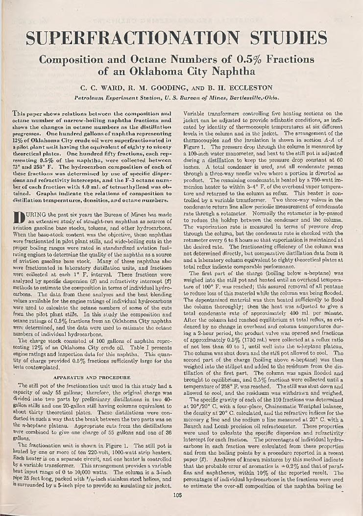
SUPERFRACTIONATION STUDIESComposition and Octane Numbers of 0.5% Fractions
of an Oklahoma City NaphthaC. C. WARD, R. M. GOODING, AND B. H. ECCLESTON
P etro leu m E xperim en t S ta tion , U. S. Bureau o f M ines, Bartlesville,'O kla.
T h is paper shows relations between the com position and octane num ber o f narrow -boiling naphtha fractions and shows the changes in octane num bers as the distillation progresses. One hundred gallons o f naphtha representing 12% o f O klahom a City crude oil were superfractionated in a pilot plant unit having the equivalent o f eighty to ninety theoretical plates. One hundred fifty fractions, each representing 0 .5 % o f the naphtha, were collected between 73° and 258° F . The hydrocarbon com position o f each o f these fractions was determ ined by use o f specific dispersions and refractivity intercepts, and the F -3 octane n u m ber of each fraction w ith 4.0 m l. o f tetraethyllead was obtained. Graphs indicate the relations o f com position to distillation tem peratures, densities, and octane num bers.
DURING the past six years the Bureau of Mines has made an extensive study of straight-run naphthas as sources of
aviation gasoline base stocks, toluene, and other hydrocarbons. When the base-stock content was the objective, these naphthas were fractionated in pilot plant stills, and wide-boiling cuts in the proper boiling ranges were rated in standardized aviation fuel- rating engines to determine the quality of the naphtha as a source of aviation gasoline base stock. Many of these naphthas also were fractionated in laboratory distillation units, and fractions were collected at each 1° F. interval. These fractions were analyzed by specific dispersion (3) and refractivity intercept (3) methods to estimate the composition in terms of individual hydrocarbons. The data from these analyses and the best blending values available for the engine ratings of individual hydrocarbons were used to calculate the octane numbers of some of the cuts from the pilot plant stills. In this study the composition and octane ratings of 0.5% fractions from an Oklahoma City naphtha were determined, and the data were used to estimate the octane numbers of individual hydrocarbons.
The charge stock consisted of 100 gallons of naphtha representing 12% of an Oklahoma City crude oil. Table I presents engine ratings and inspection data for this naphtha. This quantity of charge provided 0.5% fractions sufficiently large for the tests contemplated.
A PPA R A TU S AND P R O C ED U R E
The still pot of the fractionation unit used in this study had a capacity of only 55 gallons; therefore, the original charge was divided into two parts by preliminary distillations in two 40- gallon stills and one 20-gallon still having columns equivalent to about thirty theoretical plates. These distillations were conducted in such a way that the break between the two parts was on the n-heptane plateau. Appropriate cuts from the distillations were combined to give one charge of 55 gallons and one of 36 gallons.
The fractionation unit is shown in Figure 1. The still pot is heated by one or more of ten 220-volt, 1000-watt strip heaters. Each heater is on a separate circuit, and one heater is controlled by a variable transformer. This arrangement provides a variable heat input range of 0 to 10,000 watts. The column is a 3-inch Pipe 25 feet long, packed with 3/ 32-inch stainless steel helices, and is surrounded by a 5-inch pipe to provide an insulating air jacket.
Variable transformers controlling five heating sections on the jacket can be adjusted to provide adiabatic conditions, as indicated by identity of thermocouple temperatures at six different levels in the column and in the jacket. The arrangement of the thermocouples and the insulation is shown in section A-A of Figure 1. The pressure drop through the column is measured by a 100-inch water manometer, and heat to the still pot is adjusted during a distillation to keep the pressure drop constant at 60 inches. A total condenser is used, and all condensate passes through a three-way needle valve where a portion is diverted as product. The remaining condensate is heated by a 750-watt immersion heater to within 3-4° F. of the overhead vapor temperature and returned to the column as reflux. This heater is controlled by a variable transformer. Two three-way valves in the condensate return line allow periodic measurement of condensate rate through a rotameter. Normally the rotameter is by-passed to reduce the holdup between the condenser and the column. The vaporization rate is measured in terms of pressure drop through the column, but the condensate rate is checked with the rotameter every 6 to 8 hours so that vaporization is maintained at the desired rate. The fractionating efficiency of the column was not determined directly, but comparative distillation data from it and a laboratory column equivalent to eighty theoretical plates at total reflux indicate comparable performance.
The first part of the charge (boiling below n-heptane) was weighed into the still pot and heated until an overhead temperature of 100° F. was reached; this assured removal of all pentane to reduce loss of this material while the column was being flooded. The depentanized material was then heated sufficiently to flood the column thoroughly; then the heat was adjusted to give a total condensate rate of approximately 400 ml. per minute. After the column had reached equilibrium at total reflux, as evidenced by no change in overhead and column temperatures during a 2-hour period, the product valve was opened and fractions of approximately 0.5% (1750 ml.) were collected at a reflux ratio of not less than 40 to 1, until well into the n-heptane plateau. The column was shut down and the still pot allowed to cool. The second part of the charge (boiling above n-heptane) was then weighed into the stillpot and added to the residuum from the distillation of the first part. The column was again flooded and brought to equilibrium, and 0.5% fractions were collected until a temperature of 258° F. was reached. The still was shut down and allowed to cool, and the residuum was withdrawn and weighed.
The specific gravity of each of the 150 fractions was determined at 20°/20° C. with a four-place, Chainomatic Westphal balance, the density at 20° C. calculated, and the refractive indices for the mercury g line and the sodium d line measured at 20° C. with a Bausch and Lomb precision oil refractometer. These properties were used to calculate the specific dispersion and refractivity intercept for each fraction. The percentages of individual hydrocarbons in each fraction were calculated from these properties and from the boiling points by a procedure reported in a recent paper (2). Analyses of known mixtures by this method indicate that the probable error of aromatics is =±=0.2% and that of paraffins and naphthenes, within 10% of the reported result. The percentages of individual hydrocarbons in the fractions were used to estimate the over-all composition of the naphtha boiling be
105

106 I N D U S T R I A L A N D E N G I N E E R I N G C H E M I S T R Y Vol. 39, No. 1
INSULATED WITH 85 Vo MAGNESIA
CEMENT-
WATER INLET
85% MAGNESIA CEMENT PACKEC AT TOP OF COLUMN
COLUMN HEIGHT, 26 FEET
PACKED SECTION, 25 FEET
T O DRAIN
tween 97° and 258° F. Table II presents compositions in terms of percentages of individual hydrocarbons based on the crude oil and on the 97-258° F. naphtha.
The engine rating for each of the 0.5% fractions with 4.0 ml. of tetraethyllead was determined by the CRC-F-3 method. This lead concentration brought most of the fractions within the range of the F-3 method (above 72 octane number), and coincided with the data that were available on ratings of hydrocarbons by that method. The percentages of individual hydrocarbons in each fraction and the reported values for their ratings were used to estimate the octane number of the fraction before it was rated with the engine. Fractions that were estimated to rate above 72 octane number were rated on the engine without blending, and those estimated to rate below 72 octane number were blended 50-50 with a reference fuel blend (38.6% F-6, 61.4% C-13 + 4 ml. tetraethyllead) of octane number 100 to bring them within the range of the F-3 method.
C O M P O SIT IO N O F F R A C T IO N SFigure 2 shows the overhead temperature and the octane num
bers of individual fractions plotted against volume sum percentage distilled. The octane numbers calculated from blends with reference fuels are indicated by broken lines. The bar graph gives the composition of each fraction in terms of paraffins,
naphthenes, and aromatics to indicate relations between octane number and composition. The high octane numbers coincide with the higher concentrations of isoparaffins, naphthenes, and aromatics, whereas the greatest contributors to low octane numbers are the normal paraffins. The effects of some individual hydrocarbons are apparent. Examples of those contributing to high octane number are: 2,3- dimethylbutane (fraction 23), metliyl- cyclopentane (fractions 53-59), 1,1-di- methylcyclopentane (fraction 66), trans-1,2- and -1,3-dimethylcyclopentane (fractions 75-77), trimethylcyclopentanes (fraction 114), toluene (fractions 119— 121), and frans-dimethylcyclohexanes (fractions 136-137). Hydrocarbons contributing to low octane number (in addition to n-paraffins) are: cyclohexane (fraction 64), methylcyclohexane (fraction 107-110), and methylheptanes (fractions 124^128).
Experience in calculating octane numbers of fractions from composition and from reported octane numbers of individual hydrocarbons indicated that some of the reported values might be in error; consequently, the compositions and engine ratings obtained in this study were used to calculate the blending octane numbers of the individual hydrocarbons. Most of the fractions contained only two hydrocarbons in addition to benzene, toluene, or ethylbenzene, whose F-3 ratings with 4.0 ml. of tetraethyllead are fairly well established as 97,100, and 102, respectively. These aromatic values were accepted as accurate, and the octane numbers of the other two constituents were determined graphically, as shown in Figure 3 for methylcyclohexane in re-heptane. The octane number that a blend of the nonaromatic components
of a fraction would have if blended in the ratio in which they occur in the fraction was calculated by the following equation:
COLUMN HEATING ELEMENT NO. 18 NICHROME V WIRE
OUTSIDE THERMOCOUPLE JUNCTION IN TRANSITE
BLOCK
i/e’ x 2 “ ASBESTOS LISTING
•% 2h STAINLESS STEEL HELICES
STD. PIPE
INSIDE THERMOCOUPLE JUNCTION
Figure 1. F ifty-G allon Fractionation U nit
Of — X a O a
100 - X a ~ (lOO - X a) + (l00 - X a) ° 2where X a = aromatic component in fraction, %
Xi = component 1 in fraction, %Xs = component 2 in fraction, %Oa — octane number of aromatic component01 = octane number of component 102 = octane number of component 20/ = octane number of fraction
The octane number thus obtained was plotted against the percentage of methylcyclohexane in «-heptane. A straight line was- drawn through these points using the method of averages; the 100% methylcyclohexane intercept was called the blending octane number of methylcyclohexane, and the 0% methylcyclohexane intercept, the blending octane number of the n-heptane. The data points for this mixture defined a fairly good line, but with some other mixtures the two nonaromatic hydrocarbons occurred in only a few fractions and in approximately the same relative percentages, so that the slope of a line through the data points could not be established definitely. However, most of the hydrocarbons for which the data are doubtful were present only

OCTANE—- NUMBERS
DISTILLATIONCURVE
DASHED LIN C S A R E O CTAN E N U M B E R S C A LC U LA T E D FROM 5 0 /5 0 B L E N D W ITH 100 OCTAN E N U M BER STO C K
COMPOSITION OF FRACTIONS
O NORM AL PARAFFIN S @ ISOPARAFFINS Q N APH TH EN ES B AROMATICS
60 I I 80 I 100 ! 120FR A C T IO N NO.
in small percentages, and the errors are not large enough to affect appreciably octane numbers calculated for the iso cuts or for naphthas. Table III lists the blending octane numbers of the hydrocarbons in this naphtha calculated from the composition and octane numbers of the fractions. Some of these values may lie in error by several octane numbers because of the difficulty in establishing a line through the data points and because of errors in analysis of the fractions.
EVALU ATIO N O F IS O CUTS
Although this study provided a means of calculating the blending octane numbers of hydrocarbons from the composition and octane number of the fractions, its original purpose (4) was to determine how much base stock from the Oklahoma City naphtha could be utilized in grade 115/145 aviation fuel. For this reason the octane number 84 with 4.0 ml. of tetraethyllead was arbitrarily selected as the lowest octane number fraction that would he included in a superfractionation iso cut. On this basis consecutive fractions in the appropriate boiling ranges having ratings higher than 84 were combined to provide an isohexane cut, an tsoheptane cut, and an iso-octane cut. Two additional cuts were trade by combining the isohexane and isohcptane cuts and the tsohcxane, isoheptane, iso-octane cuts in the same proportions as they were present in the original naphtha, to determine ratings of the base stock after removal of the normal hexane, heptane, and octane from the naphtha. To facilitate the evaluation of the iso cuts as base stock for 115/145 grade fuel, they were adjusted to 7-pound Reid vapor pressure with isopentane and leaded to ■h6 ml; then the CRC-F-3 lean mixture and the CRC-F-4 supercharge ratings were determined. The engine ratings with 4.6 ml.
of tetraethyllead for each of the five base stocks are given in Table IV. A.G.A.C. tables (1) were used to convert F-3 ratings in terms of iso-octane plus tetraethyllead to octane numbers, and to convert F-4 ratings from per cent S/M or S plus tetraethyllead to index numbers. The ratings of each of the 7-pound iso cuts were used with those of 7-pound alkylate and 7-pound toluene to estimate the quantity of the iso cut that could be used in 115/145 grade fuel. For comparison of the iso cuts with the fractions that make up the cuts and with the ratings of the component hydrocarbons in the iso cuts, it appeared more applicable to use the octane number of the iso cuts with 4.0 ml. of tetraethyllead and without isopentane. Large enough samples were not available for these ratings after the other tests had been made; consequently, the ratings with 4.0 ml. of tetraethyllead and with no isopentane were calculated from the 7-pound blend with 4.6 ml. of tetraethyllead. Many base stocks and blends were rated in these laboratories with both 4.0 and 4.6 ml. of tetraethyllead, and these values were plotted to give the curves shown in
T a b l e I . Sa m p l e I d e n t if ic a t io n b t I n sp e c t io n o f 2 8 2 ° F. E n d -P o in t V ir g in N a p h t h a f r o m C r u d e O il
(Crude oil source, Oklahoma C ity field, pipe line sample; naphtha prepared by Deep R ock Refinery, Cushing, Okla.)
C R C -F -3 Octane N o.Clear 5 6 .3 °4 ml. T .E .L . 83.34 .6 ml. T .E .L . 84.3
Reid vapor pressure, lb. 12.5 Sulfur, % 0.004Corrosion NegativeD octor test SourGravity, °A .P .I. 69 .9
A .S .T .M . distillation Initial, b. p ., °F .
10% evapd., ° F. 50% evapd., 0 F. 90% evapd., ° F.
End point, 0 F. Residue, %Loss, %
a Calculated from blend with reference fuel.
^ ieo y 70
|K50HEXANE CUTj N-l
January 1947 I N D U S T R I A L A N D E N G I N E E R I N G C H E M I S T R Y
N -H EXA N E C U T ISO H EPTA N E C U T N -H EP TA N C C U T ISO O CTAN E C U T N -O C T A N E C U T
15 2 0 2 5 3 0 3 5 4 0 4 5 5 0 55VO LU M E SUM P E R C E N T O F N A PH TH A
Figure 2. F -3 Octane Num bers o f Fractions with 4.0 M l. Tetraethyllead

108 I N D U S T R I A L A N D E N G I N E E R I N G C H E M I S T R Y Vol. 39, No. 1
T a b l e II. C o m p o s i t i o n o p N a p h t h a in B o i l i n g R a n g e 97-258° F.
n-PcntaneCyclopentane2.2-Dim ethylbutane2.3-Dim e thylbutane2-M ethylpentanc3-M ethylpentane n-HexaneM ethylcyclopentane2.2- and 2.4-Dimethylpentane BenzeneCyclohexane1.1-Dimethylcyelopentane2.3-Dimethylpentanel2-M ethylhexane J frans-1,3-Dimethylcyclopentane trans-1,2-Dim ethylcyclopentane3-M ethylhexane «-H eptane M ethylcyclohexane Ethylcyclopentane2.2-Dimethylhexane2,5- and 2,4-Dimethylhexane TolueneTrimethylcyclopentanes (?)2.3-DimethylhexaneA tri methylcyclopentane (?)2.4-Dimethylhexane frans-Dimcthylcyclohexanes 3-M ethylheptane Ethylbenzene«-Octane
Total
ParaffinsNaphthenesAromatics
% of % o f9 7 -2 5 8 cCrude Oil Naphtha
0.050 0.970.047 1.030.006 0.130.047 1.030.226 4.880.121 2.610.70S 15.340.203 4 .400.030 * 0 .650.04S 1.050.234 5.060.017 0.3S0.236 5.100.0S3 1.800.155 3 .350.216 4.670.611 13.210.349 7.550.10S 2.340.037 0.810.036 0.790.167 3.620.112 2.410.067 1.460.006 0.130.102 2.200.272 .5 .890.203 4 .400.002 0.040.125 2.70
1 4.624 100.00
61.034.3
4 .7100.0
Figure 4 for converting ratings of aviation gasoline from one tetraethyllead concentration to the other. These curves were used to calculate the ratings of the iso cut at 4.0 ml. of tetraethyllead from the values at 4.6. The effect of the isopentane was calculated from its percentage in the blend and the blending value of 113.0 octane number and 144.0 index number with 4.0 ml. of tetraethyllead, as determined on the isopentano used in this study. The calculated engine ratings of the unblended iso cuts at 4.0 ml. of tetraethyllead after adjusting for the extra tetraethyllead and the isopentane are given in Table IV, along with inspection data on the unblended iso cuts.
To determine the reliability of the blending octane numbers of the individual hydrocarbons, the approximate composition of each of the iso cuts given in Table V was calculated from the composition of its component fractions.. These percentages, when multiplied by the blending octane numbers listed in Table III,
gave the calculated octane numbers shown in Table VI, where they are compared with the determined values. The greatest deviation was only 2 octane numbers. However, the octane numbers used were developed in this study, and it was believed that hydrocarbon compositions from other studies would be a better test of the method for calculating octane numbers. The hydrocarbon compositions and the octane numbers of iso cuts from an East Texas naphtha and a Hull-Silk-Sikes naphtha were available; therefore, the octane numbers of the five iso cuts from each of these naphthas were calculated from the octane number values listed in Table III. The comparison of these values with the determined values also are listed in Table VI. The maximum deviation of t hese ten iso cuts is 3 octane numbers.
O
O //
0 //
//■ 0A1A FRCM FRA mows 85- 110
0o /
o
ft-10 ZO 30 40 50 60 70 80 90
% METHYLCYCLOHEXANE IN N-HEPTANE
Figure 3. Graphical Determ ination o f Octane N um bers for M ethylcyclohexane
in re-Heptane
In previous studies of straight-run base stocks several hundred naphthas were fractionated in pilot scale stills to obtain wide- boiling cuts for engine testing to rate their value as base stocks. Some of these cuts corresponded to the 97-243 ° F. boiling range. Thirteen of the naphthas on which F-3 engine ratings for this boiling range were available also were fractionated in a laboratory fractionation unit of eighty theoretical plates; small fractions wore collected and analyzed by refractivity intercept and specific
T a b l e III. C a l c u l a t e d F-3 B l e n d i n g O c t a n e N u m b e r s o r P u r e H y d r o c a r b o n s w i t h 4.0 M l . T.E.L. F -3 OCTANE NUMBER AT 4.6 ML. TE;L/GAL.
Paraffins2,3-Dimethylbutane2-M ethylpentane3-M ethylpentane «-H eptane2.2- and 2,4-Dimethylpentane2.3-Dimethylpentane )2-M ethylhexane /3-M ethylhexane «-H eptane Dimethyihexanes2- and 4-Methyiheptane3-M ethylheptane ii-Octane
NaphthenesM ethylcyclopentaneCyclonexaneirans-l,3-D im ethylcyclopentaneM ethylcyclohexaneEthylcyclopentaneT rimethylcyclopentanes/rons-1,3- and 1,4-Dimethylcyclohexanes/ra«s-l,2-D im othylcyclohexane
Aromatics (I)BenzeneTolueneEthylbenzene
10698976497899250807172 39
97S69690 899791 91
97100102 Figure 4 . Relation between Engine Ratings at 4.0 and
4.6 M l. Tetraethyllead per Gallon

January 1947 I N D U S T R I A L A N D E N G I N E E R I N G C H E M I S T R Y 109
T a b l e IV. P r o p e r t i e s o f Iso C u t s a n d T h e i r B le n d s
Crude oil, %Naphtha, %Engine ratings of 7-lb.
blends F-3 octane N o., 4.6
ml. T .E .L .
F-4 ratings, 4.6 ml. T .E .L .
S + T .E .L .Index No.
Ce Ct 0 .7 0 1.735 .8 5 14.42
Ce (Ce + C;) (Ce 4- C ; + C»)1.089.03
101.2 96 .6 95 .9(iso-octane 4- 0 .09)
0 .39111
1.13128
1.13128
2 .4 320.25
98.4
1.13128
Engine ratings o f unblended iso cuts, calcd. from 7-lb. blends with 4.6 ml. T .E .L .
F-3 octane N o., 4.0 ml. T .E .L . 100.4 9 0 .8 88 .3 94 .5
F-4 index N o., 4.0 ml.T .E .L . 106 119 117 121
A.S .T .M . D-86 distillation
Initial b .p ., ° F.5% evapd., °F .10% evapd., °F .50% evapd., °F .90% evapd., ° F. End point, 0 F. Residue, %Loss, %Sp. gr., 6 0 °/6 0° F. Gravity, °A .P .I.Reid vapor pressure,
lb.
124135136 138 140 142 0 .4 1 .30.6698 0.7555 79 .8 71 .4
177178 178 182 188 192 0.6 0 .4
7 .2 3 .1
2102142142162182220 .70.60.778050.4
1.5
3.5129.28
98.1
1.25130
93.2
122
T a b l e VII. C o m p a r iso n o f C a l c u l a t e d a n d D e t e r m in e d F-3 O c t a n e N u m b e r s (4 .0 M l . T .E .L . p e r G a l l o n ) o f N a p h th a s
B o i l in g f r o m 9 7 ° t o 243° F.F-------------------- Octane N o.—-------------------N
Naphtha Calcd. Detd. Difference
Tom O ’Conner 88 86 + 2Coalinga 89 89 0Saxet 91 89 4-2Old Ocean 86 87 - 1K .M .A . Strawn 84 85 - 1Golden Meadow 88 88 0Chapel Hill 82 83 - 1Conroe 89 89 0Plymouth 89 90 - 1Segno 88 90 - 2Jennings 88 87 + 1W ade City 91 89 4-2Carthage 84 84 0
dispersion methods to estimate the composition in terms of individual hydrocarbons. The percentages of individual hydrocarbons and the blending octane numbers listed in Table III were used to calculate the octane numbers of the naphtha cuts. The calculated octane numbers and the determined values are compared in Table VTI. The maximum deviation is 2 octane numbers.
T a b l e V . A p p r o x im a t e C o m p o sit io n o f Iso C u t s , V o l u m e P e r C e n t
Isohexane Cut Isoheptane Cut Iso-octane Cut
P a r a f f i n s
2.2-Dimethylbutane2.3-Dimethylbutane2-Methylpentane3-Methylpentane n-Hexane
3 .910.24 7 .027.4
1.6
7i-Hexane2.2-Dim ethylpentane) 2,4-Dim ethylpentanef2.3-Dim ethylpentanej2-M ethylhexane /3-M ethylhexane
1.4
2 .5
2 1.516.1
n-Heptane2.2-Dimethylhexane 2,5-Dim ethylhexanel 2,4-DimethylhexaneJ2.3-Dimethylhexane
3 .35 .3
1.13 .0
Total paraffins 90.1
N a p h t h e n e s
41.5 12.7
Gyclopentane 9 .8 M ethylcyclopentaneCyclohexane1,1-Dim ethylcyclopentane trans-1,3-Dim ethylcyclopen-
tanetrans-1,2-Dim ethylcyclopen-
tane
18.017.0
1.4
8 .2
12.2
M ethylcyclohexaneEthylcvclopentaneTrim ethylcyclopentanes
36. <12.317.3
Total naphthenes 9 .8
A r o m a t i c s
5 6 .8 66.0
Benzene Total aromatics Grand total
0 .10 .1
100.0
Benzene 1.71 .7
100.0
Toluene1 21.321.3
100.0
c o n c l u s i o n s
A naphtha from an Oklahoma City crude oil was superfractionated, and 0.5% fractions were collected and rated with 4.0 ml. of tetraethyllead by the CRC-F-3 method. A graph of the octane number of fractions plotted against sum per cent distilled indicates boiling points at which cuts should be made on superfractionators and the effect of changing cut points on the volume per cent and engine ratings of the superfractionated base stock. Analyses of the 0.5% fractions and the engine ratings provide a means for calculating the blending octane numbers of individual hydrocarbons blended with the hydrocarbons with which they normally are associated. These blending octane numbers can be used to calculate the octane numbers of naphthas having a boiling range of 97-243° F. to within ±3 octane numbers, from superfractionations made in laboratory distillation units and from analyses of the fractions by specific dispersion and refractivity intercept methods.
T a b le V I . C o m p a r iso n o f C a l c u l a t e d a n d D e t e r m in e d F-3 ■Octane N u m b e r s (4 .0 M l . T.E.L. p e r G a l l o n ) o f I n d iv id u a l
C u t s f r o m T h r e e N a p h th a s
A C K N O W L E D G M E N T
Fraction Calcd,-Octane N um ber----------- -
Detd. Difference
Oklahoma C ity
Isohexane cutIsoheptane cutIso-octane cutIso-C« 4- ÍS0-C7 blendIso-C® + ÍS0-C 7 4- iso-Cs blend
100 100 092 91 4* 190 88 4-294 95 - 194 93 4-1
East TexasIso-C® cut Iso-C7 cut Iso-Cs cutIso-C« -f- ÍS0-C 7 blend Iso-Cí 4- iso-C? 4" iso-Cs-blend
Iso-Cs cut Iso-C? cut Iso-Cs cutIso-Cs 4- iso-Cr blend Iso-Cs 4* Í80-C7 4* iso-Cs blend
99 100 - 194 91 4-387 86 4-194 95 - 191 91 0
t-Sikes
98 100 - 293 93 088 86 4-294 97 - 391 92 - 1
This study required the services of many members of the chemistry and refining sections of the Petroleum Experiment Station, and their helpful cooperation made this paper possible. We also wish to acknowledge the cooperation of the Deep Rock Oil Corporation in supplying the naphtha.
L IT E R A T U R E C IT E D
(1) Aviation Gasoline Advisory Committee, Subcommittee on Blending Octane Numbers, Rept. No. 5, June 1, 1944.
(2) Gooding, R. M „ Adams, N. G., and Rail, H. T., I n d . E n g . C h e m .,A n a l . E d ., 18, 2 - 1 3 (1 9 4 6 ) .
(3) Throne, II. M „ Murphy, Walter, and Ball, J. S., Ib id ., 17, 481-6(1 9 4 5 ) .
(4) U. S. Bur. of Mines, restricted rept., “ Preparation of 115/145Grade Aviation Fuel Using Base Stock Made by Superirac- tionation of Naphtha from Oklahoma City, Oklahoma Crude Oil” , Deo. 1945.
P r e s e n t e d before the D ivision o f Petroleum Chemistry at the 109th M eeting of the A m e r i c a n C h e m i c a l S o c i e t y , Atlantic C ity , N . J. Published by permission o f the D irector, U. S. Bureau of Mines.

Continuous Preparation of Butadiene-Styrene Copolymer
J. J. OWEN, C. T. STEELE, AN D P. T. PARKERLouisiana D ivision, Standard Oil C om pany o f New Jersey, B aton R ouge, La.
E. W. CARRIERStandard Oil D evelopm en
1 lie continuous preparation o f Buna S 011 a laboratory scale was investigated in one-stage, three-stage, and five- stage system s, the additional stages being added to m inimize “ short-circuiting” . Runs varying from 45 to 618 hours were m ade during which the num ber o f stages, percentage conversion, am ou n t and m anner o f catalyst and modifier addition, hydrogen ion concentration, and ratio of water to hydrocarbon wère the principal variables in vestigated. The data from these runs indicated that (a) under com parable conditions and at the sam e conversion levels the products from the one-, three-, and five-stage operation showed sim ilar properties. The product evaluation data did not show the appreciable advantage expected
C om pany, E lizabeth, N. J.
in increasing the num ber o f stages; (6) under conditions equivalent to those em ployed in batch operation, the reaction rates were slower but could be increased by increasing the reaction temperature and by the interstage injection o f additional catalyst; and (c) a Buna S o f good quality equivalent to th at obtained in typical batch operation was produced either by lowering the conversion level or at higher conversion levels by certain m odifications o f the reaction conditions, including interstage addition o f m odifier, interstage addition o f catalyst, decreasing the water to hydrocarbon ratio, and lowering the pH o f the soap solution. The results o f this study indicated that the continuous production o f Buna S was entirely feasible.
AN INVESTIGATION of the continuous preparation of l Buna S on a laboratory scale was begun in May 1941. Continuous polymerization had been reported previously (2) and
its commercial utilization has since been described (/). The purpose of this investigation was to determine the feasibility of continuous operation and the conditions required to obtain a product equivalent in quality to that produced in conventional batch operation. In batch operation the emulsion components —butadiene, styrene, modifying agent, emulsifying agent, catalyst, and water—are charged to a pressure vessel and agitated at temperatures in the region of 110° F. until the desired conversion is attained. The possibility of adapting this type of operation to a continuous process by continuously feeding the emulsion components to the system and continuously withdrawing the latex at rates to give suitable residence times was investigated in one-, three-, and five-stage systems. Series flow was maintained in the multistage systems; the additional stages were added to minimize short-circuiting. The runs varied from 45 to 618 hours.
Polymer of good quality, equivalent in tensile strength, elongation, and plasticity to that obtained in the batch process, was produced in continuous operation. It was found, however, that the conditions necessary to obtain products of good quality by the continuous process were somewhat different from those considered optimum for the batch process.
Figure 1 is a simplified flow diagram of the apparatus. The reactors were jacketed autoclaves equipped with turbine-type agitators. Temperature control was maintained by the introduction of steam or cooling water into the jackets. A temperature of 105° F. was generally used in the first stage and 113° F. in the other stages. Aqueous phase feed components were pumped into the first stage continuously and the hydrocarbons fed continuously from a blow case. The nominal residence time was governed by the feed rate. The standard proportions of the various feed components and the streams in which they were fed were as follows:
Stream No. Component Parts by W t.1 Distilled water 180
Soap 5M ercaptan0 0.5
2 Butadiene 75Styrene 25
3 Distilled water 20Potassium persulfate 0.3
° Prepared from Lorol, a Du Pont commercial product containing predom inantly Cl* and Cn alcohols.
It was found in the initial run, and subsequently confirmed in batch experiments, that the modifying effect of the mercaptan was diminished when the mercaptan was mixed with the styrene and allowed to stand before being used. This was encountered when the mercaptan was fed in stream 2, when the mixtures had
PRODUCTW ITHDRAW AL
Figure 1. Flvc-Stage U nit for Continuous Preparation o f Butadiene-Styrene Copolymer Levels he ld in last tw o stages to give 3 -ga llon h o ld u p volu m e.
110

January 1947 I N D U S T R I A L A N D E N G I N E E R I N G C H E M I S T R Y 111
been prepared long in advance. This difficulty was obviated by premixing the mercaptan with the soap solution, as indicated in the previous table. It was found advantageous to warm the soap solution to prevent gelation. It was also desirable to maintain a high pH value in the catalyst solution to minimize decomposition of the persulfate.
Yields were determined by the concentration of polymer in the latex. Since it was assumed that all hydrocarbons reacting appeared as polymer, yield and conversion were equivalent. The product was stabilized with 2% phenyl-|3-naphthylamine. Product quality was evaluated by the Williams plasticity value (5 kg.) and the tensile strength and elongation, using the following compounding recipe:
Order of Addn. Material Parts by W eight1 Buna S 1002 Zinc oxide 5
Stearic acid 2Sulfur 2
3 Carbon black (Kosr'kobile 66) 504 Santocure 1
The compounded material was cured for 60 minutes at 287° F.
NUMBER OF STAGES
Under comparable conditions of operation and at the same conversion levels, the results from one-, three-, and five-stage systems checked very closely (Figure 2). In the three-stage run the average conversion was slightly lower than that of the other runs; however, agreement was good at corresponding levels. The advantage of the increased number of stages in improving the quality of the product was not shown by these data; however, inspections were quite limited, and the data were not comprehensive enough to show that such an advantage did not exist.
When this investigation was started in the laboratory, a mathematical analysis of continuous polymerization systems was made to calculate the amount of short circuiting—that is, by-passing
of portions of the feed into the overflow which were retained in the system either less or more than the nominal holdup time. It was apparent that increasing the number of stages would decrease the quantities of feed materials which were held in the continuous polymerization system less or more than the nominal holdup time. It was hoped that additional stages would minimize the formation of some copolymers with undesirable properties, such as might be produced at high conversion levels in batch emulsion polymerization of butadiene and styrene. The effect sought was not realized when up to five stages were added, perhaps because of the chain mechanism of this type of polymerization; this chain mechanism indicates that growth of a particular chain molecule is almost instantaneous and that, once terminated, the chance of such a chain becoming altered (as by branching or cross linking) depends on attack by the free radical end of another growing chain. The experimental data indicated that the probability of such attack is not increased appreciably by longer retention in the polymerization system through short circuiting, but is determined by other factors.
E FFEC T O F CONVERSION
Under standard operating conditions similar to the conditions employed in batch operation, optimum product quality was obtained at about 50% conversion. Higher conversions under these operating conditions resulted in tougher products with lower tensile strengths and elongation values, as shown by the following data from five-stage operation:
A v. Evaluations
RunNo. Hours
Av. Conversion,
%
Tensile strength,
lb ./sq . in.Elongation, %
Williams plasticity
(5 kg.)6 90-140 50 3700 600 105- 37 4 7 - 70 66 3600 450 145-156 183-194 72 3400 400 155-17
119 Control“ 74 3400 700 104- 2120 Control“ 70 3700 625 103- 2 .
a Polymerized in batch operation for 18.5 hours at 113° F.
A One stage, ru n 4B
Figure 2. Product Evaluations V T hree stages, ru n 5 O Five stage», ru n 6
<000

112 I N D U S T R I A L A N D E N G I N E E R I N G C H E M I S T R Y Vol. 39, No. 1
T a b l e I. E f f e c t o f M b r c a p t a n A d d it io n on P r o d u c t Q u a l it y
Run Tim e,
Av.Conver
sion,
NominalHoldupTime,
Mercaptan W t. % on Manner
TensileStrength,
L b ./Elonga
tion,WilliamsPlasticity
No. Hours % Hr. reactants of addn. Sq. In. % (5 Kg.)
7 4 7 - 70 66 2 2 .0 0 .5 a 3650 450 145-157 111-138 66 2 2 .0 0 .6 a 3650 475 127-87 177-192 66 2 2 .0 0 .6 b 2500 600 6 0 -07 245-262 61 2 2 .0 0 .5 b 3125 600 8 0 -07 291-302 66 2 5 .0 0 .5 b 3500 600 91 -38 153-168 71 2 6 .0 0 .5 b 3450 525 105-57 363-374 75 2 8 .0 0 .5 b 3300 425 118-9
° All added to first stage.* One third added to each of first three stages.
By suitable modifications of operating conditions, a product of good quality was produced at conversions in the region of 65 - 70% .
m e r c a p t a 'n a d d i t i o n
Some improvement in plasticity at higher yields was obtained by increasing the mercaptan concentration in the feed to the first stage. A much greater increase in the plasticity of the product was obtained by feeding part of the mercaptan to the second and third stages, as well as to the first, of a five-stage system. Data from five-stage operation showing the effect of the manner of mercaptan addition on product quality are summarized in Table I. The evaluations shown are average values over fairly long periods of uniform operation, under conditions approaching equilibrium at the holdup times necessary to obtain given conversions.
Nominal holdup times considerably in excess of those of normal batch runs were necessary to obtain equivalent yields in continuous operation under comparable conditions. Under the conditions investigated, holdup times of approximately 18 hours were required for 50 % conversion and 22 to 25 hours for 05% conversion, whereas comparable batch runs gave 65 -70% conversion in 18 hours. There was no apparent reason for this lower rate, which was obtained in one- and three-stage as well as in five-stage runs. It is quite possible that contaminants from pump packing and impeller-shaft packing in the autoclaves and other "poisons” were introduced continuously in sufficient magnitude to suppress the reaction rate. Sufficient data are not available to determine whether this was the cause or whether other forces were operating to affect the reaction rate. As indicated by the data given, an increase in mercaptan concentration to the first stage apparently had little effect on the reaction rate. The interstage addition of the usual 0.5 weight % mercaptan apparently resulted in a slight decrease in reaction rate; this necessitated an increase in the holdup time to maintain the same conversion level. The interstage addition of 0.6 weight % mercaptan gave the same reaction rate as 0.5 weight % added to the first stage under otherwise comparable conditions.
Variations in the relative amount of mercaptan fed to the first three stages also had some effect on product quality. The limited data obtained indicated that equal amounts of mercaptan fed to the first three stages of a five-stage system yielded a slightly more plastic product than did a greater portion of the total mercaptan feed introduced into the third stage. The summarized data for run 8 are as follows:
Tim e, hr,Mercaptan, wt. % on hydrocarbons
To 1st stage To 2nd stage T o 3rd stage
Nominal holdup time, hr.Av . conversion, wt. %
Product evaluations, av.Tensile strength, lb ./sq . in.Elongation, %Williams plasticity (5 kg.)
341-354 479-498
0 .1 6 7 0 .10 .1 6 7 0 .10 .1 6 7 0 .3
2 6 .0 2 6 .068 69
3425 3375500 425
113-8 127-10
at the second and lowing table:
T E M P E R A T U R E
Within the range investigated, higher temperatures on the final stages of a five-stage system gave somewhat less improvement in reaction rates than would be expected from batch operation. A 9° P. increase in temperature (113° to 122° P.) on the last two stages increased the conversion from, 50 to 57% for the same holdup time. The decreased plasticity and elongation of the product ai the higher temperature is in line with the higher yield level. The temperature at the first stage was 105° F .; that
third stages, 113° F., for run 6 in the fol-
Time,Tem p, at 4th & 5th
Av.Conver
TensileStrength, Elonga
tion, %
WilliamsPlasticity
Hr. Stages, ° F. sion, % L b ./S q . In. (5 Kg.)50-142 113 50 3700 600 106-3
235-258 122 57 3650 525 124-7
A 5° P. increase in temperature (113° to 118° P.) on the last four stages with no other change in conditions increased the average conversion level about 2 % . In the fo1 lowing table for run 8 the temperature at the first stage was 105° P. and the elongation was 550% :
Time,Hours
217-236261-284
Tem p, at Last 4
Stages, 0 F.
113118
Conversion,%6668
Tensile Strength,
L b ./S q . In.31253400
Williams Plasticity (5 Kg.)
8 3 -29 8 -5
555-569 607-6182 6 .0 2 0 .0105 118118 12264 633200 3200525 50095-3 102-5
With interstage addition of mercaptan, 0 .3 % catalyst charged to the first stage, and a water to hydrocarbon ratio of 1.5 to 1, a considerable increase in over-all reaction rate was effected by increasing the first stage temperature from 105° to 118° P., and the temperature on the last four stages from 118° to 122° P. This is illustrated by the following data for run 8 . At the higher temperature a much shorter holdup time was necessary to maintain a comparable conversion level. Average product quality was only slightly inferior at the higher temperature.
Tim e, hr.Nominal holdup time, hr. Tem p, on 1st stage, ° F. Tem p, on other stages, ° F . Conversion, %Tensile strength, lb ./sq . in. Elongation, %Williams plasticity (5 kg.)
C A T A L Y S T A D D IT IO N
Limited studies of variations in the amount of catalyst used and in the manner of addition were made in three-stage and five- stage operation. The data indicated:
1. Increasing the catalyst concentration in the feed to the first stage of a three-stage system apparently did not increase the
T a b l e II. S u m m a r ize d D a t a f o r R un 8(Temperature at first stage, 105° F .; mercaptans added to first, second, and
third stages, 0.167 weight % on hydrocarbons)
N o. of stages Tim e, hoursTem p, of last 4 stages, ° F.
Catalyst, wt. % on hydrocarbons T o 1st stage T o 3rd stage
Nominal holdup time, hr.A v . conversion, %Product evaluations, av.
Tensile strength, lb ./sq . in.Elongation, %Williams plasticity (5 kg.)
5 .5 5 5 57 3 -8 4 153-168 225-236 261-284 341-354113 113 113 118 118
i0 .3 0 .3 0 .2 0 .2 0 .3
0 .1 5 0 .1 0 .1 0 .1 52 e !o 2 6 .0 2 6 .0 2 6 .0 2 6 .066 71 66 68 68
3475 3475 3075 3400 3425500 525 550 550 500107-4 105-5 8 3 -2 9 8 -5 113-8

January 1947 I N D U S T R I A L A N D E N G I N E E R I N G C H E M I S T R Y 113
over-all reaction rate or significantly affect the product quality. Data are summarized in the following table for run 3, with the nominal holdup 22.2 hours:
Time,Hr.
106-121152-167
Catalyst to 1st Stage,
W t. % on Hydrocarbons
0 .3 0 .4 5
A v . Conversion,
%6058
Tensile Strength,
L b ./S q . In.29753175
Elongation, %
325375
Williams Plasticity
(5 Kg.)148-9139-10
2. In a five-stage system, with interstage addition of mercap- tan, the introduction of additional catalyst into the third stage gave some increase in reaction rate at the usual reaction temperatures (105° P. on the first stage and 113° F. on the other four stages) without affecting product quality. At higher temperatures (105° F. on the first stage and 118° F. on the other four stages) the injection of additional catalyst into the third stage resulted in no visible increase in reaction rate but did give a slightly inferior product.
3. With the standard amount of catalyst (0.3 weight % on reactants) the addition of 0.2 weight.% to the first stage and 0.1 weight % to the third stage did not increase the reaction rate over that obtained by adding all of the catalyst to the first stage. However, the data (Table II) showed an increase in plasticity and elongation of the product.
RATIO OF WATER TO HYDROCARBONS
A rather large decrease in the ratio of water to hydrocarbons in the reaction mixture apparently did not appreciably affect the product quality. Although data are not available for a strict comparison of the results of operation at the lower water to hydrocarbon ratio with the results from other periods of operation, the data suggest that the over-all reaction rate was slightly depressed. Summarized data for a five-stage system follow for run 8 . The roercaptan addition to the first, second, and third stages was 0.167 weight % on hydrocarbons, the holdup time was 26 hours, and the temperatures were 105° F. for the first stage and 118° F. for the other stages.
261-284 341-354 555-569
2 :1 2 :1 1 .5 .1
0 .2 0 .3 0 .30 .1 0 .1 55 .0 5 .0 3^3368 68 633400 3425 • 3200550 500 5259 8 -5 113-8 9 5 -3
Tim e, hoursH jO : hydrocarbon ratio
Catalyst, wt. % on hydrocarbons To 1st stage To 3rd stage
Soap concn., wt. % on hydrocarbons Conversion, %Tensile strength, lb ./sq . in. Elongation, %Williams plasticity (5 kg.)
HYDROGEN ION CONCENTRATION
In five-stage continuous operation, the pH of the soap solution fed to the unit was adjusted to about 9.0, which gave a pH of 8.5-8.7 on the flashed latex from the fifth stage. No variations in pH were made in the later work. In earlier three-stage operation a change in the pH of the soap solution from 9.8 to 9.0 did not alter the reaction rate. However, the lower pH resulted in an improved product of better elongation and plasticity. The following table gives average data (run 4A) from representative periods of operation (average conversion, 59 % ):
pH Av. Av.Tensile Av. Williams
Time, Soap Flashed Strength, Elonga PlasticityHours soln. latex L b ./S q . In. tion, % (5 K g.)
84-139 9 .8 9 .5 3375 400 168-21180-192 9 .0 8 .6 3600 525 134-10
C O N C L U S IO N
Although the work vras limited in scope, the data indicated that a Buna S of good quality could be obtained in a five-stage continuous system at yields and production rates approaching those secured in batch operation, by suitable modifications of operating conditions. Such modifications would include interstage addition of mercaptan, interstage addition of catalyst, and elevation of reaction temperatures. It was anticipated that further gains in product quality and reaction rate could be obtained by appropriate combination and extension of the several reaction variables recognized as-important. The results of this work indicated that a continuous process for the production of Buna S would be feasible. This information was reported to the Rubber Reserve Company in 1942.
LITERATURE CITED(1) Gracia, Chem. Ind., 57, 628-30 (1946).(2) Reppe, Starck, and Voss (to I. G. Farbenindustrie A.-G.),
Patent 2,118,945 (May 31, 1938).U. S.
Calorimetric Measurements of Heats of Hydration of Starches
W . G . S C H R E N K , A . C . A N D R E W S , AN D H . H . K I N GKansas S tate College, M anh attan , Kans.
A N U M BE R of different properties of starches are regularly determined as a means of classifying a starch for possible
use. Such properties are also studied from the standpoint of contributing to the fundamental knowledge of these substances. Some of the properties commonly studied include granule diam- eter, granule density, rate of swelling, and alkali lability; but probably one of the more important measurements is the change m viscosity that occurs when a starch suspension is heated. This measurement has considerable influence upon the final use of a starch.
Adequate procedures for the measurements of starch viscosity have been developed {2, S) which permit the characterization of a
starch by such methods. Since the initial step in all such wrork involves the addition of a starch to v'ater, it appeared desirable to investigate the energy released under these conditions, in order to determine its magnitude and also to compare the heat of hydration with other known properties of starches.
The literature revealed only a fewr references to heats of hydration of starch. Itodew'ald {11, 12) measured the heats of hydration of several starches at 0 ° C. These included starch obtained from wheat, rice, arrowroot, and white potato. He obtained values which varied somewhat with the source and ranged from 23.8 to 26.4 calories per gram. Winkler and Geddes {20) also measured heats of hydration of starches and flours but always

114 I N D U S T R I A L A N D E N G I N E E R I N G C H E M I S T R Y Vol. 39, No. 1
T h e heats o f hydration o f a n um ber o f different starches »•ere determ ined . D ifferent varieties o f starches show d if ferent heats o f h ydration , and m od ification o f starches by physical m eans also changes their heats o f h ydration . G ranule size seem s to have little effect on the m agn itude o f the heat o f h ydration . T h is w ould in d icate th at the w ater penetrates the granule during the h ydration p roc ess. Som e correlation seem s to exist betw een peak viscosities on pasting and heat o f h ydration . A lcoh ol extraction — th at is, defattin g— slows dow n the rate o f reach ing the m axim u m licat o f hydration b u t does n o t appreciably change its m agn itude. T h e rate at w h ich energy is released w hen w ater reacts w ith starch seem s to follow the law o f a first-order reaction .
had residual moisture in their samples. Daniels, Kepner, and Murdick (6) made a few measurements on a related material, wheat flour, but did not take into account the moisture content. Since moisture levels were not the same in all cases, there is poor agreement on heats of hydration, although some of the data obtained by Rodewald were apparently made with all the moisture removed.
Since the literature revealed such a relatively small amount of data it was felt desirable to make a carefully controlled study of the maximum heats of hydration of several different varieties of starches, including some not previously reported. It was also considered desirable to include starches modified by various treatments. These data should permit comparison with some of the other previously mentioned properties of starches.
APPARATUS
Since the reaction was shown to be quite rapid, a Dewar flask type of calorimeter was considered to be satisfactory. It was constructed so that it could be lowered into a thermostatically controlled water bath maintained at 25° — 0 .10 C.
A 50-junction copper-constantan thermocouple was constructed and calibrated following all the precautions suggested by White (16-19). The calibration of the thermocouple gave the following equation relating temperature to potential:
6 = 0.51492? - 2.501 X lQ-LE2
T a b l e I. R e l a t i o n o p H e a t or H y d r a t i o n * o p S t a r c h e s t oO t h e r P r o p e r t i e s
Heat of Hydra
tion, C a l./
PeakGelatini-
zationViscosity, Alkali
Sample Treatm ent Gram Grams Lability
Blackhull 398-0 2 5 .5 374Blackhull 398-1 Extracted H *0 2 5 .5 420Blackhull 398-2 Extracted N aCl 2 3 .1 401Blackhull 398-3 Extracted E tO H ° 2 7 .2 456Blackhull 398-4 Extracted Ca(OH )s 2 5 .3 433Blackhull 210 2 6 .7 22Blackhull 502 2 6 .0 755Blackhull C -8 2 6 .7 470Blackhull C C -10-A 2 4 .9 556W hite potato A-3 2 9 .2W hite potato A-3 Defatted 2 9 .6W axy corn 2 8 .3W axy corn Defatted 2 8 .3Tapioca 2 5 .8 450Tapioca Defatted 2 5 .5Rice 2 6 .4 430Rice Defatted 2 6 .2Sweet potato A-0 2 7 .7 7Î7 lè !8 5Sweet potato A-0 Defatted 2 6 .8 669Sweet potato A-2 2 7 .8 750 1 4 ‘.4 6Sweet potato A-2 Defatted 2 9 .8 625Sweet potato A-4 2 5 .7 705 20*. 12Sweet potato A-4 Defatted* 2 6 .0 652Sweet potato A-6 2 5 .5 673 2 Ü 2 6Sweet potato A-6 Defatted 2 4 .3 601Sweet potato A -9 2 5 .6 622 2 Ü 4 6Sweet potato A-9
a Ethanol.
Defatted 2 7 .0 594
Figure 1. A rrangem ent o f C alorim eter and Associated E qu ipm en t
A, therm ocouple; B, heater coil; C, sam ple tube; D, point for breaking sample tube; E, rod to force tube down on p oin t; F, stirrer; G, water level; IT, ice and water m ixture; I, electrical leads to
/ beater coil
w'here E is expressed in millivolts, and 0 in " C . The reference point was the ice point.
A type K potentiometer and galvanometer arrangement was used to read the potential developed in the thermocouple. Calibration of the calorimeter was made by means of a heater coil whose resistance was accurately known, a standard 1-obm resistance, and heavy-duty storage cells.
In order to check the accuracy and reliability of the calorimeter and its associated equipment, the heat of neutralization of sodium hydroxide and hydrochloric acid was determined. Triplicate determinations gave values of 13,600, 13,700, and 13,600 calories per gram equivalent weight. These data are in excellent agreement with the classical work of Richards and Rowe (9).
The heating effect caused by stirring was determined and found to be 0.70 calorie per minute. Heat losses from the calorimeter were calculated to be 0.30 calorie per minute for the rise in temperature encountered.
The complete calorimeter arrangement is shown in Figure 1.
PROCEDURE
P r e p a r a t i o n o f S a m p le s . In order to obtain the maximum energy of hydration it was necessary that the samples be completely dry, since Rodewald (12) and Winkler and Geddes (20) had shown that residual moisture lowers the heat of hydration. The following procedure was finally adopted: The sample (5 to 6 grams) was first dried 16 to 18 hours in a vacuum oven at 100° C. After cooling, the sample was placed in previously weighed glass tubes and reheated in a vacuum oven for 24 hours. After removal from the vacuum oven the tubes were placed on a holder which could be attached to a vacuum pump, and the residual air was pumped out. The holder was placed in an air oven at 80° C. and maintained at this temperature for 48 hours under the vacuum produced by a Cenco Hyvac pump. The samples were then removed and sealed off while under vacuum and weighed. The sealed tubes were kept in a jar in the thermostat

January 1947 I N D U S T R I A L A N D E N G I N E E R I N G C H E M I S T R Y 115
and maintained at 25° C. until used. Numerous determinations showed that the samples contained essentially no moisture after this treatment.
D e t e r m i n a t i o n o f H e a t s o f H y d r a t i o n During a determination a sample which had been maintained at thermostat temperature was placed in position in the holder C (Figure 1). From 400 to 425 grams of distilled water, also at thermostat temperature, were placed in the calorimeter. The other Dewar flask was filled with a mixture of distilled water and ice. The calorimeter cover and thermocouple were fastened in position. The calorimeter was then allowed to stand for several hours to make certain temperature equilibrium had been attained. The stirrer was started, electrical connections were made, and temperature readings recorded at one-minute intervals in order to establish the slope of the time-temperature curve. The sample was .then introduced into the water by breaking the bottom of the glass container holding it. This was done by hitting rod E (Figure 1) sharply with a hammer. Readings were continued to establish again the slope of the time-temperature curve. A definite quantity of electrical energy was then introduced into the calorimeter by means of a current passing through the heater coil. The current was measured with a potentiometer and a standard 1-ohm resistance. The resulting temperature rise was again measured.
The method of calculating heats of hydration from the data described is similar to the method used by Harkins and Dahl- strom (7) in the calculation of-heats of immersion of insoluble paint pigments. One calorie was considered to be equivalent to 4.1833 joules.
RESULTS AND DISCUSSION
The data obtained on a number of different starches are shown in Table I. Other data on the same starches are given for comparison. Each value given on the heat of hydration represents an average of at least two separate determinations. Good agreement was obtained on duplicate determinations.
EXTRACTED UNEXTRACTED
4 9 2 —
48/>toOO-OQ-¿0 10 2 0 3 0 40
TIME IN MINUTES
Figure 2. Effects o f A lcoh ol Extraction on T im e-T cm peratu re
Curve
The values obtained for the heat of hydration of starch ranged from 23.0 to 29.8 calories per gram. The magnitude of the heat of hydration is somewhat greater than the results obtained by W inkier and Geddes (SO), although direct comparison is not Possible, since their samples always contained some residual moisture. With the samples on which comparison is possible, the data agree well with those of Rodewald (IS).
The heat of hydration of starch is much higher than the values obtained by Harkins and Boyd (6) on the heats of wetting of dry Powders, such as silicon dioxide and titanium dioxide, and thus indicate that a different group of forces must be considered. If it
is assumed that every part of the starch granule is affected similarly by the water, the energy released on hydration amounts to 4.96 to 3.73 kilocalories per gram-molecular unit.
Caesar (4) discussed information available on starches from the standpoint of hydrogen bonding. The evidence is all indirect in nature. Rodebush and Buswell (10) presented similar data. They agree that a strong probability exists that starches could form hydrogen bonds under proper conditions. This type of reaction could account for the energy values obtained, since they are well in the range usually given for hydrogen bonds.
centage o f U nreacted Sam ple and T im e
Table I indicates that slightly different values were obtained on starches from different sources. This is in accord with the results of Rodewald (IS) and Winkler and Geddes (20). The data also confirm the work of Rodewald (IS) which indicated that potato starch had a relatively high and rice starch a low heat of hydration. It is interesting to note that waxy corn starch has a relatively high heat of hydration.
The data on viscosity and alkali lability presented in Table I are data of Barham and his associates. Alkali lability was determined by the method of Taylor et al. (14), and viscosity measurements were made in a rotating cylinder viscometer (S). The interpretations of such data are adequately presenfed elsewhere (1,2, IS, 16). In the series of samples of Blackhull starches which were modified by the various treatments listed, it will be noticed that, in general, as the viscosity increased, the heat of hydration also increased. This relation does not hold in different starches, however; interpretations must therefore be limited to starches of a given origin.
In a few of the samples of sweet potato starches alkali lability was also measured. In these samples there appears to be an inverse relation between alkali lability and the heat of hydration.
When a starch is extracted with 85% methanol— that is, defatted— some changes occur in its properties. These changes are reflected in the heat of hydration curves, principally in the length of time required for the starch to release the energy associated with the reaction between the water and starch. Figure 2 presents a typical case showing the increase in time of reaction. The two samples were identical except for the alcohol extraction. The defatted sample required considerably more time than did the corresponding unextracted sample. The heights of the curves are not comparable because the samples differed in weight. The hydration energy per gram, however, was

116 I N D U S T R I A L A N D E N G I N E E R I N G C H E M I S T R Y Vol. 39, No. 1
almost the ¿ame. Apparently removal of the adsorbed fatty layer considerably alters the path by which the water penetrates the granule.
Granule size apparently has little effect on the heat of hydration. In a number of cases in which average granule diameter had been measured, there seemed to be no relation between the two properties. As an example, the rice starch and white potato starch have average granule diameters of 6 .0 y a n d 3 3 .9 m , respectively. Their corresponding heats of hydration are 26.4 and 29.2 calories per gram, the smaller granule size having the lower heat of hydration. This is the opposite of the effect to be. expected if the outer surface areas were responsible for the energy released, as is the case with insoluble powders.
A N A L Y S IS O F H Y D R A T IO N R E A C T IO N
Most of the reactions occurring between water and starch were quite rapid, being completed in four or five minutes. In the case of the methanol-extracted samples, however, the reaction was much slower. This suggested a study of the reaction from the standpoint of reaction type.
If it is assumed that half of the material has reacted when the temperature rise is half of the maximum, and the same relation is considered to hold subsequently; it is possible to plot the percentage of the sample reacted against time. When data are calculated in this way and plotted logarithmically, Figure 2 results. The linearity of the graph is an indication of a reaction which releases energy in accordance with the laws of a first-order reaction.
H E A T O F H Y D R A T IO N O F ST A R C H A N D H E A T O F S O L U T IO N O F G L U C O S E
Since the starch molecule is considered to be composed of a large number of glucose units (less one molecule of water per unit), it seemed advisable to compare the heat of solution of glucose with the heat of hydration of starch. Hendricks, Steinbach, Leltoy, and Moseley (8) measured heats of solution of sugars in water and obtained values of —14.5 for d-glucose and —25.2 for d-glucose hydrate, all values being given in calories per gram. The determination of the heat of solution of d-glucose in the calorimeter described in this paper confirmed the negative sign and gave a value of —14.1 calories per gram.
The differences in behavior of these two materials in water may be partially explained by their individual behaviors in water. Glucose has a definite crystal lattice which is completely broken in water. This process of solution is presumably followed by hydration. The AH measured is the sum of all such changes, as Hendricks and co-workers indicated (S). The starch, however, does not break its lattice arrangement in the same manner at temperature« employed, although some slight changes may take place.
The difference in the behavior of the starch and the glucose may therefore be illustrated somewhat as follows:
starch hydrated starch(dry granule) -------------------------------------------—— A/ / — 4 -26 cal./g .
d-glucose separate hydrated glucose(crystal lattice) ------ >- moleoules-------->■ AH — — 1 4 .6 c a l./g .
A considerable amount of energy is required in the breaking of any crystal lattice; this process is endothermic in character. Hydration energy is exothermic. The net result is the AH value obtained for the complete process. On this basis it would seem that the large amount of endothermic energy required for breaking the lattice of the glucose produces an over-all result that is negative. In the starch, where the structure is not greatly changed and the endothermic heat requirements are probably quite small, the over-all reaction is positive. Further confirmation of this explanation is seen in the difference between AH for glucose and for glucose hydrate. The hydrate should not produce so much exothermic energy as would the glucose and, consequently, should have a lower AH value than the glucose. The actual difference is 10.7 calories per gram, calculated from Hendricks’ data.
A C K N O W L E D G M E N T
The authors are indebted to H. N. Barham and his associates of the starch laboratory of Kansas State College for samples used in this investigation, and also for the data on the viscosity, alkali lability, and particle size on these same samples.
L IT E R A T U R E C IT E D
(1) Barham, H. N., and Wagoner, J. A ., J. Agr. Research (in press).(2) Barham, H . N., Wagoner, J. A., Campbell, C., and Harclerode,
E. H., Kansas Agr. Expt. Sta., Tech. Bull. 61 (1946).(3) Barham, H. N., Wagoner, J. A., and Reed, G. N., I n d . E no .
C h em ., 34, 1490 (1942).(4) Caesar, G. V., “ Chemistry and Industry of Staroh” , edited by
R. W. Kerr, Chap. IX, p. 178, New York, Academic Press, Inc., 1944.
(5) Daniels, F., Kepner, B. H., and Murdick, P. P., I n d . E n o .C h em ., 12, 760 (1920).
(6) Harkins, W. D ., and Boyd, G. E ., J. Am. Chem. Soc., 64, 1190(1942).
(7) Harkins, W. D ., and Dahlstrom, R., I n d . E n o . Chem ., 22, 397(1930).
(8) Hendricks, B. C., Steinbach, W. H., LeRoy, R. H., and Moseley,A. G., J. Am. Chem. Soc., 56, 99 (1934).
(9) Richards, T. W „ and Rowe, A. W., Ibid., 44, 684 (1922).(10) Rodebush, W. H., and Buswell, A. M., J. Phys. Chem., 43, 219
(1939).(11) Rodewald, H., Z. physik. Chem., 24, 193 (1897).(12) Ibid., 33, 593 (1900).(13) Schoch, T . J., and Jensen, C. C., I n d . E n o . Chem ., A n a l . E d.,
12, 531 (1940).(14) Taylor, T . C ., Fletcher, H. H., and Adams, M. H., Ibid., 7, 321
(1935).(15) Taylor, T. C., and Salzman, G. M., J. Am. Chem. Soc., 55, 264
(1933).(16) White, W. P., Ibid., 36, 1856 (1914).(17) Ibid., 36, 2292 (1914).(18) Ibid., 36, 2313 (1914).(19) White, W. P., Dickinson, H. C ., and Mueller, E. F., Phys. Revs.,
31, 159 (1910).(20) Winkler, C. A., and Geddes, W. F., Cereal Chem., 8, 455 (1931).
P resen ted before the Division of Physical and Inorganic Chemistry at the 109th M eeting of the A m e r ica n C h em ical So c ie ty , Altantic C ity, N . J. Contribution 309, Department of Chemistry, Kansas State College; this paper is part of a thesis presented in partial fulfillment of the requirements for the degree of doctor of philosophy in chemistry, Kansas State College.

D e c e m b e r ’ s H E A D L I N E S . . .Events of Interest to Chemists, Chemical Engineers, and Executives^— Reviewed by the Editors
If D e c e m b e r 1. Political and Security Committee, UN General Assembly, turns veto dispute over to 14-nation subcommittee. — International cartels are going concerns in eight major industrial fields, Twentieth Century Fund reports in new research survey.— Civilian Production Administration says streptomycin suppliers will be allowed to distribute it through normal trade outlets for first time this month.~~International rubber group estimates 1946 world rubber production, both synthetic and natural, will be 100,000 tons greater than needs. — Government sells Tacoma, Wash., aluminum plant to Permanete Metals Corp.
U D e c e m b e r 2. Today marks 4th anniversary of birth of atomic age, for on Dec. 2, 1942, underneath the stands of Stagg Field, University of Chicago campus, man succeeded ip operating an atomic furnace. '— Senator Tom Connally tells UN that U. S. wants all weapons brought under arms control, including atomic bomb and other weapons for mass destruction.
U D e c e m b e r 3 . Wm. R. Boyd, Jr., president American Petroleum Institute, announces formation of committee of top-flight oil men to correct misunderstanding concerning industry and supervise financing of new public relations program.— Dan M . Rugg, vice president and general manager of chemical division, says Koppers Co. plans to build polystyrene plant at Kobuta, Pa., with annual capacity of 15 million pounds1.
If D e c e m b e r 4. Secretary of-War Patterson names five generals to study Army’s part in protecting civilian population. — CP A says it will give priorities for paper plant expansion.
If D e c e m b e r 5. *■ Bernard M . Baruch appeals to Soviet Union to join with other members of UN Atomic Energy Commission in approving U. S. plans for international atomic control.
H D e c e m b e r 6 . R. R. Williams, designated to receive Perkin Medal of Society of Chemical Industry for 19462, announces process to enrich rice with vitamin Bi, niacin, and iron to combat beri beri, pellagra, and nutritional anemia.
' i D e c e m b e r 7 . Richard M . Gummere, chairman committee on admissions, Harvard, says from 1950 on Harvard College will not graduate bachelors of science.— General Eisenhower denies U. S. has sent atomic bombs overseas. — Du Pont breaks ground for $20,000,000 nylon yarn plant at Chattanooga, Tenn.
H D e c e m b e r 8. City-wide School Science Fair opens in Madison Square Garden, New York City.— O. E. Sieder, chairman advisory board on Utilization of Surplus Industrial Facilities of Office of Engineers, War Department, wants U. S. to keep chemical plants since sale as surplus would bring little return.
'a D e c e m b e r 9. Surgeon General’s Office warns Army experience shows streptomycin is not “sure shot” medicine.— — Rohm and Haas announce purchase of 500 acres on Houston Ship Channel, Deer Park, Tex., for new chemical plant*.— Trial opens in Nuremberg, Germany, for 23 German doctors, scientists, and medical administrators for “science crimes” .
H D e c e m b e r 10 . Hydrocarbon Research, Inc., wins War Department’s atomic energy project contract for Brookhaven National Laboratory at Patchogue, L. I.
1 Chem. Eng. N ew s, 24, 3360 (Dec. 25, 1946).3216 (Dec. 10, 1946).
' Ibid., 3362 (Dec. 25, 1946).
f D e c e m b e r 11. Atomic Energy Commission announces it will assume formal control of Army’s atomic energy project about Jan. 1, 1947.— Ralph K . Davies, Petroleum Administrator for War, urges aggressive exploration for new sources of petroleum in domestic regions and increased imports to conserve reserves.— Heyden Chemical officials announce construction of $450,000 plant addition at Fords, N. J., for production of organic chemicals4.—" —Du Pont reports it is ready to market trioxane, a polymer of formaldehyde, useful as a fuel, solvent, plastieizer, and intermediate in organic reaction processes.-"-Victor C. Meyers, Western Reserve University, School of Medicine, reports to ACS that shortage of chemists in hospital laboratories is serious threat to public health.—" —Eastman Kodak makes first shipment of carbon 13, rare new isotope and product of atomic research, to Memorial Hospital, New York5.
If D e c e m b e r 12. A political and security subcommittee of the UN General Assembly reaches unanimous agreement on resolution paving way for world-wide ban on atomic bombs.—" —President Truman appoints nine scientists and engineers to advise Atomic Energy Commission. Gommittee includes J. B. Conant, president Harvard University, Lee A. DuBridge, president California Institute of Technology, Enrico Fermi and I. I. Rabi, Nobel prize whiners in physics, J. R. Oppenheimer, University of California, Hartley Rowe, United Fruit Co., Glenn T . Seaborg, University of California, Cyril S. Smith, director Institute of Metals, University of Chicago, Hood Worthington, chemical engineer Du Pont.—" —Monsanto Chemical says it expects to meet all normal requirements for saccharin on current basis during early 1947.—" —War Assets Administration says it will sell almost 2,000,000 gallons of surplus xylidine on competitor bid basis.— James G. Chesnutt, San Francisco Call Bulletin, gets award from AAAS as author of best newspaper science story.— Office of Rubber Reserve, Reconstruction Finance Corp., says production of synthetic rubber reached an annual rate of more than 1,000,000 long tons before war’s end cutbacks.
D e c e m b e r 13. Vannevar Bush, president Carnegie Institution of Washington, in report to trustees says federal support of expanding scientific work is essential but presents many dangers.
If D e c e m b e r 14. The 54 members of UN adopt world disarmament resolution which may lead to world-wide reduction of armed forces and instruments of war and to the abolition of atomic bomb.— Navy Department says atom-smashing rays will be tracked this month in flying laboratories 40,000 feet above the Mojave Desert.— Frank D . Fackenthal, acting president of Columbia University, says one of largest cyclotrons planned for peacetime nuclear research will be built at university as part of research center to be established in cooperation with Office of Naval Research.
If D e c e m b e r 15. George M. Tisdale, vice president U. S. Rubber, upon his return from Europe says there will be a world shortage of natural rubber in 1947.
IT D e c e m b e r 17. Russia blocks immediate UN vote of U. S. atomic energy plan.
1f D e c e m b e r 18. Government declares its $43,000,000 synthetic rubber plant at Louisville, Ky., operated during the war by
< Ib id ., 3368 (Deo. 25, 1946).* Ib id ., 3367 (Dec. 25, 1946).
117

f
118
Du Pont, as surplus. ~ ~ J o h n s Hopkins scientists discover that a strip of Columbian, smaller than a common pin, treated with nitride to make it superconductive, is a radio receiver through which broadcast waves may be picked up without tubes, electric current, antenna, or condensers. ~~C arn egie Tech announces plans to build 200,000,000-volt synchrocyclotron within next two years.'~~Carbide and Carbon Chemicals announces construction will start soon on addition to its Texas City plant as part of its 515,000,000 general expansion program.
If D e c e m b e r 19. ACS announces election of Charles A. Thomas, vice president and technical director Monsanto Chemical Co. of St. Louis and project director of Monsanto-operated Clinton Laboratories at Oak Ridge, Tenn., as President-Elect of the ACS for 1948*. ~ ~ U . S. and Canada divide sharply on immediate vote on U. S. plan for International Atomic Energy Control. Charles Pfizer & Co. buys government-owned shipyard at Groton, Conn.~~Supplies of most insecticides will remain short through 1947, Lee S. Hitchner, executive secretary Agricultural Insecticide and Fungicide Association, says. John L. Collyer, B. F. Goodrich president, gets War Department Medal for Merit, for exceptional wartime service.~~Aluminum Co. of America proposes to build two all-aluminum ships.
If D e c e m b e r 2 0 . Manufacturing Chemists Association files brief on behalf of chemical industry that the time is not ripe for changes in tariff rules or classifications of chemicals or chemical products originating from 18speeified countries. ~ ~ U N approves U. S. atomic energy plan 10 to 0 with Soviet delegate Gromyko withdrawing from discussions and Poland abstaining from voting, and at suggestion of Canada refers to working committee Baruch’s demand for immediate approval of U. S. plan for international atomic energy control.~'~Office of Tempprary Controls orders decontrol of lead. ~ ~ A to m ic Energy Conynittee of New England Council reports atomic piles could operate within five years to produce electric power.— ~Cabinct council appropriates51,500,000 to build factory in Rome for production of penicillin. ~ ~ C a rb o n and Carbide Chemicals announces it will soon start building new plant units for manufacture of vinylite plastics at. its Texas City plant.
If D e c e m b e r 22. Monsanto announces $3,000,000 plant now under construction in Monsanto, 111., will be in operation in 1947, to expand production of synthetic detergents. ~~Scientists of General Foods Corp. and Radio Corp. of America announce use of electronic “super eye” in research program to improve taste, texture, and appearance of many familiar food products.
If D e c e m b e r 23. Office of Temporary Controls frees penicillin from distribution controls. ~ ~ D o w Chemical buys surplus portions of Dow Velasco plants at Velasco, Texas, W A A announces and offers for sale two surplus butadiene plants built during war to supply raw material for synthetic rubber. ■~~Canadian delega-. tion on UN Atomic Energy Commission believes U. S. resolution on establishment of international atomic control should be almost entirely rewritten.
f D e c e m b e r 2 4 . Office of Temporary Controls announces it will soon free lead for use in chemicals and in the ethyl fluid used in blending high-octane gasoline.
H D e c e m b e r 2 5 . Office of International Trade announces termination of all export restrictions on penicillin.
f D e c e m b e r 26. Without dissent Atomic Energy Commission’s Committee 2 adopts comprehensive draft report on international atomic controls. ~~Carborundum Co., Niagara Falls, officials disclose plan for expansion to meet growing demand of buyers market. ~~Standard Oil (N. J.) and Socony-Vacuum Oil announce preliminary agreement has been reached whereby each will purchase a substantial volume of crude oil from Anglo
• Chetn. Eng. N ew s, 24, 3305 (Dec. 25, 1946).
Iranian Oil Co. over next 10 to 20 years. ~ ~ N a tio n a l Association of Manufacturers urges strike moratorium so industry can gain peak production.
1f D e c e m b e r 27. Baruch warns U. S. will not take part in any atomic control’plan unless it contains specific iron-clad guarantees that veto could not be used to protect violators. ~ ~ W A A renews call for bids for purchase of big and little inch pipelines.Ciba Pharmaceutical Products, Inc., Summit, N . J., at meeting of American Association for Advancement of Science in Boston, exhibits new drug which it claims will bring relief to 85 to 95% of hay fever victims. ~ ~ C P A drops lead use curbs.
f D e c e m b e r 28. Senator Vandenberg tells Baruch Senate will not ratify any international system of atomic energy control that leaves loopholes for violators to escape punishment.
1Î D e c e m b e r 29. W A A offers prepared and packaged photographic chemicals for sale as surplus. ~~G ood year Tire and Rubber announces $1,850,000 modernization and expansion program for its Jackson, Mich.,- plant, which will complete a reconversion plan to increase tire and tube production 2 8 % over prewar level.~~F irst sizable chemical shipment from Germany since prewar days, 7334 bags of urea, arrives in U. S .~ ~ V a n n e - var Bush, president Carnegie Institution of Washington and director Office of Scientific Research and Development, is named to receive Hoover Medal, outstanding honor in engineering field, as a mark of distinguished public service. ~~Sesretary of Commerce Harriman and Sir Stafford Cripps, president Great Britain’s board of trade, in joint statement announce U. S .- Britain agree to exchange of German technical information acquired by both nations since V-E D a y .~ ~ P . G. Agnew, vice president and secretary American Standards Association, says U. S. is first country to ratify pact setting up 25-nation international organization for standardization.
U D e c e m b e r 30. With Soviet Union and Poland abstaining U N Atomic Energy Commission approves plan for international atomic control conforming exactly with original proposals presented by Baruch at Commission’s opening .session June 14. ~~President Truman names Carroll Louis Wilson, right-hand man of Vannevar Bush in development of scientific weapons during the war and consultant to U. S. Atomic Energy Commission since its appointment in October, as Commission’s general man- a g e r .~ ~ In nationwide poll of chemists and chemical engineers conducted by ACS, Glenn T. Seaborg, University of California, and codiscoverer of plutonium, is chosen chemist of the y e a r .~ ~ John L. Collyer, president B. F. Goodrich Co., says America’s rubber industry operated at a record high in 1946, when consumption topped 1,000,000 tons with about 73% American-made. ~~M anufacturing Chemists Association opposes reduction of tariffs on chemical imports before removal of wartime barriers. ~ ~ M a n so n Benedict, director of development for hydrocarbon research, Inc., and design supervisor for .$500,000,000 gaseous diffusion plant at Oak Ridge, Tenn., at dinner in connection with 13th annual chemical engineering symposium sponsored by ACS Division of Industrial and Engineering Chemistry, reveals new class of plastics, solvents, and lubricants with immediate applications have been made available through research in preparation of uranium for atomic bomb.
If D e c e m b e r 3 1 . U. S. proposes UN Security Council give first priority to U. S. plan for international atomic control- approved unanimously yesterday by Atomic Energy Commission. ~~P resident Truman signs executive order transferring, Army’s so-called Manhattan District from the War Department to the recently appointed U. S. Atomic Energy Commission, headed by David E. LilienthaI.~~State Department announces that rubber purchasing agreements with Ecuador, Haiti, and Bolivia expire today.
Vol. 39, No. 1I N D U S T R I A L A N D E N G I N E E R I N G C H E M I S T R Y

January 1947 I N D U S T R I A L A N D E N G I N E E R I N G C H E M I S T R Y 73 A
UNIVERSAL SERVICE PROTECTS YOUR RETINERY
u n i u E R s m o n p r o d u i t s c o m p n n vGeneral Offices: 310 S. MICHIGAN AVE. ( j j ^ C H I C A G O 4 , ILLIN OI S, U. S. A.
But that’s only part of the story. This unit was converted from an isomerization unit, operated hy the refinery during the war in production of high octane aviation gasoline components. After the war Frontier had to consider how this equipment could be used effectively in producing for a peace time market. An analysis by U O P engineers indicated that this unit could be economically converted into a non-selective catalytic polymerization unit. Most of the existing equipment was utilized and a relatively small investment in new equipment was required. The results speak for themselves.
This is a typical example of the application of UOP research, engineering, processes, and service to a specific refinery problem. A four way technique that is helping refineries all over the world find a profitable solution to the strict demands of their present day operations.
Gasoline production increased by 5 to 6%. Production of 150 to 2 0 0 bbls. per day of 8 2 V2 octane polymer with a blending value of 100. That’s a quick picture of the operation of Frontier Refining Company’s new polymerization unit at the Cheyenne Refinery.

IT ’S IM PO R T A N T TO K N O W ALL THE FACTORS
AFFECTING C O N D EN SER TUBES
7 4 A I N D U S T R I A L A N D E N G I N E E R I N G C H E M I S T R Y Vol. 39, No. 1
IN selecting condenser tubes it is often the case that such conditions as temperatures, pressures, and
com positions o f the gases and fluids w ill be taken into account fully, only to have the tubes thus chosen give short service. In such cases, it is wise to call in Revere and ask for a thorough check o f the situation before assuming that the w rong alloy was specified.
Here is a case in point. Admiralty tubes in a high stage condenser in a refinery were lasting only three or four months. In the effort to increase life, the sour gas had been treated, but as no improvement was experienced, the treatment was discontinued. The Revere Research report, made after laboratory investigation, stated that Admiralty metal was the correct alloy and its use should be continued, but that m icroscopic study o f a failed tube showed definite and conclusive evidence o f fatigue corrosion , probably due to vibration. A conference with the people at the plant revealed that the condenser vibrated considerably. H ence the
obvious recom m endations: cut dow n the vibration by better bracing, resume treatment o f the gas, and con tinue to use Admiralty tubes. These recom m endations were follow ed , and when last checked the new A d miralty tubes had been serving for eight months and were still going.
The Revere Technical Advisory Service is eager to serve all users o f condenser tubes and plates through close collaboration in the study o f difficult problem s.
REVERECOPPER A N D BRASS I NC O R P O R A T ED
Founded by Paul Revere in 1801 230 Park Avenue, New York 17, New York Mills: Baltimore, Md.; Chicago, III.; Detroit, Mich.;New Bedford, Mass.; Rome, N. Y. — Sales Offices in
Principal Cities, Distributors Everywhere.
Listen to Exploring the Unknown on the Mutual Network every Sunday evening, 9 to 9*30 p.m., EST.
• Combines the advantage of electrical and Dowtherm heating.
• Self-contained — little space required — low installation cost.
• Low electrical cost — 100% power factor.
• Explosion resistant — submerged heaters.
• Controlled heat at the right temperature — where you want it.
Let Blaw-Knox prepare an electro-vapor recommendation for your next high temperature reaction vessel.
BLAW -KNOX DIVISION OF BLAW -KNOX CO.
2081 Fanners Bank Bldg., Pittsburgh 22, Pa.New York • Chicago • Philadelphia • Birmingham • Washington
ELECTRICALENERGY

W jlte for our 2 0 page Catalog No. 145 which com pletely describes the operation and construction of our complete line of cooling tow ers-
T4 7 t)tioo do h STEAM C O N D E N S E R S • A IR EJECTORS C O O LIN G TOWERS • HEAT EXCHANGERS
—
W ater Distribution System of C . H. W heeler W ater Cooling Towers of both Induced and Forced Droft Types* Fully described in catalog. COOLING TOWERS ENGINEERED
FOR ANY CLIMATIC EXTREMESC. H. W heeler W ater Cooling Towers are installed in practically every. State and in many other countries where the w eather is cold, such as C an ad a , arid as in Mexico, and tropical as in Colombia, South America. From this it is obvious that every w ater cooling tower presents its own individual engineering considerations, in order to insure correct operation under the climatic extremes of its location. . . . C. H .W heeler W ater Cooling Towers have one exclusive feature which is "Our Experience,” and this is second to none. W e have been building cooling towers since the days of horse cars and gas light, so today no water cooling problem would be new to us. W e guarantee every one of our towers to produce the results for which it is designed.
C. H. WHEELER MFG. COMPANYT 8 0 6 SE&GLEY AVENUE, PH ILADELPH IA 3 2 , PA.
REPRESENTATIVES IN M O S t PRINCIPAL CJTIES

Equipment and Design
P r e s e n t m o n e t a r y c o n d i t i o n s i n t h i s c o u n t r y m a k e c o s t e s t i m a t i o n s u n p r e d i c t a b l e a n d c o n s e q u e n t l y i n a c c u r a t e .
i^URiNG the war, when deaths hi England from buzz bombs were tragically high, someone in Wash
ington made the comment, “ It is mighty fortunate this city has not been bom bed.” The listeners all felt it was a real blessing that no American city had so suffered. W hy was Washington, particularly, more fortunate than other cities? The com m entator answered, “ Because bombing would disturb the confusion so greatly.” As a result of our continued immunity, the confusion, now countrywide, has become really entrenched. A class of technical man who has been hardest hit is the estimator. The cost estimation of plants and equipment today is truly in a pitiful plight, and no one realizes how many more dollars are now needed for the same result.
Hollar values
The best informed, guided by their careful studies, have determined that the United States dollar today is equal to only 60 to 65 cents compared to SI.00 as recently as 1939. In seven years we have lost 40% of our fixed assets. This is a serious matter. Even more serious, however, is the trend which bids fair to continue the flight from the dollar. M any foreign nations, including our good neighbor Canada, have taken note of this fact and arbitrarily raised their m oney units to parity with our dollar.
Every manufacturing project or smaller piece of construction originates from a careful economic survey of the size of the available market, the cost of producing the article or material, and a balance to show the extent o f profit possibilities. M ost of these data are compiled by estimators. The cost of production, including indirect items such as insurance, social security, and local and federal taxes, is estimated. Estimates showing a favorable balance are necessary before any project is authorized. Failure to obtain a favorable balance sheet after careful estimating kills many a project. W e often wonder if the business world realizes the great fatality of new projects at the estimating stage. Inability to estimate accurately hurts all people at every level. This present confusion, with constantly shifting standards, is retarding progress. The responsibility for it must be shared b y labor unions as well as by government, because the most uncertain factor of all is the amount of real or actual production which a dollar paid for labor will produce. M any man-hours
77 A
b y Charles Oteen llrotrn
are now paid for at high rates which produce absolutely nothing, salable or taxable.
The life of an estimator today is a miserable existence. His reputation, backed by a few or by many years of careful experience, is hanging by a slender cord over the black pit o f error and disgrace. A further cruel aspect is that the more skillful and well documented estimators are apt to make the more serious mistakes; they may find a favorable answer resulting in approval of a project which is bankrupt before construction is completed. The less detailed but pessimistic estimate carrying a 10% normal contingency plus a special 15% contingency is often nearer to fact.
The trend, consistently in the wrong direction in recent years, is unpredictable. There are two reasons for this: Materials or com m odity prices are increasing erratically, and labor costs are even more uncertain
^because of two influences— decreased production per man-hour and new demands before or at the termination of short labor contracts without regard for contracts. Since complete projects and even small minor modifications to plants require several months to two years to develop, estimate, and build, it becomes impossible to guarantee a favorable result at the estimating stage.
E stim atin g proced u res
There are many systems and theories used by chemical engineering estimators, and we do not know them all. W e fear, however, that one and all are in the same difficulty today. Estimating can be divided into several types. One type might have to do with a minor job involving only standard equipment of a single manufacturer, such as a multiclone dust separator or any mass-produced unit. The equipment cost probably remains nearly constant for several months because of mass production. The estimator has several well known charges in the erection cost of the job . Only a few items have to be specifically estimated, and some of these represent only a small part of the total. One might think that, even today, such estimating could be done with a fair amount of accuracy and enjoyment. Unhappily this is not true, since on this type of work the per cent precision required is (Continued, on page 78 A )

We Change J ^ c
Our
According to
What We're
W h e n w e face corrosion problem s w e eliminate them
b y supplying Aerofin in noncorroding metals or special
coatings.
A nd Aerofin has other "stuff on the b a ll":
"F lexitube" heating coils that overcom e strains of contraction and ex
pansion on tubes and headers.Non-freeze and non-stratifying heating coils.Crown-type orifice in heating coils prevents
scale clogging.R em ovable headers for quick reconditioning
where water conditions are unfavorable.Highest practical heat transfer.Tables and charts nationally known for
accuracy.Engineering that fits the right equipment to
the job.A erofin designs have solved cooling, con
densing, refrigeration and air conditioning problem s as varied as the chem ical industry. Let us work on yours.
SPECIFIED BY LEADING ENGINEERS
A e r o f i nCORPORATION
406 South Geddos St., Syracuse, N. Y.
C H I C A G O • DETROI T • C L E VEL A ND NEW Y OR K • PHI LADEL P HI A
D A L L A S • T O R O N T O
Equipment and Design
very exacting. Although the amount of variation between two estimates may be small, the amount of latitude permitted is also very small. A recent comparison of bids between three manufacturers o f dust-removing equipment showed a spread of only 1.91% between the low and high bidder.
A second type of estimating, involving complete jobs of new construction, is really difficult now. One way of estimating such projects when the type of plant and process is new is to specify the plant completely and develop a bill of materials. Then quotations are secured from manufacturers on all materials, and a tender is obtained from a good contractor on the construction. Today the time consumed in completing this job , plus the time needed for construction, is so changed that the result is often a serious underrun. On the other hand, suppose the estimator is studying a more or less standard project— a sulfuric acid contact plant, or an acid phosphate plant, or a petroleum recycling plant. M any of each of these plants, closely alike in design, have been built. The estimator therefore has many percentage factors and unit prices on equipment practically as good as quotations. He usually develops an f.o.b. equipment price, adds 1% for contingencies, and uses this total as a basis for determining the cost of piping, valves and fittings, instruments, structures, supports and stairways, heat insulation materials, and painting and foundations, by applying a proved percentage figure. These items are again totaled, a 1% contingency is added, and again a percentage figure is used, based on experience, for the cost of erection. This theory of estimating on the same type of plant became very accurate and also very rapid.
U nreliability o f m ethodToday, however, the fundamental data based on
past experience, from which the estimator fixes the percentages for the various items, are no longer reliable. Data requiring years to collect and tabulate are nearly useless. The equipment containing a large amount of material but relatively little labor is not so far out of line as equipment which is made up of little material and a large proportion of labor. The general result is a discordant answer. Erection, consisting mostly of labor, is even more unsatisfactory.
The result is confusion, uncertainty, and, in a large number of recent cases, abandonment. Both our government and labor unions should realize that present conditions are diverting important amounts of business from United States industries to English, European, and Russian firms.
Aerolin is sold only b y manufacturers oi nationally advertised fan system apparatus.
List on request.
78 A

January 1947 I N D U S T R I A L A N D E N G I N E E R I N G C H E M I S T R Y 7 9 A
R E Q U E S T P E R F O R M A N C E
I F Y O U N E E D A NOTHING ELSE WILL DO
t h e L a b o u r c o m p a n y , inc.E lkhart In d ia n a , U .S .A .
So closely does the LaBour y Type G meet the pum ping
requirements of the chem ical industry— particularly for handling corrosive or dangerous liquids— that you might almost say the Type G w as planned by the men in that field.
Everyone responsible for pum p perform ance in chem ical plants knows the trouble and expense involved in m aintaining a m echanical seal. That's w hy w e say LaBour designed the Type G to your specifications. There is no packing, no rubbing seal in the Type G — hence no production tim e lost in in sp e ctin g , tigh ten in g and repacking glands— .and no possible loss o f v a lu a b le ch em ica ls th rou gh le a k in g around the shaft.
Only LaBour gives you a packingless, self-priming centrifugal pump. This unique feature of the Type G, added to the reliability and simplicity for which all LaBour pum ps have long been famous, m a k e s it a fa c t that when you need a LaBour nothing else will do.
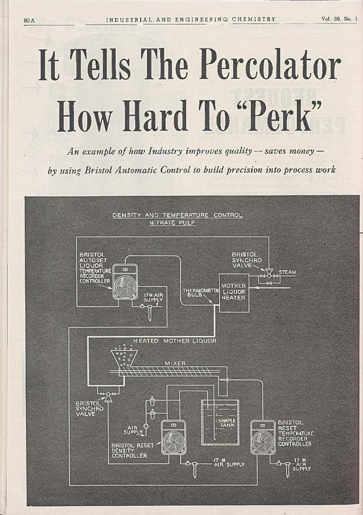
80 A I N D U S T R I A L A N D E N G I N E E R I N G C H E M I S T R Y Vol. 39, No. 1
D E N S IT Y AMD TEM P ER A TU R E CONTROL N ITRATE PU LP
B R ISTO LAUTO SETLIQUORTEMPERATURERECORDERCONTROLLER
B R ISTO L SYNCHRO V ALV E \
S T E A M
MOTHERLIQUORHEATER
THERMOMETER BULB \17» A IR
S U P P L Y
BR ISTO LSYNCHROVALVE
SAMPLET A N K BR ISTO L
RESETTEMPERATURERECORDERCONTROLLER
AIRS U P P L Y
BRISTOL RESET’DENSITYCONTROLLER
17 # -AIR SU P P LY
17 nA IR S U P P LY
It Tells The Percolator How Hard To “Perk”
A n example o f how Industry improves quality — saves money —
by using Bristol Automatic Control to build precision into process work
H EA TED MOTHER LIQ UO R

January 1947 I N D U S T R I A L A N D E N G I N E E R I N G C H E M I S T R Y 8 1 A
Bristol Magniset Free-Vane Air-operated Controller (right half of dial plate removed).
In the nitrate industry, pulp density and temperature must stay within narrow limits in order to prom ote crystallization in the solution that results from leaching the fines with hot m other liquor. Bristol Free- Vane Air-operated controllers are used to control the filtering.
D ensity is controlled b y dropping the pulp into a sampling tank where a Bristol Reset Controller measures the density and makes any necessary adjustments through the diaphragm valve in the line supplying the heated m other liquor to the mixer.
Tem perature is controlled b y a com bination o f a Bristol R eset Controller located at the sam pling tank and a Bristol A utoset Controller on the steam line. The control points on the latter are varied b y the Reset Controller.
Free-Vane Controllers are offered *in these types: M onoset, Am pliset,Preset, Reset and M agniset, each o f
which can be equ ipped w ith the A u to se t
fea ture which measures and regulates the control medium in response to direction from another Bristol instru
ment that measures the value o f the controlled variable.
Bulletin A112 gives further inform ation. Address T H E B R IS T O L C O M P A N Y , 110 Bristol R oad, W aterbury 91, Conn.
BRISTO L CAN M AK E Y O U “ THE BO SS” OF V A R IA B L E S IN PROCESS W O R K
W herever production or quality is at the m ercy o f variable values — temperature, rate o f flow, liquid level, pressure, draft, humidity, pH , etc. — consider what Bristol can do to help you eliminate losses due to uncontrolled or inaccurately controlled variables.
Bristol engineers, working from a long and broad experience in process work, can show you h o w b y providing continuously accurate in fo rm a tio n or b y putting variables under autom atic
control . . . you can get the desired end result with minimum expense. It costs you nothing to investigate. Get in touch with Bristol now.
£/iq//teers p r o c e s s c o r f r o /
/o r / e f f e r p ro o /u e fs a / tc /p ro // fs
a u t o m a t i c c o n t r o l l i n g a n d r e c o r d i n g i n s t r u m e n t s

I N D U S T R I A L A N D E N G I N E E R I N G C H E M I S T R Y Vol. 39, No. 1
vvi i n BAILEY PYROTRON ELECTRONIC RESISTANCE THERMOMETERS
1. F O R A IR - O P E R A T E D S Y S T E M S
A free floating air pilot valve actuated by the Pyrotron slidewire unit establishes an air loading pressure for the control of valves and drives. Adjustments and relays provide flexibility of range, sensitivity, and speed of response, as well as reset action, easy coordination with other factors, and remote manual control.
2 . F O R O N - O F F E L E C T R IC A L S Y S T E M S
By Electronic R e lay— Two slidewires, one set manually to the desired temperature standard by a convenient knob and scale, and the other automatically positioned by the Pyrotron slidewire unit, form a control bridge which operates an electronic relay.
B y Electric Contacts — Adjustable cam on Pyrotron slidew ire unit o p erates a totally enclosed snap switch.
3 . F O R M O D U L A T E D E L E C T R O N IC SY ST EM S
A control bridge formed by two slidewires establishes a small signal voltage which changes in phase and intensity to operate a standard electronic control unit. The d-c output of this unit is accurately regulated according to the signal and applied to a saturable core reactor to vary voltage on the a-c heating circuit.
U N U S U A L F E A T U R E S O F THE B A I L E Y P Y R O T R O N
ELEC TR O N IC R ES ISTA N C E THERMOMETER
1. Resists vibration and shock.
2 . Needs no careful leveling.
3 . Motor drive provides abundant power for operation of recording pen, controller, alarms and signals.
4 . Simple a-c measuring bridge needs no battery.
5 . Sturdy electronic units keep the bridge in continuous balance and replace the usual galvanometer and its attendant mechanism for step by step balancing.
6 . Interchangeability of packaged units simplifies replacement.
For details on this unusual Electronic Resistance Thermometer, which indicates, recordsand controls temperatures between —100°F.and 1200°F. ask for Bulletin 230-A. mo
BAILEY M ETER COMPANY1 0 2 3 I V A N H O E R O A D • . . C L E V E L A N D 1 0 , O H I O
G o n t f io h JjQ S i P n & c e A A in c p
-t e m p e r a t u r e l ^ v e l
p r e s s u r e . d e n s i t y

InstrumentationConstructional details and advantages o£ a new electric hygrometer are reported.
b y R a l p h M i. M u n c h
T h e old expression, “ It isn’ t the heat, it’s the humidity” , is evidence that
even the layman recognizes the importance of humidity as one of the factors in his environment which affects his comfort.In spite of this recognition, he probably does not realize the importance of humidity in industrial processes. Last October (advertising section, page 79) we reported several of the most widely used methods of measuring humidity and described in detail an automatic dew- point recorder. One of the humidity measuring instruments mentioned but not described was the Aminco-Dunmore electric hygrometer made by the American Instrument Company, Silver Spring, M d.
The heart of the electric hygrometer is the humidity sensing element shown in Figure 1. I t consists of a polystyrene cylinder wound with a double winding, one wire being connected to each pin of the base. The wound surface is coated with a film of partially hydrolyzed polyvinyl acetate containing a small percentage of lithium chloride. Since lithium chloride is hygroscopic, this thin film gains or loses moisture until it is in equilibrium with the partial pressure of water vapor in the atmosphere around it. The water content of the film is therefore a function of the atmospheric humidity. The electrical conductivity of the film is a function of its water content. Thus, the atmospheric humidity can be measured by measuring the electrical resistance of the element. B y taking suitable precautions in their manufacture, these elements can be made very stable. Precious metal wire is used to avoid the effects of corrosion. Precision spacing of the wire assures uniform current density over the surface of the wire. It is carefully anchored and wound under tension to ensure that the spacing between turns remains constant. Uniform thickness of the coating is of great importance and is assured by special coating methods.
The relative humidity range for which the element is suited is determined by the lithium chloride content of the coating. T o obtain high accuracy, eight elements are used to cover the range from 7 to 100% relative humidity. Calibration curves are for 80 ° F .; correction curves permit use of the elements at other temperatures in the range 40° to 120° F. In addition to the simple humidity elements, units which combine a humidity element and a resistance element for measuring dry-bulb temperature are available. However, these do not respond so rapidly as the simple humidity elements. Separate resistance elements for temperature measurement can also be secured.
A variety of types of indicators, controllers, and recorders is available for use with these humidity sensitive elements. They include a line-voltage-operated indicator, a portable- battery-operated indicator, a simple indicating controller, as well as round- and strip-chart recorders or recorder-control- lers. Figure 2 shows the type R -l round-chart recorder. In addition, a multiple mounting which accommodates as many as eight humidity sensing elements is available. This mount makes possible compact, convenient installation of the complete set of eight elements (Continued on page 84 A )
Figure 1. H u m id ity Sensing E lem ent o f A m erican 1 In stru m en t C om pan y ’ s E lectric H ygrom eter
83 A

I n s t r u m e n t a t i o nALSOP "H Y -SPEED
MIXERS & AGITATORSwhen it is necessary to cover the entire humidity range. The mount to hold eight elements is only 37/% inches in diameter and 6V 2 inches in over-all length.
The electrical hygrometer has many advantages. Chief among them is its rapid response. Changes of humidity as small as 0 .5 % are detectable. The makers guarantee that humidity elements will retain their calibration within ± 1 .5 % relative humidity for one year. The element is small in size, z/, inch in diameter and 15/ 8 inches in over-all length. It does not add moisture to or remove it from the surrounding air space in significant amounts. It thus makes possible measurement in small containers where other methods are not applicable.
The electrical hygrometer is an interesting example of the class of instruments in which the variable to be measured is made to cause a change in an easily measurable electrical quantity (in this case resistance) so that electrical measurements can be used to measure the unknown quantity. Many such methods have been developed because of the ease and accuracy with which electrical measurements can be made.
F o r e v e r y l i q u i d m i x i n g j o b
F P o r t a b le " H y -S fte e d "\\\ ' j Mixers are designed for rim
w(l is*£36fc» m ounting to open tanks.Vv- i Makes every tank a Mixing
V\ Tank.\\ 'v-; ■" ■.!
AdjjjJ.- , Iff j \\ i Our universally adjustable»May« clamp permits positioning of
the shaft with its propellers G&■'&* on nny ang]c fr0m tank side
y. wall or from tank center,\\ thereby giving the most suit-yi able mixing action for the job
at hand.
All "liy-kpccd” Mixers are a v a ila b le for p erm an en t
mounting through closed tank tops. They are easily adapted to special requirements.
Fixed Side-Entering Type Agitators are available for large tanks where portable and top entering units cease to be practical. Our experience of over a quarter century in the design and application of “ Hy-Spced” Mixers of all types is at your service. Write for full information.
;urc 2. R ou n d-C h art Recorder o f A m erican In stru m en t Com pany
The Brown Instrument Company, Philadelphia 44, Pa., recently issued three new catalogs. The first, Catalog 6707, describes rectangular case thermometers and pressure gages. Vapor-, gas-, and mercury-actuated thermometers, as well as pressure gages, are described. Large, clearly labeled illustrations show the design features and improvements found in Brown thermometers and pressure gages.
Catalog 15-10 covers Brown electronic strip chart potentiometers. It gives the story behind their development and describes the electronic detector which replaces the galvanometer in these instruments. The constructional features are described and illustrated. The various forms in which these instruments are available are reported in detail.
Catalog 5902 gives information on Brown Newmatic remote transmission systems. These are meant for applications where electrical transmission of data is neither desirable nor
ENGINEERING CO RPO RA TIO N
F i l t e r s - F i l t e r D i s c s 4 S h e e t s - M i x e r s - A g i t a t o r s
201 Black Road M illdale, Connecticut
84 A
permissible. There are several schematic diagrams of typical applications. Operating features are fully explained, and there is a comprehensive description of the component parts which make up the system.
P H Y SIC A L C H A R A C T E R IST IC S*
Specific Gravity: 0.775 to 0.895 @ 60 °F. Saybolt Viscosity: 30 to 345 @ 100°F. Distillation Range: 370 to 800°F.Flash Point: 170 to 420°F.Fire Point: 190 to 480 °F.Pour Test: +40°F. to - 3 5 °F.Aniline Point: 175 to 230°F.Refractive Index (o; 20°C.: 1.43 to 1.48 Dielectric Strength: Above 29 K.V.Siigh Oxidation Number: 0.0 to 0.9 Copper Stability Test: Not less than 20 Molecular Weight: 175 to 400 Conradson Carbon Test: Below 0.005% Unsulfonatable Residue: Above 97.5%("These characteristics represent .the entire range ot Sonneborn Hydrocarbon Oils — not any one oil/)
W hite Oil and Petrolatum Division, L. SO N N E B O R N S O N S , IN C .Dept. JE -1, 88 Lexington Avenue, New York 16, N . Y .
Please send information on properties of Sonneborn Purified Hydrocarbon Oils for use specified on dotted line below:
Name-------------------------------------------------------------------------- (T itle)
Company____________________________________________ _
Address----------------------------------------------------------------------------- -
A broad com bination of unusual and highly desirable properties is responsible for the increasingly widespread
adoption of Sonneborn purified petroleum hydrocarbon oils (white mineral oils) in place of ordinary mineral oils and
oils of other origin.A few of these properties are show n above. There are many
others. A large number of firms in chem ical processing industries have benefited from S onnebom 's help in selecting
the right specifications to meet individual requirements. Send coupon or write, specifying use intended, for latest
information and help on your problem.
January 1947
W h ite O il , a n d P e t ro la tu m D iv is io n
L. SONNEBORN SONS, INC.Refiners of Petroleum Products
88 Lexington Avenue, New York 16, N. Y.

86 A I N D U S T R I A L A N D E N G I N E E R I N G C H E M I S T R Y Vol. 39, No. 1
" I p i l Í
FEATURED CHEMICALS* PFIZER FAMILY
■'■¿Vi?:.. •;r-: -’ -i
■ ■
Ammonium Oxalate
Ascorbic AcidBi-Cap Flour Enrichment
MixturesBismuth PreparationsCalcium GluconateCitric Acid
Citrate Esters
Cream TartarFumaric AcidGluconic AcidGiucono Delta LactoneIron and Ammonium
CitratesIron and Ammonium
OxalateIron GluconateIron OxalateItaconic AcidNiacin
Niacinamide
Oxalates Penicillin Potassium Iodide Potassium Oxalate Riboflavin Rochelle Salt Sodium Citrate Sodium Gluconate Tartaric Acid Thiamine—»and many other chemicals
IS *
n o . 9 in a series :
THIAM IN E
( / N co rre ctin g *=<1
U d ietnrv d efic ien cies , th iam in e has esta -
n m aioe vitam ins. K n ow n popularly as Vet
•, U c f ro m P6» « * ^ m in B „ it is a v a i la b le fro m
tha fs beyond question and quan-
tides that range from 1gram in a bottle to drums
o f 10 k ilo s .
Into the manufactureof Vitamin B. (Thiamine H y d r o c h lo r id e USP)
,o the essentials in P6» ' > b “ k 6 ' ° " n ': „ „ ol, skiU„ r a i „ e .p e r s o n n e l ,apecence-.
a p p lie d to the m a in te n an ce ° t p ro d u c t ^r Thas Pfizer Sc <~o.,
and Physical uniformity. Chas^
Tnc 81 M aiden Lane, Netv Y o rk 7 ,^ ’ 444 W est Grand Avenue, Chicago
1 0 , I l l in o is ; 605 Third Street, San
Francisco 7, California.
tÀ la/nu^ actitA rn^ ^ /ienilàlà £Pi/nce -J849

January 1947 I N D U S T R I A L A N D E N G I N E E R I N G C H E M I S T R Y 87 A
FOR DRYING PROBLEMS
1 \ IIETIIER your problem involves the Y V drying of materials which are hard to
dry efficiently; or to improve present drying techniques to assure a profit under new competitive conditions — a General American engineer should he able to assist you.
_ He has available the results of years of experience in designing and fabricating equipment to profitably dry a wide variety of chemical and metallurgical materials for use in many
processes. He lias at his disposal to assist him in arriving at a satisfactory solution, excellent physical and chemical laboratories and a pilot plant capable of providing accurate engineering data to provide an optimum design for the final plant.
Ask a General American engineer to work with you to develop a solution to your drying problem which will produce maximum profits.
O T H E R G E N E R A L A M E R I C A N P R O D U C T SFilters Turbo-Mixers
Evaporators Tanks Dewaterers
•TowersThickeners Bins
T R A N S P O R T A T I O N C O R P O R A T I O Np r o c e s s e q u i p m e n t • s t e e l a n d a l l o y p l a t e f a b r i c a t i o n
SALES OFFICE: 10 East 49th St., Dept. 800a, New York 17, N.Y.WORKS: Sharon, Pa„ East Chicago, Ind. I P
OFFICES: Chicago, Sharon, Louisville, Orlando, Washington, D. C. V I Pittsburgh, St. Louis, Salt Lake City, Cleveland.
j

88 A I N D U S T R I A L A N D E N G I N E E R I N G C H E M I S T R Y Vol. 39, No. 1
I hat’s because the inner wall and baffle core of the Durco No. 4 heat exchangers are made of Duriron.
This Durco alloy contains 1 4 ^ % silicon and just isn’t gnawable for most corrosives. It can safely handle almost any commercial acid, including all concentrations and temperatures of sulfuric acid, acetic acid, nitric acid, as well as such corrosives as brine, nickel plating, chrome plating and anodizing solutions.-
D URCO A LLO Y SDuriron ond Durichlor— high-silkon irons Durimet—a special, sulfuric acid-resisting stainless Durco Stainless Steels—(chrome-nickel series)
D U RCO EQUIPM EN T
Centrifugal Pumps VolvBI
Pipe ond Fittings {Flanged and Bell and Spigot)
Exhaust Fanj Heat Exchanger*Steam Jet*Tank OutletsElectorsKettles
From a ll the above a l lo y s , * also Monel, Inconel,
Nickel, Ni-Resist, Steel
y Duriron, Durichlor
CAPACITY— The Durco No. 4 heat exchanger handles an acid flow of 4 to 14 gpm with pressure drops of 5 to 34 ft. The heat transfer capacity o f the unit used as a heater is 135,000 to 155,000 BTU per hour with 75 lb. steam and inlet temperature of liquid between 70° F and 130° F. As a cooler the capacity is 45,000 to 90,000 BTU per hour, based on 100° F mean temperature differential. •
OTHER DURCO HEAT EXCHANGERS with heat transfer capacities up to 300,000 BTU are also available. Complete information available on request.
F o r fu ll details on the N o . 4
unit ask fo r new bulletin 1610.DURCO Adv. 24-GM
THE DURIRON CO., INC.DAYTON 1, OHIO
Branch Offices in Principal Cities
C O R R O SIV E SO LU TIO N S C A N ’T GN AW THROUGH * * I S. HEAT EXCHANGER
D E S IG N F EA T U R ES
1, The steam (or coolant) is separated from the acid by a Duriron corrosion-resistant tube.
2. The units can be installed vertically or horizontally.
3. There is no packing against the corrosive solution.
4. The units weigh only 145 lbs. and can be easily handled.
5. Can be connected together in series or in parallel.
6. The Duriron parts can be removed without disturbing the steam (or coolant) inlet and outlet connections.

[arrosionT h e e x t e n t a n d i m p o r t a n c e o f t h e c o r r o s i o n p r o b l e m a r e o u t l i n e d .
Se n s a t i o n a l figures have been published with regard to the annual cost of contision and of protection against corrosion.
One estimate places this loss at over 3 billion dollars. An accurate estimate is, of course, impossible, but it is not difficult to perceive that the cost is enormous when we consider that corrosion occurs, with varying degrees of severity, in practically all cases where metals and alloys arc used. Everyone is familiar with the rapid rate at which iron and steel corrode or rust when exposed to atmosphere and rain.
Some of the fluids which cause corrosion difficulties serious enough to warrant actual investigation are the following: fresh, distilled, salt, and mine waters; rural, urban, and industrial atmospheres; steam and other gases sucn as chlorine, ammonia, oxygen, carbon disulfide, sulfur dioxide, and fuel gases; mineral acids such as nitric, sulfuric, and hydrochloric; organic acids such as acetic, formic, and citric; alkalies such as caustic and ammonium hydroxide; soils; solvents such as alcohols and dry cleaning materials; vegetable and petroleum oils and a variety of food products. Two of the most common and most plentiful materials known— namely, air and water— also cause corrosion, and considerable effort and money have been spent to minimize their destructive effects.
Aside from the cost in dollars, corrosion is a serious problem because it directly and definitely contributes to the depletion of our natural resources. For example, steel is made from iron ore and our reserves of iron ore are diminishing. In addition, approximately 4 tons of coal are required to produce 1 ton of steel. Our copper reserves are dwindling, and copper is one of the principal elements used in the production of corrosion-resistant alloys.
The war years have placed further accent on corrosion. We often read about the millions of dollars worth of equipment which is rusting and deteriorating, particularly in tropical and marine atmospheres. We know, too, that failure of parts or failure of equipment to function properly because of corrosion often seriously handicapped our military forces. These facts account for the large amount of effort expended during the war, and now in the postwar period, on studying and combating corrosion. The increased effort and interest are reflected in the corrosion “forums” that are being held throughout the country and in the large number of technical society sessions and papers devoted to the subject.
Corrosion is truly a major industry but, unfortunately, one which is “in reverse” . Its waste obliges all concerned to minimize or eliminate it in so far as possible.
In addition, chemists and chemical engineers have other vital
b y M a r s G. Fontana
interests in the corrosion problem. Some of their reasons for concern are described in the following paragraphs.
H i g h e r T e m p e r a t u r e s a n d P r e s s u r e s . The trend, conspicuous during recent years, in the chemical industry toward higher temperatures and pressures have made possible new processes or improvements in old processes— for example, better yields, greater speed, or lower cost of production. Higher temperatures and pressures usually involve more severe corrosion conditions. Many of the present day operations would not have been possible or economical without the use of corrosion-resistant materials. The annual tonnage of stainless steel purchased by the chemical industry today is many times greater than that purchased ten years ago. A powder plant of World War II would be almost unrecognizable, from the standpoint of materials of construction, to an operator of a similar plant in World War I.
R e d u c t i o n in M a i n t e n a n c e C o s t s . Substantial savings can be obtained in most types of chemical plants through the use of corrosion-resistant materials of construction. One example is classic in this respect. A plant effected an annual saving of more than 10,000 dollars merely by changing the bolt material on some equipment from one alloy to another more resistant to the conditions involved. The cost of this change was negligible. In another case a waste-acid recovery plant operated in the red for several months until a serious corrosion problem was solved. This plant was built to take care of an important waste disposal problem. Maintenance costs are now scrutinized because the labor picture accents the necessity of low cost operation.
C o n t a m i n a t i o n o f P r o d u c t . In many cases the market value of a chemical plant product— for example, titanium dioxide pigments— is directly related to its purity and quality. Freedom from contamination is also a vital factor in the manufacture of transparent plastics, food products, and drugs. In some instances contamination causes adverse catalytic effects which are noticeable— for example, in the manufacture and transport of hydrogen peroxide.
Life of the equipment is not generally an important factor in cases where contamination or degradation of product are concerned. Ordinary steel generally lasts many years, but more expensive material is used because the presence of iron rust is undesirable from the product standpoint.
The history of sodium hydroxide presents an interesting example of improvement of a chemical plant product through the use of corrosion-resistant materials. The variety of colors in the first commercial caustic produced was due principally to the iron pick-up from the cast iron pots used.
('Continued on page 90 A)
Mars G . Fontana, after eleven years as a m etallurgica l and industrial engineer with the Du P on t C om pany, jo in ed the staff o f O hio State University in 1945 as professor o f m etallurgica l engineering in the D epartm ent o f M etallurgy, professor of m etallurgica l research in the Engineering Experim ent S tation , and director of the C orrosion Research Laboratory. His w ork involves teach ing and research for graduate students and industrial research, chiefly on corrosion . He is now handling a fu n dam en ta l corrosion research pro ject for the Navy and other problems for the A rm y Air Forces. He is also a consu ltin g m etallurgical engineer w ith particular interest in the field o f m aterials o f con stru ction for the chem ica l in dustry. F on tan a ’s training and experience qualify h im to discuss problem s o f corrosion fo r ou r readers. D uring his graduate work at the University o f M ich igan he was research assistant in the D epartm ent o f Engineering Research, and som e o f his research projects included vacuum fu sion analysis o f m etals for hydrogen , oxygen, and n itrogen , the developm ent o f h igh tem perature alloys, creep properties o f m etals, and scaling o f steels at forging tem peratures. M ost o f his work for Du P on t also concerned corrosion— for exam ple, developm ent o f alloys resistant to su lfu ric acid , selection and specification o f con stru ction m aterials for all Du P on t p lants, cooperation w ith the D esign D ivision on new p lant con stru ction, and “ trouble sh ootin g ” in the plants on corrosion and oth er types o f equ ip m ent failure. Fontana is acting as co -ch a irm a n for all tech nica l sessions o f the annual m eeting (April 1947) o f the N ational A ssociation o f Corrosion Engineers. The editors w elcom e iiim to the staff o f con tribu tin g editors, and feel sure that his colum n each m on th will prove valuable.
89 A

-----------------------
Low-cost operation with ILLCO-WAYC o r r o s i o n
Caustic was regarded as an extremely corrosive material, and its manufacture and use were not greatly encouraged. During the late twenties the rayon industry demanded a high purity caustic because any impurities were extremely detrimental to its product. During recent years white or rayon-grade caustic has been accepted as a normal commercial item. Its impurities are low and usually expressed as parts per million. Nickel and nickel alloy equipment play an impo^ant part in its production and handling. Natural and synthetic rubber linings and paints also prevent its contamination by steel equipment.
High purity caustic has played an important part in the development of high strength rayon for tire cord during the war, for photographic film, and for high grade soaps.
P l a n t S h u t d o w n s . Far too often plants are shut down or portions of the process stopped because of unexpected corrosion failures. Perhaps nothing is more exasperating to management or industrial plant staffs, particularly during periods of high demand for the product, when a direct loss in revenue is involved. Sometimes these shutdowns are caused by corrosion involving no change in process conditions; but often they are caused by changes in operating procedures regarded as incapable of increasing the severity of the corrosive conditions. It is surprising how often some minor change in process or the addition of a new ingredient changes completely the corrosion picture. The production of a chemical compound vital to aircraft performance during a critical period of the last war is an example. To increase its production, the temperature of the cooling mediuip in a heat exchanger system was lowered and the time required per batch decreased. Lowering the temperature of the cooling medium resulted, however, in more severe thermal gradients across the metal wall. They, in turn, induced higher stresses in the metal. Stress- corrosion cracking of the vessels occurred quickly, and finally a plant was shut down with production delayed for some time.
Sudden and rapid corrosion of stainless steel equipment caused another example of plant shutdown. The cause of the accelerated corrosion and crippling operation had to be determined and corrected before operation could be resumed, because expensive and hard-to-obtain stainless centrifugals were involved. The accelerated attack was finally traced to faulty valves which allowed leakage of hydrogen sulfide into the system.
Unexpected plant shutdowns are particularly troublesome during the start-up of new process plants. The inadequacy of present corrosion test methods are sometimes responsible, but in many cases the necessary preliminary testing is incomplete or the construction materials installed are unsuitable.
V a l u a b l e C h e m i c a l s . Particularly during recent years, the products or intermediates handled in a chemical plant are often expensive. Substantial production losses of these materials to the sewer because of corrosion failures are, of course, to bo avoided.
S a f e t y . Last but not least is the consideration of this factor. The handling of chemicals at high temperatures and pressures, explosive materials, and acids such as hydrofluoric and concentrated sulfuric demand materials of construction which minimize corrosion failures if severe injury or loss of life are to be avoided. Corroding equipment is known to have caused fairly harmless compounds to become explosive. Economizing on materials of construction is generally not desirable if safety is risked.
The chemist and the chemical engineer should be familiar with j corrosion and the corrosion problem. Each should be able to appreciate the problems involved, and should know where to obtain the necessary information or how to go about obtaining it, if he has to do the job himself. Many of the larger companies have !materials engineers or corrosion engineers trained and experienced in this type of work. In many plants, especially the smaller ones, jhowever, the chemist or the chemical engineer has to handle the work himself. So-called details are often of major importance. For example, the correct stainless steel may be specified for a given application but the results are often poor if the material is not properly heat-treated.
Corrosion may be defined as the destruction or deterioration of metals and alloys by chemical reaction with their environments. The definition can lie amplified by including electrochemical reaction if we wish to differentiate between the two general classes of corrosion— namely, chemical and electrochemical. Chemical j corrosion involves direct chemical attack, and electrochemical : corrosion concerns destruction by electrolytes. These two classes could be more simply described as dry and wet corrosion.
This definition holds for the corrosion of metals and alloys. In a broader sense of the word, however, other materials also corrode. The slag in a steel-making furnace fluxes the brick lining, acids and other chemicals attack rubber and plastics, and sunlight deteriorates paints. These are all examples of corrosion. Corrosion can therefoie be defined simply as the deterioration of materials by chemical attack.
90 A
De-iomzed Water(the m o dern .lo w -co st
e q u iv a le n t of d is tilled w a te r)
Illinois Water Treatment Co.852-1 Cedar Street
Rockford , Illino is
7310-J1 Em pire State Build ing New York City
ANOTHER ILLCO-WAY INSTALLATION: Pure water is produced by this compact ILLCO-WAY De-ionizer (flow rate: 650 gph). No fuel, no cooling water required, no periodic dismantling for cleaning.
Whether you need high-quality water for a laboratory or for an entire processing plant, Illco-W ay D e-ionizing equipment can cut costs for you to a remarkable extent!
Chemically pure water— the equivalent of distilled water— is produced by I l l c o -W a y at a fra ction o f the cost o f d is t illa t io n . Quality o f water remains uniformly high throughout entire operating cycle.
Units are designed to meet your needs; flow rates from 12 gph (portable unit) up to500,000 gph or more. Investigate this modern ion-exchange process . . . used currently in hundreds o f chemical, industrial and pharmaceutical plants. W rite fo r latest litera ture .

January 1947 I N D U S T R I A L A N D E N G I N E E R I N G C H E M I S T R Y 91 A
S E A M L E S SFORGED
PRESSED and WELDED
Cooper offers a complete line of Stainless Steel Welding
Fittings including 4 5 °, 90° and 180° e lbow s, tees, caps,
ends. Each are annealed,
sandblasted and passivated
for m axim um corrosion,
abrasion and heat resisting
characteristics. The unusual
perform ance of these fittings
is the result of Cooper’s
25 years of Stainless
Steel “ know -how .”
TH E C O O P E R A L L O Y F O U N D R Y C O .H I L L S I D E , N E W J E R S E Y
World's largest producer of Stainless Steel Screwed, Flanged and Welding Fittings
— ..„„.a-.-.p. -- —------------- .......... -— --■■■>■' »¡Ml

THE CO ST IS V ER Y LO W — initial investm ent is m oderate and the plants quick ly pay for them selves. Solvent is usually recovered at a cost o f less than one cent
per pound.
A COM PLETE S O LV EN T -R EC O V ER Y PLA N T to m eet the specific requirem ents o f you r process can be designed and supplied b y Carbide and C arbon Chem icals C orporation. T he equipm ent m ay be com pletely autom atic in operation.
For further in form ation write for the booklet 'Solvent R ecov ery ” (Form 4410).
C a r b i d e a n d C a r b o n C h e m ic a l s C o r p o r a t i o nUnit o f Union C arbide and Carbon Corporation
3 0 East 4 2 m l Street, New Y o rk 1 7 , N . Y .
C O L U M B I A
C a /d o n- ¿ j c w e r
Vol. 39, No. 1
A LL TYPES O F V A P O R IZ ED SO LV EN T S CAN BE R ECO V ERED — alone or in com bination , in very low concentrations, and in the presence o f water vapor.
R EC O V ER Y IS EFFIC IEN T — often better tban 99 per cent o f all solvent passed through the adsorbers is recovered.
SOLVENT RECOVERY • CATALYSIS • GAS AND AIR PURIFICATION

Plant managementA c t i v e p a r t i c i p a t i o n i n c o s t e s t i m a t i n g i s r e c o m m e n d e d f o r p r o d u c t i o n e x e c u t i v e s i n t h e c h e m i c a l i n d u s t r y .
hg W a it e r van E e e h m a n n
A c c o u n t i n g is frequently thought of by production chemists and chemical engineers as a means of accumu
lating and computing historical data for the purpose of measuring and/or evaluating past performance. Not always is it realized that the accountant is also called upon to predetermine elements of cost and thereby to set a pattern for future job performance which management expects to be executed by production personnel. It is therefore to the interest of the production executive to participate actively in gathering figures which reflect conditions prevailing in the plant after the introduction of a new product. He should also familiarize himself with the technique of cost estimating in order to check estimates for accuracy when they are submitted to him for approval. Active participation by the production executive in establishing cost estimates requires a cooperation with the accounting department. The production executive will expect the accountant to utilize records of past experience, chemical and mathematical formulas, etcl, so that no time will be wasted with questions which can be answered in the accounting department. The accountant, on the other hand, will have to take it for granted that the figures given him were derived by conventional methods and not by approximation based on feelings. To the casual observer it may seem that the job of estimating future job performance is simple. Materials, labor, as well as factory overhead are added together.
Anyone familiar with cost estimating, however, knows that considerable groundwork is necessary before figuring can be started. The cost of the various operations in a chemical plant depends upon volume of production. It is therefore essential that the sales department supply the accountant with anticipated sales. These figures must be submitted in sufficient detail so that seasonal fluctuations are clearly indicated. The sales department must also tell the accountant to what extent finished goods inventories are allowed to accumulate. This information is needed to determine the peak of production. Let us assume, for example, that a product is to be manufactured which will be sold only during three months of the year and is highly perishable. In this case the sales department may request that the product not be manufactured more than three months in advance, and it thus becomes necessary to produce one year’s output within a few months. Naturally, more machinery will be required than if the product could be made six or eight months in advance.
After determination of the maximum amount of production needed within a certain time cycle, the necessary machinery and labor can be decided upon by the production executive. Consideration, however, must be given the fact that it is often more economical to utilize existing machinery, even if it is less efficient than new equipment, and that operating cost can often be reduced by rescheduling production.Estim ating m aterial
When estimates are made for materials to be used for the manufacture of a new product, laboratory or pilot plant figures are often extended without consideration being given to possible inaccuracies due to conversion. A sufficient amount of material should be allowed for waste. Attention is called
to the practice in some chemical plants of keeping measurements and weights on the low side in order to absorb normal wastage. In this event no allowance should be made for spoilage. Opinions seem to vary about what constitutes normal wastage. The production executive is usually inclined to overestimate the amount, especially when he has to set up new operations for which no comparative waste figures are available. The accountant sometimes fails to realize that spoilage is unavoidable. He may also want to put allowable wastage for all materials used on a straight percentage basis, not realizing that the waste is naturally highest percentagewise when small amounts are used. Cost for materials should be based on the price paid op amounts normally required and not on small amounts which are usually purchased at the beginning of new production.
Attention is also called to the importance of pricing only direct materials and not so-called indirect materials which are considered overhead expense. When raw materials are used which are produced within the plant, or when part of the material is salvaged, pricing often becomes a problem. The practice of evaluating recovered materials used within the department on the basis of the original purchase price is unsound, since production departments would then conduct their salvage operations at a profit and thus distort the picture of actual manufacturing costs.
E stim atin g laborDepartment heads frequently dislike to give out labor
figures on future operations because labor estimates are often inaccurate. Improvements may reduce the estimated labor cost and unforeseen circumstances may increase it. This, however, is no excuse for a department head not to provide labor estimates. Despite possible inaccuracies, the production executive is in a better position to foresee labor needs than the accountant who is often unfamiliar with chemical operations. The following steps are recommended when difficulties are met in predetermining labor figures:
1. Obtain a clear picture of future operations by laying out the flow of work in detail.
2. Consult supervisory personnel. It is good practice not to ask questions outright but to give the foreman an opportunity to think the problem over and possibly to discuss it with workers. Oniy too often the foreman gives a hasty answer which is of no value because he is afraid his superior may question his ability if he does not reply immediately.
3. Employ the services of the industrial engineering department when they are available. Construct models and go through the steps of manufacturing. Many elements of labor cost may appear which have not been thought of.
4. Consider company policies (such as rest periods, etc.) and union agreements which may increase the' labor normally required.
E stim atin g fa ctorg overheadFactory overhead is frequently considered a cost element
which is simply attached to the product in relation to the money spent for director labor. More often it is thought of as a necessary evil of minor (Continued, on page 0 .'t A )
93 A

Plant Management
OLDBURY E L E C T R O -C H E M IC A L
C O M PA N Y
A M O R P H O U S
P H O S P H O R U S
P H O S P H O R U S
S E S Q U I S U L P H I D E
Manufactured to strict specifications
for the M atch Trade
Plant and M a in Office:
NIAGARA FALLS, NEW YORK
Torl{ Office:
19 RECTOR ST., NEW YORK 6, N. Y.
importance which influences the total cost of the product to only a small degree. A clear conception of factory overhead involves the realization that the total cost of the product includes material, labor, and overhead. This means that all the expenses except material and labor must be covered by overhead.
Let us assume that someone intends to start a chemical plant and that he has sufficient capital to take care of material and labor. W hat are the cost elements not provided for? Here are some: rent, depreciation of machinery, indirect labor, supplies, taxes, heating, lighting, energy consumption, maintenance, building repair, machine repair, insurance, tool expense, shop, office, and storeroom expenses. From this point of view, two facts seem outstanding: (1) Factory overhead is an important part of the total cost. (This applies especially to chemical manufacture where overhead is sometimes one third of the total cost.) (2) Cost elements making up the overhead are in many instances not proportional to direct labor costs.
The production executive who is conscious of the importance of apportioning factory overhead correctly to the product will wish to express his opinion on the way overhead expenses are attached to his department. He will not agree that the entire factory overhead is distributed according to direct labor cost. He must realize, however, that it is not practical from the accountant’s point of view to show separate items of factory expense distribution for every cost element. Therefore, it will be necessary to group the cost-elements according to a selected number of apportioning factors, even if the expense is not in direct relation to the item selected. For example, power expenses can be apportioned on the basis of the number of machines in each department, maehine-hours of production, and kilowatt-hours of electricity. Only in rare cases will it be found that any one of these apportioned items applies to all power consumption in one department. Nevertheless, the executive may be requested by the accounting department to select the factor of cost distribution which applies in most instances since the theoretically correct apportionment involves too much work. Instead of prorating the various elements of cost making up the factory overhead individually to each department or each product, the accounting department may request that a supplementary rate be used which is arrived at by combining cost elements with a common denominator. For instance, supervision, factory lunchroom expense, factory hospital expense, cost accounting expense, and toolroom expense can be combined and distributed on the basis of the number of workers employed in each department. Rent and taxes, depreciation and repair of buildings, and fire insurance are best apportioned according to the square footage occupied by each department. There is no reason why a production executive should not consent to have these elements of cost grouped together in the accounting department and charged to his department in a lump sum.
Although both estimated and standard costs are predetermined, they should never be considered similar in nature. Estimated costs represent attempts to predetermine the actual costs under existing conditions without too great an expenditure of time and money. They are not presumed to be correct and are therefore subject to correction. Standard costs, however, must be determined on the basis of past experience and set up so that they can be used as a measuring stick of factory efficiency. M any concerns have a form of estimated cost and call it “ standard cost” . Estimated costing has a specific purpose— namely, to determine selling prices in advance of actual manufacturing Or to reduce the expense of clerical work of cost keeping. It should be used only for this purpose.
94 A

January 1947 I N D U S T R I A L A N D E N G I N E E R I N G C H E M I S T R Y 9 5 A
Sterility can be maintained throughout penicillin production, but . . .
That won’t necessarily insure product purity. Inorganic contamination has spoiled entire batches.
D isco v er a SAFE m eta l
As a means of protecting the sensitive drug, Cutter Laboratories, Berkeley, Calif., use Lukens Inconel-Clad Steel for their 5,000-gallon fermentation tanks. And solid Inconel* agitators and aerators. For they’ve found Inco- nel safe for use in contact with penicillin.
Here’s a statement from their report: "Engineers at Cutter Laboratories find Inconel* the best material for tank linings, temperature control coils and accessory equipment. By test, Inconel is the least soluble of all metals tested.”
E x tre m e ly lo w co rro sio n ra te
The tests mentioned took place in Cutter Laboratories over a 42-day period. The corrosion rate of Inconel in a corn steep water medium (standard culture medium for penicillin) under operational temperature o f 75°F., and rising to periodic sterilization heats, was 0.00002 ipy.
Inconel forms no harmful contaminating corrosion products, and causes no dangerous chemical reactions with sensitive penicillin solutions. Its use, therefore, meets one of the chief problems of penicillin production —the extreme susceptibility of the drug to contamination during almost every stage o f manufacture.
Which proves once more that it’s a good idea to consider Inconel (and other I n c o N i c k e l A l l o y s such as Nickel and Monel*) whenever you need corrosion- resistant equipment that will help you maintain or improve product purity. Nickel Alloys have solved many problems. Chances are, they can solve yours, too.
•Reg. TJ. S. Pat. Off.
■ M A A I M I P ■ PROTECTS T H E i n t e r n a t i o n a l N I C K E L C O M P A N Y , I N C .
I N C O i E L product 6 7 W A LL S T R E E T N EW Y O R K 5 , N . Y.
PURITYk i i r i / r i Æ ü ik i i m v e M0HEL* ' “K"*M0NEL * "s"*monel * inconel* • “r"*mqnelN I L iVl L / illtftiril\ A L L U l j ‘w monei • nickel • ‘v *nickei • 't ^nickel
ONE OF THE 5,000 GALLON penicillin fermentation tanks o f Lukens Inconel-Clad Steel at Cutter Labora- tories, Berkeley, Calif. Hazard o f contamination by alien bacteria is great, so tanks, coils and agitating equipment are thoroughly cleaned and checked after each harvest of penicillin.

96 A I N D U S T R I A L A N D E N G I N E E R I N G C H E M I S T R Y Vol. 39, No. 1
PatentNumbers1,935,270
and2,057,597
Jacket Water Coolers serving engines of 7,300 H.P. Muddy well water used as cooling medium.
H E A T T R A N S F E R E Q U IP M E N T
Vogt engineers have taken a familiar refrigeration plant "old timer" and developed it into this modern, efficient heat exchanger.
The film type exchanger operates in a vertical position. W ater introduced in the top chamber is distributed in a thin film against the inner tube walls by means of special ferrules. The shell side of the exchanger has baffles arranged to provide optimum velocities, pressure drops, and heat transfer rates. Shutdowns are eliminated because tubes can be cleaned while the unit is in operation; thus permitting the use of dirty, mud and silt depositing water.
Vogt Film Type Exchangers now serve as Jacket W ater Coolers, Sulphuric Acid Coolers, and Sulphur Dioxide Condensers, and can be designed to condense any vapor. They are also applicable for handling liquids other than water in film flow.
H EN RY V O G T M A CH IN E C O ., INC.L O U I S V I L L E 1 0 , K E N T U C K Y
Branch Officos: New York, Philadelphia, Cleveland, Chicago, St. Louis, Dallas
HE-5 Is a pictorial presentation of standard and special types of Vogt Heat Exchangers. Write for your copy.

January 1947 I N D U S T R I A L A N D E N G I N E E R I N G C H E M I S T R Y 9 7 A
The extrem ely long life of D e Lava l W orm a n d G e a r sets is d u e , in part, to the h eat
treatm ent to w hich the w orm s a re su b je cted . M a d e from ca re fu lly se le cte d a llo y
stee l, D e La v a l w orm s a re c a s e h a rd e n e d in the m ost m odern , co n tro lle d atm os
p h e re , fo rce d convection , e lectric fu rn ace s u nd er care fu l m eta llu rg ica l inspection
an d control. The h e a t treatm ent p ro ce ss em p lo yed p ro v id e s a h a rd , uniform
c a s e an d co rrect co re structure o f high tensile strength, fre e from internal stresses.WG-2

I N D U S T R I A L A N D E N G I N E E R I N G C H E M I S T R Y Vol. 39, No. 1
E t h y l a t i o n R e a c t o r V a l v e s A r e
M a d e o f H A S T E L L O Y A l l o y B
• These valves at the .top of ethylation reactors used in the production of aromatic hydrocarbons are made of H a s t e l l o y alloy B because they must handle a reaction solution containing chlorides. The iron valves previously used leaked after less than one month of service, requiring frequent and costly replacement. Valves made of H a s t e l l o y alloy B do not corrode in this service and, therefore, last indefinitely.
H a s t e l l o y alloy B has many other applications in the production of aromatic hydrocarbons, where parts are subjected to severe
conditions of chemical corrosion. It is particularly well suited for such equipment as pump parts, pipes, coolers, and tubes, because it stands up under such severely corrosive media as boiling hydrochloric acid and wet hydrochloric acid gas. It also has high resistance to sulphuric and phosphoric acids, and retains its high strength even at elevated temperatures.
For further information about this m aterial, write for the booklet “ H a s t e l l o y
H igh-Strength N ickel-B ase Corrosion- Resistant Alloys,” Form 3361.
H a y n e s S t e l l i t e C o m p a n yUnit of Union Carbide and Carbon Corporation
ŒHEG en eral O ffices and W ork s , K ok om o, Ind.
Chicago— C leve lan d — D etro it— H ouston— L o s A n g eles— N e w Y o r k — San F ra n c isc o — Tulsa
HIG H-S TR EN GTH N IC K EL- BA SE A L L O Y S FOR C O R R O S I O N R ES I STA NC E

January 1947 I N D U S T R I A L A N D E N G I N E E R I N G C H E M I S T R Y 99'A
n o ! i
2 Then the next step . . . DO THIS
CHECK THE MAKERWhen choosing the heating or cooling coil that will do the best job for your specific installation first consider the engineering background and reputation of the maker.
'Y ou ’ll find in short order that American Blower is one of the oldest and largest designers and manufacturers of air handling, air conditioning, heating, cooling and cleaning equipment.
New Am erican Blow er H eating Coil
Send for these two new bulletins, prepared by American Blower engineers. They make the work of selecting the best in coils quicker and easier. W e’ve been told these bulletins are the most convenient guides and references ever printed on the subjects of coil selection, sizing and installation. All material is authoritative and up-to-the- minute. Here’s all the information you will need in concise, easy-to-understand form.
Call the nearest Am erican B low er B ranch Office for you r copies tod ay . O r w rite for B ulletins B -1218 and 1521.
AMERICAN BLOWERAMERICAN BLOWER CORP., DETROIT 32, MJCH.
DlvUion of A merican R a d ia tor & d>taudard <$anitap^ co«po«ation
In Canada: CANADIAN SIROCCO CO.,r.LTD., W indsor, Ont.

100 A I N D U S T R I A L A N D E N G I N E E R I N G C H E M I S T R Y Vol. 39, No. 1
W ISSCO M E T A L C O N V E Y O R B E L T SA PRODUCT, O F WICKWIRE SPEN CER STEEL D IV ISIO N O F THE COLORADO FUEL AND IRO N CO RPO RATIO N
Sales O ffice and Plant— 56 Sterling Street, Clinton, Mass. General Sales O ffice— 361 Delaware Ave., Buffalo 2, N. Y. District O ffices : Boston, Chicago, Denver, New York. The California Wire Cloth Corporation, Oakland 6, Calif.
WISSCO METAL CONVEYOR BELTS
R I D E S A F E L Y O N
W I S S C O M E T A L C O N V E Y O R B E L T S A R E B E IN G U S E D IN
Annealing Ovens Baking Ovens Brazing Furnaces Chemical
Processing Decorating Glass Ceramic Products
Canning Dehydrating Degreasing Hardening Furnaces Infra-Red Drying Reclaiming
Tin, etc.
The Wissco Conveyor Belts which carry tiny rollers for roller bearings through hardening furnaces are an example o f how these custom-engineered wire mesh belts meet scores o f industrial requirements.
The Wissco Belt at the charging end o f the hardening furnace is designed for operation at I800°F. It is No. 16 gauge, 7 mesh, rod reinforced every spiral. The quench tank belt, to which side chains are affixed, has 1 }4" high angle lifts brazed to the belt and spaced every six inches; also a 13 " high, interlocking plate type guard edge.
Built to operate at temperatures as high as 2100°F., Wissco Belts are the accepted standard for heat treatment o f metals, glass and ceramic ware and for processing o f foods, chemicals and other materials. They are fabricated in any length; in widths from 1" to 192"; and to resist corrosion, abrasion and other destructive forces.
Send for illustrated catalog showing types and advantages o f numerous conveyor belt constructions.

January 1947
W I L F L E Y is the dependable pump that takes
the trouble out of handling acids, corrosives, hot liquids, mild abrasive and other tricky solutions. It's the pump that runs continuously on a 24-hour schedule without attention. Works on intermittent as well as continuous operations. 1 0 - to 2 ,0 0 0 - G .P.M . capacities, 15 - to 150-ft. heads and higher. Individual en gin eerin g on every application. WILFLEY is the pump to buy when you're seeking economy and efficiency. Write or wire for details.
A. R. WILFLEY & SONS, i n c .
D E N V E R , C O L O R A D O , U . S . A .
N e w Y o r k O f f i c e : 1 7 7 5 B r o a d w a y , N e w Y o r k C i f y
101 A

102 A I N D U S T R I A L A N D E N G I N E E R I N G C H E M I S T R Y Vol. 39, No. I
Announcing VOLUME IV o f t h i s i m p o r t a n t A C S M o n o g r a p h
PHYSICAL CONSTANTSo f H y d r o c a r b o n s
I n F i v e V o lu m e s
Volume IV — Polynuclear Aromatic Compounds
Organic research chemists, development engineers, and physical chemists in the many industries in which aromatic compounds are involved will find this volume of critically evaluated data a noteworthy and highly useful addition to the literature. It will be indispensable to workers in the petroleum and related fields and also to those in the coal-tar, dye, pharmaceutical and synthetic chemical industries. This monumental series, of which this is the fourth volume, will also be of prime interest to technical librarians, professors of chemistry, and advanced students specializing in organic synthesis.
The organization of Volume IV is the same as that of the three preceding volumes. The name and structural formula, together with melting point, boiling point, density and refractive index values as determined by numerous investigators at widely different atmospheric pressures, are given for all known compounds whose chemical nucleus consists of more than one ring. Ideal values as selected by the author are indicated for each compound on which a large number of determinations is reported. The material is copiously documented; additional data are presented when available.
540 Double-Column Pages $17.50
S end toda y fo r n ew 1 9 4 7 FREE c a ta lo g — "Let's Look It Up'
REINHOLD PUBLISHING CORPORATION330 West 42nd Street New York 18, N . V.
b y G U S T A V E G L O F F
Director of Research, Universal O il Products Co., Chicago, III.
Am erican Chemical Society
M onograph No. 78
Also publishers of Chemical Engineering Catalog, Metal Industries Catalog, Materials & Methods (formerly Metals and Alloys'), ami Progressive Architecture— Pencil Points
PHYSICAL CONSTANTS OF HYDROCARBONS
by Gustav Egloff
To be published in Five Volumes
Volumes of this important American Chemical Society Monograph already published —
• Volume I— Paraffins, Olefins, Acetylenes, and Other Aliphatic Hydrocarbons.
403 pages, $10.00
• Volume II— Cyclanes, Cyclenes, Cyclynes, and Other Alicyclic Hydrocarbons.
605 pages, $12.50
• Volume III— Mononuclear Aromatic Compounds.
672 pages, $16.00
• V o l ume IV— P o l y n u c l e a r Aromatic Compounds.
540 pages, $17.50
• I n P r e p a r a t io n .
Volume V — Systematizes and correlates the physical properties with the structures of the Hydrocarbons of Homologous series, thus disclosing possible errors in experimental values. Interrelationships between other properties of Hydrocarbons yet unknown.

1
January 1947 I N D U S T R I A L A N D E N G I N E E R I N G C H E M I S T R Y 103A
Nash A ir Com pressors furnish clean compressed air, free from dust, heat or oil. Nash Com pressors perfectly meet the need for clean compressed air in transferring beer or wort by pressure displacement, for maintaining pressure displacement, and for supplying clean compressed air to bottling machines.
Nash Com pressors furnish clean air without supplementary filters or air washers. They are simple, efficient and economical. O ne moving part, rotating on ball bearings. No internal wearing parts in metallic contact, and no internal lubrication. Ask for Bulletin D-236.

104 A I N D U S T R I A L A N D E N G I N E E R I N G C H E M I S T R Y Vo!. 39, No. 1
Copper and Copper A llo y s... time-tried standbys for Processing Equipment
ANACONDA M etals . . . copper, brass, bronze and Everdur* Metal are consistently pre
ferred in many types of equipment for the chemical and process industries.
Where high strength and high corrosion resistance are required in combination with ease of forming and welding, Everdur Copper- Silicon Alloys are widely used.
In other cases where the utmost in thermal conductivity, ductility and workability are essential, as well as corrosion resistance, copper is usually specified.
Anaconda Metals are produced in a wide variety of commercial shapes and sizes. Manufacturers and users of processing and heat transfer equipment are invited to consult our Technical Department on unusual problems. For detailed information on Anaconda Alloys, write for publications B-30 and B-2 • 46225•Retr. U . S. P at. O ff.
cw ta coH tizCOPPER & COPPER ALLOYSTHE AMERICAN BRASS COMPANY
General Offices: Waterbury 88, Connecticut Subsidiary o f Anaconda Copper Mining Company
I n Canada: A N A C O N D A A M E R IC A N B R A S S LTD., N e w Toronto, Ont.
13V2-joot acid oil and liquid sludge heater. Heads, baffle plates, fixed and floating tube sheets as well as tubes, are Everdur. Fabricated and assembled by Schutte .& Koerting Co., Phila., Pa.

Some Everdur Metal Uses in the
Chemical and Process Industries
January 1947 I N D U S T R I A L A N D E N G I N E E R I N G C H E M I S T R Y 105 A
This 20,000-gallon tank o f Anaconda Cold-Rolled Deoxidized Copper was fabricated for a large chemical company by Matt Corcoran & Company of Louisville, Ky. The tank, 10 ft. in
diameter and 34 ft. long is silver alloy brazed and con- structed of 8 sheets, thick by JOd'/i” by
188%". Heads ivere form ed of soft temper 5/16" copper sheets
.. 128" square.
Kettles Calandrias Vapor Scrubbers Screens FiltersFilter Drums Cone Blenders Valves
Stills.VatsPressure Vessels Vacuum Tanks Storage Heaters Acidulators Pipe and Tubes Storage Vessels
Fractionating Columns Screws, Bolts, Fastenings
Condensate Traps Electrical Conduit
Fabricated Fittings
Made o f sheet copper in sections, brazed and smoothly finished by Thomas Burkhard, Inc., Brooklyn, and predecessors, these revolving tablet coating pans are part of a battery o f 20 in the Brooklyn plant o f E. R. S<iuibb & Sons. Several of these pans have been in service over 30 years.
This Pulp Knotter Cylinder, by the Trimbcy Machine Works, Glens Falls, N. Y ., is fabricated entirely of Everdur, except for the brass encased shaft. In processing 60 tons o f pulp a day, this machine exemplifies the strength, toughness and corrosion resistance of Everdur.

106 A I N D U S T R I A L A N D E N G I N E E R I N G C H E M I S T R Y Vol. 39, No. I
M c G R A W -H IL L B O O K C O ., 330 W . 42nd St., N . Y . C. 18
Send me the books checked below for 10 days' examination on approval. In 10 days I will send remittance, plus few cents postage, or return books postpaid. (Postage paid 011 cash orders.)
I □ Griswold — Fuels, Combustion and Furnaces, $5.50• □ M orton — The Chemistry of Heterocyclic Compounds, $6.00
□ Sasso — Plastics Handbook for Product Engineers, $6.00□ Perry— Chemical Engineers' Handbook, $11.00N am e........................................................................................................................................
j A ddress...................................................................................................................................City and State......................................................................................................................
I Company.................................................................................................................................I Position ,%................................................................................IEC 1-47
(For Canadian prices write Em bassy Book Co., 12 Richmond St. E .. Toronto 1)
ALLOY LININGi s o n l y a s g o o d a s t h e
Ti/eidivtÿf
_ J data-paehed .
McGraw-Hill BooksSee them 10
FU ELS , C O M B U S T IO N A N D F U R N A C E SBy J O H N G R ISW O LD , Professor o f Chemical Engineering, University o f Texas. Chemical Engineer: ing Series. 496 pages, 6 x 9 ,1 9 5 illustrations, $5.50This book covers the fundam ental background and the m ore essential details o f the technology, com bustion properties, and utilization of fuels, as well as the apparatus and equipm ent involved. Also covers petroleum refining technology and engineering, chem ical engineering therm odynam ics, chemical kinetics, technology and utilization o f refractories, and the process industries that use furnaces and heaters.
P LA ST IC S H A N D B O O K F O R P R O D U C T E N G IN E E R SCompiled and Edited by J O H N S A S S O , Formerly M anaging Editor, Product Engineering. 465 pages, 6 x 9 , 149 illustrations, $6.00This handbook brings together practical and fundamental data on plastics and synthetic rubber for designers and engineers who want com plete facts on the suitability o f these materials in new product designs. T ho book contains specific inform ation on all types o f plastics and the properties o f each; how to select the right type for a given application; processing, machining, and finishing plastic parts; design details such as tolerances, threads, fastening; etc. Valuable inform ation is given on com m on faults, causes and remedies in m olded plastic parts. Synthetic rubbers are also covered, from both the chem ical and engineering standpoints.
C H E M IC A L E N G IN E E R S ’ H A N D B O O KEdited by J O H N H . PERRY, E. I. Du Pont de Nemours Co. Prepared by a Staff o f Specialists. Chemical Engineering Series. Second Edition. 3029 pages, 4 l/ j x Tl/t, illustrated, $11.00Gives concise descriptions and working fundamentals o f processes and equipment, supplemented by comprehensive formulas, equations, charts, tables, data, schem atic diagrams, etc. A ll material carefully selected for its practical application and arranged for quick reference to the essentials required by men in practical contact with chem ical engineering problem s of all types. Second edition contains 400 more pages than the original edition.
Sec them 10 days FR EE — Mail Coupon
A cid w ill w alk righ t through a poor w eld in a lloy lin in g!
T h at's w h y W estern P ip e & Steel has developed its ow n w e ld in g techniques and trained special w e ld in g crew s to handle a lloy and stainless steel installations. A s a result o f this specialization , and its p ion eerin g in every phase o f steel fabrication , W estern is today regularly serv in g the d istillin g , petroleum refin ing, chem ical and food processing industries.
For detailed information on alloy linings, write Western’s Los Angeles office, or send for the new booklet, "Rubber Lined Steel and Alloy Linings.”
W E S T E R N PIPE & STEEL C O M P A N YF a b r ic a to r s • E re c to rs
P. O. Box 2015, Terminal Annex,5717 Santa Fe Ave., Los Angeles 54
200 Bush Street, San Francisco 6
F I V E P L A N T S S E R V I N G T H E W E S T
sw
T H E C H EM IST R Y O F H E T E R O C Y C L IC C O M P O U N D SBy A V E R Y A . M O R TO N , Professor Organic Chemistry, Massachusetts Institute of Technology. International Chemical Series. 549 pages, 53/< x 83/ . , $6.00Covers the m ethods o f form ation of the various hetero rings, the chem ical behavior of each system with particular reference to tho similarity which that system bears to aliphatic and arom atic chem istry, and the com pounds o f m ajor im portance which have m ade heterocyclic chem istry so interesting. _ General relationships are stressed wherever possible, and emphasis is placed upon heterocyclic chem istry as the logical continuation o f elementary organic chemistry.

January 1947 I N D U S T R I A L A N D E N G I N E E R I N G C H E M I S T R Y 107 A
R a y m o n d P u l v e r i z e r D i v i s i o n
COMBUSTION ENGINEERING COMPANY, INC.1313 North Branch Street C H I C A G O 2 2 , Illinois
Sales Offices in Principal Cities Canada: Combustion Engineering Corp., Montreal
TH E revolving w hizzer separator is one of the m ain features that is m aking the Raym ond Roller M ill so increasingly popular in the chemical and process industries.
This im portant unit is furnished either in the single or double whizzer, according to the nature of the material to be pulverized or the fineness of grind.
The revolving whizzer blades are operated independent of the m ill through an individual m otor drive with variable speed transm ission. Changing the speed of the whizzer provides a wide range of classification from 60% m inus 100-mesh up to 99.9% passing 325-m esh.
This flexible fineness control is a special advantage in custom grinding, where different grades of products are ground in the same m ill. The whizzer separator not only gives closer product control, but also results in higher capacities and more uniform finished m aterials.
W hizzer-equipped Roller M ills are econom ically adapted for handling such products as chem icals, pigm ents, barytes, bentonite, bauxite, kaolin, m agnesium oxide, phosphate rock and talc.
W hizzer Separators m ay be bu ilt integral w ith new Raym ond Roller M ills, Im p M ills and Autom atic Pulverizers . . . or furn ished as a motor driven un it for attaching to your present Raym ond M ill. W rite for fu rther details.

108 A I N D U S T R I A L A N D E N G I N E E R I N G C H E M I S T R Y Vol. 39, No. 1
DRACCO CORPORATION4055 E. 116th St., Cleveland 5, Ohio New York Office: 130 W. 42nd St.
I DUST C O N T R O L EQ U IP M EN T |I^N ^LJM A TI^CO N V E YO RS^M E TA LFAB R IC A nO ^
Dust is the cause of M A N Y expenses
that may add up to a B IG total. It’ s
a daily health hazard . . . slows down
production . . . causes excess wear of
bearings and other working parts.
Frequently makes it difficult to maintain
high quality of a product. Dust
A L W A Y S causes loss, and D R A C C O
Dust Control A L W A Y S saves money.
W h y not discuss your dust problems
with D R A C C O Engi neers? Their
recommendations, based on over thirty
years’ experience in dust and fume
control, may lead to considerable
savings in your plant.
For Further In form a tion W rite
APCO Single Stage Turbine-Type Pump
YOU REALWAYS SUREm *
W R IT E /o r C O M PLETE D ET A ILS
" l iq u id s w o r t h s t o r in g a r e w o r t h m e a s u r in g "
The APCO Pump—available in capacities to 150 G.P.M . and heads to 600 feet—is the highest development of the Turbine-Type Pump. Handles any free flowing liquid including NONLUBRICATING liquids almost indefinitely without wear. Distinguished on small capacity, high head duties — water supply, Boiler Feed, Condensation Return, Circulating, Transfer, Booster, Self Priming, Marine, Distillery, Dairy, Special Metal — "1001" Duties. Delivers with slight change in capacity against drastic head conditions.
AURORA CENTRIFUGAL PUMPSA complete line, notable for streamline coordination between impellers and shells, including Horizontally Split Case, Single and Two Stage Side Suction, Vertical, Non- Clog, Sump. Mixed Flow, Special Design, etc.
DISTRIBUTORS IN
• Simple — Wear-Free — Compact
• High Efficiency• Silent Operation• Will not vapor-bind• Hydraulically Balanced• Accessible• High Suction Lift• No Metal-to-Metal
contact• High Pressure per stage• Double Suction• Precision Shafts• Two outboard ball
bearings• Right or Left hand
operation• Replaceable cover
plates
W rite fo r CONDENSED CATALOG
" M " or Consult SWEETS
PRINCIPAL C ITIES
64 Loucks Street, AURORA, ILLINOIS
THE LlßUIPOMETER CORP.
38-13 S K I L L M A N A V E . , L O N G I S L A N D C I T Y , | , N Y .

C A U S T I C S O D A
P O T A S S I U MP R O D U C T S
S o l v a y ,k W T RA 0 t HARK m e . U. S- PAT. 0 F f. Æ
P A R A - D I C H L O R OB E N Z E N E
ÏHAOI
January 1947 I N D U S T R I A L A N D E N G I N E E R I N G C H E M I S T R Y
THE EHEST Ia n d r e l a t e d p r o d u c t s
When your new p rod u ct d evelopm ent or new process
calls fo r the use o f alkalies, S O L V A Y , the largest makers
o f alkalies in A m erica , is a source you can trust. . . .
T he quality o f S O L V A Y products—backed by intensive
resea rch an d e x te n s iv e e x p e r ie n c e —has re su lte d
in sixty-five years o f continuous leadership in our field.
T his extensive k n ow ledge o f alkalies w orked out by the
S O L V A Y T echnical Staff is at y o u r service to help you in
new p rod u ct developm ent. W e w ill w elcom e the o p p o r
tunity to w ork on your chem ical prob lem s, in strict
confidence, o r co-operate w ith your ow n research staff.
W h y n o t c a l l o r w r ite t o d a y ? T h e r e is n o o b l ig a t io n .
v S O L V A Y / SOLVAY SALES CORPORATION • Alkalies and Chemical Products Manufactured by The Solcay Proem Company • 40 RlCtOr Street, HeW York 6, H. Y.
109 A
A M M O N I U MP R O D U C T S
S P E C I A L T Y C L E A N S E R S

AMERCOAT PREVENTS THIS WASTE!
cnsdLinE plmits rrd refireries
110 A
EQUIPM ENT
G YRO -SIFTERSr i o u s
.. Illustration show s BBS* t y p ic a l a p p lica -
tion being made toy,
! salt w ater disposalÇf'iVafH tJ tu b in g b y G reen
C o n tra c tin g and E n g in eer in g Co., Inc., Wichita, Kan.
L IT E R A T U R E A V A I L A B L E
Crushers, Grinders, Sifters, Attrition M ills . . . Material Processing Machinery of every type. Designed to your requirements by experienced engineers whose reputation is founded upon doing things right. Inquiries invited!
R O B I N S O N M A N U F A C T U R I N G C OP la n t : M uncy , Pa .
SALES REPRESENTATIVEMERCER-ROBINSON COMPANY, INC. 30 CHURCH ST., NEW YORK 7, N.Y.
G E T P O S I T I V E P R O T E C T I O N w i t h / 7 .„ ¿ d t '
Ravages of corrosion send millions of dollars worth of pipe and other costly equipment to the junk pile before its time. AM ER CO AT produces a -long-lasting, non-brittle coating that gives positive corrosion protection. In addition, there is n eg lig ib le reduction of inside diameters and much lower friction loss.
Since AMERCOAT is unaffected by salt water, crude, acids, alkalies and sulfur compounds, it is being successfully used for the protection of:
Production Tubing • Injection Well Tubing Chokes • Disposal Tubing • Packers High Pressure Gate Valves • Submerged Pumps and Motors • Sour Crude Tanks
Line Pipe
Cost is negligible, compared to failure of vital equipment, loss of materials, wasted time and expensive repairs. Application can be made quickly. For full details, write us about your needs today.
I M M E D I A T E D E L I V E R Y
d e A iq s te d jf i s i ..cnsounEBUTHIIE • PROPRflE • CRUSTICS DUDS • BUTdDIEIfE • 5TVREHE. . write our Engineering Dept., McGowan
VV Pump Division, Leyman Mig. Corp., Cincin-nati 2, Ohio, for complete information.
W R ITEFOR
C A T A LO G200
AMERCOAT DIVISION American Pipe & Construction Co.
D E P T . 4 GP. O . Box 3 4 2 8 , Terminal A nnex
Los A ngeles 5 4 , California

Do your requirements call for accurate separation o f fines . . . at increased production rates . . . at lower costs—then you should investigate the Sturtevant Centrifugal Air Separators. These efficient separators may be used for removing dust from materials already milled or in their natural state . . . or in a “ closed-circuit” with a grinder where they separate and remove the finished product from the pulverizer.
Sturtevant Air Separators are easy to operate. Quick, simple adjustments provide a range o f fineness from 4 0 to 3 5 0 mesh. They increase finished product output up to 3 0 0 % . . . cut power costs as much as 5 0 % . Sturtevant Air
Separators are the only separators quickly adjustable to meet all requirements for accurate separation under all conditions. They are available in capacities from % ton to 50 ton per hour. Write for complete information and bulletin 087, today.
S T U R T E V A N TMI L L C O M P A N Y
55 Harrison S q u a re , Boston 2 2 , M ass.Designers and Manufacturers o f
CRUSHERS • GRINDERS • SEPARATORS • CONVEYORS MECHANICAL DENS and EXCAVATORS • ELEVATORS • MIXERS
January 1947 I N D U S T R I A L A N D E N G I N E E R I N G C H E M I S T R Y I L I A
Closed-Circuit unit with Sturtevant R ing R oll and Air Separator ; . . increases output o f accurately sized fines.
S T U R T E V A N T A I R S E P A R A T O R SUp Production of Fines . . . Provide M ore Uniform Fines . . . at Low er Cost p er Ton

112 A I N D U S T R I A L A N D E N G I N E E R I N G C H E M I S T R Y Vol. 39, No. 1
HARDINGE-built Ruggles-Coles Dryers
YORK, PENNSYLVANIA — 240 Arch St. . Main Office and Work» NEW YORK 17— 122 E. 42nd St. • 205 W. Wacker Drive—CHICAGO t SAN FRANCISCO 5—94 Natoma St. • 200 Bay St.—TORONTO 1
HflRDINGE Constant-Weight Feeders
H e r e ! A NEW IRECONTROLLED AGITATION
R E A C T O R FOR PRODUCTS THAT
CH AN GE CO N SISTEN CY
I N D U S T R I A LP R O C E S S E N G I N E E R S
"S p e c ia l and Standard Process Equipment
Engineered to Your Requirements"
5208 HUDSON AVE., WEST NEW YORK, N. J.
iuUetoïu&i e n g i n e e r i n g
e x c e l l e n c e i s p r i z e d . . .
HARDINGE Conical Mills
HflRDINGE Counter-Current Classifiers
D U R IN G P R O C E S S IN G !
i c " T a i l o r e d ” to y o u r own m a n u fa ctu rin g process.
★ T r o u b l e - f r e e ! N o O i l L eaks on V e r t ica l S h a ft.
★ M a d e o f a n y w e ld a b le m eta l— A .S .M .E . C ode.
Variable speed agitation may be the answer to your processing problem !—This new I*P *E kettle is built in sizes up to 3000 gal. and each installation is engineered to your own specific manufacturing requirements.
I *P *E also designs and builds complete equipment—for resin estérification, continuous neutralization, continuous organic processing, paint and varnish m anufacture, etc.—and DELIVERS ON TIM E.
Let I*P *E analyze your production process, make suggestions to help step up your output. We can point to engineering problems solved, attempted by few other manufacturers. Write, phone, wire today !
V a r ia b le S p eed A g i t a t i o n a l l o w s p rocess in g over w ide ran ge o f v iscos it ies .
★ No step bearin g req u ired in tank . . . w id e s p a c e d a n t i fr ic t io n bea rin g s on v ertica l sh a ft e l im inates need.
->•
J

January 1947 I N D U S T R I A L A N D E N G I N E E R I N G C H E M I S T R Y 113 A
P h y s i c a l P r o p e r t i e sFormula :
Mol. Wt. 141.9Melting Pt. Less than —60°C Boiling Pt. 125#CSpec. Gr. 1.14at25#C%BF3 47.8% min.
Some o f the P rin cipa l R eaction s
C a ta ly ze d b y B F 3
/ . Polymerization of un$aturated compounds such as olefins, diolefins, vinyl ethers, fatty oils, and terpenes. The products may be solid polymers useful as plastics or liquids as in the bodying of drying oils for paints and varnishes.
2. Condensation of aromatic nuclei with olefins and diolefins, paraffins, and olefins, and aromatic nuclei or olefins with acids.
3. As a cyclizing agent for rubber.
4. As an estérification catalyst.
5. As a catalyst in the synthesis of aliphatic acids from alcohols and carbon monoxide.
6 . As a promoter and dehydrating agent in the sulfonation and nitration of aromatic compounds.
G E N E R A L C H E M I C A L C O M P A N Y40 RECTOR STREET. N E W YO R K 6, N . Y .
Sales and Technical Service O ffices: A lbany . Atlanta . Baltim ore Birm ingham . B oston • B ridgeport . B uffa lo • Charlotte • Chicago Cleveland . Denver . D etroit • Houston • Kansas C ity • Los Angeles Minneapolis • New. York • P h iladelph ia . P ittsburgh • Providence San Francisco • Seattle • St. Lou is • W enatchee & 'Y ak im a (W ash .) In W isconsin : G eneral Chemical W isconsin Corporation. M ilwaukee. W ls.
In C a n a d a : T h e N ieh ols C h em ical C o m pan y, L im ite d M o n trea l . T oronto . V ancouver
principal applications for BF3 as a catalyst. Perhaps they indicate ways in which you can utilize a chemical of these characteristics in your development or production program.
Boron Fluoride Etherate is commercially available in drums. For full information, contact General Chemical Company, Fluorine Division, 40 Rector Street, N ew York 6, N . Y . When writing, if you outline your proposed application for this new catalyst, the technical experts of our Fluorine Division can work with you toward an early solution of your problem.
T H E C A T A L Y S T T O
C H A R T N E W C O U R S E S F O R A M E R I C A N I N D U S T R Y
Boron Fluoride Etherate . . . valuable catalytic chemical of wide ranging potentialities for American Industry!
This new liquid fluorine compound has a multitude o f uses. Technical literature — filling volumes — contains extensive data on the reactions catalyzed by BF3 as well as by its complexes with other organic molecules. Repeated reference is made to its superiority to other catalysts since reactions are moderated and fewer undesirable by-products result.
Outlined at right are some of the

T»*peFOR DEPENDABLE COOLIN G SERVICE
LO O K TO FRICK EQUIPMENT
W hen your cooling problems ere put up to Frick Engineers you get the
benefit of experience since 1 8 8 2 . Hundreds of Frick installations have
been operating 3 0 , 4 0 or more years. W rite us about that special
cooling job of yours.
F R I C K C O M P A N Y . W A Y N E S B O R O . P E N N A .
:
114 A Vol. 39, No. 1
A L C O H O L SY I E L D — C O S T S = ?
One w a y to m ake sure o f profitable production of com m ercial a lcohols or potable spirits is to ca ll upon Hicks for plant and equipm ent engineering an d design.Hicks plants and specia l distillery equipm ent are d ep en d ab le low ' cost producers for m any clients in the United States and abroad.
C a n Y o u
A f f o r d
O v e r w e i g h t s
? ? ?
415 SO U TH C LIN T O N S T R E E T , C H IC A G O 7, IL L IN O IS
Hicks specia lized experience in engineering, design, fabrication and construction o f distilleries and distillery equipm ent can b e the maximum profit factor in y ie ld — quantity and quality — in relation to costs of operation.
Your inquiry to us about an y distillation project — com plete plant or single p iece o f equipment -— w ill re ceive expert attention. W rite or telephone S. D. Hicks 5 Sons Co., H yde Park, 1671 H yde Park A ve., Boston 36, Mass.
J i i c k â -C H E M I C A L dc P R O C E S S
E N G I N E E R I N GB .F .G u m p C o .
ENGINEERS AND M AN UFACTURERS SINCE 1872
E d t b a u e r Net W e i g h e r s May Mean Material Savings Nos. A_3 and A_4Investigate the savings possible when package overweights are minimized with Edtbauer-Duplex Automatic Net Weighers. Accuracies o f f l / l O o f 1% are possible with many types o f dry, powdered, or granular materials.A variety o f models and sizes are available. Let us recommend the proper Edtbauer Weigher for your application.

January 1947 I N D U S T R I A L A N D E N G I N E E R I N G C H E M I S T R Y 115A
CENTRIFUGE MECHANICAL EQUIPMENT, Inc., N. J.Pioneers and specialists in centrifugal separation 9 5 R i v e r S t r e e t , H o b o k e n , N . J .
A P P L I C A T I O N S
For separating granular, amorphous, and crystalline mate- For separating fines or mixed sizes fractionated to particlerials that will surface on a screen, such as caustic recover- size or specific gravity, for refining or degritting clays roies, salts from brine solutions, sugars, coal, scrap rub- non-metallics, and for treating slimes, crystalline and fiber, ground cork, cut sponge, and pulps, screen type brous matter, metal salts, fish reductions, and fine chemicals,units having an output of 1 to 11 tons per hour are solid bowl type units are available with yp to 6 tons per houravailable. capacity.
CM E Continuous Centrifuges offer you fast, continuous filtration at lower cost than with any other type equipment. These self-contained, compact units extract solids from liquids and separate immiscible liquids of unequal specific gravity automatically. There are no filter elements to renew or service. Uninterrupted operation results in high output.
The same engineers who developed and built the first commercially successful continuous centrifuge are available for consultation about your filtration problems. Send for bulletin giving details of this modern, efficient, low cost filtration equipment.
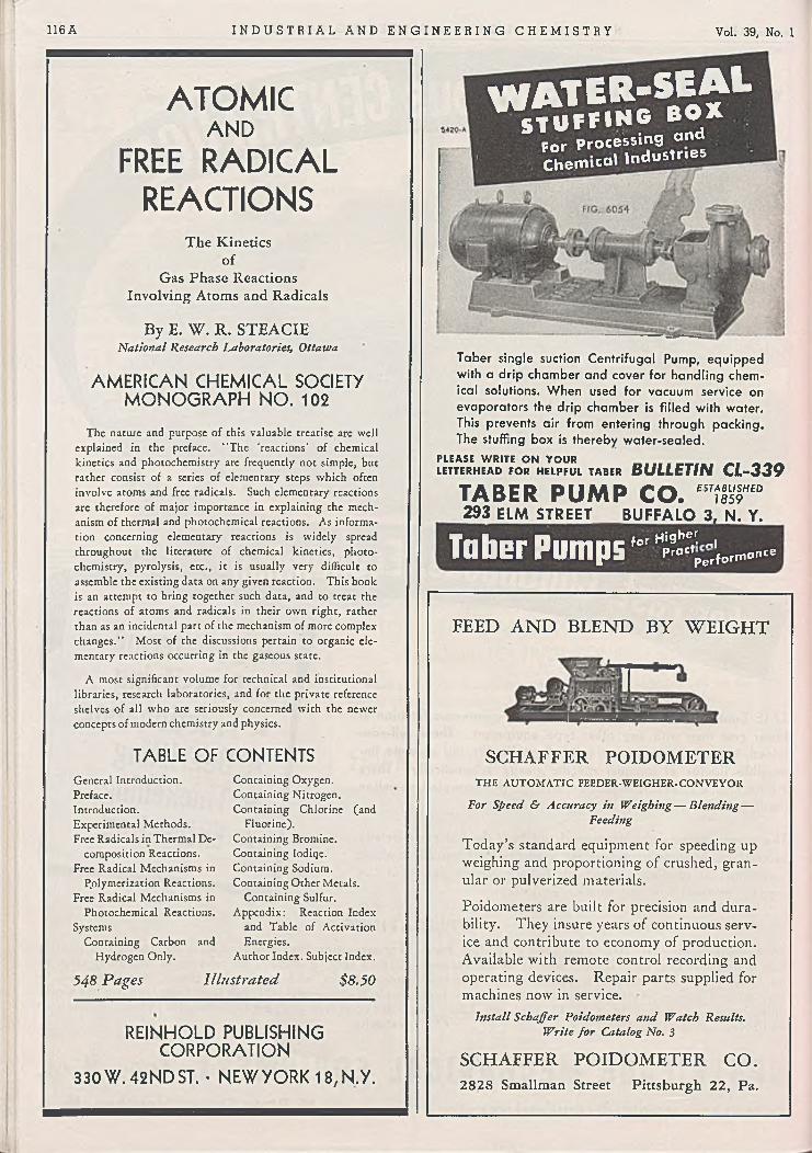
116 A I N D U S T R I A L A N D E N G I N E E R I N G C H E M I S T R Y Vol. 39, No. 1
ATOMICAND
FREE RADICAL REACTIONS
The Kinetics o f
Gas Phase Reactions Involving Atoms and Radicals
By E. W . R. STEACIENational Research Laboratories, Ottawa
AMERICAN CHEMICAL SOCIETY M ONOGRAPH NO. 102
The nature and purpose o f this valuable treatise are well explained in the preface. “ The ‘ reactions' o f chemical kinetics and photochemistry are frequently not simple, but rather consist o f a series o f elementary steps which often involve atoms and free radicals. Such elementary reactions arc therefore o f m ajor importance in explaining the mechanism o f thermal and photochemical reactions. As information concerning elementary reactions is widely spread throughout the literature o f chemical kinetics, p hotochemistry, pyrolysis, etc., it is usually very difficult to assemble the existing data on any given reaction. This book is an attempt to bring together such data, and to treat the reactions o f atoms and radicals in their ow n right, rather than as an incidental part o f the mechanism o f more complex changes." M ost o f the discussions pertain to organic elementary reactions occurring in the gaseous state.
A most significant volume for technical and institutional libraries, research laboratories, and for the private reference shelves o f all w h o arc seriously concerned w ith the newer concepts o f modern chemistry and physics.
TABLE OF CONTENTSGeneral Introduction. Preface.Introduction.Experimental M ethods.Free Radicals in Thermal De
composition Reactions. Free Radical Mechanisms in
P.olymerization Reactions. Free Radical Mechanisms in
Photochemical Reactions. Systems
Containing Carbon and Hydrogen Only.
Containing Oxygen. Containing Nitrogen. Containing Chlorine (and
Fluorine).Containing Bromine. Containing Iodiqc. Containing Sodium. Containing Other Metals.
Containing Sulfur. A ppendix: Reaction Index
and Table o f Activation Energies.
Author Index. Subject Index.
548 Pages Illustrated $8.50
REINHOLD PUBLISHING CORPORATION
330 W. 42NDST. • NEW YORK 18, N.Y.
WATER-SEALS T U F f lN 6 B O X
for Processing and Chemical lndusm.es
Taber single suction Centrifugal Pump, equipped with a drip chamber and cover for handling chemical solutions. When used for vacuum service on evaporators the drip chamber is filled with water. This prevents air from entering through packing. The stuffing box is thereby water-sealed.
PLEASE WRITE ON YOUR „ _ _ _LETTERHEAD FOR HELPFUL TABER BULLETIN CL-339
TABER PUMP CO. f”iiS"£D293 ELM STREET BUFFALO 3, N. Y.
f o r H ig b ei; „ i
Pr° " p c ,(orrr.o"ccTaber Pumps
FEED A N D BLEND B Y W E IG H T
SCHAFFER POIDOMETERT H E A U T O M A T IC FEEDER-W EIGHER. C O N V E Y O R
For Speed & Accuracy in Weighing— Blending — Feeding
T oday’s standard equipment for speeding up weighing and proportioning o f crushed, granular or pulverized materials.
Poidometers are built for precision and durability. They insure years o f continuous service and contribute to economy o f production. Available with remote control recording and operating devices. Repair parts supplied for machines now in service.
Install Schaß er Poidometers and Watch Results. Write jo r Catalog No. 3
SCHAFFER PO ID O M ETER C O .2828 Smallman Street Pittsburgh 22, Pa.

SERIES 300 GATE VAIVE
GLOBE CHECK No. 45-A
SWING CHECK No. 571
Y-FLANGED No. 341
A L O Y C O Stainless Steel Valve Success
Is Due to Primary Factors
GLOBE No. 311O M R IF N il I ' l l
A LO Y CO Valves and Fittings are made in a Jl x . wide variety o f stainless steels and other corrosion-resisting alloys. Each of these differs from all others in relative resistance to various corrosive fluids, under different conditions of temperature and concentration. It has taken us many years of specialization in the manufacture o f corrosion- resisting valves, exclusively, to gain the experience which enables us to recommend the one best alloy for any specific application.Of equal importance with the selection of the correct
alloy, is the quality ofALOYCO GATE VALVE NO. I l l
t This popular valve has double* disc, ball-and-socket type wedges that are free to rotate and are non-fouling in any position. The design insures tightness on both seats and permits easy repairs.
design and construction o f the valve. In pattern shop, foundry and machine shop, part i cularly , corrosion- resisting alloys require very different handling from all other metals. Here again, our concentration on corrosion problems makes Aloyco Valves distinctive for mechanical excellence. You get more out of Aloyco Valves, because we put more into them. Consult us on your requirements.
January 1947 I N D U S T R I A L A N D E N G I N E E R I N G C H E M I S T R Y ________________________ 117A
STAINLESS STEELVALVES AND FITTINGS
A l l o y St e e l Pro d u cts Co m p a n y , Inc.flUSH BOTTOM TANK No. 751
GLOBE No. 40-A

118 A I N D U S T R I A L A N D E N G I N E E R I N G C H E M I S T R Y Vol. 39, No. 1
G E O R G E A R M IS T E A D , JR .Chemical Engineer
I Engineering.Industrial Safety.Surveys1 5 19 Connecticut A v e n u e
Washington 6 , D . C .
M IN E R L . H A R T M A N N , Ph.D.Registered Patent Attorney
Specialist in Chemical and Metallurgical Patent Matters
1151 South Broadway, Los Angeles 15
Harvey A . Seil, Ph.D. Earl B. Putt, B.Sc.S E IL , P U T T & R U S B Y
IncorporatedConsulting Chemists
Specialists in the analysis of Foods, Drugs and Organic Products
16 E. 34th Street, New York 16, N. Y. Telephone — MUrray Hill 3-6368
R O B E R T C A L V E R T
Chemical PatentsU. S. and Foreisn Applications
Interferences — Reports 155 East 44th Street, New York 17, N. Y.
Telephone MUrray Hill 2-4980
E . W . D . H U F F M A N , Ph.D.
M icroanalytical Laboratories
Organic, Inorganic — Quantitative, Qualitative Precision Analyses — Special Analytical Problems
Majestic Bidg. Denver, Colorado
SPECTROGRAPHIC SERVICES AND SUPPLIES, INC. 1 Research — Consulting — Testing — Analysis j
! Composition of Minerals, Structure, Physical Properties, j Metals, Chemicals
Spectrographic Analysis — X-Ray Diffraction Optical Crystallography — Petrography
Metallography — Metallurgy | Spectrographic Electrodes and Standards to Order
Laboratory — 21 Madison Ave., Saratoga Springs, N.Y. Lester W. Strock, Ph.D., Director
G U ST A V U S J. E S S E L E N , IN C.
Chemical Research
and Development
857 Boylston Street Boston, Mass.
"Today’s Research Is Tomorrow's Industry"
L A W A L L & H A R R IS S O NBiological Assays—1 Clinical Tests
Chemical — Bacteriological — Problems Organic Synthesis
Pharmaceutical and Food Problems , Research
I 1921 W alnut St. Philadelphia 3 , Pa.
T E X T IL E , P L A S T IC S T E C H N IC A L S E R V IC E , IN C .
Research and Development Projects in
Textiles, Plastics and
Related FieldsNorristown-Penn Trust Building
Norristown, Penna.
L O U IS L O N G , JR ., Ph.D .Consulting Chemist
REPORTS SURVEYS RESEARCH
i 53 State Street Boston, Mass.
T H E W ESTP O R T M IL L
W estport, Conn.
Laboratories and Testins Plant of The D O R R C O M P A N Y
.j Chemical, Industrial, Metallurgical and Sanitary
Engineers| Consultation — Testing — Research — Plant Design
Descriptive brochure, "Testing that Pays Dividends" upon request
!
CONSULTATION FUNDAMENTAL RESEARCH
M ANAGEM ENT
R A L P H L . E V A N S
A S S O C IA T E S
25 0 East 43rd St., N ew York 17 , N . Y .
C. L . M A N T E L L Consulting Engineer
Electrochemical Processes and Plant Design
601 W . 26th St., N ew York 1 , N . Y .
M E T C A L F & E D D YEngineers
Industrial Waste Treatment Water Supply and Water Purification
Stream Pollution Investigations Laboratory
Statler Bidg. Boston 1 6 , Mass.
m r y o - u s i ^
A * M X H i* L c e m e * t t
ofPR OFESSIO NAL SERVICES ;
may be inserted in this section. Here you can carry your message to the readers of the leading publication of the chemical process industries.
*
Rates upon request
*
INDUSTRIAL AND ENGINEERING CHEMISTRY
A d vertis in g O ffice 330 West 42nd Street New York 18, N. Y.
EVANSR E S E A R C H and D E V E L O P M E N T
C O R P O R A T IO N
Organic and Inorganic Chemistry Processes . Products
UNUSUALLY EXTENSIVE FACILITIES YOUR INSPECTION INVITED
250 East 43rd St., N ew York 1 7 , N . Y .
CONSULTINGRubber Technologist
N a tu ra l an d S yn th e tic R u b b e r R. R. OLIN LABORATORIES
Complete Rubber Testing Facilities Established 1927
P. O. Box 372, Akron 9, Ohio Telephone HE 3724, FR 8551.
H A R R Y PRICEChemical Patents-
Suite 2618 Graybar Building ' 420 Lexington Ave.New York 17, N. Y.
Founded 1922
FO O D RESEARCH LABORATORIES, i n c .
Research, A n a lyses , and Consultation for the
Food, Drug and A ll ie d Industries
48-14 Thirty-Third Street Long island City 1, New York Telephone - STillwell 4-4814
Descriptive Brochure Available on Request
P R O C ES S & IN STRU M EN TSCONSULTANTS IN
AUTOMATIC ANALYSIS PROCESS DEVELOPMENT
HIGH VACUUM ENGINEERING
60 GREENPOINT AVE. BROOKLYN 22, N. Y.
Established 1891S A M U E L P. S A D T L E R & S O N , IN C .
Consulting and Analytical Chemists i Chemical Engineers
Chemical Research, Micro & other analyses 210 S. 13th Street Philadelphia 7, Pa. 1
"Nothing Pays Like Research"
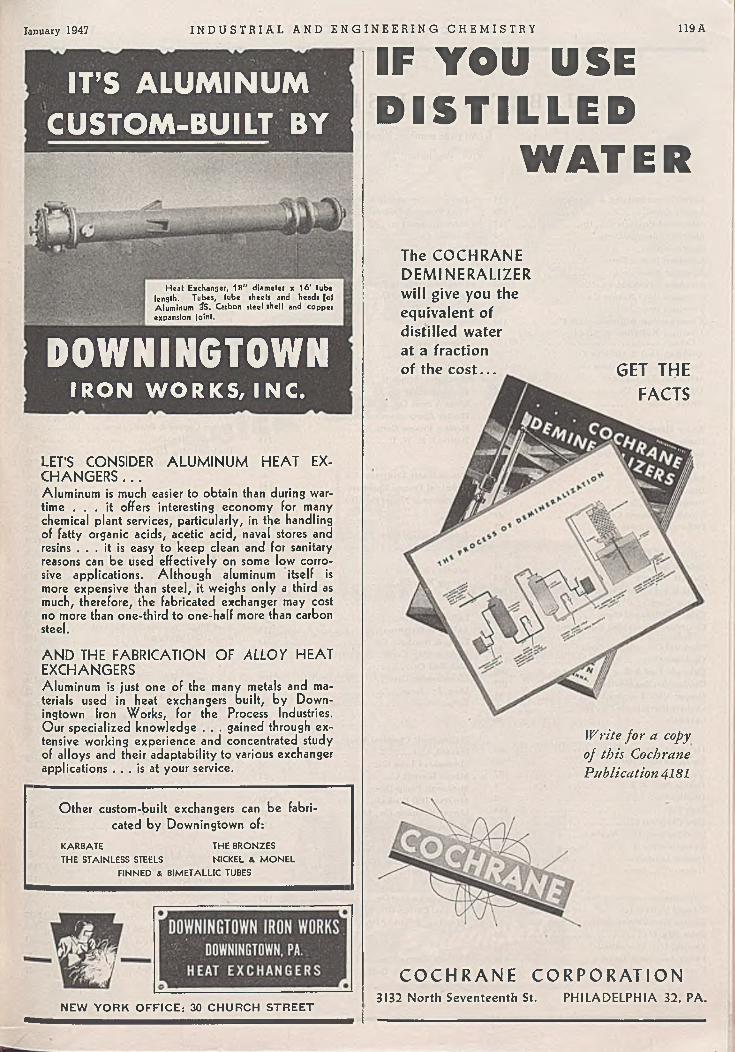
IT’S ALUMINUM CUSTOM-BUILT BY
Heat Exchanger, 18" diameter x 16' tube length. Tubes, tube sheets and heads lof Aluminum SS. Carbon steel shell and copper expansion Joint.
DOWNINGTOWNIRON WORKS, INC.
L E T ’S C O N S ID E R A L U M IN U M H E A T E X C H A N G E R S . . .Aluminum is much easier to obtain than during wartime . . . it offers interesting economy for many chemical plant services, particularly, in the handling of fatty organic acids, acetic acid, naval stores and resins . . . it is easy to keep clean and for sanitary reasons can be used effectively on some low corrosive applications. Although aluminum itself is more expensive than steel, it weighs only a third as much, therefore, the fabricated exchanger may cost no more than one-third to one-half more than carbon steel.
A N D T H E F A B R IC A T IO N O F ALLOY H E A T E X C H A N G E R SAluminum is just one of the many metals and materials used in heat exchangers built, by Down- ingtown Iron Works, for the Process Industries. Our specialized knowledge . . . gained through extensive working experience and concentrated study of alloys and their adaptability to various exchanger applications . . . is at your service.
Other custom-built exchangers can be fabricated by Downingtown of:
KARBATE THE BRONZESTHE STAINLESS STEELS NICKEL & MONEL
FINNED & BIMETALLIC TUBES
NEW Y O R K O F F IC E : 30 C H U R C H S T R E E T
January 1947 I N D U S T R I A L A N D E N G I N E E R I N G C H E M I S T R Y 119A
IF YOU USE D I S T I L L E D
W A T E R
The C O C H R A N E D EM IN ER A LIZ ER will give you the equivalent of distilled water at a fraction of the c o st . . . GET THE
FACTS
Write for a copy of this Cochrane Publication 4181
C O C H R A N E C O R P O R A T I O N3132 North Seventeenth St. P H ILA D ELP H IA 32, PA.

120 A I N D U S T R I A L A N D E N G I N E E R I N G C H E M I S T R Y Vol. 39, No. 1
A L P H A B E T I C A L L I S T OF A D V E R T I S E R S(A ll page numbers listed below are com plem ented
w ith the letter “ A ” on the respective pages.)
Acm e Coppersmithing & Machine C o 121Aerofin Corp................................................................. 78Alloy Steel Products Co., Inc............................. 117Alsop Engineering Corp......................................... 84Amercoat D iv .............................................................. 110American Blower Corp........................................... 99American Brass C o ................................................104-105American Cyanamid C o........................................ 09American Hard Rubber C o.................................. 123American Optical C o ............................................... 68American Pipe <fc Construction C o................. 110American Radiation & Standard Sanitary
Corp..............................................................................4 6 :9 9American Tool & Machine C o............................ 42Anaconda Copper Mining C o......................... 104-105Armistead, Jr., George............................................ 118Attapulgus Clay C o................................................. 36Aurora Pump C o....................................................... 108
Bailey M eter C o........................................................ 82Bartlett dc Snow C o., C . 0 ................................... 54Bell Telephone Laboratories............................... 58Blaw -Knox C o............................................................. 6 7 :7 5Blickman, Inc., S ....................................................... 8Bristol C o....................................................................... 80 -S IBrown & Root, Inc................................................... 26Brown Instrument C o............................................ 49Buflovak Equipment D iv ....................................... 67
Cabot, Inc., Godfrey L ........................................... 24 -25Calgon, Inc................................................................... 48Calvert, R obert......................................................... 118Carbide & Carbon Chemicals Corp..................7 2 :9 2Carrier Corp................................................................. 64Celanese Chemical Corp....................................... 53Centrifuge Mechanical Equipment, Inc., of
N .J ............................................................................... 115Chemical Construction Corp............................... 47Cochrane Corp............................................................ 119Colorado Fuel & Iron Corp................................. 100Combustion Engineering Co., Inc...................... 107Cooper Alloy Foundry C o.................................... 91Corhart Refractories Co., Inc............................. 60Crane C o........................................................................ 50
Davison Chemical Corp......................................... 28De Laval Separator C o.......................................... 29D e Laval Steam Turbine C o............................... 97Devine D iv ., J. P ...................................................... 9Dicalite C o.................................................................... 2Dorr C o.......................................................................... 118D ow Chemical C o..................................... 11Downingtown Iron W orks................................... 119Dracco Corp................................................................. 108Dresser Industries.................................................... 30Duriron Co., Inc........................................................ 88
Edge M oor Iron Works, Inc................................ 33Edward Valves, Inc................................................. 70Electro Metallurgical C o....................................... 45Eriez M fg. C o...............................................* ........... 35Esselen, Inc., Gustavus J...................................... 118Evans Associates, Ralph L ............................. 118Evans Research & Development Corp 118
Ferguson Perforating & Wire C o...................... 6Food Research Laboratories, Inc...................... 118Foote Mineral C o...................................................... 34Foxboro C o................................................................... 43Frick C o......................................................................... 114
General American Transportation C orp.. . . 87General Chemical Co............................................... 113Gump C o., B. F ......................................................... 114
Hagan Corp.................................................................. 48Hamrnel-Dahl C o...................................................... 55Ilardinge Co., Inc..................................................... 112Hartmann, M iner L ................................................. 118Haynes Stellite Co.................................................... 98Hicks & Sons Co., fe. D ......................................... 114Hooker Electrochemical C o................................. 65Iloudry Process Corp.............................................. 51Huffman, E . W . D .................................................... 118
Illinois W ater Treatment C o.............................. 90Industrial Process Engineers.............................. 112International Nickel C o., Inc............................. 95
Johns-Manvilie Corp............................................... 4
Kimble Glass C o................................................ . ! 61Kinney M fg. C o......................................................... 16
LaBour Co., Inc......................................................... 79La W all & Harrisson................................................ 118Leeds & Northrup C o............................................. 44Leyman M fg. Corp................................................... 110Link-Belt C o ................................................................ 7Liquidometcr Corp................................................... 108Long, Jr., Louis......................................................... 118Lummus Co.................................................................. 32
Mallinckrodt Chemical W orks........................... 66Manteil, C. L ............................................................... 118Marblehead Lime C o............................................... 39
. Master Electric C o................................................... 21M cGowan Pump Div-............................................. 110M cGraw -H ill Book C o............................................ 106Mcrcer-Robinson Co., Inc.................................... 110M etcalf & E d d y ......................................................... 118M ilton R oy C o........................................................... 22
Patterson Foundry & Machine C o................... 126Pfizer & Co., Inc., Chas......................................... 86Pittsburgh Coke & Chemical C o....................... 18Porocel Corp................................................................ 36Porter Co., Inc., H . K . . ..................................... 9Price, H arry................................................................. 118Pritchard & C o., J. F .............................................. 15Process & Instruments........................................... 118Professional Directory............................................ 118Proportioneers, Inc................................................... 124Pulverizing Machinery C o.................................... 122
Quimby Pump D iv ................................................... 9
Raymond Pulverizer D iv...................................... 107Reed Roller Bit C o................................................... 10Reinhold Publishing Corp................................ 102:116Republic Steel Corp................................................. 23Revere Copper <fc Brass, Inc................................ 74Robinson M fg. C o .................................................... 110Rockwell M fg. C o..................................................... 70Ross Heater & M fg. Co., Inc.............................. 46
Sadtler & Son, Inc., Samuel P .......................... 118Sarco Co., Inc.............................................................. 31Schaffer Poidometer C o.......................................... 116Seil, Putt & R u sby ................................................... 118Sharpies Chemicals Inc.......................................... 37-38Solvay Sales Corp.................................................... . 109Sonneborn & Sons, Inc., L ................................... 85Spectrographic Services & Supplies, I n c . . . . 118Spencer Lens C o........................................................ 68Stacey Bros. Gas Construction C o................... 30Standard Oil Co. (Indiana)................................. 14Steel Plate Construction Products.................. 30Sturtevant Mill C o................................................... I l lSwenson Evaporator C o......................................... 12-13
Taber Pump C o.......................................................... 116Taylor Forge & Pipe W orks................................ 27Taylor Instrument Cos............................................40-41Textile, Plastics Technical Service. I n c . . . . 118Tri-Clovdr Machine C o.......................................... 59
Union Carbide & Carbon C orp.. . 1 7 :4 5 :7 2 :9 2 :9 8U. S. Industrial Chemicals, Inc........................ 19-20Universal Oil Products Co.................................... 73
Vogt Machine Co., In c ., H enry....................... 96Vulcan Copper & Supply Co................................ 125
Minneapolis-Honeywell Regulator C o 49M onsanto Chemical C o..........................................62 -63
Nash Engineering C o.............................................. 103National Carbon Co., Inc..................................... 17Niles Steel Products D iv....................................... 23
Oldbury Electro-Chemical C o............................ 94Olin Laboratories, R . R ......................................... 118
W ar Assets Adm inistration................................. 52Western Pipe & Steel C o....................................... 106Westport M ill .............................................................. 118Wheelco Instruments C o ..................................... 56Wheeler M fg. Co., C . H ......................................... 76Whiting Corp................................................................12-13W ick wire Spencer Steel D iv ................................ 100Wilfley & Sons, Inc., A . R .................................... 101
Youngstown Miller C o ........................................... 57
January 1947 I N D U S T R I A L A N D E N G I N E E R I N G C H E M I S T R Y 121 A
on process plant equipmentIn spite o f production difficulties, A cm e is still m aking deliveries on t im e ! One of the
reasons for this faster service is the com prehensive inventory o f ferrous and non-ferrous
m etals we generally carry. From our stocks o f stainless steel, copper, alum inum , monel
metal, steel, and the m any clad materials, it is often possible to start im m ediate
production of equipm ent ordered. This added A cm e service can mean the saving of
weeks or months in delivery. W hy not consult A cm e now regarding yo u r engineering and
production problems and schedules?

Finer Pulverizing' -L O WE R P R O C E S S I N G COSTS
^ 3
T h is p h o to m icro g ra p h (1 5 0 x ) i l lu s t r a t e s the fineness of com m ercially produced pigments prior to the application of the M IK R O - A T O M IZ E R in 1 9 4 6. T h e r e l a t i v e coarseness of the pigm ents re q u ire d c o s t ly subsequent milling in the production of paints, lacquers and inks.
T h is p h o to m icro g ra p h (150x ) i l lu s t r a t e s th e fineness of the sam e pigment w hen ground in a M IKRO -ATO M IZER.M ost of the particles are 2 to 4 microns in size. This extreme fineness reduces the subsequent milling time of most paints, lacquers and inks by as much as 80 per cent"— and in some cases a finished producthas been produced by a simple mixing of the Mikro- Atom ized product and the vehicle.
The u l t r a - f i n e g r i n d s p r o d u c e d b y M I K R O - A T O M I Z E R — a h i g h l y efficient, screenless, mechanical pulverizer— have proved to be of great ad
vantage in the production of a wide variety of materials, other than pigments, that are subsequently to be used for either wet or dry dispersions. Our Laboratory is prepared to make test grindings of your products in the MIKRO-ATOMIZER, in order that you may determine the advantages of its application.
No. 6 M IKRO-ATO M IZER
S e n d for new 4 8 - p a g e M IKRR-PULVERIZER, M IK RO-ATOM IZER CATALOG
P U L V E R I Z I N G M A C H I N E R Y C O M P A N Y4 0 CH ATH AM R O A D • SUMMIT, N .J .
NOW ; : ; 2 TYPES TO MEET MOST PULVERIZING NEEDS
Reg. U.S. P a t.O ff.
■ Women comprised 25 % of all persons employed in England outside the government service in 1938. By 1944, largely because of the war, the ratio had risen to 34% . In many of the industries and trades the rates of pay for women arc 65 to 80 % of those for men. In the professions, however, equal pay is the rule. A Royal Commission created to investigate the problem concluded that pay differential based on sex is justified in many industrial occupations. The majority of the women members on the Commission disagreed with that finding, however. (The Chemical Age, p. 625, Nov. 23, 1946)■ A war surplus bomb-release control has been adapted to activate a solenoid stirrer of the type used in freezing point determinations. The agitation cycle may be varied between 0.08 and 1 second. (Journal of Chemical Education, p. 612, Dec. 1946)■ A one-pound aerosol insect “ bomb” contains enough material to treat 150,000 cubic feet of space. Household fly spray demand increased from 14 million to 30 million gallons from 1939 to 1945, the latter figure being equivalent to 15 million one-pound aerosol bombs. (Domestic Commerce, p. 50, Nov. 1946)■ Effective August 19, 1946, the official Central Bank of China selling rate became 3350 Chinese dollars for one United States dollar. For the first seven months of 1946, the excess of imports to China over exports from that country was between 6 and 7 to 1. (Foreign Commerce Weekly, p. 3, Dec. 14, 1946)■ The United States has replaced Germany as Sweden’s most important source of supply. Twenty-six per cent of imports to that country came from the United States in the first nine months of 1946. This is about two and a half times the amount supplied by Great Britain, the second largest source. (Foreign Commerce Weekly, p. 21, Dec. 14,1946)■ Ink cartridges for some ball-point pens are x-rayed during manufacture to detect faulty units containing air bubbles or other impurities. (News Release, Ever sharp, Inc., Dec. 5, 1946)■ Los Angeles is now second only to Akron, Ohio, in production of rubber products. (James E. Bone, speaking before California State Chamber of Commerce, Dec. 1946)■ A one-piece, ‘ /-i-inch thick, molded acrylic top is now available as a clear plastic or in red, green, or blue tints for convertible models of Ford and Mercury cars. Installation requires no tools and involves fastening the top at only four points. (Modern Plastics, p. 104, Dec. 1946)■ Anatomical models in which arterial and veinous circulatory systems and organs are distinguished by color can be prepared by biology students through use of a method involving injection of a plastic-forming liquid into the specimen. Removal of the original tissue completes the operation. (Modem Plastics, p. 127, Dec. 1946)■ Iron and manganese deficiencies in fruit trees have been corrected by insertion of soluble mineral tablets in the lieartwood of the tree. Effective beneficial results last four to five years. (Chemistry and Industry, p. 426, Nov. 1946)■ A solution of chemicals composed of dextrose, several amino salts, eleven vitamins, and twelve amino acids has been used successfully in maintaining life in fragments of embryo chick heart for as much as six weeks. Previous fluids used in similar experiments were obtained from animal bodies, and their exact chemical composition was not known. (Science News Letter, p. 373, Dec. 14, 1946).
122 A

January 1947 I N D U S T R I A L A N D E N G I N E E R I N G C H E M I S T R Y 123 A
SET NEW PRODUCTION RECORDS WITH ACE
RUBBER PROTECTIONCorrosion! It’s there, whether you see it or not! It’s a behind-the-scenes threat that makes equipment old before its time, impairs plant efficiency, often affects the very quality of your finished product.You can put a stop to corrosion with Ace Hard Rubber. It guards your operations at such vital points as in the linings of tanks used for processing and storage— in pumps, pipe, fittings and valves for circulating active solutions— in a score of other important installations. Our research and engineering staffs will be glad to advise you on the applications of Ace Hard Rubber in your plant.
American Hard Rubber Company G en era l Sales O ffice : 11 M e rc e r S t., N e w Y 'o r k 13, N . Y .
B ranch Sales O ffices :111 \V . W ashing ton S t ., C hicago 2, 111.
A k ro n 9, O hio
Ace Rubber lined sectional tank for paper processing.
PLANT EXECUTIVESWrite for free copy of 64 page handbook containing valuable information about anti - corrosion equipment.
Gate, diaphragm and check valves with fully bonded Ace Hard Rubber linings over all inner surfaces.
Ace-Saran Anti-Corrosion Equipment Hard and Soft Rubber Lined Tanks, Pipe and Fittings
All-Hard Rubber Pipe, Fittings and Utensils Hard Rubber Pumps in a Wide Range of Sizes and Capacities
Made-to-Specification Equipment— Hard Rubber and Hard Rubber Lined
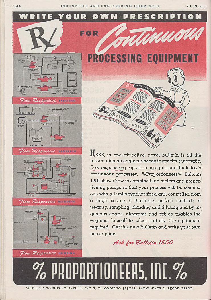
124 A Vol. 39, No. 1
WRITE TO ^PRO PO RTIO N EE RS, IN C .% . 27 CODDING STREET, PROVIDENCE 1, RHODE ISLAND
HERE, in one attractive, novel bulletin is all the information an engineer needs to specify automatic, flow responsive proportioning equipment for today's continuous processes. %Proportioneers% Bulletin 1200 shows how to combine fluid meters and proportioning-pumps so that your process will be continuous with all units synchronized and controlled from a single source. It illustrates proven methods of treating, sampling, blending and diluting and by ingenious charts, diagrams and tables enables the engineer himself to select and size the equipment required. Get this new bulletin and write your own prescription.
IB u iietctt t 2 0 0

E c o n o m i c A n a l y s i s o f Requirements • P r o c e s s D e v e l o p m e n t • P r o c e s s a n d Equipment Design Fabrication and Erection • I n i t i a l O p e r a t i o n
F or Production and R eco ve ry of Alcohols, O rganic Acids, Esters, Aldehydes, Ketones, Ethers, G lycols, Phenols, H y d r o c a r b o n s , Chlorinated H ydrocarbons

S A TIS FA C T O R Y
s T h iJf -. v 'Z vV i--'i 1 i ' : 11
■ ■ ■■■- M m o» r™ * » ¿IT O R .««» «ttHTKRRY * M A fillN R W T O , m