University of Zimbabwe Industrial Attachment Web-based ...
134
University of Zimbabwe Industrial Attachment Web-based Supervision System By Mahoko Abraham Submitted in partial fulfillment of the requirements for the degree of BSC INFORMATION SYSTEMS HONOURS DEGREE Department of Computer Science and Information Systems in the Faculty of Science and Technology at the MIDLANDS STATE UNIVERSITY GWERU May 2017 Supervisor : Mrs. Mutembedza
-
Upload
khangminh22 -
Category
Documents
-
view
0 -
download
0
Transcript of University of Zimbabwe Industrial Attachment Web-based ...

University of Zimbabwe Industrial Attachment Web-based
Supervision System
By
Mahoko Abraham
Submitted in partial fulfillment of the requirements for the degree of
BSC INFORMATION SYSTEMS HONOURS DEGREE
Department of Computer Science and Information Systems in the
Faculty of Science and Technology at the
MIDLANDS STATE UNIVERSITY
GWERU
May 2017
Supervisor : Mrs. Mutembedza

UNIVERSITY OF ZIMBABWE INDUSTRIAL
ATTACHMENTWEB-BASED SUPERVISION SYSTEM
MAHOKO ABRAHAM (R121880Z)

i
Abstract
University of Zimbabwe Industrial Attachment Web-based Supervision system was developed to
computerize the processes involved in the work-related supervision system. The institution was
using a manual system in the supervision of students on attachment which means students were
manually submitting their logbooks in hand, supervision was done manually, and therefore time
consuming. The main aim of this research was to come up with a computerized web-based
supervision system that rectifies all the problems associated with the manual system that was
being used. The data was gathered using three different research techniques to have enough
knowledge about the manual system that was being used and to find out if the users were
comfortable with a computerized one. Questionnaires, interviews and focus groups were used to
have a rich research and possibly to reach different users. Additionally, to develop a user friendly
and interactive web-based solution system, PHP programming integrated with some java scripts
and HTML5 was used. The database was designed through the use of MySQL server since this
database designing tool enables data to be stored, manipulated, edited, deleted and updated. The
system was tested and successfully installed. The system was implemented using a pilot
changeover approach to minimize risks of failure. The main system functionality is that, it allows
three types of users, that is, students on attachment, work supervisors and academic supervisors
to be registered on the platform. Work-related supervisor assigns tasks/duties to attachés online
and view completed tasks, giving feedback, supervising students as well as assessing the
performance of the students. Student can view assigned tasks and update them upon completion
on a daily basis. Various measures such as user identification, user authentication and access
control have been put in place in order to counteract unauthorized users from using the system.
For more security features, the system can be further developed using Java programming
language or using Android Programming Language and or IOS for easy access and convenience
purposes.

ii
Declaration
I, Abraham Mahoko hereby declare that I am the sole author of this dissertation. I authorize
Midlands State University to lend this project to other institutions or individuals for the purpose
of scholarly research.
Signature _________________________________ Date _____________________________

iii
Approval
This dissertation entitled “University of Zimbabwe Industrial Attachment Web-based
Supervision System” by Abraham Mahoko meets the regulations governing the award of the
degree of BSc Information Systems Honours Degree of theMidlands State University, and is
approved for its contribution to knowledge and literal presentation.
Supervisor’s signature: _______________________________
Date: _____________________________________________

iv
Acknowledgements
"Not unto us O LORD, not unto us, but unto thy name be the glory, because of your love and
faithfulness." Psalms 115:1.
First of all, I would like to join King David in glorifying our heavenly Father, without Him our
existence would never have been. I am grateful to the LORD, who have taken me this far in my
academics and allowing me the opportunity to complete this project.
Special thanks go to the academic staff at the Midlands State University who supported me
throughout the four years I have been with the institution so far. Without their assistance, it
would have been difficult to get this far, and to the Department of Computer Science and
Information Systems students and staff, I really thank you for your unwavering support. Your
support is greatly appreciated.
Special thanks to my supervisor Mrs. Mutembedza for her super guidance and leadership during
the development of this project.
Finally, I would like to express my gratitude to my sister in Christ, Alice Muzembi, Pastor Fenny,
Mrs. Chitendeni, all my friends and all Wisdom Church International members for their prayers,
unreserved support and encouragement in all that I set on my heart to do.
Last but not least I am grateful to my parents Mr H. Mahoko and Mrs. R. Mahoko, my brother
Noah Mahoko and aunt P. Mahoko for putting me through and seeing to every cost of this
program and all the moral and financial support during this very crucial phase of my academic
life.
God, bless you all!

v
Dedication
This project is dedicated to the Midlands State University.
vi
Table of contents
Abstract.........................................................................................................................................i
Declaration.................................................................................................................................. ii
Approval..................................................................................................................................... iii
Acknowledgements.................................................................................................................... iv
Dedication....................................................................................................................................v
Table of contents........................................................................................................................ vi
List of acronyms........................................................................................................................ xii
List of tables............................................................................................................................. xiv
List of figures.............................................................................................................................xv
List of appendices....................................................................................................................xvii
Chapter 1: Introduction...............................................................................................1
1.1 Introduction.......................................................................................................................1
1.2 Background of the study................................................................................................... 1
1.2.1 Background of the organization.................................................................................2
1.2.2 Organizational structure.............................................................................................2
1.2.3 Vision.........................................................................................................................3
1.2.4 Mission statement...................................................................................................... 4
1.2.5 Company core values.................................................................................................4
1.3 Problem definition.............................................................................................................4
1.4 Aim of the research study................................................................................................. 4
1.5 Objectives of the research study....................................................................................... 4
1.6 Instruments and methods.................................................................................................. 5
1.7 Justification and rationale of the study............................................................................. 6

vii
1.8 Conclusion........................................................................................................................ 6
Chapter 2: Planning.....................................................................................................7
2.1 Introduction.......................................................................................................................7
2.2 Business value...................................................................................................................7
2.2.1 Work supervisor value...............................................................................................7
2.2.2 Student value............................................................................................................. 7
2.2.3 Employee value (University supervisor)................................................................... 7
2.2.4 Managerial value....................................................................................................... 8
2.3 Feasibility study................................................................................................................ 8
2.3.1 Technical feasibility...................................................................................................8
2.3.2 Technical expertise.................................................................................................... 8
2.3.2.1 Hardware............................................................................................................ 9
2.3.2.2 Software..............................................................................................................9
2.3.3 Economic feasibility................................................................................................ 10
2.3.3.1 Cost benefit analysis.........................................................................................10
2.3.4 Social feasibility...................................................................................................... 17
2.3.5 Operational feasibility............................................................................................. 17
2.4 Risk analysis................................................................................................................... 18
2.4.1 Economic risks.........................................................................................................19
2.4.2 Other risks................................................................................................................20
2.5 Stakeholder analysis........................................................................................................20
2.5.1 Stakeholders.............................................................................................................20
2.5.2 Management............................................................................................................ 20
2.5.3 Employees................................................................................................................21

viii
2.6 Work plan........................................................................................................................21
2.6.1 Gantt chart............................................................................................................... 21
2.7 Conclusion...................................................................................................................... 22
Chapter 3: Analysis phase........................................................................................ 23
3.1 Introduction.....................................................................................................................23
3.2 Information gathering methodologies.............................................................................23
3.2.1 Questionnaires......................................................................................................... 23
3.2.2 Interviews................................................................................................................ 26
3.2.3 Focus groups............................................................................................................28
3.3 Analysis of existing system.............................................................................................30
3.4 Process analysis...............................................................................................................30
3.4.1 Activity diagram of current system......................................................................... 30
3.5 Data analysis................................................................................................................... 33
3.5.1 Context diagram of the current system....................................................................33
3.5.2 Dataflow diagram of the current system..................................................................34
3.6 Weaknesses of current system........................................................................................ 35
3.7 Alternatives evaluation................................................................................................... 35
3.7.1 Outsourcing..............................................................................................................35
3.7.2 Improvement............................................................................................................36
3.7.3 Development............................................................................................................37
3.7.3.1 Buying a software package (off-shelf-package)...............................................37
3.7.3.2 In-house development...................................................................................... 38
3.7.4 Alternative selection................................................................................................ 39
3.8 Requirements analysis.....................................................................................................40
ix
3.8.1 Functional requirements.......................................................................................... 40
3.8.2 Non-functional requirements................................................................................... 41
3.9 Conclusion...................................................................................................................... 42
Chapter 4: Design phase........................................................................................... 43
4.1 Introduction.....................................................................................................................43
4.2 System design................................................................................................................. 43
4.2.1 Context diagram.......................................................................................................45
4.2.2 Data flow diagram................................................................................................... 45
4.3 Architectural design........................................................................................................ 47
4.4 Physical design................................................................................................................47
4.4.1 Interaction between hardware and software............................................................ 47
4.5 Database design...............................................................................................................48
4.5.1 Physical database design..........................................................................................49
4.5.2 Logical database design...........................................................................................51
4.5.3 Entity relationship diagram......................................................................................52
4.5.4 Enhanced entity relationship model.........................................................................54
4.6 Program design............................................................................................................... 56
4.6.1 Class diagram...........................................................................................................56
4.6.2 Package diagram......................................................................................................58
4.6.3 Sequence diagram....................................................................................................59
4.7 Interface design............................................................................................................... 60
4.7.1 Menu design.............................................................................................................60
4.7.1.1 Main menu........................................................................................................61
4.7.1.2 Sub-menus........................................................................................................ 61

x
4.7.2 Input design............................................................................................................. 61
4.7.3 Output design...........................................................................................................64
4.8 Pseudo code.....................................................................................................................65
4.9 Security design................................................................................................................67
4.9.1 Physical security...................................................................................................... 67
4.9.2 Network security......................................................................................................67
4.9.3 Operational security.................................................................................................68
4.9.4 Database security..................................................................................................... 68
4.9.5 User security............................................................................................................ 68
4.10 Conclusion...................................................................................................................69
Chapter 5: Implementation phase.............................................................................69
5.1 Introduction.....................................................................................................................69
5.2 Coding.............................................................................................................................69
5.3 Testing.............................................................................................................................69
5.3.1 Validation................................................................................................................ 70
5.3.2 Verification.............................................................................................................. 70
5.3.3 Testing processes..................................................................................................... 70
5.3.3.1 System testing...................................................................................................71
5.3.3.2 Unit testing....................................................................................................... 71
5.3.3.3 Security testing................................................................................................. 71
5.3.4 System vs Objectives...............................................................................................74
5.4 Installation.......................................................................................................................77
5.4.1 Data migration......................................................................................................... 77
5.4.2 System changeover strategies.................................................................................. 78
xi
5.4.2.1 Direct cutover................................................................................................... 78
5.4.2.2 Parallel conversion........................................................................................... 78
5.4.2.3 Pilot conversion................................................................................................79
5.4.2.4 Phased conversion............................................................................................ 80
5.4.2.5 Recommendation..............................................................................................80
5.4.3 User training............................................................................................................ 81
5.5 Maintenance.................................................................................................................... 81
5.5.1 Corrective maintenance........................................................................................... 81
5.5.2 Adaptive maintenance............................................................................................. 82
5.5.3 Perfective maintenance............................................................................................82
5.5.4 Preventive maintenance........................................................................................... 82
5.5.5 Software backup...................................................................................................... 83
5.6 Recommendations for future/further development......................................................... 83
5.7 Conclusion...................................................................................................................... 84
Reference list.............................................................................................................85
Appendices................................................................................................................89

xii
List of acronyms
ANSI American National Standards Institute
CAT Computer Assisted Translation.
CBA Cost Benefit Analysis
CD Compact Disc
CF Cash Flow
CPU Central Processing Unit
DB Database
DBA Database Administrator
DBMS Database Management System
DC Domain Controller
DDL Data Definition Language
DFD Data Flow Diagram
DML Data Manipulation Language
DVD Digital Video Disc
EER Enhanced Entity Relationship
ER Entity Relationship
FRs Functional Requirements
GB Gigabytes
GUI Graphical User Interface
HDD Hard Drive Disk
HR Human Resource
IAWBS Industrial Attachment Web-based Supervision System
IP Internet Protocol
xiii
IT Information Technology
LAN Local Area Network
MS Microsoft
NFRs Non-functional Requirements
NPV Net Present Value
OS Operating System
PC Personal Computer
PHP Hyper-text Processor
PV Present Value
RAM Random Access Memory
ROI Return on Investment
SQL Structured Query Language
SPARC Standards Planning and Requirements Committee
UTP Unshielded Twisted Pair
US United States
UZ University of Zimbabwe
WAN Wide Area Network
xiv
List of tables
Table 2.1: Configuration of the work station...................................................................................9
Table 2.2: Server configuration....................................................................................................... 9
Table 2.3: Software specifications...................................................................................................9
Table 2.4: Network specifications................................................................................................. 10
Table 2.5: Tangible benefits.......................................................................................................... 11
Table 2.6: Development costs........................................................................................................12
Table 2.7: Operational cost............................................................................................................13
Table 2.8: Cost benefit analysis.....................................................................................................14
Table 2.9: Net Present Value......................................................................................................... 16
Table 2.10: Risk management plan............................................................................................... 19
Table 2.11: Proposed work plan.................................................................................................... 21
Table 2.12: Gantt chart.................................................................................................................. 22
Table 4.1: Users and their roles..................................................................................................... 44
Table 4.2: Student entity relationship table................................................................................... 51
Table 4.3: Work supervisor entity relationship table.....................................................................52
Table 4.4: Academic supervisor entity relationship table............................................................. 52
Table 4.5: Company entity relationship table................................................................................52
Table 4.6: View logbook............................................................................................................... 64
Table 4.7: List of students............................................................................................................. 65
Table 4.8: Current students for supervision...................................................................................65
Table 4.9: Assigned task................................................................................................................65
Table 4.10: Work related supervisor’s view of task list................................................................ 65
xv
List of figures
Figure 1.1: University of Zimbabwe organogram........................................................................... 3
Figure 3.1: Responses for and against the implementation of a new system................................ 26
Figure 3.2: Activity diagram..........................................................................................................32
Figure 3.3: Context diagram.......................................................................................................... 33
Figure 3.4: Dataflow diagram........................................................................................................34
Figure 3.5: Use case diagram.........................................................................................................41
Figure 4.1: Context Diagram......................................................................................................... 45
Figure 4.2: Data flow diagram.......................................................................................................46
Figure 4.3: Physical design............................................................................................................48
Figure 4.4: Database schema......................................................................................................... 49
Figure 4.5: Data architecture design..............................................................................................50
Figure 4.6: Entity relationship diagram......................................................................................... 53
Figure 4.7: Enhanced entity relationship model............................................................................ 55
Figure 4.8: Class diagram.............................................................................................................. 57
Figure 4.9: Package diagram......................................................................................................... 58
Figure 4.10: Sequence diagram..................................................................................................... 59
Figure 4.11 Menu desing............................................................................................................... 61
Figure 4.12: Sub menus................................................................................................................. 61
Figure 4.13: Academic supervisor registration form.....................................................................62
Figure 4.14: Work related supervisor registration form................................................................ 63
Figure 4.15: Student registration form...........................................................................................64
Figure 4.16: Login form................................................................................................................ 64
Figure 4.17: Password recovery form............................................................................................64
xvi
Figure 5.1: Testing process............................................................................................................71
Figure 5.2: Database security........................................................................................................ 72
Figure 5.3: User security testing....................................................................................................73
Figure 5.4: Login testing................................................................................................................73
Figure 5.5: Direct cutover..............................................................................................................78
Figure 5.6: Parallel conversion...................................................................................................... 79
Figure 5.7: Pilot conversion...........................................................................................................79
Figure 5.8: Phased conversion.......................................................................................................80
Figure A1: Getting started............................................................................................................. 90
Figure A2: User login.................................................................................................................... 91
Figure A3: Administrator homepage............................................................................................. 92
Figure A4: Student homepage....................................................................................................... 93
Figure A5: Starting a new task (Students only).............................................................................94
Figure A6: To declare a new task, start time (Students only)....................................................... 95
Figure A7: Updating a task (Students only).................................................................................. 96
Figure A8: Work supervisor’s homepage......................................................................................97
Figure A9: Assigning of a task (Work supervisors only).............................................................. 98
Figure A10: How to comment completed tasks (Work supervisors only).................................... 99
Figure A11: Putting a comment (Work supervisors only)...........................................................100
Figure A12: Academic supervisor’s homepage...........................................................................101
Figure A13: Logout..................................................................................................................... 102
xvii
List of appendices
Appendix A: User manual............................................................................................................. 89
Appendix B1: Letter of consent to conduct research...................................................................103
Appendix B2: Questionnaire....................................................................................................... 104
Appendix C: Interview checklist................................................................................................. 106
Appendix D: Focus groups checklist...........................................................................................107
Appendix E: Snippet of code.......................................................................................................108
1
Chapter 1: Introduction
1.1 Introduction
University of Zimbabwe (UZ) is the oldest and leading university in Zimbabwe which is
involved in teaching and research and it offers a variety of degrees, diplomas and certificates in
various disciplines such as arts, agriculture, law, medicine, social studies, science, engineering,
education, commerce and veterinary sciences. However, regardless of being the finest university
in Zimbabwe, UZ is currently doing most of its processes manually, such as work related
learning supervision. To keep up with technology, the developer has come up with an idea to
develop a web based supervision system to mitigate all the issues associated with the current
Work Related Learning Supervision system.
This chapter highlighted the background of UZ and its essence business values. The profundity
of the subject problem was then resumed, showing that this project was done because there was a
conscious understanding of business difficulties. Objectives were then formulated suggesting
how the proposed system would resolve the perceived problems. A hypothesis on development
methodology and tools for the project was made. The chapter also justified the development of
the proposed project.
1.2 Background of the study
Education has been always a key to success and coming up finest graduates, UZ is considered to
be the best. However, when it comes to technology, UZ has not done much on its systems and
processes. It offers different degree programmes and under graduate students are expected to go
under industrial attachment at the level of three (3) if they are fulltime student or at level two (2)
if they are part time students in order for them to complete their degree programmes. During
industrial attachment, students are expected to write log books and submit to their respective
supervisors and student monitoring is done manually. However, these days almost every service
is now computerized and maybe done online due to the fastest growing of web application and
technology. Since API web applications are growing fast, Industrial Attachment Web-based
Supervision system (IAWBS) was developed to be the most genuine and proficient system the
institution could adopt to computerise all the processes involved in industrial attachment
assessment.

2
1.2.1 Background of the organization
The University of Zimbabwe (UZ) located in Harare, is the oldest and formerly largest university
in Zimbabwe. It was founded through a superior relationship with the University of London and
it opened its doors to its first students in 1952. The university has ten faculties (Agriculture, Arts,
Commerce, Education, Engineering, Law, Science, Social Studies, Veterinary Sciences and
College of Health Sciences) offering a wide variety of degree programmes and many specialist
research centres and institutes. The university is accredited through the National Council for
Higher Education, under the Ministry of Higher and Tertiary Education. English is the language
of instruction. Although once a very successful university, UZ has been facing challenges since
2008 and now the University is on a rebounding drive. Major work is being done to uplift the
status of the University. Refurbishments are being carried out on the main campus and many
facilities are being upgraded to make the university an International Academic Brand. Students
from the faculties such as Commerce, Engineering and Science are required to go under
industrial attachment in order to complete their degree programmes. Normally industrial
attachment is done at level 3.
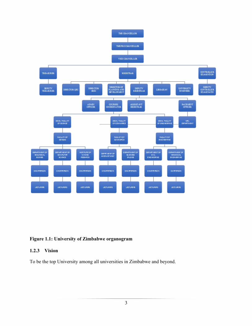
1.2.2 Organizational structure
Borrington (2013) put forth that an organogram is a chart showing the lines of responsibly
between departments in an organisation that is, it is a chart that shows the flow of authority from
top to bottom in an organisation, indicating out how positions, responsibility and power are
regulated and assigned in the organization. The university is an academic institution directed by
President R.G Mugabe, the Chancellor of all state Universities in Zimbabwe. The Vice
Chancellor is selected by the Chancellor bearing accountability of seeing how the university is
running on its daily bases.
3
Figure 1.1: University of Zimbabwe organogram
1.2.3 Vision
To be the top University among all universities in Zimbabwe and beyond.”

4
1.2.4 Mission statement
Enabling “our clients and customers to make meaningful contributions to sustainable
development in Zimbabwe. To this end we provide high quality education, training and advisory
services on a needs oriented basis. We guarantee the above by maintaining excellence in
Teaching, Learning, Research and Service to the community.”
1.2.5 Company core values
Intelligence,
Diligence
Integrity
1.3 Problem definition
Riley and Hunt (2014) mentioned that problem “definition is a brief document that designates the
particular type of the problem and offers wide statements regarding how the anticipated system
will help the institution.”
The system that was being used had a number of problems:
Students were manually submitting their logbooks in hand which sometimes was not
convenient when the supervisor is absent.
Supervision was done manually, and therefore time consuming.
Too much hierarchies that was sometimes-hindering communication.
Student on attachment records were kept as papers which was risky in case of disasters
like fire.
1.4 Aim of the research study
The aim of this research was to come up with a computerized web-based supervision system that
rectifies the identified problems associated with the manual system that was being used.
1.5 Objectives of the research study
The major objective of the new system was to computerize the work-related learning supervision
process and address the major problems noted above. The newly proposed system is a web based
and it allows the supervisors to supervise the students on industrial attachment online.
5
The objectives were;
a) To develop a system that enables work-related supervisors to assign tasks to attachés
online.
b) To develop a system that enables the students on attachment to upload their daily duties
online.
c) To develop a system that allows work-related supervisors to monitor performance of an
attaché, giving feedback as the student logs duties
d) To develop a system that enables the work-related supervisors to complete required
academic reports online.
e) To develop a system that enables the academic supervisors to view the student log books.
f) To develop a system that enables the academic supervisor to view the work-related
supervisor’s assessment report and other reports that may be required.
g) To develop a system that facilitates communication between the academic supervisor and
work-related supervisors, as well as between the students and the 2 sets of supervisors.
h) To maintain a record of all attachment students and performance for reference.
1.6 Instruments and methods
The problems that were being faced by UZ can be determined through the execution and use of
some component rich, viable IAWBS system. The proposed system ought to have the capacity to
cover every one of the issues that exude from the usage of the present framework and takes care
of these issues.
In order to undertake the proposed system, the following tools were required.
Dreamweaver Creative Cloud - This is an adaptable and basic RAD device which empower
outlining graphical web application interfaces
PHP - A programming dialect utilized for the development of web-based applications otherwise
called Hyper-Texting Processor Language.
MySQL - Is most ordinarily used for Web applications and for installed applications and has
turned into a prominent contrasting option to exclusive database frameworks on account of its
rate and dependability. It is openly available for use.
6
1.7 Justification and rationale of the study
The indicated framework spares a great deal of time, it exterminates the separation obstruction
and this enhances effectiveness.
The Industrial Attachment Web-Based Supervision “system which was under study
attempted to let students on attachment to upload their logbooks and reports wherever
they are attached, online irrespective of their physical areas via any networked device to
the internet, the same as the respective supervisors to views these materials.”
The “proposed IAWBS system tries to find ways to cut the workload and the use of
paperwork since all the process will be computerized.”
The “anticipated system have a central database that permits easy, quicker retrieving of
information and it has a decreased level of data idleness.
The use of JavaScript enables efficiency of operations of the IAWBS system which
include validation of the system. The anticipated IAWBS system allows efficiency,
correctness and safe flow of the student information.”
The use of HTML5 also enables the production of clear visual charts and will lead to
efficient analysis and report.”
Modification of records can only be performed by suitable approved staffs from time to
time.”
The “system ensures a solid data security structure.”
1.8 Conclusion
Every one of the issues associated with the manual system that was being used were noted and
the targets of the task were expressed. The next chapter, the planning phase was mainly focusing
on the feasibility study, risk analysis and this research prompted the generation of a work plan
and calendar.
7
Chapter 2: Planning
2.1 Introduction
This chapter was mainly focusing on how the time plan was going to be applied in the
development of the project, and additionally putting down every activity that was going to be
carried out. At this phase, the developer analysed whether it was feasible for the university to
embark on the idea of this project or not, by critically undertaking project feasibility study and
risk analysis.
2.2 Business value
Schwartz (2016) suggested that business values are referred to as the estimated benefits to the
whole functionality of proposed system that will affect the goodwill of the University positively
in terms of efficiency. Some of the values that were anticipated to be brought by the proposed
system are as follows:
2.2.1 Work supervisor value
The system will enable the work supervisors to assign the attachés tasks without
necessarily meeting them thus time saving.
The supervisor will be able to view the uploaded students’ logbooks on the go, that is
wherever there is internet connection.
2.2.2 Student value
Students will be able to log their duties on the system even when the industrial supervisor
is absent at the workplace. In other words, the students will be able to upload their
logbooks on the go.
2.2.3 Employee value (University supervisor)
The implementation of this new system is going to fundamentally reduce the cost of
working time.
Use of automated database system for information decreases printed material and
information repetition which enhances the effectiveness of the system.

8
2.2.4 Managerial value
Improvement on administration arranged reports and auspicious report generation will
help basic leadership prepare along these lines helping in the fulfillment of authoritative
expressed objectives.
2.3 Feasibility study
Wallace and Webber (2015) revealed that feasibility study is the way of finding out if the costs
of developing the system will be exceeded by the benefits of developing the project. This
concocted a choice whether to go for the proposed system or to dispose of it. It can be sub
partitioned as technical, economic, social and operational feasibility.
2.3.1 Technical feasibility
Bharat and Pratash (2007), proposed that technical feasibility is concerned about the intensive
examination of the availability of technical expertise within the institution. Technical feasibility
was carried out to assess whether the institution had technical resources enough to support the
project in terms of software, hardware and technical expertise. Mostly it was concerned about the
following questions:
a) Are the technologies required by the proposed system available within the institution?
- The technologies to be used are found in Zimbabwe subsequently open to the
institution and already the institution was equipped enough for the project to be
carried on.
b) Does the institution have the required technical expertise?
- There is a development team that is already employed that can further undertake the
project.
c) Are the required technical resources available?
- All required technical resources were available.
2.3.2 Technical expertise
Amman (2008) suggested that technical expertise is concerned with taking note of the request,
for instance, 'is there enough human resources within the university, and is the readily available
staff possess the required expertise.'

9
2.3.2.1 Hardware
For, effectively use of the new system, the following hardware requirements were met.
Table 2.1: Configuration of the work station
Component Lowest Limit Required Available
Type of processor Intel 1.24 GHz Processor Intel® Core™ 2 Duo CPU L7500 @ 1.75GHz
RAM 2GB 4GB
Hard Disk Drive (HDD) 30GB 320GB
Network Adapter Card 10/100 LAN 10/100 LAN
Printer Dot Matrix Laser jet printer
Table 2.2: Server configuration
Component Lowest Limit Required Available
Type of processor Intel® 1.4GHz P4 Celeron Processor 1.7 GHz Intel® P4 Processor
RAM 2GB 8GB
HDD 30GB 1TB
Tape Drive 40/80 40/80
CD/DVD R/W Drive 48x Read/12x Write 52x Read/24x Write
Network Adapter Cards 10/100 LAN 100/200 LAN
Printer Dot Matrix Laser Jet
2.3.2.2 Software
The following softwares were required and they were readily available for the development and
execution of the new system.
Table 2.3: Software specifications
Software Required Version Available Version
Work Station OS Microsoft Windows 7 or better Microsoft Windows 10
Server OS Windows 2003 server or better Windows 2007 Server
MS Office MS 2003 MS 2013
Microsoft Security Essentials 2009 2011
Adobe Dreamweaver CS3 Creative Cloud 2015
MySQL 5 7.5.2

10
Table 2.4: Network specifications
Item Minimum required Available
HUB 4 port 8port
Connecting Cables UTP CAT 5, Fly leads patch codes UTP CAT 5, Fly leads patch codes
Cabinet 3U 3U
Patch panel 12 Port Patch Panel 12 Port Patch Panel
Uninterrupted Power Supply Power Backup 220v Power Backup 220v
An examination of the present foundation at UZ was adequate for the system to be considered as
specialized doable to be produced and executed.
2.3.3 Economic feasibility
Foster (2014) describes economic feasibility as a way of assessing the benefits of the system
over the costs. It tries to figure out if the expense brought about in the development of the system
will be exceeded by the benefits of the system as a complete package. According to Dines (1998)
the profit of the project is realised after deducting all the expenses. The project is said to be
economic feasible when the net benefit outweighs the costs and unfavourable when the net
benefit is negative. A few procedures were utilized to weigh economic plausibility using Return
on Investment (ROI) and Net present value (NPV).
2.3.3.1 Cost benefit analysis
Johansson and Kriström (2015), mentioned Cost Benefit Analysis (CBA) is carried out to find
out if it is worth to embark on the proposed system or not. It gives a clear chart of the cost
associated with execution of the project.
Advantages of the purported system
These are the positive picks up that the institution will get from utilizing the system. These
advantages can be ordered as tangible advantages and intangible advantages.
Tangible benefits
Beveridge (2007) hypothesizes that these are measurable benefits that can be seen right away.
Tangible benefits are quantifiable, and ought to be incorporated into the CBA:
Increased income through sponsors who might have helped their trust in the institution.

11
Reduced work costs because of disposal of extra time hours
Increment in income
Table 2.5: Tangible benefits
Year 2017 2018 2019
Currency US$ US$ US$
Benefits
Increased revenue 800 1 200 1 500
Hardware cost savings 700 900 1 000
Resource cost savings 700 1 000 1 200
Software cost savings 500 900 1 100
Reduced transport costs 600 800 1 000
Process Improvements 400 500 900
Productivity gain 200 500 700
Reduction in stationary costs 400 600 900
Total Benefits 4 300 6 400 8 300
Intangible benefits
These are the focal points that the institution will acknowledge from using the framework, which
cannot be computable in money related terms however they must be observed. These benefits
include:
Better nature of information and service conveyance.
Improved proficiency to the extent dispersal of data is concerned.
Increment in goodwill and stakeholder fulfillment.
Tangible costs
Typically, these costs include all things the institution can buy directly for specific costs, such as
labour, materials and space. These include:
The salary of the system administrator.
12
Transportation
Expenses of equipment overhauls and programming redesigns.
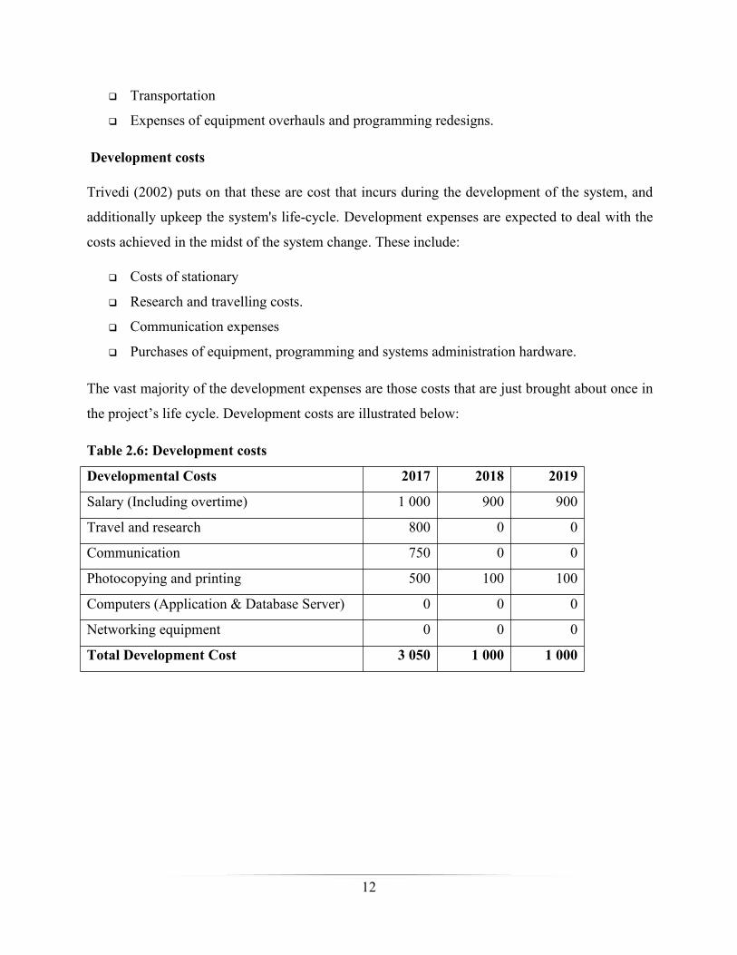
Development costs
Trivedi (2002) puts on that these are cost that incurs during the development of the system, and
additionally upkeep the system's life-cycle. Development expenses are expected to deal with the
costs achieved in the midst of the system change. These include:
Costs of stationary
Research and travelling costs.
Communication expenses
Purchases of equipment, programming and systems administration hardware.
The vast majority of the development expenses are those costs that are just brought about once in
the project’s life cycle. Development costs are illustrated below:
Table 2.6: Development costs
Developmental Costs 2017 2018 2019
Salary (Including overtime) 1 000 900 900
Travel and research 800 0 0
Communication 750 0 0
Photocopying and printing 500 100 100
Computers (Application & Database Server) 0 0 0
Networking equipment 0 0 0
Total Development Cost 3 050 1 000 1 000
13
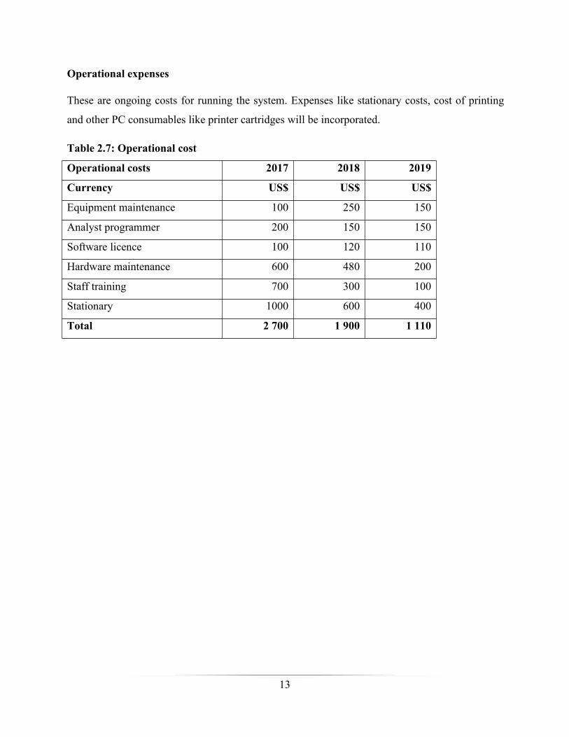
Operational expenses
These are ongoing costs for running the system. Expenses like stationary costs, cost of printing
and other PC consumables like printer cartridges will be incorporated.
Table 2.7: Operational cost
Operational costs 2017 2018 2019
Currency US$ US$ US$
Equipment maintenance 100 250 150
Analyst programmer 200 150 150
Software licence 100 120 110
Hardware maintenance 600 480 200
Staff training 700 300 100
Stationary 1000 600 400
Total 2 700 1 900 1 110

14
Below is a table that illustrates the projected cash flows over a period of three years:
Table 2.8: Cost benefit analysis
Year 2017 2018 2019 TotalCurrency US$ US$ US$ US$BenefitsIncreased revenue 800 1 200 1 500 3 500Hardware cost savings 700 900 1 000 2 600Resource cost savings 700 1 000 1 200 2 900Software cost savings 500 900 1 100 2 500Reduced transport costs 600 800 1 000 2 400Process Improvements 400 500 900 1 800Productivity gain 200 500 700 1 400Reduction in stationary costs 400 600 900 1 900Total Benefits 4 300 6 400 8 300 19 000
Developmental CostsSalary (Including overtime) 1 000 900 900 2 800Travel and research 800 0 0 800Communication 750 0 0 750Photocopying and printing 500 100 100 700Computers (Application & DatabaseServer)
0 0 0 0
Networking equipment 0 0 0 0Total Development Cost 3 050 1 000 1 000 5 050
Operational CostsEquipment Maintenance 100 250 150 500Analyst Programmer 200 150 150 500Software License 100 120 110 330Hardware maintenance 600 480 200 1 280Staff training 700 300 100 1 100Stationary 1000 600 400 2 000Total Operational Costs 2 700 1 900 1 110 5 710
Total cost 5 750 2 900 2 110 10 760
Net Benefits/(Costs) (1 450) 3 500 6 190 8 240
15
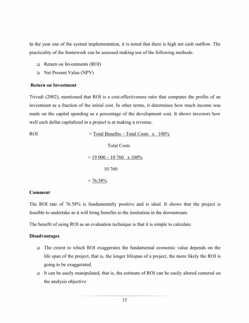
In the year one of the system implementation, it is noted that there is high net cash outflow. The
practicality of the framework can be assessed making use of the following methods:
Return on Investments (ROI)
Net Present Value (NPV)
Return on Investment
Trivedi (2002), mentioned that ROI is a cost-effectiveness ratio that computes the profits of an
investment as a fraction of the initial cost. In other terms, it determines how much income was
made on the capital spending as a percentage of the development cost. It shows investors how
well each dollar capitalized in a project is at making a revenue.
ROI = Total Benefits – Total Costs x 100%
Total Costs
= 19 000 – 10 760 x 100%
10 760
= 76.58%
Comment
The ROI rate of 76.58% is fundamentally positive and is ideal. It shows that the project is
feasible to undertake as it will bring benefits to the institution in the downstream.
The benefit of using ROI as an evaluation technique is that it is simple to calculate.
Disadvantages
The extent to which ROI exaggerates the fundamental economic value depends on the
life span of the project, that is, the longer lifespan of a project, the more likely the ROI is
going to be exaggerated.
It can be easily manipulated, that is, the estimate of ROI can be easily altered centered on
the analysis objective
16
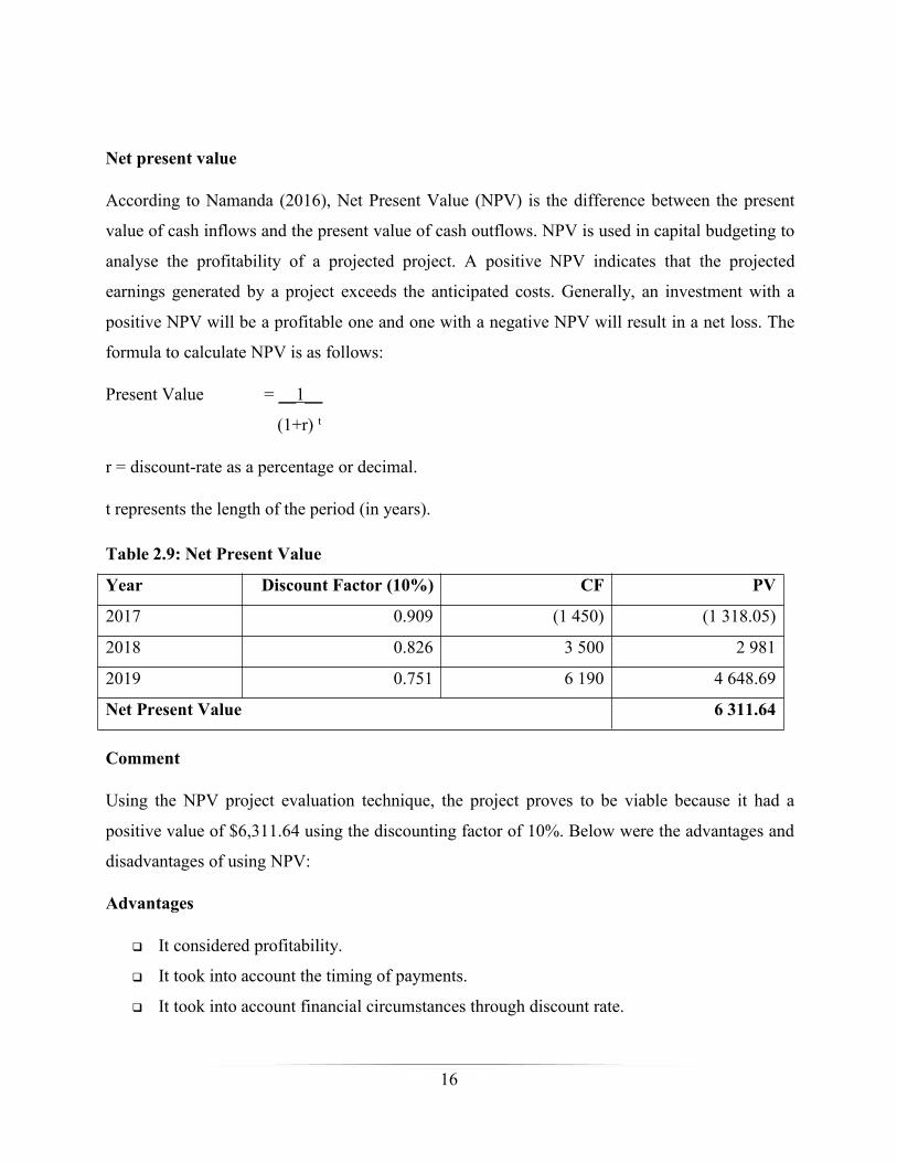
Net present value
According to Namanda (2016), Net Present Value (NPV) is the difference between the present
value of cash inflows and the present value of cash outflows. NPV is used in capital budgeting to
analyse the profitability of a projected project. A positive NPV indicates that the projected
earnings generated by a project exceeds the anticipated costs. Generally, an investment with a
positive NPV will be a profitable one and one with a negative NPV will result in a net loss. The
formula to calculate NPV is as follows:
Present Value = __1__
(1+r) t
r = discount-rate as a percentage or decimal.
t represents the length of the period (in years).
Table 2.9: Net Present Value
Year Discount Factor (10%) CF PV
2017 0.909 (1 450) (1 318.05)
2018 0.826 3 500 2 981
2019 0.751 6 190 4 648.69
Net Present Value 6 311.64
Comment
Using the NPV project evaluation technique, the project proves to be viable because it had a
positive value of $6,311.64 using the discounting factor of 10%. Below were the advantages and
disadvantages of using NPV:
Advantages
It considered profitability.
It took into account the timing of payments.
It took into account financial circumstances through discount rate.

17
Disadvantages
It was difficult to come up with a suitable discount rate.
Overview of economic feasibility
Looking at the analysis of the project it was noted that the economic benefits were favourable
since they outweighed the costs, therefore, therefore the project was said to be economic feasible.
2.3.4 Social feasibility
Buragga and Zaman (2013) highlighted that social feasibility assesses whether the system users
easily adapt the changed system or the new system. It was a detailed study on how each user
would interact with others within the system or the organization.
This project should create employment opportunities to qualified individuals and general
laborers in the society. This will only benefit individuals with programming capabilities
for further development of the system.
2.3.5 Operational feasibility
Burraga and Zaman (2013) indicated that operational feasibility refers to a measure of resolving
problems with the aid of a proposed system. It expressed whether the system would be used at its
best if implemented. The main aim for performing operational feasibility was to assess if the
development of proposed project fits in with the existing business environment and objectives
with regard to development schedule, delivery date, corporate culture and existing business
processes. The following are some of the essential questions that helped in testing the operational
feasibility of the proposed system:
Does the existing system deliver end users and managers with appropriate, relevant,
correct and valuable structured information?
Does the existing style of operation deliver profitable information services to the
University?
Possibly will there be a decrease in cost and or a boost in profits?

18
Does the existing style of operation utilize the existing resources, including human
resource, time, and flow of forms?
If the system is developed, will it be used?
Are the users not pleased with the existing business procedures?
The developer found out that the proposed system would bring the following benefits:
Relations between the institution and its customers, and the overall population will be
improved through the use of this proposed system.
The daily running of business and flow of information will be improved.
As described by (Ibid), a system that is operationally feasible will be easily used and supported.
Fortunately, workers, stakeholders and administration comfortably welcomed the requirement
for it therefore the project was operationally feasible.
2.4 Risk analysis
Virine and Trumper (2017) hypothesizes that, risk analysis is a process that helps in identifying
and manage potential problems that could undermine key business initiatives or projects. To
carry out a risk analysis, the developer first identified the possible threats that would be faced,
and then estimated the likelihood that these threats would materialize. Some of the threats that
the developer identified were:
Human – Sickness, death, injury, or other loss of a vital person.
Operational – Interruption to provisions and operations, loss of entry to vital resources, or
failures in supply.
Reputational – Loss of client or member self-assurance, or damage to market reputation.
Procedural – Failures of responsibility, interior systems, or regulations, or from fraud.
Project – Going beyond the budget, consuming much time on vital activities, or suffering
problems with product or service quality.
Financial –Unavailability of funding.
Technical – Changes in technology, or from technical failure.
Natural – Weather, natural disasters, or disease.
19
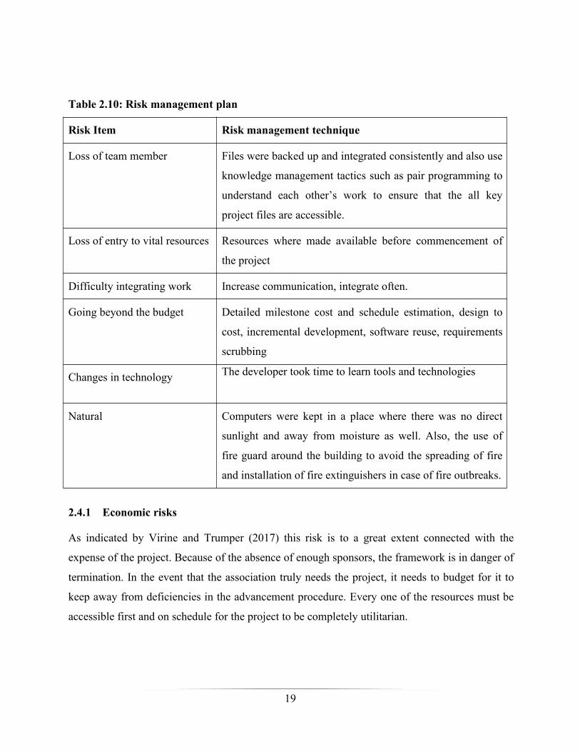
Table 2.10: Risk management plan
Risk Item Risk management technique
Loss of team member Files were backed up and integrated consistently and also use
knowledge management tactics such as pair programming to
understand each other’s work to ensure that the all key
project files are accessible.
Loss of entry to vital resources Resources where made available before commencement of
the project
Difficulty integrating work Increase communication, integrate often.
Going beyond the budget Detailed milestone cost and schedule estimation, design to
cost, incremental development, software reuse, requirements
scrubbing
Changes in technology The developer took time to learn tools and technologies
Natural Computers were kept in a place where there was no direct
sunlight and away from moisture as well. Also, the use of
fire guard around the building to avoid the spreading of fire
and installation of fire extinguishers in case of fire outbreaks.
2.4.1 Economic risks
As indicated by Virine and Trumper (2017) this risk is to a great extent connected with the
expense of the project. Because of the absence of enough sponsors, the framework is in danger of
termination. In the event that the association truly needs the project, it needs to budget for it to
keep away from deficiencies in the advancement procedure. Every one of the resources must be
accessible first and on schedule for the project to be completely utilitarian.
20
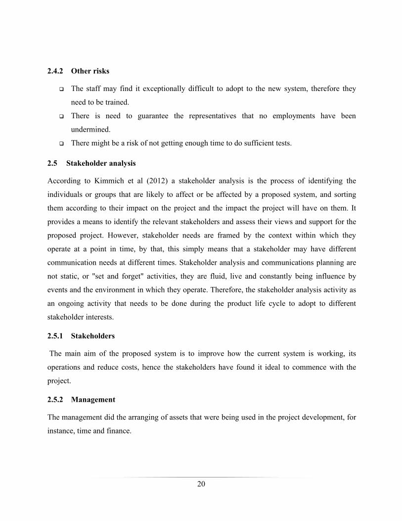
2.4.2 Other risks
The staff may find it exceptionally difficult to adopt to the new system, therefore they
need to be trained.
There is need to guarantee the representatives that no employments have been
undermined.
There might be a risk of not getting enough time to do sufficient tests.
2.5 Stakeholder analysis
According to Kimmich et al (2012) a stakeholder analysis is the process of identifying the
individuals or groups that are likely to affect or be affected by a proposed system, and sorting
them according to their impact on the project and the impact the project will have on them. It
provides a means to identify the relevant stakeholders and assess their views and support for the
proposed project. However, stakeholder needs are framed by the context within which they
operate at a point in time, by that, this simply means that a stakeholder may have different
communication needs at different times. Stakeholder analysis and communications planning are
not static, or "set and forget" activities, they are fluid, live and constantly being influence by
events and the environment in which they operate. Therefore, the stakeholder analysis activity as
an ongoing activity that needs to be done during the product life cycle to adopt to different
stakeholder interests.
2.5.1 Stakeholders
The main aim of the proposed system is to improve how the current system is working, its
operations and reduce costs, hence the stakeholders have found it ideal to commence with the
project.
2.5.2 Management
The management did the arranging of assets that were being used in the project development, for
instance, time and finance.
21
2.5.3 Employees
A few delegates were contradicting the change since they had a fear of losing their
occupations as the system requires people with IT capacities.
Other representatives were comfortable with this change since use of an advanced system
is less monotonous, ease of use, and offers fast reaction time to their solicitations.
The project was exceptionally supported by every one of these stakeholders thus the risk was low.
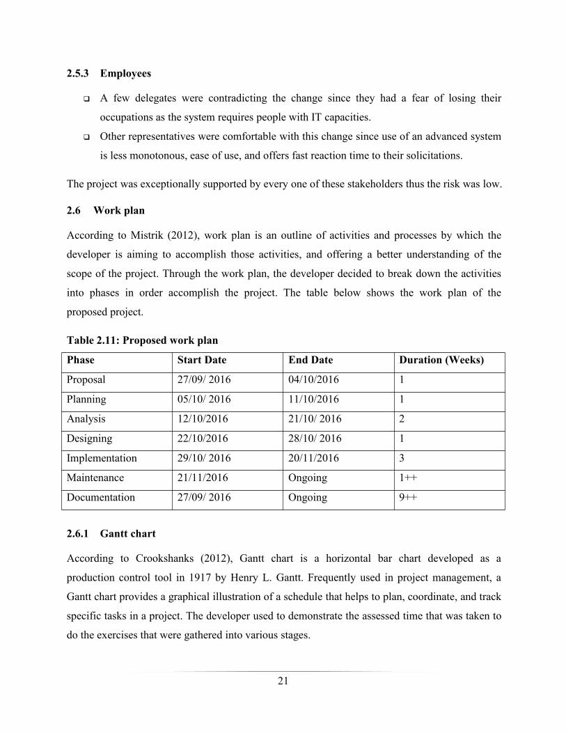
2.6 Work plan
According to Mistrik (2012), work plan is an outline of activities and processes by which the
developer is aiming to accomplish those activities, and offering a better understanding of the
scope of the project. Through the work plan, the developer decided to break down the activities
into phases in order accomplish the project. The table below shows the work plan of the
proposed project.
Table 2.11: Proposed work plan
Phase Start Date End Date Duration (Weeks)
Proposal 27/09/ 2016 04/10/2016 1
Planning 05/10/ 2016 11/10/2016 1
Analysis 12/10/2016 21/10/ 2016 2
Designing 22/10/2016 28/10/ 2016 1
Implementation 29/10/ 2016 20/11/2016 3
Maintenance 21/11/2016 Ongoing 1++
Documentation 27/09/ 2016 Ongoing 9++
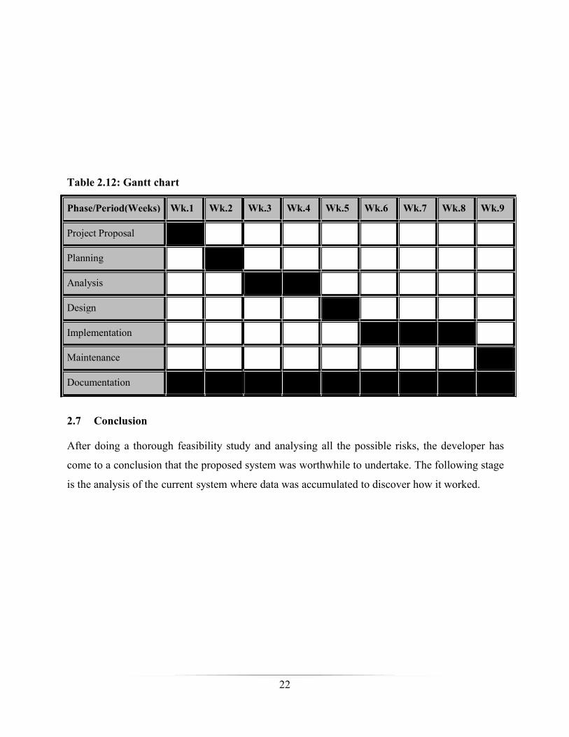
2.6.1 Gantt chart
According to Crookshanks (2012), Gantt chart is a horizontal bar chart developed as a
production control tool in 1917 by Henry L. Gantt. Frequently used in project management, a
Gantt chart provides a graphical illustration of a schedule that helps to plan, coordinate, and track
specific tasks in a project. The developer used to demonstrate the assessed time that was taken to
do the exercises that were gathered into various stages.
22
Table 2.12: Gantt chart
Phase/Period(Weeks) Wk.1 Wk.2 Wk.3 Wk.4 Wk.5 Wk.6 Wk.7 Wk.8 Wk.9
Project Proposal
Planning
Analysis
Design
Implementation
Maintenance
Documentation
2.7 Conclusion
After doing a thorough feasibility study and analysing all the possible risks, the developer has
come to a conclusion that the proposed system was worthwhile to undertake. The following stage
is the analysis of the “current” system where data was accumulated to discover how it worked.
23
Chapter 3: Analysis phase
3.1 Introduction
The analysis stage is like an interview of a journalist as it asks and answers the essential
questions, like, who will be using the system, what the system tends to accomplish, as well as
when and where it will be executed (Rainer et al, 2011). The analysis stage helped in solving the
essential question, "What the current system does?" It encompassed all the system requirements
planned to be met. The study helped to come up with a system that addresses the deficiencies of
the system that was being used. The goal was to have the knowledge on how the system that was
being used operated and to determine the significance of its problems. The developer used
different techniques to acquire full knowledge about the current system and address what the
proposed system was expected to do, to solve the problems that were being experienced by the
users.
3.2 Information gathering methodologies
Karathiya (2014) described information gathering as the act of collecting information about the
research topic in question from different sources using various techniques. The main reason for
information gathering was to know if the current system was meeting all user requirements. In
order to collect all the necessary information, the developer used three different techniques, that
is interviews, questionnaires and focus groups with a specific goal to review information about
the current system. The developer likewise gathered information from interior and outside
sources which enhanced the quality and feasibility of the findings analysis.
3.2.1 Questionnaires
O'Neill (2012) alluded a questionnaire as a general form to include all data collection methods in
which every single individual is entreated to respond to the same set of questions in a
programmed order. This involved the preparation of standard questions that are printed and
issued to the system end users, who answered the questions in the spaces, provided using
structured responses that would be summarized into statistical distributions.
24
The developer distributed questionnaires to certain individuals in the department of computer
centre aiming to get information to those who may have been skipped out during interviews. The
questions were largely directed on the operational challenges, recommendations and suggestions
on the development of the proposed system.
Motives for using questionnaires
Ease and success of use of questionnaires
User requirements, anticipations, perspectives, main concerns and preferences were
easily represented in the paper
they were user satisfaction with collections and services
questionnaires were relevant as they shift in user states of mind and assessments
Managerial questionnaire: This was specifically designed for the managers and the control as a
whole in a bid to apprehend what they anticipate from their workers to achieve.
Lecturer/Supervisor questionnaire: This was distributed to the lecturers to collect all their
thoughts about the current system.
Student questionnaire: This was given to students to understand what they anticipate from the
organisation pertaining the current system.
Forty-five questionnaires were issued with fifteen to every target reflected above and users were
given a due date to submit the answers, out of the forty-five questionnaires issued we managed to
have thirty-six back.
The following are the merits derived from the use of questionnaires:
They were generally simple to break down.
A great sample of the group populace was contacted at reasonably low cost.
They were so easy to manage.
The layout was generally common to most respondents.
They were easy to understand and brief for the respondent to finish.
The developer was able to collect information in a standardized manner.
The developer was able to do straightforward analysis.

25
They helped the developer to explore sensitive subjects which users might also felt
uncomfortable talking to an interviewer approximately.
Respondents had time to consider their answers, they were not expected to reply instantly.
However, the following setbacks were also noted:
In case of forgotten questions on the questionnaire, it was impossible to go back to
respondents, especially since they were unknown.
In some cases, it was difficult to get enough wide variety of reactions, in particular from
postal questionnaires
Respondents were ignoring some of the questions.
Some questions were incorrectly completed.
The developer was not able to investigate long, complex issues.
Some respondents were misunderstanding some of the questions in light of perhaps poor
outlining and additionally vague dialect.
Questionnaires were unsuitable or a few sorts of respondents, for example. visually
impaired students.
There was the risk of questionnaire fatigue because the surveys were carried out too
frequently.
Findings from questionnaires
Questionnaires took into account unknown information and in this way created exact data
in a few occurrences.
The findings showed that the current system has some problems leads to loss of much
time on as university supervisors will be moving from one place to another.
The questionnaires demonstrated that the respondent matches precisely what should be
gathered by the developer in order to carry on with the project.
26
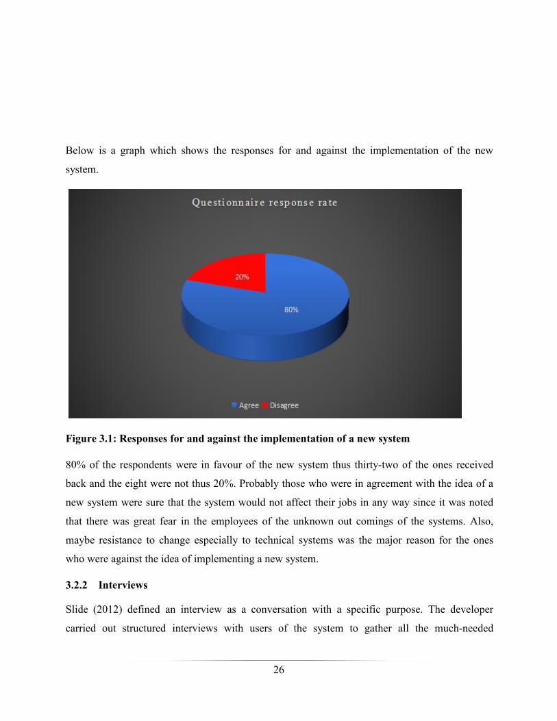
Below is a graph which shows the responses for and against the implementation of the new
system.
Figure 3.1: Responses for and against the implementation of a new system
80% of the respondents were in favour of the new system thus thirty-two of the ones received
back and the eight were not thus 20%. Probably those who were in agreement with the idea of a
new system were sure that the system would not affect their jobs in any way since it was noted
that there was great fear in the employees of the unknown out comings of the systems. Also,
maybe resistance to change especially to technical systems was the major reason for the ones
who were against the idea of implementing a new system.
3.2.2 Interviews
Slide (2012) defined an interview as a conversation with a specific purpose. The developer
carried out structured interviews with users of the system to gather all the much-needed
27
information about what they think of the existing system as well of the proposed system. In this
fact-finding technique, all the potential interviewees were selected and appointments were made.
A set of questions were drafted for each particular user. The selected persons were then
interviewed individually and their responses were recorded.
Reasons for using interviews
The researcher wanted to dig down and exhaust all the information about the problems
related to the current system.
To discover in what way individuals, think and feel regarding the current system and why
they have certain thoughts.
To research the use, effectiveness and usability of specific library collections and
facilities
Inform decision making, allotment of resources and strategic planning.
To ask sensitive subjects which individuals may feel embarrassing talk over in a focus
group.
To add a human aspect to impersonal facts.
Advantages of interviews
They were valuable for the researcher to acquire comprehensive information regarding
personal feelings, insights and thoughts.
The researcher was able to ask detailed questions and discuss them.
A high response rate was achieved.
Respondents' own words were recorded.
Ambiguous answers were clarified and the developer was able to follow up on
incomplete answers.
Interviewees were speaking upon themselves without being influenced by others as
compared to focus groups.
Disadvantages of interviews
28
They were really time-consuming in sense of setting up, interviewing, transcribing,
analyzing, feedback, reporting.
The developer interviewed staff from the Computer Centre and Technical Departments.
Generally, the staff indicated dissatisfaction and had no confidence with the current system.
Interview questions (Framework)
Briefly explain how your current industrial learning assessment system works?
How long have you been using the current system?
Does the current system meet your organizational needs?
Are there any weaknesses that you can highlight on the current system?
Do you have any suggestions you think can help to improve the current system?
Do you feel comfortable to change the system completely to a computerized one, or do
you want to improve the manual system?
Do you think all staff members are going to accept the change of the manual system to a
computerized system?
Findings from interviews
The Computer Centre Director specified that their main activity was to assess students on
attachment at the most convenience manner.
The department give information about the time being spend by the students on house
searching and they gave also some proposals on how best to build this house searching
system.
3.2.3 Focus groups
As indicated by Phillips and Stawarski (2008), a focus group discussion is a composed
discussion that typically involves 5 to 10 participants. The developer used focus group dialogs as
they furnish members with a space to discuss, in a context where they were allowed to agree or
disagree with each other. Focus group discussions permitted the researcher to investigate how a
group contemplates an issue, the scope of feelings and thoughts, and the irregularities and
varieties that exist in a specific group as far as beliefs and their encounters and practices.

29
Reasons why the developer used focus groups
To examine complicated actions.
To find out in what manner different groups, view and consider the current system and
why they have particular views.
To pin point changes in behavior.
To check or potentially elucidate the outcomes from the reviews.
To see if there are suggestions on potential solutions to problems identified.
to add a human aspect to impersonal data in order to intensify understanding and clarify
statistical facts.
Advantages of using focus groups
They were helpful to acquire comprehensive information regarding personal and group
feelings, insights and thoughts.
Time and money was spared when contrasted with individual interviews
They provided a more extensive scope of data
The developer could look for clarification.
They gave helpful material, for example quotes for presentations.
Drawbacks of using focus groups
At times, they were some arguments and inappropriate discussion which were diverting
from the key focus
They were difficult to run and oversee.
They were truly tricky to break down.
It was hard to inspire a scope of individuals to take an interest in the group.
A few members found focus groups state frightening or offensive therefore some
partakers felt under pressured to come to an agreement with the prevailing view.
Since they were self-selecting groups, the outcomes may not be illustrative of non-users.
Overview of information gathering:
30
After every one of the strategies were utilized it has been found that the survey had low reaction
when contrasted with the other two techniques for which interviews and focus groups had all
around approved, abridged data upheld by the record testing.
3.3 Analysis of existing system
Dixit (2007), defined analysis of the existing system as an organised analysis and appraisal of
facts or information, by means of breaking it into its module parts to find out their
interrelationships. It encompasses the analysing of the processes and the data that is being
processed by the system.
3.4 Process analysis
Process analysis solves the question: “How?” Process analysis clarifies in what way the
chronological phases of a formula direct to its completion; or, in what way a particular sequence
of events occurred. Here are the two classes of process analysis: directional and informational.
The developer used descriptive process analysis which tries to find out, how does the present
system works? How is it done? This sort of examination clarifies how the system is, or was,
proficient. The analysis gives data, as in the layout of a natural procedure, or portrays how (not
why) certain occasions prompted a specific result.
The analysis of the present system was best performed through an inside and out survey of how
the work-related supervision process was being done at the University. This was led by
specifying the sources of info, procedures and yields of the present system.
Inputs: Contract form, student details, student daily tasks, project topic details, weekly logbook,
project progress
Processes: Signing of contract, assigning of duties, student assessment
Output: Student’s project, contract details, student marks, printed logbook, project
documentation
3.4.1 Activity diagram of current system
Heath (2016), an activity diagram outwardly presents a series of activities or stream of control in
a system like a flowchart or a dataflow chart. Activity diagrams are commonly used as a portion
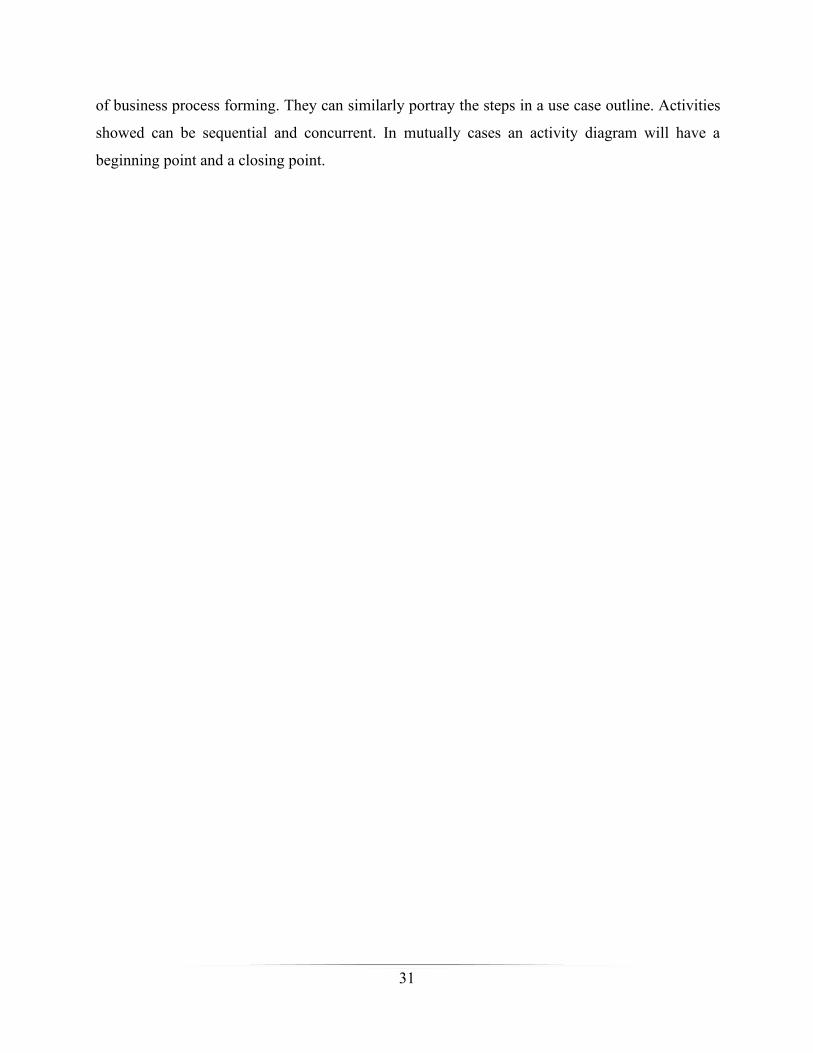
31
of business process forming. They can similarly portray the steps in a use case outline. Activities
showed can be sequential and concurrent. In mutually cases an activity diagram will have a
beginning point and a closing point.

32
Start Login
Log daily tasks
Log outEnd
[No]
[No]
[Yes]
[Yes]
Key:
Start A decision that facilitatesbranching
A process Flow direction
Figure 3.2: Activity diagram
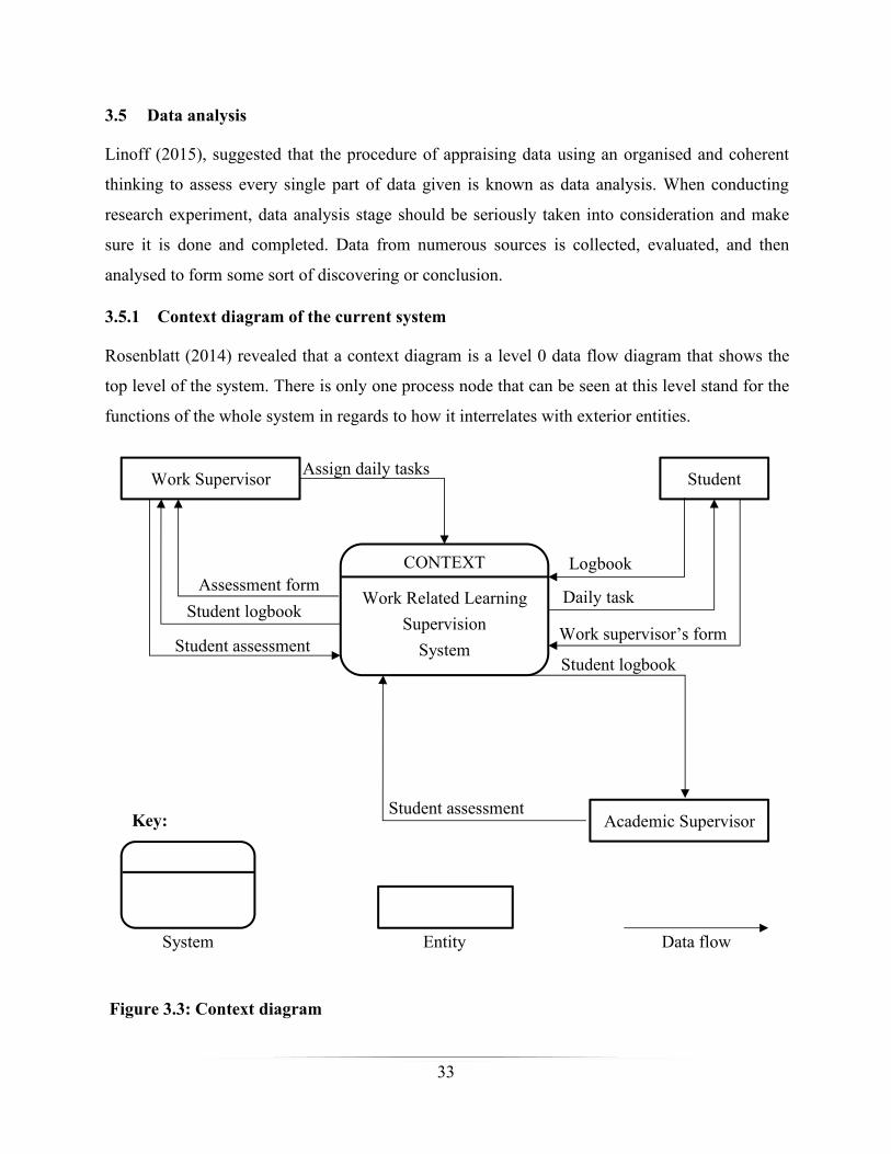
33
3.5 Data analysis
Linoff (2015), suggested that the procedure of appraising data using an organised and coherent
thinking to assess every single part of data given is known as data analysis. When conducting
research experiment, data analysis stage should be seriously taken into consideration and make
sure it is done and completed. Data from numerous sources is collected, evaluated, and then
analysed to form some sort of discovering or conclusion.
3.5.1 Context diagram of the current system
Rosenblatt (2014) revealed that a context diagram is a level 0 data flow diagram that shows the
top level of the system. There is only one process node that can be seen at this level stand for the
functions of the whole system in regards to how it interrelates with exterior entities.
CONTEXT
Work Related LearningSupervisionSystem
Work Supervisor Student
Academic SupervisorKey:
System Entity Data flow
Assign daily tasks
Student logbookDaily task
Work supervisor’s form
Student assessment
Student assessmentStudent logbook
Assessment formLogbook
Figure 3.3: Context diagram
34
3.5.2 Dataflow diagram of the current system
Miller et al (2010), defined Data Flow Diagram (DFD) as a diagram that illustrate module
processes of a system and how data flows from on process to another in a system. DFD shows
the movement of data into an information system and how the exchange of data is processed
graphically. DFD is more like a flowchart but in terms of comprehensive illustration, DFD is
regarded to exhibit a more comprehensive diagram.
Student details 1
Signing of contract
2
3
Student
Assigning of duties
AttachésD1
Student LogbooksD2
AssessmentD3
Contractdetails
Worksupervisor
Academicsupervisor
Logbook ofweekly activities
User credentials
Studentassessment
Logbooks
Assessmentdetails
Contract form
Student details andlogbook content
List of duties
List of duties
Assessment formAssessment form
Student logbook
Key:
Process Entity Data store Flow direction
Figure 3.4: Dataflow diagram
35
3.6 Weaknesses of current system
Students were manually submitting their logbooks in hand which sometimes was not
convenient when the supervisor is absent.
Too much hierarchies that sometimes were hindering communication.
Student on attachment records were kept as papers which was risky in case of disasters
like fire.
3.7 Alternatives evaluation
Alternatives were assessed to reveal their effectiveness in attending to the difficulties, taking
advantage the of chances, and achieving goals of the proposed system. This was done by
carefully examining the merits and demerits of each option. The developer considered the effects
and the impacts of each option. The options were assessed to benchmark conditions to weigh if
they can solve problems, meet quality standards and meet the goals of the project. The developer
evaluated the three alternatives which are outsourcing, improvement and in-house development.
3.7.1 Outsourcing
Henderson (2010), hypothesized that outsourcing happens when an organisation purchases a
software package from an external supplier, instead of developing their own using its own
facilities, for it to reduce costs. The choice to outsource is a vital one for most organizations,
since it includes measuring the possible cost savings against the results of a loss in control over
the software package. Outsourcing most commonly known as offshoring has pros and cons to it.
The advantages of outsourcing
Better quality output can be developed as far as timeliness is concerned. Outsourced
venders have got better advanced equipment and technologies and they have experience
since the specialize on developing softwares hence better quality packages can be
produced.
Risks can be shared between the institution and contracting company since the
outsourcing sellers are masters they can arrange their risks relieving components better.
There is reduction in operational and recruiting costs since the individuals who will be
working on the project are enrolled by the developing company.

36
The disadvantages of out sourcing
Confidential information may be exposed to third-parties.
Synchronizing the deliverables: In case a choice for the right partner for outsourcing was
poorly done, a portion of the basic issue areas include stretched delivery time periods,
poor quality output and improper classification of duties.
Not Sustainable: They ordinarily have a limited number of developers, and when they get
a new contract they usually push yours back contingent upon project cost.
Due to different time zones communication between the developer and the institution
might be difficult if they choose developers from overseas.
Fake Profiles: Some organizations/individuals misrepresent their ability in marketplaces
that can lead to uncertain outcomes.
Reasons why not accepted
The developer rejected the outsourcing alternative because of the threat to security and
confidentiality since there is a risk of revealing private university’s information to third parties
and also it is probably going to be costlier to execute this methodology weigh against in-house
development.
3.7.2 Improvement
Improving the current system would have been advised but because there are some problems that
cannot be solved even if the current system is improved, since the current system is a manual
system which is the reason why the it needs to be computerized. Through computerising and
improving the current system, most of the problems that are being faced can be solved in an
effective way.
Advantages
Fear of the unknown will be eradicated since the system will be easy and quite simple to
use.
Upgrading the current system will reduce development costs and time will be saved.
Since the development will be done within the facilities of the university, maintenance
and support will not be an issue to the institution.
37
Disadvantages
Since the current system is a manual system therefore it will be difficult to improve
because there is need to computerize the whole system.
Improvement in some sort is just a short-term solution as the current problems might
resurface in the downstream.
Reasons why not accepted
The traditional system that was being used was a manual system; hence improvement was not
ideal and also the solution was a short term one.
3.7.3 Development
Langer (2012) hypothesized that development is the process of writing and retaining the
ownership of the source code, however in a sensible way, it encompasses everything from the
initial state of the software/project to the final product in an organized manner. Thus,
development may combine research, new amendment, prototyping, modification, reprocess, re-
developing, support, or whatever extra tasks that result in software projects. Two techniques
were picked to review which one of them is cost effective, and these are:
Purchase a software package (off shelf-package)
Developing in-house.
3.7.3.1 Buying a software package (off-shelf-package)
According to Zykov (2016) off-shelf-package includes the buying of software packages which
are already on the shelves and afterward adjusted to fulfil the necessities of the obtaining
organisation, instead of the authorizing of hand crafted ones. This includes the acquiring of
perfect equipment for the product being purchased furthermore hiring of specialized expertise
might be required for the support and software installation. The merits and detriments of this
alternative are listed below:
Merits
Ready-made solutions, available when needed
Greater flexibility and adaptability

38
Thousands of hours have already gone into developing the application and working out
the kinks
Expert support and training are available to existing and future staff with no additional
burden on your IT team
Typically, functionality is enhanced through customer feedback, anticipating changing
business needs rather than reacting to them.
There is really no need to develop some that has already been developed before, there
some software in the market that can meet the organization’s needs.
Demerits
Developer retains the rights to the source code hence there is no ownership.
Product functionality is determined by the vendor, and may not fit the institution
requirements.
Readymade software packages or solutions may seem to be cheap in short terms, but over
time they will be expensive as their licenses expires over a given time period.
Rely on vendor's support to fix issues may take long.
The software bundle might be overstuffed with redundant elements, yet misbehaving in
some significant areas.
Reasons why not accepted
Purchasing of an off-shelf package was not ideal because their expensiveness and they may
become obsolescence as some softwares may become outdated or phased out and there will be
no systems support for such softwares. On the other hand, the institution may need to purchase a
new licence key to continue using the upgraded one. The institution will be required to upgrade
to a newer version or continue using the unsupported, out-dated version of the software.
3.7.3.2 In-house development
According to Langer (2012), in-house development is the development of a software within the
facilities of a particular institution with the intend of using it. Building up the system in-house
will enormously guarantee that all tweaked client prerequisites are mulled over and are fulfilled.
The system is thoroughly tried before it is executed over the spectrum, thus there is a great
39
chance that the system will meet the particular business needs. Building up a system has a
tremendous beginning capital yet benefits acknowledged over the downstream make this cost
worthy
Advantages
The institution will have full control of the system as it will retain the ownership of the
source code.
The development costs were perceived as being cheaper.
There is intensive user involvement hence a better-quality output will be obtained and
user requirements will be met.
The system will be built to fit the existing environment and system requirements.
Training can be easily offered if there is any need since the development team is within
the organization.
User support will be available at any given time.
Disadvantages
The project may take long to complete as user requirements changes and due to excessive
user involvement.
The available IT team may not have the needed skill to perform the task.
It is costly spending valuable money developing something that has been made before.
Reasons for acceptance
According to the feasibility study that was carried out, all the software and hardware
requirements and technical expertise of the project matches with the already available equipment
therefore in-house development is the best alternative.
3.7.4 Alternative selection
Given all the advantages of all the alternatives that were available in-house development
alternative was chosen because it was cheaper to have an in-house developed system as the costs
revealed in the Table 2.8 of Chapter 2 outweighed by the benefits and in-house development had
some advantages

40
The institution has full proprietorship and control of the final output and in addition its
source code and the knowledge picked up while developing the product.
Upgrades can be done within the institution without buying new licenses since the
technical expertise is already there.
Institutional data is secured as far as confidentiality is concerned.
3.8 Requirements analysis
The major requirements of the proposed system were to computerize the work-related
learning supervision process and address the major weaknesses noted above in Chapter
3.6. The newly proposed system is a web based and should allow the work-related
supervisors to monitor students on industrial attachment online.
3.8.1 Functional requirements
Functional requirements (FRs) stipulate all the functions that a system should do or all the
objectives that should be met by the system. Adams (2015), described FRs as what the system
should do. It can be documented in various ways. A use case signifies a part of the functionality
of the system and allows the user (referred to as an actor) to gain entry to this functionality.
The requirements are;
To enable the student on attachment to upload their daily duties online.
To enable the academic supervisor from any of the universities to view the log book of
any selected student under their supervision.
To enable the work-related supervisors to complete the student assessment form online.
To enable the academic supervisor to view the work-related supervisor's assessment form
and other reports that may be required.
To facilitate communication between the academic supervisor and work-related
supervisors, as well as between the students and the 2 sets of supervisors.
To allow work-related supervisors to monitor performance of an attaché, giving feedback
as the student logs duties
To maintain a record of all attachment students and performance for reference.

41
Actors
An actor is a user of the system either a human user, a machine or even another system.
Anything that interacts with the system from outside the system boundary is termed an actor. In
this case, there are four actors namely student, work supervisor, academic supervisor and
administrator.
Student Work supervisor
Academic supervisor
Work-related learning assessment
Administrator
Manage users
Assign tasks
Loggingperformed tasks
Update task
Commentuploaded tasks
Assess student
Print logbook
Figure 3.5: Use case diagram
3.8.2 Non-functional requirements
Non-functional requirements (NFRs, or system qualities) are sometimes referred to as global
constrains as they cannot be implemented in a single module of a program such as security,
reliability, maintainability, scalability, robustness, understandability, modifiability and
performance (Adams, 2015). These non-requirements constraints are sometimes vital to the

42
performance of the entire system as they help to meet the system objectives. Examples of
required service levels are:
Response times
Security and access requirements
Technical constraints
Users' desired interfacing and other systems;
3.9 Conclusion
In conclusion, this phase has showed to be productive as the developer was able to evaluate the
results from the findings, assessing the current system and evaluate two development techniques
and finally come up with the conclusion to proceed with the proposed system. In the following
phase, the developer was looking at the design of the proposed system.
43
Chapter 4: Design phase
4.1 Introduction
The process of using numerous techniques and principles with the aim of outlining the system
into detail to allow its physical attainment is referred to as system designing (Rosenblatt, 2014).
The focal point of the designing phase was mainly on functional requirements showing how were
they going to be transformed into physical functions. It was a framework of how the proposed
system should work and focus on exactly how to design an effective, consistent and sustainable
system. This phase encompassed the architectural design, database design, user interface and the
design of the program and this was the most vital phase in the development of this system.
4.2 System design
Maier et al (2013) view system design as the process of satisfying the specified requirements of
an organisation by defining the system’s structural design, mechanisms, modules, interfaces and
the data to be processed. System design strived to produce a well-designed system with features
like effectiveness, reliability and maintainability. The new system performs the following:
Effectiveness: The system was designed in such a way that it is able to achieve its objectives
within its predefined condition and it should result in some benefits or reduction of costs and
work load. The system was able to satisfy user requirements as they are defined by the objectives.
The system will be completeness, consistency and robustness.
Security: The system was constructed in such a manner that no unauthorized users will be
granted access to its content. This was done in order to provide privacy and confidentiality, so
only authorized users will enter their login credentials to enter into the system.
Reliability: Moderately a number of computer systems are vulnerable to flop. In situations
where UZ may experience power cuts or power failures, this system was designed in such a way
that it can position itself to uphold a certain level of consistency. The DBMS is in a position to
guarantee four properties of database transactions to keep up data when there is simultaneous
access and system failure.
Efficiency: The system was designed in such a way that it uses a few resources in terms of
processing time, memory, network access and so on.

44
User friendliness: The system is ease to use even with or without user support.
Maintainability: Since technology is changing each and every day, the system was designed in
such a way that it is able to uphold and update in cases where there are changes in technology
and or when the business need changes.
Overview of the proposed system
Industrial Attachment Web-based Supervision system (IAWBS) is a web application where UZ
students on industrial attachment will be able to upload their logbooks and other attachment
materials online. Students on attachment will be registered on the platform for them to be able to
upload their log books and supervisors will be able to view the log books as well as assessing the
performance of the students. The system will provide interaction between users through the use
of chat room.
How the system works
The system has four (4) different types of users that is the administrator, student, work
supervisor and university supervisor.
Table 4.1: Users and their roles
User Role
Administrator The role of the administrator is to monitor the system as a whole
Student Student should login to the system to see their daily assigned tasks and give
feedback by uploading their logbooks for their respective supervisors to
view, comment and assess the assigned duties. Students are also able to
communicate with both of their supervisors.
Work
supervisor
Work supervisor are the ones to assign tasks to the student, and to comment
on the student’s performance as well as assisting the student where
necessary.
Academic
supervisor
This user is there to assess the student’s logbook, downloading all useful
reports including the student’s attachment report.
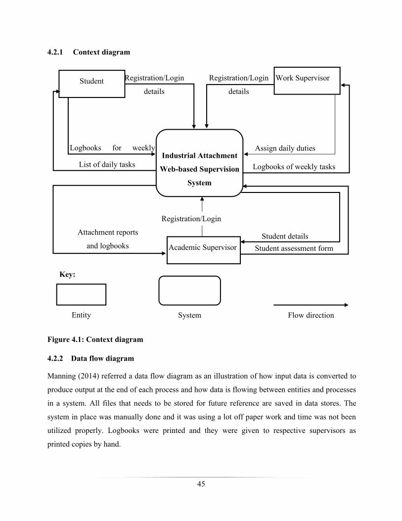
45
4.2.1 Context diagram
Student Work Supervisor
Academic Supervisor
Industrial Attachment
Web-based Supervision
System
Student assessment form
Attachment reports
and logbooks
Registration/Login
details
Registration/Login
Registration/Login
details
Logbooks of weekly tasks
Assign daily dutiesLogbooks for weekly
List of daily tasks
Student details
Key:
Entity System Flow direction
Figure 4.1: Context diagram
4.2.2 Data flow diagram
Manning (2014) referred a data flow diagram as an illustration of how input data is converted to
produce output at the end of each process and how data is flowing between entities and processes
in a system. All files that needs to be stored for future reference are saved in data stores. The
system in place was manually done and it was using a lot off paper work and time was not been
utilized properly. Logbooks were printed and they were given to respective supervisors as
printed copies by hand.
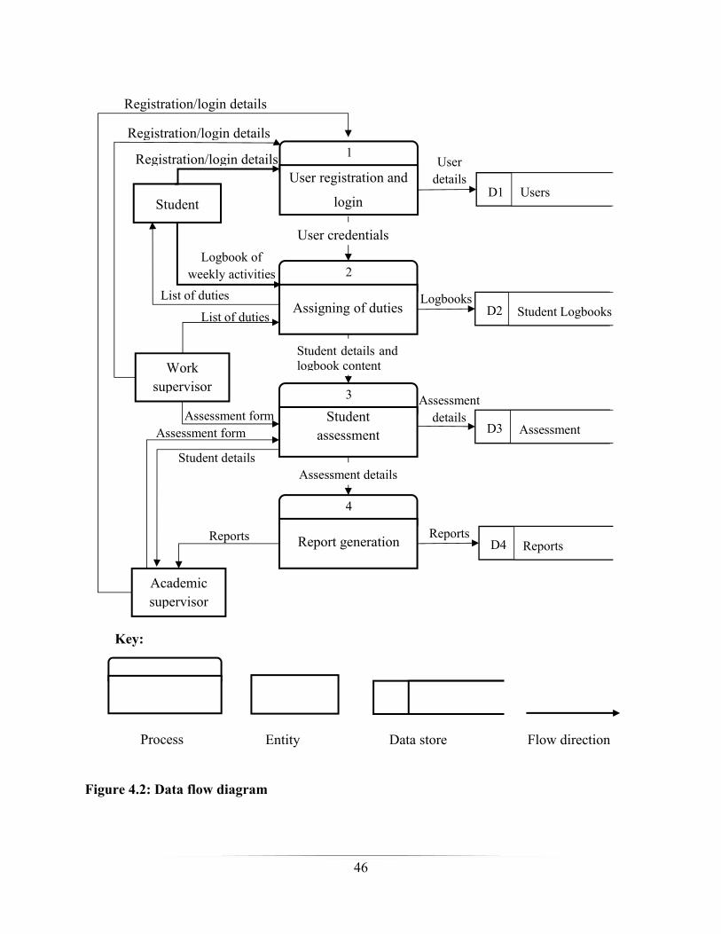
46
Registration/login details 1
User registration and
login
2
3
4
Student
Assigning of duties
UsersD1
Student LogbooksD2
AssessmentD3
ReportsD4
Userdetails
Worksupervisor
Academicsupervisor
Logbook ofweekly activities
User credentials
Studentassessment
Report generation Reports
Logbooks
Assessmentdetails
Registration/login details
Registration/login details
Student details andlogbook content
Assessment details
List of duties
List of duties
Assessment form
Reports
Assessment form
Student details
Key:
Process Entity Data store Flow direction
Figure 4.2: Data flow diagram
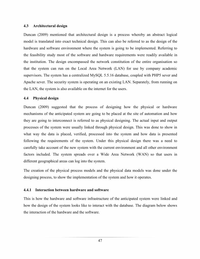
47
4.3 Architectural design
Duncan (2009) mentioned that architectural design is a process whereby an abstract logical
model is translated into exact technical design. This can also be referred to as the design of the
hardware and software environment where the system is going to be implemented. Referring to
the feasibility study most of the software and hardware requirements were readily available in
the institution. The design encompassed the network constitution of the entire organisation so
that the system can run on the Local Area Network (LAN) for use by company academic
supervisors. The system has a centralized MySQL 5.5.16 database, coupled with PHP5 sever and
Apache sever. The security system is operating on an existing LAN. Separately, from running on
the LAN, the system is also available on the internet for the users.
4.4 Physical design
Duncan (2009) suggested that the process of designing how the physical or hardware
mechanisms of the anticipated system are going to be placed at the site of automation and how
they are going to interconnect is referred to as physical designing. The actual input and output
processes of the system were usually linked through physical design. This was done to show in
what way the data is placed, verified, processed into the system and how data is presented
following the requirements of the system. Under this physical design there was a need to
carefully take account of the new system with the current environment and all other environment
factors included. The system spreads over a Wide Area Network (WAN) so that users in
different geographical areas can log into the system.
The creation of the physical process models and the physical data models was done under the
designing process, to show the implementation of the system and how it operates.
4.4.1 Interaction between hardware and software
This is how the hardware and software infrastructure of the anticipated system were linked and
how the design of the system looks like to interact with the database. The diagram below shows
the interaction of the hardware and the software.
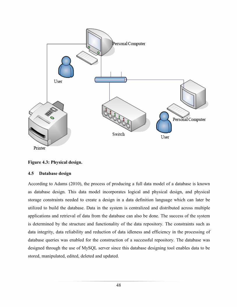
48
Figure 4.3: Physical design.
4.5 Database design
According to Adams (2010), the process of producing a full data model of a database is known
as database design. This data model incorporates logical and physical design, and physical
storage constraints needed to create a design in a data definition language which can later be
utilized to build the database. Data in the system is centralized and distributed across multiple
applications and retrieval of data from the database can also be done. The success of the system
is determined by the structure and functionality of the data repository. The constraints such as
data integrity, data reliability and reduction of data idleness and efficiency in the processing of
database queries was enabled for the construction of a successful repository. The database was
designed through the use of MySQL server since this database designing tool enables data to be
stored, manipulated, edited, deleted and updated.
49
Physical Schema
View 1 View 2 View 3
Logical SchemaStudent
Stud_ID Stud_Name Reg_Number Level
Figure 4.4: Database schema
4.5.1 Physical database design
Bleisch (2013) revealed that, this is the real construction of the database schemas, that is, the
description of the database. Sometimes a database schema is referred to as the basic structure that
denotes the logical view of the whole database. The actual storage of data in form of files or
indices is related to this schema. There are three schemas that were specified during the design of
the database namely the physical, logical and application schemas. The database design
architecture of the proposed system is illustrated by the following diagram.
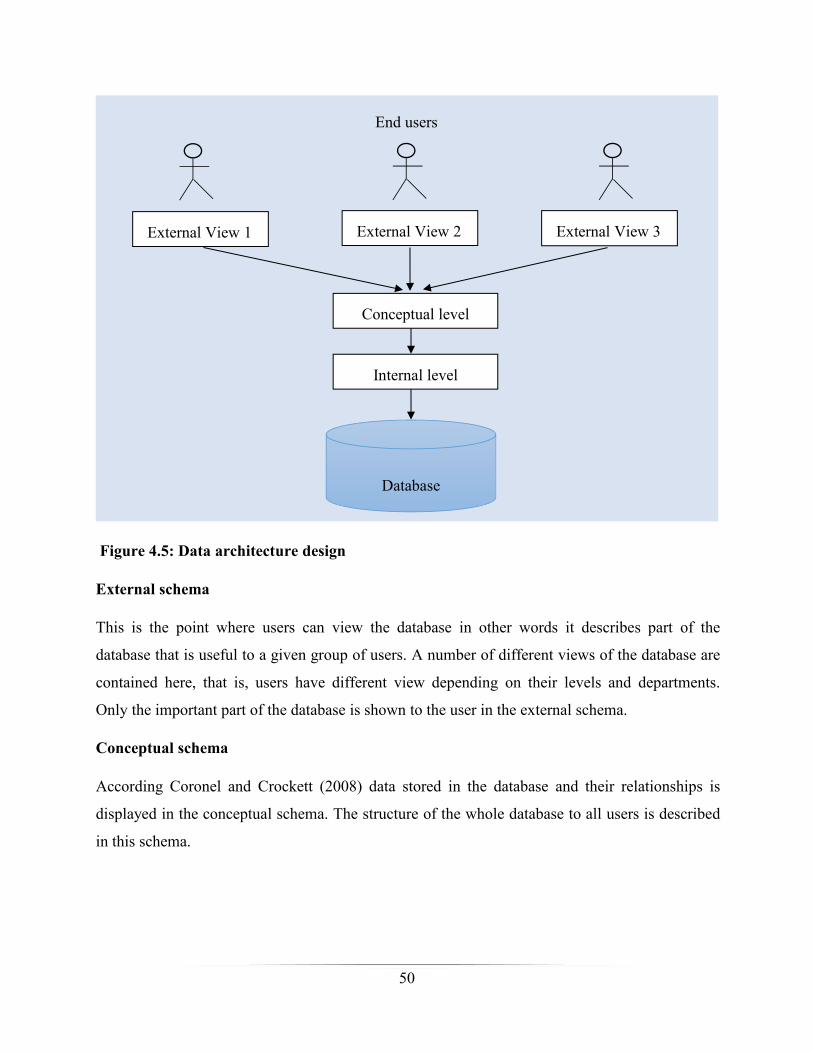
50
External View 1 External View 2 External View 3
Conceptual level
Internal level
Database
End users
Figure 4.5: Data architecture design
External schema
This is the point where users can view the database in other words it describes part of the
database that is useful to a given group of users. A number of different views of the database are
contained here, that is, users have different view depending on their levels and departments.
Only the important part of the database is shown to the user in the external schema.
Conceptual schema
According Coronel and Crockett (2008) data stored in the database and their relationships is
displayed in the conceptual schema. The structure of the whole database to all users is described
in this schema.
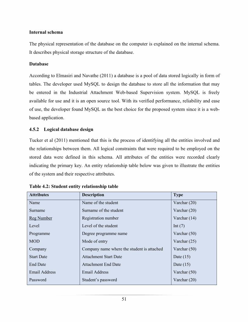
51
Internal schema
The physical representation of the database on the computer is explained on the internal schema.
It describes physical storage structure of the database.
Database
According to Elmasiri and Navathe (2011) a database is a pool of data stored logically in form of
tables. The developer used MySQL to design the database to store all the information that may
be entered in the Industrial Attachment Web-based Supervision system. MySQL is freely
available for use and it is an open source tool. With its verified performance, reliability and ease
of use, the developer found MySQL as the best choice for the proposed system since it is a web-
based application.
4.5.2 Logical database design
Tucker et al (2011) mentioned that this is the process of identifying all the entities involved and
the relationships between them. All logical constraints that were required to be employed on the
stored data were defined in this schema. All attributes of the entities were recorded clearly
indicating the primary key. An entity relationship table below was given to illustrate the entities
of the system and their respective attributes.
Table 4.2: Student entity relationship table
Attributes Description Type
Name
Surname
Reg Number
Level
Programme
MOD
Company
Start Date
End Date
Email Address
Password
Name of the student
Surname of the student
Registration number
Level of the student
Degree programme name
Mode of entry
Company name where the student is attached
Attachment Start Date
Attachment End Date
Email Address
Student’s password
Varchar (20)
Varchar (20)
Varchar (14)
Int (7)
Varchar (50)
Varchar (25)
Varchar (50)
Date (15)
Date (15)
Varchar (50)
Varchar (20)
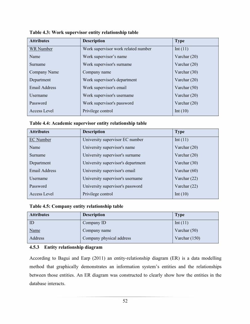
52
Table 4.3: Work supervisor entity relationship table
Attributes Description Type
WR Number
Name
Surname
Company Name
Department
Email Address
Username
Password
Access Level
Work supervisor work related number
Work supervisor’s name
Work supervisor's surname
Company name
Work supervisor's department
Work supervisor's email
Work supervisor's username
Work supervisor's password
Privilege control
Int (11)
Varchar (20)
Varchar (20)
Varchar (30)
Varchar (20)
Varchar (50)
Varchar (20)
Varchar (20)
Int (10)
Table 4.4: Academic supervisor entity relationship table
Attributes Description Type
EC Number
Name
Surname
Department
Email Address
Username
Password
Access Level
University supervisor EC number
University supervisor's name
University supervisor's surname
University supervisor's department
University supervisor's email
University supervisor's username
University supervisor's password
Privilege control
Int (11)
Varchar (20)
Varchar (20)
Varchar (30)
Varchar (60)
Varchar (22)
Varchar (22)
Int (10)
Table 4.5: Company entity relationship table
Attributes Description Type
ID
Name
Address
Company ID
Company name
Company physical address
Int (11)
Varchar (50)
Varchar (150)
4.5.3 Entity relationship diagram
According to Bagui and Earp (2011) an entity-relationship diagram (ER) is a data modelling
method that graphically demonstrates an information system’s entities and the relationships
between those entities. An ER diagram was constructed to clearly show how the entities in the
database interacts.
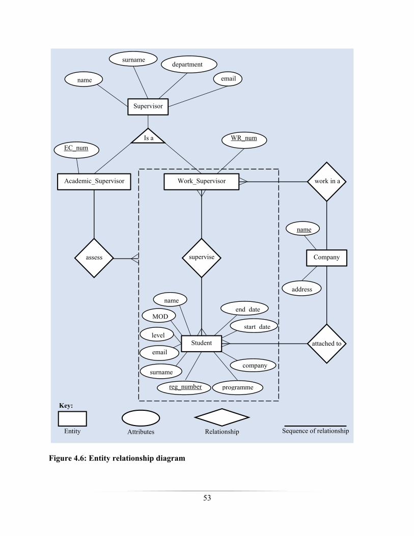
53
Supervisor
name email
surnamedepartment
Academic_Supervisor Work_Supervisor
Company
Student
name
surname
reg_number programme
end_date
start_date
company
level
MOD
superviseassess
work in a
attached to
name
address
Entity Attributes Relationship Sequence of relationship
Key:
Is a WR_numEC_num
Figure 4.6: Entity relationship diagram
54
4.5.4 Enhanced entity relationship model
Date (2014) described an enhanced entity-relationship (EER) model as an advanced-level
abstract model that precisely signify the requirements of complex databases. An EER diagram, is
a dedicated diagram that deviates from traditional entity-relationship diagrams in other words it
is an extension of the entity relationship diagram. It uses a number of philosophies that are
closely linked to object-oriented design and programming. EER diagrams include the same
concepts that normal ER diagrams incorporate. Additionally, EER diagrams include:
Specialization or generalization
Category or union type
Attribute and relationship inheritance
Subtypes and super types (sometimes known as subclasses and super classes)

55
Supervisor
name
surname department
EC_num
supervisor_type
W
A
“A” “W”
Academic_Supervisor Work_Supervisor
Company
Student
name
surname
reg_number programme
end_date
start_date
company
level
MOD
superviseassess
work in a
attached to
d
name
address
Entity Attributes Relationship Sequence of relationship
Key:
WR_num
Figure 4.7: Enhanced entity relationship model
56
4.6 Program design
Waldo (2006) suggested that program design is where all known user requirements are converted
into a practical software structure. Numerous activities were included, that is, designing of user
interfaces, the knowledge base, database and other programs. The reports and other outputs that
the system generates are defined in the following sections.
4.6.1 Class diagram
Hoffer et al (2009) agreed that a class diagram is designed to give an outline of the target system
by clearly showing the relationships between the objects and classes inside the system. The
developer used a class diagram to illustrate how objects in a system are connected to each other.
Class diagrams were an easy way to express all the classes, packages, and interfaces that set up a
system and how they are related with each other. Also, comprehensive class diagrams were used
as a prime reference for the conversion of a designed system into a programming code.
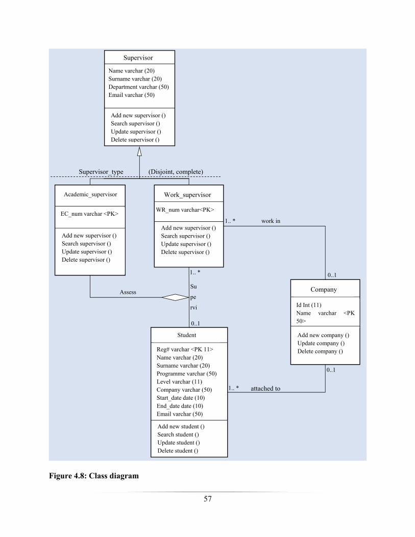
57
Supervisor
Name varchar (20)Surname varchar (20)Department varchar (50)Email varchar (50)
Add new supervisor ()Search supervisor ()Update supervisor ()Delete supervisor ()
Student
Reg# varchar <PK 11>Name varchar (20)Surname varchar (20)Programme varchar (50)Level varchar (11)Company varchar (50)Start_date date (10)End_date date (10)Email varchar (50)
Add new student ()Search student ()Update student ()Delete student ()
Academic_supervisor
EC_num varchar <PK>
Add new supervisor ()Search supervisor ()Update supervisor ()Delete supervisor ()
Work_supervisor
WR_num varchar<PK>
Add new supervisor ()Search supervisor ()Update supervisor ()Delete supervisor ()
Supervisor_type (Disjoint, complete)
Su
pe
rvi
Assess
1.. *
0..1
Company
Id Int (11)Name varchar <PK50>Address varchar (150)Add new company ()Update company ()Delete company ()
work in1.. *
0..1
attached to
0..1
1.. *
Figure 4.8: Class diagram
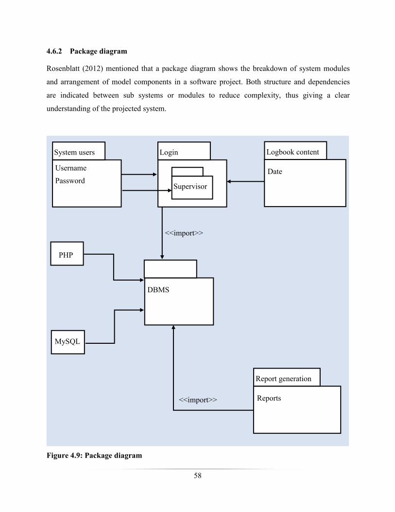
58
4.6.2 Package diagram
Rosenblatt (2012) mentioned that a package diagram shows the breakdown of system modules
and arrangement of model components in a software project. Both structure and dependencies
are indicated between sub systems or modules to reduce complexity, thus giving a clear
understanding of the projected system.
UsernamePassword
System users
Date
Logbook contentLogin
Supervisor
DBMS
Reports
Report generation
PHP
MySQL
<<import>>
<<import>>
Figure 4.9: Package diagram

59
4.6.3 Sequence diagram
Rosenblatt (2012) described a sequence diagram as an illustration of classes and how messages
are exchanged between a number of lifelines in a diagrammatic way. It describes the
communication by concentrating on the order of message that is being exchanged, along with
their equivalent occurrence conditions over a period of time. This is illustrated on the diagram
below:
User AdministratorSupervisorDatabaseLogin
Key:
Object Message Activity
Database backup
Backup confirmation
Check logbookstatus
Marked andcommented logbook
Update details
Login request
Response
Capture logbookcontent
Report request
Report
Figure 4.10: Sequence diagram
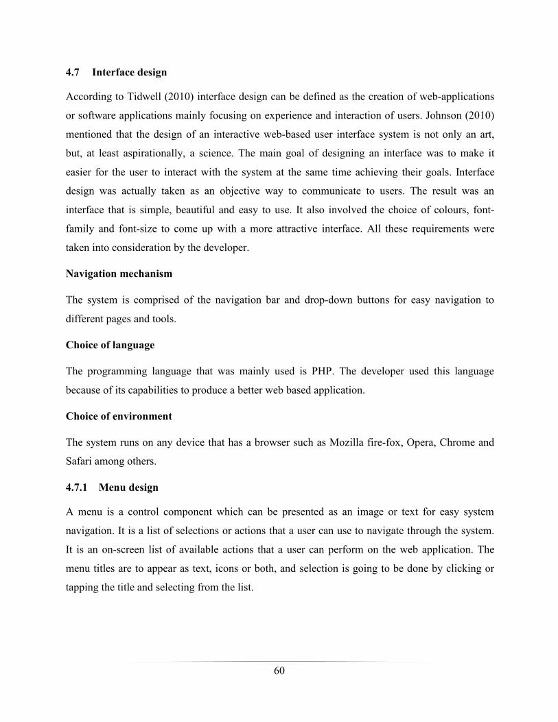
60
4.7 Interface design
According to Tidwell (2010) interface design can be defined as the creation of web-applications
or software applications mainly focusing on experience and interaction of users. Johnson (2010)
mentioned that the design of an interactive web-based user interface system is not only an art,
but, at least aspirationally, a science. The main goal of designing an interface was to make it
easier for the user to interact with the system at the same time achieving their goals. Interface
design was actually taken as an objective way to communicate to users. The result was an
interface that is simple, beautiful and easy to use. It also involved the choice of colours, font-
family and font-size to come up with a more attractive interface. All these requirements were
taken into consideration by the developer.
Navigation mechanism
The system is comprised of the navigation bar and drop-down buttons for easy navigation to
different pages and tools.
Choice of language
The programming language that was mainly used is PHP. The developer used this language
because of its capabilities to produce a better web based application.
Choice of environment
The system runs on any device that has a browser such as Mozilla fire-fox, Opera, Chrome and
Safari among others.
4.7.1 Menu design
A menu is a control component which can be presented as an image or text for easy system
navigation. It is a list of selections or actions that a user can use to navigate through the system.
It is an on-screen list of available actions that a user can perform on the web application. The
menu titles are to appear as text, icons or both, and selection is going to be done by clicking or
tapping the title and selecting from the list.
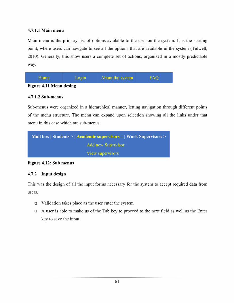
61
4.7.1.1 Main menu
Main menu is the primary list of options available to the user on the system. It is the starting
point, where users can navigate to see all the options that are available in the system (Tidwell,
2010). Generally, this show users a complete set of actions, organized in a mostly predictable
way.
Home Login About the system FAQ
Figure 4.11 Menu desing
4.7.1.2 Sub-menus
Sub-menus were organized in a hierarchical manner, letting navigation through different points
of the menu structure. The menu can expand upon selection showing all the links under that
menu in this case which are sub-menus.
Mail box | Students > | Academic supervisors – | Work Supervisors >
Add new Supervisor
View supervisors
Figure 4.12: Sub menus
4.7.2 Input design
This was the design of all the input forms necessary for the system to accept required data from
users.
Validation takes place as the user enter the system
A user is able to make us of the Tab key to proceed to the next field as well as the Enter
key to save the input.

62
Supervisor registration form: - a form where a new supervisor can be added to the system.
First name
Email address
Password
Enter Module code
Register
Name
Email Address
Password
Module
Department
Confirm passwordConfirm Password
Enter department name
Enter surname
EC Number EC12344
Figure 4.13: Academic supervisor registration form
Work related registration form - this is where a new work related supervisor can be added to
the system

63
First name
Email address
Password
Enter department
Register
Name
Email Address
Password
Department
Company
Confirm passwordConfirm Password
Enter company name
Enter surname
WR Number WR12344
Figure 4.14: Work related supervisor registration form
Student registration form: - a form where a new student can be added into the system.
Enter first name
Enter where the student is attached
Enter attachment start date
Enter academic level
Enter Reg#
Enter attachment end date
Email address
Enter programme
Password
Register
Name
Company
Attachment Start Date
Level
Registration Number
Attachment End Date
Email Address
Programme
Password
Enter surname
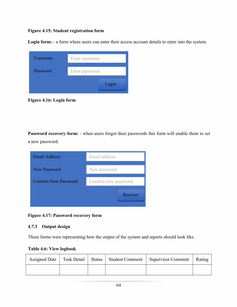
64
Figure 4.15: Student registration form
Login form: - a form where users can enter their access account details to enter into the system.
Enter password
Enter username
Login
Password
Username
Figure 4.16: Login form
Password recovery form: - when users forgot their passwords this form will enable them to set
a new password.
New password
Confirm new password
Email address
New Password
Confirm New Password
Email Address
Recover
Figure 4.17: Password recovery form
4.7.3 Output design
These forms were representing how the output of the system and reports should look like.
Table 4.6: View logbook
Assigned Date Task Detail Status Student Comment Supervisor Comment Rating
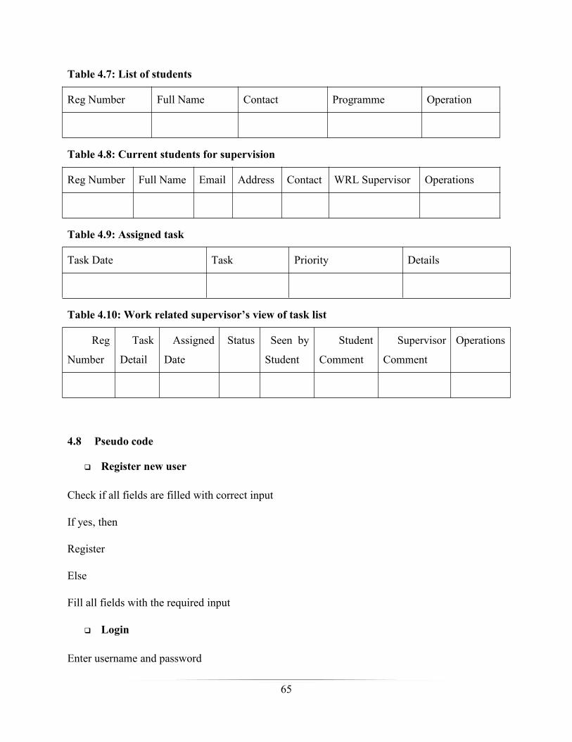
65
Table 4.7: List of students
Reg Number Full Name Contact Programme Operation
Table 4.8: Current students for supervision
Reg Number Full Name Email Address Contact WRL Supervisor Operations
Table 4.9: Assigned task
Task Date Task Priority Details
Table 4.10: Work related supervisor’s view of task list
Reg
Number
Task
Detail
Assigned
Date
Status Seen by
Student
Student
Comment
Supervisor
Comment
Operations
4.8 Pseudo code
Register new user
Check if all fields are filled with correct input
If yes, then
Register
Else
Fill all fields with the required input
Login
Enter username and password
66
If successful
Go to user homepage
Else
Try again
Creating a new task
Validate the input
If the input data is invalid
Show error message
Else
Save details
Updating data in the database
Get the key fields
Check if there is matching record
If not, then
Show error message
Else
Validate all the information
If the input is not valid
Show error message
Else
Save data
Searching for a student

67
Get the student reg number
Retrieve data
If there is no match, then
Show error message
Else
Show data
Permit the user to edit
4.9 Security design
Gasser (2012 put forth that security is a fusion of procedural, logical and physical actions
designed to prevent, detect and correct certain kinds of misuse, together with instruments to
mount, operate and uphold these actions. Security is a property of a system that assures right
status, behaviour, accessibility and reliability. Security design is an art of making sure the
information confidentiality, availability, integrity and system data is being maintained properly
by putting standard security measures such as physical security, personal security, operational
security, database security and network security.
4.9.1 Physical security
Gasser (2012) cited that physical security is the physical protection of the facility/building and
the surrounding premises to prevent theft, data damages fire, water and any other physical threats.
The measures that were used for physical security include fencing, locks, access control cards,
biometric access control systems and fire suppression systems
4.9.2 Network security
All access to the network are restricted by the domain controller (DC), which is a server that
handles network access leases, levels and privileges. All network logins are authenticated by this
DC and IP address of requesting client must be within the specified range, otherwise access will
be denied.

68
4.9.3 Operational security
Operations security which sometimes can be abbreviated as OPSEC is a process of identifying
and protecting uncategorized critical information from being accessed or used by a competitor
(Gasser, 2012). Even though the information is unclassified under the OPSEC, it might be an
advantage to a competitor or other threats. Operational security mainly focusee on identifying
and protecting information that could give rivals hints to put the university at a disadvantage.
4.9.4 Database security
Elmasri and Navathe (2011) emphasized that database security indicates all the measures used to
protect a database from unlawful/illegal use, alteration of data and malicious threats and or
attacks. It incorporates a collection of processes, instruments and procedures that guarantee
security within the database atmosphere. It ensures and imposes security measures on all features
and mechanisms of the database. Which are data stored in database, database server, database
management system (DBMS) and other database workflow applications
The database administrator is responsible for the planning, implementation and maintenance of
database security. Database is placed on the system sever and its access is through a password
protected phpMyAdmin, which is installed on that machine only. Backup will be done
periodically in the event of a crash. The database is password protected as well.
4.9.5 User security
The system decides who has access to the system through the use of a unique identifier in this
case which is a username. The username must be unique; this is the only way the system can
identify users differently. Users have passwords known to themselves. Also, users are able and
encouraged to regularly change their passwords. The use of access control also work as a
security key to users, as the system have three different access control tasks which are:
Permission: defining which users are permitted to have access to which objects
Controlling right of access; this encompasses the right to write, read, execute, delete, and
append.
Imposing the right of entry
Accessibility
69
The system is online 24/7 and accessible wherever there is internet access.
4.10 Conclusion
During the designing phase, the developer transformed the baselined requirements into a detailed
system design. All the needed designs have been carried out including system design, physical
design, database design, interface design and security design, and the proposed system was
supported within the existing infrastructure environment. It was clearly safe for the new system
to be coded and tested. The next chapter is going to cover the implementation phase.
Chapter 5: Implementation phase
5.1 Introduction
The process of taking the system into the working environment, testing it to verify and confirm
that the system components have been accurately done is sometimes referred to as system
implementation. This phase focused on the creation of the actual system, system testing, security,
validation, verification, installation, user training and maintenance.
5.2 Coding
According to Medard and Sprintson (2012) coding is a process of converting what is on the
designing phase to the format that a computer understands thus writing a program. This was done
through the use of PHP programming language and MSQL for SQL statements for database
communication. Pseudo code is a short statement that is used to show the flow of the system in
an understandable manner (Goel, 2010).
5.3 Testing
According to Parsons and Oja (2014) application testing is a process is the process of trying out
various sequence of input values and checking the results to verify that the application system
works correctly. The idea behind system testing was to check all potential circumstances that are
likely to occur in the future.“It is an on-going procedure that should be done on an incremental
basis at every suitable level.”Testing was also used to identify any and all functionality problems

70
and therefore the testing involved inputting known data to investigate whether the results were as
expected.
5.3.1 Validation
Murray-Smith (2015) highlighted that validation is when the application is tested with regard to
its distinctive working environment. Subsequently, for many procedures no clear partition among
validation and system testing can be made. A search was done to see if the system would give
results according to user specifications. The output of the system was the expected result hence
the system is valid to use.
5.3.2 Verification
According to Honour (2013), verification is checking whether an item or artefact has been
designed/built to conform with requirements. This was applied to the final system. Performance
testing - This is when the function requirements, if any were tested these including the response
time of the system on searching. A search was conducted to observe how long it takes for the
system to produce results. It only took us a few seconds to run and compile the system source
code. The system’s response and searching time were very high.
5.3.3 Testing processes
The system was tested in different ways such as unit testing, module testing, login testing, sub-
system testing, system testing and acceptance testing. The summary of these tests is shown on
the diagram below:

71
Unit testing
Module testing
Login testing
Sub-system testing
System testing
Acceptance testing
Flow of data
Figure 5.1: Testing process
5.3.3.1 System testing
The system was tested as a whole to test if its components will function effectively when
integrated as a system. The inference engine, knowledge base and interfaces were tested together
to ensure that they could function effectively when brought together as a system. The system was
able to query the ontology and store the results in the database.
5.3.3.2 Unit testing
Unit testing was also performed where the different components of the system were tested
individually to confirm functionality. Each implemented module is tested with respect to their
desired functionality and behaviour and other requirements.
5.3.3.3 Security testing
Database security testing
Database is secured by the use of username and password. The database administrator should
enter correct credentials to access the contents of the database.

72
Figure 5.2: Database security
User security testing
As mentioned in chapter 4.9 that the system will decide who is going to access the system
through the use of a unique identifier in this case which is a username. Permission: defining
which users are permitted to have access to which objects. Controlling right of access; this
encompasses the right to write, read, execute, delete, and append. The screenshot below shows
the different access levels of the users

73
Figure 5.3: User security testing
Login testing
If a user input a wrong username or wrong password, the system will regard the user as an
unauthorised user, an attempt to proceed will give the following error:
Figure 5.4: Login testing.
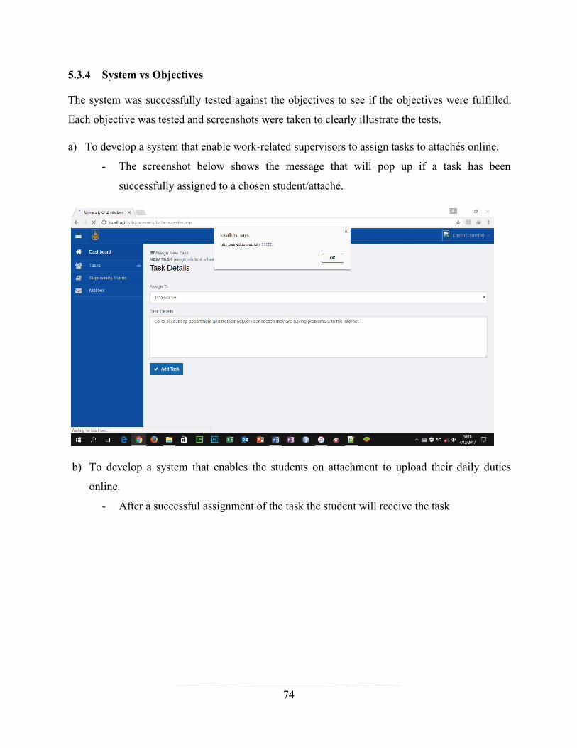
74
5.3.4 System vs Objectives
The system was successfully tested against the objectives to see if the objectives were fulfilled.
Each objective was tested and screenshots were taken to clearly illustrate the tests.
a) To develop a system that enable work-related supervisors to assign tasks to attachés online.
- The screenshot below shows the message that will pop up if a task has been
successfully assigned to a chosen student/attaché.
b) To develop a system that enables the students on attachment to upload their daily duties
online.
- After a successful assignment of the task the student will receive the task

75
c) To develop a system that allows work-related supervisors to monitor performance of an
attaché, giving feedback as the student logs duties.
- After the student has completed the task the work supervisor will give a comment to
the logged task and give feedback to the student as shown on the screenshot below.
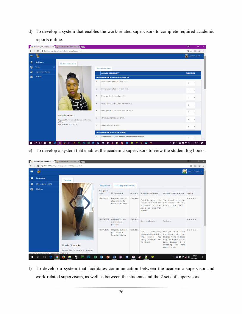
76
d) To develop a system that enables the work-related supervisors to complete required academic
reports online.
e) To develop a system that enables the academic supervisors to view the student log books.
f) To develop a system that facilitates communication between the academic supervisor and
work-related supervisors, as well as between the students and the 2 sets of supervisors.

77
5.4 Installation
Chemuturi (2013) revealed that installation involves deploying all the machines including
servers, workstations and networking equipment and then installing the software on the
respective machines. This also involved user training and all methods which are going to be used
to position the system in system servers. Installation also involves the process of inserting the
system onto a web server where the users will use it from (ibid). The installation was done in the
UZ servers.
The XAMPP Server with MYSQL database server was installed.
Autocreation of a root folder in XAMPP called www.
Type the URL www.localhost/wrlss.
Users will be redirected to the homepage where they can find the login button for them to
login using their usernames and passwords
5.4.1 Data migration
Data migration is used to describe the process of interpreting data from one format to another.
Dufrasne et al (2015) mentioned that “data migration is needed when an organization chooses to
use a new computerized systems or DBMS that is not compatible with the existing system.

78
Normally, data migration is performed by a set of personalized programs or scripts that
automatically convey the data.
5.4.2 System changeover strategies
As the name propose, system changeover is the“process of changing the traditional system to a
new system. Rosenblatt (2013) revealed that, system changeover is the process of putting the
new system online and retiring the traditional system.” Normally, there are four system
conversion methods namely direct cutover, parallel conversion, phased changeover and pilot
cutover. Their description, advantages, disadvantages and the effects of using each of these
methods at UZ to replace the current system with the new online system are as follows-:
5.4.2.1 Direct cutover
The entire UZ will immediately stop using the old system at one time and start to use the new
one. The institution stops using the old system one day, start using the new system on the next
day. This is a dangerous method to use. Direct changeover is a cheap method among all four but
comprises high risk of data loss. With the direct changeover approach, it will be impossible for
the institution to return to the old system.
Old system New system
Figure 5.5: Direct cutover
Direct conversion encompasses more dangers of total system failure and if there is a system
failure in the institution then it will not be easy to store students’ information and as a result this
will lead to improper storage of data. Since this approach saves money, it may be a possible
choice because of it is cheap among all four methods.
5.4.2.2 Parallel conversion
The introduction of the new system will be done while the traditional one is still in use. Both
systems will run simultaneously and the results are compared. Once there is sureness that the
new system works fine, the traditional one will be replaced.
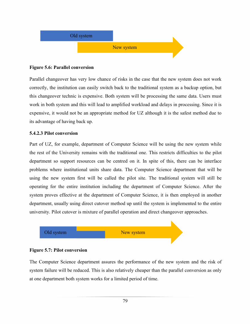
79
Old system
New system
Figure 5.6: Parallel conversion
Parallel changeover has very low chance of risks in the case that the new system does not work
correctly, the institution can easily switch back to the traditional system as a backup option, but
this changeover technic is expensive. Both system will be processing the same data. Users must
work in both system and this will lead to amplified workload and delays in processing. Since it is
expensive, it would not be an appropriate method for UZ although it is the safest method due to
its advantage of having back up.
5.4.2.3 Pilot conversion
Part of UZ, for example, department of Computer Science will be using the new system while
the rest of the University remains with the traditional one. This restricts difficulties to the pilot
department so support resources can be centred on it. In spite of this, there can be interface
problems where institutional units share data. The Computer Science department that will be
using the new system first will be called the pilot site. The traditional system will still be
operating for the entire institution including the department of Computer Science. After the
system proves effective at the department of Computer Science, it is then employed in another
department, usually using direct cutover method up until the system is implemented to the entire
university. Pilot cutover is mixture of parallel operation and direct changeover approaches.
Old system New system
Figure 5.7: Pilot conversion
The Computer Science department assures the performance of the new system and the risk of
system failure will be reduced. This is also relatively cheaper than the parallel conversion as only
at one department both system works for a limited period of time.
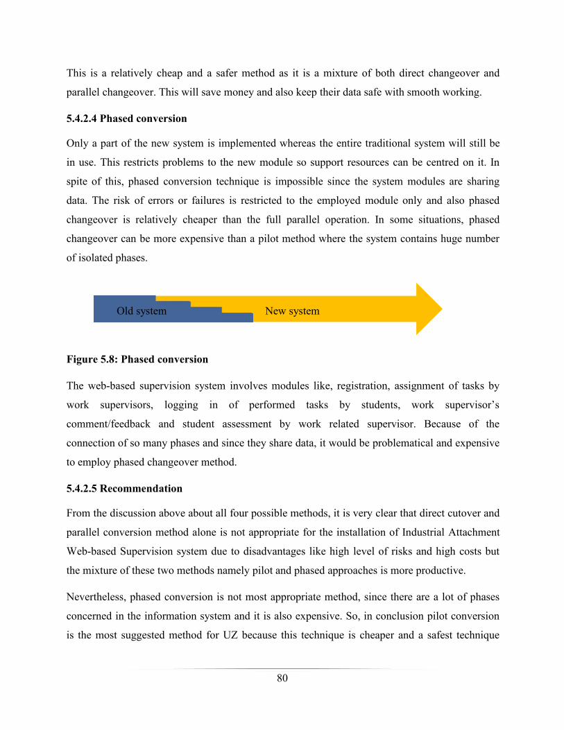
80
This is a relatively cheap and a safer method as it is a mixture of both direct changeover and
parallel changeover. This will save money and also keep their data safe with smooth working.
5.4.2.4 Phased conversion
Only a part of the new system is implemented whereas the entire traditional system will still be
in use. This restricts problems to the new module so support resources can be centred on it. In
spite of this, phased conversion technique is impossible since the system modules are sharing
data. The risk of errors or failures is restricted to the employed module only and also phased
changeover is relatively cheaper than the full parallel operation. In some situations, phased
changeover can be more expensive than a pilot method where the system contains huge number
of isolated phases.
New systemOld system
Figure 5.8: Phased conversion
The web-based supervision system involves modules like, registration, assignment of tasks by
work supervisors, logging in of performed tasks by students, work supervisor’s
comment/feedback and student assessment by work related supervisor. Because of the
connection of so many phases and since they share data, it would be problematical and expensive
to employ phased changeover method.
5.4.2.5 Recommendation
From the discussion above about all four possible methods, it is very clear that direct cutover and
parallel conversion method alone is not appropriate for the installation of Industrial Attachment
Web-based Supervision system due to disadvantages like high level of risks and high costs but
the mixture of these two methods namely pilot and phased approaches is more productive.
Nevertheless, phased conversion is not most appropriate method, since there are a lot of phases
concerned in the information system and it is also expensive. So, in conclusion pilot conversion
is the most suggested method for UZ because this technique is cheaper and a safest technique
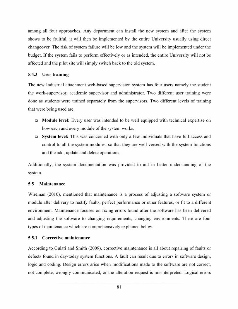
81
among all four approaches. Any department can install the new system and after the system
shows to be fruitful, it will then be implemented by the entire University usually using direct
changeover. The risk of system failure will be low and the system will be implemented under the
budget. If the system fails to perform effectively or as intended, the entire University will not be
affected and the pilot site will simply switch back to the old system.
5.4.3 User training
The new Industrial attachment web-based supervision system “has four users namely the student
the work-supervisor, academic supervisor and administrator. Two different user training were
done as students were trained separately from the supervisors. Two different levels of training
that were being used are:
Module level: “Every user was intended to be well equipped with technical expertise on
how each and every module of the system works.
System level: “This was concerned with only a few individuals that have full access and
control to all the system modules, so that they are well versed with the system functions
and the add, update and delete operations.
Additionally, the system documentation was provided to aid in better understanding of the
system.
5.5 Maintenance
Wireman (2010), mentioned that maintenance is a process of adjusting a software system or
module after delivery to rectify faults, perfect performance or other features, or fit to a different
environment. Maintenance focuses on fixing errors found after the software has been delivered
and adjusting the software to changing requirements, changing environments. There are four
types of maintenance which are comprehensively explained below.
5.5.1 Corrective maintenance
According to Gulati and Smith (2009), corrective maintenance is all about repairing of faults or
defects found in day-today system functions. A fault can result due to errors in software design,
logic and coding. Design errors arise when modifications made to the software are not correct,
not complete, wrongly communicated, or the alteration request is misinterpreted. Logical errors
82
result from invalid tests and conclusions, inappropriate implementation of design stipulations,
defective logic flow, or partial test of data. The need for corrective maintenance is usually
initiated by bug reports drawn by the users. Corrective maintenance usually is an unscheduled
amendment performed to temporarily keep the system operational, since it is done when the bugs
arises.
5.5.2 Adaptive maintenance
Wireman (2010), highlighted that adaptive maintenance is the execution of modifications in a
portion of the system, which has been affected by an alteration that arisen in some other portion
of the system. Adaptive maintenance comprises of adjusting the software to variations in the
environment such as the hardware or the operating system. This usually can be done when the
students are on vacation or semester break to avoid delays in system process.
5.5.3 Perfective maintenance
Tripathy and Naik (2014) hypothesized that perfective maintenance largely focuses on
implementing new or altered user requirements. Perfective maintenance encompasses making
functional improvements to the system in addition to the actions to boost the system's
performance and functionality even when the alterations have not been proposed by errors. This
include improving both the function and efficiency of the code and modifying the functionalities
of the system as per the users' changing requirements. This can be done on public holydays or
bigger holidays such as Christmas to reduce interruption with users.
5.5.4 Preventive maintenance
Conferring to Braude and Bernstein (2016), preventive maintenance encompasses executing
activities to avoid the manifestation of errors. It tends to lessen the software difficulty thereby
refining program understandability and increasing software maintainability. It includes
documentation updating, code optimization, and code reformation. Documentation updating
comprises adjusting the documents affected by the alterations in order to match to the current
state of the system. Code optimization comprises altering the programs for quicker execution or
efficient use of storage space. This can be done every time when the system has been modified to
keep up with any system updates.

83
5.5.5 Software backup
Nelson (2011) emphasized that data is the most vital part of computer systems. An operating
system can be reinstalled and so can applications, but it may not be easy or it may be impossible
to reinvent the original data.
Therefore, it is crucial that back up of vital information is frequently done and to have a plan for
recovering from a system failure. A hacker or virus could crash a computer's operating system or
data may be corrupted or deleted by a hardware problem. Computers can be lost, stolen, or
destroyed in a fire or other disaster.
Crucial work data should be backed up on an even basis. This means copying files over to a
protected system that can be accessed when those files are needed.
5.6 Recommendations for future/further development
The system is subject to evaluation and updates and it can be advanced to have capacity for the
“WHAT IF ANALYSIS” that improves the management to come up with an uncompromised
choice for future University information sharing and how it is organized within the University.
Below are the recommendations for the system.
The server should be continuously up and the internet should not be interrupted. Also,
there is need for frequent database backup like every week.
The system can be combined with the institution website to permit access from
researchers and improve search engine optimization, hence adding value to it.
In future, shifting to Java is strongly suggested as a programming language that is robust
and more secure for web applications.
More functions can also be added in future such as the use of SMS notification when a
new task has been assigned to the student or to notify the work-related supervisor when
the task has been completed. The same SMS notification feature may also be used to
notify the academic supervisor when the assessment of the student is scheduled. Even the
whole system can be migrated to an android and iOS application.
The system can also be perfected to accommodate cases like if the student changed the
company, the deferment of a student on attachment or if the student dies.
84
5.7 Conclusion
The functionality of the system and how it interacts with the user was clearly illustrated. The
systems functionality was tested against the requirements provided. It demonstrated the
appearance of the system with the use of screenshots and described the sample code used to
produce the functionality and the appearance. All possible changeover strategies have been given
and all maintenance approaches to improve the system in future, to adapt to new technology
changes and functions.
85
Reference list
Adams, K. (2015), Non-functional Requirements in Systems Analysis and Design, Springer
International, Switzerland.
Agarwal, B. (2010), Software Engineering, LAXMI Publications, Delhi.
Amman, P, (2008), Introduction to Software Testing, CUP, New York.
Bagui, S. and Earp, R. (2011), Database Design Using Entity-Relationship Diagrams, 2nd Edition,
CRC Press, England.
Bharat, B. and Pratash, T. (2007), Software Engineering, LAXMI Publications, Delhi.
Braude, J. E. and Bernstein, M. E. (2016), Software Engineering: Modern Approaches, 2nd
Edition, Waveland Press, USA.
Buragga, A. K. and Zaman, N. (2013), Software Development Techniques for Constructive
Information Systems Design, IGI Global. USA.
Chemuturi, M. (2013), Requirements Engineering and Management for Software Development
Projects, Springer Science & Business Media, London.
Coronel, A. and Crocket, K. (2008), Principles of database, Prentice Hall, UK.
Edward Crookshanks (2012), Practical Software Development Techniques, Apress, USA.
David, J. (2011), Advances in Multimedia, Software Engineering, Springer, New York.
Dixit, J. B. (2007), Structured System Analysis and Design, LAXMI Publications, New Delhi.
Dufrasne, B., Warmuth, A., Appel, J., Bauer, W., Douglass, S., Klee, P., Pura, M., Wells, M. and
Wesselbaum, B. (2015), DS8870 Data Migration Techniques, IBM Redbooks, USA.
Elmasri, R. and Navathe, S. (2011), Fundamentals of Database Systems, 6th Edition, Pearson
Addison-Wesley, USA.
Foster, E. (2014), Software Engineering: A Methodical Approach, Apress, USA.
Foster, R. (2015), Code Igniter Web Application Blueprints, Packt Publishing Ltd, UK.
86
Gasser, M. (2012, Building A Secure Computer System, 3rd Edition, Van Nostrand Reinhold,
Australia.
Gottel, O. (2009), System Design, Spring, New York.
Gulati, R. and Smith, R. (2009), Maintenance and Reliability Best Practices, Industrial Press,
New York.
Heath, J (2016), The eBook on Software Development, Prentice Hall, UK.
Hoffer, J. A., Prescott, M. B. and Topi, H. (2009), Modern Database Management 9th Edition,
Prentice Hall, USA.
Holcombe, M. (2008), Running an Agile Software Development Project, Wiley, USA.
Honour, E. (2013), Verification and Validation Issues in Systems of Systems, Honourcode Inc.,
Spring Hill.
James, K., L. (2009), Software Engineering PHI, Delhi.
Johnson, J. (2010), Designing with the Mind in Mind, Elsevier Inc., USA.
Karathiya, M. (2014), Information Gathering Through Interactive Technique, Grin Verlag,
Germany.
Kimmich, C., Janetschek, H., Meyer-Ohlendorf, L., Meyer-Ueding, J. and Sagebiel, J. (2012),
Methods for Stakeholder Analysis, Europaeisher Hochshulverlag, German.
Langer, A. M. (2012), Guide to Software Development: Designing and Managing the Life Cycle,
Springer, UK.
Leffingwell, D. (2011), Agile Software Requirements, Pearson Addison Wesley, India.
Linoff, G. S. (2015), Data Analysis Using SQL and Excel, John Wiley & Sons, Canada.
Maidasani, D. (2007), Software Testing, Firewall Media, India.
Miller, P. F., Vandome, A. F. and McBrewster, J. (2010), Data Flow Diagram: Information
System, Visualization, Computer Data Processing, Flowchart, Control Flow Diagram, Data
Island, Dataflow, Functional Flow Block Diagram, Alphascript Publishing, USA.

87
Mistrik, I. (2012), ligning Enterprise, System, and Software Architectures, IGI Global, USA.
Murray-Smith, D., J. (2015), Testing and Validation of Computer Simulation Models: Principles,
Methods and Applications, Springer, UK.
Namanda, M. (2016), Capital Budgeting, Net Present Value and other Business Decision Making
Tools, Grin Verlag Publishers, New York.
Nelson, S (2011), Pro Data Backup and Recovery, Apress, USA.
O'Neill, E. (2012), User-Developer Cooperation in Software Development: Building Common
Ground and Usable Systems, Springer, UK.
Parsons, J., J. and Oja, D. (2014), New Perspectives on Computer Concepts, Cengage Learning,
USA.
Per-Olov, J. and Kriström, B. (2015), Cost-Benefit Analysis for Project Appraisal, Cambridge
University Press, UK.
Phillips, P. P. and Stawarski, C. A. (2008) Data Collection: Planning for and Collecting All
Types of Data, Wiley & Sons, USA.
Riley, D. D. and Hunt, K. A. (2014), Computational Thinking for the Modern Problem Solver,
CRC Press, USA.
Rogers, H., Sharp H., and Preece, J. (2015), Interaction Design: Beyond Human-Computer
Interaction, 4th Edition, Wiley, USA.
Rosenblatt, H., J. (2014), Systems Analysis and Design, 10th edition, Cengage Learning, USA.
Schneidewind, N., F. (2012), Computer, Network, Software, and Hardware Engineering with
Applications, John Wiley & Sons Inc., Canada.
Schwartz, M. (2016), The Art of Business Value, IT Revolution Press, Portland.
Scott, W. A. and Mark, L. (2012), Disciplined Agile Delivery: A Practitioner's Guide to Agile
Software Delivery in the Enterprise, IBM Press, USA.
Slide, A. (2012), D. W. Griffith: Interviews, University Press of Mississippi, USA.
88
Tidwell, J. (2010), Designing Interfaces, 2nd Edition, O’Reilly Media, USA.
Tripathy, P. and Naik, K. (2014), Software Evolution and Maintenance, John Willey & Sons,
Canada.
Trivedi, M., L. (2002), Managerial Economics, Tata McGraw, Delhi.
Tucker, A., Morelli, R, and De’ Silva C. (2011), Software Development: An Open Source
Approach, Chapman & Hall, France.
Virine, L. and Trumper, M. (2017), Project Risk Analysis Made Ridiculously Simple, World
Scientific Publishing Co. Pte. Ltd., Singapore.
Waldo, J. (2006), On System Design, Sun Microsystems Laboratories, USA.
Wallace, M. and Webber, L. (2015), It Governance: Policies and Procedures, Wolters Kluwer,
New York.
Wireman, T. (2010), Benchmarking Best Practices in Maintenance Management (2nd edition),
Industrial Press Inc., New York.
Zykov, V. S. (2016), Crisis Management for Software Development and Knowledge Transfer,
Springer, UK.
http://www2.uz.ac.zw/index.php/about-uz/university-infor/university-of-zimbabwe-profile
accessed 23/09/2016.
https://people.uwec.edu/piercech/ResearchMethods/Data%20collection%20methods/DATA%20
COLLECTION%20METHODS.htm accessed 15/10/2016.
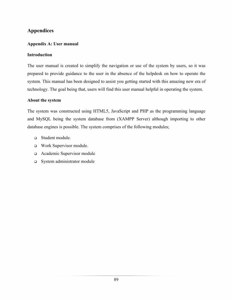
89
Appendices
Appendix A: User manual
Introduction
The user manual is created to simplify the navigation or use of the system by users, so it was
prepared to provide guidance to the user in the absence of the helpdesk on how to operate the
system. This manual has been designed to assist you getting started with this amazing new era of
technology. The goal being that, users will find this user manual helpful in operating the system.
About the system
The system was constructed using HTML5, JavaScript and PHP as the programming language
and MySQL being the system database from (XAMPP Server) although importing to other
database engines is possible. The system comprises of the following modules;
Student module.
Work Supervisor module.
Academic Supervisor module
System administrator module
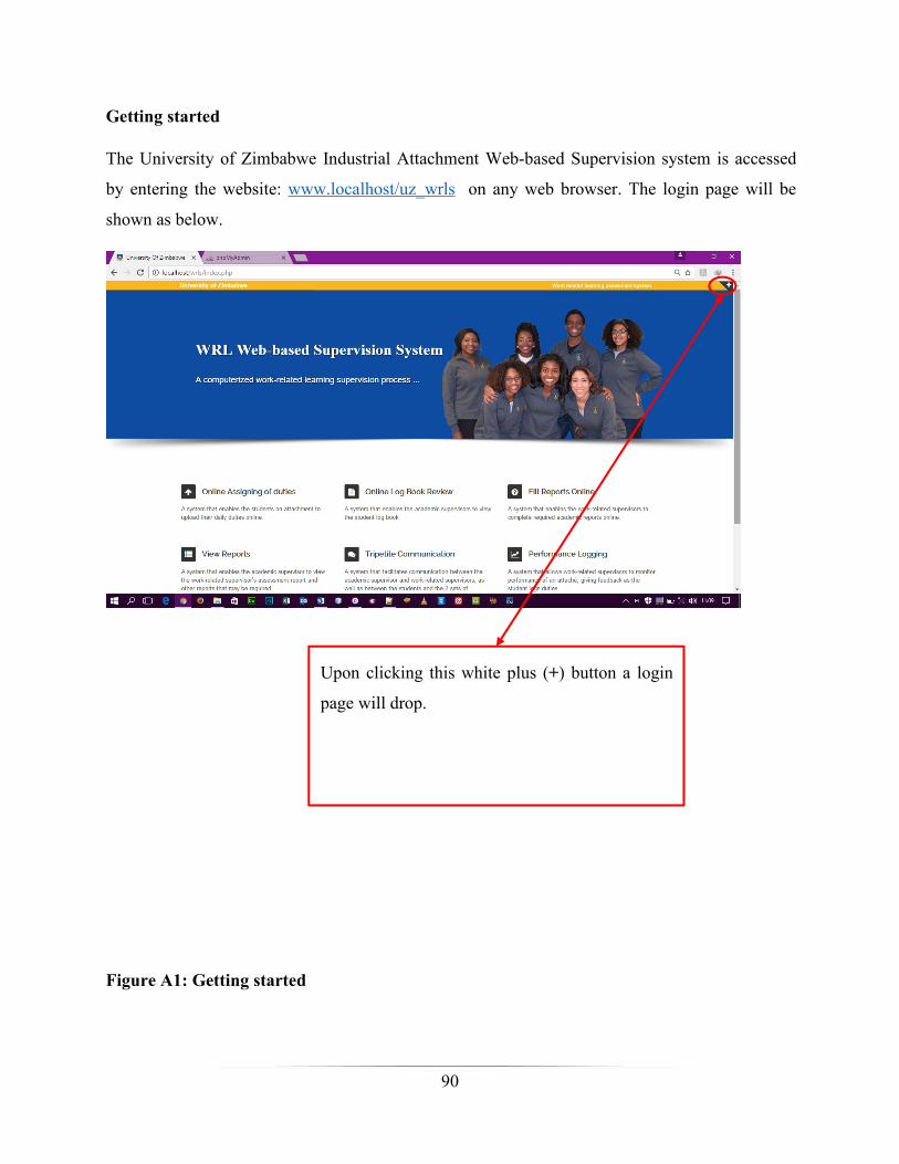
90
Getting started
The University of Zimbabwe Industrial Attachment Web-based Supervision system is accessed
by entering the website: www.localhost/uz_wrls on any web browser. The login page will be
shown as below.
Upon clicking this white plus (+) button a login
page will drop.
Figure A1: Getting started
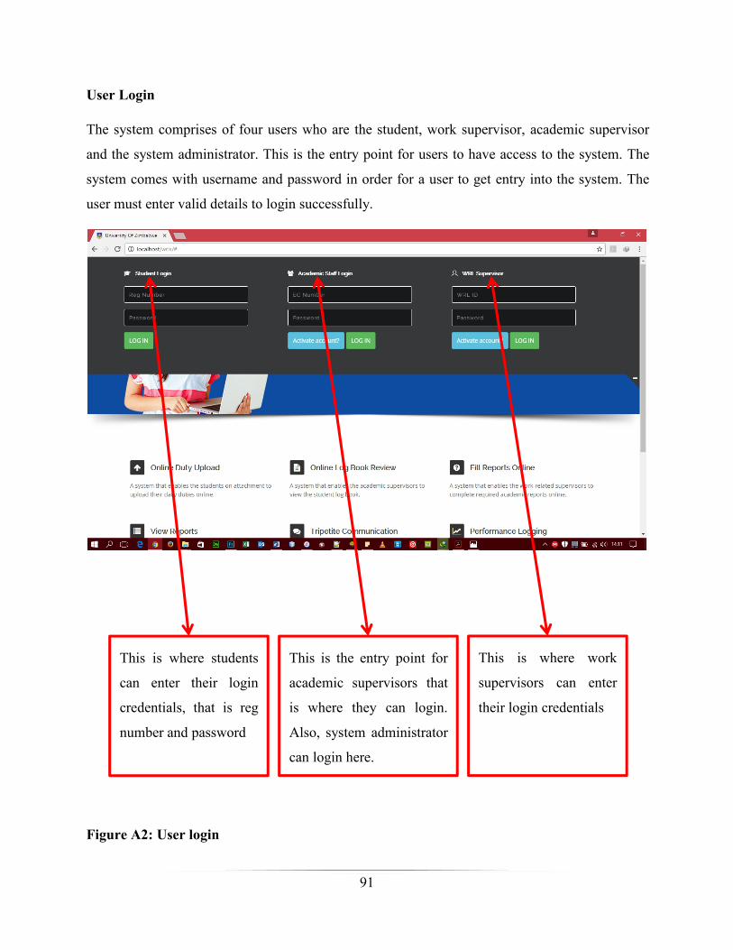
91
User Login
The system comprises of four users who are the student, work supervisor, academic supervisor
and the system administrator. This is the entry point for users to have access to the system. The
system comes with username and password in order for a user to get entry into the system. The
user must enter valid details to login successfully.
This is where students
can enter their login
credentials, that is reg
number and password
This is the entry point for
academic supervisors that
is where they can login.
Also, system administrator
can login here.
This is where work
supervisors can enter
their login credentials
Figure A2: User login
92
Administrator homepage
Click here to add
new student
Click here to
view students,
update or delete
Click here to add
new academic
supervisor.
Click here to view
academic
supervisors, update
or delete.
Click here to add
new degree or view
degrees, update or
delete.
Click here to add
new faculty, view,
update or delete
faculty
Click here to view
work supervisors,
update or delete.
Click here to
add new work
supervisor
Figure A3: Administrator homepage

93
Student homepage
After a successful login, students will be redirected to the following homepage where they can
navigate to different commands as shown below.
To check or start a
newly assignment, a
student should click
this link
When a task has been
completed a student
should update it by
clicking that link.
To view all logged
tasks, a student should
click this command.
To view logbook or
to print logbook, a
student should click
here.
Task overview is where
a student can find all the
assigned tasks even
unattended jobs.
Click here to chat
with supervisors or to
check new messages
Figure A4: Student homepage

94
Starting a new task (Students only)
This is what a student should do when a new task has been successfully assigned by a work
supervisor.
A student should click on
the command new task to
start a new task
To move to the next stage
of declaring a start time of
the task the student should
click here.
Figure A5: Starting a new task (Students only)
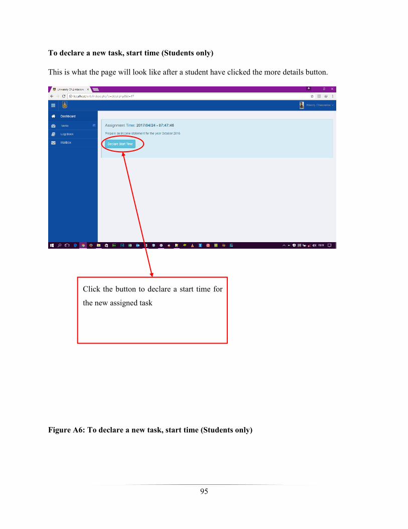
95
To declare a new task, start time (Students only)
This is what the page will look like after a student have clicked the more details button.
Click the button to declare a start time for
the new assigned task
Figure A6: To declare a new task, start time (Students only)
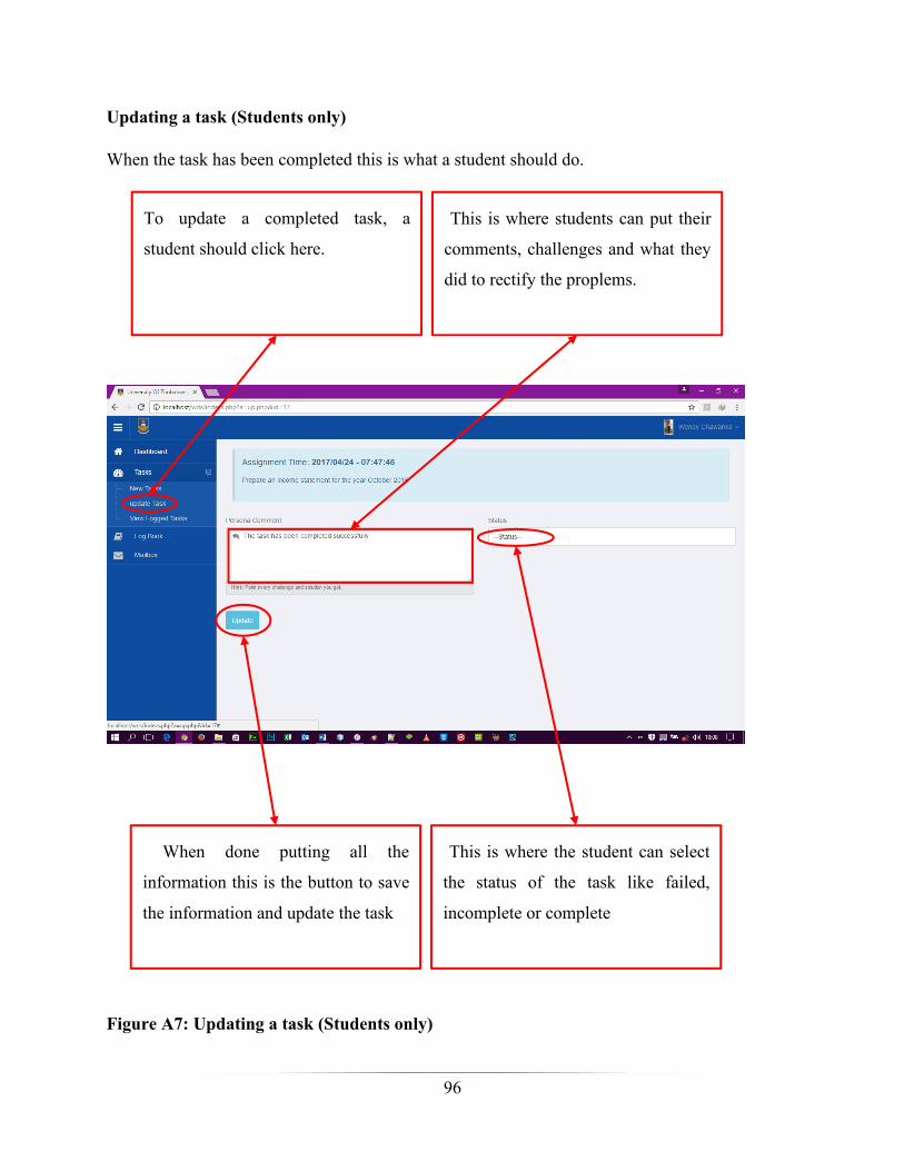
96
Updating a task (Students only)
When the task has been completed this is what a student should do.
To update a completed task, a
student should click here.
This is where students can put their
comments, challenges and what they
did to rectify the proplems.
When done putting all the
information this is the button to save
the information and update the task
This is where the student can select
the status of the task like failed,
incomplete or complete
Figure A7: Updating a task (Students only)

97
Work supervisor’s homepage.
After successfully login, a work supervisor will be redirected to this page where he/she can
navigate to different functions.
When the work supervisor want to chat
with the student or academic
supervisor, or to check messages, this
is where to click.
When the student’s assessment date
has been scheduled, this is where a
work supervisor should click to find
the assessment form.
When the work supervisor
what to create a new task,
that is a button to click
To view all created tasks a
work supervisor should
click this button
To view the history or the
tasks assigned to a chosen
student the work
supervisor should click this
button
Figure A8: Work supervisor’s homepage.
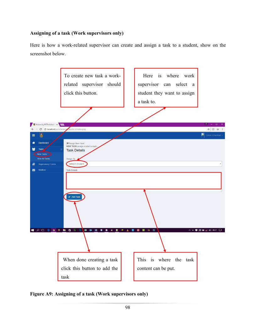
98
Assigning of a task (Work supervisors only)
Here is how a work-related supervisor can create and assign a task to a student, show on the
screenshot below.
To create new task a work-
related supervisor should
click this button.
Here is where work
supervisor can select a
student they want to assign
a task to.
When done creating a task
click this button to add the
task
This is where the task
content can be put.
Figure A9: Assigning of a task (Work supervisors only)

99
How to comment completed tasks (Work supervisors only)
When the student has completed the assigned task, it is now a work-related supervisor’s duty to
put a comment and rank the performance of the student. Upon clicking the view all tasks the
following page will appear.
To put a comment on a
student completed task
a work supervisor
should click this
command
For work supervisors
to put a comment on a
task they should check
if the status of the task
if it changed from
pending to complete,
incomplete or failed
before putting a
comment.
In order to put a
comment, this is the
icon for operation. A
work supervisor
should click this icon
that looks like an eye.
Figure A10: How to comment completed tasks (Work supervisors only)

100
Putting a comment (Work supervisors only)
Upon clicking an operation icon that looks like an eye the following page will appear.
This is where a work
supervisor should put a
comment.
When done
commenting, this is the
button to save.
This is where a
supervisor can select a
rating command from
the predefined
commands which are
failed, poorly done,
fairly done, good and
Figure A11: Putting a comment (Work supervisors only)
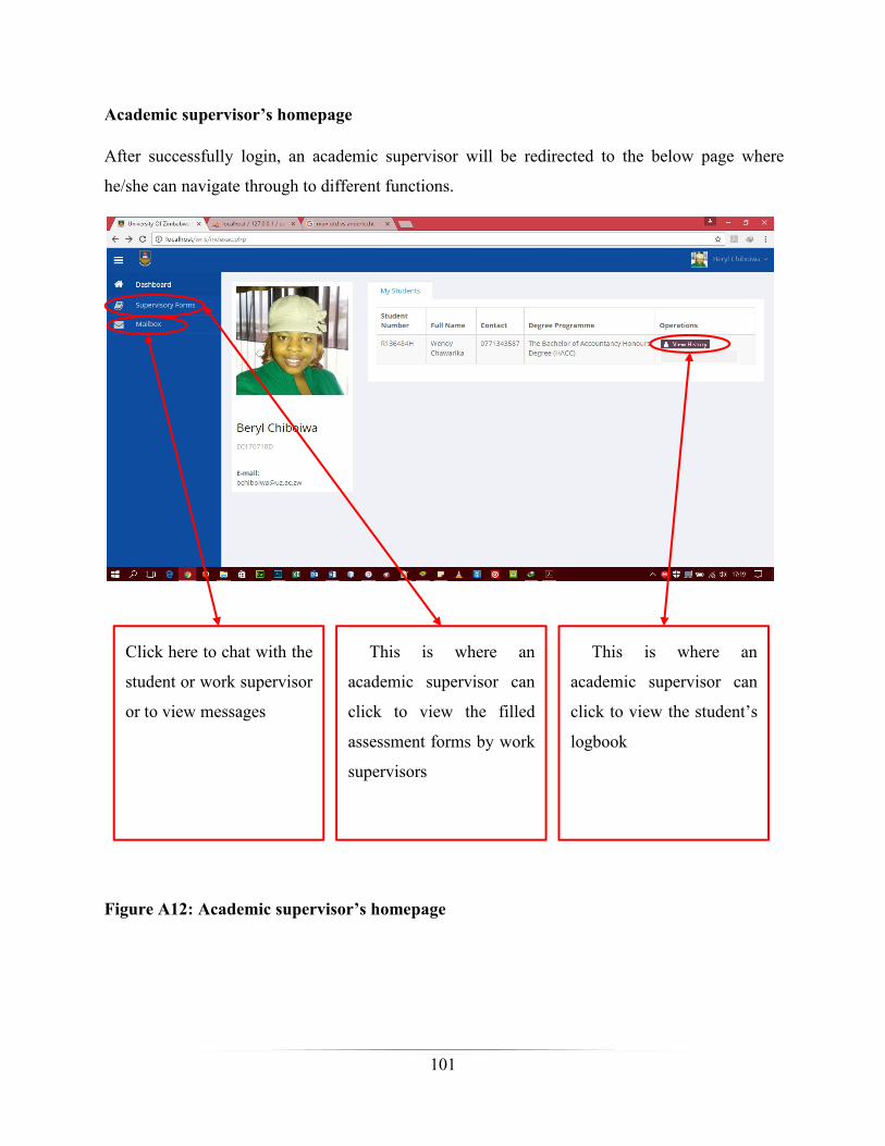
101
Academic supervisor’s homepage
After successfully login, an academic supervisor will be redirected to the below page where
he/she can navigate through to different functions.
Click here to chat with the
student or work supervisor
or to view messages
This is where an
academic supervisor can
click to view the filled
assessment forms by work
supervisors
This is where an
academic supervisor can
click to view the student’s
logbook
Figure A12: Academic supervisor’s homepage
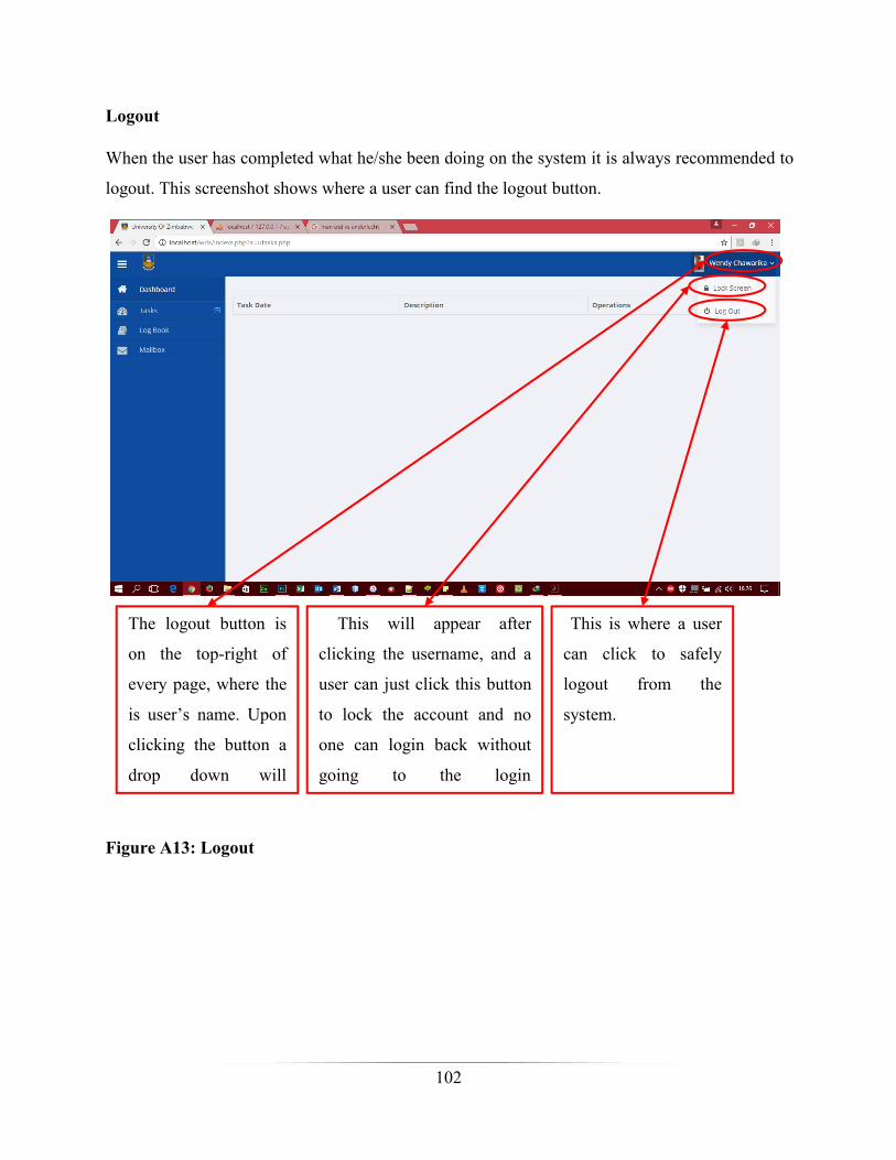
102
Logout
When the user has completed what he/she been doing on the system it is always recommended to
logout. This screenshot shows where a user can find the logout button.
The logout button is
on the top-right of
every page, where the
is user’s name. Upon
clicking the button a
drop down will
This will appear after
clicking the username, and a
user can just click this button
to lock the account and no
one can login back without
going to the login
This is where a user
can click to safely
logout from the
system.
Figure A13: Logout

103
Appendix B1: Letter of consent to conduct research
03 October 2016
Dear Participant
My name is Abraham Mahoko and I am a student at Midlands State University. I am developing
a system called University of Zimbabwe Industrial Attachment Web-based Supervision System
for my final project. This is a platform where industrial attachment activities can be logged
online. Students on attachment will be registered on the platform for them to be able to upload
their log books and work-related supervisors will be able to view the log books as well as
assessing the performance of the students. Also, academic supervisor will be able to view and or
print the student logbooks as well as assessment forms from work-related supervisors.
I am inviting you to participate in this research study by completing the attached surveys. The
following questionnaire will require approximately 72 hours completing. There is no
compensation for responding nor is there any known risk. In order to ensure that all information
will remain confidential, please do not put your personal details including your name. If you
choose to participate in this project, please answer all questions as honestly as possible and
return the completed questionnaires promptly. Participation is strictly voluntary and you may
refuse to participate at any time.
Thank you for taking the time to assist me in my educational endeavours. The information from
this study will be used for academic purposes only
Sincerely,
Abraham Mahoko
+263 77 442 6014
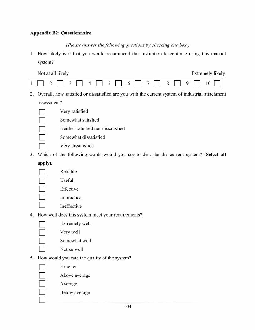
104
Appendix B2: Questionnaire
(Please answer the following questions by checking one box.)
1. How likely is it that you would recommend this institution to continue using this manual
system?
Not at all likely Extremely likely
1 2 3 4 5 6 7 8 9 10
2. Overall, how satisfied or dissatisfied are you with the current system of industrial attachment
assessment?
Very satisfied
Somewhat satisfied
Neither satisfied nor dissatisfied
Somewhat dissatisfied
Very dissatisfied
3. Which of the following words would you use to describe the current system? (Select all
apply).
Reliable
Useful
Effective
Impractical
Ineffective
4. How well does this system meet your requirements?
Extremely well
Very well
Somewhat well
Not so well
5. How would you rate the quality of the system?
Excellent
Above average
Average
Below average

105
Poor
(Please answer the following questions in the space provided)
6. List 5 challenges you are having with the current system, if there is any.
i. _____________________________________________________________________
ii. _____________________________________________________________________
iii. _____________________________________________________________________
iv. _____________________________________________________________________
v. _____________________________________________________________________
7. Do you think a web assessment system is ideal for the institution like UZ?
Yes No
Comment: _________________________________________________________________
___________________________________________________________________________
___________________________________________________________________________
8. If the system is to be improved, what might be your suggestions and or requirements?
___________________________________________________________________________
___________________________________________________________________________
___________________________________________________________________________
9. If the system is to be changed completely, what might be your suggestions and or
requirements?
___________________________________________________________________________
___________________________________________________________________________
___________________________________________________________________________
___________________________________________________________________________
10. Do you have any other comments or concerns?
___________________________________________________________________________
___________________________________________________________________________
___________________________________________________________________________
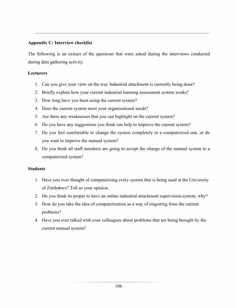
106
___________________________________________________________________________
Appendix C: Interview checklist
The following is an extract of the questions that were asked during the interviews conducted
during data gathering activity.
Lecturers
1. Can you give your view on the way Industrial attachment is currently being done?
2. Briefly explain how your current industrial learning assessment system works?
3. How long have you been using the current system?
4. Does the current system meet your organizational needs?
5. Are there any weaknesses that you can highlight on the current system?
6. Do you have any suggestions you think can help to improve the current system?
7. Do you feel comfortable to change the system completely to a computerized one, or do
you want to improve the manual system?
8. Do you think all staff members are going to accept the change of the manual system to a
computerized system?
Students
1. Have you ever thought of computerizing every system that is being used at the University
of Zimbabwe? Tell us your opinion.
2. Do you think its proper to have an online industrial attachment supervision system, why?
3. How do you take the idea of computerization as a way of migrating from the current
problems?
4. Have you ever talked with your colleagues about problems that are being brought by the
current manual system?
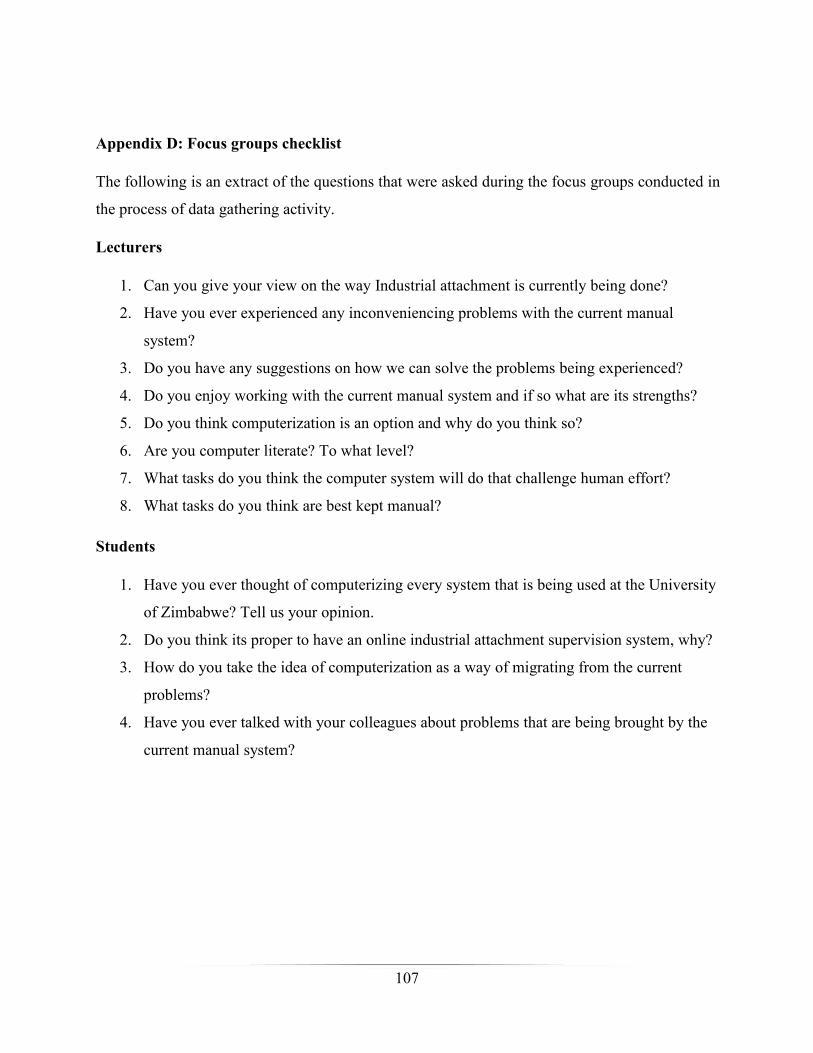
107
Appendix D: Focus groups checklist
The following is an extract of the questions that were asked during the focus groups conducted in
the process of data gathering activity.
Lecturers
1. Can you give your view on the way Industrial attachment is currently being done?
2. Have you ever experienced any inconveniencing problems with the current manual
system?
3. Do you have any suggestions on how we can solve the problems being experienced?
4. Do you enjoy working with the current manual system and if so what are its strengths?
5. Do you think computerization is an option and why do you think so?
6. Are you computer literate? To what level?
7. What tasks do you think the computer system will do that challenge human effort?
8. What tasks do you think are best kept manual?
Students
1. Have you ever thought of computerizing every system that is being used at the University
of Zimbabwe? Tell us your opinion.
2. Do you think its proper to have an online industrial attachment supervision system, why?
3. How do you take the idea of computerization as a way of migrating from the current
problems?
4. Have you ever talked with your colleagues about problems that are being brought by the
current manual system?
108
Appendix E: Snippet of code
<? php
error_reporting(0);
include "config.php";
session_start();
if(isset($_POST['stlogin'])) {
$username = $_POST["reg"];
$password = $_POST["spassword"];
$result ="";
$query = "SELECT * from student where reg='$username' AND password =
'$password'";
$result = mysqli_query($dbc, $query);
$row = mysqli_num_rows($result);
$rows=mysqli_fetch_array($result);
$access=$rows['level'];
$id=$rows['id'];
$state=$rows['state'];
$assigned=$rows['assigned'];
$zita =$rows['name']." ".$rows['surname'];
$localIP = gethostbyname(trim(exec("hostname")));
$os = $_SERVER['HTTP_USER_AGENT'];
$numbers="0987654321";

109
$length= 8;
If (!$result) {
die ( "\n\ncould'nt send the query because".mysqli_error());
exit;
}
else {
if($row==1 ) {
$_SESSION['avatar']="../".$rows['script'];
$_SESSION['username'] = $username;
$_SESSION['level']=$rows['level'];
$_SESSION['userid']=$rows['id'];
$_SESSION['usertype']="student";
$_SESSION['name']=$rows['name']." ".$rows['surname'];
$sessionid ="h";
for($p=0; $p < $length; $p++){
$sessionid .= $numbers[mt_rand( 0 , strlen($numbers))];
}
$_SESSION['sessionid']=$sessionid;
mysqli_query($dbc, "INSERT INTO `user_log`( `username`, `login_date`, `session_id`,
`machine_ip`, `OS`)
VALUES ('$username',NOW(),'$sessionid','$localIP','$os')")
or die (mysqli_error($dbc));
if($assigned==0){
110
echo "<SCRIPT LANGUAGE='JavaScript'>window.alert('Login Successful. Welcome:
".$zita." Please Activate your account.');window.location='activate.php?id=".$id."';</SCRIPT>";
exit;
}
elseif($assigned==1){
echo "<SCRIPT LANGUAGE='JavaScript'>window.alert('Login Successful. Welcome:
".$zita." Please Activate your
account.');window.location='inprocess.php?id=".$id."';</SCRIPT>";
exit;
}
else {
echo "<SCRIPT LANGUAGE='JavaScript'>window.alert('Login Successful. Welcome:
".$zita."');window.location='indexs.php';</SCRIPT>";
exit;
}
}
if($row!=1) {
echo "<script type='text/javascript'>alert('Invalid username and password!');</script> ";
echo "<script> window.location='index.php';</script>";
exit;
}
}
}
if(isset($_POST['slogin'])){
111
$username = $_POST["username"];
$password = $_POST["password"];
$result ="";
$query = "SELECT * from users where ecnum='$username' AND password = '$password'";
$result = mysqli_query($dbc, $query);
$row = mysqli_num_rows($result);
$rows=mysqli_fetch_array($result);
$access=$rows['access'];
$state=$rows['state'];
$zita =$rows['name']." ".$rows['surname'];
$localIP = gethostbyname(trim(exec("hostname")));
$os = $_SERVER['HTTP_USER_AGENT'];
$numbers="0987654321";
$length= 8;
if(!$result) {
die( "\n\ncould'nt send the query because".mysqli_error());
exit;
}
else {
if($row==1 && $access== '0'){
$_SESSION['avatar']="../".$rows['script'];
$_SESSION['username'] = $username;

112
$_SESSION['user_type']=$rows['access'];
$_SESSION['usertype']="admin";
$_SESSION['userid']=$rows['id'];
$_SESSION['name']=$rows['name']." ".$rows['surname'];
$sessionid ="h";
for($p=0; $p < $length; $p++){
$sessionid .= $numbers[mt_rand( 0 , strlen($numbers))];
}
$_SESSION['sessionid']=$sessionid;
mysqli_query($dbc, "INSERT INTO `user_log`( `username`, `login_date`, `session_id`,
`machine_ip`, `OS`)
VALUES ('$username',NOW(),'$sessionid','$localIP','$os')")
or die (mysqli_error($dbc));
echo "<SCRIPT LANGUAGE='JavaScript'>window.location='indexad.php';window.alert('Login
Successful. Welcome: ".$zita."');</SCRIPT>";
exit;
}
if($row==1 && $access== '1' && $state=='1'){
$_SESSION['avatar']="../".$rows['script'];
$_SESSION['username'] = $username;
$_SESSION['user_type']=$rows['access'];
$_SESSION['usertype']="chairperson";
$_SESSION['userid']=$rows['id'];
113
$_SESSION['name']=$rows['name']." ".$rows['surname'];
$sessionid ="h";
for($p=0; $p < $length; $p++){
$sessionid .= $numbers[mt_rand( 0 , strlen($numbers))];
}
$_SESSION['sessionid']=$sessionid;
mysqli_query($dbc, "INSERT INTO `user_log`( `username`, `login_date`, `session_id`,
`machine_ip`, `OS`)
VALUES ('$username',NOW(),'$sessionid','$localIP','$os')")
or die (mysqli_error($dbc));
echo "<SCRIPT LANGUAGE='JavaScript'>window.alert('Login Successful. Welcome:
".$zita."');window.location='indexac.php';</SCRIPT>";
exit;
}
if($row!=1) {
echo "<script type='text/javascript'>alert('Invalid username and password!');</script> ";
echo "<script> window.location='index.php';</script>";
exit;
}
}
}
if(isset($_POST['wrllogin'])){
$username = $_POST["wrlreg"];
114
$password = $_POST["wrlpassword"];
$result ="";
$query = "SELECT * from wrl_supervisors where wrl_id='$username' AND
password = '$password' and activated='1'";
$result = mysqli_query($dbc, $query);
$row = mysqli_num_rows($result);
$rows=mysqli_fetch_array($result);
$id=$rows['id'];
$zita =$rows['name']." ".$rows['surname'];
$localIP = gethostbyname(trim(exec("hostname")));
$os = $_SERVER['HTTP_USER_AGENT'];
$numbers="0987654321";
$length= 8;
if(!$result){
die( "\n\ncould'nt send the query because".mysqli_error());
exit;
}
else{
if($row==1 ){
$_SESSION['username'] = $username;
$_SESSION['level']='7';
$_SESSION['userid']=$rows['id'];
$_SESSION['usertype']="wrl";
115
$_SESSION['name']=$rows['name']." ".$rows['surname'];
$sessionid ="";
for($p=0; $p < $length; $p++){
$sessionid .= $numbers[mt_rand( 0 , strlen($numbers))];
}
$_SESSION['sessionid']=$sessionid;
mysqli_query($dbc, "INSERT INTO
`user_log`( `username`, `login_date`, `session_id`, `machine_ip`, `OS`)
VALUES ('$username',NOW(),'$sessionid','$localIP','$os')")
or die (mysqli_error($dbc));
echo "<SCRIPT LANGUAGE = 'JavaScript' > window.location = 'indexwrl.php'; window.alert
('Login Successful. Welcome: ".$zita."');</SCRIPT>";
exit;
}
if($row!=1){
echo "<SCRIPT LANGUAGE='JavaScript'>window.location='index.php';window.alert('Invalid
username and password!');</SCRIPT>";
exit;
}
}
}
?>