University of Bradford eThesis - CORE
329
University of Bradford eThesis This thesis is hosted in Bradford Scholars – The University of Bradford Open Access repository. Visit the repository for full metadata or to contact the repository team © University of Bradford. This work is licenced for reuse under a Creative Commons Licence.
-
Upload
khangminh22 -
Category
Documents
-
view
0 -
download
0
Transcript of University of Bradford eThesis - CORE

University of Bradford eThesis This thesis is hosted in Bradford Scholars – The University of Bradford Open Access repository. Visit the repository for full metadata or to contact the repository team
© University of Bradford. This work is licenced for reuse under a Creative Commons
Licence.

Design and Implementation of System Components for Radio Frequency Based
Asset Tracking Devices to Enhance Location Based Services
R. Asif
Ph.D.
UNIVERSITY OF BRADFORD
2017

Design and Implementation of System Components for Radio Frequency Based
Asset Tracking Devices to Enhance Location Based Services
Study of angle of arrival techniques, effects of mutual coupling, design of an angle of arrival algorithm, design of a novel miniature reconfigurable antenna optimised
for wireless communication systems
Rameez Asif
B.Eng., M.Sc., M.Phil.
Submitted for the Degree of Doctor of Philosophy
Faculty of Engineering and Informatics University of Bradford
2017

i
Design and Implementation of System Components for Radio Frequency Based
Asset Tracking Devices to Enhance Location Based Services
Study of angle of arrival techniques, effects of mutual coupling, design
of an angle of arrival algorithm, design of a novel miniature reconfigurable antenna optimised for wireless communication systems
Keywords
Angle of Arrival, Direction of Arrival, ESPIRIT Signal to Noise Ratio (SNR), Multiple Signal Classification (MUSIC), Antenna Array, Mutual Coupling, Reconfigurable
Antenna, Log Spiral Antenna, Impedance Bandwidth
Abstract
The angle of arrival estimation of multiple sources plays a vital role in the field of array signal processing as MIMO systems can be employed at both the transmitter and the receiver end and the system capacity, reliability and throughput can be significantly increased by using array signal processing. Almost all applications require accurate direction of arrival (DOA) estimation to localize the sources of the signals. Another important parameter of localization systems is the array geometry and sensor design which can be application specific and is used to estimate the DOA. In this work, various array geometries and arrival estimation algorithms are studied and then a new scheme for multiple source estimation is proposed and evaluated based on the performance of subspace and non-subspace decomposition methods. The proposed scheme has shown to outperform the conventional Multiple Signal Classification (MUSIC) estimation and Bartlett estimation techniques. The new scheme has a better performance advantage at low and high signal to noise ratio values (SNRs). The research work also studies different array geometries for both single and multiple incident sources and proposes a geometry which is cost effective and efficient for 3, 4, and 5 antenna array elements. This research also considers the shape of the ground plane and its effects on the angle of arrival estimation and in addition it shows how the mutual couplings between the elements effect the overall estimation and how this error can be minimised by using a de-coupling matrix. At the end, a novel miniaturised multi element reconfigurable antenna to represent the receiver base station is designed and tested. The antenna radiation patterns in the azimuth angle are almost omni-directional with linear polarisation. The antenna geometry is uniplanar printed log-spiral with striplines feeding network and biased components to improve the impedance bandwidth. The antenna provides the benefit of small size, and re-configurability and is very well suited for the asset tracking applications.

ii
Acknowledgement
First and Foremost, I would like to thank Allah (S.W.T) for giving me this
opportunity to take on this challenge and achieve this landmark.
The completion of this thesis would not have been possible without the help and
support of the following people. I would like to express my extreme appreciation
and gratitude to my supervisor and mentor Prof R. A. Abd-Alhameed. He has been
very generous in his time and always a source of encouragement and inspiration to
me. Also, I would like to thank, Dr. J.M. Noras, Dr. SMR Jones and Dr. C. H. See
for their ideas, support, and guidance throughout this work.
In addition, I would also like to extend my gratitude to the industrial colleagues from
Seven Technologies Company, UK, Dr. Taherah Ghazaany and Dr. Sharon Zhu for
their excellent help and support to join their work on antenna array design for
localization purposes.
Moreover, I extend my thanks to all the members of the Radio Frequency and
antenna lab, workshop, and computer officers, for their great support and help.
I wish to express my deepest thanks to my friends Mohammad Al-Sadoon and
Ammar Ali for their endless support throughout my research.
Finally, special thanks are also given to my family for their support and
encouragement through all my pursuits over this period of time.

iii
Dedication
I would like to dedicate my whole life and work to my parents. There are not
enough words in any dictionary that can express my gratitude to my parents.
Throughout my life despite of all the constraints they provided me with all the
comfort. My mother who dedicated her life to me and always prayed and asked
Allah Almighty for just one thing and that was my success. She provided me with
every possible support and comfort. Whenever I lost the motivation or got worried
she was right there to console and encourage me. My father who was a constant
source of inspiration for me, he believed in my abilities, supported my decisions,
encouraged me at every step and made me believe in myself. Throughout my
career I never had to worry about anything because he was always there to take
care of things for me. I consider myself blessed to have such loving, dedicated and
supportive parents. I know I can never thank my parents enough for all the
sacrifices they have made for me. I pray that may Allah Almighty give them a
healthy long life so that they can see their dreams coming true. Ameen.
iv
Table of Contents ABSTRACT…………………………………………………………………………………I
ACKNOWLEDGEMENT .......................................................................................... II
DEDICATION .......................................................................................................... III
Chapter 1.
1. INTRODUCTION ............................................................................................ 1
1.1 INTRODUCTION ................................................................................................ 1
1.2 LOCATION AWARE SERVICES ............................................................................ 1
1.3 BACKGROUND AND MOTIVATION ....................................................................... 2
1.4 AIMS, OBJECTIVES AND NEW CONTRIBUTIONS ................................................... 8
1.5 ORGANIZATION OF THE THESIS ....................................................................... 10
Chapter 2.
2. LOCATION BASED SERVICES: A REVIEW .............................................. 13
2.1 INTRODUCTION .............................................................................................. 13
2.2 POSITIONING METHODS FOR LBS ................................................................... 16
2.2.1 Indoor Positioning Systems ................................................................ 16
2.2.2 Radio Frequency Identification (RFID) ............................................... 18
2.2.3 Global Positioning Systems (GPS) ..................................................... 19
2.3 OUTDOOR SYSTEMS USING TERRESTRIAL BASE STATIONS ............................... 20
2.3.1 GSM (with Enhanced-Observed Time Difference (E-OTD)) ............... 21
2.3.2 GSM (With CELL-ID) .......................................................................... 22

v
2.3.3 CDMA/GPRS (With A-GPS) ............................................................... 22
2.3.4 CDMA/GPRS (With A-GPS) - AFLT+AGPS ....................................... 23
2.3.5 Wireless Assisted GPS and AFLT: GPS One a Hybrid Solution ........ 23
2.3.6 WCDMA (With IPDL, TA-IPDL and OTDOA-PE)................................ 23
2.3.7 Distributed Antenna Systems (DAS) .................................................. 24
2.3.8 WIFI Technology with Access Points (AP) ......................................... 24
2.4 TECHNIQUES OF THE EXISTING LBS METHODS ................................................ 26
2.4.1 Localization by CELL-ID ..................................................................... 26
2.4.2 Localization by Prediction (Dead-Reckoning Method) ........................ 26
2.4.3 Localization by Angle of Arrival (AOA) ............................................... 27
2.4.4 Localisation by Time of Arrival (TOA) and Observed Time Difference
of Arrival (OTDOA) ................................................................................................. 28
2.4.5 Hybrid Localization AoA-ToA Based .................................................. 30
2.4.6 Localization by Finger-Printing ........................................................... 30
2.5 LATEST TRENDS AND MODERN APPLICATIONS OF LOCATION BASED SERVICES .. 32
2.5.1 Enhanced – 911 (E911) and Enhanced – 112 (E112) Services ......... 33
2.5.2 Mobile Guides .................................................................................... 34
2.5.3 Transport Location Based Services .................................................... 34
2.5.4 Location Based Gaming ..................................................................... 36
2.5.5 Location Based Health and Assistive Technology .............................. 36
2.5.6 Mobile Marketing ................................................................................ 38
2.5.7 Community Based Services ............................................................... 40
2.5.8 Crime Fighting .................................................................................... 42

vi
2.5.9 Real Time Shopping ........................................................................... 44
2.5.10 Information and Entertainment ........................................................... 45
2.5.11 Location Based Services in Politics .................................................... 45
2.6 CONCLUSION ................................................................................................ 48
Chapter 3.
3. NEW SIGNAL SUBSPACE BASED ANGLE OF ARRIVAL ESTIMATION
ALGORITHM ......................................................................................................... 55
3.1 INTRODUCTION .............................................................................................. 55
3.2 DOA ESTIMATION ALGORITHMS USING ANTENNA ARRAYS ............................... 56
3.2.1 Interferometry ..................................................................................... 59
3.2.2 Conventional or Classical Beamformer .............................................. 61
3.2.3 Capon’s Minimum Variance Distortionless Response Algorithm ........ 63
3.2.4 Subspace Based DOA Estimation Method of Multiple Signal
Classification (MUSIC) ........................................................................................... 64
3.3 MATHEMATICAL MODEL OF THE PROPOSED ANGLE OF ARRIVAL (AOA)
ESTIMATION TECHNIQUE .......................................................................................... 67
3.4 RESULTS AND DISCUSSION ............................................................................ 69
3.4.1 Performance Evaluation of the Proposed Algorithm ........................... 70
3.4.2 3-element IFA Antenna Array ............................................................. 78
3.4.3 Interferometry vs. Proposed Algorithm ............................................... 80
3.4.4 Individual Algorithm Performance for Different Array Geometries ...... 86
3.4.5 Narrowband vs. Wideband ................................................................. 87
3.4.6 Effect of Number of Elements on the Angle Estimation Ambiguities .. 88

vii
3.5 CONCLUSION ................................................................................................ 91
Chapter 4.
4. EFFECTS OF MUTUAL COUPLING IN ANTENNA ARRAYS ON ANGLE
OF ARRIVAL ESTIMATION .................................................................................. 93
4.1 MUTUAL COUPLING BEHAVIOUR ..................................................................... 94
4.2 REVIEW OF DECOUPLING METHODS ................................................................ 97
4.2.1 Conventional Mutual Impedance Method ........................................... 97
4.2.2 Receiving Mutual Impedance Method ................................................ 98
4.3 PERFORMANCE EVALUATION OF ANGLE OF ARRIVAL ALGORITHMS WITH MUTUAL
COUPLING AND WITH COUPLING COMPENSATED ...................................................... 100
4.3.1 Simulation Setup .............................................................................. 100
4.3.2 AOA Estimation Error in Presence of Mutual Coupling .................... 103
4.4 APPLIED DECOUPLING METHODS TO DIRECTION FINDING ALGORITHMS ........... 104
4.4.1 Conventional Impedance Method ..................................................... 105
4.4.2 Receiving Impedance Method .......................................................... 109
4.5 COMPARISON OF PROPOSED ANGLE OF ARRIVAL ESTIMATION ALGORITHM FOR
DIFFERENT ANTENNA ARRAY GEOMETRIES WITH MUTUAL COUPLING AND COUPLING
COMPENSATED ..................................................................................................... 116
4.5.1 5-element Circular Ring Array .......................................................... 117
4.5.2 4-element Circular Ring Array .......................................................... 121
4.6 CONCLUSION .................................................................................................. 127

viii
Chapter 5.
5. NOVEL RECONFIGURABLE ELECTRICALLY SMALL ANTENNA FOR
ASSET TRACKING ............................................................................................. 128
5.1 ANTENNA DESIGN AND IMPLEMENTATION ....................................................... 131
5.1.1 Antenna Geometry ........................................................................... 132
5.1.2 Design Methodology ......................................................................... 135
5.1.3 Switch Design .................................................................................. 136
5.2 RESULTS AND DISCUSSIONS ......................................................................... 138
5.2.1 Reflection Coefficient ....................................................................... 139
5.2.2 Radiation Pattern.............................................................................. 141
5.2.3 Gain .................................................................................................. 144
5.3 CONCLUSION .............................................................................................. 144
Chapter 6.
6. MEASUREMENT RESULTS FOR THE PROPOSED ANGLE OF ARRIVAL
ESTIMATION TECHNIQUE EMPLOYING AN ARRAY OF PROPOSED
ELECTRICALLY SMALL RECONFIGURABLE MULTI-ELEMENT ANTENNA . 145
6.1 INTRODUCTION ............................................................................................ 145
6.2 SIMULATION SETUP 4-RING CIRCULAR ARRAY ............................................... 145
6.2.1 Results and Discussion .................................................................... 147
6.3 AVERAGE ERROR PERFORMANCE COMPARISON USING RESTRICTED POWER
THRESHOLD .......................................................................................................... 151
6.4 SIMULATION SETUP 3-RING CIRCULAR ARRAY ............................................... 152
6.4.1 Results and Discussion .................................................................... 153

ix
6.5 CONCLUSION .............................................................................................. 155
Chapter 7.
7. ORTHOGONAL FREQUENCY DIVISION MULTIPLEXING SCHEME FOR
ANGLE OF ARRIVAL APPLICATIONS .............................................................. 156
7.1 INTRODUCTION ............................................................................................ 156
7.2 MATHEMATICAL MODEL FOR ORTHOGONAL FREQUENCY DIVISION MULTIPLEXING
(OFDM) FOR ANGLE OF ARRIVAL ESTIMATION ........................................................ 158
7.3 SIMULATION MODEL .................................................................................... 160
5.2 RESULTS AND DISCUSSION .......................................................................... 162
7.4 CONCLUSION .............................................................................................. 164
Chapter 8.
8. CONCLUSION AND FUTURE WORK ...................................................... 165
8.1 CONCLUSION .............................................................................................. 165
8.2 THESIS SUMMARY ....................................................................................... 166
8.3 RECOMMENDATIONS FOR FUTURE WORK ...................................................... 169
REFERENCES…………………………………………………………………………169
AUTHOR PUBLICATIONS .................................................................................. 227
LIST OF PUBLICATIONS .......................................................................................... 228
JOURNALS ……………………………………………………………………………..228
CONFERENCES ................................................................................................. 229

x
LIST OF FIGURES
Figure 3-1: Geometry representing the DOA of the signal as an azimuth and
elevation angle pair on an antenna array ............................................................... 57
Figure 3-2: Uniform Linear Array ............................................................................ 58
Figure 3-3: Correlative Interferometer .................................................................... 61
Figure 3-4: Performance Comparison Between the Beamformer and Minimum
Variance Distortionless Response ......................................................................... 64
Figure 3-5: Flow Diagram of the Proposed AoA Method ........................................ 69
Figure 3-6: ULA for The Performance Comparison of the Proposed Algorithm ..... 70
Figure 3-7: Effects of Total Number of Snap Shots on the Proposed Angle of
Arrival Estimation Algorithm ................................................................................... 72
Figure 3-8: Effects of SNR on the Proposed Angle of Arrival Estimation Algorithm
............................................................................................................................... 73
Figure 3-9: Time of Execution Comparison ............................................................ 74
Figure 3-10: Signals with Different Amplitudes ...................................................... 75
Figure 3-11: Effects of number of elements and Inter-element spacing on the
Proposed Angle of Arrival Estimation Algorithm ..................................................... 76
Figure 3-12: Performance Comparison of the Proposed Algorithm in the Presence
of Correlated Sources ............................................................................................ 77
Figure 3-13: Three element array structure in CST ................................................ 78
Figure 3-14: Angle of arrival estimation error using interferometry, Covariance and
MUSIC ................................................................................................................... 79

xi
Figure 3-15: Simulation setup with (a) Three Elements (b) Four Elements ............ 80
Figure 3-16: AOA = 0, (a) 3 Elements with Infinite and Finite Ground Plane (b) 4
Elements with Infinite and Finite Ground Plane ..................................................... 81
Figure 3-17: AOA = 10, (a) 3 Elements with Infinite and Finite Ground Plane (b) 4
Elements with Infinite and Finite Ground Plane ..................................................... 82
Figure 3-18: AOA = 45, (a) 3 Elements with Infinite and Finite Ground Plane (b) 4
Elements with Infinite and Finite Ground Plane ..................................................... 83
Figure 3-19: Four element array, Multiple Source Case ........................................ 84
Figure 3-20: (a) Three element array (b) Four element array, Multiple Source Case
............................................................................................................................... 85
Figure 3-21: Comparison of Array Geometries for (a) Interferometry (b) Proposed
(c) MUSIC for Multiple Rays................................................................................... 87
Figure 3-22: Comparison of the Performance of AoA Techniques Using Different
Bandwidths ............................................................................................................ 88
Figure 3-23: Angle Ambiguities in a 3-element (/4) Array (A) 3D (B) 2D .............. 89
Figure 3-24: Angle Ambiguities in a 3-element (/2) Array (A) 3D (B) 2D .............. 90
Figure 3-25: Angle Ambiguities in a 5-element (/4) Array (A) 3D (B) 2D .............. 91
Figure 4-1 (a) Mutual coupling paths in transmitting mode; (b) Mutual coupling
paths in receiving mode ......................................................................................... 95
Figure 4-2: (a) Receiver antennas geometry in simulation (b) Monopole antennas
(c) IFA antennas (d) IFA Antenna Dimensions ..................................................... 102
Figure 4-3: AOA estimation error for monopole array in presence of mutual
coupling, wideband signal with BW=25 MHz ....................................................... 103

xii
Figure 4-4: AOA estimation error for monopole array after using receiving mode
coupling compensation (DM 30 degrees applied to all angles) ............................ 111
Figure 4-5: AOA estimation error for monopole array after using receiving mode
coupling compensation (DM 325 degrees applied to all angles) .......................... 112
Figure 4-6: Performance Evaluation of the AOA Algorithms for a 5- element UCA
with Mutual Coupling and Coupling Compensated for a True Angle of 0 Degrees
............................................................................................................................. 117
Figure 4-7: Performance Evaluation of the AOA Algorithms for a 5- element UCA
with Mutual Coupling and Coupling Compensated for a True Angle Of 0 Degrees
............................................................................................................................. 118
Figure 4-8: Comparison of the Performance of the Proposed Algorithm for a 5-Ring
Circular Array with Mutual Coupling and with Mutual Coupling Compensated .... 119
Figure 4-9: Performance Evaluation of the AOA Algorithms for a 4- element UCA
with Mutual Coupling and Coupling Compensated for a True Angle of 0 Degrees
............................................................................................................................. 122
Figure 4-10: Performance Evaluation of the AOA Algorithms for a 5- element UCA
with Mutual Coupling and Coupling Compensated for a True Angle Of 180 Degrees
............................................................................................................................. 123
Figure 4-11: Performance of the Proposed Algorithm for a 4-ring Circular Array . 124
Figure 4-12: Performance of The Proposed Algorithm for a 5-ring and a 4-ring
Circular Array with Mutual Coupling and with Mutual Coupling Compensated .... 125
Figure 5-1: Geometry of The Proposed Antenna ................................................. 133

xiii
Figure 5-2: (a) Top Layer with Multi Element Log Spirals (b) Matching Circuit with
Tuning Extensions ............................................................................................... 133
Figure 5-3: Matching Circuit with Tuning Extensions ........................................... 134
Figure 5-4: (a) Antenna Mounted on The Ground Plane (b) Tuning Circuit ......... 135
Figure 5-5: Antenna Design Methodology ............................................................ 136
Figure 5-6: PIN Diode as A Shunt ........................................................................ 137
Figure 5-7: PIN Diode as A Shunt ........................................................................ 137
Figure 5-8: Antenna Tuning Circuit ...................................................................... 138
Figure 5-9: (a) Simulated Reflection Coefficient (b) Measured Reflection Coefficient
............................................................................................................................. 140
Figure 5-10: (a) Prototype Antenna (b) Measured Return Loss Using Diode
Combinations ....................................................................................................... 141
Figure 5-11: Measured Radiation Pattern of the Prototype Antenna in E-Plane and
H-Plane Co polarization and Cross polarization................................................... 142
Figure 5-12: Measured Radiation Pattern of the Prototype Antenna for Various
Operating Frequencies ........................................................................................ 143
Figure 6-1: Simulation Setup for Prototype Antenna Array Testing ...................... 146
Figure 6-2: Performance Comparison Using 4-element UCA for True Angle of 0
Degree ................................................................................................................. 147
Figure 6-3: Performance Comparison Using a 4-element UCA for a True Angle of
180 Degrees ........................................................................................................ 148
Figure 6-4: Performance Comparison Using a 4-element UCA for the Whole
Azimuth Plane ...................................................................................................... 149

xiv
Figure 6-5: Performance Comparison of 4-element UCA for the Whole Azimuth
Plane Using Simulated and Measured Data ........................................................ 150
Figure 6-6: Performance Comparison Using a 4-element UCA for Multiple
Received Rays ..................................................................................................... 151
Figure 6-7: Average Error Performance of AoA Algorithms at Power Thresholds of
(a) 25% (b) 50% (c) 75% ..................................................................................... 152
Figure 6-8: Performance Comparison Using a 3-element UCA for the Whole
Azimuth Plane ...................................................................................................... 153
Figure 6-9: Performance Comparison Using 3 and 4-element UCAs for the Whole
Azimuth Plane ...................................................................................................... 154
Figure 7-1: Assumed bandwidth range ................................................................ 159
Figure 7-2: Study Area for OFDM ........................................................................ 161
Figure 7-3: Multipaths travelled by the transmitted signal .................................... 162
Figure 7-4: 3-element Circular Ring Array using OFDM ...................................... 163
Figure 7-5: 5-element Circular Ring Array using OFDM ...................................... 163

xv
LIST OF TABLES
Table 2-1: Location Based Technology for the Network Solutions ......................... 29
Table 2-2: Location Based Technology for the Handset Solutions ......................... 30
Table 2-3: Applications of Location Based Services Discussed in This Chapter ... 52
Table 3-1: Comparison of different AOA/DOA estimation algorithms ..................... 66
Table 3-2: Simulation Parameters Using the ULA for the Performance Comparison
of the Proposed Algorithm ..................................................................................... 70
Table 3-3: Simulation Parameters Using the ULA for the Study of the Effects of
Total Number of Snap Shots on the Proposed Angle of Arrival Estimation Algorithm
............................................................................................................................... 71
Table 3-4: Simulation Parameters Using the ULA .................................................. 72
Table 3-5: Simulation Parameters .......................................................................... 75
Table 4-1: Monopole antenna transmission mode decoupling matrix for different
incoming signals .................................................................................................. 106
Table 4-2: AOA estimation error using transmission mode coupling compensation
for monopole array ............................................................................................... 107
Table 4-3: IFA antenna array transmission mode decoupling matrix for different
incoming signals .................................................................................................. 108
Table 4-4: AOA estimation error before and after transmission mode compensation
for IFA array ......................................................................................................... 108
Table 4-5: Monopole antenna transmission mode decoupling matrix for different
incoming signals .................................................................................................. 111

xvi
Table 4-6: AOA estimation error for monopole array before and after using
receiving mode coupling compensation (decoupling matrix from 325 degrees
applied to all angles)-two rays received ............................................................... 113
Table 4-7: IFA antenna array receiving mode decoupling matrix for different
incoming signals .................................................................................................. 115
Table 4-8: AOA estimation error before and after receiving mode compensation for
IFA array .............................................................................................................. 116
Table 4-9: Performance Analysis of Five Element Circular Ring Array ................ 119
Table 4-10: Angle Estimation Performance of the Five Element Circular Ring Array
with Mutual Coupling and with Coupling Compensated ....................................... 120
Table 4-11: Performance Analysis of Four Element Circular Ring Array ............. 124
Table 4-12: Angle Estimation Performance of the 4-element Circular Ring Array
with Mutual Coupling and with Coupling Compensated ....................................... 126
Table 5-1: Possible Frequency Reconfiguration Combinations for the Proposed
Antenna Design ................................................................................................... 139
Table 6-1: Measurement Parameters for the 4 – Elements Uniform Circular Array
............................................................................................................................. 146
Table 6-2: Measurement Parameters for the 3 – Elements Uniform Circular Array
............................................................................................................................. 153

xvii
Acronyms
AFLT Advanced Forward Link Trilateration
A-GPS Assisted Global Positioning System
AOA Angle of Arrival
AWGN Additive White Gaussian Noise
BSS Base Station Subsystem
BW Bandwidth
CDMA Code Division Multiple Access
CGI Cell Global Identity
CST Computer Simulation Technology, (https://www.cst.com)
DAS Distributed Antenna System
DOA Direction of Arrival
DRSS Difference Received Signal Strength
E-911 Enhanced 911
EFLT Enhanced Forward Link Trilateration
E-OTD Enhanced Observed Time Difference
ESPIRIT Estimation of Signal Parameters Via Rotational Invariance
Techniques
FB Facebook
FOU Four Square
GIS Geographic Information System

xviii
GLA Google Latitude
GNSS Global Navigation Positioning Satellite System
GOW Gowalla
GPRS General Packet Radio Service
GPS Global Positioning System
GSM Global System for Mobile Communications
HT Hybrid Techniques
IPDL Idle Period on the Down Link Trilateration
IR Infra-Red
LMU Location Measurement Unit
LOS Line of Sight
MAC Media Access Control
MEMS Micro Electro-Mechanical Systems
MIMO Multiple Input Multiple Output
MISO Multiple Input Single Output
ML Maximum Likelihood
MS Mobile Stations
MUSIC Multiple Signal Classification
NLOS Non-Line of Sight
NEC Numerical Electromagnetic Code, https://www.nec.com
OUTLIERS Observations That Do Not Follow the Pattern of The Majority of The
Data

xix
RAU Remote Antenna Units
RFID Radio Frequency Identification
RSS Received Signal Strength
RTD Real Time Difference
SIMO Single Input Multiple Output
SISO Single Input Single Output
SNR Signal to Noise Ratio
TDM Time Division Multiplexing
TDOA Time Difference of Arrival
THP Tomlinson Harashima Precoding
TOA Time of Arrival
TTFF Time to First Fix
VANETS Vehicular Ad-Hoc Networks
WAG Wireless Assisted GPS
WAVE Wireless Access for Vehicular Environment
WCDMA Wireless Code Division Multiple Access
WLAN Wireless Local Area Network

xx
LIST OF NOTATIONS
Signal Propagation Time
Distance between two nodes
Arrival time of signal on node
Speed of light
Start time of the signal
Position of node on -axis
Position of node on -axis
Arrival time of signal on node
Arrival time of signal on node
Position of node on -axis
Position of node on -axis
Position of node on -axis
Position of node on -axis
Position of on -axis
Position of node on -axis
Azimuthal Angle
Elevation Angle
Peak amplitude
Wave Vector
Wavelength

xxi
Frequency
Total number of omni directional antennas
Distance between two antennas
Angular Frequency
Steering factor of the
Wave propagation time
Radius of the circle
u t Input Signal at M omni-directional antennas
y t Output signal
φ Steering Vector
L Number of Signals
k Total number of iterations

1
1. INTRODUCTION
1.1 Introduction
In the exponentially increasing market of wireless communications location based
services serve as the key enabling technology. Location based services (LBS)
exists from short range Bluetooth and ad hoc to long range telecom networks.
Location based services in a broad sense are considered to provide the basic
information about the whereabouts of the service users by using the location of the
wireless devices within the network. The latter is the critical issue among all to
uniquely identify the device.
1.2 Location Aware Services
The demand for the location aware services has considerably increased with the
increase of mobile and wireless devices. e.g. in the field of medical science patient
management and movement [1-5], concept of smart spaces that enables the
physical space and human interaction [6-10], in the field of [11] logistics for the
transportation of goods [12, 13], inventory management and warehousing [14-17],
environmental monitoring services use sensor network for real time weather
predictions and to determine the source of pollutants that are present in air and
water [18] and content sharing using mobile peer to peer connections [19-21].

2
1.3 Background and Motivation
Estimation problem and in specific parameter estimation has been a topic of great
interest for the engineer’s due to its applications and their ever-growing
requirement for an improved performance [15 - 17]. With the expansion in the
applications the accurate estimation of temporal and spatial parameters found wide
spread interest. Sensor array processing has been an area of active research
during the past decade because of the requirement to gather data from all sensors
to provide an estimation. Array sensor processing relies on the prior knowledge of
the geometry of the array and the characteristics and number of array elements.
The most regarded achievement of this method is the source location estimation
using radars and sonars. One of the earliest angle of arrival (AoA) techniques was
suggested in 1961 [22] and named as the classical beamformer method. The
fundamental principle of this method suggests to apply an equal weighting on each
antenna element to construct the steering vector in a certain specific direction [23].
This approach is ideal to rotate the steering vector of array mechanically in a
specific direction and measuring the output power. However, due to the high level
of side lobes, output power is the sum of the power from the direction of array
steering vector and from other directions where the side lobes are pointing. Thus,
the revolving power depends on the size of antenna array and beamwidth of main
lobe. In 1969, author in [24] proposed an algorithm to estimate the power of
incoming signals. This algorithm is known as minimum variance distortionless
response (MVDR) method. The idea of this approach is to estimate a signal from
one direction and consider all other signals as interference. MVDR method has

3
much better resolution compared with the classical beamformer method. On the
other hand, when the signals are similar or highly correlated the resolution of
MVDR becomes worse than classical beamformer algorithm [25]. In 1971, author
in [26, 27] developed a technique to control the cancellation of interference signals
adaptively. This technique was called as the Howells-Applebaum method. At the
time, authors in [28, 29] utilized a least mean square to minimize error between the
output of antenna array and self-training of reference signal. This technique is
known as least mean square (LMS) method, which uses the steepest descent or
gradients methods to find the optimum weights. The convergence of approach is
mainly based upon on the eigenvalues spread. The eigenvalues become larger as
the convergence time increases [30]. The convergence time of this method is
dependent on the gradient step size parameter, which is given in [31]. As they
were affected by the Rayleigh fading channel conditions, this method suffers from
many problems such as poor resolution, wide main beam and higher side lobes
level. These issues limited the ability of delay and sum methods to separate closely
spaced signals and acquire satisfying performance and high resolution [32].
However, MVDR method can overcome the poor resolution problem associated
with the delay-and-sum method, and gives a significant improvement compared
with this type of techniques.
Unlike traditional techniques, subspace algorithms utilize the structure of the
received signal, instead of exploiting the statistic characteristics of received data;
which is leading into a significant improvement in resolution. This type of

4
algorithms provides better resolution and performance compared with previous
types. In 1972, a maximum entropy (ME) algorithm was proposed by [33]. The
main idea of this method is to determine the pseudo spectrum that maximizes the
entropy function subject to conditions. In 1973, author in [34] proposed an AOA
method which is called Pisarenko harmonic decomposition (PHD), which exploits
the Eigen structure of covariance matrix to estimate the direction of incoming
signals. The main idea of this technique is to minimize the mean squared error
(MSE) of the antenna array output under the specific condition that makes the
norm of weight vector equal to unity. This approach has better resolution compared
with Classical Beamformer, MVDR and ME methods [35]. In 1975, [36] proposed a
linear prediction error method to estimate the direction of incoming sources by
minimizing the mean squared prediction error between the output of antenna array
and actual output. In 1979, a Minimum Norm algorithm was proposed by [37] and
then developed in 1983 by [38]. This method is employed by optimizing the weight
vector of array output. The limitation of this algorithm is that it is only applicable on
the uniform linear arrays (ULA). In (1983) [161] proposed Root MUSIC technique to
reduce the computational complexity of MUSIC method. The main idea of this
approach is to search for the roots, which are associated with direction of arrival
signals. This method is faster than MUSIC because it does not need the manifold
and give better accuracy even when the angle of arrivals is close to each other.
The main limitation of this method is that it is also applicable on the uniform linear
antenna array. Moreover, not all roots give the correct location of AOA, therefore
requires extra processing to select the right roots. In 1986, a multiple emitter

5
location and signal parameter estimation (MUSIC) method was suggested by [39].
MUSIC is an Eigen structure technique, which provides fair estimates for the
angles of arrival, number of signals, and the strength of each waveform. The idea
of this algorithm is dependent on the orthogonality between the noise subspace
and steering vector of antenna array. In 1989, [40] suggested the Cyclic MUSIC
algorithm, which utilized the spectral coherence characteristics of the received
signal and made it has ability to solve signals spaced more accurately. Additionally,
the Cyclic MUSIC algorithm averts the condition that the total number of incoming
signals on the array are less than the number of antenna elements. Many efforts
have been made to simulate and develop this algorithm [41-50]. Also In 1989, [51]
suggested an Estimation of Signal Parameters via Rotational Invariance Technique
(ESPRIT) to estimate the direction of arrival signals. ESPRIT method assumes that
the type of sources are narrowband as well as number of received signals is less
than number of the antenna elements. The main idea of this technique depends on
exploiting the rotational invariance of the signal subspace, which is produced by
two arrays with a translational invariance structure. It is very much necessary to
separate these subarrays as translationally and not rotationally. In 1991, [52]
proposed the propagator method to estimate the DOA of signal. This technique has
low complexity since it does not require decomposition of the eigenvalues and
eigenvector of the covariance matrix. However, it utilizes the whole covariance
matrix to obtain the propagation operator. Thus, this technique is only suitable in
the presence of AWGN and its performance will significantly deteriorate under

6
spatial non-uniform noise. The performance of this method was analysed and
evaluated in addition to its advantages and drawbacks in [53].
Many efforts and attempts have been done to improve performance and increase
resolution of the conventional MUSIC algorithm. One of these attempts was
achieved in 1991 by [54]. He proposed a Root-MUSIC algorithm to find roots that
represent the location of incident signals. Root-MUSIC method depends on
polynomial rooting [55]. Simply, the goal of this method is to reduce the complexity
of MUSIC by finding the roots that are associated with received signals. However,
this algorithm is only applicable on the uniform linear arrays. In 1997, [56]
suggested Norm Root MUSIC to reduce the complexity of root computational and
minimize the order of the polynomial [56]. Briefly, the idea of this technique is to
apply the rules of Root MUSIC method on the Min-Norm algorithm. This algorithm
gives better resolution than MUSIC. However, this approach is only suitable for
uniform linear array and this limits its application. Additionally, the roots sometimes
do not give the correct indication toward the angles of arrival especially at poor
SNR. In 2004, [57] presented a method for signal direction estimation based on the
spatial filter. This method combined subspace approach with spatial filter algorithm
to obtain good performance for angles estimation at medium signal to noise ratio.
Further, it can solve sources under resolution threshold. In 2013, [58] presented a
method to estimate the direction of received signals by combing the delay profile
estimation method with AoA estimation technique. The advantage of this method is
that it uses delay profile technique to separate the incoming signal under multipath

7
conditions and then employs AoA approach to estimate the direction of the
incoming signals. In 2015, [59] proposed hybrid MUSIC and hybrid ESPRIT
methods to estimate the direction of angles of arrival in hybrid antenna array
technique. The hybrid antenna array approach employs the same analogue to
digital converter (ADC). The purpose of this work was to estimate multiple received
signals simultaneously instead of one AoA. The essential idea is to divide the
incoming information into several orthogonal frequency division multiple (OFDM)
symbols. Enormous efforts have been made to improve the accuracy of the
estimation algorithms to provide better location estimates to improve the quality of
the location based services and some algorithms are very highly regarded but
there is a room for improvement in this field to present a faster and reliable
algorithm and this will be the first focus of this work.
In addition to the estimation problem the design of a small enough antenna array
for localization applications using TETRA VHF/UHF frequencies is another great
challenge [60]. These frequencies are a preferred choice for radio frequency based
tracking systems and applications due to their longer wavelengths and thus the
ability to travel longer distances and easy detection but due to the longer
wavelengths the conventional techniques of antenna design result in large
dimensioned sensors which are not suitable due to the space constraints in most
modern tracking hardware. The smaller designs that have been proposed in the
literature suffer from limited bandwidth due to their small size. But size is a major
constraint as the mobile tracking devices need to be discrete and customer friendly

8
and can have more than one tracking solution built in such as a combination of
radio frequency and Global Positioning System (GPS) which then add additional
space requirements for the GPS receivers. A new sensor array design which is
small, reliable and easy to manufacture is of great importance and this important
parameter is another focus of this thesis.
Another challenge that is faced by the world of wireless communication in general
is that of the multipath effects of the channel which in result change the signal
covariance matrix and result in wrong angle of arrival estimation.
All the needs of these fast-growing applications and current technological
limitations motivated this research.
1.4 Aims, Objectives and New Contributions
The aim of this research is to contribute on the system level towards the study,
design and implementation of system components for the tracking devices that can
be used to enhance the user or asset location estimate and to provide improved
location based services. The system level components that are focussed in this
work include the angle estimation algorithm, antenna design suitable for integration
in a tracking device in the form of an array, and transmission scheme.
Objectives identified towards this aim were to:
Review and understand the Location Aware Services their applications and
importance.

9
Understand the parameter estimation problem and model and simulate
current estimation algorithms.
Contribute new technique that enhance the capability of the current
localization framework.
Design an antenna that can be employed in a practical tracking system,
which is reliable, has a suitable radiation pattern and easy to manufacture.
The major contributions of this work are
A new signal subspace based angle of arrival estimation algorithm is
proposed in Chapter 3 and the mathematical model is derived. Simulations
and measurements have been carried out to evaluate the performance of
the proposed algorithm and the results prove that the proposed algorithm
can indeed enhance the performance of the conventional widely accepted
angle estimation algorithms.
Evaluation of the mutual coupling methods namely conventional impedance
method and receiving mutual impedance method by calculating the
decoupling matrices and applying them to the data to measure performance
improvements to propose the best algorithm to be used for localization
purposes is described in Chapter 4. In localization systems, the antenna
arrays are employed as receivers so the receiving mutual coupling method
is proposed which is easier to implement and has the same complexity as
the conventional mutual impedance method.

10
In mobile devices used for localization, size, reliability, cost and
performance of the receiver are of utmost importance. For this purpose,
Design of a novel reconfigurable miniaturised antenna suitable for
localization applications is presented in Chapter 5.
Orthogonal Frequency Division Multiplexing (OFDM) systems have been
applauded for their ability to combat multipath and for this reason OFDM
based wideband transmission scheme for angle of arrival estimation has
been evaluated.
1.5 Organization of the Thesis Chapter 2: This chapter provides an introduction of the location based services. It
describes the different positioning systems including the indoor positioning
systems, the RFID based systems and the GPS. Provides details about the
outdoor localization systems using terrestrial base stations and techniques that are
employed by the current systems to provide localization services. Then a review of
the latest trends and applications of the location aware services is presented.
Chapter 3: This chapter opens with an introduction to the term localization its
applications followed by a mathematical derivation of antenna arrays that can be
used as receivers in a localization system. Mathematical models of some of the
well-known direction of arrival (DOA) estimation techniques are presented followed
by the mathematical model of the new signal subspace based angle of arrival
estimation algorithm. This chapter further considers the performance of the

11
proposed algorithm under different constraints and provides a comparison between
the proposed algorithm and other methods including phase interferometry, MUSIC
and Bartlett, Minimum variance distortionless response etc. to highlight the
advantages of the proposed algorithm.
Chapter 4: Mutual coupling between antenna arrays which is a big problem is
discussed in this chapter with examples. Two different mutual coupling
compensation methods namely conventional and received impedance based
methods are presented. These methods were then evaluated in terms of
performance improvement in the angle of arrival and ease of implementation.
Calculation of the decoupling matrices for both methods is described and the
results are studied. The decoupling matrices were then applied to the data from
different array geometries and the performance was evaluated in terms of angle
estimation error for antenna arrays with mutual coupling and with mutual coupling
compensated.
Chapter 5: With the current knowledge of the design of the antennas it is very hard
to design an antenna that is small, has sufficient bandwidth and gain and is
capable of surface mounting for TETRA VHF/UHF frequencies. Such a novel
reconfigurable antenna is presented in this chapter. The design and
implementation of this antenna is detailed in terms of antenna geometry, design
methodology and the switch design. Results and discussion are then presented

12
which focus on the antennas performance in terms of reflection coefficient,
reconfigurability, radiation pattern and gain.
Chapter 6: This chapter entirely comprises of the measurement data received
using arrays of the prototype antenna. Different geometry configurations were
measured and the results were processed using MATLAB and the angle of arrival
estimation methods were applied including the proposed method to deduce the
angle estimations. The results obtained are then detailed and discussed.
Chapter 7: This chapter provides the mathematical description of how the OFDM
system can be employed in angle of arrival estimation. Angle of arrival estimation
performance is then presented for different number of antenna elements with
different Bandwidth and the results are discussed
Chapter 8: This chapter summarizes the whole thesis and provides the outcomes
of this research. The conclusions gathered from each chapter and how this work
can be further extended is discussed in this chapter.

13
2. LOCATION BASED SERVICES: A REVIEW
2.1 Introduction
Location Based Services (LBS) involve rendering different services to a subscriber
based on user location [61, 62], ranging from security [63], infotainment [64],
healthcare [65-70], retailing [71] , tracking [72] and so on. These can be done in
either position-aware technology in which a device is aware of its own position or
other devices track the location of the device [73]. LBS was first pursued to offer
efficient safety to subscriber by determining exact user geographical location [74]
and later infotainment services which can be delivered to the user using the
geographical location identity of the mobile devices [75, 76]. Some LBS have the
capability of detecting when the boundaries between regions or zones have been
crossed while others can detect the location services based on service logic
capability [77, 78]. These LBS techniques can as well be applied in the tracking
services of old and disabled persons [79], monitoring health of patients [80, 81],
navigational services at the airports [82], traffic telematics [83], fleet management
[84, 85], enquiry and information services, crime fighting [86], toll systems [87],
marketing [88], gaming [89], geography mark-up and community services [74, 90,
91]. Some modern applications include location enabled web services [92] such as
social networking [93] including Gowalla (GOW), Facebook (FB), Four Square
(FOU), Google Latitude (GLA), etc. The location of the user is disclosed to
enhance the social networking scenario. LBS are based on second generation

14
(2G), third generation (3G), fourth generation (4G) long term evolution (LTE) and
fifth generation (5G) mobile positioning systems [94-96]. In 2G and 3G systems
radio resource control (RRC), IS-801, and radio resource location services protocol
to meet the criteria for the location based emergency services and applications, the
current 4G standard supports techniques such as assisted global navigation
satellite system (a-GNSS), enhanced cell-ID (ECID) and observed time difference
of arrival (OTDOA) using the LTE positioning protocol (LPP) which enables
localization over LTE [97]. There are five different technologies that have been
proposed for the upcoming 5G systems which include device-centric architecture,
massive multiple input multiple output (Massive MIMO), millimetre wave (MW),
smarter devices and support for the machine to machine (M2M) communications
and most of those will help improve the location accuracy as suggested in [98, 99]
As the geographical position of the user changes, location management first
requires the network to authenticate the user and update the location profile of the
user [100-102]. The second step is the delivery of the call in which the network
identifies the updated location profile of the user and finds the present position of
the mobile terminal [103, 104]. There are different positioning systems for mobile
terminals in LBS which differ in reliability, accuracy, and time. These include
satellite positioning systems [105], network based positioning systems and local
positioning systems [106, 107].

15
The US government upholds a self-regulatory environment for corporations, such
that the firms are permitted to access, use, and sell consumer proprietary
information. European regulations, for example in Germany, contrast with this by
restricting with stricter laws about access to and use of private information. This
dichotomy limits the adoption of LBS by subscribers (who are aware), for example
in retail LBS services. In fact, location tracking services generate more concerns
for privacy than position-aware services. This is solved by offering the user the
option of turning off location data services.
Other major challenges facing LBS include measuring the mobility of the client,
location reliant obstacles and delivering services with high performance [108] and
security [109, 110]. LBS Actors involve regulation and standardization
organizations, location information providers, logistics providers and users. The
localization infrastructure for LBS include LBS indoor systems, LBS satellite
systems, LBS Global Positioning Systems (GPS), outdoor systems using terrestrial
base stations (BSs). Present geo-location techniques for LBS are categorized into
Global Navigation Satellite System (GNSS) based [111], cellular network based, or
the combination of both [112]. GNSS based methods depends largely on the
visibility of the satellite and the geometry of the receiver satellite. It can create
problems in urban areas and in indoor locations [113-116] . In the past years, more
attention was paid to outdoor localization but with the rapid advancement in the
technology in the recent year’s indoor localization techniques have also become
popular [117-119]. Information gained from indoor spatial localization has been

16
used to deal with disaster management [120] in case of natural disaster and
emergency cases [121-124]. Indoor localization methods do not depend on GPS
[125-127].
2.2 Positioning Methods for LBS
In this section, a discussion is presented on LBS using different positioning
methods. Both indoor and outdoor positioning methods are discussed.
2.2.1 Indoor Positioning Systems
Indoor localization uses various techniques such as Radio Frequency Identification
(RFID) [70, 128], Bluetooth [119, 129-134] and Wi-Fi technologies. An indoor
location system is comprised of a set of antennas containing wireless tags. These
antennas transfer data wirelessly by means of tags which are attached to an object
or a person or an animal. The antennas communicate wirelessly with tags, which
are attached to humans, or to desired positions. The method for communication
might include Bluetooth, RFID, Wireless Local Area Network (WLAN) and Infrared
(IR) [135-137]. In the case of outdoor localization, GPS is required which depends
on Line of Sight (LOS) to the GPS satellites. Satellite-based GPS systems are only
suitable for outdoor localization but localization within the indoor environments
such as buildings can be attained using assisted GPS (a-GPS) [138]. Infrared-
based systems such as active badges are also used for indoor localization but their
drawback is that they require supplementary hardware and have short range
transmitters. An indoor positioning system detects the position of a person or an
17
object in an indoor space such as hospital, organization, home, etc. [139]. Indoor
positioning such as indoor mobility systems need accuracy of the location of the
user. In indoor Wi-Fi based systems, the influence of multipath propagation must
be considered, namely the reflection and absorption of the signals. When the
signal strength is matched with the values of the earlier recorded database, it is
necessary to consider a range of values due to the multipath that are reasonably
similar.
Advancement in the Wi-Fi technology and in smart devices has made it easier for
locating people indoors. For this purpose, the trilateration method is used which
calculates the distance from a close-by access points through Media Access
Control (MAC) addresses. In this case, the recorded signal strength values are
used to estimate the distance of a user [140-142]. Unconnected Wi-Fi micro
location based applications do not depend on cellular networks. Location enabled
Wi-Fi networks in buildings, campuses and indoor public places deliver micro
Geographic Information Systems (GIS) application opportunities for education,
business, health care, supply chain management etc.
The indoor positioning system comprises of three layers, namely the location
sensing system, software location abstraction and location based applications. The
quality criteria for the localization methods include localization accuracy, availability
and consistency, applicability, power consumption, the size of the hardware,
software processing load and the supported positioning modes, signalling and

18
network dependent load, cost, standardization, and latency.
2.2.2 Radio Frequency Identification (RFID)
Radio Frequency Identification (RFID) uses a chip containing a radio frequency
electromagnetic field coil. It transmits a coded identification number transmitted by
the electromagnetic field coil when it is queried by the reader device [143]. RFID
chips are usually integrated in products and are also implanted in animals for their
identification. For transferring data, RFID uses a wireless system comprising of
radio frequency electromagnetic fields and are rapidly replacing the bar codes.
RFIDs are used for various purposes such as toll collection, access management
and for tracking of animals, goods or people [144]. RFID system comprises of a
reader and numerous active or passive tags. An active tag contains an internal
battery which is readable from a remote distance [145-147]. The limitation of RFID
tags is that they cannot work in an environment where there is shortage of power,
gate count and memory storage. Hence, privacy and security are the major hurdles
in the deployment of the RFID technology [148-151] .
For transmitting and receiving data, RFID tags and readers use well-defined radio
frequencies and protocols defined by International Telecommunications Unit (ITU)
and European Telecommunication Standards Institute (ETSI) for Europe [152, 153]
and the frequency ranges which are used for RFID systems include low
frequencies (LF) ranging from 100 kHz to 500 kHz [154], high frequencies (HF)

19
from 10 MHz to 15 MHz [155] and ultra-high frequencies (UHF) ranging from 850
to 950 MHz [156, 157] .
2.2.3 Global Positioning Systems (GPS)
Global Positioning System (GPS) is a successful commercial system providing
LBS including reliable navigational, positioning, and timing services. This satellite
navigational system is formed by the 24 satellites circling around the earth’s orbit
and their compatible receivers here on earth. GPS receivers can calculate accurate
speed, location, and time.
The GPS services are widely employed in industries like for mineral exploration
and for the management of wildlife habitation, in forestry, in tracking people and
objects, land surveying, map-making, and scientific applications such as study of
seismic activity, management of telecom networks, etc. GPS does not provide
accuracy in urban areas and in indoor places as the walls of tall buildings block the
signals from the satellites [158]. GPS is a satellite based navigation system, it
requires a Line of Sight (LOS) between the signals from the satellites and their
receiving antenna. If a land vehicle is used, the Line of Sight principle will not be
met as signals cannot reach the antenna when a land vehicle moves in an urban
environment [159]. The limitation of GPS technology is that buildings and foliage
greatly intercept GPS signals.

20
For precise calculations GPS requires at least three satellites. If the altitude of the
user is also required, an additional satellite will be required for that. Any number of
satellites can be used in GPS, but only three satellites are used due to satellite
failure, poor geometry, constellation build-up and long acquisition time. GPS is
extensively used as GPS receivers are cheap and it gives the precise location of
the user.
Assisted GPS also known as A-GPS or aGPS is a system which can recuperate
the Time to First Fix (TTFF) that is; the start-up operation of a Global Satellite-
based Positioning System. A-GPS incorporates the mobile network with the GPS
for providing precision of 5 to 10 meters. This system provides better coverage and
adjusts the system within seconds. It also uses fewer satellites, saves power and
can be used indoor [160]. Hence, A-GPS is more precise and has a shorter
acquisition time of less than 10 seconds. The cost per unit of this system is quite
cheaper than the GPS but it requires some changes at the Base Station (BS)
Level. The receiver of A-GPS can detect weaker signals as compared to the
receiver in the GPS. A-GPS is cheaper due to decreased search space and
sensitivity support.
2.3 Outdoor Systems Using Terrestrial Base Stations
The Outdoor systems using Terrestrial BS’s comprise
Global System for Mobile Communications GSM (with Enhanced Observed
Time Difference (E-OTD)).
21
Global System for Mobile Communications GSM (with CELL-ID).
Code Division Multiple Access (CDMA) / General Packet Radio Service
(GPRS) (with A-GPS)
CDMA/GPRS (with A-GPS) - Advance Forward Link Trilateration (AFLT) +
A-GPS.
Wirelessly Assisted GPS and AFLT.
Wideband Code Division Multiple Access (WCDMA) (with Idle Periods in the
Downlink (IPDL), Time Alignment Idle Periods in the Downlink (TA-IPDL)
and Observed Time Difference of Arrival with Positioning Elements
(OTDOA-PE)).
Systems with Smart Antennas and Distributed Antenna Systems (DAS) and
Wi-Fi Access Points (Aps).
These systems are discussed next.
2.3.1 GSM (with Enhanced-Observed Time Difference (E-OTD))
This is a triangulation system based on the network finding locations by calculating
signals’ arrival times [161]. It mainly calculates based on Angle of Arrival (AOA)
and Time Difference of Arrival (TDOA) [162, 163]. This is a standard technique
which is used for calculating the location of mobile phones by using multi-
lateration. It has an accuracy of localization within 50 - 125 m and acquisition time
about 5 seconds. This system requires changes in both the software and the
hardware of the GSM system, e.g. E-OTD offers a process to allow pseudo-
synchronization. The transmission time counterbalance can be assessed by using

22
a Location Measurement Unit (LMU) between the two base stations. This quantity
is referred to as Real Time Difference (RTD). Pseudo-synchronization can be
achieved using RTD.
2.3.2 GSM (With CELL-ID)
This system is simple but its accuracy depends on the size of the cell. This system
can be improved by using hybrid methods. The combination of different methods to
constitute a hybrid method allows for the increased reliability, precision,
applicability and accessibility [164-166]. This method can combine any
standardized method with any of the measurements from the physical layer such
as Evolved Cell Global Identifier (E-CGI) and CELL ID + Round Trip Time (RTT),
Angle of Arrival (AOA)+ Round Trip Time (RTT) while the other methods use two
complete location techniques, such as Observed Time Difference of Arrival (OTDA)
+ Angle of Arrival (AOA).
2.3.3 CDMA/GPRS (With A-GPS)
Code Division Multiple Access (CDMA) provides the main radio modelling
positioning methods which depends on the Time Difference of Arrival (TDOA)
trilateration. This system works on two positioning technologies namely Advance
and Enhanced Forward Link Trilateration (AFLT), (EFLT) [167].

23
2.3.4 CDMA/GPRS (With A-GPS) - AFLT+AGPS
Advance Forward Link Trilateration (AFLT) accepts a methodology like that of Idle
Period Downlink (IPDL) [168], but it uses GPS other than Location Measurement
Unit (LMU) to locate all BS’s and requires supplementary units to utilize the
preliminary information to measure the mobile station’s (MS’s) position [169].
2.3.5 Wireless Assisted GPS and AFLT: GPS One a Hybrid Solution
This technique of localization is distinctive to CDMA networks, as they are
integrally synchronous in their functioning. It calculates the phase delay between
the signals which has been sent to a pair of BSs. After that it compares this to the
same data taken from another pair of BSs. The GPS type is a joint Wireless
Assisted GPS (WAG) and Advance Forward Link Trilateration (AFLT) technology
proposed by Qualcomm. It is developed based upon the WAG [170-172].
2.3.6 WCDMA (With IPDL, TA-IPDL and OTDOA-PE)
This is a spread-spectrum modulation methodology primarily used in 3G mobile
networks. The channels with higher bandwidth than the transmitted data are
employed in this scheme. In IPDL based positioning in WCDMA, the system makes
no effort to avoid loss of data as compared to the compressed mode. IPDL method
is the prime 3GPP standard reference for this operation [169].

24
2.3.7 Distributed Antenna Systems (DAS)
In sky-scrapers, DAS are usually used to reduce the antenna receiver separation
[173, 174]. Within a building, there is a Central Unit (CU) that controls the Remote
Antenna Units (RAU) installed on every floor. DAS lessens the transmission power
and provides higher rates of data transmission for the Mobile Terminals indoors.
2.3.8 WIFI Technology with Access Points (AP)
Wi-Fi is a Local Area Network (LAN) technology which was invented to add
mobility to the private wired LAN. It is not just getting connection to a computer or
to a network. It is now being used in gaming gadgets, MP3 players, phones, etc. It
uses a decentralized and end-user-centric method for providing services to its
users. It is an IEEE 802.11ad wireless Ethernet standard which supports wireless
LAN [175-177].
Wi-Fi technology is used to efficiently locate persons and objects, improve
workflow and WLAN planning, improve productivity by proper allocation, reduces
loss, improve customer satisfaction and security [178, 179]. The most commonly
used standard in Wi-Fi is IEEE 802.11b/g which works in the 2.4 GHz band. At this
frequency, the broadcasting signals are altered due to noise and distorted due to
the obstacles (such as wall, buildings, objects, humans, etc.). The WLAN
infrastructure comprises of wireless Access Points (APs) which are connected to a
LAN. When the Wi-Fi-supported mobile device enters a cell, the mobile device
receives the MAC address of the AP [180].

25
Wi-Fi APs are universal and are providing significant connectivity for extensive
variety of mobile networking devices. Management tasks such as enhancing AP
placement and sensing distorted APs wants a user to effectively verify the location
of the wireless APs. The wireless APs issues a MAC address which is a unique
identifier to distinguish it from the other APs. The APs play the role of a verifier
[181-183]. The physical or virtual port comprises of two logical ports namely
Authentication Port Access Entity (PAE) and Service PAE. The authentication PAE
is permanently open whereas the service PAE opens just upon positive
authentication for a default time of an hour [184]. The internal transmission lines
are small in diameter but the cable run is less as it is of few inches [185].
Researchers have proposed the use of commodity smartphones for locating APs in
real time [186]. This method does not require the use of outdoor measurements or
any specialized equipment. By revolving a smartphone around the body of the
user, one can successfully imitate the operations of a directional antenna. The
results have shown that the signal strength artefacts can be detected on numerous
smartphone positions for multiple outdoor environments. In the meantime,
researchers have developed a system called Borealis which gives accurate
guidance related to the direction and after few measurements it directs the user to
the desired AP. this system gives accurate values as compared to other real time
localization systems. It detects signal inclinations created by the blocking obstacles
which precisely measure the direction of the AP [187].

26
2.4 Techniques of the Existing LBS Methods
The techniques for estimating the existing localization based services include
Localization by Cell-ID, Localization using Prediction (Dead -Reckoning Method),
Angle of Arrival (AOA), Time of Arrival (TOA), Finger-Printing, Observed Time
Difference of Arrival (OTDOA) and Hybrid localization techniques employing AOA-
TOA. These are explained below:
2.4.1 Localization by CELL-ID
The localization by Cell-ID involves Cell Global Identity (CGI) that results in
locating a region as large as the cell itself [188, 189]. This positioning method can
be stretched to sectorial cell positioning and can also be combined with TOA-
based distance calculation methods. Generally, in GSM networks, three antennas
are fixed at most of the Base Transceiver Station (BTS) locations, with the purpose
that sectorial cell positioning is recognized automatically.
The identification (ID) codes like Subscriber Identifiers (Mobile Stations (MS)) are
required in order to localize by Cell-ID and also the following identifiers can also be
used: Location Area (LA) and Routing Identifiers (Mobile Switching Centre (MSC))
[190].
2.4.2 Localization by Prediction (Dead-Reckoning Method)
Localization by dead-reckoning or prediction involves localizing the position of a
moving target by using the memory of the last position of the target [191, 192].

27
Various applications of dead-reckoning methods include air navigation, automotive
navigation, marine navigation, animal navigation, personal navigation systems, etc.
Automotive navigation systems overcome the limitations of the GPS and GNSS
technology. In robots, the dead-reckoning method reduces the requirement for
ultrasonic sensors [193, 194]. Multi-scale dead-reckoning algorithms are used for
network localization which is anchor-free and does not need any network topology.
It uses local distance and angular information for close-by sensors.
2.4.3 Localization by Angle of Arrival (AOA)
Angle of Arrival (AOA) based measurement found significant fame in wireless
networks for localization [195-200]. The properties that characterize the direction of
the radio waves propagation on the antenna array can be calculated using this
method.
The applications of AOA include geodesic location or geo-location of mobiles [201].
Numerous receivers present on a base station can estimate the AOA of the
mobile’s signal and calculate the location of the mobile. AOA is also used for
finding the location of military or spy radio transmitters. It is also used for localizing
objects with active or passive ranging in submarines. It is also used in
interferometry in optics.
AOA positioning is a simple method. In mobile communications, the base stations
measures the AOA with respect to an absolute reference, say north, for example

28
[74, 202]. The absolute angles can be calculated keeping in view that the location
of the base station (xb, yb) are known and the position (xu, yu) of the user can be
measured by transecting two lines which are passing across the base stations with
the angles which are measured [203].
The AOA positioning precision decreases with increasing distance between the
positioning system and the mobile. So, AOA may not be suitable for many
applications of positioning. In WLAN, the Access Points are near the mobile and
can provide positioning precision with time based systems having equivalent signal
bandwidth [204]. A major drawback of Angle of Arrival measurements is that it uses
an array of sensors (microphones, antennas and ultrasonic sensors). Due to size
and high costs, arrays are considered unsuitable for integration, but as radio
communications attains higher frequencies, the dimensions of the antenna
contracts and micro electro-mechanical systems (MEMS) progresses. The
integration becomes possible in the presence of the array empowered node
platforms. By incorporating multiple antennas in the same dimensions, a platform
can be designed using four antenna elements, which does not cost very much.
2.4.4 Localisation by Time of Arrival (TOA) and Observed Time Difference of
Arrival (OTDOA)
Information can either be collected by a Mobile Station (MS) from the Base Station
(BS) or sent by the MS towards BS [74]. In the earlier case, the TOA information
for the MS is collected by the BS and in the latter case, the information of OTDOA
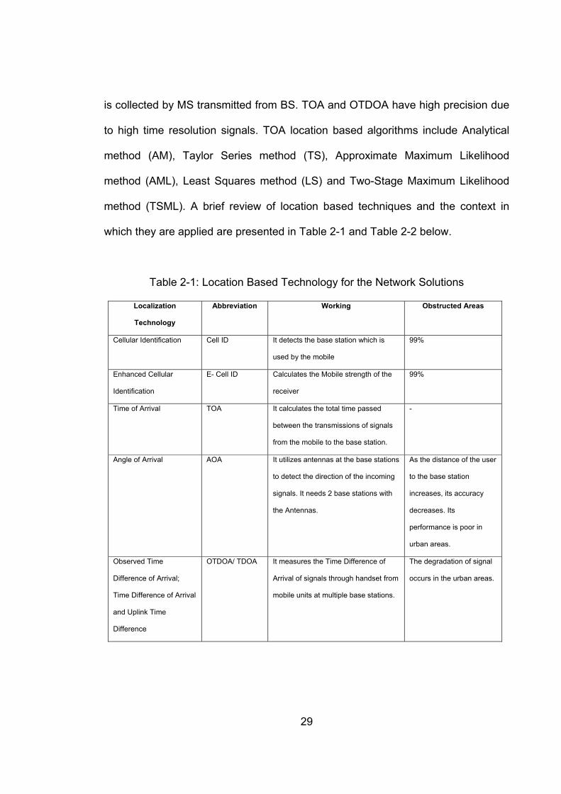
29
is collected by MS transmitted from BS. TOA and OTDOA have high precision due
to high time resolution signals. TOA location based algorithms include Analytical
method (AM), Taylor Series method (TS), Approximate Maximum Likelihood
method (AML), Least Squares method (LS) and Two-Stage Maximum Likelihood
method (TSML). A brief review of location based techniques and the context in
which they are applied are presented in Table 2-1 and Table 2-2 below.
Table 2-1: Location Based Technology for the Network Solutions
Localization
Technology
Abbreviation Working Obstructed Areas
Cellular Identification Cell ID It detects the base station which is
used by the mobile
99%
Enhanced Cellular
Identification
E- Cell ID Calculates the Mobile strength of the
receiver
99%
Time of Arrival TOA It calculates the total time passed
between the transmissions of signals
from the mobile to the base station.
-
Angle of Arrival AOA It utilizes antennas at the base stations
to detect the direction of the incoming
signals. It needs 2 base stations with
the Antennas.
As the distance of the user
to the base station
increases, its accuracy
decreases. Its
performance is poor in
urban areas.
Observed Time
Difference of Arrival;
Time Difference of Arrival
and Uplink Time
Difference
OTDOA/ TDOA It measures the Time Difference of
Arrival of signals through handset from
mobile units at multiple base stations.
The degradation of signal
occurs in the urban areas.

30
Table 2-2: Location Based Technology for the Handset Solutions
Localization
Technology
Abbreviation Working Obstructed Areas
Enhanced Observed
Time Difference
E-OTD It matches the Time Difference of signals sent to
the mobile and to LMU by the base station. The
software in the mobile handset measures the
position. It needs 3 base stations.
The signals degrade
in buildings and
urban areas.
Assisted - GPS A-GPS It measures the mobile unit position by utilizing the
satellites and Global Positioning Receiver
50 to 70%
2.4.5 Hybrid Localization AoA-ToA Based
Hybrid localization involves both AOA and TOA. These two and more techniques
are combined to attain a more precise position location. The accuracy of TOA or
AOA depends on the environment [205]. However, the mobile prefers TOA where
there are many scatterers and otherwise, AOA.
2.4.6 Localization by Finger-Printing
Finger-printing is a method in which the reference measurements at the possible
way-points are involved to increase localization precision. When the GPS systems
are not working, then indoor positioning systems such as locating finger prints of
wireless local area networks are used. It uses finger-printing techniques, that is; it
receives signal strength with respect to a location and derives the location on the
basis of this data [206, 207]. It involves two stages, on line phase and offline stage.
In the online stage, a site survey is done for the Received Signal Strength Indices
(RSSIs) from the access points (AP). The vector created using the RSSI values at
a point can be considered as the location fingerprint for that point. In offline stage,

31
many location fingerprints are gathered at each point. The drawback of this method
is that it requires a lot of time [208].
Location finger-printing involving ultra-wideband radio frequency signals is a
provides a substitute to the traditional positioning methods which are based on the
angle estimation, range and the strength of the received signals [209]. This type of
finger-printing method is useful for indoor environments and uses multipath
propagation information. It requires large bandwidth RF signals. The location
finger-printing method comprises of two stages i.e. the training stage and the
localization stage. In the first stage the location finger prints are gathered from the
known position by the system, while in the localization finger-printing method, the
location fingerprints are gathered from the agents with unknown positions and are
matched with the training data. There are numerous approaches for matching
these positions with the training data such as neural networks, Bayesian
approaches, vector machines, etc. [210]. The large bandwidth gives less
restrictions and the benefit is that a single broadcaster serves for suitable
localization performance. The limitation of this method is that a large quantity of
training data is needed, so the training phase becomes tedious and time
consuming.
The drawback of finger-printing is that it can attain precision of just few meters.
More research is needed for the probabilistic method. The finger-printing method is
effective in Wireless LAN positioning but the problem lies in locating the unknown
32
location. Two approaches have been used for solving this problem. The
deterministic approach and the probabilistic approach [211]. In the deterministic
method, the standard sample scan of each wireless LAN access point calculated
for each reference point is then used to generate the database of the fingerprint.
As the difference in the sample scan calculated at each segment is big, and it does
not consider a lot of information present in the database, so a probabilistic method
has been used to remove this discrepancy [212]. Information related to the average
signal strength and the difference in each access point varies and it must be
considered to maximize accuracy.
Bayesian method has been used by the researchers to remove limitations of finger-
printing method [213]. For each fingerprint, the probability distribution is created
using the regularity in the occurrence of each signal strength value. The main
drawback of finger-printing method is that just a few meters’ accuracy is achieved.
More research is needed in probabilistic methods for removing the discrepancies
[214].
2.5 Latest Trends and Modern Applications of Location Based
Services
LBS Services are useful for orientation and localization [215], navigation [216],
searching [217], identification [218] and event search [219]. Information services
[220, 221] are the earliest application of the LBS technology. Presently, they are
integrated into vehicles for route finding and are also used for emergency and

33
health services [222, 223]. LBSs have appeared as the most interactive technology
for mobile computing due to the fast developments in the wireless and positioning
technology. In order to further improve the efficiency of these services, data
caching techniques have been used which removes the faults of the restricted
wireless bandwidth in mobile environments [224]. Modern applications of LBS
include the following:
2.5.1 Enhanced – 911 (E911) and Enhanced – 112 (E112) Services
The motivation behind the development of LBS technology applications in United
States by the Federal Communications Commission (FCC) in 1996 was to locate
mobile devices during emergency calls [225]. This service was named Enhanced -
911 or E911 [226]. The need arose as calls from the mobile phones showed a
growing percentage of emergency calls which reached 45 million in 2001. A similar
service with the name of E112 was promoted in European Union countries [227,
228]. About 40 million calls were made through the mobile phones in 2011 out of
which 15% were not addressed due to the insufficient or non-availability of the
location of the callers. Public Safety Answering Points (PSAPs) were used to find
the location and number of the caller [229] . The network based solutions such as
Automatic Location Identification (ALI) for wireless carriers are used to find the
location of the user within 150 to 300 meters of their location [230].

34
2.5.2 Mobile Guides
Mobile guides are information rich, movable and location sensitive digital guides
which provide information that is related to the surroundings of the user [231, 232].
They are the largest group of LBSs applications which are portal and information
rich digital guides [233, 234]. The mobile guides were categorized on the basis of
geo-positioning (GPS, Wi-Fi, etc.), architecture, adaptation (handling), situational
factors, interfacing, network access and map boundaries [233, 235-237]. Mobile
guides are also being used for mobile social networking [238]. Mobile guides exist
in different categories such as resource adapted (having regular patterns for use),
resource adaptive (has a single strategy for the use of resources) and resource
adapting (uses multiple strategies).
2.5.3 Transport Location Based Services
Intelligent Transport Systems (ITS) is a rapidly growing technological concept for
the incorporation of the information between the extensive variety of organizations
working in transport planning and functioning [239-241]. The intelligent systems
hold the capability of performing situational analysis and adaptive rationalizing
[242]. The future of transportation system is effective, time saving, economical, and
will be much safer for the well-informed users than now. ITS have grown to the
establishment of institutions like the ITS and Services for Europe (ERTICO) [243,
244]. The International Standard systems such as ISO 14813 (ISO 2007) have also
played a vital role in its advancement. The technologies used for ITS, are known as
telematics and include wireless communications, geo-positioning, spatial

35
databases and mobile computing platforms. The transport LBS include but are not
limited to services like assistance for the drivers [245-247], information for the
passenger, management of the vehicles and applications involving vehicle-to-
vehicle communication [248]. The services provided by traffic telematics includes
automatic configuration of appliances and features inside the vehicles, navigation,
detection of faults and broadcasting of caution messages [249, 250]. Traffic
telematics are also used to calculate the distance between the various vehicles in a
fleet and between a vehicle and its destination [251]. Today computer hardware
and software are used in vehicles for monitoring fuel usage and releases, engine
performance, brake performance and for handling electrical systems [252]. The
user services for travel and traffic management comprise collection and
broadcasting of information and dispensation for the external transportation
system. These services are used for providing commands to different traffic control
devices [253]. Traffic telematics promotes exchange of data between service
providers and the vehicles which helps in improving traffic management processes
[254]. Today with the advancement of the wireless communication systems,
vehicles are fitted with wireless communication devices which enable them to
communicate with other vehicles [255]. Vehicular networks can also enable
vehicles to transmit information in case of any accident or obstacles. Fleet
management is another interactive service in transportation system. The fleet
management systems provide freight services, public transportation and
emergency services. The fleet asset and management units are wireless handsets

36
or devices that track the fleet of vehicles and facilitates in faster transportation
through different modes [256].
2.5.4 Location Based Gaming
Location based games are the computer games in which the game development
depends upon the real-world location of the player (user) [257-259]. Multiplayer
games include street games and urban games. The characteristics of location
based gaming include movement, communication in public, specification of the
location and incorporation of the digital world and the real physical world [260]. In
pervasive gaming, real world games, supplemented with the functionality and the
power of computer and the entertainment provided by the computers are brought
to life [261-264].
2.5.5 Location Based Health and Assistive Technology
LBSs play a vital role in fulfilling the navigational needs of the visually impaired
people [265-268]. MoBic (Mobility of Blind and elderly people) was the first system
to be used to help the elderly and visually impaired. This system helped the
visually impaired and elderly people in finding destination and location of the route
[269]. It informs the traveller about the journey through a map. It was made up of a
MoPS (MoBic Pre-Journey System) and a MoODS (MoBic Outdoor System). A
MoPS considers the account preferences of the users, distance and time for
travelling in order to measure the direction. The MoODS uses the information
measured by MoPS to keep the user informed through warning and audio guides.

37
A famous wireless pedestrian navigation system is Drishti which is used both
indoors and outdoors for the guidance of visually impaired and special persons. It
provides route and destination information to the users. This system uses Routing
according to the user preferences and also take in account the shortest route [270].
The dead-reckoning method can be used for outdoor movement and for indoor
environments protective ultrasonic sensing is used [271]. Information of the route is
downloaded on the device of the user. Any new information related to the direction
or obstacle is uploaded by the device to keep the server updated. It guides the
users through various transportation means such as buses, trains, footpaths,
trams, etc. It takes use of the mobile devices with Global Positioning System
capabilities, wireless connection and voice production. Location based health
services have also been developed to track the mobility of the patients and old
persons [272]. Ambient Assistant Living (AAL) system is an LBS system which
provides location information in indoor environments. For example; it gives help to
old people living alone to perform their daily tasks. It also provides information to
elderly people about the location of shopping stores and public places. It also helps
to find a specific product within a shop [273]. Location based health services have
also been used for monitoring the health of children [274] and for measuring health
and fitness [275]. In [276] the research was conducted on around developing an
assistive technology to improve the mobility of manual wheelchair’s user. During
the research, questionnaires were also designed based on the seven key
principles of universal design. Per the questionnaires, the users of manual
wheelchair are fatigued and suggested a change in the type of hub (rather than its

38
location) to improve the speed of the wheelchair. The solution has been developed
on the following: parameter changes (wheelchair), mechanical substitution and
self-service. In [277] a system is presented that supports cognitively impaired
people in their daily activities. The most interesting part of the research is to
generate user friendly names for streets and various routes based on user context
– especially for people who aren’t accustomed to using new technologies e.g.
elderly people. The system also enables the relatives of the user to establish tasks
that must be performed at specific locations and to monitor the activities of the user
to detect potentially risky situations.
2.5.6 Mobile Marketing
Mobile advertising or marketing is an interactive LBS which works in the same way
as directory services. It involves all the activities undertaken in order to
communicate with the customers by using mobile devices for promoting the sale of
products or services and for providing information to the customers about the
products and services [278]. It has two categories namely pull model and push
model. The information can be requested using the pull mode from the marketer,
while it can be sent from the marketer to the customer in push mode although it is
not requested by the customer [279]. Interactive and personalization of the content
message is possible in mobile marketing [108]. In [280], a method is presented to
implement some trust level so that only genuine mobile users can use the system
and identify malicious users. For this purpose, it is proposed by the authors to store
the IMEI number of the mobile devices in a central controller. The system can also

39
be deployed on cloud server for storing the distributed data. In [281], a business
model is presented for internet and mobile based marketing for smart parking
operators with a focus on personalisation of advertisements. This method can be
used to increase parking operator’s revenues and thus attract more investments in
the future. Among the variety of mobile services, significant attention has been
dedicated to mobile marketing specifically to mobile customer relationship
management (CRM) services. In [282] authors investigate which type of mobile
marketing has a significant relationship with which type of CRM. The research
done in this project also proves that future is brighter for mobile advertising rather
than any other type of advertising.
In [283], the potential of using mobile marketing for increasing the value for
customers and retailers has been has been explored. It has been observed that the
consumer behaviour on mobile shopping is an extension of their behaviours
developed on internet connected PCs. However, new behaviours are also
integrated during this such as camera, scanners and GPS. This concept is
specifically useful for development of managerial concepts related to mobile
marketing.
The growth of Location Based Social Networks (LBSNs) has greatly enhanced the
people’s urban experience through social media and so the number of users has
increased exponentially. Vast amount of data related to human behaviour is
available – Big Data - and so there is an opportunity to apply advanced data

40
analysis tools and algorithms to build our learning on this data. In [284], the
background, framework and distinct properties of location based mobile social
networking are presented – illustrating the application of data mining to real world
location based social networks.
In [285] the authors have investigated the customers’ privacy concerns, and their
attitude towards the Mobile based Location Based Advertising (LBA). The sample
data comprised of 224 cases in which consumers’ acceptance of LBA was found. It
was found that although customers viewed LBA in a positive way, the information
privacy concern influenced their overall perception of the LBA and its types,
namely push (product/service information relayed) versus pull (customer
information collection + processing). It is crucial to understand the customers’
attitude and acceptance of LBA before adopting either a push or a pull model.
2.5.7 Community Based Services
These services are location supported having personal interaction component and
a central communication system [286]. Online social networks are using Location
Based Services to assist social networking and for discovering places [287]. Virtual
mobile communities comprise users who communicate with each other and interact
with each other electronically through mobile devices [288]. Community based
services have facilitated visually impaired persons as they provide advanced
navigation in urban areas where satellite systems have failed to do so as the
signals get degraded due to obstacles such as buildings. Community based

41
location services enable the community members to interact with each other
through services such as mapping my friends (finding the physical location of
friends), friend alert (when friends visit each other they get alerts) and portable
messages [289]. Localization and tracking of pedestrians involves a combination of
active and passive positioning systems. It involves multi sensor systems which not
only detects the location of objects and person but also provides precision related
to the position [290]. The GSM signal strength finger-printing provides better indoor
and outdoor localization techniques. This method is useful for delivering warning
messages related to weather or in case of emergency traffic situations. It is also
useful for tracking people inside a building [291].
In [292], a system for real-time event detection, tracking, monitoring and
visualisation has been developed. The main motive behind the project was to help
Information/Data Analysts to gain a better comprehension of complex events as
they unfold in the world. At the end, the information is used to categorise security
relevant events which are then tracked, geo-located, summarised, and visualised
for the end user.
Lighting systems are undergoing a revolution from fluorescent lamps or tubes to
light emitting diodes that offer an energy efficient solution and longer lifetime. In
[293], a low-cost deployment solution has been presented for a system that uses
the characteristics of visible light to complement existing wireless communication
systems. The proposed system has following three features: (a) It provides a

42
provable and secure wireless communication capability – the user is authenticated
based on their location (b) It also offers high precision indoor positioning system (c)
and most importantly it offers broadcast of information with a high frequency reuse
factor. So, the system presents a novel approach to authentication based on user’s
location.
2.5.8 Crime Fighting
LBSs have the potential to be used in fighting terrorism as the suspects can be
watched and tracked through this service. RFID services can be used for biometric
passports and for managing disaster. GPS devices are used for monitoring
emergency response teams at crime sights [294]. Control and management of
information for national security can be done through the use of LBSs as terrorists’
organizations can use the government websites for planning terrorist attacks [295].
Theft of vehicles and bikes are also controlled by installing tracking devices in them
[296]. [296] emphasized that location based services offers remarkable benefits in
safety and security areas such as by tracking criminals, lost vehicles, mobiles, etc.
and by responding to the emergency calls. The emergency response time has
been greatly reduced due to the use of location based services [297]. Law
enforcement agencies are increasingly using facial recognition software as a
crime-fighting tool. Mobile Cloud Computing (MCC) enforces the idea of moving
most of the processing and storage capability of the mobile phone to the cloud. In
[298], an efficient architecture has been presented that enables the face
recognition algorithms to run on the smartphone and reduce overall processing

43
time. Digital media has greatly enhanced the capability of information systems.
Although, the humanity has benefited from this revolution, it has also resulted in
new methods of forged authentication. Therefore, in, the methodologies to fight
against these forgery attacks has been presented.
Urban crime rates are expected to increase keeping in line with the population
growth by the year 2030. Studies have shown that crime only increases in certain
areas of an urban landscapes. This has attracted the attention of spatial crime
analysis that primarily focuses on crime hotspots that are basically the areas with
disproportionally higher crime density. The problem might arise if areas outside of
hotspots are overlooked and proper analysis techniques aren’t applied. Therefore,
in [299] Crimetracer, has been developed that enables an accurate crime location
prediction outside of hotspots. A probabilistic model of spatial behaviour is
proposed within the activity space of the known offenders.
The fear of crime has been the central theme in criminological research from the
1970s onwards. The research methodologies used in these projects have been
well documented and revolve around neighbourhood effects. However, the specific
location of home has been largely overlooked during these researches. Therefore,
in [300], the fear of crime was examined from a location based approach and took
neighbourhood and location of one’s home into perspective. The demographic data
was also used in relation to the research to find the variations in fear of crime

44
across racial/ethnic groups.
2.5.9 Real Time Shopping
LBSs involving indoor positioning have made it possible for the exploration of
products and things existing in the physical world as simple as it can be performed
on the internet. In stores, indoor positioning technology has been utilized to find
products on shelves and for other in-store services. Hence, by doing so, the
shoppers involve themselves in real time shopping experience, similar to as they
do on the internet [301].
In [302], context aware automated service system was developed that basically
worked as “Intelligent Shopping-aid Sensing System (iS3). For recognition,
collection and delivery of user contexts, RFID is used. Another benefit of using
RFID is that the information of products e.g. locations, specifications and
characteristics are collected quickly. Local applications were also developed that
enabled real time interactions between central system and end users.
The scientific community is continuously exploring new services that make
effective use of the developing wireless technologies. In [303] the authors focus on
connecting various sources of information based on the protocol stack of IEEE
802.11 and Bluetooth interfaces. The corresponding software architecture along
with the preliminary results for the tracking of visitors in smart shopping
environments has been presented.

45
2.5.10 Information and Entertainment
LBSs such as Facebook, Gowalla, Where, GeoLife2 [304] and Foursquare [305]
utilize the geo-location function of a mobile phone or smart phone to deliver
infotainment to people. Facebook places controls the prevailing Facebook network
of more than 500 million users for sharing, connecting with friends and finding local
transactions [306]. Hence, these services provide free advertising and promotion of
products and services [307]. It permits the customers to “Check in” places such as
hotels, airports, restaurants for transacting physical and intangible rewards. Yelp
website provides rating and reviews and their mobile applications allow customers
to check and review stores, hotels and restaurants. Similarly, WHERE facilitates its
customers in locating things and providing suggestions to them regarding
purchasing products or services.
2.5.11 Location Based Services in Politics
During the 2009 elections, many social networking sites such as Facebook,
Twitter, Youtube, etc. provided platform to the politicians to express their views and
policies in front of the public. Lots of politicians such as the president of the United
States, Barack Obama and former president of Pakistan, General Pervaiz
Musharaff used Facebook to express themselves before the public. In the case of
Barack Obama political campaign, there was found a cause and effect between the
votes and social media. Foursquare issued an “I Voted” badge and a website that
was a combined effort with the Pew Center, Google and Rock the Vote. It truly
demonstrated that location based services can influence elections. It was a test run

46
for the 2012 presidential elections. The users were encouraged to check in at their
voting location and to attain the distinct limited-edition badge. This project had
50,416 check-ins obtained from 23,560 variant venues. It was considered that the
Foursquare badge got minimum one person out to vote.
This idea followed the idea of Howard Dean's online micro donation. It was found
that approximately 15% of Americans with ages 18 and over took part in the 2008
presidential election using social media networks such as Facebook.
Hence, LBSs can be used in almost all fields of life for improving the standard of
living and making communication system better. However, the use of LBSs may
not have succeeded well in collecting real time images such as photos. Meanwhile,
the use of LBS in the MOPSI applications, as by using the split smart swap
clustering method, the disorder problem in map visualization can be reduced and
photo collections can be clustered through the use of grid based clustering with
bounding box method [308]. LBSs are also used for localizing the position of the
Robots and mapping the environment [309]. LBS applications are also used in
Geographical Information Systems as it provides spatial analysis opportunities
[310]. The beginning of mobile communication technologies, such as General
Packet Radio Service (GPRS) and then the evolution of Universal Mobile
Telecommunications System (UMTS) has empowered users of mobile devices to
use internet regardless of time and place [311]. LBS services involve client/server
relation, while LBA involves IT applications based on geo-spatial locating. Both use

47
real time for location objects or users and are suitable for mobile applications [312].
It has been reported that LBSs can provide multiple services ranging from tourist
navigation to rescue systems for managing disaster. These services were
developed separate from the geographic information Service (GIS) stream used for
the wireless services, but today more than 80% of data being supplied is the
spatial form (2D map) Hence, location based services are also a special kind of
GIS [313].
So far, LBS are basically mobile applications which provide information that are
related to the location of the users. These services are quickly capturing the market
and have tremendous growth opportunities [314]. The position of a user or object
can be informal, absolute or relative to a certain point whether they are located
through Bluetooth, infrared, RFID, mobile or through satellites [315]. Today LBSs
have a well-established role in value added services and their applications are
continuously growing [316]. Calculating the distance error through uncertainty and
confidence constraints is useful in locating the position of a user or object but the
Distance error produces inconsistent location estimates [316]. Reinforcing LBS
needs focusing on a number of issues such as software, hardware, network
structure, security, database, etc. [317]. The application of the location based
technologies depend on well-established and accessible multi layered client server
technologies. The fundamental infrastructure to assist LBS applications is
developed to assist mobile client functions with wireless communication [131].

48
Another application of location based services deployed by the government is to
assist people with the management of emergencies via their mobile phones.
Therefore, in [318] the viability of location based mobile emergency services has
been assessed. The study was conducted in a three-pronged way: (a) exploring
the challenges of location based services and their use at a national/country level
for emergency management (b) investing the impact of these of these services in
terms of behaviours and attitudes (c) understanding the social acceptance or
rejection of these services and outlining the factors that determine their
acceptance. The common theme found in the results is the trust factor: the
collection of personal location information adversely affected the trust level.
2.6 Conclusion
Location based services have been elaborately reviewed in this chapter. It is used
to give services in both public and business sectors. Some of which include
tracking services for old and disabled persons, monitoring health of patients,
navigational services at the airports, traffic telematics, fleet management, enquiry
and information services, crime fighting, toll systems, marketing, gaming,
geography mark-up and community services.
The localization infrastructure for LBS include LBS indoor systems, LBS satellite
systems, LBS GPS system, outdoor systems using terrestrial BSs and LBS
Outdoor Systems using terrestrial BSs. The techniques for the existing localization
were also enumerated. Different solutions for improving the existing LBS

49
technology and services were described. The modern applications of Location
Based Services include Enhanced – 911 (E911) and Enhanced–112 (E112)
Services, mobile guides, transport location based services, location based gaming
and location based health and assistive technology. The emergency and location
based health applications have assisted in saving lives of people and improving the
standard of living of people. The prospects of LBS are very high as with further
research the existing technologies can be improved and new ones can be created.
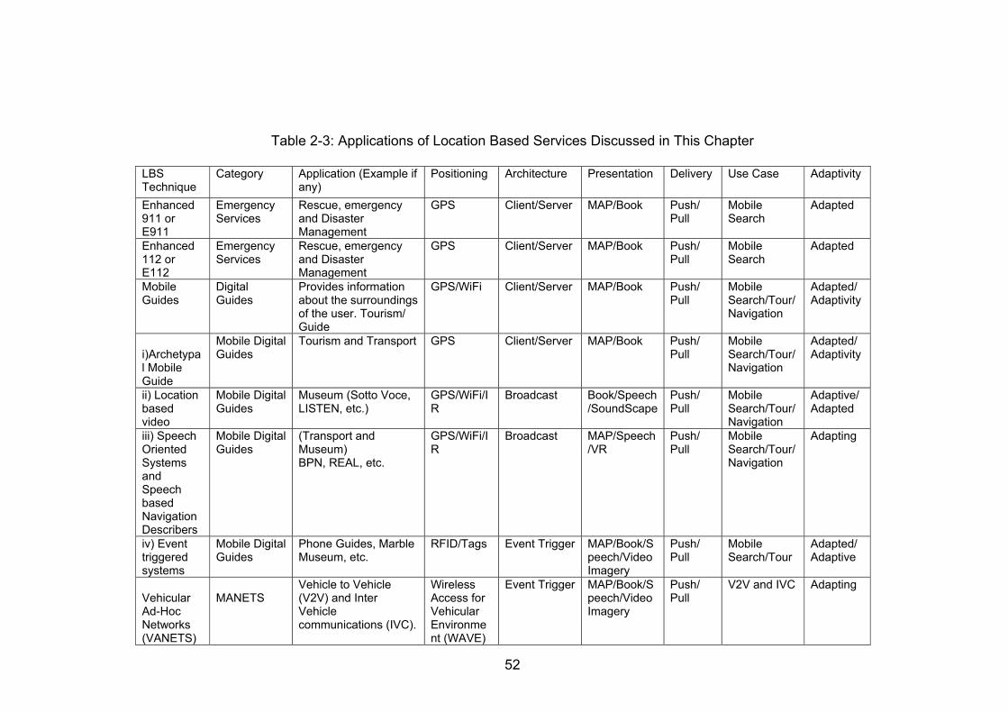
52
Table 2-3: Applications of Location Based Services Discussed in This Chapter
LBS Technique
Category Application (Example if any)
Positioning Architecture Presentation Delivery Use Case Adaptivity
Enhanced 911 or E911
Emergency Services
Rescue, emergency and Disaster Management
GPS
Client/Server MAP/Book Push/ Pull
Mobile Search
Adapted
Enhanced 112 or E112
Emergency Services
Rescue, emergency and Disaster Management
GPS Client/Server MAP/Book Push/ Pull
Mobile Search
Adapted
Mobile Guides
Digital Guides
Provides information about the surroundings of the user. Tourism/ Guide
GPS/WiFi Client/Server MAP/Book Push/ Pull
Mobile Search/Tour/Navigation
Adapted/Adaptivity
i)Archetypal Mobile Guide
Mobile Digital Guides
Tourism and Transport GPS Client/Server MAP/Book Push/ Pull
Mobile Search/Tour/Navigation
Adapted/Adaptivity
ii) Location based video
Mobile Digital Guides
Museum (Sotto Voce, LISTEN, etc.)
GPS/WiFi/IR
Broadcast Book/Speech/SoundScape
Push/ Pull
Mobile Search/Tour/Navigation
Adaptive/Adapted
iii) Speech Oriented Systems and Speech based Navigation Describers
Mobile Digital Guides
(Transport and Museum) BPN, REAL, etc.
GPS/WiFi/IR
Broadcast MAP/Speech/VR
Push/ Pull
Mobile Search/Tour/Navigation
Adapting
iv) Event triggered systems
Mobile Digital Guides
Phone Guides, Marble Museum, etc.
RFID/Tags Event Trigger MAP/Book/Speech/Video Imagery
Push/ Pull
Mobile Search/Tour
Adapted/Adaptive
Vehicular Ad-Hoc Networks (VANETS)
MANETS
Vehicle to Vehicle (V2V) and Inter Vehicle communications (IVC).
Wireless Access for Vehicular Environment (WAVE)
Event Trigger MAP/Book/Speech/Video Imagery
Push/ Pull
V2V and IVC Adapting
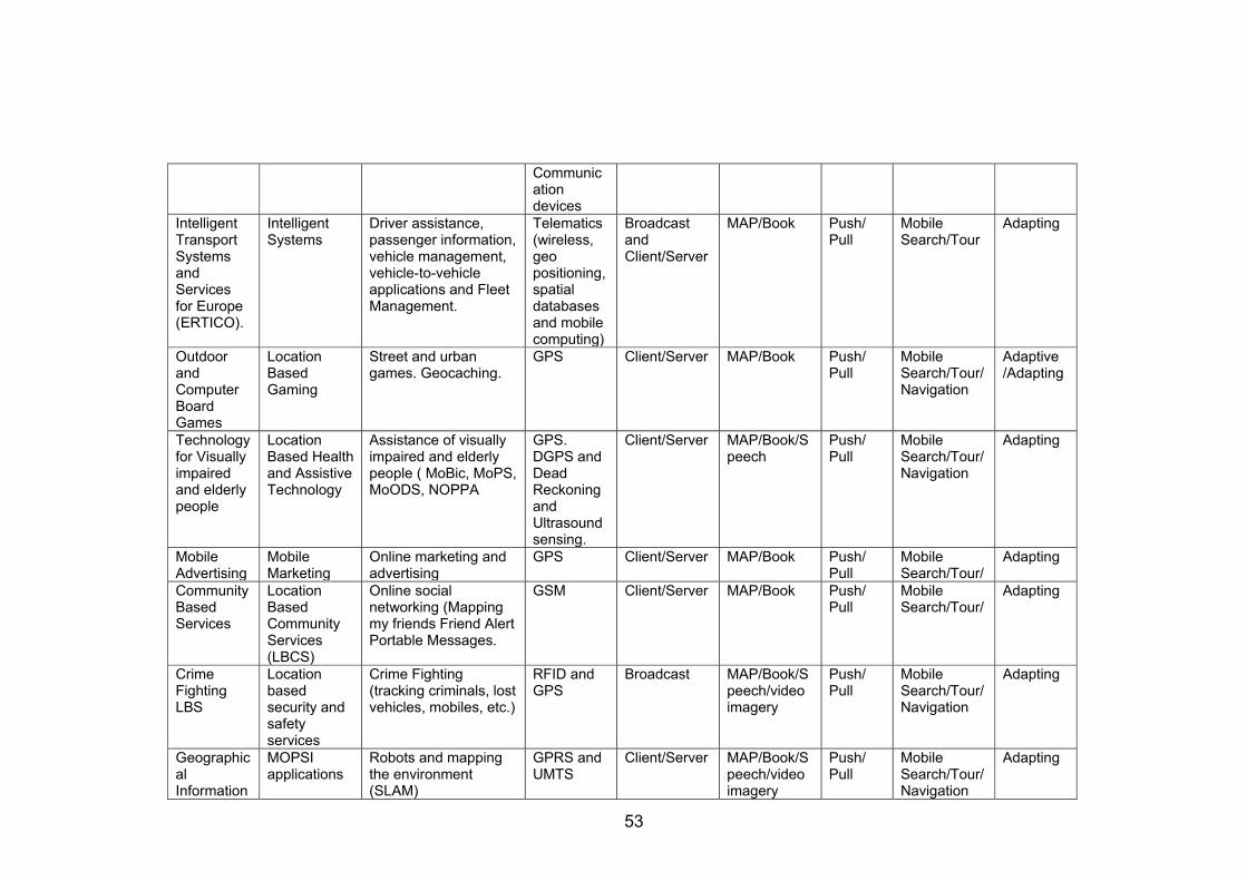
53
Communication devices
Intelligent Transport Systems and Services for Europe (ERTICO).
Intelligent Systems
Driver assistance, passenger information, vehicle management, vehicle-to-vehicle applications and Fleet Management.
Telematics (wireless, geo positioning, spatial databases and mobile computing)
Broadcast and Client/Server
MAP/Book Push/ Pull
Mobile Search/Tour
Adapting
Outdoor and Computer Board Games
Location Based Gaming
Street and urban games. Geocaching.
GPS Client/Server MAP/Book Push/ Pull
Mobile Search/Tour/Navigation
Adaptive /Adapting
Technology for Visually impaired and elderly people
Location Based Health and Assistive Technology
Assistance of visually impaired and elderly people ( MoBic, MoPS, MoODS, NOPPA
GPS. DGPS and Dead Reckoning and Ultrasound sensing.
Client/Server MAP/Book/Speech
Push/ Pull
Mobile Search/Tour/Navigation
Adapting
Mobile Advertising
Mobile Marketing
Online marketing and advertising
GPS Client/Server MAP/Book Push/ Pull
Mobile Search/Tour/
Adapting
Community Based Services
Location Based Community Services (LBCS)
Online social networking (Mapping my friends Friend Alert Portable Messages.
GSM Client/Server MAP/Book Push/ Pull
Mobile Search/Tour/
Adapting
Crime Fighting LBS
Location based security and safety services
Crime Fighting (tracking criminals, lost vehicles, mobiles, etc.)
RFID and GPS
Broadcast MAP/Book/Speech/video imagery
Push/ Pull
Mobile Search/Tour/Navigation
Adapting
Geographical Information
MOPSI applications
Robots and mapping the environment (SLAM)
GPRS and UMTS
Client/Server MAP/Book/Speech/video imagery
Push/ Pull
Mobile Search/Tour/Navigation
Adapting

54
Systems LBS in politics
Location Based Community Services (LBCS)
Political campaigns GPS/WiFi/GPRS
Broadcast Client/Server
MAP/Book/Speech/video imagery
Push/ Pull
Voting/political rallies Facebook, Gowalla, Where and Foursquare
Adapting
Information and Entertainment
Location Based Community Services (LBCS)
Online social networking
GPS/WiFi/GPRS
Client/Server MAP/Book/Speech/video imagery
Push/ Pull
Search/Shopping/in-store services Facebook, Gowalla, Where and Foursquare
Adapting

55
3. NEW SIGNAL SUBSPACE BASED ANGLE
OF ARRIVAL ESTIMATION ALGORITHM
3.1 Introduction
Latest advancement in technology and consumer demand has created a great deal
of interest in the subject of identifying the spatial relationship between different
objects. This procedure is referred to as localisation and has found wide spread
applications [319-321]. When the earth is used as the reference frame in
localization operations it is referred to as Geolocation. The data collected for these
applications however is useless without the accurate location information of the
transmitter node. The direction-finding algorithms have a key role to play in the
smart antenna technology of the future as the Global Positioning System (GPS)
technology has restrictions due to the requirement of Line of Sight (LOS) between
the satellite and the GPS receiver [322]. These algorithms are required to precisely
estimate the bearing angle on the receiver array which is highly important for both
military and non-military services. The accuracy of these algorithms is extremely
important when it concerns the emergency response services. The massive
enhancement in the smart antenna technologies in the past decade has triggered
an increased interest in the field of direction finding (DF). In smart antenna
technology, multiple antenna elements can be combined using digital signal
processing (DSP) to adjust the antenna radiation pattern per surrounding channel.

56
These smart antenna systems can improve the capacity of the cellular wireless
networks through beam steering [323]. To steer the beam into the direction of the
right user who is requesting access to the network resources it is important that the
right estimate of the user location be calculated. In [324] and [325, 326] the authors
have provided detailed references and quantification of the performance of the
existing localisation techniques. Localization techniques have been applied to a
variety of applications including autonomous mobile robot navigation [327-330],
Underwater navigation [331], public health and social medial [332] [333, 334],
emergency services [335] etc.
This chapter is arranged as follows. Section 3.2 presents the mathematical model
for deducing the direction of arrival using antenna arrays and then presents a
review for some of the well-known Angle of Arrival estimation techniques which
have been employed in this work 1) Interferometry 2) Classical Beamformer 3)
Capon’s Minimum Variance Distortionless Response (MVDR) and 4) Super
resolution Eigen decomposition based Multiple Signal Classification (MUSIC)
algorithm. Section 3.3 presents the mathematical model of the Novel proposed
algorithm. Results and discussion are presented in Section 3.4 followed by the
conclusion in Section 3.5.
3.2 DOA Estimation Algorithms Using Antenna Arrays
The direction of arrival problem relates to the estimation of , ) where stands
for the azimuthal angle and stands for the elevation angle of the impinging plane

57
wave on an antenna or an array of antennas. The plane wave is assumed to be of
constant frequency and has infinite parallel wave fronts with constant amplitudes.
In a (1-D i.e. one-dimensional plane the estimation problem reduces to only the
estimation of the azimuthal angle ;
The expression for the plane wave that impinges at point at time t can be written
as:
s , t Ae . 3-1
(a) (b)
Figure 3-1: Geometry representing the DOA of the signal as an azimuth and
elevation angle pair on an antenna array
where A is the peak amplitude, β
is the wave factor, λ c/f is the wavelength
of frequency f, c is the speed of light and ω is the angular frequency defined as

58
ω 2πf. Using the above equation 3-1, the arriving signal at an antenna located at
x ,x , x with origin 0,0,0 can be defined as:
s , t s , t e 3-2
If there are Momnidirectional isotropic antennas that have a unity gain arranged in
a uniform linear array (ULA) with uniform spacing d between them on the x -axis
then the arriving signal at the mth element can be described as:
s t s md, 0,0 , t s , t a φ, θ 3-3
where, is the steering factor of the element and is equal to:
a φ, θ e 3-4
The above equation 3-4 describes a progressive phase shift
βmdcosφsinθ 2πλmdcosφsinθ 2πf
mdcosφsinθv fλ
ωt 3-5
Figure 3-2: Uniform Linear Array

59
Equation 3-5 represents the time t it will take the plane wave to propagate
mdcosφsinθ in the direction of the incident wave.
Now for the case of uniform circular array (UCA) with element spacing of
arranged on a circle of radius R the arriving signal at the m element can be
described as
s t s Re , t s , t a φ, θ 3-6
where in this case, the antenna factor for the m antenna can be described as:
a φ, θ e 3-7
For simplicity from here onward unless otherwise stated it is assumed that the
elevation angle 90 making 1.
3.2.1 Interferometry
The principle of interferometry states that if a plane wave arrives at an antenna
array with an angle it will be received by two different elements with a time delay
due to the difference in the length of the path. This path length difference results in
a phase difference between signals received by antennas.
∆2
cos 3-8
To estimate the angles some baselines should be defined. To form two baselines
three antenna elements are necessary which can be placed on an equilateral
triangle. The phase measurement techniques are analogue, digital and Fourier
transform.

60
In correlative interferometry at each wave angle the measured phase differences
are compared with the reference phase differences for the direction finding (DF)
antenna. The column of measured phase angles is moved through the matrix of
reference phase angles and the values with maximum correlation are used. This
value corresponds to the angle of arrival of the incoming signal.
The reference phase differences or “array manifold” is measured during the
calibration process, in which a model is designed to understand the behaviour of
the antennas. The theoretical array response values might be considerably
different in practical so it is very important that the non-ideal aspects of the system
should be considered while making a theoretical model to increase accuracy of the
practical systems. A signal is transmitted to the receiver using known locations and
regular azimuthal and frequency stepping. The differential phase and the amplitude
values are then used to form a calibration table. Figure 3-3 depicts an example of
the correlative interferometry. The data set is from an antenna array of 5-elements
and the columns in the data matrix represent the direction and are used to form a
comparison vector. The measured phase differences are contained in the upper
data vector. In the reference and measurement vector matrices each column is
correlated between the two matrices. Thus, the angle that will be linked with the
comparison vector matrix because of the maximum correlation will be the true
angle.

61
Figure 3-3: Correlative Interferometer
3.2.2 Conventional or Classical Beamformer
This method was proposed in [336] .If there are Momnidirectional isotropic
antennas that have a unity gain arranged in a uniform linear array with uniform
spacing d between them on the axis as shown in Figure 3-2 then the input at
each element in the presence of noise can be written as
u t a φ s t n t 3-9
where a φ for a ULA with sinθ 1 can be written as:
a φ e 3-10
The conventional beamforming method introduces a phase delay in the signals and
weights and then sum them together as the output y t which can be written as:
y t t 3-11
Substituting the value of t from equation 3-9 into equation 3-11 gives:
y t ( φ s t t 3-12

62
y t w∗w∗ …w∗
a φa φ⋮
a φ
s t
n tn t⋮
n t
3-13
where φ is the steering vector and are the weights or beamforming vector.
The pseudospectrum of the DAS beamformer can be written as:
P |y | Ε | t | Ε t t
t t
3-14
R is the autocorrelation matrix of the data received from the array.
R t t φ s t t s t φ t
σ φ φ σ I
3-15
where represents the signal power and is the noise
power.
If a signal s t with an azimuthal angle of φ arrives at the array, then the
maximum output of the beamformer with no noise present would be maximum for
φ thus aligning the phases of the antenna element input so that the
components of the incoming signal can add constructively. Thus, the estimated
angle can be any value of φ that will maximise the following:
P φ | R | φ R φ 3-16
Equation 3-16 is referred to as the spatial spectrum of the DAS (Conventional)
beamformer whose peaks can be determined to estimate the azimuth angle of
arrival.

63
3.2.3 Capon’s Minimum Variance Distortionless Response Algorithm This method was proposed in [337] to improve the poor resolution of the
beamformer method as shown in Figure 3-4. This method also measures the
received signal power in all directions possible and suppresses the contribution of
the unwanted signals by modifying the spatial spectrum. This modification is
accomplished by solving the constrained minimization equation below and then the
resultant constrained optimal weight vector in Equation 3-14.
Min |y | Min R condition: φ 1 3-17
Equation 3-17 can be solved using the Lagrange multiplier
J12
R λ 1 ; 3-18
∂∂
J R λ ; R λ 1
∂∂λJ 0; 1 → λ R 1; λ
1R
2
3-19
Equation 3-19 results in
R λ R φφ R φ
3-20
Substituting Equation 3-20 in Equation 3-17 results in Capon’s Pseudospectrum:
P φ R R = 3-21
The disadvantage of using the MVDR method is that it requires computation of
inverse matrix which can become ill conditions in the presence of highly correlated
signals.

64
Figure 3-4: Performance Comparison Between the Beamformer and Minimum
Variance Distortionless Response
3.2.4 Subspace Based DOA Estimation Method of Multiple Signal
Classification (MUSIC)
Schmidt proposed this method to estimate the direction of an incoming plane wave
in the presence of noise [39].
The linear combination of L incident signals and noises arriving at an M-element
array can be written in a form of a as:
t φ s t t A t t 3-22

65
u tu t⋮
u t
a φ … a φa φ … a φ
⋮a φ
……
⋮a φ
s ts t⋮
s t
n tn t⋮
n t
3-23
where φ a φ a φ …a φ is the antenna array steering vector of
size Mx1 for the l signal that has a direction of arrival (DOA) (φ and t
s t s t … s t is the vector containing L signals that are arriving on the
antenna array.
The steps in the computation of the MUSIC algorithm are:
Step 1: Collect the array input vector samples.
u nT , n 0,…… . N 1 whereN: Numberofsnapshots 3-24
Step 2: Calculate the array correlation matrix as:
R1N
nT nT 3-25
where is the signal correlation matrix and is the noise correlation
matrix.
Step 3: Apply Eigen decomposition to the input correlation matrix as:
Λ 3-26
where
… 3-27
and
Λ
0 … 00 … 0⋮0
⋮0
⋱ ⋮…
3-28

66
Step 4: Estimate the total number of signals , where, is the total
number of the smallest eigenvalues that create the Matrix of form
containing the noise eigenvectors that correspond to the smallest eigenvalues.
… 1 3-29
Step 5: Compute the MUSIC pseudospectrum using:
1
3-30
Step 6: Select the highest peaks of the pseudospectrum to estimate the DOA.
Super-resolution techniques allow estimating the AOA of multiple co-channel
signals. It has a DF accuracy about 1° and can search for azimuth and elevation at
the same time.
A brief comparison of different direction of arrival estimation techniques is provided
in Table 3-1
Table 3-1: Comparison of different AOA/DOA estimation algorithms
Sensitivity to noise
Sensitivity to calibration
Sensitivity to multipath
Ability to separate closely spaced multipath
Complexity
DAS (spectralestimation methods)
High Moderate High Low Low
MUSIC Low Higher Low High HighRoot-MUSIC Lower High Lower High HighESPRIT Lower Low Low High High
Fusion (DAS& root-MUSIC)
Low Moderate Lowest Very high Moderate

67
3.3 Mathematical Model of the Proposed Angle of Arrival (AoA)
Estimation Technique
The proposed technique makes use of the signal subspace to provide an estimate
of the direction of arrival. The steps of the proposed algorithm are summarised as
follows:
Step 1: Collect the array input vector samples.
u nT , n 0, …… .N 1 whereN: Numberofsnapshots 3-31
Step 2: Calculate the array correlation matrix as:
R1N
nT nT 3-32
where is the signal correlation matrix and is the noise correlation
matrix.
Step 3: Apply Eigen decomposition to the input correlation matrix as:
Λ 3-33
where
… 3-34
and
Λ
0 … 00 … 0⋮0
⋮0
⋱ ⋮…
3-35
Step 4: Estimate the total number of signals , where, is the total
number of the smallest eigenvalues.
Step 5: Estimate the signal subspace .

68
… 1
The signal subspace is computed using the eigenvectors that correspond to the
largest eigenvalues.
Step 6: Compute:
P φ a φ a φ 3-36
This will result in the peaks in the direction of arrival. However, the peaks produced
by the above equation result in a very wide side lobed spectrum which results in
erroneous estimation at low power levels and for this reason it is proposed to
search for the nulls in the direction of arrival which can be achieved by subtracting
all the values of P φ from its max value.
P φ P φ P φ 3-37
The pseudo spectrum of the proposed technique then can be written as:
1
3-38
where ε =1/ Max is added to remove any singularities that might be present.
Finally, the error can then be calculated between the true direction of arrival and
the estimated direction. The absolute error for each incoming signal can be
mathematically described as
er i Real i Estimated i 3-39
and the average error for each impinging ray (eav-angle) can be calculated as:
∑ |er i |
k
3-40
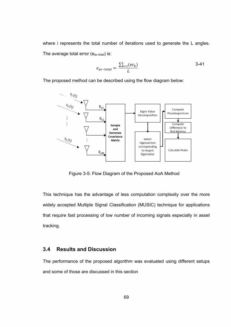
69
where i represents the total number of iterations used to generate the L angles.
The average total error (eav-total) is:
∑ er
3-41
The proposed method can be described using the flow diagram below:
Figure 3-5: Flow Diagram of the Proposed AoA Method
This technique has the advantage of less computation complexity over the more
widely accepted Multiple Signal Classification (MUSIC) technique for applications
that require fast processing of low number of incoming signals especially in asset
tracking.
3.4 Results and Discussion The performance of the proposed algorithm was evaluated using different setups
and some of those are discussed in this section

70
3.4.1 Performance Evaluation of the Proposed Algorithm
A 10-element uniform linear antenna array was constructed using MATLAB, with
inter-element spacing of to compare the performance of the proposed
algorithm. The simulation parameters used are listed in Table 3-2.
Table 3-2: Simulation Parameters Using the ULA for the Performance Comparison
of the Proposed Algorithm
Parameter Value Number of Elements 10 SNR 20 dB Antenna Spacing λ/2 True Angle 0 Degree Number of Snapshots 100 Noise AWGN
Figure 3-6: ULA for The Performance Comparison of the Proposed Algorithm

71
The Capon’s algorithm is famous for its ability to improve the spectral resolution as
shown in Figure 3-4, and something of the similar nature is evident from the results
produced in Figure 3-6 where the proposed algorithm clearly shows its ability to
have superior resolution and a much higher normalised power that the signal can
be accurately estimated at lower power thresholds.
Effect of Number of SNR on the Proposed Algorithm
The same 10-element ULA was used to understand the effect of the number of
snapshots on the proposed angle estimation method for multiple closely spaced
angles. The simulation parameters are as shown in Table 3-3
Table 3-3: Simulation Parameters Using the ULA for the Study of the Effects of
Total Number of Snap Shots on the Proposed Angle of Arrival Estimation Algorithm
Parameter Value Number of Elements 10 SNR 0 dB Antenna Spacing λ/2 True Angle [-20, 0, 20] Degrees Number of Snapshots 100, 500 1000 Noise AWGN
The results obtained in Figure 3-7 show that even with 100 data snapshots the
proposed algorithm could resolve three closely spaced angles, the performance
however can be further increased as for N = 1000, with a higher number of data
snapshots.

72
Figure 3-7: Effects of Total Number of Snap Shots on the Proposed Angle of
Arrival Estimation Algorithm
Effect of SNR on the Accuracy of Proposed AoA Algorithm
To evaluate the effect of signal to noise ratio (SNR) the same 10-element ULA was
used and the simulation parameters are described in Table 3-4. The results
obtained in Figure 3-8 show that even at SNR of -20 dB the estimator could identify
the three different peaks at the normalised power level of approx. -40 dB. However,
as the SNR increases three highly identifiable peaks emerge to point in the
direction of the source signals.
Table 3-4: Simulation Parameters Using the ULA
Parameter Value Number of Elements 10 SNR [-20 -10 0 10 20] dB Antenna Spacing λ/2 True Angle [-20, 0, 20] Degrees Number of Snapshots 100

73
Figure 3-8: Effects of SNR on the Proposed Angle of Arrival Estimation Algorithm
All the results obtained using the simulation model built in MATLAB support the
enhanced performance of the proposed algorithm. However, when designing a
practical antenna array system, the designer must face many challenges including
the required geometry and size of the antenna array according to the application
specifications, in addition depending on the application the choice of antenna as
different antennas has different radiation patterns and gains etc. These
requirements then introduce further variables in the estimation system. To further
test the performance of the proposed algorithm in a more real-world scenario
different antenna arrays and geometries were constructed using computer
simulation technology (CST) software and Numerical Electromagnetic Code (NEC).

74
Execution Time
In practical localization applications, it is necessary that the processing algorithm
be computationally fast. In Figure 3-9 the comparison is made for the time of
execution of four different algorithms that are used in this study for a total of 1000
iterations, it is suggested by the results that the proposed algorithm has the fastest
execution performance as compared to any of the other methods presented.
Figure 3-9: Time of Execution Comparison
Signals with Different Power Levels
Five signals are constructed such that each signal is arriving from a different
source or because of a multipath scatter with different direction of arrival and has
different received power due to the path travelled. The directions and amplitude
power of these signals are [-600, -300, 00, 300, 600] and [1, 0.8, 0.6, 0.3, 0.1] Watts.
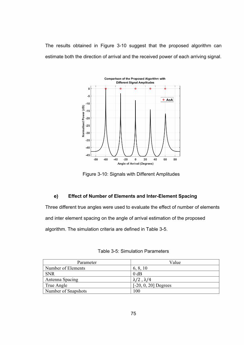
75
The results obtained in Figure 3-10 suggest that the proposed algorithm can
estimate both the direction of arrival and the received power of each arriving signal.
Figure 3-10: Signals with Different Amplitudes
Effect of Number of Elements and Inter-Element Spacing
Three different true angles were used to evaluate the effect of number of elements
and inter element spacing on the angle of arrival estimation of the proposed
algorithm. The simulation criteria are defined in Table 3-5.
Table 3-5: Simulation Parameters
Parameter Value Number of Elements 6, 8, 10 SNR 0 dB Antenna Spacing λ/2 , λ/4 True Angle [-20, 0, 20] Degrees Number of Snapshots 100

76
Figure 3-11: Effects of number of elements and Inter-element spacing on the
Proposed Angle of Arrival Estimation Algorithm
The results in Figure 3-11 show the performance of the proposed algorithm with
the change in the number of elements and the element spacing from /2 to /4
which is expressed as “L/4” in Figure 3-11. The estimation algorithm has the best
performance with the highest number of elements when the inter element spacing
is /2. Even 10 elements with /4 show worse performance than 6 elements with
/2. This explains how the interelement spacing degrades the performance and
how it creates a challenge for the antenna array designer for localization systems
when the space constraints are present.

77
Performance Comparison of the Proposed Algorithm in the
Presence of Correlated Sources
Correlation or similarity between signals reduces the performance of direction
estimation algorithms. Hence, a simulation was run for two received signals with
95% correlation coefficients incident on linear array consisting of ten elements
spaced by d = 0.5λ. The performance of the various methods is shown in Figure 3
12. Although MUSIC and Capon give correct estimates for both signals, their
performance significantly deteriorates. The Bartlett method gives reasonable
performance and accuracy, but the proposed algorithm is the most accurate, with
sharpest peaks and very low side lobe levels.
Figure 3-12: Performance Comparison of the Proposed Algorithm in the Presence
of Correlated Sources

78
3.4.2 3-element IFA Antenna Array
A three-element inverted F antenna (IFA) based array was constructed using the
computer simulation technology (CST) antenna design software. The elements
were separated at 120 degrees in azimuth plane over 1 1 square finite
conducting ground plane with antenna spacing of λ/4, where λ is the wavelength at
the desired carrier frequency of 400 MHz, the selection of /4 spacing between the
antenna elements was to keep the overall antenna array footprint to the minimum.
The transmitter and the receiver array were placed in the same plane thus only
azimuth angle calculations were done. The transmitter was placed in the far field
zone i.e. at least 3 meters away from the receiver array. The construction of the
simulation environment is shown in Figure 3-13.
Figure 3-13: Three element array structure in CST
Four different angle of arrival estimation algorithms were compared, namely,
Interferometry, Bartlett, Proposed method and Multiple Signal Classification
technique (MUSIC). The receiver array was turned at 20-degree step size for the
whole azimuth plane (i.e. 360 degrees) and additive white Gaussian noise (AWGN)

79
was introduced to the received signal. The results in terms of estimation error at
SNR of 0dB from the four algorithms are plotted in Figure 3-14.
Figure 3-14: Angle of arrival estimation error using interferometry, Covariance
and MUSIC
As envisaged, the super-resolution signal subspace based proposed algorithm and
noise subspace based MUSIC algorithm outperform the conventional Bartlett
algorithm and the interferometry method for determination of angle of arrival in
terms of angle error. The results also suggest that both subspace based methods
show similar angle estimation error performance. The maximum estimation error
from the signal subspace techniques was 6 degrees which is acceptable
considering the low antennas spacing between the elements of the antenna array
and low SNR.

80
3.4.3 Interferometry vs. Proposed Algorithm
Next a comparative study has been carried out to evaluate the performance of the
proposed algorithm against the phased interferometry algorithm and to understand
the effect of the ground plane (finite/infinite) on the angle estimation. Three
antenna and four antenna circular array geometries have been used for this study
and simulated using Numerical Electromagnetics Code (NEC) antenna design
software. The diagram of the two geometries is presented in Figure 3-15 (a) and
(b). In the study, the size of the finite ground plane was 1λx1λ. The ground plane
was made up of conducing material with properties like that of copper.
(a) (b)
Figure 3-15: Simulation setup with (a) Three Elements (b) Four Elements
a) True Angle = 0 degrees
The study was conducted for a total of 72 angles using a single transmit source,
i.e. the receiver array was rotated at 5-degree step size, but for illustration
purposes only a few angles have been chosen and the results are discussed. It

81
was assumed for simplicity that there is no additive noise present. The antennas
however, do have mutual coupling present between them.
(a) (b)
Figure 3-16: AOA = 0, (a) 3 Elements with Infinite and Finite Ground Plane (b) 4
Elements with Infinite and Finite Ground Plane
The results obtained in Figure 3-16 (a) for the 0 degree as the true angle of arrival
suggested an ambiguity in the interferometry method as the solution was unable to
resolve the correct angle using 3 elements with infinite ground, the proposed
method did provide an accurate estimate to the true bearing angle. However, when
a finite ground plane was introduced the interferometry method and the proposed
method were both able to closely estimate the true bearing angle with a 1 degree
angle estimation error. The same true angle was then tested using a 4-element
circular antenna array and the results in Figure 3-16 (b) show that with infinite
ground the interferometry solution pointed in the opposite direction of the true
bearing angle i.e. 180-degree error and a big angle ambiguity, whereas the
proposed algorithm could closely resolve the true angle. Again, it was seen that the

82
introduction of a finite ground plane helps resolve the ambiguity present in the
interferometry algorithm. In addition to improving the antenna radiation the ground
planes also reduce the unwanted reflections which can explain the improvement in
the angle estimation performance of the interferometry algorithm.
b) True Angle = 10 degrees
Second example presented is of 10 degree as the true bearing angle, for this angle
again the solution for interferometry algorithm is 180 degrees in error for a three
element array with infinite ground plane and there is a large error in the proposed
algorithm also as shown in Figure 3-17 (a), but when an infinite ground plane is
introduced the angle estimated points towards the true bearing angle, which
supports the theory, that a finite ground plane actually improves the angle
estimation by reducing reflections.
(a) (b)
Figure 3-17: AOA = 10, (a) 3 Elements with Infinite and Finite Ground Plane (b) 4
Elements with Infinite and Finite Ground Plane

83
In Figure 3-17 (b) by increasing the number of elements in the antenna array the
estimation error in the proposed algorithm is negligible even with infinite ground
however the interferometry algorithm still cannot accurately estimate the angle
information and suggests the solution to be in 180 degrees opposite direction. This
is a good example to show that the eigen structure based proposed method does
show enhanced angle estimation resolution with an additional antenna element but
that is not enough in the case of phase interferometry to increase the algorithms
performance. To further illustrate this issue of angle ambiguity caused by the
interferometry algorithm a few more examples of different bearing angles are
presented below.
c) True Angle = 45 degrees
(a) (b)
Figure 3-18: AOA = 45, (a) 3 Elements with Infinite and Finite Ground Plane (b) 4
Elements with Infinite and Finite Ground Plane

84
In Figure 3-18 the true bearing angle is 45 degrees, in Figure 3-18 (a) with a 3-
element array it can be seen the interferometry solution is again approx.180
degrees in error.
All the results obtained in section 3.4.3 suggest that the interferometry algorithm is
finite ground plane dependent. Next, the same setup is repeated for multiple
arriving angles.
3.4.3.1 Multiple Sources Case
Multiple transmitter sources were introduced to simulate the effect of a multipath
environment on angle estimation where various copies of the same transmitted
signal reach the receiver with time delays caused by the difference in length of the
path travelled by the ray in a narrowband system.
a) True Angle = 45 and 300 degrees
Figure 3-19: Four element array, Multiple Source Case

85
The first comparison that is shown in Figure 3-19 is of two angles, 45 degrees and
300 degrees. It is assumed that both the rays arrive at the receiver at the same
time but with different magnitudes and the ray arriving from 300 degrees has 5
times the power as compared to the one arriving from 45 degrees. The results
suggested that none of the solutions proposed by the interferometry method point
toward either of the two angles. The proposed algorithm does provide a solution
and point towards the dominant angle as in the case of Line of Sight environment
the dominant ray will be the true angle as it will travel the shortest distance
between the transmitter and receiver array.
b) True Angle = 0 and 90 degrees
(a) (b)
Figure 3-20: (a) Three element array (b) Four element array, Multiple Source
Case
This example is presented as it shows some very interesting results regarding the
phase interferometry based angle of arrival estimation solution. Figure 3-20 (a)

86
represents the solution using a 3-element circular array for both the proposed
algorithm and the phase interferometry algorithm. Results suggest that both
solutions are in agreement that the dominant angle is the true bearing angle
however theoretically and from previous knowledge it is known that increasing the
number of elements and the addition of the finite ground plane helps improve the
angle estimation accuracy, which is not seen for the case of phase interferometry
in Figure 3-20 (b) rather the phase interferometry has shown an ambiguity with the
addition of an extra antenna element, this shows the unstable behaviour of the
algorithm and even though it is computationally easy to implement but not if all
factors are considered such as signal processing based corrections that the
algorithm require to correct the angle ambiguities.
3.4.4 Individual Algorithm Performance for Different Array Geometries In this sub section, the effect of different array geometries on an individual angle of
arrival algorithm is discussed. It was assumed that there are multiple rays arriving
at the receiver with same power levels and complex noise was present.
From the results obtained in Figure 3-21 it is safe to say that five-element arrays
show the best estimation accuracy. The results also suggest that the 5-element
ring array can provide greater accuracy than the concentric ring array of 5
elements.

87
(a) (b) (c)
(c) (d) (e)
Figure 3-21: Comparison of Array Geometries for (a) Interferometry (b) Proposed
(c) MUSIC for Multiple Rays
3.4.5 Narrowband vs. Wideband
In this sub section, the role of the bandwidth in angle estimation is studied. A
comparison of Angle of Arrival algorithms is presented in terms of RMSE.
(a) (b)

88
(c) Figure 3-22: Comparison of the Performance of AoA Techniques Using Different
Bandwidths
The results achieved showed how the available bandwidth improves the angle of
arrival estimation accuracy for all algorithms. These results also support that the
proposed algorithm can provide the same if not better the estimation accuracy as
that of the MUSIC algorithm.
3.4.6 Effect of Number of Elements on the Angle Estimation Ambiguities
In this section the study is presented which looked at the fact that at least how
many antennas are required in an array ideally to remove any angle ambiguities
such as those shown by the interferometry algorithm in Section 3.4.3 where the
true bearing angle was suggested to be in 180 degrees in error e.g. true bearing
angle of 0 degree was solved by interferometry method and resulted in the solution
of estimated angle as 180 degree as shown in Figure 3-16 (a) which makes it
imperative to understand this phenomenon and its relation to the number of
antenna elements regardless of the constraints of physical space available to

89
mount these receiver antenna arrays in practical mobile localization and tracking
devices.
inverted F antennas (IFA) based receiver arrays were used for this study. Firstly,
three element antenna array with element spacing of /4 was evaluated. The
results obtained suggested that using this type of antenna geometry can cause
some angle ambiguities between several angles, e.g. as can be seen from Figure
3-23 (a) in a 3D view and Figure 3-23 in a 2D view that if the true angle of arrival
was 60 degrees there are two peaks in the solution one at 60 degrees and the
second one at approx. 240 degrees, also the same is true in the case of 120
degree that there are two peaks and the second peak is lying at 180 degrees in the
opposite direction at 300 degrees. These results thus suggest that 3-element
spaced at are not sufficient to resolve the true angle completely and
unambiguously.
(a) (b)
Figure 3-23: Angle Ambiguities in a 3-element (/4) Array (A) 3D (B) 2D

90
The next logical solution was to keep the number of elements the same but
increase the inter element spacing within the array to thus reducing the
degrading effects of the mutual coupling between the antenna elements. The
results obtained in Figure 3-24 suggest that even though the performance has
improved to a certain extent but there still exists high correlation between some of
the angles thus this geometry also fails to resolve the ambiguities completely
without any further processing.
(a) (b)
Figure 3-24: Angle Ambiguities in a 3-element (/2) Array (A) 3D (B) 2D
The study was repeated for several geometries with different inter-element spacing
including circular and concentric designs until finally a geometry emerged which
can resolve these ambiguities and that is the uniform circular design with 5-
elements as shown in Figure 3-25.

91
(a) (b)
Figure 3-25: Angle Ambiguities in a 5-element (/4) Array (A) 3D (B) 2D
3.5 Conclusion
A novel high-resolution direction of arrival estimation algorithm based on the signal
subspace decomposition has been presented in this chapter. The core idea of the
technique is to find the difference between the maximum absolute value of the
pseudo-spectrum and the absolute value of the pseudo-spectrum thus minimizing
the denominator and producing larger peaks in the direction of arrival of the
incoming signal. The proposed method exploits the signal subspace with array
steering vector as opposed to the MUSIC algorithm that exploits the noise
subspace with array steering vector. The proposed algorithm has been tested and
evaluated using different criteria. As was expected, increased SNR, number of
antennas in the array and number of samples will significantly increase the
resolution and make the peaks sharper of the proposed algorithm. In addition, the
increase in available bandwidth will also increase the performance of the proposed

92
algorithm. This chapter has also covered the mathematical backgrounds of the
proposed algorithm and some of the conventional algorithms and compared the
performance of the proposed algorithm with those conventional algorithms. The
results have proved that the proposed algorithm provides superior performance as
opposed to any of the previously known direction of arrival estimation algorithms
along with faster computation time which is an essential part of any real-time
localization system.

93
4. EFFECTS OF MUTUAL COUPLING IN
ANTENNA ARRAYS ON ANGLE OF
ARRIVAL ESTIMATION
When dealing with antenna arrays there is a common problem of mutual coupling.
Mutual coupling results in degraded performance of the array signal processing
algorithm which results in wrong direction of arrival (DOA) estimates.
Enormous studies have been done on the compensation of mutual coupling effect
and various approaches have been developed [338-346]. Conventionally the
mutual coupling can be defined through mutual impedances between the array
elements in their transmitting mode. However, several studies have shown that the
mutual coupling effects the transmitting and receiving antenna arrays differently
and should therefore be treated differently.
In this chapter, detailed effects of mutual coupling in antenna arrays are presented,
then a few decoupling methods are reviewed which are applied in this work to
assess the performance level of the proposed algorithm. In the end, these

94
decoupling methods were applied to different direction-finding algorithms and
performance was compared against the proposed algorithm to draw a conclusion.
4.1 Mutual Coupling Behaviour
In antenna arrays when the number of antennas increases, every increasing
element will be affected by the electromagnetic field of the other radiating element,
in addition to the one produced by itself. This results in the induction of coupling
current and this phenomenon is referred to as mutual coupling. The mutual
coupling effect is inversely proportional to the antenna array element spacing, i.e. if
the spacing between the elements is increased the effect of mutual coupling will
decrease and vice versa. The effects of mutual coupling can be studied in terms of
mutual impedances. Mutual impedance is a complex value that relates to the
position of the elements of the antenna array in the geometrical plane.
In [338] it was shown that the effects produced by the mutual coupling when the
antennas are in transmit mode are different than when the antennas are in the
receive mode. If there are two antenna elements m and n the effects of mutual
coupling in two different modes for these elements is different and is shown in
Figure 4-1. In transmit mode if an antenna element n is excited using a source,
with condition that antenna m is passive and not transmitting, the generated power
travels to the element n and then as shown in Figure 4-1 (a) with a label (0) will
radiate into the free space which is labelled as (1). Antenna element m will also

95
receive some of that energy resulting in an induced current and in Figure 4-1 it is
labelled as (2). Some of the energy from the induced current is radiated back into
the free space which is labelled as (3), the label (4) shows the energy that is
dissipated into the passive load connected to the antenna element m. When the
energy is radiated due to the induced current on the antenna element m, it is quite
possible that the antenna n will also receive some part of that energy as shown by
label (5) making it an infinite loop process which will be repeated if the antenna
element m is excited. If the excitation is provided to all the antenna elements the
total field can be looked at as the sum of the radiated field and the fields that are
re-scattered from all the elements.
(a) (b)
Figure 4-1 (a) Mutual coupling paths in transmitting mode; (b) Mutual coupling
paths in receiving mode

96
In Figure 4-1 (b) an antenna array in the receive mode is shown. The incident ray
from the free space labelled as (0) hits the antenna element m resulting in an
induced current. Energy is radiated to the free space by the induced current (2),
and some part of that energy move towards the load (1). Antenna element n also
receives some part of that energy (3). Some part of the energy will also be
reflected and will travel in to the free space (4). Again, like the transmit mode
antennas, in receive mode once the antenna element n receives some part of the
energy from element m, it will result in an induced current. The same process takes
place if the incident wave hits the antenna element n. If the incident ray impinges
on all the elements at the same time the total field can be calculated by calculating
the sum of the radiated fields and the re-scattered fields of all the antenna
elements. To analyse mutual coupling effects on an N element antenna array,
choose any two elements and then repeat the procedure for all possible pairs.
In the direction-finding radio systems, the received signal matrix is processed to
obtain the direction information. In an antenna array, corresponding vectors are
changed due to the mutual coupling. Mutual coupling changes the structure of the
received signal correlation matrix and thus results in degraded DOA estimates.
Proper estimates and decoupling methods are required to improve the accuracy of
the direction-finding algorithms.

97
4.2 Review of Decoupling Methods
4.2.1 Conventional Mutual Impedance Method
The conventional mutual impedance method is also known as the open-circuit
voltage method. In conventional mutual impedance method as explained in [347] ,
the mutual coupling is defined using the mutual impedance, in network analysis it is
usually referred to as the Z parameter. The mathematical relationship between the
voltages at antenna terminals and the voltage at terminal k can be written as:
, . ⋯ , ⋯ , ⋯ , (4-1)
where Zk,i represents the ratio between the excitation current Ii and the induced
open circuit voltage of terminal k at terminal i, Zk,k represents the self-impedance of
the antenna element k, The open circuit voltage is represented by Vock while all
other antenna elements are in the open-circuit condition. The detailed
mathematical background of this technique can be found in [347] which shows that
mathematically the terminal voltages and the open circuit voltages are related as:
1
1
⋯
⋯
⋮ ⋮ ⋱ ⋮
⋯ 1
⋮ ⋮
(4-2)
For most of the applications the conventional mutual impedance can be calculated
by assuming the antenna array as a network of N-ports. The open circuit voltages
Vock can then be determined together with the measured.

98
Although this method was popularly used in the previous researches and practices,
there are a few issues when the conventional mutual impedance method is applied
to the receiving antenna arrays:
1. This method is derived under the assumption that mutual coupling follows
the path shown in Figure 4-1(a), where the antenna elements are radiating with an
active source. While for a receiving array, the actual mutual coupling is
characterised by Figure 4-1 (b), where the antenna elements are passively excited
by a far-field plane wave;
2. Load impedance is used to terminate the antenna elements in practical
situations rather than open circuit.
3. In the 'open-circuit voltages' concept it is assumed that the antenna
elements that are open-circuit do not radiate. This concept is not true as the
electromagnetic fields will still be generated by the antenna elements due to the
induced current.
4.2.2 Receiving Mutual Impedance Method
This method assumes the following conditions for the calculations
Impedance ZL (Load Impedance) value used to terminate the antenna
elements is known.
The elements in the antenna array are in receiving mode and they are
excited through an external incoming wave.

99
Assume an antenna array containing N number of elements and are all terminated
using the same impedance load, ZL then under excitation by the incoming wave the
voltage at the terminal K can be written as:
(4-3)
Because of the incoming signal, the terminal voltage at K is represented by Uk, the
voltage caused by the other elements due to the mutual coupling is represented by
Wk and can be mathematically written as:
, , ⋯ , , ⋯ , (4-4)
The receiving mutual impedance among two different antenna elements i.e. k and i
is represented by , and the value of the induced current is represented by Ii,
where the subscript i is the element number. The defined mutual impedance at the
receiving antenna terminal is shown by the subscript t and the values of Uk and Vk
are related as follows.
1
1
⋯
⋯
⋮ ⋮⋱ ⋮⋯ 1
⋮ ⋮
(4-5)
The value of the receiving mutual impedance is dependent on the currents and
voltages at the terminal. As standard, the current distribution on an antenna will
vary with the direction i.e. both with azimuth and elevation of the external signal

100
and thus the value of the receiving mutual impedance will be dependent as
function to that direction of the signal.
In the case of an omni-directional antenna, e.g. a dipole, the current distribution at
the resonance frequency is independent of the azimuth angle of the impinging
signal if the signal is arriving from the plane that is perpendicular to antenna axis (θ
= 90°). This means that the resultant mutual impedance will be the same
irrespective of the incoming signals azimuth angle [348] making it a very suitable
choice for applications such as direction of arrival. The current distribution also
does not change significantly in the case where the incoming signal is close to the
horizontal plane (e.g., θ = 70°), the current distribution also does not change
considerably, and the value of the receiving mutual impedance calculated in the
horizontal plane, still provides a rational approximation that can be used for
decoupling purposes.
4.3 Performance Evaluation of Angle of Arrival Algorithms with
Mutual Coupling and with Coupling Compensated
4.3.1 Simulation Setup
To evaluate the performance of AOA estimation algorithms in the presence of
mutual coupling and with coupling compensated using different coupling
compensation techniques a simple propagation scenario was built in Computer

101
Simulation Technology (CST) software. This simulation setup includes a single
transmitter antenna, 3 meters away from the centre of the receiver antenna array,
and three receiver antennas in an equilateral triangle shape, as shown in Figure
4-2 (a). The transmitter antenna was modelled using a half wavelength dipole,
which radiates omni-directionally in the azimuth plane. The receiver antennas were
modelled using two types of antennas as shown in Figure 4-2(b) and Figure 4-2(c),
quarter wavelength monopole antenna of length 17.83 cm, which has isotropic
radiation patterns in the azimuth plane, and Inverted F antenna (IFA) dimensions of
which are shown in Figure 4-2 (c), which has non-symmetrical radiation patterns.
A finite size square ground plane 1 1 was used for both types of receiver
antennas. Both the transmitter antenna and the receiver antennas were designed
individually to work at 400MHz frequency band.
In the simulation, the transmitter and receiver antennas were placed at same level
in elevation plane, therefore only azimuth plane was observed in terms of AOA
estimation. During the observation, the transmitter antenna was rotated anti-
clockwise with a 5-degree step size within the range of 0-359 degrees. Therefore,
overall 72 incoming signals with azimuth angle Ф were investigated with a 5-
degree resolution.

102
(a)
(b) (c)
(d)
Figure 4-2: (a) Receiver antennas geometry in simulation (b) Monopole antennas
(c) IFA antennas (d) IFA Antenna Dimensions

103
4.3.2 AOA Estimation Error in Presence of Mutual Coupling
Three of the direction-finding algorithms whose mathematical models were
presented in Chapter 3 namely the proposed algorithm, Multiple Signal
Classification (MUSIC) and interferometry were used to study the effects of mutual
coupling on the AOA estimation. Figure 4-3 demonstrates the AOA estimation
errors for a monopole array in presence of mutual coupling when a wideband
signal with BW equal to 25 MHz radiated by transmitter. The simulation was run
from 390 MHz to 415 MHz with 25 kHz step size (1001 samples).
Figure 4-3: AOA estimation error for monopole array in presence of mutual
coupling, wideband signal with BW=25 MHz

104
The results obtained in Figure 4-3: AOA estimation error for monopole array in
presence of mutual coupling, wideband signal with BW=25 MHz show the superior
performance of the proposed algorithm and the MUSIC algorithm. It is also evident
from the results that as the interferometry algorithm only accounts for the phase
difference between the elements to predict the angle of arrival if the amplitude of
the received signal is normalised the performance of the other two algorithms with
only the phase information seem to match the performance of the interferometry
algorithm.
4.4 Applied Decoupling Methods to Direction Finding Algorithms
Because the receiver antenna elements are spaced only quarter wavelength apart,
the mutual coupling effect between the elements could be the major reason that
caused the high AOA estimation error. The mutual coupling effects of the setups
shown in Figure 4-2 are investigated next in this section. Decoupling matrices
using different compensation methods were generated and employed in the
direction-finding algorithms for performance evaluation. Two objectives were
observed for each compensation method, the first one was to test the AoA
estimation error after mutual coupling compensation to find the most effective
method, and the second aim was to find out the angular dependence of the
decoupling matrix on incoming signals for each type of antenna.

105
4.4.1 Conventional Impedance Method
The open circuit mutual impedance was obtained by considering two antennas in
the array at a time while leaving the other elements in loaded status as in practice
[347]. The two antennas were treated as a two-port network, and the S
parameters, S11, S12, S21, and S22 were calculated. This process was repeated for
all possible pairs in the array, and the S parameter matrix was obtained. The
impedance parameters, Z, was then transferred from the S parameters using
(4-6)
where Z0 is the system impedance, Z and S are N×N matrices from the N elements
array, and I is the N-by-N identity matrix. Z matrix in Equation (4-6) was applied
into Equation (4-2) together with the loaded impedance ZL and the received voltage
V at each terminal and the open circuit voltage at each antenna element without
coupling was recovered.
4.4.1.1 Monopole Antenna Array
First, the monopole antenna arrays were simulated in CST to get all the
parameters and then the data was exported to MATLAB for the decoupling matrix
calculation. For angular dependence investigation, four angles were studied and
the corresponding decoupling matrices are listed in Table 4-1.

106
Table 4-1: Monopole antenna transmission mode decoupling matrix for different
incoming signals
30 Degree 90 Degree
. . . . . .. . . . . .. . . . . .
. . . . . .. . . . . .. . . . . .
200 Degree 325 Degree
. . . . . .. . . . . .. . . . . .
. . . . . .. . . . . .. . . . . .
Table 4-1 shows that for monopole antenna array, the decoupling matrix remains
consistent for most of the angles, as claimed in many literatures. The decoupling
matrix for each angle was then applied to various direction-finding algorithms to
compensate the mutual coupling effect.
The calculated AOA estimation errors before and after coupling compensation are
compared in Table 4-2. The accuracy of AOA estimation algorithms was much
improved for all the observed angles.

107
Table 4-2: AOA estimation error using transmission mode coupling compensation
for monopole array
AOA-Ref
(deg)
AOA error -Proposed- Phase only
AOA error -Proposed
Amplitude and Phase
AOA error -MUSIC
Phase only
AOA error -MUSIC
Amplitude and Phase
AOA error -Interferometry
Before After Before After Before After Before After Before After
30 8 -3 6 -3 8 -3 6 -3 7.86 -2.63
90 -5 3 -2 3 -5 3 -2 3 -5.28 3.3
200 -6 1 -4 1 -6 1 -4 1 -5.98 0.7841
325 -8 1 -5 1 -8 1 -5 1 -7.64 1.4128
4.4.1.2 IFA Antenna Array
The conventional mutual impedance method was also applied to IFA antenna
arrays. Four different incoming signal angles were studied for this occasion. The
decoupling matrices are listed in Table 4-3. For IFA antennas, for some angles, the
decoupling matrix remain stable, but for other angles, the change is significant.
Again, these matrices were applied to different direction-finding algorithms to
observe the AOA estimation error after coupling compensation. Table 4-4 shows
that for IFA antenna array, the transmitting mode decoupling matrix did not reduce
the estimation error. For some angles, the error even got much worse and was
indicated by a few direction-finding algorithms.

108
Table 4-3: IFA antenna array transmission mode decoupling matrix for different
incoming signals
15 Degree 120 Degree
2.0342 0.1108 0.9906 0.1693 0.9901 0.16960.1123 0.1831 2.2702 0.1127 0.8665 0.06150.1124 0.1839 0.8677 0.0623 2.2719 0.1131
2.7299 0.4858 1.2278 0.4304 1.2278 0.43041.5506 0.4493 2.8179 0.4045 1.4069 0.33441.553 0.4512 1.407 0.3349 2.8177 0.4046
205 Degree 320 Degree
2.7418 0.474 1.2403 0.4186 1.2329 0.41011.5641 0.4379 2.8282 0.39284 1.4094 0.31381.5785 0.4353 1.4313 0.3194 2.8341 0.388
2.7272 0.4942 1.229 0.4446 1.2258 0.43821.545 0.4515 2.8161 0.4111 1.4105 0.3351.5486 0.4602 1.4086 0.3487 2.8165 0.4124
Table 4-4: AOA estimation error before and after transmission mode compensation
for IFA array
AOA-ref (deg)
AOA error -Proposed- phase only
AOA error -Proposed
Amplitude and phase
AOA error -MUSIC
phase only
AOA error -MUSIC
Amplitude and phase
AOA error -Interferometry
before after before after before after before after before after
15 ‐4 ‐6 ‐4 ‐6 ‐4 ‐6 ‐4 ‐6 ‐2.41 ‐6.3
120 ‐1 ‐1 ‐1 0 ‐1 ‐1 ‐1 0 ‐1.38 ‐0.83
205 ‐4 ‐1 ‐2 ‐8 ‐4 ‐1 ‐2 ‐8 ‐3.77 ‐0.67
320 ‐3 7 ‐1 ‐6 ‐3 7 ‐1 ‐6 ‐3.12 6.92

109
4.4.2 Receiving Impedance Method
The receiving mutual impedance was calculated using the received power wave
(the S12 parameter). Using the transmitter antenna in free space to create the plane
wave source, and the receiving antenna array was placed at a fixed position. The
following steps were then used to retrieve the corresponding S12 parameters:
(1) Measure S12 at element 1's terminal with element 2's terminal connected to
a load. Denote this as S12_1;
(2) Measure S12 at element 2's terminal with element 1's terminal connected to
a load. Denote this as S12_2;
(3) Measure S12 at element 1's terminal with element 2 removed from the array.
Denote this as S'12_1;
(4) Measure S12 at element 2's terminal with element 1 removed from the array.
Denote this as S'12_2;
Then the measured receiving mutual impedances were calculated as follows:
_ _
_
(4-7)
_ _
_
(4-8)
For an N-element array, the mutual impedances can be measured by considering
two elements at a time with all the rest elements loaded, and repeating the above
procedure for all the possible pairs of elements in the array. After all the Z
110
parameters, have been measured, the decoupling matrix can be obtained using
Equation (4-5) and then the uncoupled voltage U matrix at each element can be
recovered for direction finding application.
Again, this method was tested on different types of receiving antenna arrays:
monopole and IFA arrays. The result analysis will be discussed in the following
sections.
4.4.2.1 Monopole antenna array
The decoupling matrices using the receiving mode method for monopole antenna
array are studied for a few incoming ray angles. Results for four typical angles are
listed in Table 4-5 where it is seen that the decoupling matrices for 30, 90 and 325
degrees are relatively consistent. For 200 degrees, the matrix has more obvious
difference at some components, but overall for monopole antenna arrays, the
decoupling matrix is not very angular dependent. To validate this conclusion, the
30 degrees and 325 degree matrices are applied to all the 72 angles to observe
the estimation error improvement, and the results are listed in Figure 4-4 and
Figure 4-5. From the results, it is obvious that for a single incoming ray, only one
matrix applying to all angles improves the AOA estimation error for all direction-
finding methods.

111
Table 4-5: Monopole antenna transmission mode decoupling matrix for different
incoming signals
30 Degree 90 Degree
. . . .. . . .. . . .
. . . .
. . . .
. . . .
200 Degree 325 Degree
. . . .. . . .. . . .
. . . .
. . . .
. . . .
Figure 4-4: AOA estimation error for monopole array after using receiving mode
coupling compensation (DM 30 degrees applied to all angles)

112
Figure 4-5: AOA estimation error for monopole array after using receiving mode
coupling compensation (DM 325 degrees applied to all angles)
4.4.2.2 Receiving Impedance Method for two coming rays
CST simulation results were used to model two signals from different angles
arriving at the receiver. The dominant signal arrives from different azimuth between
0 and 360 degrees, while the second ray’s AOA is fixed at 60 degrees. The
decoupling matrix calculated from a 325-degree signal was applied to all the
combined signals. Table 4-6 compares the estimation error before and after
compensation for all 72 angles, and the results show that for multiple incoming
signals, the mutual coupling compensation sometimes does not improve the
estimation error. The reason for this is that for a three-element circular array, the

113
maximum solved incoming rays is one, therefore the number of antenna elements
is not sufficient to solve two incoming rays.
Table 4-6: AOA estimation error for monopole array before and after using
receiving mode coupling compensation (decoupling matrix from 325 degrees
applied to all angles)-two rays received
AOA-ref
(deg)
AOA error -Proposed- phase only
AOA error -Proposed
Amplitude and phase
AOA error -MUSIC
phase only
AOA error -MUSIC
Amplitude and phase
AOA error -Interferometry
Before After Before After Before After Before After Before After
0 12 7 12 7 12 7 12 7 11.53 7.03
5 12 6 11 6 12 6 11 6 11.57 6.43
10 13 6 12 6 13 6 12 6 12.54 6.31
15 12 5 12 5 12 5 12 5 11.91 5.12
20 12 5 11 5 12 5 11 5 11.92 5.23
25 14 7 13 7 14 7 13 7 13.56 7.42
30 13 8 12 8 13 8 12 8 13.11 8.22
35 12 8 11 8 12 8 11 8 11.68 7.85
40 9 6 9 7 9 6 9 7 9.29 6.25
45 8 5 7 6 8 5 7 6 7.61 5.42
50 5 4 5 4 5 4 5 4 5.32 4.05
55 3 2 3 2 3 2 3 2 2.94 2.42
60 1 2 1 2 1 2 1 2 0.99 1.52
65 ‐1 0 ‐1 0 ‐1 0 ‐1 0 ‐1.13 0.14
70 ‐2 0 ‐2 0 ‐2 0 ‐2 0 ‐2.39 ‐0.01
75 ‐4 0 ‐3 ‐1 ‐4 0 ‐3 ‐1 ‐3.65 ‐0.31
80 ‐7 ‐4 ‐7 ‐4 ‐7 ‐4 ‐7 ‐4 ‐7.44 ‐4.09
85 ‐7 ‐3 ‐6 ‐3 ‐7 ‐3 ‐6 ‐3 ‐7.29 ‐2.72
90 ‐10 ‐5 ‐10 ‐6 ‐10 ‐5 ‐10 ‐6 ‐10.35 ‐5.14
95 ‐14 ‐8 ‐13 ‐8 ‐14 ‐8 ‐13 ‐8 ‐13.67 ‐7.58
100 ‐12 ‐5 ‐12 ‐6 ‐12 ‐5 ‐12 ‐6 ‐12.23 ‐5.28
105 ‐16 ‐9 ‐16 ‐9 ‐16 ‐9 ‐16 ‐9 ‐16.29 ‐9.38
110 ‐16 ‐9 ‐16 ‐9 ‐16 ‐9 ‐16 ‐9 ‐15.99 ‐9.35
115 ‐14 ‐8 ‐14 ‐8 ‐14 ‐8 ‐14 ‐8 ‐13.91 ‐8.26
120 ‐14 ‐10 ‐14 ‐10 ‐14 ‐10 ‐14 ‐10 ‐14.46 ‐9.85
125 ‐8 ‐7 ‐8 ‐7 ‐8 ‐7 ‐8 ‐7 ‐8.33 ‐6.74
130 ‐6 ‐7 ‐6 ‐7 ‐6 ‐7 ‐6 ‐7 ‐5.98 ‐6.53
135 ‐4 ‐7 ‐4 ‐7 ‐4 ‐7 ‐4 ‐7 ‐4.05 ‐6.55
140 ‐2 ‐7 ‐3 ‐7 ‐2 ‐7 ‐3 ‐7 ‐2.38 ‐6.54

114
145 ‐1 ‐6 ‐2 ‐6 ‐1 ‐6 ‐2 ‐6 ‐0.89 ‐6.33
150 0 ‐6 ‐1 ‐6 0 ‐6 ‐1 ‐6 0.45 ‐5.80
155 1 ‐5 0 ‐5 1 ‐5 0 ‐5 1.46 ‐4.94
160 2 ‐4 0 ‐4 2 ‐4 0 ‐4 2.28 ‐4.12
165 2 ‐4 1 ‐4 2 ‐4 1 ‐4 2.36 ‐3.82
170 1 ‐5 ‐1 ‐5 1 ‐5 ‐1 ‐5 1.09 ‐4.85
175 0 ‐5 ‐1 ‐5 0 ‐5 ‐1 ‐5 0.38 ‐5.01
180 ‐3 ‐8 ‐5 ‐8 ‐3 ‐8 ‐5 ‐8 ‐3.47 ‐8.25
185 ‐8 ‐12 ‐9 ‐12 ‐8 ‐12 ‐9 ‐12 ‐8.12 ‐12.14
190 ‐10 ‐13 ‐10 ‐12 ‐10 ‐13 ‐10 ‐12 ‐9.56 ‐12.54
195 ‐11 ‐14 ‐12 ‐14 ‐11 ‐14 ‐12 ‐14 ‐11.45 ‐14.09
200 ‐10 ‐11 ‐10 ‐10 ‐10 ‐11 ‐10 ‐10 ‐9.91 ‐11.20
205 ‐11 ‐12 ‐11 ‐11 ‐11 ‐12 ‐11 ‐11 ‐11.24 ‐11.84
210 ‐10 ‐9 ‐10 ‐8 ‐10 ‐9 ‐10 ‐8 ‐9.64 ‐9.02
215 ‐9 ‐8 ‐9 ‐6 ‐9 ‐8 ‐9 ‐6 ‐9.19 ‐7.63
220 ‐9 ‐7 ‐9 ‐5 ‐9 ‐7 ‐9 ‐5 ‐8.73 ‐6.67
225 ‐8 ‐6 ‐8 ‐5 ‐8 ‐6 ‐8 ‐5 ‐8.02 ‐5.88
230 ‐7 ‐5 ‐7 ‐4 ‐7 ‐5 ‐7 ‐4 ‐6.80 ‐4.99
235 ‐5 ‐4 ‐5 ‐3 ‐5 ‐4 ‐5 ‐3 ‐4.72 ‐3.64
240 ‐1 ‐1 ‐1 ‐1 ‐1 ‐1 ‐1 ‐1 ‐1.34 ‐1.38
245 4 2 4 2 4 2 4 2 3.70 2.32
250 9 6 9 5 9 6 9 5 8.63 6.17
255 11 8 11 6 11 8 11 6 11.32 8.33
260 11 8 11 6 11 8 11 6 10.74 7.52
265 11 9 11 7 11 9 11 7 10.96 8.83
270 8 6 7 5 8 6 7 5 7.69 6.24
275 6 5 6 4 6 5 6 4 6.12 5.20
280 6 6 6 5 6 6 6 5 6.06 6.05
285 5 6 5 5 5 6 5 5 4.74 5.83
290 4 7 5 6 4 7 5 6 4.34 6.85
295 4 8 5 7 4 8 5 7 3.92 7.77
300 2 7 3 7 2 7 3 7 2.07 7.16
305 1 7 2 6 1 7 2 6 0.69 6.63
310 ‐1 6 1 6 ‐1 6 1 6 ‐0.54 6.08
315 ‐1 6 0 6 ‐1 6 0 6 ‐1.37 5.77
320 ‐2 6 0 6 ‐2 6 0 6 ‐1.70 5.75
325 ‐1 6 0 6 ‐1 6 0 6 ‐1.32 6.12
330 0 7 1 7 0 7 1 7 0.13 7.02
335 3 8 3 8 3 8 3 8 3.00 8.27
340 7 10 7 10 7 10 7 10 6.82 9.78
345 10 10 10 10 10 10 10 10 9.50 10.07
350 9 8 10 8 9 8 10 8 9.47 8.41
355 12 9 12 9 12 9 12 9 12.32 8.99

115
4.4.2.3 IFA Antenna Array
The receiving mode method was used to generate the decoupling matrices for the
IFA antenna array. The Table 4-7 shows that the decoupling matrix is much more
angle-dependent for this non-isotropic type of antennas. The decoupling matrices
for four different angles are completely different from each other, therefore more
attention is needed when implementing mutual coupling compensation in practice.
The true angles are calculated using the receiving mode matrices as shown in
Table 4-8. In contrast to the transmitting mode method, the receiving mode method
shows considerable improvement in the true angle estimation. The maximum
estimation error after compensation is 1 degree for all direction-finding algorithms.
Table 4-7: IFA antenna array receiving mode decoupling matrix for different
incoming signals
15 Degree 120 Degree
. . . .. . . .. . . .
. . . .
. . . .
. . . .
205 Degree 320 Degree
. . . .. . . .. . . .
. . . .
. . . .. . . .

116
Table 4-8: AOA estimation error before and after receiving mode compensation for
IFA array
AOA-ref
(deg)
AOA error -Proposed- phase only
AOA error -Proposed
Amplitude and phase
AOA error -MUSIC
phase only
AOA error -MUSIC
Amplitude and phase
AOA error -Interferometry
Before After Before After Before After Before After Before After
15 ‐2 1 ‐4 1 ‐2 1 ‐4 1 ‐2.4 1.2415
120 ‐1 ‐1 ‐1 ‐1 ‐1 ‐1 ‐1 ‐1 ‐1.38 ‐0.8
205 ‐4 1 ‐2 1 ‐4 1 ‐2 1 ‐3.8 0.53
320 ‐3 0 ‐1 0 ‐3 0 ‐1 0 ‐3.12 ‐0.23
4.5 Comparison of Proposed Angle of Arrival Estimation
Algorithm for Different Antenna Array Geometries with
Mutual Coupling and Coupling Compensated
Multi-element antenna arrays were constructed on a 1 1 square conducting
surface with element spacing of /4 to compare the performance of the proposed
algorithm using different antenna geometries against the phase interferometry,
Bartlett and MUSIC AoA algorithms and to evaluate the improvement in angle
estimation by applying decoupling matrices. The receiver array was rotated at 10-
degree steps for the whole azimuth plane and the results are discussed below.

117
4.5.1 5-element Circular Ring Array
A 5-element uniform circular antenna array (UCA) with element separation of 72
degrees was evaluated first. It was assumed that a single ray is impinging on the
receiver array and complex noise was added to the received signal. The signal to
noise ratio was kept at 0 dB.
Figure 4-6: Performance Evaluation of the AOA Algorithms for a 5- element UCA
with Mutual Coupling and Coupling Compensated for a True Angle of 0 Degrees
The results obtained in Figure 4-6 show how the estimation error performance was
improved for the Interferometry, Bartlett and MUSIC algorithms. The interferometry
algorithm had estimation error which was removed after the decoupling matrix was
applied, and for the Bartlett and MUSIC algorithms the lobes sharpened after the
decoupling matrix was applied. The proposed algorithm showed superior

118
performance with no side lobes and no estimation error occurred for this angle so
the estimation angle before and after the coupling compensation remains the
same.
Figure 4-7: Performance Evaluation of the AOA Algorithms for a 5- element UCA
with Mutual Coupling and Coupling Compensated for a True Angle Of 0 Degrees
In Figure 4-7 another angle was evaluated to be a true angle and again it can be
seen that the estimation performance of the proposed algorithm is far superior to
any of the know AoA techniques. The performance of the proposed algorithm
remains unchanged after the application of the decoupling matrix as there were no
estimation errors and no side lobes however, the decoupling matrix does provide
improvement in terms of improved side lobes for Bartlett and MUSIC and removes
the angle estimation error in interferometry algorithms.

119
Table 4-9: Performance Analysis of Five Element Circular Ring Array
Figure 4-8: Comparison of the Performance of the Proposed Algorithm for a 5-
Ring Circular Array with Mutual Coupling and with Mutual Coupling
Compensated
From Table 4-9, the maximum angle error was 4 degrees for the proposed angle of
arrival estimation method when there was mutual coupling present between the
antenna elements. The maximum error was reduced by 1 degree by applying the
received mutual impedance decoupling method. The results for all the 36 angles
are listed in Table 4-10.
Max. Error
(Degrees) Without
Coupling
Compensation
Max. Error
(Degrees) After
Coupling
Compensation
Number of
Angles
Improved
Number of
Angles
Unchanged
Number of
Angles
worsened
44 3 13 19

120
Table 4-10: Angle Estimation Performance of the Five Element Circular Ring
Array with Mutual Coupling and with Coupling Compensated
AoA_REFWithout Coupling
CompensationAfter Coupling Compensation
Error Without Coupling
Compensation
Error After Coupling
Compensation
0 0 0 0 0
10 8 8 2 2
20 17 17 3 3
30 30 30 0 0
40 41 41 -1 -1
50 51 51 -1 -1
60 61 62 -1 -2
70 74 73 -4 -3
80 83 81 -3 -1
90 91 90 -1 0
100 99 99 1 1
110 109 108 1 2
120 121 121 -1 -1
130 131 131 -1 -1
140 141 140 -1 0
150 151 150 -1 0
160 163 162 -3 -2
170 172 170 -2 0
180 180 180 0 0
190 188 189 2 1
200 197 198 3 2
210 209 209 1 1
220 219 219 1 1
230 229 228 1 2
240 239 238 1 2
250 251 251 -1 -1
260 261 260 -1 0
270 269 270 1 0
280 277 279 3 1
290 286 287 4 3
300 299 299 1 1
310 309 309 1 1
320 319 319 1 1
330 330 330 0 0
340 343 343 -3 -3
350 352 352 -2 -2
5 Element Circular Ring Array

121
A total of 13 angles were improved out of which the error was reduced to 0
degrees for 7 angles. In total for 24 angles the total error was reduced to 1 degree
or less. The other main benefit of the proposed algorithm which is also evident
from the results is that due to the sharper peaks average error for different power
thresholds is very less while on the other hand in the MUSIC algorithm, the
coupling compensation helps reduce the size of the lobes and make it sharper but
the average error is still greater than the proposed algorithm. This technique is
further tested using a 4–element circular ring array where the receiver elements
are placed at 0 degrees, 90 degrees, 180 degrees and 270 degrees in the azimuth
plane and in the level plane with the transmitter antenna. 1λ x 1λ square
conducting surface with element spacing of λ/4 was used for the next simulations.
The total error performance comparison of this five-element circular ring geometry
with mutual coupling and with mutual coupling compensated is shown in Table
4-10.
4.5.2 4-element Circular Ring Array
A 4-element uniform circular antenna array (UCA) with element separation of 90
degrees was constructed. It was again assumed that only a single ray is impinging
on the receiver array and complex noise was added to the received signal. The
signal to noise ratio was kept at 0 dB as was for the previous experiment with 5-
element uniform circular array to provide consistency in the comparison results
between the different array geometries. The results obtained are discussed below.

122
Figure 4-9: Performance Evaluation of the AOA Algorithms for a 4- element UCA
with Mutual Coupling and Coupling Compensated for a True Angle of 0 Degrees
The results obtained in Figure 4-9 show very similar results to those of the results
obtained for the 5-element array in Figure 4-6 for the true angle of 0 degrees that
the estimation error performance was improved for the Interferometry, Bartlett and
MUSIC algorithms. The interferometry algorithm had an estimation error which was
resolved after the decoupling matrix was applied, and for the Bartlett and MUSIC
algorithms the spectrum became more streamlined with smaller side lobes after the
decoupling matrix was applied. The proposed algorithm showed superior
performance with no side lobes and no estimation error occurred for this angle so
the estimation angle before and after the coupling compensation remains the
same.

123
Figure 4-10: Performance Evaluation of the AOA Algorithms for a 5- element
UCA with Mutual Coupling and Coupling Compensated for a True Angle Of 180
Degrees
In Figure 4-10, 180 degrees was evaluated to be a true angle and again it can be
seen that the estimation performance of the proposed algorithm is very similar to
that of the 5-element array as shown in Figure 4-7 and far superior to any of the
other evaluated AoA techniques. The performance of the proposed algorithm
remains unchanged after the application of the decoupling matrix as there were no
estimation errors and no side lobes however, the decoupling matrix does provide
improvement in terms of narrower side lobes for Bartlett and MUSIC and removes
the angle estimation error in interferometry algorithm. The performance of the 4-
element array for all angles before and after the application of the decoupling
matrix is discussed next.

124
Table 4-11: Performance Analysis of Four Element Circular Ring Array
From Table 4-11 the maximum angle error in degrees was 5 degrees when there
was mutual coupling present between the antenna elements. The max error was
reduced by 3 degrees by applying the received mutual impedance based
decoupling method. Total 23 angles were improved out of which the error was
reduced to 0 degrees for 10 angles. All the angles after the mutual coupling
compensation had 1 degree or less estimation error. Figure 4-11 provides a good
visual understanding on the improvements in the performance of the proposed
estimator with mutual coupling present and compensated. It can be suggested
here that in the presence of complex noise and with an SNR of 0 dB angle error of
2 degrees is quite acceptable.
Figure 4-11: Performance of the Proposed Algorithm for a 4-ring Circular Array
Max. Error (Degrees) Without
Coupling Compensation
Max. Error
(Degrees) After
Coupling
Compensation
Number of Angles
Improved
Number of
Angles
Unchanged
Number of
Angles
Worsened
5 2 23 13 0

125
A comparison between the estimation performance of the proposed algorithm with
a 5-element UCA and a 4-element UCA in the presence of mutual coupling and
after the application of the decoupling matrix is presented in Figure 4-12.
Figure 4-12: Performance of The Proposed Algorithm for a 5-ring and a 4-ring
Circular Array with Mutual Coupling and with Mutual Coupling Compensated
It is clear from the results that the increased number of elements provided a higher
estimation accuracy when there was mutual coupling present between the antenna
elements but on the other hand once the degrading effects of the mutual coupling
were removed the angle estimation performance for both arrays is very similar with
the advantage of one less element in the array thus resulting is easier
implementation and lower cost as well as less processing. The detailed results of
all angles for a 4-element array with mutual coupling and with coupling
compensated are presented in Table 4-12.

126
Table 4-12: Angle Estimation Performance of the 4-element Circular Ring Array
with Mutual Coupling and with Coupling Compensated
AoA_REFWithout
Coupling Compensation
After Coupling Compensation
Error Without Coupling
Compensation
Error After Coupling
Compensation
0 0 0 0 0
10 7 9 3 1
20 16 20 4 0
30 28 32 2 ‐2
40 39 41 1 ‐1
50 51 50 ‐1 0
60 62 59 ‐2 1
70 75 71 ‐5 ‐1
80 83 81 ‐3 ‐1
90 90 90 0 0
100 97 99 3 1
110 106 109 4 1
120 118 121 2 ‐1
130 129 130 1 0
140 141 139 ‐1 1
150 152 148 ‐2 2
160 165 160 ‐5 0
170 173 171 ‐3 ‐1
180 180 180 0 0
190 187 190 3 0
200 195 200 5 0
210 207 210 3 0
220 219 221 1 ‐1
230 231 229 ‐1 1
240 243 239 ‐3 1
250 255 250 ‐5 0
260 263 261 ‐3 ‐1
270 270 270 0 0
280 277 280 3 0
290 285 290 5 0
300 298 302 2 ‐2
310 309 311 1 ‐1
320 321 319 ‐1 1
330 333 329 ‐3 1
340 345 341 ‐5 ‐1
350 353 351 ‐3 ‐1
4 Element Circular Ring Array

127
4.6 Conclusion
In this chapter, the mutual coupling effect on antenna arrays was discussed. It is
important to compensate this negative effect in direction finding applications.
Different mutual coupling compensation methods were introduced and the
implementation method was explained. The decoupling matrices using these
methods were then generated and applied to simulation data. After validating these
matrices by various direction-finding algorithms, compared to other methods, the
receiving mode method is easy to apply, requiring the same amount of calculation
and memory space as the open-circuit voltage method. In summary, per the results
provided by simulation the receiving mode decoupling method can provide more
improvements in terms of AOA estimation in situations requiring real-time
processing, such as adaptive direction finding.

128
5. NOVEL RECONFIGURABLE
ELECTRICALLY SMALL ANTENNA FOR
ASSET TRACKING
The increase in demand of the wireless technology applications and the scarcity of
the microwave spectrum has caused a tremendous increase in the requirement of
new and efficient antenna design techniques. In a tracking system, it is ideal that
both the transmitter antenna and receiver arrays are small and discrete. In
practise, the tracking systems might employ more than one localisation solution
such as a combination of radio frequency (RF) and GPS thus greatly affecting the
available space for the antenna array as there will be a requirement of a GPS
receiver antenna. In addition to the small design the antenna must also provide
suitable and reliable performance. The lower frequencies are also of great interest
for the localization purposes because of their longer wavelengths but the design of
antennas for those frequencies poses a challenge because the conventional
techniques result in structures that are physically too big and thus integration of
those antennas into mobile devices with low profiles is very challenging. In this
regard the electrically small antenna have been regarded as a viable solution
[349-351] but the design of such antennas is challenging due to the limitations as

129
described in [352] and then revisited in [349], the author in [353] also details the
limitations applicable on electrically small antennas.
In [354, 355] the authors have proposed miniaturized low profile antennas that
exhibit omni-directional radiation pattern with vertical polarisation. In [356] authors
have proposed low profile antennas that can be installed on automotive. An omni-
directional antenna radiation pattern is of paramount importance for applications
where the sensor deployment is random such as in localization applications and in
non-line of sight situations. Per [354] for line of sight or non-line of sight
applications the antenna with a vertical polarization is less prone to path loss. The
large wavelength at the low frequencies results in a high Q value and narrow
bandwidth for the electrically small antennas due to their compact size. Therefore,
an electrically small antenna with decent operational bandwidth for low frequency
applications is highly desirable.
Reconfigurable antennas are active antennas that has the capability to modify
their properties such as bandwidth, frequency, radiation pattern and polarization
according to the application needs [357, 358]. This frequency reconfigurability is a
beneficial trade in antennas for diverse applications, as it reduces the bandwidth
requirement, because the antenna does not have to operate on all frequencies
simultaneously thus improving the antenna functionalities without increasing the
size and design complexity [359, 360]. Other desirable features of frequency
reconfigurable antennas include low profiles and cost and their ability to be used
130
for a range of applications making them highly desirable for modern wireless
systems [361].
Several works have been published where authors have achieved the frequency
reconfigurability by altering the antenna’s effective length by using methods such
as RF-Micro-Electro-Mechanical Systems RF-MEMS for the purpose of frequency
tuning [362-364]. In 11 the authors have employed varactor diodes to redirect the
surface currents, thereby producing a change in capacitance which in turn allows
for smooth frequency change, the use of RF-P-I-N diodes is another way for
achieving tuneable frequency bands as reported in [365-368]. The antenna
frequency reconfigurability using RF-MEMS exhibits lower loss and higher Q
factors in comparison with varactor and PIN diodes [369]. On the other hand, PIN
diodes have low cost, relatively high power handling capability, faster switching
speed, good isolation, low insertion loss and are easier to fabricate for optimal
performance [370]
The solution to the problem of limited bandwidth of the electrically small antennas
at low frequencies can be solved using the frequency reconfigurability if the
antenna does not have to operate at all frequencies simultaneously. It is a common
practice among telecom industry to have frequency reconfigurable antennas in the
mobile devices for worldwide connectivity.

131
In this chapter, the design and implementation of an electrically small
reconfigurable low profile logarithmic spiral antenna for low frequency applications
is presented. The antenna exhibits an omni-directional radiation pattern. The low
profile, low cost and ease of manufacturing makes this antenna the best suited
candidate for localization applications. The antenna was designed using Computer
Simulation Technology and the prototype was built and tested using an anechoic
chamber.
The chapter is organized as follows. Firstly, in Section 5.1 the design and
implementation of the antenna is discussed followed by Section 5.2 which will
highlight the results of the antenna design including return loss and radiation
pattern. The chapter is concluded in Section 6.3
5.1 Antenna Design and Implementation
As the front-end of the wireless communication link, the antenna performance has
a huge impact on the system quality, e.g. link budget, direction finding accuracy,
etc. On the other hand, the antenna design need to consider the system
requirement, for example to meet the bandwidth requirement of the modulation
scheme and to qualify the polarisation and radiation pattern requirement of the
direction-finding algorithms. The antenna should be designed under consideration
of the entire integrated hardware devices and its possible working environment.

132
Finally, a good antenna design should have long life, low power consumption, and
suitable to work under various environmental conditions.
The antenna design requirements for any localization system in general can be
summarised as below.
Radiation pattern: Approximately omni-directional radiation pattern in the
azimuthal plane and wide beamwidth in the vertical direction.
Input impedance: The input impedance should be well matched to the
source impedance over the whole bandwidth of operation, even in the
presence of detuning from the objects in the proximity.
Efficiency: Able to achieve a high conversion of the input RF power into
radiation over the whole range of conditions of use.
Manufacturability: Ease of manufacturing and low cost.
Size: As small as possible, consistent with meeting the performance
requirements. Increasingly, the ability to fit into a consumer product of
acceptable size.
5.1.1 Antenna Geometry
The proposed antenna is designed using an FR-4 as a substrate with a thickness
of 1.6 mm, the substrate has a tangential loss of 0.02 and the relative permittivity
of 4.3. The geometry of the antenna is shown in Figure 5-1. The antenna is
comprised of two double sided printed boards.
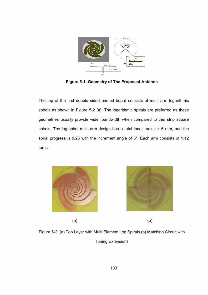
133
Figure 5-1: Geometry of The Proposed Antenna
The top of the first double sided printed board consists of multi arm logarithmic
spirals as shown in Figure 5-2 (a). The logarithmic spirals are preferred as these
geometries usually provide wider bandwidth when compared to thin strip square
spirals. The log-spiral multi-arm design has a total inner radius = 6 mm, and the
spiral progress is 0.26 with the increment angle of 5°. Each arm consists of 1.12
turns.
(a) (b)
Figure 5-2: (a) Top Layer with Multi Element Log Spirals (b) Matching Circuit with
Tuning Extensions

134
The bottom layer consists of the matching circuit and the tuning extensions as
shown in Figure 5-2 (b), the total diameter of the substrate is D = 72 mm. The total
length of the matching circuit is Ls = 25 mm and the length of the tuning extension
circuit is Lt = 11 mm as shown in Figure 5-3. The matching strip width on the
bottom of the substrate is s1 = 1 mm, and the width of the parallel matching stubs
s2 = 0.5 mm. The shorting vias are used to connect the logarithmic spirals to the
matching circuit and the shorting pins are used to connect to the ground plane.
There are total 4 shorting vias and 4 shorting pins. The total height of the antenna
is h = 16 mm.
Figure 5-3: Matching Circuit with Tuning Extensions
PIN diodes are added between the tuning extensions and the tuning extensions
are then connected to the tuning circuit on the bottom of the second double sided

135
printing board which is also made of FR-4 substrate and has copper ground plane
on the top side as shown in Figure 5-4(a) and the tuning circuit on the bottom as
shown in Figure 5-4 (b). The tuning circuit is then used to provide the 3V DC
voltage to turn the diodes ON/OFF thus changing the current distribution and
allowing for frequency reconfigurability.
(a) (b)
Figure 5-4: (a) Antenna Mounted on The Ground Plane (b) Tuning Circuit
5.1.2 Design Methodology
The addition of the tuning extensions causes a change in the total matching circuit
and thus results in new resonant frequencies which is very useful because at lower
frequencies with higher wavelengths and electrically small antenna designs the Q
values are high thus very small bandwidths. The frequency reconfigurability
provides the added advantage of extra bandwidth for the antenna designs working
in lower frequency bands. The total size of the proposed antenna is /43 and the
resonant frequency is 400 MHz. The addition of the tuning circuit does not affect
the antenna’s fundamental frequency. Various steps that were adopted for the

136
design and optimization of this antenna are illustrated in a way of a flow chart in
Figure 5-5.
Figure 5-5: Antenna Design Methodology
5.1.3 Switch Design
To implement the electronic frequency reconfigurability, PIN diodes were used to
replace the ideal shunt switches. PIN diodes are ideal for this antenna design due

137
to their small size, high reliability, fast switching speed and negligible capacitance
and resistance in the OFF and ON states. The circuit diagram of the PIN diode
acting as a shunt is shown in Figure 5-6
Figure 5-6: PIN Diode as A Shunt
The ON/OFF states equivalent circuits of the PIN diode based on Figure 5-6 are
illustrated in Figure 5-7 (a) and (b); where and define the packaging effect
values while the rest of the components model the electrical properties for the PIN
diode junction in (a) OFF (b) ON states.
(OFF)
(ON)
(a) (b)
Figure 5-7: PIN Diode as A Shunt

138
The circuit diagram of the electrical tuning circuit is illustrated in detail in Figure
5-8.
Figure 5-8: Antenna Tuning Circuit
5.2 Results and Discussions
The simulations of the reconfigurable antenna with the PIN diodes was carried out
to achieve an agreement between the simulated and measured results. The
simulations were carried out using the CST Microwave Studio Design Suite.
Return loss, radiation patterns and antenna gain were simulated and the values
were then checked against the measurement results obtained using the prototype

139
antenna measured in an anechoic chamber with the HP 8510C network analyser.
Both the simulated results and measured results show great agreement.
5.2.1 Reflection Coefficient
The possible switching states that can be obtained using the five PIN diodes are
summarised in Table 5-1. The diodes provide the antenna tuning over a band of
390 MHz – 415 MHz. CST design studio was used to first evaluate impedance
bandwidth (for S11 < -10 dB) for the five basic states with one diode ON and the
remaining diodes in the OFF state. Similarly, the prototype antenna was analysed
the network analyser to validate the results for the same setup. The simulated
results are presented in Figure 5-9 (a) and the measurement results are presented
in Figure 5-9 (b).
Table 5-1: Possible Frequency Reconfiguration Combinations for the Proposed
Antenna Design
SEQUENCE DIODE 1 DIODE 2 DIODE 3 DIODE 4 DIODE 5 1 ON OFF OFF OFF OFF 12 ON ON OFF OFF OFF 13 ON OFF ON OFF OFF 14 ON OFF OFF ON OFF 15 ON OFF OFF OFF ON 123 ON ON ON OFF OFF 124 ON ON OFF ON OFF 125 ON ON OFF OFF ON 134 ON OFF ON ON OFF 135 ON OFF ON OFF ON 145 ON OFF OFF ON ON
1234 ON ON ON ON OFF 1245 ON ON OFF ON ON 12345 ON ON ON ON ON

140
2 OFF ON OFF OFF OFF 23 OFF ON ON OFF OFF 24 OFF ON OFF ON OFF 25 OFF ON OFF OFF ON 234 OFF ON ON ON OFF 245 OFF ON OFF ON ON
2345 OFF ON ON ON ON 3 OFF OFF ON OFF OFF 34 OFF OFF ON ON OFF 35 OFF OFF ON OFF ON 345 OFF OFF ON ON ON 4 OFF OFF OFF ON OFF 45 OFF OFF OFF ON ON 5 OFF OFF OFF OFF ON
It can be seen from Figure 5-9 (a) that the return loss for all the resonant
frequencies is better than -20 dB. In the corresponding Figure 5-9 (b) it can also be
seen that the return loss for all resonant frequencies is again better than -20 dB
with minor differences which can be attributed to the fabrication error. Thus, both
the simulated and the measured results are in good agreement.
350 370 390 410 430 450
Frequency (MHz)
-35
-30
-25
-20
-15
-10
-5
0
Ref
lect
ion
co
effi
cien
t (d
B)
Lt=0Lt=2Lt=4Lt=6Lt=8
(a) (b)
Figure 5-9: (a) Simulated Reflection Coefficient (b) Measured Reflection Coefficient
350 370 390 410 430 450
Frequency (MHz)
-25
-20
-15
-10
-5
0
Ref
lect
ion
co
effi
cien
t (d
B)
MeasurementLt=0Lt=2Lt=4Lt=6Lt=8

141
The prototype antenna is shown in Figure 5-10 (a) and the measured return loss
for six different states is presented in Figure 5-10 (b) with no diode, with diode 1
ON only, with diode 1 and 2 ON, with diode 1 and 3 ON, with diode 1 and 4 ON
and with diode 1 and 5 ON, all the results show the reflection coefficient to be
better than -20 dB.
(a) (b)
Figure 5-10: (a) Prototype Antenna (b) Measured Return Loss Using Diode Combinations
5.2.2 Radiation Pattern
The normalised radiation pattern of the antenna at 400 MHz is shown in Figure
5-11, from which the radiation pattern of the antenna in the H-plane is omni-
directional, while in the E-plane the antenna exhibits a radiation pattern that looks
like a figure-of-eight. Due to the small ground plane size of the antenna for the 400
MHz resonant frequency the cross-polarization level decrease by 5 -10 dB from the
co-polar level, the antenna has a measured gain of 0.3 dB and the simulated gain
370 380 390 400 410 420 430 440 450
Frequency (MHz)
-35
-30
-25
-20
-15
-10
-5
0
Ref
lect
ion
Co
effi
cien
t (d
B)
MeasurementDiode1-5Diode1-4Diode1-3Diode1-2Diode1No diode

142
of 0.5 dB. In Figure 5-11 the E-CO and E-x represent the co-polarization and cross-
polarization characteristics, respectively.
0
30
60
90
120
150
180
210
240
270
300
330
-40
-30
-30
-20
-20
-10
-10
420MHzE-coH-coE-xH-x
Figure 5-11: Measured Radiation Pattern of the Prototype Antenna in E-Plane
and H-Plane Co polarization and Cross polarization
The Figure 5-12 represents the radiation patterns in the electrical and magnetic
field planes for different frequency points achieved by using the PIN diode
combinations. These radiation patterns indicate that the designed prototype
antenna meets the objectives of the designs for an electrically small
reconfigurable antenna that is well suited for the tracking system integration with
25 MHz bandwidth.

143
Figure 5-12: Measured Radiation Pattern of the Prototype Antenna for Various
Operating Frequencies
030
60
90
120
150180
210
240
270
300
330
-90
-80
-80
-70
-70
-60
-60
390 MHzH-planeE-plane
030
60
90
120
150180
210
240
270
300
330
-90
-80
-80
-70
-70
-60
-60
392 MHzH-planeE-plane
030
60
90
120
150180
210
240
270
300
330
-90
-80
-80
-70
-70
-60
-60
396 MHzH-planeE-plane
030
60
90
120
150180
210
240
270
300
330
-90
-80
-80
-70
-70
-60
-60
402 MHzH-planeE-plane
030
60
90
120
150180
210
240
270
300
330
-90
-80
-80
-70
-70
-60
-60
410 MHzH-planeE-plane
030
60
90
120
150180
210
240
270
300
330
-90
-80
-80
-70
-70
-60
-60
422 MHzH-planeE-plane

144
5.2.3 Gain
The proposed antenna has a simulated gain of -3 dB and measured gain of -5 dB.
The variation in the result can be attributed to the non-ideal absorbers and the
coaxial cable length in the anechoic chamber.
5.3 Conclusion
A new miniaturized low profile reconfigurable antenna design is presented. The
antenna has a low profile (16mm) and a compact size (diameter = 72 mm) and
provides a vertical polarized monopole like the omni-directional radiation pattern.
The use of the log-spirals in the design allows for the sensor structure to provide
better performance and a wide band and is very suitable for TETRA wideband and
wideband VHF/UHF frequency applications. The antenna has a sufficient gain and
provides considerable efficiency with a small finite ground plane making it a very
suitable choice for applications that require antenna surface mountings with size
constraints.

145
6. MEASUREMENT RESULTS FOR THE
PROPOSED ANGLE OF ARRIVAL
ESTIMATION TECHNIQUE EMPLOYING AN
ARRAY OF PROPOSED ELECTRICALLY
SMALL RECONFIGURABLE MULTI-ELEMENT
ANTENNA 6.1 Introduction
After simulating the proposed angle of arrival estimation design for various antenna
geometries under different environments using different radiators i.e. monopole
and inverted F antenna (IFA) based arrays, it is now necessary to test the
performance of the proposed algorithm described in Chapter 3, with an antenna
array consisting of the proposed antenna detailed in Chapter 5 to get a good
agreement between the simulated results and the measured results.
6.2 Simulation Setup 4-Ring Circular Array
Different antenna array geometries were constructed using the prototype antenna.
The first array geometry was a ring of 4 elements arranged in a uniform circular
array (UCA) with inter-element spacing of /4 at an operating frequency of
400MHz and elemental separation of 90 degrees using a circular finite ground
plane of 1m x 1m A 400 MHz log periodic reference antenna was used as a
transmitter for the measurements. The measurement setup is summarised for the

146
4-element UCA in Table 6-1 and shown in Figure 6-1 The real and imaginary
values obtained from each antenna were then imported into MATLAB to perform
the digital signal processing (DSP).
Table 6-1: Measurement Parameters for the 4 – Elements Uniform Circular Array
Parameter Value Number of Elements 4 SNR 0 dB Antenna Spacing λ/4 Number of Snapshots 100 Noise AWGN
.
Figure 6-1: Simulation Setup for Prototype Antenna Array Testing

147
6.2.1 Results and Discussion
In the measurements, the receiver array was rotated at 10-degree step size for the
whole azimuth plane of 360 degrees and the results were captured and processed.
Figure 6-2 shows the angle estimation performance of the four algorithms for the
angle of arrival reference or true angle of 0 Degrees. The Bartlett algorithm
produced enormous side lobes and the resolution is not good.
Figure 6-2: Performance Comparison Using 4-element UCA for True Angle of 0
Degree
Even though all algorithms could resolve the true angle with 1 degree error only the
proposed algorithm produced a very fine peak. For the interferometry algorithm, it
has been seen during simulations in Chapter 3 that the estimator has an
acceptable performance when there is a finite ground plane available which is

148
visible from Figure 6-2. Performance of the angle estimation algorithms is plotted
for another true angle of 180 degrees in Figure 6-3: and again, pretty similar results
are obtained where the proposed algorithm produces a very fine peak in the
direction of the true angle whereas the Bartlett algorithm and the MUSIC algorithm
have very wide side lobes.
Figure 6-3: Performance Comparison Using a 4-element UCA for a True Angle of
180 Degrees
The overall comparison of all algorithms for all 36 angles in the azimuth plane is
presented in Figure 6-4 and the performance of all algorithms is quite similar
except for some angles where interferometry algorithm has shown a big angle error

149
performance and that is because of the angle ambiguities caused by the number of
elements present in the antenna array are not sufficient to completely resolve the
angle for the interferometry algorithm as discussed in Section 3.4.5.
Figure 6-4: Performance Comparison Using a 4-element UCA for the Whole
Azimuth Plane
From the measurement results obtained for the 4-element array the performance
advantage of the proposed algorithm is quite clear. The proposed solution with its
advantage of sharper peaks and quite reliable estimation performance makes this
algorithm a better choice for applications that require information regarding the
source angle of arrival.

150
The angle estimation performance comparison between the simulated results and
the measured results are presented in Figure 6-5. The results show that even
though the measurement error was a little higher than the simulated but it is within
acceptable limits without any sort of addition digital signal processing for a 4-
element array with a quarter wavelength spacing.
Figure 6-5: Performance Comparison of 4-element UCA for the Whole Azimuth
Plane Using Simulated and Measured Data
Next the performance of the proposed algorithms was compared using multiple
impinging rays. From Figure 6-6 the proposed algorithm, Bartlett and MUSIC
algorithms could closely resolve the two incoming rays while the Interferometry
algorithm completely failed to estimate the true angle.

151
Up to this point it has been shown how all the algorithms could resolve the correct
angle for a single source. Next it will be shown how the performance of these
algorithms relate under power thresholds.
Figure 6-6: Performance Comparison Using a 4-element UCA for Multiple
Received Rays
6.3 Average Error Performance Comparison Using Restricted
Power Threshold
To verify the performance of the proposed method and to compare it against the
widely-accepted MUSIC and phase interferometry algorithms the results from the

152
same 4-element array were used. The performance of these algorithms was
compared using the power threshold limits. The results suggested that the wider
side lobes produced by the MUSIC algorithms cause the estimator to result in more
than one true angle of arrival estimation thus the total average error increases and
thus reducing the performance efficiency. For all three threshold levels of 0.25%,
0.50% and 0.75% the phase interferometry technique outperforms the super
resolution techniques.
(a) (b) (c)
Figure 6-7: Average Error Performance of AoA Algorithms at Power Thresholds of
(a) 25% (b) 50% (c) 75%
6.4 Simulation Setup 3-Ring Circular Array
The second array geometry was a ring of 3-elements arranged in a uniform circular
array (UCA) with inter-element spacing of /4 at an operating frequency of
400MHz and elemental separation of 120 degrees using a circular finite ground
plane of 1m x 1m. A 400 MHz log periodic reference antenna was used as a
transmitter for the measurements. The measurement setup is summarised for the

153
3-element UCA in Table 6-2 The real and imaginary values obtained from each
antenna were then imported into MATLAB to perform the digital signal processing
(DSP).
Table 6-2: Measurement Parameters for the 3 – Elements Uniform Circular Array
Parameter Value Number of Elements 3 SNR 0 dB Antenna Spacing λ/4 Number of Snapshots 100 Noise AWGN
6.4.1 Results and Discussion
In the measurements, the receiver array was rotated at 10-degree step size for the
whole azimuth plane of 360 degrees and the results were captured and processed
and are shown in Figure 6-8.
Figure 6-8: Performance Comparison Using a 3-element UCA for the Whole
Azimuth Plane

154
The pattern of estimation algorithms remains consistent where Bartlett, MUSIC and
Proposed algorithms have consistent performance but interferometry algorithms
suffers from degraded estimation performance.
When compared with the 4-element UCA the 3-element presents a higher error.
This error is still within acceptable levels depending upon the application type and
the design cost constraints.
Figure 6-9: Performance Comparison Using 3 and 4-element UCAs for the
Whole Azimuth Plane
155
6.5 Conclusion
The performance of the antenna array consisting of 4 elements and 3 elements of
the proposed sensor was measured using the anechoic chamber and the angle of
arrival estimation algorithms were applied and compared. The results showed that
the proposed direction of arrival estimation scheme provides very sharp peaks in
the direction of the source which in turn improves the overall average estimation
error at low power levels. The other algorithms suffer from big side lobes which at
low power levels result in the estimation of multiple angles and increase average
estimation error.
156
7. ORTHOGONAL FREQUENCY DIVISION
MULTIPLEXING SCHEME FOR ANGLE OF
ARRIVAL APPLICATIONS
7.1 Introduction
With the advancements in wireless communications the number of applications
requiring the knowledge of the number and location of the sources is growing
rapidly. In the world of array signal processing the primary technique supporting
these applications is Angle of Arrival estimation through antenna array [371]. In
AOA algorithms, the bearing between the receiver and the transmit signal source is
determined based on the angle of the incoming signal. The multipath fading effects
of the of the environment such as Doppler shift [372], signal attenuation and low
values of signal-to-noise ratio make the process of detection of the signal source
extremely difficult [373]. In cases where there is a LOS signal present the problem
lies in the separation of the true line of sight signal from the delayed and
overlapped replicas arriving at the receiver and the addition of noise further
complicates the process. All these problems make it extremely difficult to detect the
LOS signal with absolute certainty. To improve the detection of the LOS
component the resolution of the channel response in time domain requires
enhancement to resolve for paths and enhance the estimation accuracy of the

157
AOA algorithm. In several scenarios if the wideband system is employed it
mitigates the negative effects of the multipath and in turn improve the ability of the
localization system to successfully resolve the paths. Majority of the AOA
estimation techniques are narrowband estimators. However, the extended versions
of these algorithms can be applied to wideband scheme.
This chapter presents a coded OFDM system to be used in the application of
localization systems. In a practical wireless transmission, the spectral response of
the channel is not flat. The spectral response has nulls present in it which are
caused by the reflected signals. These reflected signals cannot only cause the
certain frequencies to be cancelled at the receiver but can also result in deep fades
in the received signal strength if they arrive at the receiver with the same power as
that of the direct signal and destructively interfere. In a narrowband transmission,
the entire signal can be lost if the null is present in the frequency response at the
transmit frequency. By employing a wideband signal, complete signal loss can be
avoided. Another solution to complete signal loss is to split the transmission into
many small narrowband carriers by using Orthogonal Frequency Division
Multiplexing (OFDM). In such a transmission scheme, multiple carrier frequencies
can be used to digitally encode the data. This results in the transformation of the
frequency selective channel into several flat fading channels [374]. Any loss of data
can be prevented by using coded OFDM in which forward error correction (FEC)
codes can be applied to the signal before transmission.

158
Moreover, as explained earlier, the received signal at the receiver consists of direct
line of sight (LOS) signals and non-line of sight (NLOS) signals caused by the
reflections from the scatterers present in the propagation path between the
transmitter and the receiver. These reflected signals arrive at the receiver with a
delay due to the difference in the path length travelled and the received energy is
spread in time which is referred to as channel delay spread. The channel delay
spread can be described as the time between first and the last significant multipath
signal arriving at the receiver. This delay spread is responsible for the inter symbol
interference (ISI) in the digital wireless communications. The inter-symbol
interference occurs when a delayed multipath signal overlaps the following
symbols. One method to reduce the ISI is to divide the bandwidth into several sub
channels by using OFDM.
This chapter is arranged as follows: Section 7.2 provides the mathematical model
for the orthogonal frequency division multiplexing scheme that can be employed for
the angle of arrival estimation followed by Section 7.3 which describes the
simulation model. Results and discussion are presented in Section 7.4 followed by
the conclusion in Section 7.5
7.2 Mathematical Model for Orthogonal Frequency Division Multiplexing
(OFDM) For Angle of Arrival Estimation
Assume the broadband impulse channel response is given by

159
)()(1
kj
k
n
k
keah
(7-1)
Apply an input signal:
tjetf ),( (7-2)
Then the output can be simplified to the following:
)(
1),( kk tjj
k
n
keeats
(7-3)
This alternatively can be given by:
)(),(1
Ueeeaets tjjjk
n
k
tj kk
(7-4)
Extend U() over baseband bandwidth B (shown in Figure 1) for N frequency
samples, then the ith frequency sample might be expressed by:
))1(1()1()1( 2222 N
nBNBBB
i inifnif (7-5)
where
BfN (7-6)
Figure 7-1: Assumed bandwidth range
The sampling time can be stated as follows:
-B/2 B/2

160
22
1 B
t
, hence
Bt
1 (7-7)
Thus, the minimum sampling frequency assumed by:
BB
fs 2
2 (7-8)
The ith uniform frequency sample of U() can be given by:
kikk fjjjk
n
ki eeeafU 2
1
)2(
(7-9)
7.3 Simulation Model
The wireless propagation simulation software Wireless Insite by Remcom is utilised
in this study as it can provide the most realistic simulation model for real life
wireless propagation. It is an electromagnetic simulation tool that helps predict the
propagation behaviour of electromagnetic waves in the presence of objects with
different electrical properties. The propagation scenario used in this work is of
Ottawa city in Canada available from Remcom which can be classified as an urban
environment as shown in Figure 7-2.

161
Figure 7-2: Study Area for OFDM
A 3-element array of ideal dipoles spatially distributed in the azimuthal plane with
angular separation of 120 degrees at known locations with inter-element spacing of
/3 was used to receive the electromagnetic field propagating from the far field
transmitter. The output of each element in the antenna array was then used to
calculate the angle of arrival. The receiver array and the far field transmitter lie in
the same plane so only azimuthal angle calculations were done. Complex
Gaussian noise uncorrelated from the signals was added to each element of the
array. The IFFT was applied to the received channel transfer function to acquire
the impulse response with 10 multipath including the LOS path over the desired
band. Each impulse in the frequency range was assigned an AOA and the AOA
assigned to the impulse with the highest amplitude was the true bearing angle. The
phase adjustments were done on the received components to account for the
antenna position within the array so that the impulse response is in line with each
receiver channel. The dominant impulse from all received channels was then

162
passed to the narrow band angle of arrival estimation technique and the
performance is evaluated in terms of AOA estimation error
5.2 Results and Discussion The results from two different array types, 1) 3-element uniform circular ring array
with element spacing of 120 degrees and 2) 5-Elements uniform circular array with
an element spacing of 72 degrees are presented for available bandwidths of 1MHz
and 10 MHz.
.
Figure 7-3: Multipaths travelled by the transmitted signal
The Figure 7-4 (a) shows the results for the 3-element UCA where the
transmission is split into small narrowband carriers using 1 MHz and b) where the
transmission is split using 10MHz for the total of 11 carriers. It is to be noted that
there is noise and multipaths presents in the system and the resultant frequency
domain and time domain results are close to the true AoA for most carriers but still
not sufficient enough clarity to deduce the true AoA. To further improve the
performance, the same experiment was repeated with a 5-element UCA.

163
(a) (b)
Figure 7-4: 3-element Circular Ring Array using OFDM
The results obtained in Figure 7-5 clarify the usefulness of the transmission
division into narrowband carriers and show how all carriers are in sync with using
either time or frequency domain estimation technique. It can also be seen that by
increasing the bandwidth as in Figure 7-5 (b) any minute errors present between
the time and frequency domain estimation were also resolved.
(a) (b)
Figure 7-5: 5-element Circular Ring Array using OFDM

164
7.4 Conclusion In this chapter, a multi carrier modulation scheme is evaluated for use in
localization systems. OFDM can provide many suitable solutions which the single
carrier modulation scheme or the FDM scheme cannot provide. The ability of the
OFDM systems to combat multipath make them the most suitable scheme for
angle of arrival estimation. The higher time resolution and the higher number of
array elements makes it easier to place decisions on the true angle of arrival
estimation. In such systems, however for accuracy an assumption must stand that
there is a line of sight present between the transmitter and receiver and there will
always be a dominant ray present. If this assumption is to be taken out of the
equation, then further processing must be applied to cater for non-line of sight
(NLOS) scenarios and this can include having a memory bank based on previous
calculations to calibrate the localization system in case a sudden dominant NLOS
component appears.

165
8. CONCLUSION AND FUTURE WORK
8.1 Conclusion
An in-depth analysis of the techniques involved in the angle of arrival estimation for
several antenna configurations and different scenarios for both narrowband and
wideband spectrum estimations were presented. This type of work has high
significance in military applications, patient tracking and in providing the location
based services to the continuously growing community of mobile users. A new
signal subspace based algorithm is designed, implemented and testes using both
simulation and measurement models and has shown an improved performance as
compared to any of the previously proposed algorithms. In addition, a new and
novel miniaturized reconfigurable logarithmic spiral antenna with improved
bandwidth performance and reconfigurable frequency bands is designed,
implemented and tested using multiple element arrays measure the performance.
The results suggest the proposed antenna is highly suitable for localization
systems that have size constraints for the antenna array implementation, cost
constraints and require reliability and is also suited for mobile wireless devices that
require antenna surface mounting. Also, the degrading effects of the mutual
coupling on antenna arrays was studied and the procedures were detailed to
deduce the decoupling methods which were then applied to different data sets and
the performance of the AoA algorithms was evaluated before and after the mutual
coupling compensation, Finally an OFDM based transmission scheme was

166
evaluated by dividing the whole transmission into narrow band carriers which is
suitable for AoA estimation systems and is capable of negating the multipath
effects of the channel and improve estimation accuracy. A brief thesis summary is
presented below.
8.2 Thesis Summary
Chapter 2 – A detailed review of the location based services and their applications
both in public and private sector was presented. Location based services have
found its place in the next generation wireless communication system applications
such as tracking, health, navigation etc. The chapter also presents the
infrastructure model for both indoor and outdoor LBS. The existing localization
techniques were also reviewed and solutions were presented to improve the
existing localization applications and techniques.
Chapter 3 – Mathematical background on the antenna arrays and angle of arrival
estimation techniques was presented. A novel high-resolution direction of arrival
estimation algorithm based on the signal subspace decomposition has been
presented with the core idea of finding the difference between the maximum
absolute value of the pseudo-spectrum and the absolute value of the pseudo-
spectrum thus minimizing the denominator and producing larger peaks in the
direction of arrival of the incoming signal. The proposed method exploits the signal

167
subspace with array steering vector as opposed to the MUSIC algorithm that
exploits the noise subspace with array steering vector. The proposed algorithm has
been tested and evaluated using different criteria and has shown great potential to
be employed as the next generation localization technique.
Chapter 4 – The degrading effects of mutual coupling on antenna array elements
were discussed. Two methods of mutual coupling compensation namely the
conventional mutual impedance method and the receiving mutual impedance
methods were discussed and evaluated. Based on these methods, decoupling
matrices were generated and applied to the simulation data. The results showed
that receiving mutual impedance method is easier to implement with the same
computational complexity as that of the conventional mutual impedance method
and has better results and is a better fit for application requiring real time
processing.
Chapter 5 – In this chapter the design and implementation of a novel
reconfigurable electrically small antenna for wideband UHF frequencies is
presented. The antenna design makes use of the logarithmic spirals with biased
components and has considerable stable gain and efficiency with a small ground
plane making it a suitable candidate for surface mounting on tracking devices
which has size constraints. The performance of this antenna in terms of reflection
coefficient, radiation pattern and gain were presented which show the suitability of

168
the antenna for localization applications with reconfigurable bandwidth, omni-
directional radiation pattern, vertical polarisation and small size.
Chapter 6 – In this chapter the performance of the antenna array consisting of 4-
elements and 3-elements of the proposed sensor was measured using the
anechoic chamber and the angle of arrival estimation algorithms were applied and
compared. The results showed that the proposed direction of arrival estimation
scheme provides very sharp peaks in the direction of the source which in turn
improves the overall average estimation error at low power levels. The other
algorithms suffer from big side lobes which at low power levels result in the
estimation of multiple angles and increase average estimation error.
Chapter 7 – A multicarrier modulation OFDM based system is evaluated to be
used for angle of arrival estimation. The channel characteristics received from the
electromagnetic propagation software were converted into time domain using IFFT
and spread across the desired band using subcarriers making the system more
robust against multipath effects. The time resolution provided by the wideband
transmission improved the angle estimation accuracy. The comparison between
the time domain and frequency domain estimation is presented and how the
bandwidth made an effect on these estimations.

169
8.3 Recommendations for Future Work
As the topic of source localization is quite wide spread and the market demands
are ever growing there is always a margin for improvement. Some of the topics that
can be of interest for further research are listed below.
As most this study was comprised around receiver antenna arrays it was
shown in Chapter 4 that received mutual impedance method calculated for one
angle helps reduce coupling error in majority of angles but this can be extended
further to develop a single mutual coupling compensation method that can be
applied to all angles.
The proposed angle of arrival estimation algorithm can be used to test the
performance of angle of arrival estimation with more antenna geometries and can
be enhanced to include 3D angle of arrival estimation.
Another important piece of work that is presented in Chapter 7 is the multi
carrier modulation scheme of OFDM for angle of arrival estimation. This work using
the proposed technique can be enhanced and further improved by adding space
time coding, improved channel estimations, frequency offset estimations, path loss
estimations and channel compensation techniques.

170
REFERENCES
[1] J. E. Bardram and H. B. Christensen, "Pervasive Computing Support For
Hospitals: An Overview Of The Activity-Based Computing Project," IEEE Pervasive
Computing, Vol. 6, No. 1, pp. 44 - 51, January - March 2007. DOI:
10.1109/MPRV.2007.19
[2] J. E. Bardram, "Applications Of Context-Aware Computing In Hospital Work:
Examples And Design Principles," ACM Symposium on Applied Computing, pp.
1574-1579, March 14 - 17, 2004. DOI: 10.1145/967900.968215
[3] R. Zekavat and R. M. Buehrer, “Handbook of position location: Theory,
practice and advances, ” John Wiley & Sons, Vol. 27, November 2011. ISBN: 978-
0-470-94342-7
[4] A. Solanas et al., "Smart Health: A Context-Aware Health Paradigm Within
Smart Cities," IEEE Communications Magazine, Vol. 52, No. 8, pp. 74 - 81, August
2014. DOI: 10.1109/MCOM.2014.6871673
[5] T. A. Khan, H. Asmat, F. Shahzad, M. F. Mushtaq, M. M. S. Missen, and N.
Akhtar, "SN2SMS: Location-Aware Social Network Based SMS Health-Care
System," International Journal of Computer Science Issues (IJCSI), Vol. 11, pp.
144 - 149, July 2014. ISSN (Print): 1694-0814 | ISSN (Online): 1694-0784
[6] P. Steggles and S. Gschwind, "The Ubisense Smart Space Platform," Third
International Conference on Pervasive Computing, Vol. 191, pp. 73 - 76, 2005.
doi=10.1.1.176.362
[7] B. Simon, Z. Miklós, W. Nejdl, M. Sintek, and J. Salvachua, "Smart Space
For Learning: A Mediation Infrastructure For Learning Services," Twelfth

171
International Conference on World Wide Web, pp. 20 - 24, May 2003. ISBN 963-
311-355-5.
[8] S. Helal, W. Mann, H. El-Zabadani, J. King, Y. Kaddoura, and E. Jansen,
"The Gator Tech Smart House: A Programmable Pervasive Space," John Wiley &
Sons, Ltd., 2008. DOI: 10.1002/9780470379424.ch37
[9] S. Alletto et al., "An Indoor Location-Aware System for an IoT-Based Smart
Museum," IEEE Internet of Things Journal, Vol. 3, No. 2, pp. 244 - 253, April 2016.
DOI: 10.1109/JIOT.2015.2506258
[10] A. Martinez-Balleste, P. A. Perez-martinez and A. Solanas, "The Pursuit Of
Citizens' Privacy: A Privacy-Aware Smart City Is Possible," IEEE Communications
Magazine, Vol. 51, No. 6, pp. 136 - 141, June 2013. DOI:
10.1109/MCOM.2013.6525606
[11] S. A. Applin and M. D. Fischer, "Thing Theory: Connecting Humans to
Location-Aware Smart Environments," 3rd Workshop On Location Awareness For
Mixed And Dual Reality: LAMDa’13, pp. 29, March 2013.
DOI:10.1145/2451176.2451228
[12] P. M. Singh and M. van Sinderen, "Interoperability Challenges For Context
Aware Logistics Services-The Case Of Synchromodal Logistics," 6th International
IFIP Working Conference on Enterprise Interoperability, Vol. 1414, pp. 9 – 9, 2015.
ISSN (Print): 1613-0073
[13] I. Durazo-Cardenas, A. Starr, A. Tsourdos, M. Bevilacqua, and J. Morineau,
"Precise Vehicle Location As A Fundamental Parameter For Intelligent Self-Aware

172
Rail-Track Maintenance Systems," Procedia CIRP, Vol. 22, pp. 219 - 224, 2014.
DOI: https://doi.org/10.1016/j.procir.2014.07.002
[14] L. Evers, M. J. Bijl, M. Marin-Perianu, R. Marin-Perianu, and P. J. Havinga,
"Wireless Sensor Networks And Beyond: A Case Study On Transport And
Logistics," University of Twente, Centre for Telematica and Information Technology
(CTIT), Vol. 05, pp. 1 – 6, 2005. ISBN (Print): 1381 – 3625.
[15] K. Kuladinithi, O. Bergmann, T. Pötsch, M. Becker, and C. Görg,
"Implementation of COAP And Its Application In Transport Logistics," Proceedings
of Extending the Internet to Low Power and Lossy Networks (IP+ SN) , pp. 1 – 6,
April 2011.
[16] W. Zhou, S. Piramuthu, F. Chu, and C. Chu, "RFID-Enabled Flexible
Warehousing," Decision Support Systems, Vol. 98, pp. 99 - 112, June 2017. DOI:
https://doi.org/10.1016/j.dss.2017.05.002
[17] D. Ma, N. Saxena, T. Xiang and Y. Zhu, "Location-Aware and Safer Cards:
Enhancing RFID Security and Privacy via Location Sensing," IEEE Transactions on
Dependable and Secure Computing, Vol. 10, No. 2, pp. 57 - 69, March-April 2013.
DOI: 10.1109/TDSC.2012.89
[18] P. L. Smith, "Effects Of Imperfect Storm Reporting On The Verification Of
Weather Warnings," Bulletin of the American Meteorological Society, Vol. 80, pp.
1099
1105,June1999.DOI:https://doi.org/10.1175/15200477(1999)080<1099:EOISRO>2
.0.CO;2

173
[19] Steinmetz R., Wehrle K. “Chapter 2. What Is This “Peer-to-Peer” About?,
Peer-to-Peer Systems and Applications”, Lecture Notes in Computer Science, Vol
3485. pp. 9 – 16, Springer. 2005. DOI: https://doi.org/10.1007/11530657_2
[20] V. Lenders, E. Koukoumidis, P. Zhang, and M. Martonosi, "Location-Based
Trust For Mobile User-Generated Content: Applications, Challenges And
Implementations," 9th Workshop On Mobile Computing Systems And Applications,
pp. 60 - 64, 2008. DOI:10.1.1.139.1903
[21] C. Xu, S. Jia, L. Zhong and G. M. Muntean, "Socially Aware Mobile Peer-To-
Peer Communications For Community Multimedia Streaming Services," IEEE
Communications Magazine, Vol. 53, No. 10, pp. 150 - 156, October 2015.
DOI: 10.1109/MCOM.2015.7295477
[22] M. Bartlett, "An Introduction to Stochastic Processes with Special
References to Methods and Applications," Cambridge University Press, New York,
1961.
[23] L. C. Godara, “Smart antennas,” CRC press, January 2004. ISBN
9780849312069 - CAT# 1206
[24] J. Capon, "High-Resolution Frequency-Wavenumber Spectrum Analysis,"
Proceedings of the IEEE, Vol. 57, No. 8, pp. 1408 - 1418, Aug. 1969.
DOI: 10.1109/PROC.1969.7278
[25] F. Gross, "Smart Antennas For Wireless Communications," McGraw-Hill
Companies Inc, ed: New York, 2005. ISBN: 9780071447898
[26] S. Applebaum, "Adaptive Arrays”, Syracuse University Research
Corporation, SPL, TR66-1, August 1966.

174
[27] S. Applebaum, "Adaptive Arrays," IEEE Transactions on Antennas and
Propagation, Vol. 24, No. 5, pp 585 – 598, September 1976. DOI:
10.1109/TAP.1976.1141417
[28] B. Widrow and M. Hoff, “Adaptive Switching Circuits,” IRE WESCON
Convention Record: At The Western Electronic Show And Convention, Vol. 4, pp.
96 - 104, 1960.
[29] B. Widrow, P. E. Mantey, L. J. Griffiths, and B. B. Goode, "Adaptive Antenna
Systems," Proceedings of the IEEE, Vol. 55, pp. 2143 - 2159, December 1967.
[30] W. Gabriel, "Adaptive Processing Antenna Systems," IEEE Antennas and
Propagation Society Newsletter, Vol. 25, No. 5, pp. 4 - 11, October 1983.
DOI: 10.1109/MAP.1983.27703
[31] L. C. Godara, "Application Of Antenna Arrays To Mobile Communications. II.
Beam-Forming And Direction-Of-Arrival Considerations," Proceedings of the IEEE,
Vol. 85, No. 8, pp. 1195 - 1245, August 1997.DOI: 10.1109/5.622504
[32] J. C. Liberti and T. S. Rappaport, "Smart Antennas For Wireless
Communications: IS-95 And Third Generation CDMA Applications,” Prentice Hall
Communications Engineering And Emerging Technologies Series, Prentice Hall
PTR, 1999. ISBN 0137192878, 9780137192878
[33] J. P. Burg, "The Relationship Between Maximum Entropy Spectra And
Maximum Likelihood Spectra," Geophysics, Vol. 37, pp. 375 – 376, April 1972.
DOI: https://doi.org/10.1190/1.1440265

175
[34] V. F. Pisarenko, "The Retrieval of Harmonics from a Covariance Function,"
Geophysical Journal of the Royal Astronomical Society, Vol. 33, pp. 347 – 366,
September 1973. DOI: https://doi.org/10.1111/j.1365-246X.1973.tb03424.x
[35] M. Wax, Tie-Jun Shan and T. Kailath, "Spatio-Temporal Spectral Analysis
By Eigenstructure Methods," IEEE Transactions on Acoustics, Speech, and Signal
Processing, Vol. 32, No. 4, pp. 817 - 827, Aug 1984. DOI:
10.1109/TASSP.1984.1164400
[36] J. Makhoul, "Linear Prediction: A Tutorial Review," Proceedings of the
IEEE, Vol. 63, No. 4, pp. 561 - 580, April 1975. DOI: 10.1109/PROC.1975.9792
[37] S. S. Reddi, "Multiple Source Location-A Digital Approach," IEEE
Transactions on Aerospace and Electronic Systems, Vol. AES-15, No. 1, pp. 95 -
105, January 1979. DOI: 10.1109/TAES.1979.308800
[38] R. Kumaresan and D. W. Tufts, "Estimating The Angles Of Arrival Of
Multiple Plane Waves," IEEE Transactions on Aerospace and Electronic Systems,
Vol. AES-19, No. 1, pp. 134 - 139, January 1983. DOI:
10.1109/TAES.1983.309427
[39] R. Schmidt, "Multiple Emitter Location And Signal Parameter
Estimation," IEEE Transactions on Antennas and Propagation, Vol. 34, No. 3, pp.
276 - 280, March 1986. DOI: 10.1109/TAP.1986.1143830
[40] S. V. Schell, R. A. Calabretta, W. A. Gardner and B. G. Agee, "Cyclic
MUSIC Algorithms For Signal-Selective Direction Estimation," International
Conference on Acoustics, Speech, and Signal Processing, Vol.4, pp. 2278 - 2281,
1989. DOI: 10.1109/ICASSP.1989.266920

176
[41] T. E. Biedka and B. G. Agee, "Subinterval Cyclic MUSIC-Robust DF With
Error In Cycle Frequency Knowledge," Conference Record of the Twenty-Fifth
Asilomar Conference on Signals, Systems & Computers, Vol.1, pp. 262 - 266,
1991. DOI: 10.1109/ACSSC.1991.186453
[42] K. D. Mauck, "Wideband cyclic MUSIC," IEEE International Conference on
Acoustics, Speech, and Signal Processing, Vol.4, pp. 288 - 291, 1993. DOI:
10.1109/ICASSP.1993.319651
[43] S. V. Schell, "Performance Analysis Of The Cyclic MUSIC Method Of
Direction Estimation For Cyclostationary Signals," IEEE Transactions on Signal
Processing, Vol. 42, No. 11, pp. 3043 - 3050, November 1994. DOI:
10.1109/78.330364
[44] P. Charg, Y. Wang, and J. Saillard, "An Extended Cyclic Music Algorithm,"
IEEE International Conference on Acoustics, Speech, and Signal Processing
(ICASSP), pp. III-3025 - III-3028, 2002.
[45] P. Charge, Yide Wang and J. Saillard, "An Extended Cyclic MUSIC
Algorithm," IEEE Transactions on Signal Processing, Vol. 51, No. 7, pp. 1695 -
1701, July 2003. DOI: 10.1109/TSP.2003.812834
[46] H. Yan and H. H. Fan, "Improved Cyclic And Conjugate Cyclic
MUSIC," Sensor Array and Multichannel Signal Processing Workshop, pp. 289 -
293, 2004. DOI: 10.1109/SAM.2004.1502955
[47] H. Yan and H. H. Fan, "Extended Wideband Cyclic MUSIC," Sensor Array
and Multichannel Signal Processing Workshop, pp. 318 - 322, 2004. DOI:
10.1109/SAM.2004.1502961

177
[48] Zhigang Liu and Jinkuan Wang, "Unitary Cyclic MUSIC Algorithm In A
Multipath Environment," 12th European Signal Processing Conference, pp. 2155 -
2158, 2004.
[49] M. Sahmoudi and M. G. Amin, "Unitary Cyclic MUSIC for Direction Finding
in GPS Receivers," Fourth IEEE Workshop on Sensor Array and Multichannel
Processing, pp. 70 - 73, 2006. DOI: 10.1109/SAM.2006.1706093
[50] S. Ali and P. Aarabi, "A Cyclic Interface For The Presentation Of Multiple
Music Files," IEEE Transactions on Multimedia, Vol. 10, No. 5, pp. 780 - 793,
August 2008.DOI: 10.1109/TMM.2008.922848
[51] R. Roy and T. Kailath, "ESPRIT-Estimation Of Signal Parameters Via
Rotational Invariance Techniques," IEEE Transactions on Acoustics, Speech, and
Signal Processing, Vol. 37, No. 7, pp. 984 - 995, July 1989. DOI:
10.1109/29.32276.
[52] J. Munier and G. Y. Delisle, "Spatial Analysis Using New Properties Of The
Cross-Spectral Matrix," IEEE Transactions on Signal Processing, Vol. 39, No. 3,
pp. 746 - 749, March 1991. DOI: 10.1109/78.80863
[53] S. Marcos, A. Marsal and M. Benidir, "Performances Analysis Of The
Propagator Method For Source Bearing Estimation," IEEE International
Conference on Acoustics, Speech, and Signal Processing, Vol.4, pp. IV/237 -
IV/24, 1994. DOI: 10.1109/ICASSP.1994.389823
[54] K. V. S. Babu, "A Fast Algorithm For Adaptive Estimation Of Root-MUSIC
Polynomial Coefficients," International Conference on Acoustics, Speech, and

178
Signal Processing, Vol. 3, pp. 2229 - 2232, 1991. DOI:
10.1109/ICASSP.1991.150830
[55] A. Barabell, "Improving The Resolution Performance Of Eigenstructure-
Based Direction-Finding Algorithms," IEEE International Conference on Acoustics,
Speech, and Signal Processing, pp. 336 - 339, 1983. DOI:
10.1109/ICASSP.1983.1172124
[56] Q. S. Ren and A. J. Willis, "Fast Root MUSIC Algorithm," Electronics
Letters, Vol. 33, No. 6, pp. 450 - 451, 13 March 1997. DOI: 10.1049/el:19970272
[57] C. S. MacInnes, "Source Localization Using Subspace Estimation And
Spatial Filtering," IEEE Journal of Oceanic Engineering, Vol. 29, No. 2, pp. 488 -
497, April 2004. DOI: 10.1109/JOE.2004.827290
[58] T. Hayashi, M. Nakano and A. Yamaguchi, "Novel AOA Estimation Method
Using Delay Profile In Downlink," International Workshop on Antenna Technology
(iWAT), pp. 35-38, 2013. DOI: 10.1109/IWAT.2013.6518293
[59] S. F. Chuang, W. R. Wu and Y. T. Liu, "High-Resolution AoA Estimation for
Hybrid Antenna Arrays," IEEE Transactions on Antennas and Propagation, Vol. 63,
No. 7, pp. 2955-2968, July 2015. DOI: 10.1109/TAP.2015.2426795
[60] C. A. Balanis, " Antenna Theory: Analysis and Design," Wiley-Blackwell,
2005. ISBN: 978-0471667827
[61] H. Zhu, F. Liu, and H. Li, "Efficient and Privacy-Preserving Polygons Spatial
Query Framework for Location-Based Services," IEEE Internet of Things Journal,
Vol. 4, pp. 536 - 545, 2017. DOI: 10.1109/JIOT.2016.2553083

179
[62] Y. Song, Z. Hu, X. Leng, H. Tian, K. Yang, and X. Ke, "Friendship Influence
on Mobile Behaviour of Location Based Social Network Users," Journal of
Communications and Networks, Vol. 17, pp. 126 - 132, 2015.
DOI: 10.1109/JCN.2015.000026
[63] T. Peng, Q. Liu, and G. Wang, "Enhanced Location Privacy Preserving
Scheme in Location-Based Services,” IEEE Systems Journal, Vol. 11, pp. 219 -
230, 2017.
[64] A. Baiocchi and F. Cuomo, "Infotainment Services Based on Push-Mode
Dissemination in An Integrated VANET and 3G Architecture," Journal of
Communications and Networks, Vol. 15, pp. 179 - 190, 2013.
DOI: 10.1109/JCN.2013.000031
[65] E. Jovanov and A. Milenkovic, "Body Area Networks for Ubiquitous
Healthcare Applications: Opportunities and Challenges," Journal of medical
systems, Vol. 35, pp. 1245 - 1254, 2011.
[66] M. S. Hossain, "Cloud-Supported Cyber–Physical Localization Framework
for Patients Monitoring," IEEE Systems Journal, Vol. 11, pp. 118 - 127, 2017.
DOI: 10.1109/JSYST.2015.2470644
[67] P. A. Moreno, M. E. Hernando, and E. J. Gómez, "Design and Technical
Evaluation of an Enhanced Location-Awareness Service Enabler for Spatial
Disorientation Management of Elderly with Mild Cognitive Impairment,” IEEE
Journal of Biomedical and Health Informatics, Vol. 19, pp. 37 - 43, 2015.
DOI: 10.1109/JBHI.2014.2327638

180
[68] H. Huang, J. Zhou, W. Li, J. Zhang, X. Zhang, and G. Hou, "Wearable
Indoor Localisation Approach in Internet of Things," IET Networks, Vol. 5, pp. 122 -
126, 2016. DOI:10.1049/iet-net.2016.0007
[69] L. Calderoni, M. Ferrara, A. Franco, and D. Maio, "Indoor Localization in A
Hospital Environment Using Random Forest Classifiers," Expert Systems with
Applications, Vol. 42, No.1, pp. 125 - 134, 2015. DOI: 10.1016/j.eswa.2014.07.042
[70] A. Athalye, V. Savic, M. Bolic, and P. M. Djuric, "Novel Semi-Passive RFID
System For Indoor Localization," IEEE Sensors Journal, Vol. 13, pp. 528 - 537,
2013. DOI: 10.1109/JSEN.2012.2220344
[71] D. Grewal, A. L. Roggeveen, and J. Nordfält, "The Future of Retailing,"
Journal of Retailing, Vol. 93, pp. 1 - 6, 2017.
[72] K. Zheng, H. Wang, H. Li, W. Xiang, L. Lei, J. Qiao, et al., "Energy-Efficient
Localization and Tracking of Mobile Devices in Wireless Sensor Networks," IEEE
Transactions on Vehicular Technology, Vol. 66, pp. 2714 - 2726, 2017.
DOI: 10.1109/TVT.2016.2584104
[73] M. Yassin and E. Rachid, "A Survey of Positioning Techniques and Location
Based Services in Wireless Networks," IEEE International Conference on Signal
Processing, Informatics, Communication and Energy Systems (SPICES), pp. 1 – 5,
2015. DOI: 10.1109/SPICES.2015.7091420
[74] A. H. Sayed, A. Tarighat, and N. Khajehnouri, "Network-Based Wireless
Location: Challenges Faced in Developing Techniques for Accurate Wireless
Location Information," IEEE Signal Processing Magazine, Vol. 22, pp. 24 - 40,
2005. DOI: 10.1109/MSP.2005.1458275

181
[75] P. H. Tseng and K. T. Lee, "A Femto-Aided Location Tracking Algorithm in
LTE-A Heterogeneous Networks," IEEE Transactions on Vehicular Technology,
Vol. 66,No. 1, pp. 748 - 762, Jan. 2017. DOI: 10.1109/TVT.2016.2544790
[76] I. D. Constantiou, C. Lehrer, and T. Hess, "Changing Information Retrieval
Behaviours: An Empirical Investigation Of Users’ Cognitive Processes In The
Choice Of Location-Based Services," European Journal of Information Systems,
Vol. 23, pp. 513 - 528, September 2014. DOI: 10.1057/ejis.2014.12
[77] G. Zhao, X. Qian, and C. Kang, "Service Rating Prediction By Exploring
Social Mobile Users; Geographical Locations," IEEE Transactions on Big Data,
Vol. 3, pp. 67 - 78, 2017. DOI: 10.1109/TBDATA.2016.2552541
[78] J. T. Penttinen, “The LTE-Advanced Deployment Handbook: The Planning
Guidelines for the Fourth Generation Networks”, John Wiley & Sons, 2016.
[79] R. Y. Chan, X. Bai, X. Chen, S. Jia, and X.-h. Xu, "iBeacon and HCI in
Special Education: Micro-Location Based Augmentative and Alternative
Communication for Children with Intellectual Disabilities," CHI Conference
Extended Abstracts on Human Factors in Computing Systems, pp. 1533 - 1539,
2016. DOI:10.1145/2851581.2892375
[80] E. S. Lohan, P. F. e Silva, A. Basiri, and P. Peltola, "Location Based
Services Analysis Through Analytical Hierarchical Processes: An e-Health-Based
Case Study," Multi-Technology Positioning, ed: Springer, pp. 283-301, 2017.
[81] A. Grillon, A. Perez-Uribe, H. Satizabal, L. Gantel, D. D. S. Andrade, A.
Upegui, et al., "A Wireless Sensor-Based System for Self-tracking Activity Levels
Among Manual Wheelchair Users," eHealth 360°, ed: Springer, pp. 229-240, 2017.

182
[82] A. Boulmakoul, L. Karim, A. Elbouziri, and A. Lbath, "A System Architecture
for Heterogeneous Moving-Object Trajectory Metamodel Using Generic Sensors:
Tracking Airport Security Case Study," IEEE Systems Journal, Vol. 9, pp. 283 -
291, 2015. DOI: 10.1109/JSYST.2013.2293837
[83] J. Wahlström, I. Skog, and P. Händel, "Smartphone-Based Vehicle
Telematics: A Ten-Year Anniversary," IEEE Transactions on Intelligent
Transportation Systems, Vol. PP, No. 99, pp. 1 - 24, 2017. DOI:
10.1109/TITS.2017.2680468
[84] W. Lin, J. Liu, Y. Zhou, and J. Huang, "Estimation Of TOA Based MUSIC
Algorithm And Cross Correlation Algorithm Of Appropriate Interval," AIP
Conference Proceedings, pp. 08 – 011, 2017.
[85] Y. Huang and Y. Xu, "Advanced Technology in GIS/GPS-Based
Transportation Systems," Recent Patents on Mechanical Engineering, Vol. 10, pp.
18-29, 2017.
[86] M. A. Tayebi, M. Ester, U. Glässer and P. L. Brantingham,
"CRIMETRACER: Activity Space Based Crime Location Prediction," IEEE/ACM
International Conference on Advances in Social Networks Analysis and Mining
(ASONAM 2014), pp. 472 – 480, 2014. DOI: 10.1109/ASONAM.2014.6921628
[87] N. M. Drawil, H. M. Amar and O. A. Basir, "GPS Localization Accuracy
Classification: A Context-Based Approach," IEEE Transactions on Intelligent
Transportation Systems, Vol. 14, No. 1, pp. 262 - 273, March 2013.
DOI: 10.1109/TITS.2012.2213815

183
[88] S. Dibb, "Changing Times for Social Marketing Segmentation,"
Segmentation in Social Marketing, ed: Springer, pp. 41 – 59, 2017.
[89] O. Ahlqvist, "Location‐Based Games," The International Encyclopedia of
Geography, 2017.
[90] M. Capra, M. Radenkovic, S. Benford, L. Oppermann, A. Drozd, and M.
Flintham, "The Multimedia Challenges Raised by Pervasive Games," 13th annual
ACM international conference on Multimedia, pp. 89 - 95, 2005. DOI:
10.1145/1101149.1101163
[91] Z. Sun, L. Di, G. Heo, C. Zhang, H. Fang, P. Yue, et al., "Geofairy: Towards
A One-Stop And Location Based Service For Geospatial Information Retrieval,"
Computers, Environment and Urban Systems, Vol. 62, pp. 156 - 167, March 2017.
DOI: https://doi.org/10.1016/j.compenvurbsys.2016.11.007
[92] A. Roy, P. De, and N. Saxena, "Location-Based Social Video Sharing Over
Next Generation Cellular Networks," IEEE Communications Magazine, Vol. 53, pp.
136 - 143, 2015. DOI: 10.1109/MCOM.2015.7295475
[93] J. Bao, Y. Zheng, D. Wilkie, and M. Mokbel, "Recommendations In Location-
Based Social Networks: A Survey," GeoInformatica, Vol. 19, pp. 525 - 565, 2015.
[94] T. Deng, X. Wang, P. Fan, and K. Li, "Modelling and Performance Analysis
of a Tracking-Area-List-Based Location Management Scheme in LTE Networks,"
IEEE Transactions on Vehicular Technology, Vol. 65, No. 8 pp. 6417 - 6431,
August 2016. DOI: 10.1109/TVT.2015.2473704
[95] K. Katsaros, M. Dianati, R. Tafazolli, and X. Guo, "End-to-End Delay Bound
Analysis for Location-Based Routing in Hybrid Vehicular Networks," IEEE

184
Transactions on Vehicular Technology, Vol. 65, No. 9, pp. 7462 - 7475, September
2016. DOI: 10.1109/TVT.2015.2482362
[96] A. Nessa, M. Kadoch, and B. Rong, "Fountain Coded Cooperative
Communications for LTE-A Connected Heterogeneous M2M Network," IEEE
Access, Vol. 4, pp. 5280-5292, 2016. DOI: 10.1109/ACCESS.2016.2601031
[97] P. Zhang, J. Lu, Y. Wang, and Q. Wang, "Cooperative Localization In 5G
Networks: A Survey," ICT Express, Vol. 3, No. 1, pp. 27 - 32, March 2017 .DOI:
10.1016/j.icte.2017.03.005
[98] R. E. Hattachi, "Next Generation Mobile Networks Alliance", NGMN 5G
White Paper, Vol. 1.0, pp. 1 - 125, February 2015.
[99] F. Boccardi, R. W. Heath, A. Lozano, T. L. Marzetta, and P. Popovski, "Five
Disruptive Technology Directions For 5G," IEEE Communications Magazine, Vol.
52, No. 2, pp. 74 - 80, February 2014. DOI: 10.1109/MCOM.2014.6736746
[100] L. Hua and J. Dai, "A Location Authentication Scheme Based On Adjacent
Users," IEEE International Conference on Progress in Informatics and Computing,
pp. 158-162. 2014. DOI: 10.1109/PIC.2014.6972316
[101] Z. Dou, I. Khalil, and A. Khreishah, "A Novel and Robust Authentication
Factor Based on Network Communications Latency," IEEE Systems Journal, Vol.
PP, No. 99, pp. 1 - 12, 2017. DOI: 10.1109/JSYST.2017.2691550
[102] M. Thorpe, M. Kottkamp, A. Rössler, and J. Schütz, "LTE Location Based
Services Technology Introduction," Rohde & Schwarz, 2013.
[103] U. Mahbub, S. Sarkar, V. M. Patel, and R. Chellappa, "Active User
Authentication for Smartphones: A Challenge Data Set And Benchmark Results,"

185
IEEE 8th International Conference on Biometrics Theory, Applications and
Systems (BTAS), pp. 1 - 8, 2016. DOI: 10.1109/BTAS.2016.7791155
[104] L. Fridman, S. Weber, R. Greenstadt and M. Kam, "Active Authentication on
Mobile Devices via Stylometry, Application Usage, Web Browsing, and GPS
Location," IEEE Systems Journal, Vol. 11, No. 2, pp. 513 - 521, June 2017. DOI:
10.1109/JSYST.2015.2472579
[105] C. Cummins, R. Orr, H. O’Connor, and C. West, "Global Positioning
Systems (GPS) And Microtechnology Sensors in Team Sports: A Systematic
Review," Sports Medicine, Vol. 43, No.10, pp. 1025 - 1042, 2013.
DOI:10.1007/s40279-013-0069-2
[106] R. Pfeil, S. Schuster, and A. Stelzer, "Optimized Parameter Estimation for
the LPM Local Positioning System," IEEE Transactions on Instrumentation and
Measurement, Vol. 62, No.1 pp. 153 - 166, January 2013.
DOI: 10.1109/TIM.2012.2212593
[107] R. Gierlich, J. Huettner, A. Ziroff, R. Weigel, and M. Huemer, "A
Reconfigurable MIMO System for High-Precision FMCW Local Positioning," IEEE
Transactions on Microwave Theory and Techniques, Vol. 59, No. 12, pp. 3228 -
3238, December 2011. DOI: 10.1109/TMTT.2011.2169079
[108] R. Di Taranto, S. Muppirisetty, R. Raulefs, D. Slock, T. Svensson, and H.
Wymeersch, "Location-Aware Communications For 5G Networks: How Location
Information Can Improve Scalability, Latency, And Robustness Of 5G," IEEE
Signal Processing Magazine, Vol. 31, No. 6, pp. 102 - 112, November 2014. DOI:
10.1109/MSP.2014.2332611

186
[109] Z. Montazeri, A. Houmansadr and H. Pishro-Nik, "Achieving Perfect
Location Privacy in Wireless Devices Using Anonymization," IEEE Transactions on
Information Forensics and Security, Vol. 12, No. 11, pp. 2683 - 2698, November
2017. DOI: 10.1109/TIFS.2017.2713341
[110] K. Fawaz and K. G. Shin, "Location Privacy Protection For Smartphone
Users," ACM SIGSAC Conference on Computer and Communications Security, pp.
239 - 250, November 2014. DOI: http://dx.doi.org/10.1145/2660267.2660270
[111] P. D. Groves, “Principles of GNSS, Inertial, And Multisensor Integrated
Navigation System,” Artech house, 2nd Revised Edition, April 2013. ISBN-13: 978-
1608070053
[112] Y. Gao, S. Liu, M. M. Atia, and A. Noureldin, "INS/GPS/LiDAR Integrated
Navigation System For Urban And Indoor Environments Using Hybrid Scan
Matching Algorithm," Sensors Journal, Vol. 15, pp. 23286 - 23302, 2015.
DOI:10.3390/s150923286
[113] A. Angrisano, S. Gaglione and C. Gioia, "RAIM Algorithms For Aided GNSS
In Urban Scenario," 2012 Ubiquitous Positioning, Indoor Navigation, and Location
Based Service (UPINLBS), Helsinki, Finland, 2012, pp. 1 - 9.
DOI: 10.1109/UPINLBS.2012.6409786
[114] Narula, K. P. Singh and M. G. Petovello, "Accelerated Collective Detection
Technique For Weak GNSS Signal Environment," 2014 Ubiquitous Positioning
Indoor Navigation and Location Based Service (UPINLBS), Corpus Christ, TX,
2014, pp. 81-89. DOI: 10.1109/UPINLBS.2014.7033713

187
[115] D. Margaria, E. Falletti and T. Acarman, "The Need For GNSS Position
Integrity And Authentication In ITS: Conceptual And Practical Limitations In Urban
Contexts," 2014 IEEE Intelligent Vehicles Symposium Proceedings, Dearborn, MI,
June 2014, pp.1384 - 1389. DOI: 10.1109/IVS.2014.6856485
[116] T. Váradi, M. Tadić, A. Gulyás, and M. Niculescu, "Language Technology in
the Service of Intelligent Transport Systems," 22nd ITS World Congress, Bordeaux,
France, October 2015, pp. 2878 – 2889.
[117] P. Karbownik, G. Krukar, A. Shaporova, N. Franke, and T. von der Grün,
"Evaluation of Indoor Real Time Localization Systems on the UWB Based System
Case," 2015 International Conference on Indoor Positioning and Indoor Navigation
(IPIN2015), Banff, Canada, October 2015.
[118] C. Luo, H. Hong and M. C. Chan, "PiLoc: A Self-Calibrating Participatory
Indoor Localization System," IPSN-14 Proceedings of the 13th International
Symposium on Information Processing in Sensor Networks, Berlin, 2014, pp. 143-
153. DOI: 10.1109/IPSN.2014.6846748
[119] Z. Farid, R. Nordin, and M. Ismail, "Recent Advances in Wireless Indoor
Localization Techniques and System," Journal of Computer Networks and
Communications, Vol. 2013, pp. 1 – 13, August 2013. DOI:
http://dx.doi.org/10.1155/2013/185138
[120] N. Simon, J. Bordoy, F. Höflinger, J. Wendeberg, M. Schink, R. Tannhäuser,
et al., "Indoor Localization System for Emergency Responders with Ultra Low-
Power Radio Landmarks," IEEE International Instrumentation and Measurement

188
Technology Conference (I2MTC), pp. 309 - 314, 2015.
DOI: 10.1109/I2MTC.2015.7151285
[121] J. Rantakokko, J. Rydell, P. Strömbäck, P. Händel, J. Callmer, D. Törnqvist,
et al., "Accurate and Reliable Soldier and First Responder Indoor Positioning:
Multisensor Systems and Cooperative Localization," IEEE Wireless
Communications, Vol. 18, No. 2, pp. 10 - 18, April 2011.
DOI: 10.1109/MWC.2011.5751291
[122] R. Zhang, F. Hoflinger, and L. Reindl, "Inertial Sensor Based Indoor
Localization And Monitoring System For Emergency Responders," IEEE Sensors
Journal, Vol. 13, No. 2, pp. 838 - 848, February 2013.
DOI: 10.1109/JSEN.2012.2227593
[123] J. O. Nilsson, J. Rantakokko, P. Händel, I. Skog, M. Ohlsson and K. V. S.
Hari, "Accurate Indoor Positioning Of Firefighters Using Dual Foot-Mounted Inertial
Sensors And Inter-Agent Ranging," IEEE/ION Position, Location and Navigation
Symposium, pp. 631 - 636, May 2014. DOI: 10.1109/PLANS.2014.6851424
[124] H. Yoon, R. Shiftehfar, S. Cho, B. F. Spencer Jr, M. E. Nelson, and G.
Agha, "Victim Localization And Assessment System For Emergency Responders,"
Journal of Computing in Civil Engineering, Vol. 30, pp. 1- 14 , August 2015. DOI:
10.1061/(ASCE)CP.1943-5487.0000483
[125] K. J. Wu, T. S. Gregory, J. Moore, B. Hooper, D. Lewis, and Z. T. H. Tse,
"Development of An Indoor Guidance System for Unmanned Aerial Vehicles With
Power Industry Applications," IET Radar, Sonar & Navigation, Vol. 11, No.1, pp.
212-218, April 2017. DOI: 10.1049/iet-rsn.2016.0232

189
[126] M. D. Souza, B. Schoots, and M. Ros, "Indoor Position Tracking Using
Received Signal Strength-Based Fingerprint Context Aware Partitioning," IET
Radar, Sonar & Navigation, Vol. 10, No. 8, pp. 1347-1355, October 2016. DOI:
10.1049/iet-rsn.2015.0396
[127] H. Koyuncu and S. H. Yang, "Improved Adaptive Localisation Approach For
Indoor Positioning By Using Environmental Thresholds With Wireless Sensor
Nodes," IET Wireless Sensor Systems, Vol. 5, No. 3, pp. 157-165, June 2015. DOI:
10.1049/iet-wss.2013.0100
[128] Z. Zhang, Z. Lu, V. Saakian, X. Qin, Q. Chen, and L.-R. Zheng, "Item-Level
Indoor Localization With Passive UHF RFID Based On Tag Interaction Analysis,"
IEEE Transactions on Industrial Electronics, Vol. 61, No. 4, pp. 2122-2135, April
2014. DOI: 10.1109/TIE.2013.2264785
[129] S. Puri, "Indoor Positioning System Using Bluetooth," International Journal
of Engineering Research, Vol. 4, No.5, pp: 244-247, May 2015. ISSN: (2319-6890)
(online), 2347-5013 (print)
[130] F. Palumbo, P. Barsocchi, S. Chessa and J. C. Augusto, "A Stigmergic
Approach To Indoor Localization Using Bluetooth Low Energy Beacons," 12th
IEEE International Conference on Advanced Video and Signal Based Surveillance
(AVSS), pp. 1-6, August 2015. DOI: 10.1109/AVSS.2015.7301734
[131] L. Chen, L. Pei, H. Kuusniemi, Y. Chen, T. Kröger, and R. Chen, "Bayesian
Fusion for Indoor Positioning Using Bluetooth Fingerprints," Wireless Personal
Communications, Vol. 70, No.4, pp. 1735-1745, June 2013. DOI:
https://doi.org/10.1007/s11277-012-0777-1

190
[132] R. Faragher and R. Harle, "An Analysis of The Accuracy of Bluetooth Low
Energy For Indoor Positioning Applications," 27th International Technical Meeting
of The Satellite Division of the Institute of Navigation (ION GNSS+ 2014), Tampa,
FL, USA, pp. 201-210, September 2014.
[133] J. Niu, B. Wang, L. Shu, T. Q. Duong, and Y. Chen, "ZIL: An Energy-
Efficient Indoor Localization System Using Zigbee Radio To Detect WIFI
Fingerprints," IEEE Journal on Selected Areas in Communications, Vol. 33, No. 7
pp. 1431-1442, July 2015. DOI:10.1109/JSAC.2015.2430171
[134] C. Yang and H.-R. Shao, "WIFI-Based Indoor Positioning," IEEE
Communications Magazine, Vol. 53, No. 3, pp. 150-157, March 2015. DOI:
10.1109/MCOM.2015.7060497
[135] C. H. Huang, L. H. Lee, C. C. Ho, L. L. Wu, and Z. H. Lai, "Real-Time RFID
Indoor Positioning System Based on Kalman-Filter Drift Removal and Heron-
Bilateration Location Estimation," IEEE Transactions on Instrumentation and
Measurement, Vol. 64, No. 3, pp. 728-739, March 2015. DOI:
10.1109/TIM.2014.2347691
[136] S. Karakaya, H. Ocak, G. Küçükyildiz, and O. Kilinç, "A Hybrid Indoor
Localization System Based on Infra-Red Imaging and Odometry," International
Conference on Image Processing, Computer Vision, and Pattern Recognition
(IPCV), pp. 224-228, 2015.
[137] E. Martin-Gorostiza, F. J. Meca-Meca, J. L. Lázaro-Galilea, D. Salido-
Monzú, E. Martos-Naya, and A. Wieser, "Infrared Local Positioning System Using
Phase Differences," Ubiquitous Positioning Indoor Navigation and Location Based

191
Service (UPINLBS), pp. 238-247, November 2014. DOI:
10.1109/UPINLBS.2014.7033733
[138] M. C. Sundaramurthy, S. N. Chayapathy, A. Kumar and D. Akopian, "Wi-Fi
Assistance To SUPL-Based Assisted-GPS Simulators For Indoor
Positioning," IEEE Consumer Communications and Networking Conference
(CCNC), Las Vegas, NV, pp. 918-922, January 2011. DOI:
10.1109/CCNC.2011.5766641
[139] L. Liu, W. Zhang, C. Deng, S. Yin and S. Wei, "BriGuard: A Lightweight
Indoor Intrusion Detection System Based On Infrared Light Spot Displacement,"
IET Science, Measurement & Technology, Vol. 9, No. 3, pp. 306-314, April 2015.
DOI: 10.1049/iet-smt.2013.0171
[140] M. N. Husen and S. Lee, "Design Guideline Of Wi-Fi Fingerprinting In Indoor
Localization Using Invariant Received Signal Strength," International Conference
on Information and Communication Technology (ICICTM), pp. 260-265, May 2016.
DOI: 10.1109/ICICTM.2016.7890811
[141] N. Etemadyrad and J. K. Nelson, "A Sequential Detection Approach To
Indoor Positioning Using RSS-Based Fingerprinting," IEEE Global Conference on
Signal and Information Processing (GlobalSIP), pp. 1127 - 1131, December 2016.
DOI: 10.1109/GlobalSIP.2016.7906017
[142] M. Zhou, A. Wilford, Z. Tian, and Q. Zhang, "Composite Peer Hand-Shake
Radio Map for Indoor WLAN Localization," IEEE Sensors Letters, Vol. 1, No.1, pp.
1-4, February 2017. DOI: 10.1109/LSENS.2017.2679018

192
[143] K. Finkenzeller, "Fundamentals and Applications in Contactless Smart
Cards, Radio Frequency Identification and Near-Field Communication," Wiley, 3rd
Edition, June 2010. ISBN: 978-0-470-69506-7
[144] S. A. Ahson and M. Ilyas, “RFID Handbook: Applications, Technology,
Security, And Privacy,” CRC press, March 2008. ISBN: 9781420054996
[145] K. Finkenzeller, “RFID Security: Techniques, Protocols, and System-On-
Chip Design,” Springer, November 2008. ISBN: 978-0-387-76480-1
[146] P. Kolhe, R. Dharaskar, M. Tharkar, S. Joshi, S. Desai, and B. Dapoli,
"Information Technology Tool In Library Barcode & Radio Frequency Identification
RFID," International Journal of Innovative Science Engineering and
Technology (IJISET), Vol. 3, No.1, pp. 81 - 86, January 2016. ISSN 2348 – 7968
[147] F. Abate, G. Di Leo, A. Paolillo, and V. Paciello, "An Advanced Traceability
System Based On Semiactive RFID Devices," 20th IMEKO TC4 Symposium on
Measurements of Electrical Quantities: Research on Electrical and Electronic
Measurement for the Economic Upturn, Together with 18th TC4 International
Workshop on ADC and DCA Modelling and Testing, IWADC 2014, pp. 1106 -
1109, September 2014. ISBN-14: 978-92-990073-2-7
[148] L. McIntyre, K. Michael, and K. Albrecht, "RFID: Helpful New Technology or
Threat to Privacy and Civil Liberties?," IEEE Potentials, Vol. 34, No. 5, pp. 13 - 18,
Sept.-October 2015. DOI: 10.1109/MPOT.2015.2410392
[149] H. Knospe and H. Pohl, "RFID Security," Information Security Technical
Report, Vol. 9, No. 4, pp. 39 - 50, 2004. DOI:/10.1016/S1363-4127(05)70039-X

193
[150] F. Rahman, M. Z. A. Bhuiyan and S. I. Ahamed, "A Privacy Preserving
Framework For RFID Based Healthcare Systems," Future Generation Computer
Systems, Vol. 72, pp. 339 - 352, July 2017. DOI: /10.1016/j.future.2016.06.001
[151] R. Doss, S. Sundaresan, and W. Zhou, "A Practical Quadratic Residues
Based Scheme For Authentication And Privacy In Mobile RFID Systems," Ad Hoc
Networks, Vol. 11, No. 1 pp. 383-396, January 2013. DOI:
/10.1016/j.adhoc.2012.06.015
[152] Information technology--Smart transducer interface for sensors and
actuators--Part 7: Transducers to radio frequency identification (RFID) systems
communication protocols and transducer electronic data sheet (TEDS)
formats," ISO/IEC/IEEE 21451-7:2011(E) (Revision of 1451.7-2010), pp.1 - 92,
February 2012. DOI: 10.1109/IEEESTD.2012.6155051
[153] F. Thornton and C. Lanthem, "RFID Security," Springer, 1st Edition, June
2005. ISBN: 9781597490474
[154] F. P. Cortes et al., "A Low-Power RF/Analog Front-End Architecture For LF
Passive RFID Tags With Dynamic Power Sensing," IEEE International Conference
on RFID (IEEE RFID), Orlando, FL, April 2014, pp. 60 - 66. DOI:
10.1109/RFID.2014.6810713
[155] J. Fernández-Salmerón, A. Rivadeneyra, M. A. C. Rodríguez, L. F. Capitan-
Vallvey and A. J. Palma, "HF RFID Tag as Humidity Sensor: Two Different
Approaches," in IEEE Sensors Journal, Vol. 15, No. 10, pp. 5726 - 5733, October
2015. DOI: 10.1109/JSEN.2015.2447031

194
[156] L. R. M. Costa, "UHF RFID Tags In A Controlled Environment: Anechoic
Chamber Case," 2015 IEEE Brasil RFID, Sao Paulo, 2015, pp. 1 - 5.
DOI: 10.1109/BrasilRFID.2015.7523836
[157] V. Bhogal, Z. G. Prodanoff, S. P. Ahuja, and K. Martin, "On BFSA Collision
Resolution in LF, HF, and UHF RFID Networks," International Journal of Wireless
Networks and Broadband Technologies (IJWNBT), Vol. 4, pp. 44 - 55, 2015. DOI:
10.4018/IJWNBT.2015040104
[158] T. J. Gallagher, B. Li, A. G. Dempster, and C. Rizos, "Power Efficient
Indoor/Outdoor Positioning Handover," Procs 2nd Int. Conf. on Indoor Positioning
& Indoor Navigation, Guimarães, Portugal, 21-23 September 2011.
[159] M. Aftatah, A. Lahrech and A. Abounada, "Fusion Of GPS/INS/Odometer
Measurements For Land Vehicle Navigation With GPS Outage," 2nd International
Conference on Cloud Computing Technologies and Applications (CloudTech), pp.
48 - 55, 2016. DOI: 10.1109/CloudTech.2016.7847724
[160] G. Huang, D. Akopian, and C. L. P. Chen, "Network Delay Modeling For
Assisted GPS," IEEE Transactions on Aerospace and Electronic Systems, Vol. 51,
No. 1, pp. 52 - 64, January 2015. DOI: 10.1109/TAES.2014.120686
[161] S. Sand, A. Dammann, and C. Mensing, “Positioning in Wireless
Communications Systems,” John Wiley & Sons, April 2014. ISBN: 978-0-470-
77064-1
[162] S. Fischer, "Observed time difference of arrival (OTDOA) positioning in
3GPP LTE," Qualcomm White Paper, June 2014.

195
[163] D. Asghar, M. Zubair, and D. Ahmad, "A Review of Location Technologies
for Wireless Mobile Location-Based Services," Journal of American Science, Vol.
10, No. 7, pp. 110 - 118, June 2014. (ISSN:1545-1013)
[164] M. N. Borenovic, M. I. Simic, A. M. Neskovic, and M. M. Petrovic,
"Enhanced Cell-ID + TA GSM Positioning Technique," EUROCON 2005 - The
International Conference on "Computer as a Tool", pp. 1176 - 1179, November
2005. DOI: 10.1109/EURCON.2005.1630164
[165] N. Deblauwe and P. Ruppel, "Combining GPS And GSM Cell-ID Positioning
For Proactive Location-Based Services," Fourth Annual International Conference
on Mobile and Ubiquitous Systems: Networking & Services (MobiQuitous), pp. 1 -
7, August 2007. DOI: 10.1109/MOBIQ.2007.4450985
[166] D. Papadimitriou and I. Vardiambasis, "Hybrid Algorithms For Adaptive
Array Systems," 4th International Conference on Telecommunications and
Informatics, TELE-INFO, pp. 1 - 6, 2005.
[167] A. Bensky, “Wireless positioning technologies and applications,” Artech
House, 2nd Edition, 2016. ISBN: 9781608079513
[168] T. Islam, "System And Method For Hybrid Location In A CDMA 2000
Network," Google Patents, 2011.
[169] M. Z. Asghar, S. Ahmad, M. R. Yasin, M. Qasim, "A Review of Location
Technologies for Wireless Mobile Location-Based Services," Journal of American
Science, Vol. 10, No. 7, pp. 110 – 118, 2014. (ISSN: 1545-1003)
[170] T. K. Bhattacharya, "Estimating The Location Of A Wireless Terminal Based
On Assisted GPS And Pattern Matching," Google Patents, November 2007.

196
[171] A. Havlark, V. Burton, and J. Ahrens, "Wireless Telecommunications
Location Based Services Scheme Selection," Google Patents, January 2003.
[172] G. Huang, D. Akopian, and C. P. Chen, "Network Delay Modeling For
Assisted GPS," IEEE Transactions on Aerospace and Electronic Systems, Vol. 51,
No. 1, pp. 52 - 64, January 2015. DOI: 10.1109/TAES.2014.120686
[173] J. Joung, Y. K. Chia, and S. Sun, "Energy-Efficient, Large-Scale Distributed-
Antenna System (L-DAS) For Multiple Users," IEEE Journal of Selected Topics in
Signal Processing, Vol. 8, No. 5, pp. 954 - 965, October 2014.
DOI: 10.1109/JSTSP.2014.2309942
[174] S. Jeong, O. Simeone, A. Haimovich, and J. Kang, "Beamforming Design
For Joint Localization And Data Transmission In Distributed Antenna System,"
IEEE Transactions on Vehicular Technology, Vol. 64, No. 1, pp. 62 - 76, January
2015. DOI: 10.1109/TVT.2014.2317831
[175] S. V. SV, S. Srikanth, and V. Ramaiyan, "Performance Analysis Of An IEEE
802.11 Ac WLAN With Dynamic Bandwidth Channel Access," Twenty Second
National Conference on Communication (NCC), pp. 1 - 6, 2016.
[176] O. Bejarano, E. W. Knightly and M. Park, "IEEE 802.11ac: From
Channelization To Multi-User MIMO," IEEE Communications Magazine, Vol. 51,
No. 10, pp. 84 - 90, October 2013. DOI: 10.1109/MCOM.2013.6619570
[177] Eng Hwee Ong, J. Kneckt, O. Alanen, Z. Chang, T. Huovinen and T. Nihtilä,
"IEEE 802.11ac: Enhancements For Very High Throughput WLANS," IEEE 22nd
International Symposium on Personal, Indoor and Mobile Radio Communications,
Toronto, ON, September 2011, pp. 849-853. DOI: 10.1109/PIMRC.2011.6140087

197
[178] C. Luo, L. Cheng, M. C. Chan, Y. Gu, J. Li and Z. Ming, "Pallas: Self-
Bootstrapping Fine-Grained Passive Indoor Localization Using WiFi Monitors,"
IEEE Transactions on Mobile Computing, Vol. 16, No. 2, pp. 466 - 481, February
2017. DOI: 10.1109/TMC.2016.2550452
[179] N. Goga et al., "Evaluating Indoor Localization Using Wifi For Patient
Tracking," International Symposium on Fundamentals of Electrical Engineering
(ISFEE), Bucharest, July 2016, pp. 1-4. DOI: 10.1109/ISFEE.2016.7803173
[180] M. L. Damiani, "Third Party Geolocation Services In LBS: Privacy
Requirements And Research Issues," Transactions on Data Privacy, Vol. 4, pp. 55
-72, August 2011.
[181] E. Laitinen and E. S. Lohan, "Access Point Topology Evaluation And
Optimization Based On Cramér-Rao Lower Bound For WLAN Indoor
Positioning," International Conference on Localization and GNSS (ICL-GNSS),
Barcelona, August 2016, pp. 1 -5. DOI: 10.1109/ICL-GNSS.2016.7533850
[182] N. Chatzipanagiotis and M. M. Zavlanos, "Distributed Scheduling of Network
Connectivity Using Mobile Access Point Robots," in IEEE Transactions on
Robotics, Vol. 32, No. 6, pp. 1333 - 1346, December 2016. DOI:
10.1109/TRO.2016.2593041
[183] A. Pham, K. Huguenin, I. Bilogrevic, I. Dacosta and J. P. Hubaux,
"SecureRun: Cheat-Proof and Private Summaries for Location-Based Activities,"
in IEEE Transactions on Mobile Computing, Vol. 15, No. 8, pp. 2109 - 2123,
August 2016. DOI: 10.1109/TMC.2015.2483498

198
[184] M. Outmesguine, "Wi-Fi Toys: 15 Cool Wireless Projects For Home, Office,
And Entertainment", Wiley, July 2004. ISBN: 978-0-7645-5894-8
[185] I. F. Akyildiz, W. Wang, and Y.-J. Lee, "Location Management In 3G/4G
Wireless Systems," SPIE - The Convergence of Information Technologies and
Communications (ITCom 2001) Conference, Denver, USA, July 2001. DOI:
10.1117/12.434442
[186] H. Yoon, Y. Ham, M. Golparvar‐Fard, and B. F. Spencer, "Forward‐
Backward Approach for 3D Event Localization Using Commodity Smartphones for
Ubiquitous Context‐Aware Applications in Civil and Infrastructure Engineering,"
Computer‐Aided Civil and Infrastructure Engineering, Vol. 31, pp. 245-260, June
2015. DOI: 10.1111/mice.12154
[187] Z. Zhang, X. Zhou, W. Zhang, Y. Zhang, G. Wang, B. Y. Zhao, et al., "I Am
The Antenna: Accurate Outdoor Ap Location Using Smartphones," 17th annual
international conference on Mobile computing and networking, pp. 109-120,
September 2011.
[188] N. Krommenacker, Ó. C. Vásquez, M. D. Alfaro and I. Soto, "A Self-
Adaptive Cell-ID Positioning System Based On Visible Light Communications In
Underground Mines," IEEE International Conference on Automatica (ICA-ACCA),
Curico, October 2016, pp. 1 - 7. DOI: 10.1109/ICA-ACCA.2016.7778427
[189] R. Margolies, R. Becker, S. Byers, S. Deb, R. Jana, S. Urbanek, et al., "Can
You Find Me Now? Evaluation of Network-based Localization in a 4G LTE
Network," IEEE INFOCOM 2017, 2017.

199
[190] K. Abed-Meraim, "Mobile Localization Techniques," IEEE International
Conference on Signal Processing and Communications, Dubai, November 2007,
pp. xlvi - xlvii.DOI: 10.1109/ICSPC.2007.4728235
[191] S. A. Shaukat, K. Munawar, M. Arif, A. I. Bhatti, U. I. Bhatti and U. M. Al-
Saggaf, "Robust Vehicle Localization With GPS Dropouts," 6th International
Conference on Intelligent and Advanced Systems (ICIAS), Kuala Lumpur, August
2016, pp. 1-6. DOI: 10.1109/ICIAS.2016.7824135
[192] J. Racko, P. Brida, A. Perttula, J. Parviainen and J. Collin, "Pedestrian Dead
Reckoning with Particle Filter for handheld smartphone," International Conference
on Indoor Positioning and Indoor Navigation (IPIN), Alcala de Henares, October
2016, pp. 1 - 7. DOI: 10.1109/IPIN.2016.7743608
[193] S. Qiu, Z. Wang, H. Zhao, K. Qin, Z. Li, and H. Hu, "Inertial/Magnetic
Sensors based Pedestrian Dead Reckoning by Means of Multi-sensor Fusion,"
Information Fusion, Vol. 39, pp 108 – 119, January 2018. DOI:
https://doi.org/10.1016/j.inffus.2017.04.006
[194] Y. H. Cheng, Q. H. Meng, Y. J. Liu, M. Zeng, L. Xue and S. G. Ma, "Fusing
Sound And Dead Reckoning For Multi-Robot Cooperative Localization," 12th World
Congress on Intelligent Control and Automation (WCICA), Guilin, 2016, pp.1474 -
1478. DOI: 10.1109/WCICA.2016.7578703
[195] P. Xu, B. Yan, and S. Hu, "Angle of arrival (AOA)-based Cross-localization
Algorithm using Orientation Angle for Improved Target Estimation in Far-field
Environments," International Journal of Simulation--Systems, Science &
Technology, Vol. 17, pp. 1 – 8, 2016.

200
[196] Y. Norouzi, E. S. Kashani and A. Ajorloo, "Angle Of Arrival-Based Target
Localisation With Low Earth Orbit Satellite Observer," IET Radar, Sonar &
Navigation, Vol. 10, No. 7, pp. 1186 - 1190, July 2016. DOI: 10.1049/iet-
rsn.2015.0437
[197] A. Badawy, T. Khattab, D. Trinchero, T. M. Elfouly and A. Mohamed, "A
Simple Cross Correlation Switched Beam System (XSBS) for Angle of Arrival
Estimation," IEEE Access, Vol. 5, No. , pp. 3340 - 3352, February 2017. DOI:
10.1109/ACCESS.2017.2669202
[198] A. Chamseddine, O. Akhrif, F. Gagnon and D. Couillard, "Communication
Relay For Multi-Ground Units Using Unmanned Aircraft," 14th International
Conference on Control, Automation, Robotics and Vision (ICARCV), Phuket,
November 2016, pp. 1 - 6. DOI: 10.1109/ICARCV.2016.7838647
[199] M. Dirix and D. Heberling, "Full-Sphere Angle of Arrival Detection using
CMRCLEAN," IEEE Transactions on Antennas and Propagation, Vol. 65, No. 5,
pp. 2769 - 2772, May 2017. DOI: 10.1109/TAP.2017.2670568.
[200] J. Moghaddasi, T. Djerafi, and K. Wu, "Multiport Interferometer-Enabled 2-D
Angle of Arrival (AOA) Estimation System," IEEE Transactions on Microwave
Theory and Techniques, Vol. 65, No. 5, pp. 1767 - 1779, May 2017.
DOI: 10.1109/TMTT.2017.2690869
[201] L. Zimmermann, A. Goetz, G. Fischer, and R. Weigel, "Performance
Analysis of Time Difference of Arrival and Angle of Arrival Estimation Methods for
GSM Mobile Phone Localization," Communication, Signal Processing &

201
Information Technology: Extended Papers from the Multiconference on Signals,
Systems and Devices, p. 17 -34, 2017.
[202] A. Dempster, "Dilution Of Precision In Angle-Of-Arrival Positioning
Systems," Electronics Letters, Vol. 42, pp. 291 - 292, April 2006. DOI:
10.1049/el:20064410
[203] J. Uren and W. F. Price, “Surveying for Engineers,” Palgrave Macmillan, 5th
Edition, March 2010. ISBN-13: 978-0230221574
[204] C. Wong, R. Klukas, and G. Messier, "Using WLAN Infrastructure For Angle-
Of-Arrival Indoor User Location," IEEE 68th Vehicular Technology Conference, pp.
1 - 5, September 2008. DOI:10.1109/VETECF.2008.146
[205] S. Jeong, J. Kang, K. Pahlavan, and V. Tarokh, "Fundamental Limits of
TOA/DOA and Inertial Measurement Unit-Based Wireless Capsule Endoscopy
Hybrid Localization," International Journal of Wireless Information Networks, pp. 1 -
11, February 2017. DOI: 10.1007/s10776-017-0342-7
[206] X. Wang, L. Gao, S. Mao, and S. Pandey, "CSI-Based Fingerprinting For
Indoor Localization: A Deep Learning Approach," IEEE Transactions on Vehicular
Technology, Vol. 66, pp. 763-776, 2017.
[207] Y. Shu, Y. Huang, J. Zhang, P. Coué, P. Cheng, J. Chen, et al., "Gradient-
Based Fingerprinting For Indoor Localization And Tracking," IEEE Transactions on
Industrial Electronics, Vol. 63, pp. 2424-2433, April 2016.
DOI: 10.1109/TIE.2015.2509917

202
[208] J. Yim, "Comparison between RSSI-based and TOF-based Indoor
Positioning Methods," International Journal of Multimedia and Ubiquitous
Engineering, Vol. 7, No. 2, pp. 221 – 234, April 2012.
[209] C. Steiner and A. Wittneben, "Efficient Training Phase for Ultrawideband-
Based Location Fingerprinting Systems," IEEE Transactions on Signal Processing,
Vol. 59, No. 12 pp. 6021 - 6032, December 2011.
DOI: 10.1109/TSP.2011.2166390
[210] C. M. Bishop, “Pattern recognition and machine learning,” Springer, 1st
Edition, February 2007.
[211] V. Honkavirta, T. Perala, S. Ali-Loytty, and R. Piché, "A Comparative Survey
Of WLAN Location Fingerprinting Methods," 6th Workshop on Positioning,
Navigation and Communication, pp. 243 – 251, March 2009.
DOI: 10.1109/WPNC.2009.4907834
[212] M. A. Youssef, A. Agrawala, and A. Udaya Shankar, "WLAN Location
Determination Via Clustering And Probability Distributions," 1st IEEE International
Conference on Pervasive Computing and Communications, pp. 143 - 150, April
2003. DOI: 10.1109/PERCOM.2003.1192736
[213] L. Koski, R. Piché, V. Kaseva, S. Ali-Löytty and M. Hännikäinen, "Positioning
With Coverage Area Estimates Generated From Location Fingerprints," 7th
Workshop on Positioning, Navigation and Communication, Dresden, pp. 99 – 106,
March 2010. DOI: 10.1109/WPNC.2010.5653409

203
[214] S. He and S. H. G. Chan, "Tilejunction: Mitigating Signal Noise for
Fingerprint-Based Indoor Localization," IEEE Transactions on Mobile Computing,
Vol. 15, No. 6, pp. 1554 - 1568, June 2016. DOI: 10.1109/TMC.2015.2463287
[215] T. Xue, X. Dong and Y. Shi, "Resource-Allocation Strategy for Multiuser
Cognitive Radio Systems: Location-Aware Spectrum Access," IEEE Transactions
on Vehicular Technology, Vol. 66, No. 1, pp. 884-889, January 2017. DOI:
10.1109/TVT.2016.2531738
[216] L. Zeng and G. Weber, "Exploration of Location-Aware You-Are-Here Maps
on a Pin-Matrix Display," IEEE Transactions on Human-Machine Systems, Vol. 46,
No. 1, pp. 88 - 100, February 2016. DOI: 10.1109/THMS.2015.2477999
[217] C. Chen, X. Meng, Z. Xu and T. Lukasiewicz, "Location-Aware Personalized
News Recommendation With Deep Semantic Analysis," IEEE Access, Vol. 5, pp.
1624 - 1638, January 2017. DOI: 10.1109/ACCESS.2017.2655150
[218] Y. Wang, D. Xu and F. Li, "Providing Location-Aware Location Privacy
Protection For Mobile Location-Based Services," Tsinghua Science and
Technology, Vol. 21, No. 3, pp. 243 - 259, June 2016. DOI:
10.1109/TST.2016.7488736
[219] Y. Huang, Z. Liu and P. Nguyen, "Location-Based Event Search In Social
Texts," 2015 International Conference on Computing, Networking and
Communications (ICNC), Garden Grove, CA, 2015, pp. 668-672.
DOI: 10.1109/ICCNC.2015.7069425

204
[220] W. Xu and C. Y. Chow, "A Location- and Diversity-Aware News Feed
System for Mobile Users," IEEE Transactions on Services Computing, Vol. 9, No.
6, pp. 846 - 861, December 2016. DOI: 10.1109/TSC.2015.2436396
[221] S. Qi, D. Wu and N. Mamoulis, "Location Aware Keyword Query Suggestion
Based On Document Proximity," IEEE 32nd International Conference on Data
Engineering (ICDE), Helsinki, 2016, pp. 1566 - 1567. DOI:
10.1109/ICDE.2016.7498428
[222] S. Benford, C. Magerkurth, and P. Ljungstrand, "Bridging The Physical And
Digital In Pervasive Gaming," Communications of the ACM, Vol. 48, pp. 54 - 57,
March 2005. DOI: 10.1145/1047671.1047704
[223] H. Ghafghazi, A. Elmougy, H. T. Mouftah, and C. Adams, "Location-Aware
Authorization Scheme for Emergency Response," IEEE Access, Vol. 4, pp. 4590-
4608, August 2016. DOI: 10.1109/ACCESS.2016.2601442
[224] K. Lee, W.-C. Lee, B. Zheng, and J. Xu, "Caching Complementary Space
For Location-Based Services," Advances in Database Technology-EDBT 2006, pp.
1020 - 1038, 2006.
[225] R. Oorni and A. Goulart, "In-Vehicle Emergency Call Services: eCall and
Beyond," IEEE Communications Magazine, Vol. 55, pp. 159 - 165, January 2017.
DOI: 10.1109/MCOM.2017.1600289CM
[226] C. Evans, "Intelligent Retail Business: Location Based Services for Mobile
Customers," 2007 2nd International Conference on Pervasive Computing and
Applications, Birmingham, pp. 354 – 359, July 2007.
DOI: 10.1109/ICPCA.2007.4365468

205
[227] A. LaMarca and Eyal de Lara, “Location Systems: An Introduction to the
Technology Behind Location Awareness,” Morgan & Claypool, 2008. DOI:
(https://doi.org/10.2200/S00115ED1V01Y200804MPC004)
[228] F. H. Bruneteau, Thomas; Lumbreras, Cristina ; O'Brien, Tony; Heward,
Andy, "Caller Location in Support of Emergency Services," Europen emergency
number association (EENA), Vol. 2.0, pp. 1 – 30, November 2014.
[229] A. J. Jara, Y. Bocchi, D. Genoud, I. Thomas and L. Lambrinos, "Enabling
Federated Emergencies And Public Safety Answering Points With Wearable And
Mobile Internet Of Things Support: An Approach Based On EENA And OMA
LWM2M Emerging Standards," IEEE International Conference on Communications
(ICC), London, pp. 679-684, June 2015. DOI: 10.1109/ICC.2015.7248400
[230] J. Raper, G. Gartner, H. Karimi, and C. Rizos, "Applications Of Location–
Based Services: A Selected Review," Journal of Location Based Services, Vol. 1,
pp. 89-111, December 2007. DOI: http://dx.doi.org/10.1080/17489720701862184
[231] A. M. Hendawi, M. Khalefa, H. Liu, M. Ali, and J. A. Stankovic, "A Vision For
Micro And Macro Location Aware Services," 24th International Conference on
Advances in Geographic Information Systems, 2016. ISBN: 978-1-4503-4589-7
[232] B. Klein and U.-D. Reips, "Innovative Social Location-aware Services for
Mobile Phones," The SAGE Handbook of Social Media Research Methods, p. 421,
2017.
[233] J. Baus, A. Krüger, and W. Wahlster, "A Resource-Adaptive Mobile
Navigation System," 7th International Conference On Intelligent User Interfaces,
pp. 15 - 22, 2002.

206
[234] M. Pagani and G. Malacarne, "Experiential Engagement and Active vs.
Passive Behavior in Mobile Location-based Social Networks: The Moderating Role
of Privacy," Journal of Interactive Marketing, Vol. 37, pp. 133-148, January 2017.
DOI: 10.1016/j.intmar.2016.10.001
[235] A. Krüger, J. Baus, D. Heckmann, M. Kruppa, and R. Wasinger, "Adaptive
Mobile Guides," Springer, Vol 4321 pp. 521-549, 2007. DOI:
https://doi.org/10.1007/978-3-540-72079-9_17
[236] J. Santa, F. Pereniguez-Garcia, F. Bernal, P. J. Fernandez, R. Marin-Lopez
and A. F. Skarmeta, "A Framework for Supporting Network Continuity in Vehicular
IPv6 Communications," IEEE Intelligent Transportation Systems Magazine, Vol. 6,
No. 1, pp. 17 - 34, Spring 2014. DOI: 10.1109/MITS.2013.2274876
[237] M. Birsak, P. Musialski, P. Wonka and M. Wimmer, "Dynamic Path
Exploration on Mobile Devices," in IEEE Transactions on Visualization and
Computer Graphics, Vol. PP, No. 99, pp. 1 - 1. DOI: 10.1109/TVCG.2017.2690294
[238] T. S. Cooner, A. Knowles, and B. Stout, "Creating A Mobile App To Teach
Ethical Social Media Practices," Social Work Education, Vol. 35, pp. 245 - 259,
2016.
[239] H. Fouchal, E. Bourdy, G. Wilhelm and M. Ayaida, "A Framework for
Validation of Cooperative Intelligent Transport Systems," IEEE Global
Communications Conference (GLOBECOM), Washington, DC, 2016, pp. 1 - 6.
DOI: 10.1109/GLOCOM.2016.7841500

207
[240] A. Karapantelakis, A. Vulgarakis, L. Mokrushin, R. Inam, C. Azevedo, K.
Raizer, et al., "A Framework For Knowledge Management And Automated
Reasoning Applied On Intelligent Transport Systems," January 2017.
[241] K. Malone, A. Silla, C. Johanssen, and D. Bell, "Safety, Mobility And
Comfort Assessment Methodologies Of Intelligent Transport Systems For
Vulnerable Road Users," European Transport Research Review, Vol. 9, pp. 21,
2017.
[242] E. Osaba, E. Onieva, A. Moreno, P. Lopez-Garcia, A. Perallos, and P. G.
Bringas, "Decentralised Intelligent Transport System With Distributed Intelligence
Based On Classification Techniques," IET Intelligent Transport Systems, Vol. 10,
pp. 674 - 682, 2016.
[243] H. A. Karimi and A. Hammad, “Telegeoinformatics: Location-Based
Computing And Services,” CRC Press, March 2004. ISBN 9780415369763
[244] K. Sjoberg, P. Andres, T. Buburuzan and A. Brakemeier, "Cooperative
Intelligent Transport Systems in Europe: Current Deployment Status and Outlook,"
IEEE Vehicular Technology Magazine, Vol. 12, No. 2, pp. 89 - 97, June 2017. DOI:
10.1109/MVT.2017.2670018
[245] D. N. Tien, T. MacDonald and Z. Xu, "TDplanner: Public Transport Planning
System with Real-Time Route Updates Based on Service Delays and Location
Tracking," IEEE 73rd Vehicular Technology Conference (VTC Spring), Yokohama,
2011, pp. 1 - 5. DOI: 10.1109/VETECS.2011.5956479
[246] V. R. Tomás, M. Pla-Castells, J. J. Martínez and J. Martínez, "Forecasting
Adverse Weather Situations in the Road Network," IEEE Transactions on

208
Intelligent Transportation Systems, Vol. 17, No. 8, pp. 2334 - 2343, August 2016.
DOI: 10.1109/TITS.2016.2519103
[247] J. Joshi, A. Singh, L. G. Moitra, and M. J. Deka, "DASITS: Driver Assistance
System in Intelligent Transport System," 30th International Conference on
Advanced Information Networking and Applications Workshops (WAINA), pp. 545
– 550, 2016.
[248] K. Siddiqi, A. D. Raza, and S. S. Muhammad, "Visible Light Communication
For V2V Intelligent Transport System," International Conference on Broadband
Communications for Next Generation Networks and Multimedia Applications
(CoBCom), pp. 1 – 4, 2016.
[249] H. KaiSheng, H. Jianye, L. RongSheng, and R. Dakai, "Energy
Consumption Optimization Of Vehicle Power System Based On Big Data," IET
International Conference on Intelligent and Connected Vehicles (ICV 2016), pp. 1-
6, 2016.
[250] C. A. R. L. Brennand, F. D. da Cunha, G. Maia, E. Cerqueira, A. A. F.
Loureiro and L. A. Villas, "FOX: A Traffic Management System Of Computer-Based
Vehicles FOG," IEEE Symposium on Computers and Communication (ISCC),
Messina, pp. 982 – 987, 2016. DOI: 10.1109/ISCC.2016.7543864
[251] K. H. Johansson, "Cyber-Physical Control of Road Freight Transport," 2016
IEEE International Conference on Autonomic Computing (ICAC), Wurzburg, pp. 4
– 4, 2016. DOI: 10.1109/ICAC.2016.47
[252] M. Aldibaja, N. Suganuma and K. Yoneda, "Robust Intensity-Based
Localization Method for Autonomous Driving on Snow–Wet Road Surface," in IEEE

209
Transactions on Industrial Informatics, Vol. 13, No. 5, pp. 2369 - 2378, October
2017. DOI: 10.1109/TII.2017.2713836
[253] A.-M. Roxin, C. Dumez, M. Wack, and J. Gaber, "Middleware Models For
Location-Based Services: A Survey," 2nd international workshop on Agent-oriented
software engineering challenges for ubiquitous and pervasive computing, pp. 35-
40, 2008.
[254] F. J. Martinez, C.-K. Toh, J.-C. Cano, C. T. Calafate, and P. Manzoni,
"Emergency Services In Future Intelligent Transportation Systems Based On
Vehicular Communication Networks," Intelligent Transportation Systems Magazine,
IEEE, Vol. 2, pp. 6 - 20, 2010.
[255] J. Huang and P. Uys, "A Location-Based Services System (LBSS) Designed
For An Arboretum," 2012 IEEE/ION Position, Location and Navigation Symposium,
Myrtle Beach, SC, 2012, pp. 1008 - 1012. DOI: 10.1109/PLANS.2012.6236842
[256] S. Benford, W. Seager, M. Flintham, R. Anastasi, D. Rowland, J. Humble, et
al., "The Error Of Our Ways: The Experience Of Self-Reported Position In A
Location-Based Game," UbiComp 2004: Ubiquitous Computing, pp. 70 - 87, 2004.
[257] J. Garay-Cortes and A. Uribe-Quevedo, "Location-Based Augmented
Reality Game To Engage Students In Discovering Institutional Landmarks," 7th
International Conference on Information, Intelligence, Systems & Applications
(IISA), pp. 1 - 4, 2016.
[258] J. Melero and D. HernÁndez-Leo, "Design and Implementation of Location-
Based Learning Games: Four Case Studies with “QuesTInSitu: The Game”,” IEEE

210
Transactions on Emerging Topics in Computing, Vol. 5, No. 1, pp. 84 - 94, March
2017. DOI: 10.1109/TETC.2016.2615861
[259] C. Nolêto, M. Lima, L. F. Maia, W. Viana, and F. Trinta, "An Authoring Tool
for Location-Based Mobile Games with Augmented Reality Features," 14th
Brazilian Symposium on Computer Games and Digital Entertainment (SBGames),
pp. 99 – 108, 2015.
[260] J. Shin, J. Kim, and W. Woo, "Narrative Design For Rediscovering
Daereungwon: A Location-Based Augmented Reality Game," IEEE International
Conference on Consumer Electronics (ICCE), pp. 384 – 387, 2017.
[261] C. Magerkurth, A. D. Cheok, R. L. Mandryk, and T. Nilsen, "Pervasive
Games: Bringing Computer Entertainment Back To The Real World," Computers in
Entertainment (CIE), Vol. 3, pp. 4 - 4, 2005.
[262] M. Laibowitz, v. samanta, S. Ali and R. Azuma, "Chamber of Mirrors: A
Socially Activated Game Exploits Pervasive Technology," IEEE Pervasive
Computing, Vol. 11, No. 2, pp. 38 - 45, Feb. 2012. DOI: 10.1109/MPRV.2012.18
[263] E. Pasher, G. Bendersky, H. Raz and G. Gabrielli, “Pervasive Games,”
Directory of Open Access Journals, Vol. 1, pp. 1 – 2, January 2015.
DOI: https://doi.org/10.4108/sg.1.4.e1
[264] R. Dörner, S. Göbel, W. Effelsberg, and J. Wiemeyer, “Serious Games:
Foundations, Concepts and Practice,” Springer, August 2016.
[265] H. Petrie, V. Johnson, T. Strothotte, A. Raab, R. Michel, L. Reichert, et al.,
"MoBIC: An Aid To Increase The Independent Mobility Of Blind Travellers," British
Journal of Visual Impairment, Vol. 15, pp. 63 - 66, 1997.
211
[266] O. Dialameh, D. Miller, C. Blanchard, T. C. Dorcey, and J. M. Sudol,
"Augmented Reality Panorama Supporting Visually Impaired Individuals," Google
Patents, 2016.
[267] K. L. Lim, K. P. Seng, L. S. Yeong, and L.-M. Ang, “Handbook of Research
on Recent Developments in Intelligent Communication Application,” Scopus, 2016.
ISBN-13: 9781522517856
[268] S. Gowtham, M. Gokulamanikandan, P. Pavithran, and K. Gopinath,
"Interactive Voice & IOT Based Route Navigation System For Visually Impaired
People Using Lifi," International Journal of Scientific Research in Computer
Science, Engineering and Information Technology, Vol. 2, No. 2, 2017. ISSN :
2456-3307
[269] T. Strothotte, S. Fritz, R. Michel, A. Raab, H. Petrie, V. Johnson, et al.,
"Development Of Dialogue Systems For A Mobility Aid For Blind People: Initial
Design And Usability Testing," 2nd Annual ACM conference on Assistive
Technologies, pp. 139 – 144, 1996.
[270] L. Ran, S. Helal, and S. Moore, "Drishti: An Integrated Indoor/Outdoor Blind
Navigation System And Service," 2nd IEEE Annual Conference on Pervasive
Computing and Communications, 2004. PerCom 2004, pp. 23 - 30, 2004.
[ 271] A. Wattal, A. Ojha, and M. Kumar, "Obstacle Detection for Visually Impaired
Using Raspberry Pi and Ultrasonic Sensors," National Conference on Product
Design (NCPD 2016), July 2016.

212
[272] R. L. Mackett, Y. Gong, K. Kitazawa, and J. Paskins, "Children’s Local
Travel Behaviour: How The Environment Influences, Controls, And Facilitates It,"
11th World Conference on Transport Research, 2007.
[273] Z. Hunaiti, V. Garaj, and W. Balachandran, "A Remote Vision Guidance
System For Visually Impaired Pedestrians," Journal of Navigation, Vol. 59, pp. 497
- 504, 2006.
[274] M. N. K. Boulos, A. Rocha, A. Martins, et al., “CAALYX: A New Generation
Of Location-Based Services In Healthcare,” International Journal of Health
Geographics 2007, March 2007. DOI: https://doi.org/10.1186/1476-072X-6-9
[275] V. Poornima and R. Ganesan, "Implementation Of Health Information
System Using Location Based Services," IEEE International Conference on
Advanced Communications, Control and Computing Technologies,
Ramanathapuram, pp. 1692 – 1696, 2014. DOI: 10.1109/ICACCCT.2014.7019397
[276] L. Herdiman, F. Kusumawardani, S. Susmartini, and I. Pryadhitama,
"Manual Wheelchair Intervention On Transmission System By Assistive
Technology To Increase User Mobility," International Conference on Industrial,
Mechanical, Electrical, and Chemical Engineering (ICIMECE), pp. 225 – 230, 2016.
[277] R. Hervás, J. Bravo, and J. Fontecha, "An Assistive Navigation System
Based On Augmented Reality And Context Awareness For People With Mild
Cognitive Impairments," IEEE Journal of Biomedical and Health Informatics, Vol.
18, pp. 368 - 374, 2014.
[278] S. J. Barnes, "Wireless Digital Advertising: Nature And Implications,"
International Journal Of Advertising, Vol. 21, pp. 399 - 420, 2002.

213
[279] V. Zeimpekis, P. E. Kourouthanassis, and G. M. Giaglis, "Mobile And
Wireless Positioning Technologies," Telecommunication Systems and
Technologies, Vol. 1, 2003.
[280] P. G. Date and N. Patil, "Proximity Based And Security Aware Rewarding
System For Mobile Marketing," Advances in Signal Processing (CASP), pp. 350-
353, 2016.
[281] I. Trebaljevac and Z. Bojovic, "Business Model For The Internet And Mobile
Based Marketing For The Smart Parking Operators," 23rd Telecommunications
Forum Telfor (TELFOR), pp. 752 – 755, 2015.
[282] K. Hadadi and M. K. Almsafir, "The Relationship between Mobile Marketing
and Customer Relationship Management (CRM)," 3rd International Conference on
Advanced Computer Science Applications and Technologies (ACSAT), pp. 61 - 66,
2014.
[283] R. Ström, M. Vendel, and J. Bredican, "Mobile marketing: A Literature
Review On Its Value For Consumers And Retailers," Journal of Retailing and
Consumer Services, Vol. 21, pp. 1001 - 1012, 2014.
[284] H. Gao and H. Liu, "Data Analysis On Location-Based Social Networks,"
Mobile social networking, Springer, pp. 165 - 194, 2014.
[285] N. Limpf and H. A. Voorveld, "Mobile Location-Based Advertising: How
Information Privacy Concerns Influence Consumers' Attitude And Acceptance,"
Journal of Interactive Advertising, Vol. 15, pp. 111 - 123, 2015.

214
[286] A. Bawa-Cavia, "Sensing The Urban: Using Location-Based Social Network
Data In Urban Analysis," Second Workshop on Pervasive Urban Applications
(PURBA), 2011.
[287] M. Koch, G. Groh, C. Hillebrand and N. Fremuth, "Mobile Support for
Lifestyle Communities," Community Online Services and Mobile Solutions, pp. 1 –
26, November 2002. ISSN 0942-5098
[288] A. Tasch and O. Brakel, "Location Based Community Services New
Services For A New Type Of Web Communities," IADIS Conference on Web
Based Communities, pp. 294 – 302, 2004. DOI: 10.1.1.96.4798
[289] G. Retscher and Q. Fu, "Integration Of RFID, GNSS And DR For Ubiquitous
Positioning In Pedestrian Navigation," Journal of Global Positioning Systems, Vol.
6, No. 1, pp. 56 - 64, September 2007.
[290] B. S. Lakmali and D. Dias, "Database Correlation For GSM Location In
Outdoor & Indoor Environments," 4th International Conference on Information and
Automation for Sustainability (ICIAFS), pp. 42 – 47, 2008. DOI:
10.1109/ICIAFS.2008.4783992
[291] H. Tootell, "Investigating The Relationship Between Location-Based
Services And National Security," TENCON IEEE Region 10 Conference,
Melbourne, Qld., pp. 1 – 4, 2005. DOI: 10.1109/TENCON.2005.300973
[292] M. Osborne, S. Moran, R. McCreadie, A. Von Lunen, M. D. Sykora, E.
Cano, et al., "Real-Time Detection, Tracking, And Monitoring Of Automatically
Discovered Events In Social Media," 52nd annual meeting of the Association for
Computational Linguistics (ACL), pp. 1 – 6, June 2014. ISBN: 978-1-937284-73-2

215
[293] S. W. Ho, J. Duan, and C. S. Chen, "Location‐Based Information
Transmission Systems Using Visible Light Communications," Transactions on
Emerging Telecommunications Technologies, Vol. 28, No. 1, January 2017.
DOI: 10.1002/ett.2922
[294] L. E. Halchin, "Electronic government: Government capability and terrorist
resource," Government Information Quarterly, Vol. 21, No. 4, pp. 406 - 419, 2004.
DOI: https://doi.org/10.1016/j.giq.2004.08.002
[295] L. Andreu, I. Ng, R. Maull, and W. Shadbolt, "Reducing The Fear Of Crime
In A Community As A Complex Service System: The Case Of London Borough Of
Sutton," European Management Journal, Vol. 30, p. 410, 2012.
[296] R. Boondao, V. Esichaikul, and N. K. Tripathi, "A Model Of Location Based
Services For Crime Control," 37th ASEE/IEEE Frontiers in Education Conference,
October 2003.
[297] S. Chanta, M. E. Mayorga and L.A. McLay, “Improving Emergency Service
In Rural Areas: A Bi-Objective Covering Location Model For EMS Systems,”
Annals of Operations Research, Vol. 22, No. 1, pp. 133 – 159, September 2011.
DOI: https://doi.org/10.1007/s10479-011-0972-6
[298] M. Ayad, M. Taher and A. Salem, "Real-Time Mobile Cloud Computing: A
Case Study in Face Recognition," 28th International Conference on Advanced
Information Networking and Applications Workshops, Victoria, BC, pp. 73 – 78,
2014. DOI: 10.1109/WAINA.2014.22
[299] M. A. Tayebi, M. Ester, U. Glässer, and P. L. Brantingham, "Crimetracer:
Activity Space Based Crime Location Prediction," IEEE/ACM International

216
Conference on Advances in Social Networks Analysis and Mining (ASONAM), pp.
472 - 480, 2014. DOI: 10.1109/ASONAM.2014.6921628
[300] F. Luo, L. Ren, and J. S. Zhao, "Location-Based Fear of Crime: A Case
Study in Houston, Texas," Criminal Justice Review, Vol. 41, No 1, pp. 75 - 97,
December 2016. DOI: 10.1177/0734016815623035
[301] J. H. Schiller and A. Voisard, “Location-based services,” Morgan Kaufmann
Publications, May 2004. ISBN-13: 978-1558609297
[302] C.-C. Chen, T.-C. Huang, J. J. Park, and N. Y. Yen, " Real-Time
Smartphone Sensing And Recommendations Towards Context-Awareness
Shopping," Multimedia systems, Vol. 21, No. 1, pp. 61 - 72, February 2013. DOI:
10.1007/s00530-013-0348-7
[303] J. R. Santana, J. Carrasco, J. A. Galache, L. Sanchez, and R. Agüero, "A
Solution for Tracking Visitors in Smart Shopping Environments: A Real Platform
Implementation Based on Raspberry Pi," International Conference on Mobile
Networks and Management, Vol. 191, pp. 72-87, 2016. DOI
https://doi.org/10.1007/978-3-319-52712-3_6
[304] Y. Zheng, Y. Chen, X. Xie, and W.-Y. Ma, "GeoLife2. 0: A Location-Based
Social Networking Service," Tenth International Conference on Mobile Data
Management: Systems, Services and Middleware, pp. 357 - 358, May 2009. DOI:
10.1109/MDM.2009.50.
[305] J. Lindqvist, J. Cranshaw, J. Wiese, J. Hong, and J. Zimmerman, "I'm The
Mayor of My House: Examining Why People Use Foursquare-A Social-Driven

217
Location Sharing Application," Annual Conference on Human Factors in Computing
Systems, pp. 2409 - 2418. 2011. DOI=10.1145/1978942.1979295
[306] J. Samsioe, A. Samsioe, “Introduction to Location Based Services —
Markets and Technologies,” R. Reichwald Mobile Kommunikation, 2002, DOI
https://doi.org/10.1007/978-3-322-90695-3_25
[307] S. Dhar and U. Varshney, "Challenges and Business Models for Mobile
Location-Based Services and Advertising," Communications of the ACM, Vol. 54,
No. 5, pp. 121 - 128, May 2011. DOI: 10.1145/1941487.1941515
[308] Q. Zhao, Z. Liao, J. Li, Y. Shi and Q. Tang, "A Split Smart Swap Clustering
for Clutter Problem in Web Mapping System," IEEE/WIC/ACM International
Conference on Web Intelligence (WI), Omaha, NE, 2016, pp. 439 - 443.
DOI: 10.1109/WI.2016.0070
[309] T. Yeh, K. Tollmar, and T. Darrell, "IDeixis: Image-Based Deixis For Finding
Location-Based Information," Human factors in computing systems, pp. 781 - 782,
2004. DOI: 10.1145/985921.985933.
[310] K. Ogawa, E. Verbree, S. Zlatanova, N. Kohtake, and Y. Ohkami, "Toward
Seamless Indoor-Outdoor Applications: Developing Stakeholder-Oriented
Location-Based Services," Geo-spatial Information Science, Vol. 14, No. 2, pp. 109
- 118, 2011. DOI: https://doi.org/10.1007/s11806-011-0469-0
[311] M. Espeter and M. Raubal, "Location-Based Decision Support For User
Groups," Journal of Location Based Services, Vol. 3, pp. 165 - 187, September
2009. DOI: 10.1080/17489720903339668

218
[312] M. Bãdut, "A Perspective Over The Location-Based Applications/Services–
Lbs/Lba," 10th EC GI & GIS Workshop, ESDI State of the Art, Warsaw, Poland, 23
– 25, June 2004.
[313] S. Zlatanova and E. Verbree, " Technological Developments Within 3D
Location-Based Services," International Symposium and Exhibition on
Geoinformation, pp. 13-14, October 2003.
[314] S. He and S. H. G. Chan, "Wi-Fi Fingerprint-Based Indoor Positioning:
Recent Advances and Comparisons," IEEE Communications Surveys & Tutorials,
Vol. 18, No. 1, pp. 466 - 490, Firstquarter 2016. DOI:
10.1109/COMST.2015.2464084
[315] U. Rerrer and O. Kao, "Suitability of Positioning Techniques for Location-
based Services in Wireless LANs," International Workshop on Positioning,
Navigation and Communication (WPNC), pp. 51 - 56, January 2004.
[316] M. N. Borenović and A. M. Nešković, "Positioning In WLAN Environment By
Use Of Artificial Neural Networks And Space Partitioning," Annals of
Telecommunications, Vol. 64, pp. 665 - 676, 2009. DOI:
https://doi.org/10.1007/s12243-009-0115-0
[317] M. Borenović and A. NeśNović, "Positioning in Indoor Mobile Systems,"
Radio Communications, pp. 978-953, April 2010. DOI: 10.5772/9466
[318] A. Aloudat, K. Michael, X. Chen, and M. M. Al-Debei, "Social Acceptance Of
Location-Based Mobile Government Services For Emergency Management,"
Telematics and Informatics, Vol. 31, No. 1, pp. 153 - 171, February 2014. DOI:
https://doi.org/10.1016/j.tele.2013.02.002

219
[319] P. Khomchuk, I. Stainvas and I. Bilik, "Pedestrian Motion Direction
Estimation Using Simulated Automotive MIMO Radar," IEEE Transactions on
Aerospace and Electronic Systems, Vol. 52, No. 3, pp. 1132 - 1145, June 2016.
DOI: 10.1109/TAES.2016.140682
[320] G. Wang, J. Xin, J. Wang, N. Zheng and A. Sano, "Subspace-Based Two-
Dimensional Direction Estimation And Tracking Of Multiple Targets," IEEE
Transactions on Aerospace and Electronic Systems, Vol. 51, No. 2, pp. 1386 -
1402, April 2015. DOI: 10.1109/TAES.2014.130018
[321] Z. Lu, Y. Li and M. Gao, "Direction Estimation For Two Steady Targets In
Monopulse Radar," Journal of Systems Engineering and Electronics, Vol. 26, No.
1, pp. 61 - 68, February 2015. DOI: 10.1109/JSEE.2015.00009
[322] N. Iliev and I. Paprotny, "Review and Comparison of Spatial Localization
Methods for Low-Power Wireless Sensor Networks," IEEE Sensors Journal, Vol.
15, No. 10, pp. 5971 - 5987, October 2015. DOI: 10.1109/JSEN.2015.2450742
[323] T. D. Bui, B. H. Nguyen, Q. C. Nguyen, and M. T. Le, "Design Of Beam
Steering Antenna For Localization Applications," International Symposium on
Antennas and Propagation (ISAP), pp. 956-957, 2016.
[324] S.-K. Lin, "Electronic Warfare Target Location Methods,”Artech House,
2012, ISBN: 9781608075232
[325] F. Gross, “Smart antennas with Matlab: Principles and Applications in
Wireless Communication” McGraw-Hill Professional, 2015. ISBN-13: 978-
0071822381

220
[326] W. Y. Yang, Y. S. Cho, and C. Y. Choo, “MATLAB/SIMULINK for Digital
Signal Processing,” Hongrung Publishing Company, 2012.
[327] C. Siagian, C. K. Chang, and L. Itti, "Autonomous Mobile Robot Localization
And Navigation Using A Hierarchical Map Representation Primarily Guided By
Vision," Journal of Field Robotics, Vol. 31, No. 3, pp. 408 - 440,May/June 2014.
DOI: 10.1002/rob.21505
[328] C. H. Lin and K. T. Song, "Probability-Based Location Aware Design and
On-Demand Robotic Intrusion Detection System," IEEE Transactions on Systems,
Man, and Cybernetics, Vol. 44, No. 6, pp. 705 - 715, June 2014. DOI:
10.1109/TSMC.2013.2277691
[329] H. Cheng, H. Chen and Y. Liu, "Topological Indoor Localization and
Navigation for Autonomous Mobile Robot," IEEE Transactions on Automation
Science and Engineering, Vol. 12, No. 2, pp. 729 - 738, April 2015. DOI:
10.1109/TASE.2014.2351814
[330] P. J. Costa, N. Moreira, D. Campos, J. Gonçalves, J. Lima and P. L. Costa,
"Localization and Navigation of an Omnidirectional Mobile Robot: The
Robot@Factory Case Study," IEEE Revista Iberoamericana de Tecnologias del
Aprendizaje, Vol. 11, No. 1, pp. 1-9, February 2016. DOI:
10.1109/RITA.2016.2518420
[331] L. Paull, S. Saeedi, M. Seto and H. Li, "AUV Navigation and Localization: A
Review," IEEE Journal of Oceanic Engineering, Vol. 39, No. 1, pp. 131 - 149,
January 2014. DOI: 10.1109/JOE.2013.2278891

221
[332] M. Dredze, M. J. Paul, S. Bergsma, and H. Tran, "Carmen: A Twitter
Geolocation System With Applications To Public Health," AAAI Workshop On
Expanding The Boundaries of Health Informatics Using AI (HIAI), pp. 20-24, 2013.
[333] J. He, K. Pahlavan, S. Li and Q. Wang, "A Testbed for Evaluation of the
Effects of Multipath on Performance of TOA-Based Indoor Geolocation," IEEE
Transactions on Instrumentation and Measurement, Vol. 62, No. 8, pp. 2237-2247,
August 2013. DOI: 10.1109/TIM.2013.2255976
[334] A. Redondi, M. Chirico, L. Borsani, M. Cesana, and M. Tagliasacchi, "An
Integrated System Based On Wireless Sensor Networks For Patient Monitoring,
Localization And Tracking," Ad Hoc Networks, Vol. 11, No. 1, pp. 39 - 53, January
2013. DOI: https://doi.org/10.1016/j.adhoc.2012.04.006
[335] B. Doshi, E. Gunduzhan, Jay Chang and O. Farrag, "Mobile Geolocation
Techniques For Location-Aware Emergency Response Services," IEEE Military
Communications Conference, Tampa, FL, pp. 1618 - 1623, 2015. DOI:
10.1109/MILCOM.2015.7357676
[336] M. S. Bartlett, “An introduction to stochastic processes: with special
reference to methods and applications,” Cambridge University Press Archive, 3rd
Edition 1980. ISBN-13: 978-0521280853
[337] J. Capon, "High-resolution frequency-wavenumber spectrum analysis,"
Proceedings of the IEEE, Vol. 57, No. 8, pp. 1408 - 1418, August 1969. DOI:
10.1109/PROC.1969.7278
[338] Hoi-Shun Lui, H. T. Hui and Mook Seng Leong, "A Note on the Mutual-
Coupling Problems in Transmitting and Receiving Antenna Arrays," IEEE Antennas
222
and Propagation Magazine, Vol. 51, No. 5, pp. 171 - 176, October 2009. DOI:
10.1109/MAP.2009.5432083
[339] H. S. Lui and H. T. Hui, "Direction-of-Arrival Estimation: Measurement Using
Compact Antenna Arrays Under The Influence Of Mutual Coupling.," IEEE
Antennas and Propagation Magazine, Vol. 57, No. 6, pp. 62 - 68, December 2015.
DOI: 10.1109/MAP.2015.2480072
[340] H. S. Lui and H. T. Hui, "Mutual coupling compensation for direction finding
using receiving mutual impedance," International Symposium on Antennas and
Propagation, Kaohsiung, 2014, pp. 61 - 62. DOI: 10.1109/ISANP.2014.7026530
[341] H. T. Hui, "Decoupling methods for the mutual coupling effect in antenna
arrays: A review," Recent Patents on Engineering, Vol. 1, No. 2, pp. 187-193,
2007.
[342] Y. Yu, H. S. Lui, C. H. Niow and H. T. Hui, "Improved DOA Estimations
Using the Receiving Mutual Impedances for Mutual Coupling Compensation: An
Experimental Study," IEEE Transactions on Wireless Communications, Vol. 10,
No. 7, pp. 2228 - 2233, July 2011. DOI: 10.1109/TWC.2011.041311.101062
[343] W. Du and S. Xie, "Mutual Coupling Analysis of Adcock Watson Watt
Direction Finding System Based on the Receiving Mutual Impedance," 10th
International Symposium on Antennas, Propagation & EM Theory (ISAPE), pp. 302
- 305, 2012. DOI: 10.1109/ISAPE.2012.6408769
[344] H. s. Lui and H. T. Hui, "Improved Mutual Coupling Compensation In
Compact Antenna Arrays," IET Microwaves, Antennas & Propagation, Vol. 4, No.
10, pp. 1506 - 1516, October 2010. DOI: 10.1049/iet-map.2009.0200

223
[345] S. Henault and Y. M. Antar, "Wideband Analysis Of Mutual Coupling
Compensation Methods," International Journal of Antennas and Propagation, Vol.
2011, 2011.
[346] M. A. G. Al-Sadoon et al., "The Effects Of Mutual Coupling Within Antenna
Arrays On Angle Of Arrival Methods," Loughborough Antennas & Propagation
Conference (LAPC), Loughborough, pp. 1 – 5, 2016. DOI:
10.1109/LAPC.2016.7807547
[347] I. Gupta and A. Ksienski, "Effect Of Mutual Coupling On The Performance
Of Adaptive Arrays," IEEE Transactions on Antennas and Propagation, Vol. 31,
No. 5, pp. 785 - 791, September 1983. DOI: 10.1109/TAP.1983.1143128
[348] H. T. Hui, H. P. Low, T. T. Zhang and Y. L. Lu, "Antenna Designer's
Notebook - Receiving Mutual Impedance Between Two Normal-Mode Helical
Antennas (NMHAs)," IEEE Antennas and Propagation Magazine, Vol. 48, No. 4,
pp. 92 - 96, August 2006. DOI: 10.1109/MAP.2006.1715238
[349] J. S. McLean, "A Re-Examination Of The Fundamental Limits On The
Radiation Q Of Electrically Small Antennas," IEEE Transactions on Antennas and
Propagation, Vol. 44, No. 5, pp. 672 - 676, May 1996.
DOI: 10.1109/8.496253
[350] O. S. Kim, "Rapid Prototyping of Electrically Small Spherical Wire
Antennas," IEEE Transactions on Antennas and Propagation, Vol. 62, No. 7, pp.
3839 - 3842, July 2014. DOI: 10.1109/TAP.2014.2317489
[351] R. W. Ziolkowski, M. C. Tang and N. Zhu, "An Efficient, Electrically Small
Antenna With Large Impedance Bandwidth Simultaneously With High Directivity

224
And Large Front-To-Back Ratio," International Symposium on Electromagnetic
Theory, Hiroshima, pp. 885-887, 2013.
[352] R. C. Hansen, "Fundamental Limitations In Antennas," Proceedings of the
IEEE, Vol. 69, No. 2, pp. 170 - 182, February 1981. DOI:
10.1109/PROC.1981.11950
[353] K. Fujimoto and H. Morishita, “Modern small antennas,” Cambridge
University Press, January 2014. DOI: https://doi.org/10.1017/CBO9780511977602
[354] J. Oh and K. Sarabandi, "Low Profile Vertically Polarized Omnidirectional
Wideband Antenna With Capacitively Coupled Parasitic Elements," IEEE
Transactions on Antennas and Propagation, Vol. 62, No. 2, pp. 977 - 982,
February 2014. DOI: 10.1109/TAP.2013.2291891
[355] S. Zhu et al., "Improved Bandwidth Low-Profile Miniaturized Multi-Arm
Logarithmic Spiral Antenna," The 8th European Conference on Antennas and
Propagation (EuCAP 2014), The Hague, pp. 1918 - 1920, 2014.
DOI: 10.1109/EuCAP.2014.6902174
[356] M. Li and K. M. Luk, "A Low-Profile Wideband Planar Antenna," IEEE
Transactions on Antennas and Propagation, Vol. 61, No. 9, pp. 4411 - 4418,
September 2013. DOI: 10.1109/TAP.2013.2267715
[357] C. A. Balanis, “Modern Antenna Handbook” John Wiley & Sons, Inc,
September 2008. ISBN: 978-0-470-03634-1
[358] Yuan Zhang and Chang-Ying Wu, "An Approach For Optimizing The
Reconfigurable Antenna And Improving Its Reconfigurability," IEEE International
225
Conference on Signal Processing, Communications and Computing (ICSPCC),
Hong Kong, pp. 1 – 5, 2016. DOI: 10.1109/ICSPCC.2016.7753587
[359] L. Ke and Z. Wang, "Degrees of Freedom Regions of Two-User MIMO Z
and Full Interference Channels: The Benefit of Reconfigurable Antennas," IEEE
Transactions on Information Theory, Vol. 58, No. 6, pp. 3766 - 3779, June 2012.
doi: 10.1109/TIT.2012.2185483
[360] J. M. Hannula, J. Holopainen and V. Viikari, "Concept for Frequency-
Reconfigurable Antenna Based on Distributed Transceivers," IEEE Antennas and
Wireless Propagation Letters, Vol. 16, pp. 764 - 767, 2017.
DOI: 10.1109/LAWP.2016.2602006
[361] H. A. Majid, M. K. Abdul Rahim, M. R. Hamid, N. A. Murad and M. F. Ismail,
"Frequency-Reconfigurable Microstrip Patch-Slot Antenna," IEEE Antennas and
Wireless Propagation Letters, Vol. 12, pp. 218 - 220, 2013.
DOI: 10.1109/LAWP.2013.2245293
[362] G. Chaabane, C. Guines, M. Chatras, V. Madrangeas and P. Blondy,
"Reconfigurable PIFA antenna using RF MEMS switches," 9th European
Conference on Antennas and Propagation (EuCAP), Lisbon, pp. 1-4, 2015.
[363] B. A. Cetiner, G. Roqueta Crusats, L. Jofre and N. Biyikli, "RF MEMS
Integrated Frequency Reconfigurable Annular Slot Antenna," in IEEE Transactions
on Antennas and Propagation, Vol. 58, No. 3, pp. 626-632, March 2010. DOI:
10.1109/TAP.2009.2039300
[364] R. George, C. R. S. Kumar and S. A. Gangal, "Design Of A Frequency
Reconfigurable Pixel Patch Antenna For Cognitive Radio Applications,"

226
International Conference on Communication and Signal Processing (ICCSP),
Melmaruvathur, pp. 1684 - 1688, 2016. DOI: 10.1109/ICCSP.2016.7754451
[365] L. R. Tan, R. X. Wu, C. Y. Wang and Y. Poo, "Ferrite-Loaded SIW Bowtie
Slot Antenna With Broadband Frequency Tunability," IEEE Antennas and Wireless
Propagation Letters, Vol. 13, pp. 325-328, 2014. DOI:
10.1109/LAWP.2014.2305431
[366] G. Chen, X. l. Yang and Y. Wang, "Dual-Band Frequency-Reconfigurable
Folded Slot Antenna for Wireless Communications," IEEE Antennas and Wireless
Propagation Letters, Vol. 11, pp. 1386 - 1389, 2012. DOI:
10.1109/LAWP.2012.2227293
[367] J. Perruisseau-Carrier, P. Pardo-Carrera and P. Miskovsky, "Modeling,
Design and Characterization of a Very Wideband Slot Antenna With
Reconfigurable Band Rejection," IEEE Transactions on Antennas and Propagation,
Vol. 58, No. 7, pp. 2218 - 2226, July 2010. DOI: 10.1109/TAP.2010.2048872
[368] Symeon Nikolaou et al., "Pattern And Frequency Reconfigurable Annular
Slot Antenna Using PIN Diodes," IEEE Transactions on Antennas and
Propagation, Vol. 54, No. 2, pp. 439 - 448, February 2006.
DOI: 10.1109/TAP.2005.863398
[369] S. Lucyszyn and S. Pranonsatit, "RF MEMS For Antenna Applications," 7th
European Conference on Antennas and Propagation (EuCAP), Gothenburg, pp.
1988 – 1992, 2013.
[370] H. A. Majid, M. K. A. Rahim, R. Dewan and M. F. Ismail, "Frequency
Reconfigurable Square Ring Slot Antenna," IEEE International RF and Microwave

227
Conference (RFM), Kuching, pp. 147 – 150, 2015.
DOI: 10.1109/RFM.2015.7587732
[371] P. Kułakowski, J. Vales-Alonso, E. Egea-López, W. Ludwin, and J. García-
Haro, "Angle-Of-Arrival Localization Based On Antenna Arrays For Wireless
Sensor Networks," Computers & Electrical Engineering, Vol. 36, No. 6, pp. 1181 -
1186, November 2010. DOI:https://doi.org/10.1016/j.compeleceng.2010.03.007
[372] L. Yang, L. Yang and K. C. Ho, "Moving Target Localization In Multistatic
Sonar Using Time Delays, Doppler Shifts And Arrival Angles," IEEE International
Conference on Acoustics, Speech and Signal Processing (ICASSP), New Orleans,
LA, pp. 3399 - 3403, 2017. DOI: 10.1109/ICASSP.2017.7952787
[373] B. Sklar, "Rayleigh fading channels in mobile digital communication systems
.I. Characterization," IEEE Communications Magazine, Vol. 35, No. 7, pp. 90 - 100,
July 1997. DOI: 10.1109/35.601747
[374] S. Dixit and H. Katiyar, "Performance Analysis Of OFDM Under Frequency
Selective Fading In Varying Power Delay Profile," International Conference on
Emerging Trends in Electrical Electronics & Sustainable Energy Systems
(ICETEESES), Sultanpur, pp. 213 - 215, 2016.
DOI: 10.1109/ICETEESES.2016.7581387

228
AUTHOR PUBLICATIONS

229
List of Publications
JOURNAL PAPERS
1. R. Asif, Raed Abd-alhameed and J M Noras. “MIMO Wavelet Transform
Using Optimized Successive Interference Cancellation” International Journal of
Computer Applications, vol. 178, Nov. 2017, (Accepted Paper)
2. R. Asif, Raed Abd-alhameed and J M Noras. “Effects of Transmit Diversity
on a Discrete Wavelet Transform and Wavelet Packet Transform-based
Multicarrier Systems” International Journal of Computer Applications, vol. 178,
Nov. 2017, (Accepted Paper)
3. A. F. Mirza, R. Asif et al., "An Active Microwave Sensor for Near Field
Imaging,” IEEE Sensors Journal, vol. 17, no. 9, pp. 2749-2757, May1, 1 2017.doi:
10.1109/JSEN.2017.2673961
4. R. Asif, Raed Abd-alhameed and J M Noras, “A Unique Wavelet-based
Multicarrier System with and without MIMO over Multipath Channels with AWGN”
International Journal of Computer Applications, vol. 117, issue 9, May 2015, pp.
31-40, ISSN: 0975 – 8887, DOI: 10.5120/20585-3015
5. K. Anoh, R. Asif, R. Abd-Alhameed, J. Rodriguez, J. M. Noras, S.M.R.
Jones, A. S. Hussaini, "Multi-Antenna OFDM System Using Coded Wavelet with
Weighted Beamforming", Radio Engineering, vol. 24, no. 1, pp. 356-361, April
2014, pp. 356-361. http://www.radioeng.cz/fulltexts/2014/14_01_0356_0361.pdf
6. R. Asif, T.S. Ghazaany, R.A. Abd-Alhameed, J.M. Noras, S.M.R. Jones, J
Rodriguez and C.H. See, “MIMO Discrete Wavelet Transform for the Next

230
Generation Wireless Systems,” International Journal of Advanced Research in
Electrical, Electronics and Instrumentation Engineering (IJAREEIE), vol. 2, no 10,
October 2013, pp. 4791-4800. ISSN: 2278-8875 (online), ISSN: 2320-3765 (Print).
7. C. H. See, R. A. Abd-Alhameed, N. J. McEwan, S. M. R. Jones, R. Asif, P.
S. Excell, “Design of a Printed MIMO/Diversity Monopole Antenna for Future
Generation Handheld Devices,” International Journal of RF and Microwave.
Computer-Aided Engineering, Published in Wiley Online Library, vol. 24, no. 3, pp.
348-359, May 2014 (wileyonlinelibrary.com); DOI: 10.1002/mmce.20767; ISSN
(Print) 1096-4290 - ISSN (Online) 1099-047X
8. R. Asif, R. A. Abd-alhameed, O. O. Anoh, Y. A. S. Dama, “Performance
Evaluation of DWT-OFDM and FFT-OFDM for Multicarrier Communications
Systems using Time Domain Zero Forcing Equalization”, International Journal of
Computer Applications, vol. 51, no.4, August 2012, pp. 34-38. ISSN: 0975 – 8887;
Digital Library URI: http://www.ijcaonline.org/archives/volume51/number4/8032-
1314

231
CONFERENCE PAPERS
1. Imran Ahmed, R. Asif, R. A. Abd-Alhameed, et.al, “Current Technologies
and location based services”, IEEE Seventh International Conference on Internet
Technologies & Applications, Wales, United Kingdom, pp: 299 - 304, 2017. DOI:
10.1109/ITECHA.2017.8101958
2. R. Asif, R. A. Abd-Alhameed, “Angle of Arrival Estimation Using Inverse
Difference Maximum Signal Subspace”, Festival of Radio Science, December
2017.
3. M.A.G. Sadoon, R. Asif, R. A. Abd-Alhameed,” OFDM Wideband DOA
System for Detecting and Tracking Vehicles Applications, ” 12th European
Conference on Antennas and Propagation (Submitted Paper), 2018.
4. R. Asif, R. A. Abd-Alhameed, O. O. Anoh, “Performance comparison
between DWT-OFDM and FFT-OFDM using time domain zero forcing
equalization”, International Conference on Telecommunications and Multimedia
(TEMU), DOI: 10.1109/TEMU.2012.6294712, pp: 175 – 179, 2012.
5. R. Asif, A. S. Hussaini, R. A. Abd-Alhameed, et al: “MIMO wavelet
multicarrier system using feedback circuit”, Proceeding of the 2013 19th European
Wireless Conference (EW), Guildford UK, Print ISBN 978-3-8007-3498-6, pp: 1 –
4, 16 – 18 April 2013.
6. R. Asif, N.T. Ali, H.S.O. Migdadi, R.A. Abd-Alhameed, A.S. Hussaini,
Tahereh S. Ghazaany, S. Naveed, J.M. Noras, P.S. Excell, J. Rodriguez, “Wavelet
Based MIMO-Multicarrier System Using Forward Error Correction and Beam
232
Forming”, Fifth International Conference on Internet Technologies and
Applications, Wrexham, North East Wales, UK, 2013
7. R. A. Abd-Alhameed, R. Asif, et. Al: “A Review of Location Based Services:
Current Developments, Trends and Issues, Fifth International Conference on
Internet Technologies and Applications, Wrexham, North East Wales, UK, 2013
8. R. Asif, R. A. Abd-Alhameed, et al: “ Performance of Different Wavelet
Families Using DWT and DWPT- Channel Equalization Using ZF and MMSE ”, 7th
IEEE International Design and Test Symposium, Doha, Qatar, 2012
9. R. Asif, R. A. Abd-Alhameed, “Evaluation of The Angel of Arrival Based
Techniques”, IEEE International design and test symposium, Marrakech, Morocco,
December, 2013
10. R. Asif, R. A. Abd-Alhameed, “Performance Evaluation of ZF and MMSE
Equalizers for Wavelets V-Blast”, IEEE International design and test symposium,
Marrakech, Morocco, December, 2013
11. A.F. Mirza, R. Asif, R. A. Abd-Alhameed, “Breast Cancer Detection Using
1D, 2D, and 3D FDTD Numerical Methods.”, IEEE International Conference on
Computer and Information Technology; Ubiquitous Computing and
Communications; Dependable, Autonomic and Secure Computing; Pervasive
Intelligence and Computing, pp. 1042 – 1045, 2015, DOI:
10.1109/CIT/IUCC/DASC/PICOM.2015.158
12. A. Ghani, C.H. See, R. Asif, “Reconfigurable neurons - making the most of
configurable logic blocks (CLBs), Internet, Technologies and Applications, pp. 475
– 478, 2015.

233
13. R. Asif, R. A. Abd-Alhameed, “Performance analysis of angle of arrival
estimation algorithms in a multi-source environment including mutual coupling
effects and compensation techniques.”, Loughborough Antennas and Propagation
Conference (LAPC), pp. 359 – 362, 2014, DOI: 10.1109/LAPC.2014.6996397
14. R. Asif, R. A. Abd-Alhameed, “Study on specific absorption rate”,
Loughborough Antennas and Propagation Conference (LAPC), pp. 148 – 150,
2014, DOI: 10.1109/LAPC.2014.6996342
15. S. Adnan; R. A. Abd-Alhameed; R. Asif; C. H. See; P. S Excell, “Microwave
antennas for near field imaging”, IEEE MTT-S International Microwave Workshop
Series on RF and Wireless Technologies for Biomedical and Healthcare
Applications, pp. 1 – 3, 2014, DOI: 10.1109/IMWS-BIO.2014.7032405

234

235

236

237

238

239

240

241
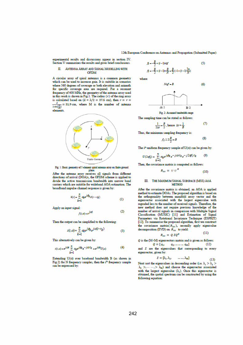
242

243

244

245

246

247

248

249

250

251

252

253

254

255

256

257

258

259

260

261

262

263

264

265

266

267

268

269

270

271

272

273

274

275
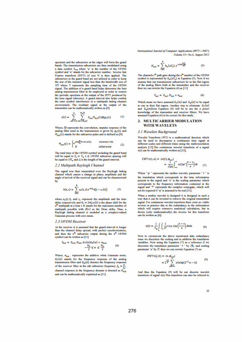
276

277

278

279

280

281
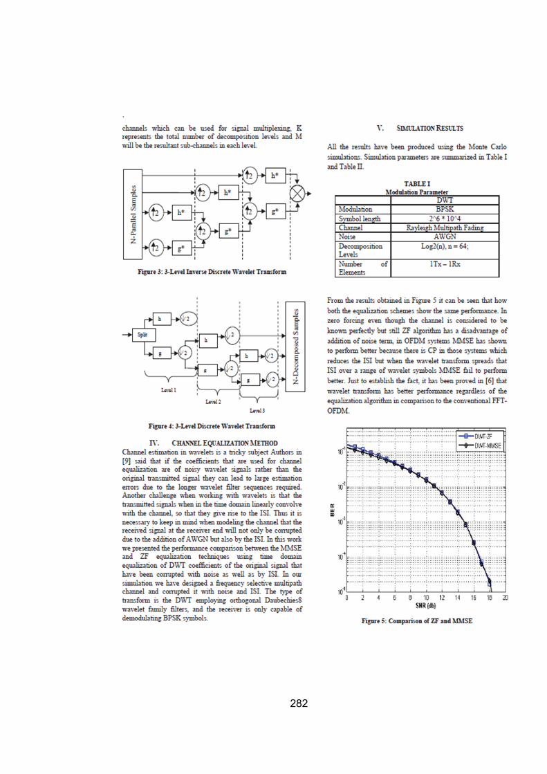
282
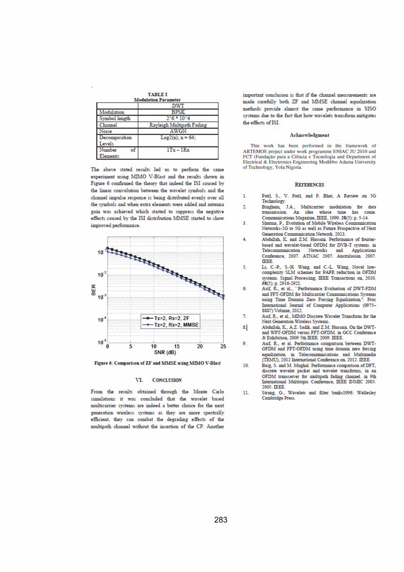
283

284

285

286

287
288

289

290

291

292

293

294

295

296

297

298

299

300

301

302

303

304

305

306

307