UNIT – I- AIRCRAFT SYSTEMS AND INSTRUMENTS
65
SCHOOL OF MECHANICAL ENGINEERING DEPARTMENT OF AERONAUTICAL ENGINEERING UNIT – I- AIRCRAFT SYSTEMS AND INSTRUMENTS – SAEA1303
-
Upload
khangminh22 -
Category
Documents
-
view
4 -
download
0
Transcript of UNIT – I- AIRCRAFT SYSTEMS AND INSTRUMENTS

SCHOOL OF MECHANICAL ENGINEERING
DEPARTMENT OF AERONAUTICAL ENGINEERING
UNIT – I- AIRCRAFT SYSTEMS AND INSTRUMENTS – SAEA1303
UNIT I -AIRCRAFT SYSTEMS.
AIRCRAFT HYDRAULIC SYSTEMS
The word hydraulics is based on the Greek word water, and 'originally meant the study of
the physical behaviour of water at rest and in motion. and the meaning has been expanded to
include physical behaviour of all liquids, including hydraulic fluid.
HYDRAULIC FLUID
Hydraulic system liquids are used primarily to transmit and distribute forces to various
units to be actuated. Liquids can do this because of they almost incompressible. Pascal's Law
states that pressure applied to any part of a confined liquid is transmitted with undiminished
intensity to every other part. Thus, if many passages exist in the system, pressure can be
distributed through all of m by means of the liquid. Manufacturers of hydraulic devices usually
spec-the type of liquid best suited for use with their equipment, in view of the working
conditions, the service required, temperatures expected inside and outside the systems, pressures
the liquid must withstand, the possibilities of corrosion, and other conditions that must be
considered.
If incompressibility and fluidity were the only qualities required, any liquid not too thick
might be used in a hydraulic system. But a satisfactory liquid for a particular installation must
possess a number of other properties. Some of the properties and characteristics that must be
considered when selecting a satisfactory liquid for a particular system are discussed in the
following paragraphs.
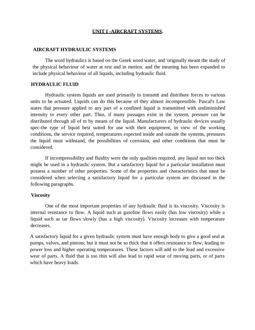
Viscosity
One of the most important properties of any hydraulic fluid is its viscosity. Viscosity is
internal resistance to flow. A liquid such as gasoline flows easily (has low viscosity) while a
liquid such as tar flows slowly (has a high viscosity). Viscosity increases with temperature
decreases.
A satisfactory liquid for a given hydraulic system must have enough body to give a good seal at
pumps, valves, and pistons; but it must not be so thick that it offers resistance to flow, leading to
power loss and higher operating temperatures. These factors will add to the load and excessive
wear of parts. A fluid that is too thin will also lead to rapid wear of moving parts, or of parts
which have heavy loads.

The viscosity of a liquid is measured with a viscosimeter or viscometer. There are several
types, but the instrument most often used by engineers in the U.S. is the Saybolt universal
viscosimeter. This instrument measures the number of seconds it takes for a fixed quantity of
liquid (60cc. (cubic centimetres)) to flow through a small orifice of standard length and diameter
at a specific temperature. This time of a flow is taken in seconds, and the viscosity reading is
expressed as SSU (seconds, Saybolt universal). For example, a certain liquid might have a
viscosity of 80 SSU at 130° F.
Chemical Stability
Chemical stability is another property which is exceedingly important in selecting a
hydraulic liquid. The liquid can resist oxidation and deterioration for long periods. All liquids
tend to undergo unfavourable chemical changes under severe operating conditions. This is the
case, for example, when a system operates for a considerable period at high temperatures.
Excessive temperatures have a great effect on the life of a liquid. It should be noted that
the temperature of the liquid in the reservoir of an operating hydraulic system does not always
represent a true state of operating conditions. Localized hot spots occur on bearings, gear teeth,
or at the point where liquid under pressure is forced through a small orifice. Continuous passage
of a liquid through these points may produce local temperatures high enough to carbonize or
sludge the liquid, yet the liquid in the reservoir may not indicate an excessively high
temperature. Liquids with a high viscosity have a greater resistance to heat than light or low
viscosity liquids which have been derived from the same source. The average hydraulic liquid
has a low viscosity. Fortunately, there is a wide choice of liquids available for use within the
viscosity range required of hydraulicliquids.
Liquids may break down if exposed to air, water, salt, or other impurities, especially if
they are in constant motion or subject to heat. Some metals,
Fig.1 Chemical Stability
such as zinc, lead, brass, and copper, have an undesirable chemical reaction on certain
liquids. These chemical processes result in the formation of sludge, gums, and carbon or other
deposits which clog openings, cause valves and pistons to stick or leak, and give poor lubrication
to moving parts. As soon as small amounts of sludge or other
deposits are formed, the rate of formation generally increases more rapidly. As they are formed,
certain changes in the physical and chemical properties of the liquid take place. The liquid
usually becomes darker in colour, higher in viscosity, and acids areformed.
Flash Point
Flashpoint is the temperature at which a liquid gives off vapour in sufficient quantity to
ignite momentarily or flash when a flame is applied. A high flash point is desirable for
hydraulic liquids because it indicates good resistance to combustion and a low degree of
evaporation at normaltemperatures.
Fire Point
The fire point is the temperature at which a substance gives off vapour in sufficient
quantity to ignite and continue to burn when exposed to a spark or flame. Like flashpoint, a high
fire point is required of desirable hydraulic liquids.
TYPES OF HYDRAULIC FLUIDS
To assure proper system operation and to avoid damage to non-metallic components of
the hydraulic system, the correct fluid must be used.
When adding fluid to a system, use the type specified in the aircraft manufacturer's
maintenance manual or on the instruction plate affixed to the reservoir or unit being serviced.
There are three types of hydraulic fluids currently being used in civil aircraft.
Vegetable Base Hydraulic Fluid
Vegetable-based hydraulic fluid (MIL-H-7644) is composed essentially of castoroil
andalcohol. It has a pungent alcoholic odour and is generally dyed blue. Although it has a
similar composition to automotive type hydraulic fluid, it is not interchangeable. This fluid is
used primarily in older type aircraft. Natural rubber seals are used with vegetable-based
hydraulic fluid. If it is contaminated with petroleum base or phosphate ester-based fluids, the
seals will swell, break down and block the system. This type of fluid is flammable.
Mineral Base Hydraulic Fluid
Mineral-based hydraulic fluid (MIL-H-5606) is processed from petroleum. It has an
odour similar to penetrating oil and is dyed red. Synthetic rubber seals are used with petroleum-
based fluids. Do not mix with a vegetable base or phosphate ester based hydraulic fluids. This
type of fluid isflammable
PHOSPHATE ESTER BASE FLUIDS
Non-petroleum based hydraulic fluids were introduced in 1948 to provide a fire-resistant
hydraulic fluid for use in high-performance piston engines and turboprop aircraft.

These fluids were fire-resistance tested by being sprayed through a welding torch flame
(6000°). There was no burning, but only occasional flashes of fire. These and other tests proved
non-petroleum base fluids would not support combustion. Even though they might flash at
exceedingly high temperatures, Skydrol ® fluids could not spread a fire because burning was
localized at the source of heat. Once the heat source was removed or the fluid flowed away from
the source, no further flashing or burning occurred.
Several types of phosphate ester base hydraulic fluids have been discontinued. Currently
used in aircraft are Skydrol ® 500B — a clear purple liquid having good low temperature
operating characteristics and low corrosive side effects; and, Skydrol ® LD —a clear purple low
weight fluid formulated for use in large and jumbo jet' transport aircraft where weight is a prime
factor.
Intermixing of Fluids
Due to the difference in composition, vegetable base, petroleum base and phosphate ester
fluids will not mix. Neither are the seals for anyone fluid useable with or tolerant of any of the
other fluids. Should an aircraft hydraulic system be serviced with the wrong type fluid,
immediately drain and flush the system and maintain the seals according to the manufacturer's
specifications?
Compatibility With Aircraft Materials
Aircraft hydraulic systems designed around Skydrol fluids should be virtually trouble-
free if properly serviced. Skydrol does not appreciably affect common aircraft metals—
aluminium, silver, zinc, magnesium, cadmium, iron, stainless steel, bronze, chromium, and
others as long as the fluids are kept free ofcontamination.
Due to the phosphate ester base of Skydrol fluids, thermoplastic resins, including vinyl
compositions, nitrocellulose lacquers, oil-base paints, linoleum and asphalt may be softened
chemically by Skydrol fluids. However, this chemical action usually requires longer
than just momentary exposure; and spills that are wiped up with soap and water do not harm
most of thesematerials.
Paints which are Skydrol resistant include epoxies and polyurethanes. Today
polyurethanes are the standard of the aircraft industry because of their ability to keep a bright,
shiny finish for long periods and for the ease with which they can be removed.
Skydrol ® is a registered trademark of Monsanto Company. The Skydrol fluid is
compatible with natural fibres and with many synthetics, including nylon and polyester, which
are used extensively in most aircraft
Petroleum oil hydraulic system seals of neoprene or Buna-N are not compatible with
Skydrol and must be replaced with seals of butyl rubber or ethylene-propylene elastomers. These
seals are readily available from any suppliers.

BASIC HYDRAULIC SYSTEM
Regardless of its function and design, every hydraulic system has a minimum number of
basic components in addition to a means through which the fluid is transmitted.
Hand Pump System
Figure 8-5 shows a basic hydraulic system. The first of the basic components, the
reservoir, stores the supply of hydraulic fluid for operation of the system. It replenishes the
system fluid when needed, provides room for thermal expansion, and in some systems provides
a means for bleeding air from thesystem.
A pump is necessary to create a flow of fluid. The pump shown is hand operated: however,
aircraft systems are, in most instances equipped with engine-driven or electric motor-driven
pumps.
The selector valve is used to direct the flow of fluid. These valves are normally actuated
by solenoids or manually operated, either directly or indirectly through use of mechanical
linkage. An actuating cylinder converts fluid pressure into useful work by linear or reciprocating
mechanical motion, Whereas a motor converts fluid pressure into useful work by rotary
mechanical motion.
The flow of hydraulic fluid can be traced from the reservoir through the pump to the
selector valve in figure 8-5. With the selector valve in the position shown, the hydraulic fluid
flows through the selector valve to the right-hand end of the actuating cylinder. Fluid pressure
then forces the piston to the left, and at the same time, the fluid which is on the left side of the
piston (figure 8-5) is forced out, up through the selector valve, and back to the reservoir through
the return line.
When the selector valve is moved to the opposite position, the fluid from the pump flows
to the left side of the actuating cylinder, thus reversing the process. Movement of the piston can
be stopped at any time by moving the selector valve to neutral. In this position, all four ports are
closed and pressure is trapped in both working lines.
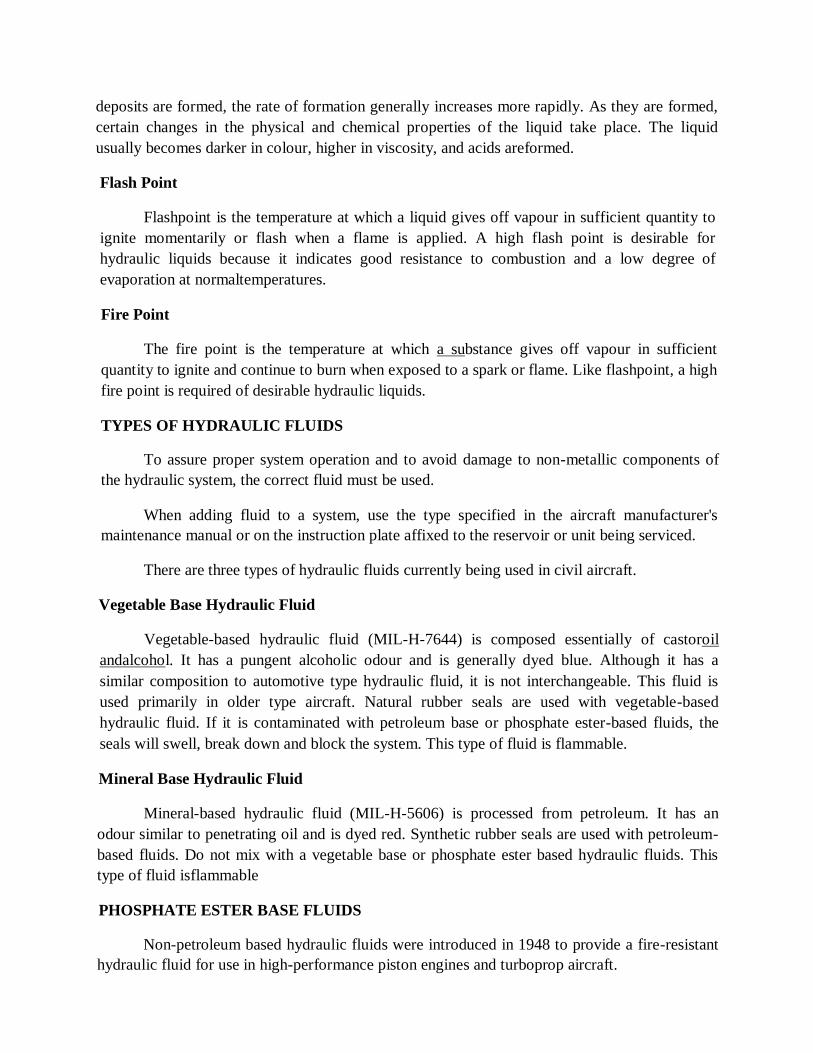
Power Driven Pump System
The figure shows a basic system with the addition of a power-driven pump and filter,
pressure regulator, accumulator, pressure gage, relief valve, and two check valves. The function
of each of these components is described in the following paragraphs.
The filter removes foreign particles from the hydraulic fluid, preventing dust, grit, or
other undesirable matter from entering the system.
The pressure regulator unloads or relieves the power-driven pump when the desired
pressure in the system is reached. Thus, it is often referred to as an unloading valve. When one
of the actuating units is being operated and pressure in the line between the pump and selector
valve builds up to the desired point, a valve in the pressure regulator automatically opens and
fluid is bypassed back to the reservoir. This bypass line is shown in figure 8-6 leading from the
pressure regulator to the returnline.
Many hydraulic systems do not use a pressure regulator but have other means of
unloading the Accumulator
The accumulator is a steel sphere divided into two chambers by a synthetic rubber
diaphragm. The upper chamber contains fluid at system pressure, while the lower chamber is
charged with air.
The function of an accumulator is to:
a. Dampen pressure surges in the hydraulic system caused by actuation of a unit and theeffort of the pump to maintain pressure at a presetlevel
b. Aid or supplement the power pump when several units are operating at once by supplying extra power from its "accumulated" or storedpower.
c. Store power for the limited operation of a hydraulic unit when the pump is notoperating.
d. Supply fluid under pressure to compensate for small internal or external (not desired) leaks
which would cause the system to cycle continuously by the action of the pressure switches
continually "kickingin."
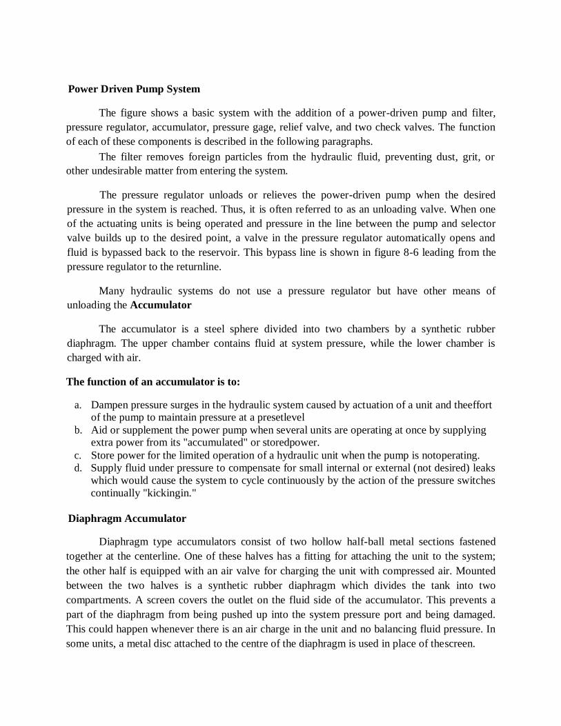
Diaphragm Accumulator
Diaphragm type accumulators consist of two hollow half-ball metal sections fastened
together at the centerline. One of these halves has a fitting for attaching the unit to the system;
the other half is equipped with an air valve for charging the unit with compressed air. Mounted
between the two halves is a synthetic rubber diaphragm which divides the tank into two
compartments. A screen covers the outlet on the fluid side of the accumulator. This prevents a
part of the diaphragm from being pushed up into the system pressure port and being damaged.
This could happen whenever there is an air charge in the unit and no balancing fluid pressure. In
some units, a metal disc attached to the centre of the diaphragm is used in place of thescreen.

Fig.2 Bladder-Type Accumulators
The bladder-type accumulator operates on the same principle as the diaphragm type. It serves the
same purpose but varies in construction. This unit consists of a one-piece metal sphere with a
fluid pressure inlet at the top. Th ere is an opening at the bottom for inserting the bladder. A
large screw-type plug at the bottom of the accumulator retains the bladder and also seals the unit.
The high-pressure air valve is also mounted in the retainer plug. A round metal disc attached to
the top of the bladder prevents air pressure from forcing the bladder out through the pressure
port. As fluid pressure rises, it forces the bladder downward against the air charge, filling the
upper chamber with fluid pressure. The broken lines in figure 8-20 show the approximate shape
of the bladder when the accumulator ischarged.
Piston-Type Accumulators
The piston-type accumulator also serves the same purpose and operates much like the
diaphragm and bladder accumulators. As shown in figure 8-21 this unit is a cylinder (B) and
piston assembly (E) with openings on each end. System fluid pressure enters the top port (A) and
forces the piston down against the air charge in the bottom chamber (D). A high-pressure air
valve (C) is located at the bottom of the cylinder for servicing the unit. There are two rubber
seals (represented by the black dots) which prevent leakage between the two chambers (D and
G). A passage (F) is drilled from the fluid side of the piston to the space between the seals. This
provides lubrication between the cylinder walls and thepiston.
ACTUATING CYLINDERS
An actuating cylinder transforms energy in the form of fluid pressure into mechanical
force or action, to perform work. It is used to impart powered linear motion to some movable
object or mechanism.
A typical actuating cylinder consists fundamentally of cylinder housing, one or more
pistons and piston rods, and some seals. The cylinder housing contains a polished bore in which
the piston operates and one or more ports through which fluid enters and leaves the bore. The
piston and rod form an assembly. The piston moves forward and backwards within the cylinder
bore and an attached piston rod moves into and out of the cylinder housing through an opening
in one end of the cylinder housing. Seals are used to prevent leakage betweenthe

piston and the cylinder bore, and between the piston rod and the end of the cylinder. Both the
cylinder housing and the piston rod have provisions for mounting and for attachment to an
object or mechanism which is to be moved by the actuatingcylinder.
Actuating cylinders are of two major types: (1) Single-action and (2) Double-action. The
single-action (single port) actuating cylinder is capable of producing powered movement in one
direction only. The double-action (two ports) actuating cylinder is capable of producing
powered movement in twodirections.
Single-Action Actuating Cylinder
A single-action actuating cylinder is illustrated in the figure. Fluid under pressure enters
the port at the left and pushes against the face of the piston, forcing the piston to the right. As
the piston moves, the air is forced out of the spring chamber through the vent hole, compressing
the spring. When pressure on the fluid is released to the point that it exerts less force than is
present in the compressed spring, the spring pushes the piston toward the left. As the piston
moves to the left, fluid is forced out of the fluid port. At the same time, the moving piston pulls
air into the spring chamber through the venthole. A three-way control valve is normally used for
controlling the operation of a single-action actuatingcylinder
Fig.3 Single-Action Actuating Cylinder
Double-Action Actuating Cylinder
A double-action (two-port) actuating cylinder is illustrated in figure 8-25. The operation of a
double-action actuating cylinder is usually controlled by a four-way selector valve. The figure
shows an actuating cylinder interconnected with a selector valve. Operation of the selector valve
and actuating cylinder is discussed below.
Placing the selector valve in the '" on" position admits fluid pressure to the left-hand
chamber of the actuating cylinder. This results in the piston being forced toward the right.

Fig.4 Double-Action Actuating Cylinder
As the piston moves toward the right, it pushes return fluid out of the right-hand chamber
and through the selector valve to the reservoir.
When the selector valve is placed in its other "on" position, as illustrated in figure 8-26B,
fluid pressure enters the right-hand chamber, forcing the piston toward the left. As the piston
moves toward the left, it pushes return fluid out of the left-hand chamber and through the
selector valve to the reservoir. Besides having the ability to move a load into position, a double-
acting cylinder also can hold a load in position. This capability exists because when the selector
valve used to control the operation of the actuating cylinder is placed in the, "off" position, fluid
is trapped in the chambers on both sides of the actuatingcylinder
PNEUMATIC SYSTEM COMPONENTS
Pneumatic systems are often compared to hydraulic systems, but such comparisons can
only hold in general term s. Pneumatic systems do not utilize reservoirs, hand pumps,
accumulators, regulators, or engine-driven or electrically-driven power pumps for building
normal pressure. But similarities do exist in some components
Relief Valves
Relief valves are used in pneumatic systems to prevent damage. They act as pressure-
limiting units and prevent excessive pressures from bursting lines and blowing out seals. Figure
8-35 illustrates a cutaway view of a pneumatic system reliefvalve.
At normal pressures, a spring holds the valve closed and air remains in the pressure
line. If pressure grows too high, the force it creates on the disk overcomes spring tension and
opens the relief valve. Then, excess air flows through the valve and is exhausted as surplus air
into the atmosphere. The valve remains open until the pressure drops tonormal.
Control Valves
Control valves are also a necessary part of a typical pneumatic system. Figure 8-36
illustrates how a valve is used to control emergency air brakes. The control valve consists of a
three-port with two lobes.
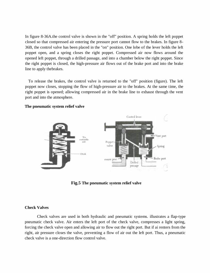
In figure 8-36A.the control valve is shown in the "off" position. A spring holds the left poppet
closed so that compressed air entering the pressure port cannot flow to the brakes. In figure 8-
36B, the control valve has been placed in the "on" position. One lobe of the lever holds the left
poppet open, and a spring closes the right poppet. Compressed air now flows around the
opened left poppet, through a drilled passage, and into a chamber below the right poppet. Since
the right poppet is closed, the high-pressure air flows out of the brake port and into the brake
line to apply thebrakes.
To release the brakes, the control valve is returned to the "off" position (figure). The left
poppet now closes, stopping the flow of high-pressure air to the brakes. At the same time, the
right poppet is opened; allowing compressed air in the brake line to exhaust through the vent
port and into the atmosphere.
The pneumatic system relief valve
Fig.5 The pneumatic system relief valve
Check Valves
Check valves are used in both hydraulic and pneumatic systems. illustrates a flap-type
pneumatic check valve. Air enters the left port of the check valve, compresses a light spring,
forcing the check valve open and allowing air to flow out the right port. But if ai renters from the
right, air pressure closes the valve, preventing a flow of air out the left port. Thus, a pneumatic
check valve is a one-direction flow control valve.

Restrictors
Restrictors are a type of control valve used in pneumatic systems. Figure 8-38 illustrates
an orifice type restrictor with a large inlet port and a small outlet port. The small outlet port
reduces the rate of airflow and the speed of operation of an actuating unit.
Variable Restrictor
Another type of speed-regulating unit is the variable restrictor shown in figure 8-39. It
contains an adjustable needle valve, which has threads around the top and a point on the lower
end. Depending on the direction turned, the needle valve moves the sharp point either into or out
of a small opening to decrease or increase the size of the opening. Since air entering the inlet
port must pass through this opening before reaching the outlet port, this adjustment also
determines the rate of airflow through therestrictor.
Filters
Pneumatic systems are protected against dirt using various types of filters. A micronic
filter (figure 8-40) consists of a housing with two ports, a replaceable cartridge, and a relief
valve. Normally, air enters the inlet, circulates the cellulose cartridge, then flows to the centre of
the cartridge and out the outlet port. If the cartridge becomes clogged with dirt, pressure forces
the relief valve open and allows unfiltered air to flow out the outletport.
A screen-type filter (figure 8-41) is similar to the micronic filter but contains a permanent
wire screen instead of a replaceable cartridge. In the screen filter, a handle extends through the
top of the housing and can be used to clean the screen by rotating it against metal scrapers.
Fig.6 Pneumatic system check valve.
Air Bottle
The air bottle usually stores enough compressed air If the main hydraulic braking system
fails, power brakes are usually equipped with some type of emergency pressurizing system for
stopping the aircraft. In many instances, these emergency systems for several applications of the
brakes. A high-pressure airline connects the bottle to an air valve which controls the operation of
the emergency brakes.

If the normal brake system fails, place the control handle for the air valve in the "on"
position. The valve then directs high-pressure air into lines leading to the brake assemblies. But
before the air enters the brake assemblies, it must first flow through a shuttle valve.
Variable pneumatic restrictor
Fig.7 Variable pneumatic restrictor
Brake Shuttle Valve
Brake Shuttle Valve the circled inset at the upper right of figure 8-42 shows one type of
shuttle valve. The valve consists of a shuttle enclosed by a four-port housing. The shuttle is a sort
of floating piston that can move up or down in the hollow housing. Normally, the shuttle is
down, and in this position, it seals off the lower airport and directs hydraulic fluid from the upper
port into the two side ports, each of which leads to a brake assembly. But when the emergency
pneumatic brakes are applied, high-pressure air raises the shuttle, seals off the hydraulic line, and
connects air pressure to the side ports of the shuttle valve. This action sends high-pressure air
into the brake cylinder to apply thebrakes.
After application and when the emergency brakes are released, the air valve closes,
trapping pressure in the air bottle. At the same time, the air valve vents the pneumatic brake line
to outside air pressure. Then as air pressure in the brake line drops, the shuttle valve moves to
the lower end of the housing, again connecting the brake cylinders to the hydraulic line. Air
pressure remaining in the brake cylinders then flows out the upper port of the shuttle valve and
into the hydraulic returnline.
Lines and Tubing
Lines for pneumatic systems consist of rigid metal tubing and flexible rubber hose. Fluid
lines and fittings are covered in detail in Chapter 5 of the Airframe and Powerplant Mechanics
General Handbook, AC 65-9A.

Fig.8 Screen type filter
TYPICAL PNEUMATIC POWER SYSTEM
A typical turbine-engine pneumatic power system supplies compressed air for various
normal and emergency actuating systems. The compressed air is stored in storage cylinders in
the actuating systems until required by actuation of the system. These cylinders and the power
system manifold are initially charged with compressed air or nitrogen from an external source
through a single air-charge valve. In-flight, the air compressor replaces the air pressure and
volume lost through leakage, thermal contraction, and actuating system operation. The air
compressor is supplied with supercharged air from the engine bleed air system. This ensures an
adequate air supply to the compressor at all altitudes. The air compressor may be driven either by
an electric motor or a hydraulic motor. The system described here is hydraulically driven. The
following description is illustrated by the pneumatic power system shown in figure. The
compressor inlet air is filtered through a high-temperature, 10-micron filter and the air pressure
is regulated by an absolute pressure regulator.
Fig.9 Typical Pneumatic Power System


SCHOOL OF MECHANICAL ENGINEERING
DEPARTMENT OF AERONAUTICAL ENGINEERING
UNIT – II- AIRCRAFT SYSTEMS AND INSTRUMENTS – SAEA1303

UNIT II LANDING GEAR SYSTEMS
Landing gear
The following three types of landing gears are mainly used in aeroplanes.
1. Tricycle with a single wheel or wheelbogey.
2. Bicycle with outrigger wheels onwings.
3. Tailwheeltype.
The tricycle type is also called nose-wheel landing gear. It is the most commonly usedlanding
gear. The main wheels and the nose wheels are located such that they take roughly 90% & 10%
of the weightrespectively
In the bicycle-type landing gear, the front and the rear landing gear are located on the fuselage reference line. When this landing gear is used, outrigger wheels are provided on wingtips to prevent the airplane from toppling sideways.
In the tail wheel type or the tail dragger type landing gear, two mail wheels are provided ahead of the c.g and an auxiliary wheel near the tail. This landing gear is used mainly in low-speed
aeroplanes and is generally non-retractable.
Fig.1: Types of landing gears
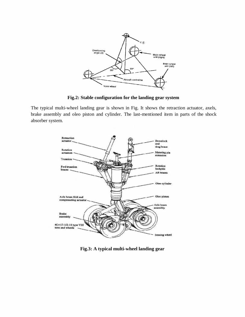
Fig.2: Stable configuration for the landing gear system
The typical multi-wheel landing gear is shown in Fig. It shows the retraction actuator, axels,
brake assembly and oleo piston and cylinder. The last-mentioned item in parts of the shock
absorber system.
Fig.3: A typical multi-wheel landing gear

Advantages and Disadvantages
The main advantages of employing a tri-cycle undercarriage layout are;
– Ground manoeuvring is easier with a steerable nosewheel.
– The pilot’s view is improved duringtaxying.
– The aircraft floor is horizontal when it’s on theground.
– Aerodynamic drag g on take-off is reduced, giving much bettertake-off
performance.
– Directional stability on the ground is improved because the C of G is forward of
the mainwheels.
– Braking is more straightforward, and brake parachutes can beused.
– There is less tendency to float and bounce on landing, making landingeasier.
Despite all the advantages of utilising the tri-cycle undercarriage layout within the
airframe design, there are some disadvantages;
– Nose wheels need to be stronger and therefore heavier than tailwheels.
– More damage is done to the aircraft if the nose wheelcollapses
Types of Oleo Leg
Most service aircraft, as well as most civil transports, are fitted with oleo-pneumatic or
oil-compression type undercarriages.
The operation of both units is very similar.
– An oleo-pneumatic unit compresses air or nitrogengas.
– An oil-compression unit (often known as liquid spring) works by compressingoil.
How an Oleo Works
Fig.4: Oleo Strut
Compressing the strut reduces the volume inside and compresses the gas or oil, like
operating a bicycle pump. Any tendency to bounce is prevented by forcing the damping
oil through small holes so that the strut can only extend quite slowly. The gas or oil will

stay slightly compressed when it weights the aircraft on it, so it is cushioned whilst
taxying.
Wheel Units
All of these factors mean that the undercarriage positions must be very carefully
designed. Each main-wheel unit consists of a single, double, tandem or bogie unit, of four
or morewheels.
There are even more variations than this, but they are not common. As aircraft become
heavier, the loading on a single wheel increases, leading to a great increase in the damage
done to runways
Fig.5: Wheel Units
Undercarriage Retraction
An undercarriage causes a lot of drag in flight, so it is retracted into the wings or fuselage
in most aircraft, except when needed. In most cases, a hydraulic jack is used t o pull the
undercarriage legs, about a pivot at the top. The doors to the undercarriage well may be
attached to the legs or may use separate jacks to open and close them. In many cases, the undercarriage needs to fit into a very small space, and the units may be turned, twisted or
folded to enable this to be done.
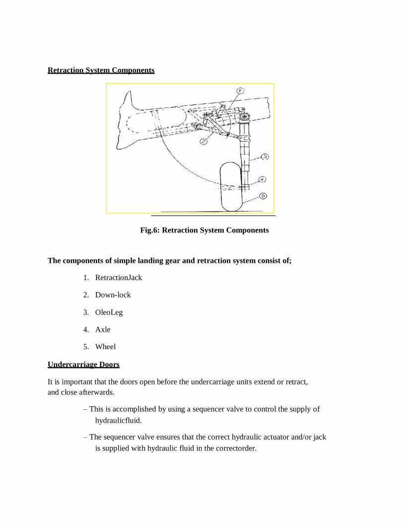
Retraction System Components
Fig.6: Retraction System Components
The components of simple landing gear and retraction system consist of;
1. RetractionJack
2. Down-lock
3. OleoLeg
4. Axle
5. Wheel
Undercarriage Doors
It is important that the doors open before the undercarriage units extend or retract,
and close afterwards.
– This is accomplished by using a sequencer valve to control the supply of
hydraulicfluid.
– The sequencer valve ensures that the correct hydraulic actuator and/or jack
is supplied with hydraulic fluid in the correctorder.

Undercarriage Locks
Fig.7: Undercarriage Locks
To prevent undercarriage collapsing on the ground, and to hold it firmly in position
in flight, uplocksand down locks are fitted.
– These are unlocked as part of the extension and retractionsequence.
It would be catastrophic if the undercarriage were retracted accidentally with the aircraft on
the ground, so additional lock s are fitted, disabling the retraction mechanism.
Brake Systems
Fig.8: Brake Systems
Modern large aircraft often land at high weights and speeds. This means that the braking system
must be capable of absorbing and dissipating very large amounts of heat, as the energy of motion
is converted into heat.

Types of Brakes
There are two main types of brake:
– DrumBrakes
– DiscBrakes
The Drum Brake is rarely used, because it suffers from poor heat dissipation, causing the brakes to overheat and fade.
– Fading is where the brakes lose their braking effectiveness astheir
temperatureincreases.
The Disc Brake is much more effective at dispersing the heat produced, and
maintain their effectiveness during long periods of heavy braking.
Disc Brakes
These consist of a disc or series of discs of aluminium alloy, steel, carbon or other material, gripped between pads of friction material.
– These pads are forced against the discs by pistons under hydraulicpressure.
– Control is usually achieved by placing a toe pedal for the brake on each sideon
its respective rudderpedal.
– These can then be operated differentially by the pilot, giving the ability to steer
the aircraft by applying different amounts of braking on each mainwheel.
– Applying the brakes equally on both main units allows the aircraft to bebraked
smoothly in a straightline.
Anti-Skid
An anti-skid unit called a Maxaret unit prevents skidding by detecting when the wheel or wheels on any unit stop turning and momentarily releases brake pressure on that unit
only. This gives the aircraft the ability to stop in the shortest possible distance without
loss of control. Similar units, known as ABS, are fitted to many cars and work in the
sameway.
Alternative Braking Methods
Another form of braking is air brakes, used in flight, which consist of large plates fitted
to the fuselage (or wings – Viking and Vigilant) which can be lifted into the airflow when required. They cause a large increase in drag to slow theaircraft.
After touch-down, reverse thrust can be deployed, by moving doors into the jet exhaust to
deflect the flow forwards. Turboprop engines can achieve a similar effect by changing the pitch of the propeller to reverse the airflow.

SCHOOL OF MECHANICAL ENGINEERING
DEPARTMENT OF AERONAUTICAL ENGINEERING
UNIT – III- AIRCRAFT SYSTEMS AND INSTRUMENTS – SAEA1303

UNIT III -- FUEL AND PRESSURIZING SYSTEM
Fuel is a substance that, when combined with oxygen, will burn and produce heat. Fuels
may be classified according to their physical state as solid, gaseous, or liquid.
Solid Fuels
Solid fuels are used extensively for external-combustion engines, such as a steam engine,
where the burning takes place under boilers or in furnaces. They include such fuels as wood and
coal. Solid fuels are not used in reciprocating engines, where the burning takes place inside the
cylinder, because of their slow rate of burning, low heat value, and numerousotherdisadvantages.
Gaseous Fuels
Gaseous fuels are used to some extent for internal-combustion engines, where a large
supply of combustible gas is readily available. Natural gas and liquefied petroleum gas are two
of the more common types. Gaseous fuels can be disregarded for use in aircraft engines. The
large space they occupy limits the supply of fuel that can be carried-
Liquid Fuels
Liquid fuels, in many respects, are the ideal fuel for use in internal-combustion engines.
Liquid fuels are classified as either nonvolatile or volatile. The nonvolatile fuels are the heavy
oils used in diesel engines. The volatile class includes those fuels that are commonly used with a
fuel metering device and are carried into the engine cylinder or combustion chamber in a
vaporized or partially vaporized condition. Among these are alcohol, benzol, kerosene, and
gasoline.
Aviation fuel is a liquid containing chemical energy that, through combustion, is released
as heat energy and then converted to mechanical energy by the engine. This mechanical energy
is used to produce thrust, which propels the aircraft. Gasoline and kerosene are the two most
widely used aviation fuels;

CHARACTERISTICS AND PROPERTIES OF AVIATION GASOLINE
Aviation gasoline consists almost entirely of hydrocarbons, namely, compounds
consisting of hydrogen and carbon. Some impurities in the form of sulphur and dissolved water
will be present. The water cannot be avoided since the gasoline is exposed to moisture in the
atmosphere. A small amount of sulphur, always present in crude petroleum, is left in the process
of manufacture.
Tetraethyl lead (TEL) is added to the gasoline to improve its performance in the engine.
Organic bromides and chlorides are mixed with TEL so that during combustion volatile lead
halides will be formed. These then are exhausted with the combustion products. TEL, if added
alone, would burn to solid lead oxide and remain in the engine cylinder. Inhibitors are added to
gasoline to suppress the formation of substances that would be left as solids when the gasoline
evaporates.
Certain properties of the fuel affect the engine performance. These properties are
volatility, how the fuel burns during the combustion process, and the heating value of the fuel.
Also important is the corrosiveness of the gasoline as well as its tendency to form deposits in
the engine during use. These latter two factors are important because of their effect on general
cleanliness, which has a bearing on the time between engineoverhauls.
Volatility
Volatility is a measure of the tendency of a liquid substance to vaporize under given
hydrocarbon compounds that have a wide range of boiling points and vapour pressures. It is
blended in such a way that a straight chain of boiling points is obtained. This is necessary to
obtain the required starting, acceleration, power, and fuel mixture characteristics for the engine.
Gasoline is a complex blend of volatile
If the gasoline vaporizes too readily, fuel lines may become filled with vapour and cause
decreased fuel flow. If the fuel does not vaporize readily enough, it can result in hard-starting,
slow warm-up, poor acceleration, and uneven fuel distribution to cylinders, and excessive
crankcase dilution.

Gage
Bomb
Sample
Fig.1: Vapour pressure test apparatus
The lower grades of automobile fuel are not held within the tolerances required for aviation
gasoline and usually contain a considerable amount of cracked gasoline, which may form
excessive gum deposits. For these reasons, automobile fuels should not be used in aircraft
engines, especially air-cooled engines operating at high cylinder temperatures.
Vapour Lock
Vaporization of gasoline in fuel lines results in a reduced supply of gasoline to the
engine. In severe cases, it may result in engine stoppage. This phenomenon is referred to as
vapour locking. A measure of a gasoline's tendency to vapour lock is obtained from the Reid
vapour pressure test. In this test, a sample of the fuel is sealed in a "bomb" equipped with a
pressure gage. The apparatus (see figure ) is then immersed in a constant-temperature bath and
the indicated pressure is noted. The higher the corrected vapour pressure of the sample under
test, the more susceptible it is to vapour locking. Aviation gasoline is limited to a maximum of7
p.s.i. because of their increased tendency to vapour lock at highaltitudes.
Carburettor Icing
Carburettor icing is also related to volatility. When the fuel changes from a liquid to a
vapour state, it extracts heat from its surroundings to make this change. The more volatile the
fuel, the more rapid the heat extraction will be. As the gasoline leaving the carburettor discharge
nozzle vaporizes, it can freeze water vapour contained in the incoming air. The moisture freezes
on the walls of the induction system, the venturi throat, and the throttle valves. This type of ice
formation restricts the fuel and air passages of the carburettor. It causes loss of power and, if not
eliminated, eventual engine stoppage. Extreme icing conditions can make the operation of

the throttle controls impossible. This icing condition is most severe in the temperature range of
30° to 40° F. outside air temperature.
Aromatic Fuels
Some fuels may contain considerable quantities of aromatic hydrocarbons, which are
added to increase the rich mixture performance rating of the fuel. Such fuels, known as aromatic
fuels, have a strong solvent and swelling action on some types of hose and other rubber parts of
the fuel system. For this reason, aromatic-resistant hose and rubber parts have been developed
for use with aromaticfuels.
Detonation
In an engine that is operating in a normal manner, the flame front traverses the charge at
a steady velocity of about 100 feet per second until the charge is consumed. When detonation
occurs, the first portion of the charge burns in a normal manner but the last portion burns almost
instantaneously, creating an excessive momentary pressure unbalance in the combustion
chamber. This abnormal type of combustion is called detonation. This tremendous increase in
the speed of burning causes the cylinder head temperature to rise. In severe cases, the increase in
burning speed will decrease engine efficiency and may cause structural damage to the cylinder
head orpiston.
During normal combustion, the expansion of the burning gases presses the head of the
piston down firmly and smoothly without excessive shock. The increased pressure of detonation
exerted in a short period produces a heavy shock load to the walls of the combustion chamber
and the piston head. It is this shock to the combustion chamber that is heard as an audible knock
in an automobile engine. If other sounds could be filtered out, the knock would be equally
audible in an aircraft engine. Generally, it is necessary to depend upon instruments to detect
detonation in an aircraftengine.
Surface Ignition
Ignition of the fuel/air mixture by hot spots or surfaces in the combustion chamber is
called surface ignition. If this occurs before the normal ignition event, the phenomenon is
referred to as preignition. When it is prevalent, the result is a power loss and engine roughness.
Preignition is generally attributed to overheating of such parts as spark plug electrodes, exhaust
valves, carbon deposits, etc. Where preignition is present, an engine may continue to operate
even though the ignition has been turned off.
Present information indicates that gasoline high in aromatic hydrocarbon contentis much
more likely to cause surface ignition than fuels with lowcontent.

Octane and Performance Number Rating
Octane and performance numbers designate the antiknock value of the fuel mixture in an
engine cylinder. Aircraft engines of high power output have been made possible principally as a
result of blending to produce fuels of high octane ratings. The use of such fuels has permitted
increases in compression ratio and manifold pressure, resulting in improved engine power and
efficiency. However, even the high-octane fuels will detonate under severe operating conditions
and when certain engine controls are improperly operated.
Antiknock qualities of aviation fuel are designated by grades. The higher the grade, the
more compression the fuel can stand without detonating. For fuels that have two numbers, the
first number indicates the lean-mixture rating and the second the rich-mixture rating. Thus,
grade 100/130 fuel has a lean-mixture rating of 100 and a rich-mixture rating of 130. Two
different scales are used to designate fuel grade. For fuels below grade 100, octane numbers are
used to designate grade. The octane number system is based on a comparison of any fuel with
mixtures of iso-octane and normal heptane. The octane number of a fuel is the percentage of iso-
octane in the mixture that duplicates the knock characteristics of the particular fuel being rated.
Thus, grade 91 fuel has the same knock characteristics as a blend of 91 percent iso-octane and 9
percent normalheptane.
With the advent of fuels having antiknock characteristics superior to iso-octane, another
scale was adopted to designate the grade of fuels above the 100-octane number. This scale
represents the performance rating of the fuel—its knock-free power available as compared with
that available with pure iso-octane. It is arbitrarily assumed that 100 percent power is obtained
from iso-octane alone. An engine that has a knock-limited horsepower of 1,000 with 100-octane
fuel will have a knock-limited horsepower of 1.3 times as much (1,300 horsepower) with 130
performance number fuel.
The grade of aviation gasoline is no indication of its fire hazard. Grade 91/96 gasoline is
as easy to ignite as grade 115/145 and explodes with as much force. The grade indicates only the
gasoline's performance in the aircraft's engine.A convenient means of improving the antiknock
characteristics of fuel is to add a knock inhibitor. Such a fluid must have a minimum of corrosive or
other undesirable qualities, and probably the best available inhibitor in general use at present is TEL
(tetraethyl lead). The few difficulties encountered because of the corrosion tendencies of ethylized
gasoline are insignificant when compared with the results obtained from the high antiknock value of
the fuel. For most aviation fuels the addition of more than 6 ml. per gallon is not permitted. Amounts
over this have little effect on the antiknock value, but increase corrosion and spark plug trouble.
There are two distinct types of corrosion caused by the use of ethyl gasoline. The first is
caused by the reaction of the lead bromide with hot metallic surfaces, and occurs when the
engine is in operation; the second is caused by the condensed products of combustion, chiefly
hydro-bromic acid, when the engine is notrunning.

Purity
Aviation fuels must be free of impurities that would interfere with the operation of the
engine or the units in the fuel and induction system.
Even though all precautions are observed in storing and handling gasoline, it is not
uncommon to find a small amount of water and sediment in an aircraft fuel system. A small
amount of such contamination is usually retained in the strainers in the fuel system. Generally,
this is not considered a source of great danger, provided the strainers are drained and cleaned at
frequent intervals. However, the water can present a serious problem because it settles to the
bottom of the fuel tank and can then be circulated through the fuel system. A small quantity of
water will flow with the gasoline through the carburetor metering jets and will not be especially
harmful. An excessive amount of water will displace the fuel passing through the jets and restrict
the flow of fuel; it will cause loss of power and can result in engine stoppage.
Under certain conditions of temperature and humidity, condensation of moisture (from
the air) occurs on the inner surfaces of the fuel tanks. Since this condensation occurs on the
portion of the tank above the fuel level, it is obvious that the practice of servicing an airplane
immediately after flight will do much to minimize thishazard.
Fuel Identification
Gasolines containing TEL must be colored to conform with the law. In addition, gasoline
may be colored-for purposes of identification. For example, grade 100 low lead aviation gasoline
is blue, grade 100 is green and grade 80 is red. See figure.
100/130 gasoline is manufactured (1975) in two grades high-lead, up to 4.6 milliliters of
lead per gallon and low-lead, not over 2.0 milliliters per gallon. The purpose being to eliminate
two grades of lower octane fuel (80/87) and 91/96). The high-lead will continue to be colored
green whereas the low-lead will be blue.
The low-lead will replace the 80/87 and 91/96 octane fuels as they are phased out. Engine
manufacturers have prepared instructions to be followed in making adjustments necessary for
changeover to the 100 octane fuel.
A change in color of an aviation gasoline usually indicates contamination with another
product or a loss of fuel quality. A color change can also be caused by a chemical reaction that
has weakened the lighter dye component. This color change in itself may not affect the quality of
the fuel.
A color change can also be caused by the preservative in a new hose. Grade 115/145
gasoline that has been trapped for a short period of time in new hose may appear green. Flushing
a small amount of gasoline through the hose usually removes all traces of color change.

Fig.2: Fuel Types
TURBINE ENGINE FUELS
The aircraft gas turbine is designed to operate on distillate fuel, commonly called jet fuel.
Jet fuels are also composed of hydrocarbons with a little more carbon and usually a
highersulphur content than gasoline. I inhibitors may be added to reduce corrosion and oxidation.
Anti- icing additives are also being blended to prevent fuel icing.
Two types of jet fuel in common use today are (1) Kerosene grade turbine fuel, now
named jet A; and (2) a blend of gasoline and kerosene fractions, designated Jet B. There is a
third type, called Jet A-l, which is made for operation at extremely low temperatures. Seefigure.
There is very little physical difference between Jet A (JP-5) fuel and commercial kerosene.
Jet A was developed as heavy kerosene having a higher flash point and lower freezing point than
most kerosenes. It has a very low vapour pressure, so there is little loss of fuel from evaporation or
boil-off at higher altitudes. It contains more heat energy per gallon than does J et B(JP-4).
Jet B is similar to Jet A. It is a blend of gasoline and kerosene fractions. Most commercial
turbine engines will operate on either Jet A or Jet B fuel. However, the difference in the specific

the gravity of the fuels may require fuel control adjustments. Therefore, the fuels cannot always
be considered interchangeable.
Both Jet A and Jet B fuels are blends of heavy distillates and tend to absorb water. The
specific gravity of jet fuels, especially kerosene, is closer to water than is aviation gasoline; thus,
any water introduced into the fuel, either through refuelling or condensation, will take an
appreciable time to settle out. At high altitudes, where low temperatures are encountered, water
droplets combine with the fuel to form a frozen substance referred to as "gel." The mass of "gel"
or "icing" that may be generated from moisture held in suspension in jet fuel can be much
greater than ingasoline.
Volatility
One of the most important characteristics of jet fuel is its volatility. It must, of necessity, be a
compromise between several opposing factors. A highly volatile fuel is desirable to aid in
starting in cold weather and to make aerial restarts easier and surer. Low volatility is desirable to
reduce the possibility of vapour lock and to reduce fuel losses by evaporation.
50F 100F 150F 200F
Fig.3: Temperature Vaporization of aviation fuels at atmospheric pressure.
At normal temperatures, gasoline in a closed container or tank can give off so much
vapour that the fuel/air mixture may be too rich to burn. Under the same conditions, the vapour
given off by Jet B fuel can be in the flammable or explosive range. Jet A fuel has such low
volatility that at normal temperatures it gives off very little vapour and does not form flammable
or explosive fuel/air mixtures. Figure 4-4 shows the vaporization of aviation fuels at atmospheric
pressure.

Identification
Because jet fuels are not dyed, there is no on-sight identification for them. They range in
colour from a colourless liquid to a straw-coloured (amber) liquid, depending on age or the crude
petroleum source.
Jet fuel numbers are type numbers and have no relation to the fuel's performance in the
aircraft engine.
FUEL SYSTEM CONTAMINATION
There are several forms of contamination in aviation fuel. The higher the viscosity of the
fuel, the greater is its ability to hold contaminants in suspension. For this reason, jet fuels having
a high viscosity are more susceptible to contamination than aviation gasoline. The principal
contaminants that reduce the quality of both gasoline and turbine fuels are other petroleum
products, water, rust or scale, and dirt.
Water
Water can be present in the fuel in two forms: (1) Dissolved in the fuel or (2) entrained or
suspended in the fuel. Entrained water can be detected with the naked eye. The finely divided
droplets reflect light and in high concentrations give the fuel a dull, hazy, or cloudy appearance.
Particles of entrained water may unite to form droplets of free water.
Fuel can be cloudy for several reasons. If the fuel is cloudy and the cloud disappears at
the bottom, the air is present. If the cloud disappears at the top, water is present. A cloud usually
indicates a water-in-fuel suspension. Free water can cause icing of the aircraft fuel system,
usually in the aircraft boost-pump screens and low-pressure filters. Fuel gauge readings may
become erratic because the water short-circuits the aircraft's electrical fuel cell quantity probe.
Large amounts of water can cause engine stoppage. If the free water is saline, it can cause
corrosion of the fuel systemcomponents.
Foreign Particles
Most foreign particles are found as sediment in the fuel. They are composed of almost
any material with which the fuel comes into contact. The most common types are rust, sand,
aluminium and magnesium compounds, brass shavings, andrubber.
Rust is found in two forms: (1) Red rust, which is nonmagnetic and (2) black rust, which
is magnetic. They appear in the fuel as a red or black powder (which may resemble a dye),
rouge, or grains. Sand or dust appears in the fuel in a crystalline, granular, or glasslikeform.
Aluminium or magnesium compounds appear in the fuel as a form of white or gray
powder or paste. This powder or paste becomes very sticky or gelatinous when water is

present. Brass is found in the fuel as bright gold-coloured chips or dust. Rubber appears in the
fuel as fairly large irregular bits. All of these forms of contamination can cause sticking or
malfunctions of fuel metering devices, flow dividers, pumps, and nozzles.
FUEL SYSTEM
The aircraft fuel system stores fuel and delivers the proper amount of clean fuel at the
right pressure to meet the demands of the engine. A well-designed fuel system ensures positive
and reliable fuel flow throughout all phases of flight, which include changes in altitude, violent
manoeuvres and sudden acceleration and deceleration. Furthermore, the system must be
reasonably free from the tendency to vapour lock, which can result from changes in ground and
in-flight climatic conditions. Such indicators as fuel pressure gages, warning signals, and tank
quantity gages are provided to give continuous indications of how the system is functioning.
Gravity feed fuel system.
Fig.4: Gravity feed fuel system.
Engine-Driven Fuel Pump
The purpose of the engine-driven fuel pump is to deliver a continuous supply of fuel at the
proper pressure at all times during engine operation. The pump widely used at present is the
positive-displacement, rotary-vane-type pump.
A schematic diagram of a typical engine-driven pump (vane-type) is shown in the figure.
Regardless of variations in design, the operating principle of all vane-type fuel pumps is the
same.

Booster pump pressure Engine-driven pump pressure
A. Balance line B. Pump outlet C. Pump inlet
Fig.5: Engine-driven fuels pump (pressure delivery).
The engine-driven pump is usually mounted on the accessory section of the engine. The
rotor, with its sliding vanes, is driven by the crankshaft through the accessory gearing. Note how
the vanes carry fuel from the inlet to the outlet as the rotor turns in the direction indicated. A sea]
prevents leakage at the point where the drive shaft enters the pump body, and a drain carries
away any fuel that leaks past the seal. Since the fuel provides enough lubrication for the pump,
no special lubrication isnecessary.
Since the engine-driven fuel pump normally discharges more fuel than the engine
requires, there must be some way of relieving excess fuel to prevent excessive fuel pressures at
the fuel inlet of the carburettor. This is accomplished through the use of a spring-loaded relief
valve that can be adjusted to deliver fuel at the recommended pressure for a particular
carburettor. The figure, shows the pressure relief valve in operation, by passing excess fuel hack
to the inlet side of the pump. Adjustment is made by increasing or decreasing the tension of the
spring.
The relief valve of the engine-driven pump is designed to open at the set pressure
regardless of the pressure of the fuel entering the pump. To maintain the proper relation between
fuel pressure and carburetor inlet air pressure, the chamber above the fuel pump relief valve is
vented either to the atmosphere or through a balanced line to carburetor air inlet pressure.
Fuel Pressure Gage
The fuel pressure gage indicates the pressure of the fuel entering the carburetor. This gage
may be included with the oil pressure gage and the oil temperature gauge in one casing called the
engine gage unit. Most aircraft today have separate gages for these functions. An engine gage unit is
shown in figure the fuel pressure gage is a differential pressure indicator with two connections
on the back of the indicator housing. The air connection (see figure) is vented to the carburetor
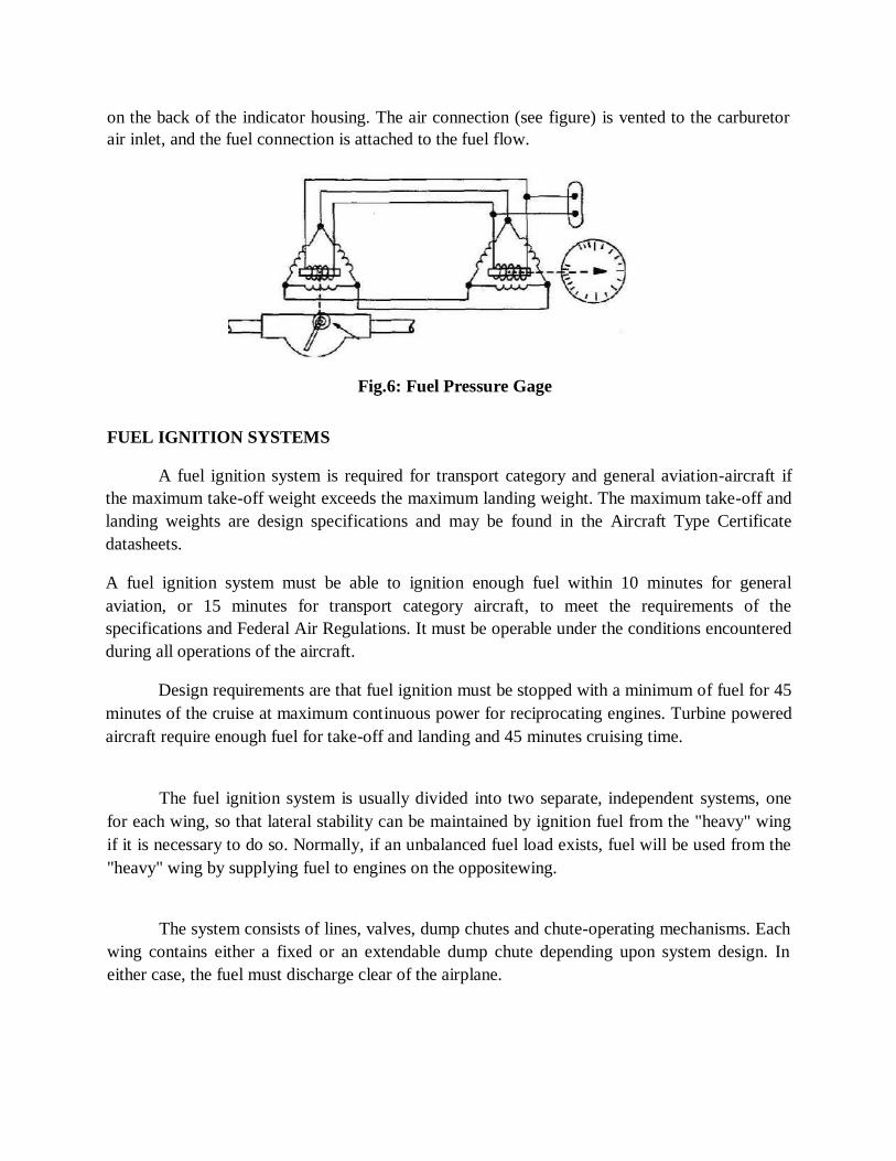
air inlet, and the fuel connection is attached to the fuel flow.
Fig.6: Fuel Pressure Gage
FUEL IGNITION SYSTEMS
A fuel ignition system is required for transport category and general aviation-aircraft if
the maximum take-off weight exceeds the maximum landing weight. The maximum take-off and
landing weights are design specifications and may be found in the Aircraft Type Certificate
datasheets.
A fuel ignition system must be able to ignition enough fuel within 10 minutes for general
aviation, or 15 minutes for transport category aircraft, to meet the requirements of the
specifications and Federal Air Regulations. It must be operable under the conditions encountered
during all operations of the aircraft.
Design requirements are that fuel ignition must be stopped with a minimum of fuel for 45
minutes of the cruise at maximum continuous power for reciprocating engines. Turbine powered
aircraft require enough fuel for take-off and landing and 45 minutes cruising time.
The fuel ignition system is usually divided into two separate, independent systems, one
for each wing, so that lateral stability can be maintained by ignition fuel from the "heavy" wing
if it is necessary to do so. Normally, if an unbalanced fuel load exists, fuel will be used from the
"heavy" wing by supplying fuel to engines on the oppositewing.
The system consists of lines, valves, dump chutes and chute-operating mechanisms. Each
wing contains either a fixed or an extendable dump chute depending upon system design. In
either case, the fuel must discharge clear of the airplane.


SCHOOL OF MECHANICAL ENGINEERING
DEPARTMENT OF AERONAUTICAL ENGINEERING
UNIT – IV- AIRCRAFT SYSTEMS AND INSTRUMENTS – SAEA1303

UNIT IV -- AIRPLANE CONTROL SYSTEMS
AIRCRAFT CONTROL SYSTEMS
Control Surfaces
The control surfaces used on aircraft operating at transonic and supersonic flight speeds
involves some important considerations. Trailing edge control surfaces can be affected adversely
by the shock waves formed in flight above the control surface critical Mach number. If the
airflow is separated by the shock wave, the resulting buffet of the control surface can be very
objectionable. Installation of vortex generators can reduce buffet caused by shock-induced flow
separation. In addition to the buffet of the surface, the change in the pressure distribution due to
separation and shock-wave location can create very large changes in control surfacehinge
moments. Such large changes in hinge moments produce undesirable control forces which may
require the use of an irreversible control system. An irreversible control system employs
powerful hydraulic or electric actuators to move the control surfaces, hence the air loads
developed on the surfaces cannot be felt by the pilot. Suitable feedback- must be synthesized by
bungees, "q" springs, bob weights, and soforth.
AERODYNAMIC HEATING
When air flows over any aerodynamic surface, certain reductions in velocity take place
which produces corresponding increases in temperature. The greatest reduction in velocity and
increase in temperature occurs at the various stagnation points on the aircraft. Of course, smaller
changes occur at other points on the aircraft, but these lower temperatures can be related to the
ram temperature rise at the stagnation point. While subsonic flight does not produce
temperatures of any real concern, the supersonic flight can create temperatures high enough to be
of major importance to the airframe, fuel system, andpowerplant.
Higher temperatures produce definite reductions in the strength of aluminium alloys and
require the use of titanium alloys and stainless steels. Continued exposure at elevated
temperatures further reduces strength and magnifies the problems of creep failure and structural
stiffness.

The effect of aerodynamic heating on the fuel system must be considered in the design
of a supersonic aeroplane. If the fuel temperature is raised to the spontaneous ignition
temperature, the fuel vapours will burn in the presence of air without the need for an initial
spark orflame.
Turbojet engine performance is adversely affected by high compressor inlet air
temperature. The thrust output of the turbojet is some function of the fuel flow. But the
maximum allowable, fuel flow, .depends on the maximum permissible. Turbine operating
temperature If the air entering the engine is already hot, less fuel can be added to avoid
exceeding theturbine.
FLIGHT CONTROL SYSTEMS
Three types of control systems commonly used are: (1) The cable, (2) push-pull, and (3)
the torque tube system. The cable system is the most widely used because deflections of the
structure to which it is attached do not affect its operation. Many aircraft incorporate control
systems that are combinations of all three types.
Flight Control System Hardware, Mechanical Linkage, and Mechanisms. The systems
which operate the control surfaces, tabs, and flaps include flight control system hardware,
linkage, and mechanisms. These items connect the control surfaces to the cockpit controls.
Included in these systems are cable assemblies, cable guides, linkage, adjustable stops, control
surface snubber or locking devices, surface control booster units, actuators operated by electric
motors, and actuators operated by hydraulic motors.
Cable Assembly
The conventional cable assembly consists of flexible cable, terminals (end fittings) for
attaching to other units, and turnbuckles. Information concerning conventional cable
construction and end fittings is contained in Chapter 6 of the Airframe and Powerplant
Mechanic.-. General Handbook, AC65-9A.
At each regular inspection period, cables should be inspected for broken wires by passing
a cloth along their length and observing points where the cloth snags. To thoroughly inspect the
cable, move the surface control to its extreme travel limits. This will reveal the cable in pulley,
fairlead, and drum areas. If the surface of the cable is corroded, relieve cable tension. Then
carefully force the cable open by reverse twisting, and visually inspect the interior for corrosion.
Corrosion on the interior strands of the cable indicates the failure of the cable and requires
replacement of the cable. If there is no internal corrosion, remove external corrosion with a
coarse-weave rag or fibre brush. Never use metallic wools or solvents to clean flexible cable.
Metallic wools imbed dissimilar metal particles, which cause further corrosion. Solvents remove
the internal cable lubricant, which also results in further corrosion. After thoroughly cleaning the
flexible cable, apply the corrosion-preventive compound. This compound preserves and
lubricates thecable.

Breakage of wires occurs most frequently where cables pass over pulleys and through
failing leads. Typical breakage points are shown in the figure. Control Cables and wires should
be replaced if worn, distorted, corroded, or otherwise damaged.
Lockclad cable is used on some large aircraft for all long, straight runs. It consists of the
conventional flexible steel cable with aluminium tubing swaged to it to lock the cable inside
the tubing. Lockclad cable construction has certain advantages. Changes in tension due to
temperature are less than with conventional cable. Furthermore, the amount of stretch at a
given load is less than with conventionalcable.
Fig.1: Cable Assembly
Lockclad cables should be replaced when the covering is worn through, exposing worn wire
strands; is broken, or shows worn spots which cause the cable to bump when passing over
fairlead rollers.
Turnbuckles
The turnbuckle is a device used in cable control systems to adjust cable tension. The
turnbuckle barrel is threaded with left-hand threads inside one end and right-hand threads inside
the other. When adjusting cable tension, the cable terminals are screwed into either end of the
barrel an equal distance by turning the barrel. After a turnbuckle is adjusted, it must be safetied.
Cable Connectors
In addition to turnbuckles, cable connectors are used in some systems. These connectors
enable a cable length to be quickly connected or disconnected from a system. The figure
illustrates one type of cable connector in use. This type is connected or disconnected by
compressing the spring

HYDRAULIC OPERATED CONTROL SYSTEMS
As the airspeed of late-model aircraft increased, actuation of controls in flight became
more difficult. It soon became apparent that the pilot needed assistance to overcome the airflow
resistance to control movement. Spring tabs which were operated by the conventional control
system were moved so that the airflow over them moved the primary control surface. This was
sufficient for the aircraft operating in the lowest of the high-speed ranges (250-300 mph). For
high speeds, a power assist (hydraulic) control system was designed.
Gust Lock
A cam on the control quadrant shaft engages a spring-loaded roller to centre and
neutralize the controls with the hydraulic system off (aircraft parked). The pressure is trapped in
the actuators and since the controls are neutralized by the cam and roller, no movement of the
control surface s is permitted.
CABLE GUIDES
Cable guides consist of primarily of fairleads, pressure seals, and pulleys. A fairlead may
be made from a nonmetallic material such as phenolic or a metallic material such as soft
aluminium. The fairlead completely encircles the cable where it passes through holes in
bulkheads or other metal parts. Fairleads are used to guide cables in a straight line.

Fig.2: Cable Guides
MECHANICAL LINKAGE
Various mechanical linkages connect the cockpit controls to control cables and surface
controls. These devices either transmit motion or change the direction of motion of the control
system. The linkage consists primarily of control (push-pull) rods, torque tubes, quadrants,
sectors, bellcranks, and cable drums.

Fig.3: Mechanical Linkage
TORQUE TUBES
Where an angular or twisting motion is needed in a control system, a torque tube is
installed. View B of the figure shows how a torque tube is used to transmit motion in opposite
directions.
Quadrants, bellcranks, sectors, and drums change the direction of motion and transmit motion
to parts such as control rods, cables, and torque tubes. The quadrant shown is typical of flight
control system linkages used by various manufactures. View E illustrates a cable drum. Cable
drums are used primarily in trim tab systems. As the trim tab control wheel is moved clockwise
or counterclockwise, the cable drum winds or unwinds to actuate the trim lab cables.
STOPS
Adjustable and non adjustable stops (whichever the case requires) are used to limit the throw-
range or travel movement of the ailerons, elevator, and rudder. Usually, there are two sets of
stops for each of the three main control surfaces, one set being located at the control surface,
either in the snubber cylinders or as structural stops, and the other at the cockpit control. Either
of these may serve as the actual limit stop. However, those situated at the control surface usually
perform this function. The other stops do not normally contact each other but are adjusted to a
definite clearance when the control surface is at the full extent of its travel. These work as over-
ride stops to prevent stretching of cables and damage to the control system during violent
manoeuvres. When rigging control systems, refer to the applicable maintenance manual for the
sequence of steps for adjusting these stops to limit the control surfacetravel
Fig.4: Adjustable and non adjustable stops

CONTROL SURFACE SNUBB ERS AND LOCKING DEVICES
Various types of devices are in use to lock the control surfaces when the aircraft is
parked or moored. Locking devices prevent damage to the control surfaces and their linkages
from gusts and high-velocity winds. Common devices that are in use are the internal locking
brake (sector brake) spring-loaded plunger and external controlsurface
Internal Locking Devices
The internal locking device is used to secure the ailerons, rudder, and elevator in their
neutral positions. The locking device is usually operated through a cable system by a spring-
loaded plunger (pin) that engages a hole in the control surface mechanical linkage to lock the
surface. A spring connected to the pin forces it back to the unlock position when the cockpit
control lever is placed in the "unlock" position. An over-centre toggle linkage is used on some
other type aircraft to lock the control surfaces.
Fig.5: Internal Locking Devices
Control Surface Snubbers
Hydraulic booster units are used on some aircraft to move the control surfaces. The
surfaces are usually protected from wind gusts by snubbers incorporated into the booster unit On
some aircraft an auxiliary snubber cylinder is connected directly to the surface to provide
protection. The snubbers hydraulically check or cushion' control surface movement when the
aircraft is parked. This prevents wind gusts from slamming the control surfaces into their stops
and possibly causing damage.
External Control Surface Locks
External control surface locks are in the form of channelled woodblocks. The
channelled wood blocks slide into the openings between the ends of the movable surfaces and
the aircraft structure. This locks the surfaces in neutral. When not in use, these locks are stowed
within theaircraft.
Tension Regulators
Cable tension regulators are used in some flight control systems because there is a
considerable difference in temperature expansion of the aluminium aircraft structure and the
steel control cables. Some large aircraft incorporate tension regulators in the control cable

systems to automatically maintain given cable tension. The unit consists of a compression
spring and a locking mechanism which allows the spring to correct the system only when the
cable system is in neutral.
AIRCRAFT RIGGING
Control surfaces should move a certain distance in either direction from the neutral
position. These movements must be synchronized with the movement of the cockpit controls.
The flight control system must be adjusted (rigged) to obtain these requirements.
Generally speaking, the rigging consists of the following: (1) Positioning the flight
control system in neutral and temporarily locking it there with rig pins or blocks, and (2)
adjusting surface travel, system cable tension, linkages, and adjustable stops to the aircraft
manufacturer's specifications.
When rigging flight control systems, certain items of rigging equipment are needed.
Primarily, this equipment consists of tensiometers, cable rigging tension charts, protractors,
rigging fixtures, contour templates, and rulers.
Measuring Cable Tension
To determine the amount of tension on a cable, a tensiometer is used. When properly
maintained, a tensiometer is 98% accurate. Cable tension is determined by measuring the
amount of force needed to make an offset in the cable between two hardened steel blocks,
called anvils. A riser or plunger is pressed against the cable to form the offset. Several
manufacturers make a variety of tensiometers, the type designed for different kinds of cable,
cable sizes, and cable tensions.
One type of tensiometer is illustrated. With the trigger lowered, place the cable to be
tested under the two anvils. Then close the trigger (move it up). Movement of the trigger
pushes up the riser, which pushes the cable at right angles to the two clamping points under the
anvils. The force that is required to do this is indicated by the dial pointer. As the sample chart
beneath the illustration shows, different numbered risers are used with different size cables.
Each riser has an identifying number and is easily inserted into thetensiometer.
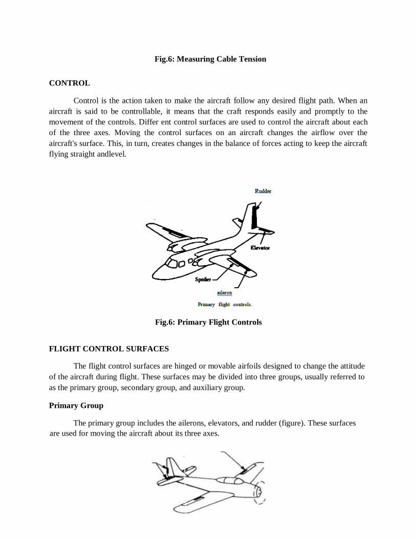
Fig.6: Measuring Cable Tension
CONTROL
Control is the action taken to make the aircraft follow any desired flight path. When an
aircraft is said to be controllable, it means that the craft responds easily and promptly to the
movement of the controls. Differ ent control surfaces are used to control the aircraft about each
of the three axes. Moving the control surfaces on an aircraft changes the airflow over the
aircraft's surface. This, in turn, creates changes in the balance of forces acting to keep the aircraft
flying straight andlevel.
Fig.6: Primary Flight Controls
FLIGHT CONTROL SURFACES
The flight control surfaces are hinged or movable airfoils designed to change the attitude
of the aircraft during flight. These surfaces may be divided into three groups, usually referred to
as the primary group, secondary group, and auxiliary group.
Primary Group
The primary group includes the ailerons, elevators, and rudder (figure). These surfaces
are used for moving the aircraft about its three axes.

TRIM TABS
The ailerons and elevators are generally operated from the cockpit by a control stick on
single-engine aircraft and by a wheel and yoke assembly on multi-engine aircraft. The rudder is
operated by foot pedals on all types of aircraft.
Secondary Group
Included in the second group are the trim tabs and spring tabs. Trim tabs are small
airfoils recessed into the trailing edges of the primary control surfaces. The purpose of trim tabs
is to enable the pilot to trim out any unbalanced condition which may exist during flight, without
exerting any pressure on the primary controls. Each trim tab is hinged to its parent primary
control surface but is operated by an independentcontrol.
Spring tabs are similar in appearance to trim tabs but serve an entirely different purpose.
Spring tabs are used to aid the pilot in moving the primary control surfaces.
Auxiliary Group
Included in the auxiliary group of flight control surfaces are the wing flaps, spoilers,
speed brakes, slats, leading-edge flaps and slots.
The auxiliary groups may be divided into two sub-groups. Those whose primary purpose
is to lift augmenting and those whose primary purpose is to lift decreasing. In the first group are
the flaps, both trailing edge and leading edge (slats), and slots. The lift decreasing devices are
speed brakes and spoilers.
The trailing edge airfoils (flaps) increase the wing area thereby increasing lift on takeoff
and decrease the speed during landing. These airfoils are retractable and fair into the wing
contour. Others are simply a portion of the lower skin which extends into the airstream thereby
slowing the aircraft.
Leading-edge flaps are airfoils extended from and retracted into the leading edge of the
wing. Some installations create a slot (an opening between the extended airfoil and the leading
edge). The flap (termed slat by some manufacturers) and slot create additional lift at the slower
speeds of takeoff and landing. Other installations have permanent slots, built in the leading edge
of the wing. At cruising speeds, the trailing edge and leading-edge flaps (slats) are retracted into
the wing proper.
Lift decreasing devices are the speed brakes (spoilers). In some installations, there are
two types of spoilers. The ground spoiler is extended only after the aircraft is on the ground
thereby assisting in the braking action assists in lateral control by being extended whenever the
aileron on that wing is rotated up. When actuated as speed brakes, the spoiler panels on both
wings raise the panel on the "up" aileron wing raising more than the panel on the down aileron
side. This provides speed brake operation and later controlsimultaneously.

Slats are movable control surfaces attached to the leading edges of the wings. When the
slat is closed, it forms the leading edge of the wing. When in the open position (extended
forward), a slot is created between the slat and the wing leading edge. At low airspeeds this
increases lift and improves handling characteristics, allowing the aircraft to be controlled at
airspeeds below the otherwise normal landing speed.
CONTROL AROUND THE LONGITUDINAL AXIS
The motion of the aircraft about the longitudinal axis is called rolling or banking. The
ailerons are used to control this movement. The ailerons form a part of the wing and are located
in the trailing edge of the wing toward the tips. Ailerons are the movable surfaces of an
otherwise fixed-surface wing. The aileron is in a neutral position when it is streamlined with the
trailing edge of the wing.
As a result of the increased lift on the wing with the lowered aileron, drag is also
increased. This drag attempts to pull the nose in the direction of the high wing. Since the
ailerons are used with the rudder when making turns, the increased drag tries to turn the aircraft
in the direction opposite to that desired. To avoid this undesirable effect, aircraft are often
designed with differential travel of the ailerons.
Differential aileron travel provides more aileron up travel than down travel for a given
movement of the control stick or wheel in the cockpit.
The spoilers, or speed brakes as they are also called, are plates fitted to the upper surface
of the wing. They are usually deflected upward by hydraulic actuators in response to control
wheel movement in the cockpit. The purpose of the spoilers is to disturb the smooth airflow
across the top of the airfoil thereby creating an increased amount of drag and a decreased
amount of lift on that airfoil.
Spoilers are used primarily for lateral control. When banking the aeroplane, the spoilers
function with the ailerons. The spoilers on the up aileron side raise with that aileron to further
decrease the lift on that wing. The spoiler on the opposite side remains in the faired position.
When the spoilers are used as a speed brake, they are all deflected upward simultaneously. A
separate control lever is provided for operating the spoilers as speed brakes.
While we tend to think of a spoiler as being a fairly complicated, controlled device, we
should keep in mind that some are not controllable. Some spoilers are automatic in operation in
that they come into effect only at a high angle of attack. This arrangement keeps them out of the
slipstream at cruise and high speeds. A fixed spoiler may be a small wedge affixed. This type
spoiler causes the inboard portion of the wing to stall ahead of the outboard portion which results
in aileron control right up to the leading edge of the airfoil as shown in figure occurrence of
complete wing stall.

Aileron control system.
Fig.7: Aileron control system.

Use extreme accuracy in positioning leading edge spoilers when re-installing them after
they have been removed for maintenance. Improper positioning may result in adverse stall
characteristics. Always follow the manufacturers’ instructions regarding the location and
method of
attachment.
CONTROL AROUND THE VERTICAL AXIS
Turning the nose of the aircraft causes the aircraft to rotate about its vertical axis.
Rotation of the aircraft about the vertical axis is called yawing. This motion is controlled by
using the rudder as illustrated.
The rudder is a movable control surface attached to the trailing edge of the vertical
stabilizer. To turn the aircraft to the right, the rudder is moved to the right. The rudder protrudes
into the air-stream, causing a force to act upon it. This is the force necessary to give a turning
movement about the centre of gravity which turns the aircraft to the right. If the rudder is moved
to the left, it induces a pivot.
The elevators are used to make the aircraft climb or dive and also to obtain sufficient lift
from the wings to keep the aircraft in level flight at various speeds.
The elevators can be moved either up or down. If the elevator is rotated up, it decreases
the lift force on the tail causing the tail to lower and the nose to rise. If the elevator is rotated
downward, it increases the lift force on the tail causing it to rise and the nose to lower. Lowering
the aircraft's nose increases forward speed, and raising die nose decreases forward speed. Some
aircraft, use a movable horizontal surface Jed a stabilator The stabilator serves the same purpose
as the horizontal stabilizer counterclockwise rotation and the aircraft similarly turns to the left.
The rudder can also be used in controlling a hank or turn in flight.
The main function of the rudder is to turn the aircraft in flight. This turn is maintained by
the side pressure of the air moving past the vertical surfaces. When an aircraft begins to slip or
skid, rudder pressure is applied to keep the aircraft headed in the desired direction (balanced).
Slip or side slipping refers to any motion of the aircraft to the side and downward toward
the inside of a turn. Skid or skidding refers to any movement upward and outward away from
the centre of aturn.
CONTROL AROUND THE LATERAL AXIS
When the nose of an aircraft is raised or lowered, it is rotated about its lateral axis. Elevators
are the movable control surfaces that cause this Rotation. They arc normally hinged to the
trailing edge of the horizontal stabilizer. and elevator combined. When the cockpit control is
moved, the complete stabilator is moved to raise or lower the leading edge, thus changing the
the angle of attack and the amount of lift on the tail surfaces.


SCHOOL OF MECHANICAL ENGINEERING
DEPARTMENT OF AERONAUTICAL ENGINEERING
UNIT – V- AIRCRAFT SYSTEMS AND INSTRUMENTS – SAEA1303

UNIT V AIRCRAFT INSTRUMENTS
AIRCRAFT INSTRUMENTS
TACHOMETERS
The tachometer indicator is an instrument for indicating the speed of the crankshaft of a
reciprocating engine and the speed of the main rotor assembly of a gas turbine engine.
The dials of tachometer indicators used with reciprocating engines are calibrated
in r.p.m.; those used with turbine engines are calibrated in the percentage of r.p.m. being used,
based on the takeoff r.p.m. The figure shows a typical dial for each of the indicators just
described.
Fig.1: Tachometer. (A) Reciprocating engine type. (B) Turbine engine type.
There are two types of tachometer systems in wide use today: (1) The mechanical indicating
system, and (2) the electrical indicating system.
Mechanical Indicating Systems
Mechanical indicating systems consist of an indicator connected to the engine by a
flexible drive shaft. The indicator contains a flyweight assembly coupled to a gear mechanism
that drives a pointer. As the drive shaft rotates, centrifugal force acts on the flyweights assembly
and moves them to an angular position. This angular position varies with the r.p.rn. of

the engine. Movement of the flyweights is transmitted through the gear mechanism to the
pointer. The pointer rotates to indicate the r.p.m. of the engine on the tachometer indicator.
Electric Indicating Systems
A number of different types and sizes of tachometer generators and indicators are used in
aircraft electrical tachometer systems. Generally, the various types of tachometer indicators and
generators operate on the same basic principle. Thus, the system described will be representative
of most electrical tachometer systems; the manufacturer's instructions should always be
consulted for details of a specific tachometersystem.
The typical tachometer system (figure 12-35) is a three-phase a.c. generator coupled to
the aircraft engine and connected electrically to an indicator mounted on the instrument panel.
These two units are connected by a current-carrying cable. The generator transmits three-phase
power to the synchronous motor in the indicator. The frequency of the transmitted power is
proportional to the engine speed. Through the use of the magnetic drag principle, the indicator
furnishes an accurate indication of enginespeed.
Tachometer generators are small compact units, generally available in three types: (1)
The pad, (2) the swivel-nut, and (3) the screw type. These names are derived from the kind of
mounting used in attaching the generator to the engine. The pad-type tachometer generator
(figure 12-36A) is constructed with an end shield designed to permit attachment of the generator
to a fiat plate on the engine frame, or accessory reduction gearbox, with four bolts. The swivel-
nut tachometer generator is constructed with a mounting nut which is free to turn in respect to
the rest of the instrument. This type of generator can be held stationary while the mounting nut is
screwed into place. The screw-type tachometer generator (figure 12-36B) is constructed with a
mounting nut inserted in one of the generator end shields. The mounting nut is a rigid part of the
instrument, and the whole generator must be turned to screw the nut onto its matingthreads.
The dual tachometer consists of two tachometer indicator units housed in a single case.
The indicator pointers show simultaneously on a single dial the r.p.m. of two engines. Some
tachometer indicators are equipped with a flight-hour meter dial, usually located in the lower
centre area of the dial face, just below the pointer pivot.
SYNCHROSCOPE
The synchroscope is an instrument that indicates whether two (or more) engines are
synchronized; that is, whether they are operating at the same r.p.m. The instrument consists of a
small electric motor which receives electrical current from the tachometer generators of both
engines. The synchroscope is designed so that current from the faster-running engine controls
the direction in which the synchroscope motorrotates.
If both engines are operating at the same speed, the synchroscope motor does not
operate. If, however, one engine is operating faster than the other, its generatorsignal

will cause the synchroscope motor to turn in a given direction. If the speed of the other engine
then becomes greater than that of the first engine, the signal from its generator will then cause
the synchroscope motor to reverse itself and turn in the oppositedirection.
The motor of the synchroscope is connected using a shaft to a double-ended pointer on
the dial of the instrument (figure 12-38). It is necessary to designate one of the two engines a
master engine if the synchroscope indicators are to be useful. The dial readings, with the
leftward rotation of the pointer indicating "slow" and rightward motion indicating "fast," then
refer to the operation of the second engine in relation to the speed of the masterengine.
For aircraft with more than two engines, additional synchroscopes are used. One engine
is designated the master engine, and synchroscopes are connected between its tachometer and
those of each of the other individual engines. On a complete installation of this kind, there will,
of course, be one less instrument than there are engines, since the master engine is common to
all thepairs.
One type of four-engine synchroscopeis a special instrument that is actually three
individual synchroscopes in one case
Fig.2: Four-engine synchroscope.
The rotor of each is electrically connected to the tachometer generator of the engine
designated as the master, while each stator is connected to one of the other engine tachometers.
There are three hands, each indicating the relative speed of the number two, three, or four-
engine, as shown in figure 12-40.
The separate hands revolve clockwise when their respective engine is running faster than
the master and counterclockwise when it is running slower. Rotation of the hand begins as the
speed difference reaches about 350 r.p.m., and as the engines approach synchronization, the
hand revolves at a ratio proportional to the speeddifference.

TEMPERATURE INDICATORS
Various temperature indications must be known for an aircraft to be operated properly.
The temperature of the engine oil, carburetor mixture, inlet air, free air, engine cylinders, heater
ducts, and exhaust gas temperature of turbine engines must be known. Many other temperatures
must also be known, but these are some of the more important. Different types of thermometers
are used to collect and present this information.
Electrical Resistance Thermometer
Electrical resistance thermometers are used widely in many types of aircraft to measure
carburettor air, oil, and free air temperatures.
The principal parts of the electrical resistance thermometer are the indicating instrument,
the temperature-sensitive element (or bulb), and the connecting wires and plug connectors.
Oil temperature thermometers of the electrical resistance type have typical ranges of from
—10° to + 120° C, or from —70° to +150° C. Carburetor air and mixture thermometers
may have a range of from —50° to -j-50° C., as do many free air thermometers.
A typical electrical resistance thermometer is shown in figure 12-41. Indicators are also
available in a dual form for use in multi-engine aircraft. Most indicators are self-compensated for
changes in cockpit temperature.
The electrical resistance thermometer operates on the principle of the change in the
electrical resistance of most metals with changes in temperature. In most cases, the electrical
resistance of a metal increases as the temperature rises. The resistance of some metals increases
more than the resistance of others with a given rise in temperature. If a metallic resistor with a
high temperature-resistant coefficient (a high rate of resistance rise for a given increase in
temperature) is subjected to a temperature to be measured, and a resistance indicator is
connected to it, all the requirements for an electrical thermometer system are present.
The heat-sensitive resistor is the main element in the bulb. It is manufactured so that it
has a definite resistance for each temperature value within its working range. The temperature-
sensitive resistor element is a winding made of various alloys, such as nickel/manganese wire,
in suitable insulating material. The resistor is protected by a closed-end metal tube attached to a
threaded plug with a hexagon head (figure 12-42). The two ends of the winding are brazed or
welded to an electrical receptacle designed to receive the prongs of the connectorplug.
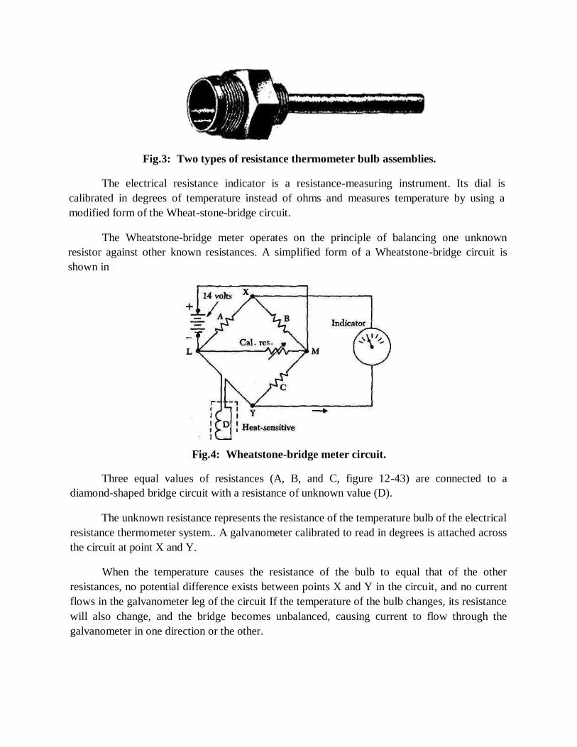
Fig.3: Two types of resistance thermometer bulb assemblies.
The electrical resistance indicator is a resistance-measuring instrument. Its dial is
calibrated in degrees of temperature instead of ohms and measures temperature by using a
modified form of the Wheat-stone-bridge circuit.
The Wheatstone-bridge meter operates on the principle of balancing one unknown
resistor against other known resistances. A simplified form of a Wheatstone-bridge circuit is
shown in
Fig.4: Wheatstone-bridge meter circuit.
Three equal values of resistances (A, B, and C, figure 12-43) are connected to a
diamond-shaped bridge circuit with a resistance of unknown value (D).
The unknown resistance represents the resistance of the temperature bulb of the electrical
resistance thermometer system.. A galvanometer calibrated to read in degrees is attached across
the circuit at point X and Y.
When the temperature causes the resistance of the bulb to equal that of the other
resistances, no potential difference exists between points X and Y in the circuit, and no current
flows in the galvanometer leg of the circuit If the temperature of the bulb changes, its resistance
will also change, and the bridge becomes unbalanced, causing current to flow through the
galvanometer in one direction or the other.

The dial of the galvanometer is calibrated in degrees of temperature, converting it to a
temperature-measuring instrument. Most indicators are provided with a zero adjustment screw
on the face of the instrument to set the pointer at a balance point (the position of the pointer
when the bridge is balanced and no current flows through the meter).
Thermocouple Thermometer Indicators
The cylinder temperature of most air-cooled reciprocating aircraft engines is measured
by a thermometer which has its heat-sensitive element attached to some point on one of the
cylinders (normally the hottest cylinder). In the case of turbojet engines, the exhaust
temperature is measured by attaching thermocouples to thetailcone.
A thermocouple is a circuit or connection of two unlike metals; such a circuit has two
junctions. If one of the junctions is heated to a higher temperature than the other, an
electromotive force is produced in the circuit. By including a galvanometer in the circuit, this
force can be measured. The hotter the high-temperature junction (hot junction) becomes, the
greater the electromotive force produced. By calibrating the galvanometer dial in degrees it
becomes a thermometer.
A typical thermocouple thermometer system (figure 12-44) used to indicate engine
temperature consists of a galvanometer indicator calibrated in degrees of centigrade, a
thermocouple, and thermocouple leads.
Fig.5: Thermocouple Thermometer Indicators
Reciprocating engine cylinder head temperature thermocouple system.
Thermocouple leads are commonly made from iron and constantan, but copper and
constantan or chromel and alumel are other combinations of dissimilar metals in use.
Iron/constantan is used mostly in radial engines, and chromel/alumel is used in jet engines.
Thermocouple leads are designed to provide a definite amount of resistance in the
thermocouple circuit. Thus, their length or cross-sectional size cannot be altered unless some
compensation is made for the change in total resistance.
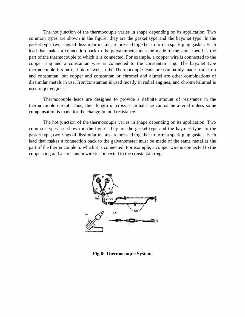
The hot junction of the thermocouple varies in shape depending on its application. Two
common types are shown in the figure; they are the gasket type and the bayonet type. In the
gasket type, two rings of dissimilar metals are pressed together to form a spark plug gasket. Each
lead that makes a connection back to the galvanometer must be made of the same metal as the
part of the thermocouple to which it is connected. For example, a copper wire is connected to the
copper ring and a constantan wire is connected to the constantan ring. The bayonet type
thermocouple fits into a hole or well in the Thermocouple leads are commonly made from iron
and constantan, but copper and constantan or chromel and alumel are other combinations of
dissimilar metals in use. Iron/constantan is used mostly in radial engines, and chromel/alumel is
used in jet engines.
Thermocouple leads are designed to provide a definite amount of resistance in the
thermocouple circuit. Thus, their length or cross-sectional size cannot be altered unless some
compensation is made for the change in total resistance.
The hot junction of the thermocouple varies in shape depending on its application. Two
common types are shown in the figure; they are the gasket type and the bayonet type. In the
gasket type, two rings of dissimilar metals are pressed together to form a spark plug gasket. Each
lead that makes a connection back to the galvanometer must be made of the same metal as the
part of the thermocouple to which it is connected. For example, a copper wire is connected to the
copper ring and a constantan wire is connected to the constantan ring.
Fig.6: Thermocouple System.

GYROSCOPIC INSTRUMENTS
Three of the most common flight instruments, the attitude indicator, heading indicator,
and the turn needle of the turn and bank indicator, are controlled by gyroscopes. To understand
how these instruments operate requires knowledge of gyroscopic principles, instrument power
systems, and the operating principles of each instrument.
A gyroscope is a wheel or disk mounted to spin rapidly about an axis and is also free to rotate
about one or both of two axes perpendicular to each other and the axis of spin. A spinning
gyroscope offers resistance to any force which tends to change the direction of the axis of spin.
Fig.7: Gyroscopic Instruments
A rotor and axle are the heart of a basic gyro (A); a supporting ring with bearings on
which the rotor and its axle can revolve are added to the basic unit (B), and an outer ring with
bearings at 90° to the rotor bearings has been added (C). The inner ring with its rotor and axle
can turn through 360° inside this outerring.
A gyro at rest is shown in six different positions to demonstrate that unless the rotor is
spinning a gyro has no unusual properties; it is simply a wheel universally mounted.

When the rotor is rotated at a high speed, the gyro exhibits one of its two gyroscopic
characteristics. It acquires a high degree of rigidity, and its axle points in the same direction no
matter how much its base is turned about Gyrocsopic rigidity depends upon several design
factors:
Weight. For a given size, a heavy mass is more resistant to disturbing forces than a light mass.
Angular velocity. The higher the rotational speed, the greater the rigidity or resistance to deflection.
Radius at which the weight is concentrated. The maximum effect is obtained froma mass when its principal weight is concentrated near the rim rotating at highspeed.
Bearing friction. Any friction applies a deflecting force to a gyro. Minimumbearing friction keeps deflecting forces at aminimum.
A second gyroscopic characteristic, precession, is illustrated in figure 12-58A by
applying a force or pressure to the gyro about the horizontal axis. The applied force is resisted,
and the gyro, instead of turning about its horizontal axis, turns or "pre-cesses" about its vertical
axis in the direction indicated by the letter P. Similarly, if pressure is applied to the vertical axis,
the gyro will precess about its horizontal axis in the direction shown by the arrow P in figure 12-
58BTwo types of mountings are used, depending upon how the gyroscopic properties are to be
used in the operation of an instrument. A freely or universally mounted gyro is set on three
gimbals (rings), with the gyro free to rotate in any plane. Regardless of the position of the gyro
base, the gyro tends to remain rigid in space. In the attitude indicator, the horizon bar is gyro-
controlled to remain parallel to the natural horizon, and changes in the position of the aircraftare
shown pictorially on theindicator.
INERTIAL NAVIGATION SYSTEM
The inertial navigation system is presently being used on large aircraft as a long-range
navigation aid. It is a self-contained system and does not require signal inputs from ground
navigational facilities. The system derives attitude, velocity, and heading information from the
measurement of the aircraft's accelerations. Two accelerometers are required, one reference to
the north and the other to east. The accelerometers are mounted on a gyro-stabilized unit, called
the stable platform, to avert the introduction of errors resulting from the acceleration due to
gravity.
An inertial navigation system is a complex system containing four basic components. They are:
(1) A stable platform which is oriented to maintain accelerometers horizontal to the earth's surface and provide azimuthorientation.
(2) Accelerometers arranged on the platform to supply specific components ofacceleration.
(3) Integrators which receive the output from the accelerometers and furnish velocityand
distance.
(4) A computer which receives signals from the integrators and changes distance travelledto a position in selectedcoordinates.
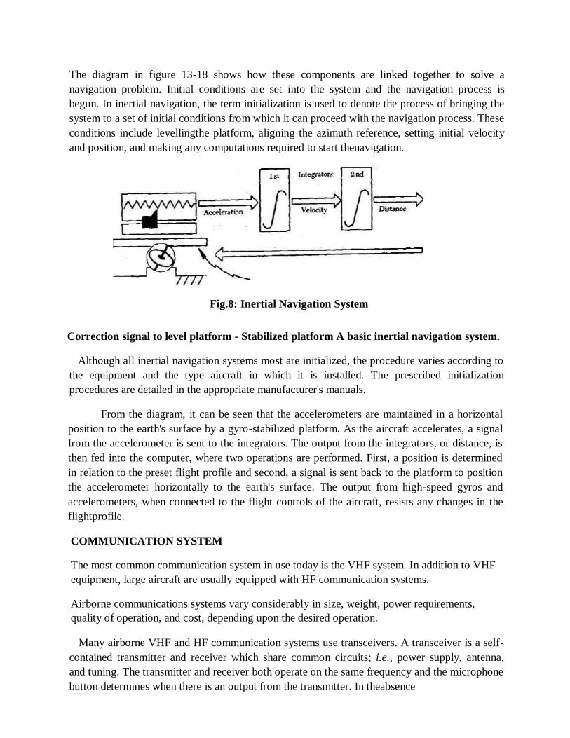
The diagram in figure 13-18 shows how these components are linked together to solve a
navigation problem. Initial conditions are set into the system and the navigation process is
begun. In inertial navigation, the term initialization is used to denote the process of bringing the
system to a set of initial conditions from which it can proceed with the navigation process. These
conditions include levellingthe platform, aligning the azimuth reference, setting initial velocity
and position, and making any computations required to start thenavigation.
Fig.8: Inertial Navigation System
Correction signal to level platform - Stabilized platform A basic inertial navigation system.
Although all inertial navigation systems most are initialized, the procedure varies according to
the equipment and the type aircraft in which it is installed. The prescribed initialization
procedures are detailed in the appropriate manufacturer's manuals.
From the diagram, it can be seen that the accelerometers are maintained in a horizontal
position to the earth's surface by a gyro-stabilized platform. As the aircraft accelerates, a signal
from the accelerometer is sent to the integrators. The output from the integrators, or distance, is
then fed into the computer, where two operations are performed. First, a position is determined
in relation to the preset flight profile and second, a signal is sent back to the platform to position
the accelerometer horizontally to the earth's surface. The output from high-speed gyros and
accelerometers, when connected to the flight controls of the aircraft, resists any changes in the
flightprofile.
COMMUNICATION SYSTEM
The most common communication system in use today is the VHF system. In addition to VHF
equipment, large aircraft are usually equipped with HF communication systems.
Airborne communications systems vary considerably in size, weight, power requirements,
quality of operation, and cost, depending upon the desired operation.
Many airborne VHF and HF communication systems use transceivers. A transceiver is a self-
contained transmitter and receiver which share common circuits; i.e., power supply, antenna,
and tuning. The transmitter and receiver both operate on the same frequency and the microphone
button determines when there is an output from the transmitter. In theabsence

of transmission, the receiver is sensitive to incoming signals. Since weight and space are of great
importance in aircraft, the transceiver is widely used. Large aircraft may be equipped with
transceivers or a communications system that uses separate transmitters and receivers.
The operation of radio equipment is essentially the same whether installed on large
aircraft or small aircraft. In some radio installations the controls for frequency selection,
volume, and the "on-off" switch are integral with the radio main chassis. In other installations,
the controls are mounted on a panel located in the cockpit and the radio equipment is located in
racks in another part of theaircraft.
Because of the many different types and models of radios in use, it is not possible to
discuss the specific techniques- for operating each in this manual. However, there are various
practices of a nonspecific nature which apply to all radios. These general practices will be
described.
VHF (Very High Frequency) Communications
VHF airborne communication sets operate in the frequency range from 108.0 MHz to
135.95 MHz. VHF receivers are manufactured that cover only the communications frequencies,
or both communications and navigation frequencies. In general, the VHF radio waves follow
approximately straight lines. Theoretically, the range of contact is the distance to the horizon and
this distance is determined by the heights of the transmitting and receiving antennas. However,
communication is sometimes possible many hundreds of miles beyond the assumed horizon
range.