
Understanding Materials & Corrosion to API 571-my self study notes Part-D
Upload
independentCategory
view
3download
0
4.3 Uniform or Localized Loss of Thickness 均匀与局部厚度减薄

4.3 Uniform or Localized Loss of Thickness均匀或局部厚度损失
4.3.1 Galvanic Corrosion4.3.2 Atmospheric Corrosion4.3.3 Corrosion Under Insulation (CUI) 4.3.4 Cooling Water Corrosion4.3.5 Boiler Water Condensate Corrosion4.3.6 CO2 Corrosion 4.3.7 Flue-Gas Dew-Point Corrosion4.3.8 Microbiologically Induced Corrosion (MIC)4.3.9 Soil Corrosion 4.3.10 Caustic Corrosion4.3.11 Dealloying4.3.12 Graphitic Corrosion

Par. 3. - Definitions 4.2.3 – Temper Embrittlement 4.2.7 – Brittle Fracture 4.2.9 – Thermal Fatigue 4.2.14 – Erosion/Erosion-Corrosion 4.2.16 – Mechanical Failure 4.3.2 – Atmospheric Corrosion 4.3.3 – Corrosion Under Insulation (CUI) 4.3.4 – Cooling Water Corrosion 4.3.5 – Boiler Water Condensate Corrosion 4.3.10 – Caustic Corrosion 4.4.2 – Sulfidation 4.5.1 – Chloride Stress Corrosion Cracking (Cl-SCC) 4.5.2 – Corrosion Fatigue 4.5.3 – Caustic Stress Corrosion Cracking 5.1.2.3 – Wet H2S Damage (Blister/HIC/SOHIC/SCC) 5.1.3.1 – High Temperature Hydrogen Attack (HTHA)
Par. 3 – Definitions 4.2.7 – Brittle Fracture 4.2.9 – Thermal Fatigue 4.2.14 – Erosion/Erosion Corrosion 4.2.16 – Mechanical Fatigue 4.2.17 – Vibration-Induced Fatigue 4.3.1 – Galvanic Corrosion 4.3.2 – Atmospheric Corrosion 4.3.3 – Corrosion Under Insulation (CUI) 4.3.5 – Boiler Water Condensate Corrosion 4.3.7 – Flue Gas Dew Point Corrosion 4.3.8 – Microbiological Induced Corrosion (MIC) 4.3.9 – Soil Corrosion 4.4.2 – Sulfidation 4.5.1 – Chloride Stress Corrosion Cracking (Cl-SCC) 4.5.3 – Caustic Stress corrosion Cracking 5.1.3.1 – High Temperature Hydrogen Attack (HTTA)
2013-API510 Examination2013- API570 Examination

4.3.1 Galvanic Corrosion 电偶腐蚀4.3.1.1 Description of Damage
A form of corrosion that can occur at the junction of dissimilar metals when they are joined together in a suitable electrolyte, such as a moist or aqueous environment, or soils containing moisture.
4.3.1.2 Affected Material
All metals with the exception of most noble metals.

4.3.1.3 Critical Factors 关键因素
a) For galvanic corrosion, three conditions must be met:
1. Presence of an electrolyte, a fluid that can conduct a current. Moisture or a separate water phase is usually required for the solution to have enough conductivity.
2. Two different materials or alloys known as the anode and the cathode, in contact with an electrolyte.
3. An electrical connection must exist between the anode and the cathode.
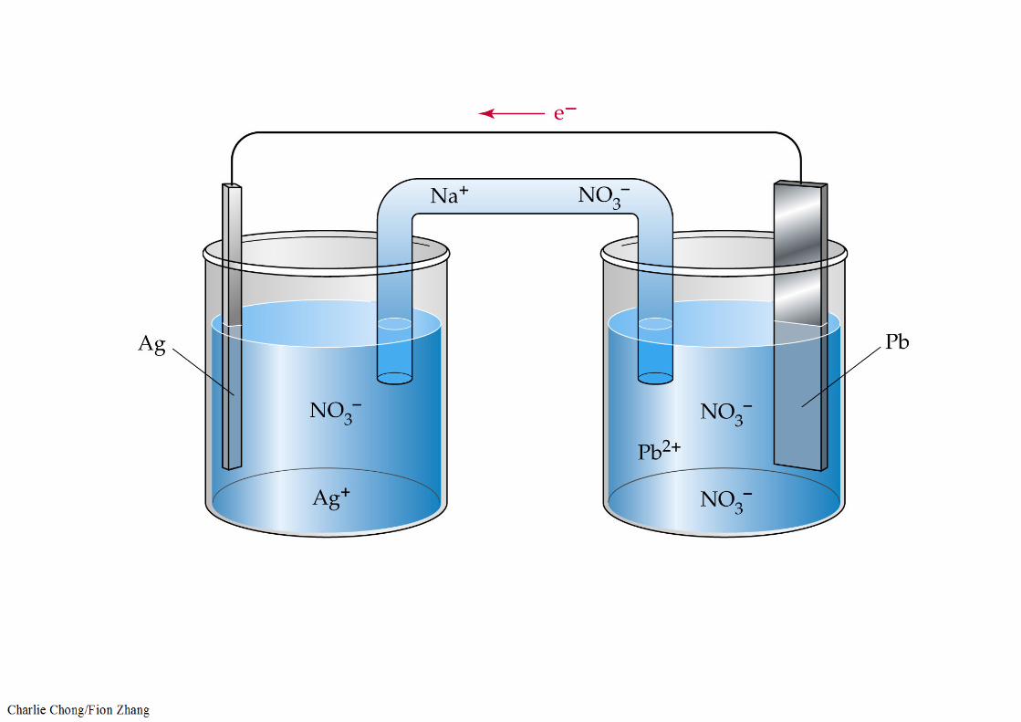

b) The more noble material (cathode) is protected by sacrificial corrosion of the more active material (anode). The anode corrodes at a higher rate than it would if it were not connected to the cathode.
c) A typical listing of the relative position of alloys in seawater is shown in Table 4-6.
d) The farther the alloys are apart in the table, the higher the driving force for corrosion.

e) The relative exposed surface areas between anodic material and the cathodic material has a significant affect.
1. Corrosion rates of the anode can be high, if there is a small anode to cathode ratio.
2. Corrosion rates of the anode will be less affected if there is a large anode to cathode ratio.
3. If there is a galvanic couple, the more noble material may need to be coated. If the active material were coated, a large cathode to anode area can accelerate corrosion of the anode at any breaks in the coating.
4. The same alloy may act as both an anode and a cathode due to surface films, scale, and/or local environment (for example, old steel pipe connected to new steel pipe).

4.3.1.4 Affected Units or Equipment 影响单元/设备
a) Galvanic corrosion can occur in any unit where there is a conductive fluid and alloys are coupled. Heat exchangers are susceptible if the tube material is different from the tubesheet and/or baffles, particularly if salt water cooling is utilized.
b) Buried pipelines, electrical transmission support towers and ship hulls are typical locations for galvanic corrosion.

Galvanic corrosion can occur in any unit where there is a conductive fluid and alloys are coupled. Heat exchangers are susceptible if the tube material is different from the tubesheet and/or baffles, particularly if salt water cooling is utilized.

4.3.1.5 Appearance or Morphology of Damage 破坏外观形
a) Damage occurs where two materials are joined at welded or boltedconnections.
b) The more active material can suffer generalized loss in thickness or may have the appearance of a crevice, groove or pitting corrosion, depending on the driving force, conductivity and relative anodic/cathodic areas ratio.
c) Corrosion of the anode may be significantly higher immediately adjacent to the connection to the cathode, depending on solution conductivity (Figure 4-70 and Figure 4-71).

Figure 4-71 – Galvanic corrosion of a carbon steel nipple in a SS vessel in warm water service.

4.3.1.6 Prevention / Mitigation 预防/缓解
a) The best method for prevention/mitigation is through good design.
b) Differing alloys should not be in intimate contact in conductiveenvironments unless the anode/cathode surface area ratio is favorable.
c) Coatings can be helpful, but the more noble material should be coated.
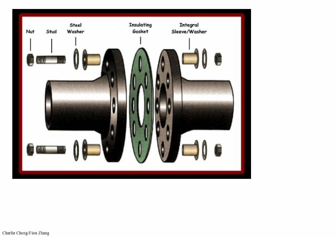
d) For piping, specially designed electric insulating bolt sleeves and gaskets can eliminate the electrical connection.
e) Galvanic corrosion is the principle used in galvanized steel, where the Zn corrodes preferentially to protect the underlying carbon steel. (If there is a break in the galvanized coating, a large anode to small cathode area prevents accelerated corrosion of the steel). This anode-to-cathode relationship reverses at water temperatures over about 150°F (66°C).

4.3.1.7 Inspection and Monitoring
Visual inspection and UT thickness gauging are very effective methods for detecting galvanic corrosion. The damage may sometimes be hiddenunderneath a bolt or rivet head.
4.3.1.8 Related Mechanisms
Soil corrosion (see 4.3.9).

This anode-to-cathode relationship reverses at water temperatures over about 150oF (66oC).


The same alloy may act as both an anode and a cathode due to surface films, scale, and/or local environment (for example, old steel pipe connected to new steel pipe).


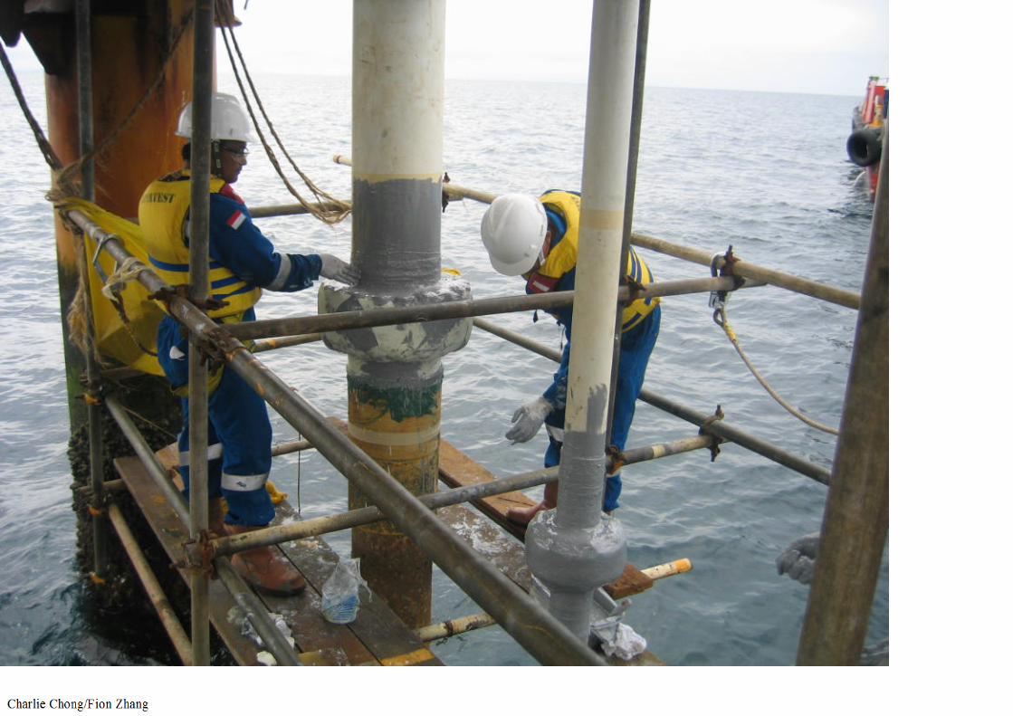


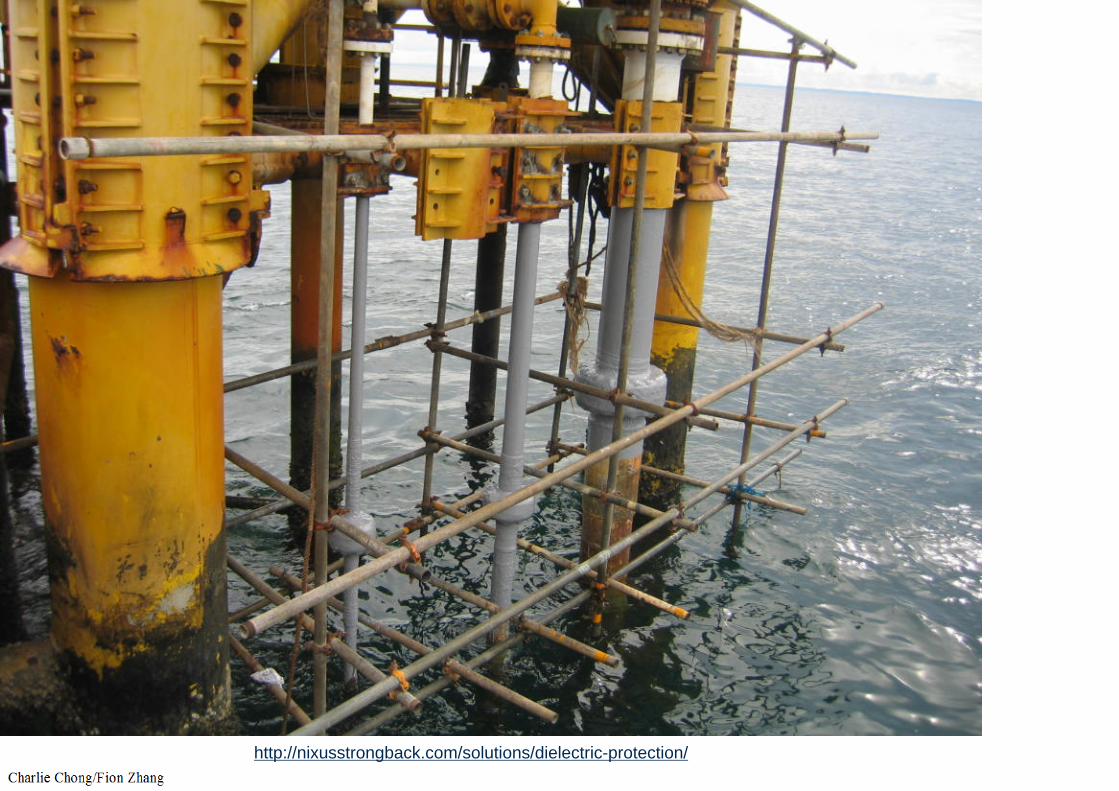
http://nixusstrongback.com/solutions/dielectric-protection/
电偶腐蚀学习重点:
1. 温度: 操作温度2. 受影响材料: 全部3. 损伤原理: 不同电位差金属结合在一起接触电解液,表面腐蚀现象.4. 预防/缓解: 设计,涂层有效减少腐蚀量(受保护/阴极), 5. 不是API 510/570考试学习项.

4.3.2 Atmospheric Corrosion 大气腐蚀4.3.2.1 Description of Damage
A form of corrosion that occurs from moisture associated with atmospheric conditions. Marine environments and moist polluted industrial environments with airborne contaminants are most severe. Dry rural environments cause very little corrosion.
4.3.2.2 Affected Materials
Carbon steel, low alloy steels and copper alloyed aluminum.
API510/570-Exam

4.3.2.3 Critical Factors 关键因素
a) Critical factors include the physical location (industrial, marine, rural); moisture (humidity), particularly designs that trap moisture or when present in a cooling tower mist; temperature; presence of salts, sulfur compounds and dirt.
b) Marine environments can be very corrosive (20 mpy) as are industrial environments that contain acids or sulfur compounds that can form acids (5-10 mpy).
c) Inland locations exposed to a moderate amount of precipitation or humidity are considered moderately corrosive environments (~1-3 mpy).
d) Dry rural environments usually have very low corrosion rates (<1 mpy).
API510/570-Exam

e) Designs that trap water or moisture in crevices are more prone to attack.
f) Corrosion rates increase with temperature up to about 250°F (121°C).Above 250°F (121°C), surfaces are usually too dry for corrosion to occur except under insulation (see 4.3.3).
g) Chlorides, H2S, fly ash and other airborne contaminates from cooling tower drift, furnace stacks and other equipment accelerate corrosion.
h) Bird turds can also cause accelerated corrosion and unsightly stains.
API510/570-Exam

4.3.2.4 Affected Units or Equipment 影响单元/设备
a) Piping and equipment with operating temperatures sufficiently low to allow moisture to be present.
b) A paint or coating system in poor condition.
c) Equipment may be susceptible if cycled between ambient and higher or lower operating temperatures.
d) Equipment shut down or idled for prolonged periods unless properly mothballed.
e) Tanks and piping are particularly susceptible. Piping that rests on pipe supports is very prone to attack due to water entrapment between the pipe and the support.
f) Orientation to the prevailing wind and rain can also be a factor.
g) Piers and docks are very prone to attack.
h) Bimetallic connections such as copper to aluminum electrical connections.
API510/570-Exam
API510/570-Exam

API510/570-Exam

API510/570-Exam

4.3.2.5 Appearance or Morphology of Damage
a) The attack will be general or localized, depending upon whether or not the moisture is trapped.
b) If there is no coating, corrosion or loss in thickness can be general.c) Localized coating failures will tend to promote corrosion.d) Metal loss may not be visually evident, although normally a distinctive iron
oxide (red rust) scale forms as shown in Figure 4-72.
4.3.2.6 Prevention / Mitigation
Surface preparation and proper coating application are critical for long-term protection in corrosive environments.
4.3.2.7 Inspection and Monitoring
VT and UT are techniques that can be used.
4.3.2.8 Related Mechanisms
Corrosion under insulation (see 4.3.3).
API510/570-Exam

API510-Exam
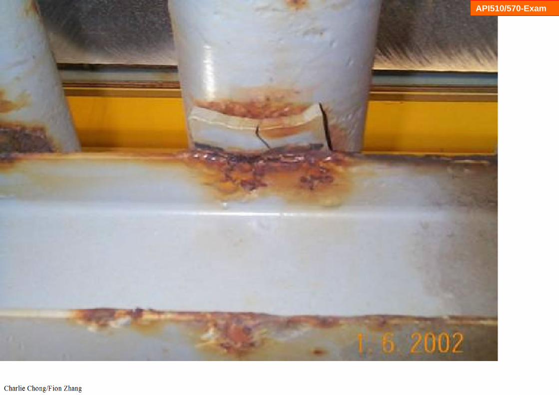
Atmospheric corrosion of an LPG line at close proximity to an cooling tower
API510/570-Exam

API510/570-Exam

API510/570-Exam

API510/570-Exam

Corrosion rates increase with temperature up to about 250oF (121oC). Above 250oF (121oC), surfaces are usually too dry for corrosion to occur except under insulation
API510/570-Exam

API510/570-Exam
大气腐蚀学习重点:
1. 温度: 操作温度2. 受影响材料:碳钢,低合金钢和铜合金铝.3. 损伤原理: 大气腐蚀.4. 关键因素:海洋环境和湿污染的工业环境空气中的污染物是最严重的.干燥,
农村环境造成很小的腐蚀,5. 考试题:腐蚀速率随着温度增加至大约250oF(121oC),大于此温度腐蚀率下降.6. 预防/缓解:表面处理和适当的涂料应用,7. API 510考试学习项.
API510/570-Exam

4.3.3 Corrosion Under Insulation (CUI) 保温层下腐蚀4.3.3.1 Description of Damage
Corrosion of piping, pressure vessels and structural components resulting from water trapped under insulation or fireproofing.
4.3.3.2 Affected Materials 影响材料
Carbon steel, low alloy steels, 300 Series SS, and duplex stainless steels.碳钢,低合金钢,奥氏体不锈钢,双相不锈钢.(马氏体/铁素体不锈钢?)
API510/570-Exam

API510/570-Exam
4.3.3.3 Critical Factors 关键因素
a) a) It affects externally insulated piping and equipment and those that are in intermittent service or operate between:
1. 10°F (-12°C) and 350°F (175°C) for carbon and low alloy steels,
2. 140ºF (60°C) and 400ºF (205°C) for austenitic stainless steels and duplex stainless steels
b) Corrosion rates increase with increasing metal temperature up to the point where the water evaporates quickly. For insulated components, corrosion becomes more severe at metal temperatures between the boiling point 212°F (100°C) and 350°F (121°C), where water is less likely to vaporize and insulation stays wet longer.
c) Design of insulation system, insulation type, temperature and environment are critical factors.

API510/570-Exam
d) Poor design and/or installations that allow water to become trapped will increase CUI.
e) Insulating materials that hold moisture (wick) can be more of a problem.f) Cyclic thermal operation or intermittent service can increase corrosion.g) Equipment that operates below the water dewpoint tends to condense
water on the metal surface thus providing a wet environment and increasing the risk of corrosion.
h) Damage is aggravated by contaminants that may be leached out of the insulation, such as chlorides.
i) Plants located in areas with high annual rainfall or warmer, marine locations are more prone to CUI than plants located in cooler, drier, mid-continent locations.
j) Environments that provide airborne contaminants such as chlorides (marine environments, cooling tower drift) or SO2 (stack emissions) can accelerate corrosion.

API510/570-Exam

API510/570-Exam

API510/570-Exam
API510/570-Exam
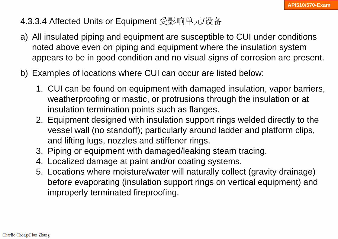
4.3.3.4 Affected Units or Equipment 受影响单元/设备
a) All insulated piping and equipment are susceptible to CUI under conditions noted above even on piping and equipment where the insulation system appears to be in good condition and no visual signs of corrosion are present.
b) Examples of locations where CUI can occur are listed below:
1. CUI can be found on equipment with damaged insulation, vapor barriers, weatherproofing or mastic, or protrusions through the insulation or at insulation termination points such as flanges.
2. Equipment designed with insulation support rings welded directly to the vessel wall (no standoff); particularly around ladder and platform clips, and lifting lugs, nozzles and stiffener rings.
3. Piping or equipment with damaged/leaking steam tracing.4. Localized damage at paint and/or coating systems.5. Locations where moisture/water will naturally collect (gravity drainage)
before evaporating (insulation support rings on vertical equipment) and improperly terminated fireproofing.

API510/570-Exam
6. Vibrating piping systems that have a tendency to inflict damage to insulation jacketing providing a path for water ingress.
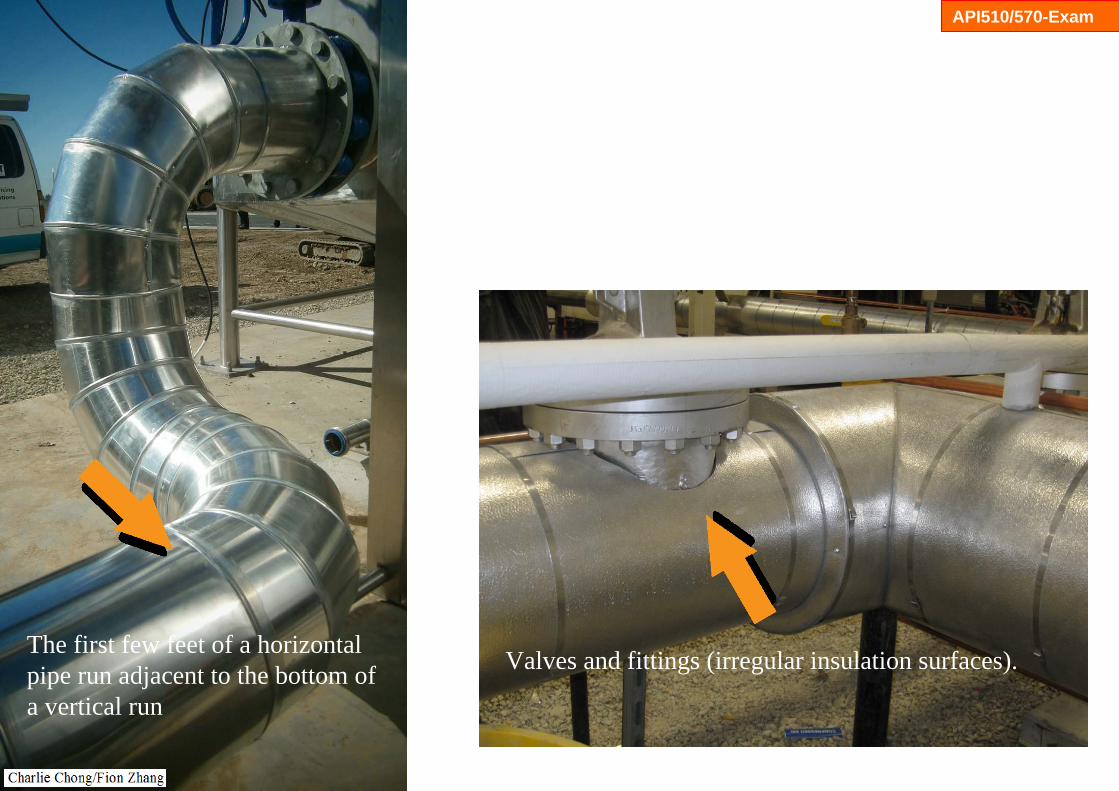
7. Deadlegs (vents, drains, and other similar items).8. Pipe hangers and other supports.9. Valves and fittings (irregular insulation surfaces).10. Bolted-on pipe shoes.11. Steam tracer tubing penetrations.12. Termination of insulation at flanges and other piping components.13. Insulation jacketing seams located on the top of horizontal piping or
improperly lapped or sealed insulation jacketing.14. Termination of insulation in a vertical pipe.15. Caulking that has hardened, has separated, or is missing.

API510/570-Exam
16. Bulges or staining of the insulation or jacketing system or missing bands. (Bulges may indicate corrosion product buildup.)
17. Low points in piping systems that have a known breach in the insulation system, including low points in long unsupported piping runs.
18. Carbon or low-alloy steel flanges, bolting, and other components under insulation in high-alloy piping systems.
19. Locations where insulation plugs have been removed to permit piping thickness measurements on insulated piping and equipment should receive particular attention. These plugs should be promptly replaced and sealed. Several types of removable plugs are commercially available that permit inspection and identification of inspection points for future reference.
20. The first few feet of a horizontal pipe run adjacent to the bottom of a vertical run.

API510/570-Exam
Equipment designed with insulation support rings welded directly to the vessel wall (no standoff); particularly around ladder and platform clips, and lifting lugs, nozzles and stiffener rings.
Stand-off installed

API510/570-Exam
Equipment designed with insulation support rings welded directly to the vessel wall (no standoff); particularly around ladder and platform clips, and lifting lugs, nozzles and stiffener rings.
Stand-off installed
API510/570-Exam
Valves and fittings (irregular insulation surfaces).The first few feet of a horizontal pipe run adjacent to the bottom of a vertical run

API510/570-Exam
Valves and fittings (irregular insulation surfaces).
API510/570-Exam
4.3.3.5 Appearance or Morphology of Damage
a) Carbon and low alloy steels are subject to localized pitting corrosion and or localized loss in thickness.
b) 300 Series SS are also subject to Stress Corrosion Cracking (SCC) if chlorides are present, while the duplex SS are less susceptible.
c) 300 Series SS and duplex SS are subject to pitting and localized corrosion. For 300 Series SS, specifically in older calcium silicate insulation (known to contain chlorides), localized pitting and chloride stress corrosion cracking can occur.
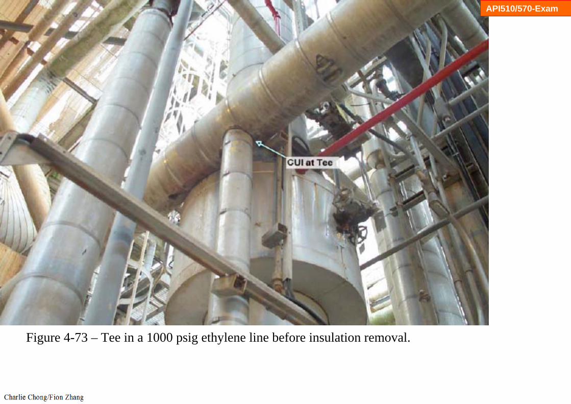
d) After insulation is removed from carbon and low alloy steels, CUI damage often appears as loose, flaky scale covering the corroded component. Damage may be highly localized (Figure 4-73 to 4-79).
e) In some localized cases, the corrosion can appear to be carbuncle type pitting (usually found under a failed paint/coating system).
f) Tell tale signs of insulation and paint/coating damage often accompany CUI.

API510/570-Exam
300 Series SS are also subject to Stress Corrosion Cracking (SCC) if chlorides are present, while the duplex SS are less susceptible

API510/570-Exam
4.3.3.6 Prevention / Mitigation
a) Since the majority of construction materials used in plants are susceptible to CUI degradation, mitigation is best achieved by using appropriate paints/coatings and maintaining the insulation/sealing/vapor barriers to prevent moisture ingress.
b) Flame-sprayed aluminum coatings have been used on carbon steels. The coating corrodes preferentially by galvanic action, thereby protecting the base metal.
c) High quality non-metallic coatings, properly applied to the surfaces to be insulated can provide long term protection.
d) Thin aluminum foil wrapped on stainless steel piping and equipment has been used on stainless steels as an effective barrier under insulation.
API510/570-Exam
e) Careful selection of insulating materials is important. Closed-cell foam glass materials will hold less water against the vessel/pipe wall than mineral wool and potentially be less corrosive.
f) Low chloride insulation should be used on 300 Series SS to minimize the potential for pitting and chloride SCC.
g) It is not usually possible to modify operating conditions. However, consideration should be given to removing the insulation on equipment where heat conservation is not as important.

API510/570-Exam
Closed-cell foam glass materials will hold less water against the vessel/pipe wall than mineral wool and potentially be less corrosive

API510/570-Exam
4.3.3.7 Inspection and Monitoring
a) An inspection plan for corrosion under insulation should be a structured and systematic approach starting with prediction/analysis, then looking at the more invasive procedures. The inspection plan should consider operating temperature; type and age/condition of coating; and type and age/condition of insulation material. Additional prioritization can be added from a physical inspection of the equipment, looking for evidence of insulation, mastic and/or sealant damage, signs of water penetration and rust in gravity drain areas around the equipment.
b) Although external insulation may appear to be in good condition, CUI damage may still be occurring. CUI inspection may require removal of some or all insulation. If external coverings are in good condition and there is no reason to suspect damage behind them, it may not be necessary to remove them for inspection of the vessel. (考试题)

API510/570-Exam
c) Considerations for insulation removal are not limited to but include:
1. History of CUI for the vessel or comparable equipment.2. Visual condition of the external covering and insulation.3. Evidence of fluid leakage, e.g. stains.4. Equipment in intermittent service.5. Condition/age of the external coating, if applicable.
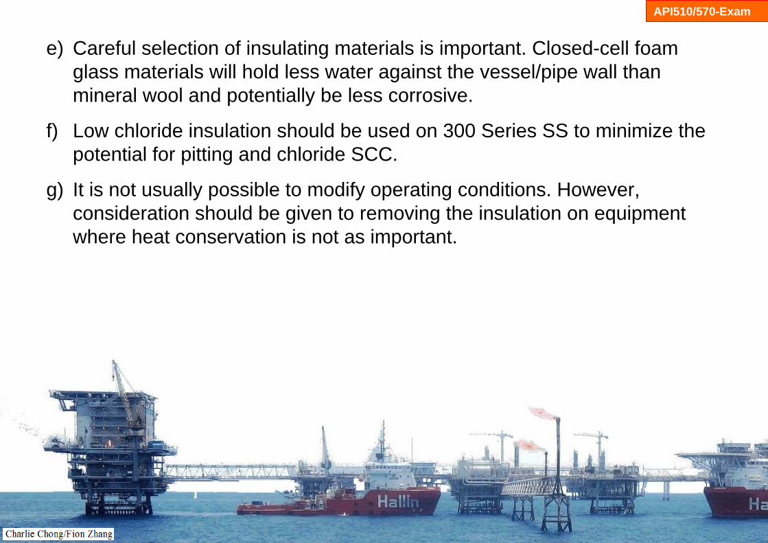
d) Common areas of concern in process units are high moisture areas such as those down-wind from cooling towers, near steam vents, deluge systems, acid vapors, or near supplemental cooling with water spray.
API510/570-Exam
Common areas of concern in process units are high moisture areas

API510/570-Exam
e) When developing the inspection plan for CUI inspection, the inspector should consider
1. Areas that are most susceptible to CUI. If CUI damage is found, the inspector should inspect other susceptible areas on the vessel.
2. Utilize multiple inspection techniques to produce the most cost effective approach, including:
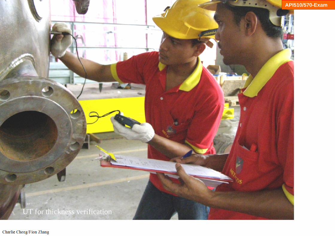
• Partial and/or full stripping of insulation for visual examination.• UT for thickness verification.• Real-time profile x-ray (for small bore piping).• Neutron backscatter techniques for identifying wet insulation.• Deep penetrating eddy-current inspection (can be automated with a
robotic crawler).• IR thermography looking for wet insulation and/or damaged and missing
insulation under the jacket.• Guided wave UT.

API510/570-Exam
4.3.3.8 Related Mechanisms
Atmospheric corrosion (see 4.3.2), oxidation (see 4.4.1) and chloride SCC (see 4.5.1).

API510/570-Exam
Guided wave UT

API510/570-Exam
Guided wave UT

API510/570-Exam
UT for thickness verification

API510/570-Exam
http://www.impresub.com/en/services/ndt-inspection.html
UT for thickness verification
API510/570-Exam
UT for thickness verification

API510/570-Exam

API510/570-Exam

API510/570-Exam
API510/570-Exam
Figure 4-73 – Tee in a 1000 psig ethylene line before insulation removal.

API510/570-Exam
Figure 4-74 – Close-up of Tee CUI of a Tee in Figure 4-73 after insulation removal.

API510/570-Exam
Figure 4-75 – CUI of a 30 inch CS Butadiene line showing highly localized corrosion which could only be found by stripping the entire line. Note the 0.25 in (6.5 mm) diameter hole at arrow

API510/570-Exam
Figure 4-76 – CUI of nozzle on a bottom head.

API510/570-Exam
Figure 4-77 – CUI of nozzle on a top head.

API510/570-Exam
Figure 4-78 – CUI of vessel wall. Note leak at arrow.

API510/570-Exam
Figure 4-79 – CUI at attachment supports and vessel head.
API510/570-Exam
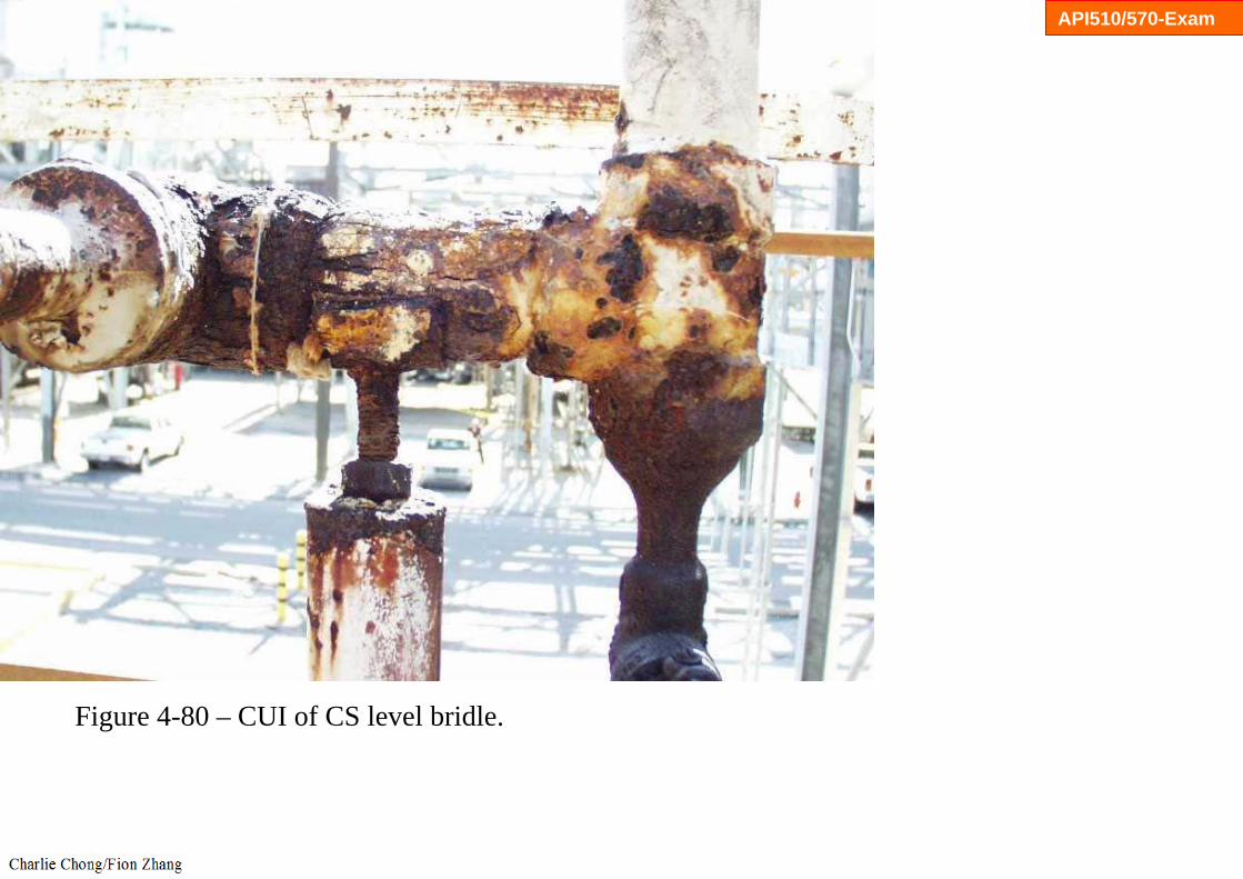
Figure 4-80 – CUI of CS level bridle.

保温层下腐蚀学习重点:
1. 温度: 操作温度2. 受影响材料:碳钢,低合金钢,奥氏体不锈钢,双相不锈钢,3. 损伤原理: 潮湿腐蚀(碳钢,低合金钢)/氯化物应力腐蚀开裂(奥氏体不锈钢/双
相不锈钢).4. 关键因素: 易感温度(碳钢 -10oF~350oF) / (奥氏体不锈钢 140oF~400oF), 损
坏保温层,保温层突漏点(T点,垂直高点,阀门突漏点)5. 预防/缓解:表面处理和适当的涂料应用,低氯绝缘应使用在300系列不锈钢,6. API 510/570 考试学习项.
API510/570-Exam

4.3.4 Cooling Water Corrosion 冷却水的腐蚀4.3.4.1 Description of Damage
General or localized corrosion of carbon steels and other metals caused by dissolved salts, gases, organic compounds or microbiological activity.溶解的盐, 气体, 有机化合物的, 或微生物的活动引起的均匀与局部腐蚀.
4.3.4.2 Affected Materials
Carbon steel, all grades of stainless steel, copper, aluminum, titanium and nickel base alloys.
API510-Exam

API510-Exam
4.3.4.3 Critical Factors
a) Cooling water corrosion and fouling are closely related and should be considered together. Fluid temperature, type of water (fresh, brackish, salt water) and the type of cooling system (once-through, open circulating, closed circulating), oxygen content, and fluid velocities are critical factors.
b) Increasing cooling water outlet temperatures and or process side inlet temperatures tend to increase corrosion rates as well as fouling tendency.
c) Increasing oxygen content tends to increase carbon steel corrosion rates.d) If the process side temperature is above 140°F (60°C), a scaling potential
exists with fresh water and becomes more likely as process temperatures increase and as cooling water inlet temperatures rise. Brackish and salt water outlet temperatures above about 115°F (46°C) may cause serious scaling.
e) Fouling may occur from mineral deposits (hardness), silt, suspended organic materials, corrosion products, mill scale, marine and microbiological growth.

API510-Exam
f) Velocities should be high enough to minimize fouling and drop out of deposits but not so high as to cause erosion. Velocity limits depend on the tube material and water quality.
g) Low velocities can promote increased corrosion. Velocities below about 3 fps (1 m/s) are likely to result in fouling, sedimentation and increased corrosion in fresh and brackish water systems. Accelerated corrosion can also result from dead spots or stagnant areas if cooling water is used on the shell side of condensers/coolers rather than the preferred tube side.
h) 300 Series SS can suffer pitting corrosion, crevice corrosion and SCC in fresh, brackish and salt water systems.

API510-Exam
i) Copper/zinc alloys can suffer dezincification in fresh, brackish and salt water systems. The copper/zinc alloys can suffer SCC if any ammonia or ammonium compounds are present in the water or on the process side.
j) ERW carbon steel may suffer severe weld and/or heated affected zone corrosion in fresh and/or brackish water.
k) When connected to a more anodic material, titanium may suffer severe hydriding embrittlement. Generally, the problem occurs at temperatures above 180°F (82°C) but can occur at lower temperatures.

API510-Exam
Copper/zinc alloys can suffer dezincification
API510-Exam
4.3.4.4 Affected Units or Equipment
Cooling water corrosion is a concern with water-cooled heat exchangers andcooling towers in all applications across all industries.
4.3.4.5 Appearance or Morphology of Damage
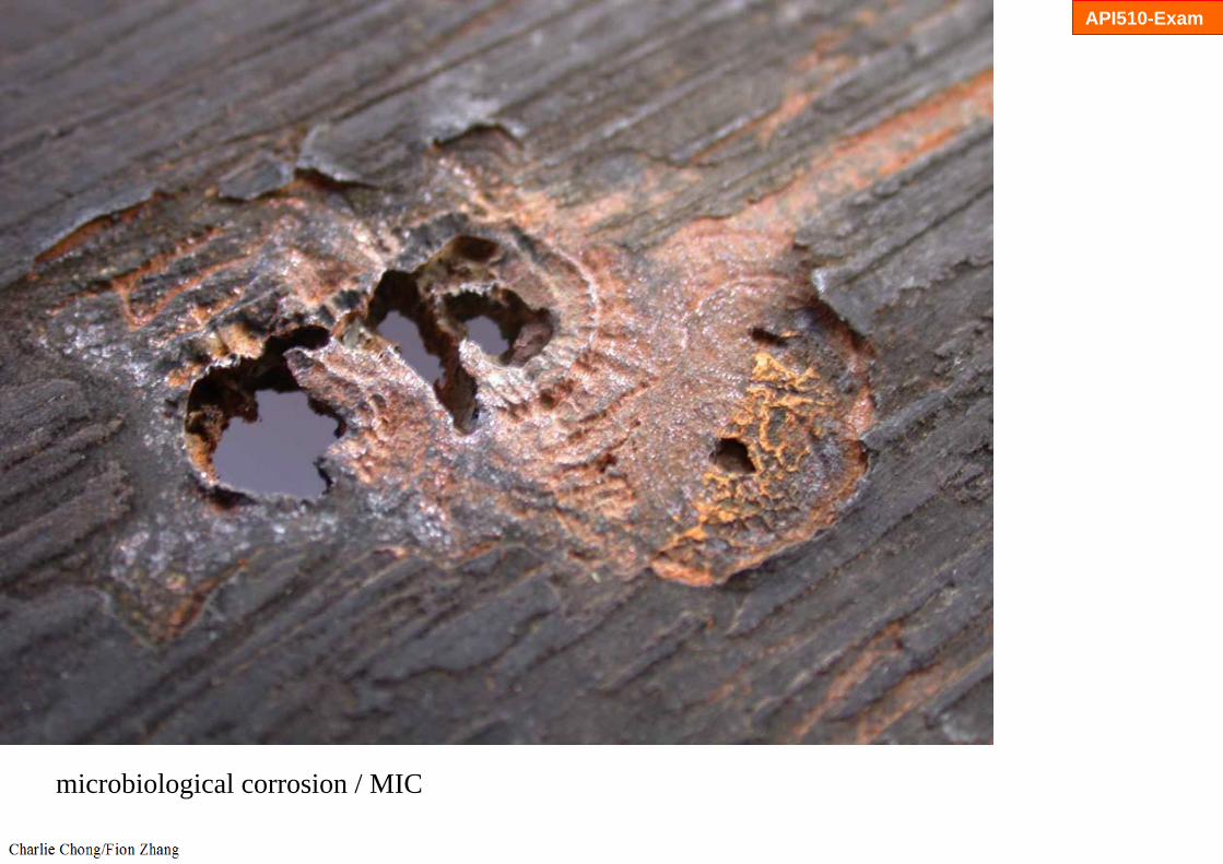
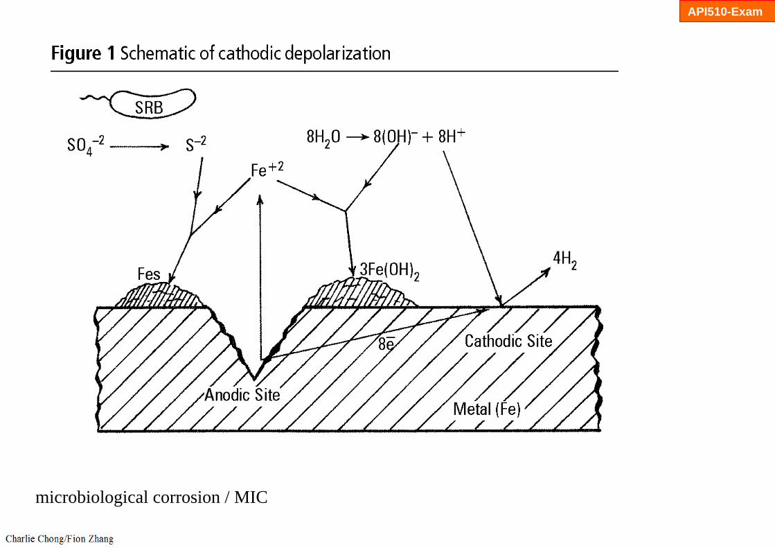
a) Cooling water corrosion can result in many different forms of damage including general corrosion, pitting corrosion (Figure 4-81), MIC, stress corrosion cracking and fouling.
b) General or uniform corrosion of carbon steel occurs when dissolved oxygen is present.
c) Localized corrosion may result from under-deposit corrosion, crevice corrosion or microbiological corrosion.
d) Deposits or crevices can lead to under-deposit or crevice corrosion of any of the affected materials.

API510-Exam
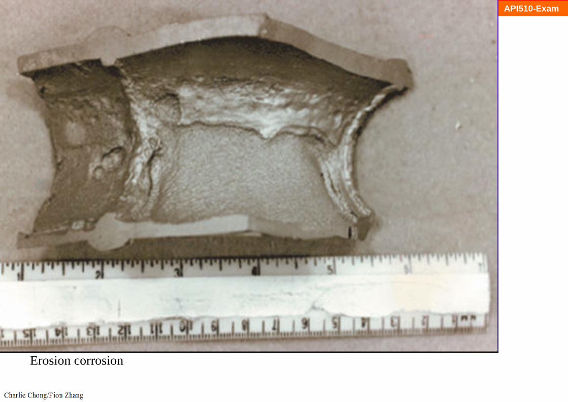
e) Wavy or smooth corrosion at nozzle inlets/outlets and tube inlets may be due to flow induced corrosion, erosion or abrasion.
f) Corrosion at ERW weld areas will appear as grooving along the weld fusion lines.
g) Metallurgical analysis of tube samples may be required to confirm the mode of failure.

API510-Exam
Crevice corrosion

API510-Exam
Crevice corrosion
API510-Exam
microbiological corrosion / MIC

API510-Exam
microbiological corrosion / MIC
API510-Exam
microbiological corrosion / MIC

API510-Exam
pitting corrosion

API510-Exam
General or uniform corrosion

API510-Exam
stress corrosion cracking

API510-Exam
stress corrosion cracking
API510-Exam
Erosion corrosion
API510-Exam
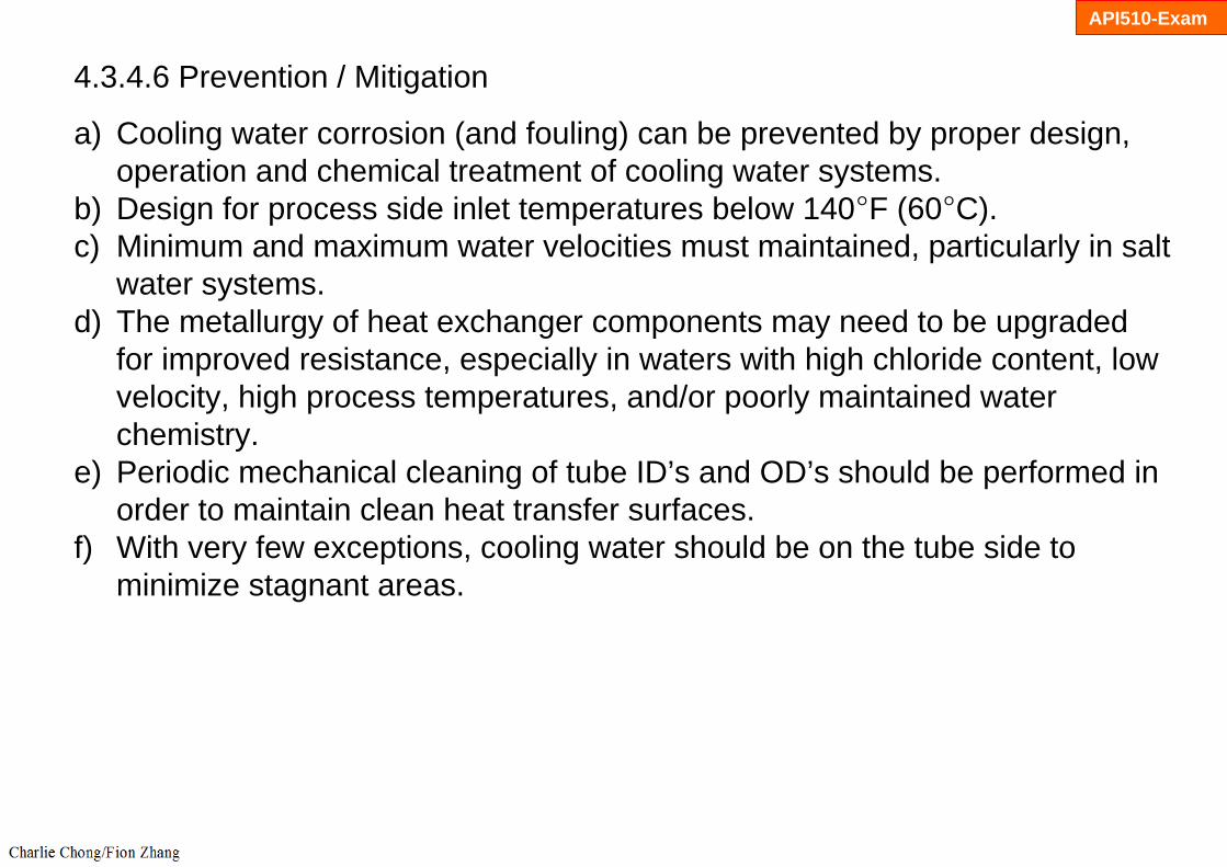
4.3.4.6 Prevention / Mitigation
a) Cooling water corrosion (and fouling) can be prevented by proper design, operation and chemical treatment of cooling water systems.
b) Design for process side inlet temperatures below 140°F (60°C).c) Minimum and maximum water velocities must maintained, particularly in salt
water systems. d) The metallurgy of heat exchanger components may need to be upgraded
for improved resistance, especially in waters with high chloride content, low velocity, high process temperatures, and/or poorly maintained water chemistry.
e) Periodic mechanical cleaning of tube ID’s and OD’s should be performed in order to maintain clean heat transfer surfaces.
f) With very few exceptions, cooling water should be on the tube side to minimize stagnant areas.
API510-Exam
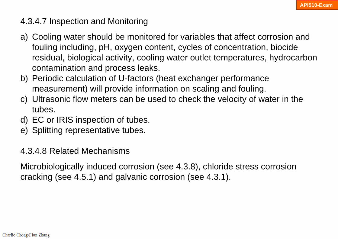
4.3.4.7 Inspection and Monitoring
a) Cooling water should be monitored for variables that affect corrosion and fouling including, pH, oxygen content, cycles of concentration, biocide residual, biological activity, cooling water outlet temperatures, hydrocarbon contamination and process leaks.
b) Periodic calculation of U-factors (heat exchanger performance measurement) will provide information on scaling and fouling.
c) Ultrasonic flow meters can be used to check the velocity of water in the tubes.
d) EC or IRIS inspection of tubes.e) Splitting representative tubes.
4.3.4.8 Related Mechanisms
Microbiologically induced corrosion (see 4.3.8), chloride stress corrosioncracking (see 4.5.1) and galvanic corrosion (see 4.3.1).

API510-Exam
Figure 4-81 – Cooling water corrosion on the I.D. of a CS heat exchanger tube operating at 86°F (30°C).

API510-Exam
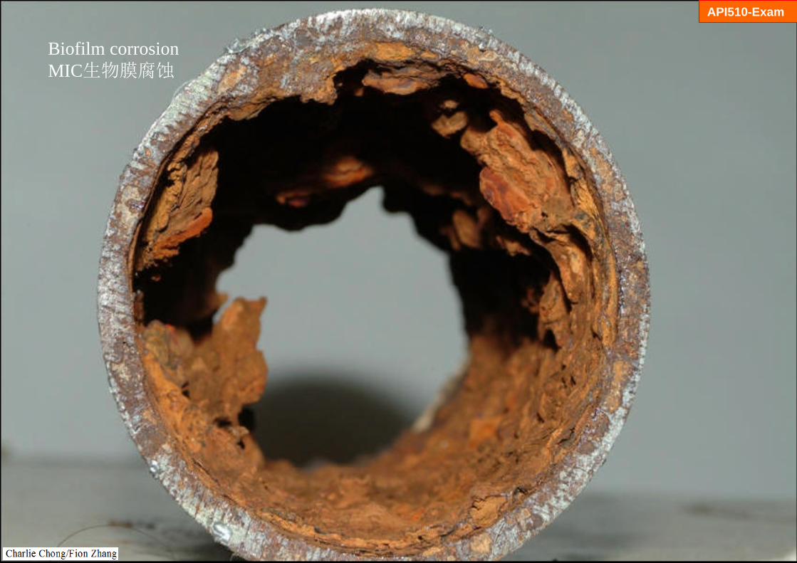
Biofilm corrosion MIC生物膜腐蚀

API510-Exam
Biofilm corrosion MIC生物膜腐蚀

API510-Exam
Biofilm corrosion MIC生物膜腐蚀

Biofilm corrosion MIC生物膜腐蚀
API510-Exam
API510-Exam
Biofilm corrosion MIC生物膜腐蚀

API510-Exam
Biofilm corrosion MIC生物膜腐蚀

API510-Exam
Biofilm corrosion MIC生物膜腐蚀

API510-Exam
Biofilm corrosion MIC生物膜腐蚀

API510-Exam
Biofilm corrosion MIC生物膜腐蚀

API510-Exam
Biofilm corrosion MIC生物膜腐蚀

冷却水的腐蚀学习重点:
1. 温度: 操作温度2. 受影响材料:碳钢,低合金钢,奥氏体不锈钢,双相不锈钢,3. 损伤原理: 潮湿腐蚀(碳钢,低合金钢)/氯化物应力腐蚀开裂(奥氏体不锈钢/双
相不锈钢).4. 关键因素: 易感温度(碳钢 -10oF~350oF) / (奥氏体不锈钢 140oF~400oF), 损
坏保温层,保温层突漏点(T点,垂直高点,阀门突漏点)5. 预防/缓解:表面处理和适当的涂料应用,低氯绝缘应使用在300系列不锈钢,6. API 510/570 考试学习项.
API510-Exam
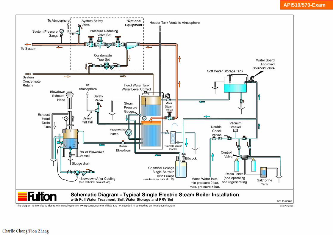
4.3.5 Boiler Water Condensate Corrosion 锅炉冷凝水腐蚀4.3.5.1 Description of Damage
General corrosion and pitting in the boiler system and condensate return piping.
4.3.5.2 Affected Materials
Primarily carbon steel, some low alloy steel, some 300 Series SS and copper based alloys.
API510/570-Exam

API510/570-Exam
General corrosion and pitting in the boiler system and condensate return piping

API510/570-Exam
API510/570-Exam
4.3.5.3 Critical Factors
a) Corrosion in boiler feedwater and condensate return systems is usually the result of dissolved gases, oxygen and carbon dioxide, which lead to oxygen pitting corrosion and carbonic acid corrosion, respectively.
b) Critical factors are the concentration of dissolved gas (oxygen and or carbon dioxide), pH, temperature, quality of the feedwater, and the specific feedwater treating system.
c) Corrosion protection in the boiler is accomplished by laying down and continuously maintaining a layer of protective Fe3O4 (magnetite).
d) The chemical treatment for scale and deposit control must be adjusted to coordinate with the oxygen scavenger for the specific water service and boiler feed-water treating system.
e) Ammonia SCC of Cu-Zn alloys can occur due to hydrazine, neutralizing amines or ammonia containing compounds.

API510/570-Exam
Ammonia SCC of Cu-Zn alloys

API510/570-Exam
Amines - Diethanolamine (DEA) – used in amine treating to remove H2S and CO2from hydrocarbon streams.
Ammonia SCC of Cu-Zn alloys

API510/570-Exam
ammonia
Ammonia SCC of Cu-Zn alloys

API510/570-Exam
hydrazine
Ammonia SCC of Cu-Zn alloys

API510/570-Exam
4.3.5.4 Affected Units or Equipment
Corrosion can occur in the external treatment system, deaerating equipment, feedwater lines, pumps, stage heaters and economizers as well as the steam generation system on both the water and fire sides and thecondensate return system.
4.3.5.5 Appearance or Morphology of Damage
a) Corrosion from oxygen tends to be a pitting type damage and can show up anywhere in the system even if only very small quantities break through the scavenging treatment. Oxygen is particularly aggressive in equipment such as closed heaters and economizers where there is a rapid water temperature rise (Figure 4-82).
b) Corrosion in the condensate return system tends to be due to carbon dioxide although some oxygen pitting problems can occur if the oxygen scavenging treatment is not working correctly. Carbon dioxide corrosion tends to be a smooth grooving of the pipe wall (Figures 4-83 and 4-84).

API510/570-Exam
Figure 4-82 – Pits caused by oxygen corrosion.
Corrosion from oxygen tends to be a pitting type damage and can show up anywhere in the system

API510/570-Exam
Figure 4-83 – General metal loss (left end of tube) on steel resulting from oxygen corrosion. The color of hydrous ferric oxide is orange to red brown.

API510/570-Exam
Figure 4-84 – Jagged fir-tree pattern of corrosion inside a tilted steel pipe caused by condensing steam containing high concentrations of carbon dioxide.

API510/570-Exam
4.3.5.6 Prevention/Mitigation
a) Oxygen scavenging treatments typically include catalyzed sodium sulfite or hydrazine depending on the system pressure level along with proper mechanical deaerator operation. A residual of the oxygen scavenger is carried into the steam generation system to handle any oxygen ingress past the deaerator.
b) If the scale/deposit control/magnetite maintenance treatment scheme does not minimize carbon dioxide in the condensate return system, an amine inhibitor treatment might be required.

API510/570-Exam
4.3.5.7 Inspection and Monitoring
a) Water analysis is the common monitoring tool used to assure that the various treatment systems are performing in a satisfactory manner. Parameters which can be monitored for signs of upset include the pH, conductivity, chlorine or residual biocide, and total dissolved solids to check for leaks in the form of organic compounds.
b) There are no proactive inspection methods other than developing an appropriate program when problems such as a ruptured boiler tube or condensate leaks are recognized in the various parts of complex boiler water and condensate systems.
c) Deaerator cracking problems can be evaluated off-line at shutdowns by utilizing properly applied wet fluorescence magnetic particle inspection.
4.3.5.8 Related Mechanisms
CO2 corrosion (see 4.3.6), corrosion fatigue (see 4.5.2), and erosion / erosion-corrosion (see 4.2.14).

API510/570-Exam

API510/570-Exam

API510/570-Exam

API510/570-Exam
API510/570-Exam

API510/570-Exam

锅炉冷凝水腐蚀学习重点:
1. 温度: 操作温度2. 受影响材料:主要是碳钢,低合金钢,300系列不锈钢和铜基合金,3. 损伤原理:管道系统,溶解气体,氧气与二氧化碳的介入导致氧点蚀与碳酸腐
蚀(沟状).4. 关键因素: 锅炉的腐蚀保护是通过,四氧化三铁锈层管理,催化亚硫酸钠或联
氨作为氧清除处理,胺抑制剂作为二氧化碳清除处理5. API 510/570 考试学习项.
API510/570-Exam

4.3.6 CO2 Corrosion 二氧化碳腐蚀4.3.6.1 Description of Damage
Carbon dioxide (CO2) corrosion results when CO2 dissolves in water to form carbonic acid (H2CO3). The acid may lower the pH and sufficient quantities may promote general corrosion and/or pitting corrosion of carbon steel.
4.3.6.2 Affected Materials
Carbon steel and low alloy steels.

4.3.6.3 Critical Factors
a) The partial pressure of CO2, pH and temperature are critical factors.b) Increasing partial pressures of CO2 result in lower pH condensate and
higher rates of corrosion.c) Corrosion occurs in the liquid phase, often at locations where CO2
condenses from the vapor phase.d) Increasing temperatures increase corrosion rate up to the point where CO2
is vaporized.e) Increasing the level of chromium in steels offers no major improvement in
resistance until a minimum of 12% is reached.

4.3.6.4 Affected Units or Equipment
a) Boiler feedwater and condensate systems in all units are affected.b) Effluent gas streams of the shift converters in hydrogen plants can be
affected. Corrosion usually occurs when the effluent stream drops below the dew point, approximately 300°F (149°C). Corrosion rates as high as 1000 mpy have been observed.
c) Overhead systems of regenerators in CO2 removal plants are affected.
4.3.6.5 Appearance or Morphology of Damage
a) Localized thinning and/or pitting corrosion of carbon steel (Figure 4-85, Figure 4-86 and Figure 4-87).
b) Carbon steel may suffer deep pitting and grooving in areas of turbulence (Figure 4-88).
c) Corrosion generally occurs in areas of turbulence and impingement and sometimes at the root of piping welds.

Figure 4-85 – CO2 corrosion of a carbon steel oil and gas production flow line.

Figure 4-87 – CO2 corrosion of CS pipe nipple in CO2 contaminated water.

Figure 4-88 – A view inside the nipple in Figure 4-87 showing “Mesa” type corrosion typical of CO2 corrosion.
4.3.6.6 Prevention / Mitigation
a) Corrosion inhibitors can reduce corrosion in steam condensate systems. Vapor phase inhibitors may be required to protect against condensing vapors.
b) Increasing condensate pH above 6 can reduce corrosion in steam condensate systems.
c) The 300 Series SS are highly resistant to corrosion in most applications. Selective upgrading to stainless steels is usually required in operating units designed to produce and/or remove CO2 (such as hydrogen plants and CO2 removal units).
d) Steam condensate systems that experience CO2 corrosion are usually the result of operating problems.
e) 400 Series SS and duplex SS are also resistant.

4.3.6.7 Inspection and Monitoring
a) VT, UT and RT inspection techniques should focus on general and local loss in thickness where water wetting is anticipated.
b) Preferential corrosion of weld seams may require angle probe UT or RT.c) Corrosion may occur along the bottom surface of the pipe if there is a
separate water phase, at the top surface of the pipe if condensation in wet gas systems is anticipated, and in the turbulent flow areas at elbow and tees.
d) Monitor water analyses (pH, Fe, etc.) to determine changes in operating conditions.
4.3.6.8 Related Mechanisms
Boiler water condensate corrosion (see 4.3.5) and carbonate cracking (see 5.1.2.5).
二氧化碳腐蚀学习重点:
1. 温度: 操作温度2. 受影响材料:主要是碳钢,低合金钢,3. 损伤原理:二氧化碳溶解为碳酸导致碳酸腐蚀.4. 关键因素: 增加温度,增加二氧化碳分压加剧腐蚀, 材料铬含量超过12%才能
有效的抗拒碳酸腐蚀.5. 非API 510/570 考试学习项.
4.3.7 Flue-Gas Dew-Point Corrosion 烟气露点腐蚀4.3.7.1 Description of Damage
a) Sulfur and chlorine species in fuel will form sulfur dioxide, sulfur trioxide and hydrogen chloride within the combustion products.在燃料中的硫和氯的物种会形成二氧化硫,三氧化硫和氯化氢
a) At low enough temperatures, these gases and the water vapor in the flue gas will condense to form sulfurous acid, sulfuric acid and hydrochloric acid which can lead to severe corrosion.上述气体在温度下降区域, 凝结成亚硫酸, 硫酸和盐酸, 可导致严重的腐蚀
4.3.7.2 Affected Materials
Carbon steel, low alloy steels and 300 Series SS.
API570-Exam
API570-Exam
4.3.7.3 Critical Factors
a) The concentration of contaminants (sulfur and chlorides) in the fuel and the operating temperature of flue gas metal surfaces determine the likelihood and severity of corrosion.
b) Since all fuels contain some amount of sulfur, sulfuric and sulfurous acid dewpoint corrosion can occur if the metal temperatures are below the dewpoint.
c) The dewpoint of sulfuric acid depends on the concentration of sulfur trioxide in the flue gas, but is typically about 280°F (138°C).
d) Similarly, the dewpoint of hydrochloric acid depends on the concentration of hydrogen chloride. It is typically about 130°F (54°C).

API570-Exam
4.3.7.4 Affected Units or Equipment
a) All fired process heaters and boilers that burn fuels containing sulfur have the potential for sulfuric acid dewpoint corrosion in the economizer sections and in the stacks.
b) Heat-Recovery Steam Generators (HRSG’s) that have 300 Series SS feedwater heaters may suffer chloride-induced stress corrosion cracking from the gas side (OD) when the temperature of the inlet water is below the dewpoint of hydrochloric acid.
c) 300 Series SS feedwater heaters in HRSG’s are potentially at risk if the atmosphere of the combustion turbine includes chlorine. Cooling tower drift from cooling towers that use chlorine based biocides may blow into the combustion turbine and lead to potential damage in the feedwater heaters.

API570-Exam
4.3.7.5 Appearance or Morphology of Damage
a) Sulfuric acid corrosion on economizers or other carbon steel or low alloy steel components will have general wastage often with broad, shallow pits, depending on the way the sulfuric acid condenses.
b) For the 300 Series SS feedwater heaters in HRSG’s, stress corrosion cracking will have surface breaking cracks and the general appearance will be somewhat crazed.

API570-Exam
4.3.7.6 Prevention / Mitigation
a) Maintain the metallic surfaces at the back end of the boilers and fired heaters above the temperature of sulfuric acid dewpoint corrosion.
b) For HRSG’s, avoid the use of 300 Series SS in the feedwater heaters if the environment is likely to contain chlorides.
c) Similar damage occurs in oil-fired boilers when the units are water-washed to remove ash if the final rinse does not neutralize the acid salts. Sodium carbonate should be added to the final rinse as a basic solution to neutralize the acidic ash constituents.
API570-Exam
4.3.7.7 Inspection and Monitoring
a) Wall-thickness measurements by UT methods will monitor the wastage ineconomizer tubes.
b) Stress corrosion cracking of 300 Series SS can be found using VT and PT inspection.
4.3.7.8 Related Mechanisms
At lower temperatures, hydrochloric acid may condense and promote HCL corrosion of carbon steels (see5.1.1.4) and chloride stress corrosion cracking of 300 Series SS (see 4.5.1).

API570-Exam

API570-Exam

API570-Exam

API570-Exam

API570-Exam

API570-Exam

API570-Exam

API570-Exam

API570-Exam
http://www.smt.sandvik.com/en/materials-center/material-datasheets/tube-and-pipe-
seamless/sandvik-saf-2507/

API570-Exam

API570-Exam
http://www.smt.sandvik.com/en/materials-center/corrosion-tables/hydrochloric-acid/

API570-Exam
http://www.smt.sandvik.com/en/materials-
center/corrosion-tables/sulphuric-acid/

API570-Exam

API570-Exam

烟气露点腐蚀学习重点:
1. 温度: 高温2. 受影响材料:主要是碳钢,低合金钢,奥氏体不锈钢,3. 损伤原理:在燃料中的硫和氯的物种会形成二氧化硫,三氧化硫和氯化氢,上
述气体在温度下降区域, 凝结成亚硫酸, 硫酸和盐酸, 可导致严重的腐蚀.4. 关键因素:避免温度低于露点..5. 预防/缓解: 避免温度低于露点,氯化氢服务用奥氏体不锈钢,6. API 570 考试学习项.
API570-Exam

4.3.8 Microbiologically Induced Corrosion (MIC) 微生物腐蚀4.3.8.1 Description of Damage
A form of corrosion caused by living organisms such as bacteria, algae or fungi. It is often associated with the presence of tubercles or slimy organic substances.
4.3.8.2 Affected Materials
Most common materials of construction including carbon and low alloy steels, 300 Series SS and 400 Series SS, aluminum, copper and some nickel base alloys.
API570-Exam

http://www.powershow.com/view/992fc-ZGU2N/MIC_Presentation_powerpoint_ppt_presentation
API570-Exam

API570-Exam

API570-Exam

API570-Exam
API570-Exam

API570-Exam
4.3.8.3 Critical Factors
a) MIC is usually found in aqueous environments or services where water is always or sometimes present, especially where stagnant or low-flow conditions allow and/or promote the growth of microorganisms.
b) Because there are several types, organisms can survive and grow under severe conditions including lack of oxygen, light or dark, high salinity, pH range of 0 to 12, and temperatures from 0°F to 235°F (-17°C to 113°C).
c) Systems may become “inoculated” by the introduction of organisms that multiply and spread unless controlled.
d) Different organisms thrive on different nutrients including inorganic substances (e.g., sulfur, ammonia, H2S) and inorganic substances (e.g., hydrocarbons, organic acids). In addition, all organisms require a source of carbon, nitrogen and phosphorous for growth.
e) In-leakage of process contaminants such as hydrocarbons or H2S may lead to a massive increase in biofouling and corrosion.
API570-Exam
4.3.8.4 Affected Units or Equipment
a) MIC is most often found in heat exchangers, bottom water of storage tanks, piping with stagnant or low flow, and piping in contact with some soils.
b) MIC is also found in equipment where the hydrotest water has not been removed or equipment has been left outside and unprotected.
c) Product storage tanks and water cooled heat exchangers in any unit where cooling water is not properly treated can be affected.
d) Fire water systems can be affected.

API570-Exam
4.3.8.5 Appearance or Morphology of Damage
a) MIC corrosion is usually observed as localized pitting under deposits or tubercles that shield the organisms.
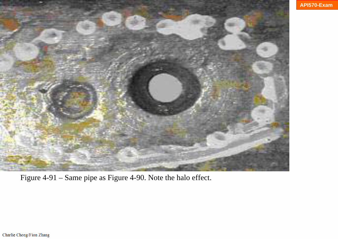
b) Damage is often characterized by cup-shaped pits within pits in carbon steel or subsurface cavities in stainless steel (Figure 4-89 through Figure 4-95).
API570-Exam
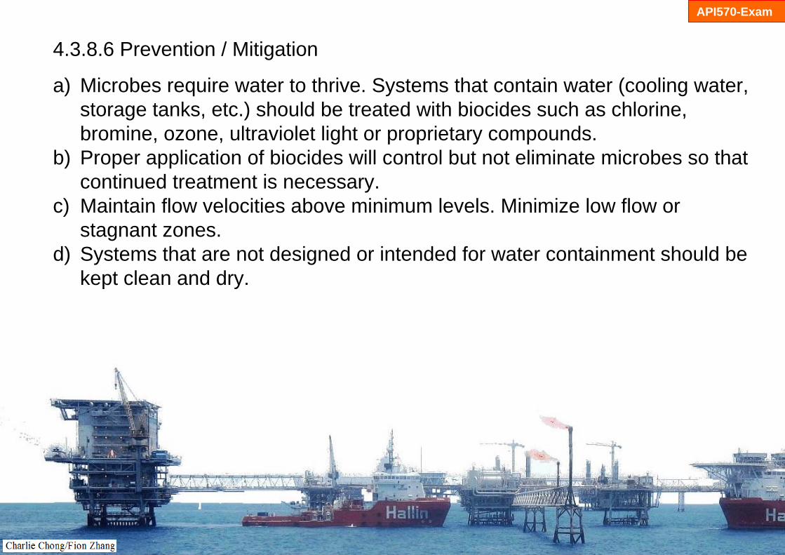
4.3.8.6 Prevention / Mitigation
a) Microbes require water to thrive. Systems that contain water (cooling water, storage tanks, etc.) should be treated with biocides such as chlorine, bromine, ozone, ultraviolet light or proprietary compounds.
b) Proper application of biocides will control but not eliminate microbes so that continued treatment is necessary.
c) Maintain flow velocities above minimum levels. Minimize low flow or stagnant zones.
d) Systems that are not designed or intended for water containment should be kept clean and dry.
API570-Exam
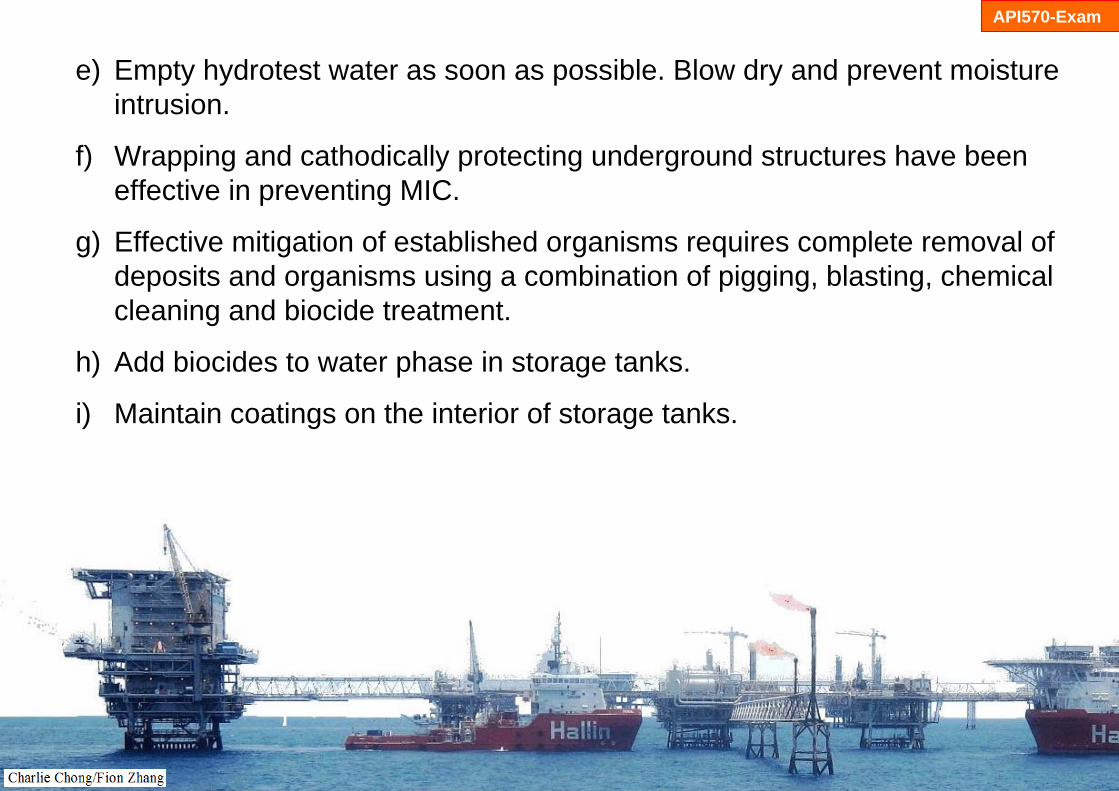
e) Empty hydrotest water as soon as possible. Blow dry and prevent moisture intrusion.
f) Wrapping and cathodically protecting underground structures have been effective in preventing MIC.
g) Effective mitigation of established organisms requires complete removal of deposits and organisms using a combination of pigging, blasting, chemical cleaning and biocide treatment.
h) Add biocides to water phase in storage tanks.
i) Maintain coatings on the interior of storage tanks.
API570-Exam
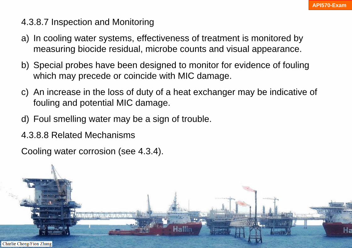
4.3.8.7 Inspection and Monitoring
a) In cooling water systems, effectiveness of treatment is monitored by measuring biocide residual, microbe counts and visual appearance.
b) Special probes have been designed to monitor for evidence of fouling which may precede or coincide with MIC damage.
c) An increase in the loss of duty of a heat exchanger may be indicative of fouling and potential MIC damage.
d) Foul smelling water may be a sign of trouble.
4.3.8.8 Related Mechanisms
Cooling water corrosion (see 4.3.4).

API570-Exam

API570-Exam

API570-Exam

API570-Exam

API570-Exam

API570-Exam
API570-Exam

API570-Exam

API570-Exam
Wrapping and cathodically protecting underground structures

API570-Exam

API570-Exam
Figure 4-89 – MIC of diesel tank bottom.

API570-Exam
Figure 4-90 – Pitting corrosion on the I.D. of a 6-inch CS sour crude line after 2.5 years of service. Pits are approximately 1-inch to 2-inch wide. Note the halo effect in Figure 4-91.
API570-Exam
Figure 4-91 – Same pipe as Figure 4-90. Note the halo effect.

Figure 4-92 – Oil line with MIC damage beneath tubercles.
API570-Exam

Figure 4-93 – Same oil line as Figure 4-92. Hemispherical pitting typical of MIC can be seen after grit blasting to remove the scale.
API570-Exam

Figure 4-94 – Type 304 stainless steel exchanger tubes failed from pitting corrosion on the shell side in cooling water service after 2.5 years without biocide treatment.
Figure 4-95 – A cross section of the tube (Figure 4-94) revealing severe subsurface tunneling, typical of MIC.
API570-Exam

微生物腐蚀学习重点:
1. 温度: 操作温度2. 受影响材料: 全部3. 损伤原理: 由生物如细菌,海藻或真菌引起的腐蚀现象.4. 预防/缓解: 材料选择(?),设计(流速/停滞),涂层,灭菌剂,阴极保护,有效减少
腐蚀量, 5. API 570考试学习项.
API570-Exam

4.3.9 Soil Corrosion 土壤腐蚀
4.3.9.1 Description of DamageThe deterioration of metals exposed to soils is referred to as soil corrosion.
4.3.9.2 Affected MaterialsCarbon steel, cast iron and ductile iron.
API570-Exam

API570-Exam

API570-Exam

API570-Exam
4.3.9.3 Critical Factors
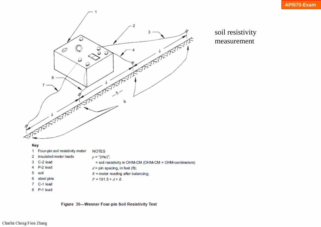
a) The severity of soil corrosion is determined by many factors including operating temperature, moisture and oxygen availability, soil resistivity (soil condition and characteristics), soil type (water drainage), and homogeneity (variation in soil type), cathodic protection, stray current drainage, coating type, age, and condition.
b) There is no single parameter that can be used to determine soil corrosivity. Instead, a number of characteristics must be combined to estimate the corrosion in particular soil as outlined in ASTM STP 741 as well as API RP 580 and API RPl 581.
c) Soil resistivity is frequently used to estimate soil corrosivity, mainly because it is easy to measure. Soil resistivity is related to soil moisture content and dissolved electrolytes in the soil water.

API570-Exam
d) Soils having high moisture content, high dissolved salt concentrations, and high acidity are usually the most corrosive.
e) Soil-to-air interface areas are often much more susceptible to corrosionthan the rest of the structure because of moisture and oxygen availability (Figure 4-96).
f) Corrosion rates increase with increasing metal temperature.
g) Other factors that affect soil corrosion include galvanic corrosion, dissimilar soils, stray currents, differential aeration corrosion cells, and microbiologically induced corrosion.

http://www.esgroundingsolutions.com/about-electrical-grounding/what-is-soil-resistivity-testing.php
API570-Exam
soil resistivity measurement

API570-Exam
soil resistivity measurement

API570-Exam
soil resistivity measurement
API570-Exam
soil resistivitymeasurement

API570-Exam
stray currents

API570-Exam

API570-Exam
API RP 581 Risk-Based Inspection Technology, Second Edition ** HARDCOPY INCLUDES BINDERstandard published 09/01/2008 by American Petroleum Institutehttp://www.irantpm.ir/wp-content/uploads/2011/08/API-581-2008.pdf

API570-Exam
4.3.9.4 Affected Units or Equipment
a) Underground piping and equipment as well as buried tanks and the bottoms of above ground storage tanks (Figure 4-97).
b) Ground supported metal structures (Figure 4-98).
4.3.9.5 Appearance or Morphology of Damage
a) Soil corrosion appears as external thinning with localized losses due to pitting. The severity of corrosion depends on the local soil conditions and changes in the immediate environment along the equipment metal surface.
b) Poor condition of a protective coating is a tell tale sign of potential corrosion damage.

API570-Exam

API570-Exam
4.3.9.6 Prevention / Mitigation
Soil corrosion of carbon steel can be minimized through the use of special backfill, coatings and cathodic protection. The most effective protection is a combination of a corrosion resistant coating and a cathodic protection system.

API570-Exam

API570-Exam
4.3.9.7 Inspection and Monitoring
a) The most common method used for monitoring underground structures is measuring the structure to soil potential using dedicated reference electrodes near the structure (corrected for IR drop error). Cathodic protection should be performed and monitored in accordance with.
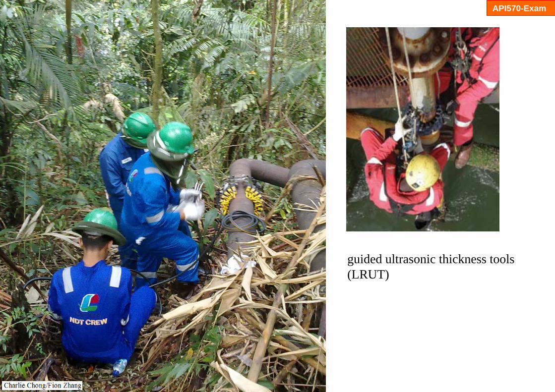
b) There are many techniques for inspecting buried or on-grade metallic components. Piping may be inspected by inline inspection devices, guided ultrasonic thickness tools, indirectly by pressure testing, or visually by evaluation. The same or similar techniques may be used on other structures.
4.3.9.8 Related Mechanisms
Galvanic corrosion (see 4.3.1).

API570-Exam
http://www.scribd.com/doc/124321433/NACE-RP-0169

API570-Exam

API570-Exam
Cathodic Protection- Impressed current

API570-Exam

API570-Exam

API570-Exam
measuring the structure to soil potential using dedicated reference electrodes near the structure

API570-Exam
measuring the structure to soil potential using dedicated reference electrodes near the structure

API570-Exam
measuring the structure to soil potential using dedicated reference electrodes near the structure

API570-Exam
measuring the structure to soil potential using dedicated reference electrodes near the structure

API570-Exam
measuring the structure to soil potential using dedicated reference electrodes near the structure

API570-Exam
measuring the structure to soil potential using dedicated reference electrodes near the structure

API570-Exam
guided ultrasonic thickness tools
API570-Exam
guided ultrasonic thickness tools (LRUT)

API570-Exam
guided ultrasonic thickness tools

Figure 4-96 – Corrosion of carbon steel pipe at the soil-air interface where the pipe emerges fromunderground.
Figure 4-97 – Coupons removed from the bottom of an unprotected steel condensate storage tankafter 3 years of service. The external surface is shown.
API570-Exam
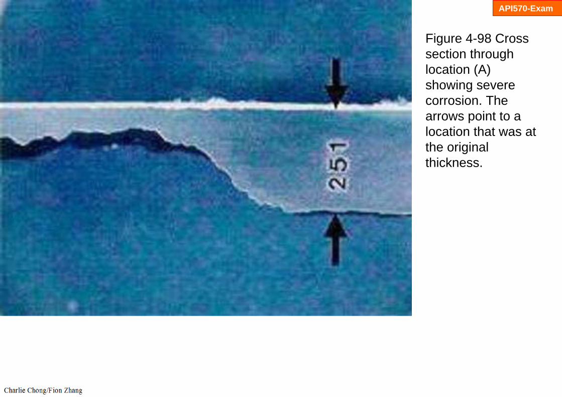
Figure 4-98 Cross section through location (A) showing severe corrosion. The arrows point to a location that was at the original thickness.
API570-Exam

土壤腐蚀学习重点:
1. 温度: 操作温度2. 受影响材料: 全部3. 损伤原理: 由生物如细菌,海藻或真菌引起的腐蚀现象.4. 预防/缓解: 材料选择(?),设计(流速/停滞),涂层,灭菌剂,阴极保护,有效减少
腐蚀量, 5. API 570考试学习项.
API570-Exam

API510-Exam
4.3.10 Caustic Corrosion 碱腐蚀4.3.10.1 Description of Damage
Localized corrosion due to the concentration of caustic or alkaline salts that usually occurs under evaporative or high heat transfer conditions. However, general corrosion can also occur depending on alkali or caustic solution strength.由于碱或碱性盐浓度的局部腐蚀.
4.3.10.2 Affected Materials
Primarily carbon steel, low alloy steels and 300 Series SS.碳钢,低合金钢,奥氏体不锈钢.

API510-Exam
4.3.10.3 Critical Factors
Major contributing factors are the presence of caustic (NaOH or KOH). The following are sources of caustic: 主要碱来源-氢氧化钠或氢氧化钾
a) Caustic is sometimes added to process streams for neutralization or as a reactant.
b) It is sometimes intentionally added to boiler feedwater at low concentrations or may enter inadvertently during regeneration ofdemineralizers.
c) Alkaline salts may also enter process streams through leaks in condensers or process equipment.
d) Some process units utilize caustic solutions for neutralizing, for removal of sulfur compounds, or for removal of chloride compounds.
e) A concentrating mechanism must exist to build up the caustic strength.f) Caustic may become concentrated by departure from DNB, evaporation
and deposition.

API510-Exam
4.3.10.4 Affected Units or Equipment 受影响设备
a) Caustic corrosion is most often associated with boilers and steam generating equipment including heat exchangers. 最常见于锅炉和蒸汽发生设备包括热交换器.
b) Similar concentrating effects of caustic may occur where caustic is added to crude unit charge. 也出现在原油蒸馏装置.
c) Accelerated localized corrosion can occur in preheat exchangers, furnace tubes and transfer lines, unless the caustic is effectively mixed in the oil stream. 带碱的预热交换器,炉管及输送线.
d) Units that use caustic for removing sulfur compounds from product streams. 其他运用碱作为产品流中除去硫化合物的工艺设备.

API510-Exam
API510-Exam

API510-Exam
Departure from nucleate boiling DNB

API510-Exam

API510-Exam

API510-Exam
API510-Exam

API510-Exam

API510-Exam
4.3.10.5 Appearance or Morphology of Damage
a) Typically characterized by localized metal loss which may appear as grooves in a boiler tube or locally thinned areas under insulating deposits (Figure 4-99 and Figure 4-100).
b) Deposits may fill corroded depressions and mask damage below. Probing suspect areas with a sharp instrument may be required.
c) Localized gouging may result along a waterline where corrosives concentrate. In vertical tubes, this may appear as a circumferential groove.
d) In horizontal or sloped tubes, grooving may appear at the top of the tube or as longitudinal grooves on opposite sides of the tube.
e) Exposure to high solution strength caustic can result in general corrosion of carbon steel above 175°F (79°C) and very high corrosion rates above 200°F (93°C).

API510-Exam
Figure 4-99 – I.D. deposits on CS boiler tube with damage due to caustic corrosion.

API510-Exam
Figure 4-100 – Cross-section of tube in Figure 4-99 showing localized attack due to caustic corrosion.

API510-Exam
4.3.10.6 Prevention / Mitigation
a) In steam generating equipment, caustic corrosion is best prevented through proper design. Damage can be minimized by reducing the amount of free caustic, by ensuring adequate water flooding and water flow, by ensuring proper burner management to minimize hot spots on heater tubes, and by minimizing the ingress of alkaline producing salts into condensers. 设计; 避免浓缩状况(例如确保适当的水驱与水流量,适当的燃烧器管理以减少加热器管热点),降低碱性盐的产生与流入冷凝器.
b) In process equipment, caustic injection facilities should be designed to allow proper mixing and dilution of caustic in order to avoid the concentration of caustic on hot metal surfaces.
c) Carbon steel and 300 Series SS have serious corrosion problems in high strength caustic solutions above about 150°F (66°C). Alloy 400 and some other nickel base alloys exhibit much lower corrosion rates.

API510-Exam
4.3.10.7 Inspection and Monitoring
a) For process equipment, UT thickness gauging is useful to detect and monitor general corrosion due to caustic. However, localized losses due to caustic corrosion may be difficult to locate.
b) Injection points should be inspected in accordance with API 570.
c) UT scans and radiography can be used.
d) Steam generation equipment may require visual inspection with the use a boroscope.
4.3.10.8 Related Mechanisms
Caustic corrosion is also referred to as caustic gouging or ductile gouging. A related mechanism is known as Departure from Nucleate Boiling (DNB) as discussed in steam blanketing (See 4.2.11).

API510-Exam

API510-Exam

Concentration of caustic (NaOH) can occur as a result of steam blanketing (which allow salts to concentrate on boiler metal surface) or by localized boiling beneath porous deposits on tube surface. Caustic corrosion occurs when caustic is concentrated and dissolves the protective magnetite (Fe3O4) layer, causing a loss of base metal and eventual failure.
API510-Exam
Read more: http://www.lenntech.com/boiler/caustic-corrosion.htm#ixzz2YgaXh1SD

API510-Exam

API510-Exam

Carbon steel and 300 Series SS have serious corrosion problems in high strength caustic solutionsabove about 150oF (66oC). Alloy 400 and some other nickel base alloys exhibit much lowercorrosion rates.
API510-Exam

碱性腐蚀学习重点:
1. 温度: 操作温度2. 受影响材料: 碳钢,低合金钢,奥氏体不锈钢,3. 损伤原理: 碱性物把材料表面氧化皮溶解,导致材料腐蚀,4. 预防/缓解: 设计(减少碱浓缩机制), 5. API 510考试学习项.
API510-Exam
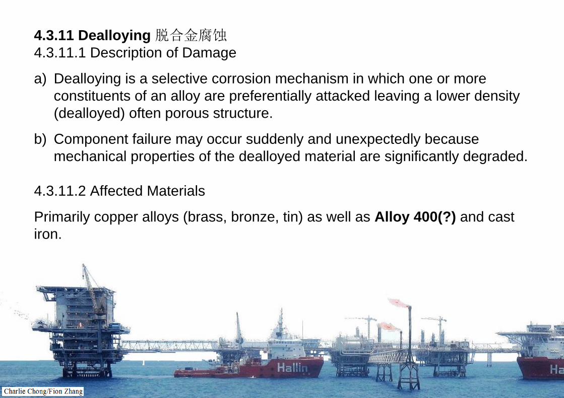
4.3.11 Dealloying 脱合金腐蚀4.3.11.1 Description of Damage
a) Dealloying is a selective corrosion mechanism in which one or more constituents of an alloy are preferentially attacked leaving a lower density (dealloyed) often porous structure.
b) Component failure may occur suddenly and unexpectedly because mechanical properties of the dealloyed material are significantly degraded.
4.3.11.2 Affected Materials
Primarily copper alloys (brass, bronze, tin) as well as Alloy 400(?) and cast iron.


MONEL® alloy 400 (UNS N04400)
Ni 66.5 Cu 31 Fe 2.5 Mn 2.0 C 0.3 Si 0.5 S 0.024
High Performance Alloys stocks and produces this grade in the following forms: Bar, wire, sheet, plate, coil, fasteners and forgings. Request quote on this grade. See our on-line catalog for sizes stocked
OverviewA Nickel-Copper alloy, resistant to sea water and steam at high temperatures as well as to salt and caustic solutions.
Alloy 400 is a nickel-copper alloy with excellent corrosion resistance in a wide variety of media. The alloy is characterized by good general corrosion resistance, good weldability and moderate to high strength. The alloy has been used in a variety of applications. It has excellent resistance to rapidly flowing brackish water or seawater. It is particularly resistant to hydrochloric and hydrofluoric acids when they are de-aerated. The alloy is slightly magnetic at room temperature. The alloy is widely used in the chemical, oil and marine industries.
http://www.hpalloy.com/alloys/descriptions/MONEL400.html

N04405Monel K-405
N05500B865Monel K-500
N04404B164Monel 404
N04401Monel 401
N04400B127, B164Monel 400
UNSSteel typeP NumberTrade
http://en.wikipedia.org/wiki/Monel http://www.hbs.edu/leadership/database/leaders/ambrose_monell.html
Alloy 400Monel is a trademark of Special Metals Corporation for a series of nickel alloys, primarily composed of nickel (up to 67%) and copper, with some iron and other trace elements. Monel was created by David H. Browne, chief metallurgist for International Nickel Co. Monel alloy 400 is binary alloy of the same proportions of nickel and copper as is found naturally in the nickel ore from the Sudbury (Ontario) mines. Monel was named after company president Ambrose Monell, and patented in 1906.[2] One L was dropped, because family names were not allowed as trademarks at that time

4.3.11.3 Critical Factors
a) Factors which influence dealloying include the composition of the alloy and exposure conditions including temperature, degree of aeration, pH and exposure time.
b) Dealloying occurs with several different alloys but is usually limited to very specific alloy-environment combinations.
c) Exact conditions under which dealloying occurs are often hard to define and damage may occur progressively over many years in service.
d) Common examples of where dealloying has been found to occur are listed in Table 4-7.


4.3.11.4 Affected Units or Equipment
a) Underground cast iron piping when exposed to certain soils.
b) In cooling water applications, heat exchanger tubing (brass, Al brass) is susceptible to dealloying in some brackish and seawater applications but often the tubesheets suffer significant damage. Problems may also occur in some fresh or domestic water systems.
c) Boiler feedwater piping systems and afterboiler components may suffer dealloying including bronze pumps, Monel strainers and brass pressure gage fittings.

4.3.11.5 Appearance or Morphology of Damage
a) There is often a significant color change or a deep etched (corroded) appearance as one element is removed from the alloy. However, depending on the alloy, the outward appearance of the affected material may not be noticeable upon visual inspection, even where the full wall thickness is degraded.
b) Attack may be uniform through the cross-section (layer-type) or it can be localized (plug-type) (Figure 4-101 and Figure 4-102).
c) In some cases, the original material is completely dealloyed yet the component exhibits virtually no dimensional or other visible changes.

Figure 4-101 – Cross section of a silicon-brass alloy C87500 pump impeller from stagnant firewater service. Layer-type dezincification depleted the zinc and left this porous red color of the copper. Mag. 50X

Figure 4-102 – A zone of denickelification in a Monel valve plug (at the port), due to oxygen contamination in hot hydrofluoric acid.

Dealumnification of a C95800 nickel aluminum bronze pump impeller in service in a wastewater plant.
http://hghouston.com/resources/corrosion-images/dealuminification-of-nial-bronze-impeller.aspx

Dezincification
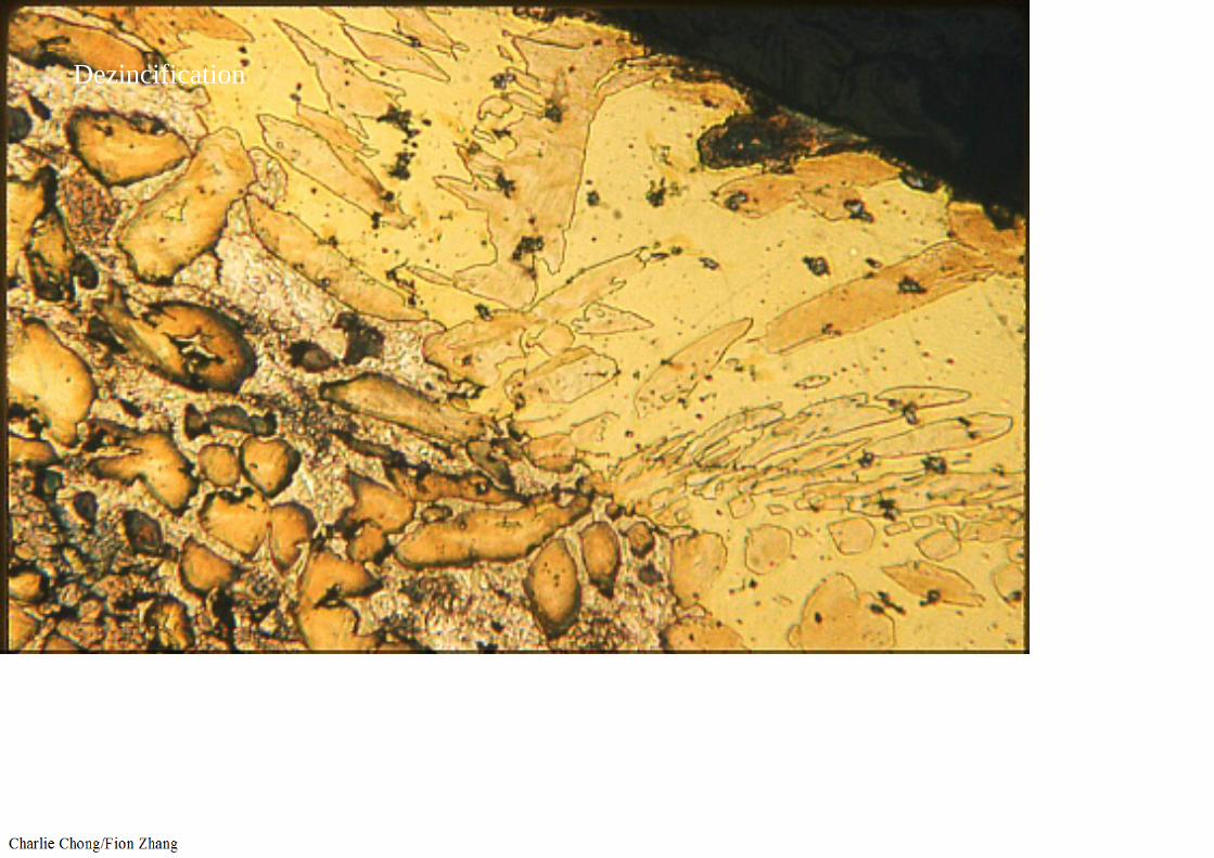
Dezincification

Dezincification

4.3.11.6 Prevention / Mitigation
a) It is often difficult to predict whether conditions will be conducive to dealloying in a particular environment or service, so that one must be cognizant of the susceptibility of certain alloys, and the possible resulting consequences.
b) Resistance to dealloying can sometimes be improved by the addition of certain alloying elements so that a similar alloy with a different composition may be resistant. For example, tin tends to inhibit dealloying of copper alloys; admiralty brass is inhibited by the addition of a very small amount of phosphorous, antimony or arsenic; and dealuminificationof aluminum-bronze can be prevented by heat treatment to produce an α and β microstructure.
c) Continued degradation of a dealloyed component can only be prevented by altering the exposure conditions or replacing it with a resistant material.
d) Depending on the alloy-environment combination, cathodic protection or barrier coatings may be effective.


脱合金腐蚀学习重点:
1. 温度: 操作温度2. 受影响材料: 铜合金(锌-黄铜.青铜,锡) 镍铜合金 400, 铸铁,3. 损伤原理:限于特定合金环境组合下其一的元素流失,4. 预防/缓解: 添加某种化学成分, 热处理更改金相, 更改接触环境, 阴极保护, 5. 非API 510/570考试学习项.

4.3.12 Graphitic Corrosion 石墨化腐蚀4.3.12.1 Description of Damage
a) Cast irons are comprised of graphite particles embedded in an iron matrix. Graphitic corrosion is a form of dealloying in which the iron matrix is corroded, leaving corrosion products and porous graphite.
b) Attack results in a porous structure with a loss of strength, ductility and density. It usually occurs under low pH and stagnant conditions, especially in contact with soils or waters high in sulfates.
4.3.12.2 Affected Materials
Primarily gray cast iron, but also nodular and malleable cast irons experience graphitic corrosion. However, nodular and malleable cast irons tend to crumble when attacked. White iron is not subject to this damage because there is no free graphite.
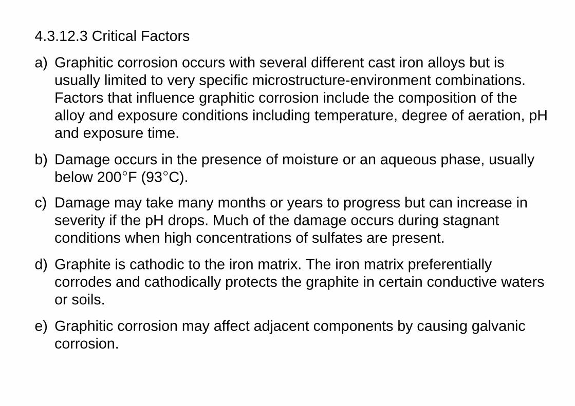
4.3.12.3 Critical Factors
a) Graphitic corrosion occurs with several different cast iron alloys but is usually limited to very specific microstructure-environment combinations. Factors that influence graphitic corrosion include the composition of the alloy and exposure conditions including temperature, degree of aeration, pH and exposure time.
b) Damage occurs in the presence of moisture or an aqueous phase, usually below 200°F (93°C).
c) Damage may take many months or years to progress but can increase in severity if the pH drops. Much of the damage occurs during stagnant conditions when high concentrations of sulfates are present.
d) Graphite is cathodic to the iron matrix. The iron matrix preferentially corrodes and cathodically protects the graphite in certain conductive waters or soils.
e) Graphitic corrosion may affect adjacent components by causing galvanic corrosion.

4.3.12.4 Affected Units or Equipment
Graphitic corrosion can occur in soft water, salt water, mine waters, dilute acids and in underground piping as well as in boiler feedwater equipment. Typical examples include feedwater piping, pumps (including pumpimpellers), valves, and underground cast iron pipe. Fire water systems are particularly vulnerable.

4.3.12.5 Appearance or Morphology of Damage
a) Damage may be widespread or it may also occur in localized areas in which the majority of the component is unaffected.
b) The damage may not be noticeable upon visual inspection even where the full wall thickness is degraded.
c) Damaged areas will be soft and easily gouged with a knife or hand tool.
d) Metallographic examination may be required to confirm the extent of damage (Figure 4-103 through Figure 4-110).

4.3.12.6 Inspection and Monitoring
a) UT is not a good method for detecting damage.
b) Acoustic techniques (loss of “metallic ring”) and ultrasonic attenuation are applicable.
c) A significant reduction in hardness may accompany dealloying, although affected areas may be localized.
4.3.12.7 Prevention / Mitigation
a) It is often difficult to predict if exposure conditions will cause this form of dealloying in a particular environment or service. One must be aware of the potential susceptibility of cast irons.
b) Internal graphitic corrosion can be prevented by coatings and/or cement linings.
c) External graphitic corrosion can be prevented by external coatings or cathodic protection in severely corrosive soils.
4.3.12.8 Related Mechanisms
Also known as selective leaching, graphitic corrosion is a form of dealloying (see 4.3.11) of cast irons. It should not be confused with graphitization, the decomposition of carbides at high temperatures (see 4.2.1).
Graphitization Graphitic Corrosion
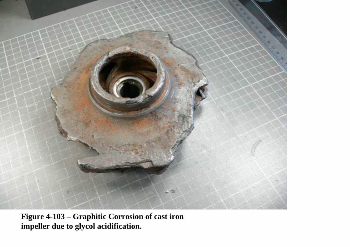
Figure 4-103 – Graphitic Corrosion of cast iron impeller due to glycol acidification.

Figure 4-104 – Cut away of cast iron impeller shown above. The dark phase around the outside perimeter (at arrows) is graphite which surround the unaffected metal in the middle.

Figure 4-105 – View of the outside of an underground concrete-lined salt water service line that failed from graphitic corrosion.

Figure 4-106 – View of concrete lining inside the failed line shown in Figure 105.

Figure 4-107 – Cross section of a gray cast iron drainpipe showing charcoal colored thru-wall graphitic corrosion encroaching from both sides. Note the through wall crack at the bottom.

Figure 4-108 – Cross section of a gray cast iron pipe with graphitic corrosion coming from O.D. (Point B).

Figure 4-109 – Higher magnification view of unaffected area “A” shown in Figure 4-108.

Figure 4-110 – Higher magnification view of the damage from shown in 4-108 (area “B”).


石墨(留碳)腐蚀学习重点:
1. 温度: 操作温度2. 受影响材料: 铸铁(不包含白口铸铁),3. 损伤原理:限于特定合金环境组合下其一的元素流失,4. 预防/缓解: 更改接触环境, 阴极保护?, 涂层(内外), 5. 非API 510/570考试学习项.

Copyright © 2022 FDOKUMEN