Ultricool User Guide - Ross Video
36
Ultricool User Guide
-
Upload
khangminh22 -
Category
Documents
-
view
1 -
download
0
Transcript of Ultricool User Guide - Ross Video

Ultricool User Guide

Thank You for Choosing RossYou've made a great choice. We expect you will be very happy with your purchase of Ross Technology.
Our mission is to:
1. Provide a Superior Customer Experience
• offer the best product quality and support
2. Make Cool Practical Technology
• develop great products that customers love
Ross has become well known for the Ross Video Code of Ethics. It guides our interactions and empowers our employees. I hope you enjoy reading it below.
If anything at all with your Ross experience does not live up to your expectations be sure to reach out to us at [email protected].
David RossCEO, Ross [email protected]
Ross Video Code of EthicsAny company is the sum total of the people that make things happen. At Ross, our employees are a special group. Our employees truly care about doing a great job and delivering a high quality customer experience every day. This code of ethics hangs on the wall of all Ross Video locations to guide our behavior:
1. We will always act in our customers’ best interest.
2. We will do our best to understand our customers’ requirements.
3. We will not ship crap.
4. We will be great to work with.
5. We will do something extra for our customers, as an apology, when something big goes wrong and it's our fault.
6. We will keep our promises.
7. We will treat the competition with respect.
8. We will cooperate with and help other friendly companies.
9. We will go above and beyond in times of crisis. If there's no one to authorize the required action in times of company or customer crisis - do what you know in your heart is right. (You may rent helicopters if necessary.)

Ultricool · User Guide• Ross Part Number: 2101DR-404-01
• Release Date: April 8, 2019.
The information contained in this Guide is subject to change without notice or obligation.
Copyright©2019 Ross Video Limited, Ross®, and any related marks are trademarks or registered trademarks of Ross Video Limited. All other trademarks are the property of their respective companies. PATENTS ISSUED and PENDING. All rights reserved. No part of this publication may be reproduced, stored in a retrieval system, or transmitted in any form or by any means, mechanical, photocopying, recording or otherwise, without the prior written permission of Ross Video. While every precaution has been taken in the preparation of this document, Ross Video assumes no responsibility for errors or omissions. Neither is any liability assumed for damages resulting from the use of the information contained herein.
PatentsPatent numbers US 7,034,886; US 7,508,455; US 7,602,446; US 7,802,802 B2; US 7,834,886; US 7,914,332; US 8,307,284; US 8,407,374 B2; US 8,499,019 B2; US 8,519,949 B2; US 8,743,292 B2; GB 2,419,119 B; GB 2,447,380 B; and other patents pending.
NoticeThe material in this manual is furnished for informational use only. It is subject to change without notice and should not be construed as commitment by Ross Video Limited. Ross Video Limited assumes no responsibility or liability for errors or inaccuracies that may appear in this manual.
Trademarks• Google® is a registered trademark of Google Inc.
• Microsoft® Excel® and Internet Explorer® are either registered trademarks or trademarks of Microsoft Corporation in the United States and/or other countries.
• Mozilla® and Firefox® are registered trademarks of the Mozilla Foundation.
• Oracle® and Java® are registered trademarks of Oracle and/or its affiliates. Other names may be trademarks of their respective owners.
• Safari® is a trademark of Apple Inc., registered in the U.S. and other countries.
Safety NoticesRefer to the “Important Regulatory and Safety Notices” document that accompanied your product.
EMC NoticesUS FCC Part 15
This equipment has been tested and found to comply with the limits for a class A Digital device, pursuant to part 15 of the FCC Rules. These limits are designed to provide reasonable protection against harmful interference when the equipment is operated in a Commercial environment. This equipment generates, uses, and can radiate radio frequency energy and, if not installed and used in accordance with the instruction manual, may cause harmful interference to radio communications. Operation of this equipment in a residential area is likely to cause harmful interference in which case the user will be required to correct the interference at his own expense.
CANADA
This Class “A” digital apparatus complies with Canadian ICES-003.
Cet appareil numerique de la classe “A” est conforme a la norme NMB-003 du Canada.
Notice — Changes or modifications to this equipment not expressly approved by Ross Video Ltd. could void the user’s authority to operate this equipment.

EUROPE
This equipment is in compliance with the essential requirements and other relevant provisions of CE Directive 93/68/EEC.
AUSTRALIA
This equipment has been tested to AS/NZS CISPR 22:2008 and found to comply with the limits for a Class A Digital device.
INTERNATIONAL
This equipment has been tested to CISPR 22:2008 and found to comply with the limits for a Class A Digital device.
Warranty and Repair PolicyThe product is backed by a comprehensive one-year warranty on all components.
If an item becomes defective within the warranty period Ross will repair or replace the defective item, as determined solely by Ross.
Warranty repairs will be conducted at Ross, with all shipping FOB Ross dock. If repairs are conducted at the customer site, reasonable out-of-pocket charges will apply. At the discretion of Ross, and on a temporary loan basis, plug in circuit boards or other replacement parts may be supplied free of charge while defective items undergo repair. Return packing, shipping, and special handling costs are the responsibility of the customer.
This warranty is void if products are subjected to misuse, neglect, accident, improper installation or application, or unauthorized modification.
In no event shall Ross Video Limited be liable for direct, indirect, special, incidental, or consequential damages (including loss of profit). Implied warranties, including that of merchantability and fitness for a particular purpose, are expressly limited to the duration of this warranty.
This warranty is TRANSFERABLE to subsequent owners, subject to Ross’ notification of change of ownership.
Environmental InformationThe equipment may contain hazardous substances that could impact health and the environment.
To avoid the potential release of those substances into the environment and to diminish the need for the extraction of natural resources, Ross Video encourages you to use the appropriate take-back systems. These systems will reuse or recycle most of the materials from your end-of-life equipment in an environmentally friendly and health conscious manner.
The crossed-out wheeled bin symbol invites you to use these systems.
If you need more information on the collection, reuse, and recycling systems, please contact your local or regional waste administration. You can also contact Ross Video for more information on the environmental performances of our products.
This appliance may contain a Coin type battery which should not be treated as household waste.
To ensure that the battery will be treated properly use the appropriate take-back systems in your area. These systems will reuse or recycle most of the materials from your end-of-life equipment in an environmentally friendly and health conscious manner.
Notice — This is a Class A product. In domestic environments, this product may cause radio interference, in which case the user may have to take adequate measures.
Notice — Changes or modifications to this equipment not expressly approved by Ross Video Limited could void the user’s authority to operate this equipment.

Company Address
Ross Video Limited
8 John StreetIroquois, OntarioCanada, K0E 1K0
Ross Video Incorporated
P.O. Box 880Ogdensburg, New YorkUSA 13669-0880
General Business Office: (+1) 613 652 4886
Fax: (+1) 613 652 4425
Technical Support: (+1) 613 652 4886
After Hours Emergency: (+1) 613 349 0006
E-mail (Technical Support): [email protected]
E-mail (General Information): [email protected]
Website: http://www.rossvideo.com

Ultricool User Guide (v1.0) Contents • i
Contents
Introduction 9Related Publications .................................................................................................................................................9Documentation Conventions ....................................................................................................................................9
Interface Elements .................................................................................................................................................9User Entered Text .................................................................................................................................................9Referenced Guides ..............................................................................................................................................10Menu Sequences ..................................................................................................................................................10Important Instructions .........................................................................................................................................10Contacting Technical Support .............................................................................................................................10
Getting Started 11Ultrix Support Overview ........................................................................................................................................11
Supported Devices ..............................................................................................................................................11Features ..................................................................................................................................................................11
Hardware Overview 13Front Panel Overview ............................................................................................................................................13Rear Panel Overview .............................................................................................................................................14
Physical Installation 15Before You Begin ..................................................................................................................................................15Unpacking the Equipment ......................................................................................................................................15Mounting Requirements .........................................................................................................................................15Connecting Ultricool to a Network ........................................................................................................................16Connecting to a Power Source ...............................................................................................................................16Using the ALARM Connector ...............................................................................................................................17
Configuration 19Launching DashBoard ...........................................................................................................................................19Using Walkabout to Assign the IP Address to the Ultricool .................................................................................19Adding the Ultricool to the Tree View in DashBoard ...........................................................................................20Accessing the Ultricool Interfaces in DashBoard ..................................................................................................21Configuring the Fan Mode .....................................................................................................................................21
Connecting to an Ultrix 23Before You Begin ..................................................................................................................................................23Using Auto Detect Mode .......................................................................................................................................23Manual IP Mode ....................................................................................................................................................23Verifying the Connection .......................................................................................................................................24
External Controls 25RossTalk Support ...................................................................................................................................................25
Monitoring the Ultricool 27Monitoring via the Front Panel LEDs ....................................................................................................................27Monitoring the ENET Port LEDs ..........................................................................................................................28Monitoring via DashBoard ....................................................................................................................................28
Monitoring the Status of the Fans .......................................................................................................................28

ii • Contents Ultricool User Guide (v1.0)
Monitoring the Ultricool PSU States ...................................................................................................................28
Maintenance 29Moving the Duct on the Rear Panel .......................................................................................................................29
Remove the Duct .................................................................................................................................................29Installing the Duct ...............................................................................................................................................30
DashBoard Interface Overview 31Status Tabs Overview .............................................................................................................................................31
Product Tab .........................................................................................................................................................31Hardware Tab ......................................................................................................................................................31
Setup Tab ................................................................................................................................................................32Network Tab ...........................................................................................................................................................33
Technical Specifications 35Physical Dimensions ..............................................................................................................................................35General Specifications ............................................................................................................................................35Power Consumption ...............................................................................................................................................35

Ultricool User Guide (v1.0) Introduction • 9
IntroductionThis guide is for system administrators and installers of the Ross Video Ultricool. It provides instructions on how to install, configure, and monitor your Ultricool rack mount cooling system.
This guide contains the following chapters that cover the installation and setup of an Ultricool:
• “Introduction” summarizes the guide and provides important terms, and conventions.
• “Getting Started” provides general information to keep in mind before installing and configuring your Ultricool.
• “Hardware Overview” provides a basic introduction to the Ultricool front and rear panels.
• “Physical Installation” provides instructions for the basic physical installation of the Ultricool.
• “Configuration” provides instructions on navigating the Ultricool interfaces, and establishing communications in DashBoard.
• “External Controls” lists the third-party protocol commands the Ultricool supports.
• “Monitoring the Ultricool” provides instructions on how to monitor the Ultricool status via the chassis and the DashBoard read-only status fields.
• “Maintenance” provides instructions on how to move the duct on the rear panel of the chassis.
• “DashBoard Interface Overview” summarizes the tabs, menus, fields, and parameters displayed in the DashBoard window for Ultricool.
• “Technical Specifications” provides the specifications, such as dimensions and power consumption, for the Ultricool.
If you have questions pertaining to installation of this Ross Video product, please contact us at the numbers listed in the section “Contacting Technical Support” on page 10. Our technical staff is always available for consultation, training, or service.
Related Publications
It is recommended to consult the following Ross documentation before installing your Ultricool:
• Ultricool Quick Start Guide, Ross Part Number: 2101DR-402
• ULTRIX-FR1 and ULTRIX-FR2 Quick Start Guide, Ross Part Number: 2101DR-002
• ULTRIX-FR5 Quick Start Guide, Ross Part Number: 2101DR-502
• Ultrix Installation Guide, Ross Part Number: 2101DR-003
• Ultrix User Guide, Ross Part Number: 2101DR-004
Documentation Conventions
Special text formats are used in this guide to identify parts of the user interface, text that a user must enter, or a sequence of menus and sub-menus that must be followed to reach a particular command.
Interface Elements
Bold text is used to identify a user interface element such as a dialog box, menu item, or button. For example:
In the Save Layout dialog, click OK.
User Entered Text
Courier text is used to identify text that a user must enter. For example:
In the Language box, enter English.

10 • Introduction Ultricool User Guide (v1.0)
Referenced Guides
Italic text is used to identify the titles of referenced guides, manuals, or documents. For example:
For more information, refer to the Ultrix Installation Guide.
Menu Sequences
Menu arrows are used in procedures to identify a sequence of menu items that you must follow. For example, if a step reads “File > Save,” you would click the File menu and then click Save.
Important Instructions
Star icons are used to identify important instructions or features. For example:
When the Ultricool cannot connect to the network, a Message dialog box opens to report the connection problem.
Contacting Technical Support
At Ross Video, we take pride in the quality of our products, but if problems occur, help is as close as the nearest telephone.
Our 24-hour Hot Line service ensures you have access to technical expertise around the clock. After-sales service and technical support is provided directly by Ross Video personnel. During business hours (Eastern Time), technical support personnel are available by telephone. After hours and on weekends, a direct emergency technical support phone line is available. If the technical support person who is on call does not answer this line immediately, a voice message can be left and the call will be returned shortly. This team of highly trained staff is available to react to any problem and to do whatever is necessary to ensure customer satisfaction.
• Technical Support: (+1) 613-652-4886
• After Hours Emergency: (+1) 613-349-0006
• E-mail: [email protected]
• Website: http://www.rossvideo.com

Ultricool User Guide (v1.0) Getting Started • 11
Getting StartedThe Ultricool is a smart, directional 1RU rack mount cooling system to compliment equipment thermal performance when in extreme conditions or in confined spaces. Ultricool can be configured to provide directional airflow from front to back, front to right side, or front to left side depending on equipment requirements.
Ultricool may integrate with an Ultrix router to provide automatic thermal adjustments, or operate stand-alone with manual fan speed controls. Ultricool also provides a RossTalk interface to set the fan speeds.
Ultrix Support Overview
The default configuration of Ultricool provides enhanced thermal management for Ultrix routers particularly in confined spaces. The right hand side fans duct front-of-rack cool air to the Ultrix router frame air intake, whilst the left hand side fans creates a low pressure where Ultrix exhaust is drawn up and vented out the rear of the system enclosure. This helps to prevent Ultrix ingesting the warm air within an enclosure.
Supported Devices
The Ultricool supports the following Ultrix devices:
• ULTRIX-FR1
• ULTRIX-FR2
• ULTRIX-FR5
Features
The Ultricool includes the following features:
• Directional 1RU rack mount cooling system
• Rear duct that can be moved to change airflow from right to left, or left to right
• Multiple modes for fan control:
› Manual — via DashBoard or RossTalk commands
› Bonded — automatically adjusted via connection to an Ultrix router
• DashBoard interface to all reported status data

12 • Getting Started Ultricool User Guide (v1.0)

Ultricool User Guide (v1.0) Hardware Overview • 13
Hardware OverviewThis chapter presents information on the Ultricool front and rear panels.
Front Panel Overview
This section summarizes the Ultricool front panel features.
Figure 3.1 Ultricool — Front Panel
1. Fans 1-4
Fans 1-4 draw air into the Ultricool and if the duct is installed on the rear panel over these fans, directs the air down and to the left of the chassis.
2. MODE Button
Toggle this button to set the sets the speed of all fans to a specific rate.
3. Status LEDs
The Status LEDs monitor the overall fan speed, communication status, and power supplies. Refer to “Monitoring via the Front Panel LEDs” on page 27 for details.
4. Fans 5-8
Fans 5-8 draw air into the Ultricool and if the duct is installed on the rear panel over these fans, directs the air down and to the right of the chassis.
A duct is installed over fans 5-8 when shipped from the factory.
1) Fans 1-4 3) Status LEDs
2) MODE Button 4) Fans 5-8
MODEHIG
HMED
ENETALARM
PWR2PWR1
LOWMINAUTO

14 • Hardware Overview Ultricool User Guide (v1.0)
Rear Panel Overview
The rear panel provides a support structure for connecting power inputs, power outputs, and to your facility network. This section summarizes the Ultricool rear panel features.
Figure 3.2 Ultricool — Rear Panel (Duct Removed) Overview
1. Fans 5-8
Fans 5-8 draw air into the Ultricool and if the duct is installed on the rear panel over these fans, directs the air down and to the right of the chassis.
When shipped from the factory, a duct is installed over fans 5-8. This duct can be removed entirely or installed over fans 1-4.
2. PWR Ports 1, 2
There are two power supply connectors located on the rear of the Ultricool. Each connector requires a 15VDC connection to an external power supply.
The Ultricool ships with one power supply. An option is available to order a second power supply for redundancy.
3. ALARM Connector
The ALARM connector is a general purpose output that provides contact closure alarm state monitoring. Refer to the section “Using the ALARM Connector” on page 17 for details.
4. ENET Port
The ENET port is an RJ45 connector used to connect the Ultricool to an external Ethernet network. This port is required for monitoring and control of Ultricool.
5. Fans 1-4
Fans 1-4 draw air into the Ultricool and if the duct is installed on the rear panel over these fans, directs the air down and to the left of the chassis.
1) Fans 5-8 3) ALARM Connector 5) Fans 1-4
2) PWR Ports 1, 2 4) ENET Port
Notice — The Ultricool automatically powers on when power is applied.
Notice — The ENET port does not provide Power-over-Ethernet (PoE).
ENET±15VDC
max.60W
NO
ALARM
C NC
PWR 2
PWR 1
5
6
7
8
1
2
3
4
Ultricool User Guide (v1.0) Physical Installation • 15
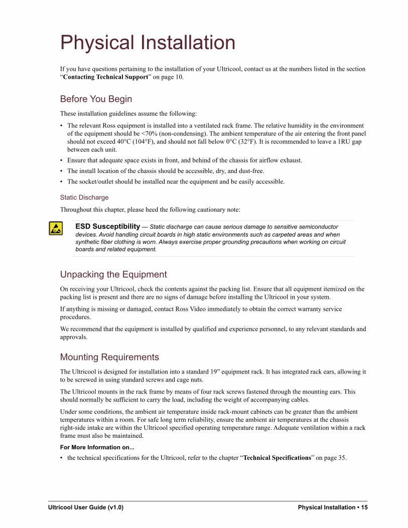
Physical InstallationIf you have questions pertaining to the installation of your Ultricool, contact us at the numbers listed in the section “Contacting Technical Support” on page 10.
Before You Begin
These installation guidelines assume the following:
• The relevant Ross equipment is installed into a ventilated rack frame. The relative humidity in the environment of the equipment should be <70% (non-condensing). The ambient temperature of the air entering the front panel should not exceed 40°C (104°F), and should not fall below 0°C (32°F). It is recommended to leave a 1RU gap between each unit.
• Ensure that adequate space exists in front, and behind of the chassis for airflow exhaust.
• The install location of the chassis should be accessible, dry, and dust-free.
• The socket/outlet should be installed near the equipment and be easily accessible.
Static Discharge
Throughout this chapter, please heed the following cautionary note:
Unpacking the Equipment
On receiving your Ultricool, check the contents against the packing list. Ensure that all equipment itemized on the packing list is present and there are no signs of damage before installing the Ultricool in your system.
If anything is missing or damaged, contact Ross Video immediately to obtain the correct warranty service procedures.
We recommend that the equipment is installed by qualified and experience personnel, to any relevant standards and approvals.
Mounting Requirements
The Ultricool is designed for installation into a standard 19” equipment rack. It has integrated rack ears, allowing it to be screwed in using standard screws and cage nuts.
The Ultricool mounts in the rack frame by means of four rack screws fastened through the mounting ears. This should normally be sufficient to carry the load, including the weight of accompanying cables.
Under some conditions, the ambient air temperature inside rack-mount cabinets can be greater than the ambient temperatures within a room. For safe long term reliability, ensure the ambient air temperatures at the chassis right-side intake are within the Ultricool specified operating temperature range. Adequate ventilation within a rack frame must also be maintained.
For More Information on...
• the technical specifications for the Ultricool, refer to the chapter “Technical Specifications” on page 35.
ESD Susceptibility — Static discharge can cause serious damage to sensitive semiconductor devices. Avoid handling circuit boards in high static environments such as carpeted areas and when synthetic fiber clothing is worn. Always exercise proper grounding precautions when working on circuit boards and related equipment.

16 • Physical Installation Ultricool User Guide (v1.0)
Connecting Ultricool to a Network
The ENET port is a standard 10/100 RJ45 Ethernet connector and is used to exchange data and communicate with control and monitoring applications such as DashBoard.
Contact your IT department before connecting to your facility network to ensure that there are no conflicts. They will provide you with an appropriate value for the IP Address, Subnet Mask, and Gateway for your device.
The Ultricool is connected directly to your network so that it can interface with the devices and the computer running the DashBoard client. After a physical connection is established, DashBoard is used to configure the network settings for the Ultricool.
For More Information on...
• downloading and installing DashBoard, refer to the DashBoard User Manual.
If difficulties or problems are experienced when connecting the Ultricool to a network hub, or with assigning IP addresses, please contact your network administrator.
To establish a physical connection to the network
1. Connect one free end of a standard CAT 5/5e/6 Ethernet cable to a free port of the network hub.
2. Connect the other end of the same cable to the ENET port on the rear of the Ultricool.
Figure 4.1 Ultricool — Network Connection
Connecting to a Power Source
For redundancy, each power cord should be connected to a separate power source for protection against failure of the A/C power circuit. Under normal conditions with two power supply modules operating, the DC output power is shared between the two modules.
Warning Hazardous Voltages — The safe operation of this product requires that a protective earth connection be provided. This protective earth is provided by the ground conductor in the equipment’s supply cord. To reduce the risk of electrical shock to operator and service personnel, this ground connector must be connected to an earthed ground.
Warning — In some countries it may be necessary to supply the correct mains supply cord. Use only certified cords for the country of use.
ENET±15VDC
max.60W
NO
ALARM
C NC
PWR 2
PWR 1
5
6
7
8
1
2
3
4

Ultricool User Guide (v1.0) Physical Installation • 17
To connect the power cables to the Ultricool
1. Connect the supplied power supply DC cable into the socket marked PWR 1 on the Ultricool rear panel.
Figure 4.2 Ultricool — Power Connections
2. If available, connect the redundant power supply DC cable into the socket marked PWR 2.
3. Connect the supplied AC power cable into the power module(s).
4. Connect the supplied power cable’s three-prong male connector to Mains Power.
Using the ALARM Connector
Refer to Figure 4.3 for pin designations.
Figure 4.3 ALARM Connector — Pin Designations
Refer to Table 4.1 for the pinout assignment of the ALARM port on the chassis.
Under normal operation (unit powered with no alarms activated), Pin C is connected to Pin NO. An alarm condition connects Pin C to Pin NC. (Figure 4.4)
Table 4.1 Alarm Pinouts
Pin Number Function
NO Normally Open
C Common terminal
NC Normally Closed
ENET±15VDC
max.60W
NO
ALARM
C NC
PWR 2
PWR 1
5
6
7
8
1
2
3
4
To Power Source 1
To Power Source 2
NO
ALARM
C NC

18 • Physical Installation Ultricool User Guide (v1.0)
Figure 4.4 De-energized or Alarm State Equivalent Circuit
Refer Figure 4.5 to for the signal pinouts for the 3-pin connector plug.
Figure 4.5 Connector Plug — Pinouts for Alarm Port
PIN C
PIN NO
PIN NC
ConnectorEnd View
ConnectorSide View
Cable
Connector
Tie Wrap
ConnectorTop Views
(without cable)

Ultricool User Guide (v1.0) Configuration • 19
ConfigurationThe DashBoard client software enables you to configure and monitor the Ultricool. Using the tabs provided via the DashBoard client software, you can:
• Configure the network settings for your Ultricool
• Monitor the status of each fan
This chapter outlines how to assign an IP address to the Ultricool, and access the interfaces and status fields displayed in the Ultricool DashBoard interface.
Launching DashBoard
DashBoard must be run on a computer that has a physical wired ethernet connection. Wireless connections do not allow device discovery.
For More Information on...
• downloading and installing the DashBoard client software, refer to the DashBoard User Manual.
To launch DashBoard
1. Ensure that you are running DashBoard software version 8.5 or higher.
2. Launch DashBoard by double-clicking its icon on your computer desktop.
Using Walkabout to Assign the IP Address to the Ultricool
Once the Ultricool is physically installed and cabled to your facility network, you will need to assign it a static IP Address to enable DashBoard to locate it on your network. Establishing an IP Address enables DashBoard to communicate with the Ultricool and update the Basic Tree View with the Ultricool nodes.
The default IP Address of the Ultricool is 192.168.20.125.
To assign a static IP address to the Ultricool
1. Launch DashBoard.
2. From the DashBoard client main toolbar, select File > Show Walkabout.
The DashBoard window displays the Walkabout table.
3. Click Refresh, located at the bottom of the Walkabout tab, to ensure the list in the Walkabout interface is current.
4. In the Walkabout table, find the entry for the Ultricool you want to configure.
5. Use the Name field to assign a unique identifier to the Ultricool. This will be the name displayed in the Tree View of DashBoard.
After you edit a cell in the Walkabout table, the Connection/Link Quality value for the device reports 1%. It is recommended to wait approximately 1 minute, then click Refresh to apply the new settings.
6. Use the Address field to specify the IP Address supplied by your IT Department for this device.
7. Ensure the Netmask field is set to match your network requirements.
8. Use the Gateway field to specify the IP Address for connection outside of the local area network (LAN).
Press Enter on your keyboard after editing each field.
9. Click Reboot in the row of the Walkabout table for the Ultricool.

20 • Configuration Ultricool User Guide (v1.0)
After initial setup, you can edit the network settings of the Ultricool using the Network tab options in DashBoard.
Adding the Ultricool to the Tree View in DashBoard
Once you have assigned the Ultricool a static IP Address, you can then manually add it to the Tree View. Manually adding the Ultricool displays its node in the Tree View, granting you access to the interfaces described used to monitor the status of the power supplies.
To manually add the Ultricool to the Tree View in DashBoard
1. In the Basic Tree View toolbar of DashBoard, click .
The Select Equipment or Service Type to Add dialog opens.
2. Expand the openGear/DashBoard Connect node.
3. Select TCP/IP DashBoard Connect or openGear Device.
4. Click Next >.
The TCP/IP DashBoard Connect/openGear Device dialog opens.
5. Select the OGP radio button as the Protocol.
6. Enter the IP Address for the Ultricool in the IP Address field that you assigned in the section “To assign a static IP address to the Ultricool” on page 19.
7. In the text fields provided, enter the display name for the Ultricool.
8. Click Finish.
The Ultricool displays in the Tree View.

Ultricool User Guide (v1.0) Configuration • 21
Accessing the Ultricool Interfaces in DashBoard
The interface is accessed by expanding the Ultricool node in the DashBoard Tree View and selecting the sub-node. The interface is divided vertically to show status and frame information on the left, and configuration options on the right.
To access the Ultricool interfaces in DashBoard
1. Locate the Ultricool in the Tree View of DashBoard.
2. Expand the Ultricool node to display the frame in the Tree View.
3. Double-click the Ultricool sub-node to display its interface in the right-side of the DashBoard window.
4. Select a tab to displays its contents in the DashBoard window.
In the example below, the Product and Setup tabs are selected.
For More Information on...
• the Status tabs, refer to the section “Monitoring via DashBoard” on page 28.
Configuring the Fan Mode
The Fan Mode sets the speed of all fans to a specific rate, or whether the fans will run at a speed as determined by the connected Ultrix router.
For More Information on...
• the physical fan locations, refer to the section “Rear Panel Overview” on page 14.
• establishing communications between an Ultrix router and the Ultricool, refer to the chapter “Connecting to an Ultrix” on page 23.
To specify a fan mode
1. Display the Ultricool interface in DashBoard as outlined in the procedure “To access the Ultricool interfaces in DashBoard” on page 21.
2. Select the Setup tab.

22 • Configuration Ultricool User Guide (v1.0)
3. Choose a Fan Setting:
• Auto — Enables communications with Ultrix (if set) or RossTalk external control. Ensure that you establish a connection to a router as outlined in the chapter “Connecting to an Ultrix” on page 23.
• Min. — Sets the fan speed to the minimum RPM (less than 20%).
• Low — Sets the fan speed to approximately 20% of the maximum speed.
• Medium — Sets the fan speed to approximately 50% of the maximum speed.
• High — Sets the fan speed to approximately 100% of the maximum speed.

Ultricool User Guide (v1.0) Connecting to an Ultrix • 23
Connecting to an UltrixThere are two methods for establishing a connection between the Ultricool and an Ultrix: Manual IP Mode or via Auto Detect Mode. This chapter outlines both methods.
Before You Begin
Before establishing communications between the Ultricool and an Ultrix router:
• Ensure the Ultrix router is installed and configured as outlined in its user documentation.
• Know the IP Address of the Ultrix router that will communicate with the Ultricool.
• Ensure the Ultricool is installed as outlined in its Quick Start Guide.
Using Auto Detect Mode
Ultricool uses the Discovered Devices feature of Walkabout to poll the network for a list of available Walkabout compatible devices (such as Ultrix routers). The Device Control menu displays this list for the Ultricool.
To establish a connection using Walkabout
1. Display the Setup tab for the Ultricool as outlined in the procedure “Accessing the Ultricool Interfaces in DashBoard” on page 21.
2. Set the Fan Speed mode to Auto.
3. Click Refresh to update the Device Control list of available control devices available in your routing system.
The Ultricool will poll the network for Ultrix routers using the Walkabout Discovery feature of DashBoard and populate the Device Control list.
4. Use the Device Control menu to select the required Ultrix router.
5. Click Apply to establish the connection.
Manual IP Mode
This mode is useful if the Walkabout multi-cast UDP port is blocked via network policy.

24 • Connecting to an Ultrix Ultricool User Guide (v1.0)
To establish a connection using Manual IP mode
1. Display the Setup tab for the Ultricool as outlined in the procedure “Accessing the Ultricool Interfaces in DashBoard” on page 21.
2. Set the Fan Speed mode to Auto.
3. Click Refresh to update the list of available control devices available in your routing system.
4. Use the Device Control menu to select Manual IP.
5. Specify the Ultrix router that will control the Ultricool as follows:
a. Use the Ultrix IP Address to specify the IP Address of the Ultrix router.
b. Press Enter to apply the new value.
6. Click Apply to establish the connection.
Verifying the Connection
You can verify the connection between the Ultricool and the Ultrix router in two ways:
• via the LED on the front panel (refer to Table 8.1)
• via the Hardware tab in DashBoard
To use DashBoard to verify the connection between Ultricool and Ultrix
1. Select the Hardware tab in the Ultricool window of DashBoard.
2. Locate the Status field on the tab and verify that:
• the indicator is lit blue
• the field reports as message of Connected to Ultrix

Ultricool User Guide (v1.0) External Controls • 25
External ControlsThis chapter lists the third-party protocol commands the Ultricool supports.
RossTalk Support
The RossTalk protocol is a plain text based protocol that allows control of Ross Video equipment.
Each command should be terminated by a carriage return and a line feed (CR/LF).
To establish communications using the RossTalk protocol
1. Display the Setup tab as outlined in the procedure “To access the Ultricool interfaces in DashBoard” on page 21.
2. Use the Device Control menu to select RossTalk client.
To send RossTalk commands to Ultricool
1. On the RossTalk client, create a network connection to the Ultricool on Port 7788.
2. Set the Fan Speed Mode on the Ultricool to Auto. Refer to the section “To specify a fan mode” on page 21.
3. At the prompt, enter the commands you wish to send. Refer to Table 7.1 for a list of supported commands.
Table 7.1 RossTalk Protocol Commands
MessageNotes
Command Description
fan_speed:### Controls the fan speed where ### is the speed percentage (0-100)

26 • External Controls Ultricool User Guide (v1.0)
Ultricool User Guide (v1.0) Monitoring the Ultricool • 27
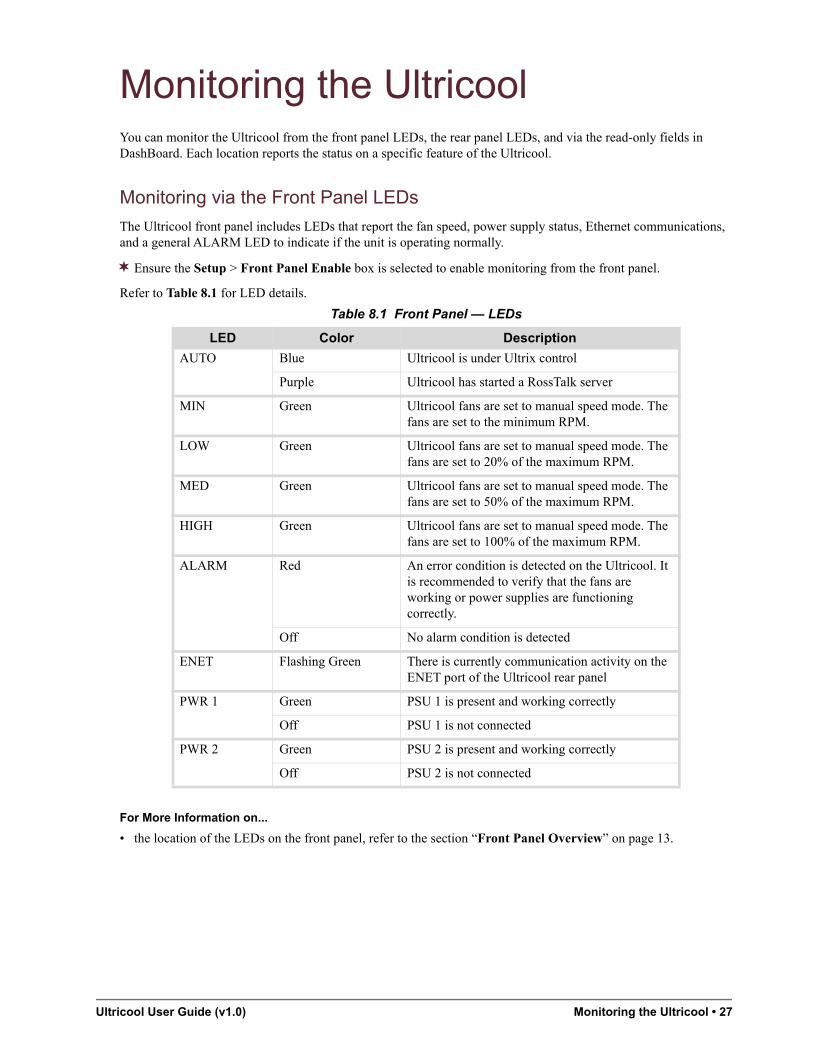
Monitoring the UltricoolYou can monitor the Ultricool from the front panel LEDs, the rear panel LEDs, and via the read-only fields in DashBoard. Each location reports the status on a specific feature of the Ultricool.
Monitoring via the Front Panel LEDs
The Ultricool front panel includes LEDs that report the fan speed, power supply status, Ethernet communications, and a general ALARM LED to indicate if the unit is operating normally.
Ensure the Setup > Front Panel Enable box is selected to enable monitoring from the front panel.
Refer to Table 8.1 for LED details.
For More Information on...
• the location of the LEDs on the front panel, refer to the section “Front Panel Overview” on page 13.
Table 8.1 Front Panel — LEDs
LED Color Description
AUTO Blue Ultricool is under Ultrix control
Purple Ultricool has started a RossTalk server
MIN Green Ultricool fans are set to manual speed mode. The fans are set to the minimum RPM.
LOW Green Ultricool fans are set to manual speed mode. The fans are set to 20% of the maximum RPM.
MED Green Ultricool fans are set to manual speed mode. The fans are set to 50% of the maximum RPM.
HIGH Green Ultricool fans are set to manual speed mode. The fans are set to 100% of the maximum RPM.
ALARM Red An error condition is detected on the Ultricool. It is recommended to verify that the fans are working or power supplies are functioning correctly.
Off No alarm condition is detected
ENET Flashing Green There is currently communication activity on the ENET port of the Ultricool rear panel
PWR 1 Green PSU 1 is present and working correctly
Off PSU 1 is not connected
PWR 2 Green PSU 2 is present and working correctly
Off PSU 2 is not connected

28 • Monitoring the Ultricool Ultricool User Guide (v1.0)
Monitoring the ENET Port LEDs
The Ultricool rear panel includes an ENET port. (Figure 8.1)
Figure 8.1 ENET Port LEDs
Monitoring via DashBoard
The read-only fields in DashBoard enable you to monitor the state of the Ultricool chassis.
For More Information on...
• the status tabs and fields in DashBoard, refer to the section “Status Tabs Overview” on page 31.
Monitoring the Status of the Fans
The state of the fans is constantly monitored. The fan status may be observed in DashBoard by selecting the Hardware tab. Ultricool fan speeds below 2000rpm (approx.) will cause an alarm state.
To view the status of a fan via DashBoard
1. Display the Ultricool interface in DashBoard as outlined in “Accessing the Ultricool Interfaces in DashBoard” on page 21.
2. Select the Hardware tab.
The tab displays a read-only field for each fan in the Ultricool chassis.
Contact Ross Technical Support if you experience an error with Ultricool.
Monitoring the Ultricool PSU States
You can use DashBoard to monitor the overall status of each PWR port on the chassis. Refer to the section “Hardware Tab” on page 31 for a list of possible messages in these fields.
To enable monitoring the redundant power supply
1. Display the Ultricool interface in DashBoard as outlined “Accessing the Ultricool Interfaces in DashBoard” on page 21.
2. Select the Setup tab.
3. Select the Redundant Power Alarm box to enable the alarm on a missing redundant power supply.
Table 8.2 Rear Panel — ENET LEDs
LED Status Description
LINK /ACTIVITY
Green When lit solid green, this LED indicates an invalid link is detected on the RJ45 port or an absence of communication.
Flashing Green When flashing green, this LED indicates communication activity is occurring on the RJ45 port.
Off When unlit, this LED indicates an invalid link is detected on the RJ45 port or an absence of communication.
PORT SPEED Yellow When lit yellow, this LED indicates a 100Base-T Ethernet connection.
Off When unlit, this LED indicates a 10Base-T Ethernet connection.
LINK / ACTIVITY LEDPORT SPEED LED

Ultricool User Guide (v1.0) Maintenance • 29
MaintenanceThis chapter provides additional information for the ongoing maintenance of your Ultricool.
Moving the Duct on the Rear Panel
The duct affixed to the back of Ultricool is located, by default, on the right side when facing the chassis front. This is to ensure that the Ultricool assists in cooling an Ultrix router which is located below.
If your setup requires that the cooling air that the Ultricool outputs is instead directed to the left side, you will need to remove the duct from its default position and re-affix it to the Ultricool chassis on the opposite side.
Remove the Duct
To move the duct from the default position to the opposite side of the chassis, you must first remove the four screws, remove the duct from the chassis, and rotate the duct.
To remove the duct from the Ultricool chassis
1. Remove the four screws that affix the duct to the Ultricool chassis (two on the top and two on the bottom).
Set the screws aside as you will need them to affix the duct to the other side of the chassis.
2. Grasp the duct on both sides and gently pull the duct towards you to fully disengage it from the chassis.

30 • Maintenance Ultricool User Guide (v1.0)
3. Rotate the duct 180° clockwise.
Installing the Duct
To install the duct in its new position, you must position the duct over the screw holes and affix the duct to the chassis using four screws.
To install the duct on the right-side of the Ultricool chassis
1. Position the duct on the right-side of the chassis so that:
• the screw holes on the duct align over top the screw holes on the chassis
• the exit wall on the duct is aligned with the right side of the chassis
2. Use the four screws from the procedure “To remove the duct from the Ultricool chassis” on page 29 to affix the duct to the right-side of the chassis.

Ultricool User Guide (v1.0) DashBoard Interface Overview • 31
DashBoard Interface OverviewUltricool groups the configuration and monitoring features in two areas in the DashBoard client window: Status (tabs in the left pane of the window), and Configuration (tabs in the right pane of the window). The following sections outline the fields, menus, and parameters displayed in each area.
Status Tabs Overview
This section summarizes the read-only information displayed in the Status tabs. Some fields in the Status tabs vary in severity from green (valid), yellow (caution), to red (alarm). DashBoard reports the most severe alarm for a single field. Alarm colors are noted within the tables as text set in brackets next to the menu parameter name.
Product Tab
Table 10.1 summarizes the read-only information displayed in the Product tab.
Hardware Tab
Table 10.2 summarizes the read-only information displayed in the Hardware tab.
Table 10.1 Product Tab
Item Parameters Description
Device Name # Indicates the name assigned to the device in the Setup tab
Product Ultricool Indicates the model name of this unit
Supplier Ross Video Indicates the supplier of this unit
Board Rev # Indicates the hardware version of the Ultricool control module
Board S/N # Indicates the serial number assigned to this unit
MAC Address # Media Access Control (MAC) address for ethernet connectivity
Software Rev # Read-only information used by Ross Technical Support
Table 10.2 Hardware Tab
Item Parameters Description
Status RossTalk (Purple) The RossTalk server was started and will adjust the fan speed as per the received command
Manual override (Yellow) The user selected one of the fixed Fan Mode settings (Min, Low, Medium, or High). Refer to Table 10.3 for a list of settings.
Connecting... (Blue) Ultricoolis attempting to connect with Ultrix
Connected to Ultrix (Blue) Ultricool is connected and controlled by an Ultrix

32 • DashBoard Interface Overview Ultricool User Guide (v1.0)
Setup Tab
Table 10.3 summarizes the options in the Setup tab.
PSU # State Present -OK The specified power supply connection is present and working correctly
Missing The specified power supply connection is missing; no power supply is detected on this port
Missing - Alarm masked The Redundant Power Alarm is disabled
Voltage Error The specified power supply is out of voltage range
Fan # (rpm) # Reports the speed of the specified fans (~4000-18000rpm)
Temp (°C) # Reports the current interior temperature of the Ultricool chassis
Table 10.3 Setup Tab
Item Parameters Description
Fan Settings
Mode Auto Enables communications with Ultrix (if set) or RossTalk mode
Min Sets the fan speed to the minimum RPM
Low Sets the fan speed to approximately 20% of the maximum speed
Medium Sets the fan speed to approximately 50% of the maximum speed
High Sets the fan speed to approximately 100% of the maximum speed
Ultrix Connection
Device Control Manual IP Enables you to manually specify the IP Address of the Ultrix router that will control the Ultricool. It is recommended to use this setting if your network policy blocks the Walkabout multi-cast UDP port.
RossTalk client Enables the Ultricool to get and send RossTalk commands from an external device
Ultrix # The specific Ultrix router will control the Ultricool
Refresh Device List
Refresh Ultricool polls the network for Ultrix routers. Updates the list of detected routers, to a maximum of six, that are available for communication.
Ultrix IP Address
##.##.##.### Specifies the IP Address of the Ultrix router that is communicating with the Ultricool. The Device Control is set to Manual IP.
Table 10.2 Hardware Tab
Item Parameters Description

Ultricool User Guide (v1.0) DashBoard Interface Overview • 33
Network Tab
Table 10.4 summarizes the options in the Network tab.
Alarms
Redundant Power Alarm
Selected The front panel PWR LEDs and the rear panel GPI will trigger upon a missing redundant power supply connection
Cleared Disables this alarm reporting
Front Panel Enable
Selected The Fan Setting mode can be changed using the MODE button on the front panel
Cleared Disables the MODE button on the front panel
Factory Settings
Restore Restores all alarm options to selected, the Ultrix connection is cleared, and the fans are set to Low.
Table 10.4 Network Tab
Item Parameters Description
Device Name # Assigns a unique name to the Ultricool. This name also displays in the DashBoard tree view. The default is Ultricool.
IP Address #.#.#.# Specifies the IP address for the Ultricool. The default is 192.168.20.125.
Subnet Mask #.#.#.# Specifies the subnet mask for the Ultricool. The default is 255.255.255.0.
Default Gateway
#.#.#.# Specifies the gateway for communication outside of the local area network (LAN).
Table 10.3 Setup Tab
Item Parameters Description

34 • DashBoard Interface Overview Ultricool User Guide (v1.0)

Ultricool User Guide (v1.0) Technical Specifications • 35
Technical SpecificationsThis chapter provides technical information for the Ultricool. Note that specifications are subject to change without notice.
Physical Dimensions
General Specifications
Power Consumption
Table 11.1 Physical Dimensions
Item Specifications
Width 18.90” (48cm)
Depth (approx.) With duct 6.20” (15.75cm)
Without duct 1.60” (4.10cm)
Height 1.72” (4.40cm)
Weight (approx.) 2.69lb (1.25kg)
Table 11.2 General Specifications
Item Specifications
Communications 10/100Mbps Ethernet
Ultrix communication TCP port 8877
RossTalk communication TCP port 7788
DashBoard communication TCP port 5253
Walkabout communication UDP port 5555
Table 11.3 Power Specifications
Item Specifications
Voltage 15VDC
Power 60W max. 50W (all fans operation at 100% RPM)

36 • Technical Specifications Ultricool User Guide (v1.0)