WiFi Video Door Phone - USER MANUAL - image
20
USER MANUAL SEE THRU PRO WiFi Video Door Phone The introductory information in this document may be changed for product improvement without prior notice. We reserve the right of final explanation and revision. Attend to your visitor anywhere, at anytime! INDOOR UNIT
-
Upload
khangminh22 -
Category
Documents
-
view
2 -
download
0
Transcript of WiFi Video Door Phone - USER MANUAL - image

USER MANUAL
SEE THRU PROWiFi Video Door Phone
The introductory information in this document may be changed for product improvement without prior notice. We reserve the right of final explanation and revision.
Attend to your visitor anywhere, at anytime!
INDOOR UNIT
Table of Contents
1. Features And Functions ........................................................................2
2. Packing Contents ..................................................................................2
3. Name And Functions Of Each Part .......................................................3
3.1 Front And Rear Part .......................................................................3
4. Connection Diagram .............................................................................4
4.1 System Layout ...............................................................................4
4.2 Wiring Diagram ..............................................................................4
5. Installation .............................................................................................6
6. Operation Description ...........................................................................6
6.1 Main Screen ...................................................................................6
6.2 Visitor Call ......................................................................................7
6.3 Monitor Function ............................................................................8
6.4 Multimedia .....................................................................................8
6.4.1 Image & Video Storage .........................................................8
6.4.2 Image & Video Review ..........................................................8
6.4.3 Voicemail Function ................................................................9
6.5 Intercom Function ..........................................................................9
6.6 Wifi Function(optional) ...................................................................9
6.6.1 Add Device ............................................................................9
6.6.2 Control The Monitor By Cellphone .....................................12
6.6.3 Call Forwarding Latency ......................................................13
6.7 Setting Page ................................................................................13
7. Specifications ......................................................................................15

1
WARNING AND CAUTION
Please make sure to follow the instructions to prevent any danger or property losses.
Warning: Death or serious injury is expected
Do not disassemble, install, or repair this product on your own accord
Do not place the product near a hot or humid place
Do not forcibly bend the cord or put a heavy object on the product
Do not use water, thinner or a detergent used to wash oil products to wash the exterior
Do not connect to other products while in use
Make sure to clean the unit with a dry cloth to prevent any breakdown or electric shock
If the product emits a peculiar noise, odor or smoke, immediately cut off the power, and then contact the service center
Do not put the plug in the socket with a wet hand
Caution: An injury or property loss is expected
Make sure that dust or foreign substances does not gather on the product
Make sure to prevent foreign substances from entering the product
Avoid direct rays of the sun or heating devices at a time of installation
Install the product in a flat and stable place
Pull the plug if the product is not in use for a long time
Do not unplug the micro SD card when recording, this generally causes loss of data

2
1. Features And Functions
Remark:
• The micro USB to RJ45 cable is only for the monitor with the WiFi function.
7” capacitive touch screen monitor,1024*600 resolution
GUI menu support sliding operation
Up to 2 door stations, 2 CCTV cameras,1 master monitor + 3 slave monitors
Built-in WiFi module can support local and remote mobile phone control (optional)
Inner flash memory and micro SD card
Auto & manual video/picture recording
Point-to-point intercom and broadcast
Selective 16 MP3 melodies
Ringtone volume & talking volume adjustable
Brightness, color and contrast adjustable
Leave voice message for visitors
Supports call forwarding function
Supports motion detection
DC power input
Multi-language
Do not disturb function
•
•
•
•
•
•
•
•
•
•
•
•
•
•
•
•
•
2. Packing Contents
Power supply
User manual
Main body Two foams
Micro USB to
RJ45 cable
4*4 pin wiring cable
Screw (KM M4* 10mm)
M4*35mm
Plastic expansion pipe
KA M4*35mm
Mounting screw
PM M3*6mm
Door Camera Hood Cover
Rubber StopperH2 Wrench
Wall bracket
3
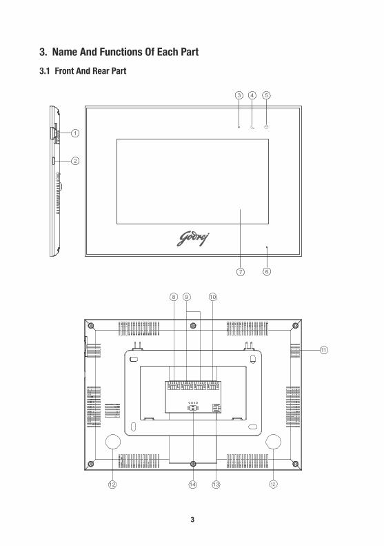
3. Name And Functions Of Each Part
3.1 Front And Rear Part
1
2
3 4 5
67
8 9 10
11
12131412

4
4 4 4Master Ext 1 Ext 2 Ext 34
4
2 2 2 2 2 2 2 2
4. Connection Diagram
4.1 System Layout
4.2 Wiring Diagram
Please be careful to wiring on polarity.
NO. Part Name Description
1 Micro SD Card Slot Socket for micro SD card
2 Micro USB SlotSocket for micro USB to Rj45 (only for monitor with WiFi)
3 Power Indicator White LED switches on when power is on
4 Do-not-disturb/Leaving Mode Indicator
Purple LED switches on when mute function is enabled /Purple LED flashes on when leaving mode is enabled
5 Message Indicator Green LED flashes when there is a new Image / video
6 Microphone Receives voice from the user
7 Screen 7” digital touch screen
8 CCTV Input Interface for CCTV 1 / CCTV 2
9 Video Input Interface for door station 1 / door station 2
10 Intercom Interface for extension monitors
11 Speaker
12 Foam Pasting Location Protection from deformation
13 DC Power Input Connector for DC adapter
14 Switch Impedance matching for video signal

5
» Intercom wiring diagram with one monitor.
GND
VD-IN
GND
VD-IN
SYV-75-5VIDEO2VCC 2GNDAUDIO2
CCTV2GND
CCTV1GND
GN
D
VCC
AD1GNDVCC1VD1
AD I/OGNDDATAVD I/O
AD2GNDVCC2VD2
SYV-75-5VIDEO1VCC 1GNDAUDIO1
» Intercom wiring diagram with master monitor and extensions (please pay attention to the impedance matching switch)
GND
VD-IN
GND
VD-IN
SYV-75-5VIDEO2VCC 2GNDAUDIO2
CCTV2GND
CCTV1GND
GN
D
VCC
AD1GNDVCC1VD1
AD I/OGNDDATAVD I/O
AD2GNDVCC2VD2
SYV-75-5VIDEO1VCC 1GNDAUDIO1
CCTV2GND
CCTV1GND
GN
D
VCC
AD1GNDVCC1VD1
AD I/OGNDDATAVD I/O
AD2GNDVCC2VD2
Master monitor
Extension 1
CCTV2GND
CCTV1GND
GN
D
VCC
AD1GNDVCC1VD1
AD I/OGNDDATAVD I/O
AD2GNDVCC2VD2
Extension N N≤3
ON
1 2
ON
1 2
ON
1 2
ON
1 2

6
5. Installation
» Monitor installation locationStandard monitor installation height is about 1,500mm where screen center is at eye level;
in this case, wall-hanging metal center is 1,450mm above ground level.
» Wiring and installation of indoor monitor1) Remove mounting bracket behind monitor and fix it on the wall with screws;
2) Pull the cable out and connect the system according to 4.2 wiring diagram;
3) Hang the monitor on the mounting bracket;
4) Plug DC adapter’s power plug into the power socket.
6.1 Main Screen
Touch the screen anywhere in standby mode, the main page will be shown as follows:
6. Operation Description
It will show corresponding functions on pressing each icon on the main screen. It will also
show the main setting page when you slide the main page to the right or left.

7
When door station calls in, the visitor’s image will be shown on the monitor screen and
you can press [Talk] icon to talk with the visitor and press it again to terminate the call.
6.2 Visitor Call
※ Icon Definition
capture a picture record a video
switch between door stations and CCTV cameras
talk
release the electric lock call transfer manually
adjust display parameters (brightness/color/contrast) and volume
back to main screen
During the talk :
• You can record a video or capture a picture from the calling door station
automatically depending on the system setting.
You can press [Change] icon to switch to another door station or CCTV camera, and
the current talk will be terminated.
You can press [Transfer] icon to transfer the current call to other extension monitors.
•
•

8
6.3 Monitor Function
When you press the [Camera] icon on the main screen, the system will enter monitor mode,
and will show image from the corresponding door station and CCTV camera.
6.4 Multimedia
6.4.1 Image & Video Storage
6.4.2 Image & Video Review
Press [Memory] icon on main screen, to review the image/video.The image/video list
with a red circle means that the image/video is not viewed. Press the corresponding
list directly to review the image/video.
Remark:
• The [Transfer] icon will be disabled in monitor mode.
If you insert micro SD card, the monitor can record images and videos; if you do not insert the
micro SD card, the monitor will capture only images.
Maximum Capacity: micro SD card:1000 images and 128 videos
Storage:100 images
When full, the newest image/video will automatically overwrite the oldest image/video.
Remark:
• Micro SD card must be formatted by the monitor before usage.
Micro SD card is excluded in the package.
The videos include both the video recorded during monitoring as well as during
motion detection.
•
•

9
6.6 WiFi Function (optional)
6.6.1 Add Device
The monitor can work as a WiFi hotspot and connect to the home router. The WiFi settings can be
controlled by cellphone which uses Android or IOS system .
6.5 Intercom Function
Press the [Intercom] icon on main screen, choose the monitor you want to call, and
then press [Call] icon to start the call. You can then talk with the corresponding monitor
if the called monitor answers the call. The talking and ringtone volume of the intercom can
be adjusted.
Press the [Setting] icon on the main screen and enter [Voicemail] setting page, press [For visitor]
icon, and then you can record and review messages.
6.4.3 Voicemail Function
recorddelete play returnprev next
Remarks:
• The monitor supports up to
two voice messages for
visitors. When full, the newest
message will automatically
overwrite the oldest message.
The voicemail function can
be supported with micro SD
card only.
•

10
◆ IOS system
① ② ③
④ ⑤ ⑥
※ Add a new device
1. When the monitor is in [WiFi] setting page, select “WiFi factory setting” item to reset WiFi;
2. IOS system should connect with monitor UID (starts with letters “UID”), while Android
system connects to home router before configuration.
3. Open the application «MyBell», press the “+” icon and select “New Device” item;
4. For IOS system select “Wi-Fi Config” item to go to the next step, while for Android system select
“next” and then select the right UID of the monitor go to next;
5. Input the WiFi password of the home router and wait for the device to configure successfully
(if IOS system is connected to home router before configuring, the user will only need to input
the WiFi password; if not, the WiFi name and password will need to be entered manually);
6. You can set the device name, channels and password can be modified after being configured
successfully.
Note 2: If your device's WiFi is
already configured before, please reset
WiFi first, you can operate it on your
door intercom monitor
11
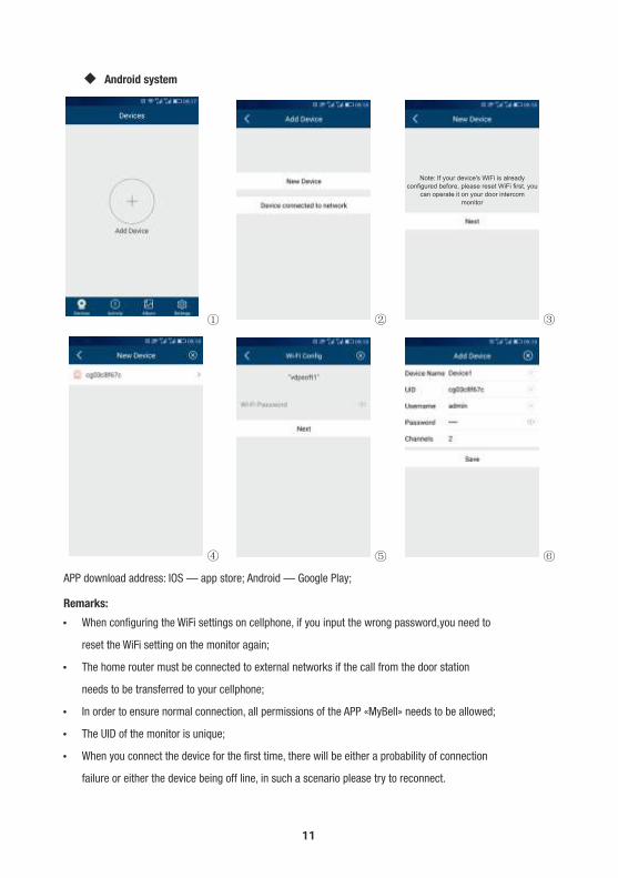
Remarks:
Ÿ When configuring the WiFi settings on cellphone, if you input the wrong password,you need to
reset the WiFi setting on the monitor again;
Ÿ The home router must be connected to external networks if the call from the door station
needs to be transferred to your cellphone;
Ÿ In order to ensure normal connection, all permissions of the APP «MyBell» needs to be allowed;
Ÿ The UID of the monitor is unique;
Ÿ When you connect the device for the first time, there will be either a probability of connection
failure or either the device being off line, in such a scenario please try to reconnect.
① ② ③
④ ⑤ ⑥
◆ Android system
APP download address: IOS — app store; Android — Google Play;
Note: If your device's WiFi is already
configured before, please reset WiFi first, you
can operate it on your door intercom
monitor

12
※ Add a connected device
Step 1&2 can refer to the above operation.
3. Open the application «MyBell», click the “+” icon and select “Device connected to network” icon;
4. Select “Online Device” or “Manual Adding” icon (select “online device” when cellphone and
device connect to the same wifi, select “manual adding” when cellphone and device connect to
different WiFi), and then select the UID of the monitor;
5. You can set the device name, channels, user name and password (the default password 1234).
6.6.2 Control The Monitor By Cellphone
1.Select the device and enter the monitor page;
2.Press the setting icon at the upper-right corner and set “Lock Number” to 2 and then press
the corresponding lock icon and input the password (1234), to release the door
lock and open the automatic door;
3.The monitor screen on the cellphone
can be switched to full-screen display mode;
4.An indoor monitor can support up to
four cellphones online at the same time.
※ Icon Definition
pause play
mute unmute
record a video capture a picture

13
6.7 Setting Page
Press the [Setting] icon on the main screen or slide the main page to the right or left, and then
the screen will display the main setting page.
6.6.3 Call Forwarding Latency
switch between CAM1/CAM2 full-screen display
release door lock hold to talk
release the electric lock open the automatic door
Remark:
• When you change the SIM card in the cellphone,
you need to restart “Ring Alerts” to ensure that the cellphone receives messages
normally.
1.When the monitor is in [WiFi] setting page, select "call forwarding
latency" icon to set the time for call forwarding latency;
2.Press the setting icon at the upper-right corner and turn “Ring
Alerts” to ON;
3.When door station calls in, the cellphone will receive a message
and will show the ringing page;
4.Press the accept icon and talk with the visitor;
5.Press the lock icon and input the password(1234), and then you
can release the door lock.
14
Ÿ In [Time] setting page, you can set the date & time of the monitor and select the date format.
Ÿ In [Mute] setting page,you can enable/disable the mute function and set the time range of do not disturb mode.
Ÿ In [General] setting page,you can set the language of the monitor and restore system to factory settings (except date & time, intercom address).
Ÿ In [Voicemail] setting page,you can select one voicemail for a visitor as the message to play in [Leaving] mode and delete all voicemails for visitor.You can also record and review voice message.
Ÿ In [WiFi] setting page,you can turn [WiFi] on or off and set call forwarding latency for the monitor,you can also reset WiFi settings.
Ÿ In [Rec] setting page,you can turn [Monitor record] on or off and select picture or video record mode.
Ÿ In [Melody] setting page,you can set the ring melody for CAM1/CAM2/Intercom and set ring time.
Ÿ In [Memory] setting page,you can delete all images or videos in the micro SD card or FLASH, copy all images in the FLASH to micro SD card and format micro SD card.
Ÿ In [Motion detection] setting page, you can turn [Motion detection] on or off, set one camera as default for motion detection, set frame rate and time range of motion detection.
Ÿ In [Address] setting page, you can set the intercom address of the monitor. The address of different monitors in one network cannot be duplicated.
Remarks:
Ÿ The Voicemail message is stored on the micro SD card. To record and review message, please see 6.4.3.
Ÿ If you want to use voicemail function normally, you’ll need to turn off “Call forwarding latency” and make sure that the monitor is in “Leaving” mode.
Ÿ The WiFi function is enabled only when the address of the indoor monitor is set up as “Master”.
Ÿ Once a moving object is detected, the monitor will record a video of 15s automatically. When monitoring door station or CCTV, motion detection will pause until the monitoring ends.
Ÿ 4G micro SD supports 4 motion detection videos and 128 monitor videos; 8G or above 8G, supports 128 motion detection videos and 128 monitor videos.

15
7. Specifications
Category Specification
Input power DC: 14.5V
TFT LCD 7 inch digital IPS LCD
LCD Resolution 1024(RGB) x 600
Connection with door station Support two 4-wire door stations
Connection with extension monitor Support three extension monitors
Connection with CCTV Support two 2-wire CCTV input
Memory capacityMicro SD card: 1000 images, 128 videosStorage: 100 images
Dimensions (mm)222(W) x 154(H) x 9.9(D) (without wall bracket)
222(W) x 154(H) x 14.6(D) (with wall bracket)
Category Specification
Input power AC:150V~240V,0.35A,50Hz/60Hz
Output power DC:14.5V,0.8A
Dimensions(mm) 45 (W) * 45 (H) * 30 (D)
※ Power supply
※ Indoor monitor

NOTES

NOTES

Godrej & Boyce Mfg. Co. Ltd.Godrej Security SolutionsRegd. Office: Plant No. 17, Pirojshanagar, Vikhroli, Mumbai 400 079Tel: 022-67961700/1800 Fax: 91-22-67961509Toll-free: 1800 209 9955 | SMS 'GSS' to 53636 | Email: [email protected] | Visit: www.godrejsecure.com
In view of the Godrej Policy of continuous development and improvement, the dimensions of the products as seen on the catalogue may not match with the actual product. The colour combinations of the products as seen on the catalogue may vary and not match with the actual colour of the product due to printing limitations.
An ISO 9001:2008, ISO 14001:2004 & BS OHSAS 18001:2007Products Marketed and Serviced By Godrej & Boyce Mfg. Co. Ltd.