La necropoli delle Coste di S.Febronia presso Palagonia, Kokalos 39-40, 1993-1994, pp.881-900.
Upload
khangminh22Category
view
1download
0
881/882 Video Test Instrument
User Guide - 882EA for HDMI

881/882 Video Test Instrument, User Guide, Revision A.38 (10/18/13)
Copyright 2012 Quantum Data. All rights reserved.
The information in this document is provided for use by our customers and may not be incorporated into other products or publications without
the expressed written consent of Quantum Data. Quantum Data reserves the right to make changes to its products to improve performance,
reliability, producibility, and (or) marketability. Information furnished by Quantum Data is believed to be accurate and reliable. However, no
responsibility is assumed by Quantum Data for its use.
Updates to this manual are available at http://www.quantumdata.com/support/downloads/.

881/882 Video Test Instrument User Guide (Rev A.37) 1
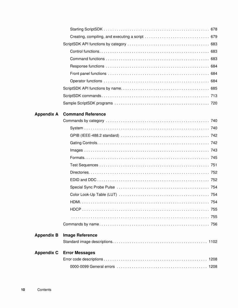
Table of Contents
Chapter 1 Getting Started
Introduction . . . . . . . . . . . . . . . . . . . . . . . . . . . . . . . . . . . . . . . . . . . . . . . . . . . . . . . . . . . . 2
Video interfaces . . . . . . . . . . . . . . . . . . . . . . . . . . . . . . . . . . . . . . . . . . . . . . . . . . . . . . . . 5
Computer interfaces . . . . . . . . . . . . . . . . . . . . . . . . . . . . . . . . . . . . . . . . . . . . . . . . . . . . . 7
Front panel interface . . . . . . . . . . . . . . . . . . . . . . . . . . . . . . . . . . . . . . . . . . . . . . . . . . . . . 9
Status indicators . . . . . . . . . . . . . . . . . . . . . . . . . . . . . . . . . . . . . . . . . . . . . . . . . . . . . 9
Menu selection keys . . . . . . . . . . . . . . . . . . . . . . . . . . . . . . . . . . . . . . . . . . . . . . . . . 10
882 file system and media . . . . . . . . . . . . . . . . . . . . . . . . . . . . . . . . . . . . . . . . . . . . . . . 13
882 file system . . . . . . . . . . . . . . . . . . . . . . . . . . . . . . . . . . . . . . . . . . . . . . . . . . . . . 13
882 media . . . . . . . . . . . . . . . . . . . . . . . . . . . . . . . . . . . . . . . . . . . . . . . . . . . . . . . . . 13
882 operational modes . . . . . . . . . . . . . . . . . . . . . . . . . . . . . . . . . . . . . . . . . . . . . . . . . . 14
Booting up the 882 . . . . . . . . . . . . . . . . . . . . . . . . . . . . . . . . . . . . . . . . . . . . . . . . . . 14
Basic mode. . . . . . . . . . . . . . . . . . . . . . . . . . . . . . . . . . . . . . . . . . . . . . . . . . . . . . . . 15
Browse mode . . . . . . . . . . . . . . . . . . . . . . . . . . . . . . . . . . . . . . . . . . . . . . . . . . . . . . 15
Web interface . . . . . . . . . . . . . . . . . . . . . . . . . . . . . . . . . . . . . . . . . . . . . . . . . . . . . . . . . 20
Working with the Virtual Front Panel . . . . . . . . . . . . . . . . . . . . . . . . . . . . . . . . . . . . 20
Working with the CMD (Command) Terminal . . . . . . . . . . . . . . . . . . . . . . . . . . . . . . 22
Working with the 882 FTP Browser . . . . . . . . . . . . . . . . . . . . . . . . . . . . . . . . . . . . . 23
Copying files between 882s . . . . . . . . . . . . . . . . . . . . . . . . . . . . . . . . . . . . . . . . . . . 27
Command line interface . . . . . . . . . . . . . . . . . . . . . . . . . . . . . . . . . . . . . . . . . . . . . . . . . 30
Working with the serial interface. . . . . . . . . . . . . . . . . . . . . . . . . . . . . . . . . . . . . . . . 30
Working with the network interface. . . . . . . . . . . . . . . . . . . . . . . . . . . . . . . . . . . . . . 33
Sending commands interactively . . . . . . . . . . . . . . . . . . . . . . . . . . . . . . . . . . . . . . . 34
Sending command files (serial interface only) . . . . . . . . . . . . . . . . . . . . . . . . . . . . . 34
Working with user profiles . . . . . . . . . . . . . . . . . . . . . . . . . . . . . . . . . . . . . . . . . . . . . . . 36
Chapter 2 Testing Video Displays
General video display testing procedures . . . . . . . . . . . . . . . . . . . . . . . . . . . . . . . . . . . . 40
Making physical connection . . . . . . . . . . . . . . . . . . . . . . . . . . . . . . . . . . . . . . . . . . . 40
Selecting interface type . . . . . . . . . . . . . . . . . . . . . . . . . . . . . . . . . . . . . . . . . . . . . . 41

2 Contents
Selecting video format . . . . . . . . . . . . . . . . . . . . . . . . . . . . . . . . . . . . . . . . . . . . . . . 43
Selecting image . . . . . . . . . . . . . . . . . . . . . . . . . . . . . . . . . . . . . . . . . . . . . . . . . . . . 47
Testing analog computer (IT) CRTs . . . . . . . . . . . . . . . . . . . . . . . . . . . . . . . . . . . . . . . . 52
Testing digital computer (IT) FPDs . . . . . . . . . . . . . . . . . . . . . . . . . . . . . . . . . . . . . . . . . 55
Testing analog composite video SDTV (CE) CRTs . . . . . . . . . . . . . . . . . . . . . . . . . . . . 58
Testing analog component video SDTV (CE) CRTs . . . . . . . . . . . . . . . . . . . . . . . . . . . . 61
Testing digital component video HDTV (CE) FPDs . . . . . . . . . . . . . . . . . . . . . . . . . . . . 64
Using the Image Caching feature . . . . . . . . . . . . . . . . . . . . . . . . . . . . . . . . . . . . . . . . . . 69
Using the AuxTest image . . . . . . . . . . . . . . . . . . . . . . . . . . . . . . . . . . . . . . . . . . . . . . . . 71
Using the ImageShift utility . . . . . . . . . . . . . . . . . . . . . . . . . . . . . . . . . . . . . . . . . . . . . . . 73
Using the ImageShift utility through the front panel . . . . . . . . . . . . . . . . . . . . . . . . . 73
Using the ImageShift utility through the command line interface . . . . . . . . . . . . . . . 76
Adjust Frequency Function . . . . . . . . . . . . . . . . . . . . . . . . . . . . . . . . . . . . . . . . . . . . . . . 78
Keypad Utility . . . . . . . . . . . . . . . . . . . . . . . . . . . . . . . . . . . . . . . . . . . . . . . . . . . . . . . . . 79
Chapter 3 Administrative Tasks
Overview . . . . . . . . . . . . . . . . . . . . . . . . . . . . . . . . . . . . . . . . . . . . . . . . . . . . . . . . . . . . . 84
Calibrating the generator. . . . . . . . . . . . . . . . . . . . . . . . . . . . . . . . . . . . . . . . . . . . . . . . . 85
Calibrating signal level . . . . . . . . . . . . . . . . . . . . . . . . . . . . . . . . . . . . . . . . . . . . . . . 85
Calibrating frequency . . . . . . . . . . . . . . . . . . . . . . . . . . . . . . . . . . . . . . . . . . . . . . . . 86
Auto Upgrade . . . . . . . . . . . . . . . . . . . . . . . . . . . . . . . . . . . . . . . . . . . . . . . . . . . . . . . . . 88
Auto upgrade - Network Method. . . . . . . . . . . . . . . . . . . . . . . . . . . . . . . . . . . . . . . . 88
Auto upgrade - PCMCIA/Compact Flash Method. . . . . . . . . . . . . . . . . . . . . . . . . . . 95
Upgrading the generator locally . . . . . . . . . . . . . . . . . . . . . . . . . . . . . . . . . . . . . . . . . . 107
Manually upgrading using PCMCIA Compact Flash card. . . . . . . . . . . . . . . . . . . . 107
Manually upgrading the generator without using PC Card . . . . . . . . . . . . . . . . . . . 110
Connecting generator directly to a PC . . . . . . . . . . . . . . . . . . . . . . . . . . . . . . . . . . 112
Reconfiguring and booting a stalled generator . . . . . . . . . . . . . . . . . . . . . . . . . . . . . . . 117
Cloning generators . . . . . . . . . . . . . . . . . . . . . . . . . . . . . . . . . . . . . . . . . . . . . . . . . . . . 122
Cloning a generator using the PC card. . . . . . . . . . . . . . . . . . . . . . . . . . . . . . . . . . 122
Cloning a generator using the Generator FTP Browser . . . . . . . . . . . . . . . . . . . . . 123
Resetting a generator . . . . . . . . . . . . . . . . . . . . . . . . . . . . . . . . . . . . . . . . . . . . . . . . . . 126
Viewing generator configuration information. . . . . . . . . . . . . . . . . . . . . . . . . . . . . . . . . 127

881/882 Video Test Instrument User Guide (Rev A.37) 3
Chapter 4 Networking 882s
Overview . . . . . . . . . . . . . . . . . . . . . . . . . . . . . . . . . . . . . . . . . . . . . . . . . . . . . . . . . . . . 134
882 file system . . . . . . . . . . . . . . . . . . . . . . . . . . . . . . . . . . . . . . . . . . . . . . . . . . . . 134
Configuring a file server . . . . . . . . . . . . . . . . . . . . . . . . . . . . . . . . . . . . . . . . . . . . . . . . 135
File server specifications . . . . . . . . . . . . . . . . . . . . . . . . . . . . . . . . . . . . . . . . . . . . 135
Installing an FTP server . . . . . . . . . . . . . . . . . . . . . . . . . . . . . . . . . . . . . . . . . . . . . 135
Copying resource files to the FTP site on the file server . . . . . . . . . . . . . . . . . . . . 138
Establishing a network environment . . . . . . . . . . . . . . . . . . . . . . . . . . . . . . . . . . . . . . . 140
Connecting 882s to the network . . . . . . . . . . . . . . . . . . . . . . . . . . . . . . . . . . . . . . . 140
Setting the 882’s IP address. . . . . . . . . . . . . . . . . . . . . . . . . . . . . . . . . . . . . . . . . . 141
Setting the file server IP address in the 882 . . . . . . . . . . . . . . . . . . . . . . . . . . . . . . 144
Network operations . . . . . . . . . . . . . . . . . . . . . . . . . . . . . . . . . . . . . . . . . . . . . . . . . . . . 146
Booting a 882 from the file server. . . . . . . . . . . . . . . . . . . . . . . . . . . . . . . . . . . . . . 146
Sharing objects on a file server . . . . . . . . . . . . . . . . . . . . . . . . . . . . . . . . . . . . . . . 147
Controlling a 882 remotely . . . . . . . . . . . . . . . . . . . . . . . . . . . . . . . . . . . . . . . . . . . . . . 149
Using the Virtual Front Panel to operate a 882 remotely . . . . . . . . . . . . . . . . . . . . 149
Operating the 882 remotely through the command line interface. . . . . . . . . . . . . . 149
Upgrading 882s over a network . . . . . . . . . . . . . . . . . . . . . . . . . . . . . . . . . . . . . . . . . . 150
Upgrade options and procedures . . . . . . . . . . . . . . . . . . . . . . . . . . . . . . . . . . . . . . 150
Backing up the current files on the file server. . . . . . . . . . . . . . . . . . . . . . . . . . . . . 150
Copying files to the PC file server. . . . . . . . . . . . . . . . . . . . . . . . . . . . . . . . . . . . . . 151
Removing current files from the 882s . . . . . . . . . . . . . . . . . . . . . . . . . . . . . . . . . . . 152
Copying the new files to each 882 . . . . . . . . . . . . . . . . . . . . . . . . . . . . . . . . . . . . . 152
Reboot the 882s . . . . . . . . . . . . . . . . . . . . . . . . . . . . . . . . . . . . . . . . . . . . . . . . . . . 152
Cloning 882s using the 882 FTP Browser. . . . . . . . . . . . . . . . . . . . . . . . . . . . . . . . . . . 153
Chapter 5 Using GPIB Interface
Overview . . . . . . . . . . . . . . . . . . . . . . . . . . . . . . . . . . . . . . . . . . . . . . . . . . . . . . . . . . . . 156
Setting the GPIB port address . . . . . . . . . . . . . . . . . . . . . . . . . . . . . . . . . . . . . . . . . . . 157
Queries and commands . . . . . . . . . . . . . . . . . . . . . . . . . . . . . . . . . . . . . . . . . . . . . . . . 159
Commands . . . . . . . . . . . . . . . . . . . . . . . . . . . . . . . . . . . . . . . . . . . . . . . . . . . . . . . 159
Queries . . . . . . . . . . . . . . . . . . . . . . . . . . . . . . . . . . . . . . . . . . . . . . . . . . . . . . . . . . 160
Sending commands and queries . . . . . . . . . . . . . . . . . . . . . . . . . . . . . . . . . . . . . . 161
Status queries and control . . . . . . . . . . . . . . . . . . . . . . . . . . . . . . . . . . . . . . . . . . . . . . 163

4 Contents
Status byte . . . . . . . . . . . . . . . . . . . . . . . . . . . . . . . . . . . . . . . . . . . . . . . . . . . . . . . 163
Bus commands . . . . . . . . . . . . . . . . . . . . . . . . . . . . . . . . . . . . . . . . . . . . . . . . . . . . 165
Chapter 6 Working with Formats
Overview . . . . . . . . . . . . . . . . . . . . . . . . . . . . . . . . . . . . . . . . . . . . . . . . . . . . . . . . . . . . 168
Format library . . . . . . . . . . . . . . . . . . . . . . . . . . . . . . . . . . . . . . . . . . . . . . . . . . . . . . . . 169
Composite television format names . . . . . . . . . . . . . . . . . . . . . . . . . . . . . . . . . . . . 169
Component television format names . . . . . . . . . . . . . . . . . . . . . . . . . . . . . . . . . . . 170
Computer display format names. . . . . . . . . . . . . . . . . . . . . . . . . . . . . . . . . . . . . . . 171
Aperture designators . . . . . . . . . . . . . . . . . . . . . . . . . . . . . . . . . . . . . . . . . . . . . . . 172
Viewing the source list of formats . . . . . . . . . . . . . . . . . . . . . . . . . . . . . . . . . . . . . . . . . 174
Configuring format parameters . . . . . . . . . . . . . . . . . . . . . . . . . . . . . . . . . . . . . . . . . . . 175
Viewing and modifying format parameters through the front panel . . . . . . . . . . . . 175
Viewing and modifying format parameters via the command line . . . . . . . . . . . . . 179
Viewing and modifying format parameters by editing XML files . . . . . . . . . . . . . . . 180
Format Editor Overview . . . . . . . . . . . . . . . . . . . . . . . . . . . . . . . . . . . . . . . . . . . . . . . . 182
Format Editor - Basic Window Configuration and Operation . . . . . . . . . . . . . . . . . 182
Format Editor - Top Level Menus . . . . . . . . . . . . . . . . . . . . . . . . . . . . . . . . . . . . . . 183
Format Editor - Menu Buttons. . . . . . . . . . . . . . . . . . . . . . . . . . . . . . . . . . . . . . . . . 185
Format Editor - New Format . . . . . . . . . . . . . . . . . . . . . . . . . . . . . . . . . . . . . . . . . . 186
Format Editor - New Report . . . . . . . . . . . . . . . . . . . . . . . . . . . . . . . . . . . . . . . . . . 207
Format Editor - New Source Menu . . . . . . . . . . . . . . . . . . . . . . . . . . . . . . . . . . . . . 211
Format Editor - Open . . . . . . . . . . . . . . . . . . . . . . . . . . . . . . . . . . . . . . . . . . . . . . . 213
Format Editor - Save. . . . . . . . . . . . . . . . . . . . . . . . . . . . . . . . . . . . . . . . . . . . . . . . 214
Creating a new format using the Format Editor . . . . . . . . . . . . . . . . . . . . . . . . . . . . . . 215
Creating custom formats using the command line interface . . . . . . . . . . . . . . . . . . . . . 220
Format catalogs . . . . . . . . . . . . . . . . . . . . . . . . . . . . . . . . . . . . . . . . . . . . . . . . . . . . . . 221
Using format catalogs. . . . . . . . . . . . . . . . . . . . . . . . . . . . . . . . . . . . . . . . . . . . . . . 221
Creating format catalogs. . . . . . . . . . . . . . . . . . . . . . . . . . . . . . . . . . . . . . . . . . . . . 222
Deleting format catalogs . . . . . . . . . . . . . . . . . . . . . . . . . . . . . . . . . . . . . . . . . . . . . 223
Chapter 7 Working with Images
Overview . . . . . . . . . . . . . . . . . . . . . . . . . . . . . . . . . . . . . . . . . . . . . . . . . . . . . . . . . . . . 228
Viewing the Content list of images . . . . . . . . . . . . . . . . . . . . . . . . . . . . . . . . . . . . . . . . 229
Viewing and modifying image options . . . . . . . . . . . . . . . . . . . . . . . . . . . . . . . . . . 229

881/882 Video Test Instrument User Guide (Rev A.37) 5
Viewing image versions . . . . . . . . . . . . . . . . . . . . . . . . . . . . . . . . . . . . . . . . . . . . . 229
Creating custom images . . . . . . . . . . . . . . . . . . . . . . . . . . . . . . . . . . . . . . . . . . . . . . . . 232
Rendering bitmap images . . . . . . . . . . . . . . . . . . . . . . . . . . . . . . . . . . . . . . . . . . . . . . . 235
Setting image component values . . . . . . . . . . . . . . . . . . . . . . . . . . . . . . . . . . . . . . . . . 237
Creating image catalogs . . . . . . . . . . . . . . . . . . . . . . . . . . . . . . . . . . . . . . . . . . . . . . . . 239
Creating an image catalog . . . . . . . . . . . . . . . . . . . . . . . . . . . . . . . . . . . . . . . . . . . 239
Deleting an image catalog . . . . . . . . . . . . . . . . . . . . . . . . . . . . . . . . . . . . . . . . . . . 243
Chapter 8 Working with Test Sequences
Overview . . . . . . . . . . . . . . . . . . . . . . . . . . . . . . . . . . . . . . . . . . . . . . . . . . . . . . . . . . . . 248
Viewing the test sequence list. . . . . . . . . . . . . . . . . . . . . . . . . . . . . . . . . . . . . . . . . . . . 249
Viewing the test sequence list using the front panel. . . . . . . . . . . . . . . . . . . . . . . . 249
Viewing the test sequence list using the command line interface. . . . . . . . . . . . . . 249
Running a test sequence . . . . . . . . . . . . . . . . . . . . . . . . . . . . . . . . . . . . . . . . . . . . . . . 251
Running a test sequence using the front panel . . . . . . . . . . . . . . . . . . . . . . . . . . . 251
Running a test sequence using the command line interface . . . . . . . . . . . . . . . . . 252
Creating a test sequence . . . . . . . . . . . . . . . . . . . . . . . . . . . . . . . . . . . . . . . . . . . . . . . 254
Creating a test sequence using the command line interface . . . . . . . . . . . . . . . . . 254
Editing a test sequence XML file . . . . . . . . . . . . . . . . . . . . . . . . . . . . . . . . . . . . . . 258
Deleting a test sequence. . . . . . . . . . . . . . . . . . . . . . . . . . . . . . . . . . . . . . . . . . . . . . . . 261
Chapter 9 Analyzing Digital Sources and Cables
Getting started. . . . . . . . . . . . . . . . . . . . . . . . . . . . . . . . . . . . . . . . . . . . . . . . . . . . . . . . 264
Analyzer connections . . . . . . . . . . . . . . . . . . . . . . . . . . . . . . . . . . . . . . . . . . . . . . . 265
Measuring timing of video signal. . . . . . . . . . . . . . . . . . . . . . . . . . . . . . . . . . . . . . . . . . 270
Measuring timing parameters . . . . . . . . . . . . . . . . . . . . . . . . . . . . . . . . . . . . . . . . . 270
Testing cables and distribution systems . . . . . . . . . . . . . . . . . . . . . . . . . . . . . . . . . . . . 277
Testing video signal quality from a source . . . . . . . . . . . . . . . . . . . . . . . . . . . . . . . . . . 281
Running the Pseudo-Random Noise test . . . . . . . . . . . . . . . . . . . . . . . . . . . . . . . . 281
Running the Pixel Error test . . . . . . . . . . . . . . . . . . . . . . . . . . . . . . . . . . . . . . . . . . 286
Running the ViewPix test . . . . . . . . . . . . . . . . . . . . . . . . . . . . . . . . . . . . . . . . . . . . 292
Generating Pseudo-random noise . . . . . . . . . . . . . . . . . . . . . . . . . . . . . . . . . . . . . 295
Testing InfoFrames (HDMI only) . . . . . . . . . . . . . . . . . . . . . . . . . . . . . . . . . . . . . . . . . . 296
Testing HDMI transmit device InfoFrame capability . . . . . . . . . . . . . . . . . . . . . . . . 296
Testing audio (HDMI only) . . . . . . . . . . . . . . . . . . . . . . . . . . . . . . . . . . . . . . . . . . . . . . 304

6 Contents
Monitoring HDMI audio from a source device. . . . . . . . . . . . . . . . . . . . . . . . . . . . . 304
Viewing the SPDIF audio metadata from a source device . . . . . . . . . . . . . . . . . . . 308
Controlling the analyzer using the command line interface. . . . . . . . . . . . . . . . . . . . . . 310
Signal timing analysis commands. . . . . . . . . . . . . . . . . . . . . . . . . . . . . . . . . . . . . . 310
Pseudo-random noise generation commands . . . . . . . . . . . . . . . . . . . . . . . . . . . . 311
Analyzing pixel data (pixel error test) . . . . . . . . . . . . . . . . . . . . . . . . . . . . . . . . . . . 313
Reading pixel data . . . . . . . . . . . . . . . . . . . . . . . . . . . . . . . . . . . . . . . . . . . . . . . . . 314
Controlling the analyzer with Signal Analysis Module. . . . . . . . . . . . . . . . . . . . . . . . . . 316
Setting up the Signal Analysis Module . . . . . . . . . . . . . . . . . . . . . . . . . . . . . . . . . . 316
Chapter 10 Testing HDMI Sink Devices
Overview of HDMI display testing . . . . . . . . . . . . . . . . . . . . . . . . . . . . . . . . . . . . . . . . . 326
Physical connections . . . . . . . . . . . . . . . . . . . . . . . . . . . . . . . . . . . . . . . . . . . . . . . 326
Format selection . . . . . . . . . . . . . . . . . . . . . . . . . . . . . . . . . . . . . . . . . . . . . . . . . . . 327
Image selection. . . . . . . . . . . . . . . . . . . . . . . . . . . . . . . . . . . . . . . . . . . . . . . . . . . . 330
Setting up the 882 for HDMI testing . . . . . . . . . . . . . . . . . . . . . . . . . . . . . . . . . . . . . . . 331
Selecting video format . . . . . . . . . . . . . . . . . . . . . . . . . . . . . . . . . . . . . . . . . . . . . . 332
Testing HDMI displays . . . . . . . . . . . . . . . . . . . . . . . . . . . . . . . . . . . . . . . . . . . . . . . . . 336
Testing HDMI 1.3 displays . . . . . . . . . . . . . . . . . . . . . . . . . . . . . . . . . . . . . . . . . . . . . . 338
Testing Deep Color. . . . . . . . . . . . . . . . . . . . . . . . . . . . . . . . . . . . . . . . . . . . . . . . . 338
Testing xvYCC . . . . . . . . . . . . . . . . . . . . . . . . . . . . . . . . . . . . . . . . . . . . . . . . . . . . 349
Testing HDMI 1.4 displays with 3D . . . . . . . . . . . . . . . . . . . . . . . . . . . . . . . . . . . . . . . . 356
Rendering 3D images. . . . . . . . . . . . . . . . . . . . . . . . . . . . . . . . . . . . . . . . . . . . . . . 356
Testing HDMI video pixel repetition (882 only) . . . . . . . . . . . . . . . . . . . . . . . . . . . . . . . 363
Testing HDMI audio . . . . . . . . . . . . . . . . . . . . . . . . . . . . . . . . . . . . . . . . . . . . . . . . . . . 367
Testing 2-channel HDMI audio output from internal SPDIF source . . . . . . . . . . . . 367
Testing 8-channel HDMI audio output from internal source . . . . . . . . . . . . . . . . . . 370
Testing multi-channel compressed HDMI audio formats . . . . . . . . . . . . . . . . . . . . 374
Testing HDMI audio using an external audio source . . . . . . . . . . . . . . . . . . . . . . . 377
Testing HDMI InfoFrames (882 only) . . . . . . . . . . . . . . . . . . . . . . . . . . . . . . . . . . . . . . 380
Viewing InfoFrame contents (882 only) . . . . . . . . . . . . . . . . . . . . . . . . . . . . . . . . . 380
Testing with Active Format Description (AFD) (882 only). . . . . . . . . . . . . . . . . . . . 385
Chapter 11 CEC Interactive Troubleshooting Environment (ITE)
Overview . . . . . . . . . . . . . . . . . . . . . . . . . . . . . . . . . . . . . . . . . . . . . . . . . . . . . . . . . . . . 390

881/882 Video Test Instrument User Guide (Rev A.37) 7
CEC Introduction. . . . . . . . . . . . . . . . . . . . . . . . . . . . . . . . . . . . . . . . . . . . . . . . . . . . . . 391
CEC devices. . . . . . . . . . . . . . . . . . . . . . . . . . . . . . . . . . . . . . . . . . . . . . . . . . . . . . 391
CEC features . . . . . . . . . . . . . . . . . . . . . . . . . . . . . . . . . . . . . . . . . . . . . . . . . . . . . 392
Testing CEC Devices . . . . . . . . . . . . . . . . . . . . . . . . . . . . . . . . . . . . . . . . . . . . . . . . . . 393
Testing CEC devices for messaging. . . . . . . . . . . . . . . . . . . . . . . . . . . . . . . . . . . . 393
Stress testing a CEC device . . . . . . . . . . . . . . . . . . . . . . . . . . . . . . . . . . . . . . . . . . 407
Controlling the Audio Return Channel (ARC) . . . . . . . . . . . . . . . . . . . . . . . . . . . . . 424
CEC Bus Monitor . . . . . . . . . . . . . . . . . . . . . . . . . . . . . . . . . . . . . . . . . . . . . . . . . . . . . 430
Activating the CEC bus monitor . . . . . . . . . . . . . . . . . . . . . . . . . . . . . . . . . . . . . . . 430
Querying the CEC bus monitor. . . . . . . . . . . . . . . . . . . . . . . . . . . . . . . . . . . . . . . . 430
Chapter 12 CEC Compliance Testing
Overview . . . . . . . . . . . . . . . . . . . . . . . . . . . . . . . . . . . . . . . . . . . . . . . . . . . . . . . . . . . . 436
CEC Compliance Controller . . . . . . . . . . . . . . . . . . . . . . . . . . . . . . . . . . . . . . . . . . 436
TME . . . . . . . . . . . . . . . . . . . . . . . . . . . . . . . . . . . . . . . . . . . . . . . . . . . . . . . . . . . . 436
CEC Introduction. . . . . . . . . . . . . . . . . . . . . . . . . . . . . . . . . . . . . . . . . . . . . . . . . . . . . . 438
CEC devices. . . . . . . . . . . . . . . . . . . . . . . . . . . . . . . . . . . . . . . . . . . . . . . . . . . . . . 438
CEC features . . . . . . . . . . . . . . . . . . . . . . . . . . . . . . . . . . . . . . . . . . . . . . . . . . . . . 438
Setting up CEC compliance testing. . . . . . . . . . . . . . . . . . . . . . . . . . . . . . . . . . . . . . . . 440
Running the CEC Compliance Test . . . . . . . . . . . . . . . . . . . . . . . . . . . . . . . . . . . . . . . 447
CEC Compliance test procedure . . . . . . . . . . . . . . . . . . . . . . . . . . . . . . . . . . . . . . 447
Running the CEC Compliance Test with the TME Software . . . . . . . . . . . . . . . . . . . . . 456
Completing the Capabilities Declaration Form (CDF). . . . . . . . . . . . . . . . . . . . . . . 458
Running the CEC Compliance Test . . . . . . . . . . . . . . . . . . . . . . . . . . . . . . . . . . . . 464
Viewing the results of the CEC compliance test . . . . . . . . . . . . . . . . . . . . . . . . . . . 473
Chapter 13 Auxiliary Channel Analyzer
Auxiliary Channel Analyzer Overview . . . . . . . . . . . . . . . . . . . . . . . . . . . . . . . . . . . . . . 478
Setting up and using the ACA . . . . . . . . . . . . . . . . . . . . . . . . . . . . . . . . . . . . . . . . . . . . 479
Monitoring the HDMI auxiliary channels . . . . . . . . . . . . . . . . . . . . . . . . . . . . . . . . . . . . 487
Chapter 14 Testing EDID for HDMI
Overview . . . . . . . . . . . . . . . . . . . . . . . . . . . . . . . . . . . . . . . . . . . . . . . . . . . . . . . . . . . . 500
Testing with display (sink) devices . . . . . . . . . . . . . . . . . . . . . . . . . . . . . . . . . . . . . . . . 501
Viewing EDID from a display (882 only) . . . . . . . . . . . . . . . . . . . . . . . . . . . . . . . . . 501

8 Contents
Generating an EDID Information Report. . . . . . . . . . . . . . . . . . . . . . . . . . . . . . . . . 504
Modifying EDID in a display . . . . . . . . . . . . . . . . . . . . . . . . . . . . . . . . . . . . . . . . . . 506
Testing with source devices . . . . . . . . . . . . . . . . . . . . . . . . . . . . . . . . . . . . . . . . . . . . . 508
Capturing and storing EDID from display device . . . . . . . . . . . . . . . . . . . . . . . . . . 508
Creating or editing EDID contents . . . . . . . . . . . . . . . . . . . . . . . . . . . . . . . . . . . . . 509
Testing EDID for HDMI compliance in display (sink) devices . . . . . . . . . . . . . . . . . . . . 512
Testing HDMI sink device for EDID compliance . . . . . . . . . . . . . . . . . . . . . . . . . . . 512
Verifying pixel encoding and rate support. . . . . . . . . . . . . . . . . . . . . . . . . . . . . . . . 537
Testing EDID for HDMI compliance in source devices . . . . . . . . . . . . . . . . . . . . . . . . . 540
Overview of HDMI compliance testing . . . . . . . . . . . . . . . . . . . . . . . . . . . . . . . . . . 540
Testing HDMI source devices for EDID compliance . . . . . . . . . . . . . . . . . . . . . . . 540
EDID emulation for physical layer testing of source devices . . . . . . . . . . . . . . . . . . . . 544
Using the EDID Editor tool . . . . . . . . . . . . . . . . . . . . . . . . . . . . . . . . . . . . . . . . . . . . . . 546
Loading EDIDs with the EDID Editor . . . . . . . . . . . . . . . . . . . . . . . . . . . . . . . . . . . 546
Editing an existing EDID. . . . . . . . . . . . . . . . . . . . . . . . . . . . . . . . . . . . . . . . . . . . . 550
Creating a new EDID . . . . . . . . . . . . . . . . . . . . . . . . . . . . . . . . . . . . . . . . . . . . . . . 553
Saving an EDID to a file . . . . . . . . . . . . . . . . . . . . . . . . . . . . . . . . . . . . . . . . . . . . . 562
Putting (Writing) EDID to a display . . . . . . . . . . . . . . . . . . . . . . . . . . . . . . . . . . . . . 563
Running an EDID HDMI compliance test . . . . . . . . . . . . . . . . . . . . . . . . . . . . . . . . 564
Running an EDID data report . . . . . . . . . . . . . . . . . . . . . . . . . . . . . . . . . . . . . . . . . 565
Testing a Source’s Response by Emulating EDIDs . . . . . . . . . . . . . . . . . . . . . . . . . . . 567
Using the EDID Compare tool. . . . . . . . . . . . . . . . . . . . . . . . . . . . . . . . . . . . . . . . . . . . 568
Comparing EDIDs. . . . . . . . . . . . . . . . . . . . . . . . . . . . . . . . . . . . . . . . . . . . . . . . . . 568
Chapter 15 Testing HDCP on HDMI & MHL
Overview . . . . . . . . . . . . . . . . . . . . . . . . . . . . . . . . . . . . . . . . . . . . . . . . . . . . . . . . . . . . 572
Testing DVI displays with HDCP. . . . . . . . . . . . . . . . . . . . . . . . . . . . . . . . . . . . . . . . . . 573
Testing HDMI displays with HDCP . . . . . . . . . . . . . . . . . . . . . . . . . . . . . . . . . . . . . . . . 575
Running HDCP test in step mode . . . . . . . . . . . . . . . . . . . . . . . . . . . . . . . . . . . . . . . . . 578
Running an HDMI HDCP self-test. . . . . . . . . . . . . . . . . . . . . . . . . . . . . . . . . . . . . . . . . 580
Understanding the HDCP test. . . . . . . . . . . . . . . . . . . . . . . . . . . . . . . . . . . . . . . . . . . . 581
HDMI HDCP test sequence: . . . . . . . . . . . . . . . . . . . . . . . . . . . . . . . . . . . . . . . . . . 581
Running the HDCP compliance test for HDMI devices with the 882EA . . . . . . . . . . . . 582
Overview. . . . . . . . . . . . . . . . . . . . . . . . . . . . . . . . . . . . . . . . . . . . . . . . . . . . . . . . . 582

881/882 Video Test Instrument User Guide (Rev A.37) 9
Encryption Status Tester . . . . . . . . . . . . . . . . . . . . . . . . . . . . . . . . . . . . . . . . . . . . 583
List of Tests . . . . . . . . . . . . . . . . . . . . . . . . . . . . . . . . . . . . . . . . . . . . . . . . . . . . . . 584
Running HDCP compliance test on HDMI transmitters . . . . . . . . . . . . . . . . . . . . . 588
Running HDCP compliance tests on HDMI receivers. . . . . . . . . . . . . . . . . . . . . . . 595
Running HDCP compliance tests on HDMI repeaters . . . . . . . . . . . . . . . . . . . . . . 601
Running the HDCP compliance test for MHL devices with the Quantum Data 882EA . 619
Overview. . . . . . . . . . . . . . . . . . . . . . . . . . . . . . . . . . . . . . . . . . . . . . . . . . . . . . . . . 619
MHL Test Point Adapter (TPA-MHL-8R) . . . . . . . . . . . . . . . . . . . . . . . . . . . . . . . . 619
Encryption Status Tester . . . . . . . . . . . . . . . . . . . . . . . . . . . . . . . . . . . . . . . . . . . . 620
List of Tests . . . . . . . . . . . . . . . . . . . . . . . . . . . . . . . . . . . . . . . . . . . . . . . . . . . . . . 621
Running HDCP compliance test on MHL transmitters . . . . . . . . . . . . . . . . . . . . . . 623
Running HDCP compliance tests on MHL Sinks (receivers) and MHL Dongles . . 630
Running HDCP compliance tests on MHL repeaters . . . . . . . . . . . . . . . . . . . . . . . 636
Viewing HDCP compliance tests Reports. . . . . . . . . . . . . . . . . . . . . . . . . . . . . . . . 649
Chapter 16 Testing Lipsync
Overview . . . . . . . . . . . . . . . . . . . . . . . . . . . . . . . . . . . . . . . . . . . . . . . . . . . . . . . . . . . . 656
Testing display (sink) devices . . . . . . . . . . . . . . . . . . . . . . . . . . . . . . . . . . . . . . . . . . . . 657
Chapter 17 Using Special Sync Output
Overview . . . . . . . . . . . . . . . . . . . . . . . . . . . . . . . . . . . . . . . . . . . . . . . . . . . . . . . . . . . . 664
Operating special sync for probe pulse. . . . . . . . . . . . . . . . . . . . . . . . . . . . . . . . . . . . . 665
Probe coordinate numbering . . . . . . . . . . . . . . . . . . . . . . . . . . . . . . . . . . . . . . . . . 665
Configuring the probe feature . . . . . . . . . . . . . . . . . . . . . . . . . . . . . . . . . . . . . . . . . 665
Controlling the probe using the command line interface. . . . . . . . . . . . . . . . . . . . . 668
Configuring special sync for FS, LS, or CS. . . . . . . . . . . . . . . . . . . . . . . . . . . . . . . . . . 669
Chapter 18 Script SDK
Overview . . . . . . . . . . . . . . . . . . . . . . . . . . . . . . . . . . . . . . . . . . . . . . . . . . . . . . . . . . . . 672
Installation. . . . . . . . . . . . . . . . . . . . . . . . . . . . . . . . . . . . . . . . . . . . . . . . . . . . . . . . 672
Image programs versus script programs . . . . . . . . . . . . . . . . . . . . . . . . . . . . . . . . 673
Creating executable program scripts . . . . . . . . . . . . . . . . . . . . . . . . . . . . . . . . . . . . . . 674
Getting Started . . . . . . . . . . . . . . . . . . . . . . . . . . . . . . . . . . . . . . . . . . . . . . . . . . . . 674
About the ScriptSDK main window. . . . . . . . . . . . . . . . . . . . . . . . . . . . . . . . . . . . . 675
ScriptSDK menu summary . . . . . . . . . . . . . . . . . . . . . . . . . . . . . . . . . . . . . . . . . . . 676
10 Contents
Starting ScriptSDK . . . . . . . . . . . . . . . . . . . . . . . . . . . . . . . . . . . . . . . . . . . . . . . . . 678
Creating, compiling, and executing a script . . . . . . . . . . . . . . . . . . . . . . . . . . . . . . 679
ScriptSDK API functions by category . . . . . . . . . . . . . . . . . . . . . . . . . . . . . . . . . . . . . . 683
Control functions. . . . . . . . . . . . . . . . . . . . . . . . . . . . . . . . . . . . . . . . . . . . . . . . . . . 683
Command functions . . . . . . . . . . . . . . . . . . . . . . . . . . . . . . . . . . . . . . . . . . . . . . . . 683
Response functions . . . . . . . . . . . . . . . . . . . . . . . . . . . . . . . . . . . . . . . . . . . . . . . . 684
Front panel functions . . . . . . . . . . . . . . . . . . . . . . . . . . . . . . . . . . . . . . . . . . . . . . . 684
Operator functions . . . . . . . . . . . . . . . . . . . . . . . . . . . . . . . . . . . . . . . . . . . . . . . . . 684
ScriptSDK API functions by name. . . . . . . . . . . . . . . . . . . . . . . . . . . . . . . . . . . . . . . . . 685
ScriptSDK commands . . . . . . . . . . . . . . . . . . . . . . . . . . . . . . . . . . . . . . . . . . . . . . . . . . 713
Sample ScriptSDK programs . . . . . . . . . . . . . . . . . . . . . . . . . . . . . . . . . . . . . . . . . . . . 720
Appendix A Command Reference
Commands by category . . . . . . . . . . . . . . . . . . . . . . . . . . . . . . . . . . . . . . . . . . . . . . . . 740
System . . . . . . . . . . . . . . . . . . . . . . . . . . . . . . . . . . . . . . . . . . . . . . . . . . . . . . . . . . 740
GPIB (IEEE-488.2 standard) . . . . . . . . . . . . . . . . . . . . . . . . . . . . . . . . . . . . . . . . . 742
Gating Controls. . . . . . . . . . . . . . . . . . . . . . . . . . . . . . . . . . . . . . . . . . . . . . . . . . . . 742
Images . . . . . . . . . . . . . . . . . . . . . . . . . . . . . . . . . . . . . . . . . . . . . . . . . . . . . . . . . . 743
Formats. . . . . . . . . . . . . . . . . . . . . . . . . . . . . . . . . . . . . . . . . . . . . . . . . . . . . . . . . . 745
Test Sequences . . . . . . . . . . . . . . . . . . . . . . . . . . . . . . . . . . . . . . . . . . . . . . . . . . . 751
Directories. . . . . . . . . . . . . . . . . . . . . . . . . . . . . . . . . . . . . . . . . . . . . . . . . . . . . . . . 752
EDID and DDC . . . . . . . . . . . . . . . . . . . . . . . . . . . . . . . . . . . . . . . . . . . . . . . . . . . . 752
Special Sync Probe Pulse . . . . . . . . . . . . . . . . . . . . . . . . . . . . . . . . . . . . . . . . . . . 754
Color Look-Up Table (LUT) . . . . . . . . . . . . . . . . . . . . . . . . . . . . . . . . . . . . . . . . . . 754
HDMI. . . . . . . . . . . . . . . . . . . . . . . . . . . . . . . . . . . . . . . . . . . . . . . . . . . . . . . . . . . . 754
HDCP . . . . . . . . . . . . . . . . . . . . . . . . . . . . . . . . . . . . . . . . . . . . . . . . . . . . . . . . . . . 755
. . . . . . . . . . . . . . . . . . . . . . . . . . . . . . . . . . . . . . . . . . . . . . . . . . . . . . . . . . . . . . . . 755
Commands by name . . . . . . . . . . . . . . . . . . . . . . . . . . . . . . . . . . . . . . . . . . . . . . . . . . . 756
Appendix B Image Reference
Standard image descriptions. . . . . . . . . . . . . . . . . . . . . . . . . . . . . . . . . . . . . . . . . . . . 1102
Appendix C Error Messages
Error code descriptions . . . . . . . . . . . . . . . . . . . . . . . . . . . . . . . . . . . . . . . . . . . . . . . . 1208
0000-0099 General errors . . . . . . . . . . . . . . . . . . . . . . . . . . . . . . . . . . . . . . . . . . 1208

881/882 Video Test Instrument User Guide (Rev A.37) 11
2000-2999 Format errors . . . . . . . . . . . . . . . . . . . . . . . . . . . . . . . . . . . . . . . . . . . 1208
3000-3999 Image errors . . . . . . . . . . . . . . . . . . . . . . . . . . . . . . . . . . . . . . . . . . . . 1223
4000-4999 Test sequence errors . . . . . . . . . . . . . . . . . . . . . . . . . . . . . . . . . . . . . 1224
5000-5999 Directory errors. . . . . . . . . . . . . . . . . . . . . . . . . . . . . . . . . . . . . . . . . . 1226
6000-6999 Bitmap errors . . . . . . . . . . . . . . . . . . . . . . . . . . . . . . . . . . . . . . . . . . . 1226
7000-7999 LUT errors . . . . . . . . . . . . . . . . . . . . . . . . . . . . . . . . . . . . . . . . . . . . . 1227
8000-8999 Font errors . . . . . . . . . . . . . . . . . . . . . . . . . . . . . . . . . . . . . . . . . . . . . 1227
9000-9999 System errors . . . . . . . . . . . . . . . . . . . . . . . . . . . . . . . . . . . . . . . . . . . 1228
10000-10999 System errors . . . . . . . . . . . . . . . . . . . . . . . . . . . . . . . . . . . . . . . . . 1233
Appendix D Format Reference
SDTV Formats . . . . . . . . . . . . . . . . . . . . . . . . . . . . . . . . . . . . . . . . . . . . . . . . . . . 1237
HDTV Formats . . . . . . . . . . . . . . . . . . . . . . . . . . . . . . . . . . . . . . . . . . . . . . . . . . . 1240
VESA DMT Formats . . . . . . . . . . . . . . . . . . . . . . . . . . . . . . . . . . . . . . . . . . . . . . . 1241
VESA CVT Formats . . . . . . . . . . . . . . . . . . . . . . . . . . . . . . . . . . . . . . . . . . . . . . . 1242
Game Formats . . . . . . . . . . . . . . . . . . . . . . . . . . . . . . . . . . . . . . . . . . . . . . . . . . . 1246
Medical Formats . . . . . . . . . . . . . . . . . . . . . . . . . . . . . . . . . . . . . . . . . . . . . . . . . . 1247
Military Formats . . . . . . . . . . . . . . . . . . . . . . . . . . . . . . . . . . . . . . . . . . . . . . . . . . 1248
TTL Formats . . . . . . . . . . . . . . . . . . . . . . . . . . . . . . . . . . . . . . . . . . . . . . . . . . . . . 1248
Misc. Formats . . . . . . . . . . . . . . . . . . . . . . . . . . . . . . . . . . . . . . . . . . . . . . . . . . . . 1249
Test Formats. . . . . . . . . . . . . . . . . . . . . . . . . . . . . . . . . . . . . . . . . . . . . . . . . . . . . 1249
Manufacturer Associated Formats . . . . . . . . . . . . . . . . . . . . . . . . . . . . . . . . . . . . 1250

12 Contents

881/882 Video Test Instrument User Guide (Rev A.38) 1
1 Getting Started
Topics in this chapter:
• Introduction
• Video interfaces
• Computer interfaces
• Front panel interface
• 882 file system and media
• 882 operational modes
• Web interface
• Command line interface
• Working with user profiles

2 Chapter 1 Getting Started
Introduction
This User’s Guide describes the features, functions and operating procedures for the 881 and 882 Quantum Data video test instruments for testing analog and digital video display devices. The 881 provides features for testing video displays in production environments. The 882 is its complement. It provides extended features to test video displays for development environments and quality assurance applications.
There are three versions of the 882: 1) the 882C (and CA which includes the analyzer) and 2) the 882D and 3) 882E. The 882C provides two HDMI output ports (and two HDMI input ports if the analyzer option is present), a composite video and S-video connector and a VGA connector. The 882D provides a single HDMI output connector, a dual link DVI-I connector and a composite video and S-video connector. The SDI/HD-SDI outputs are an option for either the 882C or the 882D. The 882D does not support the analyzer option. The 882E provides either HDMI outputs and inputs or a DisplayPort output and input.
Please note that you must us a PCMCIA card that is formatted in FAT16 filesystem. If you
use an card that is formatted in FAT32, the 882 will not boot.
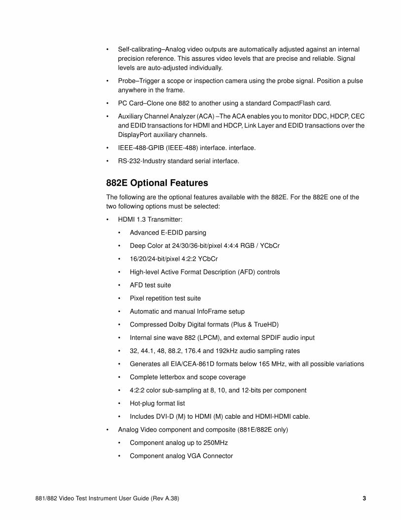
882E features
The following are the standard and optional features of the 882E
• Image Control Tool to fine tune deep color images (882E only).
• DTV ready–Pre-programmed standard DTV formats are ready for immediate use. Digital outputs support YCbCr color encoding. Analog outputs support tri-level composite sync and YPbPr.
• Built-in formats–Over 350 popular video formats are built-in including VESA, ATSC, EIA-770.x, SMPTE 170, 240, 259, 267, 274, 292, 293, 295, 296, Australian, EIA/CEA-861D, NTSC and PAL.
• Central administration–Update and configure all networked instruments from a single computer.
• Network control–Fully control instrument from any network location with web browser or Telnet client.
• Graphics SDK–Create complex patterns based on your specifications using C++ software development kit.
• HDMI–Full single-link HDMI 1.3. DVI HDCP production keys for HDMI output.
• Easy to use–Access powerful features easily using intuitive user interface.
• Multiple configurations–Save and restore different instrument configurations for different applications.
• Local pattern storage–Store multiple custom images (.bmp, .jpg, and .png) images in instrument.
881/882 Video Test Instrument User Guide (Rev A.38) 3
• Self-calibrating–Analog video outputs are automatically adjusted against an internal precision reference. This assures video levels that are precise and reliable. Signal levels are auto-adjusted individually.
• Probe–Trigger a scope or inspection camera using the probe signal. Position a pulse anywhere in the frame.
• PC Card–Clone one 882 to another using a standard CompactFlash card.
• Auxiliary Channel Analyzer (ACA) –The ACA enables you to monitor DDC, HDCP, CEC and EDID transactions for HDMI and HDCP, Link Layer and EDID transactions over the DisplayPort auxiliary channels.
• IEEE-488-GPIB (IEEE-488) interface. interface.
• RS-232-Industry standard serial interface.
882E Optional Features
The following are the optional features available with the 882E. For the 882E one of the two following options must be selected:
• HDMI 1.3 Transmitter:
• Advanced E-EDID parsing
• Deep Color at 24/30/36-bit/pixel 4:4:4 RGB / YCbCr
• 16/20/24-bit/pixel 4:2:2 YCbCr
• High-level Active Format Description (AFD) controls
• AFD test suite
• Pixel repetition test suite
• Automatic and manual InfoFrame setup
• Compressed Dolby Digital formats (Plus & TrueHD)
• Internal sine wave 882 (LPCM), and external SPDIF audio input
• 32, 44.1, 48, 88.2, 176.4 and 192kHz audio sampling rates
• Generates all EIA/CEA-861D formats below 165 MHz, with all possible variations
• Complete letterbox and scope coverage
• 4:2:2 color sub-sampling at 8, 10, and 12-bits per component
• Hot-plug format list
• Includes DVI-D (M) to HDMI (M) cable and HDMI-HDMI cable.
• Analog Video component and composite (881E/882E only)
• Component analog up to 250MHz
• Component analog VGA Connector

4 Chapter 1 Getting Started
• Composite analog on S-video and BNC Connectors
• For the 882E one of the two following analyzer options can be selected:
• HDMI Analyzer available with HDMI Tx on 882E only
• Supports full single-link HDMI 1.3 (with deep color) and DVI analyzer up to (150MHz) in same instrument.
• Measure source timing and source pixel errors. Also useful for testing cables. Test results can be issued as formatted reports.
• Emulate EDIDs.
• Dual HDMI Tx and dual HDMI Rx ports

881/882 Video Test Instrument User Guide (Rev A.38) 5
Video interfaces
This section describes the 882’s video interfaces.
The video interfaces on the 882EA HDMI are shown below (the 882E will not have the HDMI inputs but can have analog video outputs).
Interface Description
1 HDMI OUT 1 connector outputs full single link HDMI 1.3 video, as well as DVI and modern HDMI-compatible digital video signals.
2 HDMI OUT 2 connector outputs full single link HDMI 1.3 video, as well as DVI and modern HDMI-compatible digital video signals.
3 HDMI IN 1 connector accepts full single link HDMI 1.3 video, as well as DVI and modern HDMI-compatible digital video signals.
4 HDMI IN 2 connector accepts full single link HDMI 1.3 video, as well as DVI and modern HDMI-compatible digital video signals.
5 SPECIAL connector provides multiple outputs, including:
• digital composite sync
• line sync
• frame sync
• movable scope trigger (probe) pulse
• pixel clock signal
6 SPDIF OUT connector outputs audio to an external receiver.
7 SPDIF IN connector inputs audio from an external source.

6 Chapter 1 Getting Started
VGA interface
The VGA interface, available on the model 882C generator, outputs analog video for testing analog video displays. The following table describes the VGA connector pinouts.
HDMI interface
The HDMI interface emulates an HDMI-compliant video display. The HDMI connector pinouts are shown in the following table.
HDMI Type A Connector Pinouts
Special Sync interface
Use the Special connector to output frame sync, line sync, composite sync, or a special probe pulse. For more information, see Chapter 17, “Using Special Sync Output.”
S-Video interface
The 882 generator has an S-Video connector labeled “S-VIDEO.” This is a miniDIN connector that emulates an S-Video compliant source for outputting composite TV signal.
Composite video BNC
The 882 generator has a composite TV BNC connector labeled “CVBS.” This interface emulates an analog composite TV source.
Pin Signal Pin Signal Pin Signal
1 Analog Red Video 6 Analog Red Video Ground 11 No Connection
2 Analog Green Video 7 Analog Green Video Ground 12 DDC/EDID Serial Data
3 Analog Blue Video 8 Analog Blue Video Ground 13 Horizontal Sync
4 No Connection 9 DDC/EDID +5 Vdc Out 14 Vertical Sync
5 Digital Ground 10 Digital Ground 15 DDC/EDID Data Clock
Pin Signal Pin Signal Pin Signal
1 TMDS Data 2+ 7 TMDS Data0+ 13 CEC
2 TMDS Data2 Shield 8 TMDS Data0 Shield 14 Reserved (N.C.)
3 TMDS Data2- 9 TMDS Data0- 15 SCL
4 TMDS Data1+ 10 TMDS Clock+ 16 SDA
5 TMDS Data1 Shield 11 TMDS Clock Shield 17 DDC/SEC Ground
6 TMDS Data1- 12 TMDS Clock- 18 +5 V Power
19 Hot Plug Detect

881/882 Video Test Instrument User Guide (Rev A.38) 7
Computer interfaces
This section describes the 882’s computer interfaces. The computer interfaces are shown below (882C shown).
RS-232 interface
Each 882 has a standard RS-232 serial connector, labeled “SERIAL.” This is a 9-pin D-Sub male connector which enables you to connect the 882 with a computer. A null modem cable is provided to support this interface. You can communicate with the 882 through the command line interface using a terminal emulator such as HyperTerminal. For more information, see “Working with the serial interface” on page 30. The pinouts for the RS-232 connector are shown in the following table.
Connector Description
1 SERIAL connector provides RS-232C serial data communication interface for the 882.
2 DEBUG connector is for Quantum Data use only.
3 ETHERNET connector is used to connect the 882 with a TCP/IP network, for remote administration and control, and for sharing resources from a file server.
4 GPIB connector provides IEEE-488 GPIB interface to the generator (882 only; not provided on 881 generators).
Pin Signal Pin Signal Pin Signal
1 Data Carrier Detect 4 Data Terminal Ready 7 Request to Send
2 Received Data 5 Signal Ground 8 Clear to Send
3 Transmitted Data 6 Data Set Ready 9 Ring Indicator
HDMI OUT 1 HDMI OUT 2 HDMI IN 1 HDMI IN 2VGA
1 2 3 4

8 Chapter 1 Getting Started
GPIB interface
The GPIB interface allows you to use the 882 as a programmable video signal source in a larger automated test system. The GPIB connector pinouts are listed in the following table.
Pin Signal Pin Signal Pin Signal Pin Signal
1 DIO1 7 NRFD 13 DIO5 19 Shield
2 DIO2 8 NDAC 14 DIO6 20 Shield
3 DIO3 9 IFC 15 DIO7 21 Shield
4 DIO4 10 SRQ 16 DIO8 22 Shield
5 EOI 11 ATN 17 REN 23 Shield
6 DAV 12 Shield 18 Shield 24 Signal Ground

881/882 Video Test Instrument User Guide (Rev A.38) 9
Front panel interface
This section describes the front panel interface for operating the 882. The front panel keys are shown below.
Status indicators
Status indicators provide feedback about the operational status of the 882. The graphic below shows the location of the status indicators.
Recent FolderFolder
Tool!SettingRejectedSelected *
- Disabled+ Enabled
Item Display
Menu Selection Keys
Soft Keys Status Indicators
Ethernet connection active
Multi-link video active
Digital video active
Browse mode active
Output encrypted (HDCP)
Packet video active
Output contains data (InfoFrames)
Color difference video active

10 Chapter 1 Getting Started
Menu selection keys
You can access the 882’s menus using the menu selection keys depicted below.
Selecting menu items
When you press a menu selection key, a menu appears on the 882’s display. Each menu item corresponds to a key located adjacent to the item. These keys are called “soft keys” because their functions change depending on the items that appear on the 882’s display. For example, for the menu shown below, the soft key at the upper left corresponds to the System item on the 882’s display.
Pressing a soft key either selects an item, enables or disables the item, or causes additional information about the item to appear on the 882’s display. An icon located next to an item provides additional information about the item. Following is a list of icons and their meanings.
Icon Meaning
Folder containing related items.
Recently visited folder.
Displays information about UUT
Select device type
Go to selected item
Page down,
decrease value
Page up,
increase value
Select output
Select image
Select format
Select tool
Set advanced parameters
for current items
Set basic options
for current item
Select user profile
Press thiskey to select
Probe
System Reports
Sequence ImgShift
Probe Analyzer
AFC CEC

881/882 Video Test Instrument User Guide (Rev A.38) 11
Item selection examples
The following examples show the different types of menu items.
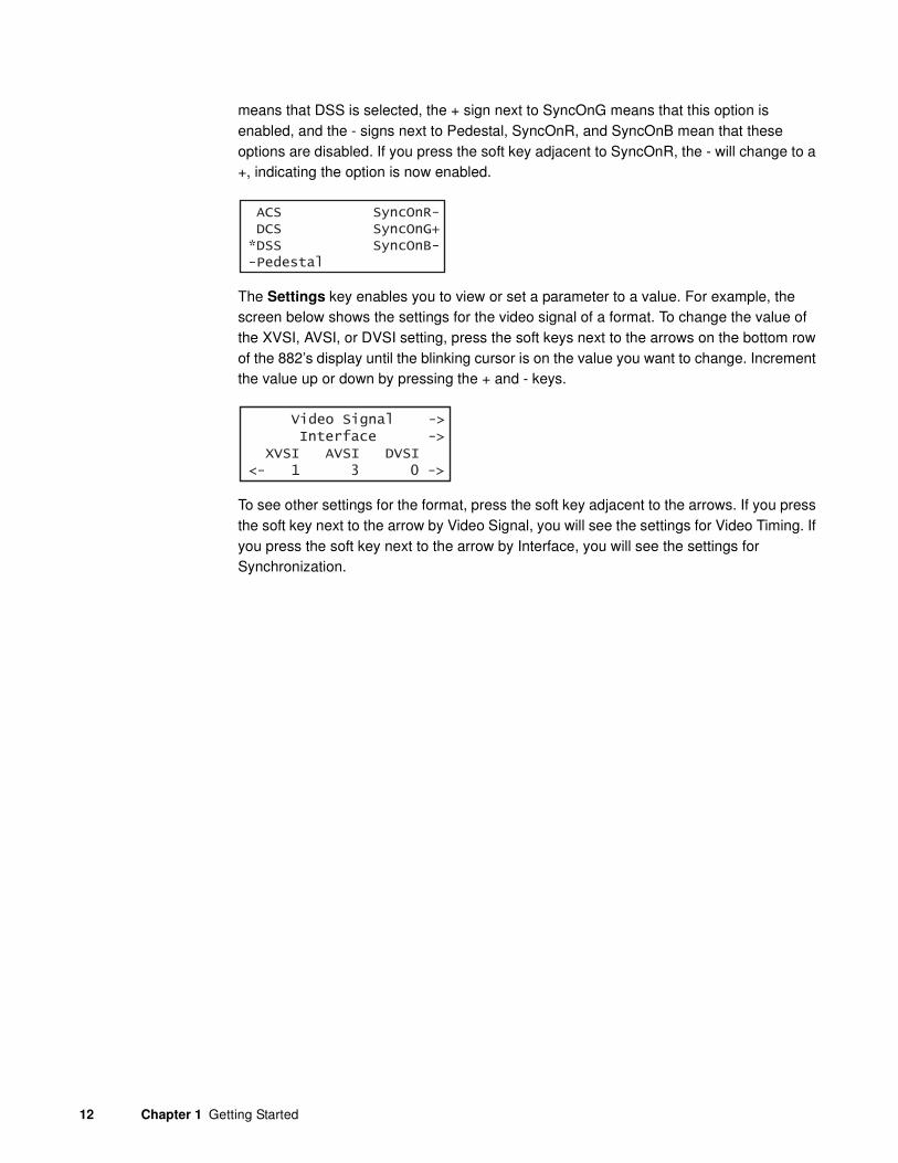
About the Settings and Options keys
The Options key enables you to view or set basic options for the selected item. For items with multiple pages of options, press the Options key again to view additional pages. Typically, options are attributes that are either enabled or disabled. For example, the screen below shows the options for a format. On this screen, the asterisk (*) next to DSS
Indicates active item in list of mutually exclusive items.
Item is active, but may be deactivated by pressing soft key.
Item is not active, but may be activated by pressing soft key.
Value may be increased by pressing Up (+) key, or decreased by pressing Down (-) key.
Page down to view more items.
Scroll left to previous option, or right to next option
Selecting this item will cause an action.
Icon Meaning
ACSDCS
AFD:1PR:5
DSS Pedestal*
+
This represents asetting that is changedusing the spot keys
This represents anoption that is enabled (+)or disabled (-) using theadjacent item key
These represent membersof a group where only one item can be selected using an adjacent item key
Image
Rendition
IVER
These represent navigational directionarrows to other settingsusing adjacent item key
ISUB0000 0
These represent navigatingdirection arrows for movingthe flashing cursor to anotherdigit using adjacent item key
This is a commandsetting that is setone digit at a timevia flashing cursorusing spot keys
12 Chapter 1 Getting Started
means that DSS is selected, the + sign next to SyncOnG means that this option is enabled, and the - signs next to Pedestal, SyncOnR, and SyncOnB mean that these options are disabled. If you press the soft key adjacent to SyncOnR, the - will change to a +, indicating the option is now enabled.
The Settings key enables you to view or set a parameter to a value. For example, the screen below shows the settings for the video signal of a format. To change the value of the XVSI, AVSI, or DVSI setting, press the soft keys next to the arrows on the bottom row of the 882’s display until the blinking cursor is on the value you want to change. Increment the value up or down by pressing the + and - keys.
To see other settings for the format, press the soft key adjacent to the arrows. If you press the soft key next to the arrow by Video Signal, you will see the settings for Video Timing. If you press the soft key next to the arrow by Interface, you will see the settings for Synchronization.
ACS SyncOnR- DCS SyncOnG+*DSS SyncOnB--Pedestal
Video Signal -> Interface -> XVSI AVSI DVSI<- 1 3 0 ->

881/882 Video Test Instrument User Guide (Rev A.38) 13
882 file system and media
The 882 has a file system comprised of a System folder and a Library folder of resource files that can be stored on multiple media (storage devices or locations). The files in the file system are briefly described below.
882 file system
The 882 generator file system is comprised of two main directories (folders): 1) System and 2) Library. The System folder contains the realtime operating system and firmware file (vxWorks) and the gateware. The Library folder contains the following resource files:
• Fonts - Object files used to define the font types.
• Formats - XML files defining the format parameter settings.
• FormatLib - XML files for configuring the source list of formats.
• Images - C++ object files, executables, bitmaps, and XML files for rendering images.
• ImageLib - XML files for configuring the content list of images.
• Sequences - XML files with instructions for test sequences.
• Users - XML files for user configuration profiles.
882 media
The 882 provides for two read/write local storage media and one server-based medium (storage locations):
• Flash memory.
• PCM CIA card.
• Host server.
Each of these storage locations contains or can contain all the 882’s System and Library files.

14 Chapter 1 Getting Started
882 operational modes
The 882 has two operational modes: 1) Basic mode and 2) Browse mode. The 882 boots up in the Basic mode which is the main operating mode you will be using. Both modes are described below along with instructions for booting up the 882.
Booting up the 882
When the 882 is powered up it presents a screen enabling you to select the boot device. The 882 loads its operating system and firmware from a from the selected boot device or specified medium (storage location). If you do not press a key within 5 seconds the currently specified boot location is used and boot up proceeds. This feature enables you to control where the 882 boots from in instances where the default location is either inaccessible or known to have a suspect application file. Follow the procedure below to boot the 882:
To boot the 882:
1. Apply power to the 882. The following display appears.
If you are sure you want to boot from the current storage location you can let the system boot automatically.
a. To boot from an alternative device, press any key within five seconds. The following screen appears on the 882’s display:
2. Choose the !BootDev item by pressing the adjacent soft key. The following menu appears:
3. Do one of the following:
• To boot from the file server, press the soft key adjacent to Network Boot.
• To boot from the 882’s flash memory, press the soft key adjacent to Internal Flash.
Quantum Data Windriver vxWorks System BootPress any key for setup
!BootDev !Passwd!HostName !Flags!FileName !Other!InetAddr !TrgtName
881/882 Video Test Instrument User Guide (Rev A.38) 15
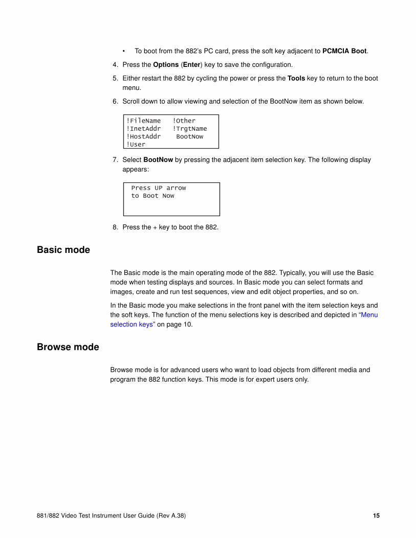
• To boot from the 882’s PC card, press the soft key adjacent to PCMCIA Boot.
4. Press the Options (Enter) key to save the configuration.
5. Either restart the 882 by cycling the power or press the Tools key to return to the boot menu.
6. Scroll down to allow viewing and selection of the BootNow item as shown below.
7. Select BootNow by pressing the adjacent item selection key. The following display appears:
8. Press the + key to boot the 882.
Basic mode
The Basic mode is the main operating mode of the 882. Typically, you will use the Basic mode when testing displays and sources. In Basic mode you can select formats and images, create and run test sequences, view and edit object properties, and so on.
In the Basic mode you make selections in the front panel with the item selection keys and the soft keys. The function of the menu selections key is described and depicted in “Menu selection keys” on page 10.
Browse mode
Browse mode is for advanced users who want to load objects from different media and program the 882 function keys. This mode is for expert users only.
!FileName !Other!InetAddr !TrgtName!HostAddr BootNow!User
Press UP arrow to Boot Now
16 Chapter 1 Getting Started
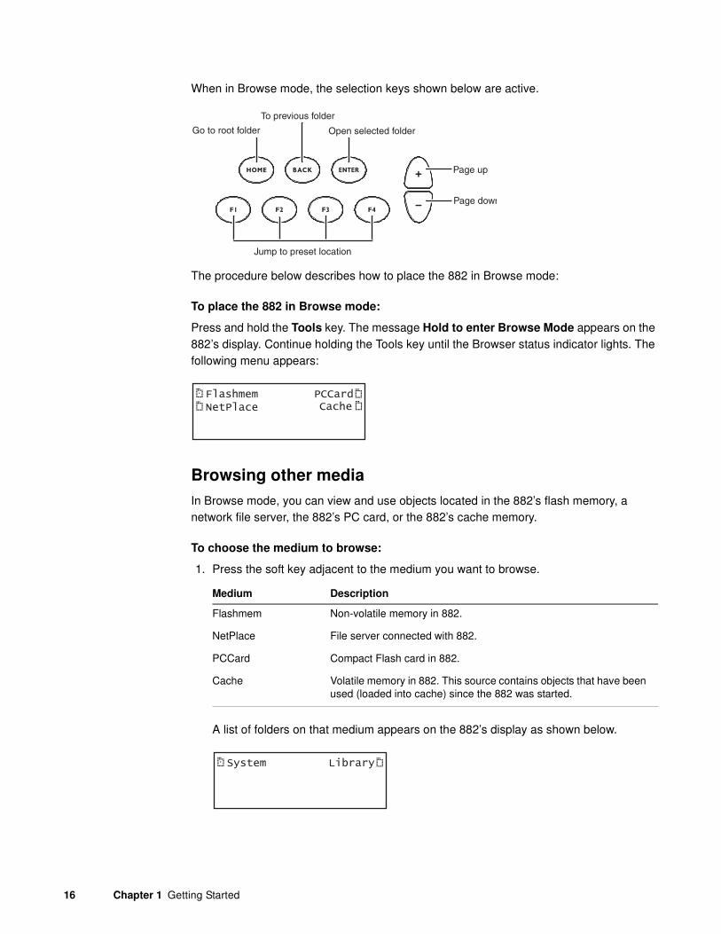
When in Browse mode, the selection keys shown below are active.
The procedure below describes how to place the 882 in Browse mode:
To place the 882 in Browse mode:
Press and hold the Tools key. The message Hold to enter Browse Mode appears on the 882’s display. Continue holding the Tools key until the Browser status indicator lights. The following menu appears:
Browsing other media
In Browse mode, you can view and use objects located in the 882’s flash memory, a network file server, the 882’s PC card, or the 882’s cache memory.
To choose the medium to browse:
1. Press the soft key adjacent to the medium you want to browse.
A list of folders on that medium appears on the 882’s display as shown below.
Go to root folder
To previous folder
Jump to preset location
Open selected folder
Page up
Page down
FlashmemNetPlace
PCCardCache
Medium Description
Flashmem Non-volatile memory in 882.
NetPlace File server connected with 882.
PCCard Compact Flash card in 882.
Cache Volatile memory in 882. This source contains objects that have been used (loaded into cache) since the 882 was started.
System Library
881/882 Video Test Instrument User Guide (Rev A.38) 17
2. Choose the folder you want to open by pressing the adjacent soft key. The contents of the folder appears on the 882’s display. If you need to return to the previous menu list press the back (settings) key.
3. Continue selecting folders to open until you locate the item you need. To use an item, press the adjacent soft key.
Setting the 882’s path
The 882 can be set to access format, image, and sequence files stored on its flash memory, PC card, or on a file server. To do this, you must set the 882’s path to point to the corresponding folders on the desired medium. You can set the path using the command line interface or the front panel.
To set the 882’s path using the front panel:
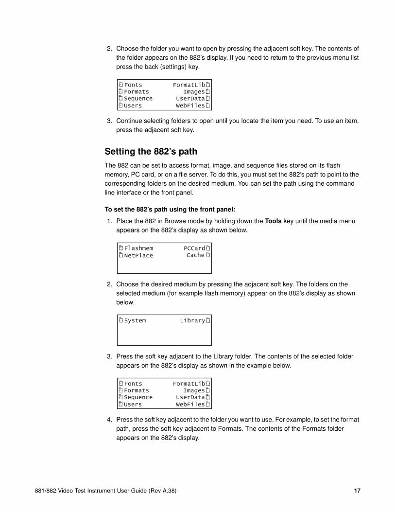
1. Place the 882 in Browse mode by holding down the Tools key until the media menu appears on the 882’s display as shown below.
2. Choose the desired medium by pressing the adjacent soft key. The folders on the selected medium (for example flash memory) appear on the 882’s display as shown below.
3. Press the soft key adjacent to the Library folder. The contents of the selected folder appears on the 882’s display as shown in the example below.
4. Press the soft key adjacent to the folder you want to use. For example, to set the format path, press the soft key adjacent to Formats. The contents of the Formats folder appears on the 882’s display.
Fonts FormatLibFormats ImagesSequence UserDataUsers WebFiles
FlashmemNetPlace
PCCardCache
System Library
Fonts FormatLibFormats ImagesSequence UserDataUsers WebFiles
18 Chapter 1 Getting Started
5. Select a format by pressing the adjacent soft key. The format path is now set to the selected folder on the selected medium.
To set the 882’s path using the command line interface:
1. Establish a session with the 882 using either HyperTerminal over a serial connection or Telnet over an Ethernet LAN. See “Establishing a terminal session with the 882” on page 30 or “Establishing a Telnet session with the 882” on page 33.
2. For each file type (format, image, and sequence), set the path parameter to the corresponding folder on the desired medium. In the command syntax, specify the medium as follows:
• Flash memory: tffs0 (TFFS - Transaction Flash File System)
• PC card: card0
Note: Please note that you must us a PCMCIA card that is formatted in FAT16
filesystem. If you use an card that is formatted in FAT32, the 882 will not boot.
• File server: <server name>
3. For each file type (format, image, and sequence), set the path parameter to the corresponding folder on local 882 media using the following commands:
FMTP /medium/Library/Formats
IMGP /medium/Library/Images
SEQP /medium/Library/Sequences
For example the medium name for the PC card is /card0. So you would enter the following command to set the image path to the image directory on the PC card:
IMGP /card0/Library/Images
The 882 will now display the images on the PC card when you press the Contents key.
The medium name for the flash memory is /tffs0. So you would enter the following command to set the image path to the format directory on the flash memory:
FMTP /tffs0/Library/Formats
The 882 will now display the formats on the flash memory when you press the Source key.
The medium name for the network is the server (host name) memory. So you would enter the following command to set the image path to the format directory on the flash memory:
SEQP /Server030/Library/Sequences
The 882 will now display the sequences on the server when you press the Tools key and then select sequences.

881/882 Video Test Instrument User Guide (Rev A.38) 19
Programming the 882’s function keys
The 882 is equipped with four function keys (F1 through F4) that can be programmed as shortcuts to folders. The procedure below describes how to program the function keys.
To program a function key as a folder shortcut:
1. Browse to the folder to which you want to create a shortcut.
2. Hold down a function key (F1, F2, F3, or F4) to assign the key to the folder.
Switching from Browse mode to Basic mode
To switch from Browse mode to Basic mode:
Press and hold the Tools key. The message Hold to enter Basic Mode appears on the 882’s display. Continue holding the Tools key until the Browse Mode status indicator turns off and the Tools menu appears.
System
Sequence
Probe
AFC
Analyzer
Reports
ImgShift
CEC

20 Chapter 1 Getting Started
Web interface
The 882 has a built-in Web server that enables you to interact with the 882 using a PC and an Ethernet connection. The Web interface includes the following functions:
• Format Editor for creating formats and modifying and viewing format parameters. For more information about the Format Editor, see “Creating a new format using the Format Editor” on page 215.
• Virtual Front Panel for operating the 882 remotely.
• CMD Terminal for operating the 882 using the command line interface.
• 882 FTP Browser for copying files between media within the 882, between 882s, and between a 882 and a PC.
• Calibration reports (Currently not available)
This section describes how to operate the Virtual Front Panel, CMD Terminal, and the 882 FTP Browser.
Working with the Virtual Front Panel
The Virtual Front Panel enables you to perform remotely the same tasks as you would with the 882’s front panel. To use the Virtual Front Panel, you must have a PC connected to a 882 either through an Ethernet LAN or locally through an Ethernet crossover cable connected between the Ethernet ports on the 882 and the PC. These configurations are described in more detail in “Establishing a network environment” on page 140. You must also have the Java Runtime Environment (JRE) 1.5 or later installed on your PC. You can download the JRE from http://www.java.com/en/download/windows_ie.jsp.
To use the Virtual Front Panel, you must know the IP address of the 882. The following procedures describe how to determine the 882’s IP address and how to access the Virtual Front Panel using a Web browser.
To determine the IP address of the 882:
1. Press the Tools key. The Tools menu appears on the 882’s display as shown below.
System
Sequence
Probe
AFC
Analyzer
Reports
ImgShift
CEC
881/882 Video Test Instrument User Guide (Rev A.38) 21
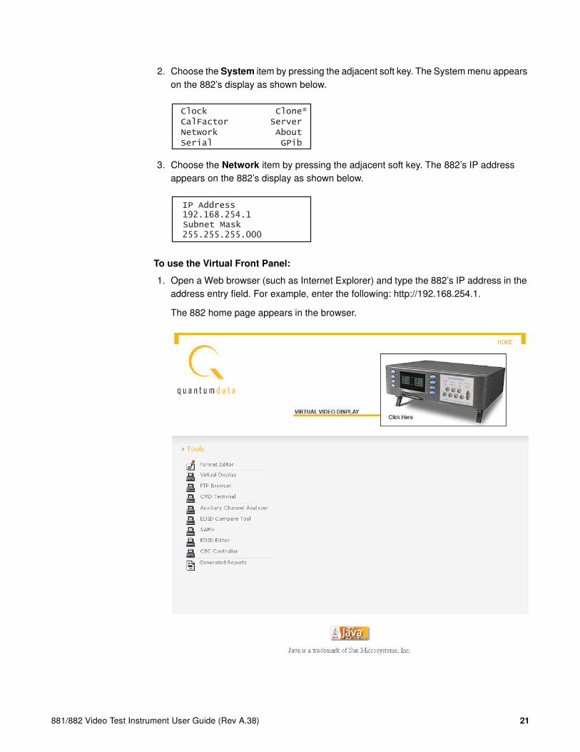
2. Choose the System item by pressing the adjacent soft key. The System menu appears on the 882’s display as shown below.
3. Choose the Network item by pressing the adjacent soft key. The 882’s IP address appears on the 882’s display as shown below.
To use the Virtual Front Panel:
1. Open a Web browser (such as Internet Explorer) and type the 882’s IP address in the address entry field. For example, enter the following: http://192.168.254.1.
The 882 home page appears in the browser.
Clock Clone* CalFactor Server Network About Serial GPib
IP Address 192.168.254.1Subnet Mask 255.255.255.000
22 Chapter 1 Getting Started
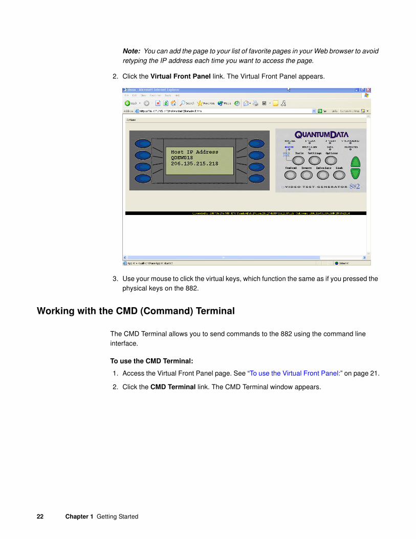
Note: You can add the page to your list of favorite pages in your Web browser to avoid
retyping the IP address each time you want to access the page.
2. Click the Virtual Front Panel link. The Virtual Front Panel appears.
3. Use your mouse to click the virtual keys, which function the same as if you pressed the physical keys on the 882.
Working with the CMD (Command) Terminal
The CMD Terminal allows you to send commands to the 882 using the command line interface.
To use the CMD Terminal:
1. Access the Virtual Front Panel page. See “To use the Virtual Front Panel:” on page 21.
2. Click the CMD Terminal link. The CMD Terminal window appears.

881/882 Video Test Instrument User Guide (Rev A.38) 23
3. In the box at the top of the CMD Terminal window, enter a command, and then press Enter. The command appears in the lower pane.
Working with the 882 FTP Browser
If you create objects on a PC, such as images or formats, you can use the 882 FTP Browser to copy these objects to a 882. You can also use the 882 FTP Browser to copy objects between media in a 882 and to copy objects from one 882 to another.
Copying files from a PC to a 882
To copy files from a PC to a 882:
1. Access the 882’s FTP browser by choosing the FTP Browser menu item from the main web page. The 882 FTP Browser appears. The Instrument Files area

24 Chapter 1 Getting Started
2. shows the files stored on the 882. The Host Files area shows the files stored on the PC.
3. In the Host Files area, locate and select the file or folder you want to copy.
4. In the Instrument Files area, locate the destination folder for the file as follows:
a. In the Look in box, click the down arrow and select the medium where you want to copy the file. Select tffs0 for the 882’s flash memory or card0 for the 882’s PC card.
b. In the list of files, open the destination folder.
5. In the Host Files area, click Download. The Transfer Files dialog box appears.
6. Verify that the source file or folder and the destination folder are correct, and then click OK.
7. The Copying Files dialog box appears showing the status of the operation. When the status is 100%, click Done.

881/882 Video Test Instrument User Guide (Rev A.38) 25
Copying files from a 882 to a PC
To copy files from a 882 to a PC:
1. Access the 882’s FTP browser by choosing the FTP Browser menu item from the main web page. The 882 FTP Browser appears. The Instrument Files area shows the files stored on the 882. The Host Files area shows the files stored on the PC.
2. In the Instrument Files area, locate and select the file or folder you want to copy as follows.
a. In the Look in box, click the down arrow and select the medium where the file is located. Select tffs0 for the 882’s flash memory or card0 for the 882’s PC card.
b. In the list of files, select the file or folder you want to copy.
3. In the Host Files area, open the destination folder where you want to copy the files.
4. In the Instrument Files area, click Upload. The Transfer Files dialog box appears.

26 Chapter 1 Getting Started
5. Verify that the source file or folder and the destination folder are correct, and then click OK.
6. The Copying Files dialog box appears showing the status of the operation. When the status is 100%, click Done.
Copying files between the 882’s flash memory
and PC card
To copy files between media in a 882:
1. Access the 882’s FTP browser by choosing the FTP Browser menu item from the main web page. The 882 FTP Browser appears. The Instrument Files area shows the files stored on the 882. The Host Files area shows the files stored on the PC.
2. In the Instrument Files area, click the down arrow by the Look in box and select tffs0. This is the 882’s flash memory.
3. Repeat step 2 to open a second 882 FTP Browser. In the Instrument Files area of the second 882 FTP Browser window, click the down arrow by the Look in box and select card0. This is the 882’s PC card.
881/882 Video Test Instrument User Guide (Rev A.38) 27
Note: Please note that you must us a PCMCIA card that is formatted in FAT16
filesystem. If you use an card that is formatted in FAT32, the 882 will not boot.
4. Locate the file or folder you want to copy in the source window.
5. Locate and open the destination folder in the destination window.
6. Drag the file or folder from the Instrument Files area of the source window to the Instrument Files area of the destination window.
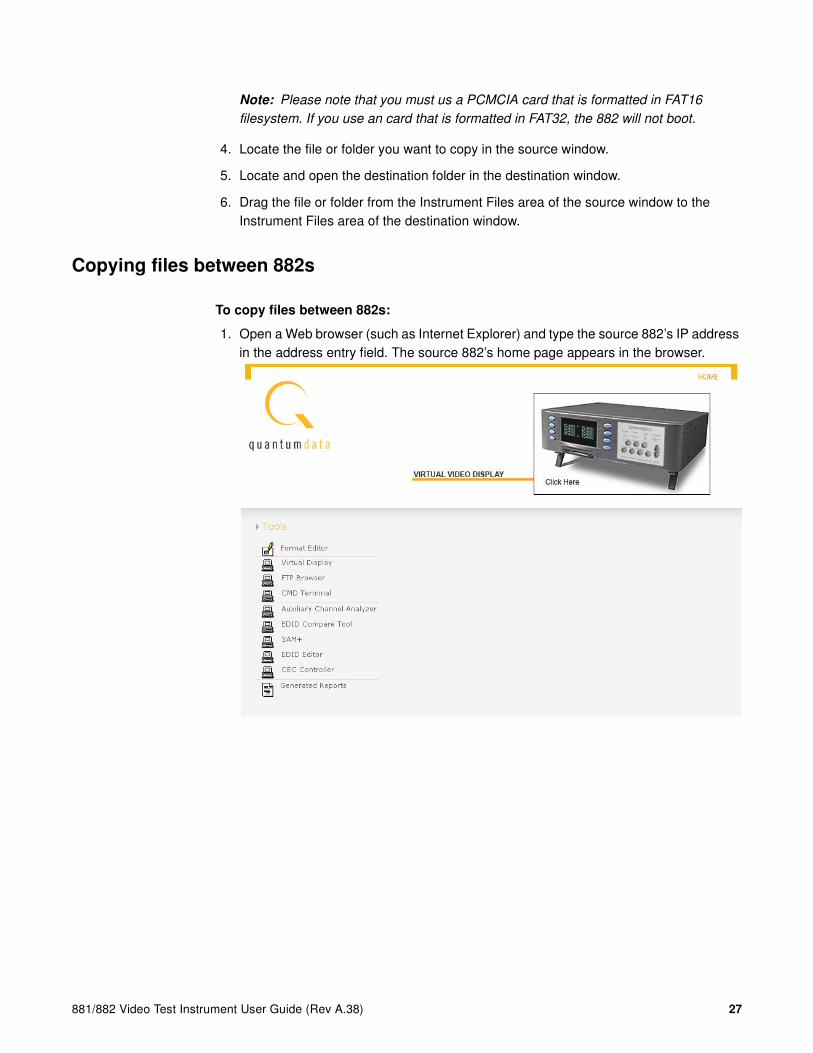
Copying files between 882s
To copy files between 882s:
1. Open a Web browser (such as Internet Explorer) and type the source 882’s IP address in the address entry field. The source 882’s home page appears in the browser.

28 Chapter 1 Getting Started
2. Access the 882’s FTP browser by choosing the FTP Browser menu item from the main web page. The 882 FTP Browser appears. The Instrument Files area shows the files stored on the 882. The Host Files area shows the files stored on the PC.
3. Repeat steps 1 and 2 for the target 882.
Note: You now have two instances of the 882 FTP Browser running: one for the source
882 and one for the target 882.
4. In the 882 FTP Browser window for the source 882, locate the file or folder you want to copy as follows:
a. In the Look in box, click the down arrow and select the medium where the file or folder is located. Select tffs0 for the 882’s flash memory or card0 for the 882’s PC card.
Note: Please note that you must us a PCMCIA card that is formatted in FAT16
filesystem. If you use an card that is formatted in FAT32, the 882 will not boot.
b. In the list of files, select the file or folder.
881/882 Video Test Instrument User Guide (Rev A.38) 29
5. In the 882 FTP Browser window for the target 882, open the destination folder as follows:
a. In the Look in box, click the down arrow and select the medium to which you want to copy the file or folder. Select tffs0 for the 882’s flash memory or card0 for the 882’s PC card.
b. In the list of files, open the destination folder.
6. Drag the file or folder from the Instrument Files area to the Host Files area of the source window. A confirmation dialog box appears.
7. Click OK to copy the files.
8. Locate the file or folder in the Host Files area in the target window. Drag the file or folder from the Host Files area to the destination folder in the Instrument Files area of the target window. A confirmation dialog box appears.
9. Click OK to copy the files.
30 Chapter 1 Getting Started
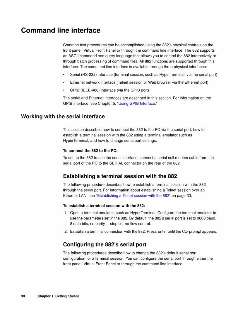
Command line interface
Common test procedures can be accomplished using the 882’s physical controls on the front panel, Virtual Front Panel or through the command line interface. The 882 supports an ASCII command and query language that allows you to control the 882 interactively or through batch processing of command files. All 882 functions are supported through this interface. The command line interface is available through three physical interfaces:
• Serial (RS-232) interface (terminal session, such as HyperTerminal, via the serial port)
• Ethernet network interface (Telnet session or Web browser via the Ethernet port)
• GPIB (IEEE-488) interface (via the GPIB port)
The serial and Ethernet interfaces are described in this section. For information on the GPIB interface, see Chapter 5, “Using GPIB Interface.”
Working with the serial interface
This section describes how to connect the 882 to the PC via the serial port, how to establish a terminal session with the 882 using a terminal emulator such as HyperTerminal, and how to change serial port settings.
To connect the 882 to the PC:
To set up the 882 to use the serial interface, connect a serial null modem cable from the serial port of the PC to the SERIAL connector on the rear of the 882.
Establishing a terminal session with the 882
The following procedure describes how to establish a terminal session with the 882 through the serial port. For information about establishing a Telnet session over an Ethernet LAN, see “Establishing a Telnet session with the 882” on page 33.
To establish a terminal session with the 882:
1. Open a terminal emulator, such as HyperTerminal. Configure the terminal emulator to use the parameters set in the 882. By default, the 882’s serial port is set to 9600 baud, 8 data bits, no parity, 1 stop bit, no flow control.
2. Establish a terminal connection with the 882. Press Enter until the C:> prompt appears.
Configuring the 882’s serial port
The following procedures describe how to change the 882’s default serial port configuration for a terminal session. You can configure the serial port through either the front panel, Virtual Front Panel or through the command line interface.

881/882 Video Test Instrument User Guide (Rev A.38) 31
To configure the 882’s serial port through the front panel or Virtual Front Panel:
1. Press the Tools key. The Tools menu appears on the 882’s display as shown below.
2. Choose the System item by pressing the adjacent soft key. The System menu appears on the 882’s display as shown below.
3. Choose the Serial item by pressing the adjacent soft key. The serial port settings appear on the 882’s display.
Selec
4. Press the Settings key. The following information appears on the 882’s display:
5. To change the baud rate, do the following:
a. Position the blinking cursor on the baud rate setting. To do this, press the soft key adjacent to the arrow by the baud rate setting to move the cursor left or right until it appears on the baud rate setting.
b. Press the + or - keys to adjust the baud rate setting up or down.
6. To change the flow control state, do the following:
a. Position the blinking cursor on the flow control setting. To do this, press the soft keys adjacent to the arrow by the flow control setting until the cursor appears on the current flow control setting (N, H, or T).
b. Press the + or - keys to change the setting.
System
Sequence
Probe
AFC
Analyzer
Reports
ImgShift
CEC
Clock Clone* CalFactor Server Network About Serial GPib
Serial Port 9600 baud 8 N 1
Serial Port Set Params BAUD FLOW -> 9600 N ->

32 Chapter 1 Getting Started
7. To change the number of data bits, do the following:
a. Press the soft keys adjacent to the third row until CHAR appears. The current data bits setting is shown in the bottom row.
b. Position the blinking cursor on the CHAR setting. To do this, press the soft keys adjacent to the arrow by the CHAR setting until the cursor appears on the current data bits setting.
c. Press the + or - keys to adjust the setting up or down.
8. To change the parity, do the following:
a. Position the blinking cursor on the PRTY setting. To do this, press the soft keys adjacent to the arrow by the PRTY setting until the cursor appears on the current parity setting.
b. Press the + or - keys to adjust the setting up or down.
9. To change the stop bits, do the following:
a. Position the blinking cursor on the STOP setting. To do this, press the soft keys adjacent to the arrow by the STOP setting until the cursor appears on the current stop bits setting.
b. Press the + or - keys to adjust the setting up or down.
10. To save the changes, press the Enter (Options) key. The following choices appear on the 882’s display:
To save the changes, choose the Yes item by pressing the adjacent soft key.
To exit without saving the changes, choose the No item.
To return to the previous screen without saving the changes, choose the Back item.
To configure the 882’s serial port through the command line interface:
1. Establish a session with the 882 using HyperTerminal over a serial connection or Telnet over an Ethernet LAN. For instructions, see “Establishing a terminal session with the 882” on page 30 and “Establishing a Telnet session with the 882” on page 33.
2. At the session prompt, enter the following command to query the 882 for the current serial port settings:
Serial Port Set Params<- CHAR PRTY STOP 8 N 1 ->
Apply Settings?
Back
Yes No

881/882 Video Test Instrument User Guide (Rev A.38) 33
MODE?
The 882 returns the current values:
9600,N,8,1,N,N
3. To change the settings, enter the following command:
MODE baud parity data stop handshake protocol
For example, to change the baud rate to 38400, enter the following command:
MODE 38400 n 8 1 n n
Note: In this example, after you press Enter, the baud rate of the session and baud
rate of the 882 will no longer match. This will cause the session to lose its connection
with the 882. Close the session, change the session baud rate to 38400, and then
re-open the session.
Working with the network interface
This section describes how to connect the 882 to a PC via an Ethernet LAN and how to establish a Telnet session with the 882.
To connect the 882 to a PC over an Ethernet LAN:
1. Connect the Ethernet cable between the PC’s Ethernet port and an active Ethernet jack.
2. Connect an Ethernet cable between the 882’s ETHERNET port and an active Ethernet jack.
Establishing a Telnet session with the 882
The following procedure describes how to establish a Telnet session with the 882 over an Ethernet LAN. For information about establishing a terminal session over a serial connection, see “Establishing a terminal session with the 882” on page 30.
To establish a Telnet session with the 882:
1. Using a text terminal application, such as DOS Command Prompt, enter the following command:
telnet 882IPaddress
Example:
telnet 192.168.254.220
2. The /tffs0> prompt appears. Type commands at the /tffs0> prompt, and press Enter after each command.

34 Chapter 1 Getting Started
Sending commands interactively
This section describes how to send commands through an interactive command line interface session. The 882 parses command lines one at a time. Command lines must be terminated with a carriage return (<cr>). The 882 immediately echoes each character as it is received and places it in a command line buffer. Commands are not case sensitive.
When sending multiple commands at once, separate each command with a semi-colon. For example, to load the 480p59 format with the SMTPEbar image, send the following commands:
FMTL 480p59
IMGL SMPTEbar
ALLU
Common commands
• To apply an image and format to the 882 hardware, enter:
ALLU
• To display the name of the format currently in the format buffer, enter:
FMTL?
• To load a format, enter:
FMTL format_name
• To apply the format to the 882 hardware, enter:
FMTU
• To load an image, enter:
IMGL image_name
• To apply the image to the 882 hardware, enter:
IMGU
Sending command files (serial interface only)
When developing more complex, custom test sequences or formats, it is easiest to enter commands in a text file, and then send the file to the 882. This approach allows you to modify the file without entering the entire command script.
Note: Sending command text files can be performed via the serial interface only.
To send a text file to the 882:
1. Using a text editor, enter commands into a text file, and save the text file using a *.txt extension.

881/882 Video Test Instrument User Guide (Rev A.38) 35
2. Establish a session with the 882 using a terminal emulator, such as HyperTerminal over a serial connection.
3. At the C:> prompt, transfer the text file to the 882. For example, to transfer a file using HyperTerminal, do the following:
a. On the Transfer menu, click Send Text File. The Send Text File dialog box appears.
b. Select the text file you want to send, and then click Open. HyperTerminal displays the commands as they are sent.
c. Press Enter once to ensure that the last command is sent.

36 Chapter 1 Getting Started
Working with user profiles
The 882 provides user profiles that enable you to quickly load pre-defined configurations. This can be done either through the front panel, virtual front panel or the command line. For example, you can create different profiles for each operator, production line, display type under test, and so on.
A user profile is always active on the 882 (“User1” is the default profile). While active, the 882 tracks subsequent format and format options, format catalogs, interface, and content selections made by the user. These configuration settings are saved to the active profile when a different user profile is chosen on the 882.
To choose a user profile:
1. Press the Source and Content keys simultaneously (or press USER on the Virtual Front Panel) to access the list of user profiles.
The following is an example of a set of user profiles that might appear on the 882’s display. Note that User1 is active, which is indicated by the = sign.
wr
2. Choose another user by pressing the adjacent soft key. For example, to change to User5, press the soft key adjacent to User5. This will save the configuration settings for User1 and select the profile for User5. Any subsequent configuration changes will apply to User5.
Alternatively, to switch users using the command line interface, enter the following command:
USRU username.xml
For example, to select User5, enter
USRU User5.xml
To query the current user, enter
USRU?
The 882 returns the current user name.
/tffs0/Library/Users/User5.xml
To create a new user profile:
The procedure for setting up a new user profile is accomplished using the command line interface.
=User1 User2
User3 User4
User5 User6
User7 User8
881/882 Video Test Instrument User Guide (Rev A.38) 37
1. Establish a session with the 882 using either HyperTerminal over a serial connection or Telnet over an Ethernet LAN. See “Establishing a terminal session with the 882” on page 30 or “Establishing a Telnet session with the 882” on page 33.
2. Enter the following command:
USRA username.xml
USRU username.xml
Note: A user name is 8 alphanumeric characters.
For example, to set up a user profile called “User3,” enter:
USRA User3.xml
USRU User3.xml
A new user profile is created with default configuration settings and becomes the active profile on the 882. While active, the 882 tracks subsequent format and format options, format catalogs, interface, and content selections made by the user. These configuration settings are saved to the active profile when a different user profile is chosen on the 882.
To delete a user profile:
1. Enter the following command:
USRK username.xml
For example to delete User5, enter:
USRK User5.xml

38 Chapter 1 Getting Started
881/882 Video Test Instrument User Guide (Rev A.38) 39
2 Testing Video Displays
Topics in this chapter:
• General video display testing procedures
• Testing digital computer (IT) FPDs
• Testing analog composite video SDTV (CE) CRTs
• Testing analog component video SDTV (CE) CRTs
• Testing digital component video HDTV (CE) FPDs
• Using the Image Caching feature
• Using the AuxTest image
• Using the ImageShift utility
• Adjust Frequency Function
• Keypad Utility
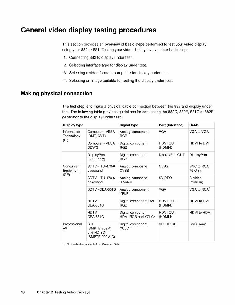
40 Chapter 2 Testing Video Displays
General video display testing procedures
This section provides an overview of basic steps performed to test your video display using your 882 or 881. Testing your video display involves four basic steps:
1. Connecting 882 to display under test.
2. Selecting interface type for display under test.
3. Selecting a video format appropriate for display under test.
4. Selecting an image suitable for testing the display under test.
Making physical connection
The first step is to make a physical cable connection between the 882 and display under test. The following table provides guidelines for connecting the 882C, 882E, 881C or 882E generator to the display under test.
Display type Signal type Port (Interface) Cable
Information Technology (IT)
Computer - VESA (DMT, CVT)
Analog component RGB
VGA VGA to VGA
Computer - VESA DDWG
Digital component RGB
HDMI OUT (HDMI-D)
HDMI to DVI
DisplayPort(882E only)
Digital component RGB
DisplayPort OUT DisplayPort
Consumer Equipment (CE)
SDTV - ITU-470-6 baseband
Analog composite CVBS
CVBS BNC to RCA 75 Ohm
SDTV - ITU-470-6 baseband
Analog composite S-Video
SVIDEO S-Video (miniDin)
SDTV - CEA-861B Analog component YPbPr
VGA VGA to RCA1
1. Optional cable available from Quantum Data.
HDTV - CEA-861C
Digital component DVI RGB
HDMI OUT (HDMI-D)
HDMI to DVI
HDTV - CEA-861C
Digital component HDMI RGB and YCbCr
HDMI OUT (HDMI-H)
HDMI to HDMI
Professional AV
SDI (SMPTE-259M) and HD-SDI (SMPTE-292M-C)
Digital component YCbCr
SDI/HD-SDI BNC Coax

881/882 Video Test Instrument User Guide (Rev A.38) 41
Use the following table to connect the 882D or 881D generator to the display under test.
Selecting interface type
After making the physical connection, you are ready to select the interface type for your display under test.
You can select the interface using either the front panel keys or the command line interface. The interface is one of the following:
• CVBS - For testing composite analog consumer electronic displays.
• S-Video - For testing composite (separate luma and chroma) consumer electronic displays.
• DVI-D - For testing digital VESA displays (dual link) on the 882D.
• HDMI-D - For testing DVI displays through an HDMI interface.
• HDMI-H - For testing HDMI consumer electronic displays.
Display type Signal type Port (Interface) Cable
Information Technology (IT)
Computer - VESA (DMT, CVT)
Analog component RGB
DVI-A with DVI to VGA adapter
VGA to VGA
Computer - VESA DDWG
Digital component RGB
DVI for single and dual link or HDMI OUT (HDMI-D) for single link only
DVI to DVI cable for DVI connector or HDMI to DVI for HDMI-D con-nector
Consumer Equipment (CE)
SDTV - ITU-470-6 baseband
Analog composite CVBS
CVBS BNC to RCA 75 Ohm
SDTV - ITU-470-6 baseband
Analog composite S-Video
SVIDEO S-Video (miniDin)
SDTV - CEA-861B Analog component YPbPr
DVI with DVI to VGA adapter
VGA to RCA1
1. Optional cable available from Quantum Data.
HDTV - CEA-861C
DVI for single and dual link or HDMI OUT (HDMI-D) for single link only
HDMI OUT (HDMI-D)
DVI to DVI cable for DVI connector or HDMI to DVI for HDMI-D con-nector
HDTV - CEA-861C
Digital component HDMI RGB and YCbCr
HDMI OUT (HDMI-H)
HDMI to HDMI
Profes-sional AV
SDI (SMPTE-259M) and HD-SDI (SMPTE-292M-C)
Digital component YCbCr
SDI/HD-SDI BNC Coax

42 Chapter 2 Testing Video Displays
To select an interface:
1. Press the Interface key to access the list of interfaces. A listing of signal interfaces appears on the 882’s display as shown below.
2. Choose the interface by pressing the adjacent soft key. The interface is activated and the port outputs the currently selected image and format. An asterisk is shown beside the selected interface.
Alternatively, to select the interface through the command line interface, enter commands like shown below:
XVSI 9 // Selects the VGA interface
ALLU // Applies the interface setting to the 882
To define the display size:
Once you have selected the interface, you can change the parameters specifying the physical size of the display (if your application calls for that).
1. After selecting the interface, press the Sink key and then the Settings key. The following information appears on the 882’s display.
2. Navigate to the other parameters for physical size (VSIZ and USIZ) to set the display size for your test application.
To gate off the output:
You can gate off and on the interface output as follows:
1. Press the Interface key, then press the Options key. The following information appears on the 882’s display.
2. Enable or disable the interface output by pressing the adjacent soft key.
VGA
HDMI-D
CVBS
S-VIDEO
SDI
*
HDMI-H
Display Physical Size HSIZ -><- 300.00
+Output Mark #1-Disable 2-

881/882 Video Test Instrument User Guide (Rev A.38) 43
Selecting video format
Once you have selected the interface type for the display under test, you need to select a video output format. A format defines a set of video, timing, and sync parameters for a specific device or standard. This section explains how to configure the 882 to output video formats that are supported by the display under test.
Important: If the display under test has not implemented hot plug correctly, you will have
to bypass hot plug detection in the 882 to enable video output. See below for procedure on
bypassing hot plug detection.
Note: For more information about formats, see Chapter 6, “Working with Formats.”
Setting Source list of formats
The 882 provides a Source list of standard (pre-defined) formats. The Source list can be set automatically when connecting to a EDID-compatible display. Otherwise, you can manually set which formats are listed.
To automatically set Source list of formats for EDID-compatible display:
When testing EDID-compatible displays, the 882 can automatically update the Source list to include only formats supported by the display under test. To do this:
1. Connect the 882 to the display you want to test.
2. Press the Sink key. The following information appears on the 882’s display.
Note: If there are two displays connected you will have to press the Sink key a second time
to access the display connected to the second HDMI output.
3. Press the Options key. The following information appears on the 882’s display.
4. Choose the EDID Formats item by pressing the adjacent soft key. A + appears next to EDID Formats indicating enabled.
The 882 loads the Source list with formats supported by the connected display (hot-plug formats read via EDID structure of attached display).
5. To redisplay all formats, press the soft key adjacent to EDID Formats. A ‘-’ (minus sign) next to EDID Formats indicates it is disabled.
Manufacturer:SNYProduct Code:144Serial#:7011007Week:20 Year:1998
-EDID Formats CDF+HP Bypass-Emulate
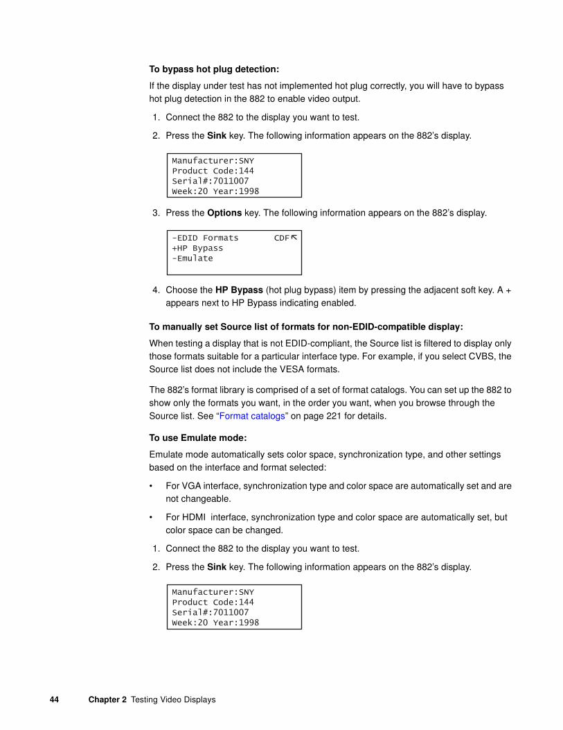
44 Chapter 2 Testing Video Displays
To bypass hot plug detection:
If the display under test has not implemented hot plug correctly, you will have to bypass hot plug detection in the 882 to enable video output.
1. Connect the 882 to the display you want to test.
2. Press the Sink key. The following information appears on the 882’s display.
3. Press the Options key. The following information appears on the 882’s display.
4. Choose the HP Bypass (hot plug bypass) item by pressing the adjacent soft key. A + appears next to HP Bypass indicating enabled.
To manually set Source list of formats for non-EDID-compatible display:
When testing a display that is not EDID-compliant, the Source list is filtered to display only those formats suitable for a particular interface type. For example, if you select CVBS, the Source list does not include the VESA formats.
The 882’s format library is comprised of a set of format catalogs. You can set up the 882 to show only the formats you want, in the order you want, when you browse through the Source list. See “Format catalogs” on page 221 for details.
To use Emulate mode:
Emulate mode automatically sets color space, synchronization type, and other settings based on the interface and format selected:
• For VGA interface, synchronization type and color space are automatically set and are not changeable.
• For HDMI interface, synchronization type and color space are automatically set, but color space can be changed.
1. Connect the 882 to the display you want to test.
2. Press the Sink key. The following information appears on the 882’s display.
Manufacturer:SNYProduct Code:144Serial#:7011007Week:20 Year:1998
-EDID Formats CDF+HP Bypass-Emulate
Manufacturer:SNYProduct Code:144Serial#:7011007Week:20 Year:1998

881/882 Video Test Instrument User Guide (Rev A.38) 45
3. Press the Options key. The following information appears on the 882’s display.
4. Choose the Emulate item by pressing the adjacent soft key. A + appears next to Emulate indicating enabled.
Alternatively, to select the emulate mode through the command line interface, enter the command shown below:
EMUG 1 // Enables emulate mode
To disable the emulate mode through the command line interface, enter the command shown below:
EMUG 0 // Disables emulate mode
Selecting a format
From the Source list of formats, you select the video format output for your display under test.
To select a format:
1. Identify the type of display (composite television, component standard definition television, component high definition television, computer equipment, or other specialty display).
Note: The 882 has a library of standard formats. For a description of how the library is
organized, see “Understanding the format library” on page 46.
2. For non-EDID compliant displays, check the specifications of your display for supported formats.
3. Press the Source key to access the list of formats. A list of formats appears on the 882’s display as shown below. To see all of the formats, press the + and - keys.
Note: The list of formats displays when pressing the Source key may be a filtered or
abbreviated list. Formats not suitable for the selected interface type will not appear by
default on the Source list. Also, you can disable format catalogs to prevent certain
formats from appearing on the Source list. For more information about format catalogs,
see “Format catalogs” on page 221.
4. Choose a format by pressing the adjacent soft key.
-EDID Formats CDF+HP Bypass-Emulate
*DMT0660 DMT0672 DMT0675 DMT0685 DMT0785H DMT0856 DMT0860 DMT0872

46 Chapter 2 Testing Video Displays
Upon selecting a format, you can modify the format options and settings if necessary. For instructions on this, see “Configuring format parameters” on page 175.
Understanding the format library
The 882 has several built-in formats to test a broad range of display types. These formats are grouped in the following categories:
• Composite television formats
• Component standard definition television formats
• Component high definition television formats
• Computer display formats
• Military and medical display formats
• Miscellaneous formats
Note: A summary of the format naming conventions is provided in this section. For a
detailed description of the naming conventions, see “Format library” on page 169.
Composite television formats
Composite television formats are named by the standards defining them. The first three to five characters of the format name indicate the color coding scheme. The first set of characters refers to the standard. The next characters are optional and indicate adjustments to the format. Examples of these formats are:
• NTSC (North American TV)
• PAL (European TV)
• NTSC-J (where J refers to a Japan standard per NTSC without 7.5 IRE setup)
• PAL-N (where N indicates 3.58205625 MHz color sub-carrier)
• PAL# (where # indicates that the sampling rate is reduced to achieve square pixels)
Component standard definition television formats
Component SDTV formats are applicable in the case of RGB and YPbPr. These formats are named by their vertical resolution, scanning method, and frame rate. The initial characters indicating the resolution are followed by the scanning method. The two characters following the scanning method indicate the frame rate. A typical example of a component standard definition TV video format is:
• 480i2x30 (for a vertical resolution of 480 pixels with interlaced scanning and a 30 Hz frame refresh rate; 2x indicates that the pixels are double-clocked for DVI compatibility).

881/882 Video Test Instrument User Guide (Rev A.38) 47
Component high definition television formats
Component high definition television formats, like the standard definition television formats, are named by their vertical resolution, scanning method, and frame rate. These formats are applicable in the case of RGB, YPbPr, and YCbCr. These initial characters indicating the resolution are followed by the scanning method. The two characters following the scanning method indicate the frame rate. A typical example of a component high definition TV video format is:
• 1080i30 (for a vertical resolution of 1080 active vertical lines with interlaced scanning and a 30 Hz frame refresh rate).
Computer display formats
Computer display formats are assumed to use progressive scanning. Computer display format names consist of four blocks. The initial three characters indicate the vendor ID using the EISA ID (for example, IBM, SUN, and VSC) or the standard body or acronym (for example, SMT, DMT, GTF, CEA, and EIA). The next two characters provide the first two digits of the horizontal resolution in pixels. Following the horizontal resolution are two characters which indicate the frame rate. The final character indicates the aperture, which is used only if the aperture is not 1.33 (A). The following are examples of computer display formats:
• VSC1275 for Viewsonic 1280 by 1024 at 75 Hz
• DMT0685 for Discrete Monitor Timing with 680 by 480 at 85 Hz
Viewing or modifying format parameters
You can use the Format image to view detailed information about formats in the 882.
You can also modify format parameters through the front panel, through the command line interface, or through the Format Editor. These procedures are provided in “Configuring format parameters” on page 175.
Selecting image
Once you have determined the format or formats appropriate for testing the display, you will apply a series of images suitable for evaluating the display. Of primary importance is determining what type of display you are testing (for example, CRT or digital flat panel display). You must also determine if you are testing composite TV and use images appropriate for these formats and video types.
Each image in the 882’s library is intended to test one or more attributes of a particular display type and video type.
Rendering images
Use the following procedures to view primary images.

48 Chapter 2 Testing Video Displays
Once you have selected an image you can modify the image options if necessary. For instructions on this refer to “Viewing and modifying image options” on page 229.
To select an image:
1. Identify the type of display (CRT or FPD) and the images that are used for testing this type of display (see the table below).
2. Press the Content key. A list of images appears on the 882’s display as shown below. Press the + and - keys to see all of the images.
Note: The list of images that appears when you press the Content key may be a
filtered or abbreviated list. You may have disabled certain image catalogs, preventing
the images in those catalogs from appearing on the Content list. For more information
about image catalogs, see “Creating image catalogs” on page 239.
3. Choose an image by pressing the adjacent soft key.
Acer1 Acer2 Acer3 Acer4 Acer5 Acer6 Acer7 Acer8

881/882 Video Test Instrument User Guide (Rev A.38) 49
The table below provides a summary of display characteristics and the images used to evaluate them. For details on the images and display attributes, see Appendix B, “Image Reference.”
Display type Display test Recommended images
Analog CRT Geometry(pin and barrel, linearity)
Static imagesHatch (TVHatch, Hatch_16, Hatch_20), Cir-clesL, Geom_1 - Geom_5, SMPTE133
Focus Focus_@6, Focus_@7, Focus_@8, Focus_@9, Text_9, Text_9T, Text_11, Text_12T, Text_16
Photometry (chrominance, contrast, levels)
Flat, Flat07, Flat13, Flat20, Flat27, Flat33, Flat40, Flat47, Flat53, Flat60, Flat67, Flat73, Flat80, Flat87, Flat93, FlatGray, Flat_01, Flat_02, Flat_03, Flat_04, Flat_05, Flat_06, Flat_07, Flat_08, Flat_09, Flat_10, Flat_11, Flat_12, Flat_13, Flat_14, Flat_15, Flat_16, Ramp_B, Ramp_G, and Ramp_R,ColorBar, SMPTEbar, TVBar100 & TVBar_75 (TV formats only)
Luminance SMPTE133 (grayscale), Grays5, Grays9, Grays11, Grays16, Grays32, Grays64
Gamma correction SMPTE133 (checkerbox)
Resolution BurstTCE, Burst (TV formats only), Grill_11, Grill_15, Grill_22, Grill_33, Grill_44
Pulse (CE SDTV) PulseBar
Centering Outline0, Outline1, Outline2, Outline3
Voltage Regulation Regulate
Electromagnetic Interference
EMITest1, EMITest2, EMITest3, EMITest4, EMITest5

50 Chapter 2 Testing Video Displays
Rendering image versions
Many images have secondary or alternate versions and some images have many versions. Use the procedures below to view the alternate and multiple image versions.
To view alternate image versions in the Content list:
1. Select an image by pressing the Contents key and selecting an image with the adjacent soft key until a * appears next to image name.
2. Enable and view image versions as follows:
a. Press the Options key. The following menu will appear on the 882’s display for images with a single secondary image:
b. Choose the Alternate item by pressing the adjacent soft key until a + appears next to the item.
Digital flat panel (fixed pixeldisplay)
Pixel anomalies (stuck pixels, misc sampling)
Flat, Raster, Ramp_B, Ramp_G, and Ramp_R,Focus_@6, Focus_@7, Focus_@8, Focus_@9, Text_9, Text_9T, Text_11, Text_12T, Text_16
Photometry (chrominance, contrast, levels)
Flat, Flat07, Flat13, Flat20, Flat27, Flat33, Flat40, Flat47, Flat53, Flat60, Flat67, Flat73, Flat80, Flat87, Flat93, FlatGray, Flat_01, Flat_02, Flat_03, Flat_04, Flat_05, Flat_06, Flat_07, Flat_08, Flat_09, Flat_10, Flat_11, Flat_12, Flat_13, Flat_14, Flat_15, Flat_16, Ramp_B, Ramp_G, and Ramp_R, ColorBar, SMPTEbar, SMPTE133
Luminance SMPTE133 (Grayscale), Grays5, Grays9, Grays11, Grays16, Grays32, Grays64
Centering Outline0, Outline1, Outline2, Outline3
Resolution BurstTCE, Grill_11, Grill_15, Grill_22, Grill_33, Grill_44
Persistence Animated images: Persist, Cubes, SlideBox
3D (HDMI only) 3DCRTK, 3DCUBES, custom bitmap images
Display type Display test Recommended images
-Alternate Red+-NoGamma Green+-Noise Blue+
+Alternate Red+-NoGamma Green+-Noise Blue+
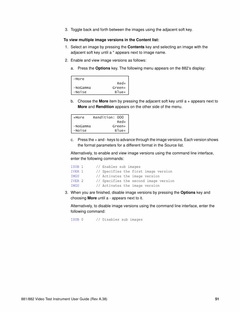
881/882 Video Test Instrument User Guide (Rev A.38) 51
3. Toggle back and forth between the images using the adjacent soft key.
To view multiple image versions in the Content list:
1. Select an image by pressing the Contents key and selecting an image with the adjacent soft key until a * appears next to image name.
2. Enable and view image versions as follows:
a. Press the Options key. The following menu appears on the 882’s display:
b. Choose the More item by pressing the adjacent soft key until a + appears next to More and Rendition appears on the other side of the menu.
c. Press the + and - keys to advance through the image versions. Each version shows the format parameters for a different format in the Source list.
Alternatively, to enable and view image versions using the command line interface, enter the following commands:
ISUB 1 // Enables sub images
IVER 1 // Specifies the first image version
IMGU // Activates the image version
IVER 2 // Specifies the second image version
IMGU // Activates the image version
3. When you are finished, disable image versions by pressing the Options key and choosing More until a - appears next to it.
Alternatively, to disable image versions using the command line interface, enter the following command:
ISUB 0 // Disables sub images
-More Red+-NoGamma Green+-Noise Blue+
+More Rendition: 000 Red+-NoGamma Green+-Noise Blue+

52 Chapter 2 Testing Video Displays
Testing analog computer (IT) CRTs
This section describes how to test analog computer (IT) displays. The display responses shown as examples in the procedures use the 882C. However you can also test analog composite with the 882D using the same format and image selections. The interface selection is different and is noted.
To set up the 882 to test an analog computer CRT:
1. Connect a standard VGA cable between the VGA connector on the 882 and the VGA connector on the display under test.
2. Calibrate the 882 in accordance with the procedures described in “Calibrating signal level” on page 85.
3. Determine the formats to test (see “Setting Source list of formats” on page 43).
4. Determine additional formats to test based on the resolution of the display. The VESA formats are shown below:
5. Determine the images to test. For analog CRTs, you typically want to select images to test for geometry, focusing, photometry, resolution, cross talk, EMI, and regulation characteristics. For more details on what images test these specific display attributes, see “Selecting image” on page 47 or Appendix B, “Image Reference.”
To activate the VGA interface on the output port:
1. Press the Interface key to access the list of interfaces. A listing of signal interfaces appears on the 882’s display as shown below.
Standard Quantum Data format name
VGA DMT06xx
SVGA DMT08xx
XGA DMT10xx
SXGA DMT12xx
UXGA DMT16xx
QXGA DMT20xx
QSXBA DMT25xx
VGA
HDMI-D
CVBS
S-VIDEO
SDI
*
HDMI-H

881/882 Video Test Instrument User Guide (Rev A.38) 53
2. Choose the VGA item by pressing the adjacent soft key. The interface is activated and the port outputs the currently selected image and format. An asterisk is shown beside the selected interface.
Alternatively, to select the interface through the command line interface, enter the following commands:
XVSI 9 // Selects the VGA interface
ALLU // Applies the interface setting to the 882
If you are using the 882D you select the DVI-A interface.
To verify the test set-up:
1. Press the Source key to access the list of formats.
2. Choose a standard format (for example, DMT0660) by pressing the adjacent soft key.
Alternatively, you can load the format with the following command:
FMTL DMT0660
FMTU
3. Press the Content key to access the list of images.
4. Choose a suitable image (for example, ColorBar) by pressing the adjacent soft key.
Alternatively, you can load the image with the following command:
IMGL ColorBar
IMGU
5. Verify that the image appears on the display under test.
To test the display:
1. Press the Source key and select the first test format.
Alternatively, you can load the format with the following command:
FMTL format_name
FMTU
2. Press the Content key and select the first test image.
Alternatively, you can load the image with the following command:
IMGL image_name
IMGU
3. Repeat steps 1 and 2 for all formats and test images. Use the following guidelines to verify proper operation:
• When testing geometry with the Hatch images (for example, Hatch20) look for distortion with concave or convex lines near the periphery of the display. Look for irregular spacing on the cross hatch patterns.
• When testing photometry such as chrominance, use the ColorBar, SMPTE133, or SMPTEbar images. Look for missing bars which may indicate a dead or

54 Chapter 2 Testing Video Displays
unconnected channel. Also, look at the transitions between the bars; they should be sharp and distinct. Each bar also should be uniform in color and intensity across its entire width.
• To test luminance, you can use the SMPTE133 (grayscale portion) image. To test gamma correction, you can use the SMPTE133 (checkerbox portion) image. The detailed methods for verifying these parameters on the SMPTE133 image are provided in Appendix B, “Image Reference.”
• When testing focus with the Focus or Text images, the characters in all areas of the display should be well-formed and in focus.
• When testing resolution with the Grill images, you should be able to see individual and distinct stripes in all areas of the display at all four resolutions.
• When testing for centering use the Outline images. For detailed methods for verifying centering with the Outline images, see Appendix B, “Image Reference.”
• When testing for high voltage regulation with the Regulate image, observe the outline at the edges of the image. It should stay in place and not pull away from the area of the large white blinking patch (when it appears).
Note: You can customize your 882 to run through a specified set of formats and
images automatically or manually by creating test sequences. See Chapter 8, “Working
with Test Sequences.” for details.

881/882 Video Test Instrument User Guide (Rev A.38) 55
Testing digital computer (IT) FPDs
This section describes how to test digital computer (IT) displays. You can test DVI on digital computer displays using the 882C up to single link through the HDMI connector. However you can test DVI digital computer displays up to full dual link on the 882D through the dual link DVI connector. The procedures below describe how to test HDMI, DVI or DisplayPort computer digital displays using the 882.
HDMI interface testing
To set up the 882 to test a digital FPD:
1. Connect a single or dual link DVI cable between the DVI connector on the 882 and the DVI connector on the display under test.
2. Determine the formats to test. See “Setting Source list of formats” on page 43 for instructions.
3. Determine the images to test. For digital flat panel displays, you typically want to select images to test for pixel anomalies, persistence, photometry, and resolution-related problems. For more information, see “Selecting image” on page 47 or Appendix B, “Image Reference.”
To activate the HDMI-D interface on the output port:
1. Press the Interface key. A listing of signal interfaces appears on the 882’s display as shown below.
2. Choose the DVI-D item by pressing the adjacent soft key. The interface is activated and the port outputs the currently selected image and format that is compatible with the interface. An asterisk is shown beside the selected interface.
Alternatively, to activate the interface through the command line interface, enter the following commands:
XVSI 2 // Selects the HDMI-D interface
ALLU // Applies the interface setting to the 882
To verify the test set-up:
1. Press the Source key to access the list of formats.
2. Choose a standard format (for example, DMT0660) by pressing the adjacent soft key.
Alternatively, you can load the format with the following command:
DVI-A
DVI-DHDMI-D
CVBS
S-VIDEO
SDI*
HDMI-H

56 Chapter 2 Testing Video Displays
FMTL DMT0660
FMTU
3. Press the Content key to access the list of images.
4. Choose a suitable image (for example, SMPTE133) by pressing the adjacent soft key.
Alternatively, you can load the image with the following command:
IMGL SMPTE133
IMGU
5. Verify that the image appears on the display under test.
To test the display:
1. Press the Source key and select the first test format.
Alternatively, you can load the format with the following command:
FMTL format_name
FMTU
2. Press the Content key and select the first test image.
Alternatively, you can load the image with the following command:
IMGL image_name
IMGU
3. Repeat steps 1 and 2 for all formats and test images. Use the following guidelines to verify proper operation:
• When testing photometry such as chrominance, use the ColorBar, SMPTE133, or SMPTEbar images. Look for missing bars which may indicate a dead or unconnected channel. Also, look at the transitions between the bars; they should be sharp and distinct. Each bar also should be uniform in color and intensity across its entire width.
• To test luminance, you can use the SMPTE133 (grayscale portion) image. To test gamma correction, you can use the SMPTE133 (checkerbox portion) image. The detailed methods for verifying these parameters on the SMPTE133 image are provided in Appendix B, “Image Reference.”
• When testing for centering use the Outline images. The detailed methods for verifying centering with the Outline images (Outline0, Outline1, Outline2, Outline3) are provided in Appendix B, “Image Reference.”
• When testing resolution with the Grill images, you should be able to see individual and distinct stripes in all areas of the display at all four resolutions.
• When testing for pixel anomalies use the Flat, Raster, and Ramp images. Use the Raster and Flat images to look for pixels that may be stuck on or off, respectively. The luminance should increase uniformly for the Ramp image. Also, look for sparkles indicating problems with sampling.

881/882 Video Test Instrument User Guide (Rev A.38) 57
• When testing for persistence with the animated images (for example, Cubes and Persist), look for bleeding or trails in the wake of the moving object.
Note: You can customize your 882 to run through a specified set of formats and
images automatically or manually by creating test sequences. See Chapter 8, “Working
with Test Sequences.” for details.

58 Chapter 2 Testing Video Displays
Testing analog composite video SDTV (CE) CRTs
This section describes how to test CRT composite televisions with analog composite video inputs. The display responses shown as examples in the procedures use the 882C. However you can also test analog composite with the 882D or 882E using the same interface, format and image selections.
To set up the 882 to test analog composite video SDTV:
1. Connect a standard coax cable between the CVBS connector on the 882 and the display under test.
Or, connect an S-video cable between the S-VIDEO connector on the 882 and the S-Video input on the display under test.
2. Determine which composite television standard you need, such as NTSC or PAL, and then select the formats compatible with the standard. Typically, you would test all the formats in the family of formats for a standard.
3. Determine the images to test. For analog CRTs you typically want to select images to test for geometry, focusing, photometry, resolution, cross talk, EMI, and regulation characteristics. For more details on what images test these specific display attributes, see “Selecting image” on page 47 or Appendix B, “Image Reference.”
To activate the CVBS or S-Video interface on the output port:
1. Press the Interface key. A listing of signal interfaces appears on the 882’s display as shown below.
2. Choose either the CVBS or S-VIDEO item by pressing the adjacent soft key. The interface is activated and the port outputs the currently selected image and format. An asterisk is shown beside the selected interface CVBS or S-VIDEO.
Alternatively, to activate the interface through the command line interface, enter the following commands:
XVSI 6 // Selects the CVBS interface
or
XVSI 5 // Selects the S-VIDEO interface
ALLU // Applies the interface setting to the 882
To verify the test set-up:
1. Press the Source key to access the list of formats.
VGA
HDMI-D
CVBS
S-VIDEO
SDI
*
HDMI-H

881/882 Video Test Instrument User Guide (Rev A.38) 59
2. Choose a typical composite format (for example, NTSC) by pressing the adjacent soft key.
Alternatively, you can load the format with the following command:
FMTL NTSC
FMTU
3. Press the Content key to access the list of images.
4. Choose a suitable image (for example, SmpteBar) by pressing the adjacent soft key.
Alternatively, you can load the image with the following command:
IMGL SmpteBar
IMGU
5. Verify that the image appears on the display under test.
To test the display:
1. Press the Source key and select the first test format.
Alternatively, you can load the format with the following command:
FMTL format_name
FMTU
2. Press the Content key and select the first test image.
Alternatively, you can load the image with the following command:
IMGL image_name
IMGU
3. Repeat steps 1 and 2 for all formats and test images. Use the following guidelines to verify proper operation:
• When testing geometry with the Hatch images (for example, TVHatch and Hatch20) look for distortion with concave or convex lines near the periphery of the display. Look for irregular spacing on the cross hatch patterns.
• When testing photometry such as chrominance, use the TVBar100 & TVBar_75 (TV formats only), TVSplBar, SMPTE133, or SMPTEbar images. Look for missing bars which may indicate a dead or unconnected channel. Also, look at the transitions between the bars; they should be sharp and distinct. Each bar also should be uniform in color and intensity across its entire width.
• When testing luminance, you can use the Pluge image.
• When testing focus with the Focus images, the characters in all areas of the display should be well-formed and in focus.
• When testing resolution with the Grill images, you should be able to see individual and distinct stripes in all areas of the display at all four resolutions. When testing for resolution with the Burst image, the peak intensities of all of the bursts should match the white reference level. The darkest portions between the peaks should match the black reference level.

60 Chapter 2 Testing Video Displays
• When testing for centering, use the Outline and TVoutLin images. The detailed methods for verifying centering with the Outline images (Outline0, Outline1, Outline2, Outline3) are provided in Appendix B, “Image Reference.”
• When testing for high voltage regulation with the Regulate image, observe the outline at the edges of the image. It should stay in place and not pull away from the area of the large, white blinking patch (when it appears).
Note: You can customize your 882 to run through a specified set of formats and
images automatically or manually by creating test sequences. See Chapter 8, “Working
with Test Sequences.” for details.
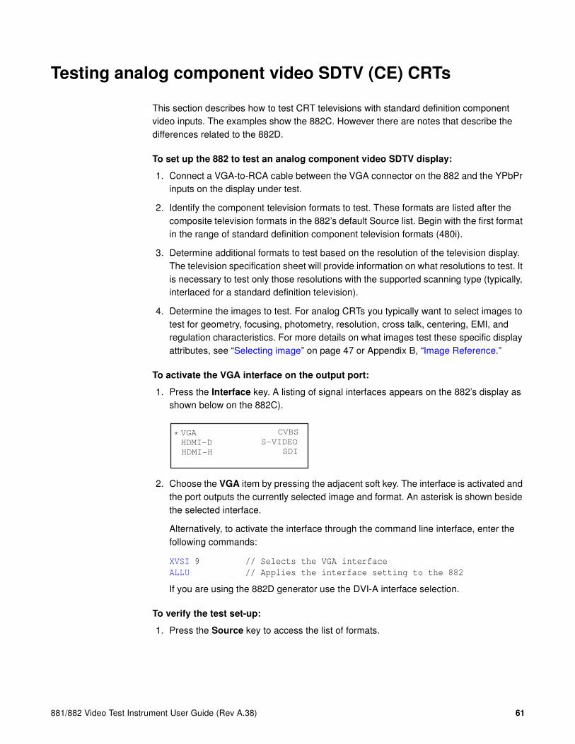
881/882 Video Test Instrument User Guide (Rev A.38) 61
Testing analog component video SDTV (CE) CRTs
This section describes how to test CRT televisions with standard definition component video inputs. The examples show the 882C. However there are notes that describe the differences related to the 882D.
To set up the 882 to test an analog component video SDTV display:
1. Connect a VGA-to-RCA cable between the VGA connector on the 882 and the YPbPr inputs on the display under test.
2. Identify the component television formats to test. These formats are listed after the composite television formats in the 882’s default Source list. Begin with the first format in the range of standard definition component television formats (480i).
3. Determine additional formats to test based on the resolution of the television display. The television specification sheet will provide information on what resolutions to test. It is necessary to test only those resolutions with the supported scanning type (typically, interlaced for a standard definition television).
4. Determine the images to test. For analog CRTs you typically want to select images to test for geometry, focusing, photometry, resolution, cross talk, centering, EMI, and regulation characteristics. For more details on what images test these specific display attributes, see “Selecting image” on page 47 or Appendix B, “Image Reference.”
To activate the VGA interface on the output port:
1. Press the Interface key. A listing of signal interfaces appears on the 882’s display as shown below on the 882C).
2. Choose the VGA item by pressing the adjacent soft key. The interface is activated and the port outputs the currently selected image and format. An asterisk is shown beside the selected interface.
Alternatively, to activate the interface through the command line interface, enter the following commands:
XVSI 9 // Selects the VGA interface
ALLU // Applies the interface setting to the 882
If you are using the 882D generator use the DVI-A interface selection.
To verify the test set-up:
1. Press the Source key to access the list of formats.
VGA
HDMI-D
CVBS
S-VIDEO
SDI
*
HDMI-H

62 Chapter 2 Testing Video Displays
2. Choose a standard component format (for example, 480i) by pressing the adjacent soft key.
Alternatively, you can load the format with the following command:
FMTL 480i
FMTU
3. Press the Content key to access the list of images.
4. Choose a suitable image (for example, SMPTE133) by pressing the adjacent soft key.
Alternatively, you can load the image with the following command:
IMGL SMPTE133
IMGU
5. Verify that the image appears on the display under test.
To test the display:
1. Press the Source key and select the first test format.
Alternatively, you can load the format with the following command:
FMTL format_name
FMTU
2. Press the Content key and select the first test image.
Alternatively, you can load the image with the following command:
IMGL image_name
IMGU
3. Repeat steps 1 and 2 for all formats and test images. Use the following guidelines to verify proper operation:
• When testing geometry with the Hatch images (for example, TVHatch and Hatch20), look for distortion with concave or convex lines near the periphery of the display. Look for irregular spacing on the cross hatch patterns.
• When testing photometry such as chrominence, use the TVBar100 & TVBar_75 (TV formats only), ColorBar, SMPTE133, or SMPTEbar images. Look for missing bars which may indicate a dead or unconnected channel. Also, look at the transitions between the bars; they should be sharp and distinct. Each bar also should be uniform in color and intensity across its entire width.
• When testing luminance you can use the SMPTE133 (grayscale portion) image. To test gamma correction you can use the SMPTE133 (checkerbox portion) image. The detailed methods for verifying these parameters on the SMPTE133 image are provided in Appendix B, “Image Reference.”
• When testing focus with the Focus or Text images, the characters in all areas of the display should be well-formed and in focus.
• When testing resolution with the Grill images, you should be able to see individual and distinct stripes in all areas of the display at all four resolutions.

881/882 Video Test Instrument User Guide (Rev A.38) 63
• When testing for centering use the TVOutline and Outline images. The detailed methods for verifying centering with the Outline images (Outline0, Outline1, Outline2, Outline3) are provided in Appendix B, “Image Reference.”
• When testing for high voltage regulation with the Regulate image, observe the outline at the edges of the image. It should stay in place and not pull away from the area of the large white blinking patch (when it appears).
Note: You can customize your 882 to run through a specified set of formats and
images automatically or manually by creating test sequences. See Chapter 8, “Working
with Test Sequences.” for details.

64 Chapter 2 Testing Video Displays
Testing digital component video HDTV (CE) FPDs
This section describes how to test digital DVI and HDMI component video for HDTV flat panel displays. The display responses shown as examples in the procedures use the 882C and 882E. However, you can also test dual-link digital component video with DVI using the 882D. The different selection options are provided for the 882D throughout the procedure.
DVI interface testing
To set up the 882 to test a digital DVI component video HDTV display:
1. Connect an HDMI to DVI cable between the HDMI OUT (1 or 2) connector on the 882 and the DVI connector on the television display under test.
Note: If the display under test has a DVI-D connector, you will need a DVI-I to DVI-D
adapter.
2. Identify the high-definition component television formats to test. These formats are listed after the composite television formats in the 882’s default Source list. Begin with the first format (720p) in the range of high definition component television formats. See “Setting Source list of formats” on page 43.
3. Determine additional formats to test based on the resolution of the television display. The television product specification sheet will provide information on what resolutions to test. It is necessary to test only those resolutions with the supported scanning type (typically interlaced for a high definition television).
4. Determine the images to test. For digital television flat panel displays, you would typically want to select images to test for pixel anomalies, persistence, photometry, and resolution-related problems. For more details on which images test these specific display attributes, see “Selecting image” on page 47 or Appendix B, “Image Reference.”
To activate the HDMI-D interface on the output port:
1. Press the Interface key. A listing of signal interfaces appears on the 882’s display as shown below.
2. Choose the HDMI-D item by pressing the adjacent soft key. The interface is activated and the port outputs the currently selected image and format.
VGA
HDMI-D
CVBS
S-VIDEO
SDI
*
HDMI-H

881/882 Video Test Instrument User Guide (Rev A.38) 65
Alternatively, to activate the interface through the command line interface, enter the following commands:
XVSI 3 // Selects the HDMI-D interface
ALLU // Applies the interface setting to the 882
If you are using the 882D you can select either HDMI-D or DVI-D interface. The DVI-D option provide dual link, the HDMI-D offers signal link only.
To verify the test set-up:
1. Press the Source key to access the list of formats.
2. Choose a high definition component format (for example, 720p50) by pressing the adjacent soft key.
Alternatively, you can load the format with the following command:
FMTL 720p50
FMTU
3. Press the Content key to access the list of images.
4. Choose a suitable image (for example, SMPTE133) by pressing the adjacent soft key.
Alternatively, you can load the image with the following command:
IMGL SMPTE133
IMGU
To test the display:
1. Press the Source key and select the first test format.
Alternatively, you can load the format with the following command:
FMTL format_name
FMTU
2. Press the Content key and select the first test image.
Alternatively, you can load the image with the following command:
IMGL image_name
IMGU
3. Repeat steps 1 and 2 for all formats and test images. Use the following guidelines to verify proper operation:
• When testing photometry such as chrominence, use the ColorBar, SMPTE133, or SMPTEbar images. Look for missing bars which may indicate a dead or unconnected channel. Also, look at the transitions between the bars; they should be sharp and distinct. Each bar also should be uniform in color and intensity across its entire width.
• When testing luminance, you can use the SMPTE133 (grayscale) images. To test gamma correction, you can use the SMPTE133 (checkerbox) image. The detailed
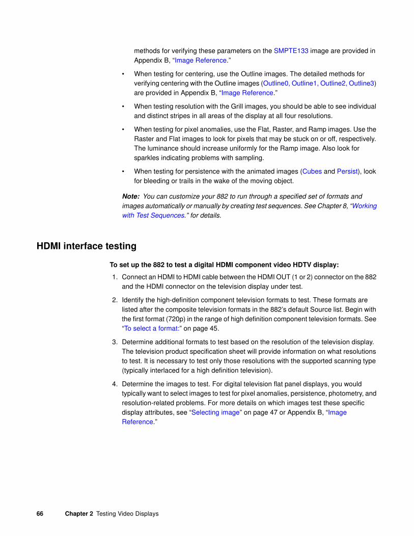
66 Chapter 2 Testing Video Displays
methods for verifying these parameters on the SMPTE133 image are provided in Appendix B, “Image Reference.”
• When testing for centering, use the Outline images. The detailed methods for verifying centering with the Outline images (Outline0, Outline1, Outline2, Outline3) are provided in Appendix B, “Image Reference.”
• When testing resolution with the Grill images, you should be able to see individual and distinct stripes in all areas of the display at all four resolutions.
• When testing for pixel anomalies, use the Flat, Raster, and Ramp images. Use the Raster and Flat images to look for pixels that may be stuck on or off, respectively. The luminance should increase uniformly for the Ramp image. Also look for sparkles indicating problems with sampling.
• When testing for persistence with the animated images (Cubes and Persist), look for bleeding or trails in the wake of the moving object.
Note: You can customize your 882 to run through a specified set of formats and
images automatically or manually by creating test sequences. See Chapter 8, “Working
with Test Sequences.” for details.
HDMI interface testing
To set up the 882 to test a digital HDMI component video HDTV display:
1. Connect an HDMI to HDMI cable between the HDMI OUT (1 or 2) connector on the 882 and the HDMI connector on the television display under test.
2. Identify the high-definition component television formats to test. These formats are listed after the composite television formats in the 882’s default Source list. Begin with the first format (720p) in the range of high definition component television formats. See “To select a format:” on page 45.
3. Determine additional formats to test based on the resolution of the television display. The television product specification sheet will provide information on what resolutions to test. It is necessary to test only those resolutions with the supported scanning type (typically interlaced for a high definition television).
4. Determine the images to test. For digital television flat panel displays, you would typically want to select images to test for pixel anomalies, persistence, photometry, and resolution-related problems. For more details on which images test these specific display attributes, see “Selecting image” on page 47 or Appendix B, “Image Reference.”
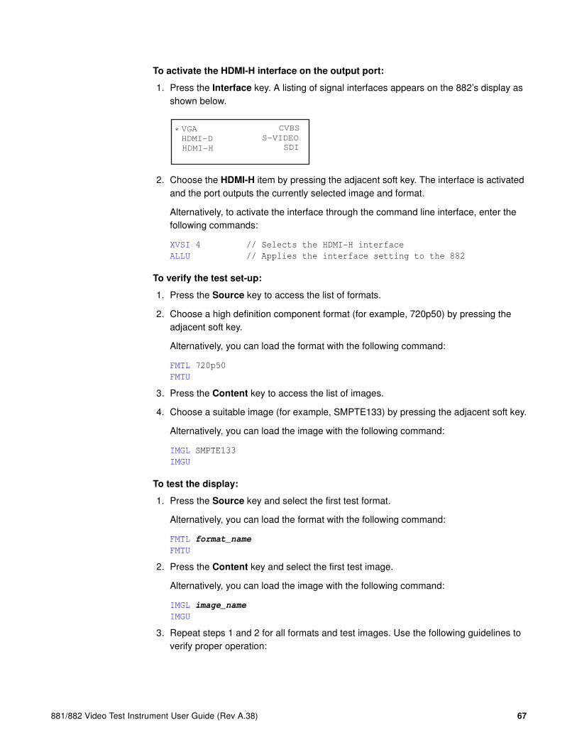
881/882 Video Test Instrument User Guide (Rev A.38) 67
To activate the HDMI-H interface on the output port:
1. Press the Interface key. A listing of signal interfaces appears on the 882’s display as shown below.
2. Choose the HDMI-H item by pressing the adjacent soft key. The interface is activated and the port outputs the currently selected image and format.
Alternatively, to activate the interface through the command line interface, enter the following commands:
XVSI 4 // Selects the HDMI-H interface
ALLU // Applies the interface setting to the 882
To verify the test set-up:
1. Press the Source key to access the list of formats.
2. Choose a high definition component format (for example, 720p50) by pressing the adjacent soft key.
Alternatively, you can load the format with the following command:
FMTL 720p50
FMTU
3. Press the Content key to access the list of images.
4. Choose a suitable image (for example, SMPTE133) by pressing the adjacent soft key.
Alternatively, you can load the image with the following command:
IMGL SMPTE133
IMGU
To test the display:
1. Press the Source key and select the first test format.
Alternatively, you can load the format with the following command:
FMTL format_name
FMTU
2. Press the Content key and select the first test image.
Alternatively, you can load the image with the following command:
IMGL image_name
IMGU
3. Repeat steps 1 and 2 for all formats and test images. Use the following guidelines to verify proper operation:
VGA
HDMI-D
CVBS
S-VIDEO
SDI
*
HDMI-H

68 Chapter 2 Testing Video Displays
• When testing photometry such as chrominence, use the ColorBar, SMPTE133, or SMPTEbar images. Look for missing bars which may indicate a dead or unconnected channel. Also, look at the transitions between the bars; they should be sharp and distinct. Each bar also should be uniform in color and intensity across its entire width.
• When testing luminance, you can use the SMPTE133 (grayscale) images. To test gamma correction, you can use the SMPTE133 (checkerbox) image. The detailed methods for verifying these parameters on the SMPTE133 image are provided in Appendix B, “Image Reference.”
• When testing for centering, use the Outline images. The detailed methods for verifying centering with the Outline images (Outline0, Outline1, Outline2, Outline3) are provided in Appendix B, “Image Reference.”
• When testing resolution with the Grill images, you should be able to see individual and distinct stripes in all areas of the display at all four resolutions.
• When testing for pixel anomalies, use the Flat, Raster, and Ramp images. Use the Raster and Flat images to look for pixels that may be stuck on or off, respectively. The luminance should increase uniformly for the Ramp image. Also look for sparkles indicating problems with sampling.
• When testing for persistence with the animated images (Cubes and Persist), look for bleeding or trails in the wake of the moving object.
Note: You can customize your 882 to run through a specified set of formats and
images automatically or manually by creating test sequences. See Chapter 8, “Working
with Test Sequences.” for details.

881/882 Video Test Instrument User Guide (Rev A.38) 69
Using the Image Caching feature
The Image Cache feature enables you to render images quickly. This feature is ideal for applications, such as production line testing, which require rapid image rendering.
The Image Cache features renders a number of images in advance and stores them in memory for immediate recall. The number of images that can be stored in cache depends on the resolution and bit depth of the chosen format. The cached images are stored in video RAM, and are lost on power cycle, reboot, or issuance of the ICHC command.
Usage of cached images can be divided into two sets of operations. First, the desired formats and images are loaded in the conventional non-cached manner. As each image is displayed, it can be saved in the cache to be later recalled in the same format. When all images have been saved with the proper video formats, they can be quickly recalled from the cache and displayed.
Use the procedure below to render images quickly with the Image Cache feature.
To test a sink with the Image Caching feature:
1. Load the cache with some images in 2 different formats.
IMGX:SRC Render // specify normal render mode
ICHC // clear the cache
FMTL DMT0660 // select first format
FMTU // use this format
IMGL SmpteBar // load image SmpteBar
IMGU // use this image
ICHA IMG1 // save this image to cache as IMG1 for DMT0660
IMGL Master // load image Master
IMGU // use this image
ICHA IMG2 // save this image to cache as IMG2 for DMT0660
IMGL TVBarH // load image TVBarH
IMGU // use this image
ICHA IMG3 // save this image to cache as IMG3 for DMT0660
FMTL 720p60 // load 720p60 format
FMTU // use this format
IMGL SmpteBar // load image SmpteBar
IMGU // use this image
ICHA IMG4 // save this image to cache as IMG4 for 720p60
IMGL Ramp_B // load image Ramp_B
IMGU // use this image
ICHA IMG5 // save this image to cache as IMG5 for 720p60
2. Display these images from cache.
IMG:SRC Cache // enable image caching
FMTL DMT0660 // load format DMT0660
ICHL IMG3 // load cached TVBarH for DMT0660
FMTU // fast display of TVBarH for DMT0660
ICHL IMG1 // load cached SmpteBar for DMT0660
ICHU // fast display of SmpteBar from cache
FMTL 720p60 // load format 720p60

70 Chapter 2 Testing Video Displays
ICHL IMG4 // load cached SmpteBar for 720p60
FMTU // fast display of SmpteBar from cache
ICHL IMG5 // load cached Ramp_B for 720p60
ICHU // fast display of Ramp_B
FMTL DMT0660 // load format DMT0660
ICHL IMG2 // load cached Master for DMT0660
FMTU // fast display of Master
3. Return to normal rendering mode.
IMGX:SRC Render // specify normal render mode

881/882 Video Test Instrument User Guide (Rev A.38) 71
Using the AuxTest image
This section describes the AuxTest composite test image used in production. This image tests an HDMI sink for CEC, EDID and HDCP at the same time. The CEC test is a simple ping test. The HDCP test is an authentication test. The EDID test is a checksum test.
Use the procedure below to test a sink for CEC, EDID and HDCP.
To test an HDMI sink for CEC, EDID and HDCP:
1. Physically connect a monitor to the HDMI Tx port.
There are two AuxTest images. AuxTest1 tests out the HDMI Tx port1 and AuxTest2 tests out the HDMI Tx port2:
2. Press the Interface key. A listing of signal interfaces appears on the 882’s display as shown below.
3. Choose the HDMI-H item by pressing the adjacent soft key. The interface is activated and the port outputs the currently selected image and format.
Alternatively, to activate the interface through the command line interface, enter the following commands:
XVSI 4 // Selects the HDMI-H interface
ALLU // Applies the interface setting to the 882
4. Press the Content key and select the first AuxTest image.
Alternatively, you can load the image with the following command:
IMGL AuxTest1
IMGU
The test image is shown below. The upper left section shows the results of the EDID test which verifies the checksum. The upper right section shows the result of the CEC test which does a basic ping test and also reads the physical address of a connected
VGA
HDMI-D
CVBS
S-VIDEO
SDI
*
HDMI-H

72 Chapter 2 Testing Video Displays
device. The section in the center shows the step by step results (11 steps) of the first phase of the HDCP authentication. Below that is the ongoing test results of the third phase of authentication, i.e. exchanging the Ri values.

881/882 Video Test Instrument User Guide (Rev A.38) 73
Using the ImageShift utility
This section describes the ImageShift utility and how to use it. The ImageShift utility allows you to set in motion any of the built-in or bitmap static images stored in the 882. Image shifting can be controlled at both the pixel level in horizontal and vertical directions, and on a per frame basis. The shift pattern can be set to either a repeated pattern or back and forth (reversed).
You can create your own imageshift files in order to specify particular image shifting configurations to invoke. This enables you to quickly invoke an image shifting set of parameters to apply.
The ImageShift function can be configured and run either through the front panel or the command line. Procedures for both are provided.
Using the ImageShift utility through the front panel
The procedure for configuring and running the ImageShift utility is provided below.
To use the ImageShift utility through the front panel:
1. Physically connect a monitor to the 882 at any of the interfaces using a suitable cable.
2. Press the Tools key. The Tools menu appears on the 882’s display as shown below.
3. Choose ImgShift by pressing the adjacent soft key. The following menu appears on the 882’s display.
This display enables you to browse for a bitmap image or a built-in image stored in cache.
4. Choose Cache to browse for a built-in image. The following menu appears on the 882’s display.
System
Sequence
Probe
AFC
Analyzer
Reports
ImgShift
CEC
Flash Card Sequence Cache
Exit!
Images Fonts Tools

74 Chapter 2 Testing Video Displays
5. Choose Images, and then select the image you want to use.
The image appears and begins shifting in accordance with default settings for both speed and method of shifting (either repeat or reversed). The following settings appear on the 882’s display as shown below.
a. Configure image shifting parameters by selecting a parameter using its adjacent soft key, then adjusting the value by pressing the + or - keys.
Refer to the following table for a description of the parameters used to control image shifting.
6. To set the starting point of the image shift, press the Settings key. The following settings appear on the 882’s display.
You can set the starting coordinates of the image shift as follows:
a. To specify the X Start Point, position the blinking cursor on the digits of the X coordinate you wish to change. To do this, press the soft key adjacent to the arrow
Parameter Action
Line Selects image shifting pattern. This can be either Reverse or Repeat.
• Reverse moves the image in both directions in accordance with the shift parameters.
• Repeat moves the image in only one direction.
HInc Specifies number of pixels the image travels in a horizontal direction per time period.
VInc Specifies number of lines the image travels in a vertical direction per time period.
TInc Specifies movement to occur per N number of frames.
>Line Reversed< HInc: 1 VInc: 1*TInc: 1 Exit!
Path Start Point -> X Y 000 000 ->

881/882 Video Test Instrument User Guide (Rev A.38) 75
by the coordinates to move the cursor left or right until it appears on the digit in the X coordinate. Adjust the value of the setting up or down by pressing the + or - keys.
b. To specify the Y Start Point, position the blinking cursor on the digits of the Y coordinate you wish to change. To do this, press the soft key adjacent to the arrow by the coordinates to move the cursor left or right until it appears on the digit in the Y coordinate. Adjust the value of the setting up or down by pressing the + or - keys.
7. To set the ending point of the image shift, press the soft key to the right of Start Point. The following settings appear on the 882’s display.
You can set the ending coordinates of the image travel as follows:
a. To specify the X End Point, position the blinking cursor on the digits of the X coordinate you wish to change. To do this, press the soft key adjacent to the arrow by the coordinates to move the cursor left or right until it appears on the digit in the X coordinate. Adjust the value of the setting up or down by pressing the + or - keys.
b. To specify the Y End Point, position the blinking cursor on the digits of the Y coordinate you wish to change. To do this, press the soft key adjacent to the arrow by the coordinates to move the cursor left or right until it appears on the digit in the Y coordinate. Adjust the value of the setting up or down by pressing the + or - keys.
Note: The movement that you see may not always correspond to the settings for HInc
and VInc. The reason is that the number of shifts from start point to end point is
determined by the quotient of the total travel in the horizontal (pixels) and vertical (lines)
directions and the total increment defined. The lowest quotient of the two (horizontal
vs. vertical) will determine how many shifts the utility will make from start point to end
point. For example, if the start point is 0,0 and the end point is 100,100. An HInc setting
of 10 and a VInc setting of 20 will result in 5 shift movements (100/20 = 5). The 882 will
not produce shifts of 10 horizontal pixels per increment because it cannot move from 0
to 100 in 5 shifts by only moving 10 horizontal increments.
8. To save the changes, press the Enter (Options) key. The following choices appear on the 882’s display:
• To save the changes, choose the Yes item by pressing the adjacent soft key.
• To exit without saving the changes, choose the No item.
Path<- End Point X Y 100 100 ->
Apply Settings?
Back
Yes No

76 Chapter 2 Testing Video Displays
• To return to the previous screen without saving the changes, choose the Back item.
Using the ImageShift utility through the command line interface
The procedures for configuring and running the ImageShift utility from the command line interface are given below. To run the ImageShift utility from the command line interface, you must utilize an imageshift file. An imageshift file specifies both the image and parameters necessary to run the ImageShift utility.
To create an imageshift file:
1. Establish a session with the 882 using either HyperTerminal over a serial connection or Telnet over an Ethernet LAN. See “Configuring the 882’s serial port” on page 30 or “Establishing a Telnet session with the 882” on page 33.
2. Set the path to the imageshift files using the ISHP command. For example:
ISHP tffs0/library/imageshifts
3. Create a new imageshift file using the ISHN command. For example:
ISHN Newshift
4. Define the imageshift file settings as shown in the example below:
ISHB //begins an imageshift editing session
XISH:SRCN /cache0/images/SMPTEBar //selects the SMPTEBar image
XISH:PATH 0,0 150,20 //sets the imageshift path x,y coordinates
XISH:TTYP 1 //sets the trace type to Repeat (1)
XISH:HINC 4 //sets the horizontal shift increment to 4
XISH:VINC 2 //sets the vertical shift increment to 2
XISH:TINC 5 //sets the time shift value to 5
ISHE //ends the imageshift editing session
5. Save the settings to the same imageshift file using the ISHS command, For example:
ISHS //saves the settings to the Newshift file
To run the ImageShift utility through the command line interface:
1. Establish a session with the 882 using either HyperTerminal over a serial connection or Telnet over an Ethernet LAN. See “Configuring the 882’s serial port” on page 30 or “Establishing a Telnet session with the 882” on page 33.
2. Set the path to the imageshift files using the ISHP command. For example:
ISHP tffs0/library/imageshifts
3. Enter the following commands to display the list of imageshift files.
ISHQ? //Displays the first 5 imageshift filenames
ISHQ? //Displays 5 more imageshift filenames
4. Load an imageshift file and apply the image to hardware. For example:

881/882 Video Test Instrument User Guide (Rev A.38) 77
ISHL Newshift //Loads the values from the imageshift file named
//Newshift
ISHG 1 //Initiates (gates on) the imageshift function
ISHU //Applies the values to the hardware
5. Apply the imageshift file to the hardware using the ISHU command. For example:
ISHU //applies the imageshift file to the hardware
To stop the ImageShift utility through the command line interface:
1. To stop the Imageshift enter the following command.
ISHG 0 //Stops (gates off) the imageshift function

78 Chapter 2 Testing Video Displays
Adjust Frequency Function
This section describes the adjust frequency control (AFC) function.
The AFC function provides you with the ability to increase or decrease the horizontal frequency (HRAT parameter) of the active video format in increments of 2%.
Use the following procedures to increase or decrease the frequency of the active format.
To utilize the AFC function:
1. Physically connect a monitor to the 882 at any of the interfaces using a suitable cable.
2. Press the Tools key. The Tools menu appears on the 882’s display as shown below.
3. Choose AFC by pressing the adjacent item selection key. The following display appears on the 882’s display.
This display enables you to increase or decrease the horizontal frequency parameter in increments of 2% using the +/- keys.
System
Sequence
Probe
AFC
Analyzer
Reports
ImgShift
CEC
Hz Frequency Shift -10% -----+----- +10% ^ H = 45000.000

881/882 Video Test Instrument User Guide (Rev A.38) 79
Keypad Utility
This section describes the Keypad utility and how to use it.
The keypad provides you with a quick and convenient way of changing between formats and images. The interface from the Keypad to the 882 is through the serial interface. Once connected you can change between formats and image with a single key stroke. You can also control test sequences using the Keypad.
Use the following procedures to install and operate the remote keypad.
To install and enable the keypad:
1. Shut off the 882.
2. Connect the keypad to the serial port on the 882.
The serial port is on the back of the 882 on the lower panel. It is labeled Serial.
3. Press the Tools key. The Tools menu appears on the 882’s display as shown below.
4. Choose System pressing the adjacent item selection key. The following display appears on the 882’s display.
5. Choose Serial to access the menu for enabling the Keypad. The following display appears on the 882’s display.
6. Press the Options key. The following information appears on the 882’s display:
7. Press the softkey adjacent to the Keypad item to enable the keypad function.
A + appears next to the Keypad item indicating that the functionality is enabled.
System
Sequence
Probe
AFC
Analyzer
Reports
ImgShift
CEC
Clock Clone* CalFactor Server Network About Serial GPib
Serial Port 9600 baud 8 N 1
-Keypad

80 Chapter 2 Testing Video Displays
To monitor the status of the keypad:
1. Press the Tools key. The Tools menu appears on the 882’s display.
When the keypad has been enabled there is an additional item in the Tools menu. This is indicated by an arrow key. If you scroll down using the - key the following menu appears:
2. Select the Keypad item to view the keypad status. The screen shown below appears.
This display shows the Mode which is either normal or Sequence and the current format and image. The Exit enables you to exit from the menu without disabling the keypad function.
Sequence ^
Probe
AFC
Keypad
Analyzer
ImgShift
Mode: Normal
FMT:720p60
IMG:Flat
Exit!

881/882 Video Test Instrument User Guide (Rev A.38) 81
To operate the keypad
1. Use the figure below to operate the keypad. The keypad has two basic modes: 1) Normal which enables you to change the formats, images and colorimetry and 2) Sequence mode which enables you to control a running test sequence.
Sequence mode key functionsNormal mode key functions
Num
Lock
Home Pg Up
Pg Dn
DelIns
Enter
Esc
(Light on)
Tab
End
5 64
2 31
8 97
\
+
.
*/
Switch to Sequence Mode
Select imageSelect format
Cycle R-G-B gating
Previous format
Previous image
Next format
Next image
Image invert toggle0
Num
Lock
Home Pg Up
Pg Dn
DelIns
Enter
Esc Tab
End
5 64
2 31
8 97
\
+
.
*/
Switch to Normal Mode
Cycle step mode
Toggle display mode
Select sequence
Previous step
Next step
Select step0
(Light off)
ksaT erudecorP
tsiltnerrucmorfegamitceleS otsyekciremunesu,yek*sserP
nehtdna,rebmunegamiehtyficeps
.retnEsserp
egamitxentceleS .retnEsserP
egamisuoiverptceleS .yek+sserP
egamifonoisrevetanretlatceleS
)elbaliavafi(
.yekleDsserP
gnitagoedivG-B-RegnahC hguorhtelcycotyek–sserP
.snoitanibmocgnitag
tsiltnerrucmorftamrofynatceleS otsyekciremunesu,yek/sserP
nehtdna,rebmuntamrofyficeps
.retnEsserp
tamroftxentceleS .2sserP
tamrofsuoiverptceleS .8sserP
edoMecneuqeSothctiwS .yekcoLmuNsserP
ksaT erudecorP
tsiltnerrucmorfecneuqestceleS otsyekciremunesu,yek–sserP
nehtdna,rebmunecneuqesyficeps
.retnEsserp
ecneuqesnipetsynatceleS otsyekciremunesu,yekleDsserP
nehtdna,rebmunpetsyficeps
.retnEsserp
petstxentceleS .retnEsserP
petssuoiverptceleS .yek+sserP
dohtempetsecneuqesegnahC
)noosdna,otua,parw,pets(
hguorhtelcycotyek*sserP
.snoitpo
sgnittesMUNDegnahC hguorhtelcycotyek/sserP
.snoitpo
edoMlamroNothctiwS .yekcoLmuNsserP

82 Chapter 2 Testing Video Displays

881/882 Video Test Instrument User Guide (Rev A.38) 83
3 Administrative Tasks
Topics in this chapter:
• Overview
• Calibrating the generator
• Auto Upgrade
• Upgrading the generator locally
• Reconfiguring and booting a stalled generator
• Cloning generators
• Resetting a generator
• Viewing generator configuration information

84 Chapter 3 Administrative Tasks
Overview
This section describes how to accomplish administrative tasks, including calibrating the generator, upgrading a generator, cloning a generator and maintaining the generator’s file system.

881/882 Video Test Instrument User Guide (Rev A.38) 85
Calibrating the generator
The 882 generator can calibrate itself. Once calibrated, the generator does not require periodic calibration. There are no physical controls to adjust. All calibration is electronic. Calibration factors are saved in non-volatile memory.
Calibrating signal level
The calibration accuracy of the generator for analog video voltage swing is specified to be ±14 mV (or ±2% for a nominal 700 mV signal). Using a typical oscilloscope such as a Tektronix VM700T, which might have a swing measurement accuracy of ±14 mV, readings should be between 674 mV to 726 mV.
You can set the analog output calibration factors to values other than those set by the generator's own self-calibration function. Each channel is calibrated using two independent, zero calibration points, and two independent, slope calibration points. Interpolation equations for the different video types are used to set the caldac values that control the output sync and voltage levels to the correct values.
You can calibrate the generator using the front panel keys or the command line interface. Follow the procedures below to calibrate the generator.
To self-calibrate the generator using the front panel:
1. (Optional) Load the outputs of the generator. Although it is not necessary to load the outputs during self-calibration, attaching a nominal load may yield a slight increase in accuracy.
2. Press the Tools key. The Tools menu appears on the generator’s display as shown below.
3. Choose the System item by pressing the adjacent soft key. The System menu appears. Press the - key to scroll down until the CalFactor item appears.
System
Sequence
Probe
AFC
Analyzer
Reports
ImgShift
CEC
CalFactor Host Network About Serial Gpib BootFrom Init
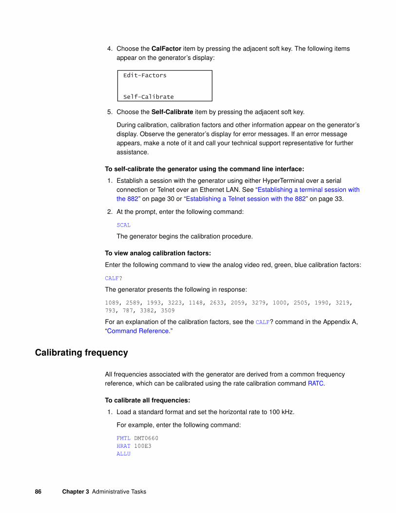
86 Chapter 3 Administrative Tasks
4. Choose the CalFactor item by pressing the adjacent soft key. The following items appear on the generator’s display:
5. Choose the Self-Calibrate item by pressing the adjacent soft key.
During calibration, calibration factors and other information appear on the generator’s display. Observe the generator’s display for error messages. If an error message appears, make a note of it and call your technical support representative for further assistance.
To self-calibrate the generator using the command line interface:
1. Establish a session with the generator using either HyperTerminal over a serial connection or Telnet over an Ethernet LAN. See “Establishing a terminal session with the 882” on page 30 or “Establishing a Telnet session with the 882” on page 33.
2. At the prompt, enter the following command:
SCAL
The generator begins the calibration procedure.
To view analog calibration factors:
Enter the following command to view the analog video red, green, blue calibration factors:
CALF?
The generator presents the following in response:
1089, 2589, 1993, 3223, 1148, 2633, 2059, 3279, 1000, 2505, 1990, 3219,
793, 787, 3382, 3509
For an explanation of the calibration factors, see the CALF? command in the Appendix A, “Command Reference.”
Calibrating frequency
All frequencies associated with the generator are derived from a common frequency reference, which can be calibrated using the rate calibration command RATC.
To calibrate all frequencies:
1. Load a standard format and set the horizontal rate to 100 kHz.
For example, enter the following command:
FMTL DMT0660
HRAT 100E3
ALLU
Edit-Factors
Self-Calibrate

881/882 Video Test Instrument User Guide (Rev A.38) 87
2. Measure the TTL horizontal sync frequency with the frequency counter.
3. Divide the frequency that you expect by the frequency that you measure on the frequency counter. For example, if you measure 99.9955782499875 kHz, when you expect 100.000000000KHz, then divide 100.000000000 kHz by 99.9950002499875 kHz; the result is 1.0000442194553987.
4. Enter the result into the generator. This will raise all frequencies output by the generator and make them exact. To enter the results through the front panel using the following procedures:
5. Press the Tools key. The Tools menu appears on the generator’s display as shown below.
6. Choose the System item by pressing the adjacent soft key. The System menu appears. Press the - key to scroll down until the CalFactor item appears.
7. Choose the CalFactor item by pressing the adjacent soft key. The following items appear on the generator’s display:
8. Choose the Edit Factors item by pressing the adjacent soft key. The following items appear on the generator’s display:
a. Edit the RATC factor by pressing the soft keys adjacent to the bottom row until the cursor appears on the digit you want to change. Press the + or - keys to adjust the setting up or down.
b. Press the Enter (Options) key to save the new setting.
Alternatively, to enter the result using the command line interface, use the RATC command. For example:
RATC 1.0000442194553987
System
Sequence
Probe
AFC
Analyzer
Reports
ImgShift
CEC
CalFactor Host Network About Serial Gpib BootFrom Init
Edit-Factors
Self-Calibrate
Cal Factors Frequency -> RATC<- 1.000000000

88 Chapter 3 Administrative Tasks
Auto Upgrade
This section provides procedures on how to upgrade your generator using the auto upgrade feature. Note that there are also procedures for manually upgrading your 880 series generator, refer to “Manually upgrading using PCMCIA Compact Flash card” on page 107 or “Manually upgrading the generator without using PC Card” on page 110.
Quantum Data periodically makes available new firmware releases for the 880 series generators. The Auto Update utility automates the process of upgrading firmware. It guides the user through the upgrade process, checking the Quantum Data website for the latest version and installing all files in the correct location on the generator.
The Auto Update utility provides for two methods of copying the firmware files into the generator: 1) The network method and 2) the PCMCIA/Compact Flash method. These are provided below.
Auto upgrade - Network Method
The first method is the Network Upgrade. This is the recommended upgrade method. This method requires that the generator and your computer be connected by Ethernet, either via a direct crossover cable, or by being accessible to each other on a common network. The generator must possess a valid IP address, either through manual setting or via a

881/882 Video Test Instrument User Guide (Rev A.38) 89
DHCP server on the network. The PC has to be connected to the Internet. Refer to the 880 Series User Guide, Chapter 4, “Networking 882s.” for full information on configuring a generator for network use. Refer to the diagrams below.
Downloading and installing the Auto Update utility:
The Auto Update utility is java-based, and requires the Java Virtual Machine (Java runtime) to be installed on the computer. This can be obtained from http://www.java.com.
The Auto Update utility can be downloaded from the downloads section of the Quantum Data website, at http://www.quantumdata.com/downloads/index.asp.
After downloading the Auto Update ZIP file, installation is simply a matter of unzipping it into a folder on your hard disk.
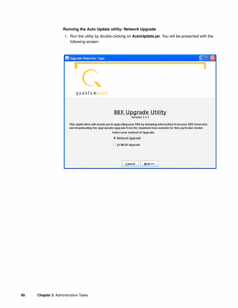
90 Chapter 3 Administrative Tasks
Running the Auto Update utility: Network Upgrade
1. Run the utility by double-clicking on AutoUpdate.jar. You will be presented with the following screen:

881/882 Video Test Instrument User Guide (Rev A.38) 91
2. Select Network Upgrade, then Next. The Network Upgrade screen will appear:
3. Make sure you have network access to the generator, then select Next.
Next you will have the opportunity to back up the files in the generator. If you have any custom images, formats, reports, or other files stored on the /tffs0 flash drive within the generator, they will be lost unless you choose to back up the files.

92 Chapter 3 Administrative Tasks
4. Optionally browse to a new backup directory, then click Next to begin the backup. If you don’t want to back up any files from the generator, click on Skip Backup.
5. Next, enter the IP address for the generator:

881/882 Video Test Instrument User Guide (Rev A.38) 93
6. Click Next to continue.
7. If you see this screen, click Continue With Upgrade:
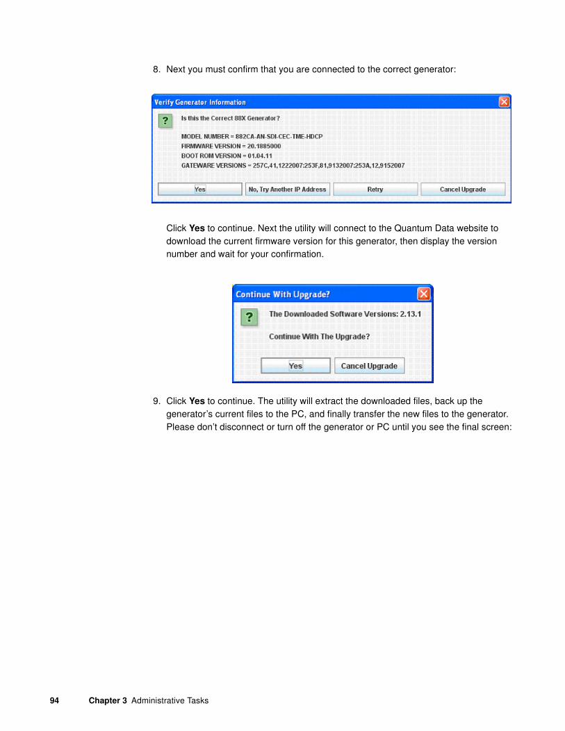
94 Chapter 3 Administrative Tasks
8. Next you must confirm that you are connected to the correct generator:
Click Yes to continue. Next the utility will connect to the Quantum Data website to download the current firmware version for this generator, then display the version number and wait for your confirmation.
9. Click Yes to continue. The utility will extract the downloaded files, back up the generator’s current files to the PC, and finally transfer the new files to the generator. Please don’t disconnect or turn off the generator or PC until you see the final screen:

881/882 Video Test Instrument User Guide (Rev A.38) 95
10. Now you must power cycle the generator to boot from the new firmware.
Auto upgrade - PCMCIA/Compact Flash Method
The second method of upgrading the generator using the auto upgrade feature is the PCMCIA/Compact Flash upgrade. This method is used when you connect the generator to the network and you cannot connect the PC to the generator but requires that you have a PC that is connected to the network (Internet). This method uses the PCMCIA/Compact Flash card (or compact flash with the PCMCIA/Compact Flash adapter) to transport the

96 Chapter 3 Administrative Tasks
upgrade files from the computer to the generator. The Auto Upgrade utility prompts the user when the PCMCIA/Compact Flash card must be moved between the computer and the generator.
Running the Auto Update utility: PCMCIA Upgrade
1. Run the utility by double-clicking on AutoUpdate.jar. You will be presented with the following screen:

881/882 Video Test Instrument User Guide (Rev A.38) 97
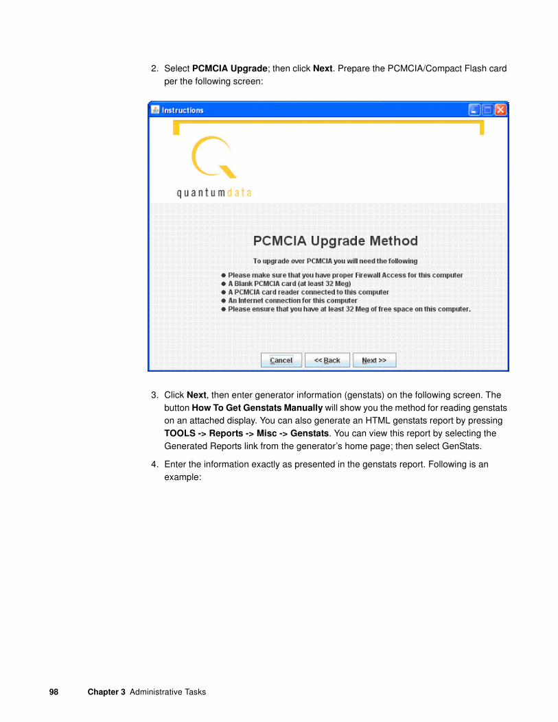
98 Chapter 3 Administrative Tasks
2. Select PCMCIA Upgrade; then click Next. Prepare the PCMCIA/Compact Flash card per the following screen:
3. Click Next, then enter generator information (genstats) on the following screen. The button How To Get Genstats Manually will show you the method for reading genstats on an attached display. You can also generate an HTML genstats report by pressing TOOLS -> Reports -> Misc -> Genstats. You can view this report by selecting the Generated Reports link from the generator’s home page; then select GenStats.
4. Enter the information exactly as presented in the genstats report. Following is an example:

881/882 Video Test Instrument User Guide (Rev A.38) 99
5. When this information is correct, click on Next.
6. The utility will download the new firmware files from the Quantum Data website, and report the version number of the release:
7. Click on Yes, and the utility will extract the individual files from the downloaded release archive. Then you will be prompted to insert a blank PCMCIA/Compact Flash card into the generator.

100 Chapter 3 Administrative Tasks

881/882 Video Test Instrument User Guide (Rev A.38) 101
8. Next you will be prompted to hit the Clone Capture button (Tools -> System -> Clone
-> Capture.) This will cause the generator to back up the internal files to the PCMCIA/Compact Flash card. When this process is complete, insert the card into the computer and click on Next.
9. Then you will be asked to specify the location of the PCMCIA/Compact Flash drive on the computer. You can type the drive letter into the space provided (such as G:\) or you can browse to the location. In either case, you must specify the root of the PCMCIA/Compact Flash card.

102 Chapter 3 Administrative Tasks
10. When the drive address is selected, click Next, and the backup files will be copied from the card onto the PC. When the backup is completed, the new release files will be

881/882 Video Test Instrument User Guide (Rev A.38) 103
copied onto the card. Then you will be prompted to insert the card back into the generator.
11. Click Next, and you will see the following screen instructing you to initiate the clone restore process by pressing Tools -> System -> Clone -> Restore.

104 Chapter 3 Administrative Tasks
12. After the clone restore is complete, you will again see the menu on the generator’s screen. Then click on Next.

881/882 Video Test Instrument User Guide (Rev A.38) 105

106 Chapter 3 Administrative Tasks
13. Power cycle the generator, and it will boot the upgraded firmware.

881/882 Video Test Instrument User Guide (Rev A.38) 107
Upgrading the generator locally
This section provides procedures for upgrading a generator locally. Procedures for upgrading multiple generators over a network are provided in “Upgrading 882s over a network” on page 150.
There are two methods for upgrading a generator locally:
• Upgrading using PC card
• Upgrading without using PC card
Upgrading using the PC card is the recommended approach to upgrade the generator locally. However, you may prefer to leave the current files on the PC card so you can return to a known operational state should the upgrade fail. In this case, you can upgrade by transferring the new release files directly to flash memory in the generator.
Manually upgrading using PCMCIA Compact Flash card
This procedure requires that you put the new release files (System and Library directories) on the PC card, then use the Restore function to transfer the files from PCMCIA Compact Flash card (PC Card) to flash memory on the generator.
Note: Please note that you must us a PCMCIA card that is formatted in FAT16 filesystem.
If you use an card that is formatted in FAT32, the 882 will not boot.
Important: If you have custom files stored in flash memory or PC card, you must back
them up to your PC before upgrading your generator. These files will be deleted during this
upgrade procedure. See “Copying files from a 882 to a PC” on page 25 for details on using
the FTP Browser to back up generator files. Once your generator is upgraded, you will need
to restore these files.
Follow this procedure to upgrade a generator using the PC card.
To upgrade a generator using the PC card:
1. Download the new release zip file from the Quantum Data download page (http://www.quantumdata.com/downloads/index.asp) and extract into a folder on your PC.
2. If you have a PCMCIA slot accessible with your PC, perform the following steps. Otherwise, proceed to Step 3.
a. Insert the PC card into the PC’s PCMCIA slot.
108 Chapter 3 Administrative Tasks
Note: Please note that you must us a PCMCIA card that is formatted in FAT16
filesystem. If you use an card that is formatted in FAT32, the 882 will not boot.
b.
c. Transfer the new release files (System and Library directories) to the PC card.
d. Remove the PC card from your PC and insert into the generator’s PC card slot.
3. If your PC does not have access to a PCMCIA slot or device, use the following procedure. You can skip this step if you performed Step 2 above.
a. Access the generator’s main web page. For details on this, see “To connect directly to the generator:” on page 114.
b. Access the generator’s FTP browser by choosing the FTP Browser menu item from the generator’s main web page. The Generator FTP Browser appears. The
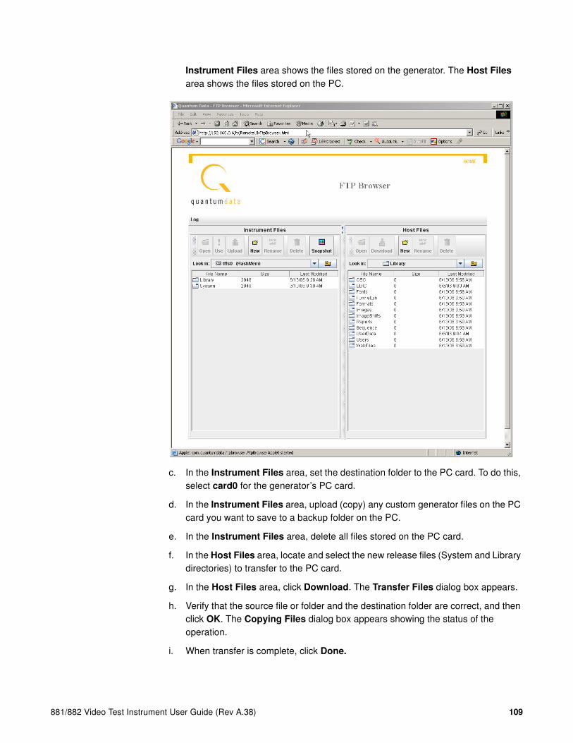
881/882 Video Test Instrument User Guide (Rev A.38) 109
Instrument Files area shows the files stored on the generator. The Host Files area shows the files stored on the PC.
c. In the Instrument Files area, set the destination folder to the PC card. To do this, select card0 for the generator’s PC card.
d. In the Instrument Files area, upload (copy) any custom generator files on the PC card you want to save to a backup folder on the PC.
e. In the Instrument Files area, delete all files stored on the PC card.
f. In the Host Files area, locate and select the new release files (System and Library directories) to transfer to the PC card.
g. In the Host Files area, click Download. The Transfer Files dialog box appears.
h. Verify that the source file or folder and the destination folder are correct, and then click OK. The Copying Files dialog box appears showing the status of the operation.
i. When transfer is complete, click Done.

110 Chapter 3 Administrative Tasks
4. On the generator front panel, press the Tools key. The Tools menu appears on the generator’s display as shown below.
5. Choose the System item by pressing the adjacent soft key. The System menu appears on the generator’s display as shown below.
6. Choose the Clone item by pressing the adjacent soft key. The Clone menu appears on the generator’s display as shown below.
7. Choose the Restore item by pressing the adjacent soft key. The current files on the generator’s flash memory are replaced by the new release files from the PC card. You are prompted to confirm the restore.
8. Choose Yes to proceed with the upgrade by pressing the adjacent soft key. When restore operation is complete, the Tools menu is displayed.
9. Restart the generator while booting from flash memory.
10. Restore any custom files to flash memory or PC card.
Manually upgrading the generator without using PC Card
This procedure allows you to transfer (copy) the new release files (System and Library directories) directly to flash memory without using a PC Card.
Follow this procedure to upgrade a generator without using a PC Card.
1. Download the new release zip file from the Quantum Data download page (http://www.quantumdata.com/downloads/index.asp) and extract into a folder on your PC.
2. Access the generator’s main web page. For details on this, see “To connect directly to the generator:” on page 114.
3. Access the generator’s FTP browser by choosing the FTP Browser menu item from the generator’s main web page. The Generator FTP Browser appears. The Instrument
System
Sequence
Probe
AFC
Analyzer
Reports
ImgShift
CEC
Clock Clone* CalFactor Server Network About Serial GPib
Capture Restore
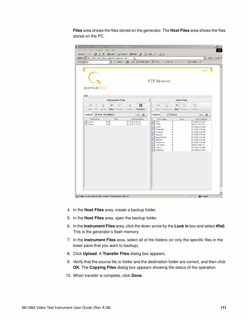
881/882 Video Test Instrument User Guide (Rev A.38) 111
Files area shows the files stored on the generator. The Host Files area shows the files stored on the PC.
4. In the Host Files area, create a backup folder.
5. In the Host Files area, open the backup folder.
6. In the Instrument Files area, click the down arrow by the Look in box and select tffs0. This is the generator’s flash memory.
7. In the Instrument Files area, select all of the folders (or only the specific files in the lower pane that you want to backup).
8. Click Upload. A Transfer Files dialog box appears.
9. Verify that the source file or folder and the destination folder are correct, and then click OK. The Copying Files dialog box appears showing the status of the operation.
10. When transfer is complete, click Done.

112 Chapter 3 Administrative Tasks
11. In the Instrument Files area, select all of the folders (System and Library) in the lower pane.
12. Click Delete. A Deleting Files dialog box appears.
13. Verify that the selected folders on the generator’s flash memory (tffs0) are correct, and then click OK. The Deleting Files dialog box appears showing the status of the operation.
14. When delete is complete, click Done.
15. In the Host Files area, locate and select the new release files (System and Library directories).
16. In the Host Files area, click Download. A Transfer Files dialog box appears.
17. Verify that the source file or folder and the destination folder are correct, and then click OK. The Copying Files dialog box appears showing the status of the operation.
18. When transfer is complete, click Done.
19. Restart the generator while booting from flash memory.
20. Restore any custom files to flash memory from backup.
Connecting generator directly to a PC
This section describes how to connect your generator directly to a PC using a crossover cable. For instructions on connecting to an Ethernet LAN, see “Connecting 882s to the network” on page 140.
Use the procedures below to set the IP addresses in your generator and PC, and connect directly to the generator through an Ethernet crossover cable.
1. “Setting the generator’s IP address”
2. “Setting the PC’s network settings”
Setting the generator’s IP address
To establish communication between the PC and the generator, the generator must have an IP address. You can view and set the IP address through the front panel using the following procedures.
To set the generator’s IP address:
1. Press the Tools key. The Tools menu appears on the generator’s display as shown below.
System
Sequence
Probe
AFC
Analyzer
Reports
ImgShift
CEC

881/882 Video Test Instrument User Guide (Rev A.38) 113
2. Choose the System item by pressing the adjacent soft key. The System menu appears on the generator’s display as shown below.
3. Choose the Network item by pressing the adjacent soft key. The generator’s IP address and subnet mask appear on the generator’s display as shown below.
4. Press the Settings key. The Network Connection screen appears on the generator’s display as shown below.
If the IP Address configuration option is not visible, press the soft key adjacent to the arrow symbol by SubnetMask until IP Address appears.
5. Change the IP address as follows:
a. Position the blinking cursor on the address digit you want to change. To do this, press the soft key adjacent to the arrow by the address to move the cursor left or right until it appears on the digit you want to change.
b. Adjust the value of the digit up or down by pressing the + or - keys. Repeat for each IP address digit you want to change.
6. To save the changes, press the Enter (Options) key. The following choices appear on the generator’s display:
To save the changes, choose the Yes item by pressing the adjacent soft key.
To exit without saving the changes, choose the No item.
To return to the previous screen without saving the changes, choose the Back item.
7. Reboot the generator.
Clock Clone* CalFactor Server Network About Serial GPib
IP Address 192.168.254.1Subnet Mask 255.255.255.000
Network Connection
Set TCP/IP
IP Address206.135.215.168
Apply Settings?
Back
Yes No

114 Chapter 3 Administrative Tasks
Setting the PC’s network settings
To establish a local ethernet connection between PC and generator, follow these steps to configure a static IP address on your PC and connect using a crossover cable.
To connect directly to the generator:
1. Determine the IP address of the generator by pressing the Tools key, choosing the System item, and then choosing the Network item. The IP address of the generator appears on the generator’s display. Refer to the procedures above “Setting the 882’s IP address” on page 141 for more details on accessing this display.
2. Configure the IP address of your PC. To enter the IP address, open Windows Control Panel, and then open the Network Connections window.
3. In the Network Connections window, right click the connection that represents your Ethernet card and select Properties. Select the Internet Protocol TCP/IP connection, and then click Properties.
Note: If you have more than one Ethernet card make sure you configure the select the
correct one.

881/882 Video Test Instrument User Guide (Rev A.38) 115
4. In the Internet Protocol (TCP/IP) Properties dialog box, select Use the following IP
address and type the IP address in the box.
Note: IP addresses consist of a network component and a host component. The
network component is represented by the first 3, 6, or 9 digits of the address,
depending on the network class. The host component is the last 3 digits. The network
component of the IP address you enter for the PC must match the network component
of the generator’s IP address. The host component of both IP addresses must be
different. You do not have to specify the DNS server.
5. Enter the subnet mask such that the network portion of the address is masked to a value of 255 for each.
6. Connect the crossover cable between the ETHERNET jack on the generator and the Ethernet jack on the PC.

116 Chapter 3 Administrative Tasks
7. Open a Web browser (such as Internet Explorer) and type the generator’s IP address in the address entry field. For example, enter the following: http://206.135.215.189/
The generator web page appears in the browser.

881/882 Video Test Instrument User Guide (Rev A.38) 117
Reconfiguring and booting a stalled generator
If a generator fails to boot as expected, it may be set to boot from a location with a corrupt system file or without the necessary system files. The symptom of this problem could be that the generator just fails to boot. In other cases you could see an error such as “tffs0 failed to load.” Starting in Release 2.6 (vxWorks file 20.1883600) the generator has a feature which reformats a corrupt file system. Follow the procedures below to boot the generator in these instances.
To boot a generator that is in a stalled state:
1. Apply power to the generator. The following display appears.
To boot from an alternative device, press any key within three seconds. The following display appears. Note that you can also obtain this screen by powering up the generator and holding down any key, e.g. Tools key.
2. Choose the !BootDev item by pressing the adjacent soft key.
3. Do one of the following:
• To boot from the file server, press the soft key adjacent to Network Boot.
• To boot from the generator’s flash memory, press the soft key adjacent to Internal
Flash.
• To boot from the generator’s PC card, press the soft key adjacent to PCMCIA
Boot.
Note: Please note that you must us a PCMCIA card that is formatted in FAT16
filesystem. If you use an card that is formatted in FAT32, the 882 will not boot.
4. Press the Options (Enter) key to save the configuration.
5. Either restart the generator by cycling the power or press the Tools key to return to the boot menu.
Quantum Data Windriver vxWorks System BootPress any key for setup
!BootDev !Passwd!HostName !Flags!FileName !Other!InetAddr !TrgtName

118 Chapter 3 Administrative Tasks
6. Scroll down to the allow viewing and selection of the BootNow item as shown below.
7. Select BootNow by pressing the adjacent item selection key.
8. The following display appears:
9. Press the + key to boot the generator.
To boot a generator that has a corrupt file system:
1. Configure a PCcard with Release 2.6 (vxWorks file: 20.1883600) or later including all the System and Library files.
Note: Please note that you must us a PCMCIA card that is formatted in FAT16
filesystem. If you use an card that is formatted in FAT32, the 882 will not boot.
2. Insert the PCcard in the generator’s card slot.
3. Power down the generator, hold down the Tools key and then re-apply power to the generator. The following screen appears on the generator’s display:
4. Choose the !BootDev item, and then choose the PCMCIA Boot item from the menu below:
5. Press the Options (Enter) key to save the configuration.
6. Either restart the generator by cycling the power or press the Tools key to return to the boot menu.
!FileName !Other!InetAddr !TrgtName!HostAddr BootNow!User
Press UP arrow to Boot Now
!BootDev !Passwd!HostName !Flags!FileName !Other!InetAddr !TrgtName

881/882 Video Test Instrument User Guide (Rev A.38) 119
7. Scroll down to the allow viewing and selection of the BootNow item as shown below.
8. Select BootNow by pressing the adjacent item selection key.
9. The following display appears:
10. Press the + key to boot the generator.
The following display appears and the generator boots up.
11. Press the Tools key. The Tools menu appears on the generator’s display as shown below.
12. Choose the System item by pressing the adjacent soft key. The System menu appears on the generator’s display as shown below.
ite
13. Choose the Clone item by pressing the adjacent soft key. The Clone menu appears on the generator’s display as shown below.
14. Choose the Restore item by pressing the adjacent soft key.
A progress indicator appears. This will take some time.
!FileName !Other!InetAddr !TrgtName!HostAddr BootNow!User
Press UP arrow to Boot Now
Quantum Data Windriver vxWorks System BootPress any key for setup
System
Sequence
Probe
AFC
Analyzer
Reports
ImgShift
CEC
Clock Clone* CalFactor Server Network About Serial GPib
Capture Restore

120 Chapter 3 Administrative Tasks
15. Reconfigure the generator to boot from the Flashmem using the procedures described in “To boot a generator that is in a stalled state:” on page 117.
16. Restart the generator.
17. If the problem persists you may have to unseat the video board from the main board:
http://www.quantumdata.com/support/videos/video.asp
18. Repeat the procedure.
To boot a stalled generator from a different host:
1. Power down the generator, hold down the Tools key and then re-apply power to the generator. The following screen appears on the generator’s display:
2. Choose the !BootDev item, and then choose the Network Boot item.
3. Press the Tools key and choose the !HostName item by pressing the adjacent soft key. The following appears on the generator’s display:
4. Change the host name as follows:
a. Position the blinking cursor on the character you want to change. To do this, press the soft key adjacent to the arrow by the host name to move the cursor left or right until it appears on the character you want to change.
b. Select the desired character by pressing the + or - keys to scroll through uppercase letters, lowercase letters, and numbers. Repeat for each character you want to change.
5. Press the Options (Enter) key to save the configuration.
6. Return to the Tools menu and choose the !HostAddr item by pressing the adjacent soft key. The following appears on the generator’s display:
!BootDev !Passwd!HostName !Flags!FileName !Other!InetAddr !TrgtName
Boot Line Setup Boot Host Hostname QDEW018 ->
Boot Line Setup TCP_IP Host IP Address 192.168.254.102 ->

881/882 Video Test Instrument User Guide (Rev A.38) 121
7. Change the host IP address as follows:
a. Position the blinking cursor on the digit of the IP address you want to change. To do this, press the soft key adjacent to the arrow by the address to move the cursor left or right until it appears on the digit you want to change.
b. Adjust the value of the digit up or down by pressing the + or - keys. Repeat for each digit you want to change.
8. Press the Options (Enter) key to save the configuration.
9. Restart the generator by cycling the power.
To change the IP address of the generator:
1. From the Boot Menu select !InetAddr.
2. Choose the !InetAddr by pressing the adjacent item selection key. The generator’s IP address and subnet mask appear on the generator’s display as shown below.
If the IP Address configuration option is not visible, press the soft key adjacent to the arrow symbol by SubnetMask until IP Address appears.
3. Change the host IP address as follows:
a. Position the blinking cursor on the digit of the IP address you want to change. To do this, press the soft key adjacent to the arrow by the address to move the cursor left or right until it appears on the digit you want to change.
b. Adjust the value of the digit up or down by pressing the + or - keys. Repeat for each digit you want to change.
!BootDev !Passwd!HostName !Flags!FileName !Other!InetAddr !TrgtName
Network Connection
Set TCP/IP
IP Address206.135.215.168

122 Chapter 3 Administrative Tasks
Cloning generators
You can clone generators using either the generator’s PC card or the Generator FTP Browser over an Ethernet connection. To clone a generator, the firmware revision of the source and target generators must match.
Cloning a generator using the PC card
Follow this procedure to clone a generator using the PC card.
Note: Please note that you must us a PCMCIA card that is formatted in FAT16 filesystem.
A card that is formatted in FAT32, the 882 will not work.
To clone a generator using the PC card:
1. Establish a session with the generator using either HyperTerminal over a serial connection or Telnet over an Ethernet LAN. See “Establishing a terminal session with the 882” on page 30 or “Establishing a Telnet session with the 882” on page 33.
2. Insert the PC card into the source generator.
3. Press the Tools key. The Tools menu appears on the generator’s display as shown below.
4. Choose the System item by pressing the adjacent soft key. The System menu appears on the generator’s display as shown below.
5. Choose the Clone item by pressing the adjacent soft key. The Clone menu appears on the generator’s display as shown below.
6. Choose the Capture item by pressing the adjacent soft key.
Note: The contents on the PC card are replaced by the contents on the flash memory.
A progress indicator appears.
System
Sequence
Probe
AFC
Analyzer
Reports
ImgShift
CEC
Clock Clone* CalFactor Server Network About Serial GPib
Capture Restore
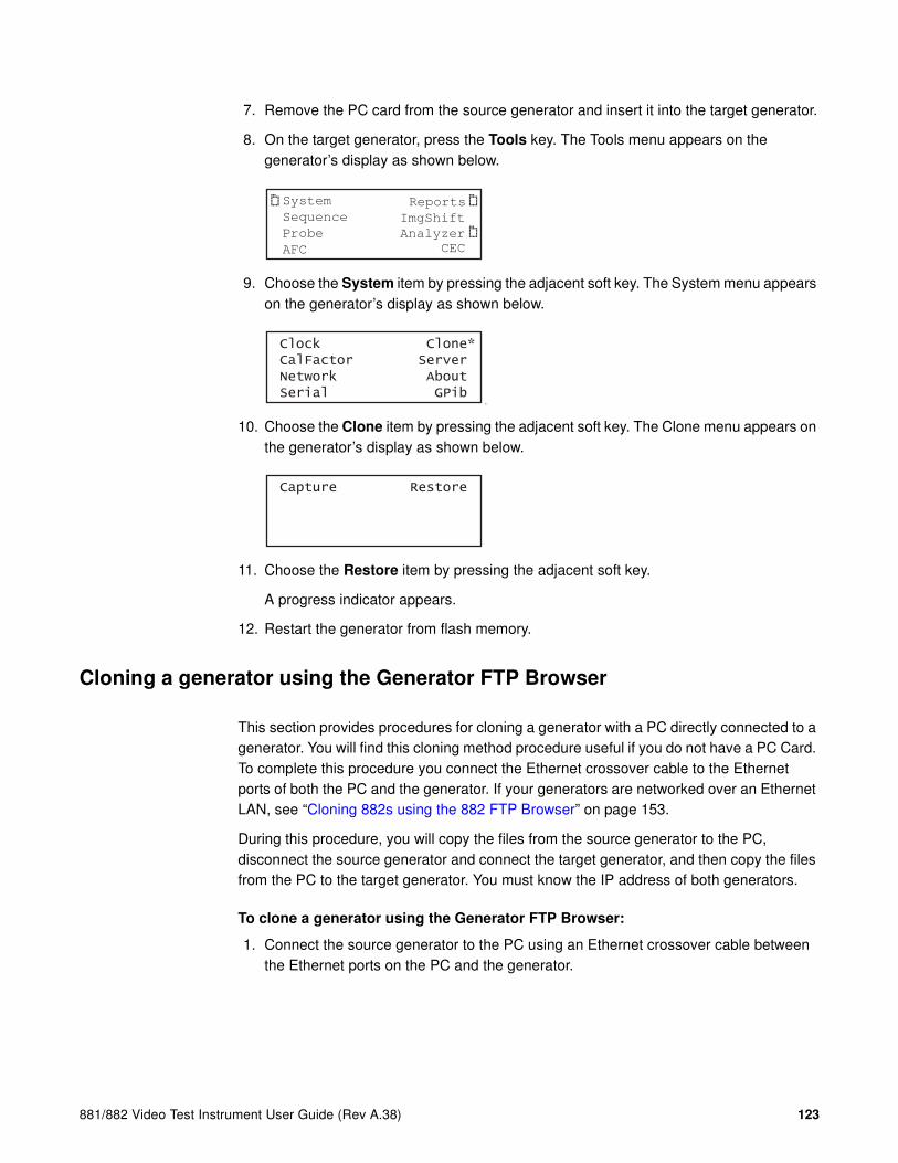
881/882 Video Test Instrument User Guide (Rev A.38) 123
7. Remove the PC card from the source generator and insert it into the target generator.
8. On the target generator, press the Tools key. The Tools menu appears on the generator’s display as shown below.
9. Choose the System item by pressing the adjacent soft key. The System menu appears on the generator’s display as shown below.
ite
10. Choose the Clone item by pressing the adjacent soft key. The Clone menu appears on the generator’s display as shown below.
11. Choose the Restore item by pressing the adjacent soft key.
A progress indicator appears.
12. Restart the generator from flash memory.
Cloning a generator using the Generator FTP Browser
This section provides procedures for cloning a generator with a PC directly connected to a generator. You will find this cloning method procedure useful if you do not have a PC Card. To complete this procedure you connect the Ethernet crossover cable to the Ethernet ports of both the PC and the generator. If your generators are networked over an Ethernet LAN, see “Cloning 882s using the 882 FTP Browser” on page 153.
During this procedure, you will copy the files from the source generator to the PC, disconnect the source generator and connect the target generator, and then copy the files from the PC to the target generator. You must know the IP address of both generators.
To clone a generator using the Generator FTP Browser:
1. Connect the source generator to the PC using an Ethernet crossover cable between the Ethernet ports on the PC and the generator.
System
Sequence
Probe
AFC
Analyzer
Reports
ImgShift
CEC
Clock Clone* CalFactor Server Network About Serial GPib
Capture Restore

124 Chapter 3 Administrative Tasks
2. Access the source generator’s Generator FTP Browser. See “Working with the 882 FTP Browser” on page 23.
3. Copy all of the files in the source generator’s flash memory to the PC as follows:
a. In the Instrument Files area of the Generator FTP Browser window, click the down arrow by the Look in box and select tffs0 (FlashMem).
b. Select the system and library folders in the lower pane.
c. In the Host Files area, open the folder where you want to copy the files. To create a new folder, click New.
d. In the Instrument Files area, click Upload. A confirmation dialog box appears.
e. Click OK to copy the files.
4. Close the Generator FTP Browser.
Note: If both generators on the Ethernet/IP network you do not have to close the
source generator FTP Browser.

881/882 Video Test Instrument User Guide (Rev A.38) 125
5. Disconnect the source generator from the Ethernet cable and connect the target generator.
Note: If both generators on the Ethernet/IP network you do not have to disconnect the
generator.
6. Access the target generator’s FTP Browser.
7. Delete the current system and library resource folders from the target generator’s flash memory as follows:
a. In the Instrument Files area, click the down arrow by the Look in box and select tffs0 (FlashMem).
b. Select all of the files in the lower pane.
c. Click the Delete button. A confirmation dialog box appears.
d. Click OK to delete the files.
8. Copy the source system and library folders from the PC to the target generator’s flash memory as follows:
a. In the Host Files area, open the folder containing the system and library folder.
b. Select the system and library folders in the lower pane.
c. In the Instrument Files area, click the down arrow by the Look in box and select tffs0 (FlashMem).
d. In the Host Files area, click Download. A confirmation dialog box appears. Click OK to download the source files to the generator.
9. Reboot the generator by cycling the power.

126 Chapter 3 Administrative Tasks
Resetting a generator
You can reset a generator to a known good condition.
Note: Resetting does not restore the generator to factory default condition. Thus, it should
not be used to restore proper operation of the generator.
Follow this procedure to reset a generator.
To reset the generator using the command line interface:
1. Establish a session with the generator using either HyperTerminal over a serial connection or Telnet over an Ethernet LAN. See “Establishing a terminal session with the 882” on page 30 or “Establishing a Telnet session with the 882” on page 33.
2. Enter one of the following commands:
• To reset the generator, enter:
*RST
• To reset and calibrate the generator, enter:
*RST // Resets the generator
SCAL // Calibrates the generator

881/882 Video Test Instrument User Guide (Rev A.38) 127
Viewing generator configuration information
You can view information about a generator’s configuration, including the firmware and gateware revisions, installed options, board serial numbers, and so on. The procedure for accessing this information depends on the type of information you want.
• For information about the main board and video board memory, use the front panel.
• For complete generator statistics, view the GenStats image.
• For firmware and gateware versions, use the command line interface.
This section describes the procedures for accomplishing these methods of accessing generator configuration information.
To view generator configuration information using the front panel:
1. Press the Tools key. The Tools menu appears on the generator’s display as shown below.
2. Choose the System item by pressing the adjacent soft key. The System menu appears on the generator’s display.
3. Choose the About item by pressing the adjacent soft key. A following message appears on the generator’s display as shown below.
4. Press the Settings key. The main board information appears. Press the soft key adjacent to the arrow by Serial Number to see other information about the main board.
System
Sequence
Probe
AFC
Analyzer
Reports
ImgShift
CEC
CalFactor Host Network About Serial Gpib BootFrom Init
About the Phoenix Press Settings
About Main Board -> Serial Number -> 39298E000000

128 Chapter 3 Administrative Tasks
5. To view the video board information, pressing the soft key adjacent to the arrow by Main Board. The video board build date appears as shown below. Press the soft key adjacent to the arrow by Build Date to see other information about the video board.
To view generator configuration information using the GenStats image:
1. Press the Source key and select a standard format such as DMT0660.
Alternatively, enter the following commands to load the format:
FMTL DMT0660.xml; FMTU
2. Press the Content key and select the GenStats image.
Alternatively, enter the following commands to load the GenStats image:
IMGL GenStats.img; IMGU
The GenStats image appears as shown below.
3. Establish a session with the generator using either HyperTerminal over a serial connection or Telnet over an Ethernet LAN. See “Establishing a terminal session with the 882” on page 30 or “Establishing a Telnet session with the 882” on page 33.
About<- Video Board Build Date -> 2004/08/30

881/882 Video Test Instrument User Guide (Rev A.38) 129
4. Enter the following command to view the generator firmware version (runtime and boot code versions):
VERF?
20.0882002,01.04.11
5. Enter the following command to view the generator gateware information for each programmable device:
VERG?
253C,36,1272005:253F,73,8292005:253A,5,4252005
The information provided for each gateware is the Product Code, Revision Code and Date Code. There are three sets of gatewares listed. The first listing is for an CPLD which does not have an associated file in the System directory. The second listing is for the transmitter and the third listing is for the receiver if the analyzer option is present.
To get a report of the genstats image (or any active image):
1. Press the Tools key. The Tools menu appears on the generator’s display as shown below.
2. Choose the Reports item by pressing the adjacent soft key. The Report menu appears on the generator’s display.
3. Choose the Misc item by pressing the adjacent soft key. The following menu appears on the generator’s display.
4. Choose the !GenStats item by pressing the adjacent soft key. The generator display will briefly indicate that the report is being generated.
System
Sequence
Probe
AFC
Analyzer
Reports
ImgShift
CEC
EDID Packets Misc
!Formats
!Genstats

130 Chapter 3 Administrative Tasks
5. Open a Web browser (such as Internet Explorer) and type the generator’s IP address in the address entry field. For example, enter the following: http://206.135.215.189/
The generator home page appears in the browser.
Note: You can add the page to your list of favorite pages in your Web browser to avoid
retyping the IP address each time you want to access the page.

881/882 Video Test Instrument User Guide (Rev A.38) 131
6. Choose the Generated Reports item. The Generator the provides a list of reports currently available as shown below.

132 Chapter 3 Administrative Tasks
7. Select the GenStats report. The GenStats report then appears in the browser window as shown below. You can then save the report as an web page file for distribution.

881/882 Video Test Instrument User Guide (Rev A.38) 133
4 Networking 882s
Topics in this chapter:
• Overview
• Configuring a file server
• Establishing a network environment
• Network operations
• Controlling a 882 remotely
• Upgrading 882s over a network
• Cloning 882s using the 882 FTP Browser

134 Chapter 4 Networking 882s
Overview
This chapter describes how to use the 882 in a networked environment.
Quantum 882 generators can operate and be administered over an Ethernet LAN connection. By networking multiple 882s together, you can centralize control in production environments.
When networking 882s, a file server containing a set of system and resource files is installed on the network. This arrangement allows you to:
• Set up 882s to automatically retrieve and use a centrally-stored set of system and firmware files upon startup. This ensures that each 882 on the network is running the same firmware.
• Set up 882s to access a common set of objects, such as images and formats, from a file server. This allows each 882 on the network to access the same set of standard and custom library files.
• Easily upgrade a 882’s local system and library files from the file server. This ensures that each 882 on the network is using the most current system and library files when booting and accessing files locally.
• Control and maintain your network of 882s remotely from a single host PC. You can manage the 882s through the command line interface, through the Virtual Front Panel in a Web browser, or by transferring files using the 882 FTP Browser.
882 file system
The 882 generator file system is comprised of two main directories (folders): 1) System and 2) Library. The System folder contains the realtime operating system and firmware file (vxWorks) and the gateware. The Library folder contains the following resource files:
• Fonts - Object files used to define the font types.
• Formats - XML files defining the format parameter settings.
• FormatLib - XML files for configuring the source list of formats
• Images - C++ object files, executables, bitmaps, and XML files for rendering images.
• ImageLib - XML files for configuring the content list of images
• Sequences - XML files with instructions for test sequences.
• Users - XML files for user configuration profiles

881/882 Video Test Instrument User Guide (Rev A.38) 135
Configuring a file server
This section describes how to set up a file server. The file server is a PC used to host the 882 system and resource files to be shared by networked 882s. To configure the file server, you must install FTP server software on it, create an FTP directory (site), and copy the 882 system and resource files into the FTP directory.
File server specifications
The minimum configuration for the file server should be as follows:
• Windows NT, Windows 2000, or Windows XP operating system
• Pentium-based processor (for example, Pentium 4)
• 256 MB SDRAM
• 20 MB of free disk space
Note: If you will be using the Software Development Kit and gcc compiler to create
custom images, an additional 100 MB of free disk space is required.
• Ethernet card and a connection to the corporate LAN
• CD-ROM drive (for loading the 882 system and resource files and documentation from the ResourceCD)
• Java Runtime Environment 1.5 or later
Installing an FTP server
Setting up an FTP server on the file server is necessary if you want the 882s to boot from the file server or if you want to store files on the server that you can access from the 882 in the Browse mode. Any standard FTP server program, such as Microsoft FTP Server, can be used. Microsoft FTP Server operates with Microsoft Internet Information Services; therefore, both must be installed on the server PC.

136 Chapter 4 Networking 882s
To set up the FTP server:
1. Install the FTP server software on the file server PC and create the FTP site directory.
You can use Microsoft Internet Information Services shown below.
2. Configure the FTP site properties.
a. On the Home Directory tab, enter the name of the Local Path (your default directory for the FTP server). By default, Microsoft Internet Information Services
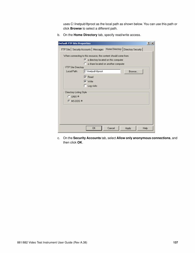
881/882 Video Test Instrument User Guide (Rev A.38) 137
uses C:\Inetpub\ftproot as the local path as shown below. You can use this path or click Browse to select a different path.
b. On the Home Directory tab, specify read/write access.
c. On the Security Accounts tab, select Allow only anonymous connections, and then click OK.

138 Chapter 4 Networking 882s
Copying resource files to the FTP site on the file server
After installing the FTP server, you can download the 882 system and resource files from the Quantum Data Web site and copy them to the FTP site on the file server.
To copy 882 system and resource files to the file server:
1. Create a download folder in a convenient location on your PC.
2. Access the download page of the Quantum Data Web site at: http://www.quantumdata.com/support/downloads/
3. Copy the contents of the 882 folder from the download folder to the root folder on the FTP server. The resulting folder structure on the file server PC is shown below.

881/882 Video Test Instrument User Guide (Rev A.38) 139
4. Move the vxWorks file out of the System folder and into the ftproot folder.
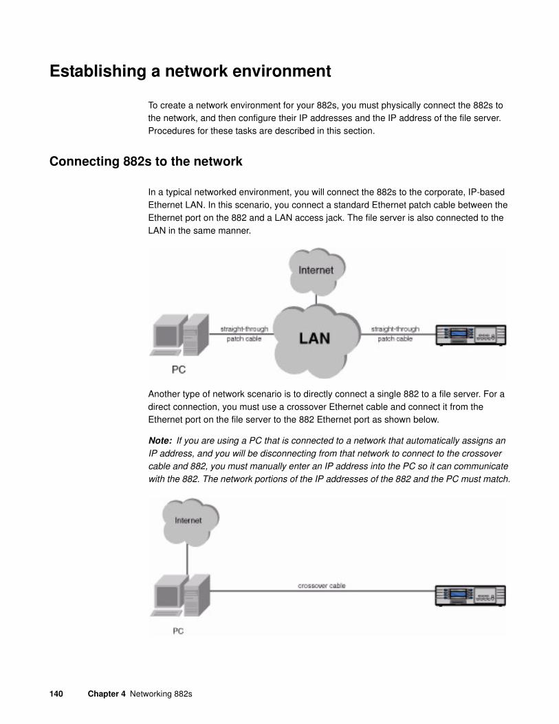
140 Chapter 4 Networking 882s
Establishing a network environment
To create a network environment for your 882s, you must physically connect the 882s to the network, and then configure their IP addresses and the IP address of the file server. Procedures for these tasks are described in this section.
Connecting 882s to the network
In a typical networked environment, you will connect the 882s to the corporate, IP-based Ethernet LAN. In this scenario, you connect a standard Ethernet patch cable between the Ethernet port on the 882 and a LAN access jack. The file server is also connected to the LAN in the same manner.
Another type of network scenario is to directly connect a single 882 to a file server. For a direct connection, you must use a crossover Ethernet cable and connect it from the Ethernet port on the file server to the 882 Ethernet port as shown below.
Note: If you are using a PC that is connected to a network that automatically assigns an
IP address, and you will be disconnecting from that network to connect to the crossover
cable and 882, you must manually enter an IP address into the PC so it can communicate
with the 882. The network portions of the IP addresses of the 882 and the PC must match.

881/882 Video Test Instrument User Guide (Rev A.38) 141
When the network connection on the 882 is active, the Network LED lights on the front panel.
Setting the 882’s IP address
You can either set the IP address of the 882 manually with an address you select or automatically by using the built in DHCP support. The default state of the 882 is that DHCP is off. So you have to enable it if you want the IP address to be set automatically from a DHCP server. The procedures for setting the IP address manually and enabling DHCP for auto configuration are provided below.
Each 882 on the network must have a unique IP address if you want to control the 882 over a network, or want the 882 to share resources located on a file server. Typically, your site’s LAN administrator will provide you with IP addresses for each 882. Depending on how your site’s LAN is configured, your LAN adminstrator may also provide you with a subnet mask.
To set the IP address of the 882:
1. Press the Tools key. The Tools menu appears on the 882’s display as shown below.
2. Choose the System item by pressing the adjacent soft key. The System menu appears on the 882’s display as shown below.
3. Choose the Network item by pressing the adjacent soft key. The 882’s IP address and subnet mask appear on the 882’s display as shown below.
System
Sequence
Probe
AFC
Analyzer
Reports
ImgShift
CEC
*Clock Clone CalFactor Server Network About Serial Gpib
IP Address 192.168.254.1Subnet Mask 255.255.255.000

142 Chapter 4 Networking 882s
4. Press the Settings key. The Network Connection screen appears on the 882’s display as shown below.
If the IP Address configuration option is not visible, press the soft key adjacent to the arrow symbol by SubnetMask until IP Address appears.
5. Change the IP address as follows:
a. Position the blinking cursor on the address digit you want to change. To do this, press the soft key adjacent to the arrow by the address to move the cursor left or right until it appears on the digit you want to change.
b. Adjust the value of the digit up or down by pressing the + or - keys. Repeat for each IP address digit you want to change.
6. If necessary, change the subnet mask as follows:
a. If the SubnetMask configuration option is not visible, press the soft key adjacent to the arrow symbol by IP Address until SubnetMask appears.
b. Position the blinking cursor on the subnet mask digit you want to change. To do this, press the soft key adjacent to the arrow by the subnet mask to move the cursor left or right until it appears on the digit you want to change.
c. Adjust the value of the digit up or down by pressing the + or - keys. Repeat for each subnet mask digit you want to change.
7. To save the changes, press the Enter (Options) key. The following choices appear on the 882’s display:
To save the changes, choose the Yes item by pressing the adjacent soft key.
To exit without saving the changes, choose the No item.
To return to the Network Connection screen without saving the changes, choose the Back item.
8. Power cycle the 882 to invoke the new IP address.
Network Connection
Set TCP/IP
IP Address206.135.215.168
Network Connection
Set TCP/IP
SubnetMask000.000.000.000
Apply Settings?
Back
Yes No

881/882 Video Test Instrument User Guide (Rev A.38) 143
To enable DHCP for auto IP address configuration of the 882:
1. Press the Tools key. The Tools menu appears on the 882’s display as shown below.
2. Choose the System item by pressing the adjacent soft key. The System menu appears on the 882’s display as shown below.
3. Choose the Network item by pressing the adjacent soft key. The 882’s IP address and subnet mask appear on the 882’s display as shown below.
4. Press the Settings key. The Network Connection screen appears on the 882’s display as shown below.
If the DHCP configuration option is not visible, press the soft key adjacent to the arrow symbol by SubnetMask or IP Address until the DHCP configuration screen appears.
5. Change the setting to YES by pressing the + key.
System
Sequence
Probe
AFC
Analyzer
Reports
ImgShift
CEC
*Clock Clone CalFactor Server Network About Serial Gpib
IP Address 192.168.254.1Subnet Mask 255.255.255.000
Network Connection
Set TCP/IP
IP Address206.135.215.168
Network Connection
TCP/IP
NO
DHCP Enabled
Network Connection
TCP/IP
YES
DHCP Enabled

144 Chapter 4 Networking 882s
6. To save the changes, press the Enter (Options) key. The following choices appear on the 882’s display:
To save the changes, choose the Yes item by pressing the adjacent soft key.
To exit without saving the changes, choose the No item.
To return to the Network Connection screen without saving the changes, choose the Back item.
7. Power cycle the 882 to set the IP address of the 882.
Setting the file server IP address in the 882
You must enter the IP address of the file server in each 882 so the 882 can communicate with the file server. In addition, you can also enter a name (called the Host Name) for the file server.
To specify the IP address and host name of the file server:
1. Press the Tools key. The Tools menu appears on the 882’s display as shown below.
2. Choose the System item by pressing the adjacent soft key. The System menu appears on the 882’s display as shown below.
3. Choose the Server item by pressing the adjacent soft key. The server name and IP address appear on the 882’s display.
Apply Settings?
Back
Yes No
System
Sequence
Probe
AFC
Analyzer
Reports
ImgShift
CEC
*Clock Clone CalFactor Server Network About Serial Gpib
Host IP AddressHost001206.135.215.218

881/882 Video Test Instrument User Guide (Rev A.38) 145
4. Press the Settings key. The Network Host screen appears on the 882’s display as shown below.
If the Host Address configuration option is not visible, press the soft key adjacent to the arrow symbol by Host Name until Host Address appears.
5. Change the host address as follows:
a. Position the blinking cursor on the address digit you want to change. To do this, press the soft key adjacent to the arrow by the address to move the cursor left or right until it appears on the digit you want to change.
b. Adjust the value of the digit up or down by pressing the + or - keys. Repeat for each address digit you want to change.
6. (Optional) Change the host name as follows:
a. If the Host Name configuration option is not visible, press the soft key adjacent to the arrow symbol by Host Address until Host Name appears.
b. Position the blinking cursor on the character you want to change. To do this, press the soft key adjacent to the arrow by the name to move the cursor left or right until it appears on the character you want to change.
c. Select the desired character by pressing the + or - keys to scroll through uppercase letters, lowercase letters, and numbers. Repeat for each character you want to change.
7. To save the changes, press the Enter (Options) key. The following choices appear on the 882’s display:
To save the changes, choose the Yes item by pressing the adjacent soft key.
To exit without saving the changes, choose the No item.
To return to the Network Host screen without saving the changes, choose the Back item.
8. Power cycle the 882 to set the server IP address.
Network Host
Set Boot Host
Host Address
206.135.215.218
Network Host
Set Boot Host
Host Name
Host001
Apply Settings?
Back
Yes No

146 Chapter 4 Networking 882s
Network operations
This section provides common networking tasks, such as booting 882s from the file server, accessing files stored on the file server, transfering files from the file server to the 882, and controlling the 882 remotely.
Booting a 882 from the file server
A 882 can be set up to boot from an operating system (vxWorks) file stored on the file server. To do this, you must set the IP address of the file server in the 882, and then configure the 882 to use the file server as a boot device. For instructions on setting the IP address of the file server in the 882, see “To enable DHCP for auto IP address configuration of the 882:” on page 143.
Procedures for booting the 882 from the file server are provided below. For procedures to boot a stalled 882 refer to “Reconfiguring and booting a stalled generator” on page 117.
To configure the 882 to boot from the file server:
1. Copy the vxWorks folder into the ftproot folder using the procedures described in “Copying resource files to the FTP site on the file server” on page 138.
2. Press the Tools key. The Tools menu appears on the 882’s display as shown below.
3. Choose the System item by pressing the adjacent soft key. The System menu appears on the 882’s display as shown below.
4. Scroll down to the end of the System menu by pressing the - key until the following menu items appear on the 882’s display:
5. Choose the BootFrom item by pressing the adjacent soft key. The BootFrom menu appears on the 882’s display as shown below.
6. Choose the NetPlace item by pressing the adjacent soft key.
System
Sequence
Probe
AFC
Analyzer
Reports
ImgShift
CEC
CalFactor Host Network About Serial Gpib BootFrom Init
Boot From
Server Flash*Card
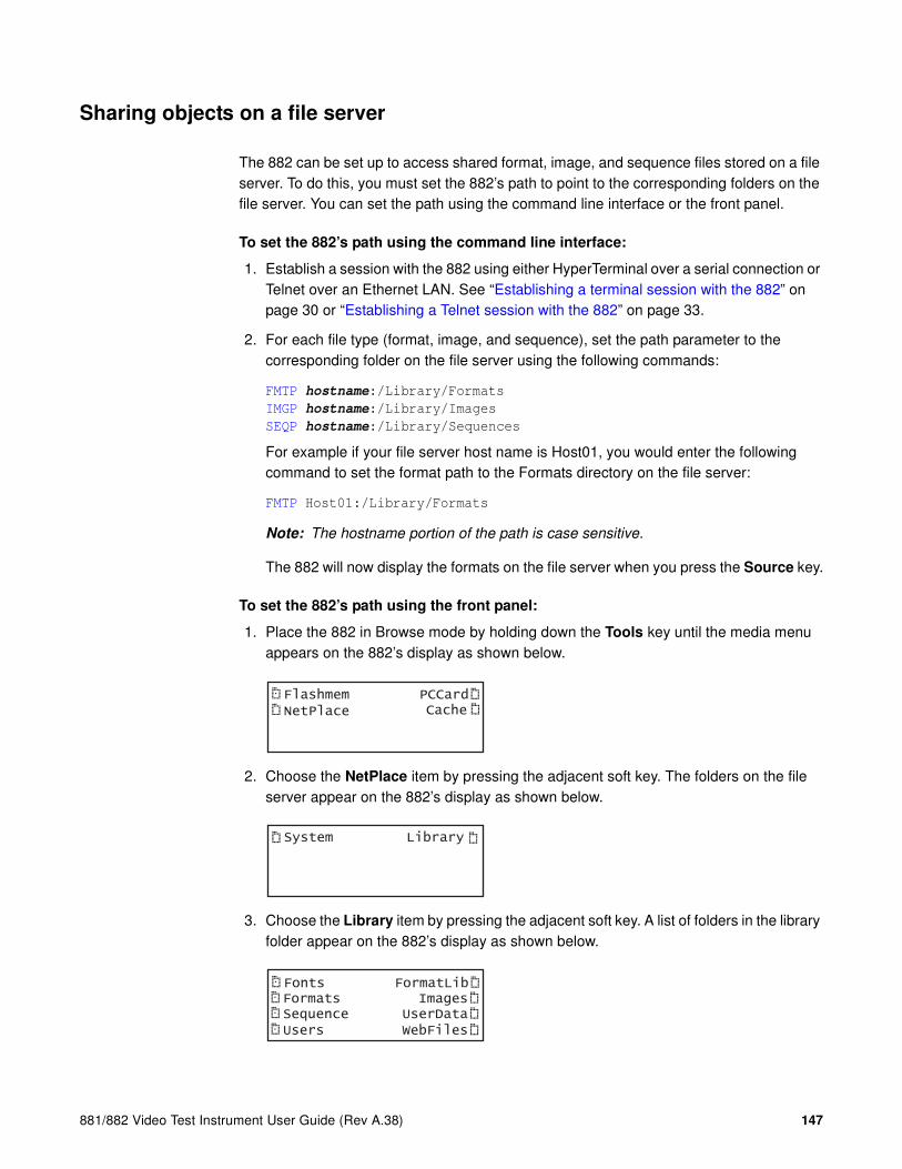
881/882 Video Test Instrument User Guide (Rev A.38) 147
Sharing objects on a file server
The 882 can be set up to access shared format, image, and sequence files stored on a file server. To do this, you must set the 882’s path to point to the corresponding folders on the file server. You can set the path using the command line interface or the front panel.
To set the 882’s path using the command line interface:
1. Establish a session with the 882 using either HyperTerminal over a serial connection or Telnet over an Ethernet LAN. See “Establishing a terminal session with the 882” on page 30 or “Establishing a Telnet session with the 882” on page 33.
2. For each file type (format, image, and sequence), set the path parameter to the corresponding folder on the file server using the following commands:
FMTP hostname:/Library/Formats
IMGP hostname:/Library/Images
SEQP hostname:/Library/Sequences
For example if your file server host name is Host01, you would enter the following command to set the format path to the Formats directory on the file server:
FMTP Host01:/Library/Formats
Note: The hostname portion of the path is case sensitive.
The 882 will now display the formats on the file server when you press the Source key.
To set the 882’s path using the front panel:
1. Place the 882 in Browse mode by holding down the Tools key until the media menu appears on the 882’s display as shown below.
2. Choose the NetPlace item by pressing the adjacent soft key. The folders on the file server appear on the 882’s display as shown below.
3. Choose the Library item by pressing the adjacent soft key. A list of folders in the library folder appear on the 882’s display as shown below.
FlashmemNetPlace
PCCardCache
System Library
Fonts FormatLibFormats ImagesSequence UserDataUsers WebFiles

148 Chapter 4 Networking 882s
4. Press the soft key adjacent to the folder you want to use. For example, to use the Formats folder, press the soft key adjacent to Formats. The contents of the selected folder appears on the 882’s display.
5. Choose an item by pressing the adjacent soft key. The path is now set to the selected folder on the file server.

881/882 Video Test Instrument User Guide (Rev A.38) 149
Controlling a 882 remotely
In addition to controlling the 882 using the front panel keys, you can also control the 882 from a remote PC either through the Virtual Front Panel Web-based interface or the command line interface.
Using the Virtual Front Panel to operate a 882 remotely
The 882 generator has a built-in Web server that provides a graphical interface called the Virtual Front Panel to control the 882. With the Virtual Front Panel, you can perform the same tasks as you would with the 882’s front panel. To use the Virtual Front Panel on your PC you must have the Java Runtime Environment (JRE) 1.5 or later installed on your PC. You can download the JRE from http://www.java.com/en/download/windows_ie.jsp. For more information about using the Virtual Front Panel, see “Working with the Virtual Front Panel” on page 20.
Maintaining the 882’s file system using the 882 FTP Browser
If you create objects on a PC, such as images or formats, you can copy these objects to a 882 if you want the 882 to load them locally. For example, you may want to create a new image on the file server PC, and then copy the image to certain 882s in your production environment. The 882 FTP Browser enables you to copy files between the file server PC and the 882s.
You can also use the 882 FTP Browser to copy files between media in the 882. For example, you can update the 882’s PC card with the 882’s flash memory or update the flash memory with files on the PC card. You can also update the media of one 882 with the contents of another 882’s media.
For more information about using the 882 FTP Browser, see “Working with the 882 FTP Browser” on page 23.
Operating the 882 remotely through the command line interface
You can operate the 882 remotely using the command line interface through either a Telnet session over an Ethernet LAN or the command terminal on the Virtual Front Panel Web page. For instructions on connecting to the 882 using Telnet, see “Establishing a Telnet session with the 882” on page 33. For instructions on using the command terminal through the Virtual Front Panel, see “Working with the CMD (Command) Terminal” on page 22.
150 Chapter 4 Networking 882s
Upgrading 882s over a network
An upgrade to a network of 882s can involve a new system and firmware file (“vxWorks”), a new gateware file, and new library resource files. In some cases you may be upgrading only the firmware or only the gateware, but not both. In other cases, the upgrade may involve only new images or formats. The procedures you follow for an upgrade will therefore depend on what you are upgrading.
This section provides procedures for upgrading 882s over a LAN. The procedures for upgrading a single 882 that is not connected to a LAN are provided in “Upgrading the generator locally” on page 107.
Upgrade options and procedures
The recommended procedure for upgrading is to upgrade the file server and the flash memory of each 882. Upgrading the PC card is optional, depending on how your site uses the PC card. For example, you may decide to leave the current files on the PC card so you can return to a known operational state should the upgrade fail.
To begin an upgrade, you must either have a CD-ROM containing the new files, or download the files from the Quantum Data Web site. You will copy the new files to your file server PC which must be connected to the LAN through the Ethernet cable.
Overview of upgrade procedures
The following are the high-level steps for performing a complete upgrade (system and firmware file, gateware, and library resource files) to 882s over a network. Detailed instructions for each step are provided in the sections that follow.
1. Back up the current file server system and firmware file, gateware, and library files.
2. Copy the new 882 system and firmware file, gateware, and resource files onto the file server PC.
3. Remove the system and firmware file, gateware, and library resource files from each 882’s flash memory.
4. Copy the new system and firmware file, gateware, and library resource files from the file server PC to each 882’s flash memory.
5. Reboot all 882s.
Backing up the current files on the file server
Backing up the current files ensures that you can return to a known operational state should the upgrade fail.

881/882 Video Test Instrument User Guide (Rev A.38) 151
To back up the current files on the file server:
1. Create a separate, backup folder on your file server PC (not in the FTP folder) to house the files currently used by the network of 882s.
2. Open the FTP site folder and copy the contents of the folder to your backup folder. These should include the 882 directory and the System and Library folders as shown below.
3. If any of the 882s have custom format, image, sequence, or font files that do not also reside on the file server, you must back them up to the backup folder on the file server independently to preserve them. See “Backing up the current files on the file server” on page 150 for instructions.
You might want to back up only the custom files on the 882 to a custom folder on the file server you create. Alternatively if you are sure you want to restore a 882 with its current set of library files you can simply backup its entire library folder to a custom folder on the file server.
Copying files to the PC file server
After you have backed up your existing files, you must delete the current files from the FTP folder on the file server, and then copy the new, updated files to the FTP folder. Before you begin, you must either have a CD-ROM containing the new system, gateware, and library files, or download the files from the Quantum Data Web site.
To copy the new files to the file server:
1. Open the FTP site folder and delete the contents.
2. Open the 882 folder from the location where you downloaded the files from the Quantum Data Web site.

152 Chapter 4 Networking 882s
3. Copy the contents of the 882 folder to the FTP site folder. The resulting folder structure is shown below.
Removing current files from the 882s
Prior to upgrading the 882s, you must remove the existing system and firmware file, gateware, and resource files from the flash memory of each 882. For instructions on removing files from the 882, see “Upgrading the generator locally” on page 107. If you are also installing the new files on the 882’s PC card, you must also remove the current files from the PC card.
Copying the new files to each 882
Now you are ready to copy the new, updated system and firmware, gateware, and library resource files to the 882s to complete the upgrade. See “Working with the 882 FTP Browser” on page 23 for instructions.
Reboot the 882s
The upgrade is now complete and you are ready to reboot the 882s from the updated system files you just copied to each 882’s flash memory. Reboot each 882 by cycling the power.

881/882 Video Test Instrument User Guide (Rev A.38) 153
Cloning 882s using the 882 FTP Browser
You can clone 882s either through the front panel or through the 882 FTP Browser on the Virtual Front Panel Web page. Procedures for cloning 882s through the front panel are provided in “Cloning generators” on page 122.
This section describes how to clone 882s by copying system and library files over the network using the 882 FTP Browser.
To clone a 882:
1. Access the 882’s FTP browser by choosing the FTP Browser menu item from the main web page. The 882 FTP Browser appears. The Instrument Files area shows the files stored on the 882. The Host Files area shows the files stored on the PC.
2. Open a second Web browser. You now have two instances of the 882 FTP Browser running: one for the source 882 and one for the target 882.
154 Chapter 4 Networking 882s
3. In the 882 FTP Browser window for the target 882, delete all of the files in the target 882’s flash memory as follows:
a. In the Instrument Files area, click the down arrow by the Look in box and select tffs0. This is the target 882’s flash memory.
b. Select all of the System and Library folders in the lower pane.
c. Click the Delete button. A confirmation dialog box appears.
d. Click OK to delete the files.
4. Copy all of the files in the source 882’s flash memory to the target 882’s flash memory as follows:
a. In the Instrument Files area of source 882’s 882 FTP Browser window, click the down arrow by the Look in box and select tffs0. This is the source 882’s flash memory.
b. Select the System and Library folders in the lower pane.
c. Hold down the SHIFT key and drag the selected folders to the Instrument Files area of the target 882’s FTP Browser window. A confirmation dialog box appears.
d. Click OK to copy the files.

881/882 Video Test Instrument User Guide (Rev A.38) 155
5 Using GPIB Interface
Topics in this chapter:
• Overview
• Setting the GPIB port address
• Queries and commands
• Status queries and control

156 Chapter 5 Using GPIB Interface
Overview
You can operate and program the generator from an external computer or terminal using the optional IEEE-488 (GPIB) interface. The GPIB interface enables the generator to be used as a programmable video signal source for integration into automated test systems that use IEEE-488 or GPIB communications between instruments.

881/882 Video Test Instrument User Guide (Rev A.38) 157
Setting the GPIB port address
The default GPIB address is 15. You can specify a different address as described in the procedure below.
To set the address of the GPIB port using the front panel:
1. Press the Tools key. The Tools menu appears on the generator’s display as shown below.
2. Choose the System item, and then choose the GPIB item. The GPIB address appears on the generator’s display as shown below.
3. To change the address, do the following:
a. Press the Settings key.
b. Position the blinking cursor on the address digit you want to change. To do this, press the soft key adjacent to the arrow by the address to move the cursor left or right until it appears on the digit you want to change.
c. Adjust the value of the digit up or down by pressing the + or - keys. Repeat for each address digit you want to change.
4. To save the changes, press the Enter (Options) key. The following choices appear on the generator’s display:
To save the changes, choose the Exit, Save Change item by pressing the adjacent soft key.
To exit without saving the changes, choose the Exit, No Change item.
To return to the previous screen without saving the changes, choose the Go Back item.
To set the address of the GPIB port using the command line:
1. Establish a session with the generator using either HyperTerminal over a serial connection or Telnet over an Ethernet LAN. See “Establishing a terminal session with the 882” on page 30 or “Establishing a Telnet session with the 882” on page 33.
2. (Optional) Enter the following command to check the current address:
GPIB?
System
Sequence
Probe
AFC
Analyzer
Reports
ImgShift
CEC
Apply Settings?
Back
Yes No

158 Chapter 5 Using GPIB Interface
3. Enter the following command to set the address:
GPIB address
When the address is changed with the GPIB command, the change takes place as soon at the command is issued.

881/882 Video Test Instrument User Guide (Rev A.38) 159
Queries and commands
The GPIB interface is an ASCII command line interface like the RS-232 command line interface. The communications protocol is per IEEE-488.2 specification. Queries and commands consist of four ASCII upper/lower case characters. Commands do not require a response from the generator, while queries cause the generator to respond with the required data.
You can send multiple commands on the same line by separating the commands with a semicolon (;) followed by a terminator. A terminator is defined as the NL character (ASCII 10), or EOI sent with the last byte of the command. The generator will not parse any commands received until a terminator is received. All commands are executed sequentially; that is, when a command is parsed it is allowed to finish execution before the next command is parsed, as illustrated in the following figure.
Commands
Commands instruct the generator to set a parameter to the value given or perform some function not requiring any additional data. Commands which have an asterisk (*) as their first character are common commands as defined by the IEEE-488.2 standard and generally operate the same in all instruments. All commands are listed and described in Appendix A, “Command Reference.”
Commands which do not require any additional data from the controller are self-contained and should be followed by either a message separator (;) or message terminator. Any other characters (except whitespace characters) will cause a command error.
Commands which require numeric data must be followed by at least one separator character (whitespace), and then the data. Numeric data sent with a command is in decimal format. Numeric data can be represented in one of three methods: integer, floating point, or scaled floating point.
Message Terminator
Separator ( ; )
Program Message Syntax
Command/QueryHeader
Separator( ; )
DataSeparator
(white space)
Message Unit Syntax

160 Chapter 5 Using GPIB Interface
For example, the following number can be represented in three ways:
• Integer (42)
• Floating point (42.00)
• Scaled floating point (4.200E+01)
Queries
Queries are comprised of a header followed immediately by a question mark (?). If there are any characters between the query header and the question mark character (including whitespace), a command error will result. Queries return a response message upon completion of execution. A response message is comprised of the requested data terminated with an NL (ASCII 10) character. For example, the following text would be returned in response to the HRAT? (horizontal rate query) message:
3.1500E+04<NL>
Note that the HRAT? query returns its parameter in exponential form. Possible returned parameter forms are:
• Integer (3965)
• Exponential (+3.965E+03)
• String ("text string")
Output queue
When a query is executed, the resulting response message is placed in an output queue where it can be read by the controller. The generator has an output queue that is 255 bytes long. When a message is present in the output buffer, the MAV (message available) bit in the Status Byte register is set. This varies slightly from the 488.2 standard in that the MAV bit will be set only when at least one complete response message is present in the output queue. A complete response message consists of response message text and a message terminator (NL).
Buffer deadlock
Buffer deadlock occurs when the generator tries to put a response message in the output queue when the output queue is full and the controller is held off while sending a new message because the input buffer is full. If deadlock occurs, the generator will clear its output queue, set the query error (QYE) bit in the Event Status register and proceed to parse incoming messages. If any additional queries are requested while in deadlock, those response messages will be discarded.
The generator will clear the buffer deadlock when it finishes parsing the current command/query. The QYE bit will remain set until read with the *ESR? query or cleared with the *CLS command.
881/882 Video Test Instrument User Guide (Rev A.38) 161
Sending commands and queries
The generator parses command lines one at a time. Command lines must be terminated with a carriage return (<cr>).The generator immediately echoes each character as it is received and places it in a command line buffer. This buffer currently has room for a total of 256 characters. If more than 256 characters are sent before sending a <cr>, then the following response will be given:
Buffer overflow<cr><lf><cr><lf>R:\>
Upon receiving a carriage return, the generator immediately echoes the <cr> and follows it with a line feed (<lf>). The generator then parses the command line and initiates whatever processing is implied. The generator then responds with one of the following four responses depending on the condition:
Command invalid<cr><lf><cr><lf>R:\>
<message1><cr><lf><message2><cr><lf>...<messageN><cr><lf><cr><lf>R:\>
Execution error: <nnnn><cr><lf><cr><lf>R:\>
R:\>
Where <cr> and <lf> are the carriage return and line feed characters, respectively.
Note: Handshaking routines should only look for > and not R:\>. In the future, the R:\ part
of the prompt may change (for example, may be expanded to indicate the current path).
Bench-top generators output the following prompt on their serial port after finishing the power-on procedure.
R:\>
This feature allows ATE systems to know when the generator is ready.
Sending multiple commands and queries per line
You can send multiple commands and queries per line by separating each command or query with a semi-colon (;) character. For example:
HRES 900; ALLU
The response to multiple queries will be a series of data elements separated by semi-colons (;). For example, with the VGA_m3 format loaded, the following command string will produce the response shown.
HRES?; VRES?; VTOT?
640;480;525
Normally, all of the commands on a command line associated with a single command terminator are read as a single command message without regard for execution or completion order. However, by inserting the *WAI command, you can force the generator
162 Chapter 5 Using GPIB Interface
to wait for all preceding commands to be completed before the commands that follow *WAI are processed. For example, sending the following command line causes a red rectangle to be drawn and then overwritten by the ColorBar image.
IMGL COLORBAR; IMGU; IMGE; RECT RED 200 200 0 0 GRAYPAT100
Note that the IMGU command merely requests that the current image be rendered eventually, not necessarily right away nor in a single attempt. By inserting a *WAI command after the IMGU, the generator is instructed to render the ColorBar image first, before rendering the red rectangle. This command ensures that the generator draws the red rectangle on top of the ColorBar image.
IMGL COLORBAR; IMGU; *WAI; IMGE; RECT RED 200 200 0 0 GRAYPAT100
The generator will wait until the ColorBar image has been completely rendered before it reads and executes the RECT command.
The *WAI command is required by the IEEE-488.2-1992 standard, but also works with GPIB and RS-232 protocols as well.
Completion handshake
The generator returns a > prompt immediately after an FMTU, IMGU, ALLU, BOOT, INIT, or SCAL command is received, even if these commands have not finished executing. If the system controlling the generator must know when the process started by one of these commands has been completed, then append *OPC? to the command string.
For example, the following command causes the generator to wait until all processes have been completed before responding with the number 1 and sending the > prompt.
FMTL VGA_M3; IMGL FLAT; ALLU; *OPC?
The *OPC? command is required by the IEEE-488.2-1992 standard, but also works with GPIB and RS-232 protocols as well.
Input buffer
Since some commands may take longer to execute, the generator has an input buffer. This input buffer is 255 characters long and can be written to by the host controller while the generator is busy executing or parsing previous messages. If the input buffer becomes full, the generator will hold off the controller until there is room in the buffer. For this reason, a program message cannot be longer than 255 characters including terminator.

881/882 Video Test Instrument User Guide (Rev A.38) 163
Status queries and control
To create applications that control the generator using the GPIB port, it is sometimes necessary to query the status of the generator and set or reset the status bits and bytes. There are two sets of status registers: 1) the Event Status Register and Event Status Enable Register and 2) the Status Byte Register and Service Request Enable Register. These are described in the following paragraphs.
Status byte
The status byte used by the generator is the same as that defined by the IEEE-488.2 standard and does not use any other bits of the status byte. The status byte is one part of a complete status reporting system shown in the figure on page 164. The status byte is read by using the serial poll feature of your controller.
Requesting service
The GPIB provides a method for any device to interrupt the controller-in-charge and request servicing of a condition. This service request function is handled with the status byte. When the RQS bit of the status byte is true, the generator is requesting service from the controller. There are many conditions which may cause the generator to request service. For more information about these conditions, see the *SRE command description (page 472). The table below lists the status commands and queries.
Status commands
and queries Definition
*ESE Sets the Event Status Enable register to the given mask value. When a bit in the Event Status register goes high and the corresponding bit in the Event Status Enable register is a 1, it is enabled and will cause the ESB bit in the Status Byte register to go high.
*ESR?? Returns the current value of the Event Status register. After this command is executed, the Event Status register is cleared. This is the only way of clearing any bit in the Event Status register except by the *CLS command.
*SRE Sets the Service Request Enable register to the mask value given. When a bit in the Status Byte register goes true and the corresponding bit in the Ser-vice Request Enable register is also true, the generator will request service using the GPIB.
*SRE? Returns the current value of the Service Request Enable register.
*STB? Returns the current value of the Status Byte register. The value stored in the Status Byte register is not affected by reading it.
*CLS Clears the Event Status register, the Status Byte, and the output buffer.

164 Chapter 5 Using GPIB Interface
The following figure illustrates IEEE-488 status reporting.
Status byte bit Definition
MAV Message available. Indicates that at least one complete response is present in the output buffer.
ESB Event status bit. Indicates that one of the enabled conditions in the Standard Event Status register is set.
MSS Master summary status. Indicates that the generator has a reason for requesting service.
RQS Request service. This bit is read only by executing a serial poll of the generator.
&&
&&
&&
&&
7 6 5 4 3 2 1 0
Logi
cal O
R
7 6 ESBMAV 2 1 0
7 6 5 4 3 2 1 0
RQS
MSS
Service Request
Generation
7 6 5 4 3 2 1 0
&&
&&
&&
&
Logi
cal O
RPo
wer
On
Use
r R
eque
st
Com
man
d E
rror
Exe
cutio
n E
rror
Dev
ice
Dep
ende
nt E
rror
Que
ry E
rror
Req
uest
Con
trol
Ope
ratio
n C
ompl
ete
QueueNot-Empty
Output Queue
StandardEvent Status Register
StandardEvent Status Enable
Register
Status Byte Register
Service RequestEnable Register
3

881/882 Video Test Instrument User Guide (Rev A.38) 165
Bus commands
The IEEE-488.1 standard defines bus commands, which are sent to the generator with ATN true. The following table lists bus commands supported by the generator. For more detailed descriptions of these commands, see the IEEE-488.1 and 488.2 standards.
Remote/local operation
The generator has complete remote/local operation as defined by the IEEE-488.1 standard. All four remote/local states (REMS, LOCS, RWLS and LWLS) are supported.
In the remote state (REMS), the generator is under remote control and messages are processed as received. The generator enters the remote with lockout state (RWLS) if the controller issues the local lockout (LLO) message to the generator. The generator enters the local state (LOCS) when the REN line goes false or the controller issues the go to local (GTL) message to the generator, or a front panel control is actuated.
Event Status bit Definition
OPC Operation complete. Indicates that all operations have been completed.
RQC Request control. Indicates that a device is requesting control. The generator will never request control, so this bit will always be 0.
QYE Query error. Indicates that a query request was made while the generator was in deadlock.
DDE Device dependent error. Indicates that the generator encountered an error exe-cuting a command.
EXE Execution error. Indicates that there was an error parsing a parameter.
CME Command error. Indicates that there was an unrecognizable command.
URQ User request. Indicates that a front panel key has been pressed or that the front panel knob has been turned.
PON Power on. Indicates that power has been turned off and on. This bit will always be 0 in the generator.
Command Description
DCL Device clear. Clears the input buffer and output queue, and stops parsing any commands.
SDC Selected device clear. Same as DCL.
GTL Go to local. Enters the local state. See “Remote/local operation” on page 165.
LLO Local lockout. Enters the lockout state. See “Remote/local operation” on page 165.
SPE Serial poll enable. Enables transmission of the Status Byte.
SPD Serial poll disable. Exits the serial poll state.

166 Chapter 5 Using GPIB Interface
In the remote with lockout state (RWLS), the generator is under complete remote control and front panel controls are disabled. The generator enters the RWLS state when the controller issues the local lockout (LLO) message to the generator. Front panel access is re-enabled when the controller issues the go to local (GTL) message to the generator.
In the local state (LOCS), the generator is under local control and all front panel controls are enabled. Any remote messages received are stored for processing when the generator enters the remote state again. The generator enters the remote state (REMS) if the REN line is true and the generator is addressed to listen.
In the local with lockout state (LWLS), the generator is under local control, and all front panel controls are enabled. Any remote messages received are stored for processing when the generator enters the remote state again. The generator enters the remote with lockout state (RWLS) if it is addressed to listen.

881/882 Video Test Instrument User Guide (Rev A.38) 167
6 Working with Formats
Topics in this chapter:
• Overview
• Format library
• Viewing the source list of formats
• Configuring format parameters
• Format Editor Overview
• Creating a new format using the Format Editor
• Creating custom formats using the command line interface
• Format catalogs

168 Chapter 6 Working with Formats
Overview
The generator contains a library of standard formats. You can create your own formats, however, either by using the Format Editor or by entering format commands through the command line interface. You can also create format catalogs which allow you to control the formats that appear on the generator’s display when you press the Source key.
This chapter describes the format library and provides procedures for using the generator’s front panel keys, the command line interface, and the format editor to view formats, create and customize formats, and create format catalogs.
The following functions are described in this chapter:
• Viewing the Source list of formats. You can view the Source list of formats using the front panel or the command line interface.
• Creating formats. You can create new formats through the format editor or the command line interface.
• Viewing and modifying format parameters. You can view and edit format parameter values either through the format editor, the front panel, the command line interface, or by editing the format XML file.
• Configuring the Source list. You can edit the Source list of formats to include only those formats you use.
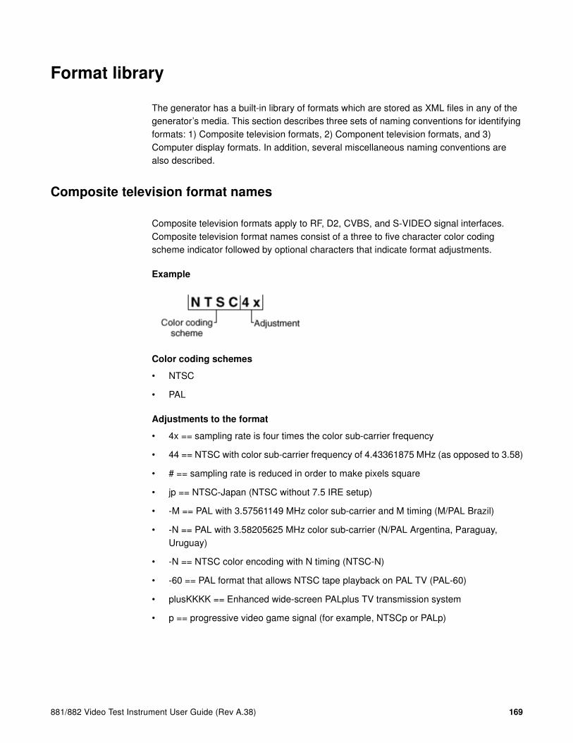
881/882 Video Test Instrument User Guide (Rev A.38) 169
Format library
The generator has a built-in library of formats which are stored as XML files in any of the generator’s media. This section describes three sets of naming conventions for identifying formats: 1) Composite television formats, 2) Component television formats, and 3) Computer display formats. In addition, several miscellaneous naming conventions are also described.
Composite television format names
Composite television formats apply to RF, D2, CVBS, and S-VIDEO signal interfaces. Composite television format names consist of a three to five character color coding scheme indicator followed by optional characters that indicate format adjustments.
Example
Color coding schemes
• NTSC
• PAL
Adjustments to the format
• 4x == sampling rate is four times the color sub-carrier frequency
• 44 == NTSC with color sub-carrier frequency of 4.43361875 MHz (as opposed to 3.58)
• # == sampling rate is reduced in order to make pixels square
• jp == NTSC-Japan (NTSC without 7.5 IRE setup)
• -M == PAL with 3.57561149 MHz color sub-carrier and M timing (M/PAL Brazil)
• -N == PAL with 3.58205625 MHz color sub-carrier (N/PAL Argentina, Paraguay, Uruguay)
• -N == NTSC color encoding with N timing (NTSC-N)
• -60 == PAL format that allows NTSC tape playback on PAL TV (PAL-60)
• plusKKKK == Enhanced wide-screen PALplus TV transmission system
• p == progressive video game signal (for example, NTSCp or PALp)
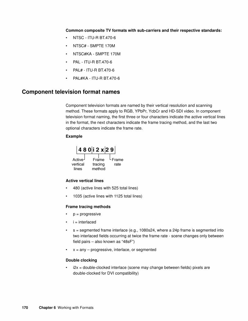
170 Chapter 6 Working with Formats
Common composite TV formats with sub-carriers and their respective standards:
• NTSC - ITU-R BT.470-6
• NTSC# - SMPTE 170M
• NTSC#KA - SMPTE 170M
• PAL - ITU-R BT.470-6
• PAL# - ITU-R BT.470-6
• PAL#KA - ITU-R BT.470-6
Component television format names
Component television formats are named by their vertical resolution and scanning method. These formats apply to RGB, YPbPr, YcbCr and HD-SDI video. In component television format naming, the first three or four characters indicate the active vertical lines in the format, the next characters indicate the frame tracing method, and the last two optional characters indicate the frame rate.
Example
Active vertical lines
• 480 (active lines with 525 total lines)
• 1035 (active lines with 1125 total lines)
Frame tracing methods
• p = progressive
• i = interlaced
• s = segmented frame interlace (e.g., 1080s24, where a 24p frame is segmented into two interlaced fields occurring at twice the frame rate - scene changes only between field pairs – also known as “48sF”)
• x = any – progressive, interlace, or segmented
Double clocking
• i2x = double-clocked interlace (scene may change between fields) pixels are double-clocked for DVI compatibility)

881/882 Video Test Instrument User Guide (Rev A.38) 171
Frame rate
Frame rate is optional. If no frame rate is given, then the frame rates are assumed.
• 24 = 24 Hz
• 60 = 60 Hz
Common component TV formats
• 480pLH Component SDTV signal containing letterboxed 16x9 high-definition content
• 480pSH Component SDTV signal containing anamorphically under-sampled 16x9 content
Computer display format names
Computer display formats are assumed to use progressive scanning. In computer format naming, the first three characters indicate the vendor ID using the EISA ID (for example, IBM, SUN, VSC) or the display type, the next two characters indicate the approximate horizontal resolution, the next two digits indicate the frame rate (which will be half the field rate with interlace scanning), and the final character designates the aperture (used only when the aperture is not A).
Example
Vendor ID (EISA)
• SMT for VESA (digital) Safe Mode Timing
• DMT for VESA Standard Discrete Monitor Timing
• GTF for VESA Generalized Timing Format standard
• CEA for Consumer Electronics Association
• EIA for Electronics Industries Association (CEA)
Approximate horizontal resolution examples
• 02 for 256 pixels
• 09 for 960 pixels
• 12 for 1200 pixels
• 30 for 3072 pixels

172 Chapter 6 Working with Formats
Frame rate examples (half the field rate with interlace scanning)
• 48 for 48 Hz
• 60 for 60 Hz
• 75 for 75 Hz
Aperture (used only when the aperture is not A)
See “Aperture designators” on page 172.
Common computer display formats
• VSC1275 for Viewsonic 1280 by 1024 at 75 Hz
• DMT0685 for Discrete Monitor Timing with 680 by 480 at 85 Hz
Aperture designators
Format names may include one or two characters that describe the aperture of the display. These are listed below.
Aspect ratio
• Q = 1.00:1 Quadrate - MIL, Radiology (square, 512x512, 1024x1024)
• G = 1.25:1 Graphics workstation (5x4, 1280x1024, 1600x1280)
• A = 1.33:1 Academy (4x3, 640x480, 800x600, 1024x768, 1280x960, 1600x1200)
• B = 1.44:1 Big (13x9, IMAX™)
• T = 1.50:1 Three halves (3x2, 1152x768 Apple Computer)
• V = 1.56:1 PALplus WWS case #2 (14x9, see ITU-R BT.1119)
• D = 1.60:1 VESA CVT proposed (16x10, 1728x1080, 1280x800)
• E = 1.67:1 European film (15x9 or 5x3, 1200x720, 1280x768, 1800x1080, a.k.a. “1.66”)
• H = 1.78:1 High-definition image (16x9, 1280x720,1920x1080)
• F = 1.85:1 US film (320x173, 1280x692, 1920x1038)
• U = 2.00:1 Univisum™ (2x1, 1280x640, 1920x960)
• C = 2.39:1 CinemaScope™ (160x67, 1280x536, 1920x804, a.k.a. “2.35”, was 2.35 before 1971)
Content fitting operators
• N = Natural (do nothing)
• L = Letterbox (linear scale to fit one axis, center w/black bars in other)
• Z = Zoom (blow- up to fill destination aperture with cropping, or LI )

881/882 Video Test Instrument User Guide (Rev A.38) 173
• S = Scope (under-sample content horizontally)
• W = Widescreen (over-sample content horizontally)
• J = Justify (non- linear horizontal expand – more near edges)
• K = Keep safe (shrink to avoid cropping – provide safe title)
• P = Pan & Scan (truncate)
• M = Mirror (horizontally – rear projection)
Other modifiers
• I = Inverse (undo operator; for example, S = Scope and SI = Inverse Scope)
• O = Orthogonally (rotate operator effect or aperture 90 degrees)
• X = Wildcard or special
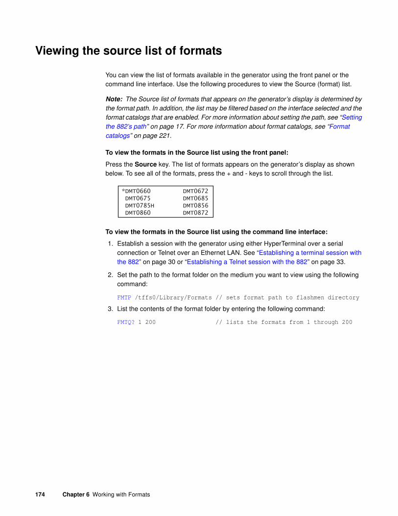
174 Chapter 6 Working with Formats
Viewing the source list of formats
You can view the list of formats available in the generator using the front panel or the command line interface. Use the following procedures to view the Source (format) list.
Note: The Source list of formats that appears on the generator’s display is determined by
the format path. In addition, the list may be filtered based on the interface selected and the
format catalogs that are enabled. For more information about setting the path, see “Setting
the 882’s path” on page 17. For more information about format catalogs, see “Format
catalogs” on page 221.
To view the formats in the Source list using the front panel:
Press the Source key. The list of formats appears on the generator’s display as shown below. To see all of the formats, press the + and - keys to scroll through the list.
To view the formats in the Source list using the command line interface:
1. Establish a session with the generator using either HyperTerminal over a serial connection or Telnet over an Ethernet LAN. See “Establishing a terminal session with the 882” on page 30 or “Establishing a Telnet session with the 882” on page 33.
2. Set the path to the format folder on the medium you want to view using the following command:
FMTP /tffs0/Library/Formats // sets format path to flashmen directory
3. List the contents of the format folder by entering the following command:
FMTQ? 1 200 // lists the formats from 1 through 200
*DMT0660 DMT0672 DMT0675 DMT0685 DMT0785H DMT0856 DMT0860 DMT0872

881/882 Video Test Instrument User Guide (Rev A.38) 175
Configuring format parameters
Each standard and custom format is defined by a set of parameters. These parameters are categorized in the generator as either Options or Settings. You can view and modify the parameters of a format in the following ways:
• On the generator’s front panel display
• On a display connected to the generator (view only)
• Through the command line interface
• In the format’s XML file
• Through the Format Editor
Viewing and modifying format parameters through the front panel
Procedures for viewing and modifying the format parameters and format options through the front panel are provided below. Format options are selections that are of a binary nature, i.e. either on or off. Settings are attributes of a format that can take on a wider range of values.
Note that format setting and option changes made through the front panel do not persist through power cycles or changes in formats. If you make a change to a format parameter, then choose another format, and then go back to the format you changed, you will find that the parameter has been reset to the default value for that format.
To view and modify a format’s options using the front panel:
1. Press the Source key and choose a format by pressing the adjacent soft key.
2. Press the Options key. The format options appear on the generator’s display as shown below.
3. To set an option, do one of the following:
a. To choose an option, press the soft key adjacent to the option. An asterisk (*) appears next to the option, indicating it is selected.
b. To enable or disable an option, press the soft key adjacent to the option. A + sign indicates the option is enabled; a - sign indicates it is disabled.
c. To set an option to a value (for example, AFD), increment the value by pressing the + key.
YYY*RGB YCbCr
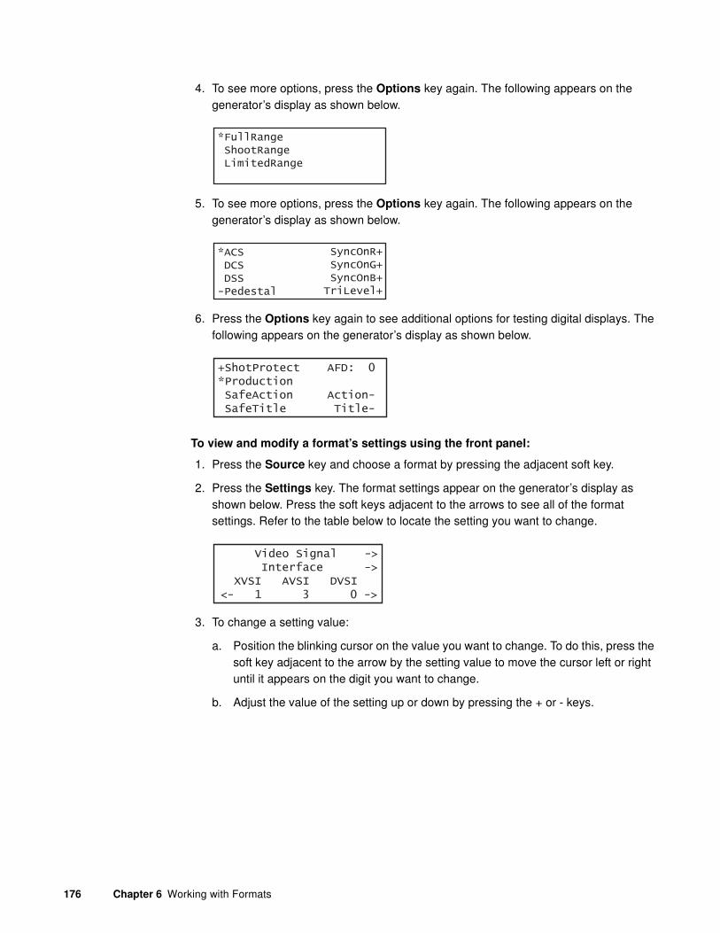
176 Chapter 6 Working with Formats
4. To see more options, press the Options key again. The following appears on the generator’s display as shown below.
5. To see more options, press the Options key again. The following appears on the generator’s display as shown below.
6. Press the Options key again to see additional options for testing digital displays. The following appears on the generator’s display as shown below.
To view and modify a format’s settings using the front panel:
1. Press the Source key and choose a format by pressing the adjacent soft key.
2. Press the Settings key. The format settings appear on the generator’s display as shown below. Press the soft keys adjacent to the arrows to see all of the format settings. Refer to the table below to locate the setting you want to change.
3. To change a setting value:
a. Position the blinking cursor on the value you want to change. To do this, press the soft key adjacent to the arrow by the setting value to move the cursor left or right until it appears on the digit you want to change.
b. Adjust the value of the setting up or down by pressing the + or - keys.
*FullRange ShootRange LimitedRange
*ACS DCS DSS-Pedestal
SyncOnR+ SyncOnG+ SyncOnB+TriLevel+
+ShotProtect AFD: 0*Production SafeAction Action- SafeTitle Title-
Video Signal -> Interface -> XVSI AVSI DVSI<- 1 3 0 ->

881/882 Video Test Instrument User Guide (Rev A.38) 177
4. To save the changes, press the Enter (Options) key. The following choices appear on the generator’s display:
To save the changes, choose the Yes item by pressing the adjacent soft key.
To exit without saving the changes, choose the No item.
To return to the parameters screen without saving the changes, choose the Back item.
The following table shows the layout of the format Settings menu.
Parameter Class Parameter Type Parameters
Video Signal Interface XVSI, AVSI, DVSI
Synchronization SSST
Gamma Correction GAMA, GAMC
Active Format CXAR, EXAR, SXAR, EXCX, SXEX, SXCX, XAFD
Manual Border XLBW, XRBW, XTBH, XBBH
Canvas PELD, NPPP
Analog Video AVST, AVSS, AVSB, AVPS, AVPG, AVCS
Analog Sync ASSS, ASCT, EQUF
Analog Sync Gates ASRG, ASGG, ASBG, TSPG
Digital Video DVST, DVQM, NCPP, NBPC, NLNK, CTLM, BALG, PREG, DVSP, DVPT, DVSM, DVSS
Digital Sync DSST, DSCT
Digital Sync Polarity HSPP, VSPP, CSPP, FSPP, PSPP
Digital Sync Gates HSPG, VSPG, CSPG, PSPG, LSPG, FSPG, PCPG
Video Timing Rates PRAT, HRAT, VRAT, FRAT, TUNE
Horizontal HTOT, HRES, HBNK
Vertical VTOT, VRES, VBNK, SCAN, RFLD
Horizontal Sync HSPD, HSPW, HSPB, HVPD
Vertical Sync VSPD, VSPW, VSPB
Composite Sync HBPD, HBPW, HEPW, EQUB, EQUA, HVSA
Frame Sync FSPD, FSPW
Probe Sync PSHD, PSVD, PSPW, PSPM
Audio Signal Interface DASI
Apply Settings?
Back
Yes No

178 Chapter 6 Working with Formats
To view a format’s parameters on a display connected to the generator:
1. Press the Source key and choose a format by pressing the adjacent soft key.
2. Press the Content key and choose the Format image. The format parameters appear on the connected display.
To view format parameters for all formats in the Source list:
1. Display the Format image as described above.
Encoding DAST, NDAS, NDAC, NBPA
Components DAXG, DAXA
Mix SDMG, DADG, DALS
Channels DACA, DACG
Audio Timing Sampling Rate ARAT, BRAT
Parameter Class Parameter Type Parameters

881/882 Video Test Instrument User Guide (Rev A.38) 179
2. Enable and view image versions as follows:
a. Press the Options key. The following menu appears on the generator’s display:
b. Choose the More item by pressing the adjacent soft key until a + and Rendition appears next to the item.
c. Press the + and - keys to advance through the image versions. Each version shows the format parameters for a different format in the Source list.
Alternatively, to enable and view image versions using the command line interface, enter the following commands:
ISUB 1 // Enables sub images
IVER 1 // Specifies the first image version
IMGU // Activates the image version
3. When you are finished, disable image versions by pressing the Options key and choosing More until a - appears next to it.
Alternatively, to disable image versions using the command line interface, enter the following command:
ISUB 0 // Disables sub images
Viewing and modifying format parameters via the command line
Procedures for viewing and modifying the format parameters through the command line are provided below.
To view and modify a format’s options using the command line interface:
1. Establish a session with the generator using either HyperTerminal over a serial connection or Telnet over an Ethernet LAN. See “Establishing a terminal session with the 882” on page 30 or “Establishing a Telnet session with the 882” on page 33.
2. Load the format whose parameters you want to view by entering the following command:
FMTL format // Specify a valid format name
FMTU
-More Red+-NoGamma Green+-Noise Blue+
+More Rendition: 000 Red+-NoGamma Green+-Noise Blue+

180 Chapter 6 Working with Formats
3. To view options, enter the commands for the format options you want to view. For example, to view the sync configuration, enter the following command:
ASSG?
The generator responds with the information as shown below:
0, 1, 0 // Indicates no sync on red, sync on green, no sync on blue
4. To modify options, enter the format commands with the new values. For example, to enable sync on red and disable sync on green, enter the following commands:
FMTL DMT0660 // Load DMT0660 for editing
ASSG 1, 0, 1 // Enable sync on red, disable sync on green
FMTU // Apply the changes to the generator
To view and modify a format’s parameter settings using the command line interface:
1. Establish a session with the generator using either HyperTerminal over a serial connection or Telnet over an Ethernet LAN. See “Establishing a terminal session with the 882” on page 30 or “Establishing a Telnet session with the 882” on page 33.
2. Load the format whose parameters you want to view by entering the following command:
FMTL format // Specify a valid format name
FMTU
3. To view parameters, enter the commands for the format settings you want to view. For example, to view the horizontal resolution, vertical resolution, horizontal period, and analog video sync type, enter the following command:
HRES?; VRES?; HTOT?; AVST?
The generator responds with the information in sequence as shown below:
640;480;800;2
4. To modify settings, enter the format commands with the new values. For example to modify the horizontal resolution and the horizontal sync pulse delay for DMT0660, enter the following commands:
FMTL DMT0660 // Load DMT0660 for editing
HRES 660 // Change horizontal res. from 640 to 660 pixels
HSPD 10 // Change pulse delay from 16 to 10 pixels
FMTU // Apply the changes to the generator
Viewing and modifying format parameters by editing XML files
Procedures for viewing and modifying the format parameters by editing the format XML files are provided below.

881/882 Video Test Instrument User Guide (Rev A.38) 181
To view and modify a format’s parameter values in the format’s XML file:
1. Using the Generator FTP Browser, copy the format’s XML file from the generator to a PC. See “Copying files from a 882 to a PC” on page 25 for instructions.
2. Open the XML file in a standard text editor.
3. To modify parameters in the XML file, do the following:
a. Make your changes in the XML file, and then save the file under a new file name, including the .xml extension.
b. Using the Generator FTP Browser, download the format XML file from your PC to the generator. See “Copying files from a PC to a 882” on page 23 for instructions.
A sample format XML is shown below.
<?xml version="1.0" encoding="UTF-8" ?>
<DATAOBJ>
<HEADER TYPE="FMT" VERSION="1.0" ></HEADER>
<DATA>
<AVPS>+7.5000000E+00</AVPS>
<GAMA>+2.2000000E+00</GAMA>
<AVSS>+0.7000000E+00</AVSS>
<ASSS>+0.3000000E+00</ASSS>
<HSIZ>+1.1200000E+01</HSIZ>
<VSIZ>+8.3999996E+00</VSIZ>
<HRAT>+3.1500000E+04</HRAT>
<TUNE>+1.0000000E+00</TUNE>
<HRAT0>+3.1500000E+04</HRAT0>
<HRES>640</HRES>
<HTOT>800</HTOT>
<VRES>480</VRES>
<VTOT>525</VTOT>
<HSPD>16</HSPD>
<HBPD>0</HBPD>
<HSPW>96</HSPW>
<VSPD>10</VSPD>
<VSPW>2</VSPW>
<EQUB>0</EQUB>
.
. // other parameters omitted
.
<SXAR>+1.3333334E+00</SXAR>
<EXAR>+1.3333334E+00</EXAR>
<NPPP>0</NPPP>
<EXCX>0</EXCX>
<XLBW>0</XLBW>
<XRBW>0</XRBW>
<XTBH>0</XTBH>
<XBBH>0</XBBH>
<DVSS>+1.0000000E+00</DVSS>
<DVPT>0</DVPT>
</DATA>
</DATAOBJ>
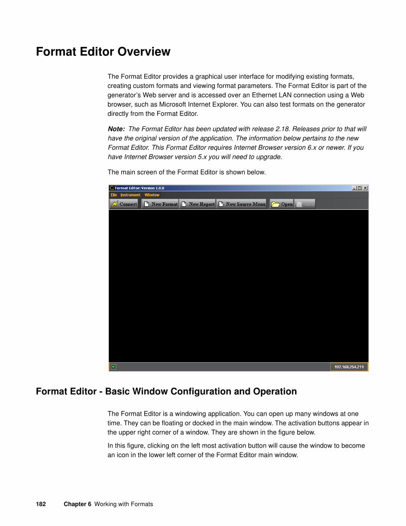
182 Chapter 6 Working with Formats
Format Editor Overview
The Format Editor provides a graphical user interface for modifying existing formats, creating custom formats and viewing format parameters. The Format Editor is part of the generator’s Web server and is accessed over an Ethernet LAN connection using a Web browser, such as Microsoft Internet Explorer. You can also test formats on the generator directly from the Format Editor.
Note: The Format Editor has been updated with release 2.18. Releases prior to that will
have the original version of the application. The information below pertains to the new
Format Editor. This Format Editor requires Internet Browser version 6.x or newer. If you
have Internet Browser version 5.x you will need to upgrade.
The main screen of the Format Editor is shown below.
Format Editor - Basic Window Configuration and Operation
The Format Editor is a windowing application. You can open up many windows at one time. They can be floating or docked in the main window. The activation buttons appear in the upper right corner of a window. They are shown in the figure below.
In this figure, clicking on the left most activation button will cause the window to become an icon in the lower left corner of the Format Editor main window.

881/882 Video Test Instrument User Guide (Rev A.38) 183
Clicking on the activation button in the center of the figure below will dock the window into the main Format Editor window such that it will occupy the entire window opening of the Format Editor.
Clicking on the right most activation button in the figure below will close the window.
Format Editor - Top Level Menus
The top level menus of the Format Editor are shown below.
The following table describes the top level menus in the Format Editor.
Menu Description
File
New Format Opens up the New Format - Timing window. Enables you to create new formats (equivalent to clicking on the New Format activation button).
New Report Opens up the Report Format window (equivalent to clicking on the New Report activation button). Enables you to view list of formats and their primary parameters.

184 Chapter 6 Working with Formats
New Source Menu Opens up the Source Menu (equivalent to clicking on the New Source Menu activation button).
Open Enables you to browse to and open an xml format file on your PC. This is equivalent to clicking on the Open activation button.
Save Enables you to save an xml format file on your PC. This is equivalent to clicking on the Save activation button.
Quit Closes out the Format Editor.
Instrument
Connect Enables you to establish a connection between the Format Editor and the 882E. A dialog pops up to enable you to enter the IP address of the 882E you wish to connect to.
FTP Browser Opens up the FTP browser application which enables you to transfer files between your host PC and the 882E generator that you are connected to.
CMD Terminal Opens up the CMD Terminal application which enables you to enter commands to the 882E generator that you are connected to.
Window
Message Log Check box enables or disables message logging.
Menu Description

881/882 Video Test Instrument User Guide (Rev A.38) 185
Format Editor - Menu Buttons
The activation buttons of the Format Editor are shown in the window below.
The following table describes the Format Editor menu buttons.
Button Description
Connect Clicking on this button enables you to establish a connection between the Format Editor and the 882E. A dialog pops up to enable you to enter the IP address of the 882E you wish to connect to. This is equivalent to selecting the Instrument Connect pull down menu.
New Format Opens up the New Format at the Timing tab. Enables you to create new formats. This is equivalent to selecting the New Format from the File menu.
New Report Opens up the Report Format window. This is equivalent to selecting New
Report from the File menu. Enables you to view list of formats and their primary parameters.
New Source Menu Opens up the Source Menu. This is equivalent to selecting New Source from the File menu.
Open Enables you to browse to and open an xml format file on your PC. This is equivalent to selecting Open from the File menu.
Save Enables you to save an xml format file on your PC. This is equivalent to selecting Save from the File menu.

186 Chapter 6 Working with Formats
Format Editor - New Format
This subsection defines the tabs and status panels available with the New Format screen shown below.
The table below describes the tabs available for the New Format window.
Tab Description / Function
Timing Selecting the Timing tab opens up an application screen that enables you to define the timing parameters for a custom format or modify the timing parameters of an existing format. (See “New Format - Timing Tab” on page 188 below for details on each of the parameters.)
General Selecting the General tab opens up an application screen that enables you to define the sync, level, pixel depth, gamma and pedestal parameters for a custom format or modify these parameters of an existing format. (See “New Format - General Tab” on page 192 below for details on each of the parameters.)
Digital Video Selecting the General tab opens up an application screen that enables you to define the digital video parameters for a custom format or modify these parameters of an existing format. (See “New Format - Digital Video Tab” on page 200 below for details on each of the parameters.)

881/882 Video Test Instrument User Guide (Rev A.38) 187
The table below describes the Problem List status panels for the New Format window.
Digital Audio Selecting the General tab opens up an application screen that enables you to define the digital audio parameters for a custom format or modify these parameters of an existing format. (See “New Format - Digital Audio Tab” on page 202 below for details on each of the parameters.)
AFD Selecting the General tab opens up an application screen that enables you to define the AFD parameters for a custom format or modify these parameters of an existing format. (See “New Format - AFD Tab” on page 205 below for details on each of the parameters.)
Entity Type Description / Function
Unit Pull-down menu Enables you to select the type of 882 unit that you are viewing problems for. Options are:
• C/CA - 882C or 882CA
• D - 882D
• E - 882E
• EA/DP - 882E (HDMI), 882EA (HDMI), 882E (DisplayPort)
•
Interface Pull-down menu Enables you to select the type of interface you are defining a format for. Options are:
• Analog - Component analog (RGB or YPbPr)
• CVBS - Composite Video Baseband Signal
• S-Video - Y/C
• DVI - DVI from the DVI output
• HDMI-D - DVI from the HDMI output
• HDMI-H - HDMI
• SDI - SDI and HDSDI
Instrument
(Connection Status)
Status text field Shows the current connection status.
Error log
Red Dot Indicates that an error has occurred. In the future warnings will be supported which will be yellow.
# (Number) An integer assigned to the error in the log list. This is a number assigned in sequence as the errors occur.
Error # The 882 error number for a particular error type. The error list can be found in “Error code descriptions”.
Description A text description of the error.
Tab Description / Function
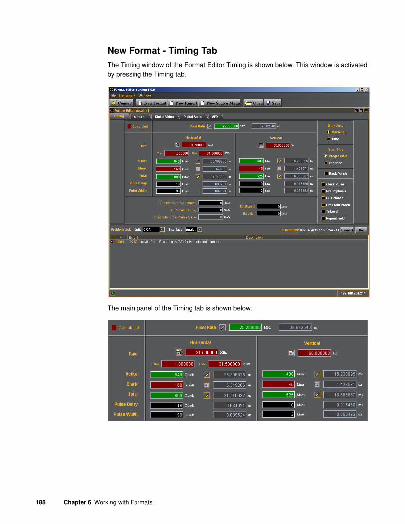
188 Chapter 6 Working with Formats
New Format - Timing Tab
The Timing window of the Format Editor Timing is shown below. This window is activated by pressing the Timing tab.
The main panel of the Timing tab is shown below.

881/882 Video Test Instrument User Guide (Rev A.38) 189
The table that follows describes each of the fields in the main panel of the Timing tab.
Entity Field Description / Function
Pixel Rate Sets the pixel rate in pixels (Machine) or microseconds (Time) of the format.
Horizontal
Rate The horizontal line rate of the format. The HRAT is the fundamental frequency in the 882. Parameter: HRAT.
Tune The tunning value of the base frame rate (base/tune) for NTSC color broadcast compatibility. The tuning value is base/1.001.
Base The base frame rate.
Active The number of active pixels (machine) or microseconds (Time) of the horizontal video. Parameter: HRES.
Blank The number of active pixels (Machine) or microseconds (Time) of the horizontal video. This parameter is calculated.
Total The total number of active pixels (Machine) or microseconds (Time) of the horizontal video. The total is the sum of the Active and Blanking. Parameter: HTOT.
Pulse Delay The number of pixels (Machine) or microseconds (Time) in the blanking preceding the horizontal sync pulse. Parameter: HSPD.
Pulse Width The number of pixels (Machine) or microseconds (Time) of the horizontal sync pulse. Parameter: HSPW.
Vertical
Rate The vertical frame rate of the format. Parameter: VRAT.
Active The number of active lines (machine) or milliseconds (Time) of the vertical video. Parameter: VRES
Blank The number of active lines (Machine) or milliseconds (Time) of the vertical video. This parameter is calculated.
Total The total number of active lines (Machine) or milliseconds (Time) of the vertical video. The total is the sum of the Active and Blanking. Parameter: VTOT.
Pulse Delay The number of lines (Machine) or milliseconds (Time) in the blanking preceding the vertical sync pulse. Parameter: VSPD.
Pulse Width The number of lines (Machine) or milliseconds (Time) of the vertical sync pulse. Parameter: VSPW.
(green calculator)
Indicates that the value in the field is calculated by the Format Editor.
(red calculator) Indicates that the value in the field is calculated by the Format Editor, and that the new value has replaced the value previously in the field.

190 Chapter 6 Working with Formats
New Format - Timing Tab (Bottom Panel)
The bottom panel of the Timing tab in the Format Editor is shown below.
The table that follows describes each of the fields in the panel.
Indicates that the values in this field are settable in the current configuration.
Red Field Indicates that the fields are in the read only mode. These fields will show a change in value when the value in a field affecting these fields is modified.
Green Field Indicates that the fields are in the read/write mode. When you make a change and hit the enter key new values will be calculated.
Black Field Indicates that the fields can be modified directly and are calculated when other related fields are modified.
Gray Field Indicates that the fields are disabled because the Entry Units are selected such that the fields are not used. However these fields will show a change when the value in a field affecting these fields is modified.
Field Description
Serration with
Adjustment
Sets the length of the serration period on composite video to a given number of pixels from the format’s nominal default value as required by some military STANAG video formats. Valid range is in pixels with integer values from 0 to less than HSPW in pixels. Parameter: HVSA
H to V Delay Displays the current value for the pixel delay between horizontal and vertical sync pulses. Parameter: HVPD?
Horizontal Broad
Pulse Delay
Equalization Before Establishes the width of the equalization interval before the vertical sync pulse in each field whenever a serrated and equalized sync type is selected via either ACST or DSCT command and the SSST command. Valid values are 0 and number of lines after vertical sync before video. Parameter: EQUB
Equalization After Establishes the width of the equalization interval after the vertical sync pulse in each field whenever a serrated and equalized sync type is selected via either ACST or DSCT command and the SSST command. Valid values are 0 and number of lines after vertical sync before video. Parameter: EQUA.
Entity Field Description / Function

881/882 Video Test Instrument User Guide (Rev A.38) 191
New Format - Timing Tab (Right Side Panel)
The right side panel of the Timing tab in the Format Editor is shown below. The table that follows describes each of the fields in the panel.
New Format - Timing (Right Side Panel)
Entity Parameter Description / Function
Entry Field
Machine Activates the fields in the timing tab window such that the timing parameter values are expressed and settable in terms of pixels and lines.
Time Activates the fields in the timing tab window such that the timing parameter values are expressed and settable in terms of time increments such as milliseconds and microseconds.
Scan Type
Progressive Sets the format scan type to Progressive. Parameter: SCAN = 2
Interlace Sets the format scan type to Interlaced. Parameter: SCAN = 1
check boxes
Back Porch Toggles the Pulse Delay field so that the value is provided for the back porch rather than the front porch.
Clock Pulse Enables and disables the pixel clock pulse output on generators that have a pixel clock output available. The pixel clock output appears on the special sync BNC connector. Parameter: PCPG.

192 Chapter 6 Working with Formats
New Format - General Tab
The Format Editor General tab is shown below. The table that follows describes each of the fields in the tab.
PreEmphasis Enables and disables adding pre-emphasis to the Open LVDI digital outputs on generators that support LVDI outputs.
DC Balance Not used
Flat Front Porch Determines if composite sync will have all equalization pulses removed in the vertical sync front porch (delay) period as required by certain military HOBO and Maverik video formats. Parameter: EQUF.
Tri-Level Sync Enables or disables Tri-Level sync. Parameter: TSPG
Repeat Field Determines if identical video information is output for each field of an interlaced (SCAN = 2) format. Parameter: RFLD.
Entity Parameter Description / Function
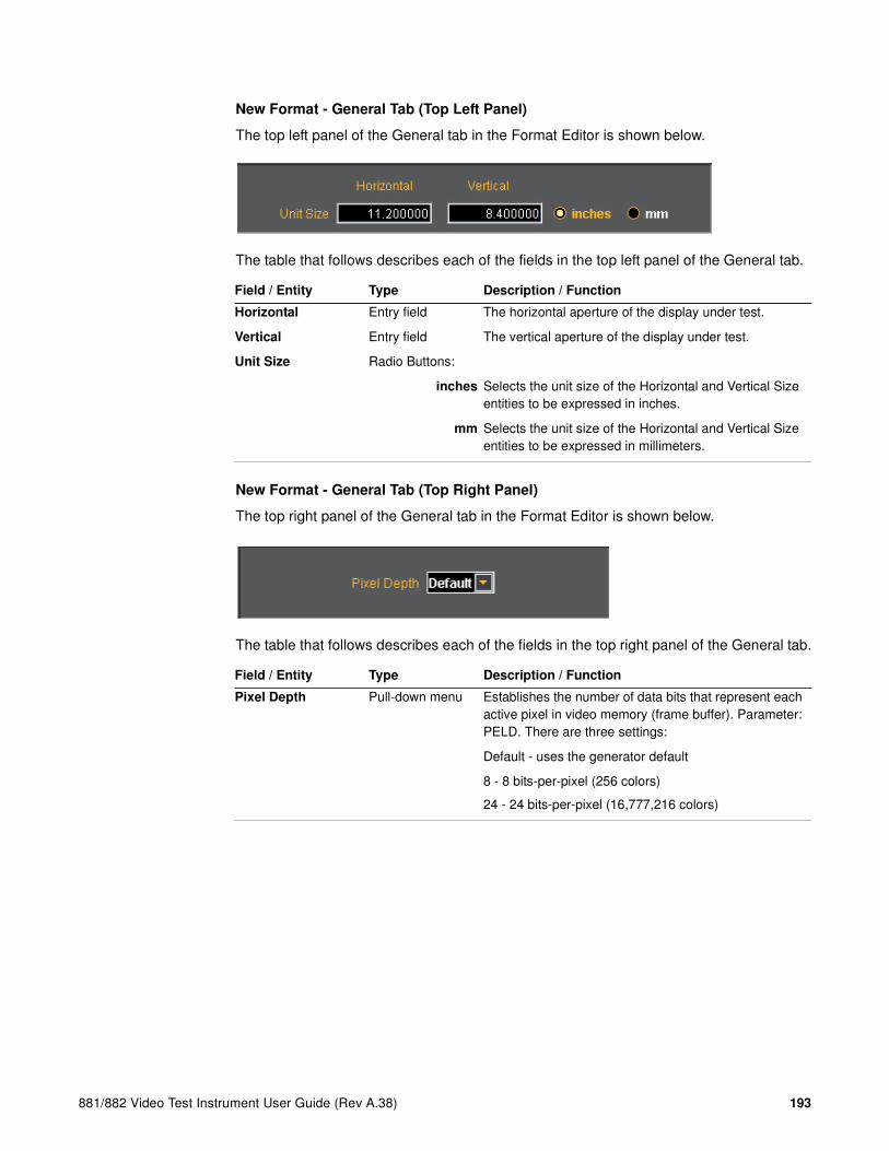
881/882 Video Test Instrument User Guide (Rev A.38) 193
New Format - General Tab (Top Left Panel)
The top left panel of the General tab in the Format Editor is shown below.
The table that follows describes each of the fields in the top left panel of the General tab.
New Format - General Tab (Top Right Panel)
The top right panel of the General tab in the Format Editor is shown below.
The table that follows describes each of the fields in the top right panel of the General tab.
Field / Entity Type Description / Function
Horizontal Entry field The horizontal aperture of the display under test.
Vertical Entry field The vertical aperture of the display under test.
Unit Size Radio Buttons:
inches Selects the unit size of the Horizontal and Vertical Size entities to be expressed in inches.
mm Selects the unit size of the Horizontal and Vertical Size entities to be expressed in millimeters.
Field / Entity Type Description / Function
Pixel Depth Pull-down menu Establishes the number of data bits that represent each active pixel in video memory (frame buffer). Parameter: PELD. There are three settings:
Default - uses the generator default
8 - 8 bits-per-pixel (256 colors)
24 - 24 bits-per-pixel (16,777,216 colors)

194 Chapter 6 Working with Formats
New Format - General Tab (Center Panel)
The center panel of the General tab in the Format Editor is shown below.

881/882 Video Test Instrument User Guide (Rev A.38) 195
The table below describes the pull-down menus in the center panel of the General tab.
Field / Entity Description / Function
Color Encoding Sets the colorimetry of the format. The parameter is AVST or DVST. The following are the selections:
• Default
• Analog Grayscale YYY
• Analog Component RGB
• Analog Composite with Color Kill
• Analog Composite with Subcarrier
• Analog Component YPbPr SDTV
• Analog Component YPbPr HDTV Legacy
• Analog Component YPbPr HDTV Modern
• Analog Component YPbPr Betacam
• Analog Component Monochrome
• Digital Direct VI MDA
• Digital Direct RGB
• Digital Direct RGBI CGA
• Digital Direct RrGgBb EGA
• Digital Component YYY
• Digital Component RGB
• Digital Component YCbCr SDTV (ITU-R BT.601-5)
• Digital Component YCbCr HDTV Legacy (SMPTE 240M)
• Digital Component YCbCr HDTV Modern (ITU-R BT.709-5)
• Digital BT.601 xvYCC
• Digital BT.709 xvYCC
Sync Type Sets the sync type of the format. The parameter is SSST. The following are the selections:
• (0) None
• (1) DSS - Digital Separate Sync
• (2) DCS - Digital Composite Sync
• (3) ACS - Analog Composite Sync
• (4) ACS, DSS - Analog Composite Sync, Digital Separate Sync
• (5) ACS, DCS - Analog Composite Sync, Digital Composite Sync
• (6) ACS, DCS, DSS - Analog Composite Sync, Digital Composite Sync and Digital Separate Sync
• (7) DPMS OFF
• (8) DPMS Suspend
• (9) DPMS Standby
• (10) DPMS ON

196 Chapter 6 Working with Formats
ACS Type Sets the analog composite sync type of the format. The parameter is ASCT. The following are the selections:
• None
• American ORed
• American Single Serrated
• American Double Serrated (ref SMPTE 170M NTSC)
• Australian AS 493.1-200X CS Serrated
• European ORed
• European Double Serrated (ref ITU-R BT.470-6 PAL)
• SMPTE 296M-EIA/CEA
• HDTV Double Serrated (ref SMPTE 296M)
• SMPTE 295M-EIA/CA
• HDTV Double Serrated (ref SMPTE 295M)
• SMPTE 274M-EIA/CA
• HDTV Double Serrated (ref SMPTE 240M, 260M, 274M)
DCS Type Sets the digital composite sync type of the format. The parameter is DSCT. The following are the selections:
• None
• American ORed
• American Single Serrated
• American Double Serrated (ref SMPTE 170M NTSC)
• Australian AS 493.1-200X CS Serrated
• European ORed
• European Double Serrated (ref ITU-R BT.470-6 PAL)
Field / Entity Description / Function

881/882 Video Test Instrument User Guide (Rev A.38) 197
New Format - General Tab (Right Panel)
The right panel of the General tab in the Format Editor is shown below.
The table below describes the entities and fields of the right-side panel of the General tab.
DSS Type Sets the digital composite sync type of the format. The parameter is DSST. The following are the selections:
• None
• American Separate
• European Separate
• American Separate HDTV
• European Separate HDTV
• Japanese Separate HDTV
• Australian AS 493.1-200X HS & VS
• IEC 62315-1 Australian AS 493.1-200X HS & VS
SubCarrier Sets the composite video subcarrier type. Only valid when the color encoding parameter (AVST) is set to Analog Composite with Subcarrier. The parameter is AVSC. The following are the selections:
• None
• NTSC M
• NTSC 443
• PAL BDGHI
• PAL NC
• PAL N
• PAL M
• PAL 60
Field / Entity Entity Type Description / Function
Analog Video Swing Entry field Sets the analog video swing.
Analog Sync Swing Entry field Sets the analog sync swing.
Field / Entity Description / Function

198 Chapter 6 Working with Formats
New Format - General Tab (Bottom Panel)
The bottom panel of the General tab in the Format Editor is shown below.
Gamma Check box Enables or disables Gamma. Used with the entry field below. Parameter: GAMC.
Entry field Enables you to set the Gamma once the Gamma check box above is enabled (checked). The allowable ranges of values is 0.1 to 10.0. Parameter: GAMA.
Pedestal Check box Enables or disables the Pedestal. Used with the entry field below. Pedestal is only supported on NTSC format types. Parameter: AVPG.
Entry field Enables you to set the Pedestal once the Pedestal check box above is enabled (checked). The allowable ranges of values is 0 IRE to 100 IRE. Parameter: AVPS.
Analog Cal. Mode Pull-down select Sets the analog calibration mode. Determines how the generator tests and calibrates its analog video outputs Parameter: AVCM. The following are the selections:
• Interpolate
• Measure Interpolate
• Measure Set Absolute
• Test Levels
Analog Color Order Pull-down select Sets the mapping of the analog video colors to the video output connections. Parameter: AVCO. The following are the selections:
• RGB - R to R, G to G, B to B (default)
• RBG - R to R, B to G, G to B
• GRB - G to R, R to G, B to B
• GBR - G to R, B to G, G to B
• BRG - B to R, R to G, G to B
• BGR - B to R, G to G, R to B
Field / Entity Entity Type Description / Function

881/882 Video Test Instrument User Guide (Rev A.38) 199
The table below describes the gating functions of the right-side panel of the General tab.
Field / Entity Entity Type Description / Function
Analog Sync Gate Select buttons Enables you to put the analog composite sync on one of the components when analog composite sync is selected as the sync type using the SSST command. Multiple selections can be made.
R Puts the analog composite sync on the Red component. Parameter: ASSG.
G Puts the analog composite sync on the Green component. Parameter: ASSG.
B Puts the analog composite sync on the Blue component. Parameter: ASSG.
Digital Sync Gate Select buttons
H Enables and disables the digital horizontal sync output. To use digital horizontal sync, the digital separate H and V sync must be selected with the SSST command. Parameter: HSPG.
V Enables and disables the digital vertical sync output. To use digital vertical sync, the digital separate H and V sync must be selected with the SSST command. Parameter: VSPG.
C Enables and disables the digital vertical sync output. To use digital composite sync, the digital composite sync must be selected with the SSST command. Parameter: CSPG.
Digital Sync Polarity Select buttons
H Determines whether the digital horizontal sync pulse polarity is positive going or negative going. To set the digital horizontal sync polarity, digital horizontal sync must be gated on with the HSPG command. Parameter: HSPP.
V Determines whether the digital vertical sync pulse polarity is positive going or negative going. To set the digital vertical sync polarity, digital vertical sync must be gated on with the VSPG command. Parameter: VSPP.
C Determines whether the digital composite sync pulse polarity is positive going or negative going. To set the digital composite sync polarity, digital composite sync must be gated on with the CSPG command. Parameter: CSPP.
Video Gate Select buttons Enables you to gate ON or OFF any of the video components. More than one can be selected.
R Gates ON or OFF the Red component/
G Gates ON or OFF the Green component/
B Gates ON or OFF the Blue component/
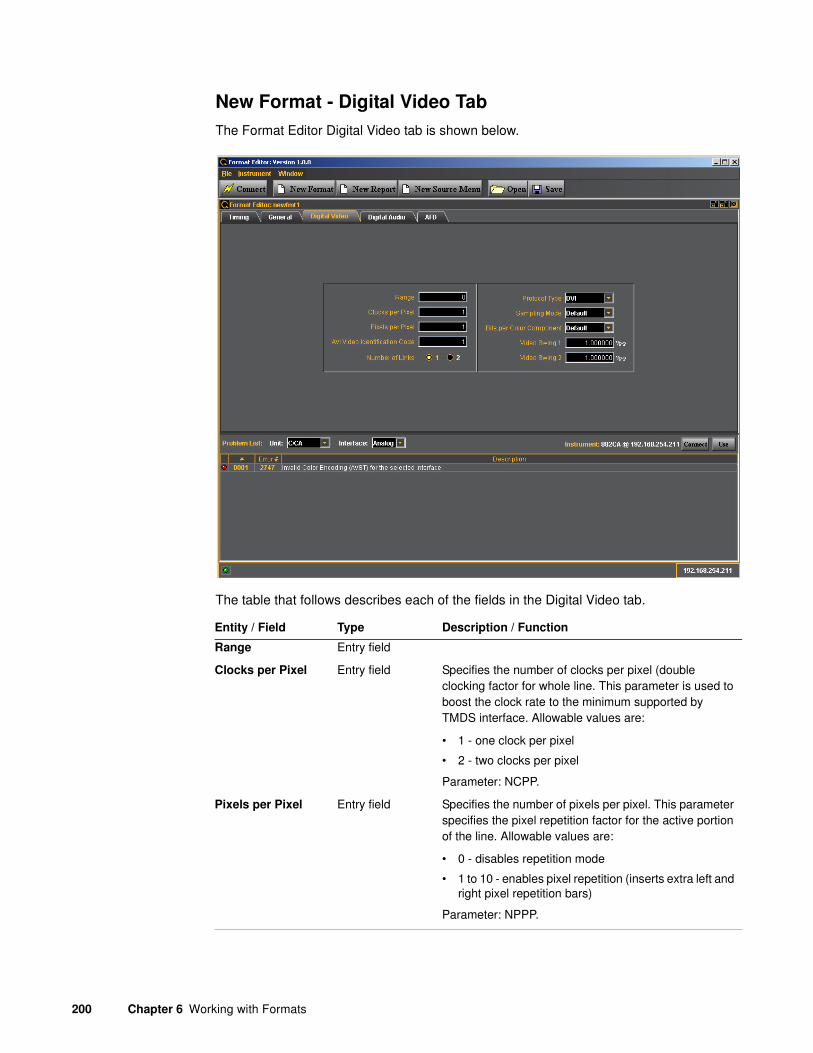
200 Chapter 6 Working with Formats
New Format - Digital Video Tab
The Format Editor Digital Video tab is shown below.
The table that follows describes each of the fields in the Digital Video tab.
Entity / Field Type Description / Function
Range Entry field
Clocks per Pixel Entry field Specifies the number of clocks per pixel (double clocking factor for whole line. This parameter is used to boost the clock rate to the minimum supported by TMDS interface. Allowable values are:
• 1 - one clock per pixel
• 2 - two clocks per pixel
Parameter: NCPP.
Pixels per Pixel Entry field Specifies the number of pixels per pixel. This parameter specifies the pixel repetition factor for the active portion of the line. Allowable values are:
• 0 - disables repetition mode
• 1 to 10 - enables pixel repetition (inserts extra left and right pixel repetition bars)
Parameter: NPPP.
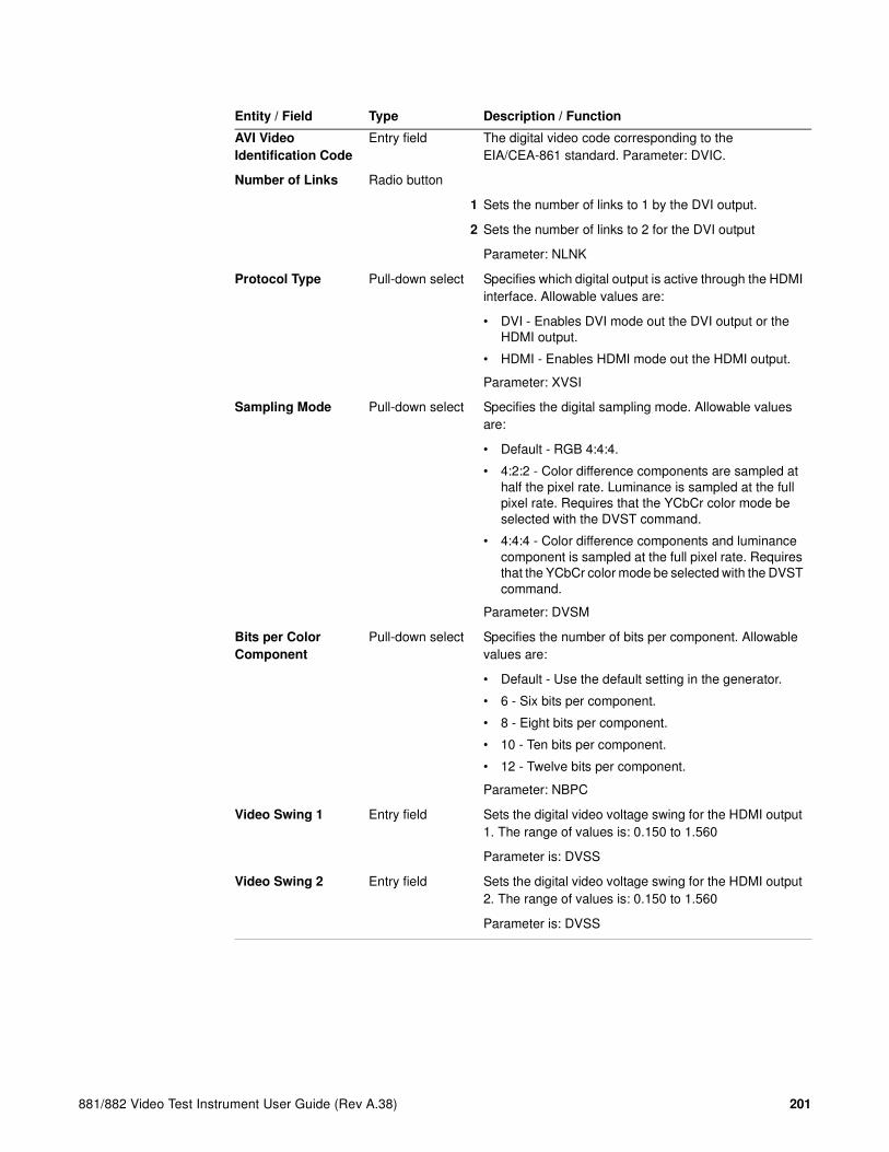
881/882 Video Test Instrument User Guide (Rev A.38) 201
AVI Video
Identification Code
Entry field The digital video code corresponding to the EIA/CEA-861 standard. Parameter: DVIC.
Number of Links Radio button
1 Sets the number of links to 1 by the DVI output.
2 Sets the number of links to 2 for the DVI output
Parameter: NLNK
Protocol Type Pull-down select Specifies which digital output is active through the HDMI interface. Allowable values are:
• DVI - Enables DVI mode out the DVI output or the HDMI output.
• HDMI - Enables HDMI mode out the HDMI output.
Parameter: XVSI
Sampling Mode Pull-down select Specifies the digital sampling mode. Allowable values are:
• Default - RGB 4:4:4.
• 4:2:2 - Color difference components are sampled at half the pixel rate. Luminance is sampled at the full pixel rate. Requires that the YCbCr color mode be selected with the DVST command.
• 4:4:4 - Color difference components and luminance component is sampled at the full pixel rate. Requires that the YCbCr color mode be selected with the DVST command.
Parameter: DVSM
Bits per Color
Component
Pull-down select Specifies the number of bits per component. Allowable values are:
• Default - Use the default setting in the generator.
• 6 - Six bits per component.
• 8 - Eight bits per component.
• 10 - Ten bits per component.
• 12 - Twelve bits per component.
Parameter: NBPC
Video Swing 1 Entry field Sets the digital video voltage swing for the HDMI output 1. The range of values is: 0.150 to 1.560
Parameter is: DVSS
Video Swing 2 Entry field Sets the digital video voltage swing for the HDMI output 2. The range of values is: 0.150 to 1.560
Parameter is: DVSS
Entity / Field Type Description / Function

202 Chapter 6 Working with Formats
New Format - Digital Audio Tab
The Format Editor Digital Audio tab is shown below. The table that follows describes each of the fields in the tab.

881/882 Video Test Instrument User Guide (Rev A.38) 203
The table below describes each of the fields in the Digital Audio tab.
Field Type Description / Function
Signal Interface Pull-down select Sets the digital audio signal interface. The valid values are:
• None - Use HDMI.
• SPDIF.
• AES3 (not used).
• AESid (not used).
• TOSlink optical (not used).
• MiniPlug (not used).
Parameter is: DASI.
Signal Type Pull-down select Sets the digital audio signal type. The valid values are:
• None
• IEC 60958-3 Consumer LPCM.
• IEC 60958-4 Professional LPCM.
• IEC 61937 w/AC-3 (Dolby Digital).
• MP2 (Video CD) (not used).
• MP3 (MPEG1 Layer 3) (not used).
• MPEG2 5.1 channels Advanced Audio Coding (AAC)
• MPEG2 7.1 channel CBR or VBR
• IEC 61937 w/’DTS
• ATRAC
Parameter is: DAST.
Level Shift Entry field Sets the digital audio level shift value. The valid values are: 0 - 15 dBFS.
Parameter is: DALS.
Sampling Rate Entry field Sets the digital audio sampling rate. The valid values are:
• 32.0kHz
• 44.1kHz
• 48.0kHz
• 88.2kHz
• 96.0kHz
• 176.4kHz
• 192.0kHz
Parameter is: ARAT.
Number of Streams Entry field Sets the digital audio streams. The valid value is: 1.
Parameter is: NDAS.
Number of Channels Entry field Sets the digital audio sampling rate. The valid values are: 2 through 8
Parameter is: NDAC.

204 Chapter 6 Working with Formats
Bits per Sample Pull-down select Sets the digital audio sampling rate. The valid values are:
• 16
• 20
• 24
Parameter is: NBPA.
Contents Gated Entry field Sets the digital audio content gate. The valid values are: 0 through 4095. Refer to EIA/CEA-861-x.
Parameter is: DAXG.
Contents Available Entry field Sets the digital audio content available. The valid values are: 0 through 4095. Refer to EIA/CEA-861-x.
Parameter is: DAXA.
Mix Down Gate Check box Sets the digital audio down-mix gate. The valid values are: enabled or disabled.
Parameter is: DADG.
Channels Available Entry field Sets the digital audio channels available. The valid values are: 0 through 255. Refer to EIA/CEA-861-x.
Parameter is: DACA.
Channels Gated Entry field Sets the digital audio channel gate. The valid values are: 0 through 255. Refer to EIA/CEA-861-x.
Parameter is: DACG.
Field Type Description / Function

881/882 Video Test Instrument User Guide (Rev A.38) 205
New Format - AFD Tab
The Format Editor AFD tab is shown below. The table that follows describes each of the fields in the tab.
The table that follows describes each of the text entry fields in the AFD tab.
Heading Field Description / Function
Active Format
Content Aspect
Ratio
Sets the aspect ratio of the source image content. The valid parameter range is: 0.75 to 2.39.
Parameter: CXAR.
Embedded
Aspect Ratio
Sets the aspect ratio of the extended image content. The valid parameter range is: 0.75 to 2.39.
Parameter: EXAR.
Signal Aspect
Ratio
Sets the aspect ratio of the video signal image content. The valid parameter range is: 0.75 to 2.39.
Parameter: SXAR.

206 Chapter 6 Working with Formats
Extended From
Content Apert.
Map
Enables you to set the mapping type for mapping CXAR-shaped image content into the extended EXAR-shaped aperture.
Parameter: EXCX
Signal from
Extended Apert.
Map
Enables you to set the mapping type for mapping EXAR-shaped image content into the SXAR-shaped signal interface.
Parameter: SXEX
Bars
Left Sets the left side letterbox bars in pixels.
Right Sets the right side letterbox bars in pixels.
Top Sets the top letterbox bars in pixels.
Bottom Sets the bottom letterbox bars in pixels.
Heading Field Description / Function

881/882 Video Test Instrument User Guide (Rev A.38) 207
Format Editor - New Report
This subsection defines the New Report screen. The contents of the New Report tab is shown below.

208 Chapter 6 Working with Formats
The table below describes the top selection panels for the New Report activation button
The table below describes the activation buttons available for the New Report screen.
Entity Type Description / Function
Instrument
(Connection Status)
Status text field Shows the current connection status.
Connect Activation Button Enables you to connect to an 882 generator. When clicked a dialog box will pop up enabling you to specify an IP address to connect to.
Type Pull-down menu Always set to Format.
Path Entry Field The path to the directory where the list of formats used to configure a format list.
Edit Path Activation Button Enables you to change the path to a list of formats.
Button Description / Function
Configure Clicking on the Configure button will open up a dialog box that enables you to configure which format parameters appear in the report and in what order.
Fill / Cancel Clicking on the Fill activation button will cause the Format Editor application to begin loading the formats from the list that the Path is set to. The completion status is shown below the list. The Cancel button on the lower right enables you to halt the filling (reading) of the formats from the list in the directory that the path parameter is set to.

881/882 Video Test Instrument User Guide (Rev A.38) 209
The table below describes the report fields available for the New Report screen.
Generate HTML
Report
Clicking on this button will cause the Format Editor application to generate an HTML report of the list of formats. A dialog box pops up to allow you to specify a location and name on your PC.
Edit Format This activation button is only enabled when you select a format from the list. Clicking on this button will open up the Format Editor window at the Timing tab.
Use Format This activation button is only enabled when you select a format from the list. Clicking on this button activate this format in the connected 882 generator.
Report Parameter Parameter Description
Name The format name.
Digital Video
Identification Code
Writes the specified Video Identification Code (VIC) into the AVI InfoFrame.
Horizontal Total The total number of active pixels (Machine) or microseconds (Time) of the horizontal video. The total is the sum of the Active and Blanking. Parameter: HTOT.
Horizontal Active The number of active pixels (machine) or microseconds (Time) of the horizontal video. Parameter: HRES.
Horizontal Sync
Pulse Polarity
Indicates whether the digital horizontal sync pulse polarity is positive going or negative going. Parameter: HSPP.
Horizontal Rate
(kHz)
The horizontal line rate of the format. The HRAT is the fundamental frequency in the 882. Parameter: HRAT.
Vertical Total The total number of active lines (Machine) or milliseconds (Time) of the vertical video. The total is the sum of the Active and Blanking. Parameter: VTOT.
Vertical Active The number of active lines (machine) or milliseconds (Time) of the vertical video. Parameter: VRES.
Vertical Sync Pulse
Polarity
Indicates whether the vertical sync pulse polarity is positive or negative going. Parameter: VSPP.
Vertical Rate The vertical frame rate of the format. Parameter: VRAT.
Sync Type Indicates the sync type of the format. The parameter is SSST.
Button Description / Function

210 Chapter 6 Working with Formats
The screen below shows the Format Table Configuration Screen. This screen enables you to configure the fields for the format report.
The table below describes the fields and buttons for the Table Configuration Screen.
Entity Description / Function
Column Choices Configuration Field
Provides a list of format parameters to select and move to the report.
Column in the Table Configuration Field
Shows the current list of format parameters that will appear in the report. The format parameters will appear in the order (top to bottom / left to right) in the report.
Add Activation Button Enables you to move format parameters from the Column Choices to the Columns in the Table (that will appear in the reports).
Remove Activation Button Enables you to remove format parameters from the Columns that will appear in the table.
Remove All Activation Button Enables you to remove all the format parameters currently shown in the Column in the Table field.
Move Up Activation Button Enables you to change the order (move up) the selected format parameters in the Columns in Table that will appear in the format report. The top most parameters will appear in the left most side of the report.
Move Down Activation Button Enables you to change the order (move down) the selected format parameters in the Columns in Table that will appear in the format report. The top most parameters will appear in the left most side of the report.

881/882 Video Test Instrument User Guide (Rev A.38) 211
Format Editor - New Source Menu
This subsection defines the New Source Menu dialog box. The New Source Menu dialog box is shown below:
The table below describes the top panels fields, activation buttons and pull down menus.
Entity Type Description / Function
Instrument
(Connection Status)
Status text field Shows the current connection status.
Connect Activation Button Enables you to connect to an 882 generator. When clicked a dialog box will pop up enabling you to specify an IP address to connect to.
Save and Use Activation Button Enables you to save the format source list to the generator you are connected to and then apply this list to the current generator configuration.
Reset Source Menu Activation Button
Type Pull-down menu Always set to Format.
Path Entry Field The path to the directory where the list of formats used to configure a source list.
Edit Path Activation Button Enables you to change the path to a list of formats.

212 Chapter 6 Working with Formats
The table below describes the main panels fields, of the New Source Menu.
Entity Type Description / Function
Directory Listing Configuration Field
Provides a list of formats to select and move to a particular (set by the Path entry field) directory on the 882 generator.
Source Menu Listing Configuration Field
Shows the current list of formats that will appear in a particular directory (set by the Path entry field) on the 882 generator.
Add Activation Button Enables you to move formats from the Directory Listings to the Source Menu Listing fields (formats that will appear a particular format directory i.e. set by the Path entry field).
Remove Activation Button Enables you to remove formats from the Source Menu Listing fields so that they will not appear in a particular format directory (set by the Path entry field).
Remove All Activation Button Enables you to remove all the formats currently shown in the Source Menu Listing field.
Move Up Activation Button Enables you to change the order (move up) the selected formats in the Source Menu Listing field that will appear in a particular format directory (set by the Path entry field). The top most formats will appear first in the list.
Move Down Activation Button Enables you to change the order (move down) the selected formats in the Source Menu Listing field that will appear in a particular format directory (set by the Path entry field). The top most formats will appear first in the list.

881/882 Video Test Instrument User Guide (Rev A.38) 213
Format Editor - Open
This subsection defines the Open [File] dialog box. The Open dialog box is shown below. This enables you to open an existing format file either from your PC (Local tab) or from the 882 instrument (Remote tab).

214 Chapter 6 Working with Formats
Format Editor - Save
This subsection defines the Save [File] dialog box. The Save dialog box is shown below. You use the Save function to store a format that you have defined. You can either save it to your PC (Local tab) or the 882 instrument (Remote tab).

881/882 Video Test Instrument User Guide (Rev A.38) 215
Creating a new format using the Format Editor
The procedure below describes how to create a new format using the Format Editor.
To create a new format using the Format Editor:
1. Open a Web browser (such as Internet Explorer) and type the generator’s IP address in the address entry field. For example, enter the following: http://206.135.215.189/
The generator home page appears in the browser.
Note: You can add the page to your list of favorite pages in your Web browser to avoid
retyping the IP address each time you want to access the page.
2. Select Format Editor. The Format Editor appears.

216 Chapter 6 Working with Formats
3. Click New Format. The Timing tab of the format definition page appears as shown below.

881/882 Video Test Instrument User Guide (Rev A.38) 217
4. Open an existing file to work from by clicking on the Open activation button near the top of the window.
The open file dialog box appears as shown below.
You can either load a file from your PC or from the 882 test instrument by selecting the appropriate tab: 1) Local (host PC) or 2) Remote (882).
If you are loading a format from the 882 instrument, you will need to make sure that the path is pointing to the directory where the format you wish to use as a base format is stored at. If it is not you will have to edit the path by clicking on the Edit Path activation button on the right side of the Path field.
5. Navigate and select a format file to use as a starting point for defining your new format or to make simple modifications on an existing format.
6. The format parameters of the selected format will appear in the new format Timing window as shown below.
7. Modify the parameters as required for the new format. You can reference the parameter definitions in the subsections above “Format Editor Overview” on page 182. The following guidelines will help you modify the format parameters.
• There are parameter values that you may want to change on multiple tabs: 1) Timing “New Format - Timing Tab” on page 188, 2) General “New Format - General

218 Chapter 6 Working with Formats
Tab” on page 192, 3) Digital Video “New Format - Digital Video Tab” on page 200, 4) Digital Audio “New Format - Digital Audio Tab” on page 202.
• When selecting a parameter to modify on the Timing tab, ensure that the value is editable. To be editable, the field either needs to have a pencil icon next to it or a black field background. Gray fields are disabled for editing. Fields in red (with the calculator icon) cannot be modified. However you can change whether a field can be modified by clicking on the calculator icon which will cause it to change to a pencil icon allowing you to change its value.
• Upon modifying a format value hit the enter key to invoke the change. The Format Editor applies the new value to the timing algorithm and updates any values dependent on the value you entered (or changed).
For example, to change the horizontal resolution to 660, enter the value in the Active field under Pixels in the Horizontal area.
You will notice that the Format Editor has calculated and written values to the Blank and Period fields as indicated by the red calculator ( ) symbol. Although the Period value has not changed, the Format Editor still indicates it is a calculated value by displaying the red calculator.
• To apply the format settings on the generator, click the Use activation button on the lower right side.
8. Save new format.
a. Click the Save activation button or the select Save from the File pulldown menu to save the format. The save dialog box appears as shown below.
a. Enter new format name in File Path field.
You can either save it to your PC (Local tab) or the 882 instrument (Remote tab).

881/882 Video Test Instrument User Guide (Rev A.38) 219
Note: It is recommended that you save custom formats in a directory on the PCcard
because of file storage limitations in the flash memory.

220 Chapter 6 Working with Formats
Creating custom formats using the command line interface
There are two methods for creating formats through the command line interface. The first method is to use the FMTN command to set all format parameters in the format buffer to their default values, and then modify each value. The second method is to select an existing format to use as a template for the new format, and then modify only the values needed to create the new format. When using this method, you can save the new format under a new name or the existing name.
Independent of the method you choose, you can enter each command interactively or create a text file containing all the commands you want to issue, and then download the text file to the generator. See “Configuring the 882’s serial port” on page 30 for more information about sending commands to a generator.
The FMTN command is used in creating a new format. This command sets all of the format parameters to known, default values. For a list of the parameters and their default values, see “FMTN” on page 888. Use the following procedure to create a new format using interactive commands.
To create a new format using the command line interface:
1. Establish a session with the generator using HyperTerminal over a serial connection or Telnet over an Ethernet LAN. For instructions, see “Establishing a terminal session with the 882” on page 30 and “Establishing a Telnet session with the 882” on page 33.
2. Set the format path to the medium where you want the new format stored using the following command:
FMTP /tffs0/Library/Formats // sets format path to flashmem directory
3. Enter the following commands to initialize all parameters to default values and begin a format editing session:
FMTN // initializes all parameters to default values
FMTB // begins a format editing session
4. Enter the format parameter commands in sequence to set the values for the new format.
HRES 654 // sets the horizontal resolution to 654 pixels
.
. // other format parameters
.
HTOT 720 // sets the horizontal total to 720 pixels
Note: You do not need to enter a parameter value if it matches the FMTN default
setting. You can query a parameter to determine its current value.
5. End the editing session and save the new format using the following commands:
FMTE // ends a format editing session
FMTA new_fmt_name // saves format as new specified name

881/882 Video Test Instrument User Guide (Rev A.38) 221
Format catalogs
Scrolling through all of the available formats on the Source list can be time consuming. This is particularly true if you regularly use only a few formats that may be scattered throughout the list. You can set up the generator to show only the formats you want, in the order you want, when you browse through the Source list.
The generator’s format library is comprised of a set of format catalogs. A format catalog is an XML file that lists related format names. When a catalog is enabled, the format names in the catalog appear on the Source list.
The generator is configured with a default set of catalogs in the Source library. Each catalog represents a set of formats categorized per testing application. You can configure the generator to show only the formats contained in the catalogs you use regularly. Furthermore, you can create your own catalogs and enable them.
With 2.5.x an enhancement has been made to the format catalog function. You can now configure the generator such that your custom formats appear in the Source list along with the 882's default formats. Use the following procedures to create and enable format catalogs.
Using format catalogs
Use the following procedures to enable and disable format catalogs.
To enable catalogs in the Source library using the front panel:
1. Press the Source key. The list of formats appears on the generator’s display.
2. Press the Options key repeatedly until the Library folder appears on the generator’s display as shown below:
3. Choose the Library item by pressing the adjacent soft key. The format library appears as shown below. Each item in the format library is a format catalog.
Library
+Medical Military++SDTV VESA++HDTV Game++TTL Misc+

222 Chapter 6 Working with Formats
4. Press the soft key adjacent to a catalog to enable or disable it. A + sign next to the item indicates the item is enabled; a - sign indicates it is disabled.
For example, to see only the VESA formats when you press the Source key, disable all catalogs except DMT and CVT.
5. Press the Source key to see the formats in the selected catalogs.
Creating format catalogs
Use the following procedures to create format catalogs.
To create a new format catalog:
Note: Format catalogs are created using the command line interface. Although the catalog
itself is a file, you will use the Directory (DIR) commands to create the file.
1. Determine the formats you want to include in your catalog. For example, to create a catalog for testing computer CRTs, you might include the following formats:
DMT0660 DMT0659
DMT00675 DMT0685
DMT0856 DMT0860
2. Establish a session with the generator using HyperTerminal over a serial connection or Telnet over an Ethernet LAN. For instructions, see “Establishing a terminal session with the 882” on page 30 and “Establishing a Telnet session with the 882” on page 33.
3. Verify or set directory path is set to the FormatLib directory using the following command:
DIRP? // to view the current path
or...
DIRP /tffs0/Library/FormatLib // to set the path
4. Create the catalog by entering the following commands:
DIRN Vesa1 // creates a catalog named Vesa1
DIRT Source // identifies new catalog as a source catalog
DIRB // begins a directory editing session
NAMI 1 /tffs0/Library/Formats/DMT0660 // adds DMT0660 to catalog
.
. // add other formats
.
NAMI 6 /tffs0/Library/Formats/DMT0860 // adds DMT0860 to catalog
DIRE // ends the directory editing session
DIRA Vesa1 // saves the catalog
DIRL Vesa1 // loads the catalog
DIRU // applies the catalog
When you press the Source key, the formats in the catalog you created appear in the Source list.
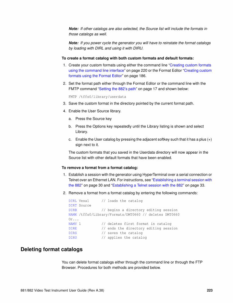
881/882 Video Test Instrument User Guide (Rev A.38) 223
Note: If other catalogs are also selected, the Source list will include the formats in
those catalogs as well.
Note: If you power cycle the generator you will have to reinstate the format catalogs
by loading with DIRL and using it with DIRU.
To create a format catalog with both custom formats and default formats:
1. Create your custom formats using either the command line “Creating custom formats using the command line interface” on page 220 or the Format Editor “Creating custom formats using the Format Editor” on page 186.
2. Set the format path either through the Format Editor or the command line with the FMTP command “Setting the 882’s path” on page 17 and shown below:
FMTP /tffs0/library/userdata
3. Save the custom format in the directory pointed by the current format path.
4. Enable the User Source library.
a. Press the Source key
b. Press the Options key repeatedly until the Library listing is shown and select Library.
c. Enable the User catalog by pressing the adjacent softkey such that it has a plus (+) sign next to it.
The custom formats that you saved in the Userdata directory will now appear in the Source list with other default formats that have been enabled.
To remove a format from a format catalog:
1. Establish a session with the generator using HyperTerminal over a serial connection or Telnet over an Ethernet LAN. For instructions, see “Establishing a terminal session with the 882” on page 30 and “Establishing a Telnet session with the 882” on page 33.
2. Remove a format from a format catalog by entering the following commands:
DIRL Vesa1 // loads the catalog
DIRT Source
DIRB // begins a directory editing session
NAMK /tffs0/Library/Formats/DMT0660 // deletes DMT0660
Or...
NAMY 1 // deletes first format in catalog
DIRE // ends the directory editing session
DIRS // saves the catalog
DIRU // applies the catalog
Deleting format catalogs
You can delete format catalogs either through the command line or through the FTP Browser. Procedures for both methods are provided below.

224 Chapter 6 Working with Formats
To delete a format catalog through the command line:
1. Establish a session with the generator using HyperTerminal over a serial connection or Telnet over an Ethernet LAN. For instructions, see “Establishing a terminal session with the 882” on page 30 and “Establishing a Telnet session with the 882” on page 33.
2. Delete a format catalog by entering the following command:
DIRK /tffs0/Library/FormatLib/Vesa1.xml // deletes catalog named Vesa1
3. Power cycle the generator.
To delete a format catalog through the Generator FTP Browser:
1. Access the source generator’s Virtual Front Panel. See “Front panel interface” on page 9.
2. From the Options menu (upper left corner of the Virtual Front Panel), choose the FTP Browser menu item. The Generator FTP Browser appears.
3. In the Instrument Files area, click the down arrow and select the tffs0. This is the generator’s flash memory.
4. Double click the Library folder, and then double-click the FormatLib folder to open it.

881/882 Video Test Instrument User Guide (Rev A.38) 225
5. Select the catalog you want to delete.
6. Click the Delete button to delete the catalog.

226 Chapter 6 Working with Formats

881/882 Video Test Instrument User Guide (Rev A.38) 227
7 Working with Images
Topics in this chapter:
• Overview
• Viewing the Content list of images
• Creating custom images
• Rendering bitmap images
• Creating image catalogs

228 Chapter 7 Working with Images
Overview
The 882 generator includes a library of 250 test images. The images in the library are compiled in the application and stored as .img files; you cannot modify them.
In addition to the library images there are other types of images that you can create and store on the generator media. You can create your own images either by writing your own code using the generator’s Software Development Kit (SDK) or by entering image primitive commands using the command line interface. Furthermore, you can render JPEG images stored on the generator media or a file server PC.
Using the SDK, you can create complex, custom images through the C/C++ API. When you create images through the API, they reside on the generator as object files. You can then render them by selecting the image through the front panel or through the command line interface. When you select one of these images, it gets linked, compiled, and stored in the generator’s cache. Please refer to the SDK manual for details on creating custom images using the API.
You can create static images through the command line interface using the image primitive commands, such as RECT (draw rectangle), OVAL (draw oval), Line (draw line), and so on. You can select the grayscale and color tables used in the image and save the images in flash memory. Drawing commands are processed by the generator and stored as XML files. These XML files can be modified if necessary.
JPEG and bitmap images can be stored on any of the generator media and rendered just like any other image type through the Contents key.
This chapter provides procedures for viewing lists of images, creating images using the drawing primitive commands, rendering bitmap and jpg images, and creating image catalogs.

881/882 Video Test Instrument User Guide (Rev A.38) 229
Viewing the Content list of images
You can view the list of images available in the generator through the front panel or the command line interface. Use the following procedure to view the image list using the front panel.
Note: The list of images that appears on the generator’s display is determined by the
image path. In addition, the list may be filtered based on the image catalogs that are
enabled. For more information about setting the path, see “Setting the 882’s path” on page
17. For more information about image catalogs, see “Creating image catalogs” on page
239.
To view the images in the Content list using the front panel:
Press the Content key. A list of images appears on the generator’s display as shown below. You can scroll through the list using the + and - keys.
Viewing and modifying image options
Procedures for viewing and modifying the image options through the front panel are provided below.
To view and modify a format’s options using the front panel:
1. Press the Contents key and choose an image by pressing the adjacent soft key.
a. Press the Options key. The image options appear on the generator’s display as shown below.
2. Enable or disable the desired option by pressing the adjacent soft key.
Viewing image versions
Many images have secondary or alternate version and some images have many versions. Use the procedures below to view the alternate and multiple image versions.
Acer1 Acer2 Acer3 Acer4 Acer5 Acer6 Acer7 Acer8
-Alternate Red+-NoGamma Green+-Noise Blue+

230 Chapter 7 Working with Images
To view an alternate version for an image in the Content list:
1. Select an image by pressing the Content key.
2. Enable and view the alternate image version as follows:
a. Press the Options key. The following menu appears on the generator’s display for images with a single, alternate image:
b. Choose the Alternate item by pressing the adjacent soft key until a + appears next to the item.
3. Toggle back and forth between the images by pressing the soft key adjacent to Alternate.
To view multiple image versions in the Content list:
1. Select an image by pressing the Content key.
2. Enable and view image versions as follows:
a. Press the Options key. The following menu appears on the generator’s display:
b. Choose the More item by pressing the adjacent soft key until a + and Rendition appears next to the item.
c. Press the + and - keys to advance through the image versions.
Alternatively, to enable and view image versions using the command line interface, enter the following commands:
ISUB 1 // Enables sub images
IVER 1 // Specifies the first image version
IMGU // Activates the image version
-Alternate Red+-NoGamma Green+-Noise Blue+
+Alternate Red+-NoGamma Green+-Noise Blue+
-More Red+-NoGamma Green+-Noise Blue+
+More Rendition: 000 Red+-NoGamma Green+-Noise Blue+

881/882 Video Test Instrument User Guide (Rev A.38) 231
3. When you are finished, disable image versions by pressing the Options key and choosing More until a - appears next to it.
Alternatively, to disable image versions using the command line interface, enter the following command:
ISUB 0 // Disables sub images

232 Chapter 7 Working with Images
Creating custom images
This section describes how to create images using drawing primitive commands and add them to the generator’s Content list. The recommended method for sending drawing primitive commands to the generator is to create a text file containing the commands for creating the image, and then transfering the text file to the generator. For more information about using command files, see “Sending command files (serial interface only)” on page 34.
To create a custom image with a text file:
1. Using a text editor, open a text file on your computer and enter the following commands.
OUTG 0 // gates all video and sync outputs off
IMGN new_image // creates a new image
IMGB // begins an image editing session
XRES 640 // sets the horizontal resolution to 640
YRES 480 // sets the vertical resolution to 480
.
. // image drawing primitives
.
IMGE // ends an image editing session
IMGA path/new_image// saves image as new_image in specified path
OUTG 1 // gates all video and sync outputs on
IMGU // draws the image
ALLU // applies buffer to the generator hardware
2. Save the text file with a *.txt extension.
3. Set the image path to the image folder where you want to store your image.
IMGP /tffs0/Library/Images // sets image path to folder in flashmem
4. Establish a terminal session with the generator. See “Establishing a terminal session with the 882” on page 30.
5. At the R:> prompt, transfer the text file to the generator. For example, to transfer a file using HyperTerminal, do the following:
a. On the Transfer menu, click Send Text File. The Send Text File dialog box appears.
b. Select the text file you want to send, and then click Open. HyperTerminal displays the commands as they are sent.
c. Press Enter once to ensure that the last command is sent.
The generator processes the commands and creates an image XML file in the Images folder you specified above.
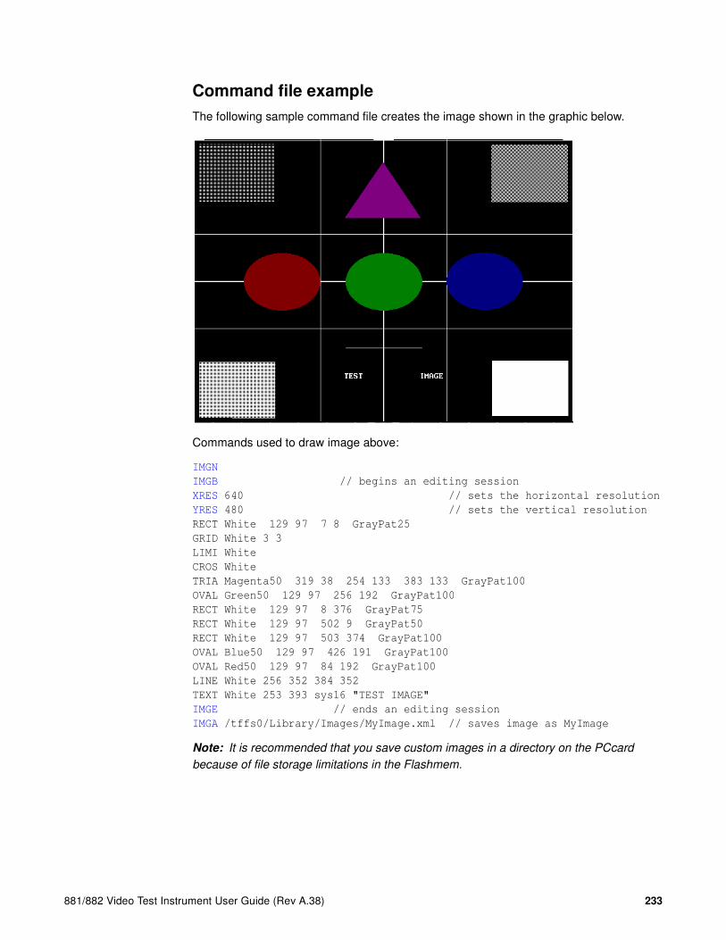
881/882 Video Test Instrument User Guide (Rev A.38) 233
Command file example
The following sample command file creates the image shown in the graphic below.
Commands used to draw image above:
IMGN
IMGB // begins an editing session
XRES 640 // sets the horizontal resolution
YRES 480 // sets the vertical resolution
RECT White 129 97 7 8 GrayPat25
GRID White 3 3
LIMI White
CROS White
TRIA Magenta50 319 38 254 133 383 133 GrayPat100
OVAL Green50 129 97 256 192 GrayPat100
RECT White 129 97 8 376 GrayPat75
RECT White 129 97 502 9 GrayPat50
RECT White 129 97 503 374 GrayPat100
OVAL Blue50 129 97 426 191 GrayPat100
OVAL Red50 129 97 84 192 GrayPat100
LINE White 256 352 384 352
TEXT White 253 393 sys16 "TEST IMAGE"
IMGE // ends an editing session
IMGA /tffs0/Library/Images/MyImage.xml // saves image as MyImage
Note: It is recommended that you save custom images in a directory on the PCcard
because of file storage limitations in the Flashmem.
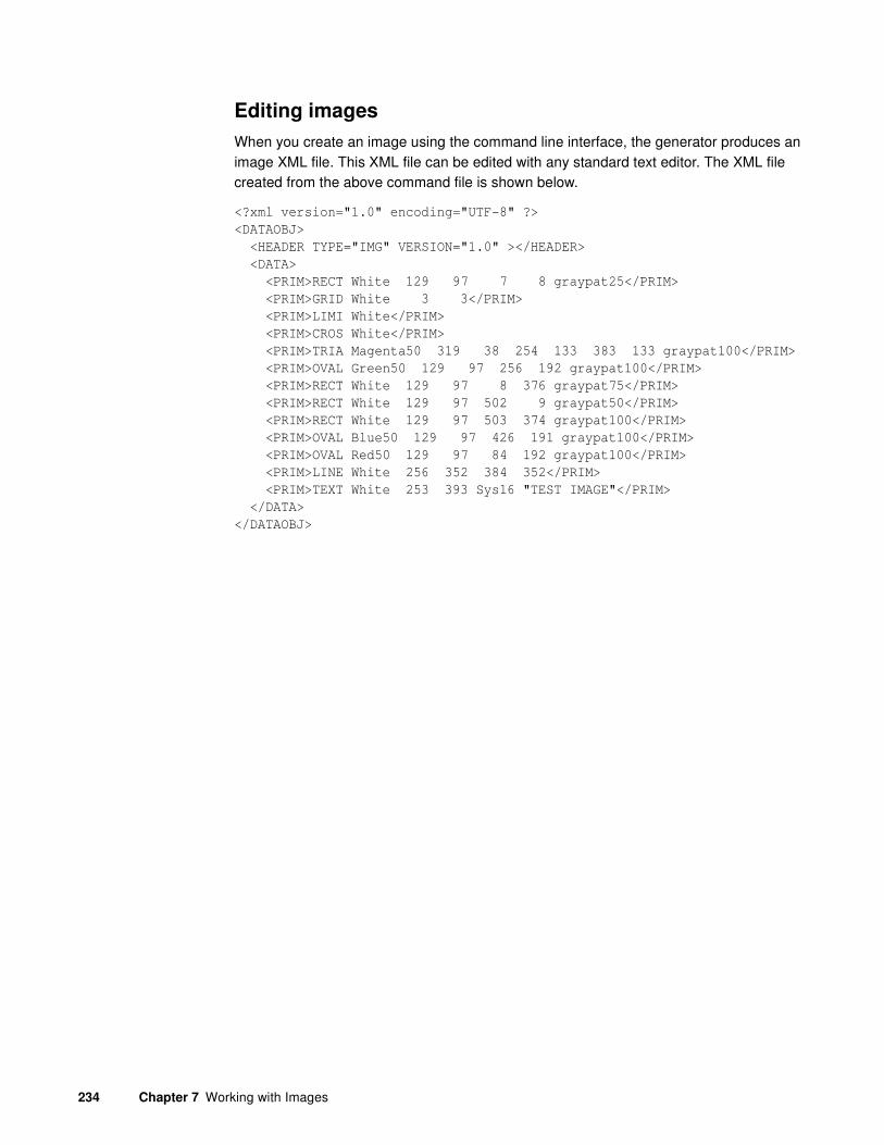
234 Chapter 7 Working with Images
Editing images
When you create an image using the command line interface, the generator produces an image XML file. This XML file can be edited with any standard text editor. The XML file created from the above command file is shown below.
<?xml version="1.0" encoding="UTF-8" ?>
<DATAOBJ>
<HEADER TYPE="IMG" VERSION="1.0" ></HEADER>
<DATA>
<PRIM>RECT White 129 97 7 8 graypat25</PRIM>
<PRIM>GRID White 3 3</PRIM>
<PRIM>LIMI White</PRIM>
<PRIM>CROS White</PRIM>
<PRIM>TRIA Magenta50 319 38 254 133 383 133 graypat100</PRIM>
<PRIM>OVAL Green50 129 97 256 192 graypat100</PRIM>
<PRIM>RECT White 129 97 8 376 graypat75</PRIM>
<PRIM>RECT White 129 97 502 9 graypat50</PRIM>
<PRIM>RECT White 129 97 503 374 graypat100</PRIM>
<PRIM>OVAL Blue50 129 97 426 191 graypat100</PRIM>
<PRIM>OVAL Red50 129 97 84 192 graypat100</PRIM>
<PRIM>LINE White 256 352 384 352</PRIM>
<PRIM>TEXT White 253 393 Sys16 "TEST IMAGE"</PRIM>
</DATA>
</DATAOBJ>

881/882 Video Test Instrument User Guide (Rev A.38) 235
Rendering bitmap images
Bitmap images residing in the generator’s flash memory, on the PC card, or on the file server can be rendered on a display by selecting the image through the front panel or the command line interface. This section describes how to store and render bitmap images.
To render a bitmap image using the front panel:
1. Copy the bitmap image to the Image folder on either the file server or the generator’s flash memory or PC card. See “Copying files from a PC to a 882” on page 23.
Note: You can transfer either a single bitmap or an entire folder of bitmaps. It is
recommended that you save bitmaps in a directory on the PCcard because of file
storage limitations in the Flashmem.
2. Set the generator’s image path to the image folder on the desired medium. See “Setting the 882’s path” on page 17.
3. If necessary, place the generator in Basic mode by pressing and holding the Tools key.
4. Press the Content key. A list of images appears on the generator’s display.
5. Press the soft key adjacent to the desired image to render the bitmap on the display.
To render a bitmap image using the command line interface:
1. Copy the bitmap image to the Image folder on either the file server or the generator’s flash memory or PC card. See “Copying files from a PC to a 882” on page 23.
Note: You can transfer either a single bitmap or an entire folder of bitmaps.
2. Establish a terminal session with the generator. See “Establishing a terminal session with the 882” on page 30.
3. Set the generator’s image path to the image folder on the desired medium. In the command syntax, specify the medium as follows:
• Flash memory: tffs0
• PC card: card0
• File server: server_name (case sensitive without a forward slash in front, and with a colon after the name)
Enter the following command for flash memory and PC card:
IMGP /medium/Library/Images
Enter the following command for file server:
IMGP server_name:

236 Chapter 7 Working with Images
4. Enter the following commands to select and render the image from flash memory or PC card:
IMGL image_name // Select the test image
IMGU // Draw the selected test image

881/882 Video Test Instrument User Guide (Rev A.38) 237
Setting image component values
You can increment the color component values or can decrement the color component values for all pixels of any image through the front panel or the command line. This feature enables you to increment or decrement the values in increments (or decrements) of 1, 10 or 100 throughout a range of 0 to 255 through the front panel or by any increment 1 or greater through the command line. The LEVP feature increments or decrements all color component values (R,G,B) for each action by the user either through the command line or through the front panel.
You can also increment the R, G, B color component values individually through the command line in increments of 1 or greater using the LEVP:R command. And you can use the LEVP:R and LEVP commands together.
Note: These commands are best used with component color formats (RGB color scheme).
The color mode is set by the AVST or DVST command. AVST 2 is analog RGB color mode;
DVST 10 is digital RGB color mode. If you have a format and configuration with color
difference (YPbPr or YCbCr) you see a reduction or increase of the chrominance difference
values but the Y component values will remain. Therefore as your reduce the color
component values for red, green and blue you will see a pronounced green image.
This subsection describes these procedures.
To increment or decrement all color component values for an image:
1. Select an image by pressing the Content key.
2. Press the Options key repeatedly to access the component increment menu. The following menu appears on the generator’s display:
3. Set the increment value to either 001, 010 or 100 by pressing the soft key adjacent to the Inc:001 item on the menu.
4. Increment or decrement the image color component values by pressing the + and - keys.
To increment or decrement all color component values for an image through the command line:
1. Select any image you want to modify by pressing the Content key.
Alternatively you can enter the following command:
IMGL SMPTEBar // Loads the SMPTEbar test image
IMGU // Renders the test image that is loaded
2. Enter the following commands to set the color component values:
Inc:001 LEVP:225

238 Chapter 7 Working with Images
LEVP:R 52 // Sets all color component (R,G,B) at 52% full
color
To increment or decrement each color component value individually for an image:
1. Select any image you want to modify by pressing the Content key.
Alternatively you can enter the following command:
IMGL SMPTEBar // Loads the SMPTEbar test image
IMGU // Renders the test image that is loaded
2. Enter the following commands to select and render the image:
LEVP:R 33 // Sets the red component at 33% of maximum color
LEVP:G 50 // Sets the green component at 50% of maximum color
LEVP:B 66 // Sets the blue component at 66% of maximum color

881/882 Video Test Instrument User Guide (Rev A.38) 239
Creating image catalogs
An image catalog is an XML file that lists image names. When a catalog is enabled, the image names in the catalog appear in the Content list. You can create image catalogs and use them to control which image names appear when you press the Content key. If your test environment requires only a subset of the built-in images (for example, only images for testing TV CRTs), you can create an image catalog containing only those image names. You can arrange the image names in the order you want them to appear in the Content list, and you can create multiple catalogs and use them simultaneously. You can create an image catalog with images from the default library or custom images created either with the SDK or through the command line.
Creating image catalogs is a two-step process. The first step is to create the catalog. The second step is to add the catalog to the Content library. Once in the Content library, you can enable one or more catalogs to control which images appear when you press the Content key.
Creating an image catalog
The process for creating image catalogs is somewhat different than creating format catalogs. The generator is not configured with an image catalog library as there is for formats. Therefore you first have to create an image library (ImageLib) to put the image catalogs in. Also the images are stored in cache and because of this there is some administration overhead involved in re-establishing the default content list of images that is not required for the source list of formats.
Image catalogs are created using the command line interface. Although the catalog itself is a file, you will use the Directory (DIR) commands to create the file. Follow the procedures below to create an image catalog and add it to the Content library.

240 Chapter 7 Working with Images
To create an image catalog using the Generator FTP Browser:
1. Access the generator’s Virtual Front Panel. See “Working with the Virtual Front Panel” on page 20.
2. From the Options menu (upper left corner of the Virtual Front Panel), choose the FTP Browser menu item. The Generator FTP Browser appears.
3. In the Instrument Files area, click the down arrow by the Look in box and select tffs0. This is the generator’s flash memory.
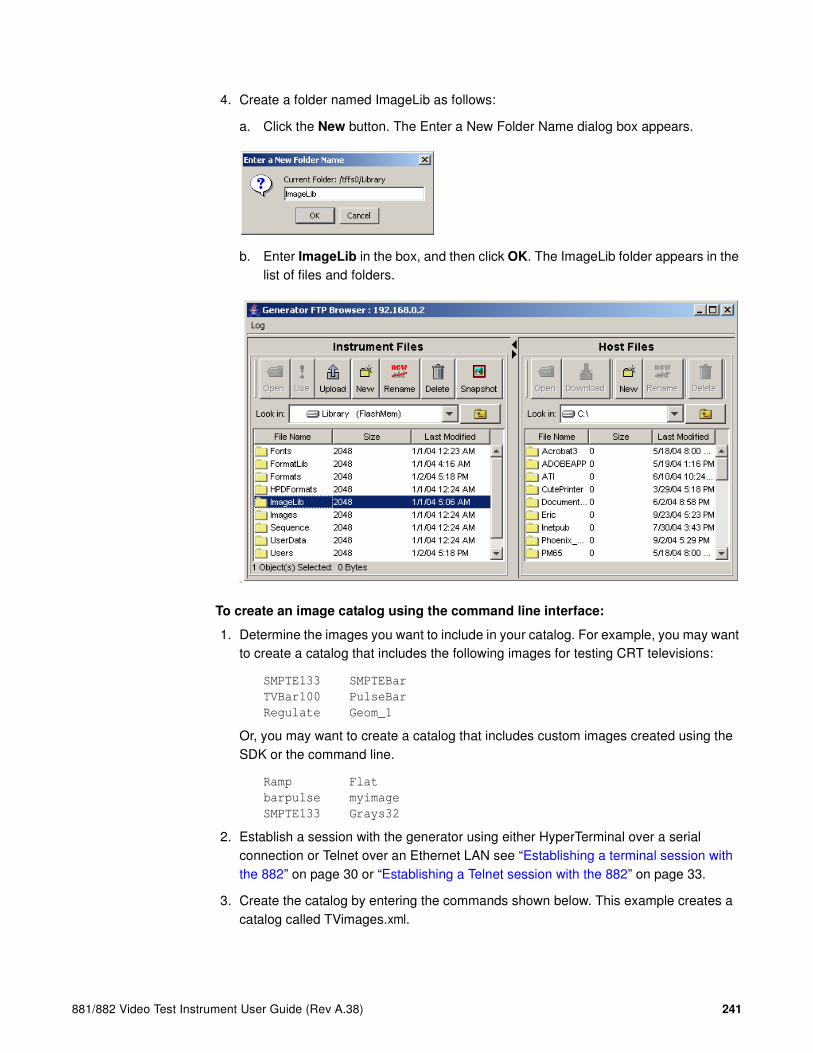
881/882 Video Test Instrument User Guide (Rev A.38) 241
4. Create a folder named ImageLib as follows:
a. Click the New button. The Enter a New Folder Name dialog box appears.
b. Enter ImageLib in the box, and then click OK. The ImageLib folder appears in the list of files and folders.
dir
To create an image catalog using the command line interface:
1. Determine the images you want to include in your catalog. For example, you may want to create a catalog that includes the following images for testing CRT televisions:
SMPTE133 SMPTEBar
TVBar100 PulseBar
Regulate Geom_1
Or, you may want to create a catalog that includes custom images created using the SDK or the command line.
Ramp Flat
barpulse myimage
SMPTE133 Grays32
2. Establish a session with the generator using either HyperTerminal over a serial connection or Telnet over an Ethernet LAN see “Establishing a terminal session with the 882” on page 30 or “Establishing a Telnet session with the 882” on page 33.
3. Create the catalog by entering the commands shown below. This example creates a catalog called TVimages.xml.

242 Chapter 7 Working with Images
DIRN TVImages // creates a catalog named TVImages
DIRT Content // identifies the catalog as a Content catalog
DIRB // begins a directory editing session
NAMI 1 /Cache0/Images/SMPTE133 // add SMPTE133 to catalog
.
. // add other images to the catalog
.
NAMI 6 /Cache0/Images/Geom_1 // add Geom_1 to catalog
DIRE // ends the directory editing session
DIRA /tffs0/Library/ImageLib/TVImages // saves the catalog
DIRL /tffs0/Library/ImageLib/TVImages // loads the TVImages catalog
DIRU // applies the TVImages catalog
This example creates a catalog called FPDImage.xml.
DIRN FPDImage // creates a catalog named FPDImage
DIRT Content // identifies new catalog as a content catalog
DIRB // begins a directory editing session
NAMI 1 /Cache0/Images/Ramp // add Ramp to the catalog
NAMI 2 /Cache0/Images/Flat
NAMI 3 /tffs0/Library/userdata/myimage // adds a custom image created
through the command line
NAMI 4 /tffs0/Library/Images/barpulse.o // adds a custom image created
through the SDK
NAMI 4 /Cache0/Images/SMPTE133
NAMI 6 /Cache0/Images/Grays32 // add Grays32 to catalog
DIRE // ends the directory editing session
DIRA /tffs0/Library/ImageLib/FPDImages // saves the catalog
DIRL /tffs0/Library/ImageLib/FPDImages // loads the FPDImages catalog
DIRU // applies FPDImages catalog
To restore the default image library:
1. Power cycle the generator.
Or, you can restore the default Source list of images by entering the commands below.
DIRN // creates a blank catalog
DIRB // begins a directory editing session
DIRT Contentlib // identifies new catalog as a contentlib catalog
DIRE // ends the directory editing session
DIRU // applies the empty catalog
To restore the custom image library:
1. You can restore your custom Source list of images by entering the commands below.
DIRL /tffs0/Library/ImageLib/FPDImages // loads the FPDImages catalog
DIRU // applies FPDImages catalog
To enable catalogs in the Content list using the front panel:
1. Press the Content key. The list of images appears on the generator’s display.

881/882 Video Test Instrument User Guide (Rev A.38) 243
2. Press the Options key repeatedly until the Library folder appears on the generator’s display as shown below:
3. Choose the Library item by pressing the adjacent soft key. The image library appears as shown below. Each item in the image library is an image catalog.
4. Press the soft key adjacent to a catalog to enable or disable it. A + sign next to the item indicates the item is enabled; a - sign indicates it is disabled.
5. Press the Content key to see the images in the selected catalogs.
To remove an image from a catalog:
1. Establish a session with the generator using either HyperTerminal over a serial connection or Telnet over an Ethernet LAN.see “Establishing a terminal session with the 882” on page 30 or “Establishing a Telnet session with the 882” on page 33.
2. To remove an image from a catalog, enter the following commands:
DIRL /tffs0/Library/ImageLib/TVImages // loads the TVImages catalog
DIRT ContentLib // identifies directory as a content directory
DIRB // begins a directory editing session
NAMK /cache0/Library/Images/TVImages/SMPTE133.img
Or...
NAMY 1 // deletes SMPTE133 (index 1)
DIRE // ends the directory editing session
DIRS // saves the catalog
Deleting an image catalog
You can delete an image catalogs either through the command line or through the Generator FTP Browser. Procedures for both methods are provided below.
Library
-TVImages FPDImages-
SMPTE133 SMPTEBar TVBar100 PulseBar Regulate Geom_1
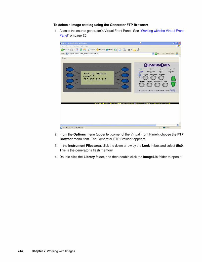
244 Chapter 7 Working with Images
To delete a image catalog using the Generator FTP Browser:
1. Access the source generator’s Virtual Front Panel. See “Working with the Virtual Front Panel” on page 20.
2. From the Options menu (upper left corner of the Virtual Front Panel), choose the FTP
Browser menu item. The Generator FTP Browser appears.
3. In the Instrument Files area, click the down arrow by the Look in box and select tffs0. This is the generator’s flash memory.
4. Double click the Library folder, and then double click the ImageLib folder to open it.
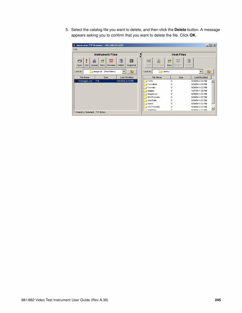
881/882 Video Test Instrument User Guide (Rev A.38) 245
5. Select the catalog file you want to delete, and then click the Delete button. A message appears asking you to confirm that you want to delete the file. Click OK.

246 Chapter 7 Working with Images

881/882 Video Test Instrument User Guide (Rev A.38) 247
8 Working with Test Sequences
Topics in this chapter:
• Overview
• Viewing the test sequence list
• Running a test sequence
• Creating a test sequence
• Deleting a test sequence

248 Chapter 8 Working with Test Sequences
Overview
When testing video displays, you typically select a format using the Source key, and then select an image using the Content key. In a production environment, where there might be a need to test several combinations of formats and images, you can create a test sequence to automate the process of selecting formats and images. Test sequences provide a way to progress through a pre-defined sequence of format and images, either manually or automatically. Multiple test sequences can be stored in the generator and selected by the operator.
This section describes how to create and run test sequences. New test sequences are created through the command line interface and stored as XML files. Existing sequences can be modified by editing the sequence XML files using a text editor. Test sequences can be activated (run) or deactivated through the generator front panel or the command line interface.
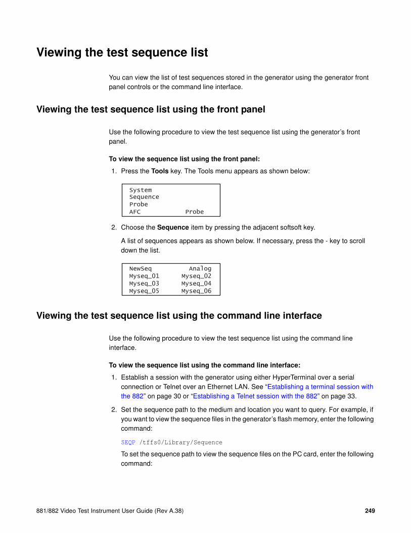
881/882 Video Test Instrument User Guide (Rev A.38) 249
Viewing the test sequence list
You can view the list of test sequences stored in the generator using the generator front panel controls or the command line interface.
Viewing the test sequence list using the front panel
Use the following procedure to view the test sequence list using the generator’s front panel.
To view the sequence list using the front panel:
1. Press the Tools key. The Tools menu appears as shown below:
2. Choose the Sequence item by pressing the adjacent softsoft key.
A list of sequences appears as shown below. If necessary, press the - key to scroll down the list.
Viewing the test sequence list using the command line interface
Use the following procedure to view the test sequence list using the command line interface.
To view the sequence list using the command line interface:
1. Establish a session with the generator using either HyperTerminal over a serial connection or Telnet over an Ethernet LAN. See “Establishing a terminal session with the 882” on page 30 or “Establishing a Telnet session with the 882” on page 33.
2. Set the sequence path to the medium and location you want to query. For example, if you want to view the sequence files in the generator’s flash memory, enter the following command:
SEQP /tffs0/Library/Sequence
To set the sequence path to view the sequence files on the PC card, enter the following command:
SystemSequenceProbeAFC Probe
NewSeq Analog Myseq_01 Myseq_02 Myseq_03 Myseq_04 Myseq_05 Myseq_06

250 Chapter 8 Working with Test Sequences
SEQP /card0/Library/Sequence
3. List the contents of the sequence folder by entering the following command:
SEQQ? 1 4 // lists test sequences from the first through the fourth

881/882 Video Test Instrument User Guide (Rev A.38) 251
Running a test sequence
Test sequences are initiated through the generator’s front panel or the command line interface. A sequence can run in one of three modes:
• Step and stop mode, where the progression of the sequence is under user control, and the sequence halts after the final step.
• Step and wrap mode, where the progression of the sequence is under user control, and it continuously loops (repeats the sequence steps).
• Automatic mode, which enables automatic progression through the sequence list with continuous looping.
The instructions for running test sequences using the front panel and command line interface are provided below.
Running a test sequence using the front panel
To run a sequence using the front panel:
1. Press the Tools key. The Tools menu appears as shown below:
2. Choose the Sequence item by pressing the adjacent soft key. To see all of the sequences, press the + and - keys.
SystemSequenceProbeAFC Probe
NewSeq Analog Myseq_01 Myseq_02 Myseq_03 Myseq_04 Myseq_05 Myseq_06

252 Chapter 8 Working with Test Sequences
3. Choose the sequence you want to run by pressing the adjacent soft key. The settings for the selected sequence are shown on the generator’s display:
Depending on the mode of the sequence, the sequence will either start automatically, or you can press the + or - keys to move forward or backward manually through the sequence steps.
The generator’s display shows the format and image name for each step, the mode, and the current step number. Additionally, the sync gate status and output status appear on the right, and the color gate status appears on the left, as shown below.
To stop a sequence or change the sequence mode:
1. With a sequence running, press the Options key. The mode menu appears as shown below.
2. Choose the desired mode by pressing the adjacent soft key.
3. Press the Options key to return to the sequence settings.
Running a test sequence using the command line interface
To run a sequence using the command line interface:
1. Establish a session with the generator using either HyperTerminal over a serial connection or Telnet over an Ethernet LAN. See “Establishing a terminal session with the 882” on page 30 or “Establishing a Telnet session with the 882” on page 33.
+Red myseq ACS+Grn Auto:00001 DCS+Blu DMT0660 DSS* Inv SMPTE133 Out+
+Red myseq ACS+Grn Step:00001 DCS+Blu DMT0660 DSS* Inv SMPTE133 Out+
Mode Description
Step Step and stop mode
Wrap Step and wrap mode
Auto Automatic mode.
Stop Stops the sequence
*Step Wrap Auto Stop

881/882 Video Test Instrument User Guide (Rev A.38) 253
2. Enter the following commands:
SEQL seqname // loads the sequence into sequence edit buffer
SMOD 1 // where 1=step&stop; 2=step&wrap; 3=auto
SEQU // starts running the sequence
The generator’s display shows the format and image name for each step, the mode, and the current step number. Additionally, the sync gate status and output status appear on the right, and the color gate status appears on the left, as shown below:
If the sequence is set to auto, it begins running. Otherwise, press the + and - keys to move through the sequence steps.
To stop a sequence:
Enter the following command:
SMOD 0
SEQU
To run a sequence at power up:
1. Run the sequence in the desired mode.
2. Cycle the power to the generator. Depending on the selected mode, the sequence will start automatically, or you can press the + and - keys to step through the sequence.
+Red myseq ACS+Grn Step:00001 DCS+Blu DMT0660 DSS* Inv SMPTE133 Out+

254 Chapter 8 Working with Test Sequences
Creating a test sequence
You create test sequences using the command line interface. Test sequences consist of multiple steps. Each step specifies the format and image to display, as well as the duration of the step. You can create multiple sequence files, which are stored in the generator’s flash memory.
Creating a test sequence using the command line interface
You can develop test sequences using the command line interface, either by entering commands interactively through a terminal session or by entering a series of commands in a text file and then sending the file to the generator through a terminal emulation program such as HyperTerminal. When developing long test sequences, the recommended procedure is to enter commands in a text file, and then send the file to the generator. This approach enables you to change the test sequence without entering the entire command script.
It is important to note that for digital formats you will need to create separate formats using the format editor to ensure that the digital video signal type (DVST) is set properly. When a format is loaded during a test sequence its video type defaults to analog. So if you want to create for example a test sequence for HDMI for testing high definition televisions you will need to create the HDMI version of the format setting DVST appropriately. Examples are provided below.
Use the following procedure to create a test sequence and save it to the sequence directory on the generator.
To create and save an analog test sequence interactively using the command line interface:
1. Establish a session with the generator using either HyperTerminal over a serial connection or Telnet over an Ethernet LAN. See “Establishing a terminal session with the 882” on page 30 or “Establishing a Telnet session with the 882” on page 33.
2. Set the sequence path to the sequence directory in the generator’s flash memory or on the PC card. For example, to set the path to the generator’s flash memory, enter the following command:
SEQP /tffs0/Library/Sequence
To set the sequence path to the PC card, enter the following command:
SEQP /card0/Library/Sequence
3. Enter the following commands to create a three-step sequence named MySeq.
SEQN // initializes the sequence edit buffer
SEQB // begins a sequence editing session
STEP 1 // selects a step to be edited
SDLY 5.0 // sets the delay for the current step to five seconds

881/882 Video Test Instrument User Guide (Rev A.38) 255
FMTL 480p59 // loads a format
IMGL SMPTEbar // loads an image
STEP 2 // selects a step to be edited
SDLY 5.0 // sets the delay for the current step to five seconds
FMTL 720p60 // loads a second format (same image)
IMGL Outline1 // loads an image
STEP 3 // selects a step to be edited
SDLY 5.0 // sets the delay for the current step to five seconds
FMTL 1080i29 // loads a third format
IMGL Geom_4 // loads another image
SEQE // ends the sequence editing session
SEQA MySeq // saves the current contents of the sequence editor
After sending the last command, the file is automatically converted to an XML file and is available to use at the generator.
To create and save an analog test sequence from a text file:
1. Using a text editor, open a text editor on your computer and enter the following commands to create a three-step sequence named MySeq:
SEQN // initializes the sequence edit buffer
SEQB // begins a sequence editing session
STEP 1 // selects a step to be edited
SDLY 5.0 // sets the delay for the current step to five seconds
FMTL 480p59 // loads a format
IMGL SMPTEbar // loads an image
STEP 2 // selects a step to be edited
SDLY 5.0 // sets the delay for the current step to five seconds
FMTL 720p60 // loads a second format (same image)
IMGL Outline1 // loads an image
STEP 3 // selects a step to be edited
SDLY 5.0 // sets the delay for the current step to five seconds
FMTL 1080i29 // loads a third format
IMGL Geom_4 // loads another image
SEQE // ends the sequence editing session
SEQA MySeq // saves the current contents of the sequence editor
Note: If you wish to use a format or image that is in a location that is not the current
location of the format path (fmtp) or image path (imgp) you will have to specify the
complete path. For example if you wand to use an image from the PCcard in the
Library/Image directory you would use the following:
IMGL /card0/library/images/SMPTEbar // loads an image from PCcard
And if you wanted to use a format from the PCcard but the current format path was set to Flashmem, you would enter the following:
FMTL /card0/library/formats/DMT0660a // loads a format from PCcard
2. Save the text file with a .txt extension.
Note: When you send the .txt file to the generator, the file will be automatically
converted to an XML file.

256 Chapter 8 Working with Test Sequences
3. Set the sequence path to the sequence directory on the generator’s flash memory or the PC card. For example, to set the path to the generator’s flash memory, enter the following command:
SEQP /tffs0/Library/Sequence
To set the sequence path to the PC card, enter the following command:
SEQP /card0/Library/Sequence
4. Establish a session with the generator using either HyperTerminal over a serial connection or Telnet over an Ethernet LAN. See “Establishing a terminal session with the 882” on page 30 or “Establishing a Telnet session with the 882” on page 33.
5. Transfer the text file to the generator. For example, to transfer the file using HyperTerminal, do the following:
a. On the Transfer menu, click Send Text File. The Send Text File dialog box appears.
b. Select the text file you want to send, and then click Open. HyperTerminal displays the commands as they are sent.
c. Press Enter once to ensure that the last command is sent.
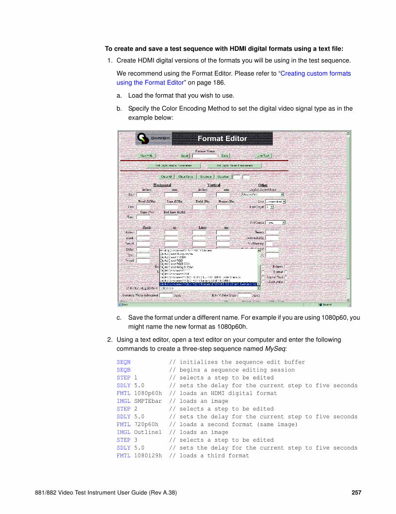
881/882 Video Test Instrument User Guide (Rev A.38) 257
To create and save a test sequence with HDMI digital formats using a text file:
1. Create HDMI digital versions of the formats you will be using in the test sequence.
We recommend using the Format Editor. Please refer to “Creating custom formats using the Format Editor” on page 186.
a. Load the format that you wish to use.
b. Specify the Color Encoding Method to set the digital video signal type as in the example below:
c. Save the format under a different name. For example if you are using 1080p60, you might name the new format as 1080p60h.
2. Using a text editor, open a text editor on your computer and enter the following commands to create a three-step sequence named MySeq:
SEQN // initializes the sequence edit buffer
SEQB // begins a sequence editing session
STEP 1 // selects a step to be edited
SDLY 5.0 // sets the delay for the current step to five seconds
FMTL 1080p60h // loads an HDMI digital format
IMGL SMPTEbar // loads an image
STEP 2 // selects a step to be edited
SDLY 5.0 // sets the delay for the current step to five seconds
FMTL 720p60h // loads a second format (same image)
IMGL Outline1 // loads an image
STEP 3 // selects a step to be edited
SDLY 5.0 // sets the delay for the current step to five seconds
FMTL 1080i29h // loads a third format

258 Chapter 8 Working with Test Sequences
IMGL Geom_4 // loads another image
SEQE // ends the sequence editing session
SEQA MySeq // saves the current contents of the sequence editor
3. Save the text file with a .txt extension.
Note: When you send the .txt file to the generator, the file will be automatically
converted to an XML file.
4. Set the sequence path to the sequence directory on the generator’s flash memory or the PC card. For example, to set the path to the generator’s flash memory, enter the following command:
SEQP /tffs0/Library/Sequence
To set the sequence path to the PC card, enter the following command:
SEQP /card0/Library/Sequence
5. Establish a session with the generator using either HyperTerminal over a serial connection or Telnet over an Ethernet LAN. See “Establishing a terminal session with the 882” on page 30 or “Establishing a Telnet session with the 882” on page 33.
6. Transfer the text file to the generator. For example, to transfer the file using HyperTerminal, do the following:
a. On the Transfer menu, click Send Text File. The Send Text File dialog box appears.
b. Select the text file you want to send, and then click Open. HyperTerminal displays the commands as they are sent.
c. Press Enter once to ensure that the last command is sent.
Editing a test sequence XML file
You can modify an existing test sequence by copying the sequence XML file from the generator to a PC, editing the file, and then transferring the file back to the generator. Use the following procedure to edit an existing test sequence XML file.
To edit a test sequence:
1. Using the Generator FTP Browser, copy the sequence XML file from the generator to a PC. See “Copying files from a 882 to a PC” on page 25 for instructions.
Note: You can also copy the contents of a test sequence file from the Generator FTP
Browser to your text editor. Locate the file you want to copy in the Instrument Files area
of the Generator FTP Browser window. Select the file, and then click the Open button.
The sequence XML file will open in a window. Press CTRL-A to select the contents of
the window. Press CTRL-C to copy the selected text. You can then paste the contents
into a text editor on your PC.

881/882 Video Test Instrument User Guide (Rev A.38) 259
2. Open the XML file in a standard text editor.
A sample sequence XML file for the sequence named MySeq01 is shown below:
<?xml version="1.0" encoding="UTF-8" ?>
<DATAOBJ>
<HEADER TYPE="SEQ" VERSION="1.0" ></HEADER>
<DATA>
<STEP>
<FMT>/tffs0/Library/TestAnalog/DMT0660.xml</FMT>
<IMG>master.img</IMG>
<DELY>+3.0000000E+00</DELY>
</STEP>
<STEP>
<FMT>/tffs0/Library/TestAnalog/DMT0659.xml</FMT>
<IMG>SMPTEBar.img</IMG>
<DELY>+3.0000000E+00</DELY>
</STEP>
<STEP>
<FMT>/tffs0/Library/TestAnalog/DMT0675.xml</FMT>
<IMG>SMPTE133.img</IMG>
<DELY>+3.0000000E+00</DELY>
</STEP>
<STEP>
<FMT>/tffs0/Library/TestAnalog/DMT0685.xml</FMT>
<IMG>Flat.img</IMG>
<DELY>+3.0000000E+00</DELY>
</STEP>
<STEP>
<FMT>/tffs0/Library/TestAnalog/DMT0856.xml</FMT>
<IMG>Grill_11.img</IMG>
<DELY>+3.0000000E+00</DELY>
</STEP>
<STEP>
<FMT>/tffs0/Library/TestAnalog/DMT0680.xml</FMT>
<IMG>Hatch4x3.img</IMG>
<DELY>+3.0000000E+00</DELY>
</STEP>
<STEP>
<FMT>/tffs0/Library/TestAnalog/DMT0872.xml</FMT>
<IMG>ColorBar.img</IMG>
<DELY>+3.0000000E+00</DELY>
</STEP>
<STEP>
<FMT>/tffs0/Library/TestAnalog/DMT0885.xml</FMT>
<IMG>Ramp.img</IMG>
<DELY>+3.0000000E+00</DELY>
</STEP>
</DATA>
</DATAOBJ>
3. Make the edits in the XML file as necessary. An example is provided below showing how to change the format, image, and delay for the second step in the test sequence.

260 Chapter 8 Working with Test Sequences
Before:
...
<STEP>
<FMT>/tffs0/Library/TestAnalog/DMT0659.xml</FMT>
<IMG>SMPTEBar.img</IMG>
<DELY>+3.0000000E+00</DELY>
</STEP>
...
After (modified text in bold):
...
<STEP>
<FMT>/tffs0/Library/TestAnalog/DMT0856.xml</FMT>
<IMG>PulseBar.img</IMG>
<DELY>+4.0000000E+00</DELY>
</STEP>
...
4. Save the text file as an XML file.
5. Using the Generator FTP Browser, download the format XML file from your PC to the generator. See “Copying files from a PC to a 882” on page 23 for instructions.

881/882 Video Test Instrument User Guide (Rev A.38) 261
Deleting a test sequence
You can delete a test sequence using the command line interface.
To delete a test sequence using the command line interface:
1. Establish a session with the generator using either HyperTerminal over a serial connection or Telnet over an Ethernet LAN. See “Establishing a terminal session with the 882” on page 30 or “Establishing a Telnet session with the 882” on page 33.
2. Set the sequence path to the medium and location you want to query. For example, if you want to delete the sequence files in the generator’s flash memory, enter the following command:
SEQP /tffs0/Library/Sequence
To delete sequence files on the PC card, enter the following command:
SEQP /card0/Library/Sequence
3. Delete the sequence by entering the following commands:
SEQK seqname
ALLU

262 Chapter 8 Working with Test Sequences

881/882 Video Test Instrument User Guide (Rev A.38) 263
9 Analyzing Digital Sources and Cables
Topics in this chapter:
• Getting started
• Measuring timing of video signal
• Testing cables and distribution systems
• Testing video signal quality from a source
• Testing InfoFrames (HDMI only)
• Testing audio (HDMI only)
• Controlling the analyzer using the command line interface
• Controlling the analyzer with Signal Analysis Module

264 Chapter 9 Analyzing Digital Sources and Cables
Getting started
The Analyzer option provides the 882 with the ability to test and verify the quality of an HDMI or DVI video signal, respectively. Having both a transmitter and receiver, the 882 with the Analyzer feature can be used to:
• View timing of an HDMI/DVI video signal. Connect an HDMI/DVI source to the HDMI IN connector to measure and analyze the timing parameters of the signal.
• Test cables and distribution systems - Test a cable or distributation system connected from the transmitter (HDMI OUT connector) to the receiver (HDMI IN connector) using pseudo-random noise.
• Analyze pixel data at different frequencies. Examine the quality of HDMI/DVI pixel transmission (including source, cables and distribution systems) for data errors and flickering pixels.
• Viewing the pixel color components. View the color components (R,G,B) of any pixel in the active video. The values shown in the analyzer can be compared against what the source is sending.
• Generate pseudo-random noise test pattern. Connect an HDMI/DVI display device to the HDMI OUT connector to receive pseudo-random noise for testing purposes.
• View InfoFrame packets from an HDMI signal. Display and validate InfoFrame packets transmitted from an HDMI source
This chapter provides procedures for testing with the analyzer through the front panel keys and through the command line interface.

881/882 Video Test Instrument User Guide (Rev A.38) 265
Analyzer connections
HDMI 1.1
This subsection describes the 882’s video interfaces for the connecting source devices to the 882CA analyzer. The HDMI video interfaces are shown below.
Interface Description
6 HDMI OUT 1 connector outputs full single link HDMI video, as well as DVI and mod-ern HDMI-compatible digital video signals.
7 HDMI OUT 2 connector outputs full single link HDMI video, as well as DVI and mod-ern HDMI-compatible digital video signals.
8 HDMI IN 1 connector for input of full single link HDMI video, as well as DVI and mod-ern HDMI-compatible digital video signals.
9 HDMI IN 2 connector for input of full single link HDMI video, as well as DVI and mod-ern HDMI-compatible digital video signals.
10 SPDIF-AV connector inputs audio from an external source and enables you to extract audio from and incoming source.
HDMI OUT 1 HDMI OUT 2 HDMI IN 1 HDMI IN 2VGA
1 2 3 54 6 7 8 9 10
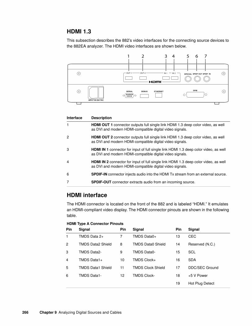
266 Chapter 9 Analyzing Digital Sources and Cables
HDMI 1.3
This subsection describes the 882’s video interfaces for the connecting source devices to the 882EA analyzer. The HDMI video interfaces are shown below.
HDMI interface
The HDMI connector is located on the front of the 882 and is labeled “HDMI.” It emulates an HDMI-compliant video display. The HDMI connector pinouts are shown in the following table.
HDMI Type A Connector Pinouts
Interface Description
1 HDMI OUT 1 connector outputs full single link HDMI 1.3 deep color video, as well as DVI and modern HDMI-compatible digital video signals.
2 HDMI OUT 2 connector outputs full single link HDMI 1.3 deep color video, as well as DVI and modern HDMI-compatible digital video signals.
3 HDMI IN 1 connector for input of full single link HDMI 1.3 deep color video, as well as DVI and modern HDMI-compatible digital video signals.
4 HDMI IN 2 connector for input of full single link HDMI 1.3 deep color video, as well as DVI and modern HDMI-compatible digital video signals.
6 SPDIF-IN connector injects audio into the HDMI Tx stream from an external source.
7 SPDIF-OUT connector extracts audio from an incoming source.
Pin Signal Pin Signal Pin Signal
1 TMDS Data 2+ 7 TMDS Data0+ 13 CEC
2 TMDS Data2 Shield 8 TMDS Data0 Shield 14 Reserved (N.C.)
3 TMDS Data2- 9 TMDS Data0- 15 SCL
4 TMDS Data1+ 10 TMDS Clock+ 16 SDA
5 TMDS Data1 Shield 11 TMDS Clock Shield 17 DDC/SEC Ground
6 TMDS Data1- 12 TMDS Clock- 18 +5 V Power
19 Hot Plug Detect
SPECIAL SPDIF OUT SPDIF IN
INPUT 90-264 YAC
SERIAL DEBUG ETHERNETGPIB
OUT 2 IN 2OUT 1 IN 1
1 2 3 4 5 6 7

881/882 Video Test Instrument User Guide (Rev A.38) 267
Monitoring HDMI 1.3 analyzer signal input
With the 882EA analyzer option, you can externally monitor the HDMI 1.3 deep color video and/or audio content of an incoming HDMI signal. This feature lets you view and hear HDMI content that is received at the HDMI In connector while analysis and testing functions are performed by the analyzer. However, unlike the 882CA where the video and audio are monitored through the SPDIF AV port, with the 882EA, the incoming video is monitored from the HDMI Tx (out) ports and the incoming audio is monitored through a separate SPDIF output port.
Note: With the release of 2.19 on the 882EA, you can passthru HDMI video content that is
protected via HDCP.
The monitored video output is an HDMI video signal and requires an HDMI display. Monitoring the incoming video signal requires that you put the 882 into a specific mode of operation called “passthru.” Passthru mode is invoked through the Interface key by selecting Options or through the command line (these procedures are described below). The monitored output from the HDMI Tx port is a pixel per pixel duplication of the resolution of the incoming signal. There are a couple important things to note about the passthru monitored video:
• The image resolution of the passthru video will not scale to the native resolution of the display used to monitor the incoming video. In other words, if the monitoring display is 1080 and the incoming video signal is 720p you will see the entire image in the upper left area of the monitoring display with unused portions of the display on the bottom and right area. Alternatively, if the 882EA generator/analyzer is receiving 1080 video but the monitoring display is only capable of displaying a 720p image then you will not see the entire image.
• When the 882 is in passthru mode, you will not be able to monitor a video signal that is looped from that 882’s HDMI Tx port (either the HDMI Tx 1 or the HDMI Tx 2).
• If the incoming video is in 4:2:2 sampling mode, the HDMI passthru video will be converted to 4:4:4 sampling. The 4:2:2 sampling mode is not supported in passthru mode.
• If the incoming video is in 12 bit deep color, the HDMI passthru video will only be able to display 10 bit deep color.
• The frame rate of the HDMI Tx passthru video is the frame rate of the format selected on the 882. This means that a scan conversion will occur. If the incoming video is 720p24 and the 882’s output is set to 720p60, then the video signal displayed on the monitoring display will be at 720p at 60Hz.
• The scan setting (progressive or interlaced) of the HDMI Tx passthru video is the scan setting of the format selected on the 882 for the HDMI Tx outputs.

268 Chapter 9 Analyzing Digital Sources and Cables
The monitored audio output is available from the SPDIF Out BNC connector when the 882 is in passthru mode. A BNC to RCA adapter cable (30-00123) is provided to enable you to connect the SPDIF audio to an RCA coaxial input of a sound system or a digital audio analyzer. The audio that is embedded into the outgoing HDMI passthru Tx stream is that of the 882EA’s internal audio source.
To monitor HDMI 1.3 input:
1. Connect the HDMI source device to an HDMI IN connector on the 882.
2. Activate the HDMI-H interface on the output port:
a. Press the Interface key to access the list of interfaces. A listing of signal interfaces appears on the 882’s display as shown below.
b. Choose the HDMI-H or HDMI-D item by pressing the adjacent soft key. The interface is activated and the port outputs the currently selected image and format.
c. Alternatively, to activate the interface through the command line interface, enter the following commands:
XVSI 4 // Selects the HDMI-H interface
ALLU // Applies the interface setting to the 882
3. Press the Interface key repeatedly until the following menu appears:
4. Choose the connector to which the transmit device is connected by pressing the adjacent soft key.
5. Monitor the HDMI 1.3 deep color video signal received on the HDMI IN connector by connecting an HDMI cable from the HDMI Tx output (either Tx 1 or Tx 2) to an HDMI display. (Ideally, the HDMI display should support the resolution of the incoming video.)
VGA
HDMI-D
CVBS
S-VIDEO
SDI
*
HDMI-H
VGA
HDMI-D
CVBS
S-VIDEO
SDI*HDMI-H
HDMI IN 1
HDMI IN 2*

881/882 Video Test Instrument User Guide (Rev A.38) 269
6. Put the 882EA into passthru mode.
a. Press the Interface key to access the list of interfaces. The list of signal interfaces appears on the 882’s display as shown below.
b. Press the Option key to access the Passthru mode selection.
c. Enable Passthru by pressing the adjacent soft key. Select either with HDCP enabled (shown below) or without HDCP depending on your application.
d. Alternatively, to enable passthru mode via the command line interface, enter the following command:
PDAX:PASS 1 // Enables passthru mode
To query the current state of the passthru mode via the command line, enter the following command:
PDAX:PASS? // Returns 0 or 1 to indicate the status
To disable passthru mode via the command line, enter the following command:
PDAX:PASS 0 // Disables passthru mode
+Output-No Passthru HDCP Passthru Non-HDCP Passthru
Mark#1-
+Output No Passthru+HDCP Passthru Non-HDCP Passthru
Mark#1-
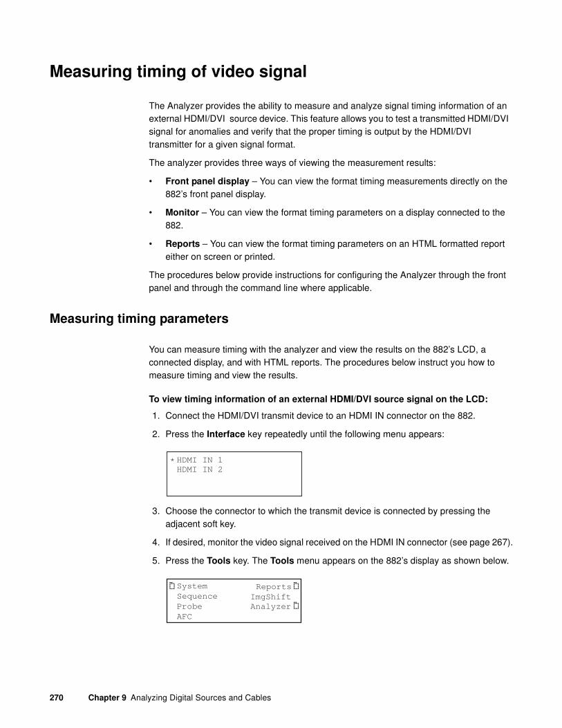
270 Chapter 9 Analyzing Digital Sources and Cables
Measuring timing of video signal
The Analyzer provides the ability to measure and analyze signal timing information of an external HDMI/DVI source device. This feature allows you to test a transmitted HDMI/DVI signal for anomalies and verify that the proper timing is output by the HDMI/DVI transmitter for a given signal format.
The analyzer provides three ways of viewing the measurement results:
• Front panel display – You can view the format timing measurements directly on the 882’s front panel display.
• Monitor – You can view the format timing parameters on a display connected to the 882.
• Reports – You can view the format timing parameters on an HTML formatted report either on screen or printed.
The procedures below provide instructions for configuring the Analyzer through the front panel and through the command line where applicable.
Measuring timing parameters
You can measure timing with the analyzer and view the results on the 882’s LCD, a connected display, and with HTML reports. The procedures below instruct you how to measure timing and view the results.
To view timing information of an external HDMI/DVI source signal on the LCD:
1. Connect the HDMI/DVI transmit device to an HDMI IN connector on the 882.
2. Press the Interface key repeatedly until the following menu appears:
3. Choose the connector to which the transmit device is connected by pressing the adjacent soft key.
4. If desired, monitor the video signal received on the HDMI IN connector (see page 267).
5. Press the Tools key. The Tools menu appears on the 882’s display as shown below.
HDMI IN 1
HDMI IN 2*
System
Sequence
Probe
AFC
Analyzer
Reports
ImgShift

881/882 Video Test Instrument User Guide (Rev A.38) 271
6. Choose the Analyzer item by pressing the adjacent soft key. The Analyzer menu appears on the 882’s display as shown below.
7. Choose the Timing item by pressing the adjacent soft key. The Timing menu appears as shown below.
8. Choose the Measure item by pressing the adjacent soft key. The Analyzer measures the video signal and displays the values on the 882’s display. Press the soft key next to H to see more values. See the example below for an explanation of the values.
To save timing measurements to a report:
1. Connect the HDMI/DVI transmit device to an HDMI IN connector on the 882.
2. Press the Interface key repeatedly until the following menu appears:
Timing
CableTest
PIX-ERR
PRN-ERR
*
ReadRGB
TIMING
Measure
Exit
!Report
! !
TIMING
Stop
V: 525 480 10 2
Exit!H: 800 640 16 96
!
→
Horizontal period (pixels)Active pixels per line
Horizontal pulse delay (pixels)Horizontal pulse width (pixels)
Vertical period (lines)Active lines
Vertical pulse delay (lines)Vertical pulse width (lines)
TIMING
Stop Exit
31500 60.000
!HS Rate VS Rate
!
→
Horizontal rate Vertical rate
HDMI IN 1
HDMI IN 2*

272 Chapter 9 Analyzing Digital Sources and Cables
3. Choose the connector to which the transmit device is connected by pressing the adjacent soft key.
4. Activate the HDMI-H or HDMI-D interface on the output port:
a. Press the Interface key to access the list of interfaces. A listing of signal interfaces appears on the 882’s display as shown below.
b. Choose the HDMI-H or HDMI-D item by pressing the adjacent soft key. The interface is activated and the port outputs the currently selected image and format.
c. Alternatively, to activate the interface through the command line interface, enter the following commands:
XVSI 3 (or 4) // Selects the HDMI-D (or HDMI-H) interface
ALLU // Applies the interface setting to the 882
5. If desired, monitor the video signal received on the HDMI IN connector (see page 267).
6. Press the Tools key. The Tools menu appears on the 882’s display as shown below.
7. Choose the Analyzer item by pressing the adjacent soft key. The Analyzer menu appears on the 882’s display as shown below.
8. Choose the Timing item by pressing the adjacent soft key. The Timing menu appears as shown below.
VGA
HDMI-D
CVBS
S-VIDEO
SDI
*
HDMI-H
VGA
HDMI-D
CVBS
S-VIDEO
SDI*HDMI-H
System
Sequence
Probe
AFC
Analyzer
Reports
ImgShift
Timing
CableTest
PIX-ERR
PRN-ERR
*
ReadRGB
TIMING
Measure
Exit
!Report
! !

881/882 Video Test Instrument User Guide (Rev A.38) 273
9. Choose the Report item by pressing the adjacent soft key. The 882 indicates that it is measuring the timing and “Generating Report.”
Note: Be sure that you have transferred any existing timing reports to your PC
otherwise generating a new report will overwrite the existing report in the Reports
folder.
10. Go back to the 882’s home page and select Generated Reports.
A list of generated reports appears in the browser.
11. Select the Timing Report from this list of available reports.
The Timing Report will appear in the browser window.

274 Chapter 9 Analyzing Digital Sources and Cables
Note: The Color Depth of the source’s video signal is shown on the timing report (last
line).
12. (optional) Transfer the report from the 882 to your PC, using the FTP browser, by highlighting the report and clicking on the upload activation button.

881/882 Video Test Instrument User Guide (Rev A.38) 275
Note: Make sure to change the names of any existing reports in the directory on your
PC to avoid overwriting existing reports.
To view timing information of an external HDMI/DVI source signal on a display:
1. Connect the HDMI/DVI transmit device to an HDMI IN connector on the 882.
2. Activate the HDMI-H or HDMI-D interface on the output port:
a. Press the Interface key to access the list of interfaces. A listing of signal interfaces appears on the 882’s display as shown below.
b. Choose the HDMI-H or HDMI-D item by pressing the adjacent soft key. The interface is activated and the port outputs the currently selected image and format.
c. Alternatively, to activate the interface through the command line interface, enter the following commands:
XVSI 3 (or 4) // Selects the HDMI-D (or HDMI-H) interface
VGA
HDMI-D
CVBS
S-VIDEO
SDI
*
HDMI-H
VGA
HDMI-D
CVBS
S-VIDEO
SDI*HDMI-H

276 Chapter 9 Analyzing Digital Sources and Cables
ALLU // Applies the interface setting to the 882
3. Press the Interface key repeatedly until the following menu appears:
4. Choose the connector to which the transmit device is connected by pressing the adjacent soft key.
5. If desired, monitor the video signal received on the HDMI IN connector (see page 267).
6. Connect an HDMI/DVI display to an HDMI OUT connector on the 882.
7. Press the Source key and choose a suitable format for the display (for example, DMT0660).
Alternatively, to load a valid HDMI or DVI format into the analyzer, enter the following commands:
FMTL DMT0660 // loads the DMT0660 (e.g.) format into the edit buffer
FMTU // applies the format to the generator/analyzer
8. Press the Content key and choose the FormatRx image by pressing the adjacent soft key.
Alternatively, to activate the FormatRx image through the command line interface, enter the following commands:
IMGL FormatRx // loads the FormatRX image into the edit buffer
IMGU // applies the FormatRX image to the generator/analyzer
HDMI IN 1
HDMI IN 2*

881/882 Video Test Instrument User Guide (Rev A.38) 277
Testing cables and distribution systems
This section describes how to test HDMI or DVI cables and distribution systems using pseudo-random noise. Using different signal formats, the HDMI/DVI cable can be tested over a wide range of frequencies.
The procedures below provide instructions for testing cable and distribution systems with the Analyzer both through the front panel and the command line.
To test a cable or distribution system through the front panel:
1. Connect the HDMI/DVI cable to be tested between an HDMI OUT and an HDMI IN connector on the 882.
Note: If you are testing a fiber optic cable, plug the fiber optic cable connector marked
“transmitter” to the HDMI OUT connector on the 882, and plug the connector marked
“receiver” to the HDMI IN connector on the 882. Use a 5 Vdc power supply adapter at
the receiver side of the cable.
Note: If you are testing a distribution system, connect an access cable to the
distribution center to the HDMI OUT connector on the 882 and a second access cable
to the HDMI IN connector on the 882.
2. Activate the HDMI-H or HDMI-D interface on the output port:
a. Press the Interface key to access the list of interfaces. A listing of signal interfaces appears on the 882’s display as shown below.
b. Choose the HDMI-H or HDMI-D item by pressing the adjacent soft key. The interface is activated and the port outputs the currently selected image and format.
3. Press the Interface key repeatedly until the following menu appears:
4. Choose the HDMI IN connector to which the cable is connected by pressing the adjacent soft key.
5. (HDMI only) If desired, monitor the video signal received on the HDMI IN connector (see “Monitoring HDMI 1.3 analyzer signal input” on page 267).
VGA
HDMI-D
CVBS
S-VIDEO
SDI
*
HDMI-H
HDMI IN 1
HDMI IN 2*

278 Chapter 9 Analyzing Digital Sources and Cables
6. Press the Source key and choose the format you want to use.
Any built-in formats may be used for this test. However, we recommend using several formats spread over a wide range of frequencies. For example, the Test150 format tests at the maximum supported pixel frequency for HDMI. The DMT0660 format can be used to test at a very low frequency (25.175 MHz).
Note: The list of formats that appears when you press the Source key may be a
filtered or abbreviated list. Formats not suitable for the selected interface type will not
appear by default on the Source list. You may have to enable the Test format library. If
the Test format library is disabled you will not see the TEST150 format. To enable the
Test format library, see “Format catalogs” on page 221.
Use the following formats to test HDMI over a range of frequencies:
7. Press the Tools key. The Tools menu appears on the 882’s display as shown below.
8. Choose the Analyzer item by pressing the adjacent soft key. The Analyzer menu appears on the 882’s display as shown below.
9. Choose the CableTest item by pressing the adjacent soft key. The CableTest menu appears as shown below.
10. Choose the Settings item by pressing the adjacent soft key or press the Settings key to select the analysis duration in the number of sequences.
Format Pixel rate (MHz)
TEST150 150.000
1080p60 148.500
720p60 74.250
DMT0660 25.175
System
Sequence
Probe
AFC
Analyzer
Reports
ImgShift
Timing
CableTest
PIX-ERR
PRN-ERR
*
ReadRGB
Start
Settings
Exit!!

881/882 Video Test Instrument User Guide (Rev A.38) 279
To change a setting value:
a. Position the blinking cursor on the value you want to change. To do this, press the soft key adjacent to the arrow by the setting value to move the cursor left or right until it appears on the digit you want to change.
b. Adjust the value of the setting up or down by pressing the + or - keys.
11. To save the changes, press the Enter (Options) key. The following choices appear on the 882’s display:
To save the changes, choose the Yes item by pressing the adjacent soft key.
To exit without saving the changes, choose the No item.
To return to the parameters screen without saving the changes, choose the Back item.
12. To start the analysis, press the soft key adjacent to Start. The results of the analysis appear on the 882’s display. Press the soft key next to the arrow to see all of the results. Refer to the table below for an explanation of the results.
AnalysisDuration
1
Sequences
→
Apply Settings?
Back
Yes No

280 Chapter 9 Analyzing Digital Sources and Cables
13. To test the cable at a different frequency, return to step 6.
Results Explanation
Total shows the total number of pixel errors detected. The bottom line shows the number of pixels errors detected per color component.
In this example, the total number of pixel errors is 9, with 9 errors on each of the color components.
In the bottom row, the left value shows the number of pixels being measured in billions and the right side shows the number of pixel errors per billion.
Note: When the number of pixel errors becomes very large, the text “Very high” is displayed in the bottom row in place of actual values.
In this example, 4.255 billion pixels were measured and 0.88 billion pixel errors were detected.
ERR shows the selected error number and Fr shows the frame in which the error occurred. The X and Y values are the screen coordinates at which the error occurred. The bottom line shows the measured RGB values.
To view the errors, press the + and - keys.
In this example, Error 001 occurred in Frame 00000001 at coordinates (44545,0000). The measured RGB val-ues were R128, G016, B128.
Start Exit!!
ERRORS PER COMP.Total:0009
R:0009 G:0009 B:0009
→
Start Exit!!
PIXEL ERROR RATEPELS/BILLION
4.255 0.88
→
Start 0009 Exit!!
ERR:001 Fr:00000001X:44545 Y:0000
R:128 G:016 B:128
→

881/882 Video Test Instrument User Guide (Rev A.38) 281
Testing video signal quality from a source
The Analyzer can test the quality of video sources and report errors to the front panel display or as reports.
If the HDMI/DVI source can generate Quantum Data’s BCM pseudo-random noise, the Analyzer can compare the pseudo-random noise from the source with a reference that you specify using the Pseudo-Random Noise test.
In cases where the HDMI/DVI source device cannot generate pseudo-random noise, the Analyzer can test and analyze the transmission quality of the external HDMI/DVI source using a Pixel Error (delta error) test.
You can also view the pixel color components (R,G,B) for a pattern transmitted by the source. The values shown in the analyzer can be compared against what the source is sending.
Instructions for testing using the Pseudo-Random Noise, Pixel Error, and ViewPix tests are given below. For instructions on implementing pseudo-random noise in the source device, see “Controlling the analyzer with Signal Analysis Module” on page 316.
The procedures below provide instructions for running the test both through the front panel and the command line.
Running the Pseudo-Random Noise test
The Pseudo-Random Noise test can be used to analyze pseudo-random noise generated by an HDMI/DVI source device. Your source device must have the QDI-BCM pseudo-random noise algorithm implemented. For instructions on implementing pseudo-random noise in the source device, see “Controlling the analyzer with Signal Analysis Module” on page 316.
To analyze pseudo-random noise from an external source through the front panel:
1. Connect the HDMI/DVI transmit device to an HDMI IN connector on the 882.
2. Press the Interface key repeatedly until the following menu appears:
3. Choose the connector to which the transmit device is connected by pressing the adjacent soft key.
4. If desired, monitor the video signal received on the HDMI IN connector (see “Monitoring HDMI 1.3 analyzer signal input” on page 267).
HDMI IN 1
HDMI IN 2*

282 Chapter 9 Analyzing Digital Sources and Cables
5. Press the Tools key. The Tools menu appears on the 882’s display as shown below.
6. Choose the Analyzer item by pressing the adjacent soft key. The Analyzer menu appears on the 882’s display as shown below.
7. Choose the PRN-ERR item by pressing the adjacent soft key. The PRN-ERR menu appears as shown below.
8. (Optional) To generate a report during the test use the following procedures.
a. Press the Options key. The following appears on the display.
b. Enable reports by pressing the soft key adjacent to Generate Report item so that there is a “+” sign next to it.
Note: Be sure that you have transferred any existing pseudo-random noise reports to
your PC otherwise generating a new report will overwrite the existing report in the
Reports folder.
c. Press the Options key again to return to the PRN-ERR menu.
9. Choose the Settings item by pressing the adjacent soft key or press the Settings key. The Pseudo Noise settings appear on the 882’s display as shown below. Press the soft keys adjacent to the arrows to see all of the settings.
10. Refer to the table below to locate the setting you want to change, for more information about a setting.
System
Sequence
Probe
AFC
Analyzer
Reports
ImgShift
Timing
CableTest
PIX-ERR
PRN-ERR
*
ReadRGB
Start
Settings
Exit!!
-Generate Report
AnalysisDuration
1
Sequences
→
→

881/882 Video Test Instrument User Guide (Rev A.38) 283
To change a setting value:
a. Position the blinking cursor on the value you want to change. To do this, press the soft key adjacent to the arrow by the setting value to move the cursor left or right until it appears on the digit you want to change.
b. Adjust the value of the setting up or down by pressing the + or - keys.
11. To save the changes, press the Enter (Options) key. The following choices appear on the 882’s display:
To save the changes, choose the Yes item by pressing the adjacent soft key.
To exit without saving the changes, choose the No item.
To return to the parameters screen without saving the changes, choose the Back item.
12. To start the analysis, press the soft key adjacent to Start. The results of the analysis appear on the 882’s display. Press the soft key next to the arrow to see all of the results. Refer to the table below for an explanation of the results.
Setting Description
Analysis Duration
Sequences
Sets the number of sequences to analyze(1-999999999).
Report Recorded Errors
Max
Sets the maximum number of errors to record (1-9999)
Results Explanation
Total shows the total number of pixel errors detected. The bottom line shows the number of pixels errors detected per color component.
In this example, the total number of pixel errors is 9, with 9 errors on each of the color components.
Apply Settings?
Back
Yes No
Start Exit!!
ERRORS PER COMP.Total:0009
R:0009 G:0009 B:0009
→

284 Chapter 9 Analyzing Digital Sources and Cables
To view the pseudo-random noise report:
1. Select a suitable directory on your PC to store the report by navigating in the FTP Browser.
2. Transfer the report from the 882’ flash memory to your PC, using the FTP browser, by highlighting the report and clicking on the upload activation button.
In the bottom row, the left value shows the number of pixels being measured in billions and the right side shows the number of pixel errors per billion.
Note: When the number of pixel errors becomes very large, the text “Very high” is displayed in the bottom row in place of actual values.
In this example, 4.255 billion pixels were measured and 0.88 billion pixel errors were detected.
ERR shows the selected error number and Fr shows the frame in which the error occurred. The X and Y values are the screen coordinates at which the error occurred. The bottom line shows the measured RGB values.
To step through the errors, press the + and - keys.
In this example, Error 001 occurred in Frame 00000001 at coordinates (44545,0000). The measured RGB val-ues were R128, G016, B128.
Results Explanation
Start Exit!!
PIXEL ERROR RATEPELS/BILLION
4.255 0.88
→
Start 0009 Exit!!
ERR:001 Fr:00000001X:44545 Y:0000
R:128 G:016 B:128
→

881/882 Video Test Instrument User Guide (Rev A.38) 285
Note: Make sure to change the names of any existing reports in the directory on your
PC to avoid overwriting existing reports.

286 Chapter 9 Analyzing Digital Sources and Cables
3. Navigate to your PC and double click on the report. A sample of the report is shown below.
Running the Pixel Error test
If your source device does not have the Quantum Data BCM pseudo-random noise algorithm you can test the signal quality with the Pixel Error test. During the Pixel Error test, the Analyzer captures an external, still-frame image (reference frame) typically from the device under test and verifies that all pixels match over a user-specified number of successive frames. The results are output to the 882’s display and can be issued as a report.
You can also capture a reference frame from another device (i.e. other than the device under test) and use that to compare with the frames from the device under test. This enables you to obtain valid results if you suspect that the device under test cannot produce an error-free reference frame. By using a reference frame from a known good source you are assured that the test results are viable.

881/882 Video Test Instrument User Guide (Rev A.38) 287
To analyze an external HDMI/DVI signal for pixel errors:
1. Connect the HDMI/DVI transmit device to an HDMI IN connector on the 882.
2. Press the Interface key repeatedly until the following menu appears:
3. Choose the HDMI IN connector to which the transmit device is connected by pressing the adjacent soft key.
4. (HDMI only) If desired, monitor the video signal received on the HDMI IN connector (see “Monitoring HDMI 1.3 analyzer signal input” on page 267).
5. Press the Tools key. The Tools menu appears on the 882’s display as shown below.
6. Choose the Analyzer item by pressing the adjacent soft key. The Analyzer menu appears on the 882’s display as shown below.
7. Choose the PIX-ERR item by pressing the adjacent soft key. The Pixel Error menu appears as shown below.
8. (Optional) To generate a report during the test use the following procedures.
a. Press the Options key. The following appears on the display.
b. Enable reports by pressing the soft key adjacent to Generate Report item so that there is a “+” sign next to it.
Note: Be sure that you have transferred any existing pixel error reports to your PC
otherwise generating a new report will overwrite the existing report.
HDMI IN 1
HDMI IN 2*
System
Sequence
Probe
AFC
Analyzer
Reports
ImgShift
Timing
CableTest
PIX-ERR
PRN-ERR
*
ReadRGB
Start
Settings
Exit!!
+Generate Report->Auto Capture

288 Chapter 9 Analyzing Digital Sources and Cables
9. Choose the Settings item by pressing the adjacent soft key or press the Settings key. The pixel error testing settings appear on the 882’s display as shown below. Press the soft keys adjacent to the arrows to see all of the settings.
10. Refer to the table below to locate the setting you want to change. For more information about a setting,
To change a setting value:
a. Position the blinking cursor on the value you want to change. To do this, press the soft key adjacent to the arrow by the setting value to move the cursor left or right until it appears on the digit you want to change.
b. Adjust the value of the setting up or down by pressing the + or - keys.
c. To save the changes, press the Enter (Options) key, and then press the soft key next to Yes.
11. To save the changes, press the Enter (Options) key. The following choices appear on the 882’s display:
To save the changes, choose the Yes item by pressing the adjacent soft key.
To exit without saving the changes, choose the No item.
To return to the parameters screen without saving the changes, choose the Back item.
12. Generate a static image from the HDMI/DVI transmit device.
Setting Description
Analysis Duration
Frames
Sets the number of frames to analyze(1-99999999).
Report Recorded Errors
Max
Sets the maximum number of errors to record (1-9999)
Analysis
Duration
1
Frames
→
→
Apply Settings?
Back
Yes No

881/882 Video Test Instrument User Guide (Rev A.38) 289
13. Capture a static reference frame.
You can either capture a reference frame from the device under test or from another device (i.e. other than the device under test). Note that you can capture a reference frame from the 882 itself. The default selection is to capture a reference frame from the device under test.
(Optional) To capture a reference frame from another device, use the following procedures.
a. Connect the HDMI/DVI transmit device you want to use as a reference frame to an HDMI IN connector on the 882.
b. Press the Options key. The following appears on the display.
c. Access the Manual Capture option by pressing the soft key adjacent to the Auto
Capture item. The following appears on the display.
d. Select Capture Frame by pressing the adjacent soft key to capture the reference frame. The following appears on the display.
e. To return to the setup screen, press the Options key item.
+Generate Report->Auto Capture
+Generate Report->Manual Capture !Capture Frame
Capturing Reference Frame ....
Start
Settings
Exit!!

290 Chapter 9 Analyzing Digital Sources and Cables
14. To start the analysis, press the soft key adjacent to Start.
a. The results of the analysis appear on the 882’s display. If there are no errors, the 882 will display the following screen.
b. Press the soft key next to the arrow to see all of the results. Refer to the table below for an explanation of the results.
To view the pixel error report:
1. Select a suitable directory on your PC to store the report by navigating in the FTP Browser.
2. Transfer the report from the 882 to your PC, using the FTP browser, by highlighting the report and clicking on the upload activation button.
Results Explanation
Total shows the total number of pixel errors detected. The bottom line shows the number of pixels errors detected per color component.
In this example, the total number of pixel errors is 169, with 128 errors on the red component, 16 on the green, and 128 on the blue.
ERR shows the selected error number and Fr shows the frame in which the error occurred. The X and Y val-ues are the screen coordinates at which the error occurred. The bottom line shows the measured RGB values.
To step through the errors, press the + and - keys.
In this example, Error 001 occurred in Frame 00000001 at coordinates (0167,0000). The measured RGB values were R128, G016, B128.
Start
->No Errors
Exit !
!
Start Exit !
!ERROR COUNTSTotal:000169
R:025 G:016 B:128
→
Start Exit !
!ERR:001 Fr:00000001
X:0169 Y:0000R:025 G:016 B:128
→

881/882 Video Test Instrument User Guide (Rev A.38) 291
Note: Make sure to change the names of any existing reports in the directory on your
PC to avoid overwriting existing reports.

292 Chapter 9 Analyzing Digital Sources and Cables
3. Navigate to your PC and double click on the report. A sample is shown below.
Running the ViewPix test
During the ViewPix test (previously called the ReadRGB test), the Analyzer captures one complete frame of pixel data. You can then view the RGB data from any pixel in the frame by specifying the coordinates. This way if you know what the source is transferring or sending for a pixel(s) you can compare it with what the analyzer detects.
You can view the captured image out the HDMI transmit port with the View Data function.
Procedures are provided below for the ViewPix test both through the front panel and the command line.
To capture and read pixel data from the front panel:
1. Connect the HDMI/DVI transmit device to an HDMI IN connector on the 882.
2. (Optional) Connect an HDMI/DVI display to an HDMI OUT connector on the 882.
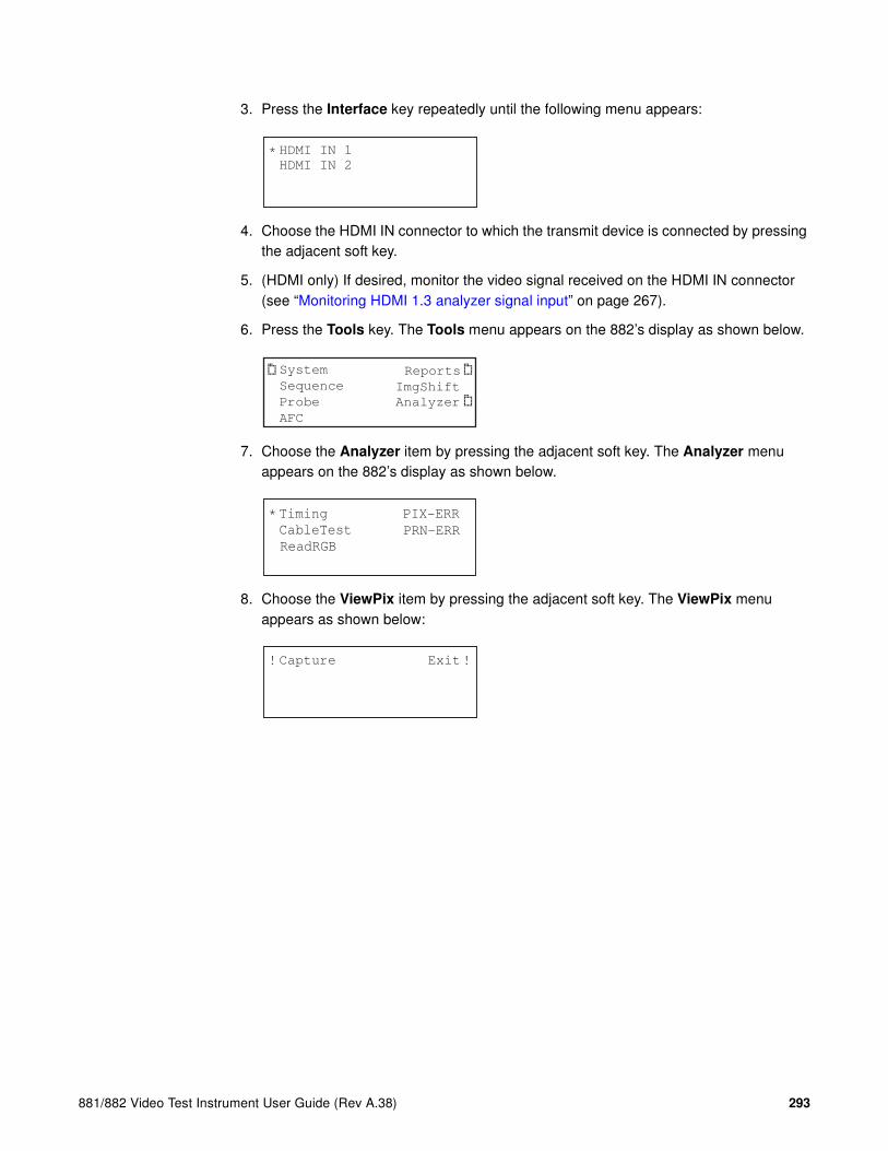
881/882 Video Test Instrument User Guide (Rev A.38) 293
3. Press the Interface key repeatedly until the following menu appears:
4. Choose the HDMI IN connector to which the transmit device is connected by pressing the adjacent soft key.
5. (HDMI only) If desired, monitor the video signal received on the HDMI IN connector (see “Monitoring HDMI 1.3 analyzer signal input” on page 267).
6. Press the Tools key. The Tools menu appears on the 882’s display as shown below.
7. Choose the Analyzer item by pressing the adjacent soft key. The Analyzer menu appears on the 882’s display as shown below.
8. Choose the ViewPix item by pressing the adjacent soft key. The ViewPix menu appears as shown below:
HDMI IN 1
HDMI IN 2*
System
Sequence
Probe
AFC
Analyzer
Reports
ImgShift
Timing
CableTest
PIX-ERR
PRN-ERR
*
ReadRGB
Capture Exit!!
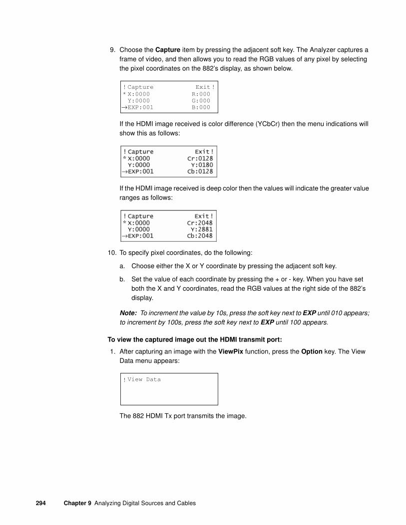
294 Chapter 9 Analyzing Digital Sources and Cables
9. Choose the Capture item by pressing the adjacent soft key. The Analyzer captures a frame of video, and then allows you to read the RGB values of any pixel by selecting the pixel coordinates on the 882’s display, as shown below.
If the HDMI image received is color difference (YCbCr) then the menu indications will show this as follows:
If the HDMI image received is deep color then the values will indicate the greater value ranges as follows:
10. To specify pixel coordinates, do the following:
a. Choose either the X or Y coordinate by pressing the adjacent soft key.
b. Set the value of each coordinate by pressing the + or - key. When you have set both the X and Y coordinates, read the RGB values at the right side of the 882’s display.
Note: To increment the value by 10s, press the soft key next to EXP until 010 appears;
to increment by 100s, press the soft key next to EXP until 100 appears.
To view the captured image out the HDMI transmit port:
1. After capturing an image with the ViewPix function, press the Option key. The View Data menu appears:
The 882 HDMI Tx port transmits the image.
Capture Exit!!
X:0000Y:0000EXP:001
R:000G:000B:000
*
→
View Data !

881/882 Video Test Instrument User Guide (Rev A.38) 295
Generating Pseudo-random noise
This section provides procedures for generating pseudo-random noise from the 882. You can use this feature to test cables, to verify that another HDMI/DVI sink device that has the Quantum Data pseudo-random noise algorithm (e.g. another 880 series analyzer) is processing pseudo-random noise properly.
To generate pseudo-random noise:
1. Connect the HDMI transport output port to the HDMI/DVI receive device.
Use the HDMI to DVI adapter cable if testing DVI.
2. Activate the HDMI-H or HDMI-D interface on the output port:
a. Press the Interface key to access the list of interfaces. A listing of signal interfaces appears on the 882’s display as shown below.
b. Choose the HDMI-H or HDMI-D item by pressing the adjacent soft key. The interface is activated and the port outputs the currently selected image and format.
c. Alternatively, to activate the interface through the command line interface, enter the following commands:
XVSI 3 (or 4) // Selects the HDMI-D (or HDMI-H) interface
ALLU // Applies the interface setting to the 882
3. Press the Content key to select an image.
4. Enable pseudo-random noise using the following steps:
a. Press the Options key. The following menu will appear on the 882’s display for images with a single secondary image:
b. Choose the Noise item by pressing the adjacent soft key until a + appears next to the item.
VGA
HDMI-D
CVBS
S-VIDEO
SDI
*
HDMI-H
VGA
HDMI-D
CVBS
S-VIDEO
SDI*HDMI-H
-Alternate Red+-NoGamma Green+-Noise Blue+

296 Chapter 9 Analyzing Digital Sources and Cables
Testing InfoFrames (HDMI only)
The HDMI analyzer can analyze InfoFrame data from an incoming HDMI signal. With this capability, an HDMI transmit device can be tested for its ability to transmit InfoFrame packets correctly.
Testing HDMI transmit device InfoFrame capability
The 882 can monitor the InfoFrame content of the received HDMI signal.
To view current HDMI InfoFrame contents received from an HDMI transmitter:
1. Connect an HDMIdisplay to an HDMI OUT connector on the 882.
2. Connect the HDMI source to an HDMI IN connector on the 882.
3. Activate the HDMI-H interface on the output port:
a. Press the Interface key to access the list of interfaces. A listing of signal interfaces appears on the 882’s display as shown below.
b. Choose the HDMI-H or HDMI-D item by pressing the adjacent soft key. The interface is activated and the port outputs the currently selected image and format.
c. Alternatively, to activate the interface through the command line interface, enter the following commands:
XVSI 3 (or 4) // Selects the HDMI-D (or HDMI-H) interface
ALLU // Applies the interface setting to the 882
4. Press the Interface key again. The following menu appears:
5. Choose the HDMI IN connector to which the HDMI source is connected by pressing the adjacent soft key.
VGA
HDMI-D
CVBS
S-VIDEO
SDI
*
HDMI-H
VGA
HDMI-D
CVBS
S-VIDEO
SDI*HDMI-H
HDMI IN 1
HDMI IN 2*

881/882 Video Test Instrument User Guide (Rev A.38) 297
6. If desired, monitor the video signal received on the HDMI Rx connector (see “Monitoring HDMI 1.3 analyzer signal input” on page 267).
7. Press the Source key and select an appropriate format for the connected HDMI display.
8. Press the Content key and select the PacketRx image.
The PacketRx image appears on the connected HDMI display. Shown in the image are the current settings for the AVI InfoFrame input.
9. Enable and view image versions for the PacketRx image as follows:
a. Press the Options key. The following menu appears on the 882’s display:
b. Choose the More item by pressing the adjacent soft key until a + and Rendition appears next to the item.
c. Press the + key to advance through the image versions.
-More Red+-NoGamma Green+-Noise Blue+
+More Rendition: 000 Red+-NoGamma Green+-Noise Blue+

298 Chapter 9 Analyzing Digital Sources and Cables
Note: The contents of the appropriate InfoFrame input appears on the HDMI display.
Alternatively, to select an image version using the command line interface, enter the following commands:
ISUB 1 // Enables sub images
IVER 1 // Specifies the first image version
IMGU // Activates the image version
10. Select additional InfoFrame subimages (as desired) to verify proper InfoFrame handling.
11. When testing is complete, disable image versions by pressing the Options key and choosing More until a - appears next to it.
Alternatively, to disable image versions using the command line interface, enter the following command:
ISUB 0 // Disables sub images
To generate a report for the PacketRx image:
1. Press the Tools key. The Tools menu appears on the 882’s display as shown below.
2. Choose the Reports item by pressing the adjacent soft key. The Reports menu appears on the 882’s display as shown below.
3. Choose the Packets item by pressing the adjacent soft key. The Packet menu appears on the 882’s display as shown below.
Note: Be sure that you have transferred any existing PacketRx reports to your PC
otherwise generating a new report will overwrite the existing report.
System
Sequence
Probe
AFC
Analyzer
Reports
ImgShift
EDID Packets
!TxPacket
!RxPacket

881/882 Video Test Instrument User Guide (Rev A.38) 299
4. Select the !PacketRx item by pressing the adjacent soft key to generate the report. The following appears on the display.
5. Select a suitable directory on your PC to store the report by navigating in the FTP Browser.
6. Transfer the report from the 882 to your PC, using the FTP browser, by highlighting the report and clicking on the upload activation button.
Note: Make sure to change the names of any existing reports in the directory on your
PC to avoid overwriting existing reports.
RX PACKETS
Finished

300 Chapter 9 Analyzing Digital Sources and Cables
7. Navigate to your PC and double click on the report. A sample of part of the PacketRx report is shown below.
8. Choose the Packets item by pressing the adjacent soft key. The Packet menu appears on the 882’s display as shown below.
Note: Be sure that you have transferred any existing PacketRx reports to your PC
otherwise generating a new report will overwrite the existing report.
Alternatively you can generate this report from the command line using the following command:
IFAX:RPTU // Initiates the Packet Rx report.
!TxPacket
!RxPacket

881/882 Video Test Instrument User Guide (Rev A.38) 301
9. Open a Web browser (such as Internet Explorer) and type the 882’s IP address in the address entry field. For example, enter the following: http://206.135.215.189/.
The 882 home page appears in the browser.

302 Chapter 9 Analyzing Digital Sources and Cables
10. Choose the Generated Reports item. The 882 the provides a list of reports currently available as shown below.

881/882 Video Test Instrument User Guide (Rev A.38) 303
11. Navigate to your PC and double click on the report. A sample of part of the PacketRx report is shown below.
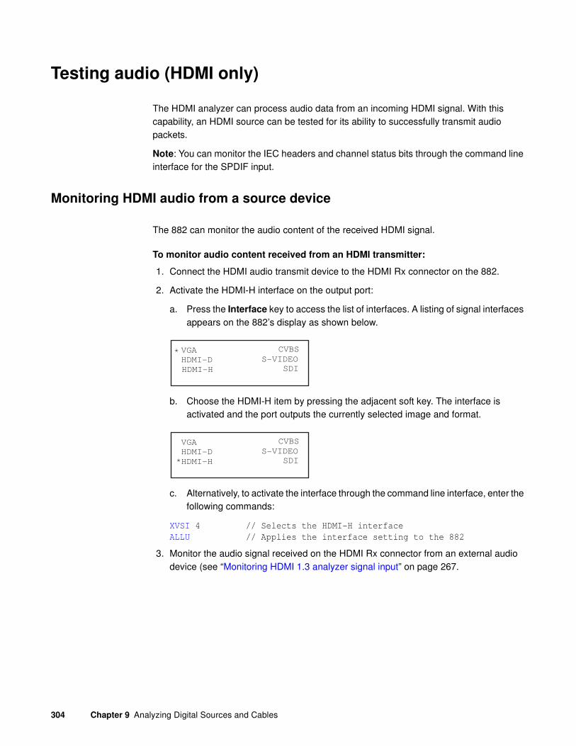
304 Chapter 9 Analyzing Digital Sources and Cables
Testing audio (HDMI only)
The HDMI analyzer can process audio data from an incoming HDMI signal. With this capability, an HDMI source can be tested for its ability to successfully transmit audio packets.
Note: You can monitor the IEC headers and channel status bits through the command line interface for the SPDIF input.
Monitoring HDMI audio from a source device
The 882 can monitor the audio content of the received HDMI signal.
To monitor audio content received from an HDMI transmitter:
1. Connect the HDMI audio transmit device to the HDMI Rx connector on the 882.
2. Activate the HDMI-H interface on the output port:
a. Press the Interface key to access the list of interfaces. A listing of signal interfaces appears on the 882’s display as shown below.
b. Choose the HDMI-H item by pressing the adjacent soft key. The interface is activated and the port outputs the currently selected image and format.
c. Alternatively, to activate the interface through the command line interface, enter the following commands:
XVSI 4 // Selects the HDMI-H interface
ALLU // Applies the interface setting to the 882
3. Monitor the audio signal received on the HDMI Rx connector from an external audio device (see “Monitoring HDMI 1.3 analyzer signal input” on page 267.
VGA
HDMI-D
CVBS
S-VIDEO
SDI
*
HDMI-H
VGA
HDMI-D
CVBS
S-VIDEO
SDI*HDMI-H

881/882 Video Test Instrument User Guide (Rev A.38) 305
To generate view the audio metadata on the PacketRx report:
1. Press the Tools key. The Tools menu appears on the 882’s display as shown below.
2. Choose the Reports item by pressing the adjacent soft key. The Reports menu appears on the 882’s display as shown below.
3. Choose the Packets item by pressing the adjacent soft key. The Packet menu appears on the 882’s display as shown below.
Note: Be sure that you have transferred any existing PacketRx reports to your PC
otherwise generating a new report will overwrite the existing report.
4. Select the !PacketRx item by pressing the adjacent soft key to generate the report. The following appears on the display.
5. Choose the Packets item by pressing the adjacent soft key. The Packet menu appears on the 882’s display as shown below.
Note: Be sure that you have transferred any existing PacketRx reports to your PC
otherwise generating a new report will overwrite the existing report.
Alternatively you can generate this report from the command line using the following command:
IFAX:RPTU // Initiates the Packet Rx report.
System
Sequence
Probe
AFC
Analyzer
Reports
ImgShift
EDID Packets
!TxPacket
!RxPacket
RX PACKETS
Finished
!TxPacket
!RxPacket

306 Chapter 9 Analyzing Digital Sources and Cables
6. Open a Web browser (such as Internet Explorer) and type the 882’s IP address in the address entry field. For example, enter the following: http://206.135.215.189/.
The 882 home page appears in the browser.

881/882 Video Test Instrument User Guide (Rev A.38) 307
7. Choose the Generated Reports item. The 882 the provides a list of reports currently available as shown below.

308 Chapter 9 Analyzing Digital Sources and Cables
8. Navigate to your PC and double click on the report. A sample of part of the PacketRx report is shown below.
Viewing the SPDIF audio metadata from a source device
The 882 enables you to view the audio metadata from an SPDIF source.
To view the audio metadata from an SPDIF audio source:
1. Connect the SPDIF audio source to the SPDIF Rx connector on the 882.
2. Initiate the measurement of the incoming audio using the following commands:
SDAU // Starts the measurement of audio metadata
SDAX:ARAT? // Returns the audio sampling rate
48000
SDAX:IECD? // Returns the IEC header byte information
SDAX:CSBA (or B)? // Returns the channel status bits for A and B

881/882 Video Test Instrument User Guide (Rev A.38) 309
020000040000000200000000000000000000000000000000

310 Chapter 9 Analyzing Digital Sources and Cables
Controlling the analyzer using the command line interface
You can operate the Analyzer using the 882’s command line interface. This section describes Analyzer functions and commands and provides examples of command sequences you can use to perform Analyzer tasks.
For command descriptions, see Appendix A, “Command Reference.”
Signal timing analysis commands
This section provides command line procedures for running and viewing signal timing parameters.
Viewing specific timing parameters
The following is an example of using commands to view the total number of horizontal pixels and horizontal frequency of the HDMI/DVI signal.
To view specific timing information of an external HDMI/DVI source signal:
1. Connect the HDMI/DVI transmit device to an HDMI IN connector on the 882.
2. Using a terminal emulator, establish a terminal connection with the 882. Refer to “Establishing a terminal session with the 882” on page 30.
3. Choose the connector to which the transmit device is connected by entering the following commands:
XVSI:IN 1 // Selects the HDMI-1 input connector
ALLU // Applies the interface setting to the 882
4. Choose the HDMI-H (or HDMI-D) item by entering the following commands:
XVSI 4 (or 3) // Selects the HDMI-H or HDMI-D interface
ALLU // Applies the interface setting to the 882
5. Enter the following commands to load a valid HDMI or DVI format into the analyzer.
FMTL DMT0660 // loads the DMT0660 (e.g.) format into the edit buffer
FMTU // applies the format to the generator/analyzer
6. Enter the following commands to initiate the measurement of timing parameters.
TMAU // measure external signal’s timing parameters
TMAX:RPTG 1 // enables generation of an HTML report
TMAX:SCAN? // queries for the SCAN parameter (interlaced or
progressive
TMAX:HRAT? // queries for the HRAT parameter (horizontal rate)
881/882 Video Test Instrument User Guide (Rev A.38) 311
Pseudo-random noise generation commands
This section provides command line procedures for configuring and controlling the transmission of pseudo-random noise from the 882’s output.
Configuring pseudo-random noise output parameters
The following is an example of using commands to configure pseudo-random noise output parameters.
To generate pseudo-random noise:
1. Connect the HDMI cable or DVI to HDMI cable between an HDMI IN connector on the 882 and the output interface on the device under test.
2. Using a terminal emulator, establish a terminal connection with the 882. Refer to “Establishing a terminal session with the 882” on page 30.
3. Choose the HDMI-H (or HDMI-D) item by entering the following commands:
XVSI 4 (or 3) // Selects the HDMI-H or HDMI-D interface
ALLU // Applies the interface setting to the 882
4. Choose the connector to which the transmit device is connected by entering the following commands:
XVSI:IN 1 // Selects the HDMI-1 input connector
ALLU // Applies the interface setting to the 882
5. Enter the following commands to configure the pseudo-random noise parameters.
PNSA 1 // sets pseudo random noise to be calculated each pixel clock
PNSM 0 // sets pseudo random noise test to run in auto mode
PNSG 1 // enables the pseudo-random noise test
PNGU // turns on the pseudo-random noise test
Analyzing pseudo-random noise from an external source
The following example tests an HDMI/DVI transmit device’s pixel data using pseudo-random noise generated by an external source.
To analyze pseudo-random noise from an external source:
1. Connect the DVI or HDMI cable between an HDMI IN connector on the 882 and the output interface on the device under test.
2. Using a terminal emulator, establish a terminal connection with the 882. Refer to “Establishing a terminal session with the 882” on page 30.
3. Choose the HDMI-H (or HDMI-D) item by entering the following commands:
XVSI 4 (or 3) // Selects the HDMI-H or HDMI-D interface
ALLU // Applies the interface setting to the 882

312 Chapter 9 Analyzing Digital Sources and Cables
4. Choose the connector to which the transmit device is connected by entering the following commands:
XVSI:IN 1 // Selects the HDMI-1 input connector
ALLU // Applies the interface setting to the 882
5. Enter the following commands to run the pseudo-random noise test.
PNSP 100 // sets pseudo-random noise for 100 sequencs
PNAU // runs the pseudo-random noise test for the specified
number of frames
Note: The test will stop automatically if configured to run in the single or multi-shot
mode. If you initiate the test in the continuous mode, you will have to enter a carriage
return to halt the test after PNAU is invoked.
6. Enter the following commands to view the results of the test.
GPER? // returns the pixel error rate in errors per billion
GNPT? // returns the number of pixels measured in billions
GCET? // returns the number of bad pixels for R, G, B components
GFED? // returns information about the first error encountered
To test cables through the command line:
1. Establish a session with the 882 using either HyperTerminal over a serial connection or Telnet over an Ethernet LAN. See “Configuring the 882’s serial port” on page 30 or “Establishing a Telnet session with the 882” on page 33.
2. Connect the HDMI cable to be tested between an HDMI OUT and an HDMI IN connector on the 882.
Note: If you are testing a distribution system, connect an access cable to the
distribution center to the HDMI OUT connector on the 882 and a second access cable
to the HDMI IN connector on the 882.
3. Enter the following commands to activate the HDMI-H interface on the output port:
XVSI 4 // Selects the HDMI-H interface
ALLU // Applies the interface setting to the 882
4. Choose the connector to which the transmit device is connected by entering the following commands:
XVSI:IN 1 // Selects the HDMI-1 input connector
ALLU // Applies the interface setting to the 882
5. Set up the pseudo-random noise parameters in accordance with “Configuring pseudo-random noise output parameters” on page 311.
6. Enter the following commands to select an HDMI-H format:
FMTL TEST150 // Selects the TEST150 (e.g.) format

881/882 Video Test Instrument User Guide (Rev A.38) 313
ALLU // Applies the format to the 882
Any built-in formats may be used for this test. However, we recommend using several formats spread over a wide range of frequencies. For example, the Test150 format is commonly used to test at the maximum pixel frequency for HDMI. The DMT0660 format can be used to test at a very low frequency (25.175 MHz).
Use the following formats to test HDMI over a range of frequencies:
7. Enter the following commands to run the pseudo-random noise test.
PNSP 100 // sets pseudo-random noise for 100 sequencs
PNAU // runs the pseudo-random noise test for the specified
number of frames
Note: The test will stop automatically if configured to run in the single or multi-shot
mode. If you initiate the test in the continuous mode, you will have to enter a carriage
return to halt the test after PNAU is invoked.
8. Enter the following commands to view the results of the test.
GPER? // returns the pixel error rate in errors per billion
GNPT? // returns the number of pixels measured in billions
GCET? // returns the number of bad pixels for R, G, B components
GFED? // returns information about the first error encountered
Analyzing pixel data (pixel error test)
The following is an example of using commands to test an HDMI/DVI transmit device’s pixel data using pixel error test.
To view specific timing information of an external HDMI/DVI source signal:
1. Connect the HDMI/DVI transmit device to an HDMI IN connector on the 882.
2. Using a terminal emulator, establish a terminal connection with the 882. Refer to “Establishing a terminal session with the 882” on page 30.
3. Choose the connector to which the transmit device is connected by entering the following commands:
XVSI:IN 1 // Selects the HDMI-1 input connector
ALLU // Applies the interface setting to the 882
4. Choose the HDMI-H (or HDMI-D) item by entering the following commands:
Format Pixel rate (MHz)
TEST150 150.000
1080p60 148.500
720p60 74.250
DMT0660 25.200

314 Chapter 9 Analyzing Digital Sources and Cables
XVSI 4 (or 3) // Selects the HDMI-H or HDMI-D interface
ALLU // Applies the interface setting to the 882
5. Enter the following commands to load a valid HDMI or DVI format into the analyzer.
FMTL DMT0660 // loads the DMT0660 (e.g.) format into the edit buffer
FMTU // applies the format to the generator/analyzer
6. Enter the following commands to setup the measurement of pixel data.
PDAX:FRMS 100 //sets the number of frames to analyze in the pixel
data analysis test to 100
PDAX:MXER 1000 //sets the maximum number of errors to record in pixel
data analysis test to 1000
PDAX:RPTG 1 //enables the generation of reports for the ppixel
data analysis test
PDAX:REFG 0 //enables auto reference capturing for the pixel
data analysis test
PDAX:CAPF //captures a frame of pixel data for the pixel
data analysis test
7. Enter the following commands to initiate the pixel data measurement test.
PDAU //runs the pixel data analysis test
8. Enter the following command to query for the results of the pixel data measurement test.
PDAX:ERRQ? 10 100 //retrieves 100 errors starting at the 10th error
in the index.
2, 110, 220, 128, 255, 64, 129, 250, 64 // shows the results
9. Enter the following command to query for the number of detailed error records.
PDAX:NERR? //retrieves number of detailed errors recorded.
111 // shows the results
Reading pixel data
The following is an example of using commands to read the pixel component values of a captured frame from an HDMI/DVI transmit device.
To view specific timing information of an external HDMI/DVI source signal:
1. Connect the HDMI/DVI transmit device to an HDMI IN connector on the 882.
2. Using a terminal emulator, establish a terminal connection with the 882. Refer to “Establishing a terminal session with the 882” on page 30.
3. Choose the connector to which the transmit device is connected by entering the following commands:
XVSI:IN 1 // Selects the HDMI-1 input connector
ALLU // Applies the interface setting to the 882
4. Choose the HDMI-H (or HDMI-D) item by entering the following commands:

881/882 Video Test Instrument User Guide (Rev A.38) 315
XVSI 4 (or 3) // Selects the HDMI-H or HDMI-D interface
ALLU // Applies the interface setting to the 882
5. Enter the following commands to load a valid HDMI or DVI format into the analyzer.
FMTL DMT0660 // loads the DMT0660 (e.g.) format into the edit buffer
FMTU // applies the format to the generator/analyzer
6. Enter the following commands to setup the measurement of pixel data.
PDAX:CAPF //captures a frame of pixel data for the pixel
data analysis test
7. Enter the following command to query the pixel data of the captured frame.
GPEL? 10 100 //retrieves pixel values at X = 10 and Y = 100

316 Chapter 9 Analyzing Digital Sources and Cables
Controlling the analyzer with Signal Analysis Module
You can operate the Analyzer timings functions through the Signal Analysis Module (SAM) application. The Signal Analysis Module is a Java-based GUI application available through the 882 generator’s internal web server.
This section describes analyzer functions available through the Signal Analysis Module and provides examples of procedures you can use to perform analyzer tasks.
Setting up the Signal Analysis Module
The Signal Analysis Module application is a Java application or applet. You can run the application from the 882 web server.
Note: You must also have the Java Runtime Environment (JRE) 1.5 or later installed on
your PC. You can download the JRE from the following website:
http://www.java.com/en/download/windows_ie.jsp
The Signal Analysis Module is supported on 882s with Release 2.3.x and higher. This release has the following firmware and gateware configuration.
Running the Signal Analysis Module
This subsection provides procedures on launching the Signal Analysis Module from the 882 web server and from your PC.
Software component 882CA Version
Boot Rom 01.04.11
vxWorks 20.1883000
Gateware 1 253F,75,4252006 (Tx p253fpga.bit)
Gateware 2 253A,7,4252006 (Rx p253Rxfpga.bit

881/882 Video Test Instrument User Guide (Rev A.38) 317
To run the Signal Analysis Module from the web server:
1. Open a Web browser (such as Internet Explorer) and type the 882’s IP address in the address entry field. For example, enter the following: http://206.135.215.189/.
The 882 home page appears in the browser.
2. Click on SAM+ (Signal Analysis Module).
The Signal Analysis Module main page appears as a separate application window as shown below:
Measuring Timing with the Signal Analysis Module
This subsection provides procedures on measuring timing with the Signal Analysis Module. When measuring timing the application will measure the timing parameters and identify the format within the 882’s default format library that most closely matches the values measured. It will then display that format and compare the measured timing values with the timing values of the identified standard format. A Pass/Fail indication is provided on the right-most field. The Pass/Fail determination is made by comparing the measured values from the source with expected values from the default format.

318 Chapter 9 Analyzing Digital Sources and Cables
To set up the 882 for HDMI:
1. Connect an HDMI-to-HDMI cable between the source device under test and either of the HDMI IN connectors on the 882.
2. Activate the HDMI-H interface on the output port:
a. Press the Interface key to access the list of interfaces. A listing of signal interfaces appears on the 882’s display as shown below.
b. Choose either the HDMI-H item by pressing the adjacent soft key.
The interface is activated and the port outputs the currently selected image and format.
Alternatively, to select the interface through the command line, enter the following commands:
XVSI 4 // Selects the HDMI-H interface
ALLU // Applies the interface setting to the 882
VGA
HDMI-D
CVBS
S-VIDEO
SDI
*
HDMI-H
VGA
HDMI-D
CVBS
S-VIDEO
SDI*HDMI-H

881/882 Video Test Instrument User Guide (Rev A.38) 319
To measure timing:
1. Set up the generator/analyzer for HDMI in accordance with the instructions above.
2. In the Signal Analysis Module, input the appropriate information in the Source Device
Information box. This includes the Source Device Type, Source Device Make, Source Device Model, Source Device Serial Number, and the HDMI Input Port Number information.

320 Chapter 9 Analyzing Digital Sources and Cables
3. To take a measurement, click Append Measurement under the Commands box.
Measurement will appear under appropriate headings in the table at bottom of the page.

881/882 Video Test Instrument User Guide (Rev A.38) 321
4. Check the Display Headers and Values Using HDMI Compliance Test
Specification Nomenclature check box to display headers and values according to the HDMI Compliance Test Specification Nomenclature.

322 Chapter 9 Analyzing Digital Sources and Cables
5. Click Save Results to save the results of the Append Measurement Command.
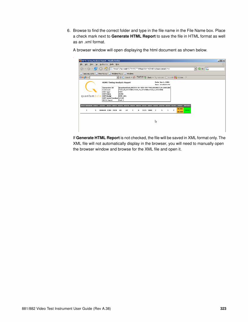
881/882 Video Test Instrument User Guide (Rev A.38) 323
6. Browse to find the correct folder and type in the file name in the File Name box. Place a check mark next to Generate HTML Report to save the file in HTML format as well as an .xml format.
A browser window will open displaying the html document as shown below.
T
If Generate HTML Report is not checked, the file will be saved in XML format only. The XML file will not automatically display in the browser, you will need to manually open the browser window and browse for the XML file and open it.
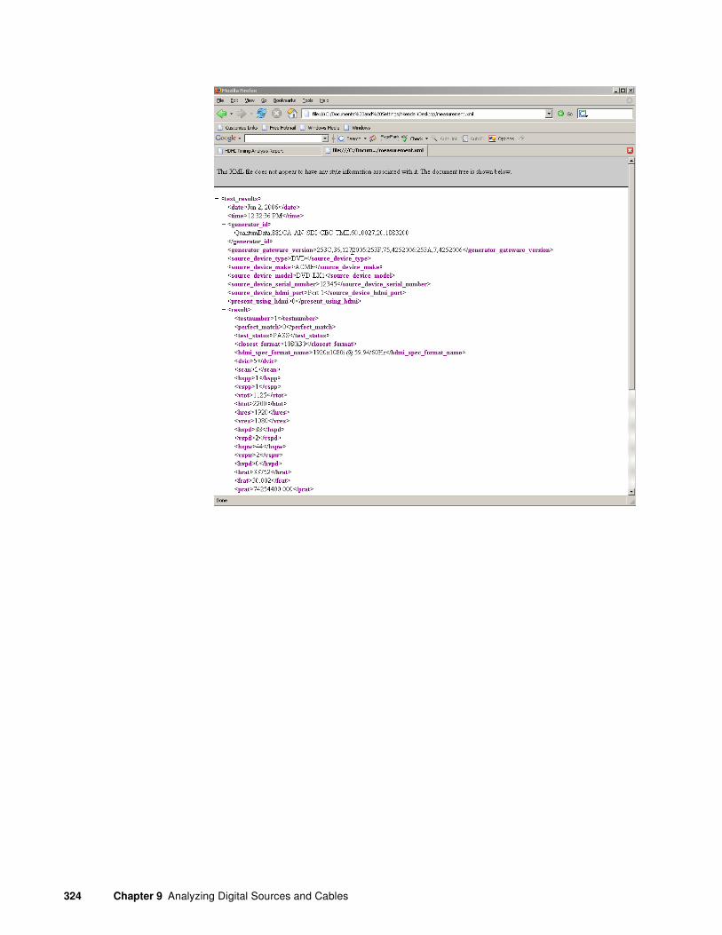
324 Chapter 9 Analyzing Digital Sources and Cables

881/882 Video Test Instrument User Guide (Rev A.38) 325
10 Testing HDMI Sink Devices
Topics in the chapter:
• Overview of HDMI display testing
• Setting up the 882 for HDMI testing
• Testing HDMI displays
• Testing HDMI 1.3 displays
• Testing HDMI 1.4 displays with 3D
• Testing HDMI video pixel repetition (882 only)
• Testing HDMI audio
• Testing HDMI InfoFrames (882 only)

326 Chapter 10 Testing HDMI Sink Devices
Overview of HDMI display testing
This section describes how to test digital displays with HDMI interfaces. The HDMI option enables the 882 to test HDMI-compliant displays. With the HDMI option, the 882 outputs HDMI-compatible TMDS video and data packets containing audio and auxiliary information.
Note: This chapter does not provide HDMI compliance test procedures. HDMI EDID
compliance testing procedures are provided in “Testing EDID for HDMI compliance in
display (sink) devices” on page 496.
The HDMI option provides the following features:
• Advanced E-EDID parsing
• Generation of all EIA/CEA-861-D formats below 165 MHz (Deep Color supports TMDS rates up to 225MHz)
• Pixel repetition test capabilities
• Internal sine wave 882 up to 8 channels and external SPDIF audio input for audio testing
• AFD test capabilities
• Automatic and manual InfoFrame configuration
Physical connections
The 882 has two HDMI OUT(Tx) connectors for testing HDMI displays. In addition, the 882 also has an SPDIF-A/V connector which allows external SPDIF audio to be input to the HDMI signal. To use the SPDIF-A/V connector, an RCA-to-VGA cable is included with the 882.

881/882 Video Test Instrument User Guide (Rev A.38) 327
The video interfaces on the 882EA are shown below.
Format selection
To support HDMI, the 882 provides pre-defined formats for every video format specified in the EIA/CEA-861-E standard. These pre-defined formats support all aspects of the HDMI signal (video, audio, and auxiliary data).
Interface Description
1 HDMI OUT 1 connector outputs full single link HDMI 1.3 video, as well as DVI and modern HDMI-compatible digital video signals.
2 HDMI OUT 2 connector outputs full single link HDMI 1.3 video, as well as DVI and modern HDMI-compatible digital video signals.
3 HDMI IN 1 connector accepts full single link HDMI 1.3 video, as well as DVI and modern HDMI-compatible digital video signals.
4 HDMI IN 2 connector accepts full single link HDMI 1.3 video, as well as DVI and modern HDMI-compatible digital video signals.
5 SPECIAL connector provides multiple outputs, including:
• digital composite sync
• line sync
• frame sync
• movable scope trigger (probe) pulse
• pixel clock signal
6 SPDIF OUT connector outputs audio to an external receiver.
7 SPDIF IN connector inputs audio from an external source.

328 Chapter 10 Testing HDMI Sink Devices
The following table lists those 882 formats used to test support for HDMI (EIA/CEA-861-E).
EIA/CEA-861-E Video
Identification Code Quantum Data format
1 DMT0659, DMT0660
2 480p59, 480p60, 480p59LH, 480p60LH
3 480p59SH, 480p60SH
4 720p59, 720p60
5 1080i29, 1080i30
6 480i2x29, 480i2x30, 480i2xL1, 480i2xL2
7 480i2xS1, 480i2xS2
8 240p2x_1, 240p2x_2, 240p2x_3, 240p2x_4, 240p2xL1, 240p2xL2, 240p2xL3, 240p2xL4
9 240p2xS1, 240p2xS4, 240p2xS3, 240p2xS4
10 480i4x29, 480i4x30, 480i4xL1, 480i4xL2
11 480i4xS1, 480i4xS2
12 240p4x_1, 240p4x_2, 240p4x_3, 240p4x_4, 240p4xL1, 240p4xL2, 240p4xL3, 240p4xL4
13 240p4xS1, 240p4xS2, 240p4xS3, 240p4xS4
14 480p2x59, 480p2x60, 480p2xL1, 480p2xL2
15 480p2xS1, 480p2xS2
16 1080p59, 1080p60
17 576p50, 576p50LH
18 576p50SH
19 720p50
20 1080i25
21 576i2x25, 576i2xLH
22 576i2xSH
23 288p2x_1, 288p2x_2, 288p2x_3, 288p2xL1, 288p2xL2, 288p2xL3
24 288p2xS1, 288p2xS2, 288p2xS3
25 576i4x25, 576i4xLH
26 576i4xSH
27 288p4x_1, 288p4x_2, 288p4x_3, 288p4xL1, 288p4xL2, 288p4xL3
28 288p4xS1, 288p4xS2, 288p4xS3

881/882 Video Test Instrument User Guide (Rev A.38) 329
29 576p2x50, 576p2xLH
30 576p2xSH
31 1080p50
32 1080p23, 1080p24
33 1080p25
34 1080p29, 1080p30
35 480p4xL1, 480p4xL2, 480p4x59, 480p4x60
36 480p4xS1, 480p4xS2
37 576p4xLH, 576p4x50
38 576p4xSH
39 108Oi25_
40 1080i50
41 720p100
42 576p100, 576p100L
43 576p100S
44 576i2x50, 576i2xL1
45 576i2xS1
46 1080i59, 1080i60
47 720p119, 720p120
48 480p119L, 480p120L, 480p119, 480p120
49 480p119S, 480p120S
50 480i2xL3, 480i2xL4, 480i2x59, 480i2x60
51 480i2xS3, 480i2xS4
52 576p200, 576p200L
53 576p200S
54 576i2x_1, 576i2xL2
55 576i2xS2
56 480p239, 480p240, 480p239L, 480p240L
57 480p239S, 480p240S
58 480i2x_1, 480i2x_2, 480i2xL5, 480i2xL6
59 480i2xS5, 480i2xS6
60 720p24
61 720p25
EIA/CEA-861-E Video
Identification Code Quantum Data format

330 Chapter 10 Testing HDMI Sink Devices
Image selection
Once you have determined the formats appropriate for testing HDMI displays, you will apply a series of images suitable for evaluating the display. For digital fixed pixel displays, you typically want to select images to test for pixel anomalies, photometry, luminance, centering, resolution, and persistence.
Each image in the 882’s library is intended to test one or more attributes of a particular display type and video type.
Note: You can also create your own images. See “Creating custom images” on page 232
for details.
The table below provides a summary of display characteristics and the images used to evaluate them.
62 720p30
63 1080p120 (not supported by 882)
64 1080p100 (not supported by 882)
EIA/CEA-861-E Video
Identification Code Quantum Data format
Display type Display test Recommended images
Digital flat panel (fixed pixel dis-play)
Pixel anomalies(stuck pixels, misc sampling)
Flat, Raster, Ramp_B, Ramp_G, and Ramp_R,Focus_@6, Focus_@7, Focus_@8, Focus_@9, Text_9, Text_9T, Text_11, Text_12T, Text_16
Photometry (chrominance, contrast, levels)
Flat, Flat07, Flat13, Flat20, Flat27, Flat33, Flat40, Flat47, Flat53, Flat60, Flat67, Flat73, Flat80, Flat87, Flat93, FlatGray, Flat_01, Flat_02, Flat_03, Flat_04, Flat_05, Flat_06, Flat_07, Flat_08, Flat_09, Flat_10, Flat_11, Flat_12, Flat_13, Flat_14, Flat_15, Flat_16, Ramp_B, Ramp_G, and Ramp_R, ColorBar, SMPTEbar, SMPTE133
Luminance SMPTE133 (grayscale), Grays5, Grays9, Grays11, Grays16, Grays32, Grays64
Centering Outline0, Outline1, Outline2, Outline3
Resolution BurstTCE, Grill_11, Grill_15, Grill_22, Grill_33, Grill_44
Persistence Animated images: Persist, Cubes, SlideX
Deep Color (882E only) Ramp12, RampDif, Checkers
3D (882E only) 3DCRTK, 3DCUBES, custom bitmap images

881/882 Video Test Instrument User Guide (Rev A.38) 331
Setting up the 882 for HDMI testing
This section provides general procedures for setting up the 882 for HDMI testing. The procedures below can be performed using the front panel or the command line interface.
To set up the 882 for HDMI testing:
1. Connect an HDMI-to-HDMI cable between the HDMI display device under test and the either one of the HDMI OUT connectors on the 882.
2. Activate the HDMI-H interface on the output port:
a. Press the Interface key to access the list of interfaces. A listing of signal interfaces appears on the 882’s display as shown below.
b. Choose the HDMI-H item by pressing the adjacent soft key.
The interface is activated and the port outputs the currently selected image and format.
Alternatively, to select the interface through the command line, enter the following commands:
XVSI 4 // Selects the HDMI-H interface
ALLU // Applies the interface setting to the 882
3. (Optional) Disable the second HDMI output:
a. Press the Options key. The following information appears on the 882’s display.
b. Disable the second output by pressing the soft key adjacent to the Disable 2 option. A + appears next to Disable 2 option, indicating it is enabled.
VGA
HDMI-D
CVBS
S-VIDEO
SDI
*
HDMI-H
VGA
HDMI-D
CVBS
S-VIDEO
SDI*HDMI-H
+Output Mark #1- Disable 2-

332 Chapter 10 Testing HDMI Sink Devices
4. (Optional) Add an identification mark on the monitor of the HDMI output number 1.
a. Press the Options key. The following information appears on the 882’s display.
b. Add an identification mark on the monitor connected to the HDMI output 1 by pressing the soft key adjacent to the Mark #1 option. A + appears next to Mark #1 option, indicating it is enabled.
A small colored patch appears on the upper right of the display connected to HDMI output 1.
To verify the test set-up:
1. Press the Source key to access the list of formats.
2. Choose a standard format (for example, DMT0660) by pressing the adjacent soft key.
Alternatively, you can load the format with the following command:
FMTL DMT0660
FMTU
3. Press the Content key to access the list of images.
4. Choose a suitable image (for example, ColorBar) by pressing the adjacent soft key.
Alternatively, you can load the image with the following command:
IMGL ColorBar
IMGU
5. Verify that the image appears on the display under test.
Selecting video format
Once you have selected the interface type for the display under test, you need to select a video output format. A format defines a set of video, timing, and sync parameters for a specific device or standard. This section explains how to configure the 882 to output video formats that are supported by the display under test.
Important: If the display under test has not implemented hot plug correctly, you will have
to bypass hot plug detection in the 882 to enable video output. See below for procedure on
bypassing hot plug detection.
Note: For more information about formats, see Chapter 6, “Working with Formats.”
+Output Mark #1- Disable 2-

881/882 Video Test Instrument User Guide (Rev A.38) 333
Setting Source list of formats
The 882 provides a Source list of standard (pre-defined) formats. The Source list can be set automatically when connecting to a EDID-compatible display. Otherwise, you can manually set which formats are listed.
To automatically set Source list of formats for EDID-compatible display:
When testing EDID-compatible displays, the 882 can automatically update the Source list to include only formats supported by the display under test. To do this:
1. Connect the 882 to the display you want to test.
2. Press the Sink key. The following information appears on the 882’s display.
3. Press the Options key. The following information appears on the 882’s display.
4. Choose the EDID Formats item by pressing the adjacent soft key. A + appears next to EDID Formats indicating enabled.
The 882 loads the Source list with formats supported by the connected display (hot-plug formats read via EDID structure of attached display).
5. To redisplay all formats, press the soft key adjacent to EDID Formats. A ‘-’ (minus sign) next to EDID Formats indicates it is disabled.
To bypass hot plug detection:
If the display under test has not implemented hot plug correctly, you will have to bypass hot plug detection in the 882 to enable video output.
1. Connect the 882 to the display you want to test.
2. Press the Sink key. The following information appears on the 882’s display.
Manufacturer:SNYProduct Code:144Serial#:7011007Week:20 Year:1998
-EDID Formats CDF+HP Bypass-Emulate
Manufacturer:SNYProduct Code:144Serial#:7011007Week:20 Year:1998

334 Chapter 10 Testing HDMI Sink Devices
3. Press the Options key. The following information appears on the 882’s display.
4. Choose the HP Bypass (hot plug bypass) item by pressing the adjacent soft key. A + appears next to HP Bypass indicating enabled.
To manually set Source list of formats for non-EDID-compatible display:
When testing a display that is not EDID-compliant, the Source list is filtered to display only those formats suitable for a particular interface type. For example, if you select CVBS, the Source list does not include the VESA formats.
The 882’s format library is comprised of a set of format catalogs. You can set up the 882 to show only the formats you want, in the order you want, when you browse through the Source list. See “Format catalogs” on page 221 for details.
To use Emulate mode:
Emulate mode automatically sets color space, synchronization type, and other settings based on the interface and format selected:
• For VGA interface, synchronization type and color space are automatically set and are not changeable.
• For HDMI interface, synchronization type and color space are automatically set, but color space can be changed.
1. Connect the 882 to the display you want to test.
2. Press the Sink key. The following information appears on the 882’s display.
3. Press the Options key. The following information appears on the 882’s display.
4. Choose the Emulate item by pressing the adjacent soft key. A + appears next to Emulate indicating enabled.
Alternatively, to select the emulate mode through the command line interface, enter the command shown below:
-EDID Formats CDF+HP Bypass-Emulate
Manufacturer:SNYProduct Code:144Serial#:7011007Week:20 Year:1998
-EDID Formats CDF+HP Bypass-Emulate

881/882 Video Test Instrument User Guide (Rev A.38) 335
EMUG 1 // Enables emulate mode
To disable the emulate mode through the command line interface, enter the command shown below:
EMUG 0 // Disables emulate mode
Selecting a format
From the Source list of formats, you select the video format output for your display under test.
To select a format:
1. Identify the type of display (composite television, component standard definition television, component high definition television, computer equipment, or other specialty display).
Note: The 882 has a library of standard formats. For a description of how the library is
organized, see “Understanding the format library” on page 46.
2. For non-EDID compliant displays, check the specifications of your display for supported formats.
3. Press the Source key to access the list of formats. A list of formats appears on the 882’s display as shown below. To see all of the formats, press the + and - keys.
Note: The list of formats displays when pressing the Source key may be a filtered or
abbreviated list. Formats not suitable for the selected interface type will not appear by
default on the Source list. Also, you can disable format catalogs to prevent certain
formats from appearing on the Source list. For more information about format catalogs,
see “Format catalogs” on page 221.
4. Choose a format by pressing the adjacent soft key.
Upon selecting a format, you can modify the format options and settings if necessary. For instructions on this, see “Configuring format parameters” on page 175.
*DMT0660 DMT0672 DMT0675 DMT0685 DMT0785H DMT0856 DMT0860 DMT0872

336 Chapter 10 Testing HDMI Sink Devices
Testing HDMI displays
This section provides procedures for testing HDMI displays. The procedures below can be performed using the front panel or the command line interface.
To test HDMI displays:
1. Set up the 882 for HDMI output. See “Setting up the 882 for HDMI testing” on page 331.
2. Press the Source key and select the first test format.
Alternatively, you can load the format with the following command:
FMTL format_name
FMTU
3. Press the Content key and select the first test image. For digital fixed pixel displays, you typically want to select images to test for pixel anomalies, photometry, luminance, centering, resolution, and persistence. For more details on what images test these specific display attributes, see “Image selection” on page 330 or Appendix B, “Image Reference.”
Alternatively, you can load the image with the following command:
IMGL image_name
IMGU
4. Repeat steps 1 and 2 for all formats and test images.
Note: You can customize your 882 to run through a specified set of formats and
images automatically or manually by creating test sequences. See “Creating a test
sequence” on page 254.
Use the following guidelines to verify proper operation:
• When testing photometry such as chrominance, use the ColorBar, SMPTE133, or SMPTEbar images. Look for missing bars which may indicate a dead or unconnected channel. Also, look at the transitions between the bars; they should be sharp and distinct. Each bar also should be uniform in color and intensity across its entire width.
• To test luminance, you can use the SMPTE133 (grayscale) images. To test gamma correction, you can use the SMPTE133 (checkerbox) image. The detailed methods for verifying these parameters on the SMPTE133 image are provided in Appendix B, “Image Reference.”
• When testing for centering, use the Outline images. The detailed methods for verifying centering with the Outline images (Outline0, Outline1, Outline2, Outline3) are provided in Appendix B, “Image Reference.”
• When testing resolution with the Grill images, you should be able to see individual and distinct stripes in all areas of the display at all four resolutions.

881/882 Video Test Instrument User Guide (Rev A.38) 337
• When testing for pixel anomalies, use the Flat, Raster, and Ramp images. Use the Raster and Flat images to look for pixels that may be stuck on or off, respectively. The luminance should increase uniformly for the Ramp image. Also look for sparkles indicating problems with sampling.
• When testing for persistence with the animated images (Cubes and Persist), look for bleeding or trails in the wake of the moving object.

338 Chapter 10 Testing HDMI Sink Devices
Testing HDMI 1.3 displays
This section provides procedures for testing HDMI 1.3 deep color displays using the 882E. There are specific images that have been created to test HDMI 1.3 deep color displays and there is an Image Control Tool accessible from the 882E web page interface that enables you to control these images.
Testing Deep Color
Image Control Tool
There are four images that can be controlled from the Image Control Tool but only three are used to test HDMI 1.3 deep color displays. These are listed and described below:
• Ramp12
• RampDif
• Checkers
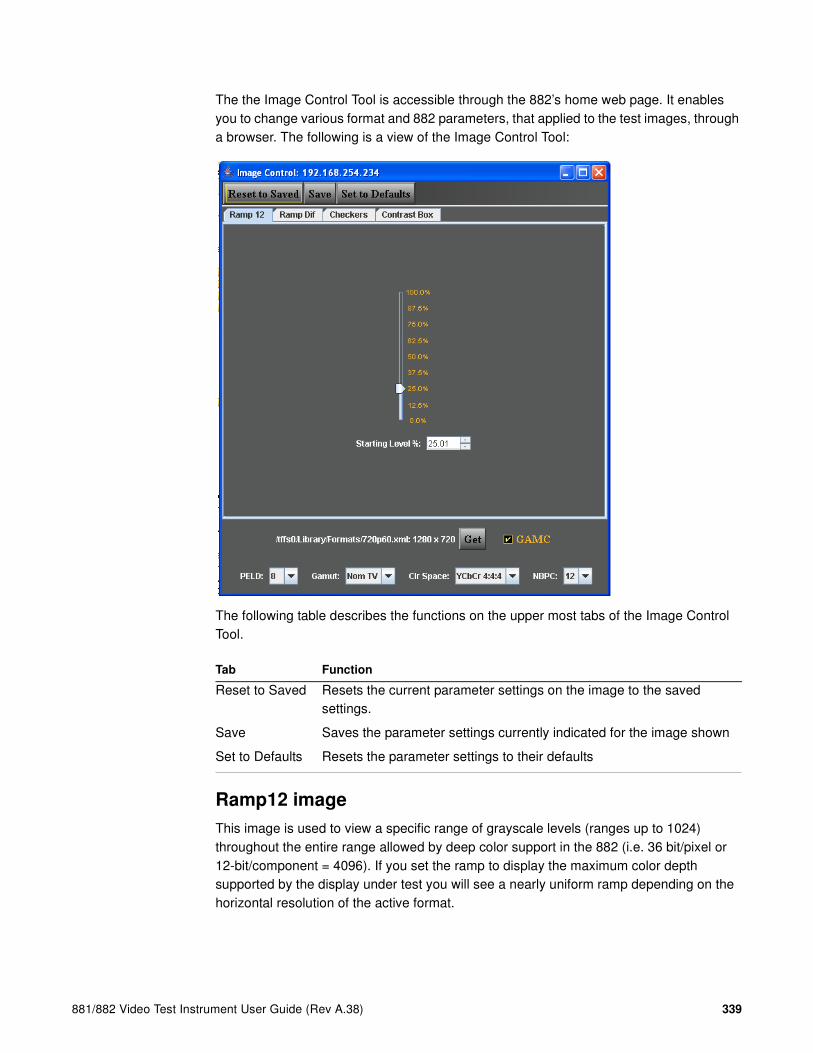
881/882 Video Test Instrument User Guide (Rev A.38) 339
The the Image Control Tool is accessible through the 882’s home web page. It enables you to change various format and 882 parameters, that applied to the test images, through a browser. The following is a view of the Image Control Tool:
The following table describes the functions on the upper most tabs of the Image Control Tool.
Ramp12 image
This image is used to view a specific range of grayscale levels (ranges up to 1024) throughout the entire range allowed by deep color support in the 882 (i.e. 36 bit/pixel or 12-bit/component = 4096). If you set the ramp to display the maximum color depth supported by the display under test you will see a nearly uniform ramp depending on the horizontal resolution of the active format.
Tab Function
Reset to Saved Resets the current parameter settings on the image to the saved settings.
Save Saves the parameter settings currently indicated for the image shown
Set to Defaults Resets the parameter settings to their defaults
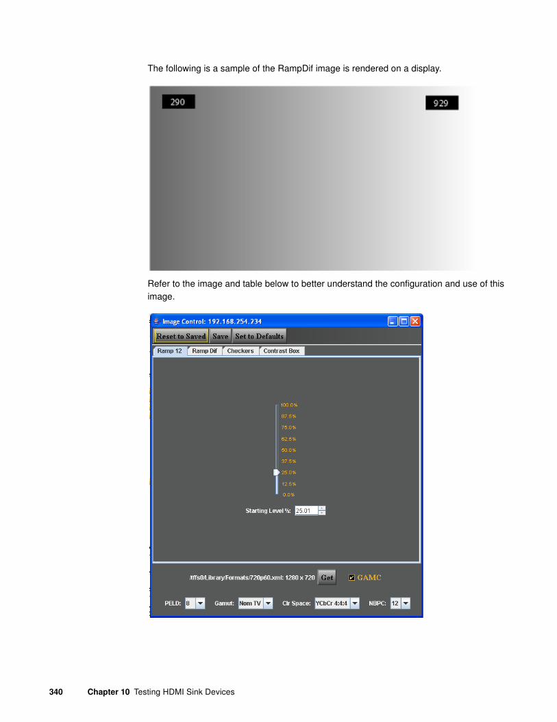
340 Chapter 10 Testing HDMI Sink Devices
The following is a sample of the RampDif image is rendered on a display.
Refer to the image and table below to better understand the configuration and use of this image.
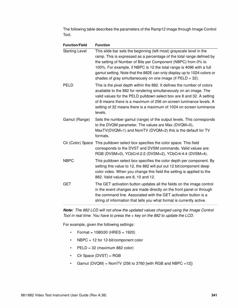
881/882 Video Test Instrument User Guide (Rev A.38) 341
The following table describes the parameters of the Ramp12 image through Image Control Tool.
Note: The 882 LCD will not show the updated values changed using the Image Control
Tool in real time. You have to press the + key on the 882 to update the LCD.
For example, given the following settings:
• Format = 1080i30 (HRES = 1920)
• NBPC = 12 for 12-bit/component color
• PELD = 32 (maximum 882 color)
• Clr Space (DVST) = RGB
• Gamut (DVQM) = NomTV (256 to 3760 [with RGB and NBPC =12])
Function/Field Function
Starting Level This slide bar sets the beginning (left most) grayscale level in the ramp. This is expressed as a percentage of the total range defined by the setting of Number of Bits per Component (NBPC) from 0% to 100%. For example, if NBPC is 12 the total range is 4096 with a full gamut setting. Note that the 882E can only display up to 1024 colors or shades of gray simultaneously on one image (if PELD = 32).
PELD This is the pixel depth within the 882. It defines the number of colors available to the 882 for rendering simultaneously on an image. The valid values for the PELD pulldown select box are 8 and 32. A setting of 8 means there is a maximum of 256 on-screen luminance levels. A setting of 32 means there is a maximum of 1024 on screen luminance levels.
Gamut (Range) Sets the number gamut (range) of the output levels. This corresponds to the DVQM parameter. The values are Max (DVQM=0), MaxTV(DVQM=1) and NomTV (DVQM=2) this is the default for TV formats.
Clr (Color) Space This pulldown select box specifies the color space. This field corresponds to the DVST and DVSM commands. Valid values are: RGB (DVSM=0), YCbCr4:2:2 (DVSM=2), YCbCr4:4:4 (DVSM=4).
NBPC This pulldown select box specifies the color depth per component. By setting this value to 12, the 882 will put out 12 bit/component deep color video. When you change this field the setting is applied to the 882. Valid values are 8, 10 and 12.
GET The GET activation button updates all the fields on the image control in the event changes are made directly on the front panel or through the command line. Associated with the GET activation button is a string of information that tells you what format is currently active.

342 Chapter 10 Testing HDMI Sink Devices
the maximum range available is (3760 - 256 = 3504) grayscale levels. Since PELD is set to 32 (24 pixel depth in the 882) the maximum number or grayscale levels that can be rendered by the 882 on a display is 1024. So if you set the Starting Level at 25%, the Ramp12 image will begin at the left with a grayscale level of 1132 (3504 * 0.25 = 876 + 256) and end at the right with a grayscale level of 2156 (1132 + 1024 = 2156). Because the horizontal image resolution of the format is 1920, you would see a ramp with bands of ~2.0 pixels each (1920 / 1024 = 1.89).
RampDif image
This image has two ramps. One on the top and one on the bottom. It enables you to show a contrast of color depths. For example you can specify that the top ramp use 12-bit/component deep color and the bottom ramp 10-bit color. You can then view the image and see whether banding occurs and how pronounced, in the either of the ramps. If the display under test supports 12-bit/component color, the top ramp will show a near uniform ramp on the top (depending on the horizontal resolution of the active format). The bottom ramp will show more pronounced banding because the range of the ramp is greater than the color depth.
This image is used to view two specific range of grayscale or color levels (ranges up to 512) throughout the entire range allowed by deep color support in the 882 (i.e. 36 bit or 4096). You need to set the pixel depth in the 882 to 24 bit (PELD = 32) in order to access 512 grayscale or color levels on a single image rendered on a display. The following is a sample of the RampDif image is rendered on a display.

881/882 Video Test Instrument User Guide (Rev A.38) 343
Refer to the image and table below to better understand the configuration and use of this image.
The following table describes the parameters of the Image Control Tool.
Function/Field Function
Color 1 These slide bars set the beginning color component and grayscale level (left most value) of the top and bottom ramps. This is expressed as a percentage of the total range defined by the setting of Number of Bits per Component (NBPC) from 0% to 100%. For example, if NBPC is 12 the total range is 4096 with a full gamut setting. Note that the 882E can only display up to 512 colors simultaneously for each ramp on this RampDif image (if PELD = 32).
Color 2 These slide bars set the ending color component and grayscale level (right most value) of the top and bottom ramps. This is expressed as a percentage of the total range defined by the setting of Number of Bits per Component (NBPC) from 0% to 100%. For example, if NBPC is 12 the total range is 4096 with a full gamut setting. Note that the 882E can only display up to 512 colors simultaneously for this RampDif image (if PELD = 32).

344 Chapter 10 Testing HDMI Sink Devices
Note: The 882 LCD will not show the updated values changed using the Image Control
Tool in real time. You have to press the + key on the 882 to update the LCD.
For example given the following settings:
• Format = 720p60 (HRES = 1280)
• NBPC = 12 for 12-bit/component color
• Number of Bits = 8 for 8-bit/component color
• PELD = 32 (maximum 882 color)
• Clr Space (DVST) = RGB
• Grayscale mode = Checked (enabled)
• Gamut (DVQM) = NomTV (256 to 3760 [with RGB and NPBC =12])
PELD This is the pixel depth within the 882. It defines the number of colors available to the 882 for rendering simultaneously on an image. The valid values for the PELD pulldown select box are 8 and 32. A setting of 8 means there is a maximum of 256 on-screen luminance levels per ramp. A setting of 32 means there is a maximum of 1024 on screen luminance levels but only 512 per ramp.
Gamut (Range) Sets the number gamut of the output signal. This corresponds to the DVQM parameter. The values are Max (DVQM=0), MaxTV(DVQM=1) and NomTV (DVQM=2) this is the default for TV formats.
Clr (Color) Space This pulldown select box specifies the color space. When you change this field the setting is applied to the 882. This field corresponds to the DVST and DVSM commands. Valid values are: RGB (DVSM=0), YCbCr4:2:2 (DVSM=2), YCbCr4:4:4 (DVSM=4).
NBPC This pulldown select box specifies the color depth per component on the top ramp. By setting this value to 12, the 882 will put out 12 bit/component deep color video on the top ramp. Valid values are 8, 10 and 12.
Number of bits This pulldown select box specifies the color depth per component on the bottom ramp. By setting this value to 12, the 882 will put out 12 bit/component deep color video on the bottom ramp. Valid values are 4-12.
Grayscale mode When checked this will set all three slide bars for each color component on each Color 1 and Color 2 to the same value. When unchecked you are free to set each color component to any value.
GET The GET activation button updates all the fields on the image control in the event changes are made directly on the front panel or through the command line. Associated with the GET activation button is a string of information that tells you what format is currently active.
Function/Field Function
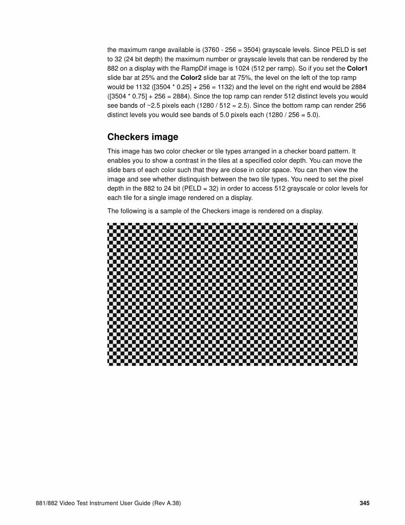
881/882 Video Test Instrument User Guide (Rev A.38) 345
the maximum range available is (3760 - 256 = 3504) grayscale levels. Since PELD is set to 32 (24 bit depth) the maximum number or grayscale levels that can be rendered by the 882 on a display with the RampDif image is 1024 (512 per ramp). So if you set the Color1
slide bar at 25% and the Color2 slide bar at 75%, the level on the left of the top ramp would be 1132 ([3504 * 0.25] + 256 = 1132) and the level on the right end would be 2884 ([3504 * 0.75] + 256 = 2884). Since the top ramp can render 512 distinct levels you would see bands of ~2.5 pixels each (1280 / 512 = 2.5). Since the bottom ramp can render 256 distinct levels you would see bands of 5.0 pixels each (1280 / 256 = 5.0).
Checkers image
This image has two color checker or tile types arranged in a checker board pattern. It enables you to show a contrast in the tiles at a specified color depth. You can move the slide bars of each color such that they are close in color space. You can then view the image and see whether distinquish between the two tile types. You need to set the pixel depth in the 882 to 24 bit (PELD = 32) in order to access 512 grayscale or color levels for each tile for a single image rendered on a display.
The following is a sample of the Checkers image is rendered on a display.

346 Chapter 10 Testing HDMI Sink Devices
Refer to the image and table below to understand the configuration and use of this image.
The following table describes the parameters of the Image Control Tool.
Function/Field Function
Color 1 These slide bars set the color component and grayscale level for one set of tiles. This is expressed as a percentage of the total range defined by the setting of Number of Bits per Component (NBPC) from 0% to 100%. For example, if NBPC is 12 the total range is 4096.
Color 2 These slide bars set the color component and grayscale level for one the other set of tiles. This is expressed as a percentage of the total range defined by the setting of Number of Bits per Component (NBPC) from 0% to 100%. For example, if NBPC is 12 the total range is 4096.
PELD This is the pixel depth within the 882. It defines the number of colors available to the 882 for rendering simultaneously on an image. The valid values for the PELD pulldown select box are 8 and 32. This parameter does not effect this image.

881/882 Video Test Instrument User Guide (Rev A.38) 347
Note: The 882 LCD will not show the updated values changed using the Image Control
Tool in real time. You have to press the + key on the 882 to update the LCD.
For example given the following settings:
• NBPC = 12 for 12-bit/component color
• Clr Space (DVST) = RGB
• Grayscale mode = Checked (enabled)
• Gamut (DVQM) = NomTV (256 to 3760 [with RGB and NBPC =12])
the maximum range available is (3760 - 256 = 3504) grayscale levels. So if you set the Color1 slide bar at 50% and the Color2 slide bar at 51%, the level for Color1 tiles would be 2008 ([3504 * 0.50] + 256 = 2008) and the level for Color2 tiles would be 2043 ([3504 * 0.51] + 256 = 2043). If the display under test supports 12 bit deep color you would be able to distinguish between the two tiles because the difference in the value (or grayscale) level between the two tiles would be within the granularity of a 12-bit/component display.
Accessing the Image Control Tool
The procedures below describe how to access the Image Control Tool.
Gamut (Range) Sets the number gamut of the output signal. This corresponds to the DVQM parameter. The values are Max (DVQM=0), MaxTV(DVQM=1) and NomTV (DVQM=2) this is the default for TV formats.
Clr (Color) Space This pulldown select box specifies the color space. This field corresponds to the DVST and DVSM commands. Valid values are: RGB (DVSM=0), YCbCr4:4:2 (DVSM=2), YCbCr4:4:4 (DVSM=4).
NBPC This pulldown select box specifies the color depth per component on the top ramp. By setting this value to 12, the 882 will put out 12 bit/component deep color video on the top ramp. Valid values are 8, 10 and 12.
Grayscale mode When checked this will set all three slide bars for each color component on each Color 1 and Color 2 to the same value. When unchecked you are free to set each color component to any value.
Square Checks Fixes the aspect ratio of the tiles to be the same width and height.
Check Width Determines the width of each tile (checker element)
Check Height Determines the height of each tile (checker element)
GET The GET activation button updates all the fields on the image control in the event changes are made directly on the front panel or through the command line. Associated with the GET activation button is a string of information that tells you what format is currently active.
Function/Field Function

348 Chapter 10 Testing HDMI Sink Devices
To access the Image Control Tool:
1. Set up the 882 for HDMI output. See “Setting up the 882 for HDMI testing” on page 331.
2. Press the Source key and select the desired format.
Alternatively, you can load the format with the following command:
FMTL format_name
FMTU
3. Open a Web browser (such as Internet Explorer) and type the 882’s IP address in the address entry field. For example, enter the following: http://206.135.215.189/.
The 882 home page appears in the browser.

881/882 Video Test Instrument User Guide (Rev A.38) 349
4. Select the Image Control Tool link.
The Image Control Tool appears in the browser.
Testing xvYCC
The 882E series test instrument enables you to test xvYCC displays. The feature provides test images and support for transmission of the gamut boundry definition (metadata transmission profile (only P0 currently).
The xvYCC or extended-gamut YCC is a color space that supports 1.8 times as many colors as the sRGB color space. The xvYCC color space uses the full range of values (1 to 254 in an 8-bit space) to represent colors.
The Munsell Color System provides a standard way of describing colors and can be applied to video systems. The Munsell Color System is shown in the figure below. A single color is represented by three separate parameters of color: 1) Hue, 2) Value and 3) Chroma. There are ten hues consisting of 5 basic hues and 5 intermediate hues. For each hue there is a number from 0 to 10 placed before the symbol for the hue. This number denotes the value which is the measure of lightness. The whitest value is given a 10 and placed at the top while black is given a 0 and placed at the bottom. Chroma is the

350 Chapter 10 Testing HDMI Sink Devices
measure of the saturation of the color. The central axis is achromatic (grayscale) and is defined as 0 and the scale is arranged concentrically. The farther one moves away from the center, the greater the saturation.
The steps are arranged such that the degree of differentiation between each step is preceived to be equal. A value differential of 1 and a chroma differential of 2 are set up such that they are preceived visually as having the same degree of difference.
The figure below depicts the Munsell Color System:
All colors in the Munsell color cascade can be mapped to the xvYCC color space but only 55% of these colors can be mapped to the sRGB color space.
The 882E instrument provides Munsell images for testing displays that support xvYCC color space. The following images are used:
• MnslGM - This is a color checker image with 24 colors arranged in a checker board.
• MnslCLR - There are a series of these images (40 in total) that are accessible as sub images through the 882E front panel. Each hue in the MnslCLR image set has 4 sub hues, labeled 2.5, 5, 7.5 and 10, that represent a hue as it traverses around the perimeter of the diagram above and transitions into the adjacent hues. Each such sub image depicts the chroma and value variances of one of these sub hues. Each sub image provides a color block for each chroma and value level for that sub hue. The value varies along the vertical axis and the chroma varies along the horizontal axis.

881/882 Video Test Instrument User Guide (Rev A.38) 351
• MnslPG - There are a series of these images (5 in total) that are accessible as sub images through the 882E front panel. Each sub image depicts two hue families (each hue family contains 4 sub hues (2.5, 5, 7.5, 10). Each set of color blocks arranged along a horizontal axis depicts the chroma and value variations for one of the sub hues which is labeled on the left. Each such horizontal set of color blocks is a cancatenation of the value and chroma variations for that particular hue. These cancatenations can be derived from the MnslCLR images. In other words, the MnslPG image is a concatenation of 8 of the MnslCLR images.
The MnslGM Image is shown below.
Note: The image as shown in this User Guide is not representative of how it will actually
appear on an xvYCC display.
This image can be used with a color probe to determine if the colors rendered on the xvYCC display match the true color.

352 Chapter 10 Testing HDMI Sink Devices
The MnsCLR Image is shown below. The example below shows only one of the 40 subimages. There are a series of these images (40 in total) that are accessible as sub images through the 882E front panel. Each hue in the MnslCLR image set has 4 sub hues, labeled 2.5, 5, 7.5 and 10, that represent a hue as it traverses around the perimeter of the diagram above and transitions into the adjacent hues. Each such sub image in the MnslCLR image depicts the chroma and value variances of one of these sub hues. Each sub image provides a color block for each chroma and value level for that sub hue. The value varies along the vertical axis and the chroma varies along the horizontal axis.
Note: The image as shown in this User Guide is not representative of how it will actually
appear on an xvYCC display.
When examining this image on an xvYCC display the differences between adjacent colors should be preceived to be the same. Note that this depends on how you have implemented the feature. Typically if you see adjacent colors that look very similar or strikingly different, then this indicates that the colors may not be represented properly on the display.

881/882 Video Test Instrument User Guide (Rev A.38) 353
The MnsPG Image is shown below. The example below shows an image that displays two (2) of the eight (8) hue families (in this case Yellow and Green Yellow). There are a series of these images (40 in total) that are accessible as sub images through the 882E front panel. Each hue in the MnslCLR image set has 4 sub hues, labeled 2.5, 5, 7.5 and 10, that represent a hue as it traverses around the perimeter of the diagram above and transitions into the adjacent hues. Each such sub image depicts the chroma and value variances of one of these sub hues. Each sub image provides a color block for each chroma and value level for that sub hue. The value varies along the vertical axis and the chroma varies along the horizontal axis.
Note: The image as shown in this User Guide is not representative of how it will actually
appear on an xvYCC display.
When examining this image on an xvYCC display the differences between adjacent colors should be preceived to be the same. Note that this depends on how you have implemented the feature. Typically if you see adjacent colors that look very similar or strikingly different, then this indicates that the colors may not be represented properly on the display.
To test an HDMI display for xvYCC:
1. Set up the 882 for HDMI output. See “Setting up the 882 for HDMI testing” on page 331.
2. Press the Source key and select the desired format.
Alternatively, you can load the format with the following command:
FMTL format_name
FMTU

354 Chapter 10 Testing HDMI Sink Devices
3. Press the Options key and select xvYCC colorimetry.
There are two color standards, xvYCC601 and xvYCC709. The appropriate one is selected depending on the format.
Alternatively, you can load the xvYCC color space with the following command:
DVST 16
FMTU
4. Press the Content key and select the desired Munsell images as shown in the following menu.
Alternatively, you can load the format with the following command:
IMGL MnslClr
IMGU
5. Enable and view image versions as follows:
a. Press the Options key. The following menu appears on the 882’s display:
b. Choose the More item by pressing the adjacent soft key until a + appears next to More and Rendition appears on the other side of the menu.
c. Press the + and - keys to advance through the image versions. Each version shows the format parameters for a different format in the Source list.
Alternatively, to enable and view image versions using the command line interface, enter the following commands:
ISUB 1 // Enables sub images
IVER 1 // Specifies the first image version
IMGU // Activates the image version
IVER 2 // Specifies the second image version
RGB 8-bits YCbCr 10-bits*xvYCC 12-bits*4:4:4 4:2:2
MESony_R MnslCLR*MnslGM MnslPG MoireX MoireX33 MoireY MoireY33
-More Red+-NoGamma Green+-Noise Blue+
+More Rendition: 000 Red+-NoGamma Green+-Noise Blue+

881/882 Video Test Instrument User Guide (Rev A.38) 355
IMGU // Activates the image version
6. When you are finished, disable image versions by pressing the Options key and choosing More until a - appears next to it.
Alternatively, to disable image versions using the command line interface, enter the following command:
ISUB 0 // Disables sub images

356 Chapter 10 Testing HDMI Sink Devices
Testing HDMI 1.4 displays with 3D
This section provides procedures for testing HDMI 1.4 3D displays. The 3D feature is available on all versions of the 88x series. The 3D feature enables you to test the ability of your 3D capable HDTV to process HDMI vendor specific infoframes with 3D metadata and to render 3D formats. The 3D feature can test 3D using the following timings (resolutions):
• 480p60, 576p59
• 720p60, 720p59, 720p50
• 1080p23, 1080p24
The 3D feature can test the following 3D structures:
• Frame packing
• Line alternative
• Side-by-side (full) (not supported by the 882EA)
• Side-by-side (half)
• Top and Bottom
Note: The 3D feature is available on all versions of the 88x series.
Rendering 3D images
This section provides detailed procedures for rendering 3D images.
Prerequisites for testing with the 3D images
In order to use the 3D utility to test your display you will need to ensure that the following prerequisites are met:
• Upgrade your 88x to the current release. Read the Release Notes to verify which release supports the 3D images.
• Locate the Quantum Data 3D bitmaps or use your own 3D bitmaps – The Quantum Data bitmaps are available from the Quantum Data website at:
• http://www.quantumdata.com/apps/3D/sample_BMP.asp.
• (optional) If you wish to create your own 3D bitmaps from stereoscopic image pairs that you have, then you will need to acquire the Quantum Data Bitmap Conversion Tool. This tool enables you to create 3D ready images that use various 3D format structures from existing stereographic bitmaps (left and right eye views). This utility is available at the Quantum Data downloads page: www.quantumdata.com/downloads/. You do not need this tool if you already have 3D bitmap test images or if you want to use the Quantum Data 3D bitmaps.

881/882 Video Test Instrument User Guide (Rev A.38) 357
• Load the 3D ready bitmap images onto the compact flash card in the 88x slot using the FTP Browser utility.
Workflow for rendering 3D images
The following describes the workflow for testing using the 882 Quantum Data 3D utility. This workflow assumes that you have satisfied the pre-requisites described above.
• Select a valid 3D timing (format) through 88x front panel in Basic mode or through the command line.
• Specify the 3D format structure.
• Select the 3D ready bitmap test image either through the 88x front panel using the Browse mode or the command line.
Creating 3D ready images
Use the following procedures to create the 3D ready images from two stereographic bitmaps using the Quantum Data 3D Bitmap Conversion Tool.
Note: If you have your own 3D bitmap images or if you are using the bitmap images
provided by Quantum Data, you do not need to use this procedure.
1. Acquire 3D stereographic image pairs (left and right) and place them in a convenient directory in your PC.
2. Download the Quantum Data 3D Bitmap Conversion Tool available from the Quantum Data website at: www.quantumdata.com/downloads/. Unzip the file and place it in a convenient location on your PC. This tool will convert a pair of 3D stereographic image pairs into a 3D bitmap of a specific 3D format that you can use in your 882.
3. Launch the Bitmap Conversion Tool by double clicking on the application icon. The application opens as shown below:
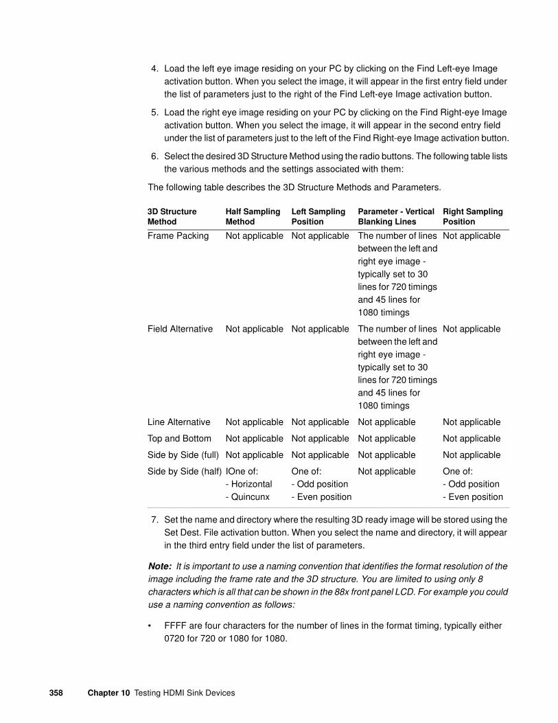
358 Chapter 10 Testing HDMI Sink Devices
4. Load the left eye image residing on your PC by clicking on the Find Left-eye Image activation button. When you select the image, it will appear in the first entry field under the list of parameters just to the right of the Find Left-eye Image activation button.
5. Load the right eye image residing on your PC by clicking on the Find Right-eye Image activation button. When you select the image, it will appear in the second entry field under the list of parameters just to the left of the Find Right-eye Image activation button.
6. Select the desired 3D Structure Method using the radio buttons. The following table lists the various methods and the settings associated with them:
The following table describes the 3D Structure Methods and Parameters.
7. Set the name and directory where the resulting 3D ready image will be stored using the Set Dest. File activation button. When you select the name and directory, it will appear in the third entry field under the list of parameters.
Note: It is important to use a naming convention that identifies the format resolution of the
image including the frame rate and the 3D structure. You are limited to using only 8
characters which is all that can be shown in the 88x front panel LCD. For example you could
use a naming convention as follows:
• FFFF are four characters for the number of lines in the format timing, typically either 0720 for 720 or 1080 for 1080.
3D Structure
Method
Half Sampling
Method
Left Sampling
Position
Parameter - Vertical
Blanking Lines
Right Sampling
Position
Frame Packing Not applicable Not applicable The number of lines between the left and right eye image - typically set to 30 lines for 720 timings and 45 lines for 1080 timings
Not applicable
Field Alternative Not applicable Not applicable The number of lines between the left and right eye image - typically set to 30 lines for 720 timings and 45 lines for 1080 timings
Not applicable
Line Alternative Not applicable Not applicable Not applicable Not applicable
Top and Bottom Not applicable Not applicable Not applicable Not applicable
Side by Side (full) Not applicable Not applicable Not applicable Not applicable
Side by Side (half) IOne of:- Horizontal- Quincunx
One of:- Odd position- Even position
Not applicable One of:- Odd position- Even position

881/882 Video Test Instrument User Guide (Rev A.38) 359
• DDDD are four characters for the 3D structure used. Either:
• TP for Top and Bottom
• FP for Frame Packing
• LALT for Line Alternative
• SBSF for Side-by-Side (Full)
• HHEE for Side-by-Side (Half) Horizontal sub-sampling Even left, Even right
• HHEO for Side-by-Side (Half) Horizontal sub-sampling Even left, Odd right
• HHOE for Side-by-Side (Half) Horizontal sub-sampling Odd left, Even right
• HHOO for Side-by-Side (Half) Horizontal sub-sampling Odd left, Odd right
• HQEE for Side-by-Side (Half) Quincunx matrix Even left, Even right
• HQEO for Side-by-Side (Half) Quincunx matrix Even left, Odd right
• HQOE for Side-by-Side (Half) Quincunx matrix Odd left, Even right
• HQOO for Side-by-Side (Half) Quincunx matrix Odd left, Odd right
For example: 1080HQEO would represent a 1080p format using the Side-by-Side structure using Quincunx matrix with Even left eye and Odd right eye.
8. Specify whether you want to save the resulting 3D ready image as a bitmap (BMP) using the checkbox provided. JPEG is not recommended.
9. Click on the Convert activation button to make the conversion and save the file in the specified directory using the specified name.
Rendering 3D ready images
Use the following procedures to render the 3D ready images with your 88x.
1. Place a compact flash card into the 88x slot provided.
2. Transfer the 3D ready images from your PC to the compact flash card using the 88x FTP Browser utility. On the Instrument Field side of the FTP Browser, navigate to the

360 Chapter 10 Testing HDMI Sink Devices
card0/library/UserData directory, and then transfer the files from your Host Files on the PC to the Instrument Files. Refer to the following screen.
3. Select the format from the 88x using either the front panel or the command line.
To load the format through the front panel:
a. Press the Source button and then select the format. Be sure and select the format that is associated with the 3D ready bitmap image you are intending to render. Note that the 88x should be in the Basic mode when you select the format.
b. Press the Options button repeatedly until the 3D menu appears. Select the desired 3D Structure as shown below:
To load the format through the command line. Enter the following commands (example only):
FMTL 720p20
X3DM 1 0 // Use the table below to determine what values to enter
FMTU

881/882 Video Test Instrument User Guide (Rev A.38) 361
The following table describes the X3DM Command Parameters.
Examples:
X3DM 1 0 // enables 3D, sends Frame Packing
X3DM 1 8 3 // enables 3D, sends side by side using Even/Left
picture, Even/Right picture horizontal subsampling
X3DM 0 // disables 3D
X3DM? // queries the value of X3DM to verify its settings
Parameter No. Descriptions Value Permitted
1 Enable or disable 3D 0 - Disable1 - Enable
2 3D Method 0 - Frame Packing2 - Line Alternative3 - Side by Side (Full)4 - L + Depth6 - Top and Bottom8 - Side by Side (Half)
3 Applies to Side by Side (half) only
Horizontal Sub-Sampling:
0 - Odd/Left picture, Odd/Right picture1 - Odd/Left picture, Even/Right picture2 - Even/Left picture, Odd/Right picture3 - Even/Left picture, Even/Right picture
Quincunx Matrix:4 - Odd/Left picture, Odd/Right picture5 - Odd/Left picture, Even/Right picture6 - Even/Left picture, Odd/Right picture7 - Even/Left picture, Even/Right picture

362 Chapter 10 Testing HDMI Sink Devices
4. Select the 3D ready image from the 88x using either the front panel or the command line:
Using the Front Panel
a. Put the 88x into the Browse mode. To use the Browse mode hold the Tools key down
b. until you see an indication on the LCD that the 88x has activated the Browse mode.
c. Select PCCard and then navigate to the Library/UserData directory
d. Select the 3D ready image using the blue button adjacent to the desired 3D ready image in the list. Return to the Basic mode after making your selection.
When you select a 3D capable format and 3D ready image, the 88x transmits the image out the HDMI output port and also sends the HDMI vendor specific infoframe with the necessary 3D metadata.
Using the command line:
e. Enter the following command to load the 3D ready image:
IMGL /card0/library/UserData/720-3D8.bmp
IMGU

881/882 Video Test Instrument User Guide (Rev A.38) 363
Testing HDMI video pixel repetition (882 only)
The EIA/CEA-861-B standard defines a number of progressively-scanned gaming formats which support variable horizontal resolutions. These formats maintain a fixed 2880-pixel format timing and use pixel repetition to provide 10 different effective horizontal resolutions. A special blanking scheme further reduces the number of active pixels (to those listed in the table below), thereby providing a horizontal safe area that insures that all of the pixels in a game will be visible on overscanned HDMI displays.
Note: This feature is not supported on the 881 generator.
To support HDMI gaming format and pixel repetition testing, the 882 allows you to sequentially apply pixel repetition (up to 10 times) to a unique image. As the pixel repetition factor is increased, the horizontal resolution of the displayed image will decrease as shown in the table below.
To test HDMI video pixel repetition:
1. Set up the 882 for HDMI output. See “Setting up the 882 for HDMI testing” on page 331.
Pixel repetition factor
(image version) Horizontal resolution
0 2880 pixels/line
1 2560 pixels/line
2 1280 pixels/line
3 853 pixels/line
4 640 pixels/line
5 512 pixels/line
6 427 pixels/line
7 366 pixels/line
8 320 pixels/line
9 284 pixels/line
10 256 pixels/line

364 Chapter 10 Testing HDMI Sink Devices
2. If you have auto configured the formats through the EDID you may have to disable this feature as follows:
a. Press the Sink key. The following information appears on the 882’s display.
b. Press the Options key. The following information appears on the 882’s display.
c. Choose not to EDID Formats by pressing the adjacent soft key. A - appears next to EDID Formats, indicating it is disabled.
3. Press the Source key and select the first test format.
Note: Gaming formats on the 882 have the characters “4x” in their names (such as
“480i4x29” or “576i4x25”). For a listing of all HDMI formats, see the table on page 328.
If you have auto configured the formats through the EDID you may have to disable this
feature.
Alternatively, to select the format through the command line interface, enter the following commands:
FMTP /tffs0/Library/Formats // Set format path to 882 memory
FMTL 480i4x29 // Loads the 480i4x29 format
FMTU // Activates the 480i4x29 format
Manufacturer:SNYProduct Code:144Serial#:7011007Week:20 Year:1998
-EDID Formats CDF+HP Bypass-Emulate
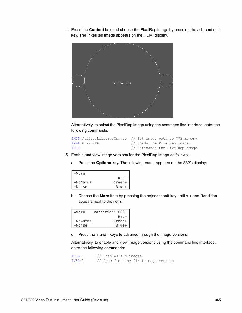
881/882 Video Test Instrument User Guide (Rev A.38) 365
4. Press the Content key and choose the PixelRep image by pressing the adjacent soft key. The PixelRep image appears on the HDMI display.
Alternatively, to select the PixelRep image using the command line interface, enter the following commands:
IMGP /tffs0/Library/Images // Set image path to 882 memory
IMGL PIXELREP // Loads the PixelRep image
IMGU // Activates the PixelRep image
5. Enable and view image versions for the PixelRep image as follows:
a. Press the Options key. The following menu appears on the 882’s display:
b. Choose the More item by pressing the adjacent soft key until a + and Rendition appears next to the item.
c. Press the + and - keys to advance through the image versions.
Alternatively, to enable and view image versions using the command line interface, enter the following commands:
ISUB 1 // Enables sub images
IVER 1 // Specifies the first image version
-More Red+-NoGamma Green+-Noise Blue+
+More Rendition: 000 Red+-NoGamma Green+-Noise Blue+

366 Chapter 10 Testing HDMI Sink Devices
IMGU // Activates the image version
The pixel repetition factor appears in the center of the image. For instance, the image displaying a pixel repetition factor of 4 (“Sent 4”) is shown in the example below.
6. To verify proper handling of the selected HDMI gaming format, check the following in the image on the HDMI display:
• The horizontal active area is resized to the appropriate number of clocked pixels using vertical bars to the left and right of the default (2880 pixel) image.
• The white vertical borders and circles in the active area appear thicker.
• The white text in the center of the active area appears stretched and bigger.
7. Select additional pixel repetition factors (as desired) to verify proper handling of the selected HDMI gaming format using variable horizontal resolutions.
8. When testing is complete, disable image versions by pressing the Options key and choosing More until a - appears next to it.
Alternatively, to disable image versions using the command line interface, enter the following command:
ISUB 0 // Disables sub images
9. To test another HDMI gaming format, return to step 3.

881/882 Video Test Instrument User Guide (Rev A.38) 367
Testing HDMI audio
This section provides steps on how to test handling of audio packets by an HDMI display. Testing can be performed using audio originating from both internal (882) and external sources. The 882 supports both 2-channel SPDIF audio from internal source and external source and up to 8-channel audio from an internal audio source. There are separate sets of images for testing 2-channel SPDIF audio and 8-channel audio.
The procedures describe how you can vary the audio amplitude, audio frequency and audio sampling rate for 2-channel or 8-channel audio. Note that there are some limitations for the 8-channel audio at high sampling rates these are described below.
Testing 2-channel HDMI audio output from internal SPDIF source
To support testing of HDMI audio, the 882 provides two-channel LPCM audio (using an internally-generated sinewave) at the highest audio sampling rate (48 kHz). Multiple scenarios are provided that allow you to test one or both audio channels at different amplitudes and frequencies, as well as test using the different supported sampling rates. The sampling rate for all channels is completed through a single image (AudioRAT).
The following table lists the images used to perform HDMI audio testing using an internal audio source.
To test an HDMI display using HDMI audio from the 882:
1. Set up the 882 for HDMI output. See “Setting up the 882 for HDMI testing” on page 331.
2. Press the Source key and select the first test format (either DMT0660 or 480i2x29).
Alternatively, to select the format using the command line interface, enter the following commands:
FMTP /tffs0/Library/Formats // Set format path to 882 memory
FMTL 480i2x29 // Loads the 480i2x29 format
FMTU // Activates the 480i2x29 format
Image Description
AudioLR Left and right audio channel output with adjustable amplitude.
AudioLRf Left and right audio channel output with adjustable frequency.
AudioRAT Left and right audio channel output with adjustable sampling rate.
Audio_L Left audio channel output with adjustable amplitude.
Audio_Lf Left audio channel output with adjustable frequency.
Audio_R Right audio channel output with adjustable amplitude.
Audio_Rf Right audio channel output with adjustable frequency.

368 Chapter 10 Testing HDMI Sink Devices
3. Press the Content key and choose an audio image (for example, AudioLR).
The selected image appears on the connected HDMI display. The image shows the current settings for the HDMI audio output. For example, the AudioLR image is shown below.
Alternatively, to select the audio image using the command line interface, enter the following commands:
IMGP /tffs0/Library/Images // Set image path to 882 memory
IMGL AUDIOLR // Loads the AudioLR image
IMGU // Activates the AudioLR image
4. Enable and view image versions for the AudioLR image as follows:
a. Press the Options key. The following menu appears on the 882’s display:
b. Choose the More item by pressing the adjacent soft key until a + and Rendition appears next to the item.
c. Press the + and - keys to advance through the image versions.
Note: Depending on the selected image, pressing the + and - keys will change the
amplitude or frequency of the HDMI audio output.
Alternatively, to enable and view an image version using the command line interface, enter the following commands:
-More Red+-NoGamma Green+-Noise Blue+
+More Rendition: 000 Red+-NoGamma Green+-Noise Blue+

881/882 Video Test Instrument User Guide (Rev A.38) 369
ISUB 1 // Enables sub images
IVER 1 // Specifies the first image version
IMGU // Activates the image version
5. To verify proper HDMI audio handling, check the following on the HDMI display:
• Audio is output from the proper channels (left, right, or both).
• When amplitude is adjusted, the volume is subsequently changed.
• When frequency is adjusted, the pitch is subsequently changed.
6. When testing is complete, disable image versions by pressing the Options key and choosing More until a - appears next to it.
Alternatively, to disable image versions using the command line interface, enter the following command:
ISUB 0 // Disables sub images
7. Press the Content key and choose the AudioRAT image to test the sampling rate.
The AudioRAT image appears on the connected HDMI display. The image shows the current settings for the HDMI audio output. Note that the sampling rate image (AudioRAT) applies to all audio channel.
Alternatively, to select the AudioRAT image using the command line interface, enter the following commands:
IMGP /tffs0/Library/Images // Set image path to 882 memory
IMGL AUDIORAT // Loads the AudioRAT image
IMGU // Activates the AudioRAT image
8. Enable and view image versions for the AudioRAT image as follows:
a. Press the Options key. The following menu appears on the 882’s display:
b. Choose the More item by pressing the adjacent soft key until a + and Rendition appears next to the item.
c. Press the + and - keys to advance through the image versions to change the audio sampling rate.
Alternatively, to enable and view an image version using the command line interface, enter the following commands:
ISUB 1 // Enables sub images
-More Red+-NoGamma Green+-Noise Blue+
+More Rendition: 000 Red+-NoGamma Green+-Noise Blue+

370 Chapter 10 Testing HDMI Sink Devices
IVER 1 // Specifies the first image version
IMGU // Activates the image version
9. To test another HDMI audio output type, repeat the procedure.
Testing 8-channel HDMI audio output from internal source
To support testing of HDMI audio, the 882 provides 8-channel LPCM audio (using an internally-generated sinewave) at the highest audio sampling rate (192 kHz). Multiple scenarios are provided that allow you to test all audio channels at different amplitudes and frequencies, as well as test using the different supported sampling rates. The sampling rate for all channels is completed through a single image (AudioRAT).
High audio sampling rates and channel counts may require additional bandwidth in the blanking intervals. The required additional blanking intervals may only be available with high definition formats for example 720p and 1080i. When outputting 8 channels, the audio sampling rate is only guaranteed to 96kHz and requires that you use a high definition format.
Only two channels are guaranteed at the 192kHz sampling rate. These two channels must be from the 882’s internal sine wave 882 as the SPDIF input is only guaranteed to 96kHz.
Note also that your receiving device must support 8-channel audio.
The following table lists the images used to perform HDMI audio testing using an internal audio source for 8 channels.
Note: Selecting any of the numbered images (for example, Audio_1, Audio_2, etc.) causes
all other channels to be deactivated.
Image Description
Audio_1 Channel 1 output with adjustable amplitude.
Audio_1f Channel 1 output with adjustable frequency.
Audio_2 Channel 2 output with adjustable amplitude.
Audio_2f Channel 2 output with adjustable frequency.
Audio_3 Channel 3 output with adjustable amplitude.
Audio_3f Channel 3 output with adjustable frequency.
Audio_4 Channel 4 output with adjustable amplitude.
Audio_4f Channel 4 output with adjustable frequency.
Audio_5 Channel 5 output with adjustable amplitude.
Audio_5f Channel 5 output with adjustable frequency.
Audio_6 Channel 6 output with adjustable amplitude.
Audio_6f Channel 6 output with adjustable frequency.
Audio_7 Channel 7 output with adjustable amplitude.

881/882 Video Test Instrument User Guide (Rev A.38) 371
To test an HDMI display using HDMI 8-channel audio from the 882:
1. Set up the 882 for HDMI output. See “Setting up the 882 for HDMI testing” on page 331.
2. Press the Source key and select the first test format (for example: DMT0660 or 480i2x29).
Alternatively, to select the format using the command line interface, enter the following commands:
FMTP /tffs0/Library/Formats // Set format path to 882 memory
FMTL 480i2x29 // Loads the 480i2x29 format
FMTU // Activates the 480i2x29 format
3. Press the Content key and choose one of the audio images used for amplitude adjustment (for example, Audio_1).
The image appears on the connected HDMI display. The image shows the current settings for the HDMI audio output. For example, the Audio_1 image is shown below.
Alternatively, to select the audio image using the command line interface, enter the following commands:
IMGP /tffs0/Library/Images // Set image path to 882 memory
IMGL AUDIO_1 // Loads the Audio_1 image
IMGU // Activates the Audio_1 image
Audio_7f Channel 7 output with adjustable frequency.
Audio_8 Channel 8 output with adjustable amplitude.
Audio_8f Channel 8 output with adjustable frequency.
Audio_X All channels output with adjustable amplitude.
Audio_Xf All channels output with adjustable frequency.
Image Description

372 Chapter 10 Testing HDMI Sink Devices
4. Enable and view image versions to modify the audio amplitude for the Audio_1 image as follows:
a. Press the Options key. The following menu appears on the 882’s display:
b. Choose the More item by pressing the adjacent soft key until a + and Rendition appears next to the item.
c. Press the + and - keys to advance through the image versions to change the audio intensity.
Note: Depending on the selected image, pressing the + and - keys will change the
amplitude or frequency of the HDMI audio output.
Alternatively, to enable and view an image version using the command line interface, enter the following commands:
ISUB 1 // Enables sub images
IVER 1 // Specifies the first image version
IMGU // Activates the image version
5. To verify proper HDMI audio handling, check the following on the HDMI display:
• Audio is output from the proper channels (left, right, or both).
• When amplitude is adjusted, the volume is subsequently changed.
-More Red+-NoGamma Green+-Noise Blue+
+More Rendition: 000 Red+-NoGamma Green+-Noise Blue+

881/882 Video Test Instrument User Guide (Rev A.38) 373
6. Press the Content key and choose one of the audio images used for frequency adjustment (for example, Audio_1f).
The image appears on the connected HDMI display. The image shows the current settings for the HDMI audio output. For example, the Audio_1f image is shown below.
Alternatively, to select the audio image using the command line interface, enter the following commands:
IMGP /tffs0/Library/Images // Set image path to 882 memory
IMGL AUDIO_1f // Loads the Audio_1f image
IMGU // Activates the Audio_1f image
7. To verify proper HDMI audio handling, check the following on the HDMI display:
• Audio is output from the proper channels (left, right, or both).
• When frequency is adjusted, the pitch is subsequently changed.
8. Press the Content key and choose the AudioRAT image to test the sampling rate.
The AudioRAT image appears and shows the current settings for the HDMI audio output. Note that the sampling rate image (AudioRAT) adjusts the sampling rate for all audio images.
Alternatively, to select the AudioRAT image using the command line interface, enter the following commands:
IMGP /tffs0/Library/Images // Set image path to 882 memory
IMGL AUDIORAT // Loads the AudioRAT image
IMGU // Activates the AudioRAT image

374 Chapter 10 Testing HDMI Sink Devices
9. Enable and view image versions for the AudioRAT image as follows:
a. Press the Options key. The following menu appears on the 882’s display:
b. Choose the More item by pressing the adjacent soft key until a + and Rendition appears next to the item.
c. Press the + and - keys to advance through the image versions to change the audio sampling rate.
Alternatively, to enable and view an image version using the command line interface, enter the following commands:
ISUB 1 // Enables sub images
IVER 1 // Specifies the first image version
IMGU // Activates the image version
10. When testing is complete, disable image versions by pressing the Options key and choosing More until a ‘-’ (minus sign) appears next to it.
Alternatively, to disable image versions using the command line interface, enter the following command:
ISUB 0 // Disables sub images
11. To test another HDMI audio output channel or format, repeat the procedure.
Testing multi-channel compressed HDMI audio formats
The 882E instrument enables you to test HDMI compressed audio formats such as AC3, EAC3 and the HDMI 1.3 high bit rate lossless compressed audio such as Dolby TrueHD format. TrueHD's may carry up to 8 discrete audio channels, at a sample depth & rate of 24-bit/96 kHz (Blu-Ray Disc format specification allows also for encoding up to 6 channels at 192 kHz).
Multiple scenarios are provided that allow you to test all audio channels at different amplitudes and frequencies, as well as test using the different supported sampling rates. The sampling rate for all channels is completed through a single image (AudioRAT).
-More Red+-NoGamma Green+-Noise Blue+
+More Rendition: 000 Red+-NoGamma Green+-Noise Blue+

881/882 Video Test Instrument User Guide (Rev A.38) 375
High audio sampling rates and channel counts may require additional bandwidth in the blanking intervals. The required additional blanking intervals may only be available with high definition formats for example 720p and 1080i. When outputting 8 channels, the audio sampling rate is only guaranteed to 96kHz and requires that you use a high definition format.
Only two channels are guaranteed at the 192kHz sampling rate. These two channels must be from the 882’s internal sine wave 882 as the SPDIF input is only guaranteed to 96kHz.
Note: Unlike the uncompressed formats (linear PCM) the compressed audio test signals
are generated from a file. As a result the amplitude and frequency cannot be adjusted
through the audio test images.
To test compressed audio formats on an HDMI device from the 882:
1. Set up the 882 for HDMI output. See “Setting up the 882 for HDMI testing” on page 331.
2. Press the Source key and select the first test format (for example: 720p60).
Alternatively, to select the format using the command line interface, enter the following commands:
FMTP /tffs0/Library/Formats // Set format path to 882 memory
FMTL 720p60 // Loads the 720p60 format
FMTU // Activates the 720p60 format

376 Chapter 10 Testing HDMI Sink Devices
3. Press the Content key and choose the Dolby audio image as shown below. Note that you can also select the DTS image to access the DTS audio clips.
The image appears on the connected HDMI display. The image shows the currently selected compressed audio format.
Alternatively, to select the Dolby image using the command line interface, enter the following commands:
IMGP /Cache0/Images // Set image path to 882 memory
IMGL Dolby // Loads the Dolby image
IMGU // Activates the Dolby image
IMGL DTS // Loads the DTS image
IMGU // Activates the DTS image
Note: You can output compressed audio formats through the command line without
selecting the Dolby image. To do this you enter the following command:
CAUD? // Queries for the list of stored compressed audio clip
configurations:
1:DTS, 5.1, 48000.00 [dts-48kHz-1509kbps-51ch.wav.pcm]
2:DTS(ES), 6.1, 48000.00 [DTES-ES-48kHz-1509kbps-61ch.wav.pcm]
3:DTS(HDHRA), 7.1, 192000.00 [dtshdhra-48kHz-5376kbps-71ch.wav.pcm]
4:DTS(HDHRA), 5.1, 192000.00 [dtshdhra-48kHz-3840kbps-51ch.wav.pcm]
5:DTS(HDHRA), 7.1, 192000.00 [dtshdhra-96kHz-5760kbps-71ch.wav.pcm]
6:DTS(HDMA), 5.1, 192000.00 [dtshdma-48kHz-VBR-51ch-HDMI_HBR.ba.pcm]
7:DTS(HDMA), 7.1, 192000.00 [dtshdma-48kHz-VBR-71ch-HDMI_HBR.ba.pcm]
ComFocus ContBars Crosshtc Cubes DecodAdj DecodeChk Diamond1 Dolby*
Dolby Audio Library
AC3,2kHz,2Ch,0dB
EAC3,2Ch,-20dB
EAC3,5.1Ch,-20dB
EAC3,7.1Ch,-20dB
TRUEHD,1kHz,7.1Ch,-20dBNow Playing:
Change Image Rendition for other Audio Formats

881/882 Video Test Instrument User Guide (Rev A.38) 377
8:DOLBY(AC3), 2.0, 48000.00 [2khz2ch-0dB_ac3.pcm]
9:DOLBY(EAC3), 2.0, 192000.00 [1khz2ch-20dB_ec3.pcm]
10:DOLBY(EAC3), 5.1, 192000.00 [1khz51ch-20dB_ec3.pcm]
11:DOLBY(EAC3), 7.1, 192000.00 [1khz71ch-1frame_ec3.pcm]
12:DOLBY(TRUEHD), 7.1, 192000.00 [1khz71ch-20dB_mlp.pcm]
13:DOLBY(TRUEHD), 2.0, 192000.00 [nxt2ch2s.mlp.pcm]
CAUD 8 // Sends a 2 channel Dolby AC3 clip with 192kHz sampling rate
at 0dB out the HDMI output.
4. Enable and view image versions to select the other audio formats as follows:
a. Press the Options key. The following menu appears on the 882’s display:
b. Choose the More item by pressing the adjacent soft key until a + and Rendition appears next to the item.
c. Press the + and - keys to advance through the image versions to change the audio intensity.
Note: Depending on the selected image, pressing the + and - keys will change the
amplitude or frequency of the HDMI audio output.
Alternatively, to enable and view an image version using the command line interface, enter the following commands:
ISUB 1 // Enables sub images
IVER 1 // Specifies the first image version
IMGU // Activates the image version
5. To verify proper HDMI audio handling, check the following on the HDMI display:
• Audio is output from the proper channels (left, right, or both).
• The proper audio format is shown on the Audio/Video receiver.
Testing HDMI audio using an external audio source
The 882 enables you to inject audio signals from an external SPDIF source (such as a DVD player) into the HDMI content stream. You can input IEC 61937 non-linear PCM encoded audio stream or compressed audio streams (for example AC-3 and DTS) into the SPDIF interface for output through the HDMI Tx connector.
-More Red+-NoGamma Green+-Noise Blue+
+More Rendition: 000 Red+-NoGamma Green+-Noise Blue+

378 Chapter 10 Testing HDMI Sink Devices
To inject external audio into the HDMI stream:
• If you have the 882CA analyzer option you will have the VGA-to-RCA cable (part 30-00150). Connect the AV connector to the 882’s SPDIF / AV port. Then connect the black RCA connector to the SPDIF output of the external audio source.
• If you have the 882C without the analyzer option, you will have the VGA-to-RCA cable (part 30-00148). Connect the AV connector to the 882’s SPDIF / AV port. Then connect the red RCA connector to the SPDIF output of the external audio source.
• If you have the 882E, you will have the (30-00123) BNC to RCA adapter (provided) so you will need a standard RCA cable. Simply connect the RCA cable from the SPDIF IN connect to the SPDIF output of the external audio source.
To test an HDMI display using HDMI audio from an external source:
1. Set up the 882 for HDMI output. See “Setting up the 882 for HDMI testing” on page 331.
2. Connect the external audio source to the SPDIF-A/V connector on the 882 as follows:
a. For the 882CA, using the RCA-to-VGA cable provided with the 882, connect the J1 connector to the SPDIF-A/V connector on the 882. Then connect the red RCA connector to the external audio source.
b. For the 882E, connect the external audio source to the SPDIF-A/V connector on the 882 using the BNC to RCA adapter provided with the 882.
3. Press the Source key and select a format suitable for the HDMI display (for example, DMT0660).
Alternatively, to select the format using the command line interface, enter the following commands:
FMTP /tffs0/Library/Formats // Set format path to 882 memory
FMTL DMT0660 // Loads the DMT0660 format
FMTU // Activates the DMT0660 format
To audio player
To audio source
Red
Green
Blue
Grey
Black
To AV
connector
To audio sourceTo AV connector
Red

881/882 Video Test Instrument User Guide (Rev A.38) 379
4. Press the Content selection key and choose any image (for example, Master).
Alternatively, to select the image using the command line interface, enter the following commands:
IMGP /tffs0/Library/Images // Set image path to 882 memory
IMGL MASTER // Loads the Master image
IMGU // Activates the Master image
5. Configure the 882 to use an external audio source by entering the following commands:
SDMG 2
FMTU
6. Set the sample frequency to match the frequency of the external source by entering the following command:
ARAT 44.1E3 //(example only)
Alternatively, configure the 882 to detect the audio sampling rate from the channel header of the incoming digital audio by entering the following command:
ARAT 0.0
Note: The default frequency is 48 kHz (which is used by DVD players). However, if the
external source is an audio CD played on a DVD player, the player will output SPDIF
with a sampling rate of 44.1 kHz (not 48 kHz). In this case, set the sampling frequency
to 44.1 kHz (or reload the format, which will detect the sampling frequency
automatically).
7. Turn on the external audio source. The external audio signal will be encoded into the HDMI signal.
Note: The 882 cannot independently control external source channels. You must use
the device generating the audio signal to control the channels.
8. To verify proper HDMI audio handling, check the following on the HDMI display:
• Audio is output from the proper channels (left, right, or both).
• When the volume is adjusted at the external source, the volume is subsequently changed.
9. Select additional audio images (as desired) to verify proper audio handling.
10. To test another HDMI audio output type, return to step 3.

380 Chapter 10 Testing HDMI Sink Devices
Testing HDMI InfoFrames (882 only)
This section provides steps on how to test handling of auxiliary (InfoFrame) packets by an HDMI display. The 882 loads and sends default Auxiliary Video Information (XAVI), Audio (XAUD), and Source Product Description (XSPD) InfoFrame packet buffers to the display for each format (see table on page 328 for a list of HDMI formats). The XAVI and the XAUD InfoFrame packets are sent at every frame (repeated mode), while the XSPD is sent only once. The XMPG and XGIF InfoFrames are gated off and not enabled.
Note: This feature is not supported on the 881 generator.
HDMI provides various types of auxiliary data in the form of InfoFrames. InfoFrames allow the HDMI source to keep an HDMI display informed as to “what is coming down the pipe” so that it can present the content optimally—without any viewer intervention.
There are five different types of InfoFrames:
• auxiliary video information (AVI)
• audio (AUD)
• source product description (SPD)
• MPEG information (MPG)
• generic (vendor-specific) information (GIF)
Each type carries information regarding a different aspect of the HDMI audio/video transmission.
The procedures below can be performed using the front panel or the command line interface.
Viewing InfoFrame contents (882 only)
The 882 provides a convenient method for monitoring the InfoFrame content of the transmitted HDMI signal. The procedure below describes how to view current InfoFrame contents.
Note: This feature is not supported on the 881 generator.
To view current HDMI InfoFrame contents transmitted from the 882:
1. Set up the 882 for HDMI output. See “Setting up the 882 for HDMI testing” on page 331.
2. Press the Source key and choose a format suitable for the HDMI display (for example, DMT0660). Refer to the table in “Format selection” on page 327.
Alternatively, to select the format using the command line interface, enter the following commands:
FMTP /tffs0/Library/Formats // Set format path to 882 memory

881/882 Video Test Instrument User Guide (Rev A.38) 381
FMTL DMT0660 // Loads the DMT0660 format
FMTU // Activates the DMT0660 format
3. Press the Content key and choose the PacketTx image.
Alternatively, to select the image using the command line interface, enter the following commands:
IMGP /tffs0/Library/Images // Set image path to 882 memory
IMGL PacketTx // Loads the PacketTx image
IMGU // Activates the PacketTX image
The PacketTx image appears on the connected HDMI display. The image shows the current settings for the AVI InfoFrame output.
4. Enable and view image versions for the PacketTx image as follows:
a. Press the Options key. The following menu appears on the 882’s display:
b. Choose the More item by pressing the adjacent soft key until a + and Rendition appears next to the item.
c. Press the + key to advance through the image versions.
-More Red+-NoGamma Green+-Noise Blue+
+More Rendition: 000 Red+-NoGamma Green+-Noise Blue+
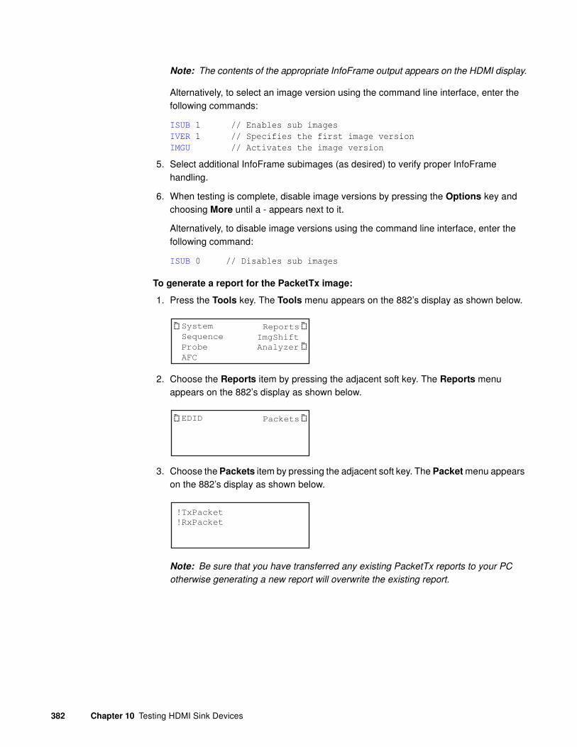
382 Chapter 10 Testing HDMI Sink Devices
Note: The contents of the appropriate InfoFrame output appears on the HDMI display.
Alternatively, to select an image version using the command line interface, enter the following commands:
ISUB 1 // Enables sub images
IVER 1 // Specifies the first image version
IMGU // Activates the image version
5. Select additional InfoFrame subimages (as desired) to verify proper InfoFrame handling.
6. When testing is complete, disable image versions by pressing the Options key and choosing More until a - appears next to it.
Alternatively, to disable image versions using the command line interface, enter the following command:
ISUB 0 // Disables sub images
To generate a report for the PacketTx image:
1. Press the Tools key. The Tools menu appears on the 882’s display as shown below.
2. Choose the Reports item by pressing the adjacent soft key. The Reports menu appears on the 882’s display as shown below.
3. Choose the Packets item by pressing the adjacent soft key. The Packet menu appears on the 882’s display as shown below.
Note: Be sure that you have transferred any existing PacketTx reports to your PC
otherwise generating a new report will overwrite the existing report.
System
Sequence
Probe
AFC
Analyzer
Reports
ImgShift
EDID Packets
!TxPacket
!RxPacket

881/882 Video Test Instrument User Guide (Rev A.38) 383
4. Select the !PacketTx item by pressing the adjacent soft key to generate the report. The following appears on the display.
Alternatively you can generate this report from the command line using the following command:
IFGX:RPTU // Initiates the Packet Tx report.
5. Open a Web browser (such as Internet Explorer) and type the 882’s IP address in the address entry field. For example, enter the following: http://206.135.215.189/.
The 882 home page appears in the browser.
TX PACKETS
Finished

384 Chapter 10 Testing HDMI Sink Devices
6. Choose the Generated Reports item. The 882 the provides a list of reports currently available as shown below.

881/882 Video Test Instrument User Guide (Rev A.38) 385
7. Navigate to your PC and double click on the report. A sample of part of the PacketTx report is shown below.
Testing with Active Format Description (AFD) (882 only)
When transporting HDMI video images from a source to a display, different formats may be used between the content, transmission signal, and display. To provide compatibility between the different formats, Active Format Description (AFD) is used.
Note: This feature is not supported on the 881 generator.

386 Chapter 10 Testing HDMI Sink Devices
AFD describes the portion of the coded video frame that is “of interest” (or “active”). The appropriate AFD information is transmitted with the video to the HDMI display as part of AVI InfoFrame packets. Using AFD information, the display is able to present the image optimally.
For AFD testing, the 882 allows you to apply different AFD cases using the AFDtest image, which provides 12 different cases (as image versions) for both 4:3 and 16:9 displays. As each image version appears, the appropriate AFD information is sent with the video to the display.
The following table lists the AFD cases (as specified in the ETSI TR 101 154 v.1.4.1
standard) that are provided by the 882.
To test an HDMI display’s ability to support AFD:
1. Set up the 882 for HDMI output. See “Setting up the 882 for HDMI testing” on page 331.
2. Press the Source key and choose a format suitable for the HDMI display (for example, DMT0660).
Alternatively, to select the format using the command line interface, enter the following commands:
FMTP /tffs0/Library/Formats // Set format path to 882 memory
FMTL DMT0660 // Loads the DMT0660 format
FMTU // Activates the DMT0660 format
3. Press the Content key and choose the AFDtest image.
Alternatively, to select the image using the command line interface, enter the following commands:
IMGP /tffs0/Library/Images // Set image path to 882 memory
IMGL AFDTEST // Loads the AFDtest image
AFD case
Image
Version
(4:3 Format)
Image
Version
(16:9 Format) Aspect Ratio of Active Area
2 8 7 box 16:9 (top)
3 5 4 box 14:9 (top)
4 9-12 9-12 box > 16:9 (center)
8 0 6 Same as the signal format
9 1 1 4:3 (center)
10 7 8 16:9 (center)
11 4 3 14:9 (center)
13 3 5 4:3 (with shoot and protect 14:9 center)
14 6 2 16:9 (with shoot and protect 14:9 center)
15 2 0 16:9 (with shoot and protect 4:3 center)

881/882 Video Test Instrument User Guide (Rev A.38) 387
IMGU // Activates the AFDtest image
The AFDtest image appears on the connected HDMI display.
4. Enable and view image versions for the AFDtest image as follows:
a. Press the Options key. The following menu appears on the 882’s display:
b. Choose the More item by pressing the adjacent soft key until a + and Rendition appears next to the item.
c. Press the + key to advance through the image versions.
Note: Select the image version that corresponds to the AFD case (or code) you want
to test. See the table on page 386 for a list of the image numbers that correspond with
each AFD case.
Alternatively, to enable and view the image versions using the command line interface, enter the following commands:
ISUB 1 // Enables sub images
IVER 1 // Specifies the first image version
IMGU // Activates the image version
-More Red+-NoGamma Green+-Noise Blue+
+More Rendition: 000 Red+-NoGamma Green+-Noise Blue+

388 Chapter 10 Testing HDMI Sink Devices
5. Using the selected AFD scenario, verify that the HDMI display presents the image correctly.
Note: Displays use the AFD information to determine how to present an image.
Different displays may present HDMI video with the same AFD differently.
6. Use the + and - keys to adjust the amplitude, frequency, or sampling rate (based on the selected image) of the HDMI audio output. The contents of the appropriate InfoFrame output appears on the HDMI display. For example, the image representing AFD case 11 (image version 4) on a 4:3 display is shown in the example below.
7. When testing is complete, disable image versions by pressing the Options key and choosing More until a - appears next to it.
Alternatively, to disable image versions using the command line interface, enter the following command:
ISUB 0 // Disables sub images

881/882 Video Test Instrument User Guide (Rev A.38) 389
11 CEC Interactive Troubleshooting Environment (ITE)
Topics in the chapter:
• Overview
• CEC Introduction
• Testing CEC Devices
• CEC Bus Monitor

390 Chapter 11 CEC Interactive Troubleshooting Environment (ITE)
Overview
This chapter provides procedures for testing HDMI source and sink devices for CEC functionality using the Interactive Troubleshooting Environment (ITE). When testing HDMI-CEC source devices the generator (analyzer) will emulate a CEC sink device such as an HDTV. When testing HDMI-CEC sink devices, the 882 generator will emulate a CEC source device such as a set top box (STB) unless you instruct it not to.
Note: The CEC ITE is an option available on generators with release 2.2.2 or higher. You
must have the ITE option on your generator to use the ITE features. To determine if your
generator has the the ITE option installed, view the GenStats image and check the
information under Video Board - Options. Refer to “Viewing generator configuration
information” on page 127.
The CEC ITE provides a set of commands to accomplish the following:
• Configure an HDMI port on the 882C(A) to emulate an HDMI source of sink
• Send and query messages on the CEC bus
• Query messages on the CEC bus
• Monitor the CEC bus for timing errors

881/882 Video Test Instrument User Guide (Rev A.38) 391
CEC Introduction
Consumer Electronic Control (CEC) is an HDMI option that provides automatic power-on, automatic signal routing, and single-point remote control for CEC-enabled products. The HDMI CEC Develoment & Compliance Test Suite enables manufacturers to quickly integrate CEC into their products and perform all CEC-related tests found in the HDMI Compliance Test Specification. There are two optional applications in the Suite that pertain to CEC:
• The Interactive Troubleshooting Environment (ITE) lets developers configure their CEC devices, and send messages and faults, so that both nominal and stressful conditions can be generated.
• The Test Management Environment (TME) is a graphical environment that houses all the tests. It runs on a PC and communicates with the generator over an Ethernet connection.
The physical interface for this bus is a single wire which connects to all of the devices in the system. The CEC protocol defines the specific use of that single wire at all times.
CEC devices
An HDMI environment can consist of several types of devices. Each of the devices can be tested using the 882CA generator/analzyer and the CEC TME application. The HDMI devices currently supported for testing are listed below.
• TV – A device with HDMI input that has the ability to display the input HDMI signal. Generally it has no HDMI output. However the HDMI specification does cover that case.
• Recording device – A device that has the ability to record a source such as an internal preset or an external connection.
• Set top box – A device that contains a tuner.
• DVD player – A playback device that has the ability to play media.
• Audio device – A device that is currently providing an AV stream via HDMI.
• CEC switch – An HDMI switch that responds to CEC commands to switch the source of audio/video.
• Unknown – Various other HDMI devices, such as:
• Menu Providing Device A non-display device that may render a menu on TV.

392 Chapter 11 CEC Interactive Troubleshooting Environment (ITE)
CEC features
The CEC channel provides a number of recommended features designed to enhance the functionality and interoperability of devices within an HDMI environment. This section gives an overview of these features.
• One Touch Play – Allows a device to be played and become the active source with a single button press.
• System Standby – Enables the user to switch all devices to standby with one button press.
• One Touch Record – Offers a What You See Is What You Record (WYSIWYR) facility, meaning that whatever is shown on the TV screen is recorded on a selected recording device.
• System Information – Queries the system to determine device addresses and configurations (e.g. language and country)
• Deck Control – Enables a device to control (e.g., play, fast forward, etc.) and interrogate a playback device (a deck).
• Tuner Control – Allows a device to control the tuner of another device.
• Vendor Specific Commands – Allows a set of vendor-defined commands to be used between devices of that vendor.
• OSD Display – Enables a device to use the on-screen display of the TV to display text strings.
• Device Menu Control – Enables a device to control the menu of another device by passing through user interface commands.
• Routing Control – Allows the control of CEC Switches for streaming of a new source device.
• Remote Control Pass Through – Enables remote control commands to be passed through to other devices within the system.
• Device OSD Name Transfer – Enables devices to upload their preferred OSD name to the TV. The TV can then use this name in any menus associated with that device.
• Audio Return Channel (ARC) - Enables devices to initiate and terminate ARC sessions. Requires the TPA-EAC-4R test point adapter.

881/882 Video Test Instrument User Guide (Rev A.38) 393
Testing CEC Devices
The CEC ITE enables you to test devices for CEC messaging and to perform stress testing on CEC devices. This section contains procedures for performing these tests.
Testing CEC devices for messaging
The CEC ITE enables customers to test their devices for CEC messaging. This process involves the following high level steps:
• Making physical connections
• Configuring the generator to emulate an HDMI source or sink device
• Verifying continuity over the CEC bus
• Setting up the CEC logging
• Sending CEC messages or causing other devices to send messages
• Querying the CEC message log
Making physical connections
The generator has two HDMI OUT(Tx) connectors for testing HDMI CEC sink devices and two inputs on the analyzer 882CA.
Note: The HDMI CEC bus is a single wire bus within an HDMI cable connecting HDMI
devices in an HDMI environment. The CEC wire is on pin 13 of the HDMI Type A
connectors. The CEC lead shares its ground with the DDC channel on pin 17 of the
HDMI Type A connector. Verify that the cable has an active CEC bus with a continuity
tester.
To connect an HDMI device to the 882 HDMI port:
1. For testing a source device, use an HDMI cable to connect the HDMI output connector of the source device (for example, set top box) to one of the receiver (Rx) HDMI IN connectors of the generator. Refer to the figure below for the locations of the HDMI.
2. For testing a sink device, use an HDMI cable to connect the HDMI output connector of the sink device (for example, TV) to one of the transmitter (Tx) HDMI OUT connectors of the generator. Refer to the figure below for the locations of the HDMI.

394 Chapter 11 CEC Interactive Troubleshooting Environment (ITE)
The video interfaces on the 882EA are shown below.
Emulating an HDMI CEC device
The 882 generator has two HDMI OUT(Tx) connectors. Either one can be configured to emulate an HDMI CEC source device. There are two HDMI Rx connectors on the 882CA analyzer option. Both these outputs are configured together to emulate a single HDMI CEC sink device. The mapping of these connectors to an emulated CEC device type is shown in the following table:
Interface Description
1 HDMI OUT 1 connector outputs full single link HDMI 1.3 video, as well as DVI and modern HDMI-compatible digital video signals.
2 HDMI OUT 2 connector outputs full single link HDMI 1.3 video, as well as DVI and modern HDMI-compatible digital video signals.
3 HDMI IN 1 connector accepts full single link HDMI 1.3 video, as well as DVI and modern HDMI-compatible digital video signals.
4 HDMI IN 2 connector accepts full single link HDMI 1.3 video, as well as DVI and modern HDMI-compatible digital video signals.
5 SPECIAL connector provides multiple outputs, including:
• digital composite sync
• line sync
• frame sync
• movable scope trigger (probe) pulse
• pixel clock signal
6 SPDIF OUT connector outputs audio to an external receiver.
7 SPDIF IN connector inputs audio from an external source.
HDMI Tx Out1 HDMI Tx Out2 HDMI Rx In1/2
CEC1 CEC2 CEC3
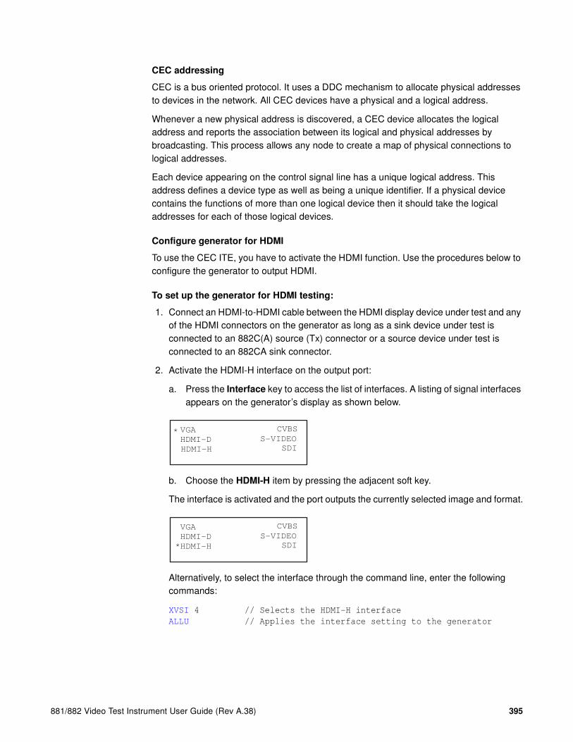
881/882 Video Test Instrument User Guide (Rev A.38) 395
CEC addressing
CEC is a bus oriented protocol. It uses a DDC mechanism to allocate physical addresses to devices in the network. All CEC devices have a physical and a logical address.
Whenever a new physical address is discovered, a CEC device allocates the logical address and reports the association between its logical and physical addresses by broadcasting. This process allows any node to create a map of physical connections to logical addresses.
Each device appearing on the control signal line has a unique logical address. This address defines a device type as well as being a unique identifier. If a physical device contains the functions of more than one logical device then it should take the logical addresses for each of those logical devices.
Configure generator for HDMI
To use the CEC ITE, you have to activate the HDMI function. Use the procedures below to configure the generator to output HDMI.
To set up the generator for HDMI testing:
1. Connect an HDMI-to-HDMI cable between the HDMI display device under test and any of the HDMI connectors on the generator as long as a sink device under test is connected to an 882C(A) source (Tx) connector or a source device under test is connected to an 882CA sink connector.
2. Activate the HDMI-H interface on the output port:
a. Press the Interface key to access the list of interfaces. A listing of signal interfaces appears on the generator’s display as shown below.
b. Choose the HDMI-H item by pressing the adjacent soft key.
The interface is activated and the port outputs the currently selected image and format.
Alternatively, to select the interface through the command line, enter the following commands:
XVSI 4 // Selects the HDMI-H interface
ALLU // Applies the interface setting to the generator
VGA
HDMI-D
CVBS
S-VIDEO
SDI
*
HDMI-H
VGA
HDMI-D
CVBS
S-VIDEO
SDI*HDMI-H

396 Chapter 11 CEC Interactive Troubleshooting Environment (ITE)
Configure an HDMI CEC device
Use the procedures below to configure the generator outputs as a particular CEC HDMI device. An 880 series generator with the CEC option is provisioned with a library of common HDMI CEC device types. You can either use one of these device types in the library or create your own descriptor file. Once you create a descriptor file you can modify it to characterize the emulated device to respond in a very specific way.
The following table lists the default device types and their parameters.
Note: All these devices have vendor ID of 1962 (07AA in hex).
To set up the generator to emulate an HDMI CEC device using default devices:
1. Establish a session with the generator using HyperTerminal over a serial connection or Telnet over an Ethernet LAN. For instructions, see “Establishing a terminal session with the 882” on page 30.
2. Query the device library to verify that it is provisioned in the generator:
CECQ? 1 16
The generator returns the CECDev types provisioned in the generator library.
CECDEV00.xml
.
Device Name
Physical
Address (PA)
Product Type
(PT) OSDN
Logical Address
(LA)
CECDev00 0 0 0 0 0 (TV) TVOSDN 0
CECDev01 1 0 0 0 1 (Rec Dev) RecDev1 1
CECDev02 2 0 0 0 1 (Rec Dev) RecDev2 2
CECDev03 1 0 0 0 3 (Set Top Box) STB1 3
CECDev04 1 0 0 0 4 (DVD) DVD1 4
CECDev05 1 0 0 0 5 (Audio System) Audio1 5
CECDev06 2 0 0 0 3 (Set Top Box) STB2 6
CECDev07 3 0 0 0 3 (Set Top Box) STB3 7
CECDev08 2 0 0 0 4 (DVD) DVD2 8
CECDev09 3 0 0 0 1 (Rec Dev) RecDev3 9
CECDev10 1 0 0 0 10 (Reserved) Reserved1 10
CECDev11 2 0 0 0 10 (Reserved) Reserved2 11
CECDev12 3 0 0 0 10 (Reserved) Reserved3 12
CECDev13 4 0 0 0 10 (Reserved) Reserved4 13
CECDev14 4 0 0 0 0 (TV) FreeUse 14
CECDev15 4 0 0 0 10 (Reserved) Unregistered 15

881/882 Video Test Instrument User Guide (Rev A.38) 397
.
.
CECDEV15.xml
3. Query the location of the log file:
CECX:LOGP?
The generator returns the path of the log file.
/card0/Library/CEC/Log
Note: By default the CEC log is on the PCCard. Therefore it is important to ensure that
there is a PCcard installed on the generator at all times.
4. Assign a CEC device to a connector:
CEC1:CECL CECDEV03 //assigns CECDEV03 to HDMI Tx Output 1
CEC1:CECU //configures (uses) the assigned device
Here is a second example:
CEC3:CECL CECDEV00 //assigns CECDev00 to HDMI Rx Output 1 and 2
CEC3:CECU //configures (uses) the assigned device
5. Verify the configuration by querying the device parameters of HDMI Tx 1:
CEC1:LA? //queries logical address of device assigned to HDMI TX1
CEC1:PT? //queries product (device) type assigned to HDMI TX1
CEC1:OSDN? //queries OSDN of device assigned to HDMI TX1
CEC1:VID? //queries vendor ID of device assigned to HDMI TX1
Now query the device assigned to the Rx outputs:
CEC3:LA? //queries logical address of device assigned to HDMI RX1/2
CEC3:PT? //queries product (device) type assigned to HDMI RX1/2
CEC3:OSDN? //queries OSDN of device assigned to HDMI RX1/2
CEC3:VID? //queries vendor ID of device assigned to HDMI RX1/2
To create a CEC device descriptor file:
1. Locate the file path for stored configurations:
CECX:CECP?
/card0/Library/CECData/
Change the path if necessary:
CECX:CECP /tffs0/Library/CECData/
2. Create a custom instance of a CEC device for CEC1 using the following commands:
CEC1:CECN <name> //e.g. myTV1
CEC1:CECB //begins the CEC editing session
3. Configure the custom CEC device parameters using the following commands:
CEC1:PA 0 0 0 0 //configures the device physical address

398 Chapter 11 CEC Interactive Troubleshooting Environment (ITE)
CEC1:PT 1 //configures the product (device) type
The table below lists the device (product) types and their codes.
CEC1:VID <vid> //configures the device vendor ID
CEC1:OSDN //configures the device OSDN
CEC1:PA 0 0 0 0 //configures the device physical address
4. Save the custom CEC device to a file:
CEC1:CECE //ends the CEC editing session
CEC1:CECS //saves the CEC device
5. Assign the custom CEC device to a connector:
CEC1:CECL myTV //assigns myTV to HDMI Rx port
CEC1:CECU //configures (uses) the assigned device
Configure generator to log CEC messages
The 882 can be configured to log CEC message and store them in a user defined directory.
To enable CEC logging:
1. Enter the following command to enable logging on the HDMI connector:
CEC1:LOGG 1 //enables logging on the HDMI Tx output 1 port
CEC3:LOGG 1 //enables logging on the HDMI Rx ports
2. Enable all logging with the following command:
CECX:LOGM 6 //enables logging of all CEC messages
To disable CEC logging:
1. Enter the following command to disable CEC logging:
CEC1:LOGG 0 //disables logging on the HDMI Tx output 1 port
CEC3:LOGG 0 //disables logging on the HDMI Rx ports
Device Type Device Code
TV 0
Recording Device 1
Set Top Box 3
DVD 4
Audio System 5

881/882 Video Test Instrument User Guide (Rev A.38) 399
Verifying continuity over the CEC bus
The procedures below describe how to ping a device under test from an 880 that is emulating a CEC device. Note that the device you ping could be another emulated device on the 882 generator. You can ping a device through the front panel, through the command line or by using the CECTest image. Procedures for each of these methods are provided below.
To ping a CEC device under test through the front panel:
1. Determine the logical address of the device under test.
2. From the main menu choose the CEC item by pressing the adjacent soft key.
The CEC menu is presented.
3. Select CEC item by pressing the adjacent soft key.
The CEC ping menu is presented.
4. Select logical address of the device you want to ping by incrementing or decrementing the spot +/- keys.
The logical address value for the LA item will change. For example, if you want to ping the device at logical address of 00 from a port that is connected to that port (e.g. CEC1 you would press the softkey adjacent to the !PingCEC1 item.
A successful ping will result in an “Acknowledged” message. If the ping fails, the message “Failed” will appear.
To ping a CEC device under test through the command line:
1. Determine the logical and physical address of the device under test.
System
Sequence
Probe
AFC
Analyzer
Reports
ImgShift
CEC
!PingCEC1
!PingCEC2
LA: 00
!PingCEC3
!PingCEC1
!PingCEC2
LA: 00
!PingCEC3
!PingCEC1
!PingCEC2
LA: 00
!PingCEC3
Acknowledged.

400 Chapter 11 CEC Interactive Troubleshooting Environment (ITE)
2. Enter the following command to check for continuity.
CEC1:MSGX 3 0 83 //request physical addr of device at addr 0 from a
device at address 3 for example
3. View the results by querying the message log.
CEC1:MSGX?
The following results would be returned.
0F 84 00 00 00
To ping a CEC device using the CEC Test image:
1. Press the Content key and select the CECTest1 or CECTest2 image.
CECTest1 is for HDMI OUT1 and CECTest2 is for HDMI OUT 2.
Alternatively, enter the following commands to load the CECTest image:
IMGL CECTest1.img; IMGU
The CECTest1 image appears as shown below.
When you invoke this image, the 882C sends two messages out the CEC1 core (HDMI Out 1) to the device that is connected to it. The two messages it sends querying for the physical address and the vendor ID. The results are shown on the screen above along with a Pass/Fail indication.

881/882 Video Test Instrument User Guide (Rev A.38) 401
Sending CEC messages from an emulated HDMI CEC device
You can send messages to a device from an emulated device over the command line using the MSGX command. You can also receive messages from a device and view them in the CEC log. The procedures below describe how to send basic messages to a CEC device.
To send CEC messages to a device under test:
1. Determine the logical and physical address of the device.
2. Identify the CEC messages that a device responds to.
Note: The HDMI CEC spec lists the messages that particular devices must respond
to. Consult this specification to ensure that the anticipated response of a device to a
particular message. The CEC spec also provides a list of functions and associated
operational codes that are specified on the CEC message command line.
3. Send a message to the device under test to get its physical address.
CEC1:MSGX 3 0 83 //request physical addr of device at logical addr 0
from address 3
4. Query message log to view response.
CEC1:MSGX? //view most recent response
CEC bus query should return the following:
0F 84 10 00 03 //device under test returns its physical address
the first digit (0) is the logical address of
the target device the device under test);
the second digit (F) is the logical address of
the sending device (the emulated device);
the opcode (84) is the returned message code
(give logical address)
5. Send a message to the device under test to get its vendor ID.
CEC1:MSGX 3 0 8c //request vendor ID of device at logical address 0
6. Query message log to view response (the most recent message).
CEC1:MSGX? //view most recent response
CEC bus query should return the following:
0F 87 00 07 AA //device under test returns its vendor ID
7. Send a message to the sink device under test to return its tuner status.
CEC1:MSGX 3 0 08 //request tuner status of device at logical addr 0

402 Chapter 11 CEC Interactive Troubleshooting Environment (ITE)
Configuring generator to not respond to CEC messages
The 882 can be configured to not respond to CEC messages from a device. When the 882 is configured to not respond to CEC messages, it acknowledges (ACKs) messages, but does not send responses to commands/queries.
To disable responses to CEC messages:
1. Enter the following command to disable responses on the HDMI connector:
CEC1:RSPG 0 //disables responses on the HDMI Tx output 1 port
CEC3:RSPG 0 //disables responses on the HDMI Rx ports
To enable responses to CEC messages:
1. Enter the following command to enable responses on the HDMI connector:
CEC1:RSPG 1 //enables responses on the HDMI Tx output 1 port
CEC3:RSPG 1 //enables responses on the HDMI Rx ports
Querying the CEC message log
You can view the CEC message log from a file or query the contents of the log through the command line. The preferred way to view the CEC messages is to use the Auxiliary Channel Analyzer (ACA) which is covered in the next subsection. The message log is a circular queue with twelve messages (frames). You can view any message in the queue through a command line query using an indexing parameter. You can also clear the log through the command line. Each CEC message in the queue contains the following information:
• Source logical address
• Destination logical address
• Opcode
• Parameters (if any)
• Parameter list length
The procedures below show how to view the CEC log either as a file or through the command line with queries.
To view CEC messages through a file:
1. Connect the source generator to the PC using an Ethernet patch cable or cross over cable between the Ethernet ports on the PC and the generator “Establishing a network environment” on page 140.

881/882 Video Test Instrument User Guide (Rev A.38) 403
2. Access the source generator’s Generator FTP Browser. See “Working with the 882 FTP Browser” on page 23.
3. Navigate to the CEC folder in the Library directory.
4. Select the Log folder and highlight the log file.
5. Select the Open activation key under Instrument Files to view the contents of the log file.
The contents of the log file appear in a text window.
To view CEC messages through the command line:
1. Enter the following command to query the most recent message in the log.
CEC1:MSGX? //queries the message log for the most recent message
2. Enter the following command to query the log for a message with a specific opcode.
CEC1:MSGX? 84 //queries log for message to request device addr
CEC bus query might return the following:
0F 84 00 00 00 //device under test returns its physical address the
first digit (0) is the logical address of the
target device (the device under test); the second

404 Chapter 11 CEC Interactive Troubleshooting Environment (ITE)
digit (3) is the logical address of the sending
device (the emulated device); the opcode (84) is
the returned message code (give logical address)
3. Enter the following command to query the log for a message with a specific opcode and to only return specific parameter values.
CEC1:MSGX? 83 D //queries log for message with specified opcode
and request return of destination address
4. Enter the following command to query the value of a specific byte number of parameters a message with a user specified opcode:
CEC1:MSGX? 83 P 2 //returns value of 2nd byte of the parameters of
a message with opcode 83
5. Enter the following command to query whether one message with a user specified opcode occurs before or after another.
CEC1:MSGX? 83 O 84 //returns order of message with opcodes specified
The response will be one of:
0 - opcode 2 occurred before opcode 11 - opcode 1 occurred before opcode 22 - opcode 1 or opcode 2 not found3 - opcode 1 and opcode 2 not found255 - opcode 1 is the same as opcode 2
To clear the CEC message log:
1. Enter the following command to clear the messages in the log.
CEC1:MSGC //clears the message log
You can also clear the message log with the following command:
CECU
Viewing CEC messages with the ACA
You can also log CEC messages using the Auxiliary Channel Analyzer (ACA).

881/882 Video Test Instrument User Guide (Rev A.38) 405
To log CEC messages:
1. Access the ACA using the procedures described in “Running the ACA” on page 479.
The ACA main page appears as a separate application window as shown below:
2. Connect to the 882 using the procedures described in “Running the ACA” on page 479.

406 Chapter 11 CEC Interactive Troubleshooting Environment (ITE)
3. Select the CEC core from the CEC pull-down menu. Send some CEC messages either from the CEC/CDC Controller or the CEC command line.

881/882 Video Test Instrument User Guide (Rev A.38) 407
4. Click the Capture activation button to monitor the CEC messages. A sample screen shot of the ACA logging some CEC messages is shown below.
Stress testing a CEC device
The CEC ITE provides both a command driven interface and a graphical Java-based application (CEC/CDC Controller) for stress testing CEC devices under test. The features in the ITE command line or CEC/CDC Controller can be used to verify certain compliance related tests under various adverse conditions such as boundry testing of timing, arbitration, corrupt bit timing, and acknowledgement.
Setting up the CEC/CDC Controller
You access the CEC/CDC Controller through the generator’s web home page.

408 Chapter 11 CEC Interactive Troubleshooting Environment (ITE)
To run the CEC/CDC Controller:
1. From the generator home page select CEC/CDC Controller from the menu shown below. Refer to “Web interface” on page 20 for instructions on access the generator home page.
L
The CEC/CDC Controller application appears in the browser:

881/882 Video Test Instrument User Guide (Rev A.38) 409
L
2. Select the port and device on the 882CA/EA that you wish to use for testing in the Select Port & Configuration area of the CEC/CDC Controller screen. This is the port of a device that you are emulating with the 882.
3. Then specify the initiator and follower for the command that you want to enter. You specify this in the lower panel under the headings Initiator and Follower. These selections are shown on the screen shot below. The Initiator is specified as a TV and the Follower as an Audio system.
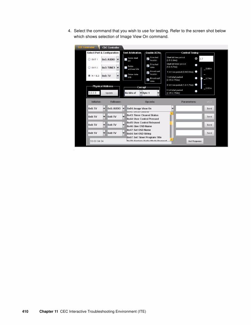
410 Chapter 11 CEC Interactive Troubleshooting Environment (ITE)
4. Select the command that you wish to use for testing. Refer to the screen shot below which shows selection of Image View On command.
L

881/882 Video Test Instrument User Guide (Rev A.38) 411
5. Click on the Send activation button associated with the command item to initiate the command.
You can view the command response using the Get Response activation button on the lower right of the CEC/CDC Controller panel. This is shown in the screen shot below:
You can also view the message and its response using the ACA application. A screen shot of CEC messages appearing in the ACA is shown below.

412 Chapter 11 CEC Interactive Troubleshooting Environment (ITE)
Bit timing tests
You can set the timing of the logical 1 or logical 0 data bit as well as the start bit in such a way to test the ability of the device under test to handle bit timings that are at the edge of what is allowable. For example, a 1 bit’s low period can be within the range from 0.4 to 0.8 milliseconds. You can set the time for the low period and entire period. When you set this timing using the commands described, it affects all 1 or 0 bits in all subsequent messages sent out by the emulated device.
To test the bit timing through the command line:
1. Enter the following command to modify the timing of the 1 bits in a message.
CEC1:CECT:1BIT 0.4 2.1 //sets the low period of a one bit to 0.4
milliseconds and the total bit time to
2.1 milliseconds
2. Enter the following command to modify the timing of the 0 bits in a message.
CEC1:CECT:0BIT 1.5 2.25 //sets the low period of a zero bit to 1.5
milliseconds and the total bit time to
2.25 milliseconds
3. Enter the following command to modify the timing of the start bit in a message.
CEC1:CECT:SBIT 3.7 4.5 //sets the low period of a start bit to 3.7
milliseconds and the total bit time to
4.5 milliseconds
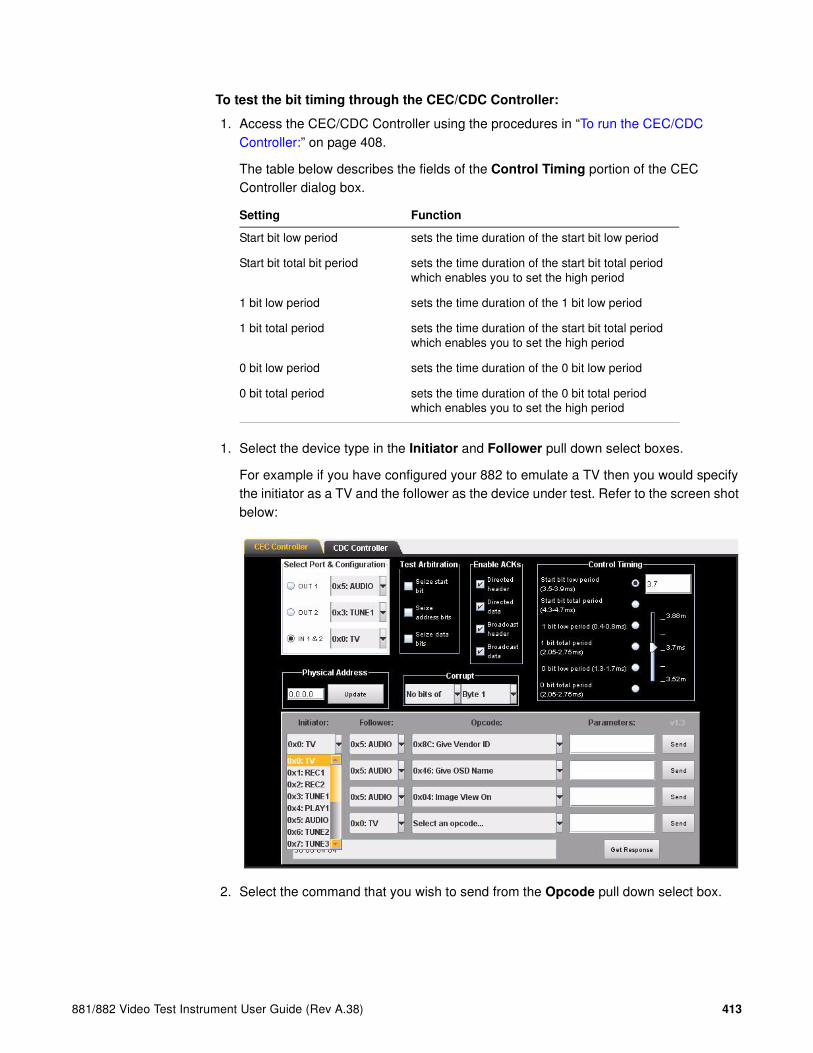
881/882 Video Test Instrument User Guide (Rev A.38) 413
To test the bit timing through the CEC/CDC Controller:
1. Access the CEC/CDC Controller using the procedures in “To run the CEC/CDC Controller:” on page 408.
The table below describes the fields of the Control Timing portion of the CEC Controller dialog box.
1. Select the device type in the Initiator and Follower pull down select boxes.
For example if you have configured your 882 to emulate a TV then you would specify the initiator as a TV and the follower as the device under test. Refer to the screen shot below:
2. Select the command that you wish to send from the Opcode pull down select box.
Setting Function
Start bit low period sets the time duration of the start bit low period
Start bit total bit period sets the time duration of the start bit total period which enables you to set the high period
1 bit low period sets the time duration of the 1 bit low period
1 bit total period sets the time duration of the start bit total period which enables you to set the high period
0 bit low period sets the time duration of the 0 bit low period
0 bit total period sets the time duration of the 0 bit total period which enables you to set the high period

414 Chapter 11 CEC Interactive Troubleshooting Environment (ITE)
3. Select the high period or low period of the start bit, logical 0 bit or logical 1 bit by selecting the associated radio button.
Note that you can apply multiple settings for each command. For example you could change the timing for both the high and low periods of the start, 0 bit and 1 bits simultaneously. You have to reset each timing change.Slide the slide bar to the desired timing setting as shown in the entry box above the slide bar.
Refer to the first screen shot below which shows and example of setting the start bit low period to 3.87ms.
Refer to the screen shot below which shows and example of setting the logical one bit total time period to 2.157ms.

881/882 Video Test Instrument User Guide (Rev A.38) 415
L
4. Send the command by clicking on the Send activation button.
5. Monitor the timing parameters of the affected commands using the ACA. Refer to “To monitor the CEC bus (channel):” on page 471 for instructions on monitoring the
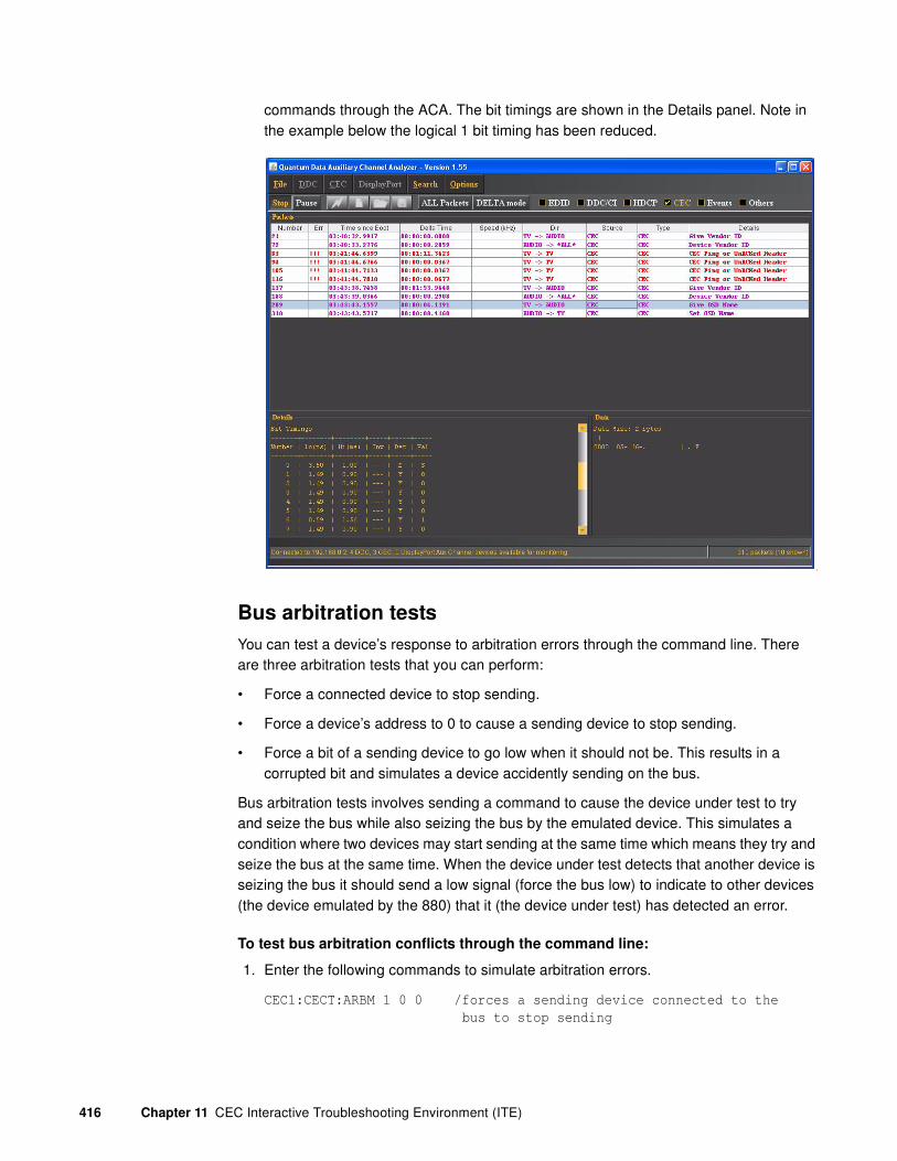
416 Chapter 11 CEC Interactive Troubleshooting Environment (ITE)
commands through the ACA. The bit timings are shown in the Details panel. Note in the example below the logical 1 bit timing has been reduced.
L
Bus arbitration tests
You can test a device’s response to arbitration errors through the command line. There are three arbitration tests that you can perform:
• Force a connected device to stop sending.
• Force a device’s address to 0 to cause a sending device to stop sending.
• Force a bit of a sending device to go low when it should not be. This results in a corrupted bit and simulates a device accidently sending on the bus.
Bus arbitration tests involves sending a command to cause the device under test to try and seize the bus while also seizing the bus by the emulated device. This simulates a condition where two devices may start sending at the same time which means they try and seize the bus at the same time. When the device under test detects that another device is seizing the bus it should send a low signal (force the bus low) to indicate to other devices (the device emulated by the 880) that it (the device under test) has detected an error.
To test bus arbitration conflicts through the command line:
1. Enter the following commands to simulate arbitration errors.
CEC1:CECT:ARBM 1 0 0 /forces a sending device connected to the
bus to stop sending
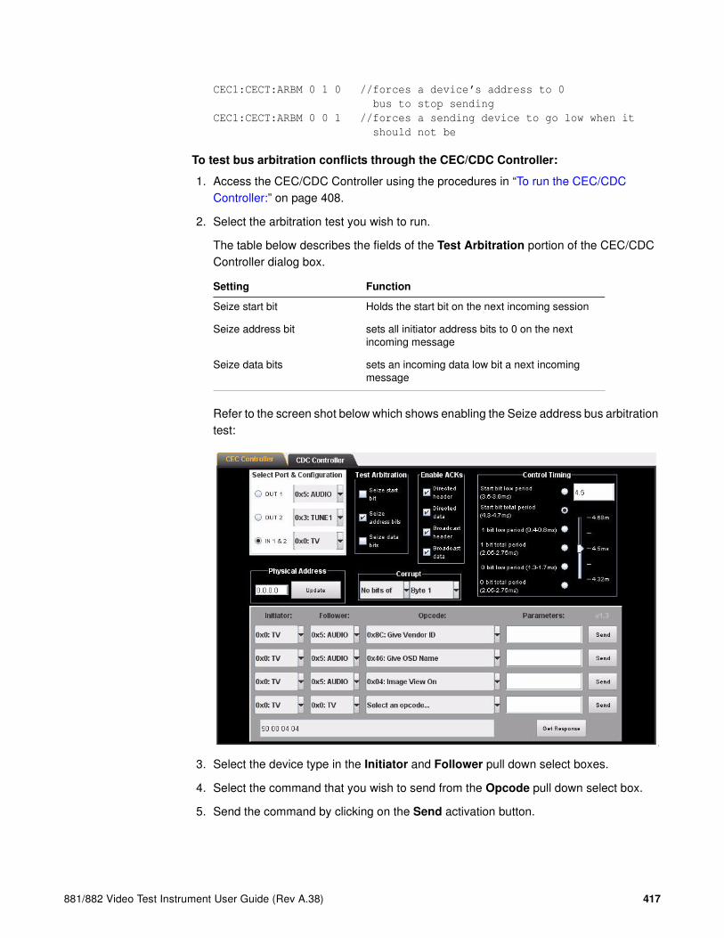
881/882 Video Test Instrument User Guide (Rev A.38) 417
CEC1:CECT:ARBM 0 1 0 //forces a device’s address to 0
bus to stop sending
CEC1:CECT:ARBM 0 0 1 //forces a sending device to go low when it
should not be
To test bus arbitration conflicts through the CEC/CDC Controller:
1. Access the CEC/CDC Controller using the procedures in “To run the CEC/CDC Controller:” on page 408.
2. Select the arbitration test you wish to run.
The table below describes the fields of the Test Arbitration portion of the CEC/CDC Controller dialog box.
Refer to the screen shot below which shows enabling the Seize address bus arbitration test:
L
3. Select the device type in the Initiator and Follower pull down select boxes.
4. Select the command that you wish to send from the Opcode pull down select box.
5. Send the command by clicking on the Send activation button.
Setting Function
Seize start bit Holds the start bit on the next incoming session
Seize address bit sets all initiator address bits to 0 on the next incoming message
Seize data bits sets an incoming data low bit a next incoming message
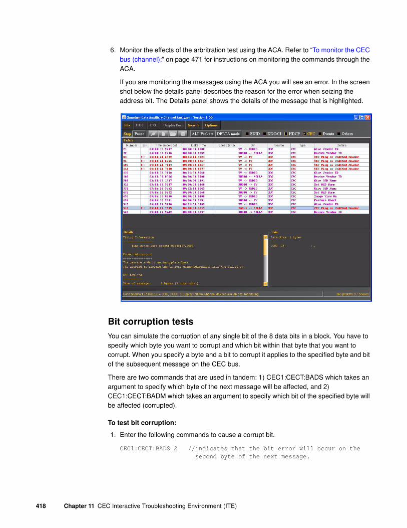
418 Chapter 11 CEC Interactive Troubleshooting Environment (ITE)
6. Monitor the effects of the arbritration test using the ACA. Refer to “To monitor the CEC bus (channel):” on page 471 for instructions on monitoring the commands through the ACA.
If you are monitoring the messages using the ACA you will see an error. In the screen shot below the details panel describes the reason for the error when seizing the address bit. The Details panel shows the details of the message that is highlighted.
Bit corruption tests
You can simulate the corruption of any single bit of the 8 data bits in a block. You have to specify which byte you want to corrupt and which bit within that byte that you want to corrupt. When you specify a byte and a bit to corrupt it applies to the specified byte and bit of the subsequent message on the CEC bus.
There are two commands that are used in tandem: 1) CEC1:CECT:BADS which takes an argument to specify which byte of the next message will be affected, and 2) CEC1:CECT:BADM which takes an argument to specify which bit of the specified byte will be affected (corrupted).
To test bit corruption:
1. Enter the following commands to cause a corrupt bit.
CEC1:CECT:BADS 2 //indicates that the bit error will occur on the
second byte of the next message.

881/882 Video Test Instrument User Guide (Rev A.38) 419
CEC1:CECT:BADM 4 //indicates that the bit error will occur on the
fourth bit of the 2nd byte in the next message.
To test acknowledgement through the CEC/CDC Controller:
1. Access the CEC/CDC Controller using the procedures in “To run the CEC/CDC Controller:” on page 408.
2. Select the acknowledgement test you wish to run.
The table below describes the checkbox fields of the Enable Acks portion of the CEC/CDC Controller dialog box.
Refer to the screen shot below which shows the Corrupt bit setting applied to Bit 3 of Byte 2:
L
3. Select the device type in the Initiator and Follower pull down select boxes.
4. Select the command that you wish to send from the Opcode pull down select box.
5. Send the command by clicking on the Send activation button.
6. Monitor the effects of the corrupt bit test using the ACA. Refer to “To monitor the CEC bus (channel):” on page 471 for instructions on monitoring the commands through the ACA.
Setting Function
No. bit of Determines which bit of a byte you want to corrupt
Byte Determines which byte of a message you want to corrupt a bit

420 Chapter 11 CEC Interactive Troubleshooting Environment (ITE)
Message acknowledgement tests
You can simulate a condition where a message is improperly acknowledged. You can set which conditions the 882 will not acknowledge a message. There are four places where the message can be not acknowledged:
• Header of a directed message
• Data block of a directed message
• Header of a broadcast message
• Data block of a broadcast message
When a directed message is normally acknowledged the acknowledging device pulls the CEC bus low. In order to not acknowledge a message the target device will not pull the CEC bus low. When a broadcast message is normally acknowledged the acknowledging device(s) leave the CEC bus high. In order to not acknowledge a broadcast message the listening device will pull the CEC bus low.
The condition of incorrect acknowledgement will remain in place until you reset it. Therefore once activated the improper acknowledgement remains for all messages received by the 882.
To test message acknowledgement:
1. Enter the following command to simulate a message acknowledgement error.
CEC1:CECT:NACK 1 0 0 0 //indicates a directed header block will not
be acknowledged
CEC1:CECT:NACK 0 0 0 1 //indicates a broadcast data block will not be
acknowledged
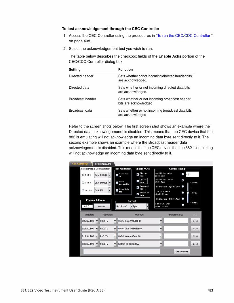
881/882 Video Test Instrument User Guide (Rev A.38) 421
To test acknowledgement through the CEC Controller:
1. Access the CEC Controller using the procedures in “To run the CEC/CDC Controller:” on page 408.
2. Select the acknowledgement test you wish to run.
The table below describes the checkbox fields of the Enable Acks portion of the CEC/CDC Controller dialog box.
Refer to the screen shots below. The first screen shot shows an example where the Directed data acknowlegemenet is disabled. This means that the CEC device that the 882 is emulating will not acknowledge an incoming data byte sent directly to it. The second example shows an example where the Broadcast header data acknowlegement is disabled. This means that the CEC device that the 882 is emulating will not acknowledge an incoming data byte sent directly to it.
L
Setting Function
Directed header Sets whether or not incoming directed header bits are acknowledged.
Directed data Sets whether or not incoming directed data bits are acknowledged.
Broadcast header Sets whether or not incoming broadcast header bits are acknowledged
Broadcast data Sets whether or not incoming broadcast data bits are acknowledged
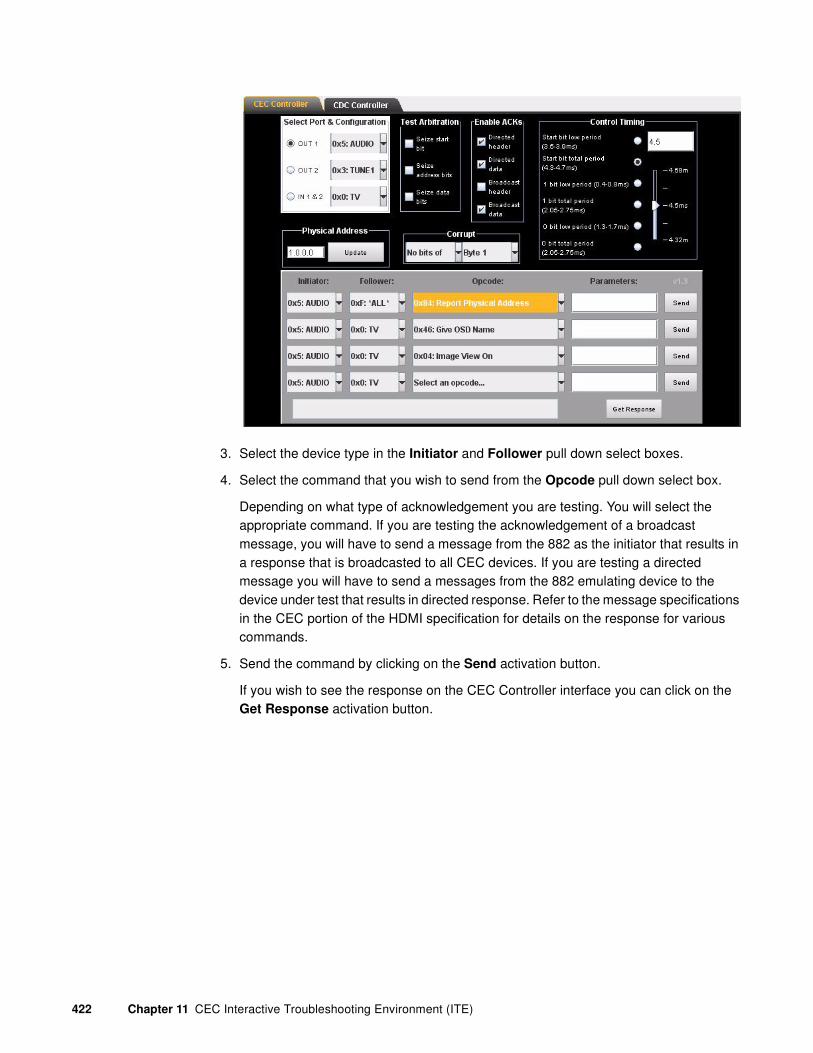
422 Chapter 11 CEC Interactive Troubleshooting Environment (ITE)
3. Select the device type in the Initiator and Follower pull down select boxes.
4. Select the command that you wish to send from the Opcode pull down select box.
Depending on what type of acknowledgement you are testing. You will select the appropriate command. If you are testing the acknowledgement of a broadcast message, you will have to send a message from the 882 as the initiator that results in a response that is broadcasted to all CEC devices. If you are testing a directed message you will have to send a messages from the 882 emulating device to the device under test that results in directed response. Refer to the message specifications in the CEC portion of the HDMI specification for details on the response for various commands.
5. Send the command by clicking on the Send activation button.
If you wish to see the response on the CEC Controller interface you can click on the Get Response activation button.

881/882 Video Test Instrument User Guide (Rev A.38) 423
6. Monitor the effects of the acknowledge test using the ACA. Refer to “To monitor the CEC bus (channel):” on page 471 for instructions on monitoring the commands through the ACA.
End of message tests
You can simulate a condition where an end of message bit is placed improperly. The end of message bit should be placed in the last block of the message. However you can place the end of message bit in a block that is not the end of message and therefore cause an incomplete message to be sent since the target device is suppose to ignore additional blocks once the end of message bit is processed.
To simulate end of message anomolies:
1. Enter the following command to simulate an end of message anomoly.
CEC1:CECT:EOMS 2 //indicates that the end of message bit will be
placed in the second block of the message.
CEC1:CECT:EOMS 1 //indicates that the end of message bit will be
placed in the first (header) block of the
message.

424 Chapter 11 CEC Interactive Troubleshooting Environment (ITE)
Controlling the Audio Return Channel (ARC)
You can issue the necessary messages to control the HDMI 1.4 Audio Return Channel (ARC) either through the command line or the CEC/CDC Controller.
To emulate an ARC device you will need the TPA-EAC-4R test point adapter. Please refer to the 882 web pages on the Quantum Data website for an Application Note on the TPA-EAC-4R.
The table below describes the ARC control messages.
To test ARC functions of an ARC-equipped AVR while emulating an ARC-equipped TV:
1. Enter the following command to initiate ARC on an ARC-equipped AVR.
Command Function Syntax Example
Initiate ARC Used by an ARC Rx device to activate the ARC functionality in an ARC Tx device.
CECx:MSGX I F CO
x = CEC core in 882I = logical address of initiatorF = logical address of followerCO = opcode for Initiate ARC message
CEC3:MSGX 5 0 C0
Sends an Initiate ARC command from CEC core 3 from an AVR to a TV.
Report ARC initiated
Used by an ARC Tx device to indicate that its ARC functionality has been activated.
CECx:MSGX I F C1
x = CEC core in 882I = logical address of initiatorF = logical address of followerC1 = opcode for Report ARC Initiated
CEC1:MSGX 0 5 C1
Sends a Report ARC initiated command from CEC core 1 from a TV to an AVR.
Report ARC terminated
Used by an ARC Tx device to indicate that ARC functionality has been deactived.
CECx:MSGX I F C2
x = CEC core in 882I = logical address of initiatorF = logical address of followerC2 = opcode for Report ARC terminated
CEC1:MSGX 0 5 C2
Sends Report ARC terminated command from CEC core 1 from a TV to an AVR.
Request ARC Initiation
Used by an ARC Tx device to request an ARC Tx device to activate the ARC functionality in the ARC Tx device.
CECx:MSGX I F C3
x = CEC core in 882I = logical address of initiatorF = logical address of followerC3 = opcode for Request ARC Initiation
CEC1:MSGX 0 5 C3
Sends Request ARC Initiation command from CEC core 1 from a TV to an AVR.
Request ARC Termination
Used by an ARC Tx device to request an ARC Rx device to deactivate the ARC functionalty in the ARC Tx deivce.
CECx:MSGX I F C4
x = CEC core in 882I = logical address of initiatorF = logical address of followerC4 = opcode for Request ARC Termination
CEC1:MSGX 0 5 C4
Sends a Request ARC Termination command from CEC core 1 from a TV to an AVR.
Terminate ARC
Used by an ARC Tx device to deactivate the ARC functionality in an ARC Tx device.
CECx:MSGX I F C5
x = CEC core in 882I = logical address of initiatorF = logical address of followerC5 = opcode for Terminate ARC
CEC3:MSGX 5 0 C5
Sends an Initiate ARC command from CEC core 3 from an AVR to a TV.

881/882 Video Test Instrument User Guide (Rev A.38) 425
CEC3:MSGX 0 5 C3 // User sends the Request ARC Initiation command from
the 882 to an AVR.
5 0 C0 // AVR responds with Initiate ARC command to the 882
CEC core device.
0 5 C1 // 882 responds with the Report ARC Initiated command
from the 882 to the AVR.
2. Enter the following command to terminate ARC on an ARC-equipped AVR.
CEC3:MSGX 0 5 C4 // User sends the Request ARC Termination command
from the 882 to the AVR.
5 0 C5 // AVR responds with Terminate ARC command to the 882
CEC core device.
0 5 C2 // 882 responds with the Report ARC Terminated
command from the 882 to the AVR.
To test ARC functions of an ARC-equipped TV while emulating an ARC-equipped AVR:
1. Enter the following command to request an ARC initiation on an ARC-equipped TV.
0 5 C3 // TV sends the Request ARC Initiation command
to the 882EA CEC core device.
5 0 C0 // 882 responds with the Initiate ARC command
from the 882 to the TV.
0 5 C1 // TV sends the Report ARC Initiated command
to the 882EA CEC core device.
2. Enter the following command to request an ARC termination on an ARC-equipped TV.
0 5 C4 // TV sends the Request ARC Termination command
to the 882EA CEC core device.
5 0 C5 // 882 responds with the Terminate ARC command from
the 882 to the TV.
0 5 C2 // TV sends the Report ARC Terminated command
to the 882EA CEC core device.

426 Chapter 11 CEC Interactive Troubleshooting Environment (ITE)
To issue ARC commands through the CEC/CDC Controller:
1. From the generator home page select CEC/CDC Controller from the menu shown below. Refer to “Web interface” on page 20 for instructions on access the generator home page.
L
The CEC/CDC Controller application appears in the browser:
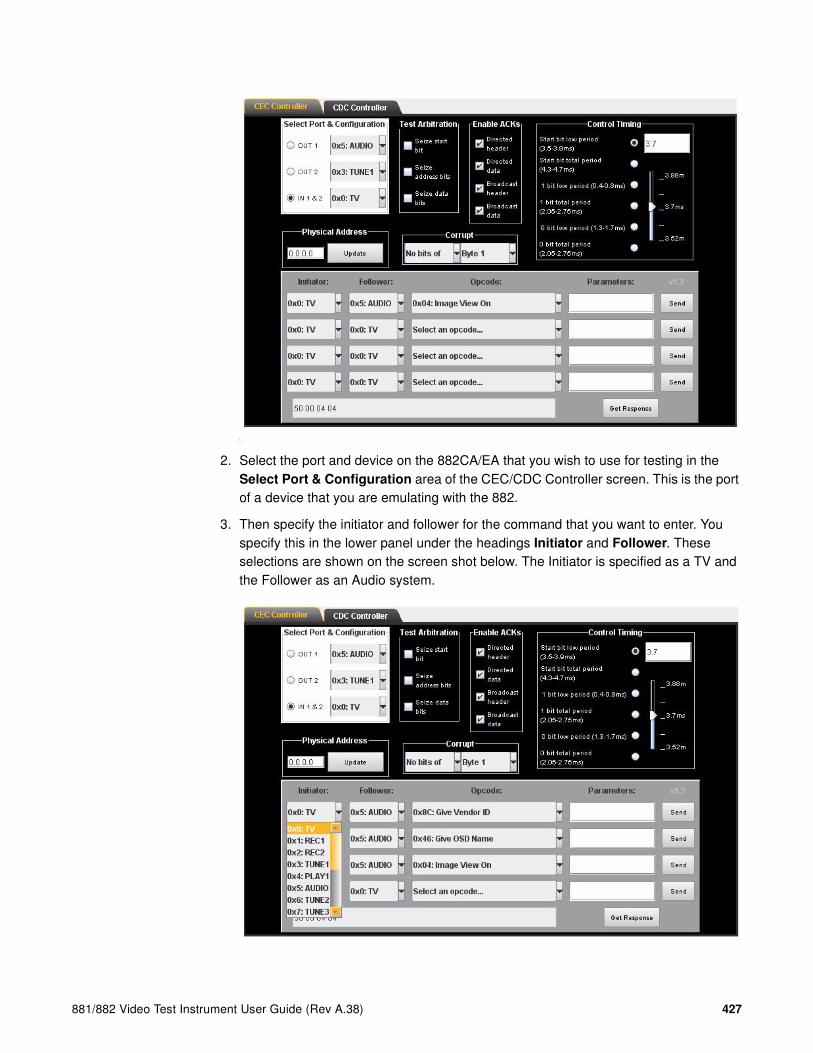
881/882 Video Test Instrument User Guide (Rev A.38) 427
L
2. Select the port and device on the 882CA/EA that you wish to use for testing in the Select Port & Configuration area of the CEC/CDC Controller screen. This is the port of a device that you are emulating with the 882.
3. Then specify the initiator and follower for the command that you want to enter. You specify this in the lower panel under the headings Initiator and Follower. These selections are shown on the screen shot below. The Initiator is specified as a TV and the Follower as an Audio system.
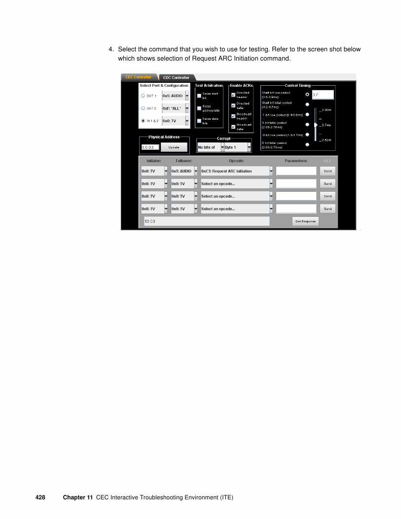
428 Chapter 11 CEC Interactive Troubleshooting Environment (ITE)
4. Select the command that you wish to use for testing. Refer to the screen shot below which shows selection of Request ARC Initiation command.
L
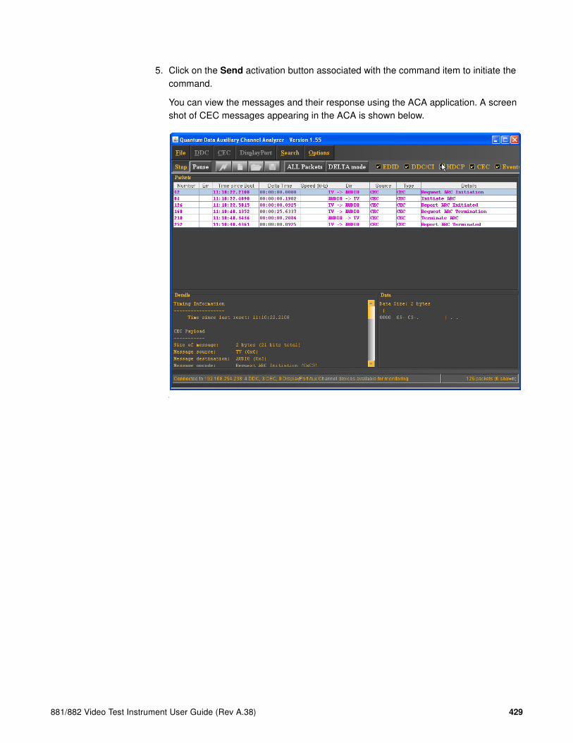
881/882 Video Test Instrument User Guide (Rev A.38) 429
5. Click on the Send activation button associated with the command item to initiate the command.
You can view the messages and their response using the ACA application. A screen shot of CEC messages appearing in the ACA is shown below.
L

430 Chapter 11 CEC Interactive Troubleshooting Environment (ITE)
CEC Bus Monitor
The 880 series CEC bus monitor is a powerful feature of the CEC ITE that enables you to identify timing defects on the CEC line that would normally required an oscilloscope and breakout box to identify using manual techniques. You can use the CEC bus monitor when you are emulating either an HDMI CEC source or sink.
Activating the CEC bus monitor
Use the procedures below to activate the bus monitor once you have configured the generator and/or analyzer to emulate a CEC device.
To activate the CEC bus monitor:
1. Enable the CEC bus monitor by entering the following command:
CEC1:BUSM:ON // Turns the bus monitor on for CEC1
2. Clear the bus monitor bit buffer by entering the following command:
CEC1:BUSM:BITC // Clears the bus monitor buffer for CEC1
Note: It is important to clear the buffer regularly to ensure that you do not lose data.
To deactivate the CEC bus monitor:
1. Disable the CEC bus monitor by entering the following command:
CEC1:BUSM:OFF // Turns the bus monitor off for CEC1
Querying the CEC bus monitor
You can query the CEC bus monitor messages and bits. You can check for bit timing errors, query the timing parameters of each bit throughout a range of bits in the buffer or throughout the entire buffer. You can also query for the correctness of the acknowledge and end of message bits.
Query the bus monitor messages
You can query the bus monitor for all messages or specific messages based on an index that you include on the command line.
To query the bus monitor for all messages:
1. Query the bus monitor for all messages by entering the following command:
CEC1:BUSM:MSGX? // Queries for all messages in the buffer for CEC1
The response will be:

881/882 Video Test Instrument User Guide (Rev A.38) 431
S 03-- 83+- End signal free time: 42.47msec.
S 3F-+ 84-+ 10-+ 00-+ 03++ End signal free time: 41.57msec.
2. Query the bus monitor for particular messages
CEC1:BUSM:MSGX? -3 // Queries for message that occurred three
messages ago
The response will be:
S 3F-+ 84-+ 10-+ 00-+ 03++ End signal free time: 41.57msec.
CEC1:BUSM:MSGX? 1 // Queries for 5th message in the buffer
The response will be:
S 03-- 83+- End signal free time: 42.47msec.
Query the bus monitor for bit timing errors and bit values
You can query the bus monitor for the number of bits, bit timing, bit timing errors as well as the value of a specific bit.
To query the number of bit values in the bus monitor buffer:
1. Query the bus monitor for bit timing errors by entering the following command:
CEC1:BUSM:NBIT? // Queries buffer for the number of bits
A typical response might be:
200 // Indicates there are 200 bits in the buffer
To query the bus monitor for bit timing errors:
1. Query the bus monitor for bit timing errors by entering the following command:
CEC1:BUSM:CHEK? // Queries buffer for bit timing errors
A typical response might be:
2 // Indicates that a logical 0 bit error occurred
The range of responses are:
0 - no error has occurred1 - an error has occurred in a one (logical 1) bit2 - an error has occurred in a zero (logical 0) bit4 - an error has occurred in a start bit8 - an unknown error has occurred
To query the bus monitor for the timing of a series of bits in the buffer:
1. Query the bus monitor for the timing of a series of bits by entering the following command:

432 Chapter 11 CEC Interactive Troubleshooting Environment (ITE)
CEC1:BUSM:TIME? 3 1000 // Queries buffer for the timing of bits 3
through 1000 in the buffer for CEC1
The response will be in a format that lists the low time in milliseconds followed by the high time in milliseconds as shown below:
3.69 0.80
1.49 0.90
0.59 1.80
1.49 0.90
.
.
.
0.59 1.80
To query the bus monitor for the value of a bit in the buffer:
1. Query the bus monitor for the value of a bit in the buffer by entering the following command:
CEC1:BUSM:BITV? -4 // Queries CEC1 buffer for value of the bit that
occurred 4 bits ago.
CEC1:BUSM:BITV? 20 // Queries CEC1 buffer for the 20th bit in the
buffer
The response will be in the format
-1 - index does not exist or the bit was corrupted0 - index is a logical zero data bit1 - index is a logical one data bit2 - index is a start data bit3 - index corresponds to an idle period only (no data)4 - index corresponds to an error signal (sent after a corrupted bit)
To query a message for the byte number of the end of message:
1. Query a message in the bus monitor for the end of message byte:
CEC1:BUSM:EOMB? -3 // Queries message in CEC1 buffer that occurred
3 messages ago
7 // Indicates that the EOM byte was the 7th in
the message queried
CEC1:BUSM:EOMB? 4 // Queries the 4th message in CEC1 buffer for EOM
byte
5 // Indicates that the EOM byte was the 5th in
the message queried
To query a message for the polarity of the acknowledge bits:
1. Query a message in the bus monitor for the polarity of the acknowledge bits in a specific message:
CEC1:BUSM:ACKV? -3 // Queries message in CEC1 buffer that occurred
3 messages ago for polarity of ack bits

881/882 Video Test Instrument User Guide (Rev A.38) 433
0 // Shows that the ACK bits were logical 0
indicating that it was a directed message
CEC1:BUSM:ACKV? 4 // Queries message in buffer that occurred 3
messages ago for polarity of ack bits
1 // Shows that the ACK bits were logical 1
indicating that it was a broadcast message

434 Chapter 11 CEC Interactive Troubleshooting Environment (ITE)

881/882 Video Test Instrument User Guide (Rev A.38) 435
12 CEC Compliance Testing
Topics in the chapter:
• Overview
• CEC Introduction
• Setting up CEC compliance testing
• Running the CEC Compliance Test
• Running the CEC Compliance Test with the TME Software

436 Chapter 12 CEC Compliance Testing
Overview
This chapter provides an overview of the CEC compliance test and describes how to set up the compliance test.
The CEC Compliance Controller, available with release 2.20, can be used along with the Test Management Environment (TME) beginning in Release 2.20. The TME remains the CEC Compliance Test Tool (CEC-CTT) recommended in the CEC Compliance Test Specification for HDMI 1.3 devices. The CEC Compliance Controller is the recommended CEC Compliance Test Tool for HDMI 1.4.
You must have the CEC compliance option on your generator to run the CEC compliance test. To determine if your generator has the the CEC option installed, view the GenStats image and check the information under Options. Refer to “Viewing generator configuration information” on page 127.
CEC Compliance Controller
The CEC Compliance Controller can run through a full CEC compliance test in less time and with less user interaction than the TME.
The CEC Compliance Controller software is java-based and runs on a standard Windows PC available through the 882 web home page. Application control is established through a standard Ethernet IP connection to the 882 test instrument. Through the CEC Compliance Test software, the 882 test instrument can be quickly configured to emulate a CEC-capable HDMI source or sink device to support compliance testing. When configured to emulate a CEC device, the 882 can send CEC query messages or issue commands to connected devices under test and it will also respond to CEC messages sent from a device connected for compliance testing.
When testing HDMI source devices the generator (analyzer) will emulate a sink device such as an HDTV. When testing sink devices the 882 generator will emulate a source device such as a set top box (STB).
TME
The TME software is java-based and runs on a standard Windows PC. Application control is established through a standard Ethernet IP connection to the 882 test instrument. Through the TME, the 882 test instrument can be quickly configured to emulate a CEC-capable HDMI source or sink device to support compliance testing. When configured to emulate a CEC device, the 882 can send CEC query messages or issue commands to connected devices under test and it will also respond to CEC messages sent from a device connected for compliance testing.

881/882 Video Test Instrument User Guide (Rev A.38) 437
When testing HDMI source devices the generator (analyzer) will emulate a sink device such as an HDTV. When testing sink devices the 882 generator will emulate a source device such as a set top box (STB).

438 Chapter 12 CEC Compliance Testing
CEC Introduction
Consumer Electronic Control (CEC) is an HDMI option that provides automatic power-on, automatic signal routing, and single-point remote control for CEC-enabled products. The HDMI CEC Develoment & Compliance Test Suite enables manufacturers to quickly integrate CEC into their products and perform all CEC-related tests found in the HDMI Compliance Test Specification.
The physical interface for this bus is a single wire which connects to all of the devices in the system. The CEC protocol defines the specific use of that single wire at all times.
CEC devices
An HDMI environment can consist of several types of devices. Each of the devices can be tested using the 882CA generator/analzyer and the CEC TME application. The HDMI devices currently supported for testing are listed below.
• TV – A device with HDMI input that has the ability to display the input HDMI signal. Generally it has no HDMI output. However the HDMI specification does cover that case.
• Recording device – A device that has the ability to record a source such as an internal preset or an external connection.
• Set top box – A device that contains a tuner.
• DVD player – A playback device that has the ability to play media.
• Audio device – A device that is currently providing an AV stream via HDMI.
• CEC switch – An HDMI switch that responds to CEC commands to switch the source of audio/video.
• Unknown – Various other HDMI devices, such as:
• Menu Providing Device A non-display device that may render a menu on TV.
CEC features
The CEC channel provides a number of recommended features designed to enhance the functionality and interoperability of devices within an HDMI environment. This section gives an overview of these features.
• One Touch Play – Allows a device to be played and become the active source with a single button press.
• System Standby – Enables the user to switch all devices to standby with one button press.

881/882 Video Test Instrument User Guide (Rev A.38) 439
• One Touch Record – Offers a What You See Is What You Record (WYSIWYR) facility, meaning that whatever is shown on the TV screen is recorded on a selected recording device.
• System Information – Queries the system to determine device addresses and configurations (e.g. language and country).
• Deck Control – Enables a device to control (e.g. play, fast forward etc.) and interrogate a playback device (a deck).
• Tuner Control – Allows a device to control the tuner of another device.
• Vendor Specific Commands – Allows a set of vendor-defined commands to be used between devices of that vendor.
• OSD Display – Enables a device to use the on-screen display of the TV to display text strings.
• Device Menu Control – Enables a device to control the menu of another device by passing through user interface commands.
• Routing Control – Allows the control of CEC Switches for streaming of a new source device.
• Remote Control Pass Through – Enables remote control commands to be passed through to other devices within the system.
• Device OSD Name Transfer – Enables devices to upload their preferred OSD name to the TV. The TV can then use this name in any menus associated with that device.
• Audio Return Channel (ARC) - Enables devices to initiate and terminate ARC sessions. Requires the TPA-EAC-4R test point adapter.

440 Chapter 12 CEC Compliance Testing
Setting up CEC compliance testing
To prepare for a compliance test involves the following:
• Making physical connections
• Establishing and verifying IP connectivity with the generator
• Physically connecting the 882 generator to the device under test
• Configuring the generator for HDMI
• Verifying continuity over the CEC bus
• Additional equipment required
Making physical connections
This subsection describes how to connect your PC to the generator and also how to connect the generator to the device under test.
To connect an HDMI device under test to the 882 HDMI port:
The generator has two HDMI OUT(Tx) connectors for testing HDMI displays and two HDMI IN (Rx). Use an HDMI cable to connect the HDMI output connector to the device under test using the proper connector. Refer to the figure below for the location of the HDMI connectors.
The video interfaces on the 882EA are shown below.
Interface Description
1 HDMI OUT 1 connector outputs full single link HDMI 1.3 video, as well as DVI and modern HDMI-compatible digital video signals.
2 HDMI OUT 2 connector outputs full single link HDMI 1.3 video, as well as DVI and modern HDMI-compatible digital video signals.
3 HDMI IN 1 connector accepts full single link HDMI 1.3 video, as well as DVI and modern HDMI-compatible digital video signals.

881/882 Video Test Instrument User Guide (Rev A.38) 441
Establishing and verifying IP communication with the
generator
This subsection describes how to establish and verify IP communication with the generator.
To connect your PC to the generator:
1. Connect your PC to the generator using the procedures described in “Connecting 882s to the network” on page 140.
Note: Refer to the figure above for the location of the Ethernet jack.
2. Set the IP address of the generator and PC to enable Ethernet IP connectivity using the procedures described in “Setting the 882’s IP address” on page 141.
Verify IP connectivity from your PC to your generator:
1. Press the Tools key. The Tools menu appears on the generator’s display as shown below.
2. Choose the System item by pressing the adjacent soft key. The System menu appears on the generator’s display as shown below.
4 HDMI IN 2 connector accepts full single link HDMI 1.3 video, as well as DVI and modern HDMI-compatible digital video signals.
5 SPECIAL connector provides multiple outputs, including:
• digital composite sync
• line sync
• frame sync
• movable scope trigger (probe) pulse
• pixel clock signal
6 SPDIF OUT connector outputs audio to an external receiver.
7 SPDIF IN connector inputs audio from an external source.
Interface Description
System
Sequence
Probe
AFC
Analyzer
Reports
ImgShift
CEC
Clock Clone* CalFactor Server Network About Serial GPib

442 Chapter 12 CEC Compliance Testing
3. Choose the Network item by pressing the adjacent soft key. The generator’s IP address appears on the generator’s display as shown below.
4. Open up a DOS command window on your PC and telnet to the generator.
To telnet to the generator with IP address 192.168.254.001 enter the following:
telnet 192.168.254.001
You then get the prompt from the generator:
\tffs0>
Configuring the generator for HDMI
To use the CEC you have to activate the HDMI interface. Use the procedures below to configure the generator to output HDMI.
To set up the generator for HDMI testing:
1. Connect an HDMI-to-HDMI cable between the HDMI display device under test and the either one of the HDMI OUT connectors on the generator.
2. Activate the HDMI-H interface on the output port:
a. Press the Interface key to access the list of interfaces. A listing of signal interfaces appears on the generator’s display as shown below.
b. Choose the HDMI-H item by pressing the adjacent soft key.
The interface is activated and the port outputs the currently selected image and format.
Alternatively, to select the interface through the command line, enter the following commands:
XVSI 4 // Selects the HDMI-H interface
ALLU // Applies the interface setting to the generator
IP Address 192.168.254.1Subnet Mask 255.255.255.000
VGA
HDMI-D
CVBS
S-VIDEO
SDI
*
HDMI-H
VGA
HDMI-D
CVBS
S-VIDEO
SDI*HDMI-H

881/882 Video Test Instrument User Guide (Rev A.38) 443
Verifying continuity over the CEC bus
The procedures below describe how to ping a device under test from an 880 that is emulating a CEC device. You can ping a device through the front panel, through the command line or by using the CECTest image. Procedures for each of these methods are provided below.
To ping a CEC device under test through the front panel:
1. Determine the logical and physical address of the device under test.
2. From the main menu choose the CEC item by pressing the adjacent soft key.
The CEC menu is presented.
3. Select CEC item by pressing the adjacent soft key.
The CEC ping menu is presented.
4. Select logical address of the device you want to ping by incrementing or decrementing the spot +/- keys.
The logical address value for the LA item will change. For example, if you want to ping the device at logical address of 00 from a port that is connected to that port (e.g. CEC1 you would press the softkey adjacent to the !PingCEC1 item.
A successful ping will result in an Acknowledged message. If the ping fails the message “Failed” will appear.
To ping a CEC device under test through the command line:
1. Determine the logical and physical address of the device under test.
2. Enter the following command to check for continuity.
System
Sequence
Probe
AFC
Analyzer
Reports
ImgShift
CEC
!PingCEC1
!PingCEC2
LA: 00
!PingCEC3
!PingCEC1
!PingCEC2
LA: 00
!PingCEC3
!PingCEC1
!PingCEC2
LA: 00
!PingCEC3
Acknowledged.

444 Chapter 12 CEC Compliance Testing
CEC1:MSGX 3 0 83 //request physical addr of device at addr 0
3. View the results by querying the message log.
CEC1:MSGX?
The following results would be returned.
0F 84 00 00 00
To ping a CEC device using the CEC Test image:
1. Press the Content key and select the CECTest1 , CECTest2 or CECTest3 image.
Alternatively, enter the following commands to load the CECTest image:
IMGL CECTest1.img; IMGU
Select the CECTest image that corresponds with the HDMI input or output that you want to ping from. The CECTest1 image will ping a connected device from HDMI Tx 1. The results of the CECTest ping are shown below.
When you invoke this image, the 882C sends two messages out the CEC1 core (HDMI Out 1) to the device that is connected to it. The two messages it sends querying for the physical address and the vendor ID. The results are shown on the screen above along with a Pass/Fail indication.

881/882 Video Test Instrument User Guide (Rev A.38) 445
Additional equipment required
Certain tests in the Electrical Specification section of the compliance test require the use of Test Point Adapters (TPAs) that Quantum Data manufactures and provides as part of the CEC compliance test option. The devices are shown below.
Dynamic Electrical Test Fixture - Model TPA-CEC-RR.
Quiescent Electrical Test Fixture - Model TPA-CEC-R.
Switch
Positions Applications
1 Turns off the TPA to save the battery
2 Connects CEC line to 3.3v via a 3kohm ±5% resistor
3 Connects CEC line to ground via 150kohm +/-5% resistor
Dynamic Elecrical Test Fixture
Model TPA-CEC-RR
HDMI METER LOADTurn OFF
when not in use
+ -
HDMI
2
1
3
OFF
Quiescent Elecrical Test Fixture
Model TPA-CEC-R
HDMI METER LOAD PowerTurn OFF
when not in use
off
on
1
2
34
5
6+ -

446 Chapter 12 CEC Compliance Testing
Multi-Purpose TPA used for CEC Device Bridge - Model TPA-MP-4R.
Use the table below to determine the correct test device needed for each test.
Load Application
1 Connects CEC line to DDC/CEC ground via a 1 MegOhm +/-5% resistor
2 Connects CEC line to 3.63V via a 27kohm ±5% resistor (multimeter in parallel with the resistor to measure the voltage drop; alternate (preferred) position for measuring the CEC line leakage current
3 Connects CEC line to 3.3v via a 27kohm ±5% resistor
4 Connects CEC line to DDC/CEC Ground via 1kO ±5%
5 Connects CEC line to 3.63V via a 27kohm ±5% resistor (multimeter in series with the resistor to measure the CEC line leakage current)
6 Measures open-circuit voltage across the CEC bus with the Multimeter (debugging only and does not correspond to any official HDMI CTS test)
Test ID Test Device
7-1: CEC Bus Logic ‘0’ and ‘1’ Voltage Level TPA-CEC-RR
7-2: CEC Maximum Rise Time and Fall Time TPA-CEC-RR
7-15: CEC Line Degradation TPA-CEC-R
8-14: CEC Line Degradation TPA-CEC-R

881/882 Video Test Instrument User Guide (Rev A.38) 447
Running the CEC Compliance Test
This section describes how to run the CEC compliance test through the Compliance Controller. The Compliance Controller is an application (Release 2.23) that is available on the 882 web home page. The CEC Compliance Controller is the approved test tool for testing HDMI 1.4 devices.
Note: Please note that the TME CEC compliance test application is the CEC Compliance test application that is approved for testing HDMI 1.3 devices.
CEC Compliance test procedure
Use the procedures below to run the CEC compliance test using the CEC Compliance Controller.
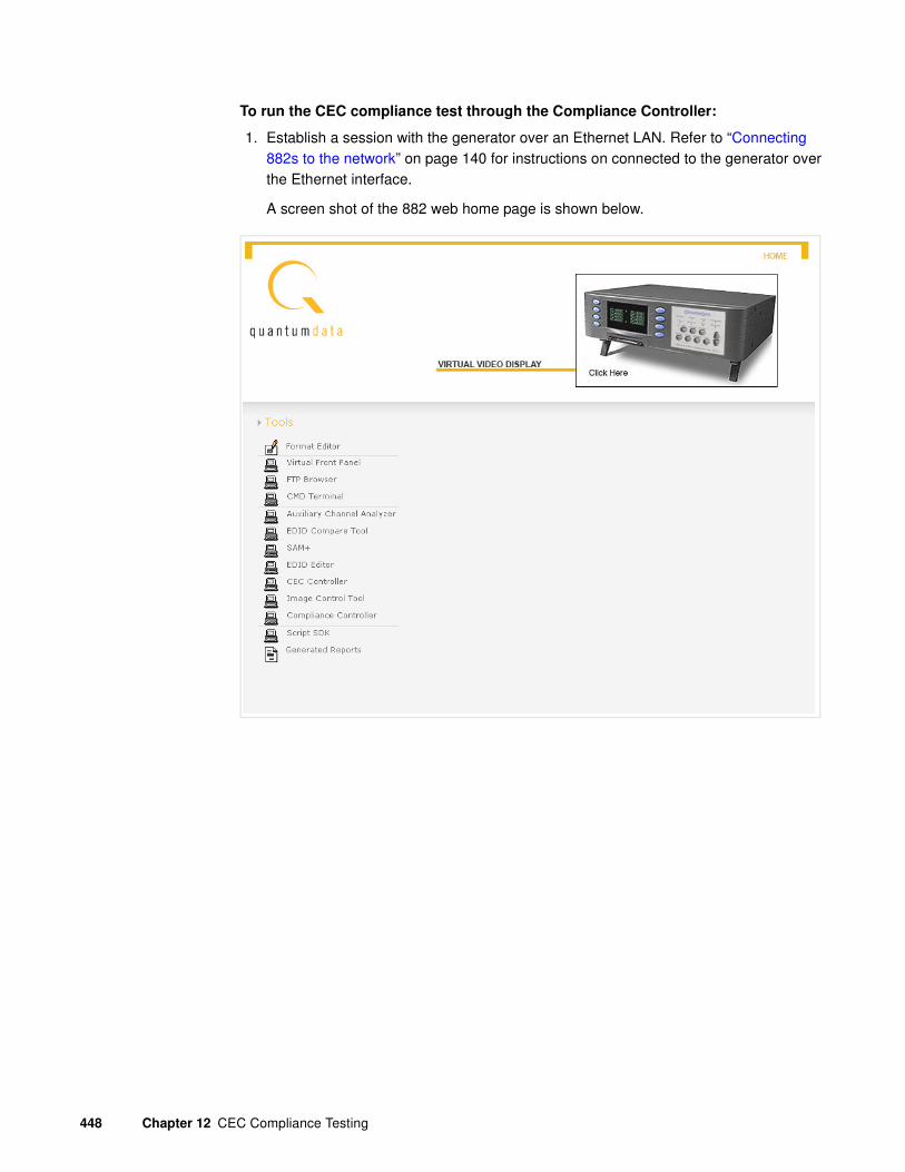
448 Chapter 12 CEC Compliance Testing
To run the CEC compliance test through the Compliance Controller:
1. Establish a session with the generator over an Ethernet LAN. Refer to “Connecting 882s to the network” on page 140 for instructions on connected to the generator over the Ethernet interface.
A screen shot of the 882 web home page is shown below.
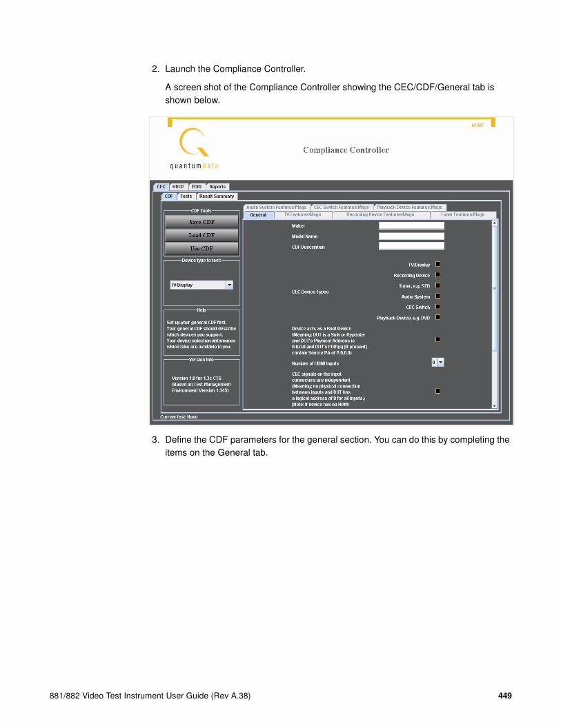
881/882 Video Test Instrument User Guide (Rev A.38) 449
2. Launch the Compliance Controller.
A screen shot of the Compliance Controller showing the CEC/CDF/General tab is shown below.
3. Define the CDF parameters for the general section. You can do this by completing the items on the General tab.

450 Chapter 12 CEC Compliance Testing
4. Define the specific CDF parameters for the type of device you are testing. Note that there are several tabs for each category of capabilities.
You can do this by manually going through the forms in each tab in the CEC/CDF tab.
A screen shot of the Compliance Controller showing part of the CEC/CDF/TV Features/Msgs tab is shown below.

881/882 Video Test Instrument User Guide (Rev A.38) 451
5. Alternatively, if you have the CDF already stored on your PC or in the 882, you can Load that CDF with the Load CDF activation button. A screen shot of the Compliance Controller showing the Load CDF pop-up dialog box is shown below.
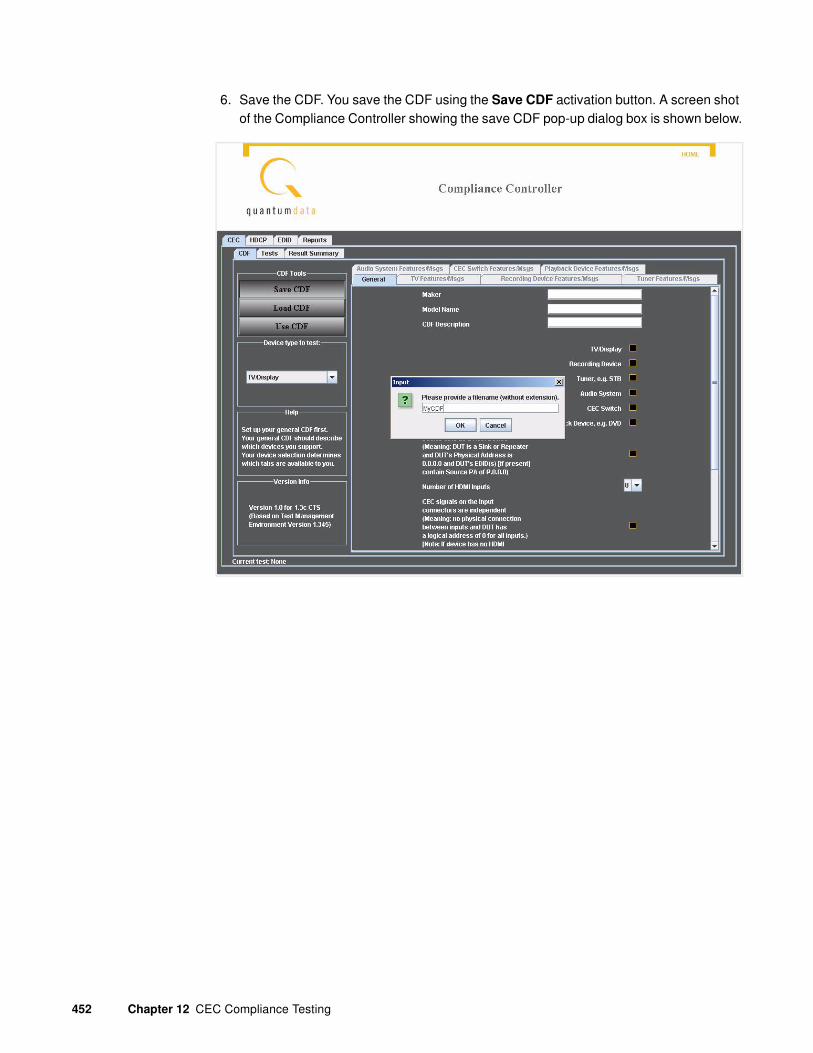
452 Chapter 12 CEC Compliance Testing
6. Save the CDF. You save the CDF using the Save CDF activation button. A screen shot of the Compliance Controller showing the save CDF pop-up dialog box is shown below.
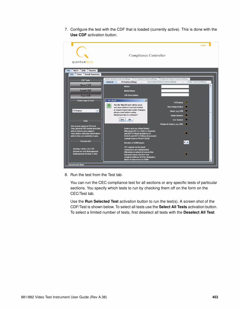
881/882 Video Test Instrument User Guide (Rev A.38) 453
7. Configure the test with the CDF that is loaded (currently active). This is done with the Use CDF activation button.
8. Run the test from the Test tab.
You can run the CEC compliance test for all sections or any specific tests of particular sections. You specify which tests to run by checking them off on the form on the CEC/Test tab.
Use the Run Selected Test activation button to run the test(s). A screen shot of the CDF/Test is shown below. To select all tests use the Select All Tests activation button. To select a limited number of tests, first deselect all tests with the Deselect All Test

454 Chapter 12 CEC Compliance Testing
activation button and then check off the tests you wish to run. When you run a test, the CEC Compliance Controller provides you with on-line help describing the physical set up required for each test. This is shown on the screen shot below.
An indication of pass or fail is provided for each test to the right of each test and also as a pop-up dialog box after each test is completed.

881/882 Video Test Instrument User Guide (Rev A.38) 455
9. View the CEC compliance test report. The results of all the CEC compliance tests are accessible from the Results Summary tab.

456 Chapter 12 CEC Compliance Testing
Running the CEC Compliance Test with the TME Software
This section describes how to install and run the TME CEC compliance test application.
Note: The TME CEC compliance test application is the CEC Compliance test application
that is approved for use in testing HDMI 1.3 devices in the Authorized Test Centers.
Installing the TME software
This subsection provides procedures on downloading and installing the TME software on your PC.
To install the TME software on your PC:
1. Download the TME software from the Quantum Data website at: http://www.quantumdata.com/downloads/index.asp.
2. Unzip the TME software and store the directory on your PC.
To run the TME software:
1. Locate the TME directory on your PC.
Note: You must also have the Java Runtime Environment (JRE) 1.5 or later installed on
your PC. You can download the JRE from
http://www.java.com/en/download/windows_ie.jsp.

881/882 Video Test Instrument User Guide (Rev A.38) 457
2. Double click on the tme.jar file.
The main screen of the TME software opens in a Java window.
Establishing communication between the TME software and
the generator
This subsection describes how establish communication between the TME software and the 882C(A) generator that is used to test the device under test.
Note: You can connect from the TME software to the generator but we highly recommend
using the Ethernet interface.
To communicate with the generator from the TME software:
1. Activate the Host softkey on the bottom of the TME interface and activate the radio button beside the next available port.

458 Chapter 12 CEC Compliance Testing
2. Enter the IP address of the generator in the field provided as shown below.
3. Click on the Connect activation button on the lower right of the interface.
A success notification is provided as shown below. This message indicates that you have connected to the generator.
If the connection fails, restart the TME to ensure proper operation.
Completing the Capabilities Declaration Form (CDF)
The first activity in executing a CEC compliance test is to identify the set of tests that apply to the particular CEC device that you are testing. The TME software contains a Compliance Test module (CEC-CT module) that greatly simplifies this initial activity. The test module provides a wizard-driven interface to populate the CEC Capabilities Declaration Form (CDF). Once the CDF is populated, the TME software automatically compiles the suite of tests necessary to test a particular device. Because the generic HDMI/CEC equipment types are modeled within the CEC-CT module, the CDF form can

881/882 Video Test Instrument User Guide (Rev A.38) 459
be rapidly populated based on a particular device classification. However, the module offers the flexibility to modify the feature requirements specified generically on the form in order to meet the particular requirements of a device. The contents of the CDF can be edited at any time prior to compiling a test series. Once the CDF is compiled, the required test sections and distinct tests are configured in the TME software and ready to run.
Defining a CDF for a device under test
This subsection defines how to specify a CDF for the device under test. This involves selecting the generic product type or a custom type then choosing a specific unit.
In configuring a test you will either be using generic CDF for a product type and adding specific tests to it or you will be creating a custom device type and defining a CDF for an instance of that product type.
To select the generic device type:
1. Select the Product activation button on the top panel.
The following dialog box appears with the Product Type tab activated.
2. Select the product type by clicking on the desired radio button.
The example in the figure above shows TV/Display selected.
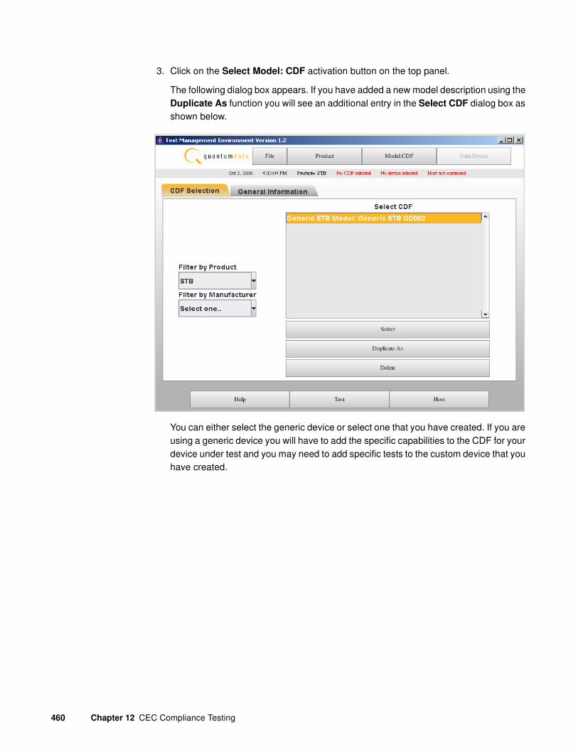
460 Chapter 12 CEC Compliance Testing
3. Click on the Select Model: CDF activation button on the top panel.
The following dialog box appears. If you have added a new model description using the Duplicate As function you will see an additional entry in the Select CDF dialog box as shown below.
You can either select the generic device or select one that you have created. If you are using a generic device you will have to add the specific capabilities to the CDF for your device under test and you may need to add specific tests to the custom device that you have created.

881/882 Video Test Instrument User Guide (Rev A.38) 461
4. Click on Duplicate As activation button to define a new device type to test.
The Add New CDF dialog box appears.
The Duplicate As function enables you to define the capabilities for any type of CEC device using any existing model definition. The capabilities of the existing model definition are inherited in the new definition and you can then modify or enhance this definition to met the specific requirements to test your device.
5. Fill in the Add New CDF form and click on Save Model when you are complete.
The following confirmation dialog box appears.
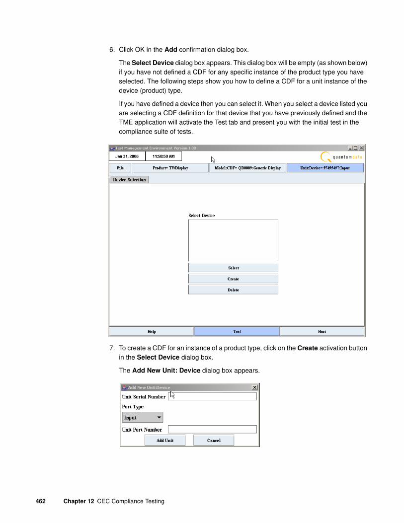
462 Chapter 12 CEC Compliance Testing
6. Click OK in the Add confirmation dialog box.
The Select Device dialog box appears. This dialog box will be empty (as shown below) if you have not defined a CDF for any specific instance of the product type you have selected. The following steps show you how to define a CDF for a unit instance of the device (product) type.
If you have defined a device then you can select it. When you select a device listed you are selecting a CDF definition for that device that you have previously defined and the TME application will activate the Test tab and present you with the initial test in the compliance suite of tests.
7. To create a CDF for an instance of a product type, click on the Create activation button in the Select Device dialog box.
The Add New Unit: Device dialog box appears.

881/882 Video Test Instrument User Guide (Rev A.38) 463
8. Fill out the information about your device on the form and click on Add Unit.
The following confirmation dialog box appears.
9. Click OK in the Add confirmation dialog box.
The Declare tab is activated enabling you to proceed through the list of features in order for you to select the ones that apply to your device. This initial screen in this list of features is shown below.
10. Specify a device capability by clicking on the check box for each test presented. Proceed to the next device capability to specify it by clicking on the Next activation button on the bottom panel. When you are done defining all the device capabilities the Next button will be grayed out.

464 Chapter 12 CEC Compliance Testing
11. Click on the Finish activation button on the bottom panel to compile the test suite.
The following dialog box will appear.
12. Click OK in the Status dialog box.
The CDF definition is completed for the model definition that you are testing and the TME application compiles the test suite. The TME application terminates and you will have to restart the TME application to run the compliance test.
Running the CEC Compliance Test
The TME software enforces the sequence of steps in a particular test but the sections of the overall test or specific tests within a test section can be performed in any order. You can suspend a test at any time and for any reason and then continue when convenient. However you cannot restart mid test. As the test proceeds through the sections and specific tests, the TME interface provides instructions where necessary to take physical actions such as making connections to the additional equipment defined in “Additional equipment required” on page 445. The equipment environment for each test is depicted through the TME interface to assist you in visualizing the test setup.
With Release 2.5.x the TME has been enhanced to run through test steps automatically where user input is not required.

881/882 Video Test Instrument User Guide (Rev A.38) 465
To run the compliance test:
1. Locate the TME directory on your PC.
2. Double click on the tme.jar file.
The main screen of the TME software opens in a Java window.
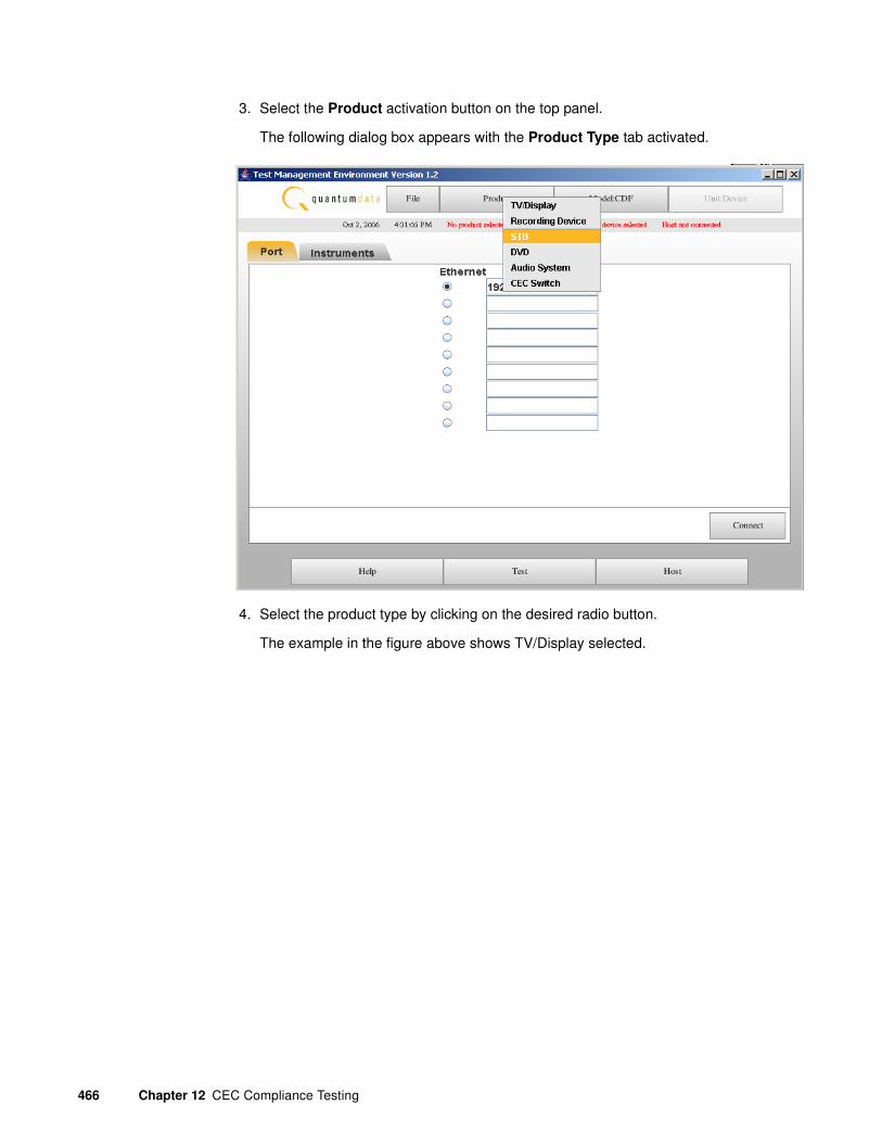
466 Chapter 12 CEC Compliance Testing
3. Select the Product activation button on the top panel.
The following dialog box appears with the Product Type tab activated.
4. Select the product type by clicking on the desired radio button.
The example in the figure above shows TV/Display selected.

881/882 Video Test Instrument User Guide (Rev A.38) 467
5. Click on the Select Model: CDF activation button on the top panel.
The following dialog box appears. If you have added a new product type using the Duplicate As function you will see an additional entry in the Select CDF dialog box as shown below.
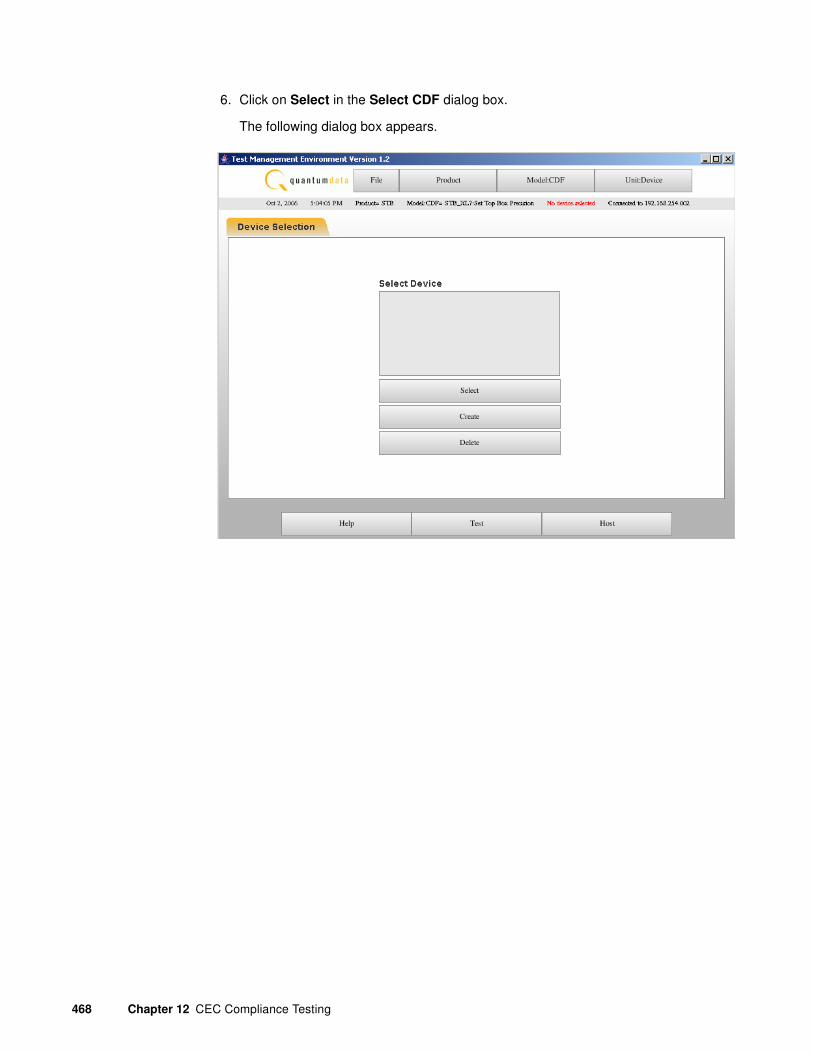
468 Chapter 12 CEC Compliance Testing
6. Click on Select in the Select CDF dialog box.
The following dialog box appears.

881/882 Video Test Instrument User Guide (Rev A.38) 469
7. Create an instance of the product type you wish to test by clicking on Create in the Select Device dialog box.
The following dialog box appears.

470 Chapter 12 CEC Compliance Testing
8. Click on the Add Unit activation button on the Add New Unit:Device dialog box.
The following dialog box appears.
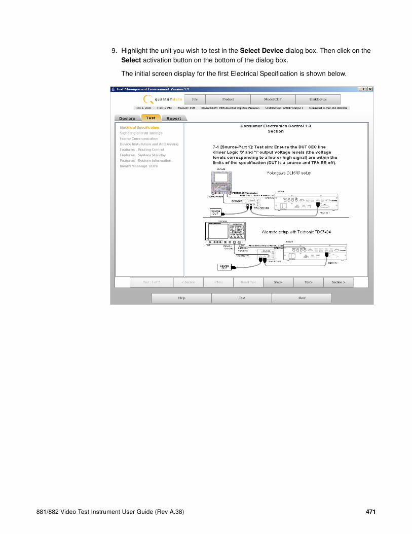
881/882 Video Test Instrument User Guide (Rev A.38) 471
9. Highlight the unit you wish to test in the Select Device dialog box. Then click on the Select activation button on the bottom of the dialog box.
The initial screen display for the first Electrical Specification is shown below.
T

472 Chapter 12 CEC Compliance Testing
10. Proceed through each test by clicking on the Step activation button on the bottom panel of buttons.
The initial screen display for the first Electrical Specification is shown below.
When you complete the tests for a specific section the TME application will proceed to the first test in the next section. The initial test in the Signaling and Bit Timing test is shown below.

881/882 Video Test Instrument User Guide (Rev A.38) 473
Viewing the results of the CEC compliance test
The status of a compliance test, for example what tests have been performed and what tests remain, as well as the results of each test completed, are available at any point. The TME software provides pass/fail results for all tests in the entire suite of tests. The results can be viewed on line, printed or saved in electronic form for viewing through a standard web browser. Because the TME software and 882CA test instrument offer a comprehensive solution for the CEC Compliance Test suite, manufacturers are assured that upon successful completion of the test series, the HDMI CEC product is ready for the compliance test.

474 Chapter 12 CEC Compliance Testing
To view the results of the compliance test:
1. Select the Report tab.
The results of the initial test in the first test section (Electrical Specification) are shown first. See the screen below.
The

881/882 Video Test Instrument User Guide (Rev A.38) 475
2. Click on the Test activation button on the bottom panel to view the test results from the next test in the section.
The test results for the first test in the second section (Signaling and Bit Timings) are shown below.
The

476 Chapter 12 CEC Compliance Testing
3. To view all the test results, click on the Hard Copy activation button on the bottom panel.
A sample report of the test results is shown below. You can view the results of all tests by scrolling through the list.
If you want to save the results to a file, click on the Save... activation button on the bottom. A Java Save dialog box is provided so that you can browse to a location on the PC to save the file.
If you want to print the results to a file, you can save the file then view it and print it from a browser. This is preferred to using the Print activation button on the bottom.
The
ini

881/882 Video Test Instrument User Guide (Rev A.38) 477
13 Auxiliary Channel Analyzer
Topics in the chapter:
• Auxiliary Channel Analyzer Overview
• Setting up and using the ACA
• Monitoring the HDMI auxiliary channels

478 Chapter 13 Auxiliary Channel Analyzer
Auxiliary Channel Analyzer Overview
The Auxiliary Channel Analyzer (ACA) is a graphical application that can be used to monitor auxiliary channels such as the DDC and CEC buses in the HDMI interface . You can monitor multiple channels simultaneously. For example, you can monitor HDCP transactions on the DDC bus while also capturing data for the HDMI CEC bus.
The ACA is accessible either from an external Java application (Jar file) downloadable from the Quantum Data web site or from the embedded web server on the 882 generator.

881/882 Video Test Instrument User Guide (Rev A.38) 479
Setting up and using the ACA
The ACA application is a Java application or applet. You can download and install the application on your PC, and then run it locally, or you can run the application from the 882 web server.
Note: You must also have the Java Runtime Environment (JRE) 1.5 or later installed on
your PC. You can download the JRE from the following website:
http://www.java.com/en/download/windows_ie.jsp
Running the ACA
This subsection provides procedures on launching the ACA from the 882 web server and from your PC.

480 Chapter 13 Auxiliary Channel Analyzer
To run the ACA from the web server:
1. Open a Web browser (such as Internet Explorer) and type the 882’s IP address in the address entry field. For example, enter the following: http://206.135.215.189/.
The 882 home page appears in the browser.

881/882 Video Test Instrument User Guide (Rev A.38) 481
2. Click Auxiliary Channel Analyzer.
The ACA main page appears as a separate application window as shown below:
Once you connect to an 882 you the filters will become available as shown below:
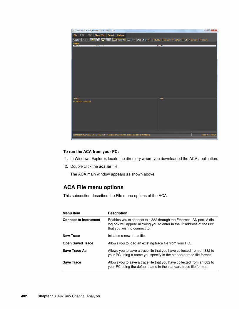
482 Chapter 13 Auxiliary Channel Analyzer
To run the ACA from your PC:
1. In Windows Explorer, locate the directory where you downloaded the ACA application.
2. Double click the aca.jar file.
The ACA main window appears as shown above.
ACA File menu options
This subsection describes the File menu options of the ACA.
Menu Item Description
Connect to Instrument Enables you to connect to a 882 through the Ethernet LAN port. A dia-log box will appear allowing you to enter in the IP address of the 882 that you wish to connect to.
New Trace Initiates a new trace file.
Open Saved Trace Allows you to load an existing trace file from your PC.
Save Trace As Allows you to save a trace file that you have collected from an 882 to your PC using a name you specify in the standard trace file format.
Save Trace Allows you to save a trace file that you have collected from an 882 to your PC using the default name in the standard trace file format.

881/882 Video Test Instrument User Guide (Rev A.38) 483
ACA Filters
This subsection describes filters on the ACA. The filters are the select buttons on the top of the ACA interface.
ACA Options
This subsection describes options on the ACA. The options are available through the Options pull-down menu on the top of the ACA interface.
Save to HTML Allows you to save a trace file as an HTML file.
Save to Text Allows you to save a trace file as a text file.
Save EDID from Trace Allows the user to save an EDID in the trace file to an XML file. The XML file can then be loaded into the EDID Editor utility for viewing or modifying. The EDID saved from the ACA is the first EDID that is logged in the trace file. For instructions on loading an XML EDID file with the EDID Editor please refer to “Loading EDIDs with the EDID Editor” on page 542.
Filter Description
EDID Enables or disables the viewing of EDID log records on the HDMI traces.
HDCP Enables or disables the viewing HDCP transaction log records for HDMI traces.
CEC Enables or disables the viewing CEC transaction log records for HDMI traces.
Events Enables or disables the viewing of Events such as hot plugs.
Other Not used.
All Packets Enables viewing of all available transactions log available in the active trace file.
Delta/Cumulative mode Toggles between the Delta and Cumulative mode. Delta mode provide a time reference on the highlighted record to which the times of all other traces are compared. Cumulative provides time stamp for all records sequentially from the time the ACA was launched and began capturing records.
Menu Item Description

484 Chapter 13 Auxiliary Channel Analyzer
ACA search
This subsection describes the ACA search capabilities.
To search through a trace file
1. Load a trace file or collect a trace file in the ACA.
Option Description
Enable 5-Volt TPA This only applies to the 882CA when using the TPAs (TPA-ACA-3R or TPA-MP-4R). This option enables monitoring of the transitions in the +5V power pin.
Enable Precharge/Sync
Detection
This option only applies to DisplayPort. It enables monitoring of the Precharge pulses. It is disabled by default.
Send command This option opens up a terminal dialog box enabling you to enter com-mands directly to the 882.
About... Provides version information about the ACA.

881/882 Video Test Instrument User Guide (Rev A.38) 485
2. Select the Search item from the top level menu.
The Search dialog box appears as shown in the screen shot below:
The following table describes the selection items in the search dialog box:
Selection Description
ASCII String radio button and text field
Specifies a search through the trace file loaded in the ACA for an ascii text string specified in the associated text field.
Hex String radio button and text field
Specifies a search through the trace file loaded in the ACA for an hex text string specified in the associated text field.
CEC radio button and pull down menu
Specifies a search through the CEC trace file that is loaded in the ACA for the opcode selected by the pull down menu.
HDCP Register radio but-ton and pull down menu
Closes the file in the current editor tab.
EDID radio button Saves the file in the current editor tab.
Search backwards check box
Initiates a search through records prior to the highlighted record.

486 Chapter 13 Auxiliary Channel Analyzer
Find Next activation button Initiates a search on the trace through records after to the highlighted record. The search will occur on the currently loaded trace file using the criteria defined.
Close activation button Closes out the Search dialog box.
Selection Description

881/882 Video Test Instrument User Guide (Rev A.38) 487
Monitoring the HDMI auxiliary channels
This subsection provides procedures on operating the ACA for monitoring the HDMI auxiliary channels such as the HDCP and EDID transactions over the DDC or the CEC transactions over the CEC bus. The procedures are the same regardless of whether you run the ACA from the web server or from your PC.
To set up the 882 for monitoring the DDC on HDMI:
1. Connect the 882 to the HDMI display device or source device under test by doing one of the following:
a. Connect an HDMI-to-HDMI cable between the HDMI display device or source device under test and either of the HDMI OUT connectors on the 882.
b. If you are using the analyzer, connect an HDMI-to-HDMI cable between the HDMI display device or source device under test and the HDMI IN connector on the 882.
2. Activate the HDMI-H interface on the output port:
a. Press the Interface key to access the list of interfaces. A listing of signal interfaces appears on the 882’s display as shown below.
b. Choose either the HDMI-H item by pressing the adjacent soft key.
The interface is activated and the port outputs the currently selected image and format.
Alternatively, to select the interface through the command line, enter the following commands:
XVSI 4 // Selects the HDMI-H interface
ALLU // Applies the interface setting to the 882
To monitor the CEC bus (channel):
1. Set up the 882 generator/analyzer for HDMI in accordance with the instructions above.
VGA
HDMI-D
CVBS
S-VIDEO
SDI
*
HDMI-H
VGA
HDMI-D
CVBS
S-VIDEO
SDI*HDMI-H

488 Chapter 13 Auxiliary Channel Analyzer
2. In the ACA, from the File menu, select Connect to Analyzer. The Connect to
Analyzer dialog box appears.
3. In the Connect To box, enter the IP address of the 882 you want to connect to, and then click Connect.
4. From the CEC menu, point to Port, and the select the port you want to monitor.
5. On the toolbar, click the CEC button to enable it. Make sure all other buttons are disabled.
6. From the File pull down menu specify New Trace.
7. Click the Capture button.

881/882 Video Test Instrument User Guide (Rev A.38) 489
8. Initiate the actions necessary to cause CEC messages to be transmitted between the HDMI source and sink device.
The ACA begins the trace and displays the results in the main window, as shown below.
T
When you click on a specific transaction you can see the detail timing information are the data. The table below describes the information in the Details and Data panels.
Details Data
Time since last reset: Field not currently sup-ported
Data size: The number of bytes in the message
Size of message: The size of the message in bytes (example 5 bytes)
Data: The data is shown for each message. The “+” sign indicates that the last bit, the acknowl-edge bit is a logical 1; the “-” sign indicates that the last bit, the acknowledge bit was a logical 0.
Message Source: The type of device (product type) and the logical address of the device that sent the message
Message Destination: The destination device of the message. If a targeted device then its logical addres is provided. If the message is a broadcast “All” is shown and the logical address is F (hex)
Message Opcode: The CEC operational code for the function of the message

490 Chapter 13 Auxiliary Channel Analyzer
1. (Optional) Click the Save button on the toolbar to save the trace to a file. The Save
Trace dialog box appears. Navigate to the folder where you want to save the file. In the File Name box, type a name for the file, and then click Save.
2. (Optional) The ACA includes a command utility available from the Options pull down menu. This utility enables you to enter CEC commands and monitor the results.
To monitor the HDCP transactions on the DDC (I2C) bus (channel):
1. Set up the 882 generator/analyzer for HDMI in accordance with the instructions above “To set up the 882 for monitoring the DDC on HDMI:” on page 487.
2. In the ACA, from the File menu, select Connect to Analyzer. The Connect to
Analyzer dialog box appears.
3. In the Connect To box, enter the IP address of the 882 you want to connect to, and then click Connect.
4. From DDC menu, point to Port, and the select the port you want to monitor.
5. On the toolbar, click the HDCP button to enable it. Make sure all other buttons are disabled.
6. From the File pull down menu specify New Trace.
Device Vendor ID: The identification code for the vendor equipment
Bit Timings: These are the timings for each bit in the block. They are numbered on the left. The timings for the bit high times are listed and the timings for the low bit times
Details Data

881/882 Video Test Instrument User Guide (Rev A.38) 491
7. Click the Capture activation button.
8. Initiate the actions necessary to cause HDCP transactions to occur. This might be selecting the HDCPprod image on the 882 if the 882 is emulating a source for testing an HDMI sink.
The ACA begins the trace and displays the results in the main window, as shown below.
T
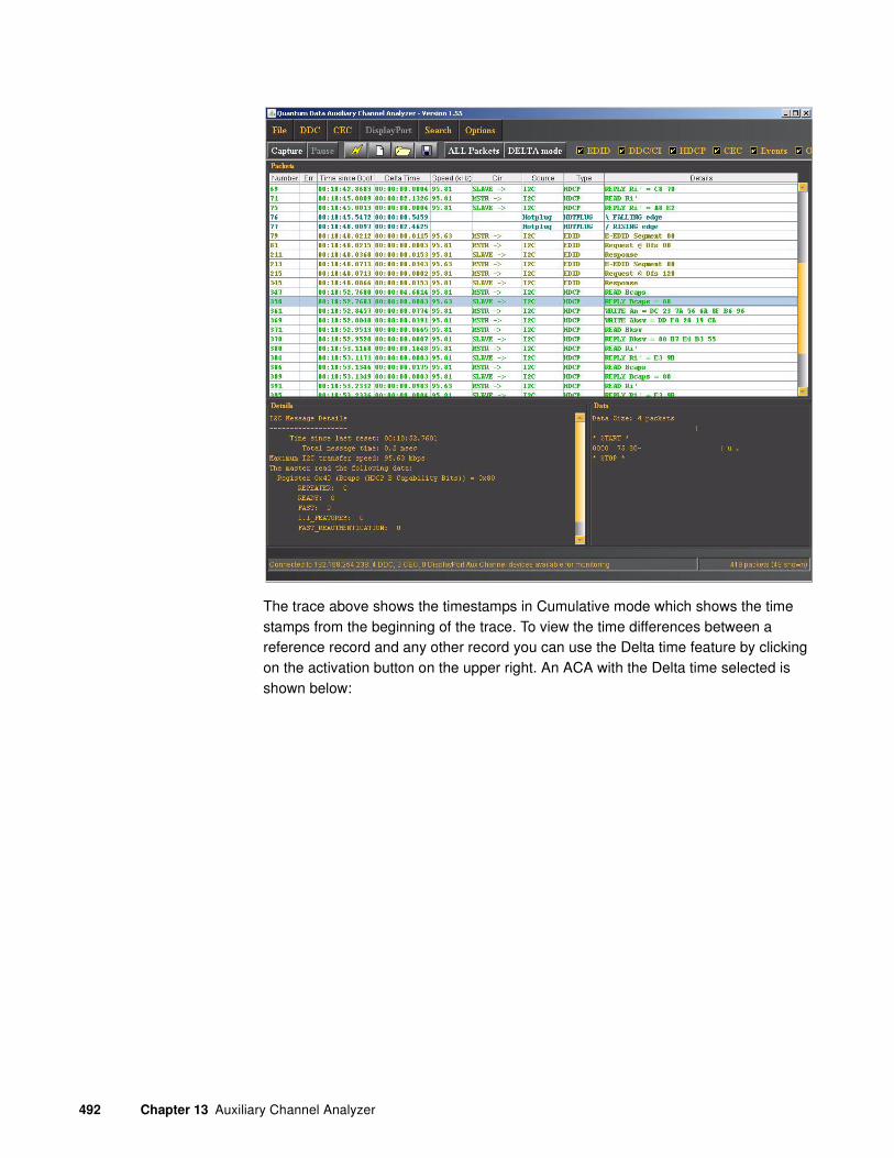
492 Chapter 13 Auxiliary Channel Analyzer
The trace above shows the timestamps in Cumulative mode which shows the time stamps from the beginning of the trace. To view the time differences between a reference record and any other record you can use the Delta time feature by clicking on the activation button on the upper right. An ACA with the Delta time selected is shown below:

881/882 Video Test Instrument User Guide (Rev A.38) 493
9. T(Optional) Click the Save button on the toolbar to save the trace to a file. The Save
Trace dialog box appears. Navigate to the folder where you want to save the file. In the File Name box, type a name for the file, and then click Save.
To monitor the EDID transactions on the DDC (I2C) bus (channel):
1. Set up the 882 generator/analyzer for HDMI in accordance with the instructions above “To set up the 882 for monitoring the DDC on HDMI:” on page 487.

494 Chapter 13 Auxiliary Channel Analyzer
2. In the ACA, from the File menu, select Connect to Analyzer. The Connect to
Analyzer dialog box appears.
3. In the Connect To box, enter the IP address of the 882 you want to connect to, and then click Connect.
4. From DDC menu, point to Port, and the select the port you want to monitor.
5. On the toolbar, click the DDC and Events buttons to enable them. Make sure all other buttons are disabled.
6. From the File pull down menu specify New Trace.
7. Click on the Capture activation button.
8. Initiate the actions necessary to cause a hot plug event for EDID transmission to occur. This might be unplugging the HDMI cable on the 882 if the 882 is emulating a source for testing an HDMI sink.
The ACA begins the trace and displays the results in the main window, as shown
below.T

881/882 Video Test Instrument User Guide (Rev A.38) 495
9. (Optional) Click the Save button on the toolbar to save the trace to a file. The Save
Trace dialog box appears. Navigate to the folder where you want to save the file. In the File Name box, type a name for the file, and then click Save.
Passive monitoring between an HDMI source and a sink
The procedures for following procedures provide instructions on how to passively monitor between an HDMI source and and HDMI sink.
To monitor the HDCP DDC transactions between a source and a sink:
1. Configure the 882 to operate in the HDMI mode.
a. Press the Interface key. A listing of signal interfaces appears on the 882’s display as shown below.
b. Choose the HDMI-H item by pressing the adjacent soft key. The interface is activated and the port outputs the currently selected image and format.
c. Alternatively, to activate the interface through the command line interface, enter the following commands:
XVSI 4 // Selects the HDMI-H interface
ALLU // Applies the interface setting to the 882
VGA
HDMI-D
CVBS
S-VIDEO
SDI
*
HDMI-H
VGA
HDMI-D
CVBS
S-VIDEO
SDI*HDMI-H

496 Chapter 13 Auxiliary Channel Analyzer
2. For the TPA-ACA-3R, connect the cables as follows:
a. Connect an HDMI-to-HDMI cable between the HDMI connector on the source device under test and the first HDMI connector on the TPA-ACA-3R Test Point Adapter labeled DUT1.
b. Connect an HDMI-to-HDMI cable between the HDMI connector on the sink device under test and the second HDMI connector on the TPA-ACA-3R Test Point Adapter labeled DUT2.
c. Connect an HDMI-to-HDMI cable between the HDMI OUT connector on the 882 generator/analyzer and the third HDMI connector on the TPA-ACA-3R Test Point Adapter labeled OUT1.
The figure below shows the TPA-ACA-3R device.
The following diagram illustrates the test setup.
ACA Passive Monitor
Model TPA-ACA-3R
DUT1 DUT2 OUT1
Device Under Test - DUT1
Source
Device Under Test - DUT2
Sink (Display)
ACA Passive Monitor
DUT1DUT2 OUT1
HDMI TX HDMI RX
HDMI TX
882CA
TPA-ACA-3R

881/882 Video Test Instrument User Guide (Rev A.38) 497
3. For the TPA-MP-4R, connect the cables as follows:
a. Connect an HDMI-to-HDMI cable between the HDMI connector on the source device under test and the HDMI connector on the TPA-MP-4R Test Point Adapter labeled “Source DUT”.
b. Connect an HDMI-to-HDMI cable between the HDMI connector on the sink device under test and the HDMI connector on the TPA-MP-4R Test Point Adapter labeled “Sink DUT”.
c. Connect an HDMI-to-HDMI cable between the HDMI OUT connector on the 882 generator/analyzer and the HDMI connector on the TPA-MP-4R Test Point Adapter labeled “Sink DUT”.
The figure below shows the TPA-MP-4R device.
The following diagram illustrates the test setup.
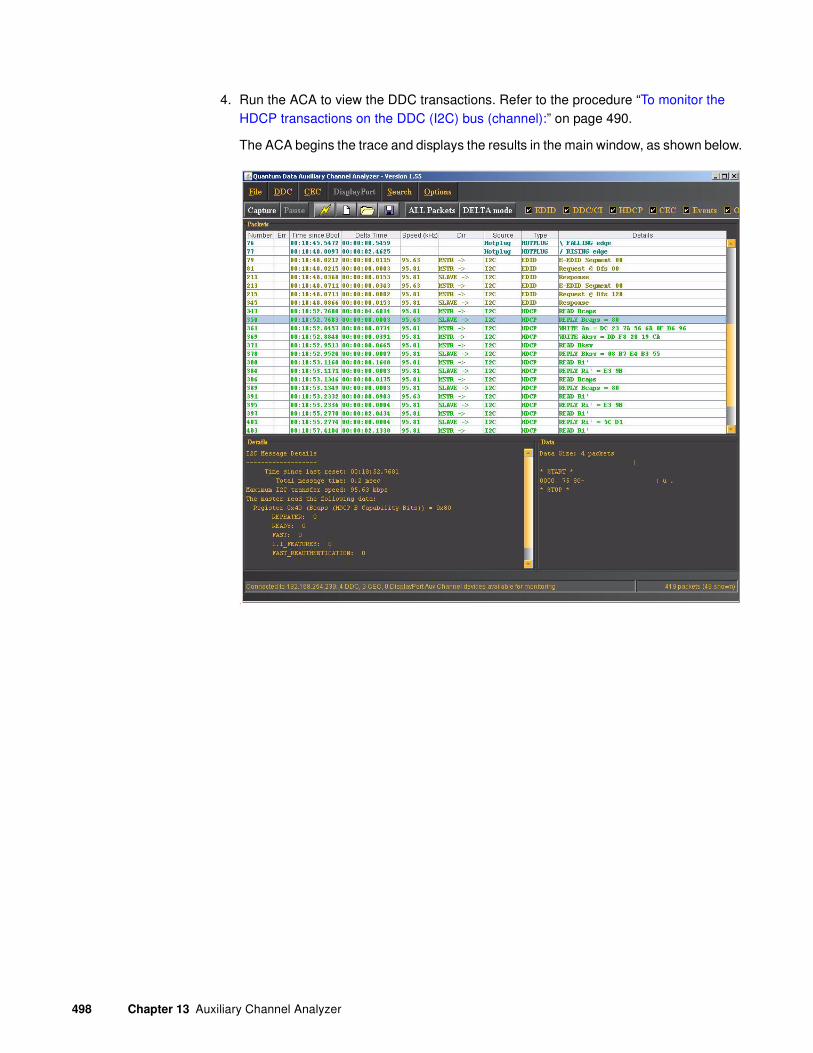
498 Chapter 13 Auxiliary Channel Analyzer
4. Run the ACA to view the DDC transactions. Refer to the procedure “To monitor the HDCP transactions on the DDC (I2C) bus (channel):” on page 490.
The ACA begins the trace and displays the results in the main window, as shown below.
T
881/882 Video Test Instrument User Guide (Rev A.38) 499
14 Testing EDID for HDMI
Topics in this chapter:
• Overview
• Testing with display (sink) devices
• Testing with source devices
• Testing EDID for HDMI compliance in display (sink) devices
• EDID emulation for physical layer testing of source devices
• Using the EDID Editor tool
• Testing a Source’s Response by Emulating EDIDs
• Using the EDID Compare tool

500 Chapter 14 Testing EDID for HDMI
Overview
This chapter provides procedures for testing EDID generation, emulating and handling. The 882 can be configured to:
• emulate an HDMI, DVI, or VGA source device to test an HDMI, DVI, or VGA sink (display) device.
• emulate an HDMI/DVI sink (display) device to test an HDMI/DVI source device.
With the 882, you can both view EDID from a display, and write EDID to a display device (with writable EEPROM). In addition, you can test an HDMI display device’s EDID structure and transmission in accordance with the HDMI Compliance Test Specification 1.2.
Additional EDID tests require the analyzer option. These include testing the EDID handling capabilities of a source device, and the HDMI compliance EDID testing for a sink (display) device.
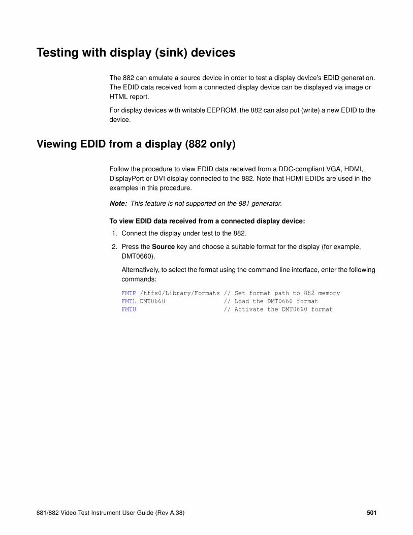
881/882 Video Test Instrument User Guide (Rev A.38) 501
Testing with display (sink) devices
The 882 can emulate a source device in order to test a display device’s EDID generation. The EDID data received from a connected display device can be displayed via image or HTML report.
For display devices with writable EEPROM, the 882 can also put (write) a new EDID to the device.
Viewing EDID from a display (882 only)
Follow the procedure to view EDID data received from a DDC-compliant VGA, HDMI, DisplayPort or DVI display connected to the 882. Note that HDMI EDIDs are used in the examples in this procedure.
Note: This feature is not supported on the 881 generator.
To view EDID data received from a connected display device:
1. Connect the display under test to the 882.
2. Press the Source key and choose a suitable format for the display (for example, DMT0660).
Alternatively, to select the format using the command line interface, enter the following commands:
FMTP /tffs0/Library/Formats // Set format path to 882 memory
FMTL DMT0660 // Load the DMT0660 format
FMTU // Activate the DMT0660 format

502 Chapter 14 Testing EDID for HDMI
3. Read the EDID from the display as follows:
a. Press the Sink key. The following information appears on the 882’s display.
b. Press the Options key. The following information appears on the 882’s display.
c. Choose the EDID Formats item by pressing the adjacent soft key. A + appears next to EDID Formats, indicating it is enabled.
The 882 loads the Source list with formats supported by the connected display (hot-plug formats read via EDID structure of attached display).
Note: To disable hot plug formats, press the soft key adjacent to EDID Formats. A -
next to EDID Formats indicates it is disabled.
4. Press the Content key. A list of images appears on the 882’s display.
5. Choose the EdidData image by pressing the adjacent soft key. The image appears on the display as shown below.
Alternatively, to select the image using the command line interface, enter the following commands:
IMGL EDIDDATA // Loads the EdidData image
IMGU // Activates the EdidData image
Manufacturer:SNYProduct Code:144Serial#:7011007Week:20 Year:1998
-EDID Formats CDF+HP Bypass-Emulate

881/882 Video Test Instrument User Guide (Rev A.38) 503
6. Enable and view image versions for the EdidData image as follows:
a. Press the Options key. The following menu appears on the 882’s display:
b. Choose the More item by pressing the adjacent soft key until a + and Rendition appears next to the item.
c. Press the + and - keys to advance through the image versions.
Alternatively, to enable and view image versions using the command line interface, enter the following commands:
ISUB 1 // Enables sub images
IVER 1 // Specifies the first image version
IMGU // Activates the image version
7. When you are finished, disable image versions by pressing the Options key and choosing More until a - appears next to it.
Alternatively, to disable image versions using the command line interface, enter the following command:
ISUB 0 // Disables sub images
-More Red+-NoGamma Green+-Noise Blue+
+More Rendition: 000 Red+-NoGamma Green+-Noise Blue+

504 Chapter 14 Testing EDID for HDMI
To view EDID data received from a connected display device using the command line interface:
1. Connect the display under test to the 882.
2. Establish a session with the 882 using either HyperTerminal over a serial connection or Telnet over an Ethernet LAN. See “Establishing a terminal session with the 882” on page 30 or “Establishing a Telnet session with the 882” on page 33.
3. Enter one of the following commands:
• To view the current EDID in ASCII hex format, enter the EDID? command..
• To view a specific segment of EDID, enter the I2CR? (OUT1:I2CR?, OUT2:I2CR?, VGA:I2CR?) command (refer to the command description identify the arguments of this query).
Generating an EDID Information Report
Follow the procedure to generate an HTML report of EDID data received from a DDC-compliant VGA, HDMI, DisplayPort or DVI display connected to the 882.
Note: HDMI EDIDs are shown in the examples in this procedure.
To generate a report of EDID data received from a connected display device:
1. Connect the display under test to the 882.
2. Press the Tools key. The Tools menu appears on the 882’s display as shown below.
3. Press the Reports key. The Reports menu appears on the 882’s display as shown below.
4. Choose the EDID item by pressing the adjacent soft key. The EDID reports menu appears on the 882’s display as shown below.
System
Sequence
Probe
AFC
Analyzer
Reports
ImgShift
EDID Packets
!DataRpt !CompRpt EditCDF
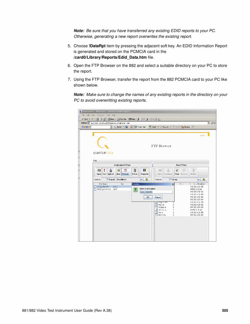
881/882 Video Test Instrument User Guide (Rev A.38) 505
Note: Be sure that you have transferred any existing EDID reports to your PC.
Otherwise, generating a new report overwrites the existing report.
5. Choose !DataRpt item by pressing the adjacent soft key. An EDID Information Report is generated and stored on the PCMCIA card in the /card0/Library/Reports/Edid_Data.htm file.
6. Open the FTP Browser on the 882 and select a suitable directory on your PC to store the report.
7. Using the FTP Browser, transfer the report from the 882 PCMCIA card to your PC like shown below.
Note: Make sure to change the names of any existing reports in the directory on your
PC to avoid overwritting existing reports.

506 Chapter 14 Testing EDID for HDMI
8. Navigate to your PC and double click on the report. A sample is shown below.
Modifying EDID in a display
If the EEPROM in the display is writable, you can write a new EDID to the device. Follow the procedure to overwrite the EDID structure stored in the connected display device with a new EDID structure.
Important: Be sure to save a backup copy of the EDID stored on the display device.
Writing an EDID using this procedure will overwrite the EDID currently stored on the display
device.
To write an EDID to the display device:
1. Establish a session with the 882 using either HyperTerminal over a serial connection or Telnet over an Ethernet LAN. See “Establishing a terminal session with the 882” on page 30 or “Establishing a Telnet session with the 882” on page 33.
2. Connect the display under test to the 882.
3. Load an EDID from the 882 using the following command:
DIDL filename

881/882 Video Test Instrument User Guide (Rev A.38) 507
4. Write the EDID to connected display device using the following command:
EDA<n>:PDID
Where <n> is the HDMIoutput port(1 or 2). For example, the command below writes the EDID out the HDMIOut 2 port.
EDA2:PDID

508 Chapter 14 Testing EDID for HDMI
Testing with source devices
With the Analyzer option, the 882 can emulate an HDMI/DVI sink (display) in order to test an HDMI source device’s EDID handling. With this capability, an HDMI/DVI source device can be tested for its ability to handle an EDID received from virtually any DDC-compatible display.
The analyzer emulates HDMI/DVIdisplays using a built-in, configurable EDID structure. You can configure the analyzer to use an EDID structure obtained directly from a display device, or from a EDID XML file stored in the 882’s file system.
Capturing and storing EDID from display device
Follow the procedure to capture and store an EDID structure from a display device connected to the 882’s HDMI output (Tx) port.
To capture and store an EDID from a connected HDMI/DVI display device:
1. Establish a session with the 882 using either HyperTerminal over a serial connection or Telnet over an Ethernet LAN. See “Establishing a terminal session with the 882” on page 30 or “Establishing a Telnet session with the 882” on page 33.
2. Connect the 882 HDMI output (Tx) port to the display device whose EDID you wish to capture.
3. Activate the HDMI-H or HDMI-D interface on the output port:
a. Press the Interface key to access the list of interfaces. A listing of signal interfaces appears on the 882’s display as shown below.
b. Choose the HDMI-H or HDMI-D item by pressing the adjacent soft key. The interface is activated and the port outputs the currently selected image and format.
c. Alternatively, to activate the interface through the command line interface, enter the following commands:
XVSI 3 (or 4) // Selects the HDMI-D (or HDMI-H) interface
ALLU // Applies the interface setting to the 882
VGA
HDMI-D
CVBS
S-VIDEO
SDI
*
HDMI-H
VGA
HDMI-D
CVBS
S-VIDEO
SDI*HDMI-H

881/882 Video Test Instrument User Guide (Rev A.38) 509
4. Capture the EDID from the connected display device by entering the following command:
EDA<port>:GDID
Where port is the HDMI output port (1 or 2) that the display is connected to. For example, the command below loads an EDID from a display device connected to the 882’s HDMI Out port 1.
EDA1:GDID
5. Store the captured EDID in the 882’s internal file system by entering the following command:
DIDA filename
Where filename is the name of a file in the default directory identified by DIDP. For example, the command below store an EDID to the default EDID path.
DIDA myedid1
If you want to store the EDID file in a location that is not the default path, you can either list the path explicitely on the DIDA command line or change the EDID path with DIDP. For example, the command below loads an EDID from a different directory in flashmem.
DIDA /tffs0/library/userdata/myedid1
6. (Optional) Use the captured EDID to emulate the display device on the analyzer by entering the following command:
EDE<port>:DIDU
Where port is the HDMI input (Rx) port (1 or 2) that you want to configure to emulate the EDID. For example, the command below loads the EDID stored in the EDID edit buffer for emulation into the HDMI input (Rx) port 2.
EDE2:DIDU
Creating or editing EDID contents
You can create or modify an EDID structure to emulate a specific display device using one of the following methods:
• Using the EDID Editor tool. See “Using the EDID Editor tool” on page 542 for details on using the EDID Editor tool
• Loading EDID into memory buffer and creating/modifying content using EDID editing commands. See following procedure for details.

510 Chapter 14 Testing EDID for HDMI
To create/edit an EDID using EDID editing commands:
1. Establish a session with the 882 using either HyperTerminal over a serial connection or Telnet over an Ethernet LAN. See “Establishing a terminal session with the 882” on page 30 or “Establishing a Telnet session with the 882” on page 33.
2. To create a new EDID, follow these steps:
a. Create a new EDID file by entering the following command:
DIDN filename
b. Define EDID structure content using EDID edit commands. The following example shows how you can create EDID content:
DIDB // begins an edid editing session
XDID 0 80
00FFFFFFFFFFFF005A63118F01010101130D010380221B782A4706A55C47
9C251E4F54BFEF008180310A010101010101010101010101302A009851002A4030
701300520E1100001E000000FF004132333033313931353335390A000000FD0032
4B1E530E000A202020202020000000FC0056583730302D330A20202020200095
DIDE // ends an edid editing session
Note: The EDID edit buffer commands are new with Release 2.3.0.
c. Save EDID file to the 882 by entering the following command:
DIDS // saves the edid
3. To modify an existing EDID (stored on the 882), follow these steps:
a. Load an EDID from the 882’s internal file system:
DIDL filename
Where filename is the name of a file in a the default directory identified by DIDP. For example, the command below loads an EDID from the default EDID path.
DIDL myedid1
If the EDID you want to load is not in the default path, you can either list the path explicitely on the DIDL command line or change the EDID path with DIDP. For example, the command below loads an EDID from a different directory in flash memory.
DIDL /tffs0/library/userdata/myedid1
b. Modify EDID structure content using EDID edit commands. The following example shows how you can modify EDID content:
DIDB // begins an edid editing session
XDID 19 A E88A82A0564796240F48 // edits EDID at 19 for 10 (0x0A)
bytes
DIDE // ends an edid editing session
Note: The EDID edit buffer commands are new with Release 2.3.0.
c. Save edits to EDID file to the 882 by entering the following command:

881/882 Video Test Instrument User Guide (Rev A.38) 511
DIDS // saves the edid

512 Chapter 14 Testing EDID for HDMI
Testing EDID for HDMI compliance in display (sink) devices
The 882 supports the following EDID and video HDMI compliance tests in accordance with the HDMI Compliance Test Specification 1.4 (CTS):
• Test ID 8-1: EDID Readable
• Test ID 8-2: EDID VESA Structure
• Test ID 8-3: CEA Timing Extension Structure
• Test ID 8-17: 861B Format Support Requirements
• Test ID 8-18: HDMI Format Support Requirements
• Test ID 8-19: Pixel Encoding Requirements
• Test ID 8-20: Video Format Timing
These tests are intended for in-house testing of products before submission to an HDMI ATC for full certification testing.
Note: This feature is not supported on the 881 generator.
Testing HDMI sink device for EDID compliance
HDMI sink compliance testing is conducted through the 882’s HDMI OUT connector. A standard HDMI-to-HDMI cable connects the device under test to the 882. The 882 must be configured to output HDMI signals.
You can run the EDID compliance test on an HDMI sink device in three ways: 1) through the front panel using the EDIDHDMI image, 2) using the EDID Compliance report also available through the front panel or 3) using the Compliance Controller. The Compliance Controller is an application (available in release 2.18 or later) that is available on the 882 web home page. This section includes procedures for running the EDID compliance test in all of the three ways.
Defining the capabilities of the display device under test
After making the physical connections, you must specify the capabilities of the sink display under test, which are based on the Capabilities Declaration Form (Appendix 3) of the Compliance Test Specification. This enables the 882 to compare the expected results with the actual results measured from the display.
The manner in which you define the CDF depends on which method you are using to run the test (front panel or Compliance Controller). The following table provides a description of the parameters in the EDID CDF that need to be defined. Use this table as a reference when entering the CDF for any test regardless of the test method (i.e. front panel or Compliance Controller). One key advantage of using the Compliance Controller to run the

881/882 Video Test Instrument User Guide (Rev A.38) 513
test and set the CDF is that it enables you to automatically generate a baseline CDF from the sink devices EDID. The following table describes the EDID CDF parameters and their settings.
Parameter Explanation
HDMI Output Count The number of outputs the sink under test has. It is a value in the range of 0-9.
HDMI Input Port The CEC input on the sink under test. It is a value in the range of 1-15.
CEC Root Device Indicates if the CEC device is a root device (i.e. a TV without a repeater). The values are + for yes and - for no.
Primary AR: 4:3 Indicates the primary aspect ratio of the sink device under test. This can be either 4:3, 16:9 or both. The values are + for yes and - for no.
HDTV Indicates if the sink under test supports HDTV. The values are + for yes and - for no. The values are + for yes and - for no.
YUV on Other Indicates if the sink under test supports YUV. The values are + for yes and - for no. The values are + for yes and - for no.
60Hz Indicates whether the device supports formats with 60Hz frame rate. The values are + for yes and - for no.
50Hz Indicates whether the sink under test supports formats with 50Hz frame rate. The values are + for yes and - for no.
640x480p/60 Indicates whether the sink supports the DMT0660 format. The values are + for yes and - for no.
720x480p/60 4:3 Indicates whether the sink supports the 480p60 format with a 4:3 aspect ratio. The values are + for yes and - for no.
720x480p/60 16:9 Indicates whether the sink supports the 480p60SH format with a 16:9 aspect ratio. The values are + for yes and - for no.
1280x720p/60 16:9 Indicates whether the sink under test supports the 720p60 for-mat. The values are + for yes and - for no.
1920x1080i/60 16:9 Indicates whether the sink under test supports the 1080i60 for-mat. The values are + for yes and - for no.
1440x480i/60 4:3 Indicates whether the sink under test supports the 480i2x60 for-mat with double clocking at 4:3 aspect ratio. The values are + for yes and - for no.
1440x480i/60 16:9 Indicates whether the sink under test supports the 480i2x60 for-mat with double clocking at 16:9 aspect ratio. The values are + for yes and - for no.
720x576p/50 4:3 Indicates whether the sink supports the 576p50 format with a 4:3 aspect ratio. The values are + for yes and - for no.
720x576p/50 16:9 Indicates whether the sink supports the 576p50 format with a 16:9 aspect ratio. The values are + for yes and - for no.
1280x720p/50 16:9 Indicates whether the sink under test supports the 720p50 for-mat. The values are + for yes and - for no.

514 Chapter 14 Testing EDID for HDMI
1920x1080i/50 16:9 Indicates whether the sink under test supports the 1080i50 for-mat. The values are + for yes and - for no.
1440x576i/50 4:3 Indicates whether the sink under test supports the 576i2x50 for-mat with double clocking at 4:3 aspect ratio. The values are + for yes and - for no.
1440x576i/50 16:9 Indicates whether the sink under test supports the 576i2x50 for-mat with double clocking at 16:9 aspect ratio. The values are + for yes and - for no.
720p/60 On Other Indicates whether the sink under test supports the analog com-ponent video input for 720p60. The values are + for yes and - for no.
1080i/60 On Other Indicates whether the sink under test supports the analog com-ponent video input for 1080i60. The values are + for yes and - for no.
480p/60 On Other Indicates whether the sink under test supports the analog com-ponent video input for 480p60. The values are + for yes and - for no.
720p/50 On Other Indicates whether the sink under test supports the analog com-ponent video input for 720p50. The values are + for yes and - for no.
1080i/50 On Other Indicates whether the sink under test supports the analog com-ponent video input for 1080i50. The values are + for yes and - for no.
576p/50 On Other Indicates whether the sink under test supports the analog com-ponent video input for 576p50. The values are + for yes and - for no.
Supports AI Indicates whether the sink under test supports audio information. The values are + for yes and - for no.
HDMI 1.4 Testing Does the sink support HDMI 1.4 features. The values are + for yes and - for no.
3D Does the sink support 3D formats. The values are + for yes and - for no.
3D Additional Does the sink support 3D additional formats in addition to the mandatory 3D formats. The values are + for yes and - for no.
4K x 2K Does the sink support 4K x 2K formats. The values are + for yes and - for no.
Basic Audio Indicates whether the sink supports basic audio. The values are + for yes and - for no.
Connector Type A Indicates whether the sink under test input connector is a Type A connector. The values are + for yes and - for no.
Write Protected Indicates whether the EDID of the sink under test is write pro-tected. The values are + for yes and - for no.
Parameter Explanation

881/882 Video Test Instrument User Guide (Rev A.38) 515
Setting up 882 for HDMI sink device EDID compliance
testing
Follow these procedures to set up the 882 for HDMI sink testing for EDID compliance. You will use this procedure regardless of whether you are running the EDID compliance test through the front panel or the Compliance Controller.
To set up the 882 for HDMI sink EDID compliance testing:
1. Connect an HDMI-to-HDMI cable between the HDMI OUT connector on the 882 and the HDMI connector on the display under test.
HDMI 1.3B CTS Indicates whether to test sink against HDMI Compliance Test Specification (CTS) 1.3b or 1.2a. The values are + for 1.3b or - for 1.2a.
Deep Color Indicates whether the sink under test supports deep color. The values are + for yes and - for no.
DC 30 Bit Indicates whether the sink under test supports deep color at 30 bits per pixel. The values are + for yes and - for no.
DC 36 Bit Indicates whether the sink under test supports deep color at 36 bits per pixel. The values are + for yes and - for no.
DC 48 Bit Indicates whether the sink under test supports deep color at 48 bits per pixel. The values are + for yes and - for no.
DC YCbCr 4:4:4 Indicates whether the sink under test supports deep color in YCbCr 4:4:4. The values are + for yes and - for no.
xvYCC Indicates whether the sink under test supports xvYCC601 or xvYCC709. The values are + for yes and - for no.
Exceeds 165MHz Indicates whether the sink under test supports any video for-mat/color mode with a TMDS clock frequency above 165MHz. The values are + for yes and - for no.
1920x1080p/60 16:9 Indicates whether the sink under test supports the 1080p60 for-mat at 16:9 aspect ratio. The values are + for yes and - for no.
1920x1080p/50 16:9 Indicates whether the sink under test supports the 1080p50 for-mat at 16:9 aspect ratio. The values are + for yes and - for no.
Dual-Link DVI Indicates whether the sink under test supports dual-link DVI. The values are + for yes and - for no.
Lipsync Indicated Indicates whether the EDID of the sink under test indicates lipsync latency values. The values are + for yes and - for no.
Dual Latencies Indicates whether the sink under test’s audio and video latency is substancially different when handling interlaced video formats versus when handling progressive video formats. The values are + for yes and - for no.
Parameter Explanation
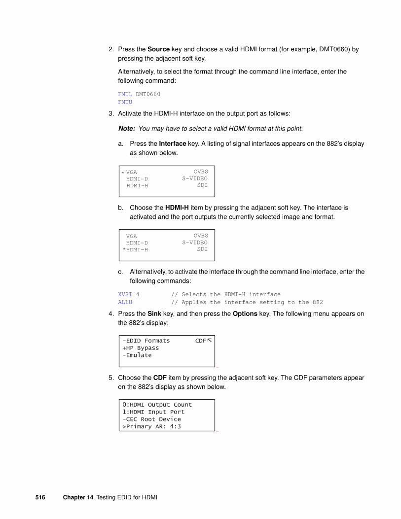
516 Chapter 14 Testing EDID for HDMI
2. Press the Source key and choose a valid HDMI format (for example, DMT0660) by pressing the adjacent soft key.
Alternatively, to select the format through the command line interface, enter the following command:
FMTL DMT0660
FMTU
3. Activate the HDMI-H interface on the output port as follows:
Note: You may have to select a valid HDMI format at this point.
a. Press the Interface key. A listing of signal interfaces appears on the 882’s display as shown below.
b. Choose the HDMI-H item by pressing the adjacent soft key. The interface is activated and the port outputs the currently selected image and format.
c. Alternatively, to activate the interface through the command line interface, enter the following commands:
XVSI 4 // Selects the HDMI-H interface
ALLU // Applies the interface setting to the 882
4. Press the Sink key, and then press the Options key. The following menu appears on the 882’s display:
Cho
5. Choose the CDF item by pressing the adjacent soft key. The CDF parameters appear on the 882’s display as shown below.
Cho.
VGA
HDMI-D
CVBS
S-VIDEO
SDI
*
HDMI-H
VGA
HDMI-D
CVBS
S-VIDEO
SDI*HDMI-H
-EDID Formats CDF+HP Bypass-Emulate
0:HDMI Output Count1:HDMI Input Port-CEC Root Device>Primary AR: 4:3

881/882 Video Test Instrument User Guide (Rev A.38) 517
6. Set characteristics of the display under test using CDF parameters. Scroll through the list by pressing the + key.
Refer to “Defining the capabilities of the display device under test” on page 508 for definitions for each parameter in the CDF.
Note: If you are running the EDID compliance test through the Compliance Controller,
you do not need to configure the CDF through the front panel.
Running the EDID compliance test through the front panel
Use the following procedure to run the EDID compliance test through the front panel. You can run the EDID compliance test through the front panel either by using the EDIDHDMI image or the EDID compliance report. Refer to “Running the HDMI EDID Compliance test report” on page 519 for instructions on running the EDID compliance test through the compliance report feature.
To perform HDMI sink EDID compliance testing using the EDID HDMI image:
1. Set up 882 for HDMI sink testing for EDID compliance. See “Setting up 882 for HDMI sink device EDID compliance testing” on page 511 on for details.
2. Press the Content key and choose the EdidHDMI image for testing displays connected to HDMI output 1 (usee EDIDHDM2 image for HDMI output 2) by pressing the adjacent soft key.
Alternatively, to select the image through the command line interface, enter the following command:
IMGL EdidHDMI
IMGU
3. Enable image versions for the EdidHDMI/EdidHDM2 image as follows:
a. Press the Options key. The following menu appears on the 882’s display:
b. Choose the More item by pressing the adjacent soft key until a + and Rendition appears next to the item.
Alternatively, to enable and view image versions using the command line interface, enter the following commands:
ISUB 1 // Enables sub images
-More Red+-NoGamma Green+-Noise Blue+
+More Rendition: 000 Red+-NoGamma Green+-Noise Blue+

518 Chapter 14 Testing EDID for HDMI
IVER 1 // Specifies the first image version
IMGU // Activates the image version
4. Press the + key to advance through the image versions and view results for tests 8-1, 8-2, 8-3, 8-17, 8-18, and 8-19. Test descriptions and sample screens are provided below.
• Testing EDID readability (Test ID 8-1)—this test verifies that the EDID can be read properly.
(
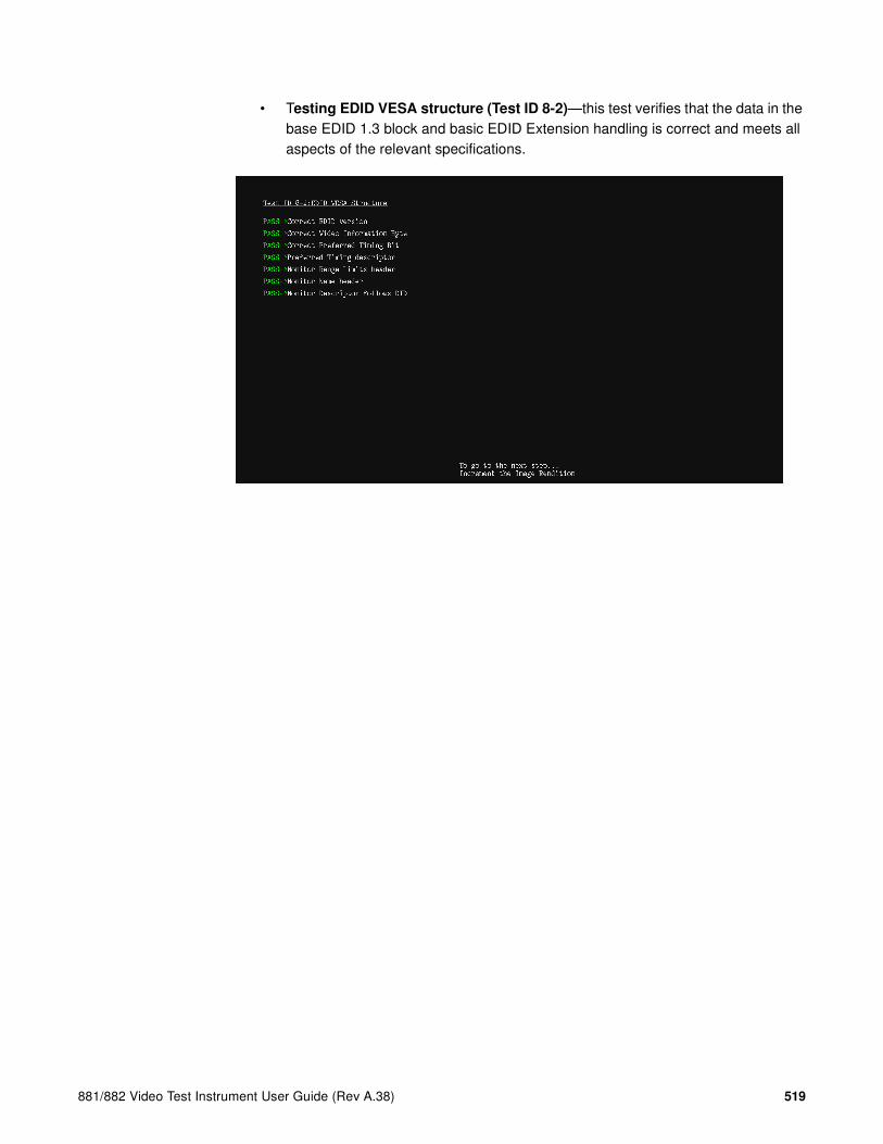
881/882 Video Test Instrument User Guide (Rev A.38) 519
• Testing EDID VESA structure (Test ID 8-2)—this test verifies that the data in the base EDID 1.3 block and basic EDID Extension handling is correct and meets all aspects of the relevant specifications.
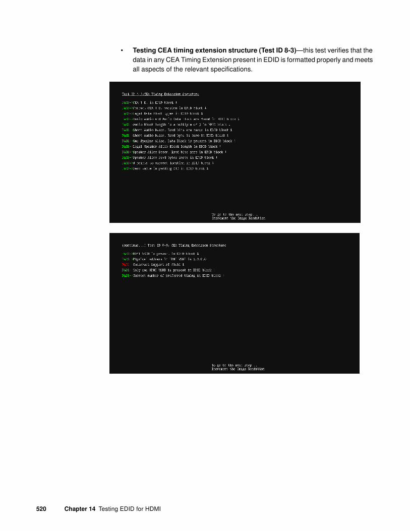
520 Chapter 14 Testing EDID for HDMI
• Testing CEA timing extension structure (Test ID 8-3)—this test verifies that the data in any CEA Timing Extension present in EDID is formatted properly and meets all aspects of the relevant specifications.

881/882 Video Test Instrument User Guide (Rev A.38) 521
• Testing 861C format support requirements (Test ID 8-17)—this test verifies that no 861D-defined video format is declared only in a Detailed Timing Descriptor.

522 Chapter 14 Testing EDID for HDMI
• Testing HDMI format support requirements (Test ID 8-18)—this test verifies that the display under test indicates support for all required video formats in its EDID.

881/882 Video Test Instrument User Guide (Rev A.38) 523
• Testing Pixel Encoding Requirements (Test ID 8-19)—verifies that the display under test supports YCbCr pixel encoding when required.
Running the HDMI EDID Compliance test report
Follow the procedure to generate an HTML report of EDID compliance test results. Prior to running this test you will need to configure the 882 for the test. Refer to “Setting up 882 for HDMI sink device EDID compliance testing” on page 511 for instructions on setting up the 882 for the EDID test.
To generate a report of EDID compliance test results:
1. Press the Tools key. The Tools menu appears on the 882’s display as shown below.
2. Press the Reports key. The Reports menu appears on the 882’s display as shown below.
System
Sequence
Probe
AFC
Analyzer
Reports
ImgShift
EDID Packets
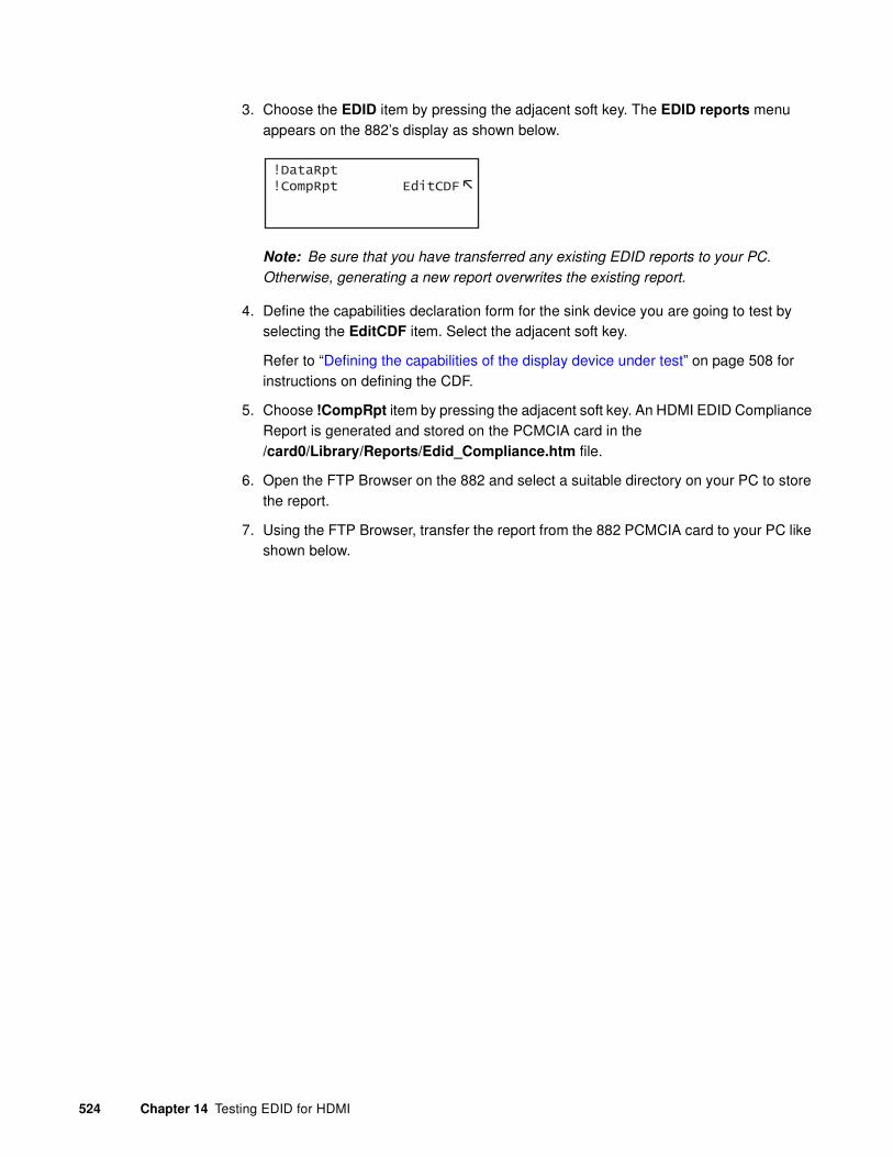
524 Chapter 14 Testing EDID for HDMI
3. Choose the EDID item by pressing the adjacent soft key. The EDID reports menu appears on the 882’s display as shown below.
Note: Be sure that you have transferred any existing EDID reports to your PC.
Otherwise, generating a new report overwrites the existing report.
4. Define the capabilities declaration form for the sink device you are going to test by selecting the EditCDF item. Select the adjacent soft key.
Refer to “Defining the capabilities of the display device under test” on page 508 for instructions on defining the CDF.
5. Choose !CompRpt item by pressing the adjacent soft key. An HDMI EDID Compliance Report is generated and stored on the PCMCIA card in the /card0/Library/Reports/Edid_Compliance.htm file.
6. Open the FTP Browser on the 882 and select a suitable directory on your PC to store the report.
7. Using the FTP Browser, transfer the report from the 882 PCMCIA card to your PC like shown below.
!DataRpt !CompRpt EditCDF

881/882 Video Test Instrument User Guide (Rev A.38) 525
Note: Make sure to change the names of any existing reports in the directory on your
PC to avoid overwritting existing reports.

526 Chapter 14 Testing EDID for HDMI
8. Navigate to your PC and double click on the report. A sample is shown below.
Running the HDMI EDID Compliance using the Compliance
Controller
Follow the procedure below to run the EDID HDMI compliance test using the Compliance Controller (available in release 2.18 or later). Prior to running this test you will need to configure the 882 for the test. Refer to “Setting up 882 for HDMI sink device EDID compliance testing” on page 511 for instructions on setting up the 882 for the EDID test.

881/882 Video Test Instrument User Guide (Rev A.38) 527
To run the EDID HDMI compliance test using the Compliance Controller:
1. Open a Web browser (such as Internet Explorer) and type the 882’s IP address in the address entry field. For example, enter the following: http://206.135.215.189/
The 882 home page appears in the browser.
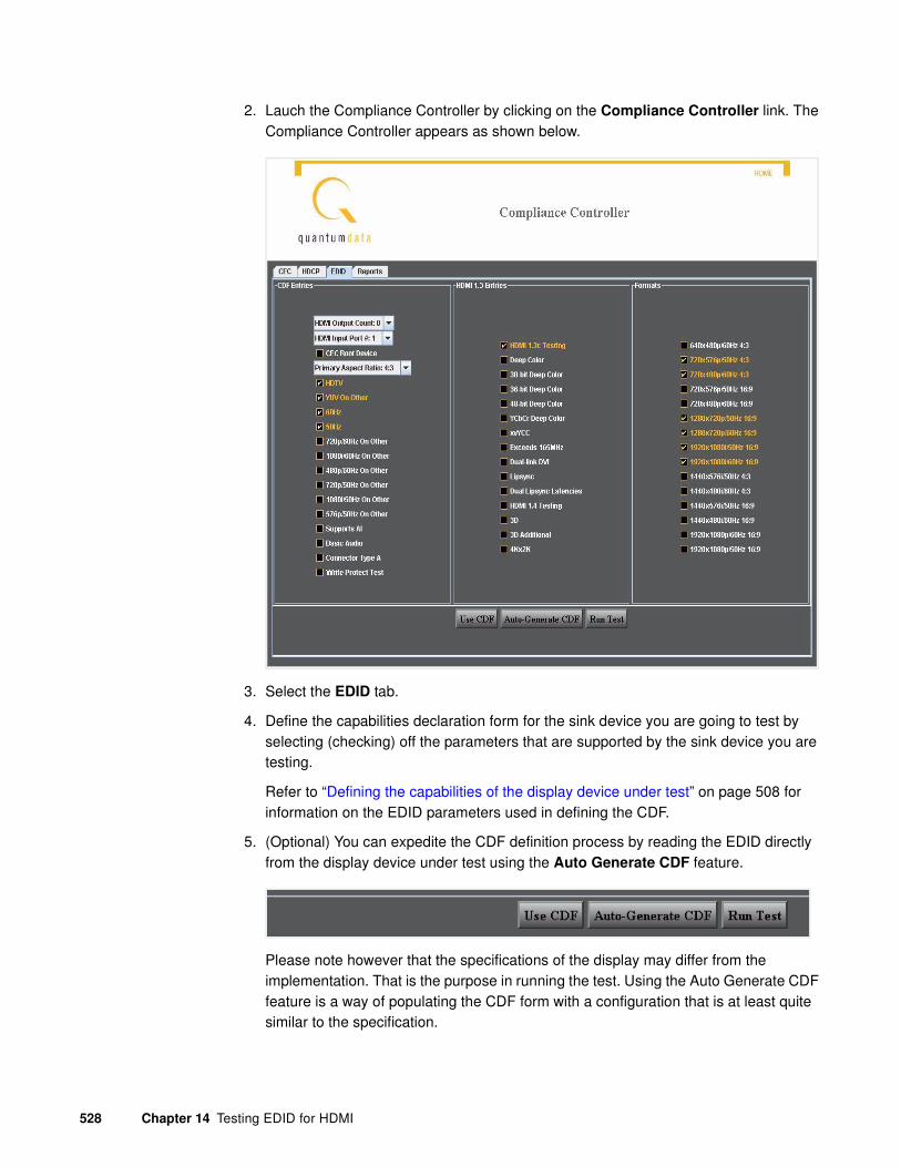
528 Chapter 14 Testing EDID for HDMI
2. Lauch the Compliance Controller by clicking on the Compliance Controller link. The Compliance Controller appears as shown below.
3. Select the EDID tab.
4. Define the capabilities declaration form for the sink device you are going to test by selecting (checking) off the parameters that are supported by the sink device you are testing.
Refer to “Defining the capabilities of the display device under test” on page 508 for information on the EDID parameters used in defining the CDF.
5. (Optional) You can expedite the CDF definition process by reading the EDID directly from the display device under test using the Auto Generate CDF feature.
Please note however that the specifications of the display may differ from the implementation. That is the purpose in running the test. Using the Auto Generate CDF feature is a way of populating the CDF form with a configuration that is at least quite similar to the specification.
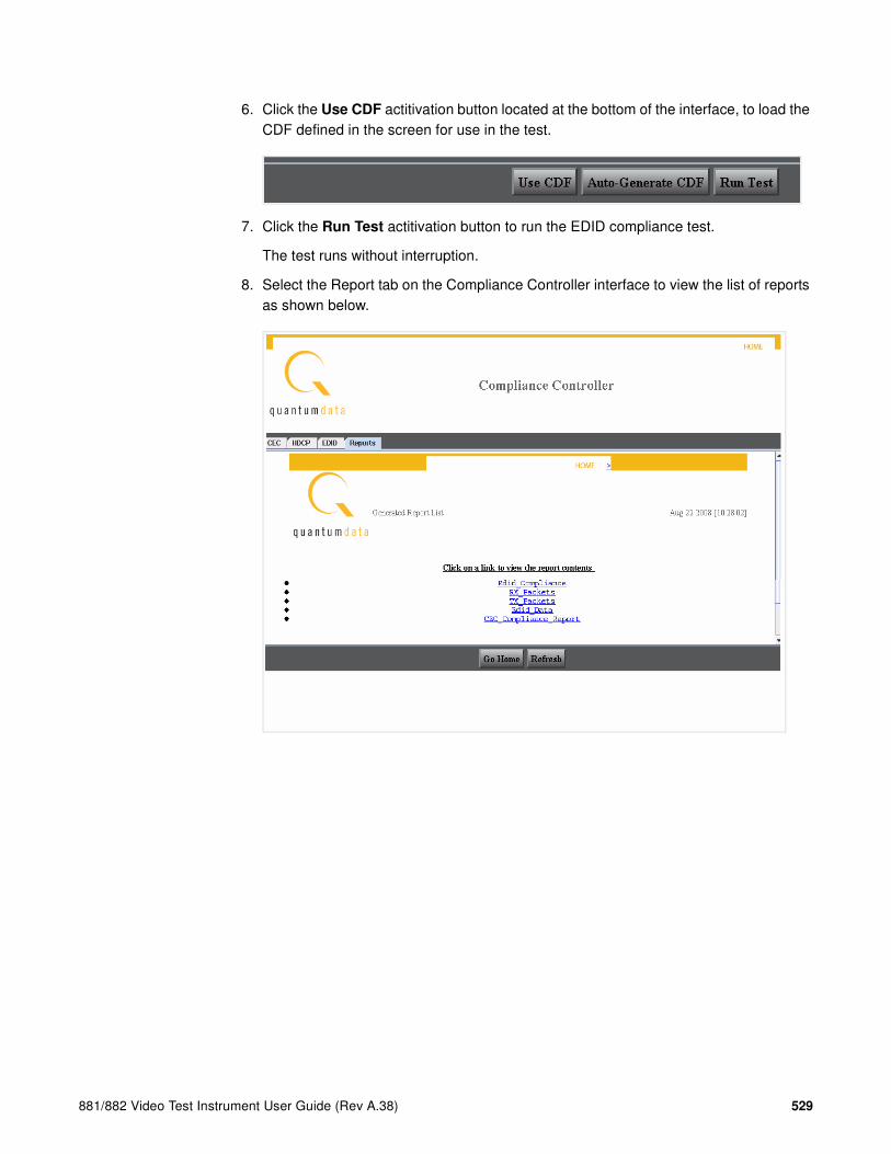
881/882 Video Test Instrument User Guide (Rev A.38) 529
6. Click the Use CDF actitivation button located at the bottom of the interface, to load the CDF defined in the screen for use in the test.
7. Click the Run Test actitivation button to run the EDID compliance test.
The test runs without interruption.
8. Select the Report tab on the Compliance Controller interface to view the list of reports as shown below.
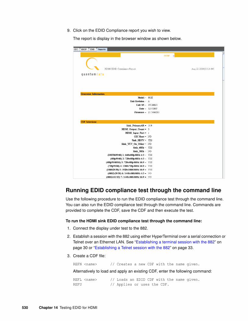
530 Chapter 14 Testing EDID for HDMI
9. Click on the EDID Compliance report you wish to view.
The report is display in the browser window as shown below.
Running EDID compliance test through the command line
Use the following procedure to run the EDID compliance test through the command line. You can also run the EDID compliance test through the command line. Commands are provided to complete the CDF, save the CDF and then execute the test.
To run the HDMI sink EDID compliance test through the command line:
1. Connect the display under test to the 882.
2. Establish a session with the 882 using either HyperTerminal over a serial connection or Telnet over an Ethernet LAN. See “Establishing a terminal session with the 882” on page 30 or “Establishing a Telnet session with the 882” on page 33.
3. Create a CDF file:
REFN <name> // Creates a new CDF with the name given.
Alternatively to load and apply an existing CDF, enter the following command:
REFL <name> // Loads an EDID CDF with the name given.
REFU // Applies or uses the CDF.

881/882 Video Test Instrument User Guide (Rev A.38) 531
4. Complete the CDF parameters using the information in the table below. For example to indicate that 60Hz timings are supported and 3D formats are supported, enter the following command:
HZ60 1 // 60HZ frame rate is supported.
3DOK 0 // 3D formats are not supported.
Parameter Command Name Explanation
HDMI Output Count OCNT The number of outputs the sink under test has. It is a value in the range of 0-9.
HDMI Input Port DIPN The CEC input on the sink under test. It is a value in the range of 1-15.
CEC Root Device CECR Indicates if the CEC device is a root device (i.e. a TV without a repeater). The values are 1 for yes and 0 for no.
Primary AR: 4:3 PRAR Indicates the primary aspect ratio of the sink device under test is 4:3. The values are 1 for yes and 0 for no.
HDTV HDTV Indicates if the sink under test supports HDTV. TThe values are 1 for yes and 0 for no.
YUV on Other YUVO Indicates if the sink under test supports YUV. The values are 1 for yes and 0 for no.
60Hz HZ60 Indicates whether the device supports formats with 60Hz frame rate. The values are 1 for yes and 0 for no.
50Hz HZ50 Indicates whether the sink under test supports formats with 50Hz frame rate. The values are 1 for yes and 0 for no.
640x480p/60 FMT7 Indicates whether the sink supports the DMT0660 format. The values are 1 for yes and 0 for no.
720x480p/60 4:3 FMT3 Indicates whether the sink supports the 480p60 format with a 4:3 aspect ratio. The values are 1 for yes and 0 for no.
720x480p/60 16:9 FMT8 Indicates whether the sink supports the 480p60SH format with a 16:9 aspect ratio. The values are 1 for yes and 0 for no.
1280x720p/60 16:9 FMT1 Indicates whether the sink under test supports the 720p60 format. The values are 1 for yes and 0 for no.
1920x1080i/60 16:9 FMT2 Indicates whether the sink under test supports the 1080i60 format. The values are 1 for yes and 0 for no.

532 Chapter 14 Testing EDID for HDMI
1440x480i/60 4:3 FM10 Indicates whether the sink under test supports the 480i2x60 format with double clocking at 4:3 aspect ratio. The values are 1 for yes and 0 for no.
1440x480i/60 16:9 FM11 Indicates whether the sink under test supports the 480i2x60 format with double clocking at 16:9 aspect ratio. The values are 1 for yes and 0 for no.
720x576p/50 4:3 FMT6 Indicates whether the sink supports the 576p50 format with a 4:3 aspect ratio. The values are 1 for yes and 0 for no.
720x576p/50 16:9 FM13 Indicates whether the sink supports the 576p50 format with a 16:9 aspect ratio. The values are 1 for yes and 0 for no.
1280x720p/50 16:9 FMT4 Indicates whether the sink under test supports the 720p50 format. The values are 1 for yes and 0 for no.
1920x1080i/50 16:9 FMT5 Indicates whether the sink under test supports the 1080i50 format. The values are 1 for yes and 0 for no.
1440x576i/50 4:3 FM12 Indicates whether the sink under test supports the 576i2x50 format with double clocking at 4:3 aspect ratio. he values are 1 for yes and 0 for no.
1440x576i/50 16:9 FM13 Indicates whether the sink under test supports the 576i2x50 format with double clocking at 16:9 aspect ratio. The values are 1 for yes and 0 for no.
720p/60 On Other FMO1 Indicates whether the sink under test supports the analog component video input for 720p60. The values are 1 for yes and 0 for no.
1080i/60 On Other FMO2 Indicates whether the sink under test supports the analog component video input for 1080i60. The values are 1 for yes and 0 for no.
480p/60 On Other FMO3 Indicates whether the sink under test supports the analog component video input for 480p60. The values are 1 for yes and 0 for no.
720p/50 On Other FMO4 Indicates whether the sink under test supports the analog component video input for 720p50. The values are 1 for yes and 0 for no.
1080i/50 On Other FMO5 Indicates whether the sink under test supports the analog component video input for 1080i50. The values are 1 for yes and 0 for no.
576p/50 On Other FMO6 Indicates whether the sink under test supports the analog component video input for 576p50. The values are 1 for yes and 0 for no.
Parameter Command Name Explanation
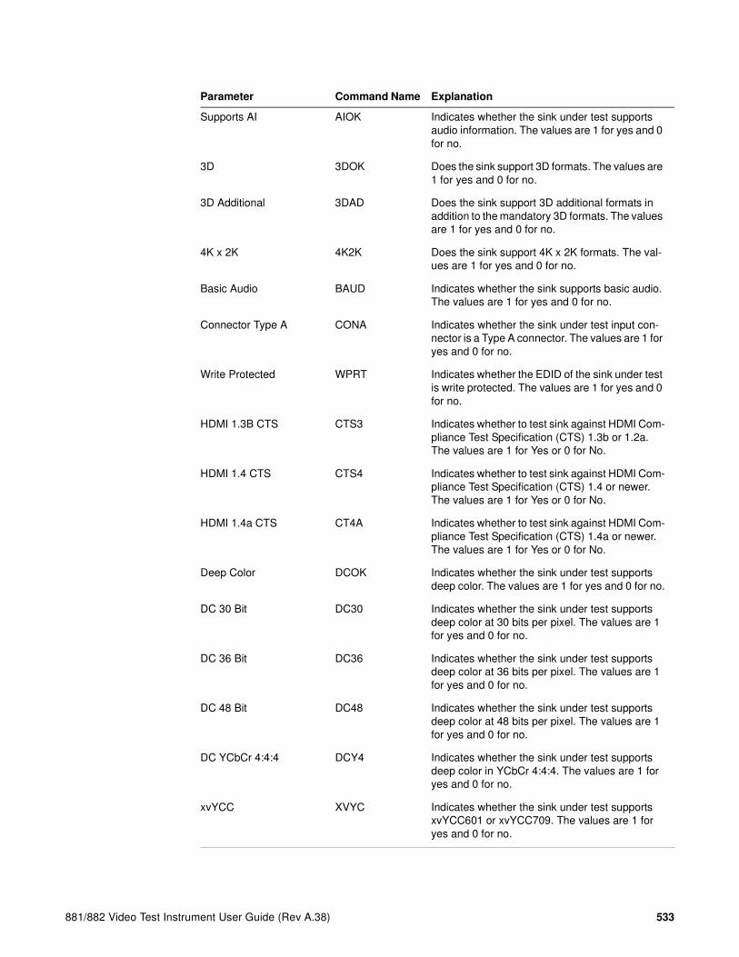
881/882 Video Test Instrument User Guide (Rev A.38) 533
Supports AI AIOK Indicates whether the sink under test supports audio information. The values are 1 for yes and 0 for no.
3D 3DOK Does the sink support 3D formats. The values are 1 for yes and 0 for no.
3D Additional 3DAD Does the sink support 3D additional formats in addition to the mandatory 3D formats. The values are 1 for yes and 0 for no.
4K x 2K 4K2K Does the sink support 4K x 2K formats. The val-ues are 1 for yes and 0 for no.
Basic Audio BAUD Indicates whether the sink supports basic audio. The values are 1 for yes and 0 for no.
Connector Type A CONA Indicates whether the sink under test input con-nector is a Type A connector. The values are 1 for yes and 0 for no.
Write Protected WPRT Indicates whether the EDID of the sink under test is write protected. The values are 1 for yes and 0 for no.
HDMI 1.3B CTS CTS3 Indicates whether to test sink against HDMI Com-pliance Test Specification (CTS) 1.3b or 1.2a. The values are 1 for Yes or 0 for No.
HDMI 1.4 CTS CTS4 Indicates whether to test sink against HDMI Com-pliance Test Specification (CTS) 1.4 or newer. The values are 1 for Yes or 0 for No.
HDMI 1.4a CTS CT4A Indicates whether to test sink against HDMI Com-pliance Test Specification (CTS) 1.4a or newer. The values are 1 for Yes or 0 for No.
Deep Color DCOK Indicates whether the sink under test supports deep color. The values are 1 for yes and 0 for no.
DC 30 Bit DC30 Indicates whether the sink under test supports deep color at 30 bits per pixel. The values are 1 for yes and 0 for no.
DC 36 Bit DC36 Indicates whether the sink under test supports deep color at 36 bits per pixel. The values are 1 for yes and 0 for no.
DC 48 Bit DC48 Indicates whether the sink under test supports deep color at 48 bits per pixel. The values are 1 for yes and 0 for no.
DC YCbCr 4:4:4 DCY4 Indicates whether the sink under test supports deep color in YCbCr 4:4:4. The values are 1 for yes and 0 for no.
xvYCC XVYC Indicates whether the sink under test supports xvYCC601 or xvYCC709. The values are 1 for yes and 0 for no.
Parameter Command Name Explanation

534 Chapter 14 Testing EDID for HDMI
5. To save the CDF file for later recall and use, enter the following command:
REFS // Creates a new CDF with the name given.
6. To run the EDID compliance test, enter the following command:
ECTU // Runs the EDID compliance test against the CDF
that has been loaded.
Exceeds 165MHz E165 Indicates whether the sink under test supports any video format/color mode with a TMDS clock frequency above 165MHz. The values are 1 for yes and 0 for no.
1920x1080p/60 16:9 FM14 Indicates whether the sink under test supports the 1080p60 format at 16:9 aspect ratio. The val-ues are 1 for yes and 0 for no.
1920x1080p/50 16:9 FM15 Indicates whether the sink under test supports the 1080p50 format at 16:9 aspect ratio. The val-ues are 1 for yes and 0 for no.
Dual-Link DVI DLDV Indicates whether the sink under test supports dual-link DVI. The values are 1 for yes and 0 for no.
Lipsync Indicated LIPS Indicates whether the EDID of the sink under test indicates lipsync latency values. The values are 1 for yes and 0 for no.
Dual Latencies LATS Indicates whether the sink under test’s audio and video latency is substantially different when han-dling interlaced video formats versus when han-dling progressive video formats. The values are 1 for yes and 0 for no.
Parameter Command Name Explanation
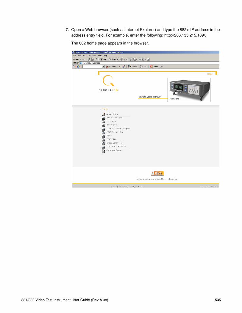
881/882 Video Test Instrument User Guide (Rev A.38) 535
7. Open a Web browser (such as Internet Explorer) and type the 882’s IP address in the address entry field. For example, enter the following: http://206.135.215.189/.
The 882 home page appears in the browser.
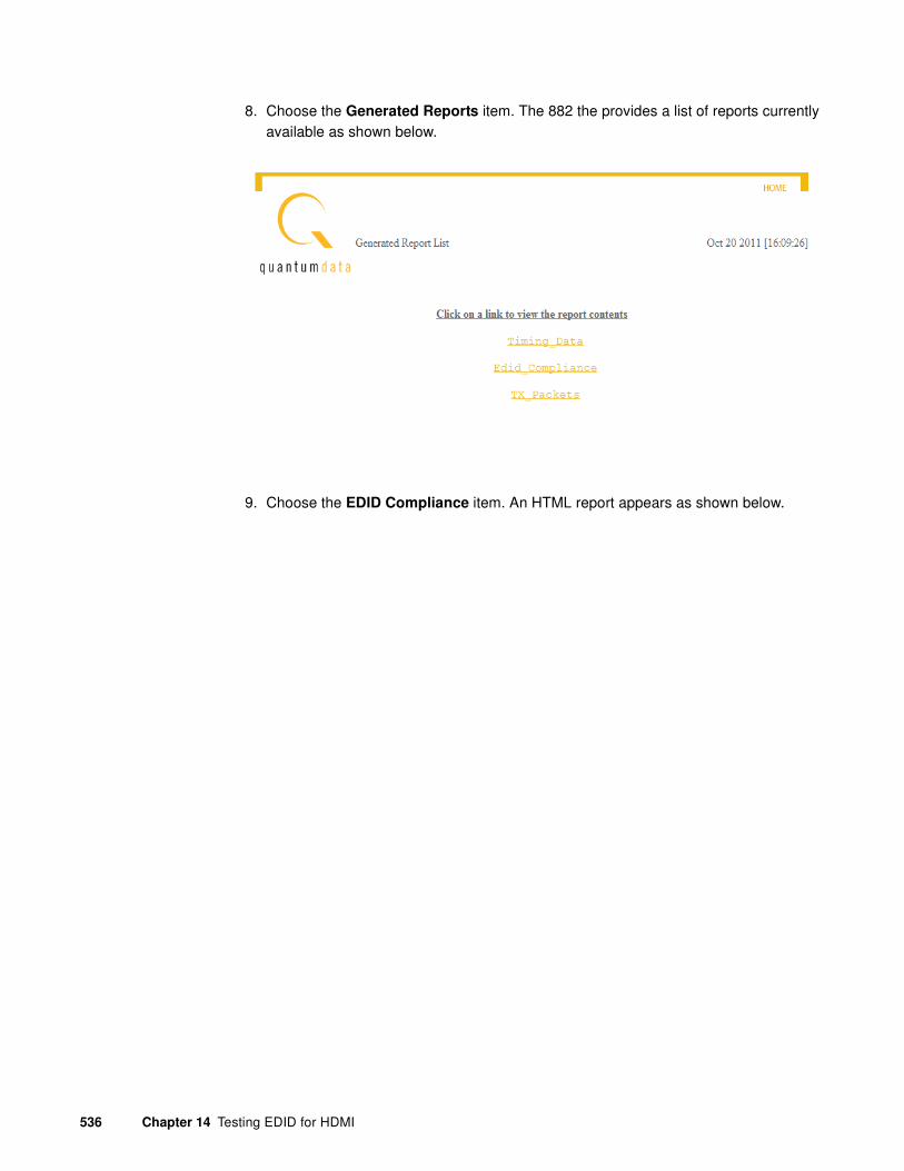
536 Chapter 14 Testing EDID for HDMI
8. Choose the Generated Reports item. The 882 the provides a list of reports currently available as shown below.
9. Choose the EDID Compliance item. An HTML report appears as shown below.

881/882 Video Test Instrument User Guide (Rev A.38) 537
10. Click on the EDID Compliance report you wish to view.
The report is display in the browser window as shown below.
Verifying pixel encoding and rate support
For test IDs 8-19 and 8-20, visual inspection of display under test is necessary to ensure proper support of pixel encoding sampling and minimum and maximum pixel clock rates using different formats. Test ID 8-19 involves testing each format with both YCbCr 4:4:4 and YCbCr 4:2:2 pixel sampling, while test ID 8-20 requires testing each format listed in the EDID at both minimum and maximum pixel clock frequencies permitted by the source device. Pixel clock rate values are as follows:
• For 50 Hz formats, the values are 49.75 Hz and 50.25 Hz (50 Hz ± 0.5%).
• For 59.94 Hz or 60 Hz formats, the frequencies are 59.64 Hz (59.94 Hz – 0.5%) and 60.3 Hz (60Hz + 0.5%).
• The tested pixel clock frequency accuracy shall be ±0.05%
To support this testing, a list of SVD formats are provided in the Source list. For pixel
encoding testing, the format naming nomenclature used is shown below:

538 Chapter 14 Testing EDID for HDMI
Example
• SVD – Short Video Descriptor
• 01 – EIA/CEA-861-C Format Video Identification Code (for example, 01, 02, 06, etc., listed on page 149)
• Y2 – Y indicates color difference. 2 = 4:2:2 pixel sample encoding. 4 = 4:4:4.
• 1 – Represents DMT0659 format, which is the first format (index 1) listed under video identification code 01 in the table on page 328.
For pixel rate testing, the format naming nomenclature used is shown below:
• SVD – Short Video Descriptor
• 01 – EIA/CEA-861-C Format Video Identification Code (for example, 01, 02, 06, etc,. listed on page 328)
• H – Indicates the format is using the maximum (H = High) frequency required by the compliance test; L indicates the format is using the minimum (L = Low) frequency required by the compliance test.
• 01 – Represents the index of the format as listed under video identification code on page 328.
To verify proper pixel encoding and pixel rate support:
1. Connect the 882 to the display under test.
2. Press the Sink key. The following information appears on the 882’s display.
Short
Video
Descriptor
VIC Format
Index
0 1 YS V D 2
Component
color
sampling
1
Short
Video
Descriptor
VIC Format
Index
0 1 HS V D 0
Frequency
(High / Low)
1
Manufacturer:SNYProduct Code:144Serial#:7011007Week:20 Year:1998

881/882 Video Test Instrument User Guide (Rev A.38) 539
3. Press the Options key. The following information appears on the 882’s display.
4. Choose the EDID Formats item by pressing the adjacent soft key. A + appears next to EDID Formats, indicating it is enabled.
The 882 loads the Source list with formats supported by the connected display (hot-plug formats read via EDID structure of attached display).
5. Press the Content key. The following information appears on the 882’s display.
6. Select an image suitable for testing the display type (such as Master) by pressing the soft key adjacent to the image.
Alternatively, to select the image using the command line interface, enter the following command:
IMGL Master
IMGU
7. Press the Source key and select a format beginning with SVD by pressing the adjacent soft key.
8. On display under test, verify format displays image properly.
9. Repeat steps 7 and 8 to test each SVD format.
-EDID Formats CDF+HP Bypass-Emulate
Acer1 Acer2 Acer3 Acer4 Acer5 Acer6 Acer7 Acer8

540 Chapter 14 Testing EDID for HDMI
Testing EDID for HDMI compliance in source devices
The 882EA and 882CA analyzers support the following EDID and video HDMI compliance tests in accordance with the HDMI Compliance Test Specification 1.3 (CTS):
• Test ID 7-1: EDID Related Behavior
This test is intended for in-house testing of products before submission to an HDMI ATC for full certification testing.
Overview of HDMI compliance testing
HDMI source compliance Test ID 7-1 is conducted through the 882’s HDMI IN connector. A standard HDMI-to-HDMI cable connects the device under test to the 882. The 882 must be configured to output HDMI signals.
Testing HDMI source devices for EDID compliance
The procedures for EDID and video testing of HDMI sink devices in accordance with the HDMI Compliance Test Specification 1.3 are provided below.
Note: Always make sure the 882 is using the lastest firmware.
To run the HDMI EDID source compliance test:
1. Connect an HDMI-to-HDMI cable between the HDMI OUT connector on the source device under test and the first HDMI connector on the TPA-DDC-RR Test Point Adapter.

881/882 Video Test Instrument User Guide (Rev A.38) 541
2. Connect an HDMI-to-HDMI cable between the HDMI IN connector on the 882 generator/analyzer and the second HDMI connector on the TPA-DDC-RR Test Point Adapter.
The figure below shows the TPA-DDC-RR device.
The following diagram illustrates the test setup.
DDC Dynamic Elecrical Test Fixture
Model TPA-DDC-RR
HDMI SDALOAD
1 = 1400pf
2 = 750pf
+ -
HDMI
1
2
SDA
+ -
Device under
test (source)
882CA EDID
Emulator
Host PC with
Auxiliary Channel Analyzer
DDC Dynamic
Electrical Test Fixture
HDMI HDMIHDMI TX HDMI RX
HDMI RX

542 Chapter 14 Testing EDID for HDMI
3. Configure the 882 to operate in the HDMI mode.
a. Press the Interface key. A listing of signal interfaces appears on the 882’s display as shown below.
b. Choose the HDMI-H item by pressing the adjacent soft key. The interface is activated and the port outputs the currently selected image and format.
c. Alternatively, to activate the interface through the command line interface, enter the following commands:
XVSI 4 // Selects the HDMI-H interface
ALLU // Applies the interface setting to the 882
4. Press the Interface key repeatedly until the following menu appears:
5. Choose the HDMI IN connector to which the source device under test is connected to by pressing the adjacent soft key.
6. Configure the generator/analyzer port you selected in the previous step to emulate the desired 2-block EDID using the procedures in “Testing EDID handling of source device” on page 13 or “The EDID that was loaded into the EDID Editor tool is now configured on the HDMI Rx port you selected (882 HDMI Rx 1 port in the example above).” on page 560.
If you need to create a custom EDID, use the EDID Editor utility described in “Creating a new EDID” on page 549.
7. Set the capacitance to the desired value by flipping the toggle switch to the “2” position (720pF).
8. Power on the source device under test.
VGA
HDMI-D
CVBS
S-VIDEO
SDI
*
HDMI-H
VGA
HDMI-D
CVBS
S-VIDEO
SDI*HDMI-H
HDMI IN 1
HDMI IN 2*

881/882 Video Test Instrument User Guide (Rev A.38) 543
9. Follow the procedures in the HDMI CTS specification for Test ID 7-1: EDID Related Behavior.
You can use the ACA to view the transactions of the EDID read. Refer to the procedure “To monitor the EDID transactions on the DDC (I2C) bus (channel):” on page 493.
During the procedure, you will have to pulse the hot plug detect lead for 100ms to cuase the source to read the 882 analyer’s EDID. To do this, use the DIDU command:
DIDU
Verify that all 256 bytes are present in the EDID by examining the ACA traces. Also verify that speed of the DDC transmission. The DDC transmission should be 100kHz or slower.
10. Repeat the procedure in the previous step for a 4-block EDID using the procedures in “Testing EDID handling of source device” on page 13 or “The EDID that was loaded into the EDID Editor tool is now configured on the HDMI Rx port you selected (882 HDMI Rx 1 port in the example above).” on page 560.
If you need to create a custom EDID, use the EDID Editor utility described in “Creating a new EDID” on page 549.

544 Chapter 14 Testing EDID for HDMI
EDID emulation for physical layer testing of source devices
The 882C/E supports some of the physical layer tests called out in the HDMI CTS such as eye measurements and TMDS rise and fall time measurements. These tests are performed using commercially available oscillocopes recommended in the HDMI CTS. In support of these tests, the Multi-Purpose Adaptor (TPA-MP-4R shown below) provides EDID emulation, a hot plug source and AVcc power source.
While standard HDMI-to-HDMI cables connect the 882 to the TPA-MP-4R device, cables available as an option through Quantum Data are used to connect that device to the source device under test. Two methods for testing EDID compliance with HDMI source devices are shown below. One uses the Tektronix Test Instrument and the second uses the Agilent Test Instrument.
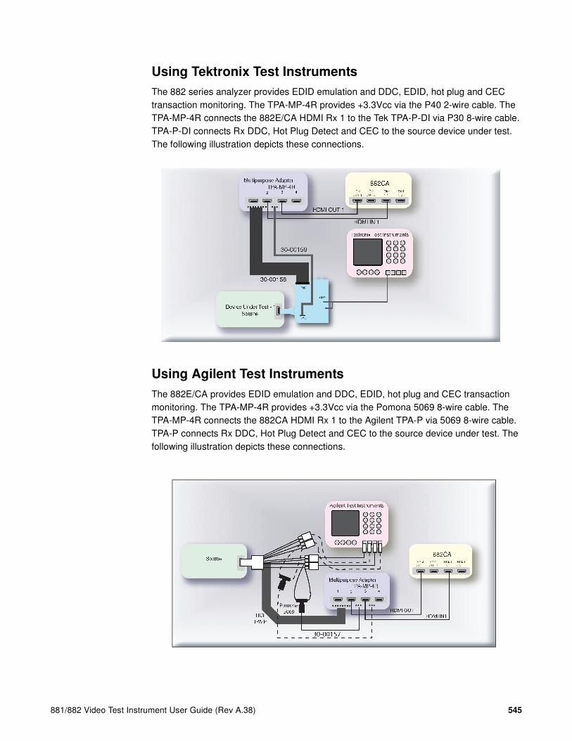
881/882 Video Test Instrument User Guide (Rev A.38) 545
Using Tektronix Test Instruments
The 882 series analyzer provides EDID emulation and DDC, EDID, hot plug and CEC transaction monitoring. The TPA-MP-4R provides +3.3Vcc via the P40 2-wire cable. The TPA-MP-4R connects the 882E/CA HDMI Rx 1 to the Tek TPA-P-DI via P30 8-wire cable. TPA-P-DI connects Rx DDC, Hot Plug Detect and CEC to the source device under test. The following illustration depicts these connections.
Using Agilent Test Instruments
The 882E/CA provides EDID emulation and DDC, EDID, hot plug and CEC transaction monitoring. The TPA-MP-4R provides +3.3Vcc via the Pomona 5069 8-wire cable. The TPA-MP-4R connects the 882CA HDMI Rx 1 to the Agilent TPA-P via 5069 8-wire cable. TPA-P connects Rx DDC, Hot Plug Detect and CEC to the source device under test. The following illustration depicts these connections.
Multipurpose Adapter
TPA-MP-4R1 2 3 4
Agilent Test Instruments
Pomona
5069HOI
TPA-P
HDMI OUT1 HDMI IN1
30-00157

546 Chapter 14 Testing EDID for HDMI
Using the EDID Editor tool
The 882 provides an EDID Editor Tool. This tool is useful for creating, modifying, and saving EDIDs, as well as applying EDIDs to HDMI emulator ports for source testing.
Using the EDID Editor Tool involves the following basic steps:
1. Loading an EDID into the Editor. An EDID is loaded from a file stored on the 882 file system or host PC, or by capturing and loading an EDID from a display connected to the 882x HDMI or VGA interface.
2. Modifying EDID settings using the tool’s user-friendly graphical interface. Operations are accomplished using check boxes, text fields and pull-down list boxes with human readable field descriptions and value options.
3. Saving a modified EDID to a file stored on the 882 file system or host PC, and/or by putting (writing) the EDID on a display connected to the 882CA or 882EA HDMI interface (display must have writable EEPROM).
4. For source testing, applying an EDID to one of the HDMI DisplayPort Rx ports for emulation.
Note: When creating EDIDs for source testing (for computer monitors in the IT market or
TV displays in the CE market), it is important to understand the specifications which define
the structure of the EDID you are creating. The EDID structure is defined by VESA and and
the extensions are defined by the CEA in the 861 specification.
Loading EDIDs with the EDID Editor
The procedure below provides instructions on loading EDIDs into the EDID Editor Tool.
To load an EDID:
1. Make appropriate cable connection as follows:
• If you are capturing and loading an EDID from an HDMI display, connect an HDMI-to-HDMI cable between the HDMI OUT connector on the 882 and the HDMI connector on the display under test.
• If you are loading an EDID from one of the HDMI Rx ports on the 882, connect an HDMI-to-HDMI cable between the HDMI Tx connector on the 882 and the HDMI Rx input ports that is configured with the EDID you wish to load.

881/882 Video Test Instrument User Guide (Rev A.38) 547
2. Activate the HDMI-H interface on the output port:
a. Press the Interface key to access the list of interfaces. A listing of signal interfaces appears on the 882’s display as shown below.
b. Choose the HDMI-H item by pressing the adjacent soft key.
The interface is activated and the port outputs the currently selected image and format.
Alternatively, to select the interface through the command line, enter the following commands:
XVSI 4 // Selects the HDMI-H interface
ALLU // Applies the interface setting to the 882
3. Press the Source key and choose a valid HDMI format (for example, DMT0660) by pressing the adjacent soft key.
Alternatively, to select the format through the command line interface, enter the following command:
FMTL DMT0660
FMTU
VGA
HDMI-D
CVBS
S-VIDEO
SDI
*
HDMI-H
VGA
HDMI-D
CVBS
S-VIDEO
SDI*HDMI-H

548 Chapter 14 Testing EDID for HDMI
4. Open a Web browser (such as Internet Explorer) and type the 882’s IP address in the address entry field. For example, enter the following: http://206.135.215.189/
The 882 home page appears in the browser.
5. Click the EDID Editor link. The EDID Editor appears as shown below.
Note: The EDID Editor is provisioned with the default Quantum Data EDID when
opened.

881/882 Video Test Instrument User Guide (Rev A.38) 549
6. Choose the EDID you want to load into the Editor. You can load EDIDs from a connected device, the 882 file system, or from your PC. The following table describes what selection ports map to which physical interface:
a. If you are loading an EDID XML file stored on the 882 generator, select Load EDID
From > 882 from the File menu. Select a valid file.
The EDID is loaded into the Editor.
b. If you are capturing and loading an EDID from a connected display device, select Load EDID From > Device Connected to > 882 Analyzer Port <x> from the File menu. (Port 1 is HDMI Tx 1, Port 2 is HDMI TX 2, and Port 3 is VGA.)
Load EDID From... Location
882 A valid EDID XML file stored on the 882 file sys-tem (in flash memory or on the PC card).
Device connected to 882 A device that is connected either to the 882’s HDMI Tx ports or the VGA port:
- 882 Analyzer Port 1 - HDMI Tx 1 - 882 Analyzer Port 2 - HDMI Tx 2 - 882 Analyzer Port 3 - VGA
File on PC A valid EDID XML file stored in the host PC.

550 Chapter 14 Testing EDID for HDMI
c. If you are loading an EDID XML file stored on the host PC, select Load EDID From
> File on PC from the File menu. Select a file.
The EDID is loaded into the Editor.
Editing an existing EDID
The procedure below provides instructions on editing EDIDs in the EDID Editor Tool.

881/882 Video Test Instrument User Guide (Rev A.38) 551
To edit an existing EDID:
1. Open the EDID Editor and load an EDID using the procedures described in “Loading EDIDs with the EDID Editor” on page 542.

552 Chapter 14 Testing EDID for HDMI
2. Expand the EDID Block in the navigation view.

881/882 Video Test Instrument User Guide (Rev A.38) 553
3. Double-click on the EDID data blocks you wish to edit.
Edit the pull-down select boxes, text fields and check boxes in accordance with the requirements of the EDID you are creating. The screen shot below shows a typical dialog box for editing the Timing Descriptor Detailed Timing Descriptor. Make sure to click on the OK button when you have completed the edits for each dialog box.
4. Save the modified EDID using the procedures described in “Saving an EDID to a file” on page 558.
Creating a new EDID
The procedure below provides instructions on creating a new EDID in the EDID Editor Tool. This procedure shows how you would create a new, 4-block EDID from the default Quantum Data 2-block EDID.
Note: To create a new EDID, you will need to obtain all the information for the various fields
in the EDID.

554 Chapter 14 Testing EDID for HDMI
To create a new EDID:
1. Open the EDID Editor and load the EDID using the procedures “Loading EDIDs with the EDID Editor” on page 542.
Upon power up the HDMI Rx ports are configured with the Quantum Data 2 block EDID.
2. Expand the EDID Block in the navigation view.

881/882 Video Test Instrument User Guide (Rev A.38) 555
3. Edit the fields in Block#1 in accordance with your requirements.
This screen shows the Vendor/Product Information screen where you will need to make some edits. When you change the value of any field (either a free form text field, pull-down select box or check box), make sure to click the OK button to invoke the change. If you make a change by mistake, click on the Cancel button.

556 Chapter 14 Testing EDID for HDMI
4. Add the CEA extension blocks by selecting New CEA Block from the Add pull down menu as shown below.
When you add a CEA block, both Block #2 and Block #3 are added. In addition, the Extension Flag field in Block #0 is updated with the value of 3.
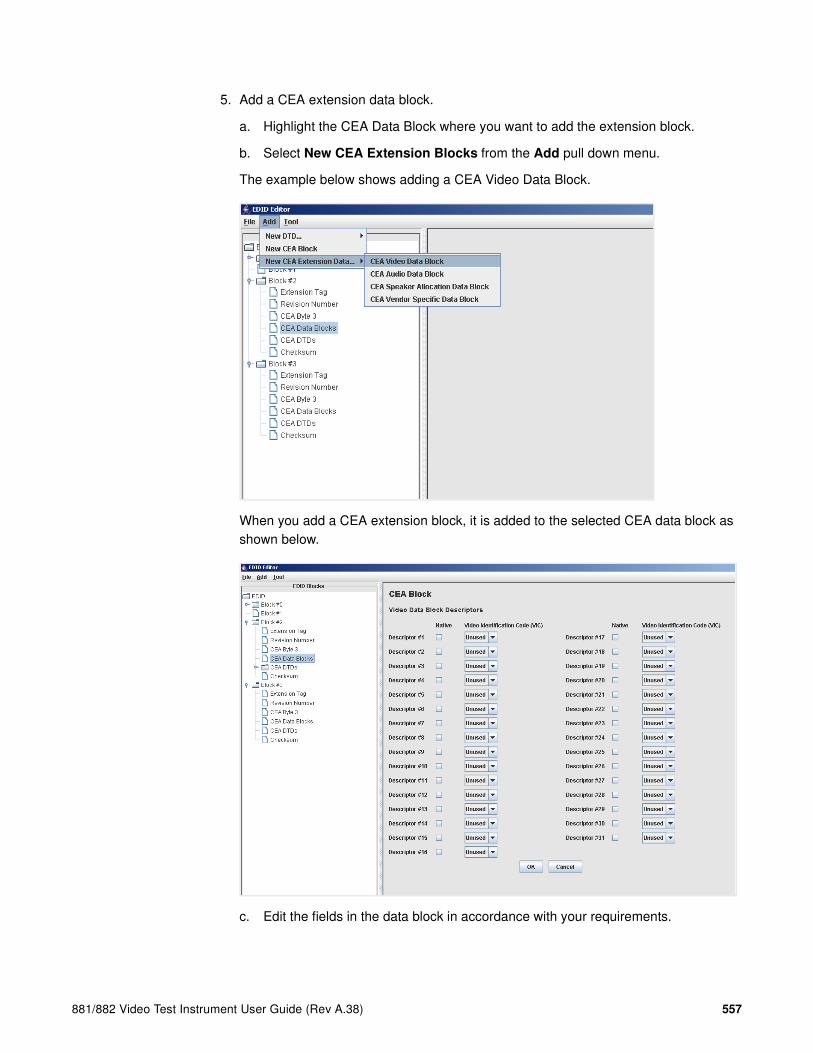
881/882 Video Test Instrument User Guide (Rev A.38) 557
5. Add a CEA extension data block.
a. Highlight the CEA Data Block where you want to add the extension block.
b. Select New CEA Extension Blocks from the Add pull down menu.
The example below shows adding a CEA Video Data Block.
When you add a CEA extension block, it is added to the selected CEA data block as shown below.
c. Edit the fields in the data block in accordance with your requirements.

558 Chapter 14 Testing EDID for HDMI
d. Click the OK button to save the data block that you added.

881/882 Video Test Instrument User Guide (Rev A.38) 559
6. Add detailed timing descriptor (DTD) data.
a. Highlight the CEA DTDs block where you want to add the DTD.
b. Select New DTD from the Add pull down menu.
The example below shows adding a Custom Timing Descriptor.
When you add a DTD, it is added to the selected DTD data block as shown below.
c. Edit the fields in the data block that in accordance with your requirements.
d. Click the OK button to save the data block that you added.

560 Chapter 14 Testing EDID for HDMI
7. Add a vendor specific data block.
a. Highlight the CEA Data block where you want to add the Vendor Specific Data block.
b. Select New CEA Extension Data from the Add pull down menu.
Use the check boxes and data entry fields to specify the data in the vendor specific data block as shown below.

881/882 Video Test Instrument User Guide (Rev A.38) 561
8. (Optional) If you need to delete an item such as a CEA extension block or data block, select the block in the EDID Blocks window, then select Delete Selected Item from the Tools pull-down menu as shown below.

562 Chapter 14 Testing EDID for HDMI
9. Complete your edits by double clicking on the EDID data blocks you wish to modify.
Edit the pull down select boxes, text fields and check boxes in accordance with the requirements of the EDID you are creating. The screen shot below shows a typical dialog box for editing the Timing Descriptor Detailed Timing Descriptor.
10. Save the modified EDID using the procedures described in “Saving an EDID to a file” on page 558.
Saving an EDID to a file
The procedure below provide instructions on saving an EDID to an EDID XML file used by the 882 generator.
To save an EDID to a file:
1. If not already loaded in the Editor, load the EDID using the procedure “Loading EDIDs with the EDID Editor” on page 542.

881/882 Video Test Instrument User Guide (Rev A.38) 563
2. Select Save EDID to... from the File pull down menu as shown below.
3. Select the location you want to store the file.
a. If you are saving the EDID to the 882 file system, select 882 and enter a filename. The EDID XML file is stored in flash memory.
b. If you are saving the EDID to the host PC, select File on PC and enter a filename. The EDID XML file is stored on the PC.
The EDID is saved to a EDID XML file used by the 882 generator.
Putting (Writing) EDID to a display
Note: The connected display device must have writable EEPROM to use this feature.
Important: This procedure will overwrite the EDID contents of your display device.
The procedure below provide instructions on putting (writing) an EDID to a display device connected to one of the 882’s HDMI Tx ports.
To put (write) an EDID to a connected display device:
1. If not already connected, connect an HDMI-to-HDMI cable between the OUT connector on the 882 and the HDMI connector on the display device.
564 Chapter 14 Testing EDID for HDMI
2. Activate the HDMI-H interface on the output port:
a. Press the Interface key to access the list of interfaces. A listing of signal interfaces appears on the 882’s display as shown below.
b. Choose the HDMI-H item by pressing the adjacent soft key.
The interface is activated and the port outputs the currently selected image and format.
Alternatively, to select the interface through the command line, enter the following commands:
XVSI 4 // Selects the HDMI-H interface
ALLU // Applies the interface setting to the 882
3. Activate the DisplayPort interface on the output port by selecting the DisplayPort item with the adjacent soft key.
Alternatively, to select the interface through the command line, enter the following commands:
XVSI 10 // Selects the DisplayPort interface
ALLU // Applies the interface setting to the generator
4. If not already loaded in the Editor, load the EDID using the procedure “Loading EDIDs with the EDID Editor” on page 542.
5. Select Save EDID to... > Device connected to 882... > 882 Analyzer Port <x> from the File menu. (Port 1 is HDMI Tx 1, and Port 2 is HDMI Tx 2.)
The EDID is written to the writable EEPROM on the display device.
The EDID that was loaded into the EDID Editor tool is now configured on the HDMI Rx port you selected (882 HDMI Rx 1 port in the example above).
Running an EDID HDMI compliance test
You can run the EDID HDMI compliance test on an HDMI EDID that is loaded into the EDID Editor. When you run the test, the tool automatically generates the HTML report as well. When you run this test the CDF that is used is the one that is currently saved in the 882. The procedures below provide instructions on running the EDID HDMI compliance test from the EDID Editor.
To run an EDID HDMI compliance test:
1. Load an existing EDID using the procedures described in “Loading EDIDs with the EDID Editor” on page 542.
2. Configure the CDF in accordance with the procedures in “Testing HDMI sink device for EDID compliance” on page 508.
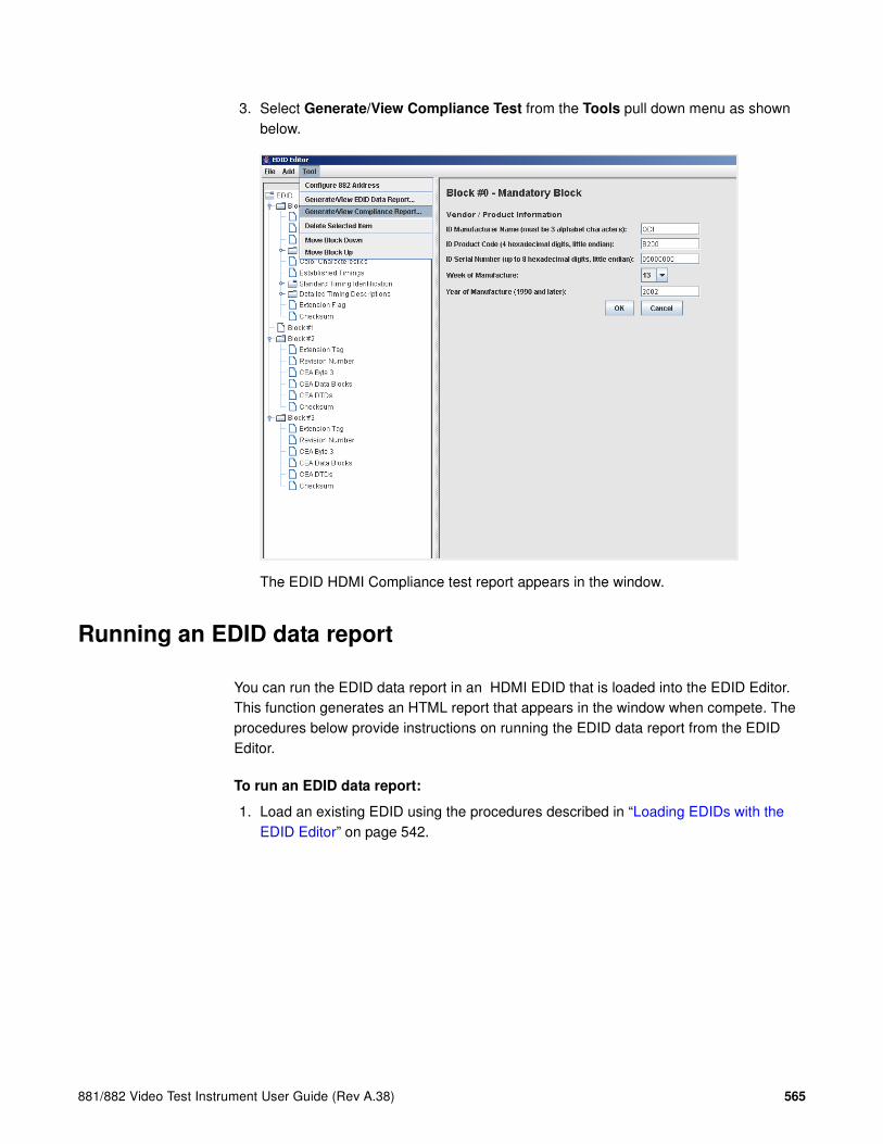
881/882 Video Test Instrument User Guide (Rev A.38) 565
3. Select Generate/View Compliance Test from the Tools pull down menu as shown below.
The EDID HDMI Compliance test report appears in the window.
Running an EDID data report
You can run the EDID data report in an HDMI EDID that is loaded into the EDID Editor. This function generates an HTML report that appears in the window when compete. The procedures below provide instructions on running the EDID data report from the EDID Editor.
To run an EDID data report:
1. Load an existing EDID using the procedures described in “Loading EDIDs with the EDID Editor” on page 542.

566 Chapter 14 Testing EDID for HDMI
2. Select Generate/View Compliance Test from the Tools pull down menu as shown below.
The EDID report appears in the window.
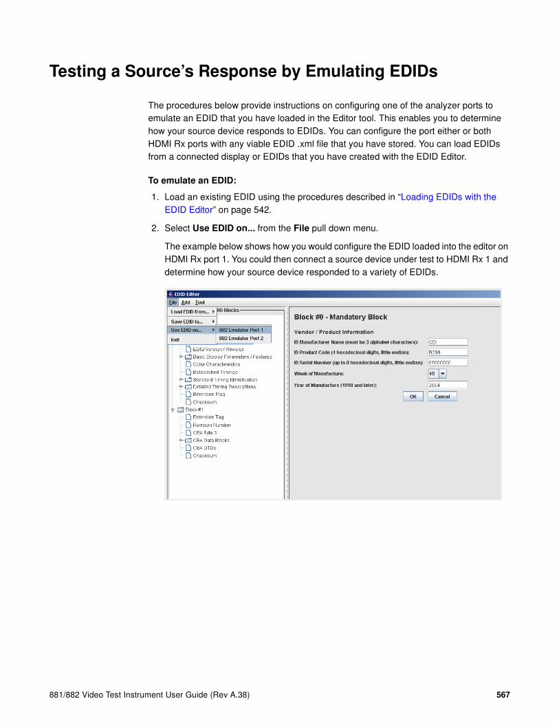
881/882 Video Test Instrument User Guide (Rev A.38) 567
Testing a Source’s Response by Emulating EDIDs
The procedures below provide instructions on configuring one of the analyzer ports to emulate an EDID that you have loaded in the Editor tool. This enables you to determine how your source device responds to EDIDs. You can configure the port either or both HDMI Rx ports with any viable EDID .xml file that you have stored. You can load EDIDs from a connected display or EDIDs that you have created with the EDID Editor.
To emulate an EDID:
1. Load an existing EDID using the procedures described in “Loading EDIDs with the EDID Editor” on page 542.
2. Select Use EDID on... from the File pull down menu.
The example below shows how you would configure the EDID loaded into the editor on HDMI Rx port 1. You could then connect a source device under test to HDMI Rx 1 and determine how your source device responded to a variety of EDIDs.

568 Chapter 14 Testing EDID for HDMI
Using the EDID Compare tool
The 882 provides an EDID Compare tool. This tool allows you to capture an EDID from a connected display, then compare its contents to subsequent EDID readings. This allows you to verify the display device is consistently generating an identical EDID.
Comparing EDIDs
Follow this procedure to verify the display device is generating an identical EDID:
To compare EDIDs:
1. Connect an HDMI-to-HDMI cable between the HDMI OUT connector on the 882 and the HDMI connector on the display under test.
2. Open a Web browser (such as Internet Explorer) and type the 882’s IP address in the address entry field. For example, enter the following: http://206.135.215.189/
The 882 home page appears in the browser.
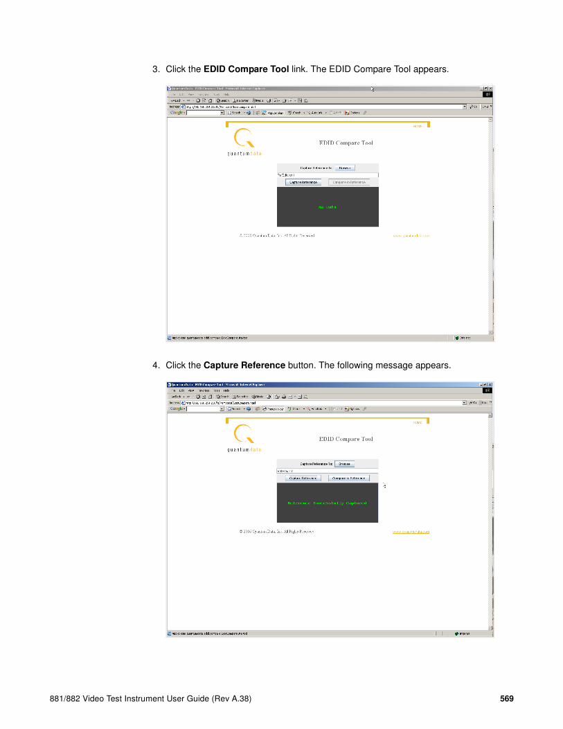
881/882 Video Test Instrument User Guide (Rev A.38) 569
3. Click the EDID Compare Tool link. The EDID Compare Tool appears.
4. Click the Capture Reference button. The following message appears.

570 Chapter 14 Testing EDID for HDMI
Note: You can use the tool to save a copy of the EDID onto your PC by clicking on the
Browse button. This enables you to browse for a location on your PC and store the
EDID.
5. Click the Compare to Reference button. The following message appears if EDID contents are identical.
If EDID contents are not identical, you see the message Mis-Matched EDID’s displayed.

881/882 Video Test Instrument User Guide (Rev A.38) 571
15 Testing HDCP on HDMI & MHL
Topics in this chapter:
• Overview
• Testing DVI displays with HDCP
• Testing HDMI displays with HDCP
• Running an HDMI HDCP self-test
• Understanding the HDCP test
• Running the HDCP compliance test for HDMI devices with the 882EA
• Running the HDCP compliance test for MHL devices with the Quantum Data 882EA

572 Chapter 15 Testing HDCP on HDMI & MHL
Overview
You can use the 882 with the High-bandwidth Digital Content Protection (HDCP) to test HDCP 1.0, 1.1 and 1.2 compliant devices. The procedures in this chapter instruct you on how to complete the HDCP tests for a DVI, HDMI or DisplayPort sink devices.
The 882E and 882C are compliant HDMI-HDCP sources. For more information about HDCP, see http://www.digital-cp.com/.

881/882 Video Test Instrument User Guide (Rev A.38) 573
Testing DVI displays with HDCP
This section describes how to test DVI and HDMI receivers with HDCP.
To set up the 882 for testing a DVI display:
1. Connect an HDMI-to-DVI converter cable between the HDMI OUT connector on the 882 and the device’s DVI receiver.
2. Activate the HDMI-D interface on the output port as follows:
a. Press the Interface key. A listing of signal interfaces appears on the 882’s display as shown below.
b. Choose the HDMI-D item by pressing the adjacent soft key. The interface is activated, and the port outputs the currently selected image and format.
Alternatively, to activate the interface through the command line interface, enter the following commands:
XVSI 3 // Activates the HDMI-D interface
ALLU // Applies the interface setting to the 882
3. Choose a standard format (for example, DMT0660) by pressing the adjacent soft key.
Alternatively, you can load the format with the following command:
FMTL DMT0660
FMTU
VGA
HDMI-D
CVBS
S-VIDEO
SDI
*
HDMI-H

574 Chapter 15 Testing HDCP on HDMI & MHL
4. Choose the HDCPprod test image, or, if you are using HDMI OUT port 2, choose the HDCP2 test image.
If you are testing a device with a production key, select the HdcpProd image (or, if you are using HDMI OUT port 2, choose the HDCP2 test image). These test images assume that both the HDCP transmitter and receiver have a production key.
The image will indicate if the test passed or failed. If the test fails, see “Understanding the HDCP test” on page 577.
5. To test another device, connect the cable to the new device.
The HDCP test starts automatically.
Alternatively, you can enter the following command to initiate and run the test with any image displayed. A zero is returned if the HDCP test is successful.
HDCP? (OUT1:HDCP?, OUT2:HDCP?)
You can also specify a number of frames to run the test for. For example to run the test for 2000 frames you would enter:
HDCP? (OUT1:HDCP?, OUT2:HDCP?) 2000

881/882 Video Test Instrument User Guide (Rev A.38) 575
Testing HDMI displays with HDCP
To test HDCP with an HDMI device:
1. Connect an HDMI cable between the HDMI OUT connector on the 882 and the HDMI display.
2. Activate the HDMI-H interface on the output port as follows:
a. Press the Interface key. A listing of signal interfaces appears on the 882’s display as shown below.
b. Choose the HDMI-H item by pressing the adjacent soft key. The interface is activated and the port outputs the currently selected image and format.
Alternatively, to activate the interface through the command line interface, enter the following commands:
XVSI 4 // Activates the HDMI-H interface
ALLU // Applies the interface setting to the 882
3. Choose a standard format (for example, DMT0660) by pressing the adjacent soft key.
Alternatively, you can load the format with the following command:
FMTL DMT0660
FMTU
VGA
HDMI-D
CVBS
S-VIDEO
SDI
*
HDMI-H

576 Chapter 15 Testing HDCP on HDMI & MHL
4. Choose the HDCPprod test image, or, if you are using HDMI OUT port 2, choose the HDCP2 test image.
If you are testing a device with a production key, select the HdcpProd image, or, if you are using HDMI OUT port 2, choose the HDCP2 test image. These test images assume that both the HDCP transmitter and receiver have a production key.
The image will indicate if the test passed or failed. If the test fails, see “Understanding the HDCP test” on page 577.
5. To test another device, connect the cable to the new device.
The HDCP test starts automatically.
Alternatively, you can enter the following command to initiate and run the test with any image displayed. A zero is returned if the HDCP test is successful.
HDCP? (OUT1:HDCP?, OUT2:HDCP?)
You can also specify a number of frames to run the test for. For example to run the test for 2000 frames you would enter:
HDCP? (OUT1:HDCP?, OUT2:HDCP?) 2000

881/882 Video Test Instrument User Guide (Rev A.38) 577
HDCP? (OUT1:HDCP?, OUT2:HDCP?) 2000
The image will indicate if the test passed or failed. If the test fails, see “Understanding the HDCP test” on page 577.
6. To test another device, connect the cable to the new device.
The HDCP test starts automatically.

578 Chapter 15 Testing HDCP on HDMI & MHL
Running HDCP test in step mode
The 882 normally runs the steps in the HDCP test automatically. However, to troubleshoot a failed test, you can run the test in “step” mode. This enables you to read the values at the step where the test failed.
To run the HDCP test in step mode:
1. Connect a cable between the HDMI OUT connector on the 882 and the device’s input.
2. Activate the HDMI-H or HDMI-D interface on the output port as follows:
a. Press the Interface key. A listing of signal interfaces appears on the 882’s display as shown below (HDMI shown in the example only).
b. Choose either the HDMI-H or HDMI-D item by pressing the adjacent soft key. The interface is activated, and the port outputs the currently selected image and format.
Alternatively, to activate the interface through the command line interface, enter the following commands:
XVSI 4 // Activates the HDMI-H interface (3 for HDMI-D)
ALLU // Applies the interface setting to the 882
3. Press the Content key and choose the HdcpProd image by pressing the adjacent soft key. Or, if you are using HDMI OUT port 2, choose the HDCP2 test image.
4. Enable and view image versions for the test image as follows:
a. Press the Options key. The following menu appears on the 882’s display:
b. Choose the More item by pressing the adjacent soft key until a + and Rendition appears next to the item.
c. Press the + key to advance through the image versions.
Alternatively, to enable and view image versions using the command line interface, enter the following commands:
VGA
HDMI-D
CVBS
S-VIDEO
SDI
*
HDMI-H
-More Red+-NoGamma Green+-Noise Blue+
+More Rendition: 000 Red+-NoGamma Green+-Noise Blue+

881/882 Video Test Instrument User Guide (Rev A.38) 579
ISUB 1 // Enables sub images
IVER 1 // Specifies the first image version
IMGU // Activates the image version
5. When you are finished, disable image versions by pressing the Options key and choosing More until a - appears next to it.
Alternatively, to disable image versions using the command line interface, enter the following command:
ISUB 0 // Disables sub images
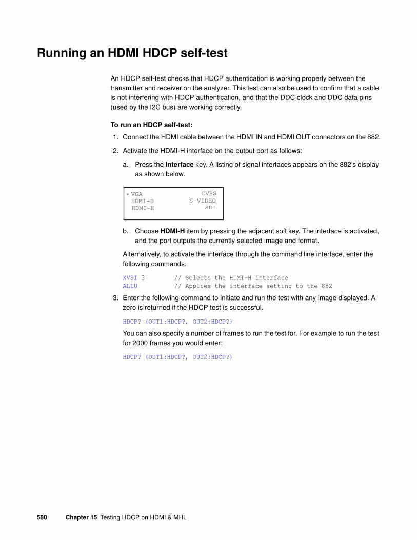
580 Chapter 15 Testing HDCP on HDMI & MHL
Running an HDMI HDCP self-test
An HDCP self-test checks that HDCP authentication is working properly between the transmitter and receiver on the analyzer. This test can also be used to confirm that a cable is not interfering with HDCP authentication, and that the DDC clock and DDC data pins (used by the I2C bus) are working correctly.
To run an HDCP self-test:
1. Connect the HDMI cable between the HDMI IN and HDMI OUT connectors on the 882.
2. Activate the HDMI-H interface on the output port as follows:
a. Press the Interface key. A listing of signal interfaces appears on the 882’s display as shown below.
b. Choose HDMI-H item by pressing the adjacent soft key. The interface is activated, and the port outputs the currently selected image and format.
Alternatively, to activate the interface through the command line interface, enter the following commands:
XVSI 3 // Selects the HDMI-H interface
ALLU // Applies the interface setting to the 882
3. Enter the following command to initiate and run the test with any image displayed. A zero is returned if the HDCP test is successful.
HDCP? (OUT1:HDCP?, OUT2:HDCP?)
You can also specify a number of frames to run the test for. For example to run the test for 2000 frames you would enter:
HDCP? (OUT1:HDCP?, OUT2:HDCP?)
VGA
HDMI-D
CVBS
S-VIDEO
SDI
*
HDMI-H

881/882 Video Test Instrument User Guide (Rev A.38) 581
Understanding the HDCP test
Understanding what the 882 does during an HDCP test can help you determine why an HDCP test failed.
HDMI HDCP test sequence:
The HDMI HDCP test sequence performed by the 882 is listed below.
1. Reset the transmitter HDCP engine.
2. Initialize the transmitter.
3. Check Bcaps over the DDC bus to determine if the sink is a receiver or a repeater and generate a new An value (8 byte random session number) in the transmitter.
4. Transmitter writes An to the receiver using the DDC bus.
5. Transmitter writes Aksv to the receiver using the DDC bus.
6. Read Bksv from the receiver over the DDC bus and validate that it has exactly 20 zeroes and 20 ones in it. You can query this value with the following command:
i2cr? hdl 74 0 5
I2CR? (OUT1:I2CR?, OUT2:I2CR?, VGA:I2CR?)
The display may return a value such as the following which is:
07BE05CEA9
The value in binary is 0000011110111110000001011100111010101001 which contains 20 zeros and 20 ones.
7. Write the Bksv value to the transmitter to trigger calculation of R0.
8. Wait for the R0 calculation in the transmitter to complete.
9. Wait for at least 100 milliseconds and then read the R0' value out of the receiver over the DDC bus and compare the value with the R0 calculation in the transmitter. If this step fails, then go to step 1.
10. Enable encryption and read Ri' from the receiver over the DDC bus every 128 frames and compare it to the Ri value calculated in the transmitter. As long as the Ri value matches the Ri' value from the receiver continue to check these every 128 frames.

582 Chapter 15 Testing HDCP on HDMI & MHL
Running the HDCP compliance test for HDMI devices with
the 882EA
Overview
The 882CA882E-Analyzer (882EA) support the running of an HDCP compliance test on HDCP-enabled HDMI sources, sinks and repeaters. The HDCP compliance test was developed while working closely with Digital Content Protection (DCP). The 882EA HDCP Compliance test tool has been approved by DCP for Compliance Test Specification 1.1. Please be sure to refer to the release notes for the appropriate release of the 882EA that has been approved by DCP.
The HDCP compliance test has been updated to support HDCP CTS 1.2. You will need to select which CTS you wish to test to (CTS 1.1 or CTS 1.2) prior to running the test. Testing to the HDCP CTS 1.2 is only supported on the 882EA.
Note: The HDCP compliance test is an optional feature available only with the 882
analyzer. You must purchase the license for this feature.
The HDCP compliance test system enables developers of HDMI products to perform a comprehensive HDCP compliance test. Because the 882 can emulate HDMI HDCP sources, sinks and repeaters, it can perform a complete HDCP compliance test on any HDCP capable HDMI source, sink or repeater.
The HDCP compliance test can be run through the 882 front panel, or through the command line. The HDCP commands enable you to run a specific subset of the tests in the series of tests.

881/882 Video Test Instrument User Guide (Rev A.38) 583
Encryption Status Tester
The HDCP compliance tests for an HDMI source, sink and repeater device require the use of the standalone hardware device called the Encryption Status Tester (EST) (below). The EST device is currently only used for the 882EA model. Although the features of the EST pertains to only a handful of tests, it should be connected into the test setup for all tests of the 882EA model.

584 Chapter 15 Testing HDCP on HDMI & MHL
The features provided by the EST are specifically used for the following tests:
List of Tests
The following table describes the HDCP compliance tests performed with the 882EA.
Index Test EST Function
1 1A_01 (Transmitter Downstream w/Receiver) w/HDMI Capable Receiver
Verifies that the encryption enable/disable pulse is transmitted during the valid period, that no data islands, video data or guard band is transmitted during the keep-out period and that no data island is transmitted during Line Key Calc period on the encrypted frame.
11 1B_01 (Transmitter Downstream w/Repeater)
Verifies that the encryption enable/disable pulse is transmitted during the valid period, that no data islands, video data or guard band is transmitted during the keep-out period and that no data island is transmitted during Line Key Calc period on the encrypted frame.
20 2C_04 (Receiver Upstream w/Transmitter) (w/DVI Transmitter)
Positions the encryption enable pulse in the vsync or vertical blanking at three different loca-tions (beginning, center and end).
21 3A_01 (Repeater Downstream w/Receiver) (Between HDMI Capable Transmitter and HDMI Capable Receiver)
Verifies that the encryption enable/disable pulse is transmitted during the valid period, that no data islands, video data or guard band is transmitted during the keep-out period and that no data island is transmitted during Line Key Calc period on the encrypted frame.
26 3B_01 (Repeater Downstream w/Repeater)
Verifies that the encryption enable/disable pulse is transmitted during the valid period, that no data islands, video data or guard band is transmitted during the keep-out period and that no data island is transmitted during Line Key Calc period on the encrypted frame.
Index Test Description
1 1A_01 (Transmitter Downstream w/Receiver) w/HDMI Capable Receiver
Regular Procedure: With HDMI Capable Receiver
2 1A_02 (Transmitter Downstream w/Receiver) w/HDMI Capable Receiver
Regular Procedure: HDCP_HPD After Writing Aksv
3 1A_03 (Transmitter Downstream w/Receiver) w/HDMI Capable Receiver
Regular Procedure: HDCP_HPD After Starting Third Part of Authentication
4 1A_04 (Transmitter Downstream w/Receiver) w/HDMI Capable Receiver
Irregular Procedure: (First Part of Authentication) HDPC Port Access

881/882 Video Test Instrument User Guide (Rev A.38) 585
5 1A_05 (Transmitter Downstream w/Receiver) w/HDMI Capable Receiver
Irregular Procedure: (First Part of Authentication) Verify Bksv
6 1A_06 (Transmitter Downstream w/Receiver) w/HDMI Capable Receiver
Irregular Procedure: (First Part of Authentication) Verify R0'
7 1A_07 (Transmitter Downstream w/Receiver) w/HDMI Capable Receiver
Irregular Procedure: (Third Part of Authentication) Verify Ri' (invalid Ri)
8 1A_07a (Transmitter Down-stream w/Receiver) w/HDMI Capable Receiver
Irregular Procedure: (Third Part of Authentication) Verify Ri' (Ri’ not returned)
9 1A_08 (Transmitter Downstream w/Receiver) w/HDMI Capable Receiver
Irregular Procedure: SRM. Requires SRM DVD disc.
10 1A_09 (Transmitter Downstream w/Receiver) w/DVI Receiver
Regular Procedure: With DVI Receiver
11 1B_01 (Transmitter Downstream w/Repeater)
Regular Procedure: With Repeater
12 1B_02 (Transmitter Downstream w/Repeater)
Regular Procedure: HPD After Reading R0'
13 1B_03 (Transmitter Downstream w/Repeater)
Irregular Procedure: (Second Part of Authentication) Timeout of KSV List READY
14 1B_04 (Transmitter Downstream w/Repeater)
Irregular Procedure: (Second Part of Authentication) Verify V'
15 1B_05 (Transmitter Downstream w/Repeater)
Irregular Procedure: (Second Part of Authentication) MAX_DEVS_EXCEEDED
16 1B_06 (Transmitter Downstream w/Repeater)
Irregular Procedure: (Second Part of Authentication) MAX_CASCADE_EXCEEDED
17 2C_01 (Receiver Upstream w/Transmitter) (w/HDMI Capable Transmitter)
Regular Procedure: With HDMI Capable Transmitter
18 2C_02 (Receiver Upstream w/Transmitter) (w/HDMI Capable Transmitter)
Irregular Procedure: (First Part of Authentication) New Authentication
19 2C_03 (Receiver Upstream w/Transmitter) (w/HDMI Capable Transmitter)
Irregular Procedure: (Third Part of Authentication) New Authentication
20 2C_04 (Receiver Upstream w/Transmitter) (w/DVI Transmitter)
Regular Procedure: With DVI Transmitter
Index Test Description

586 Chapter 15 Testing HDCP on HDMI & MHL
21 3A_01 (Repeater Downstream w/Receiver) (Between HDMI Capable Transmitter and HDMI Capable Receiver)
Regular Procedure: With HDMI Capable Receiver
22 3A_02 (Repeater Downstream w/Receiver) (Between HDMI Capable Transmitter and HDMI Capable Receiver)
Irregular Procedure: (First Part of Authentication) HDCP Port Access
23 3A_03 (Repeater Downstream w/Receiver) (Between HDMI Capable Transmitter and HDMI Capable Receiver)
Irregular Procedure: (First Part of Authentication) Verify Bksv
24 3A_04 (Repeater Downstream w/Receiver) (Between HDMI Capable Transmitter and HDMI Capable Receiver)
Irregular Procedure: (First Part of Authentication) Verify R0'
25 3A_05 (Repeater Downstream w/Receiver) (Between HDMI Capable Transmitter and DVI Receiver)
Regular Procedure: With DVI Receiver
26 3B_01 (Repeater Downstream w/Repeater)
Regular Procedure: With Repeater
27 3B_02 (Repeater Downstream w/Repeater)
Irregular Procedure: (Second Part of Authentication) Timeout of KSV List READY
28 3B_03 (Repeater Downstream w/Repeater)
Irregular Procedure: (Second Part of Authentication) Verify V'
29 3B_04 (Repeater Downstream w/Repeater)
Irregular Procedure: (Second Part of Authentication) MAX_DEVS_EXCEEDED
30 3B_05 (Repeater Downstream w/Repeater)
Irregular Procedure: (Second Part of Authentication) MAX_CASCADE_EXCEEDED
31 3C_I_01 (Repeater Upstream w/Transmitter) (Between HDMI Capable Transmitter and HDMI Capable Receiver)
Regular Procedure: Transmitter – DUT – Receiver
32 3C_I_02 (Repeater Upstream w/Transmitter) (Between HDMI Capable Transmitter and HDMI Capable Receiver)
Regular Procedure: HDCP_HPD Pulse Output Caused By User Operation
33 3C_I_03 (Repeater Upstream w/Transmitter) (Between HDMI Capable Transmitter and HDMI Capable Receiver)
Irregular Procedure: (First Part of Authentication) New Authentication
34 3C_I_04 (Repeater Upstream w/Transmitter) (Between HDMI Capable Transmitter and HDMI Capable Receiver)
Irregular Procedure: (Second Part of Authentication) New Authentication
Index Test Description

881/882 Video Test Instrument User Guide (Rev A.38) 587
35 3C_I_05 (Repeater Upstream w/Transmitter) (Between HDMI Capable Transmitter and HDMI Capable Receiver)
Irregular Procedure: (Third Part of Authentication) New Authentication
36 3C_I_06 (Repeater Upstream w/Transmitter) (Between HDMI Capable Transmitter and HDMI Capable Receiver)
Irregular Procedure: (Second Part of Authentication) Verify Bksv
37 3C_I_07 (Repeater Upstream w/Transmitter) (Between HDMI Capable Transmitter and HDMI Capable Receiver)
Irregular Procedure: (Second Part of Authentication) Verify R0'
38 3C_II_01 (Repeater Upstream w/Transmitter) (Between HDMI Capable Transmitter and Repeater)
Regular Procedure: Transmitter – DUT – Repeater-Receiver
39 3C_II_02 (Repeater Upstream w/Transmitter) (Between HDMI Capable Transmitter and Repeater)
Regular Procedure: HDCP_HPD After Writing Aksv
40 3C_II_03 (Repeater Upstream w/Transmitter) (Between HDMI Capable Transmitter and Repeater)
Regular Procedure: HDCP_HPD After Reading R0'
41 3C_II_04 (Repeater Upstream w/Transmitter) (Between HDMI Capable Transmitter and Repeater)
Regular Procedure: HDCP_HPD After Starting Third Part of Authentication
42 3C_II_05 (Repeater Upstream w/Transmitter) (Between HDMI Capable Transmitter and Repeater)
Irregular Procedure: (Second Part of Authentication) Verify V'
43 3C_II_06 (Repeater Upstream w/Transmitter) (Between HDMI Capable Transmitter and Repeater)
Irregular Procedure: (Second Part of Authentication) DEVICE_COUNT
44 3C_II_07 (Repeater Upstream w/Transmitter) (Between HDMI Capable Transmitter and Repeater)
Irregular Procedure: (Second Part of Authentication) DEPTH
Index Test Description

588 Chapter 15 Testing HDCP on HDMI & MHL
There are several configurations depending on what type of HDCP device you are testing. Procedures for each are provided below.
Running HDCP compliance test on HDMI transmitters
To run the 1A and 1B series HDCP compliance tests on an HDMI source (transmitter):
Note: For the 882E, the 1A-08 test requires that you use the SRM disc for the 1A-08 test
if the source device has an optical drive. Refer to “To run the 1A-08 HDCP compliance test
using the SRM disc:” on page 700.
45 3C_II_08 (Repeater Upstream w/Transmitter) (Between HDMI Capable Transmitter and Repeater)
Irregular Procedure: (Second Part of Authentication) MAX_DEVS_EXCEEDED
46 3C_II_09 (Repeater Upstream w/Transmitter) (Between HDMI Capable Transmitter and Repeater)
Irregular Procedure: (Second Part of Authentication) MAX_CASCADE_EXCEEDED
Index Test Description
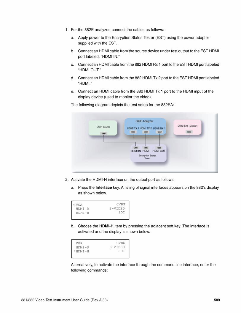
881/882 Video Test Instrument User Guide (Rev A.38) 589
1. For the 882E analyzer, connect the cables as follows:
a. Apply power to the Encryption Status Tester (EST) using the power adapter supplied with the EST.
b. Connect an HDMI cable from the source device under test output to the EST HDMI port labeled, “HDMI IN.”
c. Connect an HDMI cable from the 882 HDMI Rx 1 port to the EST HDMI port labeled “HDMI OUT.”
d. Connect an HDMI cable from the 882 HDMI Tx 2 port to the EST HDMI port labeled “HDMI.”
e. Connect an HDMI cable from the 882 HDMI Tx 1 port to the HDMI input of the display device (used to monitor the video).
The following diagram depicts the test setup for the 882EA:
2. Activate the HDMI-H interface on the output port as follows:
a. Press the Interface key. A listing of signal interfaces appears on the 882’s display as shown below.
b. Choose the HDMI-H item by pressing the adjacent soft key. The interface is activated and the display is shown below.
Alternatively, to activate the interface through the command line interface, enter the following commands:
VGA
HDMI-D
CVBS
S-VIDEO
SDI
*
HDMI-H
VGA
HDMI-D
CVBS
S-VIDEO
SDI*HDMI-H

590 Chapter 15 Testing HDCP on HDMI & MHL
XVSI 4 // Activates the HDMI-H interface
ALLU // Applies the interface setting to the 882
3. Press the Interface key repeatedly until the following menu appears:
4. Choose the HDMI IN 1 by pressing the adjacent soft key.
5. For the 882EA when using the EST, verify that the source is sending in video using the timing measurement function of the analzyer. Refer to “To view timing information of an external HDMI/DVI source signal on a display:” on page 246 for information on running the timing test.
Verify that the source is outputting one of the following formats: 1) 640x480p at 59.94/60Hz; 2) 720x480p at 59.94/60Hz; 3) 720x576p at 50Hz.
Verify that the source is outputing the RGB color space.
If the 882EA cannot detect the incoming video, enter the following command to turn on the EST:
QD:PROD:EST // Turns on the EST.
6. (For Front Panel Operation) Press the Tools key and choose the Reports item by pressing the adjacent soft key.
The following is displayed on the 882’s LCD.
7. Select HDCP to access the HDCP compliance test menu.
The following is displayed on the 882’s LCD.
8. Select EditPCP to define the capabilities of the HDCP device under test.
The following is displayed on the 882’s LCD.
HDMI IN 1
HDMI IN 2*
EDID Packets Misc HDCP
!CompRpt EditPCP
1.2 :CTS Ver.
Source :DUT Type
+1A-01 :Test Num-
+1 :Src Max KSV -
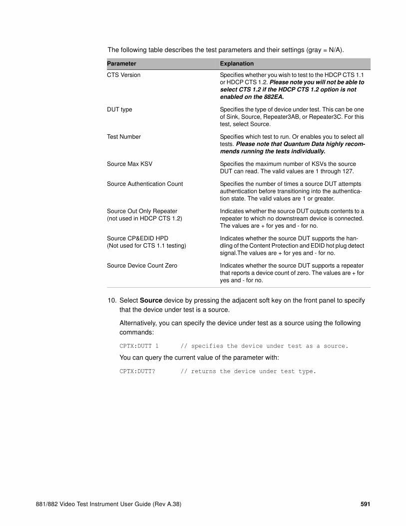
881/882 Video Test Instrument User Guide (Rev A.38) 591
The following table describes the test parameters and their settings (gray = N/A).
10. Select Source device by pressing the adjacent soft key on the front panel to specify that the device under test is a source.
Alternatively, you can specify the device under test as a source using the following commands:
CPTX:DUTT 1 // specifies the device under test as a source.
You can query the current value of the parameter with:
CPTX:DUTT? // returns the device under test type.
Parameter Explanation
CTS Version Specifies whether you wish to test to the HDCP CTS 1.1 or HDCP CTS 1.2. Please note you will not be able to
select CTS 1.2 if the HDCP CTS 1.2 option is not
enabled on the 882EA.
DUT type Specifies the type of device under test. This can be one of Sink, Source, Repeater3AB, or Repeater3C. For this test, select Source.
Test Number Specifies which test to run. Or enables you to select all tests. Please note that Quantum Data highly recom-
mends running the tests individually.
Source Max KSV Specifies the maximum number of KSVs the source DUT can read. The valid values are 1 through 127.
Source Authentication Count Specifies the number of times a source DUT attempts authentication before transitioning into the authentica-tion state. The valid values are 1 or greater.
Source Out Only Repeater(not used in HDCP CTS 1.2)
Indicates whether the source DUT outputs contents to a repeater to which no downstream device is connected. The values are + for yes and - for no.
Source CP&EDID HPD(Not used for CTS 1.1 testing)
Indicates whether the source DUT supports the han-dling of the Content Protection and EDID hot plug detect signal.The values are + for yes and - for no.
Source Device Count Zero Indicates whether the source DUT supports a repeater that reports a device count of zero. The values are + for yes and - for no.

592 Chapter 15 Testing HDCP on HDMI & MHL
11. Specify the PCP parameters through the front panel using the soft keys adjacent to the PCP parameters and the up and down arrow keys on the right side of the front panel.
The following is an example of the source PCP parameters selection screen on the 882 front panel.
Alternatively, you can specify the EditPCP parameters through the command line as follows:
CPTX:CTSV 1.2 // specifies which HDCP CTS you wish to test to.
Values are 1.1 for CTS 1.1 and 1.2 for CTS 1.2.
CPTX:SKSV 10 // specifies maximum number of downstream devices
listed in the KSV list of the device under test.
Valid values are 1-127.
CPTX:SRAC 5 // specifies number of times a source DUT attempts
authentication before transitioning into the
authenticated state. Valid values, 1 or greater.
CPTX:SOOR 0 // indicates whether DUT (source) outputs content
to the downstream repeater that does not have any
downstream device connected.
Values are: 1 = yes; 0 = no.
Note 1: This parameter is not used when testing to
HDCP CTS 1.2.
CPTX:SCEH 1 // Indicates whether DUT (source) supports the
content protection and EDID hot plug signal.
Values are: 0 = no; 1 = yes.
Note 1: This parameter is not used when testing to
HDCP CTS 1.1.
CPTX:SDCZ 0 // indicates whether what value the 882 should use
for testing. A value of 0 means the device count
specified by the SKSV will be used for testing.
A value of 1 means device count of zero will be
used.
Note 1: This parameter is only used for the
1B-01 for HDCP CTS 1.1.
Note 2: The 1B-01 test should be run for both
settings of this parameter only if the Source Out
Only Repeater is set to yes. If Source Out Only
Repeater is set to no, this parameter is ignored
in the HDCP CTS 1.1 test.
Note 3: The 1B-01 test should be run for both
settings of this parameter for the HDCP CTS 1.2
test.
12. Press the Options key to save the capabilities definition.
The 882 LCD will display the message “Saved”.
1.2 :CTS Ver.
Source :DUT Type
+1A-01 :Test Num-
+1 :Src Max KSV -

881/882 Video Test Instrument User Guide (Rev A.38) 593
13. Press the Tools key get back to the Reports menu.
The 882 LCD will display the reports menu as shown below.
14. Select HDCP to access the HDCP compliance test menu.
The following is displayed on the 882’s LCD.
15. Select !CompRpt to initiate the HDCP compliance test. Initiate each test individually.
The message “HDCP Compliance Test” is shown and then all the tests are shown in sequence.
Alternatively, to run a specific test through the command line:
CPTX:CPTR 1 // Selects specific test (e.g. 1A_01) see table below
CPTX:CPTU // Initiates the execution of the test.
You can query the complete list of tests to choose from:
CPTX:GCTN? // Queries the list of tests supported.
You can query the currently selected test to run with:
CPTX:CPTR? // Queries the selected test to run (see table
below).
Refer to “To view the HDCP compliance report:” on page 605 for procedures on how to view the generated report.
The following table describes tests run with the CPTX:CPTR command for the 882EA.
CPTX:CPTR Index Test Description
1 1A_01 (Transmitter Downstream w/Receiver) w/HDMI Capable Receiver
Regular Procedure: With HDMI Capable Receiver
2 1A_02 (Transmitter Downstream w/Receiver) w/HDMI Capable Receiver
Regular Procedure: HPD After Writing Aksv
EDID Packets Misc HDCP
!CompRpt EditPCP

594 Chapter 15 Testing HDCP on HDMI & MHL
16. Monitor the 882EA LCD for a set of prompts during the 1A-01, 1A-09, and 1B-01 tests.
Note: You will not be prompted as shown below when running the test with the 882CA.
a. When prompted with the screen shown below, examine the video on the display connected to 882EA output 1. Press the appropriate button adjacent to the indication (Yes! or No!) to continue.
3 1A_03 (Transmitter Downstream w/Receiver) w/HDMI Capable Receiver
Regular Procedure: HPD After Starting Third Part of Authentication
4 1A_04 (Transmitter Downstream w/Receiver) w/HDMI Capable Receiver
Irregular Procedure: (First Part of Authentication) HDPC Port Access
5 1A_05 (Transmitter Downstream w/Receiver) w/HDMI Capable Receiver
Irregular Procedure: (First Part of Authentication) Verify Bksv
6 1A_06 (Transmitter Downstream w/Receiver) w/HDMI Capable Receiver
Irregular Procedure: (First Part of Authentication) Verify R0'
7 1A_07 (Transmitter Downstream w/Receiver) w/HDMI Capable Receiver
Irregular Procedure: (Third Part of Authentication) Verify Ri' (Ri’ invalid)
8 1A_07a (Transmitter Down-stream w/Receiver) w/HDMI Capable Receiver
Irregular Procedure: (Third Part of Authentication) Verify Ri' (Ri’ not returned)
9 1A_08 (Transmitter Downstream w/Receiver) w/HDMI Capable Receiver
Irregular Procedure: SRM. Requires SRM disc.
10 1A_09 (Transmitter Downstream w/Receiver) w/DVI Receiver
Regular Procedure: With DVI Receiver
11 1B_01 (Transmitter Downstream w/Repeater)
Regular Procedure: With Repeater
12 1B_02 (Transmitter Downstream w/Repeater)
Regular Procedure: HDCP_HPD After Read-ing R0'
13 1B_03 (Transmitter Downstream w/Repeater)
Irregular Procedure: (Second Part of Authentication) Timeout of KSV List READY
14 1B_04 (Transmitter Downstream w/Repeater)
Irregular Procedure: (Second Part of Authentication) Verify V'
15 1B_05 (Transmitter Downstream w/Repeater)
Irregular Procedure: (Second Part of Authentication) MAX_DEVS_EXCEEDED
16 1B_06 (Transmitter Downstream w/Repeater)
Irregular Procedure: (Second Part of Authentication) MAX_CASCADE_EXCEEDED
CPTX:CPTR Index Test Description

881/882 Video Test Instrument User Guide (Rev A.38) 595
Note: The prompt asks you if the video appearing on the connected display looks
good. “Looks good” means that there is a picture and an absence of excessive snow.
To run the 1A-08 HDCP compliance test using the SRM disc:
1. Set up the test as described in “To run the 1A and 1B series HDCP compliance tests on an HDMI source (transmitter):” on page 587 using the instructions for the 882E analyzer.
Note: The SRM test is only supported on the 882E analyzer. Insert the SRM disc into
the source device and run the HDCP tests through the command line.
2. Insert the SRM disc into the optical drive.
Note: The SRM test does not apply for source devices that cannot play a DVD.
3. To run 1A-08 test, use the command line as shown below:
CPTX:DUTT 1 // Selects the device type as a source.
CPTX:CPTR 9 // Selects specific test (e.g. 1A_08).
CPTX:CPTU // Initiates the execution of the test.
Refer to “To view the HDCP compliance report:” on page 605 for procedures on how to view the generated report.
Running HDCP compliance tests on HDMI receivers
The receiver tests are the 2C-0x series.
For the 882E the 2C-01 and 2C-04 tests are run multiple times for various settings. The 2C-01 test is required to be run in two configurations: 1) combined reads and 2) short reads. The 2C-04 test is required to be run in six (6) configurations. There are two read configurations: 1) short read and 2) combined read and there are three encryption pulse configurations: 1) occurring at the beginning of the vertical blanking; 2) occurring at the middle of the vertical blanking and 3) occurring at the end of the vertical blanking.
Does the video look good?
!Yes No!

596 Chapter 15 Testing HDCP on HDMI & MHL
To run the 2C-0x compliance tests on an HDMI sink (receiver):
1. For the 882E analyzer connect the cables as follows:
a. Apply power to the Encryption Status Tester (EST) using the power adapter that is supplied with the EST.
b. Connect an HDMI cable from the sink device under test input to the EST HDMI port labeled, “HDMI OUT.”
c. Connect an HDMI cable from the 882 HDMI Tx 1 port to the EST HDMI port labeled “HDMI IN.”
d. Connect an HDMI cable from the 882 HDMI Tx 2 port to the EST HDMI port labeled “HDMI.”
The following diagram depicts the test setup for the 882EA:
2. Activate the HDMI-H interface on the output port as follows:
a. Press the Interface key. A listing of signal interfaces appears on the 882’s display as shown below.
b. Choose the HDMI-H item by pressing the adjacent soft key. The interface is activated and the display is shown below.
Alternatively, to activate the interface through the command line interface, enter the following commands:
XVSI 4 // Activates the HDMI-H interface.
ALLU // Applies the interface setting to the 882.
VGA
HDMI-D
CVBS
S-VIDEO
SDI
*
HDMI-H
VGA
HDMI-D
CVBS
S-VIDEO
SDI*HDMI-H

881/882 Video Test Instrument User Guide (Rev A.38) 597
3. Press the Tools key and choose the Reports item by pressing the adjacent soft key.
The following is displayed on the 882’s LCD.
4. Select HDCP to access the HDCP compliance test menu.
The following is displayed on the 882’s LCD.
5. Select EditPCP to define the capabilities of the HDCP device under test.
The following is displayed on the 882’s LCD.
The following table describes the test parameters and their settings (gray = N/A).
Parameter Explanation
CTS Version Specifies whether you wish to test to the HDCP CTS 1.1 or HDCP CTS 1.2. Please note you will not be able to
select CTS 1.2 if the HDCP CTS 1.2 option is not
enabled on the 882EA.
DUT type Specifies the type of device under test. This can be one of Sink, Source, Repeater3AB, or Repeater3C. For this test, select Sink.
Test Number Specifies which test to run. Or enables you to select all tests. Please note that Quantum Data highly recom-
mends running the tests individually.
Sink 1.1 Features Supported Indicates whether the sink DUT supports Advanced_Cipher mode and Enhanced Link Verifica-tion. The values are + for yes and - for no.
Sink 1.1 Audio Supported Indicates whether the sink DUT supports audio output. The values are + for yes and - for no.
Sink Short Read Ri Indicates whether the sink DUT will respond to short reads of the Ri register. The values are + for yes and - for no.
EDID Packets Misc HDCP
!CompRpt EditPCP
1.2 :CTS Ver.
Sink :DUT Type
+All :Test Num-
+ :Src Max KSV -

598 Chapter 15 Testing HDCP on HDMI & MHL
7. Select Sink device by pressing the adjacent soft key to specify that the device under test is a sink.
Alternatively, you can specify the device under test as a sink using the following commands:
CPTX:DUTT 0 // specifies the device under test as a sink.
You can query the current value of the parameter with:
CPTX:DUTT? // returns the device under test type.
8. Specify the remaining parameters through the EditPCP menu on the front panel using in the using soft keys adjacent to each item and the up and down arrow keys on the right side of the front panel. Refer to the table above for a list of the parameters and their meaning.
Alternatively, you can specify the parameters through the command line as follows:
CPTX:CTSV 1.2 // specifies which HDCP CTS you wish to test to.
Values are 1.1 for CTS 1.1 and 1.2 for CTS 1.2.
CPTX:SRFT 0 // indicates whether DUT (sink) supports 1.1
features such as Advanced Cipher and Enhanced
Link Verification. 1 = yes; 0 = no.
CPTX:WAIN 0 // indicates whether DUT (sink) supports the handling
of Ainfo commands sent by the source device.
Values are: 1 = yes; 0 = no.
CPTX:SNAS 0 // indicates whether DUT (sink) supports audio
output. Values are: 1 = yes; 0 = no.
9. For the 2C-01 tests, you will run the test 2 times for each setting of the Short Read Ri parameter. You can set these parameters either through the 882 front panel or the command line as follows:
CPTX:CRIP 0 // Specifies short read.
CPTX:CRIP 1 // Specifies combined read.
10. For the 2C-04 tests, you will run the test 6 times for each combination of settings for the Short Read Ri parameter and position of the encryption enable pulse (leading,
Sink Write Ainfo Indicates whether the sink DUT responds (supports) Ainfo writes from a source.The values are + for yes and - for no.
OESS Encryption Enable Pulse Indicates where the encryption enable pulse is located in the vertical blanking. Values are: Cent (for central); Lead (for leading edge); and Trail (tor trailing edge).
Parameter Explanation

881/882 Video Test Instrument User Guide (Rev A.38) 599
center and trailing) with respect to the vertical sync pulse. You can set these parameters either through the 882 front panel or the command line as follows:
CPTX:CRIP 0 // Specifies short read.
CPTX:CRIP 1 // Specifies combined read.
CPTX:OESS 1 // Positions pulse at leading edge of vsync.
CPTX:OESS 2 // Positions pulse at trailing edge of vsync.
CPTX:OESS 3 // Positions pulse at center of vsync.
11. Press the Tools key get back to the Reports menu.
The 882 LCD will display the reports menu as shown below.
12. Select HDCP to access the HDCP compliance test menu.
The following is displayed on the 882’s LCD.
13. Select !CompRpt to initiate the HDCP compliance test. Initiate each test individually.
The message “HDCP Compliance Test” is shown and then all the tests are shown in sequence.
Refer to “To view the HDCP compliance report:” on page 605 for procedures on how to view the generated report.
Alternatively to run a specific test you can use the command line as shown below:
CPTX:CPTR 17 // Selects specific test (e.g. 2C_01) see table below
CPTX:CPTU // Initiates the execution of the test.
You can query the complete list of tests to choose from:
CPTX:GCTN? // Queries the list of tests supported.
You can query the currently selected test to run with:
CPTX:CPTR? // Queries the selected test to run (see table).
EDID Packets Misc HDCP
!CompRpt EditPCP

600 Chapter 15 Testing HDCP on HDMI & MHL
The following table describes tests that run with the CPTX:CPTR command for the 882EA.
14. Monitor the 882EA LCD for a set of prompts during the test.
a. When the prompt shown below occurs, power cycle the device under test.
Note: Some DUTs required a hard power cycle (unplugging power cable and then
plugging it back in):
b. Press the button adjacent to the Next! indication after the device under test is back on to continue.
c. When prompted with the screen shown below, examine the video on the display under test and press the appropriate button adjacent to the indication (Yes! or No!) to continue.
Note: The prompt asks you if the video appearing on the connected display looks
good. “Looks good” means that there is a picture and an absence of excessive snow.
CPTX:CPTR
Index Test Description
17 2C_01 (Receiver Upstream w/Transmitter) (w/HDMI Capable Transmitter)
Regular Procedure: With HDMI Capable Transmitter
18 2C_02 (Receiver Upstream w/Transmitter) (w/HDMI Capable Transmitter)
Irregular Procedure: (First Part of Authentica-tion) New Authentication
19 2C_03 (Receiver Upstream w/Transmitter) (w/HDMI Capable Transmitter)
Irregular Procedure: (Third Part of Authentication) New Authentication
20 2C_04 (Receiver Upstream w/Transmitter) (w/DVI Transmitter)
Regular Procedure: With DVI Transmitter
Please power cycle the DUT
Next!
Does the video look good?
!Yes No!

881/882 Video Test Instrument User Guide (Rev A.38) 601
Running HDCP compliance tests on HDMI repeaters
To run the 3A and 3B series HDCP compliance tests on an HDMI repeater:
1. For the 882E analyzer connect the cables as follows:
a. Apply power to the Encryption Status Tester (EST) using the power adapter supplied with the EST.
b. Connect an HDMI cable from the repeater device under test output to the EST HDMI port labeled, “HDMI IN.”
c. Connect an HDMI cable from a compliant source device output to the input of the repeater device under test.
d. Connect an HDMI cable from the 882 HDMI Rx 1 port to the EST HDMI port labeled “HDMI OUT.”
e. Connect an HDMI cable from the 882 HDMI Tx 2 port to the EST HDMI port labeled “HDMI.”
f. Connect an HDMI cable from the 882 HDMI Tx 1 port to the HDMI input of the display device (used to monitor the video).
The following diagram depicts the test setup for the 882EA:

602 Chapter 15 Testing HDCP on HDMI & MHL
2. Activate the HDMI-H interface on the output port as follows:
a. Press the Interface key. A listing of signal interfaces appears on the 882’s display as shown below.
b. Choose the HDMI-H item by pressing the adjacent soft key. The interface is activated and the display is shown below.
Alternatively, to activate the interface through the command line interface, enter the following commands:
XVSI 4 // Activates the HDMI-H interface
ALLU // Applies the interface setting to the 882
3. Press the Interface key repeatedly until the following menu appears:
4. Choose the HDMI IN 1 by pressing the adjacent soft key.
5. Verify that the repeater is sending in video using the Timing measurement function of the analzyer. Refer to “Measuring timing of video signal” on page 270 for information on running the timing test.
Verify that the source is outputting one of the following formats: 1) 640x480p at 59.94/60Hz; 2) 720x480p at 59.94/60Hz; 3) 720x576p at 50Hz.
Verify that the source is outputing the RGB color space:
If the 882 cannot detect the incoming video, enter the following command to turn on the EST:
QD:PROD:EST // Turns on the EST
6. Press the Tools key and choose the Reports item by pressing the adjacent soft key.
The following is displayed on the 882’s LCD.
VGA
HDMI-D
CVBS
S-VIDEO
SDI
*
HDMI-H
VGA
HDMI-D
CVBS
S-VIDEO
SDI*HDMI-H
HDMI IN 1
HDMI IN 2*
EDID Packets Misc HDCP
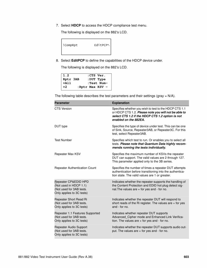
881/882 Video Test Instrument User Guide (Rev A.38) 603
7. Select HDCP to access the HDCP compliance test menu.
The following is displayed on the 882’s LCD.
8. Select EditPCP to define the capabilities of the HDCP device under.
The following is displayed on the 882’s LCD.
The following table describes the test parameters and their settings (gray = N/A).
Parameter Explanation
CTS Version Specifies whether you wish to test to the HDCP CTS 1.1 or HDCP CTS 1.2. Please note you will not be able to
select CTS 1.2 if the HDCP CTS 1.2 option is not
enabled on the 882EA.
DUT type Specifies the type of device under test. This can be one of Sink, Source, Repeater3AB, or Repeater3C. For this test, select Repeater3AB.
Test Number Specifies which test to run. Or enables you to select all tests. Please note that Quantum Data highly recom-
mends running the tests individually.
Repeater Max KSV Specifies the maximum number of KSVs the repeater DUT can support. The valid values are 2 through 127. This parameter applied only to the 3B series.
Repeater Authentication Count Specifies the number of times a repeater DUT attempts authentication before transitioning into the authentica-tion state. The valid values are 1 or greater.
Repeater CP&EDID HPD(Not used in HDCP 1.1)(Not used for 3AB tests. Only applies to 3C tests)
Indicates whether the repeater supports the handling of the Content Protection and EDID hot plug detect sig-nal.The values are + for yes and - for no.
Repeater Short Read Ri(Not used for 3AB tests. Only applies to 3C tests)
Indicates whether the repeater DUT will respond to short reads of the Ri register. The values are + for yes and - for no.
Repeater 1.1 Features Supported(Not used for 3AB tests. Only applies to 3C tests)
Indicates whether repeater DUT supports Advanced_Cipher mode and Enhanced Link Verifica-tion. The values are + for yes and - for no.
Repeater Audio Support(Not used for 3AB tests. Only applies to 3C tests)
Indicates whether the repeater DUT supports audio out-put. The values are + for yes and - for no.
!CompRpt EditPCP
1.2 :CTS Ver.
Rptr 3AB :DUT Type
+All :Test Num-
+2 :Rptr Max KSV -

604 Chapter 15 Testing HDCP on HDMI & MHL
10. Select Repeater3AB device by pressing the adjacent soft key to specify that the device under test is a repeater.
Alternatively, you can specify the device under test as a repeater for the 3AB test using the following commands:
CPTX:DUTT 2 // specifies the device under test as a repeater
for test 3AB.
You can query the current value of the parameter with:
CPTX:DUTT? // returns the device under test type.
11. (Optional) Specify the remaining parameters in the EditPCP menu using the table above.
Alternatively, you can specify the parameters through the command line as follows:
CPTX:CTSV 1.2 // specifies which HDCP CTS you wish to test to.
Values are 1.1 for CTS 1.1 and 1.2 for CTS 1.2.
CPTX:RKSV 10 // specifies maximum number of downstream devices
that can be supported in the repeater’s KSV list.
Valid values are 2-127.
CPTX:ROOR 0 // indicates whether DUT (repeater) outputs content
to the downstream repeater that does not have any
downstream device connected.
Values are: 1 = yes; 0 = no.
Note 1: This parameter only applies when testing
to HDCP CTS 1.1.
CPTX:RRAC 5 // specifies number of times a repeater DUT attempts
authentication before transitioning into the
authenticated state. Valid values, 1 or greater.
CPTX:RHPD 0 // Indicates whether the repeater DUT has the
capability to signal HDCP_HPD by user
operation. Values are: 1 = yes; 0 = no.
CPTX:SDCZ 0 // indicates whether what value the 882 should use
for testing. A value of 0 means the device count
specified by the SKSV will be used for testing.
A value of 1 means device count of zero will be
used.
Note 1: This parameter is only used for the
1B-01 for HDCP CTS 1.1.
Repeater Out OnlyRep(Not used in HDCP CTS 1.2)
Indicates whether the repeater DUT outputs content to the downstream repeater that has no downstream device connected. The values are + for yes and - for no.
Repeater HDCP HPD signal(Not used for 3AB tests. Only applies to 3C tests)
Indicates whether the repeater DUT has the capability to signal HDCP_HPD by user operation. The values are + for yes and - for no.
Repeater Device Count of Zero Indicates whether the repeater DUT supports a device count of zero reported by a downstream repeater. The values are + for yes and - for no.
Parameter Explanation
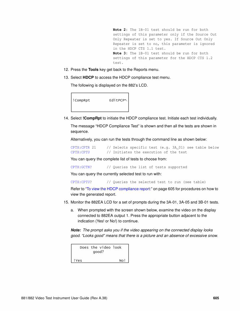
881/882 Video Test Instrument User Guide (Rev A.38) 605
Note 2: The 1B-01 test should be run for both
settings of this parameter only if the Source Out
Only Repeater is set to yes. If Source Out Only
Repeater is set to no, this parameter is ignored
in the HDCP CTS 1.1 test.
Note 3: The 1B-01 test should be run for both
settings of this parameter for the HDCP CTS 1.2
test.
12. Press the Tools key get back to the Reports menu.
13. Select HDCP to access the HDCP compliance test menu.
The following is displayed on the 882’s LCD.
14. Select !CompRpt to initiate the HDCP compliance test. Initiate each test individually.
The message “HDCP Compliance Test” is shown and then all the tests are shown in sequence.
Alternatively, you can run the tests through the command line as shown below:
CPTX:CPTR 21 // Selects specific test (e.g. 3A_01) see table below
CPTX:CPTU // Initiates the execution of the test
You can query the complete list of tests to choose from:
CPTX:GCTN? // Queries the list of tests supported
You can query the currently selected test to run with:
CPTX:CPTU? // Queries the selected test to run (see table)
Refer to “To view the HDCP compliance report:” on page 605 for procedures on how to view the generated report.
15. Monitor the 882EA LCD for a set of prompts during the 3A-01, 3A-05 and 3B-01 tests.
a. When prompted with the screen shown below, examine the video on the display connected to 882EA output 1. Press the appropriate button adjacent to the indication (Yes! or No!) to continue.
Note: The prompt asks you if the video appearing on the connected display looks
good. “Looks good” means that there is a picture and an absence of excessive snow.
!CompRpt EditPCP
Does the video look good?
!Yes No!

606 Chapter 15 Testing HDCP on HDMI & MHL
The following table describes tests run with the CPTX:CPTR command for the 882EA.
CPTX:CPTR
Index Test Description
21 3A_01 (Repeater Downstream w/Receiver) (Between HDMI Capable Transmitter and HDMI Capable Receiver)
Regular Procedure: With HDMI Capable Receiver
22 3A_02 (Repeater Downstream w/Receiver) (Between HDMI Capable Transmitter and HDMI Capable Receiver)
Irregular Procedure: (First Part of Authentication) HDCP Port Access
23 3A_03 (Repeater Downstream w/Receiver) (Between HDMI Capable Transmitter and HDMI Capable Receiver)
Irregular Procedure: (First Part of Authentication) Verify Bksv
24 3A_04 (Repeater Downstream w/Receiver) (Between HDMI Capable Transmitter and HDMI Capable Receiver)
Irregular Procedure: (First Part of Authentication) Verify R0’
25 3A_05 (Repeater Downstream w/Receiver) (Between HDMI Capable Transmitter and DVI Receiver)
Regular Procedure: With DVI Receiver
26 3B_01 (Repeater Downstream w/Repeater)
Regular Procedure: With Repeater
27 3B_02 (Repeater Downstream w/Repeater)
Irregular Procedure: (Second Part of Authentication) Timeout of KSV List READY
28 3B_03 (Repeater Downstream w/Repeater)
Irregular Procedure: (Second Part of Authentication) Verify V’
29 3B_04 (Repeater Downstream w/Repeater)
Irregular Procedure: (Second Part of Authentication) MAX_DEVS_EXCEEDED
30 3B_05 (Repeater Downstream w/Repeater)
Irregular Procedure: (Second Part of Authentication) MAX_CASCADE_EXCEEDED
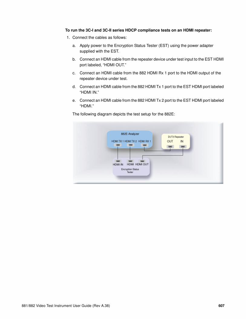
881/882 Video Test Instrument User Guide (Rev A.38) 607
To run the 3C-I and 3C-II series HDCP compliance tests on an HDMI repeater:
1. Connect the cables as follows:
a. Apply power to the Encryption Status Tester (EST) using the power adapter supplied with the EST.
b. Connect an HDMI cable from the repeater device under test input to the EST HDMI port labeled, “HDMI OUT.”
c. Connect an HDMI cable from the 882 HDMI Rx 1 port to the HDMI output of the repeater device under test.
d. Connect an HDMI cable from the 882 HDMI Tx 1 port to the EST HDMI port labeled “HDMI IN.”
e. Connect an HDMI cable from the 882 HDMI Tx 2 port to the EST HDMI port labeled “HDMI.”
The following diagram depicts the test setup for the 882E:

608 Chapter 15 Testing HDCP on HDMI & MHL
2. Activate the HDMI-H interface on the output port as follows:
a. Press the Interface key. A listing of signal interfaces appears on the 882’s display as shown below.
b. Choose the HDMI-H item by pressing the adjacent soft key. The interface is activated and the display is shown below.
Alternatively, to activate the interface through the command line interface, enter the following commands:
XVSI 4 // Activates the HDMI-H interface
ALLU // Applies the interface setting to the 882
3. Press the Interface key repeatedly until the following menu appears:
4. Choose the HDMI IN 1 by pressing the adjacent soft key.
5. Press the Tools key and choose the Reports item by pressing the adjacent soft key.
The following is displayed on the 882’s LCD.
6. Select HDCP to access the HDCP compliance test menu.
The following is displayed on the 882’s LCD.
VGA
HDMI-D
CVBS
S-VIDEO
SDI
*
HDMI-H
VGA
HDMI-D
CVBS
S-VIDEO
SDI*HDMI-H
HDMI IN 1
HDMI IN 2*
EDID Packets Misc HDCP
!CompRpt EditPCP

881/882 Video Test Instrument User Guide (Rev A.38) 609
7. Select EditPCP to define the capabilities of the HDCP device under.
The following is displayed on the 882’s LCD.
The following table describes the test parameters and their settings (gray = N/A).
Parameter Explanation
CTS Version Specifies whether you wish to test to the HDCP CTS 1.1 or HDCP CTS 1.2. Please note you will not be able to
select CTS 1.2 if the HDCP CTS 1.2 option is not
enabled on the 882EA.
DUT type Specifies the type of device under test. This can be one of Sink, Source, Repeater3AB, or Repeater3C. For this test, select Repeater3C.
Test Number Specifies which test to run. Or enables you to select all tests. Please note that Quantum Data highly recom-
mends running the tests individually.
Repeater Max KSV Specifies the maximum number of KSVs the repeater DUT can support. The valid values are 2 through 127. This parameter applied only to the 3C-II test suite.
Repeater Authentication Count(This parameter only applies to the 3AB repeater tests.)
Specifies the number of times a repeater DUT attempts authentication before transitioning into the authentica-tion state. The valid values are 1 or greater.
Repeater Out OnlyRep(not used in HDCP CTS 1.2)(This parameter only applies to the 3AB repeater tests.)
Indicates whether the repeater DUT outputs content to the downstream repeater that has no downstream device connected. The values are + for yes and - for no.
Repeater CP&EDID HPD(not used in HDCP CTS 1.1)
Indicates whether the repeater DUT supports the han-dling of the Content Protection and EDID hot plug detect signal. The values are + for yes and - for no.
Repeater Short Read Ri Indicates whether the repeater DUT will respond to short reads of the Ri register. The values are + for yes and - for no.
Repeater 1.1 Features Supported Indicates whether the supports Advanced_Cipher mode and Enhanced Link Verification. The values are + for yes and - for no.
Repeater Audio Support Indicates whether the repeater DUT supports audio out-put. The values are + for yes and - for no.
1.2 :CTS Ver.
Rptr 3C :DUT Type
+All :Test Num-
+2 :Rptr Max KSV -

610 Chapter 15 Testing HDCP on HDMI & MHL
9. Select Repeater3C device by pressing the adjacent soft key to specify that the device under test is a repeater.
Alternatively, you can specify the device under test as a repeater for the 3C test using the following commands:
CPTX:DUTT 3 // specifies the device under test as a repeater
for the 3C test.
You can query the current value of the parameter with:
CPTX:DUTT? // returns the device under test type.
10. (Optional) Specify the remaining parameters in the EditPCP menu using the table above.
Alternatively, you can specify the parameters through the command line as follows:
CPTX:CTSV 1.2 // specifies which HDCP CTS you wish to test to.
Values are 1.1 for CTS 1.1 and 1.2 for CTS 1.2.
CPTX:RCEH 1 // Indicates whether the DUT
(repeater) supports the content protection and
EDID hot plug signal.
Values are: 0 = no; 1 = yes.
Note 1: This parameter is not used when testing to
HDCP CTS 1.1.
CPTX:CRIP 0 // indicates whether the repeater will respond
to short reads of the Ri register. The values
are 0 for yes and 1 for no (combined reads).
Note 1: For the 882CA you will have to run the
3C-I-01 and 3C-II-01 test using the command line
and both methods of the Ri read.
CPTX:RPFT 0 // indicates whether DUT (repeater) supports 1.1
features such as Advanced Cipher and Enhanced
Link Verification. 1 = yes; 0 = no.
CPTX:RPAS 0 // indicates whether DUT (repeater) supports audio
output. Values are: 1 = yes; 0 = no.
CPTX:RHPD 0 // Indicates whether the repeater DUT have the
capability to signal HDCP_HPD by user
operation. Values are: 1 = yes; 0 = no.
11. For the 3C-I-01 and the 3C-II-01 tests you will run the test for each of two Ri read settings. You can either set this value through the command line or the front panel.
CPTX:CRIP 0 // Specifies short read.
CPTX:CRIP 1 // Specifies combined read.
Repeater HDCP HPD signal Indicates whether the repeater DUT has the capability to signal HDCP_HPD by user operation. The values are + for yes and - for no.
Repeater Device Count of Zero(This parameter only applies to the 3AB repeater tests.)
Indicates whether the repeater DUT supports a device count of zero reported by a downstream repeater. The values are + for yes and - for no.
Parameter Explanation
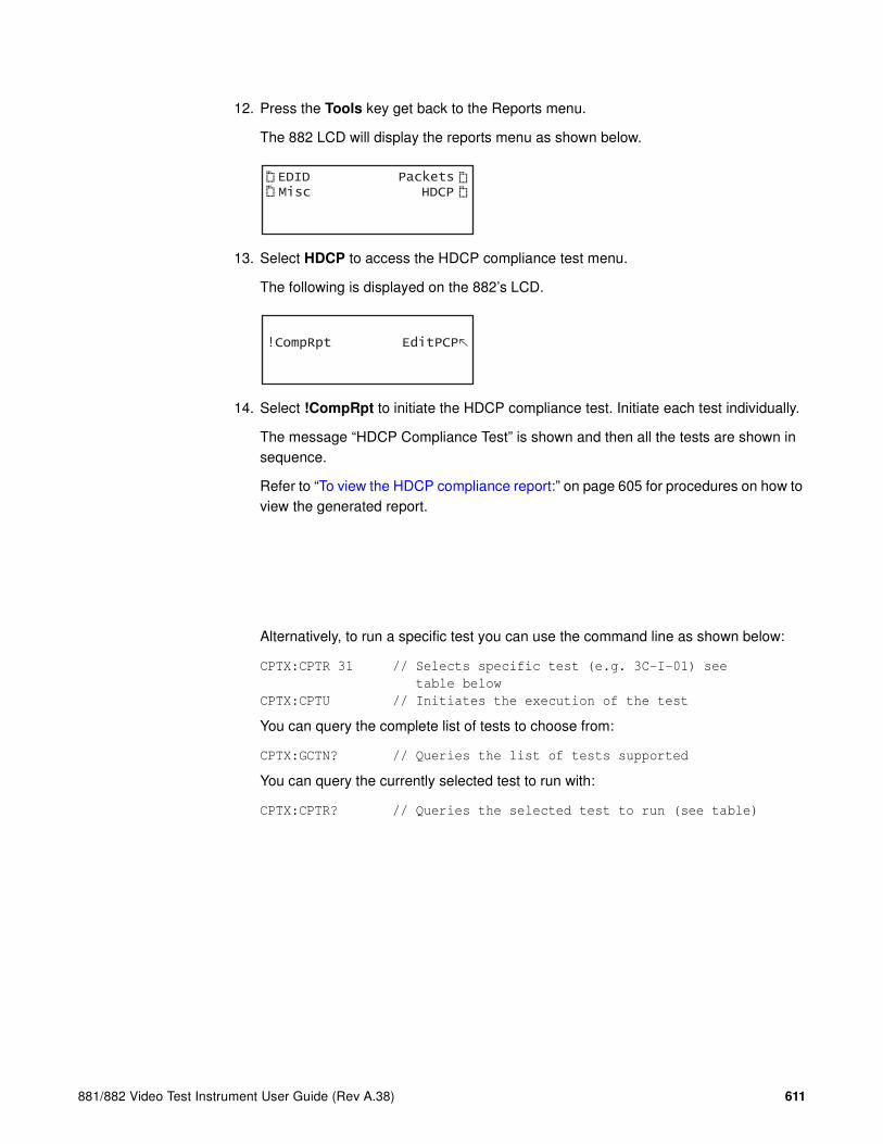
881/882 Video Test Instrument User Guide (Rev A.38) 611
12. Press the Tools key get back to the Reports menu.
The 882 LCD will display the reports menu as shown below.
13. Select HDCP to access the HDCP compliance test menu.
The following is displayed on the 882’s LCD.
14. Select !CompRpt to initiate the HDCP compliance test. Initiate each test individually.
The message “HDCP Compliance Test” is shown and then all the tests are shown in sequence.
Refer to “To view the HDCP compliance report:” on page 605 for procedures on how to view the generated report.
Alternatively, to run a specific test you can use the command line as shown below:
CPTX:CPTR 31 // Selects specific test (e.g. 3C-I-01) see
table below
CPTX:CPTU // Initiates the execution of the test
You can query the complete list of tests to choose from:
CPTX:GCTN? // Queries the list of tests supported
You can query the currently selected test to run with:
CPTX:CPTR? // Queries the selected test to run (see table)
EDID Packets Misc HDCP
!CompRpt EditPCP
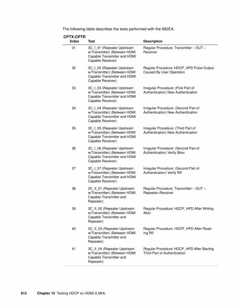
612 Chapter 15 Testing HDCP on HDMI & MHL
The following table describes the tests performed with the 882EA.
CPTX:CPTR Index Test Description
31 3C_I_01 (Repeater Upstream w/Transmitter) (Between HDMI Capable Transmitter and HDMI Capable Receiver)
Regular Procedure: Transmitter – DUT – Receiver
32 3C_I_02 (Repeater Upstream w/Transmitter) (Between HDMI Capable Transmitter and HDMI Capable Receiver)
Regular Procedure: HDCP_HPD Pulse Output Caused By User Operation
33 3C_I_03 (Repeater Upstream w/Transmitter) (Between HDMI Capable Transmitter and HDMI Capable Receiver)
Irregular Procedure: (First Part of Authentication) New Authentication
34 3C_I_04 (Repeater Upstream w/Transmitter) (Between HDMI Capable Transmitter and HDMI Capable Receiver)
Irregular Procedure: (Second Part of Authentication) New Authentication
35 3C_I_05 (Repeater Upstream w/Transmitter) (Between HDMI Capable Transmitter and HDMI Capable Receiver)
Irregular Procedure: (Third Part of Authentication) New Authentication
36 3C_I_06 (Repeater Upstream w/Transmitter) (Between HDMI Capable Transmitter and HDMI Capable Receiver)
Irregular Procedure: (Second Part of Authentication) Verify Bksv
37 3C_I_07 (Repeater Upstream w/Transmitter) (Between HDMI Capable Transmitter and HDMI Capable Receiver)
Irregular Procedure: (Second Part of Authentication) Verify R0'
38 3C_II_01 (Repeater Upstream w/Transmitter) (Between HDMI Capable Transmitter and Repeater)
Regular Procedure: Transmitter – DUT – Repeater+Receiver
39 3C_II_02 (Repeater Upstream w/Transmitter) (Between HDMI Capable Transmitter and Repeater)
Regular Procedure: HDCP_HPD After Writing Aksv
40 3C_II_03 (Repeater Upstream w/Transmitter) (Between HDMI Capable Transmitter and Repeater)
Regular Procedure: HDCP_HPD After Read-ing R0'
41 3C_II_04 (Repeater Upstream w/Transmitter) (Between HDMI Capable Transmitter and Repeater)
Regular Procedure: HDCP_HPD After Starting Third Part of Authentication

881/882 Video Test Instrument User Guide (Rev A.38) 613
42 3C_II_05 (Repeater Upstream w/Transmitter) (Between HDMI Capable Transmitter and Repeater)
Irregular Procedure: (Second Part of Authentication) Verify V'
43 3C_II_06 (Repeater Upstream w/Transmitter) (Between HDMI Capable Transmitter and Repeater)
Irregular Procedure: (Second Part of Authentication) DEVICE_COUNT
44 3C_II_07 (Repeater Upstream w/Transmitter) (Between HDMI Capable Transmitter and Repeater)
Irregular Procedure: (Second Part of Authentication) DEPTH
45 3C_II_08 (Repeater Upstream w/Transmitter) (Between HDMI Capable Transmitter and Repeater)
Irregular Procedure: (Second Part of Authentication) MAX_DEVS_EXCEEDED
46 3C_II_09 (Repeater Upstream w/Transmitter) (Between HDMI Capable Transmitter and Repeater)
Irregular Procedure: (Second Part of Authentication) MAX_CASCADE_EXCEEDED
CPTX:CPTR Index Test Description
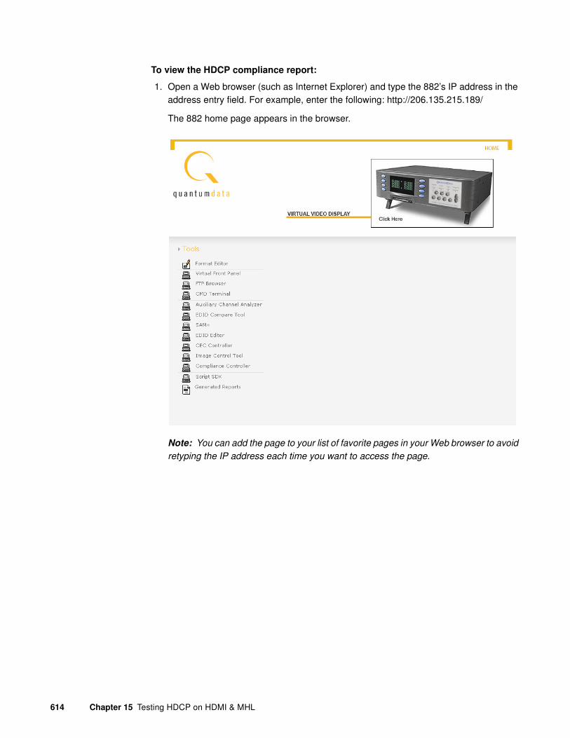
614 Chapter 15 Testing HDCP on HDMI & MHL
To view the HDCP compliance report:
1. Open a Web browser (such as Internet Explorer) and type the 882’s IP address in the address entry field. For example, enter the following: http://206.135.215.189/
The 882 home page appears in the browser.
Note: You can add the page to your list of favorite pages in your Web browser to avoid
retyping the IP address each time you want to access the page.

881/882 Video Test Instrument User Guide (Rev A.38) 615
2. Choose the Generated Reports item. The 882 the provides a list of reports currently available as shown below.
3. Select the HDCP compliance test report from the list. The report then appears in the browser window as shown below. You can then save the report as a web page file for distribution. The following is an example of a report for the HDCP compliance test for a display.
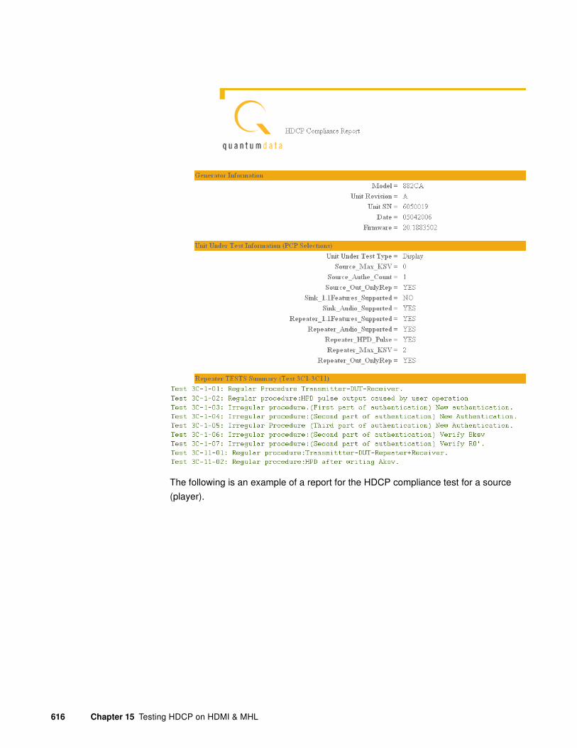
616 Chapter 15 Testing HDCP on HDMI & MHL
The following is an example of a report for the HDCP compliance test for a source
(player).

881/882 Video Test Instrument User Guide (Rev A.38) 617

618 Chapter 15 Testing HDCP on HDMI & MHL
The following is an example of a report for the HDCP compliance test for a repeater.

881/882 Video Test Instrument User Guide (Rev A.38) 619
Running the HDCP compliance test for MHL devices with
the Quantum Data 882EA
Overview
The Quantum Data 882E-Analyzer (882EA) supports the running of an HDCP compliance test on HDCP-enabled MHL sources, sinks and dongles. The HDCP compliance test was developed while working closely with Digital Content Protection (DCP). Please be sure to refer to the release notes for the appropriate release of the 882EA that has been approved by DCP.
Note: The HDCP compliance test is an optional feature available only with the 882
analyzer. You must purchase the license for this feature.
The HDCP compliance test system enables developers of MHL products to perform a comprehensive HDCP compliance test. Because the 882 can emulate an MHL HDCP source or sink/dongle, it can perform a complete HDCP compliance test on any HDCP capable MHL source, sink/dongle, or HDCP repeater.
The HDCP compliance test can be run through the 882 front panel, or through the command line. The HDCP commands enable you to run a specific subset of the tests in the series of tests.
MHL Test Point Adapter (TPA-MHL-8R)
The HDCP compliance tests for an MHL source, sink/dongle and HDCP repeater device require the use of the TPA-MHL-8R test point adapter. This TPA converts HDMI to MHL or MHL to HDMI. The TPA-MHL-8R is depicted in the illustration below.

620 Chapter 15 Testing HDCP on HDMI & MHL
Encryption Status Tester
The HDCP compliance tests for an MHL source, sink/dongle and dongle HDCP repeater device require the use of the standalone hardware device called the Encryption Status Tester (EST) (below) provided by Quantum Data. The EST device is currently only used for the 882EA model. Although the features of the EST pertains to only a handful of tests, it should be connected into the test setup for all tests of the 882EA model.

881/882 Video Test Instrument User Guide (Rev A.38) 621
The features provided by the EST are specifically used for the following tests:
List of Tests
The following table describes the HDCP compliance tests performed with the 882EA.
Index Test EST Function
1 1A_01 (Transmitter Downstream w/Receiver) w/MHL Capable Receiver
Verifies that the encryption enable/disable pulse is transmitted during the valid period, that no data islands, video data or guard band is transmitted during the keep-out period and that no data island is transmitted during Line Key Calc period on the encrypted frame.
11 1B_01 (Transmitter Downstream w/Repeater)
Verifies that the encryption enable/disable pulse is transmitted during the valid period, that no data islands, video data or guard band is transmitted during the keep-out period and that no data island is transmitted during Line Key Calc period on the encrypted frame.
20 2C_04 (Receiver Upstream w/Transmitter) (w/DVI Transmitter)
Positions the encryption enable pulse in the vsync or vertical blanking at three different loca-tions (beginning, center and end).
21 3A_01 (Repeater Downstream w/Receiver) (Between MHL Capable Transmitter and MHL Capable Receiver)
Verifies that the encryption enable/disable pulse is transmitted during the valid period, that no data islands, video data or guard band is transmitted during the keep-out period and that no data island is transmitted during Line Key Calc period on the encrypted frame.
26 3B_01 (Repeater Downstream w/Repeater)
Verifies that the encryption enable/disable pulse is transmitted during the valid period, that no data islands, video data or guard band is transmitted during the keep-out period and that no data island is transmitted during Line Key Calc period on the encrypted frame.
Index Test Description
1 1A_01 (Transmitter Downstream w/Receiver) w/MHL Capable Receiver
Regular Procedure: With MHL Capable Receiver
2 1A_02 (Transmitter Downstream w/Receiver) w/MHL Capable Receiver
Regular Procedure: HDCP_HPD After Writing Aksv
3 1A_03 (Transmitter Downstream w/Receiver) w/MHL Capable Receiver
Regular Procedure: HDCP_HPD After Starting Third Part of Authentication
4 1A_04 (Transmitter Downstream w/Receiver) w/MHL Capable Receiver
Irregular Procedure: (First Part of Authentication) HDPC Port Access

622 Chapter 15 Testing HDCP on HDMI & MHL
There are several configurations depending on what type of HDCP device you are testing. Procedures for each are provided below.
5 1A_05 (Transmitter Downstream w/Receiver) w/MHL Capable Receiver
Irregular Procedure: (First Part of Authentication) Verify Bksv
6 1A_06 (Transmitter Downstream w/Receiver) w/MHL Capable Receiver
Irregular Procedure: (First Part of Authentication) Verify R0'
7 1A_07 (Transmitter Downstream w/Receiver) w/MHL Capable Receiver
Irregular Procedure: (Third Part of Authentication) Verify Ri' (invalid Ri)
8 1A_07a (Transmitter Down-stream w/Receiver) w/MHL Capable Receiver
Irregular Procedure: (Third Part of Authentication) Verify Ri' (Ri’ not returned)
9 1A_08 (Transmitter Downstream w/Receiver) w/MHL Capable Receiver
Irregular Procedure: SRM. Requires SRM DVD disc.
10 1A_09 (Transmitter Downstream w/Receiver) w/DVI Receiver
Regular Procedure: With DVI Receiver
11 1B_01 (Transmitter Downstream w/Repeater)
Regular Procedure: With Repeater
12 1B_02 (Transmitter Downstream w/Repeater)
Regular Procedure: HPD After Reading R0'
13 1B_03 (Transmitter Downstream w/Repeater)
Irregular Procedure: (Second Part of Authentication) Timeout of KSV List READY
14 1B_04 (Transmitter Downstream w/Repeater)
Irregular Procedure: (Second Part of Authentication) Verify V'
15 1B_05 (Transmitter Downstream w/Repeater)
Irregular Procedure: (Second Part of Authentication) MAX_DEVS_EXCEEDED
16 1B_06 (Transmitter Downstream w/Repeater)
Irregular Procedure: (Second Part of Authentication) MAX_CASCADE_EXCEEDED
17 2C_01 (Receiver Upstream w/Transmitter) (w/MHL Capable Transmitter)
Regular Procedure: With MHL Capable Transmitter
18 2C_02 (Receiver Upstream w/Transmitter) (w/MHL Capable Transmitter)
Irregular Procedure: (First Part of Authentication) New Authentication
19 2C_03 (Receiver Upstream w/Transmitter) (w/MHL Capable Transmitter)
Irregular Procedure: (Third Part of Authentication) New Authentication
20 2C_04 (Receiver Upstream w/Transmitter) (w/DVI Transmitter)
Regular Procedure: With DVI Transmitter
Index Test Description
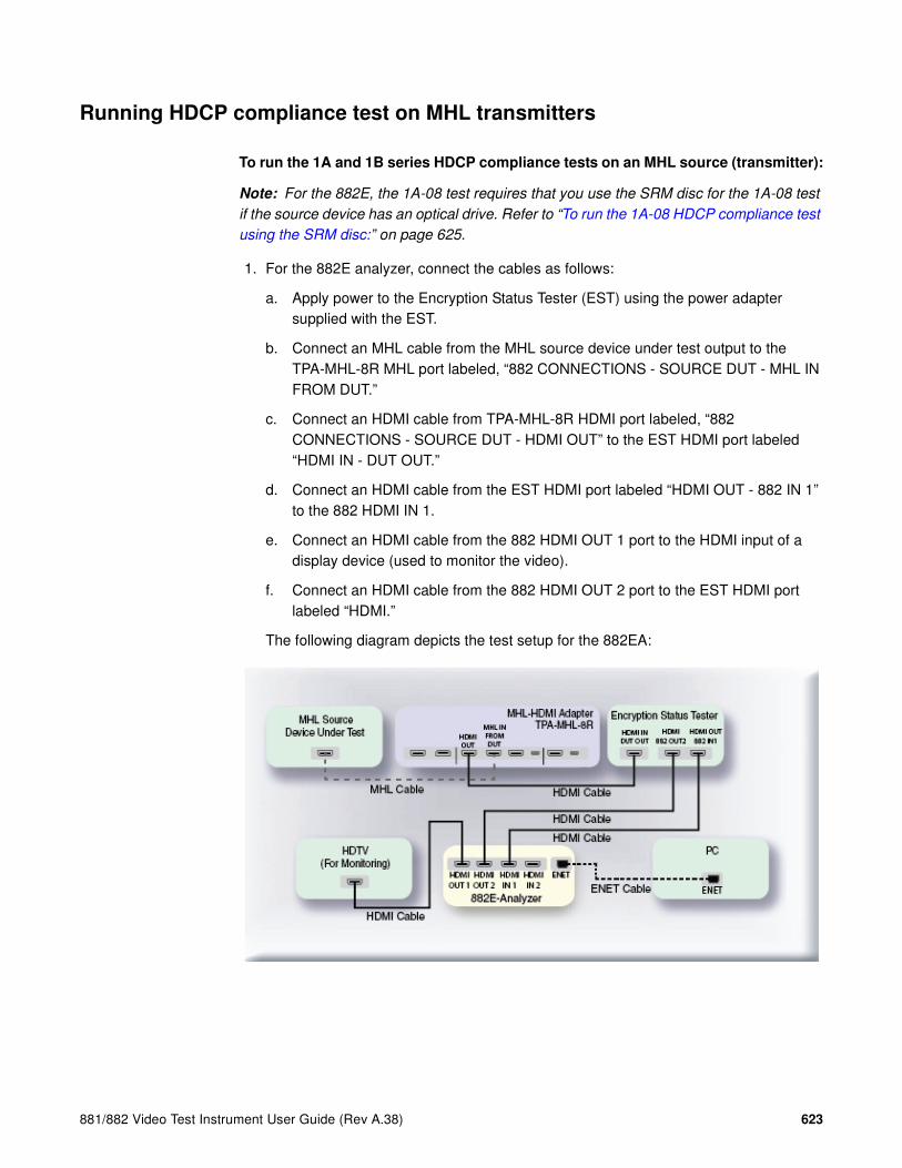
881/882 Video Test Instrument User Guide (Rev A.38) 623
Running HDCP compliance test on MHL transmitters
To run the 1A and 1B series HDCP compliance tests on an MHL source (transmitter):
Note: For the 882E, the 1A-08 test requires that you use the SRM disc for the 1A-08 test
if the source device has an optical drive. Refer to “To run the 1A-08 HDCP compliance test
using the SRM disc:” on page 625.
1. For the 882E analyzer, connect the cables as follows:
a. Apply power to the Encryption Status Tester (EST) using the power adapter supplied with the EST.
b. Connect an MHL cable from the MHL source device under test output to the TPA-MHL-8R MHL port labeled, “882 CONNECTIONS - SOURCE DUT - MHL IN FROM DUT.”
c. Connect an HDMI cable from TPA-MHL-8R HDMI port labeled, “882 CONNECTIONS - SOURCE DUT - HDMI OUT” to the EST HDMI port labeled “HDMI IN - DUT OUT.”
d. Connect an HDMI cable from the EST HDMI port labeled “HDMI OUT - 882 IN 1” to the 882 HDMI IN 1.
e. Connect an HDMI cable from the 882 HDMI OUT 1 port to the HDMI input of a display device (used to monitor the video).
f. Connect an HDMI cable from the 882 HDMI OUT 2 port to the EST HDMI port labeled “HDMI.”
The following diagram depicts the test setup for the 882EA:

624 Chapter 15 Testing HDCP on HDMI & MHL
2. Activate the HDMI-H interface on the output port as follows:
a. Press the Interface key. A listing of signal interfaces appears on the 882’s display as shown below.
b. Choose the HDMI-H item by pressing the adjacent soft key. The interface is activated and the display is shown below.
Alternatively, to activate the interface through the command line interface, enter the following commands:
XVSI 4 // Activates the MHL-H interface
ALLU // Applies the interface setting to the 882
3. Press the Interface key repeatedly until the following menu appears:
4. Choose the HDMI IN 1 by pressing the adjacent soft key.
5. Place the 882EA in the DMT0660 format (640x480p at 59.94/60Hz) and the RGB color space.
6. For the 882EA when using the EST, verify that the source is sending in video using the timing measurement function of the analzyer.
Verify that the source is outputting one of the following formats: 1) 640x480p at 59.94/60Hz; 2) 720x480p at 59.94/60Hz; 3) 720x576p at 50Hz.
Verify that the source is outputing the RGB color space.
If the 882EA cannot detect the incoming video, enter the following command to turn on the EST:
QD:PROD:EST // Turns on the EST.
VGA
HDMI-D
CVBS
S-VIDEO
SDI
*
HDMI-H
VGA
HDMI-D
CVBS
S-VIDEO
SDI*HDMI-H
HDMI IN 1
HDMI IN 2*

881/882 Video Test Instrument User Guide (Rev A.38) 625
7. (For Front Panel Operation) Press the Tools key and choose the Reports item by pressing the adjacent soft key.
The following is displayed on the 882’s LCD.
8. Select HDCP to access the HDCP compliance test menu.
The following is displayed on the 882’s LCD.
9. Select EditPCP to define the capabilities of the HDCP device under test.
The following is displayed on the 882’s LCD.
The following table describes the test parameters and their settings (gray = N/A).
Parameter Explanation
CTS Version Specifies whether you wish to test to the HDCP CTS 1.1 or HDCP CTS 1.2. Please note you will not be able to
select CTS 1.2 if the HDCP CTS 1.2 option is not
enabled on the 882EA.
DUT type Specifies the type of device under test. This can be one of Sink, Source, Repeater3AB, or Repeater3C. For this test, select Source.
Test Number Specifies which test to run. Or enables you to select all tests. Please note that Quantum Data highly recom-
mends running the tests individually.
Source Max KSV Specifies the maximum number of KSVs the source DUT can read. The valid values are 1 through 127.
Source Authentication Count Specifies the number of times a source DUT attempts authentication before transitioning into the authentica-tion state. The valid values are 1 or greater.
Source Out Only Repeater(not used in HDCP CTS 1.2)
Indicates whether the source DUT outputs contents to a repeater to which no downstream device is connected. The values are + for yes and - for no.
EDID Packets Misc HDCP
!CompRpt EditPCP
1.2 :CTS Ver.
Source :DUT Type
+1A-01 :Test Num-
+1 :Src Max KSV -

626 Chapter 15 Testing HDCP on HDMI & MHL
10. Select Source device by pressing the adjacent soft key on the front panel to specify that the device under test is a source.
Alternatively, you can specify the device under test as a source using the following commands:
CPTX:DUTT 1 // specifies the device under test as a source.
You can query the current value of the parameter with:
CPTX:DUTT? // returns the device under test type.
11. Specify the PCP parameters through the front panel using the soft keys adjacent to the PCP parameters and the up and down arrow keys on the right side of the front panel.
The following is an example of the source PCP parameters selection screen on the 882 front panel.
Alternatively, you can specify the EditPCP parameters through the command line as follows:
CPTX:CTSV 1.2 // specifies which HDCP CTS you wish to test to.
Values are 1.1 for CTS 1.1 and 1.2 for CTS 1.2.
CPTX:SKSV 10 // specifies maximum number of downstream devices
listed in the KSV list of the device under test.
Valid values are 1-127.
CPTX:SRAC 5 // specifies number of times a source DUT attempts
authentication before transitioning into the
authenticated state. Valid values, 1 or greater.
CPTX:SOOR 0 // indicates whether DUT (source) outputs content
to the downstream repeater that does not have any
downstream device connected.
Values are: 1 = yes; 0 = no.
Note 1: This parameter is not used when testing to
HDCP CTS 1.2.
CPTX:SCEH 1 // Indicates whether DUT (source) supports the
content protection and EDID hot plug signal.
Values are: 0 = no; 1 = yes.
Note 1: This parameter is not used when testing to
HDCP CTS 1.1.
Source CP&EDID HPD(Not used for CTS 1.1 testing)
Indicates whether the source DUT supports the han-dling of the Content Protection and EDID hot plug detect signal.The values are + for yes and - for no.
Source Device Count Zero Indicates whether the source DUT supports a repeater that reports a device count of zero. The values are + for yes and - for no.
Parameter Explanation
1.2 :CTS Ver.
Source :DUT Type
+1A-01 :Test Num-
+1 :Src Max KSV -
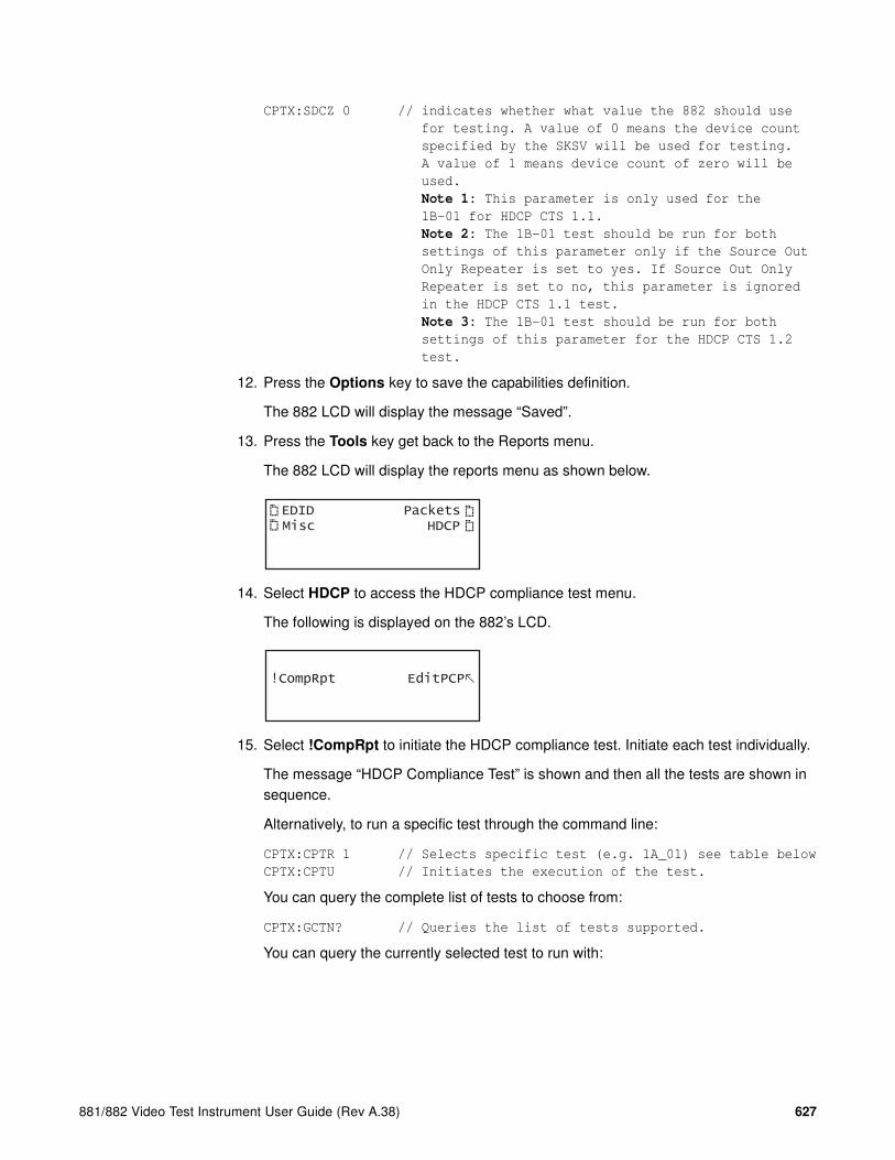
881/882 Video Test Instrument User Guide (Rev A.38) 627
CPTX:SDCZ 0 // indicates whether what value the 882 should use
for testing. A value of 0 means the device count
specified by the SKSV will be used for testing.
A value of 1 means device count of zero will be
used.
Note 1: This parameter is only used for the
1B-01 for HDCP CTS 1.1.
Note 2: The 1B-01 test should be run for both
settings of this parameter only if the Source Out
Only Repeater is set to yes. If Source Out Only
Repeater is set to no, this parameter is ignored
in the HDCP CTS 1.1 test.
Note 3: The 1B-01 test should be run for both
settings of this parameter for the HDCP CTS 1.2
test.
12. Press the Options key to save the capabilities definition.
The 882 LCD will display the message “Saved”.
13. Press the Tools key get back to the Reports menu.
The 882 LCD will display the reports menu as shown below.
14. Select HDCP to access the HDCP compliance test menu.
The following is displayed on the 882’s LCD.
15. Select !CompRpt to initiate the HDCP compliance test. Initiate each test individually.
The message “HDCP Compliance Test” is shown and then all the tests are shown in sequence.
Alternatively, to run a specific test through the command line:
CPTX:CPTR 1 // Selects specific test (e.g. 1A_01) see table below
CPTX:CPTU // Initiates the execution of the test.
You can query the complete list of tests to choose from:
CPTX:GCTN? // Queries the list of tests supported.
You can query the currently selected test to run with:
EDID Packets Misc HDCP
!CompRpt EditPCP
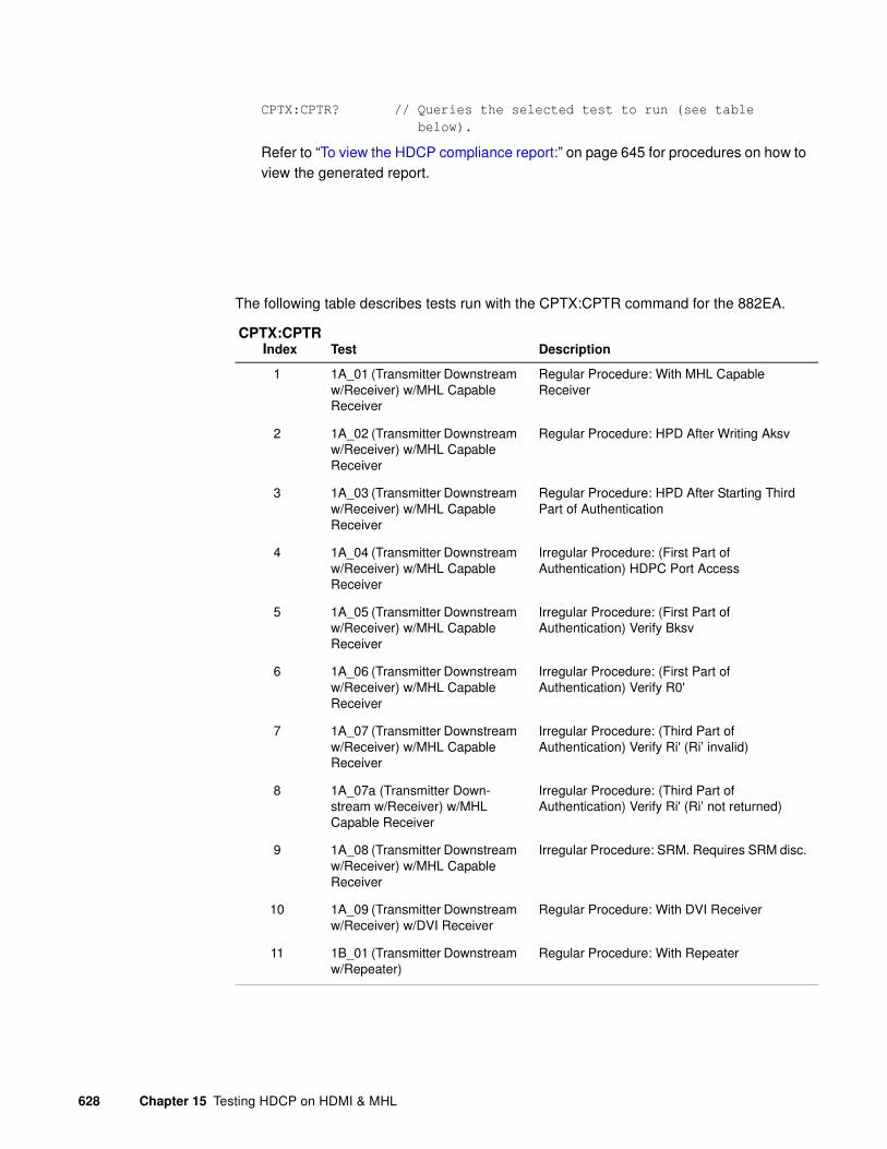
628 Chapter 15 Testing HDCP on HDMI & MHL
CPTX:CPTR? // Queries the selected test to run (see table
below).
Refer to “To view the HDCP compliance report:” on page 645 for procedures on how to view the generated report.
The following table describes tests run with the CPTX:CPTR command for the 882EA.
CPTX:CPTR Index Test Description
1 1A_01 (Transmitter Downstream w/Receiver) w/MHL Capable Receiver
Regular Procedure: With MHL Capable Receiver
2 1A_02 (Transmitter Downstream w/Receiver) w/MHL Capable Receiver
Regular Procedure: HPD After Writing Aksv
3 1A_03 (Transmitter Downstream w/Receiver) w/MHL Capable Receiver
Regular Procedure: HPD After Starting Third Part of Authentication
4 1A_04 (Transmitter Downstream w/Receiver) w/MHL Capable Receiver
Irregular Procedure: (First Part of Authentication) HDPC Port Access
5 1A_05 (Transmitter Downstream w/Receiver) w/MHL Capable Receiver
Irregular Procedure: (First Part of Authentication) Verify Bksv
6 1A_06 (Transmitter Downstream w/Receiver) w/MHL Capable Receiver
Irregular Procedure: (First Part of Authentication) Verify R0'
7 1A_07 (Transmitter Downstream w/Receiver) w/MHL Capable Receiver
Irregular Procedure: (Third Part of Authentication) Verify Ri' (Ri’ invalid)
8 1A_07a (Transmitter Down-stream w/Receiver) w/MHL Capable Receiver
Irregular Procedure: (Third Part of Authentication) Verify Ri' (Ri’ not returned)
9 1A_08 (Transmitter Downstream w/Receiver) w/MHL Capable Receiver
Irregular Procedure: SRM. Requires SRM disc.
10 1A_09 (Transmitter Downstream w/Receiver) w/DVI Receiver
Regular Procedure: With DVI Receiver
11 1B_01 (Transmitter Downstream w/Repeater)
Regular Procedure: With Repeater

881/882 Video Test Instrument User Guide (Rev A.38) 629
16. Monitor the 882EA LCD for a set of prompts during the 1A-01, 1A-09, and 1B-01 tests.
Note: You will not be prompted as shown below when running the test with the 882CA.
a. When prompted with the screen shown below, examine the video on the display connected to 882EA output 1. Press the appropriate button adjacent to the indication (Yes! or No!) to continue.
Note: The prompt asks you if the video appearing on the connected display looks
good. “Looks good” means that there is a picture and an absence of excessive snow.
To run the 1A-08 HDCP compliance test using the SRM disc:
1. Set up the test as described in “To run the 1A and 1B series HDCP compliance tests on an MHL source (transmitter):” on page 619 using the instructions for the 882E analyzer.
Note: The SRM test is only supported on the 882E analyzer. Insert the SRM disc into
the source device and run the HDCP tests through the command line.
2. Insert the SRM disc into the optical drive.
Note: The SRM test does not apply for source devices that cannot play a DVD.
3. To run 1A-08 test, use the command line as shown below:
CPTX:DUTT 1 // Selects the device type as a source.
CPTX:CPTR 9 // Selects specific test (e.g. 1A_08).
CPTX:CPTU // Initiates the execution of the test.
Refer to “To view the HDCP compliance report:” on page 645 for procedures on how to view the generated report.
12 1B_02 (Transmitter Downstream w/Repeater)
Regular Procedure: HDCP_HPD After Read-ing R0'
13 1B_03 (Transmitter Downstream w/Repeater)
Irregular Procedure: (Second Part of Authentication) Timeout of KSV List READY
14 1B_04 (Transmitter Downstream w/Repeater)
Irregular Procedure: (Second Part of Authentication) Verify V'
15 1B_05 (Transmitter Downstream w/Repeater)
Irregular Procedure: (Second Part of Authentication) MAX_DEVS_EXCEEDED
16 1B_06 (Transmitter Downstream w/Repeater)
Irregular Procedure: (Second Part of Authentication) MAX_CASCADE_EXCEEDED
CPTX:CPTR Index Test Description
Does the video look good?
!Yes No!

630 Chapter 15 Testing HDCP on HDMI & MHL
Running HDCP compliance tests on MHL Sinks (receivers) and MHL Dongles
The receiver tests are the 2C-0x series.
For the 882E the 2C-01 and 2C-04 tests are run multiple times for various settings. The 2C-01 test is required to be run in two configurations: 1) combined reads and 2) short reads. The 2C-04 test is required to be run in six (6) configurations. There are two read configurations: 1) short read and 2) combined read. There are three encryption pulse configurations: 1) occurring at the beginning of the vertical blanking; 2) occurring at the middle of the vertical blanking and 3) occurring at the end of the vertical blanking.
To run the 2C-0x compliance tests on an MHL sink (receiver):
1. For the 882E analyzer connect the cables as follows:
a. Apply power to the Encryption Status Tester (EST) using the power adapter that is supplied with the EST.
b. Connect an HDMI cable from the EST HDMI port labeled “HDMI IN - 882 OUT 1” to the 882 HDMI OUT 1.
c. Connect an HDMI cable from the 882 HDMI OUT 2 port to the EST HDMI port labeled “HDMI.”
d. Connect an HDMI cable from TPA-MHL-8R HDMI port labeled, “882 CONNECTIONS - SINK DUT - HDMI IN” to the EST HDMI port labeled “HDMI OUT DUT IN.”
e. Connect an MHL cable from the MHL sink device under test input to the TPA-MHL-8R MHL port labeled, “882 CONNECTIONS - SINK DUT - MHL OUT TO DUT.”
f. (If testing a dongle) Connect an MHL cable from the MHL dongle to the HDMI sink.
The following diagrams depict the test setup for the 882EA. The first diagram covers the sink test and the second diagram covers the dongle test.

881/882 Video Test Instrument User Guide (Rev A.38) 631
2. Activate the HDMI-H interface on the output port as follows:
a. Press the Interface key. A listing of signal interfaces appears on the 882’s display as shown below.
b. Choose the HDMI-H item by pressing the adjacent soft key. The interface is activated and the display is shown below.
Alternatively, to activate the interface through the command line interface, enter the following commands:
XVSI 4 // Activates the HDMI-H interface.
ALLU // Applies the interface setting to the 882.
3. Press the Tools key and choose the Reports item by pressing the adjacent soft key.
The following is displayed on the 882’s LCD.
VGA
HDMI-D
CVBS
S-VIDEO
SDI
*
HDMI-H
VGA
HDMI-D
CVBS
S-VIDEO
SDI*HDMI-H
EDID Packets Misc HDCP

632 Chapter 15 Testing HDCP on HDMI & MHL
4. Select HDCP to access the HDCP compliance test menu.
The following is displayed on the 882’s LCD.
5. Select EditPCP to define the capabilities of the HDCP device under test.
The following is displayed on the 882’s LCD.
The following table describes the test parameters and their settings (gray = N/A).
Parameter Explanation
CTS Version Specifies whether you wish to test to the HDCP CTS 1.1 or HDCP CTS 1.2. Please note you will not be able to
select CTS 1.2 if the HDCP CTS 1.2 option is not
enabled on the 882EA.
DUT type Specifies the type of device under test. This can be one of Sink, Source, Repeater3AB, or Repeater3C. For this test, select Sink.
Test Number Specifies which test to run. Or enables you to select all tests. Please note that Quantum Data highly recom-
mends running the tests individually.
Sink 1.1 Features Supported Indicates whether the sink DUT supports Advanced_Cipher mode and Enhanced Link Verifica-tion. The values are + for yes and - for no.
Sink 1.1 Audio Supported Indicates whether the sink DUT supports audio output. The values are + for yes and - for no.
Sink Short Read Ri Indicates whether the sink DUT will respond to short reads of the Ri register. The values are + for yes and - for no.
Sink Write Ainfo Indicates whether the sink DUT responds (supports) Ainfo writes from a source.The values are + for yes and - for no.
OESS Encryption Enable Pulse Indicates where the encryption enable pulse is located in the vertical blanking. Values are: Cent (for central); Lead (for leading edge); and Trail (tor trailing edge).
!CompRpt EditPCP
1.2 :CTS Ver.
Sink :DUT Type
+All :Test Num-
+ :Src Max KSV -

881/882 Video Test Instrument User Guide (Rev A.38) 633
6. Select Sink device by pressing the adjacent soft key to specify that the device under test is a sink.
Alternatively, you can specify the device under test as a sink using the following commands:
CPTX:DUTT 0 // specifies the device under test as a sink.
You can query the current value of the parameter with:
CPTX:DUTT? // returns the device under test type.
7. Specify the remaining parameters through the EditPCP menu on the front panel using in the using soft keys adjacent to each item and the up and down arrow keys on the right side of the front panel. Refer to the table above for a list of the parameters and their meaning.
Alternatively, you can specify the parameters through the command line as follows:
CPTX:CTSV 1.2 // specifies which HDCP CTS you wish to test to.
Values are 1.1 for CTS 1.1 and 1.2 for CTS 1.2.
CPTX:SRFT 0 // indicates whether DUT (sink) supports 1.1
features such as Advanced Cipher and Enhanced
Link Verification. 1 = yes; 0 = no.
CPTX:WAIN 0 // indicates whether DUT (sink) supports the handling
of Ainfo commands sent by the source device.
Values are: 1 = yes; 0 = no.
CPTX:SNAS 0 // indicates whether DUT (sink) supports audio
output. Values are: 1 = yes; 0 = no.
8. For the 2C-01 tests, you will run the test 2 times for each setting of the Short Read Ri parameter. You can set these parameters either through the 882 front panel or the command line as follows:
CPTX:CRIP 0 // Specifies short read.
CPTX:CRIP 1 // Specifies combined read.
9. For the 2C-04 tests, you will run the test 6 times for each combination of settings for the Short Read Ri parameter and position of the encryption enable pulse (leading, center and trailing) with respect to the vertical sync pulse. You can set these parameters either through the 882 front panel or the command line as follows:
CPTX:CRIP 0 // Specifies short read.
CPTX:CRIP 1 // Specifies combined read.
CPTX:OESS 1 // Positions pulse at leading edge of vsync.
CPTX:OESS 2 // Positions pulse at trailing edge of vsync.
CPTX:OESS 3 // Positions pulse at center of vsync.
10. Press the Tools key get back to the Reports menu.
The 882 LCD will display the reports menu as shown below.
EDID Packets Misc HDCP

634 Chapter 15 Testing HDCP on HDMI & MHL
11. Select HDCP to access the HDCP compliance test menu.
The following is displayed on the 882’s LCD.
12. Select !CompRpt to initiate the HDCP compliance test. Initiate each test individually.
The message “HDCP Compliance Test” is shown and then all the tests are shown in sequence.
Refer to “To view the HDCP compliance report:” on page 645 for procedures on how to view the generated report.
Alternatively to run a specific test you can use the command line as shown below:
CPTX:CPTR 17 // Selects specific test (e.g. 2C_01) see table below
CPTX:CPTU // Initiates the execution of the test.
You can query the complete list of tests to choose from:
CPTX:GCTN? // Queries the list of tests supported.
You can query the currently selected test to run with:
CPTX:CPTR? // Queries the selected test to run (see table).
The following table describes tests that run with the CPTX:CPTR command for the 882EA.
13. Monitor the 882EA LCD for a set of prompts during the test.
a. When the prompt shown below occurs, power cycle the device under test.
CPTX:CPTR
Index Test Description
17 2C_01 (Receiver Upstream w/Transmitter) (w/MHL Capable Transmitter)
Regular Procedure: With MHL Capable Transmitter
18 2C_02 (Receiver Upstream w/Transmitter) (w/MHL Capable Transmitter)
Irregular Procedure: (First Part of Authentica-tion) New Authentication
19 2C_03 (Receiver Upstream w/Transmitter) (w/MHL Capable Transmitter)
Irregular Procedure: (Third Part of Authentication) New Authentication
20 2C_04 (Receiver Upstream w/Transmitter) (w/DVI Transmitter)
Regular Procedure: With DVI Transmitter
!CompRpt EditPCP
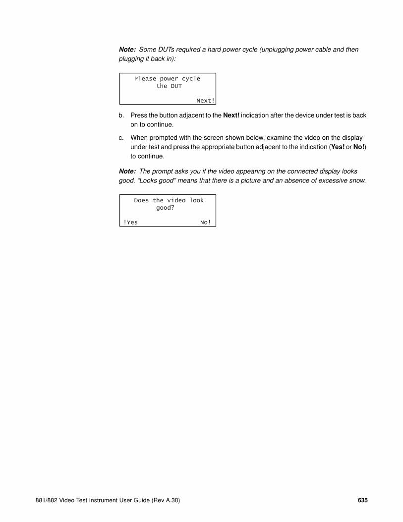
881/882 Video Test Instrument User Guide (Rev A.38) 635
Note: Some DUTs required a hard power cycle (unplugging power cable and then
plugging it back in):
b. Press the button adjacent to the Next! indication after the device under test is back on to continue.
c. When prompted with the screen shown below, examine the video on the display under test and press the appropriate button adjacent to the indication (Yes! or No!) to continue.
Note: The prompt asks you if the video appearing on the connected display looks
good. “Looks good” means that there is a picture and an absence of excessive snow.
Please power cycle the DUT
Next!
Does the video look good?
!Yes No!

636 Chapter 15 Testing HDCP on HDMI & MHL
Running HDCP compliance tests on MHL repeaters
This subsection provides procedures for running the HDCP compliance test on MHL repeater devices.
To run the 3A and 3B series HDCP compliance tests on an MHL repeater:
1. For the 882E analyzer connect the cables as follows:
a. Apply power to the Encryption Status Tester (EST) using the power adapter supplied with the EST.
b. Connect an HDMI cable from a compliant HDMI HDCP source to the TPA-MHL-8R MHL port labeled, “882 CONNECTIONS - SINK DUT - HDMI IN.”
c. Connect an MHL cable from TPA-MHL-8R MHL port labeled, “882 CONNECTIONS - SINK DUT - MHL OUT TO DUT” to the HDMI input of the repeater device under test.
d. Connect an HDMI cable from the output of the MHL repeater device under test to the HDMI IN port of the EST.
e. Connect an HDMI cable from the HDMI OUT port of the EST to the 882 HDMI IN 1 port.
f. Connect an HDMI cable from the 882EA HDMI OUT 1 port to the HDMI input of a display device (used to monitor the video).
g. Connect an HDMI cable from the 882EA HDMI OUT 2 port to the EST HDMI port labeled “HDMI.”
The following diagram depicts the test setup:

881/882 Video Test Instrument User Guide (Rev A.38) 637
2. Activate the HDMI-H interface on the output port as follows:
a. Press the Interface key. A listing of signal interfaces appears on the 882’s display as shown below.
b. Choose the HDMI-H item by pressing the adjacent soft key. The interface is activated and the display is shown below.
Alternatively, to activate the interface through the command line interface, enter the following commands:
XVSI 4 // Activates the HDMI-H interface
ALLU // Applies the interface setting to the 882
3. Press the Interface key repeatedly until the following menu appears:
4. Choose the HDMI IN 1 by pressing the adjacent soft key.
5. Place the 882EA in the DMT0660 format (640x480p at 59.94/60Hz) and the RGB color space.
6. Verify that the repeater is sending in video using the Timing measurement function of the analzyer.
Verify that the source is outputting one of the following formats: 1) 640x480p at 59.94/60Hz; 2) 720x480p at 59.94/60Hz; 3) 720x576p at 50Hz.
Verify that the source is outputing the RGB color space:
If the 882 cannot detect the incoming video, enter the following command to turn on the EST:
QD:PROD:EST // Turns on the EST
VGA
HDMI-D
CVBS
S-VIDEO
SDI
*
HDMI-H
VGA
HDMI-D
CVBS
S-VIDEO
SDI*HDMI-H
HDMI IN 1
HDMI IN 2*

638 Chapter 15 Testing HDCP on HDMI & MHL
7. Press the Tools key and choose the Reports item by pressing the adjacent soft key.
The following is displayed on the 882’s LCD.
8. Select HDCP to access the HDCP compliance test menu.
The following is displayed on the 882’s LCD.
9. Select EditPCP to define the capabilities of the HDCP device under.
The following is displayed on the 882’s LCD.
The following table describes the test parameters and their settings (gray = N/A).
Parameter Explanation
CTS Version Specifies whether you wish to test to the HDCP CTS 1.1 or HDCP CTS 1.2. Please note you will not be able to
select CTS 1.2 if the HDCP CTS 1.2 option is not
enabled on the 882EA.
DUT type Specifies the type of device under test. This can be one of Sink, Source, Repeater3AB, or Repeater3C. For this test, select Repeater3AB.
Test Number Specifies which test to run. Or enables you to select all tests. Please note that Quantum Data highly recom-
mends running the tests individually.
Repeater Max KSV Specifies the maximum number of KSVs the repeater DUT can support. The valid values are 2 through 127. This parameter applies only to the 3B test suite.
Repeater Authentication Count Specifies the number of times a repeater DUT attempts authentication before transitioning into the authentica-tion state. The valid values are 1 or greater.
Repeater CP&EDID HPD(Not used in HDCP 1.1)(Not used for 3AB tests. Only applies to 3C tests)
Indicates whether the repeater supports the handling of the Content Protection and EDID hot plug detect sig-nal.The values are + for yes and - for no.
EDID Packets Misc HDCP
!CompRpt EditPCP
1.2 :CTS Ver.
Rptr 3AB :DUT Type
+All :Test Num-
+2 :Rptr Max KSV -
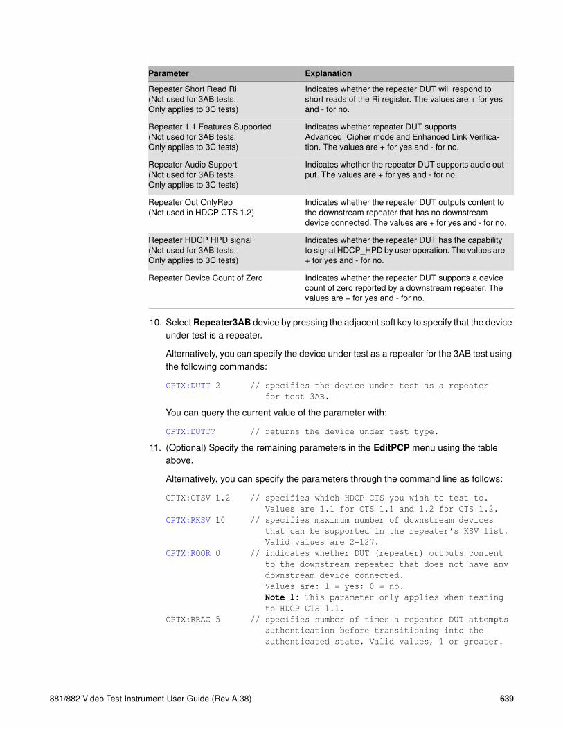
881/882 Video Test Instrument User Guide (Rev A.38) 639
10. Select Repeater3AB device by pressing the adjacent soft key to specify that the device under test is a repeater.
Alternatively, you can specify the device under test as a repeater for the 3AB test using the following commands:
CPTX:DUTT 2 // specifies the device under test as a repeater
for test 3AB.
You can query the current value of the parameter with:
CPTX:DUTT? // returns the device under test type.
11. (Optional) Specify the remaining parameters in the EditPCP menu using the table above.
Alternatively, you can specify the parameters through the command line as follows:
CPTX:CTSV 1.2 // specifies which HDCP CTS you wish to test to.
Values are 1.1 for CTS 1.1 and 1.2 for CTS 1.2.
CPTX:RKSV 10 // specifies maximum number of downstream devices
that can be supported in the repeater’s KSV list.
Valid values are 2-127.
CPTX:ROOR 0 // indicates whether DUT (repeater) outputs content
to the downstream repeater that does not have any
downstream device connected.
Values are: 1 = yes; 0 = no.
Note 1: This parameter only applies when testing
to HDCP CTS 1.1.
CPTX:RRAC 5 // specifies number of times a repeater DUT attempts
authentication before transitioning into the
authenticated state. Valid values, 1 or greater.
Repeater Short Read Ri(Not used for 3AB tests. Only applies to 3C tests)
Indicates whether the repeater DUT will respond to short reads of the Ri register. The values are + for yes and - for no.
Repeater 1.1 Features Supported(Not used for 3AB tests. Only applies to 3C tests)
Indicates whether repeater DUT supports Advanced_Cipher mode and Enhanced Link Verifica-tion. The values are + for yes and - for no.
Repeater Audio Support(Not used for 3AB tests. Only applies to 3C tests)
Indicates whether the repeater DUT supports audio out-put. The values are + for yes and - for no.
Repeater Out OnlyRep(Not used in HDCP CTS 1.2)
Indicates whether the repeater DUT outputs content to the downstream repeater that has no downstream device connected. The values are + for yes and - for no.
Repeater HDCP HPD signal(Not used for 3AB tests. Only applies to 3C tests)
Indicates whether the repeater DUT has the capability to signal HDCP_HPD by user operation. The values are + for yes and - for no.
Repeater Device Count of Zero Indicates whether the repeater DUT supports a device count of zero reported by a downstream repeater. The values are + for yes and - for no.
Parameter Explanation

640 Chapter 15 Testing HDCP on HDMI & MHL
CPTX:RHPD 0 // Indicates whether the repeater DUT has the
capability to signal HDCP_HPD by user
operation. Values are: 1 = yes; 0 = no.
CPTX:SDCZ 0 // indicates whether what value the 882 should use
for testing. A value of 0 means the device count
specified by the SKSV will be used for testing.
A value of 1 means device count of zero will be
used.
Note 1: This parameter is only used for the
1B-01 for HDCP CTS 1.1.
Note 2: The 1B-01 test should be run for both
settings of this parameter only if the Source Out
Only Repeater is set to yes. If Source Out Only
Repeater is set to no, this parameter is ignored
in the HDCP CTS 1.1 test.
Note 3: The 1B-01 test should be run for both
settings of this parameter for the HDCP CTS 1.2
test.
12. Press the Tools key get back to the Reports menu.
13. Select HDCP to access the HDCP compliance test menu.
The following is displayed on the 882’s LCD.
14. Select !CompRpt to initiate the HDCP compliance test. Initiate each test individually.
The message “HDCP Compliance Test” is shown and then all the tests are shown in sequence.
Alternatively, you can run the tests through the command line as shown below:
CPTX:CPTR 21 // Selects specific test (e.g. 3A_01) see table below
CPTX:CPTU // Initiates the execution of the test
You can query the complete list of tests to choose from:
CPTX:GCTN? // Queries the list of tests supported
You can query the currently selected test to run with:
CPTX:CPTU? // Queries the selected test to run (see table)
Refer to “To view the HDCP compliance report:” on page 645 for procedures on how to view the generated report.
15. Monitor the 882EA LCD for a set of prompts during the 3A-01, 3A-05 and 3B-01 tests.
a. When prompted with the screen shown below, examine the video on the display connected to 882EA output 1. Press the appropriate button adjacent to the indication (Yes! or No!) to continue.
!CompRpt EditPCP

881/882 Video Test Instrument User Guide (Rev A.38) 641
Note: The prompt asks you if the video appearing on the connected display looks
good. “Looks good” means that there is a picture and an absence of excessive snow.
The following table describes tests run with the CPTX:CPTR command for the 882EA.
CPTX:CPTR
Index Test Description
21 3A_01 (Repeater Downstream w/Receiver) (Between MHL Capable Transmitter and MHL Capable Receiver)
Regular Procedure: With MHL Capable Receiver
22 3A_02 (Repeater Downstream w/Receiver) (Between MHL Capable Transmitter and MHL Capable Receiver)
Irregular Procedure: (First Part of Authentication) HDCP Port Access
23 3A_03 (Repeater Downstream w/Receiver) (Between MHL Capable Transmitter and MHL Capable Receiver)
Irregular Procedure: (First Part of Authentication) Verify Bksv
24 3A_04 (Repeater Downstream w/Receiver) (Between MHL Capable Transmitter and MHL Capable Receiver)
Irregular Procedure: (First Part of Authentication) Verify R0’
25 3A_05 (Repeater Downstream w/Receiver) (Between MHL Capable Transmitter and DVI Receiver)
Regular Procedure: With DVI Receiver
26 3B_01 (Repeater Downstream w/Repeater)
Regular Procedure: With Repeater
27 3B_02 (Repeater Downstream w/Repeater)
Irregular Procedure: (Second Part of Authentication) Timeout of KSV List READY
28 3B_03 (Repeater Downstream w/Repeater)
Irregular Procedure: (Second Part of Authentication) Verify V’
29 3B_04 (Repeater Downstream w/Repeater)
Irregular Procedure: (Second Part of Authentication) MAX_DEVS_EXCEEDED
30 3B_05 (Repeater Downstream w/Repeater)
Irregular Procedure: (Second Part of Authentication) MAX_CASCADE_EXCEEDED
Does the video look good?
!Yes No!

642 Chapter 15 Testing HDCP on HDMI & MHL
To run the 3C-I and 3C-II series HDCP compliance tests on an MHL repeater:
1. For the 882E analyzer connect the cables as follows:
a. Apply power to the Encryption Status Tester (EST) using the power adapter supplied with the EST.
b. Connect an HDMI cable from the 882EA OUT 1 port to the HDMI IN port of the EST
c. Connect an HDMI cable from the HDMI OUT port of the EST to the TPA-MHL-8R HDMI port labeled, “882 CONNECTIONS - SINK DUT - HDMI IN.”
d. Connect an MHL cable from TPA-MHL-8R MHL port labeled, “882 CONNECTIONS - SINK DUT - MHL OUT TO DUT” to the HDMI input of the repeater device under test.
e. Connect an HDMI cable from the output of the MHL repeater device under test to the HDMI IN 1 port of the 882EA.
f. Connect an HDMI cable from the 882EA HDMI OUT 2 port to the EST HDMI port labeled “HDMI.”
The following diagram depicts the test setup:

881/882 Video Test Instrument User Guide (Rev A.38) 643
2. Activate the HDMI-H interface on the output port as follows:
a. Press the Interface key. A listing of signal interfaces appears on the 882’s display as shown below.
b. Choose the HDMI-H item by pressing the adjacent soft key. The interface is activated and the display is shown below.
Alternatively, to activate the interface through the command line interface, enter the following commands:
XVSI 4 // Activates the HDMI-H interface
ALLU // Applies the interface setting to the 882
3. Press the Interface key repeatedly until the following menu appears:
4. Choose the HDMI IN 1 by pressing the adjacent soft key.
5. Press the Tools key and choose the Reports item by pressing the adjacent soft key.
The following is displayed on the 882’s LCD.
6. Select HDCP to access the HDCP compliance test menu.
The following is displayed on the 882’s LCD.
VGA
HDMI-D
CVBS
S-VIDEO
SDI
*
HDMI-H
VGA
HDMI-D
CVBS
S-VIDEO
SDI*HDMI-H
HDMI IN 1
HDMI IN 2*
EDID Packets Misc HDCP
!CompRpt EditPCP

644 Chapter 15 Testing HDCP on HDMI & MHL
7. Select EditPCP to define the capabilities of the HDCP device under.
The following is displayed on the 882’s LCD.
The following table describes the test parameters and their settings (gray = N/A).
Parameter Explanation
CTS Version Specifies whether you wish to test to the HDCP CTS 1.1 or HDCP CTS 1.2. Please note you will not be able to
select CTS 1.2 if the HDCP CTS 1.2 option is not
enabled on the 882EA.
DUT type Specifies the type of device under test. This can be one of Sink, Source, Repeater3AB, or Repeater3C. For this test, select Repeater3C.
Test Number Specifies which test to run. Or enables you to select all tests. Please note that Quantum Data highly recom-
mends running the tests individually.
Repeater Max KSV Specifies the maximum number of KSVs the repeater DUT can support. The valid values are 2 through 127. This parameter applies only to the 3C-II test suite.
Repeater Authentication Count(This parameter only applies to the 3AB repeater tests.)
Specifies the number of times a repeater DUT attempts authentication before transitioning into the authentica-tion state. The valid values are 1 or greater.
Repeater Out OnlyRep(not used in HDCP CTS 1.2)(This parameter only applies to the 3AB repeater tests.)
Indicates whether the repeater DUT outputs content to the downstream repeater that has no downstream device connected. The values are + for yes and - for no.
Repeater CP&EDID HPD(not used in HDCP CTS 1.1)
Indicates whether the repeater DUT supports the han-dling of the Content Protection and EDID hot plug detect signal. The values are + for yes and - for no.
Repeater Short Read Ri Indicates whether the repeater DUT will respond to short reads of the Ri register. The values are + for yes and - for no.
Repeater 1.1 Features Supported Indicates whether the supports Advanced_Cipher mode and Enhanced Link Verification. The values are + for yes and - for no.
Repeater Audio Support Indicates whether the repeater DUT supports audio out-put. The values are + for yes and - for no.
1.2 :CTS Ver.
Rptr 3C :DUT Type
+All :Test Num-
+2 :Rptr Max KSV -
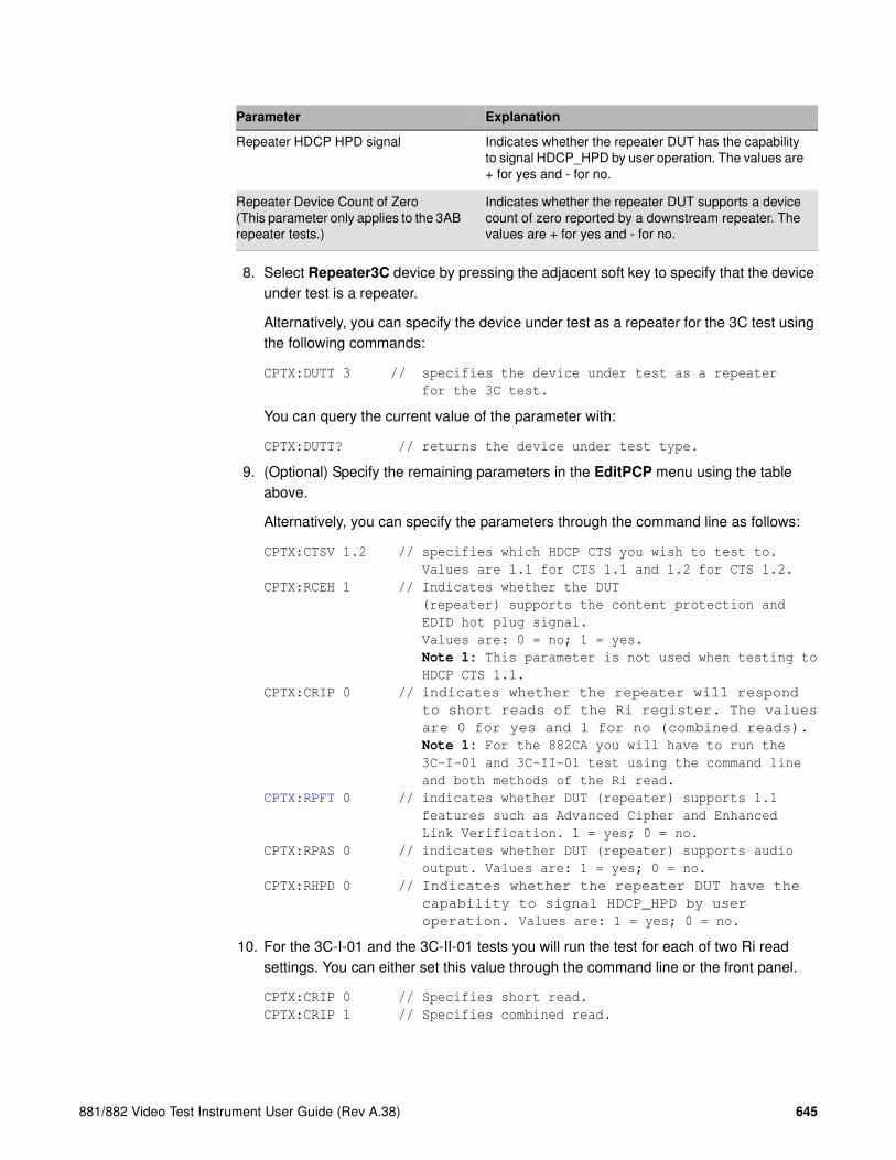
881/882 Video Test Instrument User Guide (Rev A.38) 645
8. Select Repeater3C device by pressing the adjacent soft key to specify that the device under test is a repeater.
Alternatively, you can specify the device under test as a repeater for the 3C test using the following commands:
CPTX:DUTT 3 // specifies the device under test as a repeater
for the 3C test.
You can query the current value of the parameter with:
CPTX:DUTT? // returns the device under test type.
9. (Optional) Specify the remaining parameters in the EditPCP menu using the table above.
Alternatively, you can specify the parameters through the command line as follows:
CPTX:CTSV 1.2 // specifies which HDCP CTS you wish to test to.
Values are 1.1 for CTS 1.1 and 1.2 for CTS 1.2.
CPTX:RCEH 1 // Indicates whether the DUT
(repeater) supports the content protection and
EDID hot plug signal.
Values are: 0 = no; 1 = yes.
Note 1: This parameter is not used when testing to
HDCP CTS 1.1.
CPTX:CRIP 0 // indicates whether the repeater will respond
to short reads of the Ri register. The values
are 0 for yes and 1 for no (combined reads).
Note 1: For the 882CA you will have to run the
3C-I-01 and 3C-II-01 test using the command line
and both methods of the Ri read.
CPTX:RPFT 0 // indicates whether DUT (repeater) supports 1.1
features such as Advanced Cipher and Enhanced
Link Verification. 1 = yes; 0 = no.
CPTX:RPAS 0 // indicates whether DUT (repeater) supports audio
output. Values are: 1 = yes; 0 = no.
CPTX:RHPD 0 // Indicates whether the repeater DUT have the
capability to signal HDCP_HPD by user
operation. Values are: 1 = yes; 0 = no.
10. For the 3C-I-01 and the 3C-II-01 tests you will run the test for each of two Ri read settings. You can either set this value through the command line or the front panel.
CPTX:CRIP 0 // Specifies short read.
CPTX:CRIP 1 // Specifies combined read.
Repeater HDCP HPD signal Indicates whether the repeater DUT has the capability to signal HDCP_HPD by user operation. The values are + for yes and - for no.
Repeater Device Count of Zero(This parameter only applies to the 3AB repeater tests.)
Indicates whether the repeater DUT supports a device count of zero reported by a downstream repeater. The values are + for yes and - for no.
Parameter Explanation
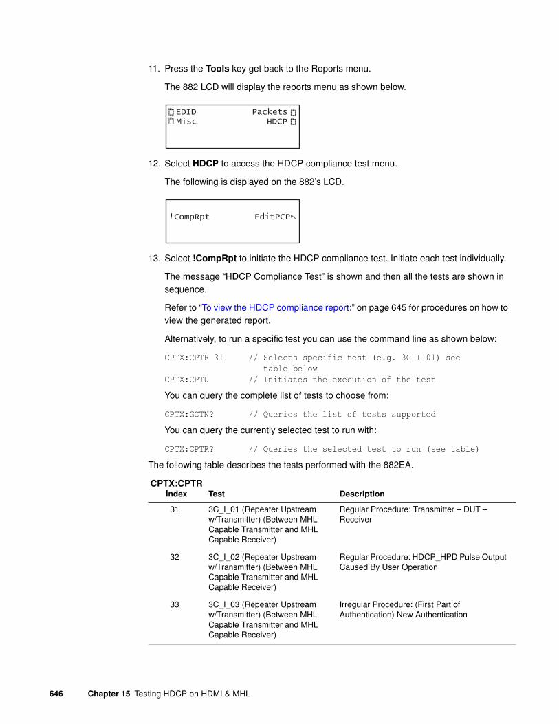
646 Chapter 15 Testing HDCP on HDMI & MHL
11. Press the Tools key get back to the Reports menu.
The 882 LCD will display the reports menu as shown below.
12. Select HDCP to access the HDCP compliance test menu.
The following is displayed on the 882’s LCD.
13. Select !CompRpt to initiate the HDCP compliance test. Initiate each test individually.
The message “HDCP Compliance Test” is shown and then all the tests are shown in sequence.
Refer to “To view the HDCP compliance report:” on page 645 for procedures on how to view the generated report.
Alternatively, to run a specific test you can use the command line as shown below:
CPTX:CPTR 31 // Selects specific test (e.g. 3C-I-01) see
table below
CPTX:CPTU // Initiates the execution of the test
You can query the complete list of tests to choose from:
CPTX:GCTN? // Queries the list of tests supported
You can query the currently selected test to run with:
CPTX:CPTR? // Queries the selected test to run (see table)
The following table describes the tests performed with the 882EA.
CPTX:CPTR Index Test Description
31 3C_I_01 (Repeater Upstream w/Transmitter) (Between MHL Capable Transmitter and MHL Capable Receiver)
Regular Procedure: Transmitter – DUT – Receiver
32 3C_I_02 (Repeater Upstream w/Transmitter) (Between MHL Capable Transmitter and MHL Capable Receiver)
Regular Procedure: HDCP_HPD Pulse Output Caused By User Operation
33 3C_I_03 (Repeater Upstream w/Transmitter) (Between MHL Capable Transmitter and MHL Capable Receiver)
Irregular Procedure: (First Part of Authentication) New Authentication
EDID Packets Misc HDCP
!CompRpt EditPCP

881/882 Video Test Instrument User Guide (Rev A.38) 647
34 3C_I_04 (Repeater Upstream w/Transmitter) (Between MHL Capable Transmitter and MHL Capable Receiver)
Irregular Procedure: (Second Part of Authentication) New Authentication
35 3C_I_05 (Repeater Upstream w/Transmitter) (Between MHL Capable Transmitter and MHL Capable Receiver)
Irregular Procedure: (Third Part of Authentication) New Authentication
36 3C_I_06 (Repeater Upstream w/Transmitter) (Between MHL Capable Transmitter and MHL Capable Receiver)
Irregular Procedure: (Second Part of Authentication) Verify Bksv
37 3C_I_07 (Repeater Upstream w/Transmitter) (Between MHL Capable Transmitter and MHL Capable Receiver)
Irregular Procedure: (Second Part of Authentication) Verify R0'
38 3C_II_01 (Repeater Upstream w/Transmitter) (Between MHL Capable Transmitter and Repeater)
Regular Procedure: Transmitter – DUT – Repeater+Receiver
39 3C_II_02 (Repeater Upstream w/Transmitter) (Between MHL Capable Transmitter and Repeater)
Regular Procedure: HDCP_HPD After Writing Aksv
40 3C_II_03 (Repeater Upstream w/Transmitter) (Between MHL Capable Transmitter and Repeater)
Regular Procedure: HDCP_HPD After Read-ing R0'
41 3C_II_04 (Repeater Upstream w/Transmitter) (Between MHL Capable Transmitter and Repeater)
Regular Procedure: HDCP_HPD After Starting Third Part of Authentication
42 3C_II_05 (Repeater Upstream w/Transmitter) (Between MHL Capable Transmitter and Repeater)
Irregular Procedure: (Second Part of Authentication) Verify V'
43 3C_II_06 (Repeater Upstream w/Transmitter) (Between MHL Capable Transmitter and Repeater)
Irregular Procedure: (Second Part of Authentication) DEVICE_COUNT
44 3C_II_07 (Repeater Upstream w/Transmitter) (Between MHL Capable Transmitter and Repeater)
Irregular Procedure: (Second Part of Authentication) DEPTH
CPTX:CPTR Index Test Description

648 Chapter 15 Testing HDCP on HDMI & MHL
45 3C_II_08 (Repeater Upstream w/Transmitter) (Between MHL Capable Transmitter and Repeater)
Irregular Procedure: (Second Part of Authentication) MAX_DEVS_EXCEEDED
46 3C_II_09 (Repeater Upstream w/Transmitter) (Between MHL Capable Transmitter and Repeater)
Irregular Procedure: (Second Part of Authentication) MAX_CASCADE_EXCEEDED
CPTX:CPTR Index Test Description
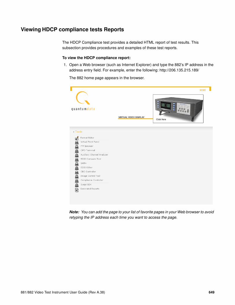
881/882 Video Test Instrument User Guide (Rev A.38) 649
Viewing HDCP compliance tests Reports
The HDCP Compliance test provides a detailed HTML report of test results. This subsection provides procedures and examples of these test reports.
To view the HDCP compliance report:
1. Open a Web browser (such as Internet Explorer) and type the 882’s IP address in the address entry field. For example, enter the following: http://206.135.215.189/
The 882 home page appears in the browser.
Note: You can add the page to your list of favorite pages in your Web browser to avoid
retyping the IP address each time you want to access the page.

650 Chapter 15 Testing HDCP on HDMI & MHL
2. Choose the Generated Reports item. The 882 the provides a list of reports currently available as shown below.

881/882 Video Test Instrument User Guide (Rev A.38) 651
3. Select the HDCP compliance test report from the list. The report then appears in the browser window as shown below. You can then save the report as a web page file for distribution.
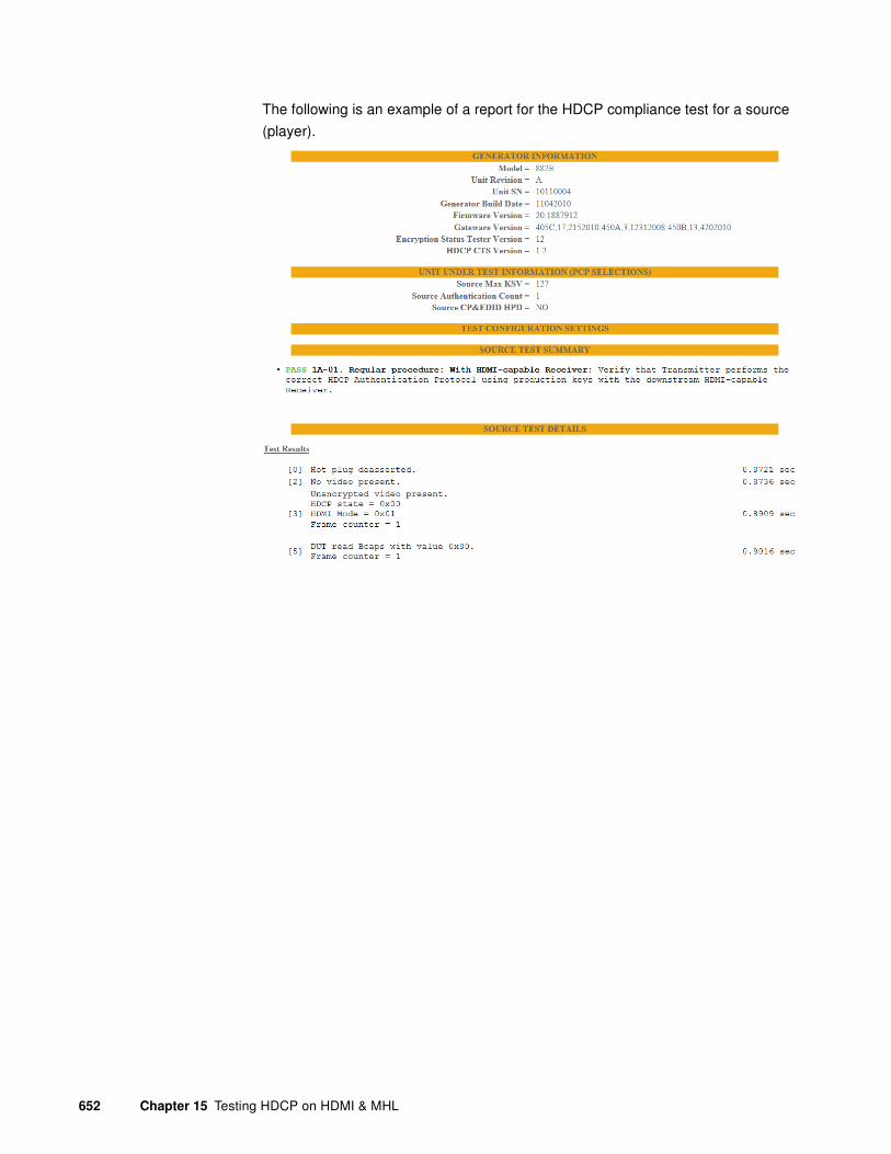
652 Chapter 15 Testing HDCP on HDMI & MHL
The following is an example of a report for the HDCP compliance test for a source
(player).

881/882 Video Test Instrument User Guide (Rev A.38) 653
The following is an example of a report for the HDCP compliance test for a display.

654 Chapter 15 Testing HDCP on HDMI & MHL
The following is an example of a report for the HDCP compliance test for a repeater.
881/882 Video Test Instrument User Guide (Rev A.38) 655
16 Testing Lipsync
Topics in this chapter:
• Overview
• Testing display (sink) devices
• Testing source devices

656 Chapter 16 Testing Lipsync
Overview
This chapter provides procedures for testing the HDMI Auto Lipsync Correction feature. The 882 can be configured to:
• emulate an HDMI source device to test an HDMI sink (display) device
• (optional feature) emulate an HDMI sink (display) device to test an HDMI source device.
With the 882, you can obtain audio and video latency values from the EDID of a connected display, generate a test image with audio/video latency correction applied, and view the image on the display device to determine correct audio/video synchronization.
With the analyzer option, you can test the lipsync correction feature of a HDMI source device. The analyzer can emulate a display device with audio and video latency. Using a test image, the source device applies audio/video latency correction and sends back the test image to the analyzer. Using a built-in application, the analyzer measures for the correct audio/video latency.
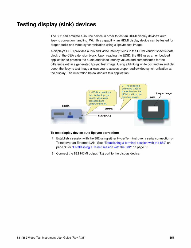
881/882 Video Test Instrument User Guide (Rev A.38) 657
Testing display (sink) devices
The 882 can emulate a source device in order to test an HDMI display device’s auto lipsync correction handling. With this capability, an HDMI display device can be tested for proper audio and video synchronization using a lipsync test image.
A display's EDID provides audio and video latency fields in the HDMI vendor specific data block of the CEA extension block. Upon reading the EDID, the 882 uses an embedded application to process the audio and video latency values and compensates for the difference within a generated lipsync test image. Using a blinking white box and an audible beep, the lipsync test image allows you to assess proper audio/video synchronization at the display. The illustration below depicts this application.
To test display device auto lipsync correction:
1. Establish a session with the 882 using either HyperTerminal over a serial connection or Telnet over an Ethernet LAN. See “Establishing a terminal session with the 882” on page 30 or “Establishing a Telnet session with the 882” on page 33.
2. Connect the 882 HDMI output (Tx) port to the display device.

658 Chapter 16 Testing Lipsync
3. Activate the HDMI-H interface on the output port:
a. Press the Interface key to access the list of interfaces. A listing of signal interfaces appears on the 882’s display as shown below.
b. Choose HDMI-H by pressing the adjacent soft key. The interface is activated and the port outputs the currently selected image and format.
c. Alternatively, to activate the interface through the command line interface, enter the following commands:
XVSI 4 // Selects the HDMI-H interface
ALLU // Applies the interface setting to the 882
4. Read the EDID from the display as follows:
a. Press the Sink key. The following information appears on the 882’s display.
b. Press the Options key. The following information appears on the 882’s display.
c. Choose the EDID Formats item by pressing the adjacent soft key. A + appears next to EDID Formats, indicating it is enabled.
VGA
HDMI-D
CVBS
S-VIDEO
SDI
*
HDMI-H
VGA
HDMI-D
CVBS
S-VIDEO
SDI*HDMI-H
Manufacturer:SNYProduct Code:144Serial#:7011007Week:20 Year:1998
-EDID Formats CDF+HP Bypass-Emulate

881/882 Video Test Instrument User Guide (Rev A.38) 659
5. Enable lipsync testing in 882 as follows:
a. Press the Content key. The following information appears on the 882’s display.
b. Choose either the LipSyncB or LipSync image.
c. Press the Settings key. The following information appears on the 882’s display.
d. Set the LSGM setting to 1 by pressing the soft keys adjacent to the bottom row until the cursor appears on the digit. Press the + or - keys to adjust the setting up or down.
e. Press the Enter (Options) key to save the new setting.
Alternatively, to enable the 882 to measure lipsync correction through the command line interface, enter the following command:
LSGX:LSGM 1 // Enables lipsync testing
LSGX:LSGU // Activates lipsync testing
6. Press the Content key. The following information appears on the 882’s display.
7. Choose the image to use for lipsync testing.
Acer1 Acer2 Acer3 Acer4 Acer5 Acer6 Acer7 Acer8
Image -> LipSync -> LSGM TLAT PLAT 1 0.0000 0 ->
Acer1 Acer2 Acer3 Acer4 Acer5 Acer6 Acer7 Acer8

660 Chapter 16 Testing Lipsync
• For basic testing, choose the LipSyncB test image on display device is similar to shown below.
The LipSyncB image utilizes a flashing white box with audible click to verify correct audio/video synchronization.
• For more detailed testing, choose the LipSync test image on display device is similar to shown below.
The LipSync image utilizes a moving box with audible beep to verify correct audio/video synchronization. When the moving box’s right edge touches the middle of a vertical line in the image, an audible beep is sent to the display.

881/882 Video Test Instrument User Guide (Rev A.38) 661
8. (Optional when using LipSync image only) To adjust vertical line spacing (thus changing frequency of audible beeps), follow these steps:
a. Choose More by pressing the adjacent soft key. A + and Rendition appears next to the item.
b. Press + and - keys to adjust vertical line interval. Changing the interval adjusts calculated moving time for white box between two lines.
Alternatively, to adjust vertical line intercal using the command line interface, enter the following commands:
ISUB 1 // Enables sub images
IVER 1 // Specifies the first image version
IMGU // Activates the image version
c. When you are finished, disable image versions by pressing the Options key and choosing More until a - appears next to it.
Alternatively, to disable image versions using the command line interface, enter the following command:
ISUB 0 // Disables sub images
+More Rendition: 000+LipSync Red+-NoGamma Green+-Noise Blue+

662 Chapter 16 Testing Lipsync
9. (Optional) To adjust lipsync testing parameters in the generated test image, follow these steps:
a. Press the Content key. The following information appears on the 882’s display.
b. Choose the LipSyncB or LipSync image.
c. Press the Options key to access the Options menu.
d. Enable LipSync settings by pressing the adjacent soft key. A + appears next to the LipSync item indicating that you can adjust it settings.
e. Press the Settings key. The following information appears on the 882’s display.
f. To select which data stream (audio or video) is generated first, edit the PLAT setting (0=video sent first, 1=audio sent first) by pressing the soft keys adjacent to the bottom row until the cursor appears on the digits. Press the + or - keys to adjust the settings up or down.
g. To adjust audio/video latency, edit the TLAT setting between 0.0 and 0.5 seconds by pressing the soft keys adjacent to the bottom row until the cursor appears on the digits. Press the + or - keys to adjust the settings up or down.
h. Press the Enter (Options) key to save the new setting(s).
Alternatively, to set lipsync testing paramters in the test image through the command line interface, enter the following command:
LSGX:TLAT // Sets audio/video latency
LSGX:PLAT // Sets which data stream is generated first
(0-Video, 1-Audio)
LSGX:LSGU // Updates hardware
Acer1 Acer2 Acer3 Acer4 Acer5 Acer6 Acer7 Acer8
+More Rendition: 000+LipSync Red+-NoGamma Green+-Noise Blue+
Image -> LipSync -> LSGM TLAT PLAT 1 0.0000 0 ->

881/882 Video Test Instrument User Guide (Rev A.38) 663
Testing source devices
With the Analyzer option, the 882 can emulate an HDMI sink (display) in order to test an HDMI source device’s auto lipsync correction handling. With this capability, an HDMI source device can be tested for its ability to handle audio and video latency values received in the HDMI vendor specific data block of the CEA extension block of a display’s EDID.
The EDID Editor application enables users to populate the audio and video latency fields in the HDMI vendor specific data block on the analyzer. These fields can be adjusted to test the source's ability to process and compensate for any permissible range of latency values. The source can then send a test image with both an audio and video component to the 882. When received, an embedded application in the 882 measures the relative delay on the test image between the audio and video components of the image. The illustration below depicts this application.
Testing HDMI source device for Lipsync handling
Follow this procedure to perform auto lipsync correction testing on a connected HDMI source device.
To use analyzer to test source device auto lipsync correction handling:
1. Establish a session with the 882 using either HyperTerminal over a serial connection or Telnet over an Ethernet LAN. See “Establishing a terminal session with the 882” on page 30 or “Establishing a Telnet session with the 882” on page 33.
2. Set EDID audio/video latency values on analyzer using the EDID Editor application. See “Using the EDID Editor tool” on page 524 for details on loading, editing, and
882CA
EDID (DDC)
(TMDS)
DVD
3 - The corrected audio
and video is transmitted
out the HDMI port in a
lip-sync test image.
1 - EDID audio/video
latency values are
configured in the EDID
emulator.
2 - EDID is read from the
emulated display. Lip-sync
latency values are
processed and
compensated for by DVD.
4 – Audio/video latencies
are measured on the lip-
sync test image by
embedded application in
emulated display.
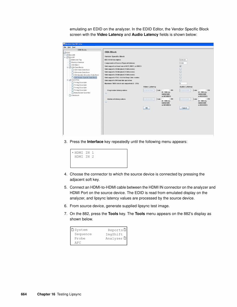
664 Chapter 16 Testing Lipsync
emulating an EDID on the analyzer. In the EDID Editor, the Vendor Specific Block screen with the Video Latency and Audio Latency fields is shown below:
3. Press the Interface key repeatedly until the following menu appears:
4. Choose the connector to which the source device is connected by pressing the adjacent soft key.
5. Connect an HDMI-to-HDMI cable between the HDMI IN connector on the analyzer and HDMI Port on the source device. The EDID is read from emulated display on the analyzer, and lipsync latency values are processed by the source device.
6. From source device, generate supplied lipsync test image.
7. On the 882, press the Tools key. The Tools menu appears on the 882’s display as shown below.
HDMI IN 1
HDMI IN 2*
System
Sequence
Probe
AFC
Analyzer
Reports
ImgShift

881/882 Video Test Instrument User Guide (Rev A.38) 665
8. Choose the Analyzer item by pressing the adjacent soft key. The Analyzer menu appears on the 882’s display as shown below.
9. Choose the LipSync item by pressing the adjacent soft key. The LipSync menu appears on the 882’s display as shown below.
Alternatively, to enable the analyzer to measure lipsync correction through the command line interface, enter the following command:
LSAX:LSGM 1 // Enables lipsync analyzer
LSAX:LSGU // Activates lipsync analyzer
10. Choose !Measure to measure audio/video latencies in the test image.
If audio/video latency is exceeded, the following appears on the 882’s display asshown below.
Alternatively, to measure audio/video latencies in the test image through the command line interface, enter the following command:
LSAX:TLAT? // Returns audio/video latency in milliseconds
LSAX:PLAT? // Returns which data stream was received first
(0-Video, 1-Audio)
LSAX:LSGU // Updates hardware
11. Press !Stop to halt lipsync measurements.
Generating an HDMI source Lipsync data report
Follow the procedure to generate an HTML report of lipsync measurement test results.
To generate a report of lipsync measurement test results:
1. Establish a session with the 882 using either HyperTerminal over a serial connection or Telnet over an Ethernet LAN. See “Establishing a terminal session with the 882” on page 30 or “Establishing a Telnet session with the 882” on page 33.
TimingCableTest
PIX-ERRPRN-ERR
*
ViewPix LipSync
LIPSYNC
Measure Exit
!Report
! !
LIPSYNC
Stop Exit
Latency Exceeded
! !

666 Chapter 16 Testing Lipsync
2. Perform steps 2 - 6 of “Testing HDMI source device for Lipsync handling” on page 605 to set up analyzer for lipsync testing.
3. Press the Tools key. The Tools menu appears on the 882’s display as shown below.
4. Choose the Analyzer item by pressing the adjacent soft key. The Analyzer menu appears on the 882’s display as shown below.
5. Choose the LipSync item by pressing the adjacent soft key. The LIPSYNC menu appears on the 882’s display as shown below.
Note: Be sure that you have transferred any existing Lipsync reports to your PC.
Otherwise, generating a new report overwrites the existing report.
6. Choose !Report item by pressing the adjacent soft key. A Lipsync Measurements Report is generated and stored on the PCMCIA card in the /card0/Library/Reports/LipSync_Data.htm file.
Alternatively, to generate a lipsync measurement report through the command line interface, enter the following command:
LSAX:RPTG 1 // generate lipsync measurement report
LSAX:LSGU // Activates lipsync analyzer
7. Open the FTP Browser on the 882 and select a suitable directory on your PC to store the report.
8. Using the FTP Browser, transfer the report from the 882 PCMCIA card to your PC like shown below.
System
Sequence
Probe
AFC
Analyzer
Reports
ImgShift
TimingCableTest
PIX-ERRPRN-ERR
*
ViewPix LipSync
LIPSYNC
Measure Exit
!Report
! !

881/882 Video Test Instrument User Guide (Rev A.38) 667
Note: Make sure to change the names of any existing reports in the directory on your
PC to avoid overwritting existing reports.

668 Chapter 16 Testing Lipsync
9. Navigate to your PC and double click on the report. A sample is shown below.

881/882 Video Test Instrument User Guide (Rev A.38) 663
17 Using Special Sync Output
Topics in this chapter:
• Overview
• Operating special sync for probe pulse
• Configuring special sync for FS, LS, or CS

664 Chapter 17 Using Special Sync Output
Overview
The generator is equipped with a Special Sync BNC connector on the rear of the generator labeled SPECIAL. You can configure the output of this video interface to output frame sync, line sync, composite sync or a special probe pulse.
The probe feature is used with a programmable probe pulse that is available on the Special Sync BNC connector. This pulse is most often used to trigger an oscilloscope or synchronize an inspection camera. The probe feature allows you to position the leading edge of the probe pulse anywhere within the video frame. This feature greatly facilitates troubleshooting by enabling you to focus on specific video signal problems occurring anywhere in the video signal.
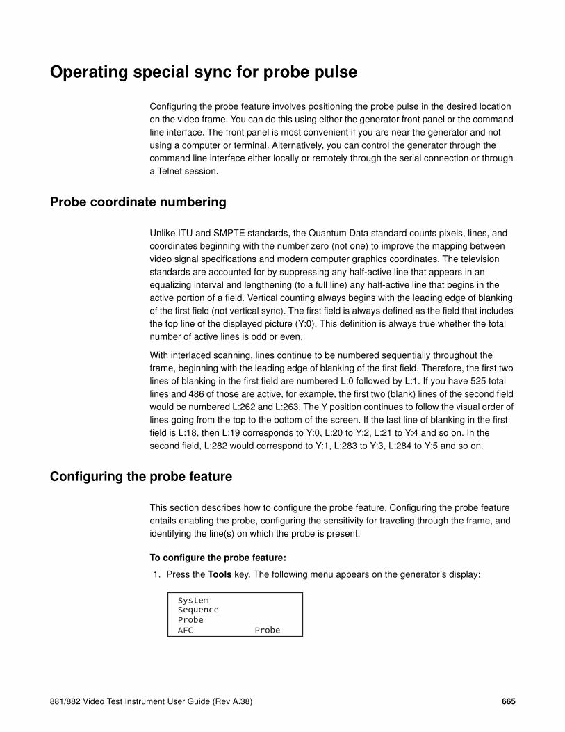
881/882 Video Test Instrument User Guide (Rev A.38) 665
Operating special sync for probe pulse
Configuring the probe feature involves positioning the probe pulse in the desired location on the video frame. You can do this using either the generator front panel or the command line interface. The front panel is most convenient if you are near the generator and not using a computer or terminal. Alternatively, you can control the generator through the command line interface either locally or remotely through the serial connection or through a Telnet session.
Probe coordinate numbering
Unlike ITU and SMPTE standards, the Quantum Data standard counts pixels, lines, and coordinates beginning with the number zero (not one) to improve the mapping between video signal specifications and modern computer graphics coordinates. The television standards are accounted for by suppressing any half-active line that appears in an equalizing interval and lengthening (to a full line) any half-active line that begins in the active portion of a field. Vertical counting always begins with the leading edge of blanking of the first field (not vertical sync). The first field is always defined as the field that includes the top line of the displayed picture (Y:0). This definition is always true whether the total number of active lines is odd or even.
With interlaced scanning, lines continue to be numbered sequentially throughout the frame, beginning with the leading edge of blanking of the first field. Therefore, the first two lines of blanking in the first field are numbered L:0 followed by L:1. If you have 525 total lines and 486 of those are active, for example, the first two (blank) lines of the second field would be numbered L:262 and L:263. The Y position continues to follow the visual order of lines going from the top to the bottom of the screen. If the last line of blanking in the first field is L:18, then L:19 corresponds to Y:0, L:20 to Y:2, L:21 to Y:4 and so on. In the second field, L:282 would correspond to Y:1, L:283 to Y:3, L:284 to Y:5 and so on.
Configuring the probe feature
This section describes how to configure the probe feature. Configuring the probe feature entails enabling the probe, configuring the sensitivity for traveling through the frame, and identifying the line(s) on which the probe is present.
To configure the probe feature:
1. Press the Tools key. The following menu appears on the generator’s display:
SystemSequenceProbeAFC Probe

666 Chapter 17 Using Special Sync Output
2. Choose the Probe item by pressing the adjacent soft key. The current probe settings appear on the generator’s display as shown below:
3. Press the Settings key to access the setting for the probe pulse width. The following appears on the generator’s display:
4. Set the probe width as follows
a. Position the blinking cursor on the digit you want to change. To do this, press the soft key adjacent to the arrow by the width value to move the cursor left or right until it appears on the digit you want to change.
b. Adjust the value of the digit up or down by pressing the + or - keys. Repeat for each you want to change.
5. To save the changes, press the Enter (Options) key. The following choices appear on the generator’s display:
To save the changes, choose the Yes item by pressing the adjacent soft key.
To exit without saving the changes, choose the No item.
To return to the previous screen without saving the changes, choose the Back item.
6. Press the Options key. The options for setting the line or lines on which the probe pulse will occur appears on the generator’s display:
7. Press the soft key adjacent to the desired option, as follows:
• OneLine: Probe pulse occurs once per frame.
• AllActive: Probe pulse occurs on every active line in the frame.
• AllLines: Probe pulse occurs on every line in the frame.
Left P:0000 ExpRight X:0000 1Up L:0000 10Down Y:0000 100
Probe Tool Probe Width PSPW<- 136
Apply Settings?
Back
Yes No
*OneLine ExitAllActiveAllLines Visible-

881/882 Video Test Instrument User Guide (Rev A.38) 667
8. Enable or disable the visibility setting by pressing the soft key adjacent to the Visible item on the display. A + indicates visibility is enabled; a - indicates it is disabled. Enabling the visibility setting will allow you to see the pulse position on a monitor.
To position the probe pulse in a specific location in the video signal:
1. Press the Tools key. The following menu appears on the generator’s display:
2. Choose the Pulse item by pressing the adjacent soft key. The current probe settings appear on the generator’s display as shown below:
3. Select the travel sensitivity of the positioning keys by pressing the soft key adjacent to the desired setting. Refer to the table below.
4. Set the horizontal position of the probe pulse by pressing the soft key adjacent to the Left or Right item on the generator’s display.
The horizontal position of the probe is simultaneously displayed in two different ways:
• The horizontal position P:nnnn is given in pixels relative to the leading edge of the horizontal sync.
• If the leading edge of the probe is within the active portion of a line, an alternate horizontal position X:nnnn is also displayed, indicating the number of pixels between the start of active video (X:0) and the leading edge of the probe pulse in the horizontal direction.
5. Set the vertical position of the probe pulse by pressing the soft key adjacent to the Up or Down item on the generator’s display.
The vertical position of the probe is simultaneously displayed in two different ways:
• The vertical position L:nnnn is given in whole scan lines relative to the leading edge of blanking of the frame or first field.
Setting Sensitivity
EXP exponential increase/decrease when +/- keys are pressed
1 increase/decrease by 1 line or pixel when +/- keys are pressed
10 increase/decrease by 10 lines or pixels when +/- keys are pressed
100 increase/decrease by 100 lines or pixels when +/- keys are pressed
SystemSequenceProbeAFC Probe
Left P:0000 ExpRight X:0000 1Up L:0000 10Down Y:0000 100

668 Chapter 17 Using Special Sync Output
• If the probe is within the active portion of the frame, an alternate vertical position Y:nnnn is also displayed, indicating the number of lines between the start of active (Y:0) and the leading edge of the probe in the vertical direction.
Controlling the probe using the command line interface
Using the command line interface to control the probe provides more control, enables you to change the polarity and width, and to change the format and image while maintaining the probe pulse parameters.
To configure the probe feature:
1. Establish a session with the generator using either HyperTerminal over a serial connection or Telnet over an Ethernet LAN. See “Establishing a terminal session with the 882” on page 30 or “Establishing a Telnet session with the 882” on page 33.
2. Enable the probe feature by entering the following commands:
FSPG 0 // disable the frame sync on special sync output
PSPG 1 // enable the probe pulse
PSPP 1 // set the probe pulse polarity (0 for low or 1 for high)
PSPW 10 // set pulse width to 10 pixels (range: 1 pixel to HTOT - 1)
PSHD 100 // set pulse horizontal position at 100 pixels from leading
// edge of horiztonal sync pulse, in range from 0 <=
// PSHD < (HTOT - PSPW - 1)
PSVW 50 // set the pulse vertical position at 50 lines from leading
// edge of vertical blanking, in range from 0 <=
// PSVD < (VTOT-1)
ALLU // apply the settings
To set the lines on which the probe pulse occurs:
1. Enter the appropriate command:
2. Send the ALLU command to apply the setting.
Set the probe pulse to occur Command
Once per frame PSPM 0
Once every active line PSPM 1
Once every line PSPM 3

881/882 Video Test Instrument User Guide (Rev A.38) 669
Configuring special sync for FS, LS, or CS
The special sync output can provide frame sync, line sync, or composite sync signals. The output is controlled by setting parameters of these signals using the command line interface. The following commands are used to set the special sync signal:
• FSPG - Frame sync
• PSPG - Probe signal
• LSPG - Line sync
• CSPG - Composite sync
Note: The special sync output is disabled whenever these parameters are set to zero.
A frame pulse can be generated and output at the beginning of each frame. In the case of interlaced video, the frame pulse is output at the beginning of the blanking interval (of the first field) that immediately precedes the top line of active video.
To configure frame sync on the special sync output:
1. Establish a session with the generator using either HyperTerminal over a serial connection or Telnet over an Ethernet LAN. See “Establishing a terminal session with the 882” on page 30 or “Establishing a Telnet session with the 882” on page 33.
2. Enable the frame sync by entering the following command:
FSPG 1
The values of the other parameters (LS? and CSPG) do not matter once FSPG is enabled.
FSPG=1, FSPP=0
FSPG=1, FSPP=1
FSPW (pixels)
FSPD (lines)
ActiveBlank Blank Active
Field 0 Field 1
VSPD (lines)
VID
VS
FS
FS

670 Chapter 17 Using Special Sync Output
3. Set the frame pulse polarity (either 0 for low or 1 for high) by entering the following command:
FSPP 1
4. Set the frame pulse pixel width by entering the following command:
FSPW 100 // range: 1 pixel to HTOT - 1
5. Set the frame pulse delay by entering the following command:
FSPD 10 // range: 0 <= FSPD < (VTOT - FSPW - 1); default = 0
6. Save these settings by entering the following command:
ALLU
To configure line sync on the special sync output:
1. Enable the line sync signal by entering the following commands:
FSPG 0
PSPG 0
LSPG 1
ALLU
The value of composite sync (CSPG) does not matter once these are set.
2. Set the line sync pulse polarity by entering the following command:
LSPP 1 // 1 = high (default)
ALLU
To configure composite sync on the special sync output:
1. Enable digital composite sync by entering the following command:
SSST 2 //(or 6,11)
2. Enable the composite sync signal by entering the following commands:
FSPG 0
PSPG 0
LSPG 0
CSPG 1
ALLU
3. Set the composite sync pulse polarity by entering the following commands:
CSPP 1 // 1 = high (default)
ALLU

881/882 Video Test Instrument User Guide (Rev. A.38) 671
18 Script SDK
Topics in this chapter:
• Overview
• Creating executable program scripts
• ScriptSDK API functions by category
• ScriptSDK API functions by name
• ScriptSDK commands
• Sample ScriptSDK programs

672 Chapter 18 Script SDK
Overview
The Quantum Data Software Development Kit (SDK) provides Application Programming Interfaces (APIs) for two categories of automation: 1) custom images (Image SDK) and 2) executable scripts (ScriptSDK). Both of these SDKs use the C++ programming language.
The Script SDK API provides a programming interface for executing any set of commands in the 880 series command language. Additional functions allow for program control, user input/output, and debugging. ScriptSDK is a much more powerful alternative to the test sequence feature in the 881/882 generators. By providing full access to the 880 series command language, ScriptSDK allows for a broad range of control and functionality in executable scripts that reside within the generator. The executable program scripts can be executed via the ScriptSDK selection in the 882’s TOOLS menu.
The entire ScriptSDK system includes components that reside on the personal computer (PC) and components that reside in the Quantum Data 881/882 generator. The PC components include:
• C++ compiler
• Libraries
• Header files
• Examples
• Templates
• Graphical User Interface
These are automatically downloaded from the Quantum Data website and installed on the PC the first time the Quantum Data SDK is run. The graphical user interface (GUI) program includes the text editor and menus to compile programs and load the executable object files into the generator. The GUI is a Java application that is loaded from the 881/882 generator each time the Quantum Data SDK is run.
The other components of this system lie within the embedded firmware in the Quantum Data 881/882 generator. This includes the Scriptrunner functionality for running the executable program scripts, as well as the proper linkages to allow the custom images to load.
Installation
The Quantum Data SDK can be accessed from the generator's home page beginning with firmware version 2.18.0. It is implemented as a Java application, and the Java Runtime Environment (JRE) is required on the host computer. JRE version 5 is recommended.

881/882 Video Test Instrument User Guide (Rev. A.38) 673
The SDK is launched from the Quantum Data SDK list item on the generator's home page. If the SDK is not yet installed, the user will be prompted through the installation process which includes connecting to the Quantum Data website. Therefore, an internet connection is required. If the older command-line version of the Image SDK is already installed on the system, it will be replaced by the Quantum Data SDK. The installation program can save the original SDK on the computer.
For first-time installation, an internet connection is required so that the automatic installation process can retrieve the installation package from the Quantum Data website. If the host computer does not yet have JRE, it can be downloaded from the java.com website, or via a link near the bottom of the generator's home page.
Image programs versus script programs
When the Quantum Data SDK is launched, the user has a choice of Image SDK or ScriptSDK, depending on the type of application to be developed. When the SDK is running, the user can freely switch between Image SDK and Script SDK at any time.
The Image SDK is used to create resolution-independent test patterns and other display images. When an image is loaded from the SDK into the generator via the Load & Execute menu selection, it is displayed immediately. An image load consists of a file transfer and the commands IMGP, IMGL, and IMGU. After loading the image via the SDK, the image is then available to be selected for display via browse mode.
The ScriptSDK is used to create executable programs that can be stored in the generator and run from the SDK menu. A ScriptSDK program can contain any commands in the 880 command language, as well as user menus, responses to key presses, numeric input, and output to the serial port.

674 Chapter 18 Script SDK
Creating executable program scripts
This sections provides information and procedures for using the ScriptSDK application.
Getting Started
The following are the important points to keep in mind when creating executable scripts:
• Naming files
• Return values on exit
• Enabling output
• Softkey functions
These are described in the following subsections.
Naming the file and the executable script
The executable script will have the same base name as the source file. This name must be lower-case, and it should be 8 characters or less in length. This name must be appended to "Script_" to name the function.
For example, for an executable script called "demo" the source file will be demo.cpp. The main function will be Script_demo(), and the resulting object file will be demo.o. The "load & execute" command will send this object file to the generator, and it will be visible in the Scripts menu as "demo."
Returning “true” on exit
The script's main function (e.g., Script_demo() ) must return "true" on exit. As in any C or C++ program, it is okay to have multiple return points. Refer to the sample programs for examples.
Enabling output to a serial terminal
By executing the CIOY command sc.Exec("CIOY"); you can enable output to the serial terminal for debugging and/or status output via printf(). You can connect a simple serial terminal (such as Hyperterm running on a PC). Serial port settings default to 9600 baud, 8 bits, no parity, 1 stop bit, no handshake. The required DB-9 null cable is included with all 880 series generators.

881/882 Video Test Instrument User Guide (Rev. A.38) 675
Writing to a log file
In some applications you may wish to write data out to a text file for later examination. For example you may want to create a script that measures the timing parameters of an incoming HDMI signal and write them out to a file. Starting in Release 2.19 you can do this. You will need to include three extern declarations at the top of the script:
extern int fopen();extern int fclose();extern int fprintf();
You will also need to include a File* declaration which points to a path where the log file is stored. Examples are shown in this chapter.
Halting a script through the front panel during execution
When a script is executing, the top right soft key on the 882 is assigned to the STOP function. If the STOP key is pressed, the sc.Canceled() method will return true. The script must check this state in order to detect whether the STOP key has been pressed. A script should always return true when exiting. See example programs testapi.cpp and tcan.cpp.
Some scripts may take over the top right soft key so it is not available for the STOP function. The example program testapi is an example of this. Therefore, the generator's OPTIONS key is always available to interrupt scripts that are running. After pressing the OPTIONS key, pressing the bottom left soft key (!Yes) will stop the script.
About the ScriptSDK main window
The Quantum Data SDK GUI is shown below. It is centered around the text editor. The title bar at the top indicates whether the program is currently set for ScriptSDK or ImageSDK. Beneath the title bar is the menu bar, featuring pull-down menu categories of File, Compile, Load&Execute, and Connection. The menu bar also contains a button for toggling between ScriptSDK and ImageSDK modes.
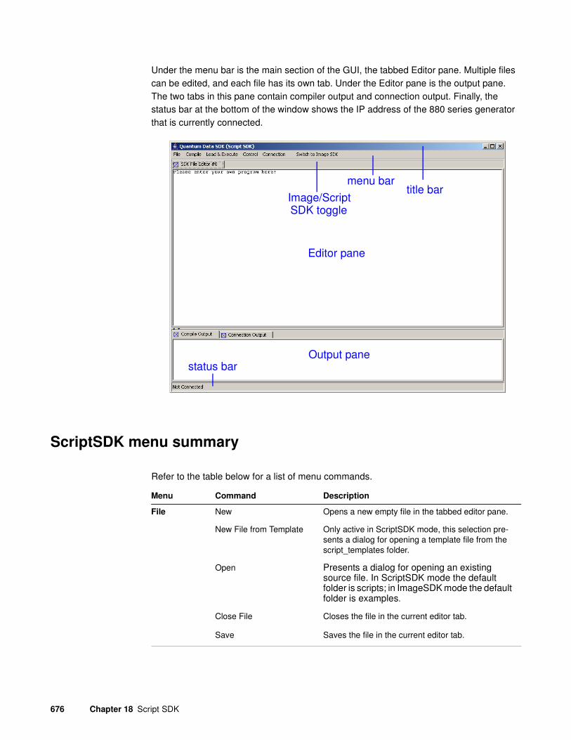
676 Chapter 18 Script SDK
Under the menu bar is the main section of the GUI, the tabbed Editor pane. Multiple files can be edited, and each file has its own tab. Under the Editor pane is the output pane. The two tabs in this pane contain compiler output and connection output. Finally, the status bar at the bottom of the window shows the IP address of the 880 series generator that is currently connected.
ScriptSDK menu summary
Refer to the table below for a list of menu commands.
title barmenu bar
Editor pane
Output pane
Image/ScriptSDK toggle
status bar
Menu Command Description
File New Opens a new empty file in the tabbed editor pane.
New File from Template Only active in ScriptSDK mode, this selection pre-sents a dialog for opening a template file from the script_templates folder.
Open Presents a dialog for opening an existing source file. In ScriptSDK mode the default folder is scripts; in ImageSDK mode the default folder is examples.
Close File Closes the file in the current editor tab.
Save Saves the file in the current editor tab.

881/882 Video Test Instrument User Guide (Rev. A.38) 677
Save as Presents a dialog for saving the current file, allowing the user to choose a new filename and/or folder.
Preference Allows the user to choose between the Quantum Data SDK text editor and another text editor on the host PC
Exit Exits the Quantum Data SDK. This will also cause the web browser to immediately terminate, so it is recommended to instead use the web browser's back button to exit the SDK.
Compile Current File Compiles the file in the curent editor tab.
Another File Presents a dialog for choosing a source file to com-pile.
Load&
Execute
Object File Presents a dialog for choosing the object file to load to the generator.
Control Pause
Terminate
Connection Connect to Presents a dialog for entering the IP address of the generator to connect to. The dialog defaults to the generator that the application was launched from.
Switch to
Image SDK
Allows the user to toggle between ImageSDK and ScriptSDK. This switch changes the default folders on the host PC for source and object files; it also changes the destination path on the generator for storing executable object files.
Menu Command Description
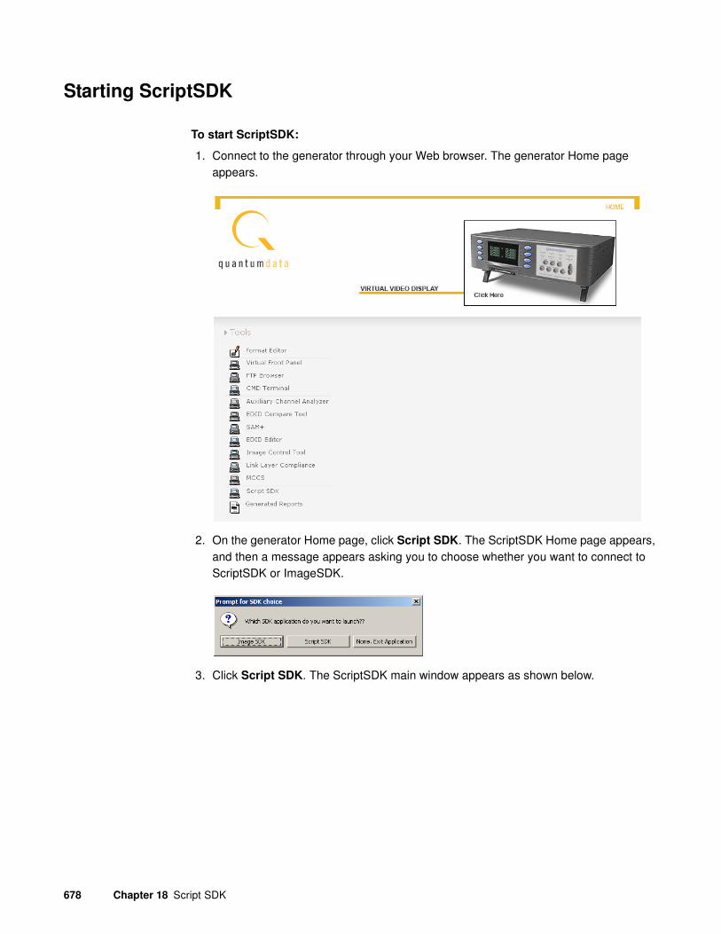
678 Chapter 18 Script SDK
Starting ScriptSDK
To start ScriptSDK:
1. Connect to the generator through your Web browser. The generator Home page appears.
2. On the generator Home page, click Script SDK. The ScriptSDK Home page appears, and then a message appears asking you to choose whether you want to connect to ScriptSDK or ImageSDK.
3. Click Script SDK. The ScriptSDK main window appears as shown below.

881/882 Video Test Instrument User Guide (Rev. A.38) 679
Creating, compiling, and executing a script
To start a scripting session:
1. With the ScriptSDK main window open, click Connection, and then click Connect to. The Input dialog box appears.
2. Enter the IP address of the generator you want to connect to. (The default address is the address of the generator from which you launched ScriptSDK.) Click OK. ScriptSDK attempts to connect to the generator and displays the message Successfully Connected to Unit when connected. Click OK.
To open an existing script:
1. Click File, and then click Open. The Open Script dialog box appears.
2. Select the script you want to open, and then click Open. The script appears in the Editor pane. You can have multiple scripts open at the same time. Each script appears as a separate tab in the Editor pane.
To create a new script:
1. Click File, and then click New. A new tab appears in the Editor pane.
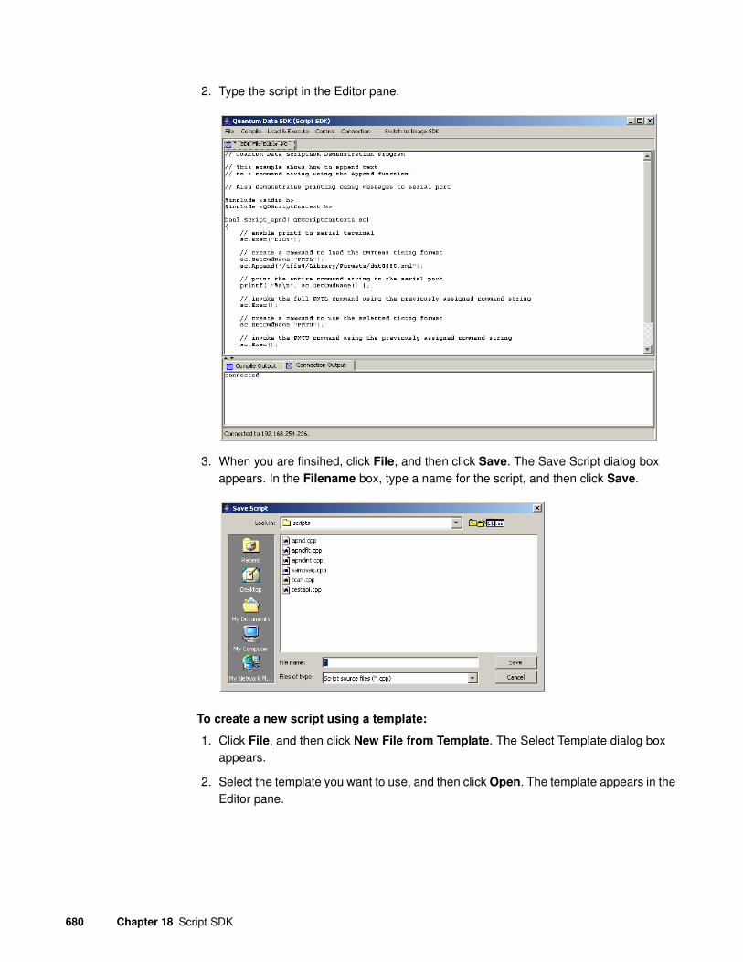
680 Chapter 18 Script SDK
2. Type the script in the Editor pane.
3. When you are finsihed, click File, and then click Save. The Save Script dialog box appears. In the Filename box, type a name for the script, and then click Save.
To create a new script using a template:
1. Click File, and then click New File from Template. The Select Template dialog box appears.
2. Select the template you want to use, and then click Open. The template appears in the Editor pane.

881/882 Video Test Instrument User Guide (Rev. A.38) 681
3. Modify the template as needed to match your requirements. When you are finsihed, click File, and then click Save. The Save Script dialog box appears. In the Filename box, type a name for the script, and then click Save.
To compile a script:
1. To compile a script, click the tab in the Editor Pane that contains the script you want to compile.
2. Click Current File from the Compile pull down menu. The file is compiled and any compiler messages appear in the Compile Output pane. The output of the compile process is an executable object file that is placed in Scripts folder, which is in the SDK folder on your 882 generator library directory.
To execute a script from the ScriptSDK GUI:
1. Click Object File from the Load&Execute pull down menu. A dialog box called Choose Object File dialog box appears.
2. Select the file you want to execute, and then click Choose. A message appears telling you if the execution was successful.
3. You can also execute a scrip
To execute a script from the 882 front panel:
1. Press the Tools key. The Tools menu appears on the generator’s display as shown below.
System
Sequence
Probe
AFC
Analyzer
Reports
ImgShift
CEC

682 Chapter 18 Script SDK
2. Scroll down until you see the ScriptSDK selection item.
The list of available scripts is presented.
3. Execute the desired script by pressing the adjacent soft key.
The script that has been selected and is now running is shown along with an option to stop the script.
To execute a script from the 882 command line:
1. Load the script file that you want to execute by entering the following command.
SCRX:LOAD testapi.o //loads script object from current scripts path
For a list of scripts, enter the following command:
SCRX:LIST?
2. Execute the script by entering the following command:
SCRX:EXEC // executes currently loaded script
To stop a script that is executing enter the following:
SCRX:STOP // stops execution of currently running script
Sampseq1 Sampseq2 Sampseq3 Sampseq4
*Sampseq1 stop
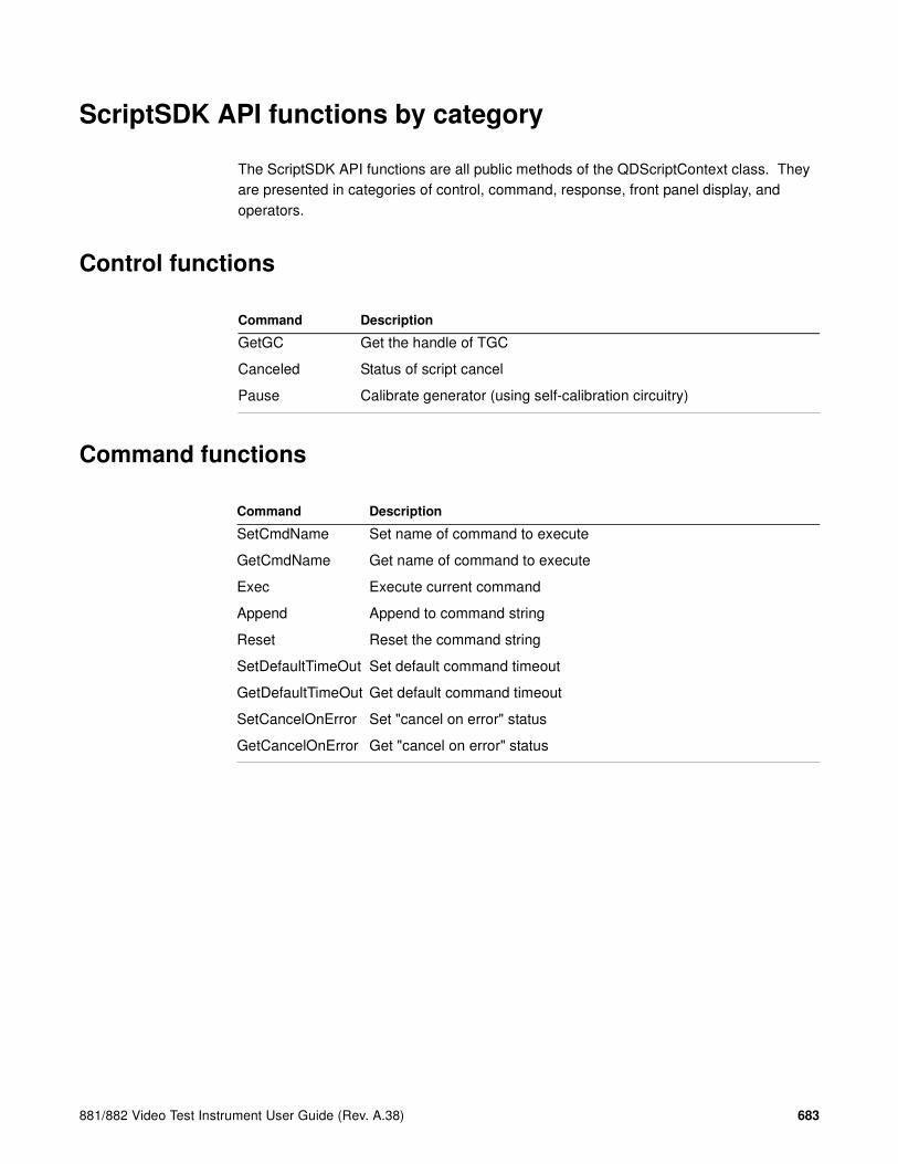
881/882 Video Test Instrument User Guide (Rev. A.38) 683
ScriptSDK API functions by category
The ScriptSDK API functions are all public methods of the QDScriptContext class. They are presented in categories of control, command, response, front panel display, and operators.
Control functions
Command functions
Command Description
GetGC Get the handle of TGC
Canceled Status of script cancel
Pause Calibrate generator (using self-calibration circuitry)
Command Description
SetCmdName Set name of command to execute
GetCmdName Get name of command to execute
Exec Execute current command
Append Append to command string
Reset Reset the command string
SetDefaultTimeOut Set default command timeout
GetDefaultTimeOut Get default command timeout
SetCancelOnError Set "cancel on error" status
GetCancelOnError Get "cancel on error" status

684 Chapter 18 Script SDK
Response functions
Front panel functions
Operator functions
Command Description
GetResponse Get most recent response string
GetIntResponse Get response as signed int
GetUIntResponse Get response as unsigned int
GetDoubleResponse Get response as double
GetRespLineCount Get number of lines in response
ClearResponse Reset the response
Failed Get fail state of most recent command
Succeed Get response state of most recent command
GetError Get error value for failed command
Command Description
Write Write a string to front panel display
InputInteger Get integer user input via front panel
InputFloat Get float user input via front panel
WaitForKeyPress Wait for user to press a soft key
ClearLCD Clear the front panel display
Command Description
= Assign name of command to be executed
+= Append to command to be executed

881/882 Video Test Instrument User Guide (Rev. A.38) 685
ScriptSDK API functions by name
This subsections lists the ScriptSDK functions by name and provides details about how to use them.

686 Chapter 18 Script SDK
Append
Class Command
Description Adds characters to an existing command string, created with a call to SetCmdName(). Allowable arguments are char pointer, integer, and double-precision float. In the case of an integer argument, the radix for the base of the resulting string can be specified optionally. The default radix is 10.
Command syntax sc.Append(const char* txt)
sc.Append(UINT32 value, UINT32 RADIX=10)
sc.Append(double value)
Example Refer to example programs apndflt.cpp, apndint.cpp, sampseq.cpp, testapi.cpp
Related commands Exec(), GetCmdName(), Reset(), SetCmdName,

881/882 Video Test Instrument User Guide (Rev. A.38) 687
Canceled
Class Control
Description Returns script cancel state. A script can be set to cancel state by pressing the STOP (upper right) soft key during execution, or by pressing the OPTIONS key and then the lower-left (!Yes) soft key to confirm. A script can also be set to cancel state if its CancelOnError status is true, and the script encounters an error while executing. To cancel script execution, the script must check the return value of Canceled(); if it is true, the script should immediately return a value of true.
Command syntax sc.Canceled(void)
Example Refer to example programs apndflt.cpp, apndint.cpp, sampseq.cpp, tcan.cpp, testapi.cpp
Related commands Exec(), GetCmdName(), Reset(), SetCmdName

688 Chapter 18 Script SDK
ClearLCD
Class Front Panel
Description Clears the entire display on the front panel of the generator
Command syntax sc.ClearLCD(void)
Example Refer to example program testapi.cpp
Related commands Write(), InputInteger(), InputFloat()

881/882 Video Test Instrument User Guide (Rev. A.38) 689
ClearReponse
Class Response
Description Resets the command response string to a default empty state. This can be used to clear a response after it is queried; therefore the next non-empty response will be a new response.
Command syntax sc.ClearResponse(void)
Related commands GetResponse(), GetIntResponse(), GetUIntResponse(), GetDoubleResponse()

690 Chapter 18 Script SDK
Exec
Class Command
Description Execute a command. Command can be pre-built using SetCmdName() and Append(), or a pointer to a command string can be passed. Command timeout in milliseconds can be specified optionally.
Command syntax sc.Exec(void)
sc.Exec( UINT32 timeout )
sc.Exec( char* cmdString )
sc.Exec( char* cmdString, UINT32 timeout )
Return type UNIT32
Example Refer to sample programs apnd.cpp, apndflt.cpp, apndint.cpp, sampseq.cpp, tcan.cpp, testapi.cpp
Related commands SetCmdName( ), Append( ), GetCmdName( ), SetDefaultTimeOut(), GetDefaultTimeOut(), Command Reference in Appendix A of 881/882 Series User Guide

881/882 Video Test Instrument User Guide (Rev. A.38) 691
Failed
Class Response
Description Returns true if previous command execution failed.
Command syntax sc.Failed(void)
Return type bool
Related commands Exec(), Succeed(), GetError()

692 Chapter 18 Script SDK
GetBoolResponse
Class Response
Description Gets the most recent query response string and returns it as a bool. If the first character of the response string is "T" or "t" the return value is "true." If the first character of the response string is "F" or "f" the return value is "false." Otherwise, it will attempt to convert the string to unsigned long via strtoul(). If the result of the conversion is zero, the return value is "false." If the result is not zero, the return value is "true."
Command syntax sc.GetBoolResponse(void)
Return type bool
Example Refer to sample program testapi.cpp
Related commands GetResponse(), GetIntResponse(), GetUIntResponse(), GetDoubleResponse(), GetRespLineCount(), ClearResponse()

881/882 Video Test Instrument User Guide (Rev. A.38) 693
GetCancelOnError
Class Command
Description Returns CancelOnError status. Return value of true indicates that an execution error will cause Canceled() to be true. To terminate script execution on error, program code should check the state of Canceled(); if it is true the program should exit via "return true;"
Command syntax sc.GetCancelOnError(void)
Return type bool
Related commands Canceled(), SetCancelOnError(), GetError()

694 Chapter 18 Script SDK
GetCmdName
Class Command
Description Returns the current contents of the command string. The command string can be built using SetCmdName(), Append(), =, and +=.
Command syntax sc.GetCmdName( void )
Return type const char*
Example Refer to sample programs apnd.cpp, apndflt.cpp, testapi.cpp
Related commands SetCmdName(), Exec(), Append(), operator =, operator +=

881/882 Video Test Instrument User Guide (Rev. A.38) 695
GetDefaultTimeOut
Class Command
Description Returns the current timeout value for commands, in milliseconds.
Command syntax sc.GetDefaultTimeOut(void)
Return type UNIT32
Related commands SetDefaultTimeOut()
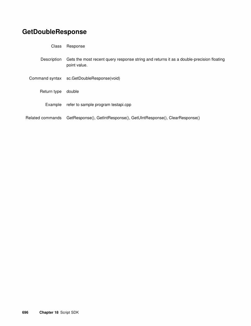
696 Chapter 18 Script SDK
GetDoubleResponse
Class Response
Description Gets the most recent query response string and returns it as a double-precision floating point value.
Command syntax sc.GetDoubleResponse(void)
Return type double
Example refer to sample program testapi.cpp
Related commands GetResponse(), GetIntResponse(), GetUIntResponse(), ClearResponse()

881/882 Video Test Instrument User Guide (Rev. A.38) 697
GetError
Class Response
Description Returns the error value of the previous command.
Command syntax sc.GetError(void)
Return type UNIT32
Example refer to sample program testapi.cpp
Related commands Exec(), Failed(), Succeed()

698 Chapter 18 Script SDK
GetGC
Class Control
Description Returns a pointer to an instance of the graphics core object that provides dynamic linking with internal generator firmware.
Command syntax GetGC(void)
Return type TGC*

881/882 Video Test Instrument User Guide (Rev. A.38) 699
GetIntResponse
Class Response
Description Gets the most recent query response string and returns it as a signed 32-bit integer value.
Command syntax sc.GetIntResponse(void)
Return type INT32
Example refer to sample program testapi.cpp
Related commands GetResponse(), GetUIntResponse(), GetDoubleResponse(), ClearResponse()

700 Chapter 18 Script SDK
GetRespLineCount
Class Response
Description Some query responses can consist of multiple lines of output. This method returns the number of lines of output from the most recent query.
Command syntax sc.GetRespLineCount(void)
Return type INT32
Example refer to sample program testapi.cpp
Related commands GetResponse(), GetIntResponse(), GetUIntResponse(), GetDoubleResponse, ClearResponse()

881/882 Video Test Instrument User Guide (Rev. A.38) 701
InputFloat
Class Front Panel
Description Presents a dialog for user input of a floating point value via front panel display and keys. Parameters allow specification of the displayed prompt, number of digits (whole and fractional,) and initial value. The prompt string is required. The whole and frac parameters are optional and both default to 4. The initValue parameter is optional and defaults to zero.
Command syntax sc.InputFloat(const char*prompt, UINT32 whole, UINT32 frac, double initValue)
Return type double
Example refer to example program testapi.cpp.
Related commands InputInteger(), ClearLCD()

702 Chapter 18 Script SDK
InputInteger
Class Front Panel
Description Presents a dialog for user input of an integer value via front panel display and keys. Parameters allow specification of the displayed prompt, number of digits, and initial value. The prompt string is required. The numDigits parameter is optional and defaults to 4. The initValue parameter is optional and defaults to zero.
Command syntax sc.InputInteger(const char* prompt, UINT32 numDigits, INT32 initValue)
Return type INT32
Example refer to example program testapi.cpp.
Related commands InutFloat(), ClearLCD()

881/882 Video Test Instrument User Guide (Rev. A.38) 703
Pause
Class Control
Description Forces a delay in program execution, for specified number of milliseconds.
Command syntax sc.Pause(UINT32 timeValue)
Return type void
Example refer to example programs apndflt.cpp, apndint.cpp, sampseq.cpp, tcan.cpp, testapi.cpp.

704 Chapter 18 Script SDK
Reset
Class Command
Description Clears the command string; resets it to the default empty state.
Command syntax sc.Reset(void)
Return type void
Example refer to example program testapi.cpp.
Related commands SetCmdName(), Append(), GetCmdName()

881/882 Video Test Instrument User Guide (Rev. A.38) 705
SetCancelOnError
Class Command
Description Sets or clears the CancelOnError status. If set (with an argument of true) an error or failure will cause the Canceled() state to be set to true. To terminate script execution on error, program code should check the state of Canceled(); if it is true the program should exit via "return true;"
Command syntax sc.SetCancelOnError(bool)
Return type void
Example refer to example program testapi.cpp.
Related commands Canceled(), GetCancelOnError(), GetError()

706 Chapter 18 Script SDK
SetCmdName
Class Command
Description Sets a command string to be executed later. The command string can be added to with Append(). The command can be executed with Exec().
Command syntax sc.SetCmdName( const char* )
Return type void
Example refer to example programs apnd.cpp, apndflt.cpp. testapi.cpp
Related commands refer to example programs apnd.cpp, apndflt.cpp. testapi.cpp
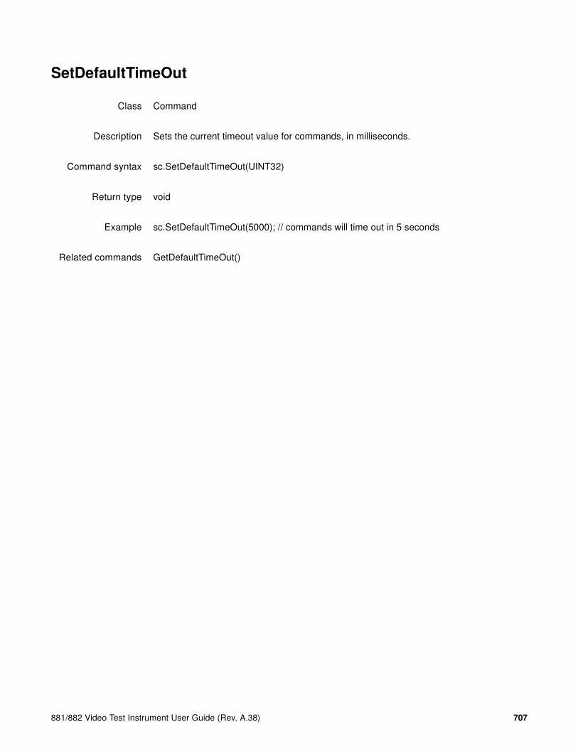
881/882 Video Test Instrument User Guide (Rev. A.38) 707
SetDefaultTimeOut
Class Command
Description Sets the current timeout value for commands, in milliseconds.
Command syntax sc.SetDefaultTimeOut(UINT32)
Return type void
Example sc.SetDefaultTimeOut(5000); // commands will time out in 5 seconds
Related commands GetDefaultTimeOut()

708 Chapter 18 Script SDK
Succeed
Class Response
Description Returns true if previous command execution was successful.
Command syntax sc.Succeed(void)
Return type bool
Example refer to example program testapi.cpp.
Related commands Exec(), Fail(), GetError()

881/882 Video Test Instrument User Guide (Rev. A.38) 709
WaitForKeyPress
Class Front Panel
Description Delays program execution until a soft key is pressed. Optional argument indicates desired timeout in milliseconds. Void argument or zero will result in wait for ever. Returns a value representing the key pressed; one of the following:
QD_KEY_LEFT_1
QD_KEY_LEFT_2
QD_KEY_LEFT_3
QD_KEY_LEFT_4
QD_KEY_RIGHT_1
QD_KEY_RIGHT_2
QD_KEY_RIGHT_3
QD_KEY_RIGHT_4
Command syntax sc.WaitForKeyPress(void)
sc.WaitForKeyPress(UINT32)
Return type QDKeyId
Example refer to example program testapi.cpp.
Related commands Write(), ClearLCD()

710 Chapter 18 Script SDK
Write
Class Front Panel
Description Write a string to the generator's front panel display. The display is 20 characters by 4 lines. Allowable values of column are in the range of 0 - 19. Allowable values of row are 0 - 3.
Command syntax sc.Write(UINT32 column, UINT32 row, char* string)
Return type void
Example refer to example programs apndflt.cpp, testapi.cpp
Related commands ClearLCD(), WaitForKeyPress(), InputFloat(), InputInteger()

881/882 Video Test Instrument User Guide (Rev. A.38) 711
Operator =
Class Operator
Description Assigns a string to the command string. The command string is represented by the pointer to the script context; sc. This is similar to SetCmdName().
Command syntax sc = "string"
Example sc = "SCRX:LOAD";// set the command string
also refer to example program testapi.cpp.
Related commands Operator +=, SetCmdName(), Append(), Exec()

712 Chapter 18 Script SDK
Operator +=
Class Operator
Description Appends characters to the command string. The argument will be converted to ASCII character string if necessary. The command string is represented by a pointer to the script context; sc. This is similar to Append().
Command syntax sc += "string"
sc += char
sc += double
sc += UINT32
Example sc += "testapi.o";// append filename to the command string
also refer to example program testapi.cpp
Related commands Operator =, Append(), SetCmdName(), Exec()

881/882 Video Test Instrument User Guide (Rev. A.38) 713
ScriptSDK commands
This subsection lists the commands related to the ScriptSDK that can be executed through the 882’s command line interface. These can be executed through the serial port, a telnet session or through the command utility available through the 882 home page.

714 Chapter 18 Script SDK
SCRX:LIST?
Class Scriptrunner
Description Lists the executable script object files currently residing in the generator
Query syntax SCRX:LIST?
Query response list of executable script object files
Example SCRX:LIST? // list executable scripts
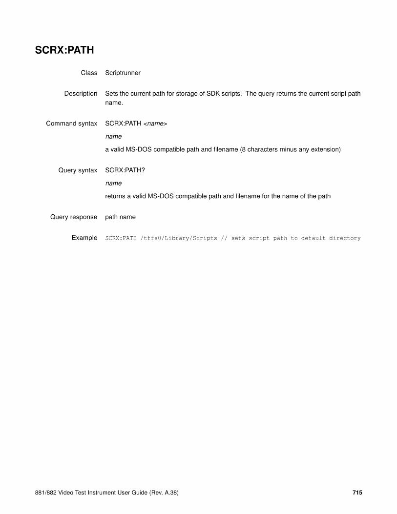
881/882 Video Test Instrument User Guide (Rev. A.38) 715
SCRX:PATH
Class Scriptrunner
Description Sets the current path for storage of SDK scripts. The query returns the current script path name.
Command syntax SCRX:PATH <name>
name
a valid MS-DOS compatible path and filename (8 characters minus any extension)
Query syntax SCRX:PATH?
name
returns a valid MS-DOS compatible path and filename for the name of the path
Query response path name
Example SCRX:PATH /tffs0/Library/Scripts // sets script path to default directory

716 Chapter 18 Script SDK
SCRX:EXEC, SCRX:EXEC?
Class Scriptrunner
Description Executes the currently loaded script. The query returns the name of the currently executing script.
Command syntax SCRX:EXEC
Query syntax SCRX:EXEC?
Query response path and name of currently executing script object file
Example SCRX:EXEC // execute currently loaded script
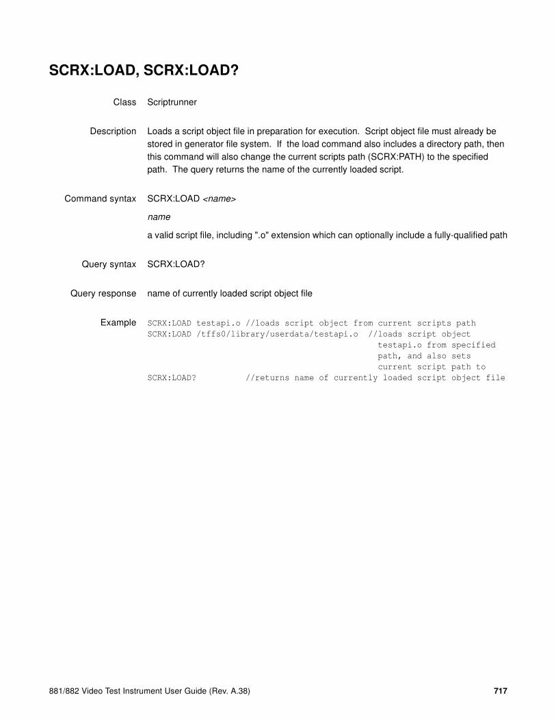
881/882 Video Test Instrument User Guide (Rev. A.38) 717
SCRX:LOAD, SCRX:LOAD?
Class Scriptrunner
Description Loads a script object file in preparation for execution. Script object file must already be stored in generator file system. If the load command also includes a directory path, then this command will also change the current scripts path (SCRX:PATH) to the specified path. The query returns the name of the currently loaded script.
Command syntax SCRX:LOAD <name>
name
a valid script file, including ".o" extension which can optionally include a fully-qualified path
Query syntax SCRX:LOAD?
Query response name of currently loaded script object file
Example SCRX:LOAD testapi.o //loads script object from current scripts path
SCRX:LOAD /tffs0/library/userdata/testapi.o //loads script object
testapi.o from specified
path, and also sets
current script path to
SCRX:LOAD? //returns name of currently loaded script object file

718 Chapter 18 Script SDK
SCRX:KILL
Class Scriptrunner
Description Deletes an executable object file from the generator
Command syntax SCRX:KILL name
name
a valid script file, including ".o" extension which can optionally include a fully-qualified path
Example SCRX:KILL testapi.o // deletes script object testapi.o from current
scripts path
SCRX:KILL /tffs0/library/userdata/testimg.o // deletes file testimg.o
from specified path

881/882 Video Test Instrument User Guide (Rev. A.38) 719
SCRX:STOP
Class Scriptrunner
Description Stops the execution of a script
Command syntax SCRX:STOP
Example SCRX:STOP // stops execution of currently running script

720 Chapter 18 Script SDK
Sample ScriptSDK programs
This subsections provides some example ScriptSDK scripts to help you understand how to create scripts for specific applications.
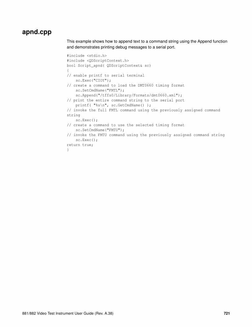
881/882 Video Test Instrument User Guide (Rev. A.38) 721
apnd.cpp
This example shows how to append text to a command string using the Append function and demonstrates printing debug messages to a serial port.
#include <stdio.h>
#include <QDScriptContext.h>
bool Script_apnd( QDScriptContext& sc)
{
// enable printf to serial terminal
sc.Exec("CIOY");
// create a command to load the DMT0660 timing format
sc.SetCmdName("FMTL");
sc.Append("/tffs0/Library/Formats/dmt0660.xml");
// print the entire command string to the serial port
printf( "%s\n", sc.GetCmdName() );
// invoke the full FMTL command using the previously assigned command
string
sc.Exec();
// create a command to use the selected timing format
sc.SetCmdName("FMTU");
// invoke the FMTU command using the previously assigned command string
sc.Exec();
return true;
}

722 Chapter 18 Script SDK
apndflt.cpp
This example shows how to add a floating point numeric value to a command string using the Append function and also demonstrates writing to the 882 front panel display.
#include <stdio.h>
#include <QDScriptContext.h>
bool Script_apndflt( QDScriptContext& sc )
{
// For RGB: step the analog video signal swing from 0.1 volts
// to 1.0 volts in steps of 0.10 volts, pausing at each level
double aswing;
// select a safe format, VGA
sc.Exec("FMTL /tffs0/Library/Formats/DMT0660.xml");
// use this selected format
sc.Exec ("FMTU");
// select a colorful image for this example
sc.Exec("IMGL /Cache0/Images/colorbar.img");
// select RGB video out
sc.Exec("XVSI 9");
// enable RGB video
sc.Exec("AVST 2");
// apply the above image and interface selections
sc.Exec("ALLU");
// step the analog video signal swing from 0.1 volts to 1.0
// volts in steps of 0.10 volts, pausing at each level
for(aswing=0.10; aswing<1.01; aswing+=0.10)
{
// build the command to set analog video swing
sc.SetCmdName("AVSS");
sc.Append(aswing);
// write the command to the bottom of the front-panel display
sc.Write( 0,3,(char *)sc.GetCmdName() );
// issue the command to set analog video swing
sc.Exec();
// use the selected format parameters
sc.Exec("FMTU");
// pause for 10 seconds at each level
sc.Pause(10000);
// this will cause script to immediately exit if STOP is pressed
if (sc.Canceled())
return true;
}
return true;
}

881/882 Video Test Instrument User Guide (Rev. A.38) 723
apndflt.cpp
This example demonstrates appending an integer to a command string. This example will sequentially test 3 different video interfaces: HDMI, S-video, and composite.
#include <stdio.h>
#include <QDScriptContext.h>
bool Script_apndint( QDScriptContext& sc )
UINT32 formatnum;
sc.Exec("CIOY"); // enable printf to serial terminal
// first load an image to use for this example:
sc.Exec("IMGL /Cache0/Images/colorbar.img");
// display the image
sc.Exec("IMGU");
// step through 3 interfaces: 4=HDMI-H, 5=SVideo, 6=CVBS
for(formatnum=4; formatnum<=6; formatnum++)
{
// build command string to set video output interface
// XVSI specifies which video output interface to use
sc.SetCmdName("XVSI ");
// use Append function to convert formatnum to character
and insert it into
// command string. Base-10 conversion.
// For this example, it will be either 4, 5, or 6.
sc.Append(formatnum, 10);
// print the entire command string to the serial port
printf( "%s\n", sc.GetCmdName() );
// execute the completed XVSI command
sc.Exec();
// This switch will select a video format that is appropriate
// for the output interface selected above switch(formatnum)
{
case 4:
printf("Now testing HDMI...\n");
// load a format that is compatible with HDMI interface
sc.SetCmdName("FMTL /tffs0/Library/Formats/dmt0660.xml");
break;
case 5:
printf("Now testing SVideo...\n");
// load a format that is compatible with SVideo interface
sc.SetCmdName("FMTL /tffs0/Library/Formats/ntsc.xml");
break;
case 6:
printf("Now testing CVBS...\n");

724 Chapter 18 Script SDK
// load a format that is compatible with CVBS interface
sc.SetCmdName("FMTL /tffs0/Library/Formats/ntsc.xml");
}
// invoke the selected format
sc.Exec();
// use the format that was selected above
sc.Exec("FMTU");
// delay for 10 seconds on each interface
sc.Pause(10000);
// this will cause script to immediately exit if STOP is pressed
if (sc.Canceled())
return true;
}
return true;
}

881/882 Video Test Instrument User Guide (Rev. A.38) 725
sampseq.cpp
// Quantum Data ScriptSDK Demonstration Program
//~~~~~~~~~~~~~~~~~~~~~~~~~~~
#include <stdio.h>
#include <QDScriptContext.h>
//~~~~~~~~~~~~~~~~~~~~~
/*******************************************************************
* Script_sampseq
********************************************************************
This is a conversion of "Sample Sequence" from chapter 8 of the 881/882 User Guide. This demonstrates how a sequence can be converted to an SDK script. Note that arguments are not always the same as in the sequence XML files, as shown in the XVSG conversions below.
In ScriptSDK, commands have the same syntax as if they were being entered at a command prompt. For full details on command syntax, refer to the Command Reference in Appendix A of the 881/882 User Guide available at: http://www.quantumdata.com/downloads/index.asp
Note: Note: this script (and the sequence that it evolved from) expects you to have
previously selected a compatible interface, such as VGA or HDMI.
********************************************************************
* Usage:
Script_sampleseq( QDScriptContext& sc );
*
* Arguments:
* sc - the script context being executed on.
*******************************************************************/
bool Script_sampseq( QDScriptContext& sc )
{
//<?xml version="1.0" encoding="UTF-8" ?>
//<DATAOBJ>
//<HEADER TYPE="SEQ" VERSION="1.0" ></HEADER>
//<DATA>
//<MODE>STEP</MODE>

726 Chapter 18 Script SDK
//<STEP>
//<FMT>/tffs0/Library/Formats/DMT0660.xml</FMT>
sc.Exec("FMTL /tffs0/Library/Formats/DMT0660.xml");
sc.Exec("FMTU");
//<IMG>/Cache0/Images/Acer1.img</IMG>
sc.Exec("IMGL /Cache0/Images/Acer1.img");
sc.Exec("IMGU");
//<DELY>+3.0000000E+00</DELY>
sc.Pause(3000);
//<VERS>0</VERS>
sc.Exec("IVER 0");
//<XVSG>7</XVSG>
sc.SetCmdName("XVSG ");
sc.Append("1 1 1");
sc.Exec();
if (sc.Canceled()) {
return true;
}
printf("Check Point 1\n");
//</STEP>
//<STEP>
//<IMG>/Cache0/Images/Cubes.img</IMG>
sc.Exec("IMGL /Cache0/Images/Cubes.img");
sc.Exec("IMGU");
//<DELY>+4.0000000E+00</DELY>
sc.Pause(4000);
if (sc.Canceled()) {
return true;
}
printf("Check Point 2\n");

881/882 Video Test Instrument User Guide (Rev. A.38) 727
//</STEP>
//<STEP>
//<IMG>/Cache0/Images/Linearty.img</IMG>
sc.Exec("IMGL /Cache0/Images/Linearty.img");
sc.Exec("IMGU");
//<DELY>+5.5000000E+00</DELY>
sc.Pause(5500);
if (sc.Canceled()) {
return true;
}
printf("Check Point 3\n");
//</STEP>
//<STEP>
//<FMT>/tffs0/Library/formats/DMT0860.xml</FMT>
sc.Exec("FMTL /tffs0/Library/Formats/DMT0860.xml");
sc.Exec("FMTU");
//<IMG>/Cache0/Images/RampX.img</IMG>
sc.Exec("IMGL /Cache0/Images/RampX.img");
sc.Exec("IMGU");
//<DELY>+3.0000000E+00</DELY>
sc.Pause(3000);
if (sc.Canceled()) {
return true;
}
printf("Check Point 4\n");
//</STEP>
//<STEP>
//<XVSG>1</XVSG>
sc.Exec("XVSG 0 0 1");

728 Chapter 18 Script SDK
//</STEP>
//<STEP>
//<XVSG>2</XVSG>
sc.Exec("XVSG 0 1 0");
//</STEP>
//<STEP>
//<XVSG>4</XVSG>
sc.Exec("XVSG 1 0 0");
//</STEP>
//<STEP>
//<XVSG>7</XVSG>
sc.Exec("XVSG 1 1 1");
if (sc.Canceled()) {
return true;
}
printf("Check Point 5\n");
//</STEP>
//<STEP>
//<FMT>/tffs0/Library/Formats/DMT1060.XML</FMT>
sc.Exec("FMTL /tffs0/Library/Formats/DMT1060.xml");
sc.Exec("FMTU");
//<IMG>/Cache0/Images/Master.img</IMG>
sc.Exec("IMGL /Cache0/Images/Master.img");
sc.Exec("IMGU");
//<DELY>+5.0000000E+00</DELY>
sc.Pause(5000);
return true;
}

881/882 Video Test Instrument User Guide (Rev. A.38) 729
sampseq.cpp
This example delays and does nothing except waits to be cancelled, then reports to a serial terminal whether it was cancelled.
#include <stdio.h>
#include <QDScriptContext.h>
bool Script_tcan( QDScriptContext& sc )
{
sc.Exec("CIOY"); // enable printf to serial terminal
printf("Pause for 10 seconds\n");
sc.Pause( 10000 ); // pause for 10 seconds
if (sc.Canceled())
{
printf("Script was canceled\n");
}
else
{
printf("Script completed\n");
}
return true;
}
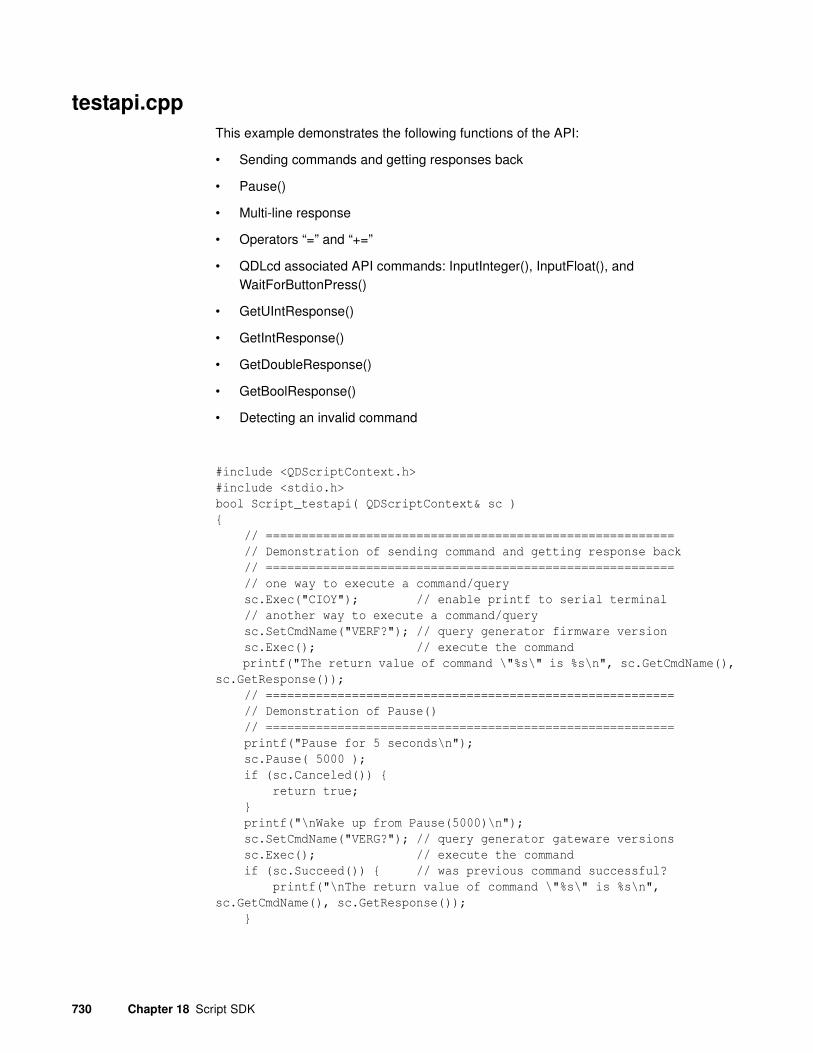
730 Chapter 18 Script SDK
testapi.cpp
This example demonstrates the following functions of the API:
• Sending commands and getting responses back
• Pause()
• Multi-line response
• Operators “=” and “+=”
• QDLcd associated API commands: InputInteger(), InputFloat(), and WaitForButtonPress()
• GetUIntResponse()
• GetIntResponse()
• GetDoubleResponse()
• GetBoolResponse()
• Detecting an invalid command
#include <QDScriptContext.h>
#include <stdio.h>
bool Script_testapi( QDScriptContext& sc )
{
// =========================================================
// Demonstration of sending command and getting response back
// =========================================================
// one way to execute a command/query
sc.Exec("CIOY"); // enable printf to serial terminal
// another way to execute a command/query
sc.SetCmdName("VERF?"); // query generator firmware version
sc.Exec(); // execute the command
printf("The return value of command \"%s\" is %s\n", sc.GetCmdName(),
sc.GetResponse());
// =========================================================
// Demonstration of Pause()
// =========================================================
printf("Pause for 5 seconds\n");
sc.Pause( 5000 );
if (sc.Canceled()) {
return true;
}
printf("\nWake up from Pause(5000)\n");
sc.SetCmdName("VERG?"); // query generator gateware versions
sc.Exec(); // execute the command
if (sc.Succeed()) { // was previous command successful?
printf("\nThe return value of command \"%s\" is %s\n",
sc.GetCmdName(), sc.GetResponse());
}

881/882 Video Test Instrument User Guide (Rev. A.38) 731
else
printf("\nThere is no response.\n");
// =========================================================
// Demonstration of multi-line respones
// =========================================================
if (sc.Canceled()) {
return true;
}
// query the first 10 test images in the generator
sc.SetCmdName("IMGQ?");
sc.Append(" 1 10");
sc.Exec();
printf("\nThe response of command \"%s\" has %d lines\n",
sc.GetCmdName(), sc.GetRespLineCount());
printf("\nThe 9th line of response is %s\n", sc.GetResponse(9));
for ( UINT32 index=1; index<sc.GetRespLineCount()+1; index++ ) {
printf("Response line %d is: %s \n", index,
sc.GetResponse(index));
}
// =========================================================
// Demonstration of Operator "=" and "+=" overloading
// =========================================================
sc.Reset();
if (sc.Canceled()) {
return true;
}
sc = "SCRX:";
sc += "LIST";
sc += "?";
sc.Exec();
printf("\nThe return value of command \"%s\" is %s\n",
sc.GetCmdName(), sc.GetResponse());
// =========================================================
// Demonstration of QDLcd associated APIs, InputInteger() &
InputFloat()
// =========================================================
if (sc.Canceled()) {
return true;
}
// Test "InputInteger( const char* prompt )" API
INT32 test = sc.InputInteger( "My test:" );
printf("\nThe input of my test is: %d\n", test);
if (sc.Canceled()) {
return true;
}
test = sc.InputInteger( "Input another one:" );
printf("\nThe input of second input is: %d\n", test);
if (sc.Canceled()) {
return true;
}
test = sc.InputInteger( "Test limity:", 3, 300 );
printf("\nThe input of test limit is: %d\n", test);
if (sc.Canceled()) {

732 Chapter 18 Script SDK
return true;
}
double test2 = sc.InputFloat( "Test Float:" );
printf("\nThe input of Test Float is: %f\n", test2);
// =========================================================
// Demonstration of QDLcd associated APIs, WaitForButtonPress()
// =========================================================
if (sc.Canceled()) {
return true;
}
sc.ClearLCD();
sc.Write(1, 1, "Test WaitForButtonPress()");
sc.Write(0, 3, "<-Yes4");
sc.Write(16, 3, "No->");
QDKeyId pressedKey = sc.WaitForKeyPress(5000);
if ( pressedKey == QD_KEY_LEFT_4 ) {
printf("\nUser pressed \"Yes\"\n");
}
else if ( pressedKey == QD_KEY_RIGHT_4 ) {
printf("\nUser pressed \"No\"\n");
}
else
{
printf("\nPressed Invalid Key\n");
}
// =========================================================
// Demonstration of GetUIntResponse()
// =========================================================
if (sc.Canceled()) {
return true;
}
sc.SetCmdName("DPTR?");
//sc.ClearScreen();
sc.Exec();
if (sc.Succeed()) {
printf("\nTest GetUIntResponse(): The return value of command
\"%s\" is %d\n", sc.GetCmdName(), sc.GetUIntResponse());
}
else
printf("\nCommand execution failed.\n");
// =========================================================
// Demonstration of GetIntResponse()
// =========================================================
if (sc.Canceled()) {
return true;
}
sc.SetCmdName("HRES?");
//sc.ClearScreen();
sc.Exec();
if (sc.Succeed()) {
printf("\nTest GetIntResponse(): The return value of command
\"%s\" is %d\n", sc.GetCmdName(), sc.GetIntResponse());
}

881/882 Video Test Instrument User Guide (Rev. A.38) 733
else
printf("\nCommand execution failed.\n");
// =========================================================
// Demonstration of GetDoubleResponse()
// =========================================================
if (sc.Canceled()) {
return true;
}
sc.SetCmdName("PRAT?");
//sc.ClearScreen();
sc.Exec();
if (sc.Succeed()) {
printf("\nTest GetDoubleResponse(): The return value of command
\"%s\" is %f\n", sc.GetCmdName(), sc.GetDoubleResponse());
}
else
printf("\nCommand execution failed. Error is %d\n",
sc.GetError());
// =========================================================
// Demonstration of GetBoolResponse()
// =========================================================
if (sc.Canceled()) {
return true;
}
sc.SetCmdName("PDAX:RPTG?");
//sc.ClearScreen();
sc.Exec();
if (sc.Succeed()) {
printf("\nTest GetBoolResponse(): The return value of command
\"%s\" is %d\n", sc.GetCmdName(), sc.GetBoolResponse());
}
else
printf("\nCommand execution failed.\n");
// =========================================================
// Demonstration of Pause()
// =========================================================
printf("Pause for 6 seconds\n");
sc.Pause( 6000 );
if (sc.Canceled()) {
return true;
}
printf("\nWake up from Pause(6000)\n");
if (sc.Canceled()) {
return true;
}
sc.SetCmdName("VERG?");
//sc.ClearScreen();
sc.Exec();
if (sc.Succeed()) {
printf("\nThe return value of command \"%s\" is %s\n",
sc.GetCmdName(), sc.GetResponse());
}

734 Chapter 18 Script SDK
else
printf("\nCommand execution failed.\n");
// =========================================================
// Demonstration of detecting invalid command
// =========================================================
// First, set CancelOnError to be FALSE, the test should continue to
next
sc.SetCancelOnError( false );
sc.SetCmdName("VERP?");
sc.Exec();
printf("\nThe error status of the invalid command %s is %d\n",
sc.GetCmdName(), sc.GetError());
if (sc.Canceled()) {
printf("The test exited because the command is not valid\n");
return true;
}
else
{
printf("Script not cancelled. Execution should continue\n");
}
// Then, set CancelOnError to be TRUE, the test should continue to
next
sc.SetCancelOnError( true );
sc.SetCmdName("VERP?");
sc.Exec();
printf("\nThe error status of the invalid command %s is %d\n",
sc.GetCmdName(), sc.GetError());
if (sc.Canceled()) {
printf("The test exited because the command is not valid\n");
return true;
}
else
{
printf("Script not cancelled. Execution should continue\n");
}
return true;
}
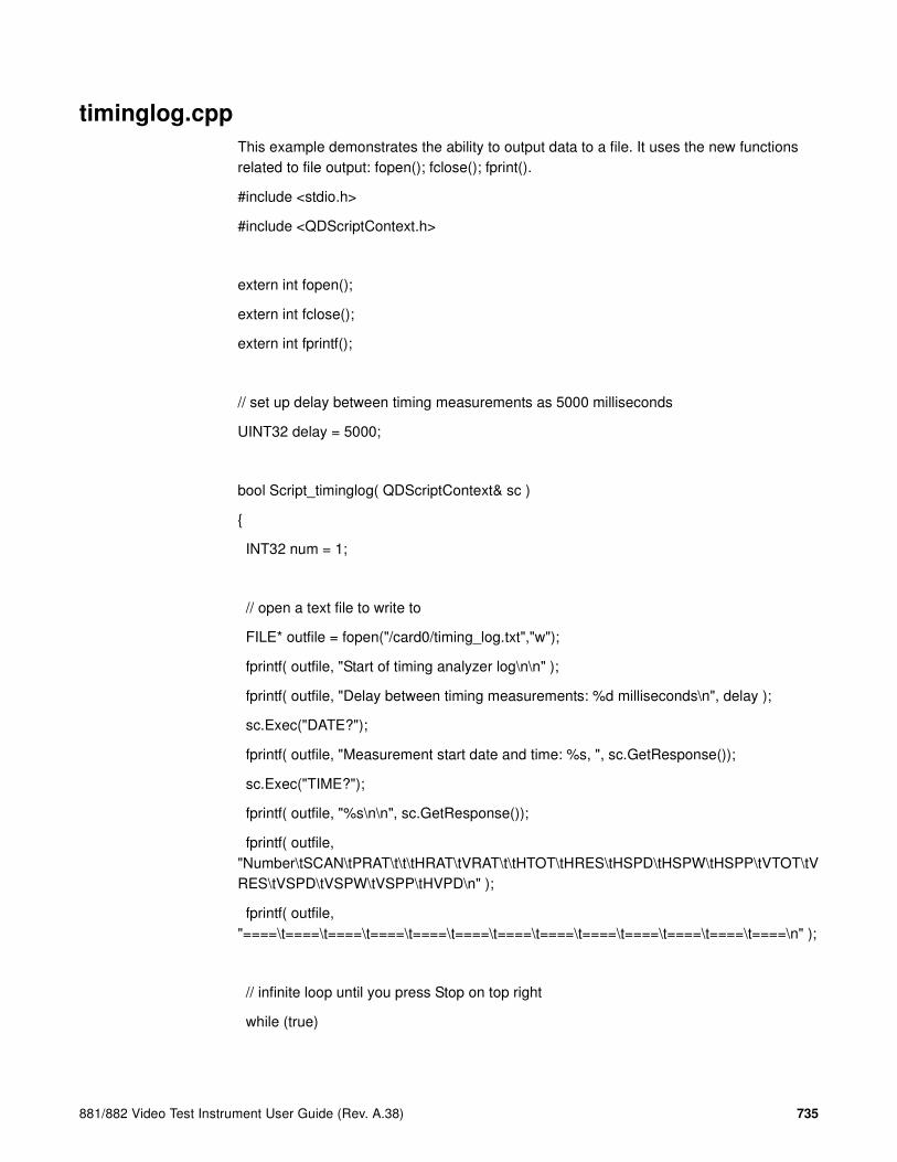
881/882 Video Test Instrument User Guide (Rev. A.38) 735
timinglog.cpp
This example demonstrates the ability to output data to a file. It uses the new functions related to file output: fopen(); fclose(); fprint().
#include <stdio.h>
#include <QDScriptContext.h>
extern int fopen();
extern int fclose();
extern int fprintf();
// set up delay between timing measurements as 5000 milliseconds
UINT32 delay = 5000;
bool Script_timinglog( QDScriptContext& sc )
{
INT32 num = 1;
// open a text file to write to
FILE* outfile = fopen("/card0/timing_log.txt","w");
fprintf( outfile, "Start of timing analyzer log\n\n" );
fprintf( outfile, "Delay between timing measurements: %d milliseconds\n", delay );
sc.Exec("DATE?");
fprintf( outfile, "Measurement start date and time: %s, ", sc.GetResponse());
sc.Exec("TIME?");
fprintf( outfile, "%s\n\n", sc.GetResponse());
fprintf( outfile, "Number\tSCAN\tPRAT\t\t\tHRAT\tVRAT\t\tHTOT\tHRES\tHSPD\tHSPW\tHSPP\tVTOT\tVRES\tVSPD\tVSPW\tVSPP\tHVPD\n" );
fprintf( outfile, "====\t====\t====\t====\t====\t====\t====\t====\t====\t====\t====\t====\t====\n" );
// infinite loop until you press Stop on top right
while (true)

736 Chapter 18 Script SDK
{
sc.SetCancelOnError( false);
// measure the incoming signal
sc.Exec("TMAU");
// repeat measurement if there is no incoming signal
while (sc.Failed())
{
sc.Pause(delay);
sc.Exec("TMAU");
}
// if Stop is pressed, close the file and end script
if (sc.Canceled()) {
sc.Exec("DATE?");
fprintf( outfile, "\nMeasurement end date and time: %s, ", sc.GetResponse());
sc.Exec("TIME?");
fprintf( outfile, "%s\n\n", sc.GetResponse());
fprintf( outfile, "End of timing analyzer log\n" );
fclose( outfile );
return true;
}
// query and write measured timing values to the text file
fprintf( outfile, "%d\t\t", num);
sc.Exec("TMAX:SCAN?");
fprintf( outfile, "%s\t", sc.GetResponse());
sc.Exec("TMAX:PRAT?");
fprintf( outfile, "%s\t", sc.GetResponse());
sc.Exec("TMAX:HRAT?");
fprintf( outfile, "%s\t", sc.GetResponse());

881/882 Video Test Instrument User Guide (Rev. A.38) 737
sc.Exec("TMAX:VRAT?");
fprintf( outfile, "%s\t", sc.GetResponse());
sc.Exec("TMAX:HTOT?");
fprintf( outfile, "%s\t", sc.GetResponse());
sc.Exec("TMAX:HRES?");
fprintf( outfile, "%s\t", sc.GetResponse());
sc.Exec("TMAX:HSPD?");
fprintf( outfile, "%s\t", sc.GetResponse());
sc.Exec("TMAX:HSPW?");
fprintf( outfile, "%s\t", sc.GetResponse());
sc.Exec("TMAX:HSPP?");
fprintf( outfile, "%s\t", sc.GetResponse());
sc.Exec("TMAX:VTOT?");
fprintf( outfile, "%s\t", sc.GetResponse());
sc.Exec("TMAX:VRES?");
fprintf( outfile, "%s\t", sc.GetResponse());
sc.Exec("TMAX:VSPD?");
fprintf( outfile, "%s\t", sc.GetResponse());
sc.Exec("TMAX:VSPW?");
fprintf( outfile, "%s\t", sc.GetResponse());
sc.Exec("TMAX:VSPP?");
fprintf( outfile, "%s\t", sc.GetResponse());
sc.Exec("TMAX:HVPD?");
fprintf( outfile, "%s\n", sc.GetResponse());
// increase the measurement number counter
num++;
// hard delay until the next measurement
sc.Pause(delay);
// if Stop is pressed, close the file and end script

738 Chapter 18 Script SDK
if (sc.Canceled()) {
sc.Exec("DATE?");
fprintf( outfile, "\nMeasurement end date and time: %s, ", sc.GetResponse());
sc.Exec("TIME?");
fprintf( outfile, "%s\n\n", sc.GetResponse());
fprintf( outfile, "End of timing analyzer log\n" );
fclose( outfile );
return true;
}
}
}

881/882 Video Test Instrument User Guide (Rev A.38) 739
A Command Reference
Topics in this appendix:
• Commands by category
• Commands by name
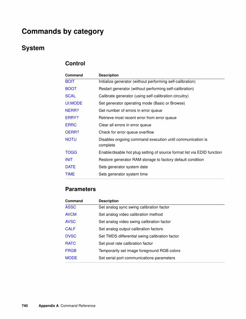
740 Appendix A Command Reference
Commands by category
System
Control
Parameters
Command Description
BOIT Initialize generator (without performing self-calibration)
BOOT Restart generator (without performing self-calibration)
SCAL Calibrate generator (using self-calibration circuitry)
UI:MODE Set generator operating mode (Basic or Browse)
NERR? Get number of errors in error queue
ERRY? Retrieve most recent error from error queue
ERRC Clear all errors in error queue
OERR? Check for error queue overflow
NOTU Disables ongoing command execution until communication is complete
TOGG Enable/disable hot plug setting of source format list via EDID function
INIT Restore generator RAM storage to factory default condition
DATE Sets generator system date
TIME Sets generator system time
Command Description
ASSC Set analog sync swing calibration factor
AVCM Set analog video calibration method
AVSC Set analog video swing calibration factor
CALF Set analog output calibration factors
DVSC Set TMDS differential swing calibration factor
RATC Set pixel rate calibration factor
FRGB Temporarily set image foreground RGB colors
MODE Set serial port communications parameters

881/882 Video Test Instrument User Guide (Rev A.38) 741
Tools
Network
User Profile
Command Description
VERF? Get generator firmware version number
VERG? Get gateway version number
FILE:LOAD Load file (image, format) on generator
FILE:SCREENCAP Capture currently displayed image to a bitmap file
LCDS? Get text displayed on generator LCD display
LEDS? Get status of generator signals
DEVS? List all devices
LS? List contents of current directory
CAT? View contents of a text file
PWD? Get current directory name
RM Remove a file from current directory
TASK? List current tasks
Command Description
ENET Get generator’s ethernet MAC address
ENET:IP Set generator’s ethernet IP address
ENET:MASK Set generator’s ethernet subnet mask address
Command Description
USRA Add user profile
USRU Create new user profile
USRK Delete user profile
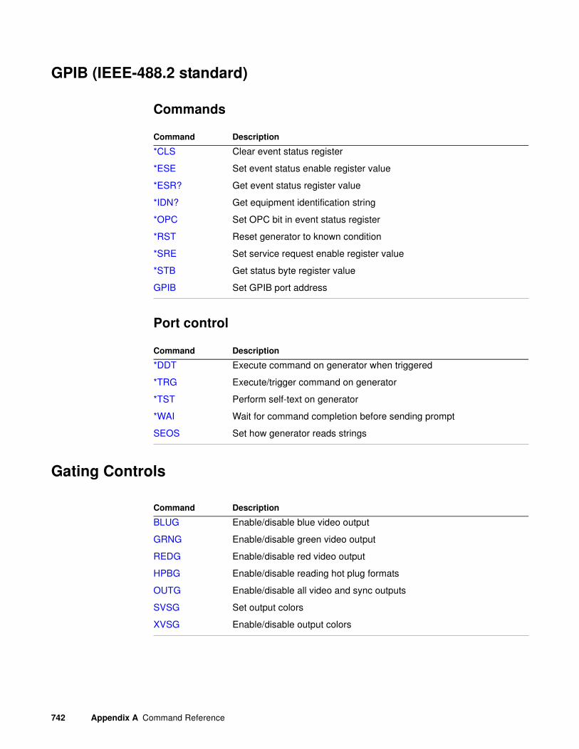
742 Appendix A Command Reference
GPIB (IEEE-488.2 standard)
Commands
Port control
Gating Controls
Command Description
*CLS Clear event status register
*ESE Set event status enable register value
*ESR? Get event status register value
*IDN? Get equipment identification string
*OPC Set OPC bit in event status register
*RST Reset generator to known condition
*SRE Set service request enable register value
*STB Get status byte register value
GPIB Set GPIB port address
Command Description
*DDT Execute command on generator when triggered
*TRG Execute/trigger command on generator
*TST Perform self-text on generator
*WAI Wait for command completion before sending prompt
SEOS Set how generator reads strings
Command Description
BLUG Enable/disable blue video output
GRNG Enable/disable green video output
REDG Enable/disable red video output
HPBG Enable/disable reading hot plug formats
OUTG Enable/disable all video and sync outputs
SVSG Set output colors
XVSG Enable/disable output colors
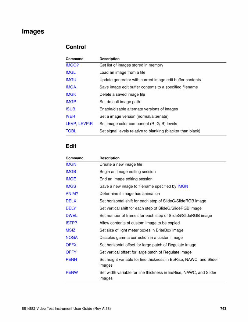
881/882 Video Test Instrument User Guide (Rev A.38) 743
Images
Control
Edit
Command Description
IMGQ? Get list of images stored in memory
IMGL Load an image from a file
IMGU Update generator with current image edit buffer contents
IMGA Save image edit buffer contents to a specified filename
IMGK Delete a saved image file
IMGP Set default image path
ISUB Enable/disable alternate versions of images
IVER Set a image version (normal/alternate)
LEVP, LEVP:R Set image color component (R, G, B) levels
TOBL Set signal levels relative to blanking (blacker than black)
Command Description
IMGN Create a new image file
IMGB Begin an image editing session
IMGE End an image editing session
IMGS Save a new image to filename specified by IMGN
ANIM? Determine if image has animation
DELX Set horizontal shift for each step of SlideG/SlideRGB image
DELY Set vertical shift for each step of SlideG/SlideRGB image
DWEL Set number of frames for each step of SlideG/SlideRGB image
ISTP? Allow contents of custom image to be copied
MSIZ Set size of light meter boxes in BriteBox image
NOGA Disables gamma correction in a custom image
OFFX Set horizontal offset for large patch of Regulate image
OFFY Set vertical offset for large patch of Regulate image
PENH Set height variable for line thickness in EeRise, NAWC, and Slider images
PENW Set width variable for line thickness in EeRise, NAWC, and Slider images

744 Appendix A Command Reference
Custom Image Draw
SPAX Set horizontal spacing
SPAY Set vertical spacing
UIDN Set test string in upper portion of SMPTE133 and Cubes images
XRES Set horizontal scaling factor
YRES Set vertical scaling factor
Command Description
ADOT Draw a single pixel
ANTI Use anti-aliasing
CENT Draw a small cross in center
CROS Draw a large cross in center
FORM Draw format data block
GRID Draw a color crosshatch with boxes
GRIH Draw equally spaced horizontal lines (grill)
GRIV Draw equally spaced vertical lines (grill)
HATI Draw inside-out color crosshatch with boxes
HATO Draw outside-in color crosshatch with boxes
LIMI Draw nine markers to define active video area
LINE Draw a line between two points
OVAL Draw an oval
PAGE Fill a rectangular area with a repeating character
RECT Draw a rectangle with sides parallel to axis of active video
SNUM Draw sequence step number (when using a sequence)
TBOX Draw information text box
TBXG Enable/disable display of information text box specified by TBOX
TEXT Draw text string
TRIA Draw a triangle
Command Description

881/882 Video Test Instrument User Guide (Rev A.38) 745
ImageShift utility
Formats
Control
Command Description
ISHG Enable/disable image shifting function
ISHQ? Get list of imageshift files stored in memory
ISHL Load values from an imageshift file
ISHN Create a new imageshift file
ISHB Begin an imageshift file editing session
XISH:HINC Set horizontal shifting increment
XISH:PATH Set shift path
XISH:SRCN Set image for shifting
XISH:TINC Set time shift increment
XISH:TTYP Set shifting method
XISH:VINC Set vertical shifting increment
ISHE End an imageshift file editing session
ISHS Save a new imageshift file to filename specified by ISHN
ISHU Update generator with current imageshift file edit buffer contents
ISHA Save imageshift file edit buffer contents to a specified filename
ISHK Delete a saved imageshift file
ISHP Set default imageshift path
Command Description
FMTQ? Get list of formats stored in memory
FMTL Load a format from a file
FMTU Update generator with current format edit buffer contents
FMTA Save format edit buffer contents to a specified filename
FMTG? Test format edit buffer contents
FMTK Delete a saved format file
FMTP Set default format path
FMTZ Clear format storage memory

746 Appendix A Command Reference
Edit
Parameters (Video Signal)
Command Description
FMTN Create a new format file
FMTB Begin a format editing session
FMTE End a format editing session
FMTS Save a new format to filename specified by FMTN
JDVI Set upper and lower pixel clock rate limit for DVI output
JLDI Set pixel clock rate for LDI output
JRAT Set pixel clock rate
PELD Set number of data bits in each active pixel
HSIZ Set horizontal physical size of image displayed
VSIZ Set vertical physical size of image displayed
USIZ Set measurement units for HSIZ and VSIZ
Command Type Description
XVSI Interface Enable/disable video signal interface output
XVSI:IN Interface Enable/disable video signal interface input
SSST Synchronization Set display sync signal type
GAMC Gamma Correction Enable/disable video gamma correction factor
GAMA Gamma Correction Set video gamma correction factor
CXAR Active Format (HDMI)
Set aspect ratio of source image content
EXAR Active Format (HDMI)
Set aspect ratio of extended image content
SXAR Active Format (HDMI)
Set natural aspect ratio of video signal format
EXCX Active Format (HDMI)
Map source image to extended image
SXCX Active Format (HDMI)
Map CXAR-shaped image to SXAR-shaped aperture
SXEX Active Format (HDMI)
Map EXAR-shaped image to SXAR-shaped aperture
XAFD Active Format (HDMI)
Set parameters to support a given AFD code

881/882 Video Test Instrument User Guide (Rev A.38) 747
PXAR? Active Format (HDMI)
Get aspect ratio of pixels in active regions of raster image
XBBH Manual Border (HDMI)
Set bottom border height
XLBW Manual Border (HDMI)
Set left border width
XRBW Manual Border (HDMI)
Set right border width
XTBH Manual Border (HDMI)
Set top border height
PELD Canvas Set pixel depth
NPPP Canvas Set pixel repetition factor
AVST Analog Video Set signal output type
AVSS Analog Video Set maximum peak-to-peak swing for analog video output
AVPS Analog Video Set analog video black pedestal level
AVPG Analog Video Enable/disable analog video set-up pedestal
AVCS Analog Video Set color subcarrier type for television output
AVCO Analog Video Set mapping of video colors to analog video output
ASSS Analog Sync Set maximum peak-to-peak swing for composite sync
ASCT Analog Sync Set composite sync type for analog video output
EQUF Analog Sync Enable/disable equalization pulses in composite sync
ASBG Analog Sync Gates Add composite sync to blue analog video output
TSPG Analog Sync Gates Enable/disable tri-level sync pulse
ASSG Analog Sync Gates Add composite sync to all three analog video outputs
DVST Digital Video Set signal type
DVQM Digital Video Set quantizing mode
NCPP Digital Video Set number of clocks per pixel
NBPC Digital Video Set color depth
LMAX Digital Video Set maximum digital quantizing level
LMIN Digital Video Set minimum digital quantizing level
NLNK Digital Video Set number of links used by LVDI digital outputs
Command Type Description
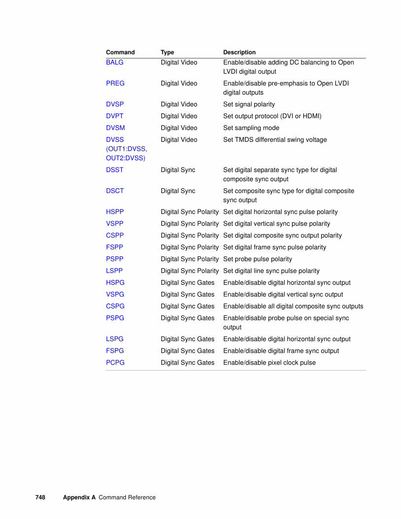
748 Appendix A Command Reference
BALG Digital Video Enable/disable adding DC balancing to Open LVDI digital output
PREG Digital Video Enable/disable pre-emphasis to Open LVDI digital outputs
DVSP Digital Video Set signal polarity
DVPT Digital Video Set output protocol (DVI or HDMI)
DVSM Digital Video Set sampling mode
DVSS (OUT1:DVSS, OUT2:DVSS)
Digital Video Set TMDS differential swing voltage
DSST Digital Sync Set digital separate sync type for digital composite sync output
DSCT Digital Sync Set composite sync type for digital composite sync output
HSPP Digital Sync Polarity Set digital horizontal sync pulse polarity
VSPP Digital Sync Polarity Set digital vertical sync pulse polarity
CSPP Digital Sync Polarity Set digital composite sync output polarity
FSPP Digital Sync Polarity Set digital frame sync pulse polarity
PSPP Digital Sync Polarity Set probe pulse polarity
LSPP Digital Sync Polarity Set digital line sync pulse polarity
HSPG Digital Sync Gates Enable/disable digital horizontal sync output
VSPG Digital Sync Gates Enable/disable digital vertical sync output
CSPG Digital Sync Gates Enable/disable all digital composite sync outputs
PSPG Digital Sync Gates Enable/disable probe pulse on special sync output
LSPG Digital Sync Gates Enable/disable digital horizontal sync output
FSPG Digital Sync Gates Enable/disable digital frame sync output
PCPG Digital Sync Gates Enable/disable pixel clock pulse
Command Type Description

881/882 Video Test Instrument User Guide (Rev A.38) 749
Parameters (Video Timing)
Parameters (Audio Signal and Timing)
Command Type Description
PRAT? Rates Get current pixel rate setting
HRAT Rates Set line frequency
VRAT? Rates Get current vertical (field) rate
FRAT? Rates Get current vertical rate setting for frame
HTOT Horizontal Set total number of pixels per horizontal line
HRES Horizontal Set number of active pixels per line
VTOT Vertical Set total number of lines per vertical frame
VRES Vertical Set number of active pixels per frame
SCAN Vertical Set number of fields scanned per frame
RFLD Vertical Enable/disable identical video information output for each field of interlaced format
HSPD Horizontal Sync Set horizontal sync pulse delay
HSPW Horizontal Sync Set width of horizontal sync pulse
HVPD? Horizontal Sync Get pixel delay between horizontal and vertical sync pulses
VSPD Vertical Sync Set vertical sync pulse delay
VSPW Vertical Sync Set vertical sync pulse width
EQUB Composite Sync Set equalization interval before vertical sync pulse
EQUA Composite Sync Set equalization interval after vertical sync pulse
HVSA Composite Sync Set pixel serration period
FSPD Frame Sync Set frame sync pulse delay
FSPW Frame Sync Set width of frame sync pulse
PSHD Probe Sync Set line delay (in pixels)
PSVD Probe Sync Set vertical delay
PSPW Probe Sync Set pixel width
PSVW Probe Sync Set vertical width
PSPM Probe Sync Set lines in frame where probe pulse occurs
Command Type Description
CAUD Encoding Set digital audio clips
DASI Interface Set digital audio signal interface

750 Appendix A Command Reference
DAST Encoding Set digital audio signal type
NDAS Encoding Set number of digital audio streams
NDAC Encoding Set number of digital audio channels (CC parameter in Audio InfoFrame)
NBPA Encoding Set number of bits (SS parameter in Audio InfoFrame)
DAXG Components Specify gated speaker locations
DAXA Components Specify available speaker locations
SDGM Mix Set generator SPDIF audio OUT source (HDMI, SPDIF IN or internal)
SDMG Mix Set generator audio source (internal or external)
DADG Mix Enable/disable audio signal downmixing (DM_I parameter in Audio InfoFrame)
DALS Mix Set level shift value for audio signal downmixing (LVS parameter in Audio InfoFrame)
DACA Channels Set active audio channels
DACG Channels Set gated audio channels
SDAU SPDIF analyzer Initiates the measurement of the audio received on the SPDIF In connector of the 882EA
SDAX:ARAT? SPDIF analyzer Queries for the sampling rate of the audio received on the SPDIF In connector of the 882EA
SDAX:IECD? SPDIF analyzer Queries for the IEC header information of the audio received on the SPDIF In connector of the 882EA
SDAX:CSBA/B? SPDIF analzyer Queries for the channel status bits of the audio received on the SPDIF In connector of the 882EA
SAMP Sinewave Set amplitude of digital audio stream sinewave output
SMAX? Sinewave Get maximum amplitude of digital audio stream sinewave output
SMIN? Sinewave Get minimum amplitude of digital audio stream sinewave output
SRAT Sinewave Set frequency of digital audio stream sinewave output
Command Type Description

881/882 Video Test Instrument User Guide (Rev A.38) 751
Test Sequences
Control
Edit
ARAT Digital Audio Timing
Set sampling rate (CT parameter in Audio InfoFrame)
BRAT Digital Audio Timing
Set bit rate (MBR parameter in Audio InfoFrame)
Command Type Description
Command Description
SEQQ? Get list of filenames of stored sequence files
SEQL Load a sequence from a file
SEQA Save sequence edit buffer contents to a specified filename
SEQU Update hardware with current sequence editor contents
SEQK Delete a saved sequence file
SEQP Set default sequence path
SMOD Set sequence mode
DNUM Enable/display sequence step number display
NSTP? Get number of sequence steps in the buffer
Command Description
SEQN Create a new sequence file
SEQB Begin a sequence editing session
STEP Select a sequence step
SDLY Set sequence step delay
SEQE End a sequence editing session
SEQS Save a new sequence to filename specified by SEQN
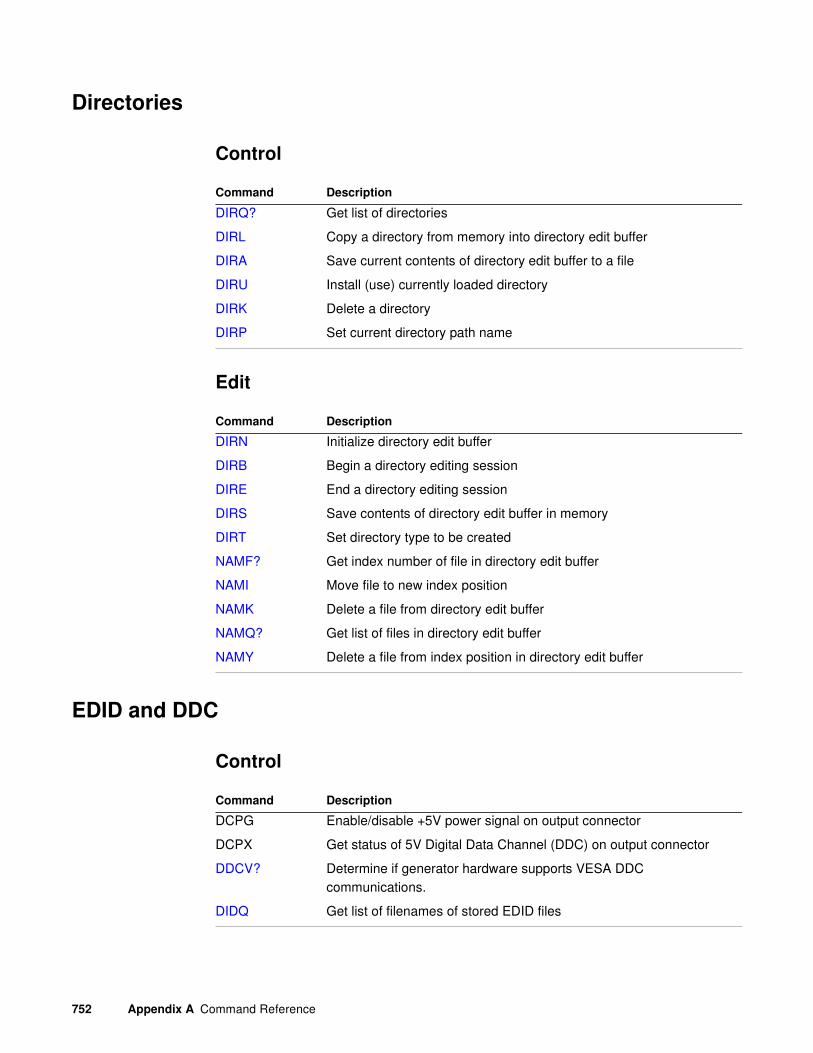
752 Appendix A Command Reference
Directories
Control
Edit
EDID and DDC
Control
Command Description
DIRQ? Get list of directories
DIRL Copy a directory from memory into directory edit buffer
DIRA Save current contents of directory edit buffer to a file
DIRU Install (use) currently loaded directory
DIRK Delete a directory
DIRP Set current directory path name
Command Description
DIRN Initialize directory edit buffer
DIRB Begin a directory editing session
DIRE End a directory editing session
DIRS Save contents of directory edit buffer in memory
DIRT Set directory type to be created
NAMF? Get index number of file in directory edit buffer
NAMI Move file to new index position
NAMK Delete a file from directory edit buffer
NAMQ? Get list of files in directory edit buffer
NAMY Delete a file from index position in directory edit buffer
Command Description
DCPG Enable/disable +5V power signal on output connector
DCPX Get status of 5V Digital Data Channel (DDC) on output connector
DDCV? Determine if generator hardware supports VESA DDC communications.
DIDQ Get list of filenames of stored EDID files

881/882 Video Test Instrument User Guide (Rev A.38) 753
Edit
DIDL Load an EDID from a file
DIDA Save an EDID to a specified filename
DIDU Update hardware with current EDID contents
DIDK Delete a saved EDID file
DIDP Set default EDID path
EDA Read/write EDID from/to device connected to HDMI output port
EDID? Read EDID from connected device
I2CR? Read EDID data using I2C bus
I2CW Write EDID data using I2C bus
XDID Set new EDID structure (DVI/HDMI Analyzer)
EDE Set HDMI input port with contents of EDID buffer (DVI/HDMI Analyzer)
STRG Enable/disable SCL low signal stretching (DVI/HDMI Analyzer)
Command Description
DIDN Create a new EDID file
DIDB Begin an EDID editing session
XDID Set new EDID structure (DVI/HDMI Analyzer)
DIDE End an EDID editing session
DIDS Save a new EDID to filename specified by DIDN
Command Description
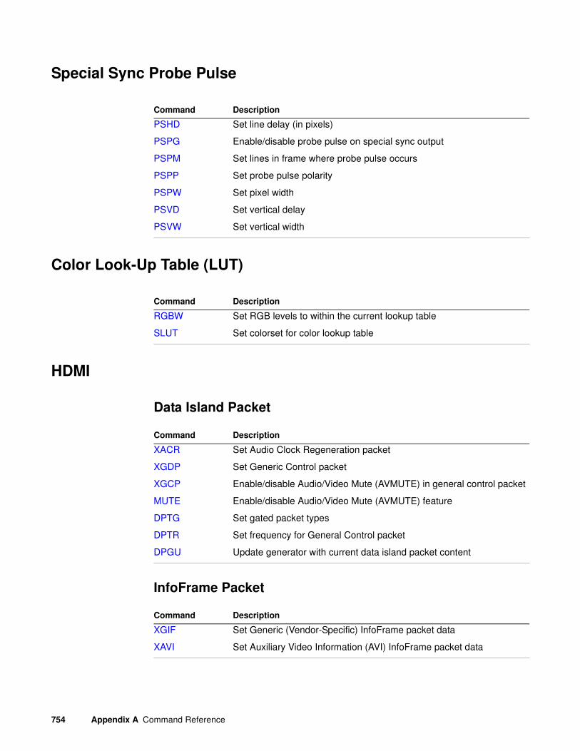
754 Appendix A Command Reference
Special Sync Probe Pulse
Color Look-Up Table (LUT)
HDMI
Data Island Packet
InfoFrame Packet
Command Description
PSHD Set line delay (in pixels)
PSPG Enable/disable probe pulse on special sync output
PSPM Set lines in frame where probe pulse occurs
PSPP Set probe pulse polarity
PSPW Set pixel width
PSVD Set vertical delay
PSVW Set vertical width
Command Description
RGBW Set RGB levels to within the current lookup table
SLUT Set colorset for color lookup table
Command Description
XACR Set Audio Clock Regeneration packet
XGDP Set Generic Control packet
XGCP Enable/disable Audio/Video Mute (AVMUTE) in general control packet
MUTE Enable/disable Audio/Video Mute (AVMUTE) feature
DPTG Set gated packet types
DPTR Set frequency for General Control packet
DPGU Update generator with current data island packet content
Command Description
XGIF Set Generic (Vendor-Specific) InfoFrame packet data
XAVI Set Auxiliary Video Information (AVI) InfoFrame packet data

881/882 Video Test Instrument User Guide (Rev A.38) 755
XSPD Set Source Product Description InfoFrame packet data
XAUD Set Audio InfoFrame packet data
XMPG Set MPEG InfoFrame packet data
DVIC Sets video identification code in AVI InfoFrame
IFAX:RPTU Set gated InfoFrame types
IFTR Set frequency for InfoFrame types
IFGU Update generator with current InfoFrame content
Command Description
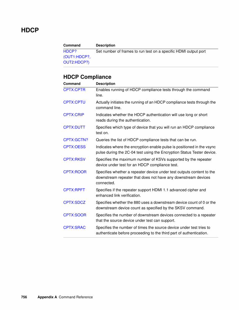
756 Appendix A Command Reference
HDCP
HDCP Compliance
Command Description
HDCP? (OUT1:HDCP?, OUT2:HDCP?)
Set number of frames to run test on a specific HDMI output port
Command Description
CPTX:CPTR Enables running of HDCP compliance tests through the command line.
CPTX:CPTU Actually initiates the running of an HDCP compliance tests through the command line.
CPTX:CRIP Indicates whether the HDCP authentication will use long or short reads during the authentication.
CPTX:DUTT Specifies which type of device that you will run an HDCP compliance test on.
CPTX:GCTN? Queries the list of HDCP compliance tests that can be run.
CPTX:OESS Indicates where the encryption enable pulse is positioned in the vsync pulse during the 2C-04 test using the Encryption Status Tester device.
CPTX:RKSV Specifies the maximum number of KSVs supported by the repeater device under test for an HDCP compliance test.
CPTX:ROOR Specifies whether a repeater device under test outputs content to the downstream repeater that does not have any downstream devices connected.
CPTX:RPFT Specifies if the repeater support HDMI 1.1 advanced cipher and enhanced link verification.
CPTX:SDCZ Specifies whether the 880 uses a downstream device count of 0 or the downstream device count as specified by the SKSV command.
CPTX:SOOR Specifies the number of downstream devices connected to a repeater that the source device under test can support.
CPTX:SRAC Specifies the number of times the source device under test tries to authenticate before proceeding to the third part of authentication.
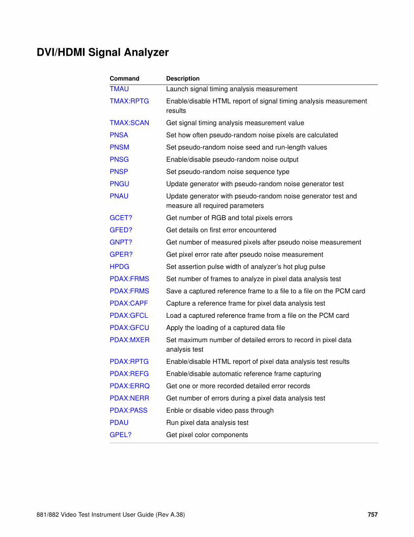
881/882 Video Test Instrument User Guide (Rev A.38) 757
DVI/HDMI Signal Analyzer
Command Description
TMAU Launch signal timing analysis measurement
TMAX:RPTG Enable/disable HTML report of signal timing analysis measurement results
TMAX:SCAN Get signal timing analysis measurement value
PNSA Set how often pseudo-random noise pixels are calculated
PNSM Set pseudo-random noise seed and run-length values
PNSG Enable/disable pseudo-random noise output
PNSP Set pseudo-random noise sequence type
PNGU Update generator with pseudo-random noise generator test
PNAU Update generator with pseudo-random noise generator test and measure all required parameters
GCET? Get number of RGB and total pixels errors
GFED? Get details on first error encountered
GNPT? Get number of measured pixels after pseudo noise measurement
GPER? Get pixel error rate after pseudo noise measurement
HPDG Set assertion pulse width of analyzer’s hot plug pulse
PDAX:FRMS Set number of frames to analyze in pixel data analysis test
PDAX:FRMS Save a captured reference frame to a file to a file on the PCM card
PDAX:CAPF Capture a reference frame for pixel data analysis test
PDAX:GFCL Load a captured reference frame from a file on the PCM card
PDAX:GFCU Apply the loading of a captured data file
PDAX:MXER Set maximum number of detailed errors to record in pixel data analysis test
PDAX:RPTG Enable/disable HTML report of pixel data analysis test results
PDAX:REFG Enable/disable automatic reference frame capturing
PDAX:ERRQ Get one or more recorded detailed error records
PDAX:NERR Get number of errors during a pixel data analysis test
PDAX:PASS Enble or disable video pass through
PDAU Run pixel data analysis test
GPEL? Get pixel color components

758 Appendix A Command Reference
HDMI LipSync Generator/Analyzer
Command Description
LSAX:LSGM Enable/disable lipsync analyzer testing of source device
LSAX:LSGU Update hardware with lipsync analyzer settings
LSAX:PLAT? Get name of first received data stream (audio or video)
LSAX:RPTG Enable/disable HTML report of lipsync analyzer measurement results
LSAX:TLAT? Get number of seconds delay between received audio and video
LSGX:LSGM Enable/disable lipsync testing of display (sink) device
LSGX:LSGU Update hardware with lipsync generator settings
LSGX:PLAT Set precedence of data streams from lipsync image
LSGX:TLAT Set latency (delay) between audio and video data streams in lipsync image

881/882 Video Test Instrument User Guide (Rev A.38) 759
Commands by name

760 Appendix A Command Reference
*CLSClear Status
Class GPIB
Description Clears the Event Status Register, the Status Byte and the output buffer.
Command syntax *CLS
Related commands *ESR?, *STB

881/882 Video Test Instrument User Guide (Rev A.38) 761
*DDTDelay Device Trigger
Class Trigger
Description Specifies a command or command string to be executed when the generator is “triggered” with the *TRG command. Only one *DDT command can be pending at a time. The command or query arguments must be enclosed in quotes.
Command syntax *DDT “command_1; command_2 ... command_n”
Example *DDT “imgl flat; imgu”
*TRG // to invoke the command line in quotes from the *DDT command
Related commands *TRG

762 Appendix A Command Reference
*ESEEvent Status Enable
Class GPIB
Description Sets the Event Status Enable register to the given mask value. The bits in the Event Status Enable register function as enable bits for each corresponding bit in the Event Status register. That is, when a bit in the Event Status register goes high, and the corresponding bit in the Event Status Enable register is a 1, it is enabled and will cause the ESB bit in the Status Byte register to go high.
The *ESE? query returns the current value of the Event Status Enable register.
Command syntax *ESE mask
mask
0 - 255
Example *ESE 8
Query syntax *ESE?
Query response mask NL
Where mask is in integer NR1 form.
See also: *CLS, *ESR?

881/882 Video Test Instrument User Guide (Rev A.38) 763
*ESR?Event Status Register
Class GPIB
Description Returns the current value of the Event Status register. After this command is executed, the Event Status register is cleared. This is the only way of clearing any bit in the Event Status register except by the *CLS command.
Query syntax *ESR?
Returns registerValue NL
Where registerValue is in integer NR1 form.
Related commands *CLS, *ESE

764 Appendix A Command Reference
*IDN?IDeNtification
Class GPIB
Description Returns an equipment identification string formatted per IEEE-488.2 standards.
Query syntax *IDN?
Returns Company,Model,SerialNumber,FirmwareVersion
Company
Always QuantumData.
Model
Product model description.
SerialNumber
Serial number of nonvolatile SRAM module (Dallas chip) in generator.
FirmwareVersion
Version number of currently installed firmware.
Example R:\*idn?
QuantumData,802BT-DVI-AN,7514191,7.38380000

881/882 Video Test Instrument User Guide (Rev A.38) 765
*OPCOPeration Complete
Class GPIB
Description Causes the 882 to set the OPC bit in the Event Status register when all operations have been completed. Since there are no overlapping commands, the *OPC command will set the OPC bit immediately when executed.
The *OPC query will put a 1 in the output buffer when all operations are complete.
Command syntax *OPC
Query syntax *OPC?
Returns NL
766 Appendix A Command Reference
*RSTReSet
Class GPIB
Description Performs a device reset. This places the 882 into a known condition. These conditions are:
• IEEE-488 address set to 15
• Status Byte cleared
• Input queue empty
• Output queue empty
Command syntax *RST
Related commands *CLS

881/882 Video Test Instrument User Guide (Rev A.38) 767
*SREService Request Enable
Class GPIB
Description Sets the Service Request Enable register to the mask value given. The bits in the Service Request Enable register function as enable bits for each corresponding bit in the Status Byte register to enable a condition to request service from the system controller. That is, when a bit in the Status Byte register goes true, and the corresponding bit in the Service Request Enable register is also true, the 882 will request service through the GPIB. The *SRE query returns the current value of the Service Request Enable register.
Command syntax *SRE mask
mask
0 - 255
Example *SRE 16
Query syntax *SRE?
Returns mask NL
Where mask is in integer NR1 form.
Related commands *STB, *ESE
768 Appendix A Command Reference
*STBSTatus Byte
Class GPIB
Description Returns the current value of the Status Byte register. The value stored in the Status Byte register is not affected by reading it.
Query syntax *STB?
Returns statusByte<NL>
Where statusByte is in integer NR1 form.
Related commands *SRE, *ESR?, *CLS

881/882 Video Test Instrument User Guide (Rev A.38) 769
*TRGTRiGger
Class GPIB port control
Description Triggers the generator programmatically. The *TRG command is used to trigger a command or command string entered with the *TRG command.
Command syntax *TRG
Example *DDT “imgl flat;imgu”
*TRG // Invoke the command line in quotes from the *DDT command
Related commands *DDT

770 Appendix A Command Reference
*TSTself TeST
Class GPIB port control
Definition: Causes the 882 to perform a self-test and report the results in a response message. If the self-test fails, an ASCII "1" is placed in the output buffer; otherwise, an ASCII "0" is placed in the output buffer.
Query syntax *TST?
Returns result<NL>
Where result is in integer NR1 form.

881/882 Video Test Instrument User Guide (Rev A.38) 771
*WAIWAIt for completion suffix
Class GPIB port control
Description Causes the generator to wait until all processes have been completed before sending the prompt. Normally, the generator returns a prompt immediately after either an FMTU, IMGU, ALLU, BOOT, INIT, or SCAL command is received, even before these commands have finished executing. If the system controlling the generator must know when a command has finished executing, use a semicolon to append the suffix … ;*WAI. .
Command syntax command; *WAI
command
FMTU, IMGU, ALLU, BOOT, INIT, or SCAL
Example FMTL vga_m3 // Load a format from memory to buffer
IMGL SMPTE133 // Load the SMPTE RP-133 image to buffer
ALLU; *WAI // Update hardware to current buffer contents and delay
// prompt until all done

772 Appendix A Command Reference
ADOTdraw A single pixel DOT
Class Custom image primitive
Description Draws a single pixel dot. A dot is the smallest graphic element that can be drawn. It uses three parameters: the color and the X and Y coordinates.
Command syntax ADOT color x y
color
available colors
x
positive integer number
y
positive integer number
Other requiredcommands
The FMTU command instructs the generator to use the new setting. The ALLU command updates hardware to the new setting and redraws the test image.
Example ADOT White 200 300 // Draw white dot at X = 200 Y = 300

881/882 Video Test Instrument User Guide (Rev A.38) 773
ALLEend ALL Editor sessions
Class Directory, format, image and sequence editor control
Description Same as entering all of the DIRE, FMTE, IMGE and SEQE commands.
Command syntax ALLE

774 Appendix A Command Reference
ALLUALL Use
Class System control
Description Checks the current contents of the format buffer for errors. If no errors are found, it reconfigures the signal generating hardware in accordance with the contents. Next, the current test image is re-rendered using the latest system and format parameter data.
Command syntax ALLU
Other requiredcommands
This command updates the generator after using the FMTL, IMGL and SEQL commands to load new files from memory. This command also can be used to see the results of work when using commands to edit formats or custom images.
Example FMTL vga_m3 // Load a format from memory to buffer
ALLU // Update hardware to current buffer contents

881/882 Video Test Instrument User Guide (Rev A.38) 775
ANIM?current test image has ANIMation
Class Image editor control
Description Returns a flag indicating if the image currently being displayed is animated.
Query syntax ANIM? imageName
Query response 0 = Not animated (static image) or the image was not found.
1 = Animated.
Example ANIM? cubes // to determine if the “cubes” image has animation
1 // response indicates that “cubes” is an animated image

776 Appendix A Command Reference
ANTIANTI-alias
Class Image drawing primitives
Description Causes other primitives to be drawn using anti-aliasing on diagonal edges when appearing anywhere in a custom image. This command affects only television formats on 801GX generators. It causes the leading and trailing edges of rectangles to have controlled rise and fall times.
Command syntax ANTI
Other requiredcommands
The IMGU or ALLU command must be used to redraw the custom image using anti-aliased primitives.

881/882 Video Test Instrument User Guide (Rev A.38) 777
ARATAudio sampling RATe
Class Format parameter setting - Audio signal
Description Sets the sampling rate of the audio stream output from the generator. This sets the CT parameter of the Audio InfoFrame (as specified in EIA/CEA-861-B, table 20).
Command syntax ARAT rate
rate
192.0E3
176.4E3
96.0E3
88.2E3
48.0E3 (default)
44.1E3
32.0E3
Example ARAT 48.0E3
ALLU
Related commands XAUD (SF parameter)
778 Appendix A Command Reference
ASBGAnalog Sync on Blue Gating
Class Format parameter setting - Analog video signal
Description Enables and disables adding composite sync to the blue analog video outputs when analog sync is selected (see SSST command) and an analog video signal is being generated (see AVST command). The ASBG? query returns the current setting of ASBG.
See the ASSG command description for information on simultaneously controlling red, green and blue sync gating.
Command syntax ASBG mode
mode
0 = OFF
1 = ON
Query syntax ASBG?
Query response mode
Other requiredcommands
The FMTU command instructs the generator to use the new setting. The ALLU command updates hardware to the new setting and redraws the test image.
Example ASBG 1 // Enable composite sync on blue in buffer
FMTU // Update hardware to current buffer contents

881/882 Video Test Instrument User Guide (Rev A.38) 779
ASCTAnalog Sync Composite Type
Class Format parameter setting - Analog video signal
Description Sets the kind of composite sync added to the analog video outputs when analog sync is enabled (see SSST command) and an analog video signal is being generated (see AVST command). The ASCT? query returns the current setting of ASCT. A setting of zero (0) indicates that the ACS sync selection cannot be activated by the operator.
Command syntax ASCT type
type
0 = none
1 = American HDTV ORed
2 = American ORed
3 = American w/serr
4 = American w/serr & eq
5 = European HDTV ORed
6 = European ORed
7 = European w/serr
8 = European w/serr & eq
9 = American HDTV w/serr
10 = American HDTV w/serr & eq
11 = European HDTV w/serr
12 = European HDTV w/serr & eq
13 = Japanese HDTV ORed
14 = Japanese HDTV w/serr
15 = Japanese HDTV w/serr & eq
Query syntax ASCT?
Query response type

780 Appendix A Command Reference
Other requiredcommands
The SSST mode must be set to 4, 5, 6, or 7 and the AVST type must be set to 1, 2 or 5 in order for the ASCT setting to have any affect on the generator's hardware outputs. The FMTU command instructs the generator to use the new setting. The ALLU command updates hardware to the new setting and redraws the test image.
Example ASCT 2 // Enable Amer ORed comp sync in buffer
SSST 4 // Enable ACS
AVST 2 // Select analog RGB as video type
FMTU // Update hardware to current buffer contents

881/882 Video Test Instrument User Guide (Rev A.38) 781
ASGGAnalog Sync on Green Gating
Class Format parameter
Description Enables and disables adding composite sync to the green analog video outputs when analog sync is selected (see SSST command) and an analog video signal is being generated (see AVST command). The ASGG? query returns the current setting of ASGG.
See the ASSG command description for information on simultaneously controlling red, green and green sync gating.
Command syntax ASGG mode
mode
0 = OFF
1 = ON
Query syntax ASGG?
Query response mode
Other requiredcommands
The FMTU command instructs the generator to use the new setting. The ALLU command updates hardware to the new setting and redraws the test image.
Example ASGG 1 // Enable composite sync on green in buffer
FMTU // Update hardware to current buffer contents

782 Appendix A Command Reference
ASRGAnalog Sync on Red Gating
Class Format parameter
Description Enables and disables adding composite sync to the red analog video outputs when analog sync is selected (see SSST command) and an analog video signal is being generated (see AVST command). The ASRG? query returns the current setting of ASRG.
See the ASSG command description for information on simultaneously controlling red, green and red sync gating.
Command syntax ASRG mode
mode
0 = OFF
1 = ON
Query syntax ASRG?
Query response mode
Other requiredcommands
The FMTU command instructs the generator to use the new setting. The ALLU command updates hardware to the new setting and redraws the test image.
Example ASRG 1 // Enable composite sync on red in buffer
FMTU // Update hardware to current buffer contents

881/882 Video Test Instrument User Guide (Rev A.38) 783
ASSCAnalog Sync Swing Calibration factor
Class System calibration settings
Description Sets the analog video calibration (or scaling) factor that's used to adjust the level set by ASSS. Issuing the command with a single factor sets all three analog video channels to the same value. Issuing the command with three factors sets each of the analog video channels to each of the given values. The actual peak-to-peak swing of the analog composite sync signals at the output connectors equals the product of ASSS multiplied by ASSC. The ASSC? query returns the current settings of ASSC. The default factory setting is 1.000 for this parameter.
Note: The ASSC parameter is a system level parameter that affects the analog video
swing of all formats that are recalled. The ASSC value is retained when the generator is
powered down and back up again. Query the current setting of ASSC if you are
experiencing problems with low or missing analog composite sync levels. Reinitializing the
generator's memory restores the setting to factory default values of 1.000.
Command syntax ASSC red_factor, green_factor, blue_factor
or
ASSC common_factor
factor
min = 0.000 (floating point accepted)
max = 1.000 (floating point accepted)
Query syntax ASSC?
Query response red_factor, green_factor, blue_factor
Example ASSC .995 .998 1.00 // Reduce red and green sync levels
FMTU // Update hardware to current buffer contents

784 Appendix A Command Reference
ASSGAnalog Sync Signal Gate
Class Format parameter setting - Analog video signal
Description Enables and disables adding composite sync to all three analog video outputs when analog sync is selected (see SSST command) and an analog video signal is being generated (see AVST command). This command can take the place of sending all three of the individual ASRG, ASGG, ASBG commands. The ASSG? query returns the current settings of the ASSG?
Command syntax ASSG red_mode, green_mode, blue_mode
or
ASSG common_mode
mode
0 = OFF
1 = ON
(0, 0, 0 or 0, 1, 0 only choices on 801GC-ISA)
Query syntax ASSG?
Query response red_mode, green_mode, blue_mode
Other requiredcommands
The SSST type must be 4, 5, 6 or 7 to output analog sync. The FMTU command instructs the generator to use the new setting. The ALLU command updates hardware to the new setting and redraws the test image.
Example ASSG 0,1,0 // Enable composite sync on green in buffer
FMTU // Update hardware to current buffer contents

881/882 Video Test Instrument User Guide (Rev A.38) 785
ASSSAnalog Sync Signal Swing
Class Format parameter setting - Analog video signal
Description Sets the maximum peak-to-peak swing for any composite sync that is added to any of the three analog video channels. The actual peak-to-peak swing of the analog sync signals at the output connectors equals the product of ASSS multiplied by ASSC. The ASSS? query returns the current setting of ASSS.
Command syntax ASSS level
level
min = 0.000 volts (floating point accepted)
max = 0.500 volts (floating point accepted)
Query syntax ASSS?
Query response level
Other requiredcommands
One or more ASSG modes must be set to ON and the SSST type must be 4, 5, 6 or 7 to output analog sync. The FMTU command instructs the generator to use the new setting. The ALLU command updates hardware to the new setting and redraws the test image.
Example ASSS 0.286 // Set sync swing to 286 mV in buffer
FMTU // Update hardware to current buffer contents

786 Appendix A Command Reference
AVCMAnalog Video Calibration Method
Class System calibration setting
Description Determines how the generator tests and calibrates its analog video outputs. The AVCM? query returns the current setting of AVCM.
Command syntax AVCM type
type
0 = Interpolate
1 = Measure Interpolate
2 = Measure Set Absolute
3 = Test Levels
Query syntax AVCM?
Query response type
Example AVCM 1 // Select Measure Interpolate
// type of self cal

881/882 Video Test Instrument User Guide (Rev A.38) 787
AVCOAnalog Video COnfiguration
Class Format parameter setting - Analog video signal
Description Sets the mapping of the analog video colors to the video output connections. The AVCO? query returns the current setting of AVCO.
Command syntax AVCO type
type
0 = RGB - R to R, G to G, B to B (Normal)
1 = RBG - R to R, B to G, G to B
2 = GRB - G to R, R to G, B to B
3 = GBR - G to R, B to G, R to B
4 = BRG - B to R, R to G, G to B
5 = BGR - B to R, G to G, R to B
Query syntax AVCO?
Query response type
Other requiredcommands
The FMTU command instructs the generator to use the new setting. The ALLU command updates hardware to the new setting and redraws the test image.
Example AVCO 5 // Output blue on red chan and red on blue chan
FMTU // Update hardware to current buffer contents

788 Appendix A Command Reference
AVCSAnalog Video Color subcarrier Selection
Class Format parameter setting - Analog video signal
Description Sets the color subcarrier type used for the television outputs on generator models that have television outputs available. The AVCS? query returns the current setting of AVCS.
Command syntax AVCS type
type
0 = No subcarrier
1 = NTSC-M, 3.579545 MHz (American)
2 = NTSC-44, 4.43361875 MHz (conversion format without phase alternation)
3 = PAL, 4.43361875 MHz (with phase alternation)
4 = PAL-Nc, 3.58205625 MHz (Argentina)
5 = PAL-M, 3.57561149 MHz
6 = PAL-60, 3.57561149 MHz
Query syntax AVCS?
Query response type
Other requiredcommands
The FMTU command instructs the generator to use the new setting. The ALLU command updates hardware to the new setting and redraws the test image.
Example AVCS 1 // Select standard American NTSC encoding
FMTU // Update hardware to current buffer contents

881/882 Video Test Instrument User Guide (Rev A.38) 789
AVPGAnalog Video Pedestal Gate
Class Format parameter setting - Analog video signal
Description Enables and disables the analog video set-up pedestal. The AVPG? query returns the current setting of AVPG.
Command syntax AVPG mode
mode
0 = OFF
1 = ON
Query syntax AVPG?
Query response mode
Other requiredcommands
Analog video must be enabled with the AVST command in order to output an analog video signal. The pedestal level is set with the AVPS command. The FMTU command instructs the generator to use the new setting. The ALLU command updates hardware to the new setting and redraws the test image.
Example
AVPG 1 // Enable use of a black level pedestal
AVPS 7.5 // Set pedestal level to 7.5 IRE
FMTU // Update hardware to current buffer contents

790 Appendix A Command Reference
AVPSAnalog Video Pedestal Swing
Class Format parameter setting - Analog video signal
Description Sets a black pedestal level between the blanking level (0.0 I.R.E.) and the peak video level (100.0 I.R.E.). The AVPS? query returns the current setting of AVPS.
Command syntax AVPS level
level
min = 0.0 I.R.E.
max = 100.0 I.R.E.
Query syntax AVPS?
Query response level
Other requiredcommands
AVPG must be set to ON to enable the use of the pedestal. The FMTU command instructs the generator to use the new setting. The ALLU command updates hardware to the new setting and redraws the test image.
Example
AVPG 1 // Enable use of a black level pedestal
AVPS 7.5 // Set pedestal level to 7.5 IRE
FMTU // Update hardware to current buffer contents

881/882 Video Test Instrument User Guide (Rev A.38) 791
AVSCAnalog Video Swing Calibration factor
Class System parameter setting
Description Sets the analog video calibration (or scaling) factor that is used to adjust the level set by AVSS. Issuing the command with a single factor sets all three analog video channels to the same value. Issuing the command with three factors sets each of the analog video channels to each of the given values. The actual peak-to-peak swing of the analog video signals at the output connectors equals the product of AVSS multiplied by AVSC. The AVSC? query returns the current setting of AVSC for each channel. The default factory settings are 1.000 for AVSC.
Note: The AVSC parameter is a system level parameter that affects the analog video
swing of all Formats that are recalled. The AVSC value is retained when the generator is
powered down and back up again. Query the current value of the AVSC if you are
experiencing low or missing analog video levels.
Command syntax AVSC red_factor, green_factor, blue_factor
or
AVSC common_factor
common_factor
min = 0.000 (floating point accepted)
max = 1.000 (floating point accepted)
Query syntax AVSC?
Query response red_factor, green_factor, blue_factor
Other requiredcommands
The FMTU command instructs the generator to use the new setting on the current format.
Example AVSC 1.000 .995 .998 // Reduce green and blue levels
FMTU // Apply new factors to current format

792 Appendix A Command Reference
AVSSAnalog Video Signal Swing
Class Format parameter setting - Analog video signal
Description Sets the maximum peak-to-peak swing for all three analog video channels. The actual peak-to-peak swing of the analog video signals at the output equals the product of AVSS multiplied by AVSC. The AVSS? query returns the current setting of AVSS.
Command syntax AVSS level
level
0.000 to 1.000 volts (floating point accepted)
Query syntax AVSS?
Query response level
Other requiredcommands
Analog video must be enabled with the AVST command in order to output an analog video signal. The FMTU command instructs the generator to use the new setting. The ALLU command updates hardware to the new setting and redraws the test image.
Example 1 This example uses the AVSS command changes the output level of the NTSC format from 714mV to 500mV.
FMTL NTSC
FMTB
AVSS 0.5
FMTE
FMTA NTSC_1
Example 2 This example enables analog video, and sets the video swing.
AVST 2 // Select RGB component color video in buffer
AVSS 0.714 // Set to 714 mV in buffer
FMTU // Update hardware to current buffer contents
Example 3 This example changes the sync level from 286mV to 200mV, and sets the video output level at 500mV.
FMTL NTSC
FMTB
ASSS 0.2
AVSS 0.7
FMTE
FMTA NTSC_1

881/882 Video Test Instrument User Guide (Rev A.38) 793
AVSTAnalog Video Signal Type
Class Format parameter setting - Analog video signal
Description Establishes the type of signal that appears on the analog video outputs of the generator. The AVST? query returns the current setting of AVST.
Command syntax AVST type
type
0 = none
1 = Analog Y (grayscale)
2 = Analog RGB (color)
3 = CVBS or S-Video grayscale
4 = CVBS or S-Video color
5 = Analog YPrPb (old SMPTE 240M HDTV)
6 = Analog YPrPb ITU BT.601 (ANSI/SMPTE 170M TV)
7 = Analog YPrPb SMPTE RP177 HDTV
8 = YPrPb ITU-R BT.709 HDTV
Query syntax AVST?
Query response type
Other requiredcommands
DVST must be set to zero when analog video is used. The FMTU command instructs the generator to use the new setting. The ALLU command updates hardware to the new setting and redraws the test image.
Example DVST 0 // Disable digital video
AVST 2 // Select RGB component color video
ALLU // Update hardware and redraw test image

794 Appendix A Command Reference
BALGdc BALancing Gate
Class Format parameter setting - Digital video signal
Description Enables and disables adding DC balancing to the Open LVDI digital outputs on generators that support LVDI outputs. FPD-Link compatible displays use unbalanced (BALG 0), while OpenLDI displays use balanced (BALG 1).
The BALG? query returns the current setting of BALG.
Command syntax BALG mode
mode
0 = OFF
1 = ON
Query syntax BALG?
Query response mode
Other requiredcommands
FMTU or ALLU

881/882 Video Test Instrument User Guide (Rev A.38) 795
BLUGBLUe Gate
Class Video Gate
Description Toggles the blue video signal gate.
Command syntax BLUG mode
mode
0 disable
1 enable
Query syntax BLUG?
Query response 0 or 1
Other requiredcommands
ALLU to invoke the command.
Related commands GRNG, REDG
Example BLUG 0; ALLU // disable blue video component

796 Appendix A Command Reference
BOITBOot and IniTialize
Class System control
Description Initializes the generator without going through a self-calibration.
Command syntax BOIT

881/882 Video Test Instrument User Guide (Rev A.38) 797
BOOTwarm BOOT
Class System control
Description Causes the generator to go through its standard power-up procedure. Self-calibration is not performed. The procedure checks all RAM storage locations for corrupt data. This command is equivalent to turning the generator off and then on.
Command syntax BOOT

798 Appendix A Command Reference
BRATBit RATe
Class Format parameter setting - Digital audio signal
Description Sets the bit rate (in Hz) for an external compressed audio source. This sets the MBR parameter of the Audio InfoFrame (as specified in EIA/CEA-861-B).
The BRAT? query returns the current compressed digital audio bit rate
Command syntax BRAT rate
rate
0.0 (audio is not compressed)
8000, 16000, 24000 (or higher multiple of 8,000)
Query syntax BRAT?
Example BRAT 32000
IFGU
Related commands XAUD (MBR parameter)

881/882 Video Test Instrument User Guide (Rev A.38) 799
CALFanalog video CALibration Factors
Class System calibration settings
Description Sets the analog output calibration factors to values other than those set by the generator's own self-calibration function. Each channel is calibrated using two independent zero calibration points, and two independent slope calibration points. Interpolation equations for the different video types are used to set the caldac values that controls the output sync and voltage levels to the correct values.
TV calibration uses two factors for NTSC output, and two factors for PAL output.
Note: Sending bad calibration factors to the generator via the CALF command can hang
the generator. If the generator hangs it will have to be reinitialized.
Command syntax CALF zero500R, zero50R, slope1500R, slope1000R, zero500G, zero50G, slope1500G, slope1000R, zero500B, zero50B, slope1500B, slope1000B, ntsc714, pal700, ntsc_blank, pal_blank
zero500R
Red calibration factor from 0 (most negative) to 4095 (least negative) at -1.0V.
zero50R
Red calibration factor from 0 (most negative) to 4095 (least negative) at -100mV.
slope1500R
Red calibration factor from 0 (maximum swing) to 4095 (minimum swing) at 2.0V.
slope1000R
Red calibration factor from 0 (maximum swing) to 4095 (minimum swing) at 1.4V.
zero500G, zero50G, slope1500G, slope1000R
Green calibration factors.
zero500B, zero50B, slope1500B, slope1000B
Blue calibration factors.
ntsc714
Factor from 0 (maximum swing) to 4095 (minimum swing) for NTSC output level at 714mV. The ntsc714 and ntsc_blank values are interrelated.
pal700
Factor from 0 (maximum swing) to 4095 (minimum swing) for PAL output level at 700mV.
ntsc_blank
Factor from 0 (least negative) to 4095 (most negative) used to set the zero level of the NTSC output at 0.0 IRE.
800 Appendix A Command Reference
pal_blank
Factor from 0 (least negative) to 4095 (most negative) used to set the zero level of the PAL output at 0.0 IRE.
Query syntax CALF?
Related commands The AVSC command matches the levels for the three analog video channels. The ALLU command updates the signal generating hardware to the new settings and redraws the test image.
Example CALF 1090, 2590, 1992, 3223, 1149, 2634, 2059, 3278, 1001, 2506, 1993,
3221, 781, 780, 3387, 3513 // Set new factors
ALLU // Use new factors

881/882 Video Test Instrument User Guide (Rev A.38) 801
CAT?
Class Tools
Description Lists the contents of a file.
Query syntax CAT? file
file.ext
any valid text file name
Query response Contents of text file
Related commands None
Example CAT?
<?xml version="1.0" encoding="UTF-8" ?>
<DATAOBJ>
<HEADER TYPE="LIB" VERSION="1.0" >
<DISPNAME>FormatVESAClassQD</DISPNAME>
</HEADER>
<DATA>
<TYPE>SOURCE</TYPE>
<NAME>/tffs0/Library/Formats/DMT0659.xml</NAME>
<NAME>/tffs0/Library/Formats/DMT0660.xml</NAME>
<NAME>/tffs0/Library/Formats/DMT0672.xml</NAME>
.
.
.
<NAME>/tffs0/Library/Formats/DMT2060.xml</NAME>
<NAME>/tffs0/Library/Formats/DMT2075.xml</NAME>
<NAME>/tffs0/Library/Formats/SMT0660.xml</NAME>
<NAME>/tffs0/Library/Formats/SMT0660D.xml</NAME>
<NAME>/tffs0/Library/Formats/SMT0760H.xml</NAME>
<NAME>/tffs0/Library/Formats/SMT0760V.xml</NAME>
</DATA></DATAOBJ>

802 Appendix A Command Reference
CAUDCompressed AUDio output
Class Audio
Description Enables you to play compressed audio out the 882E HDMI output. You can use this command with any pattern in the generator.
Command syntax CAUD clip_index
clip_index
an index representing the audio clip:
1:DTS, 5.1, 48000.00 [dts-48kHz-1509kbps-51ch.wav.pcm]
2:DTS(ES), 6.1, 48000.00 [DTES-ES-48kHz-1509kbps-61ch.wav.pcm]
3:DTS(HDHRA), 7.1, 192000.00 [dtshdhra-48kHz-5376kbps-71ch.wav.pcm]
4:DTS(HDHRA), 5.1, 192000.00 [dtshdhra-48kHz-3840kbps-51ch.wav.pcm]
5:DTS(HDHRA), 7.1, 192000.00 [dtshdhra-96kHz-5760kbps-71ch.wav.pcm]
6:DTS(HDMA), 5.1, 192000.00 [dtshdma-48kHz-VBR-51ch-HDMI_HBR.ba.pcm]
7:DTS(HDMA), 7.1, 192000.00 [dtshdma-48kHz-VBR-71ch-HDMI_HBR.ba.pcm]
8:DOLBY(AC3), 2.0, 48000.00 [2khz2ch-0dB_ac3.pcm]
9:DOLBY(EAC3), 2.0, 192000.00 [1khz2ch-20dB_ec3.pcm]
10:DOLBY(EAC3), 5.1, 192000.00 [1khz51ch-20dB_ec3.pcm]
11:DOLBY(EAC3), 7.1, 192000.00 [1khz71ch-1frame_ec3.pcm]
12:DOLBY(TRUEHD), 7.1, 192000.00 [1khz71ch-20dB_mlp.pcm]
13:DOLBY(TRUEHD), 2.0, 192000.00 [nxt2ch2s.mlp.pcm]
Query syntax CAUD?
list
a list of compressed audio formats is shown
Example 1 CAUD? // Sends an AC3 clip named “AC3Clip1” out the HDMI output
1:DTS, 5.1, 48000.00 [dts-48kHz-1509kbps-51ch.wav.pcm]
.
.
.
8:DOLBY(AC3), 2.0, 48000.00 [2khz2ch-0dB_ac3.pcm]
.
.
.
13:DOLBY(TRUEHD), 2.0, 192000.00 [nxt2ch2s.mlp.pcm]
Example 2 CAUD 8 // Sends a 2 channel Dolby AC3 clip with 192kHz sampling rate
at 0dB out the HDMI output.

881/882 Video Test Instrument User Guide (Rev A.38) 803
CENTdraw video CENTering markers
Class Custom image primitive
Description Draws a small cross in the center of active video. If the format has an even number of active pixels, the vertical line is 2 pixels thick. The horizontal line is 2 pixels thick if the format has an even number of active lines. The primitive uses a single parameter, the color of the cross.
Command syntax CENT color
color
available colors
Other requiredcommands
The FMTU command instructs the generator to use the new setting. The ALLU command updates hardware to the new setting and redraws the test image.
Example CENT red // Draw a small red cross in center of active video
ALLU // Update hardware to current buffer contents
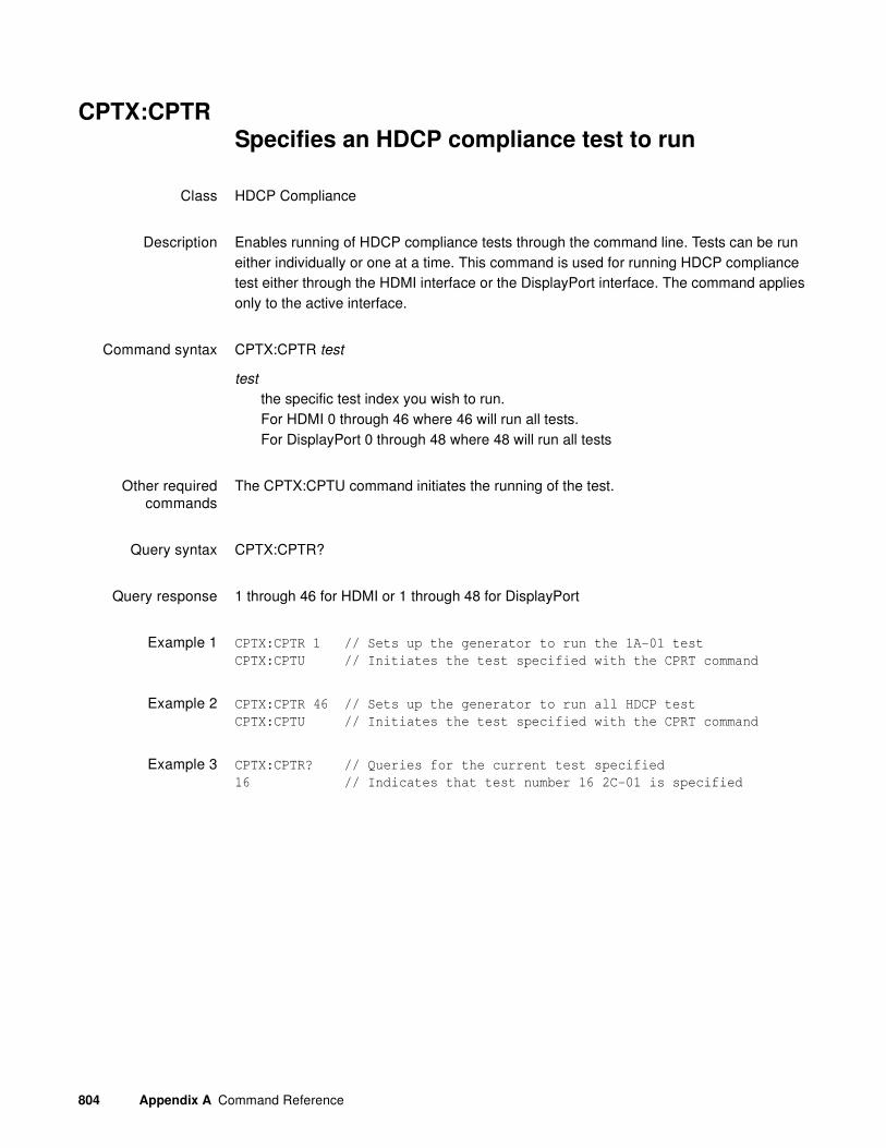
804 Appendix A Command Reference
CPTX:CPTR Specifies an HDCP compliance test to run
Class HDCP Compliance
Description Enables running of HDCP compliance tests through the command line. Tests can be run either individually or one at a time. This command is used for running HDCP compliance test either through the HDMI interface or the DisplayPort interface. The command applies only to the active interface.
Command syntax CPTX:CPTR test
test
the specific test index you wish to run.For HDMI 0 through 46 where 46 will run all tests.For DisplayPort 0 through 48 where 48 will run all tests
Other requiredcommands
The CPTX:CPTU command initiates the running of the test.
Query syntax CPTX:CPTR?
Query response 1 through 46 for HDMI or 1 through 48 for DisplayPort
Example 1 CPTX:CPTR 1 // Sets up the generator to run the 1A-01 test
CPTX:CPTU // Initiates the test specified with the CPRT command
Example 2 CPTX:CPTR 46 // Sets up the generator to run all HDCP test
CPTX:CPTU // Initiates the test specified with the CPRT command
Example 3 CPTX:CPTR? // Queries for the current test specified
16 // Indicates that test number 16 2C-01 is specified

881/882 Video Test Instrument User Guide (Rev A.38) 805
CPTX:CPTUInitiates the running of an HDCP compliance test
Class HDCP Compliance
Description Actually initiates the running of an HDCP compliance tests through the command line. This command is used with the CPTX:CPTR command which specifies which test should be run.
Command syntax CPTX:CPTU
Other requiredcommands
The CPTX:CPTR command specifies which HDCP test to run.
Example 1 CPTX:CPTR 1 // Sets up the generator to run the 1A-01 test
CPTX:CPTU // Initiates the test specified with the CPRT command
Example 2 CPTX:CPTR 46 // Sets up the generator to run all HDCP test
CPTX:CPTU // Initiates the test specified with the CPRT command

806 Appendix A Command Reference
CPTX:CRIPIndicates short or long read for HDCP
authentication
Class HDCP Compliance
Description Indicates whether the HDCP authentication will use long or short reads during the authentication. This is one of the Product Capabilities Parameters (PCP).
Command syntax CPTX:CRIP read_type
read_type
0 = short1 = long
Example 1 CPTX:CRIP 1 // Causes the test equipment to use long reads during
authentication

881/882 Video Test Instrument User Guide (Rev A.38) 807
CPTX:DUTTSpecifies the device type for an HDCP compliance
test
Class HDCP Compliance
Description Specifies which type of device that you will run an HDCP compliance test on. This is one of the Product Capabilities Parameters (PCP).
Command syntax CPTX:DUTT device
device
0 = Sink1 = Source2 = not used3 = Repeater A/B4 = Repeater 3C
Query syntax CPTX:DUTT?
Query response 0 through 4
Example CPTX:DUTT 1 // Specifies that an HDCP compliance test on a Source
will be run

808 Appendix A Command Reference
CPTX:GCTN?Queries the list of HDCP compliance tests
Class HDCP Compliance
Description Queries the list of HDCP compliance tests that can be run.
Query syntax CPTX:GCTN?
1 through 45 for HDMI1 through 47 for DisplayPort
Example CPTX:GCTN? // To list out the compliance tests
1A-01 = 1
1A-02 = 2
1A-03 = 3
1A-04 = 4
1A-05 = 5
1A-06 = 6
1A-07 = 7
1A-08 = 8
1A-09 = 9
1B-01 = 10
1B-02 = 11
1B-03 = 12
1B-04 = 13
1B-05 = 14
1B-06 = 15
2C-01 = 16
2C-02 = 17
2C-03 = 18
2C-04 = 19
3A-01 = 20
3A-02 = 21
3A-03 = 22
3A-04 = 23
3A-05 = 24
3B-01 = 25
3B-02 = 26
3B-03 = 27
3B-04 = 28
3B-05 = 29
3C-I-01 = 30
...
3C-II-09 = 45

881/882 Video Test Instrument User Guide (Rev A.38) 809
CPTX:OESSSpecifies where the Encryption enable pulse is
positioned
Class HDCP Compliance
Description Indicates where the encryption enable pulse is positioned in the vsync pulse during the 2C-04 test using the Encryption Status Tester device.
Command syntax CPTX:OESS pulse_position
pulse position
1 = encryption enable pulse is position at the beginning of the vsync pulse4 = encryption enable pulse is position at the middle of the vsync pulse5 = encryption enable pulse is position at the end of the vsync pulse
Example 1 CPTX:OESS 1 // Causes the test equipment to use long reads during
authentication

810 Appendix A Command Reference
CPTX:RKSVSpecifies number of KSVs supported by device
Class HDCP Compliance
Description Specifies the maximum number of KSVs supported by the repeater device under test for an HDCP compliance test. This is one of the Product Capabilities Parameters (PCP).
Command syntax CPTX:RKSV rksv
rksv
1 through 127
Query syntax CPTX:RKSV?
Query response 1 through 127
Example 1 CPTX:RKSV 16 // Specifies that the repeater supports 16 downstream
devices connected.
Example 2 CPTX:RKSV? // Queries to determine what the RSKV parameter is
currently set to.
1 // Indicates that the repeater only supports 1 downstream
device.
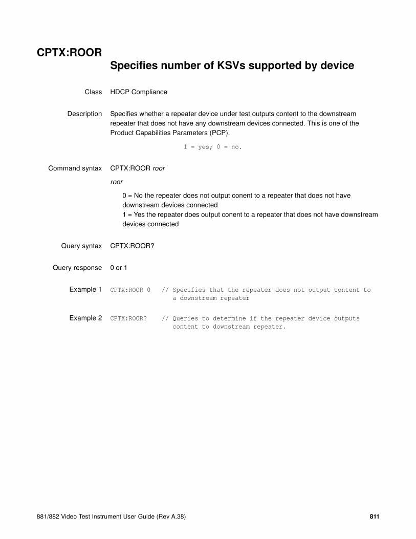
881/882 Video Test Instrument User Guide (Rev A.38) 811
CPTX:ROORSpecifies number of KSVs supported by device
Class HDCP Compliance
Description Specifies whether a repeater device under test outputs content to the downstream repeater that does not have any downstream devices connected. This is one of the Product Capabilities Parameters (PCP).
1 = yes; 0 = no.
Command syntax CPTX:ROOR roor
roor
0 = No the repeater does not output conent to a repeater that does not have downstream devices connected1 = Yes the repeater does output conent to a repeater that does not have downstream devices connected
Query syntax CPTX:ROOR?
Query response 0 or 1
Example 1 CPTX:ROOR 0 // Specifies that the repeater does not output content to
a downstream repeater
Example 2 CPTX:ROOR? // Queries to determine if the repeater device outputs
content to downstream repeater.
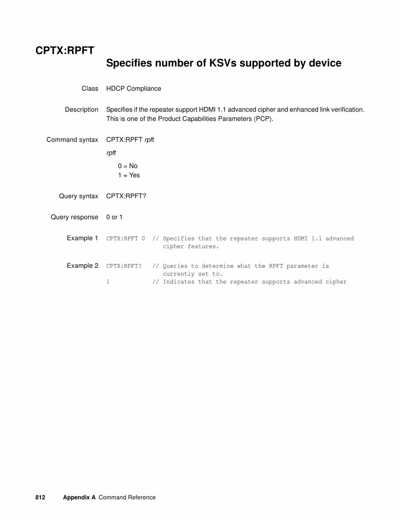
812 Appendix A Command Reference
CPTX:RPFTSpecifies number of KSVs supported by device
Class HDCP Compliance
Description Specifies if the repeater support HDMI 1.1 advanced cipher and enhanced link verification. This is one of the Product Capabilities Parameters (PCP).
Command syntax CPTX:RPFT rpft
rpft
0 = No1 = Yes
Query syntax CPTX:RPFT?
Query response 0 or 1
Example 1 CPTX:RPFT 0 // Specifies that the repeater supports HDMI 1.1 advanced
cipher features.
Example 2 CPTX:RPFT? // Queries to determine what the RPFT parameter is
currently set to.
1 // Indicates that the repeater supports advanced cipher

881/882 Video Test Instrument User Guide (Rev A.38) 813
CPTX:SDCZSpecifies how generator determines downstream
device count
Class HDCP Compliance
Description Specifies whether the 880 uses a downstream device count of 0 or the downstream device count as specified by the SKSV command. This command only applies to the 1B-01 test and the 3B-01 test when testing HDMI HDCP compliance. This is one of the Product Capabilities Parameters (PCP).
Command syntax CPTX:SDCZ device_count
device_count
0 = no downstream devices1 = uses the valued specified by the SKSV parameter
Query syntax CPTX:SDCZ?
Query response 0 or 1
Example 1 CPTX:SDCZ 0 // Specifies that there are no downstream devices connected
for the 1B-01 test and the 3B-01 test.
Example 2 CPTX:SDCZ? // Queries how to determine the number of downstream
devices.
1 // Indicates that the test will be run using the number
of downstream devices specified with the SKSV parameter.

814 Appendix A Command Reference
CPTX:SOORSpecifies number of downstream devices SOuRce
supports
Class HDCP Compliance
Description Specifies the number of downstream devices connected to a repeater that the source device under test can support. This is one of the Product Capabilities Parameters (PCP) for testing source HDMI devices when a repeater is connected.
Command syntax CPTX:SOOR devices
devices
0 = no downstream devices1 = uses the valued specified by the SKSV parameter
Query syntax CPTX:SOOR?
Query response 0 or 1
Example 1 CPTX:SOOR 0 // Specifies that there are no downstream devices connected
for the 1B-01 test and the 3B-01 test.
Example 2 CPTX:SOOR? // Queries how to determine the number of downstream
devices.
1 // Indicates that the test will be run using the number
of downstream devices specified with the SKSV parameter.
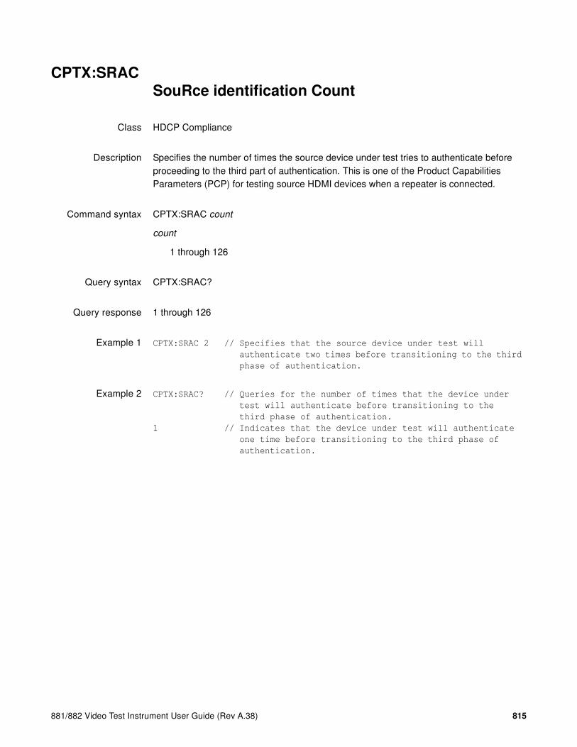
881/882 Video Test Instrument User Guide (Rev A.38) 815
CPTX:SRACSouRce identification Count
Class HDCP Compliance
Description Specifies the number of times the source device under test tries to authenticate before proceeding to the third part of authentication. This is one of the Product Capabilities Parameters (PCP) for testing source HDMI devices when a repeater is connected.
Command syntax CPTX:SRAC count
count
1 through 126
Query syntax CPTX:SRAC?
Query response 1 through 126
Example 1 CPTX:SRAC 2 // Specifies that the source device under test will
authenticate two times before transitioning to the third
phase of authentication.
Example 2 CPTX:SRAC? // Queries for the number of times that the device under
test will authenticate before transitioning to the
third phase of authentication.
1 // Indicates that the device under test will authenticate
one time before transitioning to the third phase of
authentication.

816 Appendix A Command Reference
CROSdraw a centered CROSs
Class Custom image primitive
Description Draws a large centered cross that fills the active video area. The vertical line is 2 pixels thick if the format has an even number of active pixels. The horizontal line is 2 pixels thick if the format has an even number of active lines. The primitive uses a single parameter, the color of the cross.
Command syntax CROS color
color
available colors
Other requiredcommands
The FMTU command instructs the generator to use the new setting. The ALLU command updates hardware to the new setting and redraws the test image.
Example CROS magenta // Draw a large cross in the center of the active video
ALLU // Update hardware to current buffer contents

881/882 Video Test Instrument User Guide (Rev A.38) 817
CSPGComposite Sync Pulse Gate
Class Format parameter setting - Synchronization
Description Enables and disables all of the digital composite sync outputs when digital composite sync is selected via the SSST command (SSST = 3). The CSPG? query returns the current setting of CSPG.
Command syntax CSPG mode
mode
0 = OFF
1 = ON
Query syntax CSPG?
Query response 0 or 1
Other requiredcommands
In order to use digital composite sync, it must be selected with the SSST command. The FMTU command instructs the generator to use the new setting. The ALLU command updates hardware to the new setting and redraws the test image.
Example CSPG 1 // Enable dig comp sync in buffer
SSST 2 // Choose digital comp sync type in buffer
FMTU // Update hardware to current buffer contents
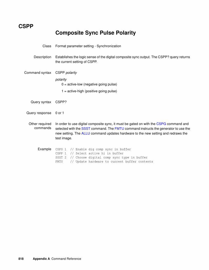
818 Appendix A Command Reference
CSPPComposite Sync Pulse Polarity
Class Format parameter setting - Synchronization
Description Establishes the logic sense of the digital composite sync output. The CSPP? query returns the current setting of CSPP.
Command syntax CSPP polarity
polarity
0 = active-low (negative going pulse)
1 = active-high (positive going pulse)
Query syntax CSPP?
Query response 0 or 1
Other requiredcommands
In order to use digital composite sync, it must be gated on with the CSPG command and selected with the SSST command. The FMTU command instructs the generator to use the new setting. The ALLU command updates hardware to the new setting and redraws the test image.
Example CSPG 1 // Enable dig comp sync in buffer
CSPP 1 // Select active hi in buffer
SSST 2 // Choose digital comp sync type in buffer
FMTU // Update hardware to current buffer contents

881/882 Video Test Instrument User Guide (Rev A.38) 819
CXARContent Aspect Ratio
Class Format parameter setting - Active Video
Description Sets the aspect ratio of the source image content.
Command syntax CXAR aspect_ratio
aspect_ratio
0.75 to 2.39
The following table provides a listing of established aspect ratios.
Aspect Ratio Symbol Description Examples
0.750 OT or T90 Television Portrait 3x4, 480x640, 600x800, 768x1024, 960x1280, 1200x1600
0.800 OG or G90 Workstation Graphics Portrait
4x5, 1024x1280, 1280x1600
1.000 Q Quadrate, "Square” 1x1, 512x512, 1024x10241.250 G Workstation Graphics 5x4, 1280x1024, 1600x1280
1.333… T (A)1
1. The letters in parenthesis are the letters that we used to use, before we updated our aspect ratio symbols for compatibiliity with existing film industry standards (i.e. the symbols defined in SMPTE RP40).
SDTV / Silent Film 4x3, 640x480, 800x600, 1024x768, 1280x960, 1600x1200
˜1.37 C (B)1 Academy2 “Classic” with sound
2. In 1932, the shape of film was changed from 1.33:1 to 1.37:1 in order to better accommodate the new optical soundtrack that was added a few years earlier. This slightly wider shape is the true aspect ratio of “classic” film. The aperture is commonly referred to as “Academy” and was the shape of the vast majority of U.S. films produced until the 1950s.
˜4x3, 0.825x0.602 SMPTE RP40 35mm "C"
1.444… I IMAX™ 13x9, IMAX™1.500 V (T)1 Vista Vision™ 3x2, 1152x768 Apple Computer
(uncropped) Vista Vision™1.555… M (V)1 Mid 14x9, AFD Shoot and Protect (half-way
between 4x3 and 16x9)1.600 D 16 Decimal 16x10, 1728x1080, 1280x800, see VESA
CVT 1.01.666… E European Film, "1.66 5x3, 1200x720, 1280x768, 1800x10801.750 Z Old Film 7x4, Old Metro-Goldwyn-Mayer and Disney
Films1.777… H HDTV 16x9, 1280x720,1920x1080
˜1.85 A (F)1 Film Standard (USA) ˜13x7, 1280x692, 1920x1038, 0.825x0.446 SMPTE RP40 35mm "A"
2.000 U Univisum™ 2x1, 1280x640, 1920x960˜2.20 F (M)1 “Flat”, MPEG "20x9” "˜11x5, 1280x582, 1920x874, 1.912x0.870
SMPTE RP91 70mm˜2.39 B (C)1 Anamorphic Cinema,
“2.35”3
3. Sometimes called “2.35”, which was the aspect ratio before it was changed to 2.39:1 in 1971 to keep splices from showing up in the projected image.
˜12x5, 1280x536, 1920x804, 1.650x0.690 SMPTE RP40 35mm "B"

820 Appendix A Command Reference
Related commands EXAR, SXAR
Example CXAR 1.33 //Sets 4:3 picture aspect ratio for source content
FMTU

881/882 Video Test Instrument User Guide (Rev A.38) 821
DACADigital Audio Channels Available
Class Format parameter setting - Audio signal
Description Specifies which audio channels are active.
Command syntax DACA mask
mask
0 to 3, based on following table.
Normally, each type of audio content is assigned to a particular channel and is always output on that channel when present. There is one exception to this rule: rear center (RC) content is switched from channel 5 to 7 whenever rear left (RL) content is simultaneously present. To simplify this, RC content is thus treated as if it were two different types of content: RC5 and RC7. When RL content is not present, RC content is output on channel 5 as RC5 content. When RL content is present, RC content is output on channel 7 as RC7 content.
Setting DACA will automatically set DAXA and XAUD:CA parameters to a corresponding value (see table below).
Note: If DACA is set to a value not found in the table above, then other parameters will not
be automatically set and an error will be generated if the format is loaded while this
condition exists.
mask
0 to 255 (based on the value in the table below).Notes:
• Setting DACA will automatically set DAXA and XAUD:CA parameters to a corresponding value (see table below). However, in the case of DACA values 243, 247, 251, and 255, two sets of DAXA and XAUD:CA values are possible. In this case, DAXA and XAUD:CA settings will be based on those highlighted (in grey) in the table.
• If DACA is set to a value not found in the table above, then other parameters will not be automatically set and an error will be generated if the format is loaded while this condition exists.
Channel 1 2
Bit 0 1
Value 1 2
DACA 3
DAXA 3
XAUD:CA 0

822 Appendix A Command Reference
Example DACA 3 //specifies audio channels 1 and 2
DACG 3 //gates audio channels 1 and 2
FMTU
Related commands DACG

881/882 Video Test Instrument User Guide (Rev A.38) 823
DACGDigital Audio Channel Gate
Class Format parameter setting - Audio signal
Description Specifies which audio channels are gated (on).
Command syntax DACG mask
mask
0 to 3 (based on the value in the table below).
Example DACA 3 //specifies audio channels 1 and 2
DACG 3 //gates audio channels 1 and 2
FMTU
Related commands DACA
Channel 1 2
Bit 0 1Value 1 2

824 Appendix A Command Reference
DADGDigital Audio Down-mix Gate
Class Format parameter setting - Audio signal
Description Enables or disables downmixing of an audio signal. This sets the DM_I parameter of the Audio InfoFrame (as specified in EIA/CEA-861-B, table 24).
Command syntax DADG mode
mode
1 = enable
0 = disable
Example DADG 1
FMTU
IFGU
Related commands XAUD (DMI parameter), DALS

881/882 Video Test Instrument User Guide (Rev A.38) 825
DALSDigital Audio Level Shift Value
Class Format parameter setting - Audio signal
Description Sets the level shift value (in decibels) for downmixing of the audio signal. This sets the LSV parameter of the Audio InfoFrame (as specified in EIA/CEA-861-B, table 23).
Command syntax DALS x
x
0 - 15 (dB)
Example DALS 5
FMTU
IFGU
Related commands XAUD (LSV parameter), DADG

826 Appendix A Command Reference
DASIDigital Audio Signal Interface
Class Format parameter setting - Audio signal
Description Sets the digital audio signal interface.
Command syntax DASI interface
interface
0 = none
1 = SPDIF
Example DASI 1
IFGU

881/882 Video Test Instrument User Guide (Rev A.38) 827
DASTDigital Audio Signal Type
Class Format parameter setting - Audio signal
Description Sets the digital audio signal type for an audio signal. This sets the CT parameter of the Audio InfoFrame (as specified in EIA/CEA-861-B, table 19).
Command syntax DAST type
type
0 = void
1 = IEC 60958-3 Consumer LPCM
Example DAST 1
IFGU
Related commands XAUD (CT parameter)

828 Appendix A Command Reference
DATEDATE
Class System parameter
Description Sets the system date in the 882.
Command syntax DATE mm dd yyyy
mm
01 - 12
dd
01 - 31
yyyy
2000 -
Query syntax DATE?
mm dd yyyy
Example 1 DATE 09 11 2008
Example 2 DATE?
01 11 2008
Related commands TIME

881/882 Video Test Instrument User Guide (Rev A.38) 829
DAXADigital Audio Content Available
Class Format parameter setting - Audio signal
Description Specifies which speaker locations are available (present).
Command syntax DAXA mask
mask
0 to 3 (based on the value in the table below).
Normally, each type of audio content is assigned to a particular channel and is always
output on that channel when present. There is one exception to this rule: rear center (RC) content is switched from channel 5 to 7 whenever rear left (RL) content is simultaneously present. To simplify this, RC content is thus treated as if it were two different types of content: RC5 and RC7. When RL content is not present, RC content is output on channel 5 as RC5 content. When RL content is present, RC content is output on channel 7 as RC7 content.
Setting DAXA will automatically set DACA and XAUD:CA parameters to a corresponding value (see table below). However, this method should not be used to gate channels. Instead, DAXG should be used after all of the available channels have been selected.
Note: If DAXA is set to a value not found in the table above, then other parameters will not
be automatically set and an error will be generated if the format is loaded while this
condition exists.
Example DAXA 3 //specifies FR and FL as having audio content
DAXG 3 //gates FR and FL content
FMTU
Related commands DAXG
Content FR FL
Bit 1 0Value 2 1
DAXA 3
DACA 3
XAUD:CA 0

830 Appendix A Command Reference
DAXGDigital Audio Content Gate
Class Format parameter setting - Audio signal
Description Specifies which speaker locations are gated (on).
Command syntax DAXG mask
mask
0 to 3 (based on the value in the table below).
Example DAXA 3 //specifies FR and FL as having audio content
DAXG 3 //gates FR and FL content
FMTU
Related commands DAXA
Content FR FL
Bit 1 0
Value 2 1

881/882 Video Test Instrument User Guide (Rev A.38) 831
DCBMDisplay Code Bit Mask
Class Direct processor control
Description Sets the 4-bit binary bit mask used by the DCRD? query. The mask is entered as the decimal equivalent of a 4-bit binary number. The binary number represents the masking of the individual sense lines from M3 (MSB) to M0 (LSB). The DCBM? query returns the current setting of DCBM.
Command syntax DCBM mask
mask
0 = 0 0 0 0 8 = 1 0 0 0
1 = 0 0 0 1 9 = 1 0 0 1
2 = 0 0 1 0 10 = 1 0 1 0
3 = 0 0 1 1 11 = 1 0 1 1
4 = 0 1 0 0 12 = 1 1 0 0
5 = 0 1 0 1 13 = 1 1 0 1
6 = 0 1 1 0 14 = 1 1 1 0
7 = 0 1 1 1 15 = 1 1 1 1
Query syntax DCBM?
Query response mask
Other requiredcommands
The FMTU command instructs the generator to use the new setting. The ALLU command updates hardware to the new setting and redraws the test image.
Example DCBM 7 // Set mask to read sense lines 0, 1 and 2 only
FMTU // Update hardware to current buffer contents

832 Appendix A Command Reference
DCEXDisplay Code EXpected
Class Format parameter settings
Description Sets up the display code that is expected from a display connected to the generator. The code is determined by one or more sense lines being connected to ground by the display. Many video controller cards for the Apple Macintosh II and VGA type cards for the IBM-PC sample the status of the display code sense lines. The information then sets up one of several different operating modes to match a particular display. An improper display code may make the controller card or display appear to malfunction.
The DCEX? query first performs a logical AND operation with the display code bit mask and the actual display code that's sensed. The decimal equivalent of the result then is returned. The mask is set with the DCEX command.
The expected setting and the actual result are both shown in the Format test image. They have no effect how a given format generates a set of test signals.
Command syntax DCEX code
code
0 = 0 0 0 0 8 = 1 0 0 0
1 = 0 0 0 1 9 = 1 0 0 1
2 = 0 0 1 0 10 = 1 0 1 0
3 = 0 0 1 1 11 = 1 0 1 1
4 = 0 1 0 0 12 = 1 1 0 0
5 = 0 1 0 1 13 = 1 1 0 1
6 = 0 1 1 0 14 = 1 1 1 0
7 = 0 1 1 1 15 = 1 1 1 1
Query syntax DCEX?
Query response code
Other requiredcommands
The FMTU command instructs the generator to use the new setting. The ALLU command updates hardware to the new setting and redraws the test image.
Example DCBM 7 // Set mask to read sense lines 0, 1 and 2 only
DCEX 5 // Only lines 0 and 1 should be grounded
FMTU // Update hardware to current buffer contents

881/882 Video Test Instrument User Guide (Rev A.38) 833
DCPG (OUT1:DCPG, OUT2:DCPG, AV:DCPG, VGA:DCPG)Data Channel Power Gate
Class EDID and DDC control
Description Enables and disables the +5V power signal at the specified connector by writing to a latch. The [OUT1|OUT2|AV|VGA]:DCPG? query reads back the latched bit at the specified connector.
Command syntax DCPG option
connector:DCPG option
option
0 = disable +5V power
1 = enable +5V power
connector
OUT1, OUT2 = HDMI OUT 1 or HDMI OUT 2 connector
AV = SPDIF/AV connector
VGA = VGA connector
Query syntax DCPG
connector:DCPG?
connector
OUT1, OUT2 = HDMI OUT 1 or HDMI OUT 2 connector
AV = SPDIF/AV connector
VGA = VGA connector
Example 1 OUT1:DCPG 0 // disables +5V power on the HDMI output 1
DCPU // initiates the command
Example 2 VGA:DCPG 1 // enables +5V power on the VGA output
Example 3 DCPG 1 // enables +5V power on all connectors
DCPU // initiates the command
Example 4 OUT2:DCPG? // queries +5V power on HDMI output 2
Example 5 DCPG? // reads back the logical AND of all connectors

834 Appendix A Command Reference
Related commands DCPX? (OUT1:DCPX?, OUT2:DCPX, AV:DCPX?, VGA:DCPX?)

881/882 Video Test Instrument User Guide (Rev A.38) 835
DCPX? (OUT1:DCPX?, OUT2:DCPX, AV:DCPX?, VGA:DCPX?)Data Channel Power Overcurrent
Class EDID and DDC control
Description Queries the status of the 5V display data channel (DDC) power level at the specified output connector.
Query syntax DCPX?
connector
OUT1, OUT2 = HDMI OUT 1 or HDMI OUT 2 ports
AV = SPDIF/AV connector
VGA = VGA connector
Returns 0 or 1
0 = OK
1 = overcurrent (for example, shorted)
Example 1 OUT1:DCPX? // queries the DDC power level of HDMI output connector 1
0
Example 2 OUT2:DCPX? // queries the DDC power level of HDMI output connector 2
1
Example 3 DCPX? // reads back the logical AND of all connectors
0
Related commands DCPG (OUT1:DCPG, OUT2:DCPG, AV:DCPG, VGA:DCPG)

836 Appendix A Command Reference
DDCV?DDC Version supported
Class EDID and DDC control
Description The DDCV? query returns a status flag indicating if the generator hardware supports VESA DDC communications.
Query syntax DDCV?
Query response 0 or 1
0 = no DDC support
1 = DDC supported
Example DDCV? // Return DDC support information

881/882 Video Test Instrument User Guide (Rev A.38) 837
DELXslider image DELta X
Class Image editor control
Description Sets the amount of horizontal shift that occurs for each step of the SlideG and SlideRGB built-in images. The command is also used to set the horizontal size of the white patch used in the Regulate image. The DELX? Query returns the current DELX setting.
Command syntax DELX delta_x
delta_x
horizontal distance in pixels
Query syntax DELX?
Query response delta_x
Example DELX 8 // Set H shift to 8 pixels per step
DELY 3 // Set V shift to 3 pixels per step
DWEL 2 // Display each step for 2 frames
IMGL “SlideG” // Select Image that uses DELX and DELY
IMGU // Draw the Image
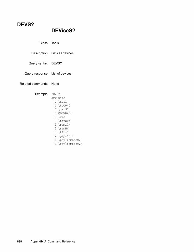
838 Appendix A Command Reference
DEVS?DEViceS?
Class Tools
Description Lists all devices.
Query syntax DEVS?
Query response List of devices
Related commands None
Example DEVS?
drv name
0 \null
1 \tyCo\0
3 \card0
5 QDEW023:
6 \vio
7 \tgtsvr
3 \ram20K
3 \ramNV
3 \tffs0
2 \pipe\cli
8 \pty\remote0.S
9 \pty\remote0.M
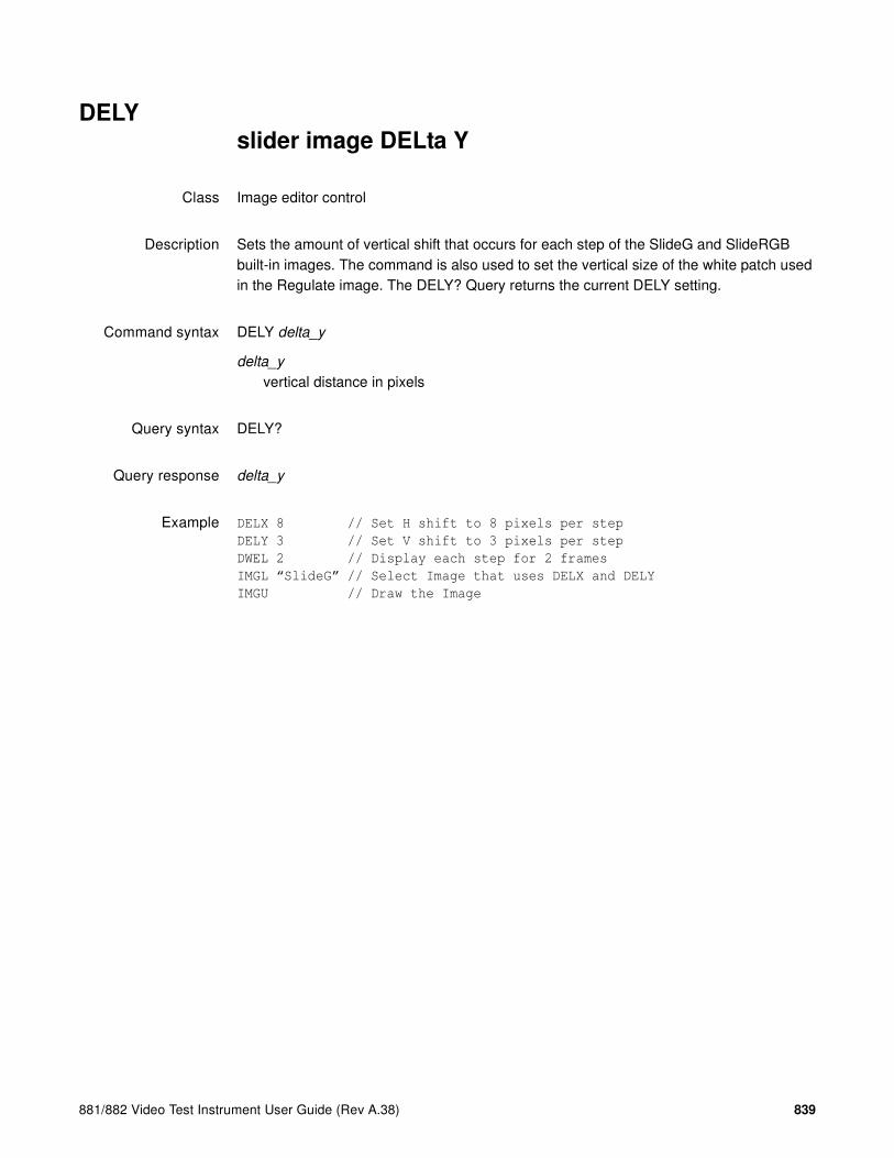
881/882 Video Test Instrument User Guide (Rev A.38) 839
DELYslider image DELta Y
Class Image editor control
Description Sets the amount of vertical shift that occurs for each step of the SlideG and SlideRGB built-in images. The command is also used to set the vertical size of the white patch used in the Regulate image. The DELY? Query returns the current DELY setting.
Command syntax DELY delta_y
delta_y
vertical distance in pixels
Query syntax DELY?
Query response delta_y
Example DELX 8 // Set H shift to 8 pixels per step
DELY 3 // Set V shift to 3 pixels per step
DWEL 2 // Display each step for 2 frames
IMGL “SlideG” // Select Image that uses DELX and DELY
IMGU // Draw the Image

840 Appendix A Command Reference
DIDAeDID save As file
Class EDID and DDC control
Description Saves an EDID to the filename specified by filename.
Command syntax DIDA filename
filename
a valid MS-DOS filename (8 characters minus any extension)
Example This example loads an EDID file, edits it, and saves the changes under a new filename, myedid8.
DIDL myedid7 // loads the EDID file named myedid7
DIDB // begins an edid editing session
XDID 19 A E88A82A0564796240F48 // edits EDID at 19 for 10 (0x0A) bytes
DIDE // ends an edid editing session
DIDA myedid8 // saves the changes to the filename myedid8
Related commands DIDB, DIDE, DIDK, DIDL, TASK?, DIDP, DIDQ, DIDS, DIDU, EDA<port>:GDID, EDA<port>:PDID, XDID
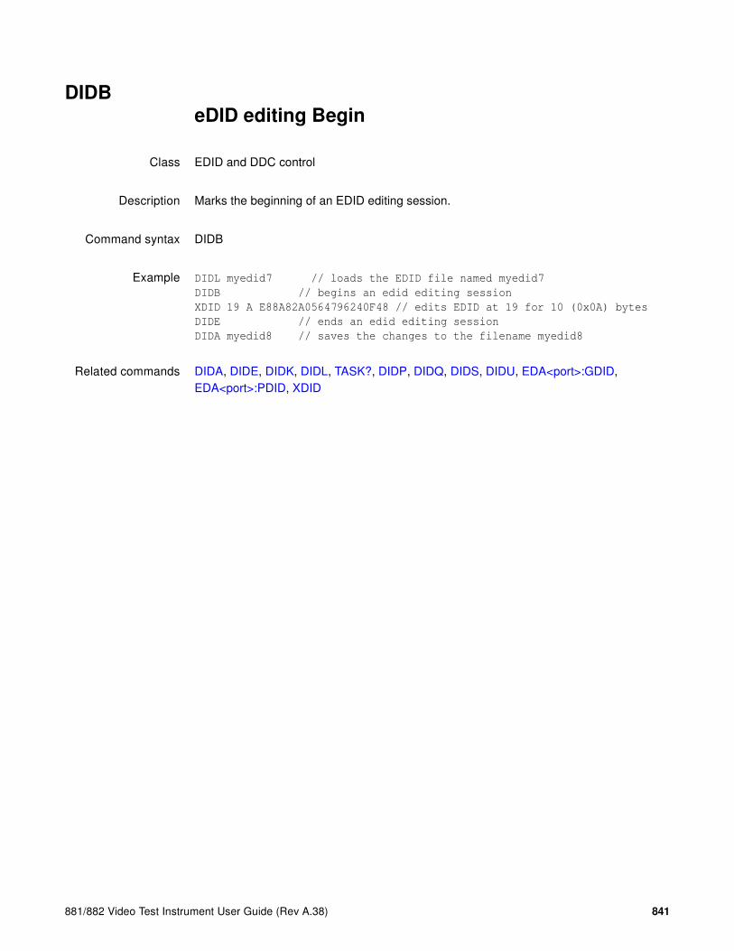
881/882 Video Test Instrument User Guide (Rev A.38) 841
DIDBeDID editing Begin
Class EDID and DDC control
Description Marks the beginning of an EDID editing session.
Command syntax DIDB
Example DIDL myedid7 // loads the EDID file named myedid7
DIDB // begins an edid editing session
XDID 19 A E88A82A0564796240F48 // edits EDID at 19 for 10 (0x0A) bytes
DIDE // ends an edid editing session
DIDA myedid8 // saves the changes to the filename myedid8
Related commands DIDA, DIDE, DIDK, DIDL, TASK?, DIDP, DIDQ, DIDS, DIDU, EDA<port>:GDID, EDA<port>:PDID, XDID

842 Appendix A Command Reference
DIDEeDID editing End
Class EDID and DDC control
Description Marks the end of an EDID editing session.
Command syntax DIDE
Example DIDL myedid7 // loads the EDID file named myedid7
DIDB // begins an edid editing session
XDID 19 A E88A82A0564796240F48 // edits EDID at 19 for 10 (0x0A) bytes
DIDE // ends an edid editing session
DIDA myedid8 // saves the changes to the filename myedid8
Related commands DIDA, DIDB, DIDK, DIDL, TASK?, DIDP, DIDQ, DIDS, DIDU, EDA<port>:GDID, EDA<port>:PDID, XDID

881/882 Video Test Instrument User Guide (Rev A.38) 843
DIDKeDID Kill file
Class EDID and DDC control
Description Deletes the EDID file specified by filename.
Command syntax DIDK path/filename
path/filename
The directory path and valid MS-DOS filename (8 characters minus any extension) of the file to be deleted. If the file to be deleted is in the default path, then path/ may be omitted.
Example This example deletes the file myedid1 in the /userdata directory on the generator.
DIDK /tffs0/library/userdata/myedid1
Related commands DIDA, DIDB, DIDE, DIDL, TASK?, DIDP, DIDQ, DIDS, DIDU, EDA<port>:GDID, EDA<port>:PDID, XDID

844 Appendix A Command Reference
DIDLeDID Load from file
Class EDID and DDC control
Description Loads an EDID from a file on the generator.
Command syntax DIDL path/filename
path/filename
The directory path and valid MS-DOS filename (8 characters minus any extension) of the file to be loaded. If the file to be loaded is in the default path, then path/ may be omitted.
Query syntax DIDL?
Query response The name of the file currently in the buffer.
Example This example loads the EDID from the file myedid1 in the /userdata directory.
DIDL /tffs0/library/userdata/myedid1
Related commands DIDA, DIDB, DIDE, DIDK, TASK?, DIDP, DIDQ, DIDS, DIDU, EDA<port>:GDID, EDA<port>:PDID, XDID

881/882 Video Test Instrument User Guide (Rev A.38) 845
DIDNeDID New file
Class EDID and DDC control
Description Creates a new EDID file with the name specified by filename.
Command syntax DIDN path/filename
path/filename
The directory path and valid MS-DOS filename (8 characters minus any extension) of the file to be created. If the file is to be created in the default path, then path/ may be omitted.
Example This example creates the file myedid1 in the /userdata directory on the generator.
DIDN /tffs0/library/userdata/myedid1
Related commands DIDA, DIDB, DIDE, DIDK, DIDL, DIDP, DIDQ, DIDS, DIDU, EDA<port>:GDID, EDA<port>:PDID, XDID
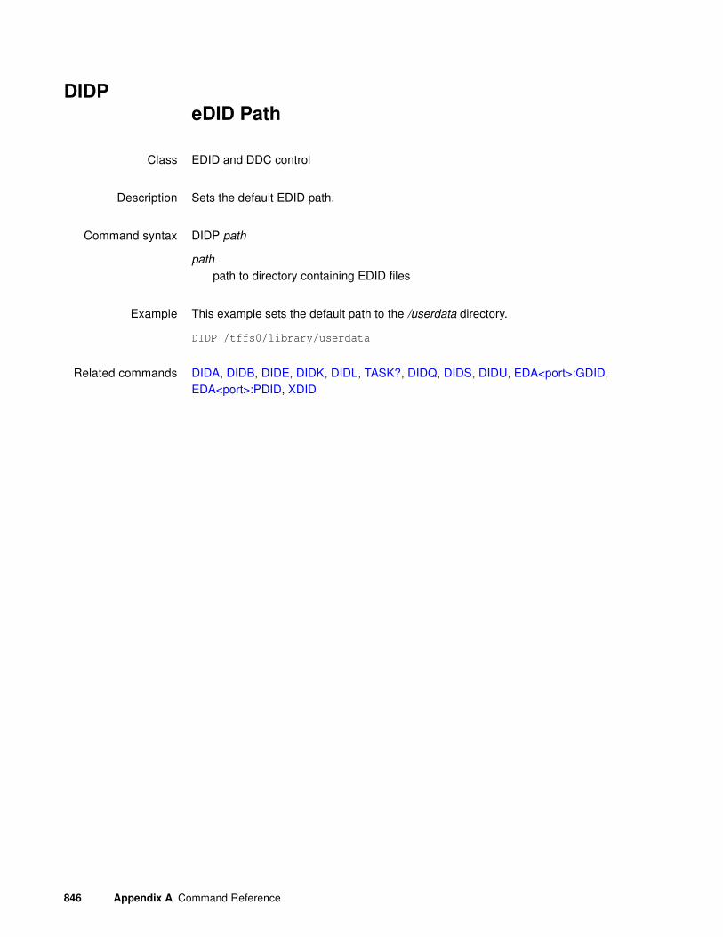
846 Appendix A Command Reference
DIDPeDID Path
Class EDID and DDC control
Description Sets the default EDID path.
Command syntax DIDP path
path
path to directory containing EDID files
Example This example sets the default path to the /userdata directory.
DIDP /tffs0/library/userdata
Related commands DIDA, DIDB, DIDE, DIDK, DIDL, TASK?, DIDQ, DIDS, DIDU, EDA<port>:GDID, EDA<port>:PDID, XDID

881/882 Video Test Instrument User Guide (Rev A.38) 847
DIDQeDID file Query
Class EDID and DDC control
Description Returns EDID filenames from the list of all the EDID filenames stored on the generator, beginning at startIndex and ending at endIndex. The filenames are kept in alphanumeric order.
Query syntax DIDQ? startIndex endIndex
startIndex
positive integer number
endIndex
positive integer number
Query response List of filenames.
Example This example returns the first 10 EDID filenames.in the default directory.
DIDQ? 1 10
Related commands DIDA, DIDB, DIDE, DIDK, DIDL, TASK?, DIDP, DIDS, DIDU, EDA<port>:GDID, EDA<port>:PDID, XDID

848 Appendix A Command Reference
DIDSeDID Save to file
Class EDID and DDC control
Description Saves an EDID to the filename given by DIDN.
Command syntax DIDS
Example This example loads an EDID file, edits it, and saves the changes to the same filename.
DIDL myedid7 // loads the EDID file named myedid7
DIDB // begins an edid editing session
XDID 19 A E88A82A0564796240F48 // edits EDID at 19 for 10 (0x0A) bytes
DIDE // ends an edid editing session
DIDS // saves the changes to myedid7
Related commands DIDA, DIDB, DIDE, DIDK, DIDL, TASK?, DIDP, DIDQ, DIDU, EDA<port>:GDID, EDA<port>:PDID, XDID

881/882 Video Test Instrument User Guide (Rev A.38) 849
DIDUeDID Use
Class EDID and DDC control
Description Updates hardware with current EDID contents. This command also causes a hot plug pulse on the hot plug detect lead.
Command syntax DIDU
Query syntax DIDU?
Query response The current EDID file in use.
Example This example edits part of an EDID and updates the hardware with the current buffer contents.
XDID 8 3 DE33FF
DIDU
Related commands DIDA, DIDB, DIDE, DIDK, DIDL, TASK?, DIDP, DIDQ, DIDS, EDA<port>:GDID, EDA<port>:PDID, XDID
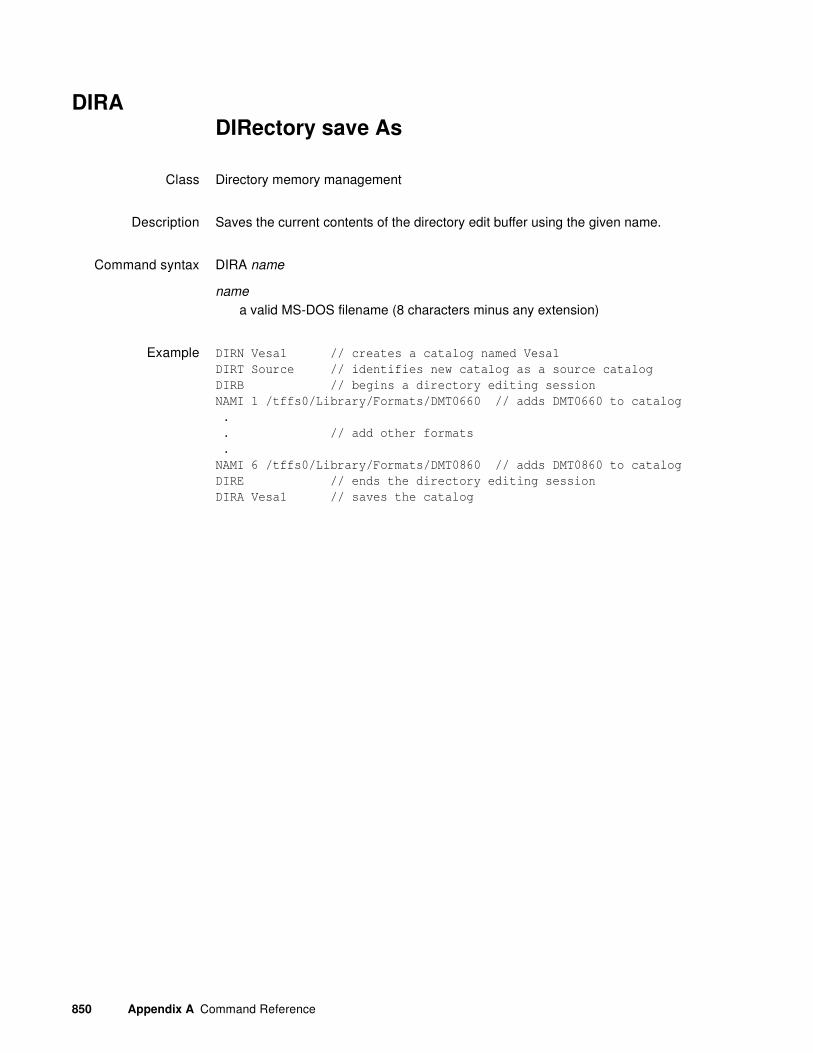
850 Appendix A Command Reference
DIRADIRectory save As
Class Directory memory management
Description Saves the current contents of the directory edit buffer using the given name.
Command syntax DIRA name
name
a valid MS-DOS filename (8 characters minus any extension)
Example DIRN Vesa1 // creates a catalog named Vesa1
DIRT Source // identifies new catalog as a source catalog
DIRB // begins a directory editing session
NAMI 1 /tffs0/Library/Formats/DMT0660 // adds DMT0660 to catalog
.
. // add other formats
.
NAMI 6 /tffs0/Library/Formats/DMT0860 // adds DMT0860 to catalog
DIRE // ends the directory editing session
DIRA Vesa1 // saves the catalog

881/882 Video Test Instrument User Guide (Rev A.38) 851
DIRBDIRectory editing Begin
Class Directory memory management
Description Marks the beginning of a directory editing session. This command does nothing in the current firmware version, but is used for compatibility with future versions of firmware.
Command syntax DIRB
Other requiredcommands
Use either a DIRL command to load an existing directory or a DIRN command to create a new directory. Use DIRE when ending the editing session.
Example DIRN // Initialize directory edit buffer
DIRB // Start directory editing session
// One or more directory editing commands ...
DIRE // End directory editing session
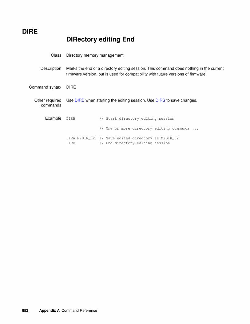
852 Appendix A Command Reference
DIREDIRectory editing End
Class Directory memory management
Description Marks the end of a directory editing session. This command does nothing in the current firmware version, but is used for compatibility with future versions of firmware.
Command syntax DIRE
Other requiredcommands
Use DIRB when starting the editing session. Use DIRS to save changes.
Example DIRB // Start directory editing session
// One or more directory editing commands ...
DIRA MYDIR_02 // Save edited directory as MYDIR_02
DIRE // End directory editing session

881/882 Video Test Instrument User Guide (Rev A.38) 853
DIRKDIRectory Kill
Class Directory memory management
Description Deletes a directory by name. The query returns a one if the named directory can be deleted. If directory is read-only or nonexistent, the query returns a zero.
Command syntax DIRK name
name
a valid MS-DOS filename (8 characters minus any extension)
Query syntax DIRK? name
name
a valid MS-DOS filename (8 characters minus any extension)
Query response 0 or 1
Example DIRK MY_DIR // Delete directory called "MY_DIR"

854 Appendix A Command Reference
DIRLDIRectory Load
Class Directory memory management
Description Copies the directory having a name equal to name from directory memory into the directory edit buffer. The query returns a one if the named directory can be loaded; otherwise, a zero is returned.
Note: Use the FMTP, IMGP and SEQP commands to select which directory is used for the
format, image, and sequence selection lists.
Command syntax DIRL name
name
a valid MS-DOS filename (8 characters minus any extension)
Query syntax DIRL? name
name
a valid MS-DOS filename (8 characters minus any extension)
Query response 0 or 1
Example DIRL MY_DIR // Load "MY_DIR" directory in edit buffer

881/882 Video Test Instrument User Guide (Rev A.38) 855
DIRNDIRectory New
Class Directory memory management
Description Initializes the directory edit buffer. The name name is assigned as the directory's name. The query will return the name that has been assigned as the directory's name.
Command syntax DIRN name
name
optional valid MS-DOS filename (8 characters minus any extension)
Query syntax DIRN?
Example DIRN // Init edit buffer without assigning a new name
or
DIRN MY_DIR // Init edit buffer with name of "MY_DIR"

856 Appendix A Command Reference
DIRPDIRectory Path
Class Directory memory management
Description Sets the current directory path name. The query will return the current directory path name.
Command syntax DIRP name
name
a valid MS-DOS filename (8 characters minus any extension)
Query syntax DIRP?
Query response name
Example DIRP DIRPTH01 // Set directory path to DIRPTH01

881/882 Video Test Instrument User Guide (Rev A.38) 857
DIRQ?DIRectory Query pointer
Class Directory memory management
Description Returns the number directory names from the list of all the directory names stored in directory memory beginning at index. The directories are kept in alphanumeric order.
Query syntax DIRQ? index number
index
positive integer number
number
positive integer number
Query response List of specified directory names
Example DIRQ? 1 5 // List the first five directories in memory
or
DIRQ? 1 9999 // List all directories in memory

858 Appendix A Command Reference
DIRSDIRectory Save
Class Directory memory management
Description Saves the current directory edit buffer contents into directory memory using the current name of the directory in the edit buffer.
Example DIRN NTSCFMT // creates a catalog named NTSCFMT
DIRT Source // identifies new catalog as a source catalog
DIRB // begins a directory editing session
NAMI 1 /tffs0/Library/Formats/NTSC // adds NTSC to catalog
DIRE // ends the directory editing session
DIRS // saves the catalog

881/882 Video Test Instrument User Guide (Rev A.38) 859
DIRTDIRectory Type
Class Directory memory management
Description Specifies a directory (catalog) type that is being created.
Command syntax DIRT type
Command response type
Directory type such as: Source, SourceLib, Content, ContentLib
Query syntax DIRT?
Query response type
The current directory type defined such as: Source, SourceLib, Content, ContentLib
Example DIRN NTSCFMT // creates a catalog named NTSCFMT
DIRT Source // identifies new catalog as a source catalog
DIRB // begins a directory editing session
NAMI 1 /tffs0/Library/Formats/NTSC // adds NTSC to catalog
.
. // add other formats
.
NAMI 6 /tffs0/Library/Formats/NTSC-J // adds NTSC-J to catalog
DIRE // ends the directory editing session
DIRS // saves the catalog
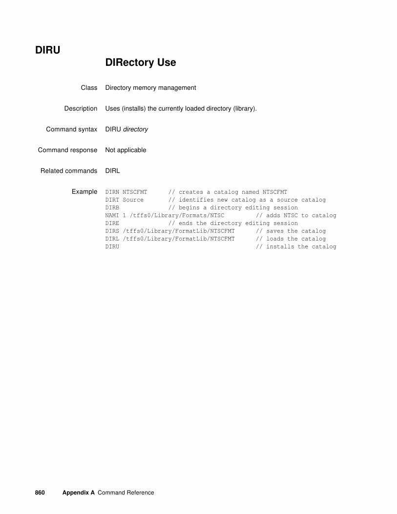
860 Appendix A Command Reference
DIRUDIRectory Use
Class Directory memory management
Description Uses (installs) the currently loaded directory (library).
Command syntax DIRU directory
Command response Not applicable
Related commands DIRL
Example DIRN NTSCFMT // creates a catalog named NTSCFMT
DIRT Source // identifies new catalog as a source catalog
DIRB // begins a directory editing session
NAMI 1 /tffs0/Library/Formats/NTSC // adds NTSC to catalog
DIRE // ends the directory editing session
DIRS /tffs0/Library/FormatLib/NTSCFMT // saves the catalog
DIRL /tffs0/Library/FormatLib/NTSCFMT // loads the catalog
DIRU // installs the catalog

881/882 Video Test Instrument User Guide (Rev A.38) 861
DNUMDisplay sequence step NUMbers
Class Sequence editor commands
Description Enables and disables the addition of the sequence step number to the displayed test image when running a sequence.
Command syntax DNUM mode
mode
0, 1 or 2
Query syntax DNUM?
Query response mode
Example DNUM 1 // Enable the displaying of the sequence step #

862 Appendix A Command Reference
DPGUData Island Packet Generator Use
Class Data Island Packet
Description Updates the hardware with content of the current Data Island packet.
Command syntax DPGU
Related Commands DPTG
Example 1 Turn mute on:
XGCP 1 0
DPTG 7
DPTR 1
DPGU
Example 2 Read mute status:
R:MUTE?
R:1
Example 3 Turn mute off:
XGCP 0 1
DPTG 7
DPTR 1
DPGU
Example 4 Read mute status:
R:MUTE?
R:0
Example 5 Change the N value to 6000, and let hardware determine CTS value:
XACR 6000
DTPG 7
DPGU
// You can read N and CTS value at the reciever for verification.
Example 6 Change the N value to 6000, and CTS to 8000:
XACR 6000 8000
DTPG 7
DPGU
// You can read N and CTS value at the reciever for verification.

881/882 Video Test Instrument User Guide (Rev A.38) 863
Example 7 Turn audio off:
DPTG 3
DPGU
Example 8 Turn audio on:
DPTG 7
DPGU

864 Appendix A Command Reference
DPTGData Island Packet Type Gate
Class Data Island Packet
Description Gates on or off the assigned packet type (Audio Sample, Audio Clock Regeneration, or General Control Packet) to be updated by the hardware and sent to the receiver.
Gating Audio Sample packets on and off also enables and disables the audio output from the transmitter. The mask value is a value ORed with the current setting.
Command syntax DPTG mask
mask
1 = General Control Packet (GCP)
2 = Audio Clock Regeneration (ACR)
4 = Audio Sample
8 = Generic Data Packet (GDP)
Related commands DPGU, DPTR
Example This example gates off the audio (the current value is 7):
DPTG 3; DPGU
See DPGU for other examples.

881/882 Video Test Instrument User Guide (Rev A.38) 865
DPTRData Island Packet Type Repeat Mask
Class Data Island Packetr
Description Specifies if a General Control packet is sent with every frame or sent once.
Note: Audio Sample and ACR packets are always enabled (and thus cannot be changed).
Command syntax DPTR mask
mask
1 = General Control Packet (GCP)
8 = Generic Data Packet (GDP)
Example See DPGU for examples.

866 Appendix A Command Reference
DSCTDigital Sync Composite Type
Class Format parameter setting - Digital video signal
Description Establishes the type of composite sync that appears at the digital composite sync outputs when digital composite sync is selected via the SSST command. The DSCT? query returns the current setting of DSCT. A setting of zero (0) indicates that digital composite sync cannot be activated by the operator.
Command syntax DSCT type
type
0 = none
2 = American HDTV w/serrations & equalization
3 = American HDTV w/serrations
4 = American HDTV w/double serrations
5 = Austrailian AS 493.1-200X CS serrations
6 = European HDTV ORed
7 = European HDTV w/single serrations
8 = European HDTV w/double serrations
Query syntax DSCT?
Query response type
Other requiredcommands
The FMTU command instructs the generator to use the new setting. The ALLU command updates hardware to the new setting and redraws the test image.
Example DSCT 2 // Select simple Amer ORed in buffer
FMTU // Update hardware to current buffer contents
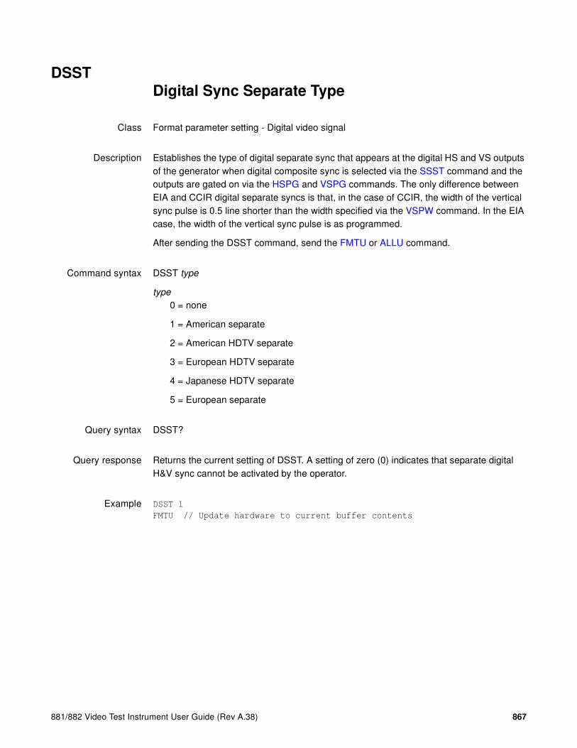
881/882 Video Test Instrument User Guide (Rev A.38) 867
DSSTDigital Sync Separate Type
Class Format parameter setting - Digital video signal
Description Establishes the type of digital separate sync that appears at the digital HS and VS outputs of the generator when digital composite sync is selected via the SSST command and the outputs are gated on via the HSPG and VSPG commands. The only difference between EIA and CCIR digital separate syncs is that, in the case of CCIR, the width of the vertical sync pulse is 0.5 line shorter than the width specified via the VSPW command. In the EIA case, the width of the vertical sync pulse is as programmed.
After sending the DSST command, send the FMTU or ALLU command.
Command syntax DSST type
type
0 = none
1 = American separate
2 = American HDTV separate
3 = European HDTV separate
4 = Japanese HDTV separate
5 = European separate
Query syntax DSST?
Query response Returns the current setting of DSST. A setting of zero (0) indicates that separate digital H&V sync cannot be activated by the operator.
Example DSST 1
FMTU // Update hardware to current buffer contents

868 Appendix A Command Reference
DVICDigital Video Identification Code
Class InfoFrame Packet
Description Writes the specified Video Identification Code (VIC) into the AVI InfoFrame.
Command syntax DVIC code
code
0 = unestablished format
1 - 34 = DVIC code corresponding to a format defined in EIA/CEA-861-C standard (Section 4). See table below for DVIC codes.
For detailed information on these timings refer to the CEA-861-C specification.
DVIC Format Name NCPP1 HRES2 VTOT3
1 DMT0659 1 640 525
1 DMT0660 1 640 525
2 480p59 1 720 525
2 480p60 1 720 525
2 480p59LH 1 720 525
2 480p60LH 1 720 525
3 480p59SH 1 720 525
3 480p60SH 1 720 525
4 720p59 1 1280 750
4 720p60 1 1280 750
5 1080i29 1 1920 1125
5 1080i30 1 1920 1125
6 480i2x29 2 720 525
6 480i2x30 2 720 525
6 480i2xL1 2 720 525
6 480i2xL2 2 720 525
7 480i2xS1 2 720 525
7 480i2xS2 2 720 525
8 240p2x_1 2 720 262
8 240p2x_2 2 720 262
8 240p2x_3 2 720 263
8 240p2x_4 2 720 263
8 240p2xL1 2 720 262
8 240p2xL2 2 720 262
8 240p2xL3 2 720 263
8 240p2xL4 2 720 263
9 240p2xS1 2 720 262

881/882 Video Test Instrument User Guide (Rev A.38) 869
9 240p2xS2 2 720 262
9 240p2xS3 2 720 263
9 240p2xS4 2 720 263
10 480i4x29 1 2880 525
10 480i4x30 1 2880 525
10 480i4xL1 1 2880 525
10 480i4xL2 1 2880 525
11 480i4xS1 1 2880 525
11 480i4xS2 1 2880 525
12 240p4x_1 1 2880 262
12 240p4x_2 1 2880 262
12 240p4x_3 1 2880 263
12 240p4x_4 1 2880 263
12 240p4xL1 1 2880 262
12 240p4xL2 1 2880 262
12 240p4xL3 1 2880 263
12 240p4xL4 1 2880 263
13 240p4xS1 1 2880 262
13 240p4xS2 1 2880 262
13 240p4xS3 1 2880 263
13 240p4xS4 1 2880 263
14 480p2x59 2 720 525
14 480p2x60 2 720 525
14 480p2xL1 2 720 525
14 480p2xL2 2 720 525
15 480p2xS1 2 720 525
15 480p2xS2 2 720 525
16 1080p59 1 1920 1125
16 1080p60 1 1920 1125
17 576p50 1 720 625
17 576p50LH 1 720 625
18 576p50SH 1 720 625
19 720p50 1 720 750
20 1080i25 1 1920 1125
21 576i2x25 2 720 625
21 576i2xLH 2 720 625
22 576i2xSH 2 720 625
23 288p2x_1 2 720 312
23 288p2x_2 2 720 313
23 288p2x_3 2 720 314
23 288p2xL1 2 720 312
23 288p2xL2 2 720 313
23 288p2xL3 2 720 314
24 288p2xS1 2 720 312
DVIC Format Name NCPP1 HRES2 VTOT3

870 Appendix A Command Reference
24 288p2xS2 2 720 313
24 288p2xS3 2 720 314
25 576i4x25 1 2880 625
25 576i4xLH 1 2880 625
26 576i4xSH 1 2880 625
27 288p4x_1 1 2880 312
27 288p4x_2 1 2880 313
27 288p4x_3 1 2880 314
27 288p4xL1 1 2880 312
27 288p4xL2 1 2880 313
27 288p4xL3 1 2880 314
28 288p4xS1 1 2880 312
28 288p4xS2 1 2880 313
28 288p4xS3 1 2880 314
29 576p2x50 1 720 625
29 576p2xLH 1 720 625
30 576p2xSH 1 720 625
31 1080p50 1 1920 1125
32 1080p23 1 1920 1125
32 1080p24 1 1920 1125
33 1080p25 1 1920 1125
34 1080p29 1 1920 1125
34 1080p30 1 1920 1125
35 480p4x59 1 2880 525
35 480p4xL1 1 2880 525
35 480p4x60 1 2880 525
35 480p4xL2 1 2880 525
36 480p4xL2 1 2880 525
36 480p4xS2 1 2880 525
37 576p4x50 1 2880 625
37 576p4xLH 1 2880 625
38 576p4xSH 1 2880 625
39 108Oi25_ 1 1920 1250
40 1080i50 1 1920 1125
41 720p100 1 1280 750
42 576p100 1 720 625
42 576p100L 1 720 625
43 576p100S 1 720 625
44 576i2x50 2 720 625
44 576i2xL1 2 720 625
45 576i2xS1 2 720 625
46 1080i59 1 1920 1125
46 1080i60 1 1920 1125
47 720p119 1 1280 750
DVIC Format Name NCPP1 HRES2 VTOT3
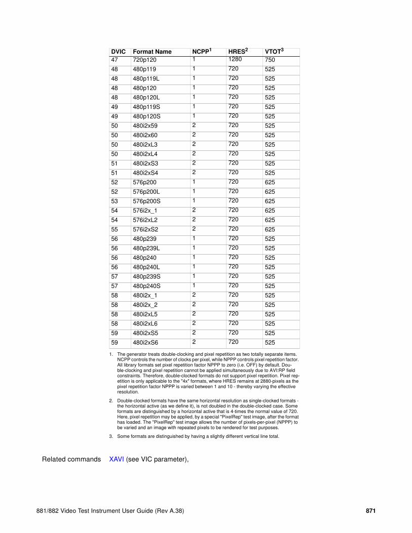
881/882 Video Test Instrument User Guide (Rev A.38) 871
Related commands XAVI (see VIC parameter),
47 720p120 1 1280 750
48 480p119 1 720 525
48 480p119L 1 720 525
48 480p120 1 720 525
48 480p120L 1 720 525
49 480p119S 1 720 525
49 480p120S 1 720 525
50 480i2x59 2 720 525
50 480i2x60 2 720 525
50 480i2xL3 2 720 525
50 480i2xL4 2 720 525
51 480i2xS3 2 720 525
51 480i2xS4 2 720 525
52 576p200 1 720 625
52 576p200L 1 720 625
53 576p200S 1 720 625
54 576i2x_1 2 720 625
54 576i2xL2 2 720 625
55 576i2xS2 2 720 625
56 480p239 1 720 525
56 480p239L 1 720 525
56 480p240 1 720 525
56 480p240L 1 720 525
57 480p239S 1 720 525
57 480p240S 1 720 525
58 480i2x_1 2 720 525
58 480i2x_2 2 720 525
58 480i2xL5 2 720 525
58 480i2xL6 2 720 525
59 480i2xS5 2 720 525
59 480i2xS6 2 720 525
1. The generator treats double-clocking and pixel repetition as two totally separate items. NCPP controls the number of clocks per pixel, while NPPP controls pixel repetition factor. All library formats set pixel repetition factor NPPP to zero (i.e. OFF) by default. Dou-ble-clocking and pixel repetition cannot be applied simultaneously due to AVI:RP field constraints. Therefore, double-clocked formats do not support pixel repetition. Pixel rep-etition is only applicable to the "4x" formats, where HRES remains at 2880-pixels as the pixel repetition factor NPPP is varied between 1 and 10 - thereby varying the effective resolution.
2. Double-clocked formats have the same horizontal resolution as single-clocked formats - the horizontal active (as we define it), is not doubled in the double-clocked case. Some formats are distinguished by a horizontal active that is 4-times the normal value of 720. Here, pixel repetition may be applied, by a special "PixelRep" test image, after the format has loaded. The "PixelRep" test image allows the number of pixels-per-pixel (NPPP) to be varied and an image with repeated pixels to be rendered for test purposes.
3. Some formats are distinguished by having a slightly different vertical line total.
DVIC Format Name NCPP1 HRES2 VTOT3

872 Appendix A Command Reference
Example DVIC 23
FMTU

881/882 Video Test Instrument User Guide (Rev A.38) 873
DVPTDigital Video Protocol Type
Class Format parameter setting - Digital video signal
Description Controls the output protocol. Setting the DVPT parameter to 2 and issuing a FMTU (or ALLU) command causes the output signal protocol to switch to HDMI, while setting DVPT to 1 causes a DVI compatible protocol to be output. All of the formats in the format library set DVPT to 0. This is a default setting, which lets the output protocol be determined, on a global basis, by the type of hardware that is present.
Command syntax DVPT type
type
0 = default (based on hardware present)
1 = DVI 1.0
2 = HDMI 1.0
Example DVPT 2
FTMU

874 Appendix A Command Reference
DVQMDigital Video Quantization Mode
Class Format parameter setting - Digital video signal
Description Controls the range of digital signals per the EIA/CEA-861-C standard.
The DVQM? query returns the current DVQM mode.
Command syntax DVQM mode
mode
Use the following table to determine the proper mode (0, 1, or 2).
Notes:
• Computer (for example, DMT and CVT) formats set DVQM=0 for full range.
• DVQM can be set to 1 to test the undershoot/overshoot signal code margins (for example, see SMPTE 296M section 7.12).
• Television formats (for example, 1080i29) set DVQM=2 for reduced range required by various television standards (for example, EIA/CEA-861-C).
Query syntax DVQM?
Example DVQM 1 // Sets the quantizing mode to 1.
FMTU // Applies the format change
Related commands LMIN, LMAX, NBPC
DVQ
ModeComponents
NBPC=8 ranges NBPC=10 ranges NBPC=12 ranges
LMIN LMAX LMIN LMAX LMIN LMAX
0 RGB 0 255 0 1023 0 4095
YCbCr 0 255 0 1023 0 4095
1 RGB 1 254 4 1019 16 4079
YCbCr 1 254 4 1019 16 4079
2 RGB 16 235 64 940 256 3760
YCbCr 16 240 64 960 256 3840

881/882 Video Test Instrument User Guide (Rev A.38) 875
DVSCDigital Video Swing Calibration factor
Class System calibration setting
Description Sets the TMDS differential swing calibration factor for the digital video signal (HDMI and DVI). The DVSC query returns the current value.
Command syntax DVSC factor
factor
0.0 to 1.1
Query syntax DVSC?
Related commands DVSS (OUT1:DVSS, OUT2:DVSS)
Examples DVSC 0.9 // sets the digital video swing calibration to 0.9
ALLU

876 Appendix A Command Reference
DVSMDigital Video Sampling Mode
Class Format parameter setting - Digital video signal
Description Controls how the color difference components (CbCr) are sampled when YCbCr signal type is selected. Set DVST to a signal type that supports the sampling mode specified by DVSM.
Command syntax DVSM mode
mode
0 = RGB 4:4:4 (default)
2 = 4:2:2 (color difference components are sampled at half the pixel rate; luminance is sampled at full pixel rate)
4 = 4:4:4 (both luminance and color difference components are sampled at the pixel rate)
Related commands NBPC, DVST
Examples DVST 10 // Selects RGB digital video type
DVSM 0 // Specifies default condition
FMTU // Applies the format change
DVST 14 // Selects YCbCr digital video type
DVSM 2 // Specifies 4:2:2 sampling mode
FMTU // Applies the format change

881/882 Video Test Instrument User Guide (Rev A.38) 877
DVSPDigital Video Signal Polarity
Class Format parameter setting - Digital video signal
Description Establishes the logic sense of the digital video outputs. The DVSP? query returns the current setting of DVSP.
Command syntax DVSP polarity
polarity
0 = active-low (negative going video)
1 = active-high (positive going video)
Query syntax DVSP?
Query response polarity
Other requiredcommands
To use the digital video outputs, digital video must be enabled with the DVST command. The FMTU command instructs the generator to use the new setting. The ALLU command updates hardware to the new setting and redraws the test image.
Example AVST 0 // Deselect analog video in buffer
DVST 5 // Select 3 bit color in buffer
DVSP 1 // Select active high video in buffer
FMTU // Update hardware to current buffer contents
DVSS 1.25 // set digital video swing to 1.25 volts on HDMI output 1
ALLU

878 Appendix A Command Reference
DVSS (OUT1:DVSS, OUT2:DVSS)Digital Video Signal Swing
Class Format parameter setting - Digital video signal
Description Sets the TMDS differential swing voltage for the digital video signal. For generators with two HDMI ports, the OUT1:DVSS or OUT2:DVSS syntax sets the voltage for the corresponding connector. The DVSS query returns the current value.
The DV_Swing image can also be used to adjust the digital swing.
Command syntax connector:DVSS voltage
connector
OUT1, OUT2 = HDMI OUT 1 or HDMI OUT 2 connector
voltage
0.0 to 2.0 volts differential peak-to-peak (nominally 1.000, 0.150 to 1.560 range guaranteed)
Query syntax OUT1:DVSS?or
DVSS?
Related commands DVST, DVSC
Example 1 DVSS 1.25 // sets the digital video signal swing voltage to 1.25
volts on HDMI output 1
ALLU
Example 2 OUT1:DVSS 1.00 // sets the digital video signal swing voltage to 1.0
volts on HDMI output 1
ALLU
Example 3 OUT2:DVSS 0.50 // sets the digital video signal swing voltage to 0.5
volts on HDMI output 2
ALLU
Example 4 OUT2:DVSS? // queries the current value of HDMI output 2
+0.500E+00
ALLU

881/882 Video Test Instrument User Guide (Rev A.38) 879
DVSTDigital Video Signal Type
Class Format parameter setting - Digital video signal
Description Establishes the kind of video signal that exits the digital video signal outputs of the generator.
The DVST? query returns the current setting of DVST.
Command syntax DVST type
type
0 = none
9 = YYY follows the sRGB (per ITU-R BT.709)
10 = RGB
13 = YCbCr (per SMPTE 260M-1999, Table 1)
14 = YCbCr (per ITU-R BT.601-5 Table 3, Item 7)
15 = YCbCr (per ITU-R BT.709-5 Part 1, Section 6.10)
16 = Reserved
17 = xvYCC ITU-R BT.601 HDTV
18 = xvYCC ITU-R BT.709 HDTV
Query syntax DVST?
Related commands AVST must be set to zero when digital video is used. Use the ALLU or FMTU command, after the DVST command, to update the hardware with the new settings.
Example AVST 0 // Deselect analog video in buffer
DVST 10 // Select digital RGB
FMTU // Update hardware to current buffer contents

880 Appendix A Command Reference
DWELslider image DWELl time
Class Image Control – System Level
Description Sets the how long each step of the SlideG and SlideRGB built-in images is displayed before the image is updated. The delay is based on the number of vertical frame refreshes that must occur for the currently loaded video format. The command is also used to set how long each step of the Regulate image is displayed. The DWEL? query returns the current DWELL setting.
Command syntax DWEL delay
delay
integer representing number of video frames
Query syntax DWEL?
Query response delay
Example DELX 8 // Set H shift to 8 pixels per step
DELY 3 // Set V shift to 3 pixels per step
DWEL 2 // Display each step for 2 frames
IMGL “SlideG” // Select Image that uses DELX and DELY
IMGU // Draw the Image

881/882 Video Test Instrument User Guide (Rev A.38) 881
EDA<port>:GDIDGet EDID from device
Class EDID and DDC control
Description Reads an EDID from a device connected to the specified HDMI out port. Requires firmware release 2.3.0 or higher.
Command syntax EDAport:GDID
port
1 = HDMI out port 1
2 = HDMI out port 2
Example This example reads an EDID from the device connected to HDMI out port 1.
EDA1:GDID
Related commands DIDA, DIDB, DIDE, DIDK, DIDL, TASK?, DIDP, DIDQ, DIDS, DIDU, EDA<port>:PDID, XDID

882 Appendix A Command Reference
EDA<port>:PDIDPut EDID to Device
Class EDID and DDC control
Description Writes current EDID to a device connected to the specified HDMI out port. Requires firmware release 2.3.0 or higher.
Command syntax EDAport:PDID
port
1 = HDMI out port 1
2 = HDMI out port 2
Example This example writes an EDID to the device connected to HDMI out port 1.
EDA1:PDID
Related commands DIDA, DIDB, DIDE, DIDK, DIDL, TASK?, DIDP, DIDQ, DIDS, DIDU, EDA<port>:PDID, XDID

881/882 Video Test Instrument User Guide (Rev A.38) 883
EDE<port>:DIDUEDID Use
Class EDID and DDC control
Description Updates hardware with current EDID contents. Requires firmware release 2.3.0 or higher.
Command syntax EDEport:DIDU
port
the HDMI IN port (1 or 2) to be configured with the contents of the EDID buffer
Query syntax EDEport:DIDU?
port
the HDMI IN port (1 or 2) to be read
Example This example edits part of an EDID and updates the HDMI IN port 1 with the current buffer contents.
XDID 8 3 DE33FF
EDE1:DIDU
Related commands DIDA, DIDB, DIDE, DIDK, DIDL, TASK?, DIDP, DIDQ, DIDS, DIDU, EDA<port>:GDID, XDID

884 Appendix A Command Reference
EDID?EDID read
Class EDID and DDC control
Description Reads all bytes in the base EDID and up to seven extensions from a DDC compliant display connected to the transmitter on the generator. The data is returned in raw ASCII hex format.
Query syntax EDID?
Query response ASCII hex test string
Related commands I2CR? (OUT1:I2CR?, OUT2:I2CR?, VGA:I2CR?)
Example This example reads a four block E-EDID.
R:\edid?
00FFFFFFFFFFFF004489B200050000000D0C010380502D780A0DC9A05747982712484C200
00001010101010101010101010101010101011D8018711C1620582C2500C48E2100009E8C
0AD08A20E02D10103E9600138E21000018000000FC0048444D492054560A2020202020000
000FD003B3D0F2E08000A2020202020200306F00202000000000000000000000000000000
0000000000000000000000000000000000000000000000000000000000000000000000000
0000000000000000000000000000000000000000000000000000000000000000000000000
0000000000000000000000000000000000000000000000000000000000000000000000000
C02031CF149850408020106141216230907078301000065030C001000011D007251D01E20
6E285500C48E2100001ED60980A020E02D1010602200128E210000188C0AD090204031200
C405500C48E21000018011D80D0721C1620102C2580C48E2100009E8C0AA01451F0160026
7C4300138E21000098000000000000000000A4020308F1431113158C0AD090204031200C4
05500138E21000018011D00BC52D01E20B8285540C48E2100001E8C0AA02051201810187E
2300C48E21000098000000000000000000000000000000000000000000000000000000000
0000000000000000000000000000000000000000000000000000000000000000000000000
71

881/882 Video Test Instrument User Guide (Rev A.38) 885
ENETReads EtherNET address
Class Tools
Description Retrieves the Ethernet (MAC) address of the generator.
Query syntax ENET?
Query response ASCII hex test string
Related commands None
Example ENET?
00:07:AA:00:20:00

886 Appendix A Command Reference
ENET:IPSets IP address for EtherNET port
Class Tools
Description Sets the IP address of the Ethernet port of the generator.
Command syntax ENET:IP IP
IP
in the format: www.xxx.yyy.zzz
Query syntax ENET:IP?
Query response IP address in format: www.xxx.yyy.zzz
Related commands None
Example ENET:IP 192.168.254.222

881/882 Video Test Instrument User Guide (Rev A.38) 887
ENET:MASKSets IP address subnet MASK for EtherNET port
Class Tools
Description Sets the IP address of the Ethernet port of the generator.
Command syntax ENET:MASK mask
mask
in the format: www.xxx.yyy.zzz
Query syntax ENET:MASK?
Query response subnet mask in format: www.xxx.yyy.zzz
Related commands None
Example ENET:MASK 255.255.255.000

888 Appendix A Command Reference
EQUAEQUalization interval After vertical sync pulse
Class Format parameter setting - synchronization
Description Establishes the width of the equalization interval after the vertical sync pulse in each field whenever a serrated and equalized sync type is selected via either ASCT or DSCT commands and selected via the SSST command. If the type specified for the selected sync signal is one of the CCIR types, then the actual equalization interval output by the generator will be 0.5 lines shorter than the whole number specified. The EQUA? query returns the current setting of EQUA.
Command syntax EQUA lines
lines
min = 0
max = number of lines after vertical sync before video
Query syntax EQUA?
Query response lines
Other requiredcommands
The FMTU command instructs the generator to use the new setting. The ALLU command updates hardware to the new setting and redraws the test image.
Example EQUA 3 // Set post-equalization to 3 lines in buffer
FMTU // Update hardware to current buffer contents

881/882 Video Test Instrument User Guide (Rev A.38) 889
EQUBEQUalization interval Before vertical sync pulse
Class Format parameter setting - synchronization
Description Establishes the width of the equalization interval before the vertical sync pulse in each field whenever a serrated and equalized sync type is selected via either ASCT or DSCT commands and selected via the SSST command. If the type specified for the selected sync signal is one of the CCIR types, then the actual equalization interval output by the generator will be 0.5 lines shorter than the whole number specified. The EQUB? query returns the current setting of EQUB.
Command syntax EQUB lines
lines
min = 0
max = number of lines after video and before vertical sync
Query syntax EQUB?
Query response lines
Other requiredcommands
The FMTU command instructs the generator to use the new setting. The ALLU command updates hardware to the new setting and redraws the test image.
Example EQUB 3 // Set pre-equalization to 3 lines in buffer
FMTU // Update hardware to current buffer contents

890 Appendix A Command Reference
EQUFEQUalization Flatten
Class Format parameter setting - synchronization
Description Determines if composite sync will have all equalization pulses removed in the vertical sync front porch (delay) period as required by certain military HOBO and Maverik video formats. The EQUF? query returns the current setting of EQUF.
Command syntax EQUF mode
mode
0 = OFF
1 = ON
Query syntax EQUF?
Query response mode
Other requiredcommands
The FMTU command instructs the generator to use the new setting. The ALLU command updates hardware to the new setting and redraws the test image.
Example EQUF 0; ALLU // This is the default

881/882 Video Test Instrument User Guide (Rev A.38) 891
ERRCERRor queue Clear
Class System error control
Description Clears all errors waiting to be reported in the error queue.
Command syntax ERRC
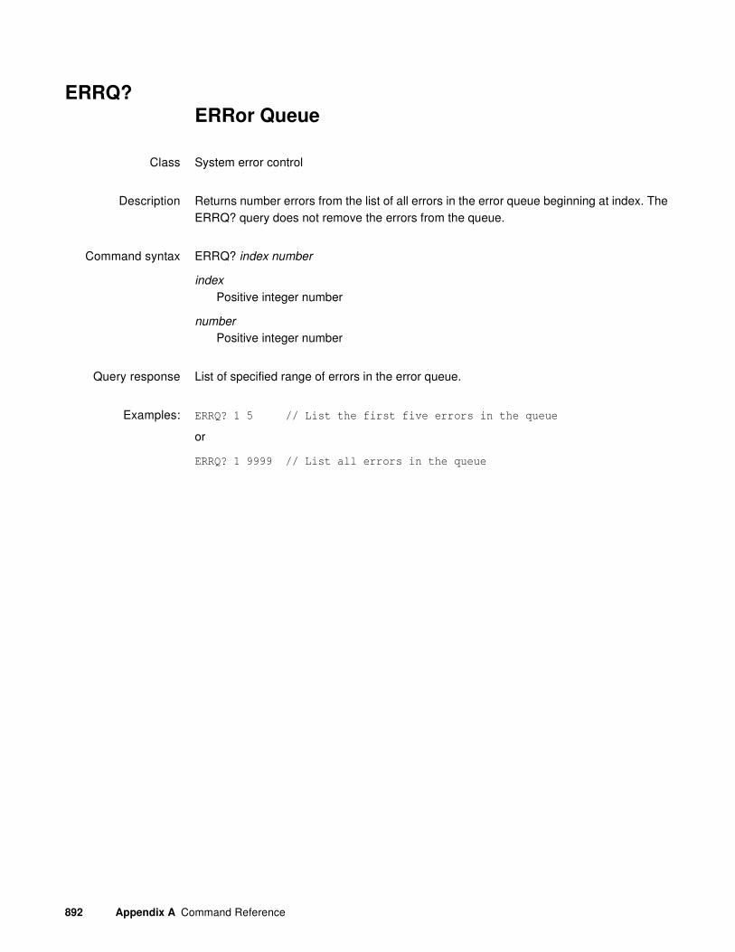
892 Appendix A Command Reference
ERRQ?ERRor Queue
Class System error control
Description Returns number errors from the list of all errors in the error queue beginning at index. The ERRQ? query does not remove the errors from the queue.
Command syntax ERRQ? index number
index
Positive integer number
number
Positive integer number
Query response List of specified range of errors in the error queue.
Examples: ERRQ? 1 5 // List the first five errors in the queue
or
ERRQ? 1 9999 // List all errors in the queue

881/882 Video Test Instrument User Guide (Rev A.38) 893
ERRY?Yank ERRor from queue
Class Format parameter setting - synchronization
Description Returns the most recent error added to the error queue and removes it from the queue.
Query syntax ERRY?
Query response Error

894 Appendix A Command Reference
EXAREXtended Aspect Ratio
Class Format parameter setting - active video
Description Sets the aspect ratio of the extended image content.
Note: If the source image content was shot for a single screen shape, then this parameter
will be the same as the CXAR parameter. Alternatively, if the source image content was
shot for two different shaped screens (using a “shoot and protect” technique), then this
parameter will be different than the CXAR parameter.
Command syntax EXAR aspect_ratio
aspect_ratio
0.75 to 2.39
Note: For a listing of established aspect ratios, see the table on page 800 (CXAR
command).
Related commands CXAR, SXAR
Example EXAR 1.77 // Sets 16:9 picture aspect ratio for extended image content
FMTU
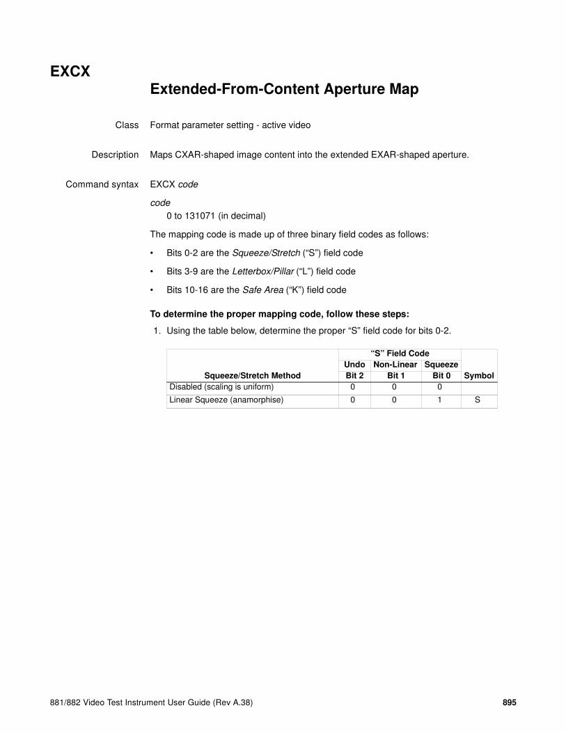
881/882 Video Test Instrument User Guide (Rev A.38) 895
EXCXExtended-From-Content Aperture Map
Class Format parameter setting - active video
Description Maps CXAR-shaped image content into the extended EXAR-shaped aperture.
Command syntax EXCX code
code
0 to 131071 (in decimal)
The mapping code is made up of three binary field codes as follows:
• Bits 0-2 are the Squeeze/Stretch (“S”) field code
• Bits 3-9 are the Letterbox/Pillar (“L”) field code
• Bits 10-16 are the Safe Area (“K”) field code
To determine the proper mapping code, follow these steps:
1. Using the table below, determine the proper “S” field code for bits 0-2.
Squeeze/Stretch Method
“S” Field Code
Symbol
Undo Non-Linear Squeeze
Bit 2 Bit 1 Bit 0
Disabled (scaling is uniform) 0 0 0
Linear Squeeze (anamorphise) 0 0 1 S

896 Appendix A Command Reference
2. Using the table below, determine the proper “L” field code for bits 3-9.
3. Use the following table to determine the proper “K” field code for bits 10-16.
Letterbox/Pillar Mode
“L” Field Code
Symbol
Undo Bars BarContents Position Shrink
Bit 9 Bit 8 Bit 71
1. Bits 6 and 7 are used to sequence redundant AFD codes.
In the case of pixel repetition (NPPP not equal to 0), the color of the (extended) bars
on the left and right sides of the image are filled in accordance with the settings of bits
6 and 7—even when the letterbox/pillar fitting method is disabled (bit 3 = 0).
Bit 61 Bit 5 Bit 4 Bit 3
Disabled 0 0 0 0 0 0 0
Centered shrink w/black bars top & bottom
0 1 0 0 0 0 1 Lcbb
Centered shrink w/gray bars top & bottom
0 1 0 1 0 0 1 Lcgb
Centered shrink w/white bars top & bottom
0 1 1 0 0 0 1 Lcwb
Centered protected shrink w/shot surround
0 0 0 0 0 0 1 Lcsp
Top shrink w/single black bar at bottom
0 1 0 0 0 1 1 Ltbb
Top shrink w/single gray bar at bottom
0 1 0 1 0 1 1 Ltgb
Top shrink w/white bar at bot-tom
0 1 1 0 0 1 1 Ltwb
(Keep) Safe Area Mode
“K” Field Code
Symbol
Undo Bars BarContents Source Save Area
Bit 16 Bit 15 Bit 14 Bit 13 Bit 12 Bit 11 Bit 10
None (w/safe area markers) 0 0 0 0 0 0 0
Shrink coded frame to action area with opaque black bar surround
0 1 0 0 0 0 1 Kabb
Shrink coded frame to action area with opaque gray bar surround
0 1 0 1 0 0 1 Kagb
Shrink coded frame to action area with opaque white bar surround
0 1 1 0 0 0 1 Kawb
Coded frame has shot-protected action area with-out graticules or bars
0 0 0 0 0 0 1 Kasp
Coded frame has shot-protected action area with action graticules without bars
0 0 0 1 0 0 1 Kaspa
Coded frame has shot-protected action area with title graticules without bars
0 0 1 0 0 0 1 Kaspt
Coded frame has shot-protected action area with action and title graticules without bars
0 0 1 1 0 0 1 Kaspb
Shrink coded frame to title area with opaque black bar surround
0 1 0 0 0 1 0 Ktbb
Shrink coded frame to title area with opaque gray bar surround
0 1 0 1 0 1 0 Ktgb

881/882 Video Test Instrument User Guide (Rev A.38) 897
Shrink coded frame to title area with opaque white bar surround
0 1 1 0 0 1 0 Ktwb
Coded frame has shot-protected title area without graticules or bars
0 0 0 0 0 1 0 Ktsp
Coded frame has shot-protected title area with action graticules without bars
0 0 0 1 0 1 0 Ktspa
Coded frame has shot-protected title area with title graticules without bars
0 0 1 0 0 1 0 Ktspt
Coded frame has shot-protected title area with action and title graticules without bars
0 0 1 1 0 1 0 Ktspb
Coded frame has shot-protected custom area with-out graticules or border
0 0 0 0 0 1 1 Kcsp
Coded frame has shot-protected custom area with action graticules without border
0 0 0 1 0 1 1 Kcspa
Coded frame has shot-protected custom area with title graticules without border
0 0 1 0 0 1 1 Kcspt
(Keep) Safe Area Mode
“K” Field Code
Symbol
Undo Bars BarContents Source Save Area
Bit 16 Bit 15 Bit 14 Bit 13 Bit 12 Bit 11 Bit 10
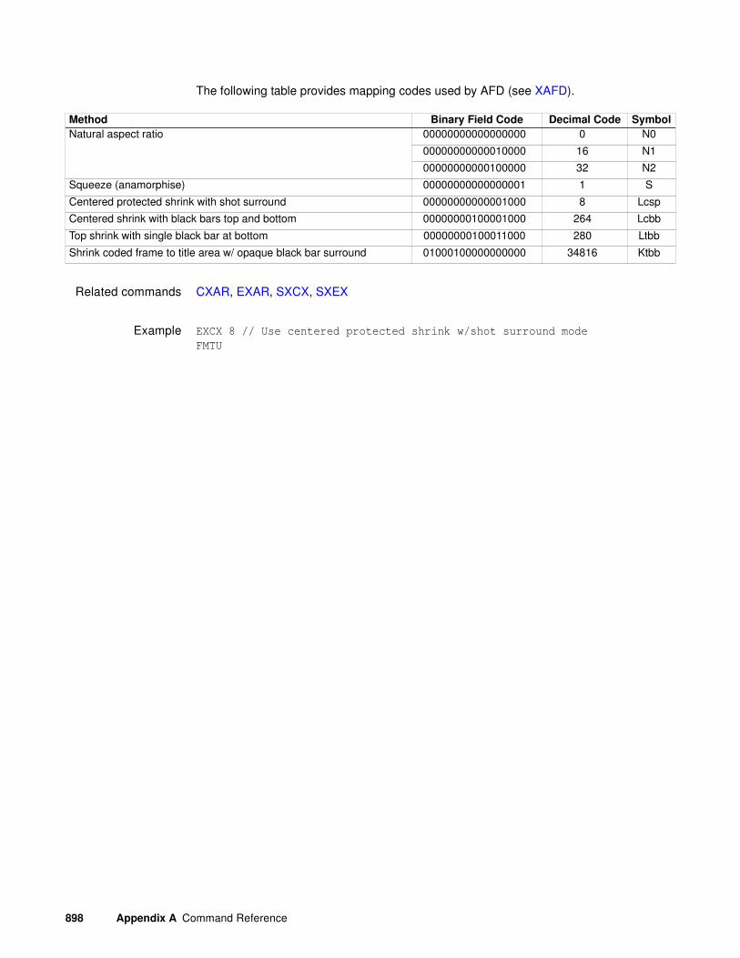
898 Appendix A Command Reference
The following table provides mapping codes used by AFD (see XAFD).
Related commands CXAR, EXAR, SXCX, SXEX
Example EXCX 8 // Use centered protected shrink w/shot surround mode
FMTU
Method Binary Field Code Decimal Code Symbol
Natural aspect ratio 00000000000000000 0 N0
00000000000010000 16 N1
00000000000100000 32 N2
Squeeze (anamorphise) 00000000000000001 1 S
Centered protected shrink with shot surround 00000000000001000 8 Lcsp
Centered shrink with black bars top and bottom 00000000100001000 264 Lcbb
Top shrink with single black bar at bottom 00000000100011000 280 Ltbb
Shrink coded frame to title area w/ opaque black bar surround 01000100000000000 34816 Ktbb

881/882 Video Test Instrument User Guide (Rev A.38) 899
FILE:LOADFILE:LOAD
Class Tools
Description Loads and uses a file such as an image or format.
Command syntax(flash memory/ PC
card)
FILE:LOAD filename
filename
Any file in a generator library directory.
Command syntax(file server)
FILE:LOAD server_name/filename
server_name
Valid hostname (no forward slash before name, and colon after name)
filename
Any file in a file server library directory.
Related commands None
Example FILE:LOAD barsmpte.o // Loads file from generator
FILE:LOAD Host1:/barsmpte.o // Loads file from file server “Host1”.

900 Appendix A Command Reference
FILE:SCREENCAPFILE:SCREENCAP
Class Tools
Description Captures an image currently rendered on the display to a bit map.
Command syntax FILE:SCREEN filename.bmp
filename.bmp
Related commands None
Example FILE:SCREENCAP diamond.bmp

881/882 Video Test Instrument User Guide (Rev A.38) 901
FMTAForMaT save As
Class Format memory management
Description Saves the current contents of the format edit buffer using the given name
Command syntax FMTA name
name
a valid MS-DOS filename (8 characters minus any extension)
Example FMTA MY_FMT // Save with the name "MY_FMT"

902 Appendix A Command Reference
FMTBForMaT editing Begin
Class Format editor control
Description Marks the beginning of a format editing session.
Command syntax FMTB
Other requiredcommands
Use either an FMTL command to load an existing image or an FMTN command to create a new format. Use FMTE when ending the editing session.
Example FMTN // Initialize format edit buffer
FMTB // Start format editing session
// One or more format editing commands ...
FMTE // End format editing session

881/882 Video Test Instrument User Guide (Rev A.38) 903
FMTEForMaT editing End
Class Format editor control
Description Marks the end of a format editing session.
Command syntax FMTE
Other requiredcommands
Use FMTB when starting the editing session. Use FMTA or FMTS to save changes.
Example FMTB // Start format editing session
// One or more format editing commands ...
FMTA My_fmt1 // Save edited format as My_fmt1
FMTE // End format editing session

904 Appendix A Command Reference
FMTG?ForMaT in buffer Good
Class Format memory management
Description Tests the format in the format buffer for errors. If no errors are found, FMTG? returns zero. Otherwise, if one or more errors exist, the number of the first error encountered is returned. To test formats residing in format memory, use the FMTT? query.
Query syntax FMTG?
Query response Returns 0 if no errors are found; otherwise, returns the number of the first error encountered.
Example FMTG? // Return format error status

881/882 Video Test Instrument User Guide (Rev A.38) 905
FMTKForMaT Kill from memory by name
Class Format memory management
Description Erases the named format from memory. The FMTK? query checks to see if the named format can be erased. The RAM location number is returned if it can be erased. Otherwise, a zero is returned.
Command syntax FMTK name
name
a valid MS-DOS filename (8 characters minus any extension)
Query syntax FMTK? name
name
valid MS-DOS filename (8 characters minus any extension)
Query response 0 or location
Example FMTK my_fmt1 // Erase format called my_fmt1

906 Appendix A Command Reference
FMTLForMaT Load from memory by name
Class Format memory management
Description Assigns a format to the current step of a sequence while between a set of SEQB and SEQE commands. The FMTL command is context sensitive. The FMTL? query returns the name of the format currently assigned to the step.
Outside of the sequence editor, the FMTL command reads the format having a name equal to name from format memory (or EPROM) into the format. FMTL does not reconfigure the signal generating hardware. This feature allows you to work on the contents of any format memory location, while continuing to output a signal based on a previously used format (see FMTU command). The FMTL? query returns the location location in which a format having a name equal to name is found. If multiple formats exist having name name, then the lowest numbered location containing a format with a matching name name is returned. The format memory (RAM) is always searched first. If a format with name name cannot be found anywhere in the format memory, then the industry-standard formats located in EPROM (negative locations) are searched next.
The FMTL? query returns zero if a format with a name equal to name cannot be found in either format space.
Command syntax FMTL name
name
a valid MS-DOS filename (8 characters minus any extension)
Query syntax FMTL? name
Query response location (returns 0 if not found)
Other requiredcommands
The ALLU command updates the hardware to the new settings and redraws the test image.
Example FMTL VGA_m3 // Load format called VGA_m3
ALLU // Update hardware and redraw image

881/882 Video Test Instrument User Guide (Rev A.38) 907
FMTNForMaT New
Class Format memory management
Description Initializes the format editing buffer. Sending this one command is equivalent to sending all of the following commands:
This should be the first command sent to the generator when creating a new format. The command only resets to a known state. The command does not create a usable format. The FMTN? query returns the current name of the format in the buffer.
Command syntax FMTN name
name
a valid MS-DOS filename (8 characters minus any extension)
Query syntax FMTN?
ASBG 0 GAMA 2.2
ASCT 1 GAMC 0
ASGG 1 HRAT 0
ASSG 0, 1, 0 HRES 0
ASSS 0.286 HSIZ 280
AVPG 0 HSPD 0
AVPS 0.0 HSPG 1
AVSB 0.0 HSPP 0
AVSS 0.714 HSPW 0
AVST 0 HTOT 0
XVSG 1, 1, 1 SCAN 1
CSPG 1 SSST 1
CSPP 0 USIZ 2
DCBM 0 VRES 0
DSEX 0 VSIZ 210
DSST 1 VSPD 0
DVSP 0 VSPG 1
DVST 0 VSPP 0
EQUA 0 VSPW 0
EQUB 0 VTOT 0

908 Appendix A Command Reference
Query response name
Example FMTN // Initialize format buffer
or
FMTN Narf // Initialize format buffer and name the format "Narf"

881/882 Video Test Instrument User Guide (Rev A.38) 909
FMTQ?ForMaT Query pointer
Class Format memory management
Description Returns number format names from the list of all the formats stored in format memory beginning at index. The formats are kept in alphanumeric order. The generator maintains internal variables for the current index and number values. The value of index is automatically incremented by number after the query is executed. Sending the query with just an index parameter returns the same number of names as the last time, starting at the given index. Sending the query with no parameters, returns the next set of names.
Query syntax FMTQ? [index [number]]
index
positive integer number
number
positive integer number
Query response List of specified format names
Example FMTQ? 1 9999 // List all formats in memory
or
FMTQ? 1 10 // List the first ten formats in memory
FMTQ? 21 10 // List the 21st through the 30th FMTes in memory
FMTQ? 31 1 // List the 31st through the 40th FMTes in memory

910 Appendix A Command Reference
FMTSForMaT Save
Class Format memory management
Description Saves the current format edit buffer contents into format memory using the current name of the format in the edit buffer.
Command syntax FMTS
Example FMTL DMT0660 // Loads a format for editing
FMTB // Begins and editing session
HRES 654 // Sets the horizontal resolution to 654 pixels
.
. // other format parameters
.
HTOT 720 // Sets the horizontal total to 720 pixels
FMTE // Ends the format editing session
FMTS // Saves format
881/882 Video Test Instrument User Guide (Rev A.38) 911
FMTUForMaT Use
Class Format memory management
Description Checks the current contents of the format buffer for errors; if no errors are found, it reconfigures the signal generating hardware in accordance with the contents. It does not redraw the previously displayed test image. In some cases this may distort the old image.
The FMTU? query returns either a format memory location location or zero. If the signal format currently being output by the signal generating hardware matches that originally loaded (using the FMTL command) from a format memory location, then the matching format memory location location is returned. Otherwise, if the format contents have been used to update the signal generating hardware since either an FMTR or FMTL command has been issued, then FMTU? query returns zero.
Command syntax FMTU
Query syntax FMTU?
Query response location or 0

912 Appendix A Command Reference
FMTZForMat Zap
Class Format memory management
Description Clears format storage memory starting at first and ending at last. The cleared locations are then tagged as being empty. If no last parameter is given, only the first location is cleared. The FMTZ? query is used to determine if a location contains a format or is empty.
Command syntax FMTZ first last
Query syntax FMTZ? location
881/882 Video Test Instrument User Guide (Rev A.38) 913
FORMdraw FORMat data block
Class Custom image primitive
Description Displays basic information about the format driving the display. The first line shows the number of horizontal active pixels and vertical active lines. The last number on the line is the number of fields per frame (1 for non-interlaced and 2 for interlaced). The second and third lines show the horizontal and vertical rates, respectively. Text is on a black rectangular background with a single pixel border.
FORM uses three (3) parameters. The first is the color of the text and border. The next two are the X and Y coordinates for the top left corner of the block of text.
Command syntax FORM color x y
color
available colors
x
positive integer number
y
positive integer number
Other requiredcommands
The FMTU command instructs the generator to use the new setting. The ALLU command updates hardware to the new setting and redraws the test image.
Example FORM blue 30 200 // Display format information
// in blue beginning at X=30, Y=200
ALLU // Update hardware to current buffer contents

914 Appendix A Command Reference
FRAT?Frame RATe Query
Class Format parameter setting - Video resolution
Description Returns the current frame (vertical) rate setting.
Query syntax FRAT?
Query response frame rate
Example FRAT?
25.0000
Related commands TMAU

881/882 Video Test Instrument User Guide (Rev A.38) 915
FRGBForeground Red, Green and Blue levels
Class System parameter settings
Description Temporarily sets the portions of an image drawn with a color selection of foreground to the given red, green and blue values. All three colors can be set to the same level using a single parameter. The color selection for one or more primitives in a custom image must be set to foreground in order to see the affect of this command on a custom image. The setting is not global and is not saved. The FRGB? query returns the current red, green and blue settings of FRGB.
Command syntax FRGB red_level green_level blue_level
or
FRGB common_gray_level
level
min = 0 (full off)
max = 255 (full on)
Example FRGB 255 128 0 // Set foreground color to orange
or
FRGB 128 // Set foreground color to a mid-gray level

916 Appendix A Command Reference
FSPDFrame Sync Pulse Delay
Class Format parameter setting - Synchronization
Description Sets the delay of the frame sync pulse relative to the last line of active video in the current format. The FSPD? query returns the current FSPD setting.
Command syntax FSPD delay
delay
min = 0 lines
max = (VTOT/SCAN) line
Query syntax FSPD?
Query response delay
Other requiredcommands
To get a pulse, frame sync must first be enabled with the FSPG command. The FMTU command instructs the generator to use the new settings. The ALLU command updates the hardware to the new settings and redraws the test image.
Example FSPG 1 // Enable Frame Sync
FSPP 1 // Set for positive going pulse
FSPW 20 // Make the pulse 20 pixels wide
FSPG 300 // Pulse to occur 300 lines after
// the last line of active video
FMTU // Update hardware to new settings

881/882 Video Test Instrument User Guide (Rev A.38) 917
FSPGFrame Sync Pulse Gate
Class Format parameter setting - Synchronization
Description Enables and disables the digital horizontal sync output. The FSPG? query returns the current FSPG mode.
Command syntax FSPG mode
mode
0 = OFF
1 = ON
Query syntax FSPG?
Query response 0 or 1
Other requiredcommands
The FMTU command instructs the generator to use the new settings. The ALLU command updates the hardware to the new settings and redraws the test image.
Example FSPG 1 // Enable Frame Sync
FMTU // Update hardware to new settings

918 Appendix A Command Reference
FSPPFrame Sync Pulse Polarity
Class Format parameter setting - Synchronization
Description Establishes the logic sense of the digital frame sync output. Setting polarity to one (1) causes the leading edge of frame sync to be a low-to-high transition. Setting polarity to zero (0) causes the leading edge of frame sync to be a high-to-low transition. The FSPP? query returns the current polarity of FSPP.
Command syntax FSPP polarity
polarity
0 = active-low (negative going pulse)
1 = active-high (positive going pulse)
Query syntax FSPP?
Query response 0 or 1
Other requiredcommands
To get a pulse, frame sync must first be enabled with the FSPG command. The FMTU command instructs the generator to use the new settings. The ALLU command updates the hardware to the new settings and redraws the test image.
Example FSPG 1 // Enable Frame Sync
FSPP 1 // Set for positive going pulse
FSPW 20 // Make the pulse 20 pixels wide
FSPG 300 // Pulse to occur 300 lines after
// the last line of active video
FMTU // Update hardware to new settings

881/882 Video Test Instrument User Guide (Rev A.38) 919
FSPWFrame Sync Pulse Width
Class Format parameter setting - Synchronization
Description Establishes the width of the frame sync pulse. The FSPW? query returns the current setting of FSPW.
Command syntax FSPW pixels
pixels
min = 1
max = HTOT - 1
Query syntax FSPW?
Query response pixels
Other requiredcommands
The FMTU command instructs the generator to use the new settings. The ALLU command updates the hardware to the new settings and redraws the test image.
Example FSPG 1 // Enable Frame Sync
FSPP 1 // Set for positive going pulse
FSPW 20 // Make the pulse 20 pixels wide
FSPG 300 // Pulse to occur 300 lines after the last line of active video
FMTU // Update hardware to new settings

920 Appendix A Command Reference
GAMAGAMmA correction factor
Class Format parameter setting - Digital video signal
Description Establishes the current video gamma correction factor. The GAMA? query returns the current setting of the gamma correction factor.
Command syntax GAMA factor
factor
min = 0.1 (floating point accepted)
max = 10.0 (floating point accepted)
For HDMI video signals GAMA is always 2.222
Query syntax GAMA?
Query response factor
Other requiredcommands
Gamma correction must be enabled with the GAMC command in order to use the gamma correction factor. The FMTU command instructs the generator to use the new setting. The ALLU command updates hardware to the new setting and redraws the test image.
Example GAMC 1 // Enable gamma correction in buffer
GAMA 2.2 // Set correction factor in buffer
FMTU // Update hardware to current buffer contents

881/882 Video Test Instrument User Guide (Rev A.38) 921
GAMCGAMma Correction mode
Class Format parameter setting - Digital video signal
Description Enables or disables application of the video gamma correction factor. The GAMC? query can be used to determine if the gamma correction factor is currently being applied.
Command syntax GAMC mode
mode
0 = disable (don't correct)
1 = enable (correct)
Query syntax GAMC?
Query response 0 or 1
Other requiredcommands
The value used for gamma correction is set with the GAMA command. The FMTU command instructs the generator to use the new setting. The ALLU command updates hardware to the new setting and redraws the test image.
Example GAMC 1 // Enable gamma correction in buffer
GAMA 2.2 // Set correction factor in buffer
FMTU // Update hardware to current buffer contents

922 Appendix A Command Reference
GCET?Get Component Error Tallies
Class DVI/HDMI Signal Analyzer
Description Reads the number of errors in the red, green, and blue components along with the total number of bad pixels.
Query syntax GCET?
Query response R, G, B, and bad pixels
Example PNAU //Pseudo-random noise generated
CR //Stop pseudo-random noise
GCET?
0,21,0,21 //Returns 21 Green pixel errors and a total of 21 bad pixels
Related commands PNAU

881/882 Video Test Instrument User Guide (Rev A.38) 923
GFED?Get First Error Data
Class DVI/HDMI Signal Analyzer
Description Returns information about the first error encountered during the signal analyzer test.
Query syntax GFED?
Query response expected value followed by the errant value (in hex)
Example PNAU //Pseudo-random noise generated
CR //Stop pseudo-random noise
GFED? //Returns expected (40018C) and errant (FFFFFF) value of first
errored pixel
40018C,FFFFFF
Related commands PNAU

924 Appendix A Command Reference
GNPT? Get Number of Pixel Tested
Class Signal analyzer - Pixel data
Description Returns the number of pixels being measured in billions after a pseudo noise measurement has finished execution (that is, completed the PNAU command).
Query syntax GNPT?
Query response zero (0) or positive number for the number of pixels tested in billions; -1 indicates an error No Signal Detected or TMDS failure.
Example PNAU //Pseudo-random noise generated
CR //Carriage return stops pseudo-random noise
GNPT? //Returns number of pixels in billion
4.255
Related commands PNAU

881/882 Video Test Instrument User Guide (Rev A.38) 925
GPEL? Get PixEL color components
Class Signal analyzer - Pixel data
Description Takes the (x, y) coordinates address of a pixel and returns the red, green, and blue color components of the pixel at that address.
Query syntax GPEL? x y
Query response R, G, B
Possible errors Should this info be integrated into the Query response area, instead of creating a new label?The GPEL? query may respond back with one of the following errors in case of a parameter is not set correctly (or in case the setup is not correct).
Example PDAX:FRMS 100 //sets the number of frames to analyze in the pixel
data analysis test to 100
PDAX:MXER 1000 //sets the maximum number of errors to record in pixel
data analysis test to 1000
PDAX:RPTG 1 //enables the generation of reports for the ppixel
data analysis test
PDAX:REFG 0 //enables auto reference capturing for the pixel
data analysis test
PDAX:CAPF //captures a frame of pixel data for the pixel
data analysis test
GPEL? 128 256 //read RGB color components at pixel address 128,256
0,255,0
Related commands PDAX:MXER, PDAX:RPTG, PDAX:REFG, PDAX:FRMS, PDAU
PNSeedExceedsLimit 2800
PNLengthExceedsLimit 2801
PNNotSupported 2802
NoInputSupported 2803
XcoordOutOfRange 2804
YcoordOutOfRange 2805

926 Appendix A Command Reference
GPER?Get Pixel Error Rate
Class Signal analyzer - Pixel data
Description Returns the pixel error rate in errors per billion after a pseudo noise measurement has finished execution (that is, completed the PNAU command).
Query syntax GPER?
Query response zero (0) or positive number representing errors per billion pixels; -1 indicates an error No Signal Detected or TMDS failure.
Example PNAU //Pseudo-random noise generated
CR //Carriage return tops pseudo-random noise
GPER? //Returns pixel error rate
0.88
Related commands PNAU

881/882 Video Test Instrument User Guide (Rev A.38) 927
GPIBGPIB address
Class GPIB port control
Description Sets the address of the generator on the GPIB port. The address change takes affect as soon as the command is issued. The new address setting will be maintained until 1) the address is changed another GPIB command, 2) the unit is re-initialized with an INIT command or 3) the unit is re-initialized because the power-up self-test found corrupted data in battery backed system memory. In cases 2 and 3, the GPIB address will revert to the address set on the GPIB address switches, if the unit has them. The address reverts to 15 if the unit does not have GPIB address switches. The GPIB? query returns the current GPIB address of the unit.
Command syntax GPIB address
address
integer, 0-30
Query syntax GPIB?
Query response address
Example GPIB 5 // Set GPIB address to 5

928 Appendix A Command Reference
GRIDdraw a centered GRID
Class Custom image primitive
Description Draws a crosshatch of a given color and forms a given number of boxes in each direction. All lines are 1 pixel thick. All of the lines in a given direction are equally spaced. Any remaining pixels are distributed as equally as possible around the perimeter of the grid. This may cause the first and last lines in each direction not to be at the very edges of video.
Command syntax GRID color horizontal_boxes vertical_boxes
color
available colors
horizontal_boxes
number of horizontal boxes (half of number of pixels)
vertical_boxes
number of vertical boxes (half of number of lines)
Other requiredcommands
The FMTU command instructs the generator to use the new settings. The ALLU command updates the hardware to the new settings and redraws the test image.
Example GRID gray75 14 10 // Draw a gray75 grid with 14 horizontal
// and 10 vertical boxes
ALLU // Update hardware to current buffer contents

881/882 Video Test Instrument User Guide (Rev A.38) 929
GRIHdraw a GRIll pattern of Horizontal lines
Class Custom image primitive
Description Draws equally spaced horizontal lines that form a grill over the entire active video area. The primitive uses three parameters. The first is the color of the lines, the second is the thickness of the lines, and the third is the thickness of the space between the lines.
Command syntax GRIH color line_width space_width
color
available colors
line_width
number of pixels in line
space_width
number of pixels in space
Other requiredcommands
The FMTU command instructs the generator to use the new settings. The ALLU command updates the hardware to the new settings and redraws the test image.
Example GRIH green 4 6 // Draw green grid with 4-pixel lines and 6-pixel spaces
ALLU // Update hardware to current buffer contents

930 Appendix A Command Reference
GRIVdraw a GRIll pattern of Vertical lines
Class Custom image primitive
Description Draws equally spaced vertical lines that form a grill over the entire active video area. The gaps are not touched and will show any previously drawn primitives. The primitive uses three parameters. The first is the color of the lines, the second is the thickness of the lines, and the third is the thickness of the space between the lines.
Command syntax GRIV color line_width space_width
color
available colors
line_width
number of pixels in line
space_width
number of pixels in space
Other requiredcommands
The FMTU command instructs the generator to use the new settings. The ALLU command updates the hardware to the new settings and redraws the test image.
Example GRIV cyan 16 16 // Draw cyan grill with 16-pixel lines
// and 16-pixel spaces
ALLU // Update hardware to current buffer contents

881/882 Video Test Instrument User Guide (Rev A.38) 931
GRNGGRNe Gate
Class Video Gate
Description Toggles the green video signal gate.
Command syntax GRNG mode
mode
0 = disable
1 = enable
Query syntax GRNG?
Query response 0 or 1
Other requiredcommands
ALLU to invoke the command.
Related commands BLUG, REDG
Example GRNG 0; ALLU // disable green video component

932 Appendix A Command Reference
HATIdraw a centered crossHATch from the Inside out
Class Custom image primitive
Description Draws a crosshatch from the inside-out of a given color and forms a given number of boxes in each direction. The primitive has center lines that divide the active video exactly in half in each direction. The vertical center line is 2 pixels thick if the format has an even number of active pixels. The horizontal center line is 2 pixels thick if the format has an even number of active lines. All other lines are 1 pixel thick. If you enter an odd number of boxes, a half box is placed at each end of the crosshatch. All lines in a given direction are spaced equally. Any remaining pixels are distributed as equally as possible around the perimeter of the grid. This may cause the first and last lines in each direction not to be at the very edges of video. In turn, this may cause any half boxes to be slightly larger.
Command syntax HATI color horizontal_boxes vertical_boxes
color
available colors
horizontal_boxes
number of horizontal boxes (half of number of pixels)
vertical_boxes
number of vertical boxes (half of number of lines)
Other requiredcommands
The FMTU command instructs the generator to use the new settings. The ALLU command updates the hardware to the new settings and redraws the test image.
Example HATI green 15 9 // Draw a green grid with 15 horizontal
// and 9 vertical boxes
ALLU // Update hardware to current buffer contents

881/882 Video Test Instrument User Guide (Rev A.38) 933
HATOdraw a centered crossHATch from the Outside in
Class Custom image primitive
Description Draws a crosshatch from the outside-in of a given color and forms a given number of boxes in each direction. All lines are 1 pixel thick. The first and last lines in each direction are at the very edges of active video. All the lines in a given direction are spaced equally. Any remaining pixels are added to the boxes along the horizontal and vertical centers of the image.
Command syntax HATO color horizontal_boxes vertical_boxes
color
available colors
horizontal_boxes
number of horizontal boxes (half of number of pixels)
vertical_boxes
number of vertical boxes (half of number of lines)
Other requiredcommands
The FMTU command instructs the generator to use the new settings. The ALLU command updates the hardware to the new settings and redraws the test image.
Example HATO yellow 15 9 // Draw a yellow grid with 15 horizontal
// and 9 vertical boxes
ALLU // Update hardware to current buffer contents

934 Appendix A Command Reference
HPDGHot Plug Detect Gate
Description: Gates on (enables) Hot Plug assert on the 882 HDMI IN ports.
Command syntax HPDG assert
disable = 0
enable = 1
Query syntax HPDG?
Query response assert
Related commands There are no other related commands.
Example HPDG 0 // disables hot plug on the 882EA HDMI In ports
HPDG 1 // enables hot plug on the 882EA HDMI In ports

881/882 Video Test Instrument User Guide (Rev A.38) 935
HPPWHot Plug Pulse Width
Description: The Hot Plug Pulse Width command is used to set the assertion pulse width of the analyzer’s hot plug pulse.
Command syntax HPPW value
value (milliseconds) in the range of 100 to 4000
Query syntax HPPW?
Query response value
Other requiredcommands
There are no other commands required.
Related commands There are no other related commands.
Example HPPW 175 // sets the hot plug assertion pulse width to 175ms
HPPW? // queries the current value for the hot plug pulse assertion

936 Appendix A Command Reference
HRATHorizontal RATe
Class Format parameter setting - Video resolution
Description Sets the line frequency. Pixel rate is equal to HTOT multiplied by HRAT. Frame rate is equal to HRAT divided by VTOT. Field rate is equal to SCAN multiplied by the frame rate. The HRAT? query returns the current horizontal frequency setting.
Command syntax HRAT frequency
frequency
typical min = 1000 Hz (floating point accepted)
typical max = 130000 Hz (floating point accepted)
Query syntax HRAT?
Query response frequency in Hz (floating point returned)
Other requiredcommands
The FMTU command instructs the generator to use the new settings. The ALLU command updates the hardware to the new settings and redraws the test image.
Example HRAT 32768 // Set 32.768 kHz rate in buffer
FMTU // Update hardware to current buffer contents
or
HRAT 32.768E3 // Set a 32.768 kHz rate
FMTU // Update hardware to current buffer contents

881/882 Video Test Instrument User Guide (Rev A.38) 937
HRESHorizontal RESolution
Class Format parameter setting - Video resolution
Description Establishes the number of active pixels per line. The HRES? query returns the current setting of HRES.
Command syntax HRES pixels
pixels
min = 16
max depends on VRES and model of generator
Query syntax HRES?
Query response pixels
Other requiredcommands
The ALLU command updates hardware to the new setting and redraws the test image.
Example HRES 480 // Set 480 active pixels line in buffer
ALLU // Configure hardware and redraw image
938 Appendix A Command Reference
HSIZHorizontal SIZe
Class Format parameter setting - Video resolution
Description Establishes the horizontal physical size of the image on the display. Units expected (or returned) vary according to the last mode set with USIZ command. The HSIZ command is context sensitive and must appear between begin and end commands FMTB and FMTE. The HSIZ? query returns the current setting of HSIZ.
Note: Make sure that the USIZ parameter is properly set before using the HSIZ command.
Changing the USIZ setting after entering HSIZ will convert the size to match the new unit
of measure.
Command syntax HSIZ physical_size
physical_size
positive value (floating point accepted)
Query syntax HSIZ?
Query response Returns physical size (floating point returned)
Other requiredcommands
The units of measure must be properly set by USIZ before entering HSIZ. The ALLU command updates hardware to the new setting and redraws the test image, taking the new size into account.
Example FMTB // Begin editing session One or more format editing commands
// ...
USIZ 1 // Select inches as unit of measure in buffer
HSIZ 10.4 // Set width to 10.4 in buffer
VSIZ 7.8 // Set height to 7.8 in buffer
ALLU // Test the new settings
// more format editing commands
// ...
FMTE // End of editing session
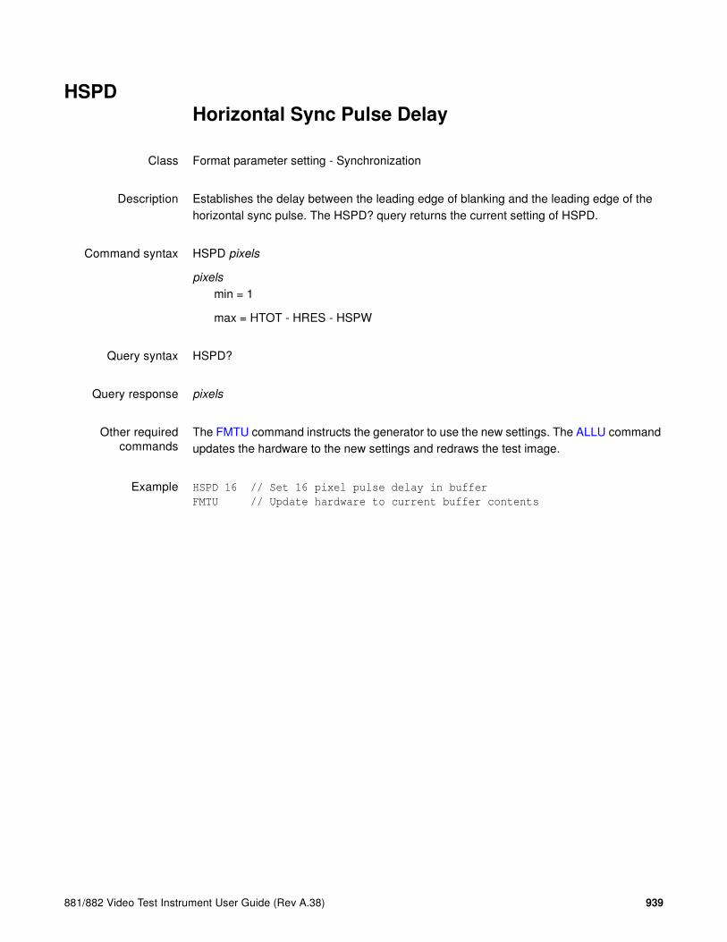
881/882 Video Test Instrument User Guide (Rev A.38) 939
HSPDHorizontal Sync Pulse Delay
Class Format parameter setting - Synchronization
Description Establishes the delay between the leading edge of blanking and the leading edge of the horizontal sync pulse. The HSPD? query returns the current setting of HSPD.
Command syntax HSPD pixels
pixels
min = 1
max = HTOT - HRES - HSPW
Query syntax HSPD?
Query response pixels
Other requiredcommands
The FMTU command instructs the generator to use the new settings. The ALLU command updates the hardware to the new settings and redraws the test image.
Example HSPD 16 // Set 16 pixel pulse delay in buffer
FMTU // Update hardware to current buffer contents

940 Appendix A Command Reference
HSPGHorizontal Sync Pulse Gate
Class Format parameter setting - Synchronization
Description Enables and disables the digital horizontal sync output. The HSPG? query returns the current HSPG mode.
Command syntax HSPG mode
mode
0 = OFF
1 = ON
Query syntax HSPG?
Query response 0 or 1
Other requiredcommands
To use digital horizontal sync, digital separate H and V sync must be selected with the SSST command. The FMTU command instructs the generator to use the new settings. The ALLU command updates the hardware to the new settings and redraws the test image.
Example HSPG 1 // Enable H sync output in buffer
FMTU // Update hardware to current buffer contents
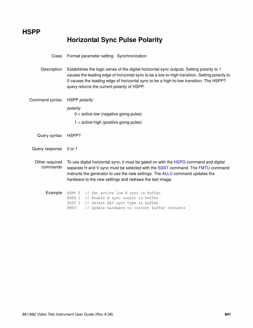
881/882 Video Test Instrument User Guide (Rev A.38) 941
HSPPHorizontal Sync Pulse Polarity
Class Format parameter setting - Synchronization
Description Establishes the logic sense of the digital horizontal sync outputs. Setting polarity to 1 causes the leading edge of horizontal sync to be a low-to-high transition. Setting polarity to 0 causes the leading edge of horizontal sync to be a high-to-low transition. The HSPP? query returns the current polarity of HSPP.
Command syntax HSPP polarity
polarity
0 = active-low (negative going pulse)
1 = active-high (positive going pulse)
Query syntax HSPP?
Query response 0 or 1
Other requiredcommands
To use digital horizontal sync, it must be gated on with the HSPG command and digital separate H and V sync must be selected with the SSST command. The FMTU command instructs the generator to use the new settings. The ALLU command updates the hardware to the new settings and redraws the test image.
Example HSPP 0 // Set active low H sync in buffer
HSPG 1 // Enable H sync output in buffer
SSST 1 // Select H&V sync type in buffer
FMTU // Update hardware to current buffer contents

942 Appendix A Command Reference
HSPWHorizontal Sync Pulse Width
Class Format parameter setting - Synchronization
Description Establishes the width of the horizontal sync pulse. The HSPW? query returns the current setting of HSPW.
Command syntax HSPW pixels
pixels
min = 1
max = HTOT - HRES - HSPD
Query syntax HSPW?
Query response pixels
Other requiredcommands
The FMTU command instructs the generator to use the new settings. The ALLU command updates the hardware to the new settings and redraws the test image.
Example HSPW 32 // Set pulse width to 32 pixels in buffer
FMTU // Update hardware to current buffer contents

881/882 Video Test Instrument User Guide (Rev A.38) 943
HTOTHorizontal TOTal pixels per line
Class Format parameter setting - Video resolution
Description Establishes the total number of pixels per horizontal line. The HTOT? query returns the current setting of HTOT.
The pixel rate is equal to HRAT multiplied by HTOT.
Note: The current version of the firmware does not allow you to directly enter a specific
pixel rate when setting up a format. If your test specifications call for a specific pixel or dot
clock rate, enter suitable values for HRAT and HTOT to give you the desired pixel rate.
Command syntax HTOT pixels
pixels
Query syntax HTOT?
Query response pixels
Other requiredcommands
The FMTU command instructs the generator to use the new settings. The ALLU command updates the hardware to the new settings and redraws the test image.
Example HTOT 800 // Set total to 800
FMTU // Update hardware to current buffer contents

944 Appendix A Command Reference
HVPD?Horizontal Vertical Sync Pulse Delay
Class Format Parameter Setting - Synchronization
Description Returns the pixel delay between the horizontal and vertical sync pulses.
Query syntax HVPD?
Query response number of pixels
Example HVPD? // read pixel delay between HSYNC and VSYNC pulses
1 // one pixel delay
Related commands None
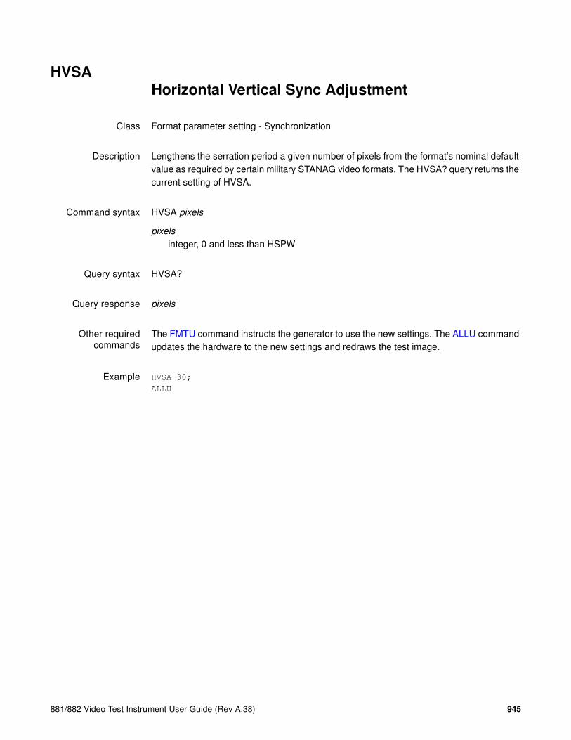
881/882 Video Test Instrument User Guide (Rev A.38) 945
HVSAHorizontal Vertical Sync Adjustment
Class Format parameter setting - Synchronization
Description Lengthens the serration period a given number of pixels from the format’s nominal default value as required by certain military STANAG video formats. The HVSA? query returns the current setting of HVSA.
Command syntax HVSA pixels
pixels
integer, 0 and less than HSPW
Query syntax HVSA?
Query response pixels
Other requiredcommands
The FMTU command instructs the generator to use the new settings. The ALLU command updates the hardware to the new settings and redraws the test image.
Example HVSA 30;
ALLU

946 Appendix A Command Reference
I2CR? (OUT1:I2CR?, OUT2:I2CR?, VGA:I2CR?)I2C port Read
Class EDID and DDC control
Description Automatically reads data using a specified I2C protocol. This command reads data from the specified connector, bus and device using the I2C bus. If no connector is specified, the query defaults to OUT1 or VGA depending on the active output. All numeric parameters are given in ASCII HEX.
Note: EDID-compatible receivers use EPROMs with single-byte or double-byte
addresses. The I2CR? query uses different parameters depending on the EPROM
type. To determine which EPROM type is used, try both syntaxes until you can read
data from the EPROM.
Query syntax(EPROM with
single-byteaddresses)
connector:I2CR? bus_name i2c_address offset #_of_bytes
Query syntax(EPROM with
double-byteaddresses)
connector:I2CR? eprom1 i2c_address offset #_of_bytes
Query syntax (deviceprotocol)
connector:I2CR? bus_name i2c_address offset #_of_bytes
connector
OUT1, OUT2 = HDMI OUT 1 or HDMI OUT 2 connector
VGA = VGA connector
bus_name (optional - text)device queried(eprom, eprom1, TV, DT, HT, HR)
i2c_address (hex)i2c bus address (A0, A1,...)
offset (hex)address offset (in bytes)
#_of_bytes (hex)number of bytes
Example 1 This example reads 10 bytes of E-EDID data, using the I2C e_ddc protocol.
R:\>i2cr? eprom a0 80 10
02031A76478502030406070123090707

881/882 Video Test Instrument User Guide (Rev A.38) 947
Example 2 This command reads four register bytes values from the transmitter TV chip of the generator
i2cr? tv 89 00 04
82021402
Example 3 This command reads the HDCP Bksv value from a receiver
i2cr? 74 00 05
07BE05CEA9
Example 4 This command reads two bytes of register values from the transmitter (output 1) HDMI chip of the generator
i2cr? HT1 7a 00 02
0002
Related commands EDA<port>:GDID, I2CW (OUT1:I2CW, OUT2:I2CW, VGA:I2CW)

948 Appendix A Command Reference
I2CW (OUT1:I2CW, OUT2:I2CW, VGA:I2CW)I2C port Write
Class EDID and DDC control
Description Writes raw binary data data using a specified I2C protocol. This command writes data to the specified connector, bus and device using the I2C bus. If no connector is specified, the query defaults to OUT1 or VGA depending on the active output. All numeric parameters are given in ASCII HEX.
Note: EDID-compatible receivers use EPROMs with single-byte or double-byte
addresses. The I2CW command uses different parameters depending on the EPROM type.
Important: When writing data with this command, ensure you send only 8 bytes of data at
a time. This is necessary since most EPROMs do not have a larger memory buffer.
Command syntax(EPROM with
single-byteaddresses)
connector:I2CW bus_name i2c_address offset data
Command syntax(EPROM with
double-byteaddresses)
connector:I2CW eprom1 i2c_address offset #_of_bytes data
Command syntax(device protocol)
connector:I2CW bus_name i2c_address offset data
connector
OUT1, OUT2 = HDMI OUT 1 or HDMI OUT 2 connector
VGA = VGA connector
bus_name (optional - text)device queried (eprom, eprom1, TV, DT, HT1, HR)
i2c_address (hex)i2c bus address (A0, A1,...)
offset (hex)address offset (in bytes)
data (hex)the data that you want to send to the register
Example 1 This example writes two bytes of E-EDID data, using the I2C e_ddc protocol.
i2cw eprom a0 80 2 FFFF

881/882 Video Test Instrument User Guide (Rev A.38) 949
Example 2 This command writes four register bytes values from the transmitter TV chip of the generator.
i2cw tv 89 00 04 FFFFFFFF
Related commands XDID, I2CR? (OUT1:I2CR?, OUT2:I2CR?, VGA:I2CR?)

950 Appendix A Command Reference
IFGUInfoFrame Generator Use
Class InfoFrame Packet
Description Updates hardware with current InfoFrame contents.
Command syntax IFGU
Example IFTG 14
IFGU
Related commands IFAX:RPTU, IFTR, XGIF, XAVI, XSPD, XAUD, XMPG

881/882 Video Test Instrument User Guide (Rev A.38) 951
IFGX:RPTUInfoFrame Generator RePorT
Class InfoFrame Packet
Description Runs a Packet Tx report on the 882E generator.
Command syntax IFGX:RPTU
Example This example generates the Packet Tx report and is available through the web interface.
IFGX:RPTU

952 Appendix A Command Reference
IFAX:RPTUInfoFrame Generator RePorT
Class InfoFrame Packet
Description Runs a Packet Rx report on the 882EA analyzer.
Command syntax IFAX:RPTU
Example This example generates the Packet Rx report and is available through the web interface.
IFAX:RPTU

881/882 Video Test Instrument User Guide (Rev A.38) 953
IFTGInfoFrame Type Gate
Class InfoFrame Packet
Description Gates the InfoFrames by type. The mask value is a value ORed with the current setting.
Note: For more information about the InfoFrame structure, see the EIA Standard
EIA/CEA-861-C (Section 6).
Command syntax IFTG mask
mask
A bit mask based on these InfoFrame type values.
Example 1 This example enables AUD (8), SPD (4), and AVI (2) InfoFrames. The MPG, GIFA, GIFB, GAMUT and 3DVSI InfoFrames are gated off, and loaded with zeros.
IFTG 14
IFGU
Example 2 This example shows how to send 3 different VSIs. Two generic VSIs are sent prior to a 3D VSI.
You first enable 3D VSI(128) infoframe and disable AUD, SPD, and AVI, MPG, GIFA, GIFB and GAMUT.
IFTR 127 // enables repeating infoframes for GIFA (1), AVI (2), SPD (4),
AUD (8), MPG (16) GIFB (32), GAMUT (64)
IFTG 63 // enables (gates on) GIFA (1), AVI (2), SPD (4), AUD (8),
MPG (16) GIFB (32)
XGIF A 1 1 5 12FA001234 // sends 5 bytes in Vendor Specific Infoframe
XGIF B 1 1 5 56AB005678 // sends 5 bytes in Vendor Specific Infoframe
IFGU // iniates the sending of the infoframe gate commands
Type Value
GIFA 1
AVI 2
SPD 4
AUD 8
MPG 16
GIFB 32
GAMUT 64
3DVSI 128

954 Appendix A Command Reference
X3DM 1 8 0 // sends 3D VSI with side-by-side half
FMTU // initiates command sequence
Related commands IFGU, IFTR

881/882 Video Test Instrument User Guide (Rev A.38) 955
IFTRInfoFrame Type Repeat Mask
Class InfoFrame Packet
Description Specifies if an InfoFrame type is to be sent once (after the IFGU command is executed), or sent in every vertical blanking period (frame).
Note: For more information about the InfoFrame structure, see the EIA Standard
EIA/CEA-861-B (Section 6).
Command syntax IFTR mask
mask
A bit mask based on these InfoFrame type values.
Example This example specifies that AUD (8) and AVI (2) InfoFrames should be repeated with every frame, and other InfoFrame types should be sent once.
IFTR 10
IFGU
Related commands IFAX:RPTU, IFGU
Type Value
GIFA 1
AVI 2
SPD 4
AUD 8
MPG 16
GIFB 32
GAMUT 64
3DVSI 128

956 Appendix A Command Reference
IMGAIMaGe save As
Class Image memory management
Description Saves the current contents of the image edit buffer using the given name.
Command syntax IMGA name
name
a valid MS-DOS filename (8 characters minus any extension)
Example IMGA MY_IMG // Save with the name "MY_IMG"

881/882 Video Test Instrument User Guide (Rev A.38) 957
IMGBIMaGe editing Begin
Class Image editor control
Description Marks the beginning of an image editing session.
Command syntax IMGB
Other requiredcommands
Use either an IMGL command to load an existing image or an IMGN command to create a new image. Use IMGE when ending the editing session.
Example IMGN // Initialize image edit buffer
IMGB // Start image editing session
// One or more image editing
// commands ...
IMGE // End image editing session

958 Appendix A Command Reference
IMGEIMaGe editing End
Class Image editor control
Description Marks the end of an image editing session.
Command syntax IMGE
Other requiredcommands
Use IMGB when starting the editing session. Use IMGA or IMGS to save changes.
Example IMGB // Start image editing session
// One or more image editing commands ...
IMGA MYIMG_02 // Save edited image as "MYIMG_02"
IMGE // End image editing session

881/882 Video Test Instrument User Guide (Rev A.38) 959
IMGKIMaGe Kill
Class Image memory management
Description Deletes an image by name. The query returns a 1 if the named image can be deleted. If the image is read-only or nonexistent, the query returns a 0.
Command syntax IMGK name
name
a valid MS-DOS filename (8 characters minus any extension)
Query syntax IMGK? name
name
a valid MS-DOS filename (8 characters minus any extension)
Query response 0 or 1
Example IMGK MY_IMG // Delete dir called "MY_IMG"

960 Appendix A Command Reference
IMGLIMaGe Load
Class Image memory management
Description Assigns an image to the current step of a sequence while between a set of SEQB and SEQE commands. The IMGL command is context sensitive. The IMGL? query returns the name of the image currently assigned to the step.
Outside of the sequence editor, the IMGL command copies the image having a name equal to name from image memory into the image edit buffer. The query returns a one (1) if the named image can be loaded, otherwise a zero (0) is returned.
Command syntax IMGL name
name
a valid MS-DOS filename (8 characters minus any extension)
Query syntax IMGL? name
name
a valid MS-DOS filename (8 characters minus any extension)
Query response 0 or 1
Other requiredcommands
An ALLU or IMGU command must be executed after the IMGL command to cause the image in the edit to draw on the unit under test.
Example IMGL MY_IMG // Load "MY_IMG" dir in edit buffer
IMGU // Draw contents of buffer

881/882 Video Test Instrument User Guide (Rev A.38) 961
IMGNIMaGe New
Class Image editor control
Description Initializes the image edit buffer. The name name is assigned as the image's name. The query will return the name that has been assigned as the image's name.
Command syntax IMGN name
name
optional valid MS-DOS filename (8 characters minus any extension)
Query syntax IMGN?
Query response name
Example IMGN // Init edit buffer without assigning a new name
or
IMGN MY_IMG // Init edit buffer with name of "MY_IMG"

962 Appendix A Command Reference
IMGPIMaGe Path
Class Image memory management
Description Sets the current image path name to a given directory. The query will return the current image path name.
Command syntax(flash memory/PC
card)
IMGP path name
path name
a valid MS-DOS filename (8 characters minus any extension)
Command syntax(file server)
IMGP server name:
server name
valid hostname (no forward slash before name, and colon after name)
Query syntax IMGP? name
name
a valid MS-DOS filename (8 characters minus any extension)
Query response name
Example IMGP FINAL // Sets image pathname to a directory called "FINAL".
IMGP hostname1: // Sets image pathname to "HOSTNAME1" file server.

881/882 Video Test Instrument User Guide (Rev A.38) 963
IMGQ?IMaGe Query pointer
Class Image memory management
Description Returns number image names from the list of all the images stored in image memory beginning at index. The images are kept in alphanumeric order.
Query syntax IMGQ? index number
index
positive integer number
number
positive integer number
Query response List of specified image names
Example IMGQ? 1 5 // List the first five images in memory
or
IMGQ? 1 9999 // List all images in memory

964 Appendix A Command Reference
IMGSIMaGe Save
Class Image memory management
Description Saves the current contents of the generator's custom image edit buffer back to the memory location from which it was originally read.
Command syntax IMGS

881/882 Video Test Instrument User Guide (Rev A.38) 965
IMGUIMaGe Use
Class Image memory management
Description Draws an image based on the current contents of the image. The IMGU? query returns the image memory location location from which the current contents of the image were read.
Command syntax IMGU
Query syntax IMGU?
Query response location
location
-1 through -26 (EPROM)
Example IMGL BriteBox // Select the BriteBox test image
IMGU // Draw the selected test image

966 Appendix A Command Reference
INITINITialize to factory default settings
Class Direct processor control
Description Restores the contents of all of the generator's RAM storage locations to factory-default conditions. The generator then goes through a complete self-test and self-calibration procedure.
Important: The INIT command permanently and irreversibly removes all user-created
formats, custom images, test sequences, and directories from memory.
Command syntax INIT

881/882 Video Test Instrument User Guide (Rev A.38) 967
ISHAImageSHift save As
Class
Description Saves the current contents of the imageshift edit buffer using the specified name.
Command syntax ISHA filename
filename
a valid MS-DOS filename (8 characters minus any extension)
Example ISHA Myshift1 // Saves with the name Myshift1
Related commands ISHB, ISHE, ISHG, ISHK, ISHL, ISHN, ISHP, ISHQ?, ISHS, ISHU, XISH:HINC, XISH:PATH, XISH:SRCN, XISH:TINC, XISH:TTYP, XISH:VINC

968 Appendix A Command Reference
ISHBImageSHift edit Begin
Class
Description Marks the beginning of an imageshift editing session.
Command syntax ISHB
Other requiredcommands
Use either an ISHL command to load an existing imageshift file or an ISHN command to create a new imageshift file. Use ISHE when ending the editing session.
Example ISHB // Begin imageshift editing session
Related commands ISHA, ISHE, ISHG, ISHK, ISHL, ISHN, ISHP, ISHQ?, ISHS, ISHU, XISH:HINC, XISH:PATH, XISH:SRCN, XISH:TINC, XISH:TTYP, XISH:VINC
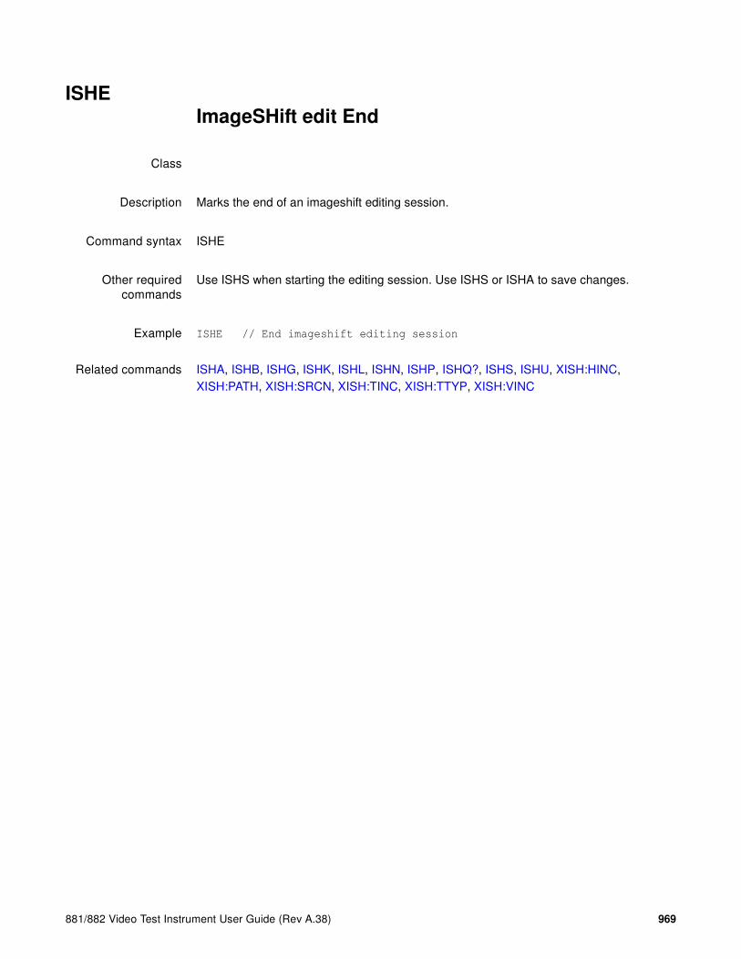
881/882 Video Test Instrument User Guide (Rev A.38) 969
ISHEImageSHift edit End
Class
Description Marks the end of an imageshift editing session.
Command syntax ISHE
Other requiredcommands
Use ISHS when starting the editing session. Use ISHS or ISHA to save changes.
Example ISHE // End imageshift editing session
Related commands ISHA, ISHB, ISHG, ISHK, ISHL, ISHN, ISHP, ISHQ?, ISHS, ISHU, XISH:HINC, XISH:PATH, XISH:SRCN, XISH:TINC, XISH:TTYP, XISH:VINC

970 Appendix A Command Reference
ISHGImageSHift Gate
Class
Description Enables and disables the image shifting function. The ISHG? query returns the current ISHG mode.
Command syntax ISHG mode
mode
0 = OFF
1 = ON
Query syntax ISHG?
Query response 0 or 1
Example ISHG 1 //Enables the image shifting function.
Related commands ISHA, ISHB, ISHE, ISHK, ISHL, ISHN, ISHP, ISHQ?, ISHS, ISHU, XISH:HINC, XISH:PATH, XISH:SRCN, XISH:TINC, XISH:TTYP, XISH:VINC

881/882 Video Test Instrument User Guide (Rev A.38) 971
ISHKImageSHift Kill
Class
Description Deletes the specified imageshift file.
Command syntax ISHK path/filename
path/filename
The directory path and valid MS-DOS filename (8 characters minus any extension) of the file to be deleted. If the file to be deleted is in the default path, then path/ may be omitted.
Example ISHK Myshift1 // Deletes the imageshift file named Myshift1
Related commands ISHA, ISHB, ISHE, ISHG, ISHL, ISHN, ISHP, ISHQ?, ISHS, ISHU, XISH:HINC, XISH:PATH, XISH:SRCN, XISH:TINC, XISH:TTYP, XISH:VINC

972 Appendix A Command Reference
ISHLImageSHift Load
Class
Description Loads the values from the specified imageshift file.
Command syntax ISHL path/filename
path/filename
The directory path and valid MS-DOS filename (8 characters minus any extension) of the file to be loaded. If the file to be loaded is in the default path, then path/ may be omitted.
Example ISHL Myshift1 // Loads the imageshift file named Myshift1
Related commands ISHA, ISHB, ISHE, ISHG, ISHN, ISHP, ISHQ?, ISHS, ISHU, XISH:HINC, XISH:PATH, XISH:SRCN, XISH:TINC, XISH:TTYP, XISH:VINC

881/882 Video Test Instrument User Guide (Rev A.38) 973
ISHNImageSHift New file
Class
Description Creates a new imageshift file with the name specified by filename.
Command syntax ISHN filename
filename
a valid MS-DOS filename (8 characters minus any extension)
Example This example creates the file Myshift1 in the /imageshifts directory on the generator.
ISHN Myshift1 //Creates an imagefile named Myshift1
Related commands ISHA, ISHB, ISHE, ISHG, ISHK, ISHL, ISHP, ISHQ?, ISHS, ISHU, XISH:HINC, XISH:PATH, XISH:SRCN, XISH:TINC, XISH:TTYP, XISH:VINC
974 Appendix A Command Reference
ISHPset ImageSHift Path
Class
Description Sets the default imageshift path.
Command syntax ISHP path
path
path to directory containing imageshift files
Query syntax ISHP?
Query response path
Example 1 This example sets the default path to the /imageshifts directory.
ISHP /tffs0/library/imageshifts
Example 2 This example queries the generator for the current imageshift path setting.
ISHP? //Query for the current imageshift path
/tffs0/library/imageshifts //current path
Related commands ISHA, ISHB, ISHE, ISHG, ISHK, ISHL, ISHN, ISHQ?, ISHS, ISHU, XISH:HINC, XISH:PATH, XISH:SRCN, XISH:TINC, XISH:TTYP, XISH:VINC

881/882 Video Test Instrument User Guide (Rev A.38) 975
ISHQ?ImageSHift Query pointer
Class
Description Returns a list of up to 5 imageshift filenames from the list of all the imageshift files in a directory. Quering repeatedly will eventually exhaust the list of filenames.
Query syntax ISHQ?
Query response List of imageshift filenames.
Example ISHQ? //List the first 5 imageshift filenames.
ISHQ? //List the nezt 5 imageshift filenames.
Related commands ISHA, ISHB, ISHE, ISHG, ISHK, ISHL, ISHN, ISHP, ISHS, ISHU, XISH:HINC, XISH:PATH, XISH:SRCN, XISH:TINC, XISH:TTYP, XISH:VINC
976 Appendix A Command Reference
ISHSImageSHift Save
Class
Description Saves the current imageshift values to the filename established using the ISHN command. If no ISHN command has been issued, then the values are saved to the default filename Shift1.xml.
Command syntax ISHS
Example ISHN Newshift //Creates a new imageshift file named NEWSHIFT
ISHB //Begins an imageshift editing session
XISH:SRCN cache0/images/SMPTEBar //selects the SMPTEBar image
XISH:PATH 0,0 150,20 //Sets the imageshift path x,y coordinates
XISH:TTYP 1 //Sets the trace type to Repeat (1)
ISHE //Ends the imageshift editing session
ISHS //Saves the values to the NEWSHIFT file
Related commands ISHA, ISHB, ISHE, ISHG, ISHK, ISHL, ISHN, ISHP, ISHQ?, ISHU, XISH:HINC, XISH:PATH, XISH:SRCN, XISH:TINC, XISH:TTYP, XISH:VINC

881/882 Video Test Instrument User Guide (Rev A.38) 977
ISHUImageSHift Use
Class
Description Applies the current imageshift file values to the hardware.
Command syntax ISHU
Example ISHL Newshift //Loads the imageshift file named NEWSHIFT
ISHU //Applies NEWSHIFT values to the hardware
Related commands ISHA, ISHB, ISHE, ISHG, ISHK, ISHL, ISHN, ISHP, ISHQ?, ISHS, XISH:HINC, XISH:PATH, XISH:SRCN, XISH:TINC, XISH:TTYP, XISH:VINC

978 Appendix A Command Reference
ISTP?Image STep
Class Image editor control
Description Allows the contents of user created custom images to be copied out of a generator. The contents of the firmware-based, built-in test images cannot be read out since they are not created as a set of primitives.
Query syntax ISTP? returns the number of steps in the custom image in the edit buffer.
or
ISTP? step_number returns the contents of the given step in the custom image in the edit buffer as a space delimited text string.
Other requiredcommands
A custom image must have been loaded with the IMGL command and editing must have been started with the IMGB command

881/882 Video Test Instrument User Guide (Rev A.38) 979
ISUBImage Step Button
Class System parameter settings
Description Determines if the Image Step key is on or off to allow activation of alternate versions of test images that have alternate versions.
The ISUB? query returns the current setting of ISUB.
Command syntax ISUB mode
mode
0 = OFF
1 = ON
Query syntax ISUB?
Query response 0 or 1
Example IMGL SlideBox // Load image
ISUB 1 // Enable alternate versions
IVER 1 // Load version 1
IMGU // Update display
980 Appendix A Command Reference
IVERImage VERsion
Class System parameter settings
Description Determines which version of an image is used for the current step of a sequence while between a set of SEQB and SEQE commands. The IVER command is context sensitive. The IVER? query returns the version currently assigned to the step.
Outside of the sequence editor, the IVER command selects which version of the current image is drawn when either an ALLU or IMGU command is executed. The IVER? query returns the current setting of IVER.
Command syntax IVER mode
mode
0 = Normal
1 = Invert or display alternate version
Query syntax IVER?
Query response 0 or 1
Other requiredcommands
The IMGU command redraws an image using the new setting. The ALLU command updates hardware and redraws the test image with the new setting.
Example IMGL Text_9 // Select image with white text on black
IVER 1 // Select inverted with black on white
IMGU // Draw the image as selected

881/882 Video Test Instrument User Guide (Rev A.38) 981
JDVIJustify pixel clock rate for DVI formats
Class Format editor control
Description Enables setting of the upper and lower bound for the pixel rate of the HDMI-D and HDMI-H outputs. The command takes two parameters: 1) upper frequency parameter and 2) lower frequency parameter. You can set either values or both values but you have to enter the first parameter if you want to set the second parameter value. The default values for HDMI-H and HDMI-D are 165MHz for the upper limit and 25MHz for the lower limit.
Command syntax JDVI upper_pixel_rate lower_pixel_rate
upper_pixel_rate lower_pixel_rate
floating point number equal to the desired pixel in MHz
Query syntax JDVI?
Query response upper_pixel_rate lower_pixel_rate
Other requiredcommands
The ALLU command updates hardware to the new settings and redraws the test image.
Examples JDVI 165E06 20E06 // sets the lower limit pixel rate to 20MHz
ALLU
JDVI 170E06 25E06 // sets the upper limit pixel rate to 170MHz
ALLU
JDVI 175E06 23E06 // sets the upper limit pixel rate to 175MHz and
the lower limit to 23MHz
ALLU
JDVI?
+175.000E+06, +23.000E+06

982 Appendix A Command Reference
JLDIJustify pixel clock rate for LDI formats
Class Format editor control
Description Scales the horizontal timing parameters of the format currently in the edit buffer. (For the 801LD used in digital mode, the default is set at 224 MHz.) The parameters are scaled to produce the given pixel rate while keeping the horizontal scan rate as close as possible to its original value. The following parameters are scaled: horizontal total pixels, horizontal active pixels, horizontal sync delay in pixels, and horizontal sync pulse width in pixels. The parameters are scaled so that their periods, in microseconds, are as close as possible to their original values.
Command syntax JLDI pixel_rate
pixel_rate
floating point number equal to the desired pixel in MHz
Query syntax JLDI?
Query response pixel_rate
Other requiredcommands
The ALLU command updates hardware to the new settings and redraws the test image.

881/882 Video Test Instrument User Guide (Rev A.38) 983
JRATJustify pixel clock RATe
Class Format editor control
Description Scales the horizontal timing parameters of the format currently in the edit buffer. The parameters are scaled to produce the given pixel rate while keeping the horizontal scan rate as close as possible to its original value. The following parameters are scaled: horizontal total pixels, horizontal active pixels, horizontal sync delay in pixels, and horizontal sync pulse width in pixels. The parameters are scaled so that their periods, in microseconds, are as close as possible to their original values.
Command syntax JRAT pixel_rate
pixel_rate
floating point number equal to the desired pixel in MHz
Other requiredcommands
The ALLU command updates hardware to the new settings and redraws the test image.
Example JRAT 202.000E6 // Adjust timing to a 202.000 MHz clock
FMTU // Update hardware to current buffer contents

984 Appendix A Command Reference
LCDS?LCD Status
Class System parameter settings
Description Returns text displayed on LCD of the generator.
Query syntax LCDS?
Example LCDS? // Return text similar to text below
// H32 15=VGA_m3 crlf
// V60 51=SMPTE133
881/882 Video Test Instrument User Guide (Rev A.38) 985
LEDS? LED Status
Class System parameter settings
Description Returns the current status of the generator's signal generating hardware as a single decimal number. The number corresponds to the status of the lighted key on the generator in normal operation. The easiest way to interpret the number is to first convert it to an 8-digit binary number. A 1 in a given position, from MSB to LSB, corresponds to the following hardware settings:
Master output control gated ON (MSB)
Digital Separate (HS&VS) Sync selected
Digital Composite Sync selected
Analog Composite Sync selected
Blue video enabled
Green video enabled
Red video enabled
Alternate image version selected (LSB)
Query syntax LEDS?
Query response decimal number from 0 to 255
Example LEDS?
// Returns the following number when the outputs are gated ON, separate
// HS & VS is selected, the red, green and blue video channels are
// enabled and the primary version of an image is selected.
206 // Binary equivalent = 11001110
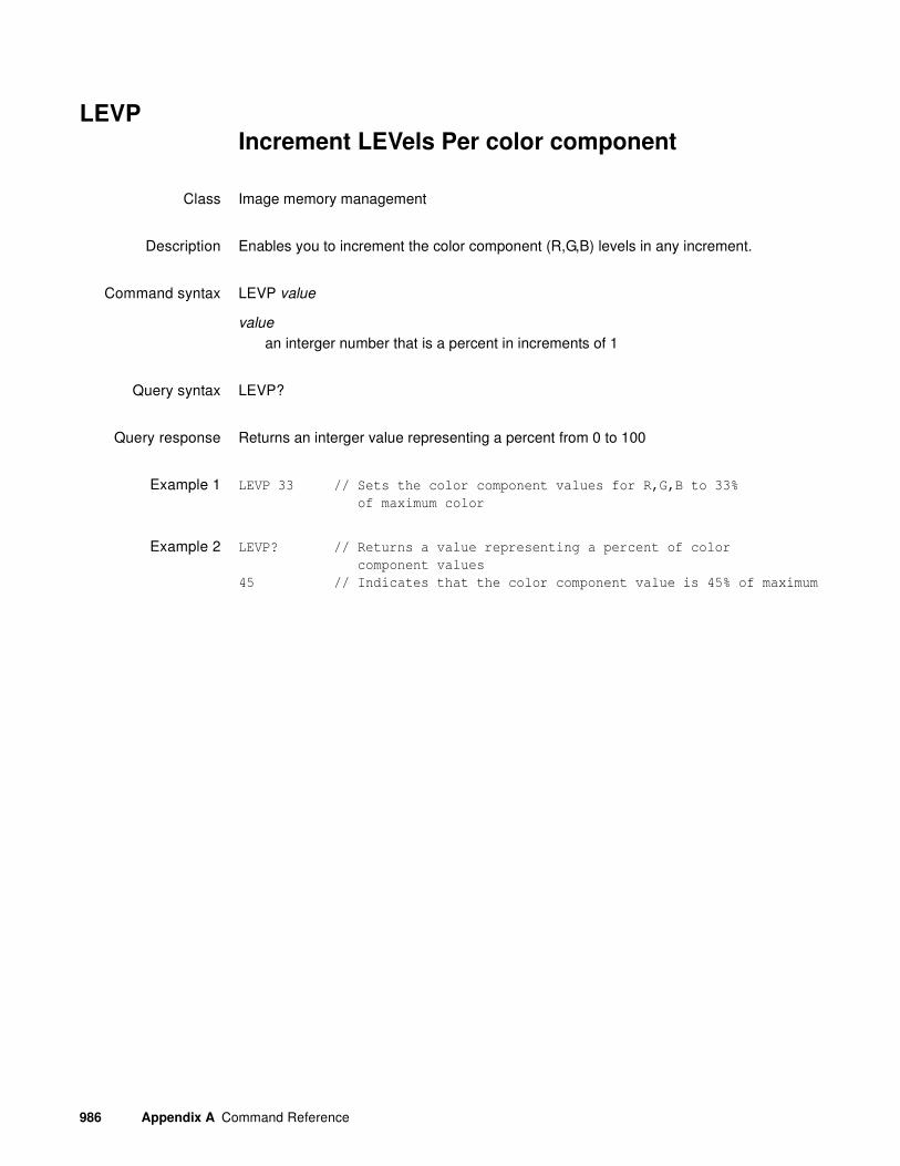
986 Appendix A Command Reference
LEVPIncrement LEVels Per color component
Class Image memory management
Description Enables you to increment the color component (R,G,B) levels in any increment.
Command syntax LEVP value
value
an interger number that is a percent in increments of 1
Query syntax LEVP?
Query response Returns an interger value representing a percent from 0 to 100
Example 1 LEVP 33 // Sets the color component values for R,G,B to 33%
of maximum color
Example 2 LEVP? // Returns a value representing a percent of color
component values
45 // Indicates that the color component value is 45% of maximum

881/882 Video Test Instrument User Guide (Rev A.38) 987
LEVP:RIncrement LEVels Per individual color component
Class Image memory management
Description Enables you to increment the color component (R,G,B) values in any increment (1 to 100) for each component color individually.
Command syntax LEVP:color value
color
a color component either R, G, B
value
an interger number that is a percent in increments of 1
Query syntax LEVP:color?
color
a color component either R, G, B
Query response Returns an interger value representing a percent from 0 to 100
Example 1 LEVP:R 33 // Sets the red color component values to 33%
of maximum color
Example 2 LEVP:G 90 // Sets the green color component values to 33%
of maximum color
Example 3 LEVP:B? // Returns a value representing a percent of color
value for the blue component
45 // Indicates that the color component value is 45% of maximum

988 Appendix A Command Reference
LIMIdraw video LIMIts markers
Class Custom image primitive
Description Places nine markers that define the active video area. An L-shaped marker is placed at each corner. T-shaped markers are centered along each edge of video, and a small cross is placed at the center of video. The primitive uses a single parameter: color.
Command syntax LIMI color
color
available colors
Other requiredcommands
The FMTU command instructs the generator to use the new setting. The ALLU command updates hardware to the new setting and redraws the test image.
Example LIMI white // Place white markers that define active video area
ALLU // Update hardware to current buffer contents

881/882 Video Test Instrument User Guide (Rev A.38) 989
LINEdraw a LINE
Class Custom image primitive
Description Draws a line between any two points. The line is 1 pixel thick. The primitive uses five parameters: the color and x,y coordinates for both endpoints.
Command syntax LINE color x_start y_start x_end y_end
color
available colors
x_start, y_start, x_ end, y_end
positive integer number
Other requiredcommands
The FMTU command instructs the generator to use the new setting. The ALLU command updates hardware to the new setting and redraws the test image.
Example LINE yellow 20 5 320 240
// Draw yellow line from X=20, Y=5 to X=320, Y=240
ALLU // Update hardware to current buffer contents

990 Appendix A Command Reference
LMAXDigital Video Maximum quantizing Level
Class Format parameter setting - Digital video signal
Description Sets the maximum quantizing level of the component video signal for white. The default varies depending on the number of bits per color component. Some applications may require that the maximum level be set lower than the maximum permissible. The query reads the current setting for the maximum level.
Command syntax LMAX video_level
video_level
unsigned integer from 59 to 63 when NBPC is 6 gamuts; 235 to 255 when NBPC is 8 gamuts; 940 to 1023 when NBPC is 10 gamuts; 3760 to 4095 when NBPC is 12 gamuts.
Query syntax LMAX?
Example LMAX 254 // To set the maximum digital quantizing level to 254
Related commands LMIN, NBPC, DVQM

881/882 Video Test Instrument User Guide (Rev A.38) 991
LMINDigital Video Minimum quantizing Level
Class Format parameter setting - Digital video signal
Description Sets the minimum quantizing level of the component video signal for black. The default is 0 for black; however, some applications may require that the minimum level be set higher. The query reads the current setting for the minimum level.
Command syntax LMIN video_level
video_level
unsigned integer from 0 to 4 when NBPC is 6 gamuts; 0 to 16 when NBPC is 8 gamuts; 0 to 64 when NBPC is 10 gamuts; 0 to 256 when NBPC is 12 gamuts
Query syntax LMIN?
Example LMIN 16 // To set the minimum digital quantizing level to 16
Related commands LMAX, NBPC, DVQM

992 Appendix A Command Reference
LS?LS?
Class Tools
Description Lists the contents of the current directory.
Query syntax LS?
Query response List of file names is presented.
Related commands None
Example LS?
barpulse.o
boxquart.o
diamond.o
tceburst.o
barsmpte.o

881/882 Video Test Instrument User Guide (Rev A.38) 993
LSAX:LSGMLipSync Analyzer Enable/Disable
Class LipSync Generator/Analyzer
Description Enable or disable LipSync analyzer for HDMI auto lipsync correction testing.
Command syntax LSAX:LSGM boolean
boolean
0 = disable
1 = enable
Query syntax LSAX:LSGM?
Query response 0 or 1
Example LSAX:LSGM 1 // Enable LipSync testing
LSAX:LSGU // Update hardware to new settings

994 Appendix A Command Reference
LSAX:LSGULipSync Analyzer Use
Class LipSync Generator/Analyzer
Description Updates hardware with current LipSync analyzer setup values and restarts the image.
Command syntax LSAX:LSGU
Example LSAX:LSGM 1 // Enable LipSync analyzer testing
LSAX:LSGU // Update hardware to new settings

881/882 Video Test Instrument User Guide (Rev A.38) 995
LSAX:PLAT?LipSync Analyzer Data Stream Order
Class LipSync Generator/Analyzer
Description Queries which data stream (audio or video) is received first by lipsync analyzer.
Query syntax LSAX:PLAT?
Query response 0 = video is received first
1 = audio is received first
Example LSAX:PLAT? // Returns data stream received first

996 Appendix A Command Reference
LSAX:RPTGLipSync Analyzer Measurement Report
Class LipSync Generator/Analyzer
Description Generates lipsync analyzer measurement report.
Command syntax LSAX:RPTG boolean
boolean
0 = disable
1 = enable
Query syntax LSAX:RPTG?
Query response 0 or 1
Example LSAX:RPTG 1 // Generates lipsync analyzer measurement report
LSAX:LSGU // Update hardware to new settings

881/882 Video Test Instrument User Guide (Rev A.38) 997
LSAX:TLAT?LipSync Analyzer Audio/Video Latency
Class LipSync Generator/Analyzer
Description Queries latency (delay) between audio and video received by lipsync analyzer.
Query syntax LSAX:TLAT?
Query response number of seconds delay
Example LSAX:TLAT? // Returns latency between audio and video data streams

998 Appendix A Command Reference
LSGX:LSGMLipSync Generator Enable/Disable
Class LipSync Generator/Analyzer
Description Enable or disable LipSync generator for HDMI auto lipsync correction testing.
Command syntax LSGX:LSGM boolean
boolean
0 = disable
1 = enable
Query syntax LSGX:LSGM?
Query response 0 or 1
Example LSGX:LSGM 1 // Enable LipSync testing
LSGX:LSGU // Update hardware to new settings

881/882 Video Test Instrument User Guide (Rev A.38) 999
LSGX:LSGULipSync Generator Use
Class LipSync Generator/Analyzer
Description Updates hardware with current LipSync generator setup values and restarts the image.
Command syntax LSGX:LSGU
Example LSGX:LSGM 1 // Enable LipSync testing
LSGX:LSGU // Update hardware to new settings

1000 Appendix A Command Reference
LSGX:PLATLipSync Generator Data Stream Order
Class LipSync Generator/Analyzer
Description Determines which data stream (audio or video) is transferred (sent) first for lipsync test image.
Command syntax LSGX:PLAT boolean
boolean
0 = video is transferred first (indicating that video takes longer to process–audio is delayed).
1 = audio is transferred first (indicating that audio takes longer to process–video is delayed).
Query syntax LSGX:PLAT?
Query response 0 or 1
Example LSGX:PLAT 1 // Audio is sent first for lipsync test image
LSGX:TLAT 0.5 // Latency between audio and video in lipsync test image
LSGX:LSGU // Update hardware to new settings

881/882 Video Test Instrument User Guide (Rev A.38) 1001
LSGX:TLATLipSync Generator Audio/Video Latency
Class LipSync Generator/Analyzer
Description Sets latency (delay) between audio and video for lipsync test image.
Command syntax LSGX:TLAT delay
delay
0.0 to 0.5 seconds
Query syntax LSGX:TLAT?
Query response delay
Example LSGX:PLAT 1 // Audio is sent first for lipsync test image
LSGX:TLAT 0.5 // Latency between audio and video in lipsync test image
LSGX:LSGU // Update hardware to new settings

1002 Appendix A Command Reference
LSPGLine Sync Pulse Gate
Class Format parameter settings
Description Enables and disables the digital horizontal sync output. The LSPG? query returns the current LSPG mode.
Command syntax LSPG mode
mode integer
0 = OFF
1 = ON
Query syntax LSPG?
Query response 0 or 1
Other requiredcommands
The FMTU command instructs the generator to use the new settings. The ALLU command updates the hardware to the new settings and redraws the test image.
Example LSPG 1 // Enable Line Sync
FMTU // Update hardware to new settings

881/882 Video Test Instrument User Guide (Rev A.38) 1003
LSPPLine Sync Pulse Polarity
Class Format parameter setting - Synchronization
Description Establishes the logic sense of the digital line sync output. Setting polarity to 1 causes the leading edge of line sync to be a low-to-high transition. Setting polarity to 0 causes the leading edge of line sync to be a high-to-low transition. The LSPP? query returns the current polarity of LSPP.
Command syntax LSPP polarity
polarity
0 = active-low (negative going pulse)
1 = active-high (positive going pulse)
Query syntax FSPP?
Query response 0 or 1
Other requiredcommands
In order to get a pulse, line sync must first be enabled with the LS? command. The FMTU command instructs the generator to use the new settings. The ALLU command updates the hardware to the new settings and redraws the test image.
Example LSPG 1 // Enable Line Sync
LSPP 1 // Set for positive going pulse
LSPW 20 // Make the pulse 20 pixels wide
LSPG 300 // Pulse to occur 300 lines after
// the last line of active video
FMTU // Update hardware to new settings

1004 Appendix A Command Reference
MODEcommunications MODE
Class System parameter settings
Description Sets the serial port communications parameters of a stand-alone model generator. The changes take effect as soon as the command is entered. The factory default settings are baud, no parity, 8 data bits, no stop bits, no handshake (handshake), and no protocol.
Command syntax MODE baud parity data stop handshake protocol
baud rate
300, 600, 1200, 2400, 4800, 9600, 19200, 38400, 57600, or 115200 bits/sec
parity
N = None, E = Even or O = Odd
data
number of data bits: 7 or 8
stop
number of stop bits: 1 or 2
handshake
N = None
H = Hardware (CTS/RTS)
protocol
N = None
Y=Y-Modem
Example MODE 9600 N 8 1 H N // Set a stand alone generator to
// communicate at 9600 Baud, No parity, 8 data bits,
// 1 stop bit, RTS//CTS handshaking and No protocol
or
MODE 2400 // Change only the baud rate
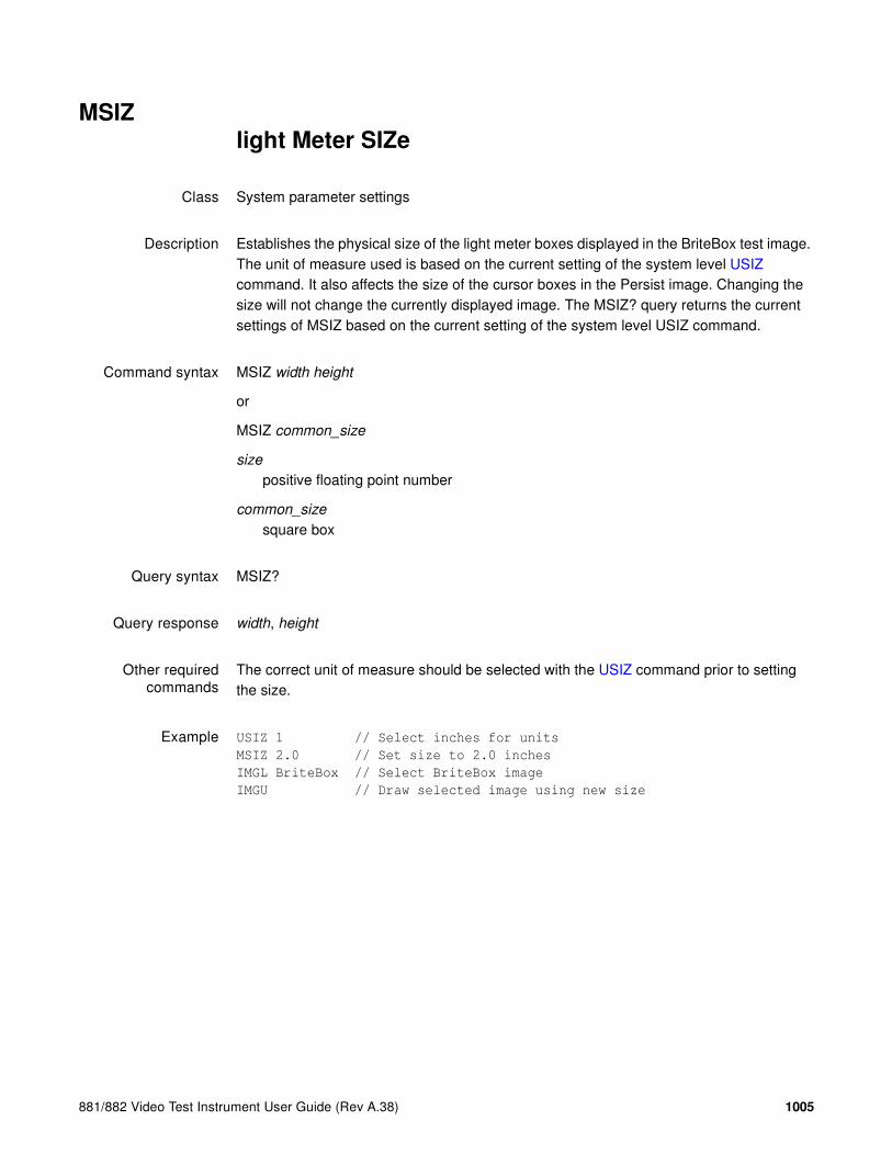
881/882 Video Test Instrument User Guide (Rev A.38) 1005
MSIZlight Meter SIZe
Class System parameter settings
Description Establishes the physical size of the light meter boxes displayed in the BriteBox test image. The unit of measure used is based on the current setting of the system level USIZ command. It also affects the size of the cursor boxes in the Persist image. Changing the size will not change the currently displayed image. The MSIZ? query returns the current settings of MSIZ based on the current setting of the system level USIZ command.
Command syntax MSIZ width height
or
MSIZ common_size
size
positive floating point number
common_size
square box
Query syntax MSIZ?
Query response width, height
Other requiredcommands
The correct unit of measure should be selected with the USIZ command prior to setting the size.
Example USIZ 1 // Select inches for units
MSIZ 2.0 // Set size to 2.0 inches
IMGL BriteBox // Select BriteBox image
IMGU // Draw selected image using new size

1006 Appendix A Command Reference
MUTEAudio/Video Mute
Class Parameters (Audio Signal and Timing)
Description Enables and disables the HDMI Audio/Video Mute (AVMUTE) feature. When enabled, audio and video are muted by the generator.
Command syntax MUTE flag
flag
0 = disable (AVMUTE_clear_flag sent repeatedly)
1 = enable (AVMUTE_set_flag sent repeatedly)
Query syntax MUTE?
Query response 0 or 1
Example To enable AVMUTE:
MUTE 1
MUTE?
Use the MUTE? to continuously check until the AVMUTE state is changed (may not take place right away).

881/882 Video Test Instrument User Guide (Rev A.38) 1007
NAMF?NAMe Find
Class Directory editor control
Description Returns the index number of the entry with name name in the directory edit buffer. The first name in the buffer has an index value of 1. If name is not found, a value of 0 is returned.
Query syntax NAMF? name
name
a valid MS-DOS filename (8 characters minus any extension)
Query response index
Example NAMF? VGA_m4 // Return position of VGA_m4 in directory
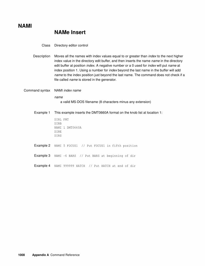
1008 Appendix A Command Reference
NAMINAMe Insert
Class Directory editor control
Description Moves all the names with index values equal to or greater than index to the next higher index value in the directory edit buffer, and then inserts the name name in the directory edit buffer at position index. A negative number or a 0 used for index will put name at index position 1. Using a number for index beyond the last name in the buffer will add name to the index position just beyond the last name. The command does not check if a file called name is stored in the generator.
Command syntax NAMI index name
name
a valid MS-DOS filename (8 characters minus any extension)
Example 1 This example inserts the DMT0660A format on the knob list at location 1:
DIRL FMT
DIRB
NAMI 1 DMT0660A
DIRE
DIRS
Example 2 NAMI 5 FOCUS1 // Put FOCUS1 in fifth position
Example 3 NAMI -6 BARS // Put BARS at beginning of dir
Example 4 NAMI 999999 HATCH // Put HATCH at end of dir

881/882 Video Test Instrument User Guide (Rev A.38) 1009
NAMKNAMe Kill
Class Directory editor control
Description Deletes the given name from the directory edit buffer. All names with index values greater than the index of the deleted name are moved to the next lower index value in the buffer. Nothing happens if name is not found in the buffer.
Command syntax NAMK name
name
a valid MS-DOS filename (8 characters minus any extension)
Example NAMK VGA_m4 // Remove VGA_m4 from dir

1010 Appendix A Command Reference
NAMQ?NAMe Query
Class Directory editor control
Description Returns number names from the list of names in the directory edit buffer beginning at index. The generator maintains internal variables for the current index and number values. The value of index is automatically incremented by number after the query is executed. Sending the query with just an index parameter, will return the same number of names as the last time, starting at the given index. Sending the query with no parameters will return the next set of names in the directory buffer.
Query syntax NAMQ? index number
index
positive integer number
number
positive integer number
Query response List of specified entry names from directory edit buffer.
Example 1 NAMQ? 1 9999 // List the entire buffer
Example 2 NAMQ? 1 10 // List the first ten names in the buffer
NAMQ? 21 // List the 21st through the 30th names in the buffer
NAMQ? // List the 31st through the 40th names in the buffer

881/882 Video Test Instrument User Guide (Rev A.38) 1011
NAMYNAMe Yank
Class Directory editor control
Description Deletes the name at the given index number from the directory edit buffer. All names with index values greater than the index of the deleted name are moved to the next lower index value in the buffer. Nothing happens if index is beyond the index number of last name in the buffer.
Command syntax NAMY index
Example NAMY 2 // Remove second item from dir

1012 Appendix A Command Reference
NBPANumber Bits Per Audio sample
Class Format parameter setting - Audio signal
Description Sets the number of bits per audio sample for an audio signal. This sets the SS parameter of the Audio InfoFrame (as specified in EIA/CEA-861-B, table 20).
Command syntax NBPA bits
bits
0 (let incoming external audio stream determine the number of bits per sample)
16
20 (882E only)
24 (882E only)
Example NBPA 16
IFGU
Related commands XAUD (SS parameter), SAMP

881/882 Video Test Instrument User Guide (Rev A.38) 1013
NBPCNumber Bits Per Component
Class Format parameter setting - Digital video signal
Description Sets the number of bits per color component (color depth).
Command syntax NBPC bits
bits
6, 8, 10, or 12 depending on output.
Example NBPC 10
FMTU
Related commands DVSM, DVQM
Output NBPC
DVI 8
TV 12
LVDS 6 (18-bit encoding) or 8 (24-bit encoding)
HDMI Digital RGB or YCbCr 4:4:4 output 8
HDMI YCbCr 4:2:2 output 8, 10, or 12.

1014 Appendix A Command Reference
NCPPNumber Clocks Per Pixel
Class Format parameter setting - Digital video signal
Description Specifies the number of clocks per pixel (double-clocking factor for whole line). Some industry standard formats (e.g. 480i) have pixel rates that are below the minimum pixel rate restriction (of 25 MHz) required by the TMDS interface. In these cases, a feature known as “double-clocking” is used to raise the TMDS clock rate to an acceptable frequency.
Double-clocking is controlled by the NCPP format parameter. When NCPP is set to 1 (normal single-clocked), each pixel, output by the generator, is paired with one clock pulse. In this case, the pixel rate is equal to the TMDS clock rate. By setting NCPP to 2 (double-clocked), two clocks are send during each pixel period and the TMDS clock rate is raised to 2 times the pixel rate.
Note that double clocking with NCPP and pixel repetition (NPPP) cannot be applied at the same time.
Command syntax NCPP factor
factor
1 or 2
Related commands NBPA, NPPP
Example NCPP 2
FMTU

881/882 Video Test Instrument User Guide (Rev A.38) 1015
NDACNumber Digital Audio Channels
Class Format parameter setting - Audio signal
Description Sets the number of digital audio channels for an audio signal. This sets the CC parameter of the Audio InfoFrame (as specified in EIA/CEA-861-B, table 20).
Command syntax NDAC channels
channels
2 or 8
Example NDAC 2
ALLU
Related Commands XAUD (CC parameter)

1016 Appendix A Command Reference
NDASNumber Digital Audio Streams
Class Format parameter setting - Audio signal
Description Sets the number of digital audio streams.
Note: Currently, only one audio stream is supported.
Command syntax NDAS streams
streams
1 (default)
Example NDAS 1
IFGU

881/882 Video Test Instrument User Guide (Rev A.38) 1017
NERR?Number of ERRors in queue
Class System memory management
Description Returns the number of errors waiting to be reported in the error queue.
Query syntax NERR?
Query response number of errors

1018 Appendix A Command Reference
NLNKNumber of digital LiNKs
Class Format parameter setting - Digital video signal
Description Determines the number of links used by the LVDI digital outputs on generators that support LVDI outputs. The NLNK? query returns the current setting of NLNK.
Command syntax NLNK links
links integer
0 = Default, let the generator decide
1 = Single link
2 = Dual link
Query syntax NLNK?
Query response links
Other requiredcommands
The FMTU command instructs the generator to use the new setting. The ALLU command updates hardware to the new setting and redraws the test image.
Example NLNK 2; FMTU

881/882 Video Test Instrument User Guide (Rev A.38) 1019
NOGAuse NO GAmma correction
Class Custom image primitive
Description Temporarily disables any gamma correction that may be selected in a format. All color intensity levels in all parts of the custom image are output without gamma correction. Gamma correction is disabled only for as long as the image is displayed.
Command syntax NOGA

1020 Appendix A Command Reference
NOTUNOT Until communication is complete
Class System Level
Description Temporarily holds-off any ongoing command execution until communication is complete and ALLU is invoked.
Command syntax NOTU
Query syntax NOTU?
Query response 0 if not enabled
non-zero when enabled
Other requiredcommands
Disabled by ALLU.

881/882 Video Test Instrument User Guide (Rev A.38) 1021
NPPPNumber Pixels Per Pixel
Class Format parameter setting - Digital video signal
Description Specifies repetition factor for active portion of line.
Command syntax NPPP factor
factor
0 to disable repetition mode (removes extra left and right repetition bars)
1 to 10 enables pixel repetition mode (inserts extra left and right repetition bars)
Related commands NCPP
Example NPPP 4; FMTU

1022 Appendix A Command Reference
NSTP?Number of STePs in sequence
Class Sequence editor control
Description Returns the number of steps in a sequence in the buffer.
Query syntax NSTP?
Query response steps

881/882 Video Test Instrument User Guide (Rev A.38) 1023
OERR?ERRor queue Overflow
Class System memory management
Description Checks for overflow in the error queue. Overflow occurs when an attempt is made to add more errors to the queue than it can hold.
Query syntax OERR?
Query response overflow status
0 = No Overflow
1 = Overflow

1024 Appendix A Command Reference
OFFXimage OFFset X
Class Image editor control
Description Sets the horizontal offset used for the large patch in the Regulate test image. It may also control other images. The OFFX? query returns the current OFFX setting.
Command syntax OFFX x_offset
x_offset integer
number of pixels
Query syntax OFFX?
Query response X offset
Example OFFX 20

881/882 Video Test Instrument User Guide (Rev A.38) 1025
OFFYimage OFFsetY
Class Image editor control
Description Sets the vertical offset used for the large patch in the Regulate test image. It may also control other images. The OFFY? query returns the current OFFY setting.
Command syntax OFFY y_offset
y_offset integer
number of pixels
Query syntax OFFY?
Query response Y offset
Example OFFY 20

1026 Appendix A Command Reference
OUT1|OUT2|AV|VGA DCPG, DCPX?, DVSS, I2CR
Description See the following commands:
DCPG (OUT1:DCPG, OUT2:DCPG, AV:DCPG, VGA:DCPG)
DCPX? (OUT1:DCPX?, OUT2:DCPX, AV:DCPX?, VGA:DCPX?)
DVSS (OUT1:DVSS, OUT2:DVSS)
I2CR? (OUT1:I2CR?, OUT2:I2CR?, VGA:I2CR?)

881/882 Video Test Instrument User Guide (Rev A.38) 1027
OUTGOUTputs Gate
Class System parameter settings
Description Gates all video and sync outputs of the generator ON and OFF. Gating the outputs OFF forces all outputs to be turned off. Gating the outputs ON turns on all outputs whose individual gating settings are turned ON. The OUTG? query returns the current status of the outputs of the generator.
Command syntax OUTG mode
mode
0 = OFF
1 = ON
Query syntax OUTG?
Query response mode
Example OUTG 0
ALLU

1028 Appendix A Command Reference
OVALdraw an OVAL
Class Custom image primitive
Description Draws an oval whose axes are parallel to the vertical and horizontal axes of displayed video. The size and position of the oval are defined by its framing rectangle. The framing rectangle is a rectangle whose sides are both tangent to the oval at four points and are parallel to the vertical and horizontal axis of video. It is not drawn as part of the primitive. OVAL uses six parameters. The first is color. The next two are the pixel width and height of the framing rectangle in pixels. The fourth and fifth parameters are the x, y coordinates for the top left corner of the framing rectangle. The last parameter is the fill.
Command syntax OVAL color width height x y fill
color
available colors
width
total number of horizontal pixels
height
total number of lines
x, y
positive integer numbers
fill
available fill patterns
Other requiredcommands
The FMTU command instructs the generator to use the new setting. The ALLU command updates hardware to the new setting and redraws the test image.
Example OVAL red 240 150 20 10 GrayPat0 // Draw a red oval 240 pixels wide
// by 150 pixels high. Start framing
// rectangle at X=20, Y=10.
// Fill = none

881/882 Video Test Instrument User Guide (Rev A.38) 1029
PAGEdraw PAGE of repeating characters
Class Custom image primitive
Description Fills a rectangular area (page or block) with a character that repeats horizontally and vertically. The color parameter sets the color used to draw the character. The width and height parameters determine the size of the block to be filled. The x and y parameters determine the top left corner of the block. The font parameter selects which font is used to draw the character. The character parameter selects a specific character (by number). For full alphanumeric fonts, the character number is the same as the character's ASCII code number. The spacing between the characters is fixed by the character block size in the font and cannot be changed. Partial characters are not drawn to completely fill the rectangular area; rather, the largest possible block of full characters is centered in the rectangular area.
Command syntax PAGE color width height x y font character
color
available colors
width
width of page in pixels
height
height of page in lines
x
position of left edge of page in pixels
y
position of top edge of page in pixels
font
available fonts
character
min = 0
max = 255
Example PAGE blue 40 30 10 10 opix9 69
// Draw a small block of blue E characters in the upper left corner

1030 Appendix A Command Reference
PCPGPixel Clock Pulse Gate
Class Format parameter settings
Description Enables and disables the pixel clock pulse output on generators that have a pixel clock output available. The pixel clock output appears on the special sync BNC connector. The PCPG? query returns the current setting of PCPG.
Command syntax PCPG mode
mode
0 = OFF
1 = ON
Query syntax PCPG?
Query response mode
Other requiredcommands
FMTU or ALLU
Example PCPG 1 // Enable pixel clk output in buffer
FMTU // Update hardware with format data

881/882 Video Test Instrument User Guide (Rev A.38) 1031
PDAUPixel Data Analyzer Use
Class Signal analyzer - Pixel data
Description Uses (runs) the pixel data analzyer test.
Command syntax PDAU
Example PDAX:FRAMS 100 //sets the number of frames to analyze in the pixel
data analysis test to 100
PDAX:MXER 1000 //sets the maximum number of errors to record in pixel
data analysis test to 1000
PDAX:RPTG 1 //enables the generation of reports for the ppixel
data analysis test
PDAX:REFG 1 //enables auto reference capturing for the pixel
data analysis test
PDAX:CAPF //captures a frame of pixel data for the pixel
data analysis test
PDAU //runs the pixel data analysis test
Related commands PDAX:MXER, PDAX:RPTG, PDAX:REFG, PDAX:CAPF

1032 Appendix A Command Reference
PDAX:FRMSPixel Data Analyzer for number of FRaMes
Class Signal analyzer - Pixel data
Description Determines how many frames to analyze.
Command syntax PDAX:FRMS frames
frames
number of frames analyzed in a range from 1 to 1,000,000
Query syntax PDAX:FRMS?
Query response frames
Example PDAX:FRMS 100 //sets the number of frames to analyze in the pixel
data analysis test to 100
PDAX:MXER 1000 //sets the maximum number of errors to record in pixel
data analysis test to 1000
PDAX:RPTG 1 //enables the generation of reports for the ppixel
data analysis test
PDAX:REFG 1 //enables auto reference capturing for the pixel
data analysis test
PDAX:CAPF //captures a frame of pixel data for the pixel
data analysis test
PDAU: //runs the pixel data analysis test
Related commands PDAX:MXER, PDAX:RPTG, PDAX:REFG, PDAX:CAPF, PDAU

881/882 Video Test Instrument User Guide (Rev A.38) 1033
PDAX:GFCAPixel Data Analyzer for Golden FRaMe CApture
Class Signal analyzer - Pixel data
Description Saves a captured frame to a file on the Card media. This is used as a reference frame or “golden” frame for comparison with subsequent captured frames.
Command syntax PDAX:GFCA filename
filename
the filename used for the captured reference frame. The default location of the captured reference frame is on the Card media “/card0”. You can save the file in a custom directory but you have to create the directory first.
Example PDAX:CAPF // captures a reference frame
PDAX:GFCA myref // saves the reference frame to the file “myref” in the
root directory of the /card0 media.
PDAX:FRMS 10 // sets the number of frames to analyze in the pixel
data analysis test to 10
PDAX:REFG 0 // (mandatory) disables auto reference capturing for
the pixel data analysis test
PDAX:GFCL myref // loads the file “myref” as the reference frame
PDAX:GFCU // applies the previous load file command
PDAU // runs the pixel data analysis test
PDAX:NERR? // examine the results
PDAX:ERRQ? // checks the error log
Related commands PDAX:MXER, PDAX:RPTG, PDAX:REFG, PDAX:CAPF, PDAU

1034 Appendix A Command Reference
PDAX:GFCLPixel Data Analyzer for Golden FRaMe CApture
Load
Class Signal analyzer - Pixel data
Description Loads a captured frame from a file on the Card media. This file is then used as a reference frame or “golden” frame for comparison with subsequent captured frames.
Command syntax PDAX:GFCL filename
filename
the filename used for the captured reference frame. The default location of the captured reference frame is on the Card media “/card0”.
Example PDAX:CAPF // captures a reference frame
PDAX:GFCA myref // saves the reference frame to the file “myref” in
the /card0 location
PDAX:FRMS 10 // sets the number of frames to analyze in the pixel
data analysis test to 10
PDAX:REFG 0 // (mandatory) disables auto reference capturing for
the pixel data analysis test
PDAX:GFCL myref // loads the file “myref” as the reference frame
PDAX:GFCU myref // applies the previous load file command
PDAU: // runs the pixel data analysis test
PDAX:NERR? // examine the results
PDAX:ERRQ? // checks the error log
Related commands PDAX:MXER, PDAX:RPTG, PDAX:REFG, PDAX:CAPF, PDAU

881/882 Video Test Instrument User Guide (Rev A.38) 1035
PDAX:GFCUPixel Data Analyzer for Golden FRaMe CApture Use
Class Signal analyzer - Pixel data
Description Uses (applies) the loaded captured frame. This file can then be used as a reference frame or “golden” frame for comparison with subsequent captured frames.
Command syntax PDAX:GFCU
Example PDAX:CAPF // captures a reference frame
PDAX:GFCA myref // saves the reference frame to the file “myref” in
the /card0 location
PDAX:FRMS 10 // sets the number of frames to analyze in the pixel
data analysis test to 10
PDAX:REFG 0 // (mandatory) disables auto reference capturing for
the pixel data analysis test
PDAX:GFCL myref // loads the file “myref” as the reference frame
PDAX:GFCU myref // applies the previous load file command
PDAU: // runs the pixel data analysis test
PDAX:NERR? // examine the results
PDAX:ERRQ? // checks the error log
Related commands PDAX:MXER, PDAX:RPTG, PDAX:REFG, PDAX:CAPF, PDAU

1036 Appendix A Command Reference
PDAX:MXER Pixel Data Analyzer MaXimum number of ERrors
Class Signal analyzer - Pixel data
Description Determines the maximum number of detailed errors to record during the pixel analzyer test.
Command syntax PDAX:MXER records
records
number of errors to record for the pixel analysis test (0 - 1000)
Query syntax PDAX:MXER?
Query response records
Example PDAX:FRMS 100 //sets the number of frames to analyze in the pixel
data analysis test to 100
PDAX:MXER 1000 //sets the maximum number of errors to record in pixel
data analysis test to 1000
PDAX:RPTG 1 //enables the generation of reports for the pixel
data analysis test
PDAX:REFG 1 //enables auto reference capturing for the pixel
data analysis test
PDAX:CAPF //captures a frame of pixel data for the pixel
data analysis test
PDAU: //runs the pixel data analysis test
Related commands PDAX:FRMS, PDAX:RPTG, PDAX:REFG, PDAX:CAPF, PDAU

881/882 Video Test Instrument User Guide (Rev A.38) 1037
PDAX:PASS Pixel Data Analyzer PASS Thru
Class Signal analyzer - Pixel data
Description Enables or disables video passthru.
Command syntax PDAX:PASS enable
enable
0 to disable passthru; 1 to enable video passthru; 2 to enable non-HDCP passthru
Query syntax PDAX:PASS?
Query response 1, 2 or 3
Example PDAX:PASS 0 // Disables passthru mode
PDAX:PASS? // Returns 0, 1, or 2 to indicate the status
Related commands PDAX:FRMS, PDAX:RPTG, PDAX:REFG, PDAX:CAPF, PDAU

1038 Appendix A Command Reference
PDAX:RPTGEnable or disable RePoRT Generation for the Pixel
Data Analyzer test
Class Signal analyzer - Pixel data
Description Enable or disable the generation of an HTML report for the results of the pixel data analysis test.
Command syntax PDAX:RPTG boolean
boolean
0 (disable), 1 (enable) report generation
Query response PDAX:RPTG?
Query response boolean
Example PDAX:FRMS 100 //sets the number of frames to analyze in the pixel
data analysis test to 100
PDAX:MXER 1000 //sets the maximum number of errors to record in pixel
data analysis test to 1000
PDAX:RPTG 1 //enables the generation of reports for the ppixel
data analysis test
PDAX:REFG 0 //enables auto reference capturing for the pixel
data analysis test
PDAX:CAPF //captures a frame of pixel data for the pixel
data analysis test
PDAU: //runs the pixel data analysis test
Related commands PDAX:MXER, PDAX:FRMS, PDAX:REFG, PDAX:CAPF, PDAU

881/882 Video Test Instrument User Guide (Rev A.38) 1039
PDAX:REFGPixel Data Analyzer auto REFerence Gate
Class Signal analyzer - Pixel data
Description Enable or disable automatic reference frame capturing. If this parameter is disabled you have to manually capture a reference frame.
Command syntax PDAX:REFG boolean
boolean
0 (disable), 1 (enable) auto capturing of a reference frame
Query response PDAX:REFG?
Query response boolean
Example PDAX:FRMS 100 //sets the number of frames to analyze in the pixel
data analysis test to 100
PDAX:MXER 1000 //sets the maximum number of errors to record in pixel
data analysis test to 1000
PDAX:RPTG 1 //enables the generation of reports for the ppixel
data analysis test
PDAX:REFG 0 //enables auto reference capturing for the pixel
data analysis test
PDAX:CAPF //captures a frame of pixel data for the pixel
data analysis test
PDAU: //runs the pixel data analysis test
Related commands PDAX:MXER, PDAX:RPTG, PDAX:FRMS, PDAX:CAPF, PDAU

1040 Appendix A Command Reference
PDAX:CAPFPixel Data Analyzer CAPture Frame
Class Signal analyzer - Pixel data
Description Manually captures a reference frame for the pixel data analysis test.
Command syntax PDAX:CAPF
Example PDAX:FRMS 100 //sets the number of frames to analyze in the pixel
data analysis test to 100
PDAX:MXER 1000 //sets the maximum number of errors to record in pixel
data analysis test to 1000
PDAX:RPTG 1 //enables the generation of reports for the ppixel
data analysis test
PDAX:REFG 0 //enables auto reference capturing for the pixel
data analysis test
PDAX:CAPF //captures a frame of pixel data for the pixel
data analysis test
PDAU: //runs the pixel data analysis test
Related commands PDAX:MXER, PDAX:RPTG, PDAX:REFG, PDAX:FRMS, PDAU

881/882 Video Test Instrument User Guide (Rev A.38) 1041
PDAX:ERRQPixel Data Analyzer ERRor Query
Class Signal analyzer - Pixel data
Description Retrieves one or more of the recorded detailed error records. The count is persistent in that the last entered count will be used in subsequent queries if a count value is not specified. If the start is not specified then the query will start where the previous query left off.
Query syntax PDAX:ERRQ? start count
start
The starting index of the error count. Default is 1.
count
The maximum number of errors to report. The initial count is 10.
Query response frame, x y mr mg mb rr rg rb
frame
The number of the frame that the error occurred in.
x, y
The coordinate that the error occurred on.
mr
The measured red component value.
mg
The measured red component value.
mb
The rmeasured red component value.
rr
The reference expected red component value.
rg
The reference expected green component value.
rb
The reference expected blue component value.
Example PDAX:FRMS 100 //sets the number of frames to analyze in the pixel
data analysis test to 100
PDAX:MXER 1000 //sets the maximum number of errors to record in pixel
data analysis test to 1000

1042 Appendix A Command Reference
PDAX:RPTG 1 //enables the generation of reports for the ppixel
data analysis test
PDAX:REFG 0 //enables auto reference capturing for the pixel
data analysis test
PDAX:CAPF //captures a frame of pixel data for the pixel
data analysis test
PDAU: //runs the pixel data analysis test
PDAX:ERRQ? 10 100 //retrieves 100 errors starting at the 10th error
in the index.
PDAX:ERRQ? //retrieves 100 errors starting at the 110th error
in the index.
Related commands PDAX:MXER, PDAX:RPTG, PDAX:REFG, PDAX:FRMS, PDAX:ERRQ, PDAU

881/882 Video Test Instrument User Guide (Rev A.38) 1043
PDAX:NERRPixel Data Analyzer Number of ERRors query
Class Signal analyzer - Pixel data
Description Retrieves the number of errors that occurred during the pixel data analysis test.
Query syntax PDAX:NERR?
Query response number
number
The number of errors that occurred.
Example PDAX:FRMS 100 //sets the number of frames to analyze in the pixel
data analysis test to 100
PDAX:MXER 1000 //sets the maximum number of errors to record in pixel
data analysis test to 1000
PDAX:RPTG 1 //enables the generation of reports for the ppixel
data analysis test
PDAX:REFG 0 //enables auto reference capturing for the pixel
data analysis test
PDAX:CAPF //captures a frame of pixel data for the pixel
data analysis test
PDAU: //runs the pixel data analysis test
PDAX:ERRQ? 10 100 //retrieves 100 errors starting at the 10th error
in the index.
PDAX:NERR? //retrieves number of errors that occurred.
Related commands PDAX:MXER, PDAX:RPTG, PDAX:REFG, PDAX:FRMS, PDAX:ERRQ, PDAU

1044 Appendix A Command Reference
PDAX:VIEWPixel Data Analyzer View Data
Class Signal analyzer - Pixel data
Description Output captured image during pixel data analysis test to HDMI output ports.
Command syntax PDAX:VIEW
Example PDAX:FRMS 100 //sets the number of frames to analyze in the pixel
data analysis test to 100
PDAX:MXER 1000 //sets the maximum number of errors to record in pixel
data analysis test to 1000
PDAX:RPTG 1 //enables the generation of reports for the ppixel
data analysis test
PDAX:REFG 0 //enables auto reference capturing for the pixel
data analysis test
PDAX:CAPF //captures a frame of pixel data for the pixel
data analysis test
PDAU: //runs the pixel data analysis test
PDAX:VIEW //output captured image from HDMI OUT ports
Related commands PDAX:MXER, PDAX:RPTG, PDAX:REFG, PDAX:FRMS, PDAU

881/882 Video Test Instrument User Guide (Rev A.38) 1045
PELDPixEL Depth
Class Format parameter settings
Description Establishes the number of data bits that represent each active pixel in video memory (frame buffer). The PELD? query returns the current setting of PELD.
Command syntax PELD depth
depth integer
0 = use generator default
4 = 4 bits-per-pixel (16 colors)
8 = 8 bits-per-pixel (256 colors)
32 = 24 bits-per-pixel (16,777,216 colors)
Query syntax PELD?
Query response depth
Other requiredcommands
The FMTU command instructs the generator to use the new setting. The ALLU command updates hardware to the new setting and redraws the test image.
Example PELD 8 // Select 8 bits-per pixel
ALLU // Configure hardware and redraw image

1046 Appendix A Command Reference
PENHPEN Height
Class Image editor control
Description Sets a variable used establish line thicknesses to draw EeRise, NAWC, and Slider test images.
Command syntax PENH height
height integer
Query syntax PENH?
Query response height
Example PENH 4

881/882 Video Test Instrument User Guide (Rev A.38) 1047
PENWPEN Width
Class Image editor control
Description Sets a variable used to establish line thicknesses to draw EeRise, NAWC and Slider test images.
Command syntax PENW width
width integer
Query syntax PENW?
Query response width
Example PENW 4

1048 Appendix A Command Reference
PNAU Measure Pseudo Noise
Class Signal Analyzer - Pseudo-random noise
Description Loads the hardware required to generate the pseudo noise and measures all the related required parameters.
Command syntax PNAU
Example PNST 1 //Pseudo-random noise signal type set to QDI-BCM
PNSA 1 //Pseudo-random noise signal advance set to ACTIVE PIXELS
PNSM 0 //Pseudo-random noise signal mode set to AUTO
PNSP 0 //Pseudo-random noise signal procedure set to CONTINUOUS
PNAU //Pseudo-random noise generated
GPER? //Returns the pixel error rate (in errors per billion)
0.88
GNPT? //Returns the number of pixels measured (in billions)
4.255
GCET? //Returns the total number of errors detected on the red, green,
and blue components along with the total number of bad pixels
0,21,0,21
GFED? //Returns data related to any error (first error only)
40018C,FFFFFF
Related commands GPER?, GNPT?, GCET?, GFED?

881/882 Video Test Instrument User Guide (Rev A.38) 1049
PNGU Pseudo Noise Generator Use
Class Signal Analyzer - Pseudo-random noise
Description Loads the hardware required to generate pseudo-random noise (per the latest pseudo-random noise signal settings).
Command syntax PNGU
Example 1 PNSF 1 //Pseudo-random noise signal format set to CURRENT (internal)
PNST 1 //Pseudo-random noise signal type set to QDI-BCM
PNSA 1 //Pseudo-random noise signal advance set to ACTIVE PIXELS
PNSM 0 //Pseudo-random noise signal mode set to AUTO
PNSP 0 //Pseudo-random noise signal procedure set to CONTINUOUS
PNSG 1 //Pseudo-random noise signal gate set to ON
PNGU //Output Pseudo-random noise using latest parameters
Example 2 To stop pseudo-random noise output:
PNSG 0 //Pseudo-random noise signal gate set to OFF
PNGU
Related commands PNSG

1050 Appendix A Command Reference
PNSA Pseudo Noise Signal Advance
Class Signal Analyzer - Pseudo-random noise
Description Controls how often pseudo-random noise pixels are calculated.
Command syntax PSNA value
value
0 = every pixel clock
1 = every active pixel clock
Query syntax PNSA?
Query response 0 or 1
Example PNSA 1 //Set calculation to pixel every clock
PNGU
Related commands PNGU

881/882 Video Test Instrument User Guide (Rev A.38) 1051
PNSG Pseudo Noise Signal Gate
Class Signal Analyzer - Pseudo-random noise
Description Gates on or off the output of pseudo-random noise.
Command syntax PNSG gate
gate
0 = Pseudo-random noise is not output (the selected image is output)
1 = Pseudo-random noise is output (replacing the selected image output)
Query syntax PNSG?
Query response 0 or 1
Example PNSG 1 //Output pseudo-random noise from the generator
PNGU
Related commands PNGU

1052 Appendix A Command Reference
PNSM Pseudo Noise Signal Mode
Class Signal Analyzer - Pseudo-random noise
Description Determines how the pseudo-random noise sequence seed and run-length are determined.
Command syntax PNSM mode
mode
0 = Auto mode. The sequence seed and run-length parameters are set automatically. The seed is automatically set to 0x08000001. Noise values are advanced according to the current setting of the PNSA parameter. If PNSA is set to 0 (every pixel), the sequence length is automatically set to the total number of pixels (per frame) minus one. Alternately, if PNSA is set to 1, noise is advanced every active pixel, and the length is set to the size of the HRES*VRES active area (per frame) minus one.
1 = Manual mode. The sequence seed and run-length must be manually set using the PNSL and the PNSS commands.
Query syntax PNSM?
Query response 0 or 1
Example PNSM 0 //set pseudo-random noise seed and run-length values automatically
PNGU
Related commands PNGU

881/882 Video Test Instrument User Guide (Rev A.38) 1053
PNSP Pseudo Noise Signal Procedure
Class Signal Analyzer - Pseudo-random noise
Description Selects the procedure used when making pseudo-random noise measurements.
PNSP procedure
procedure
0 = CONTINUOUS (stop after key press, knob turn, or any I/O). In this mode, noise testing continues until either a key-press, a knob-turn, or serial/GPIB/host I/O port activity is detected. To stop the CONTINUOUS mode remotely via the I/O ports, a “\r” is recommended.
1 = SINGLE SHOT (stop after one run-length). In this mode, a single run-length is executed before the pseudo-random noise measurement is stopped.
n = MULTI SHOT (stop after n run-length shots). In this mode, a number of run-lengths (n) are executed before pseudo-random noise measurement is stopped and results become available.
Query syntax PNSP?
Query response 0 - 2
Example PNSP 23 // run 23 sequences of the pseudo-random noise measurement
PNGU
Related commands PNGU

1054 Appendix A Command Reference
PRAT?Pixel RATe query
Class Format parameter setting - Video resolution
Description Returns the current pixel rate setting.
Query syntax PRAT?
Query response pixel rate
Example PRAT?
+25.1752E+06
Related commands TMAU

881/882 Video Test Instrument User Guide (Rev A.38) 1055
PREGPRE-emphasis Gate
Class Format parameter settings
Description Enables and disables adding pre-emphasis to the Open LVDI digital outputs on generators that support LVDI outputs. The PREG? query returns the current setting of PREG. Pre-emphasis is used to add compensation for signal loss in long cables.
Command syntax PREG mode
mode
0 = Pre-emphasis OFF
1 = Pre-emphasis ON
Query syntax PREG?
Query response mode
Other requiredcommands
FMTU or ALLU

1056 Appendix A Command Reference
PSHDProbe Sync Pulse Horizontal Delay
Class Special Sync Probe Pulse
Description Sets the delay (in pixels) of the line(s) on which the probe pulse occurs on the special sync output. The PSHD? query returns the current PSHD value.
Command syntax PSHD width
width integer
0=PSVD(HTOT - PSPW-1)
Query syntax PSHD?
Query response width
Other requiredcommands
The FMTU command instructs the generator to use the new settings. The ALLU command updates the hardware to the new settings and redraws the test image.
Related commands PSPG, PSPW, PSPP, PSVW, PSPM
Example PSPG 1 // Enables probe pulse on special sync
PSPP 1 // Sets probe pulse polarity to positive
PSPW 10 // Sets probe pulse width to 10 pixels
PSHD 200 // Sets probe pulse horizontal delay to 200 pixels
PSVD 300 // Sets probe pulse vertical delay to 300 pixels
ALLU // Applies the settings

881/882 Video Test Instrument User Guide (Rev A.38) 1057
PSPGProbe Sync Pulse Gate
Class Special Sync Probe Pulse
Description Enables and disables the probe pulse on the special sync output. The PSPG? query returns the current PSPG mode.
Command syntax PSPD mode
mode integer
0 = OFF
1 = ON
Query syntax PSPG?
Query response 0 or 1
Other requiredcommands
The FMTU command instructs the generator to use the new settings. The ALLU command updates the hardware to the new settings and redraws the test image.
Related commands PSPP, PSPW, PSHD, PSVW, PSPM
Example FSPG 0 // Disables frame sync
PSPG 1 // Enables probe pulse on special sync
ALLU // Applies the settings

1058 Appendix A Command Reference
PSPMProbe Sync Pulse Mode
Class Special Sync Probe Pulse
Description Determines what lines in the frame or field the probe pulse occurs on the special sync output. The PSPM? query returns the current PSPM value.
Command syntax PSPM mode
mode integer
0 = once per frame
1 = every active line in frame
3 = every line in frame
4 = custom pulse for specifying vertical pulse across multiple lines
Query syntax PSPM?
Query response 0, 1, 3 or 4
Other requiredcommands
The FMTU command instructs the generator to use the new settings. The ALLU command updates the hardware to the new settings and redraws the test image.
Related commands PSPG, PSPP, PSPW, PSHD, PSVW
Example PSPG 1 // Enables probe pulse on special sync
PSPP 1 // Sets probe pulse polarity to positive
PSPW 10 // Sets probe pulse width to 10 pixels
PSHD 200 // Sets probe pulse horizontal delay to 200 pixels
PSVD 300 // Sets probe pulse vertical delay to 300 pixels
PSPM 1 // Sets probe pulse to occur on each active line in a frame
ALLU // Applies the settings

881/882 Video Test Instrument User Guide (Rev A.38) 1059
PSPPProbe Sync Pulse Polarity
Class Special Sync Probe Pulse
Description Sets the polarity of the probe pulse on the special sync output. The PSPG? query returns the current PSPP value.
Command syntax PSPP polarity
polarity integer
0 = negative
1 = positive
Query syntax PSPP?
Query response 0 or 1
Other requiredcommands
The FMTU command instructs the generator to use the new settings. The ALLU command updates the hardware to the new settings and redraws the test image.
Related commands PSPG, PSPW, PSHD, PSVW, PSPM
Example PSPG 1 // Enables probe pulse on special sync
PSPP 1 // Sets probe pulse polarity to positive
ALLU // Applies the settings
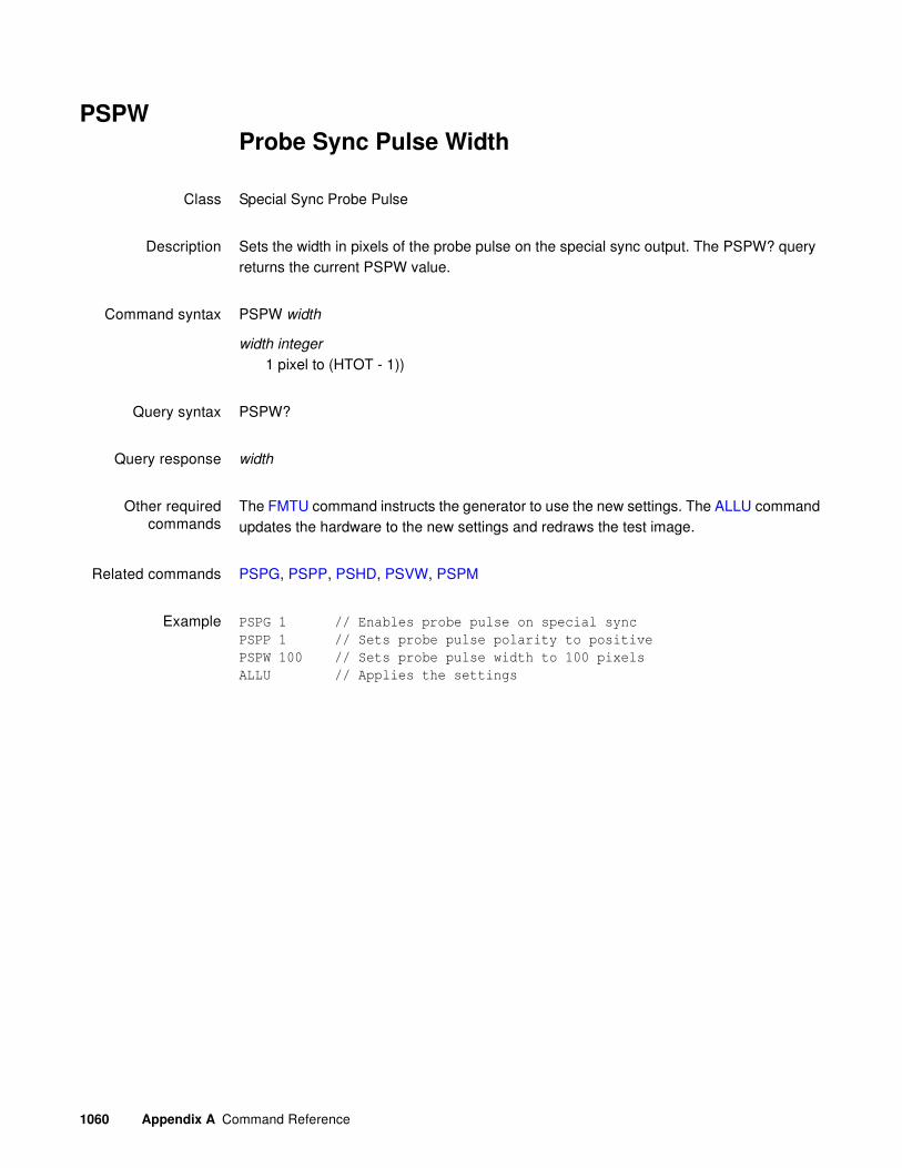
1060 Appendix A Command Reference
PSPWProbe Sync Pulse Width
Class Special Sync Probe Pulse
Description Sets the width in pixels of the probe pulse on the special sync output. The PSPW? query returns the current PSPW value.
Command syntax PSPW width
width integer
1 pixel to (HTOT - 1))
Query syntax PSPW?
Query response width
Other requiredcommands
The FMTU command instructs the generator to use the new settings. The ALLU command updates the hardware to the new settings and redraws the test image.
Related commands PSPG, PSPP, PSHD, PSVW, PSPM
Example PSPG 1 // Enables probe pulse on special sync
PSPP 1 // Sets probe pulse polarity to positive
PSPW 100 // Sets probe pulse width to 100 pixels
ALLU // Applies the settings

881/882 Video Test Instrument User Guide (Rev A.38) 1061
PSVDProbe Sync Pulse Vertical Delay
Class Special Sync Probe Pulse
Description Sets the line in the frame or field that the probe pulse occurs on the special sync output. The PSVD? query returns the current PSVD value.
Command syntax PSVD line
line integer
0 = PSVD(VTOT-1)
Query syntax PSVD?
Query response line
Other requiredcommands
The FMTU command instructs the generator to use the new settings. The ALLU command updates the hardware to the new settings and redraws the test image.
Related commands PSPG, PSPW, PSPP, PSHD, PSPM
Example PSPG 1 // Enables probe pulse on special sync
PSPP 1 // Sets probe pulse polarity to positive
PSPW 10 // Sets probe pulse width to 10 pixels
PSVD 300 // Sets probe pulse vertical delay to 300 pixels
ALLU // Applies the settings

1062 Appendix A Command Reference
PSVWProbe Sync Pulse Vertical Width
Class Special Sync Probe Pulse
Description Sets the width in lines of the probe pulse on the special sync output. The PSVW? query returns the current PSVW value. To enable the setting of the pulse in number of lines you must specify custom for probe pulse mode (PSPM=4), the probe pulse horizontal delay to 0 (PSHD=0) and the horizontal pulse width (HSPW) to HTOT -1.
Command syntax PSVW width
width integer
1 line to (VTOT - 1))
Query syntax PSVW?
Query response width
Other requiredcommands
The FMTU command instructs the generator to use the new settings. The ALLU command updates the hardware to the new settings and redraws the test image.
Related commands PSPG, PSPP, PSHD, PSVW, PSPM, PSPW
Example PSPG 1 // Enables probe pulse on special sync
PSPP 1 // Sets probe pulse polarity to positive
PSPM 4 // set pulse to custom to enable vertical length in lines
PSHD 0 // set horizontal pulse delay to 0
PSPW 639 // set horizontal pulse delay to HTOT-1
PSVW 100 // Sets probe pulse vertical width to 100 lines
ALLU // Applies the settings

881/882 Video Test Instrument User Guide (Rev A.38) 1063
PWD?Print Working Directory
Class Tools
Description Lists the current directory.
Query syntax PWD?
Query response List of the directory
Related commands None
Example PWD?
\tffs0\generator\images

1064 Appendix A Command Reference
PXAR?Pixel Aspect Ratio Query
Class Format parameter setting - HDMI active video
Description Reads the aspect ratio of pixels in active regions of the raster image.
Query syntax PXAR?
Query response aspect ratio
Related commands NCPP
Example PXAR?
+1.00000E+00

881/882 Video Test Instrument User Guide (Rev A.38) 1065
RATCpixel RATe Calibration factor
Class System parameter settings
Description Sets an internal multiplication factor used in setting the pixel clock frequency. The multiplication factor can be set to compensate for the frequency error of the internal reference crystal. Having to use a factor outside of the typical range may indicate a failure of generator's hardware. Reinitializing the generator's memory sets the calibration factor to a factory-default setting of 1.00000.
Note: The RATC parameter is a system level parameter that will affect the pixel clock
frequency of all formats that are recalled. The RATC value will be retained when the
generator is powered down and back up again. Query the current setting of RATC if you
are experiencing problems with the pixel clock or scan rate being off in frequency.
Command syntax RATC factor
factor
floating point number equal to calibration factor
typical min = 0.99990
typical max = 1.00010
Query syntax RATC?
Query response factor
Example RATC 1.00007 // Increases pix clk by factor of 1.00007

1066 Appendix A Command Reference
RECTdraw a RECTangle
Class Custom image primitive
Description Draws a rectangle whose sides are parallel to the vertical and horizontal axes of displayed video. It uses six parameters. The first is the color of the line. The next two parameters are the pixel width and height of the rectangle. The fourth and fifth parameters are the x and y coordinates for the top left corner of the rectangle. The last parameter is the fill.
Command syntax RECT color width height x y fill
color
available colors
width
total number of horizontal pixels
height
total number of lines
x, y
positive integer numbers
fill
available fill patterns
Other requiredcommands
The FMTU command instructs the generator to use the new setting. The ALLU command updates hardware to the new setting and redraws the test image.
Example RECT gray50 15 20 50 40 GrayPat50
// Draw a 50% gray rectangle 15 pixels wide and 20 pixels high
// with top left corner at X=50, Y=40 Fill with 50% active pixels
ALLU // Update hardware to current buffer contents

881/882 Video Test Instrument User Guide (Rev A.38) 1067
REDGRED Gate
Class Video Gate
Description Toggles the red video signal gate.
Command syntax REDG mode
mode
0 = disable
1 = enable
Query syntax REDG?
Query response 0 or 1
Other requiredcommands
ALLU to invoke the command.
Related commands BLUG, GRNG
Example REDG 0; ALLU // disable red video component

1068 Appendix A Command Reference
RFLDRepeat FieLD
Class Format parameter setting - Video resolution
Description Determines if identical video information is output for each field of an interlaced (SCAN = 2) format. The RFLD? query returns the current setting of RFLD.
Command syntax RFLD mode
mode
0 = disabled
1 = enabled
Query syntax RFLD?
Query response 0 or 1
Other requiredcommands
FMTU or ALLU
Example SCAN 2 // Set Interlaced scanning
RFLD 1 // Enable repeat field buffer
FMTU // Update hardware with format data

881/882 Video Test Instrument User Guide (Rev A.38) 1069
RGBWRGB Write
Class LUT Management
Description Writes RGB levels to the slot location specified within the current lookup table buffer when a lookup table editing session is active, and writes the levels directly to the LUT hardware when a lookup table editing session is not active.
Command syntax RGBW slot red_level green_level blue_level
slot integer
0 to 15 when PELD = 4
0 to 255 when PELD = 8
red_level, green_level, blue_level integer
min = 0
max = LMAX setting (255 nominal)
Related commands
Example IMGL RASTER
IMGU
SLUT 0 // clears the look up table
LINE RED 100 100 500 400 // creates red line
RECT GREEN 200 200 300 200 GRAYPAT100 // creates green rectangle
OVAL BLUE 200 200 100 100 GRAYPAT100 // creates blue oval
RGBW 1 255 255 0 // changes red line to yellow
RGBW 2 255 0 255 // changes green rect. to magenta
RGBW 3 0 255 255 // changes blue oval to cyan
1070 Appendix A Command Reference
RMReMove
Class Tools
Description Removes a file that resides in the current directory.
Command syntax RM filename
Command response filename
Any file in a generator or file server library directory.
Related commands None
Example RM hello.o

881/882 Video Test Instrument User Guide (Rev A.38) 1071
SAMPDigital Audio Sinewave Amplitude
Class Parameters (Audio Signal and Timing)
Description Sets the amplitude in decibels of the audio stream sinewave output by the generator.
Command syntax SAMP amplitude (sets all channels)
amplitude
-96.3 to 0 (if NBPA is 16-bits)
-120.4 to 0.0 (if NBPA is 20-bits)
-144.5 to 0.0 (if NBPA is 24-bits)
Query syntax SAMP?
Query response amplitude
Example SAMP -60.0 // Sets all channels to -60 amplitude
FMTU
Related commands SRAT, SMIN?, SMAX?

1072 Appendix A Command Reference
SCALSelf CALibrate
Class System calibration setting
Description Causes a generator equipped with self-calibration circuitry to go through its self-calibration cycle.
Command syntax SCAL

881/882 Video Test Instrument User Guide (Rev A.38) 1073
SCANSCAN fields per frame
Class Format parameter setting - Video resolution
Description Establishes the number of fields scanned per frame. Set to 1 for progressive (non-interlaced) scan and 2 for interlaced scan. The SCAN? query returns the current setting of SCAN.
Command syntax SCAN fields
fields
1 = progressive (non-interlaced)
2 = interlaced
Query syntax SCAN?
Query response fields
Other requiredcommands
The FMTU command instructs the generator to use the new setting. The ALLU command updates hardware to the new setting and redraws the test image.
Example SCAN 2// Select interlace in buffer
FMTU // Update hardware to current buffer contents

1074 Appendix A Command Reference
SDAUSPDIF Data Audio Analyzer
Class SPDIF audio analyzer - SPDIF data
Description Starts the measurement of the SPDIF audio header data on the SPDIF IN connector of the 882EA.
Command syntax SDAU
Example SDAU // Initiates the measurement of the SPDIF audio input
SDAX:ARAT? // Queries for the sampling rate of the SPDIF audio
input
SDAX:IECD? // Queries for the decoded IEC header information
(in human readable text) of the SPDIF audio input\
Dolby: 5ch. [L,C,R,SL,SR], 48KHz sampling rate, 448 KHz target bitrate
Related commands SDAX:ARAT?, SDAX:IEC?, SDAX:IECD?, SDAX:CSBA?, SDAX:CSBB?

881/882 Video Test Instrument User Guide (Rev A.38) 1075
SDAX:ARAT?SPDIF Data Audio Analyzer data
Class SPDIF audio analyzer - SPDIF data
Description Queries for the sampling rate in the SPDIF audio header data received on the SPDIF IN connector of the 882EA.
Query syntax SDAX:ARAT?
Query response Returns the sampling rate
Example SDAU // Initiates the measurement of the SPDIF audio input
SDAX:ARAT? // Returns the sampling rate of that audio received
on the 882EA SPDIF IN
48000
Related commands SDAU, SDAX:IEC?, SDAX:IECD?, SDAX:CSBA?, SDAX:CSBB?

1076 Appendix A Command Reference
SDAX:IECD?SPDIF Data Audio Analyzer data
Class SPDIF audio analyzer - SPDIF data
Description Queries for the IEC audio header information of the SPDIF audio header data received on the SPDIF IN connector of the 882EA.
Query syntax SDAX:IECD?
The SDAX:IEC? query returns the undecoded IEC header data (in hex).
Query response Returns the IEC SPDIF audio header data in human readable text.
Example SDAU // Initiates the measurement of the SPDIF audio input
SDAX:IECD? // Returns the decoded header information of that audio
received on the 882EA SPDIF IN
Dolby: 5ch. [L, C, R, SL, SR], 48KHz sampling rate, 448 KHz target
bitrate
Related commands SDAU, SDAX:ARAT?, SDAX:CSBA?, SDAX:CSBB?

881/882 Video Test Instrument User Guide (Rev A.38) 1077
SDAX:CSBA/B?SPDIF Data Audio Analyzer data
Class SPDIF audio analyzer - SPDIF data
Description Queries for the channel status bits of the SPDIF audio data received on the SPDIF IN connector of the 882EA.
Query syntax SDAX:CSBA?
The SDAX:CSBA? query returns the undecoded channel status bits (in hex).
Query response Returns the channel status bits from the SPDIF audio header data in hex.
Example SDAU // Initiates the measurement of the SPDIF audio input
SDAX:CSBA? // Returns the channel status bits in raw hex form from
the left and right channels.
020000060000000200000000000000000000000000000000
Related commands SDAU, SDAX:ARAT?, SDAX:IECD?
1078 Appendix A Command Reference
SDLYSequence step DeLaY
Class Sequence editor control
Description Sets how long a sequence step will pause before advancing to the next step in the auto run mode. A sequence step will use the last value set by the SDLY command. The SDLY? query returns the current setting of SDLY.
Command syntax SDLY delay | -frames
delay
Delay time in seconds as a floating point number.
frames
Delay in frames. Type minus (-) character before integer.
min = 0.0 seconds; -1 frame
max = 1.70E38 seconds (infinite)
Query syntax SDLY?
Query response delay
Other requiredcommands
SMOD setting must be equal to 3 in order for the SDLY setting to have any affect on sequence operation.
Example SDLY 5.0 // Set delay to five seconds per step
SDLY -3 // Set delay to three frames per step

881/882 Video Test Instrument User Guide (Rev A.38) 1079
SDGMSonic Data Gate for SPDIF output
Class Parameters (Audio Signal and Timing)
Description Configures what audio (from what source) is transmitted out the SPDIF audio output port.
Note: This command applies only to the 882EA.
Command syntax SDGM mask
mask
0 = HDMI Rx - SPDIF OUT audio content is from the audio on the HDMI Rx port.
2 = SPDIF IN - SPDIF OUT audio content is from the audio received from the SPDIF Input.
Example 1 SDGM 2 // Causes the 882EA pass the SPDIF audio received from its SPDIF
IN connector out through the SPDIF OUT connector.
Example 2 SDGM 0 // Causes the 882EA pass the SPDIF audio received from its HDMI
IN connector out through the SPDIF OUT connector.

1080 Appendix A Command Reference
SDMGSonic Data Mixer Gate
Class Parameters (Audio Signal and Timing)
Description Configures the generator to use either an internal or external audio source for its HDMI audio output.
Note: Setting the mask “external” bit to 1 causes the SPDIF audio signal to be passed
through the generator. In this case, the Audio InfoFrame CT, CC, SF, and SS parameters
are set to 0, indicating that the stream header should be used to determine audio coding
type, channel type, sampling frequency, and sample size, respectively. If both “external”
and “sdg” bits are set to 1 simultaneously, then an error is generated as the generator’s
sonic data mixer does not currently support proportional mixing of internal and external
sources.
Command syntax SDMG mask
mask
1 = SDG is the internal sonic generator (internal) (Default)
2 = Passthrough from SPDIF IN port (external)
Example 1 SDMG 2 // causes the generator allow the SPDIF audio signal to be
passed through to HDMI output
FMTU

881/882 Video Test Instrument User Guide (Rev A.38) 1081
SEOSSet End Of String
Class GPIB port control
Description Controls how a generator reads strings, when reading multi-line responses. In GPIB communication both the sender and receiver first have to agree on end-of-string parsing. The SEOS command enables users to determine if the generator should use line feed for end-of-string parsing.
Command syntax SEOS integer
integer
0 = Configures the generator to not test end-of-strings, and to send EOI only on the last character of the entire response. Use this option to receive an entire multi-line response in a single read operation. Leave the VISA “Enable Termination Character” option set to FALSE.
1 = Use end-of-string testing (default).
Query syntax SEOS?

1082 Appendix A Command Reference
SEQASEQuence save As
Class Sequence memory management
Description Saves the current contents of the sequence edit buffer using the given name.
Command syntax SEQA name
name
A valid MS-DOS filename (8 characters minus any extension)
Example SEQA MY_SEQ // Save with the name "MY_SEQ"

881/882 Video Test Instrument User Guide (Rev A.38) 1083
SEQBSEQuence editing Begin
Class Sequence editor control
Description Marks the beginning of a sequence editing session.
Command syntax SEQB
Other requiredcommands
Use either a SEQL command to load an existing sequence or a SEQN command to create a new sequence. Use SEQE when ending the editing session.
Example SEQN // Initialize sequence edit buffer
SEQB // Start sequence editing session
// One or more sequence editing commands ...
SEQE // End sequence editing session

1084 Appendix A Command Reference
SEQESEQuence editing End
Class Sequence editor control
Description Marks the end of a sequence editing session.
Command syntax SEQE
Other requiredcommands
Use SEQB when starting the editing session. Use SEQA or SEQS to save changes.
Example EQB // Start sequence editing session
// One or more sequence editing commands ...
SEQE // End sequence editing session
SEQA MYSEQ_02 // Save edited sequence as "MYSEQ_02"

881/882 Video Test Instrument User Guide (Rev A.38) 1085
SEQKSEQuence Kill
Class Sequence memory management
Description Deletes a sequence by name. The query returns a 1 if the named sequence can be deleted. If sequence is read-only or non-existent, the query returns a 0.
Command syntax SEQK name
name
a valid MS-DOS filename (8 characters minus any extension)
Query syntax SEQK? name
name
a valid MS-DOS filename (8 characters minus any extension)
Query response 0 or 1
Example SEQK MY_SEQ // Delete seq called "MY_SEQ"

1086 Appendix A Command Reference
SEQLSEQuence Load
Class Sequence memory management
Description Copies the sequence having a name equal to name from sequence memory into the sequence edit buffer. The query returns a 1 if the named sequence can be loaded; otherwise, a 0 is returned.
Command syntax SEQL name
name
a valid MS-DOS filename (8 characters minus any extension)
Query syntax SEQL? name
name
a valid MS-DOS filename (8 characters minus any extension)
Query response 0 or 1
Other requiredcommands
An SEQU command must be executed after the SEQL command to start running the sequence.
Example SEQL MY_SEQ // Load "MY_SEQ" dir in edit buffer
SEQU // Start running the sequence in the buffer

881/882 Video Test Instrument User Guide (Rev A.38) 1087
SEQNSEQuence New
Class Sequence editor control
Description Initializes the sequence edit buffer. The name name is assigned as the sequence's name. The query will return the name that has been assigned as the sequence's name.
Command syntax SEQN name
name
optional valid MS-DOS filename (8 characters minus any extension)
Query syntax SEQN?
Query response name
Example SEQN // Init edit buffer without assigning a new name
or
SEQN MY_SEQ // Init edit buffer with name of "MY_SEQ"

1088 Appendix A Command Reference
SEQPSEQuence Path
Class Sequence memory management
Description Sets the current sequence path name to a given directory. The query will return the current path name.
Command syntax SEQP name
name
a valid MS-DOS filename (8 characters minus any extension)
Query syntax SEQP?
Query response Current sequence path name.
Example SEQP BURN // Sequences in BURN directory will be listed

881/882 Video Test Instrument User Guide (Rev A.38) 1089
SEQQ?SEQuence Query pointer
Class Sequence memory management
Description Returns number sequence names from the list of all the sequence names stored in sequence memory beginning at index. The directories are kept in alphanumeric order. The generator maintains internal variables for the current index and number values. The value of index is automatically incremented by number after the query is executed. Sending the query with just an index parameter, will return the same number of names as the last time, starting at the given index. Sending the query with no parameters will return the next set of names in the directory buffer.
Query syntax SEQQ? index number
index
positive integer number
number
positive integer number
Query response List of specified sequence names.
Example 1 SEQQ? 1 9999 // List the names of all sequences stored in memory
Example 2 SEQQ? 1 10 // List names of the first ten sequences stored in memory
SEQQ? 21 // List names of the 21st through the 30th sequences
SEQQ? // List names of the 31st through the 40th sequences

1090 Appendix A Command Reference
SEQSSEQuence Save
Class Sequence memory management
Description Saves the current contents of the generator's sequence edit buffer back to the memory location from which they were originally read.
Command syntax SEQS

881/882 Video Test Instrument User Guide (Rev A.38) 1091
SEQUSEQuence Use
Class Sequence memory management
Description Runs the sequence currently stored in the sequence edit buffer. The SEQU? query returns the sequence name currently set in the sequence edit buffer.
Command syntax SEQU
Query syntax SEQU?
Query response name
Other requiredcommands
The sequence in the edit buffer must have a non-zero SMOD setting to run.
Example SEQL MY_SEQ // Load "MY_SEQ" dir in edit buffer
SEQU // Start running the sequence in the buffer

1092 Appendix A Command Reference
SLUT Set Look-Up Table
Class LUT Management
Description Sets up the color look-up-table (LUT) for rendering and displaying selected colors from defined sets. This command is made available for testing low-level drawing firmware and is not intended for use by end users.
Command syntax SLUT colorset
colorset integer
Bit mask indicating desired color sets
Example 1 SLUT 65536 // Setup for HUERGB colorset
Example 2 SLUT 0 // clears look up table

881/882 Video Test Instrument User Guide (Rev A.38) 1093
SMAX?Digital Audio Sinewave Maximum
Class Parameters (Audio Signal and Timing)
Description Returns the maximum amplitude of the digital audio sinewave output from the generator.
Query syntax SMAX?
Query response maximum amplitude (0 - 65,535)
Related commands SRAT, SAMP, SMIN?

1094 Appendix A Command Reference
SMIN?Digital Audio Sinewave Minimum
Class Parameters (Audio Signal and Timing)
Description Returns the minimum amplitude of the digital audio sinewave output from the generator.
Query syntax SMIN?
Query response minimum amplitude (0 - 65,535)
Related commands SRAT, SAMP, SMAX?

881/882 Video Test Instrument User Guide (Rev A.38) 1095
SMODSequence operating MODe
Class Sequence editor control
Description Sets the sequence mode. The SMOD? query returns the current setting of SMOD.
Command syntax SMOD mode
mode
0 = disable
1 = enable manual step mode that stops at last step
2 = enable manual step mode that wraps to first step after last step
3 = enable continuous auto stepping
Query syntax SMOD?
Query response mode
Other requiredcommands
The SEQL command loads the sequence and SEQU starts to run it.
Example SEQL MY_SEQ // Load "MY_SEQ" in edit buffer
SEQU // Start running the sequence in the buffer
SMOD 3 // Set the sequence mode

1096 Appendix A Command Reference
SNUMdraw sequence Step NUMber
Class Custom image primitive
Description Displays the sequence step number to an image when drawn as part of a test sequence. The number, along with the word “Step,” appears in a small box. The SNUM command uses three parameters. The first is the color used for the text and box border. The next two parameters are the x and y coordinates for the position of the box.
Command syntax SNUM color x y
color
available colors
x, y
positive integer numbers
Other requiredcommands
The displaying of sequence step numbers must be enabled with the DNUM command, and the custom image must have been loaded as part of a sequence in order for this primitive to be drawn.
Example SNUM white 50 50 // Display seq. num. in box with top left corner at
// X=50, Y=50

881/882 Video Test Instrument User Guide (Rev A.38) 1097
SPAXslider image SPAcing X
Class Image editor control
Description Sets the horizontal spacing of certain elements in some built-in test images. The SPAX? query returns the current SPAX setting.
Command syntax SPAX x_spacing
x_spacing integer
number of pixels
Query syntax SPAX?
Query response x_spacing
Example SPAX 20

1098 Appendix A Command Reference
SPAYslider image SPAcing Y
Class Image editor control
Description Sets the vertical spacing of certain elements in some built-in test images. The SPAY? query returns the current SPAY setting.
Command syntax SPAY y_spacing
y_spacing integer
number of pixels
Query syntax SPAY?
Query response y_spacing
Example SPAY 20

881/882 Video Test Instrument User Guide (Rev A.38) 1099
SRATDigital Audio Sinewave Rate
Class Parameters (Audio Signal and Timing)
Description Sets the frequency of the audio sinewave from the generator.
Command syntax SRAT rate
rate
20.0 to 20.0E3 (Hz)
Query syntax SRAT?
Query response rate
Example SRAT 10.0E3
FMTU
Related commands SAMP, SMAX?, SMIN?

1100 Appendix A Command Reference
SSSTSelect Sync Signal Type
Class Format parameter setting - Synchronization
Description Selects the type of sync signal used to synchronize the display. In general, any one of three different types of sync can be selected to synchronize the display. The availability of different sync types is specified using the ASCT, DSCT, and DSST commands. Some displays may not accept one (or more) types of sync. For example, a digital video monitor cannot accept analog composite sync because analog signal transmission is not used. Also, a PGA display cannot accept digital separate HS and VS because only one sync wire is provided in the cabling. In these cases, one (or more) of the sync types (ASCT, DSCT, or DSST) is set to 0, indicating that they are not supported. If a non-supported sync type is selected using the SSST command, then the corresponding sync outputs of the generator will remain disabled. The SSST? query returns the type of sync (if any) that is currently selected.
Command syntax SSST type
type
0 = no sync
1 = digital separate horizontal and vertical sync ( DHS & DVS )
2 = digital separate sync ( DSS )
3 = digital separate composite sync ( DCS )
4 = analog composite sync ( ACS )
5 = DSS and ACS
6 = DCS and ACS
7 = DSS, DCS, and ACS
8 = DPMS-OFF (DSS)
9 = DPMS-SUSPEND (DSS)
10 = DPMS-STANDBY (DSS)
11 = DCS & DSS
Query syntax SSST?
Query response type

881/882 Video Test Instrument User Guide (Rev A.38) 1101
Other requiredcommands
The desired sync type selected must not be set to void with the ASCT, DSCT, or DSST commands. To actually output the selected sync signal, it must be gated on with the appropriate ASSG, ASBG, ASGG, ASRG, CSPG, HSPG, and VSPG settings.
Example DSST 1 // Set Amer. H&V in buffer
HSPG 1 // Enable H sync in buffer
VSPG 1 // Enable V sync in buffer
SSST 1 // Select sep H&V sync in buffer
FMTU // Update hardware to current buffer contents

1102 Appendix A Command Reference
STRG STRetchinG SCL Low Signal
Class EDID and DDC control
Description Enables a stretching capability for the receiver of the HDMI analyzer. Each time a host accesses the I2C receiver bus (for example, to read the EDID), the receiver stretches the SCL low signal for 5 ms.
Enable stretching for testing purposes only.
Command syntax STRG value
value
0 = deactivate stretching
1 = activate stretching of SCL low signal for 5 ms
Query syntax STRG?
Query response 0 or 1
Example STRG 1
DIDU
Related commands
881/882 Video Test Instrument User Guide (Rev A.38) 1103
STEPsequence STEP number
Class Sequence editor control
Description Selects a step in the sequence edit buffer. It is context sensitive. While editing a sequence (between SEQB and SEQE commands), the STEP command selects a step to be edited. Outside of the sequence editor and while running a sequence, the command selects a step to be executed.
The STEP? query returns the current setting of STEP.
Command syntax STEP step
step
min = 1
max = See description
Query syntax STEP?
Query response step
Other requiredcommands
When running a sequence, the SEQU command must be executed after the STEP command to load the format and display the image selected in the step.
Example STEP 5 // Select fifth step in current sequence
SEQU // Load format and draw image in current step
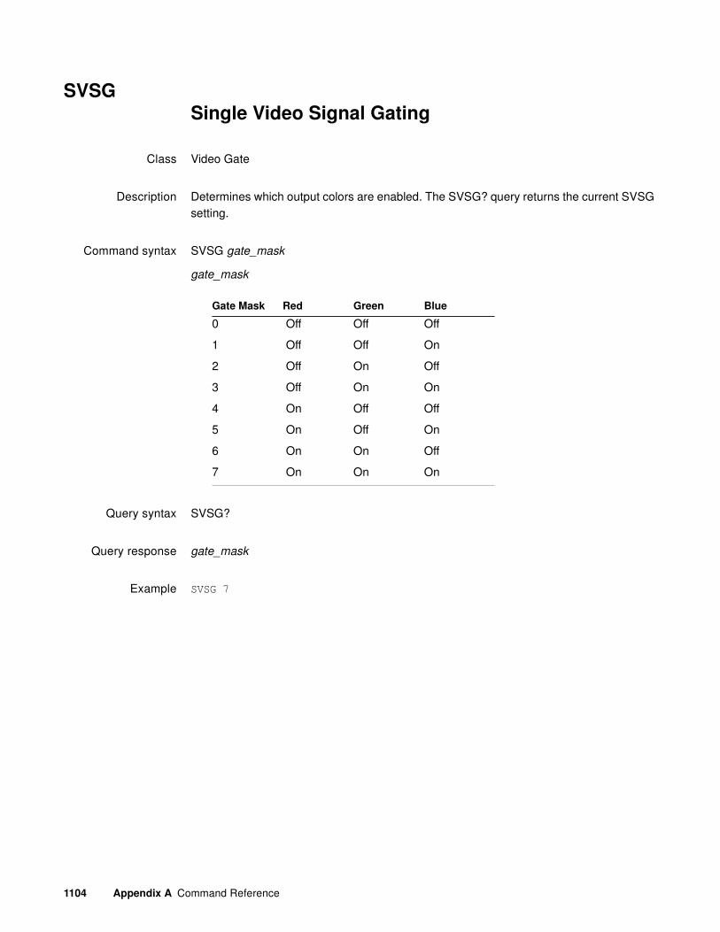
1104 Appendix A Command Reference
SVSGSingle Video Signal Gating
Class Video Gate
Description Determines which output colors are enabled. The SVSG? query returns the current SVSG setting.
Command syntax SVSG gate_mask
gate_mask
Query syntax SVSG?
Query response gate_mask
Example SVSG 7
Gate Mask Red Green Blue
0 Off Off Off
1 Off Off On
2 Off On Off
3 Off On On
4 On Off Off
5 On Off On
6 On On Off
7 On On On
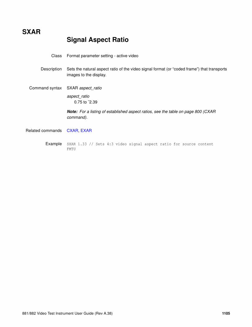
881/882 Video Test Instrument User Guide (Rev A.38) 1105
SXARSignal Aspect Ratio
Class Format parameter setting - active video
Description Sets the natural aspect ratio of the video signal format (or “coded frame”) that transports images to the display.
Command syntax SXAR aspect_ratio
aspect_ratio
0.75 to ˜2.39
Note: For a listing of established aspect ratios, see the table on page 800 (CXAR
command).
Related commands CXAR, EXAR
Example SXAR 1.33 // Sets 4:3 video signal aspect ratio for source content
FMTU

1106 Appendix A Command Reference
SXCXSignal-From-Content Aperture Map
Class Format parameter setting - active video
Description Sets the proper parameters to values necessary to fit CXAR-shaped image content to the SXAR-shaped aperture of the signal interface timing format.
Upon executing this command, the following actions are performed:
1. The EXAR value is set to the CXAR value (EXAR=CXAR).
2. The EXCX value is set to 0 (EXCX=0).
3. The SXEX value is set to value entered for this command (SXEX=SXCX).
Command syntax SXCX code
code
0 to 131071 (in decimal)
Note: For help in determining the proper mapping code, follow the procedure on page 876
(EXCX command).
Related commands SXEX, EXAR, EXCX, CXAR, SXCX, SXAR
Example SXCX 264 //Use centered shrink w/black bars top & bottom
FMTU
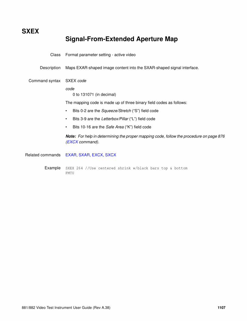
881/882 Video Test Instrument User Guide (Rev A.38) 1107
SXEXSignal-From-Extended Aperture Map
Class Format parameter setting - active video
Description Maps EXAR-shaped image content into the SXAR-shaped signal interface.
Command syntax SXEX code
code
0 to 131071 (in decimal)
The mapping code is made up of three binary field codes as follows:
• Bits 0-2 are the Squeeze/Stretch (“S”) field code
• Bits 3-9 are the Letterbox/Pillar (“L”) field code
• Bits 10-16 are the Safe Area (“K”) field code
Note: For help in determining the proper mapping code, follow the procedure on page 876
(EXCX command).
Related commands EXAR, SXAR, EXCX, SXCX
Example SXEX 264 //Use centered shrink w/black bars top & bottom
FMTU

1108 Appendix A Command Reference
TASK?TASK?
Class Tools
Description Lists the current tasks.
Query syntax TASK?
Query response Tabular list of tasks
Related commands None
Example TASK?
NAME ENTRY TID PRI STATUS PC SP ERRNO DELAY
---------- ------------ -------- --- ---------- -------- -------- ------- -----
tExcTask excTask f549d8 0 PEND 415e84 f548f8 0 0
tLogTask logTask f52050 0 PEND 415e84 f51f78 0 0
tDcacheUpd dcacheUpd f2d7d0 1 READY 39fd44 f2d748 3006c 0
tCShell 1849d0 e393a8 1 PEND 39ba74 e38eb8 0 0
tCShell0 1849d0 d2b5f8 1 READY 3a0780 d2b100 0 0
tPcmciad pcmciad f50550 2 PEND 415e84 f50470 0 0
tWdbTask 392880 e3b6e0 3 PEND 39ba74 e3b5f8 0 0
tSerRxTx RxTxTaskEntr d95580 7 READY 39fd44 d954f8 0 0
cioPipeDraiDrainPipe__8 ffeb98 8 PEND 39ba74 ffea38 3d0002 0
appMain appMain__Fv da5798 10 READY 39fd44 da55e0 0 0
tNetTask netTask e69e28 50 READY 39ba74 e69d70 0 0
tWebUI AcceptTaskEn d77088 50 PEND 39ba74 d76ef0 0 0
tTelnetd telnetd e40fa8 55 PEND 39ba74 e40e08 0 0
tFtpdTask 1c890c e3f9b8 55 PEND 39ba74 e3f850 0 0
GPIB MonitorEntry d8db68 55 READY 39c170 d8dac8 3d0004 0
tTelnetOutTtelnetOutTas d265c0 55 READY 39ba74 d262e8 0 0
tTelnetInTatelnetInTask d25020 55 READY 39b8d0 d24cf8 0 0
tSeqTask RunEntry__15 d71db8 90 PEND 39ba74 d71d00 0 0
tTffsPTask flPollTask f2a268 100 READY 39fd44 f2a1e0 0 0
tPortmapd portmapd e42570 100 PEND 39ba74 e423f0 16 0
tHTTPd 3dac04 e22ee0 200 PEND 39ba74 e22da8 0 0
value = 0 = 0x0

881/882 Video Test Instrument User Guide (Rev A.38) 1109
TBOXdraw information Text BOX
Class Custom Image Primitive
Description Renders an information text box that can be added to custom images. This command allows color, position, information, and box type to be customized.
Command syntax TBOX color %x %y info type
color
valid color name
%x
0.0 to 1.0 normalized positioning of box center in the x direction
%y
0.0 to 1.0 normalized positioning of box center in the y direction
info
0 = format, image, line-rate, and frame-rate (default =
1 = format
2 = image
3 = sequence
4 = step number
5 = format and image
6 = sequence and step
7 = line-rate and HRES X VRES
8 = pixel-rate and HRES X VRES
9 = format, image, sequence, and step
10 = format, image, HRES X VRES, and pixel rate
11 = line-rate, frame-rate, sequence, and step
12 = pixel-rate, HRES X VRES, sequence, and step
13 = line-rate, frame-rate, pixel-rate, and HRES X VRES
14 = format, image, line-rate, frame-rate, sequence, and step
15 = format, image, HRES X VRES, pixel-rate, sequence and step

1110 Appendix A Command Reference
type
0 = text only
1 = text w/ border
2 = text w/ black background
3 = text w/ border and black background
Query syntax TBOX?
Query response color %x %y info type
Other requiredcommands
TBXG
Example TBOX white 0.5 0.5 8 3

881/882 Video Test Instrument User Guide (Rev A.38) 1111
TBXGText BoX Gating
Class
Description Enables and disables the displaying of the text box defined by the TBOX command. The TBXG? query returns the current TBXG mode.
Command syntax TBXG mode
mode integer
0 = OFF
1 = ON
Query syntax TBXG?
Query response mode
Other requiredcommands
TBOX
Example TBXG 1
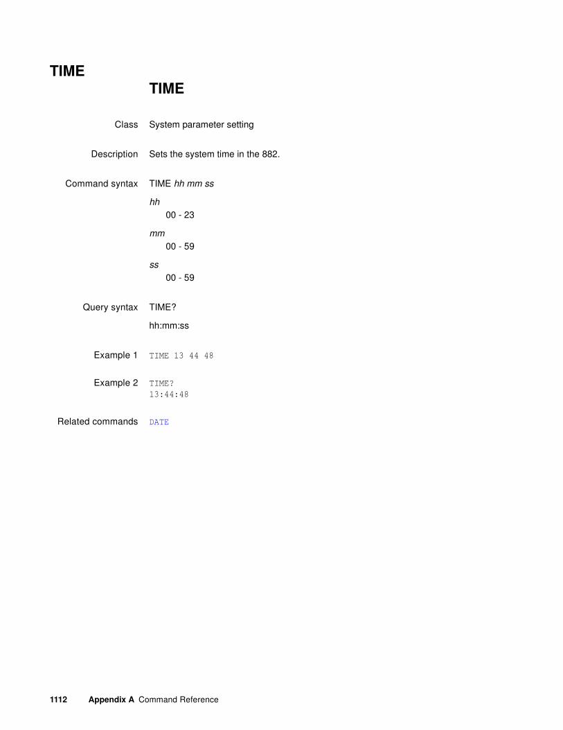
1112 Appendix A Command Reference
TIMETIME
Class System parameter setting
Description Sets the system time in the 882.
Command syntax TIME hh mm ss
hh
00 - 23
mm
00 - 59
ss
00 - 59
Query syntax TIME?
hh:mm:ss
Example 1 TIME 13 44 48
Example 2 TIME?
13:44:48
Related commands DATE

881/882 Video Test Instrument User Guide (Rev A.38) 1113
TEXTdraw TEXT string
Class Custom image primitive
Description Draws a user-defined text string. It uses five parameters. The first is color. The next two are the x and y coordinates for the upper left corner of the starting position of the string. The fourth parameter selects the font. The last parameter is the text string. If the string is longer than one word, it must be contained inside quotation marks.
All of the characters in the text string must have matching characters in the font selected by font name.
Command syntax Text color x y font "text "
color
available colors
x, y
coordinates of top left corner of page in pixels
font
available fonts
text
approximately 30 characters (must be enclosed by quotes)
Other requiredcommands
The FMTU command instructs the generator to use the new setting. The ALLU command updates hardware to the new setting and redraws the test image.
Example TEXT red 50 40 opix9 "HELLO WORLD"
// Draw red "HELLO WORLD" at x=50 y=40 in opix9 font
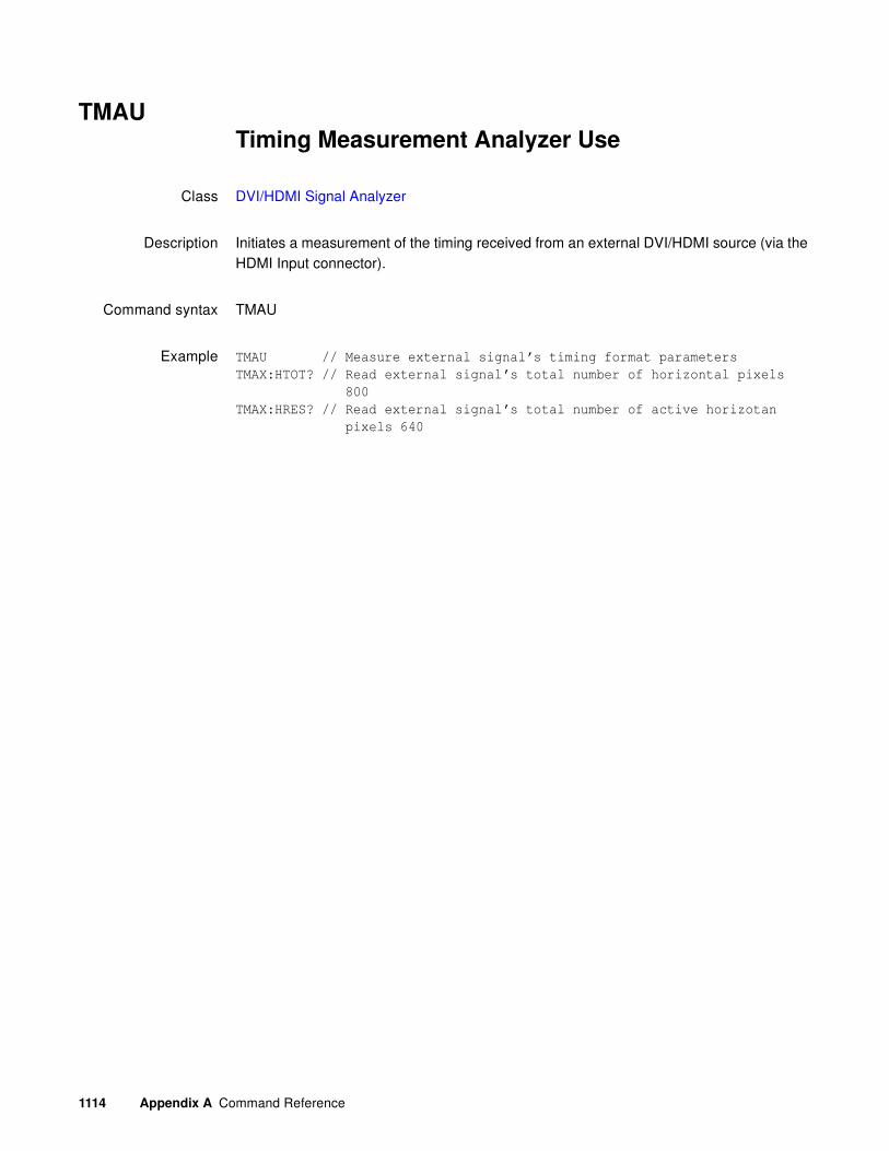
1114 Appendix A Command Reference
TMAUTiming Measurement Analyzer Use
Class DVI/HDMI Signal Analyzer
Description Initiates a measurement of the timing received from an external DVI/HDMI source (via the HDMI Input connector).
Command syntax TMAU
Example TMAU // Measure external signal’s timing format parameters
TMAX:HTOT? // Read external signal’s total number of horizontal pixels
800
TMAX:HRES? // Read external signal’s total number of active horizotan
pixels 640
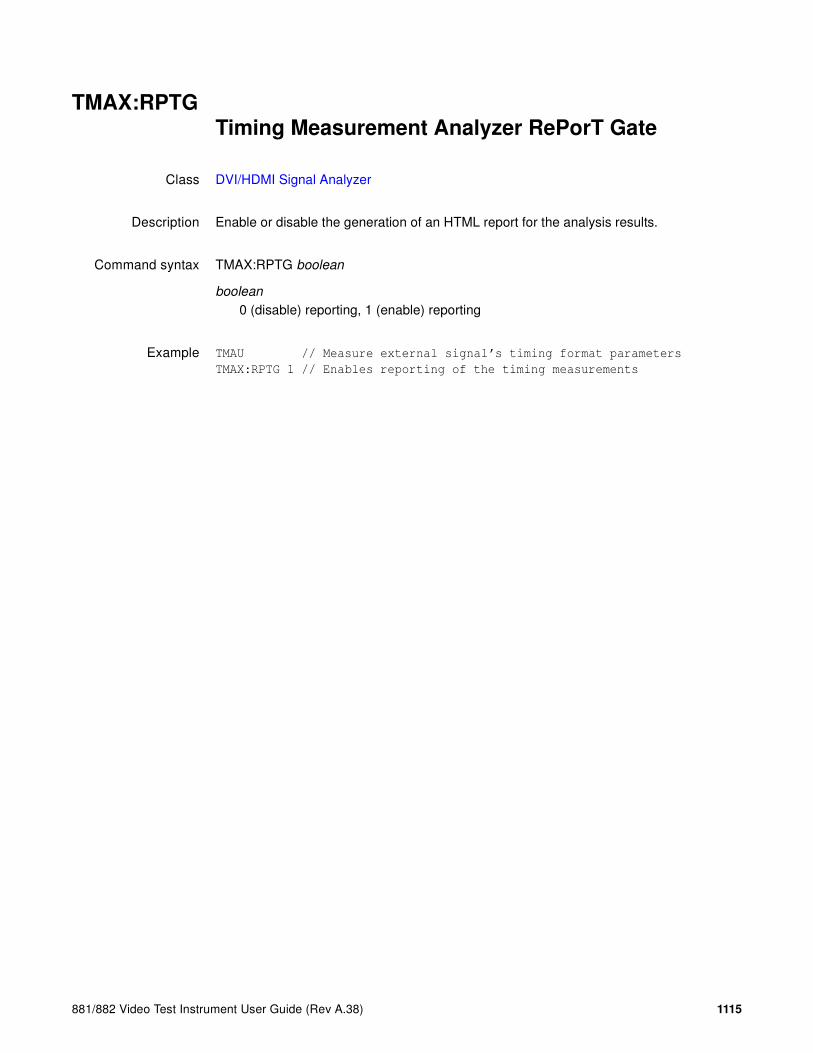
881/882 Video Test Instrument User Guide (Rev A.38) 1115
TMAX:RPTGTiming Measurement Analyzer RePorT Gate
Class DVI/HDMI Signal Analyzer
Description Enable or disable the generation of an HTML report for the analysis results.
Command syntax TMAX:RPTG boolean
boolean
0 (disable) reporting, 1 (enable) reporting
Example TMAU // Measure external signal’s timing format parameters
TMAX:RPTG 1 // Enables reporting of the timing measurements

1116 Appendix A Command Reference
TMAX:SCANTiming Measurement Analyzer parameter query
Class DVI/HDMI Signal Analyzer
Description Retrieves the measured value of the parameters queried of the last timing test run. The timing parameters can be read back via queries using the following commands
Query syntax TMAX:parameter?
parameter
The parameter name (see table above)
Example PNSF 1 // Pseudo-random noise signal format set to MEASURED
PNST 1 // Pseudo-random noise signal type set to QDI-BCM
TMAU // Measure external signal’s timing format parameters
TMAX:SCAN? // Queries for the SCAN parameter that was measured
TMAX:HRAT? // Queries for the HRAT parameter that was measured
SCAN? Returns the scan type
PRAT? Returns the pixel rate (in Hz)
VRAT? Returns the vertical (field) rate (VRAT = FRAT * SCAN)
HTOT? Returns the horizontal total (in pixels)
HRES? Returns the horizontal active (in pixels)
HSPD? Returns the horizontal sync pulse delay (in pixels)
HSPW? Returns the horizontal sync pulse width (in pixels)
HSPP? Returns the horizontal sync pulse polarity
VTOT? Returns the vertical total (in lines)
VRES? Returns the vertical active (in lines)
VSPD? Returns the vertical sync pulse delay (in lines)
VSPW? Returns the vertical sync pulse width (in lines)
VSPP? Returns the vertical sync pulse polarity
HVPD? Returns the pixel delay between the H and V sync pulses

881/882 Video Test Instrument User Guide (Rev A.38) 1117
TOBLset levels relative TO BLanking
Class Custom image primitive
Description Temporarily changes how the signal levels are determined for a given color intensity level. The default method uses black as the 0% reference level and peak video as the 100% level. Inserting TOBL moves the 0% reference point to the blanking (blacker than black) pedestal level. The reference point remains shifted only for as long as the image is displayed.
Command syntax TOBL

1118 Appendix A Command Reference
TOGGTOGGle Hot Plug (enable/disable)
Class System
Description Enables or disables reading EDID from sink to set the Source list to hot plug formats. When enabled, only EDID formats will be shown in the Source list.
Command syntax TOGG mode
mode
1
Enable reading of EDID from sink. This is equivalent to pressing the Sink->Options key sequence and enabling EDID formats.
0
Disable read of EDID from sink. This is equivalent to pressing the Sink->Options key sequence and disabling EDID formats.
Query syntax TOGG?
Query response mode
Example TOGG 0 // disables EDID formats
TOGG 1 // enables EDID formats

881/882 Video Test Instrument User Guide (Rev A.38) 1119
TRIAdraw a TRIAngle
Class Custom image primitive
Description Draws a triangle defined by its three end points. The primitive uses eight parameters. The first is line color. The next three pairs of parameters are the x and y coordinates for the three points. The last parameter is the fill. More complex filled polygons can be built up using a series of joined filled triangles.
Command syntax TRIA color x1 y1 x2 y2 x3 y3 fill
color
available colors
x1, y1, x2, y2, x3, y3
positive integer number
fill
available fill pattern
Other requiredcommands
The FMTU command instructs the generator to use the new setting. The ALLU command updates hardware to the new setting and redraws the test image.
Example TRIA red50 10 5 10 25 40 15 GrayPat50
// Draw a red50 triangle at x=10,
// y=5; x=10, y=25; x=40, y=15 with
// 50% active pixel fill
ALLU // Update hardware to current
// buffer contents

1120 Appendix A Command Reference
TSPGTri-level Sync Pulse Gate
Class Format parameter setting - Synchronization
Description Enables and disables the tri-level sync pulse. This command affects only tri-level analog composite sync types (ASCT = 1, 11, 12, 13, 14, or 15). The exact function of the TSPG command depends on the analog sync composite type selected, as shown below.
Command syntax TSPG mode
mode
0 = OFF
1 = ON
Query syntax TSPG?
Query response mode

881/882 Video Test Instrument User Guide (Rev A.38) 1121
Other requiredcommands
The FMTU command instructs the generator to use the new setting. The ALLU command updates hardware to the new setting and redraws the test image.
Example TSPG 1 // Enable tri-level sync pulse in buffer
FMTU // Update hardware to current buffer contents

1122 Appendix A Command Reference
UI:MODEOperational mode
Class System control
Description Sets generator operational mode
Command Syntax UI:MODE mode
mode
0 = Basic mode
1 = Browse mode
Query syntax UI:MODE?
Query response mode
Example UI:MODE 1 // Set operational mode to Browse mode

881/882 Video Test Instrument User Guide (Rev A.38) 1123
UIDNUser IDeNtification
Class System parameter settings
Description Sets up the text string that is placed in the upper portions of the SMPTE133 and Cubes images. The command can be used to add a company name or other identification to the images. The command will not change the text in a currently displayed image; it must be redrawn to use the new text. The factory default string is “Quantum Data.” The UIDN? query returns the current text string.
Command syntax UIDN string
string
text string 80 characters in length
Query syntax UIDN?
Query response string
Other requiredcommands
The IMGU command redraws the last selected test image. The ALLU command updates hardware to the new setting and redraws the test image.
Example UIDN "XYZ Monitor Mfg." // Change text string
IMGL SMPTE133 // Select image that uses the text string
IMGU // Draw the image using new string

1124 Appendix A Command Reference
USIZUnit of measure used for physical SIZes
Class System control
Description Sets the units of measure assumed by HSIZ and VSIZ commands to establish the physical size of the image that appears on the CRT (context sensitive; see FMTB and FMTE). The USIZ? query returns the current setting of USIZ.
Note: Changing the USIZ parameter between inches and millimeters will convert the
current HSIZ and VSIZ values to match the new unit of measure. For example, if USIZ is in
inches and the current HSIZ is 10 (inches), changing USIZ from inches to mm will change
HSIZ to 25.4 (mm). The USIZ command should be sent before specifying physical sizes in
format command files.
Command syntax USIZ units
units
0 = sizes not given (use default)
1 = inches
2 = mm
Query syntax USIZ?
Query response units
Other requiredcommands
The ALLU command updates hardware to the new setting and redraws the test image, taking the new units into account.
Example FMTB // Begin editing session
// One or more format editing commands ...
USIZ 1 // Select inches as unit of measure in buffer
HSIZ 10.4 // Set width to 10.4 in buffer
VSIZ 7.8 // Set height to 7.8 in buffer
ALLU // Test the new settings
// One or more format editing commands ...
FMTE // End editing session

881/882 Video Test Instrument User Guide (Rev A.38) 1125
USRAAdd USeR
Class Tools
Description Adds a user profile.
Command syntax USRA username
username
A name with 8 alphanumeric characters.
Example USRA janedoe
USRU janedoe

1126 Appendix A Command Reference
USRKDelete a USeR
Class Tools
Description Deletes a user profile.
Command syntax USRK username
username
An existing user name
Example USRK janedoe

881/882 Video Test Instrument User Guide (Rev A.38) 1127
USRUCreate USeR
Class Tools
Description Creates a user profile.
Command syntax USRU username
username
A name with 8 alphanumeric characters.
Query syntax USRU?
Query response username
Example USRA janedoe
USRU janedoe

1128 Appendix A Command Reference
VERF?VERsion Firmware
Class Miscellaneous system parameters
Description Returns the firmware version number for the runtime code and the boot code. The digits to the left of the decimal point represent the major release level. The digits to the right of the decimal point represent the revision number of the release. A second decimal point followed by more digits indicates the revision is at a given beta test level.
Query syntax VERF?
Query response version runtime code: version boot code
Example VERF?
20.0882002,01.03.03
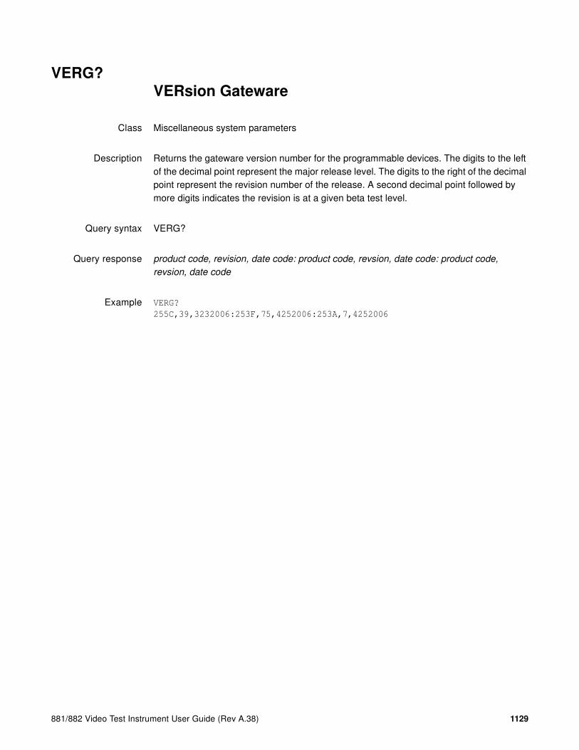
881/882 Video Test Instrument User Guide (Rev A.38) 1129
VERG?VERsion Gateware
Class Miscellaneous system parameters
Description Returns the gateware version number for the programmable devices. The digits to the left of the decimal point represent the major release level. The digits to the right of the decimal point represent the revision number of the release. A second decimal point followed by more digits indicates the revision is at a given beta test level.
Query syntax VERG?
Query response product code, revision, date code: product code, revsion, date code: product code,
revsion, date code
Example VERG?
255C,39,3232006:253F,75,4252006:253A,7,4252006

1130 Appendix A Command Reference
VRAT?Vertical RATe Query
Class Format parameter setting - Video resolution
Description Returns the current vertical (field) rate. This is equal to the product of the FRAT (frame rate) and SCAN (scan type) settings (FRAT * SCAN).
Query syntax VRAT?
Query response vertical field rate
Example VRAT? //read the product of FRAT and SCAN settings
50.0000
Related commands FRAT?

881/882 Video Test Instrument User Guide (Rev A.38) 1131
VRESVertical RESolution
Class Format parameter setting - Video resolution
Description Establishes the number of active lines per frame. The VRES? query returns the current setting of VRES.
Command syntax VRES lines
lines
min =
• 1 (when SCAN = 1) or
• 2 (when SCAN = 2)
max = the lesser of
• VTOT-1 (when SCAN = 1) or
• VTOT-3 (when SCAN = 2)
Must be an even number when SCAN = 2.
Query syntax VRES?
Query response lines
Other requiredcommands
The ALLU command updates hardware to the new setting and redraws the test image.
Example VRES 480 // Set 480 active lines in buffer
ALLU // Configure hardware and redraw image

1132 Appendix A Command Reference
VSIZVertical SIZe
Class Format parameter setting - Video resolution
Description Establishes the vertical physical size of the image on the display. Units expected (or returned) vary according to the last mode set with USIZ command. The VSIZ command is context sensitive and must appear between begin and end commands FMTB and FMTE. The VSIZ? query returns the current setting of VSIZ.
Note: Make sure that the USIZ parameter is properly set before using the VSIZ command.
Changing the USIZ setting after entering VSIZ will convert the size to match the new unit
of measure.
Command syntax VSIZ size
size
physical size; positive value (floating point accepted)
Query syntax VSIZ?
Query response size
Other requiredcommands
The units of measure must be properly set by USIZ before entering VSIZ. The ALLU command updates hardware to the new setting and redraws the test image, taking the new size into account.
Example FMTB // Begin editing session
// One or more format editing commands ...
USIZ 1 // Select inches as unit of measure in buffer
HSIZ 10.4 // Set width to 10.4 in buffer
VSIZ 7.8 // Set height to 7.8 in buffer
ALLU // Test the new settings
// One or more format editing commands ...
FMTE // End editing session

881/882 Video Test Instrument User Guide (Rev A.38) 1133
VSPDVertical Sync Pulse Delay
Class Format parameter setting - Synchronization
Description Establishes the delay between leading edge of blanking in the first (or even) field and the leading edge of the vertical sync pulse. When interlacing, delay between end of video and leading edge of vertical sync before second (or odd) field is 0.5 line shorter than the whole-line delay specified. The VSPD? query returns the current setting of the vertical sync pulse delay.
Command syntax VSPD lines
lines
min =0 (when SCAN = 1) or 1 (when SCAN = 2)
max = VTOT-VRES-VSPW (when SCAN = 1) or [(VTOT-VRES-1) /2]-VSPW (when SCAN = 2)
Query syntax VSPD?
Query response lines
Other requiredcommands
The FMTU command instructs the generator to use the new setting. The ALLU command updates hardware to the new setting and redraws the test image.
Example VSPD 11 // Set V sync delay to 11 lines in buffer
FMTU // Update hardware to current buffer contents

1134 Appendix A Command Reference
VSPGVertical Sync Pulse Gate
Class Format parameter setting - Synchronization
Description Enables and disables the digital vertical sync output. The VSPG? query returns the current mode of VSPG.
Command syntax VSPG mode
mode
0 = OFF
1 = ON
Query syntax VSPG?
Query response 0 or 1
Other requiredcommands
To use digital vertical sync, digital separate H and V sync must be selected with the SSST command. The FMTU command instructs the generator to use the new setting. The ALLU command updates hardware to the new setting and redraws the test image.
Example VSPG 1 // Enable V sync output in buffer
FMTU // Update hardware to current buffer contents

881/882 Video Test Instrument User Guide (Rev A.38) 1135
VSPPVertical Sync Pulse Polarity
Class Format parameter setting - Synchronization
Description Establishes the logic sense of the digital vertical sync outputs. Setting polarity to 1 causes the leading edge of vertical sync to be a low-to-high transition. Setting polarity to 0 causes the leading edge of vertical sync to be a high-to-low transition. The VSPP? query returns the current polarity of VSPP.
Command syntax VSPP polarity
polarity
0 = high-to-low transition
1 = low-to-high transition
Query syntax VSPP?
Query response 0 or 1
Other requiredcommands
In order to use digital vertical sync, it must be gated on with the VSPG command and digital separate H and V sync must be selected with the SSST command. The FMTU command instructs the generator to use the new setting. The ALLU command updates hardware to the new setting and redraws the test image.
Example VSPP 1 // Set active hi V sync in buffer
VSPG 1 // Enable V sync output in buffer
SSST 1 // Select H&V sync type in buffer
FMTU // Update hardware to current buffer contents

1136 Appendix A Command Reference
VSPWVertical Sync Pulse Width
Class Format parameter setting - Synchronization
Description Establishes the width of the vertical sync pulse in lines. If the type specified for the selected sync signal (see SSST, ASCT, DSCT, or DSST commands) is one of the CCIR types, then the actual sync pulse width output by the generator will be 1/2 line shorter than the whole number specified. The VSPW? query returns the current setting of VSPW.
Command syntax VSPW lines
Query syntax VSPW?
Query response lines
Other requiredcommands
The FMTU command instructs the generator to use the new setting. The ALLU command updates hardware to the new setting and redraws the test image.
Example VSPW 3 // Set V sync width to 3 lines in buffer
FMTU // Update hardware to current buffer contents

881/882 Video Test Instrument User Guide (Rev A.38) 1137
VTOTVertical TOTal lines per frame
Class Format parameter setting - Video resolution
Description Establishes the total number of lines per frame. When interlacing (SCAN=2), VTOT must be odd. The VTOT? query returns the current setting of VTOT.
The frame or picture refresh rate is equal to HRAT divided by VTOT.
The field or vertical rate is equal to the frame rate when SCAN = 1 (non-interlaced operation).
The field or vertical rate is equal to twice the frame rate when SCAN = 2 (non-interlaced operation).
Note: The current version of the firmware does not allow you to directly enter a specific
field or frame rate when setting up a format. If your test specifications call for a specific field,
frame or vertical refresh rate, enter suitable values for HRAT, SCAN and VTOT to give you
the desired rate.
Command syntax VTOT lines
lines
must be an odd number when SCAN = 2
min =
• 2 @ SCAN=1
• 5 @ SCAN=2
max =
• 801GC-ISA = 4096 @ SCAN=1; 4097 @ SCAN=2
• 801GF-ISA = 4096 @ SCAN=1; 8191 @ SCAN=2
• 801GP = 2048
• 801GC, GX = 4096 @ SCAN=1; 4097 @ SCAN=2
• 801GF = 4096 @ SCAN=1; 8191 @ SCAN=2
Query syntax VTOT?
Query response lines

1138 Appendix A Command Reference
Other requiredcommands
The FMTU command instructs the generator to use the new setting. The ALLU command updates hardware to the new setting and redraws the test image.
Example VTOT 525 // Set total lines//frame to 525 in buffer
FMTU // Update hardware to current buffer contents

881/882 Video Test Instrument User Guide (Rev A.38) 1139
XACRAudio Clock Recovery Data
Class Parameters (Audio Signal and Timing)
Description Sets the N value, and optionally sets the CTS value.
The XACR command takes effect (the new N and CTS values are encoded and transmitted to the receiver) after the packet is gated on (DPTG command) and the hardware has been updated (DPGU command).
Command syntax XACR n cts
n
value of audio clock regeneration
cts
Cycle Time Stamp. If not specified, the hardware will calculate the CTS value.
Related Commands DPTG, DPGU

1140 Appendix A Command Reference
XAFDAFD Mode Setting
Class Format parameter setting - active video
Description Sets the SXCX, SXEX, EXAR, EXCX, and CXAR parameters to values necessary to support a given AFD code.
Command syntax XAFD afd_code
afd_code
0 to 15
The following table provides a listing of AFD codes and corresponding parameter settings.
Note: This command will not change the value of SXAR (which remains fixed by the
current format). Therefore, the range of allowed AFD values are determined by the value
of SXAR in the current format.
AFD Code SXAR CXAR1 EXCX1 EXAR SXEX1
2 1.33 1.77 0 CXAR 280
1.77 1.77 0 CXAR 16
3 1.33 or 1.77 1.55 0 CXAR 280
4 1.33 or 1.77 > 1.77 0 CXAR 264
8 1.33 1.33 0 CXAR 0
1.77 1.33 0 CXAR 0
9 1.33 1.33 0 CXAR 16
1.77 1.33 0 CXAR 264
10 1.33 1.77 0 CXAR 264
1.77 1.77 0 CXAR 32
11 1.33 1.55 0 CXAR 264
1.77 1.55 0 CXAR 264
13 1.33 1.55 0 CXAR 8
1.77 1.55 8 1.33 264
14 1.33 1.55 8 1.77 264
1.77 1.55 0 CXAR 8
15 1.33 1.33 8 1.77 264
1.77 1.33 0 1.33 8

881/882 Video Test Instrument User Guide (Rev A.38) 1141
Related Commands SXCX, SXEX, EXAR, EXCX, CXAR
Example XAFD 11 //set parameters for AFD code 11
FMTU
1. Compound maps involving the EXAR extended aperture and both mapping methods SXEX & EXCX are shown in bold. In these cases, an EXCX–Lcsp operation is first used to place CXAR-shaped content into the EXAR-shaped extended aperture. This operation is then followed by a SXEX-Lcbb operation which finally places the EXAR-shaped extended aperture into the SXAR-shaped output signal aperture.

1142 Appendix A Command Reference
XAUDAudio InfoFrame Data
Class InfoFrame Packet
Description Writes Audio InfoFrame packet data.
Command syntax(individual
parameter)
XAUD:audparameter value
Command syntax(complete packet)
For uncompressed audio coding type:
XAUD type version length [CC [1 [SS [SF [CA [LSV [DMI ]]]]]]]
For compressed audio coding types:
XAUD type version length [CC [CT [SS [SF [MBR [CA [LSV [DMI ]]]]]]]]
type
4
version
1
length (bytes)10
The remaining are Audio Infoframe data parameters (audparameter) as specified in EIA/CEA-861-B standard, Section 6.3:
VERS (same as Version)Infoframe version
CC
Channel count (see EIA/CEA-861-B standard, Table 19 for settings)
CC2 CC1 CC0 Audio channel count
0 0 0 Refer to Stream Header
0 0 1 2ch
0 1 0 3ch
0 1 1 4ch
1 0 0 5ch
1 0 1 6ch
1 1 0 7ch
1 1 1 8ch
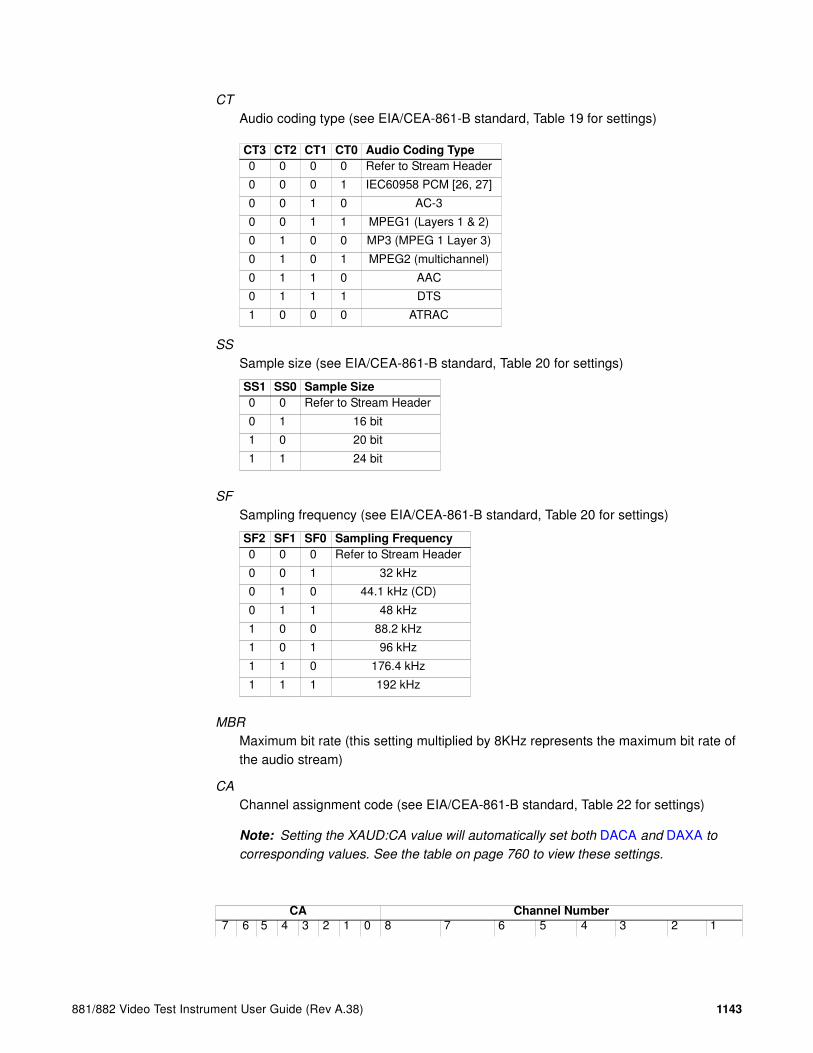
881/882 Video Test Instrument User Guide (Rev A.38) 1143
CT
Audio coding type (see EIA/CEA-861-B standard, Table 19 for settings)
SS
Sample size (see EIA/CEA-861-B standard, Table 20 for settings)
SF
Sampling frequency (see EIA/CEA-861-B standard, Table 20 for settings)
MBR
Maximum bit rate (this setting multiplied by 8KHz represents the maximum bit rate of the audio stream)
CA
Channel assignment code (see EIA/CEA-861-B standard, Table 22 for settings)
Note: Setting the XAUD:CA value will automatically set both DACA and DAXA to
corresponding values. See the table on page 760 to view these settings.
CT3 CT2 CT1 CT0 Audio Coding Type
0 0 0 0 Refer to Stream Header
0 0 0 1 IEC60958 PCM [26, 27]
0 0 1 0 AC-3
0 0 1 1 MPEG1 (Layers 1 & 2)
0 1 0 0 MP3 (MPEG 1 Layer 3)
0 1 0 1 MPEG2 (multichannel)
0 1 1 0 AAC
0 1 1 1 DTS
1 0 0 0 ATRAC
SS1 SS0 Sample Size
0 0 Refer to Stream Header
0 1 16 bit
1 0 20 bit
1 1 24 bit
SF2 SF1 SF0 Sampling Frequency
0 0 0 Refer to Stream Header
0 0 1 32 kHz
0 1 0 44.1 kHz (CD)
0 1 1 48 kHz
1 0 0 88.2 kHz
1 0 1 96 kHz
1 1 0 176.4 kHz
1 1 1 192 kHz
CA Channel Number
7 6 5 4 3 2 1 0 8 7 6 5 4 3 2 1

1144 Appendix A Command Reference
LSV
Level shift value (see EIA/CEA-861-B standard, Table 23 for settings)
0 0 0 0 0 0 0 0 - - - - - - FR FL0 0 0 0 0 0 0 1 - - - - - LFE FR FL0 0 0 0 0 0 1 0 - - - - FC - FR FL0 0 0 0 0 0 1 1 - - - - FC LFE FR FL0 0 0 0 0 1 0 0 - - - RC - - FR FL0 0 0 0 0 1 0 1 - - - RC - LFE FR FL0 0 0 0 0 1 1 0 - - - RC FC - FR FL0 0 0 0 0 1 1 1 - - - RC FC LFE FR FL0 0 0 0 1 0 0 0 - - RR RL - - FR FL0 0 0 0 1 0 0 1 - - RR RL - LFE FR FL0 0 0 0 1 0 1 0 - - RR RL FC - FR FL0 0 0 0 1 0 1 1 - - RR RL FC LFE FR FL0 0 0 0 1 1 0 0 - RC RR RL - - FR FL0 0 0 0 1 1 0 1 - RC RR RL - LFE FR FL0 0 0 0 1 1 1 0 - RC RR RL FC - FR FL0 0 0 0 1 1 1 1 - RC RR RL FC LFE FR FL0 0 0 1 0 0 0 0 RRC RLC RR RL - - FR FL0 0 0 1 0 0 0 1 RRC RLC RR RL - LFE FR FL0 0 0 1 0 0 1 0 RRC RLC RR RL FC - FR FL0 0 0 1 0 0 1 1 RRC RLC RR RL FC LFE FR FL0 0 0 1 0 1 0 0 FRC FLC - - - - FR FL0 0 0 1 0 1 0 1 FRC FLC - - - LFE FR FL0 0 0 1 0 1 1 0 FRC FLC - - FC - FR FL0 0 0 1 0 1 1 1 FRC FLC - - FC LFE FR FL0 0 0 1 1 0 0 0 FRC FLC - RC - - FR FL0 0 0 1 1 0 0 1 FRC FLC - RC - LFE FR FL0 0 0 1 1 0 1 0 FRC FLC - RC FC - FR FL0 0 0 1 1 0 1 1 FRC FLC - RC FC LFE FR FL0 0 0 1 1 1 0 0 FRC FLC RR RL - - FR FL0 0 0 1 1 1 0 1 FRC FLC RR RL - LFE FR FL0 0 0 1 1 1 1 0 FRC FLC RR RL FC - FR FL0 0 0 1 1 1 1 1 FRC FLC RR RL FC LFE FR FL
LSV3 LSV2 LSV1 LSV0 Level Shift Value
0 0 0 0 0dB
0 0 0 1 1dB
0 0 1 0 2dB
0 0 1 1 3dB
0 1 0 0 4dB
0 1 0 1 5dB
0 1 1 0 6dB
0 1 1 1 7dB
1 0 0 0 8dB
1 0 0 1 9dB
1 0 1 0 10dB
1 0 1 1 11dB
1 1 0 0 12dB
CA Channel Number

881/882 Video Test Instrument User Guide (Rev A.38) 1145
DMI
Down-mix inhibit (see EIA/CEA-861-B standard, Table 24 for settings)
Query syntax XAUD:audparameter?
Query response value
Example 1 The following example sets the number of audio channels (CC parameter) to 2 in the Audio Infoframe.
XAUD:CC 2
IFGU
Example 2 The following example sets an Audio InfoFrame with these properties:
• Seven channels (CC parameter)
• MPEG1 coding type (CT parameter)
• 16-bit sample size (SS parameter)
• 88.2KHz frequency (SF parameter)
• 72KHz maximum bit rate (MBR parameter)
• All but channel 3 (LFE) are allocated (CA parameter)
• 10dB attenuation during source device down-mixing (LSV parameter)
• Down-mixing permitted (DMI parameter)
XAUD 4 1 10 6 3 1 4 9 18 10 0;IFGU
Example 3 The following example reports the current setting for the Member Bit Rate parameter in the Audio Infoframe.
XAUD:MBR?
Related commands IFTR, IFAX:RPTU, IFGU, DAXA, DACA
1 1 0 1 13dB
1 1 1 0 14dB
1 1 1 1 15dB
DM_INH Describes whether the down mixed stereo output is permitted
0 Permitted or no information about any assertion of this
1 Prohibited
LSV3 LSV2 LSV1 LSV0 Level Shift Value

1146 Appendix A Command Reference
XAVIAuxiliary Video Information InfoFrame Data
Class InfoFrame Packet
Description Writes Auxiliary Video Information (AVI) InfoFrame packet data.
Command syntax(individual
parameter)
XAVI:aviparameter value
Command syntax(complete
packet–version 1)
XAVI type version length [S [B [A [Y [R [M [C [SC [ETB [SBB [ELB [SRB ]]]]]]]]]]]]
Command syntax(complete
packet–version 2)
XAVI type version length [S [B [A [Y [R [M [C [SC [ETB [SBB [ELB [SRB [VIC [PR [RGB [EC [ITC [CN ]]]]]]]]]]]]]]]]]]
type
2
version
1 = version 12 = version 2
length (bytes)13
The remaining are AVI Infoframe data parameters (aviparameter) as specified in EIA/CEA-861-B standard, Section 6.1:
VERS (same as Version)Infoframe version:1 = version 12 = version 2
S
Scan information (see EIA/CEA-861-B standard, Table 8 for settings)
S1 S0 Scan Information
0 0 No Data
0 1 Overscanned (television)
1 0 Underscanned (computer)
1 1 Future

881/882 Video Test Instrument User Guide (Rev A.38) 1147
B
Bar information (see EIA/CEA-861-B standard, Table 8 for settings)
A
Active Format Information (AFD) present (see EIA/CEA-861-B standard, Table 8 for settings)
Y
Video type (see EIA/CEA-861-B standard, Table 8 for settings)
R
Active Format Aspect Ratio (AFD value) (see EIA/CEA-861-B standard, Table 9 for settings)
M
Picture Aspect Ratio (see EIA/CEA-861-B standard, Table 9 for settings)
B1 B0 Bar Information
0 0 Bar data not valid
0 1 Vertical Bar info valid
1 0 Horizontal Bar info valid
1 1 Vertical & Horizontal Bar info valid
A0
Active Format Information
Present
0 No data
1 Active format information valid
Y1 Y0 RGB or YCbCr
0 0 RGB (default)
0 1 YCbCr 4:2:2
1 0 YCbCr 4:4:4
1 1 Future
R3 R2 R1 R0 Active Format Aspect Ratio
1 0 0 0 Same as picture aspect ratio
1 0 0 1 4:3 (Center)
1 0 1 0 16:9 (Center)
1 0 1 1 14:9 (Center)
other values Per DVB AFD active_format field
M1 M0
Picture Aspect
Ratio
0 0 No data
0 1 4:3
1 0 16:9
1 1 Future

1148 Appendix A Command Reference
C
Colorimetry (see EIA/CEA-861-B standard, Table 9 for settings)
SC
Non-uniform Picture Scaling (see EIA/CEA-861-B standard, Table 11 for settings)
ETB
Line number of end of top bar representing the last line of a horizontal letterbox bar area at the top of the picture (0 = no horizontal bar present at top of picture).
SBB
Line number of start of bottom bar representing the first line of a horizontal letterbox bar area at the bottom of the picture.
ELB
Pixel number of end of left bar representing the last horizontal pixel of a vertical pillar-bar area at the left side of the picture (0 = no vertical bar present at left of picture).
SRB
Pixel number of start of right bar representing the first horizontal pixel of a vertical pillar-bar area at the left side of the picture.
VIC
Video Format Identification Codes (see DVIC for settings).
PR
Pixel repetition for “2x” and “4x” formats (see EIA/CEA-861-B standard, Table 14 for settings) This field is set automatically based on settings for NCPP and NPPP.
C1 C0 Colorimetry
0 0 No data
0 1 SMPTE 170M ITU601
1 0 ITU709
1 1 Future
SC1 SC0 Non-Uniform Picture Scaling
0 0 No known non-uniform scaling
0 1 Picture has been scaled horizontally
1 0 Picture has been scaled vertically
1 1 Picture has been scaled horizontally and vertically
PR3 PR2 PR1 PR0 Pixel Repetition for Optional (2880)
0 0 0 0 No Repetition (i.e. pixel sent once)
0 0 0 1 Pixel sent 2 times (i.e. repeated once)
0 0 1 0 Pixel sent 3 times
0 0 1 1 Pixel sent 4 times
0 1 0 0 Pixel sent 5 times
0 1 0 1 Pixel sent 6 times
0 1 1 0 Pixel sent 7 times

881/882 Video Test Instrument User Guide (Rev A.38) 1149
RGB
RGB Quantization Range (see EIA/CEA-861-D standard, Table 11 for settings)
EC
Extended Colorimetry (see EIA/CEA-861-D standard, Table 11 for settings)
ITC
IT Content (see EIA/CEA-861-D standard, Table 11 for settings)
CN
IT Content Types - used when ITC flag is set (see EIA/CEA-861-E standard, Table 16 for settings)
Query syntax XAVI:aviparameter?
Query response value
0 1 1 1 Pixel sent 8 times
1 0 0 0 Pixel sent 9 times
1 0 0 1 Pixel sent 10 times
Q1 Q0
RGB Quantization
Range
0 0 Default (depends on video format)
0 1 Limited range
1 0 Full range
1 1 Reserved
EC2 EC1 EC0 Extended Colorimetry
0 0 0 xvYCC601 (IEC 61966-2-4 with standard definition primaries)
0 0 1 xvYCC709 (IEC 61966-2-4 with high definition primaries)
- - - Reserved
ITC IT Content
0 No data (DVIC of the format is neither 0 or 1)
1 IT content (DVIC of the format is either 0 or 1)
CN IT ContentType
0 Graphics
1 Photo
2 Cinema
3 Game
PR3 PR2 PR1 PR0 Pixel Repetition for Optional (2880)
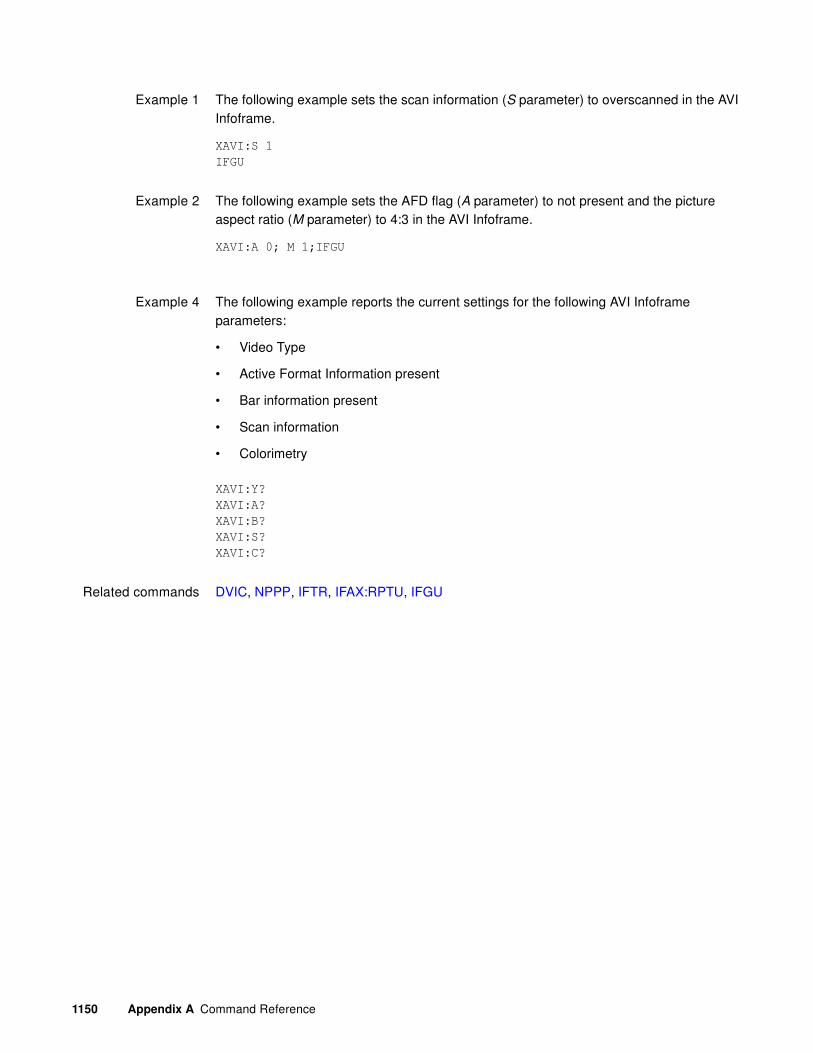
1150 Appendix A Command Reference
Example 1 The following example sets the scan information (S parameter) to overscanned in the AVI Infoframe.
XAVI:S 1
IFGU
Example 2 The following example sets the AFD flag (A parameter) to not present and the picture aspect ratio (M parameter) to 4:3 in the AVI Infoframe.
XAVI:A 0; M 1;IFGU
Example 4 The following example reports the current settings for the following AVI Infoframe parameters:
• Video Type
• Active Format Information present
• Bar information present
• Scan information
• Colorimetry
XAVI:Y?
XAVI:A?
XAVI:B?
XAVI:S?
XAVI:C?
Related commands DVIC, NPPP, IFTR, IFAX:RPTU, IFGU

881/882 Video Test Instrument User Guide (Rev A.38) 1151
XBBHArbitrary Bottom Border Height
Class Format parameter setting - active video
Description Establishes the first line of a horizontal letterbox bar area at the bottom of the image.
Command syntax XBBH line_number
line_number
0 to 65535 (in decimal)
Related commands XISH:TTYP, XRBW, XTBH
Example XBBH 769
FMTU

1152 Appendix A Command Reference
XDID EDID data write
Class EDID and DDC control
Description Writes new EDID structure for DVI Analyzer receiver.
Command syntax XDID offset bytes data
offset (hex)address offset (in bytes)
bytes
number of bytes (hex)
data
data (hex)
Example 1 To change the first 3 bytes of the EDID structure (after the header):
XDID 8 3 DE33FF
DIDU
Example 2 To write at offset 256 (start of block 2):
XDID 100 8 1122334455667788
XDID 108 8 8899AABBCCDDEEFF
DIDU
Related commands DIDA, DIDB, DIDE, DIDK, DIDL, TASK?, DIDP, DIDQ, DIDS, DIDU, EDA<port>:GDID, EDA<port>:PDID

881/882 Video Test Instrument User Guide (Rev A.38) 1153
XGCPGeneral Control Parameter Data
Class Data Island Packet
Description Enables and disables the HDMI Audio/Video Mute (AVMUTE) feature. When enabled, audio and video are muted by the generator.
Important: You can set either the AVMUTE set flag (to turn mute on) or the AVMUTE clear
flag (to turn mute off) to 1 (but not both).
Note: The status of the mute is changed only after the packet is gated ON (DPTG), the
repeat mode has been set (DPTR), and the hardware has been updated (DPGU) (see
example below).
Command syntax XGCP AVMUTE_set_flag
AVMUTE_set_flag
0 = off
1 = on
Related commands MUTE, DPTG, DPGU
Example 1 To enable AVMUTE:
DPTG 7
DPTR 1
XGCP 1
DPGU
Once executed, use the MUTE? to continuously check until the AVMUTE state is changed (may not take place right away).
Example 2 To disable AVMUTE:
DPTG 7
DPTR 1
XGCP 0
DPGU
Again, use the MUTE? command to continuously check until the AVMUTE state is changed.
1154 Appendix A Command Reference
XGDPGeneric Data Packet Data
Class Data Island Packet
Description Writes a generic data packet for sourcing highly-customized arbitrary data.
Command syntax(individual
parameter)
XGDP:gdpparameter value
Command syntax(complete packet)
XGDP data
data (ASCII)hexidecimal payload data in the form of ASCII characters (“0” through “F”)—each representing one 4-bit nibble of data (if less than 60 ASCII characters, which is less than 30 bytes of data, are specified, then the remaining bytes are set to zero)
The following are data island packet parameters (gdpparameter) as specified in HDMI specification, Section 5.3.
hb0
Packet type (see HDMI specification, Section 5.3.1 through 5.3.6 for settings)
hb1
Packet-specific data (see HDMI specification, Section 5.3.1 through 5.3.6 for settings)
hb2
Packet-specific data (see HDMI specification, Section 5.3.1 through 5.3.6 for settings)
pb0 – pb27
InfoFrame packet data (see HDMI specification, Section 5.3.5 for settings)
Example XGDP 03AABBCC
DPGU
You will have to gate on the general data packet with DPTG and DPGU

881/882 Video Test Instrument User Guide (Rev A.38) 1155
XGIFGeneric InfoFrame Data
Class InfoFrame Packet
Description Writes generic InfoFrame packet data. This allows you to emulate any InfoFrame type (including vendor-specific).
Note: The HDMI specification (section 5.2.3.2) requires that an HDMI packet must be
transmitted at least every two VSYNC periods, or the receiver will drop out of HDMI mode.
A Generic InfoFrame packet can be used for this purpose by enabling its repeat bit (see the
IFTR command).
Command syntax XGIF type version length [REG] TYPE VERS LEN INFO
REG (Register or slot) this is an optional parameter
A or B
The remaining are GIF Infoframe data parameters (gifparameter) as specified in EIA/CEA-861-D standard, Section 6.1:
TYPE (same as type)Infoframe type
VERS (same as version)Infoframe version
LEN (same as length)Infoframe length (in bytes) - maximum 27 bytes
INFO
hexidecimal payload data in the form of ASCII characters—each representing one 4-bit nibble of data. If less than 50 ASCII characters are specified, the remaining bytes are set to zero.
Query syntax XGIF:gifparameter ?
Query response value
Example The following example writes 5 bytes of Vendor Specific InfoFrame (Type 1) data.
XGIF A 1 1 5 12FA001234 // uses 882 register A, vendor specific infoframe
(type 1), version 1 and 5 bytes in length.
IFGU
Related commands IFTR, IFAX:RPTU, IFGU

1156 Appendix A Command Reference
XISH:HINCImage SHift Horizontal INCrement
Class ImageShift
Description Establishes the horizontal shifting increment value. The value must be less than or equal to the active horizontal resolution of the current video format, which can be queried with HRES?. If an imageshift editing session is in progress (the ISHB command was issued), the value will be changed, but not applied to the hardware until the ISHE and ISHU commands are issued. Otherwise, the command will take effect immediately.
Command syntax XISH:HINC increment
increment
positive integer number
Query syntax XISH:HINC?
Query response Current horizontal shifting increment value.
Example 1 XISH:HINC 4 //Sets the horizontal shifting increment to 4.
Example 2 XISH:HINC? //Queries for current horizontal shifting increment.
4
Related commands ISHA, ISHB, ISHE, ISHG, ISHK, ISHL, ISHN, ISHP, ISHQ?, ISHS, ISHU, XISH:PATH, XISH:SRCN, XISH:TINC, XISH:TTYP, XISH:VINC

881/882 Video Test Instrument User Guide (Rev A.38) 1157
XISH:PATHImage SHift Path
Class ImageShift
Description Establishes two points along which the image will be shifted. The points are defined by two sets of x,y coordinates. The default coordinates are 0,0 and 100,100. The x coordinates must be less than or equal to the active horizontal resolution of the current video format, which can be queried with HRES?. The y coordinates must be less than or equal to the active vertical resolution of the current video format, which can be queried with VRES?. If an imageshift editing session is in progress (the ISHB command was issued), the path will be changed, but not applied to the hardware until the ISHE and ISHU commands are issued. Otherwise, the command will take effect immediately.
Command syntax XISH:PATH x_start,y_start x_end,y_end
x_start,y_start x_end,y_end
positive integer numbers
Query syntax XISH:PATH?
Query response x_start,y_start x_end,y_end
Example 1 XISH:PATH 0,0 150,20 //Sets the start point to 0,0 and the end point to
//150,20
Example 2 XISH:PATH? //Queries for current path.
0,0 150,20
Related commands ISHA, ISHB, ISHE, ISHG, ISHK, ISHL, ISHN, ISHP, ISHQ?, ISHS, ISHU, XISH:HINC, XISH:SRCN, XISH:TINC, XISH:TTYP, XISH:VINC

1158 Appendix A Command Reference
XISH:SRCNImage SHift SouRCe Name
Class Image Shift
Description Establishes the image file or bitmap file that will be used for image shifting. The default file is /Cache0/Images/Ramp. If an imageshift editing session is in progress (the ISHB command was issued), the image source will be changed, but not applied to the hardware until the ISHE and ISHU commands are issued. Otherwise, the command will take effect immediately.
Command syntax XISH:SRCN path/filename
path/filename
The directory path and valid MS-DOS filename (8 characters minus any extension) of the image or bitmap file to be used for image shifting. If the file to be used is in the default path, then path/ may be omitted.
Query syntax XISH:SRCN?
Query response path/filename
Example XISH:SRCN Master //Selects the Master image as the current image to
//shift
Related commands ISHA, ISHB, ISHE, ISHG, ISHK, ISHL, ISHN, ISHP, ISHQ?, ISHS, ISHU, XISH:HINC, XISH:PATH, XISH:TINC, XISH:TTYP, XISH:VINC

881/882 Video Test Instrument User Guide (Rev A.38) 1159
XISH:TINCImage SHift Time INCrement
Class Image Shift
Description Establishes the time shift increment value, which is the number of frames to pause before shfiting the image. If an imageshift editing session is in progress (the ISHB command was issued), the value will be changed, but not applied to the hardware until the ISHE and ISHU commands are issued. Otherwise, the command will take effect immediately.
Command syntax XISH:TINC increment
increment
positive integer number 0 – 999
Query syntax XISH:TINC?
Query response Current time shift increment value.
Example 1 XISH:TINC 2 //Sets the time shift increment to 2.
Example 2 XISH:TINC? //Queries for current time shift increment.
2
Related commands ISHA, ISHB, ISHE, ISHG, ISHK, ISHL, ISHN, ISHP, ISHQ?, ISHS, ISHU, XISH:HINC, XISH:PATH, XISH:SRCN, XISH:TTYP, XISH:VINC

1160 Appendix A Command Reference
XISH:TTYPImage SHift Trace TYPe
Class Image Shift
Description Establishes the way in which image shifting will occur. A repeating trace type causes the image to shift between the start and end points, and then restart at the start point. A reverse trace type causes the image to shift between the start and end points, and then from the end point to the start point. If an imageshift editing session is in progress (the ISHB command was issued), the trace type will be changed, but not applied to the hardware until the ISHE and ISHU commands are issued. Otherwise, the command will take effect immediately.
Command syntax XISH:TTYP type
type
1 = Repeat
2 = Reverse
Query syntax XISH:TTYP?
Query response 1 or 2
Example 1 XISH:TTYP 1 //Sets the trace type to 1, Repeat.
Example 2 XISH:TTYP? //Queries for current trace type.
1
Related commands ISHA, ISHB, ISHE, ISHG, ISHK, ISHL, ISHN, ISHP, ISHQ?, ISHS, ISHU, XISH:HINC, XISH:PATH, XISH:SRCN, XISH:TINC, XISH:VINC
881/882 Video Test Instrument User Guide (Rev A.38) 1161
XISH:VINCImage SHift Vertical INCrement
Class Image Shift
Description Establishes the vertical shifting increment value. The value must be less than or equal to the active vertical resolution of the current video format, which can be queried with VRES?. If an imageshift editing session is in progress (the ISHB command was issued), the value will be changed, but not applied to the hardware until the ISHE and ISHU commands are issued. Otherwise, the command will take effect immediately.
Command syntax XISH:VINC increment
increment
positive integer number
Query syntax XISH:VINC?
Query response Current vertical shifting increment value.
Example 1 XISH:VINC 4 //Sets the vertical shifting increment to 4.
Example 2 XISH:HINC? //Queries for current vertical shifting increment.
4
Related commands ISHA, ISHB, ISHE, ISHG, ISHK, ISHL, ISHN, ISHP, ISHQ?, ISHS, ISHU, XISH:HINC, XISH:PATH, XISH:SRCN, XISH:TINC, XISH:TTYP

1162 Appendix A Command Reference
XLBWArbitrary Left Border Width
Class Format parameter setting - active video
Description Establishes the last horizontal pixel of a vertical pillar-box bar area at the left side of the image.
Command syntax XLBW pixel_number
pixel_number
0 to 65535 (in decimal)
Related commands XBBH, XRBW, XTBH
Example XLBW 64
FMTU
881/882 Video Test Instrument User Guide (Rev A.38) 1163
XMPGMPEG InfoFrame Data
Class InfoFrame Packet
Description Writes MPEG InfoFrame packet data.
Command syntax(individual
parameter)
XMPG: mpgparameter value
Command syntax(complete packet)
XMPG type version length [MB [MF [FR]]]
type
5
version
1
length (bytes)10
The remaining are MPEG Infoframe data parameters (mpgparameter) as specified in EIA/CEA-861-B standard, Section 6.4:
VERS (same as Version)Infoframe version
MB
MPEG bit rate (Enter rate in Hertz [Hz])
MF
MPEG frame (see EIA/CEA-861-B standard, Table 26 for settings)
FR
Field repeat (see EIA/CEA-861-B standard, Table 26 for settings)
Query syntax XMPG:mpgparameter?
Query response value

1164 Appendix A Command Reference
Example The following example sets the data rate of the MPEG transmission in the MPEG InfoFrame data to 44.1kHz.
XMPG:MB 44100
IFGU
Related commands IFTR, IFAX:RPTU, IFGU

881/882 Video Test Instrument User Guide (Rev A.38) 1165
XRBWArbitrary Right Border Width
Class Format parameter setting - active video
Description Establishes the first horizontal pixel of a vertical pillar-bar area at the right side of the image.
Command syntax XRBW pixel_number
pixel_number
0 to 65535 (in decimal)
Related commands XISH:TTYP, XTBH, XBBH
Example XRBW 961
FMTU

1166 Appendix A Command Reference
XRESX axis RESolution for custom images
Class Image editor control
Description Sets the width factor used to scale horizontal size and position parameters in the primitives of a custom image in the image editor buffer. The XRES? query returns the current XRES setting.
Command syntax XRES width
width integer
16 to 65,536
Query syntax XRES?
Query response width
Example XRES 1600 // Set horizontal scaling factor to 1600
YRES 900 // Set vertical scaling factor to 900

881/882 Video Test Instrument User Guide (Rev A.38) 1167
XSPDSource Product Description InfoFrame Data
Class InfoFrame Packet
Description Writes Source Product Description InfoFrame packet data.
Command syntax(individual
parameter)
XSPD: spdparameter value
Command syntax(complete packet)
XSPD type version length [VNS [PDS [SDI]]]
type
3
version
1
length (bytes)25
The remaining are Source Product Description Infoframe data parameters (spdparameter) as specified in EIA/CEA-861-B standard, Section 6.2:
VERS (same as Version)Infoframe version
VNS
Vendor name string
PDS
Product description string
SDI
Source device information (see EIA/CEA-861-B standard, Table 17 for settings)
Query syntax XSPD:spdparameter?
Query response value
Example The following example sets the vendor name string (VNS parameter) to “QDI” in the Source Product Description Infoframe.
IFGU
XSPD:VNS QDI

1168 Appendix A Command Reference
Example 2 The following example specifies a Source Product Description InfoFrame with these properties:
• Vendor name is QDI
• Product description is HDMI-Analyzer
• Source device is Digital STB (1)
XSPD 3 1 25 QDI HDMI-Analyzer 1
Example 3 The following example reports the current setting for the Product Description parameter in the Source Product Description Infoframe.
XSPD:PDS?

881/882 Video Test Instrument User Guide (Rev A.38) 1169
XTBHArbitrary Top Border Height
Class Parameters (Video Signal)
Description Establishes the last line of a horizontal letterbox bar area at the top of the image.
Command syntax XTBW line_number
line_number
0 to 65535
Related commands XISH:TTYP, XRBW, XBBH
Example XTBH 15
FMTU

1170 Appendix A Command Reference
XVSGVideo Signal Gating
Class Format parameter settings
Description Determines which video outputs are active when the format is selected. The same command controls both the analog and digital video outputs.
Command syntax XVSG red_mode, green_mode, blue_mode
red_mode, green_mode, blue_mode
0 = OFF
1 = ON
Other requiredcommands
The FMTU command instructs the generator to use the new setting. The ALLU command updates hardware to the new setting and redraws the test image.
Example XVSG 1 1 1 // Enable all color channels
FMTU // Update hardware to current buffer contents
881/882 Video Test Instrument User Guide (Rev A.38) 1171
X3DM3D Mode
Class Format video signal
Description Controls the 3D parameters.
Command syntax X3DM enable method sampling
enable
0 = Disables 3D
1 = Enables 3D
method
0 = Sets 3D mode to Frame Packing
2 = Sets 3D mode to Line Alternative
3 = Sets 3D mode to Side by Side (Full)
4 = Sets 3D mode to L + Depth
6 = Sets 3D mode to Top and Bottom
8 = Sets 3D mode to Side by Side (Half)
sampling (applies only to Side by Side half)for Horizontal Sub-Sampling:
0 = Odd/Left picture, Odd/Right picture
1 = Odd/Left picture, Even/Right picture
2 = Even/Left picture, Odd/Right picture
3 = Even/Left picture, Even/Right picture
for Quincunx Matrix:
4 = Odd/Left picture, Odd/Right picture
5 = Odd/Left picture, Even/Right picture
6 = Even/Left picture, Odd/Right picture
7 = Even/Left picture, Even/Right picture
Query syntax X3DM?
Query response enable method sampling
Example 1 X3DM 1 0 // Enables 3D, sends Frame Packing
Example 2 X3DM 1 8 3 // Enables 3D, Selects Side by Side with Even/Left; Even/Right
Example 3 X3DM 1 6 // Enables 3D, Selects Top and Bottom

1172 Appendix A Command Reference
XVSIVideo Signal Interface
Class Format video signal
Description Enables the specified video signal interface output for the analyzer.
Command syntax XVSI interface
or
XVSI:OUT interface
interface
1 = DVI-A (analog)
2 = DVI-D (digital)
3 = HDMI-D (DVI)
4 = HDMI-H (HDMI)
5 = SVIDEO
6 = CVBS
7 = SDI, HD-SDI
9 = VGA
10 = DisplayPort
Query syntax XVSI?
or
XVSI:OUT?
Query response interface
Other requiredcommands
The ALLU command updates hardware to the new setting and redraws the test image.
Example 1 XVSI 1 // Enable DVI for analog output
ALLU // Update hardware to current buffer contents
XVSI 3 // Enable HDMI interface for DVI output
ALLU // Update hardware to current buffer contents
XVSI:OUT 4 // Enable HDMI interface for HDMI output
ALLU // Update hardware to current buffer contents

881/882 Video Test Instrument User Guide (Rev A.38) 1173
Example 2 XVSI? //Queries for the currently-enabled video signal interface output
4 //HDMI-H output is currently enabled
Related commands XVSI:IN

1174 Appendix A Command Reference
YRESY axis RESolution for custom images
Class Image editor control
Description Sets the height factor used to scale vertical size and position parameters in the primitives of a custom image in the image editor buffer. The YRES? query returns the current YRES setting.
Command syntax YRES height
height integer
16 to 65,536
Query syntax YRES?
Query response height
Example XRES 1600 // Set horizontal scaling factor to 1600
YRES 900 // Set vertical scaling factor to 900
Example dirn mydir // create a directory named mymap
dirb // begin directory context
nami 1 smpte133 // insert the name smpte133 at index 1
nami 2 flat // insert the name flat at index 2
nami 3 raster // insert the name raster at index 3
dire // end directory context
dirs // save map named mymap
dirl mydir // load directory mydir into edit buffer
dirb // begin directory context
namq? 1 10 // list mydir names
namy 2 // yank name at index 2
nami 1 colorbar // insert new name at index 1
dire // end directory context
dira newdir // save modified mydir as newdir
dirq? 1 10 // list available directories
// (up to 10 maps starting with the 1st)

881/882 Video Test Instrument User Guide (Rev A.38) 1101
B Image Reference
Topics in this appendix:
• Standard image descriptions

1102 Appendix B Image Reference
Standard image descriptions
3DCRTK
Description Test image for testing 3D crosstalk.

881/882 Video Test Instrument User Guide (Rev A.38) 1103
3DCUBES
Description Test image for testing 3D motion.

1104 Appendix B Image Reference
Acer1
Description Special test image developed per customer specifications. Consists of two sets of color bars and five blocks of “#” characters on a white crosshatch with a black background.
Acer2
Description Special test image developed per customer specifications. Consists of colorbars, lines of “#” characters, and a green border.

881/882 Video Test Instrument User Guide (Rev A.38) 1105
Acer3, Acer4, Acer5 and Acer6
Description Special test images developed per customer specifications. Consists of large and small white circles centered on either a yellow (Acer3), magenta (Acer4), cyan (Acer5), or white (Acer6) crosshatch on a black background. The Acer3 image is shown below.
Acer7 and Acer8
Description Special test image developed per customer specifications. In the primary version, five blocks of either white “#” (Acer7) or “H” (Acer8) characters on a black background are displayed. A secondary version displays black characters on a white background. The Acer7 image is shown below.

1106 Appendix B Image Reference
Acer9
Description Special test image developed per customer specifications. In the primary version, a mostly white field is displayed with two rows of color bars at the bottom. A secondary version displays a black field with the two rows of color bars at the bottom.
AFDtest
Description Used to test HDMI content mapping using different EIA/CEA-861-B formats. There are 10 different versions of this image. For more information, see “Testing with Active Format Description (AFD) (882 only)” on page 385.

881/882 Video Test Instrument User Guide (Rev A.38) 1107
AnsiGray
Description The primary version displays a white background with a small black pixel in the center fills the active video area. A secondary version displays a black background with a small white pixel in the center.
AnsiLght
Description The primary version displays a white background with a small black pixel in the center fills the active video area. A secondary version displays a black background with a small white pixel in the center.

1108 Appendix B Image Reference
Apple1
Description Special test image developed per customer specifications. A secondary version shows reverse (black characters on white background).
Audio LR, AudioLRf, AudioRAT, Audio_L, Audio_Lf, Audio_R, Audio_Rf
Description Used to configure HDMI audio output signal. The AudioLR is shown below. For more information, see “Testing HDMI audio” on page 367.
BarBlack
Description Special test image developed per customer specifications.
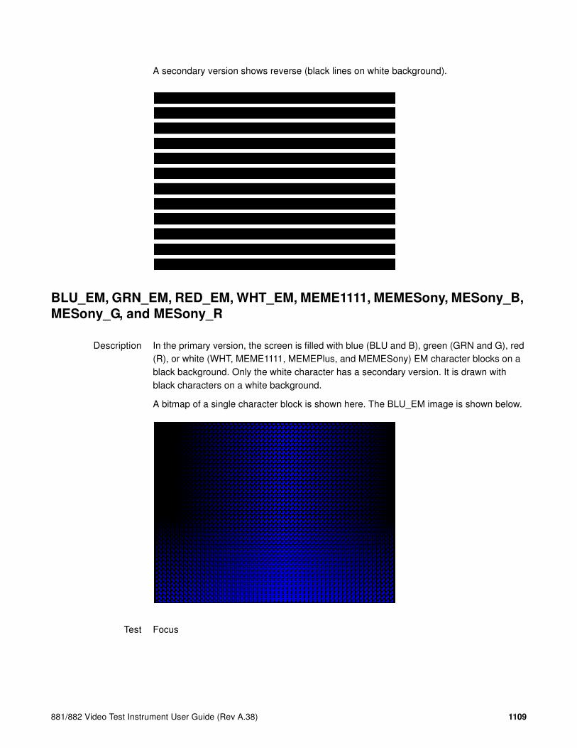
881/882 Video Test Instrument User Guide (Rev A.38) 1109
A secondary version shows reverse (black lines on white background).
BLU_EM, GRN_EM, RED_EM, WHT_EM, MEME1111, MEMESony, MESony_B,
MESony_G, and MESony_R
Description In the primary version, the screen is filled with blue (BLU and B), green (GRN and G), red (R), or white (WHT, MEME1111, MEMEPlus, and MEMESony) EM character blocks on a black background. Only the white character has a secondary version. It is drawn with black characters on a white background.
A bitmap of a single character block is shown here. The BLU_EM image is shown below.
Test Focus

1110 Appendix B Image Reference
Purpose This pattern is specified by some display manufacturers for checking and adjusting focus one color at a time.
BLU_EM+, GRN_EM+, RED_EM+, WHT_EM+, MEMEPlus, MEPlus_B,
MEPlus_G, and MEPlus_R
Description In the primary version, the screen is filled with blue (BLU and B), green (GRN and G), red (R), or white (WHT and Sony) EM character blocks on a black background. Only the white character has a secondary version. It is drawn with black characters on a white background.
A bitmap of a single character block is shown here. The BLU_EM+ image is shown below.
Test Focus
Purpose This pattern is specified by one or more display manufacturers for checking and adjusting focus one color at a time.

881/882 Video Test Instrument User Guide (Rev A.38) 1111
BLU_PIC, GRAY_PIC, GRN_PIC, RED_PIC, WHT_PIC
Description A solid blue (BLU), gray, green (GRN), red, or white (WHT) box fills the active video area. Only the white fill has a secondary version. It can be changed to a black fill by pressing the Step key. The BLU_PIC image is shown below.
Test Purity adjustment
Purpose To produce correct colors in a displayed image, the electron beams from each of the three (3) guns in the CRT should strike only their matching phosphors. A white image shows patches of various colors on a monitor with bad purity. The purity adjustment(s) should be performed before doing any brightness or color tests. In some cases, purity adjustments involve loosening and repositioning the yoke, in which case purity should be adjusted prior to doing any geometry tests.
Method The methods used for adjusting purity on a color monitor depend on the type of monitor and CRT (for example; Delta, In-Line or Single Gun). In most cases, the first step is to degauss the CRT.
Note: For a Delta Gun CRT, turn on only the red output. A solid uniform field of red should
appear. If the color is not uniform, adjust the yoke and the Purity Tabs assembly.
If purity cannot be corrected to acceptable limits, the monitor may not have been properly degaussed or there may be a defect in the CRT or purity assembly.
Test Shadow mask warping

1112 Appendix B Image Reference
Purpose The purity characteristics of your CRT can change over time if you leave it on with a lot of video being displayed. This may be due to the CRT’s electron beams striking its shadow mask with enough energy to cause the mask to heat. This internal heating may be enough to cause the shadow mask to warp and give bad purity.
Method Set the purity image to white and allow the monitor to run for a few minutes. Any mask warping shows up as a change in purity. You can use a color meter to measure the change. The BriteBox pattern may also be useful for measuring shadow mask warping.
Bosch
Description Special test image developed per customer specifications. This image has 6 versions.

881/882 Video Test Instrument User Guide (Rev A.38) 1113
Box_50mm, Box_64mm, Box100mm, Box150mm, Box200mm, Box250mm
Description The primary version has a solid white box in the center of the active video. Depending on the image selected, the box is sized by square millimeters. If there is room, information on the current format appears below and to the left of the box. This shows the number of active pixels and lines as well as the horizontal and vertical scan rates. A forward slash (I) after the number of active lines indicates the format is interlaced.
Note: The box will be the correct size only if the correct physical active video size is set in
the format.
The Box_50mm image is shown below. The secondary version draws a black box and black text on a white background.

1114 Appendix B Image Reference
Test Brightness control adjustment
Purpose The wrong brightness setting may cause other tests such as Contrast, Focus, and Beam Size to be invalid. An accurate brightness setting helps give repeatable measurements throughout other tests.
Method Center your light meter probe within the center square and adjust the monitor’s brightness control to obtain the required light meter reading.
BriteBox
Description The primary version has a single white box in the center of active video. The box size is controlled by the MSIZ system parameter. The secondary version adds four boxes in the corners of active video.
Test Brightness control adjustment
Purpose The wrong brightness setting may cause other tests such as Contrast, Focus, and Beam Size to be invalid. An accurate brightness setting helps give repeatable measurements throughout other tests.
Method Center your light meter probe within the center square and adjust the monitor’s brightness control to obtain the required light meter reading.
Test Brightness uniformity

881/882 Video Test Instrument User Guide (Rev A.38) 1115
Purpose The light output of most picture tubes varies slightly when measured across the CRT face. This test can be used to verify that the light output variation is within your specification limits.
Method Select the inverted version and perform the Brightness Control Adjustment test on the center box. Then, center the light meter probe in each of the corner squares and note the reading you get for each square. The deviation between each of the corner readings and the center reading should be within your specification limits.
Burst (TV formats only)
Description The left side starts with reference white (+100 IRE) and black (+7.5 IRE) levels. This is followed by six bursts of sine waves. Each burst is at a different frequency, forming vertical lines of various widths. The frequencies, going from left to right, are 0.5, 1, 2, 3, 3.58, and 4.43 MHz.
Test Frequency response
Method When viewed on a TV screen, the peak intensities of all of the bursts should match the white reference level. The darkest portions between the peaks should match the black reference level.
The image can also be used with a TV waveform analyzer to check the frequency response of a video system. One scan line of the image, as it would appear on a waveform analyzer, is shown at the top of the next page . High frequency roll-off (loss) would show up as a decrease in the peak-to-peak swings on the right side of the waveform. Low frequency roll-off would show up as a decrease in the peak-to-peak swings on the left side of the waveform.

1116 Appendix B Image Reference
Some waveform analyzers can be set to detect and display the amplitude of the peaks. A typical amplitude waveform for a good system is shown at the bottom of the next page.
BurstTCE
Description Fills screen with a 0.5 MHz frequency. This can be increased in 0.5 MHz increments by pressing the Contents key and then the Options key. You then enable More and use the +/- increment keys.
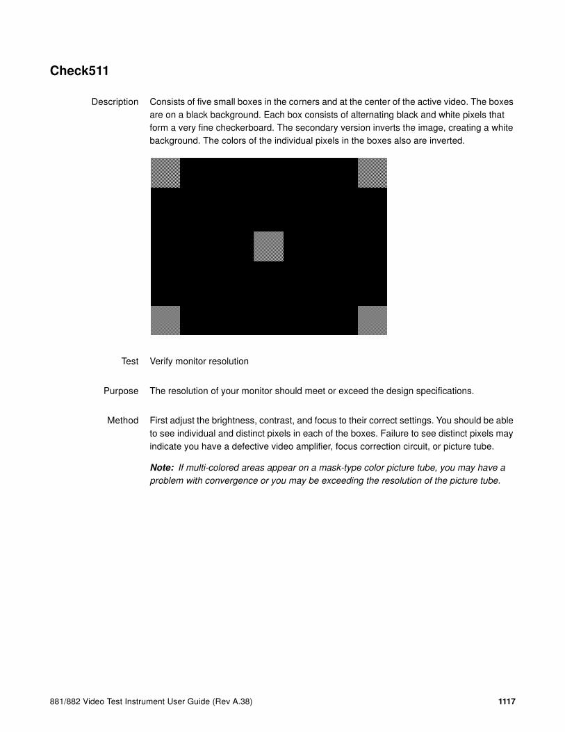
881/882 Video Test Instrument User Guide (Rev A.38) 1117
Check511
Description Consists of five small boxes in the corners and at the center of the active video. The boxes are on a black background. Each box consists of alternating black and white pixels that form a very fine checkerboard. The secondary version inverts the image, creating a white background. The colors of the individual pixels in the boxes also are inverted.
Test Verify monitor resolution
Purpose The resolution of your monitor should meet or exceed the design specifications.
Method First adjust the brightness, contrast, and focus to their correct settings. You should be able to see individual and distinct pixels in each of the boxes. Failure to see distinct pixels may indicate you have a defective video amplifier, focus correction circuit, or picture tube.
Note: If multi-colored areas appear on a mask-type color picture tube, you may have a
problem with convergence or you may be exceeding the resolution of the picture tube.

1118 Appendix B Image Reference
CheckBy3
Description The active video area is equally divided into a 3x3 checkerboard of black and white boxes. The primary version has four white boxes as shown in the image below. The secondary version has five white boxes (reverse).
Test Contrast ratio
Purpose The pattern is based on a proposed ANSI method of measuring the contrast ratio of video projection systems.
Method Using a light meter probe, measure and record the light-level reading (in foot lamberts) in the center of each of the black and white boxes. The contrast ratio is expressed as the average of all of the white readings divided by the average of all of the black readings.

881/882 Video Test Instrument User Guide (Rev A.38) 1119
Check_02
Description Primary version is shown below. The secondary version has reverse (black lines on white background).
Check_11
Description In the primary version, the active video area is filled with alternating black and white pixels that form a very fine checkerboard, as shown below. The secondary version inverts the colors in the image. The inverted image looks almost the same as the non-inverted version.
Test Verify monitor resolution

1120 Appendix B Image Reference
Purpose The resolution of your monitor should meet or exceed the design specifications.
Method Adjust the brightness, contrast, and focus to their correct settings first. You should be able to see individual and distinct pixels in each of the boxes. Failure to see distinct pixels may indicate you have a defective video amplifier, focus correction circuit, or picture tube.
Note: If multi-colored areas appear on a mask-type color picture tube, you may have a
problem with convergence, or you may be exceeding the resolution of the picture tube.
CirclesL
Description Special test image developed per customer specifications. In the primary version (shown below), the image consists of five large white circles on a black background. The circles are positioned in the center and in the corners of the active video area. The secondary version inverts the image to black circles on a white background.
Purpose This pattern is specified by some monitor manufacturers for checking and adjusting video scan size, linearity, and over scanning.

881/882 Video Test Instrument User Guide (Rev A.38) 1121
CirclesS
Description Special test image developed per customer specifications. In the primary version (shown below), the image consists of eight small white circles on a black background. The circles are positioned in the corners of the active video area and centered on each edge of the active video area. The secondary version inverts the image to black circles on a white background.
Purpose This pattern is specified by some monitor manufacturers for checking and adjusting video scan size, linearity, and over scanning.
ColorBar
Description The primary version (shown below) has 16 full-height vertical color bars. The secondary version splits the field into a top and bottom half. The bars in the bottom half of the screen are in reverse order.

1122 Appendix B Image Reference
Note: When outputting digital video, 33% Gray changes to 50% Gray, and 67% Gray
becomes either Black or some gray level depending on how the display interprets the video
information.
Test Verify that all video channels are functional
Purpose To verify that none of the video channels are bad or connected incorrectly.
Method Compare the sequence of color bars with the table. Missing bars may indicate a dead or unconnected channel. The transition between the bars should be sharp and distinct. Each bar should also be uniform in color and intensity across its entire width. Non-uniformity may indicate problems with the response of the video amplifiers. If all the bars are present but in the wrong order, one or more inputs may be swapped.
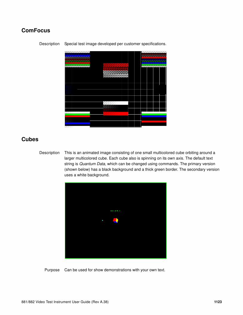
881/882 Video Test Instrument User Guide (Rev A.38) 1123
ComFocus
Description Special test image developed per customer specifications.
Cubes
Description This is an animated image consisting of one small multicolored cube orbiting around a larger multicolored cube. Each cube also is spinning on its own axis. The default text string is Quantum Data, which can be changed using commands. The primary version (shown below) has a black background and a thick green border. The secondary version uses a white background.
Purpose Can be used for show demonstrations with your own text.
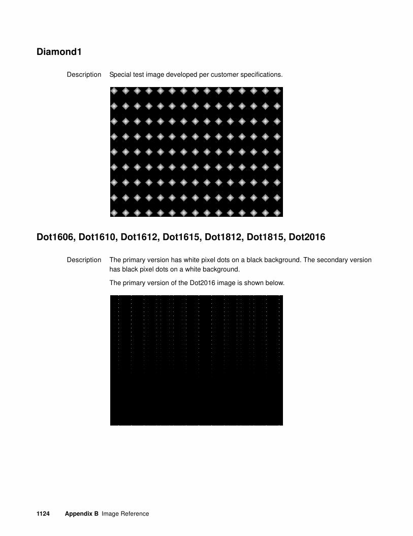
1124 Appendix B Image Reference
Diamond1
Description Special test image developed per customer specifications.
Dot1606, Dot1610, Dot1612, Dot1615, Dot1812, Dot1815, Dot2016
Description The primary version has white pixel dots on a black background. The secondary version has black pixel dots on a white background.
The primary version of the Dot2016 image is shown below.

881/882 Video Test Instrument User Guide (Rev A.38) 1125
Dot_10, Dot_12, Dot_24
Description The active video area is filled with multiple rows of white, single pixel dots. The dots define the corners of what would appear to be square boxes if all connecting pixels were lit. The number of rows of boxes and the number of boxes per row depends on which version of the image is selected and the screen aspect ratio of the currently-loaded format. The number in the image’s name refers to the number of boxes that will be formed along the minor axis for most aspect ratios. The generator calculates the ratio and then finds the closest match from the following table.
The primary version has white pixel dots on a black background. A secondary version has black pixel dots on a white background.
The primary version of the Dot_24 image is shown below.
Purpose To accurately produce an image on a color monitor, the three electron beams in the CRT must meet (converge) at the same location at the same time. Small dots displayed on a misconverged monitor appear as a group of multi-colored dots.
Aspect Ratio Dot_10 Dot_12 Dot_24
W : H Decimal Number of Rows
Boxes per Row
Number of Rows
Boxes per Row
Number of Rows
Boxes per Row
16 : 9 1.777 É 10 16 10 16 18 32
5 : 3 1.666 É 10 16 10 16 18 30
4 : 3 1.333 É 10 14 12 16 24 32
1 : 1 1.000 10 10 12 12 24 24
3 : 4 0.750 14 10 16 12 32 24

1126 Appendix B Image Reference
Method The convergence adjustments of most color monitors fall into two main categories. The first set of adjustments, usually called Static Convergence, aligns the three beams in the center of the display. This method involves turning on all three guns and adjusting the various magnets on the convergence assembly to produce all white dots in the center of the display. The convergence assembly is located on the neck of the CRT. Different monitors and CRT types may each require their own magnet-adjustment sequence.
After the center of the display is properly converged, the outer areas are adjusted by using the monitor’s Dynamic Convergence controls. The number of controls, the area of the screen they affect, and their adjustment procedure depends on the monitor under test.
Test Focus adjustments
Purpose An out-of-focus monitor displays fuzzy pixels which, in turn, result in poorly formed and hard-to-read characters.
Method On monitors with a single (static) focus adjustment, adjust the control for the best average focus over the entire screen. The focus at certain locations should be within specified limits.
Some monitors have a static and one or more dynamic focus controls. The sequence for adjusting them and the areas of the screen they affect depend on the monitor under test.
DV_Swing
Description This image is only available with DVI and HDMI. The DV_Swing image is used to temporally change the digital video swing (DVSS format parameter) between 90 and 1620 mVp-p of the HDMI and DVI digital output for the active format. This image displays the current video swing value over a graduated (ramp) background. This image is supported by HDMI boards (revision F or later), and DVI boards with FPGA F1 or later.

881/882 Video Test Instrument User Guide (Rev A.38) 1127
Note: The DVSC command can be used to set the swing value between 150 and 1500
mVp-p.
Method To adjust the swing in 6 mV increments, press the Contents key and then the Options key. You then enable More and use the +/- increment keys to proceed through the subimages.
Dyna
Description This image has multiple versions that display different sizes of the same pattern. Version 0 is shown below.
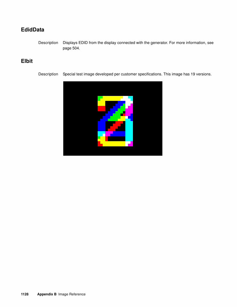
1128 Appendix B Image Reference
EdidData
Description Displays EDID from the display connected with the generator. For more information, see page 504.
Elbit
Description Special test image developed per customer specifications. This image has 19 versions.

881/882 Video Test Instrument User Guide (Rev A.38) 1129
EMITest1, EMITest2, EMITest3, EMITest4, EMITest5
Description Special test images used for electro-magnetic interference (EMI) testing of displays. The entire active video area is filled with an “H” character. The primary versions of these images draw white characters on a black background. The secondary versions draw black characters on a white background. The EMITest1 image is shown below.
The EMITest2 image is the same as EMITest1, but with the bottom row of characters constantly drawn left-to-right and then cleared.
The EMITest3 image is the same as EMITest1, but with a larger version of the “H” character.
The EMITest4 image is the same as EMITest3, but with the bottom row of characters constantly drawn left-to-right and then cleared.

1130 Appendix B Image Reference
The EMITest5 image is shown below.

881/882 Video Test Instrument User Guide (Rev A.38) 1131
Flat, Flat07, Flat13, Flat20, Flat27, Flat33, Flat40, Flat47, Flat53, Flat60, Flat67,
Flat73, Flat80, Flat87, Flat93, FlatGray, Flat_01, Flat_02, Flat_03, Flat_04,
Flat_05, Flat_06, Flat_07, Flat_08, Flat_09, Flat_10, Flat_11, Flat_12, Flat_13,
Flat_14, Flat_15, Flat_16
Description The entire active video area is filled with a shade of gray. Each image displays a different shade of gray. The FlatGray image is shown below.
Flat_B, Flat_G, Flat_R
Description The screen is filled with blue (B), green (G) or red (R). The Flat_B image is shown below.

1132 Appendix B Image Reference
Focus20
Description Primary version shown below. The secondary version has black characters on a white background.
FocusC14
Description Primary version shown below.The secondary version has black characters on a white background.

881/882 Video Test Instrument User Guide (Rev A.38) 1133
FocusCCx
Description Primary version shown below. The secondary version has black characters on a white background.
FocusEM
Description Primary version shown below. The secondary version has black characters on a white background.

1134 Appendix B Image Reference
FocusEMP
Description Primary version shown below. The secondary version has black characters on a white background.
FocusM00 - FocusM15
Description The FocusM00 image is shown below.

881/882 Video Test Instrument User Guide (Rev A.38) 1135
Focus_@6, Focus_@7, Focus_@8, Focus_@9
Description In the primary versions, the screen is filled with white “@” characters on a black background. The secondary versions are drawn with black characters on a white background. The primary version of the Focus_@6 image is shown below.
Test Focus adjustments
Purpose An out-of-focus monitor displays fuzzy graphic images and poorly formed, hard-to-read text characters.
Method On monitors with a single (static) focus adjustment, adjust the control for the best average focus over the entire screen. The focus at certain locations of the screen should be within specified limits.
Some monitors have a static and one or more dynamic focus controls. The sequence for adjusting them and the areas of the screen that they affect depend on the monitor under test.

1136 Appendix B Image Reference
Focus_Cx
Description In the primary version (shown below), the screen is filled with white Cx characters on a black background. The secondary version is drawn with black characters on a white background.
Test Focus adjustments
Purpose An out-of-focus monitor displays fuzzy graphic images and poorly formed, hard-to-read text characters.
Method On monitors with a single (static) focus adjustment, adjust the control for the best average focus over the entire screen. The focus at certain locations of the screen should be within specified limits.
Some monitors have a static and one or more dynamic focus controls. The sequence for adjusting them and the areas of the screen that they affect depend on the monitor under test.

881/882 Video Test Instrument User Guide (Rev A.38) 1137
Focus_H
Description In the primary version (shown below), the screen is filled with white H characters on a black background. The secondary version is drawn with black characters on a white background.
Test Focus adjustments)
Purpose An out-of-focus monitor displays fuzzy graphic images and poorly formed, hard-to-read text characters.
Method On monitors with a single (static) focus adjustment, adjust the control for the best average focus over the entire screen. The focus at certain locations of the screen should be within specified limits.
Some monitors have a static and one or more dynamic focus controls. The sequence for adjusting them and the areas of the screen that they affect depend on the monitor under test.

1138 Appendix B Image Reference
Focus_MM
Description In the primary version (shown below), the screen is filled with white M characters on a black background. The secondary version is drawn with black characters on a white background.
Focus_Oo
Description In the primary version (shown below), the screen is filled with white Oo characters on a black background. The secondary version is drawn with black characters on a white background.
Test Focus adjustments

881/882 Video Test Instrument User Guide (Rev A.38) 1139
Purpose An out-of-focus monitor displays fuzzy graphic images and poorly formed, hard-to-read text characters.
Method On monitors with a single (static) focus adjustment, adjust the control for the best average focus over the entire screen. The focus at certain locations of the screen should be within specified limits.
Some monitors have a static and one or more dynamic focus controls. The sequence for adjusting them and the areas of the screen that they affect depend on the monitor under test.
Format
Description A listing of the data contained in any format. The primary image lists the settings of the format driving the display. The secondary image can be used to list the contents of any stored format (via the Location field).
This pattern works best at display resolutions of at least 640 pixel by 480 lines.

1140 Appendix B Image Reference
Geom_1 - Geom_5
Description The primary version of the Geom_1 image is shown below. Secondary version is drawn with black lines on a white background.
Gray25, Gray40
Description The Gray25 image is shown below.

881/882 Video Test Instrument User Guide (Rev A.38) 1141
GrayBar
Description The primary version (shown below) has 16 full-height vertical graybars. The intensity of the bars is shown below. The secondary version splits the field into a top and bottom half. The bars in the bottom half of the screen are in reverse order.
Test Video color tracking (color monitors)
Purpose To verify that a color monitor accurately reproduces colors at all intensities.
Method Perform the Brightness Control Adjustment and Brightness Uniformity tests first.
Changes in brightness from bar to bar should be uniform. All of the bars should appear as an untinted gray at all levels.
Test Video gain linearity (monochrome monitors)
Purpose To check the video linearity (grayscale modulation)
Method Perform the Brightness Control Adjustment and Brightness Uniformity tests first.
Changes in brightness from bar to bar should be visible and uniform.

1142 Appendix B Image Reference
GrayL1, GrayL3
Description The GrayL1 image is shown below.
Grays5, Grays9, Grays11, Grays16, Grays32, Grays64
Description These images have the designated number of full-height vertical graybars.
The Grays11 image is shown below.

881/882 Video Test Instrument User Guide (Rev A.38) 1143
GraysAll
Description Contains 256 grayscale versions, from 0 (full black) to 255 (full white).
Grill_11, Grill_15, Grill_22, Grill_33, Grill_44
Description The entire active video area is filled with alternating black and white stripes. The stripes are drawn at different resolutions. Each of the stripes is four (4) pixels wide in the Grill_44 image and three (3) pixels wide in the Grill_33 image. Each of the stripes is two (2) pixels wide in the Grill_22 image and one (1) pixel wide in the Grill_11 image.
The primary versions draw vertical stripes. The secondary versions draw horizontal stripes. The primary version of the Grill_44 image is shown below.
Test Verify monitor resolution

1144 Appendix B Image Reference
Purpose The resolution of your monitor should meet or exceed the design specifications.
Method First adjust the brightness, contrast, and focus to their correct settings. You should be able to see individual and distinct stripes in all areas of the display at all four resolutions. Failure to see distinct lines at the highest resolution (Grill_11) may indicate you have a defective video amplifier or picture tube.
Note: If multi-colored lines appear on a mask-type color picture tube, you may have a
problem with convergence or you may be exceeding the resolution of the picture tube.
HalfArea
Description Primary version shown below. Secondary version is drawn with black boxes and white background.
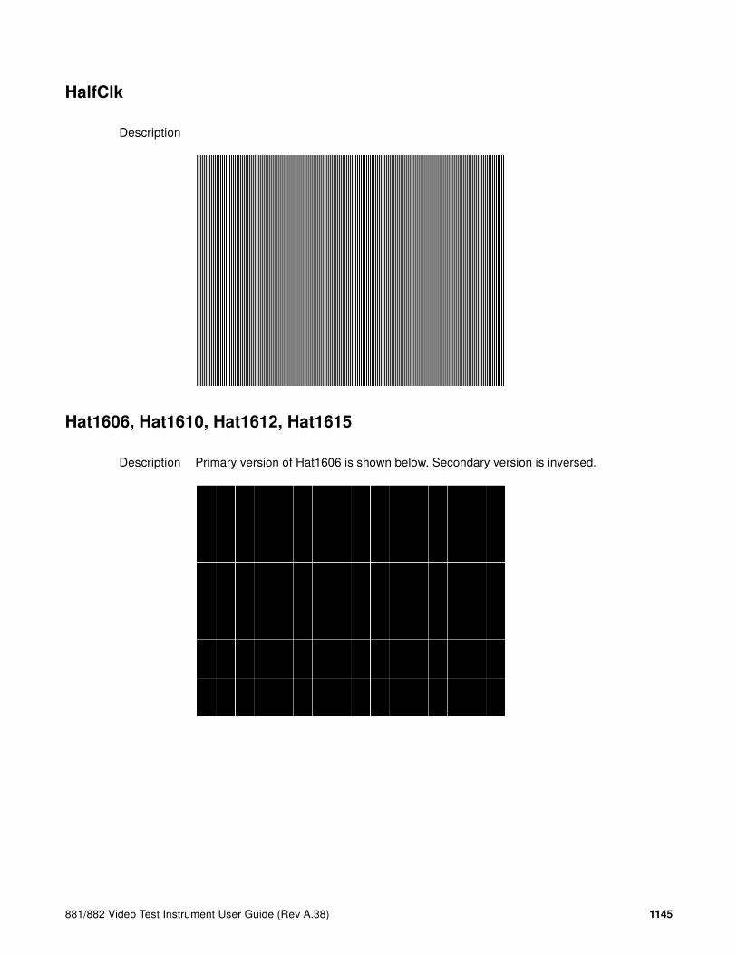
881/882 Video Test Instrument User Guide (Rev A.38) 1145
HalfClk
Description
Hat1606, Hat1610, Hat1612, Hat1615
Description Primary version of Hat1606 is shown below. Secondary version is inversed.
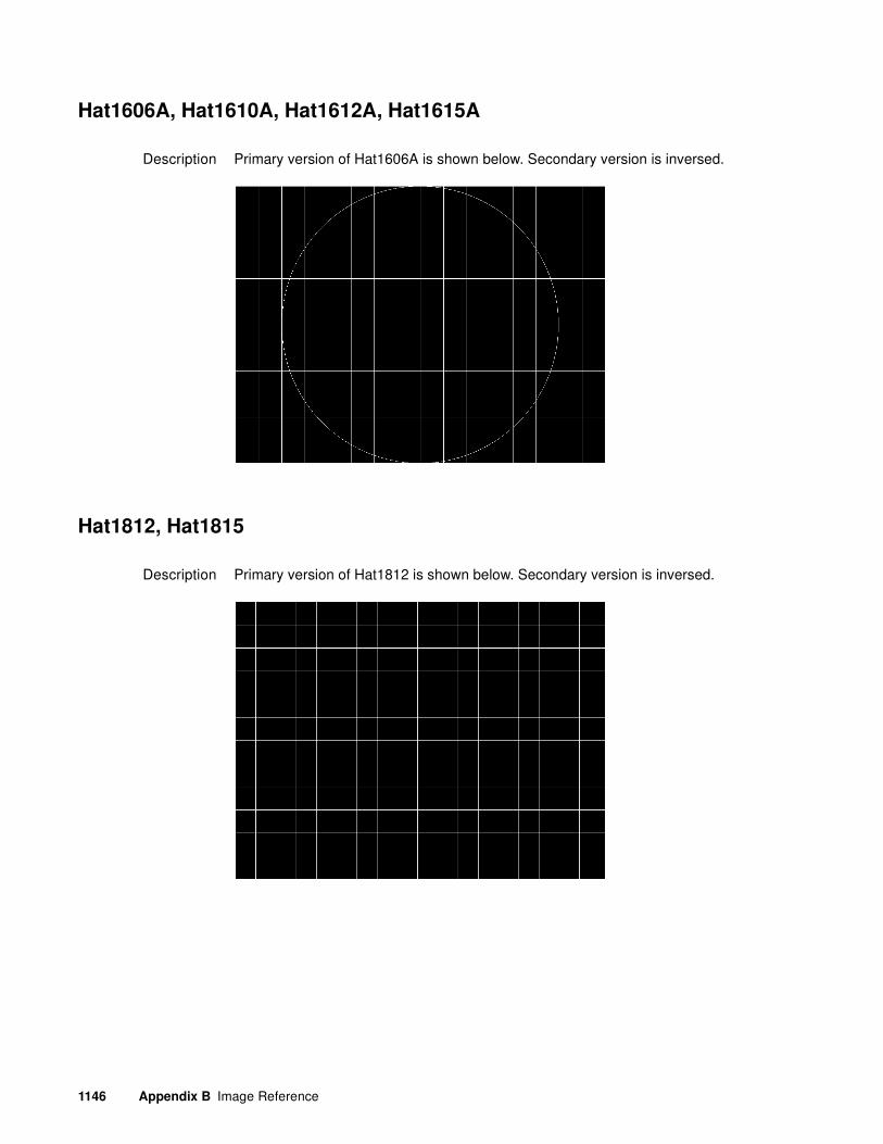
1146 Appendix B Image Reference
Hat1606A, Hat1610A, Hat1612A, Hat1615A
Description Primary version of Hat1606A is shown below. Secondary version is inversed.
Hat1812, Hat1815
Description Primary version of Hat1812 is shown below. Secondary version is inversed.
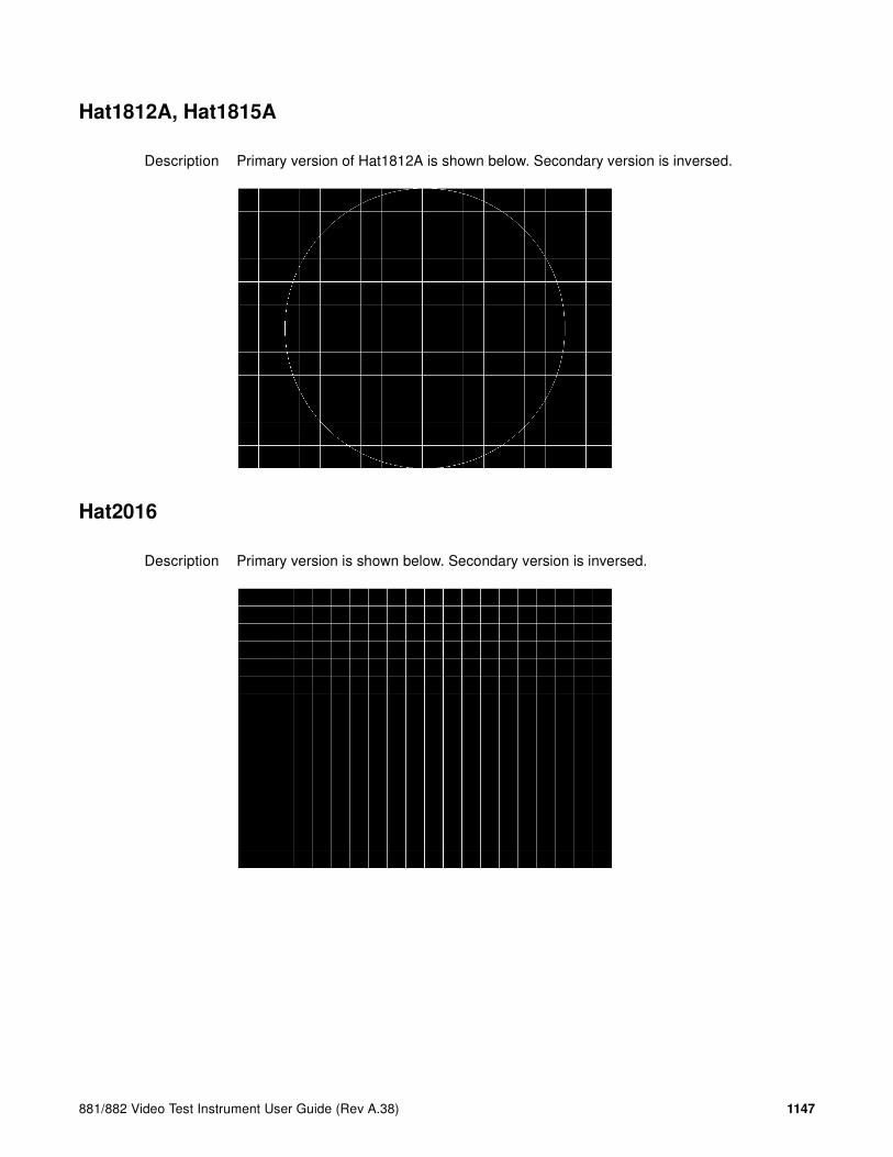
881/882 Video Test Instrument User Guide (Rev A.38) 1147
Hat1812A, Hat1815A
Description Primary version of Hat1812A is shown below. Secondary version is inversed.
Hat2016
Description Primary version is shown below. Secondary version is inversed.

1148 Appendix B Image Reference
Hat2016A
Description Primary version is shown below. Secondary version is inversed.
Hatch_6, Hatch_10i, Hatch_10o, Hatch_12i, Hatch_12o, Hatch_24i,
Hatch_24o, Hatch_24s, Hatch_G, Hatch_M, GRN_HTCH, and MAGENTA
Description The primary versions consist of a white, green (G and GRN), or magenta (M) crosshatch drawn on a black background. The lines form square boxes. A single pixel dot is located in the center of each crosshatch box. The number of boxes formed depends on the version of the image selected and the screen aspect ratio of the currently loaded format. The number in the image’s name refers to the number of boxes that are formed along the minor axis for most aspect ratios. The generator calculates the ratio and then finds the closest match from the table on the next page. Version names indicate the drawing method, as follows:
• Versions ending in “i” draw from the inside (center) out. Any partial boxes are placed around the perimeter of the image.
• Versions ending in “o” draw from the outside in. Any partial boxes are placed along the centerlines of the image.
• Versions ending in “s” are the “i” version plus a 1-pixel thick border.
The secondary versions invert the images to black lines and dots on a white background. Hatch_G, Hatch_M, GRN_HTCH and Magenta do not have secondary versions.

881/882 Video Test Instrument User Guide (Rev A.38) 1149
The primary version of the Hatch_10i image is shown below.
Test Convergence adjustment (color monitors only)
Purpose To accurately produce an image on a color monitor, the three electron beams in the CRT must meet (converge) at the same location at the same time. Lines displayed on a misconverged monitor appear as several multi-colored lines, and the transitions between different colored areas contain fringes of other colors.
Method The convergence adjustments of most color monitors fall into two main categories. The first set of adjustments, usually called Static Convergence, aligns the three beams in the center of the display. This method involves turning on all three guns and adjusting the various magnets on the convergence assembly to produce all white dots in the center of the display. The convergence assembly is located on the neck of the CRT. Different monitors and CRT types may each require their own magnet adjustment sequence.
After the center of the display is properly converged, the outer areas are adjusted by using the monitor’s Dynamic Convergence controls. The number of controls, the area of the screen they affect, and their adjustment procedure depend on the monitor under test.
Aspect Ratio Dot_10 Dot_12 Dot_24
W : H Decimal BoxesVertically
BoxesHorizon-tally
BoxesVertically
BoxesHorizon-tally
BoxesVertically
BoxesHorizon-tally
16 : 9 1.777 É 10 16 10 16 18 32
5 : 3 1.666 É 10 16 10 16 18 30
4 : 3 1.333 É 10 14 12 16 24 32
1 : 1 1.000 10 10 12 12 24 24
3 : 4 0.750 14 10 16 12 32 24

1150 Appendix B Image Reference
Hatch_16, Hatch_20
Description The primary version of the Hatch_16 image is shown below. The secondary versions draw black lines on a white background.
Hatch20
Description Primary version...The secondary version draws black lines on a white background.

881/882 Video Test Instrument User Guide (Rev A.38) 1151
Hatch4x3, Hatch5x4 and Hatch8x8
Description These are different versions of a crosshatch pattern that may be called for by some display manufacturers’ test procedures. The primary version consists of white crosshatch and circles on a black background. The secondary version inverts the image to black lines on a white background.
The primary version of the Hatch4x3 image is shown below.
Purpose This is a general purpose test image that can be used to check and adjust video scan linearity and geometry and color convergence.

1152 Appendix B Image Reference
Hatch64W
Description This is a crosshatch pattern that may be called for by some manufacturers’ test procedures. The primary version (shown below) consists of an 8x8 white crosshatch on a black background. A white rectangular patch is added in the center. The secondary version inverts the image to black lines and box on a white background.
Purpose
Method This is a general purpose test image that can be used to check and adjust video scan linearity and geometry, and color convergence. The large white rectangle also allows for checking a display’s high voltage regulation. This is done by observing the vertical lines at the left and right edges of the image. They should be fairly straight and not pull in the area of the white rectangle.
HdcpA1B1, HdcpA1B2, HdcpA2B1, HdcpA2B2, HdcpProd
Description Used with HDCP feature. For more information, see Chapter 15, “Testing HDCP on HDMI & MHL.”

881/882 Video Test Instrument User Guide (Rev A.38) 1153
Hitachi1
Description Special test image developed per customer specifications. The image consists of a 2x2 cluster of Microsoft Windows® screen simulations using Japanese characters.
HSVnRGB
Description

1154 Appendix B Image Reference
Imex1
Description
InFocus1
Description Special test image developed per customer specifications.

881/882 Video Test Instrument User Guide (Rev A.38) 1155
InFocus2
Description Special test image developed per customer specifications.
KanjiKAN
Description In the primary version (shown below), the screen is filled with white Japanese Kan characters on a black background. The secondary version is drawn with black characters on a white background.
Test Focus adjustments

1156 Appendix B Image Reference
LGLCDTVB, LGLCDTVG, LGLCDTVR, LGLCDTVW
Description Special test image developed per customer specifications. Each image has three versions. The primary version of the LGLCDTVB image is shown below.
LGRamp
Description Special test image developed per customer specifications. The image provides a grayscale of two objects. The secondary version of the LGRamp image is shown below.

881/882 Video Test Instrument User Guide (Rev A.38) 1157
Linearty (Linearity)
Description This image has three parts. The first part consists of six (6) white circles. A large circle is drawn in the center of the screen. Its diameter equals the lesser of the video height or width of the display. A smaller circle is drawn at half the diameter and concentric with the larger circle. A circle also is drawn in each of the corners of the screen. The diameter of the corner circles equals one-fifth of the display width.
The second part of the image consists of a white crosshatch. The number of boxes in the crosshatch depends on the physical size of the display.
The last part of the image consists of white tic marks on the horizontal and vertical center lines of the image. The marks are one pixel thick at every other pixel location. Every fifth mark is slightly longer. The color of the pattern can be changed with the individual video output controls.
Test Linearity adjustment
Purpose To present an undistorted display, the horizontal and vertical sweeps of the electron beam across the face of the CRT should be at uniform speeds. Any non-uniformity in the sweep causes portions of an image to stretch while other portions are compressed. Non-linearity in a monitor shows up in several ways. It may be present across the entire screen, in a large portion of the screen, or localized in a very small area.
Method The circles in the image can be used to do a general adjustment of a monitor’s linearity controls. Adjust the controls to form perfectly round circles. The crosshatch image can be used to measure linearity and to make finer control adjustments. All the full boxes in the crosshatch should be identical in size. Measure them with a ruler or a gauge made for the monitor under test. Any deviation should be within your specification limits. Use the tic

1158 Appendix B Image Reference
marks and a ruler or gauge to measure linearity over a small portion of the display. Compare the number of tic marks per unit of measure with an adjacent or overlapping area.
LinFocus
Description This image has several parts. The first part consists of a large circle in the center of the screen. Its diameter equals the lesser of the video height or width of the display.
The second part is a 10x10 box crosshatch. The crosshatch is drawn in from the outside edges, with any extra pixels in the boxes placed along the vertical and horizontal axis. The vertical centerline is two pixels thick if the format has an even number of active pixels per line. The horizontal centerline is two pixels thick if the format has an even number of active lines per frame. A smaller box is added at the center of the image. The box is one-half the height and two-fifths the width of one of the crosshatch boxes. Current format data is shown in the lower left quadrant of the image. It shows the number of active pixels (H) and lines (V) as well as the vertical and horizontal scan rates.
The primary version (shown below) consists of a white pattern on a black background. The secondary version has a black pattern on a white background.
The image also includes blocks of focus-checking characters at various locations. The blocks are positioned inside the crosshatch boxes and are up to 3x3 characters in size. The size of the blocks is limited by the number of characters that can fit in one box.
Test Linearity adjustment
Method Please see the Linearity test image on “Linearty (Linearity)” on page 1153 for information on measuring linearity.
Test Focus adjustment
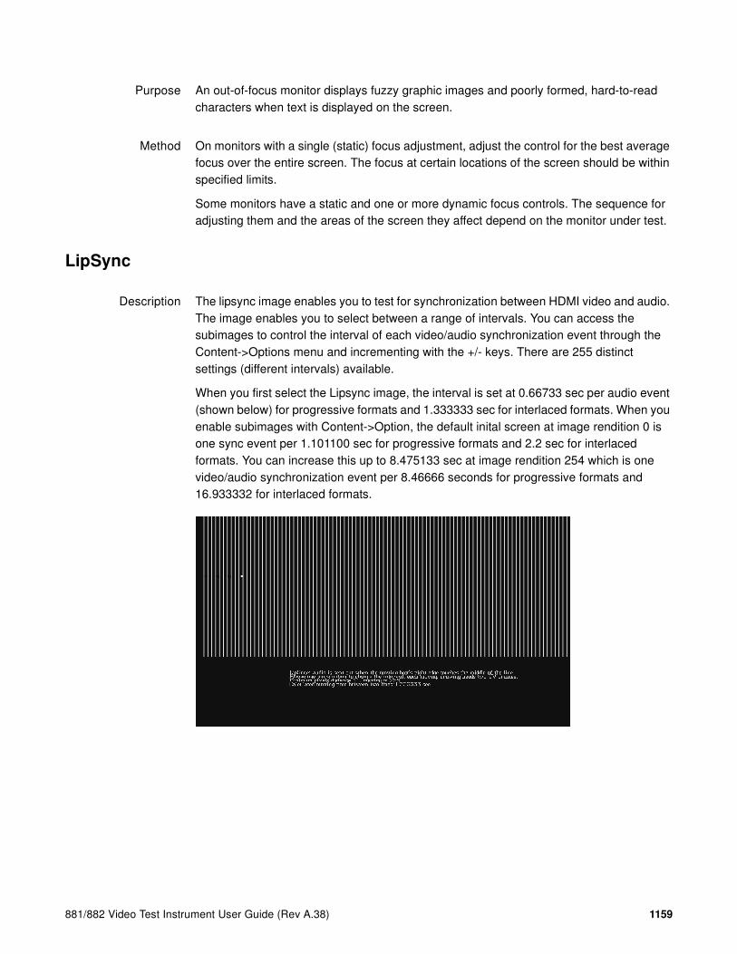
881/882 Video Test Instrument User Guide (Rev A.38) 1159
Purpose An out-of-focus monitor displays fuzzy graphic images and poorly formed, hard-to-read characters when text is displayed on the screen.
Method On monitors with a single (static) focus adjustment, adjust the control for the best average focus over the entire screen. The focus at certain locations of the screen should be within specified limits.
Some monitors have a static and one or more dynamic focus controls. The sequence for adjusting them and the areas of the screen they affect depend on the monitor under test.
LipSync
Description The lipsync image enables you to test for synchronization between HDMI video and audio. The image enables you to select between a range of intervals. You can access the subimages to control the interval of each video/audio synchronization event through the Content->Options menu and incrementing with the +/- keys. There are 255 distinct settings (different intervals) available.
When you first select the Lipsync image, the interval is set at 0.66733 sec per audio event (shown below) for progressive formats and 1.333333 sec for interlaced formats. When you enable subimages with Content->Option, the default inital screen at image rendition 0 is one sync event per 1.101100 sec for progressive formats and 2.2 sec for interlaced formats. You can increase this up to 8.475133 sec at image rendition 254 which is one video/audio synchronization event per 8.46666 seconds for progressive formats and 16.933332 for interlaced formats.

1160 Appendix B Image Reference
Master
Description
MEMEPlus, MEPlus_B, MEPlus_G, and MEPlus_R
Description In the primary version, the screen is filled with blue (BLU and B), green (GRN and G), red (R), or white (WHT and Sony) EM character blocks on a black background. Only the white character has a secondary version. It is drawn with black characters on a white background.
A bitmap of a single character block is shown here. The BLU_EM+ image is shown below.

881/882 Video Test Instrument User Guide (Rev A.38) 1161
Test Focus
Purpose This pattern is specified by one or more display manufacturers for checking and adjusting focus one color at a time.
MoireX, MoireX33, MoireY, MoireY33
Description The MoireX and MoireY images consist of black lines on a white background across the active video area. MoireX provides vertical lines; MoireY provides horizontal lines. The MoireX image is shown below.
The primary version of the MoireX33 and MoireY33 images provide a black frame around the black lines. The secondary version draws a white frame around black lines. The primary version of the MoireX33 image is shown below.

1162 Appendix B Image Reference
Monoscop
Description
MSony7, MSony8
Description Special test image developed per customer specifications. Primary version of the MSony7 image is shown below. The secondary version draws white boxes and characters with a black background.

881/882 Video Test Instrument User Guide (Rev A.38) 1163
MulBurst
Description
Orion
Description This image provides a color bar that rotates (shifts) the bars to the right on an incremental basis.
The color bars are shifted to the right at 3 second intervals. After pressing the Contents key and then the Options key you then enable More and use the +/- increment keys to proceed through the subimages to adjust the interval between 3, 10, 30 and 60 seconds.

1164 Appendix B Image Reference
Outline0, Outline1, Outline2, Outline3
Description The primary version of the Outline0 image consists of a rectangular white border on a black background. The border is one (1) pixel wide and defines the active video area. Two (2) diagonal lines join the opposite corners. A-full size cross is centered in the image. The horizontal line of the cross is one (1) pixel thick for formats with an odd number of active lines and two (2) pixels thick for formats with an even number of active lines. The vertical line of the cross is one (1) pixel thick for formats with an odd number of active pixels per line and two (2) pixels thick for formats with an even number of active pixels.
The secondary version of these images draw black lines on a white background.

881/882 Video Test Instrument User Guide (Rev A.38) 1165
In the Outline1 version, the two diagonal lines are removed and short marker lines are added to the border lines near to where the cross lines meet the border lines. The markers appear at both sides of the cross lines. The distance between the marker lines and the cross lines is the greater of either two (2) pixels or one (1) millimeter.
In the Outline2 version, the two diagonal lines are removed and short marker lines are added to the corners, and where cross lines meet and end.

1166 Appendix B Image Reference
In the Outline3 version, the two diagonal lines are removed, cross lines are shortened, and short marker lines are added.
Test Yoke tilt correction
Purpose The horizontal axis of a displayed image should line up with the horizontal axis of your monitor. Any tilt is likely due to the yoke being rotated on the neck of the CRT. A rotated yoke makes any displayed image appear rotated.
Method Place your monitor on a flat surface so the face of the CRT is perpendicular to the surface. Use a ruler or gauge to measure the height of each end of the image’s horizontal center line from the surface. The difference between the two readings should be within specification for the monitor. If it is out of specification, the yoke must be adjusted. Loosen the hardware that clamps the yoke to the neck of the CRT and rotate the yoke until the line is horizontal. Tighten the yoke-clamp hardware.
Test Yoke winding orthogonality check
Purpose The horizontal and vertical deflection coils on the yoke should have their axes cross at exactly 90 degrees. Improper orientation of the windings causes displayed rectangles to look more like nonorthogonal parallelograms. This type of defect is almost impossible to correct with adjustments. It is usually easier to replace the defective yoke.
Method First, perform the yoke tilt correction described above. The vertical center line of the image should be perpendicular to the work surface. If the deviation is beyond specification, the monitor should be rejected and sent back for repair, rather than trying to magnet a defective yoke.

881/882 Video Test Instrument User Guide (Rev A.38) 1167
Test Display size correction
Purpose A too-large active video size adjustment on a monitor may cause information to be lost around the edges of the screen. A too-small active video size adjustment may make some displayed information hard to read. The correct size is needed to obtain the correct aspect ratio. You need the correct aspect ratio to get round circles and square squares.
Method First, determine the correct physical size of the active video area for the display. This information usually is given in a display’s specification sheet or service manual. The size should match the sizes in the format you are using. The size setting of the current format can be checked using the Format test image.
Place a ruler or gauge along the horizontal line of the image and adjust the monitor's horizontal size control until the distance between the end points matches the specified value.
Move the ruler or gauge to the vertical line and adjust your monitor's vertical size control until the distance between the end points matches the specified value.
Test Parallelogram distortion check
Purpose Parallelogram distortion is very difficult to correct with magnets because the correction often causes barrel distortion. Therefore, you should decide early whether your monitor meets this specification. The problem usually can be traced to the improper winding of the yoke coils. If the problem is not too severe, it may be corrected by adding or adjusting magnets on the yoke. However, if the distortion is excessive, it may be an indication of a defective yoke which cannot be corrected with magnets.
Method Measure the lengths of the two (2) diagonal lines. Any difference is an indication of parallelogram distortion. The difference in readings should be within the specifications of the monitor.
If the difference in the readings is too far beyond specification, the monitor should be rejected and sent back for repair, rather than trying to magnet a defective yoke.
Test Trapezoid distortion correction
Purpose This image gives you a way to measure trapezoid distortion in your monitor. If the distortion is not too severe, you may be able to correct it by adding or adjusting magnets on the yoke.
Method Perform the yoke winding orthogonality check and parallelogram distortion check first to avoid wasting time on a monitor with a defective yoke.

1168 Appendix B Image Reference
Measure the width of the image at the top and bottom of the display. Any difference in readings should be within the specification limits. Measure the height of the image at both sides of the display. Again, any difference in readings should be within specification limits. If either of the differences is out of specification, the trapezoid distortion of the monitor is out of specification.
Add or adjust magnets on the yoke to correct the problem. The pin and barrel distortion correction should be repeated to make sure that it is still in specification.
Test Pin and barrel distortion correction
Purpose If perfectly linear sweep signals are sent to a perfectly wound deflection yoke mounted on a perfect CRT, you would not necessarily get a perfectly formed raster. Instead you would likely get a raster that had its corners stretched away from the center, resembling a pin cushion. This distortion occurs because the geometry of the deflected electron beam does not match the geometry of the tube face plate. Also, imperfections in the yoke or CRT may affect this problem. In some cases one or more corners may be pulled towards the center of the raster causing it to look like a barrel. Uncorrected raster distortion carries over as distortion of the displayed image.
Method A slot gauge may be used to determine if the amount of pincushion or barrel distortion is within limits. A basic slot gauge may consist of a piece of opaque film with at least two (2) transparent slots in it. One slot is used for top and bottom distortion and the other is used for the sides. By positioning the correct slot over each portion of the border line, the entire line should be visible. If this cannot be done at all four sides, the monitor requires correcting.
There are two main ways of correcting pincushion distortion. The first involves placing or adjusting magnets on the yoke. This is a trial-and-error method. However, skilled operators develop a feel for how strong a magnet to use and how to place it in order to get the desired correction. If any correction is performed, the trapezoid distortion correction should be repeated.
The other correction method involves adding correction signals to the deflection signal driving the yoke. This method is usually found in color monitors, where adding magnets to the yoke would cause problems with convergence and purity. The type and number of adjustments depends on the monitor being tested.

881/882 Video Test Instrument User Guide (Rev A.38) 1169
P1
Description This image is a 6x6 white crosshatch without a border on a black background.
P2
Description This image is a 4x4 white crosshatch with a border on a black background.

1170 Appendix B Image Reference
P3
Description This image is a 4x4 white crosshatch with a border and a small, centered white patch on a black background.
P4
Description This image is an 8x8 white crosshatch with a border on a black background.

881/882 Video Test Instrument User Guide (Rev A.38) 1171
P5
Description This image is an 8x8 white crosshatch with a border and a small, centered white patch on a black background.
P6
Description 16x12 pixel white crosshatch with a border on a black background.

1172 Appendix B Image Reference
P6_Sony
Description 6x12 pixel white crosshatch with a border on a black background.
P7
Description 16x12 white crosshatch with a border and a small, centered white patch on a black background.

881/882 Video Test Instrument User Guide (Rev A.38) 1173
P8
Description This image is an all black active video area. The secondary version draws an all white video area.
P9
Description This image is an all white active video area. The secondary version draws an all black video area.
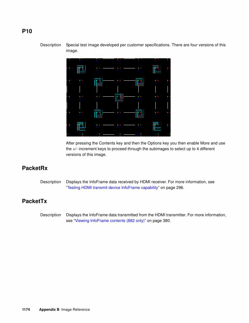
1174 Appendix B Image Reference
P10
Description Special test image developed per customer specifications. There are four versions of this image.
After pressing the Contents key and then the Options key you then enable More and use the +/- increment keys to proceed through the subimages to select up to 4 different versions of this image.
PacketRx
Description Displays the InfoFrame data received by HDMI receiver. For more information, see “Testing HDMI transmit device InfoFrame capability” on page 296.
PacketTx
Description Displays the InfoFrame data transmitted from the HDMI transmitter. For more information, see “Viewing InfoFrame contents (882 only)” on page 380.
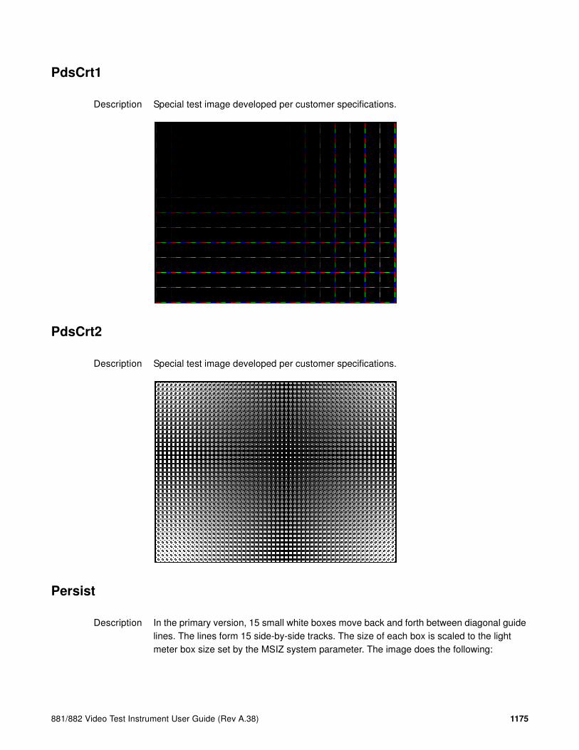
881/882 Video Test Instrument User Guide (Rev A.38) 1175
PdsCrt1
Description Special test image developed per customer specifications.
PdsCrt2
Description Special test image developed per customer specifications.
Persist
Description In the primary version, 15 small white boxes move back and forth between diagonal guide lines. The lines form 15 side-by-side tracks. The size of each box is scaled to the light meter box size set by the MSIZ system parameter. The image does the following:

1176 Appendix B Image Reference
• The box in the center track (marked “1X”) moves one scan line vertically and one pixel horizontally for each vertical frame of refresh.
• The seven boxes to the right of the center track (marked “2X” through “8X”) move 2, 3, 4, 5, 6, 7, and 8 pixels and lines per frame, respectively.
• The seven boxes to the left of the center track (marked “/2” through “/8”) move one scan line vertically and one pixel horizontally for every 2, 3, 4, 5, 6, 7, and 8 vertical frames of refresh, respectively. These boxes are at the bottom of the tracks.
In cases where the next move would cause the box to move beyond the end of its track, it immediately reverses and moves the correct distance in the opposite direction for the next frame.
A continuously-running counter appears in the upper left corner of the image. The number shown is the number of vertical frame refreshes that have occurred since the generator was first powered up.
The secondary version draws a black image on a white background.
An example of the primary version of the Persist image is shown below:
Test Phosphor persistence
Purpose The phosphors on the face of most CRTs continue to glow for a short period of time after the electron beam has stopped energizing them. This phenomenon is called persistence. A certain amount of persistence is desirable in most applications. It prevents a flickering of a displayed image that most users would find objectionable. On the other hand, a CRT with an overly long persistence time causes moving objects to leave a blurred trail.
Method A flickering in the slower moving boxes indicates that the combination of refresh rate and phosphor persistence is not suitable for long-term viewing.

881/882 Video Test Instrument User Guide (Rev A.38) 1177
A fading tail left behind by the faster moving boxes indicates that the display may not be suitable for viewing animated images.
PgBar64H, PgBar64V
Description Special test image developed per customer specifications. The PgBar64H image is shown below.
PgCB, PgCG, PgCR, PgCW, PgCWrgb
Description Special test image developed per customer specifications. Primary version of PgCB is shown below. The secondary versions draw all white over the last bar.

1178 Appendix B Image Reference
The PGCWrgb is shown below.
Philips1
Description Special test image developed per customer specifications.
PixelRep
Description Used to test HDMI pixel repetition. There are 10 different versions of this image to support the different pixel repetition settings. For more information, see “Testing HDMI video pixel repetition (882 only)” on page 363.

881/882 Video Test Instrument User Guide (Rev A.38) 1179
PRN24bit
Description This image displays pseudo-random noise using 24-bits-per-pixel color depth.
PRN_5, PRN_9
Description Used with analyer to verify the analyzer’s pseudo-random noise analysis capability. The PRN_5 image introduces 5 pixel errors per color component, while the PRN_9 image introduces 9 pixel errors per color component.
The PRN_5 image is shown below.
‘
PulseBar
Description This image is intended for TV formats, but can be displayed with any format up to 100 MHz. The image looks like two vertical lines followed by a wide vertical bar on a display’s screen. The first line is a sine-squared modulated pulse that fades from black to red and

1180 Appendix B Image Reference
back to black. The pulse is 20 T for PAL and 12.5 T for NTSC formats. The second narrower line is a 2 T white sine-squared pulse. T = 100 nSec for PAL and 125 nSec for NTSC formats. The wide bar is white with sine-squared edges.
Test Video system testing
This multi-purpose pattern can be used with other instruments to check television K factors. The modulated pulse can be used to check chrominance-to-luminance delay and gain. The narrow white line can be used to measure short term linear distortion (K2T).

881/882 Video Test Instrument User Guide (Rev A.38) 1181
QuartBox
Description The primary version (shown below) has a single white box in the center of active video. The size of the box is one-half the width and height of the active video area (a quarter of the entire active video area). The secondary version draws a black box on a white background.
Test Brightness control adjustment
Purpose The wrong brightness setting on your monitor may cause other tests such as Contrast, Focus, and Beam Size to be invalid. An accurate brightness setting helps give repeatable measurements throughout other tests. This version of the brightness box should be used if the display’s specifications call for the brightness to be set with one-fourth of the screen lit.
Method Place your light meter probe within the center box and adjust the monitor’s brightness control to obtain the required light meter reading.
Notes The color of the center box is a special color, named foreground. The FRGB command can be used to change the default color of foreground to any RGB value.
IMGL quartbox: ALLU // loads QuartBox image
FRGB 122 122 122 // sets RGB color of box
After loading a different format, send the FRGB command again to set the box fill color.
If you want to draw your own box, use foreground as the fill color, and then use the FRGB command to define the color of “foreground.” For example:
IMGL raster; ALLU // clears display
RECT foreground 100 100 100 100 dither100
FRGB 128 128 0
FRGB 192 192 64

1182 Appendix B Image Reference
FMTL DMT0660; ALLU
FRGB 192 192 64
Ramp
Description This image provides an active video area starting from full black (+7.5 IRE) at one edge of the screen to full white (+100 IRE) at opposite end of the screen.
There are 4 versions of this image—one for each edge of the display.
When selected, this image is displayed.
After pressing the Contents key and then the Options key. You then enable More and use the +/- increment keys to proceed through the subimages to change the image starting point to left, right, top, or bottom.
RampX
Description This image provides a ramp image that continuously sweeps (moves) to the right on an adjustable time basis.

881/882 Video Test Instrument User Guide (Rev A.38) 1183
When selected, this image is displayed.
After pressing the Contents key and then the Options key you then enable More and use the +/- increment keys to adjust the speed.
Ramp_B, Ramp_G, and Ramp_R
Description The active video area goes from full black (+7.5 IRE) at the left edge of the screen to full blue (_B), green (_G), or red (_R) at the right edge. The Ramp_B image is shown below.
Test Video gain linearity
Method When viewed on a TV screen, the full range of grays should be visible. There should be no color shifts visible.

1184 Appendix B Image Reference
Raster
Description The primary version shows a totally black display (nothing being displayed). The secondary version shows a totally white display.
Test Raster centering
Purpose Many monitor applications require that the displayed image or text fit completely within a bezel that surrounds the CRT. This usually requires that you first center the blank raster on the face of the CRT, and then center the image within the raster. Use this image for centering the raster on the CRT.
Method Turn up your monitor’s brightness control until the raster is just visible. Adjust the raster’s position and size using the size and raster centering controls. The raster centering adjustment for many monochrome monitors consists of moving magnetic rings on the deflection yoke.
Regulate
Description The image cycles between two (2) patterns. In the primary version, the first pattern is a white outline that defines the edges of displayed video. The other pattern has the same outline plus a solid white rectangle in the center. The size of the solid rectangle equals 95% of the height and width of displayed video. The speed of the cycle cannot be changed. The secondary version has a thick white frame with a black center for the first pattern and a solid white active video area for the other pattern.

881/882 Video Test Instrument User Guide (Rev A.38) 1185
The first pattern of the primary version is shown below.
Test High voltage regulation
Method The size of the border should not change for each half of the image. The change in border size between the two images should be within the specification limits of the monitor.
Samsung1, Samsung2
Description Special test images developed per customer specifications. The image consists of three small simulations of Microsoft Windows® screens on a blue background (Samsung1) or black background (Samsung2). A border and centered cross are formed with repeating

1186 Appendix B Image Reference
groups of the characters “e” and “m”. The repeating characters are also used to form a rectangular patch in the upper left hand corner and a circular area in the center of the image. The secondary version of Samsung2 draws a white background.
Samsung3
Description Special test image developed per customer specifications.
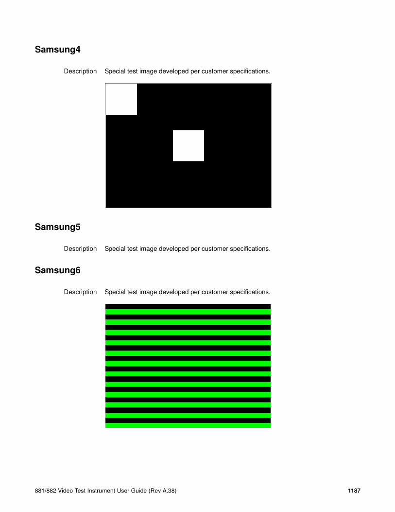
881/882 Video Test Instrument User Guide (Rev A.38) 1187
Samsung4
Description Special test image developed per customer specifications.
Samsung5
Description Special test image developed per customer specifications.
Samsung6
Description Special test image developed per customer specifications.

1188 Appendix B Image Reference
SamsungB
Description Special test image developed per customer specifications.
SamsungT
Description Special test image developed per customer specifications. There are four versions of this image. When selected, the following image is displayed.
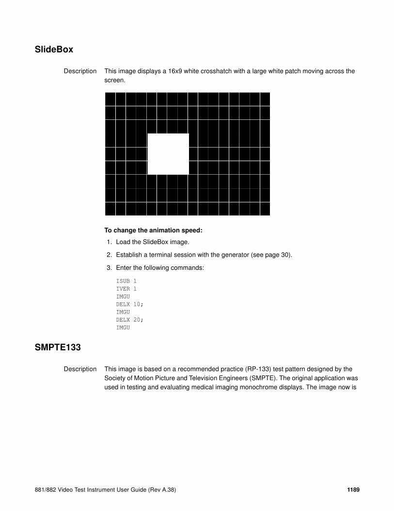
881/882 Video Test Instrument User Guide (Rev A.38) 1189
SlideBox
Description This image displays a 16x9 white crosshatch with a large white patch moving across the screen.
To change the animation speed:
1. Load the SlideBox image.
2. Establish a terminal session with the generator (see page 30).
3. Enter the following commands:
ISUB 1
IVER 1
IMGU
DELX 10;
IMGU
DELX 20;
IMGU
SMPTE133
Description This image is based on a recommended practice (RP-133) test pattern designed by the Society of Motion Picture and Television Engineers (SMPTE). The original application was used in testing and evaluating medical imaging monochrome displays. The image now is

1190 Appendix B Image Reference
used in many different display applications. The image is self-scaling as to the number of active pixels and active lines used. Some of the image’s elements have minor differences from the original SMPTE specification.
These differences are noted in descriptions of the individual elements.
• The image is drawn on a reference background having a 50% intensity level. The background covers the entire active video area.
• Crosshatch – There are 10 boxes vertically. The number of horizontal boxes is based on the physical aspect ratio determined by the HSIZ and VSIZparameters in the currently loaded format. The boxes are perfectly square with any fractional spaces placed around the outside edges of the image. The vertical lines are two (2) pixels thick while the horizontal lines are two (2) scan lines thick. Small crosses indicate the intersection of the horizontal and vertical lines when they are covered by other parts of the image. All parts of the crosshatch are normally drawn using a 70% intensity level. A 75% level is used in the secondary version.
• Resolution patch – The patch is made up of six (6) smaller boxes that are each about 6.25% of the height of the display. The boxes are made of alternating intensity (0 and 100%) stripes. The stripes run vertically and horizontally. The stripes may be one (1), two (2) or three (3) pixels wide each. Details of the patch are shown in the lower half of the following illustration. The patches are located in each corner of the main image and in the center. They are oriented with the highest resolution and contrast boxes closest to the outside corners. The 48%-53%, 48%-51% and 50%-51% level patches are omitted in the secondary version.
• Grayscale boxes – Twelve (12) boxes at eleven (11) intensity levels are clustered around the center of the main image. They start at 0% and increase in 10% steps to

881/882 Video Test Instrument User Guide (Rev A.38) 1191
100% with two (2) boxes at a 50% level. All of the grayscale boxes are omitted in the secondary version.
• Gamma check dither box – A small box is drawn inside the right-hand 50% grayscale box. The box is half the width and height of the larger box. The box consists of a checkerboard of alternate one-on and one-off pixels. The alternate pixels have levels of 0 and 100%. This smaller box is not part of the original SMPTE specification and is omitted in the secondary version.
• Contrast boxes – Two (2) boxes are drawn adjacent to the grayscale boxes. They are at 0 and 100% levels. There are smaller boxes drawn inside each box at 5 and 95% levels. The contrast boxes are omitted in the secondary version.
• Black and white windows – Two (2) horizontal bars are located above and below the grayscale boxes. Their height equals 8% of the display height. There are half-size bars centered in the larger bars. In the primary version, the dark portion of the windows is at a 5% level and the bright portion is at a 95% level. Zero and 100% levels are used in the secondary version.
• Border – A border line is drawn around the image. It is set in from the edges of displayed video a distance equal to 1% of the displayed height and has a thickness equal to 0.5% of the displayed height. The intensity level is the same as that of the crosshatch lines.
• Circle – A large circle is centered in the image. It touches the top and bottom of the active video area when the aspect ratio is wider than it is high (landscape-type display). The circle touches the left and right sides of active video when the aspect ratio is taller than it is wide (portrait-type display). The intensity level is the same as that of the crosshatch lines. The circle is not part of the original SMPTE specification.
• Resolution data - The number of active pixels per line and the number of active lines is shown as text below the lower black and white window. The pixel depth also is shown. The intensity level of the text is the same as that of the crosshatch lines. The displaying of the data is not part of the original SMPTE specification.
The secondary version adds a row of six (6) color bars above and below the black-and-white windows. The order of the colors, from left to right, is red, green, blue, cyan (g+b), magenta (r+b) and yellow (r+g). The top row is drawn at 100% intensity levels and the bottom row is drawn at 50% intensity levels. Color bars are not part of the original SMPTE specification.
Test Deflection linearity
Method If the overall height and width of the display’s active video area match the sizes in the format, the large circle should be perfectly round. Each box in the crosshatch pattern should be the same size and shape. For more information on testing linearity, refer to the Linearty test image on page 1153.

1192 Appendix B Image Reference
Test High contrast resolution
Method All the 0 and 100% level stripes in all the resolution patches should be separate and distinct.
Test Low contrast resolution and noise
Method All the mid-level 2 on - 2 off stripes in all the resolution patches should be visible and distinct. This is a sensitive test for noise in the display’s video amplifiers.
Test Quick gamma check
Method The average brightness level of the small gamma dither box should match the brightness of the larger surrounding box. This is a visual check to see if the display’s gamma correction is producing the correct mid-level response.
Test Video gain linearity and gamma
Method The individual grayscale boxes all should be at their indicated levels. A small aperture photometer is usually required to get accurate and repeatable readings.
Test Contrast and brightness check
Method On a display with properly adjusted brightness and contrast controls, both the 5% and 95% contrast boxes should be clearly visible inside their larger surrounding 0% and 100% boxes.
Test Video amplifier stability
Method The two black-and-white windows should show sharp transitions between the smaller box and the surrounding window. Streaking may be an indication of undershoot or overshoot while ghost images may indicate a ringing problem.
Test Excessive overscan and off-center alignment
Method The entire border should be clearly visible on the face of the tube and not be hidden by the edge of the glass or by any bezel.
Test Interlace flicker

881/882 Video Test Instrument User Guide (Rev A.38) 1193
Method The horizontal 1 on - 1 off stripes in the resolution boxes should not have objectionable flicker when shown with an interlaced format. Excessive flicker indicates that the combination of the display’s CRT persistence and frame scan rate is below the persistence time of the human eye.
SMPTEbar
Description This image is based on an engineering guideline (EG1-1990) test signal specified by the Society of Motion Picture and Television Engineers (SMPTE). The SMPTE pattern, in turn, is derived from an EIA standard test pattern (RS-189-A). The image, is set up to be generated by an 801GX generator as an encoded TV output. It is designed for adjusting the color settings of a television monitor by eye. It can also be used with a TV waveform analyzer and vectorscope for testing video signal processors and color decoders. The image is available on all models as a component RGB signal. Some of the image’s elements have some differences from the original SMPTE specification.
These differences are given in descriptions of the individual elements.
• The upper 67% of the image consists of a series of color bars. These bars match the order of the bars in the SMPTE and EIA patterns. They are similar to the 801GX’s TVBar_75 image without the last black bar.
• The left side of the lower 25% of the image contains isolated -I and Q color difference signals that match the original EIA and SMPTE patterns. The -I signal appears as a bluish-gray bar and the Q signal appears as a purple bar on a TV monitor. The bars are separated by a white (+100 IRE) bar.
• The right side of the lower 25% of the image contains a narrow 12.5 IRE gray bar. Due to a hardware limitation on the 801GX, this portion of the pattern does not match the original EIA and SMPTE patterns. The original patterns had +3.5 (blacker than black) and +11.5 IRE bars separated by a +7.5 IRE (black) bar.

1194 Appendix B Image Reference
• The remaining central 8% of the image contains a row of chroma set bars. These bars are part of the SMPTE pattern but are not in the EIA pattern. The order of the alternating color and black bars matches those in the SMPTE pattern.
Test Color video performance
Purpose This general purpose pattern can be used to check the video handling capabilities of most parts of a television system.
Method When viewed on a TV screen, all of the upper color bars should be correct and in the order shown. The hue and intensity of each bar should be uniform over the entire bar.
The image can be used with a TV waveform analyzer to check the performance of a video system. The upper color bars, as they would appear on a waveform analyzer, are shown on a previous page.
Test Color decoder performance
Purpose The image can used with a TV vectorscope to check for proper operation of a video color decoder. Vectorscope signatures of the upper and lower portions of the image using NTSC encoding can be found on the previous page.
Method The vectorscope signature for the color bars should hit the target test point for each color on the vectorscope’s graticule. If you are using PAL encoded video, the signature will be similar to the one shown for the TVBar_75 test image on page page 1198.
The three “legs” of the vectorscope signature for the -I and Q color difference signals should match the Burst, -I and Q reference lines on the vectorscope’s graticule.
The following tests are based on the original SMPTE guideline:

881/882 Video Test Instrument User Guide (Rev A.38) 1195
Test Visual chroma gain adjustment
Method To perform this test, you must have a way of turning off the red and green guns in the monitor under test. Turning off the red and green video components of the 801GX generator’s video output will not work for this test.
This test uses the upper and central color bars. Switch off the red and green guns on the monitor. This will produce four blue bars, separated by black bars. Adjust the chroma gain so that the brightness of each outer blue bar is uniform over the entire bar. The gain is correct when the bottom 10% of each bar is the same brightness as the rest of the bar.
Test Visual chroma phase adjustment
Method In order to perform this test, you must have a way of turning off the red and green guns in the monitor under test. Turning off the red and green video components of the 801GX generator’s video output will not work for this test.
This test uses the upper and central color bars. Switch off the red and green guns on the monitor. This will produce four blue bars, separated by black bars. Adjust the chroma phase so that the brightness of each of the two central blue bars is uniform over the entire bar. The phase is correct when the bottom 10% of each bar is the same brightness as the rest of the bar.
Test Visual black level adjustment
Method This test uses the lower right hand portion of the image. Reduce the black level until the gray bar disappears. Slowly increase the black level until the bar just becomes clearly visible.

1196 Appendix B Image Reference
Sony6
Description Special test image developed per customer specifications.
Sony6WLC
Description Special test image developed per customer specifications.

881/882 Video Test Instrument User Guide (Rev A.38) 1197
sRGBflat
Description For testing color response per Microsoft’s WinColorKit standard. This standard was developed by Microsoft to standardize methods relating to the matching of colors appearing on various displays (go to
http://www.microsoft.com/whdc/hwdev/tech/color/ColorTest.mspx for more details). There are 38 different versions of this image to support this feature.
When selected, a flat image appears with a color that is remembered from the last time the image was set up. The example below shows version 8 (Red1) of the sRGBflat image:
A small label in the upper left corner of the image indicates the Microsoft name for the color that is currently being displayed (for example, “sRGB-Gray5”). Note that some of the names that appear conflict with generator color names (for example, “sRGB-Gray5” is not the same as the generator color “Gray5”).
After pressing the Contents key and then the Options key. You then enable More and use the +/- increment keys to select up to 38 different versions of this image. Each image displays another WinColorKit color.
Note: For more information of generator support for Microsoft WinColorKit, go to
http://www.quantumdata.com/support/kb/article.asp?kbid=100152.
Staircas, Stairs20
Description The active video area goes from full black at the left edge of the screen to full white at the right edge. There are six (6) steps (Stairs20) or sixteen (16) steps (Staircas).

1198 Appendix B Image Reference
The Stairs20 image is shown below.
Test Video gain linearity
Method When viewed on a monitor’s screen, a black bar plus five (5) gray bars should be visible. There should be no color shifts, and each of the bars should be uniform in color.
The image also can be used with an oscilloscope or TV waveform analyzer to check the gain linearity and gamma correction of a video system.
Strokes0, Strokes1
Description This image may cited by some display manufacturers’ test procedures. The Strokes0 version consists of multiple groups of separated red, green and blue horizontal lines drawn on a black background. The Strokes1 version consists of multiple groups of separated red, green and blue diagonal lines drawn on a black background.

881/882 Video Test Instrument User Guide (Rev A.38) 1199
The Strokes0 image is shown below.
Purpose These images are special-purpose test patterns used in test and alignment procedures specified by some display manufacturers.
Text_9, Text_9T, Text_11, Text_12T, Text_16
Description In the primary versions, the screen is filled with random paragraphs of white text on a black background. The amount of text is determined by the size of the font used and the horizontal and vertical resolution of the format. The Text_16 image uses a larger font than the Text_9 image. The secondary versions use black text on a white background.
The primary version of the Text_9 image is shown below.
Test Word processor simulation

1200 Appendix B Image Reference
Purpose If your monitor is used in word processor workstations or other applications that call for large amounts of text to be displayed, you can use this image to simulate actual user conditions.
Method Select a suitable font size and text color. Adjust your monitor’s brightness and contrast controls to obtain the best image. The characters in all areas of the display should be well formed and in focus.
TAARamp
Description The TAARamp pattern is shown below.

881/882 Video Test Instrument User Guide (Rev A.38) 1201
TintAlign
Description
Toshiba
Description Special test image developed per customer specifications. There are two sub images, the secondary image is depicted below. The top half of the image has three small boxes (red, green, blue) with the upper left half at 92.7% luminence and the upper right half at 50% luminence. There is a series of 11 small boxes of increasing luminence left to right with the luminence identified in text. The lower left quarter of the image is 28.5% luminence and the lower right is magenta at 44.3 IRE.

1202 Appendix B Image Reference
TPVAOC1 and TPVAOC2
Description The TPVAOC1 pattern is shown below.
TVBar100 & TVBar_75 (TV formats only)
Description The image consists of seven vertical bars that fill the entire active video area. The color and order of the bars is shown in the figure below. The TVBar100 image has a peak video level of 100 IRE and the TVBar_75 image has a peak video level of 75 IRE.
The TVBar100 image is shown below.
Test Color video performance

881/882 Video Test Instrument User Guide (Rev A.38) 1203
Purpose This general purpose pattern can be used to check the video handling capabilities of most parts of a television system.
Method When viewed on a TV screen, all of the colors should be correct and in the order shown. The hue and intensity of each bar should be uniform over the entire bar.
The image can be used with a TV waveform analyzer to check the performance of a video system. Individual scan lines of each image, as they would appear on a waveform analyzer, are shown on the following page.
The image is quite effective when used with a TV vectorscope to see how a video system handles an encoded color signal.The image consists of a white crosshatch on a black background. The lines form square boxes when the display’s active video area has a 4:3 aspect ratio. The vertical lines are made using sine-squared (2 T) pulses (T = 125 nSec for NTSC and T = 100 nSec for PAL).
Test Convergence adjustment
Purpose To accurately produce an image on a color monitor, the three electron beams in the CRT must meet (converge) at the same location at the same time. Lines displayed on a mis-converged monitor will appear as several multi-colored lines, and the transitions between different colored areas will contain “fringes” of other colors.
Method The convergence adjustments of most color monitors can be divided into two main categories. The first set of adjustments, usually called “Static Convergence,” calls for aligning the three beams in the center of the display. This method involves turning on all three guns and adjusting the various magnets on the convergence assembly to produce all white lines and dots in the center of the display. The convergence assembly is located on the neck of the CRT. Different monitors and CRT types may each require their own magnet adjustment sequence.

1204 Appendix B Image Reference
After the center of the display is properly converged, the outer areas can be adjusted by using the monitor’s “Dynamic Convergence” controls. The number of controls, the area of the screen that they affect and their adjustment procedure is dependent upon the monitor under test.
Test Sweep linearity adjustment
Purpose To present an undistorted display, the horizontal and vertical sweeps of the electron beam across the face of the CRT should be at uniform speeds. Any non-uniformity in the sweep will cause portions of an image to be stretched while other portions will be compressed. Non-linearity in a monitor can show up in several ways. It may be present across the entire screen, a large portion of the screen, or it may be localized in a very small area.
Method Adjust the display’s linearity controls so that all of the boxes in the crosshatch are identical in size. You can measure the boxes with a ruler or with a gauge made for the monitor under test. Any deviation should be within your specification limits.
Taffeta
Description

881/882 Video Test Instrument User Guide (Rev A.38) 1205
TVoutLin
Description Equivalent to Outline1 image but it uses anti-aliasing for vertical bars and double horizontal lines, which reduces flickering.
TVSplBar
Description Special test image developed per customer specifications.

1206 Appendix B Image Reference

881/882 Video Test Instrument User Guide (Rev A.38) 1207
C Error Messages
Topics in this appendix:
• Error code descriptions

1208 Appendix C Error Messages
Error code descriptions
0000-0099 General errors
0001 No such command
The generator encountered an invalid command error condition.
0002 No such query
The generator encountered an invalid command query error condition.
0003 Too many arguments
The generator encountered too many arguments for the executed command.
0004 Invalid argument count
The generator encountered an invalid argument count for the executed command.
0005 Invalid argument value
The generator encountered an invalid argument value for the executed command.
0006 Invalid file
The generator encountered an invalid file error condition.
0007 Invalid file type
The generator encountered an invalid file type error condition.
0008 Invalid file data
The generator encountered an invalid file data error condition.
0099 Internal error
The generator encountered an internal error condition.
2000-2999 Format errors
2030 Number of fields per frame less than 1
A valid video format must have at least one (1) vertical filed of video per frame.
2040 Number of fields per frame greater than 2
The generator hardware configuration does not support interlaced video formats having more than two (2) vertical fields per frame.
881/882 Video Test Instrument User Guide (Rev A.38) 1209
2041 Can not repeat field if progressive
Repeat field operation is only supported in interlaced video formats.
2050 Horizontal total too small
The video format’s total (active + blanked) number of pixel clock cycles per horizontal scan line is below the minimum number supported by the generator hardware configuration.
2059 Invalid Mode
The video format setting is incompatible with the interface selected.
2060 Horizontal total too large
The video format’s total (active + blanked) number of pixel clock cycles per horizontal scan line is greater than the maximum number supported by the generator hardware configuration.
2061 Invalid pixel repetition value
The value specified by the NPPP (number of pixels per pixel) to set the repetition factor for active lines is invalid.
2062 Invalid pixel and clock values
The value specified by the NCPP (number of clocks per pixel) to set the number of clocks per pixel is invalid.
2063 Invalid embedded aspect ratio
The value specified by the EXAR (extended aspect ratio) parameter is invalid.
2064 HDMI 5V pin is bad
The 5V pin of the HDMI connectors (Pin 18) is monitored by the generator. If the generator does not detect the 5V on this pin it will issue this error.
2065 Invalid specified border
The value specified for XLBW (left border width), XRBW (right border width), XTBH (top border height), or XBBH (bottom border height) is invalid.
2066 Invalid XAFD value
The value specified for the active format descriptor (XAFD) parameter was out of range.
2067 Invalid SXEX value
The value specified by the signal from extended aperture map is invalid.

1210 Appendix C Error Messages
2068 TMDS 5V pin is bad
The 5V pin of the DVI connectors is monitored by the generator. If the generator does not detect the 5V on this pin it will issue this error.
2071 Pixel rate too high
The video format’s total (active + blanked) number of pixel clock cycles per horizontal scan line multiplied by the horizontal scan rate exceeds the maximum pixel clock frequency supported by the generator hardware configuration for the format’s video type.
2072 Pixel clock rate too high for pixel depth
The video format’s pixel depth combined with the total (active + blanked) number of pixel clock cycles per horizontal scan line and horizontal scan rate exceeds the maximum internal video data bit rate supported by the generator hardware configuration. The pixel depth and/or total number of pixels per line need to be reduced in order to keep the current horizontal scan rate.
2073 Pixel rate justification too high
The target pixel clock rate selected for justification of the video format exceeds the generator hardware configuration.
2074 Pixel depth not supported
The video format’s pixel depth is not supported by the generator hardware configuration.
2075 Analog composite sync type not supported
The video format’s analog video composite sync type selection is not supported by the generator hardware configuration.
2076 Digital sync composite type not supported
The video format’s digital composite sync type selection is not supported by the generator hardware configuration.
2077 Number of digital links not allowed
The number of serial digital video data links in the video format exceeds the number of links supported by the current firmware.
2078 Digital sync separate type not allowed for HDTV formats
The generator hardware configuration does not support digital separate sync for the specific video type selection in the video format
2079 Number of links not supported
The number of serial digital video data links in the video format exceeds the number of links supported by the generator hardware configuration.
881/882 Video Test Instrument User Guide (Rev A.38) 1211
2080 Pixel rate too low
The video format’s total (active + blanked) number of pixel clock cycles per horizontal scan line multiplied by the horizontal scan rate is less than the minimum pixel clock frequency supported by the generator hardware configuration for the format video type.
2082 Number of bits not allowed
The generator hardware configuration does not support the number of data bits per color for the serial digital video type selected in the video format.
2083 Invalid quantizing mode
An invalid value has been specified for the digital video quantizing mode (DVQM) parameter.
2084 Invalid Pixel Repetition
In digital mode, double clocking is not supported for this specific hardware. This error may be the result of an older FPGA or hardware.
2085 Invalid Sampling Mode
The value specified for digital video sampling mode (DVSM) is not valid and is inconsistent with the setting of digital video signal type (DVST).
2086 Invalid Video ID Code
The value specified for the CEA-861 Video Identification Code (VIC) with the DVIC parameter is invalid.
2087 Invalid Number of Bits per Audio Sample
The value specified for number of bits per audio sample (NBPA) is invalid.
2088 Invalid Sampling Rate
The value specified for audio sampling rate (ARAT) is invalid.
2089 Invalid Number of Audio Streams
The value specified for number of audio streams (NDAS) is invalid.
2090 Horizontal total not even
The generator hardware configuration does not support interlaced video formats with a total (active + blanked) number of pixel clock cycles per horizontal scan line that is not evenly divisible by 2.
-OR-

1212 Appendix C Error Messages
The generator hardware configuration does not support a video format with a total (active + blanked) number of pixel clock cycles per horizontal scan line that is not evenly divisible by 2 for the selected analog or digital composite sync type.
2091 Horizontal total not a multiple of 4
The generator hardware configuration does not support a video format with a total (active + blanked) number of pixel clock cycles per horizontal scan line that is not evenly divisible by 4. Mostly applies to video formats using serial digital video.
2092 Horizontal resolution not even
Number of active pixels per line must be evenly divisible by 2 for the given video format type and generator hardware configuration.
2093 Horizontal sync pulse width not even
Number of pixel clock cycles in the horizontal sync pulse width must be evenly divisible by 2 for the given video format type and generator hardware configuration.
2094 Horizontal sync pulse delay not even
The number of pixel clock cycles in the horizontal sync pulse delay must be evenly divisible by 2 for the given video format type and generator hardware configuration.
2096 Horizontal resolution not a multiple of 4
The generator hardware configuration does not support a video format with a number of active pixels per horizontal scan line that is not evenly divisible by 4. Mostly applies to video formats using serial digital video.
2097 Horizontal sync pulse width not a multiple of 4
The generator hardware configuration does not support a video format with the number of pixel clock cycles in the horizontal sync pulse width not evenly divisible by 4. Mostly applies to video formats using serial digital video.
2098 Horizontal sync pulse delay not a multiple of 4
The generator hardware configuration does not support a video format with the number of pixel clock cycles in the horizontal sync pulse delay not evenly divisible by 4. Mostly applies to video formats using serial digital video.
2099 JRAT greater than 200MHz not allowed
The 802BT generator does not support a setting of JRAT greater than 200MHz.
2110 Invalid number of audio channels
The value specified for the number of digital audio channels is out of range.

881/882 Video Test Instrument User Guide (Rev A.38) 1213
2111 Invalid digital audio signal type
The value specified for digital audio signal type (DAST) is out of range.
2112 Invalid audio digital signal interface
The value specified for digital audio signal interface (DASI) is out of range.
2113 Invalid number of audio channels available
2114 Invalid audio level shift value
The value specified for digital audio level shift (DALS) is out of range.
2115 Invalid audio sine wave rate
The value specified for digital audio sine wave rate (SRAT) is out of range.
2117 Fs measured is not equal to Fs assigned
The value detected for the sampling frequency is not equal to the value assigned for the audio sampling rate (ARAT). This typically means there is a hardware problem in the generator’s digital audio generator.
2118 Invalid audio signal amplitude
The value specified by digital audio sine wave amplitude (SAMP) is out of range.
2119 Send CP info error is not zero
The CP infoframe register on the transmitter is not set to zero and the infoframe is not transmitted. This typically means that there is a hardware problem in the HDMI board.
2120 Send AVI info error is not zero
The AVI infoframe register on the transmitter is not set to zero and the infoframe is not transmitted. This typically means that there is a hardware problem in the HDMI board.
2121 Send SPD info error is not zero
The SPD infoframe register on the transmitter is not set to zero and the infoframe is not transmitted. This typically means that there is a hardware problem in the HDMI board.
2122 Send AUD info error is not zero
The AUD infoframe register on the transmitter is not set to zero and the infoframe is not transmitted. This typically means that there is a hardware problem in the HDMI board.
2123 Send MPEG info error is not zero
The MPEG infoframe register on the transmitter is not set to zero and the infoframe is not transmitted. This typically means that there is a hardware problem in the HDMI board.

1214 Appendix C Error Messages
2124 Send GEN info error is not zero
The General infoframe register on the transmitter is not set to zero and the infoframe is not transmitted. This typically means that there is a hardware problem in the HDMI board.
2125 Invalid sonic data
The value specified for the digital audio mixer (SDMG) is out of range.
2126 Invalid content aspect ratio
The value specified by the CXAR (content aspect ratio) parameter is invalid.
2128 Invalid audio contents
2129 Invalid signal aspect ratio
The value specified by the SXAR (signal aspect ratio) parameter is invalid.
2130 Horizontal active too small
The number of active pixels per horizontal scan line is less than the minimum supported by the generator hardware configuration.
2140 Horizontal blanking too small
The video format’s horizontal blanking period expressed in microseconds and/or number of pixel clock cycles is not supported by the generator hardware configuration.
2141 Horizontal blanking too small
Same as Error number 2140. Found in some firmware releases for different generator hardware configurations.
2150 Horizontal blanking too small
Same as Error number 2140. Found in some firmware releases for different generator hardware configurations.
2151 Horizontal total less than horizontal resolution
The video format’s total (active + blanked) number of pixel clock cycles per horizontal scan line can not be less than the number of active pixels per scan line.
2152 Horizontal resolution too large or Horizontal blanking too small
Same as Error number 2140. Found in some firmware releases for different generator hardware configurations.
2155 Horizontal blanking too small
Same as Error number 2140. Found in some firmware releases for different generator hardware configurations.

881/882 Video Test Instrument User Guide (Rev A.38) 1215
2180 Horizontal pulse width too small
The generator hardware configuration does not support video formats having horizontal sync pulse widths less than one pixel clock cycle long.
2181 Horizontal sync pulse width not even
Number of pixel clock cycles in the horizontal sync pulse width must be evenly divisible by 2 at the current pixel clock rate for the video format and generator hardware configuration.
2190 HSPW too small for HDTV sync
The generator hardware configuration does not support video formats having horizontal sync pulse widths less than two pixel clock cycles long for the current video and HDTV sync type selections.
2191 HSPW must be even for HDTV sync
The number of pixel clock cycles in the horizontal sync pulse width must be evenly divisible by 2 for the current video and HDTV sync type selections.
2200 Horizontal pulse width too large
The generator hardware configuration does not support a horizontal sync pulse width that is greater than the horizontal blanking period.
2201 Horizontal pulse delay not even.
The number of pixel clock cycles in the horizontal sync pulse delay must be evenly divisible by 2 at the current pixel clock rate for the video format and generator hardware configuration.
2205 Frame sync pulse width too small
The generator hardware configuration does not support a Frame Sync pulse width less than horizontal scan period.
2206 Frame sync pulse width too large
The Frame Sync pulse width can not be greater than the total (active + blanked) number of horizontal scan lines in one frame of video.
2207 Probe sync pulse width too small
The probe sync pulse width is less than minimum supported by the generator hardware configuration.
2208 Probe sync pulse width too large
The probe sync pulse width is greater than maximum supported by the generator hardware configuration.

1216 Appendix C Error Messages
2230 Horizontal pulse delay extends sync beyond blanking
The generator hardware configuration does not support the video format’s combination of horizontal sync pulse delay and pulse width that places any portion of the horizontal sync pulse outside of the horizontal blanking period.
2231 Vertical serration adjustment too big
The video format’s HVSA setting beyond the maximum limit for the video type selected and generator hardware configuration.
2240 Vertical total too small
The total (active + Blanked) number of horizontal scan lines per frame a progressive scan (non-interlaced) video format is lees than the minimum supported by the generator hardware configuration.
2250 Vertical total too small for interlaced format
The total (active + blanked) number of horizontal scan lines per frame is less than the minimum number supported by the generator hardware configuration.
2270 Vertical total is even
The generator hardware configuration does not support interlaced scan video formats having an even total (active + blanked) number of horizontal scan lines per frame.
2280 Vertical total too large
The total (active + blanked) number of horizontal scan lines per frame exceeds the maximum limit for the generator hardware configuration.
2300 Vertical active too small
The active number of horizontal scan lines per frame of a progressive scan (non-interlaced) video format is less than the minimum supported by the generator hardware configuration.
2310 Vertical blanking too small
The number of blanked horizontal scan lines per frame for a progressive scan (non-interlaced) video format is less than the minimum supported by the generator hardware configuration.
2320 Vertical active too small for interlaced format
The active number of horizontal scan lines per frame of an interlaced video format is less than the minimum supported by the generator hardware configuration.
881/882 Video Test Instrument User Guide (Rev A.38) 1217
2321 Vertical active not even
The generator hardware configuration does not support interlaced scan video formats having an odd active number of horizontal scan lines per frame.
2330 Vertical blanking too small for interlaced format
The number of blanked horizontal scan lines per frame for an -interlaced video format is less than the minimum supported by the generator hardware configuration.
2350 Vertical pulse too small
The vertical sync pulse width is less than the minimum supported by the generator hardware configuration.
2370 Vertical pulse too large
The vertical sync pulse width is greater than the maximum supported by the generator hardware configuration.
2390 Vertical pulse too large for interlaced format
The vertical sync pulse width combined with the number of pre and post-equalization pulses for an interlaced format is greater than the maximum supported by the generator hardware configuration.
2391 Incompatible analog composite sync & digital composite sync types
The generator hardware configuration does not support the video format outputting both analog composite sync and digital composite sync type selections at the same time.
2392 Incompatible analog composite sync & digital separate sync types
The generator hardware configuration does not support the video format outputting both analog composite sync and digital separate sync type selections at the same time.
2393 Analog composite sync type not compatible with analog video type
The generator hardware configuration does not support the video format’s analog composite sync type being added to the current analog video type.
2394 ACS available on green only
The generator hardware configuration supports adding analog composite sync to only the green analog video output
2395 Sync type selection incompatible with analog video type selection
The video format’s analog video type selection requires the use of analog composite sync.

1218 Appendix C Error Messages
2396 Invalid analog composite sync type
The current firmware does not support the format’s analog composite sync type parameter value (ASCT setting) or the generator hardware configuration does not support a video format’s analog composite sync type for non-interlaced operation.
2397 Invalid digital composite sync type
The current firmware does not support the format’s digital composite sync type parameter value (DSCT setting) or the generator hardware configuration does not support a video format’s digital composite sync type for non-interlaced operation.
2398 Invalid digital separate sync type
The current firmware or generator hardware configuration does not support the format’s digital separate sync type parameter value (DSST setting)
2399 Invalid sync type selection
The current firmware does not support the format’s active sync type selection (SSST setting).
2400 Analog composite sync type and digital separate sync type incompatible
The generator hardware configuration does not support analog composite sync and digital separate sync being active at he same time for the given analog composite sync type parameter value (ASCT setting) and digital separate sync type parameter value (DSST setting).
2401 Invalid horizontal sync pulse delay
The generator hardware configuration does not support the format’s current horizontal sync pulse delay setting
2405 Frame sync pulse delay negative
The video format’s frame sync pulse delay setting must be zero or a positive number.
2406 Frame sync pulse delay too large
The video format’s frame sync pulse delay setting exceeds the maximum limit supported by the generator hardware configuration.
2407 Negative probe sync pulse vertical delay
The video format’s probe pulse vertical delay setting must be zero or a positive number.
2408 Probe sync pulse vertical delay too large
The video format’s probe pulse vertical delay setting exceeds the maximum limit supported by the generator hardware configuration.

881/882 Video Test Instrument User Guide (Rev A.38) 1219
2409 Negative probe sync pulse horizontal delay
The video format’s probe pulse horizontal delay setting must be zero or a positive number.
2410 Probe sync pulse horizontal delay too large
The video format’s probe pulse horizontal delay setting exceeds the maximum limit supported by the generator hardware configuration.
2425 Sync type selection not supported
The current firmware does not support the video format’s active sync type selection (SSST setting) or the active sync type selection is not supported by the current analog video type selection (AVST setting).
2430 Vertical pulse delay extends sync beyond blanking
The generator hardware configuration does not support non-interlaced video formats having a vertical sync pulse period greater that the vertical blanking period
2450 Vertical pulse delay extends sync beyond blanking
The generator hardware configuration does not support interlaced video formats having a vertical sync pulse period greater that the individual blanking periods between the fields.
2465 Pixel clock pulse gate = 1 and pixel depth = 8
The generator hardware configuration does not support outputting a pixel clock output when the video format’s pixel depth is eight bits-per-pixel.
2466 Pixel clock pulse gate = 1 not allowed
The generator hardware configuration does not support a pixel clock output.
2490 EQ before too large
The video format’s number of lines of pre-equalization for analog or digital composite sync must not exceed the number of lines of vertical sync pulse delay.
2495 EQ after too large for interlaced format
The interlaced video format’s number of lines of post-equalization for analog or digital composite sync must not exceed the number of scan lines from the end of the vertical sync pulse to the start of video for either field.
2496 EQ after too large
The non-interlaced video format’s number of lines of post-equalization for analog or digital composite sync must not exceed the number of scan lines from the end of the vertical sync pulse to the start of video.

1220 Appendix C Error Messages
2550 Not enough video memory
The generator hardware configuration does not have enough video memory to support the video format’s combination of active pixels per line (HRES setting) and active lines per frame (VRES setting).
2551 Insufficient memory
Not implemented at the time this document was created.
2553 No PCMCIA card found in drive
When attempting to download a bitmap no PCMCIA card was detected in the generator’s PCM slot.
2554 PCMCIA card is write-protected
When attempting to download a bitmap to a PCMCIA card, the PCM card was write-protected.
2555 PCMCIA card is bad
When attempting to download a bitmap to a PCMCIA card, the PCM card was found to be bad.
2704 Invalid horizontal physical size
The video format’s horizontal physical size value can not be negative.
2705 Invalid physical size units
The current firmware does not support the type number used for the video format’s units of measure for physical size (USIZ setting).
2706 Invalid vertical physical size
The video format’s vertical physical size value can not be negative.
2714 Pedestal swing out of range
The video format’s blanking pedestal level (AVPS setting) can not be less that 0.0% of the peak video level or more than 100.0% of the peak video level.
2715 Gamma correction out of range
The current firmware does not support a video format’s gamma correction factor (GAMA setting) of less than 0.1 or greater than 10.
2716 Analog video swing out of range
The generator hardware configuration does not support the video format’s analog video swing value (AVSS setting) for the given analog video type selection.
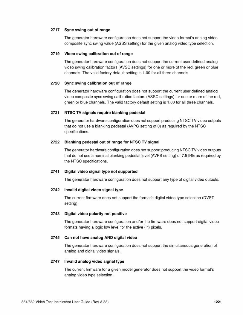
881/882 Video Test Instrument User Guide (Rev A.38) 1221
2717 Sync swing out of range
The generator hardware configuration does not support the video format’s analog video composite sync swing value (ASSS setting) for the given analog video type selection.
2719 Video swing calibration out of range
The generator hardware configuration does not support the current user defined analog video swing calibration factors (AVSC settings) for one or more of the red, green or blue channels. The valid factory default setting is 1.00 for all three channels.
2720 Sync swing calibration out of range
The generator hardware configuration does not support the current user defined analog video composite sync swing calibration factors (ASSC settings) for one or more of the red, green or blue channels. The valid factory default setting is 1.00 for all three channels.
2721 NTSC TV signals require blanking pedestal
The generator hardware configuration does not support producing NTSC TV video outputs that do not use a blanking pedestal (AVPG setting of 0) as required by the NTSC specifications.
2722 Blanking pedestal out of range for NTSC TV signal
The generator hardware configuration does not support producing NTSC TV video outputs that do not use a nominal blanking pedestal level (AVPS setting) of 7.5 IRE as required by the NTSC specifications.
2741 Digital video signal type not supported
The generator hardware configuration does not support any type of digital video outputs.
2742 Invalid digital video signal type
The current firmware does not support the format’s digital video type selection (DVST setting).
2743 Digital video polarity not positive
The generator hardware configuration and/or the firmware does not support digital video formats having a logic low level for the active (lit) pixels.
2745 Can not have analog AND digital video
The generator hardware configuration does not support the simultaneous generation of analog and digital video signals.
2747 Invalid analog video signal type
The current firmware for a given model generator does not support the video format’s analog video type selection.

1222 Appendix C Error Messages
2748 Analog video signal type not supported
The generator hardware configuration does not support the video format’s analog video type selection.
2760 Digital video not supported
The generator hardware configuration does not support the video format’s digital video type selection.
2761 Digital video signal swing out of range
The value specified for the digital video signal swing is out of range.
2762 Digital video swing calibration out of range
The value specified for the digital video swing calibration is out of range.
2763 Invalid XVSI
The value specified for the interface selection (XVSI) is invalid.
2800 Pseudo-random noise seed value exceeds limit
The seed value for the pseudo-random noise analysis exceeds its maximum value.
2801 Pseudo-random noise sequence exceeds limit
The length of the pseudo-random noise sequence exeeds maximum value.
2802 Pseudo-random noise type is not supported
The pseudo-random noise type is not supported.
2803 No signal input to analyzer or TMDS error
There is no signal input to the receive interface of the analyzer.
2804 X coordinate for delta patch out-of-range
The value specified for the X coordinate of the delta patch test is out-of-range.
2805 Y coordinate for delta patch out-of-range
The value specified for the Y coordinate of the delta patch test is out-of-range.
2806 Patch height must be greater than one
The patch height specified for a delta error test must be greater than one.

881/882 Video Test Instrument User Guide (Rev A.38) 1223
3000-3999 Image errors
3000 Invalid color name
The current firmware does not support a named color used by one or more primitives in the user defined custom image
3001 Invalid pattern name
The current firmware does not support a named fill patterns used by one or more primitives in the user defined custom image
3002 No image memory
There is not enough unused edit buffer memory space available to start a new custom image editing session.
3004 Invalid font name
The current firmware does not support a named font used by one or more primitives in the user defined custom image
3005 Image editor running
The current firmware does not allow a new custom image editing session to be started while the current custom image editing session is still running.
3006 Nothing to save
An attempt was made to save the contents of a custom image editing buffer when there was no open custom image editing session to save.
3007 Overwrite ROM Image
A user defined test image can not be saved using the same name as that of a built-in test image (case insensitive).
3008 Image save failed
Saving the contents of the custom image editing buffer failed for a reason other than those reported by error codes 3005 or 3006.
3010 R, G or B 8-Bit video DAC setting out of range
A combination of system calibration factors, user calibration multiplier settings and video output level settings have resulted in one or more calculated input values to go below zero or above the analog video Digital-to-Analog Converter’s maximum limit of 255.

1224 Appendix C Error Messages
3011 R, G or B 6-Bit video DAC setting out of range
A combination of system calibration factors, user calibration multiplier settings and video output level settings have resulted in one or more calculated input values to go below zero or above the analog video Digital-to-Analog Converter’s maximum limit of 63.
3015 R, G or B 10-Bit video DAC setting out of range
A combination of system calibration factors, user calibration multiplier settings and video output level settings have resulted in one or more calculated input values to go below zero or above the analog video Digital-to-Analog Converter’s maximum limit of 1023.
3020 Kill EPROM image
Built in test images can not be removed from the firmware.
3025 Image not found
A test image of a given name could not be found as either a built-in test image in the firmware or as a user defined custom image.
3050 Grayscale video DAC setting out of range
One or more internal calculations have resulted in an analog video DAC input grayscale setting below zero or greater than 100% video level.
4000-4999 Test sequence errors
4000 Invalid format name
The test sequence contains one or more steps that have an invalid format name parameter.
4001 Invalid image name
The test sequence contains one or more steps that have an invalid image name parameter.
4002 No sequence memory
There is not enough unused edit buffer memory space available to start a new test sequence editing session.
4003 Sequence memory full
There is not enough free battery backed user storage memory to save the sequence that is in the edit buffer.
4004 Sequence not found
A test sequence of the given name could not be found in the user storage memory area.

881/882 Video Test Instrument User Guide (Rev A.38) 1225
4005 Sequence editor running
The current firmware does not allow a new test sequence editing session to be started while the current test sequence editing session is still running.
4006 No sequence to save
An attempt was made to save the contents of a test sequence editing buffer when there was no open test sequence editing session to save.
4007 Sequence buffer full
No more steps can be added to the current sequence being edited because no more edit buffer space is available.
4008 Invalid delay setting in sequence
The test sequence contains one or more steps that have a negative number for the step delay time.
4010 Font index out of range
An attempt was made to use a font at an index location that is less than zero (0) or greater than the highest index number in use.
4020 No font present at given index
Attempt to access a font at a valid index but the specified index is empty because of a previous delete.
4030 Invalid font location
Can not install a font that has not first been transferred to memory.
4040 Sequence is running
A sequence editing session can not be started while a sequence is running.
4045 No sequence buffer
An attempt was made to change a parameter in a sequence step when there were no sequence steps in the current sequence being edited.
4100 Pattern index out of range
The selected index number for a drawing primitive’s fill pattern is less than zero or greater than the highest number used by the current firmware.
4576 Can not convert to inches, not valid units
The format’s current physical units of measure (inches or millimeters) is unknown and the firmware is unable to convert a dimension to inches.

1226 Appendix C Error Messages
4579 Can not convert to mm, not valid units
The format’s current physical units of measure (inches or millimeters) is unknown and the firmware is unable to convert a dimension to millimeters.
5000-5999 Directory errors
5002 No directory memory
The DIRN or NAMI command failed because there is an insufficient amount of managed memory for the buffer request.
5003 Directory memory full
The DIRA or DIRS command failed because there is insufficient room in the directory memory pool for the requested save.
5006 No directory to save
An attempt was made to save the contents of a directory editing buffer when there was no open directory editing session to save.
5009 Directory list full
This occurs during DIRA and DIRS commands when attempting to save more directories than supported by the current firmware.
5010 Invalid name index
The value of the <index> parameter used for a NAMQ? query is can not be zero(0).
6000-6999 Bitmap errors
6006 No map to save
An attempt was made to save the contents of a bit map editing buffer when there was no open bit map editing session to save.
6020 Map not found
An attempt was made to access a bit map whose name can not be found in the generator’s list of currently stored bitmaps
6030 Invalid map dimensions
A bit map can not have a horizontal or vertical dimension of less than one (1) pixel.

881/882 Video Test Instrument User Guide (Rev A.38) 1227
6035 Invalid map depth
The current firmware and/or generator hardware configuration does not support pixel depth setting of the selected bit map.
6036 Map data index
An attempt was made to recall a bit map at an index location that is less than zero (0) or greater than the highest index number in use for bit maps.
7000-7999 LUT errors
7006 No LUT to save
An attempt was made to save the contents of a color lookup table editing buffer when there was no open color lookup table editing session to save.
7010 No LUT buffer
An attempt was made to modify the contents of a color lookup table editing buffer when there was no open color lookup table buffer available.
7011 Invalid LUT Index
An attempt was made to recall a color lookup table at an index location that is less than zero (0) or greater than the highest index number in use for color lookup tables.
7020 LUT not found
8000-8999 Font errors
8450 Cannot remove font. Font not found.
Attempt to use FNTK command to delete a nonexistent font by name.
8455 Cannot remove built-in font
Attempt to use FNTK command to delete a built-in font.
8460 Font already exists in memory
Attempt made to transmit a font to the generator which already contained a font with the same name.

1228 Appendix C Error Messages
9000-9999 System errors
9450 Corrupted format
Checksum error in data for a particular video format
9451 Bad location for format, failed verify
This occurs during FMTV command and FMTV? query when you attempt to verify data integrity at an invalid location.
9452 Bad location for format verify
This occurs during a FMTZ? query when you try to determine if an invalid location has been erased.
9453 Kill EPROM format
Cannot delete factory default formats stored in EPROM
9453 Can not change EPROM contents
This occurs during FMTW or FMTZ commands when you try to overwrite or zero out an EPROM format.
9454 Bad location for format erase
This occurs during FMTE command when you try to access an invalid format memory location.
9456 Bad location for format read/write
This occurs during FMTR or FMTW commands when you try to read or write to an invalid format memory location.
9457 Bad location for format name read
This occurs during FMTR? query when you try to read or write to an invalid format memory location.
9458 Bad location for format copy
This occurs during FMTD command when you try during copying to access an invalid format memory location.
9459 Can not change EPROM contents
This occurs during FMTD command when you try during copying to overwrite an EPROM format.

881/882 Video Test Instrument User Guide (Rev A.38) 1229
9460 Bad location for format duplicate
This occurs during FMTD and FMTI commands when you try to use one or more invalid format memory locations as the command arguments.
9467 Bad location for format erase
This occurs during FMTZ command when you try to make one or more invalid format memory locations as the command arguments.
9470 Can not change EPROM contents
An attempt was made to insert a format using the FMTI command into an EPROM format memory location.
9471 Bad location for format yank
This occurs when you try to remove (yank) one or more formats from invalid format memory locations using the FMTY command.
9472 Can not change EPROM contents
This occurs when you try to remove (yank) one or more formats from EPROM format memory locations using the FMTY command.
9475 Can not change EPROM contents
One or more EPROM format locations was given as the destination location for the FMTD command.
9477 Error duplicating formats
The <first> memory location parameter used with the FMTD command is greater than the <last> memory location parameter.
9480 Format not found / Format data missing
The FMTR command tried to read a format from an empty format storage location.
9490 DDC mod not present
The generator hardware configuration does not support DDC communications.
9491 DDC not available
The generator hardware configuration does not support DDC communications.
9492 DDC2B no ACK from receiver
Low level DDC communications failed with Unit Under Test (UUT). No DDC acknowledgment bit was received from the UUT.

1230 Appendix C Error Messages
9493 DDC2B arbitration lost
Low level DDC communications failed with Unit Under Test (UUT). DDC bus arbitration lost with the UUT.
9494 DDC2B timeout on bus
Low level DDC communications failed with Unit Under Test (UUT). DDC communications timed out with the UUT.
9496 EDID header not found
A valid block of header data could not be found in the EDID data read back from Unit Under Test (UUT).
9497 DDC old monitor
A DDC compliant Unit Under Test (UUT) could not be found connected to the generator.
9498 I2C address missing
There was a communications error within the generator hardware architecture because the device address was missing.
9499 I2C count missing
There was a communications error within the generator hardware architecture because the data count was missing.
9500 I2C stream too big
There was a communications error within the generator hardware architecture because the data stream size exceeded the size supported by the device.
9501 I2C data missing
There was a communications error within the generator hardware architecture because the device data stream was missing.
9502 I2C register missing
There was a communications error within the generator hardware architecture.
9503 I2C data byte missing
There was a communications error within the generator hardware architecture because the device data stream had missing data.
9504 Serial digital video PLL not locked
There is an internal problem with the generator’s serial digital video hardware’s Phase Lock Loop circuit.

881/882 Video Test Instrument User Guide (Rev A.38) 1231
9505 TV output hardware not ready
The generator’s serial digital video generating hardware is not yet ready to output video
9506 Serial digital video hardware not ready
The generator’s TV signal generating hardware reports it is not yet ready to output valid video
9507 I2C offset missing
There was a communications error within the generator hardware architecture
9508 Invalid HDCP receiver KSV
The HDCP Key Selection Vector returned from the HDCP receiver in the Unit Under Test (UUT) is not valid.
9520 HDCP key combination not supported
The HDCP key combination between the Tx and the Rx is invalid. The Tx may have production keys and the Rx public keys.
9521 HDCP failed after a while
The HDCP authentication started but failed after a while.
9522 HDCP key combination not supported
The HDCP authentication did not start.
9523 HDCP production keys not supported
HDCP test initiated and specified production keys where are not supported in generator option.
9524 Invalid transmitter KSV
HDCP video transmitter KSV sent by the generator is invalid.
9525 HDCP Ri value not ready
HDCP authentication cannot start because HDCP Ri value (link verification response) at the transmitter is not ready.
9527 HDCP Ri do not match
HDCP authentication cannot start because HDCP Ri (link verification response) values at the transmitter and receiver do not match.
9528 HDCP was interrupted
HDCP authentication was interrupted possibly by disconnecting the cable.

1232 Appendix C Error Messages
9529 HDCP receiver not detected
HDCP authentication failed to start because the hot plug was not detected.
9530 HDCP invalid for animation
HDCP test will not run when an animated image is loaded.
9531 I2C segment number missing
The segment number of the enhanced DDC bus is missing.
9532 I2C address 1 missing
The first address of the enhanced DDC bus is missing.
9533 I2C address 2 missing
The second address of the enhanced DDC bus is missing.
9538 Memory address out of range
The generator encountered a memory address out of range condition.
9539 Memory count missing
The generator encountered a memory count missing condition.
9540 Memory stream too big
The generator encountered a memory stream too big condition.
9541 Memory data missing
The generator encountered a memory data missing condition.
9542 Memory address missing
The generator encountered a memory address missing condition.
9544 Repeater not ready
The generator encountered a repeater not ready condition.
9545 Repeater mismatch
The generator encountered a repeater mismatch condition.
9546 FIFO not ready
The generator encountered a FIFO not ready condition.

881/882 Video Test Instrument User Guide (Rev A.38) 1233
9600 Can not save format to EPROM
An attempt was made to save a format edit buffer’s contents to a location in the firmware EPROM.
10000-10999 System errors
10000 Out of memory
There is not enough unused battery backed user memory space to store the contents of the given edit buffer
10010 Invalid file check sum
The data object file that has been recalled from the generator’s memory contains an invalid checksum. Data may be corrupted.
10020 Invalid file version
The data object file that has been recalled from memory contains a file version number that does not match the current firmware. Data may not be properly interpreted by the firmware
10025 File type
The data object file that has been recalled from memory contains a file type identification that is not supported by the current firmware.
10026 File size
The size of the data object file that has been recalled from memory does not match the size information stored in the file’s header data.
10030 Feature not implemented
The generator hardware configuration does not support one or more settings in the video format.
10031 Feature not available
The generator hardware configuration does not support the selected feature.
10035 Video board not detected
An attempt was made to reprogram the firmware Flash EPROMs in a Model 822 series generator without a video board installed. The video board’s memory is used as a buffer for the initial uploading of the firmware data.
10040 Buffer overflow
The generator encountered a buffer overflow condition.

1234 Appendix C Error Messages
10100 Filename alias not found
An attempt was made to delete a filename alias that does not exist.
10200 Font not overwriteable
An attempt was made to save the contents of a font editing buffer to a location in the firmware EPROM.
10205 Font save failed
There is not enough unused battery backed user memory space to store the contents of the font editing buffer.
10210 Font table range
The recalled font data object contains a reference to a nonexistent table in the data object.
10215 Font table Index range
The recalled font data object contains a reference to a nonexistent location in one of the tables in the data object.
10220 Font not found
An attempt was made to recall a font by name that is not stored in the generator.
10225 Can not delete font in EPROM
Ann attempt was made to delete a font stored in the firmware EPROM.
10230 Invalid font check mode
The current firmware does not support the selected test method on the contents of the font edit buffer.
10235 No font definition
The recalled font does not contain valid font definition data need to determine the size needed by the edit buffer.
10240 Font character high range
The character height setting of the font in the edit buffer is less than one or greater than the maximum supported by the current firmware.
10241 Font ascent descent sum
The character height setting of the font in the edit buffer is does not match the sum of the character ascent and descent settings
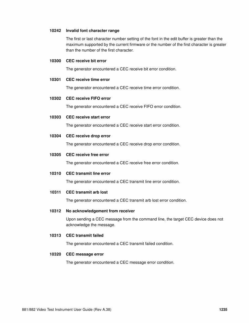
881/882 Video Test Instrument User Guide (Rev A.38) 1235
10242 Invalid font character range
The first or last character number setting of the font in the edit buffer is greater than the maximum supported by the current firmware or the number of the first character is greater than the number of the first character.
10300 CEC receive bit error
The generator encountered a CEC receive bit error condition.
10301 CEC receive time error
The generator encountered a CEC receive time error condition.
10302 CEC receive FIFO error
The generator encountered a CEC receive FIFO error condition.
10303 CEC receive start error
The generator encountered a CEC receive start error condition.
10304 CEC receive drop error
The generator encountered a CEC receive drop error condition.
10305 CEC receive free error
The generator encountered a CEC receive free error condition.
10310 CEC transmit line error
The generator encountered a CEC transmit line error condition.
10311 CEC transmit arb lost
The generator encountered a CEC transmit arb lost error condition.
10312 No acknowledgement from receiver
Upon sending a CEC message from the command line, the target CEC device does not acknowledge the message.
10313 CEC transmit failed
The generator encountered a CEC transmit failed condition.
10320 CEC message error
The generator encountered a CEC message error condition.

1236 Appendix C Error Messages

881/882 Video Test Instrument User Guide (Rev A.38) 1237
D Format Reference
Topics in this appendix:
• Formats by type
SDTV Formats
Format
Active
(HxV) Scan
Horizontal
Rate (kHz)
Vertical
Rate (Hz)
Pixel
Rate (MHz)
480i 720 x 480 Interlace 15.734 59.940 13.500
480i# 720 x 480 Interlace 15.734 59.940 12.272727480i#KA 720 x 480 Interlace 15.734 59.940 12.272727480i2x_1 720 x 480 Interlace 62.937 239.760 53.999968
480i2x_2 720 x 480 Interlace 63.000 240.000 54.054480i2x29 720 x 480 Interlace 15.734 59.940 13.500480i2x30 720 x 480 Interlace 15.750 60.000 13.5135
480i2x59 720 x 480 Interlace 31.469 119.880 27.000480i2x60 720 x 480 Interlace 31.500 120.000 27.027480i2xL1 720 x 480 Interlace 15.734 59.940 13.500
480i2xL2 720 x 480 Interlace 15.750 60.000 13.5135480i2xL3 720 x 480 Interlace 31.469 119.880 26.999984480i2xL4 720 x 480 Interlace 31.500 120.000 27.027
480i2xL5 720 x 480 Interlace 62.937 239.760 53.999968480i2xL6 720 x 480 Interlace 63.000 240.000 54.054480i2xS1 720 x 480 Interlace 15.734 59.940 13.500
480i2xS2 720 x 480 Interlace 15.750 60.000 13.513500480i2xS3 720 x 480 Interlace 31.469 119.880 26.999984480i2xS4 720 x 480 Interlace 31.500 120.000 27.027
480i2xS5 720 x 480 Interlace 62.937 239.760 53.999968480i2xS6 720 x 480 Interlace 63.000 240.000 54.054480i4x29 2880 x 480 Interlace 15.734 59.940 54.000
480i4x30 2880 x 480 Interlace 15.750 60.000 54.054480i4xL1 2880 x 480 Interlace 15.734 59.940 54.000480i4xL2 2880 x 480 Interlace 15.750 60.000 54.054
480i4xS1 2880 x 480 Interlace 15.734 59.940 54.000480i4xS2 2880 x 480 Interlace 15.750 60.000 54.054480iLH 720 x 480 Interlace 15.734 59.940 13.500
480iSH 720 x 480 Interlace 15.734 59.940 13.500480iWH 960 x 480 Interlace 15.734 59.940 18.000

1238 Appendix D Format Reference
480p# 640 x 480 Interlace 31.469 59.940 24.545454480p#KA 640 x 480 Progressive 31.469 59.940 24.545454
480p119 720 x 480 Progressive 62.937 119.880 54.000480p119L 720 x 480 Progressive 62.937 119.880 54.000480p119S 720 x 480 Progressive 62.937 119.880 54.000
480p120 720 x 480 Progressive 63.000 120.000 54.054480p120L 720 x 480 Progressive 63.000 120.000 54.054480p120S 720 x 480 Progressive 63.000 120.000 54.054
480p239 720 x 480 Progressive 125.874 239.760 107.999992480p239L 720 x 480 Progressive 125.874 239.760 107.999992480p239S 720 x 480 Progressive 125.874 239.760 107.999992
480p240 720 x 480 Progressive 126.000 240.000 108.108480p240L 720 x 480 Progressive 126.000 240.000 108.108480p240S 720 x 480 Progressive 126.000 240.000 108.108
480p2x59 1440 x 480 Progressive 31.469 59.940 54.000480p2x60 1440 x 480 Progressive 31.500 60.000 54.054480p2xL1 1440 x 480 Progressive 31.469 59.940 54.000
480p2xL2 1440 x 480 Progressive 31.500 60.000 54.054480p2xS1 1440 x 480 Progressive 31.469 59.940 54.000480p2xS2 1440 x 480 Progressive 31.500 60.000 54.054
480p4x59 2880 x 480 Progressive 31.469 59.940 108.000480p4x60 2880 x 480 Progressive 31.500 60.000 108.108480p4xL1 2880 x 480 Progressive 31.469 59.940 108.000
480p4xL2 2880 x 480 Progressive 31.500 60.000 108.108480p4xS1 2880 x 480 Progressive 31.469 59.940 108.000480p4xS2 2880 x 480 Progressive 31.500 60.000 108.108
480p59 720 x 480 Progressive 31.469 59.940 27.000480p59LH 720 x 480 Progressive 31.469 59.940 27.000480p59SH 720 x 480 Progressive 31.469 59.940 27.000
480p60 720 x 480 Progressive 31.500 60.000 27.027480p60LH 720 x 480 Progressive 31.500 60.000 27.027480p60SH 720 x 480 Progressive 31.500 60.000 27.027
480pWH 960 x 480 Progressive 31.469 59.940 36.000487i 720 x 487 Interlace 15.734 59.939 13.500576i 720 x 576 Interlace 15.625 50.000 13.500
576i# 720 x 576 Interlace 15.625 50.000 14.750576i#KA 720 x 576 Interlace 15.625 50.000 14.750576i2x_1 720 x 576 Interlace 62.500 200.000 54.000
576i2x25 720 x 576 Interlace 16.625 50.000 13.500576i2x50 720 x 576 Interlace 31.250 100.000 27.000576i2xL1 720 x 576 Interlace 31.250 100.000 27.000
576i2xL2 720 x 576 Interlace 62.500 200.000 54.000576i2xLH 720 x 576 Interlace 16.625 50.000 13.500576i2xS1 720 x 576 Interlace 31.250 100.000 27.000
576i2xS2 720 x 576 Interlace 62.500 200.000 54.000576i2xSH 720 x 576 Interlace 15.625 50.000 13.500576i4x25 2880 x 576 Interlace 15.625 50.000 54.000
Format
Active
(HxV) Scan
Horizontal
Rate (kHz)
Vertical
Rate (Hz)
Pixel
Rate (MHz)

881/882 Video Test Instrument User Guide (Rev A.38) 1239
576i4xLH 2880 x 576 Interlace 15.625 50.000 54.000576i4xSH 2880 x 576 Interlace 15.625 50.000 54.000
576i50 720 x 576 Interlace 31.250 100.000 27.000576i50_H 960 x 576 Interlace 31.250 100.000 37.125576i50_L 960 x 576 Interlace 31.250 100.000 37.125
576i50WH 960 x 576 Interlace 31.250 100.000 36.000576i50WL 960 x 576 Interlace 31.250 100.000 36.000576iLH 720 x 576 Interlace 15.625 50.000 13.500
576iSH 720 x 576 Interlace 15.625 50.000 13.500576iWH 960 x 576 Interlace 15.625 50.000 18.000576p# 768 x 576 Progressive 31.250 50.000 29.500
576p100 720 x 576 Progressive 62.500 100.000 54.000576p100L 720 x 576 Progressive 62.500 100.000 54.000576p100S 720 x 576 Progressive 62.500 100.000 54.000
576p200 720 x 576 Progressive 125.000 200.000 108.000576p200L 720 x 576 Progressive 125.000 200.000 108.000576p200S 720 x 576 Progressive 125.000 200.000 108.000
576p2x50 1440 x 576 Progressive 31.250 50.000 54.000576p2xLH 1440 x 576 Progressive 31.250 50.000 54.000576p2xSH 1440 x 576 Progressive 31.250 50.000 54.000
576p4x50 2880 x 576 Progressive 31.250 50.000 108.000576p4xLH 2880 x 576 Progressive 31.250 50.000 108.000576p4xSH 2880 x 576 Progressive 31.250 50.000 108.000
576p50 720 x 576 Progressive 31.250 50.000 27.000576p50LH 720 x 576 Progressive 31.250 50.000 27.000576p50SH 720 x 576 Progressive 31.250 50.000 27.000
576pWH 960 x 576 Progressive 31.250 50.000 36.000576pWH_ 960 x 576 Progressive 31.250 50.000 37.125576pWL 960 x 576 Progressive 31.250 50.000 36.000
576pWL_ 960 x 576 Progressive 31.250 50.000 37.125Betacam 768 x 480 Interlace 15.734 59.940 14.318NTSC#KA 640 x 480 Interface 15.734 59.940 12.273
NTSC# 640 x 480 Interface 15.734 59.940 12.273NTSC 710x 480 Interface 15.734 59.940 13.500NTSC-LH 720 x 480 Interface 15.734 59.940 13.500
NTSC-SH 720 x 480 Interface 15.734 59.940 13.500NTSC-J 710 x 480 Interface 15.734 59.940 13.500NTSC-JLH 720 x 480 Interface 15.734 59.940 13.500
NTSC-JSH 720 x 480 Interface 15.734 59.940 13.500NTSC44 720 x 480 Interface 15.734 59.940 13.500PAL-60 710 x 480 Interface 15.734 59.940 13.500
PAL-M 710 x 480 Interface 15.734 59.940 13.500PAL-N 702 x 574 Interface 15.625 50.000 13.500PAL#KA 768 x 574 Interface 15.625 50.000 14.750
PAL# 768 x 574 Interface 15.625 50.000 14.750PAL 702 x 574 Interface 15.625 50.000 13.500PAL-NC 720 x 574 Interface 15.625 50.000 13.500
Format
Active
(HxV) Scan
Horizontal
Rate (kHz)
Vertical
Rate (Hz)
Pixel
Rate (MHz)

1240 Appendix D Format Reference
HDTV Formats
TEST25 640 x 480 Progressive 31.250 59.524 25.000Format
Active
(HxV) Scan
Horizontal
Rate (kHz)
Vertical
Rate (Hz)
Pixel
Rate (MHz)
Format
Active
(HxV) Scan
Horizontal
Rate (kHz)
Vertical
Rate (Hz)
Pixel
Rate (MHz)
720p23 1280 x 720 Progressive 17.982 23.976 74.176720p24 1280 x 720 Progressive 18.000 24.000 74.250720p25 1280 x 720 Progressive 18.750 25.000 74.250
720p29 1280 x 720 Progressive 22.478 29.971 74.177720p30 1280 x 720 Progressive 22.500 30.000 74.250720p50 1280 x 720 Progressive 37.500 50.000 74.250
720p59 1280 x 720 Progressive 44.955 59.940 74.175824720p60 1280 x 720 Progressive 45.000 60.000 74.250720p100 1280 x 720 Progressive 75.000 100.000 148.500
720p119 1280 x 720 Progressive 89.910 119.880 148.351648720p120 1280 x 720 Progressive 90.000 120.000 148.5001035i29 1920 x 1035 Interlace 33.716 59.940 74.175824
1035i30 1920 x 1035 Interlace 33.750 60.000 74.2501080i25 1920 x 1080 Interlace 28.125 50.000 74.2501080i29 1920 x 1080 Interlace 33.716 59.940 74.175824
1080i30 1920 x 1080 Interlace 33.750 60.000 74.2501080i50 1920 x 1080 Interlace 56.250 100.000 148.5001080i59 1920 x 1080 Interlace 67.433 119.880 148.351648
1080i60 1920 x 1080 Interlace 67.500 120.000 148.5001080p23 1920 x 1080 Progressive 26.973 23.976 74.1758241080p24 1920 x 1080 Progressive 28.125 24.000 74.250
1080p25 1920 x 1080 Progressive 28.125 25.000 74.2501080p29 1920 x 1080 Progressive 33.716 29.970 74.1758241080p30 1920 x 1080 Progressive 33.750 30.000 74.250
1080p50 1920 x 1080 Progressive 56.250 50.000 148.5001080p59 1920 x 1080 Progressive 67.433 59.940 148.3516481080p60 1920 x 1080 Progressive 67.500 60.000 148.500
1080s23 1920 x 1080 Interlace 26.973 47.952 74.1758241080s24 1920 x 1080 Interlace 27.000 48.000 74.250108Oi25_ 1920 x 1080 Interlace 31.250 50.000 72.000
1152iLA 960 x 1152 Interlace 31.250 50.000 36.0001152iLA_ 960 x 1152 Interlace 31.250 50.000 37.1251152iLH 1920 x 1152 Interlace 31.250 50.000 72.000
1152iLH_ 1920 x 1152 Interlace 31.250 50.000 74.2501152iSH 1280 x 1152 Interlace 31.250 50.000 48.0001152iSH_ 1280 x 1152 Interlace 31.250 50.000 49.500
TEST81 1024 x 768 Progressive 61.738 77.173 81.000

881/882 Video Test Instrument User Guide (Rev A.38) 1241
VESA DMT Formats
Format
Active
(HxV) Scan
Horizontal
Rate (kHz)
Vertical
Rate (Hz)
Pixel
Rate (MHz)
DMT0659 640 x 480 Progressive 31.469 59.941 25.1752
DMT0660 640 x 480 Progressive 31.500 60.000 25.200DMT0672 640 x 480 Progressive 37.861 72.809 31.500DMT0675 640 x 480 Progressive 37.500 75.000 31.500
DMT0685 640 x 480 Progressive 43.269 85.008 36.000DMT0685D 640 x 400 Progressive 37.861 85.080 31.500DMT0685F 640 x 350 Progressive 37.861 85.080 31.500
DMT0785H 720 x 400 Progressive 37.927 85.039 35.500DMT0856 800 x 600 Progressive 35.156 56.250 36.000DMT0860 800 x 600 Progressive 37.879 60.317 40.000
DMT0872 800 x 600 Progressive 48.077 72.188 50.000DMT0875 800 x 600 Progressive 46.875 75.000 49.500DMT0885 800 x 600 Progressive 53.674 85.061 56.250
DMT1043 1024 x 768 Interlace 35.522 86.957 44.899808DMT1060 1024 x 768 Progressive 48.363 60.004 65.000DMT1070 1024 x 768 Progressive 56.476 70.069 75.000
DMT1075 1024 x 768 Progressive 60.023 75.029 78.750DMT1085 1024 x 768 Progressive 68.677 84.997 94.500DMT1170 1152 x 864 Progressive 63.851 70.013 94.500
DMT1175 1152 x 864 Progressive 67.500 75.000 108.000DMT1185 1152 x 864 Progressive 77.094 84.999 121.500DMT1243G 1280 x 1024 Interlace 46.433 86.871 78.750
DMT1260A 1280 x 960 Progressive 60.000 60.000 108.000DMT1260G 1280 x 1024 Progressive 63.981 60.020 108.000DMT1275A 1280 x 960 Progressive 75.000 75.000 126.000
DMT1275G 1280 x 1024 Progressive 79.976 75.025 135.000DMT1285A 1280 x 960 Progressive 85.938 85.002 148.500DMT1285G 1280 x 1024 Progressive 91.146 85.024 157.500
DMT1648 1600 x 1200 Interlace 62.500 96.080 135.000DMT1660 1600 x 1200 Progressive 75.000 60.000 162.000DMT1665 1600 x 1200 Progressive 81.250 65.000 175.500
DMT1670 1600 x 1200 Progressive 87.500 70.000 189.000DMT1675 1600 x 1200 Progressive 93.750 75.000 202.500DMT1680 1600 x 1200 Progressive 100.000 80.000 216.000
DMT1685 1600 x 1200 Progressive 106.250 85.000 229.500DMT1760 1792 x 1344 Progressive 83.640 60.000 204.750DMT1775 1792 x 1344 Progressive 106.270 74.997 261.000
DMT1860 1856 x 1392 Progressive 86.333 59.995 218.250DMT1875 1856 x 1392 Progressive 112.500 75.000 288.000DMT1960 1920 x 1440 Progressive 90.000 60.000 234.000
DMT1975 1920 x 1440 Progressive 112.500 75.000 297.000DMT2060 2048 x 1536 Progressive 95.820 60.000 239.933008DMT2075 2048 x 1536 Progressive 120.450 75.000 319.915008
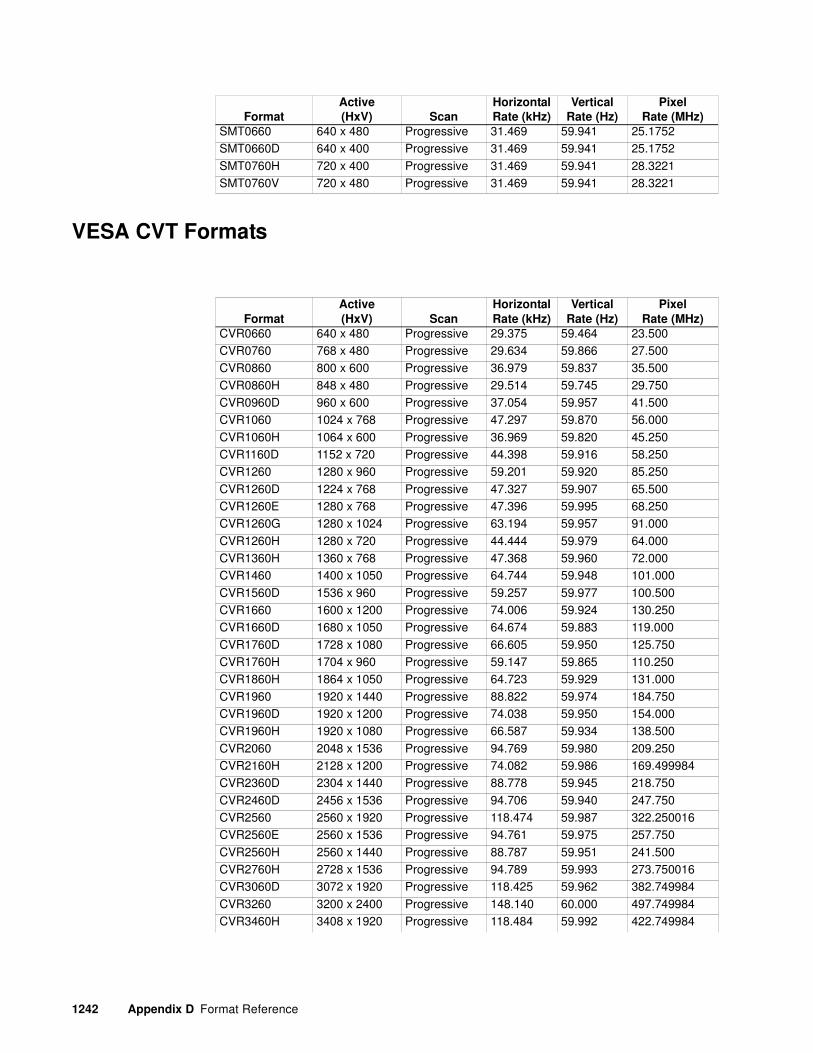
1242 Appendix D Format Reference
VESA CVT Formats
SMT0660 640 x 480 Progressive 31.469 59.941 25.1752SMT0660D 640 x 400 Progressive 31.469 59.941 25.1752
SMT0760H 720 x 400 Progressive 31.469 59.941 28.3221SMT0760V 720 x 480 Progressive 31.469 59.941 28.3221
Format
Active
(HxV) Scan
Horizontal
Rate (kHz)
Vertical
Rate (Hz)
Pixel
Rate (MHz)
Format
Active
(HxV) Scan
Horizontal
Rate (kHz)
Vertical
Rate (Hz)
Pixel
Rate (MHz)
CVR0660 640 x 480 Progressive 29.375 59.464 23.500CVR0760 768 x 480 Progressive 29.634 59.866 27.500CVR0860 800 x 600 Progressive 36.979 59.837 35.500
CVR0860H 848 x 480 Progressive 29.514 59.745 29.750CVR0960D 960 x 600 Progressive 37.054 59.957 41.500CVR1060 1024 x 768 Progressive 47.297 59.870 56.000
CVR1060H 1064 x 600 Progressive 36.969 59.820 45.250CVR1160D 1152 x 720 Progressive 44.398 59.916 58.250CVR1260 1280 x 960 Progressive 59.201 59.920 85.250
CVR1260D 1224 x 768 Progressive 47.327 59.907 65.500CVR1260E 1280 x 768 Progressive 47.396 59.995 68.250CVR1260G 1280 x 1024 Progressive 63.194 59.957 91.000
CVR1260H 1280 x 720 Progressive 44.444 59.979 64.000CVR1360H 1360 x 768 Progressive 47.368 59.960 72.000CVR1460 1400 x 1050 Progressive 64.744 59.948 101.000
CVR1560D 1536 x 960 Progressive 59.257 59.977 100.500CVR1660 1600 x 1200 Progressive 74.006 59.924 130.250CVR1660D 1680 x 1050 Progressive 64.674 59.883 119.000
CVR1760D 1728 x 1080 Progressive 66.605 59.950 125.750CVR1760H 1704 x 960 Progressive 59.147 59.865 110.250CVR1860H 1864 x 1050 Progressive 64.723 59.929 131.000
CVR1960 1920 x 1440 Progressive 88.822 59.974 184.750CVR1960D 1920 x 1200 Progressive 74.038 59.950 154.000CVR1960H 1920 x 1080 Progressive 66.587 59.934 138.500
CVR2060 2048 x 1536 Progressive 94.769 59.980 209.250CVR2160H 2128 x 1200 Progressive 74.082 59.986 169.499984CVR2360D 2304 x 1440 Progressive 88.778 59.945 218.750
CVR2460D 2456 x 1536 Progressive 94.706 59.940 247.750CVR2560 2560 x 1920 Progressive 118.474 59.987 322.250016CVR2560E 2560 x 1536 Progressive 94.761 59.975 257.750
CVR2560H 2560 x 1440 Progressive 88.787 59.951 241.500CVR2760H 2728 x 1536 Progressive 94.789 59.993 273.750016CVR3060D 3072 x 1920 Progressive 118.425 59.962 382.749984
CVR3260 3200 x 2400 Progressive 148.140 60.000 497.749984CVR3460H 3408 x 1920 Progressive 118.484 59.992 422.749984

881/882 Video Test Instrument User Guide (Rev A.38) 1243
CVR3860 3840 x 2880 Progressive 177.688 59.989 710.750016CVR3860D 3840 x 2400 Progressive 148.125 59.994 592.499968
CVR4260H 4264 x 2400 Progressive 148.113 59.989 655.249984CVR4660D 4608 x 2880 Progressive 177.695 59.992 847.249984CVR5160H 5120 x 2880 Progressive 177.699 59.993 938.249984
CVT0650 640 x 480 Progressive 24.688 49.673 19.750CVT0660 640 x 480 Progressive 29.688 59.375 23.750CVT0675 640 x 480 Progressive 37.684 74.769 30.750
CVT0685 640 x 480 Progressive 42.892 84.600 35.000CVT0750D 640 x 680 Progressive 24.740 49.778 23.749998CVT0760D 768 x 480 Progressive 29.948 59.896 28.750002
CVT0775D 768 x 480 Progressive 37.654 74.710 36.750CVT0785D 768 x 480 Progressive 42.843 84.502 42.500CVT0850 800 x 600 Progressive 30.998 49.916 30.750
CVT0850H 848 x 480 Progressive 24.621 49.540 26.000CVT0860 800 x 600 Progressive 37.654 59.861 38.250CVT0860H 848 x 480 Progressive 29.826 59.659 31.500
CVT0875 800 x 600 Progressive 47.115 74.905 49.000004CVT0875H 848 x 480 Progressive 37.684 74.769 41.000CVT0885 800 x 600 Progressive 53.741 84.898 56.750
CVT0885H 848 x 480 Progressive 42.969 84.751 46.750CVT0950D 960 x 600 Progressive 30.833 49.651 37.000CVT0960D 960 x 600 Progressive 37.212 59.635 45.250
CVT0975D 960 x 600 Progressive 47.075 74.841 58.750CVT0985D 960 x 600 Progressive 53.600 84.676 67.750CVT1050 1024 x 768 Progressive 39.634 49.980 51.999996
CVT1050H 1064 x 600 Progressive 30.871 49.712 40.750CVT1060 1024 x 768 Progressive 47.816 59.920 63.500CVT1060H 1064 x 600 Progressive 37.352 59.859 50.500
CVT1075 1024 x 768 Progressive 60.294 74.900 82.000CVT1075H 1064 x 600 Progressive 47.146 79.954 65.250CVT1085 1024 x 768 Progressive 68.677 84.895 94.500
CVT1085H 1064 x 600 Progressive 53.750 84.913 75.250CVT1150D 1152 x 720 Progressive 37.025 49.764 54.500CVT1160D 1152 x 720 Progressive 44.859 59.972 66.750
CVT1175D 1152 x 720 Progressive 56.415 74.721 85.750CVT1185D 1152 x 720 Progressive 64.453 84.918 99.000CVT1250 1280 x 960 Progressive 49.405 49.853 83.000
CVT1250D 1224 x 768 Progressive 39.499 49.809 62.250CVT1250E 1280 x 768 Progressive 39.593 49.929 65.249996CVT1250G 1280 x 1024 Progressive 52.679 49.838 88.500
CVT1250H 1280 x 720 Progressive 37.071 49.827 60.500CVT1260 1280 x 960 Progressive 59.699 59.939 101.250CVT1260D 1224 x 768 Progressive 47.739 59.823 76.000
CVT1260E 1280 x 768 Progressive 47.776 59.870 79.500CVT1260G 1280 x 1024 Progressive 63.668 59.895 109.000CVT1260H 1280 x 720 Progressive 44.772 59.855 74.500
Format
Active
(HxV) Scan
Horizontal
Rate (kHz)
Vertical
Rate (Hz)
Pixel
Rate (MHz)

1244 Appendix D Format Reference
CVT1275 1280 x 960 Progressive 75.231 74.857 130.000008CVT1275D 1224 x 768 Progressive 60.191 74.771 97.750
CVT1275E 1280 x 768 Progressive 60.289 74.893 102.250CVT1275G 1280 x 1024 Progressive 80.295 74.902 138.750CVT1275H 1280 x 720 Progressive 56.456 74.777 95.750
CVT1285 1280 x 960 Progressive 85.793 84.859 148.250CVT1285D 1224 x 768 Progressive 68.598 84.793 112.500CVT1285E 1280 x 768 Progressive 68.633 84.837 117.500
CVT1285G 1280 x 1024 Progressive 91.456 84.839 159.500CVT1285H 1280 x 720 Progressive 64.398 84.846 110.250CVT1350H 1360 x 768 Progressive 39.564 49.892 69.000
CVT1360H 1360 x 768 Progressive 47.720 59.799 84.750CVT1375H 1360 x 768 Progressive 60.288 74.891 109.000CVT1385H 1360 x 768 Progressive 68.668 84.880 125.250008
CVT1450 1400 x 1050 Progressive 54.113 49.965 100.000CVT1460 1400 x 1050 Progressive 65.317 59.978 121.750CVT1475 1400 x 1050 Progressive 82.279 74.867 156.000
CVT1485 1400 x 1050 Progressive 93.881 84.960 179.500CVT1550D 1536 x 960 Progressive 49.479 49.929 99.750CVT1560D 1536 x 960 Progressive 59.670 59.910 121.250
CVT1575D 1536 x 960 Progressive 75.218 74.844 155.250CVT1585D 1536 x 960 Progressive 85.817 84.884 178.500CVT1650 1600 x 1200 Progressive 61.795 49.915 131.500
CVT1650D 1680 x 1050 Progressive 54.121 59.974 119.500008CVT1660 1600 x 1200 Progressive 74.537 59.869 161.000CVT1660D 1680 x 1050 Progressive 65.290 59.954 146.250
CVT1675 1600 x 1200 Progressive 94.095 74.976 204.750CVT1675D 1680 x 1050 Progressive 82.306 74.892 187.000CVT1685 1600 x 1200 Progressive 107.208 84.951 235.000
CVT1685D 1680 x 1050 Progressive 93.859 84.941 214.750CVT1750D 1728 x 1080 Progressive 55.616 49.925 127.250CVT1750H 1704 x 960 Progressive 49.507 49.957 110.500
CVT1760D 1728 x 1280 Progressive 67.134 59.941 155.749984CVT1760H 1704 x 960 Progressive 59.739 59.979 135.250CVT1775D 1728 x 1080 Progressive 84.653 74.914 197.749984
CVT1775H 1704 x 960 Progressive 75.240 74.865 172.750CVT1785D 1728 x 1080 Progressive 96.514 84.884 226.999984CVT1785H 1704 x 960 Progressive 85.856 84.922 198.500
CVT1850H 1864 x 1050 Progressive 54.051 49.909 132.750008CVT1860H 1864 x 1050 Progressive 65.314 59.976 162.500CVT1875H 1864 x 1050 Progressive 82.341 74.924 207.500016
CVT1885H 1864 x 1050 Progressive 93.849 84.931 238.000CVT1950 1920 x 1440 Progressive 74.171 49.980 192.250CVT1950D 1920 x 1200 Progressive 61.816 49.932 158.250
CVT1950H 1920 x 1080 Progressive 55.621 49.929 141.500CVT1960 1920 x 1440 Progressive 89.532 59.968 233.500CVT1960D 1920 x 1200 Progressive 74.556 59.885 193.250
Format
Active
(HxV) Scan
Horizontal
Rate (kHz)
Vertical
Rate (Hz)
Pixel
Rate (MHz)

881/882 Video Test Instrument User Guide (Rev A.38) 1245
CVT1960H 1920 x 1080 Progressive 67.158 59.963 173.000CVT1975 1920 x 1440 Progressive 112.879 74.953 298.000
CVT1975D 1920 x 1200 Progressive 94.038 74.930 245.250CVT1975H 1920 x 1080 Progressive 84.643 74.906 220.750CVT1985 1920 x 1440 Progressive 128.599 84.940 339.499968
CVT1985D 1920 x 1200 Progressive 107.184 84.932 281.249984CVT1985H 1920 x 1080 Progressive 96.513 84.884 253.249984CVT2050 2048 x 1536 Progressive 79.118 49.980 219.000
CVT2060 2048 x 1536 Progressive 95.446 59.654 267.250CVT2075 2048 x 1536 Progressive 120.384 74.959 339.000CVT2085 2048 x 1536 Progressive 137.182 84.943 388.500
CVT2150H 2128 x 1200 Progressive 61.794 49.914 175.000CVT2160H 2128 x 1200 Progressive 74.633 59.516 213.750016CVT2175H 2128 x 1200 Progressive 94.095 74.976 272.500
CVT2185H 2128 x 1200 Progressive 107.229 84.967 312.250016CVT2350D 2304 x 1440 Progressive 74.179 49.986 230.249984CVT2360D 2304 x 1440 Progressive 89.525 59.963 280.750016
CVT2375D 2304 x 1440 Progressive 112.847 74.932 357.500CVT2385D 2304 x 1440 Progressive 128.612 84.948 409.500CVT2450D 2456 x 1536 Progressive 79.066 49.947 262.500
CVT2460D 2456 x 1536 Progressive 95.465 59.966 320.000CVT2475D 2456 x 1536 Progressive 120.346 74.935 407.249984CVT2485D 2456 x 1536 Progressive 137.206 84.957 466.499968
CVT2550 2560 x 1920 Progressive 98.816 49.957 346.250016CVT2550H 2560 x 1440 Progressive 74.146 49.964 256.250CVT2560 2560 x 1920 Progressive 119.247 59.953 419.749984
CVT2560H 2560 x 1440 Progressive 89.521 59.961 312.250016CVT2575 2560 x 1920 Progressive 150.408 74.979 534.249984CVT2575H 2560 x 1440 Progressive 112.855 74.937 397.250016
CVT2585 2560 x 1920 Progressive 171.453 84.962 609.000CVT2585H 2560 x 1440 Progressive 128.606 84.944 454.750016CVT2750H 2728 x 1536 Progressive 79.108 49.973 291.750016
CVT2760H 2728 x 1536 Progressive 95.430 59.944 335.000CVT2775H 2728 x 1536 Progressive 120.336 74.929 451.500CVT2785H 2728 x 1536 Progressive 137.208 84.959 516.999968
CVT3050D 3072 x 1920 Progressive 98.819 49.959 414.250016CVT3060D 3072 x 1920 Progressive 119.259 59.959 503.749984CVT3075D 3072 x 1920 Progressive 150.376 74.963 640.000
CVT3085D 3072 x 1920 Progressive 171.465 84.968 732.500032CVT3250 3200 x 2400 Progressive 123.528/ 49.991 545.499968CVT3260 3200 x 2400 Progressive 149.086 59.970 660.749952
CVT3275 3200 x 2400 Progressive 187.948 74.969 839.000CVT3285 3200 x 2400 Progressive 214.230 84.978 959.749952CVT3450H 3408 x 1920 Progressive 98.851 49.975 460.250016
CVT3460H 3408 x 1920 Progressive 119.294 59.977 559.250048CVT3475H 3408 x 1920 Progressive 150.424 74.987 710.000CVT3485H 3408 x 1920 Progressive 171.453 84.962 812.000
Format
Active
(HxV) Scan
Horizontal
Rate (kHz)
Vertical
Rate (Hz)
Pixel
Rate (MHz)

1246 Appendix D Format Reference
Game Formats
CVT3850 3840 x 2880 Progressive 148.179 49.976 789.499968CVT3850D 3840 x 2400 Progressive 123.537 49.995 794.250048
CVT3860 3840 x 2880 Progressive 178.845 59.975 955.750016CVT3860D 3840 x 2400 Progressive 149.071 59.964 794.250048CVT3875 3840 x 2880 Progressive 225.493 74.964 1212.249984
CVT3875D 3840 x 2400 Progressive 187.966 74.977 1007.500032CVT3885 3840 x 2880 Progressive 257.048 84.975 1386.000CVT3885D 3840 x 2400 Progressive 214.239 84.982 1151.750016
CVT4250H 4264 x 2400 Progressive 123.512 49.985 726.249984CVT4260H 4264 x 2400 Progressive 149.061 59.960 881.250048CVT4275H 4264 x 2400 Progressive 149.061 59.960 1117.250048
CVT4285H 4264 x 2400 Progressive 214.262 84.991 1277.000064CVT4650D 4608 x 2880 Progressive 148.222 49.991 946.250048CVT4660D 4608 x 2880 Progressive 178.850 59.976 1147.500032
CVT4675D 4608 x 2880 Progressive 225.496 74.966 1454.000CVT4685D 4608 x 2880 Progressive 257.039 84.972 1661.500032CVT5150H 5120 x 2880 Progressive 148.191 49.980 1052.749952
CVT5160H 5120 x 2880 Progressive 178.882 59.987 1276.499968CVT5175H 5120 x 2880 Progressive 225.516 74.972 1616.499968CVT5185H 5120 x 2880 Progressive 257.064 84.980 1846.750080
Format
Active
(HxV) Scan
Horizontal
Rate (kHz)
Vertical
Rate (Hz)
Pixel
Rate (MHz)
Format
Active
(HxV) Scan
Horizontal
Rate (kHz)
Vertical
Rate (Hz)
Pixel
Rate (MHz)
240p2x_1 720 x 240 Progressive 15.734 60.055 13.500240p2x_2 720 x 240 Progressive 15.750 60.115 13.5135
240p2x_3 720 x 240 Progressive 15.734 59.826 13.500240p2x_4 720 x 240 Progressive 15.750 59.886 13.5135240p2xL1 720 x 240 Progressive 15.734 60.055 13.500
240p2xL2 720 x 240 Progressive 15.750 60.155 13.5135240p2xL3 720 x 240 Progressive 15.731 59.826 13.500240p2xL4 720 x 240 Progressive 15.750 59.886 13.5135
240p2xS1 720 x 240 Progressive 15.734 60.055 13.500240p2xS2 720 x 240 Progressive 15.750 60.155 13.5135240p2xS3 720 x 240 Progressive 15.734 59.826 13.500
240p2xS4 720 x 240 Progressive 15.750 59.886 13.5135240p4x_1 2880 x 240 Progressive 15.734 60.055 54.000240p4x_2 2880 x 240 Progressive 15.750 60.115 54.054
240p4x_3 2880 x 240 Progressive 15.734 59.826 54.000240p4x_4 2880 x 240 Progressive 15.750 59.886 54.054240p4xL1 2880 x 240 Progressive 15.734 60.055 54.000
240p4xL2 2880 x 240 Progressive 15.750 60.115 54.054240p4xL3 2880 x 240 Progressive 15.734 59.826 54.000

881/882 Video Test Instrument User Guide (Rev A.38) 1247
Medical Formats
240p4xL4 2880 x 240 Progressive 15.750 59.886 54.054240p4xS1 2880 x 240 Progressive 15.734 60.055 54.000
240p4xS2 2880 x 240 Progressive 15.750 60.115 54.054240p4xS3 2880 x 240 Progressive 15.734 59.826 54.000240p4xS4 2880 x 240 Progressive 15.750 59.886 54.054
288p2x_1 720 x 288 Progressive 15.625 50.080 13.500288p2x_2 720 x 288 Progressive 15.625 49.920 13.500288p2x_3 720 x 288 Progressive 15.625 49.761 13.500
288p2xL1 720 x 288 Progressive 15.625 50.080 13.500288p2xL2 720 x 288 Progressive 15.625 49.920 13.500288p2xL3 720 x 288 Progressive 15.625 49.761 13.500
288p2xS1 720 x 288 Progressive 15.625 50.080 13.500288p2xS2 720 x 288 Progressive 15.625 49.920 13.500288p2xS3 720 x 288 Progressive 15.625 49.761 13.500
288p4x_1 2880 x 288 Progressive 15.625 50.080 54.000288p4x_2 2880 x 288 Progressive 15.625 49.920 54.000288p4x_3 2880 x 288 Progressive 15.625 49.761 54.000
288p4xL1 2880 x 288 Progressive 15.625 50.080 54.000288p4xL2 2880 x 288 Progressive 15.625 49.920 54.000288p4xL3 2880 x 288 Progressive 15.625 49.761 54.000
288p4xS1 2880 x 288 Progressive 15.625 50.080 54.000288p4xS2 2880 x 288 Progressive 15.625 49.920 54.000288p4xS3 2880 x 288 Progressive 15.625 49.761 54.000
Format
Active
(HxV) Scan
Horizontal
Rate (kHz)
Vertical
Rate (Hz)
Pixel
Rate (MHz)
Format
Active
(HxV) Scan
Horizontal
Rate (kHz)
Vertical
Rate (Hz)
Pixel
Rate (MHz)
DatRay5 2048 x 2560 Progressive 186.010 70.996 499.99488DatRay6 2456 x 2560 Progressive 186.010 70.996 607.880704
DatRay7 2864 x 2560 Progressive 186.010 70.996 700.885696DatRay8 3280 x 2560 Progressive 186.010 70.996 800.587008DOM1266O 1200 x 1600 Progressive 109.752 66.316 186.140
DOM1570O 1536 x 2048 Progressive 147.183 70.423 357.950016DOM1762O 1728 x 2304 Progressive 146.437 61.866 360.820DOM1763O 1728 x 2304 Progressive 148.364 62.893 360.820
DOM1769O 1728 x 2304 Progressive 163.415 69.039 360.820DOM1770X 1712 x 2100 Progressive 149.346 69.528 360.820DOM2060_ 2048 x 2048 Progressive 126.847 60.003 357.200
DOM2060Q 2048 x 2044 Progressive 127.769 60.382 360.820DOM2065X 2048 x 2560 Progressive 169.891 65.092 500.159968DOM2071X 2048 x 2560 Progressive 186.079 71.022 500.180032
DOM2076A 2048 x 1536 Progressive 118.691 75.599 360.820DOM2076X 2048 x 2560 Progressive 199.449 76.009 542.500032

1248 Appendix D Format Reference
Military Formats
TTL Formats
DOM2365 2304 x 1728 Progressive 116.244 64.904 360.819968DOM2569G 2560 x 2048 Progressive 144.722 69.014 500.160
DOM2571G 2560 x 2048 Progressive 150.289 71.703 500.160032MATROX 1280 x 1024 Progressive 77.000 72.368 133.056Md2 1200 x 1600 Progressive 124.430 75.504 214.019984
Md2SBX 1600 x 1200 Progressive 91.118 73.011 200.460Md4SBX 1728 x 2304 Progressive 163.415 69.039 360.820Md5SBV 2048 x 2560 Progressive 199.449 76.009 542.500032
Md5SBX 2048 x 2560 Progressive 186.012 70.997 500.000
Format
Active
(HxV) Scan
Horizontal
Rate (kHz)
Vertical
Rate (Hz)
Pixel
Rate (MHz)
Format
Active
(HxV) Scan
Horizontal
Rate (kHz)
Vertical
Rate (Hz)
Pixel
Rate (MHz)
HOBO 752 x 482 Interlace 15.734 59.940 14.444056
LMC_1 640 x 480 Interlace 15.734 59.940 12.272727LMC_2 640 x 480 Interlace 15.734 59.940 12.272727LMC_3 640 x 480 Interlace 15.734 59.940 12.272727
LMC_4 640 x 480 Interlace 15.734 59.940 12.272727MAVERIK 740 x 476 Interlace 15.734 59.940 14.318182STANAGA 1244 x 842 Interlace 26.250 60.000 40.005
STANAGB 1560 x 574 Interlace 15.625 50.000 30.000STANAGC 1262 x 484 Interlace 15.750 60.000 24.003XGA2 720 x 400 Progressive 39.444 87.849 35.4996
Format
Active
(HxV) Scan
Horizontal
Rate (kHz)
Vertical
Rate (Hz)
Pixel
Rate (MHz)
AT&T_EVC 640 x 350 Progressive 25.862 59.866 24.000AT&T_IVC 640 x 400 Progressive 25.862 59.866 24.000
AT&T_SVC 640 x 400 Progressive 25.862 59.866 24.000CGA_m14 640 x 200 Progressive 15.700 59.924 14.3184EGA_m2 640 x 350 Progressive 21.851 59.702 16.257144
HGC_text 720 x 350 Progressive 18.141 49.030 16.000362HGCgraph 720 x 348 Progressive 18.519 50.051 16.000416IBM_3164 640 x 400 Progressive 27.648 64.749 22.1184
IBM_3179 640 x 400 Progressive 25.560 60.000 20.488MDA_m7 720 x 350 Progressive 18.432 49.816 16.257144

881/882 Video Test Instrument User Guide (Rev A.38) 1249
Misc. Formats
Test Formats
Format
Active
(HxV) Scan
Horizontal
Rate (kHz)
Vertical
Rate (Hz)
Pixel
Rate (MHz)
CEA0659 640 x 480 Progressive 31.469 59.941 25.1752
EIA0629 640 x 480 Interlace 15.734 59.940 12.272727EIA0629K 512 x 384 Interlace 15.734 59.940 12.272727EIA0729 752 x 484 Interlace 15.734 59.940 14.318182
EIA0729X 752 x 484 Interlace 15.734 59.940 14.318182ICS1160 1184 x 884 Progressive 55.200 60.000 83.0208ICS1176 1184 x 884 Progressive 71.712 76.047 105.560504
ICS1660 1664 x 1248 Progressive 77.940 60.000 164.609296ICS1676 1664 x 1248 Progressive 100.726 76.020 211.121888ITU0725 768 x 574 Interlace 15.625 50.000 14.750
ITU0725K 640 x 480 Interlace 15.625 50.000 14.750ITU0925X 920 x 574 Interlace 15.625 50.000 17.750LD6Du60 1024 x 768 Progressive 48.364 60.005 65.001216
LD8Du75 1024 x 768 Progressive 60.023 75.029 78.750NEC0656D 640 x 400 Progressive 24.823 56.416 21.050NEC1140B 1120 x 750 Interlace 32.857 80.042 47.840004
Format
Active
(HxV) Scan
Horizontal
Rate (kHz)
Vertical
Rate (Hz)
Pixel
Rate (MHz)
RAMP160 4096 x 480 Progressive 31.469 59.941 161.121280TEST81 1024 x 768 Progressive 61.738 77.172 81.000
TEST150 2048 x 1024 Progressive 50.403 46.887 150.000TEST165 1600 x 1200 Progressive 76.389 61.111 165.000TEST250 2048 x 2048 Interlace 79.719 71.722 250.000016
TEST330 2048 x 1536 Progressive 94.178 59.269 330.000tst300i 2048 x 1536 Interlace 94.178 118.538 299.86304tst300p 2048 x 1536 Progressive 94.178 59.269 299.86304
tst360i 2816 x 1024 Interlace 97.000 91.037 360.064tst360p 2816 x 1024 Progressive 97.000 91.080 360.064tst400i 2816 x 1024 Interlace 97.000 91.037 399.640
tst400p 2816 x 1024 Progressive 97.000 91.080 399.640

1250 Appendix D Format Reference
Manufacturer Associated Formats
Format
Active
(HxV) Scan
Horizontal
Rate (kHz)
Vertical
Rate (Hz)
Pixel
Rate (MHz)
APP0560 512 x 384 Progressive 24.480 60.147 15.667
APP0560B 560 x 384 Progressive 24.480 60.147 17.234APP0629 640 x 480 Interlace 15.734 59.939 12.273APP0629K 512 x 384 Interlace 15.734 59.939 12.273
APP0667_ 640 x 480 Progressive 34.975 66.619 31.338APP0667 640 x 480 Progressive 35.000 66.667 30.240APP0675O 640 x 870 Progressive 68.850 75.000 57.283
APP0875 832 x 624 Progressive 49.107 75.087 55.000APP1059 1024 x 768 Progressive 48.193 59.278 64.000APP1075 1024 x 768 Progressive 60.241 74.927 80.000
APP1175 1152 x 870 Progressive 68.681 75.061 100.000HWP1060 1024 x 768 Progressive 47.700 60.000 64.109HWP1070 1024 x 768 Progressive 56.476 70.069 75.000
HWP1075 1024 x 768 Progressive 62.937 74.925 84.587HWP1075_ 1024 x 768 Progressive 60.241 75.020 80.000HWP1260G 1280 x 1024 Progressive 63.338 59.979 108.181
HWP1272G 1280 x 1024 Progressive 78.125 72.005 135.000HWP1275G 1280 x 1024 Progressive 79.976 75.024 134.999IBM0660D 640 x 400 Progressive 30.296 59.638 24.964
IBM0660 640 x 480 Progressive 30.296 59.638 25.024IBM0675 640 x 480 Progressive 39.375 75.000 31.500IBM0770U 720 x 350 Progressive 31.469 70.087 28.322
IBM0770H 720 x 400 Progressive 31.469 70.087 28.322IBM1043 1053 x 754 Interlace 35.414 86.906 45.542IBM1043_ 1056 x 768 Interlace 35.602 86.940 45.571
IBM1070 1024 x 768 Progressive 56.287 70.009 77.001IBM1060Q 1024 x 1024 Progressive 63.360 60.000 89.211IBM1076 1024 x 768 Progressive 61.080 75.782 86.001
IBM1260G 1280 x 1024 Progressive 63.363 60.003 111.519IBM1267G 1280 x 1024 Progressive 70.755 67.003 120.000IBM1267_ 1280 x 1024 Progressive 70.755 67.003 120.000
IBM1352 1360 x 1024 Interlace 56.469 102.952 102.999SNY1072 1024 x 768 Progressive 57.870 71.799 75.000SNY1274G 1280 x 1024 Progressive 78.855 74.112 135.000
SNY1276G 1280 x 1024 Progressive 81.207 76.179 140.001SUN1061Q 1024 x 1024 Progressive 65.267 61.399 92.940SUN1077 1024 x 768 Progressive 62.040 77.068 84.374
SUN1166X 1152 x 900 Progressive 61.796 65.951 92.941SUN1166_ 1152 x 900 Progressive 61.846 66.004 94.501SUN1176X 1152 x 900 Progressive 71.713 76.048 105.562
SUN1176_ 1152 x 900 Progressive 71.809 76.150 108.001SUN1267G 1280 x 1024 Progressive 71.722 66.718 117.050SUN1267_ 1280 x 1024 Progressive 71.678 66.677 118.125

881/882 Video Test Instrument User Guide (Rev A.38) 1251
SUN1276G 1280 x 1024 Progressive 81.130 76.107 135.000SUN1667G 1600 x 1280 Progressive 89.286 66.931 200.001
VSC1260G 1280 x 1024 Progressive 63.896 59.996 107.856VSC1460 1440 x 1080 Progressive 67.080 60.000 129.867VSC1660V 1680 x 1080 Progressive 67.080 60.000 151.332
VSC1875V 1868 x 1200 Progressive 93.975 75.000 240.576VSC1960H 1920 x 1080 Progressive 67.080 60.000 172.798VSC1975H 1920 x 1080 Progressive 84.060 75.000 220.637
VSC1975D 1920 x 1200 Progressive 93.975 75.000 246.590
Format
Active
(HxV) Scan
Horizontal
Rate (kHz)
Vertical
Rate (Hz)
Pixel
Rate (MHz)

1252 Appendix D Format Reference

881/882 Video Test Instrument User Guide (Rev A.38) 1
Numerics3D feature 356
AActive Format Description 385alternate image versions 50
analog component video SDTV (CE) CRTs 61analog composite video 58analog computer (IT) CRTs 52
analyze an external HDMI/DVI signal 287analyze InfoFrame data 296analyze pseudo-random noise 281
analyze signal timing 270Analyzer connections 265ARC commands 426
audio clips 376audio content 304audio data 304
Audio device 391audio image 376Audio Return Channel 424
Audio Return Channel (ARC) 439AuxTest composite test image 71
BBacking up the current files on the file server 150Basic mode 15bitmap images 235
boot a generator that is in a stalled state 117, 118boot a stalled generator from a different host 120boot device 14
BootDev 117Booting a generator from the file server 146Booting up the generator 14
BootNow 15, 118, 119Browse mode 15Browsing other media 16
Bus commands 165bypass hot plug formats 44, 333
Ccached images 69calibrate all frequencies 86calibration factors 86
capture a reference frame 289capture and read pixel data 292CDF parameters 449

CEC addressing 395CEC Compliance Controller 436, 447
CEC Compliance Test 447CEC Compliance Test Tool 436CEC devices 391
CEC features 392CEC switch 391CEC test 71
CEC/CDC Controller 407centering 54, 56, 60, 63, 66, 68clone a generator using the Generator FTP Browser 123
Cloning a generator using the PC card 122Cloning generators using the Generator FTP Browser 153CMD (Command) Terminal 22
color component values 237command line interface 30Completion handshake 162
Compliance Controller 436, 447, 526compliance test 582, 619Component high definition television formats 47
Component SDTV formats 46Component television format names 170component values 237
component video 61, 64Composite television formats 46composite test image 71
composite video SDTV 58computer (IT) CRTs 52computer (IT) FPDs 55
Computer display format names 171Computer display formats 47Configuring a file server 135
Configuring format parameters 175Configuring special sync for FS, LS, or CS 669Configuring the generator’s serial port 30
Configuring the probe feature 665Connecting a generator directly to a PC 114Connecting generators to the network 140
Content list 229Controlling a generator remotely 149Controlling the probe 668
Copying files between generators 27Copying files between the generator’s flash memory and PC card 26Copying files from a generator to a PC 25
Copying files from a PC to a generator 23Copying files to the PC file server 151Copying the new files to each generator 152
create a format catalog with both custom formats and default formats 223create a new format 215

881/882 Video Test Instrument User Guide (Rev A.38) 3
Creating a new format using the Format Editor 215Creating a test sequence 254
Creating an image catalog 239Creating custom formats using the command line interface 220Creating format catalogs 222
custom formats 220custom formats appear in the Source list 221custom images 232
DDeck Control 392deep color 338
delete a user profile 37Deleting a test sequence 261Deleting an image catalog 243
Deleting format catalogs 223Delta time 492Device OSD Name Transfer 392
DHCP 141, 143digital component video HDTV (CE) FPDs 64digital computer (IT) FPDs 55
display size 42Dolby audio 376DTS audio 376
DVD player 391DVI cables and distribution systems 277
EEDID compliance 512, 540EDID Editor Tool 546EDID Formats 539
EDID saved from the ACA 483EDID test 71Editing a test sequence 258
Editing images 234Editor Tool 546emulate an EDID 567
Emulate mode 44, 334est the quality of video sources 281Establishing a Telnet session 33
Establishing a terminal session 30ETHERNET connector 7extended-gamut 349
external audio source 377
FFAT16 filesystem 2, 18, 27, 28, 107, 108, 117, 118, 122
file server 135

file server IP address 144File server specifications 135
file system 13, 134focus 54, 59, 62Format Editor 182
format library 46format naming conventions 46format parameters 175
Front panel interface 9FTP Browser 23FTP server 135
function keys 19
GGenerator file system 13, 134
Generator FTP Browser 23Generator media 13Generator operational modes 14
generator’s function keys 19generator’s path 17geometry 53, 59, 62
GPIB connector 7GPIB port address 157
HHDCP 573HDCP compliance test 582, 619HDCP test 71
HDMI 1.3 deep color displays 338HDMI 1.4 3D displays 356HDMI 1.4 devices 447
HDMI compliance 512, 540HDMI connector pinouts 266HDMI displays 336
HDMI InfoFrame contents 296HDMI or DVI cables and distribution 277HDMI source compliance 540
HDMI testing 331HDMI video pixel repetition 363high voltage regulation 54, 60, 63
HostName 120hot plug bypass 44, 334HP Bypass 44, 334
IImage Cache 69image component values 237
Image Control Tool 338

881/882 Video Test Instrument User Guide (Rev A.38) 5
image options 229image rendering 69
image versions 50, 229increment the color component values 237indicators 9
InetAddr 121InfoFrame contents 380InfoFrame data 296
Initiate ARC 424interface 41interfaces 5
IP address 141, 144
JJava Runtime Environment 20, 149, 316, 456, 479
LLibrary folder 13Lipsync
testing display (sink) device 657luminance 54, 56, 59, 62, 65, 68
MMaintaining the generator’s file system 149measure and analyze signal timing 270menu items 10
Menu selection keys 10Modifying EDID 506modifying existing formats 182
modifying format parameters 179, 180modifying image options 229monitor audio content 304
monitor auxiliary channels 478monitor the CEC bus 319, 487monitor the EDID 493
monitor the HDCP 490Monitoring HDMI analyzer signal input 267multiple commands 161
Munsell Color System 349
Nnetwork interface 33
OOne Touch Play 392One Touch Record 392
operate a generator remotely 149
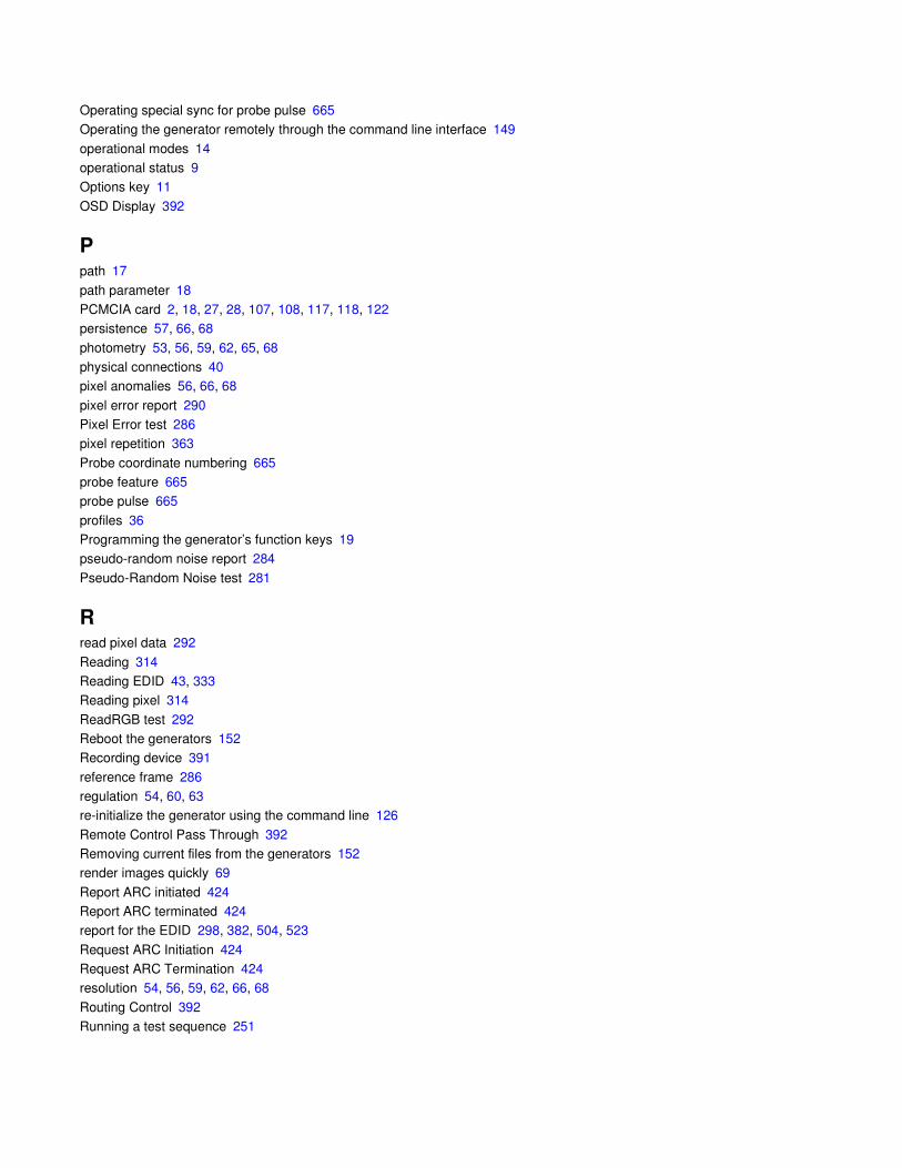
Operating special sync for probe pulse 665Operating the generator remotely through the command line interface 149
operational modes 14operational status 9Options key 11
OSD Display 392
Ppath 17
path parameter 18PCMCIA card 2, 18, 27, 28, 107, 108, 117, 118, 122persistence 57, 66, 68
photometry 53, 56, 59, 62, 65, 68physical connections 40pixel anomalies 56, 66, 68
pixel error report 290Pixel Error test 286pixel repetition 363
Probe coordinate numbering 665probe feature 665probe pulse 665
profiles 36Programming the generator’s function keys 19pseudo-random noise report 284
Pseudo-Random Noise test 281
Rread pixel data 292
Reading 314Reading EDID 43, 333Reading pixel 314
ReadRGB test 292Reboot the generators 152Recording device 391
reference frame 286regulation 54, 60, 63re-initialize the generator using the command line 126
Remote Control Pass Through 392Removing current files from the generators 152render images quickly 69
Report ARC initiated 424Report ARC terminated 424report for the EDID 298, 382, 504, 523
Request ARC Initiation 424Request ARC Termination 424resolution 54, 56, 59, 62, 66, 68
Routing Control 392Running a test sequence 251
881/882 Video Test Instrument User Guide (Rev A.38) 7
Running an HDCP self-test 580Running HDCP test in step mode 582
Running the ACA 316, 479, 482, 483, 484
Ssave an EDID 483
select the device type 41select the interface 41Selecting a boot device 14
Selecting a user profile 36Selecting images 47Selecting menu items 10
selection keys 10self-calibrate the generator 85Sending multiple commands and queries per line 161
sequence XML file 258Serial (RS-232) interface 30SERIAL connector 7
Set top box 391Setting image component values 237Setting the file server IP address in the generator 143
Setting the generator’s IP address 141Setting the generator’s path 17Setting the GPIB port address 157
setting up new users 36Setting up the generator for HDMI testing 331Settings key 12
Sharing objects on a file server 147Sink key 43, 44, 333, 334, 538soft key 10
source device responds to EDIDs 567Source list 43, 333Source list of formats 174
special sync 665Status byte 163Status indicators 9
Status queries and control 163System folder 13System Standby 392
Ttelevision format names 169Telnet session 33
Terminate ARC 424test HDMI or DVI cables and distribution systems 277test luminance 54, 56
test sequence list 249test sequence XML file 258
Testing analog component video SDTV (CE) CRTs 61Testing analog composite video SDTV (CE) CRTs 58
Testing analog computer (IT) CRTs 52Testing digital component video HDTV (CE) FPDs 64Testing digital computer (IT) FPDs 55
Testing DVI displays with HDCP 573Testing EDID for HDMI compliance in HDMI 546, 568testing focus 54, 59, 62
testing for centering 54, 56, 60, 63, 66, 68testing for high voltage regulation 54, 60, 63testing for persistence 57, 66, 68
testing for pixel anomalies 56, 66, 68testing geometry 53, 59, 62Testing HDMI displays 336
Testing HDMI displays with HDCP 575Testing HDMI video pixel repetition 348testing luminance 59, 62, 65, 68
testing photometry 53, 56, 59, 62, 65, 68testing resolution 54, 56, 59, 62, 66, 68Testing with Active Format Description 385
timing information 270Tuner Control 392TV 391
Uupgrade a generator 107Upgrade options and procedures 150
upgrade procedures 150Upgrading generators over a network 150user profiles 36
Vvideo formats 43, 332Video interfaces 2
video signal quality 281view analog calibration factors 86view current HDMI InfoFrame contents 296
View Data 292, 294view the pixel error report 290Viewing and modifying format parameters 175, 179, 180
Viewing image versions 229Viewing InfoFrame contents 380Viewing the Content list of images 229
Viewing the test sequence list 249Virtual Front Panel 20, 149voltage regulation 54, 60, 63

881/882 Video Test Instrument User Guide (Rev A.38) 9
WWeb interface 20
Web server 20
XxvYCC 349
Copyright © 2022 FDOKUMEN