
Tektronix: Video Test > Video Glossary Part 2
88
80 www.tektronix.com/video_audio 80 80 80 Video Terms and Acronyms Glossary E Mem – Term used for a panel memory system. E1 – European digital transmission channel with a data rate of 2.048 kbps. EACEM – European Association of Consumer Electronics Manufacturers EAPROM (Electrically Alterable Programmable Read-Only Memo) – A PROM whose contents can be changed. Earth Station – Equipment used for transmitting or receiving satellite communications. EAV (End of Active Video) – A term used with component digital systems. EB (Errored Block) EBR – See Electron Beam Recording. EBU (European Broadcasting Union) – An organization of European broadcasters that, among other activities, produces technical statements and recommendations for the 625/50 line televi-sion system. Created in 1950 and headquartered in Geneva, Switzerland, the EBU is the world’s largest professional association of national broadcasters. The EBU assists its members in all areas of broadcasting, briefing them on developments in the audio-visual sector, providing advice and defending their interests via international bodies. The Union has active members in European and Mediterranean countries and associate members in countries elsewhere in Africa, the Americas and Asia. EBU TECH.3267-E – a) The EBU recommendation for the serial composite and component interface of 625/50 digital video signal including embed- ded digital audio. b) The EBU recommendation for the parallel interface of 625 line digital video signal. A revision of the earlier EBU Tech.3246-E, which in turn was derived from CCIR-601 and contributed to CCIR-656 standards. EBU Timecode – The timecode system created by the EBU and based on SECAM or PAL video signals. ECC (Error Correction Code) – A type of memory that corrects errors on the fly. ECC Constraint Length – The number of sectors that are interleaved to combat bursty error characteristics of discs. 16 sectors are interleaved in DVD. Interleaving takes advantage of typical disc defects such as scratch marks by spreading the error over a larger data area, thereby increasing the chance that the error correction codes can conceal the error. ECC/EDC (Error Correction Code/Error Detection Code) – Allows data that is being read or transmitted to be checked for errors and, when nec- essary, corrected on the fly. It differs from parity-checking in that errors are not only detected but also corrected. ECC is increasingly being designed into data storage and transmission hardware as data rates (and therefore error rates) increase. Eccentricity – A mathematical constant that for an ellipse is the ratio between the major and minor axis length. Echo (or Reflection) – a) A wave which has been reflected at one or more points in the transmission medium, with sufficient magnitude and time difference to be perceived in some manner as a wave distinct from that of the main or primary transmission. Echoes may be either leading or lagging the primary wave and appear in the picture monitor as reflections or “ghosts”. b) Action of sending a character input from a keyboard to the printer or display. Echo Cancellation – Reduction of an echo in an audio system by estimating the incoming echo signal over a communications connection and subtracting its effects from the outgoing signal. Echo Plate – A metal plate used to create reverberation by inducing waves in it by bending the metal. E-Cinema – An HDTV film-complement format introduced by Sony in 1998. 1920 x 1080, progressive scan, 24 fps, 4:4:4 resolution. Using a 1/2-inch tape, the small cassette (camcorder) will hold 50 minutes while the large cassette will hold 156 minutes. E-Cinema’s camcorder will use three 2/3-inch FIT CCDs and is equivalent to a film sensitivity of ISO 500. The format will compress the electronic signal somewhere in the range of 7:1. The format is based on the Sony HDCAM video format. ECL (Emitter Coupled Logic) – A variety of bipolar transistor that is noted for its extremely fast switching speeds. ECM – See Entitlement Control Message. ECMA (European Computer Manufacturers Association) – An international association founded in 1961 that is dedicated to establishing standards in the information and communications fields. ECMA-262 – An ECMA standard that specifies the core JavaScript language, which is expected to be adopted shortly by the International Standards Organization (ISO) as ISO 16262. ECMA-262 is roughly equivalent to JavaScript 1.1. ECU (Extreme Closeup) ED-Beta (Extended Definition Betamax) – A consumer/Professional videocassette format developed by Sony offering 500-line horizontal resolution and Y/C connections. Edge – a) An edge is the straight line that connects two points. b) Synonym for key border. Used by our competitors but not preferred by Ampex. c) A boundary in an image. The apparent sharpness of edges can be increased without increasing resolution. See also Sharpness. Edge Busyness – Distortion concentrated at the edge of objects, characterized by temporally varying sharpness or spatially varying noise. Edge Curl – Usually occurs on the outside one-sixteenth inch of the videotape. If the tape is sufficiently deformed it will not make proper tape contact with the playback heads. An upper curl (audio edge) crease may affect sound quality. A lower edge curl (control track) may result in poor picture quality. E
-
Upload
khangminh22 -
Category
Documents
-
view
0 -
download
0
Transcript of Tektronix: Video Test > Video Glossary Part 2

80 www.tektronix.com/video_audio808080
Video Terms and AcronymsGlossary
E Mem – Term used for a panel memory system.
E1 – European digital transmission channel with a data rate of 2.048 kbps.
EACEM – European Association of Consumer Electronics Manufacturers
EAPROM (Electrically Alterable Programmable Read-Only Memo) –A PROM whose contents can be changed.
Earth Station – Equipment used for transmitting or receiving satellitecommunications.
EAV (End of Active Video) – A term used with component digital systems.
EB (Errored Block)
EBR – See Electron Beam Recording.
EBU (European Broadcasting Union) – An organization of Europeanbroadcasters that, among other activities, produces technical statementsand recommendations for the 625/50 line televi-sion system. Created in1950 and headquartered in Geneva, Switzerland, the EBU is the world’slargest professional association of national broadcasters. The EBU assistsits members in all areas of broadcasting, briefing them on developments in the audio-visual sector, providing advice and defending their interests via international bodies. The Union has active members in European andMediterranean countries and associate members in countries elsewhere in Africa, the Americas and Asia.
EBU TECH.3267-E – a) The EBU recommendation for the serial compositeand component interface of 625/50 digital video signal including embed-ded digital audio. b) The EBU recommendation for the parallel interface of625 line digital video signal. A revision of the earlier EBU Tech.3246-E,which in turn was derived from CCIR-601 and contributed to CCIR-656standards.
EBU Timecode – The timecode system created by the EBU and based onSECAM or PAL video signals.
ECC (Error Correction Code) – A type of memory that corrects errors onthe fly.
ECC Constraint Length – The number of sectors that are interleaved tocombat bursty error characteristics of discs. 16 sectors are interleaved inDVD. Interleaving takes advantage of typical disc defects such as scratchmarks by spreading the error over a larger data area, thereby increasingthe chance that the error correction codes can conceal the error.
ECC/EDC (Error Correction Code/Error Detection Code) – Allows datathat is being read or transmitted to be checked for errors and, when nec-essary, corrected on the fly. It differs from parity-checking in that errors arenot only detected but also corrected. ECC is increasingly being designedinto data storage and transmission hardware as data rates (and thereforeerror rates) increase.
Eccentricity – A mathematical constant that for an ellipse is the ratiobetween the major and minor axis length.
Echo (or Reflection) – a) A wave which has been reflected at one ormore points in the transmission medium, with sufficient magnitude andtime difference to be perceived in some manner as a wave distinct fromthat of the main or primary transmission. Echoes may be either leading or lagging the primary wave and appear in the picture monitor as reflections or “ghosts”. b) Action of sending a character input from a keyboard to the printer or display.
Echo Cancellation – Reduction of an echo in an audio system by estimating the incoming echo signal over a communications connectionand subtracting its effects from the outgoing signal.
Echo Plate – A metal plate used to create reverberation by inducingwaves in it by bending the metal.
E-Cinema – An HDTV film-complement format introduced by Sony in1998. 1920 x 1080, progressive scan, 24 fps, 4:4:4 resolution. Using a1/2-inch tape, the small cassette (camcorder) will hold 50 minutes whilethe large cassette will hold 156 minutes. E-Cinema’s camcorder will usethree 2/3-inch FIT CCDs and is equivalent to a film sensitivity of ISO 500.The format will compress the electronic signal somewhere in the range of 7:1. The format is based on the Sony HDCAM video format.
ECL (Emitter Coupled Logic) – A variety of bipolar transistor that isnoted for its extremely fast switching speeds.
ECM – See Entitlement Control Message.
ECMA (European Computer Manufacturers Association) – An international association founded in 1961 that is dedicated to establishingstandards in the information and communications fields.
ECMA-262 – An ECMA standard that specifies the core JavaScript language, which is expected to be adopted shortly by the InternationalStandards Organization (ISO) as ISO 16262. ECMA-262 is roughly equivalent to JavaScript 1.1.
ECU (Extreme Closeup)
ED-Beta (Extended Definition Betamax) – A consumer/Professional videocassette format developed by Sony offering 500-line horizontal resolution and Y/C connections.
Edge – a) An edge is the straight line that connects two points.b) Synonym for key border. Used by our competitors but not preferred byAmpex. c) A boundary in an image. The apparent sharpness of edges can be increased without increasing resolution. See also Sharpness.
Edge Busyness – Distortion concentrated at the edge of objects,characterized by temporally varying sharpness or spatially varying noise.
Edge Curl – Usually occurs on the outside one-sixteenth inch of the videotape. If the tape is sufficiently deformed it will not make proper tape contact with the playback heads. An upper curl (audio edge) creasemay affect sound quality. A lower edge curl (control track) may result inpoor picture quality.
E
www.tektronix.com/video_audio 81
Video Terms and AcronymsGlossary
Edge Damage – Physical distortion of the top or bottom edge of the mag-netic tape, usually caused by pack problems such as popped strands orstepping. Affects audio and control track sometimes preventing playback.
Edge Effect – See Following Whites or Following Blacks.
Edge Enhancement – Creating hard, crisp, high-contrast edges beyondthe correction of the geometric problem compensated by aperture correc-tion, frequently creates the subjective impression of increase image detail.Transversal delay lines and second-directive types of correction increasethe gain at higher frequencies while introducing rather symmetrical “under-shoot followed by overshoot” at transitions. In fact, and contrary to manycausal observations, image resolution is thereby decreased and fine detailbecomes obscured. Creating a balance between the advantages and disad-vantages is a subjective evaluation and demands an artistic decision.
Edge Enhancing – See Enhancing.
Edge Filter – A filter that applies anti-aliasing to graphics created to thetitle tool.
Edge Numbers – Numbers printed on the edge of 16 and 35 mm motionpicture film every foot which allows frames to be easily identified in an edit list.
Edgecode – See Edge Numbers, Key Numbers.
EDH (Error Detection and Handling) – Defined by SMPTE standards RP-165 and is used for recognizing inaccuracies in the serial digital signal.It may be incorporated into serial digital equipment and employ a simpleLED error indicator. This data conforms to the ancillary data formattingstandard (SMPTE 291M) for SD-SDI and is located on line 9 for 525 andline 5 for 625 formats.
Edit – a) The act of performing a function such as a cut, dissolve, wipe ona switcher, or a cut from VTR to VTR where the end result is recorded onanother VTR. The result is an edited recording called a master. b) Any pointon a video tape where the audio or video information has been added to,replaced, or otherwise altered from its original form.
Edit Control – A connection on a VCR or camcorder which allows directcommunication with external edit control devices. (e.g., LANC (Control-L)and new (Panasonic) 5-pin). Thumbs Up works with both of these controlformats and with machines lacking direct control.
Edit Controller – An electronic device, often computer-based, that allowsan editor to precisely control, play and record to various videotapemachines.
Edit Decision List (EDL) – a) A list of a video production’s edit points.An EDL is a record of all original videotape scene location time references,corresponding to a production’s transition events. EDLs are usually generated by computerized editing equipment and saved for later use and modification. b) Record of all edit decisions made for a video program(such as in-times, out-times, and effects) in the form of printed copy,paper tape, or floppy disk file, which is used to automatically assemble the program at a later point.
Edit Display – Display used exclusively to present editing data and editor’s decision lists.
Edit Master – The first generation (original) of a final edited tape.
Edit Point – The location in a video where a production event occurs.(e.g., dissolve or wipe from one scene to another).
Edit Rate – In compositions, a measure of the number of editable unitsper second in a piece of media data (for example, 30 fps for NTSC, 25 fpsfor PAL and 24 fps for film).
Edit Sequence – An assembly of clips.
Editing – A process by which one or more compressed bit streams aremanipulated to produce a new compressed bit stream. Conforming editedbit streams are understood to meet the requirements defined in the DigitalTelevision Standard.
Editing Control Unit (ECU) – A microprocessor that controls two or morevideo decks or VCRs and facilitates frame-accurate editing.
Editor – A control system (usually computerized) which allows you to con-trol video tape machines, the video switcher, and other devices remotelyfrom a single control panel. Editors enable you to produce finished videoprograms which combine video tape or effects from several differentsources.
EDL (Edit Decision List) – A list of edit decisions made during an editsession and usually saved to floppy disk. Allows an edit to be redone ormodified at a later time without having to start all over again.
EDO DRAM (Extended Data Out Dynamic Random Access Memory) –EDO DRAM allows read data to be held past the rising edge of CAS(Column Address Strobe) improving the fast page mode cycle time criticalto graphics performance and bandwidth. EDO DRAM is less expensive than VRAM.
EDTV – See Extended/Enhanced Definition Television.
E-E Mode (Electronic to Electronic Mode) – The mode obtained whenthe VTR is set to record but the tape is not running. The VTR is processingall the signals that it would normally use during recording and playback but without actually recording on the tape.
EEprom E2, E’squared Prom – An electronically-erasable, programmableread-only memory device. Data can be stored in memory and will remainthere even after power is removed from the device. The memory can beerased electronically so that new data can be stored.
Effect – a) One or more manipulations of the video image to produce adesired result. b) Multi-source transition, such as a wipe, dissolve or key.
Effective Competition – Market status under which cable TV systems areexempt from regulation of basic tier rates by local franchising authorities,as defined in 1992 Cable Act. To claim effective competition, a cable system must compete with at least one other multi-channel provider that is available to at least 50% of an area’s households and is subscribed toby more than 15% of the households.
Effects – The manipulation of an audio or video signal. Types of film orvideo effects include special effects (F/X) such as morphing; simple effectssuch as dissolves, fades, superimpositions, and wipes; complex effectssuch as keys and DVEs; motion effects such as freeze frame and slowmotion; and title and character generation. Effects usually have to be rendered because most systems cannot accommodate multiple videostreams in real time. See also Rendering.

82 www.tektronix.com/video_audio828282
Video Terms and AcronymsGlossary
Effects (Setup) – Setup on the AVC, Century or Vista includes the statusof every push-button, key setting, and transition rate. The PANEL-MEM system can store these setups in memory registers for future use.
Effects Keyer (E Keyer) – The downstream keyer within an M/E, i.e., thelast layer of video.
Effects System – The portion of the switcher that performs mixes, wipesand cuts between background and/or affects key video signals. The EffectsSystem excludes the Downstream Keyer and Fade-to-Black circuitry. Alsoreferred to as Mix Effects (M/E) system.
EFM (Eight-to-Fourteen Modulation) – This low-level and very criticalchannel coding technique maximizes pit sizes on the disc by reducing frequent transitions from 0 to 1 or 1 to 0. CD represents 1's as Land-pittransitions along the track. The 8/14 code maps 8 user data bits into 14channel bits in order to avoid single 1's and 0's, which would otherwiserequire replication to reproduce extremely small artifacts on the disc. In the1982 compact disc standard (IEC 908 standard), 3 merge bits are added to the 14 bit block to further eliminate 1-0 or 0-1 transitions betweenadjacent 8/14 blocks.
EFM Plus – DVD’s EFM+ method is a derivative of EFM. It folds the mergebits into the main 8/16 table. EFM+ may be covered by U.S. Patent5,206,646.
EGA (Enhanced Graphics Adapter) – A display technology for the IBMPC. It has been replaced by VGA. EGA pixel resolution is 640 x 350.
EIA (Electronics Industries Association) – A trade organization that has created recommended standards for television systems (and otherelectronic products), including industrial television systems with up to 1225 scanning lines. EIA RS-170A is the current standard for NTSC studioequipment. The EIA is a charter member of ATSC.
EIA RS-170A – The timing specification standard for NTSC broadcastvideo equipment. The Digital Video Mixer meets RS-170A.
EIA/IS-702 – NTSC Copy Generation Management System – Analog(CGMS-A). This standard added copy protection capabilities to NTSC videoby extending the EIA-608 standard to control the Macrovision anti-copyprocess. It is now included in the latest EIA-608 standard.
EIA-516 – U.S. teletext standard, also called NABTS.
EIA-608 – U.S. closed captioning and extended data services (XDS) stan-dard. Revision B adds Copy Generation Management System – Analog(CGMS-A), content advisory (v-chip), Internet Uniform Resource Locators(URLs) using Text-2 (T-2) service, 16-bit Transmission Signal Identifier, andtransmission of DTV PSIP data.
EIA-708 – U.S. DTV closed captioning standard. EIA CEB-8 also providesguidance on the use and processing of EIA-608 data streams embeddedwithin the ATSC MPEG-2 video elementary transport stream, and augmentsEIA-708.
EIA-744 – NTSC “v-chip” operation. This standard added content advisoryfiltering capabilities to NTSC video by extending the EIA-608 standard. It is now included in the latest EIA-608 standard, and has been withdrawn.
EIA-761 – Specifies how to convert QAM to 8-VSB, with support for OSD(on screen displays).
EIA-762 – Specifies how to convert QAM to 8-VSB, with no support forOSD (on screen displays).
EIA-766 – U.S. HDTV content advisory standard.
EIA-770 – This specification consists of three parts (EIA-770.1, EIA-770.2,and EIA-770.3). EIA-770.1 and EIA-770.2 define the analog YPbPr videointerface for 525-line interlaced and progressive SDTV systems. EIA-770.3defines the analog YPbPr video interface for interlaced and progressiveHDTV systems. EIA-805 defines how to transfer VBI data over these YPbPrvideo interfaces.
EIA-775 – EIA-775 defines a specification for a baseband digital interfaceto a DTV using IEEE 1394 and provides a level of functionality that is simi-lar to the analog system. It is designed to enable interoperability between aDTV and various types of consumer digital audio/video sources, includingset top boxes and DVRs or VCRs. EIA-775.1 adds mechanisms to allow asource of MPEG service to utilize the MPEG decoding and display capabili-ties in a DTV. EIA-775.2 adds information on how a digital storage device,such as a D-VHS or hard disk digital recorder, may be used by the DTV or by another source device such as a cable set-top box to record or time-shift digital television signals. This standard supports the use of such storage devices by defining Service Selection Information (SSI), methods for managing discontinuities that occur during recording and playback,and rules for management of partial transport streams. EIA-849 specifiesprofiles for various applications of the EIA-775 standard, including digitalstreams compliant with ATSC terrestrial broadcast, direct-broadcast satellite (DBS), OpenCable™, and standard definition Digital Video (DV)camcorders.
EIA-805 – This standard specifies how VBI data are carried on componentvideo interfaces, as described in EIA-770.1 (for 480p signals only), EIA-770.2 (for 480p signals only) and EIA-770.3. This standard does not applyto signals which originate in 480i, as defined in EIA-770.1 and EIA-770.2.The first VBI service defined is Copy Generation Management System(CGMS) information, including signal format and data structure when car-ried by the VBI of standard definition progressive and high definition YPbPrtype component video signals. It is also intended to be usable when theYPbPr signal is converted into other component video interfaces includingRGB and VGA.
EIA-861 – The EIA-861 standard specifies how to include data, such asaspect ratio and format information, on DVI and HDMI.
EIAJ (Electronic Industry Association of Japan) – The Japaneseequivalent of the EIA.
EIA-J CPR-1204 – This EIA-J recommendation specifies anotherwidescreen signaling (WSS) standard for NTSC video signals.
E-IDE (Enhanced Integrated Drive Electronics) – Extensions to the IDE standard providing faster data transfer and allowing access to largerdrives, including CD-ROM and tape drives, using ATAPI. E-IDE was adoptedas a standard by ANSI in 1994. ANSI calls it Advanced TechnologyAttachment-2 (ATA-2) or Fast ATA.
EISA (Enhanced Industry Standard Architecture) – In 1988 a consor-tium of nine companies developed 32-bit EISA which was compatible withAT architecture. The basic design of EISA is the result of a compilation ofthe best designs of the whole computer industry rather than (in the case of

www.tektronix.com/video_audio 83
Video Terms and AcronymsGlossary
the ISA bus) a single company. In addition to adding 16 new data lines to the AT bus, bus mastering, automated setup, interrupt sharing, andadvanced transfer modes were adapted making EISA a powerful and usefulexpansion design. The 32-bit EISA can reach a peak transfer rate of 33 MHz, over 50% faster than the Micro Channel architecture. The EISAconsortium is presently developing EISA-2, a 132 MHz standard.
EISA Slot – Connection slot to a type of computer expansion bus found insome computers. EISA is an extended version of the standard ISA slotdesign.
EIT (Encoded Information Type)
EIT (Event Information Table) – Contains data concerning events (agrouping of elementary broadcast data streams with a defined start andend time belonging to a common service) and programs (a concatenationof one or more events under the control of a broadcaster, such as eventname, start time, duration, etc.). Part of DVB-SI.
Electromagnetic Interference (EMI) – Interference caused by electricalfields.
Electron Beam Recording – A technique for converting television imagesto film using direct stimulation of film emulsion by a very fine long focallength electronic beam.
Electronic Beam Recorder (EBR) – Exposes film directly using an electronic beam compared to recording from a CRT.
Electronic Cinematography – Photographing motion pictures with television equipment. Electronic cinematography is often used as a termindicating that the ultimate product will be seen on a motion picturescreen, rather than a television screen. See also HDEP and Mathias.
Electronic Crossover – A crossover network which uses active filters andis used before rather than after the signal passes through the power amp.
Electronic Editing – The assembly of a finished video program in whichscenes are joined without physically splicing the tape. Electronic editingrequires at least two decks: one for playback and the other for recording.
Electronic Matting – The process of electronically creating a compositeimage by replacing portions of one image with another. One common, ifrudimentary, form of this process is chroma-keying, where a particularcolor in the foreground scene (usually blue) is replaced by the backgroundscene. Electronic matting is commonly used to create composite imageswhere actors appear to be in places other than where they are being shot.It generally requires more chroma resolution than vision does, causing contribution schemes to be different than distribution schemes. While thereis a great deal of debate about the value of ATV to viewers, there does not appear to be any dispute that HDEP can perform matting faster andbetter than almost any other moving image medium.
Electronic Pin Register (EPR) – Stabilizes the film transport of atelecine. Reduces ride (vertical moment) and weave (horizontal movement).Operates in real time.
Electrostatic Pickup – Pickup of noise generated by electrical sparkssuch as those caused by fluorescent lights and electrical motors.
Elementary Stream (ES) – a) The raw output of a compressor carrying asingle video or audio signal. b) A generic term for one of the coded video,
coded audio, or other coded bit streams. One elementary stream is carriedin a sequence of PES packets with one and only one stream_id.
Elementary Stream Clock Reference (ESCR) – A time stamp in the PESfrom which decoders of PES may derive timing.
Elementary Stream Descriptor – A structure contained in objectdescriptors that describes the encoding format, initialization information,transport channel identification, and other descriptive information about thecontent carried in an elementary stream.
Elementary Stream Header (ES Header) – Information preceding thefirst data byte of an elementary stream. Contains configuration informationfor the access unit header and elementary stream properties.
Elementary Stream Interface (ESI) – An interface modeling theexchange of elementary stream data and associated control informationbetween the Compression Layer and the Sync Layer.
Elementary Stream Layer (ES Layer) – A logical MPEG-4 Systems Layerthat abstracts data exchanged between a producer and a consumer intoAccess units while hiding any other structure of this data.
Elementary Stream User (ES User) – The MPEG-4 systems entity thatcreates or receives the data in an elementary stream.
ELG (European Launching Group) – Now superseded by DVB.
EM (Electronic Mail) – Commonly referred to as E-mail.
Embedded Audio – a) Embedded digital audio is mul-tiplexed onto a seri-al digital data stream within the horizontal ancillary data region of an SDIsignal. A maximum of 16 channels of audio can be carried as standardizedwith SMPTE 272M or ITU-R.BT.1305 for SD and SMPTE 299 for HD.b) Digital audio that is multiplexed and carried within an SDI connection –so simplifying cabling and routing. The standard (ANSI/SMPTE 272M-1994)allows up to four groups each of four mono audio channels.
Embossing – An artistic effect created on AVAs and/or switchers to makecharacters look like they are (embossed) punched from the back of thebackground video.
EMC (Electromagnetic Compatibility) – Refers to the use of compo-nents in electronic systems that do not electrically interfere with eachother. See also EMI.
EMF (Equipment Management Function) – Function connected to all the other functional blocks and providing for a local user or theTelecommunication Management Network (TMN) a mean to perform all the management functions of the cross-connect equipment.
EMI (Electromagnetic Interference) – An electrical disturbance in a sys-tem due to natural phenomena, low-frequency waves from electromechani-cal devices or high-frequency waves (RFI) from chips and other electronicdevices. Allowable limits are governed by the FCC. See also EMC.
Emission – a) The propagation of a signal via electromagnetic radiation,frequently used as a synonym for broadcast. b) In CCIR usage: radio-frequency radiation in the case where the source is a radio transmitter or radio waves or signals produced by a radio transmitting station.c) Emission in electronic production is one mode of distribution for thecompleted program, as an electromagnetic signal propagated to the point of display.
84 www.tektronix.com/video_audio848484
Video Terms and AcronymsGlossary
EMM – See Entitlement Management Message.
E-Mode – An edit decision list (EDL) in which all effects (dissolves, wipesand graphic overlays) are performed at the end. See also A-Mode, B-Mode,C-Mode, D-Mode, Source Mode.
Emphasis – a) Filtering of an audio signal before storage or transmissionto improve the signal-to-noise ratio at high frequencies. b) A boost in signal level that varies with frequency, usually used to improve SNR in FM transmission and recording systems (wherein noise increases with frequency) by applying a pre-emphasis before transmission and a complementary de-emphasis to the receiver. See also Adaptive Emphasis.
Emulate – To test the function of a DVD disc on a computer after format-ting a complete disc image.
Enable – Input signal that allows the device function to occur.
ENB (Equivalent Noise Bandwidth) – The bandwidth of an ideal rectan-gular filter that gives the same noise power as the actual system.
Encode – a) The process of combining analog or digital video signals,e.g., red, green and blue, into one composite signal. b) To express a singlecharacter or a message in terms of a code. To apply the rules of a code.c) To derive a composite luminance-chrominance signal from R, G, B signals. d) In the context of Indeo video, the process of converting the color space of a video clip from RGB to YUV and then compressing it.See Compress, RGB, YUV. Compare Decode.
Encoded Chroma Key – Synonym for Composite Chroma Key.
Encoded Subcarrier – A reference system created by Grass Valley Groupto provide exact color timing information.
Encoder – a) A device used to form a single composite color signal(NTSC, PAL or SECAM) from a set of component signals. An encoder isused whenever a composite output is required from a source (or recording)which is in component format. b) Sometimes devices that change analogsignals to digital (ADC). All NTSC cameras include an encoder. Becausemany of these cameras are inexpensive, their encoders omit many of the advanced techniques that can improve NTSC. CAV facilities can use a single, advanced encoder prior to creating a final NTSC signal.c) An embodiment of an encoding process.
Encoding (Process) – A process that reads a stream of input pictures oraudio samples and produces a valid coded bit stream as defined in theDigital Television Standard.
Encryption – a) The process of coding data so that a specific code or key is required to restore the original data. In broadcast, this is used tomake transmission secure from unauthorized reception as is often found on satellite or cable systems. b) The rearrangement of the bit stream of a previously digitally encoded signal in a systematic fashion to make theinformation unrecognizable until restored on receipt of the necessaryauthorization key. This technique is used for securing information transmit-ted over a communication channel with the intent of excluding all otherthan authorized receivers from interpreting the message. Can be used forvoice, video and other communications signals.
END (Equivalent Noise Degradation)
End Point – End of the transition in a dissolve or wipe.
Energy Plot – The display of audio waveforms as a graph of the relativeloudness of an audio signal.
ENG (Electronic News Gathering) – Term used to describe use of video-recording instead of film in news coverage.
ENG Camera (Electronic News Gathering camera) – Refers to CCDcameras in the broadcast industry.
Enhancement Layer – A relative reference to a layer (above the baselayer) in a scalable hierarchy. For all forms of scalability, its decodingprocess can be described by reference to the lower layer decoding processand the appropriate additional decoding process for the EnhancementLayer itself.
Enhancing – Improving a video image by boosting the high frequencycontent lost during recording. There are several types of enhancement.The most common accentuates edges between light and dark images.
ENRZ (Enhanced Non-Return to Zero)
Entitlement Control Message (ECM) – Entitlement control messages areprivate conditional access information. They are program-specific andspecify control and scrambling parameters.
Entitlement Management Message (EMM) – Private Conditional Accessinformation which specifies the authorization levels or the services of specific decoders. They may be addressed to individual decoder or groupsof decoders.
Entrophy – The average amount of information represented by a symbol in a message. It represents a lower bound for compression.
Entrophy Coding – Variable-length lossless coding of the digital represen-tation of a signal to reduce redundancy.
Entrophy Data – That data in the signal which is new and cannot be compressed.
Entropy – In video, entropy, the average amount of information represent-ed by a symbol in a message, is a function of the model used to producethat message and can be reduced by increasing the complexity of themodel so that it better reflects the actual distribution of source symbols in the original message. Entropy is a measure of the information containedin a message, it’s the lower bound for compression.
Entry – The point where an edit will start (this will normally be displayedon the editor screen in time code).
Entry Point – The point in a coded bit stream after which the decoder canbe initialized and begin decoding correctly. The picture that follows theentry point will be an I-picture or a P-picture. If the first transmitted pictureis not an I-picture, the decoder may produce one or more pictures duringacquisition. Also referred to as an Access Unit (AU).
E-NTSC – A loosely applied term for receiver-compatible EDTV, used byCDL to describe its Prism 1 advanced encoder/decoder family.
ENTSC – Philips ATV scheme now called HDNTSC.
Envelope Delay – The term “Envelope Delay” is often used interchange-ably with Group Delay in television applications. Strictly speaking, envelopedelay is measured by passing an amplitude modulated signal through thesystem and observing the modulation envelope. Group Delay on the other

www.tektronix.com/video_audio 85
Video Terms and AcronymsGlossary
hand, is measured directly by observing phase shift in the signal itself.Since the two methods yield very nearly the same result in practice, it issafe to assume the two terms are synonymous.
Envelope Detection – A demodulation process in which the shape of theRF envelope is sensed. This is the process performed by a diode detector.
Envelope Detector – A form of device in a television set that begins theprocess of converting a broadcast or CATV television signal into a videosignal that can be displayed. Envelope detectors are sensitive to some ofthe modifications to television signals that have been proposed for receiv-er-compatible ATV systems.
EPG (Electronic Program Guide) – a) An electronic program guide isdelivered by data transfer rather than printed paper. The EPG gives thecontent of the current program. b) Display that describes all programs andevents available to the viewer. It functions like an interactive TV guide thatallows users to view a schedule of available programming and select anevent for viewing.
EPROM (Erasable Programmable Read Only Memory) – a) A PROMthat can be reused. Most EPROMs can be erased by exposing them toultraviolet light. b) Erasable and programmable read only memory.An electronic chip used in many different security products that stores software instructions for performing various operations.
EPS (Encapsulated PostScript) – A standard file format for high-resolu-tion PostScript illustrations.
EPU (European Platforms Union) – EPU is a body that coordinatesnational platforms in Europe for widescreen TV and the migration to HDTV.EPU seeks to promote and to coordinate knowledge about widescreen TV,embracing broadcasting, medicine, corporate and cinema use. EPU empha-sizes digital aspects and the migration to HDTV, but not necessarily 1250line HDTV. Through the EPU, the national platforms may exchange experi-ence, facts and views.
EQ – See Equalization.
EQTV (Enhanced Quality Television) – See EDTV.
Equalization (EQ) – a) Process of altering the frequency response of avideo amplifier to compensate for high-frequency losses in coaxial cable.b) The selective amplification or attenuation of certain frequencies.c) The balancing of various frequencies to create a pleasing sound byattenuating or boosting specific frequencies within the sound.
Equalizer – a) Equipment designed to compensate for loss and delay frequency effects within a system. A component or circuit that allows forthe adjustment of a signal across a given band. b) The pulses which occurbefore and after the broad pulses in the vertical interval. These pulses helpthe horizontal oscillator to maintain synchronization. See Equalizing Pulses.
Equalizing Pulses – Pulses of one-half the width of the horizontal syncpulses which are transmitted at twice the rate of the horizontal sync pulsesduring the blanking intervals immediately preceding and following the vertical sync pulses. The action of these pulses causes the vertical deflec-tion to start at the same time in each interval, and also serves to keep the horizontal sweep circuits in step during the vertical blanking intervalsimmediately preceding and following the vertical sync pulse.
Equipment Noise – See Noise.
Equivalent Input Noise – Noise created by the input stage of an amplifierwhich appears in the output of the amplifier increased in level by the gainof the amp.
Erase Adj. – A control which adjusts the coupling of the bias oscillator tothe erase head in a manner which purifies the oscillator’s waveform.
Erase Field Strength – The minimum initial amplitude of a decreasingalternating field (normally applied in the longitudinal direction) required toreduce the output of a given recorded signal by a specified amount.
Erase Head – A device used to remove recorded signals from magnetictape.
Erased Noise – The noise arising when reproducing a bulk erased tapewith the erase and record heads completely de-energized.
Erasure – A process by which a signal recorded on a tape is removed andthe tape made ready for rerecording.
Error – In digital recording, either a dropout or a noise pulse that exceedsa certain limit is usually termed an error. In video and instrumentationrecording, an error has no commonly accepted meaning but is defined inrelation to the particular system requirements.
Error Blocks – A form of block distortion where one or more blocks in thereceived image bear no resemblance to the current or previous scene andoften contrast greatly with adjacent blocks.
Error Concealment – a) A technique used when error correction fails (see error correction). Erroneous data is replaced by data synthesized fromsurrounding pixels. b) When the error correction program discovers in thereproduced signal, an error too extensive to permit reconstruction, theredundancy in most image information makes it possible for error conceal-ment to make the error nearly inobvious. Video images are frequently nearly identical from frame to frame. Adjacent video lines frequently havealmost the same detail. It becomes possible, therefore, when a “bursterror” involving the modification or loss of many recorded bits occurs, todetermine from image segments adjacent in time or in space, a most probable substitution. Such substitutions, when infrequent and supportedby the image redundancy, are often accepted by the viewers as “correct”.(This is a degree of freedom in image data recording that obviously is not available to scientific and financial data recording. The additional information needed by the algorithm for decision and substitution is usually provided by a data-storage cache established during reproduction.
Error Correction Tool – One of the tools of the Protection Layer used to correct corrupted information detected by error detection tools at thesame layer.
Error Detection and Correction – a) Coding schemes incorporated intothe information before it is transmitted (or stored) in such a way that errorswhich may arise in transmission can be detected and corrected beforerestoration or retrieval. In PCM systems, error correction effectivelyimproves the SNR of the system. b) Ingenious software programs make itpossible to check that the digital stream of image information has not beencorrupted by the loss of a few bit here and there. Additional informationintroduced as “overhead” to the image bit stream (thereby increasing thebit rate, recording) is chosen to conform to specific rules of construction.Departures from this construction can be detected readily, so that many

86
potential errors can not only be identified, but corrected so that the infor-mation can be restored with high probability. Error correction contributes tothe reliability of recording/reproducing and is a normal part of all datarecording.
Error Detection Tool – One of the tools of the Protection Layer used todetect corrupted information. Further error correction can then be per-formed by error correction tools at the same layer.
Error Rate – The ratio of the number of bits incorrectly transmitted to thetotal number of bits of information received.
Error Resilience – The ability to handle transmission errors without corrupting the content beyond the ability of the receiver to properly displayit. MPEG-4 supports error resilience through the use of resynchronizationmarkers, extended header code, data partitioning, and reversible VLCs.
ES (Elementary Stream) – Data stream for video, audio or data.Preliminary stage to PES.
ESAC (Economics and Statistics Advisory Committee)
ESCR (Elementary Stream Clock Rate) – A time stamp in PES streamfrom which decoders may derive timing.
ESPRIT (European Strategic Program for Research and Developmentin Information Technology) – A funding program to develop informationtechnology in the European Economic Communities.
Essence – The actual program (audio, video and/or data) without metadata. Essence could also be graphics, telemetry, photographs or other information.
Essence Media or Essence Data – Refers to the actual bits and bytesthat represent the sound and picture. It is frequently (And incorrectly) usedby IT folks to describe a cassette, DVD, or streaming file containing audio,video, and graphics elements.
Ethernet (IEEE 802.3) – a) A type of high-speed network for intercon-necting computing devices. Ethernet can be either 10 or 100 Mbps (FastEthernet). Ethernet is a trademark of Xerox Corporation, Inc. b) A type of local area network that enables real-time communication betweenmachines connected directly together through cables. A widely implement-ed network from which the IEEE 802.3 standard for contention networkswas developed, Ethernet uses a bus topology (configuration) and relies onthe form of access known as CSMA/CD to regulate traffic on the maincommunication line. Network nodes are connected by coaxial cable (ineither of two varieties) or by twisted-pair wiring.
ETR 290 – ETSI recommendation priorities for monitoring MPEG-2/DVBtransport streams.
ETS (European Telecommunications Standards) – Standard issued bythe ETSI.
ETS (Expiration Time Stamp) – Supports the notion of object persist-ence. An object, after it is presented, is saved at the decoder (cache) untila time given by ETS. Such an object can be used multiple times before ETS runs out. A Persistent Object (PO) with an expired ETS is no longeravailable to the decoder.
ETSI (European Telecommunication Standard Institute) – A Europeanforum for standardization with participation of major players in thetelecommunications industry. ETSI replaced the CEPT in 1988 with theobjective of making the telecommunications standards needed for theimplementation of the common market in Europe. ETSI has now become aleading body on all telecommunications standards, however, and provides a strong input to international bodies. This being so, the ETSI focuses onstandards that involve interactions between public and private networks,and specifies the framework of activities that form the telecommunicationsinfrastructure. ETSI produces standards through a number of technicalcommittees, and utilizes project teams composed of paid experts to pro-duce drafts of standards. The standards produced are called EuropeanTelecommunications Standards (ETS) or Interim EuropeanTelecommunications Standards (I-ETS).
ETSI EN 300 163 – This specification defines NICAM 728 digital audio for PAL.
ETSI EN 300 294 – Defines the widescreen signaling (WSS) informationfor PAL video signals. For (B, D, G, H, I) PAL systems, WSS may be presenton line 23.
ETSI EN 300 421 – This is the DVB-S specification.
ETSI EN 300 429 – This is the DVB-C specification.
ETSI EN 300 744 – This is the DVB-T specification.
ETSI EN 300 775 – This is the specification for the carriage of VerticalBlanking Information (VBI) data in DVB bitstreams.
ETSI ETR 154 – This specification defines the basic MPEG audio and videoparameters for DVB applications.
ETSI ETS 300 231 – This specification defines information sent during thevertical blanking interval using PAL teletext (ETSI ETS 300 706) to controlVCRs in Europe (PDC).
ETSI ETS 300 706 – This is the enhanced PAL teletext specification.
ETSI ETS 300 707 – This specification covers Electronic Program Guides(EPG) sent using PAL teletext (ETSI ENTS 300 706).
ETSI ETS 300 708 – This specification defines data transmission usingPAL teletext (ETSI ETS 300 706).
ETSI ETS 300 731 – Defines the PALplus standard, allowing the transmis-sion of 16:9 programs over normal PAL transmission systems.
ETSI ETS 300 732 – Defines the ghost cancellation reference (GCR) signalfor PAL.
ETSI ETS 300 743 – This is the DVB subtitling specification.
ETT – See Extended Text Table.
ETV (Educational Television) – A term applied to any television programor equipment related to some form of education or instruction.
Eureka – A massive European research effort, sometimes called theEuropean version of Star Wars, embracing many separate R&D projects,including semiconductors, telecommunications, and computers. The Eureka EU-95 project is about ATV systems for 625 scanning line/50 field per second countries.
Video Terms and AcronymsGlossary
www.tektronix.com/video_audio
EuroDAB – This is an organization formed through the EBU with the pur-pose of paving the way for DAB in Europe. The group, which holds morethan 100 broadcasters, manufacturers, regulators, etc., looks into servicesto be offered, identified features and applications, it researches data services and receiver implementation, and monitors national regulations.Finally, the group is analyzing satellite DAB projects.
Europe – A geographic region that led the opposition to the ATSC proposalwhen it was presented to the CCIR as a proposed worldwide standard andis developing its own ATV systems. European television currently has 625scanning lines and 50 field per second as opposed to NTSC’s 525/59.94.
Evaluator – Equipment that evaluates physical and magnetic quality oftape, usually provided as an adjunct to a winder/cleaner. In contrast to acertifier, it does not stop when it detects an error.
E-Value – The difference in inches between the radii of the outside layerof tape in a roll and the outside edge of the reel flange.
Even Field – In a 2:1 interlaced system, the field that begins with a broadpulse halfway between two line syncs. For NTSC that is line 262-1/2 –525, for PAL that is line 312-1/2 – 625.
Even Number – The number of scanning lines per frame possible in aprogressively scanned television system. An interlaced scan system mustuse an odd number of lines so that sequential fields will be displaced byone scanning line.
Event – a) An event is defined as a collection of elementary streams witha common time base, an associated start time, and an associated endtime. b) A grouping of elementary broadcast data streams with a definedstart and end time belonging to a common service, e.g., first half of a football match, News Flash, first part of an entertainment show.
Event Number – Number assigned by the system (or editor) to each editthat is recorded in the EDL.
EVM (Error Vector Magnitude)
Exabyte – An 8 mm data tape format. Popular for storing graphics files dueto its low cost and high capacity (commonly 8 GB, but new models hold upto 40 GB). Exabyte is also the number of bytes that comes after petabyte.
Excursion – The amplitude difference between two levels.
Execute (Cycle) – Last cycle of instruction execution. During this time,the instruction operation is performed.
Execution Time – Time required for the execution of an instruction.
Exif (Exchangeable Image Format) – A file format used in digital cameras.
Exit – The point at which an edit will end (normally displayed by timecode).
Expander – A device which increases the dynamic range of a signal byeither reducing the level of soft signals or increasing the level of loud signals when the input is above or below a certain threshold level.
Expansion – An undesired increase in amplitude of a portion of the com-posite video signal relative to that of another portion. Also, a greater thanproportional change in the output of a circuit for a change in input level.
For example, expansion of the sync pulse means an increase in the per-centage of sync during transmission.
Expansion Slot – Electrical connection slot mounted on a computer’smotherboard (main circuit board). It allows several peripheral devices to beconnected inside a computer.
Explicit Scene Description – The representation of the compositioninformation based on a parametric description (syntax and semantic) of thespatio-temporal relationships between audiovisual objects, as opposed toImplicit Scene Description.
Exponent – Power of ten by which a number is multiplied, used in floatingpoint representation. For example, the exponent in the decimal number0.9873 x 107 is 7.
Export – To use NFS software to make all or part of your file system available to other users and systems on the network.
Exposure Sheet – In a piece of animation there are hundreds of frames.Typically, they are organized on an exposure sheet. The sheet describes,for each piece of artwork used, on which frame the art is first used, whathappens to it (on a frame by frame basis) while it is used, and on whichframe it disappears. Also noted on the sheet, for each frame, are anychanges in the animation system (animation table, camera, lights, etc.).Exposure sheets on the PictureMaker are created using the SEQ program,and are organized somewhat differently than traditional sheets, in order tobest use the computer. Each level (or layer, or plane) can be one of threetypes: Image (a file of pixel values), object (a 3D database and animationpath), and explicit command (a PictureMaker command mode command).Each level specifies a beginning from and duration (ending frame), and the computer keeps track of all levels with respect to their overlaps in both time and space.
Extended Studio PAL – A 625-line video standard that allows processingof component video quality digital signals by composite PAL equipment.The signal can be distributed and recorded in a composite digital formusing D2 or D3 VTRs.
Extended Text Table (ETT) – The optional ATSC PSIP table that carrieslong descriptions of events and channels. There are two types of ETTs:Channel ETTs, which carry channel descriptions, and Event ETTs, whichcarry event descriptions.
Extended/Enhanced Definition Television (EDTV) – a) Extended (orEnhanced) Definition Television is a proposed intermediate television system for evolution to full HDTV that offers picture quality substantiallyimproved over conventional 525-line or 625-line receivers, by employingtechniques at the transmitter and at the receiver that are transparent to(and cause no visible quality degradation to) existing 525-line or 625-linereceivers. One example of EDTV is the improved separation of luminanceand color components by pre-combing the signals prior to transmission.Also see Improved Definition Television. b) Specifically a video format withsampling frequencies 18 MHz (Y), 4.5 MHz (C), and resolution 960 pixelsby 576 lines (Y), 480 pixels by 288 lines (C).
Extensibility – A property of a system, format, or standard that allowschanges in performance or format within a common framework, whileretaining partial or complete compatibility among system that belong to the common framework.
Video Terms and AcronymsGlossary
www.tektronix.com/video_audio 87

88
Extent – a) For the volume structure and the ISO 9660 file structure, anextent is defined as a set of logical sectors, the logical sector numbers ofwhich form a continuous ascending sequence. The address, or location,of an extent is the number of the first logical sector in the sequence.b) For the UDF file structure an extent is defined as a set of logical blocks,the logical block numbers of which form a continuous ascending sequence.The address, or location, of an extent is the number of the first logicalblock in the sequence.
External Device – In computer systems, any piece of hardware that isattached to the workstation with a cable.
External Key Input – Extra key inputs that may be accessed by keyboardthat do not appear on the bus rows. Traditionally these inputs are used only for luminance keys, such as simple character generators or titlingcameras, however, they are not limited to this on Ampex switchers. Theseare sources 9 and 0 on 4100 series switchers, and 31 and 32 on AVCswitchers.
External Key Processor – See Processed External Keys.
External Synchronization – A means of ensuring that all equipment is synchronized to the one source.
Extract – To remove a selected area from an edited sequence and closethe resulting gap in the sequence.
Extrapolation – A mode that defines the shape of an animation curvebefore the first and after the last control points on the curve. Extrapolationaffects the animation before the first keyframe and after the last keyframe.Extrapolation is only apparent if there are frames before and after thekeyframes.
Extrusion – The next stop in creating a boundary rep solid is to “extrude”the silhouette. Extrusion (or sweeping) is a method of dragging a polygonthrough space in order to define a solid. There are typically two kinds ofextrusion: translational and rotational.
Eye Diagram – A means to display the health of the Physical Layer of thedigital data. It is formed by overlaying segments of the sampled digital signal in much the same way as a waveform monitor overlays lines of avideo signal to produce the familiar line display. By providing enough of the sample digital segments the eye display is produced and should ideallyconform to the digital standards for the appropriate format.
Eye Pattern – Waveform monitor pattern produced by random wavesintroduced to verify the ability to test for the presence or absence of pulsesin a digital system.
Eye Tracking – The process by means of which eyes follow a person orobject across a television screen. Many ATV techniques take advantage of the fact that human vision cannot simultaneously demand high spatial resolution and high temporal resolution to reduce the amount of spatialresolution transmitted for moving objects. However, when the eyes tracksuch an object, its image is stationary on the retina, and the visual systemcan demand as much resolution as it would for a truly stationary object.See also Dynamic Resolution.
Eyedropper – A tool for taking a color from a screen image and using that color for text or graphics.
Video Terms and AcronymsGlossary
www.tektronix.com/video_audio
Video Terms and AcronymsGlossary
www.tektronix.com/video_audio 89
Fade – Fading is a method of switching from one video source to another.Next time you watch a TV program (or a movie), pay extra attention whenthe scene is about to end and go on to another. The scene fades to black,then a fade from black to another scene occurs. Fading between sceneswithout going to black is called a dissolve. One way to do a fade is to usean alpha mixer.
Fade to Black – a) This is a video editing term that describes switchingfrom one video source to a black level or from black to a video signal. Thisis commonly called a “fade to black” or “fade from black”. b) The pictureluminance is reduced until the screen is black.
Fader – The console control which allows an operator to perform manualdissolves, fades and wipes.
Fader Bar – A vertical slide controller on audio and video equipment.
Fall Time – Usually measured from the 10% to the 90% amplitude pointsof a negative going transition. See Rise Time.
Falling Edge – High-to-low logic or analog transition.
Fan-In – Electrical load presented by an input. Usually expressed as thenumber of equivalent standard input loads.
Fan-Out – Electrical load that an output can drive. Usually expressed asthe number of inputs that can be driven.
FAP (Face Animation Parameters) – Represents a complete set of facialactions; allows representation of most of the natural facial expressions.
FAPU (Facial Animation Parameter Units) – The amount of displace-ment described by a FAP is expressed in specific measurement units,called Facial Animation Parameter Units (FAPU), which represent fractionsof key facial distances. Rotations are instead described as fractions of a radian.
Faroudja – Yves Faroudja and Faroudja Laboratories. First to market anadvanced NTSC encoder with pre-combing; proponent of the Super-NTSCATV system and of a 1050 scanning line (900 active line), progressivescan, 29.97 frame per second, 1.61:1 aspect ratio HDEP system.
FAS (Frame Alignment Signal) – The distinctive signal inserted in everyframe or once in frames that always occupies the same relative positionwithin the frame and is used to establish and maintain frame alignment,i.e. synchronization.
Fast Forward – The provision on a tape recorder permitting tape to be runrapidly through it in normal play direction, usually for search purposes.
Fast Forward Playback – The process of displaying a sequence, or partsof a sequence, of pictures in display-order faster than real-time.
Fast Reverse Playback – The process of displaying the picture sequencein the reverse of display order faster than real-time.
Fast-Page Mode – A read or write mode of DRAMs characterized by adecrease in cycle time of about 2-3 times and a corresponding increase in performance. The data accessed in Fast-Page Mode cycles must beadjacent in memory. See EDO.
FAT (File Allocation Table) – A file system used on MS-DOS andWindows computers.
Father – The metal master disc formed by electroplating the glass master.The father disc is used to make mother discs, from which multiple stam-pers (sons) can be made.
FBA (Face and Body Animation) – A collection of nodes in a scenegraph which are animated by the FAB (Face and Body Animation) objectbitstream.
FC-AL (Fiber Channel-Arbitrated Loop) – Architecture used to maintainhigh data transfer rates over long distances. With FC-AL storage arrays can be separated by as much as 20 kilometers, connected by only onenon-amplified Fibre Channel fiber optic link. In the dual-loop architecture,data transfer rates can reach 200 Mbps. Another advantage is increasedfault tolerance. In the unlikely event of a drive failure, port bypass circuitssingle out each failed drive and quickly route around it, with no limitationon the number of drives that can be bypassed.
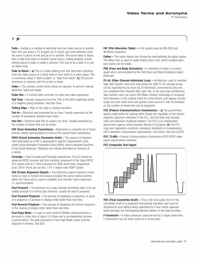
FCC (Federal Communications Commission) – a) The governmentagency responsible for (among other things) the regulation of the electro-magnetic spectrum utilization in the U.S., and the body that licenses radio and television broadcast stations. The FCC is an independent government agency, which answers directly to Congress. b) The FCC rules and regulations constitute mandatory standards for broadcasters,CATV operators, transmission organizations, and others. See also ACATS.
FCC 73.699 – Federal Communications Commission (FCC) NTSC video signal specifications standard.
FCC Composite Test Signal
FDC (Final Committee Draft) – This is the final public form of theCommittee Draft of a proposed international standard, and must be identified as such before being submitted for a four-month approval ballot amongst the Participating Member Bodies of the Subcommittee.
F-Connector – A video connector characterized by a single metal wire.F-connectors may be either push-on or screw-post.
F
90 www.tektronix.com/video_audio909090
Video Terms and AcronymsGlossary
FDDI (Fiber Distributed Data Interface) – Standards for a 100 Mbpslocal area network, based upon fiber optic or wired media configured asdual counter rotating token rings. This configuration provides a high level of fault tolerance by creating multiple connection paths between nodes,connections can be established even if a ring is broken.
FDIS (Final Draft International Standard) – This is the final form of aproposed standard before it is adopted as an International Standard. Anapproved Final Committee Draft, modified as necessary to accommodatecomments submitted by National Bodies during, or after, the approval ballot, must first be registered as a Final Draft International Standard,and then submitted to a two-month letter ballot amongst ParticipatingMember Bodies of JTC1.
FDM (Frequency Division Multiplex) – A technology that transmits multiple signals simultaneously over a single transmission path, such as a cable or wireless system. Each signal travels within its own uniquefrequency range (carrier), which is modulated by the data (text, voice,video, etc.).
FDP (Facial Definition Parameters)
Feathering – A tool that tapers the values around edges of binary alphamask for composition with the background.
Feature Connector – An expansion connector on the VGA that can acceptor drive video signals to or from the VGA. This is used in applicationsinvolving video overlay. This is also called VESA Pass-Through Connector.
FEC (Forward Error Correction) – a) A system in which redundancy is added to the message so that errors can be corrected dynamically at the receiver. b) Error control bits added to useful data in the QAM/QPSKmodulator.
Feed – The transmission of a video signal from point to point.
Feed Reel – Also called “stock”, “supply” or “storage” reel. The reel on atape recorder from which tape unwinds as the machine records or plays.
Feedback – a) Information from one or more outputs to be used as inputsin a control loop. b) A loop caused by audio or video signal being fed backinto itself. In video the effect is caused when a camera is directed at itsreceiving monitor. In audio the effect, manifested as an echo or squeal,is caused when a microphone is aimed at a speaker. c) A loud squeal or howl caused when the sound from a loudspeaker is picked up by a nearbymicrophone and reamplified. Also caused when the output of a taperecorder is fed back into the record circuit.
Female Connector – A connector that has indentations or holes intowhich you plug a male connector. An example of a female connector is anelectrical wall outlet that accepts and electrical plug.
Ferrichrome – A relatively recent word describing the technique of dualcoating with both a layer of gamma ferric oxide and a layer of chromiumdioxide. An intermediate level bias position used only for ferrichrome tapes.
Fetch – Reading an instruction from memory.
FF – See Full Field.
FFT (Fast Fourier Transform) – A mathematical means of convertingtime domain information to frequency domain information.
FGS (Fine Grain Scalability) – A tool that allows small quality steps by adding or deleting layers of extra information. It is useful in a number of environments, notably for streaming purposes but also for dynamic (statistical) multiplexing of pre-encoded content in broadcast environments.
FH – Line frequency (horizontal) 15,734 lines/sec Hz for NTSC (525 lines x 29.97 Hz).
Fiber Bundle – A group of parallel optical fibers contained within a common jacket. A bundle may contain from just a few to several hundredfibers.
Fiber Channel – See Fibre Channel.
Fiber Optics – See Optical Fiber.
Fiber-Optic Cable – “Wires” made of glass fiber used to transmit video,audio, voice or data providing vastly wider bandwidth than standard coaxialcable.
Fibre Channel – A high speed data link planned to run up to 2 Gbps on afiber optic cable. A number of manufacturers are developing products toutilize the Fiber Channel-Arbitrated Loop (FC-AL) serial storage interface at 1 Gbps so that storage devices such as hard disks can be connected.Supports signaling rates from 132.8 Mbps to 1,062.5 Mbps, over a mix-ture of physical media including optical fiber, video coax, miniature coax,and shielded twisted pair wiring. The standard supports data transmissionand framing protocols for the most popular channel and network standardsincluding SCSI, HIPPI, Ethernet, Internet Protocol, and ATM.
Field – a) In interlaced scan systems, the information for one picture isdivided up into two fields. Each field contains one-half of the lines requiredto produce the entire picture. Adjacent lines in the picture are in alternatefields. b) Half of the horizontal lines (262.5 in NTSC and 312.5 in PAL)needed to create a complete picture. c) One complete vertical scan of animage. In a progressive scanning system, all of the scanning lines compris-ing a frame also comprise a field. d) An area in a window in which you can type text. e) A television picture is produced by scanning the TV screenwith an electron beam. One complete scan of the screen is called a field.Two fields are required to make a complete picture, which is called aframe. The duration of a field is approximately 1/60 of a second in NTSCand 1/50 or 1/60 of a second in PAL. f) One half of a complete interlacedvideo picture (frame), containing all the odd or even scanning lines of the picture.
Field Alias – An alias caused by interlaced scanning. See also InterlaceArtifacts.
Field Blanking – Refers to the part of the signal at the end of each fieldthat make the vertical retrace invisible. Also called vertical blanking.
Field DCT Coding – Discrete cosine transform coding is where everyblock consists of lines from one field. The chrominance blocks in the 4:2:0 format must never be coded by using field DCT coding, but it is allowed to use field based prediction for this type of block.
Field Dominance – When a CAV laserdisc is placed in the still framemode, it continuously plays back two adjacent fields of information. Thereare no rules in the NTSC system stating that a complete video picture hasto start on field 1 or field 2. Most of the video in this program is field 1dominant. There are two sections of the disc that are field 2 dominant. In

Video Terms and AcronymsGlossary
www.tektronix.com/video_audio 91
the case of film translated to video, the start of a complete film picturechanges from field 1 to field 2 about 6 times a second. There is a code inthe vertical interval of the disc that tells the player on which field it canstart displaying each of the disc’s still frames.
Field Frequency – The rate at which one complete field is scanned,normally 59.94 time a second in NTSC or 50 times a second in PAL.
Field Period – The reciprocal of twice the frame rate.
Field Picture – A picture in which the two fields in a frame are codedindependently. Field pictures always come in sets of two fields, which arecalled top field and bottom field, respectively. When the first field is codedas a P- or a B-picture, the second picture must be coded in the samemanner; however, if the first field is coded as an I-picture, the second fieldmay be coded as either an I-picture or a P-picture (that is predicted fromthe first field).
Field Rate – Number of fields per second.
Field Time Linear Distortions – Distortions involve signals in the 64µsec to 16 msec range. Field time distortions cause field-rate tilt in videosignals. The error is expressed in IRE or as a percentage of a referenceamplitude which is generally the amplitude at the center of the line bar.
These distortions will cause top to bottom brightness inaccuracies in largeobjects in the picture. These distortions can be measured with either awindow signal or a field square wave. See Linear Distortions.
Field Time Waveform Distortions – See Field Time Linear Distortions.
Field, Depth of – a) The range of distance in subject space within whicha lens (or a system) provides an image that reproduces detail with anacceptably small circle of confusion (acceptable focus) usually smallenough for subjective evaluation as a “point”, defines the depth of field.Tables are calculated for lenses as a function of optical aperture and thesubject distance at which they are focused. Regrettably, these calculationsare strictly geometric (ignoring the possibility of diffraction effects, of alloptical aberrations, and of possible differing contributions to focal lengthfrom different annuli of the optical system). Thus, the tables are at timesoverly optimistic. b) Depth of field for a given imaging system decreaseswith increasing optical aperture of that system, and decreases as the distance to the subject decreases. A “maximum acceptable” diameter for
the “circle of confusion” may depend upon the resolution capabilities of the light-sensitive receptor (electronic or photographic) and of the systemwithin which it is functioning. Quantitative measurements for actual imaging systems may be made on an optical bench. Practical determina-tions are made from subjective examination of the actual images in thesystem of interest.
FIFO (First-In-First-Out) – a) A memory structure in which data isentered at one end and removed from the other. A FIFO is used as a bufferto connect two devices that operate asynchronously. b) A storage device(parallel shift register) which operates as a Turing machine to buffer asynchronous data where the first data stored is the first data read out.FIFOs are used to store video and act as “rubber-band” type buffers tokeep a steady video stream where memory and system clock speeds donot match. FIFOs have less delays than standard shift registers as inputand output are controlled by separate clocks.
FIG (Facial Animation Parameters Interpolation Graph)
Figure-8 Microphone – A microphone (usually a ribbon type) whose sensitivity is greatest to front and rear, and weakest to both sides.
File – A container in which you store information such as text, programs,or images.
File Set – A collection of files and directories.
File System – A hierarchy of directories and files. Directories containother directories and files; files cannot contain directories. The root (/)directory is at the top of the hierarchy. See also Format.
Fill – The video information that replaces a “hole” (video information) cutin the video picture by the key signal.
Fill (Insert) Video – A video signal which replaces a “hole” (video infor-mation) cut in background video by a key source.
Fill Bus – A separate bus or buses from which fill videos can be selectedindependently from the key source cutting the hole.
Fill Light – Fill lights, commonly referred to as “scoops”, provide a soft-edged field of light used to provide additional subject illumination toreduce harsh shadows or areas not highlighted by the key light.
Filled Clip – A segment of a sequence that contains no audio or videoinformation. Filler can be added to the source monitor (or pop-up monitor)and edited into a sequence. See also Filler Proxy.
Filled Key – A key effect in which the key source image is different fromthe foreground image. Areas not keyed (that is, not made transparent) inthe key source image are filled with the corresponding areas of the fore-ground image.
Filler Proxy – The result of a composition specifying media to be playedfor the filler clips in each track.
Film Chain – a) Projectors, multiplexers and cameras, connected for thepurpose of transferring film to video. b) A device that transfers a filmimage to a video image. It is also know as a Telecine chain.
Film Loop – A piece of file, quite short, which is to be played repeatedly.
Top of Line Bar
Field Bar
0.2 ms 0.2 ms
a
FD = a
a in % of RA
92 www.tektronix.com/video_audio929292
Video Terms and AcronymsGlossary
Film Recorder – A device for converting digital data into film output.Continuous tone recorders produce color photographs as transparencies,prints or negatives.
Film Timecode – Timecode added to the film negative during the filmshoot via a film timecode generator. Film timecode numbers are synced tothe film key numbers on the dailies during the telecine transfer process. Aspecial key link reader is required for viewing the film timecode.
Filter – A device used to remove or pass certain frequencies from a signal. Low pass filters pass the low frequency content of a signal whilehigh pass filters pass the high frequency content. A bandpass filter passesfrequencies within a certain “band”.
Filter Artifacts – Distortions introduced by filters. The most common visual artifacts introduced by filters are reduced resolution and ringing.
Filter, Brick Wall – A low-pass filter with a steep cut-off (such as 20dB/octave or greater), such that a negligible amount of higher frequencyinformation passes. The filter typically has uniform group delay.
Filter, Gaussian – A low-pass filter providing a gradual attenuation of the higher frequencies. Strictly the attenuation should follow the curveV=e^(-af^2). But the term is also applied to attenuation functions that only qualitatively resemble the precise power function.
Filter, Optical – In addition to the familiar optical filters for modifyingspectral energy distribution, and thereby color rendition, optical filters arealso produced as low-pass filters for spatial detail in an optical image,eliminating high-frequency information that would exceed the Nyquist limitof the system and produce excessive aliasing. Many of these filters are cut from optically birefringent crystals and function by providing multipleimages slightly displaced one form another so that fine detail is blurred(i.e., low-pass filtered).
Filterbank – A set of bandpass filters covering the entire media frequencyrange.
Filtering – A process used in both analog and digital image processing to reduce bandwidth. Filters can be designed to remove information con-tent such as high or low frequencies, for example, or to average adjacentpixels, creating a new value from two or more pixels.
Finite Impulse Response Filter (FIR) – A digital filter that is in general,better than analog filters but also more complex and expensive. Some specialized filter functions can only be accomplished using a FIR.
FIP (Forward Interaction Path)
FIR – See Finite Impulse Response Filter.
FireWire (IEEE P1394) – FireWire is a special high-speed bus standardcapable of over 100 megabits/sec sustained data rate.
Firmware – Program stored in ROM. Normally, firmware designates anyROM-implemented program.
First Play PGC – This Program Chain (PGC) is described in the VideoManager Information table, and has no corresponding video objects (VOB).The First Play PGC is executed at initial access, e.g. just after disc loading.
First-Frame Analysis – A transparency technique wherein the first frameof the video file is a dummy frame that supplies the color or range of col-ors to be rendered as transparent: the color of the chroma-key back-ground, for example. See Transparency, Transparency Frame.
Fit to Fill – An insert edit where an incoming source clip replaces anexisting segment (or gap) in the record clip. A fit to fill edit functions like aswap shot edit except that the edit sequence does not ripple. If the sourceclip has a different length than the segment it replaces, the source clip isshortened or lengthened proportionally to fit the duration of the replacedsegment.
FITS (Functional Interpolating Transformation System) – A formatthat contains all data used to design and assemble extremely large files ina small, efficient mathematical structure.
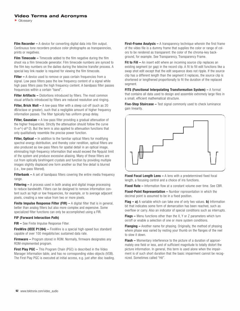
Five-Step Staircase – Test signal commonly used to check luminancegain linearity.
Fixed Focal Length Lens – A lens with a predetermined fixed focallength, a focusing control and a choice of iris functions.
Fixed Rate – Information flow at a constant volume over time. See CBR.
Fixed-Point Representation – Number representation in which the decimal point is assumed to be in a fixed position.
Flag – a) A variable which can take one of only two values. b) Informationbit that indicates some form of demarcation has been reached, such asoverflow or carry. Also an indicator of special conditions such as interrupts.
Flags – Menu functions other than the X, Y or Z parameters which turnon/off or enable a selection of one or more system conditions.
Flanging – Another name for phasing. Originally, the method of phasingwhere phase was varied by resting your thumb on the flanges of the reel to slow it down.
Flash – Momentary interference to the picture of a duration of approxi-mately one field or less, and of sufficient magnitude to totally distort thepicture information. In general, this term is used alone when the impair-ment is of such short duration that the basic impairment cannot be recog-nized. Sometimes called “Hit”.

Video Terms and AcronymsGlossary
www.tektronix.com/video_audio 93
Flash Analog to Digital Converter – A high speed digitizing devicebased on a bank of analog comparators. The analog value to be digitized isthe input to one side of the comparators bank. The other comparators inputis tied to a tap of a resistor ladder, with each comparator tied to its owntap. The input voltage at each comparators will be somewhere between thetop and bottom voltages of the resistor ladder. The comparators output a high or a low based on the comparison of the input voltage to the resistor ladder voltage. This string of 1s and 0s are converted to the binary number.
Flash Frame – After a long, complex piece is edited, small bits of videomight be accidentally left in a sequence. When the Timeline is zoomed to100 percent, these small, unwanted, pieces might not be visible. An editorcan find these bits using the Find Flash Frame command.
Flash Memory – Nonvolatile, digital storage. Flash memory has sloweraccess than SRAM or DRAM.
FlashPix – A multi-resolution image format in which the image is storedas a series of independent arrays. Developed by Kodak, Hewlett-Packard,Live Picture, Inc. and Microsoft and introduced in June 1996.
Flat Field – As used herein, the entire area viewed by a television camerawith the viewed area being uniformly white or any single specified color orany shade of gray.
Flat Shading – A polygon rendered so that its interior pixels are all thesame color has been rendered with “flat” shading. An object representedby polygons that is rendered with flat shading will look distinctly faceted.No highlights or reflections are visible.
Flatten – The process of converting a Macintosh file into a self-contained,single-forked file so that it is compatible with Windows environment. SeeSelf-Contained, Single-Forked.
Flexibility Layer – The MPEG-4 Systems Layer that specifies how someparts of the MPEG-4 terminal can be configured or downloaded. Twomodes are identified in this layer, the non-flexible mode and the flexiblemode.
Flexible Mode – The configuration of an MPEG-4 terminal in which thecapability to alter parameters or algorithms for the processing of audio-visual objects is achieved by the transmission of new classes or scripts.
FlexMux Channel (FMC) – A label to differentiate between data belonging to different constituent streams within one FlexMux stream.
FlexMux Entity – An instance of the MPEG-4 system resource thatprocesses FlexMux Protocol Data Units (PDUs) associated to one FlexMuxstream.
FlexMux Layer (FML) – A logical MPEG-4 Systems Layer between theElementary Stream Layer and the TransMux Layer used to interleave one ormore elementary streams, packetized in Adaption Layer protocol data unit,into one FlexMux stream.
FlexMux Packet – The smallest data entity managed by the FlexMux toolconsisting of a header and a payload
FlexMux Protocol Data Unit (FlexMux-PDU) – The smallest protocolunit of a FlexMux stream exchanged between peer FlexMux entities. It con-sists of FlexMux-PDU Header and FlexMux-PDU Payload. It carries datafrom one or more FlexMux channel(s).
FlexMux Protocol Data Unit Header (FlexMux-PDU Header) –Information preceding the FlexMux-PDU payload. It identifies the FlexMuxchannel(s) to which the payload of this FlexMux-PDU belongs.
FlexMux Stream – A sequence of FlexMux packets associated with one ormore FlexMux channels flowing through one TransMux channel.
Flicker – a) Flicker occurs when the refresh rate of the video is too lowand the light level on the display begins to decrease before new informa-tion is written to the screen to maintain the light level. To prevent thehuman eye from seeing flicker, the screen refresh rate needs to be at least24 frames per second. b) A rapid visible change in brightness, not part ofthe original scene. See also Flicker Frequency, Fusion Frequency, Judder,Large-Area Flicker, and Twitter.
Flicker Filter – Video data from a VGA is not interlaced. This data must be converted into interlaced format for display on a TV. If every second lineis discarded of the non-interlaced data, flicker may occur if, for example,video information is contained in just one noninterlaced line. Flicker willalso be perceptible at the top and bottom of multilane objects. A flicker filter overcomes these problems in computing a weighted average of two or three adjacent lines (noninterlaced) for each line of output (interlaced).
Flicker Frequency – The minimum rate of change of brightness at whichflicker is no longer visible. The flicker frequency increases with brightnessand with the amount of the visual field being stimulated. In a recent study,a still image flashed on and off for equal amounts of time was found tohave a flicker frequency of 60 flashes per second at a brightness of 40foot lamberts (fL) and 70 at 500. Television sets generally range around100 fL in peak brightness (though some new ones claim over 700). TheSMPTE recommends 16 fL for movie theater screens (though this is meas-ured without film, which reduces the actual scene brightness by at least 50 percent). One reason for interlaced scanning is to increase television’sflashing pictures to the flicker frequency, without increasing bandwidth.
Flip – Special effect in which the picture is either horizontally or verticallyreversed.
Floating – Logic node that has no active outputs. Three-state bus lines,such as data bus lines, float when no devices are enabled.
Floating-Point Representation – Technique used to represent a largerange of numbers, using a mantissa and an exponent. The precision of therepresentation is limited by the number of bits allocated to the mantissa.See Mantissa and Exponent.
Floppy Disk – Mass-storage device that uses a flexible (floppy) diskette torecord information. See Disk.
Flowchart or Flow Diagram – Graphical representation of program logic.Flowcharts enable the designer to visualize a procedure. A complete flow-chart leads directly to the final code.
FLSD (Fixed Linear Spline Data) – The different modes used to animatea value, for example, position, color, or rotation.
Fluid Head – Refers to a tripod mount that contains lubricating fluid whichdecreases friction and enables smooth camera movement.
Flutter – Distortion which occurs in sound reproduction as a result ofundesired speed variations during recording or reproducing. Flutter occurring at frequencies below approximately 6 Hz is termed “wow”.
94 www.tektronix.com/video_audio949494
Video Terms and AcronymsGlossary
Flux – Magnetic field generated by a record head, stored on magnetictape, and picked up by the playback head. Also the magnetic field thatexists between the poles of a magnet.
Flux Transition – A 180 degree change in the flux pattern of a magneticmedium brought about by the reversal of the magnetic poles within themedium.
Flux Transition Density – Number of flux transitions per track lengthunit.
Fly-Back – See Horizontal Retrace.
Flying Erase Head – The erase head mounted on the spinning (flying) videohead drum. Facilitates smooth, seamless edits whenever the camcorderrecording begins. Without a flying erase head, a video “glitch” may occur atscene transitions.
Flying Head – A video head that engages when the video deck is on“pause”, providing a clear still-frame image.
Fly-Through – A fly-through is a type of animation where a movingobserver flies through a seemingly stationary world.
FM – See Frequency Modulation.
FM Recording – The data signal is used to modulate the frequency of a“carrier” having a frequency much higher than any spectral component ofthe data signal. Permits the recording of DC or very low signal frequencies.
FM-FM – Dual carrier FM coded discrete stereo transmissions, analogue.Can be used for bi-lingual operation under user selection, but no auto-selection is available. Audio characteristics better than standard monosoundtrack.
FMV – See Full Motion Video.
F-Number – In lenses with adjustable irises, the maximum iris opening is expressed as a ratio (focal length of the lens)/(maximum diameter ofaperture). This maximum iris will be engraved on the front ring of the lens.
Focal Length – The distance between the secondary principal point in thelens and the plane of the imaging device. The longer the focal length, thenarrower is the angle of view.
Focus – Adjustment made to the focal length of the lens, designed to create a sharper, more defined picture.
Focusing Control – A means of adjusting the lens to allow objects at various distances from the camera to be sharply defined.
Foldover – Tape that has folded over resulting in the oxide surface facingaway from the heads.
Foley – Background sounds added during audio sweetening to heightenrealism, e.g. footsteps, bird calls, heavy breathing, short gasps, etc.
Following (or Trailing) Blacks – A term used to describe a picture condition in which the edge following a white object is overshaded towardblack. The object appears to have a trailing black border. Also called “trailing reversal”.
Following (or Trailing) Whites – A term used to describe a picture condition in which the edge following a black or dark gray object is over-shaded toward white. The object appears to have a trailing white border.Also called “trailing reversal”.
Font – A style of type. Many character generators offer the user a menu ofseveral fonts.
Foot Candles – A measure of the amount of light falling on an object (itsillumination). This is a measure only of the light energy that can be seen bythe human eye (becoming an obsolete unit; replaced by the Lux).
1 foot candle = 1 lumen per square foot
Foot Lamberts – A measurement of the brightness of an object. If 100foot candles are illuminating a 60% white chip, then its brightness will be60 foot lamberts, regardless of viewing distance. Again, remember thatbrightness is measured over the same energy response of a human eye(becoming obsolete unit; replaced by the Nit).
Footage Encoder Time Code Generator – An electronic device whichtakes the input from a reader of keycode numbers, decodes this informa-tion and correlates the numbers with the SMPTE time code it generates.These data, along with 3:2 pull-down status of the transfer, footage count,and audio time code (if applicable) are made available for window burn-ins,VITC-LTC recording and output to a computer.
Foot-Candela – An illumination light unit used mostly in American CCTVterminology. It equals ten times (more precisely, 9.29) of the illuminationvalue in luxes.
Footprint – Area on earth within which a satellite’s signal can bereceived.
Forbidden – The term forbidden when used in the clauses defining thecoded bit stream indicates that the value shall never be used. This is usually to avoid emulation of start codes.
Forbidden Value – An excluded value in the coded bit stream. A valuethat is not allowed to appear in the bit stream.
Forced Activation Button – Menu buttons that automatically perform thespecified action as soon as the button has been highlighted on the menu.
Forced Display – A DVD feature that forces the display of a sub-pictureregardless of whether or not the user wanted the sub-picture to be dis-played. This would be used, for instance, in an English movie in whichthere were non-English words spoken and it was desired that a translationbe provided even if the subtitle system was turned off.
Forced Selected Button – Menu button that is automatically selectedwhen the menu is displayed.
Forced Updating – a) The process by which macroblocks are intra codedfrom time-to-time to ensure that mismatch errors between the inverse DCT processes in encoders and decoders cannot build up excessively.b) The recurrent use of I-coding to avoid build-up of errors between theinverse DCT processes in encoders and decoders.
Foreground (FGND) – May be thought of as the front layer of video in a picture. Also used to describe the insert video (on 4100 series) of a key.
Form – A window that contains buttons that you must click and/or editablefields that you must fill in.
Format – a) The configuration of signals used for interconnecting equip-ment in a specified system. Different formats may use different signalcomposition, reference pulses, etc. A variety of formats are used to record video. They vary by tape width (8 mm, 1/2”, 3/4”, 1”), signal form

Video Terms and AcronymsGlossary
www.tektronix.com/video_audio 95
(composite, Y/C, component), data storage type (analog or digital) and signal standard (PAL, NTSC, SECAM). b) For data storage media (harddisks, floppies, etc.), the process of initializing the media prior to use.Formatting effectively deletes any data that was previously on the media.See Format Disk.
Format Conversion – The process of both encoding/decoding and resam-pling of digital rates to change a digital signal from one format to another.
Format Converter – A device that allows the reformatting of a digital datastream originating from one sampling structure (lines per frame, pixels per line) into a digital data stream of another sampling structure for thepurposes of recording or passing the original data stream through distribu-tion devices designed to accommodate the latter structure. Since the datastill represents the original sampling structure, this is not the same asstandards conversion.
Format Disk – The process of preparing a disk for data storage by deter-mining where data is to be placed and how it is to be arranged on disk.
Formatting – The transfer and editing of material to form a complete program, including any of the following: countdown, test patterns, bars and tone, titles, credits, logos, space for commercial, and so forth.
Forward Compatibility – A decoder is able to decode a bit stream coming from an encoder of a previous generation. A new coding standardis forward compatible with an existing coding standard if new decoders(designed to operate with the new coding standard) continue to be able todecode bit streams of the existing coding standard.
Forward Motion Vector – Information that is used for motion compensa-tion from a reference picture at an earlier time in display order.
Forward Prediction – Prediction from the past reference vop. SeeBidirectional Prediction.
Fourier Transformation – Mathematical transformation of time domainfunctions into frequency domain.
Four-Track or Quarter-Track Recoding – The arrangement by whichfour difference channels of sound may be recorded on quarter-inch-wideaudio tape. These may be recorded as four separate and distinct tracks(monophonic) or two stereo pairs of tracks. Tracks 1 and 3 are recorded in the “forward” direction of a given reel, and Tracks 2 and 4 are recordedin the “reverse” direction.
FP (Fixed Part)
FPGA (Field-Programmable Gate Array) – A programmable logic chip(PLD) with a high density of gates. Containing up to hundreds of thousandsof gates, there are a variety of architectures. Some are very sophisticated,including not only programmable logic blocks, but programmable intercon-nects and switches between the blocks. FPGAs are mostly reprogrammable(EEPROM or flash based) or dynamic (RAM based). See also PLD.
FPLL (Frequency- and Phase-Locked Loop)
FPS (Frames Per Second) – A measure of the film or video display rates.Film is 24 FPS, NTSE is 30 FPS, PAL/SECAM is 25 FPS.
Fractals – Mathematically generated descriptions (images) which look likethe complex patterns found in nature (e.g., the shoreline and topographicelevations of a land mass as seen from an aerial photograph). The keyproperty of fractal is self-similarity over different domain regions.
Fractional Compression – A global compression method that exploitshighly correlated data in an image. It is resolution-independent.
Fractional T1 – Part of the bandwidth of a T1 system.
Fragile Watermark – A watermark designed to be destroyed by any formof copying or encoding other than a bit-for-bit digital copy. Absence of thewatermark indicates that a copy has been made.
Fragmentation – The scattering of data over a disk caused by successiverecording and deletion operations. Generally this will eventually result inslow data recall, a situation that is not acceptable for video recording orreplay. The slowing is caused by the increased time needed to randomlyaccess data. With such stores, defragmentation routines arrange the data(by copying from one part of the disk to another) so that it is accessible in the required order for replay. Clearly any change in replay, be it a transmission running order or the revision of an edit, could require furtherdefragmentation. True random access disk stores, able to play frames inany order at video rate, never need defragmentation.
Frame – a) A frame consists of all the information required for a completepicture. For interlaced scan systems, there are two fields in a frame.For progressive video, these lines contain samples starting from one timeinstant and continuing through successive lines to the bottom of the frame.b) A complete picture composed of two fields. In the NTSC system, 525interlaced horizontal lines of picture information in 29.97 frames per second. In the PAL system, 625 interlaced horizontal lines of picture infor-mation in 25 frames per second. c) The metal cabinet which contains the switcher’s circuit boards. d) One complete video image, containing two fields. There are 30 frames in one second of NTSC video.
Frame Accurate – The importance of specific edits as compared to theability to start, stop and search for specific frames of video. Frame accu-rate editing requires the use of a timecode system.
Frame Buffer – a) A block of digital memory capable of buffering a frameof video. The amount of memory required for a frame buffer is based onthe video being stored. For example to store a 640 x 480 image using theRGB color space with eight bits per color, the amount of memory requiredwould be: 640 x 480 x 3 = 921,600 bytes. b) A frame buffer is a digitalframe store, containing a large chunk of memory dedicated to pixel memo-ry, at least one complete frame’s worth. All the pixels in the buffer have thesame depth. Each bit of depth is called a bit plane. Frame buffers can usethe bit planes in a variety of ways. First, a pixel’s bits can store the RGBvalues of colors. This simple method is called full-color mode. In full-colormode, it is common to refer to the red plane, or the blue or green plane,meaning the bits reserved for specifying the RGB components of the pixel.Full-color systems may also have an alpha channel, which encodes thetransparency of each bit. The alpha channel is like a matte or key of theimage. Alternately, the bits can store a color number, which selects thefinal color from a color map. Finally, some bit planes may be reserved foruse as overlay planes.
Frame Capture (Frame Grabber) – Taking one frame of video and storing it on a hard drive for use in various video effects.
Frame DCT Coding – Frame DCT coding is where the complete frame ofthe image is coded as a set of DCT blocks. In the case of interlace signals,the fields are combined together and then coded as a single entity.

96
Frame Doubler – A video processor that increases the frame rate (display rate) in order to create a smoother-looking video display. Compareto line doubler.
Frame Frequency – The rate at which a complete frame is scanned,nominally 30 frames per second.
Frame Grabber – a) A device that enables the real-time capture of a single frame of video. The frame is captured within a temporary buffer for manipulation or conversion to specified file format. The buffers of some frame grabbers are large enough to store several complete frames,enabling the rapid capture of many images. A frame grabber differs from a digitizer in that a digitizer captures complete sequential frames, so itmust use compression or acceleration or both to capture in real-time.b) A device that “captures” and potentially stores one complete videoframe. Also known as Frame Storer.
Frame Offset – A way of indicating a particular frame within the group offrames identified by the edge number on a piece of film. For example, aframe offset of +12 indicates the twelfth frame from the frame marked bythe edgecode.
Frame Period – The reciprocal of the frame rate.
Frame Picture – A picture in which the two fields in a frame are merged(interlaced) into one picture which is then coded.
Frame Pulse – A pulse superimposed on the control track signal. Framepulses are used to identify video track locations containing vertical syncpulses.
Frame Rate – a) The rate at which frames of video data are scanned onthe screen. In an (M) NTSC system, the frame rate is 29.97 frames persecond. For (B, D, G, H, I) PAL, the frame rate is 25 frames per second.b) The number of frames per second at which a video clip is displayed.c) The rate at which frames are output from a video decoding device orstored in memory. The NTSC frame rate is 30 frames/second while somegraphics frame rates are as high as 100 frames/second.
Frame Rate Conversion – The process of converting one frame rate toanother. Examples include converting the (M) NTSC frame of 29.97 framesper second to the PAL frame rate of 25 frames per second.
Frame Relay – A network interface protocol defined by CCITTRecommendation I.122 as a packet mode service. In effect it combines thestatistical multiplexing and port sharing of X.25 packed switching with thehigh speed and low delay of time division multiplexing and circuit switch-ing. Unlike X.25, frame relay implements no layer 3 protocols and only theso-called core layer 2 functions. It is a high-speed switching technologythat achieves ten times the packet throughput of existing X.25 networks byeliminating two-thirds of the X.25 protocol complexity. The basic units ofinformation transferred are variable length frames, using only two bytes for header information. Delay for frame relay is lower than X.25, but it isvariable and larger than that experienced in circuit switched networks.
Frame Roll – A momentary vertical roll.
Frame Store – a) Term used for a digital full-frame temporary storagedevice with memory for only one frame of video. b) An electronic devicethat digitizes a TV frame (or TV field) of a video signal and stores it inmemory. Multiplexers, fast scan transmitters, quad compressors and evensome of the latest color cameras have built-in frame stores.
Frame Store Synchronizer – A full-frame synchronizer used by a timebase corrector with full-frame memory and can be used to synchronize two video sources.
Frame Switcher – Another name for a simple multiplexer, which canrecord multiple cameras on a single VCR (and play back any camera in full screen) but does not have a mosaic image display.
Frame Synchronizer – A digital buffer, that by storage, comparison ofsync information to a reference, and time release of video signals, cancontinuously adjust the signal for any timing errors. A digital electronicdevice which synchronizes two or more video signals. The frame synchro-nizer uses one of its inputs as a reference and genlocks the other videosignals to the reference’s sync and color burst signals. By delaying theother signals so that each line and field starts at the same time, two or more video images can be blended, wiped and otherwise processedtogether. A TBC (Time Base Controller) takes this a step further by synchronizing both signals to a stable reference, eliminating time baseerrors from both sources. The Digital Video Mixer includes a frame synchronizer and dual TBCs.
Frame Transfer (FT) – Refers to one of the three principles of chargetransfer in CCD chips. The other two are interline and frame-interline transfer.
Frame-Based 2D Animation – A two-dimensional animation technique in which an object is moved from one position, size, and color to another.Adobe After Effects, for example, uses keyframes to create frame-based2D animation. One of the two main types of animation associated with digital video. Compare Cell Animation.
Frame-Interline Transfer (FIT) – Refers to one of the few principles of charge transfer in CCD chips. The other two are interline and frametransfer.
Framing – For multiplexed digital channels, framing is used as a controlprocedure. The receiver can identify time slots of the subchannels by theframing bits that were added in generating the bitstream.
Framing Tool – One of the tools of the Protection Layer used to segmentthe content of the LP-SDU in elements of a given length that can be variable.
Franchise – An agreement between a CATV operator and the governingcable authority. A franchise agreement is essentially a license to operate.
Franchising Authority – Governmental body (city, county, or state)responsible for awarding and overseeing cable franchises. In New Jersey,the Local Franchising Authority is the Board of Public Utilities (BPU).
Free-Run – Process of allowing a digital circuit (typically a microproces-sor) to run without feedback (open-loop). This is done to stimulate otherdevices in the circuit in a recurring and predictable manner.
Video Terms and AcronymsGlossary
www.tektronix.com/video_audio

Freeze Frame – Special effect in which the picture is held as a stillimage. It is possible to freeze either one field or a whole frame. Freezingone field provides a more stable image if the subject is moving, however,the resolution of the video image is half that of a full frame freeze. Digitalfreeze frame is one special effect that could be created with a specialeffects generator or a TBC (Time Base Controller). The Digital Video Mixerincludes this feature.
French Proposals – Three HDEP proposals, two closely related, suggest-ed by a number of French organizations. For countries with a field rate of50 field per second, there would be 1200 scanning lines, 1150 of themactive. For countries with a field rate of 59.94 fields per second, therewould be 1001 scanning lines, 970 of them active. Both systems wouldhave identical line rates (60,000 lines per second) and bandwidths (65MHz luminance), and would be progressively scanned. This correspondencewould allow a great deal of common equipment, as Recommendation 601does for digital component video. The third proposal is for a worldwidestandard based on 1050 scanning lines (970 active), 2:1 interlace, and100 field per second.
Frequency – The number of cycles a signal that occurs per second, meas-ured in hertz (repetition rate. In electronics, almost invariably the number oftimes a signal changes from positive to negative (or vice versa) per second.Only very simple signals (sine waves) have a single constant frequency; the concept of instantaneous frequency therefore applies to any transition,the frequency said to be the frequency that a sine wave making the sametransition would have. Images have spatial frequencies, the number oftransitions from dark to light (or vice versa) across an image, or per degreeof visual field.
Frequency Allocation Table – List of which frequencies can be used for transmission of different signals in the U.S. It may require revision for certain ATV (Advanced TV) schemes. A similar function is performed internationally by the International Frequency Registration Board (IFRB),like the CCIR, part of the International Telecommunications Union.
Frequency Domain – A concept that permits continuous functions in the space or time domain to be mapped into a representation with linear properties in frequency coordinates. It benefits the application of mathe-matical functions. For example, spectrum analysis can be performed on the sampled signal.
Frequency Interleaving – The process by which color and brightness signals are combined in NTSC.
Frequency Modulation – a) Modulation of sine wave or “carrier” by vary-ing its frequency in accordance with amplitude variations of the modulatingsignal. b) Also referring to the North American audio service broadcast over88 MHz-108 MHz.
Frequency Multiplex – See Multiplex.
Frequency Response – The range of frequencies that a piece of equip-ment can process and is directly related to the system’s ability to uniformlytransfer signal components of different frequencies over the entire videospectrum without affecting their amplitudes. This parameter is also knownas gain/frequency distortion or amplitude versus frequency response. Theamplitude variation maybe expressed in dB, percent or IRE. The referenceamplitude (0 dB, 100%) is typically the white bar or some low frequency
signal component. Frequency response numbers are only meaningful ifthey contain three pieces of information: the measured amplitude, the fre-quency at which the measurement was made and the reference frequency.There are a number of test signals that can be used including multiburst,multipulse, a swept signal or sin (x)/x.
Frequency Response Curve – The curve relating the variation in outputwith frequency of a piece of equipment or magnetic tape when the input iskept constant.
Frequency Response Rolloff – A distortion in a transmission systemwhere the higher frequency components are not conveyed at their originalfull amplitude. In video systems, this causes loss of color saturation.
Frequency Synthesizer – An electronic circuit that generates a numberof frequencies from a fixed-reference frequency. Some frequency synthe-sizers generate only a relatively small number of frequencies; others generate hundreds of different frequencies.
Fringing – The pickup of extra bass frequency signals by a playback head when reproducing a signal recorded by a head with a wider trackconfiguration, such as playing a full track tape with a half-track head.
From Source – VTR or other device that is generating the video/audio signal that is being dissolved or wiped away from.
Front Porch – The portion of the video signal between the end of activepicture time and the leading edge of horizontal sync. See Horizontal Timing.
Front-to-Back Ratio – The ratio between a cardioid microphone’s sensitivity to sounds arriving from the front and from the rear, a measure of its directionality.
FSM (Finite States Machine) – A finite states machine is a markoviansource, meaning that the evolution after the time t depends only on themachine state at the time t and the future inputs. Particularly, the evolutiondoesn’t depend on the sequence that brought the machine in its currentstate.
FSS (Fixed Satellite Services) – Provides point-to-point and point-to-multi-point satellite communications of voice, data and video between fixed or stabilized earth stations. Major providers of space segment include INTELSAT, PanAmSat Corporation, EUTELSAT, Telesat Canada and GE Americom Communications, Inc.
FST (Fast Slant Transform) – Applied on image subblocks.
FT (Fixed Termination)
FTP (File Transfer Protocol) – A client-server protocol which allowsusers to transfer files over a TCP/IP network. FTP is also the name for theclient program the user executes to transfer files. Though it was once theonly way to download files on the Internet, it has now been integrated intomany web browsers.
FTTC (Fiber to the Curb) – The installation of optical fiber to within athousand feet of the home or office.
FTTH (Fiber to the Home) – The installation of optical fiber from the carrier directly into the home or office.
FUCE – Full compatible EDTV. A Hitachi ATV scheme filling a Fukinuki holefor increased luminance detail, with recent proposed additions to increasechroma detail.
Video Terms and AcronymsGlossary
www.tektronix.com/video_audio 97

98
Fukinuki – Takahiko Fukinuki and the Fukinuki Hole named for him.Fukinuki is a Hitachi researcher who proposed filling an apparently unusedportion of the NTSC spatio-temporal spectrum with additional informationthat might be used for ATV. The signal that fills a Fukinuki hole is some-times referred to as a Fukinuki subcarrier. It is extremely similar to thecolor subcarrier and can cause an effect like cross-luminance under cer-tain conditions.
Full Duplex – Sending data in both directions at the same time. Usuallyhigher quality than half duplex, but requires more bandwidth. In video con-ferencing, full duplex will be much more natural and useable. Cheapspeakerphones are half duplex, whereas more expensive ones are fullduplex.
Full Field – All sampled points in the digital component signal as opposedto active picture (AP) which are all sampled points in the digital componentsignal with the exception of the points between EAV and SAV.
Full Field Signals – Signals with video on each line of active video.These signals can only be used for out of service testing.
Full Field Testing – See Out of Service Testing.
Full Motion Video (FMV) – Video that plays at 30 frames per second(NTSC) or 25 frames per second (PAL).
Full Track Recording – Recording monophonically on one track whosewidth is essentially the same as the tape’s.
Full-Color Mode – Full-color mode is distinguished by: each pixel con-tains its own values; a full-color render takes about three times as long as color mapped render. Anti-aliasing, transparency, and texture mappingare possible only in this mode. Full-color mode makes possible such thingsas transparency, texture mapping, and anti-aliasing.
Fusion Frequency – The minimum rate of presentation of successiveimages of a motion picture that allows motion to seem smooth, rather thanjerky. The fusion frequency is almost always lower than the flicker frequen-cy. As it applies to the rate at which images are presented, rather than the rate at which they were shot, material that appears to be at or abovethe fusion frequency when viewed at normal speed may be below it whenviewed in slow motion. Techniques to smooth motion presented at a ratebelow the fusion frequency have been developed for such purposes ascomputer-assisted animation; these are sometimes called in-betweeningtechniques. See also Judder.
Future Reference Picture – A future reference picture is a reference picture that occurs at a later time than the current picture in display order.
Future Reference VOP – A future reference vop is a reference vop thatoccurs at a later time than the current vop in display order.
Video Terms and AcronymsGlossary
www.tektronix.com/video_audio

www.tektronix.com/video_audio 99
Video Terms and AcronymsGlossary
G.711 – This ITU recommendation defines an 8-bit A-law (European companding) and µ-law (American companding) PCM audio format with 8 kHz sampling used in standard telephony. G.711 audio is also used inH.320 video conferencing. 64 kbps PCM speech coder for 3 kHz sampledbandwidth.
G.722 – This is an ITU-T recommendation which embraces 7 kHz audiocoding at 64 kbit/s. G.722 uses an adaptive differential PCM (ADPCM)algorithm in two sub-bands, and is widely used for news and sports commentary links. The sound quality is normally considered inferior compared to MPEG audio coding, but has the advantage of low codingdelay in comparison with MPEG. Due to the low delay, and because of the large installed base of G.722 equipment, the algorithm will continue to be in service.
G.723.1 – Dual-rate speech coder with 5.3/6.3 kbps compressed bitrates.It is a linear prediction analysis-by-synthesis coder using ACELP/MP-MLQexcitation methods.
G.726 – This ITU-T recommendation is entitled “40, 32, 24, 16 kbit/sadaptive differential pulse code modulation (ADPCM)”. It defines the conversion between 64 kbit/s A-law or µ-law PCM audio and a channel of the rates stated in the title, by using ADPCM transcoding.
G.728 – This ITU-T recommendation defines coding of speech at 16 kbit/sbased on code-excited linear prediction (CELP). The delay of about 2 ms in G.728 is lower than other typical implementations of this type of coding.G.728 audio is used in H.320 video conferencing.
G.729/G.729A – Conjugate structure-ACELP algorithm for 3 kHz speechbandwidth input and 8 kbps coded bitstream. Used in simultaneous voiceand data (DSVD) applications.
G.7xx – A family of ITU standards for audio compression.
GA – See Grand Alliance.
Gain – a) Any increase or decrease in strength of an electrical signal.Gain is measured in terms of decibels or number of times of magnification.b) The ratio of output power to the input power for a system or component.c) The amount of amplification of a circuit. The term gain is often usedincorrectly to denote volume and loudness which are psychological factorswhich are the results of “gain”.
Gain Ratio Error – In a three wire interconnect CAV system, the gain ofone signal may be higher or lower then what it should be because of gain distortion caused by one channel. This will cause the ratio of signalamplitudes to be incorrect. This error manifests itself as color distortions.In some cases, errors in gain ratio will generate illegal signals (see the discussion on Illegal Signals). The distorted signal may be legal within its current format but could become illegal if converted into a differentcomponent format.
Gain/Frequency Distortion – Distortion which results when all of the frequency components of a signal are not transmitted with the same gainor loss. A departure from “flatness” in the gain/frequency characteristic of a circuit. Refer also to the Frequency Response discussion.
Galaxy Group – The group of companies proposing the Galaxy watermark-ing format. (IBM/NEC, Hitachi/Pioneer/Sony.)
Gamma – Since picture monitors have a nonlinear relationship betweenthe input voltage and brightness, the signal must be correspondingly predistorted. Gamma correction is always done at the source (camera) intelevision systems: the R, G, and B signals are converted to R 1/g, G 1/g,and B 1/g. Values of about 2.2 are typically used for gamma. Gamma is atransfer characteristic. Display devices have gamma (or at least CRTs do).If you measure the actual transfer characteristic of a CRT used for eithertelevision display or computer display, you will find it obeys a power lawrelationship:
Light = Volts^gamma
where gamma is 2.35 plus or minus 0.1. CRTs have values between 2.25and 2.45, 2.35 is a common value. It is a function of the CRT itself, andhas nothing to do with the pictures displayed on it. CRT projectors are different, green tubes are typically 2.2 while red is usually around 2.1 andblue can be as low as 1.7. But there are no direct-view CRTs which havevalues lower than 2.1. Pictures which are destined for display on CRTs are gamma-corrected, it means that a transfer characteristic has beenapplied in order to try to correct for the CRT gamma. Users of TV camerashave to accept the characteristic supplied by the manufacturer, except for broadcasters who have adjustable camera curves (the video engineersadjust the controls until they like the look of the picture on the studio monitor in their area). Even so, no TV camera uses a true gamma curve,they all use rather flattened curves with a maximum slope near black of between 3 and 5. The higher this slope, the better the colorimetry butthe worse the noise performance.
Gamma Correction – a) The RGB data is corrected to compensate for the gamma of the display. b) Historically, gamma correction was a precompensation applied to the video signal at the camera to correct forthe nonlinearities of the CRT (i.e., power function of the electron gun) and,as such, it was the inverse of the electron gun function. It is now widelyused, however, to describe “the total of all transfer function manipulations”(i.e., including the departures from a true power law function), whetherinherent or intentionally introduced to act upon the video signal for the purpose of reducing the bandwidth for signal processing, making the imageon the final display conform to preconceived artistic objectives, and/or providing noise suppression, or even bit rate reduction. c) The insertion of a nonlinear output-input characteristic for the purpose of changing thesystem transfer characteristic. As this usage has grown, the IEEE definition correlating gamma to an analytical function becomes optimistic. d) Anadjustment factor used to correct an image’s intensity when it is displayed.Display devices can perform gamma correction but raster images can alsobe gamma corrected with software prior to display.
Gamma Ferric Oxide – The common magnetic constituent of magnetictapes in the form of a dispersion of fine acicular particles within the coating.
G
100 www.tektronix.com/video_audio100100100100
Video Terms and AcronymsGlossary
Gamma Table – A table of constants which functions as a nonlinearamplifier to correct the electron gun drive voltages so that the CRT displayappears to be linear. Because the gamma function for each color is differ-ent in a typical CRT, different values for each color are usually contained inthe gamma table. This processes is called Gamma Correction.
Gamma, Electronic – a) The exponent of that power law that is used toapproximate the curve of output magnitude versus input magnitude overthe region of interest. b) Video – The power function of the electro gun in aCRT. It has become customary in video, as in photography, to extend themeaning and to use gamma as a synonym for the complete transfer func-tion regardless of curve shape. Note: In the electronics system, increasinggamma decreases image contrast. c) Imaging Processing and Display –Nonlinear processing is useful in many television systems as a means ofbandwidth limiting, and is normally applied at the camera. Given the pre-dominance of CRT displays, the chosen exponent is related to that of theelectron gun (typically 2.2 for systems with 525/59.94 scanning, 2.8 forsystems with 625/50 scanning, and 2.22 for SMPTE 240M).
Gamma, Photographic – a) The slope of the transfer function: density(log of reciprocal transmission ) vs. log exposure. It is thus the power func-tion correlating transmission to exposure. b) Gamma in the photographicsense was originally applied specifically to the straight-line portion of thetransfer function. Only if all of the photographic densities corresponding to light intensities in the scene lie within that straight-line portion of thetransfer function is gamma proportional to contrast. It is sometimes looselyused to indicate either an average or a point slope of the transfer function.Note: In the photographic system, increasing gamma increases image contrast.
Gamut – The range of voltages allowed for a video signal, or a componentof a video signal. Signal voltages outside of the range (that is exceedingthe gamut) may lead to clipping, crosstalk, or other distortions.
Gang – Any combination of multiple tracks that are grouped. An edit thatis performed on one track is also performed on tracks that are gangedtogether.
Gap – The space between the pole pieces of a tape head.
GAP (Generic Access Profile) – The Generic Access Profile (GAP) is thebasic DECT profile and applies to all DECT portable and fixed parts thatsupport the 3.1 kHz telephony service irrespective of the type of networkaccessed. It defines a minimum mandatory set of technical requirements toensure interoperability between any DECT GAP fixed part and portable part.
Gap Depth – The dimension of the gap measured in the direction perpen-dicular to the surface of a head.
Gap Length – The dimension of the gap of a head measured from onepole face to the other. In longitudinal recording, the gap length can bedefined as the dimension of the gap in the direction of tape travel.
Gap Loss – The loss in output attributable to the finite gap length of thereproduce head. The loss increases as the wavelength decreases.
Gap Scatter – The phenomenon of the gaps in a multitrack head notbeing in a straight line.
Gap Smear – This is due to head wear and is the bridging or shorting outof the record or reproduce gap as the result of flowing of the pole facematerial in the direction of tape motion.
Gap Width – The dimension of the gap measured in the direction parallelto the head surface and pole faces. The gap width of the record head governs the track width. The gap widths of reproduce heads are sometimesmade appreciably less than those of the record heads to minimize tracking errors.
Gatekeeper – In the H.323 world, the gatekeeper provides several impor-tant functions. First, it controls access to the network, allowing or denyingcalls and controlling the bandwidth of a call. Second, it helps with addressresolution, making possible email type names for end users, and convertingthose into the appropriate network addresses. They also handle call track-ing and billing, call signaling, and the management of gateways.
Gateway – a) Gateways provide a link between the H.323 world and othervideo conferencing systems. A common example would be a gateway to anH.320 (ISDN) video conferencing system. b) Gateways provide functionalbridges between networks by receiving protocol transactions on a layer-by-layer basis from one protocol (SNA) and transforming them into comparablefunctions for the other protocol (OSI). In short, the gateway provides a connection with protocol translation between networks that use differentprotocols. Interestingly enough, gateways, unlike the bridge, do not requirethat the networks have consistent addressing schemes and packet framesizes. Most proprietary gateways (such as IBM SNA gateways) provide protocol converter functions up through layer six of the OSI, while OSIgateways perform protocol translations up through OSI layer seven. SeeOSI Model.
Gauss – The metric unit of magnetic flux density equal to one Maxwell persquare centimeter.
GBR Format – The same signals as RGB. The sequence is rearranged to indicate the mechanical sequence of the connectors in the SMPTE standard.
GCR – See Ghost Cancellation Reference Signal.
G-DOTS – ITU Recommendations for speech coding standards.
GE (General Electric) – A proponent of the ACTV schemes.
General Parameter (GPRM) – GPRMs are used to store the users operational history and to modify a players behavior. DVD-Video playershave 16 unique GPRMs. Each GRPM may store a fixed length, two-bytenumerical value.
General Purpose Interface (GPI) – a) A connector on the back of theswitcher frame or editor which allows remote control of the Auto Trans,DSK Mix, Fade to Black or Panel Memory Function or Sequence on the switcher. This is usually a contact closure (i.e., switch) which provides short to ground. b) A standard interface for control of electronic equipment.
General Purpose Serial Interface (GPSI) – A form of translator whichallows the switcher to talk to other devices, i.e., ADO, and to be giveninstructions by devices such as Editors serially.
www.tektronix.com/video_audio 101
Video Terms and AcronymsGlossary
Generation – The number of duplication steps between an original recording and a given copy. A second generation duplicate is a copy of the original master and a third generation duplicate is a copy of a copy ofthe original master, etc.
Generation Loss – When an analog master videotape is duplicated, thesecond-generation copy is usually inferior in some way to the master.This degradation appears as loss of detail, improper colors, sync loss, etc.Limited frequency response of audio/video magnetic tape and imperfec-tions in electronic circuitry are the main causes of generation loss. Higherperformance formats (such as 1”) exhibit much less generation loss than more basic formats. Digital formats make generation loss negligiblebecause each copy is essentially an exact duplicate of the original. Videoenhancing equipment can minimize generation loss. Some video processorspre-enhance the video signal to overcome generation loss.
Genlock – a) The process of locking both the sync and burst of one signalto the burst and sync of another signal making the two signals synchro-nous. This allows the receiver’s decoder to reconstruct the picture includ-ing luminance, chrominance, and timing synchronization pulses from thetransmitted signal. b) The ability to internally lock to a non-synchronousvideo. AVC switchers allow genlocked fades on the DSK. c) Equipment ordevice that recovers the original pixel clock and timing control signals(sync) from a video signal; thus allowing an NTSC/PAL decoder to correctlydecode the video signal. d) A way of locking the video signal of a camerato an external generator of synchronization pulses.
Genlock Outputs – A timed color black output synchronous with the input reference video. The AVC series also provides the DSK genlockedcolor black. On 4100 series switchers this also includes composite sync,subcarrier, vertical and horizontal drive pulses, burst flag pulse and composite blanking.
Geometric Distortion – Any aberration which causes the reproduced picture to be geometrically dissimilar to the perspective plane projection of the original scene.
Geometry – The shape of objects in a picture, as oppose to the pictureitself (aspect ratio). With good geometry, a picture of a square is square.With poor geometry, a square might be rectangular, trapezoidal, pillow-shaped, or otherwise distorted. Some ATV schemes propose minor adjust-ments in geometry for aspect ratio accommodation.
Geostationary Orbit – A satellite orbit 22,300 miles above earth’s equator circling the earth at the same rate earth rotates.
Ghost – A shadowy or weak image in the received picture, offset either tothe left or right of the primary image, the result of transmission conditionswhich create secondary signals that are received earlier or later than themain or primary signal. A ghost displaced to the left of the primary imageis designated as “leading” and one displaced to the right is designated as“following” (lagging). When the tonal variations of the ghost are the sameas the primary image, it is designated as “positive” and when it is thereverse, it is designated as “negative”. See Multipath Distortion.
Ghost Cancellation Reference (GCR) Signal – ITU-R BT.1124 standardreference signal found on lines 19 and 282 of (M) NTSC systems and online 318 (B, D, G, H, I) of PAL systems. This signal allows for the removal of
ghosting from TVs by filtering the entire transmitted signal based on thecondition of the transmitted GCR signal.
Ghost Point – A supplementary point included on the tangent to theacquired point in order to force the line to begin and end on the acquiredpoints.
Ghosting – A weak, secondary, ghost-like duplicate video image in a videosignal caused by the undesired mixing of the primary signal and a delayedversion of the same signal.
GHz (Gigahertz) – Billions of cycles per second.
Gibbs Effect – The mirage-like haze at the boundaries of picture objects,seen in DCT-based compression algorithms at high compression ratios. Theeffect is most noticeable around text and high-contrast geometricalshapes.
GIF (Graphic Interchange Format) – A bit-mapped graphics file formatpopular for storing lower resolution image data.
Gigabyte (GB) – One billion bytes (1,073,741,824 bytes) of information.
Glenn – William and Karen Glenn, researchers for NYIT in Dania, Florida,who developed the VISTA ATV scheme. They are often cited for their workindicating that human vision cannot simultaneously perceive high spatialdetail and high temporal detail.
Glitch – a) A form of low frequency interference, appearing as a narrowhorizontal bar moving vertically through the picture. This is also observedon an oscilloscope at field or frame rate as an extraneous voltage pip moving along the signal at approximately reference black level. b) Slangfor visual error, i.e., dropout on tape, spikes at switcher pattern boundaries.Patterns that jump off screen or any other aberration. c) Slang for a fault in data transmission or other error that does not cause a total lock up.
Glitch Impulse – A term used to define the voltage/time function of a sin-gle DAC step until the output video level has settled to within +/- 1 LSB ofthe final value. Glitches are apt to appear in output video as the input tothe DAC changes from:
0111 1111 to 1000 0000
Global (Menu) – A separate channel that allows additional rotations to be superimposed on an image and, in 3D systems, “motion on motion” inan effect.
Global Data Set – A data set with all data essence or metadata elementsdefined in the relevant data essence standard or Dynamic MetadataDictionary.
Gloss Level – A shiny surface imparted to the magnetic coating due tocalende ring.
GMC (Global Motion Compensation) – Global motion compensation(GMC) is an important tool for a variety of video processing applicationsincluding for instance segmentation and coding. The basic idea is that apart of the visible 2D motion within video sequences is caused by cameraoperation (translation, rotation, zoom).
GMSK (Gaussian Minimum Shift Keying) – Gaussian Minimum ShiftKeying is the modulation technique used in GSM networks. It employs aform of FSK (Frequency Shift Keying). GMSK was been chosen because itprovides good spectral efficiency.

102 www.tektronix.com/video_audio102102102102
Video Terms and AcronymsGlossary
GMT (Greenwich Mean Time) – Greenwich, England has been the homeof Greenwich Mean Time (GMT) since 1884. GMT is sometimes calledGreenwich Meridian Time because it is measured from the GreenwichMeridian Line at the Royal Observatory in Greenwich. Remember: ClocksSpring Forward & Fall Back (Fall = Autumn), but GMT remains the same all year around.
GOP (Group of Pictures) – a) A GOP starts with an I-picture and endswith the last picture before the next I-picture. b) A picture sequence whichcan be coded as an entity. For instance, it is possible to cut between GOPs.For that reason, the first picture in a GOP has to be intra-coded (I-picture).Time codes are carried on GOP levels.
Gouraud Shading – This type of smooth shading has no true “specular”highlights and is faster and cheaper than Phong shading (which does).
GOV (Group of Video Object Planes)
GPI (General Purpose Interface) – In computerized editing systems,GPIs allow the computer to control various remote components.
GPI Trigger – The signal sent by a GPI that instructs an external device to execute a particular command, such as to start or stop playback of avideo effect.
GPI/GPO (General Purpose Input/General Purpose Output)
GPS (Global Positioning System) – The GPS (Global Positioning System)is a “constellation” of 24 well-spaced satellites that orbit the Earth andmake it possible for people with ground receivers to pinpoint their geo-graphic location. Accuracy can be pinpointed to within one meter with special military-approved equipment. GPS equipment is widely used in science and has now become sufficiently low-cost so that almost anyonecan own a GPS receiver.
GPSI (General Purpose Serial Interface) – Allows direct access to/fromthe MAC if an external encoding/decoding scheme is desired.
Graceful Degradation – Capability of decoders to decode MPEG-4 services that are above their capacity.
Gradient – a) In graphics, having an area smoothly blend from one colorto another, or from black to white, or vice versa. b) A blended mix of two orthree colors that you can use to draw or fill objects.
Grand Alliance (GA) – The U.S.’ grouping, formed in May 1993, to pro-duce “the best of the best” initially proposed HDTV systems. The partici-pants are: AT&T, General Instrument Corporation, Massachusetts Institute of Technology, Philips Consumer Electronics, David Sarnoff ResearchCenter, Thomson Consumer Electronics and Zenith Electronics Corporation.The format proposed is known as the ATSC format.
Granules – In MPEG Audio Layer II, a set of 3 consecutive sub-band samples from all 32 sub-bands that are considered together before quantization. They correspond to 96 PCM samples. In MPEG Audio Layer III,576 frequency lines carry their own side information.
Graphic Equalizer – An equalizer which indicates its frequency responsegraphically through the position of its controls. When the controls are in astraight line at the 0 position, the response is flat.
Graphics Board – The printed circuit board within a workstation that contains the graphics processors.
Graphics Combination Profile – A combination profile that describes therequired capabilities of a terminal for processing graphical media objects.
Gray Card – A nonselective (color neutral) diffuse reflector intended to be lighted by the normal illumination of the original scene, and having a reflectance factor of 18% (compared with a perfect reflector at 100%and prepared magnesium oxide at 98%). The gray card luminance is used as a guide in determining scene exposure so that the image is placed upon the most favorable portion of the transfer function curve.
Gray Market – Dealers and distributors who sell equipment without properauthorization from the manufacturer.
Gray Point – See Gamma.
Gray Scale – a) The luminance portion of the video signal. A scale of 10from TV black to TV white indicating the shades of gray a camera can see at any one time and to which a camera can be adjusted. A gray scaleadjustment of 7 is good. b) An optical pattern in discrete steps betweenlight and dark. Note: A gray scale with ten steps is usually included in resolution test charts.
Gray Scale Shape – Gray Level Alpha Plane.
Green Book – The document developed in 1987 by Philips and Sony asan extension to CD-ROM XA for the CD-i system.
Green Screen – See Blue Screen.
Green Tape – An abrasive tape used to clean and lap heads that areunevenly worn, stained, scratched, etc. Should be used with caution andshould not be used on ferrite heads. This also applies to gray tape.
Ground (GND) – A point of zero voltage potential. The point in reference to which all voltages are measured.
Ground Loop – a) Hum caused by currents circulating through the groundside of a piece of equipment due to grounding different components atpoints of different voltage potential. b) An unwanted interference in thecopper electrical signal transmissions with shielded cable, which is a result of ground currents when the system has more than one ground.For example, in CCTV, when we have a different earthing resistance at the camera, and the switcher or monitor end. The induced electrical noisegenerated by the surrounding electrical equipment (including mains) doesnot discharge equally through the two earthings (since they are different)and the induced noise shows up on the monitors as interference.
Grounded Electrical Outlet – An electrical wall outlet that accepts a plug that has a grounding prong. In the USA, all properly wired three-prongoutlets provide a ground connection.
Group – A group is any arbitrary collection of polygons; a subset of thedatabase, usually the group represents a coherent object. A group couldcontain all the polygons constituting the model of a chair, or it could contain twenty such chairs and a table. A polygon can only be in one group at a time, but it can move to another group.

Group 1, 2, 3 and 4 – The ITU-T Group 1 to 4 specify compression ofblack and white documents and the operation of facsimile equipment.Group 3 (also known as G3 or T.4) is presently the most important standardin the world of fax and document storage applications. G3 compressionfeatures modified Huffman encoding. The ITU-T Group 4 (also known as G4or T.6) is an improvement of ITU-T G3, dedicated to digital telephone lines,in particular ISDN.
Group Delay – a) A distortion present when signal components of differ-ent frequencies experience different delays as they pass through a system.Distortions are expressed in units of time. The largest difference in delaybetween a reference low frequency and the other frequencies tested is typically quoted as the group delay distortion. Group delay problems cancause a lack of vertical line sharpness due to luminance pulse ringing,overshoot or undershoot. The multipulse or sin (x)/x signals can be used to check for group delay in the same way as these signals are used tocheck for chrominance to luminance delays. b) A signal defect caused bydifferent frequencies having differing propagation delays.
GSM (Global System for Mobile Communication) – Also known asGroupe Speciale Mobile. A European radio standard for mobile telephones(based on TDMA-8) in the 900 MHz band.
GSTN (General Switched Telephone Network) – The GSTN is what thepublic telephone network is called.
Guard Interval – Additional safety margin between two transmitting symbols in the COFDM standard. The guard interval ensure that reflectionsoccurring in the single-frequency network are eliminated until the receivedsymbol is processed.
Guest – A modeling object visualized in the presence of another databasewhich will serve as a visualization support but cannot be modified.
GUI (Graphical User Interface) – A computer interface that allows theuser to perform tasks by pointing to icons or graphic objects on the screen.Windows is a graphics user interface. Most multimedia programs requireGUIs.
Video Terms and AcronymsGlossary
www.tektronix.com/video_audio 103
104 www.tektronix.com/video_audio104104104104
Video Terms and AcronymsGlossary
H Drive – See Horizontal Drive.
H Phase (Horizontal Phase) – The horizontal blanking interval used to synchronize the timing of two or more video signals.
H Rate – The time for scanning one complete horizontal line, includingtrace and retrace. NTSC equals 1/15734 seconds (color) or 63.56 µsec.
H.222 – This ITU-T recommendation is identical to the audio specificationof MPEG-2.
H.261 – a) Recognizing the need for providing ubiquitous video servicesusing the Integrated Services Digital Network (ISDN), CCITT (InternationalTelegraph and Telephone Consultative Committee) Study Group XV estab-lished a Specialist Group on Coding for Visual Telephony in 1984 with theobjective of recommending a video coding standard for transmission at m x 384 kbit/s (m=1,2,..., 5). Later in the study period after new discover-ies in video coding techniques, it became clear that a single standard,p x 64 kbit/s (p = 1,2,..., 30), can cover the entire ISDN channel capacity.After more than five years of intensive deliberation, CCITT RecommendationH.261, Video Codec for Audio Visual Services at p x 64 kbit/s, was com-pleted and approved in December 1990. A slightly modified version of thisRecommendation was also adopted for use in North America. The intendedapplications of this international standard are for videophone and videoconferencing. Therefore, the recommended video coding algorithm has tobe able to operate in real time with minimum delay. For p = 1 or 2, due toseverely limited available bit rate, only desktop face-to-face visual commu-nication (often referred to as videophone) is appropriate. For p>=6, due tothe additional available bit rate, more complex pictures can be transmittedwith better quality. This is, therefore, more suitable for video conferencing.The IVS (INRIA Video conferencing System) is software implementation ofH.261 codec which also features PCM and ADPCM audio codecs andincludes an error control scheme to handle packet losses in the Internet.b) The ITU-T H.261 recommendation embraces video codecs for audiovisual services at p x 64 kbit/s data rate, where p is between 1 and 30.Thus, the standard is informally called “p x 64”. It is aimed at low bit ratemedia, and is used in the H.320 video conferencing recommendation.H.261 provides a resolution of 352 x 288 pixels (CIF) or 176 x 144 pixels(QCIF), independent of bit rate. The H.261 recommendation defines bothencoding and decoding. However, it defines, more strictly, how to decodethan to encode the bit stream, and has room for options in the encoder.The coding is based on DCT with word-length encoding. H.261 definesboth independently coded frames (key frames), and frames that frame by using block-based motion compensation (non-key frames). H.261 also defines error-correction codes, and it allows rate control by varyingquantization and by dropping frames and jumping blocks.
H.262 – The H.262 recommendation is identical to the video specificationof MPEG-2.
H.263 – This is an ITU-T recommendation concerning “video coding for low bit rate communication”. The H.263 is dedicated to video conferencingvia H.324 terminals using V.34 modems at 28.8 kbit/s, and to H.323 LAN-based video conferencing. The coding algorithm in H.263 is based on
H.261, but has better performance than the H.261, and it may eventuallydisplace H.261.
H.26L – A next-generation video codec, H.26L has been a universityresearch project until recently. It is now being worked on by MPEG, withthe intention of making it part 10 of the MPEG-4 standard.
H.310/H.321 – Broadband audiovisual communications systems and terminals over B-ISDN using ATM protocols. H.310 includes H.262 andH.261 video, H.222.1 systems and H.245 control. H.321 is a subset ofH.310 which enables H.320 with broadband signaling (Q.2931).
H.320 – This is an ITU-T recommendation for low bit rate visual communi-cation. The H.320 is entitled “narrow-band visual telephone systems andterminal equipment” and is widely accepted for ISDN video conferencing.The H.320 is not a compression algorithm, but is rather a suite of stan-dards for video conferencing. H.320 specifies H.261 as the video compres-sion, and defines the used of one of three audio formats: either G.711,G,722 or G.728.
H.322 – Visual telephone systems for guaranteed QoS LANs. Suite includesH.261 and H.263 video, H.225.0 and H.245 supervision and control andnumerous G-DOT speech modes.
H.323 – ITU standard for video conferencing over networks that do notguarantee bandwidth, such as the Internet. H.323 is the standard that isrecommended for most users in the education community.
H.324 – ITU recommendation H.324 describes terminals for low bit ratemultimedia applications, utilizing V.34 modems operating over the generaltelephone system. H.324 terminals may carry real-time voice, data, andvideo or any combination, including video telephony. H.324 makes use ofthe logical channel procedures of recommendation H.245, in which thecontent of each logical channel is described when the channel is opened.H.324 terminals may be used in multipoint configurations through MCUs,and may interwork with H.320 terminals on ISDN, as with terminals onwireless networks.
H.324M – Mobile multimedia terminal adapted from H.324 but withimproved error resilience.
HAD – See Half Amplitude Duration.
Half Amplitude Duration (HAD) – Commonly used as a measurement on sine-squared pulses of a test signal. It is the 50 percent point on a testwaveform and the pulses are often expressed in terms of time interval T.The T, 2T and 12.5T pulses are common examples. T is the Nyquist intervalor 1/2 fc where fc is the cutoff frequency of the system to be measured.For NTSC, fc is taken to be 4 MHz and T is therefore 125 nanoseconds.For PAL, fc is taken to be 5 MHz and T is therefore 100 nanoseconds.
Half D1 – An MPEG-2 video encoding mode in which half the horizontalresolution is sampled (352x480 for NTSC, 352x576 for PAL).
Half Splitting – Troubleshooting technique used for fault isolation. Itinvolves the examination of circuit nodes approximately midway through a circuit. Once the operational state of these nodes has been determined,
H

Video Terms and AcronymsGlossary
www.tektronix.com/video_audio 105
the source of the fault can be isolated to the circuits either before or afterthis point. This process can then be continued.
Half T1 – North American transmission rate of 768 kbps.
Half-Duplex – An operational mode in which transmission of data occursin only one direction at a time in a communications link.
Half-Duplex Transmission – Data transmitted in either direction, onedirection at a time. Cheaper speakerphones are a good example of this,where only one person can talk at a time.
Halo – a) Most commonly, a dark area surrounding an unusually brightobject, caused by overloading of the camera tube. Reflection of studiolights from a piece of jewelry, for example, might cause this effect. Withcertain camera tube operating adjustments, a white area may surrounddark objects. b) Type of pattern border with soft edges and a mix from avid to border matte gen then to “B” vid.
Halt – Command to stop the computer.
Handles – Material outside the IN and OUT points of a clip in a sequence.The Avid system creates handles when you decompose or consolidatematerial. The decompose and consolidate features can create new masterclips that are shorter versions of the original master clip. The handles areused for dissolves and trims with the new, shorter master clips.
Handshake – a) The protocol that controls the flow of informationbetween two devices. b) Control signals at an interface in which the sending device generates a signal indicating the new information is available, and the receiving device then responds with another signals indicating that the data has been received.
Handshaking – Process of exchanging communication parametersbetween two terminals.
Hanging Dots – A form of cross-luminance created by simple comb filters. It appears as a row of dots hanging below the edge of a highly saturated color. See also Cross-Luminance.
Hangover – Audio data transmitted after the silence detector indicatesthat no audio data is present. Hangover ensures that the ends of words,important for comprehension, are transmitted even though they are often of low energy.
Hann Window – A time function applied sample-by-sample to a block ofaudio samples before Fourier transformation.
Hard Banding – A variation in thickness or elasticity across the width of the tape, it may be a coating defect, or it may be caused by stretchdamage either during manufacture or in use. It results in a variation of the recovered RF due to the effect on head-to-tape contact and may resultin color saturation banding and velocity errors.
Hard Border – A hard border usually applies to patterns and is character-ized by an abrupt change from background video to the border video andby an abrupt change from the border video to the foreground video. Alsosometimes used to describe key borders with a high gain.
Hard Commit – Removing the soft edit properties of an edit sequence.Hard commits are different from soft commits in that hard commits cannotbe restored, the commit is permanent. Hard commits force a render on theselected elements.
Hard Disk – A magnetic data recording disk that is permanently mountedwithin a disk drive.
Hard Key – A key effect in which areas of the keyed image are eithercompletely transparent or completely opaque, creating a hard edgebetween the keyed image and background image.
Hard Recording – The immediate recording of all audio, video, timecodeand control tracks on a magnetic recorder. Because hard recording createsbreaks in any existing timecode or control track on the tape, the procedureis often performed on black tape when an edit is not required or in emer-gency circumstances. See also Crash Recording.
Hardware – a) Term used generically for equipment, i.e., VTRs, switchers,etc. b) Individual components of a circuit, both passive and active, havelong been characterized as hardware in the jargon of the engineer. Today,any piece of data processing equipment is informally called hardware.
Hardware Inventory – An IRIX command (HINV) used to list the hardware,memory and peripheral equipment in, or connected to, a workstation.
Hard-Wired Logic – See Random Logic.
Harmonic Distortion – If a sine wave of a single frequency is put into asystem, and harmonic content at multiples of that frequency appears at the output, there is harmonic distortion present in the system. Harmonicdistortion is caused by nonlinearities in the system.
Harmonics – a) Whole number multiples of a frequency. Fx1 is called the fundamental or first harmonic; Fx2 is the second harmonic; Fx3 is thethird harmonic; etc. b) Integral multiples of a fundamental frequency areharmonics of that frequency. A pure sine wave is free of harmonics. Addingharmonics to a fundamental frequency will change its wave shape. Asquare wave contains a fundamental frequency plus all the odd harmonicsof that frequency.
HARP (High-Gain Avalanche Rushing Amorphous Photoconductor) –A very new type of image sensor (target) for a camera tube. HARP targettubes are about 10 times more sensitive to light than conventional tube types and have been demonstrated to offer hope of overcoming the sensitivity drawbacks of HDTV cameras.
HBF (Half Band Filter) – Half band filter are used in subband coding ofdigital video and audio signals.
HBI – See Horizontal Blanking Interval.
HBO (Home Box Office) – Time Inc.’s pay-cable and entertainment production company, a co-proposer with ATC of C-HDTV and supporter of ACTV.
HCR (Huffman Codeword Reordering) – Extends the Huffman coding of spectral data in an MPEG-4 AAC bitstream. By placing some of theHuffman codewords at known positions, error propagation into these so-called “priority codewords” (PCW) can be avoided.
HD (High Definition) – A frequently used abbreviation for HDEP andsometimes HDTV. The term High Definition, applied to television, is almostas old as television itself. In its earliest stage, NTSC was considered highdefinition (previous television systems offered from 20 to 405 scanninglines per frame).

106 www.tektronix.com/video_audio106106106106
Video Terms and AcronymsGlossary
HD D5 – A compressed recording system developed by Panasonic whichuses compression at about 4:1 to record HD material on standard D5 cassettes.
HD-0 – A set of formats based on the ATSC Table 3, suggested by the DTVTeam as the initial stage of the digital television rollout.
ATSC TABLE 3
Formats for DTV Transmission(i = interlaced, p = progressive)
Vertical Size Horizontal Size Aspect Ratio Frame RateValue (active) Value (active) Information and Scan
(HD) 1,080 1,920 16:9 (square pixel) 24p, 30p, 30i
(HD) 720 1,280 16:9 (square pixel) 24p, 30p, 60p
(SD) 480 704 4:3 non-square pixel) 24p, 30p, 30i, 60p
(SD) 480 704 16:9 (non-square pixel) 24p, 30p, 30i, 60p
(SD) 480 640 4:3 (square pixel) 24p, 30p, 30i, 60p
HD-1 – A set of formats based on the ATSC Table 3, suggested by the DTVTeam as the second stage of the digital television rollout, expected to beformalized in the year 2000.
HD-2 – A set of formats based on the ATSC Table 3, suggested by the DTVTeam as the third stage of the digital television rollout contingent on someextreme advances in video compression over the next five years. The addedformat is not part of the ATSC Table 3.
HDCAM – Sometimes called HD Betacam, is a means of recording compressed high-definition video on a tape format (1/2-inch) which usesthe same cassette shell as Digital Betacam, although with a different tapeformulation.
HDDR – See High Density Digital Recording.
HDDTV (High Definition Digital Television) – The upcoming standard of broadcast television with extremely high resolution and aspect ratio of16:9. It is an advancement from the analog high definition, already usedexperimentally in Japan and Europe. The picture resolution is nearly2000_1000 pixels, and uses the MPEG-2 standard.
HDEP (High Definition Electronic Production) – A term bearing little orno implications for transmission and display systems. The SMPTE and theATSC have approved one standard for HDEP, sometimes referred to asSMPTE 240M. This standard has 1125 scanning lines per frame, 60 fieldper second, 2:1 interlace, an aspect ratio of 16:9, extended colorimetry,and a 30 MHz base bandwidth for each of its three color components. It isbased on work at NHK, but includes considerable American modifications.Clearly, the combined 90 MHz base bandwidth of this DHEP standard cannot be practically broadcast (not counting sound or modulation charac-teristics, it takes up as much bandwidth as 15 current broadcast channels). That is why there are so many ATV transmission schemes.
HDLC (High Level Data Link Control) – An ISO communications protocolused in X.25 packet switching networks. It provides error correction at theData Link Layer. SDLC, LAP and LAPB are subsets of HDLC.
HD-MAC (High Definition MAC) – A variety of systems, all Europeanexcept for HDMAC-60.
HDMAC-60 – The baseband and satellite transmission form of HDS-NA.See also MAC.
HDMI (High Definition Multimedia Interface) – This is a proposed digital audio/video interface for consumer equipment. It is designed toreplace DVI in a backwards compatible fashion and supports EIA-861 andHDCP. Digital RGB or YCbCr data at rates up to 5 Gbps are supported(HDTV requires 2.2 Gbps). Up to 8 channels of 32-192 kHz digital audioare also supported, along with AV.link (remote control) capability and asmaller connector.
HD-NTSC – The Del Rey Group’s ATV scheme, comprised primarily of aquincunx scanning scheme referred to as Tri-Scan, which would sub-sam-ple each NTSC pixel three times, in a triangular fashion, for increased vertical and horizontal static resolution, at an effective 10 frame-per-sec-ond rate. Blanking adjustment is used for aspect ratio accommodation.
HDNTSC – The terrestrial transmission form of HDS-NA, comprised of areceiver-compatible, channel-compatible signal and an augmentation chan-nel, which may be half-sized and low-power. The augmentation channelcarries increased resolution, improved sound, widescreen panels, and panand scan information to let an ATV set know where to apply the panels.
H-DOTS – Suites of ITU recommendations for multimedia terminals andsystems that define mandatory and/or optional recommendations for video,speech (or audio), multiplex and control.
HD-PRO – A universal, worldwide HDEP proposal from the Del Rey Group,said to accommodate all ATV systems. Details are not available pendingpatent protection.
HDS-NA (High Definition System for North America) – The PhilipsLaboratories (Briarcliff, NY) ATV scheme, comprised of two separate systems, HDMAC-60, a single, satellite-deliverable channel designed to get the signal to broadcast stations and CATV head-ends, and HDNTSC,a two-channel (receiver-compatible plus augmentation) system to deliver it to home TVs.
HDTV – See High Definition Television.
HDTV 1125/60 Group – An organization of manufacturers supporting theSMPTE HDEP standard.
HDVS (High Definition Video System) – A Sony trade name for its HDEPequipment and ancillary products, such as HD videodisc players.
Head – In a magnetic recorder, the generally ring-shaped electromagnetacross which the tape is drawn. Depending on its function, it either erasesa previous recoding, converts an electrical signal to a corresponding magnetic pattern and records it on the tape, or picks up a magnetic pat-tern already on the tape and converts it to an electrical playback signal.2 Head: The system used on most cassette recorders, requiring that playback occur after the recording has been made. 3 Head: Refers to the recording/playback head configuration within the recorder. A 3-headsystem allows simultaneous playback of recorded material.
Head Alignment – Mechanical adjustment of the spatial relationshipsbetween the head gaps and the tape.
Head Block – An assembly holding an erase, record and playback head in a certain physical alignment.

Video Terms and AcronymsGlossary
www.tektronix.com/video_audio 107
Head Clogging – The accumulation of debris on one or more heads usually causing poor picture clarity during playback. Clogging of the playback head with debris causes dropouts.
Head Demagnetizer or Degausser – A device used to neutralize possibleresidual or induced magnetism in heads or tape guides.
Head Frame – The first frame in a clip of film or a segment of video.
Headend – Facility in cable system from which all signals originate. Localand distant television stations, and satellite programming, are picked upand amplified for retransmission through the system.
Head-End – The part of a CATV system from which signals emanate.
Header – A block of data in the coded bit stream containing the coded representation of a number of data elements pertaining to the coded datathat follow the header in the bit stream.
Header/Descriptor – See Image File Header/Descriptor.
Headroom – a) The number of dB increases possible above the operationlevel (0 VU) before unacceptable distortion occurs. b) In composition, thespace between a subject’s head and the upper boundary of the frame.c) The difference between the nominal level (average) and the maximumoperating level (just prior to “unacceptable” distortion) in any system or device. Because it is a pure ratio, there is no unit or reference-level qualifier associated with headroom – simply “dB”; headroom expressed in dB accurately refers to both voltage and power.
Heads Out – A way of winding tape so that the beginning of a selection ison the outside of the reel.
Head-to-Tape Contact – The degree to which the surface of the magnet-ic coating approaches the surface of the record or replay heads during normal operation of a recorder. Good head-to-tape contact minimizes separation loss and is essential in obtaining high resolution.
Height – The vertical positioning of a head with respect to a piece of tape.The size of the picture in a vertical direction.
Helical Recording – A video recording method in which the information isrecorded in diagonal tracks. Also known as Slant-Track Recording.
Helical Scan – A method of recording video information diagonally on a tape, used in home and professional VCRs. High speed rotating videoheads scan these diagonal video tracks, giving an effective tape speedmuch higher than the actual tape speed allowing more information to berecorded on a given length of magnetic tape.
Hermite – An option for the interpolation of an animation curve that pro-duces a smooth curve by assigning a slope to each control point on thecurve. Each control point has a tangent handle that you can use to adjustthe slope for the point.
Herringbone – Patterning caused by driving a color-modulated compositevideo signal (PAL or NTSC) into a monochrome monitor.
Hertz (Hz) – a) The unit of frequency. Equivalent to cycles per second.b) An unit that measures the number of certain oscillations per second.
HEX (Hexadecimal) – Base 16 number system. Since there are 16 hexa-decimal digits (0 through 15) and only ten numerical digits (0 through 9),six additional digits are needed to represent 10 through 15. The first six
letters of the alphabet are used for this purpose. Hence, the hexadecimaldigits read: 0, 1, 2, 3, 4, 5, 6, 7, 8, 9, A, B, C, D, E, F. The decimal number16 becomes the hexadecimal number 10. The decimal number 26becomes the hexadecimal number 1A.
HFC – See Hybrid Fiber Coaxial.
HHR (Half Horizontal Resolution) – Part of the MPEG-2/DVB standardwhere half of the normal 720 pixel horizontal resolution is transmittedwhile maintaining normal vertical resolution of 480 pixels. Since it is a4:2:0 format, the color information is encoded at 240 pixels vertically and176 pixels horizontally. Virtually all the DBS providers use HHR format sinceit dramatically reduces the bandwidth needed for channels, though at theexpense of picture quality. Special logic in the video decoder chip in the settop box re-expands the picture to normal horizontal size by interpolationbefore display. 4:2:2 video at Standard Definition looks as good as the NBC analog feeds on GE-1 Ku. High bandwidth 4:2:0 video such as theNBC digital feeds on GE-1 Ku come very close to studio quality and the low bandwidth video encoded in HHR format looks like DBS.
Hi Con – A black and white hi contrast signal used as a key source. Seealso Matte Reel.
Hi Impedance Mike – A mike designed to be fed into an amplifier withinput impedance greater than 20 to 50 ohms.
Hi-8 – 8 mm videotape format which provides better quality than VHS.An improved version of the 8 mm tape format capable of recording better picture resolution (definition). A higher-density tape is required which provides a wider luminance bandwidth, resulting in sharper picture quality(over 400 horizontal lines vs. 240 for standard 8 mm) and improved signal-to-noise ratio. Camcorders using this format are very small, lightand provide a picture quality similar to S-VHS.
Hidden Line Removal – A wireframed object can be confusing to look atbecause edges that would be hidden are still displayed. Hidden lineremoval is the process of computing where edges are hidden and notdrawing them.
Hierarchy – A structure of levels that organizes component elements. Forexample, the IRIX operating system uses a tree-like hierarchy to organizedirectories on a hard disk drive.
Hi-Fi (High Fidelity) – Most commonly used to refer to the high qualityaudio tracks recorded by many VCRs. These tracks provide audio qualityapproaching that of a CD. However, because they are combined with the video signal before recording, audio dubs using them are impossiblewithout re-recording the video.
High Definition Films – British organization that began using the termHigh Definition for its electronic cinematography system before even colorTV was broadcast in the U.S.
High Definition Television (HDTV) – a) General term for proposed stan-dards pertaining to consumer high-resolution TV. b) An ATV term some-times confused with HDEP. HDTV is usually used to describe advanced production and delivery mechanisms that will get ATV to the home. AsHDEP cannot practically be broadcast, all broadcast HDTV schemes mustmake compromises in quality. The line between broadcast HDTV and EDTV,therefore, is difficult to define. See Minimum Performance. c) A TV format

108 www.tektronix.com/video_audio108108108108
Video Terms and AcronymsGlossary
capable of displaying on a wider screen (16 x 9) as opposed to the con-ventional 4 x 3) and at higher resolution. Rather than a single HDTV stan-dard the FCC has approved several different standards, allowing broadcast-ers to choose which to use. This means new TV sets will have to supportall of them. All of the systems will be broadcast as component digital.d) By HDTV, we normally understand transmission, rendering and displaysystems that feature about double the number of scanning lines, improvedcolor quality, and less artifacts than that of today’s composite systems. Thevideo may be analog, like the Japanese MUSE or the European HD-MAC,or digital, like the ATSC system in the USA. The European, MPEG-2 basedDigital Video Broadcasting (DVB) specifications embrace HDTV in additionto 625 line TV. In the USA, the Grand Alliance has succeeded in combiningvarious digital HDTV systems into the ATSC system – a multiple format system based on MPEG-2 video coding – that allows HDTV transmissionsto use the same frequency bands now used by regular NTSC television.The Japanese, who have had regular analog HDTV transmission for sometime, are also planning to implement digital HDTV.
The New HDTV/SDTV Standards(i = interlaced, p = progressive scan, * = SDTV)
Resolution Frame Rate Aspect Ratio
1920 x 1080 30i, 30p, 24p 16:9
1280 x 720 60p, 30p, 24p 16:9
720 x 483* 60p, 30p, 24p 16:9
640 x 480* 30i 4:3
High Density Digital Recording (HDDR) – Recording of digital data on a magnetic medium, having a flux transition density in excess of 15,000transitions per inch per track.
High Energy Oxide – Any magnetic oxide particle exhibiting a BSHC product higher than that of gamma ferric oxide. Chromium dioxide andcobalt are the two most common examples at the present time.
High Energy Tape – A tape made with a high energy oxide.
High Frequency Subcarrier – An information channel added to a televi-sion signal where the finest brightness detail is normally transmitted. Asthe human visual system is least sensitive to the finest detail, it is unlikelyto be bothered by interface from such a subcarrier. This technique was first applied to the NTSC color subcarrier; most recently it has been proposed in Toshiba’s ATV system.
High Level – A range of allowed picture parameters defined by the MPEG-2 video coding specification which corresponds to high-definitiontelevision.
High Line Rate – More than 525 scanning lines per frame.
High Resolution (Hi-Res) – An adjective describing improvement inimage quality as a result of increasing the number of pixels per squareinch.
High Resolution Sciences (HRS) – Proponent of the CCF ATV scheme.HRS plans to offer other ATV schemes, including one using synchronizedelectron beam spatial modulation (turning each scanning line into a seriesof hills and valleys) in both camera and receiver to achieve increased verti-cal resolution.
High Sierra Format – A standard format for placing files and directorieson CD-ROM, revised and adopted by the International StandardsOrganization as ISO9660.
High-Frequency Distortion – Undesirable variations that occur above the15.75 kHz line rate.
High-Frequency Interference – Interference effects which occur at highfrequency. Generally considered as any frequency above the 15.75 kc linefrequency.
High-Level Language – Problem-oriented programming language, as dis-tinguished from a machine-oriented programming language. A high-levellanguage is closed to the needs of the problem to be handled than to thelanguage of the machine on which it is to be implemented.
Highlight – a) In lighting, to add a light which will cause an area to havemore light. b) In switchers, to allow one portion of the video to have agreater luminance level. c) In screens, monitors, displays, etc., to cause aword on the display to be brighter, commonly by inverting and surroundingthe work with a box of white video.
Highlight Information (HLI) – This is used to specify button highlights for menus. HLI contains information on the button number, highlight timing,palette for sub-picture highlights, coordinates of the button, etc.
Highlighting – In the menu system for DVDs it is necessary to be able toindicate a menu selection since there is no “computer mouse” available.This highlighting is accomplished through a wide variety of graphic artsand post-production techniques coupled with the capabilities provided bythe DVD itself.
Highlights – a) Shiny areas that suggest intense reflections of lightsources. Highlights move when light sources move relative to a surface, butare independent of all other lighting types. b) Highlights may be applied toa smooth surface by both Gouraud and Phong shading, but only the lattercomputes specular reflections based on the angle between reflected lightfrom a light source and the eye’s line of sight.
High-Lights – The maximum brightness of the picture, which occurs inregions of highest illumination.
High-Order – Most significant bits of a word. Typically, bit 8 through 15 of a 16-bit word.
Highpass Filter (HPF) – a) Filter that passes only high frequencies.b) A circuit that passes frequencies above a specific frequency (the cutofffrequency). Frequencies below the cutoff frequency are reduced in ampli-tude to eliminate them.
High-Speed Shutter – A feature on video cameras and camcorders thatallows detail enhancement of fast-moving objects by electronically dividingthe CCD into imaging sections.
HIIP (Host Image Independence Protocol) – A registered trademark ofAvid Technology, Inc. HIIP allows the Avid system to import and export filesin various standard formats. Also called Image Independence.
HIIP Folder – The folder containing files that support the host image independence protocol.
HILN (Harmonic Individual Line and Noise) – A parametric codingscheme for coding of general audio signals for low bit-rates provided bythe MPEG-4 standard.

Video Terms and AcronymsGlossary
www.tektronix.com/video_audio 109
HIPPI (High Performance Parallel Interface) – A parallel data channelused in mainframe computers that supports data transfer rates of 100Mbps.
Hiss – The most common audible noise component in audio recording,stemming from a combination of circuit and tape noise. Several noisereduction systems are available, such as Dolby™, DBX, DNR (DynamicNoise Reduction), DNL (Dynamic Noise Limiter), to help alleviate such problems.
Histogram – A bar graph used in the keyer to adjust to values of the red,green, blue and luminance channels of an image when you create a matte.
Hit – See Flash.
Hitachi – Proponent of the FUCE ATV scheme and enhanced versions ofFUCE.
Hi-Vision – Japanese term for HDTV.
HLO-PAL (Half-Line Offset PAL) – An early NHK proposal for an ATVtransmission scheme.
HLS (Hue, Luminance and Saturation) – A color model based on humanperception of colors.
Hold Time – The time data must be stable following the completion of awrite signal.
Holdback Tension – Tension applied by the supply turntable to hold thetape firmly against the heads.
Hole – a) In modeling a 3D world, it is often necessary to create polygonsand solids which literally have holes in them. PictureMaker can make 2Dholes in individual surfaces and drill 3D holes through convex portions ofclosed solids. b) A volume in the three-dimensional NTSC spectrum intowhich an auxiliary sub-channel can be placed with minimal impairment.Holes are found where horizontal, vertical, and temporal detail are simulta-neously high. The most famous hole is the Fukinuki hole, but the mostcommon hole is the one carrying the NTSC color subcarrier.
Home Directory – The directory into which IRIX places you each time you log in. It is specified in your login account; you own this directory and,typically, all its contents.
Horizontal (Hum) Bars – Relatively broad horizontal bars, alternatelyblack and white, which extend over the entire picture. They may be station-ary, or may move up or down. Sometimes referred to as a “Venetian blind”effect. Caused by approximate 60 cycle interfering frequency, or one of itsharmonic frequencies.
Horizontal Blanking – a) Includes the entire time between the end of the active picture time of one line and the beginning of the active picturetime of the next line. It extends from the start of front porch to the end ofback porch. b) The video synchronizing signal before and after each active television line that defines the border or black area at the left and rightside of the display. In a CRT it hides (blanks out) the electron beam’sretrace path as it returns from the right to the left of the display to beginscanning a new line.
Horizontal Blanking Interval (HBI) – That portion of the scanning linenot carrying a picture. In NTSC, the HBI carries a synchronizing pulse and a color reference signal. Some scrambling and other systems add sound
and/or data signals to the HBI. Some ATV schemes fill it with widescreenpanel or detail enhancement signals. See also Blanking and BlankingStuffing.
Horizontal Displacements – Describes a picture condition in which thescanning lines start at relatively different points during the horizontal scan.See Serrations and Jitter.
Horizontal Drive – A pulse at the horizontal sweep rate used in TV cam-eras. Its leading edge is coincident with the leading edge of the horizontalsync pulse and the trailing edge is coincident with the leading edge of theburst flag pulse.
Horizontal Interval – The time period between lines of active video. Alsocalled Horizontal Blanking Interval.
Horizontal Lock – A subsystem in a video receiver/decoder which detectshorizontal synchronizing pulses, compares them with the on-board videoclock in the video system and uses the resultant data to stabilize theincoming video by re-synching to the system clock. In the case of severehorizontal instability, a large FIFO memory may be required to buffer therapid line changes before they are compared and re-synchronized.
Horizontal Resolution – a) Rating of the fine detail (definition) of a TVpicture, measured in scan lines. The more lines, the higher the resolutionand the better the picture. A standard VHS format VCR produces 240 linesof horizontal resolution, while over 400 lines are possible with S-VHS,S-VHS-C, and Hi-8 camcorders. b) Detail across the screen, usually speci-fied as the maximum number of alternating white and black vertical lines(line of resolution) that can be individually perceived across the width of a picture, divided by the aspect ratio. This number is usually expressed as TV lines per picture height. The reason for dividing by the aspect ratio andexpressing the result per picture height is to be able to easily comparehorizontal and vertical resolution. Horizontal chroma resolution is measuredbetween complementary colors (rather than black and white) but can vary in some systems (such as NTSC), depending on the colors chosen.Horizontal resolution in luminance and/or chrominance can vary in somesystems between stationary (static resolution) and moving (dynamic resolu-tion) pictures). It is usually directly related to bandwidth.
Horizontal Retrace – The return of the electron beam from the right tothe left side of the raster after the scanning of one line.
Horizontal Scan Frequency – The frequency at which horizontal syncpulses start the horizontal retrace for each line. A high frequency is needed for a non-interlaced scan. The horizontal sync frequency for NTSCis 15.75 kHz.
Horizontal Scan Rate – The rate at which the screen’s scanning beam isswept from side to side. For (M) NTSC systems, this rate is 63.556 µs, or15.734 kHz.
Horizontal Sync – The -40 IRE (NTSC) or the –300 mV (PAL) pulse occurring at the beginning of each line. This pulse signals the picture monitor to go back to the left side of the screen and trace another horizontal line of picture information. The portion of the video signal thatoccurs between the end of one line of signal and the beginning of the next. A negative going pulse from the blanking signal used to genlock (synchronize) equipment. It begins at the end of front porch and ends atthe beginning of back porch.
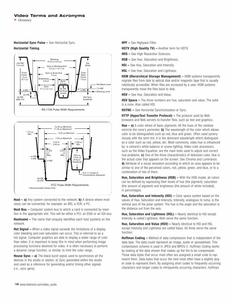
110 www.tektronix.com/video_audio110110110110
Video Terms and AcronymsGlossary
Horizontal Sync Pulse – See Horizontal Sync.
Horizontal Timing
Host – a) Any system connected to the network. b) A device where mod-ule(s) can be connected, for example: an IRD, a VCR, a PC.
Host Bus – Computer system bus to which a card is connected by inser-tion in the appropriate slot. This will be either a PCI, an EISA or an ISA bus.
Hostname – The name that uniquely identifies each host (system) on thenetwork.
Hot Signal – When a video signal exceeds the limitations of a display,color bleeding and over-saturation can occur. This is referred to as a hot signal. Computer graphics are able to display a wider range of color than video. It is important to keep this in mind when performing image processing functions destined for video. It is often necessary to perform a dynamic range function, or similar, to limit the color range.
House Sync – a) The black burst signal used to synchronize all thedevices in the studio or station. b) Sync generated within the studio and used as a reference for generating and/or timing other signals (i.e., sync gens).
HPF – See Highpass Filter.
HQTV (High Quality TV) – Another term for HDTV.
HRS – See High Resolution Sciences.
HSB – See Hue, Saturation and Brightness.
HSI – See Hue, Saturation and Intensity.
HSL – See Hue, Saturation and Lightness.
HSM (Hierarchical Storage Management) – HSM systems transparentlymigrate files from disk to optical disk and/or magnetic tape that is usuallyrobotically accessible. When files are accessed by a user, HSM systemstransparently move the files back to disk.
HSV – See Hue, Saturation and Value.
HSV Space – The three numbers are hue, saturation and value. The solidis a cone. Also called HSI.
HSYNC – See Horizontal Synchronization or Sync.
HTTP (HyperText Transfer Protocol) – The protocol used by Webbrowsers and Web servers to transfer files, such as text and graphics.
Hue – a) A color wheel of basic pigments. All the hues of the rainbowencircle the cone’s perimeter. b) The wavelength of the color which allowscolor to be distinguished such as red, blue and green. Often used synony-mously with the term tint. It is the dominant wavelength which distinguish-es a color such as red, yellow, etc. Most commonly, video hue is influencedby: a camera’s white balance or scene lighting. Video color processors,such as the Video Equalizer, are the main tools used to adjust and correcthue problems. c) One of the three characteristics of television color. Hue isthe actual color that appears on the screen. See Chroma and Luminance.d) Attribute of a visual sensation according to which an area appears to besimilar to one of the perceived colors, red, yellow, green, and blue, or to acombination of two of them.
Hue, Saturation and Brightness (HSB) – With the HSB model, all colorscan be defined by expressing their levels of hue (the pigment), saturation(the amount of pigment) and brightness (the amount of white included),in percentages.
Hue, Saturation and Intensity (HSI) – Color space system based on thevalues of Hue, Saturation and Intensity. Intensity, analogous to luma, is thevertical axis of the polar system. The hue is the angle and the saturation isthe distance out from the axis.
Hue, Saturation and Lightness (HSL) – Nearly identical to HSI exceptIntensity is called Lightness. Both serve the same function.
Hue, Saturation and Value (HSV) – Nearly identical to HSI and HSLexcept Intensity and Lightness are called Value. All three serve the samefunction.
Huffman Coding – Method of data compression that is independent of thedata type. The data could represent an image, audio or spreadsheet. Thiscompression scheme is used in JPEG and MPEG-2. Huffman Coding worksby looking at the data stream that makes up the file to be compressed.Those data bytes that occur most often are assigned a small code to rep-resent them. Data bytes that occur the next most often have a slightly larg-er code to represent them. By assigning short codes to frequently occurringcharacters and longer codes to infrequently occurring characters, Huffman
10.49 µs Minimum11.49 µs Maximum*
* Recommended Values Only
8 to 11 Cycles ofChrominance Subcarrier
90% to110% ofM Sync
Amplitude
-36 IRE-40 IRE
-4 IRE
1.27 µsMin. 9.22 µs Minimum
7.94 µs Maximum
4.45 to5.08 µs
0.38 µsMin.
+4 IRE0 IRE
0.254µsMax.
0.254µs
Max.
FCC Pulse Width Requirements
Blanking10.9 µs ±0.2 µs
Sync to Blanking End9.4 µs = ±0.1 µs
Sync to Burst End7.4 µs
RefWhite
Ref Black Level
7.5 IRE
Blanking Level
Z Z
40 IRERef Burst
Amptd
4 IRE
100 IRE714 mV)
40 IRE(286 mV)
20 IRE
Sync4.7 µ +0.1 µs
Breezeway0.6 µs
4 IRE
Burst2.5 µs
ColorBackPorch1.6 µs
Ref SyncAmplitude
FrontPorch1.5 µs±0.1 µs
RS-170A Pulse Width Requirements

minimizes the average number of bytes required to represent the charac-ters in a text. Static Huffman encoding uses a fixed set of codes, based on a representative sample of data with a single pass through the data.Dynamic Huffman encoding, on the other hand, reads each text twice; onceto determine the frequency distribution of the characters in the text andonce to encode the data. The codes used for compression are computedon the basis of the statistics gathered during the first pass with com-pressed texts being prefixed by a copy of the Huffman encoding table foruse with the decoding process. By using a single-pass technique, whereeach character is encoded on the basis of the preceding characters in atext, Gallager’s adaptive Huffman encoding avoids many of the problemsassociated with either the static or dynamic method.
Hum – Undesirable coupling of 50 Hz (PAL) or 60 Hz (NTSC) power sinewave into other electrical signals.
Hum Bug – Another name for a ground loop corrector.
Human Factors Guidelines – A set of standards and suggestions formaking the working environment more comfortable and healthy.
HUT (Households Using Television) – An estimate of the number of households within a specified coverage area which are viewing any television programming during a specified time.
HVS (Human Visual System) – Eyes and brain.
HVT (Horizontal, Vertical and Temporal) – The three axes of the spatio-temporal spectrum.
HVXC (Harmonic Vector Excitation Coding) – Harmonic VectorExcitation Coding (HVXC) enables the representation of speech signals atvery low bit rates. The standard defines two HVXC bit rates: 2 kbps and 4 kbps. Unlike the code excited linear prediction (CELP) speech coder,HVXC is a parametric coding system, which means that certain aspects ofthe coded representation can be manipulated independently. For example,the playback speed of a HVXC-encoded bitstream can be altered withoutaffecting the pitch of the voice. Similarly, the pitch of the voice can bemodified without altering playback speed. HVXC is useful for a variety ofsynthetic speech applications in bandwidth-constrained environments.
Hybrid CD-ROM – A single disc containing files for both a Windows PCand a Macintosh. See CD-ROM.
Hybrid Coder – In the archetypal hybrid coder, an estimate of the nextframe to be processed is formed from the current frame and the differenceis then encoded by some purely intraframe mechanism. In recent years, themost attention has been paid to the motion compensated DCT coder wherethe estimate is formed by a two-dimensional warp of the previous frameand the difference is encoded using a block transform (the Discrete CosineTransform). This system is the basis for international standards for videotelephony, is used for some HDTV demonstrations, and is the prototypefrom which MPEG was designed. Its utility has been demonstrated for videosequence, and the DCT concentrates the remaining energy into a smallnumber of transform coefficients that can be quantized and compactly rep-resented. The key feature of this coder is the presence of a completedecoder within it. The difference between the current frame as representedas the receiver and the incoming frame is processed. In the basic design,therefore, the receiver must track the transmitter precisely, the decoder atthe receiver and the decoder at the transmitter must match. The system is
sensitive to channel errors and does not permit random access. However, itis on the order of three to four times as efficient as one that uses no pre-diction. In practice, this coder is modified to suit the specific application.The standard telephony model uses a forced update of the decoded frameso that channel errors do not propagate. When a participant enters theconversation late or alternates between image sources, residual errors dieout and a clear image is obtained after a few frames. Similar techniquesare used in versions of this coder being developed for direct satellite televi-sion broadcasting.
Hybrid Coding – The basic coding process used by current internationalstandards for video telephony and MPEG. This predictive coding reducesdecoder processing and storage and also gives reasonable compressionand adaptability. A key feature is that a decoder is embedded in theencoder architecture.
Hybrid Editing – Combining nonlinear edited video files with linear (deck-to-deck) segments of footage.
Hybrid Fiber Coaxial – a) Hybrid fiber coaxial network is a combinationof fiber optic cable and coaxial cable with bandwidth for video distributionand communications. b) Cable TV technology that provides two-way,high-speed data access to the home using a combination of fiber opticsand traditional coaxial cable.
Hybrid Filterbank – A serial combination of Sub-band filterbank andMDCT in MPEG audio.
Hybrid Scalability – The combination of two or more types of scalability.
Hybrid Wavelet Transform – A combination of wavelet and transformalgorithms within the same compression technology.
Hydrolysis – The chemical process in which scission of a chemical bondoccurs via reaction with water. The polyester chemical bonds in tape binderpolymers are subject to hydrolysis, producing alcohol and acid end groups.Hydrolysis is a reversible reaction, meaning that the alcohol and acidgroups can react with each other to produce a polyester bond and water as a by-product. In practice, however, a severely degraded tape binderlayer will never fully reconstruct back to its original integrity when placed in a very low-humidity environment.
Hypercardioid – A directional pickup pattern where maximum discrimina-tion occurs at more than 90 and less than 180 degrees off axis.
Hyper-HAD – An improved version of the CCD HAD technology, utilizingon-chip micro-lens technology to provide increased sensitivity withoutincreasing the pixel size.
Video Terms and AcronymsGlossary
www.tektronix.com/video_audio 111
112 www.tektronix.com/video_audio112112112112112
Video Terms and AcronymsGlossary
I – Improved or Increased; also the in-phase component of the NTSC color subcarrier, authorized to have more than twice as much horizontalresolution as the Q, or quadrature component. Few TV sets have ever taken advantage of this increased chroma resolution, though there isrenewed interest.
I, W, Q, B – An NTSC test signal used to check television broadcast equip-ment. It consists of an I signal followed by a white bar, then a Q signal anda black level on each line.
I/O – See Input/Output.
I/O Device – Input/output equipment used to send information or data signals to and from an editing computer.
I/O Mapped I/O – I/O devices that are accessed by using instructions andcontrol signals that differ from those of the memory devices in a system.Assigns I/O devices to a separate address space.
I/Q – In Phase/Quadrature Phase.
I2C (Inter-Integrated Circuit) – Bidirectional, two-line interface to inter-face integrated circuits capable of transmitting 100 kbits/sec in normalmode or 400 kbits/sec in fast mode. In conjunction with a processor it canbe used to control TV reception, TV decoders/encoders, AD or DA conver-sion. In audio it can be used to control tone, volume, AD or DA conversion,amplification, etc.
I720 – Name of the programmable video processor family from Intel.
IB (In-Band)
IBA – Britain’s Independent Broadcasting Authority, home of a great deal of ATV research.
IBE (Institution of Broadcast Engineers)
IBM – Member of the AEA ATV Task Force; also one of the first organiza-tions to suggest sub-sampling as a technique for compatibility increasingdetail.
IBO (Input Back-Off) – The ratio of the signal power measured at theinput to a high power amplifier to the input signal power that produces the maximum signal power at the amplifier’s output. The input back-off isexpressed in decibels as either a positive or negative quantity. It can beapplied to a single carrier at the input to the HPA (carrier IBO), or to theensemble of input signals (total IBO).
IC (Integrated Circuit) – A small device incorporating the equivalent of hundreds or thousands of transistors, capacitors, resistors and othercomponents within a small, solid block.
IC (Interaction Channel)
ICC (International Color Consortium) – Established in 1993 by eightindustry vendors for the purpose of creating, promoting and encouragingthe standardization and evolution of an open, vendor-neutral, cross-plat-form color management system architecture and components.
ICCE (International Conference on Consumer Electronics) –Sponsored by the Consumer Electronics Society of the IEEE and held annually in the Chicago area immediately following CES. ATV has becomean increasingly important topic at ICCE.
Icon – A small picture that represents a stowed or closed file, directory,application, or IRIX process.
Iconoscope – A camera tube in which a high velocity electron beam scansa photo-emissive mosaic which has electrical storage capability.
ICPM (Incidental Carrier Phase Modulation) – A transmission defectmost noticeable as a cause of sync buzz.
ID (Identification Data) – 32-bit field identifying the sector number within the disc volume.
IDE (Integrated Development Environment) – An integrated develop-ment environment (IDE) is a programming environment that has been packaged as an application program, typically consisting of a code editor,a compiler, a debugger, and a graphical user interface (GUI) builder. TheIDE may be a standalone application or may be included as part of one or more existing and compatible applications. The BASIC programming language, for example, can be used within Microsoft Office applications,which makes it possible to write a WordBasic program within the MicrosoftWord application. IDEs provide a user-friendly framework for many modern programming languages, such as Visual Basic, Java, and PowerBuilder.
IDE (Interface Device Electronics) – Software and hardware communi-cation standard for interconnecting peripheral devices to a computer.
IDTV – See Improved Definition Television.
IEC (International Electrotechnical Commission) – The IEC and itsaffiliated International Organization for Standardization (ISO) are the twomajor global standards-making groups. They are concerned with establish-ing standards that promote interchange of products, agreement uponmethods of evaluation, and resolution of nonfunctional differences amongnational standards. They are structured as an international federation of the more than 50 national standards organizations. The USA is representedby the American National Standards Institute (ANSI).
IEC 60461 – Defines the longitudinal (LTC) and vertical interval timecode(VITC) for NTSC and PAL video systems. LTC requires an entire field time totransfer timecode information, using a separate track. VITC uses one scanline each field during the vertical blanking interval.
IEC 60958 – Defines a serial digital audio interface for consumer (SPDF)and professional applications.
IEC 61834 – Defines the DV standard.
IEC 61880 – Defines the widescreen signaling (WSS) information for NTSCvideo signals. WSS may be present on lines 20 and 283.
IEC 61883 – Defines the methods for transferring data, audio, DV andMPEG-2 data per IEEE 1394.
IEC 62107 – Defines the Super VideoCD standard.
I
www.tektronix.com/video_audio 113
Video Terms and AcronymsGlossary
IEEE – See International Electrical and Electronic Engineers.
IEEE 1394 – A high-speed “daisy-chained” serial interface. Digital audio,video and data can be transferred with either a guaranteed bandwidth or a guaranteed latency. It is hot-pluggable, and uses a small 6-pin or 4-pinconnector, with the 6-pin connector providing power.
IEEE P1394 (FireWire) – A low-cost digital interface organized by AppleComputer as a desktop LAN and developed by the IEEE P1394 WorkingGroup. This interface can transport data at 100, 200 or 400 Mbps. Serialbus management provides overall configuration control of the serial bus inthe form of optimizing arbitration timing, guarantee of adequate electricalpower for all devices on the bus, assignment of which IEEE P1394 deviceis the cycle master, assignment of isochronous channel ID and notificationof errors. There are two types of IEEE P1394 data transfer: asynchronousand isochronous. Asynchronous transport is the traditional computer mem-ory-mapped, load and store interface. Data requests are sent to a specificaddress and an acknowledgment is returned. In addition to an architecturethat scales with silicon technology, IEEE P1394 features a unique isochro-nous data channel interface. Isochronous data channels provide guaranteeddata transport at a predetermined rate. This is especially important fortime-critical multimedia data where just-in-time delivery eliminates theneed for costly buffering.
IEEE Standard 511-1979 Video Signal Transmission Measurement ofLinear Waveform Distortions – This IEEE standard gives a comprehen-sive technical discussion of linear waveform distortions.
IETF (Internet Engineering Task Force) – One of the task forces of theInternet Activities Board (IAB). The IETF is responsible for solving the short-term engineering needs of the Internet. It has over 40 working groups.
I-ETS (Interim European Telecommunications Standards) – An inter-im standard issued by the ETSI.
IF (Intermediate Frequency) – The first state in converting a broadcasttelevision signal into baseband video and audio.
IFFT (Inverse FFT) – Analytical or digital signal processing step that converts frequency domain information into a time domain sequence.
I-Frame (Intra Frame) – One of the three types of frames that are usedin MPEG-2 coded signals. The frame in an MPEG sequence, or GOP (Groupof Pictures), that contains all the data to recreate a complete image. Theoriginal information is compressed using DCT.
IGMP (Internet Group Management Protocol) – This protocol is used inmulticasting.
IIM (Interactive Interface Module)
IIOP (Internet Inter-ORB Protocol) – The CORBA message protocol used on a TCP/IP network (Internet, intranet, etc.). CORBA is the industry standard for distributed objects, which allows programs (objects) to be run remotely in a network. IIOP links TCP/IP to CORBA’s General Inter-ORB protocol (GIOP), which specifies how CORBA’s Object Request Brokers(ORBs) communicate with each other.
IIR (Infinite Impulse Response) – A type of digital filter which has aninfinite output response, as opposed to a FIR filter with a finite outputresponse. It needs usually less coefficients to define signal performance
than a FIR filter but on the other hand it can become unstable since part ofthe output is fed back to the input. A common way to express the IIR is:
y(n) = x(N) + Y(n-1)
i.e., present output = present input + previous output where n = timeinterval; x = input; y = output.
IIT (Illinois Institute of Technology) – Home of most of the researchinto the SLSC ATV scheme.
Ikegami – Broadcast equipment manufacturer involved in a number of ATVschemes, including production of HDEP equipment to the SMPTE standardand schemes involving the use of a line doubler either before or aftertransmission.
iLink – Sony’s name for their IEEE 1394 interface.
Illegal Video – a) A video signal that falls outside the appropriate gamutfor that format. For instance, the gamut limits for an R’, G’, B’ signal are 0mV to 700 mV and Y’ is 0 mV to 700 mV and P’b/P’r are +/-350 mV. If thesignal falls outside of these limits it is an illegal value. b) Some colors thatexist in the RGB color space can’t be represented in the NTSC and PALvideo domain. For example, 100% saturated red in the RGB space (whichis the red color on full strength and the blue and green colors turned off)can’t exist in the NTSC video signal, due to color bandwidth limitations.The NTSC encoder must be able to determine that an illegal color is beinggenerated and stop that from occurring, since it may cause over-saturationand blooming.
Illuminance – Quotient of the luminous flux dFv incident on an element ofthe surface containing the point by the area dA of the element. The illumi-nance also is commonly used in a qualitative or general sense to designatethe act of illuminating or the state of being illuminated. Units of luminanceare lux, foot candle.
IM4DTTV (Integrated Modem for Digital Terrestrial TV) – TheIM4DTTV project (2001-2004), aims at demonstrating the feasibility of anintegrated DVB-RCT end-to-end solution (base station and user terminal),able to meet the technical and cost requirements of the forthcoming terrestrial interactive TV services.
IMA (Interactive Multimedia Association) – IMA has been active in thedefinition of the DVD through its DVD Special Interest Group (IMA DVD SIG).The IMA DVD SIG is a committee of DVD manufacturers working for inter-active DVDs by establishing requirements and influencing specifications.
IMA ADPCM – The IMA has selected the 4:1 ADPCM audio compressionscheme from Intel’s DVI as the preferred compressed audio date type forinteractive media platforms. Intel had offered the algorithm as an openstandard to the IMA. The algorithm compresses 16-bit audio data at up to44.1 kHz sampling into 4-bit ADPCM words.
Image – A two dimensional (usually) picture. The picture may be repre-sented in digital form or mathematically as an image is a set of planes in two dimensions. The two dimensions are the resolution in X and Y(columns, lines). The origin (0, 0) of the image is sometimes its lower leftcorner. There are four basic types of images: black & white or color, maskor no mask, Z plane or no Z plane, IPR information or no IPR information.
Image Buffer – See Frame Buffer.
114 www.tektronix.com/video_audio114114114114114
Video Terms and AcronymsGlossary
Image Capture – The transducing of the information in a real image intothe photographic or electronic medium. Normally in motion-reproducingsystems, synchronous audio information is simultaneously transduced.
Image Compression – a) Process used to reduce the amount of memory required to store an image. See JPEG, MPEG and Decimation.b) Application of an appropriate transfer function to the image signal so as to limit dynamic range. c) Application of bandwidth limiting or bitrate reduction to an image signal in order to bring it within the limitationsof a lower capacity channel.
Image Enhancement – a) Techniques for increasing apparent sharpnesswithout increasing actual resolution. This usually takes the form of increas-ing the brightness change at edges. Since image enhancement hasadvanced continuously for nearly 50 years, ordinary NTSC pictures some-times look better than the NTSC pictures derived from an HDEP source,particularly when these derived pictures are designed to be augmented byother signals in an ATV receiver. It is very difficult to enhance pictures forNTSC receivers and then unenhance them for receivers with augmentation.b) Once the camera response has been made flat to 400 lines (by aperturecorrection), an additional correction is applied to increase the depth ofmodulation in the range of 250 to 300 lines (in an NTSC system), both vertically and horizontally. This additional correction, known as imageenhancement, produces a correction signal with symmetrical overshootsaround transitions in the picture. Image enhancement must be used verysparingly, if natural appearance is to be maintained.
Image Enhancer – A device used to sharpen transition lines in a videopicture.
Image File – A format for storing digital images. To save disk space,images are compressed in a binary file. The image format is contained in a file header which is read by all the programs. The header contains: theimage name, the resolution, the type of image.
Image File Architecture – The Digital Information Exchange Task Force(SMPTE, IEEE, ATSC) on digital image architecture has as its goal the multi-disciplinary agreement upon and the definition of fully flexible, interopera-ble, scalable, and extensible systems. The objective is agreement on thestructure of digital image files that will facilitate the exchange of such filesacross the technology interfaces. The scope includes both the rapid, unam-biguous but concise identification of the file and its utilization, as well asthe organization of the image data itself.
Image File Descriptor – The descriptor is a block of data that enhancesthe utility of the main data for the user. It may contain, in standardized for-mat, data concerning production, ownership, access, previous processing,etc., relevant to the basic interpretation of the data.
Image File Header – The header is a very compact label that can bedecoded by a universally accepted algorithm. Specific objectives are:identify encoding standard, specify length of the file, indicate whether areadable descriptor is included, permit random interception of data stream,and offer optional error protection.
Image File Header/Descriptor – A standard introductory identificationdirecting access to a digital image file. The header provides a brief imagefile identification, universally decodable, indicating the format and length ofthe data block. The (optional) descriptor conveys additional information
improving the usefulness of the data block to the user, such as crypto-graphic, priority, or additional error-protection information as well assource, time, authorship, ownership, restrictions on use, processing performed, etc.
Image File Motion-Picture Format – SMPTE Working Group H19.16 has proposed SMPTE Standard H19.161 defining the file format for theexchange of digital motion-picture information on a variety of mediabetween computer-based systems. This flexible file format describes pixel-based (raster) images with attributes defined in the binary file descriptor,which identifies: generic file information, image information, data format,and image orientation information, motion-picture and television industry,specific information, user defined information. The draft assumes non real-time application, with formats for real-time to be considered as thedeveloping technology permits.
Image File Video Index – Proposed descriptor developed by SMPTEWorking Group P18.41. This proposed SMPTE recommended practice isintended to provide a method of coding video index information in whichvarious picture and program related source data can be carried in conjunc-tion with the video signal. There are three classes of video index databased on type and use of the data. Class 1: Contains information that isrequired to know how to use the signal. Class 2: Contains heritage infor-mation for better usage of the signal. Class 3: Contains other informationnot required to know how to use the signal.
Image Generation – The creation of an image in the photographic orelectronic medium from an image-concept (painted or generated by computer graphics, for example).
Image Independence – See HIIP.
Image Innovator – An optional package which adds additional flags andmenus to ADO 100, including Mosaics, Posterization, Solarization and Masksubmenu, Target Defocus flag and Background menu, Border flags andSides submenu.
Image Pac – A multi-resolution image file format developed by Kodak aspart of the Photo CD System.
Image Processing, Digital – Digital images are represented by a stream,currently of 8-bit or 10-bit values representing the luminance and chromi-nance information, or a stream of 8-bit or 10-bit values representing theR’, G’, and B’ information. Image processing sometimes involves multipli-cation of each digital word by: its proportional contribution to theprocessed image, a vector to relocate the pixel, an algorithm to changeoverall image size. To control these processes, additional information maybe carried in the alpha channel synchronized to the image. As an exampleof the process, if an 8-bit sample is multiplied by an 8-bit factor, the product becomes a 16-bit word. At some point, this may have to be round-ed or truncated back to 8 bits for the next operation. This introduces slightdiscrepancies in the result which may be visible as lagged edges, colorbleeding, etc. If successive truncations are performed during a sequence of image processing steps, the artifacts frequently become increasingly visible. Good practice calls for maintaining some or all of the “extra bits”throughout as much of the image processing as the facilities permit.Experience has shown that digital image processing provides the fewestdistracting artifacts when the R’, G’, B’ signals are first converted to the

www.tektronix.com/video_audio 115
Video Terms and AcronymsGlossary
linear R, G, B. For complex image processing, and for critical results,the 8-bit encoding may be replaced by 10 bits (or more if that can beaccommodated).
Image Quality Evaluation, Interval-Scaled – For comparisons of per-ceived image quality among significantly different systems, a requirementfrequently encountered in electronic production, the technique of interval-scaling is recommended by most students of psycho-physics. Interval scaling gives some indication of the magnitude of preference for one system over another. Observers are asked to place a numerical value uponthe perceived differences (either in total or with regard to a specified characteristic such as noise, resolution, color rendition, etc.).
Image Quality Evaluation, Ordinal-Scaled – For comparisons of per-ceived image quality resulting from a controlled variant within a single system, a requirement encountered when fine-tuning a system, the tech-nique of ordinal-scaling is frequently employed. The ordinal-scale indicatesthat one image is preferred over another. Observers are asked to evaluateperceived image quality on an established scale, usually of five levels,from excellent to unacceptable. Correlations among isolated tests aresometimes uncertain.
Image Quality Evaluation, Ratio-Scaled – When images that differ significantly in creation, display, and content are being compared and inter-val-scaling becomes necessary, interpretation of the results become moreand more complex as the number of observers is increased. Ratio-scalingprovides a means for correlating multiple observations and multiple datasources. Observers are asked to assign a numerical value to perceivedimage quality (either in total or with regard to a specified characteristicsuch as noise, resolution, color rendition, etc.). They are also asked toidentify numerical values for the best possible image, and the completelyunacceptable image. Each is allowed to choose a numerical scale withwhich the observer feels most comfortable. The relationship between thevalue for the test image and the two extremes provides a useful ratio.Analyses involving comparisons among observers, comparisons with othersystems, correlation of results obtained over periods of time, etc., aremade by normalizing each observer’s scale (for example, best possible =100, completely unacceptable = 0).
Image Quality, Objective – The evaluation obtained as a result of objective measurement of the quantitative image parameters (includingtone scale, contrast, linearity, colorimetry, resolution, flicker, aliasing,motion artifacts, etc.)
Image Quality, Perceived – The evaluation obtained as a result of subjective judgment of a displayed image by a human observer.
Image Resolution – The fineness or coarseness of an image as it was digitized, measured in Dots Per Inch (DPI), typically from 200 to 400 DPI.
Image Scaling – The full-screen video image must be reduced to fit into a graphics window (usually a fraction of the total computer display area),while at the same time maintaining a clear and complete image. To do this,it is important to remove or avoid visual artifacts and other “noise” such as degradation caused by pixel and line dropping, and interlacing problemsfrom the scaling process. The challenges increase when dealing with moving images and the compression/decompression of large amounts ofvideo data.
Image Stabilization – A camcorder feature which takes out minor pictureshakiness, either optically or electronically.
Image Transform – First U.S. organization to modify television scanningfor electronic cinematography, utilizing 655 scanning lines per frame at 24frames per second. Also created ImageVision.
ImageVision – An early HDEP scheme utilizing 655 scanning lines perframe and 24 frames per second, with wide bandwidth video recording anda color subcarrier shifted to a higher frequency. Created and used byImage Transform for electronic cinematography.
Imaging Device – a) The part of the video camera or camcorder that converts light into electrical signals. b) A vacuum tube or solid state-devicein which the vacuum tube light-sensitive face plate or solid-state light-sensitive array provides an electronic signal from which an image can be created.
Immediate Addressing – In this mode of addressing, the operand con-tains the value to be operated on, and no address reference is required.
Impact Strength – A measure of the work done in breaking a test sampleof tape or base film by subjecting it to a sudden stress.
Impairments – Defects introduced by an ATV scheme.
Impedance (Z) – a) The opposition of a device to current flow. A combi-nation of resistance, inductive reactance and capacitive reactance. Whenno capacitance or inductance is present, impedance is the same as resist-ance. b) A resistance to signal flow. Microphones and audio mixers arerated for impedance. c) A property of all metallic and electrical conductorsthat describes the total opposition to current flow in an electrical circuit.Resistance, inductance, capacitance and conductance have various influences on the impedance, depending on frequency, dielectric materialaround conductors, physical relationship between conductors and externalfactors.
Impedance Matching – A video signal occupies a wide spectrum of frequencies, from nearly DC (0 Hz) to 6 MHz. If the output impedance of either the video source, cable or input impedance of the receiving equipment are not properly matched, a series of problems may arise.Loss of high frequency detail and color information as well as image instability, oscillations, snow, ghost images and component heat-up mayresult. Proper connections and cable types provide correct impedances.See Load Resistance.
Implicit Scene Description – The representation of the compositioninformation based on the transmission of classes that contains the spatio-temporal relationships between audiovisual objects, as opposed to Explicit Scene Description.
Improved Definition Television (IDTV) – IDTV is different from HDTV inthat it uses the standard transmitted (M) NTSC or (B, D, G, H, I) PAL signal.IDTV improves the display of these signals by doing further processing ofthe signal before displaying it. IDTV offers picture quality substantiallyimproved over conventional receivers, for signals originated in standard525-line or 625-line format, by processing that involves the use of fieldstore and/or frame store (memory) techniques at the receiver. One exampleis the use of field or frame memory to implement de-interlacing at thereceiver in order to reduce interline twitter compared to that of an inter-

116 www.tektronix.com/video_audio116116116116116
Video Terms and AcronymsGlossary
laced display. IDTV techniques are implemented entirely at the receiver and involve no change to picture origination equipment and no change toemission standards.
Impulsive Noise – Short, high-level, unwanted signals that tend to causea sparkling effect in the picture and/or a percussive effect in the sound.The signal-to-impulsive noise ratio is the ratio, in decibels, of the nominalamplitude of the luminance signal (100 IRE units) to the peak-to-peakamplitude of the noise. Impulsive noise is often caused by motorized appliances and tools.
IMTC (International Multimedia Teleconferencing Consortium) – Aninternational membership organization founded in 1993 as Consortium forAudiographics Teleconferencing Standards (CATS). IMTC contributes to thedevelopment of and implements the standards recommendations of the ITUfor data and videoconferencing.
IN (Interactive Network)
IN Point – The starting point of an edit. Also called a Mark IN. See alsoMark IN/OUT, OUT Point.
In the Can – Describes a scene or program which has been completed.Also, “That’s a Wrap”.
INA (Interactive Network Adapter) – Central point or hub in broadband networks that receives signals on one set frequency band and retransmitsthem to another. Every transmission in a broadband network has to gothrough the INA or head-end. In CATV technology, the head-end is the control center for a cable system where video, audio, and data signals are processed and distributed along the coaxial cable network.
Inband Signaling – Signaling is carried in the same communicationschannel as the data.
Incident Light – Light arriving at the surface of an object.
Incidental Carrier Phase Modulation (ICPM) – This is a distortion ofthe picture carrier phase caused by changes in either the chrominance orluminance video signal levels. This distortion is described in degrees usingthe following definition:
ICPM = arctan (quadrature amplitude/video amplitude)
The picture effects of ICPM will depend on the type of demodulation beingused to recover the baseband signal from the transmitted signal. ICPMshows up in synchronously demodulated signals as differential phase andmany other types of distortions, but the baseband signal is generally not asseriously affected when envelope detection is used. The effects of ICPMare therefore rarely seen in the picture in home receivers, which typicallyuse envelope detection. However ICPM may manifest itself as an audiobuzz at the home receiver. In the intercarrier sound system, the picturecarrier is mixed with the FM sound carrier to form the 4.5 MHz sound IF.Audio rate phase modulation in the picture carrier can therefore be trans-ferred into the audio system and heard as a buzzing noise. An unmodulated5 to 10 stair step signal or unmodulated ramp can be used to test for thisdistortion.
In-Circuit Emulator (ICE) – Debugging aid that connects to the systemunder test by plugging into the microprocessor’s socket. This allows theICE to gain full control over the system. Typical features include the abilityto set breakpoints, single-step a program, examine and modify registers
and memory, and divide memory and I/O between the system under testand the ICE system.
Increment – Adding the value one to the contents of a register or memorylocation.
Indeo – a) Intel’s series of compressor and decompressor technologies for digital video, capable of producing software-only video playback.b) The Indeo is a video compression/playback technique from Intel. Justlike CinePak, playback of Indeo compressed video does not require anyspecial hardware. The Indeo algorithm, which used techniques like vectorquantization and run-length coding, is used by various other companies.A video file compressed with Indeo may be played on systems that supporteither Video for Windows® or QuickTime. The new Indeo Video Interactive(IVI) software incorporates additional features to support interactive appli-cations, and used a hybrid wavelet-based algorithm with bidirectional prediction. IVI may be played on systems that support Video for Windows®,later also QuickTime, without dedicated hardware. Video encoded by IVImay be played at up to 640 x 480 pixels resolution and at up to 30 fps,depending on hardware configuration.
Indeo Video Interactive – Intel’s latest compressor and decompressor for digital video, incorporating such special features as transparency,scalability, and local decode. See Indeo Video, Local Decode, Scalability,Transparency.
Indeo-C – The Indeo-C was a compression algorithm in the PersonalConferencing Specification (PCS) from the Personal Conferencing WorkGroup (PCWG), which was an industry group led by Intel. Due to lackingsupport by the industry, the PCWG dropped the PCS, and has now consoli-dated with International Multimedia Teleconferencing Consortium (IMTC)which supports ITU-T Red. H.320 video conferencing. The Indeo-C algo-rithm did not use vector quantizing, as in Indeo, or a hybrid wavelet-basedalgorithm, as in Indeo Video Interactive, but used a transform coding calledFast Slant Transform (FST). An FST calculates frequency coefficients of pic-ture blocks, like the DCT used in MPEG, but requires less computationalpower. Both intra-frame and inter-frame coding with motion estimation wasapplied in Indeo-C and finally, run-length and Huffman coding.
Independent Television – Television stations that are not affiliated withnetworks and that do not use the networks as a primary source of theirprogramming.
Index Register – Contains address information used for indexed addressing.
Indexed Addressing – Mode in which the actual address is obtained byadding a displacement to a base address.
Indexing – Creation of a data index to speed up search and retrieval.
Indication Signals – They communicate the status of the functioning of a system.
Indirect Addressing – Addressing a memory location that contains theaddress of data rather than the data itself.
Industrial/Professional – The grade of audio and video equipment that falls between consumer (low end) and broadcast quality. Industrial/professional equipment is characterized by its durability, serviceability,and more-professional end-result.
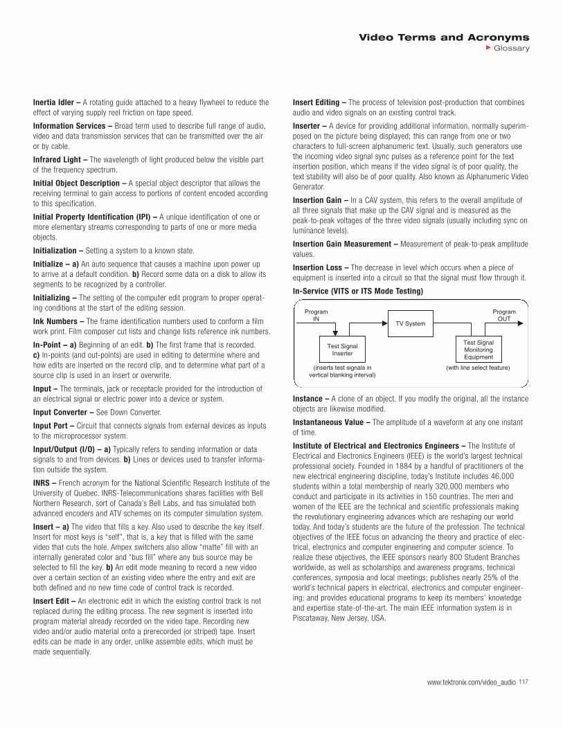
www.tektronix.com/video_audio 117
Video Terms and AcronymsGlossary
Inertia Idler – A rotating guide attached to a heavy flywheel to reduce theeffect of varying supply reel friction on tape speed.
Information Services – Broad term used to describe full range of audio,video and data transmission services that can be transmitted over the airor by cable.
Infrared Light – The wavelength of light produced below the visible partof the frequency spectrum.
Initial Object Description – A special object descriptor that allows thereceiving terminal to gain access to portions of content encoded accordingto this specification.
Initial Property Identification (IPI) – A unique identification of one ormore elementary streams corresponding to parts of one or more mediaobjects.
Initialization – Setting a system to a known state.
Initialize – a) An auto sequence that causes a machine upon power up to arrive at a default condition. b) Record some data on a disk to allow itssegments to be recognized by a controller.
Initializing – The setting of the computer edit program to proper operat-ing conditions at the start of the editing session.
Ink Numbers – The frame identification numbers used to conform a filmwork print. Film composer cut lists and change lists reference ink numbers.
In-Point – a) Beginning of an edit. b) The first frame that is recorded.c) In-points (and out-points) are used in editing to determine where andhow edits are inserted on the record clip, and to determine what part of asource clip is used in an insert or overwrite.
Input – The terminals, jack or receptacle provided for the introduction ofan electrical signal or electric power into a device or system.
Input Converter – See Down Converter.
Input Port – Circuit that connects signals from external devices as inputsto the microprocessor system.
Input/Output (I/O) – a) Typically refers to sending information or datasignals to and from devices. b) Lines or devices used to transfer informa-tion outside the system.
INRS – French acronym for the National Scientific Research Institute of theUniversity of Quebec. INRS-Telecommunications shares facilities with BellNorthern Research, sort of Canada’s Bell Labs, and has simulated bothadvanced encoders and ATV schemes on its computer simulation system.
Insert – a) The video that fills a key. Also used to describe the key itself.Insert for most keys is “self”, that is, a key that is filled with the samevideo that cuts the hole. Ampex switchers also allow “matte” fill with aninternally generated color and “bus fill” where any bus source may beselected to fill the key. b) An edit mode meaning to record a new videoover a certain section of an existing video where the entry and exit areboth defined and no new time code of control track is recorded.
Insert Edit – An electronic edit in which the existing control track is notreplaced during the editing process. The new segment is inserted into program material already recorded on the video tape. Recording new video and/or audio material onto a prerecorded (or striped) tape. Insertedits can be made in any order, unlike assemble edits, which must bemade sequentially.
Insert Editing – The process of television post-production that combinesaudio and video signals on an existing control track.
Inserter – A device for providing additional information, normally superim-posed on the picture being displayed; this can range from one or two characters to full-screen alphanumeric text. Usually, such generators usethe incoming video signal sync pulses as a reference point for the textinsertion position, which means if the video signal is of poor quality, thetext stability will also be of poor quality. Also known as Alphanumeric VideoGenerator.
Insertion Gain – In a CAV system, this refers to the overall amplitude ofall three signals that make up the CAV signal and is measured as thepeak-to-peak voltages of the three video signals (usually including sync onluminance levels).
Insertion Gain Measurement – Measurement of peak-to-peak amplitudevalues.
Insertion Loss – The decrease in level which occurs when a piece of equipment is inserted into a circuit so that the signal must flow through it.
In-Service (VITS or ITS Mode Testing)
Instance – A clone of an object. If you modify the original, all the instanceobjects are likewise modified.
Instantaneous Value – The amplitude of a waveform at any one instantof time.
Institute of Electrical and Electronics Engineers – The Institute ofElectrical and Electronics Engineers (IEEE) is the world’s largest technicalprofessional society. Founded in 1884 by a handful of practitioners of thenew electrical engineering discipline, today’s Institute includes 46,000 students within a total membership of nearly 320,000 members who conduct and participate in its activities in 150 countries. The men andwomen of the IEEE are the technical and scientific professionals makingthe revolutionary engineering advances which are reshaping our worldtoday. And today’s students are the future of the profession. The technicalobjectives of the IEEE focus on advancing the theory and practice of elec-trical, electronics and computer engineering and computer science. To realize these objectives, the IEEE sponsors nearly 800 Student Branchesworldwide, as well as scholarships and awareness programs, technicalconferences, symposia and local meetings; publishes nearly 25% of theworld’s technical papers in electrical, electronics and computer engineer-ing; and provides educational programs to keep its members’ knowledgeand expertise state-of-the-art. The main IEEE information system is inPiscataway, New Jersey, USA.
Test SignalInserter
TV System
Test SignalMonitoringEquipment
(inserts test signals invertical blanking interval)
(with line select feature)
ProgramIN
ProgramOUT

118 www.tektronix.com/video_audio118118118118118
Video Terms and AcronymsGlossary
Instruction – Single command within a program. Instructions may bearithmetic or logical, may operate on registers, memory, or I/O devices, ormay specify control operations. A sequence of instructions is a program.
Instruction Cycle – All of the machine states necessary to fully executean instruction.
Instruction Decoder – Unit that interprets the program instructions intocontrol signals for the rest of the system.
Instruction Register – Register inside the microprocessor that containsthe opcode for the instruction being executed.
Instruction Set – Total group of instructions that can be executed by agiven microprocessor. Must be supplied to the user to provide the basicinformation necessary to assemble a program.
Integrated Services Digital Networks (ISDN) – ISDN is a CCITT termfor a relatively new telecommunications service package. ISDN is basicallythe telephone network turned all-digital end to end, using existing switchesand wiring (for the most part) upgraded so that the basic call is a 64 kbpsend-to-end channel, with bit manipulation as needed. Packet and maybeframe modes are thrown in for good measure, too, in some places. It’soffered by local telephone companies, but most readily in Australia, France,Japan, and Singapore, with the UK and Germany somewhat behind, andUSA availability rather spotty. A Basic Rate Interface (BRI) is two 64K bear-er (B) channels and a single delta (D) channel. The B channels are used for voice or data, and the D channel is used for signaling and/or X.25packet networking. This is the variety most likely to be found in residentialservice. Another flavor of ISDN is Primary Rate Interface (PRI). Inside theUS, this consists of 24 channels, usually divided into 23 B channels and 1 D channel, and runs over the same physical interface as T1. Outside ofthe US then PRI has 31 user channels, usually divided into 30 B channelsand 1 D channel. It is typically used for connections such as one betweena PBX and a CO or IXC.
Intensity – Synonymous with luminance.
Intensity Stereo Coding – Stereo redundancy in stereo audio is exploited by retaining the energy envelope of the right and left channels at high frequencies only.
Inter – A mode for coding parameters that uses previously coded parame-ters to construct a prediction.
Inter Shape Coding – Shape coding that uses temporal prediction.
Interactive – Allowing random access to information.
Interactive Television (ITV) – TV programming that features interactivecontent and enhancements, blending traditional TV viewing with the inter-activity of a personal computer.
Interactive Video – The fusion of video and computer technology. A videoprogram and a computer program running in tandem under the control of the user. In interactive video, the user’s actions, choices, and decisionsaffect the way in which the program unfolds.
Interactive Videodisc – Interactive videodisc is another video relatedtechnology, using an analog approach. It has been available since the early1980s, and is supplied in the U.S. primarily by Pioneer, Sony, and IBM.
Intercarrier Sound – A method used to recover audio information in theNTSC system. Sound is separated from video by beating the sound carrieragainst the video carrier, producing a 4.5 MHz IF which contains the soundinformation.
Intercast – a) An Intel developed process which allows Web pages to besent in the vertical blanking interval of a (M) NTSC video signal. Theprocess is based on NABTS. b) Intercast technology allows televisionbroadcasters to create new interactive content-text, graphics, video, ordata around their existing programming and deliver this programmingsimultaneously with their TV signal to PCs equipped with Intercast technol-ogy. Intercast content is created with HTML which means that the interac-tive content of broadcast with the TV signal appears to the user as Webpages, exactly as if they were using the actual World Wide Web. Thesebroadcast Web pages can also contain imbedded hyperlinks to relatedinformation on the actual Internet.
Interchange – Transfer of information between two processes.
Interchannel Timing Error – This error occurs in component analogvideo three-wire or two-wire interconnect systems when a timing differencedevelops between signals being transmitted through the wires. The errormanifests itself as distortions around vertical lines, edges and in color distortions.
Inter-Coding – Compression that uses redundancy between successivepictures; also known as Temporal Coding.
Interconnect Format – See the Format definition.
Interconnect Standard – See the Standard definition.
Interface – Indicates a boundary between adjacent components, circuits,or systems that enables the devices to exchange information. Also used to describe the circuit that enables the microprocessor to communicatewith a peripheral device.
Interference – a) In a signal transmission path, extraneous energy whichtends to interfere with the reception of the desired signals. b) Defect ofsignal reproduction caused by a combination of two or more signals thatmust be separated, whether all are desired or not.
Inter-Frame Coding – a) Coding techniques which involve separating thesignal into segments which have changed significantly from the previousframe and segments which have not changed. b) Data reduction based oncoding the differences between a prediction of the data and the actualdata. Motion compensated prediction is typically used, based on referenceframes in the past and the future.
Interframe Compression – A form of compression in which the codeccompresses the data within one frame relative to others. These relativeframes are called delta frames. See Delta Frame, Key Frame. CompareIntraframe Compression.
Interframe Compression Algorithms – MPEG is one of many interframealgorithms that use certain key frames in a motion-prediction, interpolationsystem.

www.tektronix.com/video_audio 119
Video Terms and AcronymsGlossary
Interlace – a) Technique for increasing picture repetition rate withoutincreasing base bandwidth by dividing a frame into sequential fields. Whenfirst introduced, it also had the characteristic of making the scanningstructure much less visible. NTSC uses 2:1 interlace (two fields per frame).b) A process in which the picture is split into two fields by sending all theodd numbered lines to field one and all the even numbered lines to fieldtwo. This was necessary when there was not enough bandwidth to send acomplete frame fast enough to create a non-flickering image.
Interlace Artifacts – Picture defects caused by interlace. These includetwitter, line crawl, loss of resolution, and motion artifacts. In addition tocausing artifacts, interlaced scanning reduces the self-sharpening effect of visible scanning lines and makes vertical image enhancement more difficult to perform.
Interlace Coefficient – A number describing the loss of vertical resolutiondue to interlace, in addition to any other loss. It is sometimes confusedwith the Kell factor.
Interlace Ratio – Alternate raster lines are scanned producing an oddfield (odd numbered lines) and an even field (even numbered lines). Aninterlace of 1:1 implies vertically adjacent lines comprise the field.
Interlaced – Display system in which two interleaved fields are used tocreate one frame. The number of field lines is one-half of the number offrame lines. NTSC (M) systems have 262.5 lines per field. PAL (B, D, G, H,I) scan system have 312.5 lines per field. Each field is drawn on the screenconsecutively-first one field, then the other. The field scanned first is calledthe odd field, the field scanned second is called the even field. The inter-laced scanning system is used to prevent screen flicker. If frames wherescanned on the screen without interlacing fields, the light level created bythe first frame would decrease noticeably before the next frame could bescanned. Interlacing the fields allows the light level of the screen to beheld more constant and thus prevent flicker.
Interlaced Carrier – A television subcarrier at a frequency that is an oddmultiple of one half the line rate (for example, the NTSC color subcarrier).Such subcarriers fall onto a line in the spatio-temporal spectrum that issimultaneously high in vertical detail and in temporal detail, and is there-fore not likely to be objectionably visible under normal viewing conditions.
Interlaced Scanning – a) A scanning process in which each adjacent linebelongs to the alternate field. b) A technique of combining two televisionfields in order to produce a full frame. The two fields are composed of onlyodd and only even lines, which are displayed one after the other but withthe physical position of all the lines interleaving each other, hence inter-lace. This type of television picture creation was proposed in the early days of television to have a minimum amount of information yet achieveflickerless motion. See Interlaced.
Interlaced Sequence – Sequence of pictures, that can be either field picture or frame pictures.
Interlaced Video Mode – A mode in which the video raster is scannedover the face of the CRT by the electron gun tracing alternate scan lines in successive refresh cycles. The quality of interlaced video is lower thansequentially scanned (non-interlaced) video because only half of the linesare refreshed at a time and, interlaced video scans at a lower rate thannon-interlaced video allowing for the manufacture of less expensive video
monitors. NTSC video (standard TV) uses interlace video. A display systemwhere the even scan lines are refreshed in one vertical cycle (field), andthe odd scan lines are refreshed in another vertical cycle. The advantage isthat the bandwidth is roughly half that required for a non-interlaced systemof the same resolution. This results in less costly hardware. It also maymake it possible to display a resolution that would otherwise be impossibleon given hardware, The disadvantage of an interlaced system is flicker,especially when displaying objects that are only a single scan line high.
Interlacing – The process of drawing a frame by alternately drawing therows of each field, creating the illusion that the image is being redrawntwice as often as it actually is. See Field.
Interleaver – The RS-protected transport packets are reshuffled byte bybyte by the 12-channel interleaver. Due to this reshuffle, what were neigh-boring bytes are now separated by at least one protected transport packet.That is, they are at least 204 bytes apart from each other. The purpose ofthis is the burst error control for defective data blocks.
Interleaving – A technique used with error correction that breaks up bursterrors into many smaller errors.
Interline Flicker – See Twitter.
Interline Transfer – This refers to one of the three principles of chargetransferring in CCD chips. The other two are frame transfer and frame-interline transfer.
Intermediates – General term for color masters and dupes.
Intermodulation Distortion – Signal nonlinearity characterized by theappearance of frequencies in the output equal to the sums and differencesof integral multiples of the component frequencies present in the input signal. Harmonics are usually not included as part of the intermodulationdistortion.
Internal Drive – A drive that fits inside the workstation and connects toan internal port; it is never connected with a cable to a visible externalport. An internal drive is occasionally referred to as a front-loading drive.
Internal Sync – The internal generation of sync pulses in a camera usinga crystal controlled oscillator. This is needed on non-mains power cameras.
International Organization for Standardization (ISO) – This is aGeneva based organization for many of the national standardization bodies.Together with the International Electrotechnical Commission, IEC, ISO concentrates its efforts on harmonizing national standards all over theworld. The results of these activities are published as ISO standards.Among them are, for instance, the metric system of units, international stationery sizes, all kinds of bolt nuts, rules for technical drawings, electri-cal connectors, security regulations, computer protocols, file formats,bicycle components, ID cards, programming languages, InternationalStandard Book Numbers (ISBN). Over 10,000 ISO standards have beenpublished so far and you surely get in contact with a lot of things each day that conform to ISO standards you never heard of. By the way, ISO isnot an acronym for the organization in any language. It’s a wordplay basedon the English/French initials and the Greek-derived prefix iso- meaningsame. Within ISO, ISO/IEC Joint Technical Committee 1 (JTC1) deals withinformation technology.

120 www.tektronix.com/video_audio120120120120120
Video Terms and AcronymsGlossary
International Thomson – Name used by France’s Thomson group forsome recently acquired holdings outside of France. International Thomsonis a strong proponent of progressive-scan ATV and has proposed two suchschemes for NTSC countries, both of which would offer a 16:9 aspect ratioand 60 frames per second. One would have 900 scanning lines (864active), matching the number of scanning lines in International Thomson’sproposal for non-NTSC countries. The other would have 750 scanning lines(728 active), matching the digitization rates in the non-NTSC proposal.
Interoperability – The capability of providing useful and cost-effectiveinterchange of electronic image, audio, and associated data among different signal formats, among different transmission media, among different applications, among different industries, among different perform-ance levels.
Interpolation – In digital video, the creation of new pixels in the image bysome method of mathematically ma-nipulating the values of neighboringpixels. This is necessary when an image is digitally altered, such as whenthe image is expanded or compressed.
Interpolation (Line) – In television standards conversion, the techniquefor adjusting the number of lines in a 625-line television system to a 525-line system (and vice versa) without impairing the picture quality.
Interpolation (Movement) – A technique used in standards conversion to compensate for the degrading effects of different field frequencies onpictures which contain movement. Different approximate proportions ofsuccessive input fields are used in each output field.
Interpolation (Spatial) – When a digital image is repositioned or resized,different pixels are usually required from those in the original image.Simply replicating or removing pixels causes unwanted artifacts. With interpolation, the new pixels are calculated by making suitably weightedaverages of adjacent pixels, giving more transparent results. The qualitydepends on the techniques used and the area of original picture, expressedas a number of pixels or points. Compare with Interpolation (Temporal).
Interpolation (Temporal) – Interpolation between the same point inspace on successive frames. It can be used to provide motion smoothingand is extensively used in standard converters to reduce the defectscaused by the 50/60 Hz field rate difference. This technique can also be adapted to create frame averaging for special effects.
Inter-Positive – A color master positive print.
Interrupt – Involves suspension of the normal program that the micro-processor is executing in order to handle a sudden request for service(interrupt). The processor then jumps from the program it was executing to the interrupt service routine. When the interrupt service routine is completed, control returns to the interrupted program.
Interrupt Mask – Register that has one bit to control each interrupt.Used to selectively disable specific interrupts.
Interrupt Service Routine – Program that is executed when an interruptoccurs.
Interrupt Vectoring – Providing a device ID number or an actual branch-ing address in response to the interrupt acknowledge signal. Allows eachinterrupt to automatically be serviced by a different routine.
Interval Timer – Programmable device used to perform timing, counting,or delay functions. Usually treated as a peripheral.
Intra – A mode for coding parameters that does not make reference topreviously coded parameters to perform the encoding.
Intra Shape Coding – Shape coding that does not use any temporal prediction.
Intra-Coded Pictures (I-Pictures or I-Frames) – Pictures that arecoded by using information present only in the picture itself and withoutdepending on information from other pictures. I-pictures provide a mechanism for random access into the compressed video data. I-picturesemploy transform coding of the pixel blocks and provide only moderatecompression.
Intra-Coding – a) Coding of a macroblock or picture that uses informationonly from that macroblock or picture. b) Compression that works entirelywithin one picture: also known as Spatial Coding.
Intra-Frame Coding – Video coding within a frame of a video signal.
Intraframe Compression – A form of compression in which the codeccompresses the data within one frame relative only to itself. Key framesare compressed with intraframe compression because they must recon-struct an entire image without reference to other frames. See Delta Frame,Key Frame. Compare Interframe Compression.
Intraframe Compression Algorithm – A still image or photo video compression standard. JPEG compression ratios vary from 20:1 to 40:1with a lossless ratio of 5:1. JPEG is a symmetrical standard inasmuch as it takes the same amount of time to decompress as it does to compressvideo. JPEG works best with smooth transitions and little motion.
Intrinsic Coercive Force – The magnetizing field strength needed toreduce flux density from saturation to zero.
Intrinsic Coercivity – The maximum value of the intrinsic coercive force.The intrinsic coercivity is a basic magnetic parameter for the material andrequires complete saturation of the ample for its measurement as does thesaturation flux density.
Intrinsic Flux – In a uniformly magnetized sample of magnetic material,the product of the intrinsic flux density and the cross-sectional area.
Intrinsic Flux Density – In a sample of magnetic material for a givenvalue of the magnetizing field strength, the excess of the normal flux density over the flux density in vacuum.
Intrinsic Hysteresis Loop – Graph of magnetic flux (B) plotted againstthe magnetizing force (H) producing it. The value of B when H has droppedto zero is the residual magnetism, and the reverse force needed to reduce B to zero is known as the coercivity. Units used are: MagnetizingForce (H) in oersteds and Flux Density (B) in gauss. Coercivity is measuredin oersteds.

www.tektronix.com/video_audio 121
Video Terms and AcronymsGlossary
INTSC (Improved NTSC) – A term rarely used to describe ATV schemesincorporating any combination of techniques.
Techniques to Improve NTSC Compatibility
A. Monochrome and Color1. Sampling, Aperture, and Interlace Problems
• Progressive• High Line Rate Display• Progressive Camera and Prefiltering• High Line Rate Camera and Prefiltering• Image Enhancement at the Camera• Image Enhancement at the Receiver
2. Transmission Problems• Ghost Elimination• Noise Reduction• Improved Filter Design and Adjustment
3. Changing Equipment Problems• Gamma Correction• Adaptive Emphasis• Rigid Adherence to Standards
B. Color Problems1. Improved Decoder Filtering2. Prefiltering3. Full Detail Decoders4. Luminance Detail Derived from Pre-Encoded Chroma
Invar – This is an expensive, brittle metal used to make the shadow maskin a direct view color picture tube. Incorporating it allows higher picturecontrast levels from the tube without incurring long-term damage to theshadow mask itself. It allows the set manufacturer to offer higher contrastlevels. Since the phosphors in the tube reach the point of blooming wellbefore the need for the Invar mask, anyone properly setting the contrastlevel for no blooming in the picture won’t ever need the features of theInvar mask. The high contrast levels permitted by the Invar mask will eventually burn the phosphors.
Inverse Multiplexing – Operation that combines (bonds together) multiplechannels to increase the net available bandwidth into a single larger band-width channel.
Inverse Non-Additive Mix – A mixing process that compares the colorvalues of the corresponding pixels in the two source clips, and assigns thehigher value to the corresponding pixel in the output clip.
Inverse Nyquist Filter – A filter that is a complement of the filter used to reduce interference in the IF section of a television set.
Inverse Quantization (Q-1) – Rescaling the quantized values in order to recover the original quantized values.
Inverse Telecine – The reverse of 3:2 pulldown, where the frames whichwere duplicated to create 60-fields/second video from 24-frames/secondfilm source are removed. MPEG-2 video encoders usually apply an inversetelecine process to convert 60-fields/second video into 24-frames/secondencoded video. The encoder adds information enabling the decoder torecreate the 60-fields/second display rate.
Inverted Key – We think of a normal key as, for example, letters superim-posed over a background. When this key is inverted, the background
appears inside the key; it appears we are looking through the cut-out keyand seeing the background. The key insert video appears outside the key.
IO (Image Orthicon) – The picture forming tube in a TV camera.
Ion – A charged atom, usually an atom of residual gas in an electron tube.
Ion Spot – A spot on the fluorescent surface of a cathode ray tube, whichis somewhat darker than the surrounding area because of bombardment bynegative ions which reduce the phosphor sensitivity.
Ion Trap – An arrangement of magnetic fields and apertures which will allow an electron beam to pass through but will obstruct the passageof ions.
IOR (Interoperable Object Reference)
IP (Internet Protocol) – a) IP is the basic language of the Internet. It was developed by the government for use in internetworking multiple computer networks together. b) The Network Layer protocol for the Internetprotocol suite.
IP Address – The number that uniquely identifies each host (system) onthe network.
IP Datagram – Basic unit of information that passes across a connection-less TCP/IP Internet. It contains routing source and destination addresseswith the data.
IP Multicast – A system for sending IP transmissions out only one time,but allowing for multiple users to receive it. This would reduce the band-width required for audio and video broadcasting over the Internet, but it isnot widely used yet.
IP (Index of Protection) – A numbering system that describes the qualityof protection of an enclosure from outside influences, such as moisture,dust and impact.
IPCP (Internet Protocol Control Protocol) – Protocol that establishesand configures IP over PPP.
IPI (Intellectual Property Identification) – The IPI descriptor is a vehicle to convey standardized identifiers for content like internationalstandard book number, international standard music number, or digitalobject identifier if so desired by the content author. If multiple mediaobjects within one MPEG-4 session are identified by the same IPI informa-tion, the IPI descriptor may consist just of a pointer to another elementarystream, using its ES ID, that carries the IPI information.
I-Picture (Intra-Coded Picture) – One of three types of digital picturesin an MPEG data stream. An I-picture is not predictive and is essentially asnapshot picture. This type of picture generally has the most data of any ofthe picture types. A picture coded using information only from itself. Forthat reason, an I-picture can be decoded separately.
IPMP (Intellectual Property Management and Protection) – TheIntellectual Property Management and Protection (IPMP) identifies carriersof creative works. The tool was developed as a complement of MPEG-4,the ISO compression standard for digital audio-visual material. Involvedexperts, notably those representing authors’ societies, felt that MPEG-4needed extra rules designed to protect intellectual property. To this end,IPMP was constructed as a supplementary layer on the standard.
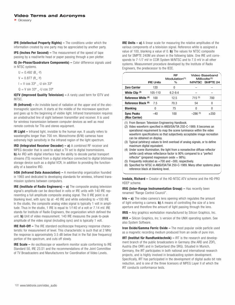
122
IPR (Intellectual Property Rights) – The conditions under which theinformation created by one party may be appreciated by another party.
IPS (Inches Per Second) – The measurement of the speed of tape passing by a read/write head or paper passing through a pen plotter.
IQ (In-Phase/Quadrature Components) – Color difference signals usedin NTSC systems.
U = 0.492 (B_-Y)
V = 0.877 (R_-Y)
I = V cos 33º _-U sin 33º
Q = V sin 33º _-U cos 33º
IQTV (Improved Quality Television) – A rarely used term for IDTV andINTSC.
IR (Infrared) – An invisible band of radiation at the upper end of the elec-tromagnetic spectrum. It starts at the middle of the microwave spectrumand goes up to the beginning of visible light. Infrared transmission requiresan unobstructed line of sight between transmitter and receiver. It is usedfor wireless transmission between computer devices as well as mostremote controls for TVs and stereo equipment.
IR Light – Infrared light, invisible to the human eye. It usually refers towavelengths longer than 700 nm. Monochrome (B/W) cameras haveextremely high sensitivity in the infrared region of the light spectrum.
IRD (Integrated Receiver Decoder) – a) A combined RF receiver andMPEG decoder that is used to adapt a TV set to digital transmissions.b) An IRD with digital interface has the ability to decode partial transportstreams (TS) received from a digital interface connected to digital bitstreamstorage device such as a digital VCR, in addition to providing the function-ality of a baseline IRD.
IrDA (Infrared Data Association) – A membership organization foundedin 1993 and dedicated to developing standards for wireless, infrared trans-mission systems between computers.
IRE (Institute of Radio Engineers) – a) The composite analog televisionsignal’s amplitude can be described in volts or IRE units with 140 IRE rep-resenting a full amplitude composite analog signal. The 0 IRE point is atblanking level, with sync tip at -40 IRE and white extending to +100 IRE In the studio, the composite analog video signal is typically 1 volt in ampli-tude. Thus in the studio, 1 IRE is equal to 1/140 of a volt or 7.14 mV. IREstands for Institute of Radio Engineers, the organization which defined theunit. b) Unit of video measurement. 140 IRE measures the peak-to-peakamplitude of the video signal (including sync) and is typically 1 volt.
IRE Roll-Off – The IRE standard oscilloscope frequency response charac-teristic for measurement of level. This characteristic is such that at 2 MHzthe response is approximately 3.5 dB below that in the flat (low frequency)portion of the spectrum, and cuts off slowly.
IRE Scale – An oscilloscope or waveform monitor scale conforming to IREStandard 50, IRE 23.S1 and the recommendations of the Joint Committeeof TV Broadcasters and Manufacturers for Coordination of Video Levels.
IRE Units – a) A linear scale for measuring the relative amplitudes of thevarious components of a television signal. Reference white is assigned avalue of 100, blanking a value of 0. b) The values for NTSC composite and for SMPTE 240M are shown in the following table. One IRE unit corre-sponds to 7-1/7 mV in CCIR System M/NTSC and to 7.0 mV in all othersystems. Measurement procedure developed by the Institute of RadioEngineers, the predecessor to the IEEE.
RF Video BasebandModulation(1) Millivolts(2)
IRE Units % M/NTSC SMPTE 24
Zero Carrier 120 0 – –
White Clip (3) 105-110 6.2-9.4 – –
Reference White (4) 100 12.5 715 (5) 700
Reference Black (6) 7.5 70.3 54 0
Blanking 0 75 0 0
Sync Peaks –40 100 –286 (5) ±350(Max Carrier)
(1) From Benson: Television Engineering Handbook.(2) Video waveform specified in ANSI/EIA/TIA 25D-C-1989. It becomes an
operational requirement to map the scene luminance within the videowaveform specifications so that subjectively acceptable image recreationcan be obtained on display.
(3) Typical (arbitrary) values to limit overload of analog signals, or to definemaximum digital equivalent.
(4) Under scene illumination, the light from a nonselective diffuse reflector(white card) whose reflectance factor is 90% compared to a “perfect reflector” (prepared magnesium oxide = 98%).
(5) Frequently indicated as +700 and –300, respectively.(6) Specified for NTSC in ANSI/EIA/TIA 250-C-1989. Many other systems place
reference black at blanking level.
Iredale, Richard – Creator of the HD-NTSC ATV scheme and the HD-PROHDEP scheme.
IRIG (Inter-Range Instrumentation Group) – Has recently beenrenamed “Range Control Council”.
Iris – a) The video camera’s lens opening which regulates the amount of light entering a camera. b) A means of controlling the size of a lensaperture and therefore the amount of light passing through the lens.
IRIS – Any graphics workstation manufactured by Silicon Graphics, Inc.
IRIX – Silicon Graphics, Inc.’s version of the UNIX operating system. Seealso System Software.
Iron Oxide/Gamma Ferric Oxide – The most popular oxide particle usedas a magnetic recording medium produced from an oxide of pure iron.
IRT (Institut für Rundfunktechnik) – IRT is the research and develop-ment branch of the public broadcasters in Germany (the ARD and ZDF),Austria (the ORF) and in Switzerland (the SRG). Situated in Munich,Germany, the IRT participates in both national and international researchprojects, and is highly involved in broadcasting system development.Specifically, IRT has participated in the development of digital audio bit ratereduction, and is one of the three licensors of MPEG Layer II of which theIRT conducts conformance tests.
Video Terms and AcronymsGlossary
www.tektronix.com/video_audio
IS (International Standard) – The series of standards from ISO and itssubcommittees.
IS&T (Society for Imaging Science and Technology) – An internationalnon-profit organization whose goal is to keep members aware of the latestscientific and technological developments in the field of imaging throughconferences, journals and other publications. We focus on imaging in all its aspects, with particular emphasis on silver halide, digital printing, elec-tronic imaging, photo finishing, image preservation, image assessment,pre-press technologies and hybrid imaging systems.
ISA (Industry Standard Architecture) – Originally designed around the16-bit 286 microprocessor and called the AT bus, the ISA bus has 24address and 16 data lines, sufficient to handle 16 megabyte memory I/Oaddresses. The ISA bus is limited to a slow 8 MHz clock speed and for thisreason, faster peripherals and memory left the ISA bus behind soon afterits development. Unlike the earlier 8-bit PC/XT bus, the ISA bus includestwo connectors. In addition to the single, 62-pin, 8-bit PC/XT bus connec-tor, the ISA bus includes a second connector with four additional addressand eight additional data lines, interrupt, and DMA control lines. AlthoughIBM documented every pin on the ISA bus, they never published strict timing specifications to signals on the bus. As a result, ISA bus systemdevelopers designing products for many platforms had to guess at timing.Problems developed as a result of holding the ISA bus to 8 MHz for back-ward compatibility. Some anxious manufacturers pushed the system speedcausing products with marginal operations characteristics, especially whenextra memory was added to high-speed PCs. Since the IEEE ISA standardof 1987, the bus signals have remained unchanged. In 1993, Intel andMicrosoft announced a joint development, Plug and Play ISA, a method formaking expansion boards work with the ISA bus, eliminating the need forDIP switch settings, jumpers, interrupts, DMA channels, ports, and ROMranges. The Plug and Play card tells the host computer what resources itrequires. This requires a large software-based isolation protocol whichkeeps an expansion board switched off until it can be addressed, allowingone card to be polled at a time because slot-specific-address enable signals for expansion cards are not part of the ISA specification. In 1987,the ISA bus made way for the IBM PS/2 “clone-killer” computer “MicroChannel” bus however, the clone makers initially ignored the PS/2 andMicro Channel.
ISA Slot – Connection slot to a type of computer expansion bus formerlyfound in most computers. It is larger in size than the PCI slots found onmost Pentium based computers and provides connections to the slower ISA bus.
ISA Transfer – One of the advantages of an ISA transfer is that it allowsthe user to process images as they go through the processor. However,its utility is limited by its low bandwidth, Even under ideal conditions, theISA transfer requires three to five BCLK cycles at 8 MHz to transfer a single pixel. This represents a severe system throughput penalty; a largepercentage of the available (and already limited) bandwidth is consumed by the transfer.
ISDB (Integrated Services Digital Broadcasting) – Japan's transmis-sion specification for digital broadcasting. ISDB uses a new transmissionscheme called BST-OFDM that ensures the flexible use of transmissioncapacity and service expandability in addition to the benefits of OFDM.
Since OFDM uses a large number of carriers that are digitally modulated.It provides sufficient transmission quality under multipath interference. Thebasic approach of BST-OFDM is that a transmitting signal consists of therequired number of narrow band OFDM blocks called BST-segments, eachwith a bandwidth of 100 kHz.
ISDB (Integrated Services Digital Broadcasting) – An NHK-suggestedbroadcast equivalent to ISDN.
ISDN – See Integrated Services Digital Network.
ISI (Inter Symbol Interference) – Inter Symbol Interference is the interference between adjacent pulses of a transmitted code.
ISMA (Internet Streaming Media Alliance) – ISMA is a group of indus-try leaders in content management, distribution infrastructure and mediastreaming working together to promote open standards for developing end-to-end media streaming solutions. The ISMA specification defines theexact features of the MPEG-4 standard that have to be implemented on the server, client and intermediate components to ensure interoperabilitybetween the entire streaming workflow. Similarly, it also defines the exactfeatures and the selected formats of the RTP, RTSP, and SDP standardsthat have to be implemented. The ISMA v1.0 specification defines two hierarchical profiles. Profile 0 is aimed to stream audio/video content onwireless and narrowband networks to low-complexity devices, such as cellphones or PDAs, that have limited viewing and audio capabilities. Profile 1is aimed to stream content over broadband-quality networks to provide theend user with a richer viewing experience. Profile 1 is targeted to morepowerful devices, such as set-top boxes and personal computers.
ISO – See International Organization for Standardization.
ISO 2202 – Information Processing: ISO 7-bit and 8-bit coded charactersets – Code extension techniques
ISO 3166 – Codes for the representation of names of countries.
ISO 3901 – Documentation: International Standard Recording Code (ISRC).
ISO 639 – Codes for the representation of names of languages.
ISO 8859-1 – Information Processing: 8-bit single-byte coded graphiccharacter sets.
ISO 9660 – The international standard for the file system used by CD-ROM. Allows file names of only 8 characters plus a 3-character extension.
ISO Reel – Multiple reels of tape of the same subject recorded simultane-ously from different cameras on different VTRs.
ISO/IEC 11172 – Information Technology: Coding of moving picturesand associated audio for digital storage media up to about 1.5 Mbit/s.(MPEG-1)
ISO/IEC 13818 – Information Technology: Generic coding of moving pictures and associated audio. (MPEG-2)
ISO/IEC DIS 13818-3 – Information technology: Generic coding of movingpictures and associated audio.
Isochronous – For digital transmission, events occur with known constantperiods. “Equal-time”. The synchronization signal is derived from the signalbearing the data.
Isokey – See External Key.
Video Terms and AcronymsGlossary
www.tektronix.com/video_audio 123

124
Isolated Key – A key where the “hole cutting” or key video is differentfrom the “key filling” or insert video. This is most commonly used withcharacter generators that provide these two outputs, and allows the character generator to create a key border that is wider and cleaner thaninternally bordered keys. Such signals may also come from a color camerathat provides its own keying output or even a monochrome camera lookingat an art card. An isolated key is always a luminance key, although com-posite chroma keys may be done with an isolated key source, ignoring theisolated input. AVC series switchers can defeat isolated inputs to standardtype keys by turning key borders on. Also referred to as a ProcessedExternal Key.
Isoparameters – The curves along a surface resulting from setting u or vto a constant value.
ISP (Internet Service Provider) – An organization that provides accessto the Internet.
ISV (Independent Software Vendor) – Company which develops andsells application tools and/or software titles.
ISVR Pro – See Smart Video Recorder Pro.
ISVYUV9 – Recording format for decompressed Indeo video technologyusing VidCap under Microsoft’s Video for Windows®.
IT (Information Technology) – Processing information by computer. Thelatest title for the information processing industry.
Iterative – Procedure or process that repeatedly executes a series ofoperations until some condition is satisfied. Usually implemented by a loopin a program.
ITFS (Instructional Television Fixed Service) – A method of broadcast-ing TV programs throughout school systems using low-power high-frequen-cy transmitters.
ITS (Insertion Test Signal) – A test signal that is inserted in one line ofthe vertical interval to facilitate in-service testing.
ITSTC (Information Technology Steering Committee) – Established by the July 2002 to provide advice and recommendations to the ViceChancellor on the overall priorities and funding level for information technology and communications for the University of Pittsburgh.
ITTF (Information Technology Task Force) – The United World Colleges(UWC) International Board of Directors created the UWC IT Task Force(ITTF) to coordinate IT development projects for the UWC movement as awhole.
iTTi (International Telecom Union – Telecommunication Sector) –Started in 1998 as part of the ACTS (Advanced CommunicationTechnologies and Services). The project goal was the specification and practical demonstration of a wireless return channel for the terrestrial digital television.
ITU (International Telecommunications Union) – This is the UnitedNations specialized agency dealing with telecommunications. At presentthere are 164 member countries. One of its bodies is the InternationalTelegraph and Telephone Consultative Committee, CCITT. A PlenaryAssembly of the CCITT, which takes place every few years, draws up a listof ‘Questions’ about possible improvements in international electronic communication. In Study Groups, experts from different countries develop‘Recommendations’ which are published after they have been adopted.
Especially relevant to computing are the V series of recommendations onmodems (e.g. V.32, V.42), the X series on data networks and OSI (e.g.,X.25, X.400), the I and Q series that define ISDN, the Z series that definesspecification and programming languages (SDL, CHILL), the T series on text communication (teletext, fax, videotext, ODA) and the H series on digital sound and video encoding.
ITU-R (International Telecommunication Union,Radiocommunication Sector) – Replaces the CCIR.
ITU-R BT.601-2 – a) Standard developed by the International RadioConsultative Committee for the digitization of color video signals. ITU-RBT.601 deals with the conversion from component RGB to YCbCr, the digi-tal filters used for limiting the bandwidth, the sample rate (defined as 13.5MHz), and the horizontal resolution (720 active samples). b) Internationalstandard for component digital television from which was derived SMPTE125M (was RP-125) and EBU 3246E standards. CCIR defines the samplingsystems, matrix values, and filter characteristics for both Y, B-Y, R-Y andRGB component digital television.
ITU-R BT.653 – Standard that defines teletext systems used around theworld.
ITU-R BT.656 – The physical parallel and serial interconnect scheme forITU-R BT.601-2. ITU-R BT.656 defines the parallel connector pinouts aswell as the blanking, sync, and multiplexing schemes used in both paralleland serial interfaces.
ITU-R BT.709-3 – Part II of the recommendation describes the unique HD-CIF standard of 1080 lines by 1920 samples/line interlace and pro-gressively scanned with an aspect ratio of 16:9 at both 50 Hz and 60 Hzfield and frame rates for high definition program production and exchange.
ITU-R.601 – See ITU-R BT.601.2.
ITU-R.624 – ITU standard that defines PAL, NTSC and SECAM.
ITU-T (International Telecommunication Union, TelecommunicationStandardization Sector) – International body that develops worldwidestandards for telecommunications technologies. The ITU-T carries out thefunctions of the former CCITT.
ITVA (International Television Association) – An association for media,film, video, and television professionals.
I-vop (Intra-coded VOP) – A vop coded using information only fromitself.
IVUE – A file format associated with FITS technology that enables imagesto be opened and displayed in seconds by showing only as much data onthe screen as is implied by the screen size and zoom factor.
IWU (Inter-Working Unit) – The network “modem” where all the digital to analogue (and visa versa) conversions take place within the digital GSMnetworks
Video Terms and AcronymsGlossary
www.tektronix.com/video_audio

Video Terms and AcronymsGlossary
www.tektronix.com/video_audio 125
J.41 – This is a recommendation from the ITU-T covering high-quality coding of audio material at 384 kbit/s. In the same family we find the J.42,the J.43 and the J.44 recommendations that define the coding of analog“medium quality” sound at 384 kbit/s, “high quality” sound at 320 kbit/s,and “medium quality” sound at 320 kbit/s, respectively.
J.81 – This ITU-T recommendation is identical to the ETSI standard ETS300 174 for video broadcast transmission at 34 Mbit/s.
Jack – Receptacle for a plug connector leading to the input or output circuit of a tape recorder or other piece of equipment. A jack matches aspecific plug.
Jaggies – a) Slang for the stair-step aliasing that appears on diagonallines. Caused by insufficient filtering, violation of the Nyquist Theory, and/orpoor interpolation. b) A term for the jagged visual appearance of lines andshapes in raster pictures that results from producing graphics on a gridformat. This effect can be reduced by increasing the sample rate in scanconversion.
Jam Sync – a) Process of locking a time-code generator to existingrecorded time code on a tape in order to recreate or extend the time code.This may be necessary because, beyond a given point on tape, time codemay be non-existent or of poor quality. b) Process of synchronizing a secondary time code generator with a selected master time code, i.e.,synchronizing the smart slate and the audio time code to the same clock.
Jam Syncing – The process of synchronizing a secondary timecode generator with a selected master timecode.
Japan Broadcasting Corporation – See NHK.
Java – A highly portable, object-oriented programming language developed by Sun Microsystems. Not to be confused with JavaScript.
JavaScript – A programming language originally created by Netscape with specific features designed for use with the Internet and HTML, andsyntax resembling that of Java and C++. Now standardized as ECMA-262.
JBIG – See Joint Bi-Level Image Experts Group.
JBOD (Just a Bunch of Disks) – A collection of optical/magnetic disksused for storing data.
JCIC (Joint Committee for Inter-Society Coordination) – A groupcomprised of the EIA, the IEEE, the NAB, the NCTA, and the SMPTE. TheJCIC created the ATSC in 1982 to handle all of the new advances in TV,including HDTV. The ATSC has since grown to 52 member and observerorganizations.
JCTEA (Japan Cable Television Engineering Association)
JEC – Joint Engineering Committee of EIA and NCTA.
Jewel Box – The plastic clamshell case that holds a CD or DVD.
Jitter – a) The variation of a digital signal’s significant instants (such astransition points) from their ideal positions in time. Jitter can cause therecovered clock and the data to become momentarily misaligned in time.In some cases the data can be misinterpreted if this misalignmentbecomes too great. b) An undesirable random signal variation with respectto time. A tendency toward lack of synchronization of the picture. It may refer to individual lines in the picture or to the entire field of view.c) A rapid, small shift in image position characteristic of film projection.Projection jitter can reduce the apparent resolution of film. d) A flickeringon a display screen. Besides a monitor or connector malfunction, jitter canbe caused by a slow refresh rate.
Jitter Amplitude – The variation in phase of the bit rate clock expressedas a percent of the bit period.
Jitter Rate – The rate of change of the jitter amplitude expressed as afrequency in Hertz.
JND (Just Noticeable Difference) – A measure of the minimum percep-tible change in quality. A one JND change is accurately detected 75 per-cent of the time; a three JND change is accurately detected 99 percent ofthe time. There is a large number of JNDs of difference between NTSC asit is now received in U.S. homes and high definition electronic production(HDEP). This difference decreases in ATV systems in a hierarchical order.Some feel that a large number of JNDs will be necessary for consumers to purchase new TV sets.
Jog/Shuttle Wheel – A dial on many video decks, VCRs and editing control units that controls jog and shuttle functions.
Jogging – Single-frame forward or backward movement of video tape.See Stepping.
Joint Bi-Level Image Experts Group (JBIG) – This is a lossless bi-level(black and white) image compression technique. JBIG is intended toreplace G3 fax algorithms. The JBIG technique can be used on either gray-scaled or color images. Some of the applied techniques have a strongresemblance with the JPEG standard. Commercially available implementa-tions of JBIT have been scarce, but some find use in remote printing ofnewspapers.
Joint Photographic Expert Group (JPEG) – Compression technique for still images, such as photographs, a single video frame, etc. JPEG canbe used to compress motion video however it is not as efficient as MPEGwhich has been optimized for motion video compression applications.
Joint Stereo Coding – Exploitation of interchannel stereophonic redundancies in audio coding resulting in the left and right stereo pairbeing coded in a single bitstream.
Jot – The text editor that comes as a standard utility on every IRIS.
Joystick – Affecting control over X, Y and Z parameters. Typical uses areswitcher pattern positioner, ADO positioner/controller, ACE switcher previewcontroller. See Positioner.
J

126
JPEG – See Joint Photographic Experts Group.
JPEG-1 – ISO/IEC DIS 10918-1 begins with a digital image in the format Y,CB, CR (such as defined in CCIR 601-2) and provides several levels ofcompression. Predictive coding and transforms are employed, with thehigher compression ratios selectively recognizing the decrease in humanvisual acuity with increasing spatial frequencies. It is optimized for about15:1 compression. As increased data storage and increased processingcapabilities are becoming available, there is exploration of adapting JPEG-1for application to successive frames in real time; i.e., full-motion JPEG.
JPEG-2 – ISO/IEC CD 11172 describes procedures for compliance testingin applications of JPEG-1.
JPG – Filename extension for graphic image files stored using JPEG compression.
JScript – A proprietary Microsoft variant of JavaScript.
JTC1 (Joint Technical Committee) – JTC1 is a joint committee of ISOand IEC. The scope of JTC1 is information technology standardization.
Judder – a) Jerkiness of motion associated with presentation rates belowthe fusion frequency. b) A temporal artifact associated with moving imageswhen the image is sampled at one frame rate and converted to a differentframe rate for display. As a result, motion vectors in the display mayappear to represent discontinuously varying velocities. The subjective effectof the artifact becomes more obvious when the frame-rate conversions are made by simple deletions or repetitions of selected frames (or fields).It may become less obvious when interpolated frames (or fields) are gener-ated by employing predictive algorithms.
Jump – Instruction that results in a change of sequence.
Jump Cut – A mismatched edit that creates a visual disturbance whenreplayed. Usually occurs when cutting between two images which share anidentical subject but place the subject at different positions in the frame.
Video Terms and AcronymsGlossary
www.tektronix.com/video_audio

www.tektronix.com/video_audio 127
Video Terms and AcronymsGlossary
K – Symbol for 1000 (103). When referring to bits or words, K=1024 (210).
K Factor – A specification rating method that gives a higher factor tovideo disturbances that cause the most observable picture degradation.
K Factor Ratings – K Factor ratings are a system that maps linear distortions of 2T pulses and line time bars onto subjectively determinedscales of picture quality. The various distortions are weighted in terms of impairment to the picture.
The usual K Factor measurements are Kpulse/bar, K2T or Kpulse (2T pulseresponse), Kbar and sometimes K60Hz. The overall K Factor rating is thelargest value obtained from all of these measurements. Special graticulescan be used to obtain the K Factor number or it can be calculated from the appropriate formula. All types of linear distortions affect the K Factorrating. Picture effects may include any of the short time, line time, fieldtime and long time picture distortions. Any signal containing the 2T pulseand an 18 µsec bar can be used to measure Kpulse/bar, K2T (Kpulse), or Kbar.A field rate square wave must be used to measure K60Hz. The FCC composite test signal contains these signal components. See the discussion on Pulse to Bar Ratios.
K2T or K-2T – K2T is a weighted function of the amplitude and time of thedistortions occurring before and after the 2T pulse. In practice, a graticuleis almost always used to quantify this distortion. Different countries andstandards use slightly different amplitude weighting factors. The figure tothe right shows a typical waveform monitor K Factor graticule display. Theouter dotted lines at the bottom of the graticule indicate 5% K2T limits.See the discussion on Pulse to Bar Ratios.
K60Hz – A field-rate square wave is used to measure this parameter. Locatethe center of the field bar time, normalize the point to 100% and measurethe maximum amplitude deviation for each half. Ignore the first and last2.5% (about 200 µsec). The largest of the two tilt measurements dividedby two is the K60Hz rating.
Karaoke – A special DVD format that allows for certain special features.The audio portion of this format is distinctive in that it is intended for “singalong” formats and may include audio tracks for “guide vocals”, “guidemelody”, “chorus” and the main Karaoke left and right channels. The audiotrack for Karaoke in DVD-video is defined to be applicable for multi-chan-nel setup with 5 channels maximum. When this vocal part is recordedmainly in track 4 and 5 except the main 2 channels, the users can enjoymany different playback modes by Karaoke type DVD players equipped with various audio on/off switches.
KB – See Kilobyte.
Kbar – A line bar (18 µsecs) is used to measure Kbar. Locate the center of the bar time, normalize that point to 100% and measure the maximumamplitude deviation for each half. Ignore the first and last 2.5% (0.45µsec) of the bar. The largest of the two is the Kbar rating.
Keeper – Term used to indicate the effect, edit was good enough to keep,but could possibly be improved on, however, the effect or edit should bestored as is in case it cannot be improved upon.
Kell Effect – Vertical resolution of a scanned image subjectively evaluatedis consistently shown to be less than the geometrically-predicted resolu-tion. Observations are usually stated in terms of the ratio of perceived television lines to active lines present in the display. From the time that R.Kelt published his studies (conducted on a progressive scanned image),there have been numerous numerical values and substantiating theoriesproposed for this effect. The range of results suggests that many details of the experiments influence the result and make defining a single “KellFactor” impossible. Reported experimental results range at least between0.5 and 0.9. In an otherwise comparable display, the “ratio” is lower forinterlaced scanning than for progressive scanning.
Kell Factor – A number describing the loss of vertical resolution from thatexpected for the number of active scanning lines, names for Ray Kell, aresearcher at RCA Laboratories. Many researchers have come up with different Kell factors for progressively scanned television systems. Thesedifferences are based on such factors as aperture shape, image content,and measurement technique. A generally accepted figure for the Kell factoris around 0.68, which, multiplied by the 484 active NTSC scanning lines,yields a vertical resolution of 330 lines, matched by NTSC’s 330 lines ofhorizontal resolution per picture height (see Square Pixels). It is importantto note that most studies of the Kell factor measure resolution reduction in a progressive scanning system. Interlaces scanning systems suffer fromboth a Kell factor and an interlace coefficient.
Kelvin – This is a system or scale used for measuring temperature.Absolute zero is 0° Kelvin or -273°C. The “color” of white light isexpressed in terms of degrees Kelvin, the color of light emitted when an ideal object is heated to a particular temperature.
KEM Roll – The roll of film used on a KEM flatbed editing system. A KEM roll combines multiple takes onto a single roll (a work print, not anegative). The maximum length of a KEM roll is 1000 feet.
W2 W1
B2 B1
SD 5%
C
Grat. B2%
5%K2T
K

128 www.tektronix.com/video_audio128128128128128128
Video Terms and AcronymsGlossary
Kerberos – Kerberos is a network authentication protocol developed by MIT. It is designed to provide strong authentication for client/serverapplications by using secret-key cryptography.
Kernel – Minimum circuitry required to allow the microprocessor to function. Usually consists of the microprocessor, clock circuit, interrupt and DMA control lines, and power supply.
Kerning – The spacing between text characters in print media, such astitles.
Key – a) A signal that can electronically “cut a hole” in the video picture to allow for insertion of other elements such as text or a smaller video picture. b) A video that has been overlaid on top of another video. Keysmay be either determined by the luminance or brightness of the key video,or determined by the chroma or hue of the key video. c) A push-button.d) To combine a selected image from one source with an image fromanother source. See also Chroma Key.
Key Channel – See Alpha Channel.
Key Color – The solid color used to key.
Key Fill – Line key effects, the video signal which is said to “fill the hole”cut in background video by the key source.
Key Frame – A frame containing all the data representing an image,rather than just the data that has changed since the last frame. The firstframe of every video file is a key frame; in addition, they occur throughoutthe file to refresh image quality and permit certain operations, such as random user access. Compare Delta Frame.
Key Gain – An adjustment for keys that determines the sharpness of thekey edges. As key gain is reduced, keys become softer at the edges andmay be adjusted to be more transparent.
Key Insert – The video that fills a key.
Key Invert – a) A luminance key mode which inverts the polarity of thekey source to allow dark areas of the source video to cut holes in back-ground instead of bright areas. b) A chroma key mode which inverts theforeground and background positions.
Key Light – The term used to describe a subject’s main source of illumination. When shooting outdoors, the key light is usually the sun.
Key Mask – A key mode which allows use of independent key mask generators to create a pattern to prevent some undesirable portions of the key source from cutting a hole in the background. This is also possible using externally generated masks on the Vista.
Key Matrix – The electronic crosspoints which switch and route key signals and key insert signals to appropriate key processing electronics.On Ampex switchers, these matrices are controlled by keypads and keyerinsert selector push-button controls and form the Phantom matrix portionof the switcher.
Key Memory – An AVC series feature that allows a key to be fully adjustedas soon as it is selected. This is accomplished by a “store” button on thekey adjust panel that may be pressed when an operator is satisfied withthe adjustment of a key. From that point on, whenever that key is selected,regardless of which keyer it is on, all adjustments and features of that keyare automatically recalled.
Key Numbers – The original frame identification numbers applied by thefilm manufacturers to the film stock. Key numbers are used by the negativecutter to conform the film negative. Film composer cut lists and changelists reference key numbers.
Key Region – See Slice.
Key Signal – A hole cutting signal.
Key Source – a) A hole cutter. The signal which is said to “cut a hole”in the background scene for a key effect. In actuality, this signal controls a video mixer which switches between the background scene and the fill video; thus, the key source determines the shape of the key effect.b) The image that contains the colors or luminance values on which youkey to create a chroma or luminance key effect.
Key Type – There are three key types on Ampex switchers; luminancekeys, RGB chroma keys and composite chroma keys.
Keyboard – a) Group of push-buttons used for inputting information to asystem. b) The human interface portion of a computer, typewriter withalpha numeric keys or push-buttons.
Keyer – a) The electronics and panel controls that create keys. There aremany types of keyers, some limited to titles only, and some capable of any type of key. All Ampex keyers are full capability. b) A tool that you useto create a composite from a clip from a background and foreground clipby using an input key-in clip to determine how the clips are combined.You use the input key-in clip to create a black and white matte that defines which areas of the foreground and background clips are used inthe result clip.
Keyframe – a) Keyframes are important frames that are guides in creatingframes that occur between the keyframes. b) A specific manipulation orpositioning of the image. An effect is composed of one or more keyframes.
Keyframe Duration – The length of the keyframe; the time from keyframeto the start of the next.
Keyframing – The process of creating an animated clip wherein by select-ing a beginning image and an ending image the software automaticallygenerates the frames in between. See also Tweening.
Keying – The process of replacing part of one television image with videofrom anther image; that is chroma keying and insert keying.
Keykode – A trademark of Eastman Kodak Company. A barcode on theedge of motion picture film which allows the film edge numbers to be electronically read and inserted into an edit list. Very useful for generatinga negative cut list from a video off-line EDL.
Keykode Numbers Reader – Device attached to a telecine or part of abench logger which read Keykode number bar code from motion picturefilm and provides electronic output to a decoder.
Key-Length-Value (KLV) – The grouping of information concerning a single metadata element that combines three pieces of information: its UL Data Key; the Length of its instantiation Value in the next field; itsinstantiated Value in the allowed format.
Keypad – The numbered push-buttons used to entered numerical data,i.e., pattern numbers, transition rates, key source numbers, etc.

KF Flags (Menu) – Miscellaneous keyframe flags, currently used to turnGlobals off and on.
kHz (Kilohertz) – One thousand cycles per second.
Kilobaud – A unit of measurement of data transmission speed equaling1000 baud.
Kilobyte (KB) – One thousand bytes. Actually 1024 bytes because of theway computer math works out.
Kinescope – a) Frequently used to mean picture tubes in general.However, this name has been copyrighted. b) A film recording of a videoimage displayed on a specially designed television monitor. Only means of recording TV programs before video recorders and tape were invented.
Kinescope Recording – Motion pictures taken of a program pho-tographed directly from images on the face of a kinescope tube. A television transcription.
KLV (Key, Length, and Value) – A data-encoding protocol (SMPTE 336M)that complies with International Standards Organization rules for ObjectIdentifier data and SMPTE Universal Label (SMPTE 298M). This is the“header” information in a metadata stream that will identify the data andwhich metadata dictionary of definitions should be used for the metadatathat follows. KLV and UMIDs (Unique Material Identifiers) are the basicengineering building blocks that have been designed to make metadataeasier to exchange between different media (such as tapes or files) andmetadata standards.
Knee – By convention, the circuitry introducing white compression into theopto-electric transfer function and thereby modifying the curve for a moregradual approach to white clip.
Kpulse/bar or K-PB – Calculation of this parameter requires the measurement of the pulse and bar amplitudes. Kpulse/bar is equal to:
1/4 | (bar-pulse)/pulse | X 100%
Ku-band – Ku-band satellites use the band of satellite downlink frequen-cies from 11.7 to 12.2 GHz. Also the group of microwave frequencies from12 to 18 GHz.
Video Terms and AcronymsGlossary
www.tektronix.com/video_audio 129

130 www.tektronix.com/video_audio130130130130130130
Video Terms and AcronymsGlossary
Label – Name assigned to a memory location. When an assembly language program is written, a label is assigned to an instruction or memory location that must be referred to by another instruction. Thenwhen the program is converted to machine code, an actual address isassigned to the label.
LAeq – An Leq measurement using A weighting. Refer to Leq andWeighting.
Lambertian Source/Surface – A surface is called a Lambert radiator or reflector (depending whether the surface is a primary or a secondarysource of light) if it is a perfectly diffusing surface.
LAN (Local Area Network) – A communications network that servesusers within a confined geographical area. It is made up of servers,workstations, a network operating system and a communications link.
LANC – See Control-L.
Land – The raised area of an optical disc.
LAP (Link Access Procedure) – An ITU family of error correction protocols originally derived from the HDLC standard.
LAP-B (Balanced) Used in X.25 networks.
LAP-D (D Channel) Used in ISDN data channel.
LAP-M (Modem) Defined in ITU V.42, which uses someLAPD methods and adds additional ones.
LAP-X (Half-Duplex) Used in ship to shore transmission.
Lap Dissolve – A slow dissolve in which both pictures are actually overlapped for a very brief period of time. Same as Dissolve.
LAR (Logarithmic Area Ratio) – Describes spectral envelope in speech coding.
Large Scale Integration (LSI) – Technology by which thousands of semiconductor devices are fabricated on a single chip.
Large-Area Flicker – Flicker of the overall image or large parts of it.See also Flicker Frequency and Twitter.
Laser Beam Recording – A technique for recording video on film.
Laser Disc – A 12-inch (or 8-inch) optical disc that holds analog video(using an FM signal) and both analog and digital (PCM) audio. A precursorto DVD.
Laser – Light amplification by stimulated emission of radiation. A laserproduces a very strong and coherent light of a single frequency.
LAT (Link Available Time)
Latch – a) Hardware device that captures information and holds sit (e.g.,group of flip-flops). b) An electronic circuit that holds a signal on once ithas been selected. To latch a signal means to hold it on or off.
Latency – a) The length of time it takes a packet to move from source todestination. b) A factor of data access time due to disk rotation. The fastera disk spins the quicker it will be at the position where the required datacan start to be read. As disk diameters have decreased so rotational
speeds have tended to increase but there is still much variation. Modern 3-1/2-inch drives typically have spindle speeds of between 3,600 and7,200 revolutions per minute, so one revolution is completed in 16 or 8milliseconds (ms) respectively. This is represented in the disk specificationas average latency of 8 or 4 ms.
Latent Image – The invisible image formed in a camera or printer by theaction of light on a photographic emulsion.
Lateral Direction – Across the width of the tape.
Latitude – In a photographic process, the range of exposure over whichsubstantially correct reproduction is obtained. When the process is repre-sented by and H and D curve, the latitude is the projection on the exposureaxis of that part of the curve which approximates a straight line within thetolerance permitted for the purpose at hand.
LATM (Low-Overhead MPEG-4 Audio Transport Multiplex) – MPEG-4audio is an audio standard that integrates many different types of audiocoding tools. Low-overhead MPEG-4 Audio Transport Multiplex (LATM)manages the sequences of audio data with relatively small overhead. Inaudio-only applications, then, it is desirable for LATM-based MPEG-4 audiobitstreams to be directly mapped onto the RTP packets without usingMPEG-4 systems.
Launch – To start up an application, often by double-clicking an icon.
Lavaliere – A microphone designed to hang from the performer’s neck.
Layback – Transferring the finished audio track back to the master video tape.
Layer – a) A term used to describe which video is on top of which back-ground versus foreground and subsequent keys superimposed. b) One ofthe levels in the data hierarchy of the video and system specification.c) In a scalable hierarchy, denotes one out of the ordered set of bitstreamsand (the result of) its associated decoding process. d) The plane of a DVDdisc on which information is recorded in a pattern of microscopic pits.Each substrate of a disc can contain one or two layers.
Layer 0 – In a dual-layer disc, this is the layer closest to the optical pick-up beam and surface of the disc, and the first to be read when scanningfrom the beginning of the disc’s data. Dual-layer discs are 10% less densethan single layer discs due to crosstalk between the layers.
Layer 1 – In a dual-layer disc, this is the deeper of the two layers, and thesecond one to be read when scanning from the beginning of the disc’sdata.
Layered Bitstream – A single bitstream associated to a specific layer(always used in conjunction with layer qualifiers).
Layered Tracks – The elements of an effect created by combining two ormore tracks in a specified way, such as nesting one track as a layer withinanother.
Layer-to-Layer Adhesion – The tendency for adjacent layers of tape in aroll to adhere to each other.
L
Video Terms and AcronymsGlossary
www.tektronix.com/video_audio 131
Layer-to-Layer Signal Transfer – The magnetization of a layer of tape ina roll by the field from a nearby recorded layer, sometimes referred to as“print-thru”.
LBR (Laser Beam Recorder) – It creates the DVD master file.
LC (Low Complexity) – The most used profile (MPEG-2) or object type(MPEG-4) in AAC (advanced audio coding) encoders and decoders nowa-days because of its low system requirements, i.e., CPU and memoryresources.
LCD (Liquid Crystal Display) – A screen for displaying text/graphicsbased on a technology called liquid crystal, where minute currents changethe reflectiveness or transparency of selected parts of the screen. Theadvantages of LCD screens are: very small power consumption (can beeasily battery driven) and low price of mass produced units. Its disadvan-tages presently include narrow viewing angle, somewhat slower responsetime, invisibility in the dark unless the display is back-lit, difficulties dis-playing true colors and resolution limitations.
LCP (Link Control Protocol) – See PPP.
L-Cut – See Overlap Edit.
Lead In – On a compact disc, the lead-in contains a table of contents forthe track layout.
Lead Out – On a compact disc, the lead-out indicates the end of data.
Leader – a) Special non-magnetic tape that can be spliced to either endof a magnetic tape to prevent damage and possible loss of recorded mate-rial and to indicate visually where the recorded portion of the tape beginsand ends. b) Any film or strip of material used for threading a motion picture machine. Leader may consist of short lengths of blank film attachedto the ends of a print to protect the print from damage during the threadingof a projector, or it may be a long length of any kind of film which is usedto establish the film path in a processing machine before the use of themachine for processing film.
Leading Blacks – A term used to describe a picture condition in whichthe edge preceding a white object is overshaded toward black. The objectappears to have a preceding or leading black border.
Leading Whites – A term used to describe a picture condition in whichthe edge preceding a black object is overshaded toward white. The objectappears to have a preceding or leading white border.
Leakage – A term describing the signal picked up by a mike which isintended to pick up other signals only.
Learn – The act of storing switcher control panel data into memory in areal-time mode (learning as they happen).
Learning Curve – An algebraic metaphor for the amount of time a learnerneeds to learn a new task (such as operating an item of television produc-tion equipment).
Leased Access – Commercial channels made available by a cable operator to third parties for a fee, as required by the Cable Acts of 1984and 1992.
Least Significant Bit (LSB) – The bit that has the least value in a binarynumber or data byte. In written form, this would be the bit on the right.For example,
Binary 1101 = Decimal 13
In this example the rightmost binary digit, 1, is the least significant bit,here representing 1. If the LSB in this example were corrupt, the decimalwould not be 13 but 12.
Lechner Distance – Named for Bernard Lechner, researcher at RCALaboratories. The Lechner distance is nine feet, the typical distanceAmericans sit from television sets, regardless of screen size. The Jacksondistance, three meters, named for Richard Jackson, a researcher at Philips in Britain, is similar. There is reason to believe that the Lechner and Jackson distances are why HDTV research was undertaken sooner in Japan (where viewing distances are shorter) than elsewhere. See alsoViewing Distance.
LED (Light Emitting Diode) – A light on a piece of hardware that indicates status or error conditions.
Legacy – A term used to describe a hybrid disc that can be played in both a DVD player and a CD player.
Legal Signal – A signal in which each component remains within the limits specified for the video signal format; that is, it does not exceed the specified gamut for the current format. For instance, the gamut limitsfor an R’, G’, B’ signal are 0 mV to 700 mV and Y’ is 0 mV to 700 mV and P’b/P’r are +/-350 mV. If the signal remains within these limits thevalue is legal.
Lempel-Ziv Welch (LZW) Compression – Algorithm used by the UNIXcompress command to reduce the size of files, e.g., for archival or trans-mission. The algorithm relies on repetition of byte sequences(strings) in its input. It maintains a table mapping input strings to their associated output codes. The table initially contains mappings for all possible stringsof length one. Input is taken one byte at a time to find the longest initialstring present in the table. The code for that string is output and then thestring is extended with one more input byte b) A new entry is added to thetable mapping the extended string to the next unused code (obtained byincrementing a counter). The process repeats, starting from byte b) Thenumber of bits in an output code, and hence the maximum number ofentries in the table is usually fixed and once this limit is reached, no moreentries are added.
Length – a) The physical length of the tape wound on a reel or on a hub,varying from 213 feet in a C45 cassette to 9200 feet in a roll of instru-mentation tape. b) The number of bytes represented by the items whoseLength is being described.
Lens – The curved glass on a video camera or camcorder that collectslight and focuses it.
Leq – Leq represents the continuous noise level, equivalent in loudnessand energy, to the fluctuating sound signal under consideration. Refer toLAeq.
Letterbox – a) An MPEG video term for which the parameters have adefined set of constraints within a particular profile. b) A television systemthat limits the recording or transmission of useful picture information to

132 www.tektronix.com/video_audio132132132132132132
Video Terms and AcronymsGlossary
about three-quarters of the available vertical picture height of the distribu-tion format (e.g., 525-line) in order to offer program material that has awide picture aspect ratio. c) Term generally used for the form of aspectratio accommodation involving increasing vertical blanking. See BlankingAdjustment.
Letterbox Filter – Circuitry in a DVD player that reduces the vertical sizeof anamorphic widescreen video (combining every 4 lines into 3) and addsblack mattes at the top and bottom.
Letterboxing – A technique that maintains the original wide aspect ratioof film when displayed as video. The top and bottom of the video screenare blackened and the total scene content is maintained.
Level – a) A defined set of constraints on the values which may be takenby some parameters within a particular profile. A profile may contain one ormore levels. b) In MPEG-2, a range of picture parameters. c) Defines thebounds of the coding parameters, such as resolution, bit rate, etc. withineach profile. The variation of performance is inherently wide in a profile.Thus, levels have been defined in order to set reasonable constraints.d) When relating to a video signal it refers to the video level in volts. InCCTV optics, it refers to the auto iris level setting of the electronics thatprocesses the video signal in order to open or close the iris.
LFE (Low Frequency Effects) – The optional LFE channel (also referredto as the “boom” channel) carries a separate, limited, frequency bandwidthsignal that complements the main channels. It delivers bass energy specifi-cally created for subwoofer effects or low-frequency information derivedfrom the other channels. The LFE channel is the “.1” in 5.1-channel audio.
Library – As in a book library, it is somewhere one might keep effects,i.e., on a disk or collection of disks hence a library of canned effects.
LIFO (Last-In-First-Out) – A buffer. Same as Push-Down Stack.See Stack.
Lift – To remove selected frames from a sequence and leave black orsilence in the place of the frames.
Light Valve Technology – A light valve projector uses a bulb as thesource of light. The valve technology changes the color and intensity of thesource to form the picture. Film or slide projectors are examples of lightvalve technology. The Digital Micro-Mirror Device (DMD); also known as theDigital Light Processor (DLP), the Image Light Amplifier (ILA), and LCD areall examples of electronic light valve technology. Obtaining black in a pic-ture produced by a light valve projector requires an ability to shut the lightoff in particular areas of the picture. Shutting light off in a small area isactually rather difficult. Consequently, the real picture contrast ratio of anumber of these projectors is rather poor.
Lightness – The brightness of an area (subjectively) judged relative to thebrightness of a similarly illuminated area that appears to be white or highlytransmitting.
Lightning Measurement Method – A measurement method that allowsfor the evaluation of the luma signal gain and for making chroma/lumagain comparisons. It can also provide simple indication of inter-channeltiming errors indicated by a bowing in the trace between the green-magen-ta transition. Tektronix developed this two-dimensional Lightning display,named because of the zigzag trace pattern it produces. This display is
created by plotting luminance versus B-Y in the upper half of the displayand inverted luminance versus R-Y in the lower half of the display. Thebright dot in the center of the screen is the luminance blanking level.The points above and below this show the plots of the different color components based on their signal amplitude. This test requires a color bar test signal be used.
Limiter – a) A compressor with a ratio greater than or equal to 10:1.b) A device that prevents the voltage of an audio or video signal fromexceeding a specified level, to prevent distortion or overloading of therecording device.
Limiting – Special circuitry is sometimes included in equipment to limitbandwidth or amplitude, i.e., white amplitude in cameras is generally limited. Saturation of matte generators in switchers are generally limited to stop illegal colors.
Line – Same as a horizontal scan line or horizontal line.
Line Blanking – The blanking signal at the end of each horizontal scanning line. Used to make the horizontal retrace invisible. Also calledhorizontal blanking.
Line Compensation – Use of a video line amplifier to pre-compensate for high frequency video signal transmission losses resulting from long distance cable runs (several hundred meters) by boosting those signal frequencies most effected. Without such compensation, deterioration ismanifested as loss of fine details and color distortion.
Line Count – The total number of horizontal lines in the picture.
Line Crawl – Tendency of the eyes to follow the sequentially flashingscanning lines of interlaced scanning up or down the screen in the sameway that the eyes follow the sequentially flashing light bulbs on a movietheater marquee. Line crawl tends to reduce vertical resolution.
Line Doubler – A video processor that doubles the number of lines in thescanning system in order to create a display with scan lines that are lessvisible. Some line doublers convert from interlaced to progressive scan.
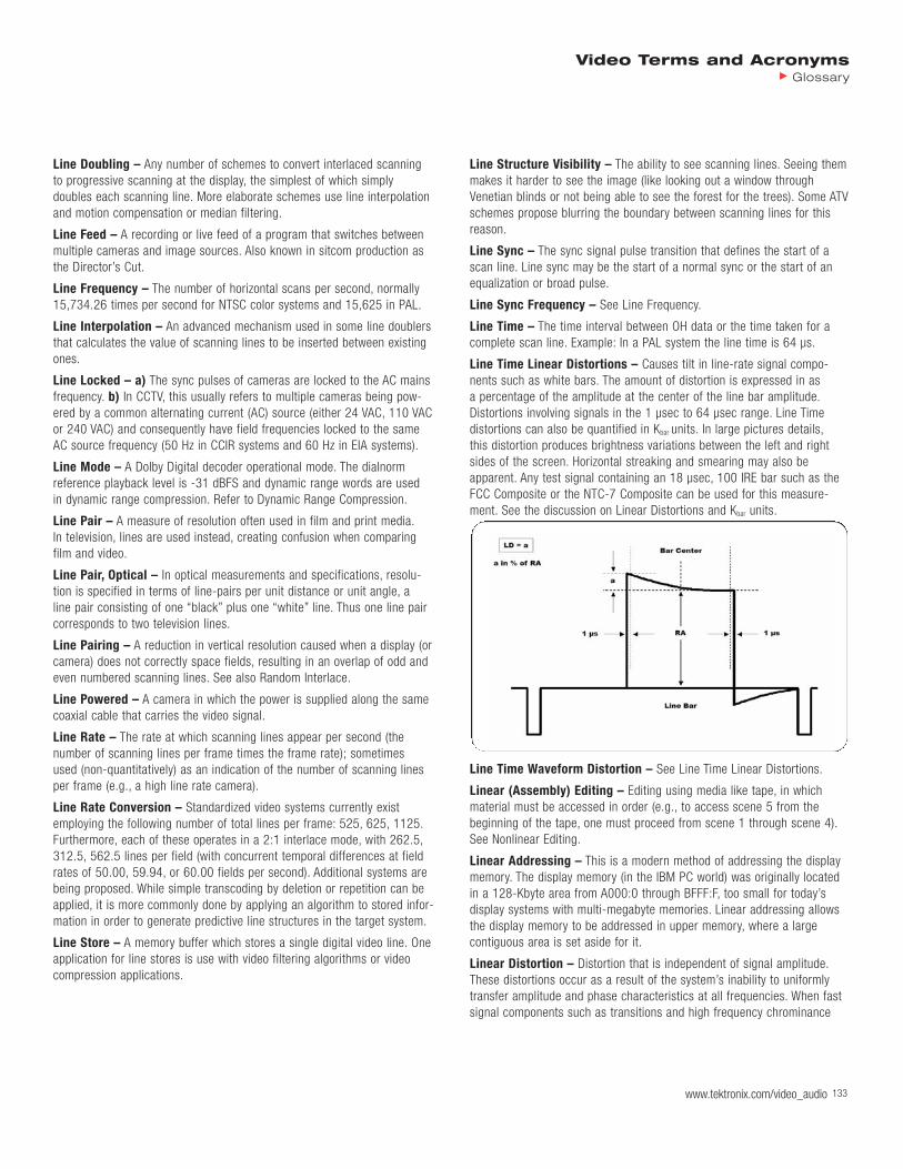
Video Terms and AcronymsGlossary
www.tektronix.com/video_audio 133
Line Doubling – Any number of schemes to convert interlaced scanningto progressive scanning at the display, the simplest of which simply doubles each scanning line. More elaborate schemes use line interpolationand motion compensation or median filtering.
Line Feed – A recording or live feed of a program that switches betweenmultiple cameras and image sources. Also known in sitcom production asthe Director’s Cut.
Line Frequency – The number of horizontal scans per second, normally15,734.26 times per second for NTSC color systems and 15,625 in PAL.
Line Interpolation – An advanced mechanism used in some line doublersthat calculates the value of scanning lines to be inserted between existingones.
Line Locked – a) The sync pulses of cameras are locked to the AC mainsfrequency. b) In CCTV, this usually refers to multiple cameras being pow-ered by a common alternating current (AC) source (either 24 VAC, 110 VACor 240 VAC) and consequently have field frequencies locked to the sameAC source frequency (50 Hz in CCIR systems and 60 Hz in EIA systems).
Line Mode – A Dolby Digital decoder operational mode. The dialnorm reference playback level is -31 dBFS and dynamic range words are used in dynamic range compression. Refer to Dynamic Range Compression.
Line Pair – A measure of resolution often used in film and print media.In television, lines are used instead, creating confusion when comparingfilm and video.
Line Pair, Optical – In optical measurements and specifications, resolu-tion is specified in terms of line-pairs per unit distance or unit angle, a line pair consisting of one “black” plus one “white” line. Thus one line paircorresponds to two television lines.
Line Pairing – A reduction in vertical resolution caused when a display (orcamera) does not correctly space fields, resulting in an overlap of odd andeven numbered scanning lines. See also Random Interlace.
Line Powered – A camera in which the power is supplied along the samecoaxial cable that carries the video signal.
Line Rate – The rate at which scanning lines appear per second (the number of scanning lines per frame times the frame rate); sometimes used (non-quantitatively) as an indication of the number of scanning linesper frame (e.g., a high line rate camera).
Line Rate Conversion – Standardized video systems currently existemploying the following number of total lines per frame: 525, 625, 1125.Furthermore, each of these operates in a 2:1 interlace mode, with 262.5,312.5, 562.5 lines per field (with concurrent temporal differences at fieldrates of 50.00, 59.94, or 60.00 fields per second). Additional systems arebeing proposed. While simple transcoding by deletion or repetition can beapplied, it is more commonly done by applying an algorithm to stored infor-mation in order to generate predictive line structures in the target system.
Line Store – A memory buffer which stores a single digital video line. Oneapplication for line stores is use with video filtering algorithms or videocompression applications.
Line Structure Visibility – The ability to see scanning lines. Seeing themmakes it harder to see the image (like looking out a window throughVenetian blinds or not being able to see the forest for the trees). Some ATVschemes propose blurring the boundary between scanning lines for thisreason.
Line Sync – The sync signal pulse transition that defines the start of ascan line. Line sync may be the start of a normal sync or the start of anequalization or broad pulse.
Line Sync Frequency – See Line Frequency.
Line Time – The time interval between OH data or the time taken for acomplete scan line. Example: In a PAL system the line time is 64 µs.
Line Time Linear Distortions – Causes tilt in line-rate signal compo-nents such as white bars. The amount of distortion is expressed in as a percentage of the amplitude at the center of the line bar amplitude.Distortions involving signals in the 1 µsec to 64 µsec range. Line Time distortions can also be quantified in Kbar units. In large pictures details,this distortion produces brightness variations between the left and rightsides of the screen. Horizontal streaking and smearing may also be apparent. Any test signal containing an 18 µsec, 100 IRE bar such as theFCC Composite or the NTC-7 Composite can be used for this measure-ment. See the discussion on Linear Distortions and Kbar units.
Line Time Waveform Distortion – See Line Time Linear Distortions.
Linear (Assembly) Editing – Editing using media like tape, in whichmaterial must be accessed in order (e.g., to access scene 5 from thebeginning of the tape, one must proceed from scene 1 through scene 4).See Nonlinear Editing.
Linear Addressing – This is a modern method of addressing the displaymemory. The display memory (in the IBM PC world) was originally locatedin a 128-Kbyte area from A000:0 through BFFF:F, too small for today’s display systems with multi-megabyte memories. Linear addressing allowsthe display memory to be addressed in upper memory, where a large contiguous area is set aside for it.
Linear Distortion – Distortion that is independent of signal amplitude.These distortions occur as a result of the system’s inability to uniformlytransfer amplitude and phase characteristics at all frequencies. When fastsignal components such as transitions and high frequency chrominance

134 www.tektronix.com/video_audio134134134134134134
Video Terms and AcronymsGlossary
are affected differently than slower line-rate or field-rate information, lineardistortions are probably present. These distortions are more commonlycaused by imperfect transfer characteristics in the signal path. Howeverlinear distortions can also be externally introduced. Signals such as powerline hum can couple into the video signal and manifest themselves as dis-tortions.
Linear Editing – A type of tape editing in which you assemble the pro-gram from beginning to end. If you require changes, you must re-recordeverything downstream of the change. The physical nature of the medium(for example, analog videotape) dictates how you place material on themedium. See Nonlinear Editing.
Linear Key – a) A term given to a key which contains soft edges andinformation at many different luminance levels. This is the ability of thekeyer to key many levels linearly and means the keyer has a gain close to one. b) A process for the selective overlay of one video image uponanother, as through chroma key. Control of the ratio of foreground to back-ground determined by the specifications derived from luminance informa-tion, and provided in the linear key data. Ratios to be applied are carriedfor each picture element in the alpha channel. The process permits realisticrendering of semi-transparent objects.
Linear PCM – One of the allowed types of audio formats for DVD. It mayhave up to 8 channels and provide very high sample rates and sampledepths. Unfortunately, these very high data rates consume so much DVDcapacity that meaningful quantities of both audio and video become prob-lematic.
Linear Predictive Coding (LPC) – LPC is a speech coding technique.It models the human vocal tract by producing a time varying filter that predicts the current speech sample from past speech samples.
Linear Pulse Distribution Amplifier (Linear Pulse DA) – A linear pulse distribution amplifier will handle 4 Vp-p signals (pulses) but is limited toamplifying and fanning out the signal. Also see Regenerative Pulse DA.
Linear Select Decoding – Address decoding technique that uses themost significant address bits to directly enable devices in the system.
Linear Time Code (LTC) – Time code recorded on a linear analog trackon a videotape. This type of time code can be read only while the tape ismoving.
Linearity – a) This is the basic measurement of how well analog to digitaland digital to analog conversion are performed. To test for linearity, amathematically perfect diagonal line is converted and then compared to acopy of itself. The difference between the two lines is calculated to showlinearity of the system and is given as a percentage or range of LeastSignificant Bits. b) The uniformity of scanning speed which primarilyaffects the accuracy of geometry along a horizontal or vertical line throughthe picture center. c) The measurement of how accurately a piece of electronic equipment processes a signal, (a measure of its transparency).
Line-Locked Clock – A design that ensures that there is always a constant number of samples per scan line, even if the timing of the linechanges.
Line-Out Monitor – A monitor connected to a recording device that displays the finished product. A line-out monitor may be a video monitor(video product), an audio speaker (audio product), or a television (bothaudio and video).
Liners/Friction Plates – Friction controlling plastic sheets used inside aPhilips cassette to control winding uniformity and torque level.
Lines – Scanning lines or lines of resolution. The latter are hypotheticallines alternating between white and black (or, in the case of chroma resolu-tion, between complementary colors). The combined maximum number of black and white lines that might be perceived in a particular direction is the number of lines of resolution. Vertical resolution is measured with horizontal lines; horizontal resolution is measured with vertical lines; diagonal resolution is measured with diagonal lines (no current televisionsystem or proposal favors one diagonal direction over the other, so thedirection of the diagonal lines does not really matter). See also PPH.
Lines, Active Horizontal – In the scanning of a video image, the linenumber associated with the format is the total number of lines assigned toone frame. It is in fact a timing specification defining the conjunction withthe field frequency the time interval allocated to each horizontal line (com-monly measured in number of samples at the specified sampling rate or inmicroseconds). Some of these lines and intervals carry image information,some from the total assigned are dedicated to operational and controlfunctions, including returning the scanning beam back to the upper leftcorner to begin the next field. Those allotted time intervals (lines) actuallycarrying image information or image-associated information such as cap-tioning, image test signals, etc., are the active lines. In further reduction oftime allocated to image information, some of each active line is dedicatedto the horizontal interval to get the scanning beam to return to the left-edge starting point for the next line and to reaffirm color subcarrier, etc.In the U.S. 525/59.94/2:1/NTSC system, about 7.6% of the total field orframe time is assigned to the vertical interval, and about 16% to the horizontal interval. Thus, the 525 television lines per frame provide about480 active lines. Correspondingly, each active line displays image dataabout 84% of its time interval. Image information is thus conveyed for onlyabout 76.4% of the total time. In digital encoding, it may be possible toreduce the number of bits assigned to the vertical and horizontal intervalsand achieve significant bit rate reduction.
Lines, Active Vertical – In a scanning standard, the number of rasterlines per frame that are not required to contain blanking. The active verticallines may include signals containing non-image information.
Lines, Television – Television images are scanned in a sequence of horizontal lines, beginning at the upper left corner, and reaching the bottom right corner at the end of the field. Thereupon the scan is returnedto the upper left corner to begin the next field. As a consequence of theline structure, all television images are sampled vertically. Within a line,the signal may remain analog or be sampled digitally. A television line isalso a measure of time, representing the interval allocated to one line.(In the U.S. system 525/59.94/2:1, the line duration is 63.5 s). Televisionlines also function as a geometric measure, with resolution (both verticaland horizontal), for example, specified in terms of “lines per pictureheight”. Since both “black” and “white” lines of a resolution chart arecounted, two television lines equal one cycle of the electrical waveform.

Video Terms and AcronymsGlossary
www.tektronix.com/video_audio 135
Link – A Physical Layer communication path.
Lip Synchronization – The absence of noticeable lag or lead between thevideo and the audio playback.
Liquid Gate – A printing system in which the original is immersed in asuitable liquid at the moment of exposure in order to reduce the effect ofsurface scratches and abrasions.
List Box – Used to make a selection from a list of options. If the list is toolong to fit inside the given area, a vertical scroll bar moves the list up anddown.
Listener – Device that inputs data from a data bus.
Little Endian – A process which starts with the low-order byte and endswith the high-order byte. Intel processors use the little endian format.
Live – Actually presented in the studio, with cameras feeding out to thelines as the performance is done.
LLC (Logical Link Control) – In the Open Systems Interconnection (OSI)model of communication, the Logical Link Control Layer is one of two sub-layers of the Data-Link Layer and is concerned with managing traffic (flowand error control) over the physical medium. The Logical Link Control Layeridentifies a line protocol, such as SDLC, NetBIOS, or NetWare, and mayalso assign sequence numbers to frames and track acknowledgements.)
LLME (Lower Layer Management Entity) – Contains the managementfunctions and functions that concern more than one layer.
LMDS (Local Multi-Point Distribution System) – A digital wirelesstransmission system that works in the 28 GHz range in the U.S. and 24-40GHz overseas. It requires line of sight between transmitter and receivingantenna, which can be from one to four miles apart depending on weatherconditions. LMDS provides bandwidth in the OC-1 to OC-12 range, whichis considerably greater than other broadband wireless services. LMDS canbe deployed in asymmetric and symmetric configurations. It is designed toprovide the “last mile” from a carrier of data services to a large building or complex that is not wired for high-bandwidth communications. In areaswithout gas or steam pipes or other underground conduits, it is less costlyto set up LMDS transceivers on rooftops than to dig up the ground toinstall optical fiber. See MMDS.
L-Member (Liaison Member) – A term used within ISO/IEC JTC1 committees. A Liaison Organization does not vote.
LNB (Low-Noise Block Converter) – A device hooked to a satellitedish’s feedhorn that receives the signal at ~4 or 12 GHz and converts it toa lower frequency for input into a receiver.
LO (Local Origination Channel) – A channel on a cable system (exclu-sive of broadcast signals) which is programmed by the cable operator andsubject to his exclusive control.
Lo/Ro (Left Only, Right Only) – A type of two-channel downmix for multichannel audio programs. Lo/Ro downmixes are intended for applica-tions where surround playback is neither desired nor required.
Load – a) A roll of film stock ready to be placed in the camera for photography. A 1000-foot load is a common standard. b) A group of multicamera reels shot at the same time, sharing the same timecode,and numbered accordingly.
Load Resistance – The impedance or resistance (load) that a cableplaces on a signal being transmitted through it. In the case of a high frequency signal, signal-to-cable matching is essential to prevent signaldeterioration. The cable should be terminated by a specific load resistance,usually 50 or 75 ohms. Improper cable loading results in signal distortion,ghost images, color loss and other adverse phenomena. Most video inputshave the proper termination built in.
LOAS (Low Overhead Audio Stream) – This is an audio-only transportformat for applications where an MPEG-4 audio object needs to be trans-mitted and additional transport overhead is an issue.
Local Bus Transfer – The host/local bus transfer consumes a smallerpercentage of available bandwidth during video/graphics transfers thanearlier bus standards but the still-noticeable performance penalty may beobjectionable for some users, especially when compared to systems thatcircumvent it.
Local Decode – A feature of Indeo video interactive allowing the playbackapplication to tell the codec to decode only a rectangular subregion of thesource video image: the viewport. See Viewport.
Local Tally – A tally of which bus on an M/E is active regardless ofwhether or not it is on air.
Local Workstation, Drive, Disk, File System, or Printer – The physicalworkstation whose keyboard and mouse you are using, all hardware that is connected to that workstation, and all software that resides on thathardware or its removable media.
Locate (Menu) – The 3D function used to move or relocate an image.Locate moves the image as if it were in three-dimensional space, eventhough the image is seen on a two-dimensional video screen.
Location – Shooting locale.
Locator – A mark added to a selected frame to qualify a particular loca-tion within a sequence. User-defined comments can be added to locators.
Locked – a) A video system is considered to be locked when the receiver is producing horizontal syncs that are in time with the transmitter.b) When a PLL is accurately producing timing that is precisely lined upwith the timing of the incoming video source, the PLL is said to be“locked”. When a PLL is locked, the PLL is stable and there is minimum jitter in the generated sample clock.
Locking Range – The time range measured in micro- or nano-secondsover which a video decoder can “lock” or stabilize a signal. Digital out ofrange signals may require “rubber-band” buffering using a parallel shiftregister (FIFO) to reduce the locking range.
Lock-Up Time – The time before a machine is activated and the time it isready for use.
LOD (Level of Detail) – An important mechanism for achieving a highlevel of performance in a 3D virtual world. It balances the quantity (extent)of an object with its quality (detail). As some measure of the distancebetween the viewer and the object change, a related change is made in the quantity and quality of the rendering of an object.
LOF (Loss of Frame) – LOF is a generic term with various meaningsdepending on the signal standards domain in which it is being used. A

136 www.tektronix.com/video_audio136136136136136136
Video Terms and AcronymsGlossary
SONET port status indicator that activates when an LOF defect occurs anddoes not clear for an interval of time equal to the alarm integration period,which is typically 2.5 seconds.
Lofting – The ability to stretch a “skin” over shapes that are in fact cross-sectional ribs.
Log – To enter information about your media into bins at the beginning ofthe editing process. Logging can be done automatically or manually. SeeShot Log.
Logarithm – A logarithm is the power to which a base (usually 10) mustbe raised in order to arrive at the desired value.
Logarithmic Scale – A mathematical function which spreads out low values and squeezes together higher values.
Logic Analyzer – Test system capable of displaying 0s and 1s, as well asperforming complex test functions. Logic analyzers typically have 16 to 32input lines and can store sequences of sixteen or more bits on each of theinput lines.
Logic Comparator – Test product that compares pin-for-pin operation ofan IC operating in-circuit with a known good reference IC.
Logic Probe – Handheld troubleshooting tool that detects logic state andactivity on digital circuit nodes.
Logic Pulser – Handheld troubleshooting tool that injects controlled digitalsignals into logic nodes.
Logical – An artificial structure or organization of information created forconvenience of access or reference, usually different from the physicalstructure or organization. For example, the application specifications ofDVD (the way information is organized and stored) are logical formats.
Logical Channel – A virtual connection between peer Multiplex Layer(FlexMux or TransMux) entities. It has associated parameters relating to itspriority or error resilience tools applied to the Adaption Layer packets to betransported in this logical channel.
Logical Unit – A physical or virtual peripheral device, such as a DVD-ROMdrive.
Logical Value – A description of the memory blocks disks used for theframe store.
Login – To log in to a workstation is to establish a connection to the workstation and to identify yourself as an authorized user.
Login Account – A database of information about each user that, at theminimum, consists of login name, user ID, and a home directory.
Login Name – A name that uniquely identifies a user to the system.
Login Screen – The window that you see after powering on the system,before you can access files and directories.
Logout – To log out from a workstation is to finish a connection to theworkstation.
Long Shot – Camera view of a subject or scene, usually from a distance,showing a broad perspective.
Long Time Distortion – The low frequency transient resulting from achange in APL. This distortion usually appears as a very low frequencydamped oscillation. The peak overshoot, in IRE, is generally quoted as theamount of distortion. Setting time is also sometimes measured.
Long Time Linear Distortions – Distortions involving signals in thegreater-than-16 msec range. Long time distortions affect slowly varyingaspects of the signal such as changes in APL which occur at intervals of a few seconds. The affected signal components range in duration from 16 msecs to tens of seconds. The peak overshoot, in IRE, which occurs asa result of an APL change is generally quoted as the amount of distortion.Settling time is also sometimes measured. Long time distortions are slowenough that they are often perceived as flicker in the picture. See the discussion on Linear Distortions.
Longitudinal Curvature – Any deviation from straightness of a length oftape.
Longitudinal Direction – Along the length of the tape.
Longitudinal Time Code (LTC) – Audio rate time code information that is stored on its own audio track. This audio rate signal allows the editingsystem to track the position of the tape even at high shuttle speeds whereVITC data could not be used.
Look Ahead Preview – See Preview.
Lookup Table (LUT) – Files used to convert color information in an image.
Loop – Piece of tape spliced beginning (head) to end (tail) for continuousplayback or recording. To fold around. A loop/slack section of film with thenecessary “play” to allow film which had been previously and continuouslymoving from a reel to be intermittently moved through a grate/projectionhead/optical lens arrangement. Proper loop size is important in threading afilm projector, i.e., in telecine for film to videotape transfer.
Loop Filter – Used in a PLL design to smooth out tiny inaccuracies in theoutput of the phase comparator that might drive the loop out of lock. Theloop filter helps to determine how well the loop locks, how long it takes tolock and how easy it is to cause the loop out of lock.
Loop Frame Store – The principal is that a series of video frames is com-pressed and stored in a continuous loop. This records a certain number offrames and then records over them again until an alarm signal is received.When this happens it carries on recording for a dozen frames or so andthen stops. This means that frames before and after the incident are

Video Terms and AcronymsGlossary
www.tektronix.com/video_audio 137
recorded. This eliminates the boring searching through hours of videotapeand concentrates on the period of activity.
Loop Through – A video signal entering a piece of equipment is returnedto the outside world for further use. Loop through circuitry requires carefuldesign to prevent signal degradation.
Looping – a) A term used to describe the chaining of a video signalthrough several video devices (distribution amplifiers, VCRs, monitors, etc.).A VCR may be hooked up to a distribution amplifier which is supplied witha video input connector and a loop output connector. When a signal is fedto the distribution amplifier, it is also fed unprocessed to the loop outputconnector (parallel connection) on the distribution amplifier. In turn, thesame signal is fed to another device which is attached to the first one andso on. Thus a very large number of VCRs or other video devices can belooped together for multiple processing. b) An input that includes two con-nectors. One connector accepts the input signal, and the other connector is used as an output for connecting the input signal to another piece ofequipment or to a monitor.
Loss – Reduction in signal strength or level.
Lossless (Compression) – a) Reducing the bandwidth required for transmission of a given data rate without loss of any data. b) Image compression where the recovered image is identical to the original.c) The reconstructed data is degraded relative to the source material bythe method of removal of redundant information from the media whilecompressing. See Lossy (Compression).
Lossy (Compression) – a) Image compression where the recoveredimage is different from the original. b) Compression after which some portion of the original data cannot be recovered with decompression. Suchcompression is still useful because the human eye is more sensitive tosome kinds of information than others, and therefore does not necessarilynotice the difference between the original and the decompressed image.c) Reducing the total data rate by discarding data that is not critical. Boththe video and audio for DTV transmission will use lossy compression.See Lossless (Compression).
Low Band Color – The old, original professional videotape color recording.
Low Delay – A video sequence does not include B-pictures when the lowdelay flag is set; consequently, the pictures follow in chronological order,and low delay is obtained. Normally, when B-pictures are included, the pictures used for prediction of a B-picture are sent in advance so they areavailable when the B-picture arrives, but this increases the delay.
Low End – The lowest frequency of a signal. See High End.
Low Impedance Mike – A mike designed to be fed into an amplifier ortransformer with input impedance of 150 to 250 ohms.
Low Key – A scene is reproduced in a low key if the tone range of thereproduction is largely in the high density portion of the H and D scale ofthe process.
Lower Layer – A relative reference to the layer immediately below a givenEnhancement Layer (implicitly including decoding of all layers below thisEnhancement Layer).
LowFER – One who experiments with radio communication at unusuallylow frequencies (typically 1750 meters, which is 160-90 kHz and can beused under FCC Part 15).
Low-Frequency Amplitude Distortion – A variation in amplitude levelthat occurs as a function of frequencies below 1 MHz.
Low-Frequency Distortion – Distortion effects which occur at low frequency. Generally considered as any frequency below the 15.75 kc linefrequency.
Low-Order – Pertaining to the weight or significance assigned to the digits of a number. In the number 123456, the lower order digit is six.The three low-order bits of the binary word 11100101 are 101.
Lowpass Filter – a) Filter that passes frequencies below a specific frequency. b) A filter specifically designed to remove frequencies above thecutoff frequency, and allow those below to pass unprocessed is called alowpass filter. The effect of a lowpass filter is to reduce the amplitude ofhigh frequencies. Common examples include the “treble” controls on manylower end radios and stereos, the passive “tone” controls often found onelectric guitars and basses, hi-cut filters on consoles, and of course, thistype of filter is found on many synthesizers.
LPC (Linear Predictive Coding) – An encoding technique used to aid inthe prediction of the next sample. This technique can be found in manyanalogue to digital conversion processes.
LPCM (Linear Pulse Code Modulation) – A pulse code modulation system in which the signal is converted directly to a PCM word withoutcompanding, or other processing. Refer to PCM.
LPTV (Low Power TV) – LPTV stations provide their communities withlocal programming, covering events and issues in a smaller area than mostTV stations. There were licensed in the United States, 2,190 LPTV stationsas of July 1, 1999. As LPTV signals are comparatively weak, LPTV stationsdon’t generally interfere with larger TV stations using the same frequency.
LS/RS (Left Surround, Right Surround) – The actual channels or speakers delivering discrete surround program material.
LSB – See Least Significant Bit.
LSI – See Large Scale Integration.
LSP (Line Spectral Pairs) – An alternative representation of linear predictor coefficients. LSPs have very good quantization properties for use in speech coding systems.
LSTTL (Low Power Schottky TTL) – Digital integrated circuits thatemploy Schottky diodes for improved speed/power performance over standard TTL.
Lt/Rt (Left Total, Right Total) – Two-channel delivery format for DolbySurround. Four channels of audio, Left, Center, Right and Surround (LCRS)are matrix encoded for two-channel delivery (Lt/Rt). Lt/Rt encoded pro-grams are decoded using Dolby Surround and Dolby Surround Pro Logicdecoders. Refer to Dolby Surround and Dolby Surround Pro Logic.
LTC – See Linear Time Code or Longitudinal Time Code.
138
LTP (Long Term Prediction) – A method to detect the innovation in thevoice signal. Since the voice signal contains many redundant voice seg-ments, we can detect these redundancies and only send information aboutthe changes in the signal from one segment to the next. This is accom-plished by comparing the speech samples of the current segment on asample by sample basis to the reconstructed speech samples from theprevious segments to obtain the innovation information and an indicator ofthe error in the prediction.
LTS (Lifetime Time Stamp) – Gives the duration (in milliseconds) anobject should be displayed in a scene. LTS is implicit in some cases suchas a video sequence where a frame is displayed for 1/frame-rate or untilthe next frame is available, whichever is larger. An explicit LTS is necessarywhen displaying graphics and text. An audiovisual object should be decod-ed only once for use during its life time.
Luma – See the definition for Luminance.
Luma (Component) – A matrix, block or single pel representing a mono-chrome representation of the signal and related to the primary colors in themanner defined in the bit stream. The symbol used for luma is Y.
Luma Bandpass – A filter used to pass luma information only. It is usedfor the same purpose as a chroma bandpass filter. See Chroma Bandpass.
Luma Delay – Luma delay is used in PAL/NTSC encoding and colordecoding in TV systems and processing of luminance in VTRs. The Y signaloccupies a greater bandwidth than the low definition, narrowband chroma.This also means that the signal is delayed less as the bandwidth of a cir-cuit increases. Without a delay, the chroma would be printed slightly laterthan the corresponding luminance signal.
Lumakey – When keying one image onto another, if the composition isbased on a combination of luminance and brightness values, it constitutesa lumakey.
Lumen (lu) – A light intensity produced by the luminosity of one candelain one radian of a solid angle.
Luminance (Y) – Video originates with linear-light (tristimulus) RGB primary components, conventionally contained in the range 0 (black) to +1 (white). From the RGB triple, three gamma-corrected primary signalsare computed; each is essentially the 0.45-power of the correspondingtristimulus value, similar to a square-root function. In a practical systemsuch as a television camera, however, in order to minimize noise in thedark regions of the picture it is necessary to limit the slope (gain) of thecurve near black. It is now standard to limit gain to 4.5 below a tristimulusvalue of +0.018, and to stretch the remainder of the curve to place the Y-intercept at -0.099 in order to maintain function and tangent continuityat the breakpoint:
Rgamma = (1.099 * pow(R,0.45)) – 0.099
Ggamma = (1.099 * pow(G,o.45) – 0.099
Bgamma = (1.099 * pow (B,0.45) – 0.099
Luma is then computed as a weighted sum of the gamma-corrected primaries.
Y = 0.299 * Rgamma + 0.587 * Ggamma + 0.114 * Bgamma
The three coefficients in this equation correspond to the sensitivity ofhuman vision to each of the RGB primaries standardized for video. Forexample, the low value of the blue coefficient is a consequence of saturated blue colors being perceived as having low brightness. The luma coefficients are also a function of the white point (or chromaticity ofreference white). Computer users commonly have a white point with a colortemperature in the range of 9300 K, which contains twice as much blue as the daylight reference CIE D65 used in television. This is reflected inpictures and monitors that look too blue. Although television primaries havechanged over the years since the adoption of the NTSC standard in 1953,the coefficients of the luma equation for 525 and 625 line video haveremained unchanged. For HDTV, the primaries are different and the lumacoefficients have been standardized with somewhat different values. Thesignal which represents brightness, or the amount of light in the picture.This is the only signal required for black and white pictures, and for colorsystems it is obtained as the weighted sum (Y = 0.3R + 0.59G + 0.11B)of the R, G and B signals.
Luminance Factor b – At a surface element of a non self-radiating medi-um, in a given direction, under specified conditions of illumination, ratio of the luminance of the surface element in the given direction to that of aperfect reflecting or transmitting diffuser identically illuminated. No “perfectreflectors” exist, but properly prepared magnesium oxide has a luminancefactor equal to 98% and this is usually employed to define the scale.
Luminance Key – A key wherein the keying signal is derived from theinstantaneous luminance of a video signal after chroma has been filteredout. That is, for a particular clip level, all parts of a scene that are brighterthan that level will appear keyed in, leaving background video everywhereelse.
Luminance Noise – Noise which manifests itself in a video picture aswhite snow, typically caused by one of the following situations: low signallevel due to poor lighting conditions, poor video signal processing, lowquality videotapes, excessively long video cables used without pre-compen-sation, dirt on the video recorder heads which interferes with reading andwriting, over-enhancement of the video signal.
Video Terms and AcronymsGlossary
www.tektronix.com/video_audio

Luminance Nonlinearity – Present if luminance gain is affected by luminance levels. This amplitude distortion is a result of the system’sinability to uniformly process luminance information over the entire amplitude range. This distortion is also called differential luminance.
The amount of luminance nonlinearity distortion is expressed as a percent-age. Measurements are made by comparing the amplitudes of the individ-ual steps in a staircase signal as shown. The result is the differencebetween the largest and smallest steps, expressed as a percentage of thelargest step. Measurements should be made at both high and low APL andthe worst error should be quoted. In black and white pictures, luminancenonlinearity will cause pictures loss of detail in shadows and highlightswhich are caused by the crushing or clipping of the white or black portionsof the signal. In color pictures, luminance nonlinearity will cause colors inthe high luminance portions of the picture to be distorted.
Luminance Range – The range in measured luminance between the lightest and the darkest element of a luminous scene or its display.
Luminance Range, Display CRT – The luminance range that can be displayed on a CRT is the ratio of maximum to minimum luminance on thetube face. The maximum practical output is determined by beam current,phosphor efficiency, shadow-mask distortion, etc. The minimum is theluminance of that portion of the tube face being scanned with beam cur-rent set to cut-off. The contributions from room illumination, external andinternal reflections, etc., must be recognized.
Luminance Range, Display Theater – The luminance range that can bedisplayed on a theater projection screen is the ratio of maximum to mini-mum luminance achievable during projection of film. The maximum achiev-able highlight is determined by light-source output capacity, projectionoptical efficiency, the transmission of minimum film densities, screen gain,etc. The minimum is the luminance contribution from house illuminationand other stray light, plus optical flare raising black levels, and the trans-mission of maximum film densities. Measured values in typical first-runtheaters show luminance ranges of 500:1 to 300:1 (usually limited byhouse illumination).
Luminance Range, Recorded – The luminance range, recorded may be reduced from the luminance range, scene intentionally and/or by thelimitations of the recording system. Most systems have a maximum effective signal level limiting the high end, and noise limiting the low
end. All of the scene that is of interest must be placed within these twolimits by the choice of an appropriate transfer function. Some analog functions permit gradual transitions to overload and/or noise. Digital functions have inflexible limits imposed by the number of levels permittedby the bit assignments.
Luminance Range, Scene – The luminance range of original scenesvaries from outdoor scenes in sunlight with a range possibly exceeding10000:1, to indoor scenes with controlled lighting, where the range may be reduced to 10:1 or even less. Adjustment of or accommodation to theluminance range, scene is one of the conditions to be evaluated in deter-mining how the scene is to be recorded. It is a test of artistic judgment to place the relative luminances for the objects of interest on a suitableportion of the opto-electronic or opto-photographic transfer function inorder to produce the desired subjective quality.
Luminance Signal – The black and white signal (the brightness signal) incolor TV. The luminance signal is formed by combining a proportion of 30%red, 50% green and 11% blue from the color signal. This combined outputbecomes the luminance (brightness/monochrome) signal.
Luminance, Constant (Video) – In an image coding system that derivesa luminance signal and two bandwidth-limited color-difference signals,constant luminance prevails if all of the luminance information is encodedinto one signal that is supplemented by but totally independent of two colorsignals carrying only chrominance information, e.g., hue and saturation.Constant luminance is only achieved when the luminance and chrominancevectors are derived from linear signals. The introduction of nonlinear transform characteristics (usually for better signal-to-noise and control ofdynamic range prior to bandwidth reduction) before creating the luminanceand chrominance vectors destroys constant luminance. Current video sys-tems do not reconstitute the luminance and chrominance signals in theirlinear form before further processing and, therefore, depart from constantluminance. Note: When R, G, B information is required to be recoveredfrom the set of luminance and color-difference signals, the values correlat-ed to the original signals are obtained only if the luminance and chromi-nance signals have been derived from the linear functions of R, G, B orhave been transformed back to linear. Constant luminance not only pro-vides a minimum of subjective noise in the display (since the luminancechannel does not respond to chrominance noise), but also preserves thisnoise minimum through chrominance transformations.
Luminance, Physics (Generic Usage) – a) Luminance has technical as well as colloquial definitions. The generic flux from a light-emitting or light-reflecting surface; the subjective response to luminance is brightness.The quotient of the luminous flux at an element of the surface surroundingthe point and propagated in directions defined by an elementary cone containing the given direction, by the product of the solid angle of the coneand the area of the orthogonal projection of the element of the surface on a plane perpendicular to the given direction. b) The luminous flux may be leaving, passing through, and arriving at the surface or both. The lumi-nance for each element of a surface within the field of view is defined asthe ratio of luminous flux per solid angle to the unit projected area of thesurface. Units are candelas per square meter, foot lamberts, nits.
Video Terms and AcronymsGlossary
www.tektronix.com/video_audio 139

140
Luminance, Relative, Scene – A convenient linear scale for measuring in arbitrary units the relative luminance amplitudes within the scene, to berecorded in a video or photographic image, as shown below. The relativeluminance scale is one factor affecting the choice of suitably artistic scenereproduction. It may establish the optimum rendition of reference white andoptimum employment of the nonlinear transfer function in image recording.Note: This relative luminance scale (linear in luminance) resembles IREunits (linear in voltage) in positioning both black level reference and refer-ence white at 0 and 100, respectively, but that it differs in recognizing theextended luminance range of many commonly encountered scenes.
Correlation of Relative Scene Luminance
Reflectance Relative Scene RelativeFactor Luminance (1) Camera
% Scale Stops
Typical Limit of Interest – 640 +5– 320 +4– 160 +3
Reference White (2) 90 100 –– 80 +2– 40 +1
Gray Card (3) 18 20 0– 10 1– 5 –2
Scene Black 0 0 –
(1) IEEE Dictionary of Electrical and Electronics Terms defines luminance factor as the ratio to a perfect reflector rather than as the ratio to referencewhite. In practical electronic production, relative scene luminance is a more useful measure.
(2) Under scene illumination, the light from a nonselective diffuse reflector(white card) whose reflectance is 90% compared to a perfect reflector (prepared magnesium oxide = 98%).
(3) Under scene illumination, the light from a nonselective diffuse reflector(gray card) whose reflectance is 18% compared with that of a perfectreflector.
Luminance, Television – a) When television was monochrome and sensors were in approximate conformance to CIE Photopic SpectralLuminous Efficiency Function, it became common to think of the video signal as the luminance signal. With the introduction of color, a matrix was designed to develop a luminance function by weighting the R, G, Bsignals in accordance with the CIE Photopic Spectral Luminance EfficiencyFunction, producing a video signal compatible with monochrome receivers.b) A signal that has major control of the image luminance. It is a linearcombination of gamma-corrected primary color signals. c) The specificratio of color primaries that provides a match to the white point in a speci-fied color space. d) The definition of luminance, television is identical forNTSC, PAL, and SECAM (CCIR Report 624-4), as follows: E’Y = (0.299) E’R+ (0.587) E’G + (0.014) E’B. The weighting function is named luminancesignal in all of the television standards. For convenience and bandwidthconservation, however, it is always formed from the gamma correction signals (i.e., R’, G’, B’) and not from the initial linear signals, and thus it is not an exact representation of luminance, physics.
Luminescence – The absorption of energy by matter and its followingemission as light. If the light follows and then completes itself quickly afterabsorption of the energy, the term fluorescence is used. If the process is ofa longer and more persistent length, the term phosphorescence is applied.
Luminosity Curve – A function that expresses the apparent brightness ofthe spectral colors. It is used in video systems to calculate the luminancesignal.
Luminous Flux – a) The time rate of flow of light. b) The time rate of flowof radiant energy evaluated in terms of a standardized visual response.Unless otherwise indicated, the luminous flux is defined for photopic vision.The unit of flux is the lumen: the luminous flux emitted within unit solidangle by a point source having an isotropic luminous intensity of 1 can-dela.
LUT (Look-Up Table) – A cross-reference table in the computer memorythat transforms raw information from the scanner or computer and correctsvalues to compensate for weakness in equipment or for differences inemulsion types.
Lux (lx) – a) The metric unit for illumination is 1 lumen per square meter.1 foot candle = 10.76 Lux. b) A measurement of light. Lux is used in television production to determine the minimum amount of light (lux rating)needed for camera operation. Hence, a “2 lux” camcorder requires lesslight than a “4 lux” camcorder.
LV (LaserVision) – Technology used in optical video disk.
LVDS (Low Voltage Differential Signal) – A transmission methoddefined by DVB for sending digital information in parallel mode The specification within EN50083-9 describes a 25-pin type D connector using differential lines. The lines consist of a clock, eight data lines,packet sync, and a data-valid line. LVDS has been widely used in laptops to send signals from the motherboard to the flat panel display, because it uses fewer wires. The technology is also used between the image scaler and the panel in some stand-alone flat panel displays such as SGI’s popular 1600SW flat panel.
Video Terms and AcronymsGlossary
www.tektronix.com/video_audio

www.tektronix.com/video_audio 141
Video Terms and AcronymsGlossary
M – The CCIR designation for 525 scanning-line/30 frame-per-second television. U.S. color television is internationally designated NTSC-M. The M standard is the world’s second oldest (the oldest was a 405-line/25frame British standard, no longer broadcast).
M and E Tracks – a) Stands for music and effects audio tracks. b) Thecommon designation for a single sound track containing music and soundeffects but not dialog.
M Load – The cassette tape loading mechanism used in VHS videotaperecorder/playback technology.
M/E – See Mix Effects.
M/E Reentries – Those buttons on a bus that allow selection of previousM/Es for further processing to be overlaid.
M/E to M/E Copy – A panel memory enhancement allowing the operatorwith three keystrokes to copy all parameters from one M/E to another.
M/E to M/E Swap – A panel memory enhancement allowing the operatorwith three keystrokes to swap all parameters between two M/Es. Allparameters include key clip levels, pattern position, all hues and modifiersused as long as the M/Es are similarly equipped.
M2 – See Miller Squared Code.
M4IF (MPEG-4 Industry Forum) – The MPEG-4 Industry Forum startswhere the MPEG ends, i.e., dealing with all issues related to practicalimplementations of the theoretical standards set by the MPEG in commer-cial applications.
MAA (MPEG ATM Adaptation)
MAC (Multiplexed Analog Components) – a) A system in which thecomponents are time multiplexed into one channel using time domain techniques; that is the components are kept separate by being sent at different times through the same channel. There are many different MACformats and standards. b) A means of time multiplexing component analogvideo down a single transmission channel such as coax, fiber or a satellitechannel. Usually involves digital processes to achieve the time compres-sion. c) A large family of television signal formats sharing the following“two characteristics: color remains in a component rather than compositeform, and luminance and chrominance components are time compressedso that active line time remains constant, with chrominance following luminance. Most of the MACs also include digital audio/data channels.Since they are non-composite, MACs do not suffer from any cross-lumi-nance or cross-color effects. Since they are time compressed, they tend to have a greater base bandwidth than composite signals. See also ACLE,A-MAC, B-MAC, D-MAC, D-MAC, D2-MAC, HD-MAC, HD-MAC60, MAC-60,MUSE and S-MAC.
MAC-60 – An early version of the HDMAC-60.
Machine Code – See Machine Language.
Machine Cycle – Basic period of time required to manipulate data in asystem.
Machine Error – A machine hardware malfunction.
Machine Language – Binary language (often represented in hexadecimal)that is directly understood by the processor. All other programming languages must be translated into binary code before they can be enteredinto the processor.
Machine Operator – A person trained in the operation of a specificmachine.
Macro Lens – A lens used for videography when the camera-to-object distance is less than two feet. The macro lens is usually installed within the zoom lens of the video camera or camcorder.
Macroblock – a) The four 8 by 8 blocks of luminance data and the two(for 4:2:0 chroma format), four (for 4:2:2 chroma format) or eight (for4:4:4 chroma format) corresponding 8 by 8 blocks of chrominance datacoming from a 16 by 16 section of the luminance component of the picture. Macroblock is sometimes used to refer to the pel data and some-times to the coded representation of the pel values and other data ele-ments defined in the macroblock header. The usage should be clear fromthe context. b) The screen area represented by several luminance andcolor-difference DCT blocks that are all steered by one motion vector.c) The entity used for motion estimation, consisting of four blocks of luminance components and a number of corresponding chrominance components depending on the video format.
Macrovision – An analog protection scheme developed by Macrovision for the prevention of analog copying. It is widely used in VHS and has now been applied to DVD.
Mag Track – This term usually refers to the sound track. It is usually used only in reference to the separate sound tape used in double systemrecording and editing. Videotape is a magnetic medium too, but the termmag track is only used in reference to sound tape and not to sound on avideotape picture.
Magnetic Density – The amount of magnetic flux within a specific area.
Magnetic Field – An area under the influence of magnetism.
Magnetic Film – Sprocketed base with a magnetic coating for audiorecording and playback.
Magnetic Force – The amount of magnetic influence/force within a specific area/field.
Magnetic Head – That part of a videotape recorder which converts electric variations into magnetic variations and vice versa.
Magnetic Induction – To magnetize by being put within the magnetic influence of a magnetic field.
Magnetic Instability – The property of a magnetic material that causesvariations in the residual flux density of a tape to occur with temperature,time and/or mechanical flexing. Magnetic instability is a function of particlesize, magnetization and anisotropy.
M

142 www.tektronix.com/video_audio142142142142142142142
Video Terms and AcronymsGlossary
142
Magnetic Recording – The technology and process of recordingaudio/video information using magnetism as the medium for storage ofinformation. The term is often used to mean the process/capability of bothrecording and reproduction/playback.
Magnetic Tape – With a few exceptions, magnetic tape consists of a basefilm coated with magnetic particles held in a binder. The magnetic particlesare usually of a circular shape and approach single domain size. SeeGamma Ferric Oxide, Chromium Dioxide and Cobalt Doped Oxide.
Magnetic Track – A sound-track recorded on magnetic film or tape.
Magnetism – The property of certain physical materials to exert a forceon other physical materials, and to cause voltage to be induced in conduct-ing bodies moving relative to the magnetized body.
Magnetizing Field Strength, H – The instantaneous strength of the magnetic field applied to a sample of magnetic material.
Magneto-Optical – Recordable disc technology using a laser to heatspots that are altered by a magnetic field. Other formats include dye-subli-mation and phase-change.
Main Channel – The basic transmission channel of an ATV channel utilizing an augmentation channel.
Main data – User data portion of each sector. 2048 bytes.
Main Level – A range of allowed picture parameters defined by the MPEG-2 video coding specification with maximum resolution equivalent toITU-R Recommendation 601. MPEG-2 standard has four level which definethe resolution of the picture, ranging from SIF to HDTV and five profileswhich determine the set of compression tools used. The four levels can be described as:
1. Low Level: SIF resolution used in MPEG-1 (up to 360 x 288 pixels)
2. Main Level: Using 4:2:0 standard (720 x 576 pixels)
3. High 1440 Level: Aimed at HDTV (up to 1440 x 1152 pixels)
4. High Level: Wide screen HDTV (up to 1920 x 1152 pixels)
Main Profile – A subset of the syntax of the MPEG-2 video coding specifi-cation that is expected to be supported over a large range of applications.MPEG-2 standard uses four levels which define picture resolution and fiveprofiles which define the compression tools used.
MPEG Levels and Profile
Simple Main SNR Spatial High
High 4:2:0 4:2:0 or 4:2:21920 x 1152 1920 x 115280 Mbits/s 100 Mbits/s
I, B, P I, B, P
High 1440 4:2:0 4:2:0 4:2:0 or 4:2:21440 x 1152 1440 x 1152 1440 x 115260 Mbits/s 60 Mbits/s 80 Mbits/s
I, B, P I, B, P I, B, P
Main 4:2:0 4:2:0 4:2:0 4:2:0 or 4:2:2720 x 576 720 x 576 720 x 576 720 x 57615 Mbits/s 15 Mbits/s 15 Mbits/s 20 Mbits/s
I, B I, B, P I, B, P I, B, P
Low 4:2:0 4:2:0360 x 288 360 x 2884 Mbits/s 4 Mbits/s
I, B, P I, B, P
(1) Simple Profile: Defined in order to simpify the encoder and the decoder atthe expense of a higher bit rate.
(2) Main Profile: Best compromise with current technology between rate andcost.
(3) SNR Profile: A quality tradeoff is made against SNR performance. A low bitrate decoderwill have full resolution but will have lesssignal-to-noise ratiothan a high bit rate one.
(4) Spatial Profile: A tradeoff against spacial resolution. The low bit rate receiver produces a picture with less resolution than the full bit rate one.
(5) High Profile: Intended for HDTV broadcast applications in 4:2:0 or 4:2:2.
Main Visual Profile – Adds support for coding of interlaced, semitrans-parent, and sprite objects to the Core Visual Profile. It is useful for interac-tive and entertainment-quality broadcast and DVD applications.
Male Connector – A connector that has raised edges, pins, or other protruding parts that you plug into a female connector. An example of amale connector is an electrical plug that you plug into a wall outlet.
MAN (Metropolitan Area Network) – Network that spans a metropolitanarea. Generally, a MAN spans a larger geographic area than a LAN, but asmaller geographic area than a WAN.
Man Page – An on-line document that describes how to use a particularIRIX or UNIX command.
Mantissa – Fractional value used as part of a floating point number.For example, the mantissa in the number 0.9873 x 10⁷ is 0.9873.
Manual Iris – A manual method of varying the size of a lens’s aperture.
Mapping – a) A technique for taking a 2D image and applying (mapping)it as a surface onto a 3D object. b) Conversion of bytes (8 bits) to 2n-bitwide symbols. Thus n is the bit width for the I and Q quantization; e.g., at64 QAM the symbol width is 2n=6 bit, n=3, i.e., I and Q are subdividedinto 23=8 amplitude values each. c) Refers to the definition of memory for storing data used by a particular display mode. The range of addressesreserved for graphics information in IBM-compatible systems is fromA000:0 to BFFF:F.

www.tektronix.com/video_audio 143
Video Terms and AcronymsGlossary
Mark – Term used to describe the function of indicating to the editorwhere the entry or exit of the edit will be done on the fly.
Mark IN – To select the first frame of a clip.
Mark IN/OUT – a) The process of entering the start and end time codesfor a clip to be edited into a sequence. b) The process of marking or logging timecode numbers to define clips during a logging, recording ordigitizing session. See also IN Point, OUT Point.
Mark OUT – To select the last frame of a clip.
Mask – a) A mask image is a black and white image, which defines howopaque each pixel is. A mask blocks out certain components of an imagebut lets other parts show through. b) Pattern used to selectively set certainbits of a word to 1 or 0. Usually ANDed or ORed with the data.
Mask Key – A key that is selectively limited in what portions of the keysource will be allowed to cut the hole. Masks are usually square, however,on Ampex switchers mask keys are done by utilizing the pattern systemwith any pattern shape on the switcher. See Preset Pattern.
Mask Programmed – An IC that is programmed by generating a uniquephotomask used in the fabrication of the IC.
Masking – Masking is one way of partial compensation for photo-receptordot sensitivity, non-optimum color filters, non-ideal display phosphors,unwanted dye absorption. Audio: The phenomenon by which loud soundsprevent the ear from hearing softer sounds of similar frequency. Theprocess of blocking out portions of a picture area/signal. A psychoacousticphenomenon whereby certain sounds cannot be heard in the presence ofothers. Video: A process to alter color rendition in which the appropriatecolor signals are used to modify each other. Note: The process is usuallyaccomplished by suitable cross coupling between primary color-signalchannels. Photography: Comparable control of color rendition is accom-plished by the simultaneous optimization of image dyes, masking dyes,and spectral sensitivities.
Masking Threshold – A measure of a function below which an audio signal cannot be perceived by the human auditory system.
Mass Storage – Secondary, slower memory for large files. Usually floppydisk or magnetic tape.
Master – The final edited tape recording from a session from which copieswill be made called sub masters. These may be used for some subsequentediting to create other effects.
Master Clip – In the bin, the media object that refers to the media filesrecorded or digitized from tape or other sources. See also Clip, Subclip.
Master Guide Table (MGT) – The ATSC PSIP table that identifies the size, type, PID value, and version number for all other PSIP tables in thetransport stream.
Master Reference Synchronizing Generator – A synchronizing pulsegenerator that is the precision reference for an entire teleproduction facility.
Master Shot – The shot that serves as the basic scene, and into which all cutaways and close-ups will be inserted during editing. A master shot is often a wide shot showing all characters and action in the scene.
Master/Slave – a) Software option which allows user to maintain syn-chronization between two or more transports using one machine as controlreference (master). b) A video-editing process in which one or more decks(the slaves) are set to imitate the actions of another deck (the master).
Mastering – The process of making a master pressing disc with a laserbeam recorder and a metal plating process. This master is then used in the replication process to make thousands of copies. The process is conceptually similar to processes used to create vinyl LPs.
Mastering Lathe – A turntable and cutting head used to cut the disk fromwhich the plates used to press records are made.
Match – Matching individual frames in assembled clips to the correspon-ding frames in the source clip.
Match Frame – An edit in which the source and record tape pick upexactly where they left off. Often used to extend a previous edit. Also calleda Tracking Edit.
Match Frame Edit – An edit in which the last frame of the outgoing clip is in sync with the first frame of the incoming clip, such that the incomingclip is an extension of the outgoing clip.
Matchback – The process allowing you to generate a film cut list from a30-fps video project that uses film as the source material.
Matchback Conversion – The conversion from film to video frame rates.
Matched Dissolve – A dissolve where the main object is matched in eachcamera.
Matched Resolution – A term sometimes used to describe matching theresolution of a television system to the picture size and viewing distance(visual acuity); more often a term used to describe the matching or hori-zontal and vertical (and sometimes diagonal) resolutions. There is someevidence that the lowest resolution in a system (e.g., vertical resolution)can restrict the perception of higher resolutions in other directions. Seealso Square Pixels.
Match-Frame Edit – Edit in which a scene already recorded on the master is continued with no apparent interruption. A match-frame edit isdone by setting the record and source in-points equal to their respectiveout-points for the scene that is to be extended.
Material Editing – Each material has a number of attributes such astransparency, ambient, diffusion, refraction, reflection, and so on.
Mathematically Lossless Compression – A method of compressingvideo without losing image quality. The video is identical to uncompressedvideo, but requires less disk space.
Mathias, Harry – Cinematographer, designer, teacher, consultant, andauthor who came up with the six priorities of electronic cinematography.
Harry Mathias’ Priorities for Electronic Cinematography(in order of importance)
(1) Practicality, Flexibility, Ruggedness(2) Aspect Ratio(3) Sensitivity(4) Gamma or Transfer Characteristic(5) Resolution(6) Standards Acceptance (or Standards Conversion)
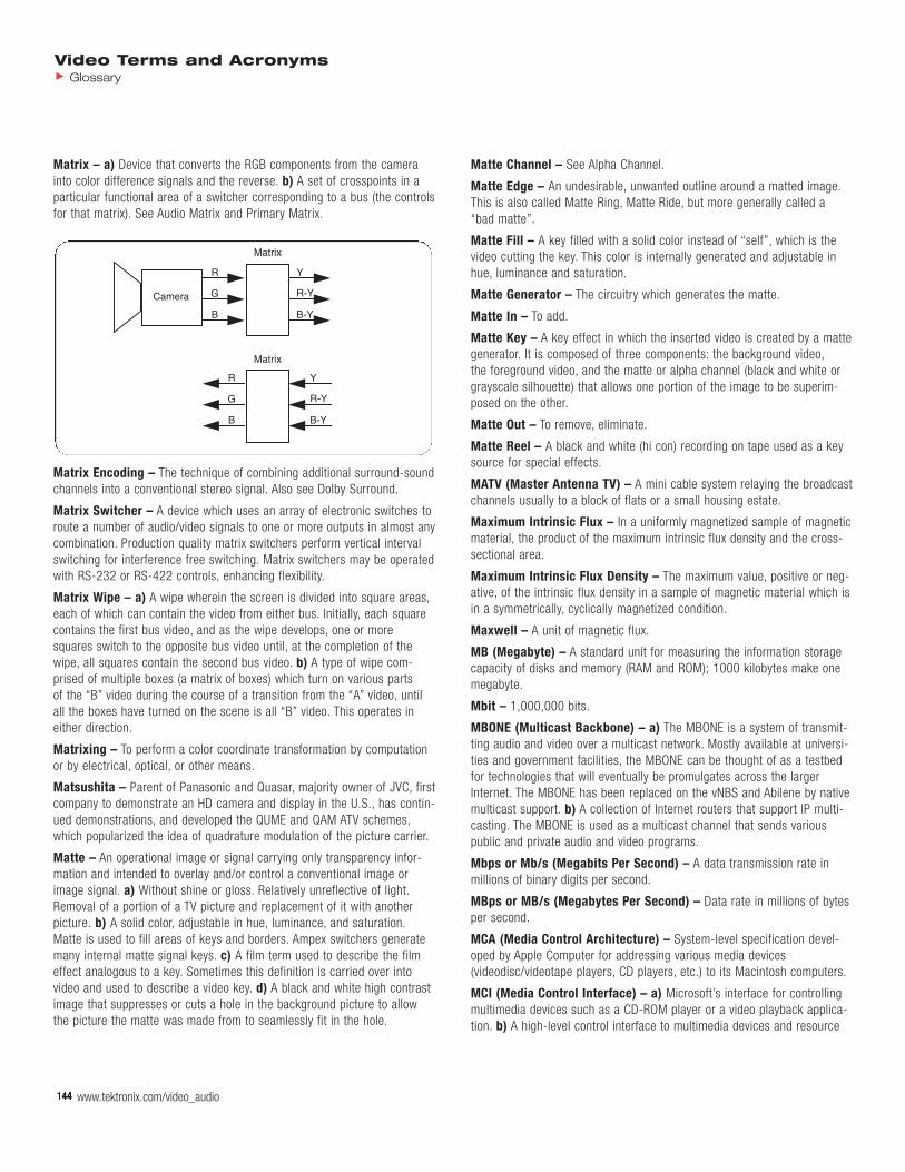
144 www.tektronix.com/video_audio144144144144144144144
Video Terms and AcronymsGlossary
144
Matrix – a) Device that converts the RGB components from the camerainto color difference signals and the reverse. b) A set of crosspoints in aparticular functional area of a switcher corresponding to a bus (the controlsfor that matrix). See Audio Matrix and Primary Matrix.
Matrix Encoding – The technique of combining additional surround-soundchannels into a conventional stereo signal. Also see Dolby Surround.
Matrix Switcher – A device which uses an array of electronic switches toroute a number of audio/video signals to one or more outputs in almost anycombination. Production quality matrix switchers perform vertical intervalswitching for interference free switching. Matrix switchers may be operatedwith RS-232 or RS-422 controls, enhancing flexibility.
Matrix Wipe – a) A wipe wherein the screen is divided into square areas,each of which can contain the video from either bus. Initially, each squarecontains the first bus video, and as the wipe develops, one or moresquares switch to the opposite bus video until, at the completion of thewipe, all squares contain the second bus video. b) A type of wipe com-prised of multiple boxes (a matrix of boxes) which turn on various parts of the “B” video during the course of a transition from the “A” video, untilall the boxes have turned on the scene is all “B” video. This operates ineither direction.
Matrixing – To perform a color coordinate transformation by computationor by electrical, optical, or other means.
Matsushita – Parent of Panasonic and Quasar, majority owner of JVC, firstcompany to demonstrate an HD camera and display in the U.S., has contin-ued demonstrations, and developed the QUME and QAM ATV schemes,which popularized the idea of quadrature modulation of the picture carrier.
Matte – An operational image or signal carrying only transparency infor-mation and intended to overlay and/or control a conventional image orimage signal. a) Without shine or gloss. Relatively unreflective of light.Removal of a portion of a TV picture and replacement of it with anotherpicture. b) A solid color, adjustable in hue, luminance, and saturation.Matte is used to fill areas of keys and borders. Ampex switchers generatemany internal matte signal keys. c) A film term used to describe the filmeffect analogous to a key. Sometimes this definition is carried over intovideo and used to describe a video key. d) A black and white high contrastimage that suppresses or cuts a hole in the background picture to allowthe picture the matte was made from to seamlessly fit in the hole.
Matte Channel – See Alpha Channel.
Matte Edge – An undesirable, unwanted outline around a matted image.This is also called Matte Ring, Matte Ride, but more generally called a “bad matte”.
Matte Fill – A key filled with a solid color instead of “self”, which is thevideo cutting the key. This color is internally generated and adjustable inhue, luminance and saturation.
Matte Generator – The circuitry which generates the matte.
Matte In – To add.
Matte Key – A key effect in which the inserted video is created by a mattegenerator. It is composed of three components: the background video,the foreground video, and the matte or alpha channel (black and white orgrayscale silhouette) that allows one portion of the image to be superim-posed on the other.
Matte Out – To remove, eliminate.
Matte Reel – A black and white (hi con) recording on tape used as a keysource for special effects.
MATV (Master Antenna TV) – A mini cable system relaying the broadcastchannels usually to a block of flats or a small housing estate.
Maximum Intrinsic Flux – In a uniformly magnetized sample of magneticmaterial, the product of the maximum intrinsic flux density and the cross-sectional area.
Maximum Intrinsic Flux Density – The maximum value, positive or neg-ative, of the intrinsic flux density in a sample of magnetic material which isin a symmetrically, cyclically magnetized condition.
Maxwell – A unit of magnetic flux.
MB (Megabyte) – A standard unit for measuring the information storagecapacity of disks and memory (RAM and ROM); 1000 kilobytes make onemegabyte.
Mbit – 1,000,000 bits.
MBONE (Multicast Backbone) – a) The MBONE is a system of transmit-ting audio and video over a multicast network. Mostly available at universi-ties and government facilities, the MBONE can be thought of as a testbedfor technologies that will eventually be promulgates across the largerInternet. The MBONE has been replaced on the vNBS and Abilene by nativemulticast support. b) A collection of Internet routers that support IP multi-casting. The MBONE is used as a multicast channel that sends variouspublic and private audio and video programs.
Mbps or Mb/s (Megabits Per Second) – A data transmission rate in millions of binary digits per second.
MBps or MB/s (Megabytes Per Second) – Data rate in millions of bytesper second.
MCA (Media Control Architecture) – System-level specification devel-oped by Apple Computer for addressing various media devices(videodisc/videotape players, CD players, etc.) to its Macintosh computers.
MCI (Media Control Interface) – a) Microsoft’s interface for controllingmultimedia devices such as a CD-ROM player or a video playback applica-tion. b) A high-level control interface to multimedia devices and resource
Matrix
Camera
Y
R-Y
B-Y
Matrix
R
G
B
R
G
B
Y
R-Y
B-Y
www.tektronix.com/video_audio 145
Video Terms and AcronymsGlossary
files that provides software applications with device-independent control ofaudio and video peripherals. MCI provides a standard command for playingand recording multimedia devices and resource files. MCI is a platform-independent layer between multimedia applications and system lower-levelsoftware. The MCI command set is extensible inasmuch as it can be incorporated in new systems via drivers and can support special featuresof multimedia systems or file formats. MCI includes commands like open,play, and close.
MCPC (Multiple Channels Per Carrier) – An average satellite transpon-der has a bandwidth of 27 MHz. Typically, the highest symbol rate that can be used in SR 26 MS/s, and multiple video or audio channels can betransmitted simultaneously. MCPC uses a technique called Time DivisionMultiplex to transmit multiple programs, which works by sending data forone channel at a certain time and then data for another channel at anothertime. Many encoder manufacturers are currently experimenting with statis-tical multiplexing of MPEG-2 data. Using this technique, channels that need high data rate bursts in order to prevent pixelization of the picture,such as live sports events will obtain the bandwidth as they need it byreducing the data rate for other services that do not. Statistical multiplex-ing should improve perceived picture quality, especially on video thatchanges rapidly. It also has the advantage of requiring no changes in thereceiver equipment.
MCU – See Multipoint Control Unit.
MDCT (Modified DCT) – Used in Layer 3 audio coding.
MDS (Multipoint Distribution Service) – A one-way domestic publicradio service rendered on microwave frequencies from a fixed stationtransmitting (usually in an omnidirectional pattern) to multiple receivingfacilities located at fixed points.
MedFER – One who experiments with radio communications at low frequencies such as those on the edges of the AM broadcast band (under FCC Part 15).
Media – The video, audio, graphics, and rendered effects that can be combined to form a sequence or presentation.
Media 100 – A nonlinear editing system that uses its own proprietary software. Often used with Adobe After Effects.
Media Clip – A video segment usually interleaved with an audio segment.
Media Data – Data from a media source. Media data can be: Analog Data:Film frames, Nagra tape audio, or videotape video and audio. Digital Data:Either data that was recorded or digitized such as video frame data andaudio samples, or data created in digital form such as title graphics, DATrecordings, or animation frames.
Media Files – Files containing the compressed digital audio and videodata needed to play Avid clips and sequences.
Media Conversion – The process of converting data from one type ofmedia to another for premastering and mastering. Premastering softwaretypically requires input data on hard disk.
Media Object – A representation of a natural or synthetic object that canbe manifested aurally and/or visually. Each object is associated with zero or more elementary streams using one or more object descriptors.
Media Object Decoder – An entity that translates between the coded representation of an elementary stream and its decoded representation.
Media Sample Data – See Safe Color Limiting.
Median Filter – An averaging technique used by PCEC in its IDTV line interpolation scheme to take an average of lines in the current and previ-ous fields to optimize resolution and avoid motion artifacts without usingmotion compensation.
Medium – The substance through which a wave is transmitted.
Medium Scale Integration (MSI) – Technology by which a dozen or moregate functions are included on one chip.
Medium Shot – Camera perspective between long shot and closeup,whereby subjects are viewed from medium distance.
Mega – One million, i.e., megacycle is one million cycles.
Megabyte (Mbyte) – One million bytes (actually 1,048,576); one thousand kilobytes.
Megaframe Initialization Packet (MIP) – A transport stream packetused by DVB-T to synchronize the transmitters in a multi-frequency network.
Megahertz (MHz) – One million hertz (unit of frequency). A normal U.S.television transmission channel is 6 MHz. The base bandwidth of the videosignal in that channel is 4.2 MHz. The SMPTE HDEP system calls for 30MHz each for red, green, and blue channels.
Memory – Part of a computer system into which information can beinserted and held for future use. Storage and memory are interchangeableterms. Digital memories accept and hold binary numbers only. Commonmemory types are core, disk, tape, and semiconductors (which includesROM and RAM).
Memory Counter (or Rewind) – A system which allows the tape to berewound automatically to any predetermined point on the tape.
Memory Effect – Loss of power storing capability in NiCad (video camera)batteries which occurs when batteries are habitually discharged only par-tially before recharging. To avoid the memory effect, always fully dischargeNiCad batteries before recharging.
Memory Map – Shows the address assignments for each device in thesystem.
Memory-Mapped I/O – I/O devices that are accessed by using the samegroup of instruction and control signals used for the memory devices in asystem. The memory and I/O devices share the same address space.
Menu – a) A list of operations or commands that the IRIS can carry out on various objects on the screen. b) A group of parameters and flags thatenable manipulation of the video image. Menus are Target, Rotate,Border, Source (with Sides submenu), Digimatte, Timeline and KF Flags.c) A graphic image, either still or moving, with or without audio provided to offer the user a variety of choices within the confines of the authoringand product material provided. It is the traditional meaning of a menu likeyou might find in a restaurant.
MER (Modulation Error Ratio) – The MER is defined as the ratio of I/Q signal power to I/Q noise power; the result is indicated in dB.
146 www.tektronix.com/video_audio146146146146146146146
Video Terms and AcronymsGlossary
146
Meridian Lossless Packing (MLP) – A lossless compression technique(used by DVD-Audio) that removes redundancy from PCM audio signals toachieve a compression ratio of about 2:1 while allowing the signal to beperfectly recreated by the MLP decoder.
MESECAM – Middle East SECAM or (B, G, D, K) SECAM. A technique ofrecording SECAM video. Instead of dividing the FM color subcarrier by four and then multiplying back up on playback, MESECAM uses the sameheterodyne conversion as PAL.
Mesh – a) A graphical construct consisting of connected surface elementsto describe the geometry/shape of a visual object. b) A grid that is placedover an image during morphing or warping.
Meshbeat – See Moiré.
Metadata – a) The descriptive and supporting data that is connected tothe program or the program elements. It is intended to both aid the directuse of program content and support the retrieval of content as needed during the post-production process. b) Generally referred to as “data aboutdata” or “data describing other data”. More specifically, information that isconsidered ancillary to or otherwise directly complementary to the essence.Any information that a content provider considers useful or of value whenassociated with the essence being provided.
Metadata Dictionary – The standard database of approved, registereddata element tags, their definitions and their allowed formats.
Metal Particle – One of the most recent developments of a magnetizableparticle for magnetic tape, products from pure iron and having very highcoercivity in the range of 850 to 1250 oersteds.
Metamorphosis – Given two databases with the same number of vertices, a metamorphosis causes the first to become the second. This is an animation tool.
Method – Methods, in the object-oriented terminology, are executable procedures associated with an object that operates on information in theobject’s data structure.
Mezzanine Compression – Contribution level quality encoded high definition television signals. Typically split into two levels: high level atapproximately 140 Mbps and low level at approximately 39 Mbps (for highdefinition with the studio, 270 Mbps is being considered). These levels ofcompression are necessary for signal routing and are easily re-encodedwithout additional compression artifacts (concatenation) to allow for picturemanipulation after decoding. DS-3 at 44.736 will be used in both terrestrialand satellite program distribution.
MFN (Multifrequency Network)
MFP (Mega Frame Packet)
MGT – See Master Guide Table.
MHEG – See Multimedia Hypermedia Expert Group.
MHP (Multimedia Home Platform) – A set of common application programming interfaces (API) designed to create an operating system independent, level playing field for broadcasters and consumer-electronicsmanufacturers. The goal is to provide all DVB-based terminals (set-tops,TVs, and multimedia PCs) full access to programs and services built on the DVB Java (DVB-J) platform.
MHz – See Megahertz.
MIB (Management Information Base) – The Management InformationBase is a collection of managed objects defined by their attributes and visible to the network management system.
MIC (MPEG-2 Interface Card)
Micro – One millionth.
Micro Channel – Personal computer bus architecture introduced by IBMin some of its PS/2 series microcomputers. Incompatible with originalPC/AT (ISA) architecture.
Micro-Cassette – A miniature cassette system originated by Olympus,allowing 30 minutes of recording per side on a capstan-driven tape, 1/7”wide, running at 15/16 ips.
Microcode – See Microprogram.
Microcomputer – Complete system, including CPU, memory and I/O interfaces.
Microdropouts – Low level, short duration dropouts. They correspond toRF envelope dropouts of 10 dB or greater with a duration of 0.5 to 0.8microseconds.
Microphone – A transducer which converts sound pressure waves intoelectrical signals.
Microphone Impedance – In order to obtain the highest quality outputsignal from a microphone, a preamplifier input should provide a load(impedance) which exactly matches a microphone’s output impedance.Microphone output impedances vary from 150 ohms to several megohms.
Microphone Preamplifier – A microphone is a transducer which convertssound waves to electrical impulses. Microphones typically generate verylow signal levels requiring low noise, high fidelity, pre-amplification toboost the output signal to a level compatible with audio amplifier circuitry.Good microphone preamplifiers provide precise matching of microphoneimpedance and low noise electronic components.
Microphonics – In video transmission, refers to the mechanical vibrationof the elements of an electron tube resulting in a spurious modulation ofthe normal signal. This usually results in erratically spaced horizontal barsin the picture.
Microprocessor – Central processing unit fabricated on one or two chips.The processor consists of the arithmetic and logic unit, control block, andregisters.
Microprogram – Program that defines the instruction set. The micropro-gram (also called microcode) tells the CPU what to do to execute eachmachine language instruction. It is even more detailed than machine language and is not generally accessible to the user.
Microsecond – One millionth of a second: 1 x 10⁻⁶ or 0.000001 second.A term used to mean very fast/instantaneous.
Microwave – One definition refers to the portion of the electromagneticspectrum that ranges between 300 MHz and 3000 GHz. The other defini-tion is when referring to the transmission media where microwave links areused. Frequencies in microwave transmission are usually between 1 GHzand 12 GHz.
www.tektronix.com/video_audio 147
Video Terms and AcronymsGlossary
Microwave Dish – A parabolic shaped antenna used for high frequencyRF signals.
Microwave Transmission – Communication systems using high frequency RF to carry the signal information.
Microwaves – Radio frequencies with very short wavelengths (UHF).
Middle Area – Unused physical area that marks the transition from layer 0 to layer 1. Middle Area only exists in dual layer discs where the tracks ofeach layer are in opposite directions.
MIDI (Musical Instrument Digital Interface) – A standard for connect-ing electronic musical instruments and computers. MIDI files can bethought of as digital sheet music, where the computer acts as the musicianplaying back the file. MIDI files are much smaller than digital audio files,but the quality of playback will vary from computer to computer.
MIDI Timecode – A system for timed device control through MIDI protocols. The importance of MIDI timecode in video post-production has increased due to the increased use of personal computers for videoproduction.
Midtones – Mid-level grays in an image.
MII – Portable, professional video component camera/recorder format,utilizing 1/2” metal particle videotape.
MII (M2) – Second generation camera/recorder system developed byPanasonic. Also used for just the recorder or the interconnect format.MII uses a version of the (Y, R-Y, B-Y) component set.
MII Format – A component videotape format created by Panasonic in an effort to compete with Sony Betacam. MII is an extension of the VHSconsumer format as Sony Betacam is an extension of the Betamax homevideo technology.
Mike – Microphone.
Mike Boom – A rigid extension to which a microphone may be attached.
Mike Pad – An attenuator placed between the output of a mike and theinput of a mike preamp to prevent overdriving the preamp.
Mil – 0.001 of an inch.
Millennium Group – The group of companies (Macrovision, Philips,Digimarc) proposing the Galaxy watermarking format.
Miller Squared Coding (M2) – A DC-free channel coding scheme used inD2 VTRs.
Millimeter – One thousandth of a meter.
Millimicron – One billionth of a meter.
Millisecond – One thousandth of a second.
MIME (Multi-Purpose Internet Mail Extensions) – Standard for trans-mitting non-text data (or data that cannot be represented in plain ASCIIcode) in Internet mail, such as binary, foreign language text (such asRussian or Chinese), audio, or video data. MIME is defined in RFC2045.
Mini-Cassette – A miniature cassette system originated by Philips,allowing 15 minutes of recording per side on a narrow tape.
Minimize – To reduce a window to an icon for later use.
Minimum Performance – The line between EDTV and HDTV. Naturally,each ATV proponent defines minimum performance so as to favor its system to the detriment of others.
MIP – See Megaframe Initialization Packet.
MIPS (Millions of Instructions Per Second) – Refers to a computer processor’s performance.
Miro Instant Video – An edit mode in Adobe Premiere for Windows,specifically for DC30 users, that allows video to be streamed out of a DC30 capture card.
Mistracking – The phenomenon that occurs when the path followed bythe read head of the recorder does not correspond to the location of therecorded track on the magnetic tape. Mistracking can occur in both longi-tudinal and helical scan recording systems. The read head must capture agiven percentage of the track in order to produce a playback signal. If thehead is too far off the track, record information will not be played back.
MIT (Massachusetts Institute of Technology) – Home of the Media Lab and its Advanced Television Research Program (ATRP), its AudienceResearch Facility, its Movies of the Future program, and other advancedimaging and entertainment technology research. In addition to conductingand publishing a great deal of ATV research, MIT has come up with twoATV proposals of its own, one called the Bandwidth Efficient Proposal andone the Receiver Compatible Proposal.
MITG (Media Integration of Text and Graphics)
Mix – a) A transition between two video signals in which one signal isfaded down as the other is faded up. Also called a dissolve or cross fade.b) This term is most often used as a synonym for additive mix but mayalso refer to a non-additive mix.
Mix Effects (M/E) – One of the console modules (or its associated signalprocessing boards) which allows an operator to perform wipes, mixes,keys, etc.
Mixdown Audio – The process that allows the user to combine severaltracks of audio onto a single track.
Mixed Mode – A type of CD containing both Red Book audio and YellowBook computer data tracks.
Mixer – The audio or video control equipment used for mixing soundand/or video. In video, a device for combining several video input signals.
Mixing – To combine various pictures and/or audio elements together.
Mixing Console – A device which can combine several signals into one ormore composite signals, in any desired proportion.
Mixing, Digital – A step in post-production during which two or more digital representations are combined to create an edited composition. In atransmission, recording, or reproducing system, combining two or moreinputs into a common output, which operates to combine linearly the sepa-rate input signals in a desired proportion in an output signal. Production:Generally the editing of digital image data, resulting in composites rangingfrom simple transitions to multilayered collages combining selected information from many interim images. The combining of digital images is accomplished by suitable arithmetic calculations on related pairs of

148 www.tektronix.com/video_audio148148148148148148148
Video Terms and AcronymsGlossary
148
digital words. Data Processing: A process of intermingling of data trafficflowing between concentration and expansion stages.
MJD (Modified Julian Date) – A day numbering system derived from the julian date. It was introduced to set the beginning of days at 0 hours,instead of 12 hours and to reduce the number of digits in day numbering.The modified julian date is obtained subtracting 2.400.000,5 from thejulian date. As a consequence, the origin of this date (day zero) begin at1858 November 17 at 0 hours. For example, 1996 January 1 at 0 hoursbegan the modified julian day 50,083.
MJPEG – See Motion JPEG.
MMCD (Multimedia CD) – A development proposal from Sony andPhilips, now integrated in the DVD.
MMDS (Multi-Point Microwave Distribution System) – This is a terrestrial broadcasting technology which utilizes low-power microwavetransmitters, and is mainly used for extending the range of cable TV systems and for TV distribution in sparsely populated areas or in areas with rough terrain. MMDS is not specifically analog or digital. In digitalMMDS, the use of MPEG is highly attractive to boost the number of channels that may be distributed.
MMI (Man Machine Interface) – Refers to the interface presented by a machine to a human operator. Another name for User Interface.
MMT (Modulation Mode Table)
Mnemonic Code – Codes designed to assist the human memory. Themicroprocessor language consists of binary words, which are a series of 0s and 1s, making it difficult for the programmer to remember the instruc-tions corresponding to a given operation. To assist the human memory,the binary numbered codes are assigned groups of letters (of mnemonicsymbols) that suggest the definition of the instruction. For example, the8085 code 100000 binary means load accumulator and is represented bythe mnemonic LDA.
Mobile Unit – Equipment designed to be movable as a unit. A truck/vanwith all the necessary equipment to do photography/production on location.Sometimes mobile units have cameras and VTRs within them and some-times they are added for specific jobs.
Mod – Abbreviation for Modulator on the 4100 series and Modifier on theAVC series.
MOD (Minimum Object Distance) – Feature of a fixed or a zoom lensthat indicates the closest distance an object can be from the lens’s imageplane, expressed in meters. Zoom lenses have MOD of around 1 m, whilefixed lenses usually much less, depending on the focal length.
Model-Based Coder – Communicating a higher-level model of the imagethan pixels is an active area of research. The idea is to have the transmit-ter and receiver agree on the basic model for the image; the transmitterthen sends parameters to manipulate this model in lieu of picture elementsthemselves. Model-based decoders are similar to computer graphics ren-dering programs. The model-based coder trades generality for extreme efficiency in its restricted domain. Better rendering and extending of thedomain are research themes.
Modeling – a) The process of creating a 3D world. There are severalkinds of 3D modeling, including: boundary representation, parametric (oranalytic), and constructive solid geometry. After the geometry of a model is determined, its surface properties can be defined. b) This processinvolves describing the geometry of objects using a 3D design program.
Modem (Modulator/Demodulator) – An electronic device for convertingbetween serial data (typically RS-232) from a computer and an audio signal suitable for transmission over telephone lines. The audio signal isusually composed of silence (no data) or one of two frequencies represent-ing 0 and 1. Modems are distinguished primarily by the baud rates theysupport which can range from 75 baud up to 56000 and beyond. Variousdata compression and error algorithms are required to support the highestspeeds. Other optional features are auto-dial (auto-call) and auto-answerwhich allow the computer to initiate and accept calls without human intervention.
Modifier – Pattern system electronics capable of modulator effects,continuous rotation effects, pattern border hue modulation, pattern borderrainbows, and position modulation.
Modulate – To impress information on an AC or RF signal by varying thesignals amplitude, frequency or phase.
Modulated – When referring to television test signals, this term impliesthat chrominance, luminance, sync, color burst and perhaps audio informa-tion is present.
Modulated Carrier Recording – Signal information recorded in the formof a modulated carrier.
Modulated Five-Step Test Signal – A test signal with five steps of luminance change, each step having a constant frequency and phasechrominance signal. This signal is used to test for differential phase distortions. There is also a 10-step version of this signal.

www.tektronix.com/video_audio 149
Video Terms and AcronymsGlossary
Modulated Pedestal – A test signal which consists of three chrominancepackets with the same phase, on the same luminance level (50 IRE), withdifferent amplitudes (20, 40 and 80 IRE). This signal is used to test forchrominance nonlinear phase distortion and chrominance to luminanceintermodulation distortion.
Modulated Ramp Test Signal – A test signal with a linear rise in lumi-nance and constant chrominance as shown in the figure to the right. Thissignal is used to test for differential phase distortions.
Modulation – a) The imposing of a signal on some type of transmissionor storage medium, such as a radio carrier or magnetic tape. b) Theprocess (or result) of changing information (audio, video, data, etc.) intoinformation-carrying signals suitable for transmission and/or recording. InNTSC-M television transmission, video is modulated onto a picture carrierusing amplitude modulation-virtual sideband, and audio is modulated ontoa sound carrier using frequency modulation.
Modulation Noise – a) Noise which results from the agitation of the oxide molecules through the recording process. The modulation noise levelincreases as record level increases and disappears when no signal is present. b) The noise arising when reproducing a tape which has beenrecorded with a given signal, and which is a function of the instantaneousamplitude of the signal. This is related to DC noise and arises from thesame causes.
Modulator – a) A section within a VTR that changes the frequency of the video signal information coming in from an external source (i.e.,an electronic camera) to signal information that is compatible with the requirements of the VTR heads, while keeping the picture information basically unchanged. b) Pattern system electronics capable of distortingthe edge of a pattern by impressing a sine or other waveform on the vertical or horizontal shape of the pattern. c) The device that places information on an RF carrier signal.
Modulator Lock – A feature that synchronizes the modulator or modifiereffect to the frame rate, thus preventing the effect from drifting or appear-ing incoherent.
Module – A small device, not working by itself, designed to perform spe-cialized tasks in association with a host, for example: a conditional accesssubsystem, an electronic program guide application module, or to provideresources required by an application but not provided directly by the host.
Module Board – Printed circuit board and mounted components that isattached to the base board using screws and spacers.
Moiré – a) An image artifact that occurs when a pattern is created on thescreen where there should not be one. The moiré pattern is generatedwhen different frequencies that are part of the video signal, create a newunwanted frequency. b) A wavy pattern, usually caused by interference.When that interference is cross-color, the pattern is colored, even if thepicture is not. c) The spurious pattern in the reproduced television pictureresulting from interference beats between two sets of periodic structures in the image. It usually appears as a curving of the lines in the horizontalwedges of the test pattern and is most pronounced near the center wherethe lines forming the wedges converge. A Moiré pattern is a natural opticaleffect when converging lines in the picture are nearly parallel to the scan-ning lines.
MOL (Maximum Output Level) – In audio tape, that record level which produces a 3rd harmonic distortion component at 3.0%.
Mole Technology – A seamless MPEG-2 concatenation technology developed by the ATLANTIC project in which an MPEG-2 bitstream enters a Mole-equipped decoder, and the decoder not only decodes the video,but the information on how that video was first encoded (motion vectorsand coding mode decisions). This “side information” or “metadata” in aninformation bus is synchronized to the video and sent to the Mole-equippedencoder. The encoder looks at the metadata and knows exactly how toencode the video. The video is encoded in exactly the same way (so theo-retically it has only been encoded once) and maintains quality. If an opaquebug is inserted in the picture, the encoder only has to decide how the bugshould be encoded (and then both the bug and the video have been theo-retically encoded only once). Problems arise with transparent or translucentbugs, because the video underneath the bug must be encoded, and there-fore that video will have to be encoded twice, while the surrounding videoand the bug itself have only been encoded once theoretically. What Molecannot do is make the encoding any better. Therefore, the highest qualityof initial encoding is suggested.
Moment of Inertia – A measure of the rotational force required to accel-erate or decelerate a reel of tape or other rotating object.

150 www.tektronix.com/video_audio150150150150150150150
Video Terms and AcronymsGlossary
150
Monitor – a) A TV set, or a TV set specifically designed for closed circuitviewing (i.e., from a VTR) without the electronic capability to receive broadcast signals. b) A hardware device that displays the images, win-dows, and text with which you interact to use the system. It is also called avideo display terminal (VDT). c) Program that controls the operation of amicrocomputer system and allows user to run programs, examine andmodify memory, etc.
Monitor Head – A separate playback head on some tape recorders thatmakes it possible to listen to the material on the tape an instant after ithas been recorded and while the recording is still in progress.
Monitor Outputs – A set of outputs from a switcher or video recorder for the specific purpose of feeding video monitors (although not limited tothat purpose). These include preview, individual M/Es, DSK, and bus rows.The AVC also provides monitor outputs for RGB signals, aux bus selections,and switcher status information.
Monitor Power Cable – The cable that connects the monitor to the workstation to provide power to the monitor. It has a male connector onone end and a female connector on the other.
Monitor Standardization – Although it is customary to make all subjec-tive judgments of image quality from the reference monitor display, the infinite possibilities for monitor adjustments have hampered reviewers inexercising effective program control, and have introduced many disparitiesand great confusion. The SMPTE Working Group on Studio Monitors,S17.28, is completing work on three specifications intended to make themonitor display follow a known electro-optic transfer function and permit a reliable evaluation of the program image quality.
Monitor Video Cable – The cable that connects the monitor to the work-station to transmit video signals. It has large connector on both ends.
Monitor, Control – A control monitor is one employed primarily for deci-sions on subject matter, composition, and sequences to be selected in real-time. It is frequently one of several monitors mounted together in close proximity as in a studio – for example, to display multiple sourcesthat are to be compared, selected, and combined in editing for immediate,direct routing to display. The physical arrangements may make it very difficult to control the surroundings for each monitor, as specified bySMPTE Working Group on Studio Monitors in Document S17.280 for thereference monitor. It is nevertheless essential when sequences on severalmonitors are being compared and intercut that the monitors match in luminance and colorimetry.
Monitor, Reference – A reference monitor is one employed for decisionson image quality. Achieving controlled reproducibility for this application is the primary objective of the specifications for monitor standardization.SMPTE Working Group on Studio Monitors, S17.28, has recognized thegreat disparity now existing among studio monitors and control monitors,and has noted the confusing variability among decisions based upon visualjudgments of program quality as evaluated on different monitors. They areworking to identify and recommend specifications for the variables affect-ing subjective judgments, coming not only from the monitor capabilities,but also from the adjustment of its controls and the bias introduced bymonitor surround and room illumination.
Monitor, Standardization – Although it is customary to make all subjec-tive judgments of image quality from the reference monitor display, the infinite possibilities for monitor adjustments have hampered reviewers inexercising effective program control, and have introduced many disparitiesand great confusion. The SMPTE Working Group on Studio Monitors,S17.27, is completing work on three specifications intended to make themonitor display follow a known transfer function, electro-optic, and permita reliable evaluation of the program image quality.
Mono, Monophonic – Single-channel sound.
Monochrome – Literally single color, usually used to indicate black andwhite. There have been monochrome high line rate cameras and displaysfor many years. The EIA has standardized rates of up to 1225 scanninglines per frame. NHK developed a monochrome HDTV system with 2125scanning lines per frame. Even higher number of scanning lines are usedin conjunction with lower frame rates in cathode ray tube scanners used in printing and in film. These extremely high rates are possible becausemonochrome picture tubes have no triads.
Monochrome Signal – A “single color” video signal – usually a black and white signal but sometimes the luminance portion of a composite orcomponent color signal.
Monochrome Transmission (Black and White) – The transmission of asignal wave which represents the brightness values in the picture but notthe color (chrominance) values in the picture.
Monophonic – One sound channel/source/signal. Sometimes called monaural.
Monotonic – A term used in D/A conversion and is used to indicate thatthe magnitude of the DAC output voltage increases every time the inputcode increases.
MooV – The file format used in the QuickTime and QuickTime for Windowsenvironments for displaying videos. See QuickTime, QuickTime forWindows.
MOPS (Millions of Operations Per Second) – In the case of DVI tech-nology, more MOPS translate to better video quality. Intel’s video processorcan perform multiple video operations per instruction, thus the MOPS rating is usually greater than the MIPS rating.
Morphing – A technique for making an object change into the shape ofanother.
MOS (Metal Oxide Semiconductor) – Integrated circuits made of fieldeffect transistors. All MOS devices originally used metal gate technology,but the term is used to describe silicon gate circuits as well.
Mosaic – a) Term used for an ADO effect which is to segmentize a videosignal into rectangles of variable block sizes and aspect ratio. b) An effectthat “blurs” an image by copying pixels into adjacent pixels both horizontal-ly and vertically. This gives the image a blocky appearance, often used tohide people’s identities on television.
Mosquito Noise – Caused by quantizing errors between adjacent pixels,as a result of compression. As the scene content varies, quantizing stepsizes change, and the quantizing errors produced manifest themselves asshimmering black dots, which look like “mosquitoes” and show at randomaround objects within a scene.

www.tektronix.com/video_audio 151
Video Terms and AcronymsGlossary
Most Significant Bit (MSB) – The bit that has the most value in a binarynumber or data byte. In written form, this would be the bit on the left. Forexample,
Binary 1110 = Decimal 14
In this example, the leftmost binary digit, 1, is the most significant bit, hererepresenting 8. If the MSB in this example were corrupt, the decimal wouldnot be 14 but 6.
Mother – The metal disc produced from mirror images of the Father discin the replication process. Mothers are used to make stampers, oftencalled Sons.
Motherboard – See Backplane.
Motion Adaptive – An ATV scheme that senses motion and changes theway it functions to avoid or reduce motion artifacts.
Motion Artifacts – a) Picture defects that appear only when there ismotion in the scene. Interlaced scanning has motion artifacts in both thevertical and horizontal directions. There is a halving of vertical resolution at certain rates of vertical motion (when the detail in one field appears inthe position of the next field one sixtieth of a second later), and horizontallymoving vertical edges become segmented (reduced in resolution) by thesequential fields. This is most apparent when a frame of a motionsequence is frozen and the two fields flash different information. All sub-sampling ATV schemes have some form of motion artifact, from twinklingdetail to dramatic differences between static and dynamic resolutions. Linedoubling schemes and advanced encoders and decoders can have motionartifacts, depending on how they are implemented. Techniques for avoidingmotion artifacts include median filtering and motion adaptation or compen-sation. b) In all temporally-sampled systems (i.e., both photographic andelectronic), realistic motion reproduction is achieved only with samplingabove the Nyquist limit. The subjective response to motion artifacts is com-plex, influences by the various degrees of smoothing and strobing affectingtemporal and spatial resolution, integration and tag in the sensing, record-ing, and display elements; sampling geometry and scanning patterns; shut-ter transmission ratio; perceptual tolerances, etc. (Motion appears “normal”only when significant frame-to-frame displacement occurs at less than half the frame rate; i.e., “significant motion” distributed over at least twoframes.) Motion artifacts most frequently observed have their origins in thefollowing: image components with velocity functions extending beyond theNyquist limit (such as rotating, spoked wheels), motion samples with suchshort exposures there is noticeable frame-to-frame separation of sharplydefined images (such as synchronized flash illumination), asynchronoussampling of intermittent motion (such as frame-rate conversions). A consid-erable number of motion artifacts appear so frequently as to be acceptedby most viewers.
Motion Compensation (MC) – In MPEG, the use of motion vectors toimprove the efficiency of the prediction of pel values. The prediction usesmotion vectors to provide offsets into the past and/or future reference pictures containing previously decoded pel values that are used to form the prediction error signal. The book Motion Analysis for Image SequenceCoding by G. Tziritas and C. Labit documents the technical advances madethrough the years in dealing with motion in image sequences.
Motion Effect – An effect that speeds up or slows down the presentationof media in a track.
Motion Estimation (ME) – The process of determining changes in videoobject positions from one video frame to the next. Object position determi-nation is used extensively in high compression applications. For instance if the background of a scene does not change but the position of an objectin the foreground does, it is advantageous to just transmit the new positionof the object rather than the background or foreground. This technology isused in MPEG, H.261, and H.263 compression.
Motion Jitters – Jerky movements in a clip, often caused by gate slipwhen film is converted into video.
Motion JPEG – Applications where JPEG compression or decompressionis speeded up to be able to process 25 or 30 frames per second and isapplied real-time to video. Even though a video signal is being processed,each field is still individually processed.
Motion Path – The movement between keyframes, changed with the Pathsoft key. There are five types of paths. BRK (Break) modifies Smooth motionby decelerating speed to zero at each keyframe (a break), then startingagain. IGN (Ignore) allows selected parameter values to be ignored whencalculating motion path. SMTH (Smooth) provides a curved path betweenkeyframes. The effect speeds up gradually as it leaves the first keyframe,and slows down gradually until it reached the last keyframe. LIN (Linear)provides a constant rate of change between keyframes, with an abruptchange at each keyframe. Linear uses the shortest distance between twopoints to travel from one keyframe to another. HOLD stops all motion be-tween keyframes. The result of the motion shows when the next keyframeappears. HOLD looks like a video “cut”, from one keyframe to the next.
Motion Path Velocity – A successful motion path has two components:geometry and timing. The geometry is created by choosing keyframes. Thetiming of the path is more complex, and can be affected by the geometry.Intuitively, the timing of a path is simply the speed of motion of the objectas it moves along the path. Since PictureMaker starts with keyframes and creates in-between positions, PictureMaker determines the velocity bydeciding how many in-betweens to place between each keyframe (andwhere to place them). Several methods can be used to determine velocityalong the path. a) Place frame evenly between all keyframes. Closelyplaced keyframes will correspond with slow moving parts of the path.b) Specify a relative velocity at selected keyframes, and specify correspon-dences between any keyframe and a frame in the final animation.
Motion Prediction – The process that reduces redundancy in a video signal by measuring an object’s motion at the encoder and sending amotion vector to the decoder in place of the encoded object.
Motion Resolution – See Dynamic Resolution.
Motion Stabilization – A feature used to eliminate the wobble in thevideo taken with a hand-held camera. The After Effects Production Bundleincludes a motion stabilizer.
Motion Surprise – A major shift in the quality of a television picture in thepresence of motion that is so jarring to the viewer that the system mightactually appear better if it had continuously lower quality, rather than jump-ing from high-quality static image to a lower quality dynamic one.
152 www.tektronix.com/video_audio152152152152152152152
Video Terms and AcronymsGlossary
152
Motion Tracking – The process of generating position information thatdescribes motion in a clip, for example, the changing position of a movingvehicle. You use motion tracking data to control the movement of effects.See also Stabilization.
Motion Vector (MV) – a) A two-dimensional vector used for motion compensation that provides an offset from the coordinate position in thecurrent picture to the coordinates in a reference picture. b) A pair of numbers which represent the vertical and horizontal displacement of aregion of a reference picture for production.
Motion Vector for Shape – A motion vector used for motion compensa-tion of shape.
Motion Video – Video that displays real motion by displaying a sequenceof images (frames) rapidly enough that the eyes see the image as a continuously moving picture.
Moto DV Playback – An edit mode in Premiere, specifically for Moto DVstudio users, that allows video to be streamed out of a Moto DV capturedcard.
Mount – To make a file system that is stored on a local or remote diskresource accessible from a specific directory on a workstation.
Mount Point – The directory on a workstation from which you accessinformation that is stored on a local or remote disk resource.
Mouse – A hardware device that you use to communicate with windowsand icons. You move the mouse to move the cursor on the screen, and youpress its buttons to initiate operations.
Mouse Pad – For an optical mouse, this is the rectangular, metallic surface that reads the movements of the mouse. For a mechanical mouse,this is a clean, soft rectangular surface that makes the mouse’s track ballroll efficiently.
MOV – The file extension used by MooV format files on Windows.See MooV.
Movie-2 Bus (or Movie-2 Bus Connector) – Over the top connectorused for high-speed data transfer. These two terms refer to the assembledcomponent, which consists of a printed circuit board (backplane) withattached connectors.
Moving Dots – See Chroma Crawl.
Moving Picture Experts Group (MPEG) – An international group ofindustry ex-perts set up to standardize compressed moving pictures andaudio. The first release of the MPEG standard was called MPEG-1 (ISO/IEC11172-1).
Moving Picture Experts Group 1 (MPEG-1) – ISO/IEC CD 11172 is thefirst of the standards designed for handling highly compressed movingimages in real-time. It accepts periodically chosen frames to be com-pressed as in JPEG-1, predicts the content of intervening frames, andencodes only the difference between the actual and the prediction. Audio is compressed synchronously. The encoder includes a decoder section inorder to generate and verify the predictions. At the display, a much simplerdecoder becomes possible. MPEG-1 is optimized for a data rate of up to 1.5 Mbps. MPEG expects to develop a series of compression codes,optimized for higher bit rates.
Moving Picture Experts Group 2 (MPEG-2) – MPEG-2 expands theMPEG-1 standard to cover a wider range of applications.
Moving Picture Experts Group 3 (MPEG-3) – MPEG 3 was originallyintended for HDTV applications but has since been incorporated into MPEG 2.
Moving Picture Experts Group 4 (MPEG-4) – The goal of MPEG-4 is toestablish a universal and efficient coding for different forms of audio-visualdata, called audio-visual objects. Coding tools for audio-visual objects arebeing developed to support various functionality’s, such as object-basedinteractivity and scalability. The syntax of the audio-visual objects is beingdeveloped to allow for description of coded objects and to describe howthey were coded. This information can then be downloaded into a decoder.
Moving-Coil – A microphone whose generating element is a coil whichmoves within a magnetic gap in response to sound pressure on thediaphragm attached to it, rather like a small loudspeaker in reverse. Themost common type of Dynamic Microphone.
MP (Multi-Link Point-to-Point Protocol)
MP@HL (Main Profile at High Level) – Widely used shorthand notationfor a specific quality and resolution of MPEG: Main Profile (4:2:0 quality),High Level (HD resolution).
MP@ML (Main Profile at Main Level) – MPEG-2 specifies differentdegrees of compression vs. quality. Of these, Main Profile at Main Level isthe most commonly used.
MP3 – A commonly used term for the MPEG-1 Layer 3 (ISO/IEC 11172-3)or MPEG-2 Layer 3 (ISO/IEC 13818-3) audio compression formats. MPEG-1Layer 3 is up to two channels of audio and MPEG-2 Layer 3 is up to 5.1channels of audio. MP3 is not the same as MPEG-3.
MPC (Multimedia PC) – A specification developed by the MultimediaCouncil. It defines the minimum platform capable of running multimediasoftware. PCs carrying the MPC logo will be able to run any software thatalso displays the MPC logo.
MPCD (Minimum Perceptible Color Difference) – This is a unit ofmeasure, developed by the CIE, to define the change in light and colorrequired to be just noticeable to the human eye. The human being in thisMPCD unit is defined as “a trained observer” because there are differencesin the way each of us perceive light.
MPE – See Multiprotocol Encapsulation.
MPEG – A standard for compressing moving pictures. MPEG uses the simi-larity between frames to create a sequence of I, B and P frames. Only the Iframe contains all the picture data. The B and P frames only contain infor-mation relating to changes since the last I frame. MPEG-1 uses a data rateof 1.2 Mbps, the speed of CD-ROM. MPEG-2 support much higher qualitywith a data rate (also called bit rate) of from 1.2 to 15 Mbps. MPEG-2 isthe format most favored for video on demand, DVD, and is the format fortransmitting digital television.
MPEG Audio – Audio compressed according to the MPEG perceptualencoding system. MPEG-1 audio provides two channels, which can be inDolby Surround format. MPEG-2 audio adds data to provide discrete multi-channel audio. Stereo MPEG audio is the mandatory audio compressionsystem for 625/50 (PAL/SECAM) DVD-Video.

MPEG Splicing – The ability to cut into an MPEG bitstream for switchingand editing, regardless of frame types (I, B, P).
MPEG TS (MPEG Transport Stream) – The MPEG transport stream is anextremely complex structure using interlinked tables and coded identifiersto separate the programs and the elementary streams within the programs.Within each elementary stream, there is a complex structure, allowing adecoder to distinguish between, for example, vectors, coefficients andquantization tables.
MPEG Video – Video compressed according to the MPEG encoding system. MPEG-1 is typically used for low data rate video such as on aVideo CD. MPEG-2 is used for higher-quality video, especially interlacedvideo, such as on DVD or HDTV.
MPEG-1 – See Moving Picture Experts Group 1.
MPEG-2 – See Moving Picture Experts Group 2.
MPEG-3 – See Moving Picture Experts Group 3.
MPEG-4 – See Moving Picture Experts Group 4.
MPEG-4 Class – MPEG-4 standardizes a number of pre-defined classes.This set of classes is called the MPEG-4 Standard Class Library. The rootof MPEG-4 classes is called MPEG-4 Object. In Flexible Mode, an MPEG-4Terminal, based on this library, will be able to produce or use new encoder-defined classes and instantiate objects according to these class definitions.Graphical methods to represent this hierarchy are commonly used. theOMT notation has been chosen within the context of MPEG-4 Systems.
MPEG-4 Object – The root of MPEG-4 classes.
MPEG-4 Systems – The “Systems” part of the MPEG-4 standard incharge of the Multiplex Layer, the Composition Layer and the FlexibilityLayer.
MPEG-4 Systems Description Language (MSDL) – The language(s)defined by MPEG-4 Systems for the purpose of the Flexibility Layer.
MPEG-4 Terminal – An MPEG-4 Terminal is a system that allows presentation of an interactive audiovisual scene from coded audiovisualinformation. It can be either a standalone application, or part of a multime-dia terminal that needs to deal with MPEG-4 coded audiovisual information,among others.
MPEG-7 – MPEG-7 is a multimedia content (images, graphics, 3D models,audio, speech, video) representation standard for information searching.Final specification is expected in the year 2000.
MPEG-J – A set of Java application program interfaces. It also sets therules for delivering Java into a bitstream and it specifies what happens atthe receiving end.
MPI (MPEG Physical Interface)
MPP (Mix to Preset Pattern) – See Preset Pattern.
MPTS (Multi-Port Presentation Time Stamps)
MPEG 4:2:2 – Also referred to as Studio MPEG, Professional MPEG and442P@ML. Sony’s Betacam SX is based on MPEG 4:2:2.
MPU (Microprocessing Unit) – See Microprocessor.
MS Stereo – Exploitation of stereo redundancy in audio programs basedon coding the sum and difference signal instead of the left and right channels.
MSB – See Most Significant Bit.
MSDL (MPEG-4 Syntactic or Systems Description Language) –An extensible description language defined in MPEG-4 that allows forselection, description and downloading of tools, algorithms and profiles.
MSI (Medium Scale Integration) – Between 100 and 3,000 transistorson a chip.
MSO (Multiple System Operator) – A major cable TV organization thathas franchises in multiple locations.
MTBF (Mean Time Between Failure) – The average time a componentworks without failure. It is the number of failures divided by the hoursunder observation.
MTS (Multichannel Television Sound) – A generic name for variousstereo audio implementations, such as BTSC and Zweiton. Used in con-junction with NTSC/525. Consists of two independent carriers each carry-ing a discrete channel. One channel provides stereo sound by providingleft/right channel difference signals relative to transmitted mono audiotrack. The second carrier carries the Secondary Audio Program (SAP) whichis used for a second language or a descriptive commentary for the blind.Uses a technique based on the dBx noise reduction to improve the fre-quency response of the audio channel.
MTTR (Mean Time to Repair) – The average time it takes to repair afailed component.
MTU (Multi-Port Transceiver Unit)
Mu-Law – The PCM coding and companding standard for digital voicecommunications that is used in North America and Japan for analog-to-digital conversion.
Multiangle – A DVD-video program containing multiple angles allowingdifferent views of a scene to be selected during playback.
Multiburst – Useful for quick approximations of the system’s frequencyresponse and can be used as an in-service VIT signal. The multiburstwaveform is shown in the figure below.
0.5 1.25 2.0 3.0 3.58 4.1 MHz
4~ 8~ 10~ 14~ 16~ 18~ (Cycles)
Video Terms and AcronymsGlossary
www.tektronix.com/video_audio 153

154
Multicamera – A production or scene that is shot and recorded from morethan one camera simultaneously.
Multichannel – Multiple channels of audio, usually containing differentsignals for different speakers in order to create a surround-sound effect.
MultiCrypt – Is used to describe the simultaneous operation of severalconditional access systems.
Multifrequency Monitor – A monitor that accommodates a variety of horizontal and vertical synchronization frequencies. This monitor typeaccepts inputs from many different display adapters, and is typically capable of either analog or digital input.
Multi-Language Support – A DVD has the ability to store 8 audiostreams. This is different than the number of channels each stream mighthave. Thus, each of the streams might contain a multi-channel audio program in a separate language.
Multi-Layer Effects – A generic term for a mix/effects system that allowsmul-tiple video images to be combined into a composite image.
Multilingual – A presentation of dialog in more than one language.
Multimedia – A somewhat ambiguous term that describes the ability to combine audio, video and other information with graphics, control,storage and other features of computer-based systems. Applicationsinclude presentation, editing, interactive learning, games and conferencing.Current multimedia systems also use mass storage computer devices such as CD-ROM.
Multimedia Computing – Refers to the delivery of multimedia informationdelivered via computers.
Multimedia Hypermedia Expert Group (MHEG) – MHEG is anotherworking group under the same ISO/IEC subcommittee that feature theMPEG. The MHEG is the Working Group 12 (WG 12) of Subcommittee 29(SC 29) of the joint ISO and IEC Technical Committee 1 (JTC 1). TheISO/IEC standards produced have number 13522. MHEG targets coding ofmultimedia and hypermedia information, and defines an interchange formatfor composite multimedia contents. The defined MHEG format encapsulatesa multimedia document, so to speak, as communication takes place in aspecific data structure. Despite the talk about multimedia, there is no verymuch said and written about MHEG, which seems odd given the realm ofMHEG. The present market significance of MHEG is very low, probably dueto the high number of proprietary standards for audio visual representationin multimedia PC environments.
Multipath Distortion – A form of interference caused by signal reflec-tions. Signals that are reflected more take a longer path to reach thereceiver than those that are reflected less. The receiver will synchronize tothe strongest signal, with the weaker signals traveling via different pathscausing ghostly images superimposed on the main image. Since many ATVschemes offer increased horizontal resolution, ghosts can have a moredeleterious effect on them than on ordinary NTSC signals. There have beenmany demonstrations of ghost canceling/ eliminating systems and robusttransmission systems over the years. It is probable that these will have tobe used for HDTV.
Multipass Encoding – True multipass encoding is currently available onlyfor WM8 and MPEG-2. An encoder supporting multipass will, in a firstpass, analyze the video stream to be encoded and write down a log abouteverything it encounters. Let’s assume there is a short clip that starts outin a dialog scene where there are few cuts and the camera remains static.Then it leads over to a karate fight with lots of fast cuts and a lot of action(people flying through the air, kicking, punching, etc.). In regular CBR,encoding every second gets more or less bitrate (it is hard to stay 100%CBR) whereas in multipass VBR mode the encoder will use the bitrateaccording to its knowledge about the video stream, i.e. the dialog part getsthe available bitrate and the fighting scene gets allotted more bitrate. Themore passes, the more refined the bitrate distribution will be. In singlepass VBR, the encoder has to base its knowledge on what it previously hasencoded.
Multiplane Animation – Multiplane animation refers to a type of cel animation where individual cels are superimposed using the painters algorithm, and their motion relative to each other is controlled. Here, theword “plane” and cel are interchangeable.
Multiple Blanking Lines – Evidenced by a thickening of the blanking linetrace or by several distinct blanking lines as viewed on an oscilloscope.May be caused by hum.
Multiple B-Roll – A duplicate of the original source tape, created so thatoverlays can be merged onto one source tape.
Multiple System Operator (MSO) – A cable TV service provider thatoperates more than one cable television system.
Multiple-FIFO Architecture – A display controller architecture character-ized by having multiple FIFOs or write buffers. There is typically one FIFO or write buffer at the CPU interface, and one or more FIFOs in the displaypipeline.
Multiplex – a) To take, or be capable of taking, several different signalsand send them through one source. b) To combine multiple signals, usuallyin such a way that they can be separated again later. There are three majormultiplexing techniques. Frequency division multiple (FDM) assigns eachsignal a different frequency. This is how radio and television stations in thesame metropolitan area can all transmit through the same air space and beindividually tuned in. Time division multiple (TDM) assigns different signalsdifferent time slots. Different programs can be broadcast over the samechannel using this technique. More technically, the MADs use TDM forluminance and chrominance. Space or path division multiplex allows differ-ent television stations in different cities to use the same channel at thesame time or different people to talk on different telephones in the samebuilding at the same time. c) A stream of all the digital data carrying oneor more services within a single physical channel. d) To transmit two ormore signals at the same time or on the same carrier frequency. e) Tocombine two or more electrical signals into a single, composite signal.
Multiplex Code Field (MC Field) – A field in the TransMux/FlexMux-PDUheader which specifies, by reference to a Multiplex Table Entry, the logicalchannel where each byte in the information field belongs.
Video Terms and AcronymsGlossary
www.tektronix.com/video_audio
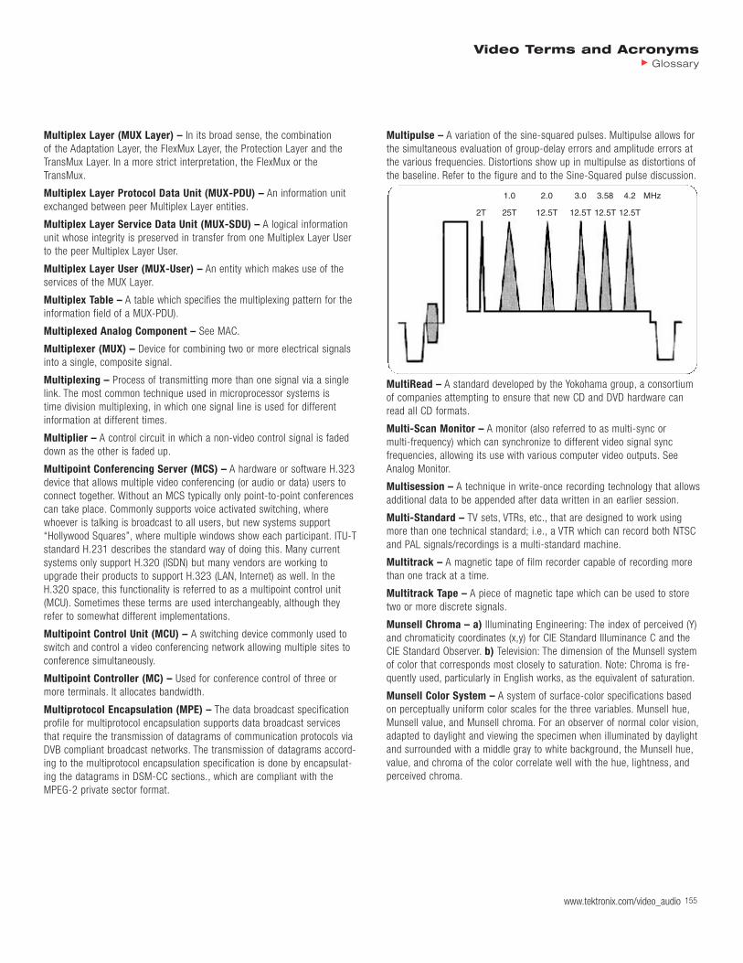
Multiplex Layer (MUX Layer) – In its broad sense, the combination of the Adaptation Layer, the FlexMux Layer, the Protection Layer and theTransMux Layer. In a more strict interpretation, the FlexMux or theTransMux.
Multiplex Layer Protocol Data Unit (MUX-PDU) – An information unitexchanged between peer Multiplex Layer entities.
Multiplex Layer Service Data Unit (MUX-SDU) – A logical informationunit whose integrity is preserved in transfer from one Multiplex Layer Userto the peer Multiplex Layer User.
Multiplex Layer User (MUX-User) – An entity which makes use of theservices of the MUX Layer.
Multiplex Table – A table which specifies the multiplexing pattern for theinformation field of a MUX-PDU).
Multiplexed Analog Component – See MAC.
Multiplexer (MUX) – Device for combining two or more electrical signalsinto a single, composite signal.
Multiplexing – Process of transmitting more than one signal via a singlelink. The most common technique used in microprocessor systems is time division multiplexing, in which one signal line is used for differentinformation at different times.
Multiplier – A control circuit in which a non-video control signal is fadeddown as the other is faded up.
Multipoint Conferencing Server (MCS) – A hardware or software H.323device that allows multiple video conferencing (or audio or data) users toconnect together. Without an MCS typically only point-to-point conferencescan take place. Commonly supports voice activated switching, where whoever is talking is broadcast to all users, but new systems support“Hollywood Squares”, where multiple windows show each participant. ITU-Tstandard H.231 describes the standard way of doing this. Many currentsystems only support H.320 (ISDN) but many vendors are working toupgrade their products to support H.323 (LAN, Internet) as well. In theH.320 space, this functionality is referred to as a multipoint control unit(MCU). Sometimes these terms are used interchangeably, although theyrefer to somewhat different implementations.
Multipoint Control Unit (MCU) – A switching device commonly used toswitch and control a video conferencing network allowing multiple sites toconference simultaneously.
Multipoint Controller (MC) – Used for conference control of three ormore terminals. It allocates bandwidth.
Multiprotocol Encapsulation (MPE) – The data broadcast specificationprofile for multiprotocol encapsulation supports data broadcast servicesthat require the transmission of datagrams of communication protocols viaDVB compliant broadcast networks. The transmission of datagrams accord-ing to the multiprotocol encapsulation specification is done by encapsulat-ing the datagrams in DSM-CC sections., which are compliant with theMPEG-2 private sector format.
Multipulse – A variation of the sine-squared pulses. Multipulse allows forthe simultaneous evaluation of group-delay errors and amplitude errors atthe various frequencies. Distortions show up in multipulse as distortions ofthe baseline. Refer to the figure and to the Sine-Squared pulse discussion.
MultiRead – A standard developed by the Yokohama group, a consortiumof companies attempting to ensure that new CD and DVD hardware canread all CD formats.
Multi-Scan Monitor – A monitor (also referred to as multi-sync or multi-frequency) which can synchronize to different video signal sync frequencies, allowing its use with various computer video outputs. SeeAnalog Monitor.
Multisession – A technique in write-once recording technology that allowsadditional data to be appended after data written in an earlier session.
Multi-Standard – TV sets, VTRs, etc., that are designed to work usingmore than one technical standard; i.e., a VTR which can record both NTSCand PAL signals/recordings is a multi-standard machine.
Multitrack – A magnetic tape of film recorder capable of recording morethan one track at a time.
Multitrack Tape – A piece of magnetic tape which can be used to storetwo or more discrete signals.
Munsell Chroma – a) Illuminating Engineering: The index of perceived (Y)and chromaticity coordinates (x,y) for CIE Standard Illuminance C and theCIE Standard Observer. b) Television: The dimension of the Munsell systemof color that corresponds most closely to saturation. Note: Chroma is fre-quently used, particularly in English works, as the equivalent of saturation.
Munsell Color System – A system of surface-color specifications basedon perceptually uniform color scales for the three variables. Munsell hue,Munsell value, and Munsell chroma. For an observer of normal color vision,adapted to daylight and viewing the specimen when illuminated by daylightand surrounded with a middle gray to white background, the Munsell hue,value, and chroma of the color correlate well with the hue, lightness, andperceived chroma.
1.0 2.0 3.0 3.58 4.2 MHz
2T 25T 12.5T 12.5T 12.5T 12.5T
Video Terms and AcronymsGlossary
www.tektronix.com/video_audio 155
156
MUSE (Multiple Sub-Nyquist Sampling Encoding) – a) 16:9 aspectratio, high definition, widescreen television being proposed in Japan.b) A term originally used for a transmission scheme developed by NHKspecifically for DBS transmission of HDTV. MUSE has since been extendedto a family of ATV transmission schemes. MUSE, as it was originally devel-oped, is a form of MAC. Recent versions of MUSE (MUSE- and MUSE-9) are said to be receiver-compatible and, as such, cannot employ MAC techniques. The sub-Nyquist part of the name indicates that MUSE is asub-sampling system and, as such, is subject to motion artifacts. While it is one of the oldest ATV transmission schemes still considered viable,MUSE is only four years old.
MUSE-6 – A family of three versions of an ATV transmission scheme saidto be both receiver-compatible and channel-compatible. Since the originalMUSE schemes are neither, there is little similarity between them, otherthan the use of sub-sampling. The differences between the three versionsrelate to how the wide aspect ratio is handled and what techniques areused for augmentation in an ATV set. Two versions of MUSE-6 use the letterbox technique for aspect ratio accommodation and both of these useblanking stuffing in the expanded VBI area for vertical resolution enhance-ment. The differences between the two versions relate to the duration ofthe sub-sampling sequence (one frame or two). The third uses the trunca-tion technique for aspect ratio accommodation, sending the side panelsstuffed into the existing VBI and HBI. Additional horizontal detail is trans-mitted via two-frame sub-sampling.
MUSE-9 – A family of three versions of an ATV transmission scheme saidto be receiver-compatible and utilizing a 3 MHz augmentation channel.The three versions are very similar to the three versions of MUSE-6, exceptthat the version using the truncation method sends the wide-screen panelson the augmentation channel rather than stuffing them into the HBI and the VBI. There are two classes of the three versions of MUSE-9, one with a contiguous augmentation channel and one without. The one without issaid to be somewhat inferior in quality to the one with.
MUSE-E – MUSE optimized for emission (i.e., broadcasting) rather thantransmission (i.e., satellite distribution). It is a non-receiver-compatible,non-channel-compatible scheme occupying 8.1 MHz of base bandwidthand requiring four fields to build up a full-resolution picture. Thus, itrequires motion compensation (and retains some motion artifacts). It offersfour channels of high-quality digital audio. It has been tested in theWashington, DC area.
MUSE-II – See MUSE-E.
MUSE-T – MUSE optimized for transmission (via satellite) rather thanemission (via terrestrial broadcasting). It occupies twice the bandwidth ofMUSE-E (16.2 MHz), but is otherwise quite similar.
Music and Effects Track(s) – Music and effects audio without video.Can be on one track, on different tracks on one piece of film or tape, or ondifferent tapes, which are combined during an audio “track mix” session.Sometimes abbreviated M&E.
MUSICAM (Masking Pattern Adapted Universal Sub-Band IntegratedCoding and Multiplexing) – Compression method for audio coding.
Must Carry – Legal requirement that cable operators carry local broadcastsignals. Cable systems with 12 or fewer channels must carry at least threebroadcast signals; systems with 12 or more channels must carry up toone-third of their capacity; systems with 300 or fewer subscribers areexempt. The 1992 Cable Act requires broadcast station to waive must-carry rights if it chooses to negotiate retransmission compensation (seeRetransmission consent).
MUX – See Multiplexer.
Mux Rate – Defined by MPEG-2 as the combined rate of all video andaudio elementary stream packets common to one program or multi-pro-gram stream. The rate of a stream is set based upon a user selection, bythe quality of the program (i.e., constant quality variable rate), or by thesymbol rate required from an RF transponder. This rate also includes theVBI and sub-picture private stream data, which MPEG treats as a privatestream type. Mux rate is always specified as 10.08 Mbps because this isthe rate at which user data arrives into the track buffer.
MVDS (Multi-Point Video Distribution System)
MXF (Material Exchange Format) – An object subset of AAF and is onthe verge of becoming a SMPTE standard. MXF was designed for less complex (less vertically rich) metadata applications, such as news editingand video streaming from servers. Because of its flatter metadata struc-ture, it is better suited to be used as a metadata wrapper within a videosignal or a TCP/IP stream. It offers performance benefits over the morecomplex AAF file structure because of its streamable nature.
MXF DMS-1 – The MXF development community has been working on a specific dialect for Descriptive Metadata, called MXF DMS-1, which isbeing designed to describe people, places, times, production billing.
Mylar – A registered trademark of E.I. duPont de Nemours & Co.,designating their polyester film.
Video Terms and AcronymsGlossary
www.tektronix.com/video_audio

www.tektronix.com/video_audio 157
Video Terms and AcronymsGlossary
NAB (National Association of Broadcasters) – An association whichhas standardized the equalization used in recording and reproducing. Thisis a station owner and/or operator’s trade association. NAB is also a partic-ipant in ATV testing and standardization work, and a charter member ofATSC. Though not a proponent of any particular ATV system, NAB lobbiesfor the interests of broadcasting as a delivery mechanism and has pub-lished some of the least biased information on the subject.
NAB Curves, NAB Equalization – Standard playback equalization curvesfor various tape speeds, developed by the National Association ofBroadcasters.
NAB Reel, NAB Hub – Reels and hubs used in professional recording,having a large center hole and usually an outer diameter of 10-1/2”.
NABET (National Association of Broadcast Employees andTechnicians) – NABET is a union of technicians that supplies membersfor many videotape, live and film productions.
NABTS – See North American Broadcast Teletext Specification.
Nagra – A brand of audio tape recorder using 1/4” wide audio tape extensively used for studio and location separate audio recording.
NAM – See Non-Additive Mix.
NANBA (North American National Broadcasters Association)
Nanosecond – One billionth of a second: 1 x 10⁻⁹ or 0.000000001 second.
NAP (North American Philips) – Philips Laboratories developed theHDS-NA ATV scheme and was among the first to suggest advanced pre-combing. See also PCEC.
Narrow MUSE – An NHK-proposed ATV scheme very similar to MUSE (and potentially able to use the same decoder) but fitting within a single,6 MHz transmission channel. Unlike MUSE-6 and MUSE-9, narrow MUSE is not receiver-compatible.
Narrowband – Relatively restricted in bandwidth.
Narrowband ISDN (N-ISDN) – Telecommunications at 1.5 Mbps on copper wire.
Narrowcasting – Broadcasting to a small audience.
National Television System Committee (NTSC) – a) The organizationthat formulated the “NTSC” system. Usually taken to mean the NTSC colortelevision system itself, or its interconnect standards. NTSC is the televisionstandard currently in use in the U.S., Canada and Japan. NTSC image for-mat is 4:3 aspect ratio, 525 lines, 60 Hz and 4 MHz video bandwidth witha total 6 MHz of video channel width. NTSC uses YIQ. NTSC-1 was set in1948. It increased the number of scanning lines from 441 to 525, andreplaced AM sound with FM. b) The name of two standardization groups,the first of which established the 525 scanning-line-per-frame/30 frame-per-second standard and the second of which established the color televi-sion system currently used in the U.S.; also the common name of theNTSC-established color system. NTSC is used throughout North Americaand Central America, except for the French islands of St. Pierre and
Miquelon. It is also used in most of the Caribbean and in parts of SouthAmerica, Asia, and the Pacific. It is also broadcast at U.S. military installa-tions throughout the world and at some oil facilities in the Middle East.Barbados was the only country in the world to transmit NTSC color on anon-525-line system; they have since switched to 525 lines. Brazil remainsthe only 525-line country to transmit color TV that is not NTSC; their sys-tem is called PAL-M. M is the CCIR designation for 525-line/30 frame tele-vision. See also M.
Native BIFS Node – A Binary Format for Scenes (BIFS) node which isintroduced and specified within the Final Committee Draft of InternationalStandard as opposed to non-native BIFS node, which is a node referencedfrom ISO/IEC 14772-1.
Native Resolution – The resolution at which the video file was captured.
NAVA (National Audio-Visual Association) – A trade association foraudio-visual dealers, manufacturers and producers.
Navigation Data – In DVD-Video there are five types of navigation data:Video Manager Information (VMGI), Video Title Set Information (VTSI),Program Chain Information (PGCI), Presentation Control Information (PCI)and Data Search Information (DSI).
Navigation Timer – In DVD-Video a system timer used during navigationoperations.
NBC – Television network that was an original proponent of the ACTV ATVschemes. NBC was also the first network to announce its intention to shiftfrom NTSC entirely to CAV recording equipment.
NB (National Body) – Responsible for developing national positions forinternational voting.
NBC (Non-Backwards Compatible)
NCTA (National Cable Television Association) – This is the primarycable TV owner and/or operator’s trade association. NCTA is performingsimilar roles to NAB in ATV research and lobbying, with an emphasis on CATV, rather than broadcasting, of course, and is a charter member of ATSC.
NDA (Non-Disclosure Agreement) – An agreement signed between two parties that have to disclose confidential information to each other inorder to do business. In general, the NDA states why the information isbeing divulged and stipulates that it cannot be used for any other purpose.NDAs are signed for a myriad of reasons including when source code ishanded to another party for modification or when a new product underdevelopment is being reviewed by the press, a prospective customer orother party.
NE (Network Element) – In general, an NE is a combination hardwareand software system that is designed primarily to perform a telecommuni-cations service function. For example, an NE is the part of the networkequipment where a transport entity (such as a line, a path, or a section) is terminated and monitored. As defined by wavelength routing, an NE isthe originating, transient, or terminating node of a wavelength path.
N
158 www.tektronix.com/video_audio158158158158158158158158
Video Terms and AcronymsGlossary
158
Near Instantaneous Companded Audio Multiplex (NICAM) – a) A digital audio coding system originally developed by the BBC for pointto point links. A later development, NICAM 728 is used in several Europeancountries to provide stereo digital audio to home television receivers.b) A digital two-channel audio transmissions with sub-code selection of bi-lingual operation. Stereo digital signals with specifications approachingthose of compact disc are possible. NICAM uses a 14 bit sample at a 32kHz sampling rate which produces a data stream of 728 kbits/sec.
Negative – a) A film element in which the light and dark areas arereversed compared to the original scene; the opposite of a positive.b) A film stock designed to capture an image in the form of a negative.
Negative Effect – Special effect in which either blacks and whites arereversed or colors are inverted. For example, red becomes a blue-green,green becomes purple, etc. The Video Equalizer and Digital Video Mixerincludes a negative effect which can be used to generate electronic colorslides from color negatives. An electronic color filter can be used for fineadjustment of the hues.
Negative Image – Refers to a picture signal having a polarity which isopposite to normal polarity and which results in a picture in which thewhite areas appear as black and vice versa.
Negative Logic – The logic false state is represented by the more positivevoltage in the system, and the logic true state is represented by the morenegative voltage in the system. For TTL, 0 becomes +2.4 volts or greater,and 1 becomes +0.4 volts or less.
Nested – Subroutine that is called by another subroutine or a loop within a larger loop is said to be nested.
NET (National Educational Television) – A public TV Network of stations.
Network – a) A group of stations connected together for common broad-cast or common business purposes; multiple circuits. b) A group of computers and other devices (such as printers) that can all communicatewith each other electronically to transfer and share information. c) A col-lection of MPEG-2 Transport Stream (TS) multiplexes transmitted on a single delivery system, e.g., all digital channels on a specific cable system.
Network Administrator – The individual responsible for setting up,maintaining, and troubleshooting the network, and for supplying setupinformation to system administrators of each system.
Network Interface Card (NIC) – A device that connects a terminal to anetwork.
Neutral – Normal; without power; not in working position; without muchcolor or brightness purposes; multiple circuits.
Neutral Colors – The range of gray levels, from black to white, but with-out color. For neutral areas in the image, the RGB signals will all be equal;in color difference formats, the color difference signals will be zero.
New York Institute of Technology – Private engineering school head-quartered in Old Westbury, NY, noted for its advanced computer graphics.Its Science and Technology Research Center, in Dania, FL, has beenresearching ATV for years. NYIT is a proponent of the VISTA ATV scheme.
NexTView – An electronic program guide (EPG) based on ETSI ETS 300707.
NFS™ (Network File System) – A distributed file system developed bySun that enables a set of computers to cooperatively access each other’sfiles transparently.
NG – An often-used term meaning “no good”.
NHK – See Nippon Hoso Kyokai.
Nibble – Four bits or half a byte. A group of four contiguous bits. A nibblecan take any of 16 (24) values.
NiCad (Nickel Cadmium) – Common Rechargeable video camera batterytype.
NICAM – See Near Instantaneous Companded Audio Multiplexer.
NICAM 728 – A technique of implementing digital stereo audio for PALvideo using another audio subcarrier. The bit rate is 728 kbps. It is discussed in BS.707 and ETSI EN 300 163. NICAM 728 is also used totransmit non-audio digital data in China.
Nighttime Mode – Name for Dolby Digital dynamic range compressionfeature to allow low-volume nighttime listening without losing legibility ofdialog.
Nippon Hoso Kyokai (NHK) – The Japan Broadcasting Corporation,principal researchers of HDTV through the 1970s, developers of the 1125 scanning-line system for HDEP and of all the MUSE systems fortransmission.
Nippon Television – See NTV.
NIST (National Institute of Standards and Technology) – This is theNorth American regional forum at which OSI implementation agreementsare decided. It is equivalent to EWOS in Europe and AOW in the Pacific.
NIT (Network Information Table) – The NIT conveys information relatingto the physical organization of the multiplex, transport streams carried via a given network, and the characteristics of the network itself. Transportstreams are identified by the combination of an original network ID and atransport stream ID in the NIT.
Nits – The metric unit for brightness. 1 foot lambert = 3.425 nits.
NIU (Network Interface Unit) – A device that serves as a common inter-face for various other devices within a local area network (LAN), or as aninterface to allow networked computers to connect to an outside network.The NIU enables communication between devices that use different proto-cols by supplying a common transmission protocol, which may be usedinstead of the device’s own protocols, or may be used to convert the spe-cific device protocol to the common one. To enable an interface between a LAN and another network, the NIU converts protocols and associatedcode and acts as a buffer between the connected hardware. A networkinterface card (NIC) is a type of NIU.
NLM (Network Loadable Module) – Software that runs in a NetWareserver. Although NetWare servers store DOS and Windows applications,they do not execute them. All programs that run in a NetWare server mustbe compiled into the NLM format.

www.tektronix.com/video_audio 159
Video Terms and AcronymsGlossary
NMI (Non-Maskable Interrupt) – A hardware interrupt request to theCPU which cannot be masked internally in the processor by a bit, but mustbe serviced immediately.
NNI (Nederlands Normalisatie-Instituut) – Standards body in theNetherlands.
Node – a) A list of calculations that you can apply to materials as part ofthe rendering tree language. The node can in turn serve as input to othernodes. b) Any signal line connected to two or more circuit elements. Alllogic inputs and outputs electrically connected together are part of thesame node.
Nodules – Clusters of materials, i.e., a large nodule of iron oxide on magnetic tape would be a tape defect.
Noise – Any unwanted electrical disturbances, other than crosstalk or dis-tortion components, that occur at the output of the reproduce amplifier.System Noise: The total noise produced by the whole recording system,including the tape. Equipment Noise: The noise produced by all the compo-nents of the system, with the exception of the tape. Tape Noise: The noisethat can be specifically ascribed to the tape. There are several sources oftape noise. See DC Noise, Erase Noise, Modulation Noise, Saturation Noise,and Zero Modulation Noise.
Noise Bars – White streaks in a picture, usually caused when video headstrace parts of the tape that have no recorded signal.
Noise Floor – The level of background noise in a signal or the level ofnoise introduced by equipment or storage media below which the signalcan't be isolated from the noise.
Noise Gate – A device used to modify a signal’s noise characteristics. Invideo, noise gates provide optimal automatic suppression of snow (signalnoise level). In audio, a noise gate provides a settable signal level thresholdbelow which all sound is removed.
Noise Pulse – A spurious signal of short duration that occurs duringreproduction of a tape and is of magnitude considerably in excess of theaverage peak value of the ordinary system noise.
Noise Reduction – The amount in dB that the noise added to a signal bytransmission or storage chain, especially a tape recorder, is reduced fromthe level at which it would be if no noise reduction devices were used.
Noise Reduction Systems – Refers to electronic circuits designed tominimize hiss level in magnetic recording.
Noise Weighting – An adjustment used in the electrical measurement oftelevision signal noise values to take into account the difference betweenthe observable effect of noise in a television picture and the actual electri-cal value of noise.
Noise/A-Weighted – Unwanted electrical signals produced by electronicequipment or by magnetic tape. Mostly confined to the extremes of theaudible frequency spectrum where it occurs as hum and/or hiss. A-weight-ed noise is noise measured within the audio frequency band using a measuring instrument that has a frequency selective characteristic. Thefrequency sensitivity of the measuring instrument is adjusted to correspondto that of the average human hearing response.
Noisy – A description of a picture with abnormal or spurious pixel values.The picture’s noise is a random variation in signal interfering with theinformation content.
Noisy Video – Noisy video (e.g., video from low quality VTRs) is more difficult to code than the cleaner version of the same sequence. The reasonis that the video encoder spends many bits trying to represent the noise asif it were part of the image. Because noise lacks the spatial coherence ofthe image, it is not coded efficiently.
Nomograph – This is a table that allows for the determination ofChrominance to Luminance Gain and Delay errors. Refer to the discussionon Chrominance to Luminance Gain and Delay.
Non-Additive Mix (NAM) – The process of combining two video signalssuch that the resultant video signal is instant-by-instant the same as thebrighter of the two weighted input signals. For example, at 50% fader,the brighter of the two videos predominates. The net effect of this type of mix is a superimposed appearance, with the picture balance controlled by the fader.
Non-Compatible – Incapable of working together.
Noncomposite Video – A video which does not contain a synchronizingpulse.
Nondirectional – A pickup pattern which is equally sensitive to soundsfrom all directions.
Non-Drop Frame – System of time code that retains all frame numbers inchronological order, resulting in a slight deviation from real clock time.
Non-Drop Frame Time Code – SMPTE time code format that continuous-ly counts a full 30 frames per second. Because NTSC video does not operate at exactly 30 frames per second, non-drop frame time code willcount 108 more frames in one hour than actually occur in the NTSC videoin one hour. The result is incorrect synchronization of time code with clocktime. Drop frame time code solves this problem by skipping or dropping 2frame numbers per minute, except at the tens of the minute count.
Non-Ferrous – Without iron or iron oxide.
Noninterlaced – Method of scanning video in which the entire frame isscanned at once rather than interleaved. The rate of scan must be fastenough that the average light level of the scene does not decreasebetween scans and cause flicker. Another term for a noninterlaced systemis progressive scan.
Non-Intra Coding – Coding of a macroblock or picture that uses informa-tion both from itself and from macroblocks and pictures occurring at othertimes.
Nonlinear – A term used for editing and the storage of audio, video anddata. Information (footage) is available anywhere on the media (computerdisk or laser disc) almost immediately without having to locate the desiredinformation in a time linear format.
Nonlinear Distortion – Amplitude-dependent waveform distortion. Thisincludes APL and instantaneous signal level changes. Analog amplifiers are linear over a limited portion of their operating range. Signals which falloutside of the linear range of operation are distorted. Nonlinear distortions

160 www.tektronix.com/video_audio160160160160160160160160
Video Terms and AcronymsGlossary
160
include crosstalk and intermodulation effects between the luminance andchrominance portions of the signal.
Nonlinear Editing (NLE) – a) The process of editing using rapid retrieval(random access) computer controlled media such as hard disks, CD-ROMsand laser discs. Its main advantages are: allows you to reorganize clips ormake changes to sections without having to redo the entire production andvery fast random access to any point on the hard disk (typically 20-40 ms).b) Nonlinear distinguished editing operation from the “linear” methodsused with tape. Nonlinear refers to not having to edit material in thesequence of the final program and does not involve copying to make edits.It allows any part of the edit to be accessed and modified without having tore-edit or re-copy the material that is already edited and follows that point.Nonlinear editing is also non-destructive, the video is not changed but thelist of how the video is played back is modified during editing.
Nonlinear Editor – An editing system based on storage of video andaudio on computer disk, where the order or lengths of scenes can bechanged without the necessity of reassembling or copying the program.
Nonlinear Encoding – Relatively more levels of quantization are assignedto small amplitude signals, relatively fewer to the large signal peaks.
Nonlinearity – The amount by which a measured video signal output dif-fers from a standard video signal output. The greater this deviation, thegreater the video signal distortion and possibility of luminance and chromi-nance problems. Having gain vary as a function of signal amplitude.
Non-Return-to-Zero (NRZ) – A coding scheme that is polarity sensitive.0 = logic low; 1 = logic high.
Non-Return-to-Zero Inverse (NRZI) – A video data scrambling schemethat is polarity insensitive. 0 = no change in logic; 1 = a transition fromone logic level to the other.
Non-Synchronous – Separate things not operating together properly, i.e.,audio and video or the inability to properly operate together with anotherspecific piece of equipment or signal. See Synchronous.
Non-Synchronous Source – A video signal whose timing information differs from the reference video by more than 800 ns.
Non-Uniform B-Splines (NURBS) – A superset of both Bézier andUniform B-Splines. NURBS introduces the feature of non-uniformity. Thus it is possible to subdivide a spline, for example, to locally increase thenumber of control points without changing the shape of the spline. This is a powerful feature which enables you to insert more control points on a spline without altering its shape; cut anywhere on a spline to generatetwo parts; and creates cusps in splines.
Non-Useful DC Component – Produced by the transmission equipmentand not related to picture content. The non-useful DC component presentacross the interface point, with or without the load impedance connected,shall be zero +/-50 µV.
Normal – a) Relating to the orientation of a surface or a solid, a normalspecifies the direction in which the outside of the surface or the solidfaces. b) The normal to a plane is the direction perpendicular to the surface.
Normal Key – On the 4100 series, an RGB chroma key or a luminancekey, as distinct from a composite (encoded) chroma key.
Normal/Reverse – The specification of the direction a pattern moves asthe fader is pulled. A normal pattern starts small at the center and growsto the outside while a reverse pattern starts from the edge of the screenand shrinks. Normal/Reverse specifies that the pattern will grow as thefader is pulled down, and shrink as it is pushed up. This definition losessome meaning for wipes that do not have a size per-se such as a verticalbar, however, this feature still will select the direction of pattern movement.
North American Broadcast Teletext Specification – Provisions for525-line system C teletext as described in EIA-516 and ITU-R BT.653.
NOS (Network Operating System) – Generic term used to refer to whatare really distributed file systems. Examples of NOSs include LAN Manager,NetWare, NFS, and VINES.
Notch Filter – A device which attenuates a particular frequency greatly,but has little effect on frequencies above or below the notch frequency.
Notifier – A form that appears when the system requires you to confirman operation that you just requested, or when an error occurs.
NRZ – See Non-Return-to-Zero.
NRZI – See Non-Return-to-Zero Inverse.
NSAP (Network Service Access Point) – Network addresses, as specified by ISO. An NSAP is the point at which OSI network service ismade available to a Transport Layer (Layer 4) entity.
NSF (Norges Standardiseringsforbund) – Standards body of Norway.
NST (Network Status Table) – The network status table shows the network name, the protocol, the interface over which the network runs(eth:1 for LAN, atm:1 or hdlc:1 for WAN), how the network was created(static for LAN, dynamic for WAN) and the network address assigned to the connection.
NRZ
NRZI
0 1 0 0 1 0 1
0 1 0 0 1 0 1
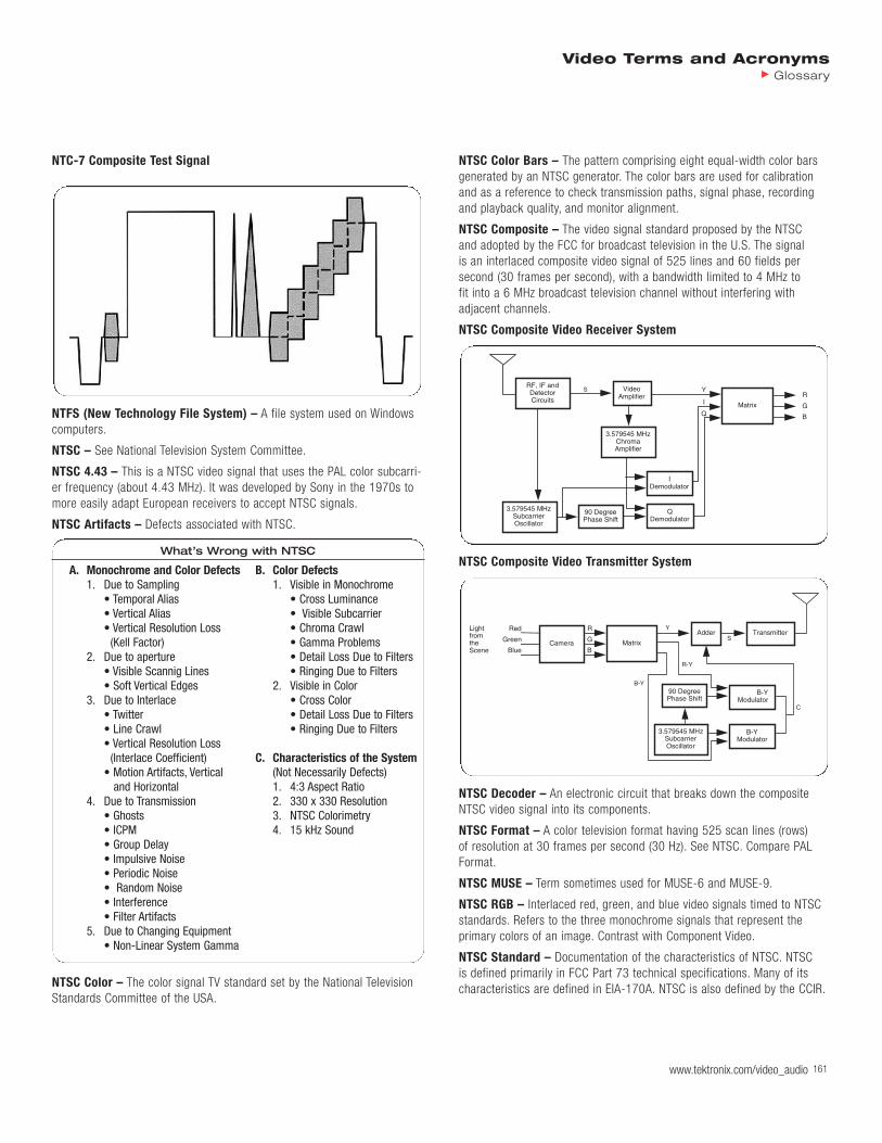
www.tektronix.com/video_audio 161
Video Terms and AcronymsGlossary
NTC-7 Composite Test Signal
NTFS (New Technology File System) – A file system used on Windowscomputers.
NTSC – See National Television System Committee.
NTSC 4.43 – This is a NTSC video signal that uses the PAL color subcarri-er frequency (about 4.43 MHz). It was developed by Sony in the 1970s tomore easily adapt European receivers to accept NTSC signals.
NTSC Artifacts – Defects associated with NTSC.
What’s Wrong with NTSC
A. Monochrome and Color Defects B. Color Defects1. Due to Sampling 1. Visible in Monochrome
• Temporal Alias • Cross Luminance• Vertical Alias • Visible Subcarrier• Vertical Resolution Loss • Chroma Crawl
(Kell Factor) • Gamma Problems2. Due to aperture • Detail Loss Due to Filters
• Visible Scannig Lines • Ringing Due to Filters• Soft Vertical Edges 2. Visible in Color
3. Due to Interlace • Cross Color• Twitter • Detail Loss Due to Filters• Line Crawl • Ringing Due to Filters• Vertical Resolution Loss
(Interlace Coefficient) C. Characteristics of the System• Motion Artifacts, Vertical (Not Necessarily Defects)
and Horizontal 1. 4:3 Aspect Ratio4. Due to Transmission 2. 330 x 330 Resolution
• Ghosts 3. NTSC Colorimetry• ICPM 4. 15 kHz Sound• Group Delay • Impulsive Noise • Periodic Noise • Random Noise • Interference • Filter Artifacts
5. Due to Changing Equipment• Non-Linear System Gamma
NTSC Color – The color signal TV standard set by the National TelevisionStandards Committee of the USA.
NTSC Color Bars – The pattern comprising eight equal-width color barsgenerated by an NTSC generator. The color bars are used for calibrationand as a reference to check transmission paths, signal phase, recordingand playback quality, and monitor alignment.
NTSC Composite – The video signal standard proposed by the NTSC and adopted by the FCC for broadcast television in the U.S. The signal is an interlaced composite video signal of 525 lines and 60 fields per second (30 frames per second), with a bandwidth limited to 4 MHz to fit into a 6 MHz broadcast television channel without interfering with adjacent channels.
NTSC Composite Video Receiver System
NTSC Composite Video Transmitter System
NTSC Decoder – An electronic circuit that breaks down the compositeNTSC video signal into its components.
NTSC Format – A color television format having 525 scan lines (rows) of resolution at 30 frames per second (30 Hz). See NTSC. Compare PALFormat.
NTSC MUSE – Term sometimes used for MUSE-6 and MUSE-9.
NTSC RGB – Interlaced red, green, and blue video signals timed to NTSCstandards. Refers to the three monochrome signals that represent the primary colors of an image. Contrast with Component Video.
NTSC Standard – Documentation of the characteristics of NTSC. NTSC is defined primarily in FCC Part 73 technical specifications. Many of itscharacteristics are defined in EIA-170A. NTSC is also defined by the CCIR.
Y
R-Y
B-Y
C
S
B
G
R
Blue
Green
RedLightfromtheScene
MatrixCamera
Adder Transmitter
3.579545 MHzSubcarrierOscillator
90 DegreePhase Shift
B-YModulator
B-YModulator
B
Y
Q
I
S
G
R
Matrix
VideoAmplifier
90 DegreePhase Shift
QDemodulator
IDemodulator
3.579545 MHzChromaAmplifier
3.579545 MHzSubcarrierOscillator
RF, IF andDetectorCircuits
162
NTSC is a living standard; as problems with it are discovered, they are corrected. For example, a former EIA standard, RS-170, omitted any phaserelationship between luminance and chrominance timing, resulting inblanking problems. EIA-170A defines that relationship (called SC/H for subcarrier to horizontal phase relationship). See also True NTSC.
NTSC-M – The U.S. standard of color television transmissions. See alsoNTSC and M.
NTU (Network Termination Unit) – An Network Termination Unit is adevice located at the final interconnect point between the PSTN (PublicSwitched Telephone Network) and the customers own equipment.
NTV (Nippon Television Network) – A Japanese broadcaster that is aproponent of ATV schemes similar to Faroudja’s SuperNTSC. NTV’s firstgeneration EDTV system would use high line-rate and/or progressive scancameras with prefiltering, adaptive emphasis, gamma correction, ghostcancellation, a progressive scan display, and advanced decoding at thereceiver. The second generation would add more resolution, a widescreenaspect ratio, and better sound. The first generation is scheduled to bebroadcast beginning in 1988.
Null Packets – Packets of “stuffing” that carry no data but are necessaryto maintain a constant bit rate with a variable payload. Null packets alwayshave a PID of 8191.
Number Crunching – Action of performing complex numerical operations.
Numerical Aperture – A number that defines the light gathering ability of a specific fiber. The numerical aperture is equal to the sine of the maximum acceptance angle.
NVOD (Near Video On Demand) – This service allows for a single TVprogram to be rebroadcast consecutively with a few minutes of differencein starting time. For example, a movie could be transmitted at 9:00, 9:15and 9:30.
NWK – See Network.
NYIT – See New York Institute of Technology.
Nyquist – Nyquist Filter, Nyquist Limit, Nyquist Rule, and Harry Nyquist,for whom they are named.
Nyquist Filter – Commonly used in the IF stage of a television receiver to separate the desired television channel from potential interference.
Nyquist Frequency – The lowest sampling frequency that can be used foranalog-to-digital conversion of a signal without resulting in significantaliasing. Normally, this frequency is twice the rate of the highest frequencycontained in the signal being sampled.
Nyquist Interval – The maximum separation in time which can be givento regularly spaced instantaneous samples of a wave of bandwidth W forcomplete determination of the waveform of the signal. Numerically, it isequal to 1/2 W seconds.
Nyquist Limit – When time-varying information is sampled at a rate R,the highest frequency that can be recovered without alias is limited to R/2.Aliasing may be generated by under sampling temporally in frame rate, orvertically in lines allocated to image height, or horizontally in analog band-width or in pixel allocation. Intermodulations prior to band limiting may“preserve” some distracting effects of aliasing in the final display. Note:Sampling at a rate below the Nyquist limit permits mathematical confirma-tion of the frequencies present (as for example in a Fourier analysis ofrecorded motion). If the sampling window is very small (as in synchronizedflash exposure), however, it may become a subjective judgment whetherstrobing is perceived in the image for motion approaching the limitingvelocity (frequency).
Nyquist Rate Limit – Maximum rate of transmitting pulse signals througha channel of given bandwidth. If B is the effective bandwidth in Hertz, then2B is the maximum number of code elements per second that can bereceived with certainty. The definition is often inverted, in effect, to read“the theoretical minimum rate at which an analog signal can be sampledfor transmitting digitally”.
Nyquist Rule – States that in order to be able to reconstruct a sampledsignal without aliases, the sampling must occur at a rate of more thantwice the highest desired frequency. The Nyquist Rule is usually observedin digital systems. For example, CDs have a sampling frequency of 44.1kHz to allow signals up to 20 kHz to be recorded. It is, however, frequentlyviolated in the vertical and temporal sampling of television, resulting inaliases. See also Alias.
Nyquist Sampling – Sampling at or above twice the maximum bandwidthof a signal. This allows the original signal to be recovered without distor-tion.
Nyquist Sampling Theorem – Intervals between successive samplesmust be equal to or less than one-half the period of highest frequency.
Video Terms and AcronymsGlossary
www.tektronix.com/video_audio

Video Terms and AcronymsGlossary
www.tektronix.com/video_audio 163
OAM (Operation, Administration and Maintenance) – ATM Forumspecification for cells used to monitor virtual circuits. OAM cells provide a virtual circuit level loopback in which a router responds to the cells,demonstrating that the circuit is up and the router is operational.
Object Based Coding (OBC) – A technique that codes arbitrarily shapedobjects within a scene. Transmitted parameters are shape, color andmotion.
Object Carousels – The object carousel specification has been added in order to support data broadcast services that require the periodic broadcasting of DSM-CC user-user (U-U) objects through DVB compliantbroadcast networks, specifically as defined by DVB systems for interactiveservices (SIS). Data broadcast according to the DVB object carousel specification is transmitted according to the DSM-CC object carousel and DSM-CC data carousel specification which are defined in MPEG-2DSM-CC.
Object Clock Reference (OCR) – A clock reference that is used by amedia object hierarchy. This notation has been chosen within the context of the MPEG-4 Systems.
Object Content Information (OCI) – Additional information about contentconveyed through one or more elementary streams. It is either attached toindividual elementary stream descriptors or conveyed itself as an elemen-tary stream.
Object Descriptor (OD) – A descriptor that associates one or more elementary streams by means of their elementary stream descriptors anddefines their logical dependencies.
Object Descriptor Message – A message that identifies the action to betaken on a list of object descriptors or object descriptor Ids, for example,update or remove.
Object Descriptor Stream – An elementary stream that conveys objectdescriptors encapsulated in object descriptor messages.
Object Modeling Technique (OMT) – A graphical method to representthe class hierarchy. This notation has been chosen within the context of theMPEG-4 Systems.
Object Program – End result of the source language program (assemblyor high-level) after it has been translated into machine language.
Object Time Base (OTB) – a) The OTB defines the notation of time of agiven encoder. All time stamps that the encoder inserts in a coded audiovi-sual object data stream refer to this time base. b) A time base valid for agiven object, and hence for its media object decoder. The OTB is conveyedto the media object decoder via object clock references. All time stampsrelating to this object’s decoding process refer to this time base.
Objects – Objects, in the object-oriented terminology, are entities thatcombine a data structure (defining the object’s state), with a set of meth-ods (defining the object’s behavior).
Objective – The very first optical element at the front of a lens.
OBO (Output Back-Off) – The ratio of the signal power measured at the output of a high power amplifier to the maximum output signal power.The output back-off is expressed in decibels as either a positive or negative quantity. It can be applied to a single carrier at the output to the HPA (carrier OBO), or to the ensemble of output signals (total OBO).
OC1 (Optical Carrier Level 1) – A signal with a bitrate of 51.8 Mbps.Fundamental transmission rate for SONET.
OC12 (Optical Carrier Level 12) – A signal with a bitrate of 622 Mbps.
OC3 (Optical Carrier Level 3) – A 155 Mbps ATM SONET signal streamthat can carry three DS-3 signals. Equivalent to SDH STM-1.
OC48 (Optical Carrier Level 48) – A signal with a bitrate of 2.4 Gbps.
Occlusion – The process whereby an area of the video raster is blocked or made non-transparent by controlling selected bits. Occlusion is usedwhen more than one picture is displayed or windowed simultaneously.
OCT (Octal Notation) – Any mathematical notation that uses 8 differentcharacters (usually the digits 0 to 7).
Octal – Base 8 number system. Often used to represent binary numbers,since each octal digit corresponds directly to three binary digits.
Octave – A two-to-one frequency ratio.
Ocular – The very last optical element at the back of a lens (the one closer to the CCD chip).
Odd Number – The number of scanning lines per frame necessary in aninterlaced scanning system. One line is split between fields to ensure proper spacing between scanning lines from different fields. A progressive-ly scanned system may use an even number of scanning lines.
OEM (Original Equipment Manufacturer) – A company which develops,produces and sells computer and consumer hardware to other companies.
Oersted – A unit of magnetic field strength.
OFDM (Orthogonal Frequency Division Multiplex) – First promoted inthe early 1990s as a wireless LAN technology. OFDM’s spread spectrumtechnique distributes the data over a large number of carriers that arespaced apart at precise frequencies. This spacing provides the “orthogonal-ity” in this technique which prevents the demodulators from seeing otherfrequencies than their own. Coded OFDM (COFDM) adds forward error correction to the OFDM method.
Off-Line, Offline – Preliminary editing done on relatively low-cost editingsystems, usually to provide an EDL for final on-line editing and assembly ofthe finished show.
Off-Line Edit – Rough cut editing used to produce an Edit Decision List.
Off-Line Editing – Editing that is done to produce an edit decision list,which is used later for assembling that program. A video tape (sometimescalled a work print) may be produced as a by-product of off-line editing.
O

164 www.tektronix.com/video_audio164164164164164164164164
Video Terms and AcronymsGlossary
Off-Line Editor – A low resolution, usually computer and disk based editsystem in which the creative editing decisions can be made at lower cost and often with greater flexibility than in an expensive fully equippedon-line bay.
Offline Encoder – The Indeo video codec’s normal mode of operation,in which it takes as long as necessary to encode a video file so that it displays the best image quality and the lowest and most consistent datarate. Compare Quick Compressor.
Offset – a) The horizontal and vertical displacement of a clip.b) Reference numbers that indicate the change, in terms of frames,that take place when you trim.
Ohm – The unit of resistance. The electrical resistance between two pointsof a conductor where a constant difference of potential of 1 V appliedbetween these points produces in the conductor a current of 1 A, the conductor not being the source of any electromotive force.
OIRT (Organisation Internationale de Radiodiffusion-Television) –The OIRT was dissolved in 1992 and integrated into the Union of theEuropean Broadcast Organizations (UER).
OLE (Object Linking and Embedding) – A standard for combining datafrom different applications that updates automatically.
O-Member (Observing Member) – A term used within ISO/IEC JTC1committees. A National Body that does not vote.
OMF, OMFI, OMF Interchange (Open Media Framework Interchange)– A media and metadata exchange solution developed by Avid Technology.A standard format for the interchange of digital media data among heterogeneous platforms. The format is designed to encapsulate all theinformation required to interchange a variety of digital media, such asaudio, video, graphics, and still images as well as the rules for combiningand presenting the media. The format includes rules for identifying theoriginal sources of the digital media, and it can encapsulate both com-pressed and uncompressed digital media data.
Omnidirectional – A microphone type that picks up sound relatively evenly from all directions.
OMWF (Open MPEG Windows Forum) – OMWF is a Japanese industryconsortium aiming at compatibility in MPEG-based multimedia applications.The group, that includes various hardware and software vendors and content providers in Japan, ahs its offspring in the popularity in Japan ofCD movies and Karaoke. Through cooperation with the Open MPEGConsortium in the USA, the OMWF cleared up details in the MCI standard,that impeded compatibility. The new specification, called the Video CDspecification, allows Windows machines to play MPEG-1 video CDs andallows Windows data and applications to be stored on the same CD alongwith the video contents.
On the Fly – a) Depressing a button causing some change while a switch-er is transitioning. b) Selecting a tape edit point while VTR is moving.
On-Air Output – Ready to use for transmission or videotaping, this is thePGM output.
One Light – A telecine transfer or film print produced with a single setting of color correction values. One light is the simplest, fastest, andleast costly type of transfer.
One Wire Interconnect – Interconnect consists of a single wire transport-ing an encoded, composite analog video signal.
One_Random_PGC Title – In DVD-Video, a Title within a Video Title Set(VTS) that contains a single Program Chain (PGC), but does not meet therequirements of a One_Sequential_PGC Title. Contrast with toOne_Sequential_PGC Title and Multi_PGC Title.
One_Sequential_PGC Title – In DVD-Video, a Title within a Video Title Set (VTS) that contains a single Program Chain (PGC) with the followingattributes: 1) PG Playback mode is Sequential, 2) no Next PGC, PreviousPGC or Go Up PGCs are defined, and 3) the Navigation Timer is neither set,nor referred to. Contrast with One_Random_PGC Title and Multi_PGC Title.
One’s Complement – Number representation system used for signedbinary integers in which the negative of a number is obtained by comple-menting it. The leftmost bit becomes the sign bit, with 0 for plus, 1 forminus.
On-Line Editing – a) Editing that is done to produce a finished programmaster. b) Final editing session, the stage of post-production in which the edited master tape is assembled from the original production footage,usually under the direction of an edit decision list (EDL).
On-Line Editor – An editing system where the actual video master is created. An on-line bay usually consists of an editing computer, videoswitcher, audio mixer, one or more channels of DVE, character generator,and several video tape machines.
On-Line, Online – Final editing or assembly using master tapes to pro-duce a finished program ready for distribution. Often preceded by off-lineediting, but in some cases programs go directly to the on-line editing suite.Usually associated with high-quality computer editing and digital effects.
On-Screen Display – A function on many VCRs and televisions in whichoperational functions (tint, brightness, VCR function, programming, etc.) are displayed graphically on the television screen.
ONU (Optical Node Unit)
OOB (Out-of-Band) – Out-of-band is any frequency outside the bandused for voice frequencies.
Opaque Macroblock – A macroblock with shape mask of all 255’s.
Opcode – See Operation Code.
OPCR (Original Program Clock Reference)
Open – To double-click an icon, or to select an icon then choose “Open”from a menu in order to display a window that contains the informationthat the icon represents.
Open Architecture – A concept for television receivers that acknowledgesan absence of ATV transmission/distribution standards and allows a receiver to deal with a multiplicity of standards and delivery mechanisms.
Open MPEG Consortium – The goal of the Open MPEG Consortium is to “create a single API for the playback of MPEG-1 titles under Windowsand DOS”. The consortium has developed the MPEG Multimedia ControlInterface (MCI) which defines how MPEG boards operate under Windows.Due to some undefined topics, the MCI specification has not been able tocurb incompatibility, but the consortium has later cooperated with theJapanese OMWF group on an enhanced specification.
Video Terms and AcronymsGlossary
www.tektronix.com/video_audio 165
Open Subtitles – See Subtitles.
Open-Ended Edit – a) Assemble mode. b) Edit that has a start time butno designated stop time.
Open-Loop – Circuit or other system operating without feedback.
Operating Level – A certain level of flux recorded on magnetic tape.
Operating Program – Computer software program which controls allfunctions of related computers and hardware devices.
Operating System – The primary software in a computer, containing gen-eral instructions for managing applications, communications, input/output,memory and other low-level tasks. DOS, Windows, Mac OS, and UNIX areexamples of operating systems.
Operation Code (Opcode) – Segment of the machine-language instruc-tion that specifies the operation to be performed. The other segmentsspecify the data, address, or port. For the 8085, the first byte of eachinstruction is the opcode.
Opposite Track Path (OTP) – Dual-layer disc where Layer 0 and Layer 1have opposite track directions. Layer 0 reads from the inside to the outsideof the disc, whereas Layer 1 reads from the outside to the inside. The disc always spins clockwise, regardless of track structure or layers. Thismode facilitates movie playback by allowing seamless (or near-seamless)transition from one layer to another. In computer applications (DVD-ROM),it usually makes more sense to use the Parallel Track Path (PTP) formatwhere random access time is more important.
Optical Effects – Trick shots prepared by the use of an optical printer inthe laboratory, especially fades and dissolves.
Optical Fiber – A glass strand designed to carry light in a fashion similarto the manner in which wires carry electrical signals. Since light is electro-magnetic radiation of tremendously high frequency, optical fibers can carrymuch more information than can wires, though multiple paths through thefiber place an upper limit on transmission over long distances due to acharacteristic called pulse dispersion. Many feel that the wide bandwidth of an optical fiber eliminates the transmission problems associated with thehigh base bandwidth of HDEP schemes. CATV and telephone companiespropose connecting optical fibers directly to homes.
Opticals – The effects created in a film lab through a process called A-roll and B-roll printing. This process involves a specified manipulation of the film negative to create a new negative containing an effect. Themost common opticals used in film editing are fades, dissolves, and superimpositions.
Option Button – Used to select from a list of related items. The selectedoption box has a black dot. (One item in the group must be selected.)
Option Drive – Any internal drive other than the system disk. Optiondrives include floppy disk drives, secondary hard disk drives, or DAT drives.
Orange Book – The document begun in 1990 which specifies the formatof recordable CD. Three parts define magneto-optical erasable (MO) andwrite-once (WO), dye-sublimation write-once (CD-R), and phase-changerewritable (CD-RW) discs. Orange Book added multisession capabilities tothe CD-ROM XA format.
Orbit – The rotation of the camera eye around the point of interest.
Orientation – a) For animation, many 3D systems fix the viewer’s locationat a specified distance from the viewing screen. Currently, PictureMaker is one of these. In such systems, the database is moved relative to theviewer. The set of motions that accomplish any particular view of the worldis called its “orientation”. Using the three coordinate axes as references,we can translate (shuffle on a plane) and rotate objects to create newviews. During animation, we change the amounts of these motions. A set ofnumbers describes orientation: x-trans, y-trans, z-trans, x-rot, y-rot, z-rot.b) A direction of presentation affecting resolution requirements. Horizontallines become vertical lines when their orientation is rotated by 90 degrees;a pattern of dots appearing to be in horizontal and vertical rows may notappear to be diagonally aligned when its orientation is rotated 45 degreesdue to characteristics of the human visual system.
Orientation Animation – We can also use splines to calculate orienta-tions for objects in between their orientations at keyframe positions. Thisallows the motions of an object to be smooth rather than robot-like. In traditional animation, orientation animation required an artist to redraw the object when it rotated out of the plane of the platen (on the animationstand) and path animation was limited to repositioning the cells in X and Y(although the whole scene could be zoomed). In computer graphics, it iseasy to rotate and reposition objects anywhere in three dimensions. That is why you see so much of it!
Orientation Direction – The arrangement of magnetic particles onrecording tape. In tapes designed for quadraplex recording applications,the orientation direction is transverse. For helical and longitudinal recording, it is longitudinal.
Orientation Ratio – In a material composed of oriented particles, the orientation ratio is the ratio of the residual flux density in the orientationdirection to the residual flux density perpendicular to the orientation direction. The orientation ratio of conventional tapes is typically about 1.7.
Origin – A reference point for measuring sections of recorded or digitizedsample data. A file mob value for the start position in the media isexpressed in relation to the origin. Although the same sample data can be re-recorded or re-digitized, and more sample data might be added,the origin remains the same so that composition source clips referencing it remain valid.
Original Negative – The actual film stock used in the camera to photograph a scene.
original_network_id – A unique identifier of a network.
Origination – The production cycle begins with the introduction of images in photographic, electronic imaging, or computational media.Image capture in real-time is usually essential for recording live subjectsand maintaining the impact of realism. Image generation, normallyachieved in non real-time, provides additional subject matter that can be edited into and combined with recorded live subjects to achieve programs that are more artistic, or more instructional, or both.
Orthicon (Conventional) – A camera tube in which a low-velocity electron beam scans a photoemissive mosaic on which the image isfocused optically and which has electrical storage capability.
Orthicon (Image) – A camera tube in which the optical image falls on aphoto-emissive cathode which emits electrons that are focused on a target

166
at high velocity. The target is canned from the rear by a low-velocity elec-tron beam. Return beam modulation is amplified by an electron multiplierto form an overall light-sensitive device.
Orthicon Effect – One or more of several image orthicon impairments that have been referred to as “Orthicon Effect” as follows: edge effect,meshbeat or Moiré, ghost, halo, burned in image. It is obviously necessaryto indicate specifically the effects experienced and, therefore, it is recommended that use of this term be discontinued.
Orthogonal Projection – With orthogonal projection, parallel recedinglines do not converge. The process of projecting from 3D to 2D is particularly simple, simply throw away the Z-value of each coordinate.
Orthogonal Sampling – a) Sampling of a line of repetitive video signal insuch a way that samples in each line are in the same horizontal position.b) Picture sampling arranged in horizontal rows and vertical columns.
Osborne, Joseph – An ATV proponent issued a patent for a data compression transmission scheme for HD signals. The Osborne compression system is said to allow channel-compatible but not receiver-compatible HDTV.
Oscilloscope – An electronic device that can measure the signal changesversus time. A must for any CCTV technician.
OSI (Open Systems Interconnection) – The OSI Reference Model wasformally initiated by the International Organization for Standardization (ISO)in March, 1977, in response to the international need for an open set ofcommunications standards. OSI’s objectives are: to provide an architecturalreference point for developing standardized procedures; to allow inter-net-working between networks of the same type; to serve as a common frame-work for the development of services and protocols consistent with the OSI model; to expedite the offering of interoperable, multi-vendor productsand services.
OSI Model – The model is similar in structure to that of SNA. It consists of seven architectural layers: the Physical Layer and Data Link Layer, theNetwork Layer; the Transport Layer; the Session Layer; the PresentationLayer; the Application Layer.
OSI Model
Physical and Provides the same functions as their SNA counterpartsData Link Layers (physical control and data link control layers.
Network Layer Selects routing services, segments blocks and messages,and provides error detection, recovery, and notification.
Transport Layer Controls point-to-point information interchange,data packet size determination and transfer, and the connection/disconnection of session entities.
Session Layer Serves to organize and synchronize the applicationprocess dialog between presentation entities, manage the exchange of data (normal and expedited) during the session, and monitor the establishment/release oftransport connections as requested by session entities.
Presentation Layer Responsible for the meaningful display of information toapplication entities. More specifically, the presentationlayer identifies and negotiates the choice of communica-tions transfer syntax and the subsequent data conversionor transformation as required.
Application Layer Affords the interfacing of application processes to systeminterconnection facilities to assist with informationexchange. The application layer is also responsible for the management of application processes including initialization, maintenance and termination of communica-tions, allocation of costs and resources, prevention ofdeadlocks, and transmission security.
OTP – See Opposite Track Path.
OUI (Organizational Unique Identifier) – The part of the MAC addressthat identifies the vendor of the network adapter. The OUI is the first threebytes of the six-byte field and is administered by the IEEE.
OUT Point – The end point of an edit, or a mark on a clip indicating atransition point. Also called a Mark OUT. See also IN Point, Mark IN/OUT.
Outer Diameter – Width of the disc. This is 12 cm for “normal” CDs andDVDs, and 8 cm for small CDs and DVDs.
Outlets – Openings in the hardware to which you attach connectors tomake an electrical connection.
Outline – A type of key border effect. An outline key with a character generator appears as if the letters have been traced; the background videois visible all around the letter as well as inside it.
Out-of-Band Signaling – A channel that is separate from the data chan-nel carries the signaling.
Video Terms and AcronymsGlossary
www.tektronix.com/video_audio
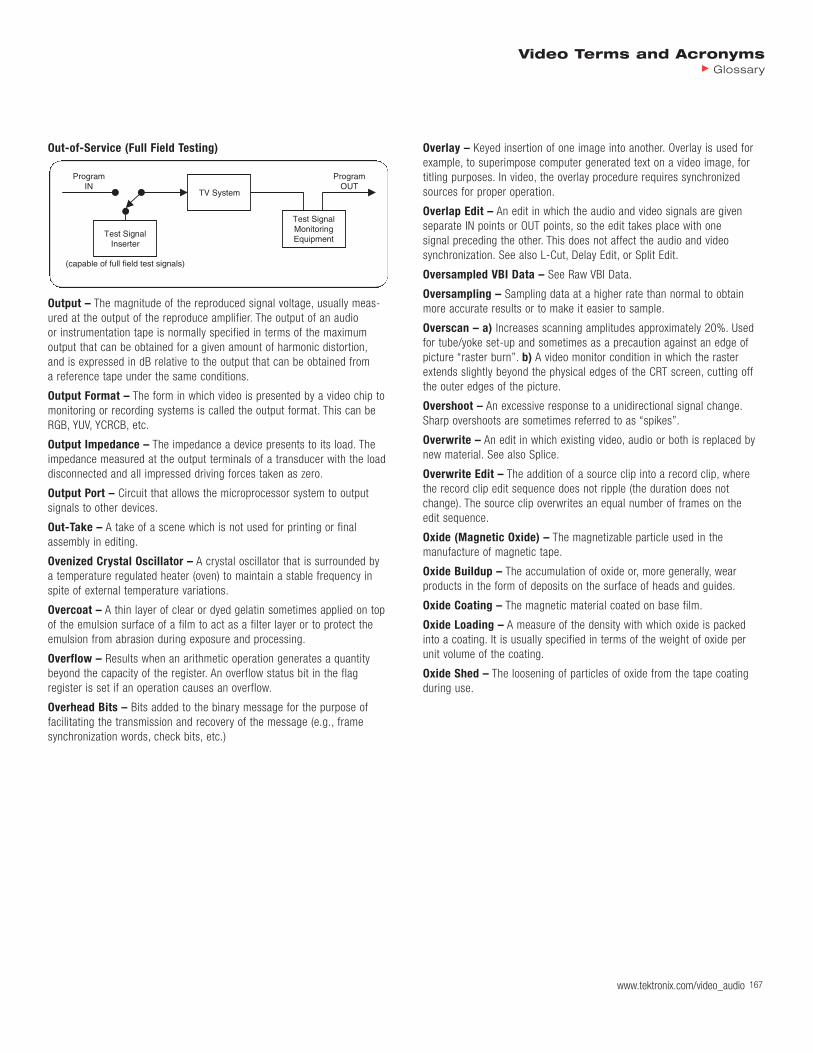
Out-of-Service (Full Field Testing)
Output – The magnitude of the reproduced signal voltage, usually meas-ured at the output of the reproduce amplifier. The output of an audio or instrumentation tape is normally specified in terms of the maximum output that can be obtained for a given amount of harmonic distortion,and is expressed in dB relative to the output that can be obtained from a reference tape under the same conditions.
Output Format – The form in which video is presented by a video chip tomonitoring or recording systems is called the output format. This can beRGB, YUV, YCRCB, etc.
Output Impedance – The impedance a device presents to its load. Theimpedance measured at the output terminals of a transducer with the loaddisconnected and all impressed driving forces taken as zero.
Output Port – Circuit that allows the microprocessor system to output signals to other devices.
Out-Take – A take of a scene which is not used for printing or final assembly in editing.
Ovenized Crystal Oscillator – A crystal oscillator that is surrounded by a temperature regulated heater (oven) to maintain a stable frequency inspite of external temperature variations.
Overcoat – A thin layer of clear or dyed gelatin sometimes applied on topof the emulsion surface of a film to act as a filter layer or to protect theemulsion from abrasion during exposure and processing.
Overflow – Results when an arithmetic operation generates a quantitybeyond the capacity of the register. An overflow status bit in the flag register is set if an operation causes an overflow.
Overhead Bits – Bits added to the binary message for the purpose offacilitating the transmission and recovery of the message (e.g., frame synchronization words, check bits, etc.)
Overlay – Keyed insertion of one image into another. Overlay is used forexample, to superimpose computer generated text on a video image, fortitling purposes. In video, the overlay procedure requires synchronizedsources for proper operation.
Overlap Edit – An edit in which the audio and video signals are given separate IN points or OUT points, so the edit takes place with one signal preceding the other. This does not affect the audio and video synchronization. See also L-Cut, Delay Edit, or Split Edit.
Oversampled VBI Data – See Raw VBI Data.
Oversampling – Sampling data at a higher rate than normal to obtainmore accurate results or to make it easier to sample.
Overscan – a) Increases scanning amplitudes approximately 20%. Usedfor tube/yoke set-up and sometimes as a precaution against an edge ofpicture “raster burn”. b) A video monitor condition in which the rasterextends slightly beyond the physical edges of the CRT screen, cutting offthe outer edges of the picture.
Overshoot – An excessive response to a unidirectional signal change.Sharp overshoots are sometimes referred to as “spikes”.
Overwrite – An edit in which existing video, audio or both is replaced bynew material. See also Splice.
Overwrite Edit – The addition of a source clip into a record clip, wherethe record clip edit sequence does not ripple (the duration does notchange). The source clip overwrites an equal number of frames on the edit sequence.
Oxide (Magnetic Oxide) – The magnetizable particle used in the manufacture of magnetic tape.
Oxide Buildup – The accumulation of oxide or, more generally, wear products in the form of deposits on the surface of heads and guides.
Oxide Coating – The magnetic material coated on base film.
Oxide Loading – A measure of the density with which oxide is packed into a coating. It is usually specified in terms of the weight of oxide perunit volume of the coating.
Oxide Shed – The loosening of particles of oxide from the tape coatingduring use.
Test SignalInserter
TV System
Test SignalMonitoringEquipment
(capable of full field test signals)
ProgramIN
ProgramOUT
Video Terms and AcronymsGlossary
www.tektronix.com/video_audio 167