Cisco Video Surveillance Operations Manager User Guide
734
Cisco Systems, Inc. www.cisco.com Cisco has more than 200 offices worldwide. Addresses, phone numbers, and fax numbers are listed on the Cisco website at www.cisco.com/go/offices. Cisco Video Surveillance Operations Manager User Guide Release 7.11
-
Upload
khangminh22 -
Category
Documents
-
view
1 -
download
0
Transcript of Cisco Video Surveillance Operations Manager User Guide
Cisco Video Surveillance Operations Manager User Guide Release 7.11
Cisco Systems, Inc.www.cisco.com
Cisco has more than 200 offices worldwide. Addresses, phone numbers, and fax numbers are listed on the Cisco website at www.cisco.com/go/offices.

THE SPECIFICATIONS AND INFORMATION REGARDING THE PRODUCTS IN THIS MANUAL ARE SUBJECT TO CHANGE WITHOUT NOTICE. ALL STATEMENTS, INFORMATION, AND RECOMMENDATIONS IN THIS MANUAL ARE BELIEVED TO BE ACCURATE BUT ARE PRESENTED WITHOUT WARRANTY OF ANY KIND, EXPRESS OR IMPLIED. USERS MUST TAKE FULL RESPONSIBILITY FOR THEIR APPLICATION OF ANY PRODUCTS.
THE SOFTWARE LICENSE AND LIMITED WARRANTY FOR THE ACCOMPANYING PRODUCT ARE SET FORTH IN THE INFORMATION PACKET THAT SHIPPED WITH THE PRODUCT AND ARE INCORPORATED HEREIN BY THIS REFERENCE. IF YOU ARE UNABLE TO LOCATE THE SOFTWARE LICENSE OR LIMITED WARRANTY, CONTACT YOUR CISCO REPRESENTATIVE FOR A COPY.
The Cisco implementation of TCP header compression is an adaptation of a program developed by the University of California, Berkeley (UCB) as part of UCB’s public domain version of the UNIX operating system. All rights reserved. Copyright © 1981, Regents of the University of California.
NOTWITHSTANDING ANY OTHER WARRANTY HEREIN, ALL DOCUMENT FILES AND SOFTWARE OF THESE SUPPLIERS ARE PROVIDED “AS IS” WITH ALL FAULTS. CISCO AND THE ABOVE-NAMED SUPPLIERS DISCLAIM ALL WARRANTIES, EXPRESSED OR IMPLIED, INCLUDING, WITHOUT LIMITATION, THOSE OF MERCHANTABILITY, FITNESS FOR A PARTICULAR PURPOSE AND NONINFRINGEMENT OR ARISING FROM A COURSE OF DEALING, USAGE, OR TRADE PRACTICE.
IN NO EVENT SHALL CISCO OR ITS SUPPLIERS BE LIABLE FOR ANY INDIRECT, SPECIAL, CONSEQUENTIAL, OR INCIDENTAL DAMAGES, INCLUDING, WITHOUT LIMITATION, LOST PROFITS OR LOSS OR DAMAGE TO DATA ARISING OUT OF THE USE OR INABILITY TO USE THIS MANUAL, EVEN IF CISCO OR ITS SUPPLIERS HAVE BEEN ADVISED OF THE POSSIBILITY OF SUCH DAMAGES.
Cisco and the Cisco logo are trademarks or registered trademarks of Cisco and/or its affiliates in the U.S. and other countries. To view a list of Cisco trademarks, go to this URL: www.cisco.com/go/trademarks. Third-party trademarks mentioned are the property of their respective owners. The use of the word partner does not imply a partnership relationship between Cisco and any other company. (1721R)
Any Internet Protocol (IP) addresses and phone numbers used in this document are not intended to be actual addresses and phone numbers. Any examples, command display output, network topology diagrams, and other figures included in the document are shown for illustrative purposes only. Any use of actual IP addresses or phone numbers in illustrative content is unintentional and coincidental.
Cisco Video Surveillance Operations Manager User Guide, Release 7.11©2012- 2018 Cisco Systems, Inc. All rights reserved.
Preface
Revised: February 13, 2018
This document, the Cisco Video Surveillance Operations Manager User Guide provides an overview of Cisco Video Surveillance Operations Manager Release 7.11, including basic procedures that should be performed when you first start to use the system, and detailed information about advanced features and configurations.
See the Release Notes for information about the new and revised features in this release.
Related DocumentationSee the Cisco Video Surveillance 7 Documentation Roadmap for descriptions and links to Cisco Video Surveillance documentation, server and storage platform documentation, and other related documentation.
Obtaining Documentation, Obtaining Support, and Security Guidelines
For information on obtaining documentation, using the Cisco Bug Search Tool (BST), submitting a service request, and gathering additional information, see What’s New in Cisco Product Documentation.
To receive new and revised Cisco technical content directly to your desktop, you can subscribe to the What’s New in Cisco Product Documentation RSS feed. The RSS feeds are a free service.
Tip See Related Documentation for more information and links to Cisco Video Surveillance documentation.
iiiCisco Video Surveillance Operations Manager User Guide

ivCisco Video Surveillance Operations Manager User Guide
C O N T E N T S
Preface iii
Related Documentation iii
Obtaining Documentation, Obtaining Support, and Security Guidelines iii
C H A P T E R 1 Overview 1-1
Operations Manager Feature Summary 1-2
Requirements 1-4
Main Elements of the User Interface 1-6
Summary Steps: Basic Configuration 1-8
Summary Steps: Advanced Configuration 1-16
Logging In and Managing Passwords 1-17
Logging In 1-17
Understanding Dual Login 1-19
Default User Accounts and Passwords 1-21
Changing Your Password 1-22
Manage Your Security Questions 1-23
Changing Another User’s Password 1-24
Understanding and Changing Your “Site” 1-24
Installing Licenses 1-27
Usage Notes 1-27
License Part Numbers 1-28
Obtaining and Installing Licenses 1-28
Displaying License Information 1-29
Deleting Licenses 1-30
Using Find 1-31
Understanding Maintenance Mode 1-32
C H A P T E R 2 Monitoring Video Using Internet Explorer 2-1
Understanding the Video Viewing Options 2-2
Operations Manager Requirements 2-3
Using the Monitor Video Page 2-3
Selecting a Multi-Pane “View” 2-4
iiiCisco Video Surveillance Operations Manager User Guide
Contents
View Video from a Panoramic Multi-lens Camera 2-6
Controlling Live and Recorded Video 2-9
Overview 2-9
Viewing Live Video 2-10
Viewing Recorded Video 2-13
Creating a Repeat Segment 2-17
Using the Pop-Up Menu 2-17
Understanding Video Pane Border Colors 2-19
Using the Privacy Mask 2-20
Using the Smooth Video Options When Viewing Live Video 2-24
Synchronizing Video Playback in Multiple Panes 2-25
Using Pan, Tilt, and Zoom (PTZ) Controls 2-29
Viewing a Thumbnail Summary of Video Archives 2-35
Using Thumbnail Search 2-37
Create Video Clips 2-40
Creating and Viewing Video Clips From a Single Camera 2-40
Create Clips From Multiple Cameras (Bulk Clipping) 2-50
Find and Download Clips (Clip Search) 2-54
C H A P T E R 3 Monitor Video Using HTML5 Enabled Browsers 3-1
Supported Browsers 3-1
Supported Features 3-2
Limitations 3-2
Log In and Access Video 3-3
Viewing Video Using an HTML5-enabled Browser 3-4
Adding Browser Security Certificates 3-6
C H A P T E R 4 Configuring Video Viewing Options 4-1
Setting the Default View 4-1
Creating Video Views 4-4
Configuring Video Walls 4-9
Hide Video From Users (Covert Cameras) 4-11
Enabling On-Demand Recording 4-14
Display or Hide Camera Health Information 4-16
C H A P T E R 5 Adding Users, User Groups, and Permissions 5-1
Overview 5-2
ivCisco Video Surveillance Operations Manager User Guide
Contents
Understanding Roles, Groups and Users 5-3
Understanding the System-Defined User Roles, Groups and Accounts 5-4
Understanding Permissions 5-4
Understanding the Impact of a User’s Location 5-10
Understanding the Super Admin 5-10
Example Roles For Different Types of Users 5-11
Defining User Roles 5-12
Adding User Groups 5-14
Adding Users 5-20
Defining Password Rules and Security Questions 5-22
Viewing and Logging Out Active Users 5-22
C H A P T E R 6 Adding Users from an LDAP Server 6-1
LDAP Usage Notes 6-1
LDAP Configuration Procedure 6-2
LDAP Server Settings 6-6
User Group Filter 6-9
LDAP Search Filters 6-9
User Name List 6-10
Look up the Access Permissions for an LDAP User 6-11
LDAP Configuration Examples 6-13
C H A P T E R 7 Creating the Location Hierarchy 7-1
Overview 7-2
Summary Steps 7-2
Understanding Permission-Based and Partition-Based Resources 7-3
Simple Deployments (User Access to All Devices and Resources) 7-4
Permission-Based Resources: Limiting User Access to Devices 7-4
Examples: Locations in Simple vs. Large Deployments 7-7
Understanding a Camera’s Installed Location Vs. the Pointed Location 7-9
Creating and Editing the Location Hierarchy 7-10
Importing the Location Hierarchy Using a CSV File 7-13
Impact of Device Location Changes on Alerts 7-16
Deleting a Location 7-17
C H A P T E R 8 Configuring Servers 8-1
Understanding Server Services 8-3
vCisco Video Surveillance Operations Manager User Guide
Contents
Requirements 8-7
Summary Steps to Add or Revise a Server 8-8
Server Settings 8-10
Server System Settings 8-10
Server Network Settings 8-12
Adding or Editing Servers 8-16
Overview 8-16
Pre-Provisioning Servers 8-17
Prerequisites 8-17
Adding or Editing a Single Server 8-17
Importing or Updating Servers Using a CSV File 8-20
Deleting a Server 8-24
Bulk Actions: Revising Multiple Servers 8-26
Viewing Server Status 8-29
Device Status 8-29
Server Status History and Service Jobs 8-30
Enable the “Unknown” State for Servers in a Transportation Environment 8-31
Resetting the Server Device State 8-33
Repairing the Configuration or Restarting the Server 8-33
Operations Manager Advanced Settings 8-34
SMTP Management Settings 8-34
C H A P T E R 9 Understanding NTP Configuration 9-1
Recommended (and Default) NTP Configuration 9-2
NTP Usage Notes 9-3
Configuring Media Servers with a User-Defined NTP Server 9-4
Changing the NTP Server for a Single Media Server 9-5
Changing the NTP Server for Multiple Media Servers 9-6
Configuring Cameras with a User-Defined NTP Server 9-8
Changing the NTP Settings for a Single Camera 9-9
Changing the NTP Server for Multiple Cameras 9-10
Defining the NTP Setting During Camera Auto-Discovery 9-11
C H A P T E R 10 Adding and Managing Cameras 10-1
Overview 10-3
Understanding Network and Analog Cameras 10-3
Requirements 10-3
Summary Steps 10-4
viCisco Video Surveillance Operations Manager User Guide
Contents
Viewing Cameras 10-5
Viewing a List of Supported Cameras 10-7
Manually Adding Cameras 10-8
Overview 10-8
Manually Adding a Single Camera 10-10
Adding Onvif Cameras 10-16
Importing or Updating Cameras or Encoders Using a CSV File 10-20
Configuring Panoramic Multi-lens Cameras 10-27
Configuring 360° (Fisheye) Cameras 10-33
Creating and Applying Preset Camera Settings 10-35
Zipstream compression support for Axis Cameras 10-38
Managing Cameras with Duplicate IP Addresses 10-40
Adding Cameras from an Existing Media Server 10-41
Adding Cameras From a 6.x or 7.x Media Server 10-41
Adding Unknown Cameras During a Media Server Synchronization 10-42
Blacklisting Cameras 10-43
Blacklisting a Camera 10-43
Viewing Cameras in the Blacklist 10-43
Removing a Camera From the Blacklist 10-43
Camera Settings 10-45
Accessing the Camera Settings 10-45
General Settings 10-47
Streaming, Recording and Event Settings 10-55
Using Custom Video Quality Settings 10-61
Zipstream compression support for Axis Cameras 10-62
Image Settings 10-64
Camera Apps 10-64
Configuring the High Availability Options for a Camera or Template 10-65
Display Text and Time in a Cisco Camera’s Video View 10-66
Enabling Panoramic Mode 10-67
Deleting Cameras 10-69
Rebooting Cameras 10-71
Reboot a Single Camera 10-71
Reboot Multiple Cameras 10-71
Changing the Camera or Encoder Access Settings (Address and Credentials) 10-72
Camera Status 10-74
Device Status 10-75
Status History 10-76
viiCisco Video Surveillance Operations Manager User Guide
Contents
Service Jobs (Cameras) 10-77
Camera Events 10-79
Repairing Configuration Errors 10-80
Configuring Camera PTZ Controls, Presets, and Tours 10-81
PTZ Requirements 10-82
PTZ Camera Configuration Summary 10-83
Defining the User Group PTZ Priority 10-85
Using Camera PTZ Controls 10-86
Configuring PTZ Presets 10-87
Configuring PTZ Tours 10-89
Configuring Advanced Settings 10-91
Configuring a PTZ “Return to Home” Countdown 10-93
Configuring Motion Detection 10-96
Motion Detection Overview 10-97
Motion Detection Settings 10-98
Configuring Motion Detection 10-99
Enabling Motion Detection on All Existing Cameras (Bulk Actions) 10-101
Enabling Motion Detection on ONVIF Cameras 10-102
Replacing a Camera 10-103
Bulk Actions: Revising Multiple Cameras 10-108
C H A P T E R 11 Configuring Media Server Services 11-1
Overview 11-2
Requirements 11-3
Summary Steps to Add, Activate, and Configure a Media Server 11-4
Media Server Settings 11-5
Accessing the Media Server Advanced Settings 11-5
High Availability Options 11-6
Partition Settings 11-6
Media Server Mode (Dynamic Proxy) 11-7
Media Server Properties 11-7
Storage Management Settings 11-8
Viewing Media Server Status 11-9
Device Status 11-10
Status History 11-10
Service Jobs (Media Server) 11-11
viiiCisco Video Surveillance Operations Manager User Guide
Contents
C H A P T E R 12 Defining Schedules 12-1
C H A P T E R 13 Adding and Editing Camera Templates 13-1
Overview 13-2
Creating or Modifying a Template 13-3
Creating a Custom Template for a Single Camera 13-5
Configuring Video Recording 13-6
Summary of Recording Options 13-6
Configuring Continuous, Scheduled, and Motion Recordings 13-7
Merging Video Streams (Smart Stream Selection) 13-11
Configuring Multicast Video Streaming 13-15
C H A P T E R 14 Monitoring and Managing Storage 14-1
Storage Retention and Recording Dashboard Overview 14-1
Using the Actual Bitrate to Estimate Storage 14-2
View Storage and Bitrate Information in the Storage Retention Dashboard 14-5
Usage Notes 14-6
How disk space is estimated using VBR 14-6
Configure Storage Retention Status Warnings and Emails 14-7
C H A P T E R 15 Video Analytics and Advanced Events 15-1
Enabling Video Analytics 15-2
Supported Analytics Metadata Tracks 15-2
Metadata Requirements 15-3
Metadata Summary Steps 15-4
Metadata Detailed Steps 15-4
Viewing the Registered Metadata Types 15-6
Using Advanced Events to Trigger Actions 15-7
Configuration Overview 15-8
Configuration Summary 15-9
Trigger and Action Descriptions 15-9
Configuring Soft Triggers 15-13
Creating Custom Event Types and Sub Types 15-16
C H A P T E R 16 Managing Camera Apps 16-1
Prerequisites 16-2
Requirements 16-2
ixCisco Video Surveillance Operations Manager User Guide

Contents
Supported Apps 16-4
IP Cameras That Support Apps 16-4
Obtaining and Installing App Licenses 16-5
Obtaining Camera Apps 16-5
Managing Camera Apps Using the Operations Manager 16-7
Overview 16-7
Using the Camera Web Interface to Define Application Settings 16-8
Camera App Status When Cameras are Added to Cisco VSM 16-9
Summary Steps 16-10
Detailed Steps 16-13
Viewing App Logs and Status 16-16
Enabling an App When the App is Not Installed 16-23
Disabling, De-installing and Deleting Apps 16-23
Upgrading Camera Apps 16-27
Troubleshooting Camera Apps 16-28
Camera Apps Cannot Be Added to Multiple Operations Managers 16-28
Camera App Licenses Must be Installed Using Operations Manager 16-28
Camera Apps Are Disabled for When Modifying Templates 16-29
Related Documentation 16-29
C H A P T E R 17 Connected Edge Storage (On-Camera Recording) 17-1
Overview 17-3
Deployment Scenarios 17-3
Copy Options 17-5
Usage Notes 17-6
Requirements 17-7
Supported IP Cameras (On-Device Storage) 17-8
Formatting Camera SD Cards 17-8
SD Card Usage Notes 17-8
Formatting the SD Card for a Single Camera 17-8
Formatting the SD Cards in Multiple Cameras (Bulk Actions) 17-9
Configuring Connected Edge Storage 17-11
Enable Connected Edge Storage (On-Camera Recording) 17-11
Auto-Merge Recordings (Automatically Copy All Recording) 17-15
Copy Continuous Recordings Triggered by an Event 17-17
Manually Copy Camera Recordings 17-18
Record Events on the Camera’s Storage Device 17-21
Understanding the Recording Options 17-24
Economical Streaming 17-25
xCisco Video Surveillance Operations Manager User Guide
Contents
Connected Edge Storage 17-26
Recording Options 17-26
Viewing Camera Storage Job Status 17-27
Timezone Best Practices 17-28
Best Practice 17-28
Specify a Range Within a Timezone Switch-Over 17-29
Related Recording Documentation 17-30
C H A P T E R 18 Configure Voice-over-IP Calling 18-1
Requirements 18-2
Create the Protocol and Address Settings 18-2
Select the SIP Protocol and Address in Camera Settings 18-4
(Optional) Set the Custom Field Values For Multiple Cameras 18-5
Call a Video or Voice Phone from Cisco SASD 18-6
C H A P T E R 19 Understanding Device Conflicts 19-1
Devices with Duplicate IP Addresses 19-1
Conflicts During Camera Discovery 19-2
Allowing Duplicate Camera or Encoder IP Addresses 19-2
Configuring Custom Camera and Encoder Ports (PAT) 19-3
Resolving ID Mismatch Errors When Changing Camera IP Addresses 19-6
C H A P T E R 20 Adding Encoders and Analog Cameras 20-1
Overview 20-2
Pre-Provisioning Encoders and Analog Cameras 20-3
Requirements 20-4
Adding External Encoders and Analog Cameras 20-5
Bulk Actions: Revising Multiple Encoders 20-12
Using “Split Model” Multi-Port Multi-IP Encoders 20-14
Encoder Status 20-16
Analog Camera Status 20-17
C H A P T E R 21 Custom Fields 21-1
Types of Custom Fields 21-2
Custom Field Settings 21-3
Summary Steps: Custom Fields 21-4
xiCisco Video Surveillance Operations Manager User Guide
Contents
Detailed Steps: Custom Fields 21-5
Modifying Custom Fields 21-8
Deleting Custom Fields 21-8
C H A P T E R 22 High Availability: Cisco Media Servers 22-1
Overview 22-2
Requirements 22-2
Summary Steps 22-3
Understanding Redundant, Failover, and Long Term Storage Servers 22-4
Understanding Failover 22-6
Define the Media Server HA Role and Associated Servers 22-8
Configuring the HA Advanced Storage Options 22-10
Configuring the Redundant and Failover Options 22-11
Archiving Recordings to a Long Term Storage Server 22-14
Archive recordings to an LTS Server 22-14
Backup Now to an LTS Server 22-18
Viewing the Server HA Status 22-21
C H A P T E R 23 Operations Manager High Availability 23-1
Overview 23-2
Understanding Operations Manager HA 23-2
Requirements 23-4
Configuring Operations Manager HA 23-6
Managing the HA Configuration 23-12
Understanding the Server Management Options 23-12
Revising the Operations Manager HA Configuration 23-12
Replacing the HA Configuration 23-13
Deleting the HA Configuration 23-14
Replacing the HA Peer Server 23-15
Backing Up and Restoring the Operations Manager Configuration 23-17
Upgrading the Operations Manager HA Servers 23-18
Forcing a Failover 23-20
Resolving a Split Brain Scenario 23-21
Split Brain Overview 23-21
Selecting the “Split Brain” Media Servers 23-23
Procedure to Resolve a Split Brain Scenario 23-25
Troubleshooting Operations Manager HA 23-27
The HA Configuration Job Does Not Complete 23-27
xiiCisco Video Surveillance Operations Manager User Guide
Contents
Database Replication Failures 23-28
File Replication Failures 23-31
Network Connectivity Loss Results in a Split Brain Scenario 23-33
Troubleshooting Errors During a Force Failover 23-33
Virtual IP Login Failure 23-35
Unmanaged Split Brain Scenario 23-36
Useful Command Line Tools for HA Troubleshooting 23-37
Alerts Displayed in Cisco SASD 23-38
C H A P T E R 24 Monitoring System and Device Health 24-1
Understanding Events and Alerts 24-2
Overview 24-2
Event Types 24-4
Triggering Actions Based on Alerts and Events 24-4
Monitoring Device Heath Using the Operations Manager 24-5
Changing the Severity Level of Alerts 24-6
Health Dashboard: Device Health Faults on an Operations Manager 24-7
Open the Health Dashboard 24-7
General Tab (Device Summary Information) 24-8
Health Information By Category or Issue 24-10
Tips 24-11
Understanding Warning and Critical Faults 24-12
Device Status: Identifying Issues for a Specific Device 24-13
Understanding the Overall Status 24-13
Understanding Device Status 24-15
Viewing the Status Error Details and History 24-18
Viewing Service Jobs 24-19
Viewing Camera Events 24-20
Viewing Recording Failure Events 24-21
Sending Alert Emails (Notification Policies) 24-23
Reports 24-27
Create a Report 24-27
Delete a Report 24-27
Synchronizing Device Configurations 24-28
Overview 24-28
Viewing Device Synchronization Errors 24-30
Understanding Device Configuration Mismatch Caused by Media Server Issues 24-31
Repairing a Mismatched Configuration 24-32
Manually Triggering a Media Server Synchronization 24-33
xiiiCisco Video Surveillance Operations Manager User Guide
Contents
Device Data That Is Synchronized 24-33
Synchronization During a Media Server Migration 24-34
Viewing the Server Management Console Status and Logs 24-35
Understanding Jobs and Job Status 24-36
Viewing Job Status and Details 24-36
Understanding Job Status 24-38
Viewing All Jobs in the System 24-39
Viewing Audit Logs 24-42
Custom Data Management 24-43
Pruning Events and Logs 24-44
C H A P T E R 25 Troubleshooting Devices and Jobs 25-1
C H A P T E R 26 Revising the System Settings 26-1
General System Settings 26-2
Password Settings 26-4
Language Settings 26-5
Language Settings 26-5
Language Pack 26-6
Alert Severity 26-6
Storage Retention Settings 26-7
C H A P T E R 27 Backup and Restore 27-1
Overview 27-2
Usage Notes 27-2
Backup Settings 27-3
Backup File Format 27-4
Backup File Information 27-5
Disk Usage for Backups 27-6
Failed Backups 27-7
Backing Up and Restoring a Single Server 27-8
Manually Backup a Single Server 27-8
Automatic Backups (Single Server) 27-9
Restoring a Backup for a Single Server 27-11
Deleting a Backup File 27-12
Backing Up Multiple Servers (Bulk Actions) 27-13
Backing Up Recordings 27-16
xivCisco Video Surveillance Operations Manager User Guide
Contents
C H A P T E R 28 Using Federator to Monitor Multiple Operations Managers 28-1
Overview 28-3
Requirements 28-4
Summary Steps 28-7
Initial Server Setup 28-10
Logging In to a Federator Server 28-15
Configuring Access to Operations Manager Resources 28-16
Configuration Summary Steps 28-17
Adding Operations Manager Servers to Federator 28-18
Adding Federator Locations 28-22
Adding Federator Regions 28-24
Adding Federator Users 28-26
Monitoring Video Using Federator 28-29
Federator Clip Search 28-31
Monitoring Device Health Using the Browser-Based Federator 28-33
Federator Health Dashboard 28-33
Federator Audit Logs 28-36
Viewing Federator Active Users 28-37
Administration Tasks 28-39
Backing up and Restoring the Federator Configuration 28-39
Updating the Federator Server System Software 28-42
C H A P T E R 29 Using Dynamic Proxy to Monitor Video From Remote Sites 29-1
Dynamic Proxy Overview 29-1
Understanding Sites 29-3
Dynamic Proxy Requirements 29-4
Summary Steps to Configure Dynamic Proxy 29-5
Detailed Steps to Configure Dynamic Proxy 29-6
C H A P T E R 30 Configuring Location Maps 30-1
Maps Overview 30-2
Usage Notes 30-3
Summary Steps 30-4
Maps Requirements 30-6
Define the Location Maps 30-8
Adding a Maps Server 30-10
Adding a Co-Located Maps Server 30-10
xvCisco Video Surveillance Operations Manager User Guide
Contents
Adding a Stand-Alone Maps Server 30-11
Adding Image Layers and Image Groups 30-13
Adding Cameras to Map Images 30-18
Managing Location Map Service Providers 30-20
Displaying Location Maps Without Public Internet Access 30-22
Migrating Map Images From a Previous Cisco VSM Release 30-25
Understanding Image Layer Status Errors 30-26
Viewing and Clearing Layer Status Errors 30-27
C H A P T E R 31 Upgrading System and Device Software 31-1
A P P E N D I X A Related Documentation A-1
A P P E N D I X B Downloading Utilities and Documentation B-1
Downloading Cisco SASD and the Cisco Review Player B-1
Downloading the Workstation Profiler Tool B-2
Accessing the Management Console B-2
Downloading Documentation B-2
xviCisco Video Surveillance Operations Manager User Guide
Cisco V
C H A P T E R 1
OverviewThe Cisco VSM Operations Manager is a browser-based configuration and administration tool used to manage the devices, video streams, archives, and policies in a Cisco Video Surveillance deployment.
The Operations Manager interface is enabled when the Operations Manager service is enabled on a Cisco Video Surveillance server (see the Cisco Video Surveillance Management Console Administration Guide for more information).
Refer to the following topics for a summary of the main Operations Manager capabilities, configuration features, and other information.
Contents
• Operations Manager Feature Summary, page 1-2
• Requirements, page 1-4
• Main Elements of the User Interface, page 1-6
• Summary Steps: Basic Configuration, page 1-8
• Summary Steps: Advanced Configuration, page 1-16
• Logging In and Managing Passwords, page 1-17
– Logging In, page 1-17
– Understanding Dual Login, page 1-19
– Default User Accounts and Passwords, page 1-21
– Changing Your Password, page 1-22
– Manage Your Security Questions, page 1-23
– Changing Another User’s Password, page 1-24
– Understanding and Changing Your “Site”, page 1-24
• Installing Licenses, page 1-27
• Using Find, page 1-31
• Understanding Maintenance Mode, page 1-32
1-1ideo Surveillance Operations Manager User Guide

Chapter 1 Overview Operations Manager Feature Summary
Operations Manager Feature SummaryThe following table summarizes the main Operations Manager features.
Table 1-1 Feature Summary
Feature Description More information
Manage physical devices Add, configure and monitor the cameras, servers, s, and encoders that provide live and recorded video.
• Configuring Servers, page 8-1
• Adding and Managing Cameras, page 10-1
• Adding and Managing Cameras, page 10-1
Manage server services Configure, enable or disable server services, such as the Media Servers that manage video playback and recording.
• Configuring Media Server Services, page 11-1
• Operations Manager Advanced Settings, page 8-34
Monitor video View live and recorded video, save video clips, search thumbnail summaries of recorded video, use the camera, Pan, Tilt and Zoom (PTZ) controls, or configure pre-defined video Views and Video Walls.
• Monitoring Video Using Internet Explorer, page 2-1
• Configuring Video Viewing Options, page 4-1
Define recording and event policies
Create recording schedules, define event-triggered actions, configure motion detection, and other features.
• Configuring Continuous, Scheduled, and Motion Recordings, page 13-7
• Configuring Camera PTZ Controls, Presets, and Tours, page 10-81
• Configuring Motion Detection, page 10-96
• Using Advanced Events to Trigger Actions, page 15-7
1-2Cisco Video Surveillance Operations Manager User Guide
Chapter 1 OverviewOperations Manager Feature Summary
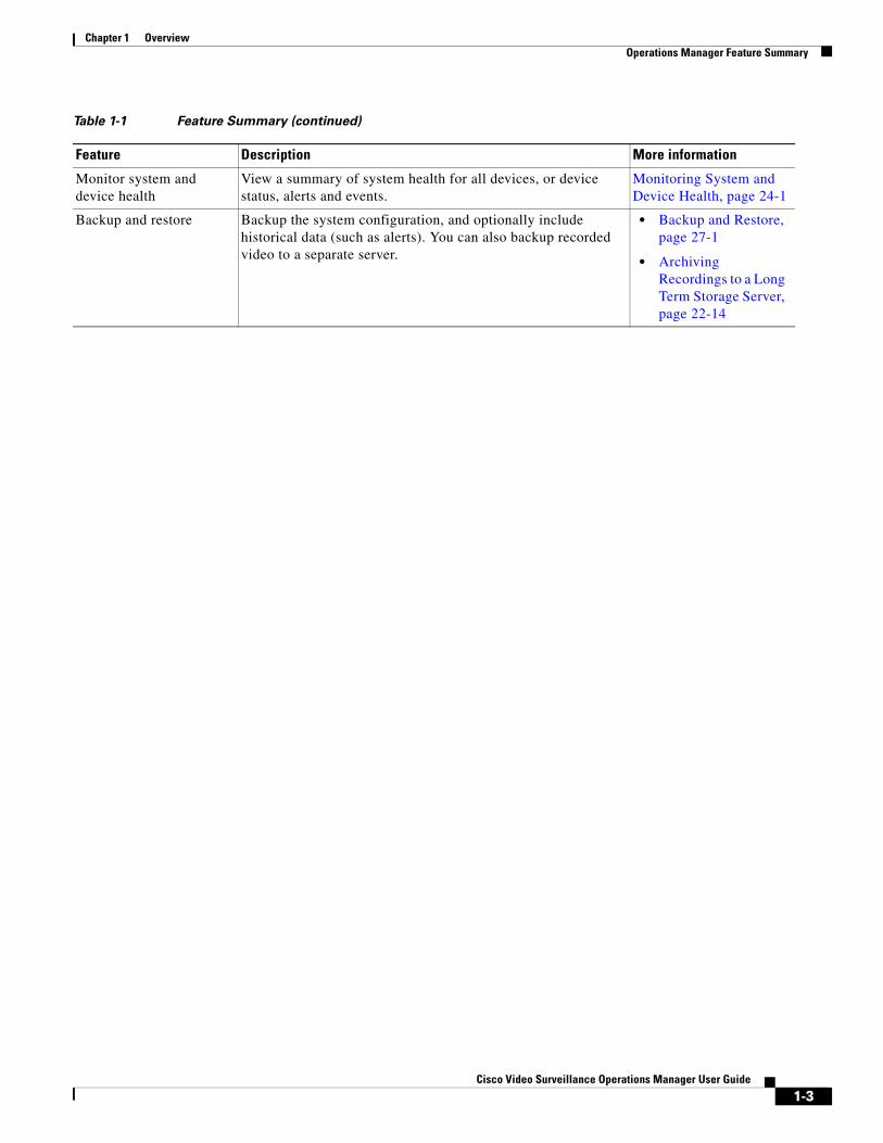
Monitor system and device health
View a summary of system health for all devices, or device status, alerts and events.
Monitoring System and Device Health, page 24-1
Backup and restore Backup the system configuration, and optionally include historical data (such as alerts). You can also backup recorded video to a separate server.
• Backup and Restore, page 27-1
• Archiving Recordings to a Long Term Storage Server, page 22-14
Table 1-1 Feature Summary (continued)
Feature Description More information
1-3Cisco Video Surveillance Operations Manager User Guide
Chapter 1 Overview Requirements
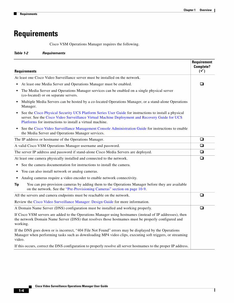
Requirements Cisco VSM Operations Manager requires the following.
Table 1-2 Requirements
Requirements
Requirement Complete?
()
At least one Cisco Video Surveillance server must be installed on the network.
• At least one Media Server and Operations Manager must be enabled.
• The Media Server and Operations Manager services can be enabled on a single physical server (co-located) or on separate servers.
• Multiple Media Servers can be hosted by a co-located Operations Manager, or a stand-alone Operations Manager.
• See the Cisco Physical Security UCS Platform Series User Guide for instructions to install a physical server. See the Cisco Video Surveillance Virtual Machine Deployment and Recovery Guide for UCS Platforms for instructions to install a virtual machine.
• See the Cisco Video Surveillance Management Console Administration Guide for instructions to enable the Media Server and Operations Manager services.
The IP address or hostname of the Operations Manager.
A valid Cisco VSM Operations Manager username and password.
The server IP address and password if stand-alone Cisco Media Servers are deployed.
At least one camera physically installed and connected to the network.
• See the camera documentation for instructions to install the camera.
• You can also install network or analog cameras.
• Analog cameras require a video encoder to enable network connectivity.
Tip You can pre-provision cameras by adding them to the Operations Manager before they are available on the network. See the “Pre-Provisioning Cameras” section on page 10-9.
All the servers and camera endpoints must be reachable on the network.
Review the Cisco Video Surveillance Manager: Design Guide for more information.
A Domain Name Server (DNS) configuration must be installed and working properly.
If Cisco VSM servers are added to the Operations Manager using hostnames (instead of IP addresses), then the network Domain Name Server (DNS) that resolves those hostnames must be properly configured and working.
If the DNS goes down or is incorrect, “404 File Not Found” errors may be displayed by the Operations Manager when performing tasks such as downloading MP4 video clips, executing soft triggers, or streaming video.
If this occurs, correct the DNS configuration to properly resolve all server hostnames to the proper IP address.
1-4Cisco Video Surveillance Operations Manager User Guide
Chapter 1 OverviewRequirements
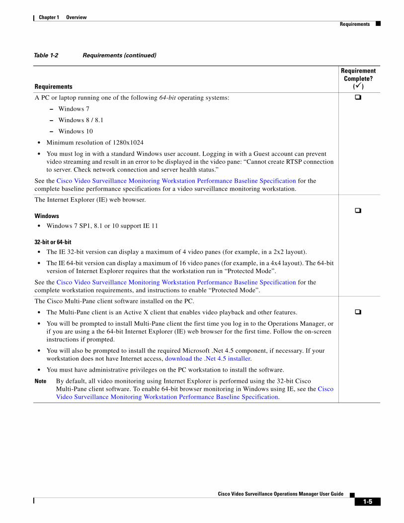
A PC or laptop running one of the following 64-bit operating systems:
– Windows 7
– Windows 8 / 8.1
– Windows 10
• Minimum resolution of 1280x1024
• You must log in with a standard Windows user account. Logging in with a Guest account can prevent video streaming and result in an error to be displayed in the video pane: “Cannot create RTSP connection to server. Check network connection and server health status.”
See the Cisco Video Surveillance Monitoring Workstation Performance Baseline Specification for the complete baseline performance specifications for a video surveillance monitoring workstation.
The Internet Explorer (IE) web browser.
Windows
• Windows 7 SP1, 8.1 or 10 support IE 11
32-bit or 64-bit
• The IE 32-bit version can display a maximum of 4 video panes (for example, in a 2x2 layout).
• The IE 64-bit version can display a maximum of 16 video panes (for example, in a 4x4 layout). The 64-bit version of Internet Explorer requires that the workstation run in “Protected Mode”.
See the Cisco Video Surveillance Monitoring Workstation Performance Baseline Specification for the complete workstation requirements, and instructions to enable “Protected Mode”.
The Cisco Multi-Pane client software installed on the PC.
• The Multi-Pane client is an Active X client that enables video playback and other features.
• You will be prompted to install Multi-Pane client the first time you log in to the Operations Manager, or if you are using a the 64-bit Internet Explorer (IE) web browser for the first time. Follow the on-screen instructions if prompted.
• You will also be prompted to install the required Microsoft .Net 4.5 component, if necessary. If your workstation does not have Internet access, download the .Net 4.5 installer.
• You must have administrative privileges on the PC workstation to install the software.
Note By default, all video monitoring using Internet Explorer is performed using the 32-bit Cisco Multi-Pane client software. To enable 64-bit browser monitoring in Windows using IE, see the Cisco Video Surveillance Monitoring Workstation Performance Baseline Specification.
Table 1-2 Requirements (continued)
Requirements
Requirement Complete?
()
1-5Cisco Video Surveillance Operations Manager User Guide
Chapter 1 Overview Main Elements of the User Interface
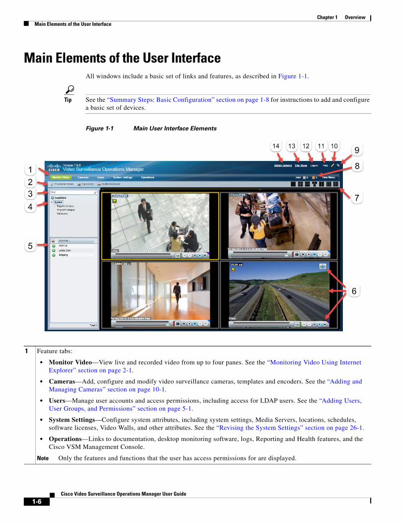
Main Elements of the User InterfaceAll windows include a basic set of links and features, as described in Figure 1-1.
Tip See the “Summary Steps: Basic Configuration” section on page 1-8 for instructions to add and configure a basic set of devices.
Figure 1-1 Main User Interface Elements
1 Feature tabs:
• Monitor Video—View live and recorded video from up to four panes. See the “Monitoring Video Using Internet Explorer” section on page 2-1.
• Cameras—Add, configure and modify video surveillance cameras, templates and encoders. See the “Adding and Managing Cameras” section on page 10-1.
• Users—Manage user accounts and access permissions, including access for LDAP users. See the “Adding Users, User Groups, and Permissions” section on page 5-1.
• System Settings—Configure system attributes, including system settings, Media Servers, locations, schedules, software licenses, Video Walls, and other attributes. See the “Revising the System Settings” section on page 26-1.
• Operations—Links to documentation, desktop monitoring software, logs, Reporting and Health features, and the Cisco VSM Management Console.
Note Only the features and functions that the user has access permissions for are displayed.
1-6Cisco Video Surveillance Operations Manager User Guide
Chapter 1 OverviewMain Elements of the User Interface
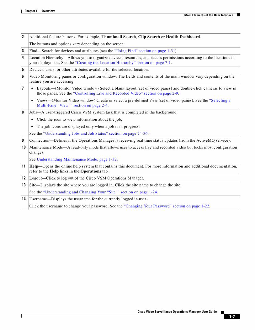
2 Additional feature buttons. For example, Thumbnail Search, Clip Search or Health Dashboard.
The buttons and options vary depending on the screen.
3 Find—Search for devices and attributes (see the “Using Find” section on page 1-31).
4 Location Hierarchy—Allows you to organize devices, resources, and access permissions according to the locations in your deployment. See the “Creating the Location Hierarchy” section on page 7-1.
5 Devices, users, or other attributes available for the selected location.
6 Video Monitoring panes or configuration window. The fields and contents of the main window vary depending on the feature you are accessing.
7 • Layouts—(Monitor Video window) Select a blank layout (set of video panes) and double-click cameras to view in those panes. See the “Controlling Live and Recorded Video” section on page 2-9.
• Views—(Monitor Video window) Create or select a pre-defined View (set of video panes). See the “Selecting a Multi-Pane “View”” section on page 2-4.
8 Jobs—A user-triggered Cisco VSM system task that is completed in the background.
• Click the icon to view information about the job.
• The job icons are displayed only when a job is in progress.
See the “Understanding Jobs and Job Status” section on page 24-36.
9 Connection—Defines if the Operations Manager is receiving real time status updates (from the ActiveMQ service).
10 Maintenance Mode—A read-only mode that allows user to access live and recorded video but locks most configuration changes.
See Understanding Maintenance Mode, page 1-32.
11 Help—Opens the online help system that contains this document. For more information and additional documentation, refer to the Help links in the Operations tab.
12 Logout—Click to log out of the Cisco VSM Operations Manager.
13 Site—Displays the site where you are logged in. Click the site name to change the site.
See the “Understanding and Changing Your “Site”” section on page 1-24.
14 Username—Displays the username for the currently logged in user.
Click the username to change your password. See the “Changing Your Password” section on page 1-22.
1-7Cisco Video Surveillance Operations Manager User Guide
Chapter 1 Overview Summary Steps: Basic Configuration
Summary Steps: Basic ConfigurationComplete the following steps to create a basic configuration. A basic configuration allows you to verify that basic system components and devices are online, configured, and working properly.
Table 1-3 Summary Steps: Basic Configuration
Task Description
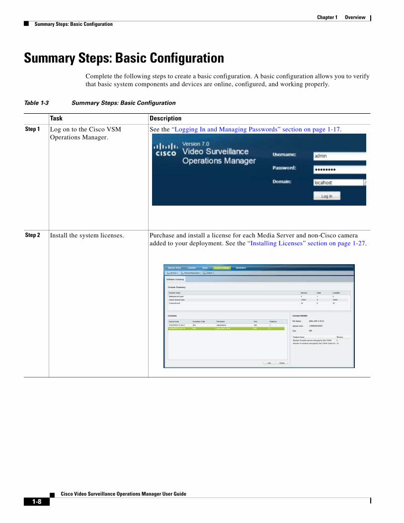
Step 1 Log on to the Cisco VSM Operations Manager.
See the “Logging In and Managing Passwords” section on page 1-17.
Step 2 Install the system licenses. Purchase and install a license for each Media Server and non-Cisco camera added to your deployment. See the “Installing Licenses” section on page 1-27.
1-8Cisco Video Surveillance Operations Manager User Guide
Chapter 1 OverviewSummary Steps: Basic Configuration
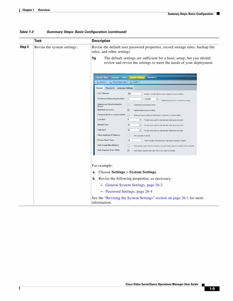
Step 3 Revise the system settings. Revise the default user password properties, record storage rules, backup file rules, and other settings.
Tip The default settings are sufficient for a basic setup, but you should review and revise the settings to meet the needs of your deployment.
For example:
a. Choose Settings > System Settings.
b. Revise the following properties, as necessary:
– General System Settings, page 26-2
– Password Settings, page 26-4
See the “Revising the System Settings” section on page 26-1 for more information.
Table 1-3 Summary Steps: Basic Configuration (continued)
Task Description
1-9Cisco Video Surveillance Operations Manager User Guide
Chapter 1 Overview Summary Steps: Basic Configuration
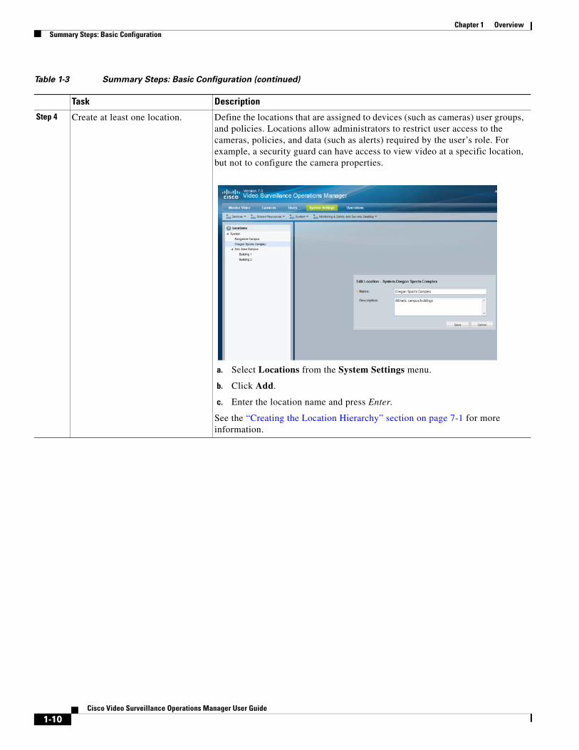
Step 4 Create at least one location. Define the locations that are assigned to devices (such as cameras) user groups, and policies. Locations allow administrators to restrict user access to the cameras, policies, and data (such as alerts) required by the user’s role. For example, a security guard can have access to view video at a specific location, but not to configure the camera properties.
a. Select Locations from the System Settings menu.
b. Click Add.
c. Enter the location name and press Enter.
See the “Creating the Location Hierarchy” section on page 7-1 for more information.
Table 1-3 Summary Steps: Basic Configuration (continued)
Task Description
1-10Cisco Video Surveillance Operations Manager User Guide

Chapter 1 OverviewSummary Steps: Basic Configuration
Step 5 Create at least one user account. Create the user accounts and access permissions that restrict the locations and tasks available to a user. For example:
Create a User Role
The Role defines the access permissions for different types of users. Roles are assigned to User Groups.
a. Select Users.
b. Select the Roles tab .
c. Click Add.
d. Enter the basic settings (see Table 5-6).
e. Select the Role permissions (see Table 5-2 and Table 5-3).
f. Click Create.
See the “Defining User Roles” section on page 5-12.
Create a User Group
User Groups allow you to create groups of users. The access Role for the User Group grants those access permissions to all users in the group.
a. Select the User Groups tab .
b. Click Add.
c. Enter the group settings, including the Role that defines the access permissions for the group (see Table 5-7).
d. Click Create.
See the “Adding User Groups” section on page 5-14.
Create a User Account
The User account defines the username and password. Users gain access permissions through the User Group assignments. A user can be assigned to multiple groups, and gains the combined access permissions of all groups.
a. Select the User tab .
b. Click Add.
c. Enter the basic user settings (see Table 5-9).
d. Add the user to one or more user groups.
– Click Add under the User Groups box.
– Select one or more user groups from the pop-up window.
– Select OK.
e. Click Create.
See the “Adding Users” section on page 5-20.
See also the “Adding Users, User Groups, and Permissions” section on page 5-1 for more information.
Table 1-3 Summary Steps: Basic Configuration (continued)
Task Description
1-11Cisco Video Surveillance Operations Manager User Guide
Chapter 1 Overview Summary Steps: Basic Configuration
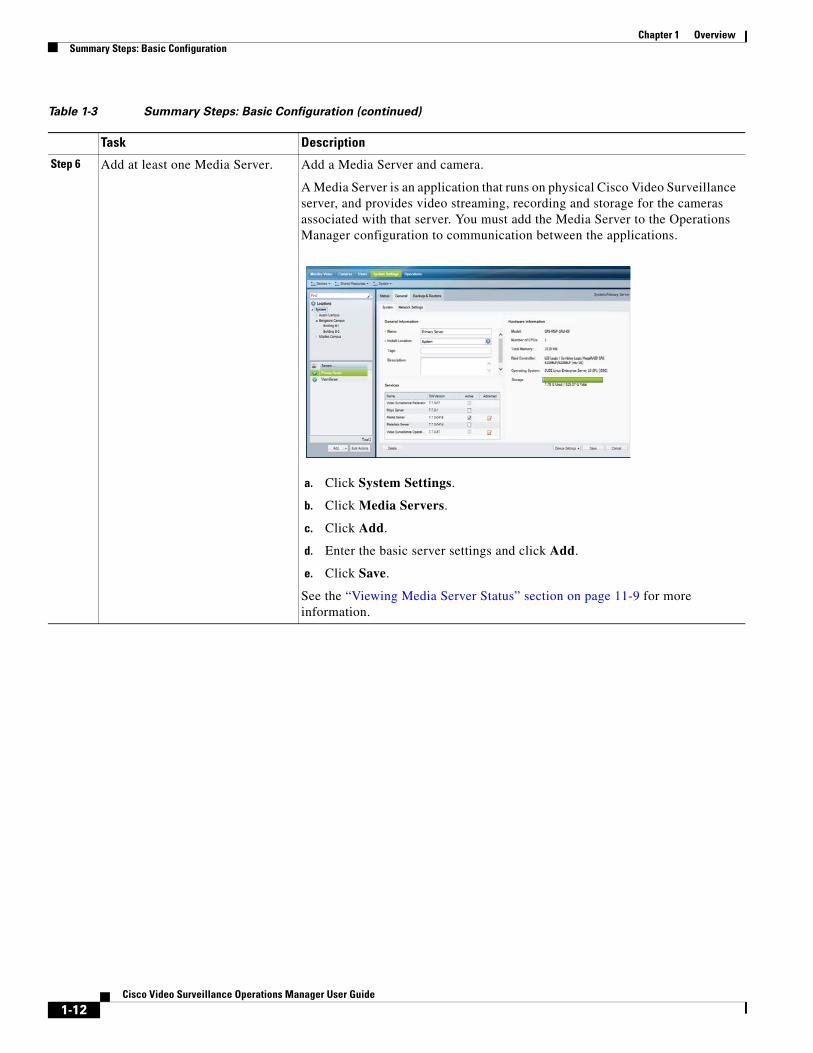
Step 6 Add at least one Media Server. Add a Media Server and camera.
A Media Server is an application that runs on physical Cisco Video Surveillance server, and provides video streaming, recording and storage for the cameras associated with that server. You must add the Media Server to the Operations Manager configuration to communication between the applications.
a. Click System Settings.
b. Click Media Servers.
c. Click Add.
d. Enter the basic server settings and click Add.
e. Click Save.
See the “Viewing Media Server Status” section on page 11-9 for more information.
Table 1-3 Summary Steps: Basic Configuration (continued)
Task Description
1-12Cisco Video Surveillance Operations Manager User Guide
Chapter 1 OverviewSummary Steps: Basic Configuration
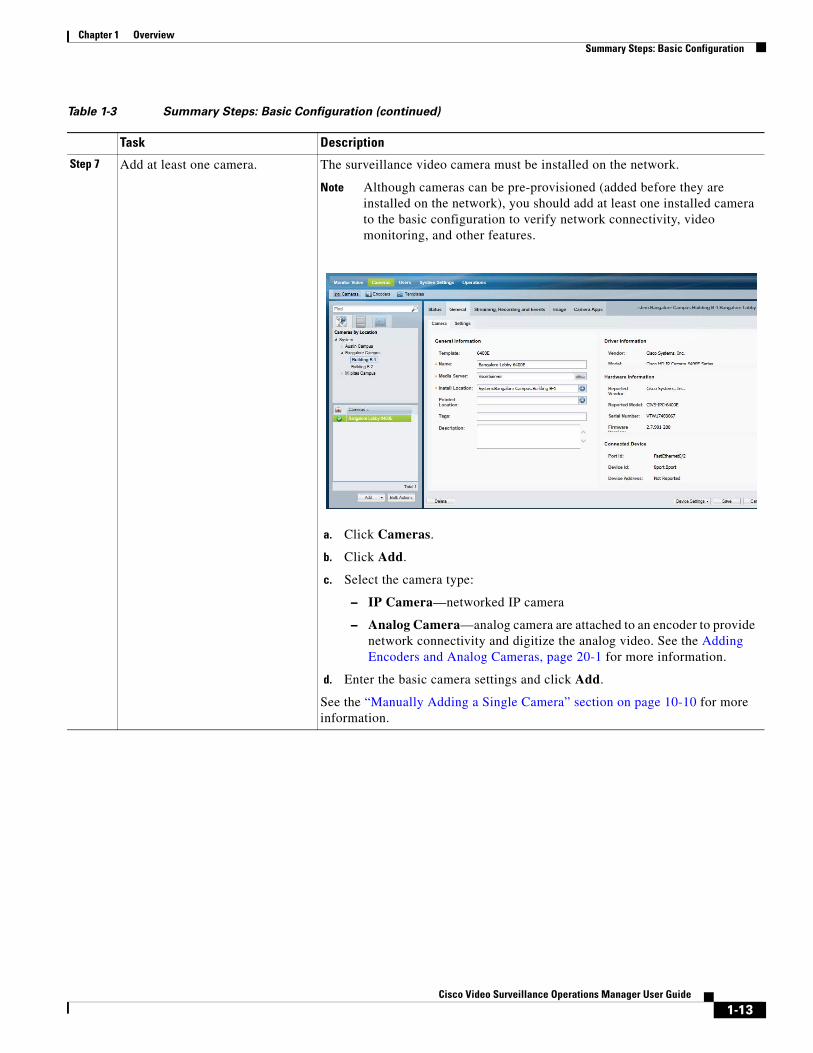
Step 7 Add at least one camera. The surveillance video camera must be installed on the network.
Note Although cameras can be pre-provisioned (added before they are installed on the network), you should add at least one installed camera to the basic configuration to verify network connectivity, video monitoring, and other features.
a. Click Cameras.
b. Click Add.
c. Select the camera type:
– IP Camera—networked IP camera
– Analog Camera—analog camera are attached to an encoder to provide network connectivity and digitize the analog video. See the Adding Encoders and Analog Cameras, page 20-1 for more information.
d. Enter the basic camera settings and click Add.
See the “Manually Adding a Single Camera” section on page 10-10 for more information.
Table 1-3 Summary Steps: Basic Configuration (continued)
Task Description
1-13Cisco Video Surveillance Operations Manager User Guide
Chapter 1 Overview Summary Steps: Basic Configuration
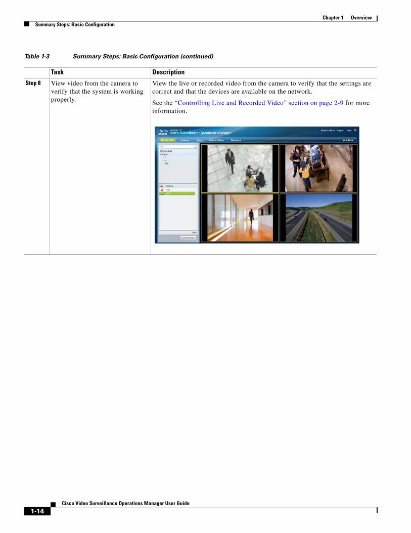
Step 8 View video from the camera to verify that the system is working properly.
View the live or recorded video from the camera to verify that the settings are correct and that the devices are available on the network.
See the “Controlling Live and Recorded Video” section on page 2-9 for more information.
Table 1-3 Summary Steps: Basic Configuration (continued)
Task Description
1-14Cisco Video Surveillance Operations Manager User Guide
Chapter 1 OverviewSummary Steps: Basic Configuration
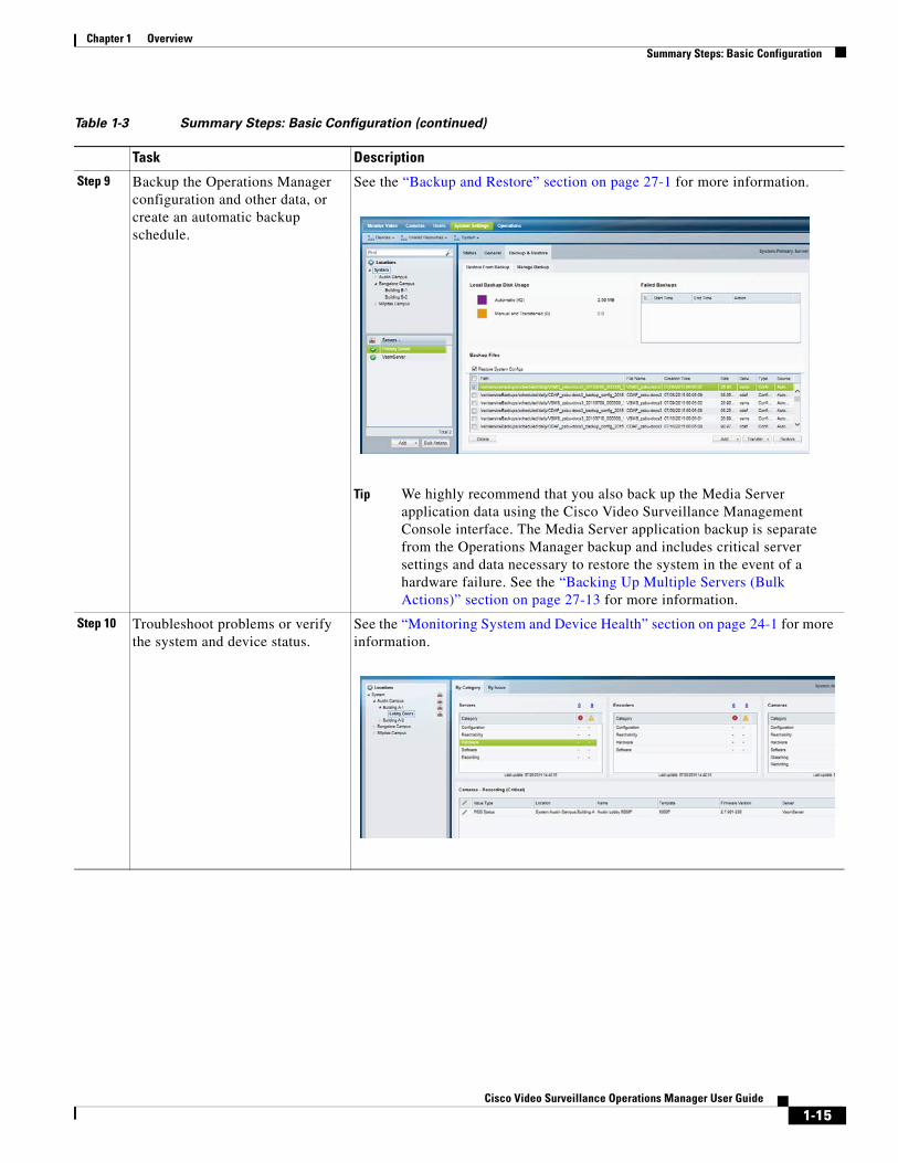
Step 9 Backup the Operations Manager configuration and other data, or create an automatic backup schedule.
See the “Backup and Restore” section on page 27-1 for more information.
Tip We highly recommend that you also back up the Media Server application data using the Cisco Video Surveillance Management Console interface. The Media Server application backup is separate from the Operations Manager backup and includes critical server settings and data necessary to restore the system in the event of a hardware failure. See the “Backing Up Multiple Servers (Bulk Actions)” section on page 27-13 for more information.
Step 10 Troubleshoot problems or verify the system and device status.
See the “Monitoring System and Device Health” section on page 24-1 for more information.
Table 1-3 Summary Steps: Basic Configuration (continued)
Task Description
1-15Cisco Video Surveillance Operations Manager User Guide
Chapter 1 Overview Summary Steps: Advanced Configuration
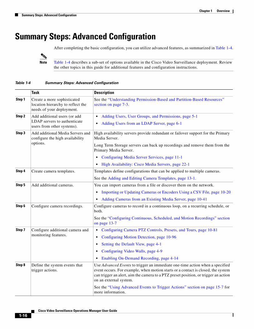
Summary Steps: Advanced ConfigurationAfter completing the basic configuration, you can utilize advanced features, as summarized in Table 1-4.
Note Table 1-4 describes a sub-set of options available in the Cisco Video Surveillance deployment. Review the other topics in this guide for additional features and configuration instructions.
Table 1-4 Summary Steps: Advanced Configuration
Task Description
Step 1
Step 2 • Adding Users, User Groups, and Permissions, page 5-1
• Adding Users from an LDAP Server, page 6-1
Step 3
• Configuring Media Server Services, page 11-1
• High Availability: Cisco Media Servers, page 22-1
Step 4
Step 5
• Importing or Updating Cameras or Encoders Using a CSV File, page 10-20
• Adding Cameras from an Existing Media Server, page 10-41
Step 6
Step 7 • Configuring Camera PTZ Controls, Presets, and Tours, page 10-81
• Configuring Motion Detection, page 10-96
• Setting the Default View, page 4-1
• Configuring Video Walls, page 4-9
• Enabling On-Demand Recording, page 4-14
Step 8
Create a more sophisticated location hierarchy to reflect the needs of your deployment.
See the “Understanding Permission-Based and Partition-Based Resources” section on page 7-3.
Add additional users (or add LDAP servers to authenticate users from other systems).
Add additional Media Servers and configure the high availability options.
High availability servers provide redundant or failover support for the Primary Media Server.
Long Term Storage servers can back up recordings and remove them from the Primary Media Server.
Create camera templates. Templates define configurations that can be applied to multiple cameras.
See the Adding and Editing Camera Templates, page 13-1.
Add additional cameras. You can import cameras from a file or discover them on the network.
Configure camera recordings. Configure cameras to record in a continuous loop, on a recurring schedule, or both.
See the “Configuring Continuous, Scheduled, and Motion Recordings” section on page 13-7
Configure additional camera and monitoring features.
Define the system events that trigger actions.
Use Advanced Events to trigger an immediate one-time action when a specified event occurs. For example, when motion starts or a contact is closed, the system can trigger an alert, aim the camera to a PTZ preset position, or trigger an action on an external system.
See the “Using Advanced Events to Trigger Actions” section on page 15-7 for more information.
1-16Cisco Video Surveillance Operations Manager User Guide
Chapter 1 OverviewLogging In and Managing Passwords
Logging In and Managing Passwords • Logging In, page 1-17
• Understanding Dual Login, page 1-19
• Default User Accounts and Passwords, page 1-21
• Changing Your Password, page 1-22
• Manage Your Security Questions, page 1-23
• Changing Another User’s Password, page 1-24
Logging InTo log in to the Cisco Video Surveillance Operations Manager:
Procedure
Step 1 Launch the 32-bit or 64-bit version of Internet Explorer on your Windows computer.
See the “Requirements” section on page 1-4 for more information.
Step 2 Enter the Operations Manager URL or IP address.
• Enter the virtual IP address or hostname provided by your system administrator if redundant (HA) Operations Manager servers are deployed.
Step 3 Enter your username and password.
• The default credentials for a new or factory restored server are admin/admin.
• The username and initial password for all other users is defined when the user account is created (see the “Adding Users” section on page 5-20).
Step 4 Select a domain:
• Choose the default “localhost” if your account was created using the Operations Manager.
• Select an alternative domain if instructed by your system administrator.
Step 5 Click Log in.
Step 6 Enter a new password and answers to security questions, if prompted.
• You must enter this information the first time you log in, or when your password periodically expires.
• To update the answers to your security questions, login and click Profile.
• To change your password, log in and click your username. See also Changing Your Password.
1-17Cisco Video Surveillance Operations Manager User Guide

Chapter 1 Overview Logging In and Managing Passwords
Step 7 Select a Site, if prompted (Figure 1-2).
Figure 1-2 Selecting a Site on First Login
• Users with Site access are prompted for a Site on first login only, but not on subsequent logins
• Users with no Site access are not prompted for a Site.
• Users can also change their Site after log in, if configured.
• See the “Understanding and Changing Your “Site”” section on page 1-24 for more information.
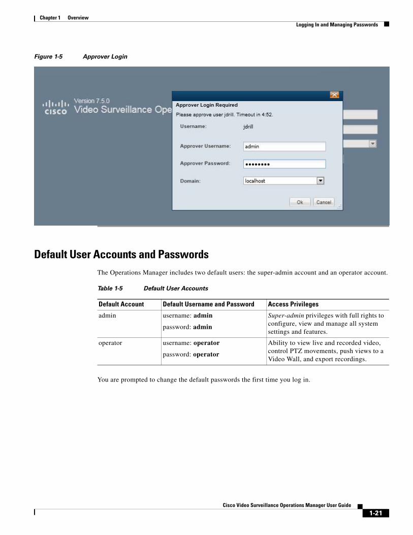
Step 8 If prompted, ask your manager or other administrator to enter their “Approver Login” (Figure 1-3).
Figure 1-3 Approver Login
• This second login is required only if configured.
• See the “Understanding Dual Login” section on page 1-19 for more information.
• If the approval is not successfully submitted within the time-out period, the login is denied.
Step 9 If prompted, complete the on-screen instructions to install or upgrade the Cisco Multi-Pane client software on your computer.
• This application is an Active X client that enables video playback and other features.
• Video will not play unless the Cisco Multi-Pane client software is correctly installed.
• If using the 64-bit version of Internet Explorer, you will be prompted to install the 64-bit version of the Cisco Multi-Pane client, if necessary.
1-18Cisco Video Surveillance Operations Manager User Guide
Chapter 1 OverviewLogging In and Managing Passwords
• You must have administrative privileges on the PC workstation to install the software.
• You will also be prompted to install the required Microsoft .Net 4.5 component, if necessary. If your workstation does not have Internet access, download the .Net 4.5 installer.
Note You must log in with a standard Windows user account. Logging in with a Guest account can prevent video streaming and result in an error to be displayed in the video pane: “Cannot create RTSP connection to server. Check network connection and server health status.”
Understanding Dual LoginDual Login requires that a second user (such as a manager) enter their credentials to approve a user’s access. When the user logs in, a second prompt appears for the manager’s credentials. This optional feature can be used when explicit approval is required whenever a user logs in.
To enable Dual Login, select the Approval Required checkbox in a User Group, and then select an “Approval Usergroup”. All users assigned to the User Group can only gain access if a member of the “Approval Usergroup” also enters their password.
Procedure
Tip See the “Adding User Groups” section on page 5-14 for more information.
Step 1 Select the User Groups tab .
Step 2 Click Add.
Step 3 Enter the settings for the group as described in the “Adding User Groups” section on page 5-14 (specifically Table 5-7 on page 5-15).
Step 4 (Optional) Select Approval Required and select an “Approval Usergroup” to require a second user to approve the user login (Figure 1-4).
1-19Cisco Video Surveillance Operations Manager User Guide
Chapter 1 Overview Logging In and Managing Passwords
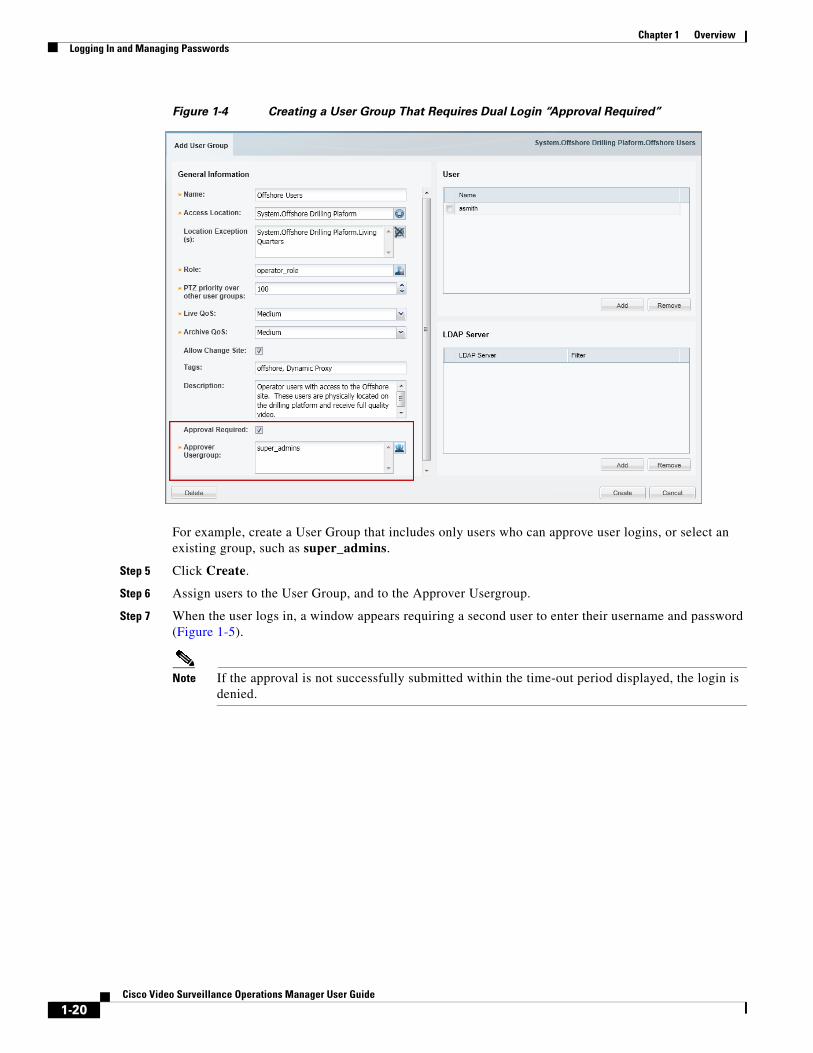
Figure 1-4 Creating a User Group That Requires Dual Login “Approval Required”
For example, create a User Group that includes only users who can approve user logins, or select an existing group, such as super_admins.
Step 5 Click Create.
Step 6 Assign users to the User Group, and to the Approver Usergroup.
Step 7 When the user logs in, a window appears requiring a second user to enter their username and password (Figure 1-5).
Note If the approval is not successfully submitted within the time-out period displayed, the login is denied.
1-20Cisco Video Surveillance Operations Manager User Guide
Chapter 1 OverviewLogging In and Managing Passwords
Figure 1-5 Approver Login
Default User Accounts and PasswordsThe Operations Manager includes two default users: the super-admin account and an operator account.
Table 1-5 Default User Accounts
Default Account Default Username and Password Access Privileges
You are prompted to change the default passwords the first time you log in.
admin username: admin
password: admin
Super-admin privileges with full rights to configure, view and manage all system settings and features.
operator username: operator
password: operator
Ability to view live and recorded video, control PTZ movements, push views to a Video Wall, and export recordings.
1-21Cisco Video Surveillance Operations Manager User Guide
Chapter 1 Overview Logging In and Managing Passwords
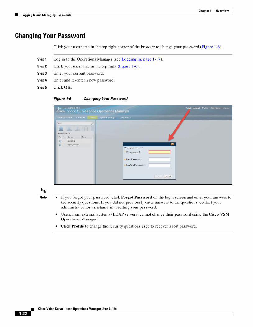
Changing Your PasswordClick your username in the top right corner of the browser to change your password (Figure 1-6).
Step 1 Log in to the Operations Manager (see Logging In, page 1-17).
Step 2 Click your username in the top right (Figure 1-6).
Step 3 Enter your current password.
Step 4 Enter and re-enter a new password.
Step 5 Click OK.
Figure 1-6 Changing Your Password
Note • If you forgot your password, click Forgot Password on the login screen and enter your answers to the security questions. If you did not previously enter answers to the questions, contact your administrator for assistance in resetting your password.
• Users from external systems (LDAP servers) cannot change their password using the Cisco VSM Operations Manager.
• Click Profile to change the security questions used to recover a lost password.
1-22Cisco Video Surveillance Operations Manager User Guide
Chapter 1 OverviewLogging In and Managing Passwords
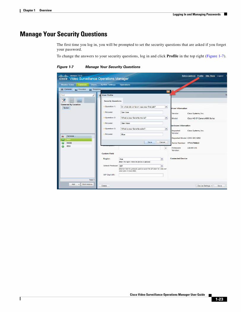
Manage Your Security QuestionsThe first time you log in, you will be prompted to set the security questions that are asked if you forget your password.
To change the answers to your security questions, log in and click Profile in the top right (Figure 1-7).
Figure 1-7 Manage Your Security Questions
1-23Cisco Video Surveillance Operations Manager User Guide
Chapter 1 Overview Logging In and Managing Passwords
Changing Another User’s PasswordCisco VSM admins with Users & Roles permissions can change the passwords for users in their location hierarchy. Super-admins can change any other user’s password.
Procedure
Step 1 Log in to the Operations Manager.
• You must belong to a User Group with permissions for Users & Roles. See the Adding Users, User Groups, and Permissions, page 5-1 for more information.
• Super users with permissions greater than the users lower in the location hierarchy can change those users’ passwords.
• Super-admins can change any other user’s password.
Step 2 Select Users, and then select the User tab .
Step 3 Highlight a username.
Step 4 Enter and re-enter a new password in the password fields.
Note The user is required to change the password the next time they log in.
Notes
• The password expiry date and the date that the password was last changed is displayed under the description.
• This method can also be used by the super-admin to change their own password. All other users can change their own password by clicking on their username in the top right corner of the browser (Figure 1-6). See Changing Your Password, page 1-22. See the Understanding the Super Admin, page 5-10 for a summary of super-admin tasks.
• Users authenticated from an LDAP server must change their password using their organization’s LDAP service.
Understanding and Changing Your “Site”“Sites” are designated location hierarchies (a location and its sub-locations) where network connectivity between the cameras and servers is good. These Sites, however, may have low-bandwidth connectivity to cameras, servers and users outside the Site.
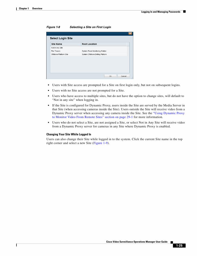
If the system is configured with Sites, and you are a member of a User Group that is assigned to a Site location, you will be prompted to select a Site the first time you log in (Figure 1-8).
1-24Cisco Video Surveillance Operations Manager User Guide
Chapter 1 OverviewLogging In and Managing Passwords
Figure 1-8 Selecting a Site on First Login
• Users with Site access are prompted for a Site on first login only, but not on subsequent logins.
• Users with no Site access are not prompted for a Site.
• Users who have access to multiple sites, but do not have the option to change sites, will default to “Not in any site” when logging in.
• If the Site is configured for Dynamic Proxy, users inside the Site are served by the Media Server in that Site (when accessing cameras inside the Site). Users outside the Site will receive video from a Dynamic Proxy server when accessing any camera inside the Site. See the “Using Dynamic Proxy to Monitor Video From Remote Sites” section on page 29-1 for more information.
• Users who do not select a Site, are not assigned a Site, or select Not in Any Site will receive video from a Dynamic Proxy server for cameras in any Site where Dynamic Proxy is enabled.
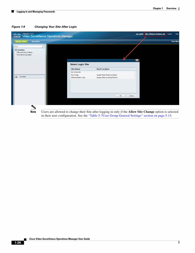
Changing Your Site While Logged In
Users can also change their Site while logged in to the system. Click the current Site name in the top right corner and select a new Site (Figure 1-9).
1-25Cisco Video Surveillance Operations Manager User Guide
Chapter 1 Overview Logging In and Managing Passwords
Figure 1-9 Changing Your Site After Login
Note Users are allowed to change their Site after logging in only if the Allow Site Change option is selected in their user configuration. See the “Table 5-7User Group General Settings” section on page 5-15.
1-26Cisco Video Surveillance Operations Manager User Guide
Chapter 1 OverviewInstalling Licenses
Installing LicensesA license must be purchased and installed for each Media Server and non-Cisco camera added to your deployment.
Note If your deployment includes a Cisco VSM Federator server, you must also purchase and install a Federator license to enable the number of Operations Managers managed by the Federator server. See the “Using Federator to Monitor Multiple Operations Managers” section on page 28-1.
Review the following information for more information.
• Usage Notes, page 1-27
• License Part Numbers, page 1-28
• Obtaining and Installing Licenses, page 1-28
• Displaying License Information, page 1-29
Usage Notes • You can add 1 Media Server and 10 non-Cisco cameras without a license for initial setup purposes
only. This feature is removed when you add any permanent license.
• A permanent license is required for each Media Server and non-Cisco camera installed in your deployment.
• A license for 10,000 Cisco cameras is included by default (you do not need to purchase and install any additional licenses for Cisco cameras).
• Licenses are installed in the Operations Manager only (not on the individual servers).
– Licenses can only be installed on a single instance of Operations Manager.
– The same license file cannot be installed more than once on the same Operations Manager.
– Do not rename the license file before installing it on the Operations Manager. Use the original file name only.
• License files can include licenses for a single device type, or for multiple device types, such as non-Cisco cameras and Media Servers.
• Licenses are cumulative: each additional license is added to the capacity of existing licenses. For example, if you initially installed a license for 100 non-Cisco cameras, you can purchase an additional license for 200 cameras to support a total of 300 non-Cisco cameras.
• The maximum number of devices in a system is 200 Media Servers, 10,000 cameras (including Cisco and non-Cisco devices), and 100 dynamic proxy servers.
• Soft deleted cameras are included in the camera license count. See the “Device Status: Identifying Issues for a Specific Device” section on page 24-13 for more information.
• Installed licenses are included in the Operations Manager backup and restore archives. We recommend backing up Operations Manager data after installing new licenses (or anytime major changes are performed). If the license file is installed after the backup is performed, the license file is not backed up and not available to be restored. You must re-install the missing license file. See the “Backup and Restore” section on page 27-1 for more information, including how to configure scheduled backups.
1-27Cisco Video Surveillance Operations Manager User Guide
Chapter 1 Overview Installing Licenses
Tip For additional information on installing licenses, see the “Using Dynamic Proxy to Monitor Video From Remote Sites” section on page 29-1 and the “Using Federator to Monitor Multiple Operations Managers” section on page 28-1.
License Part NumbersFor a summary of the Cisco VSM licenses, see the Release Notes for Cisco Video Surveillance Manager.
Note Multiple camera and Media Server licenses can be included in a single license file. For example, a single license file might include support for 25 additional cameras and two additional Media Servers. See the “Displaying License Information” section on page 1-29.
Obtaining and Installing LicensesTo install a license, purchase the license, download the license file, and then install file in Operations Manager.
Tip License files can include licenses for a single device type, or for multiple device types, such as non-Cisco cameras and Media Servers.
Procedure
Step 1 Purchase additional licenses:
a. Determine the part number for the license you want to purchase. See the “License Part Numbers” section on page 1-28.
b. Purchase the license by contacting your Cisco sales representative or any Cisco reseller. For more information, visit http://www.cisco.com/en/US/ordering/index.shtml.
c. When the purchase is complete, you are issued a Product Authorization Key (PAK) in paper form, or in an email message.
Step 2 Obtain the license file:
a. Locate the Product Authorization Key (PAK) created with the purchase.
b. In a Web browser, open the Cisco Product License Registration Web page.
http://www.cisco.com/go/license/
c. Follow the onscreen instructions to complete the form and enter the Product Authorization Key (PAK). When you are done, a license file with the extension .lic is sent to your email address.
d. Transfer the file to the drive of the PC used for the configuration.
Step 3 Install the license file in Cisco VSM:
a. Log in to the Operations Manager.
b. Select System Settings > Software Licensing (Figure 1-10).
c. Click Add and select the license file located on your local drive.
1-28Cisco Video Surveillance Operations Manager User Guide
Chapter 1 OverviewInstalling Licenses
d. Click Save to install the file and activate the additional capacity.
Tip The additional capacity is available immediately. You do not need to restart the server or take additional steps. Entries shown in red are invalid or expired.
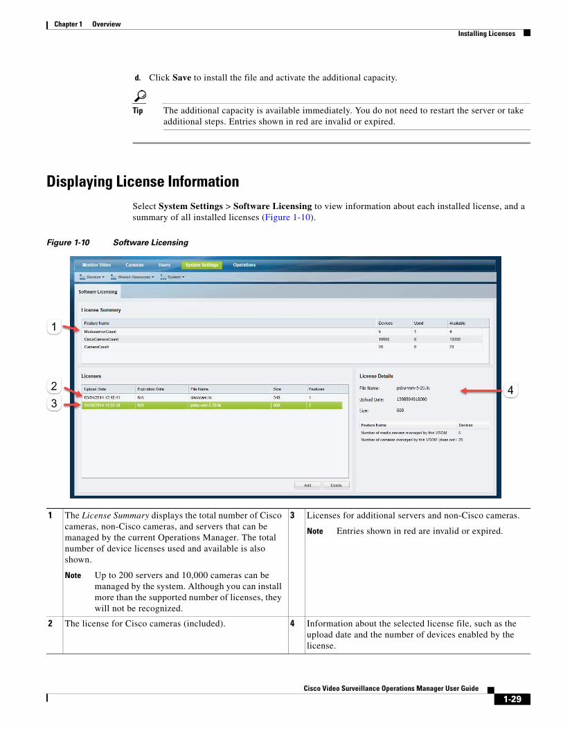
Displaying License InformationSelect System Settings > Software Licensing to view information about each installed license, and a summary of all installed licenses (Figure 1-10).
Figure 1-10 Software Licensing
1
Note Up to 200 servers and 10,000 cameras can be managed by the system. Although you can install more than the supported number of licenses, they will not be recognized.
3
Note Entries shown in red are invalid or expired.
2 4
The License Summary displays the total number of Cisco cameras, non-Cisco cameras, and servers that can be managed by the current Operations Manager. The total number of device licenses used and available is also shown.
Licenses for additional servers and non-Cisco cameras.
The license for Cisco cameras (included). Information about the selected license file, such as the upload date and the number of devices enabled by the license.
1-29Cisco Video Surveillance Operations Manager User Guide
Chapter 1 Overview Installing Licenses
Deleting LicensesDeleting a license will reduce the number of cameras and Media Server supported in your Cisco Video Surveillance deployment.
You cannot delete a license if the number of licenses devices will be less than the number added to the Operations Manager. View the number of licenses Used to verify that the license can be removed (see the “Displaying License Information” section on page 1-29).
Procedure
To remove a license:
Step 1 Select System Settings > Software Licensing.
Step 2 Highlight a license entry and click Delete (Figure 1-10).
Step 3 Click Yes to confirm.
1-30Cisco Video Surveillance Operations Manager User Guide
Chapter 1 OverviewUsing Find
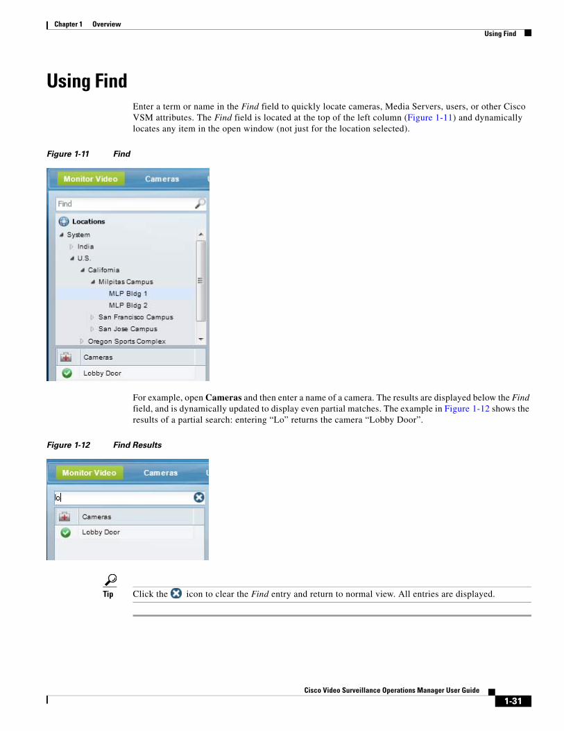
Using FindEnter a term or name in the Find field to quickly locate cameras, Media Servers, users, or other Cisco VSM attributes. The Find field is located at the top of the left column (Figure 1-11) and dynamically locates any item in the open window (not just for the location selected).
Figure 1-11 Find
For example, open Cameras and then enter a name of a camera. The results are displayed below the Find field, and is dynamically updated to display even partial matches. The example in Figure 1-12 shows the results of a partial search: entering “Lo” returns the camera “Lobby Door”.
Figure 1-12 Find Results
Tip Click the icon to clear the Find entry and return to normal view. All entries are displayed.
1-31Cisco Video Surveillance Operations Manager User Guide
Chapter 1 Overview Understanding Maintenance Mode
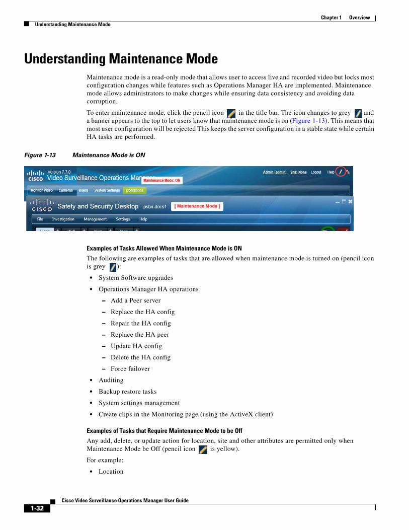
Understanding Maintenance ModeMaintenance mode is a read-only mode that allows user to access live and recorded video but locks most configuration changes while features such as Operations Manager HA are implemented. Maintenance mode allows administrators to make changes while ensuring data consistency and avoiding data corruption.
To enter maintenance mode, click the pencil icon in the title bar. The icon changes to grey and a banner appears to the top to let users know that maintenance mode is on (Figure 1-13). This means that most user configuration will be rejected This keeps the server configuration in a stable state while certain HA tasks are performed.
Figure 1-13 Maintenance Mode is ON
Examples of Tasks Allowed When Maintenance Mode is ON
The following are examples of tasks that are allowed when maintenance mode is turned on (pencil icon is grey ):
• System Software upgrades
• Operations Manager HA operations
– Add a Peer server
– Replace the HA config
– Repair the HA config
– Replace the HA peer
– Update HA config
– Delete the HA config
– Force failover
• Auditing
• Backup restore tasks
• System settings management
• Create clips in the Monitoring page (using the ActiveX client)
Examples of Tasks that Require Maintenance Mode to be Off
Any add, delete, or update action for location, site and other attributes are permitted only when Maintenance Mode be Off (pencil icon is yellow).
For example:
• Location
1-32Cisco Video Surveillance Operations Manager User Guide
Chapter 1 OverviewUnderstanding Maintenance Mode
• Site
• User, role, and user groups
• Camera and encoder configuration
• Server
• Camera apps
• Health
• Driver pack installation and upgrade
• Firmware upgrades
• Licenses
• Maps
• Adding user comments
• Create clips using the Thumbnail Search or Clips Search pages.
If maintenance mode is ON (pencil icon is grey ), these tasks are NOT permitted.
1-33Cisco Video Surveillance Operations Manager User Guide

Chapter 1 Overview Understanding Maintenance Mode
1-34Cisco Video Surveillance Operations Manager User Guide
Cisco V
C H A P T E R 2
Monitoring Video Using Internet ExplorerThe following topics describe how to view Cisco VSM live and recorded video using the Internet Explorer browser on a Windows computer.
Contents
• Understanding the Video Viewing Options, page 2-2
• Operations Manager Requirements, page 2-3
• Using the Monitor Video Page, page 2-3
• Selecting a Multi-Pane “View”, page 2-4
• View Video from a Panoramic Multi-lens Camera, page 2-6
• Controlling Live and Recorded Video, page 2-9
– Overview, page 2-9
– Viewing Live Video, page 2-10
– Viewing Recorded Video, page 2-13
– Creating and Viewing Video Clips From a Single Camera, page 2-40
– Using the Pop-Up Menu, page 2-17
– Understanding Video Pane Border Colors, page 2-19
– Using the Privacy Mask, page 2-20
– Synchronizing Video Playback in Multiple Panes, page 2-25
– Using Pan, Tilt, and Zoom (PTZ) Controls, page 2-29
• Viewing a Thumbnail Summary of Video Archives, page 2-35
– Using Thumbnail Search, page 2-37
• Create Video Clips, page 2-40
– Creating and Viewing Video Clips From a Single Camera, page 2-40
– Create Clips From Multiple Cameras (Bulk Clipping), page 2-50
– Find and Download Clips (Clip Search), page 2-54
2-1ideo Surveillance Operations Manager User Guide
Chapter 2 Monitoring Video Using Internet Explorer Understanding the Video Viewing Options
Understanding the Video Viewing Options
Table 2-1 Summary of Cisco Video Viewing Options
Viewing Tool Application Description Documentation
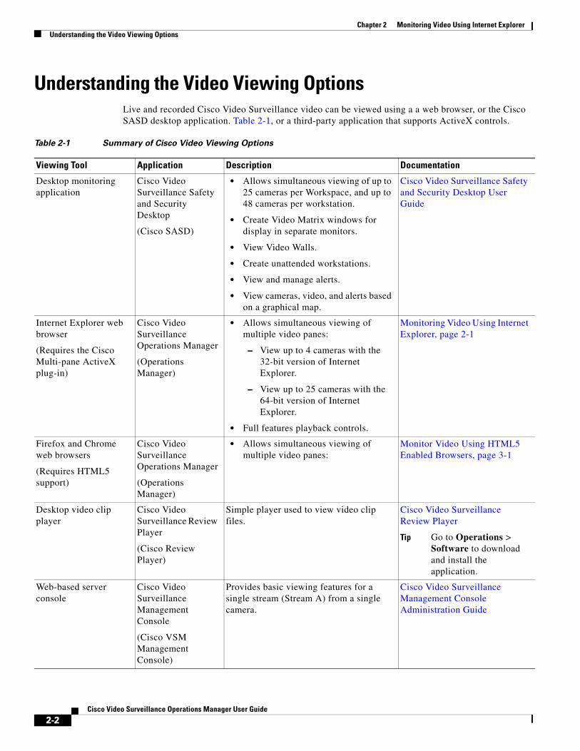
• Allows simultaneous viewing of up to 25 cameras per Workspace, and up to 48 cameras per workstation.
• Create Video Matrix windows for display in separate monitors.
• View Video Walls.
• Create unattended workstations.
• View and manage alerts.
• View cameras, video, and alerts based on a graphical map.
• Allows simultaneous viewing of multiple video panes:
– View up to 4 cameras with the 32-bit version of Internet Explorer.
– View up to 25 cameras with the 64-bit version of Internet Explorer.
• Full features playback controls.
• Allows simultaneous viewing of multiple video panes:
Tip Go to Operations > Software to download and install the application.
Live and recorded Cisco Video Surveillance video can be viewed using a a web browser, or the Cisco SASD desktop application. Table 2-1, or a third-party application that supports ActiveX controls.
Desktop monitoring application
Cisco Video Surveillance Safety and Security Desktop
(Cisco SASD)
Cisco Video Surveillance Safety and Security Desktop User Guide
Internet Explorer web browser
(Requires the Cisco Multi-pane ActiveX plug-in)
Cisco Video Surveillance Operations Manager
(Operations Manager)
Monitoring Video Using Internet Explorer, page 2-1
Firefox and Chrome web browsers
(Requires HTML5 support)
Cisco Video Surveillance Operations Manager
(Operations Manager)
Monitor Video Using HTML5 Enabled Browsers, page 3-1
Desktop video clip player
Cisco Video Surveillance Review Player
(Cisco Review Player)
Simple player used to view video clip files.
Cisco Video Surveillance Review Player
Web-based server console
Cisco Video Surveillance Management Console
(Cisco VSM Management Console)
Provides basic viewing features for a single stream (Stream A) from a single camera.
Cisco Video Surveillance Management Console Administration Guide
2-2Cisco Video Surveillance Operations Manager User Guide
Chapter 2 Monitoring Video Using Internet ExplorerOperations Manager Requirements
Operations Manager RequirementsSee the Cisco Video Surveillance Monitoring Workstation Performance Baseline Specification for the workstation requirements when monitoring video.
Using the Monitor Video Page Open the Monitor Video window to view video using the Cisco VSM Operations Manager.
Procedure
Step 1 Log on to the Cisco VSM Operations Manager.
• See the “Logging In” section on page 1-17. You must belong to a User Group with permissions for View Live Video or View Recordings.
Step 2 If prompted, complete the on-screen instructions to install or upgrade the Cisco Multi-Pane client software on your computer.
• This application is an Active X client that enables video playback and other features. Video will not play unless the Cisco Multi-Pane client software is correctly installed.
Step 3 Click Monitor Video.
Step 4 (Optional) Select a layout to view multiple panes, or click View Menu to select a pre-defined View.
See the “Selecting a Multi-Pane “View”” section on page 2-4 for more information. To create Views, go to System Settings > Views. See Creating Video Views, page 4-4.
Step 5 Expand the location tree and drag a camera from the list onto a viewing pane.
• Enter a partial or complete camera name in the Find field to display matching cameras.
• You can also select a video pane by clicking in it, and then double-click the camera name.
Step 6 See the “Controlling Live and Recorded Video” section on page 2-9 to use the video playback controls.
2-3Cisco Video Surveillance Operations Manager User Guide
Chapter 2 Monitoring Video Using Internet Explorer Selecting a Multi-Pane “View”
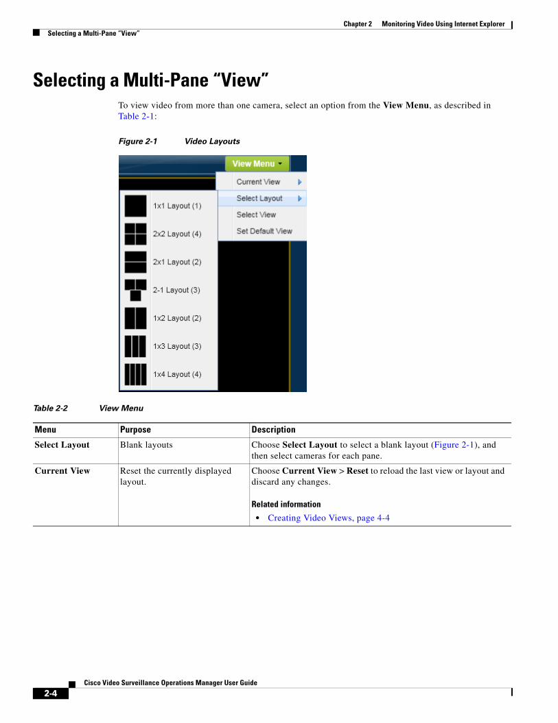
Selecting a Multi-Pane “View”To view video from more than one camera, select an option from the View Menu, as described in Table 2-1:
Figure 2-1 Video Layouts
Table 2-2 View Menu
Menu Purpose Description
Select Layout Blank layouts Choose Select Layout to select a blank layout (Figure 2-1), and then select cameras for each pane.
Current View Reset the currently displayed layout.
Choose Current View > Reset to reload the last view or layout and discard any changes.
Related information
• Creating Video Views, page 4-4
2-4Cisco Video Surveillance Operations Manager User Guide
Chapter 2 Monitoring Video Using Internet ExplorerSelecting a Multi-Pane “View”
Tip • To change the video in a View pane, drag and drop a camera name onto the pane.
• To create Views, go to System Settings > Views. See Creating Video Views, page 4-4.
• Views can be accessed using either the browser-based Operations Manager or the Cisco Video Surveillance Safety and Security Desktop (Cisco SASD) application. The Operations Manager can display a maximum of 4 video panes using the 32-bit version of Internet Explorer, and up to 16 panes when using the 64-bit version. Cisco SASD can display up to 16 panes.
• Double-click a video pane to fill the screen with that video (Figure 2-2). A preview of the other video panes is shown in a smaller grid at the bottom of the screen. Double-click the video pane again to return the grid to normal size.
Select View Display pre-defined views Choose Select View to select a pre-defined multi-pane view. Views can be configured to rotate video from multiple cameras to provide a virtual tour of a building or area. The video panes can (optionally) rotate video from different cameras to provide a virtual tour of a building or area.
Related information
• Creating Video Views, page 4-4
• Setting the Default View, page 4-1
Set Default View Define the view that is automatically loaded
The Default View is defined by each user and is automatically loaded when they click Monitor Video.
1. Create one or more Views as described in the “Setting the Default View” section on page 4-1.
2. Select View Menu > Set Default View.
3. Select a View from the pop-up window and click Select.
Note The Default View is saved as a cookie in the browser and is unique to each user/PC. The Default View is not displayed if using a different workstation.
Related information
• Setting the Default View, page 4-1
Table 2-2 View Menu (continued)
Menu Purpose Description
2-5Cisco Video Surveillance Operations Manager User Guide

Chapter 2 Monitoring Video Using Internet Explorer View Video from a Panoramic Multi-lens Camera
Figure 2-2 Enlarge a Video Pane
View Video from a Panoramic Multi-lens CameraPanoramic multi-lens cameras allows operators to view live video and recorded video from a multi-lens camera so that all images are stitched together in a continuous layout.
You can also create CVA clips from multi-lens panoramic cameras that appear as a single image. Clips in other formats cam be created for a single pane only.
Usage Notes
• Thumbnail Search and Clip Search only display video from a single lens, not the entire panoramic image.
• CVA clips can be created for the panoramic image. MP4 and virtual clips are not supported.
• You can create CVA, MP4 or virtual clips from a single lens image. Click any lens image to enlarge the view and access the controls.
Procedure
Step 1 Display the panoramic video (Figure 2-3).
a. Click Monitor.
b. Select the camera location.
c. Each lens appears as a camera entry in Cisco VSM. Click any lens from the camera to view the full panoramic image.
– If only a single lens image appears, check the encoder configuration to make sure panoramic mode is enabled, the lenses are assigned to encoder ports, and all lenses are assigned to the same template.
2-6Cisco Video Surveillance Operations Manager User Guide
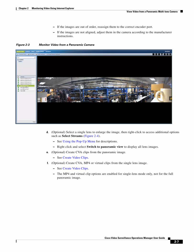
Chapter 2 Monitoring Video Using Internet ExplorerView Video from a Panoramic Multi-lens Camera
– If the images are out of order, reassign them to the correct encoder port.
– If the images are not aligned, adjust them in the camera according to the manufacturer instructions.
Figure 2-3 Monitor Video from a Panoramic Camera
d. (Optional) Select a single lens to enlarge the image, then right-click to access additional options such as Select Streams (Figure 2-4).
– See Using the Pop-Up Menu for descriptions.
– Right click and select Switch to panoramic view to display all lens images.
e. (Optional) Create CVA clips from the panoramic image.
– See Create Video Clips.
f. (Optional) Create CVA, MP4 or virtual clips from the single lens image.
– See Create Video Clips.
– The MP4 and virtual clip options are enabled for single-lens mode only, not for the full panoramic image.
2-7Cisco Video Surveillance Operations Manager User Guide
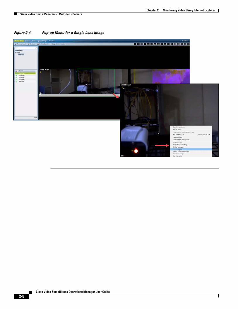
Chapter 2 Monitoring Video Using Internet Explorer View Video from a Panoramic Multi-lens Camera
Figure 2-4 Pop-up Menu for a Single Lens Image
2-8Cisco Video Surveillance Operations Manager User Guide
Chapter 2 Monitoring Video Using Internet ExplorerControlling Live and Recorded Video
Controlling Live and Recorded VideoEach video viewing pane in a Cisco Video Surveillance monitoring application supports the following controls and features.
The features available on your workstation depend on the following:
• The camera and system configuration.
• Your user account access permissions.
• The features supported by the video monitoring application.
Contents
Refer to the following topics for more information.
• Overview, page 2-9
• Viewing Live Video, page 2-10
• Viewing Recorded Video, page 2-13
• Creating and Viewing Video Clips From a Single Camera, page 2-40
• Using the Pop-Up Menu, page 2-17
• Understanding Video Pane Border Colors, page 2-19
• Using the Privacy Mask, page 2-20
• Using the Smooth Video Options When Viewing Live Video, page 2-24
• Synchronizing Video Playback in Multiple Panes, page 2-25
• Using Pan, Tilt, and Zoom (PTZ) Controls, page 2-29
OverviewTo view live and recorded video, log on to the monitoring application and drag and drop camera names onto the available viewing panes (you can also select a pane and double-click the camera name). Use Views to view multiple panes in a single window.
Each viewing pane includes various controls that allow you to do the following:
• Switch between live and recorded video.
• Select the playback timespan.
• Pause, play, or skip forward and back.
• Create and save video clips from recorded video
• Mute or un-mute the audio (if available).
• Synchronize the playback of multiple recordings.
• Control the Pan Tilt and Zoom (PTZ) movements of a camera (if supported by the camera).
• Additional options are available by right-clicking the image. Options include synchronizing multiple viewing panes, recording live video, expanding the image to fill the screen, creating a snapshot image, and configuring smooth video options to improve playback performance when network performance is poor.
2-9Cisco Video Surveillance Operations Manager User Guide
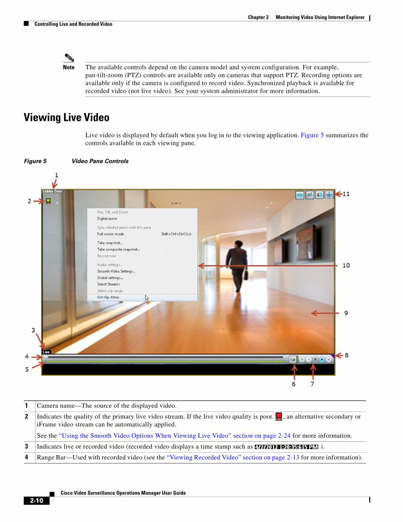
Chapter 2 Monitoring Video Using Internet Explorer Controlling Live and Recorded Video
Note The available controls depend on the camera model and system configuration. For example, pan-tilt-zoom (PTZ) controls are available only on cameras that support PTZ. Recording options are available only if the camera is configured to record video. Synchronized playback is available for recorded video (not live video). See your system administrator for more information.
Viewing Live VideoLive video is displayed by default when you log in to the viewing application. Figure 5 summarizes the controls available in each viewing pane.
Figure 5 Video Pane Controls
1 Camera name—The source of the displayed video.
2 Indicates the quality of the primary live video stream. If the live video quality is poor. , an alternative secondary or iFrame video stream can be automatically applied.
See the “Using the Smooth Video Options When Viewing Live Video” section on page 2-24 for more information.
3 Indicates live or recorded video (recorded video displays a time stamp such as ).
4 Range Bar—Used with recorded video (see the “Viewing Recorded Video” section on page 2-13 for more information).
2-10Cisco Video Surveillance Operations Manager User Guide
Chapter 2 Monitoring Video Using Internet ExplorerControlling Live and Recorded Video
Usage Notes
• Some firewall policies on enterprise PCs can block live video streams from cameras. If this occurs, add the camera IP address to the firewall trusted list.
• To maximize the video screens, move the new workspace to a separate monitor and double-click a pane to fill the entire browser window. To fill the entire monitor screen, right-click the image and select Full screen mode.
• To control the playback in multiple video panes, Shift-Click or Ctrl-Click to select the panes. The borders of all selected panes turn to orange. Controls and actions performed in one pane also affect the other selected panes. To deselect panes, select a single pane, or use Shift-Click or Ctrl-Click to deselect the panes
• Live video may be delayed 1-2 seconds. Live video can be further delayed if the smooth video option is enabled. See the “Using the Smooth Video Options When Viewing Live Video” section on page 2-24 for more information.
• Soft-deleted cameras (shown with a icon) are cameras that were removed from the system but still allow access to the camera’s recorded video. You cannot display live video from soft-deleted cameras.
• The control bar and audio icon will not display if your workstation monitor is set to 16-bit color setting. Change your monitor color setting to 32-bit.
5 Seek—Used with recorded video to choose a playback time (see the “Viewing Recorded Video” section on page 2-13 for more information).
6 The green icon indicates live video. Click the icon to switch to the recorded view .
7 Live video playback controls.
• —Pause the video playback.
• — Play the video forward at normal speed.
Note The other playback controls are used with archived video only. See Figure 6 on page 2-13 for more information.
8 —Click the triangle to pin the control bar to the screen, or auto-hide the bar when the cursor is moved.
Note The control bar and audio icon will not display if your workstation monitor is set to 16-bit color setting. Change your monitor color setting to 32-bit.
9 Video image.
10 Camera menu.
Right-click the image to open the menu and select an option. Options not supported by the camera are disabled (shown in gray). See the “Using the Pop-Up Menu” section on page 2-17 for more information.
11 Control icons.
• —Audio. The audio icon appears if the camera supports audio. Click to enable or mute live audio volume. This control does not affect recorded video.
• —Privacy Mask. Click to enable or disable the Privacy Mask. See the “Using the Privacy Mask” section on page 2-20.
• —PTZ. Click to enable or disable the Pan, Tilt and Zoom (PTZ) controls. See the “Using Pan, Tilt, and Zoom (PTZ) Controls” section on page 2-29.
• — See the “Synchronizing Video Playback in Multiple Panes” section on page 2-25.
Note The control bar and audio icon will not display if your workstation monitor is set to 16-bit color setting. Change your monitor color setting to 32-bit.
2-11Cisco Video Surveillance Operations Manager User Guide

Chapter 2 Monitoring Video Using Internet Explorer Controlling Live and Recorded Video
Additional Information
Refer to the following topics for additional options:
• Using the Pop-Up Menu, page 2-17
• Using the Smooth Video Options When Viewing Live Video, page 2-24
• Synchronizing Video Playback in Multiple Panes, page 2-25
• Using Pan, Tilt, and Zoom (PTZ) Controls, page 2-29
2-12Cisco Video Surveillance Operations Manager User Guide
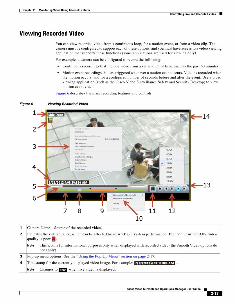
Chapter 2 Monitoring Video Using Internet ExplorerControlling Live and Recorded Video
Viewing Recorded VideoYou can view recorded video from a continuous loop, for a motion event, or from a video clip. The camera must be configured to support each of these options, and you must have access to a video viewing application that supports these functions (some applications are used for viewing only).
For example, a camera can be configured to record the following:
• Continuous recordings that include video from a set amount of time, such as the past 60 minutes.
• Motion event recordings that are triggered whenever a motion event occurs. Video is recorded when the motion occurs, and for a configured number of seconds before and after the event. Use a video viewing application (such as the Cisco Video Surveillance Safety and Security Desktop) to view motion event video.
Figure 6 describes the main recording features and controls.
Figure 6 Viewing Recorded Video
1 Camera Name—Source of the recorded video.
2 Indicates the video quality, which can be affected by network and system performance. The icon turns red if the video quality is poor .
Note This icon is for informational purposes only when displayed with recorded video (the Smooth Video options do not apply).
3 Pop-up menu options. See the “Using the Pop-Up Menu” section on page 2-17.
4 Timestamp for the currently displayed video image. For example: .
Note Changes to when live video is displayed.
2-13Cisco Video Surveillance Operations Manager User Guide
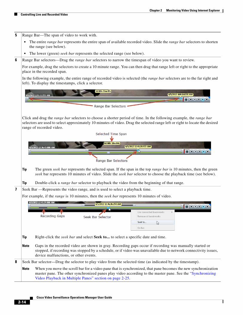
Chapter 2 Monitoring Video Using Internet Explorer Controlling Live and Recorded Video
5 Range Bar—The span of video to work with.
• The entire range bar represents the entire span of available recorded video. Slide the range bar selectors to shorten the range (see below).
• The lower (green) seek bar represents the selected range (see below).
6 Range Bar selectors—Drag the range bar selectors to narrow the timespan of video you want to review.
For example, drag the selectors to create a 10 minute range. You can then drag that range left or right to the appropriate place in the recorded span.
In the following example, the entire range of recorded video is selected (the range bar selectors are to the far right and left). To display the timestamps, click a selector.
Click and drag the range bar selectors to choose a shorter period of time. In the following example, the range bar selectors are used to select approximately 10 minutes of video. Drag the selected range left or right to locate the desired range of recorded video.
Tip The green seek bar represents the selected span. If the span in the top range bar is 10 minutes, then the green seek bar represents 10 minutes of video. Slide the seek bar selector to choose the playback time (see below).
Tip Double-click a range bar selector to playback the video from the beginning of that range.
7 Seek Bar —Represents the video range, and is used to select a playback time.
For example, if the range is 10 minutes, then the seek bar represents 10 minutes of video.
Tip Right-click the seek bar and select Seek to... to select a specific date and time.
Note Gaps in the recorded video are shown in gray. Recording gaps occur if recording was manually started or stopped, if recording was stopped by a schedule, or if video was unavailable due to network connectivity issues, device malfunctions, or other events.
8 Seek Bar selector—Drag the selector to play video from the selected time (as indicated by the timestamp).
Note When you move the scroll bar for a video pane that is synchronized, that pane becomes the new synchronization master pane. The other synchronized panes play video according to the master pane. See the “Synchronizing Video Playback in Multiple Panes” section on page 2-25.
2-14Cisco Video Surveillance Operations Manager User Guide
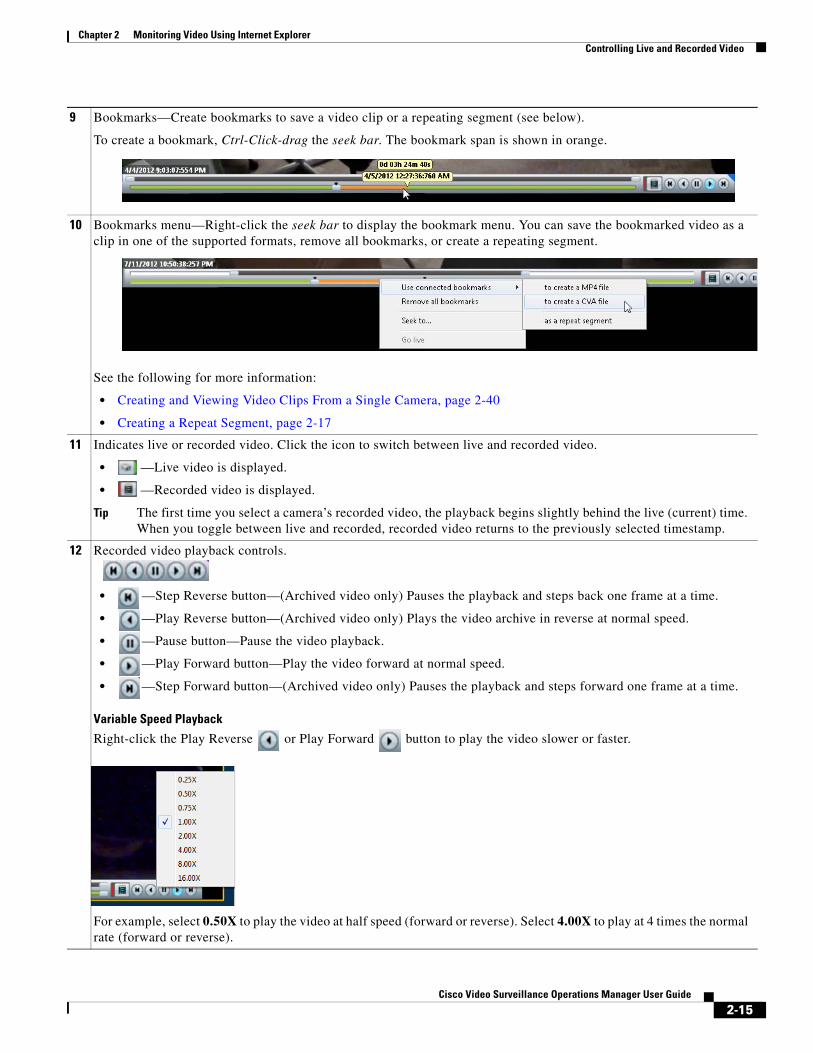
Chapter 2 Monitoring Video Using Internet ExplorerControlling Live and Recorded Video
9 Bookmarks—Create bookmarks to save a video clip or a repeating segment (see below).
To create a bookmark, Ctrl-Click-drag the seek bar. The bookmark span is shown in orange.
10 Bookmarks menu—Right-click the seek bar to display the bookmark menu. You can save the bookmarked video as a clip in one of the supported formats, remove all bookmarks, or create a repeating segment.
See the following for more information:
• Creating and Viewing Video Clips From a Single Camera, page 2-40
• Creating a Repeat Segment, page 2-17
11 Indicates live or recorded video. Click the icon to switch between live and recorded video.
• —Live video is displayed.
• —Recorded video is displayed.
Tip The first time you select a camera’s recorded video, the playback begins slightly behind the live (current) time. When you toggle between live and recorded, recorded video returns to the previously selected timestamp.
12 Recorded video playback controls.
• —Step Reverse button—(Archived video only) Pauses the playback and steps back one frame at a time.
• —Play Reverse button—(Archived video only) Plays the video archive in reverse at normal speed.
• —Pause button—Pause the video playback.
• —Play Forward button—Play the video forward at normal speed.
• —Step Forward button—(Archived video only) Pauses the playback and steps forward one frame at a time.
Variable Speed Playback
Right-click the Play Reverse or Play Forward button to play the video slower or faster.
For example, select 0.50X to play the video at half speed (forward or reverse). Select 4.00X to play at 4 times the normal rate (forward or reverse).
2-15Cisco Video Surveillance Operations Manager User Guide
Chapter 2 Monitoring Video Using Internet Explorer Controlling Live and Recorded Video
Usage Notes
• Multi-pane video clips can also be saved to your desktop and played using the Cisco Video Surveillance Review Player.
• If a camera is soft-deleted, you can still access the camera’s recorded video but cannot display live video. Recordings are retained on the system until removed according to the recording retention settings.
• Click the icon to toggle between live and recorded video. The icon appears when recorded video is displayed.
• The first time you select a camera’s recorded video, the playback begins slightly behind the live (current) time. When you toggle between live and recorded, recorded video returns to the previously selected timestamp.
• To maximize the video screens, move the new workspace to a separate monitor and double-click a pane to fill the entire browser window. To fill the entire monitor screen, right-click the image and select Full screen mode.
• To control the playback in multiple video panes, press Shift-Click to select multiple concurrent panes, or Ctrl-Click to select individual panes. The borders of all selected panes turn to orange. Controls and actions performed in one pane also affect the other selected panes. To deselect panes, select a single pane, or use Shift-Click or Ctrl-Click to deselect the panes.
13 —Click the triangle to pin the control bar to the screen, or auto-hide it when the cursor is moved.
Note The control bar and audio icon will not display if your workstation monitor is set to 16-bit color setting. Change your monitor color setting to 32-bit.
14 Camera feature icons. For example:
• or —Audio is supported by the camera and enabled or disabled in the viewing pane.
• —The synchronization icon appears in video panes that play synchronized video. See the “Synchronizing Video Playback in Multiple Panes” section on page 2-25.
Note The PTZ icons are enabled only for live video.
Note The control bar and audio icon will not display if your workstation monitor is set to 16-bit color setting. Change your monitor color setting to 32-bit.
2-16Cisco Video Surveillance Operations Manager User Guide
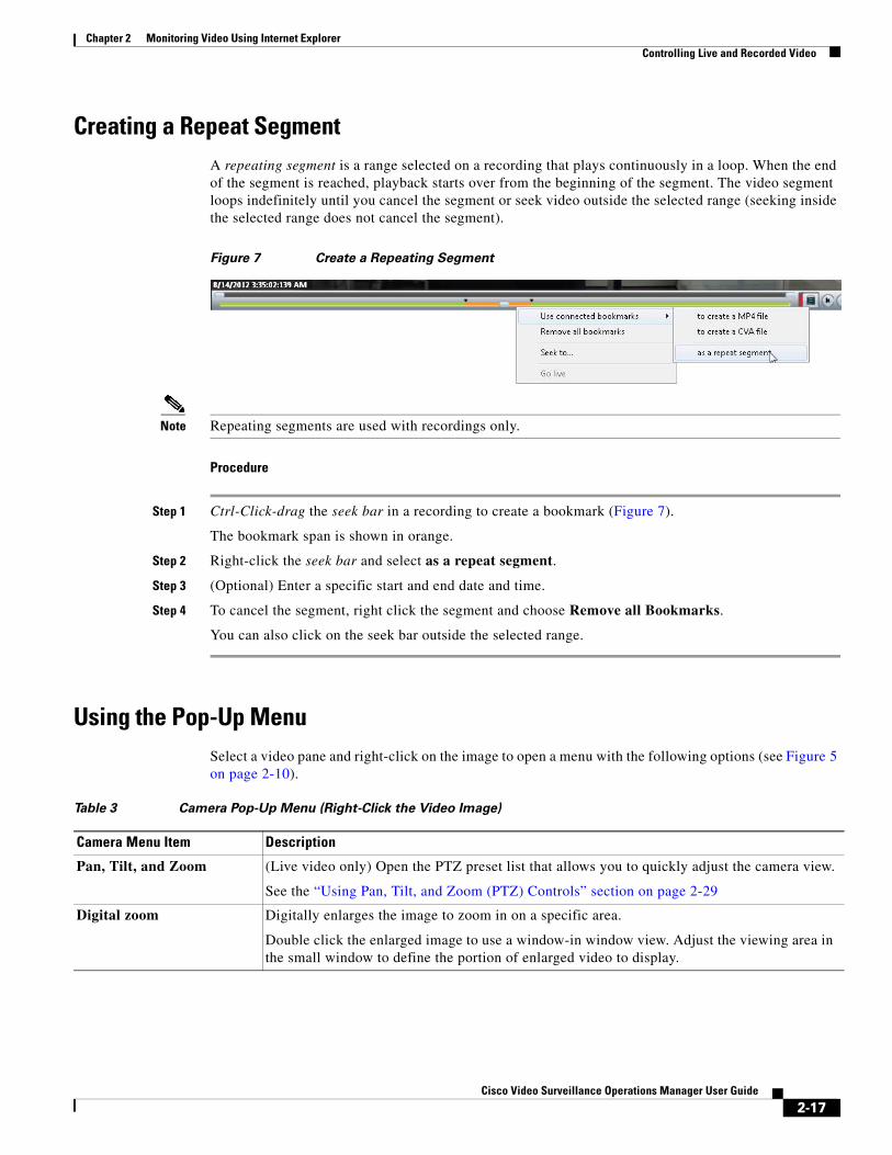
Chapter 2 Monitoring Video Using Internet ExplorerControlling Live and Recorded Video
Creating a Repeat SegmentA repeating segment is a range selected on a recording that plays continuously in a loop. When the end of the segment is reached, playback starts over from the beginning of the segment. The video segment loops indefinitely until you cancel the segment or seek video outside the selected range (seeking inside the selected range does not cancel the segment).
Figure 7 Create a Repeating Segment
Note Repeating segments are used with recordings only.
Procedure
Step 1 Ctrl-Click-drag the seek bar in a recording to create a bookmark (Figure 7).
The bookmark span is shown in orange.
Step 2 Right-click the seek bar and select as a repeat segment.
Step 3 (Optional) Enter a specific start and end date and time.
Step 4 To cancel the segment, right click the segment and choose Remove all Bookmarks.
You can also click on the seek bar outside the selected range.
Using the Pop-Up MenuSelect a video pane and right-click on the image to open a menu with the following options (see Figure 5 on page 2-10).
Table 3 Camera Pop-Up Menu (Right-Click the Video Image)
Camera Menu Item Description
Pan, Tilt, and Zoom (Live video only) Open the PTZ preset list that allows you to quickly adjust the camera view.
See the “Using Pan, Tilt, and Zoom (PTZ) Controls” section on page 2-29
Digital zoom Digitally enlarges the image to zoom in on a specific area.
Double click the enlarged image to use a window-in window view. Adjust the viewing area in the small window to define the portion of enlarged video to display.
2-17Cisco Video Surveillance Operations Manager User Guide
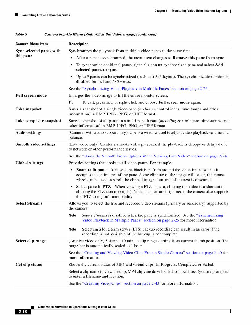
Chapter 2 Monitoring Video Using Internet Explorer Controlling Live and Recorded Video
Sync selected panes with this pane
Synchronizes the playback from multiple video panes to the same time.
• After a pane is synchronized, the menu item changes to Remove this pane from sync.
• To synchronize additional panes, right-click an un-synchronized pane and select Add selected panes to sync.
• Up to 9 panes can be synchronized (such as a 3x3 layout). The synchronization option is disabled for 4x4 and 5x5 views.
See the “Synchronizing Video Playback in Multiple Panes” section on page 2-25.
Full screen mode Enlarges the video image to fill the entire monitor screen.
Tip To exit, press Esc, or right-click and choose Full screen mode again.
Take snapshot Saves a snapshot of a single video pane (excluding control icons, timestamps and other information) in BMP, JPEG, PNG, or TIFF format.
Take composite snapshot Saves a snapshot of all panes in a multi-pane layout (including control icons, timestamps and other information) in BMP, JPEG, PNG, or TIFF format.
Audio settings (Cameras with audio support only). Opens a window used to adjust video playback volume and balance.
Smooth video settings (Live video only) Creates a smooth video playback if the playback is choppy or delayed due to network or other performance issues.
See the “Using the Smooth Video Options When Viewing Live Video” section on page 2-24.
Global settings Provides settings that apply to all video panes. For example:
• Zoom to fit pane—Removes the black bars from around the video image so that it occupies the entire area of the pane. Some clipping of the image will occur, the mouse wheel can be used to scroll the clipped image if an area of interest is obscured.
• Select pane to PTZ—When viewing a PTZ camera, clicking the video is a shortcut to clicking the PTZ icon (top right). Note: This feature is ignored if the camera also supports the ‘PTZ to region’ functionality.
Select Streams Allows you to select the live and recorded video streams (primary or secondary) supported by the camera.
Note Select Streams is disabled when the pane is synchronized. See the “Synchronizing Video Playback in Multiple Panes” section on page 2-25 for more information.
Note Selecting a long term server (LTS) backup recording can result in an error if the recording is not available of the backup is not complete.
Select clip range (Archive video only) Selects a 10 minute clip range starting from current thumb position. The range bar is automatically scaled to 1 hour.
See the “Creating and Viewing Video Clips From a Single Camera” section on page 2-40 for more information.
Get clip status Shows the current status of MP4 and virtual clips: In-Progress, Completed or Failed.
Select a clip name to view the clip. MP4 clips are downloaded to a local disk (you are prompted to enter a filename and location.
See the “Creating Video Clips” section on page 2-43 for more information.
Table 3 Camera Pop-Up Menu (Right-Click the Video Image) (continued)
Camera Menu Item Description
2-18Cisco Video Surveillance Operations Manager User Guide
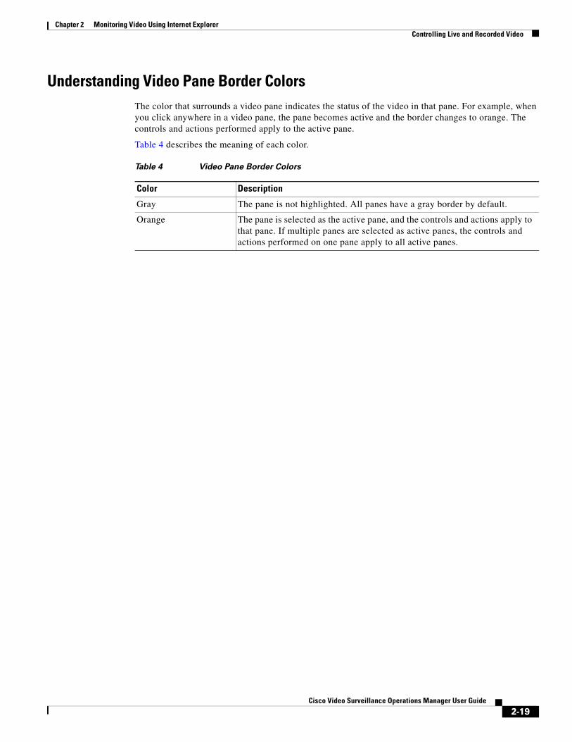
Chapter 2 Monitoring Video Using Internet ExplorerControlling Live and Recorded Video
Understanding Video Pane Border ColorsThe color that surrounds a video pane indicates the status of the video in that pane. For example, when you click anywhere in a video pane, the pane becomes active and the border changes to orange. The controls and actions performed apply to the active pane.
Table 4 describes the meaning of each color.
Table 4 Video Pane Border Colors
Color Description
Gray The pane is not highlighted. All panes have a gray border by default.
Orange The pane is selected as the active pane, and the controls and actions apply to that pane. If multiple panes are selected as active panes, the controls and actions performed on one pane apply to all active panes.
2-19Cisco Video Surveillance Operations Manager User Guide
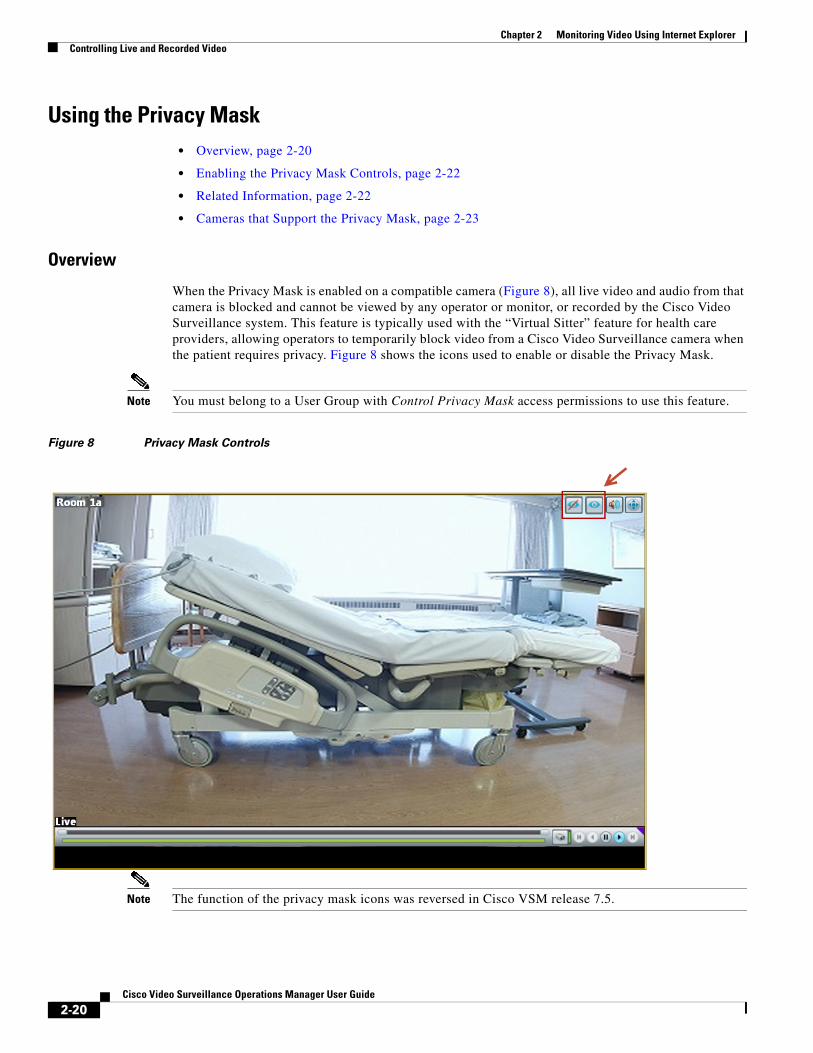
Chapter 2 Monitoring Video Using Internet Explorer Controlling Live and Recorded Video
Using the Privacy Mask • Overview, page 2-20
• Enabling the Privacy Mask Controls, page 2-22
• Related Information, page 2-22
• Cameras that Support the Privacy Mask, page 2-23
Overview
When the Privacy Mask is enabled on a compatible camera (Figure 8), all live video and audio from that camera is blocked and cannot be viewed by any operator or monitor, or recorded by the Cisco Video Surveillance system. This feature is typically used with the “Virtual Sitter” feature for health care providers, allowing operators to temporarily block video from a Cisco Video Surveillance camera when the patient requires privacy. Figure 8 shows the icons used to enable or disable the Privacy Mask.
Note You must belong to a User Group with Control Privacy Mask access permissions to use this feature.
Figure 8 Privacy Mask Controls
Note The function of the privacy mask icons was reversed in Cisco VSM release 7.5.
2-20Cisco Video Surveillance Operations Manager User Guide
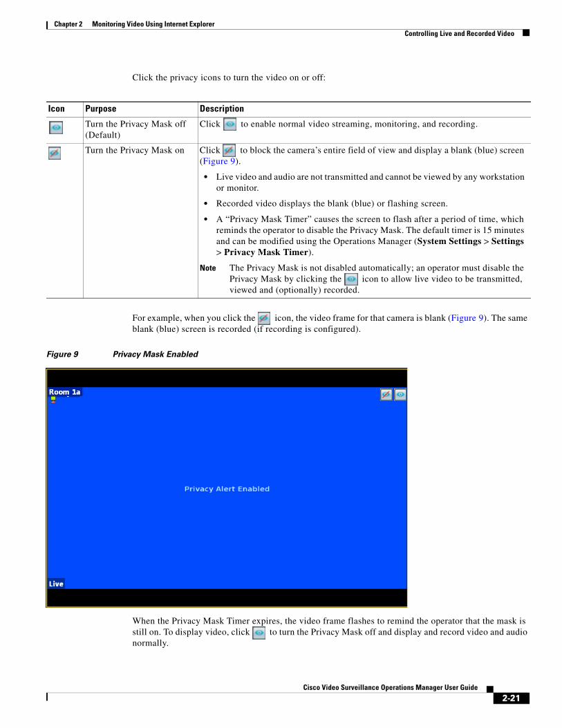
Chapter 2 Monitoring Video Using Internet ExplorerControlling Live and Recorded Video
Click the privacy icons to turn the video on or off:
Icon Purpose Description
• Live video and audio are not transmitted and cannot be viewed by any workstation or monitor.
• Recorded video displays the blank (blue) or flashing screen.
• A “Privacy Mask Timer” causes the screen to flash after a period of time, which reminds the operator to disable the Privacy Mask. The default timer is 15 minutes and can be modified using the Operations Manager (System Settings > Settings > Privacy Mask Timer).
Note The Privacy Mask is not disabled automatically; an operator must disable the Privacy Mask by clicking the icon to allow live video to be transmitted, viewed and (optionally) recorded.
For example, when you click the icon, the video frame for that camera is blank (Figure 9). The same blank (blue) screen is recorded (if recording is configured).
Figure 9 Privacy Mask Enabled
When the Privacy Mask Timer expires, the video frame flashes to remind the operator that the mask is still on. To display video, click to turn the Privacy Mask off and display and record video and audio normally.
Turn the Privacy Mask off (Default)
Click to enable normal video streaming, monitoring, and recording.
Turn the Privacy Mask on Click to block the camera’s entire field of view and display a blank (blue) screen (Figure 9).
2-21Cisco Video Surveillance Operations Manager User Guide
Chapter 2 Monitoring Video Using Internet Explorer Controlling Live and Recorded Video
Note If the camera reboots due to a power cycle or other reason, the camera will power up with the Privacy Mask in the state it was before the reboot. For example, if the mask was enabled and there was 5 minutes remaining on the timer, the camera will remember the state after the reboot.
Usage Notes
• You must belong to a User Group with Control Privacy Mask access permissions to use this feature.
• If privacy mask is enabled:
– The camera template audio settings cannot be changed.
– The following options are disabled: Reset Status, Replace Configuration, Replace camera, synchronization.
– Edge recording for audio does not stop when privacy mask is enabled.
• If Privacy Mask is enabled on any encoder port, you cannot add new encoder ports to the configuration.
• If the connection between VSOM and the Media Server is poor, the privacy mask setting will not be applied to camera.
Enabling the Privacy Mask Controls
The Privacy Mask controls (icons) are displayed only for users who belong to a User Group with Control Privacy Mask access permissions. This operator permission is de-selected by default, so you must create a user role, user group, and use that includes Privacy Mask:
Step 1 Log is as a admin or other user who has Users & Groups access permissions.
Step 2 Create a Role that includes Control Privacy Mask access permissions.
Step 3 Create a user group and assign the new role to the group.
Step 4 Create users and assign them to the user group.
Tip See Adding Users, User Groups, and Permissions, page 5-1 for more information.
Related Information
Supported cameras can also be configured with “Privacy Zones” that block portions of the video image at all times, even if the Privacy Mask is disabled. See the camera documentation for instructions to define Privacy Zones.
For more information about Cisco Virtual Patient Observation, see the following:
• White Paper—Virtual Patient Observation: Centralize Monitoring of High-Risk Patients with Video.
• At-A -Glance Overview—Benefits of Virtual Patient Observation.
• Ten Use Cases—Real-life scenarios for using video surveillance in hospitals.
• Solution Blog Post—New Solution: Cisco Virtual Patient Observation.
2-22Cisco Video Surveillance Operations Manager User Guide
http://www.cisco.com/en/US/prod/collateral/ps6712/ps10491/ps9145/ps10818/white_paper_C11-715263.html

Chapter 2 Monitoring Video Using Internet ExplorerControlling Live and Recorded Video
Cameras that Support the Privacy Mask
See the Release Notes for Cisco Video Surveillance Manager for the cameras that support the privacy mask feature in your release.
2-23Cisco Video Surveillance Operations Manager User Guide
Chapter 2 Monitoring Video Using Internet Explorer Controlling Live and Recorded Video
Using the Smooth Video Options When Viewing Live Video If live video playback is choppy due to network or other performance issues, use the Smooth video settings to automatically do the following:
• Create a video data buffer (in seconds) that delays live playback while video data is cached. Live video can then be played back smoothly despite network delays between the camera, Media Server, and workstation.
• Automatically switch to a different stream if the live video quality is poor.
Icon Colors
The video quality icons in each pane indicate the following:
• Green indicates everything is fine.
• Yellow indicates that the client workstation has detected the play back is not smooth.
• Red indicates a severe adverse situation. Action will be taken to correct the situation, such as switching to secondary stream or iFrame streaming.
Usage Notes
• The Smooth Video Options are available only for live video on non-PTZ cameras (the Smooth Video Options are automatically disabled on PTZ cameras).
• The settings are applied to all non-PTZ cameras and are persistent for the current PC workstation. For example, the settings will remain if you log out and back in, or view a different camera and then return to the current camera.
• The settings also apply to the non-PTZ cameras when using the Cisco Safety and Security Desktop (SASD) application and the Cisco Video Surveillance Management Console.
• The Smooth Video options are disabled if you manually select a stream (right-click a video pane and choose Select Streams and Clips). The pane will display the selected stream even if the video quality is poor (the video will not automatically switch to the Smooth Video alternative stream). To cancel the manually selected stream and re-enable the Smooth Video settings, reload the view or drag and drop the camera again.
• If a video stream is selected from a redundant media server, the Smooth Video option is disabled (the camera will not use a secondary stream even if the video quality icon is red).
Procedure
Step 1 Right-click a live video image to open the pop-up menu.
Step 2 Select or deselect Enable Smooth Video for Live non-PTZ Camera to enable the smooth video options.
Step 3 (Optional) Enter the Preroll Buffer Size in Seconds to define the number of seconds that live video will be delayed.
Video data is saved in a cache on your PC to avoid pauses caused by network bandwidth and other issues. We recommend a value between 1.5 and 3 seconds.
2-24Cisco Video Surveillance Operations Manager User Guide
Chapter 2 Monitoring Video Using Internet ExplorerControlling Live and Recorded Video
Caution We strongly recommend that the Preroll Buffer be disabled (enter 0 or leave the field blank) since streaming delays can cause a potential security risk. We recommend that you address the network bandwidth or performance issues causing the delays. Use the Preroll Buffer only when significant stuttering occurs and a network resolution is not available.
Step 4 Use the Smooth Video Options to define an alternative video stream that will be used if video quality is poor despite the smooth video buffer (video quality is indicated by the icon on the live viewing pane).
• Secondary Stream—(Only if configured on the camera) If the live video quality is poor , the secondary video stream is used. Secondary streams typically present a lower-quality image that requires less bandwidth and processing.
• I frame only—If the live video quality is poor , then only the iFrame video is displayed. iFrame video reduces the bandwidth requirement to correct the situation.
• None—If the live video quality is poor , no change is made and the selected stream is displayed even if it results in choppy or paused playback.
Note • These options are not used if the video quality is acceptable or if the icon is yellow (intermediate) . The selected stream is displayed normally.
• A down arrow is displayed when the secondary or iFrame stream is applied.
• If an alternative stream is applied, the settings remain until you close and reopen the video source (camera).
Synchronizing Video Playback in Multiple PanesTo synchronize video playback from multiple panes, select multiple panes, right-click the pane that defines the master time, and choose Sync Selected Panes With This Pane. All panes will play video from the same date and time.
Usage Notes
• All panes will play forward when synchronization begins, even if one or more of the panes was playing in reverse.
• Up to 9 panes can be synchronized (such as a 3x3 layout). The synchronization option is disabled for 4x4 and 5x5 views.
• Synchronization for recorded video is performed only if the time in the selected panes overlap. If the time for a video pane does not overlap with the master pane, the pane is excluded from synchronization.
• When you move the scroll bar for a video pane that is synchronized, that pane becomes the new synchronization master pane. The other synchronized panes play video according to the new master pane.
• If the seek controls are used to search video, the other synchronized panes pause until the seek completes, then continue to display video that is synchronized with the new master pane time.
2-25Cisco Video Surveillance Operations Manager User Guide

Chapter 2 Monitoring Video Using Internet Explorer Controlling Live and Recorded Video
• You can switch the synchronized panes between live and recorded video.
• To remove a pane from the synchronized playback, right-click the pane and choose Remove This Pane From Sync to remove it.
• To add un-synchronized panes, right-click the pane and choose Add selected panes to sync.
• The Select Streams and Clips menu item is disabled when a pane is synchronized.
• When 16 video panes are synchronized, some live video panes may appear to be not synchronized if the video stream is configured for the following:
Format Resolution Framerate
JPEG 640x480 30 fps
H-264 1920x1080 30 fps
2-26Cisco Video Surveillance Operations Manager User Guide
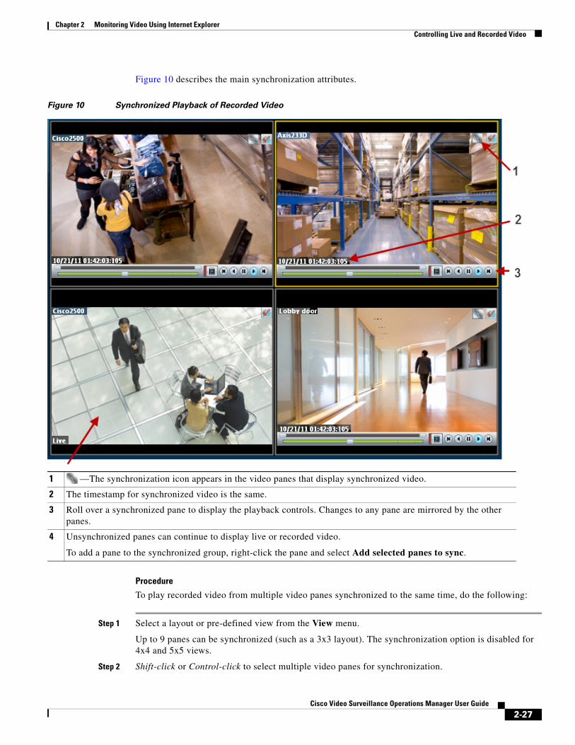
Chapter 2 Monitoring Video Using Internet ExplorerControlling Live and Recorded Video
Figure 10 describes the main synchronization attributes.
Figure 10 Synchronized Playback of Recorded Video
1
2
3
4
Procedure
To play recorded video from multiple video panes synchronized to the same time, do the following:
Step 1 Select a layout or pre-defined view from the View menu.
Up to 9 panes can be synchronized (such as a 3x3 layout). The synchronization option is disabled for 4x4 and 5x5 views.
Step 2 Shift-click or Control-click to select multiple video panes for synchronization.
—The synchronization icon appears in the video panes that display synchronized video.
The timestamp for synchronized video is the same.
Roll over a synchronized pane to display the playback controls. Changes to any pane are mirrored by the other panes.
Unsynchronized panes can continue to display live or recorded video.
To add a pane to the synchronized group, right-click the pane and select Add selected panes to sync.
2-27Cisco Video Surveillance Operations Manager User Guide

Chapter 2 Monitoring Video Using Internet Explorer Controlling Live and Recorded Video
The selected panes are displayed with a light yellow border.
Step 3 Right-click a video pane and select Sync Selected Panes With This Pane from the menu.
The selected pane becomes the master pane.
Step 4 (Optional) To remove a pane from the synchronized group, right-click the pane and choose Remove This Pane From Sync.
Note The pane continues to play video from the same timestamp, but the video can be stopped or altered without affecting the other panes.
Step 5 (Optional) To add un-synchronized panes, right-click the pane and choose Add selected panes to sync.
2-28Cisco Video Surveillance Operations Manager User Guide

Chapter 2 Monitoring Video Using Internet ExplorerControlling Live and Recorded Video
Using Pan, Tilt, and Zoom (PTZ) ControlsCameras that support pan, tilt and zoom (PTZ) movements display a PTZ icon . Click the icon to enable PTZ (the icon is blue when enabled, and do one of the following:
• To pan and tilt, hold down the left mouse button while dragging the mouse right, left, up and down (the icon appears).
• To zoom:
– Hold down the left mouse button and use the scroll wheel to zoom in and out.
or
– Hold down the Shift key and then press the left mouse button. Drag the mouse up or down to zoom.
In addition, PTZ presets allow the camera to quickly jump to a preset position. For example, a PTZ preset could zoom in on a doorway, or pan to the opposite end of a parking lot. PTZ presets can be triggered using a mouse, joystick or automatically triggered event.
Cameras can also be configured with PTZ tours that automatically cycle between PTZ preset positions. You can interrupt the tour using the PTZ controls, and the tour will resume after a set amount of time. See your system administrator for more information.
Figure 11 summarizes the controls and information available on each PTZ camera viewing pane.
Figure 11 Camera PTZ Controls
1 3
• Blue—Enabled
• Grey—Disabled
2 4
Selected Camera PTZ Enabled/Disabled Icon (click to toggle).
PTZ is available in Live mode only PTZ Preset Menu (right-click to access)
2-29Cisco Video Surveillance Operations Manager User Guide
Chapter 2 Monitoring Video Using Internet Explorer Controlling Live and Recorded Video
PTZ Usage Notes
• To use a USB joystick, see the “Calibrating a Joystick for Windows 7” section on page 2-32.
• PTZ movements are available only when viewing live video.
• PTZ can only be enabled for a single video pane if multiple panes are displayed. See the “Using PTZ Controls When Multiple Video Windows are Displayed” section on page 2-34.
• You must also belong to a user group with Perform PTZ permissions.
• PTZ commands are available only if the primary Media Server is functional. If the Primary server goes down, or is not available on the network, PTZ commands will not function even if video is still being delivered by a redundant server (if configured). See the “High Availability: Cisco Media Servers” section on page 22-1 for more information.
PTZ Control Procedure
To control a camera’s PTZ movement or trigger a PTZ preset position, do the following:
Step 1 Display the live video from a PTZ-enabled camera:
a. Click Monitor Video.
b. Expand the location tree and select the camera.
c. Highlight a video pane and double-click a camera name.
Step 2 Click the PTZ control icon to enable PTZ:
• —(Blue) PTZ controls are supported by the camera and enabled in the viewing pane.
• —(Grey) PTZ controls are disabled. Click the icon to enable PTZ controls.
Note If a higher-priority user is using the PTZ controls, the PTZ controls remain locked and you cannot control the PTZ movements until released by the higher priority user.
Step 3 To move the camera position, use the following controls.
Using a Mouse
• Pan and Tilt—Hold down the left mouse button while dragging the mouse ( ) right, left, up and down.
• Zoom—
– Hold down the left mouse button and use the scroll wheel to zoom in and out.
or
– Hold down the Shift key and then press the left mouse button. Drag the mouse up or down to zoom.
Using a USB Joystick
• Pan—move the joystick bar horizontally.
• Tilt— move the joystick bar vertically.
• Zoom —twist the joystick.
2-30Cisco Video Surveillance Operations Manager User Guide
Chapter 2 Monitoring Video Using Internet ExplorerControlling Live and Recorded Video
Tip See the “Calibrating a Joystick for Windows 7” section on page 2-32 for information to set up a USB joystick for the first time.
Step 4 (Optional) Select a PTZ preset position.
Using a Mouse
– Right-click the image and choose Pan, Tilt, and Zoom > Presets (Figure 11).
– Choose a preset to move the camera to the defined position.
Using a USB Joystick
– Press the joystick button that corresponds to the PTZ preset number.
– For example, joystick button 1 triggers PTZ preset 1, joystick button 2 triggers PTZ preset 2, etc.
Tip If Return to Home is configured, the camera will return to a default “home” PTZ location after a specific number of seconds. See “Understanding Return To Home”.
2-31Cisco Video Surveillance Operations Manager User Guide
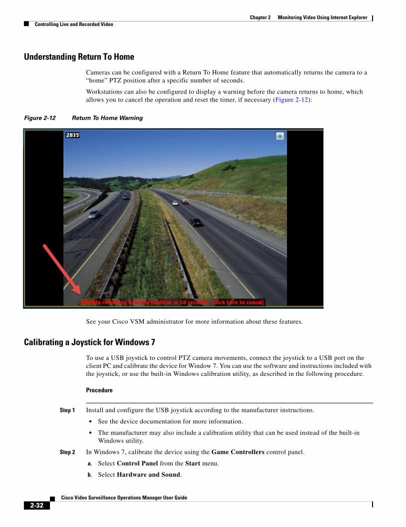
Chapter 2 Monitoring Video Using Internet Explorer Controlling Live and Recorded Video
Understanding Return To Home
Cameras can be configured with a Return To Home feature that automatically returns the camera to a “home” PTZ position after a specific number of seconds.
Workstations can also be configured to display a warning before the camera returns to home, which allows you to cancel the operation and reset the timer, if necessary (Figure 2-12):
Figure 2-12 Return To Home Warning
See your Cisco VSM administrator for more information about these features.
Calibrating a Joystick for Windows 7
To use a USB joystick to control PTZ camera movements, connect the joystick to a USB port on the client PC and calibrate the device for Window 7. You can use the software and instructions included with the joystick, or use the built-in Windows calibration utility, as described in the following procedure.
Procedure
Step 1 Install and configure the USB joystick according to the manufacturer instructions.
• See the device documentation for more information.
• The manufacturer may also include a calibration utility that can be used instead of the built-in Windows utility.
Step 2 In Windows 7, calibrate the device using the Game Controllers control panel.
a. Select Control Panel from the Start menu.
b. Select Hardware and Sound.
2-32Cisco Video Surveillance Operations Manager User Guide

Chapter 2 Monitoring Video Using Internet ExplorerControlling Live and Recorded Video
c. Select Devices and Printers.
d. Double-click Game Controllers.
e. Highlight the joystick device and click Properties.
f. Click Calibrate in the pop-up window.
g. Follow the on-screen instructions to complete the process.
Tip You can also use the Windows search function: choose Search from the Start menu and enter “set up USB game controllers” to open the Game Controllers control panel. Highlight the joystick icon and click Calibrate. Follow the on-screen instructions to complete the process.
Step 3 Click Finish or OK to close the windows.
2-33Cisco Video Surveillance Operations Manager User Guide
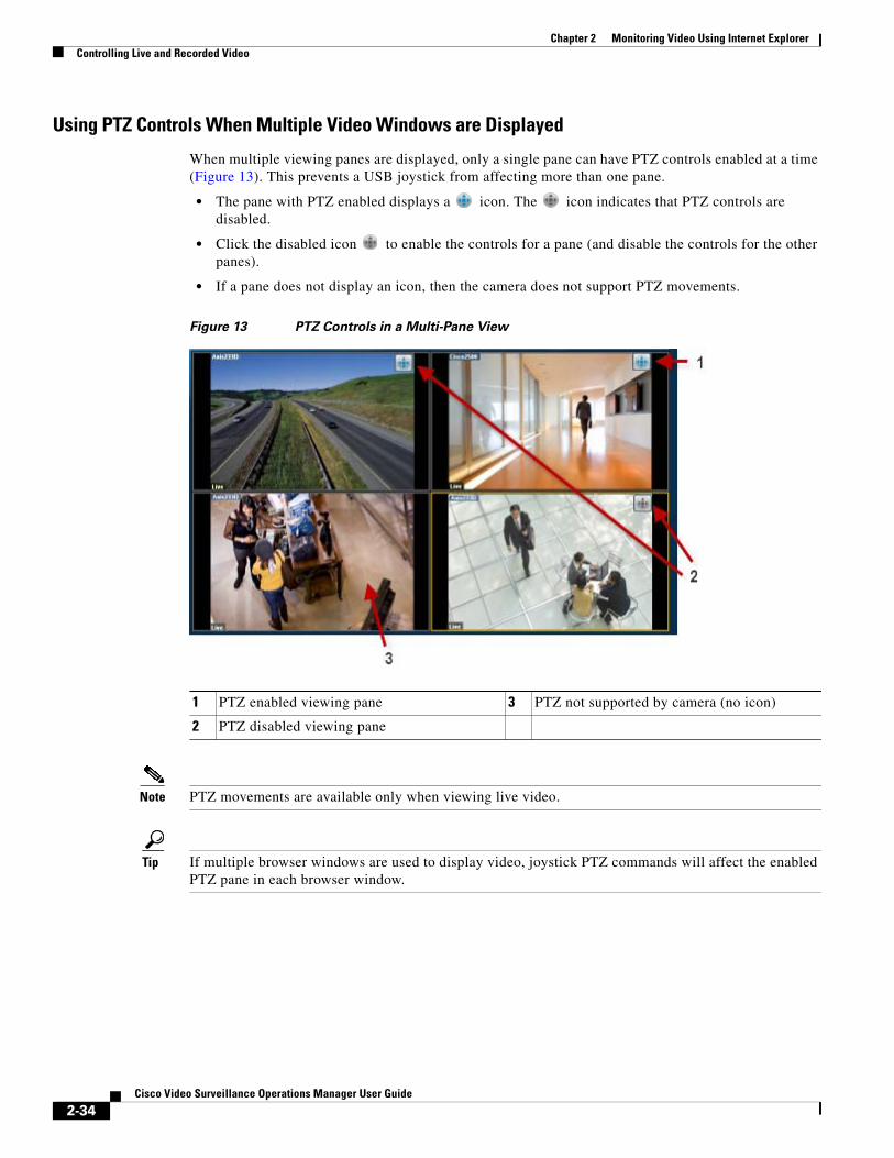
Chapter 2 Monitoring Video Using Internet Explorer Controlling Live and Recorded Video
Using PTZ Controls When Multiple Video Windows are Displayed
When multiple viewing panes are displayed, only a single pane can have PTZ controls enabled at a time (Figure 13). This prevents a USB joystick from affecting more than one pane.
• The pane with PTZ enabled displays a icon. The icon indicates that PTZ controls are disabled.
• Click the disabled icon to enable the controls for a pane (and disable the controls for the other panes).
• If a pane does not display an icon, then the camera does not support PTZ movements.
Figure 13 PTZ Controls in a Multi-Pane View
1 3
2
Note PTZ movements are available only when viewing live video.
Tip If multiple browser windows are used to display video, joystick PTZ commands will affect the enabled PTZ pane in each browser window.
PTZ enabled viewing pane PTZ not supported by camera (no icon)
PTZ disabled viewing pane
2-34Cisco Video Surveillance Operations Manager User Guide
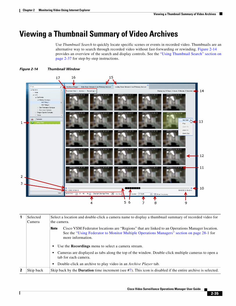
Chapter 2 Monitoring Video Using Internet ExplorerViewing a Thumbnail Summary of Video Archives
Viewing a Thumbnail Summary of Video Archives Use Thumbnail Search to quickly locate specific scenes or events in recorded video. Thumbnails are an alternative way to search through recorded video without fast-forwarding or rewinding. Figure 2-14 provides an overview of the search and display controls. See the “Using Thumbnail Search” section on page 2-37 for step-by-step instructions.
Figure 2-14 Thumbnail Window
1 Selected Camera
Select a location and double-click a camera name to display a thumbnail summary of recorded video for the camera.
Note Cisco VSM Federator locations are “Regions” that are linked to an Operations Manager location. See the “Using Federator to Monitor Multiple Operations Managers” section on page 28-1 for more information.
• Use the Recordings menu to select a camera stream.
• Cameras are displayed as tabs along the top of the window. Double-click multiple cameras to open a tab for each camera.
• Double-click an archive to play video in an Archive Player tab.
2 Skip back Skip back by the Duration time increment (see #7). This icon is disabled if the entire archive is selected.
2-35Cisco Video Surveillance Operations Manager User Guide

Chapter 2 Monitoring Video Using Internet Explorer Viewing a Thumbnail Summary of Video Archives
3 Archive start time
The start date and time for the entire video archive.
See #4 to select a new start time, or right-click a thumbnail and choose Set Start.
4 Set Start Time
The start date and time for the first thumbnail (in the top left corner of the window pane). To change the start thumbnail, select a new date and time and click Set Start.
Tip You can also select a thumbnail image and select Actions > Set Start to set the start time to a specific thumbnail (or right-click the thumbnail image and select Set Start).
5 Timeline Timeline representing the entire video archive.
6 Start time slider
The slider represents the Duration setting relative to the length of the entire archive. If the Duration setting is for the entire archive, the black slider covers the entire time line and cannot be moved.
To use the slider, choose a Duration that is less than the entire archive time and drag the slider to a different start time (the time is displayed above the slider). Release the mouse button to choose the new time.
7 Duration Choose the time span for the displayed thumbnails. The top left thumbnail displays an image from the beginning of the time span and the bottom left thumbnail displays an image from the end of the time span. The number of thumbnails and the intervals between them depend on the size of the Forensic Search window and the thumbnail size that you choose from the Thumbnail Size menu.
8 Show Timestamp
Check this check box to show the date and time displayed at the top of each thumbnail.
9 Archive end time
End date and time for the entire video archive.
10 Skip forward
Skip forward by the Duration time increment.
11 Timestamp Displays the date and time for each thumbnail. Select the Show Timestamp check box to turn timestamps on or off.
12 Video thumbnails
Thumbnails are displayed for the time span that is selected in the Duration drop-down menu. Use the Thumbnail Size menu to display larger or smaller thumbnails.
13 Actions Menu
Right click a thumbnail to select an option from the Actions menu (see #17).
14 Display length
The duration of the displayed thumbnails.
15 Camera tabs A tab is displayed for each selected camera. Click the Recordings menu to select an available camera stream or recording.
16 Archive Player tab
An Archive Player tab plays video when you select a thumbnail and select Actions > Play (or right-click a thumbnail and click Play).
2-36Cisco Video Surveillance Operations Manager User Guide
Chapter 2 Monitoring Video Using Internet ExplorerViewing a Thumbnail Summary of Video Archives
Using Thumbnail Search
Summary Steps
To view a thumbnail summary of a camera’s recordings:
1. Select Monitor and click Thumbnail Search ( ) to open the forensic search tool in a separate window (Figure 2-14).
2. Select a location and double-click a camera name.
3. Use the tools described in Figure 2-14 to locate specific video.
4. Select a different stream from the Recordings menu.
5. Double-click a thumbnail to play the video. You can also select a thumbnail and select Play from the Actions menu.
6. See the “Detailed Procedure” for more information.
17 Menu Selections
Thumbnail Size—select a smaller size to display more thumbnails for the displayed video duration. Select a larger size to display fewer thumbnails.
Recordings—select a video stream or recording.
Actions—choose one of the following options:
Note You can also right-click a thumbnail to access the Actions (see #13).
• Set Start—Sets the selected thumbnail as the first thumbnail in the range. (Tip: to select a specific date and time as the start time, use the menu at that appears beneath the thumbnails as described in #4 “Thumbnail Start Time”).
• Play —Plays the video from the selected thumbnail in an Archive Player tab.
– You can also double-click a thumbnail to play video.
– Playback begins from the start timestamp. If a start timestamp is not available, the next available frame is displayed.
• Zoom To—Set the beginning and ending thumbnail for the display. Shift-click or Ctrl-click to select multiple thumbnails and choose Zoom To from the Actions menu. The first frame in the selected thumbnails becomes the new start time. The last frame in the selected thumbnails becomes the new end time.
• Zoom In—Decreases the displayed thumbnail duration to the next available duration value. If no frames are selected, the start time does not change. If one frame is selected, that frame becomes the start time. If more than one frame is selected the frame closest to the beginning of the archive becomes the start time.
Zoom in is not available when the minimum duration is set.
• Zoom Out—Increases the duration of the displayed thumbnail duration to the next available duration value. The start time remains the same. For example, if the Duration is 3 hours, choose the Zoom Out option to increase the Duration to approximately 6 hours.
If the start time plus the duration would exceed the length of the archive, the start time will be adjusted to the archive’s end time minus the duration.
Zoom out is not available when the maximum duration is set.
2-37Cisco Video Surveillance Operations Manager User Guide
Chapter 2 Monitoring Video Using Internet Explorer Viewing a Thumbnail Summary of Video Archives
Detailed Procedure
Step 1 Click Monitor.
Step 2 Click Thumbnail Search ( ) to open the forensic search window (Figure 2-14).
Step 3 Select a location and double-click a camera name.
The camera name appears as a tab at the top of the thumbnail display. You can select multiple cameras to open multiple tabs.
Step 4 Use the controls described in Figure 2-14 to refine the search.
For example:
• To change the first thumbnail in the display, select a date and time from the menu below the thumbnails ( ) and click Set Start. The thumbnail for the selected date and time is displayed in the top left corner (you can also right0click a thumbnail and choose Set Start).
• Choose the Duration ( ) of the thumbnail display. For example, choose 1 Hour to display thumbnails for a single hour. The default is Entire Archive.
• Click the skip icons to skip back or forward by the Duration time. For example, if the Duration is 1 hour, click the skip buttons to skip forward or back by 1 hour.
• Click and drag the slider to a new start time.
– The slider date and time appears when the slider is selected.
– Release the mouse button to refresh the thumbnail display with the time displayed above the slider.
Note The slider length represents the thumbnail duration relative to the entire length of the archive. The gray time line equals 100 percent of the archive. The black slider covers the entire time line if the selected Duration is Entire Archive (default).
• Choose a Thumbnail Size to enlarge or reduce the size of each thumbnail. Larger sizes display fewer thumbnails, and each thumbnail represents a greater time span.
Step 5 (Optional) Further refine your search by choosing one or more thumbnails and choosing one of the following options in the Actions menu.
Tip You can also right-click a thumbnail to access the Actions.
• Set Start—Sets the selected thumbnail as the first thumbnail in the range (you can also select a specific date and time using the Set Start menu below the thumbnail display).
• Play —Plays the selected thumbnail video in an Archive Player tab.
– You can also double-click a thumbnail to play video.
– Playback begins from the start timestamp. If a start timestamp is not available, the next available frame is displayed.
2-38Cisco Video Surveillance Operations Manager User Guide
Chapter 2 Monitoring Video Using Internet ExplorerViewing a Thumbnail Summary of Video Archives
• Zoom To—Set the beginning and ending thumbnail for the display. Shift-click or Ctrl-click to select multiple thumbnails and choose Zoom To from the Actions menu. The first frame in the selected thumbnails becomes the new start time. The last frame in the selected thumbnails becomes the new end time.
• Zoom In—Decreases the displayed thumbnail duration to the next available duration value. If no frames are selected, the start time does not change. If one frame is selected, that frame becomes the start time. If more than one frame is selected the frame closest to the beginning of the archive becomes the start time. Zoom in is not available when the minimum duration is set.
• Zoom Out—Increases the duration of the displayed thumbnail duration to the next available duration value. The start time remains the same. For example, if the Duration is 3 hours, choose the Zoom Out option to increase the Duration to approximately 6 hours.
If the start time plus the duration would exceed the length of the archive, the start time is be set to the end of the archive minus the duration.
Zoom out is not available when the maximum duration is set.
2-39Cisco Video Surveillance Operations Manager User Guide
Chapter 2 Monitoring Video Using Internet Explorer Create Video Clips
Create Video ClipsYou can create video clips in a number of formats from a single camera, or from multiple cameras. Use Clip Search to find and download clips.
• Creating and Viewing Video Clips From a Single Camera, page 2-40
• Create Clips From Multiple Cameras (Bulk Clipping), page 2-50
• Find and Download Clips (Clip Search), page 2-54
Creating and Viewing Video Clips From a Single CameraVideo clips can be created as a file for download and playback from a PC workstation, or as a Virtual Clip that can be streamed directly from a monitoring application (such as the Cisco VSM Operations Manager or Cisco SASD). See “Clipping Support By Application” for the clip formats supported by each application in this release.
Refer to the following topics for more information:
• Clipping Support By Application, page 2-41
• Supported File Formats And Playback Options, page 2-41
• Creating Video Clips, page 2-43
• Downloading and Viewing Clips, page 2-48
Related Documentation
• Find and Download Clips (Clip Search), page 2-54
• Create Clips From Multiple Cameras (Bulk Clipping), page 2-50
Usage Notes
• In Cisco VSM 7.11 and higher, there are separate user permissions for Create Clips and Export Clips. For example, you can allow users to create but not download clips. See Operate Permissions for more information.
• You can also search for and download clips using the Clip Search feature in Operations Manager/Cisco VSM Federator and the Clip Management feature in Cisco SASD/Cisco SASD Federator.
• Timestamps are not displayed in 3rd-party video viewers. use the Cisco Review Player to play video clips that display timestamps (see the Cisco Video Surveillance Review Player User Guide for more information).
• Maintenance Mode must be off to create clips using Thumbnail Search or Clips Search (the pencil icon in the top right must be yellow ).
2-40Cisco Video Surveillance Operations Manager User Guide
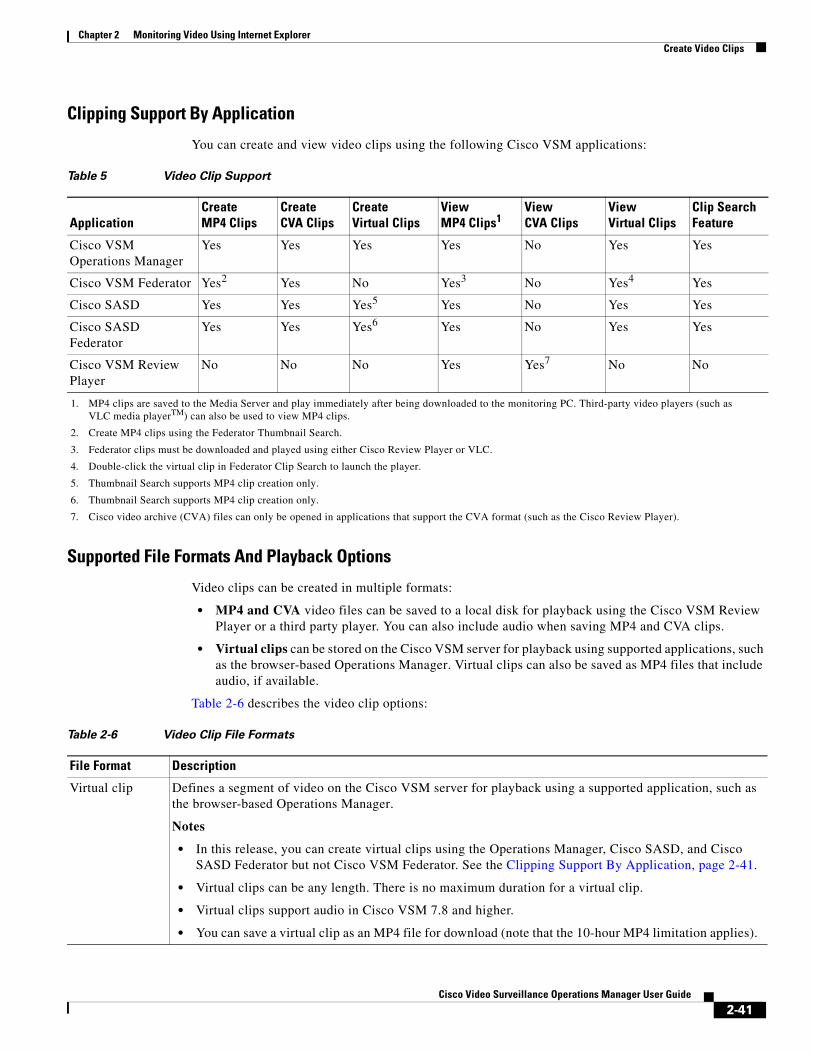
Chapter 2 Monitoring Video Using Internet ExplorerCreate Video Clips
Clipping Support By Application
You can create and view video clips using the following Cisco VSM applications:
Table 5 Video Clip Support
ApplicationCreate MP4 Clips
Create CVA Clips
Create Virtual Clips
View MP4 Clips1
1. MP4 clips are saved to the Media Server and play immediately after being downloaded to the monitoring PC. Third-party video players (such as VLC media playerTM) can also be used to view MP4 clips.
Supported File Formats And Playback Options
Video clips can be created in multiple formats:
• MP4 and CVA video files can be saved to a local disk for playback using the Cisco VSM Review Player or a third party player. You can also include audio when saving MP4 and CVA clips.
• Virtual clips can be stored on the Cisco VSM server for playback using supported applications, such as the browser-based Operations Manager. Virtual clips can also be saved as MP4 files that include audio, if available.
Table 2-6 describes the video clip options:
View CVA Clips
View Virtual Clips
Clip Search Feature
Cisco VSM Operations Manager
Yes Yes Yes Yes No Yes Yes
Cisco VSM Federator Yes2
2. Create MP4 clips using the Federator Thumbnail Search.
Yes No Yes3
3. Federator clips must be downloaded and played using either Cisco Review Player or VLC.
No Yes4
4. Double-click the virtual clip in Federator Clip Search to launch the player.
Yes
Cisco SASD Yes Yes Yes5
5. Thumbnail Search supports MP4 clip creation only.
Yes No Yes Yes
Cisco SASD Federator
Yes Yes Yes6
6. Thumbnail Search supports MP4 clip creation only.
Yes No Yes Yes
Cisco VSM Review Player
No No No Yes Yes7
7. Cisco video archive (CVA) files can only be opened in applications that support the CVA format (such as the Cisco Review Player).
No No
Table 2-6 Video Clip File Formats
File Format Description
Virtual clip Defines a segment of video on the Cisco VSM server for playback using a supported application, such as the browser-based Operations Manager.
Notes
• In this release, you can create virtual clips using the Operations Manager, Cisco SASD, and Cisco SASD Federator but not Cisco VSM Federator. See the Clipping Support By Application, page 2-41.
• Virtual clips can be any length. There is no maximum duration for a virtual clip.
• Virtual clips support audio in Cisco VSM 7.8 and higher.
• You can save a virtual clip as an MP4 file for download (note that the 10-hour MP4 limitation applies).
2-41Cisco Video Surveillance Operations Manager User Guide
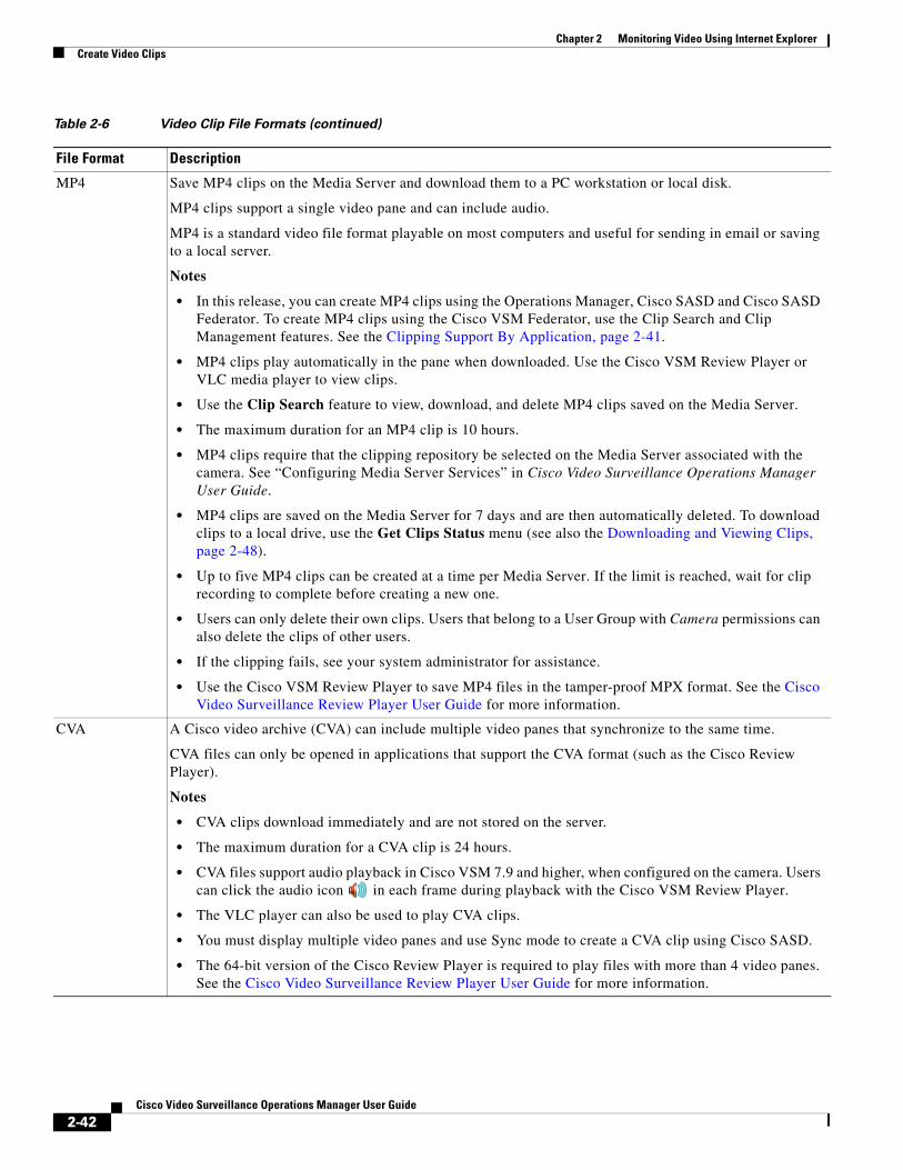
Chapter 2 Monitoring Video Using Internet Explorer Create Video Clips
MP4 Save MP4 clips on the Media Server and download them to a PC workstation or local disk.
MP4 clips support a single video pane and can include audio.
MP4 is a standard video file format playable on most computers and useful for sending in email or saving to a local server.
Notes
• In this release, you can create MP4 clips using the Operations Manager, Cisco SASD and Cisco SASD Federator. To create MP4 clips using the Cisco VSM Federator, use the Clip Search and Clip Management features. See the Clipping Support By Application, page 2-41.
• MP4 clips play automatically in the pane when downloaded. Use the Cisco VSM Review Player or VLC media player to view clips.
• Use the Clip Search feature to view, download, and delete MP4 clips saved on the Media Server.
• The maximum duration for an MP4 clip is 10 hours.
• MP4 clips require that the clipping repository be selected on the Media Server associated with the camera. See “Configuring Media Server Services” in Cisco Video Surveillance Operations Manager User Guide.
• MP4 clips are saved on the Media Server for 7 days and are then automatically deleted. To download clips to a local drive, use the Get Clips Status menu (see also the Downloading and Viewing Clips, page 2-48).
• Up to five MP4 clips can be created at a time per Media Server. If the limit is reached, wait for clip recording to complete before creating a new one.
• Users can only delete their own clips. Users that belong to a User Group with Camera permissions can also delete the clips of other users.
• If the clipping fails, see your system administrator for assistance.
• Use the Cisco VSM Review Player to save MP4 files in the tamper-proof MPX format. See the Cisco Video Surveillance Review Player User Guide for more information.
CVA A Cisco video archive (CVA) can include multiple video panes that synchronize to the same time.
CVA files can only be opened in applications that support the CVA format (such as the Cisco Review Player).
Notes
• CVA clips download immediately and are not stored on the server.
• The maximum duration for a CVA clip is 24 hours.
• CVA files support audio playback in Cisco VSM 7.9 and higher, when configured on the camera. Users can click the audio icon in each frame during playback with the Cisco VSM Review Player.
• The VLC player can also be used to play CVA clips.
• You must display multiple video panes and use Sync mode to create a CVA clip using Cisco SASD.
• The 64-bit version of the Cisco Review Player is required to play files with more than 4 video panes. See the Cisco Video Surveillance Review Player User Guide for more information.
Table 2-6 Video Clip File Formats (continued)
File Format Description
2-42Cisco Video Surveillance Operations Manager User Guide
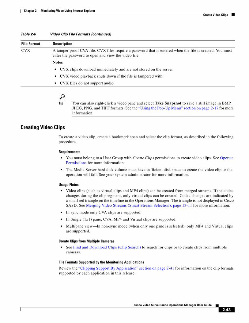
Chapter 2 Monitoring Video Using Internet ExplorerCreate Video Clips
Tip You can also right-click a video pane and select Take Snapshot to save a still image in BMP, JPEG, PNG, and TIFF formats. See the “Using the Pop-Up Menu” section on page 2-17 for more information.
Creating Video Clips
To create a video clip, create a bookmark span and select the clip format, as described in the following procedure.
Requirements
• You must belong to a User Group with Create Clips permissions to create video clips. See Operate Permissions for more information.
• The Media Server hard disk volume must have sufficient disk space to create the video clip or the operation will fail. See your system administrator for more information.
Usage Notes
• Video clips (such as virtual clips and MP4 clips) can be created from merged streams. If the codec changes during the clip segment, only virtual clips can be created. Codec changes are indicated by a small red triangle on the timeline in the Operations Manager. The triangle is not displayed in Cisco SASD. See Merging Video Streams (Smart Stream Selection), page 13-11 for more information.
• In sync mode only CVA clips are supported.
• In Single (1x1) pane, CVA, MP4 and Virtual clips are supported.
• Multipane view—In non-sync mode (when only one pane is selected), only MP4 and Virtual clips are supported.
Create Clips from Multiple Cameras
• See Find and Download Clips (Clip Search) to search for clips or to create clips from multiple cameras.
File Formats Supported by the Monitoring Applications
Review the “Clipping Support By Application” section on page 2-41 for information on the clip formats supported by each application in this release.
CVX A tamper proof CVA file. CVX files require a password that is entered when the file is created. You must enter the password to open and view the video file.
Notes
• CVX clips download immediately and are not stored on the server.
• CVX video playback shuts down if the file is tampered with.
• CVX files do not support audio.
Table 2-6 Video Clip File Formats (continued)
File Format Description
2-43Cisco Video Surveillance Operations Manager User Guide

Chapter 2 Monitoring Video Using Internet Explorer Create Video Clips
Procedure
Step 1 Select a video pane from the viewing application (such as Cisco SASD or Operations Manager).
Tip To create a multi-pane clip in the CVA format, press Shift-Click to select multiple concurrent panes, or Ctrl-Click to select individual panes. Individual panes cannot be saved in sync mode.
Step 2 In the green seek bar, Ctrl-Click and drag the mouse cursor to create a bookmark span. The bookmark span is shown in orange (Figure 15).
Tip In recording mode , you can also right-click the image and choose Select Clip Range from the pop-up menu (see the “Using the Pop-Up Menu” section on page 2-17). A 10 minute clip range is automatically selected starting from current thumb position, and the range bar is automatically scaled to 1 hour.
Step 3 Right-click the bookmark and select an option to create a MP4, CVA or virtual clip (Figure 15).
Figure 15 Creating a Video Clip.
Tip See “Clipping Support By Application” for the file formats supported by each Cisco monitoring application in this release.
Step 4 Save the file:
CVA/CVX files
CVA files include audio if enabled on the camera. During playback with the Cisco VSM Review Player, users can click the audio icon in each frame to play or mute audio. CVX files do not include audio.
a. (Optional) Revise the start and end date and time (Figure 16). Enter a time between 30 seconds and 24 hours (the range cannot include more than one codec and the start time must be before the end time).
Tip Use the Set Duration field to enter a specific length of time for the clip. The duration begins at the beginning bookmark time.
2-44Cisco Video Surveillance Operations Manager User Guide
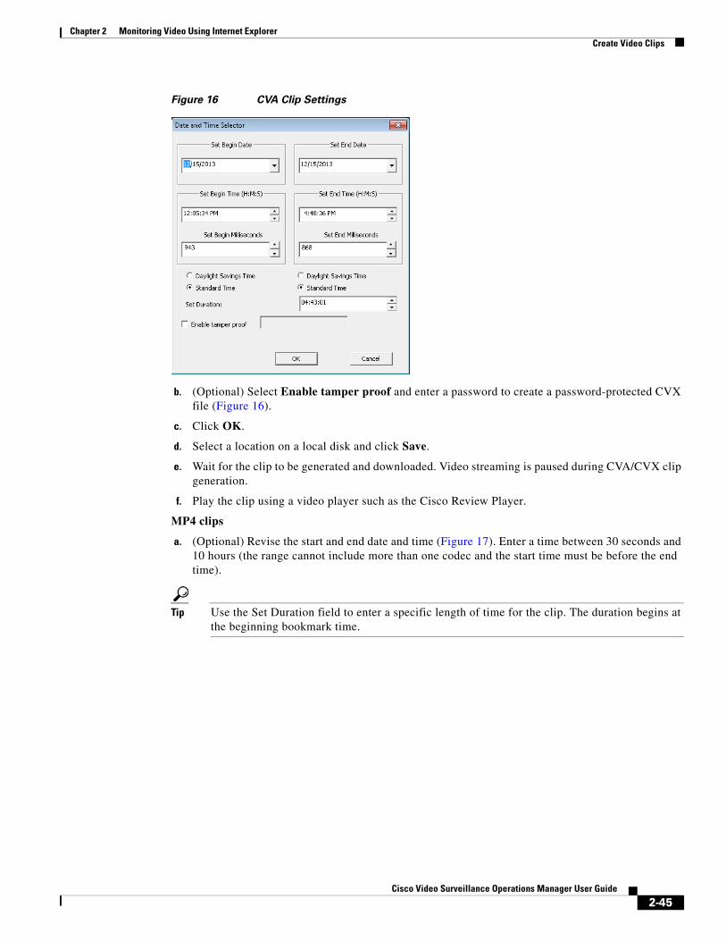
Chapter 2 Monitoring Video Using Internet ExplorerCreate Video Clips
Figure 16 CVA Clip Settings
b. (Optional) Select Enable tamper proof and enter a password to create a password-protected CVX file (Figure 16).
c. Click OK.
d. Select a location on a local disk and click Save.
e. Wait for the clip to be generated and downloaded. Video streaming is paused during CVA/CVX clip generation.
f. Play the clip using a video player such as the Cisco Review Player.
MP4 clips
a. (Optional) Revise the start and end date and time (Figure 17). Enter a time between 30 seconds and 10 hours (the range cannot include more than one codec and the start time must be before the end time).
Tip Use the Set Duration field to enter a specific length of time for the clip. The duration begins at the beginning bookmark time.
2-45Cisco Video Surveillance Operations Manager User Guide
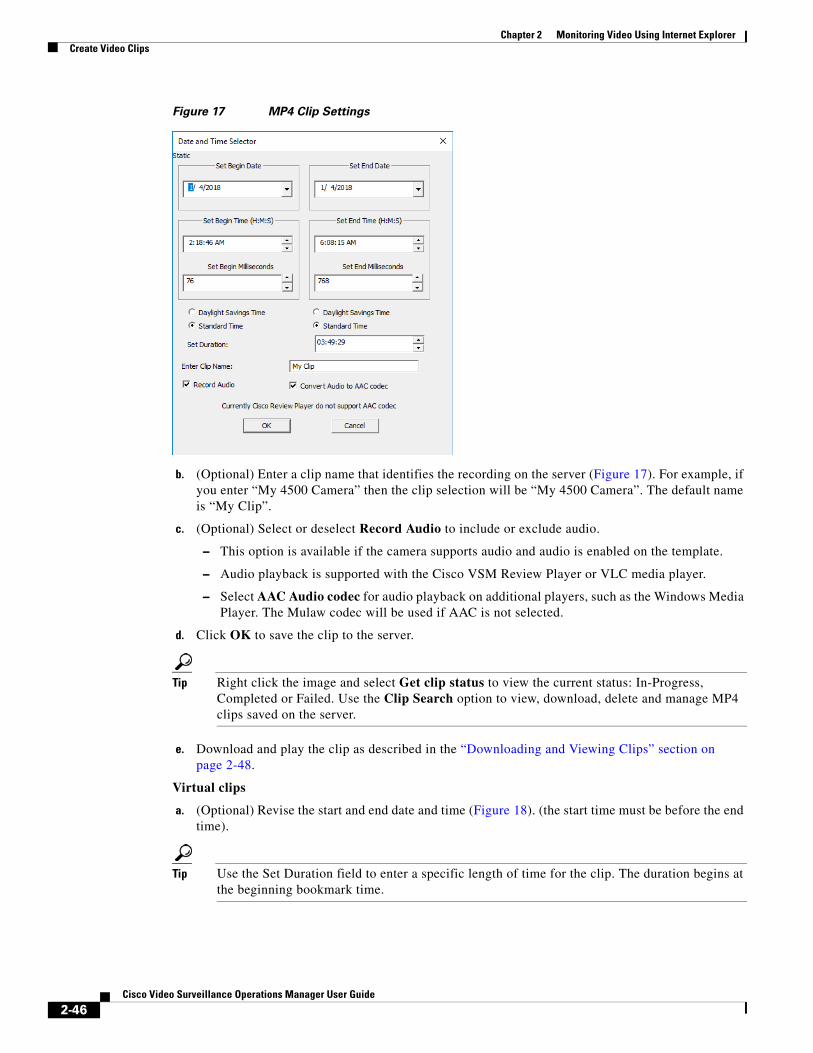
Chapter 2 Monitoring Video Using Internet Explorer Create Video Clips
Figure 17 MP4 Clip Settings
b. (Optional) Enter a clip name that identifies the recording on the server (Figure 17). For example, if you enter “My 4500 Camera” then the clip selection will be “My 4500 Camera”. The default name is “My Clip”.
c. (Optional) Select or deselect Record Audio to include or exclude audio.
– This option is available if the camera supports audio and audio is enabled on the template.
– Audio playback is supported with the Cisco VSM Review Player or VLC media player.
– Select AAC Audio codec for audio playback on additional players, such as the Windows Media Player. The Mulaw codec will be used if AAC is not selected.
d. Click OK to save the clip to the server.
Tip Right click the image and select Get clip status to view the current status: In-Progress, Completed or Failed. Use the Clip Search option to view, download, delete and manage MP4 clips saved on the server.
e. Download and play the clip as described in the “Downloading and Viewing Clips” section on page 2-48.
Virtual clips
a. (Optional) Revise the start and end date and time (Figure 18). (the start time must be before the end time).
Tip Use the Set Duration field to enter a specific length of time for the clip. The duration begins at the beginning bookmark time.
2-46Cisco Video Surveillance Operations Manager User Guide
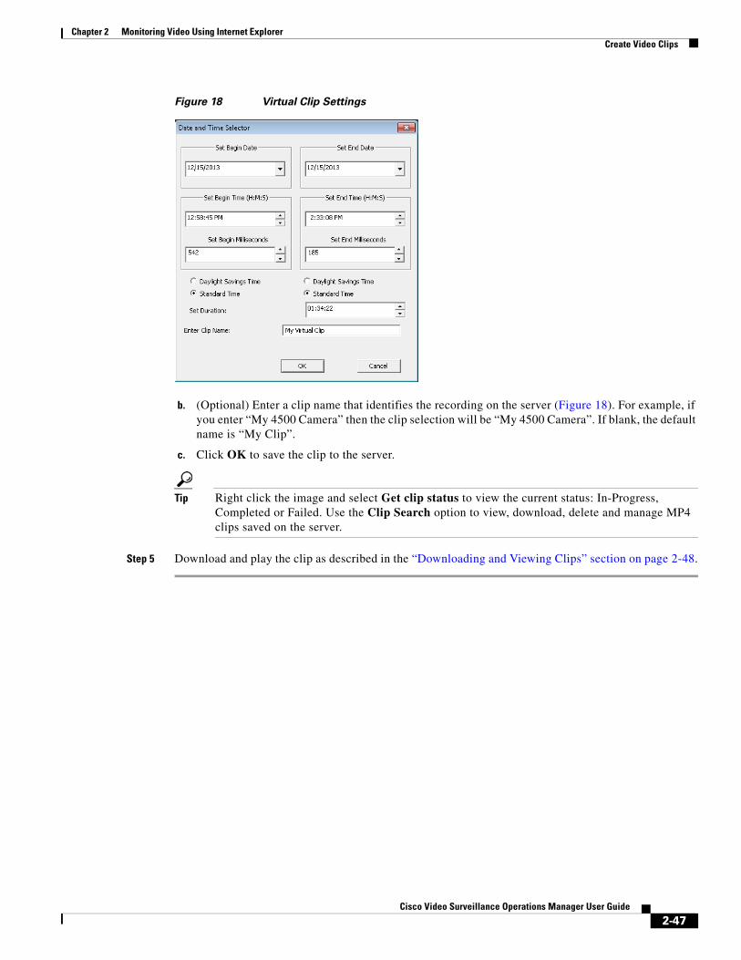
Chapter 2 Monitoring Video Using Internet ExplorerCreate Video Clips
Figure 18 Virtual Clip Settings
b. (Optional) Enter a clip name that identifies the recording on the server (Figure 18). For example, if you enter “My 4500 Camera” then the clip selection will be “My 4500 Camera”. If blank, the default name is “My Clip”.
c. Click OK to save the clip to the server.
Tip Right click the image and select Get clip status to view the current status: In-Progress, Completed or Failed. Use the Clip Search option to view, download, delete and manage MP4 clips saved on the server.
Step 5 Download and play the clip as described in the “Downloading and Viewing Clips” section on page 2-48.
2-47Cisco Video Surveillance Operations Manager User Guide
Chapter 2 Monitoring Video Using Internet Explorer Create Video Clips
Downloading and Viewing Clips
You must belong to a User Group with Export Clips permissions. See Operate Permissions for more information.
Video clip formats are accessed and played in the following ways:
Tip See “Clipping Support By Application” for the file formats supported by each Cisco monitoring application in this release. See Find and Download Clips (Clip Search) to search for clips or to create clips from multiple cameras.
Table 7 Video Clip Download Options
Clip Format Download Options
• The 64-bit version of the Cisco Review Player is required to play files with more than 4 video panes. See the Cisco Video Surveillance Review Player User Guide for more information.
• The clip automatically plays in the video pane when the download is complete.
• You can also play the clip using a supported video player such as the Cisco Review Player or VLC.
• You can also search for and download MP4 clips using the Clip Search feature in Operations Manager or the Clip Management feature in Cisco SASD.
Procedure
Step 1 Right-click the video pane and choose Get Clip Status (Figure 19).
Step 2 Select the Clip name.
• “Local” clips are MP4 clips that must be downloaded to a local disk.
• “Streamable” clips are virtual clips that can be streamed in the video pane without being downloaded.
CVA clips Downloaded when they are created. Play CVA clips using a supported video player, such as the Cisco Review Player.
MP4 Clips Right-click the video pane and select Get Clip Status (not supported in Federator in this release). Select the clip name from the list and save the file to a local disk (the clip remains on the server for 7 days after it was created).
Virtual Clips Right-click the video pane and select Get Clip Status (not supported in Federator in this release).
Select the clip name from the list to play the clip in the video pane.
To download the clip, use the Clip Search feature and select the Virtual Clip Search tab (if supported by your monitoring application).
2-48Cisco Video Surveillance Operations Manager User Guide
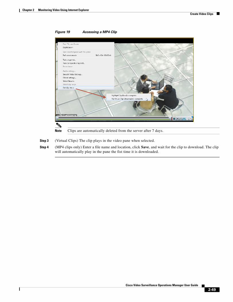
Chapter 2 Monitoring Video Using Internet ExplorerCreate Video Clips
Figure 19 Accessing a MP4 Clip
Note Clips are automatically deleted from the server after 7 days.
Step 3 (Virtual Clips) The clip plays in the video pane when selected.
Step 4 (MP4 clips only) Enter a file name and location, click Save, and wait for the clip to download. The clip will automatically play in the pane the fist time it is downloaded.
2-49Cisco Video Surveillance Operations Manager User Guide
Chapter 2 Monitoring Video Using Internet Explorer Create Video Clips
Create Clips From Multiple Cameras (Bulk Clipping)Use Bulk Clipping to create video clips from multiple cameras. The clips can be automatically transferred to an FTP server, if necessary.
Tip You can also create and download clips for a single camera by right-clicking a video pane. See the “Downloading and Viewing Clips” section on page 2-48.
Before You Begin
• Verify that the cameras are configured to record video (see Configuring Video Recording).
Usage Notes
• You must belong to a User Group with Create Clips permissions to create video clips. A separate permission to Export Clips is also available. See Operate Permissions for more information.
• Up to 30 clip requests can be queued per Cisco Media Server at a time. When 30 clips are being created, new clip creation requests are discarded.
• A maximum of 10 hours of video clips can be created.
• Bulk clip creation is supported using Operations Manager only, and is not supported using the Cisco Video Surveillance Federator.
• Bulk clipping is only supported for normal recording and failover recording. It is not supported for other recording like LTS recording.
• If a clip creation fails, the FTP transfer of remaining clips may be delayed by 12hrs.
FTP Server Requirements
If the clips will be automatically transferred to an FTP server, a Cisco VSM admin user must enter the FTP server address, login credentials, and directory path.
• Click the FTP Server Details tab and enter the required information.
• The FTP Details can be edited only by Cisco VSM admin users.
• FTP credential requirements are:
– The FTP username supports lowercase and uppercase letters and numbers only.
– The FTP password does not support the following characters:
: ] [ ? / ` ! @ $ & ( ) } | " ; ' > { \ <
• Use the Test FTP feature to check connectivity between the FTP server and all Media Servers/ Fail-over Servers.
Procedure
Step 1 From the Monitor Video > Clip Search.
Step 2 Select the Bulk Clipping tab (Figure 2-20).
2-50Cisco Video Surveillance Operations Manager User Guide
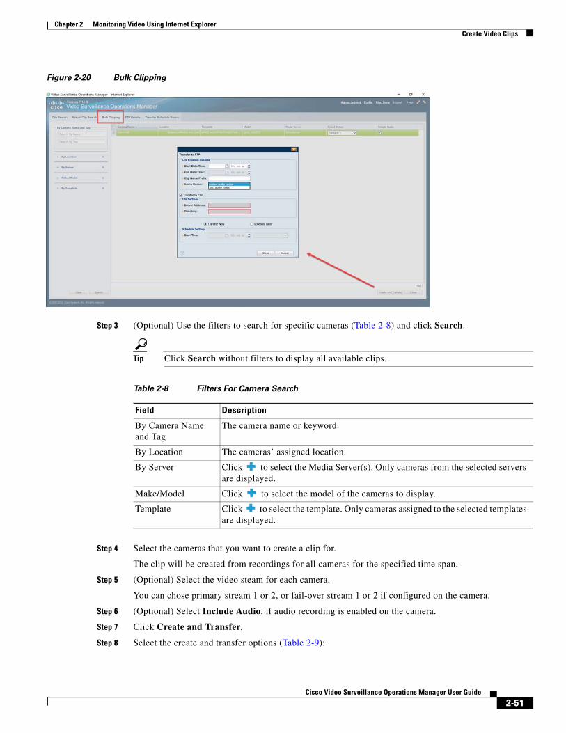
Chapter 2 Monitoring Video Using Internet ExplorerCreate Video Clips
Figure 2-20 Bulk Clipping
Step 3 (Optional) Use the filters to search for specific cameras (Table 2-8) and click Search.
Tip Click Search without filters to display all available clips.
Table 2-8 Filters For Camera Search
Field Description
Step 4 Select the cameras that you want to create a clip for.
The clip will be created from recordings for all cameras for the specified time span.
Step 5 (Optional) Select the video steam for each camera.
You can chose primary stream 1 or 2, or fail-over stream 1 or 2 if configured on the camera.
Step 6 (Optional) Select Include Audio, if audio recording is enabled on the camera.
Step 7 Click Create and Transfer.
Step 8 Select the create and transfer options (Table 2-9):
By Camera Name and Tag
The camera name or keyword.
By Location The cameras’ assigned location.
By Server Click to select the Media Server(s). Only cameras from the selected servers are displayed.
Make/Model Click to select the model of the cameras to display.
Template Click to select the template. Only cameras assigned to the selected templates are displayed.
2-51Cisco Video Surveillance Operations Manager User Guide
Chapter 2 Monitoring Video Using Internet Explorer Create Video Clips
Tip Click Search without filters to display all available clips.
Table 2-9 Create and Transfer Options
Field Description
• Date/Time: Enter the start and end time for the clip.
• Clip Name Prefix: The prefix added to the default clip name.
• Audio Codec:
– The Mulaw codec is selected by default.
– Select AAC audio codec to save the clip with the Advanced Audio Coding (AAC) codec for audio for playback in various players, such as the Windows Media Player.
• The FTP server details must be previously configured by a Cisco VSM admin user.
• If deselected, the clip will be created but not transferred. Use the Clip Search tab to download or transfer the existing clips.
• Select Now—The clip is transfered when completed.
• Schedule Later—The clip is transfered at the specified day and time.
Step 9 Click Done.
Step 10 (Optional) Click the Clip Search tab to view the clip status (Figure 2-21).
• “Failed” is displayed if the clip creation fails for any reason. For example, the camera does not have recordings for the selected time range.
• Up to 30 clip requests can be processed at a time (for example, 3 requests for 10 cameras each).
• You can also use this page to manually download or transfer the completed clips.
Clip Creation Options
Transfer to FTP Select the box if the clip should be transferred to an FTP server.
Schedule settings (Enabled if Transfer to FTP is selected)
2-52Cisco Video Surveillance Operations Manager User Guide
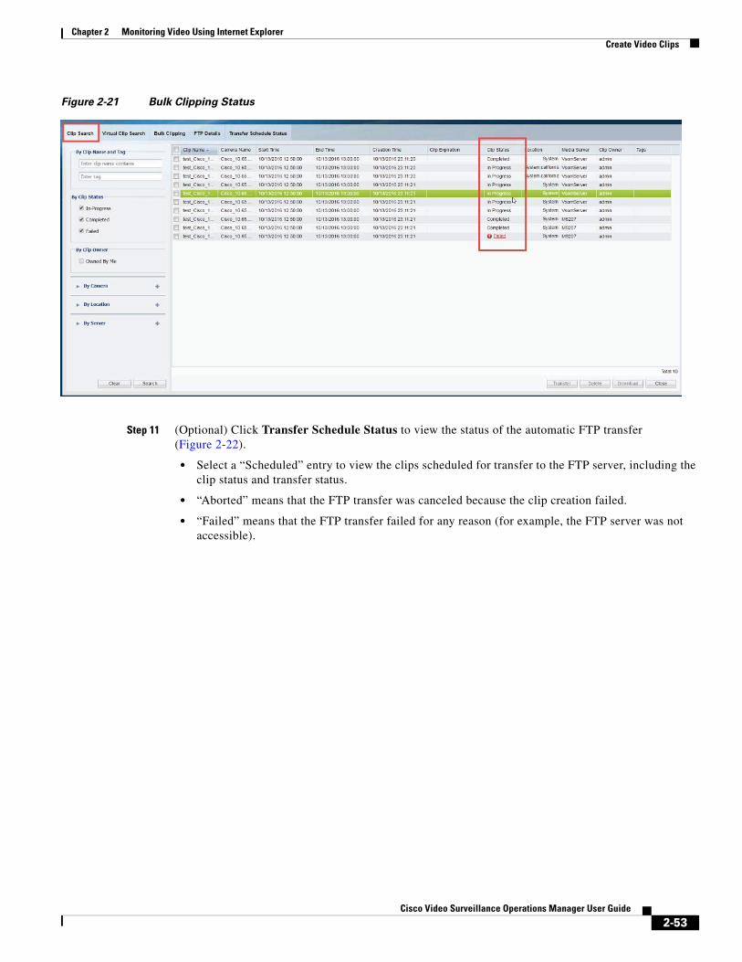
Chapter 2 Monitoring Video Using Internet ExplorerCreate Video Clips
Figure 2-21 Bulk Clipping Status
Step 11 (Optional) Click Transfer Schedule Status to view the status of the automatic FTP transfer (Figure 2-22).
• Select a “Scheduled” entry to view the clips scheduled for transfer to the FTP server, including the clip status and transfer status.
• “Aborted” means that the FTP transfer was canceled because the clip creation failed.
• “Failed” means that the FTP transfer failed for any reason (for example, the FTP server was not accessible).
2-53Cisco Video Surveillance Operations Manager User Guide

Chapter 2 Monitoring Video Using Internet Explorer Create Video Clips
Figure 2-22 Transfer Schedule Status
Find and Download Clips (Clip Search)Select Monitor Video > Clip Search (Figure 2-23) to view, download and delete MP4 and virtual clips.
Note You must belong to a User Group with Export Clips permissions. A separate permission to Create Clips is also available but not required. See Operate Permissions for more information.
Related Documentation
• Create Clips From Multiple Cameras (Bulk Clipping), page 2-50
• Downloading and Viewing Clips, page 2-48—create and download clips by right-clicking a video pane.
• Creating and Viewing Video Clips From a Single Camera, page 2-40
Procedure
Step 1 From the Monitor Video page, click Clip Search to open the Clip Search window (Figure 2-23).
Step 2 Select the clip type:
• Clip Search tab—MP4 clips
• Virtual Clip Search tab—Virtual clips
2-54Cisco Video Surveillance Operations Manager User Guide
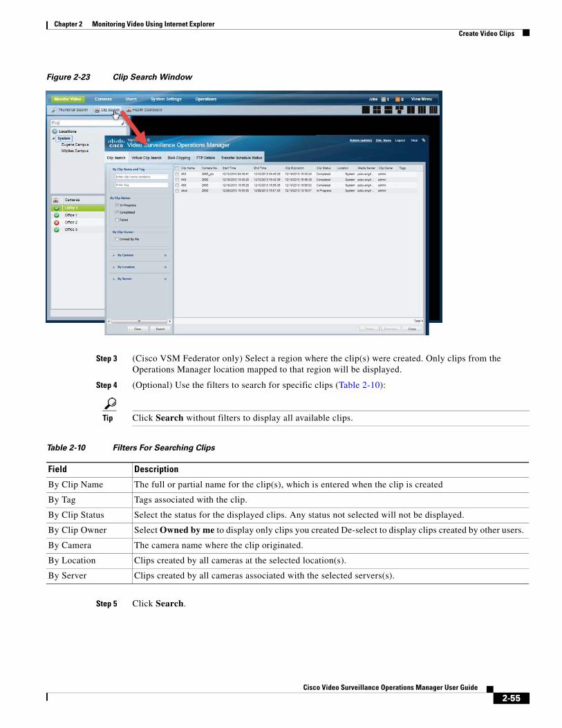
Chapter 2 Monitoring Video Using Internet ExplorerCreate Video Clips
Figure 2-23 Clip Search Window
Step 3 (Cisco VSM Federator only) Select a region where the clip(s) were created. Only clips from the Operations Manager location mapped to that region will be displayed.
Step 4 (Optional) Use the filters to search for specific clips (Table 2-10):
Tip Click Search without filters to display all available clips.
Table 2-10 Filters For Searching Clips
Field Description
Step 5 Click Search.
By Clip Name The full or partial name for the clip(s), which is entered when the clip is created
By Tag Tags associated with the clip.
By Clip Status Select the status for the displayed clips. Any status not selected will not be displayed.
By Clip Owner Select Owned by me to display only clips you created De-select to display clips created by other users.
By Camera The camera name where the clip originated.
By Location Clips created by all cameras at the selected location(s).
By Server Clips created by all cameras associated with the selected servers(s).
2-55Cisco Video Surveillance Operations Manager User Guide

Chapter 2 Monitoring Video Using Internet Explorer Create Video Clips
Step 6 Review information about the clips.
Table 2-11 Video Clip Information
Field Description
Step 7 (Optional) To download an MP4 clip:
a. Clip Search—Select a clip and click Download.
a. Virtual Clip Search—
– Select a clip and click Generate Clip.
– Select an Audio Codes: The mulaw codec is selected by default. Select AAC audio codec to enable audio playback in players such as the Windows Media Player.
– Only a single clip can be downloaded at a time.
Note If an “HTTP 400 Bad Request” error appears, it may be due to the Internet Explorer (IE) settings. In IE, go to Tools > Internet Options > Advanced and select “Use HTTP 1.1”. Also deselect “Use HTTP 1.1 through proxy connections”. Next, click the Connections tab, choose the LAN settings button and select “Automatically detect settings”.
b. Click Continue and accept the security certificate when the Internet Explorer web browser prompts you to proceed to the secure page. This prompt appears only once for each Media Server.
c. Select one of the following options:
– Open—Plays the file using your default video player.
– Save —Saves the file to the default location using a default filename.
– Save As—Enter a new filename and select a location on the local disk.
– Save and Open—Saves the file to the default location using a default filename, and then plays the clip using your default video player.
Step 8 (Optional) To permanently delete a clip from the server, select one or more clips and click Delete.
Note Only the server file is deleted. Any clips previously downloaded to a local disk are not affected.
Clip Name The clip name entered when the clip was created. The default is “My Clip” if no name is entered.
Camera Name The camera name where the clip originated.
Start Time The start timestamp for the clip.
End Time The end timestamp for the clip.
Clip Expiration The date/time when the clip will be deleted from the server.
Clip Status In-Progress, Completed or Failed
Location Location of the cameras where the clip originated.
Media Server The Media Server that manages the camera video where the clip originated.
Clip Owner The user that created the clip.
Tags Tags associated with the clip.
2-56Cisco Video Surveillance Operations Manager User Guide

Chapter 2 Monitoring Video Using Internet ExplorerCreate Video Clips
2-57Cisco Video Surveillance Operations Manager User Guide

Chapter 2 Monitoring Video Using Internet Explorer Create Video Clips
2-58Cisco Video Surveillance Operations Manager User Guide
Cisco V
C H A P T E R 3
Monitor Video Using HTML5 Enabled BrowsersWeb browsers that support HTML5 can be used for basic video monitoring functions such as playback and pause. HTML5 browsers do not require a plug-in such as VLC.
Note HTML5 based video streaming is disabled by default in Cisco VSM release 7.11 and higher. To enable HTML5 video monitoring, click the icon in the top right and click OK to confirm. Click the icon again to disable HTML5 video monitoring.
• Supported Browsers, page 3-1
• Supported Features, page 3-2
• Supported Features, page 3-2
• Log In and Access Video, page 3-3
• Viewing Video Using an HTML5-enabled Browser, page 3-4
• Adding Browser Security Certificates, page 3-6
Supported Browsers
Table 1 Supported Browsers
Supported Browser Supported versions
The following browsers are supported:
Tip: Install the latest browser on your computer. Older browser versions may not support HTML5 video monitoring using Cisco VSM.
Important notes for Firefox browser
When using Windows 10 N and KN versions only, the Firefox browser requires the Windows Media Feature Pack to enable HTML5 video playback. Learn more.
1. Install the Firefox web browser.
2. Install the Windows Media Feature Pack.
Firefox 52.0 and higher
Chrome 58.03029 and higher
3-1ideo Surveillance Operations Manager User Guide
Chapter 3 Monitor Video Using HTML5 Enabled Browsers Supported Features
Other notes
If HTML5 is not used or not supported by the browser, then the VLC browser plug in will be used instead.
• The VLC plug-in does not provide any playback controls.
• If the plug-in is not installed, video will not be displayed.
Supported FeaturesIn addition to standard playback and snapshot features, the supported HTML5 browsers support the following:
• Up to 50 live or recorded streams can be accessed at a time. Each recorded or live stream is counted against the stream limit.
– Duplicate streams (such as the same live stream with the same user in 2 different browser windows) count as a single stream.
• PTZ controls (Some limitations apply in this release).
• Multiple users can seek video without affecting other users viewing the same stream.
• HTML5 streams are supported on Dynamic proxy, redundant, failover, and LTS servers.
• Up to 2x2 views are supported, including the ability to rotate video from multiple cameras (rotation time must be greater than 5 seconds).
LimitationsBecause this is a new technology, there are some current browser limitations:
• HTML5 currently supports H.264 video only. Other media formats including audio and MJPEG are not currently supported by the HTML5 browsers.
• HTML5 video cannot be viewed using the Cisco VSM Federator or Cisco VSM Management Console.
• Some playback functionality is not supported, such as audio, creating clips, smooth video settings, and other features. In addition:
– The HTML5 player does not display recording gaps on the progress bar.
– Switching between Pause and Play introduces skips in the playback.
– To play live or recorded video, NTP should be used to sync the client and VSM server time.
• PTZ limitation:
– Streams will have several seconds latency which may go higher depending on the Media Server load or network bandwidth. When controlling a PTZ camera, you may have to wait to allow the camera to settle in the new position. We recommend using PTZ presets.
– You cannot zoom using the mouse center click.
• Some ActiveX features are not supported. Use the Internet Explorer browser instead.
– Digital Zoom
– Sync selected plane with this plane
– Full screen mode
3-2Cisco Video Surveillance Operations Manager User Guide
Chapter 3 Monitor Video Using HTML5 Enabled BrowsersLog In and Access Video
– Take composite snapshot
– Smooth video settings
– Thumbnail images
Log In and Access VideoUse a recommended browser to log in to the Cisco VSM Operations Manager and access the cameras and video in your deployment.
HTML5 based video streaming is disabled by default in Cisco VSM release 7.11 and higher. To enable HTML5 video monitoring, click the icon in the top right and click OK to confirm. Click the icon again to disable HTML5 video monitoring.
Procedure
Step 1 Log on to the Cisco VSM Operations Manager.
• See the “Logging In” section on page 1-17. You must belong to a User Group with permissions for View Live Video or View Recordings.
a. Launch a recommended version of a web browser on your computer.
b. Enter the Operations Manager URL or IP address.
• Enter the virtual IP address or hostname provided by your system administrator if redundant (HA) Operations Manager servers are deployed.
c. Enter your username and password.
d. Select a domain if your organization uses an LDAP server for verification.
e. Click Log in.
Step 2 If prompted, accept the security certificate.
For example, see Adding Browser Security Certificates.
Step 3 Click Monitor Video.
Step 4 Click the HTML5 icon in the top right and click OK when prompted
• The icon turns green when HTML5 is enabled.
• Click the icon again to disable HTML5 video monitoring.
• If you click Cancel, the VLC browser plug in will be used instead. If the plug-in is not installed, video will not be displayed.
Step 5 (Optional) Select a layout to view multiple panes, or click View Menu to select a pre-defined View.
Step 6 Expand the location tree and drag a camera onto a viewing pane.
• Enter a partial or complete camera name in the Find field to display matching cameras.
• You can also select a video pane by clicking in it, and then double-click a camera name.
3-3Cisco Video Surveillance Operations Manager User Guide
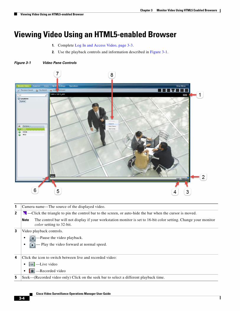
Chapter 3 Monitor Video Using HTML5 Enabled Browsers Viewing Video Using an HTML5-enabled Browser
Viewing Video Using an HTML5-enabled Browser1. Complete Log In and Access Video, page 3-3.
2. Use the playback controls and information described in Figure 3-1.
Figure 3-1 Video Pane Controls
1 Camera name—The source of the displayed video.
2 —Click the triangle to pin the control bar to the screen, or auto-hide the bar when the cursor is moved.
Note The control bar will not display if your workstation monitor is set to 16-bit color setting. Change your monitor color setting to 32-bit.
3 Video playback controls.
• —Pause the video playback.
• — Play the video forward at normal speed.
4 Click the icon to switch between live and recorded video:
• —Live video
• —Recorded video
5 Seek—(Recorded video only) Click on the seek bar to select a different playback time.
3-4Cisco Video Surveillance Operations Manager User Guide
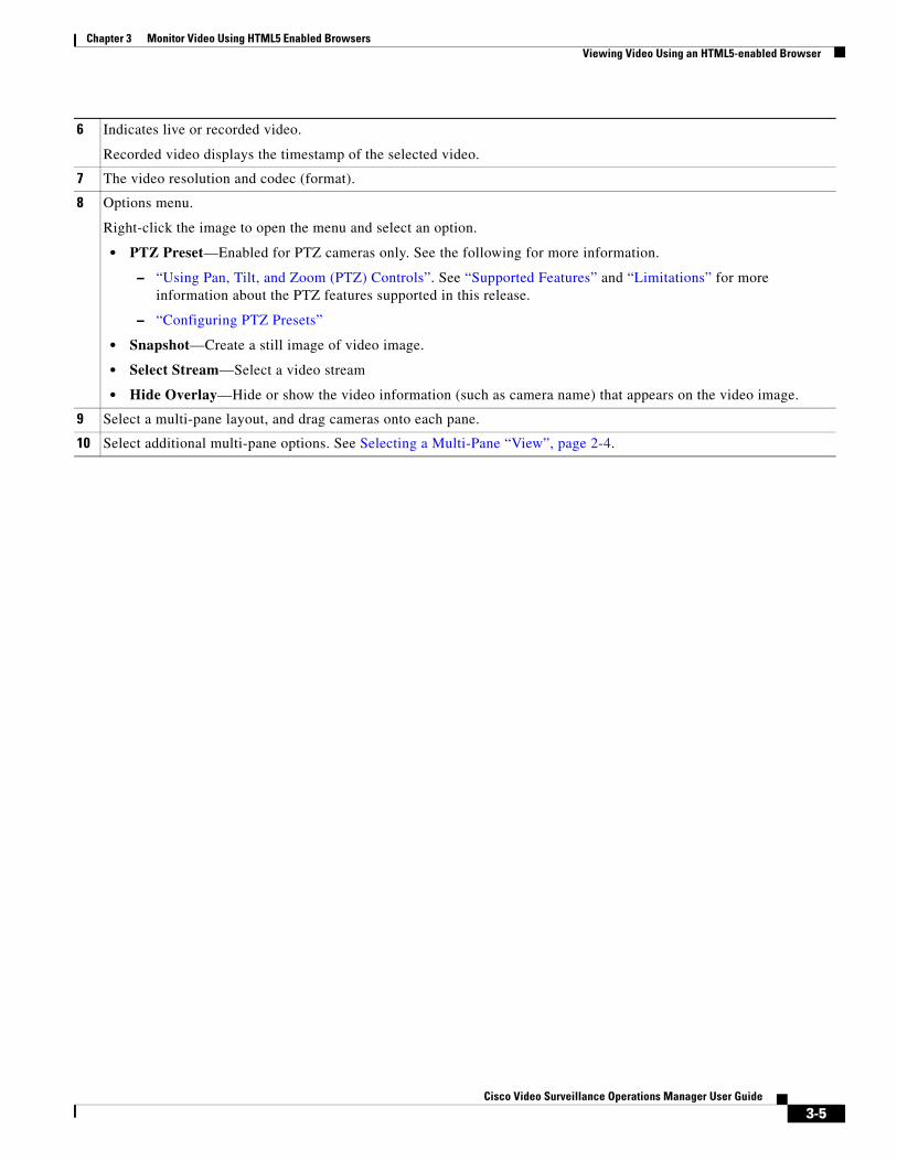
Chapter 3 Monitor Video Using HTML5 Enabled BrowsersViewing Video Using an HTML5-enabled Browser
6 Indicates live or recorded video.
Recorded video displays the timestamp of the selected video.
7 The video resolution and codec (format).
8 Options menu.
Right-click the image to open the menu and select an option.
• PTZ Preset—Enabled for PTZ cameras only. See the following for more information.
– “Using Pan, Tilt, and Zoom (PTZ) Controls”. See “Supported Features” and “Limitations” for more information about the PTZ features supported in this release.
– “Configuring PTZ Presets”
• Snapshot—Create a still image of video image.
• Select Stream—Select a video stream
• Hide Overlay—Hide or show the video information (such as camera name) that appears on the video image.
9 Select a multi-pane layout, and drag cameras onto each pane.
10 Select additional multi-pane options. See Selecting a Multi-Pane “View”, page 2-4.
3-5Cisco Video Surveillance Operations Manager User Guide
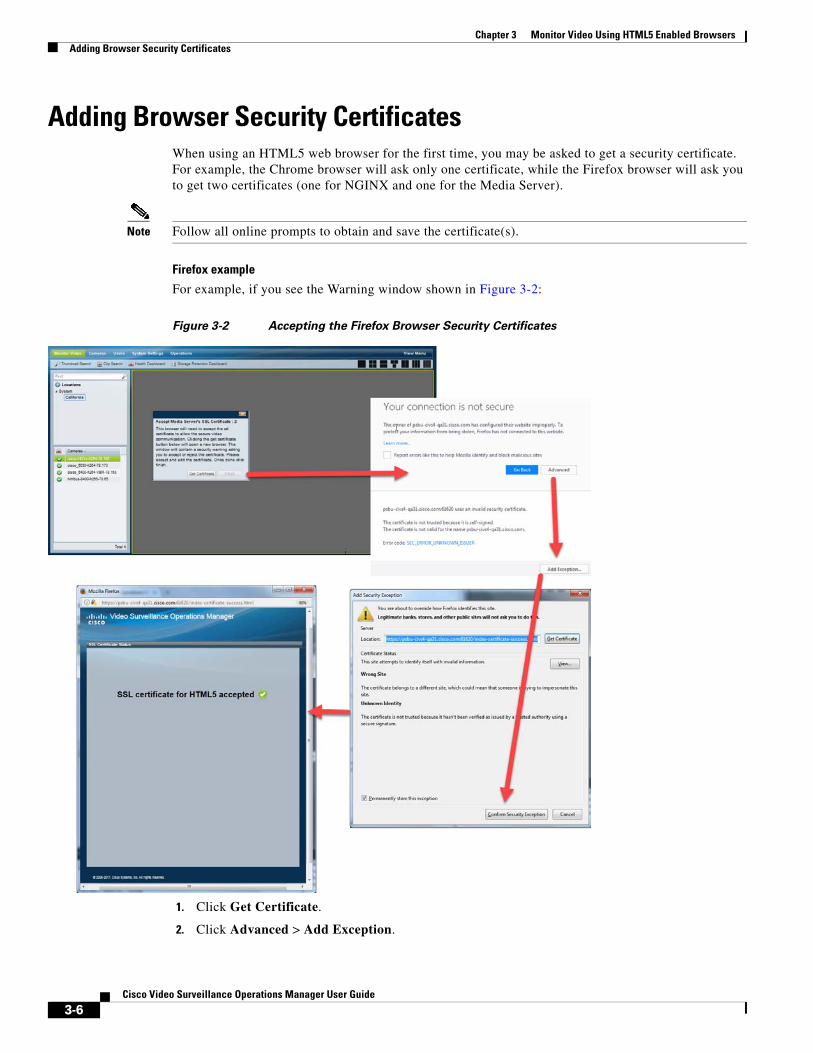
Chapter 3 Monitor Video Using HTML5 Enabled Browsers Adding Browser Security Certificates
Adding Browser Security CertificatesWhen using an HTML5 web browser for the first time, you may be asked to get a security certificate. For example, the Chrome browser will ask only one certificate, while the Firefox browser will ask you to get two certificates (one for NGINX and one for the Media Server).
Note Follow all online prompts to obtain and save the certificate(s).
Firefox example
For example, if you see the Warning window shown in Figure 3-2:
Figure 3-2 Accepting the Firefox Browser Security Certificates
1. Click Get Certificate.
2. Click Advanced > Add Exception.
3-6Cisco Video Surveillance Operations Manager User Guide
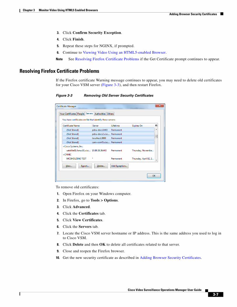
Chapter 3 Monitor Video Using HTML5 Enabled BrowsersAdding Browser Security Certificates
3. Click Confirm Security Exception.
4. Click Finish.
5. Repeat these steps for NGINX, if prompted.
6. Continue to Viewing Video Using an HTML5-enabled Browser.
Note See Resolving Firefox Certificate Problems if the Get Certificate prompt continues to appear.
Resolving Firefox Certificate Problems
If the Firefox certificate Warning message continues to appear, you may need to delete old certificates for your Cisco VSM server (Figure 3-3), and then restart Firefox.
Figure 3-3 Removing Old Server Security Certificates
To remove old certificates:
1. Open Firefox on your Windows computer.
2. In Firefox, go to Tools > Options.
3. Click Advanced.
4. Click the Certificates tab.
5. Click View Certificates.
6. Click the Servers tab.
7. Locate the Cisco VSM server hostname or IP address. This is the same address you used to log in to Cisco VSM.
8. Click Delete and then OK to delete all certificates related to that server.
9. Close and reopen the Firefox browser.
10. Get the new security certificate as described in Adding Browser Security Certificates.
3-7Cisco Video Surveillance Operations Manager User Guide

Chapter 3 Monitor Video Using HTML5 Enabled Browsers Adding Browser Security Certificates
3-8Cisco Video Surveillance Operations Manager User Guide
Cisco V
C H A P T E R 4
Configuring Video Viewing OptionsRefer to the following topics to configure the viewing options that can be accessed using the Cisco Video Surveillance Safety and Security Desktop application, the Cisco VSM Operations Manager, or other supported video viewing applications.
Tip For instructions to view video using the Cisco Safety and Security desktop application, see the Cisco Video Surveillance Safety and Security Desktop User Guide.
Contents
• Setting the Default View, page 4-1
• Creating Video Views, page 4-4
• Configuring Video Walls, page 4-9
• Hide Video From Users (Covert Cameras), page 4-11
• Enabling On-Demand Recording, page 4-14
• Display or Hide Camera Health Information, page 4-16
Additional Documentation
• Configuring Camera PTZ Controls, Presets, and Tours, page 10-81
• Configuring Motion Detection, page 10-96
• Camera Settings, page 10-45
• Adding and Editing Camera Templates, page 13-1
Setting the Default ViewThe Default View is defined by each user and is automatically loaded when they click Monitor Video.
Usage Notes
• If a default View is not defined, a blank 1x1 layout is displayed.
• Click Clear to delete the Default View setting. A blank 1x1 layout will be displayed by default.
• Only Views the user has access permissions to see can be selected as the default View.
• The Default View is saved as a cookie in the browser and is unique to each user/PC. The Default View is not displayed if using a different workstation.
4-1ideo Surveillance Operations Manager User Guide
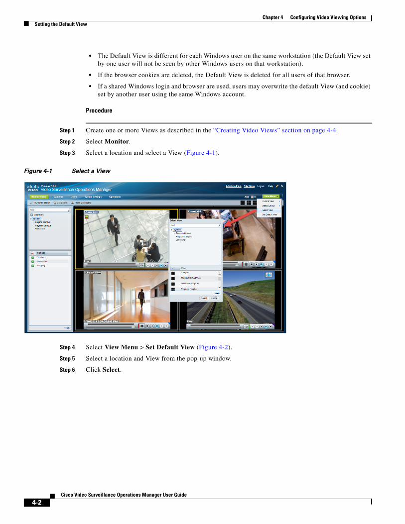
Chapter 4 Configuring Video Viewing Options Setting the Default View
• The Default View is different for each Windows user on the same workstation (the Default View set by one user will not be seen by other Windows users on that workstation).
• If the browser cookies are deleted, the Default View is deleted for all users of that browser.
• If a shared Windows login and browser are used, users may overwrite the default View (and cookie) set by another user using the same Windows account.
Procedure
Step 1 Create one or more Views as described in the “Creating Video Views” section on page 4-4.
Step 2 Select Monitor.
Step 3 Select a location and select a View (Figure 4-1).
Figure 4-1 Select a View
Step 4 Select View Menu > Set Default View (Figure 4-2).
Step 5 Select a location and View from the pop-up window.
Step 6 Click Select.
4-2Cisco Video Surveillance Operations Manager User Guide

Chapter 4 Configuring Video Viewing OptionsSetting the Default View
Figure 4-2 Setting the Default View
4-3Cisco Video Surveillance Operations Manager User Guide
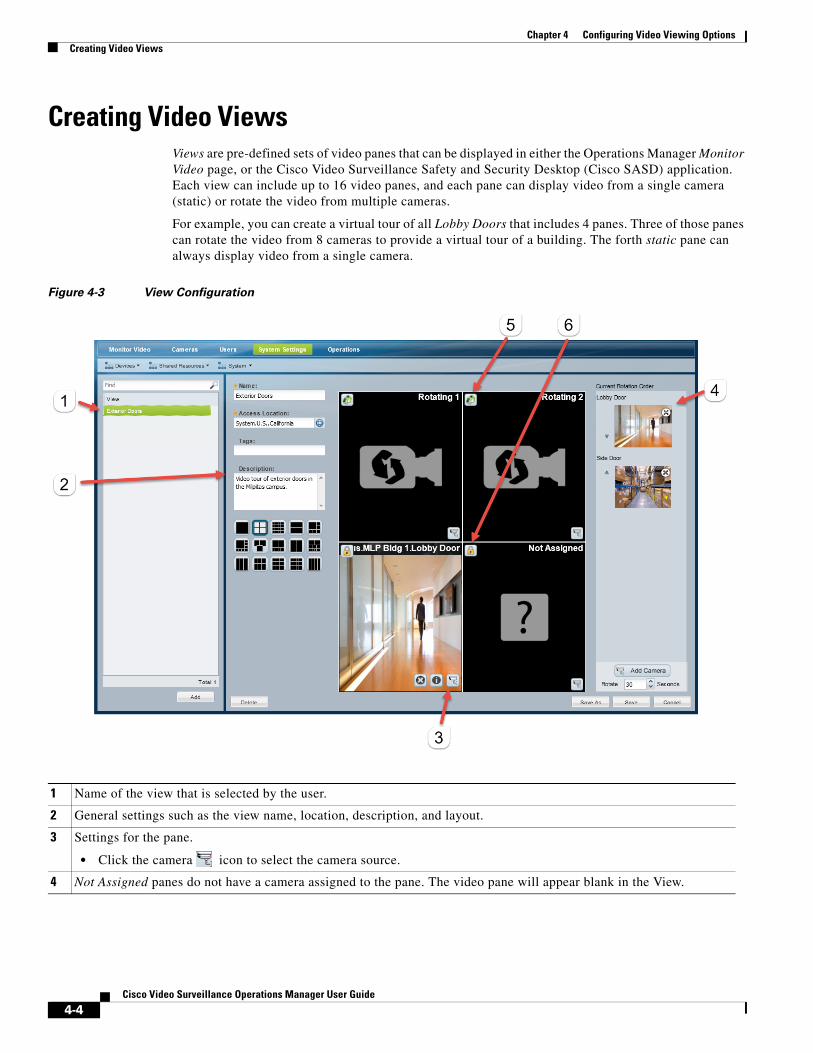
Chapter 4 Configuring Video Viewing Options Creating Video Views
Creating Video ViewsViews are pre-defined sets of video panes that can be displayed in either the Operations Manager Monitor Video page, or the Cisco Video Surveillance Safety and Security Desktop (Cisco SASD) application. Each view can include up to 16 video panes, and each pane can display video from a single camera (static) or rotate the video from multiple cameras.
For example, you can create a virtual tour of all Lobby Doors that includes 4 panes. Three of those panes can rotate the video from 8 cameras to provide a virtual tour of a building. The forth static pane can always display video from a single camera.
Figure 4-3 View Configuration
1 Name of the view that is selected by the user.
2 General settings such as the view name, location, description, and layout.
3 Settings for the pane.
• Click the camera icon to select the camera source.
4 Not Assigned panes do not have a camera assigned to the pane. The video pane will appear blank in the View.
4-4Cisco Video Surveillance Operations Manager User Guide
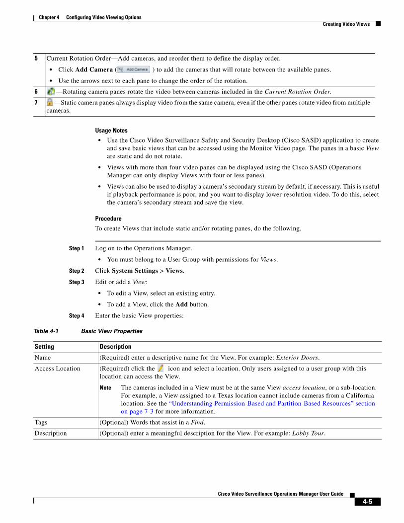
Chapter 4 Configuring Video Viewing OptionsCreating Video Views
Usage Notes
• Use the Cisco Video Surveillance Safety and Security Desktop (Cisco SASD) application to create and save basic views that can be accessed using the Monitor Video page. The panes in a basic View are static and do not rotate.
• Views with more than four video panes can be displayed using the Cisco SASD (Operations Manager can only display Views with four or less panes).
• Views can also be used to display a camera’s secondary stream by default, if necessary. This is useful if playback performance is poor, and you want to display lower-resolution video. To do this, select the camera’s secondary stream and save the view.
Procedure
To create Views that include static and/or rotating panes, do the following.
Step 1 Log on to the Operations Manager.
• You must belong to a User Group with permissions for Views.
Step 2 Click System Settings > Views.
Step 3 Edit or add a View:
• To edit a View, select an existing entry.
• To add a View, click the Add button.
Step 4 Enter the basic View properties:
5 Current Rotation Order—Add cameras, and reorder them to define the display order.
• Click Add Camera ( ) to add the cameras that will rotate between the available panes.
• Use the arrows next to each pane to change the order of the rotation.
6 —Rotating camera panes rotate the video between cameras included in the Current Rotation Order.
7 —Static camera panes always display video from the same camera, even if the other panes rotate video from multiple cameras.
Table 4-1 Basic View Properties
Setting Description
Name (Required) enter a descriptive name for the View. For example: Exterior Doors.
Access Location (Required) click the icon and select a location. Only users assigned to a user group with this location can access the View.
Note The cameras included in a View must be at the same View access location, or a sub-location. For example, a View assigned to a Texas location cannot include cameras from a California location. See the “Understanding Permission-Based and Partition-Based Resources” section on page 7-3 for more information.
Tags (Optional) Words that assist in a Find.
Description (Optional) enter a meaningful description for the View. For example: Lobby Tour.
4-5Cisco Video Surveillance Operations Manager User Guide
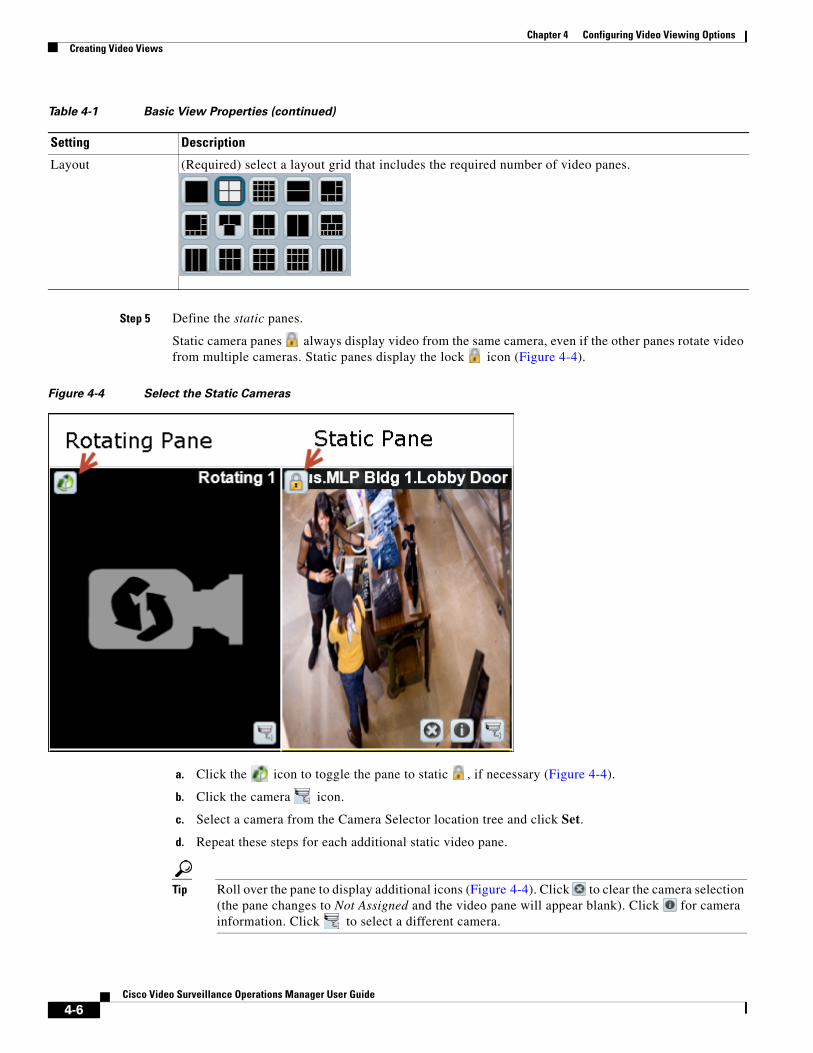
Chapter 4 Configuring Video Viewing Options Creating Video Views
Step 5 Define the static panes.
Static camera panes always display video from the same camera, even if the other panes rotate video from multiple cameras. Static panes display the lock icon (Figure 4-4).
Figure 4-4 Select the Static Cameras
a. Click the icon to toggle the pane to static , if necessary (Figure 4-4).
b. Click the camera icon.
c. Select a camera from the Camera Selector location tree and click Set.
d. Repeat these steps for each additional static video pane.
Tip Roll over the pane to display additional icons (Figure 4-4). Click to clear the camera selection (the pane changes to Not Assigned and the video pane will appear blank). Click for camera information. Click to select a different camera.
Layout (Required) select a layout grid that includes the required number of video panes.
Table 4-1 Basic View Properties (continued)
Setting Description
4-6Cisco Video Surveillance Operations Manager User Guide
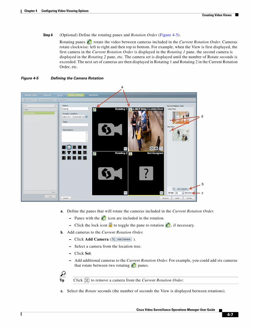
Chapter 4 Configuring Video Viewing OptionsCreating Video Views
Step 6 (Optional) Define the rotating panes and Rotation Order (Figure 4-5).
Rotating panes rotate the video between cameras included in the Current Rotation Order. Cameras rotate clockwise: left to right and then top to bottom. For example, when the View is first displayed, the first camera in the Current Rotation Order is displayed in the Rotating 1 pane, the second camera is displayed in the Rotating 2 pane, etc. The camera set is displayed until the number of Rotate seconds is exceeded. The next set of cameras are then displayed in Rotating 1 and Rotating 2 in the Current Rotation Order, etc.
Figure 4-5 Defining the Camera Rotation
a. Define the panes that will rotate the cameras included in the Current Rotation Order.
– Panes with the icon are included in the rotation.
– Click the lock icon to toggle the pane to rotation , if necessary.
b. Add cameras to the Current Rotation Order.
– Click Add Camera ( ).
– Select a camera from the location tree.
– Click Set.
– Add additional cameras to the Current Rotation Order. For example, you could add six cameras that rotate between two rotating panes.
Tip Click to remove a camera from the Current Rotation Order.
c. Select the Rotate seconds (the number of seconds the View is displayed between rotations).
4-7Cisco Video Surveillance Operations Manager User Guide

Chapter 4 Configuring Video Viewing Options Creating Video Views
The View will pause on a set of cameras before rotating to the next camera in the list.
d. Reorder the cameras in the Current Rotation Order using the up and down arrows.
When the View is first displayed, the first camera in the Current Rotation Order is displayed in the Rotating 1 pane, the second camera is displayed in the Rotating 2 pane, etc.
Step 7 Click Save.
4-8Cisco Video Surveillance Operations Manager User Guide
Chapter 4 Configuring Video Viewing OptionsConfiguring Video Walls
Configuring Video WallsVideo Walls are unattended screens that display a pre-defined set of video panes. Video Walls are typically monitored by a security guard or other attendant.
Use the following procedure to create Video Walls and define the default View.
Tip • Refer to the Cisco Video Surveillance Safety and Security Desktop User Guide for instructions to display the Video Walls.
– Users who configure unattended video walls (using the Cisco SASD Wall Configurator) must belong to a user group that allows multiple logins. This is because each unattended video wall requires a unique Cisco VSM login session for the video wall to be displayed. See the Cisco Video Surveillance Safety and Security Desktop User Guide for more information.
• To automatically display video from a different camera when an event occurs, see the “Using Advanced Events to Trigger Actions” section on page 15-7. This feature allows to you switch all instances of a Video Wall to the live or recorded video from a camera that triggers an event. For example, if motion occurs or a door is opened, the Video Wall can automatically switch to the video from the camera that triggered the event.
• This feature is similar to the Virtual Matrix client available in Cisco VSM release 6.x.
Procedure
Complete the following procedure to create or edit Video Walls.
Note Any changes to existing Video Walls will be automatically published to all instances of that Video Wall. For example, if you change the default View, all workstations viewing that Video Wall will automatically change to the new View.
Step 1 Log on to the Operations Manager.
• You must belong to a User Group with permissions for Video Walls.
Step 2 Create one or more Views.
• See the “Selecting a Multi-Pane “View”” section on page 2-4.
Step 3 Choose System Settings > Video Wall.
Step 4 Click Add or select an existing entry.
4-9Cisco Video Surveillance Operations Manager User Guide
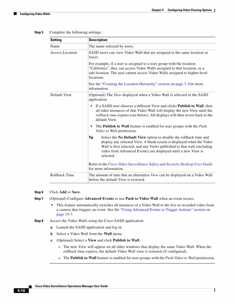
Chapter 4 Configuring Video Viewing Options Configuring Video Walls
Step 5 Complete the following settings:
Setting Description
• If a SASD user chooses a different View and clicks Publish to Wall, then all other instances of that Video Wall will display the new View until the rollback time expires (see below). All displays will then revert back to the default View.
• The Publish to Wall feature is enabled for user groups with the Push Video to Wall permission.
Tip Select the No Default View option to disable the rollback time and display any selected View. A blank screen is displayed when the Video Wall is first selected, and any Views published to that wall (including video from Advanced Events) are displayed until a new View is selected.
Step 6 Click Add or Save.
Step 7 (Optional) Configure Advanced Events to use Push to Video Wall when an event occurs.
• This feature automatically switches all instances of a Video Wall to the live or recorded video from a camera that triggers an event. See the “Using Advanced Events to Trigger Actions” section on page 15-7.
Step 8 Access the Video Walls using the Cisco SASD application:
a. Launch the SASD application and log in.
b. Select a Video Wall from the Wall menu.
c. (Optional) Select a View and click Publish to Wall.
– The new View will appear on all other windows that display the same Video Wall. When the rollback time expires, the default Video Wall view is restored (if configured).
– The Publish to Wall feature is enabled for user groups with the Push Video to Wall permission.
.
Name The name selected by users.
Access Location SASD users can view Video Wall that are assigned to the same location or lower.
For example, if a user is assigned to a user group with the location “California”, they can access Video Walls assigned to that location, or a sub-location. The user cannot access Video Walls assigned to higher-level locations.
See the “Creating the Location Hierarchy” section on page 7-1for more information.
Default View (Optional) The View displayed when a Video Wall is selected in the SASD application.
Refer to the Cisco Video Surveillance Safety and Security Desktop User Guide for more information.
Rollback Time The amount of time that an alternative View can be displayed on a Video Wall before the default View is restored.
4-10Cisco Video Surveillance Operations Manager User Guide

Chapter 4 Configuring Video Viewing OptionsHide Video From Users (Covert Cameras)
Hide Video From Users (Covert Cameras)Administrators can hide live or recorded video from users for specific cameras. You can hide all live video streams, all recorded video, or recoded video for specific time spans.
User Experience
• If users select a “covert” live stream, previously recorded video is displayed instead.
• If users select a “covert” recording, then the live stream is displayed.
• If both live and recorded video is hidden (covert), then the viewing pane is blank (no video is displayed).
• A maximum of 4 covert recording times can be created.
• Clips:
– CVA clips—Video and audio is not displayed for covert times (CSCvb73058).
– Video is not included in a clip if a covert time is included.
– MP4 clips will not be created if a covert time is included.
– Clips from multiple cameras (bulk clipping) will not succeed if any of the selected cameras include a covert recording time. An error message is not displayed.
• Rotating views—if the camera feed is live covert, then the recording stream is not displayed.
Additional Notes
• Covert options are not supported by SASD Federator or Operations Manager Federator.
• Cameras cannot be replaced by another camera if in covert mode.
• Media Servers cannot be replaced by another Media Server if any camera assigned to the server is in covert mode.
• Cameras cannot be deleted when in covert mode.
• The Cisco VSM Management Console localuser will not see live or recoded steams if covert mode is turned on. No warning is displayed.
• Changes to a user’s user group and user role require the user to log out and log back in.
Configuration
• Configure the covert options on cameras using the Operations Manager (see below). Use Bulk Actions to enable covert features on multiple cameras.
• Add users to a user group with Forbid Covert Feed permission.
Procedure
Step 1 Log on to the Operations Manager.
• See the “Logging In” section on page 1-17.
• You must belong to a User Group with manage permissions for Cameras and for Users & Roles.
Step 2 Add users to a user group with Forbid Covert Feed permission (Figure 4-6).
These users will not be able to view video from when covert options are enabled (see the following steps).
a. Add the Forbid Covert Feed permission to a user role.
4-11Cisco Video Surveillance Operations Manager User Guide
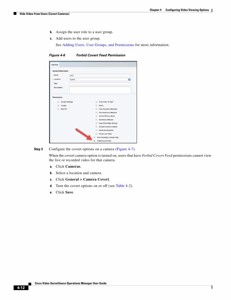
Chapter 4 Configuring Video Viewing Options Hide Video From Users (Covert Cameras)
b. Assign the user role to a user group.
c. Add users to the user group.
See Adding Users, User Groups, and Permissions for more information.
Figure 4-6 Forbid Covert Feed Permission
Step 3 Configure the covert options on a camera (Figure 4-7).
When the covert camera option is turned on, users that have Forbid Covert Feed permissions cannot view the live or recorded video for that camera.
a. Click Cameras.
b. Select a location and camera.
c. Click General > Camera Covert.
d. Turn the covert options on or off (see Table 4-2).
e. Click Save.
4-12Cisco Video Surveillance Operations Manager User Guide
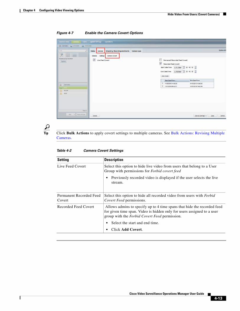
Chapter 4 Configuring Video Viewing OptionsHide Video From Users (Covert Cameras)
Figure 4-7 Enable the Camera Covert Options
Tip Click Bulk Actions to apply covert settings to multiple cameras. See Bulk Actions: Revising Multiple Cameras.
Table 4-2 Camera Covert Settings
Setting Description
• Previously recorded video is displayed if the user selects the live stream.
• Select the start and end time.
• Click Add Covert.
Live Feed Covert Select this option to hide live video from users that belong to a User Group with permissions for Forbid covert feed
Permanent Recorded Feed Covert
Select this option to hide all recorded video from users with Forbid Covert Feed permissions.
Recorded Feed Covert Allows admins to specify up to 4 time spans that hide the recorded feed for given time span. Video is hidden only for users assigned to a user group with the Forbid Covert Feed permission.
4-13Cisco Video Surveillance Operations Manager User Guide
Chapter 4 Configuring Video Viewing Options Enabling On-Demand Recording
Enabling On-Demand RecordingOn-Demand Recording allows users to immediately stop and start recording. These recordings are created in addition to any other scheduled, continuous or event recordings. On demand recordings are created based on the following:
• Recording length is determined by the On Demand Recording Duration setting in General System Settings, page 26-2.
• Recordings are retained on the system for the number of days specified in the camera’s Retain event recordings setting (see Streaming, Recording and Event Settings, page 10-55).
HA Availability for On Demand Recording
On Demand Recording is available on the Primary and Redundant servers, or on the Failover server if the Primary is down.
See the “High Availability: Cisco Media Servers” section on page 22-1 for more information.
Using On Demand Recording
See the Cisco Video Surveillance Safety and Security Desktop User Guide for end-user instructions to trigger recordings.
Summary Steps to Enable On Demand Recording
To enable On Demand Recording, you must define the following:
1. Add the users to a User Group with Operate permissions to View Live Video and View Recordings.
2. In the camera template, enable On Demand Recording and define the number of retention days. Assign the camera(s) that should allow On Demand Recording to that template.
3. Define the On Demand Recording Duration in system settings.
Procedure
Step 1 Add user access permissions to view live and recorded video.
a. Select Users.
b. Select the Roles tab .
c. Edit or add a Role:
– To edit a Role, click an existing entry to highlight it.
– To add a Role, click the Add button.
d. Select the Operate permissions to View Live Video and View Recordings.
e. Click Save.
f. Select the User Groups tab .
g. Select the Role that includes the view permissions.
h. Add the users to the role.
i. Click Save.
– See the “Adding Users, User Groups, and Permissions” section on page 5-1 for more information.
4-14Cisco Video Surveillance Operations Manager User Guide
Chapter 4 Configuring Video Viewing OptionsEnabling On-Demand Recording
Step 2 Enable the On Demand Recording option in the camera template.
a. Click Cameras.
b. Click Templates.
c. Select a location and template name.
d. Click the Streaming, Recording and Events tab.
e. In the Retain event recordings setting, enter the number of days the recordings (and other event video) should be retained on the system.
f. Scroll down to On Demand Recording and select Enable.
g. (Optional) Select Live and Recorded from the Record Audio option.
h. Click Save.
i. Assign cameras to the template, if necessary (click Cameras, select a sample, click the Streaming, Recording and Events tab, and assign the template to the camera).
For more information, see the “Adding and Editing Camera Templates” section on page 13-1 and the “Streaming, Recording and Event Settings” section on page 10-55.
Step 3 Define the duration of all On Demand Recording recordings.
a. Choose Settings > System Settings.
b. Select the General tab.
c. In the On Demand Recording Duration field, enter the number of seconds that video will be recorded for all requests.
The minimum value (and default) is 300 seconds (5 minutes).
d. Click Save.
4-15Cisco Video Surveillance Operations Manager User Guide
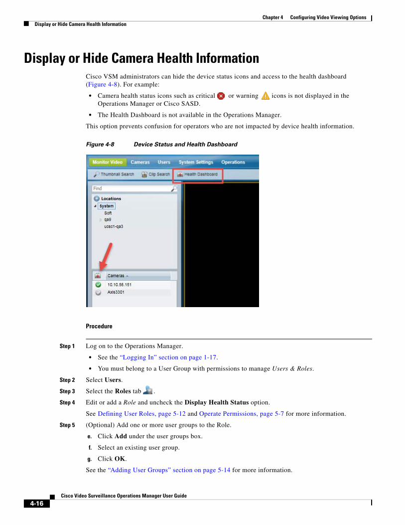
Chapter 4 Configuring Video Viewing Options Display or Hide Camera Health Information
Display or Hide Camera Health InformationCisco VSM administrators can hide the device status icons and access to the health dashboard (Figure 4-8). For example:
• Camera health status icons such as critical or warning icons is not displayed in the Operations Manager or Cisco SASD.
• The Health Dashboard is not available in the Operations Manager.
This option prevents confusion for operators who are not impacted by device health information.
Figure 4-8 Device Status and Health Dashboard
Procedure
Step 1 Log on to the Operations Manager.
• See the “Logging In” section on page 1-17.
• You must belong to a User Group with permissions to manage Users & Roles.
Step 2 Select Users.
Step 3 Select the Roles tab .
Step 4 Edit or add a Role and uncheck the Display Health Status option.
See Defining User Roles, page 5-12 and Operate Permissions, page 5-7 for more information.
Step 5 (Optional) Add one or more user groups to the Role.
e. Click Add under the user groups box.
f. Select an existing user group.
g. Click OK.
See the “Adding User Groups” section on page 5-14 for more information.
4-16Cisco Video Surveillance Operations Manager User Guide
Chapter 4 Configuring Video Viewing OptionsDisplay or Hide Camera Health Information
Step 6 Select Create or Save.
Related Information
• Defining User Roles, page 5-12
• Operate Permissions, page 5-7
• Camera Status, page 10-74
• Health Dashboard: Device Health Faults on an Operations Manager, page 24-7
• Device Status: Identifying Issues for a Specific Device, page 24-13
4-17Cisco Video Surveillance Operations Manager User Guide

Chapter 4 Configuring Video Viewing Options Display or Hide Camera Health Information
4-18Cisco Video Surveillance Operations Manager User Guide
Cisco V
C H A P T E R 5
Adding Users, User Groups, and PermissionsRefer to the following topics to create user accounts and define the features and functions that can be accessed by those users. You can also provide access to users that are managed on an external (LDAP) server.
Contents
• Overview, page 5-2
– Understanding Roles, Groups and Users, page 5-3
– Understanding the System-Defined User Roles, Groups and Accounts, page 5-4
– Understanding Permissions, page 5-4
– Understanding the Impact of a User’s Location, page 5-10
– Understanding the Super Admin, page 5-10
– Example Roles For Different Types of Users, page 5-11
• Defining User Roles, page 5-12
• Adding User Groups, page 5-14
• Adding Users, page 5-20
• Defining Password Rules and Security Questions, page 5-22
• Viewing and Logging Out Active Users, page 5-22
Related information
• Adding Users from an LDAP Server
5-1ideo Surveillance Operations Manager User Guide
Chapter 5 Adding Users, User Groups, and Permissions Overview
OverviewCisco Video Surveillance Manager (Cisco VSM) users can monitor video or configure the system based on the following:
• The user group(s) to which the user is assigned: user groups are associated with a user Role, which defines the access permissions for the group.
• The location assigned to the user group(s).
• Users can be assigned to multiple user groups, and gain the combined access permissions for all groups.
Before you begin, create the location hierarchy as described in the “Creating the Location Hierarchy” section on page 7-1. Carefully review the “Examples: Locations in Simple vs. Large Deployments” section on page 7-7.
Tip User accounts provide access to both the browser-based Operations Manager and the Cisco Safety and Security desktop application.
Tip A second user (such as a manager) can also be required to approve when a user logs in. See the “Understanding Dual Login” section on page 1-19.
Review the following topics to understand how to configure users and user access permissions in Cisco VSM.
• Understanding Roles, Groups and Users, page 5-3
• Understanding the System-Defined User Roles, Groups and Accounts, page 5-4
• Understanding Permissions, page 5-4
• Understanding the Impact of a User’s Location, page 5-10
• Understanding the Super Admin, page 5-10
• Example Roles For Different Types of Users, page 5-11
5-2Cisco Video Surveillance Operations Manager User Guide
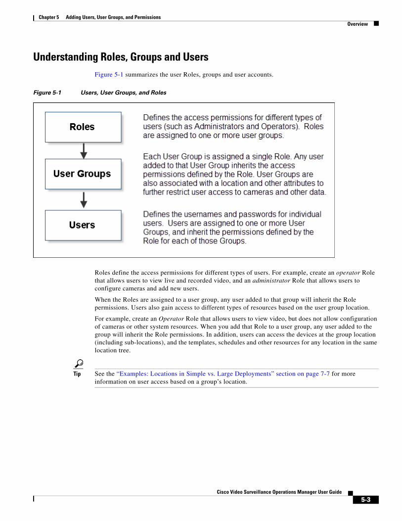
Chapter 5 Adding Users, User Groups, and PermissionsOverview
Understanding Roles, Groups and UsersFigure 5-1 summarizes the user Roles, groups and user accounts.
Figure 5-1 Users, User Groups, and Roles
Roles define the access permissions for different types of users. For example, create an operator Role that allows users to view live and recorded video, and an administrator Role that allows users to configure cameras and add new users.
When the Roles are assigned to a user group, any user added to that group will inherit the Role permissions. Users also gain access to different types of resources based on the user group location.
For example, create an Operator Role that allows users to view video, but does not allow configuration of cameras or other system resources. When you add that Role to a user group, any user added to the group will inherit the Role permissions. In addition, users can access the devices at the group location (including sub-locations), and the templates, schedules and other resources for any location in the same location tree.
Tip See the “Examples: Locations in Simple vs. Large Deployments” section on page 7-7 for more information on user access based on a group’s location.
5-3Cisco Video Surveillance Operations Manager User Guide
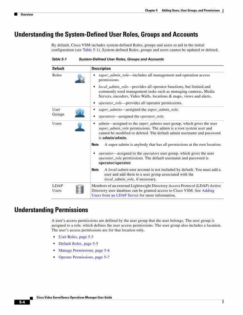
Chapter 5 Adding Users, User Groups, and Permissions Overview
Understanding the System-Defined User Roles, Groups and AccountsBy default, Cisco VSM includes system-defined Roles, groups and users to aid in the initial configuration (see Table 5-1). System-defined Roles, groups and users cannot be updated or deleted.
Table 5-1 System-Defined User Roles, Groups and Accounts
Default Description
• super_admin_role—includes all management and operation access permissions.
• local_admin_role—provides all operator functions, but limited and commonly used management tasks such as managing cameras, Media Servers, encoders, Video Walls, locations & maps, views and alerts.
• operator_role—provides all operator permissions.
• super_admins—assigned the super_admin_role.
• operators—assigned the operator_role.
• admin—assigned to the super_admins user group, which gives the user super_admin_role permissions. The admin is a root system user and cannot be modified or deleted. The default admin username and password is admin/admin.
Note A super-admin is anybody that has all permissions at the root location.
• operator—assigned to the operators user group, which gives the user operator_role permissions. The default username and password is operator/operator.
Note A local-admin user account is not included by default. You must add a user and add them to a user group associated with the local_admin_role, if necessary.
Understanding PermissionsA user’s access permissions are defined by the user group that the user belongs. The user group is assigned to a role, which defines the user access permissions. The user group also includes a location. The user’s access permissions are for that location only.
• User Roles, page 5-5
• Default Roles, page 5-5
• Manage Permissions, page 5-6
• Operate Permissions, page 5-7
Roles
User Groups
Users
LDAP Users
Members of an external Lightweight Directory Access Protocol (LDAP) Active Directory user database can be granted access to Cisco VSM. See Adding Users from an LDAP Server for more information.
5-4Cisco Video Surveillance Operations Manager User Guide
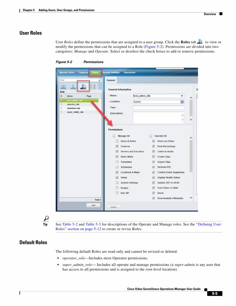
Chapter 5 Adding Users, User Groups, and PermissionsOverview
User Roles
User Roles define the permissions that are assigned to a user group. Click the Roles tab to view or modify the permissions that can be assigned to a Role (Figure 5-2). Permissions are divided into two categories: Manage and Operate. Select or deselect the check boxes to add or remove permissions.
Figure 5-2 Permissions
Tip See Table 5-2 and Table 5-3 for descriptions of the Operate and Manage roles. See the “Defining User Roles” section on page 5-12 to create or revise Roles.
Default Roles
The following default Roles are read-only and cannot be revised or deleted.
• operator_role—Includes most Operator permissions.
• super_admin_role— Includes all operate and manage permissions (a super-admin is any user that has access to all permissions and is assigned to the root-level location).
5-5Cisco Video Surveillance Operations Manager User Guide
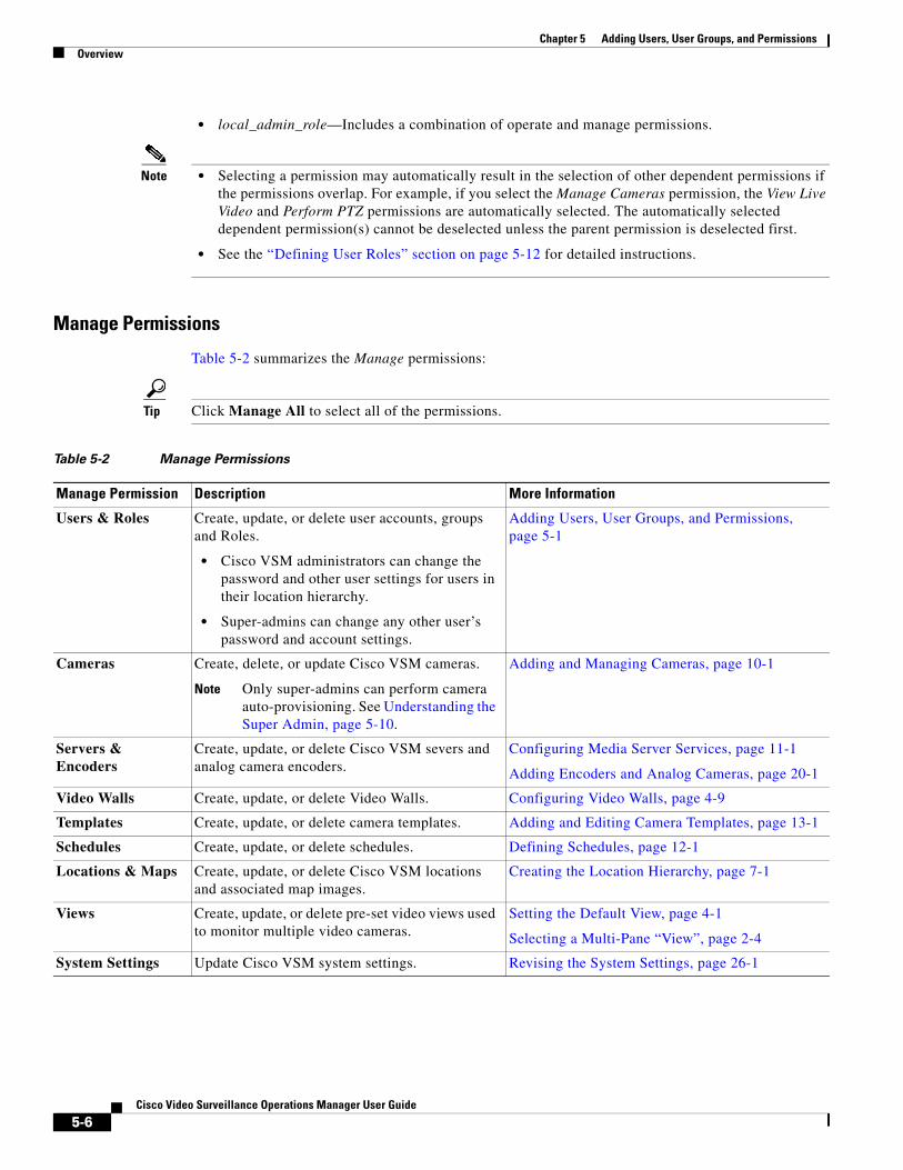
Chapter 5 Adding Users, User Groups, and Permissions Overview
• local_admin_role—Includes a combination of operate and manage permissions.
Note • Selecting a permission may automatically result in the selection of other dependent permissions if the permissions overlap. For example, if you select the Manage Cameras permission, the View Live Video and Perform PTZ permissions are automatically selected. The automatically selected dependent permission(s) cannot be deselected unless the parent permission is deselected first.
• See the “Defining User Roles” section on page 5-12 for detailed instructions.
Manage Permissions
Table 5-2 summarizes the Manage permissions:
Tip Click Manage All to select all of the permissions.
Table 5-2 Manage Permissions
Manage Permission Description More Information
Users & Roles Create, update, or delete user accounts, groups and Roles.
• Cisco VSM administrators can change the password and other user settings for users in their location hierarchy.
• Super-admins can change any other user’s password and account settings.
Adding Users, User Groups, and Permissions, page 5-1
Cameras Create, delete, or update Cisco VSM cameras.
Note Only super-admins can perform camera auto-provisioning. See Understanding the Super Admin, page 5-10.
Adding and Managing Cameras, page 10-1
Servers & Encoders
Create, update, or delete Cisco VSM severs and analog camera encoders.
Configuring Media Server Services, page 11-1
Adding Encoders and Analog Cameras, page 20-1
Video Walls Create, update, or delete Video Walls. Configuring Video Walls, page 4-9
Templates Create, update, or delete camera templates. Adding and Editing Camera Templates, page 13-1
Schedules Create, update, or delete schedules. Defining Schedules, page 12-1
Locations & Maps Create, update, or delete Cisco VSM locations and associated map images.
Creating the Location Hierarchy, page 7-1
Views Create, update, or delete pre-set video views used to monitor multiple video cameras.
Setting the Default View, page 4-1
Selecting a Multi-Pane “View”, page 2-4
System Settings Update Cisco VSM system settings. Revising the System Settings, page 26-1
5-6Cisco Video Surveillance Operations Manager User Guide
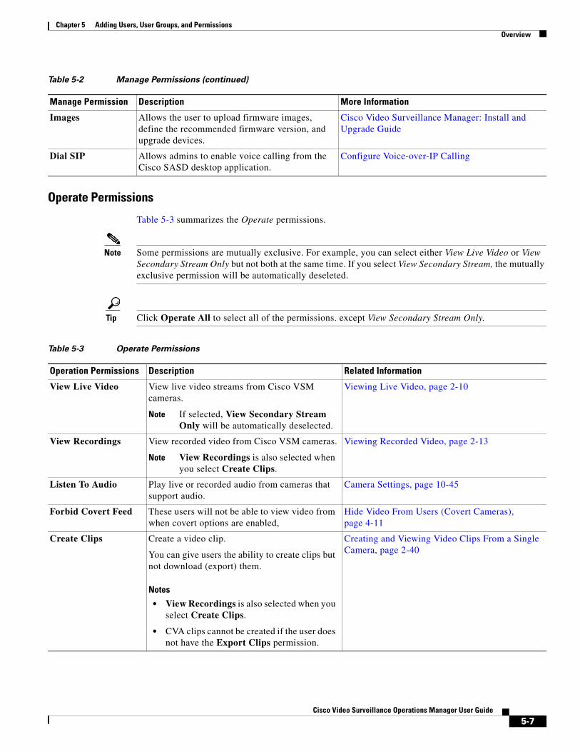
Chapter 5 Adding Users, User Groups, and PermissionsOverview
Operate Permissions
Table 5-3 summarizes the Operate permissions.
Note Some permissions are mutually exclusive. For example, you can select either View Live Video or View Secondary Stream Only but not both at the same time. If you select View Secondary Stream, the mutually exclusive permission will be automatically deseleted.
Tip Click Operate All to select all of the permissions. except View Secondary Stream Only.
Images Allows the user to upload firmware images, define the recommended firmware version, and upgrade devices.
Cisco Video Surveillance Manager: Install and Upgrade Guide
Dial SIP Allows admins to enable voice calling from the Cisco SASD desktop application.
Configure Voice-over-IP Calling
Table 5-2 Manage Permissions (continued)
Manage Permission Description More Information
Table 5-3 Operate Permissions
Operation Permissions Description Related Information
View Live Video View live video streams from Cisco VSM cameras.
Note If selected, View Secondary Stream Only will be automatically deselected.
Viewing Live Video, page 2-10
View Recordings View recorded video from Cisco VSM cameras.
Note View Recordings is also selected when you select Create Clips.
Viewing Recorded Video, page 2-13
Listen To Audio Play live or recorded audio from cameras that support audio.
Camera Settings, page 10-45
Forbid Covert Feed These users will not be able to view video from when covert options are enabled,
Hide Video From Users (Covert Cameras), page 4-11
Create Clips Create a video clip.
You can give users the ability to create clips but not download (export) them.
Notes
• View Recordings is also selected when you select Create Clips.
• CVA clips cannot be created if the user does not have the Export Clips permission.
Creating and Viewing Video Clips From a Single Camera, page 2-40
5-7Cisco Video Surveillance Operations Manager User Guide
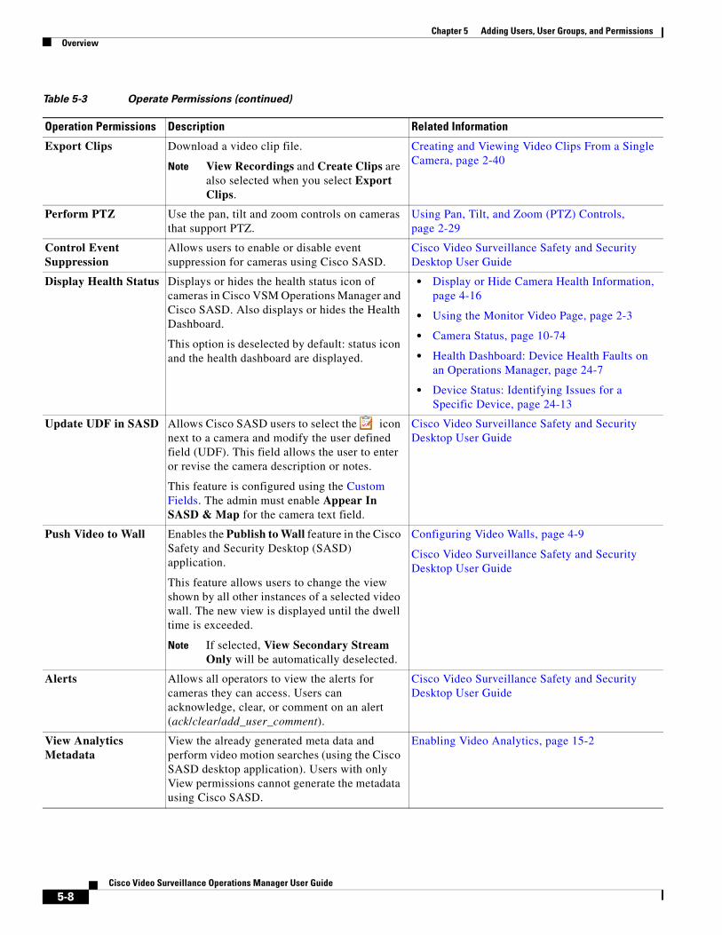
Chapter 5 Adding Users, User Groups, and Permissions Overview
Export Clips Download a video clip file.
Note View Recordings and Create Clips are also selected when you select Export Clips.
Creating and Viewing Video Clips From a Single Camera, page 2-40
Perform PTZ Use the pan, tilt and zoom controls on cameras that support PTZ.
Using Pan, Tilt, and Zoom (PTZ) Controls, page 2-29
Control Event Suppression
Allows users to enable or disable event suppression for cameras using Cisco SASD.
Cisco Video Surveillance Safety and Security Desktop User Guide
Display Health Status Displays or hides the health status icon of cameras in Cisco VSM Operations Manager and Cisco SASD. Also displays or hides the Health Dashboard.
This option is deselected by default: status icon and the health dashboard are displayed.
• Display or Hide Camera Health Information, page 4-16
• Using the Monitor Video Page, page 2-3
• Camera Status, page 10-74
• Health Dashboard: Device Health Faults on an Operations Manager, page 24-7
• Device Status: Identifying Issues for a Specific Device, page 24-13
Update UDF in SASD Allows Cisco SASD users to select the icon next to a camera and modify the user defined field (UDF). This field allows the user to enter or revise the camera description or notes.
This feature is configured using the Custom Fields. The admin must enable Appear In SASD & Map for the camera text field.
Cisco Video Surveillance Safety and Security Desktop User Guide
Push Video to Wall Enables the Publish to Wall feature in the Cisco Safety and Security Desktop (SASD) application.
This feature allows users to change the view shown by all other instances of a selected video wall. The new view is displayed until the dwell time is exceeded.
Note If selected, View Secondary Stream Only will be automatically deselected.
Configuring Video Walls, page 4-9
Cisco Video Surveillance Safety and Security Desktop User Guide
Alerts Allows all operators to view the alerts for cameras they can access. Users can acknowledge, clear, or comment on an alert (ack/clear/add_user_comment).
Cisco Video Surveillance Safety and Security Desktop User Guide
View Analytics Metadata
View the already generated meta data and perform video motion searches (using the Cisco SASD desktop application). Users with only View permissions cannot generate the metadata using Cisco SASD.
Enabling Video Analytics, page 15-2
Table 5-3 Operate Permissions (continued)
Operation Permissions Description Related Information
5-8Cisco Video Surveillance Operations Manager User Guide
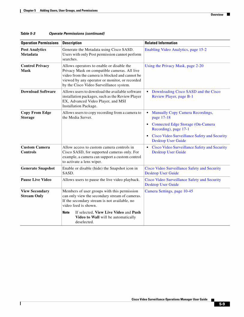
Chapter 5 Adding Users, User Groups, and PermissionsOverview
Post Analytics Metadata
Generate the Metadata using Cisco SASD. Users with only Post permission cannot perform searches.
Enabling Video Analytics, page 15-2
Control Privacy Mask
Allows operators to enable or disable the Privacy Mask on compatible cameras. All live video from the camera is blocked and cannot be viewed by any operator or monitor, or recorded by the Cisco Video Surveillance system.
Using the Privacy Mask, page 2-20
Download Software Allows users to download the available software installation packages, such as the Review Player EX, Advanced Video Player, and MSI Installation Package.
• Downloading Cisco SASD and the Cisco Review Player, page B-1
Copy From Edge Storage
Allows users to copy recording from a camera to the Media Server.
• Manually Copy Camera Recordings, page 17-18
• Connected Edge Storage (On-Camera Recording), page 17-1
• Cisco Video Surveillance Safety and Security Desktop User Guide
Custom Camera Controls
Allow access to custom camera controls in Cisco SASD, for supported cameras only. For example, a camera can support a custom control to activate a lens wiper.
• Cisco Video Surveillance Safety and Security Desktop User Guide
Generate Snapshot Enable or disable (hide) the Snapshot icon in SASD.
Cisco Video Surveillance Safety and Security Desktop User Guide
Pause Live Video Allows users to pause the live video playback. Cisco Video Surveillance Safety and Security Desktop User Guide
View Secondary Stream Only
Members of user groups with this permission can only view the secondary stream of cameras. If the secondary stream is not available, no video feed is shown.
Note If selected, View Live Video and Push Video to Wall will be automatically deselected.
Camera Settings, page 10-45
Table 5-3 Operate Permissions (continued)
Operation Permissions Description Related Information
5-9Cisco Video Surveillance Operations Manager User Guide
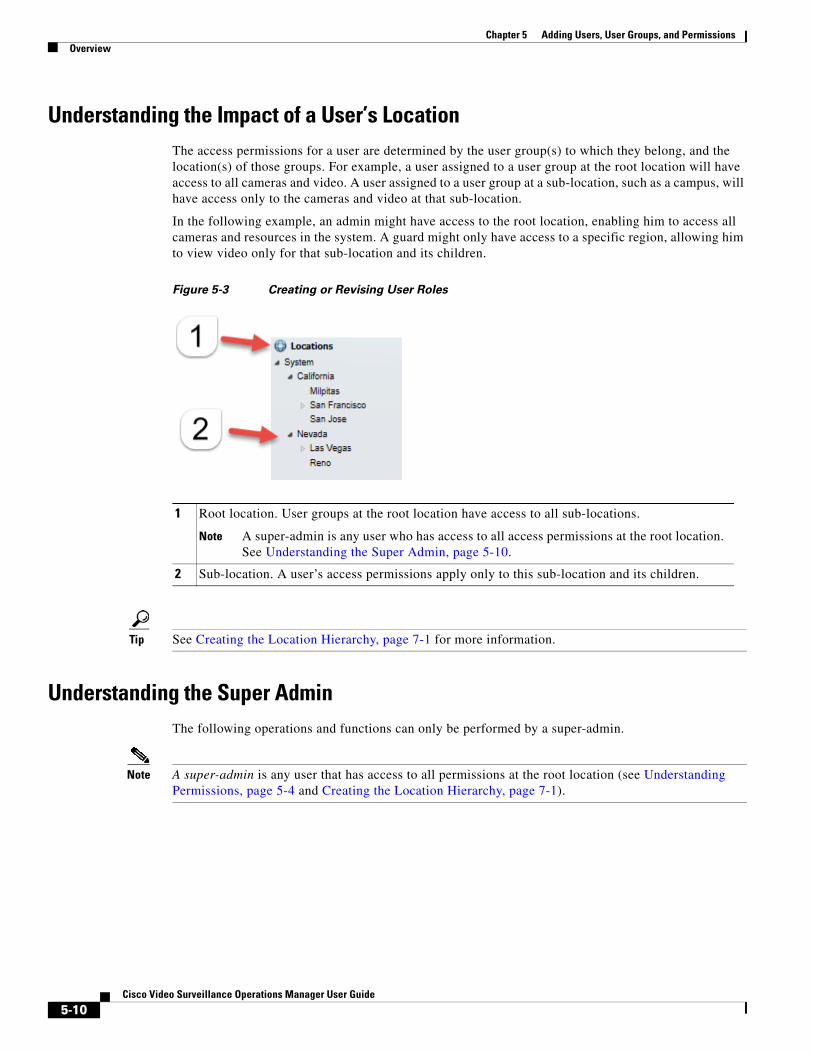
Chapter 5 Adding Users, User Groups, and Permissions Overview
Understanding the Impact of a User’s LocationThe access permissions for a user are determined by the user group(s) to which they belong, and the location(s) of those groups. For example, a user assigned to a user group at the root location will have access to all cameras and video. A user assigned to a user group at a sub-location, such as a campus, will have access only to the cameras and video at that sub-location.
In the following example, an admin might have access to the root location, enabling him to access all cameras and resources in the system. A guard might only have access to a specific region, allowing him to view video only for that sub-location and its children.
Figure 5-3 Creating or Revising User Roles
1
Note A super-admin is any user who has access to all access permissions at the root location. See Understanding the Super Admin, page 5-10.
2
Tip See Creating the Location Hierarchy, page 7-1 for more information.
Understanding the Super AdminThe following operations and functions can only be performed by a super-admin.
Note A super-admin is any user that has access to all permissions at the root location (see Understanding Permissions, page 5-4 and Creating the Location Hierarchy, page 7-1).
Root location. User groups at the root location have access to all sub-locations.
Sub-location. A user’s access permissions apply only to this sub-location and its children.
5-10Cisco Video Surveillance Operations Manager User Guide
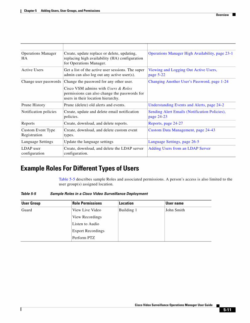
Chapter 5 Adding Users, User Groups, and PermissionsOverview
Table 5-4 Super-Admin Functions
Function Description More Information
Example Roles For Different Types of UsersTable 5-5 describes sample Roles and associated permissions. A person’s access is also limited to the user group(s) assigned location.
Operations Manager HA
Create, update replace or delete, updating, replacing high availability (HA) configuration for Operations Manager.
Operations Manager High Availability, page 23-1
Active Users Get a list of the active user sessions. The super admin can also log out any active user(s).
Viewing and Logging Out Active Users, page 5-22
Change user passwords Change the password for any other user.
Cisco VSM admins with Users & Roles permissions can also change the passwords for users in their location hierarchy.
Changing Another User’s Password, page 1-24
Prune History Prune (delete) old alerts and events. Understanding Events and Alerts, page 24-2
Notification policies Create, update and delete email notification policies.
Sending Alert Emails (Notification Policies), page 24-23
Reports Create, download, and delete reports. Reports, page 24-27
Custom Event Type Registration
Create, download, and delete custom event types.
Custom Data Management, page 24-43
Language Settings Update the language settings Language Settings, page 26-5
LDAP user configuration
Create, download, and delete the LDAP server configuration.
Adding Users from an LDAP Server
Table 5-5 Sample Roles in a Cisco Video Surveillance Deployment
User Group Role Permissions Location User name
Guard View Live Video
View Recordings
Listen to Audio
Export Recordings
Perform PTZ
Building 1 John Smith
5-11Cisco Video Surveillance Operations Manager User Guide
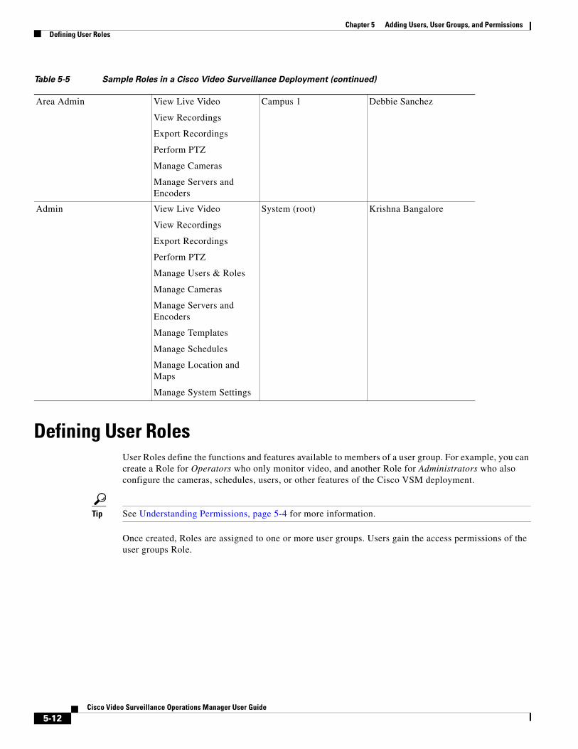
Chapter 5 Adding Users, User Groups, and Permissions Defining User Roles
Defining User Roles User Roles define the functions and features available to members of a user group. For example, you can create a Role for Operators who only monitor video, and another Role for Administrators who also configure the cameras, schedules, users, or other features of the Cisco VSM deployment.
Tip See Understanding Permissions, page 5-4 for more information.
Once created, Roles are assigned to one or more user groups. Users gain the access permissions of the user groups Role.
Area Admin View Live Video
View Recordings
Export Recordings
Perform PTZ
Manage Cameras
Manage Servers and Encoders
Campus 1 Debbie Sanchez
Admin View Live Video
View Recordings
Export Recordings
Perform PTZ
Manage Users & Roles
Manage Cameras
Manage Servers and Encoders
Manage Templates
Manage Schedules
Manage Location and Maps
Manage System Settings
System (root) Krishna Bangalore
Table 5-5 Sample Roles in a Cisco Video Surveillance Deployment (continued)
5-12Cisco Video Surveillance Operations Manager User Guide
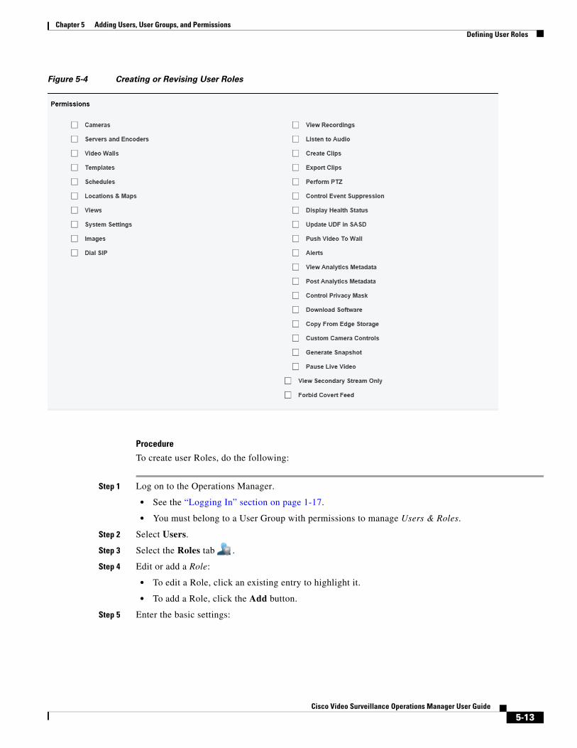
Chapter 5 Adding Users, User Groups, and PermissionsDefining User Roles
Figure 5-4 Creating or Revising User Roles
Procedure
To create user Roles, do the following:
Step 1 Log on to the Operations Manager.
• See the “Logging In” section on page 1-17.
• You must belong to a User Group with permissions to manage Users & Roles.
Step 2 Select Users.
Step 3 Select the Roles tab .
Step 4 Edit or add a Role:
• To edit a Role, click an existing entry to highlight it.
• To add a Role, click the Add button.
Step 5 Enter the basic settings:
5-13Cisco Video Surveillance Operations Manager User Guide
Chapter 5 Adding Users, User Groups, and Permissions Adding User Groups
Table 5-6 Role Settings
Setting Description
Step 6 (Required) Select or deselect the Role permissions.
See the “Understanding Permissions” section on page 5-4 for more information.
Step 7 (Optional) Add one or more user groups to the Role.
a. Click Add under the user groups box.
b. Select an existing user group.
c. Click OK.
See the “Adding User Groups” section on page 5-14 for more information.
Step 8 Select Create or Save.
Adding User Groups User groups allow multiple users to be assigned the same set of access permissions. For example, all lobby attendants can be assigned to a user group Lobby and security personnel to an Administrator group. Although members of the Lobby group can view live and recorded video, they cannot make configuration changes. Security administrators, however, can manage templates, schedules cameras, users, or other resources. These permissions are defined by the user Role assigned to the user group.
User groups are also associated with a specific location, allowing you to limit access to the Cisco VSM resources in a specific location (such as a campus, building, or floor). See the “Creating the Location Hierarchy” section on page 7-1 for more information.
Name (Required) Enter a meaningful name.
Location (Required) Select the location where the Role can be used.
Tags (Optional) Enter keywords used by the Find function.
Description (Optional) Enter a description of the permissions granted by the Role.
5-14Cisco Video Surveillance Operations Manager User Guide
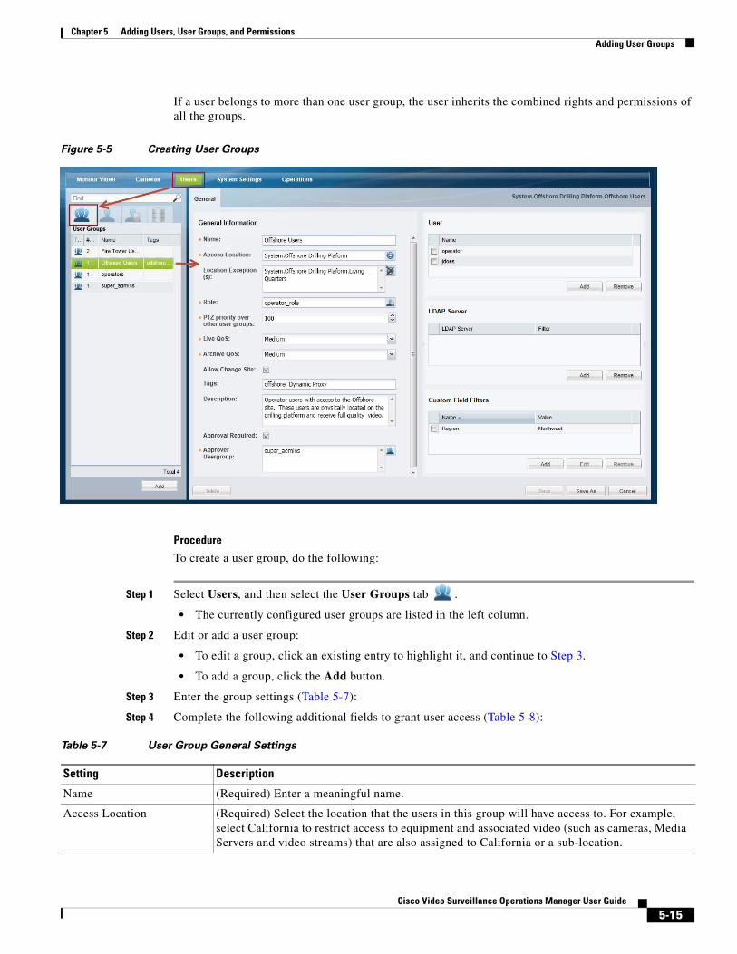
Chapter 5 Adding Users, User Groups, and PermissionsAdding User Groups
If a user belongs to more than one user group, the user inherits the combined rights and permissions of all the groups.
Figure 5-5 Creating User Groups
Procedure
To create a user group, do the following:
Step 1 Select Users, and then select the User Groups tab .
• The currently configured user groups are listed in the left column.
Step 2 Edit or add a user group:
• To edit a group, click an existing entry to highlight it, and continue to Step 3.
• To add a group, click the Add button.
Step 3 Enter the group settings (Table 5-7):
Step 4 Complete the following additional fields to grant user access (Table 5-8):
Table 5-7 User Group General Settings
Setting Description
Name (Required) Enter a meaningful name.
Access Location (Required) Select the location that the users in this group will have access to. For example, select California to restrict access to equipment and associated video (such as cameras, Media Servers and video streams) that are also assigned to California or a sub-location.
5-15Cisco Video Surveillance Operations Manager User Guide
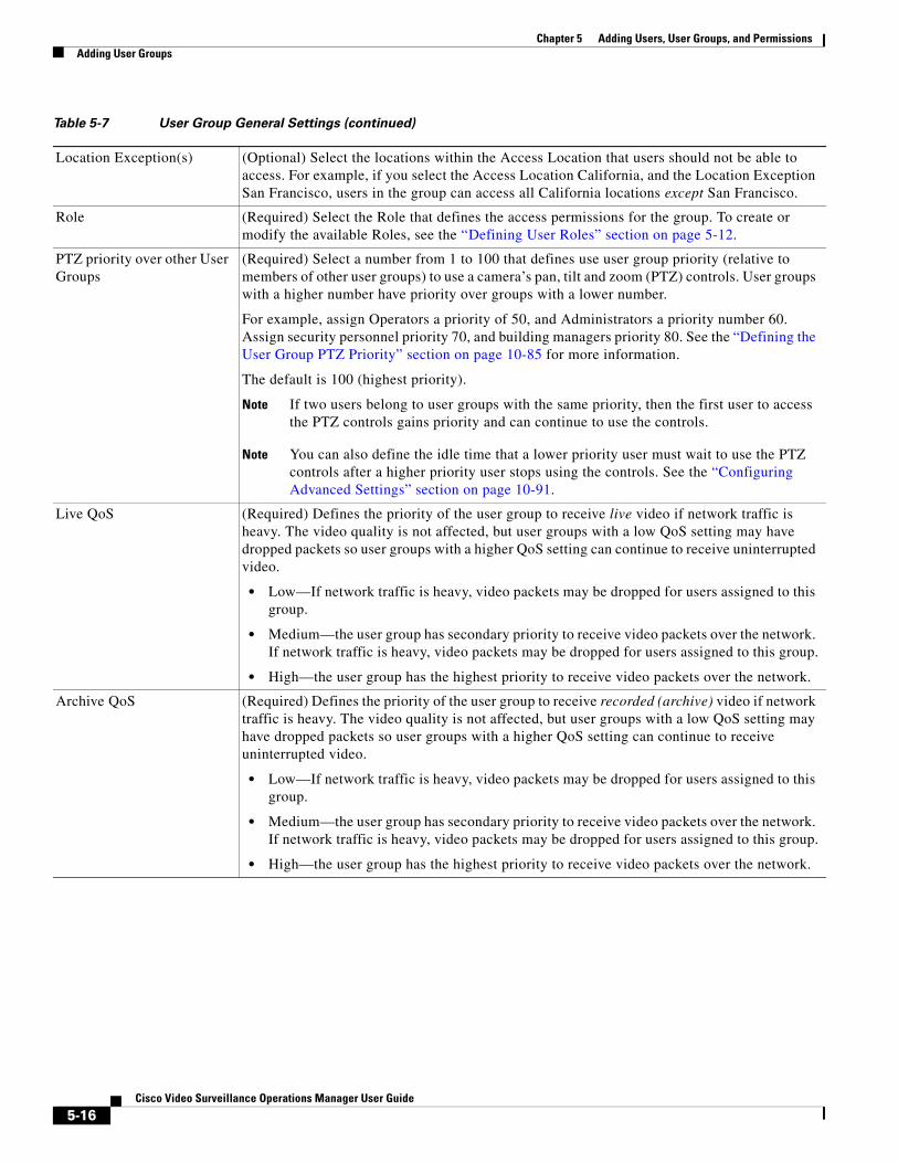
Chapter 5 Adding Users, User Groups, and Permissions Adding User Groups
Location Exception(s) (Optional) Select the locations within the Access Location that users should not be able to access. For example, if you select the Access Location California, and the Location Exception San Francisco, users in the group can access all California locations except San Francisco.
Role (Required) Select the Role that defines the access permissions for the group. To create or modify the available Roles, see the “Defining User Roles” section on page 5-12.
PTZ priority over other User Groups
(Required) Select a number from 1 to 100 that defines use user group priority (relative to members of other user groups) to use a camera’s pan, tilt and zoom (PTZ) controls. User groups with a higher number have priority over groups with a lower number.
For example, assign Operators a priority of 50, and Administrators a priority number 60. Assign security personnel priority 70, and building managers priority 80. See the “Defining the User Group PTZ Priority” section on page 10-85 for more information.
The default is 100 (highest priority).
Note If two users belong to user groups with the same priority, then the first user to access the PTZ controls gains priority and can continue to use the controls.
Note You can also define the idle time that a lower priority user must wait to use the PTZ controls after a higher priority user stops using the controls. See the “Configuring Advanced Settings” section on page 10-91.
Live QoS (Required) Defines the priority of the user group to receive live video if network traffic is heavy. The video quality is not affected, but user groups with a low QoS setting may have dropped packets so user groups with a higher QoS setting can continue to receive uninterrupted video.
• Low—If network traffic is heavy, video packets may be dropped for users assigned to this group.
• Medium—the user group has secondary priority to receive video packets over the network. If network traffic is heavy, video packets may be dropped for users assigned to this group.
• High—the user group has the highest priority to receive video packets over the network.
Archive QoS (Required) Defines the priority of the user group to receive recorded (archive) video if network traffic is heavy. The video quality is not affected, but user groups with a low QoS setting may have dropped packets so user groups with a higher QoS setting can continue to receive uninterrupted video.
• Low—If network traffic is heavy, video packets may be dropped for users assigned to this group.
• Medium—the user group has secondary priority to receive video packets over the network. If network traffic is heavy, video packets may be dropped for users assigned to this group.
• High—the user group has the highest priority to receive video packets over the network.
Table 5-7 User Group General Settings (continued)
5-16Cisco Video Surveillance Operations Manager User Guide

Chapter 5 Adding Users, User Groups, and PermissionsAdding User Groups
Allow Site Change (Optional) Select Allow Change Site to allow users to change their Site after logging into the Operations Manager. This option is disabled (deselected) by default when adding a new user group.
• Deselect to disable Site changes. Users must log out and log back in to change Sites.
• Users can only change Sites if they are assigned to User Groups with access to multiple Sites.
• If a user selects the “Not in Any Site” option, then video from cameras in Sites that have the Dynamic Proxy option enabled will be streamed from the Dynamic Proxy server.
Note Users who have access to multiple sites, but do not have the option to change sites, will default to “Not in any site” when logging in.
Note If a Site’s Dynamic Proxy option is disabled (deselected), video from cameras at the Site will be delivered to all users by the Site’s Media Servers (and not by a Dynamic Proxy server).
Tip Sites are used to define if you are inside or outside a location served by a Dynamic Proxy server. See the “Understanding Sites” section on page 29-3 for more information.
Defaults
• “Allow Site Change” is disabled by default when adding a User Group.
• “Allow Site Change” is enabled by default for all User Groups when upgrading to r7.5 from a previous release.7.5 (or higher) from a previous release.
Tags (Optional) Enter keywords used by the Find function.
Description (Optional) Enter a description of the rights granted by the Role.
Approval Required (Optional) If selected, a second user is required to approve the user login. When the user logs in, a window appears requiring a second user to enter their username and password.
See the “Understanding Dual Login” section on page 1-19 for more information.
Approval Usergroup (Required if Approval Required is selected). Select a User Group that can approve logins for members of the Approval Required usergroup.
Table 5-7 User Group General Settings (continued)
5-17Cisco Video Surveillance Operations Manager User Guide
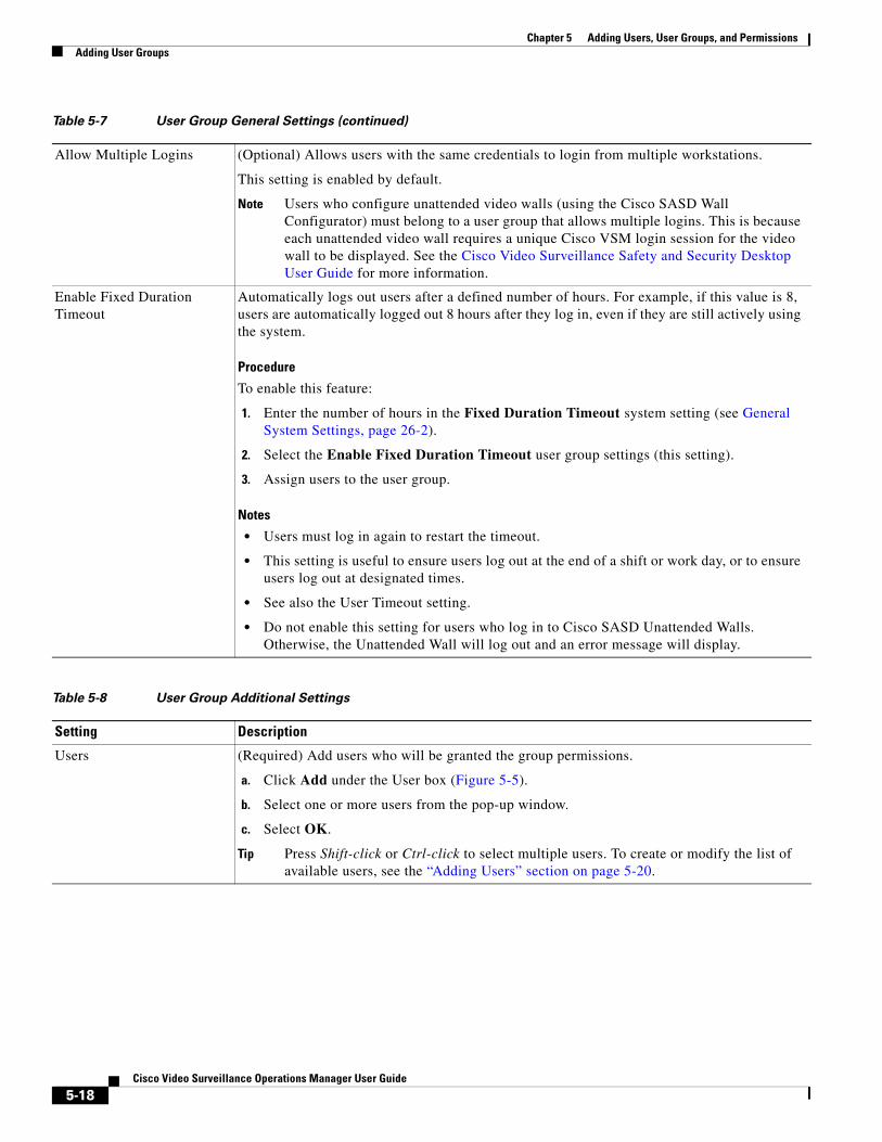
Chapter 5 Adding Users, User Groups, and Permissions Adding User Groups
Allow Multiple Logins (Optional) Allows users with the same credentials to login from multiple workstations.
This setting is enabled by default.
Note Users who configure unattended video walls (using the Cisco SASD Wall Configurator) must belong to a user group that allows multiple logins. This is because each unattended video wall requires a unique Cisco VSM login session for the video wall to be displayed. See the Cisco Video Surveillance Safety and Security Desktop User Guide for more information.
Enable Fixed Duration Timeout
Automatically logs out users after a defined number of hours. For example, if this value is 8, users are automatically logged out 8 hours after they log in, even if they are still actively using the system.
Procedure
To enable this feature:
1. Enter the number of hours in the Fixed Duration Timeout system setting (see General System Settings, page 26-2).
2. Select the Enable Fixed Duration Timeout user group settings (this setting).
3. Assign users to the user group.
Notes
• Users must log in again to restart the timeout.
• This setting is useful to ensure users log out at the end of a shift or work day, or to ensure users log out at designated times.
• See also the User Timeout setting.
• Do not enable this setting for users who log in to Cisco SASD Unattended Walls. Otherwise, the Unattended Wall will log out and an error message will display.
Table 5-8 User Group Additional Settings
Setting Description
Users (Required) Add users who will be granted the group permissions.
a. Click Add under the User box (Figure 5-5).
b. Select one or more users from the pop-up window.
c. Select OK.
Tip Press Shift-click or Ctrl-click to select multiple users. To create or modify the list of available users, see the “Adding Users” section on page 5-20.
Table 5-7 User Group General Settings (continued)
5-18Cisco Video Surveillance Operations Manager User Guide

Chapter 5 Adding Users, User Groups, and PermissionsAdding User Groups
Step 5 Click Create or Save to add or edit the user group.
LDAP server (Optional) If an LDAP server is used to authenticate users, add the LDAP groups that have access to Cisco VSM.
Related information
• Adding Users from an LDAP Server, page 6-1
• User Group Filter, page 6-9.
Custom Field Filters (Optional) Select the Custom Field Filters for the group to limit the cameras that users can access. Only cameras that match the filter will be available to user group members.
See Custom Fields, page 21-1 for more information.
Table 5-8 User Group Additional Settings (continued)
5-19Cisco Video Surveillance Operations Manager User Guide
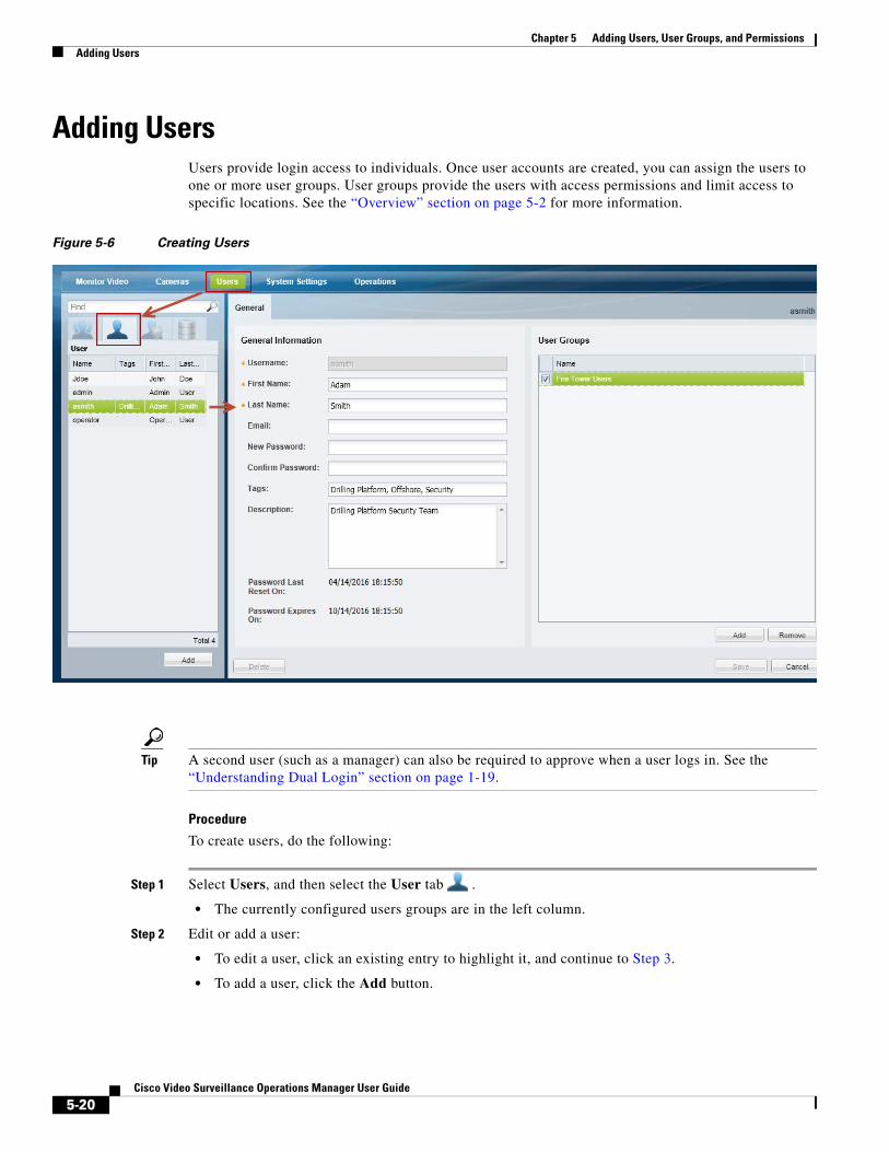
Chapter 5 Adding Users, User Groups, and Permissions Adding Users
Adding Users Users provide login access to individuals. Once user accounts are created, you can assign the users to one or more user groups. User groups provide the users with access permissions and limit access to specific locations. See the “Overview” section on page 5-2 for more information.
Figure 5-6 Creating Users
Tip A second user (such as a manager) can also be required to approve when a user logs in. See the “Understanding Dual Login” section on page 1-19.
Procedure
To create users, do the following:
Step 1 Select Users, and then select the User tab .
• The currently configured users groups are in the left column.
Step 2 Edit or add a user:
• To edit a user, click an existing entry to highlight it, and continue to Step 3.
• To add a user, click the Add button.
5-20Cisco Video Surveillance Operations Manager User Guide
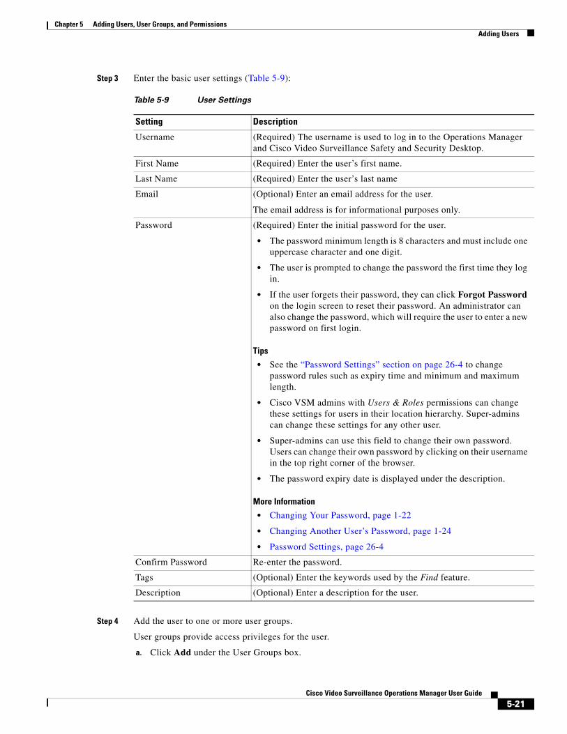
Chapter 5 Adding Users, User Groups, and PermissionsAdding Users
Step 3 Enter the basic user settings (Table 5-9):
Table 5-9 User Settings
Setting Description
• The password minimum length is 8 characters and must include one uppercase character and one digit.
• The user is prompted to change the password the first time they log in.
• If the user forgets their password, they can click Forgot Password on the login screen to reset their password. An administrator can also change the password, which will require the user to enter a new password on first login.
Tips
• See the “Password Settings” section on page 26-4 to change password rules such as expiry time and minimum and maximum length.
• Cisco VSM admins with Users & Roles permissions can change these settings for users in their location hierarchy. Super-admins can change these settings for any other user.
• Super-admins can use this field to change their own password. Users can change their own password by clicking on their username in the top right corner of the browser.
• The password expiry date is displayed under the description.
More Information
• Changing Your Password, page 1-22
• Changing Another User’s Password, page 1-24
• Password Settings, page 26-4
Step 4 Add the user to one or more user groups.
User groups provide access privileges for the user.
a. Click Add under the User Groups box.
Username (Required) The username is used to log in to the Operations Manager and Cisco Video Surveillance Safety and Security Desktop.
First Name (Required) Enter the user’s first name.
Last Name (Required) Enter the user’s last name
Email (Optional) Enter an email address for the user.
The email address is for informational purposes only.
Password (Required) Enter the initial password for the user.
Confirm Password Re-enter the password.
Tags (Optional) Enter the keywords used by the Find feature.
Description (Optional) Enter a description for the user.
5-21Cisco Video Surveillance Operations Manager User Guide
Chapter 5 Adding Users, User Groups, and Permissions Defining Password Rules and Security Questions
b. Select one or more user groups from the pop-up window.
c. Select OK.
Tip See the “Adding User Groups” section on page 5-14 for instructions to add or edit groups.
Step 5 Select Create or Save to save the changes.
Defining Password Rules and Security QuestionsUse the Password settings page to define when a user’s password expires, the minimum and maximum characters, and other rules to make sure user passwords are strong.
You can also define the security questions that allow a user to change their password if they forget it.
Step 1 Choose System Settings > Settings.
Step 2 Click the Password tab.
Step 3 See Password Settings for descriptions of the available fields.
Viewing and Logging Out Active UsersThe Active Users page displays information about the user accounts that are currently logged in to the Cisco Video Surveillance system. This page is available to super-admins only.
Choose Operations > Active Users.
To discontinue an active user session, select an entry and click Kill Session. Users that are logged out in this method can continue watching the video they are currently viewing. But users must log in again if they attempt to access new video streams or open a new video pane.
Table 5-10 Active User Fields
Setting Description
Username The username of the account used to access the system.
First Name The first name in the user account
Last Name The last name in the user account
User Group(s) The user groups the user is assigned to.
User groups define the user role and location for member users, which defines the cameras and resources they can access.
Super-admin Indicates if the user account is assigned the super-admin role.
See Understanding the System-Defined User Roles, Groups and Accounts, page 5-4.
Logged-In Time The date and time when the user logged in.
5-22Cisco Video Surveillance Operations Manager User Guide
Chapter 5 Adding Users, User Groups, and PermissionsViewing and Logging Out Active Users
Note You cannot kill (end) your own user session.
Tip To view a history of user activity, go to Operations > Audit Logs (see Viewing Audit Logs, page 24-42).
Last Access Time The date and time the user last performed any action on the system.
From IP The IP address of the device or computer used to access the system.
Table 5-10 Active User Fields (continued)
Setting Description
5-23Cisco Video Surveillance Operations Manager User Guide

Chapter 5 Adding Users, User Groups, and Permissions Viewing and Logging Out Active Users
5-24Cisco Video Surveillance Operations Manager User Guide
Cisco V
C H A P T E R 6
Adding Users from an LDAP ServerAdd an LDAP (Lightweight Directory Access Protocol) server to the Cisco VSM user configuration to provide access to members of an external user database. After the LDAP server is added, users from that system can log in to Cisco VSM using the credentials configured on the LDAP server (the users do not need to be added individually to the Operations Manager configuration).
Refer to the following topics for more information:
• LDAP Usage Notes, page 6-1
• LDAP Configuration Procedure, page 6-2
• LDAP Server Settings, page 6-6
• User Group Filter, page 6-9
– LDAP Search Filters, page 6-9
– User Name List, page 6-10
• Look up the Access Permissions for an LDAP User, page 6-11
• LDAP Configuration Examples, page 6-13
LDAP Usage Notes • LDAP users can be added or removed from the source database without affecting Cisco VSM. When
the LDAP user logs in to Cisco Video Surveillance, their credentials are authenticated with the LDAP server, and access is granted or denied based on the LDAP response.
• Use User Group filters to limit the users who can access Cisco VSM.
• To delete an LDAP server, you must unassociate the LDAP server from all Cisco VSM user groups.
• The maximum number of User Group filters is 500.
Upgrade Requirements for Release 7.0
New fields were added in Cisco VSM release 7.0.1 to simplify the LDAP server configuration. After upgrading from release 7.0.0, the administrator must reconfigure the LDAP server settings including the following:
• Review all LDAP server configurations in the Operations Manager and update missing information after the upgrade.
• Verify and reconfigure the binding requirements.
• Reconfigure the LDAP filters and User Group associations for each server.
6-1ideo Surveillance Operations Manager User Guide
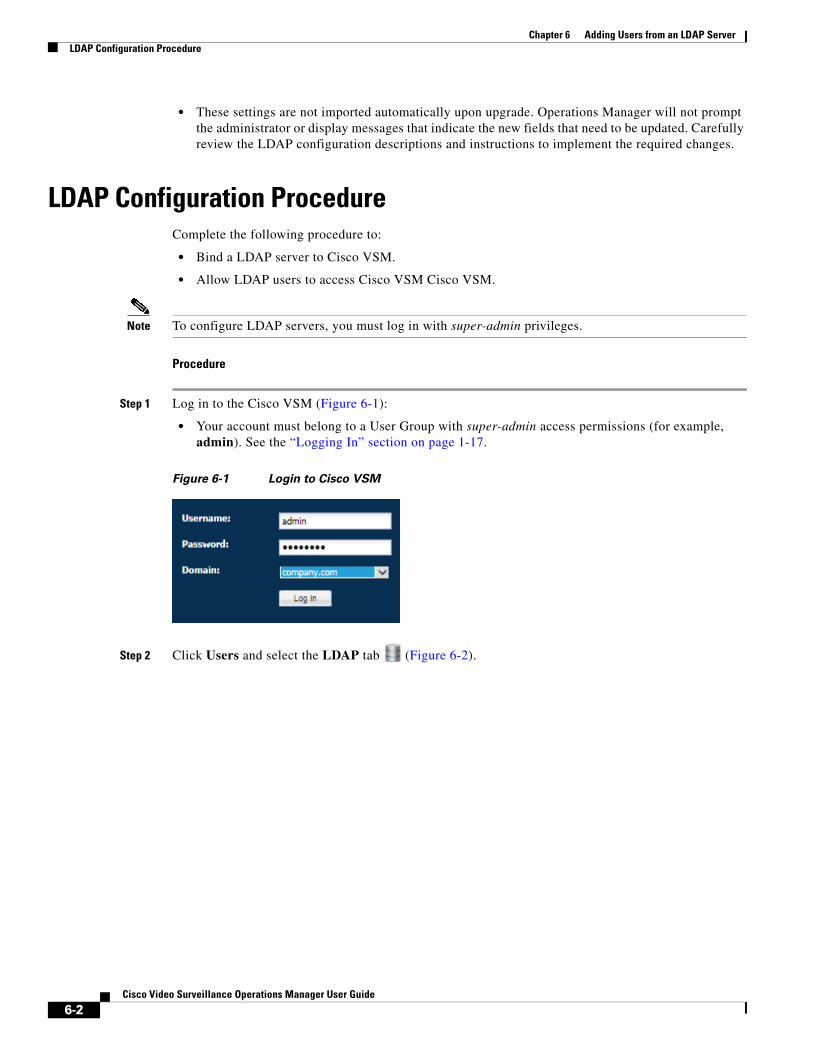
Chapter 6 Adding Users from an LDAP Server LDAP Configuration Procedure
• These settings are not imported automatically upon upgrade. Operations Manager will not prompt the administrator or display messages that indicate the new fields that need to be updated. Carefully review the LDAP configuration descriptions and instructions to implement the required changes.
LDAP Configuration ProcedureComplete the following procedure to:
• Bind a LDAP server to Cisco VSM.
• Allow LDAP users to access Cisco VSM Cisco VSM.
Note To configure LDAP servers, you must log in with super-admin privileges.
Procedure
Step 1 Log in to the Cisco VSM (Figure 6-1):
• Your account must belong to a User Group with super-admin access permissions (for example, admin). See the “Logging In” section on page 1-17.
Figure 6-1 Login to Cisco VSM
Step 2 Click Users and select the LDAP tab (Figure 6-2).
6-2Cisco Video Surveillance Operations Manager User Guide
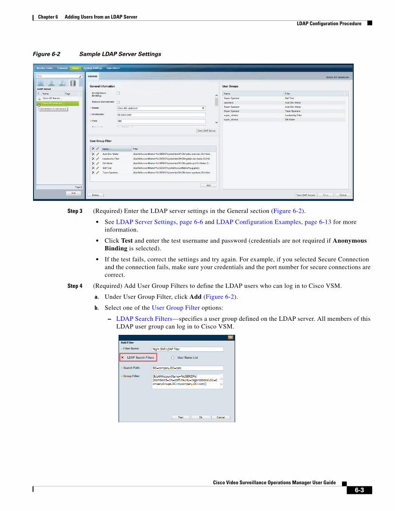
Chapter 6 Adding Users from an LDAP ServerLDAP Configuration Procedure
Figure 6-2 Sample LDAP Server Settings
Step 3 (Required) Enter the LDAP server settings in the General section (Figure 6-2).
• See LDAP Server Settings, page 6-6 and LDAP Configuration Examples, page 6-13 for more information.
• Click Test and enter the test username and password (credentials are not required if Anonymous Binding is selected).
• If the test fails, correct the settings and try again. For example, if you selected Secure Connection and the connection fails, make sure your credentials and the port number for secure connections are correct.
Step 4 (Required) Add User Group Filters to define the LDAP users who can log in to Cisco VSM.
a. Under User Group Filter, click Add (Figure 6-2).
b. Select one of the User Group Filter options:
– LDAP Search Filters—specifies a user group defined on the LDAP server. All members of this LDAP user group can log in to Cisco VSM.
6-3Cisco Video Surveillance Operations Manager User Guide
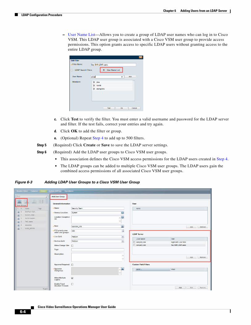
Chapter 6 Adding Users from an LDAP Server LDAP Configuration Procedure
– User Name List—Allows you to create a group of LDAP user names who can log in to Cisco VSM. This LDAP user group is associated with a Cisco VSM user group to provide access permissions. This option grants access to specific LDAP users without granting access to the entire LDAP group.
c. Click Test to verify the filter. You must enter a valid username and password for the LDAP server and filter. If the test fails, correct your entries and try again.
d. Click OK to add the filter or group.
e. (Optional) Repeat Step 4 to add up to 500 filters.
Step 5 (Required) Click Create or Save to save the LDAP server settings.
Step 6 (Required) Add the LDAP user groups to Cisco VSM user groups.
• This association defines the Cisco VSM access permissions for the LDAP users created in Step 4.
• The LDAP groups can be added to multiple Cisco VSM user groups. The LDAP users gain the combined access permissions of all associated Cisco VSM user groups.
Figure 6-3 Adding LDAP User Groups to a Cisco VSM User Group
6-4Cisco Video Surveillance Operations Manager User Guide
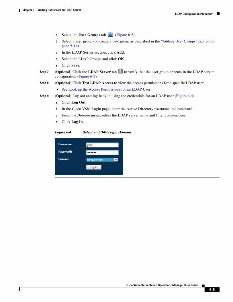
Chapter 6 Adding Users from an LDAP ServerLDAP Configuration Procedure
a. Select the User Groups tab (Figure 6-3).
b. Select a user group (or create a new group as described in the “Adding User Groups” section on page 5-14).
c. In the LDAP Server section, click Add.
d. Select the LDAP Groups and click OK.
e. Click Save.
Step 7 (Optional) Click the LDAP Server tab to verify that the user group appears in the LDAP server configuration (Figure 6-2).
Step 8 (Optional) Click Test LDAP Access to view the access permissions for a specific LDAP user.
• See Look up the Access Permissions for an LDAP User.
Step 9 (Optional) Log out and log back in using the credentials for an LDAP user (Figure 6-4).
a. Click Log Out.
b. In the Cisco VSM Login page, enter the Active Directory username and password.
c. From the Domain menu, select the LDAP server name and filter combination.
d. Click Log In.
Figure 6-4 Select an LDAP Login Domain
6-5Cisco Video Surveillance Operations Manager User Guide
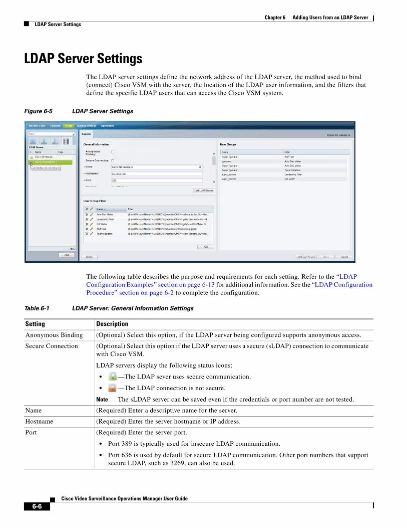
Chapter 6 Adding Users from an LDAP Server LDAP Server Settings
LDAP Server SettingsThe LDAP server settings define the network address of the LDAP server, the method used to bind (connect) Cisco VSM with the server, the location of the LDAP user information, and the filters that define the specific LDAP users that can access the Cisco VSM system.
Figure 6-5 LDAP Server Settings
The following table describes the purpose and requirements for each setting. Refer to the “LDAP Configuration Examples” section on page 6-13 for additional information. See the “LDAP Configuration Procedure” section on page 6-2 to complete the configuration.
Table 6-1 LDAP Server: General Information Settings
Setting Description
Anonymous Binding (Optional) Select this option, if the LDAP server being configured supports anonymous access.
Secure Connection (Optional) Select this option if the LDAP server uses a secure (sLDAP) connection to communicate with Cisco VSM.
LDAP servers display the following status icons:
• —The LDAP sever uses secure communication.
• —The LDAP connection is not secure.
Note The sLDAP server can be saved even if the credentials or port number are not tested.
Name (Required) Enter a descriptive name for the server.
Hostname (Required) Enter the server hostname or IP address.
Port (Required) Enter the server port.
• Port 389 is typically used for insecure LDAP communication.
• Port 636 is used by default for secure LDAP communication. Other port numbers that support secure LDAP, such as 3269, can also be used.
6-6Cisco Video Surveillance Operations Manager User Guide
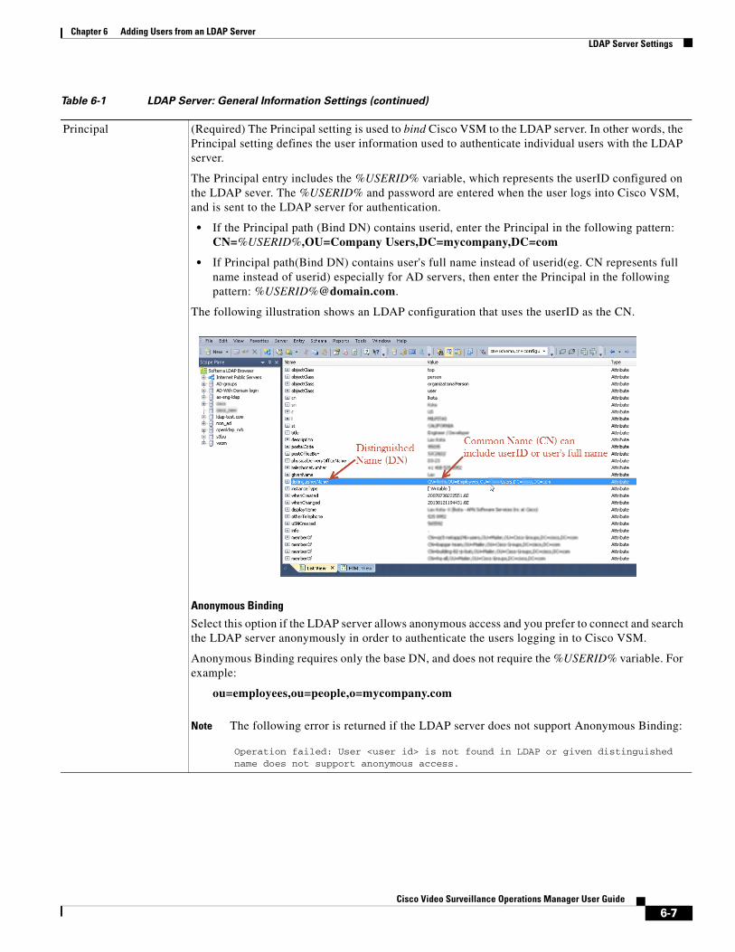
Chapter 6 Adding Users from an LDAP ServerLDAP Server Settings
Principal (Required) The Principal setting is used to bind Cisco VSM to the LDAP server. In other words, the Principal setting defines the user information used to authenticate individual users with the LDAP server.
The Principal entry includes the %USERID% variable, which represents the userID configured on the LDAP sever. The %USERID% and password are entered when the user logs into Cisco VSM, and is sent to the LDAP server for authentication.
• If the Principal path (Bind DN) contains userid, enter the Principal in the following pattern: CN=%USERID%,OU=Company Users,DC=mycompany,DC=com
• If Principal path(Bind DN) contains user's full name instead of userid(eg. CN represents full name instead of userid) especially for AD servers, then enter the Principal in the following pattern: %USERID%@domain.com.
The following illustration shows an LDAP configuration that uses the userID as the CN.
Anonymous Binding
Select this option if the LDAP server allows anonymous access and you prefer to connect and search the LDAP server anonymously in order to authenticate the users logging in to Cisco VSM.
Anonymous Binding requires only the base DN, and does not require the %USERID% variable. For example:
ou=employees,ou=people,o=mycompany.com
Note The following error is returned if the LDAP server does not support Anonymous Binding:
Operation failed: User <user id> is not found in LDAP or given distinguished name does not support anonymous access.
Table 6-1 LDAP Server: General Information Settings (continued)
6-7Cisco Video Surveillance Operations Manager User Guide
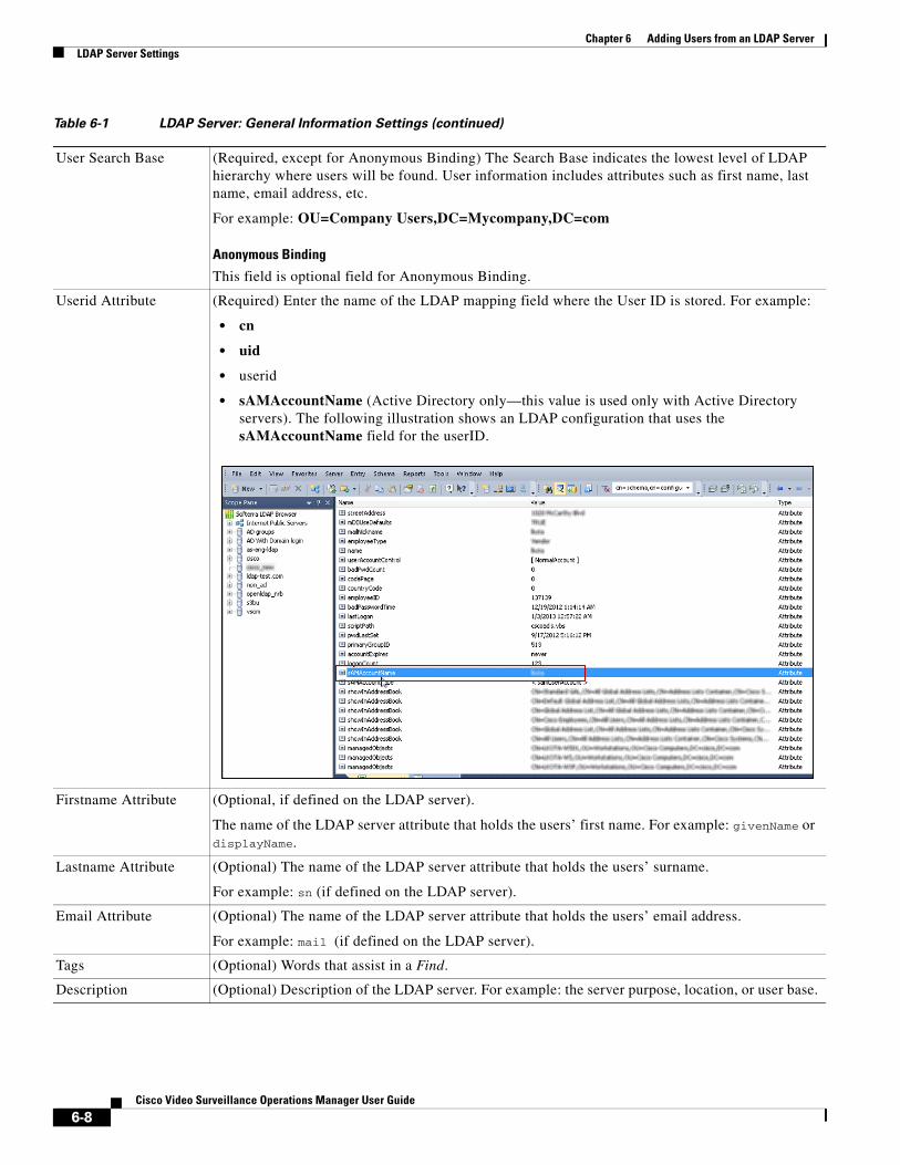
Chapter 6 Adding Users from an LDAP Server LDAP Server Settings
User Search Base (Required, except for Anonymous Binding) The Search Base indicates the lowest level of LDAP hierarchy where users will be found. User information includes attributes such as first name, last name, email address, etc.
For example: OU=Company Users,DC=Mycompany,DC=com
Anonymous Binding
This field is optional field for Anonymous Binding.
Userid Attribute (Required) Enter the name of the LDAP mapping field where the User ID is stored. For example:
• cn
• uid
• userid
• sAMAccountName (Active Directory only—this value is used only with Active Directory servers). The following illustration shows an LDAP configuration that uses the sAMAccountName field for the userID.
Firstname Attribute (Optional, if defined on the LDAP server).
The name of the LDAP server attribute that holds the users’ first name. For example: givenName or displayName.
Lastname Attribute (Optional) The name of the LDAP server attribute that holds the users’ surname.
For example: sn (if defined on the LDAP server).
Email Attribute (Optional) The name of the LDAP server attribute that holds the users’ email address.
For example: mail (if defined on the LDAP server).
Tags (Optional) Words that assist in a Find.
Description (Optional) Description of the LDAP server. For example: the server purpose, location, or user base.
Table 6-1 LDAP Server: General Information Settings (continued)
6-8Cisco Video Surveillance Operations Manager User Guide
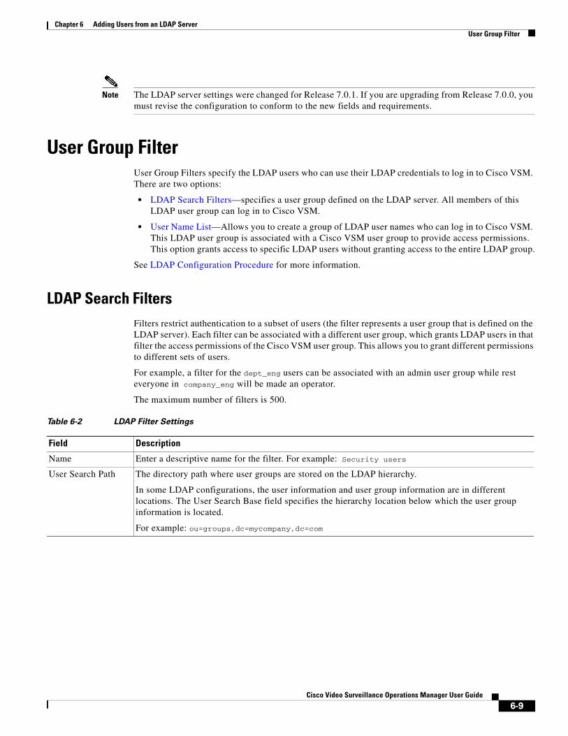
Chapter 6 Adding Users from an LDAP ServerUser Group Filter
Note The LDAP server settings were changed for Release 7.0.1. If you are upgrading from Release 7.0.0, you must revise the configuration to conform to the new fields and requirements.
User Group FilterUser Group Filters specify the LDAP users who can use their LDAP credentials to log in to Cisco VSM. There are two options:
• LDAP Search Filters—specifies a user group defined on the LDAP server. All members of this LDAP user group can log in to Cisco VSM.
• User Name List—Allows you to create a group of LDAP user names who can log in to Cisco VSM. This LDAP user group is associated with a Cisco VSM user group to provide access permissions. This option grants access to specific LDAP users without granting access to the entire LDAP group.
See LDAP Configuration Procedure for more information.
LDAP Search FiltersFilters restrict authentication to a subset of users (the filter represents a user group that is defined on the LDAP server). Each filter can be associated with a different user group, which grants LDAP users in that filter the access permissions of the Cisco VSM user group. This allows you to grant different permissions to different sets of users.
For example, a filter for the dept_eng users can be associated with an admin user group while rest everyone in company_eng will be made an operator.
The maximum number of filters is 500.
Table 6-2 LDAP Filter Settings
Field Description
Name Enter a descriptive name for the filter. For example: Security users
User Search Path The directory path where user groups are stored on the LDAP hierarchy.
In some LDAP configurations, the user information and user group information are in different locations. The User Search Base field specifies the hierarchy location below which the user group information is located.
For example: ou=groups,dc=mycompany,dc=com
6-9Cisco Video Surveillance Operations Manager User Guide
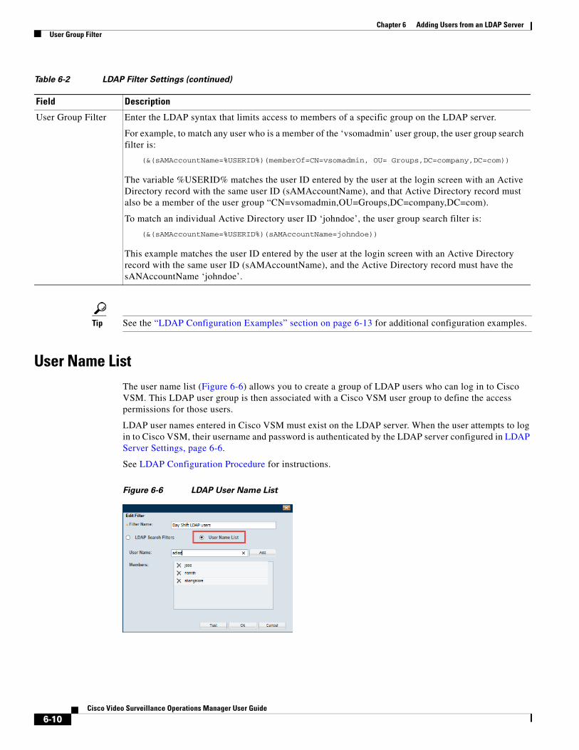
Chapter 6 Adding Users from an LDAP Server User Group Filter
Tip See the “LDAP Configuration Examples” section on page 6-13 for additional configuration examples.
User Name ListThe user name list (Figure 6-6) allows you to create a group of LDAP users who can log in to Cisco VSM. This LDAP user group is then associated with a Cisco VSM user group to define the access permissions for those users.
LDAP user names entered in Cisco VSM must exist on the LDAP server. When the user attempts to log in to Cisco VSM, their username and password is authenticated by the LDAP server configured in LDAP Server Settings, page 6-6.
See LDAP Configuration Procedure for instructions.
Figure 6-6 LDAP User Name List
User Group Filter Enter the LDAP syntax that limits access to members of a specific group on the LDAP server.
For example, to match any user who is a member of the ‘vsomadmin’ user group, the user group search filter is:
(&(sAMAccountName=%USERID%)(memberOf=CN=vsomadmin, OU= Groups,DC=company,DC=com))
The variable %USERID% matches the user ID entered by the user at the login screen with an Active Directory record with the same user ID (sAMAccountName), and that Active Directory record must also be a member of the user group “CN=vsomadmin,OU=Groups,DC=company,DC=com).
To match an individual Active Directory user ID ‘johndoe’, the user group search filter is:
(&(sAMAccountName=%USERID%)(sAMAccountName=johndoe))
This example matches the user ID entered by the user at the login screen with an Active Directory record with the same user ID (sAMAccountName), and the Active Directory record must have the sANAccountName ‘johndoe’.
Table 6-2 LDAP Filter Settings (continued)
Field Description
6-10Cisco Video Surveillance Operations Manager User Guide
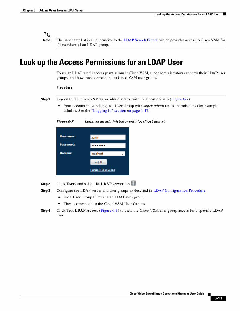
Chapter 6 Adding Users from an LDAP ServerLook up the Access Permissions for an LDAP User
Note The user name list is an alternative to the LDAP Search Filters, which provides access to Cisco VSM for all members of an LDAP group.
Look up the Access Permissions for an LDAP UserTo see an LDAP user’s access permissions in Cisco VSM, super administrators can view their LDAP user groups, and how those correspond to Cisco VSM user groups.
Procedure
Step 1 Log on to the Cisco VSM as an administrator with localhost domain (Figure 6-7):
• Your account must belong to a User Group with super-admin access permissions (for example, admin). See the “Logging In” section on page 1-17.
Figure 6-7 Login as an administrator with localhost domain
Step 2 Click Users and select the LDAP server tab .
Step 3 Configure the LDAP server and user groups as descried in LDAP Configuration Procedure.
• Each User Group Filter is a an LDAP user group.
• These correspond to the Cisco VSM User Groups.
Step 4 Click Test LDAP Access (Figure 6-8) to view the Cisco VSM user group access for a specific LDAP user.
6-11Cisco Video Surveillance Operations Manager User Guide
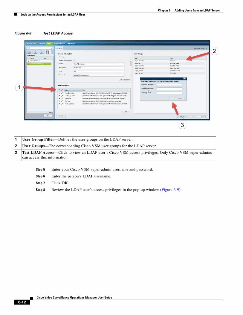
Chapter 6 Adding Users from an LDAP Server Look up the Access Permissions for an LDAP User
Figure 6-8 Test LDAP Access
1
2
3
Step 5 Enter your Cisco VSM super-admin username and password.
Step 6 Enter the person’s LDAP username.
Step 7 Click OK.
Step 8 Review the LDAP user’s access privileges in the pop-up window (Figure 6-9).
User Group Filter—Defines the user groups on the LDAP server.
User Groups—The corresponding Cisco VSM user groups for the LDAP server.
Test LDAP Access—Click to view an LDAP user’s Cisco VSM access privileges. Only Cisco VSM super-admins can access this information
6-12Cisco Video Surveillance Operations Manager User Guide
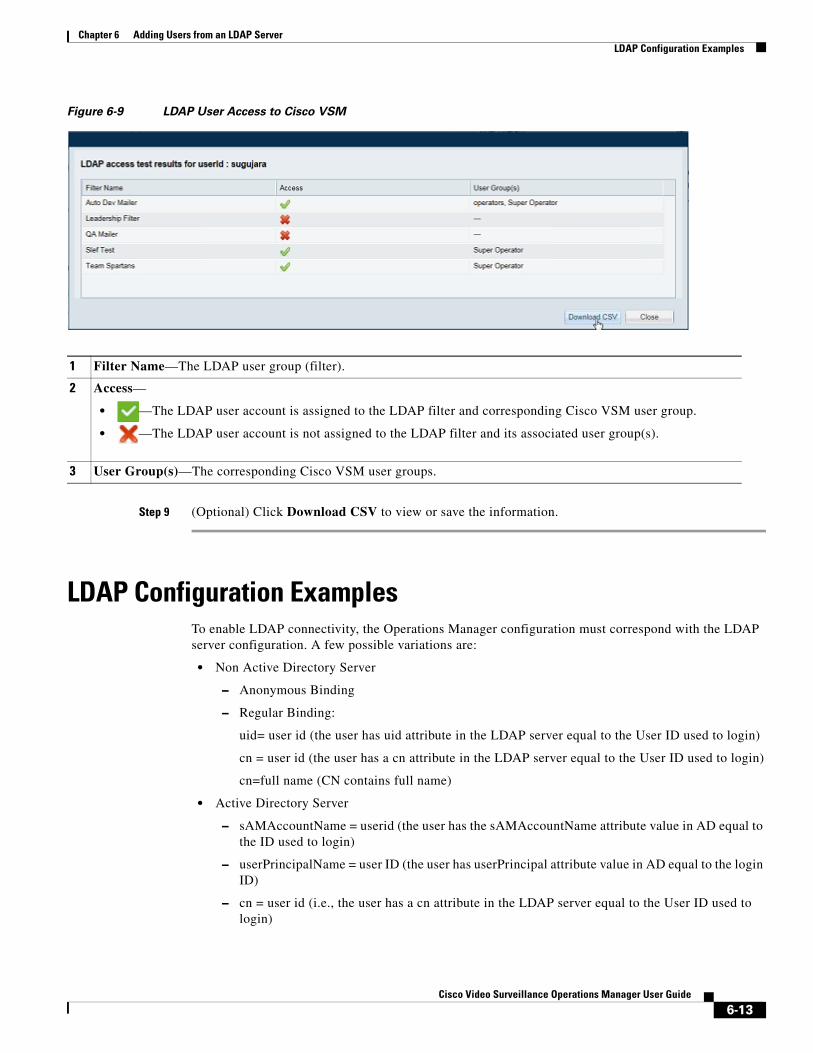
Chapter 6 Adding Users from an LDAP ServerLDAP Configuration Examples
Figure 6-9 LDAP User Access to Cisco VSM
1
2
• —The LDAP user account is assigned to the LDAP filter and corresponding Cisco VSM user group.
• —The LDAP user account is not assigned to the LDAP filter and its associated user group(s).
3
Step 9 (Optional) Click Download CSV to view or save the information.
LDAP Configuration ExamplesTo enable LDAP connectivity, the Operations Manager configuration must correspond with the LDAP server configuration. A few possible variations are:
• Non Active Directory Server
– Anonymous Binding
– Regular Binding:
uid= user id (the user has uid attribute in the LDAP server equal to the User ID used to login)
cn = user id (the user has a cn attribute in the LDAP server equal to the User ID used to login)
cn=full name (CN contains full name)
• Active Directory Server
– sAMAccountName = userid (the user has the sAMAccountName attribute value in AD equal to the ID used to login)
– userPrincipalName = user ID (the user has userPrincipal attribute value in AD equal to the login ID)
– cn = user id (i.e., the user has a cn attribute in the LDAP server equal to the User ID used to login)
Filter Name—The LDAP user group (filter).
Access—
User Group(s)—The corresponding Cisco VSM user groups.
6-13Cisco Video Surveillance Operations Manager User Guide
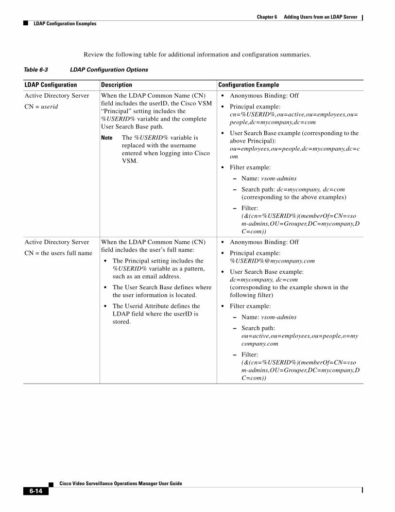
Chapter 6 Adding Users from an LDAP Server LDAP Configuration Examples
Review the following table for additional information and configuration summaries.
Table 6-3 LDAP Configuration Options
LDAP Configuration Description Configuration Example
Active Directory Server
CN = userid
When the LDAP Common Name (CN) field includes the userID, the Cisco VSM “Principal” setting includes the %USERID% variable and the complete User Search Base path.
Note The %USERID% variable is replaced with the username entered when logging into Cisco VSM.
• Anonymous Binding: Off
• Principal example: cn=%USERID%,ou=active,ou=employees,ou=people,dc=mycompany,dc=com
• User Search Base example (corresponding to the above Principal): ou=employees,ou=people,dc=mycompany,dc=com
• Filter example:
– Name: vsom-admins
– Search path: dc=mycompany, dc=com (corresponding to the above examples)
– Filter: (&(cn=%USERID%)(memberOf=CN=vsom-admins,OU=Grouper,DC=mycompany,DC=com))
Active Directory Server
CN = the users full name
When the LDAP Common Name (CN) field includes the user’s full name:
• The Principal setting includes the %USERID% variable as a pattern, such as an email address.
• The User Search Base defines where the user information is located.
• The Userid Attribute defines the LDAP field where the userID is stored.
• Anonymous Binding: Off
• Principal example: %USERID%@mycompany.com
• User Search Base example: dc=mycompany, dc=com (corresponding to the example shown in the following filter)
• Filter example:
– Name: vsom-admins
– Search path: ou=active,ou=employees,ou=people,o=mycompany.com
– Filter: (&(cn=%USERID%)(memberOf=CN=vsom-admins,OU=Grouper,DC=mycompany,DC=com))
6-14Cisco Video Surveillance Operations Manager User Guide

Chapter 6 Adding Users from an LDAP ServerLDAP Configuration Examples
Regular LDAP binding (non-Active Directory)
A non-Active Directory server uses the User Search Base path where the user information is stored in both the Principal and User Search Base fields.
The Userid Attribute defines the LDAP field where the userID is stored.
• Anonymous Binding: Off
• Principal example: CN=%USERID%,OU=people,OU=US,DC=mycompany,DC=com
• User Search Base example: ou=people,ou=us,dc=mycompany,dc=com (corresponding to the above Principal)
• Filter example:
– Name: vsom-admins
– Search path: ou=people,ou=us,dc=mycompany,dc=com (corresponding to the above Principal)
– Filter: (&(objectClass=posixGroup)(memberuid=%USERID%)(cn=vsomadmins))
Anonymous Binding
(non-Active Directory)
If the LDAP server is configured to be accessed as anonymous, the %USERID% variable is not required.
Only the correct server hostname, port and principal is required to bind Cisco VSM to the LDAP server.
Note Although the communication (binding) can occur anonymously between Cisco VSM and the LDAP server, Cisco VSM also verifies that the username and password entered by the user are valid on the LDAP server.
Note The Test button does not require you to enter a username or password since the test is only checking for server connectivity (not valid user credentials). The Test will complete successfully if the LDAP server is configured for Anonymous Binding and if the server address and port are correct.
• Anonymous Binding: On
• Principal example: ou=people,ou=us,dc=mycompany,dc=com
• User Search Base: Leave blank
• Filter example:
– Name: vsom-admins
– Search path: dc=mycompany,dc=com
– Filter: (&(objectClass=posixGroup)(memberuid=%USERID%)(cn=vsomadmins))
Table 6-3 LDAP Configuration Options (continued)
LDAP Configuration Description Configuration Example
6-15Cisco Video Surveillance Operations Manager User Guide

Chapter 6 Adding Users from an LDAP Server LDAP Configuration Examples
6-16Cisco Video Surveillance Operations Manager User Guide

Cisco V
C H A P T E R 7
Creating the Location HierarchyLocations allow you to organize your deployment according to the real-world location of equipment and users. Locations also allow administrators to restrict user access to the specific cameras, policies, and data (such as alerts) required by the user’s role within the organization. For example, while a super-admin has full access to all locations and devices, a local campus administrator might have access only to the devices and policies required to manage a specific site.
This chapter describes how to create the location hierarchy, assign locations to devices, policies, and user groups, and how those assignments impact a user’s ability to access Cisco VSM resources.
Tip Since all servers, user groups and cameras must be assigned to a location, create the location hierarchy before performing other configuration tasks. Review the information in this section carefully, and then create a location plan to ensure the users in your deployment can access only the equipment, video and policies required for their role.
Contents
• Overview, page 7-2
• Understanding Permission-Based and Partition-Based Resources, page 7-3
– Simple Deployments (User Access to All Devices and Resources), page 7-4
– Permission-Based Resources: Limiting User Access to Devices, page 7-4
– Partition-Based Resources: User Access to Templates, Schedules and Other Resources, page 7-5
• Examples: Locations in Simple vs. Large Deployments, page 7-7
• Understanding a Camera’s Installed Location Vs. the Pointed Location, page 7-9
• Creating and Editing the Location Hierarchy, page 7-10
• Importing the Location Hierarchy Using a CSV File, page 7-13
• Impact of Device Location Changes on Alerts, page 7-16
• Deleting a Location, page 7-17
7-1ideo Surveillance Operations Manager User Guide
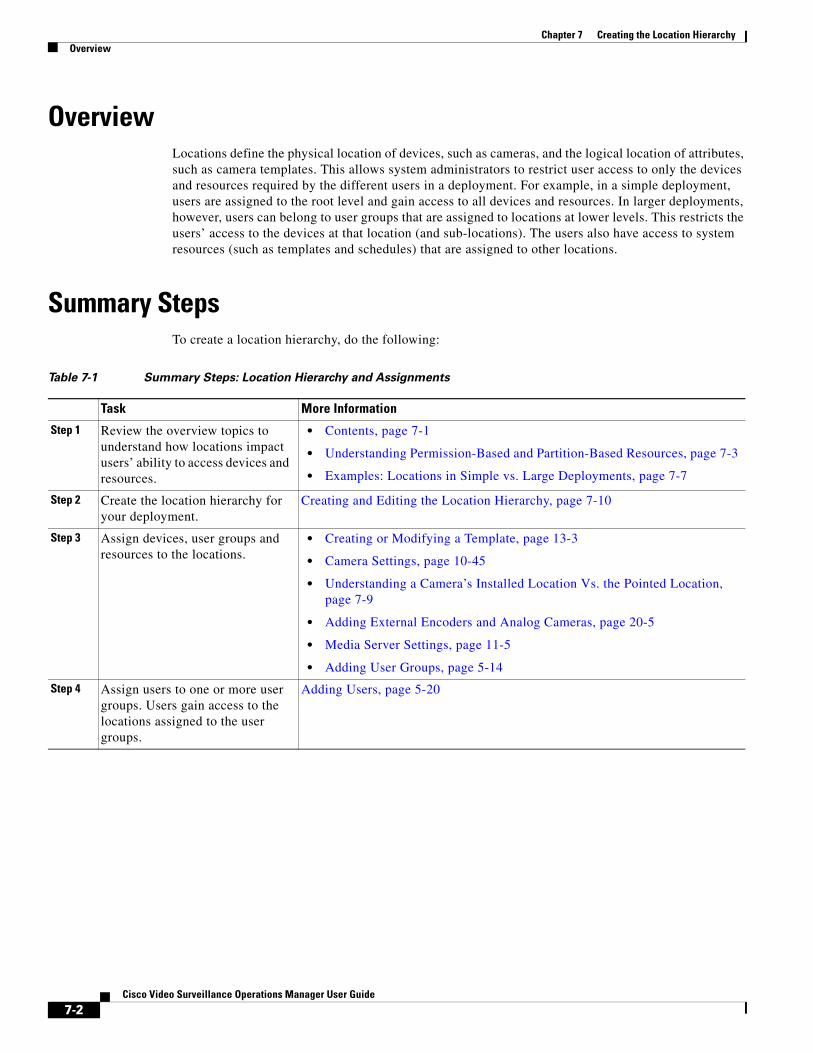
Chapter 7 Creating the Location Hierarchy Overview
OverviewLocations define the physical location of devices, such as cameras, and the logical location of attributes, such as camera templates. This allows system administrators to restrict user access to only the devices and resources required by the different users in a deployment. For example, in a simple deployment, users are assigned to the root level and gain access to all devices and resources. In larger deployments, however, users can belong to user groups that are assigned to locations at lower levels. This restricts the users’ access to the devices at that location (and sub-locations). The users also have access to system resources (such as templates and schedules) that are assigned to other locations.
Summary Steps
Table 7-1 Summary Steps: Location Hierarchy and Assignments
Task More Information
Step 1 • Contents, page 7-1
• Understanding Permission-Based and Partition-Based Resources, page 7-3
• Examples: Locations in Simple vs. Large Deployments, page 7-7
Step 2
Step 3 • Creating or Modifying a Template, page 13-3
• Camera Settings, page 10-45
• Understanding a Camera’s Installed Location Vs. the Pointed Location, page 7-9
• Adding External Encoders and Analog Cameras, page 20-5
• Media Server Settings, page 11-5
• Adding User Groups, page 5-14
Step 4
To create a location hierarchy, do the following:
Review the overview topics to understand how locations impact users’ ability to access devices and resources.
Create the location hierarchy for your deployment.
Creating and Editing the Location Hierarchy, page 7-10
Assign devices, user groups and resources to the locations.
Assign users to one or more user groups. Users gain access to the locations assigned to the user groups.
Adding Users, page 5-20
7-2Cisco Video Surveillance Operations Manager User Guide
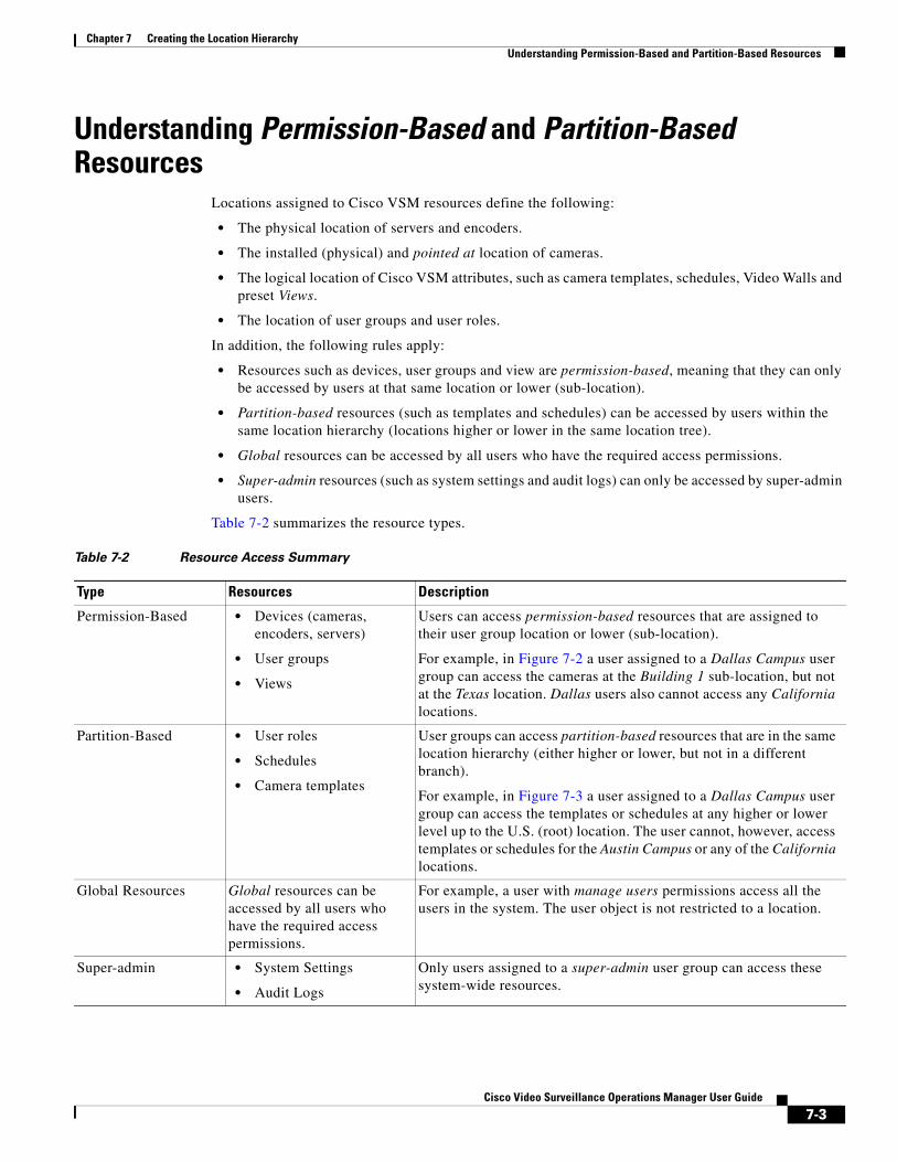
Chapter 7 Creating the Location HierarchyUnderstanding Permission-Based and Partition-Based Resources
Understanding Permission-Based and Partition-Based Resources
Locations assigned to Cisco VSM resources define the following:
• The physical location of servers and encoders.
• The installed (physical) and pointed at location of cameras.
• The logical location of Cisco VSM attributes, such as camera templates, schedules, Video Walls and preset Views.
• The location of user groups and user roles.
In addition, the following rules apply:
• Resources such as devices, user groups and view are permission-based, meaning that they can only be accessed by users at that same location or lower (sub-location).
• Partition-based resources (such as templates and schedules) can be accessed by users within the same location hierarchy (locations higher or lower in the same location tree).
• Global resources can be accessed by all users who have the required access permissions.
• Super-admin resources (such as system settings and audit logs) can only be accessed by super-admin users.
Table 7-2 summarizes the resource types.
Table 7-2 Resource Access Summary
Type Resources Description
• Devices (cameras, encoders, servers)
• User groups
• Views
• User roles
• Schedules
• Camera templates
• System Settings
• Audit Logs
Permission-Based Users can access permission-based resources that are assigned to their user group location or lower (sub-location).
For example, in Figure 7-2 a user assigned to a Dallas Campus user group can access the cameras at the Building 1 sub-location, but not at the Texas location. Dallas users also cannot access any California locations.
Partition-Based User groups can access partition-based resources that are in the same location hierarchy (either higher or lower, but not in a different branch).
For example, in Figure 7-3 a user assigned to a Dallas Campus user group can access the templates or schedules at any higher or lower level up to the U.S. (root) location. The user cannot, however, access templates or schedules for the Austin Campus or any of the California locations.
Global Resources Global resources can be accessed by all users who have the required access permissions.
For example, a user with manage users permissions access all the users in the system. The user object is not restricted to a location.
Super-admin Only users assigned to a super-admin user group can access these system-wide resources.
7-3Cisco Video Surveillance Operations Manager User Guide
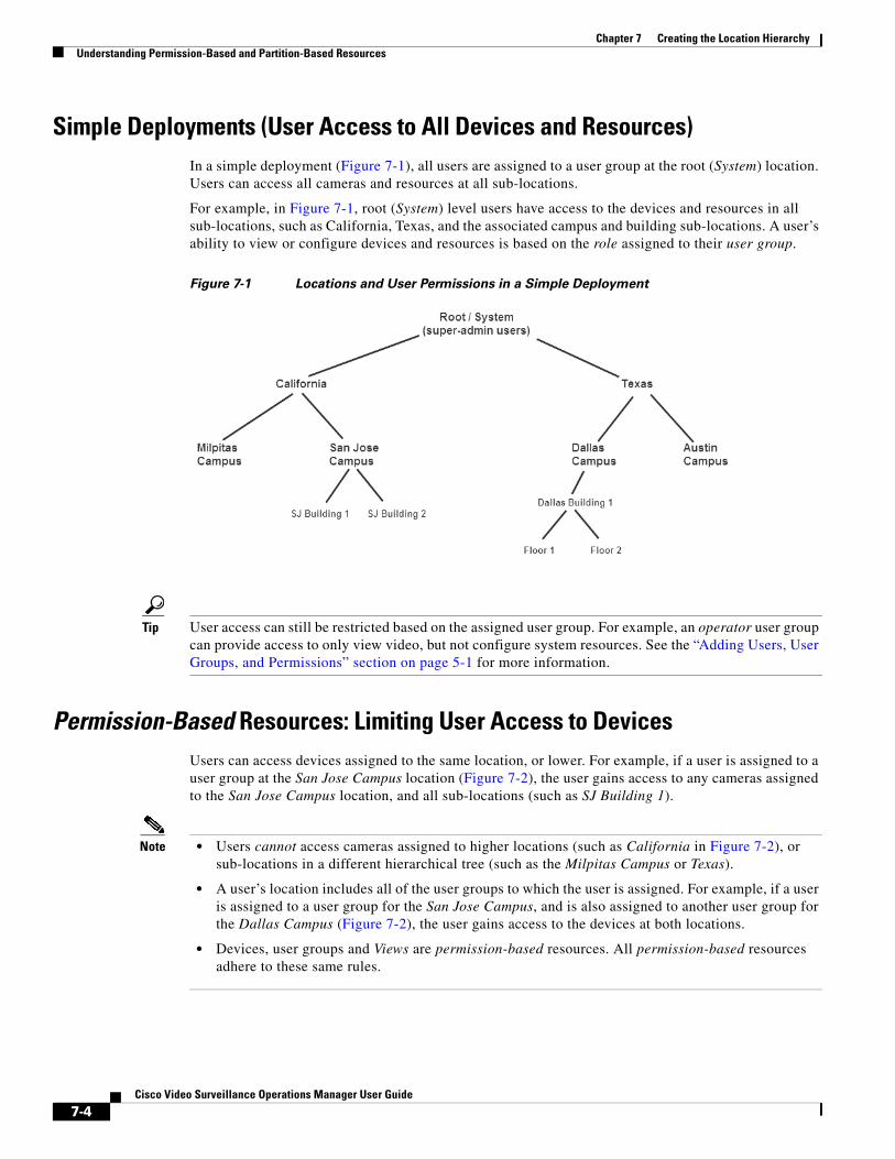
Chapter 7 Creating the Location Hierarchy Understanding Permission-Based and Partition-Based Resources
Simple Deployments (User Access to All Devices and Resources)In a simple deployment (Figure 7-1), all users are assigned to a user group at the root (System) location. Users can access all cameras and resources at all sub-locations.
For example, in Figure 7-1, root (System) level users have access to the devices and resources in all sub-locations, such as California, Texas, and the associated campus and building sub-locations. A user’s ability to view or configure devices and resources is based on the role assigned to their user group.
Figure 7-1 Locations and User Permissions in a Simple Deployment
Tip User access can still be restricted based on the assigned user group. For example, an operator user group can provide access to only view video, but not configure system resources. See the “Adding Users, User Groups, and Permissions” section on page 5-1 for more information.
Permission-Based Resources: Limiting User Access to Devices Users can access devices assigned to the same location, or lower. For example, if a user is assigned to a user group at the San Jose Campus location (Figure 7-2), the user gains access to any cameras assigned to the San Jose Campus location, and all sub-locations (such as SJ Building 1).
Note • Users cannot access cameras assigned to higher locations (such as California in Figure 7-2), or sub-locations in a different hierarchical tree (such as the Milpitas Campus or Texas).
• A user’s location includes all of the user groups to which the user is assigned. For example, if a user is assigned to a user group for the San Jose Campus, and is also assigned to another user group for the Dallas Campus (Figure 7-2), the user gains access to the devices at both locations.
• Devices, user groups and Views are permission-based resources. All permission-based resources adhere to these same rules.
7-4Cisco Video Surveillance Operations Manager User Guide
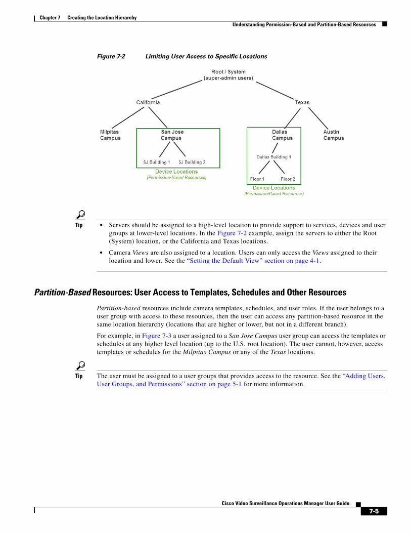
Chapter 7 Creating the Location HierarchyUnderstanding Permission-Based and Partition-Based Resources
Figure 7-2 Limiting User Access to Specific Locations
Tip • Servers should be assigned to a high-level location to provide support to services, devices and user groups at lower-level locations. In the Figure 7-2 example, assign the servers to either the Root (System) location, or the California and Texas locations.
• Camera Views are also assigned to a location. Users can only access the Views assigned to their location and lower. See the “Setting the Default View” section on page 4-1.
Partition-Based Resources: User Access to Templates, Schedules and Other Resources
Partition-based resources include camera templates, schedules, and user roles. If the user belongs to a user group with access to these resources, then the user can access any partition-based resource in the same location hierarchy (locations that are higher or lower, but not in a different branch).
For example, in Figure 7-3 a user assigned to a San Jose Campus user group can access the templates or schedules at any higher level location (up to the U.S. root location). The user cannot, however, access templates or schedules for the Milpitas Campus or any of the Texas locations.
Tip The user must be assigned to a user groups that provides access to the resource. See the “Adding Users, User Groups, and Permissions” section on page 5-1 for more information.
7-5Cisco Video Surveillance Operations Manager User Guide
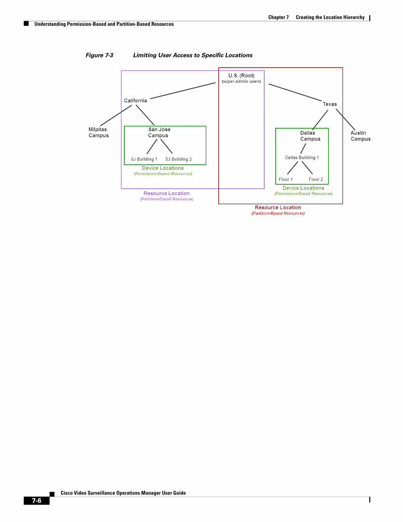
Chapter 7 Creating the Location Hierarchy Understanding Permission-Based and Partition-Based Resources
Figure 7-3 Limiting User Access to Specific Locations
7-6Cisco Video Surveillance Operations Manager User Guide
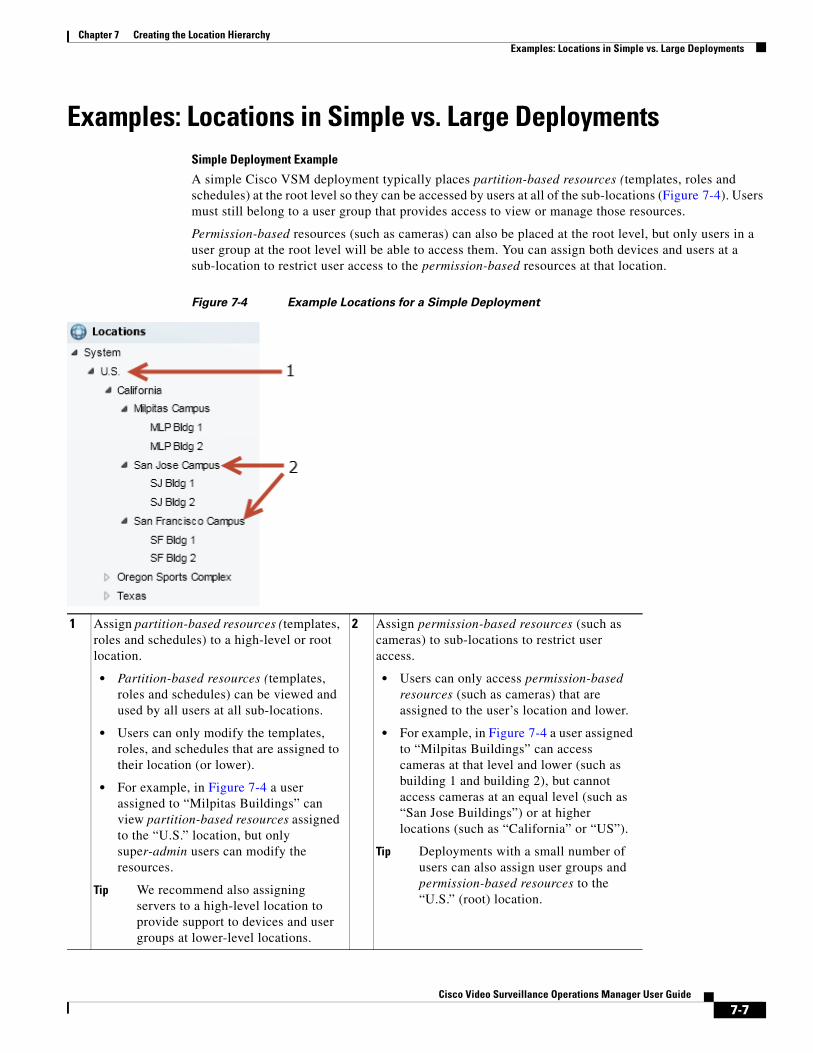
Chapter 7 Creating the Location HierarchyExamples: Locations in Simple vs. Large Deployments
Examples: Locations in Simple vs. Large DeploymentsSimple Deployment Example
A simple Cisco VSM deployment typically places partition-based resources (templates, roles and schedules) at the root level so they can be accessed by users at all of the sub-locations (Figure 7-4). Users must still belong to a user group that provides access to view or manage those resources.
Permission-based resources (such as cameras) can also be placed at the root level, but only users in a user group at the root level will be able to access them. You can assign both devices and users at a sub-location to restrict user access to the permission-based resources at that location.
Figure 7-4 Example Locations for a Simple Deployment
1
• Partition-based resources (templates, roles and schedules) can be viewed and used by all users at all sub-locations.
• Users can only modify the templates, roles, and schedules that are assigned to their location (or lower).
• For example, in Figure 7-4 a user assigned to “Milpitas Buildings” can view partition-based resources assigned to the “U.S.” location, but only super-admin users can modify the resources.
Tip We recommend also assigning servers to a high-level location to provide support to devices and user groups at lower-level locations.
2
• Users can only access permission-based resources (such as cameras) that are assigned to the user’s location and lower.
• For example, in Figure 7-4 a user assigned to “Milpitas Buildings” can access cameras at that level and lower (such as building 1 and building 2), but cannot access cameras at an equal level (such as “San Jose Buildings”) or at higher locations (such as “California” or “US”).
Tip Deployments with a small number of users can also assign user groups and permission-based resources to the “U.S.” (root) location.
Assign partition-based resources (templates, roles and schedules) to a high-level or root location.
Assign permission-based resources (such as cameras) to sub-locations to restrict user access.
7-7Cisco Video Surveillance Operations Manager User Guide
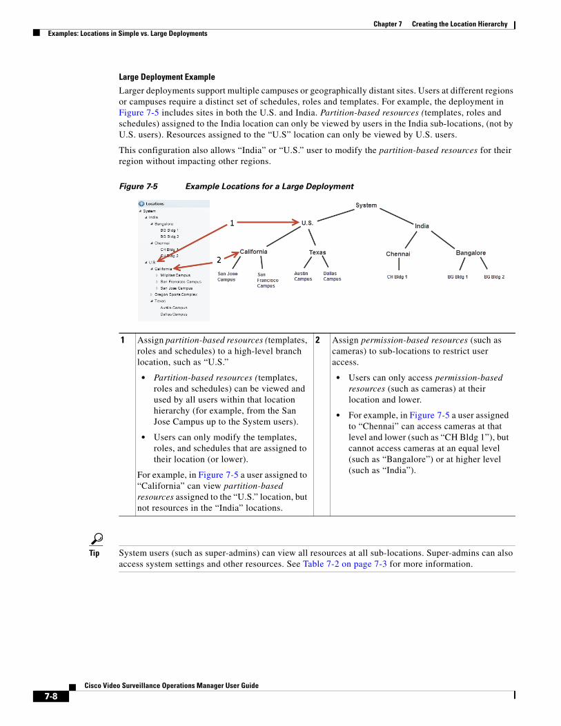
Chapter 7 Creating the Location Hierarchy Examples: Locations in Simple vs. Large Deployments
Large Deployment Example
Larger deployments support multiple campuses or geographically distant sites. Users at different regions or campuses require a distinct set of schedules, roles and templates. For example, the deployment in Figure 7-5 includes sites in both the U.S. and India. Partition-based resources (templates, roles and schedules) assigned to the India location can only be viewed by users in the India sub-locations, (not by U.S. users). Resources assigned to the “U.S” location can only be viewed by U.S. users.
This configuration also allows “India” or “U.S.” user to modify the partition-based resources for their region without impacting other regions.
Figure 7-5 Example Locations for a Large Deployment
1
• Partition-based resources (templates, roles and schedules) can be viewed and used by all users within that location hierarchy (for example, from the San Jose Campus up to the System users).
• Users can only modify the templates, roles, and schedules that are assigned to their location (or lower).
2
• Users can only access permission-based resources (such as cameras) at their location and lower.
• For example, in Figure 7-5 a user assigned to “Chennai” can access cameras at that level and lower (such as “CH Bldg 1”), but cannot access cameras at an equal level (such as “Bangalore”) or at higher level (such as “India”).
Tip System users (such as super-admins) can view all resources at all sub-locations. Super-admins can also access system settings and other resources. See Table 7-2 on page 7-3 for more information.
Assign partition-based resources (templates, roles and schedules) to a high-level branch location, such as “U.S.”
For example, in Figure 7-5 a user assigned to “California” can view partition-based resources assigned to the “U.S.” location, but not resources in the “India” locations.
Assign permission-based resources (such as cameras) to sub-locations to restrict user access.
7-8Cisco Video Surveillance Operations Manager User Guide
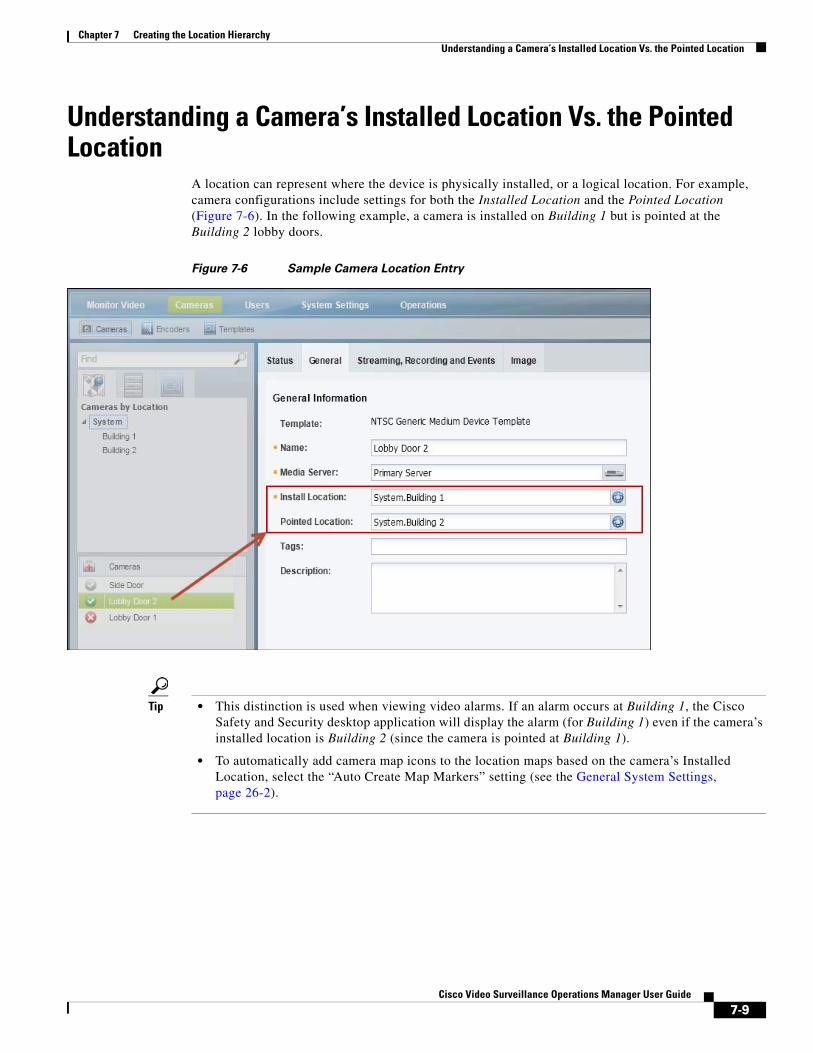
Chapter 7 Creating the Location HierarchyUnderstanding a Camera’s Installed Location Vs. the Pointed Location
Understanding a Camera’s Installed Location Vs. the Pointed Location
A location can represent where the device is physically installed, or a logical location. For example, camera configurations include settings for both the Installed Location and the Pointed Location (Figure 7-6). In the following example, a camera is installed on Building 1 but is pointed at the Building 2 lobby doors.
Figure 7-6 Sample Camera Location Entry
Tip • This distinction is used when viewing video alarms. If an alarm occurs at Building 1, the Cisco Safety and Security desktop application will display the alarm (for Building 1) even if the camera’s installed location is Building 2 (since the camera is pointed at Building 1).
• To automatically add camera map icons to the location maps based on the camera’s Installed Location, select the “Auto Create Map Markers” setting (see the General System Settings, page 26-2).
7-9Cisco Video Surveillance Operations Manager User Guide
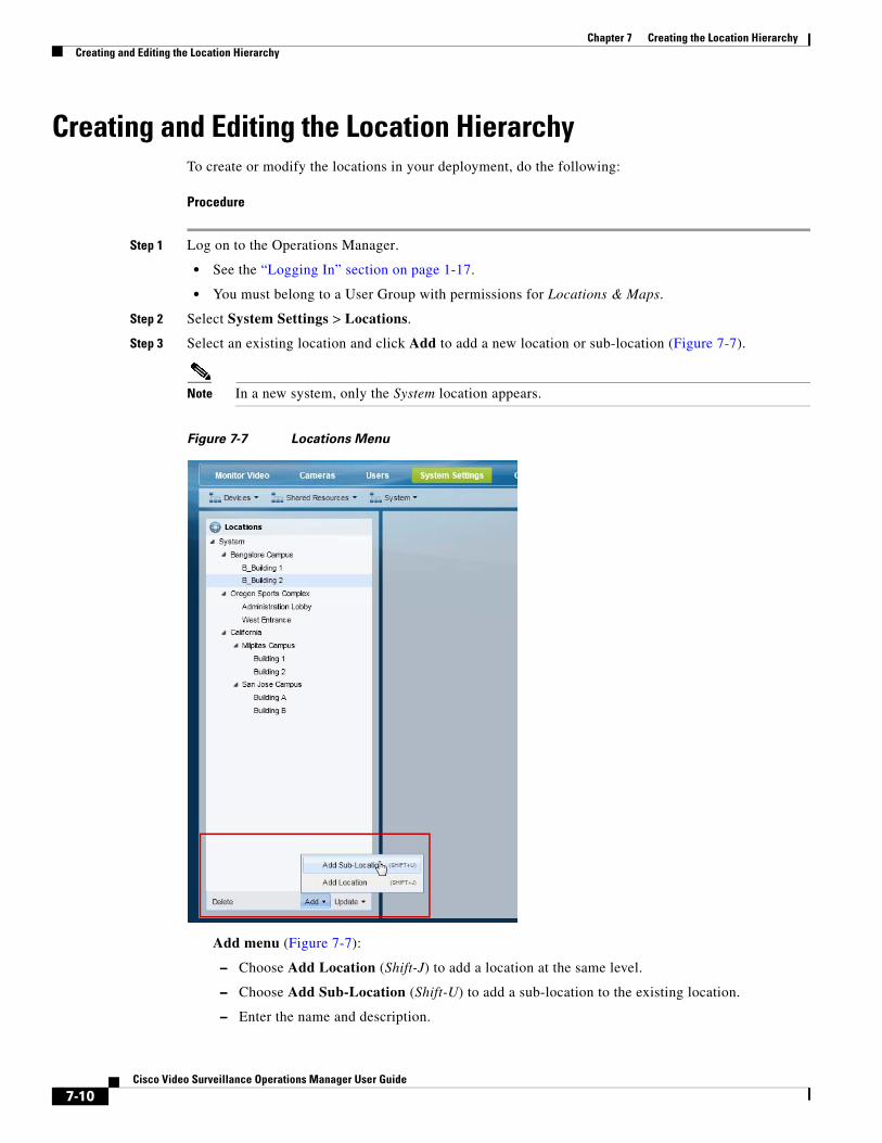
Chapter 7 Creating the Location Hierarchy Creating and Editing the Location Hierarchy
Creating and Editing the Location HierarchyTo create or modify the locations in your deployment, do the following:
Procedure
Step 1 Log on to the Operations Manager.
• See the “Logging In” section on page 1-17.
• You must belong to a User Group with permissions for Locations & Maps.
Step 2 Select System Settings > Locations.
Step 3 Select an existing location and click Add to add a new location or sub-location (Figure 7-7).
Note In a new system, only the System location appears.
Figure 7-7 Locations Menu
Add menu (Figure 7-7):
– Choose Add Location (Shift-J) to add a location at the same level.
– Choose Add Sub-Location (Shift-U) to add a sub-location to the existing location.
– Enter the name and description.
7-10Cisco Video Surveillance Operations Manager User Guide
Chapter 7 Creating the Location HierarchyCreating and Editing the Location Hierarchy
– Press Enter or click Save.
Update menu:
– Choose Detent Location (Shift-<) to move the location one level higher in the hierarchy.
– Choose Indent Location (Shift->) to move the location one level lower as a sub-location.
– Choose Rename (Enter) to edit the location name. Press Enter or click Save.
Tip Use the keyboard shortcuts (shown in parentheses) to quickly add or edit location entries.
Tip You can also drag and drop location names within the location hierarchy.
Tip Click Delete to remove an entry. You can only delete a location that does not have any resources assigned to the location, or any of its sub-locations. If the delete operation fails, remove or reassign any associated resources and try again.
Step 4 (Optional) Select a map for the location.
Select a map to define the aerial map view that is displayed when a location is selected using the Cisco Video Surveillance Safety and Security Desktop (Cisco SASD) application. See the “Define the Location Maps” section on page 30-8.
a. Click Set (Figure 7-8).
b. Use the Zoom In and Zoom Out buttons and drag the map image to locate the city, region or other aerial view that should be displayed.
c. Click Set to select the map as displayed on the screen.
Note The Longitude and Latitude of the visible map are automatically entered in the location settings (Figure 7-8). The second field displays the Zoom factor. For more information, see the “Configuring Location Maps” section on page 30-1.
7-11Cisco Video Surveillance Operations Manager User Guide
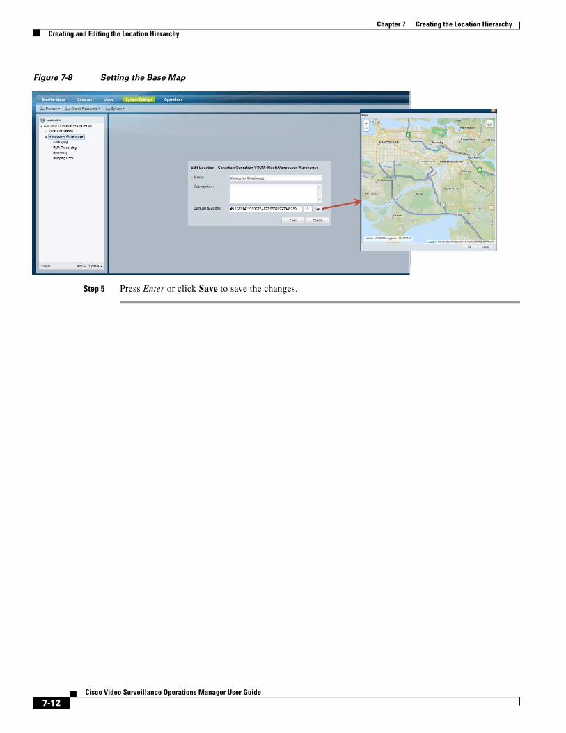
Chapter 7 Creating the Location Hierarchy Creating and Editing the Location Hierarchy
Figure 7-8 Setting the Base Map
Step 5 Press Enter or click Save to save the changes.
7-12Cisco Video Surveillance Operations Manager User Guide
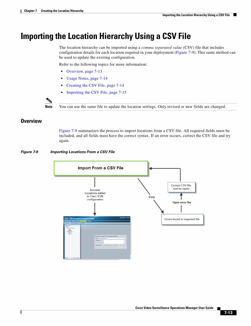
Chapter 7 Creating the Location HierarchyImporting the Location Hierarchy Using a CSV File
Importing the Location Hierarchy Using a CSV FileThe location hierarchy can be imported using a comma separated value (CSV) file that includes configuration details for each location required in your deployment (Figure 7-9). This same method can be used to update the existing configuration.
Refer to the following topics for more information:
• Overview, page 7-13
• Usage Notes, page 7-14
• Creating the CSV File, page 7-14
• Importing the CSV File, page 7-15
Note You can use the same file to update the location settings. Only revised or new fields are changed.
Overview
Figure 7-9 summarizes the process to import locations from a CSV file. All required fields must be included, and all fields must have the correct syntax. If an error occurs, correct the CSV file and try again.
Figure 7-9 Importing Locations From a CSV File
7-13Cisco Video Surveillance Operations Manager User Guide
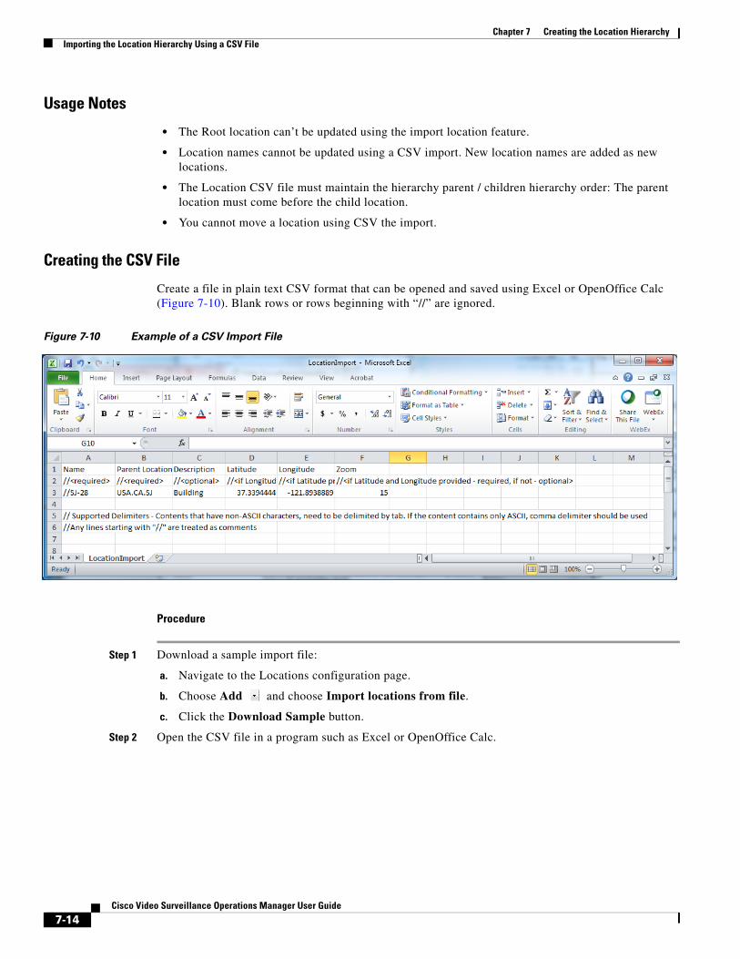
Chapter 7 Creating the Location Hierarchy Importing the Location Hierarchy Using a CSV File
Usage Notes
• The Root location can’t be updated using the import location feature.
• Location names cannot be updated using a CSV import. New location names are added as new locations.
• The Location CSV file must maintain the hierarchy parent / children hierarchy order: The parent location must come before the child location.
• You cannot move a location using CSV the import.
Creating the CSV File
Create a file in plain text CSV format that can be opened and saved using Excel or OpenOffice Calc (Figure 7-10). Blank rows or rows beginning with “//” are ignored.
Figure 7-10 Example of a CSV Import File
Procedure
Step 1 Download a sample import file:
a. Navigate to the Locations configuration page.
b. Choose Add and choose Import locations from file.
c. Click the Download Sample button.
Step 2 Open the CSV file in a program such as Excel or OpenOffice Calc.
7-14Cisco Video Surveillance Operations Manager User Guide
Chapter 7 Creating the Location HierarchyImporting the Location Hierarchy Using a CSV File
Step 3 Modify the file to include the location settings described in Table 7-3.
Table 7-3 Import File Field Descriptions
ContentRequired/Optional Description
Note The Root location can’t be updated using the import location feature.
Step 4 Save the revised file in CSV format.
For example, in Excel, create the file and then choose Save As > Other formats. Select CSV (Comma delimited) for the Save as type.
Step 5 Continue to Importing the CSV File, page 7-15.
Importing the CSV File
Complete the following procedure to import a CSV file. New location names will be added to the configuration. Existing configuration names will be revised (for example, additional settings for Latitude and Longitude can be added).
• If the CSV file details are accurate and complete, the locations are added to Cisco VSM. Cameras, Media Servers and other attributes can then be assigned to the locations.
• If any required fields are left blank, or if any entry is invalid, the import action fails and an error file is created that specifies the problems (see Figure 7-11). Correct the CSV file and try again. See Table 7-3 for the required fields and syntax.
Procedure
Step 1 Log in to the Cisco VSM Operations Manager.
You must belong to a user group with Locations & Maps permission. See the “Adding Users, User Groups, and Permissions” section on page 5-1 for more information.
Step 2 Create the camera CSV file containing details for each location.
Location Name Required Enter the location name. For example: California
You can add location names. Existing names cannot be updated.
Parent location path Required The location hierarchy. Use a delimiter (such as “.”) between the parent location and sub-locations.
In the following example, “California” is a sub-location of the “System” parent location: System.California
If California also has a sub-location, the entry would be: System.California.CampusA
Description Optional For example: “This location includes all cameras and a servers in the San Francisco campus location.”
Latitude Optional Defines the physical location of the entry on a map. All three must be entered if a map location is used.
For example, if Latitude is entered, you must also include the Longitude and Zoom. If Zoom is entered, you must also include the Latitude and Longitude.
Longitude
Zoom
7-15Cisco Video Surveillance Operations Manager User Guide
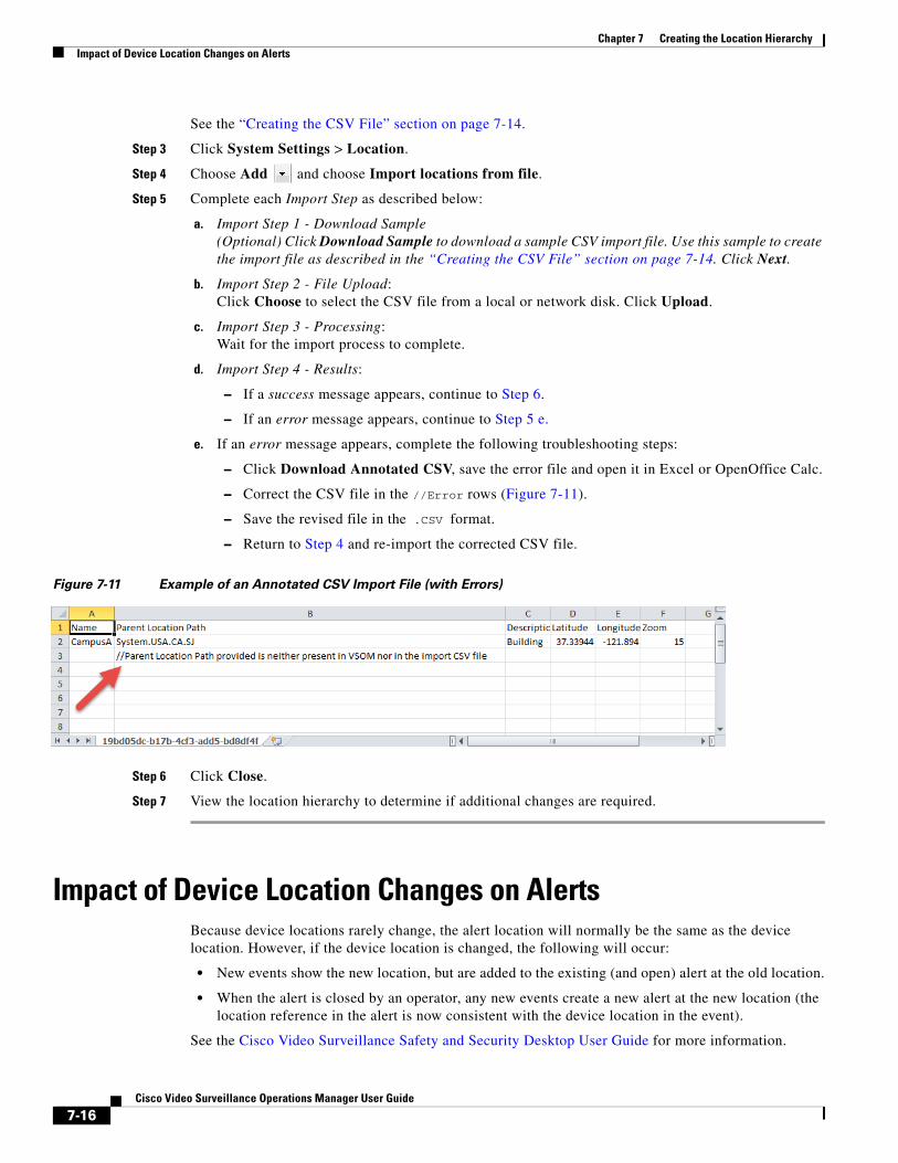
Chapter 7 Creating the Location Hierarchy Impact of Device Location Changes on Alerts
See the “Creating the CSV File” section on page 7-14.
Step 3 Click System Settings > Location.
Step 4 Choose Add and choose Import locations from file.
Step 5 Complete each Import Step as described below:
a. Import Step 1 - Download Sample(Optional) Click Download Sample to download a sample CSV import file. Use this sample to create the import file as described in the “Creating the CSV File” section on page 7-14. Click Next.
b. Import Step 2 - File Upload: Click Choose to select the CSV file from a local or network disk. Click Upload.
c. Import Step 3 - Processing: Wait for the import process to complete.
d. Import Step 4 - Results:
– If a success message appears, continue to Step 6.
– If an error message appears, continue to Step 5 e.
e. If an error message appears, complete the following troubleshooting steps:
– Click Download Annotated CSV, save the error file and open it in Excel or OpenOffice Calc.
– Correct the CSV file in the //Error rows (Figure 7-11).
– Save the revised file in the .CSV format.
– Return to Step 4 and re-import the corrected CSV file.
Figure 7-11 Example of an Annotated CSV Import File (with Errors)
Step 6 Click Close.
Step 7 View the location hierarchy to determine if additional changes are required.
Impact of Device Location Changes on AlertsBecause device locations rarely change, the alert location will normally be the same as the device location. However, if the device location is changed, the following will occur:
• New events show the new location, but are added to the existing (and open) alert at the old location.
• When the alert is closed by an operator, any new events create a new alert at the new location (the location reference in the alert is now consistent with the device location in the event).
See the Cisco Video Surveillance Safety and Security Desktop User Guide for more information.
7-16Cisco Video Surveillance Operations Manager User Guide
Chapter 7 Creating the Location HierarchyDeleting a Location
Deleting a LocationLocations can be deleted only if no resources (such as cameras) are associated with the location or any of its sub-locations. See Table 7-2 on page 7-3 for a list of the resources that use locations.
Procedure
To delete a location or sub-location:
Step 1 Remove all devices and resources from the location and sub-locations.
You can reassign the devices and resources to a different location, or delete the items.
Step 2 Select System Settings > Locations.
Step 3 Select the location or sub-location.
Step 4 Click Delete.
Step 5 If the delete operation fails and an error message appears, remove or reassign any resources that are associated with the location or sub-location and try again.
7-17Cisco Video Surveillance Operations Manager User Guide

Chapter 7 Creating the Location Hierarchy Deleting a Location
7-18Cisco Video Surveillance Operations Manager User Guide
Cisco V
C H A P T E R 8
Configuring ServersA server is a physical or virtual machine (VM) that runs the Cisco Video Surveillance system software. Each server can run one or more server services. For example, the Operations Manager is a server service that provides the user interface used to configure and manage a Cisco Video Surveillance deployment.
Additional services can be enabled when the server is added to the Operations Manager configuration. For example, a server can be added as a Media Server, Maps Server or Metadata Server that supports those features and functions for the entire deployment.
Tip The Cisco Video Surveillance Federator service can also be enabled on a stand-alone server. See the “Understanding Server Services” section on page 8-3 and the “Using Federator to Monitor Multiple Operations Managers” section on page 28-1 for more information.
Refer to the following topics for instructions to configure and monitor a server using the Operations Manager, and to enable server services.
Contents
• Understanding Server Services, page 8-3
• Requirements, page 8-7
• Summary Steps to Add or Revise a Server, page 8-8
• Server Settings, page 8-10
– General Information Settings, page 8-10
– Additional Server Settings, page 8-11
– Services, page 8-11
– Hardware Information Settings, page 8-11
– Access Information Settings, page 8-12
– Network Information, page 8-13
– Time Settings, page 8-14
• Adding or Editing Servers, page 8-16
– Prerequisites, page 8-17
– Adding or Editing a Single Server, page 8-17
– Importing or Updating Servers Using a CSV File, page 8-20
• Deleting a Server, page 8-24
8-1ideo Surveillance Operations Manager User Guide
Chapter 8 Configuring Servers
• Bulk Actions: Revising Multiple Servers, page 8-26
• Viewing Server Status, page 8-29
• Enable the “Unknown” State for Servers in a Transportation Environment, page 8-31
• Resetting the Server Device State, page 8-33
• Repairing the Configuration or Restarting the Server, page 8-33
• Operations Manager Advanced Settings, page 8-34
– SMTP Management Settings, page 8-34
8-2Cisco Video Surveillance Operations Manager User Guide
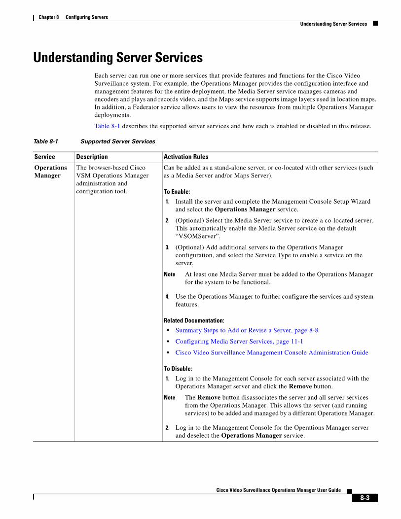
Chapter 8 Configuring ServersUnderstanding Server Services
Understanding Server ServicesEach server can run one or more services that provide features and functions for the Cisco Video Surveillance system. For example, the Operations Manager provides the configuration interface and management features for the entire deployment, the Media Server service manages cameras and encoders and plays and records video, and the Maps service supports image layers used in location maps. In addition, a Federator service allows users to view the resources from multiple Operations Manager deployments.
Table 8-1 describes the supported server services and how each is enabled or disabled in this release.
Table 8-1 Supported Server Services
Service Description Activation Rules
Operations Manager
The browser-based Cisco VSM Operations Manager administration and configuration tool.
Can be added as a stand-alone server, or co-located with other services (such as a Media Server and/or Maps Server).
To Enable:
1. Install the server and complete the Management Console Setup Wizard and select the Operations Manager service.
2. (Optional) Select the Media Server service to create a co-located server. This automatically enable the Media Server service on the default “VSOMServer”.
3. (Optional) Add additional servers to the Operations Manager configuration, and select the Service Type to enable a service on the server.
Note At least one Media Server must be added to the Operations Manager for the system to be functional.
4. Use the Operations Manager to further configure the services and system features.
Related Documentation:
• Summary Steps to Add or Revise a Server, page 8-8
• Configuring Media Server Services, page 11-1
• Cisco Video Surveillance Management Console Administration Guide
To Disable:
1. Log in to the Management Console for each server associated with the Operations Manager server and click the Remove button.
Note The Remove button disassociates the server and all server services from the Operations Manager. This allows the server (and running services) to be added and managed by a different Operations Manager.
2. Log in to the Management Console for the Operations Manager server and deselect the Operations Manager service.
8-3Cisco Video Surveillance Operations Manager User Guide
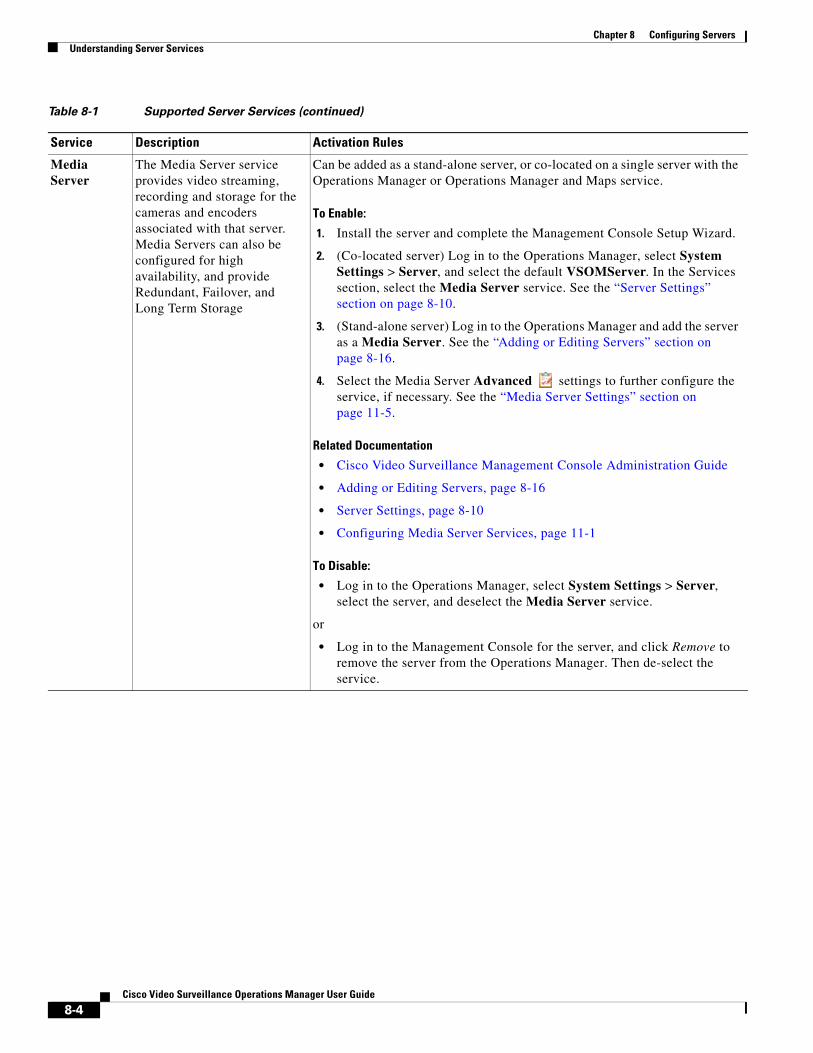
Chapter 8 Configuring Servers Understanding Server Services
Media Server
The Media Server service provides video streaming, recording and storage for the cameras and encoders associated with that server. Media Servers can also be configured for high availability, and provide Redundant, Failover, and Long Term Storage
Can be added as a stand-alone server, or co-located on a single server with the Operations Manager or Operations Manager and Maps service.
To Enable:
1. Install the server and complete the Management Console Setup Wizard.
2. (Co-located server) Log in to the Operations Manager, select System Settings > Server, and select the default VSOMServer. In the Services section, select the Media Server service. See the “Server Settings” section on page 8-10.
3. (Stand-alone server) Log in to the Operations Manager and add the server as a Media Server. See the “Adding or Editing Servers” section on page 8-16.
4. Select the Media Server Advanced settings to further configure the service, if necessary. See the “Media Server Settings” section on page 11-5.
Related Documentation
• Cisco Video Surveillance Management Console Administration Guide
• Adding or Editing Servers, page 8-16
• Server Settings, page 8-10
• Configuring Media Server Services, page 11-1
To Disable:
• Log in to the Operations Manager, select System Settings > Server, select the server, and deselect the Media Server service.
or
• Log in to the Management Console for the server, and click Remove to remove the server from the Operations Manager. Then de-select the service.
Table 8-1 Supported Server Services (continued)
Service Description Activation Rules
8-4Cisco Video Surveillance Operations Manager User Guide
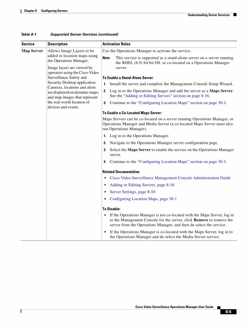
Chapter 8 Configuring ServersUnderstanding Server Services
Map Server Allows Image Layers to be added to location maps using the Operations Manager.
Image layers are viewed by operators using the Cisco Video Surveillance Safety and Security Desktop application. Cameras, locations and alerts are displayed on dynamic maps, and map images that represent the real-world location of devices and events.
Use the Operations Manager to activate the service.
Note This service is supported as a stand-alone server on a server running the RHEL (6.9) 64 bit OS, or co-located on a Operations Manager server.
To Enable a Stand-Alone Server:
1. Install the server and complete the Management Console Setup Wizard.
2. Log in to the Operations Manager and add the server as a Maps Server. See the “Adding or Editing Servers” section on page 8-16.
3. Continue to the “Configuring Location Maps” section on page 30-1.
To Enable a Co-Located Maps Server:
Maps Servers can be co-located on a server running Operations Manager, or Operations Manager and Media Server (a co-located Maps Server must also run Operations Manager).
1. Log in to the Operations Manager.
2. Navigate to the Operations Manager server configuration page.
3. Select the Maps Server to enable the service on the Operations Manager server.
4. Continue to the “Configuring Location Maps” section on page 30-1.
Related Documentation
• Cisco Video Surveillance Management Console Administration Guide
• Adding or Editing Servers, page 8-16
• Server Settings, page 8-10
• Configuring Location Maps, page 30-1
To Disable:
• If the Operations Manager is not co-located with the Maps Server, log in to the Management Console for the server, click Remove to remove the server from the Operations Manager, and then de-select the service.
• If the Operations Manager is co-located with the Maps Server, log in to the Operations Manager and de-select the Media Server service.
Table 8-1 Supported Server Services (continued)
Service Description Activation Rules
8-5Cisco Video Surveillance Operations Manager User Guide
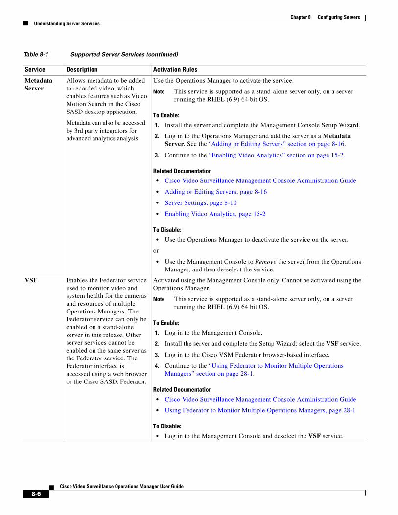
Chapter 8 Configuring Servers Understanding Server Services
Metadata Server
Allows metadata to be added to recorded video, which enables features such as Video Motion Search in the Cisco SASD desktop application.
Metadata can also be accessed by 3rd party integrators for advanced analytics analysis.
Use the Operations Manager to activate the service.
Note This service is supported as a stand-alone server only, on a server running the RHEL (6.9) 64 bit OS.
To Enable:
1. Install the server and complete the Management Console Setup Wizard.
2. Log in to the Operations Manager and add the server as a Metadata Server. See the “Adding or Editing Servers” section on page 8-16.
3. Continue to the “Enabling Video Analytics” section on page 15-2.
Related Documentation
• Cisco Video Surveillance Management Console Administration Guide
• Adding or Editing Servers, page 8-16
• Server Settings, page 8-10
• Enabling Video Analytics, page 15-2
To Disable:
• Use the Operations Manager to deactivate the service on the server.
or
• Use the Management Console to Remove the server from the Operations Manager, and then de-select the service.
VSF Enables the Federator service used to monitor video and system health for the cameras and resources of multiple Operations Managers. The Federator service can only be enabled on a stand-alone server in this release. Other server services cannot be enabled on the same server as the Federator service. The Federator interface is accessed using a web browser or the Cisco SASD. Federator.
Activated using the Management Console only. Cannot be activated using the Operations Manager.
Note This service is supported as a stand-alone server only, on a server running the RHEL (6.9) 64 bit OS.
To Enable:
1. Log in to the Management Console.
2. Install the server and complete the Setup Wizard: select the VSF service.
3. Log in to the Cisco VSM Federator browser-based interface.
4. Continue to the “Using Federator to Monitor Multiple Operations Managers” section on page 28-1.
Related Documentation
• Cisco Video Surveillance Management Console Administration Guide
• Using Federator to Monitor Multiple Operations Managers, page 28-1
To Disable:
• Log in to the Management Console and deselect the VSF service.
Table 8-1 Supported Server Services (continued)
Service Description Activation Rules
8-6Cisco Video Surveillance Operations Manager User Guide
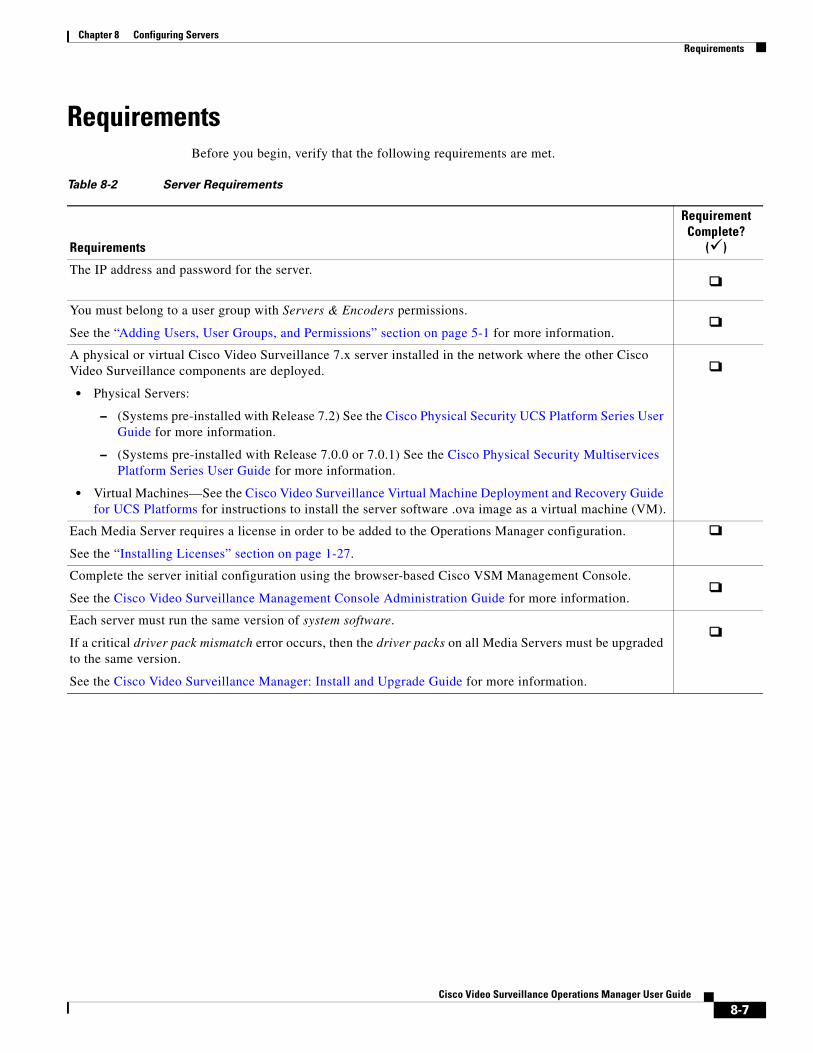
Chapter 8 Configuring ServersRequirements
Requirements Before you begin, verify that the following requirements are met.
Table 8-2 Server Requirements
Requirements
Requirement Complete?
()
• Physical Servers:
– (Systems pre-installed with Release 7.2) See the Cisco Physical Security UCS Platform Series User Guide for more information.
– (Systems pre-installed with Release 7.0.0 or 7.0.1) See the Cisco Physical Security Multiservices Platform Series User Guide for more information.
• Virtual Machines—See the Cisco Video Surveillance Virtual Machine Deployment and Recovery Guide for UCS Platforms for instructions to install the server software .ova image as a virtual machine (VM).
The IP address and password for the server.
You must belong to a user group with Servers & Encoders permissions.
See the “Adding Users, User Groups, and Permissions” section on page 5-1 for more information.
A physical or virtual Cisco Video Surveillance 7.x server installed in the network where the other Cisco Video Surveillance components are deployed.
Each Media Server requires a license in order to be added to the Operations Manager configuration.
See the “Installing Licenses” section on page 1-27.
Complete the server initial configuration using the browser-based Cisco VSM Management Console.
See the Cisco Video Surveillance Management Console Administration Guide for more information.
Each server must run the same version of system software.
If a critical driver pack mismatch error occurs, then the driver packs on all Media Servers must be upgraded to the same version.
See the Cisco Video Surveillance Manager: Install and Upgrade Guide for more information.
8-7Cisco Video Surveillance Operations Manager User Guide
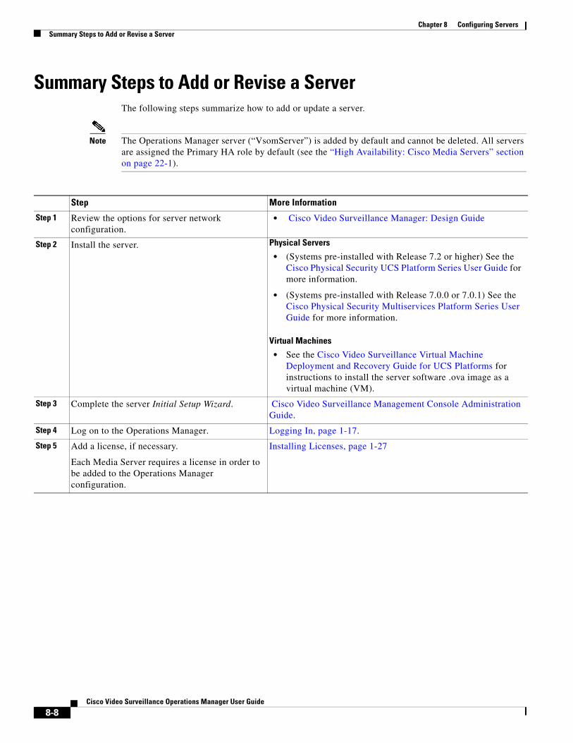
Chapter 8 Configuring Servers Summary Steps to Add or Revise a Server
Summary Steps to Add or Revise a ServerThe following steps summarize how to add or update a server.
Note The Operations Manager server (“VsomServer”) is added by default and cannot be deleted. All servers are assigned the Primary HA role by default (see the “High Availability: Cisco Media Servers” section on page 22-1).
Step More Information
Step 1 Review the options for server network configuration.
• Cisco Video Surveillance Manager: Design Guide
Step 2 Install the server. Physical Servers
• (Systems pre-installed with Release 7.2 or higher) See the Cisco Physical Security UCS Platform Series User Guide for more information.
• (Systems pre-installed with Release 7.0.0 or 7.0.1) See the Cisco Physical Security Multiservices Platform Series User Guide for more information.
Virtual Machines
• See the Cisco Video Surveillance Virtual Machine Deployment and Recovery Guide for UCS Platforms for instructions to install the server software .ova image as a virtual machine (VM).
Step 3 Complete the server Initial Setup Wizard. Cisco Video Surveillance Management Console Administration Guide.
Step 4 Log on to the Operations Manager. Logging In, page 1-17.
Step 5 Add a license, if necessary.
Each Media Server requires a license in order to be added to the Operations Manager configuration.
Installing Licenses, page 1-27
8-8Cisco Video Surveillance Operations Manager User Guide
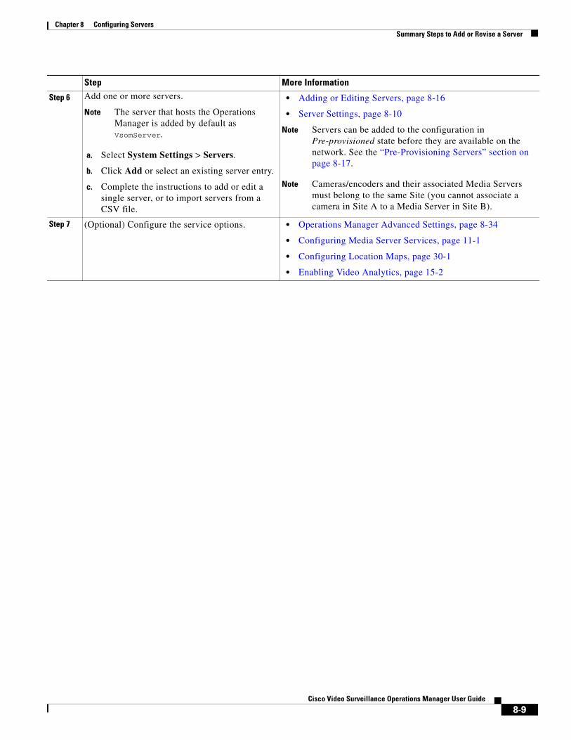
Chapter 8 Configuring ServersSummary Steps to Add or Revise a Server
Step 6 Add one or more servers.
Note The server that hosts the Operations Manager is added by default as VsomServer.
a. Select System Settings > Servers.
b. Click Add or select an existing server entry.
c. Complete the instructions to add or edit a single server, or to import servers from a CSV file.
• Adding or Editing Servers, page 8-16
• Server Settings, page 8-10
Note Servers can be added to the configuration in Pre-provisioned state before they are available on the network. See the “Pre-Provisioning Servers” section on page 8-17.
Note Cameras/encoders and their associated Media Servers must belong to the same Site (you cannot associate a camera in Site A to a Media Server in Site B).
Step 7 (Optional) Configure the service options. • Operations Manager Advanced Settings, page 8-34
• Configuring Media Server Services, page 11-1
• Configuring Location Maps, page 30-1
• Enabling Video Analytics, page 15-2
Step More Information
8-9Cisco Video Surveillance Operations Manager User Guide
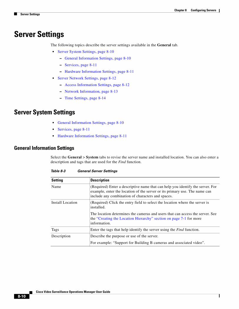
Chapter 8 Configuring Servers Server Settings
Server SettingsThe following topics describe the server settings available in the General tab.
• Server System Settings, page 8-10
– General Information Settings, page 8-10
– Services, page 8-11
– Hardware Information Settings, page 8-11
• Server Network Settings, page 8-12
– Access Information Settings, page 8-12
– Network Information, page 8-13
– Time Settings, page 8-14
Server System Settings • General Information Settings, page 8-10
• Services, page 8-11
• Hardware Information Settings, page 8-11
General Information Settings
Select the General > System tabs to revise the server name and installed location. You can also enter a description and tags that are used for the Find function.
Table 8-3 General Server Settings
Setting Description
Name (Required) Enter a descriptive name that can help you identify the server. For example, enter the location of the server or its primary use. The name can include any combination of characters and spaces.
Install Location (Required) Click the entry field to select the location where the server is installed.
The location determines the cameras and users that can access the server. See the “Creating the Location Hierarchy” section on page 7-1 for more information.
Tags Enter the tags that help identify the server using the Find function.
Description Describe the purpose or use of the server.
For example: “Support for Building B cameras and associated video”.
8-10Cisco Video Surveillance Operations Manager User Guide
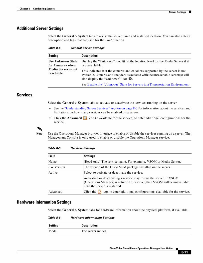
Chapter 8 Configuring ServersServer Settings
Additional Server Settings
Select the General > System tabs to revise the server name and installed location. You can also enter a description and tags that are used for the Find function.
Table 8-4 General Server Settings
Setting Description
Services
Select the General > System tabs to activate or deactivate the services running on the server.
• See the “Understanding Server Services” section on page 8-3 for information about the services and limitations on how many services can be enabled on a server.
• Click the Advanced icon (if available for the service) to enter additional configurations for the service.
Note Use the Operations Manager browser interface to enable or disable the services running on a server. The Management Console is only used to enable or disable the Operations Manager service.
Table 8-5 Services Settings
Field Settings
Hardware Information Settings
Select the General > System tabs for hardware information about the physical platform, if available.
Use Unknown State for Cameras when Media Server is not reachable
Display the “Unknown” icon at the location level for the Media Server if it is unreachable.
This indicates that the cameras and encoders supported by the server is not available. Cameras and encoders associated with the unreachable server(s) will also display the “Unknown” icon .
See Enable the “Unknown” State for Servers in a Transportation Environment.
Name (Read-only) The service name. For example, VSOM or Media Server.
SW Version The version of the Cisco VSM package installed on the server
Active Select to activate or deactivate the service.
Activating or deactivating s service may restart the server. If VSOM (Operations Manager) is active on this server, then VSOM will be unavailable until the server is restarted.
Advanced Click the icon to enter additional configurations available for the service.
Table 8-6 Hardware Information Settings
Setting Description
Model The server model.
8-11Cisco Video Surveillance Operations Manager User Guide
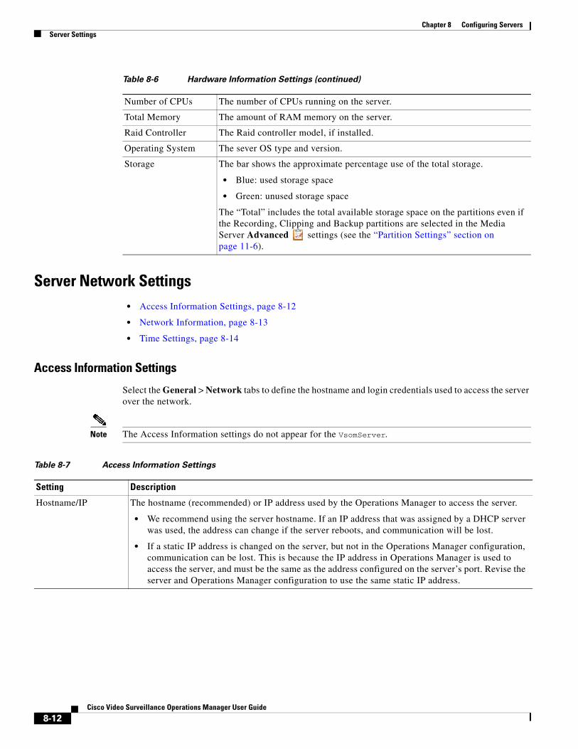
Chapter 8 Configuring Servers Server Settings
Server Network Settings • Access Information Settings, page 8-12
• Network Information, page 8-13
• Time Settings, page 8-14
Access Information Settings
Select the General > Network tabs to define the hostname and login credentials used to access the server over the network.
Note The Access Information settings do not appear for the VsomServer.
Number of CPUs The number of CPUs running on the server.
Total Memory The amount of RAM memory on the server.
Raid Controller The Raid controller model, if installed.
Operating System The sever OS type and version.
Storage The bar shows the approximate percentage use of the total storage.
• Blue: used storage space
• Green: unused storage space
The “Total” includes the total available storage space on the partitions even if the Recording, Clipping and Backup partitions are selected in the Media Server Advanced settings (see the “Partition Settings” section on page 11-6).
Table 8-6 Hardware Information Settings (continued)
Table 8-7 Access Information Settings
Setting Description
Hostname/IP The hostname (recommended) or IP address used by the Operations Manager to access the server.
• We recommend using the server hostname. If an IP address that was assigned by a DHCP server was used, the address can change if the server reboots, and communication will be lost.
• If a static IP address is changed on the server, but not in the Operations Manager configuration, communication can be lost. This is because the IP address in Operations Manager is used to access the server, and must be the same as the address configured on the server’s port. Revise the server and Operations Manager configuration to use the same static IP address.
8-12Cisco Video Surveillance Operations Manager User Guide
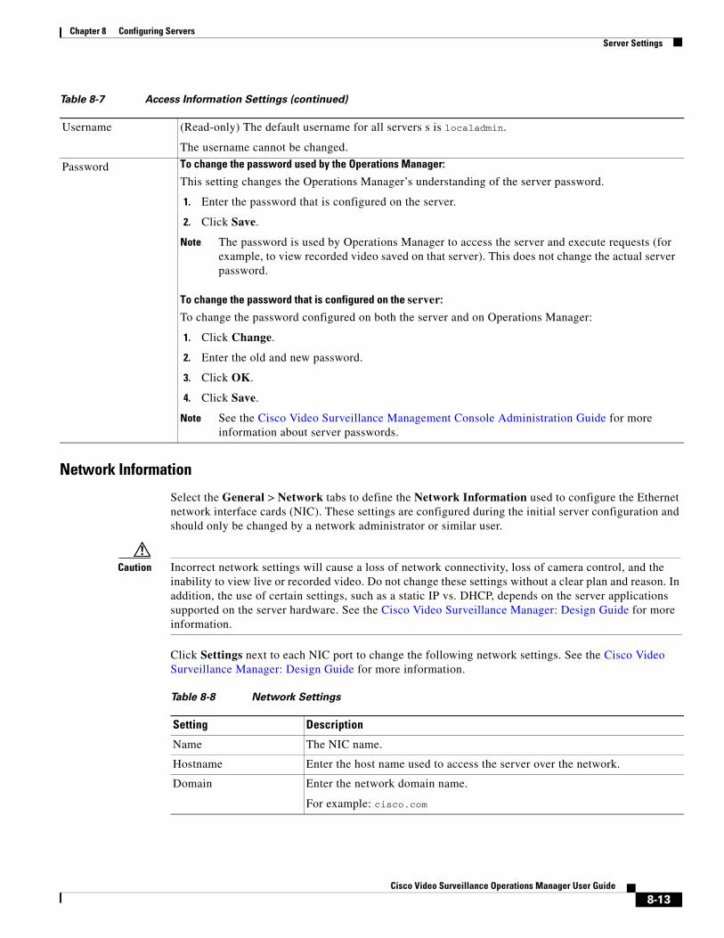
Chapter 8 Configuring ServersServer Settings
Network Information
Select the General > Network tabs to define the Network Information used to configure the Ethernet network interface cards (NIC). These settings are configured during the initial server configuration and should only be changed by a network administrator or similar user.
Caution Incorrect network settings will cause a loss of network connectivity, loss of camera control, and the inability to view live or recorded video. Do not change these settings without a clear plan and reason. In addition, the use of certain settings, such as a static IP vs. DHCP, depends on the server applications supported on the server hardware. See the Cisco Video Surveillance Manager: Design Guide for more information.
Click Settings next to each NIC port to change the following network settings. See the Cisco Video Surveillance Manager: Design Guide for more information.
Username (Read-only) The default username for all servers s is localadmin.
The username cannot be changed.
Password To change the password used by the Operations Manager:
This setting changes the Operations Manager’s understanding of the server password.
1. Enter the password that is configured on the server.
2. Click Save.
Note The password is used by Operations Manager to access the server and execute requests (for example, to view recorded video saved on that server). This does not change the actual server password.
To change the password that is configured on the server:
To change the password configured on both the server and on Operations Manager:
1. Click Change.
2. Enter the old and new password.
3. Click OK.
4. Click Save.
Note See the Cisco Video Surveillance Management Console Administration Guide for more information about server passwords.
Table 8-7 Access Information Settings (continued)
Table 8-8 Network Settings
Setting Description
Name The NIC name.
Hostname Enter the host name used to access the server over the network.
Domain Enter the network domain name.
For example: cisco.com
8-13Cisco Video Surveillance Operations Manager User Guide
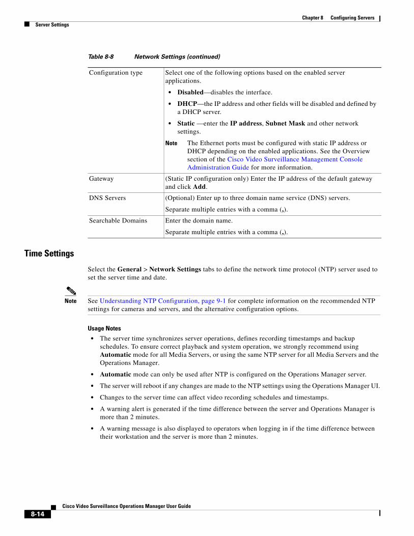
Chapter 8 Configuring Servers Server Settings
Time Settings
Select the General > Network Settings tabs to define the network time protocol (NTP) server used to set the server time and date.
Note See Understanding NTP Configuration, page 9-1 for complete information on the recommended NTP settings for cameras and servers, and the alternative configuration options.
Usage Notes
• The server time synchronizes server operations, defines recording timestamps and backup schedules. To ensure correct playback and system operation, we strongly recommend using Automatic mode for all Media Servers, or using the same NTP server for all Media Servers and the Operations Manager.
• Automatic mode can only be used after NTP is configured on the Operations Manager server.
• The server will reboot if any changes are made to the NTP settings using the Operations Manager UI.
• Changes to the server time can affect video recording schedules and timestamps.
• A warning alert is generated if the time difference between the server and Operations Manager is more than 2 minutes.
• A warning message is also displayed to operators when logging in if the time difference between their workstation and the server is more than 2 minutes.
Configuration type Select one of the following options based on the enabled server applications.
• Disabled—disables the interface.
• DHCP—the IP address and other fields will be disabled and defined by a DHCP server.
• Static —enter the IP address, Subnet Mask and other network settings.
Note The Ethernet ports must be configured with static IP address or DHCP depending on the enabled applications. See the Overview section of the Cisco Video Surveillance Management Console Administration Guide for more information.
Gateway (Static IP configuration only) Enter the IP address of the default gateway and click Add.
DNS Servers (Optional) Enter up to three domain name service (DNS) servers.
Separate multiple entries with a comma (,).
Searchable Domains Enter the domain name.
Separate multiple entries with a comma (,).
Table 8-8 Network Settings (continued)
8-14Cisco Video Surveillance Operations Manager User Guide
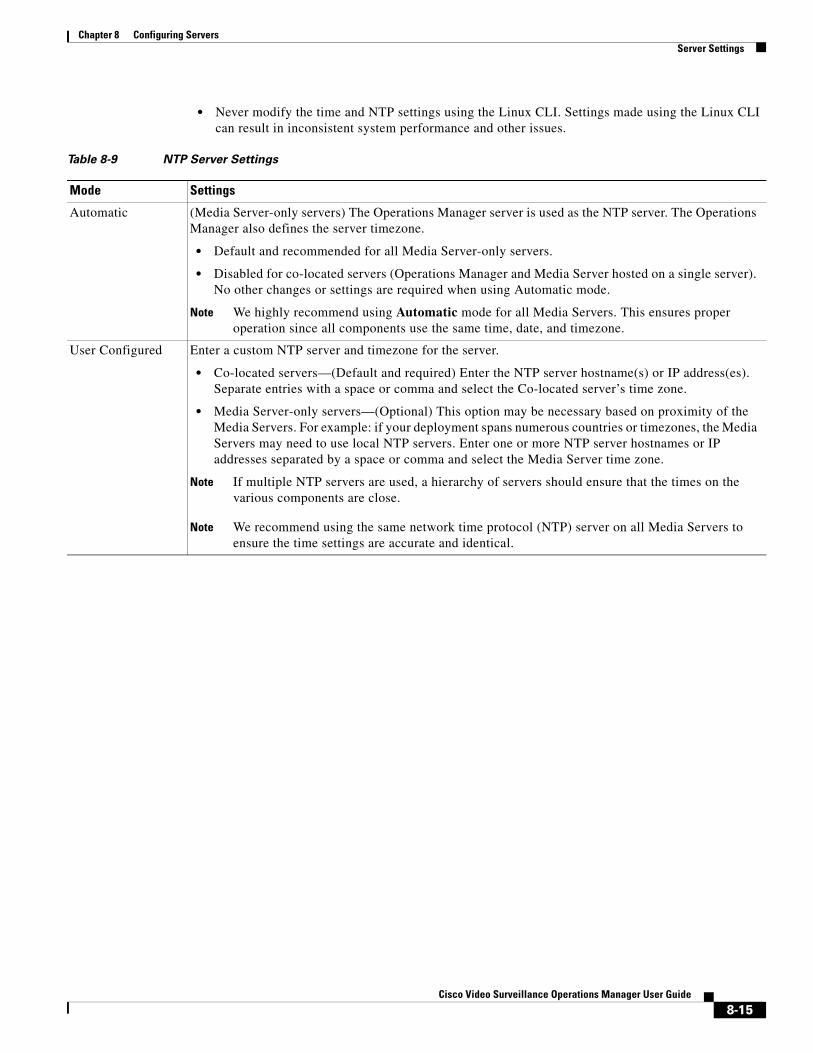
Chapter 8 Configuring ServersServer Settings
• Never modify the time and NTP settings using the Linux CLI. Settings made using the Linux CLI can result in inconsistent system performance and other issues.
Table 8-9 NTP Server Settings
Mode Settings
• Default and recommended for all Media Server-only servers.
• Disabled for co-located servers (Operations Manager and Media Server hosted on a single server). No other changes or settings are required when using Automatic mode.
Note We highly recommend using Automatic mode for all Media Servers. This ensures proper operation since all components use the same time, date, and timezone.
• Co-located servers—(Default and required) Enter the NTP server hostname(s) or IP address(es). Separate entries with a space or comma and select the Co-located server’s time zone.
• Media Server-only servers—(Optional) This option may be necessary based on proximity of the Media Servers. For example: if your deployment spans numerous countries or timezones, the Media Servers may need to use local NTP servers. Enter one or more NTP server hostnames or IP addresses separated by a space or comma and select the Media Server time zone.
Note If multiple NTP servers are used, a hierarchy of servers should ensure that the times on the various components are close.
Note We recommend using the same network time protocol (NTP) server on all Media Servers to ensure the time settings are accurate and identical.
Automatic (Media Server-only servers) The Operations Manager server is used as the NTP server. The Operations Manager also defines the server timezone.
User Configured Enter a custom NTP server and timezone for the server.
8-15Cisco Video Surveillance Operations Manager User Guide
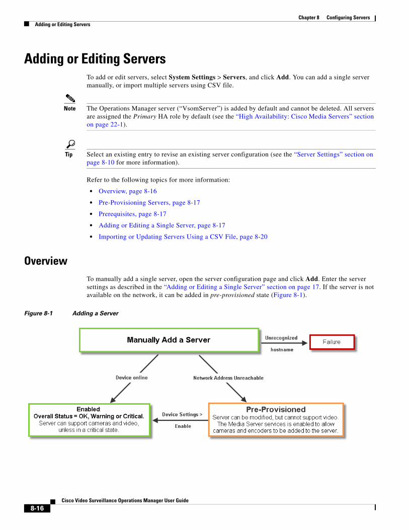
Chapter 8 Configuring Servers Adding or Editing Servers
Adding or Editing ServersTo add or edit servers, select System Settings > Servers, and click Add. You can add a single server manually, or import multiple servers using CSV file.
Note The Operations Manager server (“VsomServer”) is added by default and cannot be deleted. All servers are assigned the Primary HA role by default (see the “High Availability: Cisco Media Servers” section on page 22-1).
Tip Select an existing entry to revise an existing server configuration (see the “Server Settings” section on page 8-10 for more information).
Refer to the following topics for more information:
• Overview, page 8-16
• Pre-Provisioning Servers, page 8-17
• Prerequisites, page 8-17
• Adding or Editing a Single Server, page 8-17
• Importing or Updating Servers Using a CSV File, page 8-20
OverviewTo manually add a single server, open the server configuration page and click Add. Enter the server settings as described in the “Adding or Editing a Single Server” section on page 17. If the server is not available on the network, it can be added in pre-provisioned state (Figure 8-1).
Figure 8-1 Adding a Server
8-16Cisco Video Surveillance Operations Manager User Guide
Chapter 8 Configuring ServersAdding or Editing Servers
Pre-Provisioning ServersPre-provisioning allows you to add a server before it is installed or available on the network. The server is waiting to be added to Cisco VSM and is not available for use. A pre-provisioned server can be modified, but cannot stream or record video.
• If a server is pre-provisioned, the Media server service is activated by default. This allows pre-provisioned cameras and encoders to be added to the pre-provisioned server.
• After the server is installed and available on the network, you can enable it by choosing Device Settings > Enable from the server configuration page. The server configuration must be complete, and Cisco VSM must be able to verify network communication or the enable action will fail.
Tip Use Bulk Actions to enable multiple servers. See the “Bulk Actions: Revising Multiple Servers” section on page 8-26.
See the “Viewing Server Status” section on page 8-29 for more information.
Prerequisites • The server(s) must be installed on a physical machine, or as a virtual machine (VM).
• Complete the server initial configuration (including network settings) using the Setup Wizard available in the browser-based Cisco VSM Management Console. See the Cisco Video Surveillance Management Console Administration Guide for more information.
Adding or Editing a Single Server
Procedure
To add a new server, complete the following procedure.
Note The Operations Manager server (“VsomServer”) is added by default and cannot be deleted. All servers are assigned the Primary HA role by default. See the “High Availability: Cisco Media Servers” section on page 22-1.
Step 1 Install the server and complete the Initial Setup Wizard using the browser-based Management Console.
• Cisco Physical Security UCS Platform Series User Guide
• Cisco Video Surveillance Virtual Machine Deployment and Recovery Guide for UCS Platforms
• Cisco Video Surveillance Management Console Administration Guide.
Step 2 Log on to the Operations Manager.
• See the “Logging In and Managing Passwords” section on page 1-17.
• You must belong to a User Group with permissions for Servers & Encoders. See the “Adding Users, User Groups, and Permissions” section on page 5-1 for more information.
8-17Cisco Video Surveillance Operations Manager User Guide
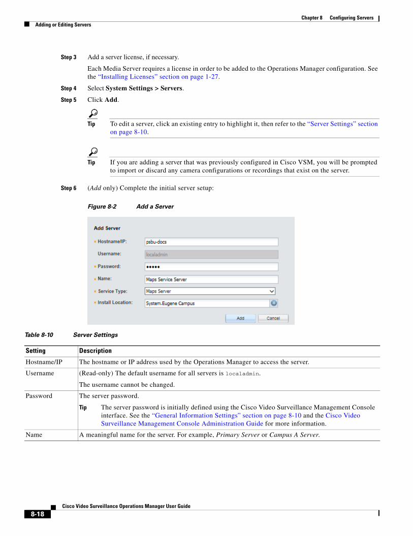
Chapter 8 Configuring Servers Adding or Editing Servers
Step 3 Add a server license, if necessary.
Each Media Server requires a license in order to be added to the Operations Manager configuration. See the “Installing Licenses” section on page 1-27.
Step 4 Select System Settings > Servers.
Step 5 Click Add.
Tip To edit a server, click an existing entry to highlight it, then refer to the “Server Settings” section on page 8-10.
Tip If you are adding a server that was previously configured in Cisco VSM, you will be prompted to import or discard any camera configurations or recordings that exist on the server.
Step 6 (Add only) Complete the initial server setup:
Figure 8-2 Add a Server
Table 8-10 Server Settings
Setting Description
Hostname/IP The hostname or IP address used by the Operations Manager to access the server.
Username (Read-only) The default username for all servers is localadmin.
The username cannot be changed.
Password The server password.
Tip The server password is initially defined using the Cisco Video Surveillance Management Console interface. See the “General Information Settings” section on page 8-10 and the Cisco Video Surveillance Management Console Administration Guide for more information.
Name A meaningful name for the server. For example, Primary Server or Campus A Server.
8-18Cisco Video Surveillance Operations Manager User Guide
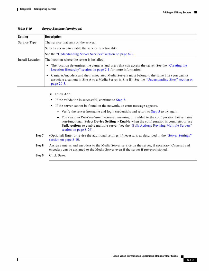
Chapter 8 Configuring ServersAdding or Editing Servers
d. Click Add.
• If the validation is successful, continue to Step 7.
• If the server cannot be found on the network, an error message appears.
– Verify the server hostname and login credentials and return to Step 5 to try again.
– You can also Pre-Provision the server, meaning it is added to the configuration but remains non-functional. Select Device Setting > Enable when the configuration is complete, or use Bulk Actions to enable multiple server (see the “Bulk Actions: Revising Multiple Servers” section on page 8-26).
Step 7 (Optional) Enter or revise the additional settings, if necessary, as described in the “Server Settings” section on page 8-10.
Step 8 Assign cameras and encoders to the Media Server service on the server, if necessary. Cameras and encoders can be assigned to the Media Server even if the server if pre-provisioned.
Step 9 Click Save.
Service Type The service that runs on the server.
Select a service to enable the service functionality.
See the “Understanding Server Services” section on page 8-3.
Install Location The location where the server is installed.
• The location determines the cameras and users that can access the server. See the “Creating the Location Hierarchy” section on page 7-1 for more information.
• Cameras/encoders and their associated Media Servers must belong to the same Site (you cannot associate a camera in Site A to a Media Server in Site B). See the “Understanding Sites” section on page 29-3.
Table 8-10 Server Settings (continued)
Setting Description
8-19Cisco Video Surveillance Operations Manager User Guide
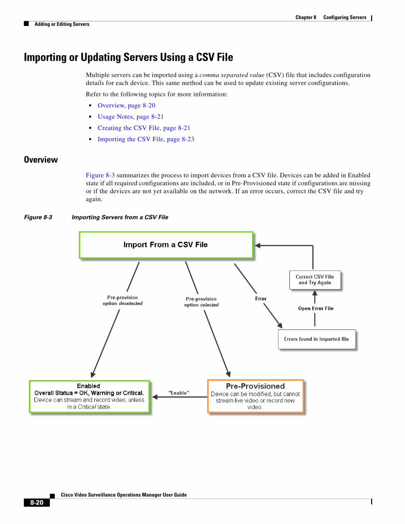
Chapter 8 Configuring Servers Adding or Editing Servers
Importing or Updating Servers Using a CSV FileMultiple servers can be imported using a comma separated value (CSV) file that includes configuration details for each device. This same method can be used to update existing server configurations.
Refer to the following topics for more information:
• Overview, page 8-20
• Usage Notes, page 8-21
• Creating the CSV File, page 8-21
• Importing the CSV File, page 8-23
Overview
Figure 8-3 summarizes the process to import devices from a CSV file. Devices can be added in Enabled state if all required configurations are included, or in Pre-Provisioned state if configurations are missing or if the devices are not yet available on the network. If an error occurs, correct the CSV file and try again.
Figure 8-3 Importing Servers from a CSV File
8-20Cisco Video Surveillance Operations Manager User Guide
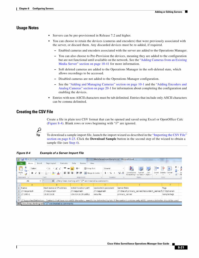
Chapter 8 Configuring ServersAdding or Editing Servers
Usage Notes
• Servers can be pre-provisioned in Release 7.2 and higher.
• You can choose to retain the devices (cameras and encoders) that were previously associated with the server, or discard them. Any discarded devices must be re-added, if required.
– Enabled cameras and encoders associated with the server are added to the Operations Manager.
– You can also choose to Pre-Provision the devices, meaning they are added to the configuration but are not functional until available on the network. See the “Adding Cameras from an Existing Media Server” section on page 10-41 for more information.
– Soft deleted cameras are added to the Operations Manager in the soft-deleted state, which allows recordings to be accessed.
– Disabled cameras are not added to the Operations Manager configuration.
– See the “Adding and Managing Cameras” section on page 10-1 and the “Adding Encoders and Analog Cameras” section on page 20-1 for information about completing the configuration and enabling the devices.
• Entries with non-ASCII characters must be tab delimited. Entries that include only ASCII characters can be comma delimited.
Creating the CSV File
Create a file in plain text CSV format that can be opened and saved using Excel or OpenOffice Calc (Figure 8-4). Blank rows or rows beginning with “//” are ignored.
Tip To download a sample import file, launch the import wizard as described in the “Importing the CSV File” section on page 8-23. Click the Download Sample button in the second step of the wizard to obtain a sample file (see Step 4).
Figure 8-4 Example of a Server Import File
8-21Cisco Video Surveillance Operations Manager User Guide
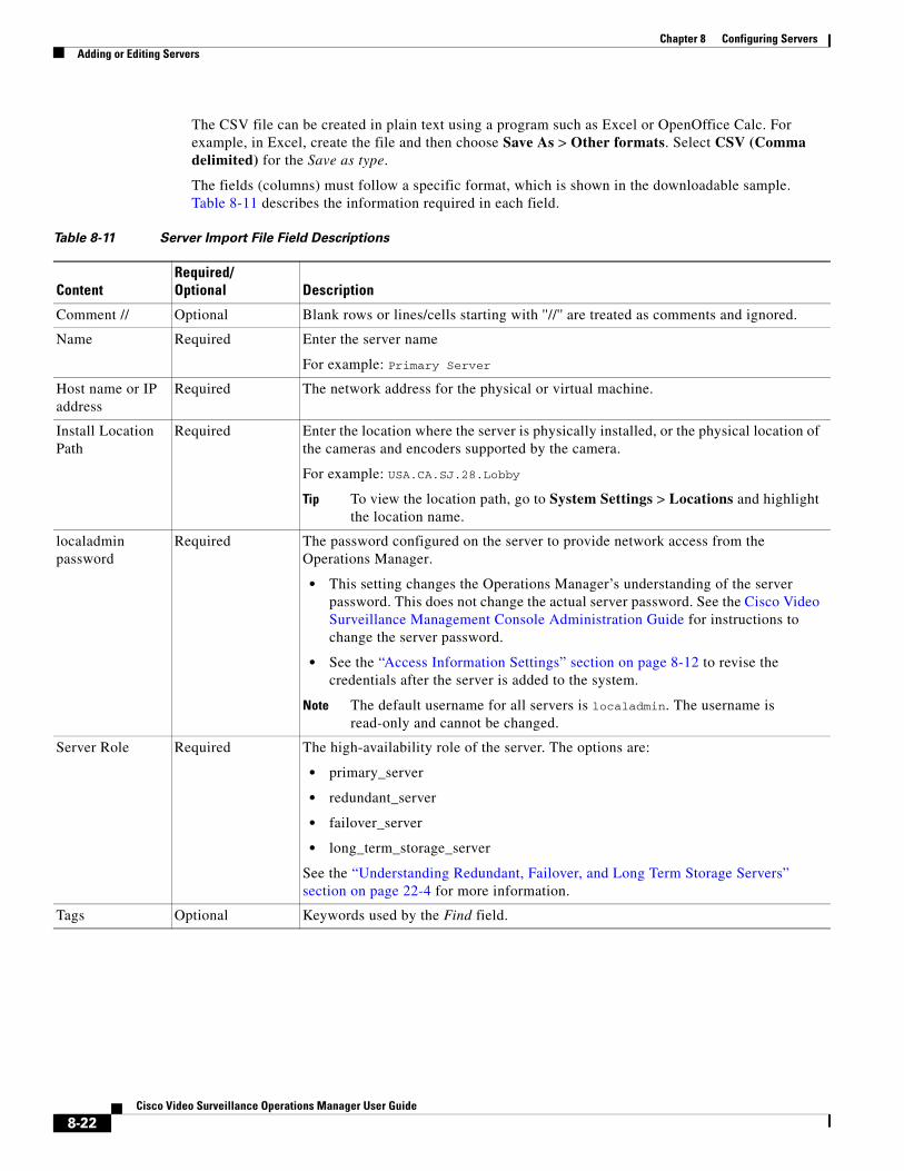
Chapter 8 Configuring Servers Adding or Editing Servers
The CSV file can be created in plain text using a program such as Excel or OpenOffice Calc. For example, in Excel, create the file and then choose Save As > Other formats. Select CSV (Comma delimited) for the Save as type.
The fields (columns) must follow a specific format, which is shown in the downloadable sample. Table 8-11 describes the information required in each field.
Table 8-11 Server Import File Field Descriptions
ContentRequired/Optional Description
Tip To view the location path, go to System Settings > Locations and highlight the location name.
• This setting changes the Operations Manager’s understanding of the server password. This does not change the actual server password. See the Cisco Video Surveillance Management Console Administration Guide for instructions to change the server password.
• See the “Access Information Settings” section on page 8-12 to revise the credentials after the server is added to the system.
Note The default username for all servers is localadmin. The username is read-only and cannot be changed.
• primary_server
• redundant_server
• failover_server
• long_term_storage_server
Comment // Optional Blank rows or lines/cells starting with ''//'' are treated as comments and ignored.
Name Required Enter the server name
For example: Primary Server
Host name or IP address
Required The network address for the physical or virtual machine.
Install Location Path
Required Enter the location where the server is physically installed, or the physical location of the cameras and encoders supported by the camera.
For example: USA.CA.SJ.28.Lobby
localadmin password
Required The password configured on the server to provide network access from the Operations Manager.
Server Role Required The high-availability role of the server. The options are:
See the “Understanding Redundant, Failover, and Long Term Storage Servers” section on page 22-4 for more information.
Tags Optional Keywords used by the Find field.
8-22Cisco Video Surveillance Operations Manager User Guide
Chapter 8 Configuring ServersAdding or Editing Servers
Importing the CSV File
Complete the following procedure to import servers using a CSV file.
Procedure
Step 1 Create the CSV file containing details for each server.
• See the “Creating the CSV File” section on page 8-21.
Step 2 Select System Settings > Servers.
Step 3 Choose Add and Import servers from file.
Step 4 Complete each Import Step as described below:
a. Import Step 1 - Retain Device(s)
(Cameras only) Select the Retain box if existing device(s) found on the server during import should be retained. If selected:
– Enabled cameras and encoders associated with the server are added to the Operations Manager.
– Soft deleted cameras are added to the Operations Manager in the soft-deleted state, which allows recordings to be accessed.
– Disabled cameras are not added to the Operations Manager configuration.
Select Pre-Provision to pre-provision the devices:
– Cameras and encoders associated with the server are added in the pre-provisioned state.
– Pre-provisioned devices must be enabled once the configuration is complete. See the “Adding and Managing Cameras” section on page 10-1 and the “Adding Encoders and Analog Cameras” section on page 20-1 for information about completing the configuration and enabling the devices.
b. Import Step 2 - Download Sample(Optional) Click Download Sample to download a sample CSV import file. Use this sample to create the import file as described in the “Creating the CSV File” section on page 8-21. Click Next.
c. Import Step 3 - File Upload: Click to select the CSV file from a local or network disk. Click Upload.
d. Import Step 4 - Processing: Wait for the import process to complete.
e. Import Step 5 - Results Success:
– If a success message appears, continue to Step 5.
– If an error message appears, continue to Step 4 f.
f. If an error message appears (Figure 8-5), complete the following troubleshooting steps:
– Click Download Annotated CSV, save the error file and open it in Excel or OpenOffice Calc.
– Correct the annotated errors and save the revised file in the .CSV format.
– Correct the CSV file in the //Error rows (Figure 8-5).
– Click Start Over to re-import the fixed file.
– Return to Step 3 and re-import the corrected CSV file.
8-23Cisco Video Surveillance Operations Manager User Guide
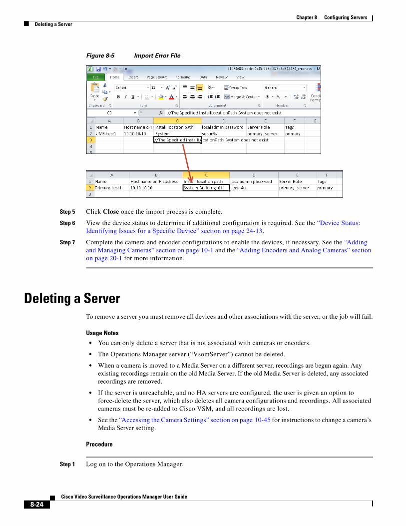
Chapter 8 Configuring Servers Deleting a Server
Figure 8-5 Import Error File
Step 5 Click Close once the import process is complete.
Step 6 View the device status to determine if additional configuration is required. See the “Device Status: Identifying Issues for a Specific Device” section on page 24-13.
Step 7 Complete the camera and encoder configurations to enable the devices, if necessary. See the “Adding and Managing Cameras” section on page 10-1 and the “Adding Encoders and Analog Cameras” section on page 20-1 for more information.
Deleting a ServerTo remove a server you must remove all devices and other associations with the server, or the job will fail.
Usage Notes
• You can only delete a server that is not associated with cameras or encoders.
• The Operations Manager server (“VsomServer”) cannot be deleted.
• When a camera is moved to a Media Server on a different server, recordings are begun again. Any existing recordings remain on the old Media Server. If the old Media Server is deleted, any associated recordings are removed.
• If the server is unreachable, and no HA servers are configured, the user is given an option to force-delete the server, which also deletes all camera configurations and recordings. All associated cameras must be re-added to Cisco VSM, and all recordings are lost.
• See the “Accessing the Camera Settings” section on page 10-45 for instructions to change a camera’s Media Server setting.
Procedure
Step 1 Log on to the Operations Manager.
8-24Cisco Video Surveillance Operations Manager User Guide

Chapter 8 Configuring ServersDeleting a Server
• You must belong to a User Group with permissions for Servers & Encoders.
Step 2 Verify that all cameras and encoders associated with the Media Server are switched to a different Media Server.
• The camera’s existing recordings will remain on the old server.
• See the “Accessing the Camera Settings” section on page 10-45 for instructions to change a camera’s Media Server setting.
Step 3 Click System Settings > Servers.
Step 4 Select the server name.
Step 5 Click Delete.
Step 6 Click OK to confirm.
Step 7 Wait for the Job to complete.
8-25Cisco Video Surveillance Operations Manager User Guide
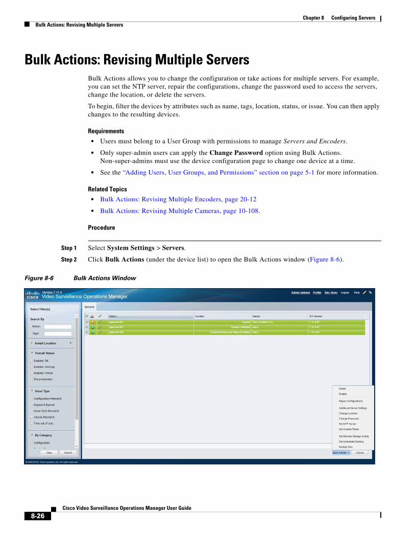
Chapter 8 Configuring Servers Bulk Actions: Revising Multiple Servers
Bulk Actions: Revising Multiple ServersBulk Actions allows you to change the configuration or take actions for multiple servers. For example, you can set the NTP server, repair the configurations, change the password used to access the servers, change the location, or delete the servers.
To begin, filter the devices by attributes such as name, tags, location, status, or issue. You can then apply changes to the resulting devices.
Requirements
• Users must belong to a User Group with permissions to manage Servers and Encoders.
• Only super-admin users can apply the Change Password option using Bulk Actions. Non-super-admins must use the device configuration page to change one device at a time.
• See the “Adding Users, User Groups, and Permissions” section on page 5-1 for more information.
Related Topics
• Bulk Actions: Revising Multiple Encoders, page 20-12
• Bulk Actions: Revising Multiple Cameras, page 10-108.
Procedure
Step 1 Select System Settings > Servers.
Step 2 Click Bulk Actions (under the device list) to open the Bulk Actions window (Figure 8-6).
Figure 8-6 Bulk Actions Window
8-26Cisco Video Surveillance Operations Manager User Guide
Chapter 8 Configuring ServersBulk Actions: Revising Multiple Servers
Step 3 Click the icon next to each field to select the filter criteria.
Table 8-12 Bulk Action Filters
Filter Description
Tip See the “Device Status: Identifying Issues for a Specific Device” section on page 24-13 for more information.
Step 4 Click Search.
Step 5 (Optional) Click the icon to view and edit the device status and configuration settings.
Step 6 Select the devices that will be affected by the action.
• Choose the Select All check box to select ALL servers matched by the filters, including the servers not shown in the grid.
• Use CTRL-CLICK and SHIFT-CLICK or to select multiple items.
Step 7 Click an Action button.
Search by Name Enter the full or partial name and press Enter.
For example, enter “Door” or “Do” to include all device names that include “Door”.
Search by Tag Enter the full or partial tag string and press Enter.
Install Location Select the location where the devices are installed.
Overall Status Select the administrative states for the devices:
Enabled (OK, Warning or Critical)—The device is enabled, although it may include a Warning or Critical event.
Issue Type Select the issues that apply to the device.
Category Select the issue categories that apply to the device. For example, hardware issues or configuration issues.
Table 8-13 Server Bulk Actions
Action Description
Delete Deletes the selected servers from the Operations Manager configuration.
See the “Deleting a Server” section on page 8-24 for more information.
Enable Enable the selected servers.
See the “Viewing Server Status” section on page 8-29 for more information.
Repair Configurations Synchronizes the configuration for the selected servers.
See the “Repairing the Configuration or Restarting the Server” section on page 8-33 for more information.
Change Location Change the location assigned to the server.
See the “Creating the Location Hierarchy” section on page 7-1 for more information.
Change Location Change the location for the selected servers.
See the “General Information Settings” section on page 8-10 and the “Creating the Location Hierarchy” section on page 7-1.
Change Password Note Only super-admin users can apply the Change Password option using Bulk Actions.
8-27Cisco Video Surveillance Operations Manager User Guide
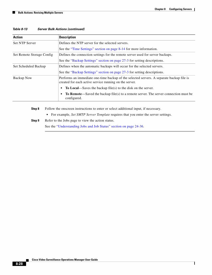
Chapter 8 Configuring Servers Bulk Actions: Revising Multiple Servers
Step 8 Follow the onscreen instructions to enter or select additional input, if necessary.
• For example, Set SMTP Server Template requires that you enter the server settings.
Step 9 Refer to the Jobs page to view the action status.
See the “Understanding Jobs and Job Status” section on page 24-36.
Set NTP Server Defines the NTP server for the selected servers.
See the “Time Settings” section on page 8-14 for more information.
Set Remote Storage Config Defines the connection settings for the remote server used for server backups.
See the “Backup Settings” section on page 27-3 for setting descriptions.
Set Scheduled Backup Defines when the automatic backups will occur for the selected servers.
See the “Backup Settings” section on page 27-3 for setting descriptions.
Backup Now Performs an immediate one-time backup of the selected servers. A separate backup file is created for each active service running on the server.
• To Local—Saves the backup file(s) to the disk on the server.
• To Remote—Saved the backup file(s) to a remote server. The server connection must be configured.
Table 8-13 Server Bulk Actions (continued)
Action Description
8-28Cisco Video Surveillance Operations Manager User Guide
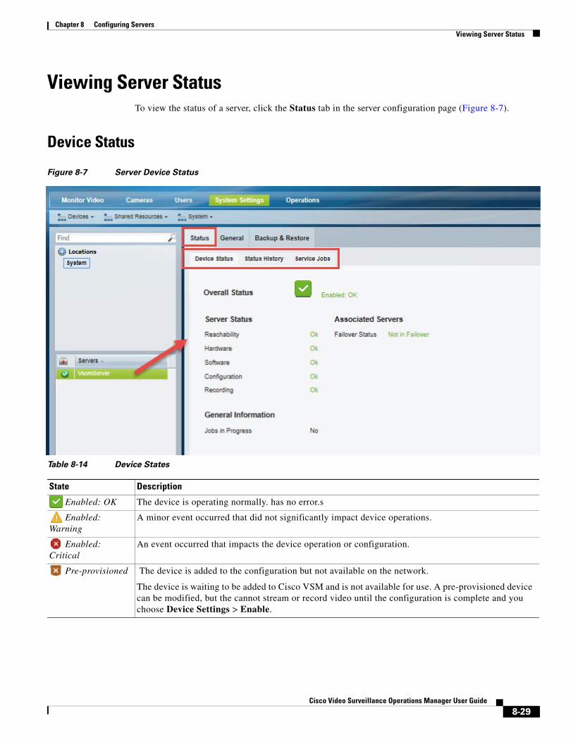
Chapter 8 Configuring ServersViewing Server Status
Viewing Server StatusTo view the status of a server, click the Status tab in the server configuration page (Figure 8-7).
Device Status
Figure 8-7 Server Device Status
Table 8-14 Device States
State Description
Enabled: OK The device is operating normally. has no error.s
Enabled: Warning
A minor event occurred that did not significantly impact device operations.
Enabled: Critical
An event occurred that impacts the device operation or configuration.
Pre-provisioned The device is added to the configuration but not available on the network.
The device is waiting to be added to Cisco VSM and is not available for use. A pre-provisioned device can be modified, but the cannot stream or record video until the configuration is complete and you choose Device Settings > Enable.
8-29Cisco Video Surveillance Operations Manager User Guide
Chapter 8 Configuring Servers Viewing Server Status
Usage Notes
• Click the Status History tab to view detailed information regarding the events or alerts that impact the Device Status. For example, if a Synchronization mismatch occurs, and the Configuration status changes from OK to a synchronization alert, click the Status History tab to view details for the errors that caused the mismatch. See the “Viewing the Status Error Details and History” section on page 24-18.
• Click Reset Status to clear status issues that do not automatically clear when the issue is resolved (see the “Resetting the Server Device State” section on page 8-33).
• See the following options to repair configuration issues or reset the device state:
– Repairing the Configuration or Restarting the Server, page 8-33
– Resetting the Server Device State, page 8-33
• See the “Viewing the Server HA Status” section on page 22-21 for more information on the Associated Servers status.
Server Status History and Service JobsFor more information about Status History and Service Jobs, see the “Viewing Media Server Status” section on page 11-9.
8-30Cisco Video Surveillance Operations Manager User Guide
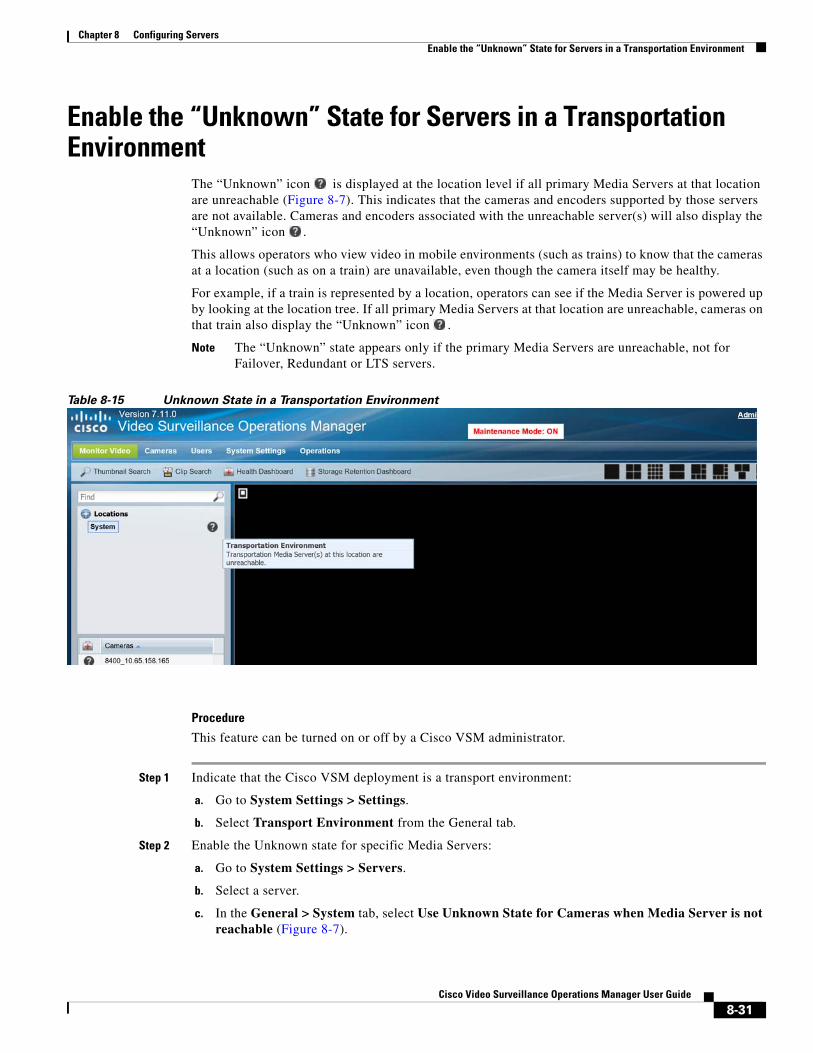
Chapter 8 Configuring ServersEnable the “Unknown” State for Servers in a Transportation Environment
Enable the “Unknown” State for Servers in a Transportation Environment
The “Unknown” icon is displayed at the location level if all primary Media Servers at that location are unreachable (Figure 8-7). This indicates that the cameras and encoders supported by those servers are not available. Cameras and encoders associated with the unreachable server(s) will also display the “Unknown” icon .
This allows operators who view video in mobile environments (such as trains) to know that the cameras at a location (such as on a train) are unavailable, even though the camera itself may be healthy.
For example, if a train is represented by a location, operators can see if the Media Server is powered up by looking at the location tree. If all primary Media Servers at that location are unreachable, cameras on that train also display the “Unknown” icon .
Note The “Unknown” state appears only if the primary Media Servers are unreachable, not for Failover, Redundant or LTS servers.
Table 8-15 Unknown State in a Transportation Environment
Procedure
This feature can be turned on or off by a Cisco VSM administrator.
Step 1 Indicate that the Cisco VSM deployment is a transport environment:
a. Go to System Settings > Settings.
b. Select Transport Environment from the General tab.
Step 2 Enable the Unknown state for specific Media Servers:
a. Go to System Settings > Servers.
b. Select a server.
c. In the General > System tab, select Use Unknown State for Cameras when Media Server is not reachable (Figure 8-7).
8-31Cisco Video Surveillance Operations Manager User Guide
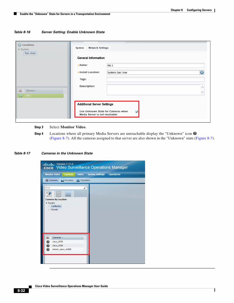
Chapter 8 Configuring Servers Enable the “Unknown” State for Servers in a Transportation Environment
Table 8-16 Server Setting: Enable Unknown State
Step 3 Select Monitor Video.
Step 4 Locations where all primary Media Servers are unreachable display the “Unknown” icon (Figure 8-7). All the cameras assigned to that server are also shown in the "Unknown" state (Figure 8-7).
Table 8-17 Cameras in the Unknown State
8-32Cisco Video Surveillance Operations Manager User Guide
Chapter 8 Configuring ServersResetting the Server Device State
Resetting the Server Device StateClick the Reset Status button on the server Status page to clear device status and configuration issues.
• Clears status issues that do not automatically clear when the issue is resolved. For example, an issue that causes a coredump might still display a critical error in the Operations Manager even if the issue is resolved.
• Performs a Repair Configuration that synchronizes the server configuration with the Operations Manager (mismatched configurations on the Media Server are replaced with the Operations Manager settings). See the “Repairing the Configuration or Restarting the Server” section on page 8-33.
Note • Any unresolved configuration issues will reappear after the reset.
• Only the server state is reset, not the device alerts or events. You must still acknowledge or clear any alert using the Cisco Video Surveillance Safety and Security Desktop.
• To access the Reset Status button, you must be a Super-Admin or belong to a user group assigned to the super_admin_role (a super-admin is anybody that has all permissions at the root location). See the “Adding Users, User Groups, and Permissions” section on page 5-1 for more information.
Repairing the Configuration or Restarting the Server From the General tab, select the Device Setting menu and select one of the actions described in Table 8-18.
Table 8-18 Server Operations
Operation Description
Note The restart period can last 1 minute or longer. During this time, the Cisco VSM system will be offline and inaccessible.
Replace Configurations
Overwrite all configuration settings on the server with the settings in the Operations Manager.
See the “Synchronizing Device Configurations” section on page 24-28 for more information.
Repair Configurations
Push only the configuration changes required to correct a mismatched field. Changes are pushed from the Operations Manager to the Media Server
See the “Synchronizing Device Configurations” section on page 24-28 for more information.
Restart Reboot the server and trigger a synchronization (Repair Configuration).
8-33Cisco Video Surveillance Operations Manager User Guide
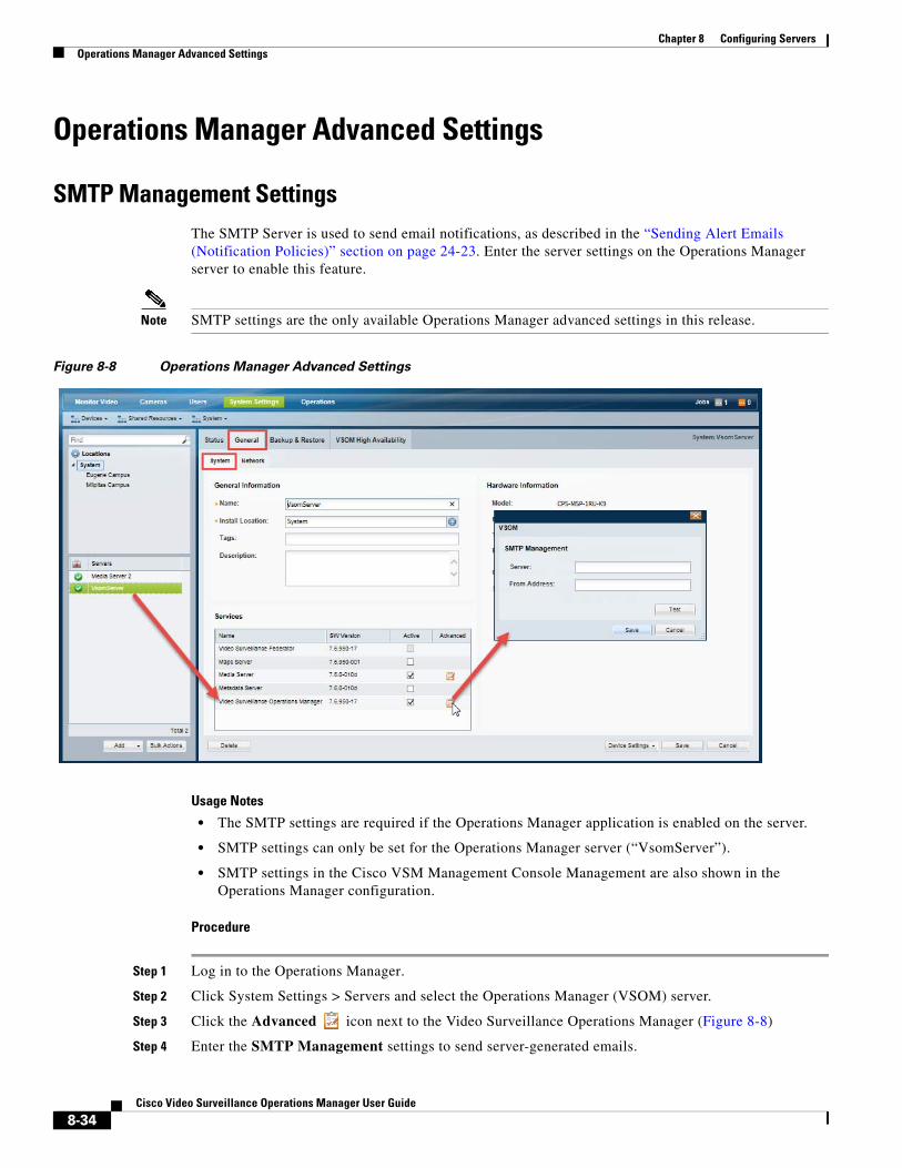
Chapter 8 Configuring Servers Operations Manager Advanced Settings
Operations Manager Advanced Settings
SMTP Management SettingsThe SMTP Server is used to send email notifications, as described in the “Sending Alert Emails (Notification Policies)” section on page 24-23. Enter the server settings on the Operations Manager server to enable this feature.
Note SMTP settings are the only available Operations Manager advanced settings in this release.
Figure 8-8 Operations Manager Advanced Settings
Usage Notes
• The SMTP settings are required if the Operations Manager application is enabled on the server.
• SMTP settings can only be set for the Operations Manager server (“VsomServer”).
• SMTP settings in the Cisco VSM Management Console Management are also shown in the Operations Manager configuration.
Procedure
Step 1 Log in to the Operations Manager.
Step 2 Click System Settings > Servers and select the Operations Manager (VSOM) server.
Step 3 Click the Advanced icon next to the Video Surveillance Operations Manager (Figure 8-8)
Step 4 Enter the SMTP Management settings to send server-generated emails.
8-34Cisco Video Surveillance Operations Manager User Guide

Chapter 8 Configuring ServersOperations Manager Advanced Settings
Table 8-19 SMTP Settings
Field Settings
SMTP Server The IP address or hostname if the SMTP server used to send emails.
From Address The email address that appears in the from field. User replies will be sent to this address. This field is required to send e-mails when an SNMP event occurs.
8-35Cisco Video Surveillance Operations Manager User Guide

Chapter 8 Configuring Servers Operations Manager Advanced Settings
8-36Cisco Video Surveillance Operations Manager User Guide
Cisco V
C H A P T E R 9
Understanding NTP ConfigurationThe server time synchronizes server operations, defines recording timestamps and backup schedules.
To ensure correct playback and system operation, we strongly recommend using a network time protocol (NTP) for all servers and devices.
Refer to the following topics for more information:
• Recommended (and Default) NTP Configuration, page 9-2
• NTP Usage Notes, page 9-3
• Configuring Media Servers with a User-Defined NTP Server, page 9-4
– Changing the NTP Server for a Single Media Server, page 9-5
– Changing the NTP Server for Multiple Media Servers, page 9-6
• Configuring Cameras with a User-Defined NTP Server, page 9-8
– Changing the NTP Settings for a Single Camera, page 9-9
– Changing the NTP Server for Multiple Cameras, page 9-10
• Defining the NTP Setting During Camera Auto-Discovery, page 9-11
9-1ideo Surveillance Operations Manager User Guide
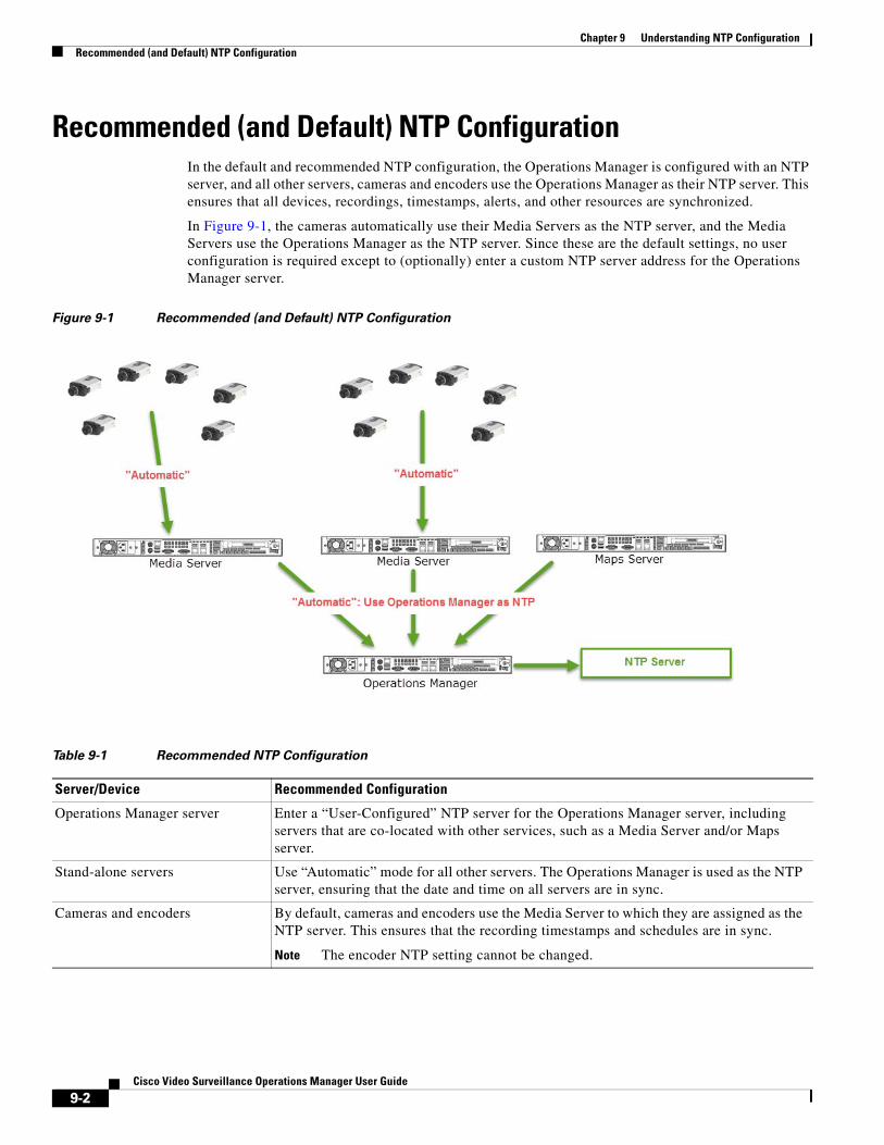
Chapter 9 Understanding NTP Configuration Recommended (and Default) NTP Configuration
Recommended (and Default) NTP ConfigurationIn the default and recommended NTP configuration, the Operations Manager is configured with an NTP server, and all other servers, cameras and encoders use the Operations Manager as their NTP server. This ensures that all devices, recordings, timestamps, alerts, and other resources are synchronized.
In Figure 9-1, the cameras automatically use their Media Servers as the NTP server, and the Media Servers use the Operations Manager as the NTP server. Since these are the default settings, no user configuration is required except to (optionally) enter a custom NTP server address for the Operations Manager server.
Figure 9-1 Recommended (and Default) NTP Configuration
Table 9-1 Recommended NTP Configuration
Server/Device Recommended Configuration
Note The encoder NTP setting cannot be changed.
Operations Manager server Enter a “User-Configured” NTP server for the Operations Manager server, including servers that are co-located with other services, such as a Media Server and/or Maps server.
Stand-alone servers Use “Automatic” mode for all other servers. The Operations Manager is used as the NTP server, ensuring that the date and time on all servers are in sync.
Cameras and encoders By default, cameras and encoders use the Media Server to which they are assigned as the NTP server. This ensures that the recording timestamps and schedules are in sync.
9-2Cisco Video Surveillance Operations Manager User Guide
Chapter 9 Understanding NTP ConfigurationNTP Usage Notes
NTP Usage Notes • Enter NTP Server names or IP addresses separated by space or comma.
• Automatic mode can only be used after NTP is configured on the Operations Manager server.
• The server will reboot if any changes are made to the NTP settings using the Operations Manager UI.
• Changes to the server time can affect video recording schedules and timestamps.
• A warning alert is generated if the time difference between the server and Operations Manager is more than 2 minutes.
• A warning message is also displayed to operators when logging in if the time difference between their workstation and the server is more than 2 minutes.
• You can modify the NTP information for up to 10,000 cameras at a time.
• The NTP servers configured on a device are displayed in the device configuration page (under NTP Information).
• NTP settings can be configured on camera only if the camera model supports NTP configuration.
• The number of NTP servers configured on a camera are limited to the number supported by the camera model. For example, if a camera model only supports a single NTP server setting, and you attempt to add three NTP servers, the configuration will be rejected.
• Never modify the time and NTP settings using the Linux CLI. Settings made using the Linux CLI can result in inconsistent system performance and other issues.
9-3Cisco Video Surveillance Operations Manager User Guide
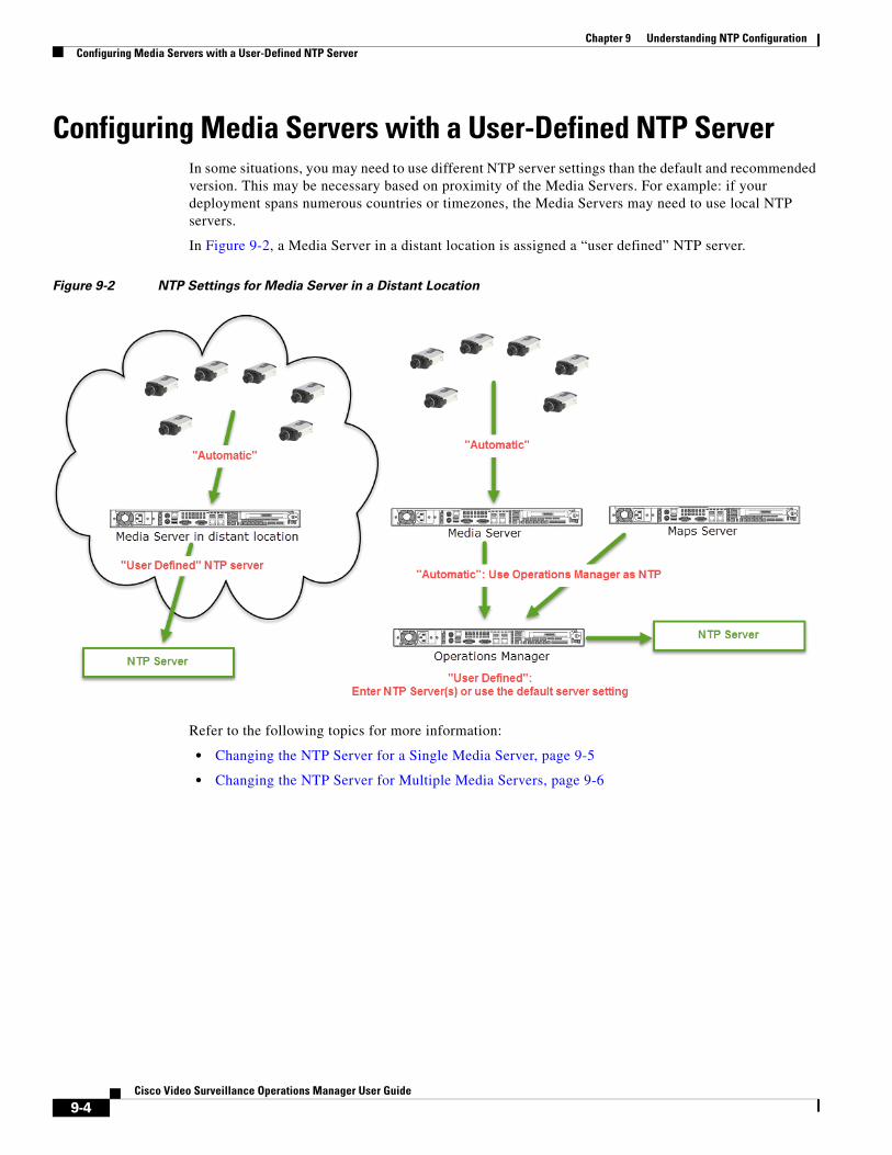
Chapter 9 Understanding NTP Configuration Configuring Media Servers with a User-Defined NTP Server
Configuring Media Servers with a User-Defined NTP ServerIn some situations, you may need to use different NTP server settings than the default and recommended version. This may be necessary based on proximity of the Media Servers. For example: if your deployment spans numerous countries or timezones, the Media Servers may need to use local NTP servers.
In Figure 9-2, a Media Server in a distant location is assigned a “user defined” NTP server.
Figure 9-2 NTP Settings for Media Server in a Distant Location
Refer to the following topics for more information:
• Changing the NTP Server for a Single Media Server, page 9-5
• Changing the NTP Server for Multiple Media Servers, page 9-6
9-4Cisco Video Surveillance Operations Manager User Guide
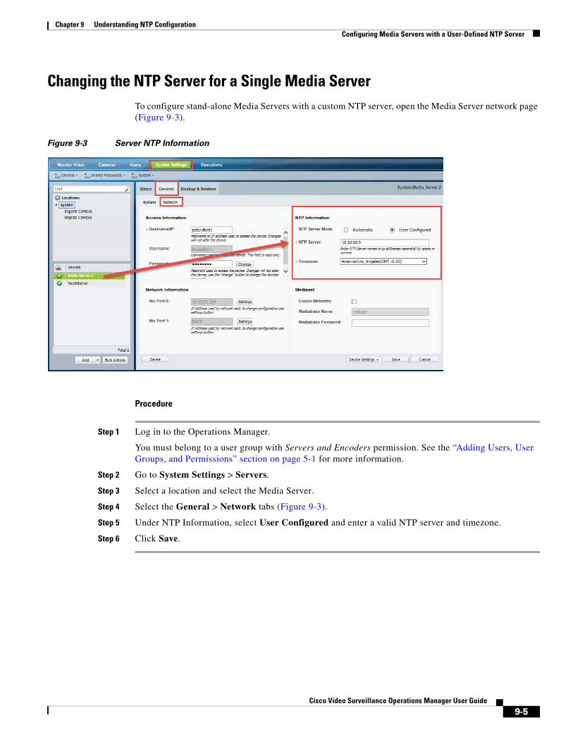
Chapter 9 Understanding NTP ConfigurationConfiguring Media Servers with a User-Defined NTP Server
Changing the NTP Server for a Single Media ServerTo configure stand-alone Media Servers with a custom NTP server, open the Media Server network page (Figure 9-3).
Figure 9-3 Server NTP Information
Procedure
Step 1 Log in to the Operations Manager.
You must belong to a user group with Servers and Encoders permission. See the “Adding Users, User Groups, and Permissions” section on page 5-1 for more information.
Step 2 Go to System Settings > Servers.
Step 3 Select a location and select the Media Server.
Step 4 Select the General > Network tabs (Figure 9-3).
Step 5 Under NTP Information, select User Configured and enter a valid NTP server and timezone.
Step 6 Click Save.
9-5Cisco Video Surveillance Operations Manager User Guide
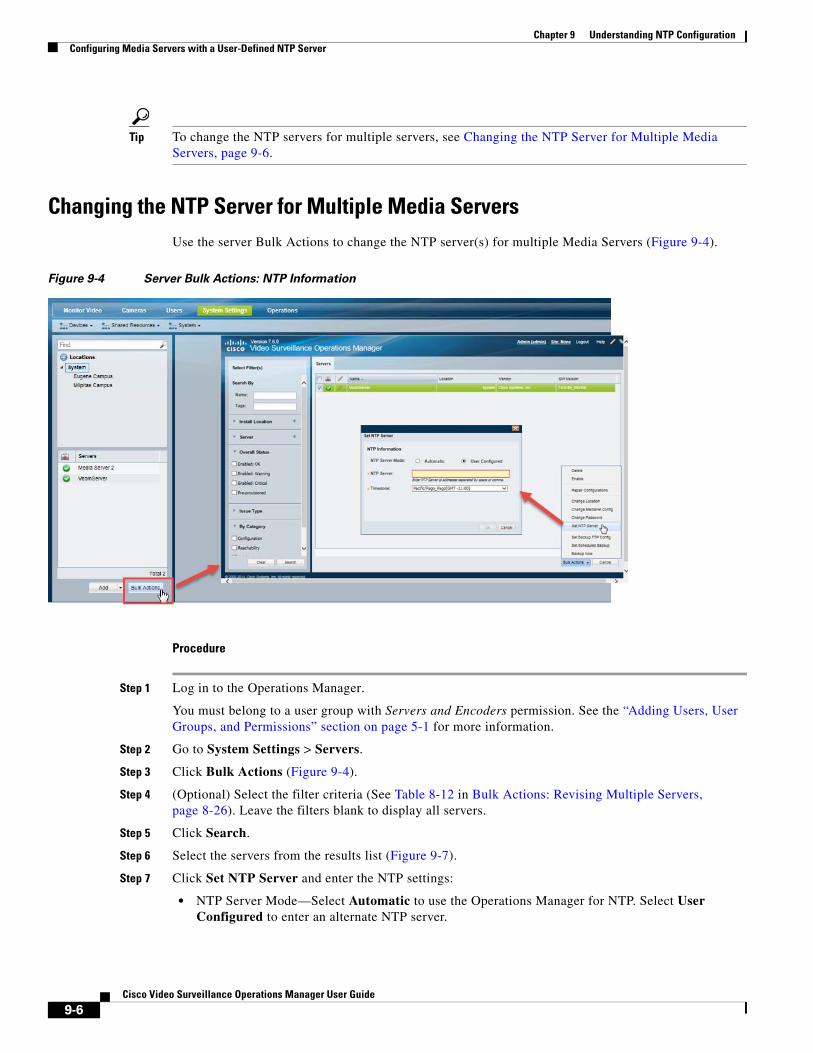
Chapter 9 Understanding NTP Configuration Configuring Media Servers with a User-Defined NTP Server
Tip To change the NTP servers for multiple servers, see Changing the NTP Server for Multiple Media Servers, page 9-6.
Changing the NTP Server for Multiple Media ServersUse the server Bulk Actions to change the NTP server(s) for multiple Media Servers (Figure 9-4).
Figure 9-4 Server Bulk Actions: NTP Information
Procedure
Step 1 Log in to the Operations Manager.
You must belong to a user group with Servers and Encoders permission. See the “Adding Users, User Groups, and Permissions” section on page 5-1 for more information.
Step 2 Go to System Settings > Servers.
Step 3 Click Bulk Actions (Figure 9-4).
Step 4 (Optional) Select the filter criteria (See Table 8-12 in Bulk Actions: Revising Multiple Servers, page 8-26). Leave the filters blank to display all servers.
Step 5 Click Search.
Step 6 Select the servers from the results list (Figure 9-7).
Step 7 Click Set NTP Server and enter the NTP settings:
• NTP Server Mode—Select Automatic to use the Operations Manager for NTP. Select User Configured to enter an alternate NTP server.
9-6Cisco Video Surveillance Operations Manager User Guide
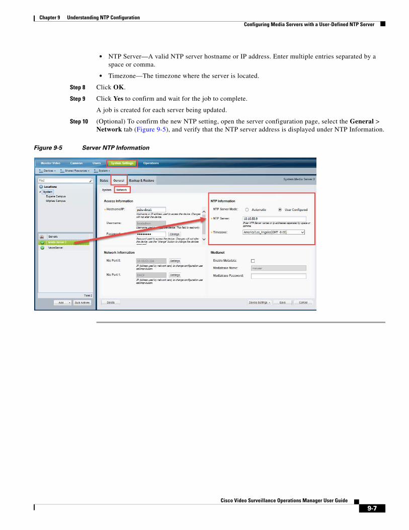
Chapter 9 Understanding NTP ConfigurationConfiguring Media Servers with a User-Defined NTP Server
• NTP Server—A valid NTP server hostname or IP address. Enter multiple entries separated by a space or comma.
• Timezone—The timezone where the server is located.
Step 8 Click OK.
Step 9 Click Yes to confirm and wait for the job to complete.
A job is created for each server being updated.
Step 10 (Optional) To confirm the new NTP setting, open the server configuration page, select the General > Network tab (Figure 9-5), and verify that the NTP server address is displayed under NTP Information.
Figure 9-5 Server NTP Information
9-7Cisco Video Surveillance Operations Manager User Guide
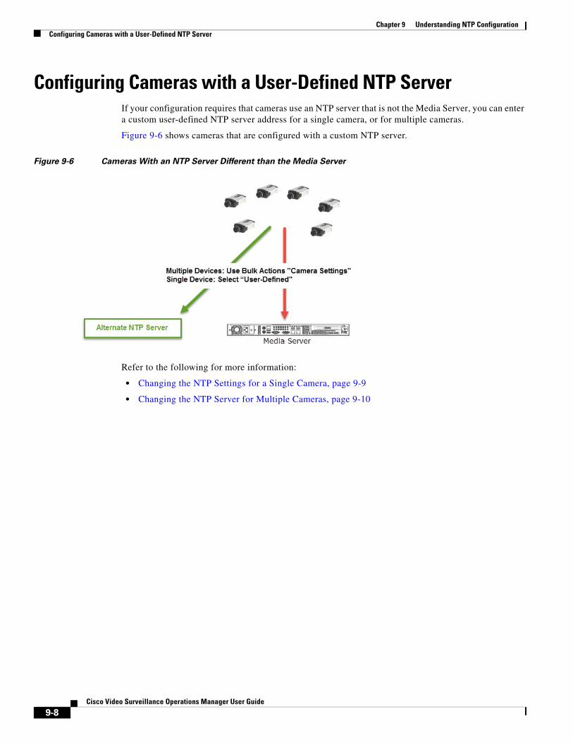
Chapter 9 Understanding NTP Configuration Configuring Cameras with a User-Defined NTP Server
Configuring Cameras with a User-Defined NTP ServerIf your configuration requires that cameras use an NTP server that is not the Media Server, you can enter a custom user-defined NTP server address for a single camera, or for multiple cameras.
Figure 9-6 shows cameras that are configured with a custom NTP server.
Figure 9-6 Cameras With an NTP Server Different than the Media Server
Refer to the following for more information:
• Changing the NTP Settings for a Single Camera, page 9-9
• Changing the NTP Server for Multiple Cameras, page 9-10
9-8Cisco Video Surveillance Operations Manager User Guide
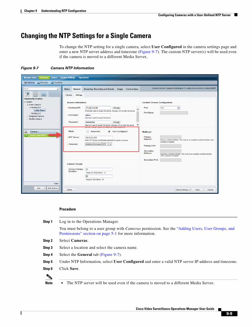
Chapter 9 Understanding NTP ConfigurationConfiguring Cameras with a User-Defined NTP Server
Changing the NTP Settings for a Single CameraTo change the NTP setting for a single camera, select User Configured in the camera settings page and enter a new NTP server address and timezone (Figure 9-7). The custom NTP server(s) will be used even if the camera is moved to a different Media Server,
Figure 9-7 Camera NTP Information
Procedure
Step 1 Log in to the Operations Manager.
You must belong to a user group with Cameras permission. See the “Adding Users, User Groups, and Permissions” section on page 5-1 for more information.
Step 2 Select Cameras.
Step 3 Select a location and select the camera name.
Step 4 Select the General tab (Figure 9-7).
Step 5 Under NTP Information, select User Configured and enter a valid NTP server IP address and timezone.
Step 6 Click Save.
Note • The NTP server will be used even if the camera is moved to a different Media Server.
9-9Cisco Video Surveillance Operations Manager User Guide
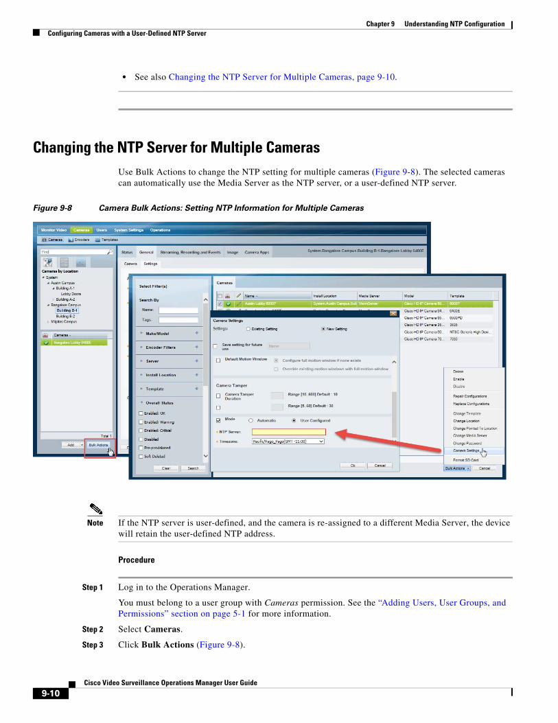
Chapter 9 Understanding NTP Configuration Configuring Cameras with a User-Defined NTP Server
• See also Changing the NTP Server for Multiple Cameras, page 9-10.
Changing the NTP Server for Multiple CamerasUse Bulk Actions to change the NTP setting for multiple cameras (Figure 9-8). The selected cameras can automatically use the Media Server as the NTP server, or a user-defined NTP server.
Figure 9-8 Camera Bulk Actions: Setting NTP Information for Multiple Cameras
Note If the NTP server is user-defined, and the camera is re-assigned to a different Media Server, the device will retain the user-defined NTP address.
Procedure
Step 1 Log in to the Operations Manager.
You must belong to a user group with Cameras permission. See the “Adding Users, User Groups, and Permissions” section on page 5-1 for more information.
Step 2 Select Cameras.
Step 3 Click Bulk Actions (Figure 9-8).
9-10Cisco Video Surveillance Operations Manager User Guide
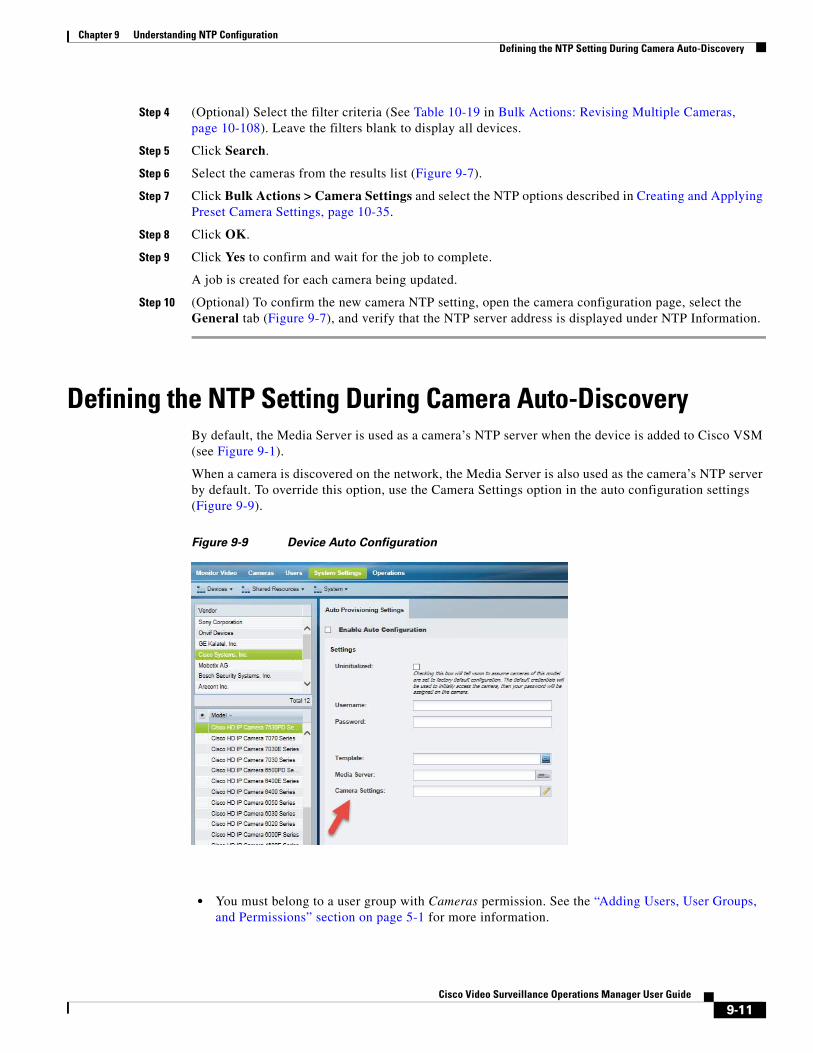
Chapter 9 Understanding NTP ConfigurationDefining the NTP Setting During Camera Auto-Discovery
Step 4 (Optional) Select the filter criteria (See Table 10-19 in Bulk Actions: Revising Multiple Cameras, page 10-108). Leave the filters blank to display all devices.
Step 5 Click Search.
Step 6 Select the cameras from the results list (Figure 9-7).
Step 7 Click Bulk Actions > Camera Settings and select the NTP options described in Creating and Applying Preset Camera Settings, page 10-35.
Step 8 Click OK.
Step 9 Click Yes to confirm and wait for the job to complete.
A job is created for each camera being updated.
Step 10 (Optional) To confirm the new camera NTP setting, open the camera configuration page, select the General tab (Figure 9-7), and verify that the NTP server address is displayed under NTP Information.
Defining the NTP Setting During Camera Auto-DiscoveryBy default, the Media Server is used as a camera’s NTP server when the device is added to Cisco VSM (see Figure 9-1).
When a camera is discovered on the network, the Media Server is also used as the camera’s NTP server by default. To override this option, use the Camera Settings option in the auto configuration settings (Figure 9-9).
Figure 9-9 Device Auto Configuration
• You must belong to a user group with Cameras permission. See the “Adding Users, User Groups, and Permissions” section on page 5-1 for more information.
9-11Cisco Video Surveillance Operations Manager User Guide

Chapter 9 Understanding NTP Configuration Defining the NTP Setting During Camera Auto-Discovery
• See the “Configuring Cameras with a User-Defined NTP Server” section on page 9-8 for information to define a new NTP server for one or more cameras.
9-12Cisco Video Surveillance Operations Manager User Guide
Cisco V
C H A P T E R 10
Adding and Managing CamerasRefer to the following topics for information to add, configure, and manage cameras in a Cisco VSM deployment.
Note • Always use the Operations Manager to configure cameras. Changes made directly to the camera are unknown to Cisco VSM and can result in incorrect device behavior.
• The camera configuration pages may not display properly if the Internet Explorer (IE) compatibility view box is checked. De-select this option, if necessary.
Contents
• Overview, page 10-3
– Understanding Network and Analog Cameras, page 10-3
– Viewing Cameras, page 10-5
– Requirements, page 10-3
– Summary Steps, page 10-4
• Manually Adding Cameras, page 10-8
– Overview, page 10-8
– Manually Adding a Single Camera, page 10-10
• Adding Onvif Cameras, page 10-16
• Importing or Updating Cameras or Encoders Using a CSV File, page 10-20
• Configuring Panoramic Multi-lens Cameras, page 10-27
• Configuring 360° (Fisheye) Cameras, page 10-33
• Creating and Applying Preset Camera Settings, page 10-35
• Zipstream compression support for Axis Cameras, page 10-38
• Managing Cameras with Duplicate IP Addresses, page 10-40
• Adding Cameras from an Existing Media Server, page 10-41
• Blacklisting Cameras, page 10-43
– Blacklisting a Camera, page 10-43
– Viewing Cameras in the Blacklist, page 10-43
10-1ideo Surveillance Operations Manager User Guide
Chapter 10 Adding and Managing Cameras
– Removing a Camera From the Blacklist, page 10-43
• Camera Settings, page 10-45
– Accessing the Camera Settings, page 10-45
– General Settings, page 10-47
– Streaming, Recording and Event Settings, page 10-55
– Using Custom Video Quality Settings, page 10-61
– Zipstream compression support for Axis Cameras, page 10-62
– Image Settings, page 10-64
– Configuring the High Availability Options for a Camera or Template, page 10-65
• Display Text and Time in a Cisco Camera’s Video View, page 10-66
• Enabling Panoramic Mode, page 10-67
• Deleting Cameras, page 10-69
• Rebooting Cameras, page 10-71
• Changing the Camera or Encoder Access Settings (Address and Credentials), page 10-72
• Camera Status, page 10-74
• Configuring Camera PTZ Controls, Presets, and Tours, page 10-81
– PTZ Requirements, page 10-82
– PTZ Camera Configuration Summary, page 10-83
– Defining the User Group PTZ Priority, page 10-85
– Using Camera PTZ Controls, page 10-86
– Configuring PTZ Presets, page 10-87
– Configuring PTZ Tours, page 10-89
– Configuring Advanced Settings, page 10-91
– Configuring a PTZ “Return to Home” Countdown, page 10-93
• Configuring Motion Detection, page 10-96
• Replacing a Camera, page 10-103
• Bulk Actions: Revising Multiple Cameras, page 10-108
Note See also Cisco Video Surveillance Manager: Install and Upgrade Guide.
10-2Cisco Video Surveillance Operations Manager User Guide
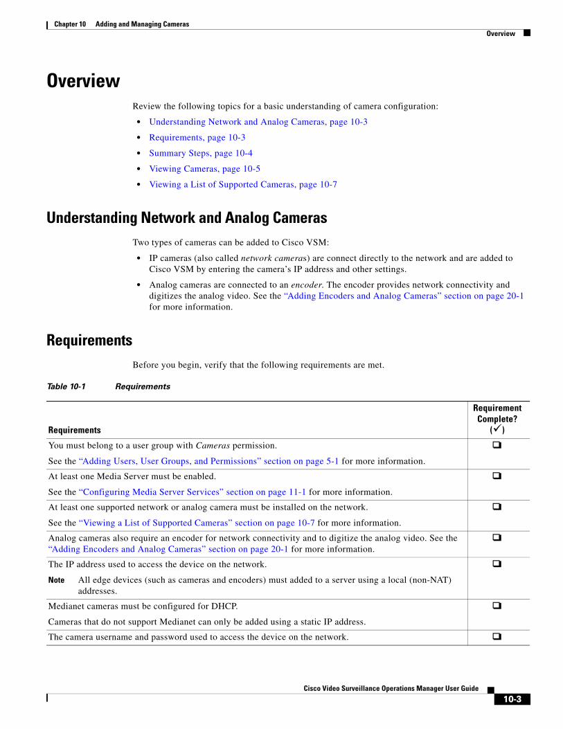
Chapter 10 Adding and Managing CamerasOverview
Overview Review the following topics for a basic understanding of camera configuration:
• Understanding Network and Analog Cameras, page 10-3
• Requirements, page 10-3
• Summary Steps, page 10-4
• Viewing Cameras, page 10-5
• Viewing a List of Supported Cameras, page 10-7
Understanding Network and Analog CamerasTwo types of cameras can be added to Cisco VSM:
• IP cameras (also called network cameras) are connect directly to the network and are added to Cisco VSM by entering the camera’s IP address and other settings.
• Analog cameras are connected to an encoder. The encoder provides network connectivity and digitizes the analog video. See the “Adding Encoders and Analog Cameras” section on page 20-1 for more information.
Requirements Before you begin, verify that the following requirements are met.
Table 10-1 Requirements
Requirements
Requirement Complete?
()
Note All edge devices (such as cameras and encoders) must added to a server using a local (non-NAT) addresses.
You must belong to a user group with Cameras permission.
See the “Adding Users, User Groups, and Permissions” section on page 5-1 for more information.
At least one Media Server must be enabled.
See the “Configuring Media Server Services” section on page 11-1 for more information.
At least one supported network or analog camera must be installed on the network.
See the “Viewing a List of Supported Cameras” section on page 10-7 for more information.
Analog cameras also require an encoder for network connectivity and to digitize the analog video. See the “Adding Encoders and Analog Cameras” section on page 20-1 for more information.
The IP address used to access the device on the network.
Medianet cameras must be configured for DHCP.
Cameras that do not support Medianet can only be added using a static IP address.
The camera username and password used to access the device on the network.
10-3Cisco Video Surveillance Operations Manager User Guide
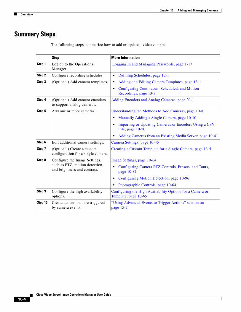
Chapter 10 Adding and Managing Cameras Overview
Summary Steps The following steps summarize how to add or update a video camera.
Step More Information
Step 1
Step 2 • Defining Schedules, page 12-1
Step 3 • Adding and Editing Camera Templates, page 13-1
• Configuring Continuous, Scheduled, and Motion Recordings, page 13-7
Step 4
Step 5
• Manually Adding a Single Camera, page 10-10
• Importing or Updating Cameras or Encoders Using a CSV File, page 10-20
• Adding Cameras from an Existing Media Server, page 10-41
Step 6
Step 7
Step 8
• Configuring Camera PTZ Controls, Presets, and Tours, page 10-81
• Configuring Motion Detection, page 10-96
• Photographic Controls, page 10-64
Step 9
Step 10
Log on to the Operations Manager.
Logging In and Managing Passwords, page 1-17
Configure recording schedules
(Optional) Add camera templates.
(Optional) Add camera encoders to support analog cameras.
Adding Encoders and Analog Cameras, page 20-1
Add one or more cameras. Understanding the Methods to Add Cameras, page 10-8
Edit additional camera settings. Camera Settings, page 10-45
(Optional) Create a custom configuration for a single camera.
Creating a Custom Template for a Single Camera, page 13-5
Configure the Image Settings, such as PTZ, motion detection, and brightness and contrast.
Image Settings, page 10-64
Configure the high availability options.
Configuring the High Availability Options for a Camera or Template, page 10-65
Create actions that are triggered by camera events.
“Using Advanced Events to Trigger Actions” section on page 15-7
10-4Cisco Video Surveillance Operations Manager User Guide
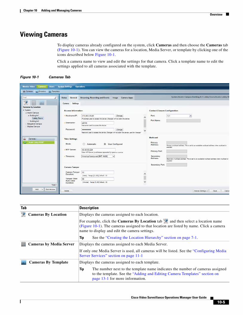
Chapter 10 Adding and Managing CamerasOverview
Viewing CamerasTo display cameras already configured on the system, click Cameras and then choose the Cameras tab (Figure 10-1). You can view the cameras for a location, Media Server, or template by clicking one of the icons described below Figure 10-1.
Click a camera name to view and edit the settings for that camera. Click a template name to edit the settings applied to all cameras associated with the template.
Figure 10-1 Cameras Tab
Tab Description
Tip See the “Creating the Location Hierarchy” section on page 7-1.
Tip The number next to the template name indicates the number of cameras assigned to the template. See the “Adding and Editing Camera Templates” section on page 13-1 for more information.
Cameras By Location Displays the cameras assigned to each location.
For example, click the Cameras By Location tab and then select a location name (Figure 10-1). The cameras assigned to that location are listed by name. Click a camera name to display and edit the camera settings.
Cameras by Media Server Displays the cameras assigned to each Media Server.
If only one Media Server is used, all cameras will be listed. See the “Configuring Media Server Services” section on page 11-1
Cameras By Template Displays the cameras assigned to each template.
10-5Cisco Video Surveillance Operations Manager User Guide
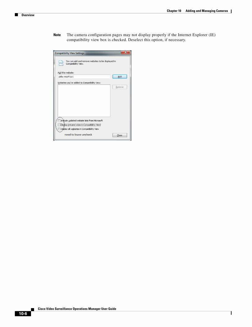
Chapter 10 Adding and Managing Cameras Overview
Note The camera configuration pages may not display properly if the Internet Explorer (IE) compatibility view box is checked. Deselect this option, if necessary.
10-6Cisco Video Surveillance Operations Manager User Guide
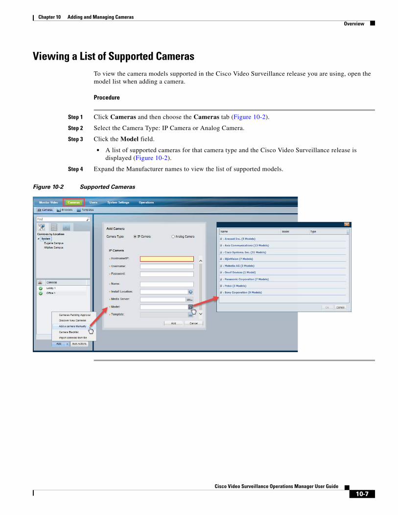
Chapter 10 Adding and Managing CamerasOverview
Viewing a List of Supported CamerasTo view the camera models supported in the Cisco Video Surveillance release you are using, open the model list when adding a camera.
Procedure
Step 1 Click Cameras and then choose the Cameras tab (Figure 10-2).
Step 2 Select the Camera Type: IP Camera or Analog Camera.
Step 3 Click the Model field.
• A list of supported cameras for that camera type and the Cisco Video Surveillance release is displayed (Figure 10-2).
Step 4 Expand the Manufacturer names to view the list of supported models.
Figure 10-2 Supported Cameras
10-7Cisco Video Surveillance Operations Manager User Guide
Chapter 10 Adding and Managing Cameras Manually Adding Cameras
Manually Adding CamerasCameras can be added to Cisco VSM individually, or in groups. You can add cameras that are already installed, or pre-provision cameras that are not yet available on the network. In addition, if you add a Media Server that was previously installed in another VSM 6.x or 7.x deployment, you will be prompted to add or discard any cameras configured on that server.
For more information, see the following topics:
• Overview, page 10-8
– Understanding the Methods to Add Cameras, page 10-8
– Pre-Provisioning Cameras, page 10-9
• Manually Adding a Single Camera, page 10-10
• Importing or Updating Cameras or Encoders Using a CSV File, page 10-20
– Creating the CSV File, page 10-21
– Importing the CSV File, page 10-26
• Adding Cameras from an Existing Media Server, page 10-41
– Adding Cameras From a 6.x or 7.x Media Server, page 10-41
– Adding Unknown Cameras During a Media Server Synchronization, page 10-42
OverviewReview the following topics to understand how cameras are added to Cisco VSM.
• Understanding the Methods to Add Cameras, page 10-8
• Pre-Provisioning Cameras, page 10-9
• Managing Cameras with Duplicate IP Addresses, page 10-40
Understanding the Methods to Add Cameras
You can add cameras to Cisco VSM using one or more of the following methods:
Table 10-2 Summary of Add Camera Methods
Add Method Description
Manually Adding a Single Camera, page 10-10 Add a single camera from the Camera configuration page. All required settings must be entered, although you can pre-provision the camera if it is not yet available on the network.
Importing or Updating Cameras or Encoders Using a CSV File, page 10-20
Multiple cameras can be imported from a comma separated value (CSV) file that defines the camera configurations. You can choose to pre-provision the cameras, and add cameras with partial configurations, if necessary. This same method can be used to update existing camera configurations.
Tip You can import network (IP) cameras, encoders and analog cameras.
10-8Cisco Video Surveillance Operations Manager User Guide

Chapter 10 Adding and Managing CamerasManually Adding Cameras
Pre-Provisioning Cameras
Pre-provisioning cameras allows you to add the cameras before they are installed or available on the network. The camera is waiting to be added to Cisco VSM and is not available for use. A pre-provisioned camera can be modified, but the camera cannot stream or record video.
After the camera is installed and available on the network, you can enable the camera by choosing Enable from the Device Settings menu. The camera configuration must be complete, and Cisco VSM must be able to verify network communication or the enable action will fail.
See the “Camera Status” section on page 10-74 for more information.
Adding Cameras From a 6.x or 7.x Media Server, page 10-41
When an existing Media Server is added to Cisco VSM 7.x, you are prompted to keep or delete any cameras, recordings, or encoders that already exist on that server.
For example, if a Media Server is migrated from a Cisco VSM 6.x deployment or re-purposed from a different Cisco 7.x system, you can choose to keep the cameras and recordings, or delete them.
Note Cameras are kept in pre-provisioned state (see the “Camera Status” section on page 10-74). Deleted cameras (and their associated recordings) are permanently removed and cannot be restored.
See the following for related information:
• Cisco Video Surveillance Migration Guide
Adding Unknown Cameras During a Media Server Synchronization, page 10-42
In the unlikely event that unknown devices are discovered on the Media Server when the Media Server and Operations Manager configurations are synchronized, the devices are added to the Cameras Pending Approval list.
Table 10-2 Summary of Add Camera Methods (continued)
Add Method Description
10-9Cisco Video Surveillance Operations Manager User Guide
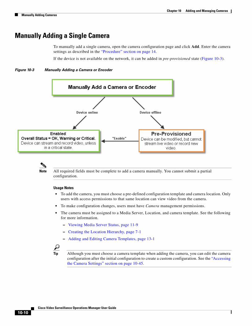
Chapter 10 Adding and Managing Cameras Manually Adding Cameras
Manually Adding a Single CameraTo manually add a single camera, open the camera configuration page and click Add. Enter the camera settings as described in the “Procedure” section on page 14.
If the device is not available on the network, it can be added in pre-provisioned state (Figure 10-3).
Figure 10-3 Manually Adding a Camera or Encoder
Note All required fields must be complete to add a camera manually. You cannot submit a partial configuration.
Usage Notes
• To add the camera, you must choose a pre-defined configuration template and camera location. Only users with access permissions to that same location can view video from the camera.
• To make configuration changes, users must have Camera management permissions.
• The camera must be assigned to a Media Server, Location, and camera template. See the following for more information.
– Viewing Media Server Status, page 11-9
– Creating the Location Hierarchy, page 7-1
– Adding and Editing Camera Templates, page 13-1
Tip Although you must choose a camera template when adding the camera, you can edit the camera configuration after the initial configuration to create a custom configuration. See the “Accessing the Camera Settings” section on page 10-45.
10-10Cisco Video Surveillance Operations Manager User Guide
Chapter 10 Adding and Managing CamerasManually Adding Cameras
• To automatically add camera map icons to the location maps (based on the camera’s Installed Location), select the “Auto Create Map Markers” setting (see the General System Settings, page 26-2 and the Understanding a Camera’s Installed Location Vs. the Pointed Location, page 7-9). You can also specify an alternative location when importing cameras from a CSV file (see Importing or Updating Cameras or Encoders Using a CSV File, page 10-20).
Network (IP) Camera Rules and Settings
The camera must be accessible on the network if the device is added in Enabled state (Figure 10-3).
• If the camera is not available on the network, you can add the camera in pre-provisioned state. The camera will be disabled until you choose Enable from the Device Settings menu (all required fields must be complete).
• If the camera is still not reachable on the network it will be in Enabled: Critical state until the network issue is resolved.
See the “Pre-Provisioning Cameras” section on page 10-9 and the “Camera Status” section on page 10-74
Table 10-3 Network Camera General Settings
Setting Description
IP Address Enter the hostname or IP address entered in the camera configuration.
See the camera documentation for instructions.
Note By default, encoders or cameras with duplicate IP addresses are not allowed and will result in an error. If your network configuration requires that devices be added with duplicate IP addresses, you can enable the Allow Duplicate IP Address system setting. See Understanding Device Conflicts for more information.
Username Enter the username for accessing the camera on the network.
See the camera documentation for instructions to configure the camera username.
Password Enter the password for accessing the camera on the network.
See the camera documentation for instructions to configure the camera password.
Name Enter a descriptive name that can help you identify the camera. The name can include any combination of characters and spaces.
Install Location Click to select the location where the camera is physically installed.
• The Installed and Pointed locations define where the camera is physically installed vs. the scene that the camera is recording. For example, a camera installed on building 2 might be pointed at the lobby door of building 1. If an alert event occurs at the Building 1 lobby, it can be flagged and viewed using the Cisco Safety and Security Desktop application even though the camera is physically installed on building 2. See the “Understanding a Camera’s Installed Location Vs. the Pointed Location” section on page 7-9.
• The camera and the associated Media Server must be in the same Site. See the “Understanding Sites” section on page 29-3 for more information.
Tip To automatically add camera map icons to the location map based on the Installed Location, select the “Auto Create Map Markers” setting (see the General System Settings, page 26-2).
Media Server Select the Media Server responsible for storing and playing video from the camera.
The camera and the associated Media Server must be in the same Site. See the “Understanding Sites” section on page 29-3 for more information.
10-11Cisco Video Surveillance Operations Manager User Guide
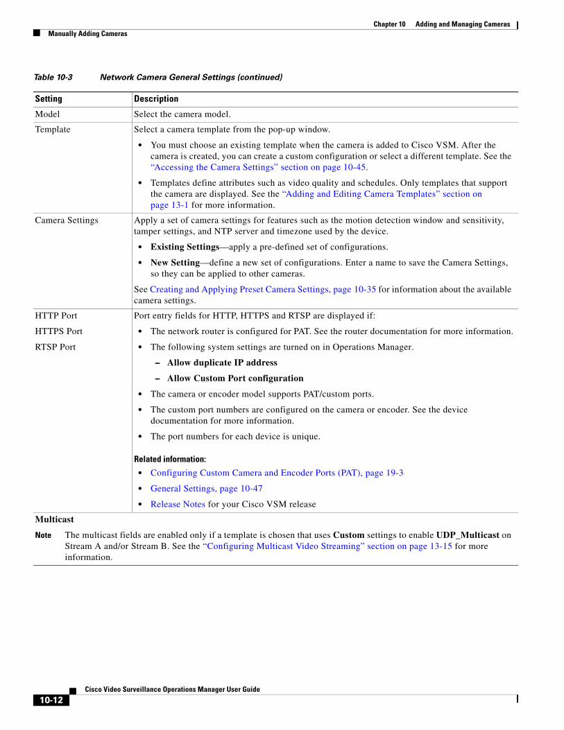
Chapter 10 Adding and Managing Cameras Manually Adding Cameras
Model Select the camera model.
Template Select a camera template from the pop-up window.
• You must choose an existing template when the camera is added to Cisco VSM. After the camera is created, you can create a custom configuration or select a different template. See the “Accessing the Camera Settings” section on page 10-45.
• Templates define attributes such as video quality and schedules. Only templates that support the camera are displayed. See the “Adding and Editing Camera Templates” section on page 13-1 for more information.
Camera Settings Apply a set of camera settings for features such as the motion detection window and sensitivity, tamper settings, and NTP server and timezone used by the device.
• Existing Settings—apply a pre-defined set of configurations.
• New Setting—define a new set of configurations. Enter a name to save the Camera Settings, so they can be applied to other cameras.
See Creating and Applying Preset Camera Settings, page 10-35 for information about the available camera settings.
HTTP Port
HTTPS Port
RTSP Port
Port entry fields for HTTP, HTTPS and RTSP are displayed if:
• The network router is configured for PAT. See the router documentation for more information.
• The following system settings are turned on in Operations Manager.
– Allow duplicate IP address
– Allow Custom Port configuration
• The camera or encoder model supports PAT/custom ports.
• The custom port numbers are configured on the camera or encoder. See the device documentation for more information.
• The port numbers for each device is unique.
Related information:
• Configuring Custom Camera and Encoder Ports (PAT), page 19-3
• General Settings, page 10-47
• Release Notes for your Cisco VSM release
Multicast
Note The multicast fields are enabled only if a template is chosen that uses Custom settings to enable UDP_Multicast on Stream A and/or Stream B. See the “Configuring Multicast Video Streaming” section on page 13-15 for more information.
Table 10-3 Network Camera General Settings (continued)
Setting Description
10-12Cisco Video Surveillance Operations Manager User Guide

Chapter 10 Adding and Managing CamerasManually Adding Cameras
Analog Camera Rules and Settings
Analog cameras are attached to an encoder that provides network connectivity. See the following documentation for more information
• See the encoder documentation for instructions to properly attach the serial cables to the cameras and determine the serial port and serial address for each camera.
• Verify that the encoder and analog cameras meet the requirements specified in the “Requirements” section on page 20-4.
• Single analog camera are attached to the encoder directly. Multiple cameras can be attached in a daisy chain configuration. A serial port and serial address is assigned to each camera. See the encoder documentation for more information.
• See the “Adding Encoders and Analog Cameras” section on page 20-1 for additional instructions to add the encoder and analog cameras. You can add analog cameras using the encoder configuration page, or the camera configuration page.
Primary Address (Optional) Enter the multicast IP address where the camera’s primary video stream (Stream A) should be sent.
This field is enabled only if the camera’s template Stream A is configured for multicast.
Addresses must be in the proper address range.
• Private network addresses: 239.0.0.0 - 239.255.255.255
• Public network addresses: 224.0.0.0 - 244.0.0.255 and 244.0.1.0 - 238.255.255.255
Note Public addresses must be individually assigned by IANA (Internet Assigned Numbers Authority)
Primary Port Enter the port value used by Cisco Video Surveillance to listen to the camera’s primary video stream.
Secondary Address (Optional) Enter the multicast IP address where the camera’s secondary video stream (Stream B) should be sent.
This field is enabled only if the camera’s template Stream B is configured for multicast.
Addresses must be in the proper address range.
• Private network addresses: 239.0.0.0 - 239.255.255.255
• Public network addresses: 224.0.0.0 - 244.0.0.255 and 244.0.1.0 - 238.255.255.255
Note Public addresses must be individually assigned by IANA (Internet Assigned Numbers Authority)
Secondary Port Enter the port value used by Cisco Video Surveillance to listen to the camera’s secondary video stream
Table 10-3 Network Camera General Settings (continued)
Setting Description
10-13Cisco Video Surveillance Operations Manager User Guide
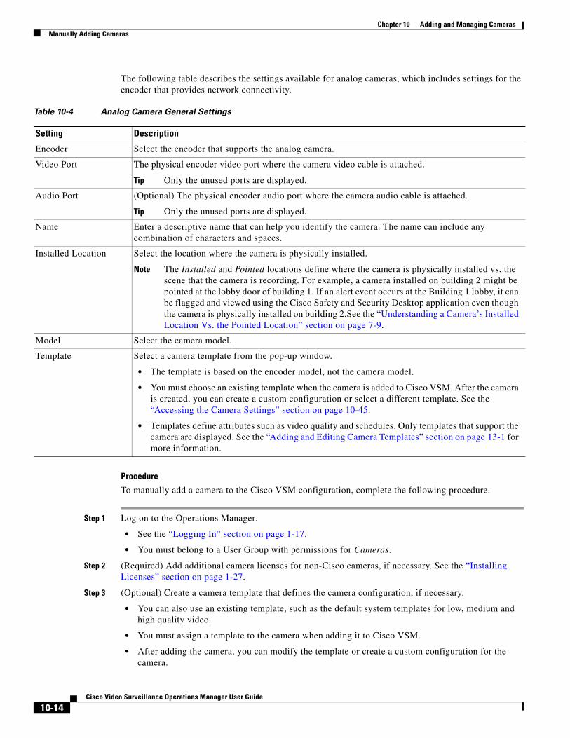
Chapter 10 Adding and Managing Cameras Manually Adding Cameras
The following table describes the settings available for analog cameras, which includes settings for the encoder that provides network connectivity.
Table 10-4 Analog Camera General Settings
Setting Description
Tip Only the unused ports are displayed.
Tip Only the unused ports are displayed.
Note The Installed and Pointed locations define where the camera is physically installed vs. the scene that the camera is recording. For example, a camera installed on building 2 might be pointed at the lobby door of building 1. If an alert event occurs at the Building 1 lobby, it can be flagged and viewed using the Cisco Safety and Security Desktop application even though the camera is physically installed on building 2.See the “Understanding a Camera’s Installed Location Vs. the Pointed Location” section on page 7-9.
• The template is based on the encoder model, not the camera model.
• You must choose an existing template when the camera is added to Cisco VSM. After the camera is created, you can create a custom configuration or select a different template. See the “Accessing the Camera Settings” section on page 10-45.
• Templates define attributes such as video quality and schedules. Only templates that support the camera are displayed. See the “Adding and Editing Camera Templates” section on page 13-1 for more information.
Procedure
To manually add a camera to the Cisco VSM configuration, complete the following procedure.
Step 1 Log on to the Operations Manager.
• See the “Logging In” section on page 1-17.
• You must belong to a User Group with permissions for Cameras.
Step 2 (Required) Add additional camera licenses for non-Cisco cameras, if necessary. See the “Installing Licenses” section on page 1-27.
Step 3 (Optional) Create a camera template that defines the camera configuration, if necessary.
• You can also use an existing template, such as the default system templates for low, medium and high quality video.
• You must assign a template to the camera when adding it to Cisco VSM.
• After adding the camera, you can modify the template or create a custom configuration for the camera.
Encoder Select the encoder that supports the analog camera.
Video Port The physical encoder video port where the camera video cable is attached.
Audio Port (Optional) The physical encoder audio port where the camera audio cable is attached.
Name Enter a descriptive name that can help you identify the camera. The name can include any combination of characters and spaces.
Installed Location Select the location where the camera is physically installed.
Model Select the camera model.
Template Select a camera template from the pop-up window.
10-14Cisco Video Surveillance Operations Manager User Guide
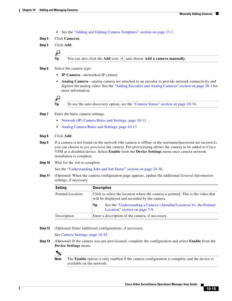
Chapter 10 Adding and Managing CamerasManually Adding Cameras
• See the “Adding and Editing Camera Templates” section on page 13-1.
Step 4 Click Cameras.
Step 5 Click Add.
Tip You can also click the Add icon and choose Add a camera manually.
Step 6 Select the camera type:
• IP Camera—networked IP camera
• Analog Camera—analog camera are attached to an encoder to provide network connectivity and digitize the analog video. See the “Adding Encoders and Analog Cameras” section on page 20-1 for more information.
Tip To use the auto-discovery option, see the “Camera Status” section on page 10-74.
Step 7 Enter the basic camera settings.
• Network (IP) Camera Rules and Settings, page 10-11
• Analog Camera Rules and Settings, page 10-13
Step 8 Click Add.
Step 9 If a camera is not found on the network (the camera is offline or the username/password are incorrect), you can choose to pre-provision the camera. Pre-provisioning allows the camera to be added to Cisco VSM as a disabled device. Select Enable from the Device Settings menu once camera network installation is complete.
Step 10 Wait for the Job to complete.
See the “Understanding Jobs and Job Status” section on page 24-36.
Step 11 (Optional) When the camera configuration page appears, update the additional General Information settings, if necessary
Setting Description
Tip See the “Understanding a Camera’s Installed Location Vs. the Pointed Location” section on page 7-9.
Step 12 (Optional) Enter additional configurations, if necessary.
See Camera Settings, page 10-45.
Step 13 (Optional) If the camera was pre-provisioned, complete the configuration and select Enable from the Device Settings menu.
Note The Enable option is only enabled if the camera configuration is complete and the device is available on the network.
Pointed Location Click to select the location where the camera is pointed. This is the video that will be displayed and recorded by the camera.
Description Enter a description of the camera, if necessary.
10-15Cisco Video Surveillance Operations Manager User Guide
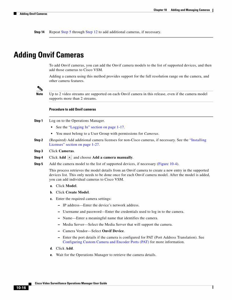
Chapter 10 Adding and Managing Cameras Adding Onvif Cameras
Step 14 Repeat Step 5 through Step 12 to add additional cameras, if necessary.
Adding Onvif CamerasTo add Onvif cameras, you can add the Onvif camera models to the list of supported devices, and then add those cameras to Cisco VSM.
Adding a camera using this method provides support for the full resolution range on the camera, and other camera features.
Note Up to 2 video streams are supported on each Onvif camera in this release, even if the camera model supports more than 2 streams.
Procedure to add Onvif cameras
Step 1 Log on to the Operations Manager.
• See the “Logging In” section on page 1-17.
• You must belong to a User Group with permissions for Cameras.
Step 2 (Required) Add additional camera licenses for non-Cisco cameras, if necessary. See the “Installing Licenses” section on page 1-27.
Step 3 Click Cameras.
Step 4 Click Add and choose Add a camera manually.
Step 5 Add the camera model to the list of supported devices, if necessary (Figure 10-4).
This process retrieves the model details from an Onvif camera to create a new entry in the supported devices list. This only needs to be done once for each Onvif camera model. After the model is added, you can add individual cameras to Cisco VSM.
a. Click Model.
b. Click Create Model.
c. Enter the required camera settings:
– IP address—Enter the device’s network address.
– Username and password—Enter the credentials used to log in to the camera.
– Name—Enter a meaningful name that identifies the camera.
– Media Server—Select the Media Server that will support the camera.
– Camera Vendor—Select Onvif Device.
– Enter the port details if the camera is configured for PAT (Port Address Translation). See Configuring Custom Camera and Encoder Ports (PAT) for more information.
d. Click Add.
e. Wait for the Operations Manager to retrieve the camera details.
10-16Cisco Video Surveillance Operations Manager User Guide
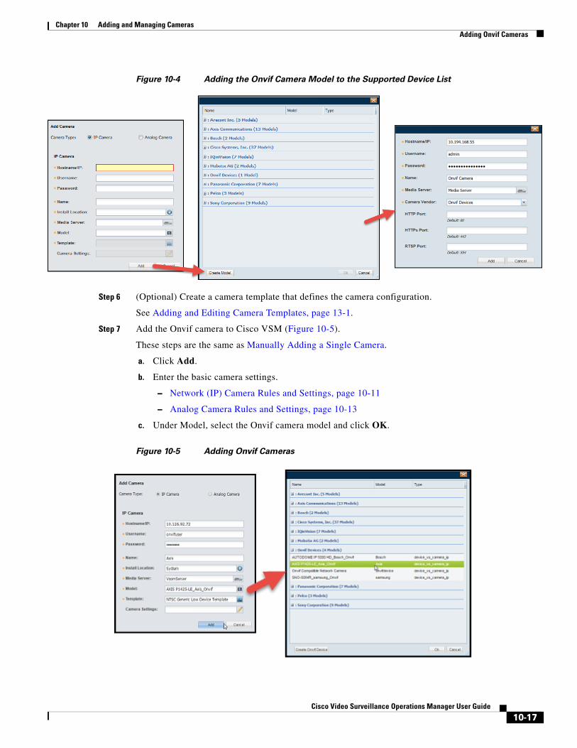
Chapter 10 Adding and Managing CamerasAdding Onvif Cameras
Figure 10-4 Adding the Onvif Camera Model to the Supported Device List
Step 6 (Optional) Create a camera template that defines the camera configuration.
See Adding and Editing Camera Templates, page 13-1.
Step 7 Add the Onvif camera to Cisco VSM (Figure 10-5).
These steps are the same as Manually Adding a Single Camera.
a. Click Add.
b. Enter the basic camera settings.
– Network (IP) Camera Rules and Settings, page 10-11
– Analog Camera Rules and Settings, page 10-13
c. Under Model, select the Onvif camera model and click OK.
Figure 10-5 Adding Onvif Cameras
10-17Cisco Video Surveillance Operations Manager User Guide
Chapter 10 Adding and Managing Cameras Adding Onvif Cameras
d. (Optional) To add Onvif cameras with the same IP address using PAT (Port Address Translation), enter the required port numbers. See Configuring Custom Camera and Encoder Ports (PAT), page 19-3.
e. Click Add.
Step 8 If a camera is not found on the network (the camera is offline or the username/password are incorrect), you can choose to pre-provision the camera. Pre-provisioning allows the camera to be added to Cisco VSM as a disabled device. Select Enable from the Device Settings menu once camera network installation is complete.
Step 9 Wait for the Job to complete.
See the “Understanding Jobs and Job Status” section on page 24-36.
Step 10 (Optional) When the camera configuration page appears, update the additional General Information settings, if necessary.
Setting Description
Tip See the “Understanding a Camera’s Installed Location Vs. the Pointed Location” section on page 7-9.
Step 11 (Optional) Enter additional configurations, if necessary.
See Camera Settings, page 10-45.
Step 12 (Optional) If the camera was pre-provisioned, complete the configuration and select Enable from the Device Settings menu.
Note The Enable option is only enabled if the camera configuration is complete and the device is available on the network.
Step 13 Repeat Step 6 through Step 12 to add additional cameras, if necessary.
Step 14 If an error message appears, continue to the following Procedure to copy Onvif model device capability files to the Media Server.
Procedure to copy Onvif model device capability files to the Media Server
When you create an Onvif model in Cisco VSM Operations Manager, a device capability file for that model is created and copied to the Cisco Media Server(s). If a Media Server is unreachable, an error message occurs and the file is not copied. When the server becomes reachable, the files are automatically copied during normal server synchronization.
To manually copy all of the Onvif device capability files from the Operations Manager to all Media Servers in your deployment, do the following. This replaces all Onvif device capability files on the Media Servers.
Procedure
Step 1 Choose System Settings > Settings.
Pointed Location Click to select the location where the camera is pointed. This is the video that will be displayed and recorded by the camera.
Description Enter a description of the camera, if necessary.
10-18Cisco Video Surveillance Operations Manager User Guide

Chapter 10 Adding and Managing CamerasAdding Onvif Cameras
Step 2 Click Onvif Model Management.
Step 3 Use the filters to narrow the results. Leave the filters blank to display all servers.
Step 4 Click Search to display the servers.
Step 5 Select one or more servers.
Step 6 Click Sync Onvif Models.
Step 7 Wait for the copy process to complete and the error message to clear.
10-19Cisco Video Surveillance Operations Manager User Guide
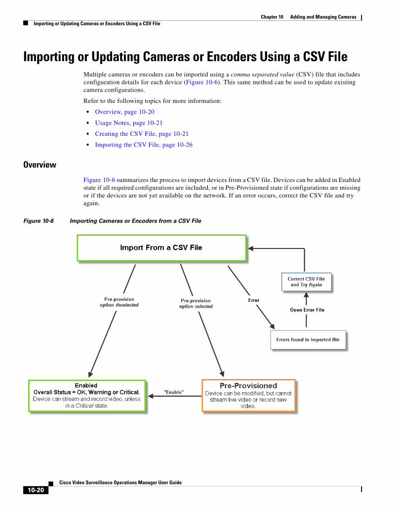
Chapter 10 Adding and Managing Cameras Importing or Updating Cameras or Encoders Using a CSV File
Importing or Updating Cameras or Encoders Using a CSV FileMultiple cameras or encoders can be imported using a comma separated value (CSV) file that includes configuration details for each device (Figure 10-6). This same method can be used to update existing camera configurations.
Refer to the following topics for more information:
• Overview, page 10-20
• Usage Notes, page 10-21
• Creating the CSV File, page 10-21
• Importing the CSV File, page 10-26
Overview
Figure 10-6 summarizes the process to import devices from a CSV file. Devices can be added in Enabled state if all required configurations are included, or in Pre-Provisioned state if configurations are missing or if the devices are not yet available on the network. If an error occurs, correct the CSV file and try again.
Figure 10-6 Importing Cameras or Encoders from a CSV File
10-20Cisco Video Surveillance Operations Manager User Guide
Chapter 10 Adding and Managing CamerasImporting or Updating Cameras or Encoders Using a CSV File
Usage Notes
• Cameras, encoders and servers can be pre-provisioned in Release 7.2 and higher.
• Pre-provisioned devices are devices waiting to be added to Cisco VSM. You can make additional configuration changes, but the device cannot stream or record video until the configuration and network issues are resolved. Choose Enable from the Device Settings menu to enable the device video functions. See the “Pre-Provisioning Cameras” section on page 10-9 for more information.
• If the CSV file details are accurate and complete, the devices are added to Cisco VSM and video from the cameras is available for viewing and recording.
• If any required fields are left blank, or if any devices in the file are not available on the network, then the devices are added to Cisco VSM in pre-provisioned state, even if the pre-provisioned option is deselected. Complete the configuration to change the status to Enabled. See Table 10-5 for the required fields.
• If any fields are inconsistent with the Cisco VSM configuration, the import action fails and an error file is created that specifies the problem(s). For example, if the CSV file specifies a Media Server or location that does not exist in your Cisco VSM configuration, an error occurs. Correct the CSV file and try again.
• You cannot mix device types in the import file. For example, the file can include servers, encoders, IP cameras, or analog cameras only.
• If cameras are updated using the CSV import, and the template is changed to one with different stream resolutions, then all motion detection windows are deleted and you must re-configure the motion windows for those cameras. To do this:
– Import the CSV file again to specify the motion detection windows (without changing the camera template).
– Apply the motion windows to cameras as described in Configuring Motion Detection, page 10-96.
Creating the CSV File
Create a file in plain text CSV format that can be opened and saved using Excel or OpenOffice Calc (Figure 10-7). Blank rows or rows beginning with “//” are ignored.
Tip To download a sample import file, launch the import wizard as described in the “Importing the CSV File” section on page 10-26. Click the Download Sample button in the second step of the wizard to obtain a sample file (see Step 4). The import file is different for each device type: IP cameras, analog cameras, and encoders.
10-21Cisco Video Surveillance Operations Manager User Guide
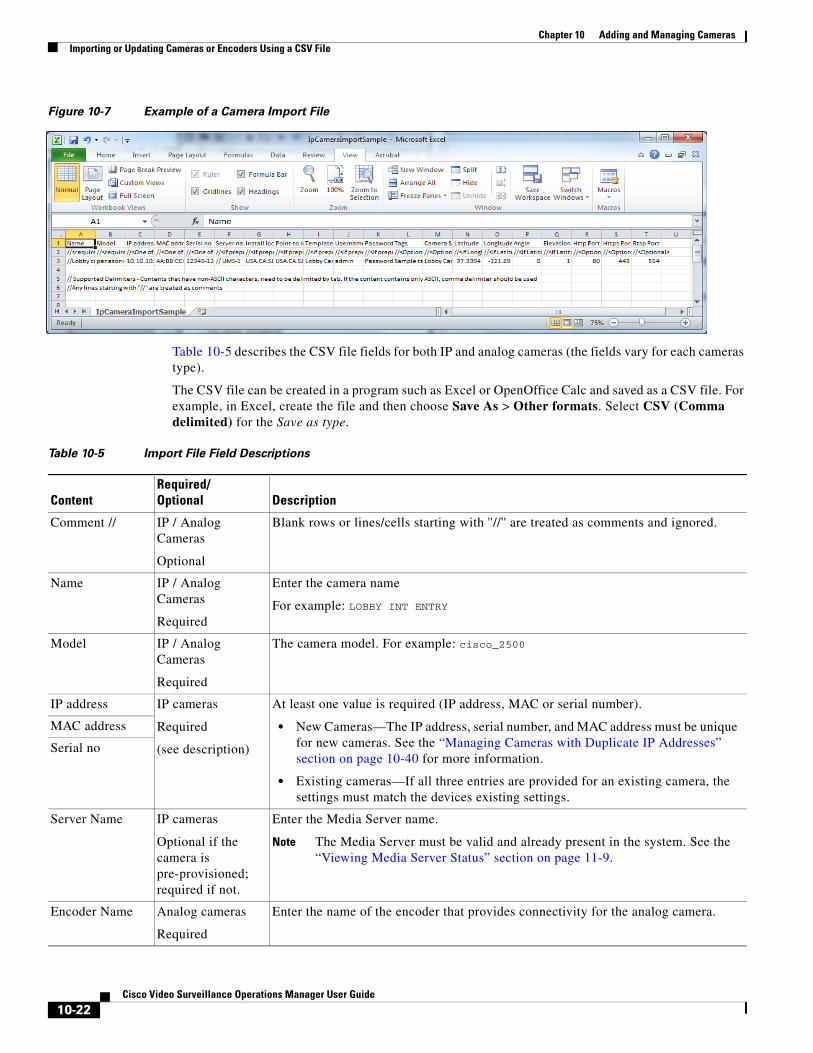
Chapter 10 Adding and Managing Cameras Importing or Updating Cameras or Encoders Using a CSV File
Figure 10-7 Example of a Camera Import File
Table 10-5 describes the CSV file fields for both IP and analog cameras (the fields vary for each cameras type).
The CSV file can be created in a program such as Excel or OpenOffice Calc and saved as a CSV file. For example, in Excel, create the file and then choose Save As > Other formats. Select CSV (Comma delimited) for the Save as type.
Table 10-5 Import File Field Descriptions
ContentRequired/Optional Description
Comment // IP / Analog Cameras
Optional
Blank rows or lines/cells starting with ''//'' are treated as comments and ignored.
Name IP / Analog Cameras
Required
Enter the camera name
For example: LOBBY INT ENTRY
Model IP / Analog Cameras
Required
The camera model. For example: cisco_2500
IP address IP cameras
Required
(see description)
At least one value is required (IP address, MAC or serial number).
• New Cameras—The IP address, serial number, and MAC address must be unique for new cameras. See the “Managing Cameras with Duplicate IP Addresses” section on page 10-40 for more information.
• Existing cameras—If all three entries are provided for an existing camera, the settings must match the devices existing settings.
MAC address
Serial no
Server Name IP cameras
Optional if the camera is pre-provisioned; required if not.
Enter the Media Server name.
Note The Media Server must be valid and already present in the system. See the “Viewing Media Server Status” section on page 11-9.
Encoder Name Analog cameras
Required
Enter the name of the encoder that provides connectivity for the analog camera.
10-22Cisco Video Surveillance Operations Manager User Guide
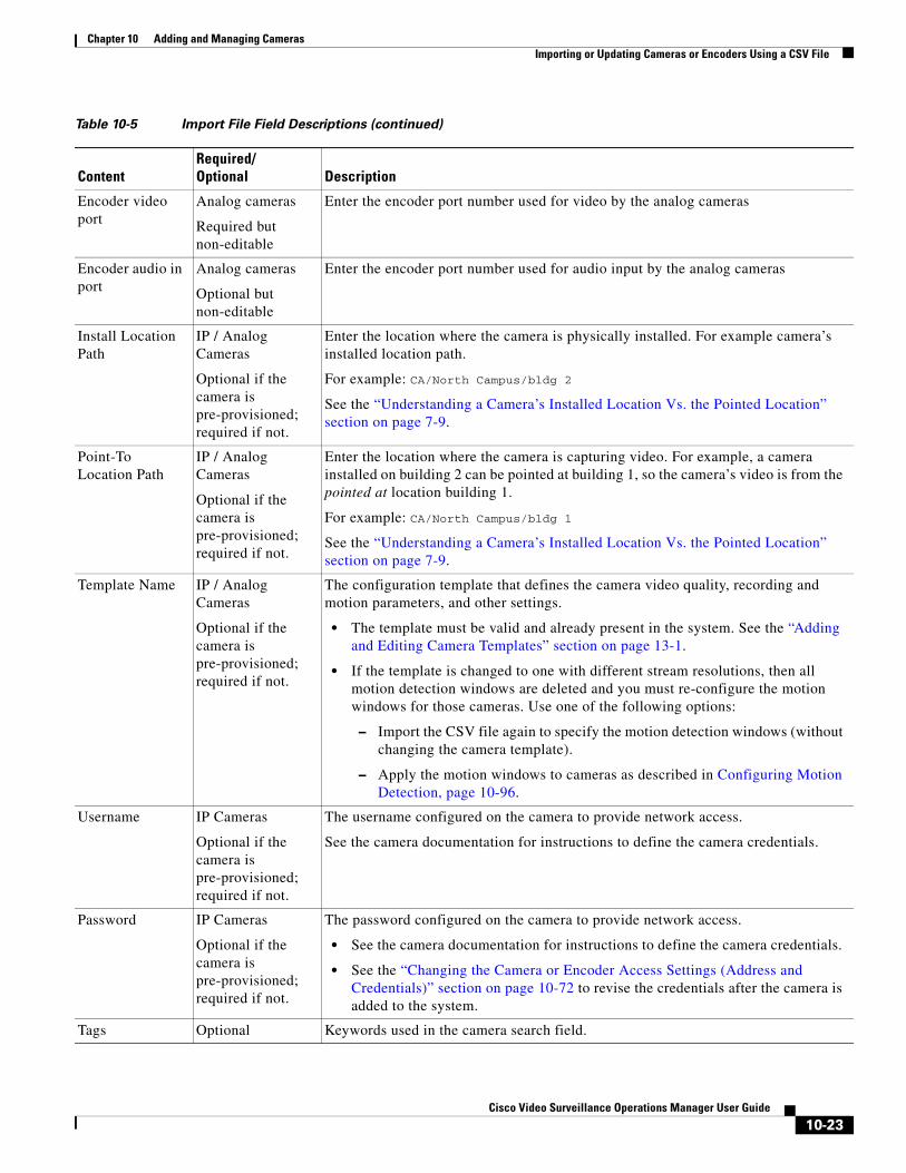
Chapter 10 Adding and Managing CamerasImporting or Updating Cameras or Encoders Using a CSV File
Encoder video port
Analog cameras
Required but non-editable
Enter the encoder port number used for video by the analog cameras
Encoder audio in port
Analog cameras
Optional but non-editable
Enter the encoder port number used for audio input by the analog cameras
Install Location Path
IP / Analog Cameras
Optional if the camera is pre-provisioned; required if not.
Enter the location where the camera is physically installed. For example camera’s installed location path.
For example: CA/North Campus/bldg 2
See the “Understanding a Camera’s Installed Location Vs. the Pointed Location” section on page 7-9.
Point-To Location Path
IP / Analog Cameras
Optional if the camera is pre-provisioned; required if not.
Enter the location where the camera is capturing video. For example, a camera installed on building 2 can be pointed at building 1, so the camera’s video is from the pointed at location building 1.
For example: CA/North Campus/bldg 1
See the “Understanding a Camera’s Installed Location Vs. the Pointed Location” section on page 7-9.
Template Name IP / Analog Cameras
Optional if the camera is pre-provisioned; required if not.
The configuration template that defines the camera video quality, recording and motion parameters, and other settings.
• The template must be valid and already present in the system. See the “Adding and Editing Camera Templates” section on page 13-1.
• If the template is changed to one with different stream resolutions, then all motion detection windows are deleted and you must re-configure the motion windows for those cameras. Use one of the following options:
– Import the CSV file again to specify the motion detection windows (without changing the camera template).
– Apply the motion windows to cameras as described in Configuring Motion Detection, page 10-96.
Username IP Cameras
Optional if the camera is pre-provisioned; required if not.
The username configured on the camera to provide network access.
See the camera documentation for instructions to define the camera credentials.
Password IP Cameras
Optional if the camera is pre-provisioned; required if not.
The password configured on the camera to provide network access.
• See the camera documentation for instructions to define the camera credentials.
• See the “Changing the Camera or Encoder Access Settings (Address and Credentials)” section on page 10-72 to revise the credentials after the camera is added to the system.
Tags Optional Keywords used in the camera search field.
Table 10-5 Import File Field Descriptions (continued)
ContentRequired/Optional Description
10-23Cisco Video Surveillance Operations Manager User Guide
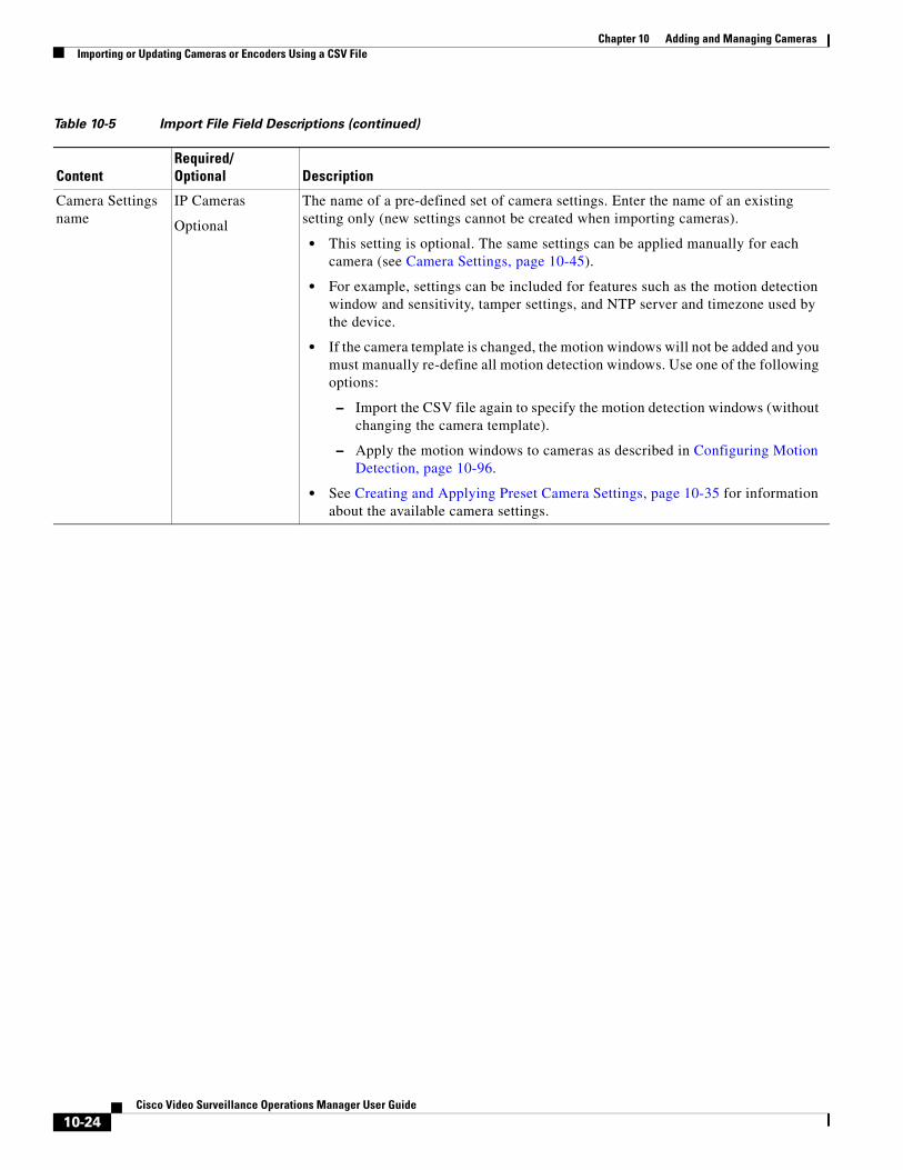
Chapter 10 Adding and Managing Cameras Importing or Updating Cameras or Encoders Using a CSV File
Camera Settings name
IP Cameras
Optional
The name of a pre-defined set of camera settings. Enter the name of an existing setting only (new settings cannot be created when importing cameras).
• This setting is optional. The same settings can be applied manually for each camera (see Camera Settings, page 10-45).
• For example, settings can be included for features such as the motion detection window and sensitivity, tamper settings, and NTP server and timezone used by the device.
• If the camera template is changed, the motion windows will not be added and you must manually re-define all motion detection windows. Use one of the following options:
– Import the CSV file again to specify the motion detection windows (without changing the camera template).
– Apply the motion windows to cameras as described in Configuring Motion Detection, page 10-96.
• See Creating and Applying Preset Camera Settings, page 10-35 for information about the available camera settings.
Table 10-5 Import File Field Descriptions (continued)
ContentRequired/Optional Description
10-24Cisco Video Surveillance Operations Manager User Guide
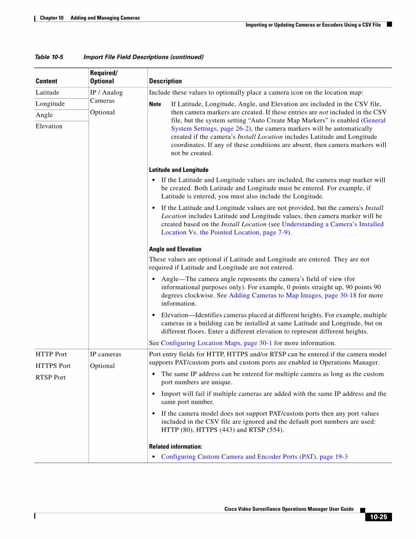
Chapter 10 Adding and Managing CamerasImporting or Updating Cameras or Encoders Using a CSV File
Latitude IP / Analog Cameras
Optional
Include these values to optionally place a camera icon on the location map:
Note If Latitude, Longitude, Angle, and Elevation are included in the CSV file, then camera markers are created. If these entries are not included in the CSV file, but the system setting “Auto Create Map Markers” is enabled (General System Settings, page 26-2), the camera markers will be automatically created if the camera’s Install Location includes Latitude and Longitude coordinates. If any of these conditions are absent, then camera markers will not be created.
Latitude and Longitude
• If the Latitude and Longitude values are included, the camera map marker will be created. Both Latitude and Longitude must be entered. For example, if Latitude is entered, you must also include the Longitude.
• If the Latitude and Longitude values are not provided, but the camera's Install Location includes Latitude and Longitude values, then camera marker will be created based on the Install Location (see Understanding a Camera’s Installed Location Vs. the Pointed Location, page 7-9).
Angle and Elevation
These values are optional if Latitude and Longitude are entered. They are not required if Latitude and Longitude are not entered.
• Angle—The camera angle represents the camera’s field of view (for informational purposes only). For example, 0 points straight up, 90 points 90 degrees clockwise. See Adding Cameras to Map Images, page 30-18 for more information.
• Elevation—Identifies cameras placed at different heights. For example, multiple cameras in a building can be installed at same Latitude and Longitude, but on different floors. Enter a different elevation to represent different heights.
See Configuring Location Maps, page 30-1 for more information.
Longitude
Angle
Elevation
HTTP Port
HTTPS Port
RTSP Port
IP cameras
Optional
Port entry fields for HTTP, HTTPS and/or RTSP can be entered if the camera model supports PAT/custom ports and custom ports are enabled in Operations Manager.
• The same IP address can be entered for multiple camera as long as the custom port numbers are unique.
• Import will fail if multiple cameras are added with the same IP address and the same port number.
• If the camera model does not support PAT/custom ports then any port values included in the CSV file are ignored and the default port numbers are used: HTTP (80), HTTPS (443) and RTSP (554).
Related information:
• Configuring Custom Camera and Encoder Ports (PAT), page 19-3
Table 10-5 Import File Field Descriptions (continued)
ContentRequired/Optional Description
10-25Cisco Video Surveillance Operations Manager User Guide
Chapter 10 Adding and Managing Cameras Importing or Updating Cameras or Encoders Using a CSV File
Importing the CSV File
Complete the following procedure to import a CSV file.
Procedure
Step 1 Create the camera CSV file containing details for each device.
• See the “Creating the CSV File” section on page 10-21.
Step 2 Click Cameras.
• Or click Cameras and then Encoders to import a list of encoders.
Step 3 Choose Add and choose Import cameras from file or Import encoders from file.
Step 4 Complete each Import Step as described below:
a. Import Step 1 - Device Type
– (Cameras only) Select IP Camera or Analog Camera.
– Click the Pre-Provision box if the devices should be pre-provisioned when added to Cisco VSM. This allows you to add the devices before they are available on the network, or before they should be available to end users.
Note If any required fields are left blank, or if any cameras in the file are not available on the network, then the devices are added to Cisco VSM in pre-provisioned state, even if the pre-provisioned option is deselected. Complete the configuration to change the status to Enabled. See Table 10-5 for the required fields.
b. Import Step 2 - Download Sample(Optional) Click Download Sample to download a sample CSV import file. Use this sample to create the import file as described in the “Creating the CSV File” section on page 10-21. Click Next.
c. Import Step 3 - File Upload: Click Choose to select the CSV file from a local or network disk. Click Upload.
d. Import Step 4 - Processing: Wait for the import process to complete.
e. Import Step 5 - Results:
– If a success message appears, continue to Step 5.
– If an error message appears, continue to Step 4 f.
f. If an error message appears (Figure 10-8), complete the following troubleshooting steps:
– Click Download Annotated CSV, save the error file and open it in Excel or OpenOffice Calc.
– Correct the annotated errors in the //Error rows (Figure 10-8).
– Save the revised file in the .CSV format.
– Return to Step 3 and re-import the corrected CSV file.
10-26Cisco Video Surveillance Operations Manager User Guide
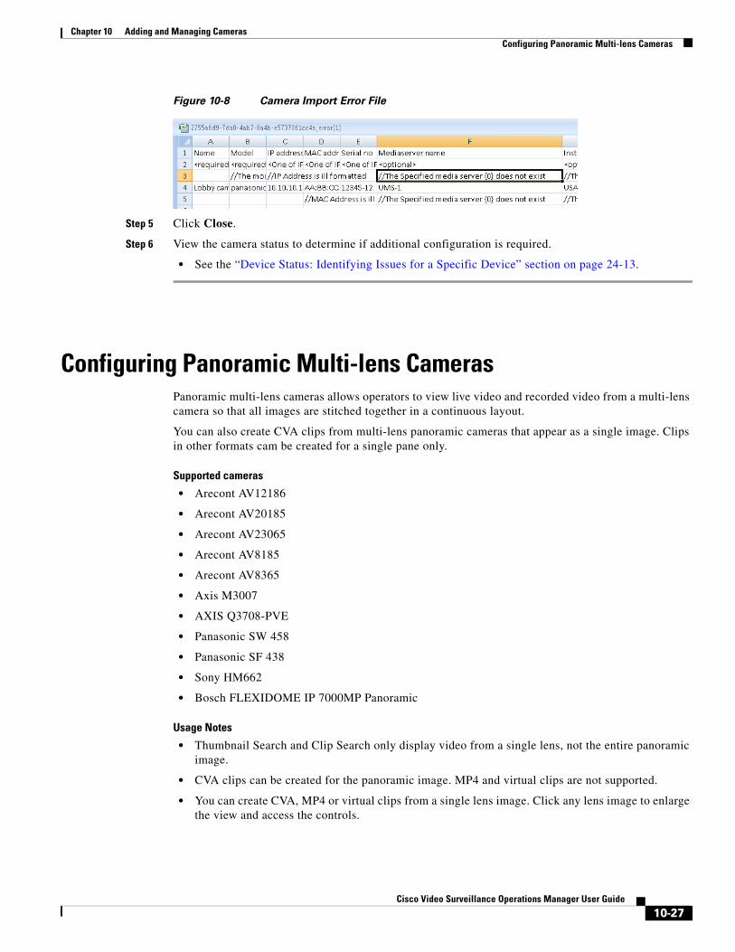
Chapter 10 Adding and Managing CamerasConfiguring Panoramic Multi-lens Cameras
Figure 10-8 Camera Import Error File
Step 5 Click Close.
Step 6 View the camera status to determine if additional configuration is required.
• See the “Device Status: Identifying Issues for a Specific Device” section on page 24-13.
Configuring Panoramic Multi-lens CamerasPanoramic multi-lens cameras allows operators to view live video and recorded video from a multi-lens camera so that all images are stitched together in a continuous layout.
You can also create CVA clips from multi-lens panoramic cameras that appear as a single image. Clips in other formats cam be created for a single pane only.
Supported cameras
• Arecont AV12186
• Arecont AV20185
• Arecont AV23065
• Arecont AV8185
• Arecont AV8365
• Axis M3007
• AXIS Q3708-PVE
• Panasonic SW 458
• Panasonic SF 438
• Sony HM662
• Bosch FLEXIDOME IP 7000MP Panoramic
Usage Notes
• Thumbnail Search and Clip Search only display video from a single lens, not the entire panoramic image.
• CVA clips can be created for the panoramic image. MP4 and virtual clips are not supported.
• You can create CVA, MP4 or virtual clips from a single lens image. Click any lens image to enlarge the view and access the controls.
10-27Cisco Video Surveillance Operations Manager User Guide
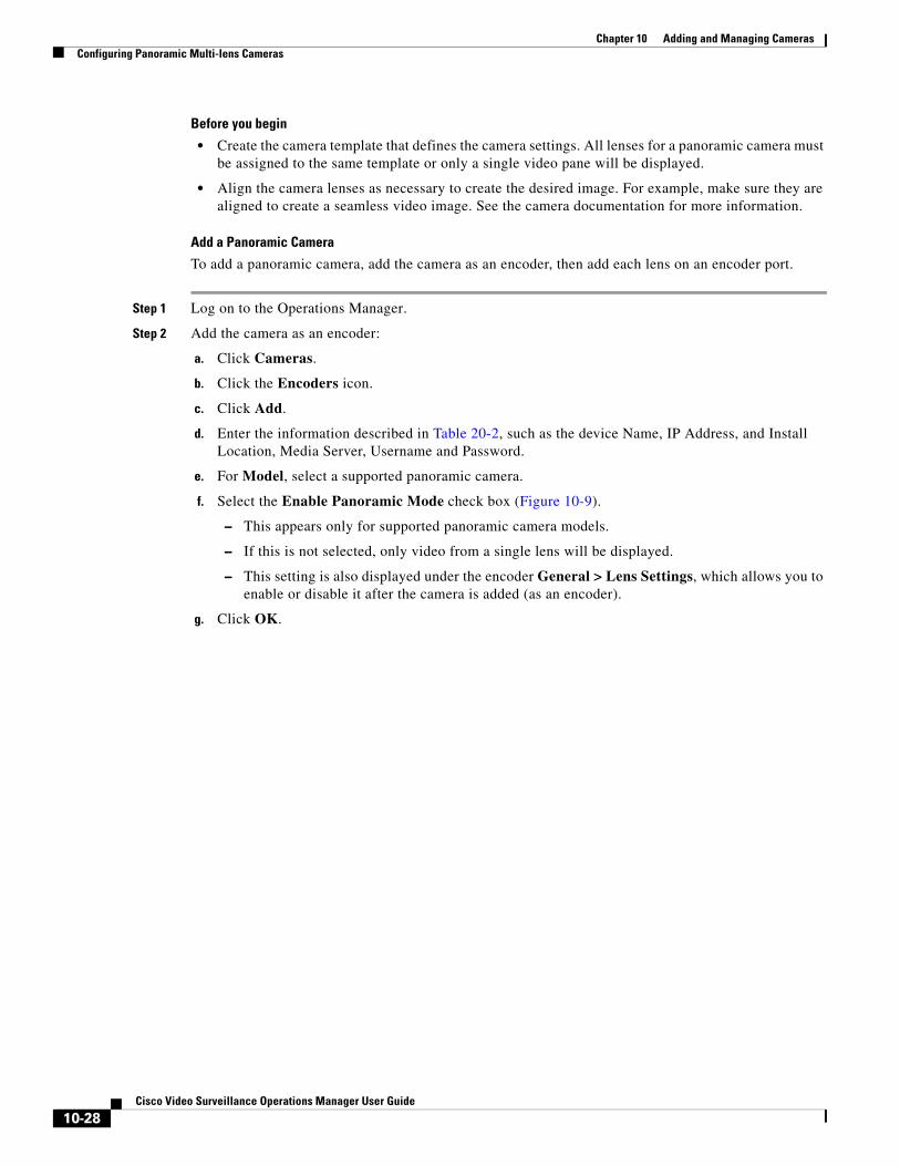
Chapter 10 Adding and Managing Cameras Configuring Panoramic Multi-lens Cameras
Before you begin
• Create the camera template that defines the camera settings. All lenses for a panoramic camera must be assigned to the same template or only a single video pane will be displayed.
• Align the camera lenses as necessary to create the desired image. For example, make sure they are aligned to create a seamless video image. See the camera documentation for more information.
Add a Panoramic Camera
To add a panoramic camera, add the camera as an encoder, then add each lens on an encoder port.
Step 1 Log on to the Operations Manager.
Step 2 Add the camera as an encoder:
a. Click Cameras.
b. Click the Encoders icon.
c. Click Add.
d. Enter the information described in Table 20-2, such as the device Name, IP Address, and Install Location, Media Server, Username and Password.
e. For Model, select a supported panoramic camera.
f. Select the Enable Panoramic Mode check box (Figure 10-9).
– This appears only for supported panoramic camera models.
– If this is not selected, only video from a single lens will be displayed.
– This setting is also displayed under the encoder General > Lens Settings, which allows you to enable or disable it after the camera is added (as an encoder).
g. Click OK.
10-28Cisco Video Surveillance Operations Manager User Guide
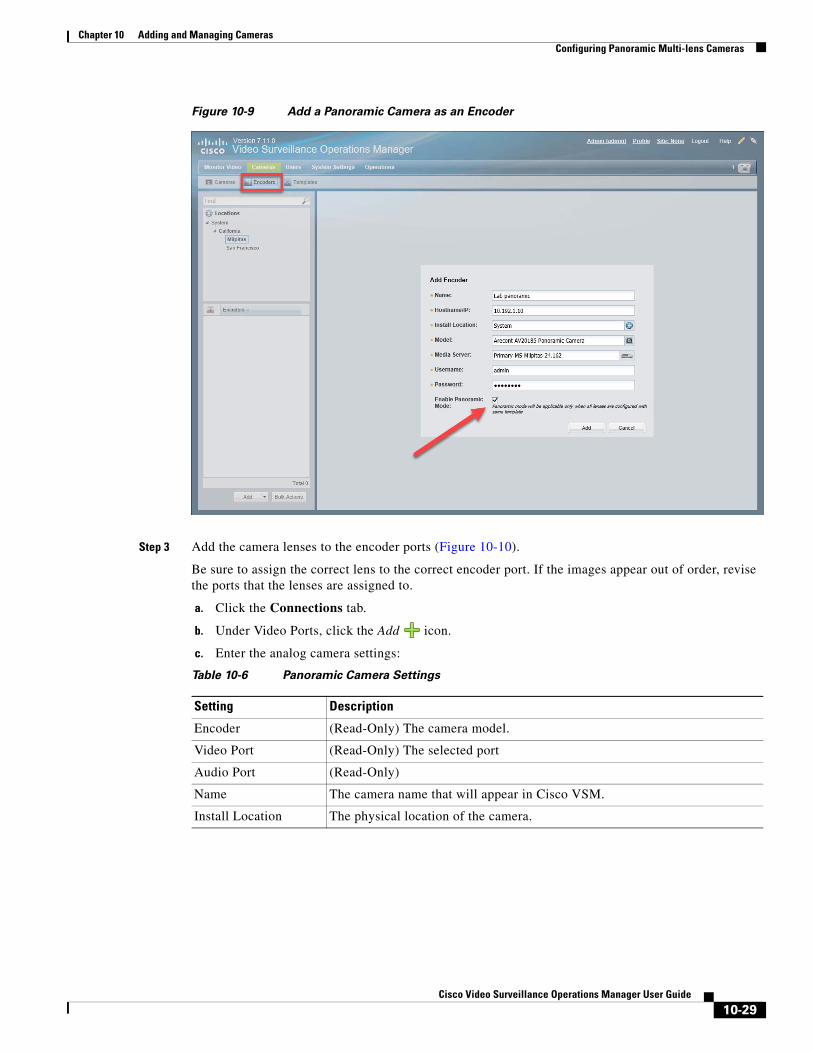
Chapter 10 Adding and Managing CamerasConfiguring Panoramic Multi-lens Cameras
Figure 10-9 Add a Panoramic Camera as an Encoder
Step 3 Add the camera lenses to the encoder ports (Figure 10-10).
Be sure to assign the correct lens to the correct encoder port. If the images appear out of order, revise the ports that the lenses are assigned to.
a. Click the Connections tab.
b. Under Video Ports, click the Add icon.
c. Enter the analog camera settings:
Table 10-6 Panoramic Camera Settings
Setting Description
Encoder (Read-Only) The camera model.
Video Port (Read-Only) The selected port
Audio Port (Read-Only)
Name The camera name that will appear in Cisco VSM.
Install Location The physical location of the camera.
10-29Cisco Video Surveillance Operations Manager User Guide
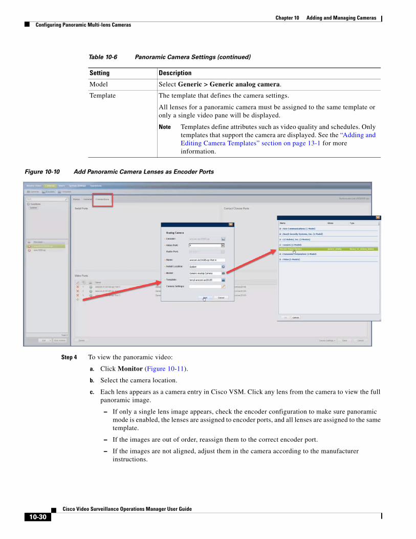
Chapter 10 Adding and Managing Cameras Configuring Panoramic Multi-lens Cameras
Figure 10-10 Add Panoramic Camera Lenses as Encoder Ports
Step 4 To view the panoramic video:
a. Click Monitor (Figure 10-11).
b. Select the camera location.
c. Each lens appears as a camera entry in Cisco VSM. Click any lens from the camera to view the full panoramic image.
– If only a single lens image appears, check the encoder configuration to make sure panoramic mode is enabled, the lenses are assigned to encoder ports, and all lenses are assigned to the same template.
– If the images are out of order, reassign them to the correct encoder port.
– If the images are not aligned, adjust them in the camera according to the manufacturer instructions.
Model Select Generic > Generic analog camera.
Template The template that defines the camera settings.
All lenses for a panoramic camera must be assigned to the same template or only a single video pane will be displayed.
Note Templates define attributes such as video quality and schedules. Only templates that support the camera are displayed. See the “Adding and Editing Camera Templates” section on page 13-1 for more information.
Table 10-6 Panoramic Camera Settings (continued)
Setting Description
10-30Cisco Video Surveillance Operations Manager User Guide
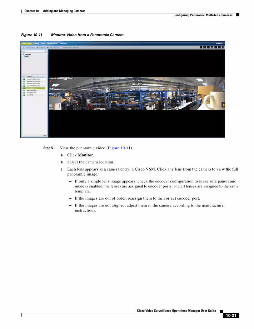
Chapter 10 Adding and Managing CamerasConfiguring Panoramic Multi-lens Cameras
Figure 10-11 Monitor Video from a Panoramic Camera
Step 5 View the panoramic video (Figure 10-11).
a. Click Monitor.
b. Select the camera location.
c. Each lens appears as a camera entry in Cisco VSM. Click any lens from the camera to view the full panoramic image.
– If only a single lens image appears, check the encoder configuration to make sure panoramic mode is enabled, the lenses are assigned to encoder ports, and all lenses are assigned to the same template.
– If the images are out of order, reassign them to the correct encoder port.
– If the images are not aligned, adjust them in the camera according to the manufacturer instructions.
10-31Cisco Video Surveillance Operations Manager User Guide
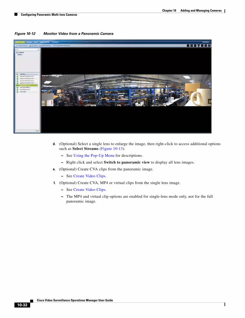
Chapter 10 Adding and Managing Cameras Configuring Panoramic Multi-lens Cameras
Figure 10-12 Monitor Video from a Panoramic Camera
d. (Optional) Select a single lens to enlarge the image, then right-click to access additional options such as Select Streams (Figure 10-13).
– See Using the Pop-Up Menu for descriptions.
– Right click and select Switch to panoramic view to display all lens images.
e. (Optional) Create CVA clips from the panoramic image.
– See Create Video Clips.
f. (Optional) Create CVA, MP4 or virtual clips from the single lens image.
– See Create Video Clips.
– The MP4 and virtual clip options are enabled for single-lens mode only, not for the full panoramic image.
10-32Cisco Video Surveillance Operations Manager User Guide
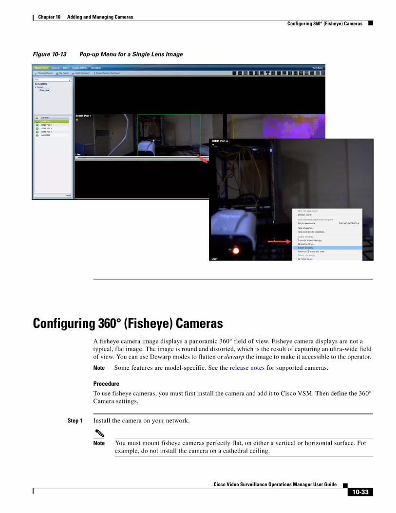
Chapter 10 Adding and Managing CamerasConfiguring 360° (Fisheye) Cameras
Figure 10-13 Pop-up Menu for a Single Lens Image
Configuring 360° (Fisheye) CamerasA fisheye camera image displays a panoramic 360° field of view. Fisheye camera displays are not a typical, flat image. The image is round and distorted, which is the result of capturing an ultra-wide field of view. You can use Dewarp modes to flatten or dewarp the image to make it accessible to the operator.
Note Some features are model-specific. See the release notes for supported cameras.
Procedure
To use fisheye cameras, you must first install the camera and add it to Cisco VSM. Then define the 360° Camera settings.
Step 1 Install the camera on your network.
Note You must mount fisheye cameras perfectly flat, on either a vertical or horizontal surface. For example, do not install the camera on a cathedral ceiling.
10-33Cisco Video Surveillance Operations Manager User Guide
Chapter 10 Adding and Managing Cameras Configuring 360° (Fisheye) Cameras
Step 2 Add the camera to the Operations Manager configuration.
Step 3 Define the camera Orientation and Dewarp settings (360° Camera Settings), using one of the following methods:
• The camera’s General Settings, page 10-47
• Pre-set Camera Settings (see Creating and Applying Preset Camera Settings, page 10-35)
Step 4 Create the video Views that include the fisheye cameras.
See Creating Video Views, page 4-4.
Step 5 Use Cisco SASD to view video from fisheye cameras. See the Cisco Video Surveillance Safety and Security Desktop User Guide for more information.
10-34Cisco Video Surveillance Operations Manager User Guide
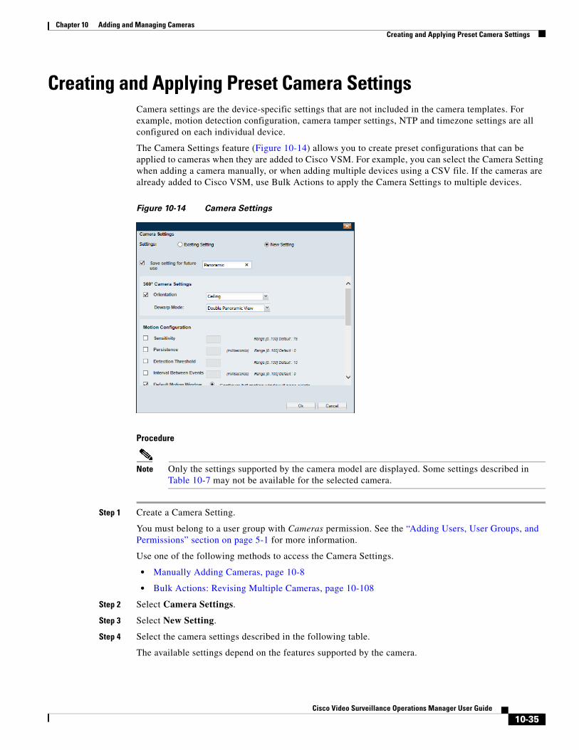
Chapter 10 Adding and Managing CamerasCreating and Applying Preset Camera Settings
Creating and Applying Preset Camera SettingsCamera settings are the device-specific settings that are not included in the camera templates. For example, motion detection configuration, camera tamper settings, NTP and timezone settings are all configured on each individual device.
The Camera Settings feature (Figure 10-14) allows you to create preset configurations that can be applied to cameras when they are added to Cisco VSM. For example, you can select the Camera Setting when adding a camera manually, or when adding multiple devices using a CSV file. If the cameras are already added to Cisco VSM, use Bulk Actions to apply the Camera Settings to multiple devices.
Figure 10-14 Camera Settings
Procedure
Note Only the settings supported by the camera model are displayed. Some settings described in Table 10-7 may not be available for the selected camera.
Step 1 Create a Camera Setting.
You must belong to a user group with Cameras permission. See the “Adding Users, User Groups, and Permissions” section on page 5-1 for more information.
Use one of the following methods to access the Camera Settings.
• Manually Adding Cameras, page 10-8
• Bulk Actions: Revising Multiple Cameras, page 10-108
Step 2 Select Camera Settings.
Step 3 Select New Setting.
Step 4 Select the camera settings described in the following table.
The available settings depend on the features supported by the camera.
10-35Cisco Video Surveillance Operations Manager User Guide
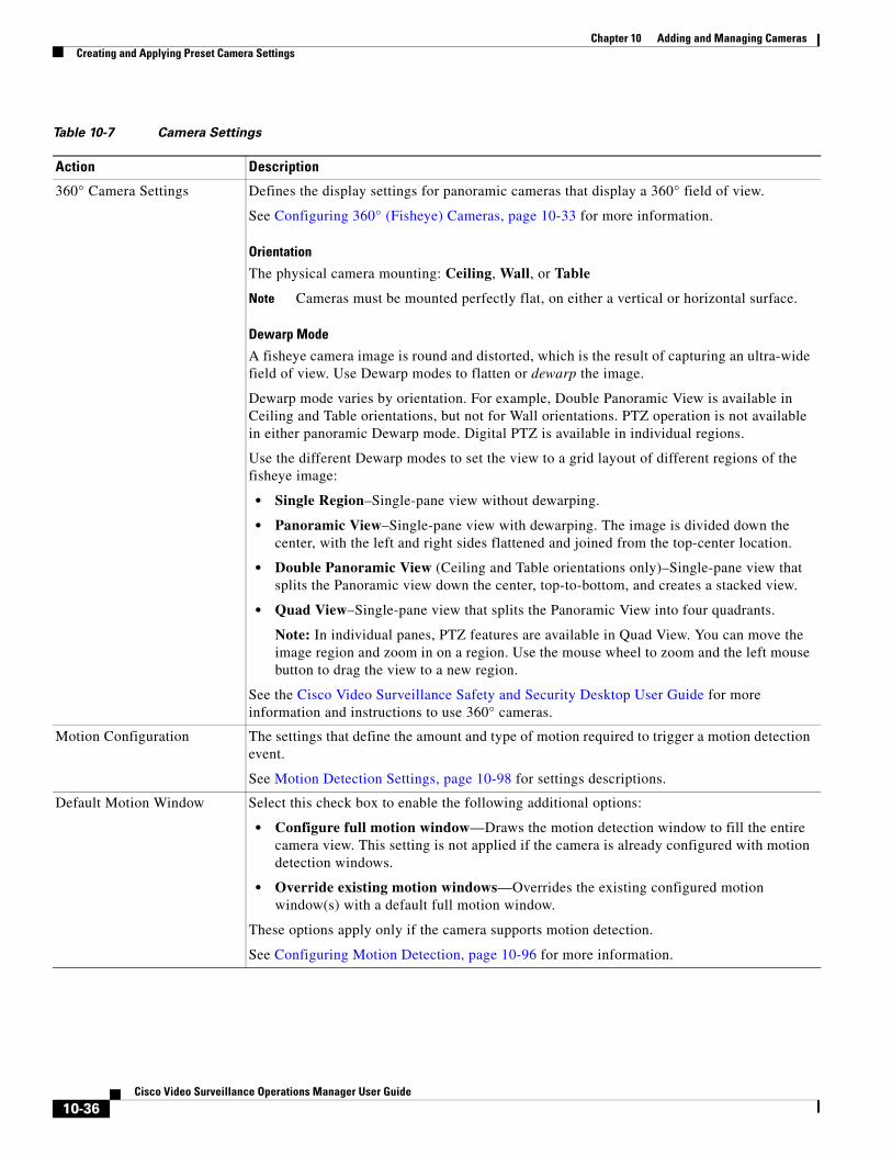
Chapter 10 Adding and Managing Cameras Creating and Applying Preset Camera Settings
Table 10-7 Camera Settings
Action Description
360° Camera Settings Defines the display settings for panoramic cameras that display a 360° field of view.
See Configuring 360° (Fisheye) Cameras, page 10-33 for more information.
Orientation
The physical camera mounting: Ceiling, Wall, or Table
Note Cameras must be mounted perfectly flat, on either a vertical or horizontal surface.
Dewarp Mode
A fisheye camera image is round and distorted, which is the result of capturing an ultra-wide field of view. Use Dewarp modes to flatten or dewarp the image.
Dewarp mode varies by orientation. For example, Double Panoramic View is available in Ceiling and Table orientations, but not for Wall orientations. PTZ operation is not available in either panoramic Dewarp mode. Digital PTZ is available in individual regions.
Use the different Dewarp modes to set the view to a grid layout of different regions of the fisheye image:
• Single Region–Single-pane view without dewarping.
• Panoramic View–Single-pane view with dewarping. The image is divided down the center, with the left and right sides flattened and joined from the top-center location.
• Double Panoramic View (Ceiling and Table orientations only)–Single-pane view that splits the Panoramic view down the center, top-to-bottom, and creates a stacked view.
• Quad View–Single-pane view that splits the Panoramic View into four quadrants.
Note: In individual panes, PTZ features are available in Quad View. You can move the image region and zoom in on a region. Use the mouse wheel to zoom and the left mouse button to drag the view to a new region.
See the Cisco Video Surveillance Safety and Security Desktop User Guide for more information and instructions to use 360° cameras.
Motion Configuration The settings that define the amount and type of motion required to trigger a motion detection event.
See Motion Detection Settings, page 10-98 for settings descriptions.
Default Motion Window Select this check box to enable the following additional options:
• Configure full motion window—Draws the motion detection window to fill the entire camera view. This setting is not applied if the camera is already configured with motion detection windows.
• Override existing motion windows—Overrides the existing configured motion window(s) with a default full motion window.
These options apply only if the camera supports motion detection.
See Configuring Motion Detection, page 10-96 for more information.
10-36Cisco Video Surveillance Operations Manager User Guide
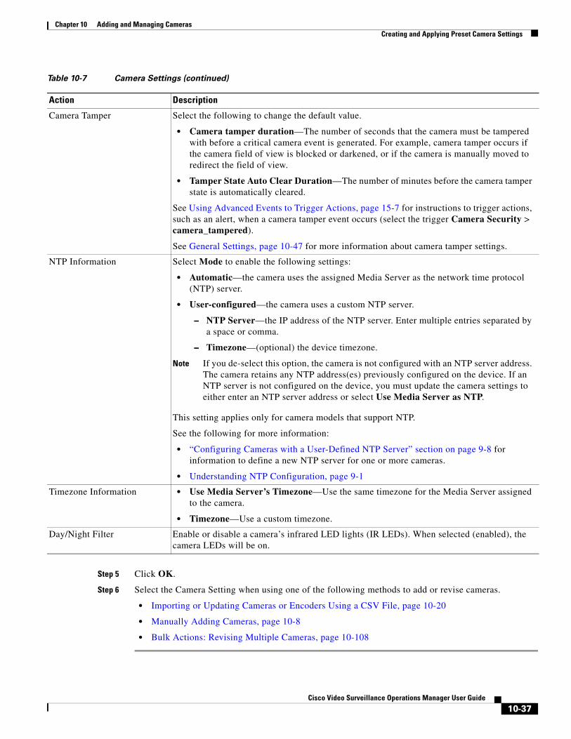
Chapter 10 Adding and Managing CamerasCreating and Applying Preset Camera Settings
Step 5 Click OK.
Step 6 Select the Camera Setting when using one of the following methods to add or revise cameras.
• Importing or Updating Cameras or Encoders Using a CSV File, page 10-20
• Manually Adding Cameras, page 10-8
• Bulk Actions: Revising Multiple Cameras, page 10-108
Camera Tamper Select the following to change the default value.
• Camera tamper duration—The number of seconds that the camera must be tampered with before a critical camera event is generated. For example, camera tamper occurs if the camera field of view is blocked or darkened, or if the camera is manually moved to redirect the field of view.
• Tamper State Auto Clear Duration—The number of minutes before the camera tamper state is automatically cleared.
See Using Advanced Events to Trigger Actions, page 15-7 for instructions to trigger actions, such as an alert, when a camera tamper event occurs (select the trigger Camera Security > camera_tampered).
See General Settings, page 10-47 for more information about camera tamper settings.
NTP Information Select Mode to enable the following settings:
• Automatic—the camera uses the assigned Media Server as the network time protocol (NTP) server.
• User-configured—the camera uses a custom NTP server.
– NTP Server—the IP address of the NTP server. Enter multiple entries separated by a space or comma.
– Timezone—(optional) the device timezone.
Note If you de-select this option, the camera is not configured with an NTP server address. The camera retains any NTP address(es) previously configured on the device. If an NTP server is not configured on the device, you must update the camera settings to either enter an NTP server address or select Use Media Server as NTP.
This setting applies only for camera models that support NTP.
See the following for more information:
• “Configuring Cameras with a User-Defined NTP Server” section on page 9-8 for information to define a new NTP server for one or more cameras.
• Understanding NTP Configuration, page 9-1
Timezone Information • Use Media Server’s Timezone—Use the same timezone for the Media Server assigned to the camera.
• Timezone—Use a custom timezone.
Day/Night Filter Enable or disable a camera’s infrared LED lights (IR LEDs). When selected (enabled), the camera LEDs will be on.
Table 10-7 Camera Settings (continued)
Action Description
10-37Cisco Video Surveillance Operations Manager User Guide
Chapter 10 Adding and Managing Cameras Zipstream compression support for Axis Cameras
Zipstream compression support for Axis CamerasZipstream compression technology can be configured on Axis Cameras using the Operations Manager.
Supported Cameras
• Axis Q1659
• Axis Q3708
• Axis cameras added with model AXIS Generic VAPIX 3.0 Network Camera (axis generic)
Usage Notes
• Zipstream settings configured using the camera UI will be overridden by the VSOM Zipstream settings.
• By default, Zipstream is set to Off in the HML template settings for the supported cameras.
• Dynamic FPS for Zipstream is not supported. It will automatically be set to off when Zipstream is enabled in a template.
• Configuring axis cameras with Zipstream results in reduced average bit rates. On Storage Retention Dashboard, in CBR mode, the “Estimated storage (by configured settings)” for these cameras might be higher than the “Estimated Storage (by actual observation)”
• Cameras added using the 'axisgeneric' model may or may not support Zipstream. Please note the following when using Zipstream with the axisgeneric driver.
– For Zipstream unsupported cameras, Zipstream values in the template should be set to off.
– For Zipstream supported cameras, please check the camera documentation for valid Zipstream values.
For example Zipstream strength “Higher” and “Extreme” is supported only for cameras with firmware version 6.30 or later. If you set these values for unsupported cameras, the template settings will save successfully, but the camera might not stream using those settings.
Create a new camera template with the Zipstream setting
Step 1 Log on to the Operations Manager.
• You must belong to a User Group with permissions for Templates.
Step 2 Select Cameras > Templates.
Step 3 Click Add to create a new template.
Step 4 Select a Zipstream supported model, such as axisq1659. axisq3708 or axisgeneric.
Step 5 Select the Streaming, Recording and Event tab.
Step 6 Click Custom in the Video Quality field.
Step 7 Enter the Zipstream settings:
Axis Q1659
• Off: Disabled
• Low, Medium, High, Higher, Extreme: Increasing the strength reduces the bit rate but will also affect the visual image quality. At value Low, visual image quality is not affected, but as the strength increases, visual image quality is degraded in unprioritized image areas, for example the background. Image details important for forensic video analysis are kept.
10-38Cisco Video Surveillance Operations Manager User Guide
Chapter 10 Adding and Managing CamerasZipstream compression support for Axis Cameras
Axis Q3708
• Off: Disabled
• Low, Medium, High, Higher, Extreme: Increasing the strength reduces the bit rate but will also affect the visual image quality. At value Low, visual image quality is not affected, but as the strength increases, visual image quality is degraded in unprioritized image areas, for example the background. Image details important for forensic video analysis are kept.
GOP (Group of Pictures):
• Dynamic GOP: Enables GOP length variation between 1 (GOP length set on H.264 tab) and 300 (max dynamic GOP below)
• Max dynamic GOP length: Enter 1 to 1200.
10-39Cisco Video Surveillance Operations Manager User Guide
Chapter 10 Adding and Managing Cameras Managing Cameras with Duplicate IP Addresses
Managing Cameras with Duplicate IP AddressesBy default, cameras must have a unique IP address, or an ID collision issue will occur. This prevents two devices with the same address from causing device and configuration errors.
If your network configuration requires devices with duplicate IP addresses, however, you can enable the Allow Duplicate IP system setting to allow multiple cameras with the same network address to be added to the Operations Manager configuration. This may be necessary when the same set of private IP addresses are used at multiple sites.
In addition, cameras can be configured with custom port numbers to differentiate devices with the same IP address. See Configuring Custom Camera and Encoder Ports (PAT), page 19-3 for more information.
Related Information
See the following documentation for more information:
• Understanding Device Conflicts, page 19-1
• Configuring Custom Camera and Encoder Ports (PAT), page 19-3
• Cisco Video Surveillance Manager: Design Guide
10-40Cisco Video Surveillance Operations Manager User Guide
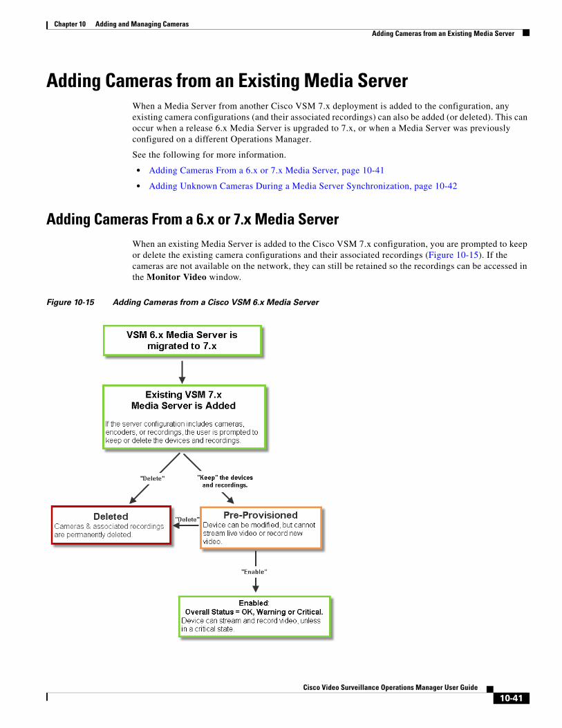
Chapter 10 Adding and Managing CamerasAdding Cameras from an Existing Media Server
Adding Cameras from an Existing Media ServerWhen a Media Server from another Cisco VSM 7.x deployment is added to the configuration, any existing camera configurations (and their associated recordings) can also be added (or deleted). This can occur when a release 6.x Media Server is upgraded to 7.x, or when a Media Server was previously configured on a different Operations Manager.
See the following for more information.
• Adding Cameras From a 6.x or 7.x Media Server, page 10-41
• Adding Unknown Cameras During a Media Server Synchronization, page 10-42
Adding Cameras From a 6.x or 7.x Media ServerWhen an existing Media Server is added to the Cisco VSM 7.x configuration, you are prompted to keep or delete the existing camera configurations and their associated recordings (Figure 10-15). If the cameras are not available on the network, they can still be retained so the recordings can be accessed in the Monitor Video window.
Figure 10-15 Adding Cameras from a Cisco VSM 6.x Media Server
10-41Cisco Video Surveillance Operations Manager User Guide
Chapter 10 Adding and Managing Cameras Adding Cameras from an Existing Media Server
Tip To add a Cisco VSM 6.x Media Server, you must first migrate the server to Cisco VSM 7.x. See the Cisco Video Surveillance Migration Guide, Release 6.3.2 to 7.0 for more information. This document is available on the Cisco Developer Network (CDN). See you Cisco support representative for more information.
Adding Unknown Cameras During a Media Server SynchronizationIn rare cases, if there are recordings from unknown device, those recordings will appear as an unknown device in the Operations Manager. A warning alert is displayed “Unknown camera with recordings is added to server”. The recordings can be viewed in the Cisco VSM Operations Manager, and you can either keep or delete it. These recordings will expire and be automatically deleted if not acted upon.
• To enable Pre-Provisioned cameras, assign a template to the camera and choose Enable from the Device Settings menu. See the “Pre-Provisioning Cameras” section on page 10-9 for more information.
• If a device is in Enabled: Warning or Enabled: Critical state, view the device Status page to resolve any additional issues (see the “Camera Status” section on page 10-74).
Note See the Cisco Video Surveillance Migration Guide, Release 6.3.2 to 7.0 for more information. This document is available on the Cisco Developer Network (CDN). See you Cisco support representative for more information.
10-42Cisco Video Surveillance Operations Manager User Guide
Chapter 10 Adding and Managing CamerasBlacklisting Cameras
Blacklisting CamerasBlacklisted cameras are deleted from the Cisco VSM configuration. Cameras can be kept in the Blacklist indefinitely.
Refer to the following topics:
• Blacklisting a Camera, page 10-43
• Viewing Cameras in the Blacklist, page 10-43
• Removing a Camera From the Blacklist, page 10-43
Blacklisting a Camera
Delete and Blacklist a Camera
Step 1 Click Cameras.
Step 2 Select the location and camera name.
Step 3 Click Delete.
Step 4 Select Blacklist & Full Delete.
Caution Full Delete permanently deletes all recordings associated with the camera.
Viewing Cameras in the Blacklist
Procedure
Step 1 Click Cameras.
Step 2 Choose Add > Camera Blacklist.
Step 3 (Optional) Use the filter settings to narrow the displayed devices.
Removing a Camera From the BlacklistTo remove a camera from the blacklist so it can be re-added to Cisco VSM, do one of the following:
• Remove the device from the blacklist, as described in the following procedure.
• Manually add the camera. This removes the camera from the blacklist and adds it to Cisco VSM. See the “Manually Adding a Single Camera” section on page 10-10.
10-43Cisco Video Surveillance Operations Manager User Guide

Chapter 10 Adding and Managing Cameras Blacklisting Cameras
Procedure
Step 1 Click Cameras.
Step 2 Choose Add > Camera Blacklist.
Step 3 (Optional) Use the filter settings to narrow the displayed devices.
Step 4 Highlight one or more entries and click Remove From Blacklist.
10-44Cisco Video Surveillance Operations Manager User Guide
Chapter 10 Adding and Managing CamerasCamera Settings
Camera SettingsCamera settings are applied to cameras, camera templates, or custom configurations.
The following settings are accessed in the Camera configuration page. You can also update camera configurations by importing a CSV file that defines the settings (see the “Importing or Updating Cameras or Encoders Using a CSV File” section on page 10-20).
See each topic for detailed information.
• Accessing the Camera Settings, page 10-45
• General Settings, page 10-47
• Streaming, Recording and Event Settings, page 10-55
• Image Settings, page 10-64
• Camera Apps, page 10-64
• Configuring the High Availability Options for a Camera or Template, page 10-65
Accessing the Camera SettingsTo revise the settings for a camera or camera template, click the Cameras tab and highlight the device (or template).
Usage Notes
• Not all settings are available for all cameras. For example, Image settings are available only if the camera supports features such as motion detection, PTZ controls, and image adjustments.
• Device configuration changes can fail is a camera firmware upgrade is in process. Make sure that a camera firmware is not being upgraded (or wait until it is complete) and try again.
• Most camera settings are applied by the template assigned to the camera. To create a configuration for a single camera, create a custom configuration for the camera. See the “Creating a Custom Template for a Single Camera” section on page 13-5.
• The camera configuration pages may not display properly if the Internet Explorer (IE) compatibility view box is checked. Deselect this option, if necessary.
Procedure
Step 1 Log on to the Operations Manager.
• See the “Logging In” section on page 1-17.
• You must belong to a User Group with permissions for Cameras.
Step 2 Click Cameras.
10-45Cisco Video Surveillance Operations Manager User Guide
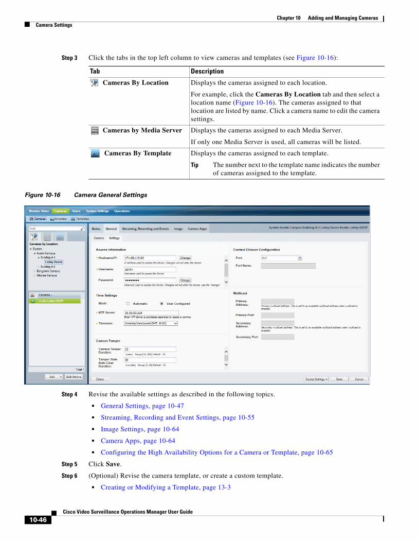
Chapter 10 Adding and Managing Cameras Camera Settings
Step 3 Click the tabs in the top left column to view cameras and templates (see Figure 10-16):
Tab Description
Tip The number next to the template name indicates the number of cameras assigned to the template.
Figure 10-16 Camera General Settings
Step 4 Revise the available settings as described in the following topics.
• General Settings, page 10-47
• Streaming, Recording and Event Settings, page 10-55
• Image Settings, page 10-64
• Camera Apps, page 10-64
• Configuring the High Availability Options for a Camera or Template, page 10-65
Step 5 Click Save.
Step 6 (Optional) Revise the camera template, or create a custom template.
• Creating or Modifying a Template, page 13-3
Cameras By Location Displays the cameras assigned to each location.
For example, click the Cameras By Location tab and then select a location name (Figure 10-16). The cameras assigned to that location are listed by name. Click a camera name to edit the camera settings.
Cameras by Media Server Displays the cameras assigned to each Media Server.
If only one Media Server is used, all cameras will be listed.
Cameras By Template Displays the cameras assigned to each template.
10-46Cisco Video Surveillance Operations Manager User Guide
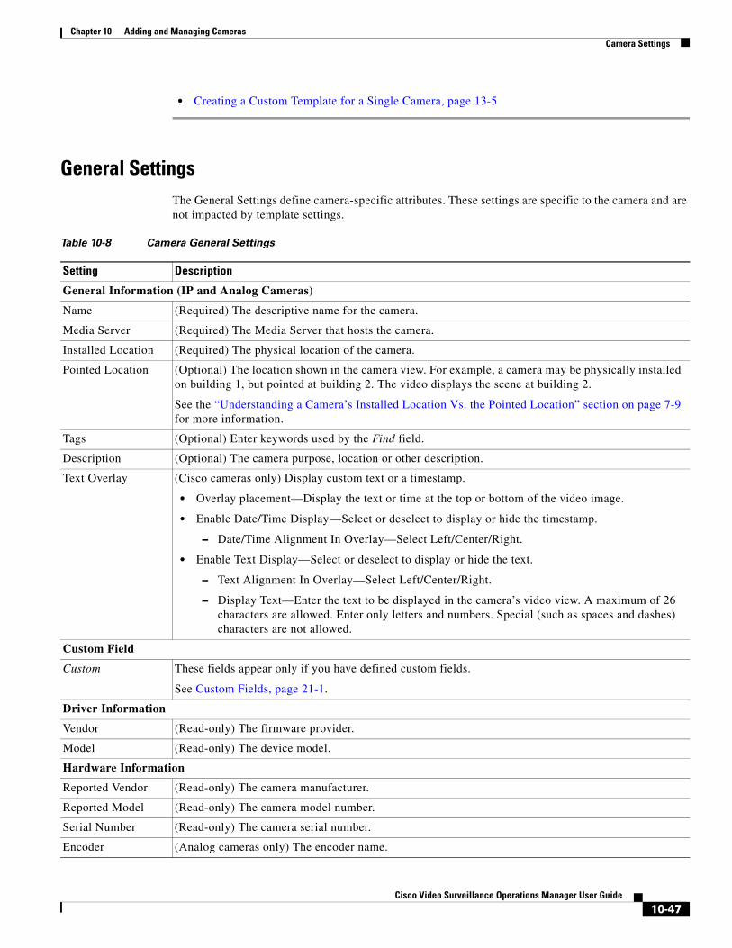
Chapter 10 Adding and Managing CamerasCamera Settings
• Creating a Custom Template for a Single Camera, page 13-5
General SettingsThe General Settings define camera-specific attributes. These settings are specific to the camera and are not impacted by template settings.
Table 10-8 Camera General Settings
Setting Description
General Information (IP and Analog Cameras)
Name (Required) The descriptive name for the camera.
Media Server (Required) The Media Server that hosts the camera.
Installed Location (Required) The physical location of the camera.
Pointed Location (Optional) The location shown in the camera view. For example, a camera may be physically installed on building 1, but pointed at building 2. The video displays the scene at building 2.
See the “Understanding a Camera’s Installed Location Vs. the Pointed Location” section on page 7-9 for more information.
Tags (Optional) Enter keywords used by the Find field.
Description (Optional) The camera purpose, location or other description.
Text Overlay (Cisco cameras only) Display custom text or a timestamp.
• Overlay placement—Display the text or time at the top or bottom of the video image.
• Enable Date/Time Display—Select or deselect to display or hide the timestamp.
– Date/Time Alignment In Overlay—Select Left/Center/Right.
• Enable Text Display—Select or deselect to display or hide the text.
– Text Alignment In Overlay—Select Left/Center/Right.
– Display Text—Enter the text to be displayed in the camera’s video view. A maximum of 26 characters are allowed. Enter only letters and numbers. Special (such as spaces and dashes) characters are not allowed.
Custom Field
Custom These fields appear only if you have defined custom fields.
See Custom Fields, page 21-1.
Driver Information
Vendor (Read-only) The firmware provider.
Model (Read-only) The device model.
Hardware Information
Reported Vendor (Read-only) The camera manufacturer.
Reported Model (Read-only) The camera model number.
Serial Number (Read-only) The camera serial number.
Encoder (Analog cameras only) The encoder name.
10-47Cisco Video Surveillance Operations Manager User Guide
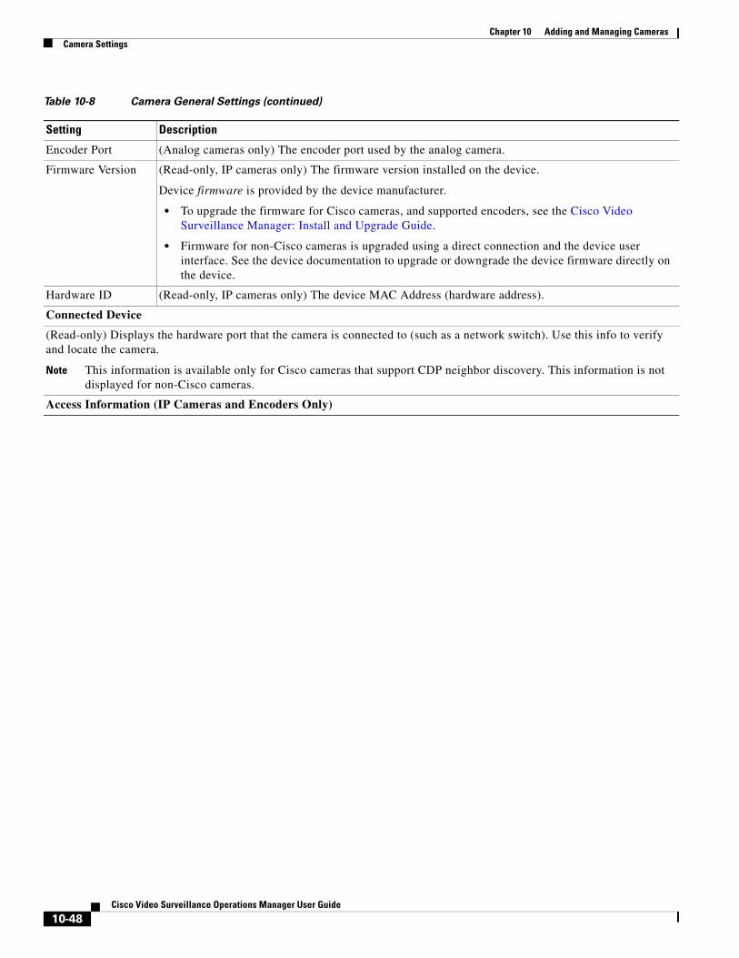
Chapter 10 Adding and Managing Cameras Camera Settings
Encoder Port (Analog cameras only) The encoder port used by the analog camera.
Firmware Version (Read-only, IP cameras only) The firmware version installed on the device.
Device firmware is provided by the device manufacturer.
• To upgrade the firmware for Cisco cameras, and supported encoders, see the Cisco Video Surveillance Manager: Install and Upgrade Guide.
• Firmware for non-Cisco cameras is upgraded using a direct connection and the device user interface. See the device documentation to upgrade or downgrade the device firmware directly on the device.
Hardware ID (Read-only, IP cameras only) The device MAC Address (hardware address).
Connected Device
(Read-only) Displays the hardware port that the camera is connected to (such as a network switch). Use this info to verify and locate the camera.
Note This information is available only for Cisco cameras that support CDP neighbor discovery. This information is not displayed for non-Cisco cameras.
Access Information (IP Cameras and Encoders Only)
Table 10-8 Camera General Settings (continued)
Setting Description
10-48Cisco Video Surveillance Operations Manager User Guide
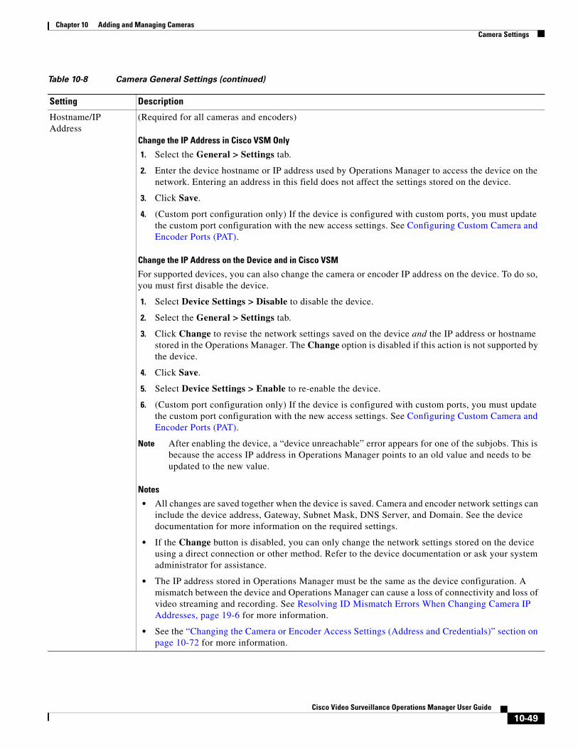
Chapter 10 Adding and Managing CamerasCamera Settings
Hostname/IP Address
(Required for all cameras and encoders)
Change the IP Address in Cisco VSM Only
1. Select the General > Settings tab.
2. Enter the device hostname or IP address used by Operations Manager to access the device on the network. Entering an address in this field does not affect the settings stored on the device.
3. Click Save.
4. (Custom port configuration only) If the device is configured with custom ports, you must update the custom port configuration with the new access settings. See Configuring Custom Camera and Encoder Ports (PAT).
Change the IP Address on the Device and in Cisco VSM
For supported devices, you can also change the camera or encoder IP address on the device. To do so, you must first disable the device.
1. Select Device Settings > Disable to disable the device.
2. Select the General > Settings tab.
3. Click Change to revise the network settings saved on the device and the IP address or hostname stored in the Operations Manager. The Change option is disabled if this action is not supported by the device.
4. Click Save.
5. Select Device Settings > Enable to re-enable the device.
6. (Custom port configuration only) If the device is configured with custom ports, you must update the custom port configuration with the new access settings. See Configuring Custom Camera and Encoder Ports (PAT).
Note After enabling the device, a “device unreachable” error appears for one of the subjobs. This is because the access IP address in Operations Manager points to an old value and needs to be updated to the new value.
Notes
• All changes are saved together when the device is saved. Camera and encoder network settings can include the device address, Gateway, Subnet Mask, DNS Server, and Domain. See the device documentation for more information on the required settings.
• If the Change button is disabled, you can only change the network settings stored on the device using a direct connection or other method. Refer to the device documentation or ask your system administrator for assistance.
• The IP address stored in Operations Manager must be the same as the device configuration. A mismatch between the device and Operations Manager can cause a loss of connectivity and loss of video streaming and recording. See Resolving ID Mismatch Errors When Changing Camera IP Addresses, page 19-6 for more information.
• See the “Changing the Camera or Encoder Access Settings (Address and Credentials)” section on page 10-72 for more information.
Table 10-8 Camera General Settings (continued)
Setting Description
10-49Cisco Video Surveillance Operations Manager User Guide
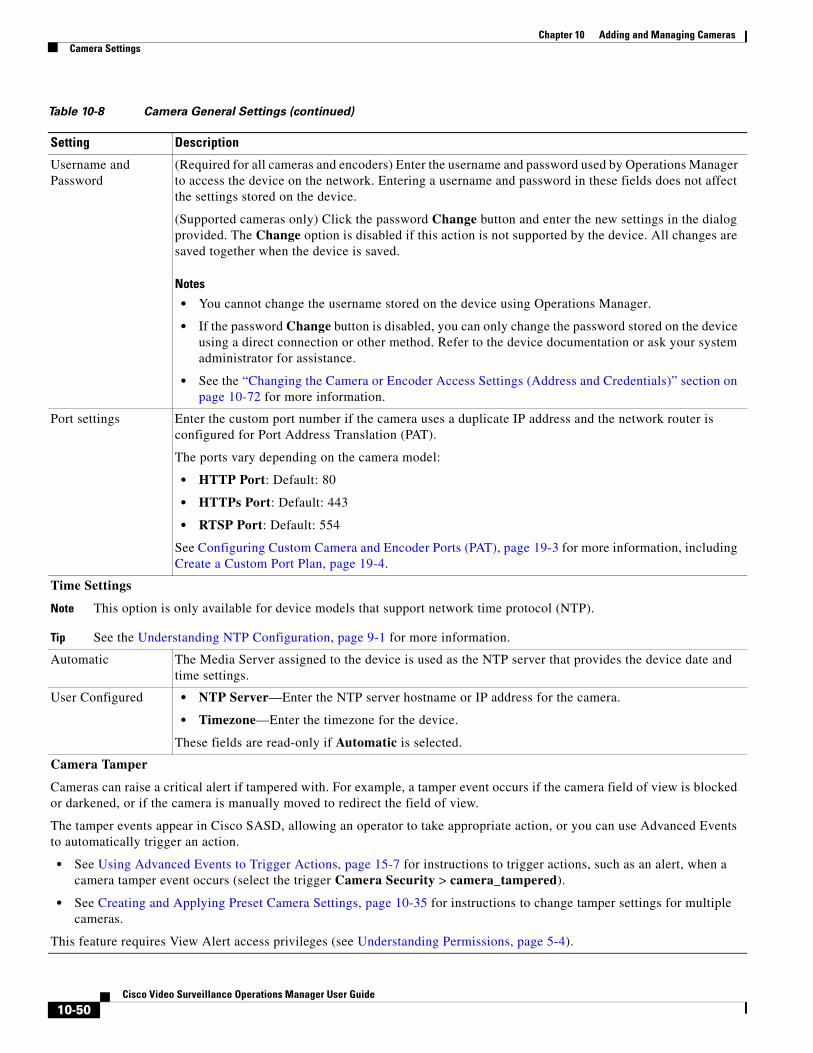
Chapter 10 Adding and Managing Cameras Camera Settings
Username and Password
(Required for all cameras and encoders) Enter the username and password used by Operations Manager to access the device on the network. Entering a username and password in these fields does not affect the settings stored on the device.
(Supported cameras only) Click the password Change button and enter the new settings in the dialog provided. The Change option is disabled if this action is not supported by the device. All changes are saved together when the device is saved.
Notes
• You cannot change the username stored on the device using Operations Manager.
• If the password Change button is disabled, you can only change the password stored on the device using a direct connection or other method. Refer to the device documentation or ask your system administrator for assistance.
• See the “Changing the Camera or Encoder Access Settings (Address and Credentials)” section on page 10-72 for more information.
Port settings Enter the custom port number if the camera uses a duplicate IP address and the network router is configured for Port Address Translation (PAT).
The ports vary depending on the camera model:
• HTTP Port: Default: 80
• HTTPs Port: Default: 443
• RTSP Port: Default: 554
See Configuring Custom Camera and Encoder Ports (PAT), page 19-3 for more information, including Create a Custom Port Plan, page 19-4.
Time Settings
Note This option is only available for device models that support network time protocol (NTP).
Tip See the Understanding NTP Configuration, page 9-1 for more information.
Automatic The Media Server assigned to the device is used as the NTP server that provides the device date and time settings.
User Configured • NTP Server—Enter the NTP server hostname or IP address for the camera.
• Timezone—Enter the timezone for the device.
These fields are read-only if Automatic is selected.
Camera Tamper
Cameras can raise a critical alert if tampered with. For example, a tamper event occurs if the camera field of view is blocked or darkened, or if the camera is manually moved to redirect the field of view.
The tamper events appear in Cisco SASD, allowing an operator to take appropriate action, or you can use Advanced Events to automatically trigger an action.
• See Using Advanced Events to Trigger Actions, page 15-7 for instructions to trigger actions, such as an alert, when a camera tamper event occurs (select the trigger Camera Security > camera_tampered).
• See Creating and Applying Preset Camera Settings, page 10-35 for instructions to change tamper settings for multiple cameras.
This feature requires View Alert access privileges (see Understanding Permissions, page 5-4).
Table 10-8 Camera General Settings (continued)
Setting Description
10-50Cisco Video Surveillance Operations Manager User Guide
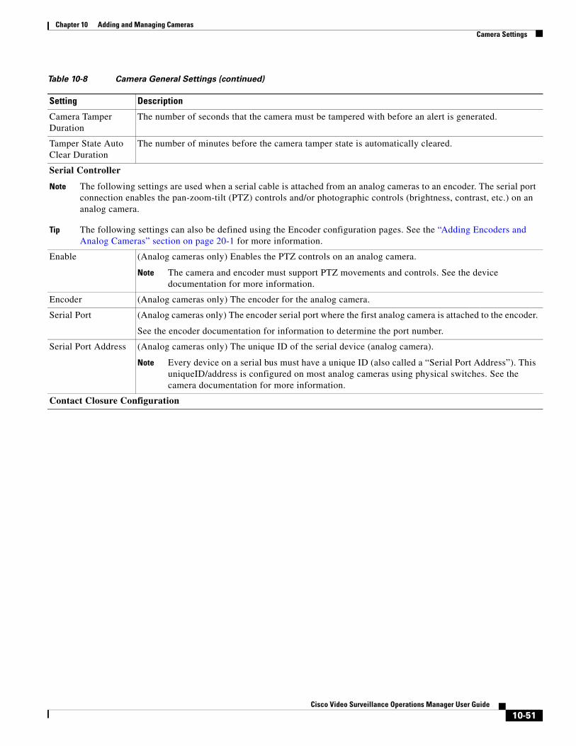
Chapter 10 Adding and Managing CamerasCamera Settings
Camera Tamper Duration
The number of seconds that the camera must be tampered with before an alert is generated.
Tamper State Auto Clear Duration
The number of minutes before the camera tamper state is automatically cleared.
Serial Controller
Note The following settings are used when a serial cable is attached from an analog cameras to an encoder. The serial port connection enables the pan-zoom-tilt (PTZ) controls and/or photographic controls (brightness, contrast, etc.) on an analog camera.
Tip The following settings can also be defined using the Encoder configuration pages. See the “Adding Encoders and Analog Cameras” section on page 20-1 for more information.
Enable (Analog cameras only) Enables the PTZ controls on an analog camera.
Note The camera and encoder must support PTZ movements and controls. See the device documentation for more information.
Encoder (Analog cameras only) The encoder for the analog camera.
Serial Port (Analog cameras only) The encoder serial port where the first analog camera is attached to the encoder.
See the encoder documentation for information to determine the port number.
Serial Port Address (Analog cameras only) The unique ID of the serial device (analog camera).
Note Every device on a serial bus must have a unique ID (also called a “Serial Port Address”). This uniqueID/address is configured on most analog cameras using physical switches. See the camera documentation for more information.
Contact Closure Configuration
Table 10-8 Camera General Settings (continued)
Setting Description
10-51Cisco Video Surveillance Operations Manager User Guide
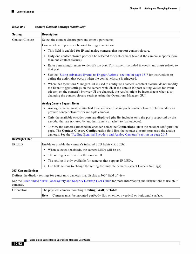
Chapter 10 Adding and Managing Cameras Camera Settings
Contact Closure Select the contact closure port and enter a port name.
Contact closure ports can be used to trigger an action.
• This field is enabled for IP and analog cameras that support contact closure.
• Only one contact closure port can be selected for each camera (even if the camera supports more than one contact closure).
• Enter a meaningful name to identify the port. This name is included in events and alerts related to that port.
• See the “Using Advanced Events to Trigger Actions” section on page 15-7 for instructions to define the action that occurs when the contact closure is triggered.
• When the Operations Manager GUI is used to configure a camera’s contact closure, do not modify the Event trigger settings on the camera web UI. If the default IO port setting values for event triggers on the camera’s browser UI are changed, the results might be inconsistent when also changing the contact closure settings using the Operations Manager GUI.
Analog Camera Support Notes
• Analog cameras must be attached to an encoder that supports contact closure. The encoder can provide contact closures for multiple cameras.
• Only the available encoder ports are displayed (the list includes only the ports supported by the encoder that are not used by another camera attached to that encoder).
• To view the cameras attached the encoder, select the Connections tab in the encoder configuration page. The Contact Closure Configuration field lists the contact closure ports used the analog cameras. See the “Adding External Encoders and Analog Cameras” section on page 20-5
Day/Night Filter
IR LED Enable or disable the camera’s infrared LED lights (IR LEDs).
• When selected (enabled), the camera LEDs will be on.
• The setting is mirrored in the camera UI.
• The setting is only available for cameras that support IR LEDs.
• Use bulk actions to change the setting for multiple cameras (select Camera Settings).
360° Camera Settings
Defines the display settings for panoramic cameras that display a 360° field of view.
See the Cisco Video Surveillance Safety and Security Desktop User Guide for more information and instructions to use 360° cameras.
Orientation The physical camera mounting: Ceiling, Wall, or Table
Note Cameras must be mounted perfectly flat, on either a vertical or horizontal surface.
Table 10-8 Camera General Settings (continued)
Setting Description
10-52Cisco Video Surveillance Operations Manager User Guide
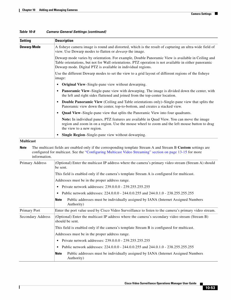
Chapter 10 Adding and Managing CamerasCamera Settings
Dewarp Mode A fisheye camera image is round and distorted, which is the result of capturing an ultra-wide field of view. Use Dewarp modes to flatten or dewarp the image.
Dewarp mode varies by orientation. For example, Double Panoramic View is available in Ceiling and Table orientations, but not for Wall orientations. PTZ operation is not available in either panoramic Dewarp mode. Digital PTZ is available in individual regions.
Use the different Dewarp modes to set the view to a grid layout of different regions of the fisheye image:
• Original View–Single-pane view without dewarping.
• Panoramic View–Single-pane view with dewarping. The image is divided down the center, with the left and right sides flattened and joined from the top-center location.
• Double Panoramic View (Ceiling and Table orientations only)–Single-pane view that splits the Panoramic view down the center, top-to-bottom, and creates a stacked view.
• Quad View–Single-pane view that splits the Panoramic View into four quadrants.
Note: In individual panes, PTZ features are available in Quad View. You can move the image region and zoom in on a region. Use the mouse wheel to zoom and the left mouse button to drag the view to a new region.
• Single Region–Single-pane view without dewarping.
Multicast
Note The multicast fields are enabled only if the corresponding template Stream A and Stream B Custom settings are configured for multicast. See the “Configuring Multicast Video Streaming” section on page 13-15 for more information.
Primary Address (Optional) Enter the multicast IP address where the camera’s primary video stream (Stream A) should be sent.
This field is enabled only if the camera’s template Stream A is configured for multicast.
Addresses must be in the proper address range.
• Private network addresses: 239.0.0.0 - 239.255.255.255
• Public network addresses: 224.0.0.0 - 244.0.0.255 and 244.0.1.0 - 238.255.255.255
Note Public addresses must be individually assigned by IANA (Internet Assigned Numbers Authority)
Primary Port Enter the port value used by Cisco Video Surveillance to listen to the camera’s primary video stream.
Secondary Address (Optional) Enter the multicast IP address where the camera’s secondary video stream (Stream B) should be sent.
This field is enabled only if the camera’s template Stream B is configured for multicast.
Addresses must be in the proper address range.
• Private network addresses: 239.0.0.0 - 239.255.255.255
• Public network addresses: 224.0.0.0 - 244.0.0.255 and 244.0.1.0 - 238.255.255.255
Note Public addresses must be individually assigned by IANA (Internet Assigned Numbers Authority)
Table 10-8 Camera General Settings (continued)
Setting Description
10-53Cisco Video Surveillance Operations Manager User Guide
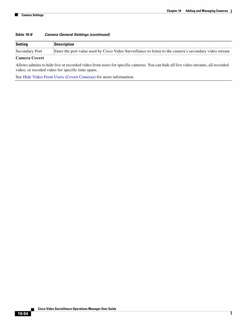
Chapter 10 Adding and Managing Cameras Camera Settings
Secondary Port Enter the port value used by Cisco Video Surveillance to listen to the camera’s secondary video stream
Camera Covert
Allows admins to hide live or recorded video from users for specific cameras. You can hide all live video streams, all recorded video, or recoded video for specific time spans.
See Hide Video From Users (Covert Cameras) for more information.
Table 10-8 Camera General Settings (continued)
Setting Description
10-54Cisco Video Surveillance Operations Manager User Guide
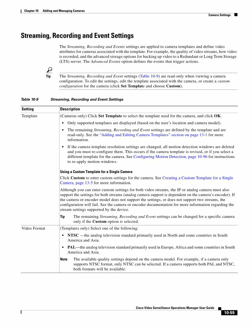
Chapter 10 Adding and Managing CamerasCamera Settings
Streaming, Recording and Event Settings The Streaming, Recording and Events settings are applied to camera templates and define video attributes for cameras associated with the template. For example, the quality of video streams, how video is recorded, and the advanced storage options for backing up video to a Redundant or Long Term Storage (LTS) server. The Advanced Events option defines the events that trigger actions.
Tip The Streaming, Recording and Event settings (Table 10-9) are read-only when viewing a camera configuration. To edit the settings, edit the template associated with the camera, or create a custom configuration for the camera (click Set Template and choose Custom).
Table 10-9 Streaming, Recording and Event Settings
Setting Description
Template (Cameras only) Click Set Template to select the template used for the camera, and click OK.
• Only supported templates are displayed (based on the user’s location and camera model).
• The remaining Streaming, Recording and Event settings are defined by the template and are read-only. See the “Adding and Editing Camera Templates” section on page 13-1 for more information.
• If the camera template resolution settings are changed, all motion detection windows are deleted and you must re-configure them. This occurs if the camera template is revised, or if you select a different template for the camera. See Configuring Motion Detection, page 10-96 for instructions to re-apply motion windows.
Using a Custom Template for a Single Camera
Click Custom to enter custom settings for the camera. See Creating a Custom Template for a Single Camera, page 13-5 for more information.
Although you can enter custom settings for both video streams, the IP or analog camera must also support the settings for both streams (analog camera support is dependent on the camera’s encoder). If the camera or encoder model does not support the settings, or does not support two streams, the configuration will fail. See the camera or encoder documentation for more information regarding the stream settings supported by the device.
Tip The remaining Streaming, Recording and Event settings can be changed for a specific camera only if the Custom option is selected.
Video Format (Templates only) Select one of the following:
• NTSC —the analog television standard primarily used in North and some countries in South America and Asia.
• PAL—the analog television standard primarily used in Europe, Africa and some countries in South America and Asia.
Note The available quality settings depend on the camera model. For example, if a camera only supports NTSC format, only NTSC can be selected. If a camera supports both PAL and NTSC, both formats will be available.
10-55Cisco Video Surveillance Operations Manager User Guide
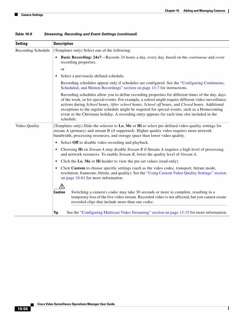
Chapter 10 Adding and Managing Cameras Camera Settings
Recording Schedule (Templates only) Select one of the following:
• Basic Recording: 24x7—Records 24 hours a day, every day, based on the continuous and event recording properties.
or
• Select a previously-defined schedule.
Recording schedules appear only if schedules are configured. See the “Configuring Continuous, Scheduled, and Motion Recordings” section on page 13-7 for instructions.
Recording schedules allow you to define recording properties for different times of the day, days of the week, or for special events. For example, a school might require different video surveillance actions during School hours, After school hours, School off hours, and Closed hours. Additional exceptions to the regular schedule might be required for special events, such as a Homecoming event or the Christmas holiday. A recording entry appears for each time slot included in the schedule.
Video Quality (Templates only) Slide the selector to Lo, Me or Hi to select pre-defined video quality settings for stream A (primary) and stream B (if supported). Higher quality video requires more network bandwidth, processing resources, and storage space than lower video quality.
• Select Off to disable video recording and playback.
• Choosing Hi on Stream A may disable Stream B if Stream A requires a high level of processing and network resources. To enable Stream B, lower the quality level of Stream A.
• Click the Lo, Me or Hi header to view the pre-set values (read-only).
• Click Custom to choose specific settings (such as the video codec, transport, bitrate mode, resolution, framerate, bitrate, and quality). See the “Using Custom Video Quality Settings” section on page 10-61 for more information.
Caution Switching a camera's codec may take 30 seconds or more to complete, resulting in a temporary loss of the live video stream. Recorded video is not affected, but you cannot create recorded clips that include more than one codec.
Tip See the “Configuring Multicast Video Streaming” section on page 13-15 for more information.
Table 10-9 Streaming, Recording and Event Settings (continued)
Setting Description
10-56Cisco Video Surveillance Operations Manager User Guide
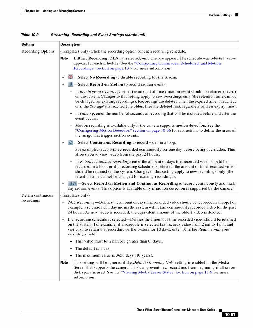
Chapter 10 Adding and Managing CamerasCamera Settings
Recording Options (Templates only) Click the recording option for each recurring schedule.
Note If Basic Recording: 24x7was selected, only one row appears. If a schedule was selected, a row appears for each schedule. See the “Configuring Continuous, Scheduled, and Motion Recordings” section on page 13-7 for more information.
• —Select No Recording to disable recording for the stream.
• —Select Record on Motion to record motion events.
– In Retain event recordings, enter the amount of time a motion event should be retained (saved) on the system. Changes to this setting apply to new recordings only (the retention time cannot be changed for existing recordings). Recordings are deleted when the expired time is reached, or if the Storage% is reached (the oldest files are deleted first, regardless of their expiry time).
– In Padding, enter the number of seconds of recording that will be included before and after the event occurs.
– Motion recording is available only if the camera supports motion detection. See the “Configuring Motion Detection” section on page 10-96 for instructions to define the areas of the image that trigger motion events.
• —Select Continuous Recording to record video in a loop.
– For example, video will be recorded continuously for one day before being overridden. This allows you to view video from the past 24 hours.
– In Retain continuous recordings enter the amount of days that recorded video should be recorded in a loop, or if a recording schedule is selected, the amount of time recorded video should be retained on the system. Changes to this setting apply to new recordings only (the retention time cannot be changed for existing recordings).
• —Select Record on Motion and Continuous Recording to record continuously and mark any motion events. This option is available only if motion detection is supported by the camera.
Retain continuous recordings
(Templates only)
• 24x7 Recording—Defines the amount of days that recorded video should be recorded in a loop. For example, a retention of 1 day means the system will retain continuously recorded video for the past 24 hours. As new video is recorded, the equivalent amount of the oldest video is deleted.
• If a recording schedule is selected—Defines the amount of time recorded video should be retained on the system. For example, if a schedule is selected that records video from 2 pm to 4 pm, and you wish to retain that recording on the system for 10 days, enter 10 in the Retain continuous recordings field.
– This value must be a number greater than 0 (days).
– The default is 1 day.
– The maximum value is 3650 days (10 years).
Note This setting will be ignored if the Default Grooming Only setting is enabled on the Media Server that supports the camera. This can prevent new recordings from beginning if all server disk space is used. See the “Viewing Media Server Status” section on page 11-9 for more information.
Table 10-9 Streaming, Recording and Event Settings (continued)
Setting Description
10-57Cisco Video Surveillance Operations Manager User Guide
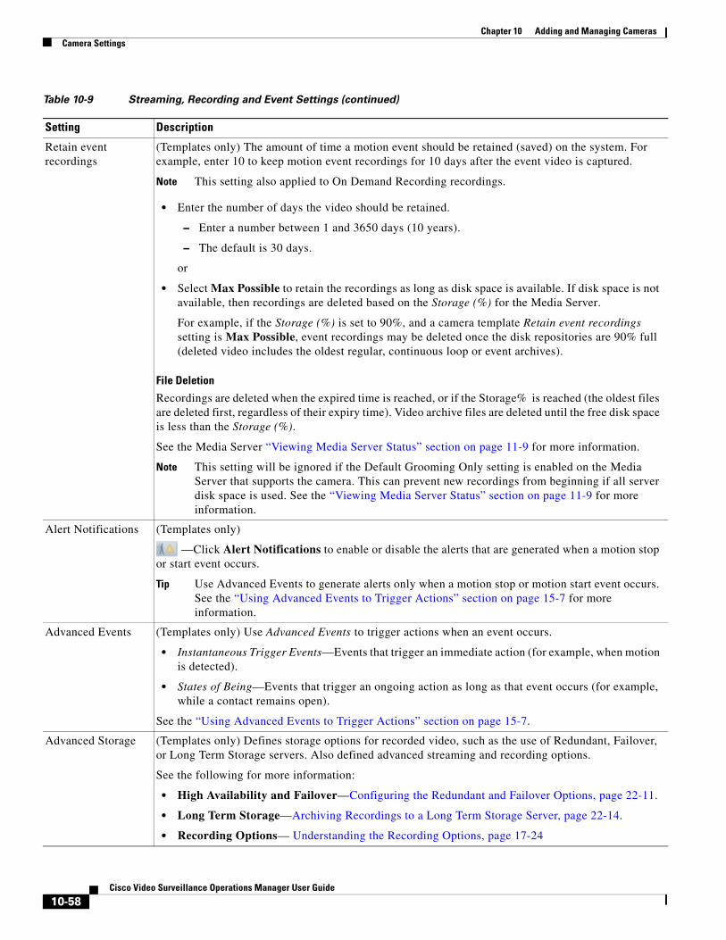
Chapter 10 Adding and Managing Cameras Camera Settings
Retain event recordings
(Templates only) The amount of time a motion event should be retained (saved) on the system. For example, enter 10 to keep motion event recordings for 10 days after the event video is captured.
Note This setting also applied to On Demand Recording recordings.
• Enter the number of days the video should be retained.
– Enter a number between 1 and 3650 days (10 years).
– The default is 30 days.
or
• Select Max Possible to retain the recordings as long as disk space is available. If disk space is not available, then recordings are deleted based on the Storage (%) for the Media Server.
For example, if the Storage (%) is set to 90%, and a camera template Retain event recordings setting is Max Possible, event recordings may be deleted once the disk repositories are 90% full (deleted video includes the oldest regular, continuous loop or event archives).
File Deletion
Recordings are deleted when the expired time is reached, or if the Storage% is reached (the oldest files are deleted first, regardless of their expiry time). Video archive files are deleted until the free disk space is less than the Storage (%).
See the Media Server “Viewing Media Server Status” section on page 11-9 for more information.
Note This setting will be ignored if the Default Grooming Only setting is enabled on the Media Server that supports the camera. This can prevent new recordings from beginning if all server disk space is used. See the “Viewing Media Server Status” section on page 11-9 for more information.
Alert Notifications (Templates only)
—Click Alert Notifications to enable or disable the alerts that are generated when a motion stop or start event occurs.
Tip Use Advanced Events to generate alerts only when a motion stop or motion start event occurs. See the “Using Advanced Events to Trigger Actions” section on page 15-7 for more information.
Advanced Events (Templates only) Use Advanced Events to trigger actions when an event occurs.
• Instantaneous Trigger Events—Events that trigger an immediate action (for example, when motion is detected).
• States of Being—Events that trigger an ongoing action as long as that event occurs (for example, while a contact remains open).
See the “Using Advanced Events to Trigger Actions” section on page 15-7.
Advanced Storage (Templates only) Defines storage options for recorded video, such as the use of Redundant, Failover, or Long Term Storage servers. Also defined advanced streaming and recording options.
See the following for more information:
• High Availability and Failover—Configuring the Redundant and Failover Options, page 22-11.
• Long Term Storage—Archiving Recordings to a Long Term Storage Server, page 22-14.
• Recording Options— Understanding the Recording Options, page 17-24
Table 10-9 Streaming, Recording and Event Settings (continued)
Setting Description
10-58Cisco Video Surveillance Operations Manager User Guide

Chapter 10 Adding and Managing CamerasCamera Settings
Record Audio (Templates only)
Defines if audio should be recorded when video is being recorded.
Note The audio settings is disabled if audio is not supported by the camera.
• Off—(Default) Audio is disabled for both live and recorded video playback.
• Live Only—Audio is enabled for live video streaming only.
• Live and Recorded—Audio is enabled for live streaming and recorded video playback.
Padding (Templates only)
Defines the number of seconds of additional recording that will be included before and after a motion event.
• Pre—Enter the number of seconds before a motion event occurs that video should be retained.
• Post—Enter the number of seconds after a motion event occurs that video should be retained.
Table 10-9 Streaming, Recording and Event Settings (continued)
Setting Description
10-59Cisco Video Surveillance Operations Manager User Guide
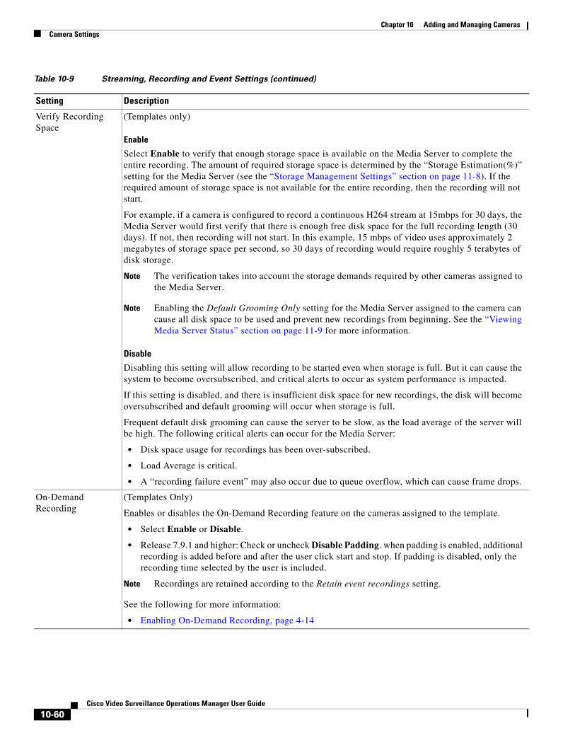
Chapter 10 Adding and Managing Cameras Camera Settings
Verify Recording Space
(Templates only)
Enable
Select Enable to verify that enough storage space is available on the Media Server to complete the entire recording. The amount of required storage space is determined by the “Storage Estimation(%)” setting for the Media Server (see the “Storage Management Settings” section on page 11-8). If the required amount of storage space is not available for the entire recording, then the recording will not start.
For example, if a camera is configured to record a continuous H264 stream at 15mbps for 30 days, the Media Server would first verify that there is enough free disk space for the full recording length (30 days). If not, then recording will not start. In this example, 15 mbps of video uses approximately 2 megabytes of storage space per second, so 30 days of recording would require roughly 5 terabytes of disk storage.
Note The verification takes into account the storage demands required by other cameras assigned to the Media Server.
Note Enabling the Default Grooming Only setting for the Media Server assigned to the camera can cause all disk space to be used and prevent new recordings from beginning. See the “Viewing Media Server Status” section on page 11-9 for more information.
Disable
Disabling this setting will allow recording to be started even when storage is full. But it can cause the system to become oversubscribed, and critical alerts to occur as system performance is impacted.
If this setting is disabled, and there is insufficient disk space for new recordings, the disk will become oversubscribed and default grooming will occur when storage is full.
Frequent default disk grooming can cause the server to be slow, as the load average of the server will be high. The following critical alerts can occur for the Media Server:
• Disk space usage for recordings has been over-subscribed.
• Load Average is critical.
• A “recording failure event” may also occur due to queue overflow, which can cause frame drops.
On-Demand Recording
(Templates Only)
Enables or disables the On-Demand Recording feature on the cameras assigned to the template.
• Select Enable or Disable.
• Release 7.9.1 and higher: Check or uncheck Disable Padding. when padding is enabled, additional recording is added before and after the user click start and stop. If padding is disabled, only the recording time selected by the user is included.
Note Recordings are retained according to the Retain event recordings setting.
See the following for more information:
• Enabling On-Demand Recording, page 4-14
Table 10-9 Streaming, Recording and Event Settings (continued)
Setting Description
10-60Cisco Video Surveillance Operations Manager User Guide
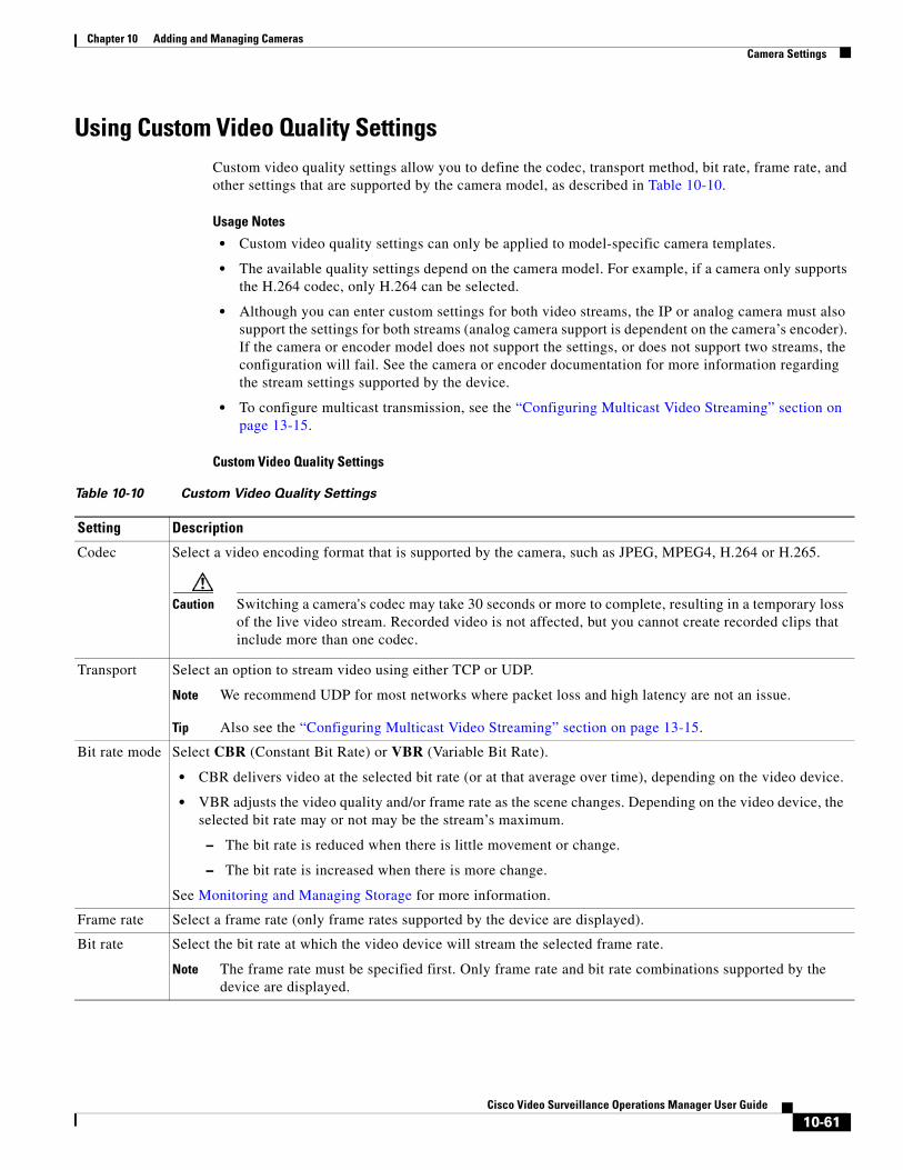
Chapter 10 Adding and Managing CamerasCamera Settings
Using Custom Video Quality SettingsCustom video quality settings allow you to define the codec, transport method, bit rate, frame rate, and other settings that are supported by the camera model, as described in Table 10-10.
Usage Notes
• Custom video quality settings can only be applied to model-specific camera templates.
• The available quality settings depend on the camera model. For example, if a camera only supports the H.264 codec, only H.264 can be selected.
• Although you can enter custom settings for both video streams, the IP or analog camera must also support the settings for both streams (analog camera support is dependent on the camera’s encoder). If the camera or encoder model does not support the settings, or does not support two streams, the configuration will fail. See the camera or encoder documentation for more information regarding the stream settings supported by the device.
• To configure multicast transmission, see the “Configuring Multicast Video Streaming” section on page 13-15.
Custom Video Quality Settings
Table 10-10 Custom Video Quality Settings
Setting Description
Codec Select a video encoding format that is supported by the camera, such as JPEG, MPEG4, H.264 or H.265.
Caution Switching a camera's codec may take 30 seconds or more to complete, resulting in a temporary loss of the live video stream. Recorded video is not affected, but you cannot create recorded clips that include more than one codec.
Transport Select an option to stream video using either TCP or UDP.
Note We recommend UDP for most networks where packet loss and high latency are not an issue.
Tip Also see the “Configuring Multicast Video Streaming” section on page 13-15.
Bit rate mode Select CBR (Constant Bit Rate) or VBR (Variable Bit Rate).
• CBR delivers video at the selected bit rate (or at that average over time), depending on the video device.
• VBR adjusts the video quality and/or frame rate as the scene changes. Depending on the video device, the selected bit rate may or not may be the stream’s maximum.
– The bit rate is reduced when there is little movement or change.
– The bit rate is increased when there is more change.
See Monitoring and Managing Storage for more information.
Frame rate Select a frame rate (only frame rates supported by the device are displayed).
Bit rate Select the bit rate at which the video device will stream the selected frame rate.
Note The frame rate must be specified first. Only frame rate and bit rate combinations supported by the device are displayed.
10-61Cisco Video Surveillance Operations Manager User Guide
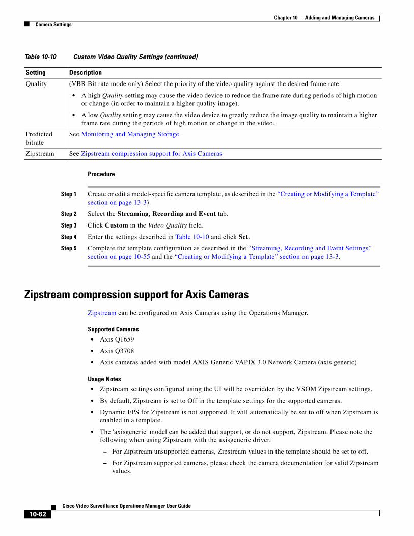
Chapter 10 Adding and Managing Cameras Camera Settings
Procedure
Step 1 Create or edit a model-specific camera template, as described in the “Creating or Modifying a Template” section on page 13-3).
Step 2 Select the Streaming, Recording and Event tab.
Step 3 Click Custom in the Video Quality field.
Step 4 Enter the settings described in Table 10-10 and click Set.
Step 5 Complete the template configuration as described in the “Streaming, Recording and Event Settings” section on page 10-55 and the “Creating or Modifying a Template” section on page 13-3.
Zipstream compression support for Axis CamerasZipstream can be configured on Axis Cameras using the Operations Manager.
Supported Cameras
• Axis Q1659
• Axis Q3708
• Axis cameras added with model AXIS Generic VAPIX 3.0 Network Camera (axis generic)
Usage Notes
• Zipstream settings configured using the UI will be overridden by the VSOM Zipstream settings.
• By default, Zipstream is set to Off in the template settings for the supported cameras.
• Dynamic FPS for Zipstream is not supported. It will automatically be set to off when Zipstream is enabled in a template.
• The 'axisgeneric' model can be added that support, or do not support, Zipstream. Please note the following when using Zipstream with the axisgeneric driver.
– For Zipstream unsupported cameras, Zipstream values in the template should be set to off.
– For Zipstream supported cameras, please check the camera documentation for valid Zipstream values.
Quality (VBR Bit rate mode only) Select the priority of the video quality against the desired frame rate.
• A high Quality setting may cause the video device to reduce the frame rate during periods of high motion or change (in order to maintain a higher quality image).
• A low Quality setting may cause the video device to greatly reduce the image quality to maintain a higher frame rate during the periods of high motion or change in the video.
Predicted bitrate
See Monitoring and Managing Storage.
Zipstream See Zipstream compression support for Axis Cameras
Table 10-10 Custom Video Quality Settings (continued)
Setting Description
10-62Cisco Video Surveillance Operations Manager User Guide

Chapter 10 Adding and Managing CamerasCamera Settings
For example Zipstream strength “Higher” and “Extreme” is supported only for cameras with firmware version 6.30 or later. If you set these values for unsupported cameras, the template settings will save successfully, but the camera might not stream using those settings.
Create a new camera template with the Zipstream setting
Step 1 Log on to the Operations Manager.
• You must belong to a User Group with permissions for Templates.
Step 2 Select Cameras > Templates.
Step 3 Click Add to create a new template.
Step 4 Select a Zipstream supported model, such as axisq1659. axisq3708 or axisgeneric.
Step 5 Select the Streaming, Recording and Event tab.
Step 6 Click Custom in the Video Quality field.
Step 7 Select the Streaming, Recording and Event tab.
Step 8 Click Custom in the Video Quality field.
Step 9 Enter the Zipstream settings:
Axis Q1659
• Off: Disabled
• Low, Medium, High, Higher, Extreme: Increasing the strength reduces the bit rate but will also affect the visual image quality. At value Low, visual image quality is not affected, but as the strength increases, visual image quality is degraded in unprioritized image areas, for example the background. Image details important for forensic video analysis are kept.
Axis Q3708
• Off: Disabled
• Low, Medium, High, Higher, Extreme: Increasing the strength reduces the bit rate but will also affect the visual image quality. At value Low, visual image quality is not affected, but as the strength increases, visual image quality is degraded in unprioritized image areas, for example the background. Image details important for forensic video analysis are kept.
GOP (Group of Pictures):
• Dynamic GOP: Enables GOP length variation between 1 (GOP length set on H.264 tab) and 300 (max dynamic GOP below)
• Max dynamic GOP length: Enter 1 to 1200.
10-63Cisco Video Surveillance Operations Manager User Guide
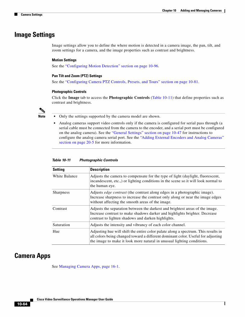
Chapter 10 Adding and Managing Cameras Camera Settings
Image SettingsImage settings allow you to define the where motion is detected in a camera image, the pan, tilt, and zoom settings for a camera, and the image properties such as contrast and brightness.
Motion Settings
See the “Configuring Motion Detection” section on page 10-96.
Pan Tilt and Zoom (PTZ) Settings
See the “Configuring Camera PTZ Controls, Presets, and Tours” section on page 10-81.
Photographic Controls
Click the Image tab to access the Photographic Controls (Table 10-11) that define properties such as contrast and brightness.
Note • Only the settings supported by the camera model are shown.
• Analog cameras support video controls only if the camera is configured for serial pass through (a serial cable must be connected from the camera to the encoder, and a serial port must be configured on the analog camera). See the “General Settings” section on page 10-47 for instructions to configure the analog camera serial port. See the “Adding External Encoders and Analog Cameras” section on page 20-5 for more information.
Table 10-11 Photographic Controls
Setting Description
Camera AppsSee Managing Camera Apps, page 16-1.
White Balance Adjusts the camera to compensate for the type of light (daylight, fluorescent, incandescent, etc.,) or lighting conditions in the scene so it will look normal to the human eye.
Sharpness Adjusts edge contrast (the contrast along edges in a photographic image). Increase sharpness to increase the contrast only along or near the image edges without affecting the smooth areas of the image.
Contrast Adjusts the separation between the darkest and brightest areas of the image. Increase contrast to make shadows darker and highlights brighter. Decrease contrast to lighten shadows and darken highlights.
Saturation Adjusts the intensity and vibrancy of each color channel.
Hue Adjusting hue will shift the entire color palate along a spectrum. This results in all colors being changed toward a different dominant color. Useful for adjusting the image to make it look more natural in unusual lighting conditions.
10-64Cisco Video Surveillance Operations Manager User Guide
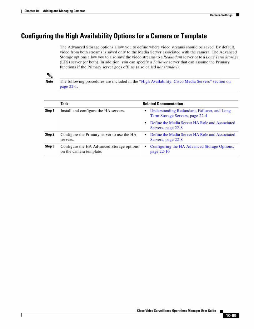
Chapter 10 Adding and Managing CamerasCamera Settings
Configuring the High Availability Options for a Camera or TemplateThe Advanced Storage options allow you to define where video streams should be saved. By default, video from both streams is saved only to the Media Server associated with the camera. The Advanced Storage options allow you to also save the video streams to a Redundant server or to a Long Term Storage (LTS) server (or both). In addition, you can specify a Failover server that can assume the Primary functions if the Primary server goes offline (also called hot standby).
Note The following procedures are included in the “High Availability: Cisco Media Servers” section on page 22-1.
Task Related Documentation
Step 1 • Understanding Redundant, Failover, and Long Term Storage Servers, page 22-4
• Define the Media Server HA Role and Associated Servers, page 22-8
Step 2 • Define the Media Server HA Role and Associated Servers, page 22-8
Step 3 • Configuring the HA Advanced Storage Options, page 22-10
Install and configure the HA servers.
Configure the Primary server to use the HA servers.
Configure the HA Advanced Storage options on the camera template.
10-65Cisco Video Surveillance Operations Manager User Guide
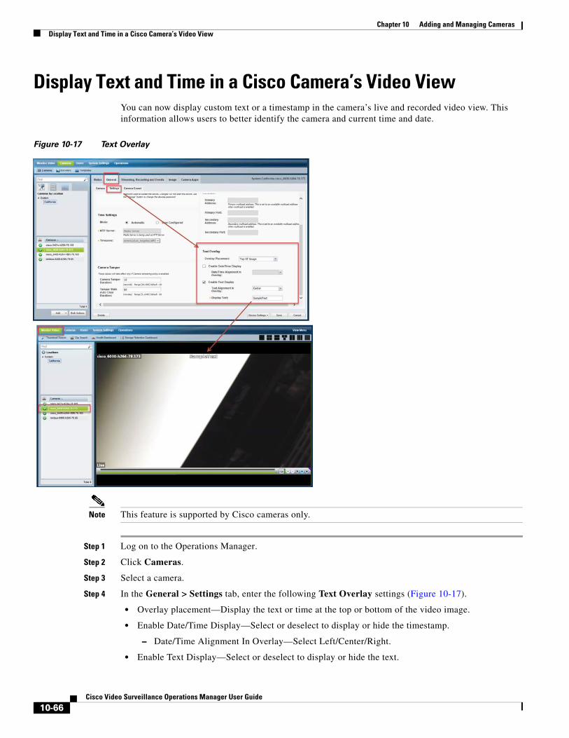
Chapter 10 Adding and Managing Cameras Display Text and Time in a Cisco Camera’s Video View
Display Text and Time in a Cisco Camera’s Video ViewYou can now display custom text or a timestamp in the camera’s live and recorded video view. This information allows users to better identify the camera and current time and date.
Figure 10-17 Text Overlay
Note This feature is supported by Cisco cameras only.
Step 1 Log on to the Operations Manager.
Step 2 Click Cameras.
Step 3 Select a camera.
Step 4 In the General > Settings tab, enter the following Text Overlay settings (Figure 10-17).
• Overlay placement—Display the text or time at the top or bottom of the video image.
• Enable Date/Time Display—Select or deselect to display or hide the timestamp.
– Date/Time Alignment In Overlay—Select Left/Center/Right.
• Enable Text Display—Select or deselect to display or hide the text.
10-66Cisco Video Surveillance Operations Manager User Guide
Chapter 10 Adding and Managing CamerasEnabling Panoramic Mode
– Text Alignment In Overlay—Select Left/Center/Right.
– Display Text—Enter the text to be displayed in the camera’s video view. Enter only letters and numbers. Special characters are not allowed, such as spaces, dashes, etc.
Step 5 Click Save.
Tip Use bulk actions to apply the settings to multiple cameras. Go to Cameras > Bulk Actions and filter the results. Select one or more Cisco Cameras and click Bulk Actions > Camera Settings. Create a setting with a text overlay or select an existing setting.
Enabling Panoramic ModePanoramic mode allows IP cameras with multiple lenses to display video in a single viewing pane (images are automatically stitched together).
Requirements
• The ActiveX client used to display and playback video must support panoramic mode. Update your Cisco Video Surveillance Safety and Security Desktop application or your Operations Manager client to the latest version when prompted.
– If this setting is enabled and the ActiveX client is outdated, then recorded video may not be properly displayed in Cisco SASD.
• Check the latest Cisco VSM release notes for feature availability and supported cameras.
Enable Panoramic Mode
Panoramic cameras appear in the encoder configuration page (Figure 10-18).
Step 1 Select Cameras > Encoders.
Step 2 Select a location and then select the panoramic camera.
Step 3 Select the General tab.
Step 4 Select Enable Panoramic Mode (under Lens Settings).
10-67Cisco Video Surveillance Operations Manager User Guide
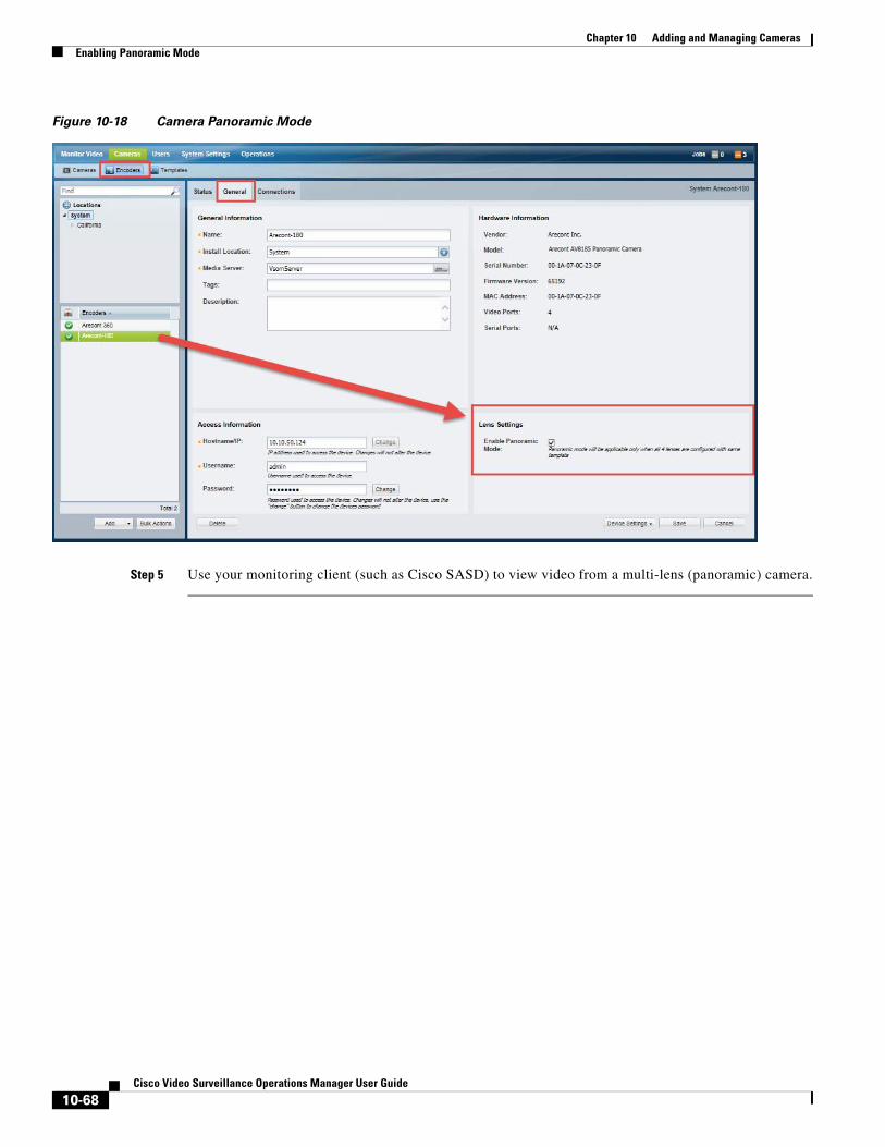
Chapter 10 Adding and Managing Cameras Enabling Panoramic Mode
Figure 10-18 Camera Panoramic Mode
Step 5 Use your monitoring client (such as Cisco SASD) to view video from a multi-lens (panoramic) camera.
10-68Cisco Video Surveillance Operations Manager User Guide
Chapter 10 Adding and Managing CamerasDeleting Cameras
Deleting CamerasWhen deleting a camera, you can delete the camera and all recordings, or keep the recordings on the system. See the Delete Options for more information.
To delete one or more cameras, use the following methods:
• (Optional) Retain the Media Server IP address
• Delete a Single Camera
• Delete Multiple Cameras
• Delete Options
• Force Delete a Device
(Optional) Retain the Media Server IP address
(Optional) Retain the Media Server IP address that is stored on the camera’s “Preferred Media Server” list.
By default, the IP address of the Media Server assigned to the camera will be deleted from the camera’s “Preferred Media Server” list. If the camera is re-added to Cisco VSM, the Media Server must be re-configured on the camera
See General System Settings, page 26-2 for more information.
To change the setting:
Step 1 Choose System Settings > Settings.
Step 2 From the General tab, enable the Preserve MS IP on camera delete option.
Delete a Single Camera
Step 1 Click Cameras.
Step 2 Select the location and camera name.
Step 3 Click Delete.
Step 4 Select one of the Delete Options.
Delete Multiple Cameras
Step 1 (Optional) Retain the Media Server IP address that is stored on the camera’s “Preferred Media Server” list.
Step 1 By default, the IP address of the Media Server assigned to the camera will be deleted from the camera’s “Preferred Media Server” list. If the camera is re-added to Cisco VSM, the Media Server must be re-configured on the camera
To change the setting:
a. Choose System Settings > Settings.
10-69Cisco Video Surveillance Operations Manager User Guide
Chapter 10 Adding and Managing Cameras Deleting Cameras
b. From the General tab, enable the Preserve MS IP on camera delete option.
See General System Settings, page 26-2 for more information.
Step 2 Click Cameras.
Step 3 Click Bulk Actions.
Step 4 Search for and select the cameras to be deleted
• See the “Bulk Actions: Revising Multiple Cameras” section on page 10-108 for more information.
Step 5 Click Bulk Actions > Delete.
Step 6 Select one of the Delete Options.
Delete Options
Select one of the following options from the camera or template configuration page:
Table 10-12 Delete Options
Delete Option Description
• Blacklisting Cameras, page 10-43
• The camera status is Soft Deleted. You can access the recorded video but cannot display live video. See the “Monitoring Video Using Internet Explorer” section on page 2-1.
• Recordings are retained on the system until removed according to the recording retention settings. See the “Configuring Continuous, Scheduled, and Motion Recordings” section on page 13-7.
• The camera is still included in the camera license count. See the “Installing Licenses” section on page 1-27.
Force Delete a Device
If the camera is stuck and delete option fails, see Troubleshooting Devices and Jobs, page 25-1 for options to force delete the device.
Blacklist & Full Delete The camera is removed from Cisco VSM and all recordings are deleted. The camera is placed in the Blacklist.
See the following for more information:
Retain Recordings The camera configuration is removed from Cisco VSM, but the camera recordings can still be accessed in the Monitor Video page.
Full Delete The camera is removed from Cisco VSM and all recordings are deleted (removed from the database). The camera can be manually re-added, but all recordings will be lost.
See Manually Adding a Single Camera, page 10-10.
Cancel Cancel the operation.
10-70Cisco Video Surveillance Operations Manager User Guide
Chapter 10 Adding and Managing CamerasRebooting Cameras
Rebooting CamerasCameras can be manually rebooted using the Cisco VSM Operations Manager. Although this is not normally required, it may be necessary with some cameras, such as after a firmware upgrade. See the release notes for your camera firmware for more information.
• Reboot a Single Camera, page 10-71
• Reboot Multiple Cameras, page 10-71
Supported Cameras
Only supported cameras can be rebooted, such as Cisco, Iqeye, Onvif, and Mobotix cameras. See the Cisco VSM Release Notes of your release for updated information.
Reboot a Single CameraUse the camera configuration page to reboot a single camera.
Procedure
Step 1 Click Cameras.
Step 2 Select the location and camera name.
Step 3 Select Device Settings > Reboot.
Step 4 Click Yes.
Reboot Multiple CamerasUse bulk actions to reboot multiple cameras at the same time. Only supported cameras will be rebooted.
Procedure
Step 1 Click Cameras.
Step 2 Click Bulk Actions.
Step 3 Search for and select the cameras to be deleted
• See the “Bulk Actions: Revising Multiple Cameras” section on page 10-108 for more information.
Step 4 Click Bulk Actions > Reboot.
Step 5 Click Yes.
10-71Cisco Video Surveillance Operations Manager User Guide
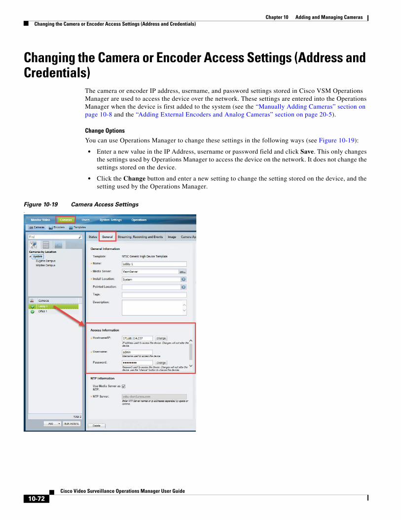
Chapter 10 Adding and Managing Cameras Changing the Camera or Encoder Access Settings (Address and Credentials)
Changing the Camera or Encoder Access Settings (Address and Credentials)
The camera or encoder IP address, username, and password settings stored in Cisco VSM Operations Manager are used to access the device over the network. These settings are entered into the Operations Manager when the device is first added to the system (see the “Manually Adding Cameras” section on page 10-8 and the “Adding External Encoders and Analog Cameras” section on page 20-5).
Change Options
You can use Operations Manager to change these settings in the following ways (see Figure 10-19):
• Enter a new value in the IP Address, username or password field and click Save. This only changes the settings used by Operations Manager to access the device on the network. It does not change the settings stored on the device.
• Click the Change button and enter a new setting to change the setting stored on the device, and the setting used by the Operations Manager.
Figure 10-19 Camera Access Settings.
10-72Cisco Video Surveillance Operations Manager User Guide
Chapter 10 Adding and Managing CamerasChanging the Camera or Encoder Access Settings (Address and Credentials)
Usage Notes
• The Change button is disabled if this action is not supported by the device, which means you must use the device UI to change the Access settings on the device. Refer to the device documentation or ask your system administrator for assistance.
• The IP address, username and password in Operations Manager must match the settings configured on the device. If a mismatch occurs, communication with the device will be lost, including new video streams and recordings.
Changing the Operations Manager Configuration Only
To change the settings used by Operations Manager to access the device over the network, do the following. The credentials configured on the device will not be affected.
Step 1 Open the camera or encoder settings page as described in the “Accessing the Camera Settings” section on page 10-45.
Step 2 Select the General tab, if necessary.
Step 3 Under Access Information, enter the new IP address, username and password.
Step 4 Click Save to apply the changes.
Changing the Device Setting and Operations Manager Configuration
If the Change button is enabled, you can change the access settings stored on the device and the Operations Manager configuration.
Step 1 Click Change next to the entry field.
Step 2 Enter the new network settings or credentials.
Step 3 Click OK to save the changes.
Step 4 (Optional) Verify the new settings:
• Click View Status to verify the Job was successfully completed.
• Click the Monitor Video tab and select the camera name to view live video from the camera. For encoders, select an analog camera associated with the encoder.
10-73Cisco Video Surveillance Operations Manager User Guide
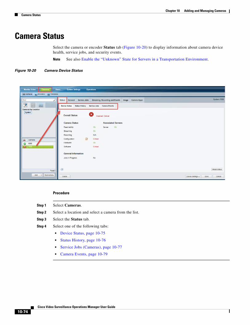
Chapter 10 Adding and Managing Cameras Camera Status
Camera StatusSelect the camera or encoder Status tab (Figure 10-20) to display information about camera device health, service jobs, and security events.
Note See also Enable the “Unknown” State for Servers in a Transportation Environment.
Figure 10-20 Camera Device Status
Procedure
Step 1 Select Cameras.
Step 2 Select a location and select a camera from the list.
Step 3 Select the Status tab.
Step 4 Select one of the following tabs:
• Device Status, page 10-75
• Status History, page 10-76
• Service Jobs (Cameras), page 10-77
• Camera Events, page 10-79
10-74Cisco Video Surveillance Operations Manager User Guide
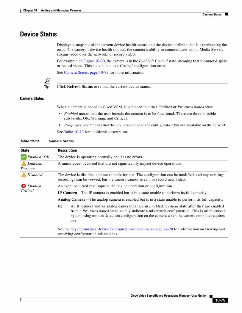
Chapter 10 Adding and Managing CamerasCamera Status
Device StatusDisplays a snapshot of the current device health status, and the device attribute that is experiencing the error. The camera’s device health impacts the camera’s ability to communicate with a Media Server, stream video over the network, or record video.
For example, in Figure 10-20, the camera is in the Enabled: Critical state, meaning that it cannot display or record video. This state is due to a Critical configuration error.
See Camera States, page 10-75 for more information.
Tip Click Refresh Status to reload the current device status.
Camera States
When a camera is added to Cisco VSM, it is placed in either Enabled or Pre-provisioned state.
• Enabled means that the user intends the camera is to be functional. There are three possible sub-levels: OK, Warning, and Critical.
• Pre-provisioned means that the device is added to the configuration but not available on the network.
See Table 10-13 for additional descriptions.
Table 10-13 Camera Status
State Description
Enabled: OK The device is operating normally and has no errors.
Enabled: Warning
A minor event occurred that did not significantly impact device operations.
Disabled The device is disabled and unavailable for use. The configuration can be modified, and any existing recordings can be viewed, but the camera cannot stream or record new video.
Enabled: Critical
An event occurred that impacts the device operation or configuration.
IP Camera—The IP camera is enabled but is in a state unable to perform its full capacity.
Analog Camera—The analog camera is enabled but is in a state unable to perform its full capacity.
Tip An IP camera and an analog camera that are in Enabled: Critical state after they are enabled from a Pre-provisioned state usually indicate a mis-match configuration. This is often caused by a missing motion detection configuration on the camera when the camera template requires one.
See the “Synchronizing Device Configurations” section on page 24-28 for information on viewing and resolving configuration mismatches.
10-75Cisco Video Surveillance Operations Manager User Guide
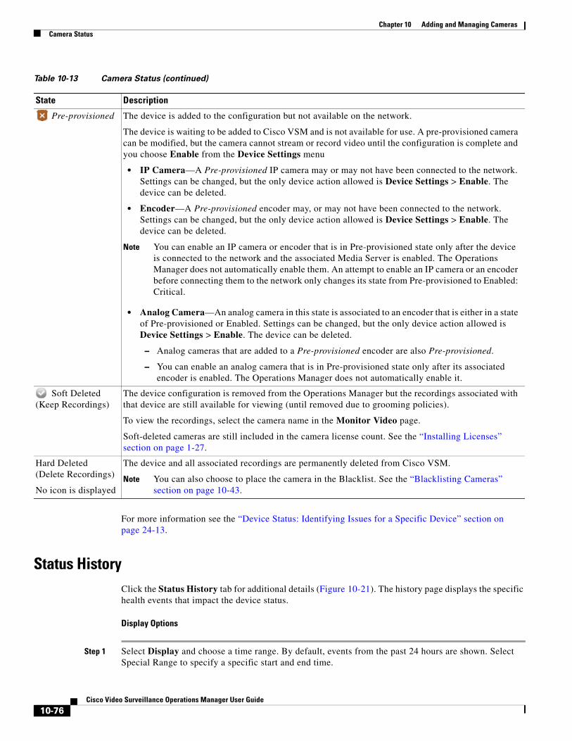
Chapter 10 Adding and Managing Cameras Camera Status
For more information see the “Device Status: Identifying Issues for a Specific Device” section on page 24-13.
Status HistoryClick the Status History tab for additional details (Figure 10-21). The history page displays the specific health events that impact the device status.
Display Options
Step 1 Select Display and choose a time range. By default, events from the past 24 hours are shown. Select Special Range to specify a specific start and end time.
Pre-provisioned The device is added to the configuration but not available on the network.
The device is waiting to be added to Cisco VSM and is not available for use. A pre-provisioned camera can be modified, but the camera cannot stream or record video until the configuration is complete and you choose Enable from the Device Settings menu
• IP Camera—A Pre-provisioned IP camera may or may not have been connected to the network. Settings can be changed, but the only device action allowed is Device Settings > Enable. The device can be deleted.
• Encoder—A Pre-provisioned encoder may, or may not have been connected to the network. Settings can be changed, but the only device action allowed is Device Settings > Enable. The device can be deleted.
Note You can enable an IP camera or encoder that is in Pre-provisioned state only after the device is connected to the network and the associated Media Server is enabled. The Operations Manager does not automatically enable them. An attempt to enable an IP camera or an encoder before connecting them to the network only changes its state from Pre-provisioned to Enabled: Critical.
• Analog Camera—An analog camera in this state is associated to an encoder that is either in a state of Pre-provisioned or Enabled. Settings can be changed, but the only device action allowed is Device Settings > Enable. The device can be deleted.
– Analog cameras that are added to a Pre-provisioned encoder are also Pre-provisioned.
– You can enable an analog camera that is in Pre-provisioned state only after its associated encoder is enabled. The Operations Manager does not automatically enable it.
Soft Deleted (Keep Recordings)
The device configuration is removed from the Operations Manager but the recordings associated with that device are still available for viewing (until removed due to grooming policies).
To view the recordings, select the camera name in the Monitor Video page.
Soft-deleted cameras are still included in the camera license count. See the “Installing Licenses” section on page 1-27.
Hard Deleted (Delete Recordings)
No icon is displayed
The device and all associated recordings are permanently deleted from Cisco VSM.
Note You can also choose to place the camera in the Blacklist. See the “Blacklisting Cameras” section on page 10-43.
Table 10-13 Camera Status (continued)
State Description
10-76Cisco Video Surveillance Operations Manager User Guide
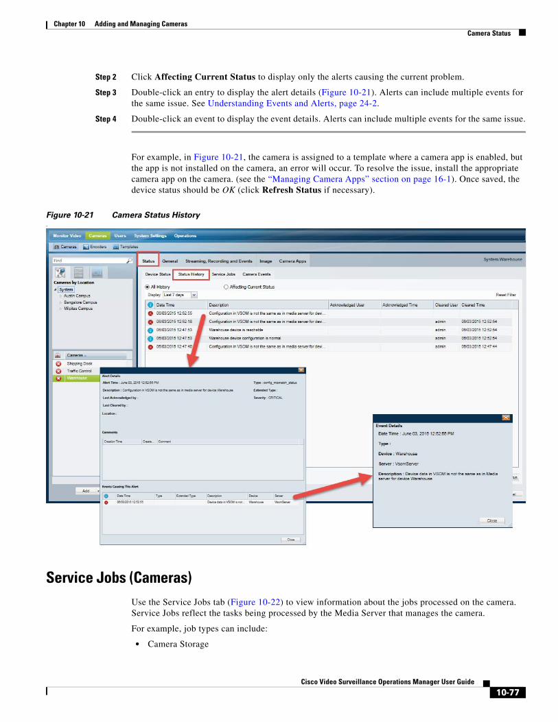
Chapter 10 Adding and Managing CamerasCamera Status
Step 2 Click Affecting Current Status to display only the alerts causing the current problem.
Step 3 Double-click an entry to display the alert details (Figure 10-21). Alerts can include multiple events for the same issue. See Understanding Events and Alerts, page 24-2.
Step 4 Double-click an event to display the event details. Alerts can include multiple events for the same issue.
For example, in Figure 10-21, the camera is assigned to a template where a camera app is enabled, but the app is not installed on the camera, an error will occur. To resolve the issue, install the appropriate camera app on the camera. (see the “Managing Camera Apps” section on page 16-1). Once saved, the device status should be OK (click Refresh Status if necessary).
Figure 10-21 Camera Status History.
Service Jobs (Cameras)Use the Service Jobs tab (Figure 10-22) to view information about the jobs processed on the camera. Service Jobs reflect the tasks being processed by the Media Server that manages the camera.
For example, job types can include:
• Camera Storage
10-77Cisco Video Surveillance Operations Manager User Guide
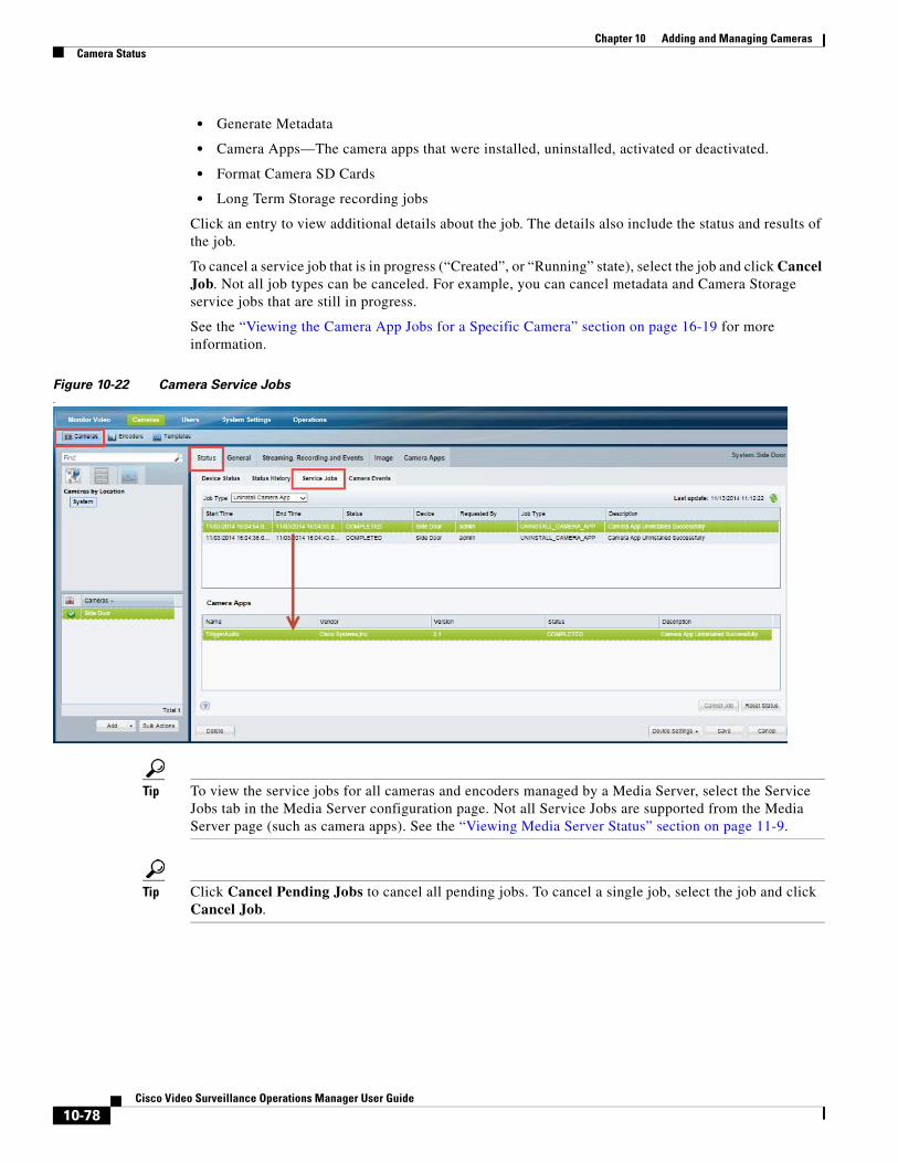
Chapter 10 Adding and Managing Cameras Camera Status
• Generate Metadata
• Camera Apps—The camera apps that were installed, uninstalled, activated or deactivated.
• Format Camera SD Cards
• Long Term Storage recording jobs
Click an entry to view additional details about the job. The details also include the status and results of the job.
To cancel a service job that is in progress (“Created”, or “Running” state), select the job and click Cancel Job. Not all job types can be canceled. For example, you can cancel metadata and Camera Storage service jobs that are still in progress.
See the “Viewing the Camera App Jobs for a Specific Camera” section on page 16-19 for more information.
Figure 10-22 Camera Service Jobs.
Tip To view the service jobs for all cameras and encoders managed by a Media Server, select the Service Jobs tab in the Media Server configuration page. Not all Service Jobs are supported from the Media Server page (such as camera apps). See the “Viewing Media Server Status” section on page 11-9.
Tip Click Cancel Pending Jobs to cancel all pending jobs. To cancel a single job, select the job and click Cancel Job.
10-78Cisco Video Surveillance Operations Manager User Guide
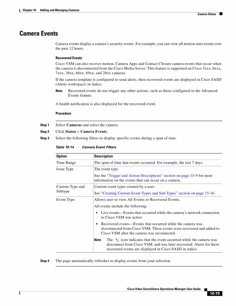
Chapter 10 Adding and Managing CamerasCamera Status
Camera EventsCamera events display a camera’s security events. For example, you can view all motion start events over the past 12 hours.
Recovered Events
Cisco VSM can also recover motion, Camera Apps and Contact Closure camera events that occur when the camera is disconnected from the Cisco Media Server. This feature is supported on Cisco 3xxx, 6xxx, 7xxx, 36xx, 66xx, 69xx, and 28xx cameras.
If the camera template is configured to send alerts, then recovered events are displayed in Cisco SASD (Alerts workspace) in italics.
Note Recovered events do not trigger any other actions, such as those configured in the Advanced Events feature.
A health notification is also displayed for the recovered event.
Procedure
Step 1 Select Cameras and select the camera.
Step 2 Click Status > Camera Events.
Step 3 Select the following filters to display specific events during a span of time.
Table 10-14 Camera Event Filters
Option Description
• Live events—Events that occurred while the camera’s network connection to Cisco VSM was active
• Recovered events—Events that occurred while the camera was disconnected from Cisco VSM. These events were recovered and added to Cisco VSM after the camera was reconnected.
Note The icon indicates that the event occurred while the camera was disconnect from Cisco VSM, and was later recovered. Alerts for these recovered events are displayed in Cisco SASD in italics
Step 4 The page automatically refreshes to display events from your selection.
Time Range The span of time that events occurred. For example, the last 7 days.
Issue Type The event type.
See the “Trigger and Action Descriptions” section on page 15-9 for more information on the events that can occur on a camera.
Custom Type and Subtype
Custom event types created by a user.
See “Creating Custom Event Types and Sub Types” section on page 15-16.
Event Type Allows user to view All Events or Recovered Events.
All events include the following:
10-79Cisco Video Surveillance Operations Manager User Guide
Chapter 10 Adding and Managing Cameras Camera Status
Repairing Configuration ErrorsIf a configuration error occurs, use the Status History to locate and correct the problem. Other issues are the result of mismatched configuration between the device, the Media Server and/or the Operations Manager. If this occurs, use the configuration repair options described in the “Repairing a Mismatched Configuration” section on page 24-32.
For example, be sure to successfully save or revert your changes while still in the motion configuration window. Clicking out of the window before changes are successfully saved or discarded can cause a configuration mismatch to occur on the camera Status page (the error will not include any additional details). If this occurs, perform a Repair Configuration on the camera,
See the “Repairing a Mismatched Configuration” section on page 24-32 for more information about the following options:
• Replace Configurations—Pushes the entire device configuration from the Operations Manager to the Media Server. The Media Server data is replaced.
• Repair Configurations—Pushes only the configuration changes required correct a mismatched field. Changes are pushed from the Operations Manager to the Media Server.
10-80Cisco Video Surveillance Operations Manager User Guide
Chapter 10 Adding and Managing CamerasConfiguring Camera PTZ Controls, Presets, and Tours
Configuring Camera PTZ Controls, Presets, and ToursCameras that support pan (left-right), tilt (up-down) and zoom (in-out) movements can be controlled using either the on-screen PTZ controls, or a third-party joystick. PTZ control is available when viewing live video only.
In addition, you can configure PTZ cameras for the following:
• Create PTZ presets that allow operators to quickly jump to a preset position.
• Create PTZ tours that automatically cycle a camera between the PTZ preset positions.
• Create Advanced Events that automatically move the camera to a PTZ preset position when an event occurs.
• Define a Return To Home preset that automatically returns the camera to a selected Home position when idle for a specified number of seconds.
• Define user groups that have priority for accessing PTZ controls.
Refer to the following topics for more information:
• PTZ Requirements, page 10-82
• PTZ Camera Configuration Summary, page 10-83
• Defining the User Group PTZ Priority, page 10-85
• Using Camera PTZ Controls, page 10-86
• Configuring PTZ Presets, page 10-87
• Configuring PTZ Tours, page 10-89
• Configuring Advanced Settings, page 10-91
Related information:
• Using Pan, Tilt, and Zoom (PTZ) Controls, page 2-29
• Calibrating a Joystick for Windows 7, page 2-32
• Using Advanced Events to Trigger Actions, page 15-7
Tip See the Example in the “Defining the User Group PTZ Priority” section on page 10-85 to understand how users, events, tours and other features gain or are denied PTZ control based on their PTZ priority.
10-81Cisco Video Surveillance Operations Manager User Guide
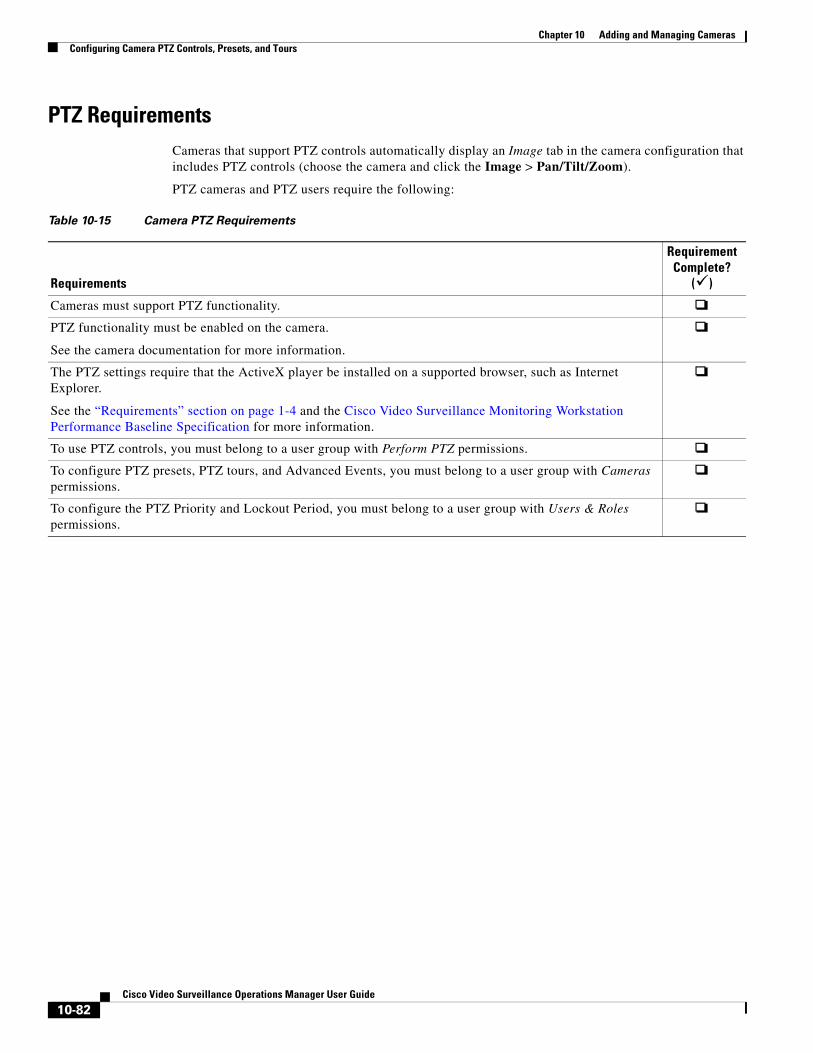
Chapter 10 Adding and Managing Cameras Configuring Camera PTZ Controls, Presets, and Tours
PTZ RequirementsCameras that support PTZ controls automatically display an Image tab in the camera configuration that includes PTZ controls (choose the camera and click the Image > Pan/Tilt/Zoom).
PTZ cameras and PTZ users require the following:
Table 10-15 Camera PTZ Requirements
Requirements
Requirement Complete?
()
Cameras must support PTZ functionality.
PTZ functionality must be enabled on the camera.
See the camera documentation for more information.
The PTZ settings require that the ActiveX player be installed on a supported browser, such as Internet Explorer.
See the “Requirements” section on page 1-4 and the Cisco Video Surveillance Monitoring Workstation Performance Baseline Specification for more information.
To use PTZ controls, you must belong to a user group with Perform PTZ permissions.
To configure PTZ presets, PTZ tours, and Advanced Events, you must belong to a user group with Cameras permissions.
To configure the PTZ Priority and Lockout Period, you must belong to a user group with Users & Roles permissions.
10-82Cisco Video Surveillance Operations Manager User Guide
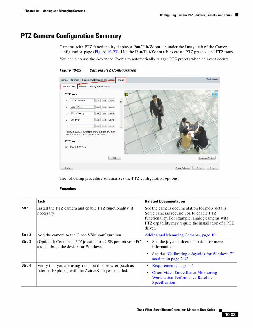
Chapter 10 Adding and Managing CamerasConfiguring Camera PTZ Controls, Presets, and Tours
PTZ Camera Configuration SummaryCameras with PTZ functionality display a Pan/Tilt/Zoom tab under the Image tab of the Camera configuration page (Figure 10-23). Use the Pan/Tilt/Zoom tab to create PTZ presets, and PTZ tours.
You can also use the Advanced Events to automatically trigger PTZ presets when an event occurs.
Figure 10-23 Camera PTZ Configuration
The following procedure summarizes the PTZ configuration options.
Procedure
Task Related Documentation
Step 1 Install the PTZ camera and enable PTZ functionality, if necessary.
See the camera documentation for more details. Some cameras require you to enable PTZ functionality. For example, analog cameras with PTZ capability may require the installation of a PTZ driver.
Step 2 Add the camera to the Cisco VSM configuration. Adding and Managing Cameras, page 10-1.
Step 3 (Optional) Connect a PTZ joystick to a USB port on your PC and calibrate the device for Windows.
• See the joystick documentation for more information.
• See the “Calibrating a Joystick for Windows 7” section on page 2-32.
Step 4 Verify that you are using a compatible browser (such as Internet Explorer) with the ActiveX player installed.
• Requirements, page 1-4
• Cisco Video Surveillance Monitoring Workstation Performance Baseline Specification
10-83Cisco Video Surveillance Operations Manager User Guide
Chapter 10 Adding and Managing Cameras Configuring Camera PTZ Controls, Presets, and Tours
Step 5 Open the camera PTZ configuration page to verify the camera PTZ controls are available:
a. Select Cameras and select a camera name.
b. Click the Image tab and verify that the Pan/Tilt/Zoom tab is selected (Figure 10-23).
Accessing the Camera Settings, page 10-45
Step 6 (Optional) Configure the camera PTZ presets.
Presets are used to quickly adjust a camera view to a pre-defined PTZ setting.
Configuring PTZ Presets, page 10-87
Step 7 (Optional) Configure the camera PTZ tours.
PTZ tours are used to cycle the camera view between PTZ presets.
Configuring PTZ Tours, page 10-89
Step 8 (Optional) Define if the camera should return to a selected Home position when idle for a specified number of seconds.
Note If a PTZ tour is enabled, then the Return to Home setting is ignored
Configuring Advanced Settings, page 10-91
Step 9 (Optional) Enter the camera PTZ idle time that defines the following:
• PTZ Tour—the number of seconds after a manual PTZ movement or event action before the PTZ tour can resume.
• Return to Home—the number of seconds after a manual PTZ movement or event action before the camera returns to the Return to Home preset position.
• User PTZ control (priority lockout or camera controls lockout)—the number of seconds that a lower priority user has to wait before being able to move the camera after a higher priority user stops using the PTZ controls.
Note PTZ tours and Return to Home have the lowest priority, allowing users and Advanced Events to assume PTZ control when necessary.
Configuring Advanced Settings, page 10-91
Step 10 (Optional) Define the user groups that have priority over other users for controlling PTZ cameras.
Note By default, all user groups have the highest priority (100).
Defining the User Group PTZ Priority, page 10-85
Step 11 (Optional) Configure the Return to Home preset position and timer.
Using Advanced Events to Trigger Actions, page 15-7
Task Related Documentation
10-84Cisco Video Surveillance Operations Manager User Guide

Chapter 10 Adding and Managing CamerasConfiguring Camera PTZ Controls, Presets, and Tours
Defining the User Group PTZ PriorityA conflict can occur if multiple users attempt to use the PTZ controls for the same camera. For example, if a security incident occurs, a security officer may need to assume control over lower-priority users. To resolve this, each user group is assigned a PTZ priority number from 1 to 100. Users in a group with a higher number are given PTZ priority over users that belong to a group with a lower number. If the PTZ controls are in use by a lower-priority user, the higher-priority user can assume control immediately.
When a higher priority user assumes control of a PTZ camera, lower priority users are denied access to the PTZ controls. The lockout continues until the higher-priority user stops accessing the PTZ controls, plus the number of idle seconds defined in the PTZ idle setting (see the “Configuring Advanced Settings” section on page 10-91).
Usage Notes
• By default, all user groups have the highest priority (100).
– See the “Defining the User Group PTZ Priority Level” section on page 10-86 to define a lower value.
– Users that belong to multiple user groups gain the highest priority from any assigned group.
• If a higher-priority user is using the PTZ controls, the PTZ controls remain locked and you cannot control the PTZ movements until released by the higher priority user (and the idle time has expired).
• If users belong to user groups with the same priority, they will be able to access the PTZ controls at the same time. This can result in conflicting movements.
• Advanced Events that trigger a PTZ preset position are assigned a priority of 50. This setting cannot be changed.
– Event-triggered PTZ presets will take control from any user group members that have a priority lower than 50 (user groups with a higher priority can take control or will maintain control).
– The camera remains at the PTZ preset unless a PTZ tour is enabled or a user accesses the PTZ controls.
– See the Using Advanced Events to Trigger Actions, page 15-7 for more information
• PTZ tours and Return to Home are assigned the lowest priority by default. This allows users to assume control of any camera that is configured with a rotating PTZ tour. Event-triggered PTZ movements also override PTZ tours.
• When all users stop accessing the PTZ controls and idle time expires, the camera PTZ Tour or Return to Home position will resume, if configured (the PTZ tour continues). The lockout idle time is reset each time the higher-priority user accesses the PTZ controls. See the “Configuring Advanced Settings” section on page 10-91.
• If the When manual PTZ idle for field is not defined, then cameras use the number of seconds in their associated Media Server’s Camera Control Lockout field (see the “Viewing Media Server Status” section on page 11-9).
Example
The following example is based on this scenario:
• A PTZ tour is configured
• user1 is in a user group with PTZ priority 60
• user2 is in a user group with PTZ priority 100
• The PTZ idle time (lockout) is 30 seconds
10-85Cisco Video Surveillance Operations Manager User Guide
Chapter 10 Adding and Managing Cameras Configuring Camera PTZ Controls, Presets, and Tours
• An Advanced Event is configured to move to the PTZ preset when a motion event occurs
A PTZ tour is enabled and rotating the camera between PTZ presets. User1 can access the PTZ controls and interrupt the tour. However, if higher-priority user2 also accesses the camera PTZ controls, then user2 will take control and user1’s PTZ commands will be ignored. This is because user2 is in a user group with priority 100 while user1 is in a user group with priority 60 (PTZ tours have the lowest priority).
When the higher-priority user2 stops moving the camera, user1 must still wait the number of seconds defined in the camera When Manual PTZ idle for setting before they can move the camera again. If user2 uses the PTZ controls within that idle time, then the timer is reset and user1 must continue to wait.
Advanced Event PTZ movement is the same as a user with priority 50 moving the camera. If lower priority users (0-49) are moving the camera, those lower priority users will loose control of the camera and the event will PTZ move the camera. If higher priority users (51-100) are using the camera then the event PTZ movement will not happen.
If the event PTZ successfully moved the camera, then the camera's idle time lockout is set preventing lower priority users from moving the camera until it expires.
When all users stop accessing the PTZ controls, the PTZ tour continues (after the idle time expires).
Defining the User Group PTZ Priority Level
Step 1 Define the PTZ priority for each user group.
a. Select Users, and then select the User Groups tab .
b. Select a user group or create a new group (see the “Adding User Groups” section on page 5-14 for more information).
c. In the PTZ priority over other user groups field, select a number from 1 to 100 (the default is 100—highest priority).
d. Click Save.
Step 2 (Optional) Enter the camera idle time to define the number of seconds a lower-priority user must wait after a higher-priority user stops using the PTZ controls. See the “Configuring Advanced Settings” section on page 10-91 for more information.
Using Camera PTZ ControlsCamera PTZ movements can be controlled using a mouse or joystick. See the “Using Pan, Tilt, and Zoom (PTZ) Controls” section on page 2-29 for more information.
10-86Cisco Video Surveillance Operations Manager User Guide
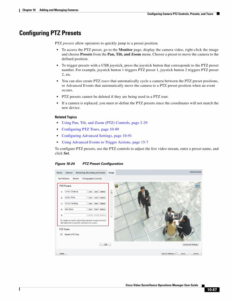
Chapter 10 Adding and Managing CamerasConfiguring Camera PTZ Controls, Presets, and Tours
Configuring PTZ PresetsPTZ presets allow operators to quickly jump to a preset position.
• To access the PTZ preset, go to the Monitor page, display the camera video, right-click the image and choose Presets from the Pan, Tilt, and Zoom menu. Choose a preset to move the camera to the defined position.
• To trigger presets with a USB joystick, press the joystick button that corresponds to the PTZ preset number. For example, joystick button 1 triggers PTZ preset 1, joystick button 2 triggers PTZ preset 2, etc.
• You can also create PTZ tours that automatically cycle a camera between the PTZ preset positions, or Advanced Events that automatically move the camera to a PTZ preset position when an event occurs.
• PTZ presets cannot be deleted if they are being used in a PTZ tour.
• If a camera is replaced, you must re-define the PTZ presets since the coordinates will not match the new device.
Related Topics
• Using Pan, Tilt, and Zoom (PTZ) Controls, page 2-29
• Configuring PTZ Tours, page 10-89
• Configuring Advanced Settings, page 10-91
• Using Advanced Events to Trigger Actions, page 15-7
To configure PTZ presets, use the PTZ controls to adjust the live video stream, enter a preset name, and click Set.
Figure 10-24 PTZ Preset Configuration
10-87Cisco Video Surveillance Operations Manager User Guide
Chapter 10 Adding and Managing Cameras Configuring Camera PTZ Controls, Presets, and Tours
Procedure
To define PTZ presets, do the following:
Step 1 Open the camera PTZ configuration page:
a. Click Cameras.
b. Click a location or Media Server and select a camera.
c. Click the Image tab and then click Pan/Tilt/Zoom (Figure 10-24).
d. Verify that the PTZ controls are enabled (if disabled, click the icon to enable PTZ controls).
Step 2 Position the camera using the following controls:
Using a Mouse
– Pan and Tilt—Left-click the image and drag the mouse right, left, up and down.
– Zoom—Shift-click the image and drag the mouse up and down to zoom in and out.
Using a USB Joystick
– Pan—move the joystick bar horizontally.
– Tilt— move the joystick bar vertically.
– Zoom —twist the joystick.
Step 3 Enter a PTZ Preset name.
• For example: Lobby Door Close-up.
Step 4 Click Set.
Step 5 (Optional) Click Test to move the camera position between different preset positions.
Step 6 Repeat Step 2 through Step 5 to define additional PTZ presets.
Step 7 Click Save to save the camera settings.
10-88Cisco Video Surveillance Operations Manager User Guide
Chapter 10 Adding and Managing CamerasConfiguring Camera PTZ Controls, Presets, and Tours
Configuring PTZ ToursPTZ tours automatically rotate a camera’s view between PTZ presets in a specified order, pausing at each position according to the specified dwell time. The camera will continue to rotate between the presets until interrupted or disabled by an operator or Advanced Event. When the last preset in the list is reached, the tour starts over at the beginning.
Usage Notes
• Any camera that supports PTZ presets also supports PTZ tours. At least two PTZ presets must be available to create a PTZ Tour.
• You can enable a single PTZ tour for each camera.
• PTZ tours have the lowest priority for PTZ camera movements. For example, operators can manually take PTZ control of the camera, or an Advanced Event can move the camera to a PTZ preset. Both users and events have priority PTZ access to the camera. See the “Defining the User Group PTZ Priority” section on page 10-85 for more information.
• Operators can interrupt the tour by manually changing the PTZ position. The camera will stay at the user-selected position for the number of seconds configured in the Advanced Setting “When manual PTZ idle for”, and then resume the tour with the next preset. For more information, see:
– Configuring Advanced Settings, page 10-91
– Using Pan, Tilt, and Zoom (PTZ) Controls, page 2-29
• To stop the PTZ tour, deselect Enable PTZ Tour. The camera will return to the first PTZ preset in the tour list.
• If a PTZ tour is enabled, then the Return to Home setting is ignored (see the “Configuring Advanced Settings” section on page 10-91).
• If the PTZ tour is disabled, the camera will stay at the current position, or go to the Return to Home setting, if configured.
Procedure
Step 1 Define at least two PTZ presets for the camera, as described in the “Configuring PTZ Presets” section on page 10-87.
Step 2 Define the PTZ presets included in the tour:
a. Click Add or Edit (Figure 10-26) to open the PTZ Tour Configuration window (Figure 10-25).
10-89Cisco Video Surveillance Operations Manager User Guide
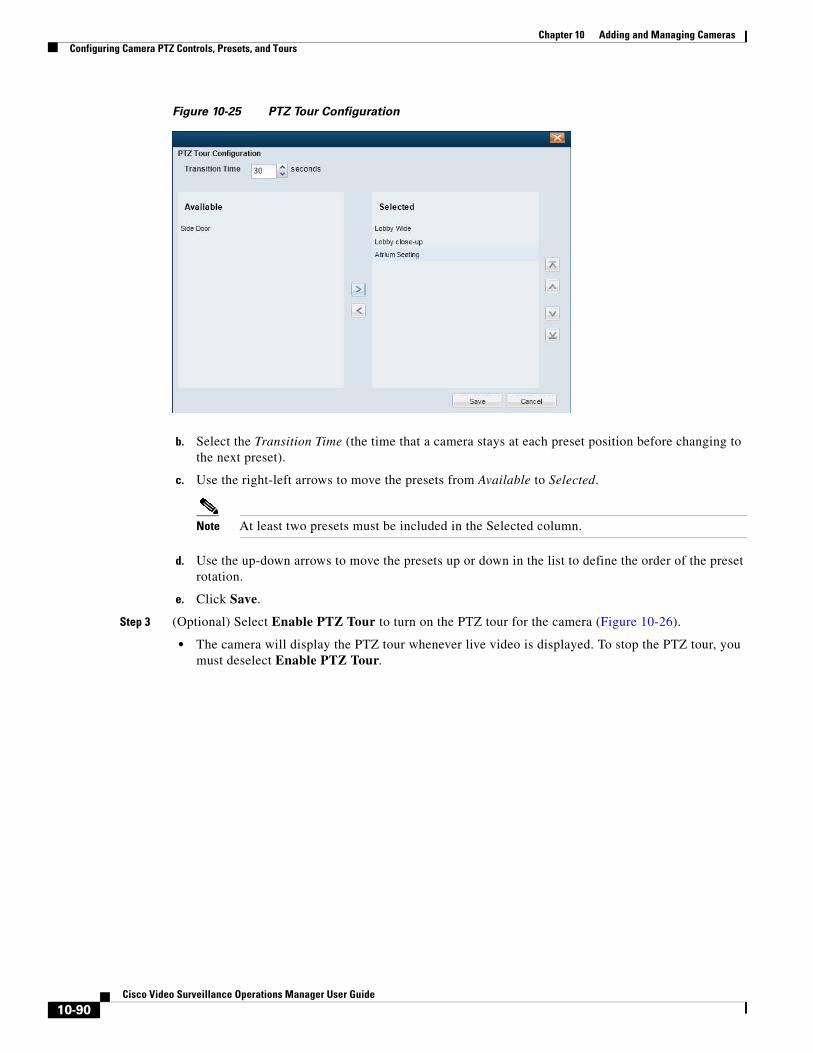
Chapter 10 Adding and Managing Cameras Configuring Camera PTZ Controls, Presets, and Tours
Figure 10-25 PTZ Tour Configuration
b. Select the Transition Time (the time that a camera stays at each preset position before changing to the next preset).
c. Use the right-left arrows to move the presets from Available to Selected.
Note At least two presets must be included in the Selected column.
d. Use the up-down arrows to move the presets up or down in the list to define the order of the preset rotation.
e. Click Save.
Step 3 (Optional) Select Enable PTZ Tour to turn on the PTZ tour for the camera (Figure 10-26).
• The camera will display the PTZ tour whenever live video is displayed. To stop the PTZ tour, you must deselect Enable PTZ Tour.
10-90Cisco Video Surveillance Operations Manager User Guide
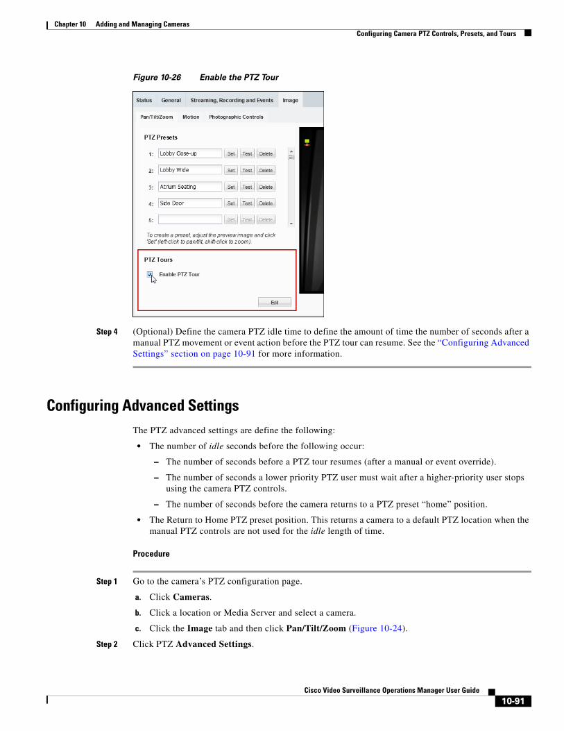
Chapter 10 Adding and Managing CamerasConfiguring Camera PTZ Controls, Presets, and Tours
Figure 10-26 Enable the PTZ Tour
Step 4 (Optional) Define the camera PTZ idle time to define the amount of time the number of seconds after a manual PTZ movement or event action before the PTZ tour can resume. See the “Configuring Advanced Settings” section on page 10-91 for more information.
Configuring Advanced SettingsThe PTZ advanced settings are define the following:
• The number of idle seconds before the following occur:
– The number of seconds before a PTZ tour resumes (after a manual or event override).
– The number of seconds a lower priority PTZ user must wait after a higher-priority user stops using the camera PTZ controls.
– The number of seconds before the camera returns to a PTZ preset “home” position.
• The Return to Home PTZ preset position. This returns a camera to a default PTZ location when the manual PTZ controls are not used for the idle length of time.
Procedure
Step 1 Go to the camera’s PTZ configuration page.
a. Click Cameras.
b. Click a location or Media Server and select a camera.
c. Click the Image tab and then click Pan/Tilt/Zoom (Figure 10-24).
Step 2 Click PTZ Advanced Settings.
10-91Cisco Video Surveillance Operations Manager User Guide
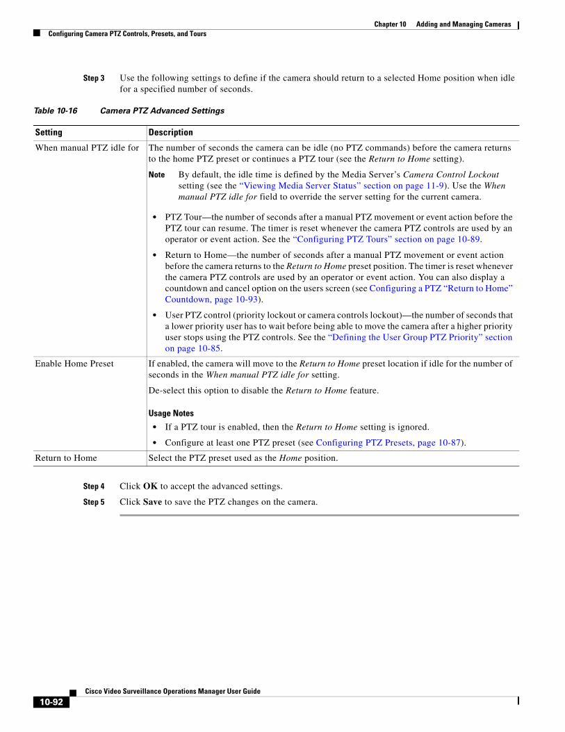
Chapter 10 Adding and Managing Cameras Configuring Camera PTZ Controls, Presets, and Tours
Step 3 Use the following settings to define if the camera should return to a selected Home position when idle for a specified number of seconds.
Table 10-16 Camera PTZ Advanced Settings
Setting Description
Note By default, the idle time is defined by the Media Server’s Camera Control Lockout setting (see the “Viewing Media Server Status” section on page 11-9). Use the When manual PTZ idle for field to override the server setting for the current camera.
• PTZ Tour—the number of seconds after a manual PTZ movement or event action before the PTZ tour can resume. The timer is reset whenever the camera PTZ controls are used by an operator or event action. See the “Configuring PTZ Tours” section on page 10-89.
• Return to Home—the number of seconds after a manual PTZ movement or event action before the camera returns to the Return to Home preset position. The timer is reset whenever the camera PTZ controls are used by an operator or event action. You can also display a countdown and cancel option on the users screen (see Configuring a PTZ “Return to Home” Countdown, page 10-93).
• User PTZ control (priority lockout or camera controls lockout)—the number of seconds that a lower priority user has to wait before being able to move the camera after a higher priority user stops using the PTZ controls. See the “Defining the User Group PTZ Priority” section on page 10-85.
Usage Notes
• If a PTZ tour is enabled, then the Return to Home setting is ignored.
• Configure at least one PTZ preset (see Configuring PTZ Presets, page 10-87).
Step 4 Click OK to accept the advanced settings.
Step 5 Click Save to save the PTZ changes on the camera.
When manual PTZ idle for The number of seconds the camera can be idle (no PTZ commands) before the camera returns to the home PTZ preset or continues a PTZ tour (see the Return to Home setting).
Enable Home Preset If enabled, the camera will move to the Return to Home preset location if idle for the number of seconds in the When manual PTZ idle for setting.
De-select this option to disable the Return to Home feature.
Return to Home Select the PTZ preset used as the Home position.
10-92Cisco Video Surveillance Operations Manager User Guide
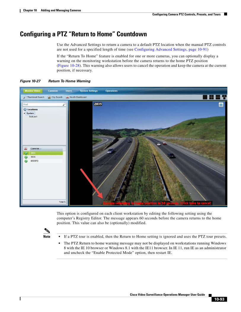
Chapter 10 Adding and Managing CamerasConfiguring Camera PTZ Controls, Presets, and Tours
Configuring a PTZ “Return to Home” CountdownUse the Advanced Settings to return a camera to a default PTZ location when the manual PTZ controls are not used for a specified length of time (see Configuring Advanced Settings, page 10-91)
If the “Return To Home” feature is enabled for one or more cameras, you can optionally display a warning on the monitoring workstation before the camera returns to the home PTZ position (Figure 10-28). This warning also allows users to cancel the operation and keep the camera at the current position, if necessary.
Figure 10-27 Return To Home Warning
This option is configured on each client workstation by editing the following setting using the computer’s Registry Editor. The message appears 60 seconds before the camera returns to the home position. This value can also be (optionally) modified.
Note • If a PTZ tour is enabled, then the Return to Home setting is ignored and uses the PTZ tour presets.
• The PTZ Return to home warning message may not be displayed on workstations running Windows 8 with the IE 10 browser or Windows 8.1 with the IE11 browser. In IE 11, run IE as an administrator and uncheck the “Enable Protected Mode” option, then restart IE.
10-93Cisco Video Surveillance Operations Manager User Guide
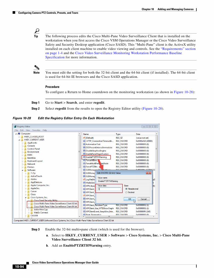
Chapter 10 Adding and Managing Cameras Configuring Camera PTZ Controls, Presets, and Tours
Tip The following process edits the Cisco Multi-Pane Video Surveillance Client that is installed on the workstation when you first access the Cisco VSM Operations Manager or the Cisco Video Surveillance Safety and Security Desktop application (Cisco SASD). This “Multi-Pane” client is the ActiveX utility installed on each client machine to enable video viewing and controls. See the “Requirements” section on page 1-4 and the Cisco Video Surveillance Monitoring Workstation Performance Baseline Specification for more information.
Note You must edit the setting for both the 32-bit client and the 64-bit client (if installed). The 64-bit client is used for 64-bit IE browsers and the Cisco SASD application.
Procedure
To configure a Return to Home countdown on the monitoring workstation (as shown in Figure 10-28):
Step 1 Go to Start > Search, and enter regedit.
Step 2 Select regedit from the results to open the Registry Editor utility (Figure 10-28).
Figure 10-28 Edit the Registry Editor Entry On Each Workstation
Step 3 Enable the 32-bit multi=pane client (which is used for the browser).
a. Select to HKEY_CURRENT_USER > Software > Cisco Systems, Inc. > Cisco Multi-Pane Video Surveillance Client 32 bit.
b. Add an EnablePTZRTHWarning entry.
10-94Cisco Video Surveillance Operations Manager User Guide
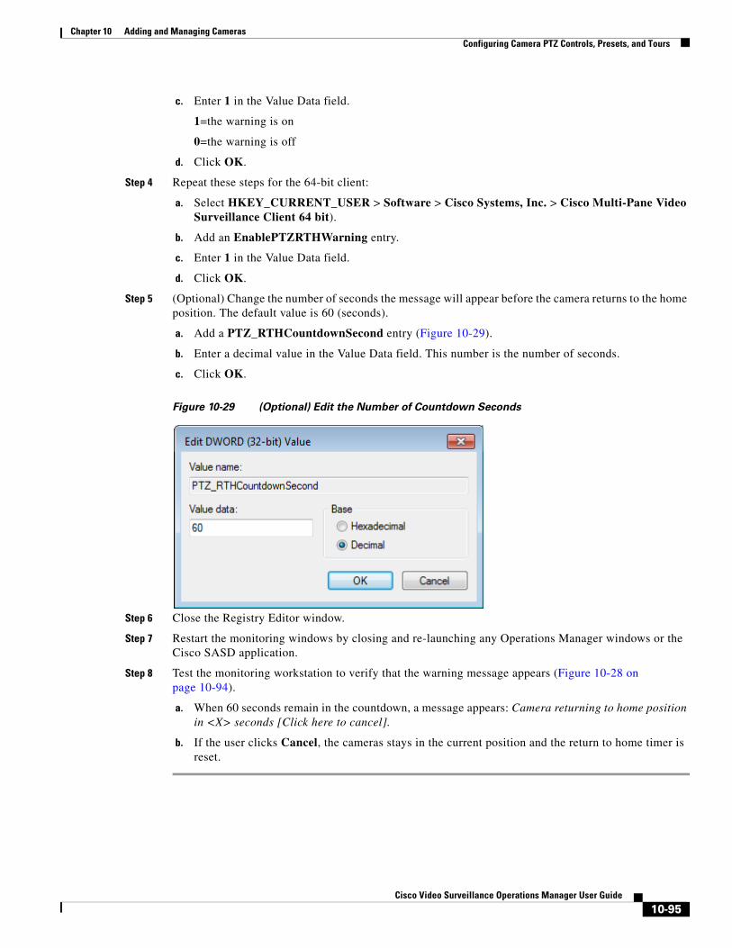
Chapter 10 Adding and Managing CamerasConfiguring Camera PTZ Controls, Presets, and Tours
c. Enter 1 in the Value Data field.
1=the warning is on
0=the warning is off
d. Click OK.
Step 4 Repeat these steps for the 64-bit client:
a. Select HKEY_CURRENT_USER > Software > Cisco Systems, Inc. > Cisco Multi-Pane Video Surveillance Client 64 bit).
b. Add an EnablePTZRTHWarning entry.
c. Enter 1 in the Value Data field.
d. Click OK.
Step 5 (Optional) Change the number of seconds the message will appear before the camera returns to the home position. The default value is 60 (seconds).
a. Add a PTZ_RTHCountdownSecond entry (Figure 10-29).
b. Enter a decimal value in the Value Data field. This number is the number of seconds.
c. Click OK.
Figure 10-29 (Optional) Edit the Number of Countdown Seconds
Step 6 Close the Registry Editor window.
Step 7 Restart the monitoring windows by closing and re-launching any Operations Manager windows or the Cisco SASD application.
Step 8 Test the monitoring workstation to verify that the warning message appears (Figure 10-28 on page 10-94).
a. When 60 seconds remain in the countdown, a message appears: Camera returning to home position in <X> seconds [Click here to cancel].
b. If the user clicks Cancel, the cameras stays in the current position and the return to home timer is reset.
10-95Cisco Video Surveillance Operations Manager User Guide
Chapter 10 Adding and Managing Cameras Configuring Motion Detection
Configuring Motion Detection Cameras that support motion detection can trigger actions or record video when motion occurs in the camera’s field of view. For example, a camera pointed at the rear door of a building can record a motion event if a person walks into the video frame. A motion event can also trigger alert notifications, a camera’s PTZ controls, or a URL action on a third party system.
Refer to the following topics for more information.
• Motion Detection Usage Notes, page 10-96
• Motion Detection Overview, page 10-97
• Motion Detection Settings, page 10-98
• Configuring Motion Detection, page 10-99
• Enabling Motion Detection on All Existing Cameras (Bulk Actions), page 10-101
• Enabling Motion Detection on ONVIF Cameras, page 10-102
Motion Detection Usage Notes
• Motion detection is supported for analog cameras only if the encoder supports motion detection.
• Motion detection is supported only for the primary (Stream A) video.
• Motion can be detected for a camera’s entire field of view, or for specified areas. If the camera or encoder supports exclusion areas, you can also exclude areas where motion should be ignored.
• ONVIF cameras support motion detection in Cisco VSM release 7.8 and later, but motion detection and the motion windows must be configured directly on the camera using the camera UI. See Enabling Motion Detection on ONVIF Cameras, page 10-102.
• Motion detection must be configured for each camera (motion detection is not defined by camera templates). Use Bulk Actions to locate cameras without motion detection and add motion detection for the cameras’ entire field of view (see Enabling Motion Detection on All Existing Cameras (Bulk Actions), page 10-101).
• Alerts can be configured for motion events, contact closures, analytic events, or soft triggers. Always configure these features carefully to avoid overwhelming operator(s) with an excessive number of alerts. If an excessive amount of alerts are generated, the system may ignore new alerts while deleting old entries.
• Be sure to successfully save or revert your changes while still in the motion configuration window. Clicking out of the window before changes are successfully saved or discarded can cause a configuration mismatch to occur on the camera Status page (the error will not include any additional details). See the “Camera Status” section on page 10-74. If this occurs, perform a Repair Configuration on the camera (see the “Repairing a Mismatched Configuration” section on page 24-32).
• If a camera configuration is changed to a template that has different resolution settings, all motion detection windows are deleted and you must re-configure them. Use the following instructions to apply motion windows to cameras, or import the motion window settings for multiple cameras (see Importing or Updating Cameras or Encoders Using a CSV File, page 10-20).
10-96Cisco Video Surveillance Operations Manager User Guide
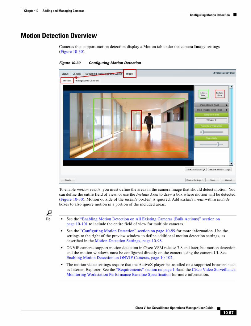
Chapter 10 Adding and Managing CamerasConfiguring Motion Detection
Motion Detection OverviewCameras that support motion detection display a Motion tab under the camera Image settings (Figure 10-30).
Figure 10-30 Configuring Motion Detection
To enable motion events, you must define the areas in the camera image that should detect motion. You can define the entire field of view, or use the Include Area to draw a box where motion will be detected (Figure 10-30). Motion outside of the include box(es) is ignored. Add exclude areas within include boxes to also ignore motion in a portion of the included areas.
Tip • See the “Enabling Motion Detection on All Existing Cameras (Bulk Actions)” section on page 10-101 to include the entire field of view for multiple cameras.
• See the “Configuring Motion Detection” section on page 10-99 for more information. Use the settings to the right of the preview window to define additional motion detection settings, as described in the Motion Detection Settings, page 10-98.
• ONVIF cameras support motion detection in Cisco VSM release 7.8 and later, but motion detection and the motion windows must be configured directly on the camera using the camera UI. See Enabling Motion Detection on ONVIF Cameras, page 10-102.
• The motion video settings require that the ActiveX player be installed on a supported browser, such as Internet Explorer. See the “Requirements” section on page 1-4and the Cisco Video Surveillance Monitoring Workstation Performance Baseline Specification for more information.
10-97Cisco Video Surveillance Operations Manager User Guide
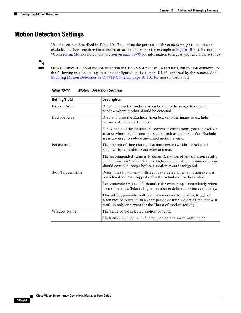
Chapter 10 Adding and Managing Cameras Configuring Motion Detection
Motion Detection SettingsUse the settings described in Table 10-17 to define the portions of the camera image to include or exclude, and how sensitive the included areas should be (see the example in Figure 10-30). Refer to the “Configuring Motion Detection” section on page 10-99 for information to access and save these settings.
Note ONVIF cameras support motion detection in Cisco VSM release 7.8 and later, but motion windows and the following motion settings must be configured on the camera UI, if supported by the camera. See Enabling Motion Detection on ONVIF Cameras, page 10-102 for more information.
Table 10-17 Motion Detection Settings
Setting/Field Description
Include Area Drag and drop the Include Area box onto the image to define a window where motion should be detected.
Exclude Area Drag and drop the Exclude Area box onto the image to exclude portions of the included area.
For example, if the include area covers an entire room, you can exclude an area where regular motion occurs, such as a clock or fan. Exclude areas are used to reduce unwanted motion events.
Persistence The amount of time that motion must occur (within the selected window) for a motion event start to occur.
The recommended value is 0 (default): motion of any duration results in a motion start event. Select a higher number if the motion duration should continue longer before a motion event is triggered.
Stop Trigger Time Determines how many milliseconds to delay when a motion event is considered to have stopped (after the actual motion has ended).
Recommended value is 0 (default): the event stops immediately when the motion ends. Select a higher number to define a motion event delay.
This setting prevents multiple motion events from being triggered when motion reoccurs in a short period of time. Select a time that will result in only one event for the “burst of motion activity”.
Window Name The name of the selected motion window.
Click an include or exclude area, and enter a meaningful name.
10-98Cisco Video Surveillance Operations Manager User Guide
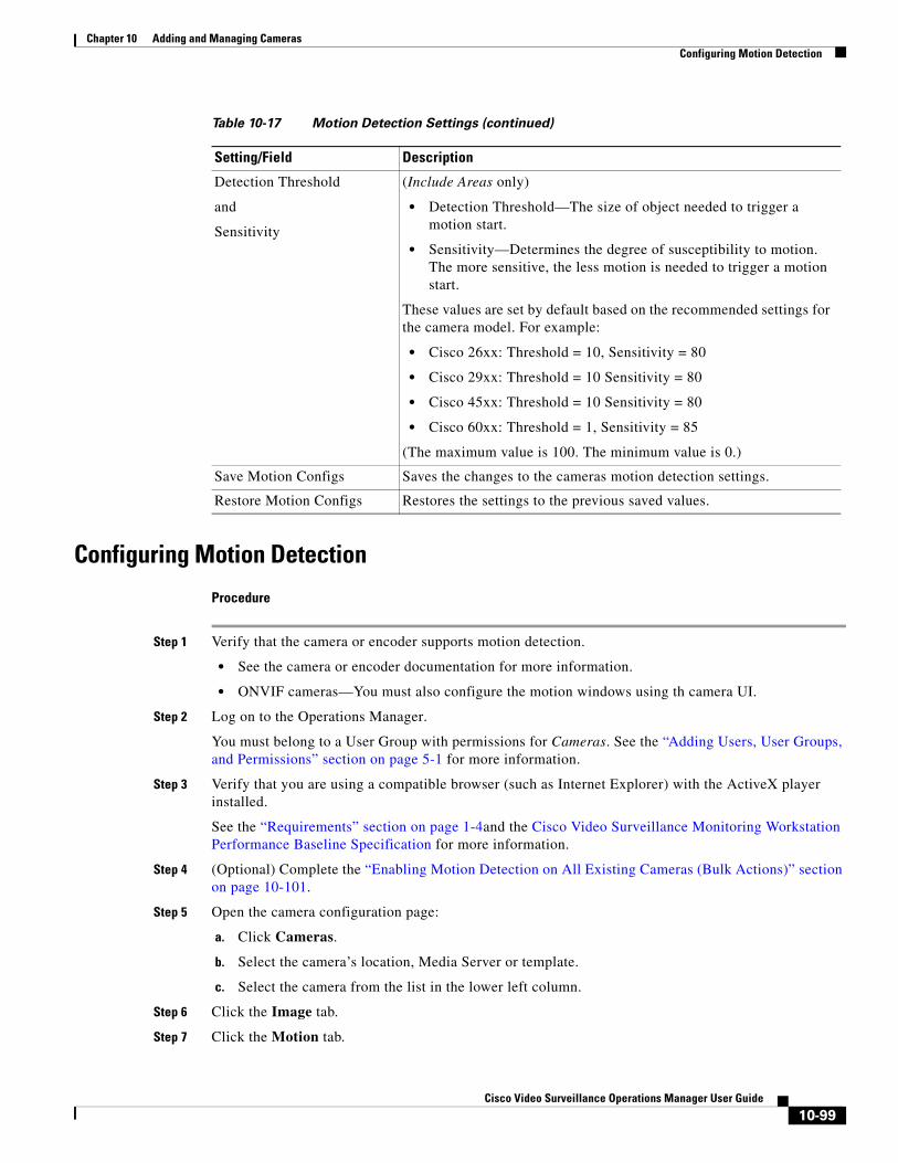
Chapter 10 Adding and Managing CamerasConfiguring Motion Detection
Configuring Motion Detection
Procedure
Step 1 Verify that the camera or encoder supports motion detection.
• See the camera or encoder documentation for more information.
• ONVIF cameras—You must also configure the motion windows using th camera UI.
Step 2 Log on to the Operations Manager.
You must belong to a User Group with permissions for Cameras. See the “Adding Users, User Groups, and Permissions” section on page 5-1 for more information.
Step 3 Verify that you are using a compatible browser (such as Internet Explorer) with the ActiveX player installed.
See the “Requirements” section on page 1-4and the Cisco Video Surveillance Monitoring Workstation Performance Baseline Specification for more information.
Step 4 (Optional) Complete the “Enabling Motion Detection on All Existing Cameras (Bulk Actions)” section on page 10-101.
Step 5 Open the camera configuration page:
a. Click Cameras.
b. Select the camera’s location, Media Server or template.
c. Select the camera from the list in the lower left column.
Step 6 Click the Image tab.
Step 7 Click the Motion tab.
Detection Threshold
and
Sensitivity
(Include Areas only)
• Detection Threshold—The size of object needed to trigger a motion start.
• Sensitivity—Determines the degree of susceptibility to motion. The more sensitive, the less motion is needed to trigger a motion start.
These values are set by default based on the recommended settings for the camera model. For example:
• Cisco 26xx: Threshold = 10, Sensitivity = 80
• Cisco 29xx: Threshold = 10 Sensitivity = 80
• Cisco 45xx: Threshold = 10 Sensitivity = 80
• Cisco 60xx: Threshold = 1, Sensitivity = 85
(The maximum value is 100. The minimum value is 0.)
Save Motion Configs Saves the changes to the cameras motion detection settings.
Restore Motion Configs Restores the settings to the previous saved values.
Table 10-17 Motion Detection Settings (continued)
Setting/Field Description
10-99Cisco Video Surveillance Operations Manager User Guide
Chapter 10 Adding and Managing Cameras Configuring Motion Detection
The current camera image appears (Figure 10-30).
Step 8 Add green Include Areas (windows) where motion should be detected in the image.
a. Drag the green Include Area box onto the video image (Figure 10-30).
b. (Optional) Enter a name in the Window Name field.
c. Move and resize the motion window.
– To move the window, click and hold within the window, then use the move cursor to drag the window to a new location.
– To resize the window, click and hold the corner or edge to change the size and shape.
d. Repeat these steps to create additional Include Areas in the video frame.
Step 9 Define the motion detection settings for each Include Area.
a. Click the motion window to select it.
b. Change the motion detection settings, as necessary, as described in Figure 10-30 on page 10-97.
Step 10 (Optional) Add a red Exclude Area box within an include box to define where motion should be ignored (Figure 10-30).
Note All areas outside of the include boxes are ignored by default. Add exclude areas within include boxes to also ignore motion within the included areas.
a. Drag the red Exclude Area box onto the video image (Figure 10-30).
b. (Optional) Enter a name in the Window Name field.
c. Move and resize the motion window.
Step 11 Click Save Motion Configs.
Tip Click Restore Motion Configs to return the settings to the previously saved value.
Note Be sure to successfully save or revert your changes while still in the motion configuration window. Clicking out of the window before changes are successfully saved or discarded can cause a configuration mismatch to occur on the camera Status page (the error will not include any additional details). See the “Camera Status” section on page 10-74 for more information. If this occurs, perform a Repair Configuration on the camera (see the “Repairing a Mismatched Configuration” section on page 24-32).
Step 12 (Optional) Configure motion event recordings for a camera or template.
See the following for more information:
• Camera Settings, page 10-45
• Configuring Continuous, Scheduled, and Motion Recordings, page 13-7
Step 13 (Optional) Configure actions that are triggered when a motion event occurs.
See the “Using Advanced Events to Trigger Actions” section on page 15-7.
10-100Cisco Video Surveillance Operations Manager User Guide
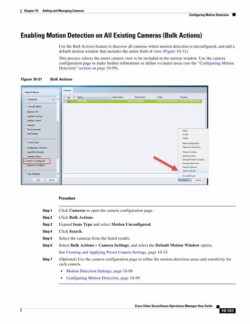
Chapter 10 Adding and Managing CamerasConfiguring Motion Detection
Enabling Motion Detection on All Existing Cameras (Bulk Actions)Use the Bulk Actions feature to discover all cameras where motion detection is unconfigured, and add a default motion window that includes the entire field of view (Figure 10-31).
This process selects the entire camera view to be included in the motion window. Use the camera configuration page to make further refinements or define excluded areas (see the “Configuring Motion Detection” section on page 10-99).
Figure 10-31 Bulk Actions
Procedure
Step 1 Click Cameras to open the camera configuration page.
Step 2 Click Bulk Actions.
Step 3 Expand Issue Type and select Motion Unconfigured.
Step 4 Click Search.
Step 5 Select the cameras from the listed results.
Step 6 Select Bulk Actions > Camera Settings, and select the Default Motion Window option.
See Creating and Applying Preset Camera Settings, page 10-35.
Step 7 (Optional) Use the camera configuration page to refine the motion detection areas and sensitivity for each camera.
• Motion Detection Settings, page 10-98
• Configuring Motion Detection, page 10-99
10-101Cisco Video Surveillance Operations Manager User Guide
Chapter 10 Adding and Managing Cameras Configuring Motion Detection
Enabling Motion Detection on ONVIF CamerasSome ONVIF cameras support motion detection in Cisco VSM, but the motion windows must be configured directly on the camera using the camera UI.
The Cisco VSM Operations Manager is used to configure a single motion window for the entire field of view. Other settings, such as those described in Table 10-17, are not available and must be defined in the camera UI, if available.
The Cisco VSM Operations Manager is also used to configure motion events, such as alerts or other actions.
Supported cameras
Only the following ONVIF cameras support motion detection.
• Vivotek: Release 7.11 and later
– Models FD8167A, FD8369A-V, FD8177-H, IB8367A, IB8369A, SD9161-H, SD9363-EH
• Hikvision and Samsung: Release 7.8 and later
Procedure
UI Description More Information
Step 1
Step 2
• Click the Alert Notifications icon to enable or disable the alerts that are generated when a motion stop or start event occurs.
or
• Use Advanced Events to trigger an action when a motion stop or start event occurs.
• Configuring Continuous, Scheduled, and Motion Recordings, page 13-7
• Using Advanced Events to Trigger Actions, page 15-7
Step 3
Notes:
• You can configure smaller motion windows directly on the camera, if supported. Only those windows will trigger events in Cisco VSM.
• If you delete the motion window in the Operations Manager, then motion events will not occur in Cisco VSM. You can re-add the default motion window in Operations Manager to receive motion events again.
• Configuring Motion Detection, page 10-99
• Enabling Motion Detection on All Existing Cameras (Bulk Actions), page 10-101
Complete the following steps in order:
Camera UI Configure motion detection and motion detection windows Using the ONVIF camera UI.
Camera documentation
Cisco VSM Operations Manager
Add motion alerts or events to the camera template:
Cisco VSM Operations Manager
Add the default motion window to the camera configuration.
The default motion window covers the entire field of view.
10-102Cisco Video Surveillance Operations Manager User Guide
Chapter 10 Adding and Managing CamerasReplacing a Camera
Replacing a CameraReplacing a camera allows you to exchange the physical camera hardware while retaining the configurations, associations and historical data of the original device. The replacement camera also uses the original camera name and device unique ID (used in API calls).
After the camera is replaced, only the hardware-specific details are changed, including the device MAC address, IP address, and camera make and model.
Camera Attributes That Are Retained
For example replacing a network or analog camera allows you to use new hardware while retaining the following:
• Existing recordings are retained.
• The new camera continues to stream video using the original camera name.
• Alert and audit records are retained.
• The camera association in maps, Views and locations is retained, allowing users to continue to access the camera based on the user’s access permissions and available features.
Custom Camera Ports
• If a camera is replaced by a model that supports custom ports. entry fields for HTTP, HTTPS and/or RTSP ports are displayed.
• If a camera is replaced by a model that does not support custom ports, then any custom port configuration is deleted and the default port numbers are used for HTTP (80), HTTPS (443) and RTSP (554).
See Configuring Custom Camera and Encoder Ports (PAT), page 19-3.
Configurations That Must Be Reapplied On the New Camera
When a network or analog camera is replaced, you must re-configure the contact closure, PTZ preset and motion detection settings. Analog cameras must also reconfigure the serial connection. You can apply the settings manually, or use the preset Camera Settings Feature.
See the following topics for more information.
• Creating and Applying Preset Camera Settings, page 10-35
• Camera Settings, page 10-45
• Configuring PTZ Presets, page 10-87
• Configuring Motion Detection, page 10-96
Analog cameras must also reconfigure the serial connection:
• Adding External Encoders and Analog Cameras, page 20-5
Replacement Options
In Release 7.5 and later, you can replace a camera with an existing camera (a camera that was previously added to Cisco VSM), or with a new camera. If replacing the camera with an existing camera, the camera must have been previously added to the Operations Manager.
See the “Camera Replacement Procedure” for more information.
10-103Cisco Video Surveillance Operations Manager User Guide
Chapter 10 Adding and Managing Cameras Replacing a Camera
Usage Notes
• Both network and analog cameras can be replaced (network cameras require the username and password configured on the device).
• Any network (IP) camera can be replaced by any other network (IP) camera, even if the devices are a different make and model (be sure to select the appropriate template for the new camera model). Network (IP) cameras cannot be replaced by an analog camera or encoder (or vice-versa).
Addressing Camera “Collisions”
When you attempt to replace a camera when a device id-collision exists, the replacement will fail and you must first clear the collision.
For example:
• If you attempt to replace CameraB with CameraA, but the devices are in id-collision.
• You attempt to replace Camera A with a newly added CameraB, but a cameraC is already in the system that is colliding with cameraB.
In these situations, the Operations Manager will not proceed with the replacement, stating that the camera is already in collision, and you must first clear the collision using one of the following methods:
• Soft-delete or delete one or more of the cameras (such as the camera already in the system). The camera may be in the Pending camera list or elsewhere.
• Replace one camera with the other (merge the devices to eliminate the collision).
Note An IP collision occurs when two devices are configured with the same IP address.
Camera Replacement Procedure
Step 1 Open the camera configuration page for the existing camera (the camera to be replaced).
See the “Accessing the Camera Settings” section on page 10-45.
Step 2 Select Device Settings > Replace Camera (Figure 10-32).
10-104Cisco Video Surveillance Operations Manager User Guide
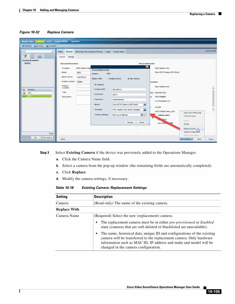
Chapter 10 Adding and Managing CamerasReplacing a Camera
Figure 10-32 Replace Camera
Step 3 Select Existing Camera if the device was previously added to the Operations Manager.
a. Click the Camera Name field.
b. Select a camera from the pop-up window (the remaining fields are automatically completed).
c. Click Replace.
d. Modify the camera settings, if necessary:
Table 10-18 Existing Camera: Replacement Settings
Setting Description
Camera (Read-only) The name of the existing camera.
Replace With
Camera Name (Required) Select the new (replacement) camera.
• The replacement camera must be in either pre-provisioned or Enabled state (cameras that are soft-deleted or blacklisted are unavailable).
• The name, historical data, unique ID and configurations of the existing camera will be transferred to the replacement camera. Only hardware information such as MAC ID, IP address and make and model will be changed in the camera configuration.
10-105Cisco Video Surveillance Operations Manager User Guide

Chapter 10 Adding and Managing Cameras Replacing a Camera
e. Wait for the job to complete.
Tip • When the page returns, the new camera will appear with the same name as the old camera, and will include all configurations, recordings, and event histories. Associations with locations, maps, and Views are also the same.
• If an error occurs, see the “Addressing Camera “Collisions”” section on page 10-104.
Step 4 Select New Camera if the device is not in the Operations Manager configuration.
a. Enter the basic device configuration:
– IP address
– Username
– Password
– Model
– Template
– Camera Settings—see Creating and Applying Preset Camera Settings, page 10-35
b. Click Replace.
c. Wait for the job to complete.
Username/ Password (Required for IP Cameras Only) Enter the credentials used to access the replacement camera on the network.
• These fields are populated if defined when the replacement camera was added.
• You can modify the username and password, if necessary, but the entries must match the credentials that were configured on the camera.
• This field is required for IP cameras only. Analog cameras do not require a password since they are connected to an encoder.
Template (Required) Select the camera template.
• The template is populated if defined when the replacement camera was added.
• You can choose a different template, if necessary. Select a template that is appropriate for the new make and model.
Camera Settings Apply a set of camera settings for features such as the motion detection window and sensitivity, tamper settings, and NTP server and timezone used by the device.
• Existing Settings—apply a pre-defined set of configurations.
• New Setting—define a new set of configurations. Enter a name to save the Camera Settings, so they can be applied to other cameras.
See Creating and Applying Preset Camera Settings, page 10-35 for information about the available camera settings.
Table 10-18 Existing Camera: Replacement Settings (continued)
10-106Cisco Video Surveillance Operations Manager User Guide
Chapter 10 Adding and Managing CamerasReplacing a Camera
Tip • When the page returns, the new camera will appear with the same name as the old camera, and will include all configurations, recordings, and event histories. Associations with locations, maps, and Views are also the same.
• If an error occurs, see the “Addressing Camera “Collisions”” section on page 10-104.
Step 5 Re-configure the contact closure, PTZ preset and motion detection settings, if necessary. See the following topics for more information. Analog cameras must also reconfigure the serial connection.
– Creating and Applying Preset Camera Settings, page 10-35
– Camera Settings, page 10-45
– Configuring PTZ Presets, page 10-87
– Configuring Motion Detection, page 10-96
– Adding External Encoders and Analog Cameras, page 20-5
10-107Cisco Video Surveillance Operations Manager User Guide
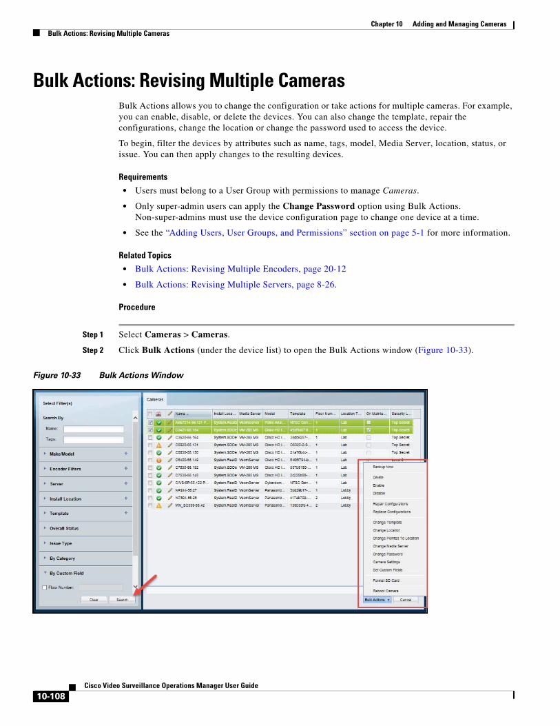
Chapter 10 Adding and Managing Cameras Bulk Actions: Revising Multiple Cameras
Bulk Actions: Revising Multiple CamerasBulk Actions allows you to change the configuration or take actions for multiple cameras. For example, you can enable, disable, or delete the devices. You can also change the template, repair the configurations, change the location or change the password used to access the device.
To begin, filter the devices by attributes such as name, tags, model, Media Server, location, status, or issue. You can then apply changes to the resulting devices.
Requirements
• Users must belong to a User Group with permissions to manage Cameras.
• Only super-admin users can apply the Change Password option using Bulk Actions. Non-super-admins must use the device configuration page to change one device at a time.
• See the “Adding Users, User Groups, and Permissions” section on page 5-1 for more information.
Related Topics
• Bulk Actions: Revising Multiple Encoders, page 20-12
• Bulk Actions: Revising Multiple Servers, page 8-26.
Procedure
Step 1 Select Cameras > Cameras.
Step 2 Click Bulk Actions (under the device list) to open the Bulk Actions window (Figure 10-33).
Figure 10-33 Bulk Actions Window
10-108Cisco Video Surveillance Operations Manager User Guide
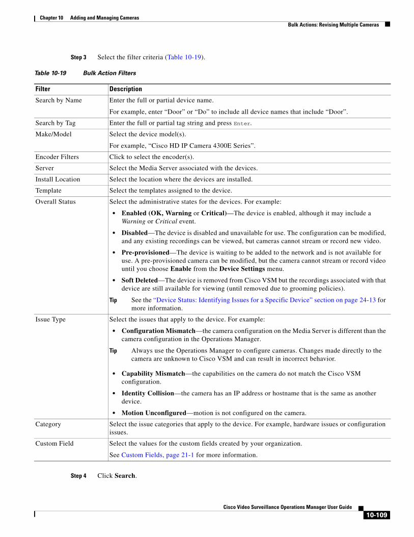
Chapter 10 Adding and Managing CamerasBulk Actions: Revising Multiple Cameras
Step 3 Select the filter criteria (Table 10-19).
Table 10-19 Bulk Action Filters
Filter Description
• Enabled (OK, Warning or Critical)—The device is enabled, although it may include a Warning or Critical event.
• Disabled—The device is disabled and unavailable for use. The configuration can be modified, and any existing recordings can be viewed, but cameras cannot stream or record new video.
• Pre-provisioned—The device is waiting to be added to the network and is not available for use. A pre-provisioned camera can be modified, but the camera cannot stream or record video until you choose Enable from the Device Settings menu.
• Soft Deleted—The device is removed from Cisco VSM but the recordings associated with that device are still available for viewing (until removed due to grooming policies).
Tip See the “Device Status: Identifying Issues for a Specific Device” section on page 24-13 for more information.
• Configuration Mismatch—the camera configuration on the Media Server is different than the camera configuration in the Operations Manager.
Tip Always use the Operations Manager to configure cameras. Changes made directly to the camera are unknown to Cisco VSM and can result in incorrect behavior.
• Capability Mismatch—the capabilities on the camera do not match the Cisco VSM configuration.
• Identity Collision—the camera has an IP address or hostname that is the same as another device.
• Motion Unconfigured—motion is not configured on the camera.
Step 4 Click Search.
Search by Name Enter the full or partial device name.
For example, enter “Door” or “Do” to include all device names that include “Door”.
Search by Tag Enter the full or partial tag string and press Enter.
Make/Model Select the device model(s).
For example, “Cisco HD IP Camera 4300E Series”.
Encoder Filters Click to select the encoder(s).
Server Select the Media Server associated with the devices.
Install Location Select the location where the devices are installed.
Template Select the templates assigned to the device.
Overall Status Select the administrative states for the devices. For example:
Issue Type Select the issues that apply to the device. For example:
Category Select the issue categories that apply to the device. For example, hardware issues or configuration issues.
Custom Field Select the values for the custom fields created by your organization.
See Custom Fields, page 21-1 for more information.
10-109Cisco Video Surveillance Operations Manager User Guide
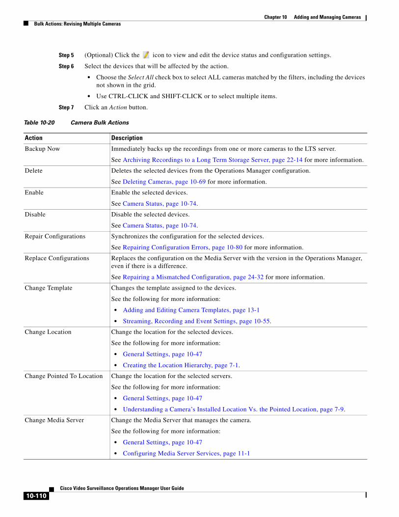
Chapter 10 Adding and Managing Cameras Bulk Actions: Revising Multiple Cameras
Step 5 (Optional) Click the icon to view and edit the device status and configuration settings.
Step 6 Select the devices that will be affected by the action.
• Choose the Select All check box to select ALL cameras matched by the filters, including the devices not shown in the grid.
• Use CTRL-CLICK and SHIFT-CLICK or to select multiple items.
Step 7 Click an Action button.
Table 10-20 Camera Bulk Actions
Action Description
Backup Now Immediately backs up the recordings from one or more cameras to the LTS server.
See Archiving Recordings to a Long Term Storage Server, page 22-14 for more information.
Delete Deletes the selected devices from the Operations Manager configuration.
See Deleting Cameras, page 10-69 for more information.
Enable Enable the selected devices.
See Camera Status, page 10-74.
Disable Disable the selected devices.
See Camera Status, page 10-74.
Repair Configurations Synchronizes the configuration for the selected devices.
See Repairing Configuration Errors, page 10-80 for more information.
Replace Configurations Replaces the configuration on the Media Server with the version in the Operations Manager, even if there is a difference.
See Repairing a Mismatched Configuration, page 24-32 for more information.
Change Template Changes the template assigned to the devices.
See the following for more information:
• Adding and Editing Camera Templates, page 13-1
• Streaming, Recording and Event Settings, page 10-55.
Change Location Change the location for the selected devices.
See the following for more information:
• General Settings, page 10-47
• Creating the Location Hierarchy, page 7-1.
Change Pointed To Location Change the location for the selected servers.
See the following for more information:
• General Settings, page 10-47
• Understanding a Camera’s Installed Location Vs. the Pointed Location, page 7-9.
Change Media Server Change the Media Server that manages the camera.
See the following for more information:
• General Settings, page 10-47
• Configuring Media Server Services, page 11-1
10-110Cisco Video Surveillance Operations Manager User Guide
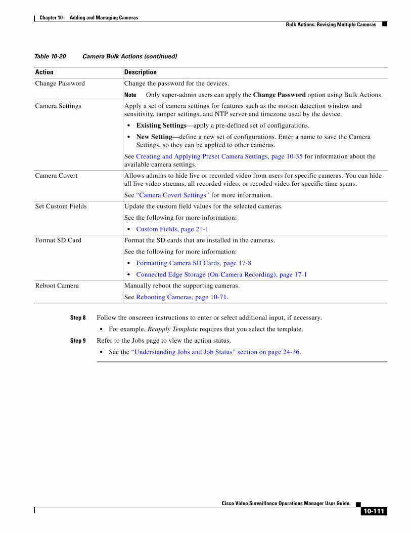
Chapter 10 Adding and Managing CamerasBulk Actions: Revising Multiple Cameras
Step 8 Follow the onscreen instructions to enter or select additional input, if necessary.
• For example, Reapply Template requires that you select the template.
Step 9 Refer to the Jobs page to view the action status.
• See the “Understanding Jobs and Job Status” section on page 24-36.
Change Password Change the password for the devices.
Note Only super-admin users can apply the Change Password option using Bulk Actions.
Camera Settings Apply a set of camera settings for features such as the motion detection window and sensitivity, tamper settings, and NTP server and timezone used by the device.
• Existing Settings—apply a pre-defined set of configurations.
• New Setting—define a new set of configurations. Enter a name to save the Camera Settings, so they can be applied to other cameras.
See Creating and Applying Preset Camera Settings, page 10-35 for information about the available camera settings.
Camera Covert Allows admins to hide live or recorded video from users for specific cameras. You can hide all live video streams, all recorded video, or recoded video for specific time spans.
See “Camera Covert Settings” for more information.
Set Custom Fields Update the custom field values for the selected cameras.
See the following for more information:
• Custom Fields, page 21-1
Format SD Card Format the SD cards that are installed in the cameras.
See the following for more information:
• Formatting Camera SD Cards, page 17-8
• Connected Edge Storage (On-Camera Recording), page 17-1
Reboot Camera Manually reboot the supporting cameras.
See Rebooting Cameras, page 10-71.
Table 10-20 Camera Bulk Actions (continued)
Action Description
10-111Cisco Video Surveillance Operations Manager User Guide

Chapter 10 Adding and Managing Cameras Bulk Actions: Revising Multiple Cameras
10-112Cisco Video Surveillance Operations Manager User Guide
Cisco V
C H A P T E R 11
Configuring Media Server ServicesA Media Server is a service that runs on a physical or virtual Cisco Video Surveillance server. The Media Server service provides video streaming, recording and storage for the cameras and encoders associated with that server. Media Servers can also be configured for high availability, and provide Redundant, Failover, and Long Term Storage options for other Media Servers.
Refer to the following topics for more information.
Contents
• Overview, page 11-2
• Requirements, page 11-3
• Summary Steps to Add, Activate, and Configure a Media Server, page 11-4
• Media Server Settings, page 11-5
– Accessing the Media Server Advanced Settings, page 11-5
– High Availability Options, page 11-6
– Partition Settings, page 11-6
– Media Server Mode (Dynamic Proxy), page 11-7
– Media Server Properties, page 11-7
– Storage Management Settings, page 11-8
• Viewing Media Server Status, page 11-9
– Device Status, page 11-10
– Status History, page 11-10
– Service Jobs (Media Server), page 11-11
11-1ideo Surveillance Operations Manager User Guide
Chapter 11 Configuring Media Server Services Overview
OverviewA Media Server is a service that runs on a physical or virtual Cisco Video Surveillance server. Media Servers perform the following functions:
• Process and store digital video streams from network cameras.
• Deliver video streams to user workstations.
• Manage the serial ports and encoders used to connect analog cameras and digitize the analog video from those cameras.
To add Media Servers, add the server to the Operations Manager configuration and select the Media Server Service Type. You can then configure Advanced settings, such as the high-availability role and associate cameras and other attributes to the Media Server to support video streaming, storage and playback.
Each deployment can include multiple Media Servers. A single Media Server instance can run on the same server as the Operations Manager server (to create a co-located server), and additional Media Servers can be added as stand-alone servers.
11-2Cisco Video Surveillance Operations Manager User Guide
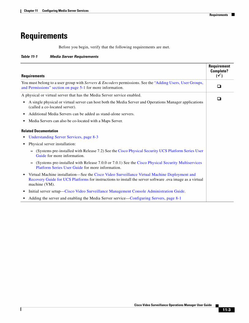
Chapter 11 Configuring Media Server ServicesRequirements
Requirements Before you begin, verify that the following requirements are met.
Table 11-1 Media Server Requirements
Requirements
Requirement Complete?
()
• A single physical or virtual server can host both the Media Server and Operations Manager applications (called a co-located server).
• Additional Media Servers can be added as stand-alone servers.
• Media Servers can also be co-located with a Maps Server.
Related Documentation
• Understanding Server Services, page 8-3
• Physical server installation:
– (Systems pre-installed with Release 7.2) See the Cisco Physical Security UCS Platform Series User Guide for more information.
– (Systems pre-installed with Release 7.0.0 or 7.0.1) See the Cisco Physical Security Multiservices Platform Series User Guide for more information.
• Virtual Machine installation—See the Cisco Video Surveillance Virtual Machine Deployment and Recovery Guide for UCS Platforms for instructions to install the server software .ova image as a virtual machine (VM).
• Initial server setup—Cisco Video Surveillance Management Console Administration Guide.
• Adding the server and enabling the Media Server service—Configuring Servers, page 8-1
You must belong to a user group with Servers & Encoders permissions. See the “Adding Users, User Groups, and Permissions” section on page 5-1 for more information.
A physical or virtual server that has the Media Server service enabled.
11-3Cisco Video Surveillance Operations Manager User Guide
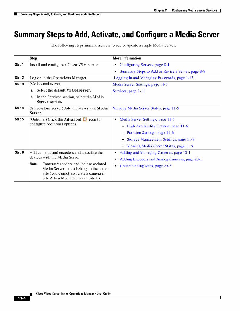
Chapter 11 Configuring Media Server Services Summary Steps to Add, Activate, and Configure a Media Server
Summary Steps to Add, Activate, and Configure a Media ServerThe following steps summarize how to add or update a single Media Server.
Step More Information
Step 1 • Configuring Servers, page 8-1
• Summary Steps to Add or Revise a Server, page 8-8
Step 2
Step 3 (Co-located server)
Select the default VSOMServer. a.
In the Services section, select the Media Server service.
b.
Step 4
Step 5 • Media Server Settings, page 11-5
– High Availability Options, page 11-6
– Partition Settings, page 11-6
– Storage Management Settings, page 11-8
– Viewing Media Server Status, page 11-9
Step 6
Note Cameras/encoders and their associated Media Servers must belong to the same Site (you cannot associate a camera in Site A to a Media Server in Site B).
• Adding and Managing Cameras, page 10-1
• Adding Encoders and Analog Cameras, page 20-1
• Understanding Sites, page 29-3
Install and configure a Cisco VSM server.
Log on to the Operations Manager. Logging In and Managing Passwords, page 1-17.
Media Server Settings, page 11-5
Services, page 8-11
(Stand-alone server) Add the server as a Media Server.
Viewing Media Server Status, page 11-9
(Optional) Click the Advanced icon to configure additional options.
Add cameras and encoders and associate the devices with the Media Server.
11-4Cisco Video Surveillance Operations Manager User Guide
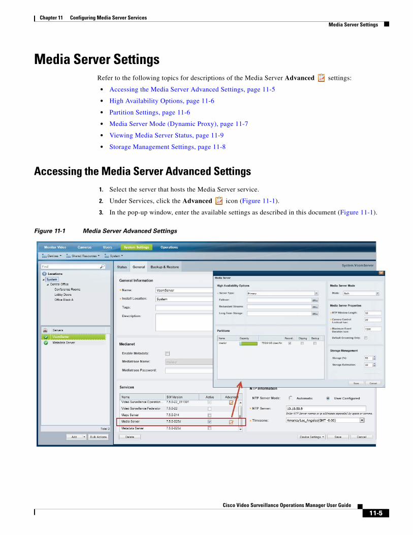
Chapter 11 Configuring Media Server ServicesMedia Server Settings
Media Server SettingsRefer to the following topics for descriptions of the Media Server Advanced settings:
• Accessing the Media Server Advanced Settings, page 11-5
• High Availability Options, page 11-6
• Partition Settings, page 11-6
• Media Server Mode (Dynamic Proxy), page 11-7
• Viewing Media Server Status, page 11-9
• Storage Management Settings, page 11-8
Accessing the Media Server Advanced Settings1. Select the server that hosts the Media Server service.
2. Under Services, click the Advanced icon (Figure 11-1).
3. In the pop-up window, enter the available settings as described in this document (Figure 11-1).
Figure 11-1 Media Server Advanced Settings
11-5Cisco Video Surveillance Operations Manager User Guide
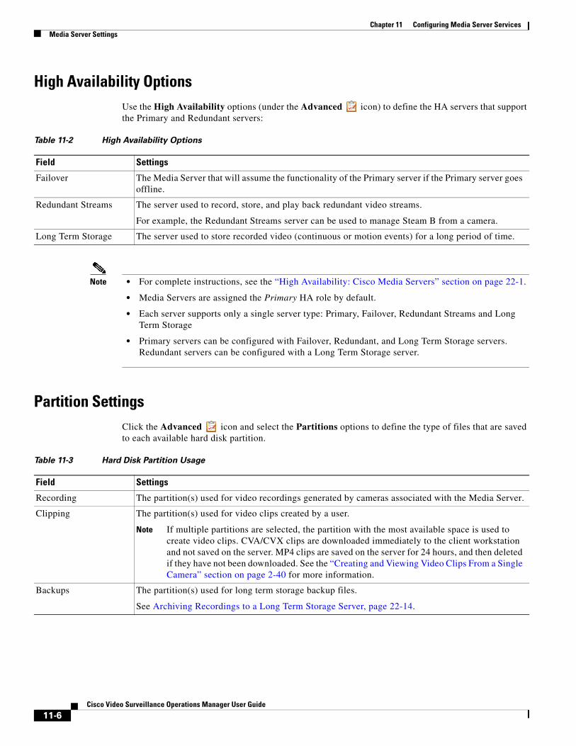
Chapter 11 Configuring Media Server Services Media Server Settings
High Availability OptionsUse the High Availability options (under the Advanced icon) to define the HA servers that support the Primary and Redundant servers:
Table 11-2 High Availability Options
Field Settings
Note • For complete instructions, see the “High Availability: Cisco Media Servers” section on page 22-1.
• Media Servers are assigned the Primary HA role by default.
• Each server supports only a single server type: Primary, Failover, Redundant Streams and Long Term Storage
• Primary servers can be configured with Failover, Redundant, and Long Term Storage servers. Redundant servers can be configured with a Long Term Storage server.
Partition SettingsClick the Advanced icon and select the Partitions options to define the type of files that are saved to each available hard disk partition.
Table 11-3 Hard Disk Partition Usage
Field Settings
Note If multiple partitions are selected, the partition with the most available space is used to create video clips. CVA/CVX clips are downloaded immediately to the client workstation and not saved on the server. MP4 clips are saved on the server for 24 hours, and then deleted if they have not been downloaded. See the “Creating and Viewing Video Clips From a Single Camera” section on page 2-40 for more information.
Failover The Media Server that will assume the functionality of the Primary server if the Primary server goes offline.
Redundant Streams The server used to record, store, and play back redundant video streams.
For example, the Redundant Streams server can be used to manage Steam B from a camera.
Long Term Storage The server used to store recorded video (continuous or motion events) for a long period of time.
Recording The partition(s) used for video recordings generated by cameras associated with the Media Server.
Clipping The partition(s) used for video clips created by a user.
Backups The partition(s) used for long term storage backup files.
See Archiving Recordings to a Long Term Storage Server, page 22-14.
11-6Cisco Video Surveillance Operations Manager User Guide
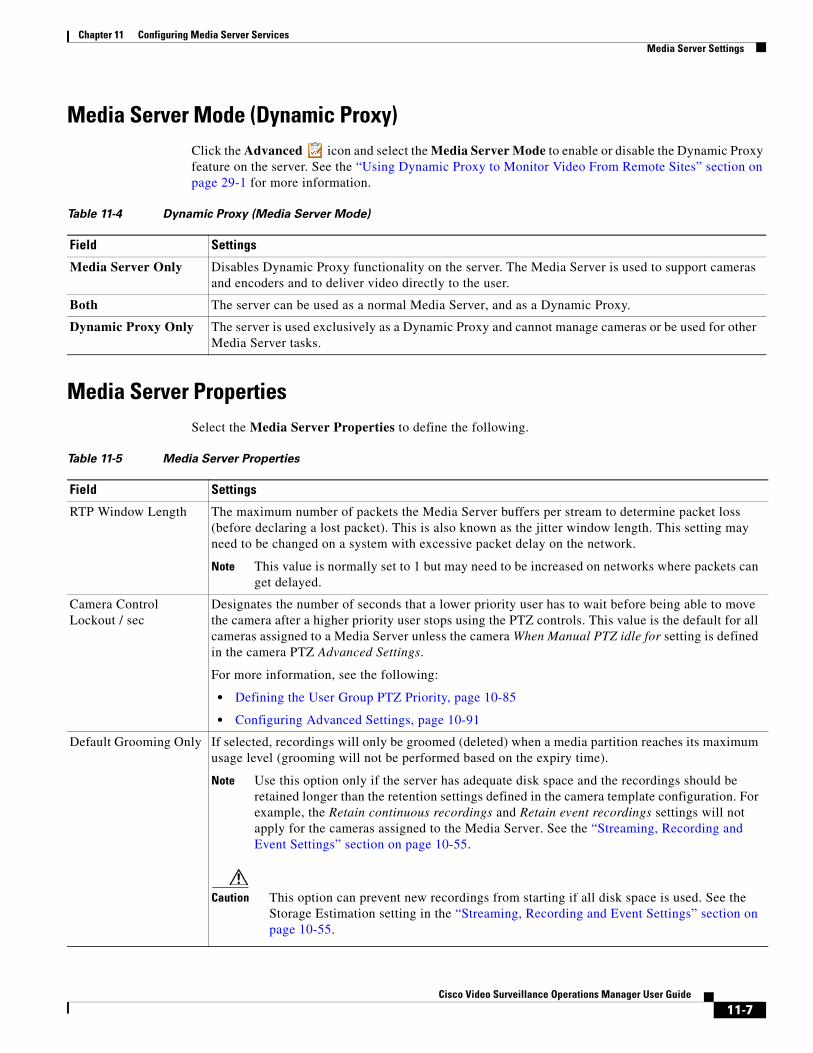
Chapter 11 Configuring Media Server ServicesMedia Server Settings
Media Server Mode (Dynamic Proxy)Click the Advanced icon and select the Media Server Mode to enable or disable the Dynamic Proxy feature on the server. See the “Using Dynamic Proxy to Monitor Video From Remote Sites” section on page 29-1 for more information.
Table 11-4 Dynamic Proxy (Media Server Mode)
Field Settings
Media Server PropertiesSelect the Media Server Properties to define the following.
Table 11-5 Media Server Properties
Field Settings
Note This value is normally set to 1 but may need to be increased on networks where packets can get delayed.
• Defining the User Group PTZ Priority, page 10-85
• Configuring Advanced Settings, page 10-91
Note Use this option only if the server has adequate disk space and the recordings should be retained longer than the retention settings defined in the camera template configuration. For example, the Retain continuous recordings and Retain event recordings settings will not apply for the cameras assigned to the Media Server. See the “Streaming, Recording and Event Settings” section on page 10-55.
Caution This option can prevent new recordings from starting if all disk space is used. See the Storage Estimation setting in the “Streaming, Recording and Event Settings” section on page 10-55.
Media Server Only Disables Dynamic Proxy functionality on the server. The Media Server is used to support cameras and encoders and to deliver video directly to the user.
Both The server can be used as a normal Media Server, and as a Dynamic Proxy.
Dynamic Proxy Only The server is used exclusively as a Dynamic Proxy and cannot manage cameras or be used for other Media Server tasks.
RTP Window Length The maximum number of packets the Media Server buffers per stream to determine packet loss (before declaring a lost packet). This is also known as the jitter window length. This setting may need to be changed on a system with excessive packet delay on the network.
Camera Control Lockout / sec
Designates the number of seconds that a lower priority user has to wait before being able to move the camera after a higher priority user stops using the PTZ controls. This value is the default for all cameras assigned to a Media Server unless the camera When Manual PTZ idle for setting is defined in the camera PTZ Advanced Settings.
For more information, see the following:
Default Grooming Only If selected, recordings will only be groomed (deleted) when a media partition reaches its maximum usage level (grooming will not be performed based on the expiry time).
11-7Cisco Video Surveillance Operations Manager User Guide
Chapter 11 Configuring Media Server Services Media Server Settings
Storage Management SettingsUnder Services, click the Advanced icon and enter the Storage Management settings to define how the storage space on a volume is used (Figure 11-1).
Table 11-6 Storage Management
Field Settings
• The maximum (and default) value is 98%. We recommend keeping this setting at or below the default value.
• 0% means that the repositories are not available to store video archives.
Note This button is enabled only if an LTS server is configured. See the “High Availability: Cisco Media Servers” section on page 22-1 for more information.
Storage (%) The maximum amount a disk can be full before it is declared unusable for any further recording. When the disk reaches this percentage, the 200 oldest media files are groomed (deleted), until the free disk space is less that the Storage (%).
For example, if the Storage % is set to 90%, and a camera template Retain event recordings setting is Max Possible, event recordings will be deleted once the disk repositories are 90% full.
Storage Estimation(%) This field defines the amount of storage space that must be available on the Media Server to start a recording if the Verify Recording Space option is enabled in a camera or template configuration. The Media Server must have this amount of storage space available or the recording will not start.
For example, if a camera is configured to record a continuous H264 stream at 15mbps for 30 days, the Media Server would first verify that there is enough free disk space for the full recording length (30 days). If not, then recording will not start. In this example, 15 mbps of video uses approximately 2 megabytes of storage space per second, so 30 days of recording would require roughly 5 terabytes of disk storage.
See the “Streaming, Recording and Event Settings” section on page 10-55 for more information on the Verify Recording Space option.
Long Term Storage Click Backup Now to save recorded events to the LTS server used to store recorded video. Backups are removed from the original server when they are transferred to the LTS server.
11-8Cisco Video Surveillance Operations Manager User Guide
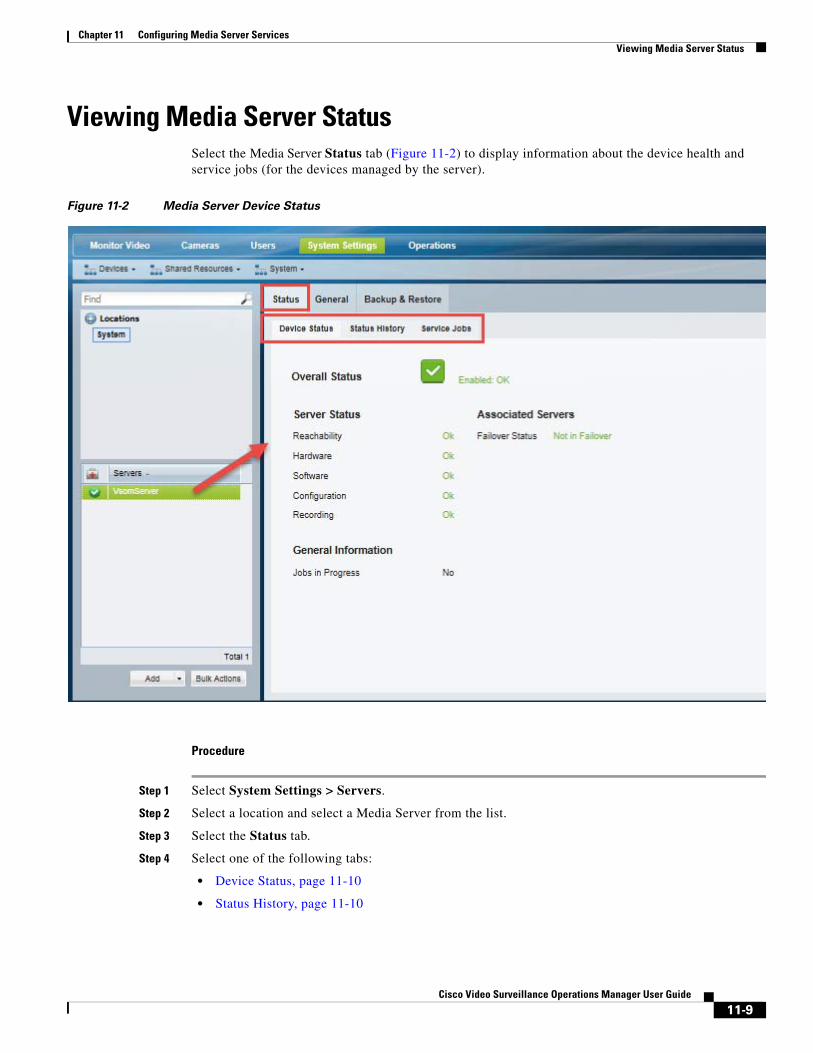
Chapter 11 Configuring Media Server ServicesViewing Media Server Status
Viewing Media Server StatusSelect the Media Server Status tab (Figure 11-2) to display information about the device health and service jobs (for the devices managed by the server).
Figure 11-2 Media Server Device Status
Procedure
Step 1 Select System Settings > Servers.
Step 2 Select a location and select a Media Server from the list.
Step 3 Select the Status tab.
Step 4 Select one of the following tabs:
• Device Status, page 11-10
• Status History, page 11-10
11-9Cisco Video Surveillance Operations Manager User Guide
Chapter 11 Configuring Media Server Services Viewing Media Server Status
• Service Jobs (Media Server), page 11-11
Device StatusDisplays a snapshot of the server health status, and the device attribute that is experiencing the error. The server’s device health impacts the server’s ability to communicate with cameras, stream video over the network, or record video.
Table 11-7 Device States
State Description
Related Information
Viewing Server Status, page 8-29
Device Status: Identifying Issues for a Specific Device, page 24-13
Tip Click Refresh Status to reload the current device status.
Status HistoryClick the Status History tab for additional details (Figure 11-3). The history page displays the specific health events that impact the device status.
• (Optional) Click Affecting Current Status to display only the alerts causing the current problem.
• (Optional) Double-click an entry to display the alert details (Figure 11-3). Alerts can include multiple events for the same issue. See Understanding Events and Alerts, page 24-2.
• (Optional) Double-click an event to display the event details. Alerts can include multiple events for the same issue.
Enabled: OK The device is operating normally. has no error.s
Enabled: Warning
A minor event occurred that did not significantly impact device operations.
Enabled: Critical
An event occurred that impacts the device operation or configuration.
Pre-provisioned The device is added to the configuration but not available on the network.
The device is waiting to be added to Cisco VSM and is not available for use. A pre-provisioned device can be modified, but the cannot stream or record video until the configuration is complete and you choose Device Settings > Enable.
11-10Cisco Video Surveillance Operations Manager User Guide
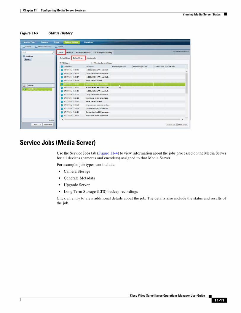
Chapter 11 Configuring Media Server ServicesViewing Media Server Status
Figure 11-3 Status History.
Service Jobs (Media Server)Use the Service Jobs tab (Figure 11-4) to view information about the jobs processed on the Media Server for all devices (cameras and encoders) assigned to that Media Server.
For example, job types can include:
• Camera Storage
• Generate Metadata
• Upgrade Server
• Long Term Storage (LTS) backup recordings
Click an entry to view additional details about the job. The details also include the status and results of the job.
11-11Cisco Video Surveillance Operations Manager User Guide
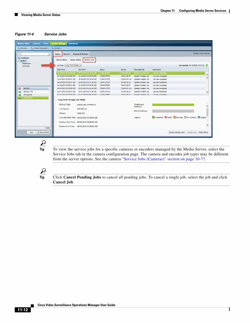
Chapter 11 Configuring Media Server Services Viewing Media Server Status
Figure 11-4 Service Jobs.
Tip To view the service jobs for a specific cameras or encoders managed by the Media Server, select the Service Jobs tab in the camera configuration page. The camera and encoder job types may be different from the server options. See the camera “Service Jobs (Cameras)” section on page 10-77.
Tip Click Cancel Pending Jobs to cancel all pending jobs. To cancel a single job, select the job and click Cancel Job.
11-12Cisco Video Surveillance Operations Manager User Guide
Cisco V
C H A P T E R 12
Defining SchedulesSchedules are used to define what type of video recording should be used at different times of the day. For example, a school administrator might want continuous recording for all lobby doors during school hours on weekdays, but only motion recording at night and on weekends. In addition, special events (such as an evening concert) or holidays (such as Christmas) might require different recording rules.
Procedure
Complete the following procedure to add or edit schedules.
Tip To apply a schedule to a camera or template configuration, see the “Adding and Managing Cameras” section on page 10-1.
Step 1 Select System Settings > Schedules.
Step 2 Add or edit a schedule:
• Click Add, or
• Select an existing schedule to edit the settings.
Step 3 (Required) Enter a schedule Name and Location.
The location defines the following:
• The users who can update or delete the schedule. Only users assigned to the same location can access the schedule.
• The users who can use the schedule in cameras and templates configurations. Users assigned to the same location, or a child location, can assign the schedule to a camera or template configuration.
For example, if a schedule is assigned the California location, a user must also have access to the same location (California) to manage the schedule. However, users who have access to child locations (such as San Jose, San Francisco or Milpitas) can use the schedule for camera and template configurations.
Step 4 (Optional) Enter a Description for the schedule.
For example: School campus when in session.
Step 5 Click Create.
Step 6 Click the Recurring Weekly Patterns tab.
Step 7 Define the Time Slots for the schedule (Figure 12-1).
In the camera or template configuration, each time slot can be assigned a different set of recording and alert rules.
12-1ideo Surveillance Operations Manager User Guide
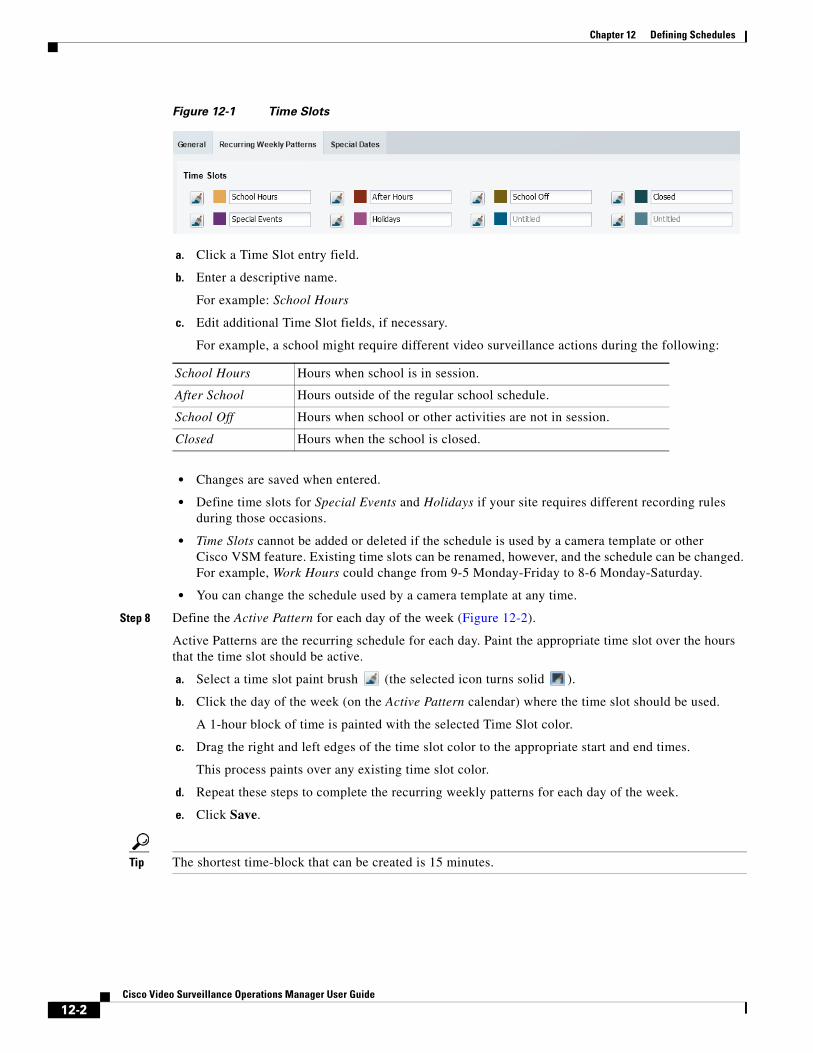
Chapter 12 Defining Schedules
Figure 12-1 Time Slots
a. Click a Time Slot entry field.
b. Enter a descriptive name.
For example: School Hours
c. Edit additional Time Slot fields, if necessary.
For example, a school might require different video surveillance actions during the following:
• Changes are saved when entered.
• Define time slots for Special Events and Holidays if your site requires different recording rules during those occasions.
• Time Slots cannot be added or deleted if the schedule is used by a camera template or other Cisco VSM feature. Existing time slots can be renamed, however, and the schedule can be changed. For example, Work Hours could change from 9-5 Monday-Friday to 8-6 Monday-Saturday.
• You can change the schedule used by a camera template at any time.
Step 8 Define the Active Pattern for each day of the week (Figure 12-2).
Active Patterns are the recurring schedule for each day. Paint the appropriate time slot over the hours that the time slot should be active.
a. Select a time slot paint brush (the selected icon turns solid ).
b. Click the day of the week (on the Active Pattern calendar) where the time slot should be used.
A 1-hour block of time is painted with the selected Time Slot color.
c. Drag the right and left edges of the time slot color to the appropriate start and end times.
This process paints over any existing time slot color.
d. Repeat these steps to complete the recurring weekly patterns for each day of the week.
e. Click Save.
Tip The shortest time-block that can be created is 15 minutes.
School Hours Hours when school is in session.
After School Hours outside of the regular school schedule.
School Off Hours when school or other activities are not in session.
Closed Hours when the school is closed.
12-2Cisco Video Surveillance Operations Manager User Guide

Chapter 12 Defining Schedules
Figure 12-2 Adding a Time Slot to the Active Pattern
Note A time slot must be defined for all hours and days.
For example, different recording rules can be applied when a school is in session, during after school activities, or when the school is closed. Each of these different time slots can be assigned different recording and alert properties (in the template configuration screen).
The example in Figure 12-2 defines the following schedule:
• School Hours are from 8 a.m. to 3 p.m. Monday through Friday.
• After School hours are 3 p.m. to 6 p.m. Monday through Friday.
• School Off hours are 6 p.m. to 8 a.m. Monday through Friday.
• The school is Closed Saturday and Sunday.
Step 9 (Optional) Click Preview in Calendar to view a monthly calendar of the recurring schedule.
Step 10 (Optional) Click Create Upcoming to define a second schedule that will become active on a specified date (Figure 12-3).
Tip When an Upcoming Pattern becomes active, the old schedule is deactivated and renamed Expired Pattern. Expired patterns cannot be reactivated.
• Each Schedule can define two weekly recurring patterns: the Active Pattern and the Upcoming Pattern.
• Active Patterns are active indefinitely unless an Upcoming Pattern is defined.
• To create a new pattern, you must first delete one of the existing patterns. To remove a pattern, select the pattern tab and click Delete.
• When the Upcoming Pattern takes effect, the following occurs:
– The Upcoming Pattern becomes the Active Pattern.
12-3Cisco Video Surveillance Operations Manager User Guide

Chapter 12 Defining Schedules
– The previous Active Pattern becomes an Expired Pattern. Click the Expired Pattern tab to delete it.
Figure 12-3 Defining an Upcoming Recurring Weekly Pattern
a. Click Create Upcoming (Figure 12-2) to create an Upcoming Pattern (Figure 12-3). An Upcoming Pattern tab is added and pre-populated with the calendar from the Active Pattern.
b. Click the Effective Date to select the date when the Upcoming Pattern will take effect.
c. Define the time slots for each day of the week (as described in Step 8).
Tip The default Upcoming Pattern is a copy of the Active Pattern.Modify the recurring pattern as necessary.
d. (Optional) Click Preview in Calendar to verify that the weekly recurring schedule changes on the time and date desired.
e. Click Save.
For example, in Figure 12-3, the school hours are extended to 4 p.m. (16:00) on Monday and Friday (beginning on the Effective Date).
Step 11 (Optional) Define Special Dates to override the normal recurring schedule (Figure 12-4).
Special dates can be created for holidays, vacations, or other one-time events that require different recording or Advanced Event settings. For example, a special schedule may be required for a few hours (during an evening event), a single day (such as a Homecoming), or an entire week (such as the Christmas holiday).
For example, in Figure 12-4, the entire week of Christmas is defined as a Holiday. Homecoming and an evening concert, however, require a different time slot for only a few hours of the day. Any time left blank will use the Recurring Schedule definitions.
12-4Cisco Video Surveillance Operations Manager User Guide
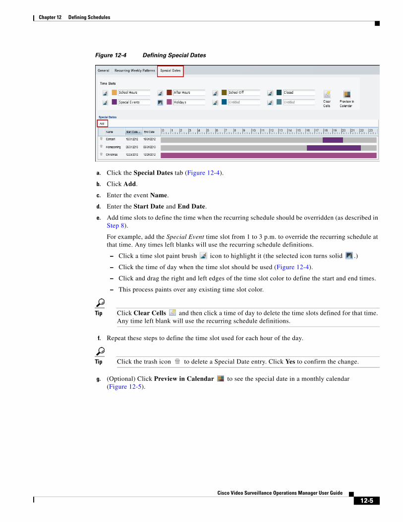
Chapter 12 Defining Schedules
Figure 12-4 Defining Special Dates
a. Click the Special Dates tab (Figure 12-4).
b. Click Add.
c. Enter the event Name.
d. Enter the Start Date and End Date.
e. Add time slots to define the time when the recurring schedule should be overridden (as described in Step 8).
For example, add the Special Event time slot from 1 to 3 p.m. to override the recurring schedule at that time. Any times left blanks will use the recurring schedule definitions.
– Click a time slot paint brush icon to highlight it (the selected icon turns solid .)
– Click the time of day when the time slot should be used (Figure 12-4).
– Click and drag the right and left edges of the time slot color to define the start and end times.
– This process paints over any existing time slot color.
Tip Click Clear Cells and then click a time of day to delete the time slots defined for that time. Any time left blank will use the recurring schedule definitions.
f. Repeat these steps to define the time slot used for each hour of the day.
Tip Click the trash icon to delete a Special Date entry. Click Yes to confirm the change.
g. (Optional) Click Preview in Calendar to see the special date in a monthly calendar (Figure 12-5).
12-5Cisco Video Surveillance Operations Manager User Guide

Chapter 12 Defining Schedules
Figure 12-5 Previewing Special Dates in the Monthly Calendar
Step 12 Click Save.
Step 13 Use the schedules to define recording schedules, alerts, or advanced events as described in the following topics:
• “Streaming, Recording and Event Settings” section on page 10-55
• “Configuring Video Recording” section on page 13-6
• “Using Advanced Events to Trigger Actions” section on page 15-7
12-6Cisco Video Surveillance Operations Manager User Guide
Cisco V
C H A P T E R 13
Adding and Editing Camera TemplatesTemplates simplify camera configuration by defining the image quality, recording schedule and other attributes used by a set of cameras.
Contents
• Overview, page 13-2
• Creating or Modifying a Template, page 13-3
• Creating a Custom Template for a Single Camera, page 13-5
• Configuring Video Recording, page 13-6
– Summary of Recording Options, page 13-6
– Configuring Continuous, Scheduled, and Motion Recordings, page 13-7
– Merging Video Streams (Smart Stream Selection), page 13-11
• Configuring Multicast Video Streaming, page 13-15
Related Documentation
• Enabling Video Analytics, page 15-2
• Using Advanced Events to Trigger Actions, page 15-7
• Enabling On-Demand Recording, page 4-14.
• Monitoring and Managing Storage, page 14-1
13-1ideo Surveillance Operations Manager User Guide
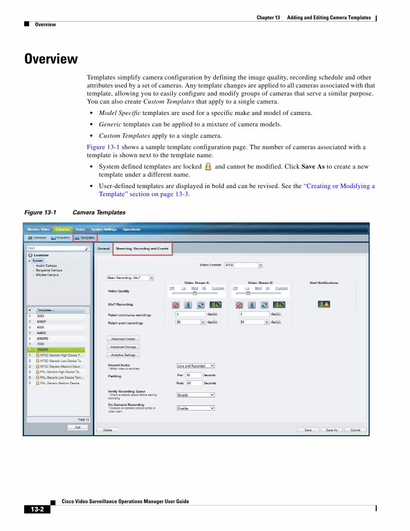
Chapter 13 Adding and Editing Camera Templates Overview
OverviewTemplates simplify camera configuration by defining the image quality, recording schedule and other attributes used by a set of cameras. Any template changes are applied to all cameras associated with that template, allowing you to easily configure and modify groups of cameras that serve a similar purpose. You can also create Custom Templates that apply to a single camera.
• Model Specific templates are used for a specific make and model of camera.
• Generic templates can be applied to a mixture of camera models.
• Custom Templates apply to a single camera.
Figure 13-1 shows a sample template configuration page. The number of cameras associated with a template is shown next to the template name.
• System defined templates are locked and cannot be modified. Click Save As to create a new template under a different name.
• User-defined templates are displayed in bold and can be revised. See the “Creating or Modifying a Template” section on page 13-3.
Figure 13-1 Camera Templates
13-2Cisco Video Surveillance Operations Manager User Guide
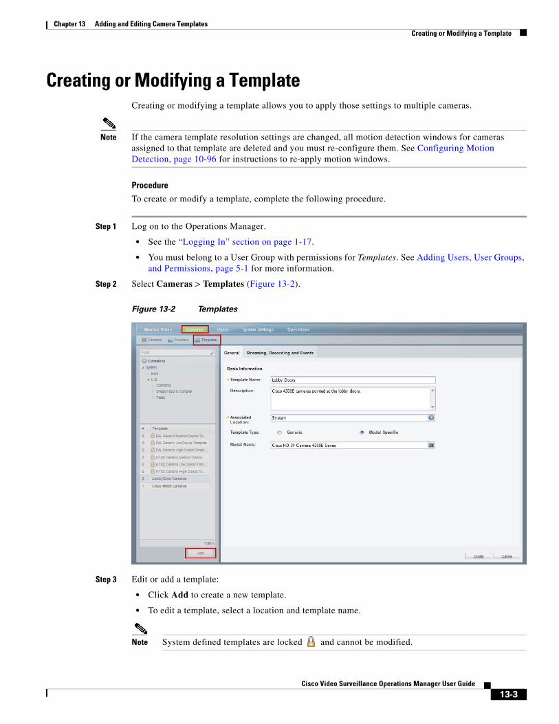
Chapter 13 Adding and Editing Camera TemplatesCreating or Modifying a Template
Creating or Modifying a TemplateCreating or modifying a template allows you to apply those settings to multiple cameras.
Note If the camera template resolution settings are changed, all motion detection windows for cameras assigned to that template are deleted and you must re-configure them. See Configuring Motion Detection, page 10-96 for instructions to re-apply motion windows.
Procedure
To create or modify a template, complete the following procedure.
Step 1 Log on to the Operations Manager.
• See the “Logging In” section on page 1-17.
• You must belong to a User Group with permissions for Templates. See Adding Users, User Groups, and Permissions, page 5-1 for more information.
Step 2 Select Cameras > Templates (Figure 13-2).
Figure 13-2 Templates
Step 3 Edit or add a template:
• Click Add to create a new template.
• To edit a template, select a location and template name.
Note System defined templates are locked and cannot be modified.
13-3Cisco Video Surveillance Operations Manager User Guide
Chapter 13 Adding and Editing Camera Templates Creating or Modifying a Template
Step 4 Enter or revise the General settings:
• Template Name—(Required) Enter a descriptive name for the template.
• Description—(Optional) Enter the purpose of the template, or other description.
• Associated Location—(Required) Select the location for the template. This can be used to restrict access to a template to a specific location. For example, to administrators located on Campus 1.
• Template Type—(Required for new templates) Select Generic or Model Specific. Model specific templates are available for use only by the specific camera model. Generic templates can be assigned to any camera model.
• Model name—(Model specific templates only) select a camera model from the pop-up window.
Step 5 Click the Streaming, Recording and Events tab to define the streaming, recording and other properties.
• For example, define the quality of video from stream A and B, the recording schedule, and advanced events and storage options.
• See the following topics for more information.
– Configuring Video Recording, page 13-6
– Streaming, Recording and Event Settings, page 10-55
Step 6 Click Create, Save or Save As.
Step 7 Wait for the Job to complete.
• If you are modifying an existing template, the changes are applied to each camera associated with the template. A Job Step is created for each camera impacted by the template change.
• If a large number of cameras are affected, the Job can take a significant amount of time to complete.
• See the “Understanding Jobs and Job Status” section on page 24-36 for more information.
• Device configuration changes can fail is a camera firmware upgrade is in process. Make sure that a camera firmware is not being upgraded (or wait until it is complete) and try again.
13-4Cisco Video Surveillance Operations Manager User Guide
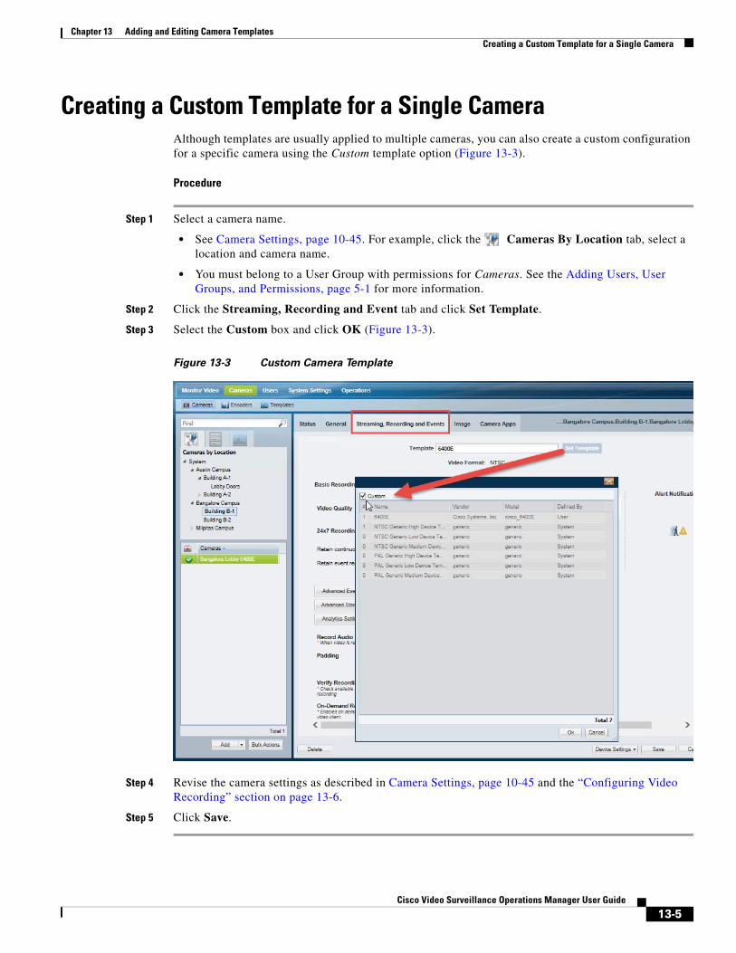
Chapter 13 Adding and Editing Camera TemplatesCreating a Custom Template for a Single Camera
Creating a Custom Template for a Single CameraAlthough templates are usually applied to multiple cameras, you can also create a custom configuration for a specific camera using the Custom template option (Figure 13-3).
Procedure
Step 1 Select a camera name.
• See Camera Settings, page 10-45. For example, click the Cameras By Location tab, select a location and camera name.
• You must belong to a User Group with permissions for Cameras. See the Adding Users, User Groups, and Permissions, page 5-1 for more information.
Step 2 Click the Streaming, Recording and Event tab and click Set Template.
Step 3 Select the Custom box and click OK (Figure 13-3).
Figure 13-3 Custom Camera Template
Step 4 Revise the camera settings as described in Camera Settings, page 10-45 and the “Configuring Video Recording” section on page 13-6.
Step 5 Click Save.
13-5Cisco Video Surveillance Operations Manager User Guide
Chapter 13 Adding and Editing Camera Templates Configuring Video Recording
Configuring Video RecordingVideo recording is usually configured to occur automatically in a continuous loop or according to a schedule. Recordings can also be triggered when events (such as motion events) occur.
See the following topics for more information:
• Summary of Recording Options, page 13-6
• Configuring Continuous, Scheduled, and Motion Recordings, page 13-7
• Merging Video Streams (Smart Stream Selection), page 13-11
Summary of Recording OptionsVideo can be recorded continuously, or when an event occurs:
Table 13-1 Recording Options
Recording Type Description More Information
Continuous recording, scheduled recordings, and/or motion event recordings.
The recordings can occur continuously in a loop (for example, the past 30 minutes), or according to a schedule (such as Monday-Friday, 8 a.m. to 11 a.m.).
In either case, recording can occur for the entire time, or only when triggered by a motion event.
Configuring Continuous, Scheduled, and Motion Recordings, page 13-7
Video is recorded at different quality on Stream A and Stream B.
For example, you can record continuous video throughout the night at a lower quality, but also record higher-quality video whenever an event occurs.
You can also merge the recordings from Stream A and Stream B into a single timeline (Figure 13-7).
Merging Video Streams (Smart Stream Selection), page 13-11
Recording is triggered when an event occurs.
Recordings can be triggered when an event occurs.
For example, recording can occur when a door contact is opened or closed, when a camera app event occurs, or when a soft trigger is received.
You can define how long to record when the event occurs, and whether to record the primary or secondary stream.
Using Advanced Events to Trigger Actions, page 15-7
User-initiated recording Describes how to enable the On Demand Recording option when a user right-clicks a camera’s live image.
Enabling On-Demand Recording, page 4-14
Save recordings on the camera
(and optionally transfer them to the Cisco Media Server).
Cameras that support on-device storage of video recordings can be used to record video even if the camera does not have communication with the Cisco Video Surveillance system. Once network communication is re-established, the on-camera recordings can be copied to a Media Server.
Connected Edge Storage (On-Camera Recording), page 17-1
13-6Cisco Video Surveillance Operations Manager User Guide
Chapter 13 Adding and Editing Camera TemplatesConfiguring Video Recording
Configuring Continuous, Scheduled, and Motion RecordingsScheduled recordings allow you to define recording properties for different times of the day, days of the week, or for special events.
For example, a school might require that cameras associated with a template record video differently during School hours, After school hours, School off hours, and Closed hours. Additional exceptions to the regular recording schedule might be required for special events, such as a Homecoming event or the Christmas holiday.
The following procedure describes how to apply schedules to a camera template or custom configuration.
Procedure
Step 1 Create the recording schedule.
See the “Defining Schedules” section on page 12-1 for instructions.
Step 2 Edit or add a camera template:
a. Click Cameras.
b. Select Templates.
c. Add or edit a template:
– Click Add to create a new template.
– To edit a template, select a location and then click a template name.
Tip You can also create a custom template for an individual camera. See the “Creating a Custom Template for a Single Camera” section on page 13-5
13-7Cisco Video Surveillance Operations Manager User Guide
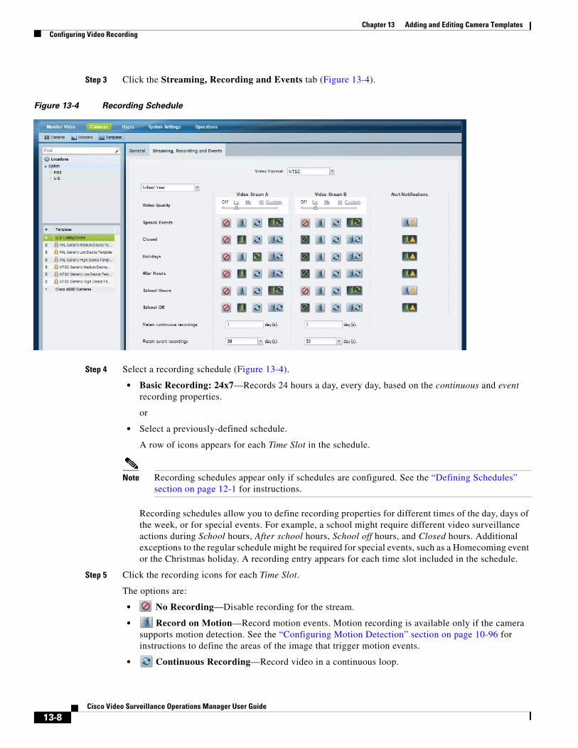
Chapter 13 Adding and Editing Camera Templates Configuring Video Recording
Step 3 Click the Streaming, Recording and Events tab (Figure 13-4).
Figure 13-4 Recording Schedule
Step 4 Select a recording schedule (Figure 13-4).
• Basic Recording: 24x7—Records 24 hours a day, every day, based on the continuous and event recording properties.
or
• Select a previously-defined schedule.
A row of icons appears for each Time Slot in the schedule.
Note Recording schedules appear only if schedules are configured. See the “Defining Schedules” section on page 12-1 for instructions.
Recording schedules allow you to define recording properties for different times of the day, days of the week, or for special events. For example, a school might require different video surveillance actions during School hours, After school hours, School off hours, and Closed hours. Additional exceptions to the regular schedule might be required for special events, such as a Homecoming event or the Christmas holiday. A recording entry appears for each time slot included in the schedule.
Step 5 Click the recording icons for each Time Slot.
The options are:
• No Recording—Disable recording for the stream.
• Record on Motion—Record motion events. Motion recording is available only if the camera supports motion detection. See the “Configuring Motion Detection” section on page 10-96 for instructions to define the areas of the image that trigger motion events.
• Continuous Recording—Record video in a continuous loop.
13-8Cisco Video Surveillance Operations Manager User Guide
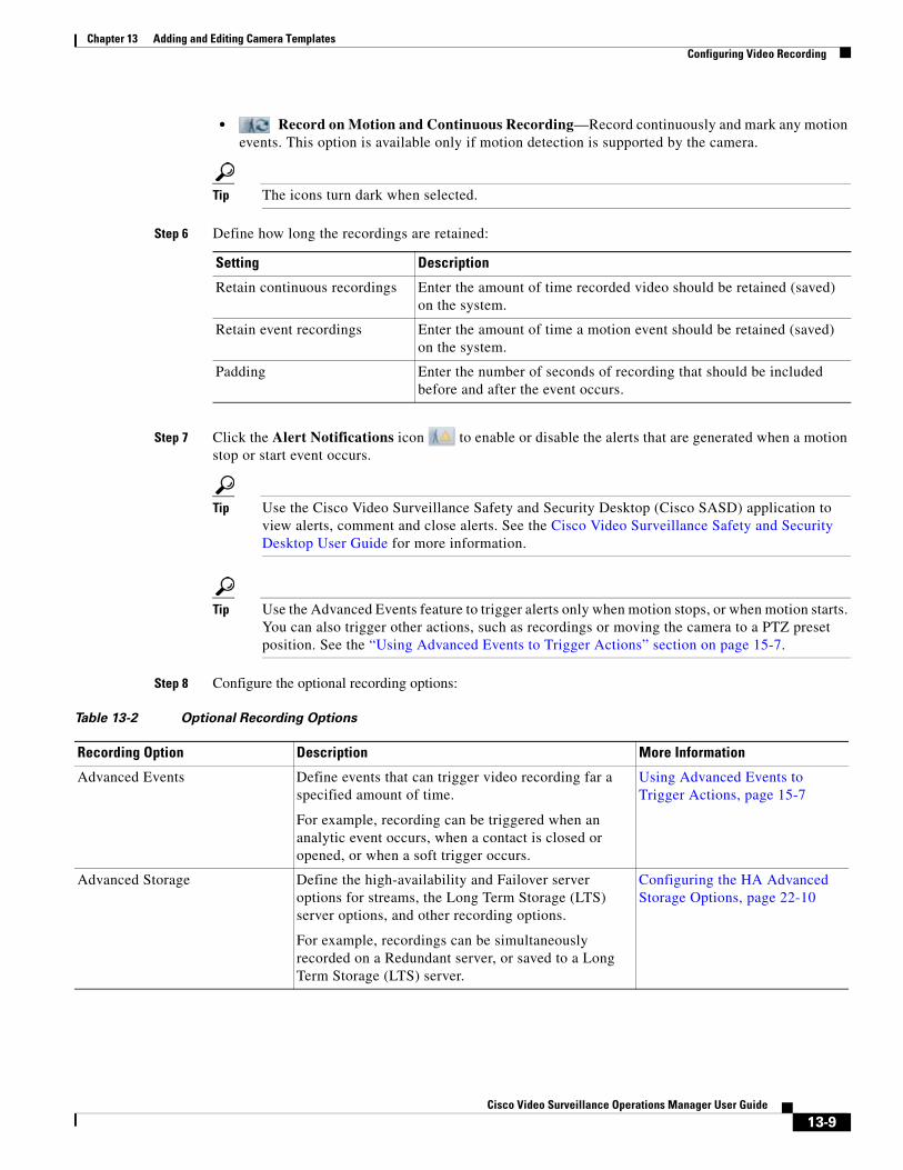
Chapter 13 Adding and Editing Camera TemplatesConfiguring Video Recording
• Record on Motion and Continuous Recording—Record continuously and mark any motion events. This option is available only if motion detection is supported by the camera.
Tip The icons turn dark when selected.
Step 6 Define how long the recordings are retained:
Setting Description
Step 7 Click the Alert Notifications icon to enable or disable the alerts that are generated when a motion stop or start event occurs.
Tip Use the Cisco Video Surveillance Safety and Security Desktop (Cisco SASD) application to view alerts, comment and close alerts. See the Cisco Video Surveillance Safety and Security Desktop User Guide for more information.
Tip Use the Advanced Events feature to trigger alerts only when motion stops, or when motion starts. You can also trigger other actions, such as recordings or moving the camera to a PTZ preset position. See the “Using Advanced Events to Trigger Actions” section on page 15-7.
Step 8 Configure the optional recording options:
Retain continuous recordings Enter the amount of time recorded video should be retained (saved) on the system.
Retain event recordings Enter the amount of time a motion event should be retained (saved) on the system.
Padding Enter the number of seconds of recording that should be included before and after the event occurs.
Table 13-2 Optional Recording Options
Recording Option Description More Information
Advanced Events Define events that can trigger video recording far a specified amount of time.
For example, recording can be triggered when an analytic event occurs, when a contact is closed or opened, or when a soft trigger occurs.
Using Advanced Events to Trigger Actions, page 15-7
Advanced Storage Define the high-availability and Failover server options for streams, the Long Term Storage (LTS) server options, and other recording options.
For example, recordings can be simultaneously recorded on a Redundant server, or saved to a Long Term Storage (LTS) server.
Configuring the HA Advanced Storage Options, page 22-10
13-9Cisco Video Surveillance Operations Manager User Guide
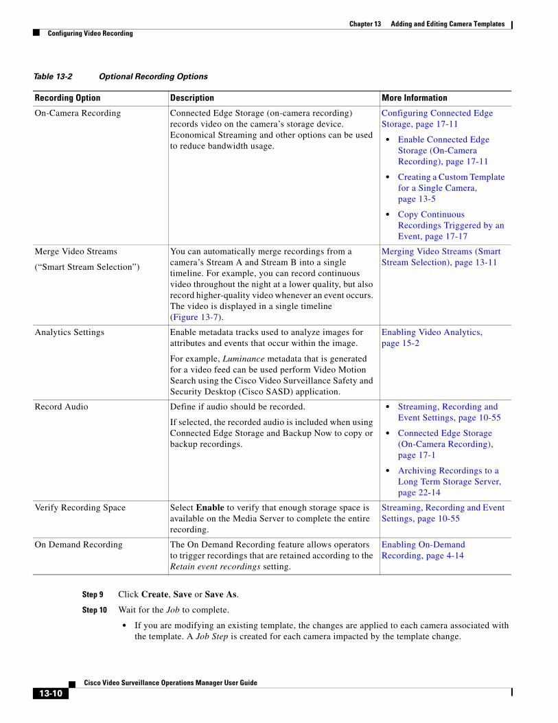
Chapter 13 Adding and Editing Camera Templates Configuring Video Recording
Step 9 Click Create, Save or Save As.
Step 10 Wait for the Job to complete.
• If you are modifying an existing template, the changes are applied to each camera associated with the template. A Job Step is created for each camera impacted by the template change.
On-Camera Recording Connected Edge Storage (on-camera recording) records video on the camera’s storage device. Economical Streaming and other options can be used to reduce bandwidth usage.
Configuring Connected Edge Storage, page 17-11
• Enable Connected Edge Storage (On-Camera Recording), page 17-11
• Creating a Custom Template for a Single Camera, page 13-5
• Copy Continuous Recordings Triggered by an Event, page 17-17
Merge Video Streams
(“Smart Stream Selection”)
You can automatically merge recordings from a camera’s Stream A and Stream B into a single timeline. For example, you can record continuous video throughout the night at a lower quality, but also record higher-quality video whenever an event occurs. The video is displayed in a single timeline (Figure 13-7).
Merging Video Streams (Smart Stream Selection), page 13-11
Analytics Settings Enable metadata tracks used to analyze images for attributes and events that occur within the image.
For example, Luminance metadata that is generated for a video feed can be used perform Video Motion Search using the Cisco Video Surveillance Safety and Security Desktop (Cisco SASD) application.
Enabling Video Analytics, page 15-2
Record Audio Define if audio should be recorded.
If selected, the recorded audio is included when using Connected Edge Storage and Backup Now to copy or backup recordings.
• Streaming, Recording and Event Settings, page 10-55
• Connected Edge Storage (On-Camera Recording), page 17-1
• Archiving Recordings to a Long Term Storage Server, page 22-14
Verify Recording Space Select Enable to verify that enough storage space is available on the Media Server to complete the entire recording.
Streaming, Recording and Event Settings, page 10-55
On Demand Recording The On Demand Recording feature allows operators to trigger recordings that are retained according to the Retain event recordings setting.
Enabling On-Demand Recording, page 4-14
Table 13-2 Optional Recording Options
Recording Option Description More Information
13-10Cisco Video Surveillance Operations Manager User Guide
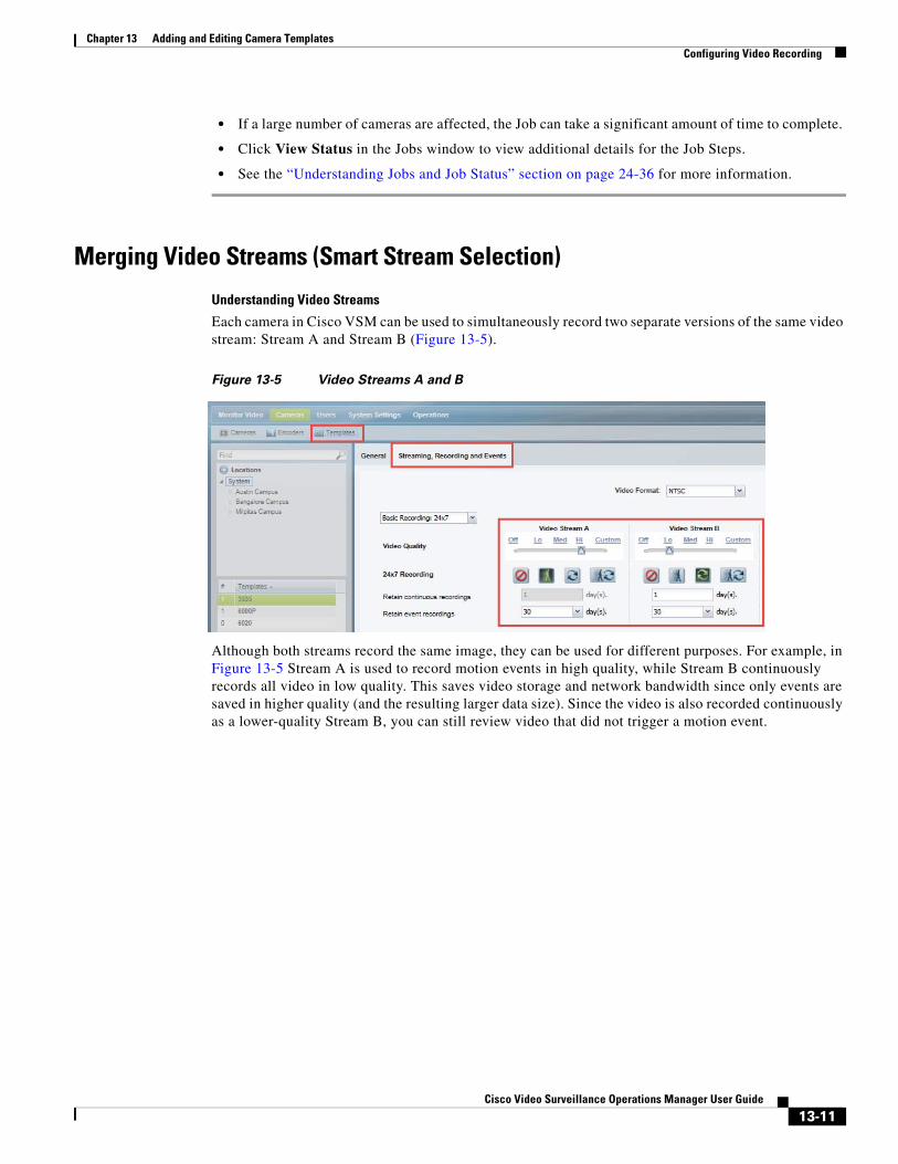
Chapter 13 Adding and Editing Camera TemplatesConfiguring Video Recording
• If a large number of cameras are affected, the Job can take a significant amount of time to complete.
• Click View Status in the Jobs window to view additional details for the Job Steps.
• See the “Understanding Jobs and Job Status” section on page 24-36 for more information.
Merging Video Streams (Smart Stream Selection)
Understanding Video Streams
Each camera in Cisco VSM can be used to simultaneously record two separate versions of the same video stream: Stream A and Stream B (Figure 13-5).
Figure 13-5 Video Streams A and B
Although both streams record the same image, they can be used for different purposes. For example, in Figure 13-5 Stream A is used to record motion events in high quality, while Stream B continuously records all video in low quality. This saves video storage and network bandwidth since only events are saved in higher quality (and the resulting larger data size). Since the video is also recorded continuously as a lower-quality Stream B, you can still review video that did not trigger a motion event.
13-11Cisco Video Surveillance Operations Manager User Guide
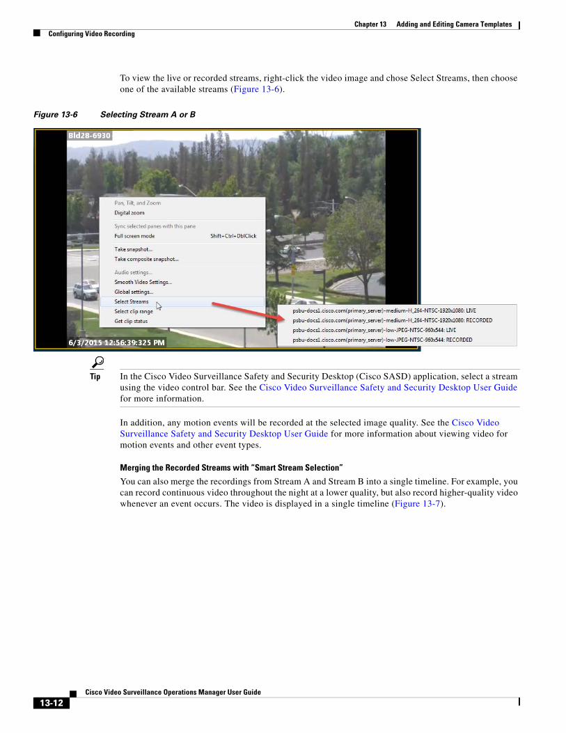
Chapter 13 Adding and Editing Camera Templates Configuring Video Recording
To view the live or recorded streams, right-click the video image and chose Select Streams, then choose one of the available streams (Figure 13-6).
Figure 13-6 Selecting Stream A or B
Tip In the Cisco Video Surveillance Safety and Security Desktop (Cisco SASD) application, select a stream using the video control bar. See the Cisco Video Surveillance Safety and Security Desktop User Guide for more information.
In addition, any motion events will be recorded at the selected image quality. See the Cisco Video Surveillance Safety and Security Desktop User Guide for more information about viewing video for motion events and other event types.
Merging the Recorded Streams with “Smart Stream Selection”
You can also merge the recordings from Stream A and Stream B into a single timeline. For example, you can record continuous video throughout the night at a lower quality, but also record higher-quality video whenever an event occurs. The video is displayed in a single timeline (Figure 13-7).
13-12Cisco Video Surveillance Operations Manager User Guide
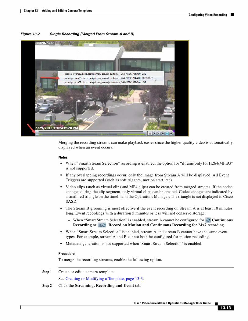
Chapter 13 Adding and Editing Camera TemplatesConfiguring Video Recording
Figure 13-7 Single Recording (Merged From Stream A and B)
Merging the recording streams can make playback easier since the higher quality video is automatically displayed when an event occurs.
Notes
• When “Smart Stream Selection” recording is enabled, the option for “iFrame only for H264/MPEG” is not supported.
• If any overlapping recordings occur, only the image from Stream A will be displayed. All Event Triggers are supported (such as soft triggers, motion start, etc).
• Video clips (such as virtual clips and MP4 clips) can be created from merged streams. If the codec changes during the clip segment, only virtual clips can be created. Codec changes are indicated by a small red triangle on the timeline in the Operations Manager. The triangle is not displayed in Cisco SASD.
• The Stream B grooming is most effective if the event recording on Stream A is at least 10 minutes long. Event recordings with a duration 5 minutes or less will not conserve storage.
– When “Smart Stream Selection” is enabled, stream A cannot be configured for Continuous Recording or Record on Motion and Continuous Recording for 24x7 recording.
• When “Smart Stream Selection” is enabled, stream A and stream B cannot have the same event types. For example, stream A and B cannot both be configured for motion recording.
• Metadata generation is not supported when ‘Smart Stream Selection’ is enabled.
Procedure
To merge the recording streams, enable the following option.
Step 1 Create or edit a camera template.
See Creating or Modifying a Template, page 13-3.
Step 2 Click the Streaming, Recording and Event tab.
13-13Cisco Video Surveillance Operations Manager User Guide
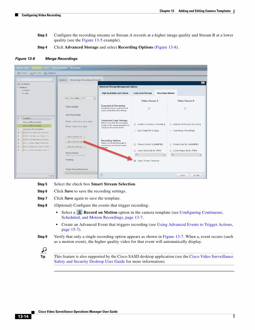
Chapter 13 Adding and Editing Camera Templates Configuring Video Recording
Step 3 Configure the recording streams so Stream A records at a higher image quality and Stream B at a lower quality (see the Figure 13-5 example).
Step 4 Click Advanced Storage and select Recording Options (Figure 13-8).
Figure 13-8 Merge Recordings
Step 5 Select the check box Smart Stream Selection.
Step 6 Click Save to save the recording settings.
Step 7 Click Save again to save the template.
Step 8 (Optional) Configure the events that trigger recording:
• Select a Record on Motion option in the camera template (see Configuring Continuous, Scheduled, and Motion Recordings, page 13-7.
• Create an Advanced Event that triggers recording (see Using Advanced Events to Trigger Actions, page 15-7).
Step 9 Verify that only a single recording option appears as shown in Figure 13-7. When a, event occurs (such as a motion event), the higher quality video for that event will automatically display.
Tip This feature is also supported by the Cisco SASD desktop application (see the Cisco Video Surveillance Safety and Security Desktop User Guide for more information).
13-14Cisco Video Surveillance Operations Manager User Guide
Chapter 13 Adding and Editing Camera TemplatesConfiguring Multicast Video Streaming
Configuring Multicast Video StreamingMulticast allows cameras to send the same video stream to multiple destinations using a single transmission. A multicast transmission uses less network bandwidth than a unicast transmission to multiple destinations.
Requirements
Table 13-3 Multicast Requirements
RequirementsComplete?
()
To configure multicast streams, you must do the following:
Usage Notes
• Audio is unicast even if multicast video is enabled.
• Multicast is performed between the supported encoding device and the Media Servers that are listening. The Media Server does not multicast video to clients.
Procedure
Step 1 Configure your network to support multicast or ask your systems administrator for the multicast IP address(es) used by the cameras.
Step 2 Configure the template to support multicast streams.
a. Select Cameras > Templates.
b. Select a location and template name.
c. Select the Streaming, Recording and Events tab.
d. Click the Custom option for either Video Stream A or Video Stream B.
e. Select JPEG from the Codec field.
f. Select UDP_Multicast from the Transport field.
g. Complete the remaining custom stream settings.
h. Click Save.
Tip To configure a single camera for multicast, you can also create a custom template for that camera and enter the same settings. See the “Creating a Custom Template for a Single Camera” section on page 13-5.
Step 3 Enter the Multicast IP address in the camera configuration page.
Configure your network for multicast streaming.
Create custom stream settings for the camera template.
Configure the multicast IP address and port number on each camera that supports multicast. The allowed multicast port range any even number from 16000 – 19999.
13-15Cisco Video Surveillance Operations Manager User Guide
Chapter 13 Adding and Editing Camera Templates Configuring Multicast Video Streaming
See the “Multicast” descriptions in the “General Settings” section on page 10-47 for more information.
a. Select Cameras.
b. Select a location and camera name.
c. From the General tab, enter the Multicast IP Address and port for the Primary and/or Secondary video streams.
– See your systems administrator for the correct multicast address.
– Primary and Secondary Multicast IP Address fields are enabled only if the corresponding template Stream A and Stream B Custom settings are configured for multicast.
d. Click Save.
Note The multicast settings can also be entered when adding a camera. See the “Manually Adding a Single Camera” section on page 10-10.
13-16Cisco Video Surveillance Operations Manager User Guide
Cisco V
C H A P T E R 14
Monitoring and Managing StorageContents
• Storage Retention and Recording Dashboard Overview, page 14-1
• Using the Actual Bitrate to Estimate Storage, page 14-2
• View Storage and Bitrate Information in the Storage Retention Dashboard, page 14-5
• Usage Notes, page 14-6
• How disk space is estimated using VBR, page 14-6
• Configure Storage Retention Status Warnings and Emails, page 14-7
Related Documentation
• Adding and Editing Camera Templates, page 13-1
• Revising the System Settings, page 26-1
Storage Retention and Recording Dashboard OverviewThe Storage Retention Dashboard displays your cameras’ estimated storage requirements based on the cameras’ actual bitrate. You can also configure this actual bitrate value in a camera template so Cisco VSM can more accurately estimate the associated camera’s storage requirements. This ensures that Cisco VSM can utilize all available disk space for adding cameras and recording video.
For example, the Storage Retention Dashboard in Figure 14-1 shows that the estimated storage needed by a camera (based on the configured settings) is almost twice the estimated storage based on the actual video being recorded.
• Estimated Storage (by configured settings)—43.65 GB
• Estimated Storage (by actual observation)—21.26 GB
This is because the camera is configured for VBR, and the configured VBR bitrate used to estimate disk usage is over twice the actual bitrate being used by the camera. To correct the discrepancy so Cisco VSM can accurately estimate the camera’s storage use, enter the actual bitrate in the camera template’s Predicted Bitrate setting.
14-1ideo Surveillance Operations Manager User Guide
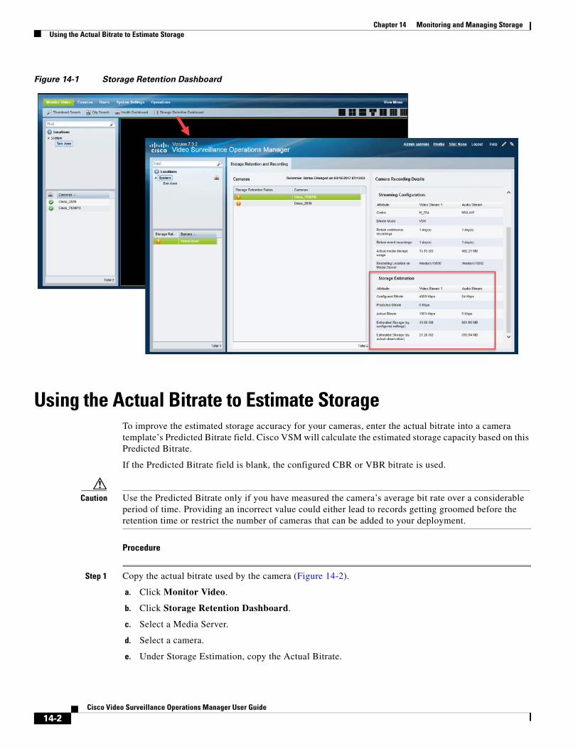
Chapter 14 Monitoring and Managing Storage Using the Actual Bitrate to Estimate Storage
Figure 14-1 Storage Retention Dashboard
Using the Actual Bitrate to Estimate StorageTo improve the estimated storage accuracy for your cameras, enter the actual bitrate into a camera template’s Predicted Bitrate field. Cisco VSM will calculate the estimated storage capacity based on this Predicted Bitrate.
If the Predicted Bitrate field is blank, the configured CBR or VBR bitrate is used.
Caution Use the Predicted Bitrate only if you have measured the camera’s average bit rate over a considerable period of time. Providing an incorrect value could either lead to records getting groomed before the retention time or restrict the number of cameras that can be added to your deployment.
Procedure
Step 1 Copy the actual bitrate used by the camera (Figure 14-2).
a. Click Monitor Video.
b. Click Storage Retention Dashboard.
c. Select a Media Server.
d. Select a camera.
e. Under Storage Estimation, copy the Actual Bitrate.
14-2Cisco Video Surveillance Operations Manager User Guide

Chapter 14 Monitoring and Managing StorageUsing the Actual Bitrate to Estimate Storage
Figure 14-2 Actual Bitrate in the Storage Retention Dashboard
Step 2 Enter the actual bitrate into the Predicted Bitrate field (Figure 14-3).
a. Select Cameras > Templates.
b. Add or edit a template.
c. Next to Video Quality, click Custom.
d. Next to Bit rate mode, verify that VBR is selected.
e. In the Predicted Bitrate field, paste the actual bitrate copied from the Storage Retention Dashboard.
f. Click Set.
g. Click Save.
h. The estimated storage needs of the cameras associated with the template will be recalculated based on the Predicted Bitrate value.
14-3Cisco Video Surveillance Operations Manager User Guide
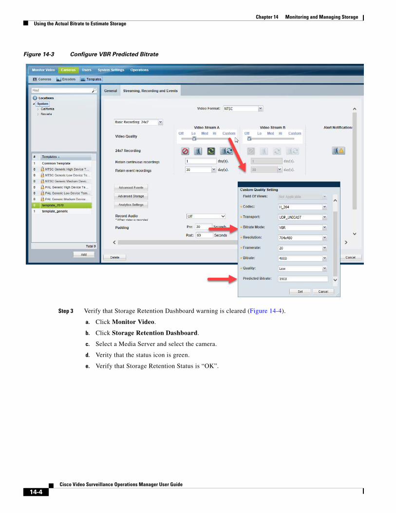
Chapter 14 Monitoring and Managing Storage Using the Actual Bitrate to Estimate Storage
Figure 14-3 Configure VBR Predicted Bitrate
Step 3 Verify that Storage Retention Dashboard warning is cleared (Figure 14-4).
a. Click Monitor Video.
b. Click Storage Retention Dashboard.
c. Select a Media Server and select the camera.
d. Verity that the status icon is green.
e. Verify that Storage Retention Status is “OK”.
14-4Cisco Video Surveillance Operations Manager User Guide
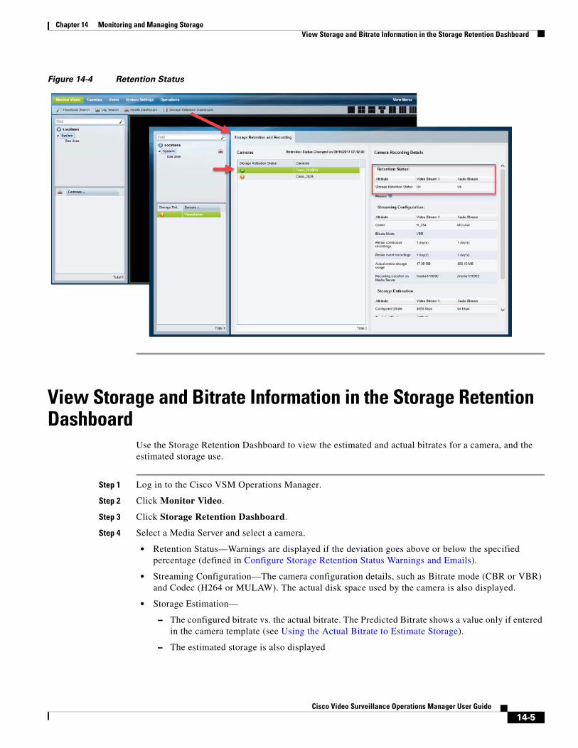
Chapter 14 Monitoring and Managing StorageView Storage and Bitrate Information in the Storage Retention Dashboard
Figure 14-4 Retention Status
View Storage and Bitrate Information in the Storage Retention Dashboard
Use the Storage Retention Dashboard to view the estimated and actual bitrates for a camera, and the estimated storage use.
Step 1 Log in to the Cisco VSM Operations Manager.
Step 2 Click Monitor Video.
Step 3 Click Storage Retention Dashboard.
Step 4 Select a Media Server and select a camera.
• Retention Status—Warnings are displayed if the deviation goes above or below the specified percentage (defined in Configure Storage Retention Status Warnings and Emails).
• Streaming Configuration—The camera configuration details, such as Bitrate mode (CBR or VBR) and Codec (H264 or MULAW). The actual disk space used by the camera is also displayed.
• Storage Estimation—
– The configured bitrate vs. the actual bitrate. The Predicted Bitrate shows a value only if entered in the camera template (see Using the Actual Bitrate to Estimate Storage).
– The estimated storage is also displayed
14-5Cisco Video Surveillance Operations Manager User Guide
Chapter 14 Monitoring and Managing Storage Usage Notes
• Review details such as the “Estimated Storage (by configured settings)” vs. the “Estimated Storage (by actual observation)”. The “Estimated Storage (by configured settings)” is adjusted if a Predicted Bitrate is entered (see Using the Actual Bitrate to Estimate Storage).
Usage Notes • Storage retention is supported only for continuous recordings. However the user will also be able to
view storage retention statistics for continuous + motion based recordings. The data will be accurate as long as the camera performs continuous recording. However when motion events occur there will be a significant deviation in the data as it is hard to predict the number of motion events.
• Retention Status Changed on mm/dd/yyyy hh:mm:ss indicates the last date and time stamp when the storage retention status changed for any camera associated with the selected Media Server.
• The supported Codecs are H264 (video) and MULAW (audio).
• The estimated storage is calculated every 30 minutes.
• If a camera configuration is changed, it may take some time (based on the retention period) to estimate and reflect the correct value of “Estimated Storage (by configured settings)”.
• If recording gaps or packet loss occurs during streaming, the calculated estimated storage or calculated bitrate may not be accurate.
• This feature supports cameras streaming to the Primary Media Server only. Streams to the Redundant, Failover and LTS servers are not supported.
• Cisco 8000 series cameras and Vivotek HD Outdoor IP PTZ cameras support the “Constrained bit rate” mode in VSM as CBR. This feature, together with the “Dynamic intra frame period” feature supported by the cameras, results in reduced average bit rates. In CBR mode, the “Estimated storage (by configured settings)” for these cameras might be higher than the “Estimated Storage (by actual observation)”.
How disk space is estimated using VBRWhen a camera is configured to use VBR, the disk space required by the camera is based on the VBR setting. Because camera manufacturers use the bitrate setting differently, Cisco VSM may overestimate or underestimate the amount of storage required by a camera, and prevent additional cameras from being added or other issues.
For example, most cameras use VBR to vary the bitrate depending on the actual scene the camera is viewing. The bitrate is reduced when there is little movement or change, or increased when there is more change.
However, the bitrate setting can mean different things for different camera models. For example:
• For some cameras, the VBR value is a maximum data rate that will not be exceeded. The actual data rate, however, is often far below this set value.
• For some cameras, the VBR is a target average bitrate. The actual bitrate varies above or below the target value. On average, the camera makes a best effort to use the target bitrate.
14-6Cisco Video Surveillance Operations Manager User Guide
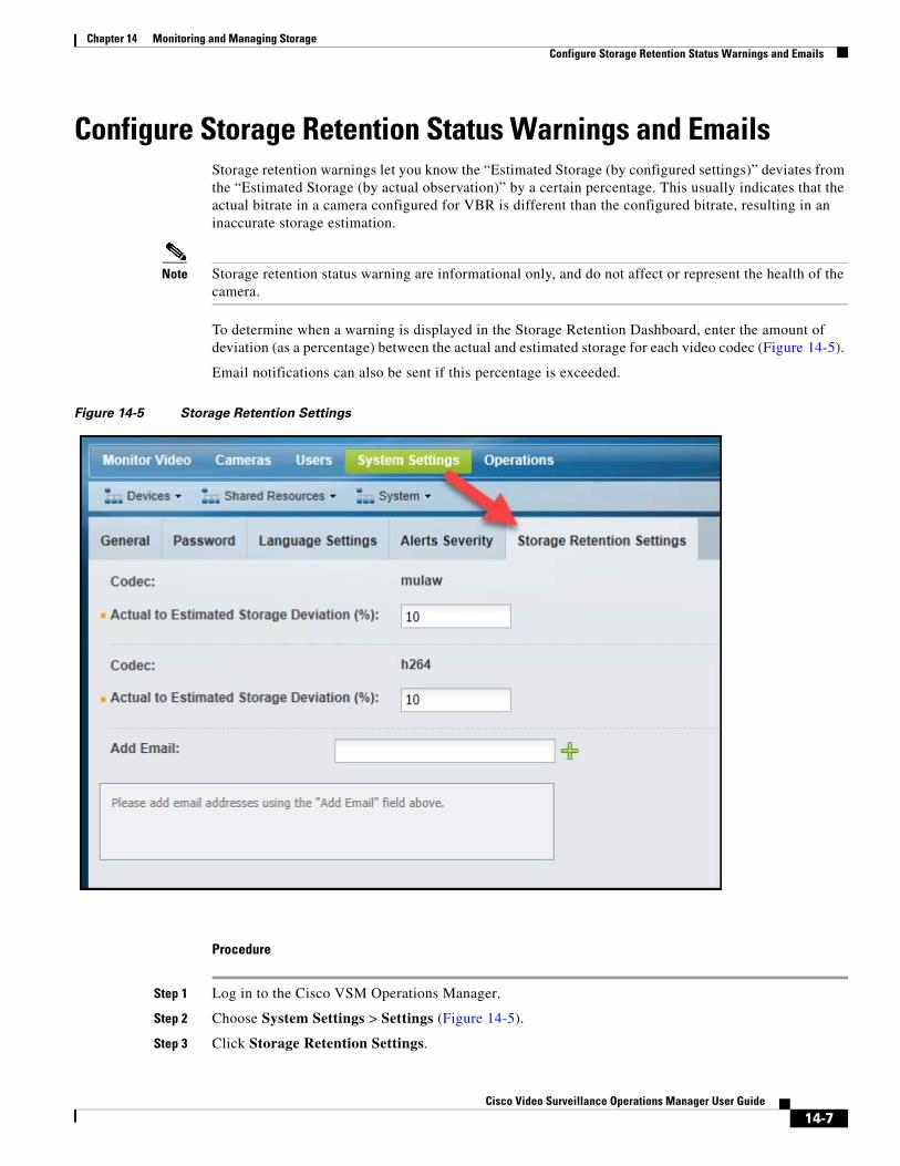
Chapter 14 Monitoring and Managing StorageConfigure Storage Retention Status Warnings and Emails
Configure Storage Retention Status Warnings and EmailsStorage retention warnings let you know the “Estimated Storage (by configured settings)” deviates from the “Estimated Storage (by actual observation)” by a certain percentage. This usually indicates that the actual bitrate in a camera configured for VBR is different than the configured bitrate, resulting in an inaccurate storage estimation.
Note Storage retention status warning are informational only, and do not affect or represent the health of the camera.
To determine when a warning is displayed in the Storage Retention Dashboard, enter the amount of deviation (as a percentage) between the actual and estimated storage for each video codec (Figure 14-5).
Email notifications can also be sent if this percentage is exceeded.
Figure 14-5 Storage Retention Settings
Procedure
Step 1 Log in to the Cisco VSM Operations Manager.
Step 2 Choose System Settings > Settings (Figure 14-5).
Step 3 Click Storage Retention Settings.
14-7Cisco Video Surveillance Operations Manager User Guide

Chapter 14 Monitoring and Managing Storage Configure Storage Retention Status Warnings and Emails
Step 4 Actual to Estimated Storage Deviation percentage (%)—Enter a percentage value for each supported codec (MULAW and H264). The dashboard will display a ‘Warning’ for cameras that deviate above or below the specified percentage.
Step 5 Add Email—Enter the email addresses where warnings should be sent if the deviation between the actual and estimated storage exceeds the defined percentage.
Step 6 Click Save.
14-8Cisco Video Surveillance Operations Manager User Guide
Cisco V
C H A P T E R 15
Video Analytics and Advanced EventsVideo analytics are used to analyze images for attributes and events that occur within the image. For example, Luminance metadata that is generated for a video feed can be used perform Video Motion Search using the Cisco Video Surveillance Safety and Security Desktop (Cisco SASD) application.
Use Advanced Events to trigger an immediate one-time action when a specified event occurs. For example, when motion starts or a contact is closed, the system can trigger an alert, aim the camera to a PTZ preset position, or trigger an action on an external system.
Refer to the following topics for more information.
Contents
• Enabling Video Analytics, page 15-2
• Using Advanced Events to Trigger Actions, page 15-7
15-1ideo Surveillance Operations Manager User Guide
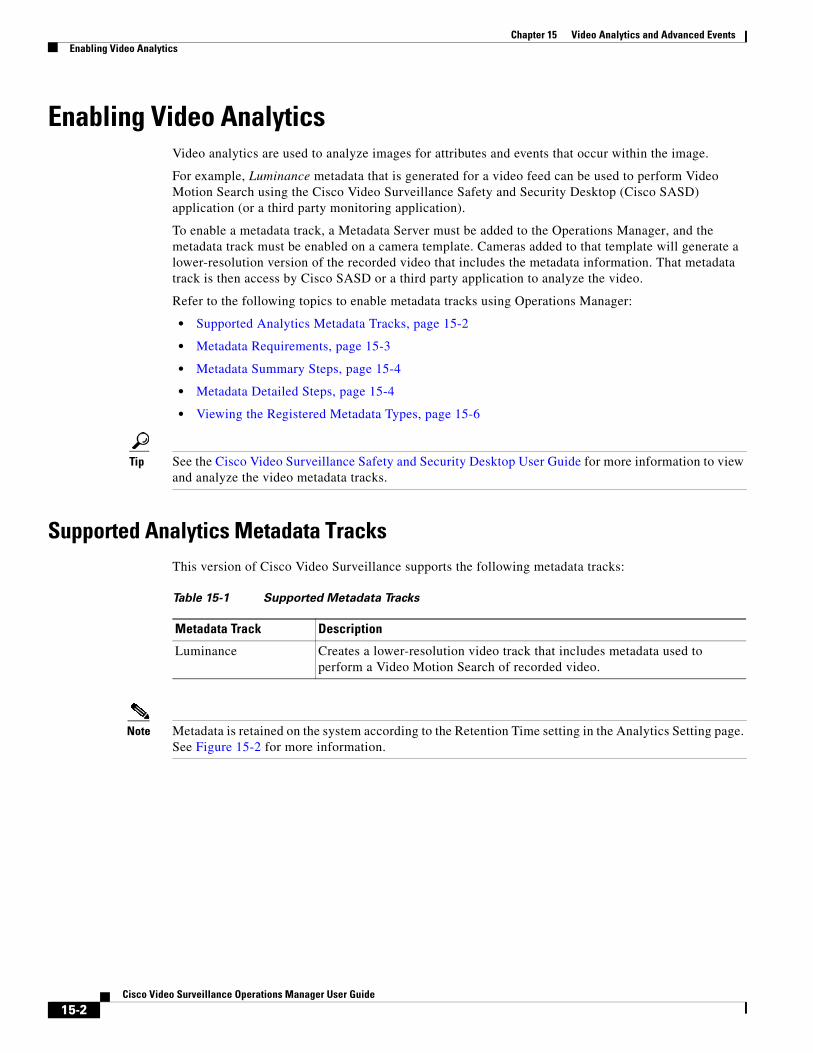
Chapter 15 Video Analytics and Advanced Events Enabling Video Analytics
Enabling Video AnalyticsVideo analytics are used to analyze images for attributes and events that occur within the image.
For example, Luminance metadata that is generated for a video feed can be used to perform Video Motion Search using the Cisco Video Surveillance Safety and Security Desktop (Cisco SASD) application (or a third party monitoring application).
To enable a metadata track, a Metadata Server must be added to the Operations Manager, and the metadata track must be enabled on a camera template. Cameras added to that template will generate a lower-resolution version of the recorded video that includes the metadata information. That metadata track is then access by Cisco SASD or a third party application to analyze the video.
Refer to the following topics to enable metadata tracks using Operations Manager:
• Supported Analytics Metadata Tracks, page 15-2
• Metadata Requirements, page 15-3
• Metadata Summary Steps, page 15-4
• Metadata Detailed Steps, page 15-4
• Viewing the Registered Metadata Types, page 15-6
Tip See the Cisco Video Surveillance Safety and Security Desktop User Guide for more information to view and analyze the video metadata tracks.
Supported Analytics Metadata TracksThis version of Cisco Video Surveillance supports the following metadata tracks:
Table 15-1 Supported Metadata Tracks
Metadata Track Description
Note Metadata is retained on the system according to the Retention Time setting in the Analytics Setting page. See Figure 15-2 for more information.
Luminance Creates a lower-resolution video track that includes metadata used to perform a Video Motion Search of recorded video.
15-2Cisco Video Surveillance Operations Manager User Guide
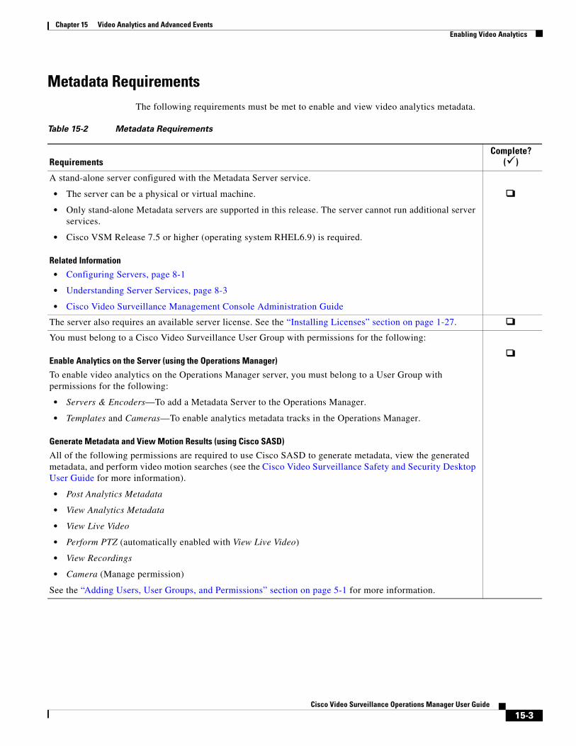
Chapter 15 Video Analytics and Advanced EventsEnabling Video Analytics
Metadata RequirementsThe following requirements must be met to enable and view video analytics metadata.
Table 15-2 Metadata Requirements
RequirementsComplete?
()
A stand-alone server configured with the Metadata Server service.
• The server can be a physical or virtual machine.
• Only stand-alone Metadata servers are supported in this release. The server cannot run additional server services.
• Cisco VSM Release 7.5 or higher (operating system RHEL6.9) is required.
Related Information
• Configuring Servers, page 8-1
• Understanding Server Services, page 8-3
• Cisco Video Surveillance Management Console Administration Guide
The server also requires an available server license. See the “Installing Licenses” section on page 1-27.
You must belong to a Cisco Video Surveillance User Group with permissions for the following:
Enable Analytics on the Server (using the Operations Manager)
To enable video analytics on the Operations Manager server, you must belong to a User Group with permissions for the following:
• Servers & Encoders—To add a Metadata Server to the Operations Manager.
• Templates and Cameras—To enable analytics metadata tracks in the Operations Manager.
Generate Metadata and View Motion Results (using Cisco SASD)
All of the following permissions are required to use Cisco SASD to generate metadata, view the generated metadata, and perform video motion searches (see the Cisco Video Surveillance Safety and Security Desktop User Guide for more information).
• Post Analytics Metadata
• View Analytics Metadata
• View Live Video
• Perform PTZ (automatically enabled with View Live Video)
• View Recordings
• Camera (Manage permission)
See the “Adding Users, User Groups, and Permissions” section on page 5-1 for more information.
15-3Cisco Video Surveillance Operations Manager User Guide
Chapter 15 Video Analytics and Advanced Events Enabling Video Analytics
Metadata Summary StepsTo enable Metadata, do the following:
1. Install and configure a stand-alone Cisco Video Surveillance server.
2. Add a server license, if necessary.
3. Add the server to the Operations Manager configuration as a Metadata Server (Service Type).
4. Create a camera template, and click Analytics Settings.
5. Add the analytics types. For example, add Luminance to enable motion video analytics.
6. Add one or more cameras to the template.
7. Use the Cisco SASD desktop application to access the video analytics features.
Metadata Detailed Steps
Procedure
Step 1 Complete the “Metadata Requirements” section on page 15-3.
Step 2 Install a physical or virtual stand-alone Cisco Video Surveillance server and enable the Metadata service.
See the following for more information:
• Cisco CSS UCS Server User Guide
• Cisco Video Surveillance Management Console Administration Guide
Step 3 Add a server license, if necessary.
Each server requires a server license in order to be added to the Operations Manager configuration. See the “Installing Licenses” section on page 1-27.
A camera template configured for analytics metadata.
For example, add the Luminance metadata track to record luminance metadata used to analyze motion events.
Note At least one camera must also be assigned to the template.
Related Information
• Adding and Editing Camera Templates, page 13-1
• Metadata Detailed Steps, page 15-4
To analyze metadata tracks (such Video Motion Search), the Cisco SASD desktop application must be installed on a monitoring PC.
Related Information
• Understanding the Video Viewing Options, page 2-2
• Cisco Video Surveillance Safety and Security Desktop User Guide
Table 15-2 Metadata Requirements (continued)
RequirementsComplete?
()
15-4Cisco Video Surveillance Operations Manager User Guide
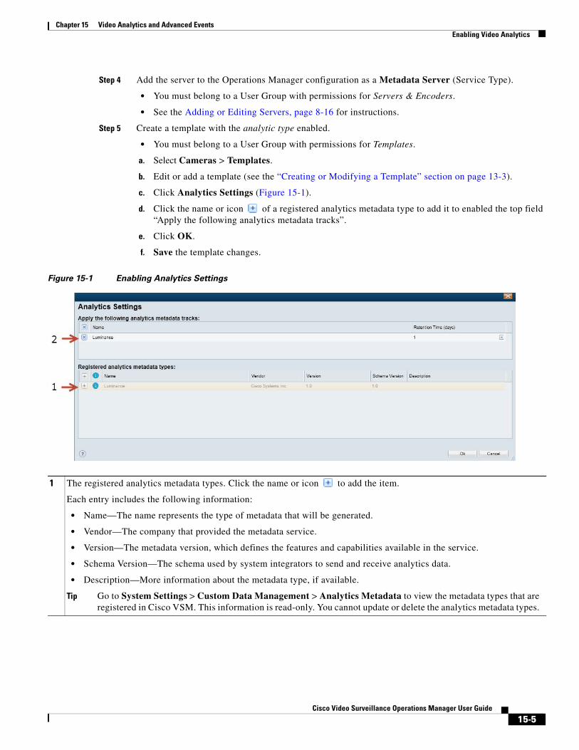
Chapter 15 Video Analytics and Advanced EventsEnabling Video Analytics
Step 4 Add the server to the Operations Manager configuration as a Metadata Server (Service Type).
• You must belong to a User Group with permissions for Servers & Encoders.
• See the Adding or Editing Servers, page 8-16 for instructions.
Step 5 Create a template with the analytic type enabled.
• You must belong to a User Group with permissions for Templates.
a. Select Cameras > Templates.
b. Edit or add a template (see the “Creating or Modifying a Template” section on page 13-3).
c. Click Analytics Settings (Figure 15-1).
d. Click the name or icon of a registered analytics metadata type to add it to enabled the top field “Apply the following analytics metadata tracks”.
e. Click OK.
f. Save the template changes.
Figure 15-1 Enabling Analytics Settings
1 The registered analytics metadata types. Click the name or icon to add the item.
Each entry includes the following information:
• Name—The name represents the type of metadata that will be generated.
• Vendor—The company that provided the metadata service.
• Version—The metadata version, which defines the features and capabilities available in the service.
• Schema Version—The schema used by system integrators to send and receive analytics data.
• Description—More information about the metadata type, if available.
Tip Go to System Settings > Custom Data Management > Analytics Metadata to view the metadata types that are registered in Cisco VSM. This information is read-only. You cannot update or delete the analytics metadata types.
15-5Cisco Video Surveillance Operations Manager User Guide
Chapter 15 Video Analytics and Advanced Events Enabling Video Analytics
Step 6 Add one or more cameras to the template.
a. Click Cameras.
b. Click Add or select an existing camera.
c. Complete the camera settings as described in the “Adding and Managing Cameras” section on page 10-1.
d. Click Template and select the template from the pop-up window.
e. Click Save or Create to save the settings.
Step 7 Use the Cisco SASD desktop application to generate luminance metadata for a span of recorded video and perform a Video Motion Search. See the Cisco Video Surveillance Safety and Security Desktop User Guide for more information.
Viewing the Registered Metadata TypesGo to System Settings > Custom Data Management > Analytics Metadata to view the metadata types that are registered in Cisco VSM.
Note This information is read-only. You cannot update or delete the analytics metadata types.
• The Luminance metadata type is registered when a Metadata server is added to the Operations Manager. Luminance metadata is used for post facto metadata generation and analysis.
• Camera apps can also have metadata types that are added to Cisco VSM when a camera app is uploaded to the Cisco VSM Operations Manager. See Managing Camera Apps, page 16-1.
2 The enabled analytics metadata types. Analytics types in this field will generate metadata tracks used to analyze the video streams. Click the name or icon to remove and disable the metadata type.
Each entry includes the following information:
• Name—The name represents the type of metadata that will be generated.
• Retention Time (days)—The number of days the metadata will be retained on the system (and available for analytics). Enter a number between 1 and 3650 (10 years). When the retention time expires, the metadata is deleted.
15-6Cisco Video Surveillance Operations Manager User Guide
Chapter 15 Video Analytics and Advanced EventsUsing Advanced Events to Trigger Actions
Using Advanced Events to Trigger ActionsUse Advanced Events to trigger an immediate one-time action when a specified event occurs. For example, when motion starts or a contact is closed, the system can trigger an alert, aim the camera to a PTZ preset position, or trigger an action on an external system.
Tip Multiple actions can be triggered for the same event.
Configure advanced events for camera templates to apply the rules to multiple cameras, or for a custom template to apply the trigger to a single camera.
This section includes the following topics:
• Configuration Overview, page 15-8
• Configuration Summary, page 15-9
• Trigger and Action Descriptions, page 15-9
• Configuring Soft Triggers, page 15-13
• Creating Custom Event Types and Sub Types, page 15-16
Note • Advanced events are different from device health events. See the “Device Status: Identifying Issues for a Specific Device” section on page 24-13 for more information.
• Some cameras do not support sending motion or contact-closure events to a Redundant server. See the “Configuring the Redundant and Failover Options” section on page 22-11 for more information.
15-7Cisco Video Surveillance Operations Manager User Guide
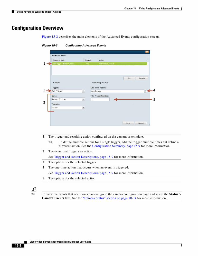
Chapter 15 Video Analytics and Advanced Events Using Advanced Events to Trigger Actions
Configuration OverviewFigure 15-2 describes the main elements of the Advanced Events configuration screen.
Figure 15-2 Configuring Advanced Events
1
Tip To define multiple actions for a single trigger, add the trigger multiple times but define a different action. See the Configuration Summary, page 15-9 for more information.
2
3
4
5
Tip To view the events that occur on a camera, go to the camera configuration page and select the Status > Camera Events tabs. See the “Camera Status” section on page 10-74 for more information.
The trigger and resulting action configured on the camera or template.
The event that triggers an action.
See Trigger and Action Descriptions, page 15-9 for more information.
The options for the selected trigger.
The one-time action that occurs when an event is triggered.
See Trigger and Action Descriptions, page 15-9 for more information.
The options for the selected action.
15-8Cisco Video Surveillance Operations Manager User Guide
Chapter 15 Video Analytics and Advanced EventsUsing Advanced Events to Trigger Actions
Configuration Summary
Procedure
To configure Advanced Events for a template or camera, do the following:
Step 1 Log on to the Operations Manager.
• See the “Logging In” section on page 1-17.
• You must belong to a User Group with permissions for Templates or Cameras. See the Adding Users, User Groups, and Permissions, page 5-1for more information.
Step 2 Select a template or camera.
Step 3 Click the Streaming, Recording and Events tab.
Step 4 Click Advanced Events.
Step 5 Click Add.
Step 6 Select a Trigger and then select the additional options as described in the “Trigger and Action Descriptions” section on page 15-9.
Step 7 Select a Timeslot when the event should trigger an action.
See the “Defining Schedules” section on page 12-1 to create timeslots.
Step 8 Select a Resulting Action for the event, as described in the “Trigger and Action Descriptions” section on page 15-9.
Step 9 Click Add to add additional entries.
To trigger multiple actions for an event, add an entry for the same trigger or state, and then select a different action.
Step 10 Click OK to save the changes.
Tip To view the events that occur on a camera, go to the camera configuration page and select the Status > Camera Events tabs. See the “Camera Status” section on page 10-74 for more information.
Trigger and Action DescriptionsThe following tables describe the event triggers and resulting actions available in Advanced Events.
Note • For templates that are model-specific, only the triggers and actions supported by the camera model are displayed. For example, triggers for Analytic, Camera App, Contact Closure, and Motion are available only on cameras that support those features.
• If a generic template is used, all options are displayed. If a camera is configured with a trigger or action that is not supported on that device, a “device capability mismatch” occurs. Remove the configuration to clear the error. See the “Camera Status” section on page 10-74 for more information.
15-9Cisco Video Surveillance Operations Manager User Guide
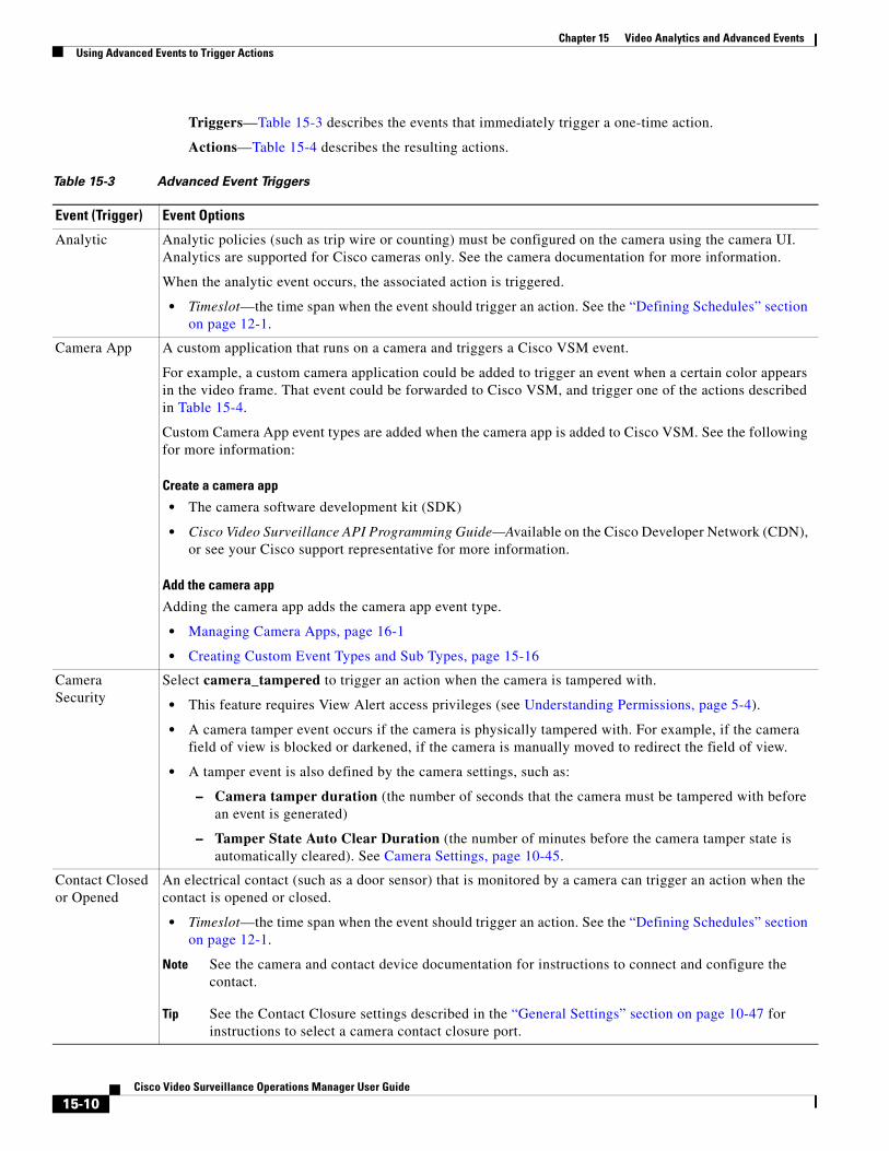
Chapter 15 Video Analytics and Advanced Events Using Advanced Events to Trigger Actions
Triggers—Table 15-3 describes the events that immediately trigger a one-time action.
Actions—Table 15-4 describes the resulting actions.
Table 15-3 Advanced Event Triggers
Event (Trigger) Event Options
Analytic Analytic policies (such as trip wire or counting) must be configured on the camera using the camera UI. Analytics are supported for Cisco cameras only. See the camera documentation for more information.
When the analytic event occurs, the associated action is triggered.
• Timeslot—the time span when the event should trigger an action. See the “Defining Schedules” section on page 12-1.
Camera App A custom application that runs on a camera and triggers a Cisco VSM event.
For example, a custom camera application could be added to trigger an event when a certain color appears in the video frame. That event could be forwarded to Cisco VSM, and trigger one of the actions described in Table 15-4.
Custom Camera App event types are added when the camera app is added to Cisco VSM. See the following for more information:
Create a camera app
• The camera software development kit (SDK)
• Cisco Video Surveillance API Programming Guide—Available on the Cisco Developer Network (CDN), or see your Cisco support representative for more information.
Add the camera app
Adding the camera app adds the camera app event type.
• Managing Camera Apps, page 16-1
• Creating Custom Event Types and Sub Types, page 15-16
Camera Security
Select camera_tampered to trigger an action when the camera is tampered with.
• This feature requires View Alert access privileges (see Understanding Permissions, page 5-4).
• A camera tamper event occurs if the camera is physically tampered with. For example, if the camera field of view is blocked or darkened, if the camera is manually moved to redirect the field of view.
• A tamper event is also defined by the camera settings, such as:
– Camera tamper duration (the number of seconds that the camera must be tampered with before an event is generated)
– Tamper State Auto Clear Duration (the number of minutes before the camera tamper state is automatically cleared). See Camera Settings, page 10-45.
Contact Closed or Opened
An electrical contact (such as a door sensor) that is monitored by a camera can trigger an action when the contact is opened or closed.
• Timeslot—the time span when the event should trigger an action. See the “Defining Schedules” section on page 12-1.
Note See the camera and contact device documentation for instructions to connect and configure the contact.
Tip See the Contact Closure settings described in the “General Settings” section on page 10-47 for instructions to select a camera contact closure port.
15-10Cisco Video Surveillance Operations Manager User Guide
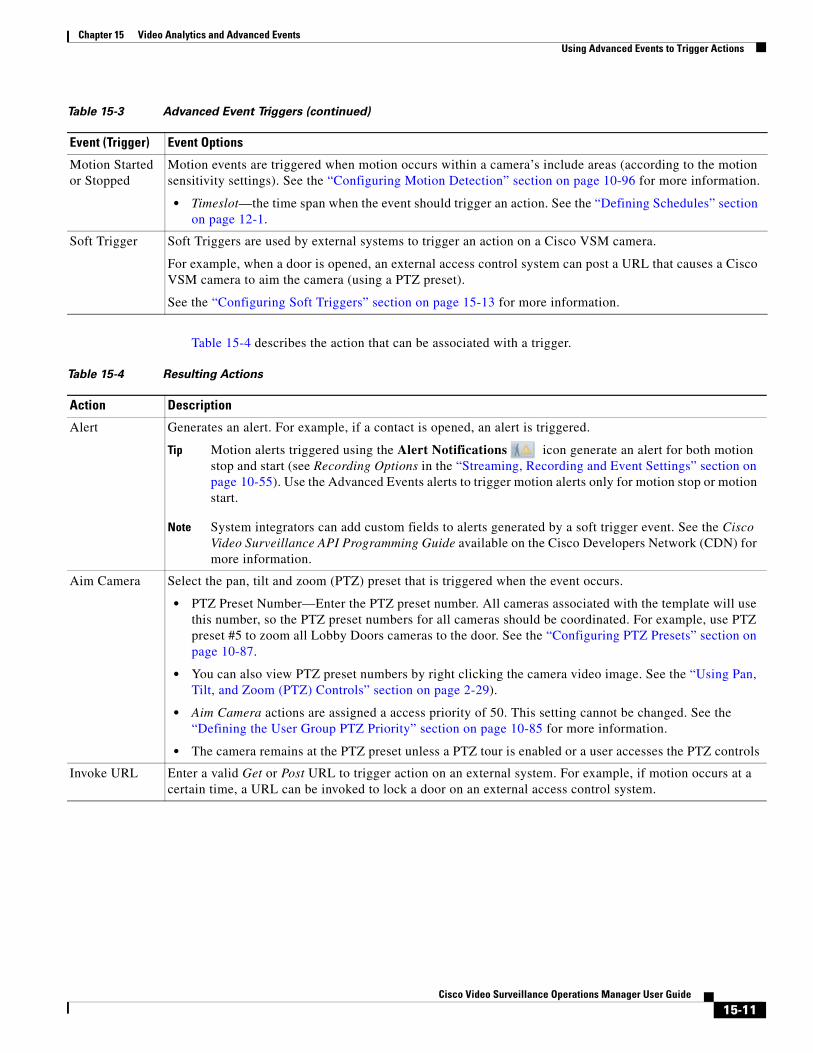
Chapter 15 Video Analytics and Advanced EventsUsing Advanced Events to Trigger Actions
Table 15-4 describes the action that can be associated with a trigger.
Motion Started or Stopped
Motion events are triggered when motion occurs within a camera’s include areas (according to the motion sensitivity settings). See the “Configuring Motion Detection” section on page 10-96 for more information.
• Timeslot—the time span when the event should trigger an action. See the “Defining Schedules” section on page 12-1.
Soft Trigger Soft Triggers are used by external systems to trigger an action on a Cisco VSM camera.
For example, when a door is opened, an external access control system can post a URL that causes a Cisco VSM camera to aim the camera (using a PTZ preset).
See the “Configuring Soft Triggers” section on page 15-13 for more information.
Table 15-3 Advanced Event Triggers (continued)
Event (Trigger) Event Options
Table 15-4 Resulting Actions
Action Description
Alert Generates an alert. For example, if a contact is opened, an alert is triggered.
Tip Motion alerts triggered using the Alert Notifications icon generate an alert for both motion stop and start (see Recording Options in the “Streaming, Recording and Event Settings” section on page 10-55). Use the Advanced Events alerts to trigger motion alerts only for motion stop or motion start.
Note System integrators can add custom fields to alerts generated by a soft trigger event. See the Cisco Video Surveillance API Programming Guide available on the Cisco Developers Network (CDN) for more information.
Aim Camera Select the pan, tilt and zoom (PTZ) preset that is triggered when the event occurs.
• PTZ Preset Number—Enter the PTZ preset number. All cameras associated with the template will use this number, so the PTZ preset numbers for all cameras should be coordinated. For example, use PTZ preset #5 to zoom all Lobby Doors cameras to the door. See the “Configuring PTZ Presets” section on page 10-87.
• You can also view PTZ preset numbers by right clicking the camera video image. See the “Using Pan, Tilt, and Zoom (PTZ) Controls” section on page 2-29).
• Aim Camera actions are assigned a access priority of 50. This setting cannot be changed. See the “Defining the User Group PTZ Priority” section on page 10-85 for more information.
• The camera remains at the PTZ preset unless a PTZ tour is enabled or a user accesses the PTZ controls
Invoke URL Enter a valid Get or Post URL to trigger action on an external system. For example, if motion occurs at a certain time, a URL can be invoked to lock a door on an external access control system.
15-11Cisco Video Surveillance Operations Manager User Guide
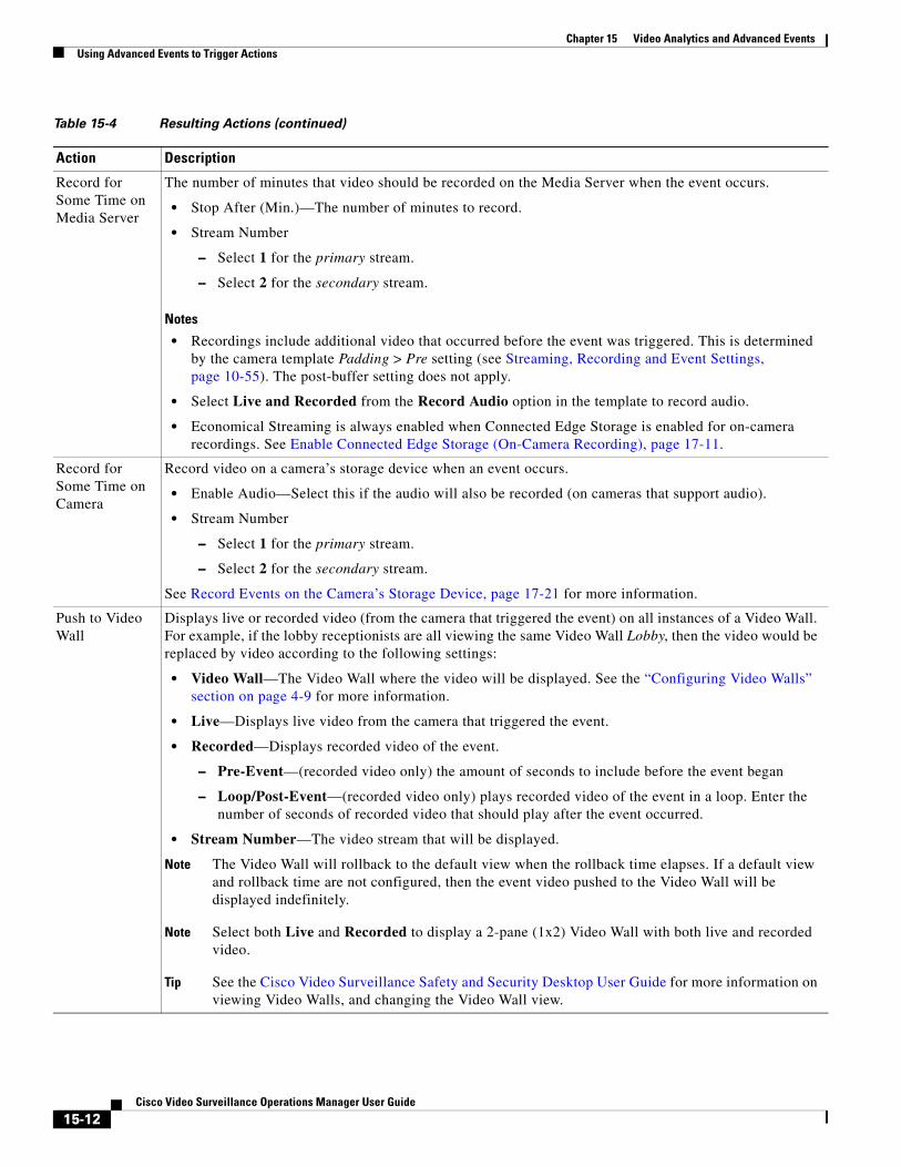
Chapter 15 Video Analytics and Advanced Events Using Advanced Events to Trigger Actions
Record for Some Time on Media Server
The number of minutes that video should be recorded on the Media Server when the event occurs.
• Stop After (Min.)—The number of minutes to record.
• Stream Number
– Select 1 for the primary stream.
– Select 2 for the secondary stream.
Notes
• Recordings include additional video that occurred before the event was triggered. This is determined by the camera template Padding > Pre setting (see Streaming, Recording and Event Settings, page 10-55). The post-buffer setting does not apply.
• Select Live and Recorded from the Record Audio option in the template to record audio.
• Economical Streaming is always enabled when Connected Edge Storage is enabled for on-camera recordings. See Enable Connected Edge Storage (On-Camera Recording), page 17-11.
Record for Some Time on Camera
Record video on a camera’s storage device when an event occurs.
• Enable Audio—Select this if the audio will also be recorded (on cameras that support audio).
• Stream Number
– Select 1 for the primary stream.
– Select 2 for the secondary stream.
See Record Events on the Camera’s Storage Device, page 17-21 for more information.
Push to Video Wall
Displays live or recorded video (from the camera that triggered the event) on all instances of a Video Wall. For example, if the lobby receptionists are all viewing the same Video Wall Lobby, then the video would be replaced by video according to the following settings:
• Video Wall—The Video Wall where the video will be displayed. See the “Configuring Video Walls” section on page 4-9 for more information.
• Live—Displays live video from the camera that triggered the event.
• Recorded—Displays recorded video of the event.
– Pre-Event—(recorded video only) the amount of seconds to include before the event began
– Loop/Post-Event—(recorded video only) plays recorded video of the event in a loop. Enter the number of seconds of recorded video that should play after the event occurred.
• Stream Number—The video stream that will be displayed.
Note The Video Wall will rollback to the default view when the rollback time elapses. If a default view and rollback time are not configured, then the event video pushed to the Video Wall will be displayed indefinitely.
Note Select both Live and Recorded to display a 2-pane (1x2) Video Wall with both live and recorded video.
Tip See the Cisco Video Surveillance Safety and Security Desktop User Guide for more information on viewing Video Walls, and changing the Video Wall view.
Table 15-4 Resulting Actions (continued)
Action Description
15-12Cisco Video Surveillance Operations Manager User Guide
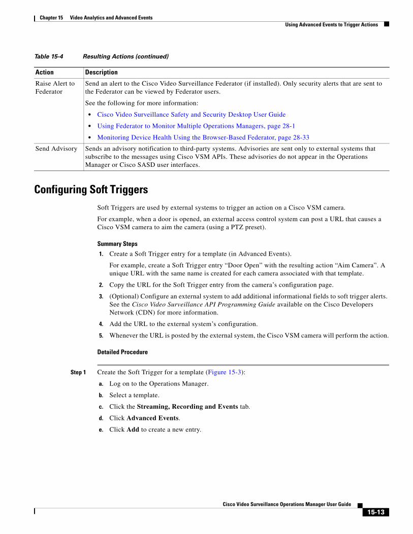
Chapter 15 Video Analytics and Advanced EventsUsing Advanced Events to Trigger Actions
Configuring Soft TriggersSoft Triggers are used by external systems to trigger an action on a Cisco VSM camera.
For example, when a door is opened, an external access control system can post a URL that causes a Cisco VSM camera to aim the camera (using a PTZ preset).
Summary Steps
1. Create a Soft Trigger entry for a template (in Advanced Events).
For example, create a Soft Trigger entry “Door Open” with the resulting action “Aim Camera”. A unique URL with the same name is created for each camera associated with that template.
2. Copy the URL for the Soft Trigger entry from the camera’s configuration page.
3. (Optional) Configure an external system to add additional informational fields to soft trigger alerts. See the Cisco Video Surveillance API Programming Guide available on the Cisco Developers Network (CDN) for more information.
4. Add the URL to the external system’s configuration.
5. Whenever the URL is posted by the external system, the Cisco VSM camera will perform the action.
Detailed Procedure
Step 1 Create the Soft Trigger for a template (Figure 15-3):
a. Log on to the Operations Manager.
b. Select a template.
c. Click the Streaming, Recording and Events tab.
d. Click Advanced Events.
e. Click Add to create a new entry.
Raise Alert to Federator
Send an alert to the Cisco Video Surveillance Federator (if installed). Only security alerts that are sent to the Federator can be viewed by Federator users.
See the following for more information:
• Cisco Video Surveillance Safety and Security Desktop User Guide
• Using Federator to Monitor Multiple Operations Managers, page 28-1
• Monitoring Device Health Using the Browser-Based Federator, page 28-33
Send Advisory Sends an advisory notification to third-party systems. Advisories are sent only to external systems that subscribe to the messages using Cisco VSM APIs. These advisories do not appear in the Operations Manager or Cisco SASD user interfaces.
Table 15-4 Resulting Actions (continued)
Action Description
15-13Cisco Video Surveillance Operations Manager User Guide
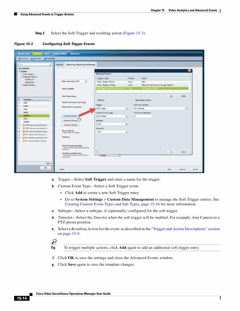
Chapter 15 Video Analytics and Advanced Events Using Advanced Events to Trigger Actions
Step 2 Select the Soft Trigger and resulting action (Figure 15-3).
Figure 15-3 Configuring Soft Trigger Events
a. Trigger—Select Soft Trigger and enter a name for the trigger.
b. Custom Event Type—Select a Soft Trigger event.
– Click Add to create a new Soft Trigger entry.
– Go to System Settings > Custom Data Management to manage the Soft Trigger entries. See Creating Custom Event Types and Sub Types, page 15-16 for more information.
c. Subtype—Select a subtype, if (optionally) configured for the soft trigger.
d. Timeslot—Select the Timeslot when the soft trigger will be enabled. For example, Aim Camera to a PTZ preset position.
e. Select a Resulting Action for the event, as described in the “Trigger and Action Descriptions” section on page 15-9.
Tip To trigger multiple actions, click Add again to add an additional soft trigger entry.
f. Click OK to save the settings and close the Advanced Events window.
g. Click Save again to save the template changes.
15-14Cisco Video Surveillance Operations Manager User Guide
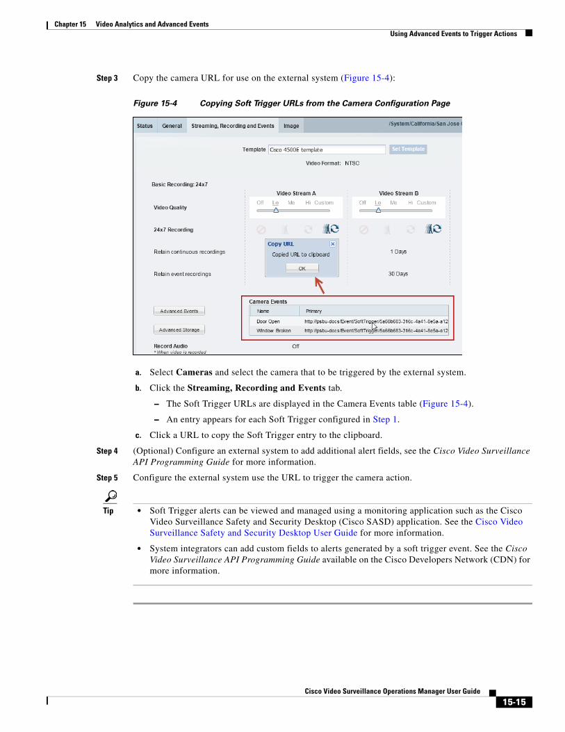
Chapter 15 Video Analytics and Advanced EventsUsing Advanced Events to Trigger Actions
Step 3 Copy the camera URL for use on the external system (Figure 15-4):
Figure 15-4 Copying Soft Trigger URLs from the Camera Configuration Page
a. Select Cameras and select the camera that to be triggered by the external system.
b. Click the Streaming, Recording and Events tab.
– The Soft Trigger URLs are displayed in the Camera Events table (Figure 15-4).
– An entry appears for each Soft Trigger configured in Step 1.
c. Click a URL to copy the Soft Trigger entry to the clipboard.
Step 4 (Optional) Configure an external system to add additional alert fields, see the Cisco Video Surveillance API Programming Guide for more information.
Step 5 Configure the external system use the URL to trigger the camera action.
Tip • Soft Trigger alerts can be viewed and managed using a monitoring application such as the Cisco Video Surveillance Safety and Security Desktop (Cisco SASD) application. See the Cisco Video Surveillance Safety and Security Desktop User Guide for more information.
• System integrators can add custom fields to alerts generated by a soft trigger event. See the Cisco Video Surveillance API Programming Guide available on the Cisco Developers Network (CDN) for more information.
15-15Cisco Video Surveillance Operations Manager User Guide
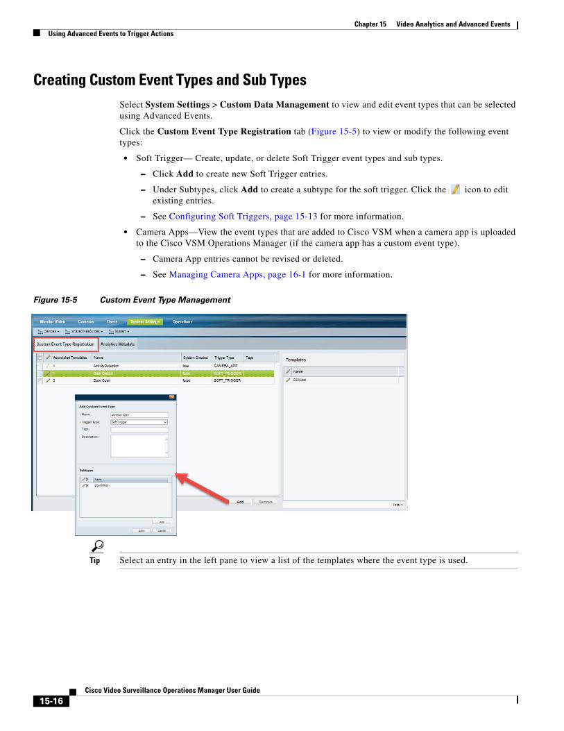
Chapter 15 Video Analytics and Advanced Events Using Advanced Events to Trigger Actions
Creating Custom Event Types and Sub TypesSelect System Settings > Custom Data Management to view and edit event types that can be selected using Advanced Events.
Click the Custom Event Type Registration tab (Figure 15-5) to view or modify the following event types:
• Soft Trigger— Create, update, or delete Soft Trigger event types and sub types.
– Click Add to create new Soft Trigger entries.
– Under Subtypes, click Add to create a subtype for the soft trigger. Click the icon to edit existing entries.
– See Configuring Soft Triggers, page 15-13 for more information.
• Camera Apps—View the event types that are added to Cisco VSM when a camera app is uploaded to the Cisco VSM Operations Manager (if the camera app has a custom event type).
– Camera App entries cannot be revised or deleted.
– See Managing Camera Apps, page 16-1 for more information.
Figure 15-5 Custom Event Type Management
Tip Select an entry in the left pane to view a list of the templates where the event type is used.
15-16Cisco Video Surveillance Operations Manager User Guide
Cisco V
C H A P T E R 16
Managing Camera AppsCamera apps allow you to extend the functionality of cameras so they can also perform analytics and other functions (in addition to sending raw video and audio). Although camera apps can be installed directly on the camera, you can also use the Cisco Video Surveillance Operations Manager (release 7.6 and higher) to install and manage the apps on multiple cameras, and to configure actions triggered by camera app events.
Note Use the camera interface to configure application-specific features and settings. See the camera or camera app documentation for more information.
Refer to the following topics to manage camera apps using the Operations Manager:
• Prerequisites, page 16-2
– Requirements, page 16-2
– Supported Apps, page 16-4
– IP Cameras That Support Apps, page 16-4
– Obtaining and Installing App Licenses, page 16-5
– Obtaining Camera Apps, page 16-5
– Creating Custom Camera Apps, page 16-6
• Managing Camera Apps Using the Operations Manager, page 16-7
– Summary Steps, page 16-10
– Detailed Steps, page 16-13
– Viewing App Logs and Status, page 16-16
– Enabling an App When the App is Not Installed, page 16-23
– Disabling, De-installing and Deleting Apps, page 16-23
– Upgrading Camera Apps, page 16-27
• Troubleshooting Camera Apps, page 16-28
• Related Documentation, page 16-29
16-1ideo Surveillance Operations Manager User Guide
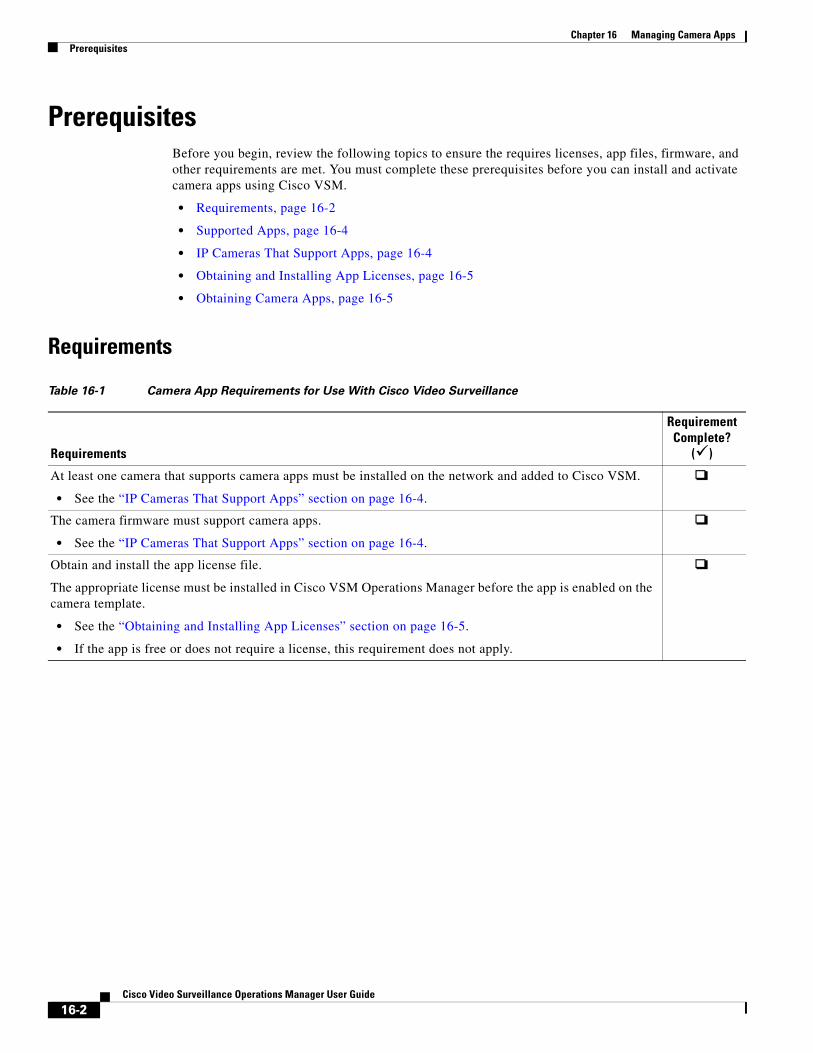
Chapter 16 Managing Camera Apps Prerequisites
PrerequisitesBefore you begin, review the following topics to ensure the requires licenses, app files, firmware, and other requirements are met. You must complete these prerequisites before you can install and activate camera apps using Cisco VSM.
• Requirements, page 16-2
• Supported Apps, page 16-4
• IP Cameras That Support Apps, page 16-4
• Obtaining and Installing App Licenses, page 16-5
• Obtaining Camera Apps, page 16-5
Requirements
Table 16-1 Camera App Requirements for Use With Cisco Video Surveillance
Requirements
Requirement Complete?
()
At least one camera that supports camera apps must be installed on the network and added to Cisco VSM.
• See the “IP Cameras That Support Apps” section on page 16-4.
The camera firmware must support camera apps.
• See the “IP Cameras That Support Apps” section on page 16-4.
Obtain and install the app license file.
The appropriate license must be installed in Cisco VSM Operations Manager before the app is enabled on the camera template.
• See the “Obtaining and Installing App Licenses” section on page 16-5.
• If the app is free or does not require a license, this requirement does not apply.
16-2Cisco Video Surveillance Operations Manager User Guide
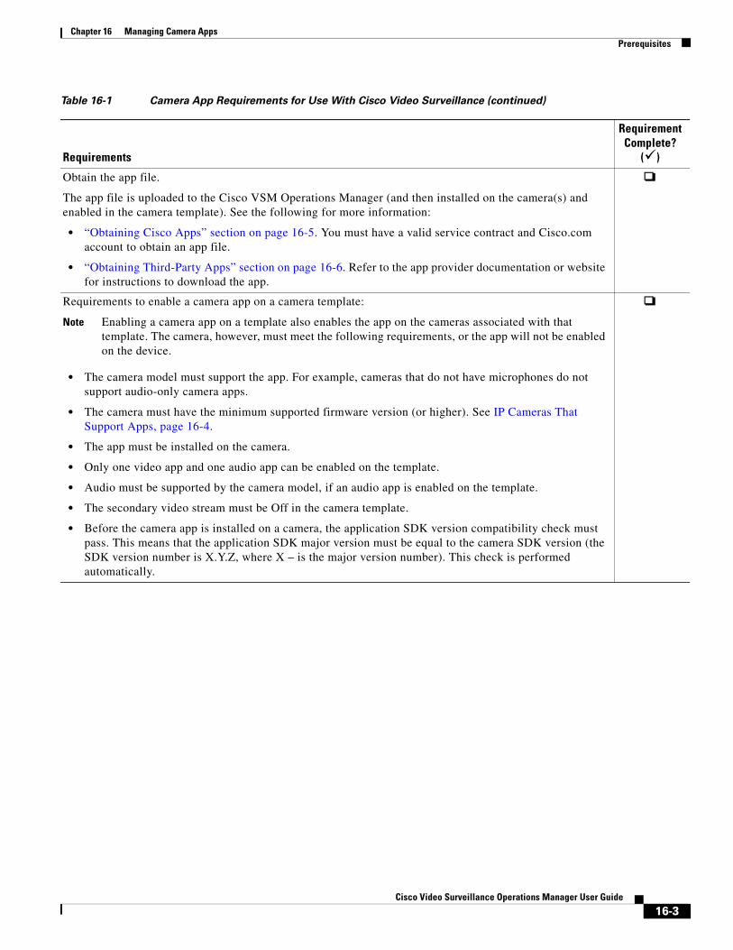
Chapter 16 Managing Camera AppsPrerequisites
Obtain the app file.
The app file is uploaded to the Cisco VSM Operations Manager (and then installed on the camera(s) and enabled in the camera template). See the following for more information:
• “Obtaining Cisco Apps” section on page 16-5. You must have a valid service contract and Cisco.com account to obtain an app file.
• “Obtaining Third-Party Apps” section on page 16-6. Refer to the app provider documentation or website for instructions to download the app.
Requirements to enable a camera app on a camera template:
Note Enabling a camera app on a template also enables the app on the cameras associated with that template. The camera, however, must meet the following requirements, or the app will not be enabled on the device.
• The camera model must support the app. For example, cameras that do not have microphones do not support audio-only camera apps.
• The camera must have the minimum supported firmware version (or higher). See IP Cameras That Support Apps, page 16-4.
• The app must be installed on the camera.
• Only one video app and one audio app can be enabled on the template.
• Audio must be supported by the camera model, if an audio app is enabled on the template.
• The secondary video stream must be Off in the camera template.
• Before the camera app is installed on a camera, the application SDK version compatibility check must pass. This means that the application SDK major version must be equal to the camera SDK version (the SDK version number is X.Y.Z, where X – is the major version number). This check is performed automatically.
Table 16-1 Camera App Requirements for Use With Cisco Video Surveillance (continued)
Requirements
Requirement Complete?
()
16-3Cisco Video Surveillance Operations Manager User Guide
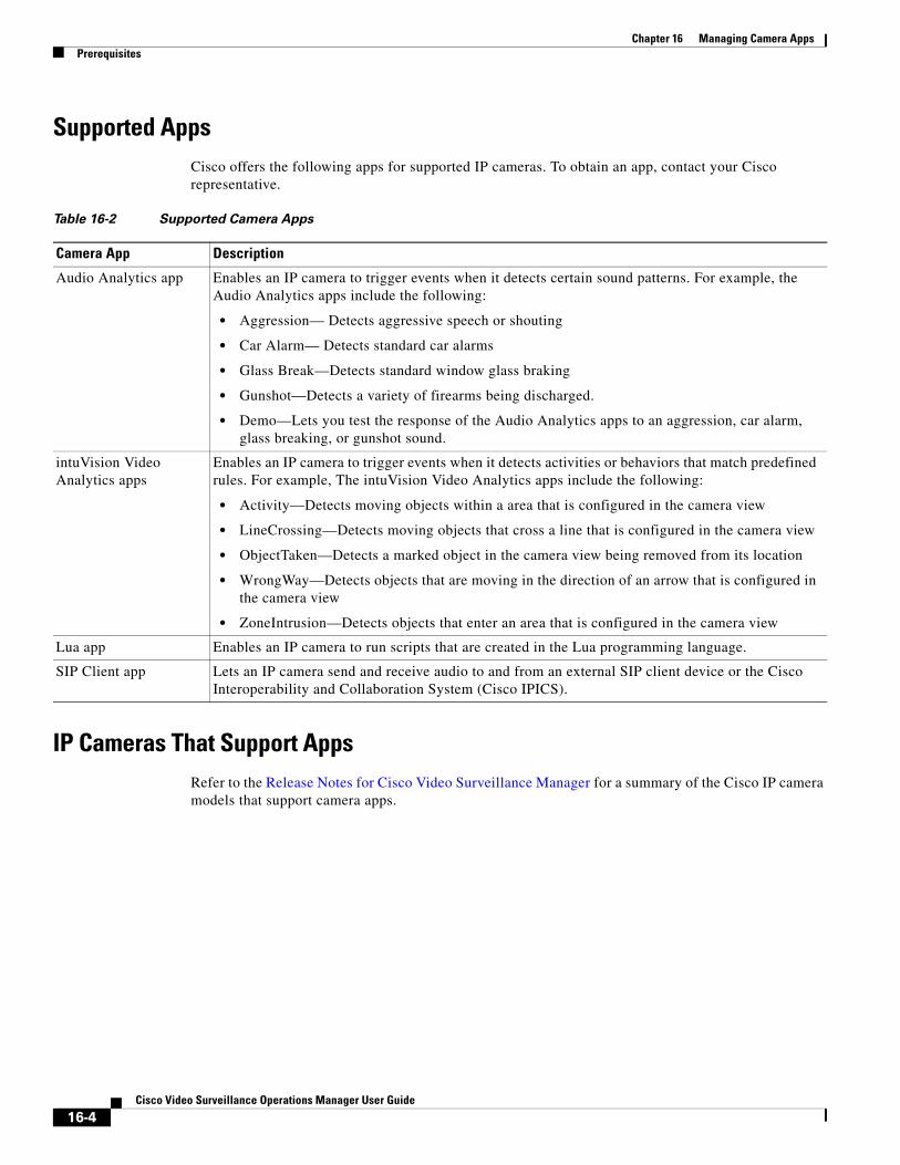
Chapter 16 Managing Camera Apps Prerequisites
Supported AppsCisco offers the following apps for supported IP cameras. To obtain an app, contact your Cisco representative.
Table 16-2 Supported Camera Apps
Camera App Description
• Aggression— Detects aggressive speech or shouting
• Car Alarm— Detects standard car alarms
• Glass Break—Detects standard window glass braking
• Gunshot—Detects a variety of firearms being discharged.
• Demo—Lets you test the response of the Audio Analytics apps to an aggression, car alarm, glass breaking, or gunshot sound.
• Activity—Detects moving objects within a area that is configured in the camera view
• LineCrossing—Detects moving objects that cross a line that is configured in the camera view
• ObjectTaken—Detects a marked object in the camera view being removed from its location
• WrongWay—Detects objects that are moving in the direction of an arrow that is configured in the camera view
• ZoneIntrusion—Detects objects that enter an area that is configured in the camera view
IP Cameras That Support AppsRefer to the Release Notes for Cisco Video Surveillance Manager for a summary of the Cisco IP camera models that support camera apps.
Audio Analytics app Enables an IP camera to trigger events when it detects certain sound patterns. For example, the Audio Analytics apps include the following:
intuVision Video Analytics apps
Enables an IP camera to trigger events when it detects activities or behaviors that match predefined rules. For example, The intuVision Video Analytics apps include the following:
Lua app Enables an IP camera to run scripts that are created in the Lua programming language.
SIP Client app Lets an IP camera send and receive audio to and from an external SIP client device or the Cisco Interoperability and Collaboration System (Cisco IPICS).
16-4Cisco Video Surveillance Operations Manager User Guide
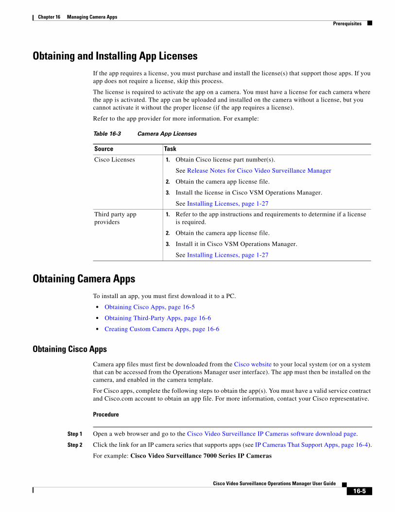
Chapter 16 Managing Camera AppsPrerequisites
Obtaining and Installing App LicensesIf the app requires a license, you must purchase and install the license(s) that support those apps. If you app does not require a license, skip this process.
The license is required to activate the app on a camera. You must have a license for each camera where the app is activated. The app can be uploaded and installed on the camera without a license, but you cannot activate it without the proper license (if the app requires a license).
Refer to the app provider for more information. For example:
Table 16-3 Camera App Licenses
Source Task
Obtain Cisco license part number(s). 1.
See Release Notes for Cisco Video Surveillance Manager
Obtain the camera app license file.2.
Install the license in Cisco VSM Operations Manager. 3.
See Installing Licenses, page 1-27
Refer to the app instructions and requirements to determine if a license is required.
1.
Obtain the camera app license file. 2.
Install it in Cisco VSM Operations Manager. 3.
See Installing Licenses, page 1-27
Obtaining Camera AppsTo install an app, you must first download it to a PC.
• Obtaining Cisco Apps, page 16-5
• Obtaining Third-Party Apps, page 16-6
• Creating Custom Camera Apps, page 16-6
Obtaining Cisco Apps
Camera app files must first be downloaded from the Cisco website to your local system (or on a system that can be accessed from the Operations Manager user interface). The app must then be installed on the camera, and enabled in the camera template.
For Cisco apps, complete the following steps to obtain the app(s). You must have a valid service contract and Cisco.com account to obtain an app file. For more information, contact your Cisco representative.
Procedure
Step 1 Open a web browser and go to the Cisco Video Surveillance IP Cameras software download page.
Step 2 Click the link for an IP camera series that supports apps (see IP Cameras That Support Apps, page 16-4).
For example: Cisco Video Surveillance 7000 Series IP Cameras
Cisco Licenses
Third party app providers
16-5Cisco Video Surveillance Operations Manager User Guide
Chapter 16 Managing Camera Apps Prerequisites
Step 3 Click your IP camera model in the list that appears on the right.
For example: Cisco Video Surveillance 7030 IP Camera.
Step 4 Click the IP Camera Applications and Utilities link near the top of the page.
Step 5 Click Download next to the app file that you want to obtain.
For example: Cisco Camera LUA Application version.
Step 6 In the Log In and Service Contract Required dialog box, click the Login button.
Step 7 In the Log In page, enter your Cisco.com user name and password, then click the Log In button.
Step 8 In the End User License Agreement dialog box, click the Cisco End User License Agreement link to review the agreement, then click the Accept License Agreement button to continue.
Step 9 Follow the on-screen prompts to save the license file to your local system or to a system that can be accessed from the IP camera user interface.
Obtaining Third-Party Apps
For third-party apps, refer to the app provider documentation or website for instructions to download the app.
The app must be installed on the camera, and enabled in the camera template.
Creating Custom Camera Apps
To create custom application that runs on a camera and triggers a Cisco VSM event, refer to the following:
• The camera software development kit (SDK) for your camera model.
• The Cisco Video Surveillance API Programming Guide—Available on the Cisco Developer Network (CDN), or see your Cisco support representative for more information.
The camera app should include a Camera App custom event type that is added to Cisco VSM Advanced Events when the app is added to Cisco VSM.
See the following for more information:
• Using Advanced Events to Trigger Actions, page 15-7
• Creating Custom Event Types and Sub Types, page 15-16
16-6Cisco Video Surveillance Operations Manager User Guide
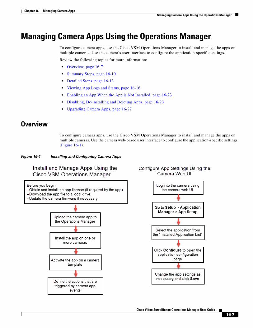
Chapter 16 Managing Camera AppsManaging Camera Apps Using the Operations Manager
Managing Camera Apps Using the Operations ManagerTo configure camera apps, use the Cisco VSM Operations Manager to install and manage the apps on multiple cameras. Use the camera’s user interface to configure the application-specific settings.
Review the following topics for more information:
• Overview, page 16-7
• Summary Steps, page 16-10
• Detailed Steps, page 16-13
• Viewing App Logs and Status, page 16-16
• Enabling an App When the App is Not Installed, page 16-23
• Disabling, De-installing and Deleting Apps, page 16-23
• Upgrading Camera Apps, page 16-27
OverviewTo configure camera apps, use the Cisco VSM Operations Manager to install and manage the apps on multiple cameras. Use the camera web-based user interface to configure the application-specific settings (Figure 16-1).
Figure 16-1 Installing and Configuring Camera Apps
16-7Cisco Video Surveillance Operations Manager User Guide
Chapter 16 Managing Camera Apps Managing Camera Apps Using the Operations Manager
Note Camera apps can only be managed by a single Operations Manager. Always delete the app and camera from the first Operations Manager before adding it to another system. See Troubleshooting Camera Apps, page 16-28
Using the Camera Web Interface to Define Application SettingsThe camera’s browser-based user interface can be used to install and manage apps on the camera, and to configure the application-specific settings. After the camera is added to Cisco VSM, however, the camera UI is used only to configure the app. Apps are installed and managed using the Operations Manager.
Related Information
• Cisco IP Camera Apps Reference Guide—describes how to configure the application-specific settings for supported apps, and how to install and manage camera apps using the camera web user interface, if the camera has not been added to Cisco VSM.
• Camera documentation—see the documentation for the camera model for device installation and management information.
Procedure
Use the following summary to access the application-specific settings on a camera that supports apps. See the Cisco IP Camera Apps Reference Guide for more information.
Step 1 Log into the camera using camera web UI.
Step 2 Go to Setup > Application Manager > App Setup (Figure 16-2).
Tip The Application Manager pages allow you to install or uninstall an app license, camera application, and start or stop an application. These features are disabled if the camera is added to Cisco VSM (use the Operations Manager to manage the camera’s apps).
16-8Cisco Video Surveillance Operations Manager User Guide
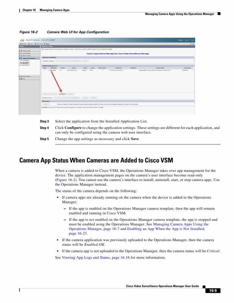
Chapter 16 Managing Camera AppsManaging Camera Apps Using the Operations Manager
Figure 16-2 Camera Web UI for App Configuration
Step 3 Select the application from the Installed Application List.
Step 4 Click Configure to change the application settings. These settings are different for each application, and can only be configured using the camera web user interface.
Step 5 Change the app settings as necessary and click Save.
Camera App Status When Cameras are Added to Cisco VSMWhen a camera is added to Cisco VSM, the Operations Manager takes over app management for the device. The application management pages on the camera’s user interface become read-only (Figure 16-2). You cannot use the camera’s interface to install, uninstall, start, or stop camera apps. Use the Operations Manager instead.
The status of the camera depends on the following:
• If camera apps are already running on the camera when the device is added to the Operations Manager:
– If the app is enabled on the Operations Manager camera template, then the app will remain enabled and running in Cisco VSM.
– If the app is not enabled on the Operations Manager camera template, the app is stopped and must be enabled using the Operations Manager. See Managing Camera Apps Using the Operations Manager, page 16-7 and Enabling an App When the App is Not Installed, page 16-23.
• If the camera application was previously uploaded to the Operations Manager, then the camera status will be Enabled:OK.
• If the camera app is not uploaded to the Operations Manager, then the camera status will be Critical.
See Viewing App Logs and Status, page 16-16 for more information.
16-9Cisco Video Surveillance Operations Manager User Guide
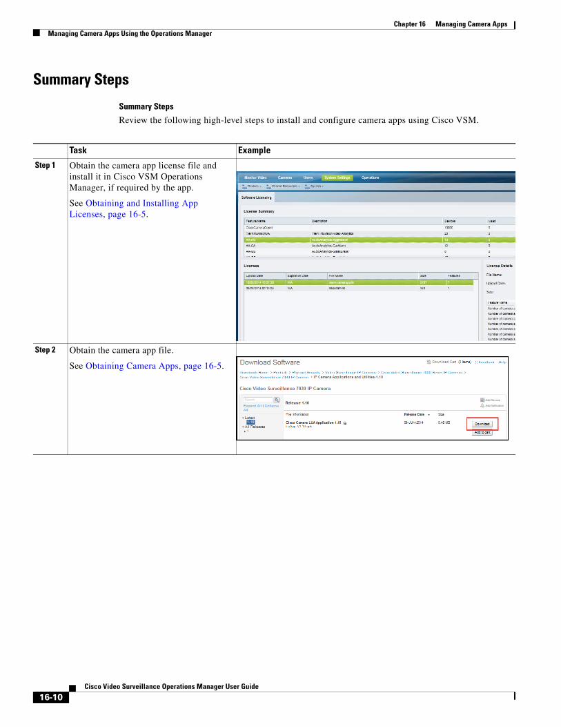
Chapter 16 Managing Camera Apps Managing Camera Apps Using the Operations Manager
Summary Steps
Summary Steps
Review the following high-level steps to install and configure camera apps using Cisco VSM.
Task Example
Step 1 Obtain the camera app license file and install it in Cisco VSM Operations Manager, if required by the app.
See Obtaining and Installing App Licenses, page 16-5.
Step 2 Obtain the camera app file.
See Obtaining Camera Apps, page 16-5.
16-10Cisco Video Surveillance Operations Manager User Guide
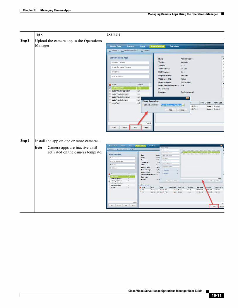
Chapter 16 Managing Camera AppsManaging Camera Apps Using the Operations Manager
Step 3 Upload the camera app to the Operations Manager.
Step 4 Install the app on one or more cameras.
Note Camera apps are inactive until activated on the camera template.
Task Example
16-11Cisco Video Surveillance Operations Manager User Guide
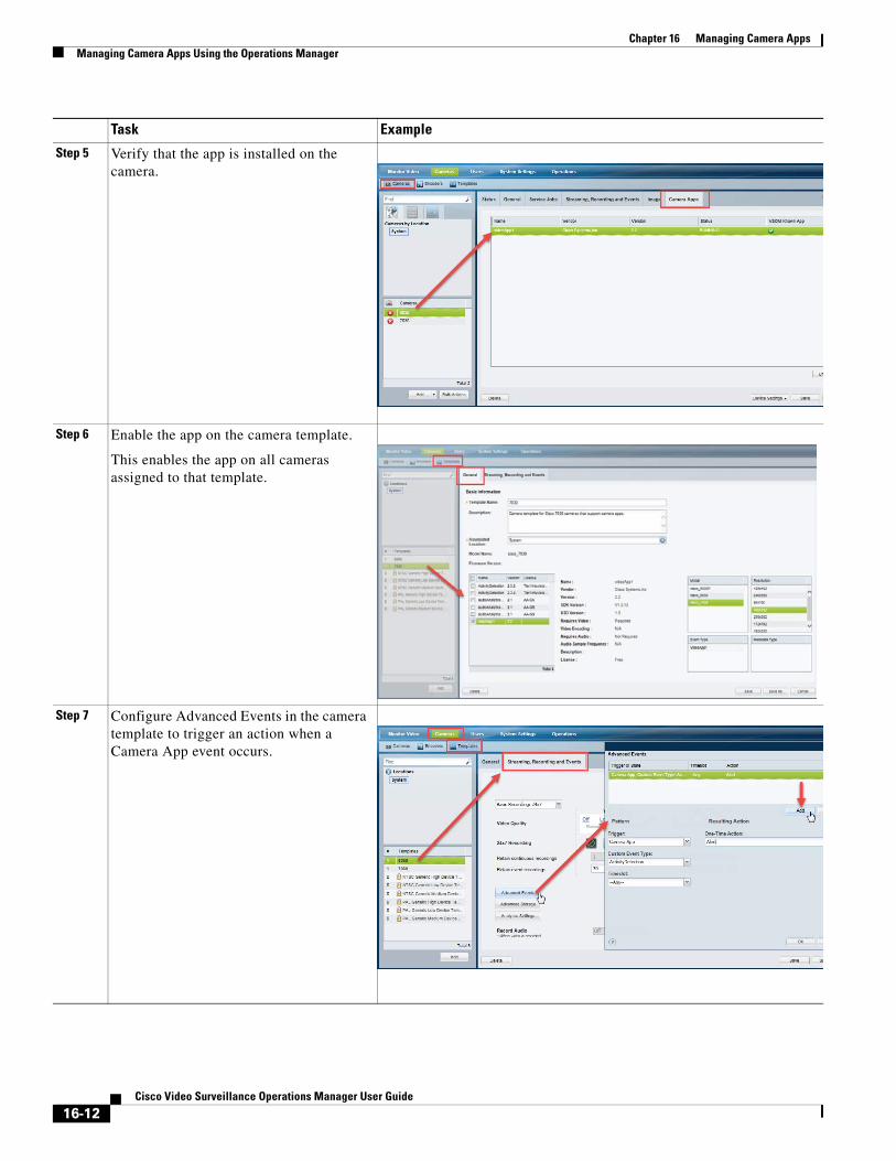
Chapter 16 Managing Camera Apps Managing Camera Apps Using the Operations Manager
Step 5 Verify that the app is installed on the camera.
Step 6 Enable the app on the camera template.
This enables the app on all cameras assigned to that template.
Step 7 Configure Advanced Events in the camera template to trigger an action when a Camera App event occurs.
Task Example
16-12Cisco Video Surveillance Operations Manager User Guide
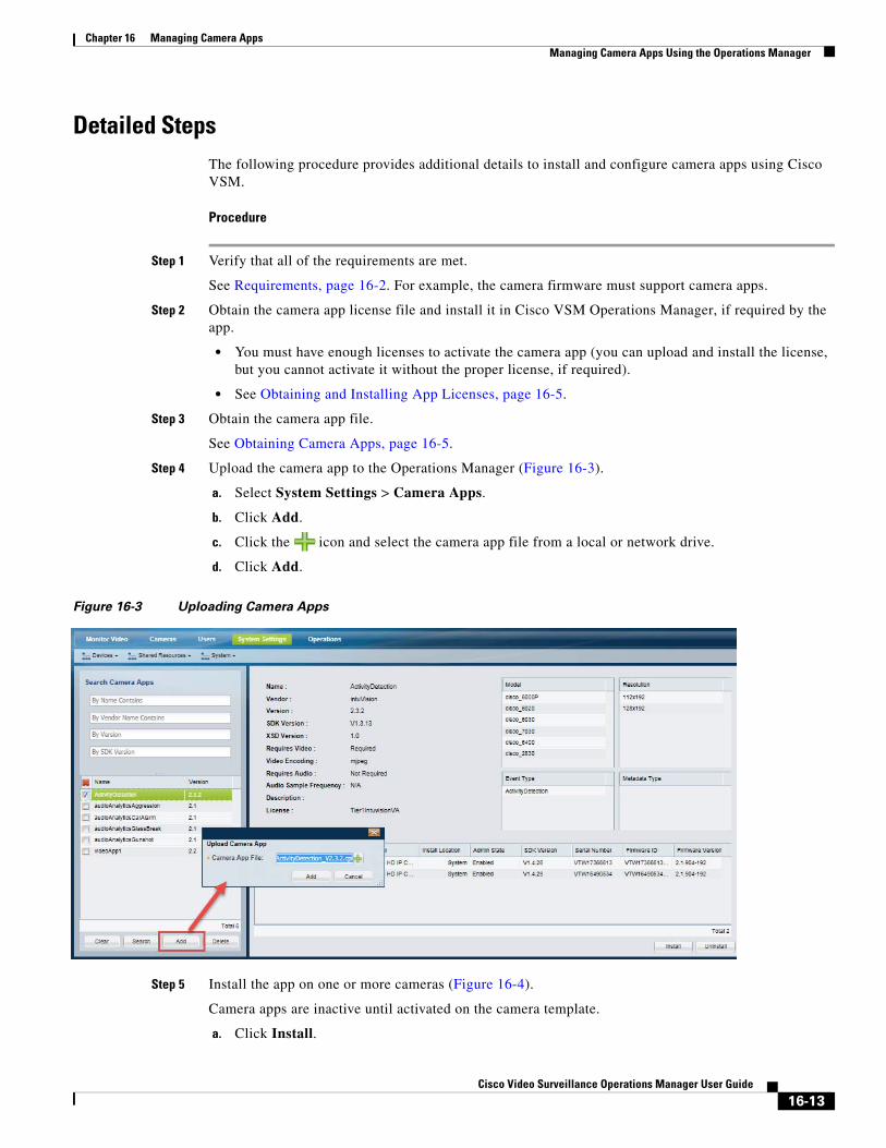
Chapter 16 Managing Camera AppsManaging Camera Apps Using the Operations Manager
Detailed StepsThe following procedure provides additional details to install and configure camera apps using Cisco VSM.
Procedure
Step 1 Verify that all of the requirements are met.
See Requirements, page 16-2. For example, the camera firmware must support camera apps.
Step 2 Obtain the camera app license file and install it in Cisco VSM Operations Manager, if required by the app.
• You must have enough licenses to activate the camera app (you can upload and install the license, but you cannot activate it without the proper license, if required).
• See Obtaining and Installing App Licenses, page 16-5.
Step 3 Obtain the camera app file.
See Obtaining Camera Apps, page 16-5.
Step 4 Upload the camera app to the Operations Manager (Figure 16-3).
a. Select System Settings > Camera Apps.
b. Click Add.
c. Click the icon and select the camera app file from a local or network drive.
d. Click Add.
Figure 16-3 Uploading Camera Apps
Step 5 Install the app on one or more cameras (Figure 16-4).
Camera apps are inactive until activated on the camera template.
a. Click Install.
16-13Cisco Video Surveillance Operations Manager User Guide
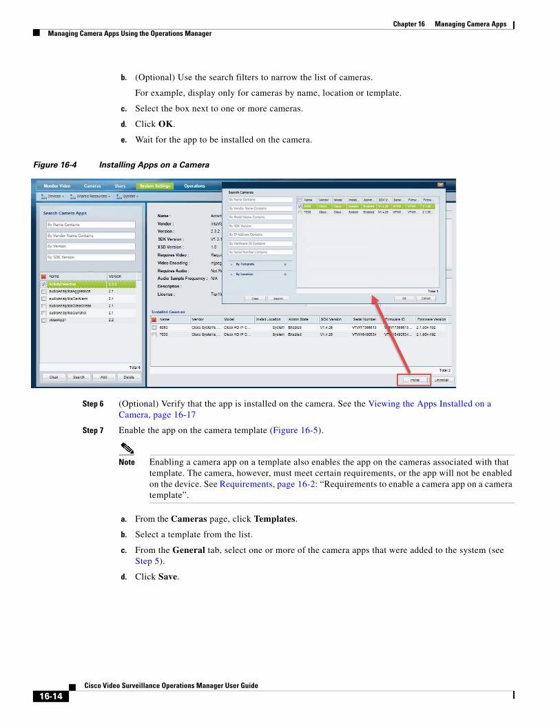
Chapter 16 Managing Camera Apps Managing Camera Apps Using the Operations Manager
b. (Optional) Use the search filters to narrow the list of cameras.
For example, display only for cameras by name, location or template.
c. Select the box next to one or more cameras.
d. Click OK.
e. Wait for the app to be installed on the camera.
Figure 16-4 Installing Apps on a Camera
Step 6 (Optional) Verify that the app is installed on the camera. See the Viewing the Apps Installed on a Camera, page 16-17
Step 7 Enable the app on the camera template (Figure 16-5).
Note Enabling a camera app on a template also enables the app on the cameras associated with that template. The camera, however, must meet certain requirements, or the app will not be enabled on the device. See Requirements, page 16-2: “Requirements to enable a camera app on a camera template”.
a. From the Cameras page, click Templates.
b. Select a template from the list.
c. From the General tab, select one or more of the camera apps that were added to the system (see Step 5).
d. Click Save.
16-14Cisco Video Surveillance Operations Manager User Guide
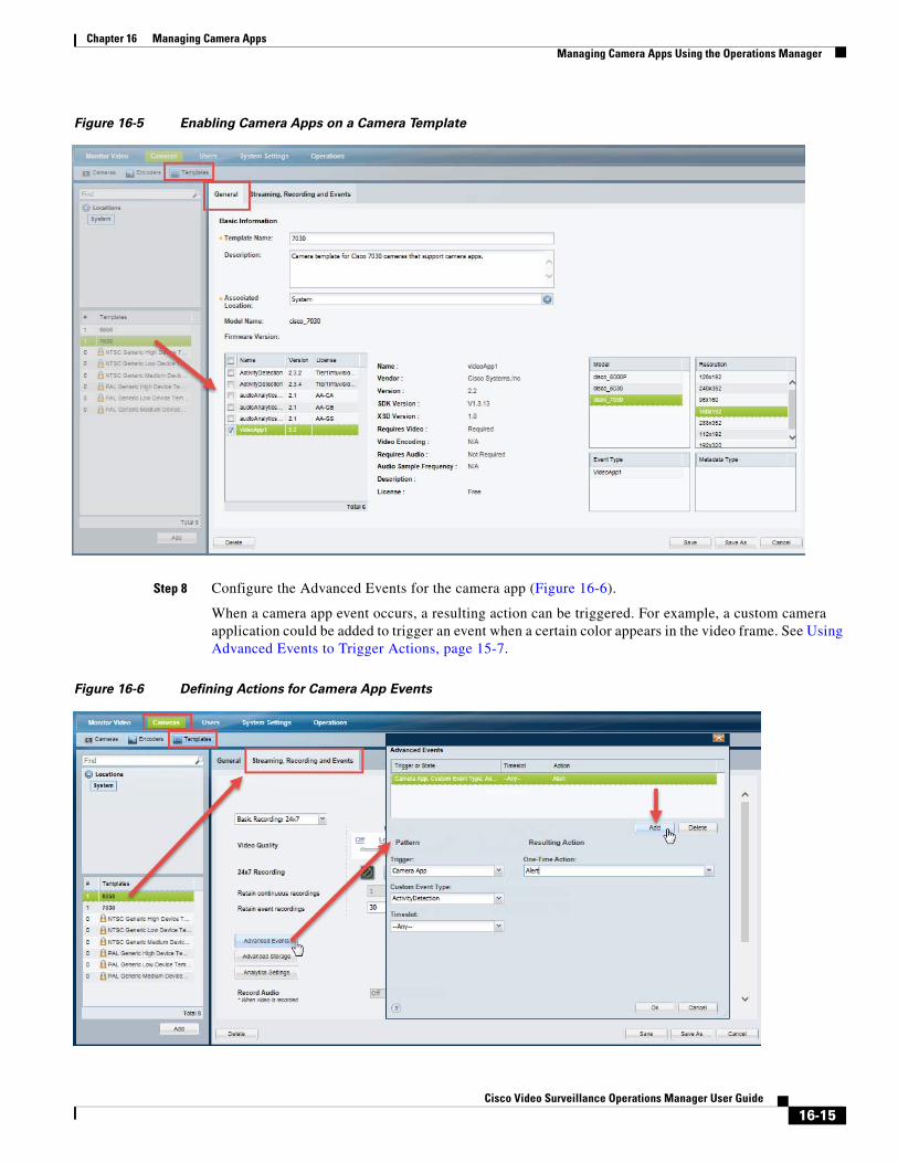
Chapter 16 Managing Camera AppsManaging Camera Apps Using the Operations Manager
Figure 16-5 Enabling Camera Apps on a Camera Template
Step 8 Configure the Advanced Events for the camera app (Figure 16-6).
When a camera app event occurs, a resulting action can be triggered. For example, a custom camera application could be added to trigger an event when a certain color appears in the video frame. See Using Advanced Events to Trigger Actions, page 15-7.
Figure 16-6 Defining Actions for Camera App Events
16-15Cisco Video Surveillance Operations Manager User Guide
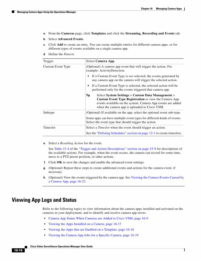
Chapter 16 Managing Camera Apps Managing Camera Apps Using the Operations Manager
a. From the Cameras page, click Templates and click the Streaming, Recording and Events tab.
b. Select Advanced Events.
c. Click Add to create an entry. You can create multiple entries for different camera apps, or for different types of events available on a single camera app.
d.
• If a Custom Event Type is not selected, the events generated by any camera app on the camera will trigger the selected action.
• If a Custom Event Type is selected, the selected action will be performed only for the events triggered that camera app.
Tip Select System Settings > Custom Data Management > Custom Event Type Registration to view the Camera App events available on the system. Camera App events are added when the camera app is uploaded to Cisco VSM.
Define the Pattern:
e. Select a Resulting Action for the event.
See Table 15-4 of the “Trigger and Action Descriptions” section on page 15-9 for descriptions of the available actions. For example, when the event occurs, the camera can record for some time, move to a PTZ preset position, or other actions.
f. Click OK to save the changes and enable the advanced event settings.
g. (Optional) Repeat these steps to create additional events and actions for the camera event, if necessary.
h. (Optional) View the events triggered by the camera app. See Viewing the Camera Events Caused by a Camera App, page 16-22.
Viewing App Logs and StatusRefer to the following topics to view information about the camera apps installed and activated on the cameras in your deployment, and to identify and resolve camera app errors.
• Camera App Status When Cameras are Added to Cisco VSM, page 16-9
• Viewing the Apps Installed on a Camera, page 16-17
• Viewing the Apps that are Enabled on a Template, page 16-18
• Viewing the Camera App Jobs for a Specific Camera, page 16-19
Trigger Select Camera App.
Custom Event Type (Optional) A camera app event that will trigger the action. For example: ActivityDetection.
Subtype (Optional) If available on the app, select the optional event sub-type.
Some apps can have multiple event types for different kinds of events. Select the event type that should trigger the action.
Timeslot Select a Timeslot when the event should trigger an action.
See the “Defining Schedules” section on page 12-1 to create timeslots.
16-16Cisco Video Surveillance Operations Manager User Guide
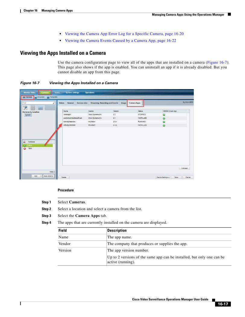
Chapter 16 Managing Camera AppsManaging Camera Apps Using the Operations Manager
• Viewing the Camera App Error Log for a Specific Camera, page 16-20
• Viewing the Camera Events Caused by a Camera App, page 16-22
Viewing the Apps Installed on a Camera
Use the camera configuration page to view all of the apps that are installed on a camera (Figure 16-7). This page also shows if the app is enabled. You can uninstall an app if it is already disabled. But you cannot disable an app from this page.
Figure 16-7 Viewing the Apps Installed on a Camera
Procedure
Step 1 Select Cameras.
Step 2 Select a location and select a camera from the list.
Step 3 Select the Camera Apps tab.
Step 4 The apps that are currently installed on the camera are displayed.
Field Description
Name The app name.
Vendor The company that produces or supplies the app.
Version The app version number.
Up to 2 versions of the same app can be installed, but only one can be active (running).
16-17Cisco Video Surveillance Operations Manager User Guide
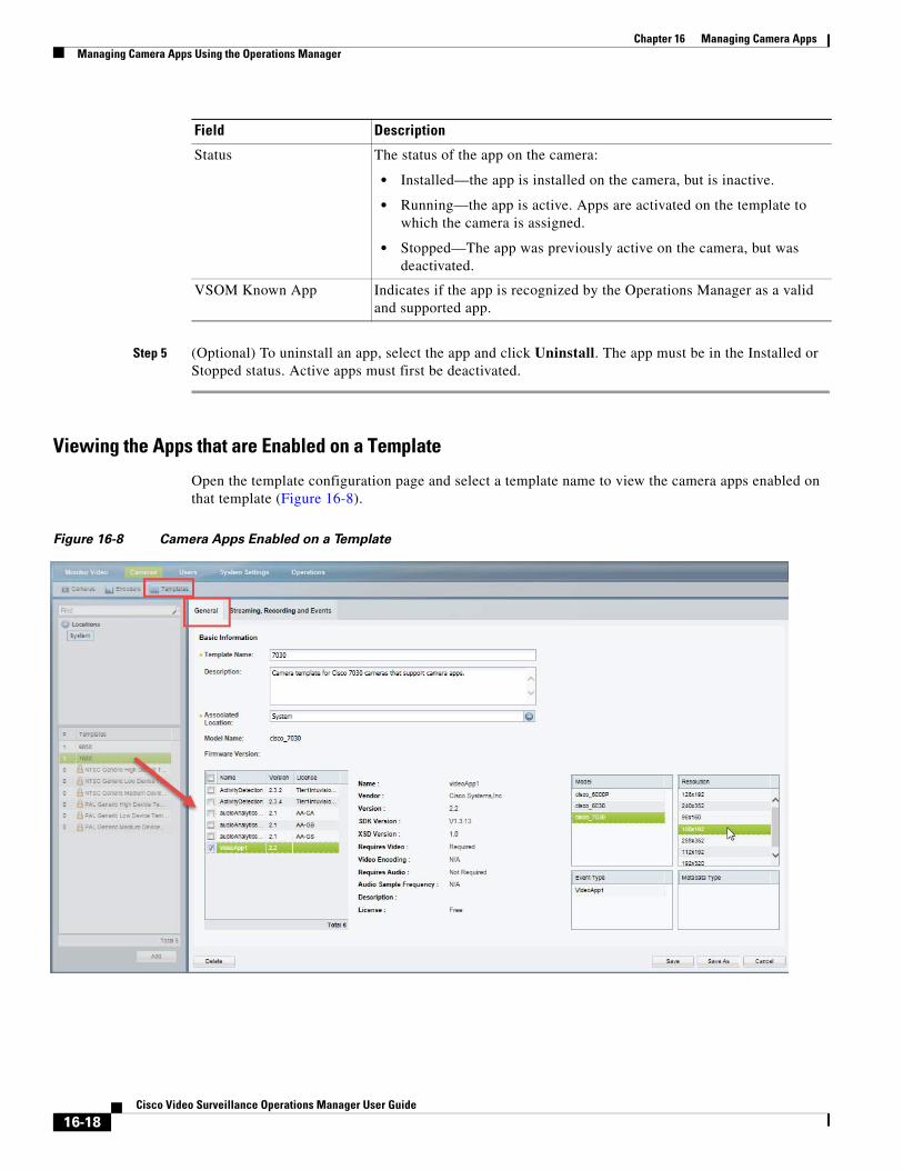
Chapter 16 Managing Camera Apps Managing Camera Apps Using the Operations Manager
Step 5 (Optional) To uninstall an app, select the app and click Uninstall. The app must be in the Installed or Stopped status. Active apps must first be deactivated.
Viewing the Apps that are Enabled on a Template
Open the template configuration page and select a template name to view the camera apps enabled on that template (Figure 16-8).
Figure 16-8 Camera Apps Enabled on a Template
Status The status of the app on the camera:
• Installed—the app is installed on the camera, but is inactive.
• Running—the app is active. Apps are activated on the template to which the camera is assigned.
• Stopped—The app was previously active on the camera, but was deactivated.
VSOM Known App Indicates if the app is recognized by the Operations Manager as a valid and supported app.
Field Description
16-18Cisco Video Surveillance Operations Manager User Guide
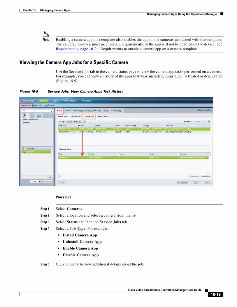
Chapter 16 Managing Camera AppsManaging Camera Apps Using the Operations Manager
Note Enabling a camera app on a template also enables the app on the cameras associated with that template. The camera, however, must meet certain requirements, or the app will not be enabled on the device. See Requirements, page 16-2: “Requirements to enable a camera app on a camera template”.
Viewing the Camera App Jobs for a Specific Camera
Use the Service Jobs tab in the camera status page to view the camera app tasks performed on a camera. For example, you can view a history of the apps that were installed, uninstalled, activated or deactivated (Figure 16-9).
Figure 16-9 Service Jobs: View Camera Apps Task History
Procedure
Step 1 Select Cameras.
Step 2 Select a location and select a camera from the list.
Step 3 Select Status and then the Service Jobs tab.
Step 4 Select a Job Type. For example:
• Install Camera App
• Uninstall Camera App
• Enable Camera App
• Disable Camera App
Step 5 Click an entry to view additional details about the job.
16-19Cisco Video Surveillance Operations Manager User Guide
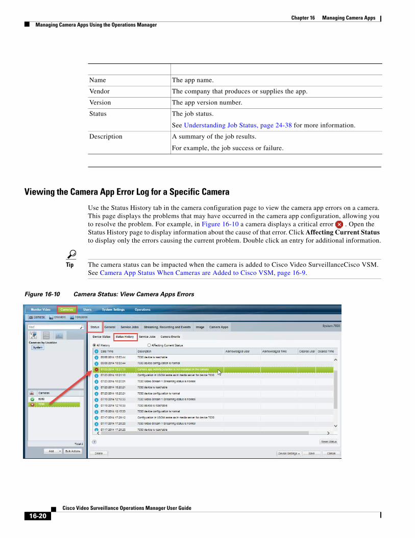
Chapter 16 Managing Camera Apps Managing Camera Apps Using the Operations Manager
Field Description
Viewing the Camera App Error Log for a Specific Camera
Use the Status History tab in the camera configuration page to view the camera app errors on a camera. This page displays the problems that may have occurred in the camera app configuration, allowing you to resolve the problem. For example, in Figure 16-10 a camera displays a critical error . Open the Status History page to display information about the cause of that error. Click Affecting Current Status to display only the errors causing the current problem. Double click an entry for additional information.
Tip The camera status can be impacted when the camera is added to Cisco Video SurveillanceCisco VSM. See Camera App Status When Cameras are Added to Cisco VSM, page 16-9.
Figure 16-10 Camera Status: View Camera Apps Errors
Name The app name.
Vendor The company that produces or supplies the app.
Version The app version number.
Status The job status.
See Understanding Job Status, page 24-38 for more information.
Description A summary of the job results.
For example, the job success or failure.
16-20Cisco Video Surveillance Operations Manager User Guide
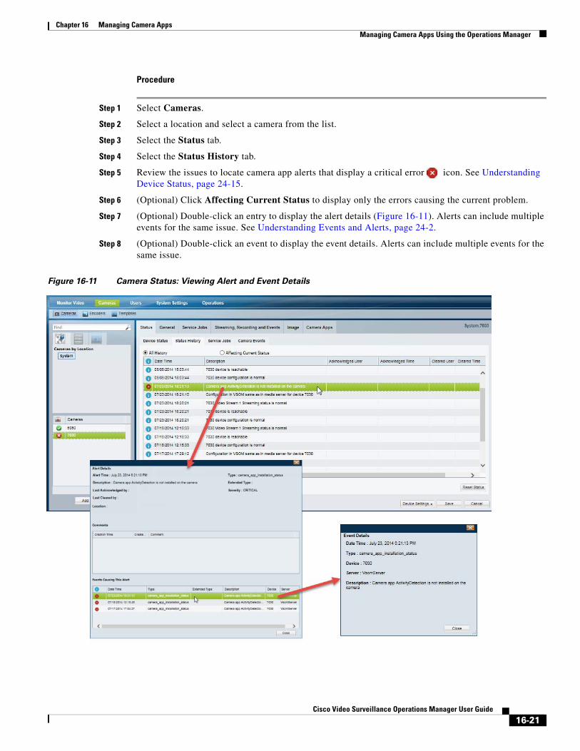
Chapter 16 Managing Camera AppsManaging Camera Apps Using the Operations Manager
Procedure
Step 1 Select Cameras.
Step 2 Select a location and select a camera from the list.
Step 3 Select the Status tab.
Step 4 Select the Status History tab.
Step 5 Review the issues to locate camera app alerts that display a critical error icon. See Understanding Device Status, page 24-15.
Step 6 (Optional) Click Affecting Current Status to display only the errors causing the current problem.
Step 7 (Optional) Double-click an entry to display the alert details (Figure 16-11). Alerts can include multiple events for the same issue. See Understanding Events and Alerts, page 24-2.
Step 8 (Optional) Double-click an event to display the event details. Alerts can include multiple events for the same issue.
Figure 16-11 Camera Status: Viewing Alert and Event Details
16-21Cisco Video Surveillance Operations Manager User Guide
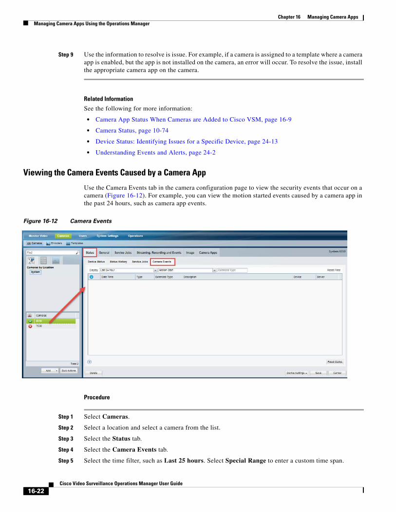
Chapter 16 Managing Camera Apps Managing Camera Apps Using the Operations Manager
Step 9 Use the information to resolve is issue. For example, if a camera is assigned to a template where a camera app is enabled, but the app is not installed on the camera, an error will occur. To resolve the issue, install the appropriate camera app on the camera.
Related Information
See the following for more information:
• Camera App Status When Cameras are Added to Cisco VSM, page 16-9
• Camera Status, page 10-74
• Device Status: Identifying Issues for a Specific Device, page 24-13
• Understanding Events and Alerts, page 24-2
Viewing the Camera Events Caused by a Camera App
Use the Camera Events tab in the camera configuration page to view the security events that occur on a camera (Figure 16-12). For example, you can view the motion started events caused by a camera app in the past 24 hours, such as camera app events.
Figure 16-12 Camera Events
Procedure
Step 1 Select Cameras.
Step 2 Select a location and select a camera from the list.
Step 3 Select the Status tab.
Step 4 Select the Camera Events tab.
Step 5 Select the time filter, such as Last 25 hours. Select Special Range to enter a custom time span.
16-22Cisco Video Surveillance Operations Manager User Guide
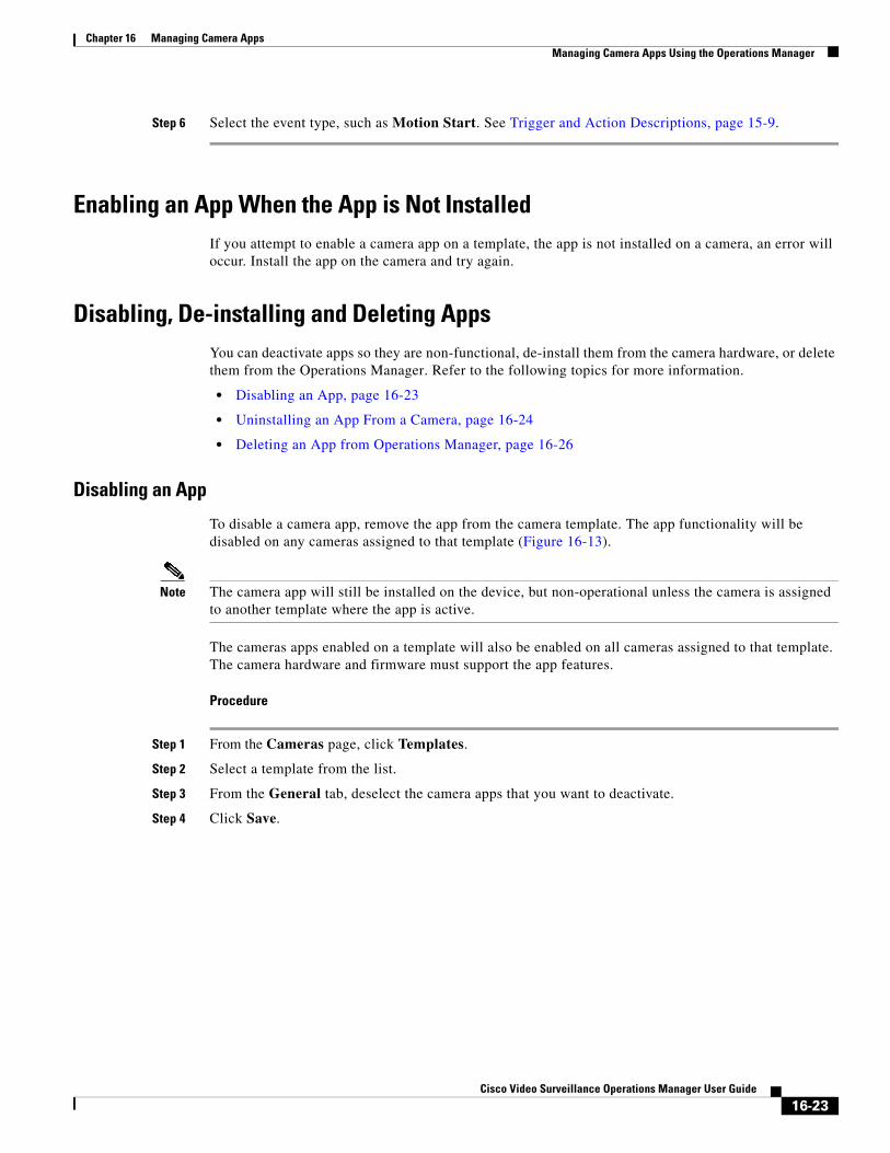
Chapter 16 Managing Camera AppsManaging Camera Apps Using the Operations Manager
Step 6 Select the event type, such as Motion Start. See Trigger and Action Descriptions, page 15-9.
Enabling an App When the App is Not Installed If you attempt to enable a camera app on a template, the app is not installed on a camera, an error will occur. Install the app on the camera and try again.
Disabling, De-installing and Deleting AppsYou can deactivate apps so they are non-functional, de-install them from the camera hardware, or delete them from the Operations Manager. Refer to the following topics for more information.
• Disabling an App, page 16-23
• Uninstalling an App From a Camera, page 16-24
• Deleting an App from Operations Manager, page 16-26
Disabling an App
To disable a camera app, remove the app from the camera template. The app functionality will be disabled on any cameras assigned to that template (Figure 16-13).
Note The camera app will still be installed on the device, but non-operational unless the camera is assigned to another template where the app is active.
The cameras apps enabled on a template will also be enabled on all cameras assigned to that template. The camera hardware and firmware must support the app features.
Procedure
Step 1 From the Cameras page, click Templates.
Step 2 Select a template from the list.
Step 3 From the General tab, deselect the camera apps that you want to deactivate.
Step 4 Click Save.
16-23Cisco Video Surveillance Operations Manager User Guide
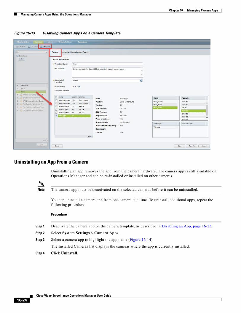
Chapter 16 Managing Camera Apps Managing Camera Apps Using the Operations Manager
Figure 16-13 Disabling Camera Apps on a Camera Template
Uninstalling an App From a Camera
Uninstalling an app removes the app from the camera hardware. The camera app is still available on Operations Manager and can be re-installed or installed on other cameras.
Note The camera app must be deactivated on the selected cameras before it can be uninstalled.
You can uninstall a camera app from one camera at a time. To uninstall additional apps, repeat the following procedure.
Procedure
Step 1 Deactivate the camera app on the camera template, as described in Disabling an App, page 16-23.
Step 2 Select System Settings > Camera Apps.
Step 3 Select a camera app to highlight the app name (Figure 16-14).
The Installed Cameras list displays the cameras where the app is currently installed.
Step 4 Click Uninstall.
16-24Cisco Video Surveillance Operations Manager User Guide
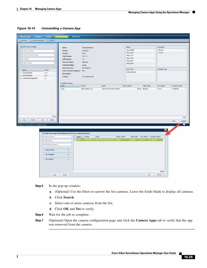
Chapter 16 Managing Camera AppsManaging Camera Apps Using the Operations Manager
Figure 16-14 Uninstalling a Camera App
Step 5 In the pop-up window:
a. (Optional) Use the filters to narrow the list cameras. Leave the fields blank to display all cameras.
b. Click Search.
c. Select one or more cameras from the list.
d. Click OK and Yes to verify.
Step 6 Wait for the job to complete.
Step 7 (Optional) Open the camera configuration page and click the Camera Apps tab to verify that the app was removed from the camera.
16-25Cisco Video Surveillance Operations Manager User Guide
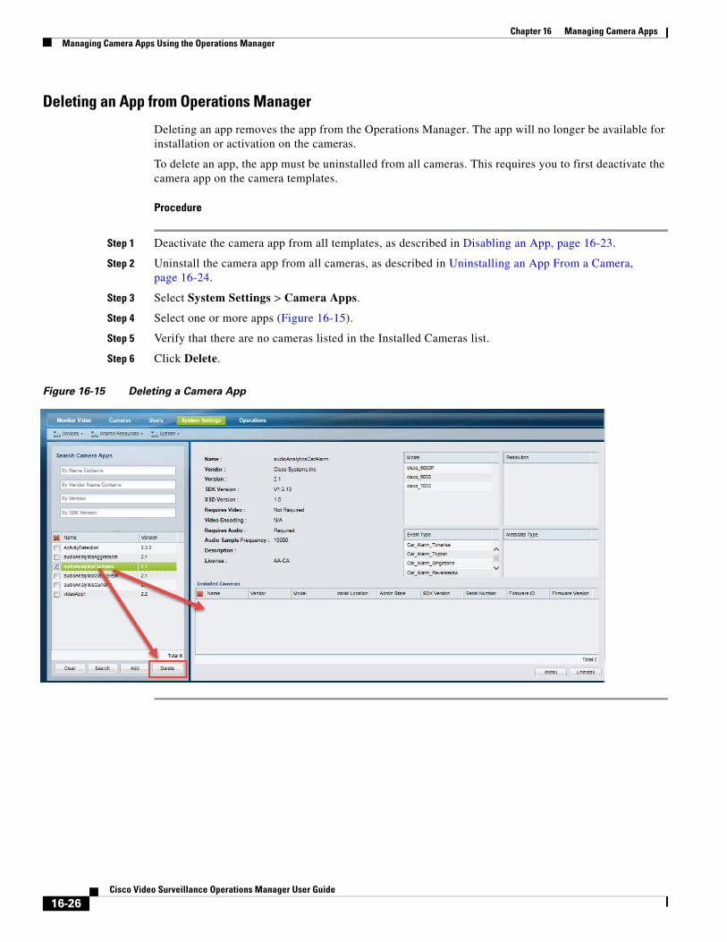
Chapter 16 Managing Camera Apps Managing Camera Apps Using the Operations Manager
Deleting an App from Operations Manager
Deleting an app removes the app from the Operations Manager. The app will no longer be available for installation or activation on the cameras.
To delete an app, the app must be uninstalled from all cameras. This requires you to first deactivate the camera app on the camera templates.
Procedure
Step 1 Deactivate the camera app from all templates, as described in Disabling an App, page 16-23.
Step 2 Uninstall the camera app from all cameras, as described in Uninstalling an App From a Camera, page 16-24.
Step 3 Select System Settings > Camera Apps.
Step 4 Select one or more apps (Figure 16-15).
Step 5 Verify that there are no cameras listed in the Installed Cameras list.
Step 6 Click Delete.
Figure 16-15 Deleting a Camera App
16-26Cisco Video Surveillance Operations Manager User Guide
Chapter 16 Managing Camera AppsManaging Camera Apps Using the Operations Manager
Upgrading Camera AppsTo upgrade a camera app, upload the new version of the app to the Operations Manager. When you activate the new app version on a template, the old version will be deactivated.
Usage Notes
• You can upload multiple versions of the app to the Operations Manager, and install up to 2 versions on the camera, but only one app version can be active on a template or camera.
• When you activate the new version, the old version is automatically uninstalled from the camera.
• Advanced Event configurations must be deleted and re-added. See Configure the Advanced Events for the camera app (Figure 16-6)., page 15.
• The template and event/trigger processing is stopped and restarted during the upgrade process (while the old app is deactivated and uninstalled, and the new app is activated). Event and trigger processing may be delayed or interrupted.
• Up to 2 camera apps can be upgraded at a time (by activating the new versions in the template). Wait for the upgrade to complete before upgrading additional apps.
Procedure
See Detailed Steps, page 16-13 for instructions to perform the following tasks.
Step 1 Upload the new version of the camera app to the Operations Manager.
Multiple app versions can be uploaded to the Operations Manager.
Step 2 Install the new camera app version on a camera.
A maximum of 2 versions of the same app can be installed on a camera.
Step 3 Activate the new app version on a template, as described in Detailed Steps, page 16-13.
When the new camera app version is activated, the old app version is automatically uninstalled on the camera.
16-27Cisco Video Surveillance Operations Manager User Guide
Chapter 16 Managing Camera Apps Troubleshooting Camera Apps
Troubleshooting Camera Apps • Camera Apps Cannot Be Added to Multiple Operations Managers, page 16-28
• Camera App Licenses Must be Installed Using Operations Manager, page 16-28
• Camera Apps Are Disabled for When Modifying Templates, page 16-29
Camera Apps Cannot Be Added to Multiple Operations ManagersIf a camera that has camera apps enabled is added to more than one Operations Manager, any changes to the camera app will not work. For example, you cannot install, start or stop the app.
Camera apps can only be managed by a single Operations Manager. Always delete the app and camera from the first Operations Manager before adding it to another system.
Recovery Procedure.
Step 1 Delete the camera from second Operations Manager.
Step 2 If the camera app is stopped because it was added to a second Operations Manager, disable the app in the associated template on the first Operations Manager.
Step 3 Enable the app in associated template in first Operations Manager.
Camera App Licenses Must be Installed Using Operations ManagerThere are two types of camera app licenses:
• A device-specific license installed directly on a single device. This license does not allow Operations Manager to manage the license or app.
• A single or group license that is installed and managed using Operations Manager.
Only one of these license types can be active on the camera device at a time. To use the license(s) managed by Operations Manager, you must first deactivate any device-specific licenses.
Procedure
Step 1 If any camera app licenses are installed on the device, deinstall those licenses using the camera UI.
Step 2 Obtain the Operations Manager license(s). See the “Installing Licenses” section on page 1-27.
Step 3 Install and manage the camera app licenses. See Managing Camera Apps Using the Operations Manager, page 16-7 for more information.
16-28Cisco Video Surveillance Operations Manager User Guide
Chapter 16 Managing Camera AppsRelated Documentation
Camera Apps Are Disabled for When Modifying Templates Camera video apps may be automatically disabled on Cisco cameras if the camera template is modified in one of the following ways:
1. Camera video apps are automatically disabled on Cisco cameras if a custom template is applied that is configured with a high primary stream resolution (5M) or a frame rate higher than 15fps. This occurs even if camera apps are enabled on the template. A configuration mismatch also occurs on the device. To avoid this, you must configure the camera custom template before enabling the camera apps.
Affected Cameras—Cisco camera models starting with 6xxx, 7xxx,3xxx and 283x.
2. If the device has camera apps enabled, and the primary stream configuration is changed from Low or Medium to High, or if you enable the secondary video stream, then the camera apps are automatically disabled on the device.
Affected Cameras—Cisco camera models starting with 3xxx and 283x.
To avoid this, you must configure the camera custom template before enabling the camera apps, as described in the following Workaround.
Workaround
1. Disable all video apps that are running on the device.
2. Change the configuration, as necessary:
a. Configure the custom template with high primary stream resolution or a frame rate higher than 15fps.
b. Enable the secondary video stream.
3. Enable all required camera apps in the camera’s custom template.
See CSCuq09351 for more information.
Related DocumentationTo install and manage camera apps directly on the camera, see the Cisco IP Camera Apps Reference Guide.
16-29Cisco Video Surveillance Operations Manager User Guide

Chapter 16 Managing Camera Apps Related Documentation
16-30Cisco Video Surveillance Operations Manager User Guide

Cisco V
C H A P T E R 17
Connected Edge Storage (On-Camera Recording)Cameras that support on-device storage can be used to record video on the device, rather than directly to a Cisco Media Server. This feature is typically used if the camera is offline (such as on a bus), or as a method to reduce network bandwidth usage (since the video can be recorded on the camera and transferred to the Media Server only when necessary).
Refer to the following topics for more information.
Contents
• Overview, page 17-3
– Deployment Scenarios, page 17-3
– Copy Options, page 17-5
– Usage Notes, page 17-6
– Requirements, page 17-7
– Supported IP Cameras (On-Device Storage), page 17-8
• Formatting Camera SD Cards, page 17-8
– SD Card Usage Notes, page 17-8
– Formatting the SD Card for a Single Camera, page 17-8
– Formatting the SD Cards in Multiple Cameras (Bulk Actions), page 17-9
• Configuring Connected Edge Storage, page 17-11
– Enable Connected Edge Storage (On-Camera Recording), page 17-11
– Auto-Merge Recordings (Automatically Copy All Recording), page 17-15
– Copy Continuous Recordings Triggered by an Event, page 17-17
• Manually Copy Camera Recordings, page 17-18
• Record Events on the Camera’s Storage Device, page 17-21
• Understanding the Recording Options, page 17-24
– Economical Streaming, page 17-25
– Connected Edge Storage, page 17-26
– Recording Options, page 17-26
• Viewing Camera Storage Job Status, page 17-27
• Timezone Best Practices, page 17-28
17-1ideo Surveillance Operations Manager User Guide

Chapter 17 Connected Edge Storage (On-Camera Recording)
• Related Recording Documentation, page 17-30
17-2Cisco Video Surveillance Operations Manager User Guide
Chapter 17 Connected Edge Storage (On-Camera Recording)Overview
Overview • Deployment Scenarios, page 17-3
• Copy Options, page 17-5
• Usage Notes, page 17-6
• Requirements, page 17-7
• Supported IP Cameras (On-Device Storage), page 17-8
Deployment ScenariosConnected Edge Storage is typically used when the camera is off network, or to save network bandwidth. Refer to the following use cases for more information:
• Network Bandwidth Savings, page 17-3
• Off-Network Cameras, page 17-4
Network Bandwidth Savings
If cameras are installed at a location where video is only required on demand, Connected Edge Storage can be used to dramatically reduce the required bandwidth and server storage. Video is saved on the camera storage device, such as an SD card, and delivered to the Media Server and end user only on demand. This eliminates the need for a locally-installed Media Server (Figure 17-1).
Instead of streaming video continuously, like most cameras, video is only sent when an event and/or request occurs.
17-3Cisco Video Surveillance Operations Manager User Guide

Chapter 17 Connected Edge Storage (On-Camera Recording) Overview
Figure 17-1 On-Camera Recording: Connected Edge Storage
This deployment scenario is useful when it is not critical to continuously monitor or record video.
Off-Network Cameras
Cameras that support on-device video storage can save recordings on the camera, and copy them to the Cisco VSM system at a later time. This feature is typically used when the camera is out of network range while recording.
For example, in Figure 17-2 a bus equipped with an IP (network) camera can save video recordings to the camera even when the bus is transporting passengers. When the bus returns to the depot, and is again in network range, the recordings can be copied to the Media Server that supports the camera. The copy action can be performed automatically when the bus camera rejoins the network, or an operator can manually trigger the copy action using the Operations Manager interface.
17-4Cisco Video Surveillance Operations Manager User Guide
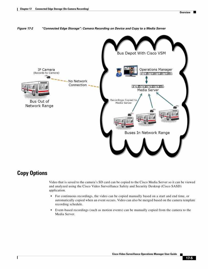
Chapter 17 Connected Edge Storage (On-Camera Recording)Overview
Figure 17-2 “Connected Edge Storage”: Camera Recording on Device and Copy to a Media Server
Copy OptionsVideo that is saved to the camera’s SD card can be copied to the Cisco Media Server so it can be viewed and analyzed using the Cisco Video Surveillance Safety and Security Desktop (Cisco SASD) application.
• For continuous recordings, the video can be copied manually based on a start and end time, or automatically copied when an event occurs. Video can also be merged based on the camera template recording schedule.
• Event-based recordings (such as motion events) can be manually copied from the camera to the Media Server.
17-5Cisco Video Surveillance Operations Manager User Guide
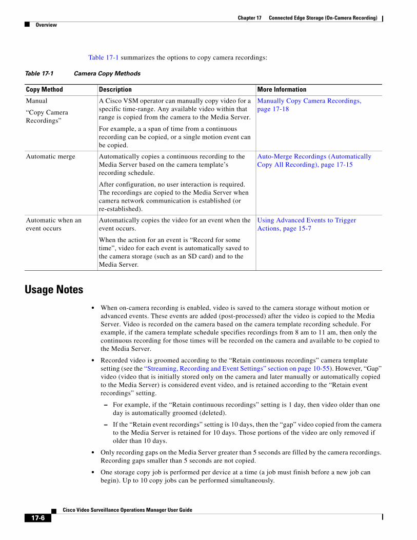
Chapter 17 Connected Edge Storage (On-Camera Recording) Overview
Table 17-1 summarizes the options to copy camera recordings:
Table 17-1 Camera Copy Methods
Copy Method Description More Information
Usage Notes • When on-camera recording is enabled, video is saved to the camera storage without motion or
advanced events. These events are added (post-processed) after the video is copied to the Media Server. Video is recorded on the camera based on the camera template recording schedule. For example, if the camera template schedule specifies recordings from 8 am to 11 am, then only the continuous recording for those times will be recorded on the camera and available to be copied to the Media Server.
• Recorded video is groomed according to the “Retain continuous recordings” camera template setting (see the “Streaming, Recording and Event Settings” section on page 10-55). However, “Gap” video (video that is initially stored only on the camera and later manually or automatically copied to the Media Server) is considered event video, and is retained according to the “Retain event recordings” setting.
– For example, if the “Retain continuous recordings” setting is 1 day, then video older than one day is automatically groomed (deleted).
– If the “Retain event recordings” setting is 10 days, then the “gap” video copied from the camera to the Media Server is retained for 10 days. Those portions of the video are only removed if older than 10 days.
• Only recording gaps on the Media Server greater than 5 seconds are filled by the camera recordings. Recording gaps smaller than 5 seconds are not copied.
• One storage copy job is performed per device at a time (a job must finish before a new job can begin). Up to 10 copy jobs can be performed simultaneously.
Manual
“Copy Camera Recordings”
A Cisco VSM operator can manually copy video for a specific time-range. Any available video within that range is copied from the camera to the Media Server.
For example, a a span of time from a continuous recording can be copied, or a single motion event can be copied.
Manually Copy Camera Recordings, page 17-18
Automatic merge Automatically copies a continuous recording to the Media Server based on the camera template’s recording schedule.
After configuration, no user interaction is required. The recordings are copied to the Media Server when camera network communication is established (or re-established).
Auto-Merge Recordings (Automatically Copy All Recording), page 17-15
Automatic when an event occurs
Automatically copies the video for an event when the event occurs.
When the action for an event is “Record for some time”, video for each event is automatically saved to the camera storage (such as an SD card) and to the Media Server.
Using Advanced Events to Trigger Actions, page 15-7
17-6Cisco Video Surveillance Operations Manager User Guide
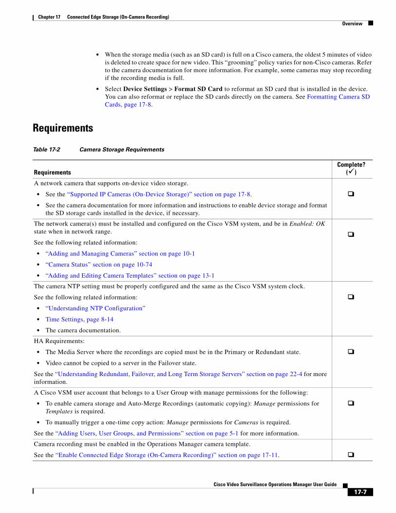
Chapter 17 Connected Edge Storage (On-Camera Recording)Overview
• When the storage media (such as an SD card) is full on a Cisco camera, the oldest 5 minutes of video is deleted to create space for new video. This “grooming” policy varies for non-Cisco cameras. Refer to the camera documentation for more information. For example, some cameras may stop recording if the recording media is full.
• Select Device Settings > Format SD Card to reformat an SD card that is installed in the device. You can also reformat or replace the SD cards directly on the camera. See Formatting Camera SD Cards, page 17-8.
Requirements
Table 17-2 Camera Storage Requirements
RequirementsComplete?
()
• See the “Supported IP Cameras (On-Device Storage)” section on page 17-8.
• See the camera documentation for more information and instructions to enable device storage and format the SD storage cards installed in the device, if necessary.
• “Adding and Managing Cameras” section on page 10-1
• “Camera Status” section on page 10-74
• “Adding and Editing Camera Templates” section on page 13-1
• “Understanding NTP Configuration”
• Time Settings, page 8-14
• The camera documentation.
• The Media Server where the recordings are copied must be in the Primary or Redundant state.
• Video cannot be copied to a server in the Failover state.
A Cisco VSM user account that belongs to a User Group with manage permissions for the following:
• To enable camera storage and Auto-Merge Recordings (automatic copying): Manage permissions for Templates is required.
• To manually trigger a one-time copy action: Manage permissions for Cameras is required.
See the “Adding Users, User Groups, and Permissions” section on page 5-1 for more information.
Camera recording must be enabled in the Operations Manager camera template.
See the “Enable Connected Edge Storage (On-Camera Recording)” section on page 17-11.
A network camera that supports on-device video storage.
The network camera(s) must be installed and configured on the Cisco VSM system, and be in Enabled: OK state when in network range.
See the following related information:
The camera NTP setting must be properly configured and the same as the Cisco VSM system clock.
See the following related information:
HA Requirements:
See the “Understanding Redundant, Failover, and Long Term Storage Servers” section on page 22-4 for more information.
17-7Cisco Video Surveillance Operations Manager User Guide
Chapter 17 Connected Edge Storage (On-Camera Recording) Formatting Camera SD Cards
Supported IP Cameras (On-Device Storage)See the Release Notes for Cisco Video Surveillance Manager for the cameras that support Connected Edge Storage (camera recording) in your release.
Formatting Camera SD CardsCamera storage (such as an SD card) must by physically installed and formatted so it is available to Cisco VSM.
To reformat the card using Cisco VSM, select the Device Settings > Format SD Card from the camera configuration page. You can also use camera Bulk Actions to format the SD cards in multiple cameras.
• SD Card Usage Notes, page 17-8
• Formatting the SD Card for a Single Camera, page 17-8
• Formatting the SD Cards in Multiple Cameras (Bulk Actions), page 17-9
SD Card Usage NotesThis formatting process will fail if:
• The SD card is not installed in the camera or is not detected.
• A format is already in progress. Wait for the format to complete.
• Recordings or clips are being downloaded from the camera to Cisco VSM.
• The SD card is not mounted. The card must be unmounted before being removed from a camera and installed in a different camera. If this occurs, use the camera UI to “mount” the card in the new camera. See the camera documentation for more information.
• To view the formatting status, see Service Jobs (Cameras), page 10-77.
Formatting the SD Card for a Single Camera
Procedure
Step 1 Physically install the storage device in the camera.
Refer to the camera documentation for more information. You can also format the storage device using the camera’s interface.
Step 2 Add the camera to Cisco VSM.
See the “Adding and Managing Cameras” section on page 10-1.
Step 3 In the Cisco VSM Operations Manager, click Cameras, select a location and select the camera name.
Step 4 Select Device Settings > Format SD Card (Figure 17-3):
17-8Cisco Video Surveillance Operations Manager User Guide
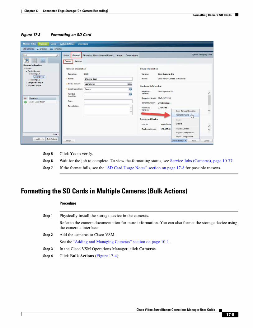
Chapter 17 Connected Edge Storage (On-Camera Recording)Formatting Camera SD Cards
Figure 17-3 Formatting an SD Card
Step 5 Click Yes to verify.
Step 6 Wait for the job to complete. To view the formatting status, see Service Jobs (Cameras), page 10-77.
Step 7 If the format fails, see the “SD Card Usage Notes” section on page 17-8 for possible reasons.
Formatting the SD Cards in Multiple Cameras (Bulk Actions)
Procedure
Step 1 Physically install the storage device in the cameras.
Refer to the camera documentation for more information. You can also format the storage device using the camera’s interface.
Step 2 Add the cameras to Cisco VSM.
See the “Adding and Managing Cameras” section on page 10-1.
Step 3 In the Cisco VSM Operations Manager, click Cameras.
Step 4 Click Bulk Actions (Figure 17-4):
17-9Cisco Video Surveillance Operations Manager User Guide
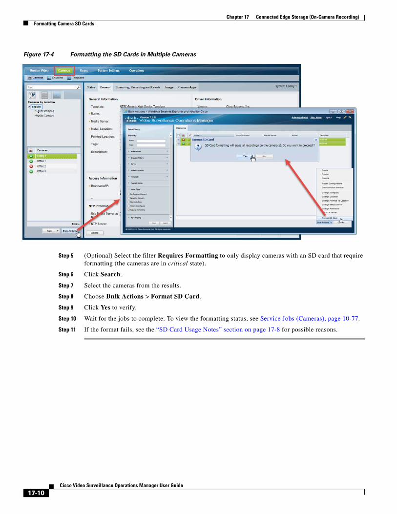
Chapter 17 Connected Edge Storage (On-Camera Recording) Formatting Camera SD Cards
Figure 17-4 Formatting the SD Cards in Multiple Cameras
Step 5 (Optional) Select the filter Requires Formatting to only display cameras with an SD card that require formatting (the cameras are in critical state).
Step 6 Click Search.
Step 7 Select the cameras from the results.
Step 8 Choose Bulk Actions > Format SD Card.
Step 9 Click Yes to verify.
Step 10 Wait for the jobs to complete. To view the formatting status, see Service Jobs (Cameras), page 10-77.
Step 11 If the format fails, see the “SD Card Usage Notes” section on page 17-8 for possible reasons.
17-10Cisco Video Surveillance Operations Manager User Guide
Chapter 17 Connected Edge Storage (On-Camera Recording)Configuring Connected Edge Storage
Configuring Connected Edge StorageTo configure Connected Edge Storage, you must first enable on-camera recording for a camera template, and assign that template to the cameras that support device recording. You can then manually copy the recordings from the camera to the Cisco Media Server, merge a continuous recording from the camera to the Media Server, or copy only event video.
Refer to the following topics for instructions:
• Enable Connected Edge Storage (On-Camera Recording), page 17-11
• Auto-Merge Recordings (Automatically Copy All Recording), page 17-15
• Copy Continuous Recordings Triggered by an Event, page 17-17
Enable Connected Edge Storage (On-Camera Recording)To store recordings on the camera, select the “Enable Continuous Recording” option in the camera template.
Procedure
Step 1 Complete the requirements to install and configure the network cameras.
• See the “Requirements” section on page 17-7.
Step 2 Log in to the Operations Manager.
• You must belong to a User Group with permissions for Templates.
• See the “Adding Users, User Groups, and Permissions” section on page 5-1 for more information.
Step 3 Select Cameras > Templates to add or edit a template (Adding and Editing Camera Templates, page 13-1).
Note System defined templates are locked and cannot be modified.
Step 4 Configure the template for continuous recording, or no recording, based on how recordings will be copied from the camera to the Cisco Media Server (Figure 17-5).
a. Click the Streaming, Recording and Events tab.
b. In the 24x7 Recording options, select the following based on how the video will be copied to the Cisco Media Server.
• Select No Recording if you will manually copy video from the camera to the Media Server.
• Select a continuous recording option if you will automatically copy video from the camera to the Media Server. This includes:
– Continuous Recording—Record video in a continuous loop.
– Record on Motion and Continuous Recording—Record continuously and mark any motion events. This option is available only if motion detection is supported by the camera.
17-11Cisco Video Surveillance Operations Manager User Guide
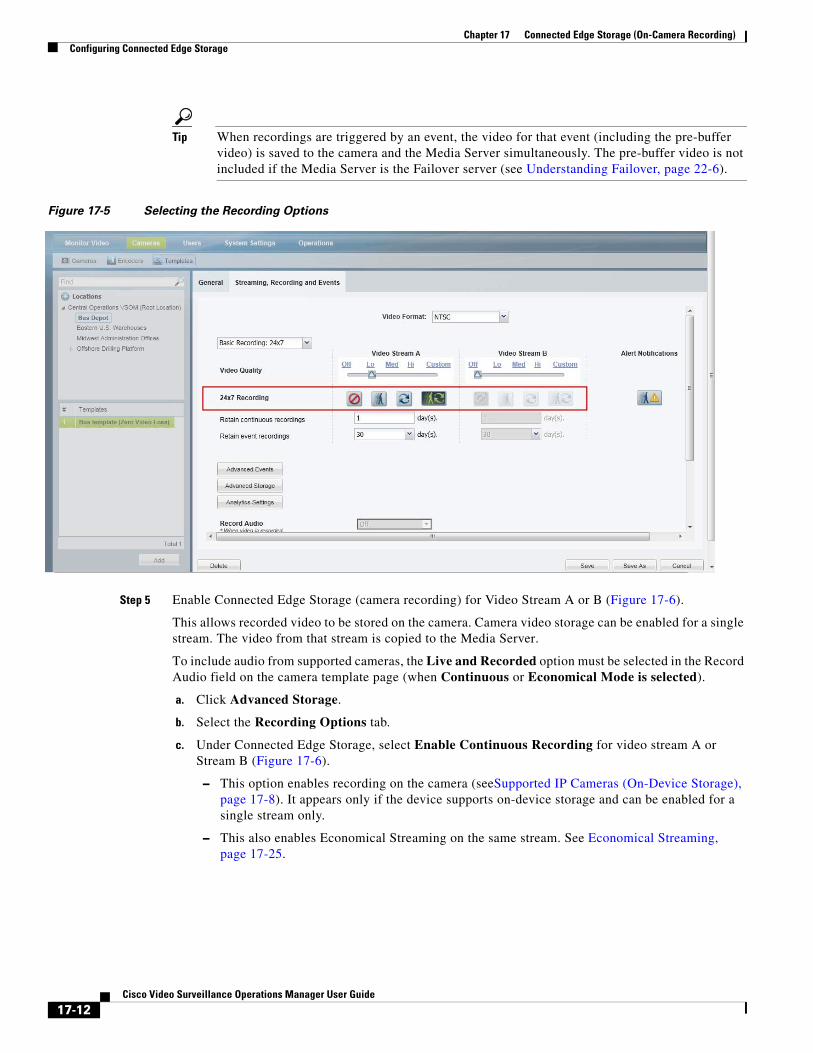
Chapter 17 Connected Edge Storage (On-Camera Recording) Configuring Connected Edge Storage
Tip When recordings are triggered by an event, the video for that event (including the pre-buffer video) is saved to the camera and the Media Server simultaneously. The pre-buffer video is not included if the Media Server is the Failover server (see Understanding Failover, page 22-6).
Figure 17-5 Selecting the Recording Options
Step 5 Enable Connected Edge Storage (camera recording) for Video Stream A or B (Figure 17-6).
This allows recorded video to be stored on the camera. Camera video storage can be enabled for a single stream. The video from that stream is copied to the Media Server.
To include audio from supported cameras, the Live and Recorded option must be selected in the Record Audio field on the camera template page (when Continuous or Economical Mode is selected).
a. Click Advanced Storage.
b. Select the Recording Options tab.
c. Under Connected Edge Storage, select Enable Continuous Recording for video stream A or Stream B (Figure 17-6).
– This option enables recording on the camera (seeSupported IP Cameras (On-Device Storage), page 17-8). It appears only if the device supports on-device storage and can be enabled for a single stream only.
– This also enables Economical Streaming on the same stream. See Economical Streaming, page 17-25.
17-12Cisco Video Surveillance Operations Manager User Guide
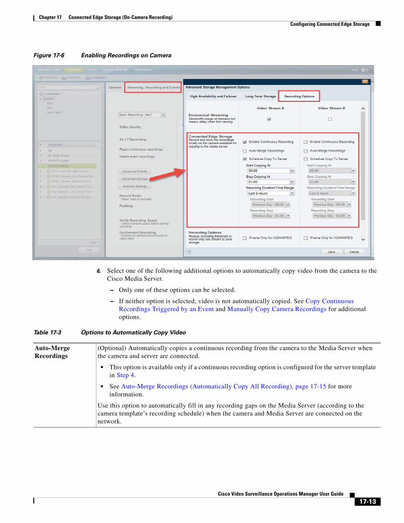
Chapter 17 Connected Edge Storage (On-Camera Recording)Configuring Connected Edge Storage
Figure 17-6 Enabling Recordings on Camera
d. Select one of the following additional options to automatically copy video from the camera to the Cisco Media Server.
– Only one of these options can be selected.
– If neither option is selected, video is not automatically copied. See Copy Continuous Recordings Triggered by an Event and Manually Copy Camera Recordings for additional options.
Table 17-3 Options to Automatically Copy Video
Auto-Merge Recordings
(Optional) Automatically copies a continuous recording from the camera to the Media Server when the camera and server are connected.
• This option is available only if a continuous recording option is configured for the server template in Step 4.
• See Auto-Merge Recordings (Automatically Copy All Recording), page 17-15 for more information.
Use this option to automatically fill in any recording gaps on the Media Server (according to the camera template’s recording schedule) when the camera and Media Server are connected on the network.
17-13Cisco Video Surveillance Operations Manager User Guide
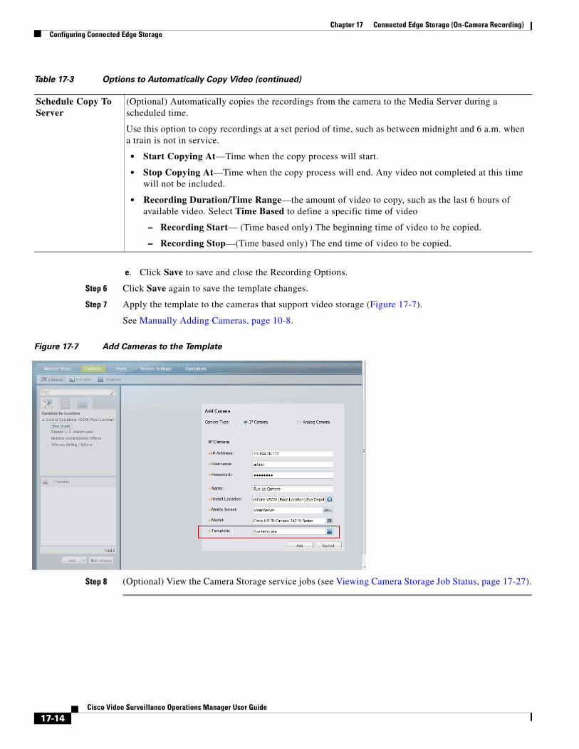
Chapter 17 Connected Edge Storage (On-Camera Recording) Configuring Connected Edge Storage
e. Click Save to save and close the Recording Options.
Step 6 Click Save again to save the template changes.
Step 7 Apply the template to the cameras that support video storage (Figure 17-7).
See Manually Adding Cameras, page 10-8.
Figure 17-7 Add Cameras to the Template
Step 8 (Optional) View the Camera Storage service jobs (see Viewing Camera Storage Job Status, page 17-27).
Schedule Copy To Server
(Optional) Automatically copies the recordings from the camera to the Media Server during a scheduled time.
Use this option to copy recordings at a set period of time, such as between midnight and 6 a.m. when a train is not in service.
• Start Copying At—Time when the copy process will start.
• Stop Copying At—Time when the copy process will end. Any video not completed at this time will not be included.
• Recording Duration/Time Range—the amount of video to copy, such as the last 6 hours of available video. Select Time Based to define a specific time of video
– Recording Start— (Time based only) The beginning time of video to be copied.
– Recording Stop—(Time based only) The end time of video to be copied.
Table 17-3 Options to Automatically Copy Video (continued)
17-14Cisco Video Surveillance Operations Manager User Guide
Chapter 17 Connected Edge Storage (On-Camera Recording)Configuring Connected Edge Storage
Auto-Merge Recordings (Automatically Copy All Recording)“Auto-Merge Recordings” automatically copies video recorded on the camera to the Cisco Media Server (Figure 17-8). Any recording gaps on the Media Server are filled in (according to the camera template’s recording schedule).
Usage Notes
When on-camera recording is enabled, video is saved to the camera storage without motion or advanced events. These events are added (post-processed) after the video is copied to the Media Server. Video is copied to the Media Server based on the camera template recording schedule. For example, if the camera template schedule specifies recordings from 8 am to 11 am, only continuous recordings for those times will be copied from the camera to the Media Server.
Important Performance Considerations When Using “Auto-Merge Recordings”
Due to bandwidth considerations, the number of cameras that can be supported by a Media Server will drop in half when all of the cameras on that server are configured for Auto-Merge Recordings. We recommended a maximum of 10 cameras on a single Media Server be configured with Auto-Merge Recordings. See the Release Notes for Cisco Video Surveillance Manager, Release 7.5, for more information about using Auto-Merge Recordings.
For example, when a camera configured with “Auto-Merge Recordings” reconnects to the Media Server after a network outage, live video recording will resume and the camera will begin copying locally-stored video to the Media Server (to fill the recording gaps on the Media Server). Video is also copied from the camera at a rate that is at least 25% faster than real-time so that all of the video from an outage is copied from the camera before it is overwritten. This means that after an outage, the total bandwidth from the camera to the Media Sever is more than 2X the video data rate until all of the video from the outage has been copied from the camera. Since the Media Server has a limit on total recording bandwidth, the use of “Auto-Merge Recordings” will reduce the total number of cameras that can be supported on a Media Server. If all of the cameras on the Media Server are configured with “Auto-Merge Recordings”, the number of supported cameras will drop by more than half.
Procedure
Step 1 Complete the requirements to install and configure the network cameras.
• See the “Requirements” section on page 17-7.
Step 2 Enable camera storage on the camera template.
• See the “Enable Connected Edge Storage (On-Camera Recording)” section on page 17-11.
Step 3 Enable “Auto-Merge Recordings” (Figure 17-8).
a. Click Advanced Storage.
b. Select the Recording Options tab.
c. Select Enable Continuous Recording for Stream A or B.
d. Select Auto-Merge Recordings to automatically copy video recordings from the camera storage to the Media Server.
This option is available only when a continuous recording option is configured for the template. See Step 4 in the “Enable Connected Edge Storage (On-Camera Recording)” section on page 17-11.
e. Click Save to save and close the Recording Options.
17-15Cisco Video Surveillance Operations Manager User Guide
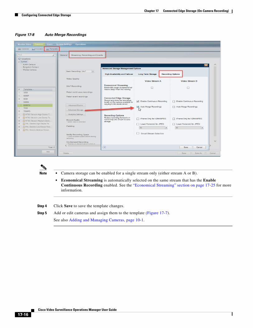
Chapter 17 Connected Edge Storage (On-Camera Recording) Configuring Connected Edge Storage
Figure 17-8 Auto Merge Recordings
Note • Camera storage can be enabled for a single stream only (either stream A or B).
• Economical Streaming is automatically selected on the same stream that has the Enable Continuous Recording enabled. See the “Economical Streaming” section on page 17-25 for more information.
Step 4 Click Save to save the template changes.
Step 5 Add or edit cameras and assign them to the template (Figure 17-7).
See also Adding and Managing Cameras, page 10-1.
17-16Cisco Video Surveillance Operations Manager User Guide
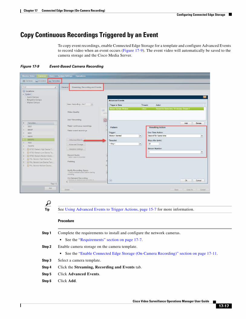
Chapter 17 Connected Edge Storage (On-Camera Recording)Configuring Connected Edge Storage
Copy Continuous Recordings Triggered by an EventTo copy event recordings, enable Connected Edge Storage for a template and configure Advanced Events to record video when an event occurs (Figure 17-9). The event video will automatically be saved to the camera storage and the Cisco Media Server.
Figure 17-9 Event-Based Camera Recording
Tip See Using Advanced Events to Trigger Actions, page 15-7 for more information.
Procedure
Step 1 Complete the requirements to install and configure the network cameras.
• See the “Requirements” section on page 17-7.
Step 2 Enable camera storage on the camera template.
• See the “Enable Connected Edge Storage (On-Camera Recording)” section on page 17-11.
Step 3 Select a camera template.
Step 4 Click the Streaming, Recording and Events tab.
Step 5 Click Advanced Events.
Step 6 Click Add.
17-17Cisco Video Surveillance Operations Manager User Guide

Chapter 17 Connected Edge Storage (On-Camera Recording) Manually Copy Camera Recordings
Step 7 Select a Trigger to define the event that triggers recording (see Table 15-3 for more information).
• (Optional) Select a Timeslot when the event should trigger an action (see the “Defining Schedules” section on page 12-1 to create timeslots).
Step 8 Under Resulting Action, select Record for some time to Media Server and enter the number of minutes that video should be recorded when the event occurs (see Table 15-4 for more information).
Step 9 Click OK to save the Advanced Event changes.
Step 10 Click Save to save the template changes.
Step 11 Add or edit cameras and assign them to the template (Figure 17-7).
See also Adding and Managing Cameras, page 10-1.
Manually Copy Camera RecordingsTo manually copy recordings stored on a camera to the Media Server, use the Copy Camera Recordings command in the camera configuration page (Figure 17-10). Manually copying recordings allows you to copy one or more recordings stored on the camera to the Media Server.
Figure 17-10 Copy Camera Recordings
Additional Copy Options
• Video can also be copied automatically based on events or Media Server synchronization. See Copy Options, page 17-5.
• You can also use the Cisco Video Surveillance Safety and Security Desktop application (Cisco SASD) to copy the recordings from a camera to the Media Server. See the Cisco Video Surveillance Safety and Security Desktop User Guide for more information.
17-18Cisco Video Surveillance Operations Manager User Guide
Chapter 17 Connected Edge Storage (On-Camera Recording)Manually Copy Camera Recordings
Usage Notes
• You must belong to a user group with Copy From Edge Storage permission. See the “Adding Users, User Groups, and Permissions” section on page 5-1 for more information.
• One storage copy job is performed per device at a time (a job must finish before a new job can begin). Up to 10 copy jobs can be performed simultaneously.
• Continuous recordings—To include audio from supported cameras, the Live and Recorded option must be selected in the Record Audio field on the camera template page.
Procedure
Step 1 Complete the requirements to install and configure the network cameras.
• See the “Requirements” section on page 17-7.
Step 2 Configure the camera template:
See “Enable Connected Edge Storage (On-Camera Recording)” section on page 17-11.
a. Configure the camera template for No Recording.
b. To include audio from supported cameras, select the Live and Recorded option in the Record Audio field.
a. Select Advanced Storage > Recording Options and select Enable Continuous Recording.
b. Save the template changes and assign cameras to the template.
Step 3 Copy the recording from the camera to the Cisco Media Server (Figure 17-11):
a. Click Cameras.
b. Select a camera.
c. Select Device Settings > Copy Camera Recordings in the camera configuration page (Figure 17-10).
d. Select the start and end times based on the “Recordings Available” on the camera.
e. Click Copy.
17-19Cisco Video Surveillance Operations Manager User Guide
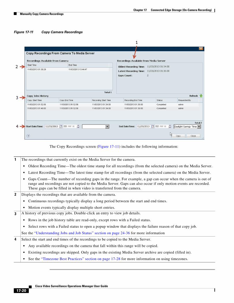
Chapter 17 Connected Edge Storage (On-Camera Recording) Manually Copy Camera Recordings
Figure 17-11 Copy Camera Recordings
The Copy Recordings screen (Figure 17-11) includes the following information:
1
• Oldest Recording Time—The oldest time stamp for all recordings (from the selected camera) on the Media Server.
• Latest Recording Time—The latest time stamp for all recordings (from the selected camera) on the Media Server.
• Gaps Count—The number of recording gaps in the range. For example, a gap can occur when the camera is out of range and recordings are not copied to the Media Server. Gaps can also occur if only motion events are recorded. These gaps can be filled in when video is transferred from the camera.
2
• Continuous recordings typically display a long period between the start and end times.
• Motion events typically display multiple short entries.
3 A history of previous copy jobs. Double-click an entry to view job details.
• Rows in the job history table are read-only, except rows with a Failed status.
• Select rows with a Failed status to open a popup window that displays the failure reason of that copy job.
4
• Any available recordings on the camera that fall within this range will be copied.
• Existing recordings are skipped. Only gaps in the existing Media Server archive are copied (filled in).
• See the “Timezone Best Practices” section on page 17-28 for more information on using timezones.
The recordings that currently exist on the Media Server for the camera.
Displays the recordings that are available from the camera.
See the “Understanding Jobs and Job Status” section on page 24-36 for more information
Select the start and end times of the recordings to be copied to the Media Server.
17-20Cisco Video Surveillance Operations Manager User Guide
Chapter 17 Connected Edge Storage (On-Camera Recording)Record Events on the Camera’s Storage Device
Record Events on the Camera’s Storage DeviceTo record motion, contact closure, or camera app events to a camera’s SD card, use the Advanced Events setting. This option allows you to save only the video from an event to the SD card. You can then manually copy the event video to the Media Server, if necessary.
Supported Event Types
Table 17-4 Supported Event Types
Event Type Description
To enable event based recording, configure Advanced Events for the a supported event type.
For more information see:
• Using Advanced Events to Trigger Actions, page 15-7
• Trigger and Action Descriptions, page 15-9
Usage Notes
The following are not supported in this release:
• Scheduled copy of all camera recordings to the Media Server is not supported in this release.
• Time-slot based camera recordings and scheduled recording on camera for events is not supported in this release.
• Data must be copied or backed-up and the SD card must be formatted while switching from event based recording to continuous recording (or vice versa) on camera storage. This is a camera limitation.
Procedure
Step 1 Complete the requirements to install and configure the network cameras.
• See the “Requirements” section on page 17-7.
Step 2 Log in to the Operations Manager.
• You must belong to a User Group with permissions for Templates.
• See the “Adding Users, User Groups, and Permissions” section on page 5-1 for more information.
Step 3 Configure the required event type on the camera.
See Supported Event Types.
Step 4 Configure the template.
a. Select Cameras > Templates and select a template.
b. Click the Streaming, Recording and Events tab.
Motion window events Configure the camera motion window if the camera should record when motion occurs.
Contact closure event Configure contact closure in the camera settings page if the camera should record when a contact opens or closes.
Camera app event Camera apps must be installed and running on the camera (if the event type is camera app).
17-21Cisco Video Surveillance Operations Manager User Guide
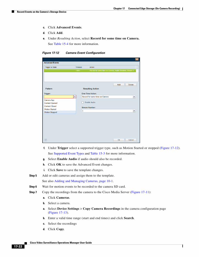
Chapter 17 Connected Edge Storage (On-Camera Recording) Record Events on the Camera’s Storage Device
c. Click Advanced Events.
d. Click Add.
e. Under Resulting Action, select Record for some time on Camera.
See Table 15-4 for more information.
Figure 17-12 Camera Event Configuration
f. Under Trigger select a supported trigger type, such as Motion Started or stopped (Figure 17-12).
See Supported Event Types and Table 15-3 for more information.
g. Select Enable Audio if audio should also be recorded.
h. Click OK to save the Advanced Event changes.
i. Click Save to save the template changes.
Step 5 Add or edit cameras and assign them to the template.
See also Adding and Managing Cameras, page 10-1.
Step 6 Wait for motion events to be recorded to the camera SD card.
Step 7 Copy the recordings from the camera to the Cisco Media Server (Figure 17-11):
a. Click Cameras.
b. Select a camera.
a. Select Device Settings > Copy Camera Recordings in the camera configuration page (Figure 17-13).
b. Enter a valid time range (start and end times) and click Search.
c. Select the recordings
d. Click Copy.
17-22Cisco Video Surveillance Operations Manager User Guide
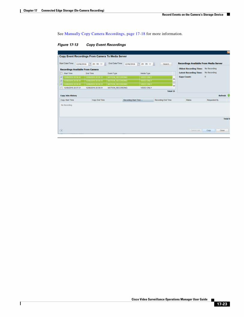
Chapter 17 Connected Edge Storage (On-Camera Recording)Record Events on the Camera’s Storage Device
See Manually Copy Camera Recordings, page 17-18 for more information.
Figure 17-13 Copy Event Recordings
17-23Cisco Video Surveillance Operations Manager User Guide
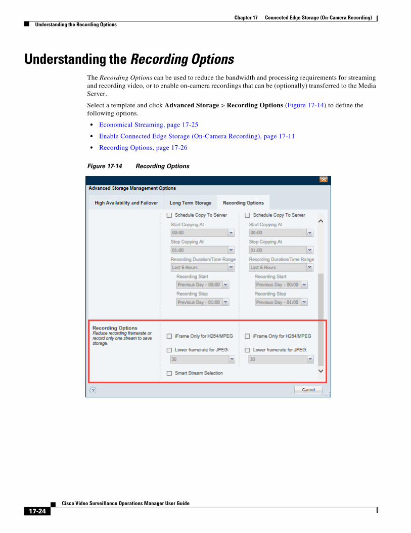
Chapter 17 Connected Edge Storage (On-Camera Recording) Understanding the Recording Options
Understanding the Recording OptionsThe Recording Options can be used to reduce the bandwidth and processing requirements for streaming and recording video, or to enable on-camera recordings that can be (optionally) transferred to the Media Server.
Select a template and click Advanced Storage > Recording Options (Figure 17-14) to define the following options.
• Economical Streaming, page 17-25
• Enable Connected Edge Storage (On-Camera Recording), page 17-11
• Recording Options, page 17-26
Figure 17-14 Recording Options
17-24Cisco Video Surveillance Operations Manager User Guide
Chapter 17 Connected Edge Storage (On-Camera Recording)Understanding the Recording Options
Economical StreamingEconomical Streaming is used to reduce the network bandwidth used by cameras. By default, all cameras stream video continuously, even if that video is not being viewed. The Economical Streaming option (Figure 17-14) places the primary or secondary stream in suspended mode, meaning that video is only streamed when requested by a user, or if an event (such as a motion or advanced event) is configured to record video.
Note By default, Economical Streaming is deselected and video is streamed at all times and is instantly available for viewing or recording. But when Economical Streaming is enabled, there is a short delay when video is requested by a user or an event. This is because video is not being streamed continuously, but must start and be sent to the user or storage device when the request occurs.
Recording Requirements
• If motion events or Advanced Events are configured to “Record for some time”, the Padding pre-buffer for the camera template must be greater than 0 (Padding, is the number of seconds of recording that should be included before and after the event occurs. See Streaming, Recording and Event Settings, page 10-55).
– The pre-buffer (Padding) ensures that video recorded in the camera during the delay in setting up the stream is also copied to the Media Server. This prevents to prevent any loss of video.
– The post buffer (Padding) is not included. Recording stops when the Record for Some time Duration is reached. When recording stops, the video stream is suspended again.
• If Connected Edge Storage is enabled, event video is automatically saved to both the camera storage device and to the Media Server. The camera must be on the network. Cameras that are off the network, such as a camera on a bus or other remote location, will copy video to the camera storage device only.
• Scheduled recordings can also be configured with Economical Streaming enabled. Streaming is automatically begins when the recording is scheduled.
Supported Configurations
• Stream A can be economical ONLY if it also being recorded at the edge (see Understanding the Recording Options, page 17-24).
• Stream B can be economical with or without being recorded at the edge.
Not Supported
Economical Streaming is not supported in the following configurations:
• Both Stream A and Stream B are sent to the Primary server.
• Both Stream A and Stream B are sent to both the Primary and Redundant servers.
Usage Notes
If a stream is configured to record only on event and the camera has a critical alert, then recording during an event is aborted. You can manually download the missing video (from the alert start time) from the camera storage, and then clear the event.
17-25Cisco Video Surveillance Operations Manager User Guide
Chapter 17 Connected Edge Storage (On-Camera Recording) Understanding the Recording Options
Connected Edge StorageThis option enables on-camera recordings, and optionally copies continuously recorded video from the camera to the Cisco Media Server.
See Configuring Connected Edge Storage, page 17-11 for more information.
Recording Options • iFrame Only for H264/MPEG—Use the iFrame format only when recording H264/MPEG video.
• Lower framerate for JPEG—Specify a lower frame rate to reduce the bandwidth, processing, and storage requirements of video recorded from Stream B. A lower framerate number requires less network and server resources, but results in lower quality video.
• Smart Stream Selection—Merges the recording from 2 streams so the higher resolution video from Stream A can be viewed for events, while the lower-resolution video from Stream B can be saved for continuous recording. See Merging Video Streams (Smart Stream Selection), page 13-11 for more information.
17-26Cisco Video Surveillance Operations Manager User Guide
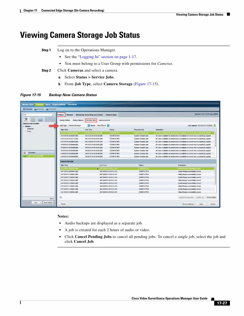
Chapter 17 Connected Edge Storage (On-Camera Recording)Viewing Camera Storage Job Status
Viewing Camera Storage Job Status
Step 1 Log on to the Operations Manager.
• See the “Logging In” section on page 1-17.
• You must belong to a User Group with permissions for Cameras.
Step 2 Click Cameras and select a camera.
a. Select Status > Service Jobs.
b. From Job Type, select Camera Storage (Figure 17-15).
Figure 17-15 Backup Now Camera Status
Notes:
• Audio backups are displayed as a separate job.
• A job is created for each 2 hours of audio or video.
• Click Cancel Pending Jobs to cancel all pending jobs. To cancel a single job, select the job and click Cancel Job.
17-27Cisco Video Surveillance Operations Manager User Guide
Chapter 17 Connected Edge Storage (On-Camera Recording) Timezone Best Practices
Timezone Best PracticesSwitching the timezone from the Standard Time to the Daylight Savings Time moves the clock forward by one hour. For example: 03/11/2013 “1:00 AM ST” becomes “2:00 AM DST”. The reverse occurs when switching the timezone from Daylight Savings Time to Standard-Time (the clock moves backward by one hour, i.e. 11/04/2013 “2:00 AM DST” becomes “1:00 AM ST”).
Cameras, however, are not impacted by this timezone switch-over. In rare cases when a recording on the camera having either its start time or its end time falls within the overlapping one hour during the timezone switch-over from the Daylight-Savings-Time to Standard-Time (for example 2:00 AM to 1:00 AM), the display of the recording time may appear overlapped because the clock is moved backward by one hour. However, the actual recordings on the camera are not overlapped.
Best PracticeThe best practice when specifying the time range to copy camera recordings is to avoid the one hour during the timezone switch-over. Specify a start time before the timezone switch-over and specify the end time after the timezone switch-over.
Example 1
On 03/10/2013 02:00 ST-to-DST switch-over, when moving the clock forward by one hour, copy 2-minute of camera recordings starting one minute before the switch-over and ending one minute after the switch-over.
1. Specify the start time at 03/10/2013 01:59:00
2. Specify the end time at 03/10/2013 03:01:00
Example 2
On 11/04/2013 02:00 DST-to-ST switch-over, when moving the clock backward by one hour, copy one-hour and 2-minute of camera recordings starting one minute before the switch-over and ending one minute after the switch-over.
1. Specify the start time at 11/04/2013 01:59:00
2. Specify the end time at 11/04/2013 02:01:00
17-28Cisco Video Surveillance Operations Manager User Guide
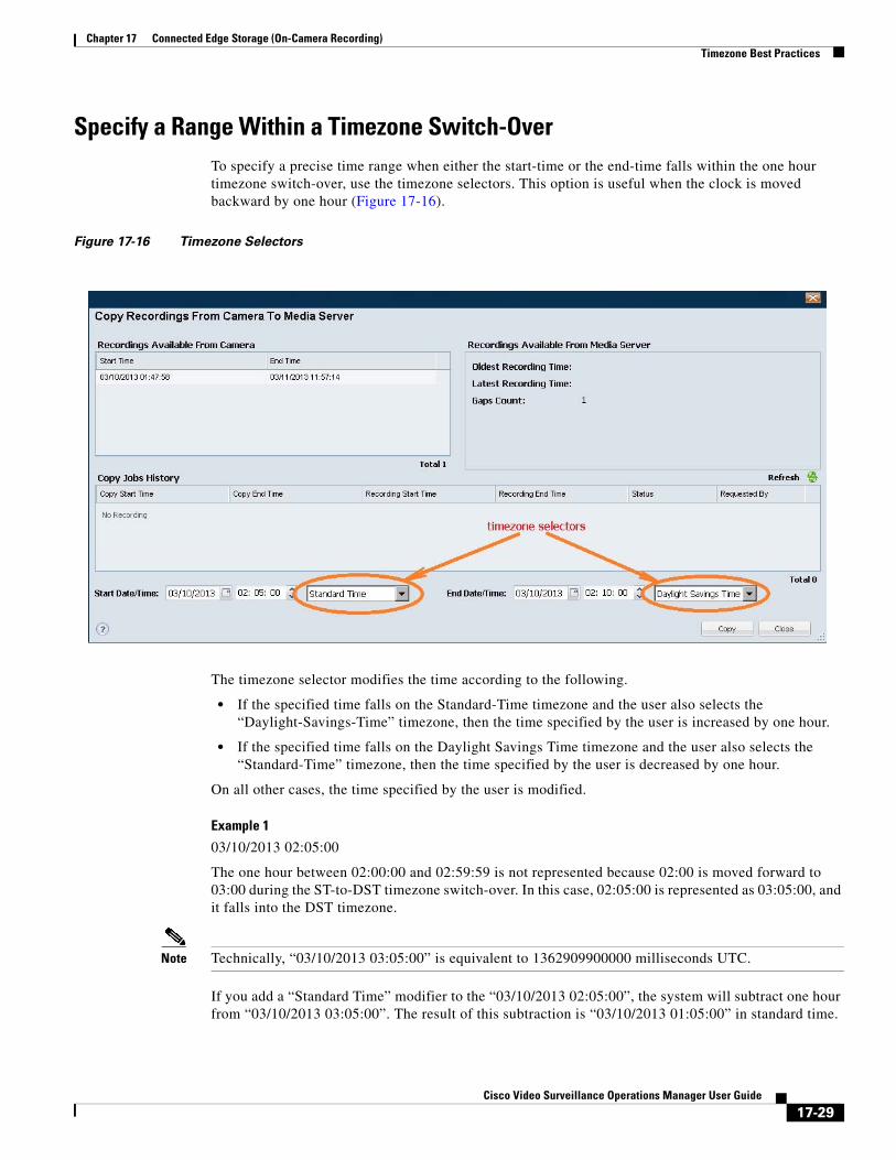
Chapter 17 Connected Edge Storage (On-Camera Recording)Timezone Best Practices
Specify a Range Within a Timezone Switch-OverTo specify a precise time range when either the start-time or the end-time falls within the one hour timezone switch-over, use the timezone selectors. This option is useful when the clock is moved backward by one hour (Figure 17-16).
Figure 17-16 Timezone Selectors
The timezone selector modifies the time according to the following.
• If the specified time falls on the Standard-Time timezone and the user also selects the “Daylight-Savings-Time” timezone, then the time specified by the user is increased by one hour.
• If the specified time falls on the Daylight Savings Time timezone and the user also selects the “Standard-Time” timezone, then the time specified by the user is decreased by one hour.
On all other cases, the time specified by the user is modified.
Example 1
03/10/2013 02:05:00
The one hour between 02:00:00 and 02:59:59 is not represented because 02:00 is moved forward to 03:00 during the ST-to-DST timezone switch-over. In this case, 02:05:00 is represented as 03:05:00, and it falls into the DST timezone.
Note Technically, “03/10/2013 03:05:00” is equivalent to 1362909900000 milliseconds UTC.
If you add a “Standard Time” modifier to the “03/10/2013 02:05:00”, the system will subtract one hour from “03/10/2013 03:05:00”. The result of this subtraction is “03/10/2013 01:05:00” in standard time.
17-29Cisco Video Surveillance Operations Manager User Guide
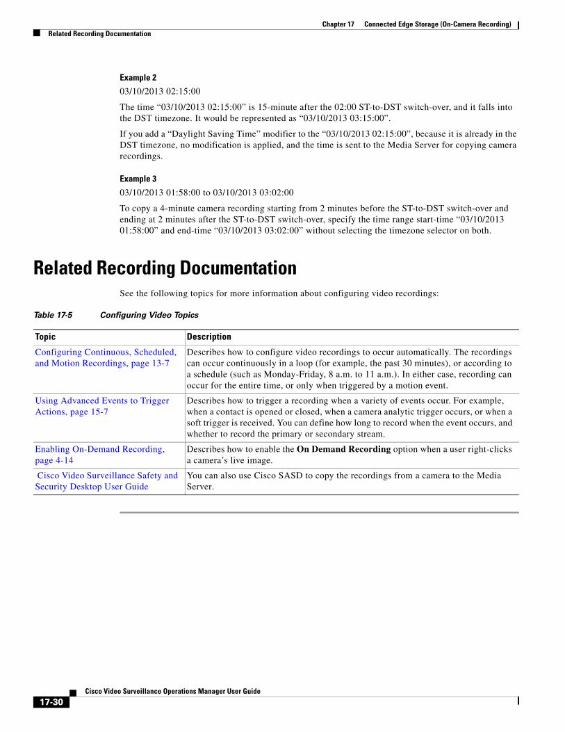
Chapter 17 Connected Edge Storage (On-Camera Recording) Related Recording Documentation
Example 2
03/10/2013 02:15:00
The time “03/10/2013 02:15:00” is 15-minute after the 02:00 ST-to-DST switch-over, and it falls into the DST timezone. It would be represented as “03/10/2013 03:15:00”.
If you add a “Daylight Saving Time” modifier to the “03/10/2013 02:15:00”, because it is already in the DST timezone, no modification is applied, and the time is sent to the Media Server for copying camera recordings.
Example 3
03/10/2013 01:58:00 to 03/10/2013 03:02:00
To copy a 4-minute camera recording starting from 2 minutes before the ST-to-DST switch-over and ending at 2 minutes after the ST-to-DST switch-over, specify the time range start-time “03/10/2013 01:58:00” and end-time “03/10/2013 03:02:00” without selecting the timezone selector on both.
Related Recording DocumentationSee the following topics for more information about configuring video recordings:
Table 17-5 Configuring Video Topics
Topic Description
Configuring Continuous, Scheduled, and Motion Recordings, page 13-7
Describes how to configure video recordings to occur automatically. The recordings can occur continuously in a loop (for example, the past 30 minutes), or according to a schedule (such as Monday-Friday, 8 a.m. to 11 a.m.). In either case, recording can occur for the entire time, or only when triggered by a motion event.
Using Advanced Events to Trigger Actions, page 15-7
Describes how to trigger a recording when a variety of events occur. For example, when a contact is opened or closed, when a camera analytic trigger occurs, or when a soft trigger is received. You can define how long to record when the event occurs, and whether to record the primary or secondary stream.
Enabling On-Demand Recording, page 4-14
Describes how to enable the On Demand Recording option when a user right-clicks a camera’s live image.
Cisco Video Surveillance Safety and Security Desktop User Guide
You can also use Cisco SASD to copy the recordings from a camera to the Media Server.
17-30Cisco Video Surveillance Operations Manager User Guide
Cisco V
C H A P T E R 18
Configure Voice-over-IP CallingIn release 7.9, each video camera can be associated with a SIP end-point, such as a phone near the camera. A Cisco SASD user who is monitoring video from that camera can then click the phone icon
to call the end-point.
This feature allows voice calls to be placed to different voice endpoints for each camera. If the Cisco IP camera has the SIP App installed, users can also place a voice call to the camera.
For example, Cisco SASD users can place IP calls using SIP applications such as Cisco Jabber or Skype. This can be useful where the person monitoring video needs to quickly communicate with a another person or location. For example, an aide monitoring a patient room can click the icon to talk to the nurses station.
To enable this, administrators must create custom field that allow the camera to be configured with the appropriate SIP protocol, and URI address of the recipient.
Note Placing a voice call to a Cisco IP camera requires special configuration using the Cisco Unified Communications Manager (CallManager). See the CallManager documentation for more information.
Complete the following tasks:
• Requirements, page 18-2
• Create the Protocol and Address Settings, page 18-2
• Select the SIP Protocol and Address in Camera Settings, page 18-4
• (Optional) Set the Custom Field Values For Multiple Cameras, page 18-5
• Call a Video or Voice Phone from Cisco SASD, page 18-6
18-1ideo Surveillance Operations Manager User Guide
Chapter 18 Configure Voice-over-IP Calling Requirements
RequirementsBefore you begin, the following requirements must be complete:
Requirements
Requirement Complete?
()
• SIP—To place a video call. For example, using the Cisco Jabber application.
• CiscoTel—(Default) To place a voice call. For example, using Cisco Jabber.
• TEL—To place a video call. For example, using the Skype application.
Note If the protocol is not specified, then CiscoTel is used.
Create the Protocol and Address SettingsDefine the protocols used by your deployment to make SIP calls from Cisco SASD clients. You can define multiple protocols, and assign the appropriate one to each camera.
This process only needs to be done once. After the SIP protocols are configured, you can select the protocol for each camera (based on the video or audio application installed on client workstations.
Procedure
Step 1 Log on to the Operations Manager.
• See the “Logging In” section on page 1-17.
• You must belong to a User Group with permissions for Dial SIP. See Adding Users, User Groups, and Permissions, page 5-1 for more information.
Step 2 Create a custom field for the SIP protocols used in your deployment.
a. Go to System Settings > Custom Data Management > Custom Field (Figure 18-1).
b. Click Add
c. Under Field Type, select List of Choices.
d. Under Field Name, enter “Select Protocol” (case sensitive)
e. Under Choice Entries, click “+” to add the following protocols. These options can be selected in the camera configuration page.
You must belong to a User Group with manage permissions for Dial SIP.
See Adding Users, User Groups, and Permissions, page 5-1 for more information.
A video or voice client that supports SIP installed on the SASD client and recipient workstation.
For example, Cisco Jabber.
Define the SIP protocol used by the video or voice application that will be installed on the Cisco SASD clients.
The supported protocols include the following:
Define the addresses (URI) that will be called using the voice or video applications installed on your Cisco SASD clients.
For example, usernames, email addresses, or phone numbers.
18-2Cisco Video Surveillance Operations Manager User Guide
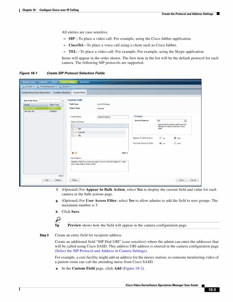
Chapter 18 Configure Voice-over-IP CallingCreate the Protocol and Address Settings
All entries are case sensitive.
– SIP—To place a video call. For example, using the Cisco Jabber application.
– CiscoTel—To place a voice call using a client such as Cisco Jabber.
– TEL—To place a video call. For example, For example, using the Skype application.
Items will appear in the order shown. The first item in the list will be the default protocol for each camera. The following SIP protocols are supported.
Figure 18-1 Create SIP Protocol Selection Fields
f. (Optional) For Appear In Bulk Action, select Yes to display the custom field and value for each camera in the bulk actions page.
g. (Optional) For User Access Filter, select Yes to allow admins to add the field to user groups. The maximum number is 5.
h. Click Save.
Tip Preview shows how the field will appear in the camera configuration page.
Step 3 Create an entry field for recipient address.
Create an additional field “SIP Dial URI” (case sensitive) where the admin can enter the addresses that will be called using Cisco SASD. This address URI address is entered in the camera configuration page (Select the SIP Protocol and Address in Camera Settings).
For example, a care facility might add an address for the nurses station, so someone monitoring video of a patient room can call the attending nurse from Cisco SASD.
a. In the Custom Field page, click Add (Figure 18-2).
18-3Cisco Video Surveillance Operations Manager User Guide
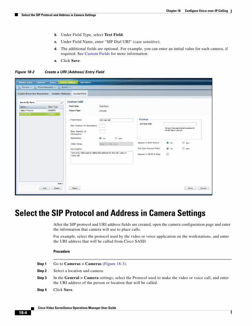
Chapter 18 Configure Voice-over-IP Calling Select the SIP Protocol and Address in Camera Settings
b. Under Field Type, select Text Field.
c. Under Field Name, enter “SIP Dial URI” (case sensitive).
d. The additional fields are optional. For example, you can enter an initial value for each camera, if required. See Custom Fields for more information.
e. Click Save.
Figure 18-2 Create a URI (Address) Entry Field
Select the SIP Protocol and Address in Camera SettingsAfter the SIP protocol and URI address fields are created, open the camera configuration page and enter the information that camera will use to place calls.
For example, select the protocol used by the video or voice application on the workstations, and enter the URI address that will be called from Cisco SASD.
Procedure
Step 1 Go to Cameras > Cameras (Figure 18-3).
Step 2 Select a location and camera.
Step 3 In the General > Camera settings, select the Protocol used to make the video or voice call, and enter the URI address of the person or location that will be called.
Step 4 Click Save.
18-4Cisco Video Surveillance Operations Manager User Guide
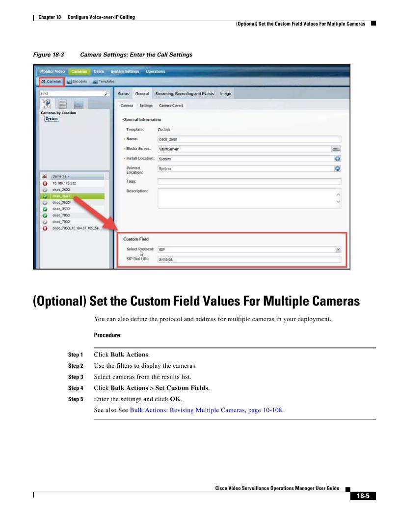
Chapter 18 Configure Voice-over-IP Calling(Optional) Set the Custom Field Values For Multiple Cameras
Figure 18-3 Camera Settings: Enter the Call Settings
(Optional) Set the Custom Field Values For Multiple CamerasYou can also define the protocol and address for multiple cameras in your deployment.
Procedure
Step 1 Click Bulk Actions.
Step 2 Use the filters to display the cameras.
Step 3 Select cameras from the results list.
Step 4 Click Bulk Actions > Set Custom Fields.
Step 5 Enter the settings and click OK.
See also See Bulk Actions: Revising Multiple Cameras, page 10-108.
18-5Cisco Video Surveillance Operations Manager User Guide
Chapter 18 Configure Voice-over-IP Calling Call a Video or Voice Phone from Cisco SASD
Call a Video or Voice Phone from Cisco SASDAfter the cameras in your deployment are configured with a SIP protocol and URI address, use Cisco SASD to call a person or location when viewing video.
Procedure
Step 1 Install and launch an IP video or voice client on the Cisco SASD workstation. For example, Cisco Jabber or Skype.
Step 2 Log in to the Cisco SASD application and select a video viewing workspace.
Step 3 Click the phone icon .
Step 4 Follow the on screen prompts to complete the connection to the configured person or location.
18-6Cisco Video Surveillance Operations Manager User Guide
Cisco V
C H A P T E R 19
Understanding Device ConflictsIf a server, camera or encoder is added to Cisco VSM with duplicate settings, such as a duplicate IP address, an error can occur. Review the following information to understand how to avoid, resolve, or allow such conflicts:
• Devices with Duplicate IP Addresses, page 19-1
• Conflicts During Camera Discovery, page 19-2
• Allowing Duplicate Camera or Encoder IP Addresses, page 19-2
• Configuring Custom Camera and Encoder Ports (PAT), page 19-3
• Resolving ID Mismatch Errors When Changing Camera IP Addresses, page 19-6
Devices with Duplicate IP AddressesBy default, servers, encoders, or cameras with duplicate IP addresses are not allowed.
If an server or device is added with a duplicate IP address (the address is the same as an existing device), the new entry will display an ID collision issue. For example:
• Devices manually added will a duplicate IP address be placed in the Enabled: Critical state.
• Discovered cameras will be placed in the Pending Approval list.
To resolve the issue, do one of the following:
• Use the Operations Manager to configure the server or device with an unused IP address.
• Directly connect to the device or server interface and enter a unique IP address, or ensure that the device can receive a reachable address from a DHCP server. The camera IP address must be reachable by the Media Server to which it is assigned.
• Use the Replace Camera or Replace Server option to transfer the old settings to the new device. For example, see Replacing a Camera, page 10-103.
• Delete the camera, encoder, or server and re-add it with a unique IP address.
• Enable the Allow Duplicate IP Address system setting to allow servers and devices to be added with duplicate IP addresses. For example, Media Servers that are installed in NATs that use the same Access IP (NAT) address. See Allowing Duplicate Camera or Encoder IP Addresses, page 19-2 for more information.
19-1ideo Surveillance Operations Manager User Guide
Chapter 19 Understanding Device Conflicts Conflicts During Camera Discovery
Conflicts During Camera DiscoveryCameras are identified in Cisco VSM discovery by the device IP Address, and serial number, mac address/hardware ID. If a camera is discovered with values in these fields that already exist in the Cisco VSM configuration, the camera records will either be merged, or placed in a collision state.
• If some identity fields in a discovered camera and existing camera are a perfect match, but some fields are empty, then the records are merged. For example, if a camera in Cisco VSM includes only a name and MAC address, and a discovered camera has the same MAC address plus additional fields for serial number and IP address, then the two records are merged into a single camera entry.
• If both the Cisco VSM camera and a discovered camera include identity fields that do not match, both cameras are placed in a collision state. You must replace or delete one of the cameras to remove the conflict.
Open the camera Status tab on the configuration page to view more information (see the “Camera Status” section on page 10-74).
– The device overall status is Enabled: Critical.
– Click the link next to the Hardware category to open a pop-up that details the collision.
– An Alert is generated for “identity collision”.
• If the discovered camera uses DHCP settings, and only the IP address is in conflict, then the IP address of the discovered camera is used. If the discovered camera uses a static IP address, however, then the camera entries are in conflict.
Open the camera Status tab on the configuration page to view more information (see the “Camera Status” section on page 10-74).
Note Settings such as name, template, location, media-server associations are configurations in the Operations Manager and are not merged or overwritten by discovered settings.
See also the Cisco Video Surveillance Manager: Design Guide.
Allowing Duplicate Camera or Encoder IP Addresses
Documentation Description
By default, servers, encoders, or cameras with duplicate IP addresses are not allowed and will result in an error.
If your network configuration requires that devices be added with duplicate IP addresses, you can enable the Allow Duplicate IP Address system setting. This setting allows multiple cameras or encoders with the same access IP address to be added to the Operations Manager configuration. For example, cameras or encoders with the same IP address can be added to different Media Servers in different locations.
See the following for more information:
General System Settings, page 26-2 Enable duplicate IP addresses
Cisco Video Surveillance Manager: Design Guide Understand how to design and deploy Cisco VSM using duplicate IP addresses.
19-2Cisco Video Surveillance Operations Manager User Guide
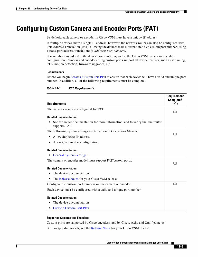
Chapter 19 Understanding Device ConflictsConfiguring Custom Camera and Encoder Ports (PAT)
Configuring Custom Camera and Encoder Ports (PAT)By default, each camera or encoder in Cisco VSM must have a unique IP address.
If multiple devices share a single IP address, however, the network router can also be configured with Port Address Translation (PAT), allowing the devices to be differentiated by a custom port number (using a static port address translation: ip-address: port-number).
Port numbers are added to the device configuration, and to the Cisco VSM camera or encoder configuration. Cameras and encoders using custom ports support all device features, such as streaming, PTZ, motion detection, firmware upgrades, etc.
Requirements
Before you begin Create a Custom Port Plan to ensure that each device will have a valid and unique port number. In addition, all of the following requirements must be complete.
Table 19-1 PAT Requirements
Requirements
Requirement Complete?
()
Related Documentation
• See the router documentation for more information, and to verify that the router supports PAT.
• Allow duplicate IP address
• Allow Custom Port configuration
Related Documentation
• General System Settings
Related Documentation
• The device documentation
• The Release Notes for your Cisco VSM release
Related Documentation
• The device documentation
• Create a Custom Port Plan
Supported Cameras and Encoders
Custom ports are supported by Cisco encoders, and by Cisco, Axis, and Onvif cameras.
• For specific models, see the Release Notes for your Cisco VSM release.
The network router is configured for PAT.
The following system settings are turned on in Operations Manager.
The camera or encoder model must support PAT/custom ports.
Configure the custom port numbers on the camera or encoder.
Each device must be configured with a valid and unique port number.
19-3Cisco Video Surveillance Operations Manager User Guide
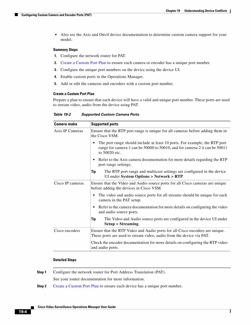
Chapter 19 Understanding Device Conflicts Configuring Custom Camera and Encoder Ports (PAT)
• Also see the Axis and Onvif device documentation to determine custom camera support for your model.
Summary Steps
1. Configure the network router for PAT.
2. Create a Custom Port Plan to ensure each camera or encoder has a unique port number.
3. Configure the unique port numbers on the device using the device UI.
4. Enable custom ports in the Operations Manager.
5. Add or edit the cameras and encoders with a custom port number.
Create a Custom Port Plan
Prepare a plan to ensure that each device will have a valid and unique port number. These ports are used to stream video, audio from the device using PAT.
Table 19-2 Supported Custom Camera Ports
Camera make Supported ports
• The port range should include at least 10 ports. For example, the RTP port range for camera-1 can be 50000 to 50010, and for camera-2 it can be 50011 to 50020 etc.
• Refer to the Axis camera documentation for more details regarding the RTP port range settings.
Tip The RTP port range and multicast settings are configured in the device UI under System Options > Network > RTP.
• The video and audio source ports for all streams should be unique for each camera in the PAT setup.
• Refer to the camera documentation for more details on configuring the video and audio source ports.
Tip The Video and Audio source ports are configured in the device UI under Setup > Streaming.
Detailed Steps
Step 1 Configure the network router for Port Address Translation (PAT).
See your router documentation for more information.
Step 2 Create a Custom Port Plan to ensure each device has a unique port number.
Axis IP Cameras Ensure that the RTP port range is unique for all cameras before adding them in the Cisco VSM.
Cisco IP cameras Ensure that the Video and Audio source ports for all Cisco cameras are unique before adding the devices in Cisco VSM.
Cisco encoders Ensure that the RTP Video and Audio ports for all Cisco encoders are unique. These ports are used to stream video, audio from the device via PAT.
Check the encoder documentation for more details on configuring the RTP video and audio ports.
19-4Cisco Video Surveillance Operations Manager User Guide
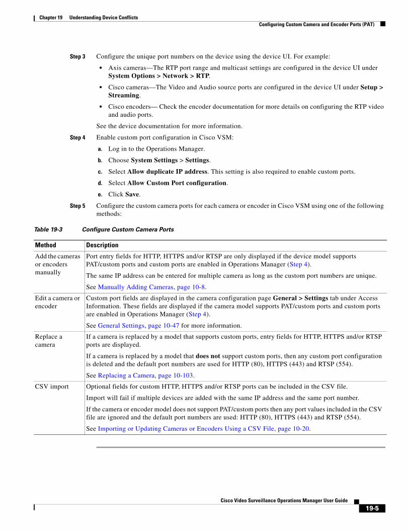
Chapter 19 Understanding Device ConflictsConfiguring Custom Camera and Encoder Ports (PAT)
Step 3 Configure the unique port numbers on the device using the device UI. For example:
• Axis cameras—The RTP port range and multicast settings are configured in the device UI under System Options > Network > RTP.
• Cisco cameras—The Video and Audio source ports are configured in the device UI under Setup > Streaming.
• Cisco encoders— Check the encoder documentation for more details on configuring the RTP video and audio ports.
See the device documentation for more information.
Step 4 Enable custom port configuration in Cisco VSM:
a. Log in to the Operations Manager.
b. Choose System Settings > Settings.
c. Select Allow duplicate IP address. This setting is also required to enable custom ports.
d. Select Allow Custom Port configuration.
e. Click Save.
Step 5 Configure the custom camera ports for each camera or encoder in Cisco VSM using one of the following methods:
Table 19-3 Configure Custom Camera Ports
Method Description
Add the cameras or encoders manually
Port entry fields for HTTP, HTTPS and/or RTSP are only displayed if the device model supports PAT/custom ports and custom ports are enabled in Operations Manager (Step 4).
The same IP address can be entered for multiple camera as long as the custom port numbers are unique.
See Manually Adding Cameras, page 10-8.
Edit a camera or encoder
Custom port fields are displayed in the camera configuration page General > Settings tab under Access Information. These fields are displayed if the camera model supports PAT/custom ports and custom ports are enabled in Operations Manager (Step 4).
See General Settings, page 10-47 for more information.
Replace a camera
If a camera is replaced by a model that supports custom ports, entry fields for HTTP, HTTPS and/or RTSP ports are displayed.
If a camera is replaced by a model that does not support custom ports, then any custom port configuration is deleted and the default port numbers are used for HTTP (80), HTTPS (443) and RTSP (554).
See Replacing a Camera, page 10-103.
CSV import Optional fields for custom HTTP, HTTPS and/or RTSP ports can be included in the CSV file.
Import will fail if multiple devices are added with the same IP address and the same port number.
If the camera or encoder model does not support PAT/custom ports then any port values included in the CSV file are ignored and the default port numbers are used: HTTP (80), HTTPS (443) and RTSP (554).
See Importing or Updating Cameras or Encoders Using a CSV File, page 10-20.
19-5Cisco Video Surveillance Operations Manager User Guide
Chapter 19 Understanding Device Conflicts Resolving ID Mismatch Errors When Changing Camera IP Addresses
Resolving ID Mismatch Errors When Changing Camera IP Addresses
If cameras are configured with IP addresses (and not hostnames), and those IP addresses change, a hardware id mismatch issue can occur and the camera will be placed in the Enabled: Critical state (red).
This occurs because the camera’s hardware ID no longer matches the device IP address. To clear this issue, correct the network configuration for each affected camera. For example:
• Scenario 1: Cameras Configured with DHCP IP Addresses, page 19-6
• Scenario 2: Cameras Configured with a Static IP Addresses, page 19-7
Note • Medianet cameras must be configured for DHCP. Cameras that do not support Medianet can only be added using a static IP address. See the Cisco Video Surveillance Manager: Design Guide and for more information.
• The following scenarios can also occur for cameras configured with hostnames, if the DNS entry does not update with the correct hostname to IP address mapping.
Scenario 1: Cameras Configured with DHCP IP Addresses
Cameras that revive a new DHCP-provided IP address after reboot will be placed in Enabled: Critical state with a hardware ID mismatch issue. This is because the IP address no longer matches the hardware address configured in the Operations Manager. This occurs for each camera where the IP address was changed.
To resolve this issue:
Cisco Cameras
The new IP address is automatically updated in Operations Manager for Cisco cameras configured with DHCP. To clear the error message, choose Repair Configuration from the Device Settings menu.
Step 1 Open the camera configuration page.
Step 2 Select the Status tab and verify the following:
• The device overall status is Enabled: Critical.
• Click the link next to the Hardware category to open a pop-up window.
• Verify that a Hardware ID Mismatch issue occurred.
See Camera Status, page 10-74 for more information.
Step 3 Select Device Settings > Repair Configuration to clear the issue.
See Repairing Configuration Errors, page 10-80 for more information.
Step 4 Verify that the camera status changes to Enabled: OK (green).
19-6Cisco Video Surveillance Operations Manager User Guide
Chapter 19 Understanding Device ConflictsResolving ID Mismatch Errors When Changing Camera IP Addresses
Non-Cisco Cameras
You must manually enter the correct IP address in the camera configuration for non-Cisco cameras configured with DHCP.
Step 1 Open the camera configuration page in Operations Manager.
Step 2 Select the Status tab and verify the following:
• The device overall status is Enabled: Critical.
• Click the link next to the Hardware category to open a pop-up window.
• Verify that a Hardware ID Mismatch issue occurred.
See Camera Status, page 10-74 for more information.
Step 3 Select the General tab.
See General Settings, page 10-47 for more information.
Step 4 Under Access Information, enter the correct IP address for the device.
• This is the setting used by Operations Manager to communicate with the device,
• The IP address stored in Operations Manager must be the same as the device configuration.
Step 5 Verify that the camera status changes to Enabled: OK (green).
Scenario 2: Cameras Configured with a Static IP Addresses
If cameras are configured with a static IP address, and that address is changed in the camera’s device user interface, the device is placed in Enabled: Critical state with a hardware ID mismatch issue. This is because the IP address no longer matches the hardware address configured in the Operations Manager. This occurs for each camera where the IP address was changed.
• If another camera has the same IP address, an ID collision issue occurs. See Understanding Device Conflicts, page 19-1 for more information and to resolve the issue.
• If the camera’s IP address is unique, but no longer matches the entry in the Operations Manager, you must correct the entry on the camera configuration page.
Procedure
Step 1 Open the camera configuration page in Operations Manager.
Step 2 Select the Status tab and verify the following:
• The device overall status is Enabled: Critical.
• Click the link next to the Hardware category to open a pop-up window.
• Verify that a Hardware ID Mismatch issue occurred.
See Camera Status, page 10-74 for more information.
Step 3 Select the General tab.
See General Settings, page 10-47 for more information.
Step 4 Under Access Information, enter the correct IP address for the device.
• This is the setting used by Operations Manager to communicate with the device,
19-7Cisco Video Surveillance Operations Manager User Guide

Chapter 19 Understanding Device Conflicts Resolving ID Mismatch Errors When Changing Camera IP Addresses
• The IP address stored in Operations Manager must be the same as the device configuration.
Step 5 Verify that the camera status changes to Enabled: OK (green).
19-8Cisco Video Surveillance Operations Manager User Guide
Cisco V
C H A P T E R 20
Adding Encoders and Analog CamerasEncoders provide network connectivity for analog cameras, and digitize the analog video so it can be saved and transmitted by the Cisco VSM system. Refer to the following topics to add and configure encoders and analog cameras:
Contents
• Overview, page 20-2
• Pre-Provisioning Encoders and Analog Cameras, page 20-3
• Requirements, page 20-4
• Adding External Encoders and Analog Cameras, page 20-5
• Bulk Actions: Revising Multiple Encoders, page 20-12
• Using “Split Model” Multi-Port Multi-IP Encoders, page 20-14
• Encoder Status, page 20-16
Tip See also the Cisco Video Surveillance Manager: Install and Upgrade Guide.
Note Encoders are not required for IP (networked) cameras.
20-1ideo Surveillance Operations Manager User Guide

Chapter 20 Adding Encoders and Analog Cameras Overview
OverviewCisco VSM 7 supports external encoders that are added to the same network as the server. and configured with an IP address, username and password. Analog cameras are then attached to the encoder with a video cable, and multiple cameras can be connected to a single encoder (Figure 20-1). In addition, serial port connections can be used between the camera and encoder to provide PTZ and other control features.
Tip See the encoder documentation for more information on the number of supported video ports, physical connections, supported features and configuration.
Figure 20-1 shows an external encoder configuration.
Figure 20-1 External Encoder Configuration
20-2Cisco Video Surveillance Operations Manager User Guide
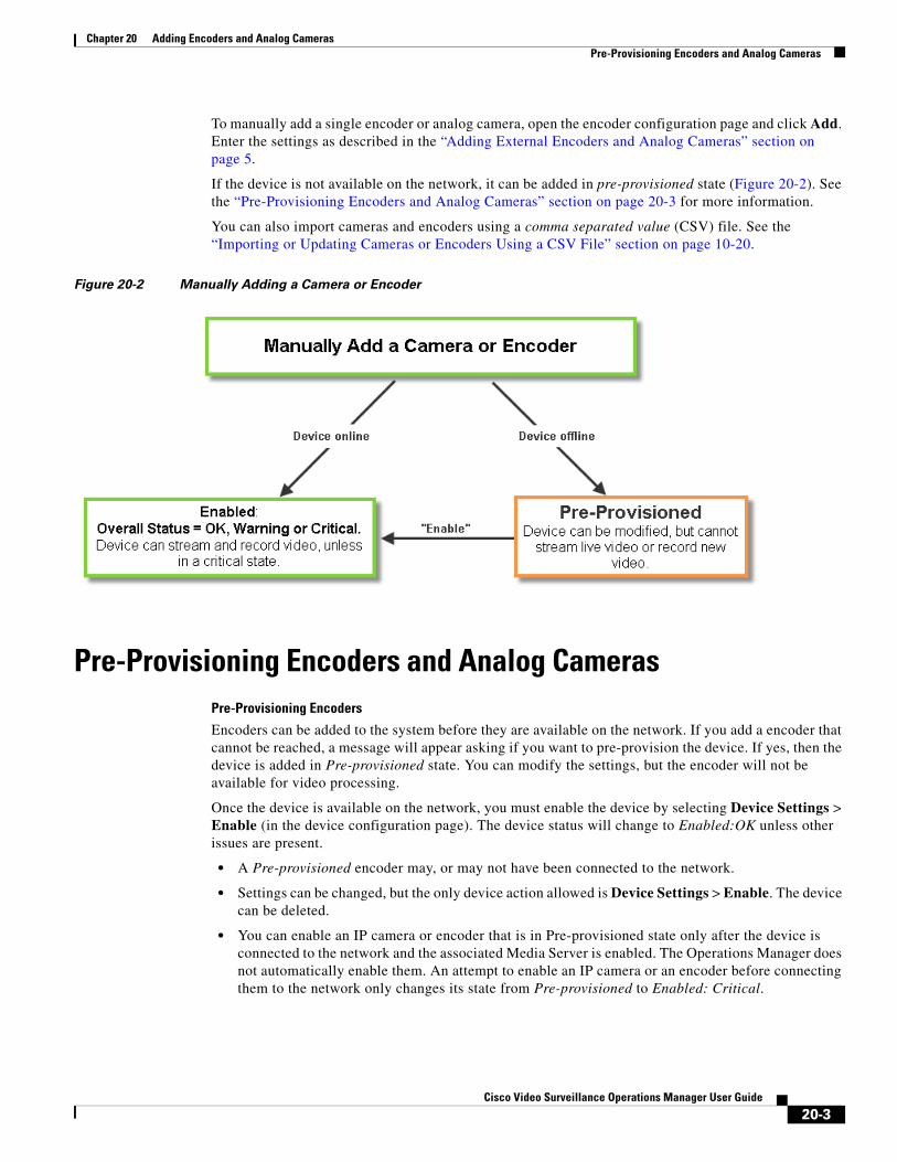
Chapter 20 Adding Encoders and Analog CamerasPre-Provisioning Encoders and Analog Cameras
To manually add a single encoder or analog camera, open the encoder configuration page and click Add. Enter the settings as described in the “Adding External Encoders and Analog Cameras” section on page 5.
If the device is not available on the network, it can be added in pre-provisioned state (Figure 20-2). See the “Pre-Provisioning Encoders and Analog Cameras” section on page 20-3 for more information.
You can also import cameras and encoders using a comma separated value (CSV) file. See the “Importing or Updating Cameras or Encoders Using a CSV File” section on page 10-20.
Figure 20-2 Manually Adding a Camera or Encoder
Pre-Provisioning Encoders and Analog CamerasPre-Provisioning Encoders
Encoders can be added to the system before they are available on the network. If you add a encoder that cannot be reached, a message will appear asking if you want to pre-provision the device. If yes, then the device is added in Pre-provisioned state. You can modify the settings, but the encoder will not be available for video processing.
Once the device is available on the network, you must enable the device by selecting Device Settings > Enable (in the device configuration page). The device status will change to Enabled:OK unless other issues are present.
• A Pre-provisioned encoder may, or may not have been connected to the network.
• Settings can be changed, but the only device action allowed is Device Settings > Enable. The device can be deleted.
• You can enable an IP camera or encoder that is in Pre-provisioned state only after the device is connected to the network and the associated Media Server is enabled. The Operations Manager does not automatically enable them. An attempt to enable an IP camera or an encoder before connecting them to the network only changes its state from Pre-provisioned to Enabled: Critical.
20-3Cisco Video Surveillance Operations Manager User Guide
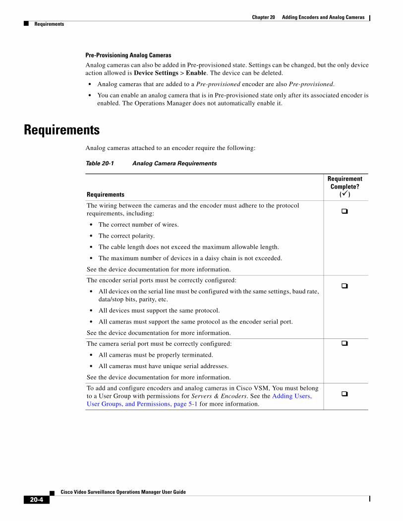
Chapter 20 Adding Encoders and Analog Cameras Requirements
Pre-Provisioning Analog Cameras
Analog cameras can also be added in Pre-provisioned state. Settings can be changed, but the only device action allowed is Device Settings > Enable. The device can be deleted.
• Analog cameras that are added to a Pre-provisioned encoder are also Pre-provisioned.
• You can enable an analog camera that is in Pre-provisioned state only after its associated encoder is enabled. The Operations Manager does not automatically enable it.
RequirementsAnalog cameras attached to an encoder require the following:
Table 20-1 Analog Camera Requirements
Requirements
Requirement Complete?
()
• The correct number of wires.
• The correct polarity.
• The cable length does not exceed the maximum allowable length.
• The maximum number of devices in a daisy chain is not exceeded.
• All devices on the serial line must be configured with the same settings, baud rate, data/stop bits, parity, etc.
• All devices must support the same protocol.
• All cameras must support the same protocol as the encoder serial port.
• All cameras must be properly terminated.
• All cameras must have unique serial addresses.
The wiring between the cameras and the encoder must adhere to the protocol requirements, including:
See the device documentation for more information.
The encoder serial ports must be correctly configured:
See the device documentation for more information.
The camera serial port must be correctly configured:
See the device documentation for more information.
To add and configure encoders and analog cameras in Cisco VSM, You must belong to a User Group with permissions for Servers & Encoders. See the Adding Users, User Groups, and Permissions, page 5-1 for more information.
20-4Cisco Video Surveillance Operations Manager User Guide
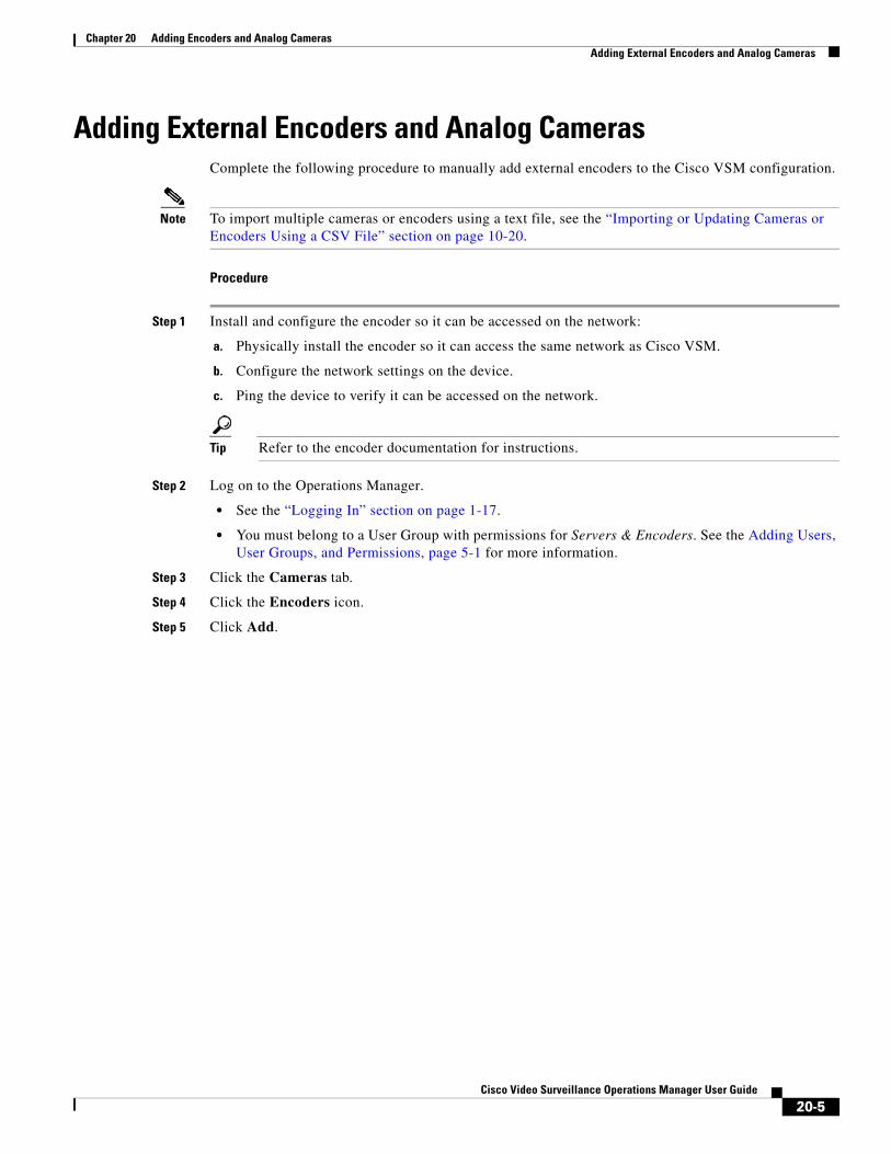
Chapter 20 Adding Encoders and Analog CamerasAdding External Encoders and Analog Cameras
Adding External Encoders and Analog CamerasComplete the following procedure to manually add external encoders to the Cisco VSM configuration.
Note To import multiple cameras or encoders using a text file, see the “Importing or Updating Cameras or Encoders Using a CSV File” section on page 10-20.
Procedure
Step 1 Install and configure the encoder so it can be accessed on the network:
a. Physically install the encoder so it can access the same network as Cisco VSM.
b. Configure the network settings on the device.
c. Ping the device to verify it can be accessed on the network.
Tip Refer to the encoder documentation for instructions.
Step 2 Log on to the Operations Manager.
• See the “Logging In” section on page 1-17.
• You must belong to a User Group with permissions for Servers & Encoders. See the Adding Users, User Groups, and Permissions, page 5-1 for more information.
Step 3 Click the Cameras tab.
Step 4 Click the Encoders icon.
Step 5 Click Add.
20-5Cisco Video Surveillance Operations Manager User Guide
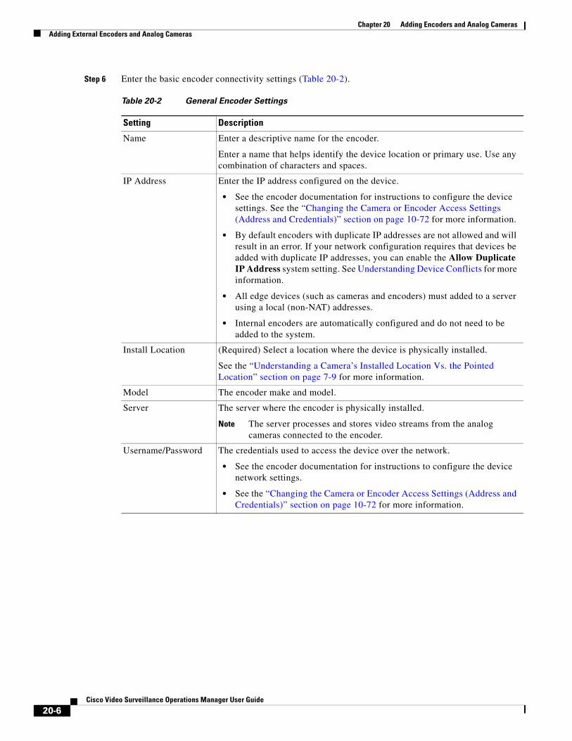
Chapter 20 Adding Encoders and Analog Cameras Adding External Encoders and Analog Cameras
Step 6 Enter the basic encoder connectivity settings (Table 20-2).
Table 20-2 General Encoder Settings
Setting Description
Name Enter a descriptive name for the encoder.
Enter a name that helps identify the device location or primary use. Use any combination of characters and spaces.
IP Address Enter the IP address configured on the device.
• See the encoder documentation for instructions to configure the device settings. See the “Changing the Camera or Encoder Access Settings (Address and Credentials)” section on page 10-72 for more information.
• By default encoders with duplicate IP addresses are not allowed and will result in an error. If your network configuration requires that devices be added with duplicate IP addresses, you can enable the Allow Duplicate IP Address system setting. See Understanding Device Conflicts for more information.
• All edge devices (such as cameras and encoders) must added to a server using a local (non-NAT) addresses.
• Internal encoders are automatically configured and do not need to be added to the system.
Install Location (Required) Select a location where the device is physically installed.
See the “Understanding a Camera’s Installed Location Vs. the Pointed Location” section on page 7-9 for more information.
Model The encoder make and model.
Server The server where the encoder is physically installed.
Note The server processes and stores video streams from the analog cameras connected to the encoder.
Username/Password The credentials used to access the device over the network.
• See the encoder documentation for instructions to configure the device network settings.
• See the “Changing the Camera or Encoder Access Settings (Address and Credentials)” section on page 10-72 for more information.
20-6Cisco Video Surveillance Operations Manager User Guide
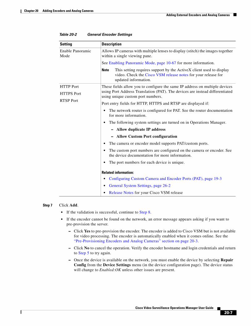
Chapter 20 Adding Encoders and Analog CamerasAdding External Encoders and Analog Cameras
Step 7 Click Add.
• If the validation is successful, continue to Step 8.
• If the encoder cannot be found on the network, an error message appears asking if you want to pre-provision the server.
– Click Yes to pre-provision the encoder. The encoder is added to Cisco VSM but is not available for video processing. The encoder is automatically enabled when it comes online. See the “Pre-Provisioning Encoders and Analog Cameras” section on page 20-3.
– Click No to cancel the operation. Verify the encoder hostname and login credentials and return to Step 5 to try again.
– Once the device is available on the network, you must enable the device by selecting Repair Config from the Device Settings menu (in the device configuration page). The device status will change to Enabled:OK unless other issues are present.
Enable Panoramic Mode
Allows IP cameras with multiple lenses to display (stitch) the images together within a single viewing pane.
See Enabling Panoramic Mode, page 10-67 for more information.
Note This setting requires support by the ActiveX client used to display video. Check the Cisco VSM release notes for your release for updated information.
HTTP Port
HTTPS Port
RTSP Port
These fields allow you to configure the same IP address on multiple devices using Port Address Translation (PAT). The devices are instead differentiated using unique custom port numbers.
Port entry fields for HTTP, HTTPS and RTSP are displayed if:
• The network router is configured for PAT. See the router documentation for more information.
• The following system settings are turned on in Operations Manager.
– Allow duplicate IP address
– Allow Custom Port configuration
• The camera or encoder model supports PAT/custom ports.
• The custom port numbers are configured on the camera or encoder. See the device documentation for more information.
• The port numbers for each device is unique.
Related information:
• Configuring Custom Camera and Encoder Ports (PAT), page 19-3
• General System Settings, page 26-2
• Release Notes for your Cisco VSM release
Table 20-2 General Encoder Settings
Setting Description
20-7Cisco Video Surveillance Operations Manager User Guide
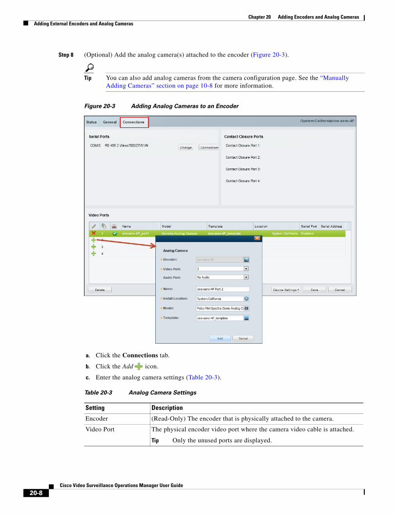
Chapter 20 Adding Encoders and Analog Cameras Adding External Encoders and Analog Cameras
Step 8 (Optional) Add the analog camera(s) attached to the encoder (Figure 20-3).
Tip You can also add analog cameras from the camera configuration page. See the “Manually Adding Cameras” section on page 10-8 for more information.
Figure 20-3 Adding Analog Cameras to an Encoder
a. Click the Connections tab.
b. Click the Add icon.
c. Enter the analog camera settings (Table 20-3).
Table 20-3 Analog Camera Settings
Setting Description
Encoder (Read-Only) The encoder that is physically attached to the camera.
Video Port The physical encoder video port where the camera video cable is attached.
Tip Only the unused ports are displayed.
20-8Cisco Video Surveillance Operations Manager User Guide
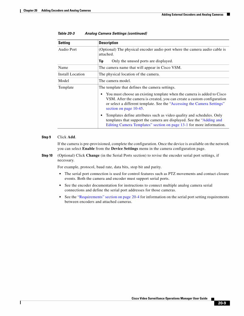
Chapter 20 Adding Encoders and Analog CamerasAdding External Encoders and Analog Cameras
Step 9 Click Add.
If the camera is pre-provisioned, complete the configuration. Once the device is available on the network you can select Enable from the Device Settings menu in the camera configuration page.
Step 10 (Optional) Click Change (in the Serial Ports section) to revise the encoder serial port settings, if necessary.
For example, protocol, baud rate, data bits, stop bit and parity.
• The serial port connection is used for control features such as PTZ movements and contact closure events. Both the camera and encoder must support serial ports.
• See the encoder documentation for instructions to connect multiple analog camera serial connections and define the serial port addresses for those cameras.
• See the “Requirements” section on page 20-4 for information on the serial port setting requirements between encoders and attached cameras.
Audio Port (Optional) The physical encoder audio port where the camera audio cable is attached.
Tip Only the unused ports are displayed.
Name The camera name that will appear in Cisco VSM.
Install Location The physical location of the camera.
Model The camera model.
Template The template that defines the camera settings.
• You must choose an existing template when the camera is added to Cisco VSM. After the camera is created, you can create a custom configuration or select a different template. See the “Accessing the Camera Settings” section on page 10-45.
• Templates define attributes such as video quality and schedules. Only templates that support the camera are displayed. See the “Adding and Editing Camera Templates” section on page 13-1 for more information.
Table 20-3 Analog Camera Settings (continued)
Setting Description
20-9Cisco Video Surveillance Operations Manager User Guide

Chapter 20 Adding Encoders and Analog Cameras Adding External Encoders and Analog Cameras
Step 11 (Optional) Click the Connections button (in the Serial Ports section) to define the analog camera serial port connections (Figure 20-4).
The following settings are used when a serial cable is attached from an analog cameras to an encoder. The serial port connection enables the pan-zoom-tilt (PTZ) controls and/or photographic controls (brightness, contrast, etc.) on an analog camera. See the “General Settings” section on page 10-47 for more information.
Figure 20-4 Serial Port Connections
a. Expand the location tree and select the camera’s Install Location (see Table 20-3).
b. Select a camera name from the list.
c. Click the add icon.
d. Enter the serial port connection settings (Table 20-4) and click Add.
Table 20-4 Analog Camera Serial Port Settings
Setting Description
Encoder The encoder for the analog camera.
20-10Cisco Video Surveillance Operations Manager User Guide
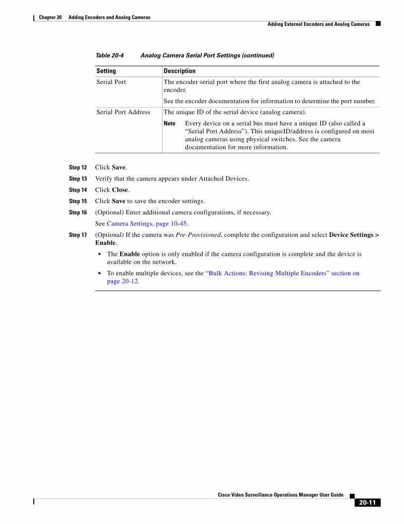
Chapter 20 Adding Encoders and Analog CamerasAdding External Encoders and Analog Cameras
Step 12 Click Save.
Step 13 Verify that the camera appears under Attached Devices.
Step 14 Click Close.
Step 15 Click Save to save the encoder settings.
Step 16 (Optional) Enter additional camera configurations, if necessary.
See Camera Settings, page 10-45.
Step 17 (Optional) If the camera was Pre-Provisioned, complete the configuration and select Device Settings > Enable.
• The Enable option is only enabled if the camera configuration is complete and the device is available on the network.
• To enable multiple devices, see the “Bulk Actions: Revising Multiple Encoders” section on page 20-12.
Serial Port The encoder serial port where the first analog camera is attached to the encoder.
See the encoder documentation for information to determine the port number.
Serial Port Address The unique ID of the serial device (analog camera).
Note Every device on a serial bus must have a unique ID (also called a “Serial Port Address”). This uniqueID/address is configured on most analog cameras using physical switches. See the camera documentation for more information.
Table 20-4 Analog Camera Serial Port Settings (continued)
Setting Description
20-11Cisco Video Surveillance Operations Manager User Guide
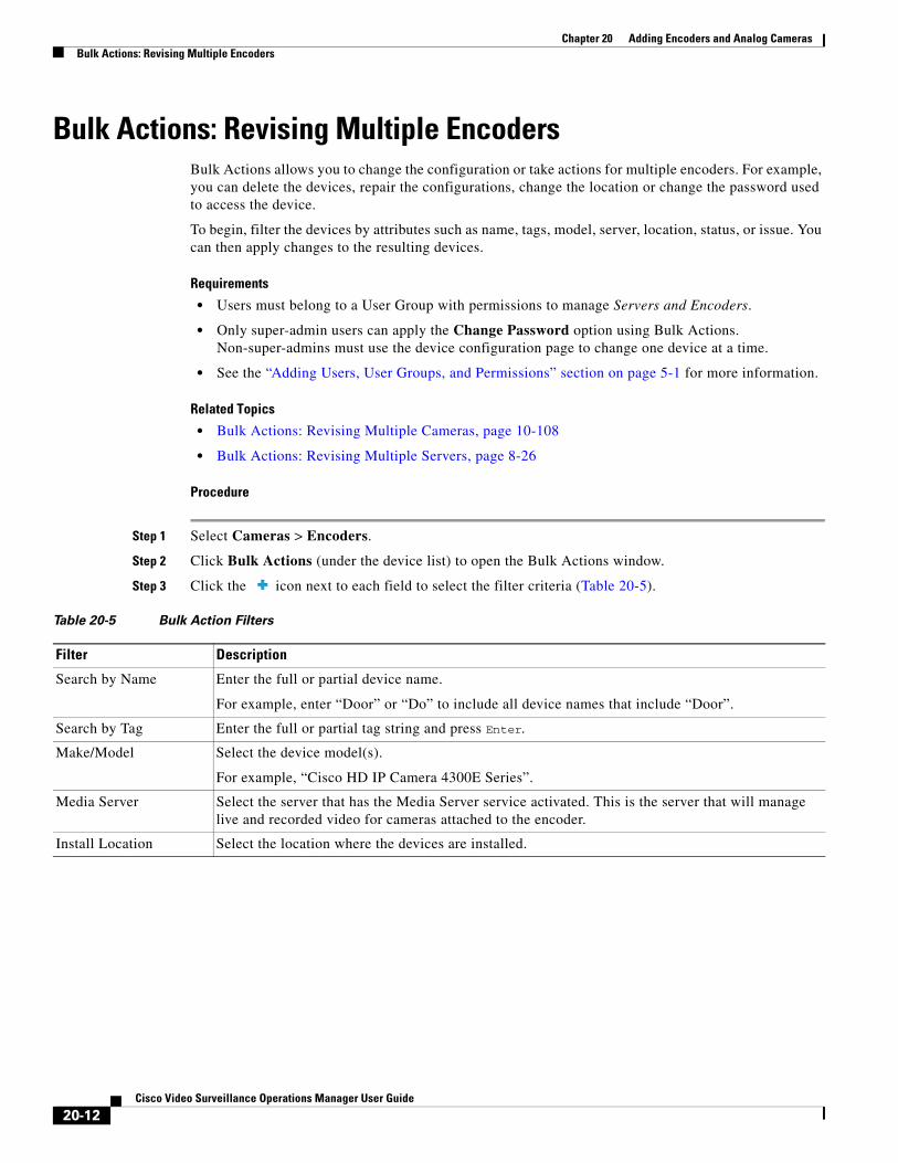
Chapter 20 Adding Encoders and Analog Cameras Bulk Actions: Revising Multiple Encoders
Bulk Actions: Revising Multiple EncodersBulk Actions allows you to change the configuration or take actions for multiple encoders. For example, you can delete the devices, repair the configurations, change the location or change the password used to access the device.
To begin, filter the devices by attributes such as name, tags, model, server, location, status, or issue. You can then apply changes to the resulting devices.
Requirements
• Users must belong to a User Group with permissions to manage Servers and Encoders.
• Only super-admin users can apply the Change Password option using Bulk Actions. Non-super-admins must use the device configuration page to change one device at a time.
• See the “Adding Users, User Groups, and Permissions” section on page 5-1 for more information.
Related Topics
• Bulk Actions: Revising Multiple Cameras, page 10-108
• Bulk Actions: Revising Multiple Servers, page 8-26
Procedure
Step 1 Select Cameras > Encoders.
Step 2 Click Bulk Actions (under the device list) to open the Bulk Actions window.
Step 3 Click the icon next to each field to select the filter criteria (Table 20-5).
Table 20-5 Bulk Action Filters
Filter Description
Search by Name Enter the full or partial device name.
For example, enter “Door” or “Do” to include all device names that include “Door”.
Search by Tag Enter the full or partial tag string and press Enter.
Make/Model Select the device model(s).
For example, “Cisco HD IP Camera 4300E Series”.
Media Server Select the server that has the Media Server service activated. This is the server that will manage live and recorded video for cameras attached to the encoder.
Install Location Select the location where the devices are installed.
20-12Cisco Video Surveillance Operations Manager User Guide
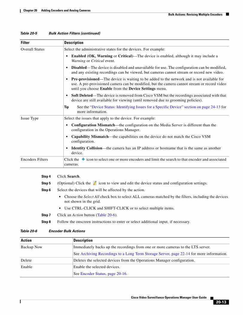
Chapter 20 Adding Encoders and Analog CamerasBulk Actions: Revising Multiple Encoders
Step 4 Click Search.
Step 5 (Optional) Click the icon to view and edit the device status and configuration settings.
Step 6 Select the devices that will be affected by the action.
• Choose the Select All check box to select ALL cameras matched by the filters, including the devices not shown in the grid.
• Use CTRL-CLICK and SHIFT-CLICK or to select multiple items.
Step 7 Click an Action button (Table 20-6).
Step 8 Follow the onscreen instructions to enter or select additional input, if necessary.
Overall Status Select the administrative states for the devices. For example:
• Enabled (OK, Warning or Critical)—The device is enabled, although it may include a Warning or Critical event.
• Disabled—The device is disabled and unavailable for use. The configuration can be modified, and any existing recordings can be viewed, but cameras cannot stream or record new video.
• Pre-provisioned—The device is waiting to be added to the network and is not available for use. A pre-provisioned camera can be modified, but the camera cannot stream or record video until you choose Enable from the Device Settings menu.
• Soft Deleted—The device is removed from Cisco VSM but the recordings associated with that device are still available for viewing (until removed due to grooming policies).
Tip See the “Device Status: Identifying Issues for a Specific Device” section on page 24-13 for more information.
Issue Type Select the issues that apply to the device. For example:
• Configuration Mismatch—the configuration on the Media Server is different than the configuration in the Operations Manager.
• Capability Mismatch—the capabilities on the device do not match the Cisco VSM configuration.
• Identity Collision—the camera has an IP address or hostname that is the same as another device.
Encoders Filters Click the icon to select one or more encoders and limit the search to that encoder and associated cameras.
Table 20-5 Bulk Action Filters (continued)
Filter Description
Table 20-6 Encoder Bulk Actions
Action Description
Backup Now Immediately backs up the recordings from one or more cameras to the LTS server.
See Archiving Recordings to a Long Term Storage Server, page 22-14 for more information.
Delete Deletes the selected devices from the Operations Manager configuration.
Enable Enable the selected devices.
See Encoder Status, page 20-16.
20-13Cisco Video Surveillance Operations Manager User Guide
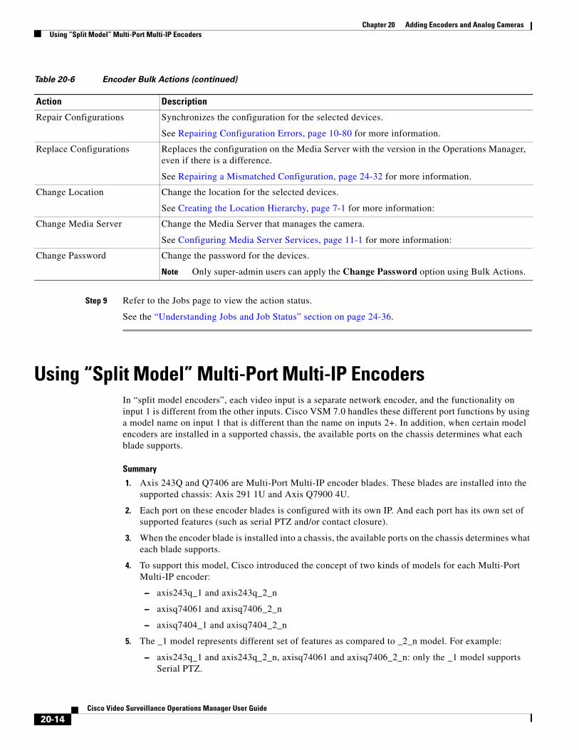
Chapter 20 Adding Encoders and Analog Cameras Using “Split Model” Multi-Port Multi-IP Encoders
Step 9 Refer to the Jobs page to view the action status.
See the “Understanding Jobs and Job Status” section on page 24-36.
Using “Split Model” Multi-Port Multi-IP EncodersIn “split model encoders”, each video input is a separate network encoder, and the functionality on input 1 is different from the other inputs. Cisco VSM 7.0 handles these different port functions by using a model name on input 1 that is different than the name on inputs 2+. In addition, when certain model encoders are installed in a supported chassis, the available ports on the chassis determines what each blade supports.
Summary
1. Axis 243Q and Q7406 are Multi-Port Multi-IP encoder blades. These blades are installed into the supported chassis: Axis 291 1U and Axis Q7900 4U.
2. Each port on these encoder blades is configured with its own IP. And each port has its own set of supported features (such as serial PTZ and/or contact closure).
3. When the encoder blade is installed into a chassis, the available ports on the chassis determines what each blade supports.
4. To support this model, Cisco introduced the concept of two kinds of models for each Multi-Port Multi-IP encoder:
– axis243q_1 and axis243q_2_n
– axisq74061 and axisq7406_2_n
– axisq7404_1 and axisq7404_2_n
5. The _1 model represents different set of features as compared to _2_n model. For example:
– axis243q_1 and axis243q_2_n, axisq74061 and axisq7406_2_n: only the _1 model supports Serial PTZ.
Repair Configurations Synchronizes the configuration for the selected devices.
See Repairing Configuration Errors, page 10-80 for more information.
Replace Configurations Replaces the configuration on the Media Server with the version in the Operations Manager, even if there is a difference.
See Repairing a Mismatched Configuration, page 24-32 for more information.
Change Location Change the location for the selected devices.
See Creating the Location Hierarchy, page 7-1 for more information:
Change Media Server Change the Media Server that manages the camera.
See Configuring Media Server Services, page 11-1 for more information:
Change Password Change the password for the devices.
Note Only super-admin users can apply the Change Password option using Bulk Actions.
Table 20-6 Encoder Bulk Actions (continued)
Action Description
20-14Cisco Video Surveillance Operations Manager User Guide
Chapter 20 Adding Encoders and Analog CamerasUsing “Split Model” Multi-Port Multi-IP Encoders
– axisq7404_1 and axisq7404_2_n: only _1 model supports audio.
Constraints
The constraints are as follows:
• If the chassis being used is Axis 291 1U Chassis and serial PTZ is working, then irrespective of Axis 243Q or Axis Q7406 being the blade, it has to be the serial port on Channel 1 (The physical port 1 on the blade encoder). For example, when importing this device it has to be _1 device model.
• If the chassis is Axis Q7900 4U and the encoder blade is Axis 243Q has PTZ working already: it still has to be Channel (Port on the encoder blade) 1 (Physical Port 1 on the blade encoder).
• If the blade is Q7406 and PTZ is already working, then it may be any of the ports on the blade (because the chassis exposes all the serial ports on this blade through the connectors on the back side). But Cisco VSM release 7.0 supports PTZ through the first port on the blade only. So the device representing the first port on this encoder has to imported using 1 device model and the rest of the ports as the 2_n device model.
20-15Cisco Video Surveillance Operations Manager User Guide
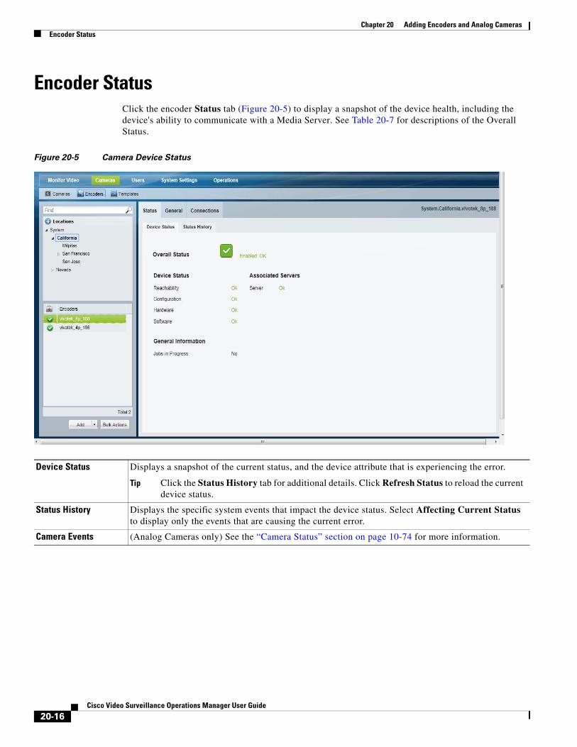
Chapter 20 Adding Encoders and Analog Cameras Encoder Status
Encoder StatusClick the encoder Status tab (Figure 20-5) to display a snapshot of the device health, including the device's ability to communicate with a Media Server. See Table 20-7 for descriptions of the Overall Status.
Figure 20-5 Camera Device Status
Device Status
Tip Click the Status History tab for additional details. Click Refresh Status to reload the current device status.
Status History
Camera Events
Displays a snapshot of the current status, and the device attribute that is experiencing the error.
Displays the specific system events that impact the device status. Select Affecting Current Status to display only the events that are causing the current error.
(Analog Cameras only) See the “Camera Status” section on page 10-74 for more information.
20-16Cisco Video Surveillance Operations Manager User Guide
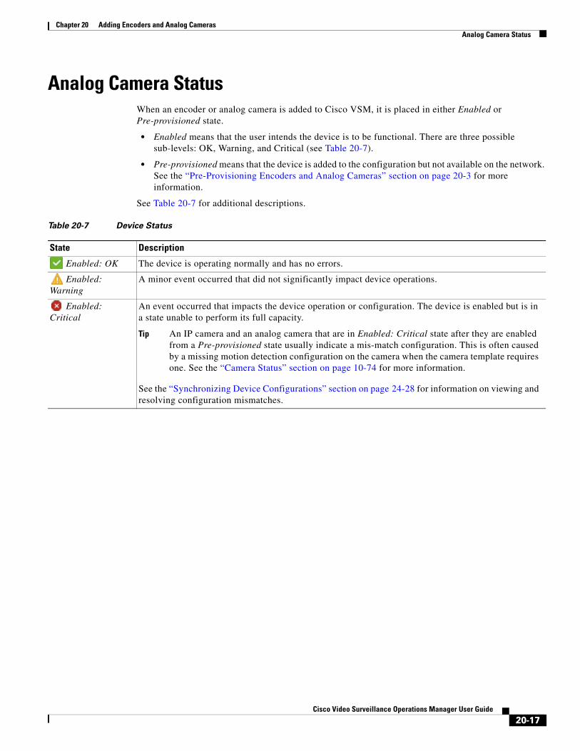
Chapter 20 Adding Encoders and Analog CamerasAnalog Camera Status
Analog Camera StatusWhen an encoder or analog camera is added to Cisco VSM, it is placed in either Enabled or Pre-provisioned state.
• Enabled means that the user intends the device is to be functional. There are three possible sub-levels: OK, Warning, and Critical (see Table 20-7).
• Pre-provisioned means that the device is added to the configuration but not available on the network. See the “Pre-Provisioning Encoders and Analog Cameras” section on page 20-3 for more information.
See Table 20-7 for additional descriptions.
Table 20-7 Device Status
State Description
Enabled: OK The device is operating normally and has no errors.
Enabled: Warning
A minor event occurred that did not significantly impact device operations.
Enabled: Critical
An event occurred that impacts the device operation or configuration. The device is enabled but is in a state unable to perform its full capacity.
Tip An IP camera and an analog camera that are in Enabled: Critical state after they are enabled from a Pre-provisioned state usually indicate a mis-match configuration. This is often caused by a missing motion detection configuration on the camera when the camera template requires one. See the “Camera Status” section on page 10-74 for more information.
See the “Synchronizing Device Configurations” section on page 24-28 for information on viewing and resolving configuration mismatches.
20-17Cisco Video Surveillance Operations Manager User Guide
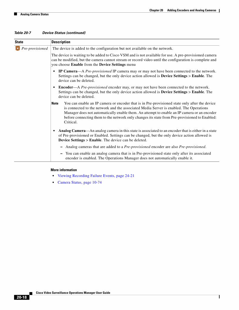
Chapter 20 Adding Encoders and Analog Cameras Analog Camera Status
More information
• Viewing Recording Failure Events, page 24-21
• Camera Status, page 10-74
Pre-provisioned The device is added to the configuration but not available on the network.
The device is waiting to be added to Cisco VSM and is not available for use. A pre-provisioned camera can be modified, but the camera cannot stream or record video until the configuration is complete and you choose Enable from the Device Settings menu
• IP Camera—A Pre-provisioned IP camera may or may not have been connected to the network. Settings can be changed, but the only device action allowed is Device Settings > Enable. The device can be deleted.
• Encoder—A Pre-provisioned encoder may, or may not have been connected to the network. Settings can be changed, but the only device action allowed is Device Settings > Enable. The device can be deleted.
Note You can enable an IP camera or encoder that is in Pre-provisioned state only after the device is connected to the network and the associated Media Server is enabled. The Operations Manager does not automatically enable them. An attempt to enable an IP camera or an encoder before connecting them to the network only changes its state from Pre-provisioned to Enabled: Critical.
• Analog Camera—An analog camera in this state is associated to an encoder that is either in a state of Pre-provisioned or Enabled. Settings can be changed, but the only device action allowed is Device Settings > Enable. The device can be deleted.
– Analog cameras that are added to a Pre-provisioned encoder are also Pre-provisioned.
– You can enable an analog camera that is in Pre-provisioned state only after its associated encoder is enabled. The Operations Manager does not automatically enable it.
Table 20-7 Device Status (continued)
State Description
20-18Cisco Video Surveillance Operations Manager User Guide

Cisco V
C H A P T E R 21
Custom FieldsCreate custom fields to improve the searchability of the devices in your deployment, and to restrict access to users. Custom fields can also be used to enable features such as IP calls using SIP applications such as Cisco Jabber or Skype.
For example, create a custom field for the countries or regions where cameras, encoders, or servers are deployed, then go to the device configuration page and select this custom field to define where the device is installed. You can then do the following:
• Use bulk actions perform actions on only the devices from a country or region. You can filter on multiple custom fields to further narrow the results.
• Use bulk actions to change the custom field settings for multiple devices.
• Create a user group and add the custom country or region. Users in that group will only access the devices assigned to that custom field. You can add up to 5 custom fields to further narrow the device access for a user group.
Contents
Refer to the following topics for more information:
• Types of Custom Fields, page 21-2
• Custom Field Settings, page 21-3
• Summary Steps: Custom Fields, page 21-4
• Detailed Steps: Custom Fields, page 21-5
• Modifying Custom Fields, page 21-8
• Deleting Custom Fields, page 21-8
Related Documentation
• Configure Voice-over-IP Calling, page 18-1
21-1ideo Surveillance Operations Manager User Guide

Chapter 21 Custom Fields Types of Custom Fields
Types of Custom FieldsYou can create up to 25 custom fields for each Object Type. For example, you can create 25 custom fields for cameras, 25 for encoders, and 25 for servers.
All custom fields can be mandatory or optional, and you can include or exclude them from the options in bulk actions and user groups. You can also define the initial value for each field.
Table 21-1 Custom Camera Fields
Custom Field Type Description
Note If mandatory is selected, the default value will be added to all existing devices.
Note If mandatory is selected, the default value will be added to all existing devices.
• Each “List of choices” can include up to 10 items.
• Only alphanumeric characters are allowed. Special characters and spaces are not supported.
Text field Allows admins and users to enter a description for the device. You can optionally define the minimum and maximum number of characters and enter the initial text.
If the text field is created for cameras, you can optionally display the field Cisco SASD and in maps. This allows users to enter or revise the camera description.
Number field Allows admins to enter a number for each device.
You can optionally define the minimum and maximum number allowed, and the initial value.
List of choices Create a list of choices that allow admins to select from a drop down menu in the device configuration page.
Check box Creates a field that is either checked or unchecked, allowing admins to define if that option is on or off.
For example, create a field for lobby doors to identify only the cameras that are used to monitor front entrances.
21-2Cisco Video Surveillance Operations Manager User Guide
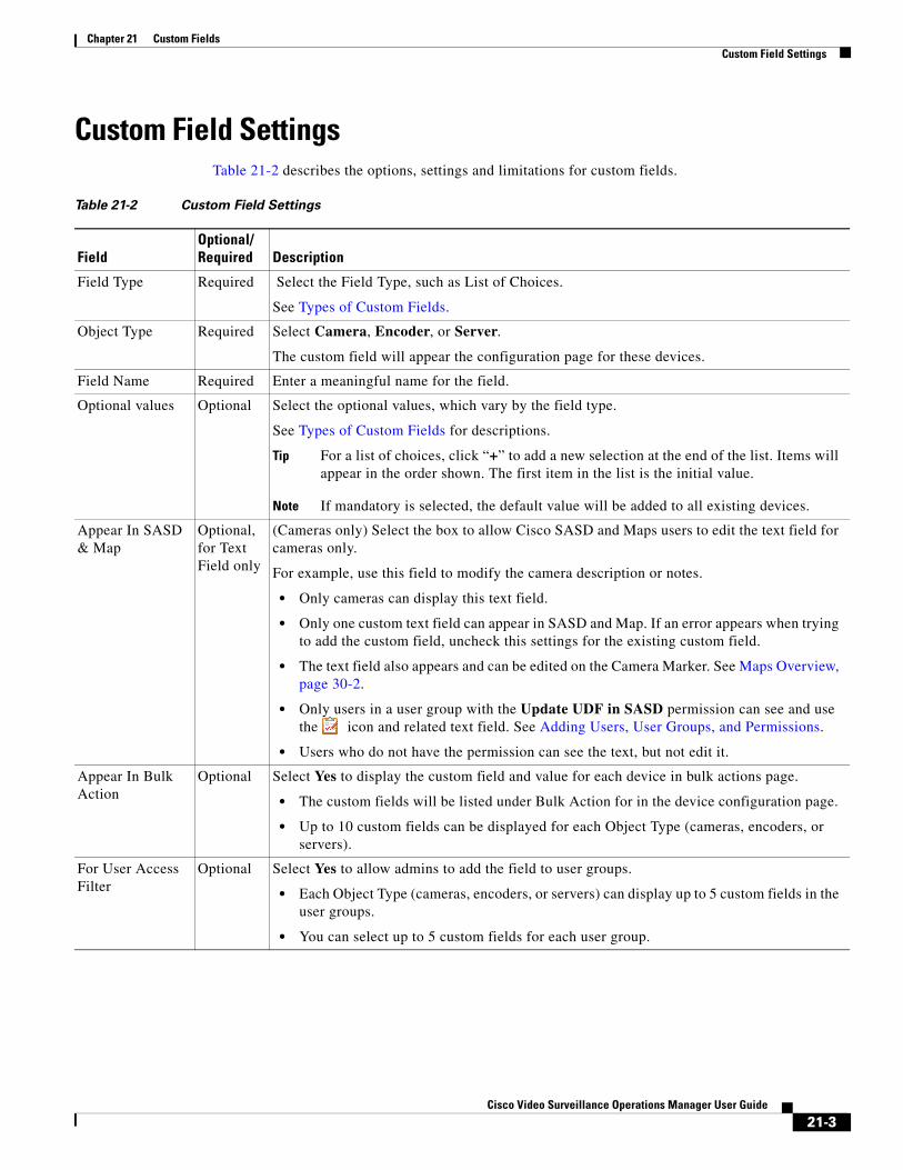
Chapter 21 Custom FieldsCustom Field Settings
Custom Field SettingsTable 21-2 describes the options, settings and limitations for custom fields.
Table 21-2 Custom Field Settings
FieldOptional/Required Description
Tip For a list of choices, click “+” to add a new selection at the end of the list. Items will appear in the order shown. The first item in the list is the initial value.
Note If mandatory is selected, the default value will be added to all existing devices.
• Only cameras can display this text field.
• Only one custom text field can appear in SASD and Map. If an error appears when trying to add the custom field, uncheck this settings for the existing custom field.
• The text field also appears and can be edited on the Camera Marker. See Maps Overview, page 30-2.
• Only users in a user group with the Update UDF in SASD permission can see and use the icon and related text field. See Adding Users, User Groups, and Permissions.
• Users who do not have the permission can see the text, but not edit it.
• The custom fields will be listed under Bulk Action for in the device configuration page.
• Up to 10 custom fields can be displayed for each Object Type (cameras, encoders, or servers).
• Each Object Type (cameras, encoders, or servers) can display up to 5 custom fields in the user groups.
• You can select up to 5 custom fields for each user group.
Field Type Required Select the Field Type, such as List of Choices.
See Types of Custom Fields.
Object Type Required Select Camera, Encoder, or Server.
The custom field will appear the configuration page for these devices.
Field Name Required Enter a meaningful name for the field.
Optional values Optional Select the optional values, which vary by the field type.
See Types of Custom Fields for descriptions.
Appear In SASD & Map
Optional, for Text Field only
(Cameras only) Select the box to allow Cisco SASD and Maps users to edit the text field for cameras only.
For example, use this field to modify the camera description or notes.
Appear In Bulk Action
Optional Select Yes to display the custom field and value for each device in bulk actions page.
For User Access Filter
Optional Select Yes to allow admins to add the field to user groups.
21-3Cisco Video Surveillance Operations Manager User Guide

Chapter 21 Custom Fields Summary Steps: Custom Fields
Summary Steps: Custom Fields
Step 1 Create the custom fields.
See Detailed Steps: Custom Fields, page 21-5.
Step 2 Edit the custom fields in the device settings page.
• If the field is mandatory, the default value will be added to all existing devices.
• If the field is optional, you must select or enter the value for each device.
Step 3 (Optional) Use bulk actions to:
– Filter devices using the custom field filters.
– Update custom field values for multiple devices.
Step 4 (Optional) Add custom fields to user groups to restrict user access.
Step 5 (Optional) If the Appear In SASD & Maps option was configured, add or update the text notes displayed for cameras in Cisco SASD and Maps (Figure 21-1).
Figure 21-1 Custom Text Fields in Maps
21-4Cisco Video Surveillance Operations Manager User Guide
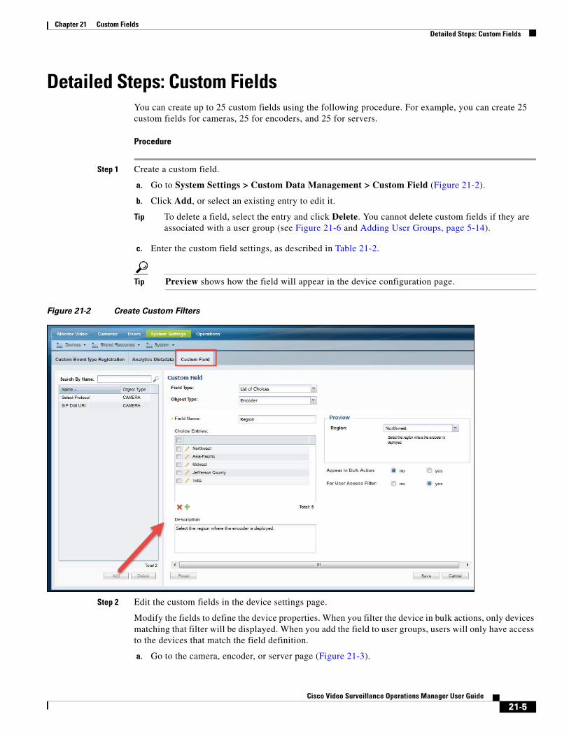
Chapter 21 Custom FieldsDetailed Steps: Custom Fields
Detailed Steps: Custom FieldsYou can create up to 25 custom fields using the following procedure. For example, you can create 25 custom fields for cameras, 25 for encoders, and 25 for servers.
Procedure
Step 1 Create a custom field.
a. Go to System Settings > Custom Data Management > Custom Field (Figure 21-2).
b. Click Add, or select an existing entry to edit it.
Tip To delete a field, select the entry and click Delete. You cannot delete custom fields if they are associated with a user group (see Figure 21-6 and Adding User Groups, page 5-14).
c. Enter the custom field settings, as described in Table 21-2.
Tip Preview shows how the field will appear in the device configuration page.
Figure 21-2 Create Custom Filters
Step 2 Edit the custom fields in the device settings page.
Modify the fields to define the device properties. When you filter the device in bulk actions, only devices matching that filter will be displayed. When you add the field to user groups, users will only have access to the devices that match the field definition.
a. Go to the camera, encoder, or server page (Figure 21-3).
21-5Cisco Video Surveillance Operations Manager User Guide
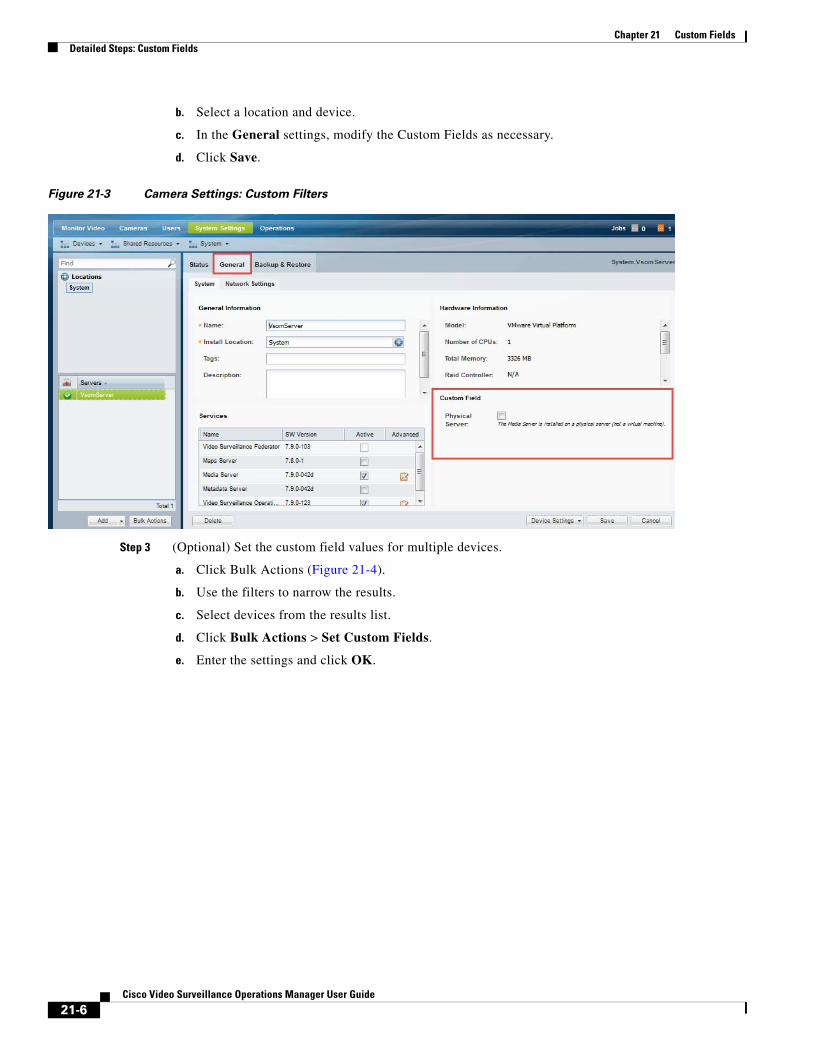
Chapter 21 Custom Fields Detailed Steps: Custom Fields
b. Select a location and device.
c. In the General settings, modify the Custom Fields as necessary.
d. Click Save.
Figure 21-3 Camera Settings: Custom Filters
Step 3 (Optional) Set the custom field values for multiple devices.
a. Click Bulk Actions (Figure 21-4).
b. Use the filters to narrow the results.
c. Select devices from the results list.
d. Click Bulk Actions > Set Custom Fields.
e. Enter the settings and click OK.
21-6Cisco Video Surveillance Operations Manager User Guide
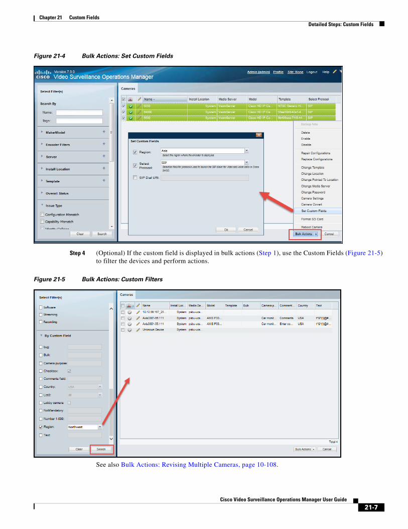
Chapter 21 Custom FieldsDetailed Steps: Custom Fields
Figure 21-4 Bulk Actions: Set Custom Fields
Step 4 (Optional) If the custom field is displayed in bulk actions (Step 1), use the Custom Fields (Figure 21-5) to filter the devices and perform actions.
Figure 21-5 Bulk Actions: Custom Filters
See also Bulk Actions: Revising Multiple Cameras, page 10-108.
21-7Cisco Video Surveillance Operations Manager User Guide
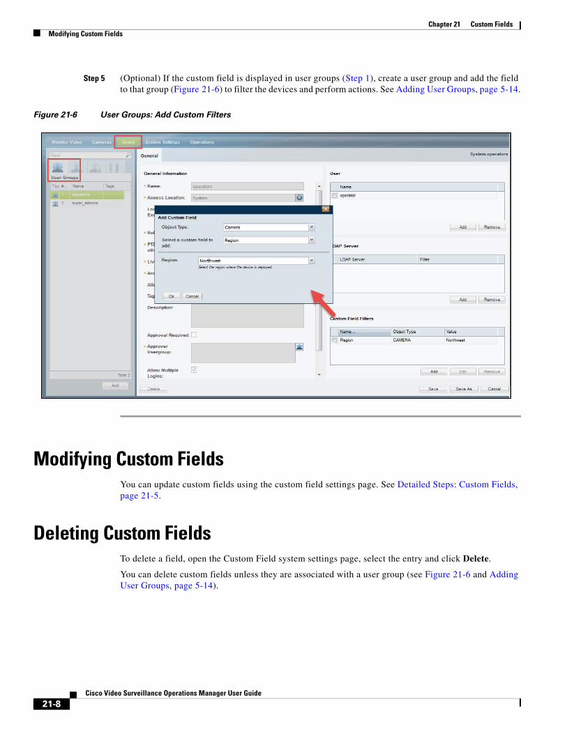
Chapter 21 Custom Fields Modifying Custom Fields
Step 5 (Optional) If the custom field is displayed in user groups (Step 1), create a user group and add the field to that group (Figure 21-6) to filter the devices and perform actions. See Adding User Groups, page 5-14.
Figure 21-6 User Groups: Add Custom Filters
Modifying Custom FieldsYou can update custom fields using the custom field settings page. See Detailed Steps: Custom Fields, page 21-5.
Deleting Custom FieldsTo delete a field, open the Custom Field system settings page, select the entry and click Delete.
You can delete custom fields unless they are associated with a user group (see Figure 21-6 and Adding User Groups, page 5-14).
21-8Cisco Video Surveillance Operations Manager User Guide
Cisco V
C H A P T E R 22
High Availability: Cisco Media ServersCisco Video Surveillance Media Servers can be configured in a high availability (HA) arrangement that allows a primary server to be paired with additional Failover, Redundant, or Long Term Storage Media Server. These HA servers provide the primary server with hot standby, redundant stream storage and playback, and long term recording storage to help ensure that functionality and recordings are not lost if the primary server goes offline.
Review the following information to understand the roles and functions of the Media Servers in and HA configuration, and for instructions to install and configure the HA servers.
Contents
• Overview, page 22-2
– Requirements, page 22-2
– Summary Steps, page 22-3
– Understanding Redundant, Failover, and Long Term Storage Servers, page 22-4
– Understanding Failover, page 22-6
• Define the Media Server HA Role and Associated Servers, page 22-8
• Configuring the HA Advanced Storage Options, page 22-10
– Configuring the Redundant and Failover Options, page 22-11
• Archiving Recordings to a Long Term Storage Server, page 22-14
– Archive recordings to an LTS Server, page 22-14
– Backup Now to an LTS Server, page 22-18
• Viewing the Server HA Status, page 22-21
Note See the “Operations Manager High Availability” section on page 23-1 for instructions to configure Operations Manager server HA.
22-1ideo Surveillance Operations Manager User Guide
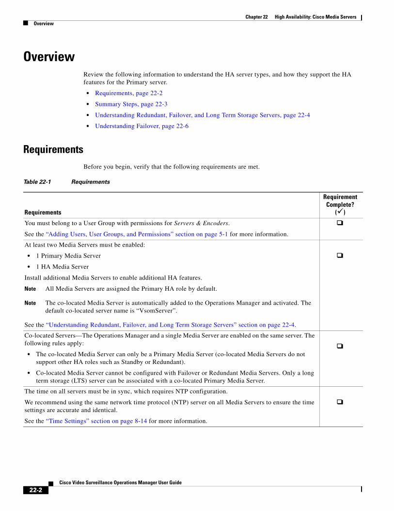
Chapter 22 High Availability: Cisco Media Servers Overview
OverviewReview the following information to understand the HA server types, and how they support the HA features for the Primary server.
• Requirements, page 22-2
• Summary Steps, page 22-3
• Understanding Redundant, Failover, and Long Term Storage Servers, page 22-4
• Understanding Failover, page 22-6
Requirements Before you begin, verify that the following requirements are met.
Table 22-1 Requirements
Requirements
Requirement Complete?
()
• 1 Primary Media Server
• 1 HA Media Server
Note All Media Servers are assigned the Primary HA role by default.
Note The co-located Media Server is automatically added to the Operations Manager and activated. The default co-located server name is “VsomServer”.
• The co-located Media Server can only be a Primary Media Server (co-located Media Servers do not support other HA roles such as Standby or Redundant).
• Co-located Media Server cannot be configured with Failover or Redundant Media Servers. Only a long term storage (LTS) server can be associated with a co-located Primary Media Server.
You must belong to a User Group with permissions for Servers & Encoders.
See the “Adding Users, User Groups, and Permissions” section on page 5-1 for more information.
At least two Media Servers must be enabled:
Install additional Media Servers to enable additional HA features.
See the “Understanding Redundant, Failover, and Long Term Storage Servers” section on page 22-4.
Co-located Servers—The Operations Manager and a single Media Server are enabled on the same server. The following rules apply:
The time on all servers must be in sync, which requires NTP configuration.
We recommend using the same network time protocol (NTP) server on all Media Servers to ensure the time settings are accurate and identical.
See the “Time Settings” section on page 8-14 for more information.
22-2Cisco Video Surveillance Operations Manager User Guide
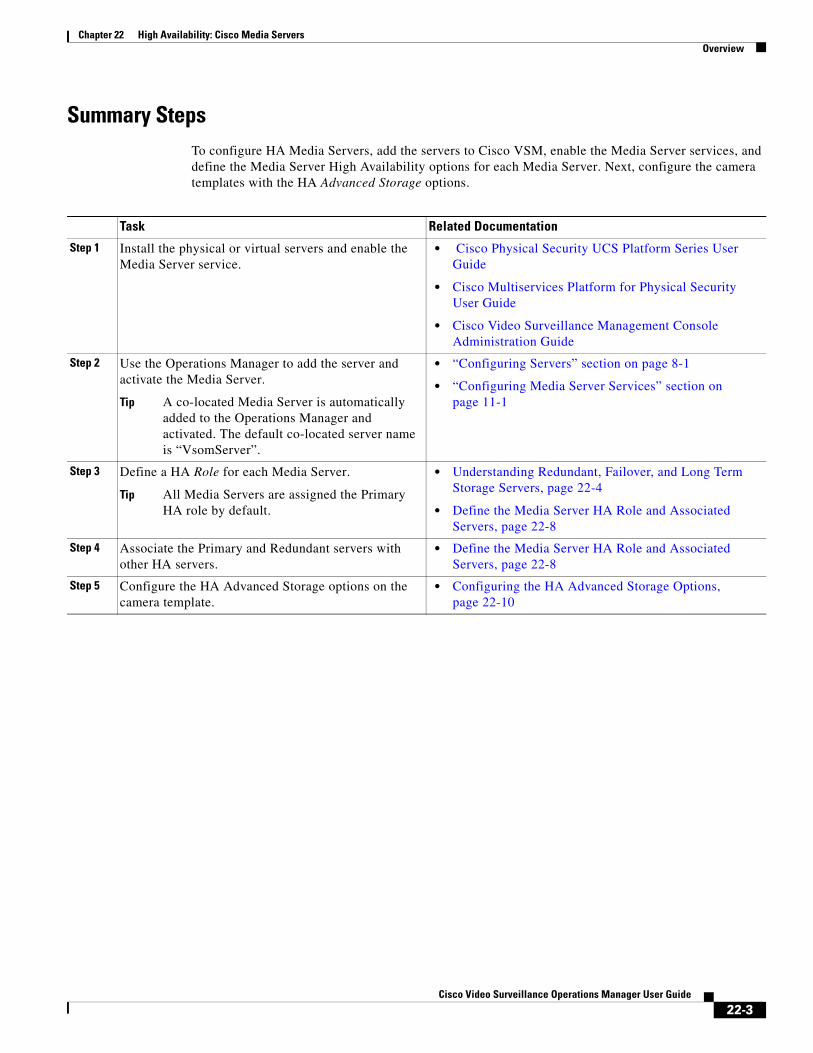
Chapter 22 High Availability: Cisco Media ServersOverview
Summary StepsTo configure HA Media Servers, add the servers to Cisco VSM, enable the Media Server services, and define the Media Server High Availability options for each Media Server. Next, configure the camera templates with the HA Advanced Storage options.
Task Related Documentation
Step 1 • Cisco Physical Security UCS Platform Series User Guide
•User Guide Cisco Multiservices Platform for Physical Security
• Cisco Video Surveillance Management Console Administration Guide
Step 2
Tip A co-located Media Server is automatically added to the Operations Manager and activated. The default co-located server name is “VsomServer”.
• “Configuring Servers” section on page 8-1
• “Configuring Media Server Services” section on page 11-1
Step 3
Tip All Media Servers are assigned the Primary HA role by default.
• Understanding Redundant, Failover, and Long Term Storage Servers, page 22-4
• Define the Media Server HA Role and Associated Servers, page 22-8
Step 4 • Define the Media Server HA Role and Associated Servers, page 22-8
Step 5 • Configuring the HA Advanced Storage Options, page 22-10
Install the physical or virtual servers and enable the Media Server service.
Use the Operations Manager to add the server and activate the Media Server.
Define a HA Role for each Media Server.
Associate the Primary and Redundant servers with other HA servers.
Configure the HA Advanced Storage options on the camera template.
22-3Cisco Video Surveillance Operations Manager User Guide
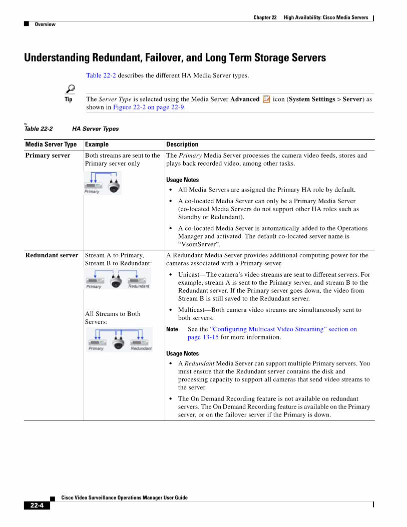
Chapter 22 High Availability: Cisco Media Servers Overview
Understanding Redundant, Failover, and Long Term Storage ServersTable 22-2 describes the different HA Media Server types.
Tip The Server Type is selected using the Media Server Advanced icon (System Settings > Server) as shown in Figure 22-2 on page 22-9.
w Table 22-2 HA Server Types
Media Server Type Example Description
Primary server Both streams are sent to the Primary server only
The Primary Media Server processes the camera video feeds, stores and plays back recorded video, among other tasks.
Usage Notes
• All Media Servers are assigned the Primary HA role by default.
• A co-located Media Server can only be a Primary Media Server (co-located Media Servers do not support other HA roles such as Standby or Redundant).
• A co-located Media Server is automatically added to the Operations Manager and activated. The default co-located server name is “VsomServer”.
Redundant server Stream A to Primary, Stream B to Redundant:
All Streams to Both Servers:
A Redundant Media Server provides additional computing power for the cameras associated with a Primary server.
• Unicast—The camera’s video streams are sent to different servers. For example, stream A is sent to the Primary server, and stream B to the Redundant server. If the Primary server goes down, the video from Stream B is still saved to the Redundant server.
• Multicast—Both camera video streams are simultaneously sent to both servers.
Note See the “Configuring Multicast Video Streaming” section on page 13-15 for more information.
Usage Notes
• A Redundant Media Server can support multiple Primary servers. You must ensure that the Redundant server contains the disk and processing capacity to support all cameras that send video streams to the server.
• The On Demand Recording feature is not available on redundant servers. The On Demand Recording feature is available on the Primary server, or on the failover server if the Primary is down.
22-4Cisco Video Surveillance Operations Manager User Guide
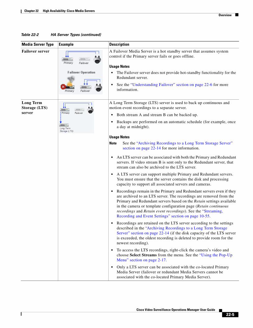
Chapter 22 High Availability: Cisco Media ServersOverview
Failover server A Failover Media Server is a hot standby server that assumes system control if the Primary server fails or goes offline.
Usage Notes
• The Failover server does not provide hot-standby functionality for the Redundant server.
• See the “Understanding Failover” section on page 22-6 for more information.
Long Term Storage (LTS) server
A Long Term Storage (LTS) server is used to back up continuous and motion event recordings to a separate server.
• Both stream A and stream B can be backed up.
• Backups are performed on an automatic schedule (for example, once a day at midnight).
Usage Notes
Note See the “Archiving Recordings to a Long Term Storage Server” section on page 22-14 for more information.
• An LTS server can be associated with both the Primary and Redundant servers. If video stream B is sent only to the Redundant server, that stream can also be archived to the LTS server.
• A LTS server can support multiple Primary and Redundant servers. You must ensure that the server contains the disk and processing capacity to support all associated servers and cameras.
• Recordings remain in the Primary and Redundant servers even if they are archived to an LTS server. The recordings are removed from the Primary and Redundant servers based on the Retain settings available in the camera or template configuration page (Retain continuous recordings and Retain event recordings). See the “Streaming, Recording and Event Settings” section on page 10-55.
• Recordings are retained on the LTS server according to the settings described in the “Archiving Recordings to a Long Term Storage Server” section on page 22-14 (if the disk capacity of the LTS server is exceeded, the oldest recording is deleted to provide room for the newest recording).
• To access the LTS recordings, right-click the camera’s video and choose Select Streams from the menu. See the “Using the Pop-Up Menu” section on page 2-17.
• Only a LTS server can be associated with the co-located Primary Media Server (failover or redundant Media Servers cannot be associated with the co-located Primary Media Server).
Table 22-2 HA Server Types (continued)
Media Server Type Example Description
22-5Cisco Video Surveillance Operations Manager User Guide
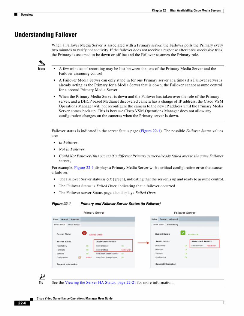
Chapter 22 High Availability: Cisco Media Servers Overview
Understanding FailoverWhen a Failover Media Server is associated with a Primary server, the Failover polls the Primary every two minutes to verify connectivity. If the failover does not receive a response after three successive tries, the Primary is assumed to be down or offline and the Failover assumes the Primary role.
Note • A few minutes of recording may be lost between the loss of the Primary Media Server and the Failover assuming control.
• A Failover Media Server can only stand in for one Primary server at a time (if a Failover server is already acting as the Primary for a Media Server that is down, the Failover cannot assume control for a second Primary Media Server.
• When the Primary Media Server is down and the Failover has taken over the role of the Primary server, and a DHCP based Medianet discovered camera has a change of IP address, the Cisco VSM Operations Manager will not reconfigure the camera to the new IP address until the Primary Media Server comes back up. This is because Cisco VSM Operations Manager does not allow any configuration changes on the cameras when the Primary server is down.
Failover status is indicated in the server Status page (Figure 22-1). The possible Failover Status values are:
• In Failover
• Not In Failover
• Could Not Failover (this occurs if a different Primary server already failed over to the same Failover server.)
For example, Figure 22-1 displays a Primary Media Server with a critical configuration error that causes a failover.
• The Failover Server status is OK (green), indicating that the server is up and ready to assume control.
• The Failover Status is Failed Over, indicating that a failover occurred.
• The Failover server Status page also displays Failed Over.
Figure 22-1 Primary and Failover Server Status (in Failover)
Tip See the Viewing the Server HA Status, page 22-21 for more information.
22-6Cisco Video Surveillance Operations Manager User Guide

Chapter 22 High Availability: Cisco Media ServersOverview
When a user attempts to access live or recorded video from a camera that is associated with the Primary server, the request will time out and be forwarded to the Failover server, which completes the request and sends the requested video.
Because the Failover server maintains the same configuration as the Primary server (in real time), users will not encounter a change in network behavior other than a slight delay while communication is established with the Failover server.
Once the Primary server comes back online, it will automatically resume control from the Failover server. The Failover server will revert to hot standby status.
Note Polling between the servers is coordinated based on the system time in each server. Use a NTP time source to ensure server synchronization.
22-7Cisco Video Surveillance Operations Manager User Guide
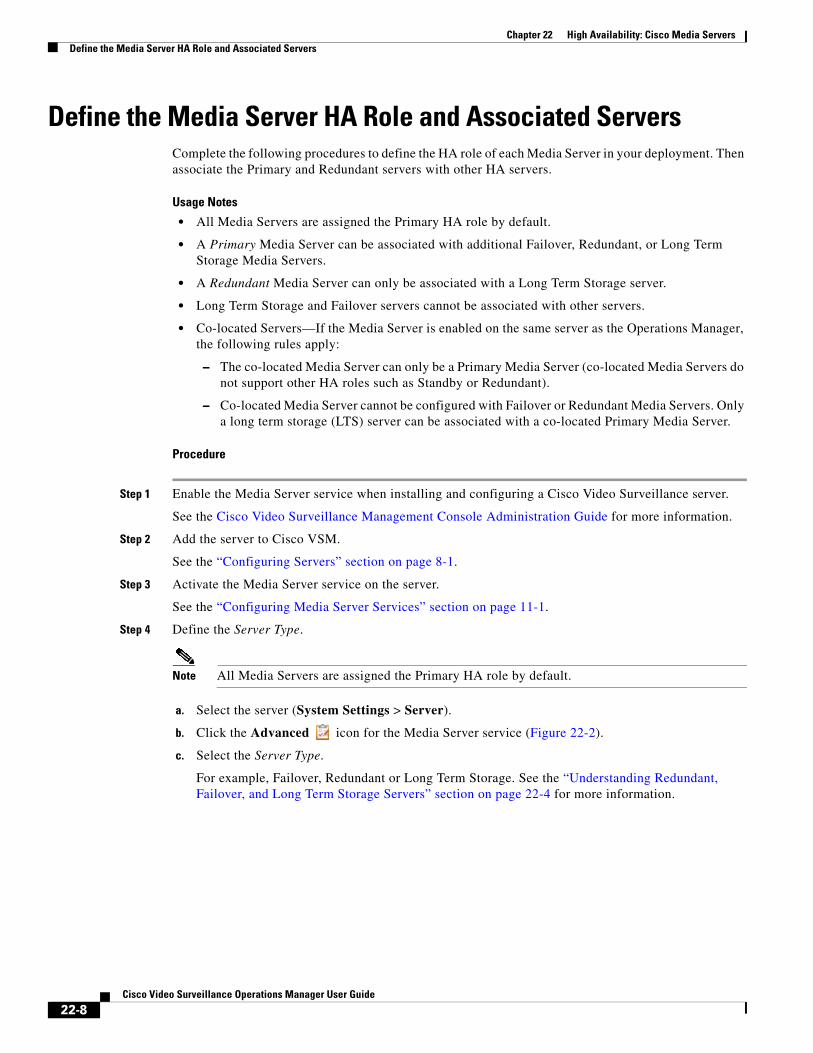
Chapter 22 High Availability: Cisco Media Servers Define the Media Server HA Role and Associated Servers
Define the Media Server HA Role and Associated ServersComplete the following procedures to define the HA role of each Media Server in your deployment. Then associate the Primary and Redundant servers with other HA servers.
Usage Notes
• All Media Servers are assigned the Primary HA role by default.
• A Primary Media Server can be associated with additional Failover, Redundant, or Long Term Storage Media Servers.
• A Redundant Media Server can only be associated with a Long Term Storage server.
• Long Term Storage and Failover servers cannot be associated with other servers.
• Co-located Servers—If the Media Server is enabled on the same server as the Operations Manager, the following rules apply:
– The co-located Media Server can only be a Primary Media Server (co-located Media Servers do not support other HA roles such as Standby or Redundant).
– Co-located Media Server cannot be configured with Failover or Redundant Media Servers. Only a long term storage (LTS) server can be associated with a co-located Primary Media Server.
Procedure
Step 1 Enable the Media Server service when installing and configuring a Cisco Video Surveillance server.
See the Cisco Video Surveillance Management Console Administration Guide for more information.
Step 2 Add the server to Cisco VSM.
See the “Configuring Servers” section on page 8-1.
Step 3 Activate the Media Server service on the server.
See the “Configuring Media Server Services” section on page 11-1.
Step 4 Define the Server Type.
Note All Media Servers are assigned the Primary HA role by default.
a. Select the server (System Settings > Server).
b. Click the Advanced icon for the Media Server service (Figure 22-2).
c. Select the Server Type.
For example, Failover, Redundant or Long Term Storage. See the “Understanding Redundant, Failover, and Long Term Storage Servers” section on page 22-4 for more information.
22-8Cisco Video Surveillance Operations Manager User Guide
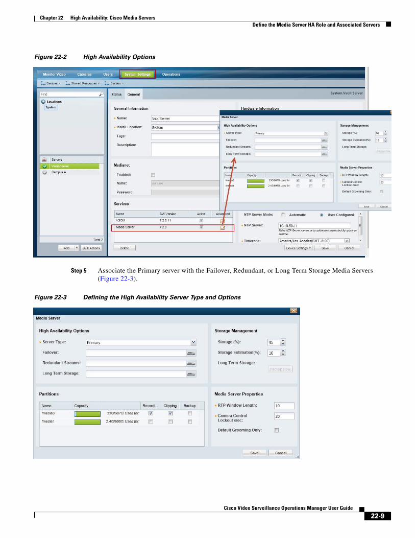
Chapter 22 High Availability: Cisco Media ServersDefine the Media Server HA Role and Associated Servers
Figure 22-2 High Availability Options
Step 5 Associate the Primary server with the Failover, Redundant, or Long Term Storage Media Servers (Figure 22-3).
Figure 22-3 Defining the High Availability Server Type and Options
22-9Cisco Video Surveillance Operations Manager User Guide

Chapter 22 High Availability: Cisco Media Servers Configuring the HA Advanced Storage Options
Server Type Description
Step 6 (Optional) Associate the Redundant Media Server with a Long Term Storage server.
Configuring the HA Advanced Storage OptionsEach camera is assigned to a Primary Media Server which processes, stores, and plays back the camera’s live and recorded video. Use the Advanced Storage options to also send the camera video to Redundant, Failover, and/or Long Term Storage servers.
Tip Use a camera template to apply the Advanced Storage options to multiple cameras, or a custom template to apply the HA settings only to a single camera.
Note You can configure the camera Advanced Storage settings if the HA servers are not available, but a configuration error and alert will be generated. Once the server configuration is complete, the errors will be removed.”
Summary Steps
Task
Step 1
Step 2
Step 3
Step 4
Tip See also Understanding the Recording Options, page 17-24 for information about Connected Edge Storage, Economical Streaming, and Recording Options.
Primary The server assigned to the camera or template. The Primary server processes the camera video feeds, stores and plays back recorded video, among other tasks.
Failover (Primary server only) The Media Server that will assume the functionality of the Primary server if the Primary server goes offline.
Redundant Streams (Primary server only) The server used to record, store, and server Redundant video streams. For example, the Redundant Streams server can be used to manage Steam B from a camera.
Long Term Storage (Primary and Redundant servers only) The server used to store recorded video (continuous or motion events) for a long period of time.
Verify that the HA Requirements are met, and review the “Summary Steps” section on page 22-3.
Complete the “Configuring the Redundant and Failover Options” section on page 22-11.
(Optional) Complete the “Archiving Recordings to a Long Term Storage Server” section on page 22-14.
(Optional) Complete the “Viewing the Server HA Status” section on page 22-21.
22-10Cisco Video Surveillance Operations Manager User Guide
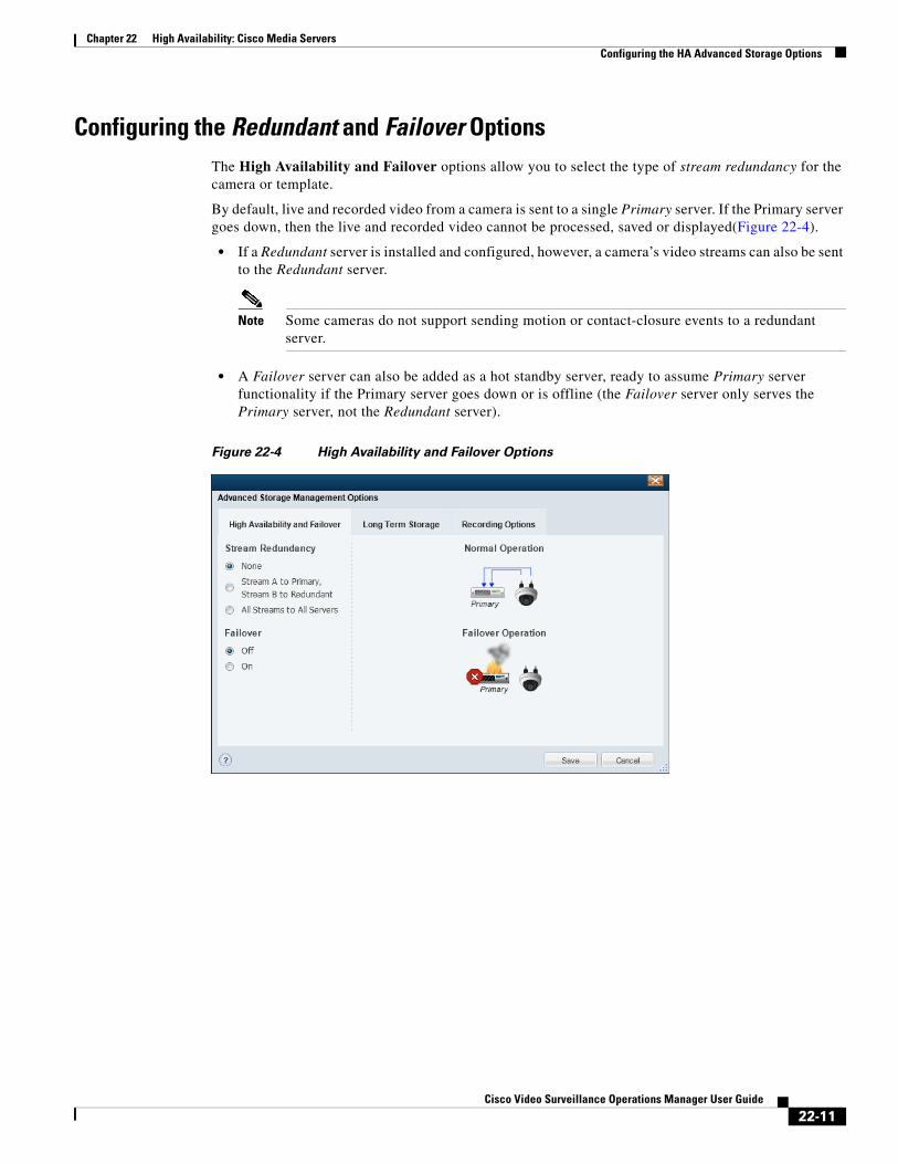
Chapter 22 High Availability: Cisco Media ServersConfiguring the HA Advanced Storage Options
Configuring the Redundant and Failover OptionsThe High Availability and Failover options allow you to select the type of stream redundancy for the camera or template.
By default, live and recorded video from a camera is sent to a single Primary server. If the Primary server goes down, then the live and recorded video cannot be processed, saved or displayed(Figure 22-4).
• If a Redundant server is installed and configured, however, a camera’s video streams can also be sent to the Redundant server.
Note Some cameras do not support sending motion or contact-closure events to a redundant server.
• A Failover server can also be added as a hot standby server, ready to assume Primary server functionality if the Primary server goes down or is offline (the Failover server only serves the Primary server, not the Redundant server).
Figure 22-4 High Availability and Failover Options
22-11Cisco Video Surveillance Operations Manager User Guide
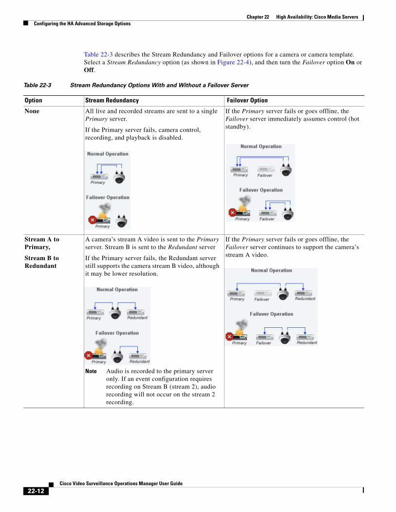
Chapter 22 High Availability: Cisco Media Servers Configuring the HA Advanced Storage Options
Table 22-3 describes the Stream Redundancy and Failover options for a camera or camera template. Select a Stream Redundancy option (as shown in Figure 22-4), and then turn the Failover option On or Off.
Table 22-3 Stream Redundancy Options With and Without a Failover Server
Option Stream Redundancy Failover Option
None All live and recorded streams are sent to a single Primary server.
If the Primary server fails, camera control, recording, and playback is disabled.
If the Primary server fails or goes offline, the Failover server immediately assumes control (hot standby).
Stream A to Primary,
Stream B to Redundant
A camera’s stream A video is sent to the Primary server. Stream B is sent to the Redundant server
If the Primary server fails, the Redundant server still supports the camera stream B video, although it may be lower resolution.
Note Audio is recorded to the primary server only. If an event configuration requires recording on Stream B (stream 2), audio recording will not occur on the stream 2 recording.
If the Primary server fails or goes offline, the Failover server continues to support the camera’s stream A video.
22-12Cisco Video Surveillance Operations Manager User Guide
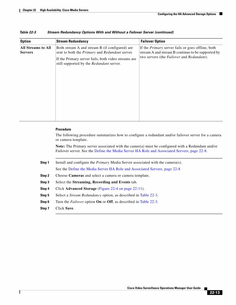
Chapter 22 High Availability: Cisco Media ServersConfiguring the HA Advanced Storage Options
Procedure
The following procedure summarizes how to configure a redundant and/or failover server for a camera or camera template.
Note: The Primary server associated with the camer(a) must be configured with a Redundant and/or Failover server. See the Define the Media Server HA Role and Associated Servers, page 22-8.
Step 1 Install and configure the Primary Media Server associated with the camera(s).
See the Define the Media Server HA Role and Associated Servers, page 22-8
Step 2 Choose Cameras and select a camera or camera template.
Step 3 Select the Streaming, Recording and Events tab.
Step 4 Click Advanced Storage (Figure 22-4 on page 22-11).
Step 5 Select a Stream Redundancy option, as described in Table 22-3.
Step 6 Turn the Failover option On or Off, as described in Table 22-3.
Step 7 Click Save.
All Streams to All Servers
Both stream A and stream B (if configured) are sent to both the Primary and Redundant server.
If the Primary server fails, both video streams are still supported by the Redundant server.
If the Primary server fails or goes offline, both stream A and stream B continue to be supported by two servers (the Failover and Redundant).
Table 22-3 Stream Redundancy Options With and Without a Failover Server (continued)
Option Stream Redundancy Failover Option
22-13Cisco Video Surveillance Operations Manager User Guide
Chapter 22 High Availability: Cisco Media Servers Archiving Recordings to a Long Term Storage Server
Archiving Recordings to a Long Term Storage ServerA Long Term Storage (LTS) server allows you to automatically transfer recorded video from the Primary server to a LTS server. This frees the limited space on the Primary server and provides a dedicated resource to store and play back old recordings.
You can also manually backup recordings for one or more cameras using the Backup Now feature.
Refer to the following for more information:
• Archive recordings to an LTS Server, page 22-14
• Backup Now to an LTS Server, page 22-18
Archive recordings to an LTS ServerTo backup recordings from a Primary or Redundant server, add an additional LTS server using the following procedure.
Notes
• Recordings remain in the Primary and Redundant servers even if they are archived to an LTS server. The recordings are removed from the Primary and Redundant servers based on the Retain continuous recordings and Retain event recordings settings available in the camera or template configuration page.
• Recordings are removed from the LTS server according to the settings described in Table 22-4.
Procedure
Step 1 Install a Media Server and add it to Cisco VSM.
See Adding or Editing Servers, page 8-16.
Step 2 Select the Long Term Storage server type and enable the Backup storage partition.
d. Select the server (System Settings > Server).
e. Click the Advanced icon for the Media Server service (Figure 22-5).
f. For Server Type select Long Term Storage.
See the “Understanding Redundant, Failover, and Long Term Storage Servers” section on page 22-4 for more information.
g. Under Partitions, select Backup for the /media1 or /media0 repository (Figure 22-5).
h. (Optional) Select the Clipping option for all partitions to enable users to create clips on the LTS server.
i. (Required) Deselect the Recording option for all partitions (or an error will occur).
Note The LTS server can be used to backup recordings or create clips, so only the Backup and Clipping options can be enabled for all partitions (Figure 22-5). Deselect the Recording option for all partitions or an error will occur. (the LTS server cannot be used as a primary store of recording data).
j. Click Save to save the settings and close the Media Server window.
22-14Cisco Video Surveillance Operations Manager User Guide
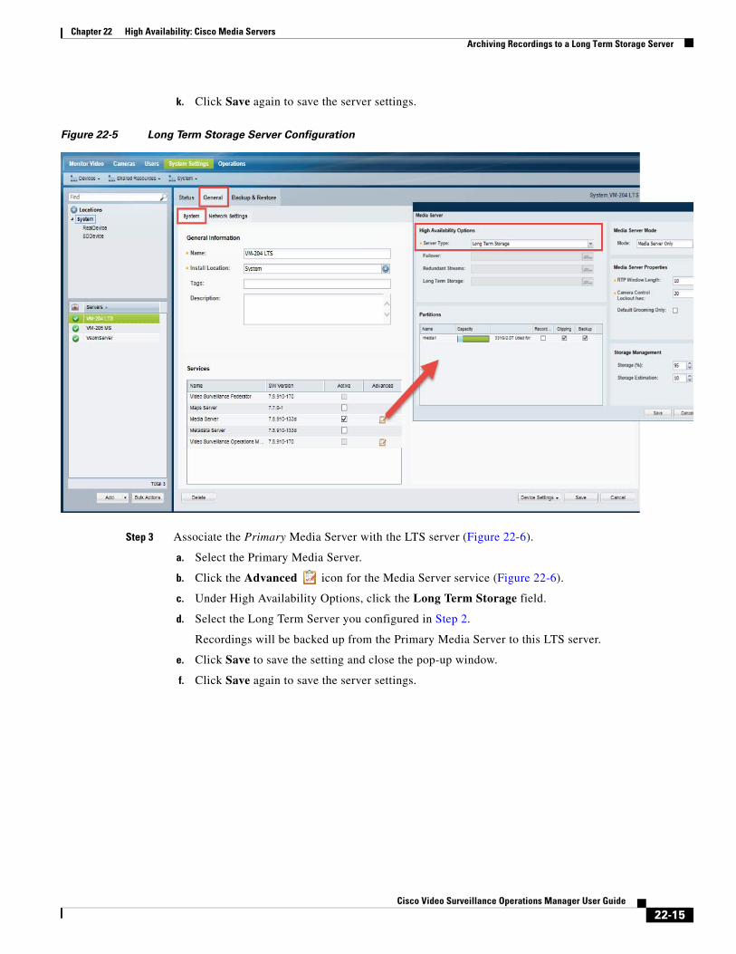
Chapter 22 High Availability: Cisco Media ServersArchiving Recordings to a Long Term Storage Server
k. Click Save again to save the server settings.
Figure 22-5 Long Term Storage Server Configuration
Step 3 Associate the Primary Media Server with the LTS server (Figure 22-6).
a. Select the Primary Media Server.
b. Click the Advanced icon for the Media Server service (Figure 22-6).
c. Under High Availability Options, click the Long Term Storage field.
d. Select the Long Term Server you configured in Step 2.
Recordings will be backed up from the Primary Media Server to this LTS server.
e. Click Save to save the setting and close the pop-up window.
f. Click Save again to save the server settings.
22-15Cisco Video Surveillance Operations Manager User Guide
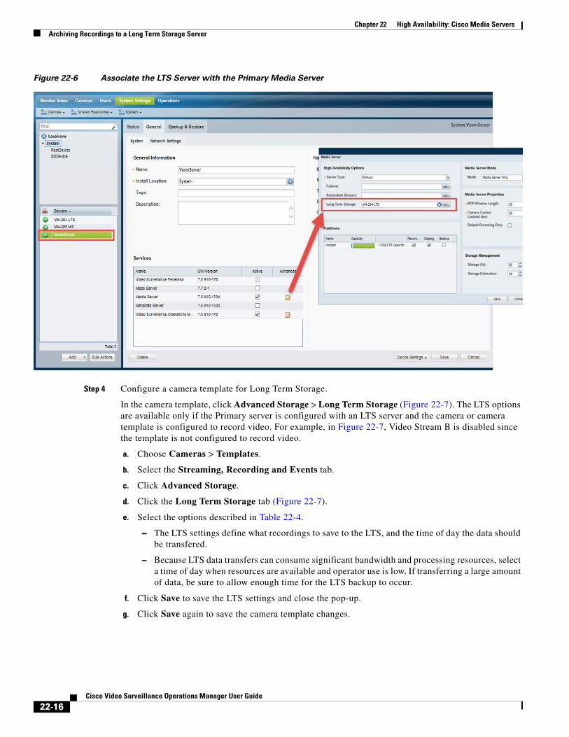
Chapter 22 High Availability: Cisco Media Servers Archiving Recordings to a Long Term Storage Server
Figure 22-6 Associate the LTS Server with the Primary Media Server
Step 4 Configure a camera template for Long Term Storage.
In the camera template, click Advanced Storage > Long Term Storage (Figure 22-7). The LTS options are available only if the Primary server is configured with an LTS server and the camera or camera template is configured to record video. For example, in Figure 22-7, Video Stream B is disabled since the template is not configured to record video.
a. Choose Cameras > Templates.
b. Select the Streaming, Recording and Events tab.
c. Click Advanced Storage.
d. Click the Long Term Storage tab (Figure 22-7).
e. Select the options described in Table 22-4.
– The LTS settings define what recordings to save to the LTS, and the time of day the data should be transfered.
– Because LTS data transfers can consume significant bandwidth and processing resources, select a time of day when resources are available and operator use is low. If transferring a large amount of data, be sure to allow enough time for the LTS backup to occur.
f. Click Save to save the LTS settings and close the pop-up.
g. Click Save again to save the camera template changes.
22-16Cisco Video Surveillance Operations Manager User Guide
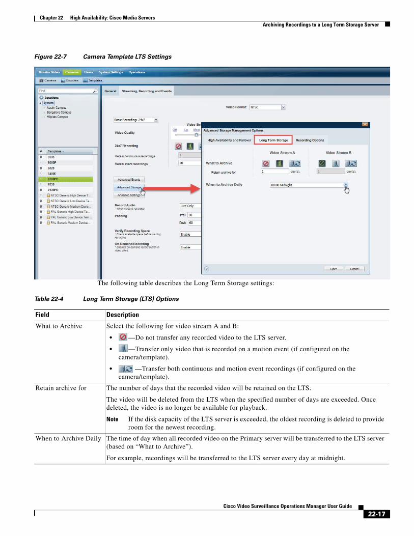
Chapter 22 High Availability: Cisco Media ServersArchiving Recordings to a Long Term Storage Server
Figure 22-7 Camera Template LTS Settings
The following table describes the Long Term Storage settings:
Table 22-4 Long Term Storage (LTS) Options
Field Description
• —Do not transfer any recorded video to the LTS server.
• —Transfer only video that is recorded on a motion event (if configured on the camera/template).
• —Transfer both continuous and motion event recordings (if configured on the camera/template).
Note If the disk capacity of the LTS server is exceeded, the oldest recording is deleted to provide room for the newest recording.
What to Archive Select the following for video stream A and B:
Retain archive for The number of days that the recorded video will be retained on the LTS.
The video will be deleted from the LTS when the specified number of days are exceeded. Once deleted, the video is no longer be available for playback.
When to Archive Daily The time of day when all recorded video on the Primary server will be transferred to the LTS server (based on “What to Archive”).
For example, recordings will be transferred to the LTS server every day at midnight.
22-17Cisco Video Surveillance Operations Manager User Guide
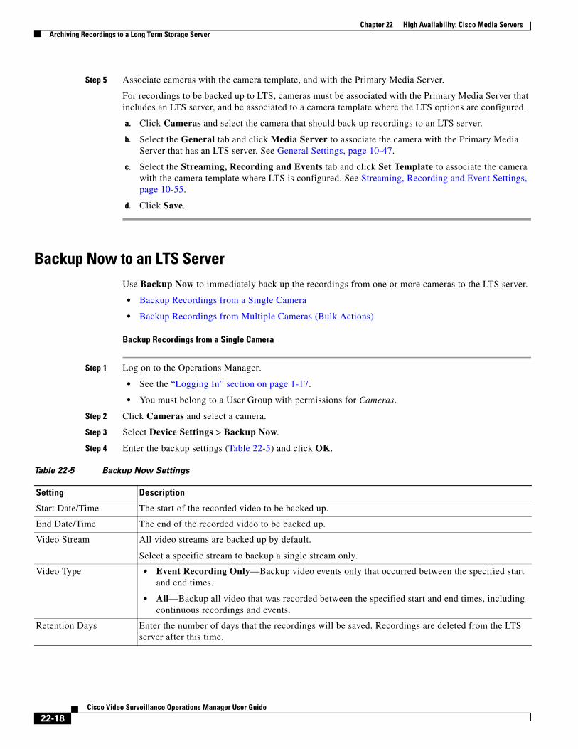
Chapter 22 High Availability: Cisco Media Servers Archiving Recordings to a Long Term Storage Server
Step 5 Associate cameras with the camera template, and with the Primary Media Server.
For recordings to be backed up to LTS, cameras must be associated with the Primary Media Server that includes an LTS server, and be associated to a camera template where the LTS options are configured.
a. Click Cameras and select the camera that should back up recordings to an LTS server.
b. Select the General tab and click Media Server to associate the camera with the Primary Media Server that has an LTS server. See General Settings, page 10-47.
c. Select the Streaming, Recording and Events tab and click Set Template to associate the camera with the camera template where LTS is configured. See Streaming, Recording and Event Settings, page 10-55.
d. Click Save.
Backup Now to an LTS Server Use Backup Now to immediately back up the recordings from one or more cameras to the LTS server.
• Backup Recordings from a Single Camera
• Backup Recordings from Multiple Cameras (Bulk Actions)
Backup Recordings from a Single Camera
Step 1 Log on to the Operations Manager.
• See the “Logging In” section on page 1-17.
• You must belong to a User Group with permissions for Cameras.
Step 2 Click Cameras and select a camera.
Step 3 Select Device Settings > Backup Now.
Step 4 Enter the backup settings (Table 22-5) and click OK.
Table 22-5 Backup Now Settings
Setting Description
• Event Recording Only—Backup video events only that occurred between the specified start and end times.
• All—Backup all video that was recorded between the specified start and end times, including continuous recordings and events.
Start Date/Time The start of the recorded video to be backed up.
End Date/Time The end of the recorded video to be backed up.
Video Stream All video streams are backed up by default.
Select a specific stream to backup a single stream only.
Video Type
Retention Days Enter the number of days that the recordings will be saved. Recordings are deleted from the LTS server after this time.
22-18Cisco Video Surveillance Operations Manager User Guide
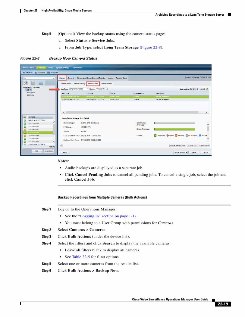
Chapter 22 High Availability: Cisco Media ServersArchiving Recordings to a Long Term Storage Server
Step 5 (Optional) View the backup status using the camera status page:
a. Select Status > Service Jobs.
b. From Job Type, select Long Term Storage (Figure 22-8).
Figure 22-8 Backup Now Camera Status
Notes:
• Audio backups are displayed as a separate job.
• Click Cancel Pending Jobs to cancel all pending jobs. To cancel a single job, select the job and click Cancel Job.
Backup Recordings from Multiple Cameras (Bulk Actions)
Step 1 Log on to the Operations Manager.
• See the “Logging In” section on page 1-17.
• You must belong to a User Group with permissions for Cameras.
Step 2 Select Cameras > Cameras.
Step 3 Click Bulk Actions (under the device list).
Step 4 Select the filters and click Search to display the available cameras.
• Leave all filters blank to display all cameras.
• See Table 22-5 for filter options.
Step 5 Select one or more cameras from the results list.
Step 6 Click Bulk Actions > Backup Now.
22-19Cisco Video Surveillance Operations Manager User Guide
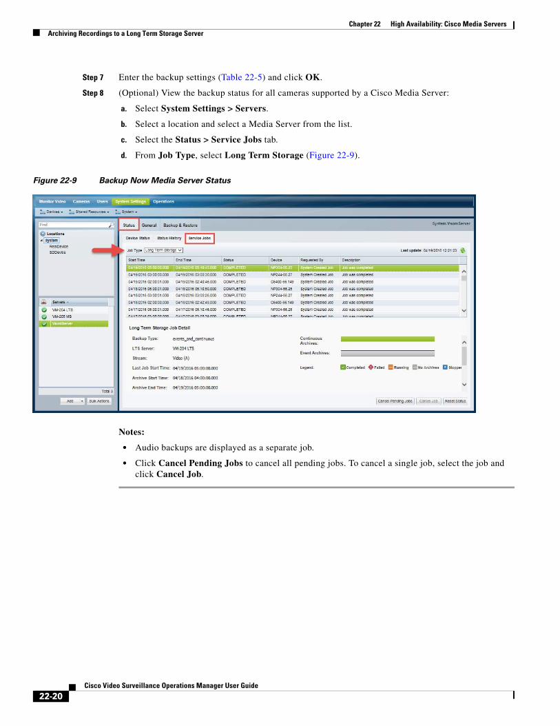
Chapter 22 High Availability: Cisco Media Servers Archiving Recordings to a Long Term Storage Server
Step 7 Enter the backup settings (Table 22-5) and click OK.
Step 8 (Optional) View the backup status for all cameras supported by a Cisco Media Server:
a. Select System Settings > Servers.
b. Select a location and select a Media Server from the list.
c. Select the Status > Service Jobs tab.
d. From Job Type, select Long Term Storage (Figure 22-9).
Figure 22-9 Backup Now Media Server Status
Notes:
• Audio backups are displayed as a separate job.
• Click Cancel Pending Jobs to cancel all pending jobs. To cancel a single job, select the job and click Cancel Job.
22-20Cisco Video Surveillance Operations Manager User Guide
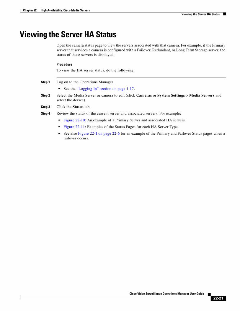
Chapter 22 High Availability: Cisco Media ServersViewing the Server HA Status
Viewing the Server HA StatusOpen the camera status page to view the servers associated with that camera. For example, if the Primary server that services a camera is configured with a Failover, Redundant, or Long Term Storage server, the status of those servers is displayed.
Procedure
To view the HA server status, do the following:
Step 1 Log on to the Operations Manager.
• See the “Logging In” section on page 1-17.
Step 2 Select the Media Server or camera to edit (click Cameras or System Settings > Media Servers and select the device).
Step 3 Click the Status tab.
Step 4 Review the status of the current server and associated servers. For example:
• Figure 22-10: An example of a Primary Server and associated HA servers
• Figure 22-11: Examples of the Status Pages for each HA Server Type.
• See also Figure 22-1 on page 22-6 for an example of the Primary and Failover Status pages when a failover occurs.
22-21Cisco Video Surveillance Operations Manager User Guide
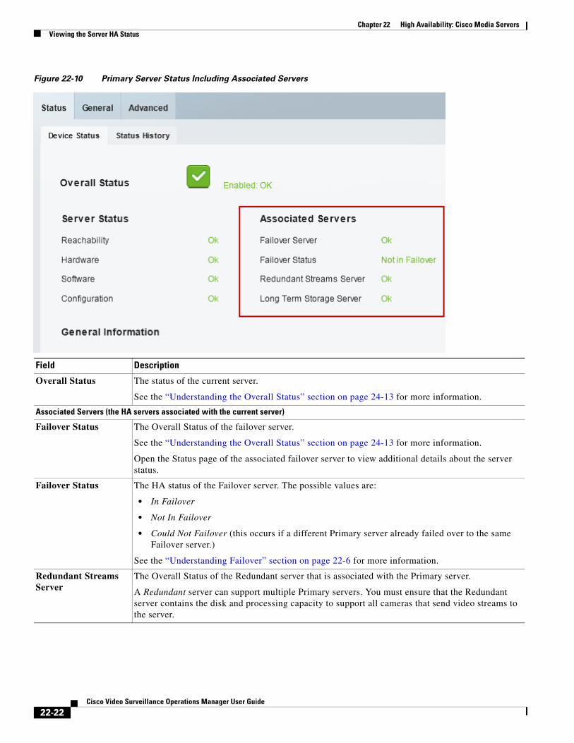
Chapter 22 High Availability: Cisco Media Servers Viewing the Server HA Status
Figure 22-10 Primary Server Status Including Associated Servers
Field Description
Overall Status The status of the current server.
See the “Understanding the Overall Status” section on page 24-13 for more information.
Associated Servers (the HA servers associated with the current server)
Failover Status The Overall Status of the failover server.
See the “Understanding the Overall Status” section on page 24-13 for more information.
Open the Status page of the associated failover server to view additional details about the server status.
Failover Status The HA status of the Failover server. The possible values are:
• In Failover
• Not In Failover
• Could Not Failover (this occurs if a different Primary server already failed over to the same Failover server.)
See the “Understanding Failover” section on page 22-6 for more information.
Redundant Streams Server
The Overall Status of the Redundant server that is associated with the Primary server.
A Redundant server can support multiple Primary servers. You must ensure that the Redundant server contains the disk and processing capacity to support all cameras that send video streams to the server.
22-22Cisco Video Surveillance Operations Manager User Guide
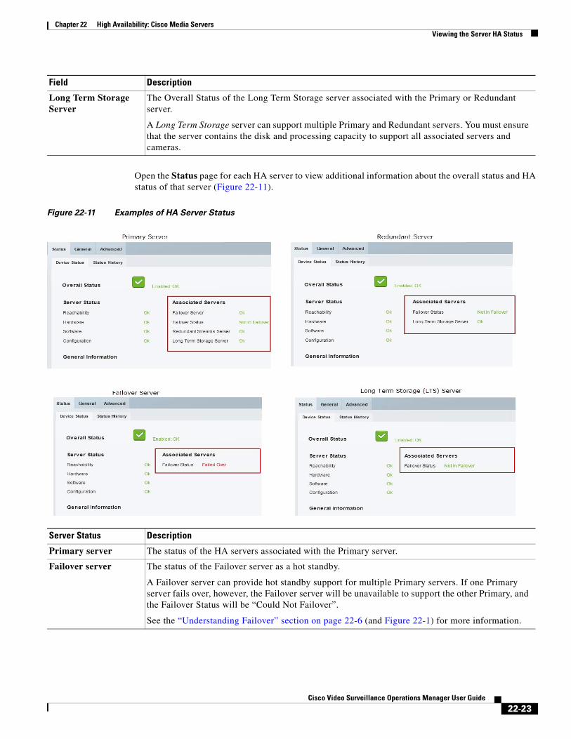
Chapter 22 High Availability: Cisco Media ServersViewing the Server HA Status
Open the Status page for each HA server to view additional information about the overall status and HA status of that server (Figure 22-11).
Figure 22-11 Examples of HA Server Status
Long Term Storage Server
The Overall Status of the Long Term Storage server associated with the Primary or Redundant server.
A Long Term Storage server can support multiple Primary and Redundant servers. You must ensure that the server contains the disk and processing capacity to support all associated servers and cameras.
Field Description
Server Status Description
Primary server The status of the HA servers associated with the Primary server.
Failover server The status of the Failover server as a hot standby.
A Failover server can provide hot standby support for multiple Primary servers. If one Primary server fails over, however, the Failover server will be unavailable to support the other Primary, and the Failover Status will be “Could Not Failover”.
See the “Understanding Failover” section on page 22-6 (and Figure 22-1) for more information.
22-23Cisco Video Surveillance Operations Manager User Guide

Chapter 22 High Availability: Cisco Media Servers Viewing the Server HA Status
Redundant server The Failover server status, and the LTS server status.
A Redundant server can support multiple servers. You must ensure that the Redundant server contains the disk and processing capacity to support all associated Primary servers.
Long Term Storage server
The Failover server status.
A Long Term Storage server can support multiple Primary and Redundant servers. You must ensure that the server contains the disk and processing capacity to support all associated servers.
Server Status Description
22-24Cisco Video Surveillance Operations Manager User Guide
Cisco V
C H A P T E R 23
Operations Manager High AvailabilityTwo Operations Manager servers can be configured as a redundant pair for high availability (HA). Since the Operations Manager is responsible for configuring and coordinating the entire Cisco Video Surveillance deployment, this helps ensure uninterrupted system access for users and administrators.
To configure Operations Manager HA, install two servers on the same network: a Master server and a second Peer server. All configurations, data, and logs on the Master server are automatically replicated on the Peer server. If the Master server goes down or is unavailable, the Peer server is ready to take control with minimal impact.
Note If an HA failover occurs, the Peer server becomes the Master, and retains that role even if the other server comes back online (and assumes the Peer role).
Review the following topics for more information:
Contents
• Overview, page 23-2
– Understanding Operations Manager HA, page 23-2
– Requirements, page 23-4
• Configuring Operations Manager HA, page 23-6
• Managing the HA Configuration, page 23-12
– Understanding the Server Management Options, page 23-12
– Revising the Operations Manager HA Configuration, page 23-12
– Replacing the HA Configuration, page 23-13
– Deleting the HA Configuration, page 23-14
– Replacing the HA Peer Server, page 23-15
– Backing Up and Restoring the Operations Manager Configuration, page 23-17
– Upgrading the Operations Manager HA Servers, page 23-18
• Forcing a Failover, page 23-20
• Resolving a Split Brain Scenario, page 23-21
– Split Brain Overview, page 23-21
– Selecting the “Split Brain” Media Servers, page 23-23
– Procedure to Resolve a Split Brain Scenario, page 23-25
23-1ideo Surveillance Operations Manager User Guide

Chapter 23 Operations Manager High Availability Overview
• Troubleshooting Operations Manager HA, page 23-27
OverviewReview the following topics before configuring Operations Manager HA.
• Understanding Operations Manager HA, page 23-2
• Requirements, page 23-4
• Troubleshooting Operations Manager HA, page 23-27
Understanding Operations Manager HAOperations Manager HA is achieved by installing two stand-alone Cisco VSM Operations Manager servers, and configuring one as the Master server, and the other as the Peer server (Figure 23-1). A virtual IP address is shared by both servers, and used by users (video monitors, administrators and other users) to access the Cisco Video Surveillance system.
Figure 23-1 Operations Manager HA: Server 1 is the Master Server
23-2Cisco Video Surveillance Operations Manager User Guide
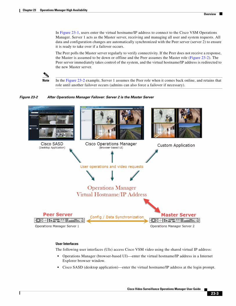
Chapter 23 Operations Manager High AvailabilityOverview
In Figure 23-1, users enter the virtual hostname/IP address to connect to the Cisco VSM Operations Manager. Server 1 acts as the Master server, receiving and managing all user and system requests. All data and configuration changes are automatically synchronized with the Peer server (server 2) to ensure it is ready to take over if a failover occurs.
The Peer polls the Master server regularly to verify connectivity. If the Peer does not receive a response, the Master is assumed to be down or offline and the Peer assumes the Master role (Figure 23-2). The Peer server immediately takes control of the system, and the virtual hostname/IP address is redirected to the new Master server.
Note In the Figure 23-2 example, Server 1 assumes the Peer role when it comes back online, and retains that role until another failover occurs (admins can also force a failover if necessary).
Figure 23-2 After Operations Manager Failover: Server 2 is the Master Server
User Interfaces
The following user interfaces (UIs) access Cisco VSM video using the shared virtual IP address:
• Operations Manager (browser-based UI)—enter the virtual hostname/IP address in a Internet Explorer browser window.
• Cisco SASD (desktop application)—enter the virtual hostname/IP address at the login prompt.
23-3Cisco Video Surveillance Operations Manager User Guide
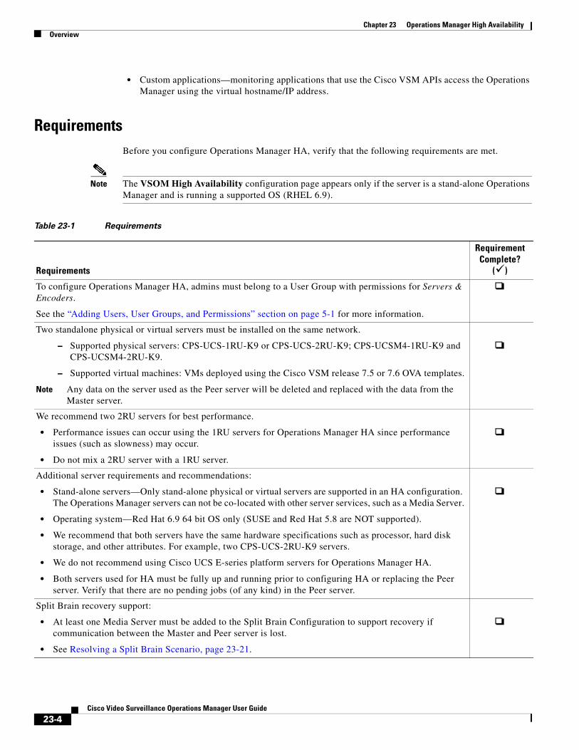
Chapter 23 Operations Manager High Availability Overview
• Custom applications—monitoring applications that use the Cisco VSM APIs access the Operations Manager using the virtual hostname/IP address.
Requirements Before you configure Operations Manager HA, verify that the following requirements are met.
Note The VSOM High Availability configuration page appears only if the server is a stand-alone Operations Manager and is running a supported OS (RHEL 6.9).
Table 23-1 Requirements
Requirements
Requirement Complete?
()
To configure Operations Manager HA, admins must belong to a User Group with permissions for Servers & Encoders.
See the “Adding Users, User Groups, and Permissions” section on page 5-1 for more information.
Two standalone physical or virtual servers must be installed on the same network.
– Supported physical servers: CPS-UCS-1RU-K9 or CPS-UCS-2RU-K9; CPS-UCSM4-1RU-K9 and CPS-UCSM4-2RU-K9.
– Supported virtual machines: VMs deployed using the Cisco VSM release 7.5 or 7.6 OVA templates.
Note Any data on the server used as the Peer server will be deleted and replaced with the data from the Master server.
We recommend two 2RU servers for best performance.
• Performance issues can occur using the 1RU servers for Operations Manager HA since performance issues (such as slowness) may occur.
• Do not mix a 2RU server with a 1RU server.
Additional server requirements and recommendations:
• Stand-alone servers—Only stand-alone physical or virtual servers are supported in an HA configuration. The Operations Manager servers can not be co-located with other server services, such as a Media Server.
• Operating system—Red Hat 6.9 64 bit OS only (SUSE and Red Hat 5.8 are NOT supported).
• We recommend that both servers have the same hardware specifications such as processor, hard disk storage, and other attributes. For example, two CPS-UCS-2RU-K9 servers.
• We do not recommend using Cisco UCS E-series platform servers for Operations Manager HA.
• Both servers used for HA must be fully up and running prior to configuring HA or replacing the Peer server. Verify that there are no pending jobs (of any kind) in the Peer server.
Split Brain recovery support:
• At least one Media Server must be added to the Split Brain Configuration to support recovery if communication between the Master and Peer server is lost.
• See Resolving a Split Brain Scenario, page 23-21.
23-4Cisco Video Surveillance Operations Manager User Guide
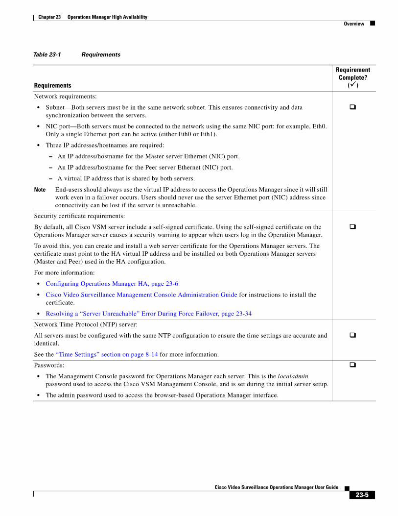
Chapter 23 Operations Manager High AvailabilityOverview
Network requirements:
• Subnet—Both servers must be in the same network subnet. This ensures connectivity and data synchronization between the servers.
• NIC port—Both servers must be connected to the network using the same NIC port: for example, Eth0. Only a single Ethernet port can be active (either Eth0 or Eth1).
• Three IP addresses/hostnames are required:
– An IP address/hostname for the Master server Ethernet (NIC) port.
– An IP address/hostname for the Peer server Ethernet (NIC) port.
– A virtual IP address that is shared by both servers.
Note End-users should always use the virtual IP address to access the Operations Manager since it will still work even in a failover occurs. Users should never use the server Ethernet port (NIC) address since connectivity can be lost if the server is unreachable.
Security certificate requirements:
By default, all Cisco VSM server include a self-signed certificate. Using the self-signed certificate on the Operations Manager server causes a security warning to appear when users log in the Operation Manager.
To avoid this, you can create and install a web server certificate for the Operations Manager servers. The certificate must point to the HA virtual IP address and be installed on both Operations Manager servers (Master and Peer) used in the HA configuration.
For more information:
• Configuring Operations Manager HA, page 23-6
• Cisco Video Surveillance Management Console Administration Guide for instructions to install the certificate.
• Resolving a “Server Unreachable” Error During Force Failover, page 23-34
Network Time Protocol (NTP) server:
All servers must be configured with the same NTP configuration to ensure the time settings are accurate and identical.
See the “Time Settings” section on page 8-14 for more information.
Passwords:
• The Management Console password for Operations Manager each server. This is the localadmin password used to access the Cisco VSM Management Console, and is set during the initial server setup.
• The admin password used to access the browser-based Operations Manager interface.
Table 23-1 Requirements
Requirements
Requirement Complete?
()
23-5Cisco Video Surveillance Operations Manager User Guide
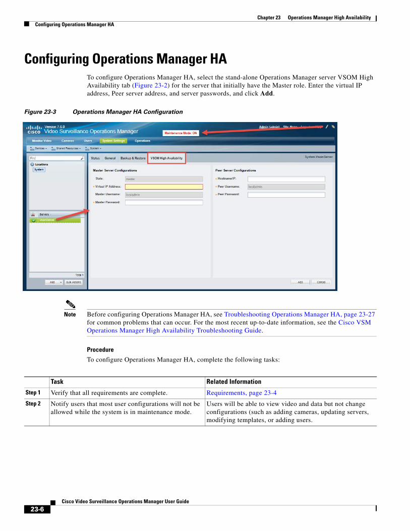
Chapter 23 Operations Manager High Availability Configuring Operations Manager HA
Configuring Operations Manager HATo configure Operations Manager HA, select the stand-alone Operations Manager server VSOM High Availability tab (Figure 23-2) for the server that initially have the Master role. Enter the virtual IP address, Peer server address, and server passwords, and click Add.
Figure 23-3 Operations Manager HA Configuration
Note Before configuring Operations Manager HA, see Troubleshooting Operations Manager HA, page 23-27 for common problems that can occur. For the most recent up-to-date information, see the Cisco VSM Operations Manager High Availability Troubleshooting Guide.
Procedure
To configure Operations Manager HA, complete the following tasks:
Task Related Information
Step 1 Verify that all requirements are complete. Requirements, page 23-4
Step 2 Notify users that most user configurations will not be allowed while the system is in maintenance mode.
Users will be able to view video and data but not change configurations (such as adding cameras, updating servers, modifying templates, or adding users.
23-6Cisco Video Surveillance Operations Manager User Guide
Chapter 23 Operations Manager High AvailabilityConfiguring Operations Manager HA
Step 3 Install two stand-alone Operations Manager servers, either physical or virtual:
a. Both Operations Manager servers must be on the same network subnet.
b. Both servers must be stand-alone Operations Manager servers (no other server services can be enabled).
See the following related documentation:
• Cisco Physical Security UCS Platform Series User Guide
• Cisco Multiservices Platform for Physical Security User Guide
• Cisco Video Surveillance Management Console Administration Guide
Step 4 Add at least one additional Cisco Media Server. At least one additional Media Server is required.
• Both Operations Manager servers must be stand-alone servers.
• An additional Media Server is required to support Operations Manager HA and the split brain configuration.
• A Media Server is also required to support video surveillance.
See the “Configuring Servers” section on page 8-1
Step 5 Create and install a custom security certificate, if required. The certificate must point to the virtual IP address and be installed on both HA servers.
a. Obtain a signed certificate by a Certification Authority. This certificate should contain the host name mapped to the virtual IP. For example: vsom-server3.
b. Install the certificate on both the Master and Peer servers using the Cisco Video Surveillance Management Console. For example vsom-server1 and vsom-server2.
c. Wait for the services to be restarted.
d. Log in again to the Operation Manager using the virtual IP address. The certificate error should not appear.
See the Cisco Video Surveillance Management Console Administration Guide for instructions to install the web server certificate on the servers.
Task Related Information
23-7Cisco Video Surveillance Operations Manager User Guide
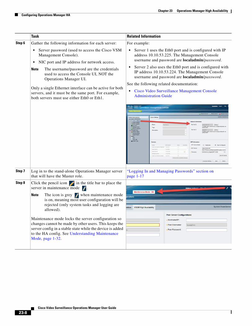
Chapter 23 Operations Manager High Availability Configuring Operations Manager HA
Step 6 Gather the following information for each server:
• Server password (used to access the Cisco VSM Management Console).
• NIC port and IP address for network access.
Note The username/password are the credentials used to access the Console UI, NOT the Operations Manager UI.
Only a single Ethernet interface can be active for both servers, and it must be the same port. For example, both servers must use either Eth0 or Eth1.
For example:
• Server 1 uses the Eth0 port and is configured with IP address 10.10.53.225. The Management Console username and password are localadmin/password.
• Server 2 also uses the Eth0 port and is configured with IP address 10.10.53.224. The Management Console username and password are localadmin/password.
See the following related documentation:
• Cisco Video Surveillance Management Console Administration Guide
Step 7 Log in to the stand-alone Operations Manager server that will have the Master role.
“Logging In and Managing Passwords” section on page 1-17
Step 8 Click the pencil icon in the title bar to place the server in maintenance mode .
Note The icon is grey when maintenance mode is on, meaning most user configuration will be rejected (only system tasks and logging are allowed).
Maintenance mode locks the server configuration so changes cannot be made by other users. This keeps the server config in a stable state while the device is added to the HA config. See Understanding Maintenance Mode, page 1-32.
Task Related Information
23-8Cisco Video Surveillance Operations Manager User Guide
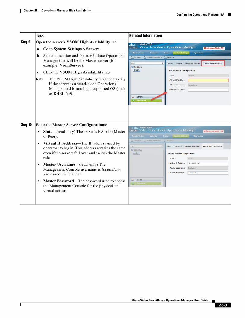
Chapter 23 Operations Manager High AvailabilityConfiguring Operations Manager HA
Step 9 Open the server’s VSOM High Availability tab.
a. Go to System Settings > Servers.
b. Select a location and the stand-alone Operations Manager that will be the Master server (for example: VsomServer).
c. Click the VSOM High Availability tab.
Note The VSOM High Availability tab appears only if the server is a stand-alone Operations Manager and is running a supported OS (such as RHEL 6.9).
Step 10 Enter the Master Server Configurations:
• State—(read-only) The server’s HA role (Master or Peer).
• Virtual IP Address—The IP address used by operators to log in. This address remains the same even if the servers fail over and switch the Master role.
• Master Username—(read-only) The Management Console username is localadmin and cannot be changed.
• Master Password—The password used to access the Management Console for the physical or virtual server.
Task Related Information
23-9Cisco Video Surveillance Operations Manager User Guide
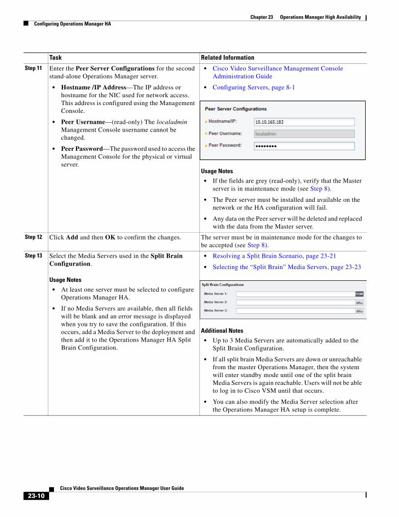
Chapter 23 Operations Manager High Availability Configuring Operations Manager HA
Step 11 Enter the Peer Server Configurations for the second stand-alone Operations Manager server.
• Hostname /IP Address—The IP address or hostname for the NIC used for network access. This address is configured using the Management Console.
• Peer Username—(read-only) The localadmin Management Console username cannot be changed.
• Peer Password—The password used to access the Management Console for the physical or virtual server.
• Cisco Video Surveillance Management Console Administration Guide
• Configuring Servers, page 8-1
Usage Notes
• If the fields are grey (read-only), verify that the Master server is in maintenance mode (see Step 8).
• The Peer server must be installed and available on the network or the HA configuration will fail.
• Any data on the Peer server will be deleted and replaced with the data from the Master server.
Step 12 Click Add and then OK to confirm the changes. The server must be in maintenance mode for the changes to be accepted (see Step 8).
Step 13 Select the Media Servers used in the Split Brain Configuration.
Usage Notes
• At least one server must be selected to configure Operations Manager HA.
• If no Media Servers are available, then all fields will be blank and an error message is displayed when you try to save the configuration. If this occurs, add a Media Server to the deployment and then add it to the Operations Manager HA Split Brain Configuration.
• Resolving a Split Brain Scenario, page 23-21
• Selecting the “Split Brain” Media Servers, page 23-23
Additional Notes
• Up to 3 Media Servers are automatically added to the Split Brain Configuration.
• If all split brain Media Servers are down or unreachable from the master Operations Manager, then the system will enter standby mode until one of the split brain Media Servers is again reachable. Users will not be able to log in to Cisco VSM until that occurs.
• You can also modify the Media Server selection after the Operations Manager HA setup is complete.
Task Related Information
23-10Cisco Video Surveillance Operations Manager User Guide
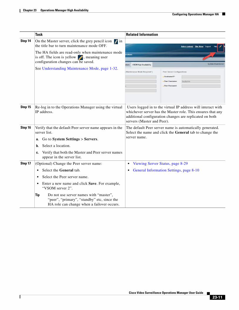
Chapter 23 Operations Manager High AvailabilityConfiguring Operations Manager HA
Step 14 On the Master server, click the grey pencil icon in the title bar to turn maintenance mode OFF.
The HA fields are read-only when maintenance mode is off. The icon is yellow , meaning user configuration changes can be saved.
See Understanding Maintenance Mode, page 1-32.
Step 15 Re-log in to the Operations Manager using the virtual IP address.
Users logged in to the virtual IP address will interact with whichever server has the Master role. This ensures that any additional configuration changes are replicated on both servers (Master and Peer).
Step 16 Verify that the default Peer server name appears in the server list.
a. Go to System Settings > Servers.
b. Select a location.
c. Verify that both the Master and Peer server names appear in the server list.
The default Peer server name is automatically generated. Select the name and click the General tab to change the server name.
Step 17 (Optional) Change the Peer server name:
• Select the General tab.
• Select the Peer server name.
• Enter a new name and click Save. For example, “VSOM server 2”.
Tip Do not use server names with “master”, “peer”, “primary”, “standby” etc, since the HA role can change when a failover occurs.
• Viewing Server Status, page 8-29
• General Information Settings, page 8-10
Task Related Information
23-11Cisco Video Surveillance Operations Manager User Guide
Chapter 23 Operations Manager High Availability Managing the HA Configuration
Managing the HA Configuration • Understanding the Server Management Options, page 23-12
• Revising the Operations Manager HA Configuration, page 23-12
• Replacing the HA Configuration, page 23-13
• Deleting the HA Configuration, page 23-14
• Replacing the HA Peer Server, page 23-15
• Backing Up and Restoring the Operations Manager Configuration, page 23-17
• Upgrading the Operations Manager HA Servers, page 23-18
Understanding the Server Management OptionsTo manage the Operations Manager HA servers, log in to the Operations Manager virtual IP address or hostname. All configuration changes and actions affect the Master server, and are automatically replicated on the Peer server.
Note Do not use the Cisco VSM Management Console to change the configuration for either server unless necessary. Changes made using the Management Console interface may not be replicated in the HA configuration.
Some configuration tasks require that the server be in Maintenance Mode. See Understanding Maintenance Mode, page 1-32 for more information.
To view the Status or alerts for either server, select System Setting > Server, select the Master or Peer server from the list, and select the Status page.
Information and Options Available on the Peer Server
If you select the Peer server from the server list, you can view server Status, change the server name, and view information about the HA configuration. No other configuration tasks or fields are enabled. All other changes must be made on the Master server.
Revising the Operations Manager HA ConfigurationTo change the HA configuration, such as changing the virtual IP address, or changing the server login credentials, access the Master server HA configuration page, enter the new configurations and save the changes.
Procedure
Step 1 Access the Master server:
a. Log in to the Operations Manager using the virtual IP address / hostname.
b. Click the pencil icon in the top right to turn maintenance mode ON.
– The icon is grey when maintenance mode is ON. Maintenance mode places the servers in a stable state and prevents other users from making most changes while high-availability tasks are performed. See Understanding Maintenance Mode, page 1-32 for more information.
23-12Cisco Video Surveillance Operations Manager User Guide
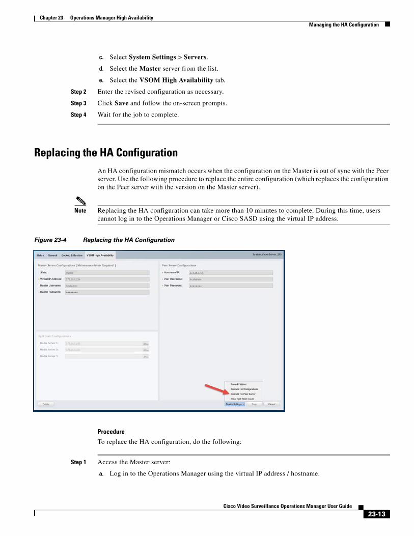
Chapter 23 Operations Manager High AvailabilityManaging the HA Configuration
c. Select System Settings > Servers.
d. Select the Master server from the list.
e. Select the VSOM High Availability tab.
Step 2 Enter the revised configuration as necessary.
Step 3 Click Save and follow the on-screen prompts.
Step 4 Wait for the job to complete.
Replacing the HA ConfigurationAn HA configuration mismatch occurs when the configuration on the Master is out of sync with the Peer server. Use the following procedure to replace the entire configuration (which replaces the configuration on the Peer server with the version on the Master server).
Note Replacing the HA configuration can take more than 10 minutes to complete. During this time, users cannot log in to the Operations Manager or Cisco SASD using the virtual IP address.
Figure 23-4 Replacing the HA Configuration
Procedure
To replace the HA configuration, do the following:
Step 1 Access the Master server:
a. Log in to the Operations Manager using the virtual IP address / hostname.
23-13Cisco Video Surveillance Operations Manager User Guide
Chapter 23 Operations Manager High Availability Managing the HA Configuration
b. Click the pencil icon in the top right to turn maintenance mode ON.
– The icon is grey when maintenance mode is ON. See Understanding Maintenance Mode, page 1-32 for more information.
c. Select System Settings > Servers.
d. Select the Master server from the list.
e. Select the VSOM High Availability tab (Figure 23-4).
Step 2 Select Device Settings > Replace HA Configuration.
Step 3 Click OK and wait for the job to complete.
Step 4 Select the server Status tab to verify that the problem is resolved.
Step 5 (Optional) If a configuration mismatch remains, you can replace the configuration on the Peer server with the version on the Master server. See the “Replacing the HA Configuration” section on page 23-13.
Step 6 On the Master server, click the grey pencil icon in the title bar to turn maintenance mode OFF.
• The icon is yellow when maintenance mode is off, meaning user configuration changes can be saved.
Deleting the HA ConfigurationDeleting the HA configuration removes the Peer Operations Manager server from the HA config. the Cisco VSM will operate with a single Operations Manager server (no HA).
To delete the Operations Manager HA config, delete the Peer server.
Procedure
Step 1 Log in to the system using the virtual IP address.
Step 2 Verify that the server you want to keep as the Operations Manager for the system is in the Master state:
Step 3 Delete the HA configuration:
a. Select System Settings > Servers.
b. Click the pencil icon in the top right to turn maintenance mode ON. The icon is grey when maintenance mode is ON.
c. Select the Master server from the list.
d. Select the VSOM High Availability tab.
e. Click Delete (Figure 23-5).
f. Click OK.
23-14Cisco Video Surveillance Operations Manager User Guide
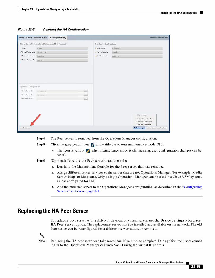
Chapter 23 Operations Manager High AvailabilityManaging the HA Configuration
Figure 23-5 Deleting the HA Configuration
Step 4 The Peer server is removed from the Operations Manager configuration.
Step 5 Click the grey pencil icon in the title bar to turn maintenance mode OFF.
• The icon is yellow when maintenance mode is off, meaning user configuration changes can be saved.
Step 6 (Optional) To re-use the Peer server in another role:
a. Log in to the Management Console for the Peer server that was removed.
b. Assign different server services to the server that are not Operations Manager (for example, Media Server, Maps or Metadata). Only a single Operations Manager can be used in a Cisco VSM system, unless configured for HA.
c. Add the modified server to the Operations Manager configuration, as described in the “Configuring Servers” section on page 8-1.
Replacing the HA Peer ServerTo replace a Peer server with a different physical or virtual server, use the Device Settings > Replace HA Peer Server option. The replacement server must be installed and available on the network. The old Peer server can be reconfigured for a different server status, or removed.
Note Replacing the HA peer server can take more than 10 minutes to complete. During this time, users cannot log in to the Operations Manager or Cisco SASD using the virtual IP address.
23-15Cisco Video Surveillance Operations Manager User Guide

Chapter 23 Operations Manager High Availability Managing the HA Configuration
Procedure
Step 1 Install a replacement stand-alone Cisco VSM Operations Manager server on the network.
Step 2 Access the Master server:
a. Log in to the Operations Manager using the virtual IP address / hostname.
b. Click the pencil icon in the top right to turn maintenance mode ON.
– The icon is grey when maintenance mode is ON. See Understanding Maintenance Mode, page 1-32 for more information.
c. Select System Settings > Servers.
d. Select the Master server from the list.
e. Select the VSOM High Availability tab.
Step 3 Click Device Settings > Replace HA Peer Server (Figure 23-6).
Figure 23-6 Replacing the Peer HA Server
Step 4 Click OK.
Step 5 Wait for the process to complete and for the Master server data to be replicated on the new Peer server.
Step 6 Re-login to the virtual IP address / hostname, if necessary.
Step 7 On the Master server, click the grey pencil icon in the title bar to turn maintenance mode OFF.
23-16Cisco Video Surveillance Operations Manager User Guide
Chapter 23 Operations Manager High AvailabilityManaging the HA Configuration
• The icon is yellow when maintenance mode is off, meaning user configuration changes can be saved.
Backing Up and Restoring the Operations Manager ConfigurationBackup operations are only supported on the server that has the Master role. All backup data is automatically synchronized with the Peer server.
Restore operations can only be performed on a non-HA (stand-alone) server. To restore data from a previous backup, you must delete the HA config, restore the backup, and re-create the HA config.
Refer to the following topics for more information:
• Backing Up the Master Operations Manager, page 23-17
• Restoring a Stand-Alone Operations Manager Server, page 23-17
Backing Up the Master Operations Manager
To back up the Master server:
Step 1 Log in to the Operations Manager virtual IP address / hostname.
Step 2 Select System Settings > Server and select the Master server.
Step 3 Configure the backup settings as described in the “Backing Up and Restoring a Single Server” section on page 27-8.
Note Backup operations are supported on the server that has the Master role only. All backup data is automatically synchronized with the Peer server.
Restoring a Stand-Alone Operations Manager Server
In an HA configuration, all Operations Manager data and configurations are automatically synchronized with the Peer server, so it is typically unnecessary to restore a backup.
• If the Master server goes down, the system will simply fail over to the Peer server.
• If the Peer server goes down, it can be replaced with a new server and the current data will be automatically replicated from the Master.
If you want to roll back the configuration to an earlier state, however, you must delete the HA config, restore the backup file to the Master server, then select Replace HA configuration to sync the restored data to the Peer server.
Procedure
Step 1 Delete the HA config.
• See the “Deleting the HA Configuration” section on page 23-14.
23-17Cisco Video Surveillance Operations Manager User Guide
Chapter 23 Operations Manager High Availability Managing the HA Configuration
Step 2 Restore the server configuration on the server that will be used as the Master.
• See the “Restoring a Backup for a Single Server” section on page 27-11.
Step 3 Replace the HA configuration on the Peer server.
• See the “Replacing the HA Configuration” section on page 23-13.
Upgrading the Operations Manager HA ServersTo upgrade the system software on a Operations Manager server in HA mode, upgrade the Peer server first, force a failover so the Peer server becomes the Master, and then upgrade again to update the second server (which now has the Peer role). Only the Peer server can be upgrading when the servers are in HA mode. An error occurs if you try to upgrade the Master server.
Note You must use the Operations Manager virtual IP address/hostname to upgrade Operations Manager servers in HA mode. HA Operations Manager servers cannot be upgraded using the Cisco VSM Management Console user interface.
Procedure
To upgrade the system software on a Operations Manager server in HA mode, do the following
Step 1 Log in to the Operations Manager using the virtual IP address / hostname.
Step 2 Click the pencil icon in the top right to turn maintenance mode ON.
• The icon is grey when maintenance mode is ON. Maintenance mode places the servers in a stable state and prevents other users from making most changes while high-availability tasks are performed.
23-18Cisco Video Surveillance Operations Manager User Guide
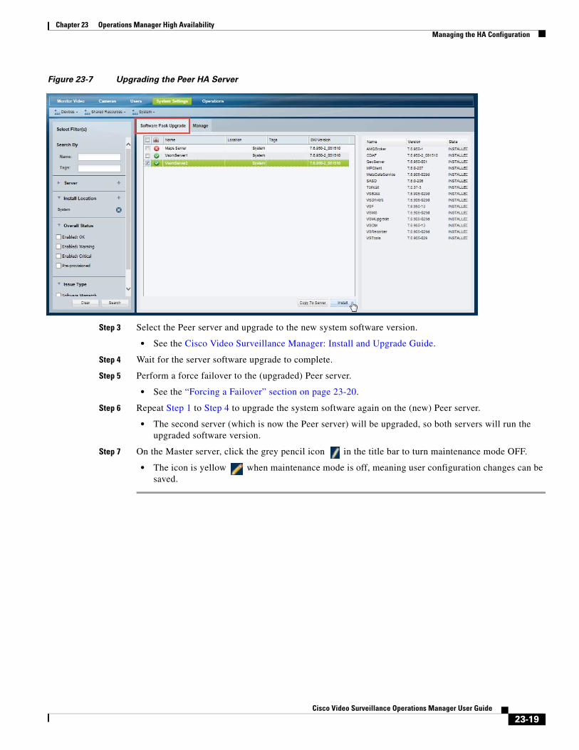
Chapter 23 Operations Manager High AvailabilityManaging the HA Configuration
Figure 23-7 Upgrading the Peer HA Server
Step 3 Select the Peer server and upgrade to the new system software version.
• See the Cisco Video Surveillance Manager: Install and Upgrade Guide.
Step 4 Wait for the server software upgrade to complete.
Step 5 Perform a force failover to the (upgraded) Peer server.
• See the “Forcing a Failover” section on page 23-20.
Step 6 Repeat Step 1 to Step 4 to upgrade the system software again on the (new) Peer server.
• The second server (which is now the Peer server) will be upgraded, so both servers will run the upgraded software version.
Step 7 On the Master server, click the grey pencil icon in the title bar to turn maintenance mode OFF.
• The icon is yellow when maintenance mode is off, meaning user configuration changes can be saved.
23-19Cisco Video Surveillance Operations Manager User Guide
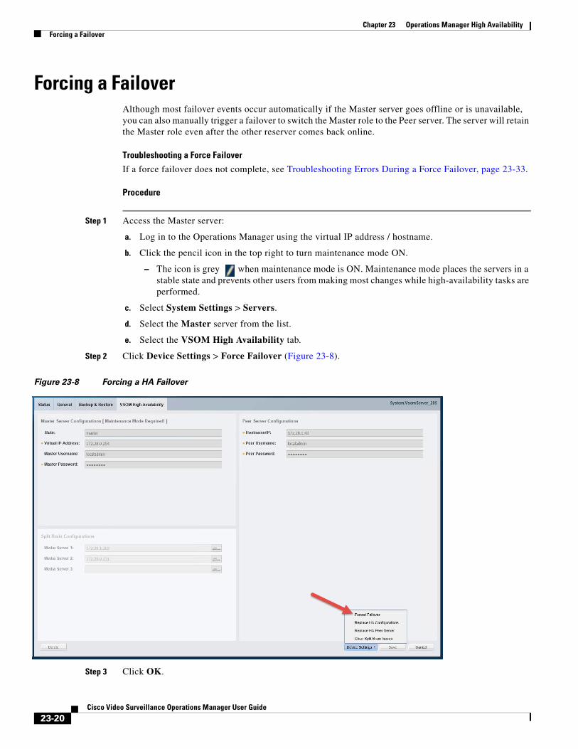
Chapter 23 Operations Manager High Availability Forcing a Failover
Forcing a FailoverAlthough most failover events occur automatically if the Master server goes offline or is unavailable, you can also manually trigger a failover to switch the Master role to the Peer server. The server will retain the Master role even after the other reserver comes back online.
Troubleshooting a Force Failover
If a force failover does not complete, see Troubleshooting Errors During a Force Failover, page 23-33.
Procedure
Step 1 Access the Master server:
a. Log in to the Operations Manager using the virtual IP address / hostname.
b. Click the pencil icon in the top right to turn maintenance mode ON.
– The icon is grey when maintenance mode is ON. Maintenance mode places the servers in a stable state and prevents other users from making most changes while high-availability tasks are performed.
c. Select System Settings > Servers.
d. Select the Master server from the list.
e. Select the VSOM High Availability tab.
Step 2 Click Device Settings > Force Failover (Figure 23-8).
Figure 23-8 Forcing a HA Failover
Step 3 Click OK.
23-20Cisco Video Surveillance Operations Manager User Guide

Chapter 23 Operations Manager High AvailabilityResolving a Split Brain Scenario
Step 4 Wait for the process to complete.
If the failover does not complete, review the information in Troubleshooting Errors During a Force Failover, page 23-33.
Step 5 When the failover is complete, you may need to refresh your browser if the servers use self-signed security certificates. See Resolving a “Server Unreachable” Error During Force Failover, page 23-34 for more information.
Step 6 Re-login to the virtual IP address / hostname, if necessary.
Step 7 On the Master server, click the grey pencil icon in the title bar to turn maintenance mode OFF.
• The icon is yellow when maintenance mode is off, meaning user configuration changes can be saved.
Resolving a Split Brain ScenarioA split brain scenario occurs when the communication between the Master and Peer servers is lost, and both servers try to independently assume the Master role. See the following for more information:
• Split Brain Overview, page 23-21
• Selecting the “Split Brain” Media Servers, page 23-23
• Procedure to Resolve a Split Brain Scenario, page 23-25
Split Brain OverviewIf communication between the Master and Peer servers is lost, both servers will try to independently assume the Master role. This is called a “Split Brain” scenario.
Cisco VSM will automatically detect a Split Brain scenario and direct all traffic to the server that was Master at the time of communication loss. The Peer server is put in standby and a Health alert is sent (Figure 23-9).
23-21Cisco Video Surveillance Operations Manager User Guide
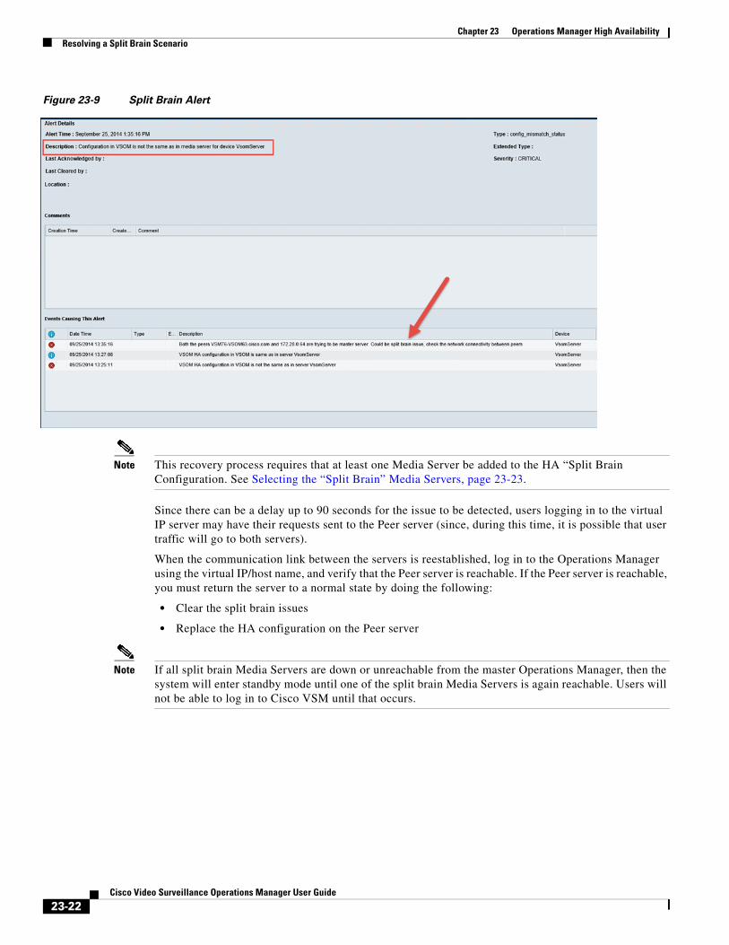
Chapter 23 Operations Manager High Availability Resolving a Split Brain Scenario
Figure 23-9 Split Brain Alert
Note This recovery process requires that at least one Media Server be added to the HA “Split Brain Configuration. See Selecting the “Split Brain” Media Servers, page 23-23.
Since there can be a delay up to 90 seconds for the issue to be detected, users logging in to the virtual IP server may have their requests sent to the Peer server (since, during this time, it is possible that user traffic will go to both servers).
When the communication link between the servers is reestablished, log in to the Operations Manager using the virtual IP/host name, and verify that the Peer server is reachable. If the Peer server is reachable, you must return the server to a normal state by doing the following:
• Clear the split brain issues
• Replace the HA configuration on the Peer server
Note If all split brain Media Servers are down or unreachable from the master Operations Manager, then the system will enter standby mode until one of the split brain Media Servers is again reachable. Users will not be able to log in to Cisco VSM until that occurs.
23-22Cisco Video Surveillance Operations Manager User Guide

Chapter 23 Operations Manager High AvailabilityResolving a Split Brain Scenario
Selecting the “Split Brain” Media ServersAt least one Media Server is required to configure Operations Manager HA and support Split Brain recovery. The Media Server is used to store the Master server info including the time when the server held the Master role.
Up to 3 Media Servers are automatically added to the Split Brain Configuration field when Operations Manager HA is first set up. If Media Servers are displayed, as shown in Figure 23-10, then no additional configuration is necessary.
Figure 23-10 Split Brain Configuration is Complete
If no Media Servers are available when Operations Manager HA is set up, the Split Brain Configuration will be blank (Figure 23-11) and an error message appears when you try to save the configuration. If this occurs, add a Media Server to the deployment and try again.
Figure 23-11 Split Brain Recovery is Not Supported if No Media Servers Are Selected
23-23Cisco Video Surveillance Operations Manager User Guide
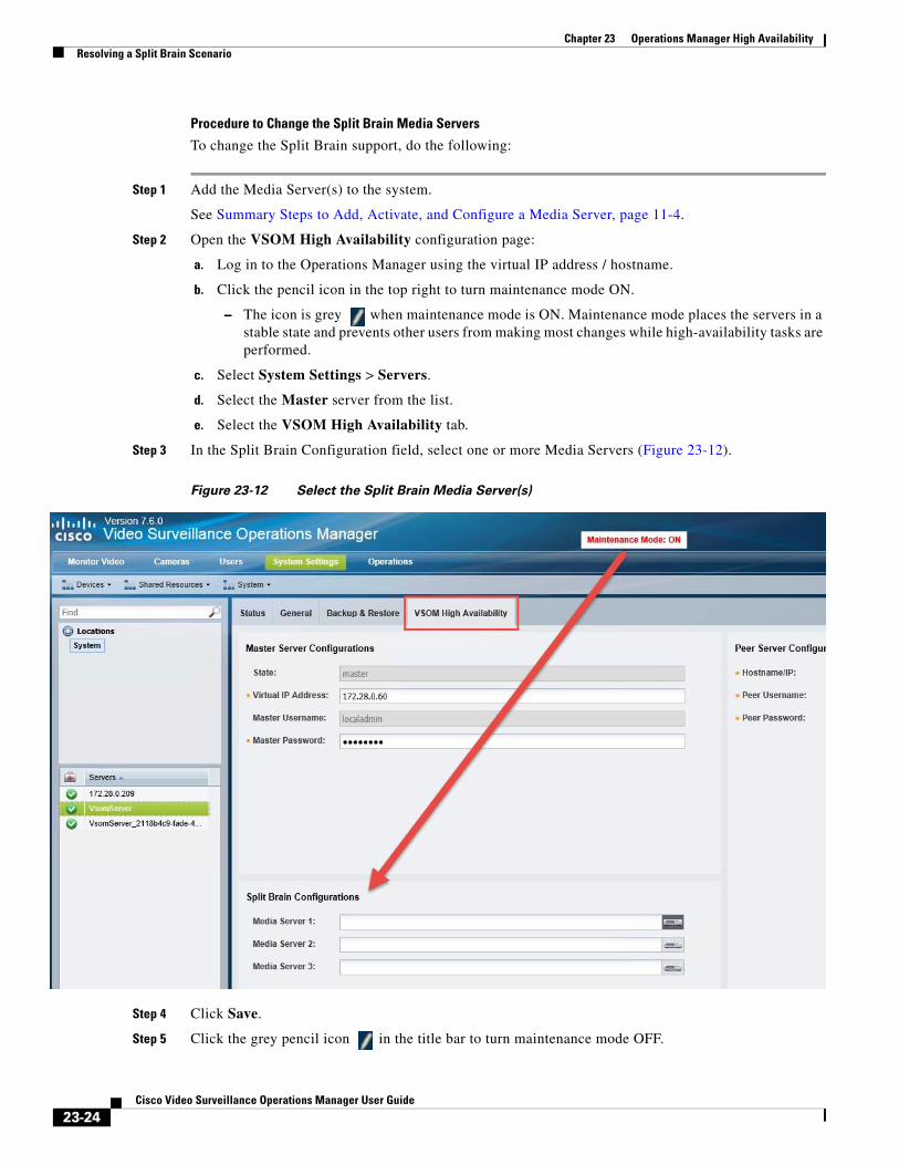
Chapter 23 Operations Manager High Availability Resolving a Split Brain Scenario
Procedure to Change the Split Brain Media Servers
To change the Split Brain support, do the following:
Step 1 Add the Media Server(s) to the system.
See Summary Steps to Add, Activate, and Configure a Media Server, page 11-4.
Step 2 Open the VSOM High Availability configuration page:
a. Log in to the Operations Manager using the virtual IP address / hostname.
b. Click the pencil icon in the top right to turn maintenance mode ON.
– The icon is grey when maintenance mode is ON. Maintenance mode places the servers in a stable state and prevents other users from making most changes while high-availability tasks are performed.
c. Select System Settings > Servers.
d. Select the Master server from the list.
e. Select the VSOM High Availability tab.
Step 3 In the Split Brain Configuration field, select one or more Media Servers (Figure 23-12).
Figure 23-12 Select the Split Brain Media Server(s)
Step 4 Click Save.
Step 5 Click the grey pencil icon in the title bar to turn maintenance mode OFF.
23-24Cisco Video Surveillance Operations Manager User Guide
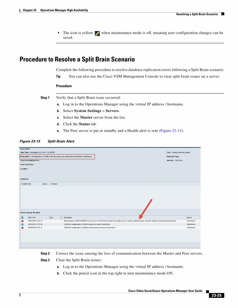
Chapter 23 Operations Manager High AvailabilityResolving a Split Brain Scenario
• The icon is yellow when maintenance mode is off, meaning user configuration changes can be saved.
Procedure to Resolve a Split Brain ScenarioComplete the following procedure to resolve database replication errors following a Split Brain scenario:
Tip You can also use the Cisco VSM Management Console to clear split brain issues on a server.
Procedure
Step 1 Verify that a Split Brain issue occurred:
a. Log in to the Operations Manager using the virtual IP address / hostname.
b. Select System Settings > Servers.
c. Select the Master server from the list.
d. Click the Status tab.
e. The Peer server is put in standby and a Health alert is sent (Figure 23-13).
Figure 23-13 Split Brain Alert
Step 2 Correct the issue causing the loss of communication between the Master and Peer servers.
Step 3 Clear the Split Brain issues:
a. Log in to the Operations Manager using the virtual IP address / hostname.
b. Click the pencil icon in the top right to turn maintenance mode ON.
23-25Cisco Video Surveillance Operations Manager User Guide
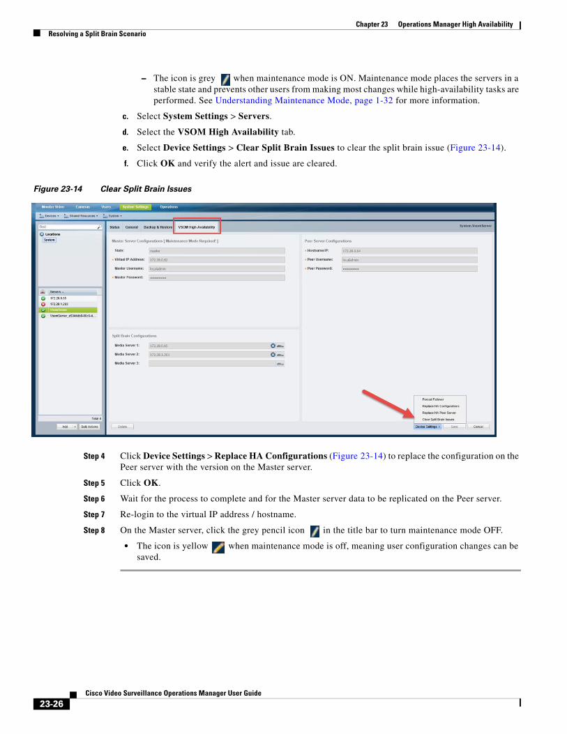
Chapter 23 Operations Manager High Availability Resolving a Split Brain Scenario
– The icon is grey when maintenance mode is ON. Maintenance mode places the servers in a stable state and prevents other users from making most changes while high-availability tasks are performed. See Understanding Maintenance Mode, page 1-32 for more information.
c. Select System Settings > Servers.
d. Select the VSOM High Availability tab.
e. Select Device Settings > Clear Split Brain Issues to clear the split brain issue (Figure 23-14).
f. Click OK and verify the alert and issue are cleared.
Figure 23-14 Clear Split Brain Issues
Step 4 Click Device Settings > Replace HA Configurations (Figure 23-14) to replace the configuration on the Peer server with the version on the Master server.
Step 5 Click OK.
Step 6 Wait for the process to complete and for the Master server data to be replicated on the Peer server.
Step 7 Re-login to the virtual IP address / hostname.
Step 8 On the Master server, click the grey pencil icon in the title bar to turn maintenance mode OFF.
• The icon is yellow when maintenance mode is off, meaning user configuration changes can be saved.
23-26Cisco Video Surveillance Operations Manager User Guide
Chapter 23 Operations Manager High AvailabilityTroubleshooting Operations Manager HA
Troubleshooting Operations Manager HAReview the following information for workarounds and solutions to Cisco Video Surveillance Operations Manager high availability (HA) issues:
• The HA Configuration Job Does Not Complete, page 23-27
• Database Replication Failures, page 23-28
• File Replication Failures, page 23-31
• Network Connectivity Loss Results in a Split Brain Scenario, page 23-33
• Troubleshooting Errors During a Force Failover, page 23-33
– Summary of Force Failover Errors and Workarounds, page 23-33
– Resolving a “Server Unreachable” Error During Force Failover, page 23-34
– Force Failover During a Software Upgrade on the Peer Server, page 23-35
• Virtual IP Login Failure, page 23-35
• Unmanaged Split Brain Scenario, page 23-36
• Useful Command Line Tools for HA Troubleshooting, page 23-37
Note For the latest, up-to-date, version of this information see the Cisco VSM Operations Manager High Availability Troubleshooting Guide.
The HA Configuration Job Does Not Complete
Issue
While configuring Operations Manager HA or replacing the HA Peer server, the sub job that updates the Peer server may not complete, and cause the job to remain in Pending/Running state.
Root Cause
This can happen if the Peer server is in any of the following states:
• The Peer server is being rebooted.
• The Peer server was recently rebooted but is not fully up.
• The Peer server has a Pending or In-progress job. This can be any job but examples include synchronization, device configuration, or template configuration.
Recovery
To clear the job and complete the HA configuration, do one or more of the following:
Step 1 Verify that there are no configuration or other tasks being performed on the Peer server, and that the Peer server does not have any Pending jobs.
a. Login to the Peer server Operations Manager interface.
b. Click System Settings > Jobs.
c. Verify that there are no Pending jobs in the Peer server.
See Viewing All Jobs in the System, page 24-39 for more information.
23-27Cisco Video Surveillance Operations Manager User Guide
Chapter 23 Operations Manager High Availability Troubleshooting Operations Manager HA
Step 2 Restart the services on the Master server:
a. Log in the Master server Management Console interface.
b. Click Restart Services at the top right corner of the page.
c. Follow the on-screen prompts and wait for the operation to complete (the login screen will reappear when services are fully restarted).
See the Cisco Video Surveillance Management Console Administration Guide for more information.
Step 3 Verify that the HA job is cleared on the Master server.
a. Login to the Master server Operations Manager interface.
b. Click System Settings > Jobs.
c. Verify that the previously stuck Operations Manager HA job is marked Failed.
See Viewing All Jobs in the System, page 24-39 for more information.
Step 4 Replace the HA configuration:
a. Select System Settings > Servers.
b. Select the Master server from the list.
c. Select the VSOM High Availability tab (Figure 23-4).
d. Click the pencil icon in the top right to turn maintenance mode ON.
– The icon is grey when maintenance mode is ON. See Understanding Maintenance Mode, page 1-32 for more information.
e. Select Device Settings > Replace HA Configuration.
f. Click OK and wait for the job to complete.
See Replacing the HA Configuration, page 23-13 for more information.
Step 5 Log in to the Operations Manager using the virtual IP address or hostname to verify that the HA setup was successful.
Database Replication FailuresSome events on either server in an HA configuration can cause database replication failures, where the data on the Master server is different than the data on the Peer server.
Events that can cause this include server reboots, power failures, database crashes, or a database going down on either of the participating servers.
Refer to the following topics for information to determine the cause of the failure and recover the database.
• Determining the if a Database Replication Error Occurred, page 23-29
• Detecting if the Database Crashed, page 23-30
• Recovering the Database, page 23-31
23-28Cisco Video Surveillance Operations Manager User Guide
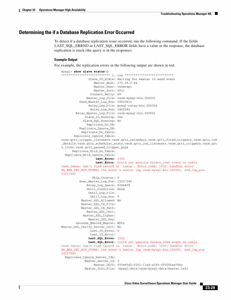
Chapter 23 Operations Manager High AvailabilityTroubleshooting Operations Manager HA
Determining the if a Database Replication Error Occurred
To detect if a database replication issue occurred, run the following command. If the fields LAST_SQL_ERRNO or LAST_SQL_ERROR fields have a value in the response, the database replication is stuck (the query is in the response).
Example Output
For example, the replication errors in the following output are shown in red:
mysql> show slave status\G*************************** 1. row *************************** Slave_IO_State: Waiting for master to send event Master_Host: 172.28.0.64 Master_User: vsomrepl Master_Port: 6611 Connect_Retry: 60 Master_Log_File: vsom-mysql-bin.000001 Read_Master_Log_Pos: 29020815 Relay_Log_File: mysql-relay-bin.000004 Relay_Log_Pos: 2462282 Relay_Master_Log_File: vsom-mysql-bin.000001 Slave_IO_Running: Yes Slave_SQL_Running: No Replicate_Do_DB: Replicate_Ignore_DB: Replicate_Do_Table: Replicate_Ignore_Table: vsom.qrtz_trigger_listeners,vsom.qrtz_calendars,vsom.qrtz_fired_triggers,vsom.qrtz_job_details,vsom.qrtz_scheduler_state,vsom.qrtz_job_listeners,vsom.qrtz_triggers,vsom.qrtz_locks,vsom.qrtz_paused_trigger_grps Replicate_Wild_Do_Table: Replicate_Wild_Ignore_Table: Last_Errno: 1032 Last_Error: Could not execute Delete_rows event on table vsom.issue; Can't find record in 'issue', Error_code: 1032; handler error HA_ERR_KEY_NOT_FOUND; the event's master log vsom-mysql-bin.000001, end_log_pos 23237993 Skip_Counter: 0 Exec_Master_Log_Pos: 23237346 Relay_Log_Space: 8246408 Until_Condition: None Until_Log_File: Until_Log_Pos: 0 Master_SSL_Allowed: No Master_SSL_CA_File: Master_SSL_CA_Path: Master_SSL_Cert: Master_SSL_Cipher: Master_SSL_Key: Seconds_Behind_Master: NULLMaster_SSL_Verify_Server_Cert: No Last_IO_Errno: 0 Last_IO_Error: Last_SQL_Errno: 1032 Last_SQL_Error: Could not execute Delete_rows event on table vsom.issue; Can't find record in 'issue', Error_code: 1032; handler error HA_ERR_KEY_NOT_FOUND; the event's master log vsom-mysql-bin.000001, end_log_pos 23237993 Replicate_Ignore_Server_Ids: Master_Server_Id: 2 Master_UUID: f55e65d2-5261-11e4-a165-005056ae786a Master_Info_File: /mysql/data/vsom/mysql/data/master.info
23-29Cisco Video Surveillance Operations Manager User Guide
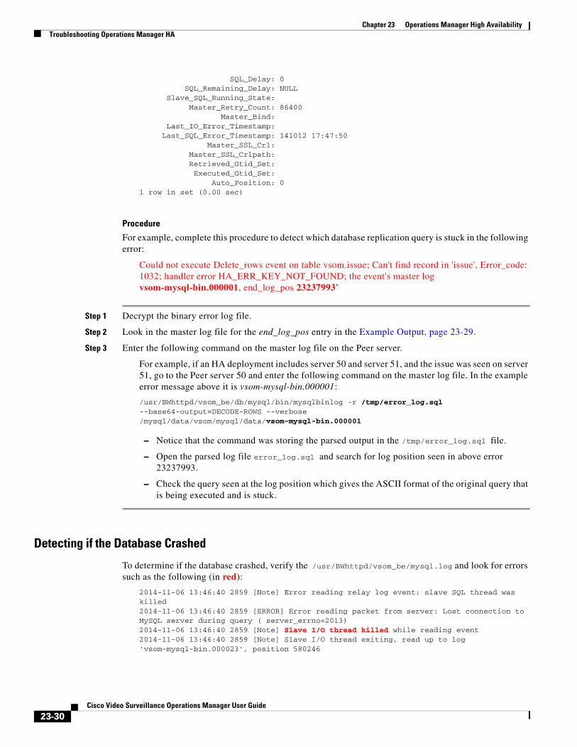
Chapter 23 Operations Manager High Availability Troubleshooting Operations Manager HA
SQL_Delay: 0 SQL_Remaining_Delay: NULL Slave_SQL_Running_State: Master_Retry_Count: 86400 Master_Bind: Last_IO_Error_Timestamp: Last_SQL_Error_Timestamp: 141012 17:47:50 Master_SSL_Crl: Master_SSL_Crlpath: Retrieved_Gtid_Set: Executed_Gtid_Set: Auto_Position: 01 row in set (0.00 sec)
Procedure
For example, complete this procedure to detect which database replication query is stuck in the following error:
Could not execute Delete_rows event on table vsom.issue; Can't find record in 'issue', Error_code: 1032; handler error HA_ERR_KEY_NOT_FOUND; the event's master log vsom-mysql-bin.000001, end_log_pos 23237993’
Step 1 Decrypt the binary error log file.
Step 2 Look in the master log file for the end_log_pos entry in the Example Output, page 23-29.
Step 3 Enter the following command on the master log file on the Peer server.
For example, if an HA deployment includes server 50 and server 51, and the issue was seen on server 51, go to the Peer server 50 and enter the following command on the master log file. In the example error message above it is vsom-mysql-bin.000001:
/usr/BWhttpd/vsom_be/db/mysql/bin/mysqlbinlog -r /tmp/error_log.sql --base64-output=DECODE-ROWS --verbose /mysql/data/vsom/mysql/data/vsom-mysql-bin.000001
– Notice that the command was storing the parsed output in the /tmp/error_log.sql file.
– Open the parsed log file error_log.sql and search for log position seen in above error 23237993.
– Check the query seen at the log position which gives the ASCII format of the original query that is being executed and is stuck.
Detecting if the Database Crashed
To determine if the database crashed, verify the /usr/BWhttpd/vsom_be/mysql.log and look for errors such as the following (in red):
2014-11-06 13:46:40 2859 [Note] Error reading relay log event: slave SQL thread was killed 2014-11-06 13:46:40 2859 [ERROR] Error reading packet from server: Lost connection to MySQL server during query ( server_errno=2013) 2014-11-06 13:46:40 2859 [Note] Slave I/O thread killed while reading event 2014-11-06 13:46:40 2859 [Note] Slave I/O thread exiting, read up to log 'vsom-mysql-bin.000023', position 580246
23-30Cisco Video Surveillance Operations Manager User Guide
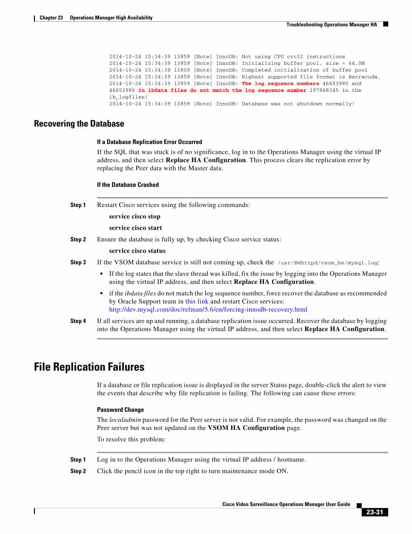
Chapter 23 Operations Manager High AvailabilityTroubleshooting Operations Manager HA
2014-10-24 15:34:39 13859 [Note] InnoDB: Not using CPU crc32 instructions 2014-10-24 15:34:39 13859 [Note] InnoDB: Initializing buffer pool, size = 64.0M 2014-10-24 15:34:39 13859 [Note] InnoDB: Completed initialization of buffer pool 2014-10-24 15:34:39 13859 [Note] InnoDB: Highest supported file format is Barracuda. 2014-10-24 15:34:39 13859 [Note] InnoDB: The log sequence numbers 46653980 and 46653980 in ibdata files do not match the log sequence number 197868345 in the ib_logfiles! 2014-10-24 15:34:39 13859 [Note] InnoDB: Database was not shutdown normally!
Recovering the Database
If a Database Replication Error Occurred
If the SQL that was stuck is of no significance, log in to the Operations Manager using the virtual IP address, and then select Replace HA Configuration. This process clears the replication error by replacing the Peer data with the Master data.
If the Database Crashed
Step 1 Restart Cisco services using the following commands:
service cisco stop
service cisco start
Step 2 Ensure the database is fully up, by checking Cisco service status:
service cisco status
Step 3 If the VSOM database service is still not coming up, check the /usr/BWhttpd/vsom_be/mysql.log:
• If the log states that the slave thread was killed, fix the issue by logging into the Operations Manager using the virtual IP address, and then select Replace HA Configuration.
• if the ibdata files do not match the log sequence number, force recover the database as recommended by Oracle Support team in this link and restart Cisco services: http://dev.mysql.com/doc/refman/5.6/en/forcing-innodb-recovery.html
Step 4 If all services are up and running, a database replication issue occurred. Recover the database by logging into the Operations Manager using the virtual IP address, and then select Replace HA Configuration.
File Replication FailuresIf a database or file replication issue is displayed in the server Status page, double-click the alert to view the events that describe why file replication is failing. The following can cause these errors:
Password Change
The localadmin password for the Peer server is not valid. For example, the password was changed on the Peer server but was not updated on the VSOM HA Configuration page.
To resolve this problem:
Step 1 Log in to the Operations Manager using the virtual IP address / hostname.
Step 2 Click the pencil icon in the top right to turn maintenance mode ON.
23-31Cisco Video Surveillance Operations Manager User Guide

Chapter 23 Operations Manager High Availability Troubleshooting Operations Manager HA
• The icon is grey when maintenance mode is ON. See Understanding Maintenance Mode, page 1-32 for more information.
Step 3 Select System Settings > Servers.
Step 4 Select the Master server from the list.
Step 5 Select the VSOM High Availability tab.
Step 6 Enter the new Peer server password.
Step 7 Click Save.
The Remote Host Identification (Hostkeys) for the Peer Server Changed
The Hostkeys for the Peer server can change if the server IP address is changed when the server is reinstalled or replaced. If this occurs:
Step 1 Log in to the Master server using an SSH client.
Step 2 SSH to the Peer server to verify that the following error is displayed. For example:
[root@psbu-server-qaha]# ssh localadmin@psbu-server-qa2
@@@@@@@@@@@@@@@@@@@@@@@@@@@@@@@@@@@@@@@@@@@@@@@@@@@@@@@@@@@
@ WARNING: REMOTE HOST IDENTIFICATION HAS CHANGED! @
@@@@@@@@@@@@@@@@@@@@@@@@@@@@@@@@@@@@@@@@@@@@@@@@@@@@@@@@@@@
IT IS POSSIBLE THAT SOMEONE IS DOING SOMETHING NASTY!
Someone could be eavesdropping on you right now (man-in-the-middle attack)!
It is also possible that the RSA host key has just been changed.
The fingerprint for the RSA key sent by the remote host is
d3:b5:e3:0d:fc:0b:ab:6a:c6:c4:b2:3e:17:21:7b:c9.
Please contact your system administrator.
Add correct host key in /root/.ssh/known_hosts to get rid of this message.
Offending key in /root/.ssh/known_hosts:8
RSA host key for psbu-server-qa2 has changed and you have requested strict checking.
Host key verification failed.
Step 3 If this message appears, edit the known hosts using the following command:
• vi /root/.ssh/known_hosts
Step 4 Delete the host key entry of the Peer server and save the changes.
Step 5 Verify that the database or file replication error is resolved. Wait at least one minute since health monitoring jobs are updated each minute.
a. Log in to the Operations Manager using the virtual IP address / hostname.
b. Select System Settings > Servers.
c. Select the Master server from the list.
d. Select the Status tab.
e. Verify that the issue is clear.
23-32Cisco Video Surveillance Operations Manager User Guide
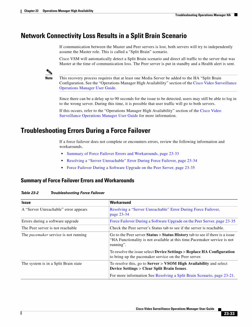
Chapter 23 Operations Manager High AvailabilityTroubleshooting Operations Manager HA
Network Connectivity Loss Results in a Split Brain ScenarioIf communication between the Master and Peer servers is lost, both servers will try to independently assume the Master role. This is called a “Split Brain” scenario.
Cisco VSM will automatically detect a Split Brain scenario and direct all traffic to the server that was Master at the time of communication loss. The Peer server is put in standby and a Health alert is sent.
Note This recovery process requires that at least one Media Server be added to the HA “Split Brain Configuration. See the “Operations Manager High Availability” section of the Cisco Video Surveillance Operations Manager User Guide.
Since there can be a delay up to 90 seconds for the issue to be detected, users may still be able to log in to the wrong server. During this time, it is possible that user traffic will go to both servers.
If this occurs, refer to the “Operations Manager High Availability” section of the Cisco Video Surveillance Operations Manager User Guide for more information.
Troubleshooting Errors During a Force FailoverIf a force failover does not complete or encounters errors, review the following information and workarounds.
• Summary of Force Failover Errors and Workarounds, page 23-33
• Resolving a “Server Unreachable” Error During Force Failover, page 23-34
• Force Failover During a Software Upgrade on the Peer Server, page 23-35
Summary of Force Failover Errors and Workarounds
Table 23-2 Troubleshooting Force Failover
Issue Workaround
A “Server Unreachable” error appears Resolving a “Server Unreachable” Error During Force Failover, page 23-34
Errors during a software upgrade Force Failover During a Software Upgrade on the Peer Server, page 23-35
The Peer server is not reachable Check the Peer server’s Status tab to see if the server is reachable.
The pacemaker service is not running Go to the Peer server Status > Status History tab to see if there is a issue “HA Functionality is not available at this time.Pacemaker service is not running”.
To resolve the issue select Device Settings > Replace HA Configuration to bring up the pacemaker service on the Peer server.
The system is in a Split Brain state To resolve this, go to Server > VSOM High Availability and select Device Settings > Clear Split Brain Issues.
For more information See Resolving a Split Brain Scenario, page 23-21.
23-33Cisco Video Surveillance Operations Manager User Guide
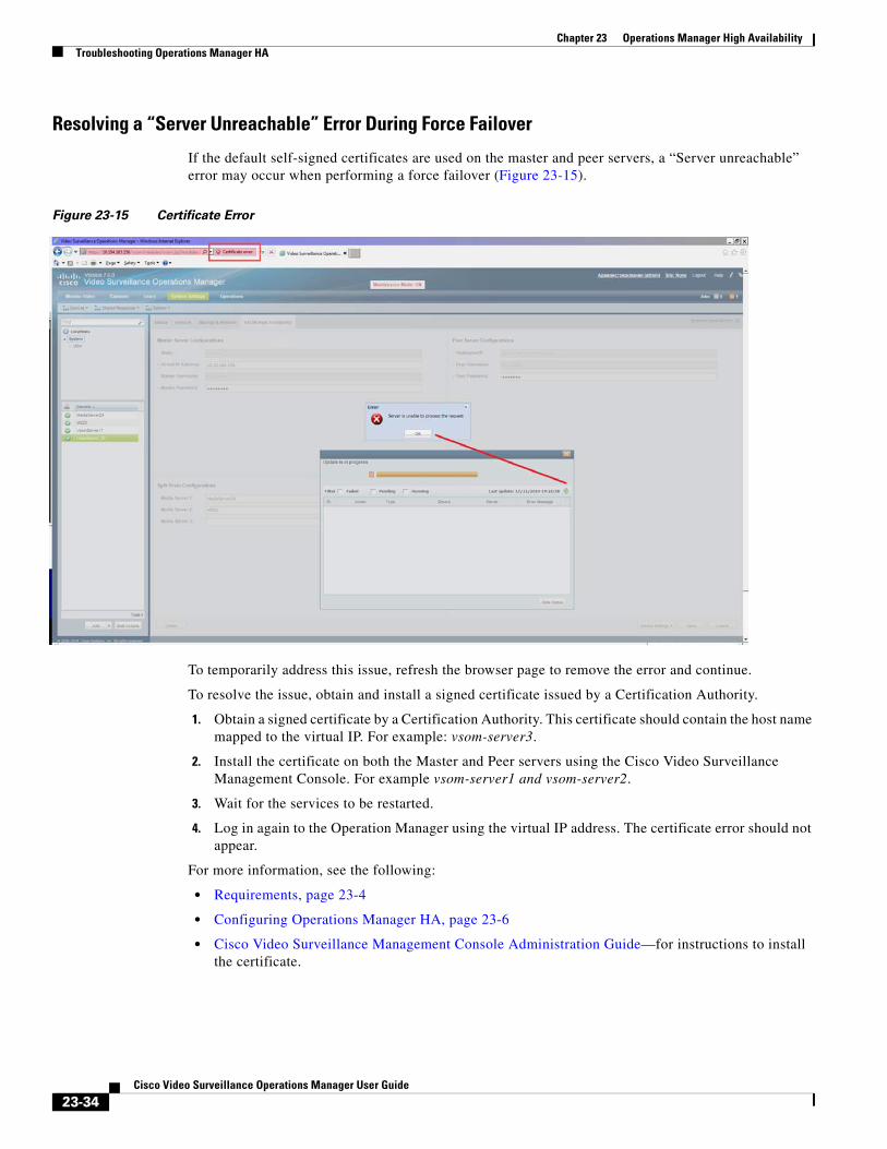
Chapter 23 Operations Manager High Availability Troubleshooting Operations Manager HA
Resolving a “Server Unreachable” Error During Force Failover
If the default self-signed certificates are used on the master and peer servers, a “Server unreachable” error may occur when performing a force failover (Figure 23-15).
Figure 23-15 Certificate Error
To temporarily address this issue, refresh the browser page to remove the error and continue.
To resolve the issue, obtain and install a signed certificate issued by a Certification Authority.
1. Obtain a signed certificate by a Certification Authority. This certificate should contain the host name mapped to the virtual IP. For example: vsom-server3.
2. Install the certificate on both the Master and Peer servers using the Cisco Video Surveillance Management Console. For example vsom-server1 and vsom-server2.
3. Wait for the services to be restarted.
4. Log in again to the Operation Manager using the virtual IP address. The certificate error should not appear.
For more information, see the following:
• Requirements, page 23-4
• Configuring Operations Manager HA, page 23-6
• Cisco Video Surveillance Management Console Administration Guide—for instructions to install the certificate.
23-34Cisco Video Surveillance Operations Manager User Guide
Chapter 23 Operations Manager High AvailabilityTroubleshooting Operations Manager HA
Force Failover During a Software Upgrade on the Peer Server
If you perform a force failover while a software upgrade is in process on the Peer server (for example, the Peer server has not fully initialized after the upgrade), the virtual IP address/hostname can be lost.
If this happens, error messages may appear when a user attempts to log in using the Operations Manager virtual IP address. Messages include: “Invalid access, server is in standby mode” or “”Must login with Virtual IP [IP address] to access system”. This is because both the Master and Peer servers are in standby state.
Recovery
To resolve this issue, you must manually release standby mode on the original Master server.
Step 1 To determine the Master server, query the following database with the following SQL from either server:
select peerserverip from haconfig where state = 2
Step 2 Log in to the Master server from the command prompt.
crm_node -n
Step 3 This provides the node name of the server.
Step 4 Release standby mode using the following command:
crm_standby -D -N server-name [node name collected from above command]
For example: crm_standby -D -N vsm-server
Step 5 After releasing the Standby mode, the server should automatically acquire the virtual IP address.
Step 6 Log back in to the Operations Manager using the virtual IP address or hostname.
Step 7 Go to the Master server and select Force Fail Over to proceed with rest of the software upgrade process.
Virtual IP Login FailureIf users are not able to login using the virtual IP address or hostname, do the following:
Determine the following
• The pacemaker service may be down or crashed.
– Check the status by entering service pacemaker status on both the servers.
– Run the command crm_mon -1 to list node status information on both the servers.
• The virtual IP address is not assigned to either of the participating Operations Manager servers:
– Enter the command ifconfig on both servers. If either server returns NO eth0:0 or eth1:0, then neither server acquired the virtual IP address.
If a software upgrade was not being performed, log in to the Master server using the server’s actual IP/Hostname and select Replace HA Configuration. Otherwise, try one of the following:
Software Upgrade Issue
If a force fail over was issued before a software upgrade was complete, see Force Failover During a Software Upgrade on the Peer Server, page 23-35.
23-35Cisco Video Surveillance Operations Manager User Guide
Chapter 23 Operations Manager High Availability Troubleshooting Operations Manager HA
Recovery for Pacemanker Down
Step 1 If the pacemaker is down, restart the pacemaker service using the command:
service pacemaker start
Step 2 If the pacemaker does not come up clean, run the script:
/usr/BWhttpd/vsom_be/ha/recoverPacemaker.sh
Step 3 Restart the pacemaker service:
service pacemaker start
Unmanaged Split Brain ScenarioIf network connectivity is lost between the Master and Peer server, both servers can assume the Master role and acquire the virtual IP address.
If connectivity is restored between the servers, user traffic can be sent to both servers.
Root Causes
This scenario can be caused by the following:
• The Master server is disconnected from the rest of the world, but the Peer server can see all other servers (including the Media Servers used for HA storage).
• The Master server has communication with all servers except the Peer server, and the Peer server loses network communication with the rest of the world.
• No Media Servers are configured for HA storage, so the system cannot resolve the split brain.
• Media Servers are configured for HA storage but the connectivity issue was shorter than a minute.
Validate
If an unmanaged split brain scenario occurs, the virtual IP address is configured on both servers. Enter the ifconfig command on both servers to view the IP address on each server and verify that both servers are using the virtual IP address.
For example, if the Eth0 interface was used, the virtual IP address is displayed under the eth0:0 entry. If the eth1 interface was used for HA configuration, the virtual IP address is displayed under eth1:0.
Recovery: Method 1
After network connectivity between the Operation Manager HA servers is restored, log in to the Operation Manager browser-based interface to replace the HA configuration.
Step 1 Log in to the Operation Manager for either server using the physical IP address.
Step 2 Select Device Settings > Replace HA Configuration. See Replacing the HA Configuration, page 23-13.
Step 3 If the issue is still not resolved, delete the HA Configuration and reconfigure Operation Manager HA:
a. Complete Deleting the HA Configuration, page 23-14.
23-36Cisco Video Surveillance Operations Manager User Guide
Chapter 23 Operations Manager High AvailabilityTroubleshooting Operations Manager HA
b. Continue to Configuring Operations Manager HA, page 23-6.
Recovery: Method 2
The following alternative method can also be performed to manually resolve the issues.
Step 1 Enter the command ifconfig on both servers to determine if both servers are configured with the virtual IP address.
• For example, if the Eth0 interface was used, the virtual IP address will appear under the eth0:0 entry.
Step 2 Verify that the Cisco service is up on both servers.
Step 3 Bring the Cisco service back up on both servers, if necessary.
Step 4 Stop the pacemaker service on both servers.
Step 5 Start the pacemaker service on the original master server.
Step 6 When the pacemaker service starts, enter the command ifconfig to verify it has the virtual IP address.
Step 7 Log in to the Operation Manager using the virtual IP address or hostname.
Step 8 View the server status.
Step 9 If the database replication issue is not automatically released, go to the VSOM High Availability tab and select Device Settings > Replace HA Configuration.
Useful Command Line Tools for HA Troubleshooting
Table 23-3 CLI Monitoring Tools
CLI Description
service pacemaker status Displays if pacemaker service is running or not.
For example: pacemakerd (pid 2583) is running...
crm_mon -1 Lists the participating servers along with where the resources are running.
For example:
Last updated: Mon Nov 17 10:47:23 2014Last change: Thu Nov 13 16:11:23 2014 via crm_attribute on vsm7-55Stack: cmanCurrent DC: vsm7-54 - partition with quorumVersion: 1.1.10-14.el6-368c7262 Nodes configured2 Resources configured
Online: [ vsm7-54 vsm7-55 ]
Resource Group: group1 ClusterIP (ocf::heartbeat:IPaddr2): Started auto-vsm7-54
vsom (lsb:vsomha): Started vsm7-54
23-37Cisco Video Surveillance Operations Manager User Guide
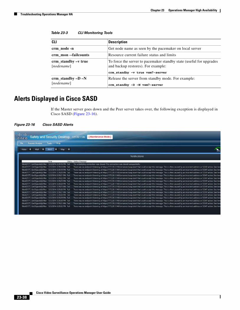
Chapter 23 Operations Manager High Availability Troubleshooting Operations Manager HA
Alerts Displayed in Cisco SASDIf the Master server goes down and the Peer server takes over, the following exception is displayed in Cisco SASD (Figure 23-16).
Figure 23-16 Cisco SASD Alerts
crm_node -n Get node name as seen by the pacemaker on local server
crm_mon --failcounts Resource current failure status and limits
crm_standby –v true [nodename]
To force the server to pacemaker standby state (useful for upgrades and backup restores). For example:
crm_standby –v true vsm7-server
crm_standby –D –N [nodename]
Release the server from standby mode. For example:
crm_standby –D –N vsm7-server
Table 23-3 CLI Monitoring Tools
CLI Description
23-38Cisco Video Surveillance Operations Manager User Guide
Cisco V
C H A P T E R 24
Monitoring System and Device HealthRefer to the following topics for information to monitor the health of the system or a device, to view the status of user-initiated jobs, a record of user actions (Audit Logs), and other features.
Contents
• Understanding Events and Alerts, page 24-2
– Overview, page 24-2
– Event Types, page 24-4
– Triggering Actions Based on Alerts and Events, page 24-4
– Monitoring Device Heath Using the Operations Manager, page 24-5
– Changing the Severity Level of Alerts, page 24-6
• Health Dashboard: Device Health Faults on an Operations Manager, page 24-7
• Device Status: Identifying Issues for a Specific Device, page 24-13
• Sending Alert Emails (Notification Policies), page 24-23
• Reports, page 24-27
• Synchronizing Device Configurations, page 24-28
– Overview, page 24-28
– Viewing Device Synchronization Errors, page 24-30
– Understanding Device Configuration Mismatch Caused by Media Server Issues, page 24-31
– Repairing a Mismatched Configuration, page 24-32
– Manually Triggering a Media Server Synchronization, page 24-33
– Device Data That Is Synchronized, page 24-33
– Synchronization During a Media Server Migration, page 24-34
• Viewing the Server Management Console Status and Logs, page 24-35
• Understanding Jobs and Job Status, page 24-36
• Viewing Audit Logs, page 24-42
• Custom Data Management, page 24-43
• Pruning Events and Logs, page 24-44
24-1ideo Surveillance Operations Manager User Guide
Chapter 24 Monitoring System and Device Health Understanding Events and Alerts
Understanding Events and AlertsEvents and alerts reflect changes to system and device health, or security events that occur in the system. These events and alerts can be viewed in a monitoring application, such as the Operations Manager or Cisco SASD, or be used to generate notifications, or trigger additional actions.
Refer to the following topics for more information:
• Overview, page 24-2
• Event Types, page 24-4
• Triggering Actions Based on Alerts and Events, page 24-4
• Monitoring Device Heath Using the Operations Manager, page 24-5
OverviewEvents represent incidents that occur in the system and devices. Alerts aggregate (group) those events together for notification purposes. For example, if a camera goes offline and comes back online repeatedly, the individual events for that issue are grouped under a single alert, which results in a single notification. This prevents operators from being flooded with notifications for every event that occurs for the same issue.
Note The alert severity reflects the severity of the most recently generated event. For example, if a camera becomes unreachable and the streaming status is Critical, the alert is Critical. When the camera becomes reachable again, and the streaming status normal event occurs, and the alert severity is changed to INFO. You can change the Alert Severity level for new alerts so they will have a higher or lower severity than the default.
Tip To prune (delete) old entries, see Pruning Events and Logs, page 24-44.
24-2Cisco Video Surveillance Operations Manager User Guide
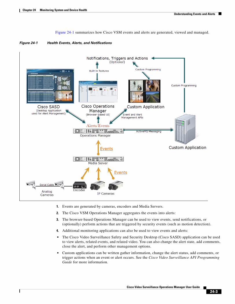
Chapter 24 Monitoring System and Device HealthUnderstanding Events and Alerts
Figure 24-1 summarizes how Cisco VSM events and alerts are generated, viewed and managed.
Figure 24-1 Health Events, Alerts, and Notifications
1. Events are generated by cameras, encoders and Media Servers.
2. The Cisco VSM Operations Manager aggregates the events into alerts:
3. The browser-based Operations Manager can be used to view events, send notifications, or (optionally) perform actions that are triggered by security events (such as motion detection).
4. Additional monitoring applications can also be used to view events and alerts:
• The Cisco Video Surveillance Safety and Security Desktop (Cisco SASD) application can be used to view alerts, related events, and related video. You can also change the alert state, add comments, close the alert, and perform other management options.
• Custom applications can be written gather information, change the alert status, add comments, or trigger actions when an event or alert occurs. See the Cisco Video Surveillance API Programming Guide for more information.
24-3Cisco Video Surveillance Operations Manager User Guide
Chapter 24 Monitoring System and Device Health Understanding Events and Alerts
Note Custom applications can also subscribe to ActiveMQ topics to receive notifications about device and system changes. For example, the Alerts topic notifies subscribers when any alert occurs in the system. The custom application can use the ActiveMQ message contents to optionally trigger additional notification or actions. See the Cisco Video Surveillance API Programming Guide for more information.
Event TypesCisco VSM generates two types of events: device health events and security events:
• Health Events are generated when a device health change occurs, such as reachability, fan speed, file system usage, or other device-related issues. Critical and warning health events generate alerts by default.
• Security Events—Events such as motion stop or start, analytics, contact closures, or soft triggers from an external system can be configured to generate alerts, or perform other actions. Security events do not generate alerts by default.
Triggering Actions Based on Alerts and EventsThe Operations Manager includes the following built-in features to trigger notifications and other actions:
Table 24-1 Triggering Actions
Action Description More Information
Critical or warning health notifications
Use the Health Notifications feature to send notifications when a critical or warning device error occurs. These errors are health events that impact the device operation or render a component unusable. For example, a Media Server that cannot be contacted on the network, or a camera that does not stream or record video.
Sending Alert Emails (Notification Policies), page 24-23
Motion event notifications Click Alert Notifications in the camera template to enable or disable the alerts that are generated when a motion event stops or starts.
Creating or Modifying a Template, page 13-3
Trigger actions when a security event occurs
Use the Advanced Events feature (in the camera template) to trigger a variety of actions when a security event occurs. For example, you can send alerts only on motion start, on motion stop, stop or start video recording, record video for a specified length of time, invoke a URL, move a camera position to a specified PTZ preset, or display video on a Video Wall.
Using Advanced Events to Trigger Actions, page 15-7
24-4Cisco Video Surveillance Operations Manager User Guide
Chapter 24 Monitoring System and Device HealthUnderstanding Events and Alerts
Monitoring Device Heath Using the Operations ManagerThe Health Dashboard displays a summary of all device errors in your deployment, allowing you to quickly view the health of all cameras, encoders and Media Servers. You can also click a link for any affected device to open the device status and configuration pages.
Table 24-2 summarizes the Operations Manager monitoring features.
Table 24-2 Monitoring Features
Monitoring Feature Location Description
Health Dashboard: Device Health Faults on an Operations Manager, page 24-7
Operations > Health Dashboard Open the Health Dashboard to view a summary of Warning or Critical errors for all configured devices. Click on an entry to open the device status and configuration page and further identify the issue.
Click the General > Servers tab to also view an estimate of the number of cameras that can be added to the server.
Device Status: Identifying Issues for a Specific Device, page 24-13
Cameras > Status
System Settings > Server > Status
System Settings > Encoder > Status
Click the Status tab in the device configuration page to view the specific type of error for a device. The status categories show where the error occurred.
• Click the Status History to view the alert messages for the device.
• Click the Affecting Current Status radio button to view only the alerts that are causing the
Sending Alert Emails (Notification Policies), page 24-23
Operations > Health Notifications Send emails to specified recipients when a device error occurs.
Reports, page 24-27 Operations > Reports Generate and download information about the Cisco Video Surveillance user activity, device configuration, and other information.
Synchronizing Device Configurations, page 24-28
Device configuration page.
Click the Repair or Replace Config button.
If a configuration mismatch error occurs, you can click the device Repair button to replace the configuration settings on the device with the settings in Operations Manager.
Viewing the Server Management Console Status and Logs, page 24-35
Operations > Management Console Displays logs, hardware status, and system trend information for the Cisco Video Surveillance server. The Management Console is a separate browser-based interface that requires a separate localadmin password.
See the Cisco Video Surveillance Management Console Administration Guide for more information.
24-5Cisco Video Surveillance Operations Manager User Guide
Chapter 24 Monitoring System and Device Health Understanding Events and Alerts
Changing the Severity Level of AlertsYou can change the severity level of new alerts so they will have a higher or lower severity than the default. See Alert Severity, page 26-6 for more information.
For example, alerts that were reported as Critical by default can be changed to Warning, and will follow the rules and actions that apply to Warning alerts. This allows you to change the importance of alerts if they should have less or more importance in your deployment.
Notes
• Changes apply to new alerts only. Existing alerts retain their original severity level.
• The events that are included in the alert will retain their default severity level, even if the alert is changed.
Understanding Jobs and Job Status, page 24-36
System Settings > Jobs Displays a summary of current and completed jobs triggered by user actions.
Viewing Audit Logs, page 24-42
Operations > Audit Logs Displays successful configuration changes. You can sort or filter the results by user, device, and other categories.
Table 24-2 Monitoring Features
Monitoring Feature Location Description
24-6Cisco Video Surveillance Operations Manager User Guide

Chapter 24 Monitoring System and Device HealthHealth Dashboard: Device Health Faults on an Operations Manager
Health Dashboard: Device Health Faults on an Operations Manager
Use the Health Dashboard (Figure 24-2) to view a summary servers, encoders and cameras in your deployment, including general information and health status.
• Open the Health Dashboard, page 24-7
• General Tab (Device Summary Information), page 24-8
• Health Information By Category or Issue, page 24-10
• Tips, page 24-11
• Understanding Warning and Critical Faults, page 24-12
Open the Health DashboardTo access the Health Dashboard and view device health issues:
Step 1 Click Operations > Health Dashboard (Figure 24-3).
Step 2 Choose a location to view a summary of the health issues at that location, including its sub-locations.
• Locations (or sub-locations) with health issues display a Health icon .
• If a sub-location has a device with a health issue, the Health icon is also displayed for the parent location(s).
Step 3 Click the General, By Category or By Issue tab.
Step 4 Click a number to display the specific issues for the device type, category or issue type.
The number represents the total number of issues for all devices at the selected location and it’s sub-locations (the number is the consolidated sum of issues in that location and it’s sub-locations).
Step 5 (Optional) Click the icon to open the device status and configuration pages.
Step 6 Continue to the “Device Status: Identifying Issues for a Specific Device” section on page 24-13 for more information.
Step 7 Take corrective action to restore the device to normal operation, if necessary.
Step 8 For example, if a configuration mismatch occurs, see the “Synchronizing Device Configurations” section on page 24-28.
24-7Cisco Video Surveillance Operations Manager User Guide
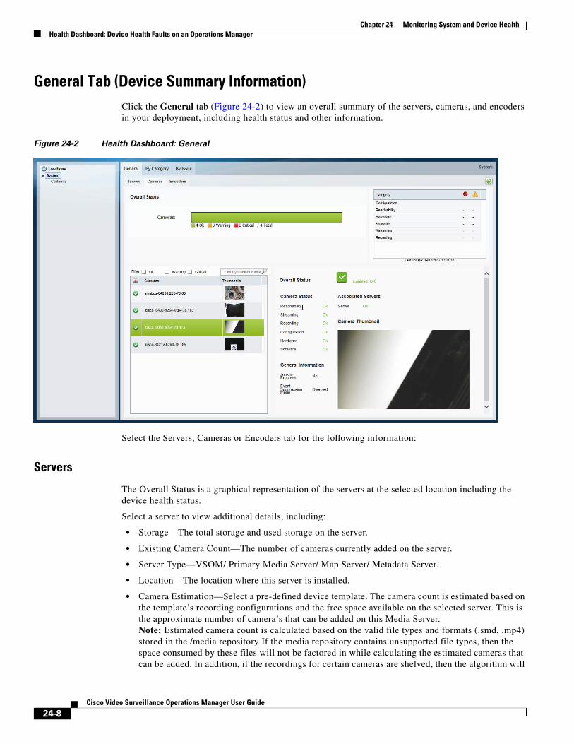
Chapter 24 Monitoring System and Device Health Health Dashboard: Device Health Faults on an Operations Manager
General Tab (Device Summary Information)Click the General tab (Figure 24-2) to view an overall summary of the servers, cameras, and encoders in your deployment, including health status and other information.
Figure 24-2 Health Dashboard: General
Select the Servers, Cameras or Encoders tab for the following information:
Servers
The Overall Status is a graphical representation of the servers at the selected location including the device health status.
Select a server to view additional details, including:
• Storage—The total storage and used storage on the server.
• Existing Camera Count—The number of cameras currently added on the server.
• Server Type—VSOM/ Primary Media Server/ Map Server/ Metadata Server.
• Location—The location where this server is installed.
• Camera Estimation—Select a pre-defined device template. The camera count is estimated based on the template’s recording configurations and the free space available on the selected server. This is the approximate number of camera’s that can be added on this Media Server.Note: Estimated camera count is calculated based on the valid file types and formats (.smd, .mp4) stored in the /media repository If the media repository contains unsupported file types, then the space consumed by these files will not be factored in while calculating the estimated cameras that can be added. In addition, if the recordings for certain cameras are shelved, then the algorithm will
24-8Cisco Video Surveillance Operations Manager User Guide
Chapter 24 Monitoring System and Device HealthHealth Dashboard: Device Health Faults on an Operations Manager
consider the space occupied by the recordings of those cameras until the time the recording state was moved to shelved. If the recording state of those cameras are altered at a later date, then “Camera Count” estimation will have to be re-run or else going with the old camera estimated count will have an impact on the number of cameras that can be added, and could result in recordings getting groomed.
Cameras
The Overall Status is a graphical representation of the cameras at the selected location including the device health status.
Select a camera to view additional details, including:
• Camera Status—The status including Reachability, Streaming, Recording, Configuration, and other information.
• General Information—The running jobs.
• Large thumbnail—A larger thumbnail of the camera’s live stream.
Encoders
The Overall Status is a graphical representation of the device at the selected location including health status.
Select a device to view additional details, including:
• Encoder Status—The status including Reachability, Configuration, and other information.
• General Information—Running jobs.
24-9Cisco Video Surveillance Operations Manager User Guide
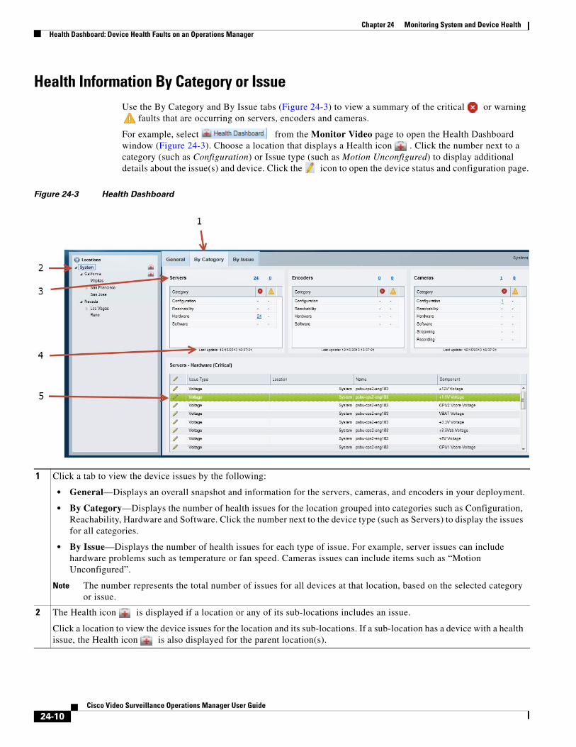
Chapter 24 Monitoring System and Device Health Health Dashboard: Device Health Faults on an Operations Manager
Health Information By Category or IssueUse the By Category and By Issue tabs (Figure 24-3) to view a summary of the critical or warning
faults that are occurring on servers, encoders and cameras.
For example, select from the Monitor Video page to open the Health Dashboard window (Figure 24-3). Choose a location that displays a Health icon . Click the number next to a category (such as Configuration) or Issue type (such as Motion Unconfigured) to display additional details about the issue(s) and device. Click the icon to open the device status and configuration page.
Figure 24-3 Health Dashboard
1 Click a tab to view the device issues by the following:
• General—Displays an overall snapshot and information for the servers, cameras, and encoders in your deployment.
• By Category—Displays the number of health issues for the location grouped into categories such as Configuration, Reachability, Hardware and Software. Click the number next to the device type (such as Servers) to display the issues for all categories.
• By Issue—Displays the number of health issues for each type of issue. For example, server issues can include hardware problems such as temperature or fan speed. Cameras issues can include items such as “Motion Unconfigured”.
Note The number represents the total number of issues for all devices at that location, based on the selected category or issue.
2 The Health icon is displayed if a location or any of its sub-locations includes an issue.
Click a location to view the device issues for the location and its sub-locations. If a sub-location has a device with a health issue, the Health icon is also displayed for the parent location(s).
24-10Cisco Video Surveillance Operations Manager User Guide
Chapter 24 Monitoring System and Device HealthHealth Dashboard: Device Health Faults on an Operations Manager
Tips • Cisco VSM administrators can hide the device status icons and access to the Health Dashboard. See
Display or Hide Camera Health Information, page 4-16
• To view the health issues for multiple Operations Managers, see the “Monitoring Device Health Using the Browser-Based Federator” section on page 28-33.
• Device errors are cleared automatically by the system or manually cleared by an operator using the Cisco SASD or another monitoring application. Refresh the page to view the latest information. Some alerts cannot be automatically reset. For example, a server I/O write error event.
• If the system or server is performing poorly, use the diagnostic tools available in the server Management Console to view performance, hardware and system information. See the “Accessing the Management Console” section on page B-2 for more information.
3 The device type (such as Servers, Encoders, or Cameras) where the issues occurred.
• Click a number to display a list of critical or warning faults for the category, issue type, or device type. For example, click the number 23 next to Hardware to display a list of the hardware issues for all servers (multiple issues can occur for a single device). See Table 24-3 for more information about critical and warning faults.
• If issues did not occur, a number is not displayed.
• The number represents the total number of issues for all devices at that location, based on the selected category or issue.
4 Last Update—Refresh the Health Dashboard page to view updated results. The dashboard does not automatically refresh.
5 The specific health issues that occurred for the selected category or issue type.
• All issues are listed. Multiple issues can be displayed for the same device
• Click the icon to open the device’s status and configuration page. See the “Device Status: Identifying Issues for a Specific Device” section on page 24-13 for more information.
24-11Cisco Video Surveillance Operations Manager User Guide
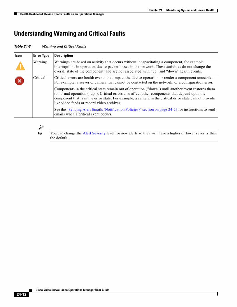
Chapter 24 Monitoring System and Device Health Health Dashboard: Device Health Faults on an Operations Manager
Understanding Warning and Critical Faults
Table 24-3 Warning and Critical Faults
Icon Error Type Description
Tip You can change the Alert Severity level for new alerts so they will have a higher or lower severity than the default.
Warning Warnings are based on activity that occurs without incapacitating a component, for example, interruptions in operation due to packet losses in the network. These activities do not change the overall state of the component, and are not associated with “up” and “down” health events.
Critical Critical errors are health events that impact the device operation or render a component unusable. For example, a server or camera that cannot be contacted on the network, or a configuration error.
Components in the critical state remain out of operation (“down”) until another event restores them to normal operation (“up”). Critical errors also affect other components that depend upon the component that is in the error state. For example, a camera in the critical error state cannot provide live video feeds or record video archives.
See the “Sending Alert Emails (Notification Policies)” section on page 24-23 for instructions to send emails when a critical event occurs.
24-12Cisco Video Surveillance Operations Manager User Guide
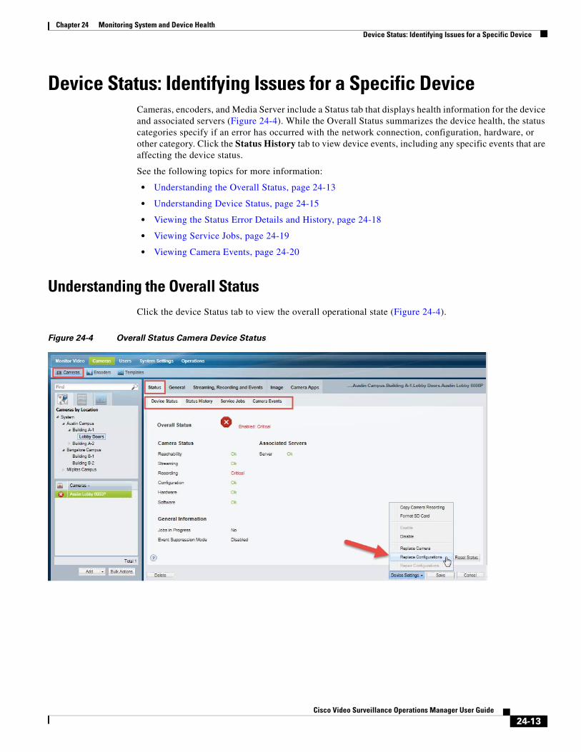
Chapter 24 Monitoring System and Device HealthDevice Status: Identifying Issues for a Specific Device
Device Status: Identifying Issues for a Specific DeviceCameras, encoders, and Media Server include a Status tab that displays health information for the device and associated servers (Figure 24-4). While the Overall Status summarizes the device health, the status categories specify if an error has occurred with the network connection, configuration, hardware, or other category. Click the Status History tab to view device events, including any specific events that are affecting the device status.
See the following topics for more information:
• Understanding the Overall Status, page 24-13
• Understanding Device Status, page 24-15
• Viewing the Status Error Details and History, page 24-18
• Viewing Service Jobs, page 24-19
• Viewing Camera Events, page 24-20
Understanding the Overall StatusClick the device Status tab to view the overall operational state (Figure 24-4).
Figure 24-4 Overall Status Camera Device Status
24-13Cisco Video Surveillance Operations Manager User Guide
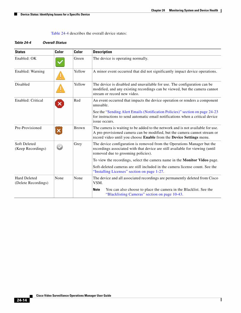
Chapter 24 Monitoring System and Device Health Device Status: Identifying Issues for a Specific Device
Table 24-4 describes the overall device states:
Table 24-4 Overall Status
Status Color Color Description
Note You can also choose to place the camera in the Blacklist. See the “Blacklisting Cameras” section on page 10-43.
Enabled: OK Green The device is operating normally.
Enabled: Warning Yellow A minor event occurred that did not significantly impact device operations.
Disabled Yellow The device is disabled and unavailable for use. The configuration can be modified, and any existing recordings can be viewed, but the camera cannot stream or record new video.
Enabled: Critical Red An event occurred that impacts the device operation or renders a component unusable.
See the “Sending Alert Emails (Notification Policies)” section on page 24-23 for instructions to send automatic email notifications when a critical device issue occurs.
Pre-Provisioned Brown The camera is waiting to be added to the network and is not available for use. A pre-provisioned camera can be modified, but the camera cannot stream or record video until you choose Enable from the Device Settings menu.
Soft Deleted (Keep Recordings)
Grey The device configuration is removed from the Operations Manager but the recordings associated with that device are still available for viewing (until removed due to grooming policies).
To view the recordings, select the camera name in the Monitor Video page.
Soft-deleted cameras are still included in the camera license count. See the “Installing Licenses” section on page 1-27.
Hard Deleted (Delete Recordings)
None None The device and all associated recordings are permanently deleted from Cisco VSM.
24-14Cisco Video Surveillance Operations Manager User Guide
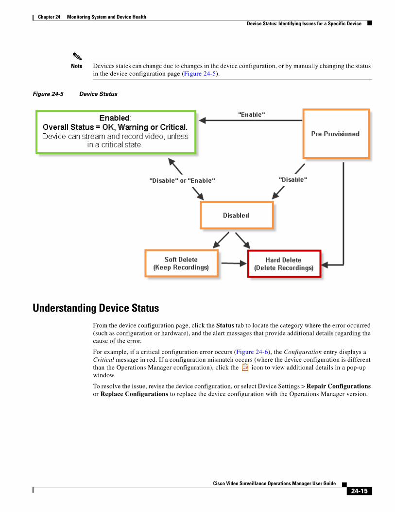
Chapter 24 Monitoring System and Device HealthDevice Status: Identifying Issues for a Specific Device
Note Devices states can change due to changes in the device configuration, or by manually changing the status in the device configuration page (Figure 24-5).
Figure 24-5 Device Status
Understanding Device StatusFrom the device configuration page, click the Status tab to locate the category where the error occurred (such as configuration or hardware), and the alert messages that provide additional details regarding the cause of the error.
For example, if a critical configuration error occurs (Figure 24-6), the Configuration entry displays a Critical message in red. If a configuration mismatch occurs (where the device configuration is different than the Operations Manager configuration), click the icon to view additional details in a pop-up window.
To resolve the issue, revise the device configuration, or select Device Settings > Repair Configurations or Replace Configurations to replace the device configuration with the Operations Manager version.
24-15Cisco Video Surveillance Operations Manager User Guide
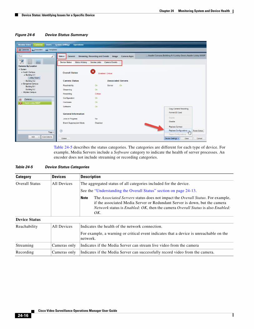
Chapter 24 Monitoring System and Device Health Device Status: Identifying Issues for a Specific Device
Figure 24-6 Device Status Summary
Table 24-5 describes the status categories. The categories are different for each type of device. For example, Media Servers include a Software category to indicate the health of server processes. An encoder does not include streaming or recording categories.
Table 24-5 Device Status Categories
Category Devices Description
Overall Status All Devices The aggregated status of all categories included for the device.
See the “Understanding the Overall Status” section on page 24-13.
Note The Associated Servers status does not impact the Overall Status. For example, if the associated Media Server or Redundant Server is down, but the camera Network status is Enabled: OK, then the camera Overall Status is also Enabled: OK.
Device Status
Reachability All Devices Indicates the health of the network connection.
For example, a warning or critical event indicates that a device is unreachable on the network.
Streaming Cameras only Indicates if the Media Server can stream live video from the camera
Recording Cameras only Indicates if the Media Server can successfully record video from the camera.
24-16Cisco Video Surveillance Operations Manager User Guide
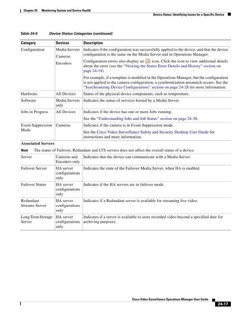
Chapter 24 Monitoring System and Device HealthDevice Status: Identifying Issues for a Specific Device
Configuration Media Servers
Cameras
Encoders
Indicates if the configuration was successfully applied to the device, and that the device configuration is the same on the Media Server and in Operations Manager.
Configuration errors also display an icon. Click the icon to view additional details about the error (see the “Viewing the Status Error Details and History” section on page 24-18)
For example, if a template is modified in the Operations Manager, but the configuration is not applied to the camera configuration, a synchronization mismatch occurs. See the “Synchronizing Device Configurations” section on page 24-28 for more information.
Hardware All Devices Status of the physical device components, such as temperature.
Software Media Servers only
Indicates the status of services hosted by a Media Server.
Jobs in Progress All Devices Indicates if the device has one or more Jobs running.
See the “Understanding Jobs and Job Status” section on page 24-36.
Event Suppression Mode
Cameras Indicates if the camera is in Event Suppression mode.
See the Cisco Video Surveillance Safety and Security Desktop User Guide for instructions and more information.
Associated Servers
Note The status of Failover, Redundant and LTS servers does not affect the overall status of a device.
Server Cameras and Encoders only
Indicates that the device can communicate with a Media Server.
Failover Server HA server configurations only
Indicates the state of the Failover Media Server, when HA is enabled.
Failover Status HA server configurations only
Indicates if the HA servers are in failover mode.
Redundant Streams Server
HA server configurations only
Indicates if a Redundant server is available for streaming live video.
Long Term Storage Server
HA server configurations only
Indicates if a server is available to store recorded video beyond a specified date for archiving purposes.
Table 24-5 Device Status Categories (continued)
Category Devices Description
24-17Cisco Video Surveillance Operations Manager User Guide
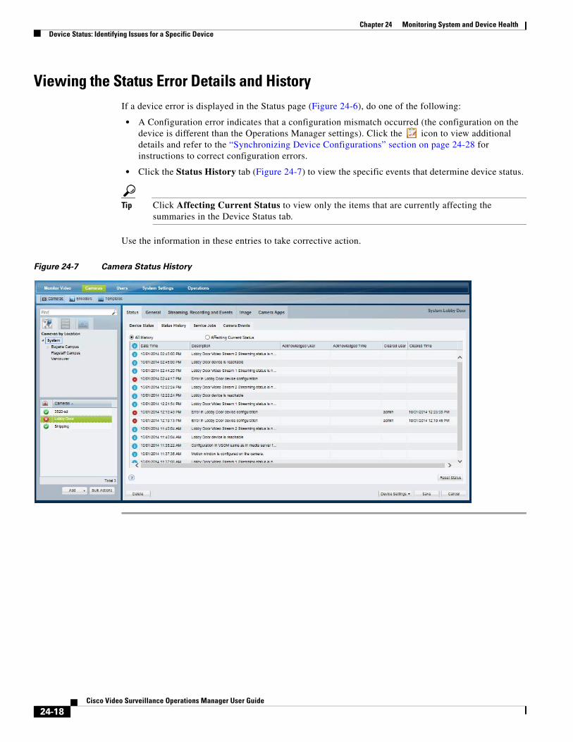
Chapter 24 Monitoring System and Device Health Device Status: Identifying Issues for a Specific Device
Viewing the Status Error Details and HistoryIf a device error is displayed in the Status page (Figure 24-6), do one of the following:
• A Configuration error indicates that a configuration mismatch occurred (the configuration on the device is different than the Operations Manager settings). Click the icon to view additional details and refer to the “Synchronizing Device Configurations” section on page 24-28 for instructions to correct configuration errors.
• Click the Status History tab (Figure 24-7) to view the specific events that determine device status.
Tip Click Affecting Current Status to view only the items that are currently affecting the summaries in the Device Status tab.
Use the information in these entries to take corrective action.
Figure 24-7 Camera Status History
24-18Cisco Video Surveillance Operations Manager User Guide
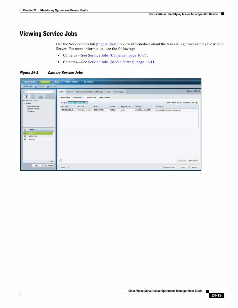
Chapter 24 Monitoring System and Device HealthDevice Status: Identifying Issues for a Specific Device
Viewing Service JobsUse the Service Jobs tab (Figure 24-8) to view information about the tasks being processed by the Media Server. For more information, see the following:
• Cameras—See Service Jobs (Cameras), page 10-77.
• Cameras—See Service Jobs (Media Server), page 11-11.
Figure 24-8 Camera Service Jobs
24-19Cisco Video Surveillance Operations Manager User Guide
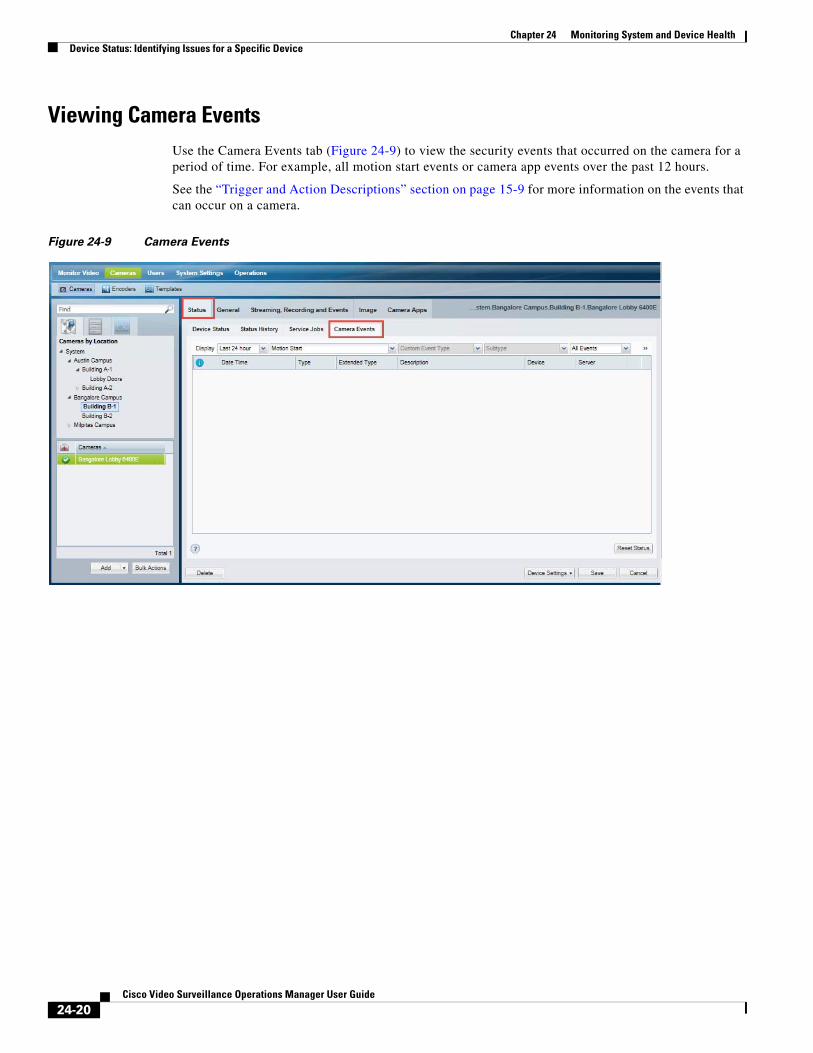
Chapter 24 Monitoring System and Device Health Device Status: Identifying Issues for a Specific Device
Viewing Camera EventsUse the Camera Events tab (Figure 24-9) to view the security events that occurred on the camera for a period of time. For example, all motion start events or camera app events over the past 12 hours.
See the “Trigger and Action Descriptions” section on page 15-9 for more information on the events that can occur on a camera.
Figure 24-9 Camera Events
24-20Cisco Video Surveillance Operations Manager User Guide
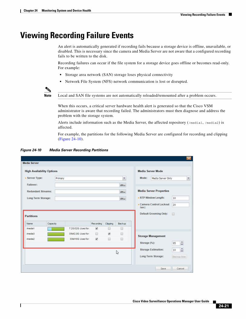
Chapter 24 Monitoring System and Device HealthViewing Recording Failure Events
Viewing Recording Failure EventsAn alert is automatically generated if recording fails because a storage device is offline, unavailable, or disabled. This is necessary since the camera and Media Server are not aware that a configured recording fails to be written to the disk.
Recording failures can occur if the file system for a storage device goes offline or becomes read-only. For example:
• Storage area network (SAN) storage loses physical connectivity
• Network File System (NFS) network communication is lost or disrupted.
Note Local and SAN file systems are not automatically reloaded/remounted after a problem occurs.
When this occurs, a critical server hardware health alert is generated so that the Cisco VSM administrator is aware that recording failed. The administrators must then diagnose and address the problem with the storage system.
Alerts include information such as the Media Server, the affected repository (/media1, /media2) is affected.
For example, the partitions for the following Media Server are configured for recording and clipping (Figure 24-10).
Figure 24-10 Media Server Recording Partitions
24-21Cisco Video Surveillance Operations Manager User Guide
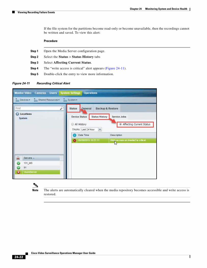
Chapter 24 Monitoring System and Device Health Viewing Recording Failure Events
If the file system for the partitions become read-only or become unavailable, then the recordings cannot be written and saved. To view this alert:
Procedure
Step 1 Open the Media Server configuration page.
Step 2 Select the Status > Status History tabs
Step 3 Select Affecting Current Status.
Step 4 The “write access is critical” alert appears (Figure 24-11).
Step 5 Double-click the entry to view more information.
Figure 24-11 Recording Critical Alert
Note The alerts are automatically cleared when the media repository becomes accessible and write access is restored.
24-22Cisco Video Surveillance Operations Manager User Guide
Chapter 24 Monitoring System and Device HealthSending Alert Emails (Notification Policies)
Sending Alert Emails (Notification Policies)Notification policies are emails sent to one or more users when a health or security event occurs.
• Health events with a critical or warning severity can be sent. These events impact the device operation or renders a component unusable. For example, a Media Server that cannot be contacted on the network, or a camera that does not stream or record video. Configuration errors do not trigger health notification emails.
• Security events can be sent based on the rules you apply. Security events can also be sent for a location, or for a set of cameras.
Usage Notes
• Emails are sent using the SMTP server address configured for the Operations Manager server.
– The SMTP server settings must be accurate or the emails will not be sent (no error or warning is given.
– See the “SMTP Management Settings” section on page 8-34 for more information.
• The maximum number of policies is 1000.
• Health Notification policies are created for a location. If a critical or warning device health error occurs for any device at that location (or sub-location), an email is sent to the specified recipients).
• Email recipients can be specified for different locations (and sub-locations) by creating a new Health Notification rule. Health Notifications operate independently so the recipient will receive emails for each rule, even if the notifications are for the same issue.
• Use the Initial Time and Wait Time as described in Table 24-5 to avoid unnecessary notifications.
• The Media Server and camera should be time synced or a mismatch between the event and snapshot can occur.
Additional Usage Notes in HA Setups
• For deployments that use Operations Manager high availability, the server hostname/address included in the notification is the virtual IP address/hostname. See Operations Manager High Availability, page 23-1.
• If emails stop after a failover occurs, you must delete and re-add the email alert notification policies.
More information
• Event Types, page 24-4
• Health Dashboard: Device Health Faults on an Operations Manager, page 24-7
• Device Status: Identifying Issues for a Specific Device, page 24-13
Procedure
Step 1 Verify that the SMTP server settings are configured correctly in the Operations Manager server (under the Advanced icon).
See the “SMTP Management Settings” section on page 8-34 for more information.
Step 2 (Security events only) Configure Alerts (using the Advanced Alert feature) for the security event types described in Table 24-6.
See Using Advanced Events to Trigger Actions, page 15-7 for more information.
24-23Cisco Video Surveillance Operations Manager User Guide
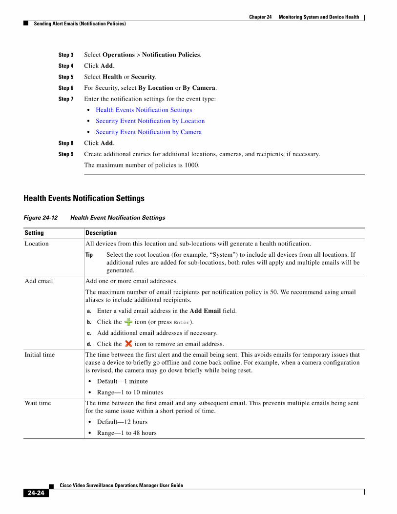
Chapter 24 Monitoring System and Device Health Sending Alert Emails (Notification Policies)
Step 3 Select Operations > Notification Policies.
Step 4 Click Add.
Step 5 Select Health or Security.
Step 6 For Security, select By Location or By Camera.
Step 7 Enter the notification settings for the event type:
• Health Events Notification Settings
• Security Event Notification by Location
• Security Event Notification by Camera
Step 8 Click Add.
Step 9 Create additional entries for additional locations, cameras, and recipients, if necessary.
The maximum number of policies is 1000.
Health Events Notification Settings
Figure 24-12 Health Event Notification Settings
Setting Description
Tip Select the root location (for example, “System”) to include all devices from all locations. If additional rules are added for sub-locations, both rules will apply and multiple emails will be generated.
Enter a valid email address in the Add Email field.a.
Click the b. icon (or press Enter).
Add additional email addresses if necessary.c.
Click the d. icon to remove an email address.
• Default—1 minute
• Range—1 to 10 minutes
• Default—12 hours
• Range—1 to 48 hours
Location All devices from this location and sub-locations will generate a health notification.
Add email Add one or more email addresses.
The maximum number of email recipients per notification policy is 50. We recommend using email aliases to include additional recipients.
Initial time The time between the first alert and the email being sent. This avoids emails for temporary issues that cause a device to briefly go offline and come back online. For example, when a camera configuration is revised, the camera may go down briefly while being reset.
Wait time The time between the first email and any subsequent email. This prevents multiple emails being sent for the same issue within a short period of time.
24-24Cisco Video Surveillance Operations Manager User Guide
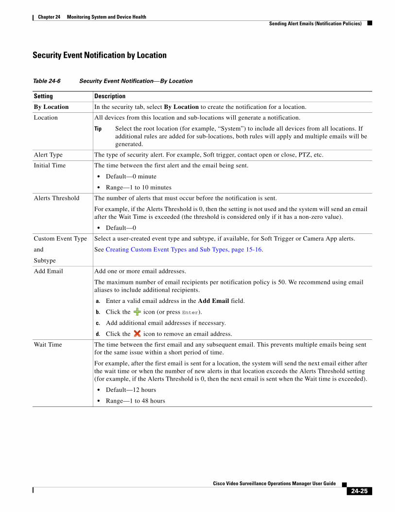
Chapter 24 Monitoring System and Device HealthSending Alert Emails (Notification Policies)
Security Event Notification by Location
Table 24-6 Security Event Notification—By Location
Setting Description
Tip Select the root location (for example, “System”) to include all devices from all locations. If additional rules are added for sub-locations, both rules will apply and multiple emails will be generated.
• Default—0 minute
• Range—1 to 10 minutes
• Default—0
Enter a valid email address in the Add Email field.a.
Click the b. icon (or press Enter).
Add additional email addresses if necessary.c.
Click the d. icon to remove an email address.
• Default—12 hours
• Range—1 to 48 hours
By Location In the security tab, select By Location to create the notification for a location.
Location All devices from this location and sub-locations will generate a notification.
Alert Type The type of security alert. For example, Soft trigger, contact open or close, PTZ, etc.
Initial Time The time between the first alert and the email being sent.
Alerts Threshold The number of alerts that must occur before the notification is sent.
For example, if the Alerts Threshold is 0, then the setting is not used and the system will send an email after the Wait Time is exceeded (the threshold is considered only if it has a non-zero value).
Custom Event Type
and
Subtype
Select a user-created event type and subtype, if available, for Soft Trigger or Camera App alerts.
See Creating Custom Event Types and Sub Types, page 15-16.
Add Email Add one or more email addresses.
The maximum number of email recipients per notification policy is 50. We recommend using email aliases to include additional recipients.
Wait Time The time between the first email and any subsequent email. This prevents multiple emails being sent for the same issue within a short period of time.
For example, after the first email is sent for a location, the system will send the next email either after the wait time or when the number of new alerts in that location exceeds the Alerts Threshold setting (for example, if the Alerts Threshold is 0, then the next email is sent when the Wait time is exceeded).
24-25Cisco Video Surveillance Operations Manager User Guide
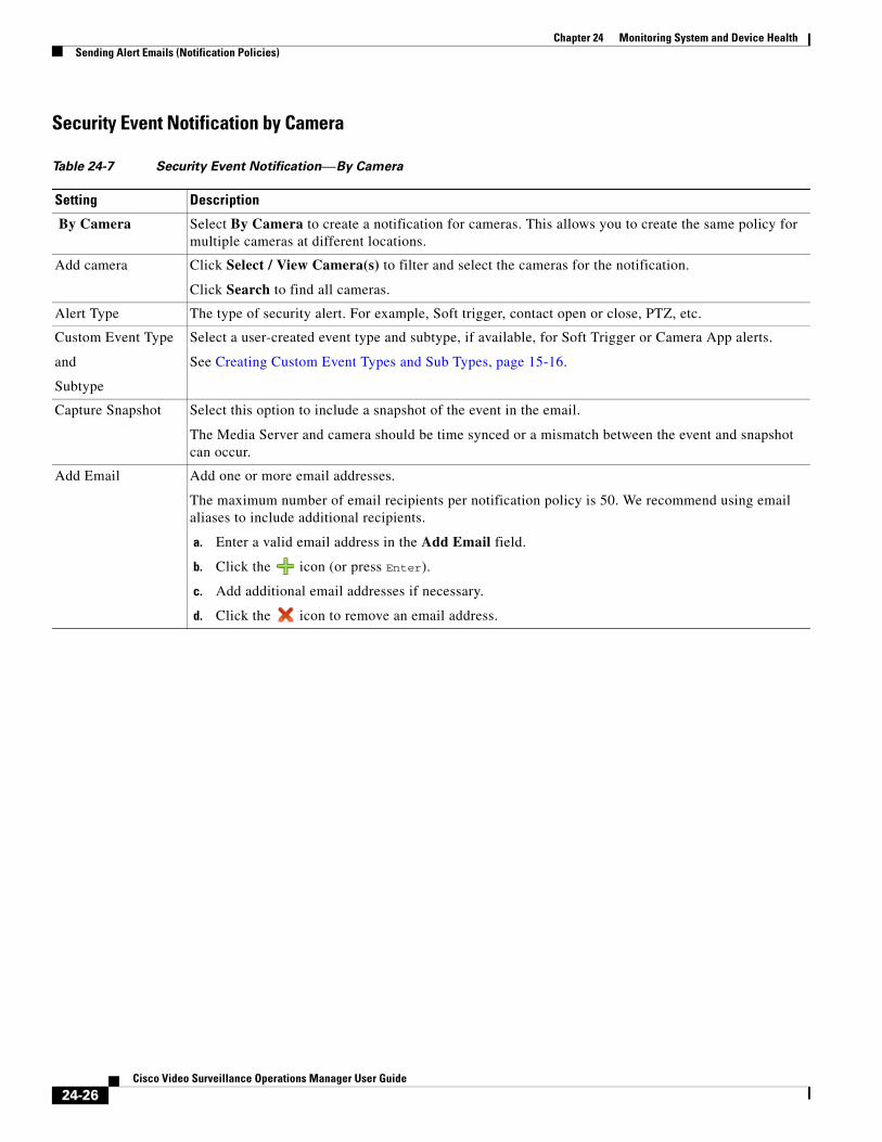
Chapter 24 Monitoring System and Device Health Sending Alert Emails (Notification Policies)
Security Event Notification by Camera
Table 24-7 Security Event Notification—By Camera
Setting Description
Enter a valid email address in the Add Email field.a.
Click the b. icon (or press Enter).
Add additional email addresses if necessary.c.
Click the d. icon to remove an email address.
By Camera Select By Camera to create a notification for cameras. This allows you to create the same policy for multiple cameras at different locations.
Add camera Click Select / View Camera(s) to filter and select the cameras for the notification.
Click Search to find all cameras.
Alert Type The type of security alert. For example, Soft trigger, contact open or close, PTZ, etc.
Custom Event Type
and
Subtype
Select a user-created event type and subtype, if available, for Soft Trigger or Camera App alerts.
See Creating Custom Event Types and Sub Types, page 15-16.
Capture Snapshot Select this option to include a snapshot of the event in the email.
The Media Server and camera should be time synced or a mismatch between the event and snapshot can occur.
Add Email Add one or more email addresses.
The maximum number of email recipients per notification policy is 50. We recommend using email aliases to include additional recipients.
24-26Cisco Video Surveillance Operations Manager User Guide
Chapter 24 Monitoring System and Device HealthReports
ReportsUse Reports to generate and download summary information about the Cisco Video Surveillance user activity, device configuration. For example, you can create Audit reports that summarize user actions, or camera and Media Server reports that summarize device configuration and status.
• Create a Report, page 24-27
• Delete a Report, page 24-27
Create a Report
Procedure
Step 1 Select Operations > Reports.
Step 2 Create one or more reports.
a. Click Add.
b. Select the General settings and click Next.
– Report Type—The device or user information to be included in the report. For example, you can create an Audit, Streaming, Active Users, All Users, Template Reports, Camera, Encoder, or Media Server report.
– Report Format—The file format for the downloadable report. For example, a CSV Format (comma-separated value) file.
c. Select the report Filters and click Next.
For example, you can include cameras based on the camera name, the Media Server associated with the camera, template assigned to the camera(s), etc. A streaming report can include a time range and details when the live or recorded stream stopped or started.
d. Use the Preview window to select or deselect the devices or users to be included in the report.
e. Click Finish.
f. Wait for the report to be generated, and then click Close.
Step 3 Select one or more reports from the list and click Download.
Delete a Report
Procedure
Step 1 Select Operations > Reports.
Step 2 Select the check-box for one or more existing reports.
Tip Click the select all box to remove all reports.
24-27Cisco Video Surveillance Operations Manager User Guide
Chapter 24 Monitoring System and Device Health Synchronizing Device Configurations
Step 3 Click Download and confirm the deletion.
Synchronizing Device ConfigurationsDevice synchronization ensures that the device configuration on the Media Server, camera or encoder is identical to the Operations Manager settings. Synchronization also ensures that no device has the same unique ID (such as a MAC address) as another device. Synchronization is automatically performed when certain events occur, such as when a Media Server goes offline and comes back online, when the Operations Manager is restarted, when drivers are upgraded, and other events.
Synchronization errors can be resolved either automatically, or manually. Refer to the following topics for more information:
• Overview, page 24-28
• Viewing Device Synchronization Errors, page 24-30
• Understanding Device Configuration Mismatch Caused by Media Server Issues, page 24-31
• Repairing a Mismatched Configuration, page 24-32
• Manually Triggering a Media Server Synchronization, page 24-33
• Device Data That Is Synchronized, page 24-33
• Synchronization During a Media Server Migration, page 24-34
OverviewThe Operations Manager configuration is the master configuration(Figure 24-13). A mismatch occurs if the configuration on the Media Server is different.
For example, if a synchronization event determines that the setting for a camera’s video resolution is different between the Operations Manager and the Media Server, a configuration mismatch occurs.
• If the Autocorrect Synchronization Errors system setting is enabled, the configuration is automatically replaced with the Operations Manager setting.
• If the Autocorrect Synchronization Errors system setting is disabled, a configuration error is displayed on the camera Status page. Click the icon to view additional details about the mismatch and then select Repair Configurations or Replace Configurations from the Device Settings menu to replace the camera setting with the Operations Manager setting. See the following for more information:
– Device Status: Identifying Issues for a Specific Device, page 24-13
– Synchronizing Device Configurations, page 24-28
24-28Cisco Video Surveillance Operations Manager User Guide
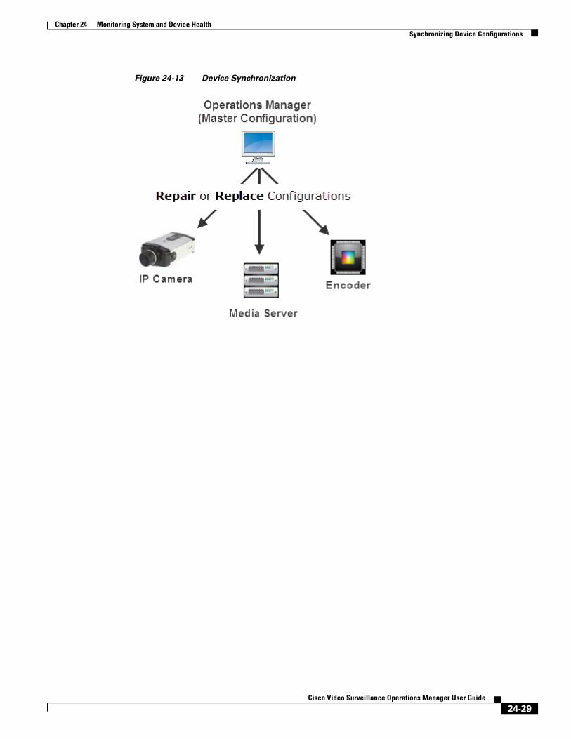
Chapter 24 Monitoring System and Device HealthSynchronizing Device Configurations
Figure 24-13 Device Synchronization
24-29Cisco Video Surveillance Operations Manager User Guide

Chapter 24 Monitoring System and Device Health Synchronizing Device Configurations
Viewing Device Synchronization ErrorsA configuration error appears on the device Status page if a synchronization error is not automatically corrected. To view details about the error, open the device Status page.
Procedure
Step 1 Open the device configuration page:
• Click Cameras and select a camera or encoder
or
• Click System Settings > Media Server and select a Media Server.
Step 2 Click the device Status tab.
Step 3 Click the icon next to Configuration (Figure 24-14).
Note The icon appears only if a configuration error occurred.
Figure 24-14 Camera Configuration Mismatch
24-30Cisco Video Surveillance Operations Manager User Guide
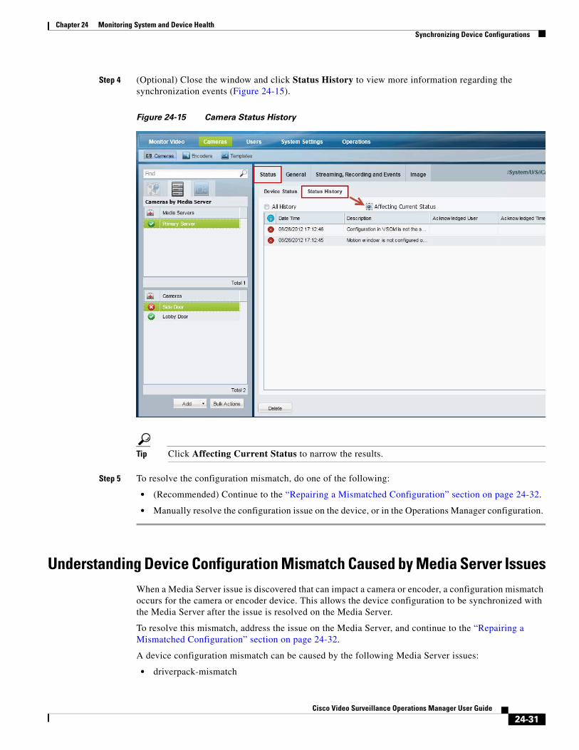
Chapter 24 Monitoring System and Device HealthSynchronizing Device Configurations
Step 4 (Optional) Close the window and click Status History to view more information regarding the synchronization events (Figure 24-15).
Figure 24-15 Camera Status History
Tip Click Affecting Current Status to narrow the results.
Step 5 To resolve the configuration mismatch, do one of the following:
• (Recommended) Continue to the “Repairing a Mismatched Configuration” section on page 24-32.
• Manually resolve the configuration issue on the device, or in the Operations Manager configuration.
Understanding Device Configuration Mismatch Caused by Media Server IssuesWhen a Media Server issue is discovered that can impact a camera or encoder, a configuration mismatch occurs for the camera or encoder device. This allows the device configuration to be synchronized with the Media Server after the issue is resolved on the Media Server.
To resolve this mismatch, address the issue on the Media Server, and continue to the “Repairing a Mismatched Configuration” section on page 24-32.
A device configuration mismatch can be caused by the following Media Server issues:
• driverpack-mismatch
24-31Cisco Video Surveillance Operations Manager User Guide
Chapter 24 Monitoring System and Device Health Synchronizing Device Configurations
• reachability
• software-mismatch
• server-pool-config-mismatch
• ntp-config-mismatch
• identity-mistmatch
• schedule-config-mismatch
Repairing a Mismatched ConfigurationSelect Device Settings > Repair Configurations or Device Settings > Replace Configurations (in a device configuration page) to manually replace the device configuration with the Operations Manager settings.
Note Devices include the Media Servers, encoders and cameras.
Procedure
Step 1 (Optional) Review the configuration mismatch errors, as described in the “Viewing Device Synchronization Errors” section on page 24-30.
Step 2 Select the device configuration General tab.
Step 3 Click one of the following options.
• Replace Configurations—Pushes the entire device configuration from the Operations Manager to the Media Server. The Media Server data is replaced.
• Repair Configurations—Pushes only the configuration changes required correct a mismatched field. Changes are pushed from the Operations Manager to the Media Server.
Step 4 (Optional) Complete the following optional troubleshooting steps:
• Wait for the synchronization Job to complete. In the Job window, click View Status to view any failed steps and click the error message to view additional information. See the “Understanding Jobs and Job Status” section on page 24-36 for more information.
• Open the Status page for the affected device to view additional details and take corrective action, if necessary. See the “Viewing Device Synchronization Errors” section on page 24-30.
24-32Cisco Video Surveillance Operations Manager User Guide
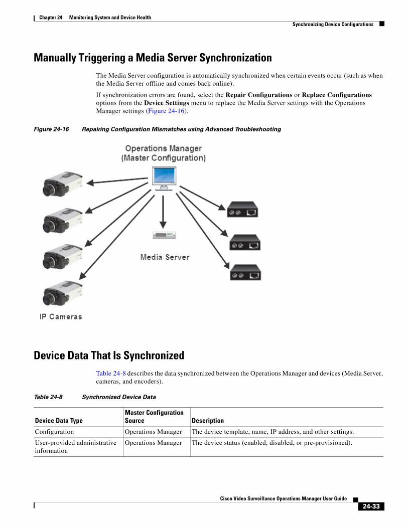
Chapter 24 Monitoring System and Device HealthSynchronizing Device Configurations
Manually Triggering a Media Server SynchronizationThe Media Server configuration is automatically synchronized when certain events occur (such as when the Media Server offline and comes back online).
If synchronization errors are found, select the Repair Configurations or Replace Configurations options from the Device Settings menu to replace the Media Server settings with the Operations Manager settings (Figure 24-16).
Figure 24-16 Repairing Configuration Mismatches using Advanced Troubleshooting
Device Data That Is SynchronizedTable 24-8 describes the data synchronized between the Operations Manager and devices (Media Server, cameras, and encoders).
Table 24-8 Synchronized Device Data
Device Data TypeMaster Configuration Source Description
Configuration Operations Manager The device template, name, IP address, and other settings.
User-provided administrative information
Operations Manager The device status (enabled, disabled, or pre-provisioned).
24-33Cisco Video Surveillance Operations Manager User Guide
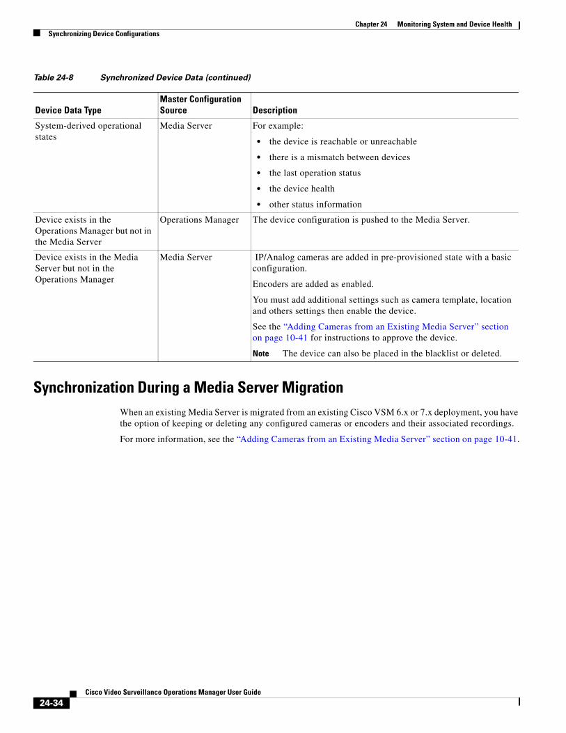
Chapter 24 Monitoring System and Device Health Synchronizing Device Configurations
Synchronization During a Media Server Migration When an existing Media Server is migrated from an existing Cisco VSM 6.x or 7.x deployment, you have the option of keeping or deleting any configured cameras or encoders and their associated recordings.
For more information, see the “Adding Cameras from an Existing Media Server” section on page 10-41.
System-derived operational states
Media Server For example:
• the device is reachable or unreachable
• there is a mismatch between devices
• the last operation status
• the device health
• other status information
Device exists in the Operations Manager but not in the Media Server
Operations Manager The device configuration is pushed to the Media Server.
Device exists in the Media Server but not in the Operations Manager
Media Server IP/Analog cameras are added in pre-provisioned state with a basic configuration.
Encoders are added as enabled.
You must add additional settings such as camera template, location and others settings then enable the device.
See the “Adding Cameras from an Existing Media Server” section on page 10-41 for instructions to approve the device.
Note The device can also be placed in the blacklist or deleted.
Table 24-8 Synchronized Device Data (continued)
Device Data TypeMaster Configuration Source Description
24-34Cisco Video Surveillance Operations Manager User Guide

Chapter 24 Monitoring System and Device HealthViewing the Server Management Console Status and Logs
Viewing the Server Management Console Status and LogsThe Cisco Video Surveillance Management Console is a browser-based interface that provides additional monitoring and troubleshooting features for the physical server that runs both the Operations Manager and Media Server.
To access the Management Console, click System Settings > Management Console.
See the Cisco Video Surveillance Management Console Administration Guide for more information.
24-35Cisco Video Surveillance Operations Manager User Guide
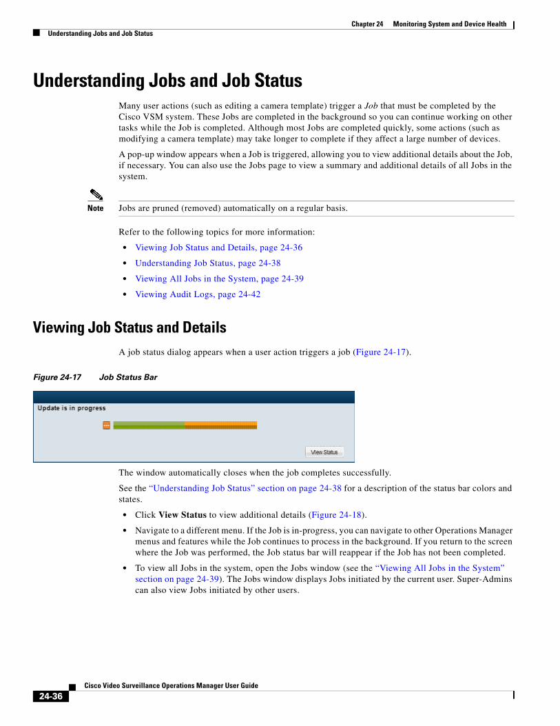
Chapter 24 Monitoring System and Device Health Understanding Jobs and Job Status
Understanding Jobs and Job Status Many user actions (such as editing a camera template) trigger a Job that must be completed by the Cisco VSM system. These Jobs are completed in the background so you can continue working on other tasks while the Job is completed. Although most Jobs are completed quickly, some actions (such as modifying a camera template) may take longer to complete if they affect a large number of devices.
A pop-up window appears when a Job is triggered, allowing you to view additional details about the Job, if necessary. You can also use the Jobs page to view a summary and additional details of all Jobs in the system.
Note Jobs are pruned (removed) automatically on a regular basis.
Refer to the following topics for more information:
• Viewing Job Status and Details, page 24-36
• Understanding Job Status, page 24-38
• Viewing All Jobs in the System, page 24-39
• Viewing Audit Logs, page 24-42
Viewing Job Status and DetailsA job status dialog appears when a user action triggers a job (Figure 24-17).
Figure 24-17 Job Status Bar
The window automatically closes when the job completes successfully.
See the “Understanding Job Status” section on page 24-38 for a description of the status bar colors and states.
• Click View Status to view additional details (Figure 24-18).
• Navigate to a different menu. If the Job is in-progress, you can navigate to other Operations Manager menus and features while the Job continues to process in the background. If you return to the screen where the Job was performed, the Job status bar will reappear if the Job has not been completed.
• To view all Jobs in the system, open the Jobs window (see the “Viewing All Jobs in the System” section on page 24-39). The Jobs window displays Jobs initiated by the current user. Super-Admins can also view Jobs initiated by other users.
24-36Cisco Video Surveillance Operations Manager User Guide
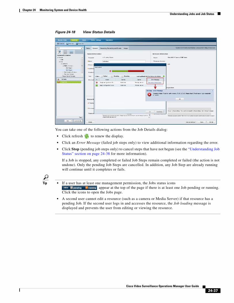
Chapter 24 Monitoring System and Device HealthUnderstanding Jobs and Job Status
Figure 24-18 View Status Details
You can take one of the following actions from the Job Details dialog:
• Click refresh to renew the display.
• Click an Error Message (failed job steps only) to view additional information regarding the error.
• Click Stop (pending job steps only) to cancel steps that have not begun (see the “Understanding Job Status” section on page 24-38 for more information).
If a Job is stopped, any completed or failed Job Steps remain completed or failed (the action is not undone). Only the pending Job Steps are cancelled. In addition, any Job Step are already running will continue until it completes or fails.
Tip • If a user has at least one management permission, the Jobs status icons appear at the top of the page if there is at least one Job pending or running.
Click the icons to open the Jobs page.
• A second user cannot edit a resource (such as a camera or Media Server) if that resource has a pending Job. If the second user logs in and accesses the resource, the Job loading message is displayed and prevents the user from editing or viewing the resource.
24-37Cisco Video Surveillance Operations Manager User Guide
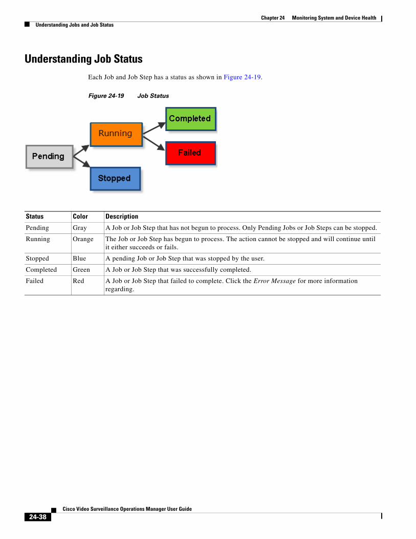
Chapter 24 Monitoring System and Device Health Understanding Jobs and Job Status
Understanding Job StatusEach Job and Job Step has a status as shown in Figure 24-19.
Figure 24-19 Job Status
Status Color Description
Pending Gray A Job or Job Step that has not begun to process. Only Pending Jobs or Job Steps can be stopped.
Running Orange The Job or Job Step has begun to process. The action cannot be stopped and will continue until it either succeeds or fails.
Stopped Blue A pending Job or Job Step that was stopped by the user.
Completed Green A Job or Job Step that was successfully completed.
Failed Red A Job or Job Step that failed to complete. Click the Error Message for more information regarding.
24-38Cisco Video Surveillance Operations Manager User Guide
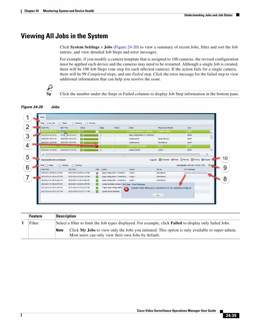
Chapter 24 Monitoring System and Device HealthUnderstanding Jobs and Job Status
Viewing All Jobs in the SystemClick System Settings > Jobs (Figure 24-20) to view a summary of recent Jobs, filter and sort the Job entries, and view detailed Job Steps and error messages.
For example, if you modify a camera template that is assigned to 100 cameras, the revised configuration must be applied each device and the cameras may need to be restarted. Although a single Job is created, there will be 100 Job Steps (one step for each affected camera). If the action fails for a single camera, there will be 99 Completed steps, and one Failed step. Click the error message for the failed step to view additional information that can help you resolve the issue.
Tip Click the number under the Steps or Failed columns to display Job Step information in the bottom pane.
Figure 24-20 Jobs
Feature Description
1 Filter Select a filter to limit the Job types displayed. For example, click Failed to display only failed Jobs.
Note Click My Jobs to view only the Jobs you initiated. This option is only available to super-admin. Most users can only view their own Jobs by default.
24-39Cisco Video Surveillance Operations Manager User Guide

Chapter 24 Monitoring System and Device Health Understanding Jobs and Job Status
2 Job events Lists the Jobs in the system. Use the filter to narrow the Jobs displayed, or click the column headings to sort the information.
Note The Job list automatically refreshes to display up-to date status information.
Each Job includes the following information:
• Start Time—The date and time when the Job was initiated by the user.
• End Time—The date and time when the Job ended. A Job can end when it is completed or fails. Jobs with at least one pending Job Step can be stopped (click the Stop button). See the “Understanding Job Status” section on page 24-38 for more information.
• Status—Indicates the Job status. Refer to the legend for a description of each color. See the “Understanding Job Status” section on page 24-38.
• Steps—The number of Job Steps required to complete the Job. Click the number to display the step details in the bottom pane.
• Failed—The number of Failed Job Steps. Click the number to display only the failed Job Steps in the bottom pane.
• Action—The action or system change performed by the Job.
• Resources Affected—The resources affected by the Job. For example, name of the Media Server or the template that is modified by the Job.
• User—The user who triggered the Job.
3 Job Double-click a job to display the sub-steps for that job.
If the job is still in progress, click Stop to cancel the job, if available.
4 Steps The number of steps for the job. Click the number to display the sub-steps (you can also double-click the job entry).
5 Job Steps The sub-steps for a Job (click the Steps number or double-click a job entry).
6 Job Steps filter
Select a filter to limit the steps displayed.
For example, click Running to display only Job Steps that are still in progress.
7 Job Steps detail
Lists each sub-step that is performed for the selected Job. Click the number under the Step or Failed column to display the steps for a Job.
Note The Job Step list does not automatically refresh. Click the refresh icon to renew the display and view up-to-date information.
Use the filter to narrow the Jobs steps displayed, or click the column headings to sort the information. Each Job Step includes the following information:
• Start Time—The date and time when the step began to process.
• End Time—The date and time when the step ended. A step can end when it is completed or fails.
• Status—Indicates the Job Step status. Refer to the legend for a description of each color. See the “Understanding Job Status” section on page 24-38.
• Action—The action or system change performed by the Job Step.
• Device—The resources affected by the Job Step. For example, a camera.
• Server—The server affected by the Job Step.
8 Error Message
The reason for a job step error. This is displayed only if an error occurred.
Click the error message to display additional details.
24-40Cisco Video Surveillance Operations Manager User Guide

Chapter 24 Monitoring System and Device HealthUnderstanding Jobs and Job Status
9 Refresh icon Click the refresh icon to renew the display and view up-to-date Job Step status.
9 Legend Describes the meaning of each status color. For example, a green Job status bar means the Job was successfully completed.
See the “Understanding Job Status” section on page 24-38 for more information.
24-41Cisco Video Surveillance Operations Manager User Guide
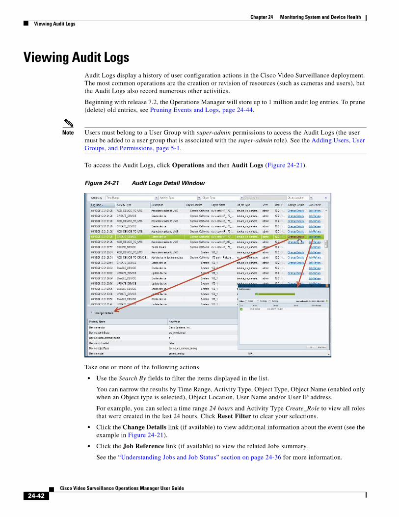
Chapter 24 Monitoring System and Device Health Viewing Audit Logs
Viewing Audit Logs Audit Logs display a history of user configuration actions in the Cisco Video Surveillance deployment. The most common operations are the creation or revision of resources (such as cameras and users), but the Audit Logs also record numerous other activities.
Beginning with release 7.2, the Operations Manager will store up to 1 million audit log entries. To prune (delete) old entries, see Pruning Events and Logs, page 24-44.
Note Users must belong to a User Group with super-admin permissions to access the Audit Logs (the user must be added to a user group that is associated with the super-admin role). See the Adding Users, User Groups, and Permissions, page 5-1.
To access the Audit Logs, click Operations and then Audit Logs (Figure 24-21).
Figure 24-21 Audit Logs Detail Window
Take one or more of the following actions
• Use the Search By fields to filter the items displayed in the list.
You can narrow the results by Time Range, Activity Type, Object Type, Object Name (enabled only when an Object type is selected), Object Location, User Name and/or User IP address.
For example, you can select a time range 24 hours and Activity Type Create_Role to view all roles that were created in the last 24 hours. Click Reset Filter to clear your selections.
• Click the Change Details link (if available) to view additional information about the event (see the example in Figure 24-21).
• Click the Job Reference link (if available) to view the related Jobs summary.
See the “Understanding Jobs and Job Status” section on page 24-36 for more information.
24-42Cisco Video Surveillance Operations Manager User Guide
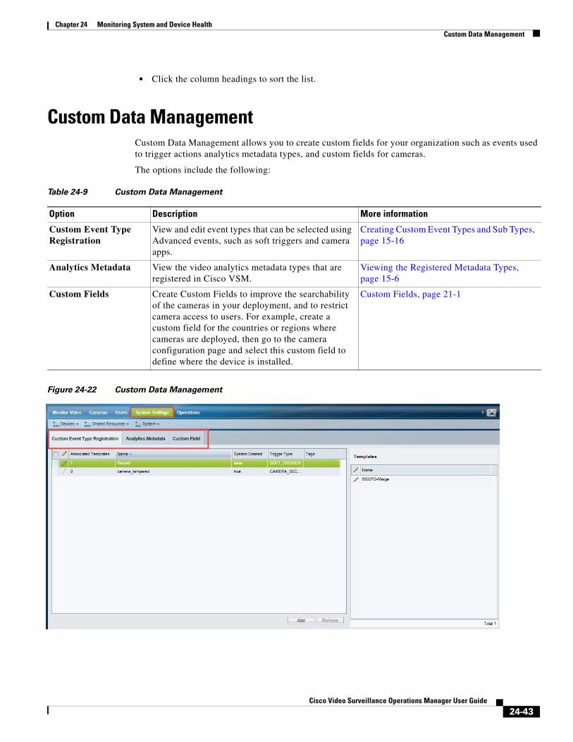
Chapter 24 Monitoring System and Device HealthCustom Data Management
• Click the column headings to sort the list.
Custom Data ManagementCustom Data Management allows you to create custom fields for your organization such as events used to trigger actions analytics metadata types, and custom fields for cameras.
The options include the following:
Table 24-9 Custom Data Management
Option Description More information
Figure 24-22 Custom Data Management
Custom Event Type Registration
View and edit event types that can be selected using Advanced events, such as soft triggers and camera apps.
Creating Custom Event Types and Sub Types, page 15-16
Analytics Metadata View the video analytics metadata types that are registered in Cisco VSM.
Viewing the Registered Metadata Types, page 15-6
Custom Fields Create Custom Fields to improve the searchability of the cameras in your deployment, and to restrict camera access to users. For example, create a custom field for the countries or regions where cameras are deployed, then go to the camera configuration page and select this custom field to define where the device is installed.
Custom Fields, page 21-1
24-43Cisco Video Surveillance Operations Manager User Guide

Chapter 24 Monitoring System and Device Health Pruning Events and Logs
Pruning Events and LogsYou can prune (delete) old records (such as event, alert, and audit logs) to remove unneeded information and free up disk space.
Procedure
Step 1 Click Operations > Prune History.
Step 2 Select the history type. For example, events, alerts, and/or audit logs.
Step 3 Click Prune.
Step 4 Click the date field and select a date.
• The date cannot be the current or future date.
• The date must be on or after the oldest prunable entry time.
Step 5 Click OK to delete the records from the selected day and before.
Tip The pruning action along with the History type and selected date is displayed in Operations > Audit Logs.
24-44Cisco Video Surveillance Operations Manager User Guide
Cisco V
C H A P T E R 25
Troubleshooting Devices and JobsChoose Operations > Troubleshooting (Figure 25-1). to view issues with jobs and devices in your deployment. You can clear the jobs status, or delete devices (such as cameras and encoders).
For example, use the Troubleshoot feature to:
• Force delete cameras or encoders that are stuck and cannot be deleted using the camera configuration page (see Deleting Cameras, page 10-69). For example, if the Cisco Media Server is unavailable, you can force delete the camera, encoder or analog camera to remove the device and configuration from Cisco VSM.
• Remove device configuration problems, such as orphaned cameras or encoders in the Cisco Media Server/Operations Manager database.
• Clear jobs that are stuck and not failing.
Procedure
Step 1 Select Operations > Troubleshoot (Figure 25-1).
Step 2 Select an option from the tabs on the top left, such as Jobs, Cameras, or Encoders.
Step 3 Select the filters to narrow the list of results.
For jobs, you must select either Running or Pending.
Step 4 Click Search.
Step 5 Select one or more items from the resulting list and select an action, such as Clear Jobs, Delete Cameras, or Delete Encoders.
25-1ideo Surveillance Operations Manager User Guide

Chapter 25 Troubleshooting Devices and Jobs
Figure 25-1 Troubleshooting
25-2Cisco Video Surveillance Operations Manager User Guide
Cisco V
C H A P T E R 26
Revising the System SettingsChoose System Settings > Settings to define basic parameters for the Operations Manager and Federator.
Note • The default settings are sufficient for a basic setup, but you should review and revise the settings to meet the needs of your deployment. System settings can only be modified by super-admin users.
• The Federator settings are a sub-set of the Operations Manager settings.
• Beginning with release 7.2, retention of alerts, events and audit log entries is now managed automatically by the Operations Manager, which can store up to 1 million alerts, 1 million events, and 1 million audit log entries.
Contents
Refer to the following topics for more information:
• General System Settings, page 26-2
• Password Settings, page 26-4
• Language Settings, page 26-5
• Alert Severity, page 26-6
• Storage Retention Settings, page 26-7
26-1ideo Surveillance Operations Manager User Guide
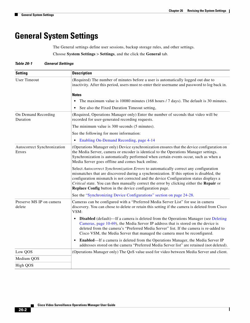
Chapter 26 Revising the System Settings General System Settings
General System SettingsThe General settings define user sessions, backup storage rules, and other settings.
Choose System Settings > Settings, and the click the General tab.
Table 26-1 General Settings
Setting Description
User Timeout (Required) The number of minutes before a user is automatically logged out due to inactivity. After this period, users must re-enter their username and password to log back in.
Notes
• The maximum value is 10080 minutes (168 hours / 7 days). The default is 30 minutes.
• See also the Fixed Duration Timeout setting,
On Demand Recording Duration
(Required, Operations Manager only) Enter the number of seconds that video will be recorded for user-generated recording requests.
The minimum value is 300 seconds (5 minutes).
See the following for more information:
• Enabling On-Demand Recording, page 4-14
Autocorrect Synchronization Errors
(Operations Manager only) Device synchronization ensures that the device configuration on the Media Server, camera or encoder is identical to the Operations Manager settings. Synchronization is automatically performed when certain events occur, such as when a Media Server goes offline and comes back online.
Select Autocorrect Synchronization Errors to automatically correct any configuration mismatches that are discovered during a synchronization. If this option is disabled, the configuration mismatch is not corrected and the device Configuration status displays a Critical state. You can then manually correct the error by clicking either the Repair or Replace Config button in the device configuration page.
See the “Synchronizing Device Configurations” section on page 24-28.
Preserve MS IP on camera delete
Cameras can be configured with a “Preferred Media Server List” for use in camera discovery. You can chose to delete or retain this setting if the camera is deleted from Cisco VSM:
• Disabled (default)—If a camera is deleted from the Operations Manager (see Deleting Cameras, page 10-69), the Media Server IP address that is stored on the device is deleted from the camera’s “Preferred Media Server” list. If the camera is re-added to Cisco VSM, the Media Server that managed the camera must be reconfigured.
• Enabled—If a camera is deleted from the Operations Manager, the Media Server IP addresses stored on the camera “Preferred Media Server list” are retained (not deleted).
Low QOS (Operations Manager only) The QoS value used for video between Media Server and client.
Medium QOS
High QOS
26-2Cisco Video Surveillance Operations Manager User Guide
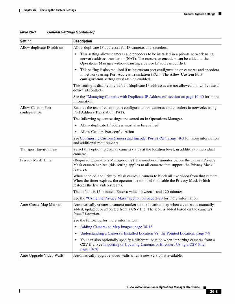
Chapter 26 Revising the System SettingsGeneral System Settings
Allow duplicate IP address Allow duplicate IP addresses for IP cameras and encoders.
• This setting allows cameras and encoders to be installed in a private network using network address translation (NAT). The camera or encoders can be added to the Operations Manager without causing a device IP address conflict.
• This setting is also required if using custom port configuration on cameras and encoders in networks using Port Address Translation (PAT). The Allow Custom Port configuration setting must also be enabled.
This setting is disabled by default (duplicate IP addresses are not allowed and will cause a device id conflict).
See the “Managing Cameras with Duplicate IP Addresses” section on page 10-40 for more information.
Allow Custom Port configuration
Enables the use of custom port configuration on cameras and encoders in networks using Port Address Translation (PAT).
The following system settings are turned on in Operations Manager.
• Allow duplicate IP address must also be enabled
• Allow Custom Port configuration
See Configuring Custom Camera and Encoder Ports (PAT), page 19-3 for more information and additional requirements.
Transport Environment Select this option to display camera status at the location level, in addition to individual cameras.
Privacy Mask Timer (Required, Operations Manager only) The number of minutes before the camera Privacy Mask camera expires (this setting applies to all cameras that support the Privacy Mask feature).
When enabled, the Privacy Mask causes a camera to block all live video from that camera. When the timer expires, the operator is reminded to disable the Privacy Mask (which restores the live video stream).
The default is 15 minutes. Enter a value between 1 and 120 minutes.
See the “Using the Privacy Mask” section on page 2-20 for more information.
Auto Create Map Markers Automatically creates a camera marker on the location map when a camera is manually added, updated, or imported from a CSV file. The icon is added based on the camera’s Install Location.
See the following for more information:
• Adding Cameras to Map Images, page 30-18
• Understanding a Camera’s Installed Location Vs. the Pointed Location, page 7-9
• You can also optionally specify a different location when importing cameras from a CSV file. See Importing or Updating Cameras or Encoders Using a CSV File, page 10-20
Auto Upgrade Video Walls Automatically upgrade video walls when a new version is available.
Table 26-1 General Settings (continued)
Setting Description
26-3Cisco Video Surveillance Operations Manager User Guide
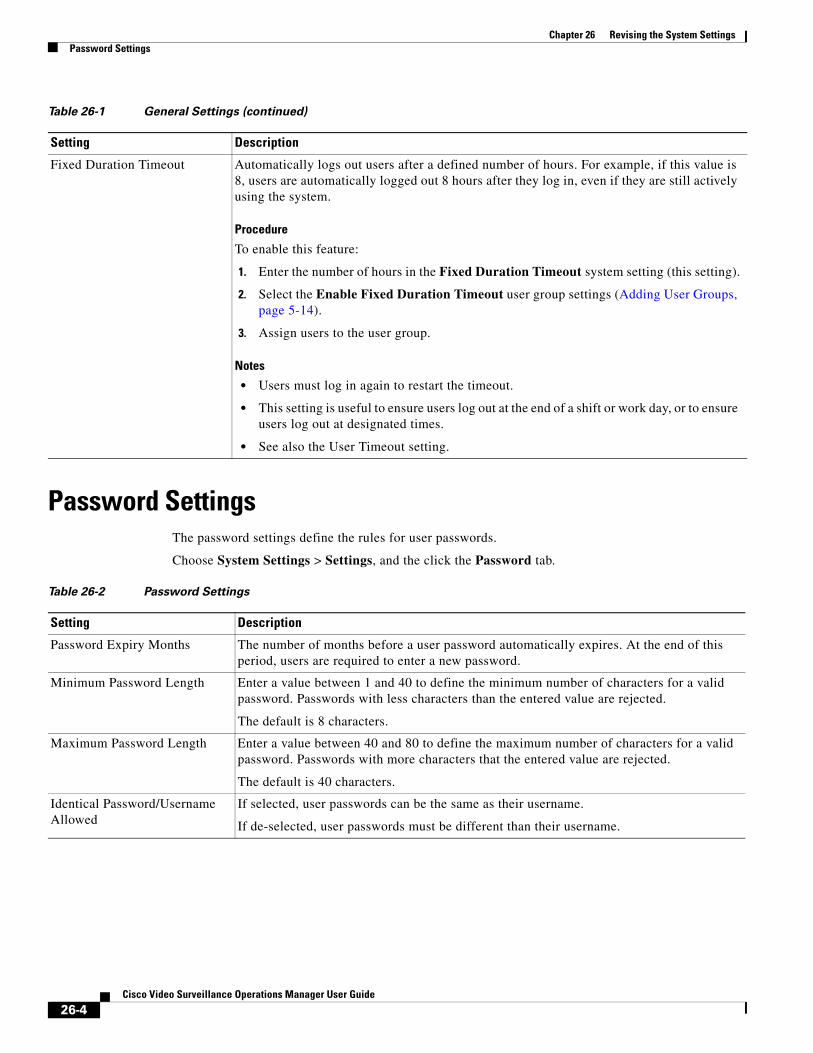
Chapter 26 Revising the System Settings Password Settings
Password SettingsThe password settings define the rules for user passwords.
Choose System Settings > Settings, and the click the Password tab.
Fixed Duration Timeout Automatically logs out users after a defined number of hours. For example, if this value is 8, users are automatically logged out 8 hours after they log in, even if they are still actively using the system.
Procedure
To enable this feature:
1. Enter the number of hours in the Fixed Duration Timeout system setting (this setting).
2. Select the Enable Fixed Duration Timeout user group settings (Adding User Groups, page 5-14).
3. Assign users to the user group.
Notes
• Users must log in again to restart the timeout.
• This setting is useful to ensure users log out at the end of a shift or work day, or to ensure users log out at designated times.
• See also the User Timeout setting.
Table 26-1 General Settings (continued)
Setting Description
Table 26-2 Password Settings
Setting Description
Password Expiry Months The number of months before a user password automatically expires. At the end of this period, users are required to enter a new password.
Minimum Password Length Enter a value between 1 and 40 to define the minimum number of characters for a valid password. Passwords with less characters than the entered value are rejected.
The default is 8 characters.
Maximum Password Length Enter a value between 40 and 80 to define the maximum number of characters for a valid password. Passwords with more characters that the entered value are rejected.
The default is 40 characters.
Identical Password/Username Allowed
If selected, user passwords can be the same as their username.
If de-selected, user passwords must be different than their username.
26-4Cisco Video Surveillance Operations Manager User Guide
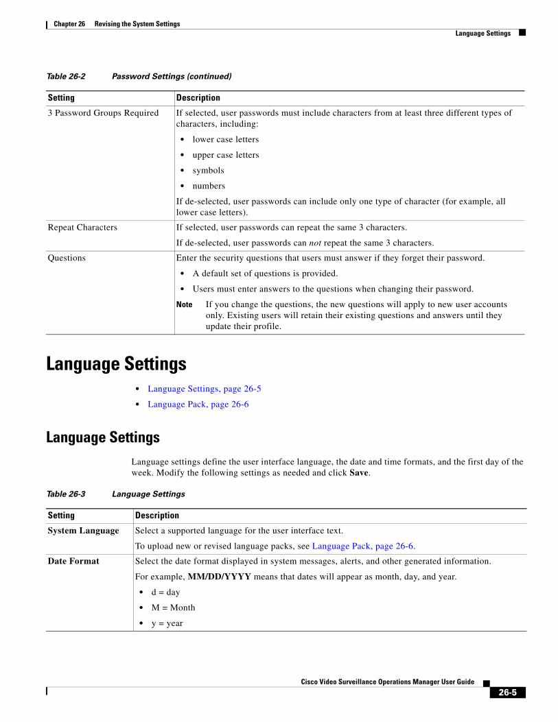
Chapter 26 Revising the System SettingsLanguage Settings
Language Settings • Language Settings, page 26-5
• Language Pack, page 26-6
Language SettingsLanguage settings define the user interface language, the date and time formats, and the first day of the week. Modify the following settings as needed and click Save.
3 Password Groups Required If selected, user passwords must include characters from at least three different types of characters, including:
• lower case letters
• upper case letters
• symbols
• numbers
If de-selected, user passwords can include only one type of character (for example, all lower case letters).
Repeat Characters If selected, user passwords can repeat the same 3 characters.
If de-selected, user passwords can not repeat the same 3 characters.
Questions Enter the security questions that users must answer if they forget their password.
• A default set of questions is provided.
• Users must enter answers to the questions when changing their password.
Note If you change the questions, the new questions will apply to new user accounts only. Existing users will retain their existing questions and answers until they update their profile.
Table 26-2 Password Settings (continued)
Setting Description
Table 26-3 Language Settings
Setting Description
System Language Select a supported language for the user interface text.
To upload new or revised language packs, see Language Pack, page 26-6.
Date Format Select the date format displayed in system messages, alerts, and other generated information.
For example, MM/DD/YYYY means that dates will appear as month, day, and year.
• d = day
• M = Month
• y = year
26-5Cisco Video Surveillance Operations Manager User Guide
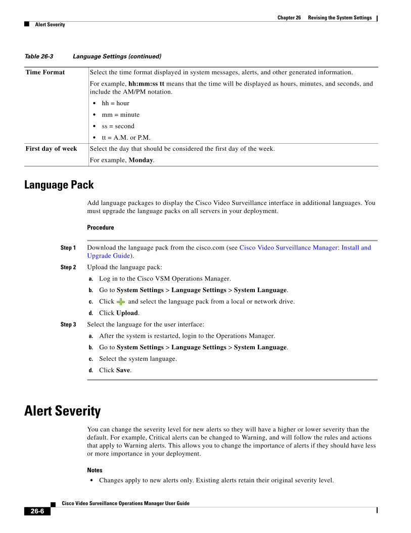
Chapter 26 Revising the System Settings Alert Severity
Language PackAdd language packages to display the Cisco Video Surveillance interface in additional languages. You must upgrade the language packs on all servers in your deployment.
Procedure
Step 1 Download the language pack from the cisco.com (see Cisco Video Surveillance Manager: Install and Upgrade Guide).
Step 2 Upload the language pack:
a. Log in to the Cisco VSM Operations Manager.
b. Go to System Settings > Language Settings > System Language.
c. Click and select the language pack from a local or network drive.
d. Click Upload.
Step 3 Select the language for the user interface:
a. After the system is restarted, login to the Operations Manager.
b. Go to System Settings > Language Settings > System Language.
c. Select the system language.
d. Click Save.
Alert SeverityYou can change the severity level for new alerts so they will have a higher or lower severity than the default. For example, Critical alerts can be changed to Warning, and will follow the rules and actions that apply to Warning alerts. This allows you to change the importance of alerts if they should have less or more importance in your deployment.
Notes
• Changes apply to new alerts only. Existing alerts retain their original severity level.
Time Format Select the time format displayed in system messages, alerts, and other generated information.
For example, hh:mm:ss tt means that the time will be displayed as hours, minutes, and seconds, and include the AM/PM notation.
• hh = hour
• mm = minute
• ss = second
• tt = A.M. or P.M.
First day of week Select the day that should be considered the first day of the week.
For example, Monday.
Table 26-3 Language Settings (continued)
26-6Cisco Video Surveillance Operations Manager User Guide
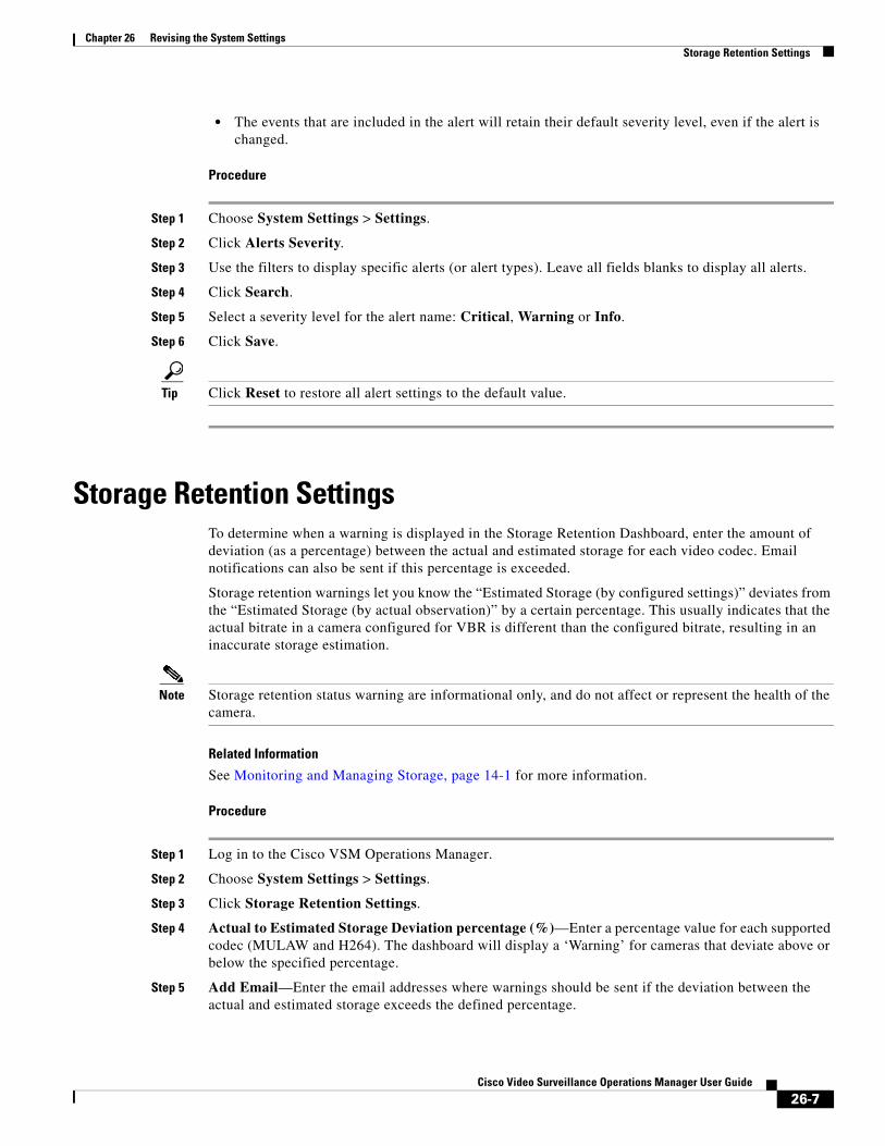
Chapter 26 Revising the System SettingsStorage Retention Settings
• The events that are included in the alert will retain their default severity level, even if the alert is changed.
Procedure
Step 1 Choose System Settings > Settings.
Step 2 Click Alerts Severity.
Step 3 Use the filters to display specific alerts (or alert types). Leave all fields blanks to display all alerts.
Step 4 Click Search.
Step 5 Select a severity level for the alert name: Critical, Warning or Info.
Step 6 Click Save.
Tip Click Reset to restore all alert settings to the default value.
Storage Retention SettingsTo determine when a warning is displayed in the Storage Retention Dashboard, enter the amount of deviation (as a percentage) between the actual and estimated storage for each video codec. Email notifications can also be sent if this percentage is exceeded.
Storage retention warnings let you know the “Estimated Storage (by configured settings)” deviates from the “Estimated Storage (by actual observation)” by a certain percentage. This usually indicates that the actual bitrate in a camera configured for VBR is different than the configured bitrate, resulting in an inaccurate storage estimation.
Note Storage retention status warning are informational only, and do not affect or represent the health of the camera.
Related Information
See Monitoring and Managing Storage, page 14-1 for more information.
Procedure
Step 1 Log in to the Cisco VSM Operations Manager.
Step 2 Choose System Settings > Settings.
Step 3 Click Storage Retention Settings.
Step 4 Actual to Estimated Storage Deviation percentage (%)—Enter a percentage value for each supported codec (MULAW and H264). The dashboard will display a ‘Warning’ for cameras that deviate above or below the specified percentage.
Step 5 Add Email—Enter the email addresses where warnings should be sent if the deviation between the actual and estimated storage exceeds the defined percentage.
26-7Cisco Video Surveillance Operations Manager User Guide

Chapter 26 Revising the System Settings Storage Retention Settings
Step 6 Click Save.
26-8Cisco Video Surveillance Operations Manager User Guide
Cisco V
C H A P T E R 27
Backup and RestoreRefer to the following topics to backup the server configuration and video recording files.
Contents
• Overview, page 27-2
– Usage Notes, page 27-2
– Backup Settings, page 27-3
– Backup File Format, page 27-4
– Disk Usage for Backups, page 27-6
• Backing Up and Restoring a Single Server, page 27-8
– Manually Backup a Single Server, page 27-8
– Automatic Backups (Single Server), page 27-9
– Restoring a Backup for a Single Server, page 27-11
– Deleting a Backup File, page 27-12
• Backing Up Multiple Servers (Bulk Actions), page 27-13
• Backing Up Recordings, page 27-16
27-1ideo Surveillance Operations Manager User Guide
Chapter 27 Backup and Restore Overview
OverviewServer backups can be performed for a single server, or for multiple servers.
• Use the Backup & Restore tab in the server configuration page to backup a single server.
• Use the server Bulk Operations feature to backup multiple servers.
You can schedule automatic backups, or perform an immediate one-time backup. Each backup creates:
• A separate backup file for each server service running on that server (such as the Media Server and Operations Manager).
• A backup file for the CDAF (Management Console) service.
To restore a backup, you must restore the files for each server service, and restore the CDAF backup file.
Note We recommend backing up all servers on a regular basis to ensure configuration and event data is not lost if a hardware failure occurs. Backups are also used to restore configurations and historical data when upgrading or moving to a new system. Backup files can be saved to the server (“local”) or to a valid FTP/SFTP server.
You can backup two types of data sets:
• Configuration Only—Includes the user-defined configuration, device settings (for cameras, encoders, and Media Servers, user accounts, and other attributes. Also includes installed licenses.
• Configuration Plus Historical Data—(Default) Includes the configuration for the server service, data plus events, health notifications, logs, and other information regarding the status, use and health of the system.
Note Recordings are backed up using a Long Term Storage server. See the “Archiving Recordings to a Long Term Storage Server” section on page 22-14.
Refer to the following topics for more information:
• Usage Notes, page 27-2
• Backup Settings, page 27-3
• Backup File Format, page 27-4
• Backup File Information, page 27-5
• Disk Usage for Backups, page 27-6
• Failed Backups, page 27-7
Usage Notes • Each backup includes a separate backup file for each active service on the server, plus a file for the
CDAF service.
• CDAF runs on all servers and provides the Cisco VSM Management Console user interface and features. CDAF backups include the server database, system information, console jobs and other data. The CDAF service must be restored along with the other server services or information may be missing and system errors can occur.
27-2Cisco Video Surveillance Operations Manager User Guide
Chapter 27 Backup and RestoreOverview
• The maximum number of allowed backups are:
– Map server service—1 manual and 1 automatic backup.
– All other server services—5 manual and 3 automatic backups.
• When the maximum number of backups is reached, an existing backup file must be deleted to make room for the new backup file. Automatic backups will automatically delete the oldest backup file. To perform a manual backup, you must manually delete an existing backup file.
• Use Bulk Operations to set the schedule for multiple servers. See Backing Up Multiple Servers (Bulk Actions), page 27-13.
• The Media Server configuration data is backed up automatically to the local server every day by default (and cannot be disabled). Automatic backups must configured for the other server services.
• Each Cisco VSM server can be configured with a single FTP or SFTP server. The same FTP or SFTP server can be used by multiple Cisco VSM servers using the Bulk Operations feature.
• Manual backups can be triggered for a single server, or for multiple servers (using Bulk Operations). Bulk action is supported for Media Servers only. The Bulk Action feature does not support Map or Metadata servers.
• Server restore can be performed for a single server only. Bulk server restores are not supported.
• Failed backup(s) are only visible for a single server (on the Server Management page). There is no bulk filtering or display of failed backups in the Bulk Operations page.
• Prior to Cisco VSM release 7.5, automatic backups to local storage could include configuration and historical data. In release 7.5 and later, however, automatic backups to the local disk support configuration data only. When upgrading from release 7.2 or earlier to release 7.5 or later, any automatic backups will be changed to the configuration only option.
Backup SettingsTable 27-1 describes the server backup and restore settings.
Table 27-1 Server Backup Settings
Field Description
Automatic Backups
Enable Select the check box to enable or disable the automatic backup schedule.
Destination Select where the backup file will be stored:
• On Local—(Default) Saves the backup file to the server hard drive.
• On Remote—Saves the backup file to a remote storage network server.
Type Select the type of data to back up:
• Configuration Only—Backs up the user-defined configuration, including device settings (for cameras, encoders, and Media Servers), user accounts, and other attributes.
• Configuration Plus Historical Data—(Default) Backs up the configuration plus events, health notifications, logs, and other data containing information regarding the status, use and health of the system.
Frequency Define how often backups will occur (Daily, Weekly, or Monthly).
27-3Cisco Video Surveillance Operations Manager User Guide
Chapter 27 Backup and Restore Overview
Backup File FormatBackup files are saved using the following formats:
Table 27-2 Backup File Formats
Backup Data File Name Format
• Service—The service acronym that defines the data stored in the file. For example: VSOM=Operations Manager, VSMC=Management Console, VSF=Federator, etc.
• HostName—the host name of the server running the Cisco VSM Operations Manager service.
• yyyyMMdd_HHmmss—the date and time when the backup file was created.
For example, if the PSBU-ENG14 server configuration and historical data was backed up on August 17, the resulting filename would be: VSOM_psbu-eng14_backup_20130817_174250.tar.gz
On Select the day of the week or day of the month when automatic backups will occur.
Note This field is disabled for daily backups. Select the time from the At field.
At Enter the time of day the backups will occur.
Remote Storage
Note These settings define the remote server used to store backup files if the Remote option is enabled. Click Test to verify the settings are correct and the remote server can be accessed.
Enable Select the check box to enable or disable the remote network storage option. If enabled, backups will be saved to the remote destination.
Protocol Select the type of remote server: FTP or SFTP.
Address Enter the server network address.
Username Enter the username used to access the server.
Password Enter the server password.
Path Enter the directory path where the backup file will be stored
Table 27-1 Server Backup Settings (continued)
Field Description
Config and Historical Service_HostName_backup_yyyyMMdd_HHmmss.tar.gz
Config Only Service_HostName_backup_config_yyyyMMdd_HHmmss.tar.gz
27-4Cisco Video Surveillance Operations Manager User Guide
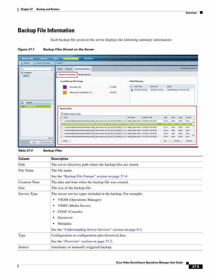
Chapter 27 Backup and RestoreOverview
Backup File InformationEach backup file saved on the server displays the following summary information:
Figure 27-1 Backup Files Stored on the Server
Table 27-3 Backup Files
Column Description
• VSOM (Operations Manager)
• VSMS (Media Server)
• CDAF (Console)
• Geoserver
• Metadata
Path The server directory path where the backup files are stored.
File Name The file name.
See the “Backup File Format” section on page 27-4.
Creation Time The date and time when the backup file was created.
Size The size of the backup file.
Service Type The server service types included in the backup. For example:
See the “Understanding Server Services” section on page 8-3.
Type Configuration or configuration plus historical data.
See the “Overview” section on page 27-2.
Source Automatic or manually triggered backup.
27-5Cisco Video Surveillance Operations Manager User Guide
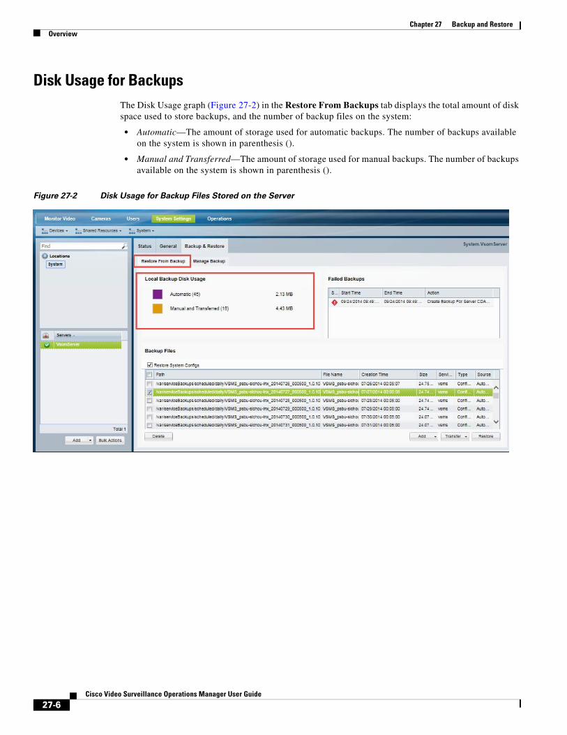
Chapter 27 Backup and Restore Overview
Disk Usage for BackupsThe Disk Usage graph (Figure 27-2) in the Restore From Backups tab displays the total amount of disk space used to store backups, and the number of backup files on the system:
• Automatic—The amount of storage used for automatic backups. The number of backups available on the system is shown in parenthesis ().
• Manual and Transferred—The amount of storage used for manual backups. The number of backups available on the system is shown in parenthesis ().
Figure 27-2 Disk Usage for Backup Files Stored on the Server
27-6Cisco Video Surveillance Operations Manager User Guide
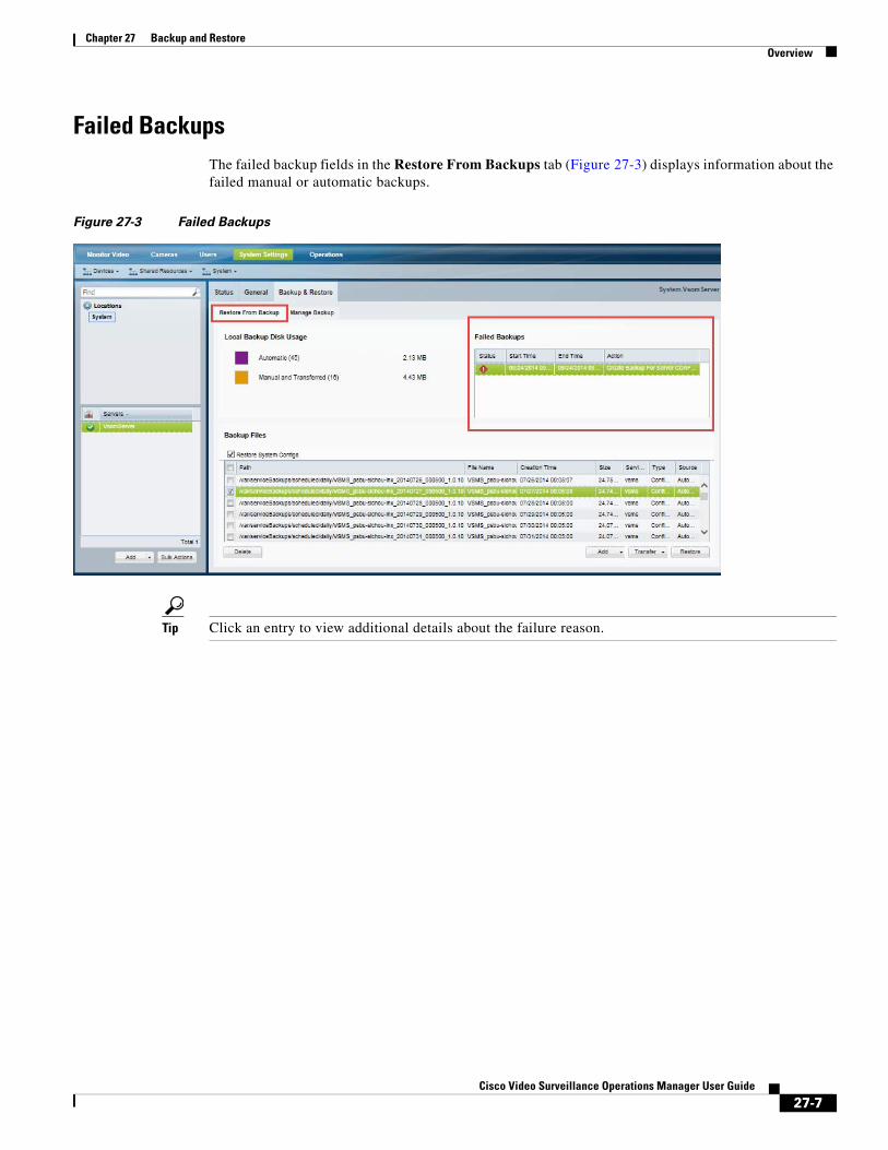
Chapter 27 Backup and RestoreOverview
Failed BackupsThe failed backup fields in the Restore From Backups tab (Figure 27-3) displays information about the failed manual or automatic backups.
Figure 27-3 Failed Backups
Tip Click an entry to view additional details about the failure reason.
27-7Cisco Video Surveillance Operations Manager User Guide
Chapter 27 Backup and Restore Backing Up and Restoring a Single Server
Backing Up and Restoring a Single ServerUse the server Backup & Restore tab to backup the configurations and historical data for all services running on the server (such as the Operations Manager and Media Server).
Note These same techniques apply when backing up a Federator server. See the “Using Federator to Monitor Multiple Operations Managers” section on page 28-1 for more information.
Contents
Refer to the following topics for more information:
• Manually Backup a Single Server, page 27-8
• Automatic Backups (Single Server), page 27-9
• Backup Settings, page 27-3
• Backup File Format, page 27-4
• Disk Usage for Backups, page 27-6
• Restoring a Backup for a Single Server, page 27-11
• Deleting a Backup File, page 27-12
Manually Backup a Single ServerTo trigger an immediate one-time backup, use the Backup & Restore tab in the server configuration page (Figure 27-4):
Procedure
Step 1 Select System Settings > Servers.
Step 2 Select the Backup & Restore tab.
Note When the maximum number of backups is reached, an existing backup file must be deleted to make room for the new backup file.
Step 3 Select the Manage Backup tab.
Step 4 Click Backup Now and select To Remote or To Local.
Step 5 From the pop-up, select the destination and backup type (see Table 27-1 for more information).
Step 6 Click OK.
Step 7 Backup files are saved to the selected destination.
• A separate file is created for each server service, plus an additional file for the DDAF server. See Overview, page 27-2 for more information.
• If saved “To Local”, the backup files are saved on the server (in the Restore From Backup tab). See the “Backup File Format” section on page 27-4 and the “Backup File Information” section on page 27-5 for more information.
27-8Cisco Video Surveillance Operations Manager User Guide

Chapter 27 Backup and RestoreBacking Up and Restoring a Single Server
• Failed backups are displayed in the Failed Manual Backups field. See the “Failed Backups” section on page 27-7.
Figure 27-4 Backup Now
Automatic Backups (Single Server)To schedule recurring backups for a single server, do the following:
Note • The Media Server configuration data is backed up automatically to the local server every day by default (and cannot be disabled). Automatic backups must configured for the other server services.
• When the maximum number of backups is reached, an existing backup file must be deleted to make room for the new backup file. Automatic backups will automatically delete the oldest backup file.
• Only the Configuration option is supported when the automatic backups are stored on the Local server.
• If a scheduled backup fails, a health notification is sent. See Sending Alert Emails (Notification Policies), page 24-23 for more information.
27-9Cisco Video Surveillance Operations Manager User Guide
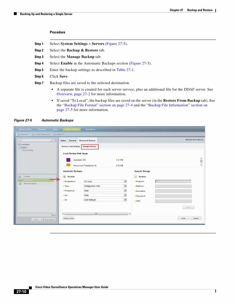
Chapter 27 Backup and Restore Backing Up and Restoring a Single Server
Procedure
Step 1 Select System Settings > Servers (Figure 27-5).
Step 2 Select the Backup & Restore tab.
Step 3 Select the Manage Backup tab.
Step 4 Select Enable in the Automatic Backups section (Figure 27-5).
Step 5 Enter the backup settings as described in Table 27-1.
Step 6 Click Save.
Step 7 Backup files are saved to the selected destination.
• A separate file is created for each server service, plus an additional file for the DDAF server. See Overview, page 27-2 for more information.
• If saved “To Local”, the backup files are saved on the server (in the Restore From Backup tab). See the “Backup File Format” section on page 27-4 and the “Backup File Information” section on page 27-5 for more information.
Figure 27-5 Automatic Backups
27-10Cisco Video Surveillance Operations Manager User Guide
Chapter 27 Backup and RestoreBacking Up and Restoring a Single Server
Restoring a Backup for a Single ServerRestoring a server backup requires that you restore the backup file for each service running on that server, and the CDAF service.
Note The CDAF service provides the server’s Management Console functionality, including the server database, system information, console jobs and other data. If the CDAF service is not restored at the same time as the other services, information may be missing and system errors can occur.
For example, if the server is running Operations Manager (VSOM) and Media Server (VSMS) services, a separate backup file is created for each service plus the CDAF (Console) service. You must restore each service backup file, one service at a time.
Caution Restoring a backup deletes any existing configurations, settings and historical data.
Procedure
To restore the server configuration from a backup file, do the following.
Step 1 Select System Settings > Servers (Figure 27-6).
Step 2 Select the Backup & Restore tab.
Step 3 Select the Restore From Backup tab (default).
Step 4 (Optional) Select Restore System Config to exclude the server configuration from the restore operation.
The server configuration is the non-Cisco VSM portion of the backup data that includes OS-related settings, such as the server network configuration. Excluding the system configuration can be used to replicate a server configuration on additional servers: create a backup from the original server and restore it to a new server while selecting the Restore System Config option.
Step 5 (Optional) If the backup file does not appear in the list, you can copy a backup file stored on a PC or remote server.
a. Select Add > From Remote or From PC.
b. Select a backup file stored on a PC or remote server.
Note You must first enter the Remote Storage settings in the Manage Backup tab before you can transfer a file from a remote server. See the “Backup Settings” section on page 27-3 for more information.
c. Click Save.
d. Repeat these steps to upload the backup file for each service, plus the CDAF (Console) service.
Step 6 Select the backup file for the service you want to restore.
• The Service Type displays the server service: For example: VSOM (Operations Manager), VSMS (Media Server), CDAF (Console), Geoserver, or Metadata.
• See also Backup File Format, page 27-4 and Backup File Information, page 27-5.
Step 7 Click Restore.
Step 8 Click Yes to confirm the backup and server restart.
27-11Cisco Video Surveillance Operations Manager User Guide
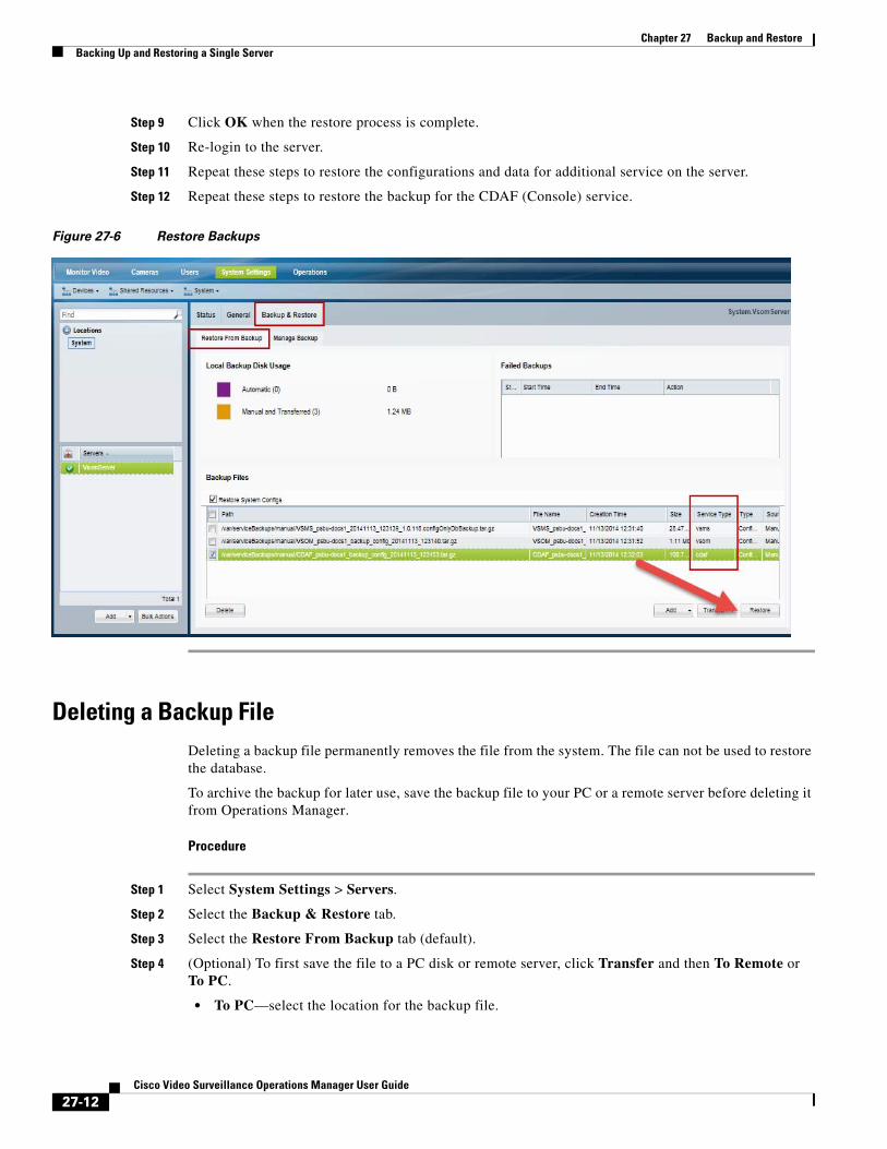
Chapter 27 Backup and Restore Backing Up and Restoring a Single Server
Step 9 Click OK when the restore process is complete.
Step 10 Re-login to the server.
Step 11 Repeat these steps to restore the configurations and data for additional service on the server.
Step 12 Repeat these steps to restore the backup for the CDAF (Console) service.
Figure 27-6 Restore Backups
Deleting a Backup FileDeleting a backup file permanently removes the file from the system. The file can not be used to restore the database.
To archive the backup for later use, save the backup file to your PC or a remote server before deleting it from Operations Manager.
Procedure
Step 1 Select System Settings > Servers.
Step 2 Select the Backup & Restore tab.
Step 3 Select the Restore From Backup tab (default).
Step 4 (Optional) To first save the file to a PC disk or remote server, click Transfer and then To Remote or To PC.
• To PC—select the location for the backup file.
27-12Cisco Video Surveillance Operations Manager User Guide
Chapter 27 Backup and RestoreBacking Up Multiple Servers (Bulk Actions)
• To Remote—the file will be transferred to the location specified in the Remote Storage section of the Configure tab. See the “Backup Settings” section on page 27-3 for more information.
Step 5 Click Delete (bottom left).
Step 6 Confirm the operation, when prompted.
Backing Up Multiple Servers (Bulk Actions)Use the server Bulk Actions feature to back up multiple servers manually, or to schedule automatic backups for multiple servers.
Tip See the “Bulk Actions: Revising Multiple Servers” section on page 8-26 for more information on other options and actions available for multiple servers.
Usage Notes
• Bulk action is supported for Media Servers only. The Bulk Action feature does not support Map or Metadata servers.
• All Active services in the selected server will be backed up.
• There is one scheduled backup per server. The schedule will be applied to all selected servers.
• One FTP or SFTP server can be configured for all selected servers.
• You can only restore backups for a single server, as described in the “Restoring a Backup for a Single Server” section on page 27-11. Bulk Actions cannot be used to restore backups on multiple servers.
• Media Server backups do not include recordings. See the “Backing Up Recordings” section on page 27-16 for instructions to back up recordings to a Long Term Storage (LTS) server.
• If a scheduled backup fails, a health notification is sent. See Sending Alert Emails (Notification Policies), page 24-23 for more information.
Procedure
Step 1 Select System Settings > Servers.
Step 2 Click Bulk Actions (under the device list) to open the Bulk Actions window (Figure 27-7).
27-13Cisco Video Surveillance Operations Manager User Guide
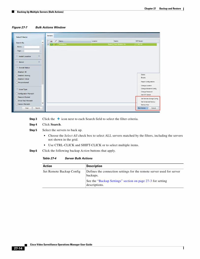
Chapter 27 Backup and Restore Backing Up Multiple Servers (Bulk Actions)
Figure 27-7 Bulk Actions Window
Step 3 Click the icon next to each Search field to select the filter criteria.
Step 4 Click Search.
Step 5 Select the servers to back up.
• Choose the Select All check box to select ALL servers matched by the filters, including the servers not shown in the grid.
• Use CTRL-CLICK and SHIFT-CLICK or to select multiple items.
Step 6 Click the following backup Action buttons that apply.
Table 27-4 Server Bulk Actions
Action Description
Set Remote Backup Config Defines the connection settings for the remote server used for server backups.
See the “Backup Settings” section on page 27-3 for setting descriptions.
27-14Cisco Video Surveillance Operations Manager User Guide
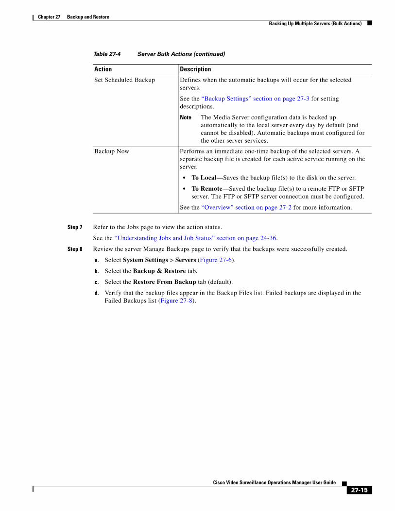
Chapter 27 Backup and RestoreBacking Up Multiple Servers (Bulk Actions)
Step 7 Refer to the Jobs page to view the action status.
See the “Understanding Jobs and Job Status” section on page 24-36.
Step 8 Review the server Manage Backups page to verify that the backups were successfully created.
a. Select System Settings > Servers (Figure 27-6).
b. Select the Backup & Restore tab.
c. Select the Restore From Backup tab (default).
d. Verify that the backup files appear in the Backup Files list. Failed backups are displayed in the Failed Backups list (Figure 27-8).
Set Scheduled Backup Defines when the automatic backups will occur for the selected servers.
See the “Backup Settings” section on page 27-3 for setting descriptions.
Note The Media Server configuration data is backed up automatically to the local server every day by default (and cannot be disabled). Automatic backups must configured for the other server services.
Backup Now Performs an immediate one-time backup of the selected servers. A separate backup file is created for each active service running on the server.
• To Local—Saves the backup file(s) to the disk on the server.
• To Remote—Saved the backup file(s) to a remote FTP or SFTP server. The FTP or SFTP server connection must be configured.
See the “Overview” section on page 27-2 for more information.
Table 27-4 Server Bulk Actions (continued)
Action Description
27-15Cisco Video Surveillance Operations Manager User Guide
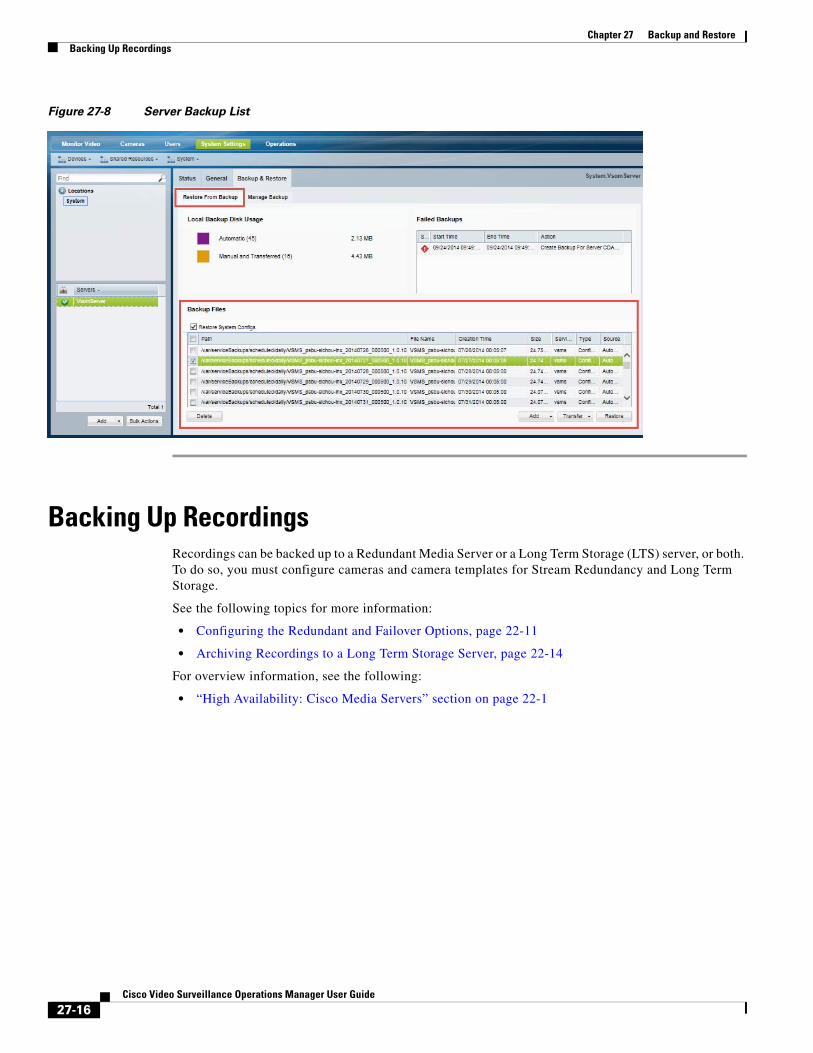
Chapter 27 Backup and Restore Backing Up Recordings
Figure 27-8 Server Backup List
Backing Up RecordingsRecordings can be backed up to a Redundant Media Server or a Long Term Storage (LTS) server, or both. To do so, you must configure cameras and camera templates for Stream Redundancy and Long Term Storage.
See the following topics for more information:
• Configuring the Redundant and Failover Options, page 22-11
• Archiving Recordings to a Long Term Storage Server, page 22-14
For overview information, see the following:
• “High Availability: Cisco Media Servers” section on page 22-1
27-16Cisco Video Surveillance Operations Manager User Guide
Cisco V
C H A P T E R 28
Using Federator to Monitor Multiple Operations ManagersFederator is a server service that allows users to monitor video and system health from multiple Operations Managers.
Refer to the following topics to install and manage a Federator server, and to view video from the associated Operations Managers using the browser-based utility.
Note • You can also use the Cisco Video Surveillance Safety and Security Desktop (Cisco SASD) application to view Federator resources. See the Cisco Video Surveillance Safety and Security Desktop User Guide for more information.
• To configure server settings such as the network time protocol (NTP) and network settings, or to view hardware information and logs, use the Cisco VSM Management Console. See the Cisco Video Surveillance Management Console Administration Guide for more information.
Contents
• Overview, page 28-3
• Requirements, page 28-4
• Summary Steps, page 28-7
• Initial Server Setup, page 28-10
• Logging In to a Federator Server, page 28-15
• Configuring Access to Operations Manager Resources, page 28-16
– Configuration Summary Steps, page 28-17
– Adding Operations Manager Servers to Federator, page 28-18
– Adding Federator Locations, page 28-22
– Adding Federator Regions, page 28-24
– Adding Federator Users, page 28-26
• Monitoring Video Using Federator, page 28-29
• Federator Clip Search, page 28-31
• Monitoring Device Health Using the Browser-Based Federator, page 28-33
– Federator Health Dashboard, page 28-33
28-1ideo Surveillance Operations Manager User Guide

Chapter 28 Using Federator to Monitor Multiple Operations Managers
– Federator Audit Logs, page 28-36
– Viewing Federator Active Users, page 28-37
• Administration Tasks, page 28-39
– Backing up and Restoring the Federator Configuration, page 28-39
– Updating the Federator Server System Software, page 28-42
28-2Cisco Video Surveillance Operations Manager User Guide
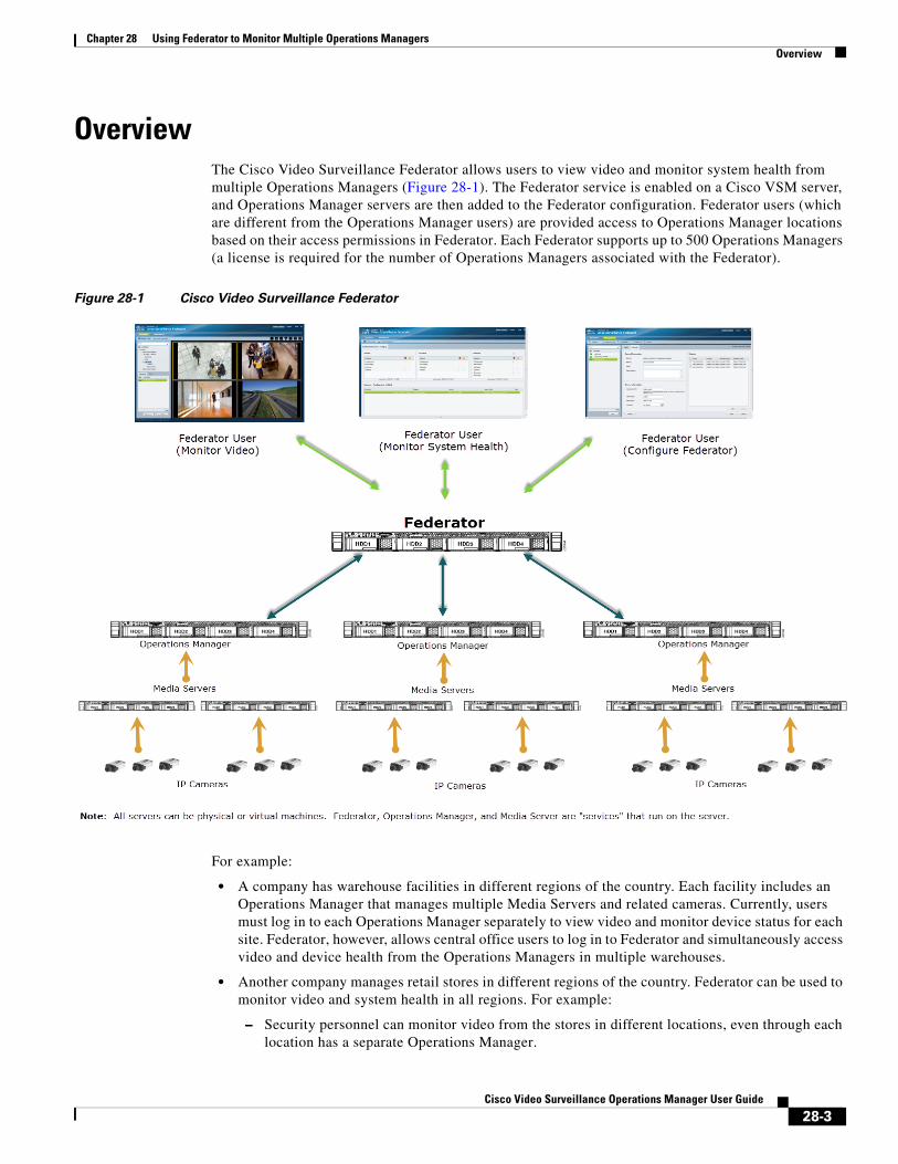
Chapter 28 Using Federator to Monitor Multiple Operations ManagersOverview
OverviewThe Cisco Video Surveillance Federator allows users to view video and monitor system health from multiple Operations Managers (Figure 28-1). The Federator service is enabled on a Cisco VSM server, and Operations Manager servers are then added to the Federator configuration. Federator users (which are different from the Operations Manager users) are provided access to Operations Manager locations based on their access permissions in Federator. Each Federator supports up to 500 Operations Managers (a license is required for the number of Operations Managers associated with the Federator).
Figure 28-1 Cisco Video Surveillance Federator
For example:
• A company has warehouse facilities in different regions of the country. Each facility includes an Operations Manager that manages multiple Media Servers and related cameras. Currently, users must log in to each Operations Manager separately to view video and monitor device status for each site. Federator, however, allows central office users to log in to Federator and simultaneously access video and device health from the Operations Managers in multiple warehouses.
• Another company manages retail stores in different regions of the country. Federator can be used to monitor video and system health in all regions. For example:
– Security personnel can monitor video from the stores in different locations, even through each location has a separate Operations Manager.
28-3Cisco Video Surveillance Operations Manager User Guide
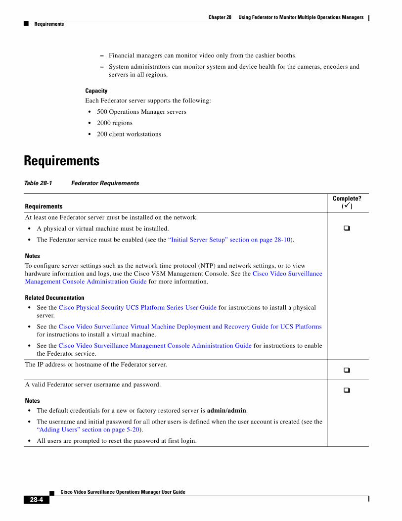
Chapter 28 Using Federator to Monitor Multiple Operations Managers Requirements
– Financial managers can monitor video only from the cashier booths.
– System administrators can monitor system and device health for the cameras, encoders and servers in all regions.
Capacity
Each Federator server supports the following:
• 500 Operations Manager servers
• 2000 regions
• 200 client workstations
RequirementsTable 28-1 Federator Requirements
RequirementsComplete?
()
At least one Federator server must be installed on the network.
• A physical or virtual machine must be installed.
• The Federator service must be enabled (see the “Initial Server Setup” section on page 28-10).
Notes
To configure server settings such as the network time protocol (NTP) and network settings, or to view hardware information and logs, use the Cisco VSM Management Console. See the Cisco Video Surveillance Management Console Administration Guide for more information.
Related Documentation
• See the Cisco Physical Security UCS Platform Series User Guide for instructions to install a physical server.
• See the Cisco Video Surveillance Virtual Machine Deployment and Recovery Guide for UCS Platforms for instructions to install a virtual machine.
• See the Cisco Video Surveillance Management Console Administration Guide for instructions to enable the Federator service.
The IP address or hostname of the Federator server.
A valid Federator server username and password.
Notes
• The default credentials for a new or factory restored server is admin/admin.
• The username and initial password for all other users is defined when the user account is created (see the “Adding Users” section on page 5-20).
• All users are prompted to reset the password at first login.
28-4Cisco Video Surveillance Operations Manager User Guide
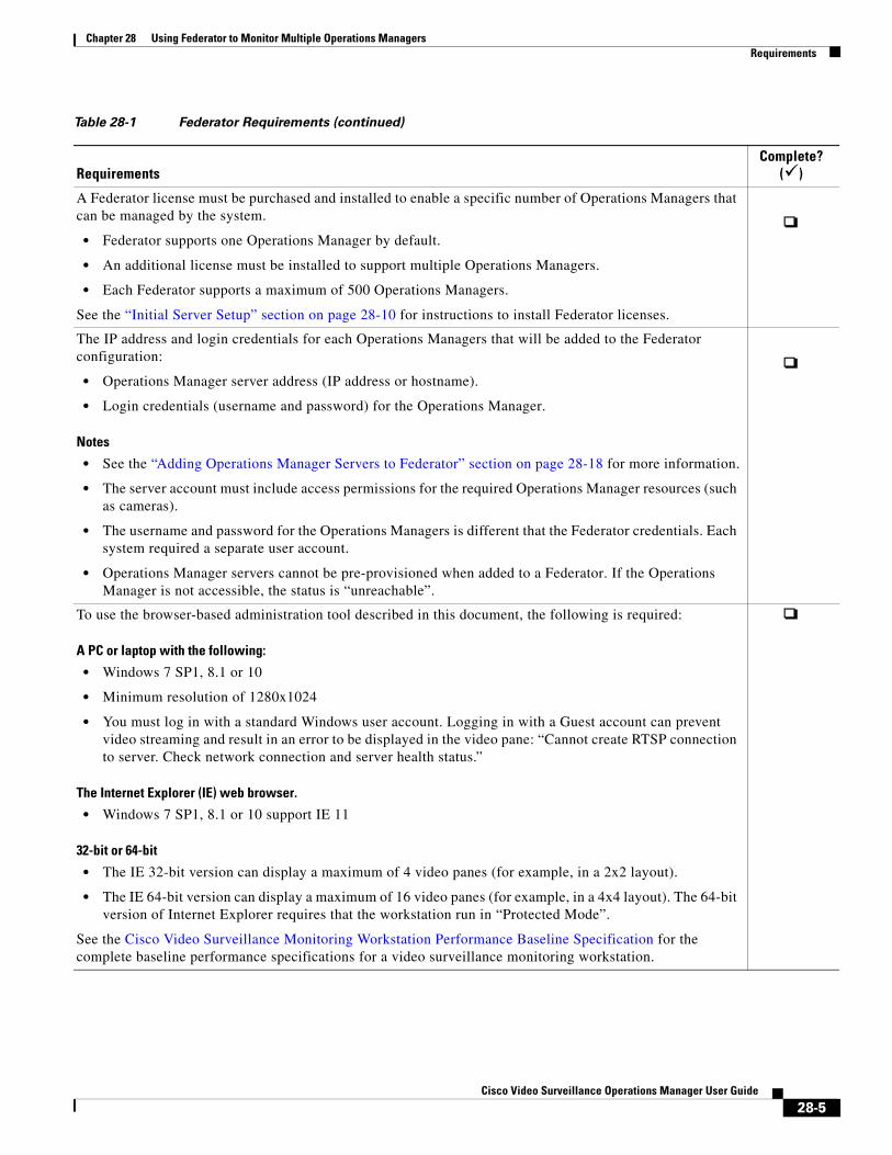
Chapter 28 Using Federator to Monitor Multiple Operations ManagersRequirements
A Federator license must be purchased and installed to enable a specific number of Operations Managers that can be managed by the system.
• Federator supports one Operations Manager by default.
• An additional license must be installed to support multiple Operations Managers.
• Each Federator supports a maximum of 500 Operations Managers.
See the “Initial Server Setup” section on page 28-10 for instructions to install Federator licenses.
The IP address and login credentials for each Operations Managers that will be added to the Federator configuration:
• Operations Manager server address (IP address or hostname).
• Login credentials (username and password) for the Operations Manager.
Notes
• See the “Adding Operations Manager Servers to Federator” section on page 28-18 for more information.
• The server account must include access permissions for the required Operations Manager resources (such as cameras).
• The username and password for the Operations Managers is different that the Federator credentials. Each system required a separate user account.
• Operations Manager servers cannot be pre-provisioned when added to a Federator. If the Operations Manager is not accessible, the status is “unreachable”.
To use the browser-based administration tool described in this document, the following is required:
A PC or laptop with the following:
• Windows 7 SP1, 8.1 or 10
• Minimum resolution of 1280x1024
• You must log in with a standard Windows user account. Logging in with a Guest account can prevent video streaming and result in an error to be displayed in the video pane: “Cannot create RTSP connection to server. Check network connection and server health status.”
The Internet Explorer (IE) web browser.
• Windows 7 SP1, 8.1 or 10 support IE 11
32-bit or 64-bit
• The IE 32-bit version can display a maximum of 4 video panes (for example, in a 2x2 layout).
• The IE 64-bit version can display a maximum of 16 video panes (for example, in a 4x4 layout). The 64-bit version of Internet Explorer requires that the workstation run in “Protected Mode”.
See the Cisco Video Surveillance Monitoring Workstation Performance Baseline Specification for the complete baseline performance specifications for a video surveillance monitoring workstation.
Table 28-1 Federator Requirements (continued)
RequirementsComplete?
()
28-5Cisco Video Surveillance Operations Manager User Guide
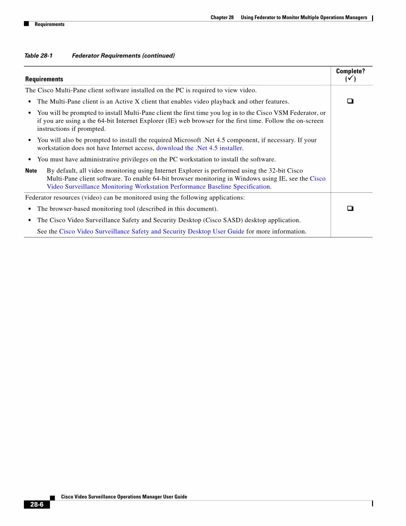
Chapter 28 Using Federator to Monitor Multiple Operations Managers Requirements
The Cisco Multi-Pane client software installed on the PC is required to view video.
• The Multi-Pane client is an Active X client that enables video playback and other features.
• You will be prompted to install Multi-Pane client the first time you log in to the Cisco VSM Federator, or if you are using a the 64-bit Internet Explorer (IE) web browser for the first time. Follow the on-screen instructions if prompted.
• You will also be prompted to install the required Microsoft .Net 4.5 component, if necessary. If your workstation does not have Internet access, download the .Net 4.5 installer.
• You must have administrative privileges on the PC workstation to install the software.
Note By default, all video monitoring using Internet Explorer is performed using the 32-bit Cisco Multi-Pane client software. To enable 64-bit browser monitoring in Windows using IE, see the Cisco Video Surveillance Monitoring Workstation Performance Baseline Specification.
Federator resources (video) can be monitored using the following applications:
• The browser-based monitoring tool (described in this document).
• The Cisco Video Surveillance Safety and Security Desktop (Cisco SASD) desktop application.
See the Cisco Video Surveillance Safety and Security Desktop User Guide for more information.
Table 28-1 Federator Requirements (continued)
RequirementsComplete?
()
28-6Cisco Video Surveillance Operations Manager User Guide
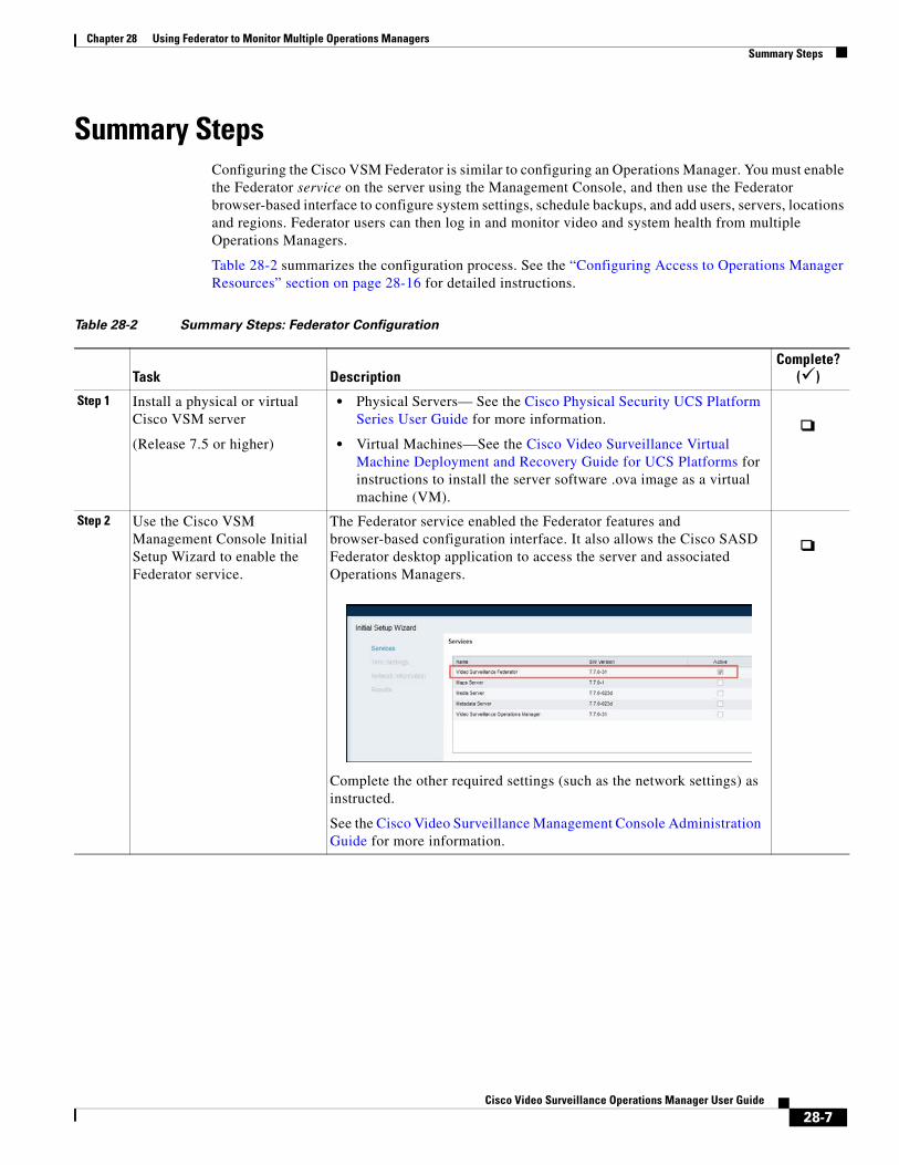
Chapter 28 Using Federator to Monitor Multiple Operations ManagersSummary Steps
Summary StepsConfiguring the Cisco VSM Federator is similar to configuring an Operations Manager. You must enable the Federator service on the server using the Management Console, and then use the Federator browser-based interface to configure system settings, schedule backups, and add users, servers, locations and regions. Federator users can then log in and monitor video and system health from multiple Operations Managers.
Table 28-2 summarizes the configuration process. See the “Configuring Access to Operations Manager Resources” section on page 28-16 for detailed instructions.
Table 28-2 Summary Steps: Federator Configuration
Task DescriptionComplete?
()
Step 1 Install a physical or virtual Cisco VSM server
(Release 7.5 or higher)
• Physical Servers— See the Cisco Physical Security UCS Platform Series User Guide for more information.
• Virtual Machines—See the Cisco Video Surveillance Virtual Machine Deployment and Recovery Guide for UCS Platforms for instructions to install the server software .ova image as a virtual machine (VM).
Step 2 Use the Cisco VSM Management Console Initial Setup Wizard to enable the Federator service.
The Federator service enabled the Federator features and browser-based configuration interface. It also allows the Cisco SASD Federator desktop application to access the server and associated Operations Managers.
Complete the other required settings (such as the network settings) as instructed.
See the Cisco Video Surveillance Management Console Administration Guide for more information.
28-7Cisco Video Surveillance Operations Manager User Guide
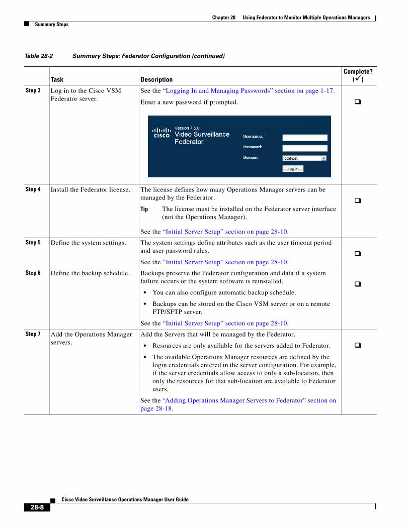
Chapter 28 Using Federator to Monitor Multiple Operations Managers Summary Steps
Step 3 Log in to the Cisco VSM Federator server.
See the “Logging In and Managing Passwords” section on page 1-17.
Enter a new password if prompted.
Step 4 Install the Federator license. The license defines how many Operations Manager servers can be managed by the Federator.
Tip The license must be installed on the Federator server interface (not the Operations Manager).
See the “Initial Server Setup” section on page 28-10.
Step 5 Define the system settings. The system settings define attributes such as the user timeout period and user password rules.
See the “Initial Server Setup” section on page 28-10.
Step 6 Define the backup schedule. Backups preserve the Federator configuration and data if a system failure occurs or the system software is reinstalled.
• You can also configure automatic backup schedule.
• Backups can be stored on the Cisco VSM server or on a remote FTP/SFTP server.
See the “Initial Server Setup” section on page 28-10.
Step 7 Add the Operations Manager servers.
Add the Servers that will be managed by the Federator.
• Resources are only available for the servers added to Federator.
• The available Operations Manager resources are defined by the login credentials entered in the server configuration. For example, if the server credentials allow access to only a sub-location, then only the resources for that sub-location are available to Federator users.
See the “Adding Operations Manager Servers to Federator” section on page 28-18.
Table 28-2 Summary Steps: Federator Configuration (continued)
Task DescriptionComplete?
()
28-8Cisco Video Surveillance Operations Manager User Guide
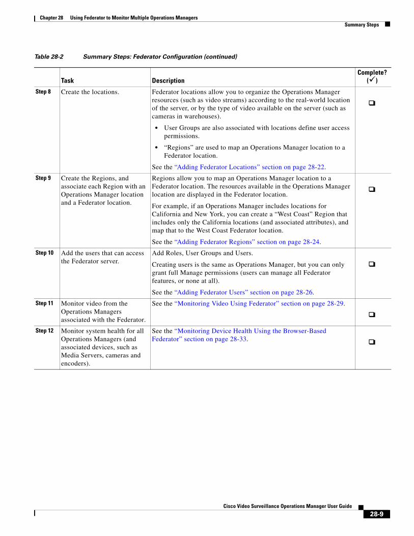
Chapter 28 Using Federator to Monitor Multiple Operations ManagersSummary Steps
Step 8 Create the locations. Federator locations allow you to organize the Operations Manager resources (such as video streams) according to the real-world location of the server, or by the type of video available on the server (such as cameras in warehouses).
• User Groups are also associated with locations define user access permissions.
• “Regions” are used to map an Operations Manager location to a Federator location.
See the “Adding Federator Locations” section on page 28-22.
Step 9 Create the Regions, and associate each Region with an Operations Manager location and a Federator location.
Regions allow you to map an Operations Manager location to a Federator location. The resources available in the Operations Manager location are displayed in the Federator location.
For example, if an Operations Manager includes locations for California and New York, you can create a “West Coast” Region that includes only the California locations (and associated attributes), and map that to the West Coast Federator location.
See the “Adding Federator Regions” section on page 28-24.
Step 10 Add the users that can access the Federator server.
Add Roles, User Groups and Users.
Creating users is the same as Operations Manager, but you can only grant full Manage permissions (users can manage all Federator features, or none at all).
See the “Adding Federator Users” section on page 28-26.
Step 11 Monitor video from the Operations Managers associated with the Federator.
See the “Monitoring Video Using Federator” section on page 28-29.
Step 12 Monitor system health for all Operations Managers (and associated devices, such as Media Servers, cameras and encoders).
See the “Monitoring Device Health Using the Browser-Based Federator” section on page 28-33.
Table 28-2 Summary Steps: Federator Configuration (continued)
Task DescriptionComplete?
()
28-9Cisco Video Surveillance Operations Manager User Guide

Chapter 28 Using Federator to Monitor Multiple Operations Managers Initial Server Setup
Initial Server SetupAfter the physical or virtual Federator server is installed and setup using the Cisco VSM Management Console, you can log in to the Federator browser-based interface and complete the initial system settings. This includes installing the license that defines how many Operations Managers can be managed by the Federator, the basic system settings, and the server backup schedule.
Initial Setup Procedure
Step 1 Install a physical or virtual Cisco VSM server.
• Physical Servers— See the Cisco Physical Security UCS Platform Series User Guide for more information.
• Virtual Machines—See the Cisco Video Surveillance Virtual Machine Deployment and Recovery Guide for UCS Platforms for instructions to install the server software .ova image as a virtual machine (VM).
Step 2 Enable the Federator service using the server’s Initial Setup Wizard (Figure 28-2).
a. Launch the 32-bit version of Internet Explorer on your Windows computer.
b.
Platform Server Address
• Eth0 port—static IP address 192.168.0.200
• Eth1 port— DHCP
Enter the URL for the server’s Cisco VSM Management Console. The syntax is: http://<server-ip-address or hostname>/vsmc/
Physical server The default (factory) static IP address is: http://192.168.0.200/vsmc/
Virtual Machine
Cisco Unified Computing System (Cisco UCS) platform
The Cisco VSM server includes two network ports with the following default configuration:
The network settings can also be changed using the guest OS console when installing the server software OVA image. See the “Configuring the Network Settings” section of the Cisco Video Surveillance Virtual Machine Deployment and Recovery Guide for UCS Platforms for more information.
28-10Cisco Video Surveillance Operations Manager User Guide
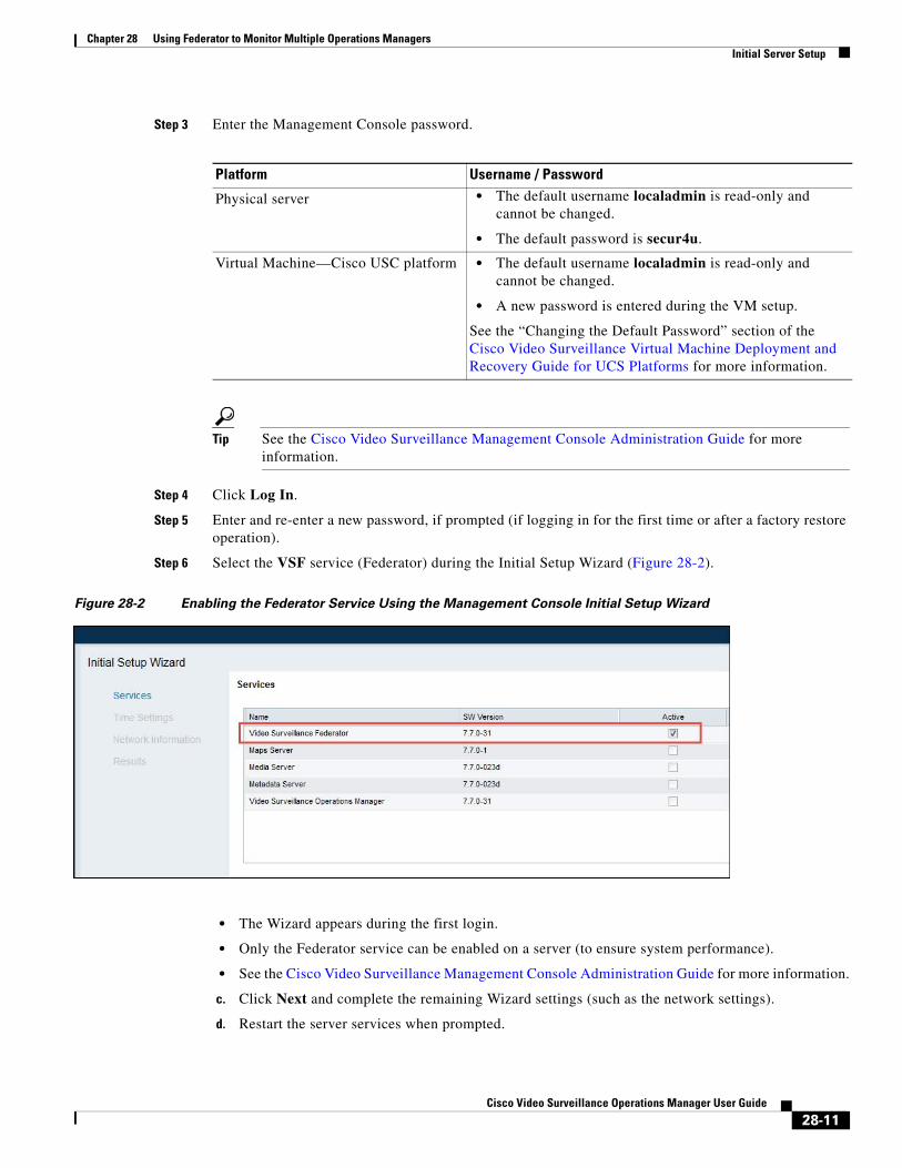
Chapter 28 Using Federator to Monitor Multiple Operations ManagersInitial Server Setup
Step 3 Enter the Management Console password.
Platform Username / Password • The default username localadmin is read-only and
cannot be changed.
• The default password is secur4u.
• The default username localadmin is read-only and cannot be changed.
• A new password is entered during the VM setup.
Tip See the Cisco Video Surveillance Management Console Administration Guide for more information.
Step 4 Click Log In.
Step 5 Enter and re-enter a new password, if prompted (if logging in for the first time or after a factory restore operation).
Step 6 Select the VSF service (Federator) during the Initial Setup Wizard (Figure 28-2).
Figure 28-2 Enabling the Federator Service Using the Management Console Initial Setup Wizard
• The Wizard appears during the first login.
• Only the Federator service can be enabled on a server (to ensure system performance).
• See the Cisco Video Surveillance Management Console Administration Guide for more information.
c. Click Next and complete the remaining Wizard settings (such as the network settings).
d. Restart the server services when prompted.
Physical server
Virtual Machine—Cisco USC platform
See the “Changing the Default Password” section of the Cisco Video Surveillance Virtual Machine Deployment and Recovery Guide for UCS Platforms for more information.
28-11Cisco Video Surveillance Operations Manager User Guide
Chapter 28 Using Federator to Monitor Multiple Operations Managers Initial Server Setup
Step 7 Log in to the browser-based Federator interface.
a. Launch the 32-bit or 64-bit version of Internet Explorer on your Windows computer.
See the “Requirements” section on page 1-4 for more information.
b. Enter the Federator URL or IP address.
The syntax is: https://server-address/vsf/
For example: https://vsm-server.cisco.com/vsf
c. Enter your username and password.
– The default credentials for a new or factory restored server are admin/admin.
– The initial system includes an admin login for the super_user. You can create additional users with various access permissions, as described in the “Adding Federator Users” section on page 28-26.
– See the “Logging In to a Federator Server” section on page 28-15 for more information.
d. Enter a new password, if prompted.
e. If prompted, complete the on-screen instructions to install or upgrade the Cisco Multi-Pane client software on your computer.
See the “Logging In and Managing Passwords” section on page 1-17 for more information.
Step 8 Install a Federator license to enable the number of Operations Manager (VSOM) servers that can be added to the Federator.
Tip See the “Installing Licenses” section on page 1-27 for more information.
a. Purchase and obtain the license.
b. Select Management > Software Licensing (Figure 28-3).
c. Click Add and select the license file located on your local drive.
d. Click Save to install the file and activate the additional capacity.
Tip The additional capacity is available immediately. You do not need to restart the server or take additional steps. The license enables the number of Operations Manager (Operations Manager) servers that can be managed by the Federator. In the Figure 28-3 example, the license supports 10 additional Operations Manager (VSOM) servers (for a total of 11).
28-12Cisco Video Surveillance Operations Manager User Guide
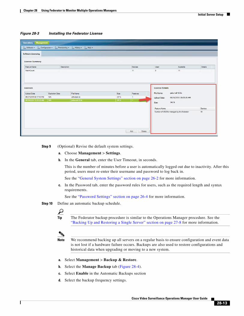
Chapter 28 Using Federator to Monitor Multiple Operations ManagersInitial Server Setup
Figure 28-3 Installing the Federator License
Step 9 (Optional) Revise the default system settings.
a. Choose Management > Settings.
b. In the General tab, enter the User Timeout, in seconds.
This is the number of minutes before a user is automatically logged out due to inactivity. After this period, users must re-enter their username and password to log back in.
See the “General System Settings” section on page 26-2 for more information.
c. In the Password tab, enter the password rules for users, such as the required length and syntax requirements.
See the “Password Settings” section on page 26-4 for more information.
Step 10 Define an automatic backup schedule.
Tip The Federator backup procedure is similar to the Operations Manager procedure. See the “Backing Up and Restoring a Single Server” section on page 27-8 for more information.
Note We recommend backing up all servers on a regular basis to ensure configuration and event data is not lost if a hardware failure occurs. Backups are also used to restore configurations and historical data when upgrading or moving to a new system.
a. Select Management > Backup & Restore.
b. Select the Manage Backup tab (Figure 28-4).
c. Select Enable in the Automatic Backups section
d. Select the backup frequency settings.
28-13Cisco Video Surveillance Operations Manager User Guide
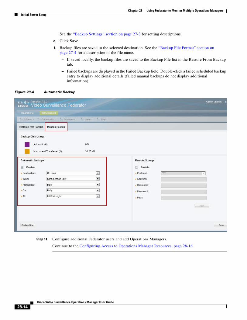
Chapter 28 Using Federator to Monitor Multiple Operations Managers Initial Server Setup
See the “Backup Settings” section on page 27-3 for setting descriptions.
e. Click Save.
f. Backup files are saved to the selected destination. See the “Backup File Format” section on page 27-4 for a description of the file name.
– If saved locally, the backup files are saved to the Backup File list in the Restore From Backup tab.
– Failed backups are displayed in the Failed Backup field. Double-click a failed scheduled backup entry to display additional details (failed manual backups do not display additional information).
Figure 28-4 Automatic Backup
Step 11 Configure additional Federator users and add Operations Managers.
Continue to the Configuring Access to Operations Manager Resources, page 28-16
28-14Cisco Video Surveillance Operations Manager User Guide
Chapter 28 Using Federator to Monitor Multiple Operations ManagersLogging In to a Federator Server
Logging In to a Federator ServerLogging in to a Federator server is similar to logging in to an Operations Manager. Enter the Federator server URL in a web browser and then enter a Federator username and password. See the “Logging In” section on page 1-17 for more information.
• The default credentials for a new or factory restored server is admin/admin.
• The username and initial password for all other users is defined when the user account is created (see the “Adding Users” section on page 5-20).
• All users are prompted to reset the password at first login.
• Users are required to select a domain if their credentials are authenticated using an external database, such as an LDAP server. See Adding Users from an LDAP Server, page 6-1.
• If Dual Login is enabled, a second user must also enter their credentials to approve the login (see the “Understanding Dual Login” section on page 1-19).
• Federator servers do not use Sites or Dynamic Proxies, and Federator users are not prompted to select a Site.
Note Federator user accounts are different than Operations Manager user account. You cannot use Operations Manager credentials to access the Federator. See the “Adding Federator Users” section on page 28-26 for instructions to create Federator users.
Login Procedure
Step 1 Launch the 32-bit or 64-bit version of Internet Explorer on your Windows computer.
See the “Requirements” section on page 1-4 for more information.
Step 2 Enter the Federator URL or IP address.
The syntax is: https://server-address/vsf/
Step 3 Enter your username and password.
• The default credentials for a new or factory restored server are admin/admin.
• The initial system includes an admin login for the super_user. You can create additional users with various access permissions, as described in the “Adding Federator Users” section on page 28-26.
g. Select a Domain, if necessary.
h. Enter a new password, if prompted.
i. If prompted, ask your manager or other administrator to enter their “Approver Login”
See the “Understanding Dual Login” section on page 1-19 for more information.
j. If prompted, complete the on-screen instructions to install or upgrade the Cisco Multi-Pane client software on your computer.
See the “Logging In and Managing Passwords” section on page 1-17 for more information.
28-15Cisco Video Surveillance Operations Manager User Guide
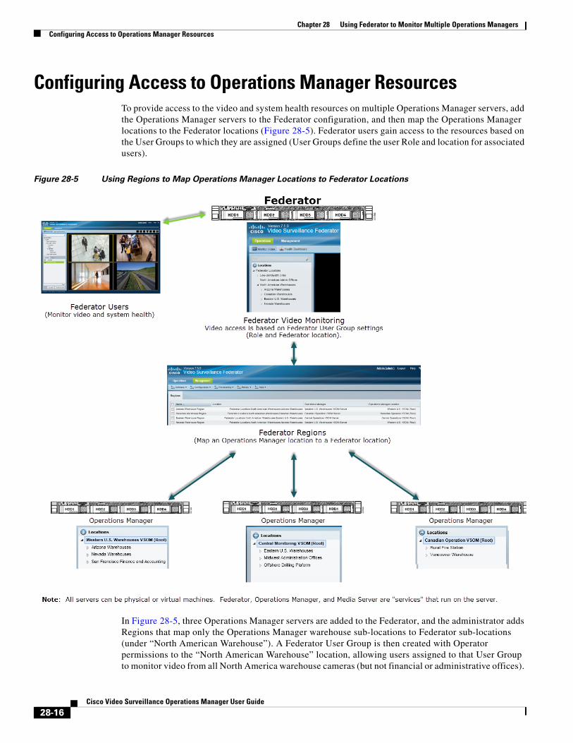
Chapter 28 Using Federator to Monitor Multiple Operations Managers Configuring Access to Operations Manager Resources
Configuring Access to Operations Manager ResourcesTo provide access to the video and system health resources on multiple Operations Manager servers, add the Operations Manager servers to the Federator configuration, and then map the Operations Manager locations to the Federator locations (Figure 28-5). Federator users gain access to the resources based on the User Groups to which they are assigned (User Groups define the user Role and location for associated users).
Figure 28-5 Using Regions to Map Operations Manager Locations to Federator Locations
In Figure 28-5, three Operations Manager servers are added to the Federator, and the administrator adds Regions that map only the Operations Manager warehouse sub-locations to Federator sub-locations (under “North American Warehouse”). A Federator User Group is then created with Operator permissions to the “North American Warehouse” location, allowing users assigned to that User Group to monitor video from all North America warehouse cameras (but not financial or administrative offices).
28-16Cisco Video Surveillance Operations Manager User Guide
Chapter 28 Using Federator to Monitor Multiple Operations ManagersConfiguring Access to Operations Manager Resources
Refer to the following topics for more information:
• Configuration Summary Steps, page 28-17
• Adding Operations Manager Servers to Federator, page 28-18
• Adding Federator Locations, page 28-22
• Adding Federator Regions, page 28-24
• Adding Federator Users, page 28-26
Configuration Summary Steps1. Add the Operations Manager servers to the Federator configuration.
2. Add locations in Federator that will include the shared resources, such as all warehouse facilities.
For example, Figure 28-5 includes a location “North American Warehouses”, and sub-locations for each Region (each Region is a mapping between a Federator location and an Operations Manager location).
3. Add Federator Regions that are associated with a Federator location and Operations Manager location.
– For example, create a Region “Phoenix Warehouses”. Associate that Region with the “Arizona Warehouse” locations in Operations Manager and Federator.
– Select a sub-location on the Operations Manager to include only a portion of the server’s resources. Select the root Operations Manager location to include all resources on the server, (such as the “Canadian Operations” server in Figure 28-5).
4. Add a Federator User Group that provides access to the location.
For example, add a “Warehouse Operators” User Group with access to the “North American Warehouses” location.
5. Add Federator users and associate them with User Group.
6. The user can monitor the resources (such as video and system health) based on their User Group membership (Figure 28-6).
Note The Operations Manager locations are displayed under the Federator location.
28-17Cisco Video Surveillance Operations Manager User Guide
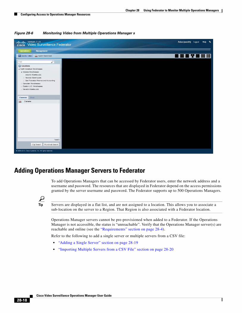
Chapter 28 Using Federator to Monitor Multiple Operations Managers Configuring Access to Operations Manager Resources
Figure 28-6 Monitoring Video from Multiple Operations Manager s
Adding Operations Manager Servers to FederatorTo add Operations Managers that can be accessed by Federator users, enter the network address and a username and password. The resources that are displayed in Federator depend on the access permissions granted by the server username and password. The Federator supports up to 500 Operations Managers.
Tip Servers are displayed in a flat list, and are not assigned to a location. This allows you to associate a sub-location on the server to a Region. That Region is also associated with a Federator location.
Operations Manager servers cannot be pre-provisioned when added to a Federator. If the Operations Manager is not accessible, the status is “unreachable”. Verify that the Operations Manager server(s) are reachable and online (see the “Requirements” section on page 28-4).
Refer to the following to add a single server or multiple servers from a CSV file:
• “Adding a Single Server” section on page 28-19
• “Importing Multiple Servers from a CSV File” section on page 28-20
28-18Cisco Video Surveillance Operations Manager User Guide
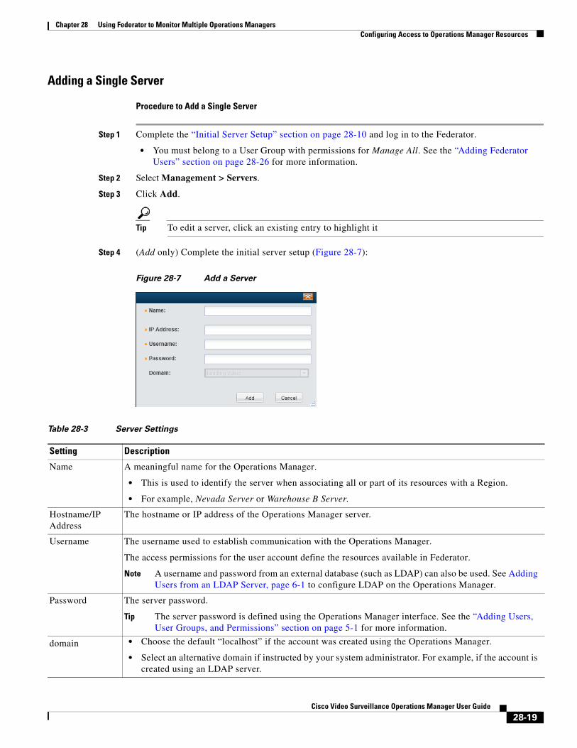
Chapter 28 Using Federator to Monitor Multiple Operations ManagersConfiguring Access to Operations Manager Resources
Adding a Single Server
Procedure to Add a Single Server
Step 1 Complete the “Initial Server Setup” section on page 28-10 and log in to the Federator.
• You must belong to a User Group with permissions for Manage All. See the “Adding Federator Users” section on page 28-26 for more information.
Step 2 Select Management > Servers.
Step 3 Click Add.
Tip To edit a server, click an existing entry to highlight it
Step 4 (Add only) Complete the initial server setup (Figure 28-7):
Figure 28-7 Add a Server
Table 28-3 Server Settings
Setting Description
• This is used to identify the server when associating all or part of its resources with a Region.
• For example, Nevada Server or Warehouse B Server.
Note A username and password from an external database (such as LDAP) can also be used. See Adding Users from an LDAP Server, page 6-1 to configure LDAP on the Operations Manager.
Tip The server password is defined using the Operations Manager interface. See the “Adding Users, User Groups, and Permissions” section on page 5-1 for more information.
• Choose the default “localhost” if the account was created using the Operations Manager.
• Select an alternative domain if instructed by your system administrator. For example, if the account is created using an LDAP server.
Name A meaningful name for the Operations Manager.
Hostname/IP Address
The hostname or IP address of the Operations Manager server.
Username The username used to establish communication with the Operations Manager.
The access permissions for the user account define the resources available in Federator.
Password The server password.
domain
28-19Cisco Video Surveillance Operations Manager User Guide
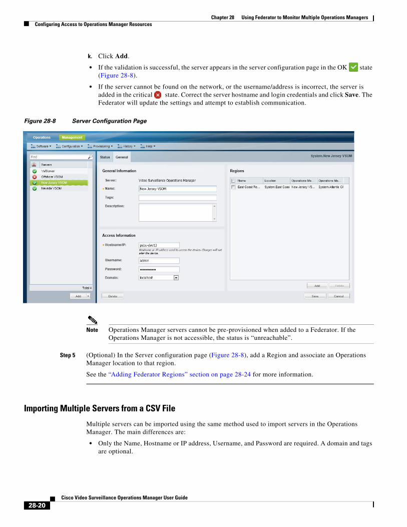
Chapter 28 Using Federator to Monitor Multiple Operations Managers Configuring Access to Operations Manager Resources
k. Click Add.
• If the validation is successful, the server appears in the server configuration page in the OK state (Figure 28-8).
• If the server cannot be found on the network, or the username/address is incorrect, the server is added in the critical state. Correct the server hostname and login credentials and click Save. The Federator will update the settings and attempt to establish communication.
Figure 28-8 Server Configuration Page
Note Operations Manager servers cannot be pre-provisioned when added to a Federator. If the Operations Manager is not accessible, the status is “unreachable”.
Step 5 (Optional) In the Server configuration page (Figure 28-8), add a Region and associate an Operations Manager location to that region.
See the “Adding Federator Regions” section on page 28-24 for more information.
Importing Multiple Servers from a CSV File
Multiple servers can be imported using the same method used to import servers in the Operations Manager. The main differences are:
• Only the Name, Hostname or IP address, Username, and Password are required. A domain and tags are optional.
28-20Cisco Video Surveillance Operations Manager User Guide
Chapter 28 Using Federator to Monitor Multiple Operations ManagersConfiguring Access to Operations Manager Resources
• The servers cannot be pre-provisioned. Servers with incorrect address or username/password will be added in a critical state. Correct the Access Information and wait for communication to be established.
Note Operations Manager servers cannot be pre-provisioned when added to a Federator. If the Operations Manager is not accessible, the status is “unreachable”.
Procedure to Import Servers
Complete the following procedure to import servers using a CSV file.
Step 1 Create a file in plain text CSV format that can be opened and saved using Excel or OpenOffice Calc. Blank rows or rows beginning with “//” are ignored.
• Only the Name, Hostname or IP address, Username, and Password are required.
• See the “Creating the CSV File” section on page 8-21.
Tip To download a sample import file, launch the import wizard as described in the Import Step 1 - Download Sample. Click the Download Sample button in the second step of the wizard to obtain a sample file (see Step 4). See the “Creating the CSV File” section on page 8-21 for more information.
Step 2 Select System Settings > Servers.
Step 3 Choose Add and Import servers from file.
Step 4 Complete each Import Step as described below:
Tip See the “Creating the CSV File” section on page 8-21 for more information.
a. Import Step 1 - Download Sample(Optional) Click Download Sample to download a sample CSV import file. Use this sample to create the import file (see the “Creating the CSV File” section on page 8-21). Click Next.
b. Import Step 2 - File Upload: Click to select the CSV file from a local or network disk. Click Upload.
c. Import Step 3 - Processing: Wait for the import process to complete.
d. Import Step 4 - Results Success:
– If a success message appears, continue to Step 5.
– If an error message appears, continue to Step 4 e.
e. If an error message appears, complete the following troubleshooting steps:
– Revise the file to correct any errors.
– Click Start Over.
– Return to Step 3 and re-import the corrected CSV file.
Step 5 Click Close when the import process is complete.
Step 6 View the device status to determine if additional configuration is required.
28-21Cisco Video Surveillance Operations Manager User Guide
Chapter 28 Using Federator to Monitor Multiple Operations Managers Configuring Access to Operations Manager Resources
Step 7 Continue to the “Adding Federator Locations” section on page 28-22.
Adding Federator LocationsFederator locations allow you to organize the Operations Manager resources (such as video streams) according to the real-world location of the server, or by the type of video available on the server (such as cameras in warehouses). User Groups are also associated with locations define user access permissions.
For example, a “Warehouse Operator” User Group can be associated to a location that includes sub-locations for warehouse video streams. Another “Finance Operator” User Group can be associated to the accounting locations.
Federator locations are mapped to Operations Manager locations using “Regions”. See the “Configuring Access to Operations Manager Resources” section on page 28-16 for more information.
Tip Federator locations are similar to locations in an Operations Manager. See the “Creating the Location Hierarchy” section on page 7-1.
Procedure to Add Federator Locations
To create the Federator locations, do the following:
Step 1 Log in to the Federator browser-based interface.
• You must belong to a User Group with permissions for Manage All.
• See the Logging In and Managing Passwords, page 1-17 and the “Adding Federator Users” section on page 28-26 for more information.
Step 2 Select Management > Locations.
Step 3 Select an existing location and click Add to add a new location or sub-location (Figure 28-9).
Note In a new system, only the System location appears.
28-22Cisco Video Surveillance Operations Manager User Guide
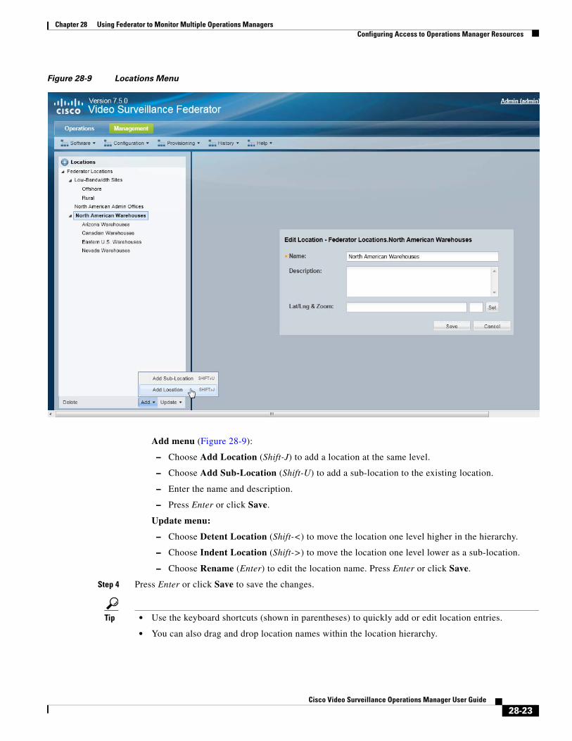
Chapter 28 Using Federator to Monitor Multiple Operations ManagersConfiguring Access to Operations Manager Resources
Figure 28-9 Locations Menu
Add menu (Figure 28-9):
– Choose Add Location (Shift-J) to add a location at the same level.
– Choose Add Sub-Location (Shift-U) to add a sub-location to the existing location.
– Enter the name and description.
– Press Enter or click Save.
Update menu:
– Choose Detent Location (Shift-<) to move the location one level higher in the hierarchy.
– Choose Indent Location (Shift->) to move the location one level lower as a sub-location.
– Choose Rename (Enter) to edit the location name. Press Enter or click Save.
Step 4 Press Enter or click Save to save the changes.
Tip • Use the keyboard shortcuts (shown in parentheses) to quickly add or edit location entries.
• You can also drag and drop location names within the location hierarchy.
28-23Cisco Video Surveillance Operations Manager User Guide
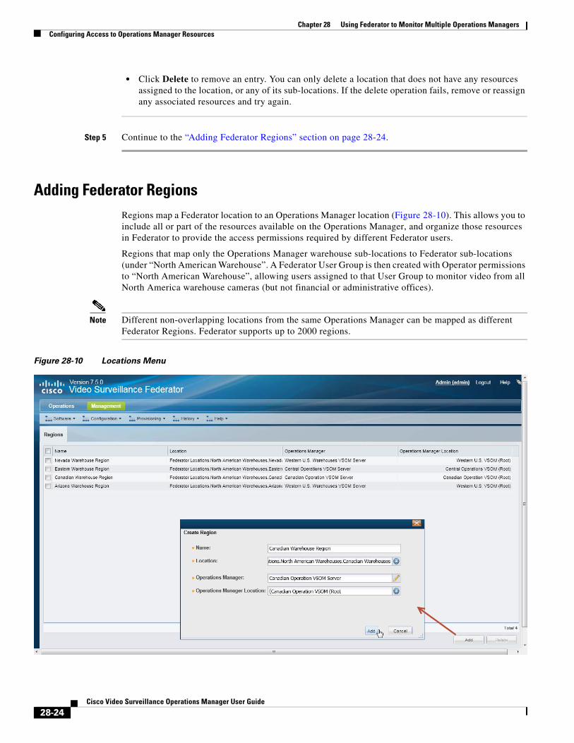
Chapter 28 Using Federator to Monitor Multiple Operations Managers Configuring Access to Operations Manager Resources
• Click Delete to remove an entry. You can only delete a location that does not have any resources assigned to the location, or any of its sub-locations. If the delete operation fails, remove or reassign any associated resources and try again.
Step 5 Continue to the “Adding Federator Regions” section on page 28-24.
Adding Federator RegionsRegions map a Federator location to an Operations Manager location (Figure 28-10). This allows you to include all or part of the resources available on the Operations Manager, and organize those resources in Federator to provide the access permissions required by different Federator users.
Regions that map only the Operations Manager warehouse sub-locations to Federator sub-locations (under “North American Warehouse”. A Federator User Group is then created with Operator permissions to “North American Warehouse”, allowing users assigned to that User Group to monitor video from all North America warehouse cameras (but not financial or administrative offices).
Note Different non-overlapping locations from the same Operations Manager can be mapped as different Federator Regions. Federator supports up to 2000 regions.
Figure 28-10 Locations Menu
28-24Cisco Video Surveillance Operations Manager User Guide
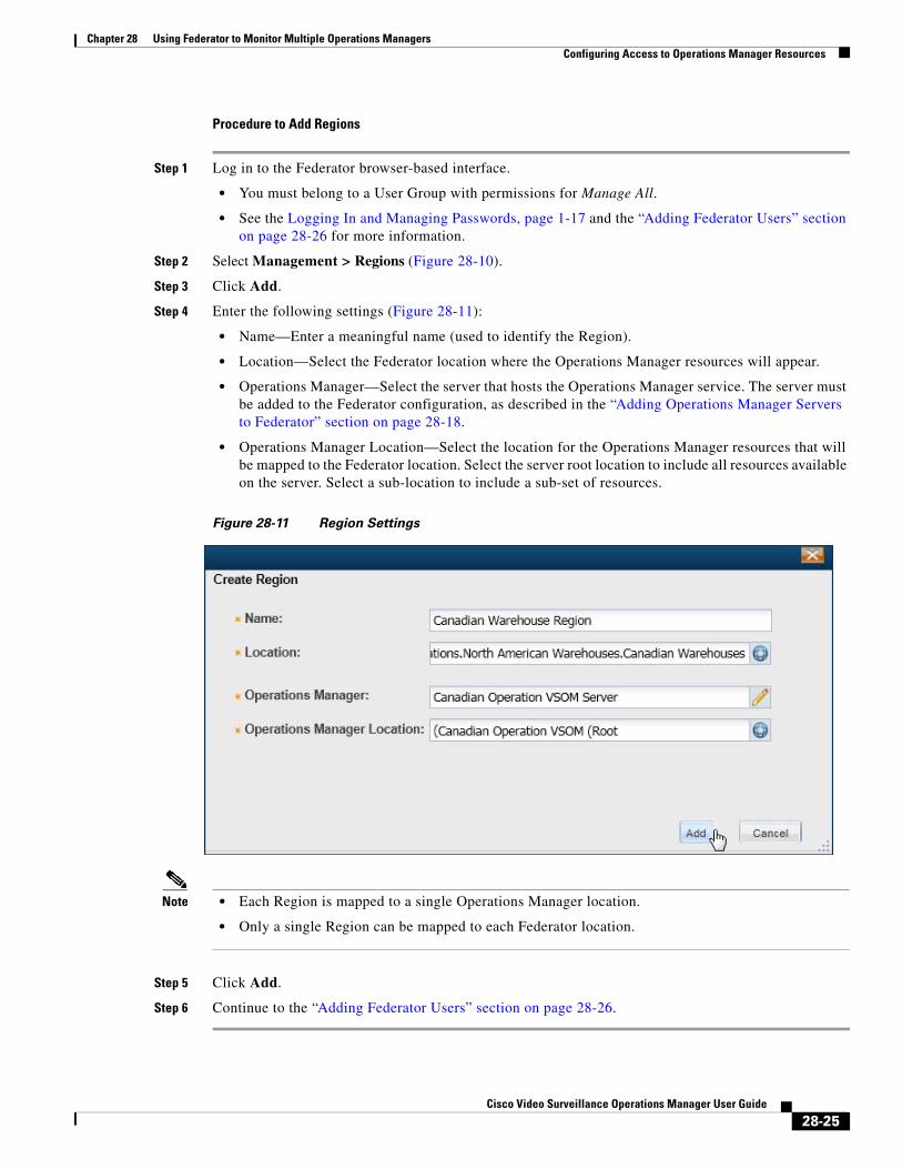
Chapter 28 Using Federator to Monitor Multiple Operations ManagersConfiguring Access to Operations Manager Resources
Procedure to Add Regions
Step 1 Log in to the Federator browser-based interface.
• You must belong to a User Group with permissions for Manage All.
• See the Logging In and Managing Passwords, page 1-17 and the “Adding Federator Users” section on page 28-26 for more information.
Step 2 Select Management > Regions (Figure 28-10).
Step 3 Click Add.
Step 4 Enter the following settings (Figure 28-11):
• Name—Enter a meaningful name (used to identify the Region).
• Location—Select the Federator location where the Operations Manager resources will appear.
• Operations Manager—Select the server that hosts the Operations Manager service. The server must be added to the Federator configuration, as described in the “Adding Operations Manager Servers to Federator” section on page 28-18.
• Operations Manager Location—Select the location for the Operations Manager resources that will be mapped to the Federator location. Select the server root location to include all resources available on the server. Select a sub-location to include a sub-set of resources.
Figure 28-11 Region Settings
Note • Each Region is mapped to a single Operations Manager location.
• Only a single Region can be mapped to each Federator location.
Step 5 Click Add.
Step 6 Continue to the “Adding Federator Users” section on page 28-26.
28-25Cisco Video Surveillance Operations Manager User Guide
Chapter 28 Using Federator to Monitor Multiple Operations Managers Configuring Access to Operations Manager Resources
Adding Federator UsersA Federator user account is required to log in to Federator and access the resources from multiple Operations Managers.
Note • Federator user accounts are different than Operations Manager user account. You cannot use Operations Manager credentials to access the Federator.
• Creating users is similar to the method to configure Operations Manager users. See the “Adding Users, User Groups, and Permissions” section on page 5-1 for more information.
• The permissions available in Federator Roles are different than those available in Operations Manager. See the “Understanding Federator Access Permissions” section on page 28-27.
Federator users can monitor video and system health based on the following:
• The user group(s) to which the user is assigned: user groups are associated with a user Role, which defines the access permissions for the group.
• The location assigned to the user group(s), and the Region(s) associated with that location (and its sub-locations).
• Users can be assigned to multiple user groups, and gain the combined access permissions for all groups.
Before You Begin
Before you begin:
1. Create the Federator location hierarchy and Regions as described in the following:
– Adding Federator Locations, page 28-22
– Adding Federator Regions, page 28-24.
2. See also the overview information in the following:
– Overview, page 28-3
– Configuring Access to Operations Manager Resources, page 28-16
3. Review the overview information and instructions to create Operations Manager users. Although the Roles are different, the general rules and configuration is the same.
– Adding Users, User Groups, and Permissions, page 5-1
28-26Cisco Video Surveillance Operations Manager User Guide
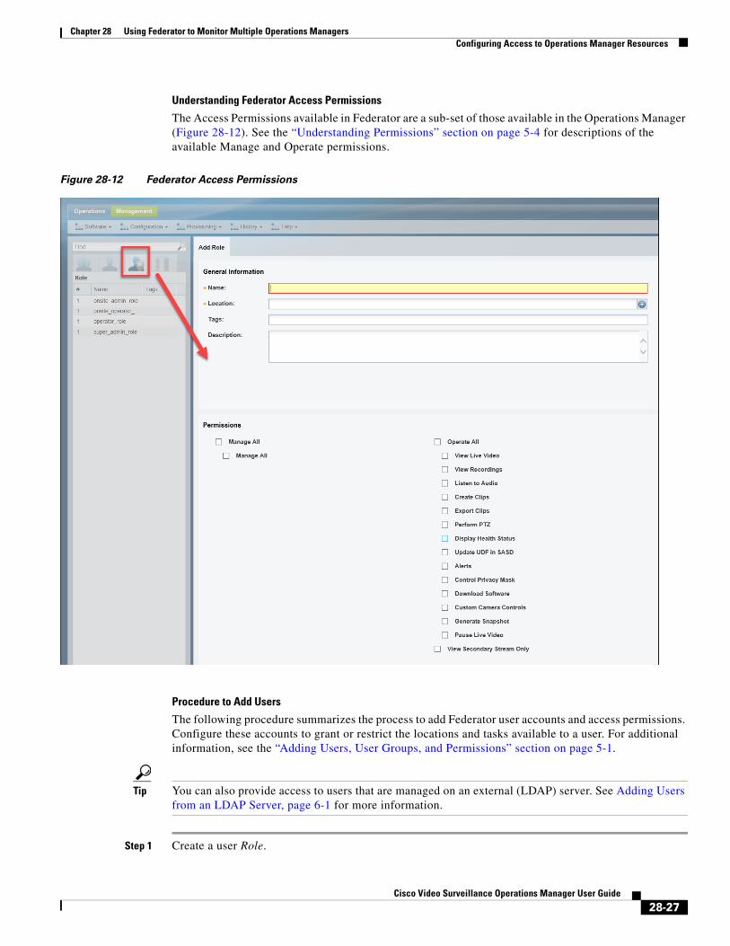
Chapter 28 Using Federator to Monitor Multiple Operations ManagersConfiguring Access to Operations Manager Resources
Understanding Federator Access Permissions
The Access Permissions available in Federator are a sub-set of those available in the Operations Manager (Figure 28-12). See the “Understanding Permissions” section on page 5-4 for descriptions of the available Manage and Operate permissions.
Figure 28-12 Federator Access Permissions
Procedure to Add Users
The following procedure summarizes the process to add Federator user accounts and access permissions. Configure these accounts to grant or restrict the locations and tasks available to a user. For additional information, see the “Adding Users, User Groups, and Permissions” section on page 5-1.
Tip You can also provide access to users that are managed on an external (LDAP) server. See Adding Users from an LDAP Server, page 6-1 for more information.
Step 1 Create a user Role.
28-27Cisco Video Surveillance Operations Manager User Guide

Chapter 28 Using Federator to Monitor Multiple Operations Managers Configuring Access to Operations Manager Resources
The Role defines the access permissions for different types of users. Roles are assigned to User Groups.
a. Select Users.
b. Select the Roles tab .
c. Click Add.
d. Enter the basic settings (see Table 5-6 on page 5-14).
e. Select the Role permissions (see Table 5-2 on page 5-6 and Table 5-3 on page 5-7).
Note The Federator permissions are different than the Operations Manager permissions.
f. Click Create.
Tip See the “Defining User Roles” section on page 5-12 for more information.
Step 2 Create a User Group.
User Groups allow you to create groups of users. The Role assigned to the User Group grants those access permissions to all users in the group.
a. Select the User Groups tab .
b. Click Add.
c. Enter the group settings, including the Role that defines the access permissions for the group (see Table 5-7 on page 5-15).
Tip Select the Approval Required checkbox (and “Approval Usergroup”) to enable Dual Login. All users assigned to the User Group can only gain access if a member of the “Approval Usergroup” also enters their password.
d. Click Create.
Tip See the “Adding User Groups” section on page 5-14.
Step 3 Create a User Account
The User account defines the username and password. Users gain access permissions through the User Group assignments. A user can be assigned to multiple groups, and gains the combined access permissions of all groups.
a. Select the User tab .
b. Click Add.
c. Enter the basic user settings (see Table 5-9 on page 5-21).
d. Add the user to one or more user groups.
– Click Add under the User Groups box.
– Select one or more user groups from the pop-up window.
– Select OK.
e. Click Create.
28-28Cisco Video Surveillance Operations Manager User Guide
Chapter 28 Using Federator to Monitor Multiple Operations ManagersMonitoring Video Using Federator
Tip See the “Adding Users” section on page 5-20. See also the “Adding Users, User Groups, and Permissions” section on page 5-1 for more information.
Step 4 Continue to the “Monitoring Video Using Federator” section on page 28-29 and the “Monitoring Device Health Using the Browser-Based Federator” section on page 28-33.
Monitoring Video Using FederatorFederator users can access video streams from the Operations Manager locations included in their access permissions. Access permissions are a combination of the following:
• The access permissions included in the Federator User Groups to which they belong. For example, View Live Video or View Recordings.
• The Federator location associated with the Federator User Groups to which they belong. For example, User Groups with access to the root location can access all Operations Managers configured on the Federator. User Groups with access to a sub-location, can view the video streams for Operations Managers at that location and lower.
• The Operations Manager locations that are mapped to the Federator locations (using “Regions”.) Regions can map to all Operations Manager locations (root) or a sub-location.
Usage Notes
• Federator users can view video from different Operations Managers in a single layout by dragging and dropping cameras in the video display grid.
• Federator users can load the Views defined in the Operations Managers.
• The Operations Manager default layouts are available in Federator.
• You can view, but not create, video clips in this release. Use the Cisco Video Surveillance Safety and Security Desktop application to create clips using Federator.
• To use the camera search, you must first select a location. Camera search is not supported across multiple Operations Managers.
Supported Monitoring Applications
Federator resources can be monitored using the following applications:
• The browser-based monitoring tool (described in this document).
• The Cisco Video Surveillance Safety and Security Desktop (Cisco SASD) desktop application.
See the Cisco Video Surveillance Safety and Security Desktop User Guide for more information.
• The Cisco Review Player desktop application.
See the Cisco Video Surveillance Review Player User Guide for more information.
Procedure
Step 1 Log in to the Federator browser-based interface.
28-29Cisco Video Surveillance Operations Manager User Guide
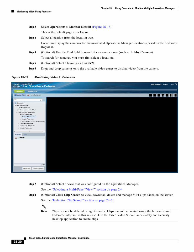
Chapter 28 Using Federator to Monitor Multiple Operations Managers Monitoring Video Using Federator
Step 2 Select Operations > Monitor Default (Figure 28-13).
This is the default page after log in.
Step 3 Select a location from the location tree.
Locations display the cameras for the associated Operations Manager locations (based on the Federator Regions).
Step 4 (Optional) Use the Find field to search for a camera name (such as Lobby Camera).
To search for cameras, you must first select a location.
Step 5 (Optional) Select a layout (such as 2x2).
Step 6 Drag-and-drop cameras onto the available video panes to display video from the camera.
Figure 28-13 Monitoring Video in Federator
Step 7 (Optional) Select a View that was configured on the Operations Manager.
See the “Selecting a Multi-Pane “View”” section on page 2-4.
Step 8 (Optional) Click Clip Search to view, download, delete and manage MP4 clips saved on the server.
See the “Federator Clip Search” section on page 28-31.
Note Clips can not be deleted using Federator. Clips cannot be created using the browser-based Federator interface in this release. Use the Cisco Video Surveillance Safety and Security Desktop application to create clips.
28-30Cisco Video Surveillance Operations Manager User Guide
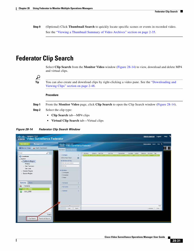
Chapter 28 Using Federator to Monitor Multiple Operations ManagersFederator Clip Search
Step 9 (Optional) Click Thumbnail Search to quickly locate specific scenes or events in recorded video.
See the “Viewing a Thumbnail Summary of Video Archives” section on page 2-35.
Federator Clip SearchSelect Clip Search from the Monitor Video window (Figure 28-14) to view, download and delete MP4 and virtual clips.
Tip You can also create and download clips by right-clicking a video pane. See the “Downloading and Viewing Clips” section on page 2-48.
Procedure
Step 1 From the Monitor Video page, click Clip Search to open the Clip Search window (Figure 28-14).
Step 2 Select the clip type:
• Clip Search tab—MP4 clips
• Virtual Clip Search tab—Virtual clips
Figure 28-14 Federator Clip Search Window
28-31Cisco Video Surveillance Operations Manager User Guide
Chapter 28 Using Federator to Monitor Multiple Operations Managers Federator Clip Search
Step 3 Select a region where the clip(s) were created. Only clips from the Operations Manager location mapped to that region will be displayed.
Step 4 (Optional) Use the filters to search for specific clips (Table 28-4):
Tip Click Search without filters to display all available clips.
Table 28-4 Filters For Searching Federator Clips
Field Description
Step 5 Click Search.
Step 6 Review information about the clips.
Table 28-5 Video Clip Information
Field Description
Step 7 (Optional) To download an MP4 clip, select a clip and click Download.
Note Only a single clip can be downloaded at a time.
By Clip Name The full or partial name for the clip(s), which is entered when the clip is created
By Tag Not available in Release 7.2.
By Clip Status Select the status for the displayed clips. Any status not selected will not be displayed.
By Camera The camera name where the clip originated.
By Location Clips created by all cameras at the selected location(s).
By Server Clips created by all cameras associated with the selected servers(s).
Clip Name The clip name entered when the clip was created. The default is “My Clip” if no name is entered.
Camera Name The camera name where the clip originated.
Start Time The start timestamp for the clip.
End Time The end timestamp for the clip.
Clip Expiration The date/time when the clip will be deleted from the server.
Clip Status In-Progress, Completed or Failed
Location Location of the cameras where the clip originated.
Media Server The Media Server that manages the camera video where the clip originated.
Clip Owner The user that created the clip.
Tags Tags associated with the clip (blank in Release 7.2)
28-32Cisco Video Surveillance Operations Manager User Guide
Chapter 28 Using Federator to Monitor Multiple Operations ManagersMonitoring Device Health Using the Browser-Based Federator
Note If an “HTTP 400 Bad Request” error appears, it may be due to the Internet Explorer (IE) settings. In IE, go to Tools > Internet Options > Advanced and select “Use HTTP 1.1”. Also deselect “Use HTTP 1.1 through proxy connections”. Next, click the Connections tab, choose the LAN settings button and select “Automatically detect settings”.
a. Click Continue and accept the security certificate when the Internet Explorer web browser prompts you to proceed to the secure page. This prompt appears only once for each Media Server.
b. Select one of the following options:
– Open—Plays the file using your default video player.
– Save —Saves the file to the default location using a default filename.
– Save As—Enter a new filename and select a location on the local disk.
– Save and Open—Saves the file to the default location using a default filename, and then plays the clip using your default video player.
Step 8 (Optional) To permanently delete a clip from the server, select one or more clips and click Delete.
Note Only the server file is deleted. Any clips previously downloaded to a local disk are not affected.
Monitoring Device Health Using the Browser-Based Federator • Federator Health Dashboard, page 28-33
• Federator Audit Logs, page 28-36
Federator Health Dashboard • Overview, page 28-33
• Viewing Device Health Using the Federator, page 28-34
• Understanding Warning and Critical Faults, page 28-36
• Procedure, page 28-36
Overview
Use the browser-based Federator Health Dashboard (Operations > Health Dashboard) to view a summary of device health issues that are occurring on the servers, encoders and cameras of all Operations Managers managed by the Federator.
The browser-based Federator displays two types of alerts:
• Federator device health alerts—health alerts generated by the Federator server.
• Operations Manager health alerts—alerts gathered from the Operations Managers monitored by the Federator.
28-33Cisco Video Surveillance Operations Manager User Guide
Chapter 28 Using Federator to Monitor Multiple Operations Managers Monitoring Device Health Using the Browser-Based Federator
Note The browser-based Federator Health Dashboard displays device health events only. To view security events (such as motion or contact events), use the Cisco SASD Federator. See the Cisco Video Surveillance Safety and Security Desktop User Guide for more information. For example, you can use Advanced events to automatically send motion events to the Cisco SASD Federator, or manually send specific alerts from an Operations Manager to the Federator.
The Federator Health Dashboard is similar to the Health Dashboard for an Operations Manager: it displays the critical and warning faults on devices, such as servers, cameras and encoders (Figure 28-15).
The Federator Health Dashboard differs from the Operations Manager dashboard in the following ways:
• Federator health information is not updated in real-time. Device health is periodically gathered (every 30 minutes) from the Operations Managers by the Federator and cannot be updated by refreshing the page.
• Locations cannot be selected in the Federator Health Dashboard. Health issues counts (not the actual issues) are displayed for the locations that the user can view. For example, if a user is assigned to a Federator user group with the California location, then the user would see only the issue counts from California and its sub-locations. If a higher-level location (such as “System”) had 10 issues, that issue count would not be displayed for California users. The Federator locations include only the Operations Manager resources mapped to the Federator regions.
• Issues do not include the icon to open the device’s configuration page. You must log in to the Operations Manager for the device to access the device status and configuration pages.
• Issues are displayed by category only (and not by issue type).
Viewing Device Health Using the Federator
To view health issues, select Operations > Health Dashboard and click a number next to a category for a servers, cameras or encoders (Figure 28-15). The issues list displays more information about the source if the health issue, allowing you to log in to the correct Operations Manager and access the device’s status and configuration page for more information or to correct the problem.
Note Federator users must be in a user groups with the Display Health Status access permission to view the device health status and the Federator Health Dashboard. See the Adding Federator Users for information to create Federator users and assign them to user groups.
Tip For more information about the Operations Manager Health Dashboard, see the “Health Dashboard: Device Health Faults on an Operations Manager” section on page 24-7.
28-34Cisco Video Surveillance Operations Manager User Guide
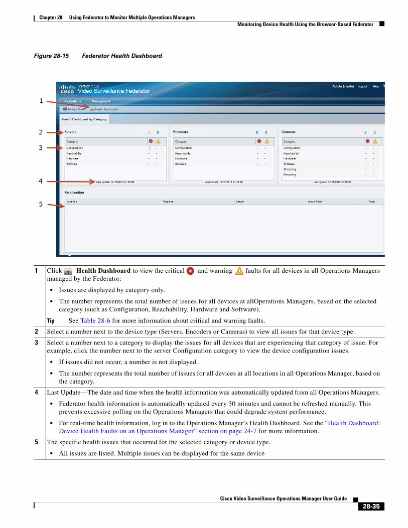
Chapter 28 Using Federator to Monitor Multiple Operations ManagersMonitoring Device Health Using the Browser-Based Federator
Figure 28-15 Federator Health Dashboard
1
• Issues are displayed by category only.
• The number represents the total number of issues for all devices at allOperations Managers, based on the selected category (such as Configuration, Reachability, Hardware and Software).
Tip See Table 28-6 for more information about critical and warning faults.
2
3
• If issues did not occur, a number is not displayed.
• The number represents the total number of issues for all devices at all locations in all Operations Manager, based on the category.
4
• Federator health information is automatically updated every 30 minutes and cannot be refreshed manually. This prevents excessive polling on the Operations Managers that could degrade system performance.
• For real-time health information, log in to the Operations Manager’s Health Dashboard. See the “Health Dashboard: Device Health Faults on an Operations Manager” section on page 24-7 for more information.
5
• All issues are listed. Multiple issues can be displayed for the same device
Click Health Dashboard to view the critical and warning faults for all devices in all Operations Managers managed by the Federator:
Select a number next to the device type (Servers, Encoders or Cameras) to view all issues for that device type.
Select a number next to a category to display the issues for all devices that are experiencing that category of issue. For example, click the number next to the server Configuration category to view the device configuration issues.
Last Update—The date and time when the health information was automatically updated from all Operations Managers.
The specific health issues that occurred for the selected category or device type.
28-35Cisco Video Surveillance Operations Manager User Guide
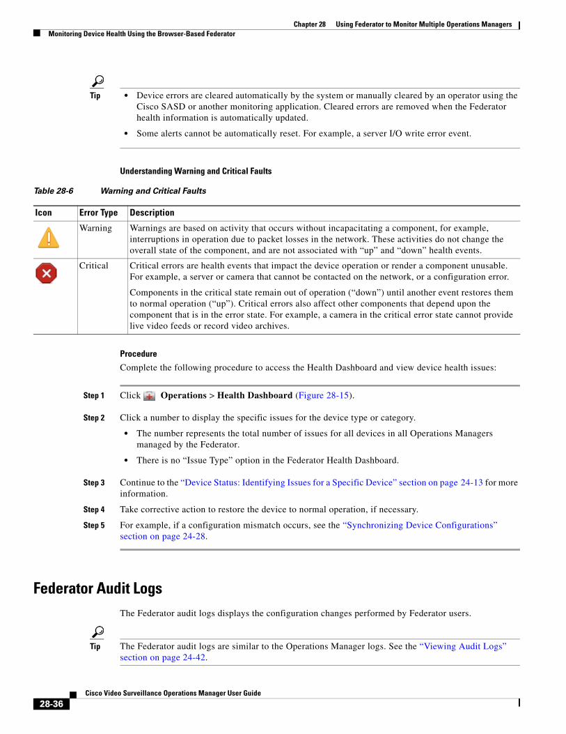
Chapter 28 Using Federator to Monitor Multiple Operations Managers Monitoring Device Health Using the Browser-Based Federator
Tip • Device errors are cleared automatically by the system or manually cleared by an operator using the Cisco SASD or another monitoring application. Cleared errors are removed when the Federator health information is automatically updated.
• Some alerts cannot be automatically reset. For example, a server I/O write error event.
Understanding Warning and Critical Faults
Table 28-6 Warning and Critical Faults
Icon Error Type Description
Procedure
Complete the following procedure to access the Health Dashboard and view device health issues:
Step 1 Click Operations > Health Dashboard (Figure 28-15).
Step 2 Click a number to display the specific issues for the device type or category.
• The number represents the total number of issues for all devices in all Operations Managers managed by the Federator.
• There is no “Issue Type” option in the Federator Health Dashboard.
Step 3 Continue to the “Device Status: Identifying Issues for a Specific Device” section on page 24-13 for more information.
Step 4 Take corrective action to restore the device to normal operation, if necessary.
Step 5 For example, if a configuration mismatch occurs, see the “Synchronizing Device Configurations” section on page 24-28.
Federator Audit LogsThe Federator audit logs displays the configuration changes performed by Federator users.
Tip The Federator audit logs are similar to the Operations Manager logs. See the “Viewing Audit Logs” section on page 24-42.
Warning Warnings are based on activity that occurs without incapacitating a component, for example, interruptions in operation due to packet losses in the network. These activities do not change the overall state of the component, and are not associated with “up” and “down” health events.
Critical Critical errors are health events that impact the device operation or render a component unusable. For example, a server or camera that cannot be contacted on the network, or a configuration error.
Components in the critical state remain out of operation (“down”) until another event restores them to normal operation (“up”). Critical errors also affect other components that depend upon the component that is in the error state. For example, a camera in the critical error state cannot provide live video feeds or record video archives.
28-36Cisco Video Surveillance Operations Manager User Guide
Chapter 28 Using Federator to Monitor Multiple Operations ManagersMonitoring Device Health Using the Browser-Based Federator
Note Users must belong to a User Group with super-admin permissions to access the Audit Logs (the user must be added to a user group that is associated with the super-admin role). See the Adding Users, User Groups, and Permissions, page 5-1.
Procedure
Step 1 Select Management > Audit Logs.
Step 2 (Optional) Search for Audit entries using the “Search By” fields.
Step 3 (Optional) Click the Column headings to sort the results by that category.
Step 4 (Optional) Click Job Reference to display additional job details about the action performed by the user.
Step 5 Refer to the “Viewing Audit Logs” section on page 24-42 for additional features and instructions.
To view active uses and log them out, see Viewing and Logging Out Active Users, page 5-22.
Viewing Federator Active UsersThe Active Users page displays information about the user accounts that are currently logged in to the Cisco VSM Federator. This page is available to super-admins only.
Choose Management > Active Users.
To discontinue an active user session, select an entry and click Kill Session. Users that are logged out in this method can continue watching the video they are currently viewing. But users must log in again if they attempt to access new video streams or open a new video pane.
Table 28-7 Active User Fields
Setting Description
Notes
• You cannot kill (end) your own user session.
• To view a history of user activity, go to Management > Audit Logs (see Federator Audit Logs, page 28-36).
Username The username of the account used to access the system.
First Name The first name in the user account
Last Name The last name in the user account
User Group(s) The user groups the user is assigned to.
User groups define the user role and location for member users, which defines the cameras and resources they can access.
Super-admin Indicates if the user account is assigned the super-admin role.
Logged-In Time The date and time when the user logged in.
Last Access Time The date and time the user last performed any action on the system.
From IP The IP address of the device or computer used to access the system.
28-37Cisco Video Surveillance Operations Manager User Guide

Chapter 28 Using Federator to Monitor Multiple Operations Managers Monitoring Device Health Using the Browser-Based Federator
• To view and log out users of a specific deployment, log in to the Operations Manager. See Viewing and Logging Out Active Users, page 5-22.
28-38Cisco Video Surveillance Operations Manager User Guide
Chapter 28 Using Federator to Monitor Multiple Operations ManagersAdministration Tasks
Administration TasksRefer to the following topics to perform common administrative tasks on the Federator server.
• “Backing up and Restoring the Federator Configuration” section on page 28-39
• “Updating the Federator Server System Software” section on page 28-42
Backing up and Restoring the Federator ConfigurationBack up the Federator configuration so the system can be restored if it becomes unstable or to revert to an older configuration.
• Manually Backing Up a Federator Server, page 28-39
• Automatic Backups (Single Federator Server), page 28-40
Note We recommend backing up all servers on a regular basis to ensure configuration and event data is not lost if a hardware failure occurs. Backups are also used to restore configurations and historical data when upgrading or moving to a new system.
You can backup a single Federator server at a time. The following instructions are to perform a manual one-time backup. To configure an automatic backup schedule, see the “Initial Server Setup” section on page 28-10.
Tip The Federator backup procedure is similar to the Operations Manager procedure. See the “Backing Up and Restoring a Single Server” section on page 27-8 for more information.
Manually Backing Up a Federator Server
To perform a one-time manual backup, do the following.
Procedure
Step 1 Select Management > Backup & Restore.
Step 2 Select the Manage Backup tab (Figure 28-16).
Step 3 Click Backup Now and select To Remote or To Local.
Step 4 From the pop-up, select the destination and backup type.
See the “Backup Settings” section on page 27-3 for more information).
Step 5 Click OK.
Step 6 Backup files are saved to the selected destination. See the “Backup File Format” section on page 27-4 for a description of the file name.
• If saved locally, the backup files are saved to the Backup File list in the Restore From Backup tab.
• Failed backups are displayed in the Failed Backup field. Double-click a failed scheduled backup entry to display additional details (failed manual backups do not display additional information).
28-39Cisco Video Surveillance Operations Manager User Guide
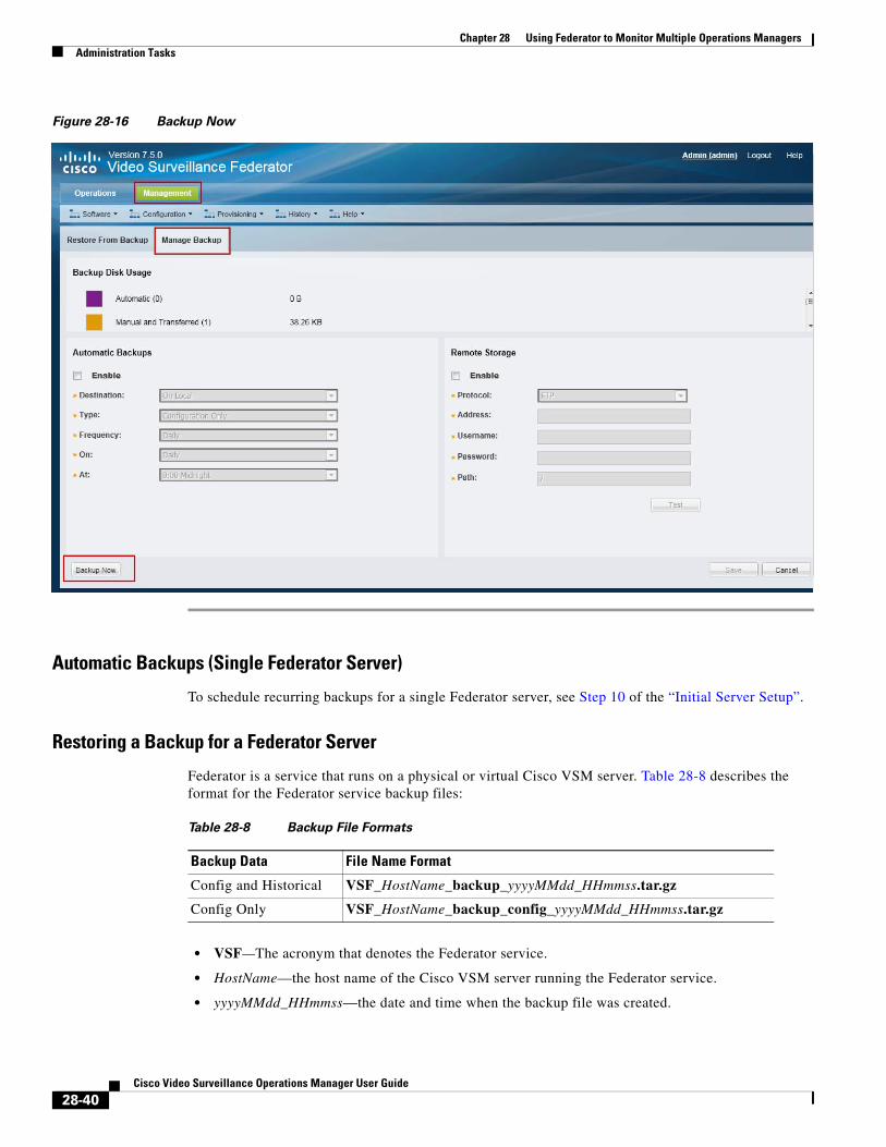
Chapter 28 Using Federator to Monitor Multiple Operations Managers Administration Tasks
Figure 28-16 Backup Now
Automatic Backups (Single Federator Server)
To schedule recurring backups for a single Federator server, see Step 10 of the “Initial Server Setup”.
Restoring a Backup for a Federator Server
Federator is a service that runs on a physical or virtual Cisco VSM server. Table 28-8 describes the format for the Federator service backup files:
Table 28-8 Backup File Formats
Backup Data File Name Format
• VSF—The acronym that denotes the Federator service.
• HostName—the host name of the Cisco VSM server running the Federator service.
• yyyyMMdd_HHmmss—the date and time when the backup file was created.
Config and Historical VSF_HostName_backup_yyyyMMdd_HHmmss.tar.gz
Config Only VSF_HostName_backup_config_yyyyMMdd_HHmmss.tar.gz
28-40Cisco Video Surveillance Operations Manager User Guide
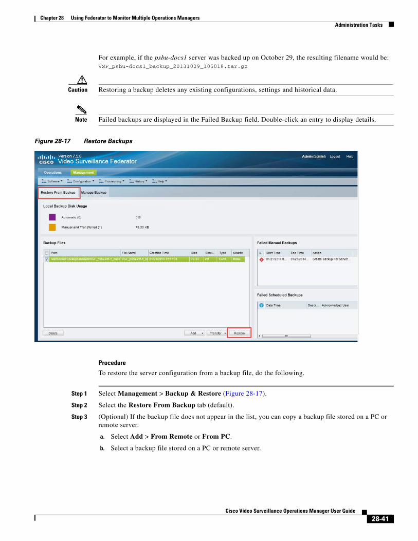
Chapter 28 Using Federator to Monitor Multiple Operations ManagersAdministration Tasks
For example, if the psbu-docs1 server was backed up on October 29, the resulting filename would be: VSF_psbu-docs1_backup_20131029_105018.tar.gz
Caution Restoring a backup deletes any existing configurations, settings and historical data.
Note Failed backups are displayed in the Failed Backup field. Double-click an entry to display details.
Figure 28-17 Restore Backups
Procedure
To restore the server configuration from a backup file, do the following.
Step 1 Select Management > Backup & Restore (Figure 28-17).
Step 2 Select the Restore From Backup tab (default).
Step 3 (Optional) If the backup file does not appear in the list, you can copy a backup file stored on a PC or remote server.
a. Select Add > From Remote or From PC.
b. Select a backup file stored on a PC or remote server.
28-41Cisco Video Surveillance Operations Manager User Guide
Chapter 28 Using Federator to Monitor Multiple Operations Managers Administration Tasks
Note You must first enter the Remote Storage settings in the Manage Backup tab before you can transfer a file from a remote server. See the “Backup Settings” section on page 27-3 for more information.
c. Click Save.
Step 4 Select the backup file for the service you want to restore.
Step 5 Click Restore.
Step 6 Click Yes to confirm the backup and server restart.
Step 7 Click OK when the restore process is complete.
Step 8 Re-login to the server.
Updating the Federator Server System SoftwareSystem Software is the Cisco VSM server software that includes the Federator service, Federator browser-based interface, and Management Console.
To update a Federator server, log in to the Federator server Management Console and use the Server Upgrade feature.
• Go to Operations > Management Console to launch the Management Console.
• See the Cisco Video Surveillance Management Console Administration Guide for more information. See your system administrator for login information.
28-42Cisco Video Surveillance Operations Manager User Guide
Cisco V
C H A P T E R 29
Using Dynamic Proxy to Monitor Video From Remote SitesDynamic Proxy allows users to access video streams from remote Sites that have limited outbound bandwidth. The video can be delivered to multiple users without placing additional load on the remote Site.
Refer to the following topics for more information:
Contents
• Dynamic Proxy Overview, page 29-1
• Understanding Sites, page 29-3
• Dynamic Proxy Requirements, page 29-4
• Summary Steps to Configure Dynamic Proxy, page 29-5
• Detailed Steps to Configure Dynamic Proxy, page 29-6
Dynamic Proxy OverviewWhen cameras and their associated Media Servers are located in Site with limited outgoing connectivity (such as an offshore oil platform), the Dynamic Proxy (DP) feature can be used to reduce the amount video data going out from that remote Site (Figure 29-1).
The Dynamic Proxy (DP) feature provides this service by retrieving video from the remote Media Servers and delivering it to the end users. The DP minimizes the amount of bandwidth used to deliver video data from the remote Site while allowing multiple users to access that video data.
29-1ideo Surveillance Operations Manager User Guide
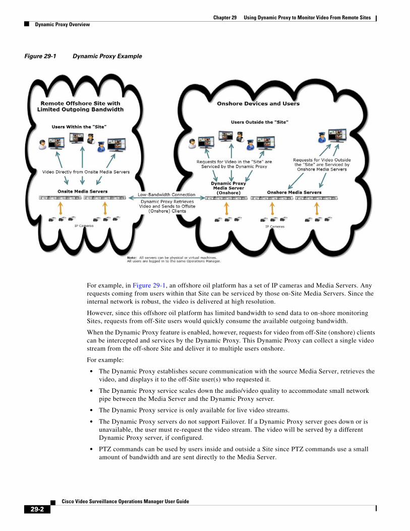
Chapter 29 Using Dynamic Proxy to Monitor Video From Remote Sites Dynamic Proxy Overview
Figure 29-1 Dynamic Proxy Example
For example, in Figure 29-1, an offshore oil platform has a set of IP cameras and Media Servers. Any requests coming from users within that Site can be serviced by those on-Site Media Servers. Since the internal network is robust, the video is delivered at high resolution.
However, since this offshore oil platform has limited bandwidth to send data to on-shore monitoring Sites, requests from off-Site users would quickly consume the available outgoing bandwidth.
When the Dynamic Proxy feature is enabled, however, requests for video from off-Site (onshore) clients can be intercepted and services by the Dynamic Proxy. This Dynamic Proxy can collect a single video stream from the off-shore Site and deliver it to multiple users onshore.
For example:
• The Dynamic Proxy establishes secure communication with the source Media Server, retrieves the video, and displays it to the off-Site user(s) who requested it.
• The Dynamic Proxy service scales down the audio/video quality to accommodate small network pipe between the Media Server and the Dynamic Proxy server.
• The Dynamic Proxy service is only available for live video streams.
• The Dynamic Proxy servers do not support Failover. If a Dynamic Proxy server goes down or is unavailable, the user must re-request the video stream. The video will be served by a different Dynamic Proxy server, if configured.
• PTZ commands can be used by users inside and outside a Site since PTZ commands use a small amount of bandwidth and are sent directly to the Media Server.
29-2Cisco Video Surveillance Operations Manager User Guide
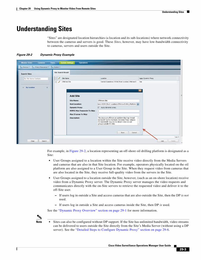
Chapter 29 Using Dynamic Proxy to Monitor Video From Remote SitesUnderstanding Sites
Understanding Sites“Sites” are designated location hierarchies (a location and its sub-locations) where network connectivity between the cameras and servers is good. These Sites, however, may have low-bandwidth connectivity to cameras, servers and users outside the Site.
Figure 29-2 Dynamic Proxy Example
For example, in Figure 29-2, a location representing an off-shore oil drilling platform is designated as a Site:
• User Groups assigned to a location within the Site receive video directly from the Media Servers and cameras that are also in that Site location. For example, operators physically located on the oil platform are also assigned to a User Group in the Site. When they request video from cameras that are also located in the Site, they receive full-quality video from the servers in the Site.
• User Groups assigned to a location outside the Site, however, (such as an on-shore location) receive video from a Dynamic Proxy server. The Dynamic Proxy server manages the video requests and communicates directly with the on-Site servers to retrieve the requested video and deliver it to the off-Site user.
– If users log in outside a Site and access cameras that are also outside the Site, then the DP is not used.
– If users log in outside a Site and access cameras inside the Site, then DP is used.
See the “Dynamic Proxy Overview” section on page 29-1 for more information.
Note • Sites can also be configured without DP support. If the Site has unlimited bandwidth, video streams can be delivered to users outside the Site directly from the Site’s Media Server (without using a DP server). See the “Detailed Steps to Configure Dynamic Proxy” section on page 29-6.
29-3Cisco Video Surveillance Operations Manager User Guide
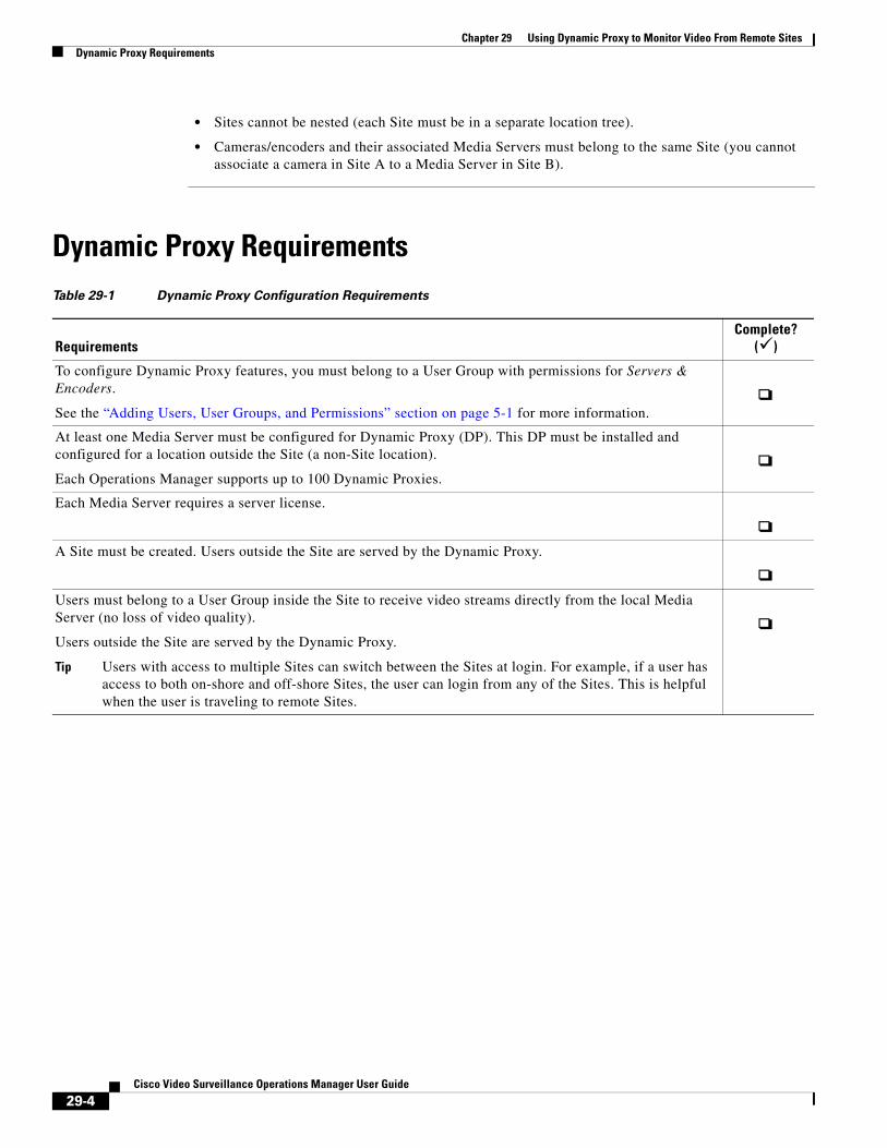
Chapter 29 Using Dynamic Proxy to Monitor Video From Remote Sites Dynamic Proxy Requirements
• Sites cannot be nested (each Site must be in a separate location tree).
• Cameras/encoders and their associated Media Servers must belong to the same Site (you cannot associate a camera in Site A to a Media Server in Site B).
Dynamic Proxy RequirementsTable 29-1 Dynamic Proxy Configuration Requirements
RequirementsComplete?
()
To configure Dynamic Proxy features, you must belong to a User Group with permissions for Servers & Encoders.
See the “Adding Users, User Groups, and Permissions” section on page 5-1 for more information.
At least one Media Server must be configured for Dynamic Proxy (DP). This DP must be installed and configured for a location outside the Site (a non-Site location).
Each Operations Manager supports up to 100 Dynamic Proxies.
Each Media Server requires a server license.
A Site must be created. Users outside the Site are served by the Dynamic Proxy.
Users must belong to a User Group inside the Site to receive video streams directly from the local Media Server (no loss of video quality).
Users outside the Site are served by the Dynamic Proxy.
Tip Users with access to multiple Sites can switch between the Sites at login. For example, if a user has access to both on-shore and off-shore Sites, the user can login from any of the Sites. This is helpful when the user is traveling to remote Sites.
29-4Cisco Video Surveillance Operations Manager User Guide
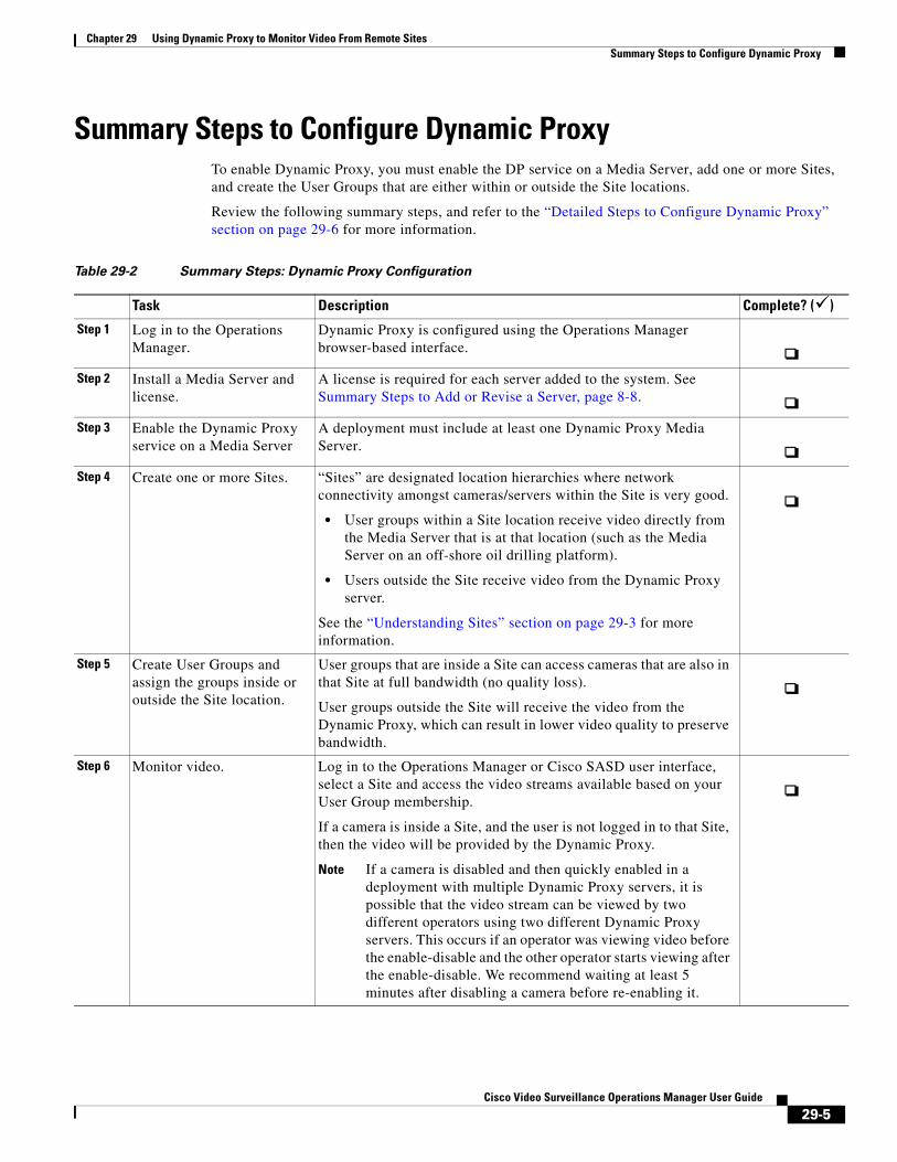
Chapter 29 Using Dynamic Proxy to Monitor Video From Remote SitesSummary Steps to Configure Dynamic Proxy
Summary Steps to Configure Dynamic Proxy To enable Dynamic Proxy, you must enable the DP service on a Media Server, add one or more Sites, and create the User Groups that are either within or outside the Site locations.
Review the following summary steps, and refer to the “Detailed Steps to Configure Dynamic Proxy” section on page 29-6 for more information.
Table 29-2 Summary Steps: Dynamic Proxy Configuration
Task Description Complete? ()
Step 1
Step 2
Step 3
Step 4
• User groups within a Site location receive video directly from the Media Server that is at that location (such as the Media Server on an off-shore oil drilling platform).
• Users outside the Site receive video from the Dynamic Proxy server.
Step 5
Step 6
Note If a camera is disabled and then quickly enabled in a deployment with multiple Dynamic Proxy servers, it is possible that the video stream can be viewed by two different operators using two different Dynamic Proxy servers. This occurs if an operator was viewing video before the enable-disable and the other operator starts viewing after the enable-disable. We recommend waiting at least 5 minutes after disabling a camera before re-enabling it.
Log in to the Operations Manager.
Dynamic Proxy is configured using the Operations Manager browser-based interface.
Install a Media Server and license.
A license is required for each server added to the system. See Summary Steps to Add or Revise a Server, page 8-8.
Enable the Dynamic Proxy service on a Media Server
A deployment must include at least one Dynamic Proxy Media Server.
Create one or more Sites. “Sites” are designated location hierarchies where network connectivity amongst cameras/servers within the Site is very good.
See the “Understanding Sites” section on page 29-3 for more information.
Create User Groups and assign the groups inside or outside the Site location.
User groups that are inside a Site can access cameras that are also in that Site at full bandwidth (no quality loss).
User groups outside the Site will receive the video from the Dynamic Proxy, which can result in lower video quality to preserve bandwidth.
Monitor video. Log in to the Operations Manager or Cisco SASD user interface, select a Site and access the video streams available based on your User Group membership.
If a camera is inside a Site, and the user is not logged in to that Site, then the video will be provided by the Dynamic Proxy.
29-5Cisco Video Surveillance Operations Manager User Guide
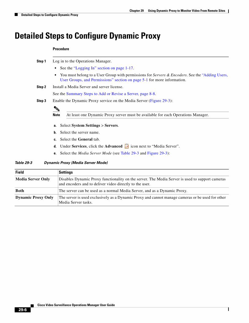
Chapter 29 Using Dynamic Proxy to Monitor Video From Remote Sites Detailed Steps to Configure Dynamic Proxy
Detailed Steps to Configure Dynamic ProxyProcedure
Step 1 Log in to the Operations Manager.
• See the “Logging In” section on page 1-17.
• You must belong to a User Group with permissions for Servers & Encoders. See the “Adding Users, User Groups, and Permissions” section on page 5-1 for more information.
Step 2 Install a Media Server and server license.
See the Summary Steps to Add or Revise a Server, page 8-8.
Step 3 Enable the Dynamic Proxy service on the Media Server (Figure 29-3):
Note At least one Dynamic Proxy server must be available for each Operations Manager.
a. Select System Settings > Servers.
b. Select the server name.
c. Select the General tab.
d. Under Services, click the Advanced icon next to “Media Server”.
e. Select the Media Server Mode (see Table 29-3 and Figure 29-3):
Table 29-3 Dynamic Proxy (Media Server Mode)
Field Settings
Media Server Only Disables Dynamic Proxy functionality on the server. The Media Server is used to support cameras and encoders and to deliver video directly to the user.
Both The server can be used as a normal Media Server, and as a Dynamic Proxy.
Dynamic Proxy Only The server is used exclusively as a Dynamic Proxy and cannot manage cameras or be used for other Media Server tasks.
29-6Cisco Video Surveillance Operations Manager User Guide
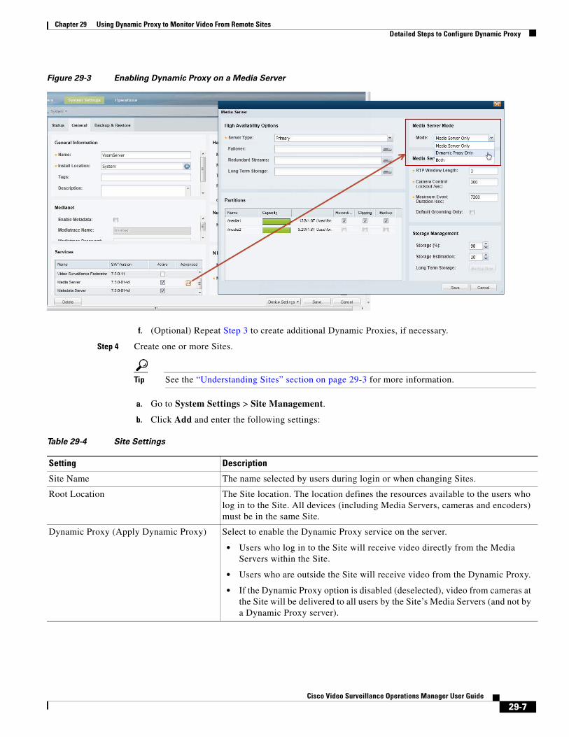
Chapter 29 Using Dynamic Proxy to Monitor Video From Remote SitesDetailed Steps to Configure Dynamic Proxy
Figure 29-3 Enabling Dynamic Proxy on a Media Server
f. (Optional) Repeat Step 3 to create additional Dynamic Proxies, if necessary.
Step 4 Create one or more Sites.
Tip See the “Understanding Sites” section on page 29-3 for more information.
a. Go to System Settings > Site Management.
b. Click Add and enter the following settings:
Table 29-4 Site Settings
Setting Description
Site Name The name selected by users during login or when changing Sites.
Root Location The Site location. The location defines the resources available to the users who log in to the Site. All devices (including Media Servers, cameras and encoders) must be in the same Site.
Dynamic Proxy (Apply Dynamic Proxy) Select to enable the Dynamic Proxy service on the server.
• Users who log in to the Site will receive video directly from the Media Servers within the Site.
• Users who are outside the Site will receive video from the Dynamic Proxy.
• If the Dynamic Proxy option is disabled (deselected), video from cameras at the Site will be delivered to all users by the Site’s Media Servers (and not by a Dynamic Proxy server).
29-7Cisco Video Surveillance Operations Manager User Guide
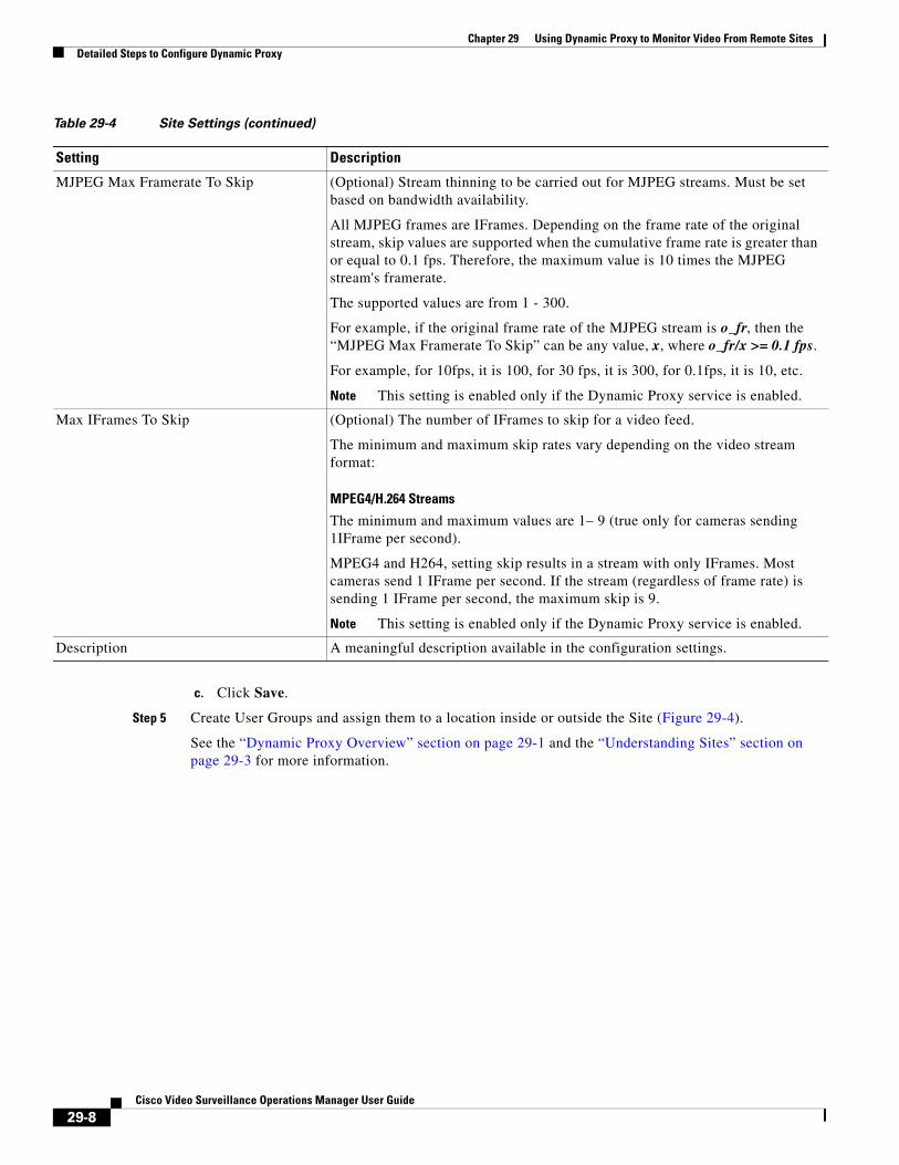
Chapter 29 Using Dynamic Proxy to Monitor Video From Remote Sites Detailed Steps to Configure Dynamic Proxy
c. Click Save.
Step 5 Create User Groups and assign them to a location inside or outside the Site (Figure 29-4).
See the “Dynamic Proxy Overview” section on page 29-1 and the “Understanding Sites” section on page 29-3 for more information.
MJPEG Max Framerate To Skip (Optional) Stream thinning to be carried out for MJPEG streams. Must be set based on bandwidth availability.
All MJPEG frames are IFrames. Depending on the frame rate of the original stream, skip values are supported when the cumulative frame rate is greater than or equal to 0.1 fps. Therefore, the maximum value is 10 times the MJPEG stream's framerate.
The supported values are from 1 - 300.
For example, if the original frame rate of the MJPEG stream is o_fr, then the “MJPEG Max Framerate To Skip” can be any value, x, where o_fr/x >= 0.1 fps.
For example, for 10fps, it is 100, for 30 fps, it is 300, for 0.1fps, it is 10, etc.
Note This setting is enabled only if the Dynamic Proxy service is enabled.
Max IFrames To Skip (Optional) The number of IFrames to skip for a video feed.
The minimum and maximum skip rates vary depending on the video stream format:
MPEG4/H.264 Streams
The minimum and maximum values are 1– 9 (true only for cameras sending 1IFrame per second).
MPEG4 and H264, setting skip results in a stream with only IFrames. Most cameras send 1 IFrame per second. If the stream (regardless of frame rate) is sending 1 IFrame per second, the maximum skip is 9.
Note This setting is enabled only if the Dynamic Proxy service is enabled.
Description A meaningful description available in the configuration settings.
Table 29-4 Site Settings (continued)
Setting Description
29-8Cisco Video Surveillance Operations Manager User Guide
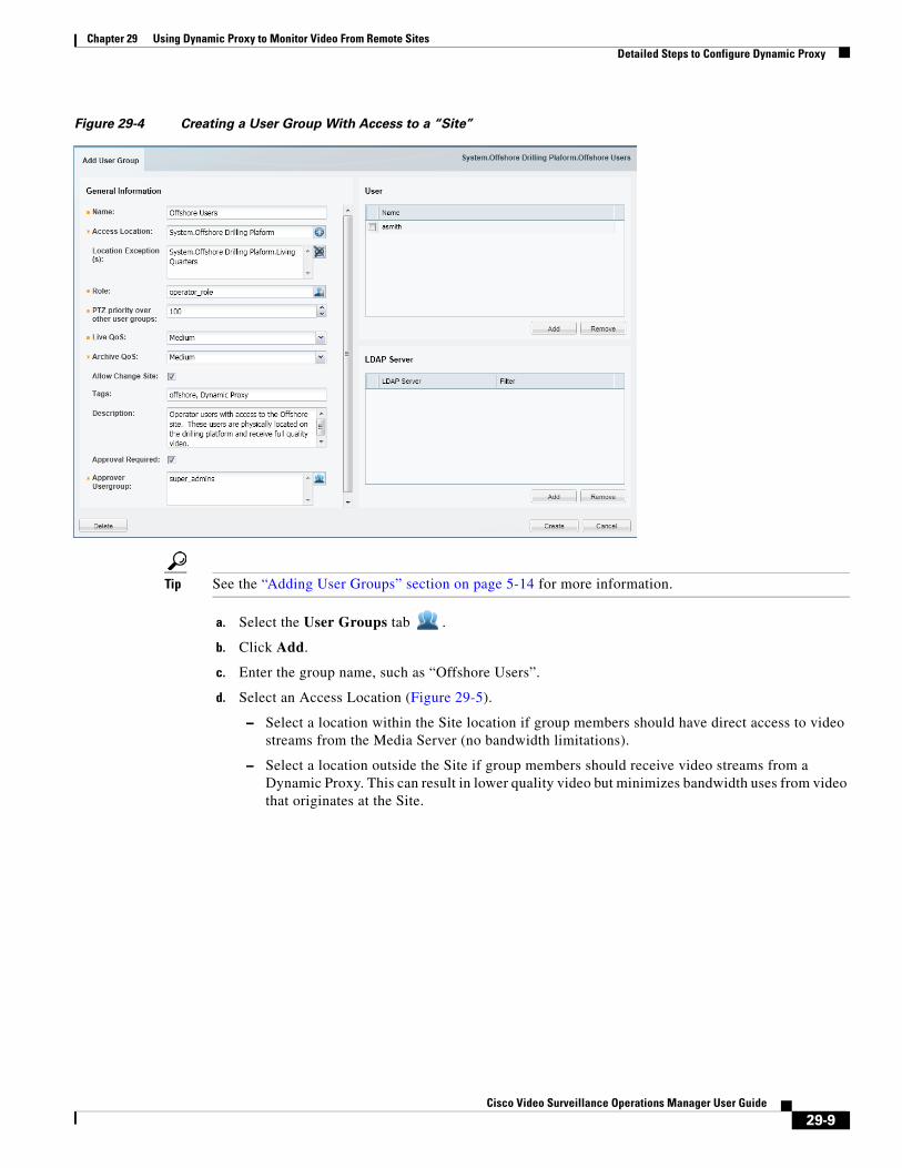
Chapter 29 Using Dynamic Proxy to Monitor Video From Remote SitesDetailed Steps to Configure Dynamic Proxy
Figure 29-4 Creating a User Group With Access to a “Site”
Tip See the “Adding User Groups” section on page 5-14 for more information.
a. Select the User Groups tab .
b. Click Add.
c. Enter the group name, such as “Offshore Users”.
d. Select an Access Location (Figure 29-5).
– Select a location within the Site location if group members should have direct access to video streams from the Media Server (no bandwidth limitations).
– Select a location outside the Site if group members should receive video streams from a Dynamic Proxy. This can result in lower quality video but minimizes bandwidth uses from video that originates at the Site.
29-9Cisco Video Surveillance Operations Manager User Guide
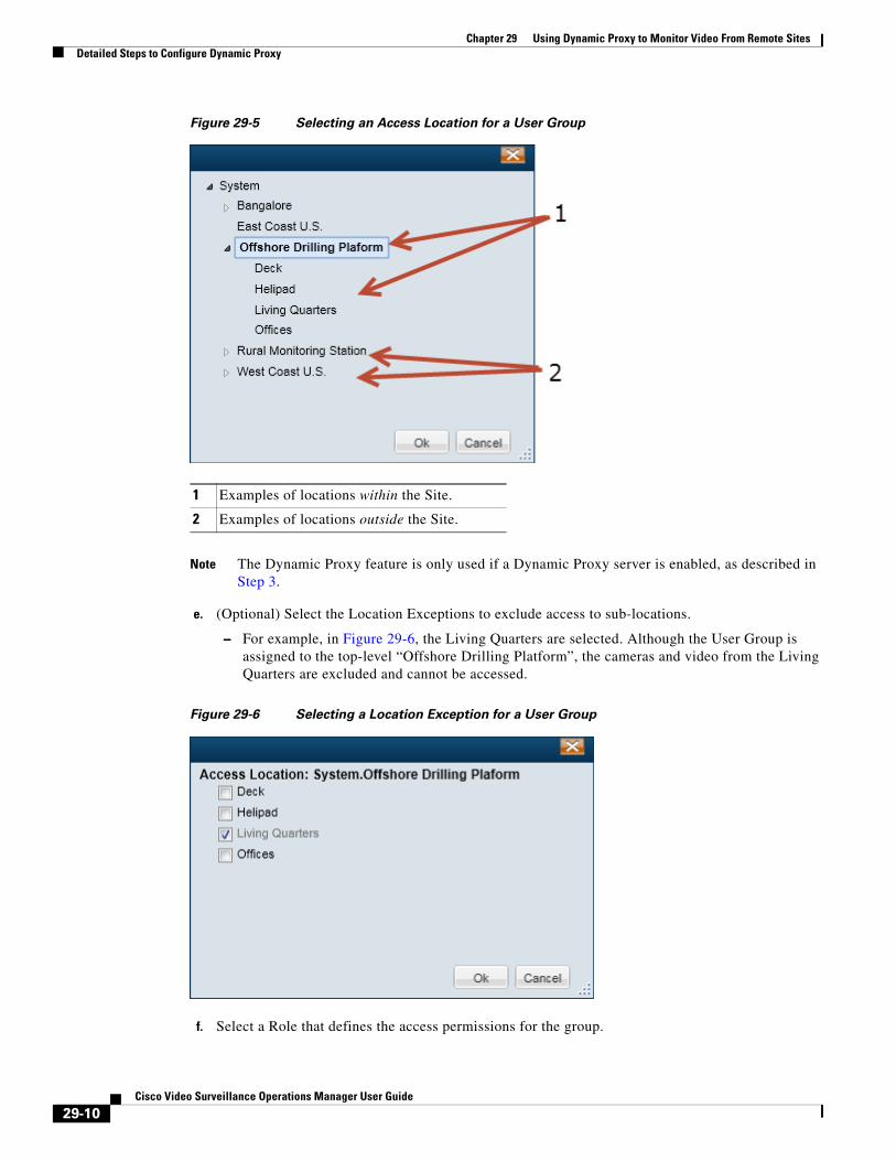
Chapter 29 Using Dynamic Proxy to Monitor Video From Remote Sites Detailed Steps to Configure Dynamic Proxy
Figure 29-5 Selecting an Access Location for a User Group
1
2
Note The Dynamic Proxy feature is only used if a Dynamic Proxy server is enabled, as described in Step 3.
e. (Optional) Select the Location Exceptions to exclude access to sub-locations.
– For example, in Figure 29-6, the Living Quarters are selected. Although the User Group is assigned to the top-level “Offshore Drilling Platform”, the cameras and video from the Living Quarters are excluded and cannot be accessed.
Figure 29-6 Selecting a Location Exception for a User Group
f. Select a Role that defines the access permissions for the group.
Examples of locations within the Site.
Examples of locations outside the Site.
29-10Cisco Video Surveillance Operations Manager User Guide
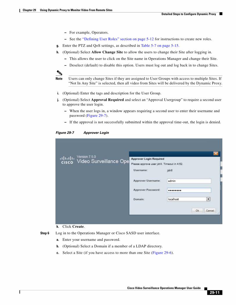
Chapter 29 Using Dynamic Proxy to Monitor Video From Remote SitesDetailed Steps to Configure Dynamic Proxy
– For example, Operators.
– See the “Defining User Roles” section on page 5-12 for instructions to create new roles.
g. Enter the PTZ and QoS settings, as described in Table 5-7 on page 5-15.
h. (Optional) Select Allow Change Site to allow the users to change their Site after logging in.
– This allows the user to click on the Site name in Operations Manager and change their Site.
– Deselect (default) to disable this option. Users must log out and log back in to change Sites.
Note Users can only change Sites if they are assigned to User Groups with access to multiple Sites. If “Not In Any Site” is selected, then all video from Sites will be delivered by the Dynamic Proxy.
i. (Optional) Enter the tags and description for the User Group.
j. (Optional) Select Approval Required and select an “Approval Usergroup” to require a second user to approve the user login.
– When the user logs in, a window appears requiring a second user to enter their username and password (Figure 29-7).
– If the approval is not successfully submitted within the approval time-out, the login is denied.
Figure 29-7 Approver Login
k. Click Create.
Step 6 Log in to the Operations Manager or Cisco SASD user interface.
a. Enter your username and password.
b. (Optional) Select a Domain if a member of a LDAP directory.
c. Select a Site (if you have access to more than one Site (Figure 29-6).
29-11Cisco Video Surveillance Operations Manager User Guide
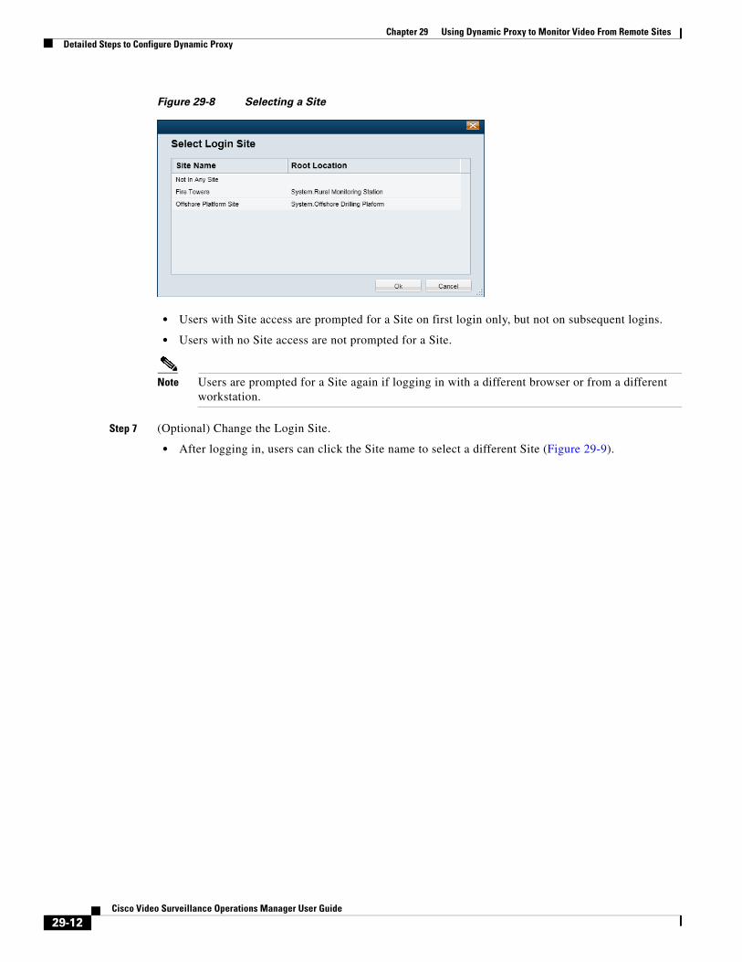
Chapter 29 Using Dynamic Proxy to Monitor Video From Remote Sites Detailed Steps to Configure Dynamic Proxy
Figure 29-8 Selecting a Site
• Users with Site access are prompted for a Site on first login only, but not on subsequent logins.
• Users with no Site access are not prompted for a Site.
Note Users are prompted for a Site again if logging in with a different browser or from a different workstation.
Step 7 (Optional) Change the Login Site.
• After logging in, users can click the Site name to select a different Site (Figure 29-9).
29-12Cisco Video Surveillance Operations Manager User Guide
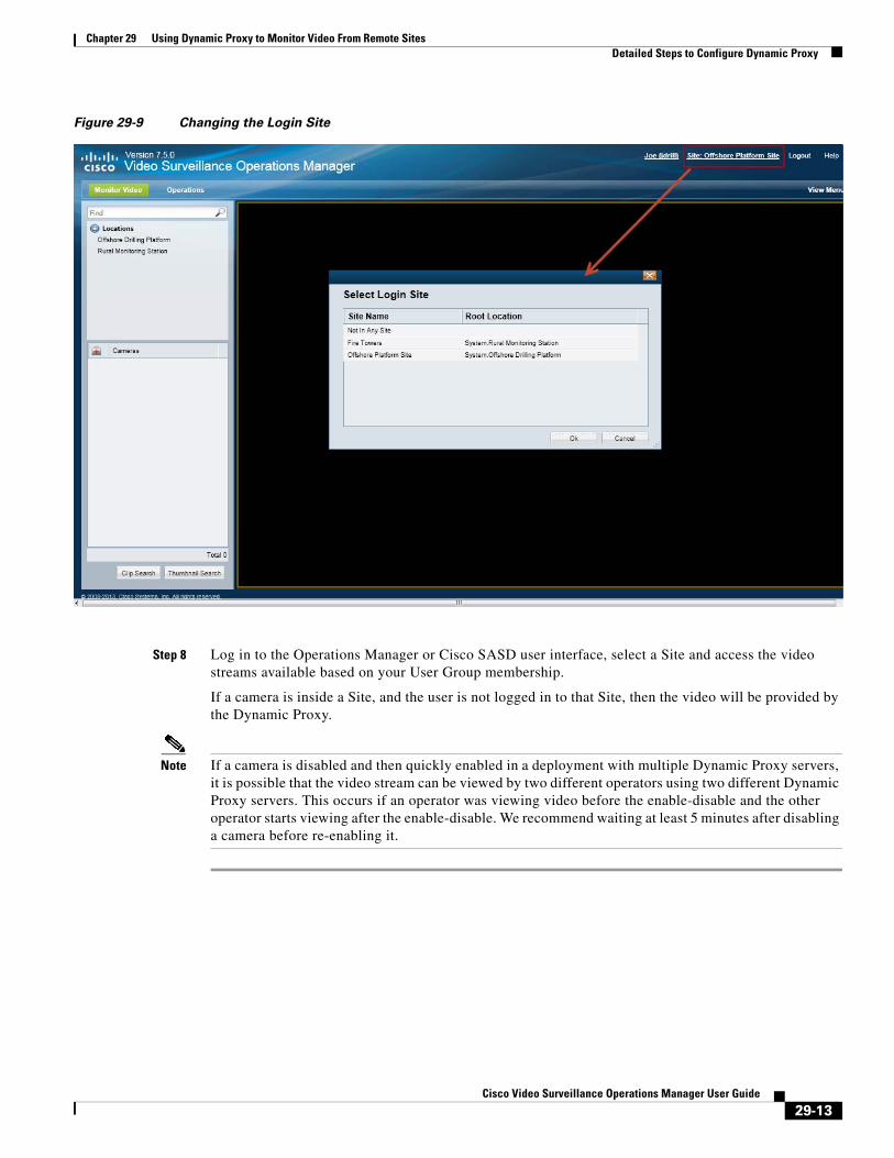
Chapter 29 Using Dynamic Proxy to Monitor Video From Remote SitesDetailed Steps to Configure Dynamic Proxy
Figure 29-9 Changing the Login Site
Step 8 Log in to the Operations Manager or Cisco SASD user interface, select a Site and access the video streams available based on your User Group membership.
If a camera is inside a Site, and the user is not logged in to that Site, then the video will be provided by the Dynamic Proxy.
Note If a camera is disabled and then quickly enabled in a deployment with multiple Dynamic Proxy servers, it is possible that the video stream can be viewed by two different operators using two different Dynamic Proxy servers. This occurs if an operator was viewing video before the enable-disable and the other operator starts viewing after the enable-disable. We recommend waiting at least 5 minutes after disabling a camera before re-enabling it.
29-13Cisco Video Surveillance Operations Manager User Guide

Chapter 29 Using Dynamic Proxy to Monitor Video From Remote Sites Detailed Steps to Configure Dynamic Proxy
29-14Cisco Video Surveillance Operations Manager User Guide
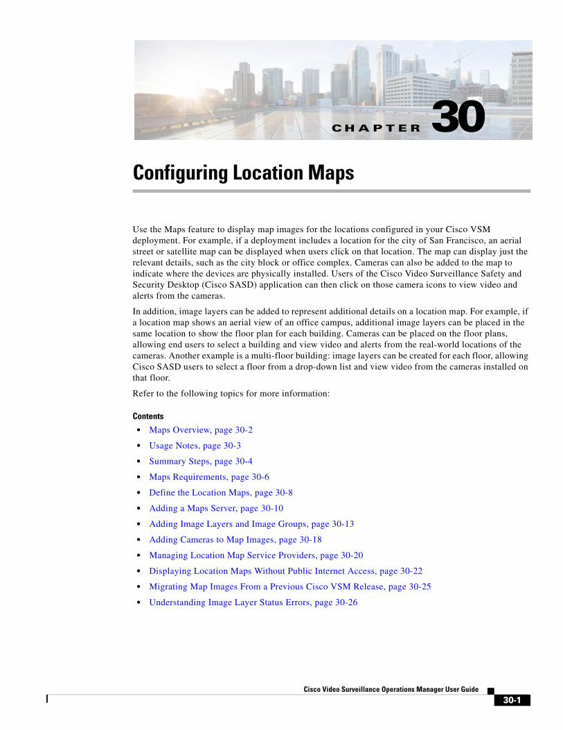
Cisco V
C H A P T E R 30
Configuring Location MapsUse the Maps feature to display map images for the locations configured in your Cisco VSM deployment. For example, if a deployment includes a location for the city of San Francisco, an aerial street or satellite map can be displayed when users click on that location. The map can display just the relevant details, such as the city block or office complex. Cameras can also be added to the map to indicate where the devices are physically installed. Users of the Cisco Video Surveillance Safety and Security Desktop (Cisco SASD) application can then click on those camera icons to view video and alerts from the cameras.
In addition, image layers can be added to represent additional details on a location map. For example, if a location map shows an aerial view of an office campus, additional image layers can be placed in the same location to show the floor plan for each building. Cameras can be placed on the floor plans, allowing end users to select a building and view video and alerts from the real-world locations of the cameras. Another example is a multi-floor building: image layers can be created for each floor, allowing Cisco SASD users to select a floor from a drop-down list and view video from the cameras installed on that floor.
Refer to the following topics for more information:
Contents
• Maps Overview, page 30-2
• Usage Notes, page 30-3
• Summary Steps, page 30-4
• Maps Requirements, page 30-6
• Define the Location Maps, page 30-8
• Adding a Maps Server, page 30-10
• Adding Image Layers and Image Groups, page 30-13
• Adding Cameras to Map Images, page 30-18
• Managing Location Map Service Providers, page 30-20
• Displaying Location Maps Without Public Internet Access, page 30-22
• Migrating Map Images From a Previous Cisco VSM Release, page 30-25
• Understanding Image Layer Status Errors, page 30-26
30-1ideo Surveillance Operations Manager User Guide
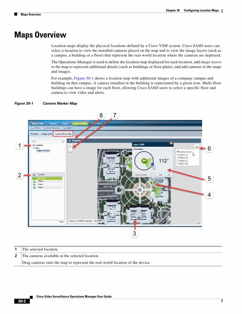
Chapter 30 Configuring Location Maps Maps Overview
Maps OverviewLocation maps display the physical locations defined by a Cisco VSM system. Cisco SASD users can select a location to view the installed cameras placed on the map and to view the image layers (such as a campus, a building or a floor) that represent the real-world location where the cameras are deployed.
The Operations Manager is used to define the location map displayed for each location, add image layers to the map to represent additional details (such as buildings or floor plans), and add cameras to the maps and images.
For example, Figure 30-1 shows a location map with additional images of a company campus and building on that campus. A camera installed in the building is represented by a green icon. Multi-floor buildings can have a image for each floor, allowing Cisco SASD users to select a specific floor and camera to view video and alerts.
Figure 30-1 Camera Marker Map
1 The selected location.
2 The cameras available at the selected location.
Drag cameras onto the map to represent the real-world location of the device.
30-2Cisco Video Surveillance Operations Manager User Guide
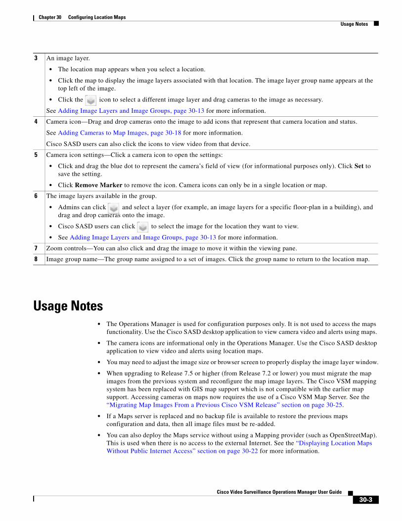
Chapter 30 Configuring Location MapsUsage Notes
Usage Notes • The Operations Manager is used for configuration purposes only. It is not used to access the maps
functionality. Use the Cisco SASD desktop application to view camera video and alerts using maps.
• The camera icons are informational only in the Operations Manager. Use the Cisco SASD desktop application to view video and alerts using location maps.
• You may need to adjust the image size or browser screen to properly display the image layer window.
• When upgrading to Release 7.5 or higher (from Release 7.2 or lower) you must migrate the map images from the previous system and reconfigure the map image layers. The Cisco VSM mapping system has been replaced with GIS map support which is not compatible with the earlier map support. Accessing cameras on maps now requires the use of a Cisco VSM Map Server. See the “Migrating Map Images From a Previous Cisco VSM Release” section on page 30-25.
• If a Maps server is replaced and no backup file is available to restore the previous maps configuration and data, then all image files must be re-added.
• You can also deploy the Maps service without using a Mapping provider (such as OpenStreetMap). This is used when there is no access to the external Internet. See the “Displaying Location Maps Without Public Internet Access” section on page 30-22 for more information.
3 An image layer.
• The location map appears when you select a location.
• Click the map to display the image layers associated with that location. The image layer group name appears at the top left of the image.
• Click the icon to select a different image layer and drag cameras to the image as necessary.
See Adding Image Layers and Image Groups, page 30-13 for more information.
4 Camera icon—Drag and drop cameras onto the image to add icons that represent that camera location and status.
See Adding Cameras to Map Images, page 30-18 for more information.
Cisco SASD users can also click the icons to view video from that device.
5 Camera icon settings—Click a camera icon to open the settings:
• Click and drag the blue dot to represent the camera’s field of view (for informational purposes only). Click Set to save the setting.
• Click Remove Marker to remove the icon. Camera icons can only be in a single location or map.
6 The image layers available in the group.
• Admins can click and select a layer (for example, an image layers for a specific floor-plan in a building), and drag and drop cameras onto the image.
• Cisco SASD users can click to select the image for the location they want to view.
• See Adding Image Layers and Image Groups, page 30-13 for more information.
7 Zoom controls—You can also click and drag the image to move it within the viewing pane.
8 Image group name—The group name assigned to a set of images. Click the group name to return to the location map.
30-3Cisco Video Surveillance Operations Manager User Guide
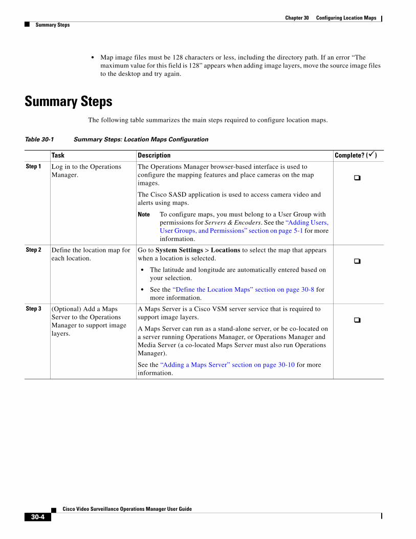
Chapter 30 Configuring Location Maps Summary Steps
• Map image files must be 128 characters or less, including the directory path. If an error “The maximum value for this field is 128” appears when adding image layers, move the source image files to the desktop and try again.
Summary StepsThe following table summarizes the main steps required to configure location maps.
Table 30-1 Summary Steps: Location Maps Configuration
Task Description Complete? ()
Step 1 Log in to the Operations Manager.
The Operations Manager browser-based interface is used to configure the mapping features and place cameras on the map images.
The Cisco SASD application is used to access camera video and alerts using maps.
Note To configure maps, you must belong to a User Group with permissions for Servers & Encoders. See the “Adding Users, User Groups, and Permissions” section on page 5-1 for more information.
Step 2 Define the location map for each location.
Go to System Settings > Locations to select the map that appears when a location is selected.
• The latitude and longitude are automatically entered based on your selection.
• See the “Define the Location Maps” section on page 30-8 for more information.
Step 3 (Optional) Add a Maps Server to the Operations Manager to support image layers.
A Maps Server is a Cisco VSM server service that is required to support image layers.
A Maps Server can run as a stand-alone server, or be co-located on a server running Operations Manager, or Operations Manager and Media Server (a co-located Maps Server must also run Operations Manager).
See the “Adding a Maps Server” section on page 30-10 for more information.
30-4Cisco Video Surveillance Operations Manager User Guide
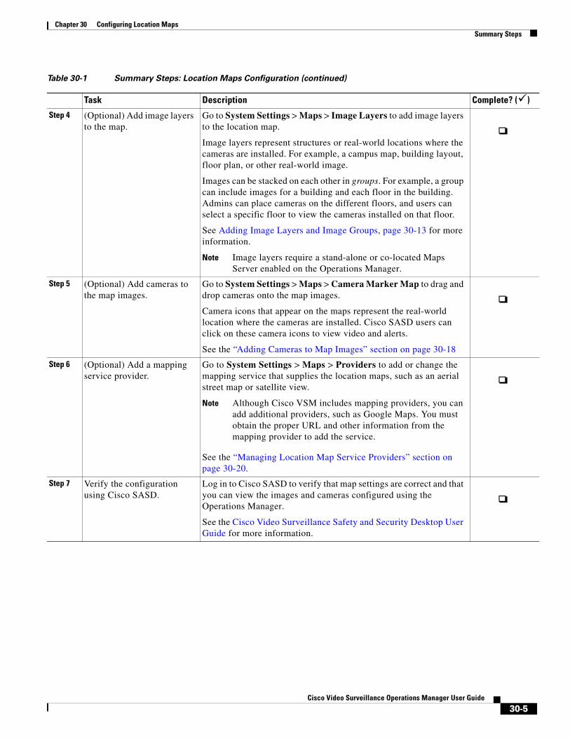
Chapter 30 Configuring Location MapsSummary Steps
Step 4 (Optional) Add image layers to the map.
Go to System Settings > Maps > Image Layers to add image layers to the location map.
Image layers represent structures or real-world locations where the cameras are installed. For example, a campus map, building layout, floor plan, or other real-world image.
Images can be stacked on each other in groups. For example, a group can include images for a building and each floor in the building. Admins can place cameras on the different floors, and users can select a specific floor to view the cameras installed on that floor.
See Adding Image Layers and Image Groups, page 30-13 for more information.
Note Image layers require a stand-alone or co-located Maps Server enabled on the Operations Manager.
Step 5 (Optional) Add cameras to the map images.
Go to System Settings > Maps > Camera Marker Map to drag and drop cameras onto the map images.
Camera icons that appear on the maps represent the real-world location where the cameras are installed. Cisco SASD users can click on these camera icons to view video and alerts.
See the “Adding Cameras to Map Images” section on page 30-18
Step 6 (Optional) Add a mapping service provider.
Go to System Settings > Maps > Providers to add or change the mapping service that supplies the location maps, such as an aerial street map or satellite view.
Note Although Cisco VSM includes mapping providers, you can add additional providers, such as Google Maps. You must obtain the proper URL and other information from the mapping provider to add the service.
See the “Managing Location Map Service Providers” section on page 30-20.
Step 7 Verify the configuration using Cisco SASD.
Log in to Cisco SASD to verify that map settings are correct and that you can view the images and cameras configured using the Operations Manager.
See the Cisco Video Surveillance Safety and Security Desktop User Guide for more information.
Table 30-1 Summary Steps: Location Maps Configuration (continued)
Task Description Complete? ()
30-5Cisco Video Surveillance Operations Manager User Guide
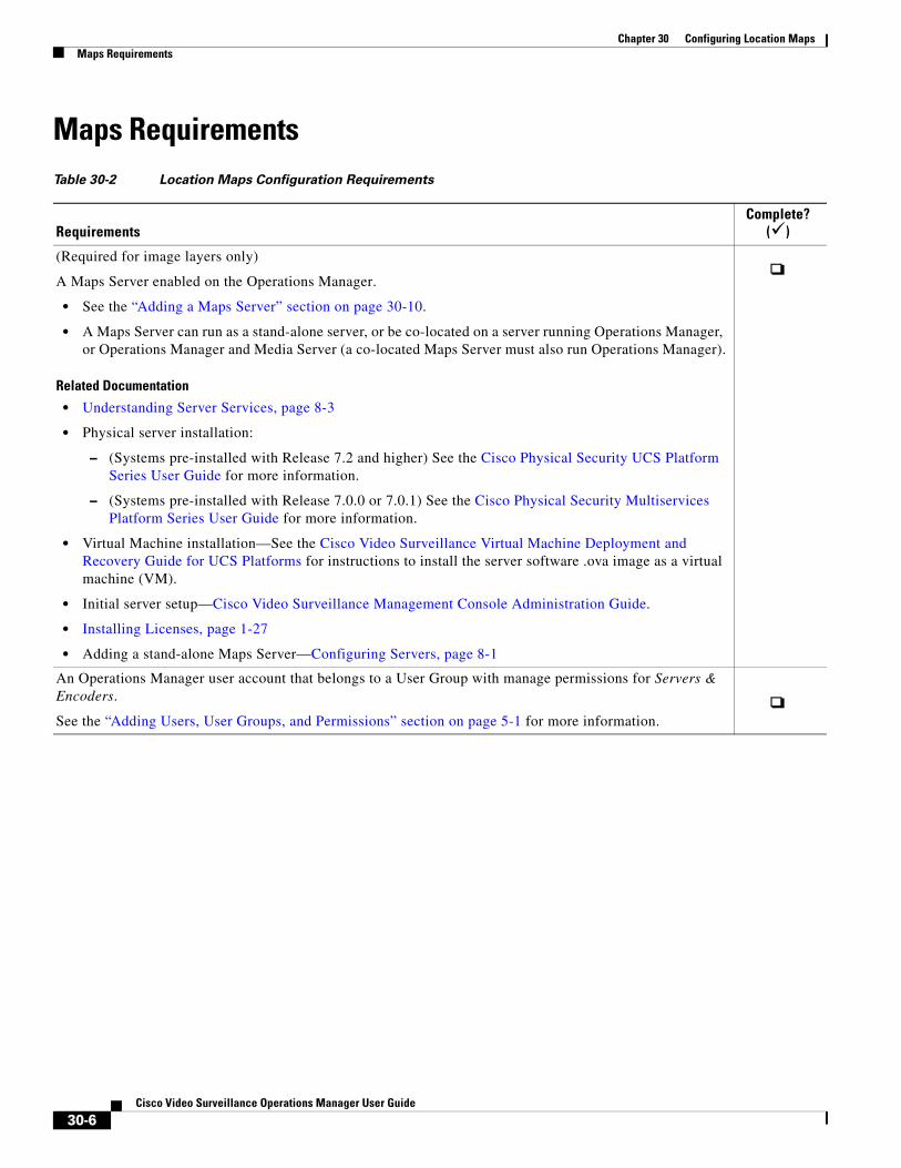
Chapter 30 Configuring Location Maps Maps Requirements
Maps RequirementsTable 30-2 Location Maps Configuration Requirements
RequirementsComplete?
()
(Required for image layers only)
A Maps Server enabled on the Operations Manager.
• See the “Adding a Maps Server” section on page 30-10.
• A Maps Server can run as a stand-alone server, or be co-located on a server running Operations Manager, or Operations Manager and Media Server (a co-located Maps Server must also run Operations Manager).
Related Documentation
• Understanding Server Services, page 8-3
• Physical server installation:
– (Systems pre-installed with Release 7.2 and higher) See the Cisco Physical Security UCS Platform Series User Guide for more information.
– (Systems pre-installed with Release 7.0.0 or 7.0.1) See the Cisco Physical Security Multiservices Platform Series User Guide for more information.
• Virtual Machine installation—See the Cisco Video Surveillance Virtual Machine Deployment and Recovery Guide for UCS Platforms for instructions to install the server software .ova image as a virtual machine (VM).
• Initial server setup—Cisco Video Surveillance Management Console Administration Guide.
• Installing Licenses, page 1-27
• Adding a stand-alone Maps Server—Configuring Servers, page 8-1
An Operations Manager user account that belongs to a User Group with manage permissions for Servers & Encoders.
See the “Adding Users, User Groups, and Permissions” section on page 5-1 for more information.
30-6Cisco Video Surveillance Operations Manager User Guide
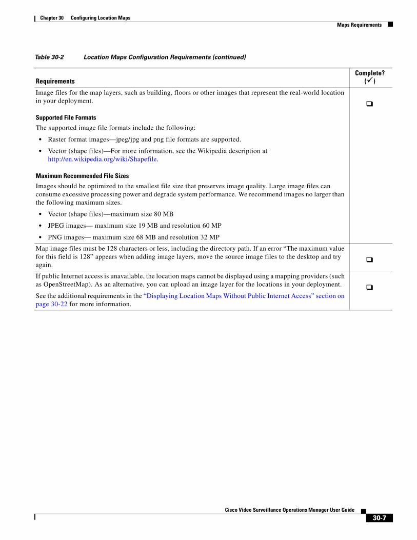
Chapter 30 Configuring Location MapsMaps Requirements
Image files for the map layers, such as building, floors or other images that represent the real-world location in your deployment.
Supported File Formats
The supported image file formats include the following:
• Raster format images—jpeg/jpg and png file formats are supported.
• Vector (shape files)—For more information, see the Wikipedia description at http://en.wikipedia.org/wiki/Shapefile.
Maximum Recommended File Sizes
Images should be optimized to the smallest file size that preserves image quality. Large image files can consume excessive processing power and degrade system performance. We recommend images no larger than the following maximum sizes.
• Vector (shape files)—maximum size 80 MB
• JPEG images— maximum size 19 MB and resolution 60 MP
• PNG images— maximum size 68 MB and resolution 32 MP
Map image files must be 128 characters or less, including the directory path. If an error “The maximum value for this field is 128” appears when adding image layers, move the source image files to the desktop and try again.
If public Internet access is unavailable, the location maps cannot be displayed using a mapping providers (such as OpenStreetMap). As an alternative, you can upload an image layer for the locations in your deployment.
See the additional requirements in the “Displaying Location Maps Without Public Internet Access” section on page 30-22 for more information.
Table 30-2 Location Maps Configuration Requirements (continued)
RequirementsComplete?
()
30-7Cisco Video Surveillance Operations Manager User Guide
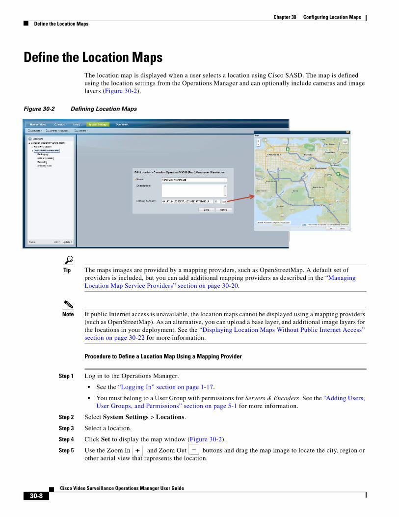
Chapter 30 Configuring Location Maps Define the Location Maps
Define the Location MapsThe location map is displayed when a user selects a location using Cisco SASD. The map is defined using the location settings from the Operations Manager and can optionally include cameras and image layers (Figure 30-2).
Figure 30-2 Defining Location Maps
Tip The maps images are provided by a mapping providers, such as OpenStreetMap. A default set of providers is included, but you can add additional mapping providers as described in the “Managing Location Map Service Providers” section on page 30-20.
Note If public Internet access is unavailable, the location maps cannot be displayed using a mapping providers (such as OpenStreetMap). As an alternative, you can upload a base layer, and additional image layers for the locations in your deployment. See the “Displaying Location Maps Without Public Internet Access” section on page 30-22 for more information.
Procedure to Define a Location Map Using a Mapping Provider
Step 1 Log in to the Operations Manager.
• See the “Logging In” section on page 1-17.
• You must belong to a User Group with permissions for Servers & Encoders. See the “Adding Users, User Groups, and Permissions” section on page 5-1 for more information.
Step 2 Select System Settings > Locations.
Step 3 Select a location.
Step 4 Click Set to display the map window (Figure 30-2).
Step 5 Use the Zoom In and Zoom Out buttons and drag the map image to locate the city, region or other aerial view that represents the location.
30-8Cisco Video Surveillance Operations Manager User Guide
Chapter 30 Configuring Location MapsDefine the Location Maps
Step 6 Click Set to select the map as displayed on the screen.
• The Longitude and Latitude of the visible map are automatically entered in the location settings (Figure 30-2).
• The second field reflects the zoom level defined in the map window (see Step 5).
Step 7 Click Save to save the map settings for the location.
Step 8 (Optional) Add image layers to the location map to represent the structures or real-world locations where the cameras are installed.
See the “Adding Image Layers and Image Groups” section on page 30-13.
Step 9 (Optional) Add cameras to the map images to represent the real-world location where the cameras are installed. Cisco SASD users can click on these camera icons to view video and alerts.
See the “Adding Cameras to Map Images” section on page 30-18
30-9Cisco Video Surveillance Operations Manager User Guide
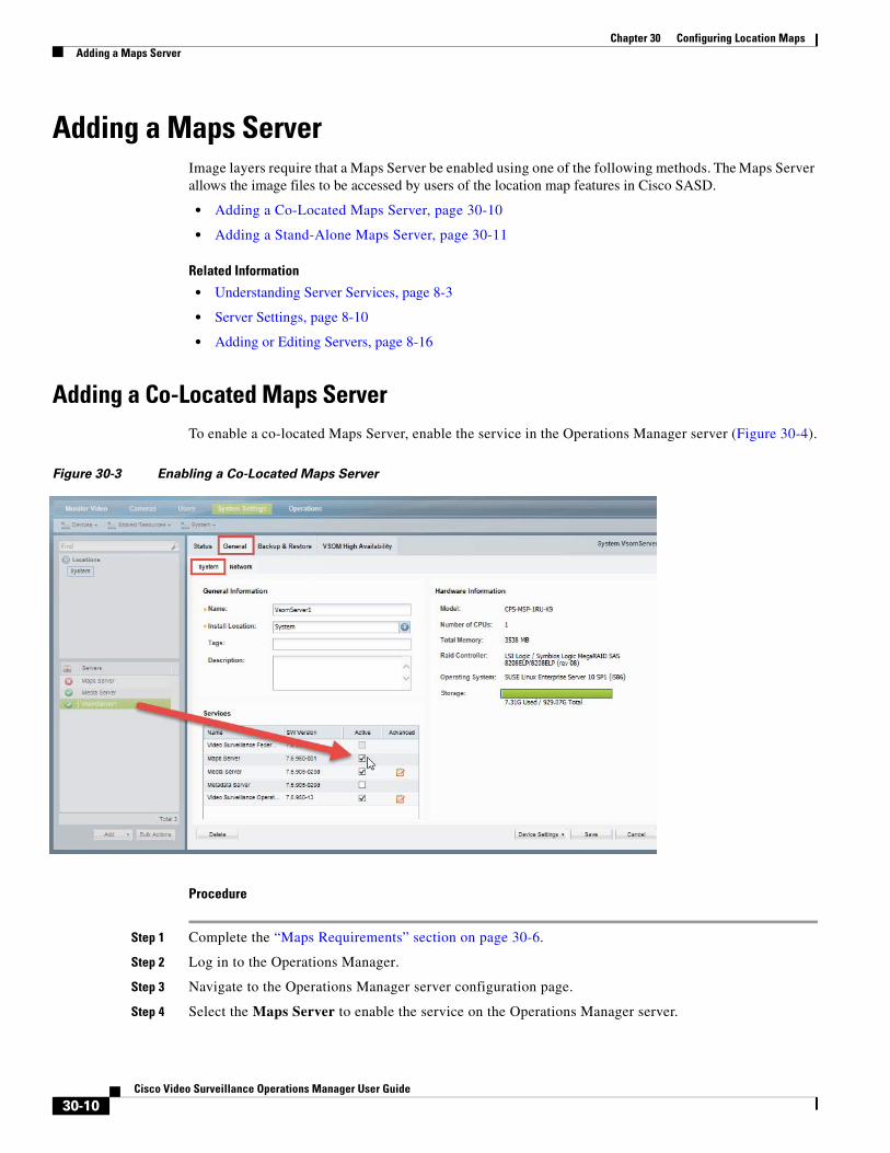
Chapter 30 Configuring Location Maps Adding a Maps Server
Adding a Maps ServerImage layers require that a Maps Server be enabled using one of the following methods. The Maps Server allows the image files to be accessed by users of the location map features in Cisco SASD.
• Adding a Co-Located Maps Server, page 30-10
• Adding a Stand-Alone Maps Server, page 30-11
Related Information
• Understanding Server Services, page 8-3
• Server Settings, page 8-10
• Adding or Editing Servers, page 8-16
Adding a Co-Located Maps ServerTo enable a co-located Maps Server, enable the service in the Operations Manager server (Figure 30-4).
Figure 30-3 Enabling a Co-Located Maps Server
Procedure
Step 1 Complete the “Maps Requirements” section on page 30-6.
Step 2 Log in to the Operations Manager.
Step 3 Navigate to the Operations Manager server configuration page.
Step 4 Select the Maps Server to enable the service on the Operations Manager server.
30-10Cisco Video Surveillance Operations Manager User Guide
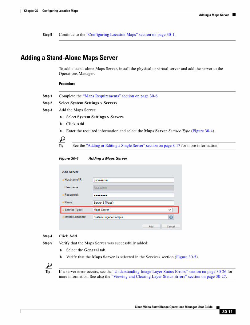
Chapter 30 Configuring Location MapsAdding a Maps Server
Step 5 Continue to the “Configuring Location Maps” section on page 30-1.
Adding a Stand-Alone Maps ServerTo add a stand-alone Maps Server, install the physical or virtual server and add the server to the Operations Manager.
Procedure
Step 1 Complete the “Maps Requirements” section on page 30-6.
Step 2 Select System Settings > Servers.
Step 3 Add the Maps Server:
a. Select System Settings > Servers.
b. Click Add.
c. Enter the required information and select the Maps Server Service Type (Figure 30-4).
Tip See the “Adding or Editing a Single Server” section on page 8-17 for more information.
Figure 30-4 Adding a Maps Server
Step 4 Click Add.
Step 5 Verify that the Maps Server was successfully added:
a. Select the General tab.
b. Verify that the Maps Server is selected in the Services section (Figure 30-5).
Tip If a server error occurs, see the “Understanding Image Layer Status Errors” section on page 30-26 for more information. See also the “Viewing and Clearing Layer Status Errors” section on page 30-27.
30-11Cisco Video Surveillance Operations Manager User Guide
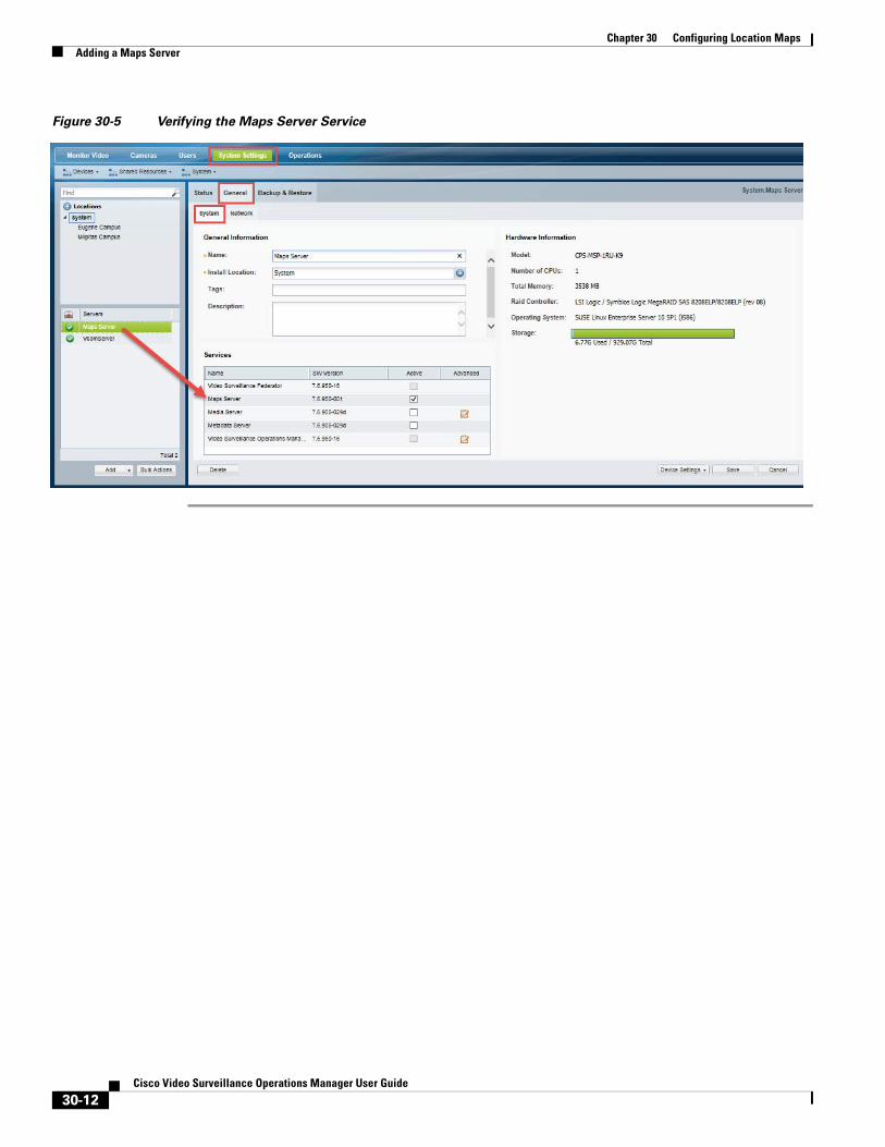
Chapter 30 Configuring Location Maps Adding a Maps Server
Figure 30-5 Verifying the Maps Server Service
30-12Cisco Video Surveillance Operations Manager User Guide
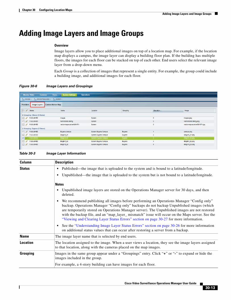
Chapter 30 Configuring Location MapsAdding Image Layers and Image Groups
Adding Image Layers and Image GroupsOverview
Image layers allow you to place additional images on top of a location map. For example, if the location map displays a campus, the image layer can display a building floor plan. If the building has multiple floors, the images for each floor can be stacked on top of each other. End users select the relevant image layer from a drop-down menu.
Each Group is a collection of images that represent a single entity. For example, the group could include a building image, and additional images for each floor.
Figure 30-6 Image Layers and Groupings
Table 30-3 Image Layer Information
Column Description
Status • Published—the image that is uploaded to the system and is bound to a latitude/longitude.
• Unpublished—the image that is uploaded to the system but is not bound to a latitude/longitude.
Notes
• Unpublished image layers are stored on the Operations Manager server for 30 days, and then deleted.
• We recommend publishing all images before performing an Operations Manager “Config only” backup. Operations Manager “Config only” backups do not backup Unpublished images (which are temporarily stored on Operations Manager server). The Unpublished images are not restored with the backup file, and an “map_layer_ mismatch” issue will occur on the Maps server. See the “Viewing and Clearing Layer Status Errors” section on page 30-27 for more information.
• See the “Understanding Image Layer Status Errors” section on page 30-26 for more information on additional status values that can occur after restoring a server from a backup.
Name The image layer name that is selected by end users.
Location The location assigned to the image. When a user views a location, they see the image layers assigned to that location, along with the cameras placed on the map images.
Grouping Images in the same group appear under a “Groupings” entry. Click “+” or “-” to expand or hide the images included in the group.
For example, a 4-story building can have images for each floor.
30-13Cisco Video Surveillance Operations Manager User Guide

Chapter 30 Configuring Location Maps Adding Image Layers and Image Groups
Procedure to Add Image Layers
Step 1 Log on to the Operations Manager.
• You must belong to a User Group with permissions for Locations & Maps. See the “Adding Users, User Groups, and Permissions” section on page 5-1 for more information.
Step 2 Add a Maps Server to the Operations Manager to enable the Image Maps feature.
See the “Adding a Maps Server” section on page 30-10.
Step 3 Select System Settings > Maps.
Step 4 Select the Image Layers tab (Figure 30-7).
Figure 30-7 Adding a Map Layer
Step 5 Add an image layer.
One or more image layers can be added to represent multiple objects in the same location. For example, you can have images for a campus, the buildings on the campus, and the floors in the building.
Elevation The order that the image layers appear in the drop menu available to end-users. Select a layer and click Move Up or Move Down to change the display order.
Image The image name.
Table 30-3 Image Layer Information (continued)
Column Description
30-14Cisco Video Surveillance Operations Manager User Guide
Chapter 30 Configuring Location MapsAdding Image Layers and Image Groups
To do this, upload an image, select a location and group (set of related images), and then use the Bounding Box to resize and relocate the image on the map.
For example, in Figure 30-7, the campus image is added and placed on the map. An additional building image is added to the same group, and resized so it appears in the correct location on the campus image. Groups allow the images to be stacked and allow the end-users to click the icon and select the relevant image layer.
a. Click Add.
b. Click the add icon and select the image(s) you want to upload from a local or network drive.
Tip You can select a single image file, or a compressed .zip file with multiple images. All images must be a supported file format (see the “Maps Requirements” section on page 30-6).
c. Click Add and wait for the job to complete.
– The upload job is complete when the image is uploaded to the Maps Server and the Image Layers pop-up settings window appears (Figure 30-7).
– Map image files must be 128 characters or less, including the directory path. If an error “The maximum value for this field is 128” appears when adding image layers, move the source image files to the desktop and try again.
d. Enter the image layer settings in the pop-up window (Table 30-4).
Table 30-4 Image Layer Settings
Field Settings
Name (Required) The image layer name. For example: “Floor 1”.
Base Layer (Optional) Select this if Internet service is not available and the image will be used as the base layer image (and not provided by a map service provider). See Displaying Location Maps Without Public Internet Access, page 30-22 for more information.
Location (Required) The location where the image layer will appear.
Image (Read-only) The image filename.
Group (Optional) The group of images that the image belongs to. Users click the icon to select an image from the group. For example, all floor images can belong to a group called “Building 2”.
• To create a group, enter the group name. The entry will be saved and can be selected when you add additional image layers.
• Select a group from the drop-down menu if the group name was previously entered.
Zoom (Required) The minimum zoom level and the maximum zoom level.
The image layer is shown on the location map only when the zoom level from the location map falls between the min/max zoom levels.
30-15Cisco Video Surveillance Operations Manager User Guide
Chapter 30 Configuring Location Maps Adding Image Layers and Image Groups
d. Click Update to save the image layer settings.
Step 6 (Optional) Add image sub-layers.
You can add additional image layers to represent sub-locations (Figure 30-8). For example:
• A campus location can have additional building layers.
• A building location can have additional floor layers.
Users click the icon to select a layer and view the cameras or alerts for the specific building, floor, or other image.
To add additional sub-layers:
a. Click Add.
b. Click the add icon and select the image to upload from a local or network drive.
c. Click Add again and wait for the job to complete.
d. Enter the settings described in Table 30-4 using the following guidelines:
– Select an existing Group. For example, select the group created for the campus image. The layers included in a group can be selected by end-users from a drop-down menu.
– Click Set to resize the sub-layer in relation to any other images in that same group (Figure 30-8). Click Set again to save the box settings.
Placed on Map (Required) Click Set to bring up the image on the location map. You can re-size the image to display it in the correct location (Figure 30-7). This value is Yes when the image is placed on the map.
a. Click Set.
b. In the pop-up map window, use your mouse to:
– Zoom in and out or re-position the map.
– Click and drag the corner of the image to resize and relocate it on the map.
– Click an image to enlarge it.
– Click the icon to select a image in the group.
c. Click Set. The Box (min, max) coordinates are automatically entered.
Note This value is No if the image has not yet been placed on the map. The value is also No for base layer since the entire image will be displayed.
Table 30-4 Image Layer Settings (continued)
30-16Cisco Video Surveillance Operations Manager User Guide
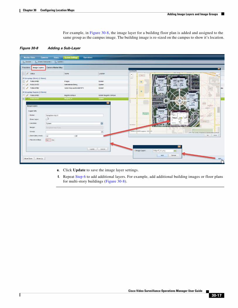
Chapter 30 Configuring Location MapsAdding Image Layers and Image Groups
For example, in Figure 30-8, the image layer for a building floor plan is added and assigned to the same group as the campus image. The building image is re-sized on the campus to show it’s location.
Figure 30-8 Adding a Sub-Layer
e. Click Update to save the image layer settings.
f. Repeat Step 6 to add additional layers. For example, add additional building images or floor plans for multi-story buildings (Figure 30-8).
30-17Cisco Video Surveillance Operations Manager User Guide
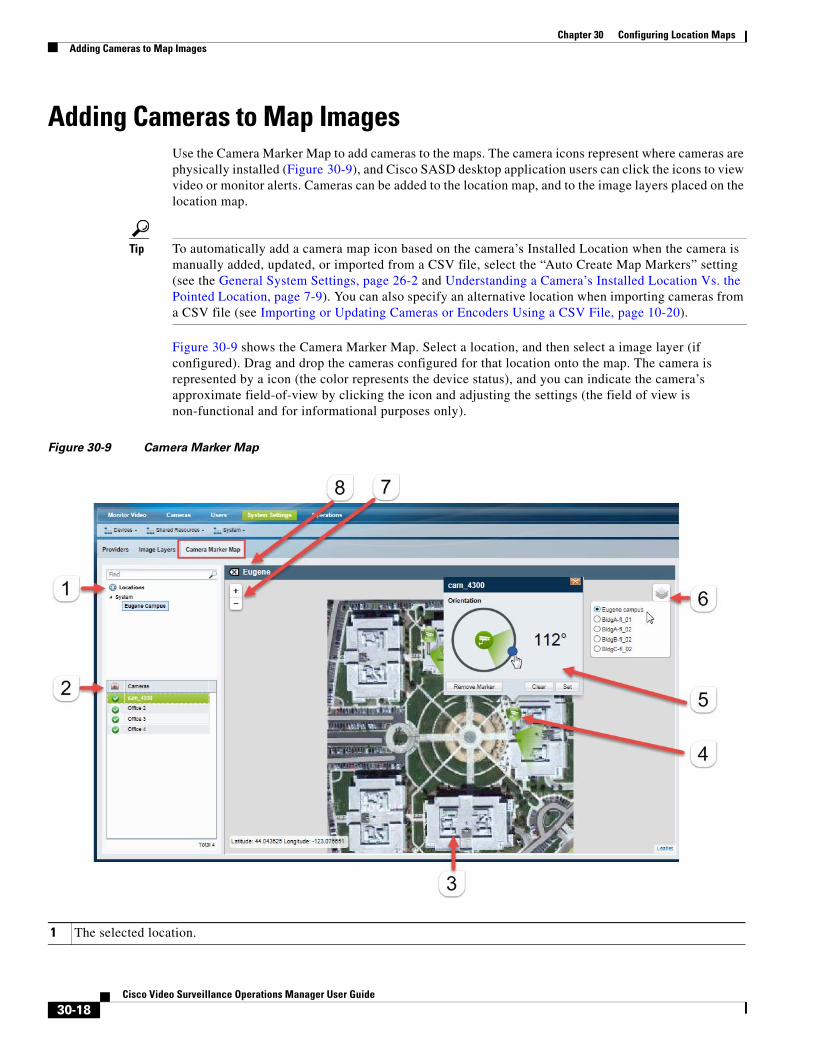
Chapter 30 Configuring Location Maps Adding Cameras to Map Images
Adding Cameras to Map ImagesUse the Camera Marker Map to add cameras to the maps. The camera icons represent where cameras are physically installed (Figure 30-9), and Cisco SASD desktop application users can click the icons to view video or monitor alerts. Cameras can be added to the location map, and to the image layers placed on the location map.
Tip To automatically add a camera map icon based on the camera’s Installed Location when the camera is manually added, updated, or imported from a CSV file, select the “Auto Create Map Markers” setting (see the General System Settings, page 26-2 and Understanding a Camera’s Installed Location Vs. the Pointed Location, page 7-9). You can also specify an alternative location when importing cameras from a CSV file (see Importing or Updating Cameras or Encoders Using a CSV File, page 10-20).
Figure 30-9 shows the Camera Marker Map. Select a location, and then select a image layer (if configured). Drag and drop the cameras configured for that location onto the map. The camera is represented by a icon (the color represents the device status), and you can indicate the camera’s approximate field-of-view by clicking the icon and adjusting the settings (the field of view is non-functional and for informational purposes only).
Figure 30-9 Camera Marker Map
1 The selected location.
30-18Cisco Video Surveillance Operations Manager User Guide

Chapter 30 Configuring Location MapsAdding Cameras to Map Images
Procedure to Add Cameras to The Location Maps and Image Layers
Complete the following steps to add cameras to the location map and to the image layer.
Note The camera icons are informational only in the Operations Manager. Use the Cisco SASD desktop application to view video and alerts using the camera icons.
Step 1 Define the location map for a location.
See the “Define the Location Maps” section on page 30-8.
Step 2 Add image layers to the same location.
See the “Adding Image Layers and Image Groups” section on page 30-13.
Step 3 Select System Settings > Maps, and click the Camera Marker Map tab.
Step 4 Select a location (Figure 30-9).
Step 5 (Optional) Click the map image to view the image layers for that location.
Step 6 (Optional) Click the selector icon to select an image layer.
Step 7 Add cameras to the image.
a. Drag and drop cameras onto the map.
b. To re-orient the camera’s field of view, click the camera icon and drag the blue dot, and click Set. The field-of-view is not functional, and for informational purposes only. For example, the PTZ controls are not affected.
c. To move the camera marker, drag and drop the camera name to a new location.
2 The cameras available at the selected location.
Drag cameras onto the map to represent the real-world location of the device.
3 An image layer.
• The location map appears when you select a location.
• Click the map to display the image layers associated with that location. The image layer group name appears at the top left of the image.
• Click the icon to select a different image layer and drag cameras to the image as necessary.
4 Camera icon—Drag and drop cameras onto the image to add icons that represent that camera location and status.
Cisco SASD users can also click the icons to view video from that device.
5 Camera icon settings—Click a camera icon to open the settings:
• Click and drag the blue dot to change the camera angle, which represents the camera’s field of view (for informational purposes only). Click Set to save the setting.
• Click Remove Marker to remove the icon. Camera icons can only be in a single location or map.
6 The image layers available in the group.
• Admins can click and select a layer (for example, an image layers for a specific floor-plan in a building), and drag and drop cameras onto the image.
• Cisco SASD users can click to select the image for the location they want to view.
7 Zoom controls—You can also click and drag the image to move it within the viewing pane.
8 Image group name—The group name assigned to a set of images. Chick the group name to return to the location map.
30-19Cisco Video Surveillance Operations Manager User Guide
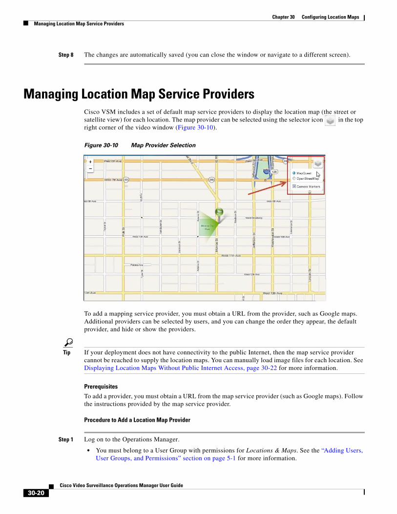
Chapter 30 Configuring Location Maps Managing Location Map Service Providers
Step 8 The changes are automatically saved (you can close the window or navigate to a different screen).
Managing Location Map Service ProvidersCisco VSM includes a set of default map service providers to display the location map (the street or satellite view) for each location. The map provider can be selected using the selector icon in the top right corner of the video window (Figure 30-10).
Figure 30-10 Map Provider Selection
To add a mapping service provider, you must obtain a URL from the provider, such as Google maps. Additional providers can be selected by users, and you can change the order they appear, the default provider, and hide or show the providers.
Tip If your deployment does not have connectivity to the public Internet, then the map service provider cannot be reached to supply the location maps. You can manually load image files for each location. See Displaying Location Maps Without Public Internet Access, page 30-22 for more information.
Prerequisites
To add a provider, you must obtain a URL from the map service provider (such as Google maps). Follow the instructions provided by the map service provider.
Procedure to Add a Location Map Provider
Step 1 Log on to the Operations Manager.
• You must belong to a User Group with permissions for Locations & Maps. See the “Adding Users, User Groups, and Permissions” section on page 5-1 for more information.
30-20Cisco Video Surveillance Operations Manager User Guide
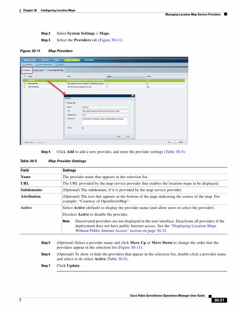
Chapter 30 Configuring Location MapsManaging Location Map Service Providers
Step 2 Select System Settings > Maps.
Step 3 Select the Providers tab (Figure 30-11)
Figure 30-11 Map Providers
Step 4 Click Add to add a new provider, and enter the provider settings (Table 30-5).
Table 30-5 Map Provider Settings
Field Settings
Note Deactivated providers are not displayed in the user interface. Deactivate all providers if the deployment does not have public Internet access. See the “Displaying Location Maps Without Public Internet Access” section on page 30-22.
Step 5 (Optional) Select a provider name and click Move Up or Move Down to change the order that the providers appear in the selection list (Figure 30-11).
Step 6 (Optional) To show or hide the providers that appear in the selection list, double-click a provider name and select or de-select Active (Table 30-5).
Step 7 Click Update.
Name The provider name that appears in the selection list.
URL The URL provided by the map service provider that enables the location maps to be displayed.
Subdomains (Optional) The subdomain, if it is provided by the map service provider.
Attribution (Optional) The text that appears at the bottom of the page indicating the source of the map. For example: “Courtesy of OpenStreetMap”.
Active Select Active (default) to display the provider name (and allow users to select the provider).
Deselect Active to disable the provider.
30-21Cisco Video Surveillance Operations Manager User Guide
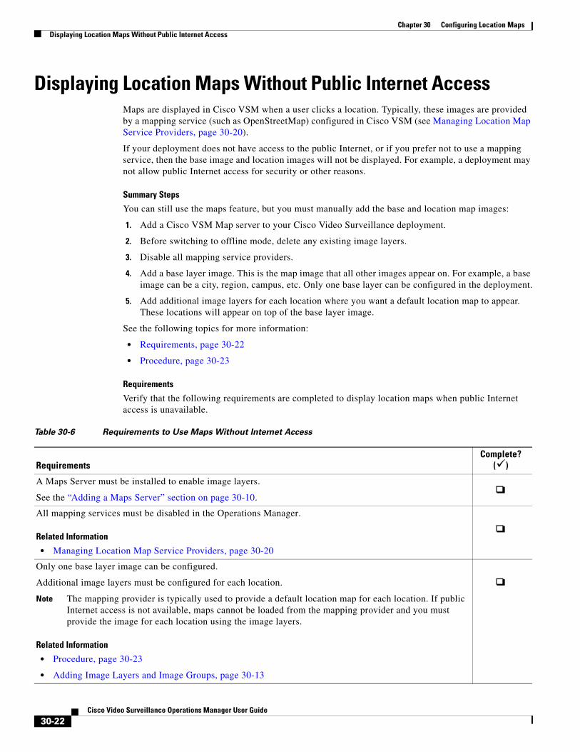
Chapter 30 Configuring Location Maps Displaying Location Maps Without Public Internet Access
Displaying Location Maps Without Public Internet AccessMaps are displayed in Cisco VSM when a user clicks a location. Typically, these images are provided by a mapping service (such as OpenStreetMap) configured in Cisco VSM (see Managing Location Map Service Providers, page 30-20).
If your deployment does not have access to the public Internet, or if you prefer not to use a mapping service, then the base image and location images will not be displayed. For example, a deployment may not allow public Internet access for security or other reasons.
Summary Steps
You can still use the maps feature, but you must manually add the base and location map images:
1. Add a Cisco VSM Map server to your Cisco Video Surveillance deployment.
2. Before switching to offline mode, delete any existing image layers.
3. Disable all mapping service providers.
4. Add a base layer image. This is the map image that all other images appear on. For example, a base image can be a city, region, campus, etc. Only one base layer can be configured in the deployment.
5. Add additional image layers for each location where you want a default location map to appear. These locations will appear on top of the base layer image.
See the following topics for more information:
• Requirements, page 30-22
• Procedure, page 30-23
Requirements
Table 30-6 Requirements to Use Maps Without Internet Access
RequirementsComplete?
()
Related Information
• Managing Location Map Service Providers, page 30-20
Note The mapping provider is typically used to provide a default location map for each location. If public Internet access is not available, maps cannot be loaded from the mapping provider and you must provide the image for each location using the image layers.
Related Information
• Procedure, page 30-23
• Adding Image Layers and Image Groups, page 30-13
Verify that the following requirements are completed to display location maps when public Internet access is unavailable.
A Maps Server must be installed to enable image layers.
See the “Adding a Maps Server” section on page 30-10.
All mapping services must be disabled in the Operations Manager.
Only one base layer image can be configured.
Additional image layers must be configured for each location.
30-22Cisco Video Surveillance Operations Manager User Guide
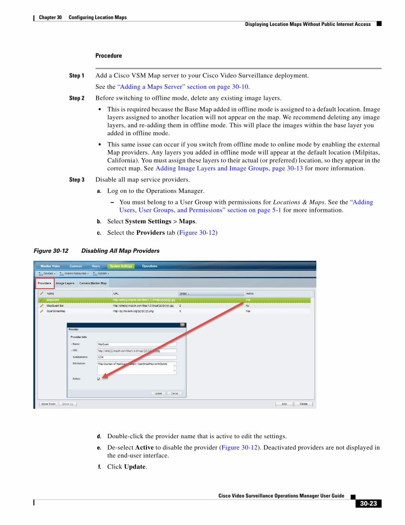
Chapter 30 Configuring Location MapsDisplaying Location Maps Without Public Internet Access
Procedure
Step 1 Add a Cisco VSM Map server to your Cisco Video Surveillance deployment.
See the “Adding a Maps Server” section on page 30-10.
Step 2 Before switching to offline mode, delete any existing image layers.
• This is required because the Base Map added in offline mode is assigned to a default location. Image layers assigned to another location will not appear on the map. We recommend deleting any image layers, and re-adding them in offline mode. This will place the images within the base layer you added in offline mode.
• This same issue can occur if you switch from offline mode to online mode by enabling the external Map providers. Any layers you added in offline mode will appear at the default location (Milpitas, California). You must assign these layers to their actual (or preferred) location, so they appear in the correct map. See Adding Image Layers and Image Groups, page 30-13 for more information.
Step 3 Disable all map service providers.
a. Log on to the Operations Manager.
– You must belong to a User Group with permissions for Locations & Maps. See the “Adding Users, User Groups, and Permissions” section on page 5-1 for more information.
b. Select System Settings > Maps.
c. Select the Providers tab (Figure 30-12)
Figure 30-12 Disabling All Map Providers
d. Double-click the provider name that is active to edit the settings.
e. De-select Active to disable the provider (Figure 30-12). Deactivated providers are not displayed in the end-user interface.
f. Click Update.
30-23Cisco Video Surveillance Operations Manager User Guide
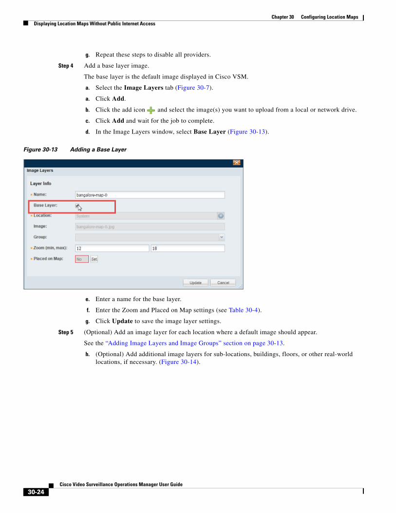
Chapter 30 Configuring Location Maps Displaying Location Maps Without Public Internet Access
g. Repeat these steps to disable all providers.
Step 4 Add a base layer image.
The base layer is the default image displayed in Cisco VSM.
a. Select the Image Layers tab (Figure 30-7).
a. Click Add.
b. Click the add icon and select the image(s) you want to upload from a local or network drive.
c. Click Add and wait for the job to complete.
d. In the Image Layers window, select Base Layer (Figure 30-13).
Figure 30-13 Adding a Base Layer
e. Enter a name for the base layer.
f. Enter the Zoom and Placed on Map settings (see Table 30-4).
g. Click Update to save the image layer settings.
Step 5 (Optional) Add an image layer for each location where a default image should appear.
See the “Adding Image Layers and Image Groups” section on page 30-13.
h. (Optional) Add additional image layers for sub-locations, buildings, floors, or other real-world locations, if necessary. (Figure 30-14).
30-24Cisco Video Surveillance Operations Manager User Guide
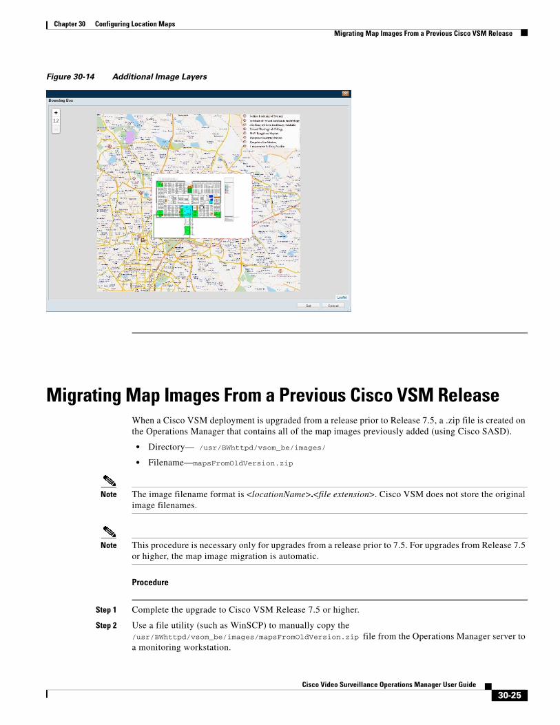
Chapter 30 Configuring Location MapsMigrating Map Images From a Previous Cisco VSM Release
Figure 30-14 Additional Image Layers
Migrating Map Images From a Previous Cisco VSM ReleaseWhen a Cisco VSM deployment is upgraded from a release prior to Release 7.5, a .zip file is created on the Operations Manager that contains all of the map images previously added (using Cisco SASD).
• Directory— /usr/BWhttpd/vsom_be/images/
• Filename—mapsFromOldVersion.zip
Note The image filename format is <locationName>.<file extension>. Cisco VSM does not store the original image filenames.
Note This procedure is necessary only for upgrades from a release prior to 7.5. For upgrades from Release 7.5 or higher, the map image migration is automatic.
Procedure
Step 1 Complete the upgrade to Cisco VSM Release 7.5 or higher.
Step 2 Use a file utility (such as WinSCP) to manually copy the /usr/BWhttpd/vsom_be/images/mapsFromOldVersion.zip file from the Operations Manager server to a monitoring workstation.
30-25Cisco Video Surveillance Operations Manager User Guide
Chapter 30 Configuring Location Maps Understanding Image Layer Status Errors
Step 3 Install and configure a Maps Server as described in the “Adding a Maps Server” section on page 30-10.
Step 4 Add the mapsFromOldVersion.zip file to the Operations Manager Maps Layers page. See the “Adding Image Layers and Image Groups” section on page 30-13 for more information.
Understanding Image Layer Status ErrorsWhen a Map or Operations Manager server is restored from a backup, the normal image Layer Status is one of the following (see Table 30-7):
• Published—the image that is uploaded to the system and is bound to a latitude/longitude.
• Unpublished—the image that is uploaded to the system but is yet to be bound to a latitude/longitude.
However, depending on the state of the backup file used to restore the images, one of the following states can also occur.
For example, We recommend publishing all images before performing an Operations Manager “Config only” backup. Operations Manager “Config only” backups do not backup Unpublished images (which are temporarily stored on Operations Manager server). The Unpublished images are not restored with the backup file, and an “map_layer_ mismatch” issue will occur on the Maps Server.
Tip These states can cause Critical server status errors. See the “Viewing and Clearing Layer Status Errors” section on page 30-27 for more information.
Table 30-7 Layer Status Error States (After a Restore)
Layer Status Description
VSOM_ONLY Only the layer details are available on the Operations Manager but the Maps Server does not have actual layer files.
Image layers in the VSOM_ONLY state are not be visible on monitoring clients (Cisco SASD). You must manually delete the layer from the Camera Marker Map and re-upload the same layer again.
This can occur when the list of layers in the Maps Server backup does not match the list in the Operations Manager configuration (usually because the Maps Server backup is older than the Operations Manager configuration).
30-26Cisco Video Surveillance Operations Manager User Guide
Chapter 30 Configuring Location MapsUnderstanding Image Layer Status Errors
Viewing and Clearing Layer Status ErrorsAny of the Layer Status states described in Table 30-7 appear as an issue in the Map Server Status tab.
• Open the Maps Server configuration page and select Status > Status History (see the “Viewing Server Status” section on page 8-29).
• The “map_layer_ mismatch” issue is also displayed in the Health Dashboard. See the “Health Dashboard: Device Health Faults on an Operations Manager” section on page 24-7.
• Go to System Settings > Maps> Image Layers (Figure 30-7) to clear the image layer issues as described in Table 30-7.
Note The “map_layer_ mismatch” issues are automatically cleared from the status and health pages when the image files are deleted or updated.
MAPSERVER_ONLY The layer files are available only on the Maps Server (and not on the Operations Manager server). The Operations Manager has no information about these layers.
Image layers in the MAPSERVER_ONLY state are not be visible on monitoring clients (Cisco SASD). You must manually delete the layer from the Camera Marker Map and re-upload the same layer again.
This can occur when the Operations Manager configuration is restored from an earlier date backup than the Maps Server. The list of deployed image layers in the Operations Manager and Maps Server will not match.
CONFIG_MISMATCH The Bounding Box values for the image layer in the Operations Manager and Maps Server do not match.
Select the layer and click Update to push the Bounding Box value of the layer from the Operations Manager to the Maps Server.
Table 30-7 Layer Status Error States (After a Restore) (continued)
Layer Status Description
30-27Cisco Video Surveillance Operations Manager User Guide

Chapter 30 Configuring Location Maps Understanding Image Layer Status Errors
30-28Cisco Video Surveillance Operations Manager User Guide
Cisco V
C H A P T E R 31
Upgrading System and Device SoftwareRefer to the Cisco Video Surveillance Manager: Install and Upgrade Guide for instructions to upgrade the Cisco Video Surveillance system software, the driver packs that enable camera and encoder models, and the device firmware for those devices.
Topics include:
• Installation and Upgrade Summary
• Downloading Cisco Software, Firmware and Driver Packs
• Deploying a Physical Cisco VSM Server
• Installing and Upgrading Driver Packs
• Upgrading Cisco Camera and Encoder Firmware
• Installing Cisco Video Surveillance Safety and Security Desktop (Cisco SASD)
• Upgrading Language Packs
• Recovering or Reinstalling the Factory Image
• Troubleshooting
31-1ideo Surveillance Operations Manager User Guide

Chapter 31 Upgrading System and Device Software
31-2Cisco Video Surveillance Operations Manager User Guide
Cisco Video S
A
P P E N D I X A
Related DocumentationUse one of the following methods to access the Cisco Video Surveillance (Cisco VSM) documentation:
• Click Help at the top of the screen to open the online help system.
• Download PDF versions at Operations > Help.
• Go to the Cisco Video Surveillance documentation web site.
• See the Cisco Video Surveillance 7 Documentation Roadmap for descriptions and links to Cisco Video Surveillance documentation, server and storage platform documentation, and other related documentation.
A-1urveillance Operations Manager User Guide

Appendix A Related Documentation
A-2Cisco Video Surveillance Operations Manager User Guide
Cisco Video S
A
P P E N D I X B
Downloading Utilities and DocumentationRefer to the following topics to download additional software tools and updates.
• Downloading Cisco SASD and the Cisco Review Player, page B-1
• Downloading the Workstation Profiler Tool, page B-2
• Accessing the Management Console, page B-2
• Downloading Documentation, page B-2
Downloading Cisco SASD and the Cisco Review PlayerTo download and install the full Cisco SASD application suite from cisco.com, see the Cisco Video Surveillance Safety and Security Desktop User Guide.
To download the following monitoring applications, go to Operations > Software. When the download is complete, double-click the installation file and follow the on-screen instructions.
Note To download these installation files, you must belong to a user group with Download Software permission. See the “Adding Users, User Groups, and Permissions” section on page 5-1 for more information.
Table B-1 Cisco Video Viewing Applications for Download from the Operations Manager
Application Description Documentation
Tip See the “Understanding the Video Viewing Options” section on page 2-2 for more information.
Cisco SASD Advanced Video Player
(Cisco SASD)
Desktop monitoring application that provides greater flexibility to monitor multiple cameras, and view alerts.
Cisco Video Surveillance Safety and Security Desktop User Guide
Cisco SASD Advanced Video Player User Guide
Cisco Video Surveillance Review Player
(Cisco Review Player)
Simple player used to view video clip files. Cisco Video Surveillance Review Player
B-1urveillance Operations Manager User Guide
Appendix B Downloading Utilities and Documentation Downloading the Workstation Profiler Tool
Downloading the Workstation Profiler ToolThe Profiler Tool is used to analyze the ability of a monitoring PC client to render video. See Using the Cisco Video Surveillance Monitoring Workstation Profiler Tool for instructions to download, install, and use this tool.
Accessing the Management ConsoleThe browser-based Cisco Video Surveillance Management Console is used to configure and monitor the server that runs the Cisco VSM services, such as the Operations Manager and Media Server.
Select to Operations > Management Console to open a new browser tab with the Management Console, or enter http://<server-ip-address or hostname>/vsmc/.
See the Cisco Video Surveillance Management Console Administration Guide for more information.
Note The Management Console requires a separate password.
Downloading DocumentationGo to Operations > Help to download to download Cisco Video Surveillance documentation. See the “Related Documentation” section on page A-1 regarding additional documentation available on cisco.com.
B-2Cisco Video Surveillance Operations Manager User Guide