Ultrasonic Propagation in the Micropores of Ion-Track Membranes
8
0885–3010/$25.00 © TBC IEEE 1 IEEE TRANSACTIONS ON ULTRASONICS, FERROELECTRICS, AND FREQUENCY CONTROL, vol. TBC, no. TBC, TBC TBC Abstract—The propagation of ultrasonic waves in the cylin- drical micro-pores (pore diam. <1 μm) of ion-track membranes (ITMs) is studied. This membrane fabrication technique pro- vides unique possibilities to obtain cylindrical micro-pores with a very high degree of accuracy in pore shape, size, and orientation. Several ITMs were specially produced having the same pore diameter, orientation, and geometry, but different thickness. Porosity, pore diameter, and shape were determined using scanning electron microscopy, and then the coefficient of ultrasound transmission was measured using air coupling and spectral analysis. These experimental conditions permit us to eliminate the influence of the boundary conditions and to achieve a strong decoupling between the fluid filling the pores and the solid constituent of the membrane. Hence, the velocity and the attenuation coefficient for ultrasound propagation in the pores can be measured. These parameters are compared with the predictions made by conventional theories for sound propagation in porous media and in cylindrical channels. The conclusions of this work provide a better understanding of wave propagation in micro-pores and establish the basis of an ultrasonic porometry technique for ITMs. I. Introduction I on-track membranes (ITMs) are known as polymer films containing straight pore channels of almost cylin- drical geometry, with precisely controlled pore size, shape, orientation, and density [1]–[3]. A unique property of ITMs is that the number of pores, their diameter (dp), and their orientation can be varied independently and at will. They are used in several separation and filtration operations. The main membrane parameter is pore diameter; any in- tegrity or quality test performed on ITMs has the purpose of determining that no oversized or undersized pores are present. The former may compromise membrane filtering capability, whereas the latter may reduce flow throughput and give rise to undesired fouling. Pore diameter is nor- mally determined by scanning electron microscopy (SEM) or by gas flowmeters; both require taking a small sample from the material and therefore both are destructive. Use of ultrasonic techniques, especially air-coupled ultrasound, is promising because it is a nondestructive and noninva- sive technique that can be used directly on the production line to continuously monitor product quality. Several ultrasonic techniques have already been applied in the field of membrane science for the verification of membrane properties, for the determination of membrane fouling, and as a nondestructive integrity test [4]— how- ever, not for ITMs, but for membranes that have porosity values over 50% and have a cellular, fibrous, or particu- late microstructure. Another ultrasonic application relat- ed to these highly porous polymeric membranes with a cellular microstructure is to produce impedance match- ing layers for air-coupled piezoelectric transducers up to 5 MHz [5], [6]. In all of these cases, ultrasonic properties of the membranes are well described by an effective me- dium approach [4], [7]. Nevertheless, recent works ([8], [9]) showed that this assumption is not applicable to ITMs. The transmission of airborne ultrasound pulses through these membranes and the influence of pore diameter and boundary conditions (open- and sealed-pore conditions) at the membrane surface were studied [8], and revealed that ultrasound transmission through ITMs is the result of 2 decoupled contributions: transmission through the solid and transmission through the pores. Subsequently, a pro- cedure was developed to separate these 2 contributions [9]. It was applied to a systematic set of membranes to analyze the influence of pore diameter, porosity, and pore orientation on the transmission of ultrasound through the pores of ITMs. Our knowledge about how sound propagates in porous media and how it is reflected and transmitted at an in- terface between a fluid and a porous medium is strongly affected and limited by the actual complexity of either the microstructure of real porous media or the interac- tions between the components or both. To cope with this situation, theories for sound propagation include some semi-empirical parameters for the description of the mi- crostructure (i.e., tortuosity, sinuosity, and shape factors) and some approximations to model the flow of the fluid in the complex pore space (i.e., Poiseuille flow) [10], [11]. In addition, the solid frame or porous skeleton may also be rather complex: it may contain fibers, grains or particles and aggregates of them, cracks, and microcracks, and so forth. Finally, these problems are especially significant when pore dimensions are in the micrometer scale where the macroscopic description of the fluid may become ques- tionable: both pore diameter and wavelength may become comparable to the mean free path of the fluid molecules [8], [9]. This case has been excluded from the analytical solutions conventionally proposed for sound propagation Ultrasound Attenuation in Cylindrical Micro- Pores: Nondestructive Porometry of Ion- Track Membranes Tomás E. Gómez Álvarez–Arenas, Pavel Yu. Apel, and Oleg Orelovitch DRAFT Manuscript received September 28, 2007; accepted April 17, 2008. T. E. Gómez Álvarez–Arenas is with Instituto de Acústica, CSIC, Ser- rano 144, 28006, Madrid, Spain (e-mail: [email protected]). P. Y. Apel and O. Orelovitch are with the Flerov Laboratory of Nucle- ar Reactions, JINR, Dubna, Moscow Region, Russia. Digital Object Identifier TBC
Transcript of Ultrasonic Propagation in the Micropores of Ion-Track Membranes

0885–3010/$25.00 © TBC IEEE
1IEEE TransaCTIons on UlTrasonICs, FErroElECTrICs, and FrEqUEnCy ConTrol, vol. TBC, no. TBC, TBC TBC
Abstract—The propagation of ultrasonic waves in the cylin-drical micro-pores (pore diam. <1 μm) of ion-track membranes (ITMs) is studied. This membrane fabrication technique pro-vides unique possibilities to obtain cylindrical micro-pores with a very high degree of accuracy in pore shape, size, and orientation. Several ITMs were specially produced having the same pore diameter, orientation, and geometry, but different thickness. Porosity, pore diameter, and shape were determined using scanning electron microscopy, and then the coefficient of ultrasound transmission was measured using air coupling and spectral analysis. These experimental conditions permit us to eliminate the influence of the boundary conditions and to achieve a strong decoupling between the fluid filling the pores and the solid constituent of the membrane. Hence, the velocity and the attenuation coefficient for ultrasound propagation in the pores can be measured. These parameters are compared with the predictions made by conventional theories for sound propagation in porous media and in cylindrical channels. The conclusions of this work provide a better understanding of wave propagation in micro-pores and establish the basis of an ultrasonic porometry technique for ITMs.
I. Introduction
Ion-track membranes (ITMs) are known as polymer films containing straight pore channels of almost cylin-
drical geometry, with precisely controlled pore size, shape, orientation, and density [1]–[3]. a unique property of ITMs is that the number of pores, their diameter (dp), and their orientation can be varied independently and at will. They are used in several separation and filtration operations. The main membrane parameter is pore diameter; any in-tegrity or quality test performed on ITMs has the purpose of determining that no oversized or undersized pores are present. The former may compromise membrane filtering capability, whereas the latter may reduce flow throughput and give rise to undesired fouling. Pore diameter is nor-mally determined by scanning electron microscopy (sEM) or by gas flowmeters; both require taking a small sample from the material and therefore both are destructive. Use of ultrasonic techniques, especially air-coupled ultrasound, is promising because it is a nondestructive and noninva-sive technique that can be used directly on the production line to continuously monitor product quality.
several ultrasonic techniques have already been applied in the field of membrane science for the verification of membrane properties, for the determination of membrane fouling, and as a nondestructive integrity test [4]— how-ever, not for ITMs, but for membranes that have porosity values over 50% and have a cellular, fibrous, or particu-late microstructure. another ultrasonic application relat-ed to these highly porous polymeric membranes with a cellular microstructure is to produce impedance match-ing layers for air-coupled piezoelectric transducers up to 5 MHz [5], [6]. In all of these cases, ultrasonic properties of the membranes are well described by an effective me-dium approach [4], [7]. nevertheless, recent works ([8], [9]) showed that this assumption is not applicable to ITMs. The transmission of airborne ultrasound pulses through these membranes and the influence of pore diameter and boundary conditions (open- and sealed-pore conditions) at the membrane surface were studied [8], and revealed that ultrasound transmission through ITMs is the result of 2 decoupled contributions: transmission through the solid and transmission through the pores. subsequently, a pro-cedure was developed to separate these 2 contributions [9]. It was applied to a systematic set of membranes to analyze the influence of pore diameter, porosity, and pore orientation on the transmission of ultrasound through the pores of ITMs.
our knowledge about how sound propagates in porous media and how it is reflected and transmitted at an in-terface between a fluid and a porous medium is strongly affected and limited by the actual complexity of either the microstructure of real porous media or the interac-tions between the components or both. To cope with this situation, theories for sound propagation include some semi-empirical parameters for the description of the mi-crostructure (i.e., tortuosity, sinuosity, and shape factors) and some approximations to model the flow of the fluid in the complex pore space (i.e., Poiseuille flow) [10], [11]. In addition, the solid frame or porous skeleton may also be rather complex: it may contain fibers, grains or particles and aggregates of them, cracks, and microcracks, and so forth. Finally, these problems are especially significant when pore dimensions are in the micrometer scale where the macroscopic description of the fluid may become ques-tionable: both pore diameter and wavelength may become comparable to the mean free path of the fluid molecules [8], [9]. This case has been excluded from the analytical solutions conventionally proposed for sound propagation
Ultrasound Attenuation in Cylindrical Micro-Pores: Nondestructive Porometry of Ion-
Track MembranesTomás E. Gómez Álvarez–arenas, Pavel yu. apel, and oleg orelovitch
DR
AFT
Manuscript received september 28, 2007; accepted april 17, 2008. T. E. Gómez Álvarez–arenas is with Instituto de acústica, CsIC, ser-
rano 144, 28006, Madrid, spain (e-mail: [email protected]).P. y. apel and o. orelovitch are with the Flerov laboratory of nucle-
ar reactions, JInr, dubna, Moscow region, russia.digital object Identifier TBC
in narrow ducts [12], [13]. Unfortunately, concurrence of such small pores is quite common in both natural and man-made porous materials.
Two main issues remain to be investigated in order to have a comprehensive theoretical description of ultra-sound transmission through ITMs and hence to take full advantage of this ultrasonic technique applied to these membranes. one is the problem of wave transmission, re-flection, and mode conversion at the surfaces of the mem-brane; the other problem refers to the ultrasound propa-gation in the membrane. The solution of the former is not straightforward, due to the complexity of the boundary conditions that do not respond to any of the convention-ally used approaches (open or sealed-pore limits) [9], [14], [15]. on the contrary, they correspond to an intermediate situation where these conventional boundary conditions depend on a parameter (a kind of surface flow imped-ance) that cannot be independently measured. The ap-plicability of this model for intermediate situations has been questioned [16], [17]. The objective of this paper is to overcome this problem and focus on the second ques-tion, that is, to measure ultrasound attenuation in the pores of ITMs and to use these measurements to check the accuracy of theoretical approaches and to determine pore diameter. Toward this end, the coefficient of sound transmission through several membranes having the same pore diameter and orientation, but different thickness, is measured using air-coupled ultrasonic pulses and spectral analysis. The procedure we have already developed [9] is applied to get the amount of energy transmitted through the pores of the membranes; the attenuation coefficient of the wave in the pores is worked out from the difference be-tween energy transmitted through the pores of membranes having different thickness but the same pore diameter. This attenuation coefficient is compared with theoretical predictions and with pore diameter figures measured by other methods.
II. Materials
several ion-track membranes were specifically produced to get membranes with the same pore diameter and differ-ent thickness. several samples were taken from the same irradiated polymer foil and etched for different times; the same was done for irradiated polymer foils of different
thickness, adjusting the etching time so that membranes with the same pore diameter but different thickness were obtained. Further details about the manufacturing process are available in [1], [2], and [9]. Pore diameter, concen-tration, and shape were obtained from scanning electron microscopy (sEM) images of the surfaces and fractures (cross-section) of the ITMs, as explained in [9]. results are in Table I (N is the number of pores per cm2). The membranes produced were gathered into 3 grades, based on their sEM measurements (Table I). The typical stan-dard deviation of the sEM pore diameter is 0.05 μm, so pore diameters of membrane grades ITM05 and ITM04 are very close.
Fig. 1 shows a typical sEM micrograph of an ITM cross-section. Figs. 2, 3, 4 show[AU1: EDITOR: replace with range 2–4.] one representative sEM micrograph of the surface for each membrane grade; this type of micro-graph was used to determine pore diameter. Fig. 5 shows the distribution of pores over the surface of ITM06/12; this type of image was used to determine pore concentra-tion. as expected, pores have a cylindrical shape and very little size dispersion and run across the membrane thick-ness perpendicular to the membrane plane (nontortuous and nonsinuous pores).
III. Theoretical Background for Ultrasound Propagation in Porous Media
sound propagation in fluid-saturated porous media is described by Biot’s theory [7], [8]. This theory predicts the simultaneous propagation of 2 different longitudinal waves (the fast and the slow compressional waves). The main difference in the nature of these 2 waves lies in the relative averaged displacement of fluid and solid. This tends to be in-phase for the fast wave and out-of-phase for the slow one. When the 2 phases are decoupled (solid frame much more rigid than the fluid and relatively high frequency), a more intuitive explanation can be provided: the fast wave corresponds to wave propagation in the solid skeleton, whereas the slow wave corresponds to the propagation in the fluid in the pores.
Biot’s approach considered 2 frequency ranges: low and high, the crossover being located at the characteristic fre-quency fc, defined as fc = μϕ/2πρfκ, where μ is the vis-
2 IEEE TransaCTIons on UlTrasonICs, FErroElECTrICs, and FrEqUEnCy ConTrol, vol. TBC, no. TBC, TBC TBC
TaBlE I. Membrane Properties.
Membrane gradesample
denominationN
(cm−2)Pore diameter
(μm)Thickness
(μm) Porosity
ITM06 ITM06/23 1.30 × 10⁸ 0.57 23 0.332ITM06/12 1.68 × 10⁷ 0.65 12 0.056ITM06/10 1.30 × 10⁸ 0.61 10 0.380
ITM05/10 ITM05/10 1.30 × 10⁸ 0.47 10 0.226ITM05/5 1.38 × 10⁸ 0.49 5 0.260
ITM04/23 ITM04/23 1.30 × 10⁸ 0.44 23 0.198ITM04/12 1.65 × 10⁷ 0.45 12 0.026

cosity of the fluid, ρf is the density of the fluid, ϕ is the porosity, and κ is the darcy’s coefficient of permeability.
Experimental conditions of measurements presented in this work correspond to the Biot’s low-frequency range; the approximate analytical solution for the velocity (v) and the attenuation (α) of the slow wave are
vv
ffc c
=-( )
+( )æ
èççç
ö
ø÷÷÷÷2 11 22 12
12 22
1 2s s sg g
/
, (1a)
ag g
s s s
p=
+( )-( )
æ
èççç
ö
ø÷÷÷÷
12
212 22
11 22 12
1 2ff
f
vc
c
c
/
, (1b)
where f is the frequency, and vc is the Biot’s reference velocity [1]; the σij nondimensional parameters determine the elastic response of the media (σ11: the solid, σ22: the fluid, and σ12: the mechanical coupling between both), while the γij nondimensional parameters define the dy-namic properties of the media (γ11: the solid, γ22: the fluid, and γ12: the inertial coupling between them). In ad-dition, under the experimental conditions given in this work, it can be assumed that: σ12 = γ12 = 0.
Experimental verification of this theoretical approach was first made in terms of the velocity of these waves [18]–[20]. However, many porous materials, either air- or water-saturated (e.g., aerogels [21] and marine sediments [22]) exhibit a linear variation of the attenuation coef-ficient over a very wide frequency range, whereas the cor-responding theoretical predictions provide a dependency on the square root of the frequency.
From a slightly different point of view, the problem of sound waves in a viscothermal fluid inside a cylindrical, rigid tube with no flow was solved exactly by Kirchhoff [23]. later, Zwicker and Kosten [24] introduced a sim-pler and approximative treatment. some reviews appeared later; see, for instance, Tijdeman [25]. during the last de-cade, there has been a renewed interest to extend this so-lution to other cross-section shapes and to account for the effects of a mean flow; one reason for this interest has been the efforts to model automobile catalytic converters [26]. Two main approaches are also considered from this point of view: narrow and wide tube. The range of applicability depends on the relationship between pore diameter and the extent of the influence of viscous and thermal influ-ence of the tube walls on the fluid.
raleigh obtained an analytical solution for the “nar-row” tube approach. In this case, viscous skin depth is larger than pore diameter: (ωa2ρ/μ ≪ 1), where ω is the angular frequency, a the tube radius, ρ the fluid density, and μ the fluid viscosity. In this case, the propagation constant k is given by
k ia c
= +2 12
( ) ,g
w r
w
m/ (2)
3GóMEZ ÁlvarEZ–arEnas ET al.: ultrasound attenuation in cylindrical micro-pores
Fig. 1. sEM micrograph of the cross-section of a typical ion-track mem-brane.
Fig. 2. sEM micrograph of the surface of ITM04/12 used to determine pore diameter at the membrane surface.
Fig. 3. sEM micrograph of the surface of ITM05/5 used to determine pore diameter at the membrane surface.

where c is the velocity of sound in the undisturbed fluid. This is similar to the solution given by (1a) and (1b), when σ12 = γ12 = 0.
Iv. Experimental setup and Procedure
Four pairs of air-coupled piezoelectric transducers were used [6]. The diameter of the transducer aperture is about 20 mm and center frequency about 0.5, 1, 2, and 5 MHz. The transducers are located facing each other and separat-ed by an air gap a few millimeters thick. The transmitter is driven by a pulser/receiver that produces a tunable elec-trical negative square semicycle (P/r 4077 Panametrics, Panametrics Inc., Waltham, Ma); it launches an ultrason-ic signal that travels across the air gap and is eventually received by the receiver transducer. This analog signal is amplified and filtered by the pulser/receiver and sent to a digital oscilloscope (Tds 5052, Tektronix Inc., Beaverton, or) where it is displayed, digitized, and filtered, and fast Fourier transform (FFT) is performed. The pulser also provides a trigger signal for the oscilloscope. The phase and magnitude of the FFT are stored and used later as reference values. Then the membrane is put in between the transducers, at normal incidence; distances between the membrane and the transducers are set so that any overlap in the time domain between the through transmit-ted signal and any of the reverberations within the air gaps is avoided. The signal is digitized and filtered, and FFT is performed again; these data are normalized to the reference values to obtain the amplitude and phase of the transfer function. Theoretically, the transfer function (T) is defined as the ratio of transmitted [At exp(iθt)] to inci-dent [Ao exp(iθ)] wave displacement potential, where A is the amplitude and θ the phase. To compare this theoretical transfer function with the measurements, it is necessary to consider that in this experimental setup a small layer of air is replaced by the ITM sample. For the simple case of ultrasonic plane waves transmitted through a homogenous foil of thickness t embedded in a fluid, T is obtained by applying boundary conditions at both foil surfaces, and solving the system for the amplitudes of the displacement wave potential (see [27]). For normal incidence:
T kt i m m ktf = + +2 2 1/( / )cos ( )sin , (3)
where superscript f stands for homogeneous (nonporous) foil, k is the wave number in the foil, t is the thickness of the foil, and m is the ratio of foil to air (surrounding fluid) acoustic impedance. Kelly et al. [5] show that the theory given by (1) describes quite well the ultrasound transmis-sion through the nonporous foils used to produce ITMs. It also describes quite accurately transmission through ITMs with sealed pores.
In the case of ITMs, this scenario is modified by the presence of pores. Following [9], the transfer function for the membrane (Tm) is made up by 2 rather decoupled con-tributions, one due to the solid part (TS) and the other to
the pore space (TP): Tm = TS + TP, where the former can be obtained from TS = (1 − Φ)TS and (3), and where Φ is the porosity of the membrane; then Tm is given by
T T T T Tm f p f p= -( ) + = -( ) +1 1f f f . (4)
If reverberations in the pores can be neglected, Tp can be written as [9]
T a a tps= ( ) - ( )( )W , exp , ,w a w (5)
where the coefficient Ω(as,ω) determines the amount of energy coupled into the pore propagation mode at the sur-face of the membrane, as is the pore radius at the surface, and a is the pore radius inside the membrane. an exact value of Ω(as,ω) is obtained from the solution of pertinent
4 IEEE TransaCTIons on UlTrasonICs, FErroElECTrICs, and FrEqUEnCy ConTrol, vol. TBC, no. TBC, TBC TBC
Fig. 4. sEM micrograph of the surface of ITM06/12 used to determine pore diameter at the membrane surface.
Fig. 5. sEM micrograph of the surface of ITM06/12 used to determine pore concentration and porosity.

boundary conditions. For the limit cases of open-pore and sealed-pore, Ω(as,ω) approaches 1 and 0, respectively [14], [15]. In this case, Ω(as,ω) corresponds to an intermediate situation, as explained in [9]: although pores are open, fluid flow in and out of the pores is not made without resistance, due to the viscous drag force between the fluid and the pore walls.
From (5) and Tp measurements of membranes hav-ing the same pore diameter (both a and as) but different thickness, the attenuation coefficient α(a,ω) can be ob-tained. First, the hypothesis that the effect of reverbera-tions is negligible has to be verified. Compared with the through transmitted wave, the first reverberation has 2 extra reflections and travels across the membrane 2 extra times. Eq. (2) can be used to determine the velocity and attenuation coefficient; then it is possible to estimate the attenuation and the reflection loss and, hence, the ratio
of the amplitude of the first reverberation to the ampli-tude of the through transmission. The criterion used is that this amplitude ratio be smaller than 0.1. In other words, we find a low-frequency limit for the experimental frequency range; below this limit, the influence of rever-berations could be significant. The frequencies obtained are: 0.2 MHz (ITM06/23), 0.6 MHz (ITM06/12), 0.8 MHz (ITM06/10), 0.6 MHz (ITM05/10), 1.5 MHz (ITM05/5), 0.05 MHz (ITM04/23), and 0.3 MHz (ITM04/23). as the experimental frequency range is 0.3–6 MHz, it is expected that the reverberations may have some influence only in the low-frequency measurements and only in some cases.
v. Experimental results
The magnitude and phase of Tm were measured for each of the membranes listed in Table I using the 4 pairs of transducers. These data along with calculated Tf from (1) are used to work out the magnitude of Tp. These re-sults are shown in Figs. 6–8.
as observed in [4], variation of Tp with frequency (f) is close to linear: T Tp p= 0 + m · f ; linear regression analy-sis of the experimental data was performed and the linear fittings obtained are also plotted in the graphs. only Tp
5GóMEZ ÁlvarEZ–arEnas ET al.: ultrasound attenuation in cylindrical micro-pores
Fig. 6. Magnitude of Tp versus frequency for the 3 samples of membrane-grade ITM06.
Fig. 8. Magnitude of Tp versus frequency for the 3 samples of membrane-grade ITM04.
TaBlE II. linear regression Coefficients For T P versus Frequency.
Membrane Ω(as,0)(dB) m/t (dB·MHz−1·μm−1)
ITM06/23 −15.4 −0.216 ± 0.0013ITM06/12 −14.8 −0.261 ± 0.02ITM06/10 −14.21 −0.176 ± 0.002ITM05/10 −17.2 −0.363 ± 0.003ITM05/5 −16.46 −0.310 ± 0.044ITM04/23 −17.2 −0.615 ± 0.033ITM04/12 −16.27 −0.516 ± 0.08
Fig. 7. Magnitude of Tp versus frequency for the 3 samples of membrane-grade ITM05.
for ITM05/5 presents a measurable departure from this linear frequency law for frequencies below 1.1 MHz. This can be explained by the contribution of reverberations in-side the pores. The 2 coefficients of the linear regression analysis are displayed in Table II, the slope divided by the thickness (m/t) and the transmission coefficient extrapo-lated at zero frequency divided by the porosity [T p
0 /Φ = Ω(as,0)]. These ultrasonic parameters are used to check whether the ultrasonic measurements confirm that pore diameter can be assumed to be similar for membranes classified (after sEM measurements) within the same grade. T p
0 depends on the pore aperture at the membrane surface and the porosity, Ω(as,0) depends only on the pore aperture at the membrane surface, and m/t depends only on the attenuation, that is, only on the pore diameter within the membrane.
Membrane classification according to m/t data (Table II) agrees quite well with membrane grades established after sEM measurements (Table I). ITMs may be gath-ered into 3 grades: ITM06 (average pore diameter: 0.61 μm and average slope: 0.218 dB·MHz−1·μm−1), ITM05 (average pore diameter: 0.48 μm and average slope: 0.336 dB·MHz−1·μm−1), and ITM04 (average pore diameter: 0.445 μm and average slope: 0.565 dB·MHz−1·μm−1). Therefore, attenuation can be obtained by comparing measurements of membranes having the same grade but different thickness. However, according to Ω(as,0) data in Table II, membranes could be gathered into 2 groups: one for ITM06 (average Ω(as,0) = −14.8 dB) and the other for ITM04 and ITM05 (average Ω(as,0) = −16.78 dB). It is interesting to note that both Ω(as,0) and sEM images of the membrane surface provide information about the same physical quantity: pore aperture at the membrane sur-face (2as), whereas m/t refers to the pore diameter within the membrane (2a). different values of m/t observed in membranes that have the same value of Ω(as,0) can be accounted for by considering how the thickness of the
membrane can affect the chemical etching rate within the pores of the membrane. In particular, ITM04 and ITM05 groups seem to have the same as (same Ω(as,0)), but ITM04 presents an effective pore diameter slightly smaller (larger m/t) that can be related to the larger thickness of ITM04 compared with ITM05. It is significant that the ultrasonic technique employed in the work is sensitive to both parameters and can discern between changes in any of them separately.
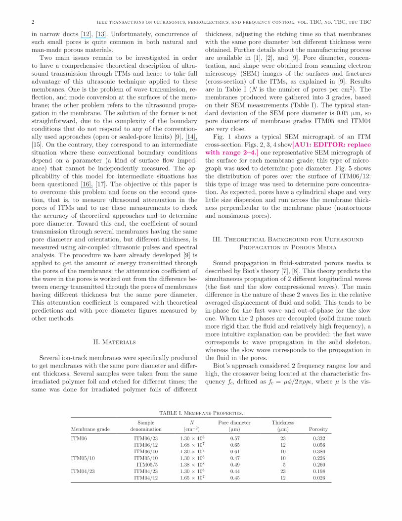
Phase difference for the propagation in the pores: (θ p – θ) is also measured; hence, phase velocity is obtained. averaged results are shown in Fig. 9; error bars represent the deviation of individual measurements from the aver-age. In addition, theoretically calculated velocities by us-ing Biot’s theory are also plotted for pore diameters of 0.4, 0.5, and 0.6 μm.
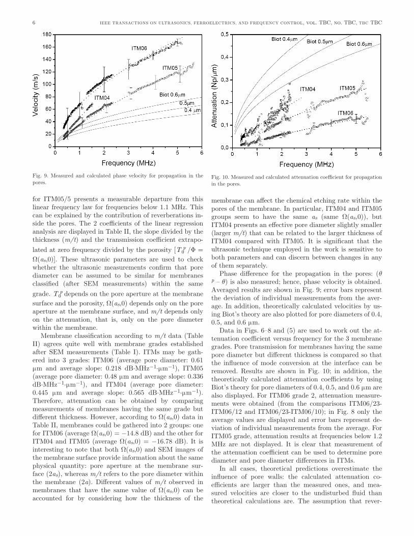
data in Figs. 6–8 and (5) are used to work out the at-tenuation coefficient versus frequency for the 3 membrane grades. Pore transmission for membranes having the same pore diameter but different thickness is compared so that the influence of mode conversion at the interface can be removed. results are shown in Fig. 10; in addition, the theoretically calculated attenuation coefficients by using Biot’s theory for pore diameters of 0.4, 0.5, and 0.6 μm are also displayed. For ITM06 grade 2, attenuation measure-ments were obtained (from the comparisons ITM06/23-ITM06/12 and ITM06/23-ITM06/10); in Fig. 8 only the average values are displayed and error bars represent de-viation of individual measurements from the average. For ITM05 grade, attenuation results at frequencies below 1.2 MHz are not displayed. It is clear that measurement of the attenuation coefficient can be used to determine pore diameter and pore diameter differences in ITMs.
In all cases, theoretical predictions overestimate the influence of pore walls: the calculated attenuation co-efficients are larger than the measured ones, and mea-sured velocities are closer to the undisturbed fluid than theoretical calculations are. The assumption that rever-
6 IEEE TransaCTIons on UlTrasonICs, FErroElECTrICs, and FrEqUEnCy ConTrol, vol. TBC, no. TBC, TBC TBC
Fig. 9. Measured and calculated phase velocity for propagation in the pores.
Fig. 10. Measured and calculated attenuation coefficient for propagation in the pores.

berations inside the pores are negligible is thus shifted toward higher frequencies. In particular, the recalculated low-frequency limits are: 1 MHz (ITM06/23), 1.6 MHz (ITM06/12), 2 MHz (ITM06/10), 1.5 MHz (ITM05/10), 2.5 MHz (ITM05/5), 0.25 MHz (ITM04/23), and 0.75 MHz (ITM04/23). above these frequencies, fittings to the fre-quency power law (least squares analysis) were performed and are also shown in Figs. 7 and 8. as expected, the frequency power law for the attenuation (α = α0 ·f n) is close to linear (n is 0.859 ± 0.02, 0.801 ± 0.03, and 0.849 ± 0.012 for ITM04, ITM05, and ITM06, respectively) and shows a clear departure from the theoretical value [n = 0.5; see (1) and (2)].
differences observed between experimental data and theoretical predictions can be attributed to the small size of the pore compared with the mean free path of the air molecules. This means that the no-slip boundary condition normally assumed at the pore wall interface is no longer valid; the fluid cannot be regarded as being in thermody-namic equilibrium, and the continuum flow hypothesis in the navier–stokes equation begins to break down.
v. Conclusions
Transmission coefficient of air-coupled ultrasound through several ITMs specially produced for this purpose has been measured. Hence, the attenuation coefficient and the phase velocity for ultrasound propagation in the nar-row cylindrical pores of these porous solids have been ob-tained. These data have been compared with theoretical predictions. It should be underlined that the theoretical calculations of the ultrasound velocity and the attenua-tion coefficient in ITMs need no fitting parameters such as tortuosity, sinuosity, or pore shape factors, so these mem-branes provide an excellent means for testing the accuracy of these predictions.
The analysis of the transmission coefficient provides in-formation about both aperture of the pores at the mem-brane surface and the pore diameter within the membrane. The former is related to the value of the magnitude of the transmission coefficient at low frequency T p
0 or T p0 /Φ =
Ω(as,0), while the latter is linked to the slope of the trans-mission coefficient versus frequency graph (m/t).
Membrane classification attending to Ω(as,0) is close to that obtained from the measurement of pore aperture from sEM images of the surface of the membrane. Ω(as,0) values of about −14.7 dB are obtained for ITM06 grade (sEM pore diameter about (0.6 ± 0.05) μm), whereas Ω(as,0) values of about −16.5 dB were obtained for the 2 membrane series, ITM05 and ITM04, that exhibit a very close sEM pore diameter: (0.48 ± 0.05) μm and (0.44 ± 0.05) μm, respectively.
The transmission coefficient also provides information about pore diameter within the membrane, in particular, the larger the parameter m/t, the smaller the pore diam-eter. according to m/t values, the 3 membrane grades
can be clearly discerned: (0.22 ± 0.04) dB·MHz−1·μm−1, (0.34 ± 0.04) dB·MHz−1·μm−1, and (0.57 ± 0.07) dB·MHz−1·μm−1 for ITM06, ITM05, and ITM04, respec-tively. The pore diameter takes different values for mem-brane grades ITM05 and ITM04, but the pore aperture is similar; this can be related to a slightly lower etching rate in the central part of the membrane for the thicker membranes.
In addition, the phase velocity and the attenuation co-efficient are also calculated. The general trend is that larg-er pores provide larger velocity values. This is observed for ITM06 and ITM05. However, ITM04 does not follow the same trend and exhibits velocity values larger than those obtained for ITM05 but smaller than those of ITM06. nevertheless, measurements of velocity in ITM04 mem-branes are constrained to the low-frequency range where the observed differences with ITM06 and ITM05 are with-in the experimental error range. Concerning attenuation, we find that the larger the pore diameter, the smaller the attenuation coefficient; even the small pore diameter dif-ference between ITM04 and ITM05 can be detected from attenuation measurements. attenuation coefficient versus frequency fits well into a power frequency law (α = α0 ·fn). no significant variations of n are observed that show a clear departure from the theoretical value and represent a behavior close to a linear law.
Measured phase velocities and attenuation coefficients are compared with calculated values by a conventional theory for sound propagation in cylindrical pores. Unlike the findings in many previous studies, the comparison be-tween experimental data and theoretical calculations is especially straightforward in this case because no adjust-able parameters to describe pore geometry are needed. It is found that the theoretical approaches overestimate the influence of the pore walls (hence, overestimate the value of the attenuation while subestimating the value of the ve-locity). also, some differences were found in the variation of the attenuation coefficient with frequency. These dif-ferences can be attributed to the size of the pores, whose radius is comparable to the mean free path of air mol-ecules.
Unlike other techniques already used, the ultrasonic technique presented here is noninvasive and nondestruc-tive, and does not require any contact with the membrane; hence, it is possible to use it at industrial levels directly on the production line to continuously monitor membrane quality, in particular, after the membrane drying (that takes place after the washing subsequent to the chemical etching) and before the membrane is rolled for storage.
references
[1] G. n. Flerov, P. yu. apel, a. yu. didyk, v. I. Kuznetsov, and r. Ts. oganessian, “The use of heavy ion accelerators for production of track membranes,” Atomic Energy (USSR), vol. 67, pp. 274–280, 1989 (in russian).
[2] P. apel, “Track etching technique in membrane technology,” Radiat. Meas., vol. 34, no. 1–4, pp. 559–566, 2001.
7GóMEZ ÁlvarEZ–arEnas ET al.: ultrasound attenuation in cylindrical micro-pores

[3] P. yu. apel, “Heavy particle tracks in polymers and polymeric track membranes,” Radiat. Meas., vol. 25, no. 1–4, pp. 667–674, 1995.
[4] T. E. Gómez Álvarez-arenas, “a nondestructive integrity test for membrane filters based on air-coupled ultrasonic spectroscopy,” IEEE Trans. Ultrason. Ferroelectr. Freq. Contr., vol. 50, no. 6, pp. 676–685, 2004.
[5] s. P. Kelly, G. Hayward, and T. E. Gómez Álvarez-arenas, “Char-acterization and assessment of an integrated matching layer for air-coupled ultrasonic applications,” IEEE Trans. Ultrason. Ferroelectr. Freq. Contr., vol. 51, no. 10, pp. 1314–1323, 2004.
[6] T. E. Gómez Álvarez-arenas, “acoustic impedance matching of piezoelectric transducers to the air,” IEEE Trans. Ultrason. Fer-roelectr. Freq. Contr., vol. 51, no. 5, pp. 624–633, 2004.
[7] T. E. Gómez Álvarez-arenas, “air-coupled ultrasonic spectroscopy for the study of membrane filters,” J. Membr. Sci., vol. 213, pp. 195–207, 2003.
[8] T. E. Gómez Álvarez-arenas, B. González, P. y. apel, o. l. ore-lovitch, and a. v. Mitrofanov, “Ultrasound propagation in the mi-cropores of track membranes,” Appl. Phys. Lett., vol. 87, art. no. 111911 2005.
[9] T. E. Gómez Álvarez-arenas, P. y. apel, and o. l. orelovitch, “Characterization of ion-track membranes by non-contact ultrasonic magnitude and phase spectroscopy,” J. Membr. Sci., vol. 301, pp. 210–220, 2007.
[10] M. a. Biot, “Theory of propagation of elastic waves in a fluid-satu-rated porous solid I. low frequency range,” J. Acoust. Soc. Am., vol. 28, no. 2, pp. 168–178, 1956.
[11] M. a. Biot, “Theory of propagation of elastic waves in a fluid-satu-rated porous solid II. Higher frequency range,” J. Acoust. Soc. Am., vol. 28, no. 2, pp. 179–191, 1956.
[12] M. r. stinson, “The propagation of plane sound waves in narrow and wide circular tubes, and generalization to uniform tubes of arbi-trary cross-sectional shape,” J. Acoust. Soc. Am., vol. 89, no. 2, pp. 550–558, 1991.
[13] d. E. Weston, “The theory of the propagation of plane sound waves in tubes,” Proc. Phys. Soc. Lond., vol. B66, pp. 695–709, 1953.
[14] H. deresiewicz and r. skalak, “on uniqueness in dynamic poroelas-ticity,” Bull. Seismol. Soc. Am., vol. 53, pp. 783–788, 1963.
[15] s. Feng and d. l. Johnson, “High-frequency acoustic properties of a fluid/porous solid interface. I. new surface mode,” J. Acoust. Soc. Am., vol. 74, no. 3, pp. 906–914, 1983.
[16] B. Gurevich and M. schoenberg, “Interface conditions for Biot’s equations of poroelasticity,” J. Acoust. Soc. Am., vol. 105, pp. 2585–2589, 1999.
[17] s. de la Fuente and T. E. Gómez Álvarez-arenas, “Influence of pore size on boundary conditions at the interface between a fluid and a poroelastic solid,” in Proc. Int. Congr. on Ultrasonics, 2007, to be published[AU2: Update?].
[18] T. J. Plona, “observation of a second bulk compressional wave in a porous medium at ultrasonic frequencies,” Appl. Phys. Lett., vol. 36, pp. 259–261, 1980.
[19] J. G. Berryman, “Confirmation of Biot’s theory,” Appl. Phys. Lett., vol. 37, pp. 382–384, 1980.
[20] n. C. dutta, “Theoretical analysis of observed second bulk compres-sional wave in a fluid saturated porous solid at ultrasonic frequen-cies,” Appl. Phys. Lett., vol. 37, pp. 898–900, 1980.
[21] T. E. Gómez Álvarez–arenas, F. Montero de Espinosa, M. Moner–Girona, E. rodríguez, a. roig, and E. Molins, “viscoelasticity of silica aerogels at ultrasonic frequencies,” Appl. Phys. Lett., vol. 81, no. 7, pp. 1198–1200, 2002.
[22] a. C. Kibblewhite, “attenuation of sound in marine sediments: a review with emphasis on new low frequency data,” J. Acoust. Soc. Am., vol. 86, pp. 716–738, 1989.
[23] G. Kirchhoff, “Über den Einfluss der Wärmeleitung in einem Gase auf die schallbewegung,” Ann. Phys. Chem, vol. 134, pp. 177–193, 1868.
[24] C. Zwicker and C. W. Kosten, Sound Absorbing Materials. amster-dam: Elsevier, 1949, Chap. 2.
[25] H. Tijdeman, “on the propagation of sound in cylindrical tubes,” J. Sound Vibrat., vol. 39, pp. 1–33, 1975.
[26] s. allam and M. Åbom, “sound propagation in an array of narrow porous channels with application to diesel particulate filters,” J. Sound Vibrat., vol. 291, pp. 882–901, 2006.
[27] l. M. Brekhovskikh, Waves in Layered Media. new york: academic Press, 1960.
Tomás E. Gómez Alvarez-Arenas received the M.s. degree in physics at Complutense Uni-versity at Madrid (spain) in 1989 and the Ph.d. degree in materials science (physics) in 1994. He was a postdoctoral fellow at the University of strathclyde at Glasgow (scotland, UK) from 1995 to 1997, conducting research in the fields of air-coupled piezoelectric transducers and numerical modelling of acoustic wave propagation in random composites. He was elected to a fellowship at the spanish research Council (CsIC) in 1998. In the
department of Ultrasonic signals, systems and Technologies (CsIC) he was appointed tenured scientist in 1999. From 2003 to 2007 he held the post of Chief of this department. His research interests are in materials characterization by ultrasound, ultrasound propagation in porous mate-rials, and air-coupled ultrasonic transducers.
Pavel Yu. Apel was graduated from the lenin-grad Technological Institute in 1976. He has been pursuing his scientific career at the Flerov labora-tory of nuclear reactions in dubna (russia) where his activity is concerned with effects of ac-celerated heavy ions on polymers. He received his Ph.d. and dr. sci. degrees in 1986 and 1998, re-spectively. during the last two decades, he closely collaborated with some laboratories abroad, such as GsI (darmstadt, Germany) and TrCrE JaEa (Takasaki, Japan), which are leading in the field
of applied research with ion beams. He published over 120 papers in rus-sian and international journals, some of which are recognized as signifi-cant contributions to the field. at present, the main focus of his work is fabrication of micro- and nanostructures using the ion-track technique.
Oleg Leonidovich Orelovich was born in ros-tov-on-don (russia) in 1954. He received his M.sc. degree from Moscow state Institute of ra-dio Engineering, Electronics and automation. during two months in 1977, he was enrolled in a special course at the Electron Microscopy school in sumy, the Ukraine. He is now a principal engi-neer at the Center of applied Physics, Flnr JInr (dubna, russia) where he has been dealing with transmission and scanning electron micros-copy. He has created some special methods of mi-
croscopic investigation of porous polymer samples, in particular track-etched membranes. His interests involve studies of micro- and nanostructured materials produced using ion-track technique.
8 IEEE TransaCTIons on UlTrasonICs, FErroElECTrICs, and FrEqUEnCy ConTrol, vol. TBC, no. TBC, TBC TBC