Ultra-fast-switching flexoelectric liquid-crystal display with high contrast
6
Ultra-fast-switching flexoelectric liquid-crystal display with high contrast Flynn Castles (SID Student Member) Stephen M. Morris Damian J. Gardiner Qasim M. Malik Harry J. Coles Abstract — The flexoelectro-optic effect provides a fast-switching mechanism (0.01–0.1 msec), suit- able for use in field-sequential-color full-motion-video displays. An in-plane electric field is applied to a short-pitch chiral nematic liquid crystal aligned in the uniform standing helix (or Grandjean) texture. The switching mechanism is experimentally demonstrated in a single-pixel test cell, and the display performance is investigated as a function of device parameters. A contrast ratio of 2000:1 is predicted. Keywords — Liquid-crystal display, flexoelectric, fast switching, high contrast ratio. DOI # 10.1889/JSID18.2.128 1 Introduction Liquid crystals (LCs) are useful in a wide range of display devices because their optical properties may be manipu- lated by an applied electric field. The speed of the response of the LC to the electric field will be governed by a number of factors, including the viscosity, the elastic restoring forces, and the specific orientation of the LC molecules. 1 Improving the response time of liquid-crystal displays (LCDs) is a primary technical challenge in their develop- ment. A faster switching speed will lead to superior quality of moving images, and a suitably fast switch will enable the use of field-sequential-color (FSC) generation. FSC has a number of associated benefits, such as increased resolution, greater brightness, and a potential reduction in cost, due to the fact that a color filter is no longer required. 2 The imple- mentation of FSC has been hindered by the restrictively slow response times of conventional display modes. The flexoelectro-optic effect is a naturally fast-switch- ing mechanism seen in short-pitch chiral nematic (N*) LCs, whereby the optic axis is rotated by an electric field applied perpendicular to it. 3 The rotation is found to be practically independent of temperature. 4 Response times are typically ultra-fast, in the context of LC switching: on the order of 0.01–0.1 msec. The effect was first discovered in, and is usually investigated in, the uniform lying helix (ULH) con- figuration, in which the helical axis of the N* lies in the plane of the device. The drawback to this configuration is that the ULH structure must usually be formed under the application of an electric field and is inherently unstable. 5 An alternative device geometry is generated when the N* is aligned in the Uniform Standing Helix (or Grandjean) con- figuration, in which the helical axis of the N* stands normal to the plane of the device. The rotation of the optic axis is now created by an in-plane electric field. An electrically driven optical switch is produced between crossed polariz- ers. This was first proposed by Broughton et al. in the con- text of a polarization controller at optical communications wavelengths. 6,7 We investigate this device in the context of a fast-switching display without motion blur. We will call this the Uniform Standing Helix Flexoelectric (USHF) display mode. In addition to the fast response in this mode, the LC structure is stable using existing, robust alignment tech- niques. An excellent dark state is also achievable, leading to a high contrast ratio (typically ≈2000:1). We investigated the primary aspects of the device per- formance as a function of material and device parameters. We present results based on theoretical modeling, analytic theory, and experiment. The switching mechanism is experi- mentally demonstrated in a single-pixel test cell. We inves- tigated the switching speed, the quality of the dark state, the electro-optic curves, and the isocontrast curves with and without a compensation film, using well-established theo- retical methods. Realistic predictions are generated using existing, experimentally determined material parameters. The structure of the device is shown in Fig. 1(a). The N* is aligned in the USH configuration using anti-planar alignment on the glass surfaces. With no field applied, the helical structure is undistorted, and the device is non-trans- missive between crossed polarizers. When an in-plane elec- tric field is applied, the optic axis of the N* rotates, and a birefringence is induced. For a sufficient tilt angle, the device becomes transmissive (the required angle depends on the birefringence of the LC). The short-pitch N* may be con- sidered as a uniaxially birefringent structure with the optic axis along the helical axis. The viewing characteristics of the device are analogous in many respects to that of the verti- cally aligned nematic (VA) mode LCD 8,9 [Fig. 1(b)]. Expanded revised version of a paper presented at the 2009 SID International Symposium (Display Week 2009) held May 31–June 5, 2009 in San Antonio, Texas, U.S.A. The authors are with the Centre of Molecular Materials for Photonics and Electronics, Electrical Engineering Division, Department of Engineering, University of Cambridge, 9 JJ Thomson Ave., Cambridge CB3 0FA, U.K.; telephone +44-122374-8366, e-mail: [email protected]. © Copyright 2010 Society for Information Display 1071-0922/10/1802-0128$1.00 128 Journal of the SID 18/2, 2010
Transcript of Ultra-fast-switching flexoelectric liquid-crystal display with high contrast
Ultra-fast-switching flexoelectric liquid-crystal display with high contrast
Flynn Castles (SID Student Member)Stephen M. MorrisDamian J. GardinerQasim M. MalikHarry J. Coles
Abstract — The flexoelectro-optic effect provides a fast-switching mechanism (0.01–0.1 msec), suit-able for use in field-sequential-color full-motion-video displays. An in-plane electric field is appliedto a short-pitch chiral nematic liquid crystal aligned in the uniform standing helix (or Grandjean)texture. The switching mechanism is experimentally demonstrated in a single-pixel test cell, and thedisplay performance is investigated as a function of device parameters. A contrast ratio of 2000:1 ispredicted.
Keywords — Liquid-crystal display, flexoelectric, fast switching, high contrast ratio.
DOI # 10.1889/JSID18.2.128
1 IntroductionLiquid crystals (LCs) are useful in a wide range of displaydevices because their optical properties may be manipu-lated by an applied electric field. The speed of the responseof the LC to the electric field will be governed by a numberof factors, including the viscosity, the elastic restoringforces, and the specific orientation of the LC molecules.1
Improving the response time of liquid-crystal displays(LCDs) is a primary technical challenge in their develop-ment. A faster switching speed will lead to superior qualityof moving images, and a suitably fast switch will enable theuse of field-sequential-color (FSC) generation. FSC has anumber of associated benefits, such as increased resolution,greater brightness, and a potential reduction in cost, due tothe fact that a color filter is no longer required.2 The imple-mentation of FSC has been hindered by the restrictivelyslow response times of conventional display modes.
The flexoelectro-optic effect is a naturally fast-switch-ing mechanism seen in short-pitch chiral nematic (N*) LCs,whereby the optic axis is rotated by an electric field appliedperpendicular to it.3 The rotation is found to be practicallyindependent of temperature.4 Response times are typicallyultra-fast, in the context of LC switching: on the order of0.01–0.1 msec. The effect was first discovered in, and isusually investigated in, the uniform lying helix (ULH) con-figuration, in which the helical axis of the N* lies in theplane of the device. The drawback to this configuration isthat the ULH structure must usually be formed under theapplication of an electric field and is inherently unstable.5
An alternative device geometry is generated when the N* isaligned in the Uniform Standing Helix (or Grandjean) con-figuration, in which the helical axis of the N* stands normalto the plane of the device. The rotation of the optic axis isnow created by an in-plane electric field. An electrically
driven optical switch is produced between crossed polariz-ers. This was first proposed by Broughton et al. in the con-text of a polarization controller at optical communicationswavelengths.6,7 We investigate this device in the context ofa fast-switching display without motion blur. We will call thisthe Uniform Standing Helix Flexoelectric (USHF) displaymode. In addition to the fast response in this mode, the LCstructure is stable using existing, robust alignment tech-niques. An excellent dark state is also achievable, leading toa high contrast ratio (typically ≈2000:1).
We investigated the primary aspects of the device per-formance as a function of material and device parameters.We present results based on theoretical modeling, analytictheory, and experiment. The switching mechanism is experi-mentally demonstrated in a single-pixel test cell. We inves-tigated the switching speed, the quality of the dark state, theelectro-optic curves, and the isocontrast curves with andwithout a compensation film, using well-established theo-retical methods. Realistic predictions are generated usingexisting, experimentally determined material parameters.
The structure of the device is shown in Fig. 1(a). TheN* is aligned in the USH configuration using anti-planaralignment on the glass surfaces. With no field applied, thehelical structure is undistorted, and the device is non-trans-missive between crossed polarizers. When an in-plane elec-tric field is applied, the optic axis of the N* rotates, and abirefringence is induced. For a sufficient tilt angle, the devicebecomes transmissive (the required angle depends on thebirefringence of the LC). The short-pitch N* may be con-sidered as a uniaxially birefringent structure with the opticaxis along the helical axis. The viewing characteristics of thedevice are analogous in many respects to that of the verti-cally aligned nematic (VA) mode LCD8,9 [Fig. 1(b)].
Expanded revised version of a paper presented at the 2009 SID International Symposium (Display Week 2009) held May 31–June 5, 2009in San Antonio, Texas, U.S.A.
The authors are with the Centre of Molecular Materials for Photonics and Electronics, Electrical Engineering Division, Department of Engineering,University of Cambridge, 9 JJ Thomson Ave., Cambridge CB3 0FA, U.K.; telephone +44-122374-8366, e-mail: [email protected].
© Copyright 2010 Society for Information Display 1071-0922/10/1802-0128$1.00
128 Journal of the SID 18/2, 2010

2 The flexoelectro-optic effectConventionally, the switching mechanisms in LCDs exploitdielectric coupling, where, due to the dielectric anisotropy∆ε, the LC molecules will tend to align in the applied elec-tric field. Flexoelectro-optic switching may be considered asa separate switching mechanism to dielectric coupling, inthat it can be seen in LCs even if there is zero dielectricanisotropy ∆ε = 0. The flexoelectro-optic effect in N* LCs isa result of flexoelectricity,10 which is caused by a linear cou-pling between the distortion of the LC and the applied elec-tric field. The strength of the flexoelectric response ischaracterized by the splay and bend flexoelectric coeffi-cients es and eb, which appear in the free-energy expressionas an additional, flexoelectric, term10,3
where E is the applied electric field and n is the director. Ina short-pitch N* under the application of an electric fieldperpendicular to the helical axis, the flexoelectric effectmanifests itself as a fast rotation of the optic axis. This isknown as the flexoelectro-optic effect. The average of theflexoelectric coefficients e = (es + eb)/2 dictates the strengthof the flexoelectro-optic response for a given electric-fieldstrength.
While all LCs are, to some degree, flexoelectric, theeffect is usually small and the response of the LC is domi-nated by the dielectric coupling in most circumstances.However, under certain circumstances, the flexoelectriceffect may dominate, particularly if the dielectric anisotropy
is small ∆ε ≈ 0 and e is large. Bimesogenic LCs have beendeveloped specifically to have large average flexoelectriccoefficients e ~ 10 pC/m and very low dielectric anisotropy∆ε ˜ 0.11–14 If ∆ε is sufficiently low (but not negative), therewill be no dielectric unwinding of the N* helical structure.
3 Response timeThe characteristic response time τ of the flexoelectro-opticeffect may be derived for small deformations as τ = γP2/(4π2K),where P is the pitch of the N*, γ is an effective viscosity, andK is the average of the splay and bend elastic constants ofthe LC.15 Here, τ is the time taken for the tilt to fall to 1/eof its initial value, where e is the base of the natural loga-rithm. From this, we may loosely approximate the 90%–10%natural fall time to be τ90–10 = 2τ, i.e.,
Typical, experimentally determined material parame-ters for pure bimesogenic LCs are shown in Table 1. Basedon these, the predicted response time of the device is sub0.1 msec for an N* pitch less than ≈360 nm. Such fast responsetimes have been confirmed experimentally in both the ULHand USH geometries.13,6 For the specific value of pitch P =150 nm, a response time of τ90–10 = 0.017 msec is predicted.
4 Field-off (dark) stateThe transmission in the field-off (dark) state will dominatethe contrast ratio of the device. With no field applied, theLC structure is that of an undistorted N*. Under certaincircumstances, the plane of polarization of light travellingalong the helical axis of a N* will be rotated by the helicalstructure. This is the regime in which the twisted-nematic(TN) and super-twisted-nematic (STN) devices operate.However, if the pitch P is suitably smaller than the wave-length of light λ, the plane of polarization of light does notfollow the helical rotation. This is the regime in which theUSHF device operates. As the pitch is reduced, the opticalrotation falls. For sufficiently short pitch, the N* providesan excellent dark state between crossed polarizers. An anal-ogy may be drawn here with the VA device (except that theshort-pitch N* i s negatively birefringent). So, how short
f e eflexo s b= - ◊ —◊ + ¥ — ¥E n n n n( ) ,
t gp
90 10
2
22- ª P
K.
FIGURE 1 — (a) The chiral nematic liquid crystal is aligned in theuniform standing helix configuration. An in-plane electric field is appliedin the same direction as the surface alignment, which rotates the opticaxis via the flexoelectro-optic effect. Crossed polarizers are positionedat ±45° to the direction of the electric field. (b) The short-pitch chiralnematic is effectively a uniaxially birefringent structure, with optic axisalong the helical axis. The viewing characteristics of the device areanalogous to the VA mode LCD.
TABLE 1 — Throughout this work, we use the followingtypical, experimentally determined values for the materialparameters of bimesogenic liquid crystals.13
Castles et al. / Ultra-fast-switching flexoelectric LCD with high contrast 129
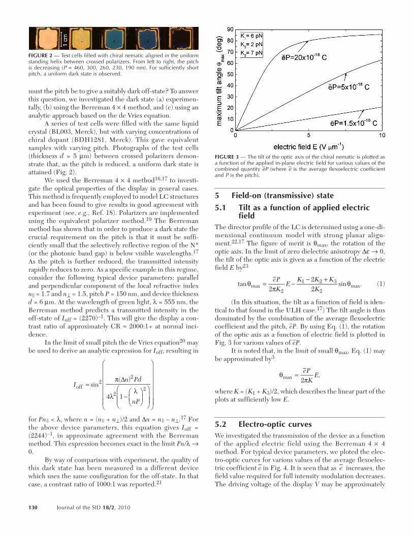
must the pitch be to give a suitably dark off-state? To answerthis question, we investigated the dark state (a) experimen-tally, (b) using the Berreman 4 × 4 method, and (c) using ananalytic approach based on the de Vries equation.
A series of test cells were filled with the same liquidcrystal (BL003, Merck), but with varying concentrations ofchiral dopant (BDH1281, Merck). This gave equivalentsamples with varying pitch. Photographs of the test cells(thickness d = 5 µm) between crossed polarizers demon-strate that, as the pitch is reduced, a uniform dark state isattained (Fig. 2).
We used the Berreman 4 × 4 method16,17 to investi-gate the optical properties of the display in general cases.This method is frequently employed to model LC structuresand has been found to give results in good agreement withexperiment (see, e.g., Ref. 18). Polarizers are implementedusing the equivalent polarizer method.19 The Berremanmethod has shown that in order to produce a dark state thecrucial requirement on the pitch is that it must be suffi-ciently small that the selectively reflective region of the N*(or the photonic band gap) is below visible wavelengths.17
As the pitch is further reduced, the transmitted intensityrapidly reduces to zero. As a specific example in this regime,consider the following typical device parameters: paralleland perpendicular component of the local refractive indexn|| = 1.7 and n⊥ = 1.5, pitch P = 150 nm, and device thicknessd = 6 µm. At the wavelength of green light, λ = 555 nm, theBerreman method predicts a transmitted intensity in theoff-state of Ioff = (2270)–1. This will give the display a con-trast ratio of approximately CR ≈ 2000:1+ at normal inci-dence.
In the limit of small pitch the de Vries equation20 maybe used to derive an analytic expression for Ioff, resulting in
for Pn|| < λ, where n = (n|| + n⊥)/2 and ∆n = n|| – n⊥.17 Forthe above device parameters, this equation gives Ioff =(2244)–1, in approximate agreement with the Berremanmethod. This expression becomes exact in the limit Pn/λ →0.
By way of comparison with experiment, the quality ofthis dark state has been measured in a different devicewhich uses the same configuration for the off-state. In thatcase, a contrast ratio of 1000:1 was reported.21
5 Field-on (transmissive) state
5.1 Tilt as a function of applied electricfield
The director profile of the LC is determined using a one-di-mensional continuum model with strong planar align-ment.22,17 The figure of merit is θmax, the rotation of theoptic axis. In the limit of zero dielectric anisotropy ∆ε → 0,the tilt of the optic axis is given as a function of the electricfield E by23
(1)
(In this situation, the tilt as a function of field is iden-tical to that found in the ULH case.17) The tilt angle is thusdominated by the combination of the average flexoelectriccoefficient and the pitch, eP. By using Eq. (1), the rotationof the optic axis as a function of electric field is plotted inFig. 3 for various values of eP.
It is noted that, in the limit of small θmax, Eq. (1) maybe approximated by3
where K = (K1 + K3)/2, which describes the linear part of theplots at sufficiently low E.
5.2 Electro-optic curvesWe investigated the transmission of the device as a functionof the applied electric field using the Berreman 4 × 4method. For typical device parameters, we ploted the elec-tro-optic curves for various values of the average flexoelec-tric coefficient e in Fig. 4. It is seen that as e increases, thefield value required for full intensity modulation decreases.The driving voltage of the display V may be approximately
In Pd
nP
off ª
-FHG
IKJ
FHGG
IKJJ
F
H
GGGGGG
I
K
JJJJJJ
sin( )2
2
22
4 1
p
ll
D
tan sin .max maxqp
q= -- +eP
KE
K K KK2
222
1 2 3
2
qpmax ,ª eP
KE
2
FIGURE 2 — Test cells filled with chiral nematic aligned in the uniformstanding helix between crossed polarizers. From left to right, the pitchis decreasing (P = 460, 300, 260, 230, 190 nm). For sufficiently shortpitch, a uniform dark state is observed.
FIGURE 3 — The tilt of the optic axis of the chiral nematic is plotted asa function of the applied in-plane electric field for various values of thecombined quantity eP (where e is the average flexoelectric coefficientand P is the pitch).
130 Journal of the SID 18/2, 2010

determined from the electro-optic curve by multiplying theelectric field required for full intensity modulation EFI bythe spacing of the in-plane electrodes V = EFI × de.
We constructed a USHF test cell to experimentallydemonstrate the switching mechanism. A d = 5 µm thick cellwith transparent inter-digitated indium-tin-oxide in-planeelectrodes was used. The electrodes spacing was de = 15 µm,and the width of the electrodes themselves was 5 µm. Anti-parallel polyimide alignment layers produced a uniformUSH texture. A highly flexoelectric mixture of nematic bimeso-genic liquid crystals was used (see, e.g., Ref. 12), togetherwith high-twisting-power chiral dopant (BDH1281, Merck).The dielectric anisotropy was less than ~2 (but not nega-tive). To avoid degradation of the N* structure near the elec-trodes, the mixture was polymer-stabilized according to theprocess described in Ref. 24. A 1-kHz square-wave signal
was applied. The transmitted intensity as a function ofapplied electric field is shown in Fig. 5, together with photo-micrographs of the test cell. The ability to control the grayscale is apparent. It is seen that the experimental regioncurrently represents only the initial part of the full electro-optic curve. The curve was truncated because at ≈15 V/µmthe structure became degraded and did not revert quicklyback to the undistorted N* upon removal of the electricfield. We are currently working to optimize the device tomake the full electro-optic curve experimentally accessibleat lower field values. Figure 6 shows that the response of theLC is dependent on the polarity of the field, and hence thedevice is flexoelectrically driven, as opposed to dielectricallydriven (see Ref. 6 for a discussion of this issue).
It is noted that the operation of the device will not besignificantly degraded by the presence of “twist-jump” domainsdue to variations in thickness. Such domains create potentialproblems for conventional N* devices. However, becausethe pitch in the USHF device is unusually small (~150 nm),it has been argued that the effect will negligible (less than~0.4% variation in transmission17).
6 Viewing-angle dependenceWe investigated the viewing-angle dependence of the dis-play by calculating the contrast ratio (CR) using the Berre-man method. The CR is defined as the ratio of theluminance of the device in the on-state to the luminance inthe off-state. To determine the CR, the spectral power den-sity of transmitted light is integrated over the visible range380–780 nm, weighted by the standard color-matching func-tion of the green component of light.25 We used StandardIlluminant A as the light source. To reduce the expense ofthe computation, we approximated the short-pitch N* to bea uniaxial, negatively birefringent structure. Figure 7(a)plots the CR as a function of viewing angle – the isocontrastcurves – with no optical compensation. The device parame-ters used for this plot are the same as for Fig. 4, with theaverage flexoelectric coefficient set to e = 10 pC/m.
It may be expected that the viewing angle will be wid-ened using optical compensation films. As a simple example
FIGURE 4 — Predicted electro-optic curves for typical device parametersat various values of the average flexoelectric coefficient e, calculatedusing the Berreman 4 × 4 method.
FIGURE 5 — Experimental demonstration of USHF switching. (a)Electro-optic curve. (b) Photomicrographs of test cell as a function ofapplied electric field.
FIGURE 6 — Oscilloscope trace of the applied voltage and the resultanttransmitted intensity show that the switching mechanism is flexoelectric.
Castles et al. / Ultra-fast-switching flexoelectric LCD with high contrast 131

of this, we implemented a c-plate compensation film. Thefilm is chosen such that its phase retardation cancels that ofthe LC. In this way, the light leakage in the dark state isgreatly reduced. The film is required to be a uniaxial posi-tively birefringent structure, with the optic axis normal tothe plane of the device. For simplicity, we set the thicknessof the film to be equal to that of the LC layer, in which casethe required birefringence of the film ∆nfilm is given by∆nfilm = –∆nN*, where ∆nN* is the effective birefringence ofthe N*. The c-plate compensated isocontrast curves areplotted in Fig. 7(b). The viewing angle is significantly widened.It is noted that the viewing-angle dependence may be fur-ther improved using additional compensation layers (see,e.g., Refs. 26 and 27), and/or a multi-domain electrodestructure.28
7 ConclusionBy applying an in-plane electric field to a short-pitch N* LCin the USH configuration, a fast optical switch may be gen-erated, which operates using the flexoelectro-optic effect.We call this the USHF display mode. Some properties ofthis mechanism have been investigated in the context of afast-switching display device. Highly flexoelectric materialswith low (but non-negative) dielectric anisotropy are required.Using typical experimentally determined material parame-ters, we predict a response time of τ90–10 = 0.017 msec,together with a contrast ratio at normal incidence of CR ≈2000+. In this respect, the USHF device may be consideredas an ultra-fast-switching VA device. While the typical driv-ing voltage for the display remains relatively high, furtherdevelopments in materials with higher average flexoelectriccoefficients e may reduce this. The predicted isocontrastcurves for the device were plotted, and we demonstratedthat the viewing angle may be improved by implementing apositively birefringent c-plate compensation film.
Our results suggest the USHF display is a promisingcandidate for future display devices, and further theoreticaland experimental work is being undertaken.
AcknowledgmentsWe would like to thank the Engineering and Physical Sci-ences Research Council (UK) for financial support. One ofthe authors (FC) gratefully acknowledges Merck.
References1 D. Pauluth and K. Tarumi, “Optimization of liquid crystals for televi-
sion,” J. Soc. Info. Display 13, No. 8, 693–702 (2005).2 N. Koma et al., “A novel driving method for field sequential color using
OCB TFT-LCD,” J. Soc. Info. Display 9, No. 4, 331–336 (2001).3 J. S. Patel and R. B. Meyer, “Flexoelectric electro-optics of a
cholesteric liquid crystal,” Phys. Rev. Lett. 58, 1538 (1987).4 P. Ruquist et al., “Linear electro-optic effect based on flexoelectricity
in a cholesteric with sign change of dielectric anisotropy,” J. Appl. Phys.76, 7778 (1994).
5 G. Carbone et al., “Short pitch cholesteric electro-optical device basedon periodic polymer structures,” Appl. Phys. Lett. 95, 011102 (2009).
6 B. J. Broughton et al., “Optimized flexoelectric response in a chiralliquid-crystal phase device,” J. Appl. Phys. 98, 34109 (2005).
7 H. J. Coles et al., “Flexoelectro-optic liquid crystal device,” Patent No.WO/2006/003441 (2006).
8 S. -T. Wu, “Film compensated homeotropic liquid crystal cell for directview display,” J. Appl. Phys. 76, 5975 (1994).
9 K. Ohmuro et al., “Development of super-high-image-quality vertical-alignment-mode LCD,” SID Symposium Digest 28, 845 (1997).
10 R. B. Meyer, “Piezoelectric effects in liquid crystals,” Phys. Rev. Lett.22, 918 (1969).
11 B. Musgrave et al., “A new series of chiral nematic bimesogens for theflexoelectro-optic effect,” Liquid Crystals 26, 1235 (1999).
12 H. J. Coles et al., “Strong flexoelectric behavior in bimesogenic liquidcrystals,” J. Appl. Phys. 99, 34104 (2006).
13 S. M. Morris et al., “Structure-flexoelastic properties of bimesogenicliquid crystals,” Phys. Rev. E 75, 041701 (2007).
14 H. J. Coles, “Bimesogenic liquid crystals: New materials for high per-formance flexoelectric and blue phase displays,” Proc. IDW ‘06, 15(2006).
15 J. S. Patel and S.-D. Lee, “Fast linear electro-optic effect based oncholesteric liquid crystals,” J. Appl. Phys. 66, 1879 (1989).
16 D. W. Berreman, “Optics in stratified and anisotropic media: 4 × 4matrix formulation,” J. Opt. Soc. Am. 62, 502 (1972).
17 F. Castles et al., “The flexoelectro-optic properties of chiral nematicliquid crystals in the uniform standing helix configuration,” Phys. Rev.E. 80, 031709 (2009).
18 H. G. Yoon and H. F. Gleeson, “Accurate modelling of multilayer chiralnematic devices through the Berreman 4 × 4 matrix methods,” J. Phys.D: Appl. Phys. 40 3579 (2007).
19 H. A. van Sprang, “Angular dependence of the transmission ofnontwisted liquid crystal displays,” J. Appl. Phys. 71, 4826 (1992).
20 H. De Vries, “Rotary power and other optical properties of certainliquid crystals,” Acta Cryst. 4, 219 (1951).
21 S. S. Choi et al., “High contrast nematic liquid crystal deivce usingnegative dielectric material,” Appl. Phys. Lett. 95, 193502 (2009).
22 A. J. Davidson et al., “Investigation Into chiral active waveplates,”J. Appl. Phys. 99, 93109 (2006).
23 S.-D. Lee et al., “Effect of flexoelectric coupling on helix distortions inCholesteric liquid crystals,” J. Appl. Phys. 67, 1293 (1990).
24 B. J. Broughton et al., “Effect of polymer concentration on stabilizedlarge-tilt-angle flexoelectro-optic switching,” J. Appl. Phys. 99, 023511(2006).
25 J. Schanda, Colorimetry: Understanding the CIE System (Wiley, 2007).26 Z. Ge et al., “Extraordinarily wide-view circular polarizers for liquid
crystal displays,” Opt. Express 16, 3120 (2008).27 Z. Ge et al., “Switchable transmissive and reflective liquid-crystal dis-
play using a multi-domain vertical alignment,” J. Soc. Info. Display 17,No. 7, 561–566 (2009).
28 A. Takeda et al., “A super-high image quality multi-domain verticalalignment LCD by new rubbing-less technology,” SID SymposiumDigest 29, 1077 (1998).
FIGURE 7 — Contrast ratio (CR) as a function of viewing angle (a) withno optical compensation and (b) with positive c-plate compensation.Lines denote equal CR contours. Polarizers are at 0° and 90° azimuthalangles, and the electric field E is applied at 45°.
132 Journal of the SID 18/2, 2010
Flynn Castles received his B.A. and M.S. degrees in experimental andtheoretical physics (2006) and his M.A. degree (2009), from the Univer-sity of Cambridge. He is currently working towards his Ph.D. in electri-cal engineering under the supervision of Prof. H. Coles at the Center ofMolecular Materials for Photonics and Electronics at the University ofCambridge. His research interests include liquid-crystal display devices,flexoelectricity in liquid crystals, and liquid-crystal blue phases. He is amember of St. Catharine’s College, Cambridge.
Stephen M. Morris obtained his M.S. degree in physics from the Univer-sity of Southampton (2000) and his Ph.D. in electrical engineering fromthe University of Cambridge (2005). He subsequently continued as aResearch Associate at the Center of Molecular Materials for Photonicsand Electronics, working in collaboration with an industrial partner toproduce a new hybrid display, which can be viewed in both low- andhigh-light-level environments. At present, he is currently involved indeveloping miniature tunable laser light sources for next-generation dis-plays and photonics applications. He is a Fellow of St. Catharine’s Col-lege, Cambridge.
Damian J. Gardiner received his M.Phys. degree in physics fromSouthampton University (2001). Subsequently, he worked at the SpaceDepartment, Qinetiq Ltd., before moving to Wolfson College, Universityof Cambridge, where he received his Ph.D. degree. His doctoral thesiswas focused on organosiloxane-based bistable materials for use in dis-plays and other applications. Following his Ph.D., he worked at Cam-bridge Display Technology, Ltd., developing organic electroluminescentand photovoltaic systems. He re-joined the Center of Molecular Materi-als for Photonics and Electronics, University of Cambridge, in February2008. He is currently working on a hybrid electroluminescent liquid-crystal project in collaboration with Pelikon, Ltd.
Qasim M. Malik received his M.S. degree in chemistry (2000) fromQuaid-I-Azam University Islamabad (Pakistan), researching naturalproduct synthesis (Isocumarine and its dihydro-derivatives). This wasfollowed by his M.Phil. in organic chemistry (2002) from the same insti-tute. The research project was based on synthesis of mesogens compris-ing of Schiff’s base analogues derived from benzyl amine derivatives. Hewas then appointed a lecturer in chemistry at APSC Rawalpindi. In2008, he received his Ph.D. in chemistry from Macquarie University,Sydney (Australia). His Ph.D. involved the synthesis and charac-terization of liquid-crystal molecules possessing chiral scaffold ana-logues. He joined the Center of Molecular Materials for Photonics andElectronics, University of Cambridge, in June 2008 and is working onthe synthesis and characterization of materials leading to devices andlasing liquid crystals in general.
Harry J. Coles is Professor of photonics of molecular materials at theEngineering Department of Cambridge University and Director of themultidisciplinary Cambridge Center of Molecular Materials for Photon-ics and Electronics, and Fellow of the Institute of Physics. His researchinterests cover extremely wide areas: synthesis and characterization ofliquid crystals, oligomers, and polymers; structure–property correla-tions; spectroscopic and electro-optic techniques; linear and non-linearoptics of liquid crystals; organic lasers; thin-film optical devices and dis-plays; telecommunications and photonic switches/interconnects; anddevice fabrication. To date, he has published over 200 refereed papers,26 patents, and some 400 published abstracts. He is Chairman of themultimillion-dollar COSMOS EPSRC funded Basic Technology ResearchGrant developing new all organic lasers, which involves the Depart-ments of Physics, Chemistry and Engineering. In 2002, he was invitedby the British Liquid Crystal Society to give the Ben Sturgeon MemorialLecture and in April 2003 was awarded the George Gray Medal for hisresearch on Liquid Crystals and their Applications. He is a ProfessorialFellow of St. Catharine’s College, University of Cambridge.
Castles et al. / Ultra-fast-switching flexoelectric LCD with high contrast 133