5.1 Switching techniques - AWS
14
UNT-5 Switching & Routing 5.1 Circuit Switching networks 5.2 Packet Switching principles 5.3 X.25 5.4 Routing in Packet switching 5.5 Congestion 5.6 Effects of congestion, congestion control 5.7 Traffic Management 5.8 Congestion Control in Packet Switching Network 5.1 Switching techniques In large networks, there can be multiple paths from sender to receiver. The switching technique will decide the best route for data transmission. Switching technique is used to connect the systems for making one-to-one communication. Classification Of Switching Techniques Circuit Switching o Circuit switching is a switching technique that establishes a dedicated path between sender and receiver. o In the Circuit Switching Technique, once the connection is established then the dedicated path will remain to exist until the connection is terminated. o Circuit switching in a network operates in a similar way as the telephone works. o A complete end-to-end path must exist before the communication takes place. o In case of circuit switching technique, when any user wants to send the data, voice, video, a request signal is sent to the receiver then the receiver sends back the acknowledgment to ensure the availability of the dedicated path. After receiving the acknowledgment, dedicated path transfers the data. o Circuit switching is used in public telephone network. It is used for voice transmission. o Fixed data can be transferred at a time in circuit switching technology.
-
Upload
khangminh22 -
Category
Documents
-
view
1 -
download
0
Transcript of 5.1 Switching techniques - AWS

UNT-5 Switching & Routing
5.1 Circuit Switching networks
5.2 Packet Switching principles
5.3 X.25
5.4 Routing in Packet switching
5.5 Congestion
5.6 Effects of congestion, congestion control
5.7 Traffic Management
5.8 Congestion Control in Packet Switching Network
5.1 Switching techniques
In large networks, there can be multiple paths from sender to receiver. The switching
technique will decide the best route for data transmission.
Switching technique is used to connect the systems for making one-to-one communication.
Classification Of Switching Techniques
Circuit Switching
o Circuit switching is a switching technique that establishes a dedicated path between
sender and receiver.
o In the Circuit Switching Technique, once the connection is established then the
dedicated path will remain to exist until the connection is terminated.
o Circuit switching in a network operates in a similar way as the telephone works.
o A complete end-to-end path must exist before the communication takes place.
o In case of circuit switching technique, when any user wants to send the data, voice,
video, a request signal is sent to the receiver then the receiver sends back the
acknowledgment to ensure the availability of the dedicated path. After receiving the
acknowledgment, dedicated path transfers the data.
o Circuit switching is used in public telephone network. It is used for voice transmission.
o Fixed data can be transferred at a time in circuit switching technology.

Communication through circuit switching has 3 phases:
o Circuit establishment
o Data transfer
o Circuit Disconnect
Circuit Switching can use either of the two technologies:
Space Division Switches:
o Space Division Switching is a circuit switching technology in which a single transmission
path is accomplished in a switch by using a physically separate set of crosspoints.
o Space Division Switching can be achieved by using crossbar switch. A crossbar switch is
a metallic crosspoint or semiconductor gate that can be enabled or disabled by a
control unit.
o The Crossbar switch is made by using the semiconductor. For example, Xilinx crossbar
switch using FPGAs.
o Space Division Switching has high speed, high capacity, and nonblocking switches.
Space Division Switches can be categorized in two ways:
o Crossbar Switch
o Multistage Switch
Crossbar Switch
The Crossbar switch is a switch that has n input lines and n output lines. The crossbar
switch has n2 intersection points known as crosspoints.
Disadvantage of Crossbar switch:
The number of crosspoints increases as the number of stations is increased. Therefore, it
becomes very expensive for a large switch. The solution to this is to use a multistage
switch.
Multistage Switch
o Multistage Switch is made by splitting the crossbar switch into the smaller units and
then interconnecting them.
o It reduces the number of crosspoints.
o If one path fails, then there will be an availability of another path.
Advantages Of Circuit Switching:
o In the case of Circuit Switching technique, the communication channel is dedicated.
o It has fixed bandwidth.

Disadvantages Of Circuit Switching:
o Once the dedicated path is established, the only delay occurs in the speed of data
transmission.
o It takes a long time to establish a connection approx 10 seconds during which no data
can be transmitted.
o It is more expensive than other switching techniques as a dedicated path is required for
each connection.
o It is inefficient to use because once the path is established and no data is transferred,
then the capacity of the path is wasted.
o In this case, the connection is dedicated therefore no other data can be transferred
even if the channel is free.
Message Switching
o Message Switching is a switching technique in which a message is transferred as a
complete unit and routed through intermediate nodes at which it is stored and
forwarded.
o In Message Switching technique, there is no establishment of a dedicated path between
the sender and receiver.
o The destination address is appended to the message. Message Switching provides a
dynamic routing as the message is routed through the intermediate nodes based on the
information available in the message.
o Message switches are programmed in such a way so that they can provide the most
efficient routes.
o Each and every node stores the entire message and then forward it to the next node.
This type of network is known as store and forward network.
o Message switching treats each message as an independent entity.
Advantages Of Message Switching
o Data channels are shared among the communicating devices that improve the
efficiency of using available bandwidth.
o Traffic congestion can be reduced because the message is temporarily stored in the
nodes.
o Message priority can be used to manage the network.
o The size of the message which is sent over the network can be varied. Therefore, it
supports the data of unlimited size.

Disadvantages Of Message Switching
o The message switches must be equipped with sufficient storage to enable them to
store the messages until the message is forwarded.
o The Long delay can occur due to the storing and forwarding facility provided by the
message switching technique.
5.2 Packet Switching
o The packet switching is a switching technique in which the message is sent in one go,
but it is divided into smaller pieces, and they are sent individually.
o The message splits into smaller pieces known as packets and packets are given a unique
number to identify their order at the receiving end.
o Every packet contains some information in its headers such as source address,
destination address and sequence number.
o Packets will travel across the network, taking the shortest path as possible.
o All the packets are reassembled at the receiving end in correct order.
o If any packet is missing or corrupted, then the message will be sent to resend the
message.
o If the correct order of the packets is reached, then the acknowledgment message will
be sent.
Approaches Of Packet Switching:
There are two approaches to Packet Switching:
Datagram Packet switching:
o It is a packet switching technology in which packet is known as a datagram, is
considered as an independent entity. Each packet contains the information about the
destination and switch uses this information to forward the packet to the correct
destination.
o The packets are reassembled at the receiving end in correct order.
o In Datagram Packet Switching technique, the path is not fixed.
o Intermediate nodes take the routing decisions to forward the packets.
o Datagram Packet Switching is also known as connectionless switching.
Virtual Circuit Switching
o Virtual Circuit Switching is also known as connection-oriented switching.

o In the case of Virtual circuit switching, a preplanned route is established before the
messages are sent.
o Call request and call accept packets are used to establish the connection between
sender and receiver.
o In this case, the path is fixed for the duration of a logical connection.
Concept of virtual circuit switching through a diagram:
o In the above diagram, A and B are the sender and receiver respectively. 1 and 2 are the
nodes.
o Call request and call accept packets are used to establish a connection between the
sender and receiver.
o When a route is established, data will be transferred.
o After transmission of data, an acknowledgment signal is sent by the receiver that the
message has been received.
o If the user wants to terminate the connection, a clear signal is sent for the
termination.
Differences b/w Datagram approach and Virtual Circuit approach
Datagram approach Virtual Circuit approach
Node takes routing decisions to forward the packets. Node does not take any routing decision.
Congestion cannot occur as all the packets travel in
different directions.
Congestion can occur when the node is busy, and it
does not allow other packets to pass through.
It is more flexible as all the packets are treated as an
independent entity.
It is not very flexible.

Advantages Of Packet Switching:
o Cost-effective: In packet switching technique, switching devices do not require
massive secondary storage to store the packets, so cost is minimized to some extent.
Therefore, we can say that the packet switching technique is a cost-effective
technique.
o Reliable: If any node is busy, then the packets can be rerouted. This ensures that the
Packet Switching technique provides reliable communication.
o Efficient: Packet Switching is an efficient technique. It does not require any
established path prior to the transmission, and many users can use the same
communication channel simultaneously, hence makes use of available bandwidth very
efficiently.
Disadvantages Of Packet Switching:
o Packet Switching technique cannot be implemented in those applications that require
low delay and high-quality services.
o The protocols used in a packet switching technique are very complex and requires high
implementation cost.
o If the network is overloaded or corrupted, then it requires retransmission of lost
packets. It can also lead to the loss of critical information if errors are nor recovered.
X.25
X.25 is an ITU-T standard protocol suite for packet switched wide area network (WAN)
communication.
X.25 was originally defined by the International Telegraph and Telephone Consultative
Committee (CCITT, now ITU-T) in a series of drafts and finalized in a publication known
as The Orange Book in 1976.
.X.25 is a family of protocols that was popular during the 1980s with telecommunications
companies and in financial transaction systems such as automated teller machines.
X.25 is a standard suite of protocols used for packet switching across computer
networks. The X.25 protocols works at the physical, data link, and network layers
(Layers 1 to 3) of the OSI model.
Each X.25 packets contains up to 128 bytes of data. The X.25 network handles packet
assembly at the source device, delivery, and then dis-assembly at the destination. X.25
packet delivery technology includes not only switching and network-layer routing, but
also error checking and re-transmission logic should delivery failures occur. X.25
supports multiple simultaneous conversations by multiplexing packets and using virtual
communication channels.
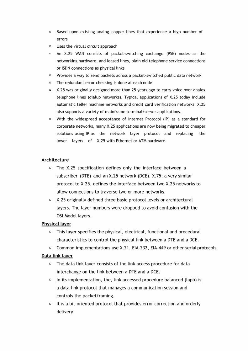
Based upon existing analog copper lines that experience a high number of
errors
Uses the virtual circuit approach
An X.25 WAN consists of packet-switching exchange (PSE) nodes as the
networking hardware, and leased lines, plain old telephone service connections
or ISDN connections as physical links
Provides a way to send packets across a packet-switched public data network
The redundant error checking is done at each node
X.25 was originally designed more than 25 years ago to carry voice over analog
telephone lines (dialup networks). Typical applications of X.25 today include
automatic teller machine networks and credit card verification networks. X.25
also supports a variety of mainframe terminal/server applications.
With the widespread acceptance of Internet Protocol (IP) as a standard for
corporate networks, many X.25 applications are now being migrated to cheaper
solutions using IP as the network layer protocol and replacing the
lower layers of X.25 with Ethernet or ATM hardware.
Architecture
The X.25 specification defines only the interface between a
subscriber (DTE) and an X.25 network (DCE). X.75, a very similar
protocol to X.25, defines the interface between two X.25 networks to
allow connections to traverse two or more networks.
X.25 originally defined three basic protocol levels or architectural
layers. The layer numbers were dropped to avoid confusion with the
OSI Model layers.
Physical layer
This layer specifies the physical, electrical, functional and procedural
characteristics to control the physical link between a DTE and a DCE.
Common implementations use X.21, EIA-232, EIA-449 or other serial protocols.
Data link layer
The data link layer consists of the link access procedure for data
interchange on the link between a DTE and a DCE.
In its implementation, the, link accessed procedure balanced (lapb) is
a data link protocol that manages a communication session and
controls the packet framing.
It is a bit-oriented protocol that provides error correction and orderly
delivery.

Packet layer
This layer defined a packet-layer protocol for exchanging control and
user data packets to form a packet-switching network based on virtual
calls, according to the packet layer.
X.25 provides a set of user facilities defined and described in ITU-T
Recommendation
X.2. The X.2 user facilities fall into five categories:
1. Essential facilities;
2. Additional facilities;
3. Conditional facilities;
4. Mandatory facilities.
5. Optional facilities.
Advantages of X.25
Frame delivery is more reliable
Frames are delivered in order
Retransmission of frames is possible
Flow control is provided
X.25 supports the switched virtual circuits and permanent circuits
Disdvantage of X.25
X.25 is much slower than Frame relay
5.5 Network Congestion
Just like in road congestion, Network Congestion occurs when a network is not able to
adequately handle the traffic flowing through it. Network congestion is usually a temporary
state of a network rather than a permanent feature.
Network congestion in data networking is the reduced quality of service that occurs when a
network node or link is carrying more data than it can handle. Its effects include queueing
delay, packet loss or the blocking of new connections.
In this section, we will discuss five (5) common causes of network congestion including:
Over-subscription
Poor network design/mis-configuration
Over-utilized devices

Faulty devices
Security attack
Over-Subscription
Over-Subscription where a system (e.g. a network) is handling more traffic than it was
designed to handle per time. Over-subscription is usually done on purpose as it may result in
cost savings.
For example, An organization has 100 users and it has been determined that a 100Mbps
Internet link will be suitable for all these users.
Now imagine that most of the staff of this organization work from home. In this case, it will be
more cost efficient to go for a lower link capacity, say 50Mbps, since only a handful of
employees will be using the link per time. But what happens when there is a company-wide
meeting and all employees come into the office? You guessed right – Network congestion.
Poor Network Design/Mis-Configuration
A more serious cause of network congestion is poor design or device Mis-Configuration. Take
for example a broadcast storm, where a large volume of broadcast and/or multicast traffic is
seen on the network within a short time, resulting in severe performance degradation.
Since broadcasts are contained within subnets, the larger the subnet the more serious the
effect of a broadcast storm. Therefore, a network that has been designed with large subnets
without giving proper consideration to broadcast storms can result in network congestion.
Over-Utilized Devices
Devices such as routers, switches, and firewalls have been designed to handle certain network
throughput.
For example, the Juniper MX5 has a capacity of 20Gbps. Therefore, constantly pushing ~20Gbps
of traffic through that device means that the device will be over-utilized and will likely result
in high CPU utilization and packet drops, leading to congestion on the network.
Another issue related to over-utilized devices that can cause network congestion
is Bottlenecks. As in most hierarchical designs where multiple devices feed into a higher-level
device, care must be taken to ensure that the higher-level device is capable of handling all the
traffic from the lower-level devices.
Faulty Devices
Example (lower speed device): Network performance assessment for an organization. They
were buying 100Mbps link capacity from their ISP but the users on the network were struggling
to connect to the Internet effectively.

They complained that the network was always “slow” (user speak for network congestion)
even when few people were on the network. Upon investigation, it was found that, their ISP
was truly giving the agreed upon 100Mbps, the edge device was only providing 30Mbps to the
network!
Apart from the fact that this organization had wrongly terminated the link on a FastEthernet
interface (which gives a theoretical speed of 100Mbps but much lower practical speed), that
interface was also faulty. By moving the ISP link to another interface (we used a
GigabitEthernet interface instead), the performance problem was solved.
Security Attack
Example (attacker using server) : In another organization, a network of about 10 users had
poor browsing experience even with the 4Mbps link they were getting from their ISP.
Ideally, this capacity should have been enough because the users were not doing anything
heavy on the Internet – just emails, web searches, and normal user activities.
Upon investigation, it was discovered that one of their servers had been compromised and it
seems the attacker was using this server to host illicit content resulting in a huge amount of
traffic being sent to/from this server. By cleaning up this server, the congested network was
once again “free” for normal user traffic.
Other security attacks that can result in network congestion include viruses, worms, and Denial
of Service (DoS) attacks.
5.6 Effects of Network Congestion
Everyone on a network generally “feels” the effects of network congestion. They may not be
able to explain it in technical terms but will say things like “The connection is so slow”, “I
can’t open web pages”, “The network is really bad, I can’t hear you”.
From a technical perspective, the effects of a congested network include:
Delay:
Also known as Latency, Delay is the time it takes for a destination to receive the packet
sent by the sender. For example, the time it takes for a webpage to load is a result of how
long it takes for the packets from the web server to get to the client. Another evidence of
delay is the buffering you experience when watching a video, say on YouTube.
Packet Loss:
While packets may take a while to get to their destination (delay), packet loss is an even
more negative effect of network congestion. This is especially troubling for applications like
Voice over IP (VoIP) that do not deal well with delay and packet loss, resulting in dropped
calls and Call Detail Records, lag, robotic voices, and so on.
Timeouts:
Network congestion can also result in timeouts in various applications. Since most

connections will not stay up indefinitely waiting for packets to arrive, this can result in lost
connections.
5.6 Troubleshooting Network Congestion
Feeling the effects of network congestion is one thing but actually confirming that a network is
congested is another. In this section, we will look at some activities that can be performed to
confirm the congestion of a network.
1. Ping
One of the fastest ways to check if a network is congested is to use Ping because not only can
it detect packet loss, it can also reveal delay in a network i.e. through the round-trip time (RTT).
Using a tool like MTR (which combines ping and traceroute) can also reveal parts of the
network where congestion is occurring.
2. LAN Performance Tests
A tool like iPerf can be very useful in determining performance issues on a network, measuring
statistics like bandwidth, delay, jitter, and packet loss. This can help reveal bottlenecks on the
network and also identify any faulty devices/interfaces.
3. Bandwidth Monitoring
During the investigation of the compromised server I mentioned above, we used a tool
called ntopng to discover “Top Talkers” which revealed that the server was using up all the
bandwidth on the network. In the same way, tools that monitor bandwidth can reveal network
congestion especially during a security attack or if a particular host is using up all the
bandwidth.

You can read this article for more information about performing a network performance
assessment.
5.8 Congestion Control in Packet Switching Network
Different congestion control approaches in packet switching network (datagram subnet and
also in virtual circuit subnets) are :
i) Choke packets
ii) Load Shedding
iii) Jitter control
i) Choke Packets :
In this technique, each router associates a real variable with each of its output
lines. This real value “u” has a value between 0 and 1 and it indicates the
percentage utilization of that line. If he value “u” goes above the threshold (defined
values that determine if a statistic is above, below, or within a normal range on your network) then
the output line will enter into a warning state. The router will check each newly
arriving packet to see if its output line is in the warning state. If it is in the warning
state, then the router will send back a choke packet signal to the sending host.
Then the sender will not generate any more choke packets. Depending on the
threshold vale, the choke packets can contain a mild warning, a stern warning or
an ultimatum.
Drawback :
The action to be taken by the source host on receiving a choke packet is voluntary
and not compulsory.
ii) Load Shedding
It is one of the simplest and more effective techniques. In this method, whenever a
router finds that there is congestion in the network, it simply starts dropping out
the packets.
The principle of load shedding states that, when the routers are being inundated
(overwhelmed) by the packets that they cant not handle, they should simply throw
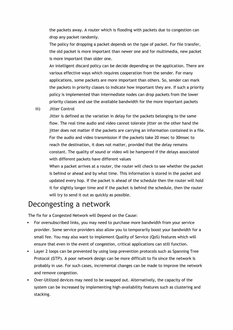
the packets away. A router which is flooding with packets due to congestion can
drop any packet randomly.
The policy for dropping a packet depends on the type of packet. For file transfer,
the old packet is more important than newer one and for multimedia, new packet
is more important than older one.
An intelligent discard policy can be decide depending on the application. There are
various effective ways which requires cooperation from the sender. For many
applications, some packets are more important than others. So, sender can mark
the packets in priority classes to indicate how important they are. If such a priority
policy is implemented than intermediate nodes can drop packets from the lower
priority classes and use the available bandwidth for the more important packets
iii) Jitter Control
Jitter is defined as the variation in delay for the packets belonging to the same
flow. The real time audio and video cannot tolerate jitter on the other hand the
jitter does not matter if the packets are carrying an information contained in a file.
For the audio and video transmission if the packets take 20 msec to 30msec to
reach the destination, it does not matter, provided that the delay remains
constant. The quality of sound or video wll be hampered if the delays associated
with different packets have different values
When a packet arrives at a router, the router will check to see whether the packet
is behind or ahead and by what time. This information is stored in the packet and
updated every hop. If the packet is ahead of the schedule then the router will hold
it for slightly longer time and if the packet is behind the schedule, then the router
will try to send it out as quickly as possible.
Decongesting a network The fix for a Congested Network will Depend on the Cause:
For oversubscribed links, you may need to purchase more bandwidth from your service
provider. Some service providers also allow you to temporarily boost your bandwidth for a
small fee. You may also want to implement Quality of Service (QoS) features which will
ensure that even in the event of congestion, critical applications can still function.
Layer 2 loops can be prevented by using loop prevention protocols such as Spanning Tree
Protocol (STP). A poor network design can be more difficult to fix since the network is
probably in use. For such cases, incremental changes can be made to improve the network
and remove congestion.
Over-Utilized devices may need to be swapped out. Alternatively, the capacity of the
system can be increased by implementing high-availability features such as clustering and
stacking.

Faulty devices definitely need to be replaced. In some cases (like the example I gave above
about the 100Mbps link reduced to 30Mbps), only a part of the device (e.g. an interface)
needs to be replaced.
Security attacks need to be combated as soon as they are discovered. In the case of the
compromised server, the first thing we did was to remove that server from the network
completely. Since this is not always a feasible solution (e.g. the compromised device is a
critical server), other temporary measures such as applying access control lists to deny the
offending traffic may need to be implemented.