UFGS 03 01 32 Concrete Rehabilitation for Civil Works
73
************************************************************************** USACE / NAVFAC / AFCEC / NASA UFGS-03 01 32 (November 2009) ----------------------------- Preparing Activity: USACE Superseding UFGS-03 01 32 (April 2006) UNIFIED FACILITIES GUIDE SPECIFICATION References are in agreement with UMRL dated April 2014 ************************************************************************** SECTION TABLE OF CONTENTS DIVISION 03 - CONCRETE SECTION 03 01 32 CONCRETE REHABILITATION FOR CIVIL WORKS 11/09 PART 1 GENERAL 1.1 RELATED SECTIONS 1.1.1 Formwork 1.1.2 Reinforcing Steel 1.1.3 Field-Molded Sealants 1.1.4 Compression Seals 1.1.5 Concrete 1.1.6 Shotcrete 1.1.7 Preplaced-Aggregate Concrete 1.1.8 Precast Concrete 1.1.9 Disposal of Waste Materials 1.2 UNIT PRICES 1.2.1 Concrete Removal 1.2.1.1 Payment 1.2.1.2 Measurement 1.2.1.3 Unit of Measure 1.2.2 Concrete Removal (Alternate) 1.2.2.1 Payment 1.2.2.2 Measurement 1.2.2.3 Unit of Measure 1.2.3 Drilling and Grouting Dowels and Anchors 1.2.3.1 Payment 1.2.3.2 Measurement 1.2.3.3 Unit of Measure 1.2.4 Dowels and Anchors 1.2.5 Concrete 1.2.5.1 Payment 1.2.5.2 Measurement 1.2.5.3 Unit of Measure 1.2.6 Mortar 1.2.6.1 Payment 1.2.6.2 Measurement 1.2.6.3 Unit of Measure 1.2.7 Grout 1.2.7.1 Payment SECTION 03 01 32 Page 1
-
Upload
khangminh22 -
Category
Documents
-
view
0 -
download
0
Transcript of UFGS 03 01 32 Concrete Rehabilitation for Civil Works

**************************************************************************USACE / NAVFAC / AFCEC / NASA UFGS-03 01 32 (November 2009) -----------------------------Preparing Activity: USACE Superseding UFGS-03 01 32 (April 2006)
UNIFIED FACILITIES GUIDE SPECIFICATION
References are in agreement with UMRL dated April 2014**************************************************************************
SECTION TABLE OF CONTENTS
DIVISION 03 - CONCRETE
SECTION 03 01 32
CONCRETE REHABILITATION FOR CIVIL WORKS
11/09
PART 1 GENERAL
1.1 RELATED SECTIONS 1.1.1 Formwork 1.1.2 Reinforcing Steel 1.1.3 Field-Molded Sealants 1.1.4 Compression Seals 1.1.5 Concrete 1.1.6 Shotcrete 1.1.7 Preplaced-Aggregate Concrete 1.1.8 Precast Concrete 1.1.9 Disposal of Waste Materials 1.2 UNIT PRICES 1.2.1 Concrete Removal 1.2.1.1 Payment 1.2.1.2 Measurement 1.2.1.3 Unit of Measure 1.2.2 Concrete Removal (Alternate) 1.2.2.1 Payment 1.2.2.2 Measurement 1.2.2.3 Unit of Measure 1.2.3 Drilling and Grouting Dowels and Anchors 1.2.3.1 Payment 1.2.3.2 Measurement 1.2.3.3 Unit of Measure 1.2.4 Dowels and Anchors 1.2.5 Concrete 1.2.5.1 Payment 1.2.5.2 Measurement 1.2.5.3 Unit of Measure 1.2.6 Mortar 1.2.6.1 Payment 1.2.6.2 Measurement 1.2.6.3 Unit of Measure 1.2.7 Grout 1.2.7.1 Payment
SECTION 03 01 32 Page 1

1.2.7.2 Measurement 1.2.7.3 Unit of Measure 1.2.8 Precast Concrete Units 1.2.8.1 Payment 1.2.8.2 Measurement 1.2.8.3 Unit of Measure 1.2.9 Overlays 1.2.9.1 Payment 1.2.9.2 Measurement 1.2.9.3 Unit of Measure 1.2.10 Crack Injection 1.2.10.1 Payment 1.2.10.2 Measurement 1.2.10.3 Unit of Measure 1.2.11 Crack or Joint Sealing 1.2.12 Notch and Seal Crack Filling 1.2.12.1 Payment 1.2.12.2 Measurement 1.2.12.3 Unit of Measure 1.2.13 Mechanical Anchoring of Cracks 1.2.13.1 Payment 1.2.13.2 Unit of Measure 1.2.14 Crack Stitching 1.2.14.1 Payment 1.2.14.2 Measurement 1.2.14.3 Unit of Measure 1.2.15 Drilling and Plugging Cracks 1.2.15.1 Payment 1.2.15.2 Measurement 1.2.15.3 Unit of Measure 1.2.16 Gravity Crack Filling 1.2.16.1 Payment 1.2.16.2 Measurement 1.2.16.3 Unit of Measure 1.2.17 Measurement Procedures 1.2.17.1 Concrete Removal 1.2.17.2 Measurement of Vertical Concrete Removal 1.2.17.3 Measurement of Horizontal Concrete Removal 1.2.17.4 Measurements of Concrete 1.3 REFERENCES 1.4 DEFINITIONS 1.4.1 Concrete 1.4.2 Mortar 1.4.3 Grout 1.4.4 Cement-Based Material 1.4.5 Polymer-Modifier 1.4.6 Polymer-Modified Material 1.4.7 Epoxy Resin Binder 1.4.8 Epoxy Concrete 1.4.9 Epoxy Mortar 1.4.10 Non-Pressure Epoxy Grout 1.4.11 Epoxy Injection Adhesive 1.4.12 Rapid-Hardening Repair Material 1.4.13 Non-Structural Cracks 1.4.14 Structural Cracks 1.5 SYSTEM DESCRIPTION 1.5.1 Design Requirements 1.5.2 Repair Material Performance Requirements 1.5.3 Sequencing and Scheduling
SECTION 03 01 32 Page 2

1.6 SUBMITTALS 1.7 QUALITY ASSURANCE 1.7.1 Qualifications 1.7.1.1 Contractor Qualifications 1.7.1.2 Worker Qualifications 1.7.1.3 Blasting Personnel Qualifications 1.7.1.4 Quality Control Personnel Qualifications 1.7.2 Regulatory Requirements 1.7.3 Pre-Construction Conference 1.7.4 Repair Material Mixture Proportioning 1.7.5 Test Reports 1.7.5.1 Epoxy Resin Binder 1.7.5.2 Epoxy Resin Grout 1.7.5.3 [Cement-Based Concrete] [and] [Cement-Based Mortar] 1.7.5.4 [Polymer-Modified Concrete] [and] [Polymer-Modified Mortar] 1.7.6 Field Samples 1.7.6.1 Concrete Removal 1.7.6.2 Joint and Crack Sealing 1.7.6.3 Precast Unit Assembly Test 1.7.6.4 Sample Repair Panels 1.8 DELIVERY, STORAGE, AND HANDLING 1.8.1 Packing, Shipping, Handling, and Unloading 1.8.2 Epoxy-Resin Materials 1.8.3 Polymer Materials 1.8.4 Chemical Admixtures 1.8.5 Waste Management and Disposal 1.9 PROJECT/SITE CONDITIONS 1.9.1 Environmental Requirements 1.9.2 Existing Conditions 1.9.2.1 Concrete Test Data 1.9.2.2 Concrete Core(s) 1.9.2.3 Embedded Materials
PART 2 PRODUCTS
2.1 MATERIALS 2.1.1 Cement-Based Materials 2.1.1.1 Rapid-Hardening Repair Material 2.1.1.2 Ultra-fine Cement 2.1.2 Admixtures 2.1.3 Aggregate 2.1.4 Water 2.1.5 Fiber Reinforcement 2.1.6 Polymer Materials 2.1.6.1 Polymer Modifier for Concrete or Mortar 2.1.6.2 Polyurethane Injection Adhesive 2.1.6.3 Polyester Resin Grout 2.1.6.4 Latex Bonding Compound 2.1.6.5 High Molecular Weight Methacrylate (HMWM) Sealer 2.1.7 Epoxy Resin Materials 2.1.7.1 Epoxy Resin Binder for Concrete and Mortar 2.1.7.2 Non-Pressure Epoxy Grout 2.1.7.3 Epoxy Injection Adhesive 2.1.7.4 Crack Surface Sealer for Injection Grouting 2.1.7.5 Epoxy Bonding Agent 2.1.8 Bond Breaker 2.1.9 Field-Molded Sealants and Primer 2.1.10 High-Strength Steel Bars 2.1.11 Compression Seals and Lubricant
SECTION 03 01 32 Page 3

2.1.12 Epoxy-Coated Steel Bars 2.1.13 Anchors 2.1.14 Dowels 2.1.15 Anchor Head 2.1.16 Mechanical Anchors 2.2 EQUIPMENT 2.2.1 Cement-Based Concrete Mixing Equipment 2.2.2 Polymer-Modified Concrete Mixing Equipment 2.2.3 Epoxy Mixing Equipment 2.2.4 Grout Mixing Equipment 2.2.5 Joint and Crack [Cleaning] and [Sealing] Equipment 2.2.6 Drilling Equipment 2.2.7 Vehicle-Mounted Breakers 2.2.8 Hand-Held Breaker 2.2.9 Hydromilling Equipment 2.2.10 Rotary Milling Equipment 2.2.10.1 Horizontal Surfaces 2.2.10.2 Vertical Surfaces 2.3 ACCESSORIES 2.3.1 Stitching staples 2.3.2 Neoprene Bearing Pads for Precast Units 2.3.3 Plastic Shims 2.3.4 Expansion Joint Filler Strips, Premolded 2.4 MIXTURE PROPORTIONING 2.4.1 Cement-Based Concrete 2.4.2 Fiber-Reinforced Concrete 2.4.3 Dry-Pack Mortar 2.4.4 Polymer-Modified Mortar 2.4.5 Polymer-Modified Concrete 2.4.6 Precast Concrete Units 2.4.7 Cement-Based Grout 2.4.8 Ultra-fine Cement Grout
PART 3 EXECUTION
3.1 PROTECTION 3.1.1 Protection of Existing Features 3.1.2 Protection of Personnel 3.2 REMOVAL OF EXISTING CONCRETE 3.2.1 General 3.2.1.1 Determination of Removal Limits 3.2.1.2 Perimeter Saw Cut 3.2.1.3 Preliminary Surface Cleaning 3.2.1.4 Reinforcing Steel 3.2.1.5 Shallow Repairs 3.2.2 Cutting 3.2.2.1 General 3.2.2.2 Abrasive-Water-Jet Cutting 3.2.2.3 Diamond-Blade Cutting 3.2.2.4 Diamond-Wire Cutting 3.2.2.5 Stitch Drilling 3.2.3 Impacting 3.2.3.1 Vehicle-Mounted Breaker 3.2.3.2 Hand-Held Breaker 3.2.4 Milling 3.2.4.1 Hydromilling 3.2.4.2 Rotary Head Milling 3.2.5 Presplitting 3.2.5.1 Expansive Agents
SECTION 03 01 32 Page 4
3.2.5.2 Mechanical Presplitting 3.2.6 Controlled Blasting 3.2.6.1 General 3.2.6.2 Safety 3.2.6.3 Procedure 3.2.6.4 Preblasting and Postblasting Inspections 3.2.6.5 Vibration Monitoring 3.3 ANCHORING AND REINFORCING 3.3.1 Drilling and Grouting Dowels and Anchors 3.3.2 Drilling and Installing Mechanical Anchors 3.3.3 Installing Reinforcement 3.4 MIXING MATERIALS 3.5 SURFACE PREPARATION 3.5.1 General 3.5.2 Cleaning 3.5.3 Waste Water Disposal 3.6 SURFACE REPAIRS 3.6.1 Epoxy Mortar 3.6.2 Epoxy Concrete 3.6.3 Polymer-Modified Mortar or Concrete 3.6.3.1 Horizontal Surfaces 3.6.3.2 Vertical Surfaces 3.6.4 Dry-Pack Mortar 3.6.5 Cement-Based Mortar or Concrete 3.6.6 Spalls at Joints and Cracks 3.6.7 Rapid-Hardening Repair Material 3.7 CRACK REPAIR 3.7.1 Routing and Sealing 3.7.1.1 Preparation 3.7.1.2 Rate of Progress 3.7.1.3 Time of Application 3.7.1.4 Sealing 3.7.1.5 Preformed Compression Seals 3.7.2 Filling Cracks with Grout or Mortar 3.7.2.1 Preparation 3.7.2.2 Epoxy Grout 3.7.2.3 Dry-Pack Mortar 3.7.2.4 Curing 3.7.3 Gravity Crack Filling 3.7.3.1 Surface Preparation 3.7.3.2 Applying Sealer 3.7.4 Drilling and Plugging Cracks 3.7.5 Injection Grouting Cracks 3.7.5.1 Preparation 3.7.5.2 Injection 3.7.6 Crack Repair with Additional Reinforcement 3.7.6.1 Stitching 3.7.6.2 Conventional Reinforcement 3.7.6.3 Internal Prestressing Reinforcement 3.7.6.4 External Stressing 3.8 CLEANING AND RESEALING JOINTS 3.8.1 Preparation of Joints 3.8.1.1 Existing Sealant Removal 3.8.1.2 Sandblasting and Waterjetting 3.8.1.3 Rate of Progress of Joint Preparation 3.8.2 Installation of Sealant 3.8.2.1 Time of Application 3.8.2.2 Back-Up Material and Bond Breaker 3.8.2.3 Sealing Joints
SECTION 03 01 32 Page 5

3.8.3 Installation of Preformed Compression Seals 3.9 OVERLAYS 3.9.1 Cement-Based Concrete Overlay 3.9.2 Polymer-Modified Concrete Overlay 3.9.3 Joints 3.10 REFACING VERTICAL SURFACES 3.10.1 Cement-Based Concrete 3.10.2 Preplaced-Aggregate Concrete 3.10.3 Precast Concrete Units 3.10.3.1 Erection of Precast Units 3.10.3.2 Temporary Unit Supports 3.10.3.3 Neoprene Bearing Pads and Joint Filler Material 3.10.3.4 Placement of Infill Concrete 3.10.4 Shotcrete 3.11 TESTS AND INSPECTIONS 3.11.1 General 3.11.2 Preparations for Placing 3.11.3 Grouted Dowels and Anchors 3.11.4 Epoxy Mortar 3.11.4.1 Sampling 3.11.4.2 Testing 3.11.4.3 Inspection 3.11.5 [Cement-Based ] [or] [Polymer-Modified] Concrete and Mortar 3.11.5.1 Air Content 3.11.5.2 Slump 3.11.5.3 Consolidation and Protection 3.11.5.4 Compression Tests 3.11.5.5 Curing 3.11.6 Aggregates 3.11.7 Action Required 3.11.7.1 Placing 3.11.7.2 Grouted Anchors and Dowels 3.11.7.3 Air Content 3.11.7.4 Slump 3.11.7.5 Curing 3.11.8 Final Inspection 3.11.9 Reports 3.11.10 Manufacturer Field Service 3.12 CLEAN UP 3.13 DUST CONTROL 3.14 PROTECTION PRIOR TO ACCEPTANCE
-- End of Section Table of Contents --
SECTION 03 01 32 Page 6

**************************************************************************USACE / NAVFAC / AFCEC / NASA UFGS-03 01 32 (November 2009) -----------------------------Preparing Activity: USACE Superseding UFGS-03 01 32 (April 2006)
UNIFIED FACILITIES GUIDE SPECIFICATION
References are in agreement with UMRL dated April 2014**************************************************************************
SECTION 03 01 32
CONCRETE REHABILITATION FOR CIVIL WORKS11/09
**************************************************************************NOTE: This guide specification covers the requirements for rehabilitation of concrete for Civil Works type structures.
Adhere to UFC 1-300-02 Unified Facilities Guide Specifications (UFGS) Format Standard when editing this guide specification or preparing new project specification sections. Edit this guide specification for project specific requirements by adding, deleting, or revising text. For bracketed items, choose applicable items(s) or insert appropriate information.
Remove information and requirements not required in respective project, whether or not brackets are present.
Comments, suggestions and recommended changes for this guide specification are welcome and should be submitted as a Criteria Change Request (CCR).
**************************************************************************
PART 1 GENERAL
**************************************************************************NOTE: This guide specification was prepared to be compatible with the guidance given in EM 1110-2-2000, EM 1110-2-2002, ACI 224.1R, UFC 3-270-03 and UFC 3-270-04.
The following information should be shown on the project drawings:
1. Location and extent of spalled, cracked or damaged concrete to be repaired with epoxy;
2. Location and extent of cracked concrete or saw kerfs to be filled with epoxy mortar;
3. Location of dowels to be installed and cracks to
SECTION 03 01 32 Page 7

be repaired with non-pressure grout; and
4. Location and sizes of cracks to be filled by pressure grouting.
**************************************************************************
1.1 RELATED SECTIONS
1.1.1 Formwork
Formwork shall conform to the requirements of Section 03 11 13.00 10 STRUCTURAL CAST-IN-PLACE CONCRETE FORMING. Do not use form oil with epoxy or polymer-modified repair materials.
1.1.2 Reinforcing Steel
Reinforcing Steel shall conform to the requirements of Section 03 20 00.00 10 CONCRETE REINFORCING.
1.1.3 Field-Molded Sealants
Field-molded sealants shall conform to the requirements of Section 03 15 00.00 10 CONCRETE ACCESSORIES.
1.1.4 Compression Seals
Compression seals shall conform to the requirements of Section 03 15 00.00 10 CONCRETE ACCESSORIES.
1.1.5 Concrete
Unless otherwise specified, concrete shall conform to the requirements of Section [03 30 00.00 10 CAST-IN-PLACE CONCRETE] [03 31 01.00 10 CAST-IN-PLACE STRUCTURAL CONCRETE FOR CIVIL WORKS] [Section 03 30 53 MISCELLANEOUS CAST-IN-PLACE CONCRETE].
1.1.6 Shotcrete
Shotcrete shall conform to the requirements of Section 03 37 13 SHOTCRETE.
1.1.7 Preplaced-Aggregate Concrete
Preplaced-aggregate concrete shall conform to the requirements of Section 03 37 00 PREPLACED-AGGREGATE CONCRETE.
1.1.8 Precast Concrete
Precast concrete shall conform to the requirements of Section 03 45 33 PRECAST [PRESTRESSED] STRUCTURAL CONCRETE.
1.1.9 Disposal of Waste Materials
Dispose waste materials in accordance with the requirements of Section 01 74 19 CONSTRUCTION AND DEMOLITION WASTE MANAGEMENT. Dispose of waste water in accordance with 01 57 20.00 10 ENVIRONMENTAL PROTECTION.
1.2 UNIT PRICES
**************************************************************************
SECTION 03 01 32 Page 8

NOTE: If Section 01 22 00.00 10 MEASUREMENT AND PAYMENT is included in the project specifications, this paragraph title (UNIT PRICES) should be deleted from this section and the remaining appropriately edited subparagraphs below should be inserted into Section 01 22 00.00 10. For additional guidance on payment items, see International Concrete Repair Institute Guidelines No. 03735 "Guide for Methods of Measurement and Contract Types for Concrete Repair Work".
For small projects where other relevant guide specifications are not included in the project specification, insert applicable measurement and payment paragraphs either here or in Section 01 22 00.00 10.
**************************************************************************
1.2.1 Concrete Removal
**************************************************************************NOTE: Repeat this bid item and its respective subparagraphs for each bid item of concrete removal, renumbering the bid items appropriately. Unit price bid items should be inserted in paragraph UNIT PRICE BID ITEMS of Section 01 22 00.00 10 MEASUREMENT AND PAYMENT. Where concrete removal depth is uniform across an area, measurement and payment may be made on an area basis, in which case the "ALTERNATE" paragraph may be used.
**************************************************************************
1.2.1.1 Payment
Payment will be made for costs associated with concrete removal, which includes preparatory work, removal of concrete and embedded items, and disposal of debris. Payment will be made at the contract price per cubic meter yard of concrete removed. No payment will be made for concrete removal, as such, that is in connection with items for which payment is made as a lump sum.
1.2.1.2 Measurement
Concrete removal will be measured for payment based upon the actual volume of concrete removed within the pay lines as indicated on the drawings. Measurement will be made in accordance with paragraph MEASUREMENT PROCEDURES. No measurement will be made of concrete removal outside the pay lines shown which is incidental to the indicated removal unless such removal is specifically authorized by the Contracting Officer. No deductions will be made for rounded or beveled edges or for voids or embedded items that are either less than 0.15 cubic meters five cubic feet in volume or 0.10 square meter one square foot in cross section.
1.2.1.3 Unit of Measure
Unit of measure: cubic meters yards.
SECTION 03 01 32 Page 9

1.2.2 Concrete Removal (Alternate)
**************************************************************************NOTE: Repeat this bid item and its respective subparagraphs for each bid item of concrete removal, renumbering the bid items appropriately. Unit price bid items should be inserted in paragraph UNIT PRICE BID ITEMS of Section 01 22 00.00 10 MEASUREMENT AND PAYMENT. Where concrete removal depth is not uniform across an area, measurement and payment should be made on a volume basis basis, in which case the previous paragraph should be used.
**************************************************************************
1.2.2.1 Payment
Payment will be made for costs associated with concrete removal, which includes preparatory work, removal of concrete and embedded items, and disposal of debris. Payment will be made at the contract price per square meter yard of concrete removed. No payment will be made for concrete removal, as such, that is in connection with items for which payment is made as a lump sum.
1.2.2.2 Measurement
Concrete removal will be measured for payment based upon the actual area of concrete removed within the pay lines as indicated on the drawings. No measurement will be made of concrete removal outside the pay lines shown which is incidental to the indicated removal.
1.2.2.3 Unit of Measure
Unit of measure: square meters yards.
1.2.3 Drilling and Grouting Dowels and Anchors
1.2.3.1 Payment Payment will be made for costs associated with drilling holes and grouting dowels and anchors for anchoring new concrete and for repairs to existing concrete. The price shall include the cost of furnishing all equipment, labor, and materials, except dowels and anchors, and all other incidental costs in connection with completing the item of work as shown and as specified. Payment for dowels and anchors will be made as specified for dowels, anchors, and reinforcing steel bars.
1.2.3.2 Measurement
Measurement of drilling holes and grouting dowels and anchors will be made by the linear meter foot of hole actually drilled and grouted to the depth indicated. Measurement will be made from the surface of the concrete after removal or surface preparation and will be made to the nearest 25 mm inch. No payment will be made for holes improperly drilled or grouted nor for repairs required due to damage caused by the drilling and grouting operations.
1.2.3.3 Unit of Measure
Unit of measure: linear meter feet.
SECTION 03 01 32 Page 10
1.2.4 Dowels and Anchors
Measurement and payment for furnishing and placing dowels, anchors and reinforcing steel bars for anchorage will be made as specified in Section 03 20 00.00 10 CONCRETE REINFORCING.
1.2.5 Concrete
Measurement and payment for cement-based concrete will be made as specified in Section [03 30 00.00 10 CAST-IN-PLACE CONCRETE] [03 31 01.00 10 CAST-IN-PLACE STRUCTURAL CONCRETE FOR CIVIL WORKS] [03 30 53 MISCELLANEOUS CAST-IN-PLACE CONCRETE].
1.2.5.1 Payment
Payment for [epoxy] [polymer-modified] [fiber-reinforced] concrete will be made at the respective contract unit prices per cubic meter yard. These payments shall constitute full compensation for performing the work and shall include the cost of all labor, equipment and tools, materials and supplies required to complete the concrete work under this contract; except steel reinforcement, and embedded parts which are specified to be paid for separately. No measurement and payment will be made for concrete, as such, which is placed in structures for which payment is made as a lump sum. No separate payment will be made for bonding coats or agents.
1.2.5.2 Measurement
Measurement of concrete will be made on the basis of the actual volume of concrete placed, within the limits of work, as indicated on the contract drawings. Measurement of concrete placed against the sides of any excavation without the use of intervening forms will be made only within the pay lines of the structure shown on the contract drawings. Measurement will be made in accordance with paragraph MEASUREMENT PROCEDURES. No deductions will be made for rounded or beveled edges or space occupied by metal work, electrical conduits or other materials, nor for individual voids or embedded items which are either less than 0.15 cubic meters five cubic feet in volume or 0.10 square meter one square foot in cross section.
1.2.5.3 Unit of Measure
Unit of measure: cubic meter yard.
1.2.6 Mortar
1.2.6.1 Payment
Payment for [cement-based mortar] [epoxy mortar] [polymer-modified mortar] [Rapid-Hardening Repair Mortar] will be made at the respective contract unit prices per cubic meter foot. These payments shall constitute full compensation for performing the work and shall include the cost of all labor, equipment and tools, materials and supplies required to complete the mortar work under this contract; except steel reinforcement, and embedded parts which are specified to be paid for separately. No measurement and payment will be made for mortar, as such, which is placed in structures for which payment is made as a lump sum. No separate payment will be made for bonding coats or agents.
SECTION 03 01 32 Page 11

1.2.6.2 Measurement
Measurement of mortar will be made on the basis of the actual volume of mortar placed, within the limits of work, as indicated on the contract drawings. Measurement will be made in accordance with paragraph MEASUREMENT PROCEDURES. No deductions will be made for rounded or beveled edges or space occupied by metal work, electrical conduits or other materials, nor for voids or embedded items.
1.2.6.3 Unit of Measure
Unit of measure: cubic meter foot.
1.2.7 Grout
1.2.7.1 Payment
Payment for [cement-based] [epoxy] [polymer-modified] grout will be made at the respective contract unit prices per cubic meter foot. These payments shall constitute full compensation for performing the work and shall include the cost of all labor, equipment and tools, materials and supplies required to complete the grout work under this contract. No measurement and payment will be made for grout, as such, which is placed in structures for which payment is made as a lump sum. No separate payment will be made for bonding coats or agents.
1.2.7.2 Measurement
Measurement of grout will be made on the basis of the actual volume of grout placed, within the limits of work, as indicated on the contract drawings. Measurement will be made in accordance with paragraph MEASUREMENT PROCEDURES. No deductions will be made for rounded or beveled edges or space occupied by metal work, electrical conduits or other materials, nor for individual voids or embedded items.
1.2.7.3 Unit of Measure
Unit of measure: cubic meter foot.
1.2.8 Precast Concrete Units
**************************************************************************NOTE: Repeat this bid item and its respective subparagraphs for each bid item of precast concrete units, renumbering the bid items appropriately. Unit price bid items should be inserted in paragraph UNIT PRICE BID ITEMS of Section 01 22 00.00 10 MEASUREMENT AND PAYMENT. When uniform thickness and construction precast units are used, area measurement is appropriate. If the units are not uniform, either separate area measurements of volume measurements should be specified.
**************************************************************************
1.2.8.1 Payment
Payment will be made for costs associated with fabricating, transporting and erecting precast concrete units. The payment will include bearing pads, shims, and all temporary supports required for erection. Payment for
SECTION 03 01 32 Page 12

precast units will be made at the contract price per square meter foot for:
[_____]
1.2.8.2 Measurement
Construction tolerances for erection of precast concrete units shall meet the requirements of PCI MNL-116. Measurement of precast concrete units will be made on the basis of the actual surface area of precast units placed, and accepted, within the limits of work as indicated on the contract drawings. No deductions will be made for beveled edges or space occupied by metal work, or for embedded items.
1.2.8.3 Unit of Measure
Unit of measure: square meter feet.
1.2.9 Overlays
1.2.9.1 Payment
Payment for [cement-based] [polymer-modified] concrete overlay will be made at the respective contract unit prices per square meter yard. These payments shall constitute full compensation for performing the work and shall include the cost of all labor, equipment and tools, materials and supplies required to complete the overlay work under this contract, including surface preparation. No separate payment will be made for bonding agents or primers, when required.
1.2.9.2 Measurement
Measurement of [cement-based] [polymer-modified] concrete overlay will be made on the basis of the actual area of overlay placed, within the limits of work, as indicated on the contract drawings. No deductions will be made for voids or embedded items which are less than 0.09 square meter one square foot in area.
1.2.9.3 Unit of Measure
Unit of measure: square meter yard.
1.2.10 Crack Injection
1.2.10.1 Payment
**************************************************************************NOTE: If there is considerable uncertainty concerning the quantity to be used, consideration should be given to using subdivided payment items, with the first amount being the minimum anticipated and subitems to cover unknown quantities above the minimum.
**************************************************************************
Payment will be made for costs associated with injecting cracks with [ultra-fine cement grout] [epoxy injection adhesive] [polyurethane injection adhesive], including cleaning the cracks, preparing the surface for crack surface sealer, placing crack surface sealer, installing injection ports, and cleanup upon completion of injection. Payment for
SECTION 03 01 32 Page 13

will be made at the contract price per liter gallon of material injected.
1.2.10.2 Measurement
Measurement of crack injection will be made on the basis of the actual volume of [ultra-fine cement] [epoxy] [polyurethane] material injected, and accepted, within the limits of work as indicated on the contract drawings. No measurement will be made of grout that is released through ports or otherwise wasted.
1.2.10.3 Unit of Measure
Unit of measure: cubic meter foot.
1.2.11 Crack or Joint Sealing
Measurement and payment for crack or joint sealing, including sawing or routing cracks or joints, removing existing deteriorated sealants and joint materials, surface preparation, installing sealant and backup materials, and cleanup upon completion of sealing will be made as specified in Section 32 01 19 FIELD MOLDED SEALANTS FOR SEALING JOINTS IN RIGID PAVEMENTS.
1.2.12 Notch and Seal Crack Filling
1.2.12.1 Payment
Payment will be made for costs associated with filling cracks with [dry-pack mortar] [polymer-modified mortar], including preparing the cracks. Payment for will be made at the contract price per cubic meter foot of material placed.
1.2.12.2 Measurement
Measurement of crack filling will be made on the basis of the actual volume of mortar placed, and accepted, within the limits of work as indicated on the contract drawings.
1.2.12.3 Unit of Measure
Unit of measure: cubic meter foot.
1.2.13 Mechanical Anchoring of Cracks
**************************************************************************NOTE: When a substantial amount of work involves mechanical anchoring of cracks, consideration may be given to using separate unit prices for drilling, reinforcing or prestressing steel, and miscellaneous metals for anchorages.
**************************************************************************
1.2.13.1 Payment
Payment will be for costs associated with preparation and installation of mechanical anchorage systems for crack repair.
1.2.13.2 Unit of Measure
Unit of measure: [each] [lump sum].
SECTION 03 01 32 Page 14

1.2.14 Crack Stitching
**************************************************************************NOTE: When the area of stitching is small and/or well defined, payment may be lump sum.
**************************************************************************
1.2.14.1 Payment
Payment will be made for costs associated with stitching cracks, including drilling, grouting, and furnishing and installing stitching staples. Payment for will be made at the contract price per stitching staple installed. Payment for sealing cracks will be made as specified for the specific type of crack treatment.
[1.2.14.2 Measurement
Measurement of crack stitching will be made on the basis of the actual number of stitching staples installed and accepted, within the limits of work as indicated on the contract drawings.
]1.2.14.3 Unit of Measure
Unit of measure: [each] [lump sum].
1.2.15 Drilling and Plugging Cracks
1.2.15.1 Payment
Payment will be made for costs associated with drilling and plugging cracks with [portland cement grout] [polymer-modified mortar], including drilling the cracks and furnishing and placing the [grout] [mortar]. Payment for will be made at the contract price per cubic meter foot of material placed.
1.2.15.2 Measurement
Measurement of drilling and plugging cracks will be made on the basis of the actual volume of [portland cement grout] [polymer-modified mortar]placed, and accepted, within the limits of work as indicated on the contract drawings.
1.2.15.3 Unit of Measure
Unit of measure: cubic meter foot.
1.2.16 Gravity Crack Filling
1.2.16.1 Payment
Payment for gravity filling of cracks will be made at the contract unit price per square meter yard. This payments shall constitute full compensation for performing the work and shall include the cost of all labor, equipment and tools, materials and supplies required to complete the gravity filling work under this contract, including surface preparation.
1.2.16.2 Measurement
Measurement of gravity crack filling will be made on the basis of the
SECTION 03 01 32 Page 15
actual area of concrete surface treated, within the limits of work, as indicated on the contract drawings.
1.2.16.3 Unit of Measure
Unit of measure: square meter yard.
1.2.17 Measurement Procedures
1.2.17.1 Concrete Removal
**************************************************************************NOTE: One-inch (25 mm) tolerance is suitable for concrete removal over 6 inches (150) deep. For thinner repairs, a tighter tolerance would be more appropriate. The methods of removal should also be considered. The relative costs of achieving closer tolerance should be weighed against the anticipated benefits.
**************************************************************************
Remove concrete to the lines of removal indicated on the contract drawings. A tolerance of plus or minus [25 mm 1 inch] [13 mm 1/2 inch] will be allowed about the lines indicated [except in the thin wall areas where no removal beyond that indicated will be permitted]. Concrete removals that vary by more than the indicated tolerance will be acceptable, unless evidence indicates that deteriorated concrete is still present or the variation in tolerance results in a violation of the requirements for material placement, in which case removal shall continue to the lines indicated. Additional concrete removal beyond the allowable tolerance will be acceptable when deteriorated concrete is found as determined in accordance with paragraph Determination of Removal Limits, and the limits of such removal are set and approved by the Contracting Officer. Unauthorized concrete removals in excess of 25 mm 1 inch beyond the lines shown will not be acceptable, and repair of such excess area shall be performed by the Contractor to the satisfaction of the Contracting Officer and at no additional cost to the Government.
1.2.17.2 Measurement of Vertical Concrete Removal
Determine the volume of vertical concrete removal from cross sections made prior to and after removal. Make cross sections from surveyed measurements [on a 1.5 by 1.5 meter 5 by 5 foot grid system] [at a minimum of 20 points], unless otherwise specified by the Contracting Officer. Take initial survey of the existing surface prior to removal, and take final surveys on the same control stations. Calculate volumes by the average-end-area method using the cross sections surveyed, unless otherwise specified. For areas of vertical concrete removal which are not readily accessible for survey, determine the volume of concrete from the neat lines of concrete removal as shown on the contract drawings, with the approval of the Contracting Officer,. Do not include any volume of concrete removal made beyond the allowable tolerances specified.
1.2.17.3 Measurement of Horizontal Concrete Removal
Determine volumes of horizontal concrete removal from cross sections made prior to and after removal. Make cross sections from surveyed measurements [on a 3 by 3 meter 10 by 10 foot grid system] [at a minimum of 20 points], unless otherwise specified by the Contracting Officer. Take initial survey
SECTION 03 01 32 Page 16

of the existing surface prior to removal, and take final cross sections at the same control stations. Calculate volumes by the average-end-area method using the cross sections surveyed, unless otherwise specified. Do not include any volume of concrete removal made beyond the allowable tolerances specified.
1.2.17.4 Measurements of Concrete
For areas that are readily accessible by a survey crew, determine volumes by cross sections of the areas prior to and after concrete placement. Take the initial and final cross sections at the same control stations used for concrete removal where possible. Calculate volumes by the average-end-area method using the cross sections surveyed, unless otherwise specified. For areas of concrete placement which are not readily accessible for survey, determine the volume of concrete from the neat lines of concrete placement as shown on the contract drawings. Do not include any volume of concrete placed to compensate for removal made beyond the allowable tolerances specified.
1.3 REFERENCES
**************************************************************************NOTE: This paragraph is used to list the publications cited in the text of the guide specification. The publications are referred to in the text by basic designation only and listed in this paragraph by organization, designation, date, and title.
Use the Reference Wizard's Check Reference feature when you add a RID outside of the Section's Reference Article to automatically place the reference in the Reference Article. Also use the Reference Wizard's Check Reference feature to update the issue dates.
References not used in the text will automatically be deleted from this section of the project specification when you choose to reconcile references in the publish print process.
**************************************************************************
The publications listed below form a part of this specification to the extent referenced. The publications are referred to in the text by basic designation only.
AMERICAN ASSOCIATION OF STATE HIGHWAY AND TRANSPORTATION OFFICIALS (AASHTO)
AASHTO M 288 (2006; R 2011) Standard Specification for Geotextile Specification for Highway Applications
AASHTO T 334 (2008) Standard Method of Test for Estimating the Cracking Tendency of Concrete
SECTION 03 01 32 Page 17

AMERICAN CONCRETE INSTITUTE INTERNATIONAL (ACI)
ACI 117 (2010; Errata 2011) Specifications for Tolerances for Concrete Construction and Materials and Commentary
ACI 211.1 (1991; R 2009) Standard Practice for Selecting Proportions for Normal, Heavyweight and Mass Concrete
ACI 318 (2011; Errata 1 2011; Errata 2 2012; Errata 3-4 2013) Building Code Requirements for Structural Concrete and Commentary
ACI 318M (2011; Errata 2013) Building Code Requirements for Structural Concrete & Commentary
ACI 548.4 (2011) Standard Specification for Latex-Modified Concrete (LMC) Overlays
ACI SP-66 (2004) ACI Detailing Manual
ASTM INTERNATIONAL (ASTM)
ASTM A36/A36M (2012) Standard Specification for Carbon Structural Steel
ASTM A615/A615M (2013) Standard Specification for Deformed and Plain Carbon-Steel Bars for Concrete Reinforcement
ASTM A722/A722M (2012) Standard Specification for Uncoated High-Strength Steel Bar for Prestressing Concrete
ASTM A775/A775M (2007b) Standard Specification for Epoxy-Coated Steel Reinforcing Bars
ASTM A820/A820M (2011) Standard Specification for Steel Fibers for Fiber-Reinforced Concrete
ASTM A996/A996M (2009b) Standard Specification for Rail-Steel and Axle-Steel Deformed Bars for Concrete Reinforcement
ASTM C1012/C1012M (2013) Standard Test Method for Length Change of Hydraulic-Cement Mortars Exposed to a Sulfate Solution
ASTM C1017/C1017M (2007) Standard Specification for Chemical Admixtures for Use in Producing Flowing Concrete
ASTM C1059/C1059M (2013) Standard Specification for Latex Agents for Bonding Fresh to Hardened Concrete
SECTION 03 01 32 Page 18

ASTM C1077 (2014) Standard Practice for Laboratories Testing Concrete and Concrete Aggregates for Use in Construction and Criteria for Laboratory Evaluation
ASTM C109/C109M (2013) Standard Test Method for Compressive Strength of Hydraulic Cement Mortars (Using 2-in. or (50-mm) Cube Specimens)
ASTM C1116/C1116M (2010a) Standard Specification for Fiber-Reinforced Concrete
ASTM C117 (2013) Standard Test Method for Materials Finer than 75-um (No. 200) Sieve in Mineral Aggregates by Washing
ASTM C136 (2006) Standard Test Method for Sieve Analysis of Fine and Coarse Aggregates
ASTM C143/C143M (2012) Standard Test Method for Slump of Hydraulic-Cement Concrete
ASTM C1438 (2013) Standard Specification for Latex and Powder Polymer Modifiers for Hydraulic Cement Concrete and Mortar
ASTM C144 (2011) Standard Specification for Aggregate for Masonry Mortar
ASTM C150/C150M (2012) Standard Specification for Portland Cement
ASTM C157/C157M (2008) Standard Test Method for Length Change of Hardened Hydraulic-Cement Mortar and Concrete
ASTM C172/C172M (2010) Standard Practice for Sampling Freshly Mixed Concrete
ASTM C192/C192M (2013a) Standard Practice for Making and Curing Concrete Test Specimens in the Laboratory
ASTM C231/C231M (2010) Standard Test Method for Air Content of Freshly Mixed Concrete by the Pressure Method
ASTM C273/C273M (2011) Shear Properties of Sandwich Core Materials
ASTM C31/C31M (2012) Standard Practice for Making and Curing Concrete Test Specimens in the Field
ASTM C33/C33M (2013) Standard Specification for Concrete Aggregates
ASTM C39/C39M (2014) Standard Test Method for Compressive Strength of Cylindrical
SECTION 03 01 32 Page 19
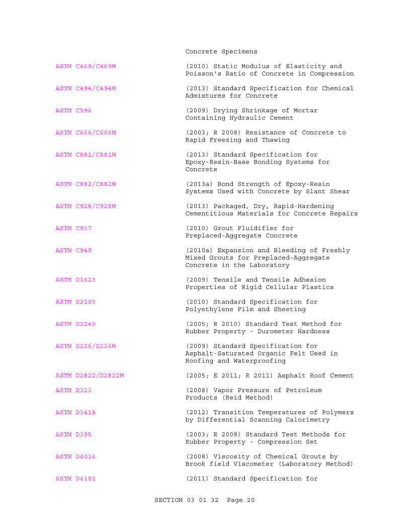
Concrete Specimens
ASTM C469/C469M (2010) Static Modulus of Elasticity and Poisson's Ratio of Concrete in Compression
ASTM C494/C494M (2013) Standard Specification for Chemical Admixtures for Concrete
ASTM C596 (2009) Drying Shrinkage of Mortar Containing Hydraulic Cement
ASTM C666/C666M (2003; R 2008) Resistance of Concrete to Rapid Freezing and Thawing
ASTM C881/C881M (2013) Standard Specification for Epoxy-Resin-Base Bonding Systems for Concrete
ASTM C882/C882M (2013a) Bond Strength of Epoxy-Resin Systems Used with Concrete by Slant Shear
ASTM C928/C928M (2013) Packaged, Dry, Rapid-Hardening Cementitious Materials for Concrete Repairs
ASTM C937 (2010) Grout Fluidifier for Preplaced-Aggregate Concrete
ASTM C940 (2010a) Expansion and Bleeding of Freshly Mixed Grouts for Preplaced-Aggregate Concrete in the Laboratory
ASTM D1623 (2009) Tensile and Tensile Adhesion Properties of Rigid Cellular Plastics
ASTM D2103 (2010) Standard Specification for Polyethylene Film and Sheeting
ASTM D2240 (2005; R 2010) Standard Test Method for Rubber Property - Durometer Hardness
ASTM D226/D226M (2009) Standard Specification for Asphalt-Saturated Organic Felt Used in Roofing and Waterproofing
ASTM D2822/D2822M (2005; E 2011; R 2011) Asphalt Roof Cement
ASTM D323 (2008) Vapor Pressure of Petroleum Products (Reid Method)
ASTM D3418 (2012) Transition Temperatures of Polymers by Differential Scanning Calorimetry
ASTM D395 (2003; R 2008) Standard Test Methods for Rubber Property - Compression Set
ASTM D4016 (2008) Viscosity of Chemical Grouts by Brook field Viscometer (Laboratory Method)
ASTM D4101 (2011) Standard Specification for
SECTION 03 01 32 Page 20

Polypropylene Injection and Extrusion Materials
ASTM D412 (2006a; R 2013) Standard Test Methods for Vulcanized Rubber and Thermoplastic Elastomers - Tension
ASTM D450/D450M (2007; E 2013; R 2013) Coal-Tar Pitch Used in Roofing, Dampproofing, and Waterproofing
ASTM D471 (2012a) Standard Test Method for Rubber Property - Effect of Liquids
ASTM D4869/D4869M (2005; E 2011; R 2011) Standard Specification for Asphalt-Saturated Organic Felt Underlayment Used in Steep Slope Roofing
ASTM D572 (2004; R 2010) Rubber Deterioration by Heat and Oxygen
ASTM D75/D75M (2013) Standard Practice for Sampling Aggregates
ASTM E488/E488M (2010) Standard Test Methods for Strength of Anchors in Concrete and Masonry Elements
CONCRETE SAWING AND DRILLING ASSOCIATION (CSDA)
CSDA-W-104 (June 1, 1998; R 2007) Track Mounted Wall Sawing
POST-TENSIONING INSTITUTE (PTI)
PTI TAB.1 (2006) Post-Tensioning Manual
PRECAST/PRESTRESSED CONCRETE INSTITUTE (PCI)
PCI MNL-116 (1999) Manual for Quality Control for Plants and Production of Structural Precast Concrete Products, 4th Edition
U.S. ARMY CORPS OF ENGINEERS (USACE)
COE CRD-C 164 (1992) Standard Test Method for Direct Tensile Strength of Cylindrical Concrete or Mortar Specimens
COE CRD-C 39 (1981) Test Method for Coefficient of Linear Thermal Expansion of Concrete
COE CRD-C 400 (1963) Requirements for Water for Use in Mixing or Curing Concrete
EM 385-1-1 (2008; Errata 1-2010; Changes 1-3 2010; Changes 4-6 2011; Change 7 2012) Safety and Health Requirements Manual
SECTION 03 01 32 Page 21

U.S. GENERAL SERVICES ADMINISTRATION (GSA)
CID A-A-1922 (Rev A; Notice 2) Shield, Expansion (Caulking Anchors, Single Lead)
CID A-A-1923 (Rev A; Notice 2) Shield, Expansion (Lag, Machine and Externally Threaded Wedge Bolt Anchors)
CID A-A-55614 (Basic; Notice 2) Shield, Expansion (Non-Drilling Expansion Anchors)
1.4 DEFINITIONS
**************************************************************************NOTE: See ACI 201.1 for definitions of various types of concrete deterioration.
**************************************************************************
1.4.1 Concrete
A mixture of binder material, water, and fine and coarse aggregate, with or without admixtures.
1.4.2 Mortar
A mixture of binder material, water, and fine aggregate, with or without admixtures.
1.4.3 Grout
A mixture of binder material and water, with or without a filler.
1.4.4 Cement-Based Material
A material consisting of portland cement and/or other cementitious materials as a binder and aggregate. As used in this specification, cement-based materials do not include materials with polymer modifiers.
1.4.5 Polymer-Modifier
A polymer used to modify the properties of a cement-based concrete or mortar. The polymers commonly associated with concrete rehabilitation are styrene-butadiene and acrylic latex.
1.4.6 Polymer-Modified Material
A combination of polymer, portland cement and/or other cementitious materials, and fine and/or coarse aggregate. Polymer-modified concrete is normally placed to a thickness of 25 mm 1 inch or greater. Polymer-modified mortar is normally placed to a thickness of less than 25 mm 1 inch.
1.4.7 Epoxy Resin Binder
A two-component epoxy resin binder system in low and medium viscosities used by itself as a primer or for producing epoxy concrete or mortars when mixed with aggregate.
SECTION 03 01 32 Page 22

1.4.8 Epoxy Concrete
A combination of epoxy resin and fine and coarse aggregate.
1.4.9 Epoxy Mortar
A combination of epoxy resin, a mineral filler, and fine aggregate.
1.4.10 Non-Pressure Epoxy Grout
A combination of epoxy resin binder, a mineral filler and a thixotropic agent.
1.4.11 Epoxy Injection Adhesive
A low viscosity epoxy resin system pumped under pressure into cracks.
1.4.12 Rapid-Hardening Repair Material
A combination of rapid-setting cement and aggregate(s) that can develop sufficient compressive strength at an early age to permit intended use.
1.4.13 Non-Structural Cracks
Cracks that do not affect the load-carrying capacity of the structure.
1.4.14 Structural Cracks
Cracks that affect the load-carrying capacity of the structure.
1.5 SYSTEM DESCRIPTION
1.5.1 Design Requirements
**************************************************************************NOTE: If higher earlier strength is needed for repairs, revise this paragraph to provide appropriate criteria. The mixture design should maximize aggregate size and minimize the water-cementitious material ratio to reduce shrinkage. Material properties should be coordinated with EM 1110-2-2002 Evaluation and Repair of Concrete Structures. Where other guide specifications are included in the project specification, ensure that appropriate parameters are inserted in the applicable specification. Consideration should be given to including and alternative age other than 28 days such as 90 days when pozzolan is used to provide more cost effective use of materials. If flowability of the grout is important, use ASTM C1017/C1017M for admixture and specify where it is to be used; otherwise use ASTM C494/C494M.
**************************************************************************
Submit manufacturer's literature from suppliers that demonstrates compliance with applicable specifications for the above materials. For proportioned materials, submit three copies of the proposed mix design prior to placement. The mix design shall indicate the weight of each
SECTION 03 01 32 Page 23

ingredient of the mixture. No concrete shall be placed prior to approval of the proposed mix design. No deviation from the approved job-mix formula will be permitted without prior approval.
a. Concrete. Design the concrete mixtures in accordance with Section [03 30 00.00 10 CAST-IN-PLACE CONCRETE] [03 31 01.00 10 CAST-IN-PLACE STRUCTURAL CONCRETE FOR CIVIL WORKS] [03 30 53 MISCELLANEOUS CAST-IN-PLACE CONCRETE].
b. Mortar. Design the mortar mixtures to produce material having an average compressive strength of [_____] kPa psi at 28 days of age, determined in conformance with ASTM C109/C109M. Design the mixtures to secure an air content by volume of [5] [_____] percent, plus or minus 1-1/2 percent, based on measurements made on concrete at the point of placement in conformance with ASTM C231/C231M. The range of slump shall be 13 to 50 mm 1/2 to 2 inches when tested in accordance with ASTM C143/C143M except that maximum slump may be increased to 100 mm 4 inches when the Contractor has included an approved water-reducing, high range, admixture conforming to ASTM C494/C494M in the mix design. To minimize drying shrinkage, the maximum water-cementitious materials ratio by weight shall be 0.45 and the maximum cement content shall be kept to a minimum to limit water volume. Make mix design studies and tests in accordance with ASTM C39/C39M and ASTM C192/C192M, and submit the test results for approval.
c. Grout. Design the grout mixtures to produce material having an average compressive strength of [_____] kPapsi at 28 days of age, determined in conformance with ASTM C109/C109M. Design the mixtures to secure an air content by volume of [5] [_____] percent, plus or minus 1-1/2 percent, based on measurements made on concrete at the point of placement in conformance with ASTM C231/C231M. The range of slump shall be 13 to 50 mm 1/2 to 2 inches when tested in accordance with ASTM C143/C143M except that maximum slump may be increased to 100 mm 4 inches when the Contractor has included an approved water-reducing, high range, admixture conforming to [ASTM C494/C494M] [ASTM C1017/C1017M] in the mix design. To minimize drying shrinkage, the maximum water-cementitious materials ratio by weight shall be 0.45 and the maximum cement content shall be kept to a minimum to limit water volume. Make mix design studies and tests in accordance with ASTM C39/C39M and ASTM C192/C192M, and submit the test results for approval.
d. Repair Materials. [Provide the services of a technical specialist experienced in using the polymer for repair materials.]
1.5.2 Repair Material Performance Requirements
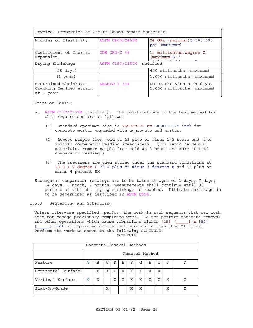
Place repair materials to the lines indicated on the drawings. Construction tolerances for concrete and mortar repair materials shall meet the requirements of ACI 117. Design repair materials to conform to the following requirements at 28 days unless otherwise indicated:
Physical Properties of Cement-Based Repair materials
Property Test method Criteria
Tensile Strength (28 days)
COE CRD-C 164 2.8 MPa (minimum)400 psi (minimum)
SECTION 03 01 32 Page 24
Physical Properties of Cement-Based Repair materials
Modulus of Elasticity ASTM C469/C469M 24 GPa (maximum)3,500,000 psi (maximum)
Coefficient of Thermal Expansion
COE CRD-C 39 12 millionths/degree C (maximum)6.7 illi th /d FDrying Shrinkage ASTM C157/C157M (modified)
(28 days) 400 millionths (maximum)
(1 year) 1,000 millionths (maximum)
Restrained Shrinkage Cracking Implied strain at 1 year
AASHTO T 334 No cracks within 14 days,1,000 millionths (maximum)
Notes on Table:
a. ASTM C157/C157M (modified). The modifications to the test method for this requirement are as follows:
(1) Standard specimen size is 76x76x275 mm 3x3x11-1/4 inch for concrete mortar expanded with aggregate and mortar.
(2) Remove sample from mold at 23 plus or minus 1/2 hours and make initial comparator reading immediately. (For rapid hardening materials, remove sample from mold at 3 hours and make initial comparator reading.)
(3) The specimens are then stored under the standard conditions at 23.0 + 2 degree C 73.4 plus or minus 3 degrees F and 50 plus or minus 4 percent RH.
Subsequent comparator readings are to be taken at ages of 3 days, 7 days, 14 days, 1 month, 2 months; measurements shall continue until 90 percent of ultimate drying shrinkage is reached. Ultimate shrinkage is to be determined as described in ASTM C596.
1.5.3 Sequencing and Scheduling
Unless otherwise specified, perform the work in such sequence that new work does not damage previously completed work. Do not perform concrete removal and other operations which cause vibrations within [15] [_____] m [50] [_____] feet of repair materials that have cured less than 24 hours. Perform the work as shown in the following SCHEDULE.
SCHEDULE
Concrete Removal Methods
Removal Method
Feature A B C D E F G H I J K
Horizontal Surface X X X X X X X X
Vertical Surface X X X X X X X X X X
Slab-On-Grade X X X X X
SECTION 03 01 32 Page 25

Concrete Removal Methods
Removal Method
Feature A B C D E F G H I J K
A Controlled Blasting
B Abrasive Water Jet Cutting
C Diamond Blade Cutting
D Diamond Wire Cutting
E Stitch Cutting
F Boom Mounted Breaker
G Hand Held Breaker
H Hydromilling
I Rotary Head Milling
J Presplitting (Expansive Agent)
K Mechanical Presplitting
Repair Material
Repair Material
Feature A B C D E F G H I
Horizontal Surfaces (repair)
X X X X X
Horizontal Surfaces (Overlay)
X X X X
Vertical Surfaces (repair)
X X X X X X X X
Vertical Surfaces (Refacing)
X X X X X X
SECTION 03 01 32 Page 26

Repair Material
Repair Material
Feature A B C D E F G H I
A Cement-Based Concrete
B Cement-Based Mortar
C Precast Portland Cement Concrete
D Polymer-Modified Mortar
E Polymer-Modified Concrete
F Epoxy Mortar
G Epoxy Concrete
H Preplaced-Aggregate Concrete
I Shotcrete
Crack Repair
Repair Method
Type of Crack A B C D E F
Open Crack on Surface X X
Structural Crack (Inactive)
X X X X
Structural Crack (Active)
X X
A Clean and Seal
B Clean and Fill
C Drill and Plug
D Injection
E Stitching
F Mechanical Anchoring
1.6 SUBMITTALS
**************************************************************************NOTE: Review submittal description (SD) definitions in Section 01 33 00 SUBMITTAL PROCEDURES and edit the following list to reflect only the submittals
SECTION 03 01 32 Page 27

required for the project.
The Guide Specification technical editors have designated those items that require Government approval, due to their complexity or criticality, with a "G." Generally, other submittal items can be reviewed by the Contractor's Quality Control System. Only add a “G” to an item, if the submittal is sufficiently important or complex in context of the project.
For submittals requiring Government approval on Army projects, a code of up to three characters within the submittal tags may be used following the "G" designation to indicate the approving authority. Codes for Army projects using the Resident Management System (RMS) are: "AE" for Architect-Engineer; "DO" for District Office (Engineering Division or other organization in the District Office); "AO" for Area Office; "RO" for Resident Office; and "PO" for Project Office. Codes following the "G" typically are not used for Navy, Air Force, and NASA projects.
Choose the first bracketed item for Navy, Air Force and NASA projects, or choose the second bracketed item for Army projects.
**************************************************************************
Government approval is required for submittals with a "G" designation; submittals not having a "G" designation are for [Contractor Quality Control approval.] [information only. When used, a designation following the "G" designation identifies the office that will review the submittal for the Government.] Submit the following in accordance with Section 01 33 00 SUBMITTAL PROCEDURES:
SD-01 Preconstruction Submittals
Work Plan[; G][; G, [_____]]Demolition Plan[; G][; G, [_____]]Blasting Plan[; G][; G, [_____]]Water Control Plan[; G][; G, [_____]]Erection Plan for Precast UnitsAlignment Plan for Precast UnitsContractor QualificationsWorker QualificationsBlasting Personnel Qualifications
SD-03 Product Data
Rapid-Hardening Repair MaterialPolymer ModifierLatex Bonding CompoundPolyurethane Injection AdhesivePolyester Resin GroutEpoxy Resin MaterialsBond BreakerFiber ReinforcementNeoprene Bearing Pads for Precast Units
SECTION 03 01 32 Page 28

Mechanical AnchorsHigh Molecular Weight Methacrylate (HMWM) SealerTesting Technicians
SD-04 Samples
Field-Molded Sealants and Primer[ Epoxy-Coated Steel Bars]
SD-05 Design Data
Repair material mixture proportioning
SD-06 Test Reports
**************************************************************************NOTE: Test reports should be required unless the repairs are considered minor and non-critical, in which case manufacturer's certificates could be accepted.
**************************************************************************
Compression Seals and LubricantCement-Based ConcreteCement-Based MortarRapid-Hardening Repair Material.Dry-Pack Mortar.Polymer-Modified ConcretePolymer-Modified Mortar
**************************************************************************NOTE: Use the following submittal on projects involving injection grouting of cracks, and other projects where the total surface area of the structure to be repaired exceeds 2 square meters (20 square feet).
**************************************************************************
Sieve analysis test for aggregateEpoxy resin binder testsEpoxy resin grout testsSeismographic Monitoring Records
SD-07 Certificates
Grout FluidifierAggregate
**************************************************************************NOTE: Use this submittal on small repair projects, not requiring injection grouting of cracks, whose total surface area to be repaired does not exceed 2 square meters (20 square feet).
**************************************************************************
Epoxy Resin BinderEpoxy Grout
[ Epoxy-Coated Steel Bars]
SECTION 03 01 32 Page 29
SD-08 Manufacturer's Instructions
Polymer-Modified MortarPolymer-Modified ConcretePolymer ModifierEpoxy ConcreteEpoxy MortarEpoxy GroutEpoxy Injection AdhesiveRapid-Hardening Repair MaterialPolyurethane Injection AdhesiveHigh Molecular Weight Methacrylate (HMWM) SealerManufacturer's Material Safety Data Sheets
1.7 QUALITY ASSURANCE
Perform all work in accordance with EM 385-1-1. To protect personnel from overexposure to toxic materials, conform to the applicable manufacturer's Material Safety Data Sheets (MSDS) or local regulation. Submit the MSDS for epoxies, polyurethanes, and other potentially hazardous materials.
1.7.1 Qualifications
The submittals shall, where applicable, identify individuals who will be working on this contract and their relevant experience. Do not make changes in approved personnel without prior approval of the Contracting Officer.
1.7.1.1 Contractor Qualifications
The Contractor performing the repair work shall have been involved in a minimum of [three] [_____] concrete repair projects similar in size and scope to this project for at least [five] [_____] years. Submit information, including name, dollar value, date, and point-of-contact for similar projects which demonstrates the required experience and/or training.
1.7.1.2 Worker Qualifications
Each worker engaged in the use of specialized removal or application equipment, including [saw operators,] [milling machine operators,] [hydromilling equipment operators,] [epoxy] [polyurethane] injection process, shall have satisfactorily completed an instruction program in the operation of the equipment. [The instruction program for workers engaged in the use of grout injection equipment shall have included theory on the nature and causes of cracking in concrete, methods for permanently repairing damaged structural members, the technical aspects of correct material selection and use, and the operation, maintenance, and troubleshooting of equipment used in the repair work.] Each worker engaged in the operation of specialized equipment for the contract work shall have a minimum of three years of experience in the operation of the equipment.
1.7.1.3 Blasting Personnel Qualifications
Provide a Blasting Engineer to supervise the overall job and a Blasting Foreman for each shift that blasting will occur. The Blasting Engineer shall be experienced in the supervision of controlled blasting operations and shall be responsible for the drilling plan, supervising blasting operations, and maintaining required records. The Blasting Engineer does not need to be at the site for the entire blasting operation. The Blasting
SECTION 03 01 32 Page 30

Engineer and Blasting Foreman shall have a minimum of 10 years experience in controlled blasting.
1.7.1.4 Quality Control Personnel Qualifications
The individuals who sample and test concrete, as required in this specification, shall have demonstrated a knowledge and ability to perform the necessary test procedures equivalent to the ACI minimum guidelines for certification of Concrete Field Testing Technicians, Grade I. Submit resumes, pertinent information, past experience, training, and education of all operators of specialized demolition equipment if needed for this and the three paragraphs above.
1.7.2 Regulatory Requirements
Perform all work in accordance with applicable Federal, State and local safety, health and environmental requirements, and EM 385-1-1. The Contractor is responsible for obtaining all permits required by Federal, State and local agencies for the performance of the work.
1.7.3 Pre-Construction Conference
**************************************************************************NOTE: Appropriate technical representatives for specialized repair materials should be required to meet with the Government and Contractor representatives to ensure that all parties involved are knowledgeable of the material properties and application requirements.
**************************************************************************
Arrange a pre-construction conference for [the repair materials] [_____] to ensure that the Contractor's personnel understand all aspects of the repair material, its properties and application procedures. The conference shall include the Contracting Officer or authorized representative, the Contractor, and a competent Technical Representative of the material manufacturer. The Technical Representative shall be fully qualified to perform the work.
1.7.4 Repair Material Mixture Proportioning
Submit, at least 15 days before work commences, a repair material mixture proportioning for each use of [polymer-modified mortar] [polymer-modified concrete] [dry-pack mortar]. Test reports and test results shall accompany the mixture proportions. Identify the proposed source of the materials and state the proportions of each constituent. When determining the mixture design, use samples of materials to be used on the job.
a. Trial batches: Trial batches and testing requirements for various repair materials specified shall be the responsibility of the Contractor. The laboratory performing the tests shall be on site and shall conform to ASTM C1077. Samples of aggregates shall be obtained in accordance with the requirements of ASTM D75/D75M. Samples of materials other than aggregate shall be representative of those proposed for the project and shall be accompanied by the manufacturer's test reports indicating compliance with applicable specified requirements. Trial mixtures having proportions, consistencies, and air content suitable for the work shall be made based on methodology described in ACI 211.1, which will produce a range of strength
SECTION 03 01 32 Page 31

encompassing those required for the work. The maximum water-cementitious materials ratios required in Section [03 30 00.00 10 CAST-IN-PLACE CONCRETE] [03 31 01.00 10 CAST-IN-PLACE STRUCTURAL CONCRETE FOR CIVIL WORKS] [03 30 53 MISCELLANEOUS CAST-IN-PLACE CONCRETE], paragraph MAXIMUM WATER-CEMENTITIOUS MATERIALS RATIO will be converted to a weight ratio of water to cementitious materials.
b. Supporting criteria: Include in the submittal the following data for each trial batch:
(1) Proportions by weight
(2) Unit weights and specific gravities of constituents
(3) Batch weights
(4) Compressive strengths in accordance with the following:
Material Specimen Size Test
Concrete 150 by 300 mm 6 by 12 inch cylinders
ASTM C39/C39M
Mortar 75 by 150 mm 3 by 6 inch cylinders
ASTM C39/C39M
Grout 50 mm 2 inch cube ASTM C109/C109M
(5) Curing time
(6) Working time (polymer-modified materials)
(7) Slump
(8) Air content
1.7.5 Test Reports
1.7.5.1 Epoxy Resin Binder
Include the following:
a. Viscosity
b. Consistency
c. Gel time
d. Absorption
e. Shrinkage
f. Thermal compatibility
1.7.5.2 Epoxy Resin Grout
Include the following:
a. Epoxy number
SECTION 03 01 32 Page 32

b. Consistency
c. Compressive single shear strength
d. Pot life
1.7.5.3 [Cement-Based Concrete] [and] [Cement-Based Mortar]
Include the following:
a. Initial Slump
b. Slump over Time
c. Air Content
d. Compressive Strength at 7, [14,] 28, 56, [and] [90] days.
e. Water to cementitious materials ratio
[ f. Tensile Strength]
[ g. Flexural Strength]
1.7.5.4 [Polymer-Modified Concrete] [and] [Polymer-Modified Mortar]
Include the following:
a. Tensile Strength (28 days)
b. Modulus of Elasticity
c. Coefficient of Thermal Expansion
d. Drying Shrinkage
e. Restrained Shrinkage
f. Cracking
g. Implied strain at 1 year
1.7.6 Field Samples
Prepare a work plan describing the methods of concrete removal and repair, including methods, equipment and materials to be used for each feature. Submit the work plan for approval at least 30 days prior to the start of the work. The plan shall include, but shall not be limited to, repair materials to be used with specific information on products and/or constituents, and requirements for handling, storage, etc., equipment to be used, surface preparation, and requirements for placement, finishing, curing and protection specific to the materials used. The work plan shall include a description of field demonstrations. Do not commence work until the work plan and field demonstration representative of the type of work are approved.
1.7.6.1 Concrete Removal
**************************************************************************
SECTION 03 01 32 Page 33

NOTE: The size of the removal demonstration area should be sufficient to show the proposed methods and the results under typical conditions.
**************************************************************************
Prior to commencement of production concrete removal, perform a test break on an area of [sufficient size] [3 m by 3 m 10 feet by 10 feet] [_____] to demonstrate that the proposed removal procedure will result in compliance with the specified requirements. The test break shall verify [proper spacing of holes and procedure for control of crack propagation,] [selection of abrasive materials,] [loading and stemming of charges,] and suitability of the equipment to remove the existing materials.
1.7.6.2 Joint and Crack Sealing
Prepare and seal a test section consisting of approximately [61] [_____] meters [20] [_____] feet at a location determined by the Contracting Officer to demonstrate the preparatory and application procedures prior to beginning production sealing. Additional test sections may be required by the Contracting Officer. Remove any material that does not comply with the contract requirements and replace at no additional cost to the Government. Test sections that comply with the contract requirements may remain in place and will be included payment for the work. Use the same procedures and materials as used in the successful test section for production work. [The test section may be incorporated in the final work if accepted by the Contracting Officer.]
1.7.6.3 Precast Unit Assembly Test
Perform a demonstration of all methods and techniques to be used for erecting the precast units.
1.7.6.4 Sample Repair Panels
**************************************************************************NOTE: Edit this paragraph as appropriate. Specify location for all field test panels. Add requirements for mock-ups if applicable.
**************************************************************************
Construct field test panels prior to beginning of work using the repair materials and procedures proposed for use on the job, to demonstrate the results to be attained. The panel shall contain reinforcing steel and embedded items as the production work. The quality and appearance of each panel shall be subject to the approval of the Contracting Officer, and, if not judged satisfactory, additional panels shall be constructed until approval is attained. Formed and finished surfaces in the completed structure shall match the quality and appearance of the approved sample repair panel. For wall refacing, construct a minimum of one sample panel at least 1.25 m 4 feet by 1.5 m 5 feet and the same thickness as the production panel to demonstrate each type of formed and unformed finish required. Each panel shall include a full length and full width joint line.
1.8 DELIVERY, STORAGE, AND HANDLING
1.8.1 Packing, Shipping, Handling, and Unloading
Inspect materials delivered to site for damage, unload and store with a minimum of handling. Deliver resin components and aggregate materials in
SECTION 03 01 32 Page 34

original sealed containers where applicable.
1.8.2 Epoxy-Resin Materials
Deliver epoxy-resin materials to the site in such manner as to avoid damage or loss. Do not allow epoxy-resin materials to freeze. Storage areas shall be in a windowless and weatherproof, but ventilated, insulated noncombustible building, with provision nearby for conditioning the material to 20 degrees C 70 degrees F to 30 degrees C 85 degrees F for a period of 48 hours prior to use. Store epoxy resin components and aggregate materials in dry covered areas at temperatures below 30 degrees C 90 degrees F. Remove unused mixed materials that have reached end of working or pot life from the job site. Use epoxy-resin materials before the expiration date marked on the packaging.
1.8.3 Polymer Materials
Storage areas shall be in a windowless and weatherproof, but ventilated, insulated noncombustible building. Store polymer materials at temperatures between 4.4 degrees C 40 degrees F to 30 degrees C 85 degrees F. Do not allow polymer materials to freeze.
1.8.4 Chemical Admixtures
Protect chemical admixtures and store and maintain between 5 degrees C 40 degrees F to 30 degrees C 90 degrees F. Remove from the site any admixtures subjected to temperatures outside this range, or stored for longer than recommended by the manufacturer. Do not use any admixture that has been in storage for longer than recommended by the manufacturer or that has been subjected to freezing in the work. Remove such materials from the site.
1.8.5 Waste Management and Disposal
Prepare a water control plan to describe methods and equipment to be used for controlling, collection, treatment and disposal of wastewater from drilling, sawing and other concrete removal operations at least [30] [60] days prior to performance of any operations that produce wastewater. The plan shall include copies of required permits or other evidence of compliance with applicable Federal, State and local laws and regulations.. Unless otherwise specified, do not permit concrete and other debris to drop into the [water] [_____]. Collect concrete and/or debris and retain near to its point of removal. Submit the demolition plan describing the method of debris control and removal, and the procedures proposed for the accomplishment of the demolition and removal work. The procedures shall provide for safe conduct of the work, including procedures and methods to provide necessary supports, lateral bracing and shoring when required, careful removal and disposition of materials specified to be salvaged, protection of property which is to remain undisturbed, coordination with other work in progress, and timely disconnection of utility services. The procedures shall include a detailed description of the methods and equipment to be used for each operation, and the sequence of operations in accordance with EM 385-1-1. Where applicable, the plan shall include drilling patterns and means of controlling crack propagation. The work plan shall also include an access plan for personnel; [a Lead Protection Plan]; and method of controlling, collecting, and removing debris. The method of debris control and removal shall be approved by the Contracting Officer. Dispose of debris in accordance with Section 01 74 19 CONSTRUCTION AND DEMOLITION WASTE MANAGEMENT. Remove all concrete which
SECTION 03 01 32 Page 35

falls into the [water] [_____] at no additional cost to the Government. [Do not permit waste water from surface preparation, cleaning, drilling and cutting operations to directly enter the [water] [_____]. Collect wastewater and treat in accordance with Section 01 57 20.00 10 ENVIRONMENTAL PROTECTION.]
1.9 PROJECT/SITE CONDITIONS
1.9.1 Environmental Requirements
**************************************************************************NOTE: The maximum placement temperature is a function of the humidity in accordance with EM 1110-2-2000 (Table 8-2) for thin repairs or the mass of the placement for larger repairs. Limitations if ready-mix concrete is specified must also be considered
**************************************************************************
Do not place repair materials when weather conditions detrimentally affect the quality of the finished product. Do not place cement-based repair materials when the air temperature is below 5 degrees C 40 degrees F in the shade. When air temperature is likely to exceed 35 degrees C 90 degrees F, the cement-based repair material shall have a temperature not exceeding 35 degrees C 90 degrees F when deposited, and the surface of such placed cement-based repair material shall be kept damp with a water fog until the approved curing medium is applied. Do not place polymer-modified repair materials when the air temperature is below 7 degrees C 45 degrees F or above 30 degrees C 85 degrees F unless approved by the polymer manufacturer. Do not place sealant in joints or cracks when the temperature is below 10 degrees C 50 degrees F. Placement restrictions for other materials shall be in accordance with the manufacturer's published literature. Halt work when weather conditions are potentially detrimental to the quality of repairing or bonding concrete. Apply epoxy resin materials only when the contact surfaces are completely dry and if the ambient and surface temperature ranges are suitable for the specified epoxy material. Follow manufacturer's instructions for weather conditions and temperature ranges.
1.9.2 Existing Conditions
1.9.2.1 Concrete Test Data
**************************************************************************NOTE: Test information and evaluation reports should be included with the contract package if applicable. When a substantial amount of information is available, a summary of pertinent information should be included and the remaining information should be made available for review.
**************************************************************************
The existing concrete has been evaluated by means of [core drilling and destructive testing] [petrographic examination] [determination of rebound number] [determination of penetration resistance] [ultrasonic pulse-velocity evaluation]. The results of the evaluation are [given in [_____]] [available for review at [_____]].
SECTION 03 01 32 Page 36

1.9.2.2 Concrete Core(s)
Concrete core(s) obtained from the structure, which was (were) not destroyed by testing, is (are) available for viewing at [_____].
1.9.2.3 Embedded Materials
The contract drawings and reference drawings do not constitute a complete description of all metal parts and other materials that may be encountered, but represent the best information available to the Government. Other items, or different locations for items shown, may exist. Exercise care to avoid drilling through functional embedded items intended to remain in service. The Contractor's selection of equipment and methods shall consider the presence of such materials, and the Government will not be responsible in any way for the effect of such items on the Contractor's equipment or progress. Where indicated, remove existing metal items to the limits noted on drawings.
PART 2 PRODUCTS
2.1 MATERIALS
**************************************************************************NOTE: Material selection, including type of cement and other cementitious materials, aggregates and admixtures should be in accordance with EM 1110-2-2000 and EM 1110-2-2002.
**************************************************************************
2.1.1 Cement-Based Materials
**************************************************************************NOTE: See the appropriate concrete aggregates design memorandum or thermal study to select the proper requirements for cementitious materials options, pozzolan, and silica fume and insert in the referenced sections as applicable. Determination of the type of cement, including optional physical and chemical requirements, must be based on consideration of environmental exposure, material reactivity and heat of hydration.
**************************************************************************
Cementitious materials shall meet the requirements specified in Section [03 30 00.00 10 CAST-IN-PLACE CONCRETE] [ 03 31 01.00 10 CAST-IN-PLACE STRUCTURAL CONCRETE FOR CIVIL WORKS] [03 30 53 MISCELLANEOUS CAST-IN-PLACE CONCRETE].
2.1.1.1 Rapid-Hardening Repair Material
**************************************************************************NOTE: ASTM C928/C928M does not provide requirements for for freeze-thaw durability, for sulphate exposure or alkali reactivity. These materials should be used only when the properties are needed, and then only when a service record for the proposed material, in the same environment, is available or when Government testing is performed. Use the bracketed requirements when necessary for the
SECTION 03 01 32 Page 37

exposure. See Table 1 in ASTM C928 for properties of Type R1, R2 and R3.
**************************************************************************
Prepackaged or site-mixed material: ASTM C928/C928M, Type [R1] [R2] [R3], [with Durability Factor of 50 or more when subjected to freezing and thawing in accordance with ASTM C666/C666M, Procedure A] [and] [length change of not more than [ ] percent when tested for sulfate expansion in accordance with ASTM C1012/C1012M]. Use bonding agent as recommended by the manufacturer.
2.1.1.2 Ultra-fine Cement
Maximum particle size shall be less than 10 microns. The ultra-fine cement shall contain a dispersing agent.
2.1.2 Admixtures
**************************************************************************NOTE: High-range water reducers are only appropriate for high slump (150 mm+ (6"+)) mixtures. Accelerating or retarding admixtures should not be used unless specific project requirements justify their use. Accelerators may promote more cracking, and the retarder may make the concrete susceptible to damage, settlement, etc.
**************************************************************************
Admixtures to be used, when required or permitted, shall conform to the appropriate specification listed. Admixtures shall meet the requirements specified in Section [03 30 00.00 10 CAST-IN-PLACE CONCRETE] [03 31 01.00 10 CAST-IN-PLACE STRUCTURAL CONCRETE FOR CIVIL WORKS] [03 30 53 MISCELLANEOUS CAST-IN-PLACE CONCRETE]. Grout Fluidifier shall conform to ASTM C937; submit manufacturer's certifications in lieu of laboratory test results for proposed materials. Certificates should certify compliance with the appropriate specification referenced herein. Do not place materials without prior approval from the Contracting Officer.
2.1.3 Aggregate
**************************************************************************NOTE: Aggregate quality requirements shall be selected based on exposure and environmental conditions, and shall consider quality issues and potential material reactivity for the locality where the work is to be performed.
The maximum practical size of coarse aggregate should be used. The maximum size aggregate should be based on depth of concrete removal, as well as reinforcing and form clearances.
**************************************************************************
Aggregates shall meet the quality and grading requirements of [ASTM C33/C33M Class Designations 4M or better] [or] [state highway department specification] and the following specific requirements. For material passing No. 200 sieve provide a non-plastic material composed of a minimum of 75 percent limestone dust, talc or silica inert filler. Provide dry aggregate.
SECTION 03 01 32 Page 38

a. For epoxy concrete: ASTM C33/C33M, [maximum size [_____] [13 mm 1/2 inch]].
b. For epoxy mortar: ASTM C144, [maximum size [_____] [mm inch] [No. 8 sieve] [No. 40 sieve] [[_____] sieve]].
c. For dry-pack mortar: ASTM C144, maximum size No. 16 sieve
d. For polymer-modified concrete: ASTM C33/C33M, Size No. 8.
e. For polymer-modified mortar: ASTM C144, [maximum size [_____] [mm inch] [No. 8 sieve] [No. 40 sieve] [[_____] sieve]].
2.1.4 Water
Water for cleaning, mixing and curing shall be fresh, clean, potable, and free of injurious amounts of oil, acid, salt, or alkali, except that non-potable water may be used if it meets the requirements of COE CRD-C 400.
2.1.5 Fiber Reinforcement
**************************************************************************NOTE: For nominal maximum aggregate size less than 40 mm (1-1/2 inch), consider using fibers which are slightly larger than the maximum aggregate size.
**************************************************************************
[Fiber reinforcement shall be fibrillated polyolefin fiber made from virgin polypropylene meeting the requirements for Type III fibers in accordance with ASTM C1116/C1116M.] [Fiber reinforcement shall be steel deformed type meeting the requirements of ASTM A820/A820M, Type I or II. The aspect ratio (length divided by diameter or equivalent diameter) of the fibers shall be between 45 and 100.] Length of fibers shall be 40 mm 1-1/2 inch.
2.1.6 Polymer Materials
2.1.6.1 Polymer Modifier for Concrete or Mortar
ASTM C1438, Type II.
2.1.6.2 Polyurethane Injection Adhesive
**************************************************************************NOTE: Polyurethane injection adhesive is intended for sealing non-structural cracks. Polyurethane injection adhesive is not intended for, and should not be used for, structural repairs.
**************************************************************************
Two part system composed of polyurethane resin and water. Polyurethane resin shall be 100 percent hydrophilic resin, capable of forming either a flexible closed-cell foam or cured gel when mixed with water. When mixed with water, the resin shall meet the following requirements.
SECTION 03 01 32 Page 39

Performance Criteria Properties of the Cured Polyurethane Injection Grout
Property Test Method Criteria
Tensile Strength ASTM D1623 138 kPa (minimum)20 psi (minimum)
Elongation ASTM D1623 400 percent (minimum)
Bond to Concrete (wet) ASTM C273/C273M 138 kPa (minimum)20 psi (minimum)
2.1.6.3 Polyester Resin Grout
**************************************************************************NOTE: Polyester resin grout should not be used for anchors installed in wet holes unless the two-step procedure specified in paragraph ANCHORING AND REINFORCING is used. Single stage grouting can be accomplished with polyester resin grout by using fast setting resin grout cartridges or capsules in the bond zone and slower setting resin grout in the free stressing zone.
**************************************************************************
Polyester resin grout consisting of high strength, unsaturated polyester resin filled with nonreactive, inorganic aggregate and a separated catalyst contained in a cartridge of polyester film or glass capsule. Gel time and cure time shall be appropriate for the installation procedures. The polyester resin grout shall have the following minimum properties:
Compressive Strength 83 MPa 12000 psi
Tensile Strength 27.6 MPa 4000 psi
Shear Strength 20.7 MPa 3000 psi
Do not use resin cartridges or capsules with expired shelf life.
2.1.6.4 Latex Bonding Compound
Latex bonding compound agents for bonding fresh to hardened concrete shall conform to ASTM C1059/C1059M, Type II.
2.1.6.5 High Molecular Weight Methacrylate (HMWM) Sealer
High molecular weight methacrylate shall be a 2-component, rapid curing, solvent-free, penetrating sealer with components meeting the following requirements:. Sand for covering the HMWM shall meet the quality and grading requirements of aggregate for masonry mortar in accordance with ASTM C144. Submit manufacturer's written mixing, application and curing instructions for each type of material.
a. HMWM Monomer. The monomer shall be a high molecular weight or
SECTION 03 01 32 Page 40

substituted methacrylate that conforms the following properties:
Physical Properties of HMWH Monomer
Property Test Method Criteria
Vapor Pressure Flash Point Density
ASTM D323Pensky-Martens
CC
Less than 133 Pa at 25 degrees C Greater than 93 degrees C Greater than 1.0 g per cubic cm at 25 degrees CLess than 0.02 psi at 77 degrees F Greater than 200 degrees F Greater than 8.4 lb. per gal. at 77 degrees F 12 plus or minus 4 cps at 73
Viscosity Index of Refraction Boiling point @ 133 Pa Shrinkage on cure
ASTM D4016 .012 + .004 Pas at 23 degrees C1.470 + 0.002 70 degrees C less than 11 percent1.470 plus or minus 0.002158 degrees Fless than 11 percent
Glass Transition Temperature (DSC)
ASTM D3418 57.2 degrees C158 degrees F
Curing Time(100 g mass)
ASTM D3418 Greater than 40 minutes at 25degrees C, with 4 percent cuemenehydroperoxideGreater than 40 minutes at 73degrees F, with 4 percent cuemenehydroperoxide
Bond Strength ASTM C882/C882M Greater than 10.3 mPaGreater than 1,500 psi
b. Initiator/Promoter System
Initiator Cuemene Hydroperoxide 78 percent
Promoter Cobalt Napthenate 6 percent
The initiator/promoter system shall be capable of providing a surface cure time of not less than 40 minutes nor more than 3 hours at the surface temperature of the concrete during application. The initiator/promoter system shall be such that the gel time may be adjusted to compensate for changes in temperature that may occur throughout the treatment application.
2.1.7 Epoxy Resin Materials
**************************************************************************NOTE: The grades for ASTM C881/C881M and classes for both standards are as follows:
1. Grade 1: Low viscosity
2. Grade 2: Medium viscosity
3. Grade 3: Non-sagging consistency
4. Class B: For use between 5 and 15 degrees C (40
SECTION 03 01 32 Page 41
and 60 degrees F).
5. Class C: For use above 15 degrees C (60 degrees F).
Epoxy mortars and concrete do not have thermal characteristics compatible with portland cement concrete. This thermal incompatibility should be carefully considered before specifying epoxy mortar or concrete for exterior concrete surface repairs.
**************************************************************************
Epoxy compounds for repairs shall be moisture insensitive.
2.1.7.1 Epoxy Resin Binder for Concrete and Mortar
ASTM C881/C881M, Type III, Grade [1] [2], Class [B] [C] without mineral filler. [For [vertical] [and] [overhead] use ASTM C881/C881M, Type III, Grade 3, Class [B] [C] with filler.]
2.1.7.2 Non-Pressure Epoxy Grout
ASTM C881/C881M Type IV, Grade [2] [3], Class [B] [C] with or without mineral filler. For setting anchors and dowels, use Type III, Grade [2] [3] with mineral filler.
2.1.7.3 Epoxy Injection Adhesive
ASTM C881/C881M, Type IV, Grade 1, Class [B] [C] without filler.
2.1.7.4 Crack Surface Sealer for Injection Grouting
ASTM C881/C881M, Type IV, Grade 3, Class [B] [C] with mineral filler.
2.1.7.5 Epoxy Bonding Agent
ASTM C881/C881M, Type II or V. Type II material for non-loadbearing applications. Type V material for load bearing applications.
2.1.8 Bond Breaker
**************************************************************************NOTE: ASTM D2822/D2822M is an asphalt roofing cement, ASTM D226/D226M and ASTM D4869/D4869M are asphalt saturated organic felt. ASTM D2103 is polyethylene sheet. AASHTO M 288 is geotextile. ASTM D450/D450M is a bituminous coating.
**************************************************************************
[ASTM D2822/D2822M], [ASTM D4869/D4869M], [ASTM D226/D226M, Type I] ,ASTM D2103, minimum thickness 0.25 mm 0.010 inch, [AASHTO M 288, Erosion Control, Class B], [ASTM D450/D450M, Type II].
2.1.9 Field-Molded Sealants and Primer
**************************************************************************NOTE: Verify with ACI 504 that sealants are appropriate for the project requirements.
**************************************************************************
SECTION 03 01 32 Page 42

Sealants and primers shall meet the requirements specified in Section [03 15 00.00 10 CONCRETE ACCESSORIES] [03 30 53 MISCELLANEOUS CAST-IN-PLACE CONCRETE]. Submit 4 L one gallon of field-molded sealant and 1 L one quart of primer (when primer is recommended by the sealant manufacturer) for testing.
2.1.10 High-Strength Steel Bars
ASTM A722/A722M, Type [I] [or] [II], meeting all supplementary requirements.
2.1.11 Compression Seals and Lubricant
Compression seals shall meet the requirements specified in Section 03 15 00.00 10 CONCRETE ACCESSORIES.
2.1.12 Epoxy-Coated Steel Bars
ASTM A722/A722M, Type [I] [or] [II], conforming to the coating requirements of ASTM A775/A775M, 0.3 mm 8 mils minimum thickness. Coating at the anchorage end may be omitted over the length provided for threading the nut against the bearing plate. Submit sample of coating material, 700 g 1.5 pounds of patching material and written certification for coating material and coated bars with the delivery of the bars.
2.1.13 Anchors
ASTM A615/A615M, ASTM A996/A996M, ASTM A36/A36M.
2.1.14 Dowels
ASTM A615/A615M, ASTM A996/A996M, ASTM A36/A36M.
2.1.15 Anchor Head
Anchor head shall consist of steel bearing plate with nut. Anchorage devices shall be capable of developing 95 percent of the guaranteed ultimate strength of prestressing steel. The anchorage devices shall conform to the static strength requirements of Section 3.1.6 (1) and Section 3.1.8 (1) and (2) of PTI TAB.1. [Threaded anchorage items for epoxy coated bars shall be designed to fit over the epoxy coating and maintain the capacity of the prestressing steel.]
2.1.16 Mechanical Anchors
[CID A-A-1922] [CID A-A-1923] [CID A-A-55614], galvanized unless otherwise indicated. Provide sleeve anchors of the length and diameter indicated. Minimum concrete embedment shall be as shown. Design values listed shall be as tested according to ASTM E488/E488M.
a. Minimum [ultimate] [allowable] pullout value shall be [_____] kN lb.
b. Minimum [ultimate] [allowable] shear value shall be [_____] kN lb.
2.2 EQUIPMENT
Assemble at the site of the work sufficient equipment that is dependable, appropriate and adequate to accomplish the work specified. Deliver the equipment a sufficient time before the start of repairs to permit thorough
SECTION 03 01 32 Page 43

inspection, calibration of weighing and measuring devices, adjustment of parts, and the making of any repairs that may be required. Machines, tools, and equipment used in the performance of the work shall be approved before the work is started and shall be maintained in satisfactory condition at all times. Maintain the equipment in good working condition. Provide dust suppression on equipment as needed to comply with Section 01 57 20.00 10 ENVIRONMENTAL PROTECTION.
2.2.1 Cement-Based Concrete Mixing Equipment
Mixing equipment shall conform to the requirements of Section [03 30 00.00 10 CAST-IN-PLACE CONCRETE] [ 03 31 01.00 10 CAST-IN-PLACE STRUCTURAL CONCRETE FOR CIVIL WORKS] [Section 03 30 53 MISCELLANEOUS CAST-IN-PLACE CONCRETE].
2.2.2 Polymer-Modified Concrete Mixing Equipment
Use proportioning and mixing equipment with capacity and continuous rate so that final finishing can be completed prior to the formation of a plastic film on the polymer-modified concrete surface. The equipment shall consistently produce a uniformly blended mixture within the specified air content and slump limits. The mixer shall also:
a. Be equipped with a recording meter with a ticket printout device to record an indication of the cement quantity being introduced into the mix. The metering device shall be accurate within a tolerance of -1 to +3 percent.
b. Be equipped with a polymer metering device to indicate volume dispensed. The metering device shall be accurate within a tolerance of -1 to +2 percent. In addition the polymer tank shall have a stand pipe marked in liters gallons.
c. Be equipped with a water flow indicator, and have a water flow control that is readily adjustable to provide for minor variations in aggregate moisture content. The flow indicator shall be accurate within a tolerance of plus or minus 1 percent in the range of expected use.
d. Be equipped with a control to regulate the quantity of each of the polymer-modified concrete components to permit production of a mix having the specified composition. To ensure that the mixer can accurately proportion and blend all components of the polymer-modified concrete on a continuous or intermittent basis, the mixer shall be calibrated prior to the start of the overlay placement.
2.2.3 Epoxy Mixing Equipment
Use a container recommended by the epoxy manufacturer as the mixing vessel. Use a power drive (air or spark-proof) propeller type blade for mixing except that hand mixing may be used for small batches. Use equipment specified by epoxy manufacturer for field mixing of aggregates and epoxy resin.
2.2.4 Grout Mixing Equipment
Use a high-speed, high-shear, colloidal type grout mixer capable of continuous mechanical mixing that will produce uniform and thoroughly mixed grout which is free of lumps and undispersed cement. The mixer shall be equipped with a suitable water [and admixture] measuring device[s]
SECTION 03 01 32 Page 44
calibrated to read in cubic centimeters cubic feet and tenths and so designed that after each delivery the device can be conveniently set back to zero.
2.2.5 Joint and Crack [Cleaning] and [Sealing] Equipment
Joint and crack [cleaning] and [sealing] equipment shall meet the requirements specified in [Section 32 01 19 FIELD MOLDED SEALANTS FOR SEALING JOINTS IN RIGID PAVEMENTS] [Section 03 15 00.00 10 CONCRETE ACCESSORIES].
2.2.6 Drilling Equipment
Use percussion or rotary drilling equipment of a type suitable for the depth, diameter and material to be drilled. Use only rotary drilling equipment where vibration from percussion drilling could damage the concrete to remain or adjacent structures. Use equipment capable of maintaining the required alignment.
2.2.7 Vehicle-Mounted Breakers
**************************************************************************NOTE: The energy of breakers should be limited to prevent damage to concrete and other structures which are to remain. Verify that the stated energy limits are appropriate for the project requirements.
**************************************************************************
Use boom or vehicle mounted impact breakers, spring-action hammers or drop balls with blow energy not exceeding approximately [205] [_____] newton-meters [150] [_____] ft-lbs.
2.2.8 Hand-Held Breaker
Use 14 kg 30 pound breaker for removal of concrete above reinforcing steel. Use 7 kg 15 pound chipping hammer to remove concrete around reinforcing steel.
2.2.9 Hydromilling Equipment
Use hydromilling equipment consisting of filtering and pumping units operating in conjunction with a remote-controlled robotic device or beam. The equipment shall operate at a noise level of less than 90 decibels at a distance of 15 meters 50 feet from the equipment. The equipment shall produce a highly roughened, bondable surface.
2.2.10 Rotary Milling Equipment
2.2.10.1 Horizontal Surfaces
Use milling equipment for horizontal surfaces consisting of a self-propelled unit with rotary cutter head with tungsten-carbide bits.
2.2.10.2 Vertical Surfaces
Use rotary equipment consisting of a boom-mounted rotary cutter.
SECTION 03 01 32 Page 45
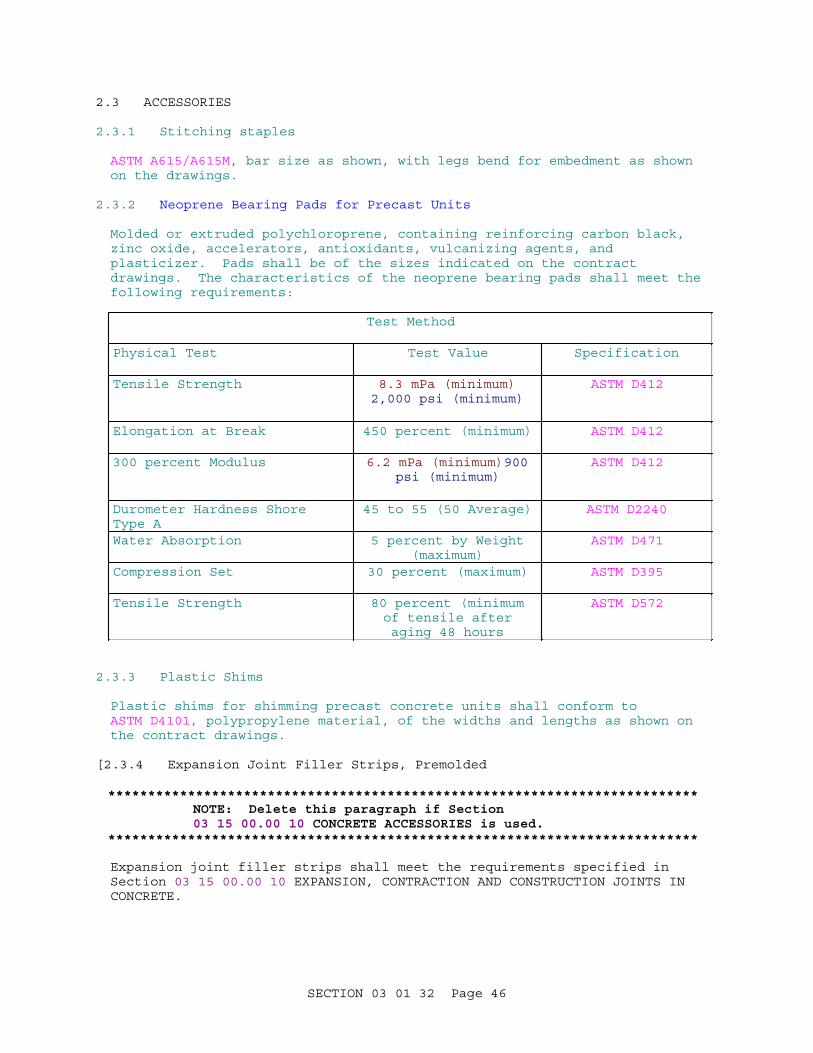
2.3 ACCESSORIES
2.3.1 Stitching staples
ASTM A615/A615M, bar size as shown, with legs bend for embedment as shown on the drawings.
2.3.2 Neoprene Bearing Pads for Precast Units
Molded or extruded polychloroprene, containing reinforcing carbon black, zinc oxide, accelerators, antioxidants, vulcanizing agents, and plasticizer. Pads shall be of the sizes indicated on the contract drawings. The characteristics of the neoprene bearing pads shall meet the following requirements:
Test Method
Physical Test Test Value Specification
Tensile Strength 8.3 mPa (minimum)2,000 psi (minimum)
ASTM D412
Elongation at Break 450 percent (minimum) ASTM D412
300 percent Modulus 6.2 mPa (minimum)900psi (minimum)
ASTM D412
Durometer Hardness Shore Type A
45 to 55 (50 Average) ASTM D2240
Water Absorption 5 percent by Weight(maximum)
ASTM D471
Compression Set 30 percent (maximum) ASTM D395
Tensile Strength 80 percent (minimumof tensile afteraging 48 hours
ASTM D572
2.3.3 Plastic Shims
Plastic shims for shimming precast concrete units shall conform to ASTM D4101, polypropylene material, of the widths and lengths as shown on the contract drawings.
[2.3.4 Expansion Joint Filler Strips, Premolded
**************************************************************************NOTE: Delete this paragraph if Section 03 15 00.00 10 CONCRETE ACCESSORIES is used.
**************************************************************************
Expansion joint filler strips shall meet the requirements specified in Section 03 15 00.00 10 EXPANSION, CONTRACTION AND CONSTRUCTION JOINTS IN CONCRETE.
SECTION 03 01 32 Page 46

]2.4 MIXTURE PROPORTIONING
2.4.1 Cement-Based Concrete
Mixes for cement-based concrete shall be in accordance with paragraph DESIGN REQUIREMENTS and the applicable provisions of Section [03 30 00.00 10 CAST-IN-PLACE CONCRETE] [03 31 01.00 10 CAST-IN-PLACE STRUCTURAL CONCRETE FOR CIVIL WORKS] [Section 03 30 53 MISCELLANEOUS CAST-IN-PLACE CONCRETE]. Approved batch tickets shall be furnished for each load of ready-mixed concrete.
2.4.2 Fiber-Reinforced Concrete
Mixtures for fiber-reinforced concrete shall be in accordance with ASTM C1116/C1116M, paragraph DESIGN REQUIREMENTS and the applicable provisions of Section [03 30 00.00 10 CAST-IN-PLACE CONCRETE] [03 31 01.00 10 CAST-IN-PLACE CONCRETE FOR CIVIL WORKS] [Section 03 30 53 MISCELLANEOUS CAST-IN-PLACE CONCRETE].
2.4.3 Dry-Pack Mortar
**************************************************************************NOTE: For severe conditions, the water-cementitious materials ratio may need to be 0.40 or less. Dry-pack mortar may be polymer-modified when appropriate.
**************************************************************************
Prepare mortar consisting of one part portland cement, three parts fine sand which passes a No. 16 sieve, [polymer proportioned as recommended by the manufacturer, ]and only enough water so the mortar will stick together in a ball when molded by hand. The water-cementitious materials ratio shall not be greater than [0.45] [_____] by weight. Let mortar set 1/2 hour prior to placing.
2.4.4 Polymer-Modified Mortar
Polymer-modified mortar shall consist of portland cement, fine aggregate, water, and polymer. Proportion mortar in accordance with polymer manufacturer's recommendations. Cured mortar shall comply with the requirements of paragraph REPAIR MATERIAL PERFORMANCE REQUIREMENTS.
2.4.5 Polymer-Modified Concrete
Polymer-modified concrete shall consist of portland cement, fine and coarse aggregate, water, and polymer. Proportion concrete in accordance with polymer manufacturer's recommendations. Cured concrete shall comply with the requirements of paragraph REPAIR MATERIAL PERFORMANCE REQUIREMENTS. Polymer-modified concrete for overlays shall conform to ACI 548.4.
2.4.6 Precast Concrete Units
**************************************************************************NOTE: Consider use of harder aggregates and pozzolan in the design of precast concrete to assure that the units are durable and abrasion resistant.
**************************************************************************
Cement for precast concrete may be Type I portland cement or Type III high
SECTION 03 01 32 Page 47

early strength portland cement in accordance with ASTM C150/C150M. If using Type III cement, make all necessary adjustments pursuant to ACI requirements to assure the dimensional stability of the units.
2.4.7 Cement-Based Grout
Cement-based grout shall consist of equal parts of Type [I or II], [III] portland cement [and] sand by dry weight, [and water-reducing admixture, ]thoroughly mixed with water to yield a thick, creamy mixture. The water-cementitious materials ratio shall not be greater than 0.45 by weight. The sand shall meet the requirements of the fine aggregate specified herein, except 100 percent shall pass a 2.36 mm No. 8 sieve.
2.4.8 Ultra-fine Cement Grout
Proportion the ultra-fine cement grout to eliminate shrinkage. The water/cement ratio shall be by volume and shall not exceed manufacturer recommendations for the required strength. Proportion the grout to limit bleed water. The final bleeding in accordance with ASTM C940 shall be less than 2 percent. The expansion in accordance with ASTM C940 shall be 0 to 5 percent. Mix the ultra-fine cement using a high shear colloidal mixer.
PART 3 EXECUTION
3.1 PROTECTION
3.1.1 Protection of Existing Features
Before beginning any concrete removal work, carefully survey the structure and examine the drawings and specifications to determine the extent of the work. Take all necessary precautions to insure against damage to existing concrete or other structures to remain in place, and repair or replace any damage to such items as approved by the Contracting Officer at no additional cost to the Government. Carefully coordinate the work of this section with all other work, and construct and maintain shoring, bracing and supports, as required. Insure that structural elements are not overloaded, and increase structural supports or add new supports as may be required as a result of any removal work performed under any part of this contract.
3.1.2 Protection of Personnel
Insure that adequate measures are in place to protect workers, facility operation personnel and the public from injury due to the operations being performed. Provide protective measures in accordance with EM 385-1-1.
3.2 REMOVAL OF EXISTING CONCRETE
**************************************************************************NOTE: Depending on the method of concrete removal and the condition of the existing concrete, microfracturing may occur beyond the removal limits. Additional concrete removal by other methods such as hand-held breakers, bushhammering, or high-pressure water may be required to remove some of the microfractured concrete.
**************************************************************************
SECTION 03 01 32 Page 48

3.2.1 General
Prepare a demolition plan describing the methods and equipment to be used to remove existing concrete. Remove the existing concrete in the area to be repaired to the minimum depth indicated and to such additional depth where necessary to expose a surface of sound, unweathered concrete that is uncontaminated by oils, greases, or deicing salts or solutions. The actual depth of removal shall be subject to approval by the Contracting Officer. Remove concrete with care to avoid damage to adjacent structures and concrete that is not to be repaired under this contract and embedded metal that is not to be removed. Repair any such damage at no additional cost to the Government. Mark on the surface the limits of concrete removal for approval by the Contracting Officer prior to any removal. Do not remove metal and other embedded items exposed during the concrete removal operations without authorization of the Contracting Officer. Unless otherwise indicated, continue removal using appropriate equipment to remove unsound concrete and to eliminate any offsets in the area to be repaired which would cause an abrupt change in thickness of the repair and to remove protrusions between holes. Variations in the final prepared surface shall not exceed the nominal maximum size aggregate of the repair material, except for relatively thin repairs in which case the variation shall not exceed 25 percent of the repair thickness. Any removal beyond the limits shown on the drawings shall be approved by the Contracting Officer prior to performing the additional removal. All equipment and removal methods shall comply with applicable sections of EM 385-1-1.
3.2.1.1 Determination of Removal Limits
Approximate locations and areas of repairs are indicated on the drawings. Determine actual locations and limits of deteriorated concrete by visual inspection and by tapping with a hammer or steel rod and listening for dull or hollow sounds. On horizontal surfaces, a chain drag may be used in lieu of the hammer or rod. Perform sounding in the presence of the Contracting Officer or authorized representative. Mark areas where sounding does not produce a solid tone with highly visible paint. After the investigation process is completed, the Contracting Officer will inspect the areas marked by the Contractor to confirm and/or adjust the limits of removal. Do not remove concrete from these areas until the Contracting Officer or authorized representative approves the areas. Upon completion of removal, sound the surface and remove additional concrete until testing produces a solid tone. Additional removal of concrete within these areas will be measured for payment as specified.
3.2.1.2 Perimeter Saw Cut
**************************************************************************NOTE: In general, the minimum depth of saw cut should be the nominal maximum size coarse aggregate.
**************************************************************************
Make a perpendicular saw cut at least [25] [50] [_____] mm [1] [2] [_____] inches deep, but no deeper than the reinforcing steel, a minimum of [25] [_____] mm [1] [_____] inch outside of the area to be repaired to delineate the perimeter of the repair area and avoid feather edges. The perimeter saw cut shall have no angles less than 90 degrees. Exercised care not to cut through existing steel reinforcement or embedded metal that is not to be removed. Omit saw-cutting where prohibited by existing metal or other items which are not to be removed. Perform sawing in accordance with CSDA-W-104, except as specified herein. Edges of repaired areas which are
SECTION 03 01 32 Page 49

not mechanically anchored shall be dove-tailed. Where concrete is being removed from a vertical face by controlled blasting, mechanical presplitting, or expansive agents, sawcut the bottom limit of the removal area to the full depth of the removal.
3.2.1.3 Preliminary Surface Cleaning
**************************************************************************NOTE: Where the depth of removal exceeds the anticipated depth of contamination, removal of such contamination prior to removal of the concrete is not normally necessary. Where depth of removal is shallow or where the removal methods may result in spreading of contamination or contamination of exposed concrete surfaces, the contaminants must be remove prior to removal of the concrete.
**************************************************************************
Clean concrete surfaces that are contaminated with oil, grease or dirt prior to beginning concrete removal in the area. Use detergents, proprietary cleaners formulated for removal of contaminants from concrete, or steam cleaning in accordance with the manufacturer's written instructions. Do not use solvents for removal of oil or grease. All traces of cleaning agents and contaminants shall be removed from the surface.
3.2.1.4 Reinforcing Steel
**************************************************************************NOTE: The deterioration point at which reinforcing steel must be replaced should be made by a structural engineer and should consider the function of the reinforcing steel (i.e. temperature vs. tension). If the referenced specification is not included in the project specification, applicable portions should be inserted here.
**************************************************************************
Following the concrete removal operation, inspect the condition of all exposed reinforcing bars designated to remain in place. Remove and replace bars which are deteriorated at any point where the original cross section of any bar has been reduced by more than [25] [_____] percent or the original cross section of adjacent bars has been reduced by more than [20] [_____] percent. Splice new replacement steel in accordance with the provisions of ACI 318MACI 318. Secure to adjacent bars all reinforcing steel that is free to vibrate or otherwise move excessively. Concrete reinforcement shall conform to Section 03 20 00.00 10 CONCRETE REINFORCING. Where the bond between the concrete and any reinforcing steel has been destroyed, or where the concrete deterioration is caused by corrosion of the reinforcing steel, remove the adjacent concrete to a depth that will permit cleaning of the steel and bonding of the concrete. Provide a minimum clearance below the steel of 25 mm 1 inch or 6 mm 1/4 inch plus the maximum size of aggregate in the repair material, which ever is greater, clearance around the steel, except where other reinforcing steel makes this impractical. Use chipping hammers weighing less than 7 kg 15 pounds, abrasive water cutting, or high-pressure water for removal of concrete around reinforcing steel. Remove all corrosion from reinforcing steel by sandblasting.
SECTION 03 01 32 Page 50
3.2.1.5 Shallow Repairs
For shallow repairs that do not require reinforcing steel, remove the existing concrete to a minimum depth of [50] [_____] mm [2] [_____] inches below the finished surface and to such additional depth where necessary to expose a surface of sound, unweathered concrete that is uncontaminated by oils, greases, or deicing salts or solutions. Remove all loose and deteriorated concrete from the spalled areas indicated.
3.2.2 Cutting
3.2.2.1 General
Use cutting to remove segments of concrete intact or to define the limits of removal by other methods.
[3.2.2.2 Abrasive-Water-Jet Cutting
**************************************************************************NOTE: EM 1110-2-2002 does not consider abrasive-water-jet cutting to be cost effective when compared to diamond blade cutting. This method should only be used when unique project conditions require its use.
**************************************************************************
Perform abrasive-water-jet cutting by injecting abrasive material into a high pressure stream of water. The water pressure shall be 200 to 340 MPa 30,000 to 50,000 psi. Adjust the water pressure and amount of abrasive added as required to provide optimum cutting action.
]3.2.2.3 Diamond-Blade Cutting
Use diamond-blade cutting for cutting through relatively thin sections and defining limits of removal to be performed by other methods. Perform diamond blade cutting using equipment of the correct type and power and with appropriate blade composition for the material being cut. Use a track system for maintaining the alignment of the saw for vertical cuts or where multiple cuts are required for deep cuts. Provide supports as required to support the concrete to be removed. [Core drill corners of removal area or use corner saw to avoid overcutting.]
3.2.2.4 Diamond-Wire Cutting
Perform diamond wire cutting using equipment of the correct type and power using continuous loop cable with appropriate diamond beads for the material being cut. Core drill holes at corners of removal section to the accuracy required for the wire cutting. Provide supports as required to support the concrete to be removed.
3.2.2.5 Stitch Drilling
**************************************************************************NOTE: Rotary-percussion drilling is more efficient for unreinforced concrete. Core drilling may be required for reinforced concrete or where the vibration of rotary-percussion drilling may cause damage to adjacent structures or equipment.
**************************************************************************
SECTION 03 01 32 Page 51

Drill overlapping holes of appropriate size along the removal line. Unless otherwise indicated, drill holes using rotary-percussion or core drilling equipment. Utilize guides as required to maintain alignment. Provide supports as required to support the concrete to be removed.
3.2.3 Impacting
Removal of concrete may be accomplished by use of impact-type power tools. Take adequate precautions to prevent impact equipment from vibrating on reinforcing steel. All demolition equipment shall be subject to approval of the Contracting Officer.
3.2.3.1 Vehicle-Mounted Breaker
**************************************************************************NOTE: Vehicle-mounted breakers may result in microfracture damage of the concrete which remains. Additional concrete removal by other methods such as hand-held breakers or high-pressure water may be required to remove some of the microfractured concrete.
**************************************************************************
Use boom or vehicle mounted impact breakers or spring-action hammers or drop balls to remove concrete in relatively thin sections or to break up concrete which has been separated from the structure by other methods.
3.2.3.2 Hand-Held Breaker
Use hand-held breakers or chipping hammers for removal of concrete in small or restricted areas, where the energy to be applied is limited to prevent damage to adjacent concrete, structures or facilities which are not to be removed, and to complete removal where other methods have been used.
3.2.4 Milling
3.2.4.1 Hydromilling
Remove concrete from vertical or horizontal surfaces by means of high pressure water applied though nozzles attached to a remotely-controlled device or beam. Adjust water pressure and rate of movement as required to remove concrete to the required depth and avoid excessive removal. Supplement hydromilling with abrasive water-jet, high-pressure wand, or other methods in areas not accessible to the hydromilling equipment. Submit proposed hydromilling equipment and procedures to the Contracting Officer for review and approval before beginning work. Remove slurry from the prepared surface before it hardens.
3.2.4.2 Rotary Head Milling
Use rotary head milling for uniform depth removal on horizontal or vertical surfaces. Use boom-mounted milling head for vertical surfaces. When operating rotary head equipment from top of wall for removal from vertical surfaces, provide communication between observer and operator to aid in control of removal.
SECTION 03 01 32 Page 52

3.2.5 Presplitting
**************************************************************************NOTE: Presplitting only separates the concrete. Other measures must be employed to remove reinforcing steel and other embedded items. Hole spacing and diameter are critical to proper development of the presplit plane. A test break should be performed to verify the proposed procedure.
**************************************************************************
3.2.5.1 Expansive Agents
Use an expansive compound, manufactured for concrete and rock demolition. Drill holes, including relief holes, of the size and at the spacing recommended by the manufacturer. Mix and place the material in accordance with the manufacturer's recommendations. Insert closed-end plastic tubes into each hole prior to placing the expansive material to prevent dilution of the material and to prevent slurry from entering existing cracks.
3.2.5.2 Mechanical Presplitting
Drill holes of size and spacing as recommended by the manufacturer for the conditions present. Insert and operate mechanical splitters in accordance with the manufacturer's instructions.
3.2.6 Controlled Blasting
**************************************************************************NOTE: Blasting may result in microfracturing of the concrete which remains. Additional concrete removal by other methods such as hand-held breakers or high-pressure water may be required to remove some of the microfractured concrete.
**************************************************************************
3.2.6.1 General
Controlled blasting shall consist of a systematic process of sawcutting, drilling, loading and blasting to break the concrete on a controlled plane. Submit a detailed blasting plan for blasting, safety, and traffic controls for approval at least [30] [60] days prior to performance of any blasting and for each individual blast for approval at least 24 hours prior to drilling for the blast. The blasting plan shall state location, number of holes, size, depth, spacing, loading of individual holes, type of explosives, time delay sequences, and seismographic monitoring to be performed. The plan shall also address coordination with highway, railroad and river traffic, project personnel and the public as applicable. All use of explosives shall be subject to prior approval of the Contracting Officer. Do not deviate from the approved plan without authorization of the Contracting Officer. After blasting, submit an "as-built" blasting plan showing any approved changes. Approval of the Contractor's blasting plan shall not relieve him of responsibility for any damages or injuries resulting from blasting.
3.2.6.2 Safety
Handle, store, and use explosives in accordance with applicable provisions of the EM 385-1-1 and state and local regulations. All blasting work shall
SECTION 03 01 32 Page 53

be at the risk and responsibility of the Contractor. Conduct all blasting operations with due regard to the safety of persons in the vicinity and traffic passing the site. Make provisions for warning personnel and traffic in advance of blasting.
3.2.6.3 Procedure
**************************************************************************NOTE: The suggested peak particle velocity applies to concrete adjacent to structures which are to remain. The permissible peak particle velocity should be determined based on the existing materials and conditions to avoid damage to structures and equipment to remain.
**************************************************************************
Determining the diameter, depth and spacing of holes, and loading, delays and stemmings for explosives. Drill holes with equipment competent to maintain the alignment and plane of the drill hole pattern throughout the full depth of the holes. Limit extent of blasting area and use delays as required, to prevent damage to the structure. Peak particle velocity shall not exceed [50] [_____] mm [2] [_____] inches per second. Airblast pressure shall not exceed 0.7 kPa 0.1 psi. Should vibration exceed the specified limits, modify the blasting plan as required, subject to approval by the Contracting Officer. Use detonating cord as explosives. Use blasting mats as necessary to control flyrock and contain debris.
3.2.6.4 Preblasting and Postblasting Inspections
Perform a preblast and postblast inspection of all structures within [180] [_____] meters [600] [_____] feet of the blasting operations. The inspection shall include preblast and postblast notes, diagrams, and/or tape recorded descriptions of defects in interior walls, ceilings, floors and foundations; photographs and/or videotape recordings of all prominent interior and exterior cracks; notes on walkways, retaining walls, accessible roofs, chimneys, and similar features. Complete the preblast inspection prior to the beginning of any blasting. Complete the postblast inspection immediately upon cessation of all blasting. Notify the Contracting Officer in writing a minimum of [7] [_____] days in advance of the inspections.
3.2.6.5 Vibration Monitoring
Perform vibration monitoring by placing recording devices on adjacent structures as indicated on the drawings. Modifications to the monitoring procedure may be directed by the Contracting Officer. In order to control blasting vibrations within specified limits, provide the services of an approved commercial vibration-testing laboratory. Submit seismographic monitoring records and written interpretations of such to the Contracting Officer within 48 hours, except that in the event that any record or records indicate the potential for damage or imminent danger, make an immediate verbal report and remedial recommendation. The vibration monitoring record shall include the following minimum data:
a. Date and time of blast.b. Location of seismological instruments, manufacture and Model No.c. Velocity measured in mm inches per second in vertical, longitudinal and
transverse directions.d. Displacement measured in mm inches.
SECTION 03 01 32 Page 54

e. Acceleration measured in mm inches per second squared.f. Energy ratio computation.g. Peak particle velocity.
3.3 ANCHORING AND REINFORCING
**************************************************************************NOTE: For core drilled holes, use epoxy grout only.
**************************************************************************
3.3.1 Drilling and Grouting Dowels and Anchors
Drill holes for dowels and anchors using drilling equipment suitable for the intended purpose, as approved by the Contracting Officer. Diameter of holes shall be [as shown on the drawings] [as recommended by the adhesive manufacturer]. Clean holes by flushing with water and compressed air prior to placing grout. Anchor [dowels] [anchors] with [epoxy grout], [polyester resin grout], [polyester resin grout cartridges] [or] [cement-based grout]. Place grout and install [dowels] [and] [anchors] as recommended by the grout manufacturer. Remove excess grout after the [dowel] [or] [anchor] has been set in place. [When installing resin cartridges or capsules in submerged conditions, place properly proportioned resin material in bottom of hole using a mixing tube prior to inserting the cartridge or capsule.]
3.3.2 Drilling and Installing Mechanical Anchors
Drill holes for anchors using drilling equipment suitable for the intended purpose, as approved by the Contracting Officer. Diameter of holes shall be [as shown on the drawings] [as recommended by the anchor manufacturer]. Clean holes by flushing with water and compressed air prior to placing grout. Install anchors and set anchors in place in accordance with the manufacturer's recommendations.
3.3.3 Installing Reinforcement
**************************************************************************NOTE: If the referenced specification is not included in the project specification, applicable portions should be inserted here.
**************************************************************************
Place reinforcement steel and accessories as specified and as shown on the contract drawings. Placement details of steel and accessories not specified or shown on the drawings shall be in accordance with ACI SP-66 and ACI 318MACI 318 or as directed by the Contracting Officer. Fabricate and place reinforcing steel in accordance with 03 20 00.00 10 CONCRETE REINFORCING.
3.4 MIXING MATERIALS
Make batches small enough to ensure placement before binder sets. Mix materials in accordance with manufacturer's recommendations.
3.5 SURFACE PREPARATION
**************************************************************************NOTE: For additional guidance on surface preparation, see International Concrete Repair
SECTION 03 01 32 Page 55

Institute Guidelines No. 03732 "Selecting and Specifying Concrete Surface Preparation for Sealers, Coatings, and Polymer Overlays".
**************************************************************************
3.5.1 General
After removal of concrete to the specified limits, clean the surface to which the repair material is to be applied to remove dust, debris and laitance. Perform final cleaning immediately prior to placement of the repair material. Unless otherwise specified, keep the existing concrete wet for a minimum of 12 hours and dried for 12 hours immediately prior to placing new concrete. The surface shall be dry with no standing water on the surface upon which concrete is placed.
3.5.2 Cleaning
**************************************************************************NOTE: If the referenced specification is not included in the project specification, applicable portions should be inserted here.
**************************************************************************
Perform all cleaning operations to the satisfaction of the Contracting Officer. Protect adjacent structures and embedded items. Use potable water for all cleaning operations. Perform a preliminary washing as soon as the chipping and trimming are completed to remove loose materials and dust particles. Clean surfaces to which new concrete is to be bonded in accordance with Section 03 31 01.00 10 CAST-IN-PLACE STRUCTURAL CONCRETE FOR CIVIL WORKS, paragraph CONSTRUCTION JOINT TREATMENT. Final cleaning shall remove all laitance, carbonation, scum, dirt, oil, grease, and loose or disintegrated concrete. Perform additional surface chipping to remove coarse aggregate that is undercut by cleaning process. Perform such additional chipping as determined necessary by the Contracting Officer at no additional cost to the Government. Wire brush or sandblast metal surfaces against which concrete is to be placed to remove rust and other contaminants which would prevent proper bond with the concrete. Perform final cleaning immediately prior to concrete placement. Protect all work from contamination during all phases of cleanup and preparation prior to repair.
3.5.3 Waste Water Disposal
Dispose of waste water employed in cutting, washing, and rinsing of concrete surfaces in a manner such that the waste water does not stain, discolor, or affect exposed surfaces of the structures, or damage the environment of the project area. The method of disposal shall meet all requirements of Section 01 57 20.00 10 ENVIRONMENTAL PROTECTION.
3.6 SURFACE REPAIRS
**************************************************************************NOTE: Dry-pack mortar is also typically used for small spalled areas with high depth to surface area ration. Polymer-modified mortar, polymer-modified concrete and cement-based concrete are typically used for larger repair areas.
**************************************************************************
SECTION 03 01 32 Page 56

Place dowels and anchors as shown on the contract drawings. [Construct formwork in accordance with Section 03 11 13.00 10 STRUCTURAL CAST-IN-PLACE CONCRETE FORMING.]
3.6.1 Epoxy Mortar
Prime surfaces with epoxy resin binder. Scrub prime coat into surface with a stiff bristle brush. Make coating approximately 0.5 mm 20 mils thick. Place epoxy mortar while primer is still tacky. Apply at a thickness recommended by the manufacturer. Work mortar into place and consolidate thoroughly so that contact surfaces are wetted by the mortar. Finish surface of mortar to the required texture. Do not feather edge epoxy mortar onto adjacent surfaces.
3.6.2 Epoxy Concrete
**************************************************************************NOTE: Do not place epoxy concrete in layers greater than 25 mm (one inch) in thickness. This is to avoid heat buildup and subsequent thermal contraction.
**************************************************************************
Prime dry cavity surfaces with epoxy resin using a stiff bristle brush. Make coating approximately 0.5 mm 20 mils thick. Place epoxy concrete while primer is still tacky and in layers not exceeding 25 mm one inch thick. Use vibratory floats, plates, or hand tampers to consolidate the concrete. Level each layer and screed the final surface to match the adjoining surfaces. Remove excess epoxy concrete on adjacent surfaces before the concrete hardens. Do not feather epoxy concrete out onto adjacent surfaces.
3.6.3 Polymer-Modified Mortar or Concrete
3.6.3.1 Horizontal Surfaces
Prime surfaces prepared to receive repair material using the manufacturer's recommended bonding agent using a stiff bristle brush and in accordance with the manufacturer's instructions. Place polymer-modified concrete before the bonding agent dries and in layers not exceeding 25 mm one inch thick for mortar and 50 mm two inches thick for concrete. Moist cure polymer-modified material for a minimum of 24 hours but not more than 48 hours, and then air dry.
3.6.3.2 Vertical Surfaces
For vertical surfaces that are troweled follow the procedure for horizontal surfaces. For formed vertical surfaces follow the procedure for cement-based concrete for vertical surfaces. Moist cure polymer-modified material for a minimum of 24 hours but not more than 48 hours, and then air dry.
3.6.4 Dry-Pack Mortar
Prime surfaces prepared to receive repair material with a cement-based grout, an epoxy resin meeting the requirements of paragraph EPOXY RESIN, or a latex bonding agent meeting the requirements of paragraph LATEX BONDING COMPOUND. For cement-based grout, dampen the area with water prior to applying the grout. Place the mortar immediately after applying the
SECTION 03 01 32 Page 57

bonding agent. Place mortar in approximately 10 mm 3/8-inch lifts, compact each lift thoroughly with a blunt stick or hammer, and scratch the surface to promote bonding with subsequent lifts. Place consecutive layers continuously. Finish the top layer flush with the surrounding concrete and cure with saturated burlap or curing compound.
3.6.5 Cement-Based Mortar or Concrete
**************************************************************************NOTE: When formwork prevents application of bonding agents in a timely manner, new concrete should be applied directly to the existing concrete. Bonding agent should not be used when the concrete placement exceeds 3 inches in thickness.
Placement through a chimney at the top of the form is the preferred method of placement. Internal vibration should be used unless conditions prevent proper operation, in which case external vibration may be used.
Delete the options for form and pump placement and external vibration unless placement through a chimney is not possible and/or external vibration is permitted.
If the referenced specifications are not included in the project specification, applicable portions should be inserted here.
**************************************************************************
[For vertical surfaces, construct forms with a chimney at top for placement and consolidation of concrete.] [Prime surfaces prepared to receive repair material, using a cement-based grout meeting the requirements of paragraph Cement-Based Grout, an epoxy resin meeting the requirements of paragraph EPOXY RESIN, or a latex bonding agent meeting the requirements of paragraph LATEX BONDING COMPOUND. For cement-based grout, dampen the area with water prior to applying the grout. Place the concrete immediately after applying the bonding agent.] Place, consolidate and finish concrete in accordance with applicable requirements of Section [03 30 00.00 10 CAST-IN-PLACE CONCRETE] [ 03 31 01.00 10 CAST-IN-PLACE STRUCTURAL CONCRETE FOR CIVIL WORKS] [Section 03 30 53 MISCELLANEOUS CAST-IN-PLACE CONCRETE]. [Use form and pump method of placement where placement through a form chimney is not possible. Inspect concrete surfaces to ensure that no areas remain which would trap air between the new and existing concrete. Make forms grout tight and brace to withstand pumped concrete pressures. Provide vents to release air from within the forms as concrete is placed. Pump concrete into form using variable output pump of appropriate size.] [Use external vibration only where internal vibration is not possible. After the cavity is filled with concrete, install a pressure cap at the form chimney and apply pressure while the form is vibrated.] [Remove chimney projection after 24 hours.] Cure in accordance with Section [03 30 00.00 10 CAST-IN-PLACE CONCRETE] [03 31 01.00 10 CAST-IN-PLACE STRUCTURAL CONCRETE FOR CIVIL WORKS] [Section 03 30 53 MISCELLANEOUS CAST-IN-PLACE CONCRETE].
3.6.6 Spalls at Joints and Cracks
**************************************************************************NOTE: If the referenced specification is not
SECTION 03 01 32 Page 58
included in the project specification, applicable portions should be inserted here.
**************************************************************************
For spalls to be repaired that are adjacent to joints and working cracks insert preformed joint filler to the working faces of the spall. Trim filler to fit shape of the working faces of joint or crack so repair material is prevented from bypassing filler. Where practicable, extend filler horizontally and vertically into joint or crack opening. Secure filler strip in place prior to and during placement of repair material. [Apply a bond breaker to working faces at keyed joints. Keep bond breaker off of concrete surface to be bonded.] After the repair material has completely cured, saw out the top 25 mm inch of the preformed joint filler and install joint sealant in accordance with Section 03 15 00.00 10 CONCRETE ACCESSORIES.
3.6.7 Rapid-Hardening Repair Material
Mix and place material in accordance with the manufacturer's recommendations.
3.7 CRACK REPAIR
3.7.1 Routing and Sealing
**************************************************************************NOTE: Surface sealing is not effective for active cracks. The minimum width of the prepared crack should be 6 mm (1/4 inch).
**************************************************************************
3.7.1.1 Preparation
Clean cracks by saw cutting or routing to provide the proper profile for sealants. After the crack is sawcut or routed, clean the surfaces by sandblasting and/or waterjetting. Adjust the height, angle of inclination and the size of the nozzle as necessary to provide satisfactory results. Provide protective covers and barriers as required to prevent over-spray onto adjacent surfaces. Remove dust, dirt and loosely bonded materials resulting from cleaning. Ensure surfaces are dry before application of repair material. Apply bond breaker to the bottom of the routed or sawed crack. Where cracks extend through surfaces to be repaired, make the repair first and then tool, rout or saw the original line of the cracks into the repaired area.
3.7.1.2 Rate of Progress
Limit the stages of crack sealing, which includes preparation and placement of bond breaker, so only that length of crack that can be sealed during the same workday is prepared.
3.7.1.3 Time of Application
Seal prepared cracks immediately following the cleaning and drying process. Walls of the prepared crack shall be surface dry, and the atmospheric and concrete temperatures shall be above 10 degrees C 50 degrees F at the time of application of the sealant. Provide an approved temporary seal for open routed cracks that cannot be sealed under the conditions specified.
SECTION 03 01 32 Page 59

3.7.1.4 Sealing
Do not apply sealant until the prepared cracks have been inspected and approved. [Place masking tape on the finish surface on one or both sides of a crack cavity to protect adjacent finish surfaces from primer or sealant smears. Remove masking tape within 10 minutes after crack has been filled and tooled.] Fill the cracks from the bottom up and tool the top surface as indicated or as recommended by the manufacturer. Apply sealant as recommended by the manufacturer.
3.7.1.5 Preformed Compression Seals
Rout or cut the crack to the dimensions indicated. Install the seals with equipment that is capable of installing joint seals to the prescribed depth without cutting, nicking, twisting, or otherwise distorting or damaging the seal and with no more than five percent stretching of the seal. Cover the sides of the crack and, if necessary, the sides of the compression seal with a coating of lubricant, and install the seal to the depth indicated with joint installation equipment. Coat butt joints with liberal applications of lubricant.
3.7.2 Filling Cracks with Grout or Mortar
**************************************************************************NOTE: Filling cracks is not effective for active cracks. The prepared crack should be minimum 25 mm (1 inch) wide and 25 mm (1 inch) deep.
**************************************************************************
3.7.2.1 Preparation
Clean cracks by saw cutting or routing to provide the proper profile for sealants. After the crack is sawcut or routed, clean the surfaces by sandblasting and/or waterjetting. Adjust the height, angle of inclination and the size of the nozzle as necessary to provide satisfactory results. Provide protective covers and barriers as required to prevent over-spray onto adjacent surfaces. Remove dust, dirt and loosely bonded materials resulting from cleaning. Dry surfaces to receive repair material as recommended by the grout or polymer manufacturer.
[3.7.2.2 Epoxy Grout
Apply epoxy grout at a thickness recommended by the manufacturer. Work grout into place and consolidate thoroughly so that contact surfaces are wetted by the grout. Finish surface of grout to the required texture. Do not feather edge epoxy grout onto adjacent surfaces.
]3.7.2.3 Dry-Pack Mortar
Coat the surfaces of the crack with a slurry consisting of equal parts portland cement and fine sand mixed with water to a fluid paste consistency. Place the mortar immediately after applying the slurry. Place mortar in approximately 10 mm 3/8-inch lifts, compact each lift thoroughly with a blunt stick or hammer, and scratch the surface to promote bonding with subsequent lifts. Place consecutive layers continuously. Finish the top layer flush with the surrounding concrete and cure with saturated burlap or curing compound.
SECTION 03 01 32 Page 60

3.7.2.4 Curing
**************************************************************************NOTE: If the referenced specifications are not included in the project specification, applicable portions should be inserted here.
**************************************************************************
Cure epoxy materials in accordance with manufacturer's recommendations. Cure dry-pack mortar in accordance with Section [03 30 00.00 10 CAST-IN-PLACE CONCRETE] [03 31 01.00 10 CAST-IN-PLACE STRUCTURAL CONCRETE FOR CIVIL WORKS] [Section 03 30 53 MISCELLANEOUS CAST-IN-PLACE CONCRETE].
3.7.3 Gravity Crack Filling
3.7.3.1 Surface Preparation
Clean concrete surfaces that are contaminated with oil, grease or dirt prior to beginning surface preparation in the area. Use only detergents or proprietary cleaners formulated for removal of contaminants from concrete, and use them in accordance with the manufacturer's written instructions. Do not use solvents for removal of oil or grease. Remove all traces of cleaning agents and contaminants from the surface and cracks. Perform final surface cleaning immediately prior to application of gravity filling in accordance with paragraph REMOVAL OF EXISTING CONCRETE, subparagraph Surface Preparation. Dry surfaces to receive repair material as recommended by the grout or polymer manufacturer.
3.7.3.2 Applying Sealer
Apply high molecular weight methacrylate sealer to prepared surfaces in accordance with manufacturer's directions. Remove excess sealer, leaving no visible surface film. Fill cracks greater than 3 mm 1/8 inch wide in accordance with sealer manufacturer's recommendations. Apply a second treatment of sealer evenly over the cracks and remove excess sealer on the surface. Cover with light broadcast of a dry masonry sand. Distribute evenly over the surface at the rate recommended by the sealer manufacturer. After a curing period of 12 hours at 23 degrees C 73 degrees F, remove any loose sand by lightly brooming.
3.7.4 Drilling and Plugging Cracks
**************************************************************************NOTE: Drilling and plugging is applicable only for cracks which are reasonably straight and accessible from one end. The hole must be large enough to intercept the crack for its entire length. If load transfer is necessary, plug the hole with grout. If watertightness is necessary, but not load transfer, plug the hole with resilient material.
**************************************************************************
Drill a [50] [75] mm [2] [3] inch diameter hole centered on the crack. Clean the hole by flushing with water and compressed air prior to placing grout. Fill the hole with [portland cement grout consisting of one part portland cement, three parts fine aggregate, and sufficient water to permit placement in the hole] [bituminous joint sealant]. Place the grout in lifts to avoid pressure from the weight of the grout causing the grout to leak through the crack at lower levels.
SECTION 03 01 32 Page 61

3.7.5 Injection Grouting Cracks
**************************************************************************NOTE: Portland cement grout is normally used to seal wide cracks, but may be used to seal cracks as narrow as 0.05 mm (0.002 inch). Ultra-fine cement grout may be used to seal cracks of a smaller size. Epoxy resin is normally used for cracks between 0.13 and 6.3 mm (0.005 and 0.25 inch) wide. Polyurethane is normally used for cracks greater than 0.13 mm (0.005 inch) wide.
The interval between valves should be greater than the thickness of the member being repaired.
**************************************************************************
3.7.5.1 Preparation
Clean each crack of dust, dirt, loose concrete and unsound material by vacuuming or flushing with water and allowing to dry to remove free water in the crack. Insert a valve at both ends of each crack, at the junction of two cracks, and along the length of each crack at [400 to 500] [_____] mm [16 to 20] [_____] inch intervals. Fill crack between valves with crack surface sealer.
3.7.5.2 Injection
After crack surface sealer has hardened and cured, pump [epoxy injection adhesive] [polyurethane injection adhesive] [ultra-fine cement grout] into valve at one end of crack. For vertical surfaces start at lowest valve and work upwards. As crack sealer appears at next valve, pinch pumping valve closed and move to next valve and commence pumping. Continue procedure until other end of crack is reached. Avoid delays in pumping operation. After crack sealer has hardened and cured grind valves off flush with concrete surface. Coat areas of valves with crack surface sealer and allow to harden and cure.
3.7.6 Crack Repair with Additional Reinforcement
**************************************************************************NOTE: Repairing cracks with additional reinforcement is used to stabilize active cracks to permit sealing and to reestablish tensile strength across cracks.
**************************************************************************
Stabilize cracks by anchoring as shown on the drawings.
3.7.6.1 Stitching
**************************************************************************NOTE: When the crack must be made watertight, one of the methods for sealing or repairing the crack should be used prior to stabilizing the crack.
**************************************************************************
Drill holes of appropriate size and depth for grouting the stitching staples and at the spacing shown on the drawings. Reduce spacing at ends
SECTION 03 01 32 Page 62

of crack. Vary the orientation and length of stitching staples to avoid applying tension to a single plane within the concrete. If the end of the crack within the structure can be determined, drill a hole at the end of the crack to relieve stress concentration. Clean the holes by flushing with water and compressed air prior to placing grout. Dry surfaces to receive grout as recommended by the grout manufacturer. Partially fill the holes with epoxy resin grout and insert the stitching staples into the holes. Place additional grout and consolidate it by rodding until remainder of the hole is filled. Place grout with the equipment capable of supplying, mixing, and placing the grout in the holes in a manner that will ensure complete filling of the holes and elimination of voids, air pockets, and water. After placing, allow the grout to set for a period of not less than 24 hours, and protect the stitching staples against damage. Remove and reset any stitching staples which are disturbed during curing.
3.7.6.2 Conventional Reinforcement
Drill holes, of a size appropriate for the reinforcement and grout used, at right angle to the crack plane, and extending a minimum of 0.45 m 18 inches on each side of the crack. Space holes as indicated on the drawings. Clean the holes by flushing with water and compressed air prior to placing grout. Insure that holes are dry before placing grout. Inject epoxy grout at a pressure sufficient to distribute the grout in the hole but not great enough to cause additional damage to the concrete. Insert reinforcing bar so that it extends at least 0.45 m 18 inches on each side of the crack. [After grout has set, seal the crack by injection grouting.]
3.7.6.3 Internal Prestressing Reinforcement
**************************************************************************NOTE: Where both sides of the structure are accessible, the prestressing steel may extend from an anchor plate on one side with the stressing head at the other side with the hole grouted after stressing. When only one side is exposed, the prestressing steel is grouted in place and stressed.
**************************************************************************
a. Drill holes of the size and depth [shown on the drawings] [recommended by the grout manufacturer] and at the location shown. Cut recess for [anchor plate and] stressing head in the concrete as shown. Clean the hole by flushing with water and compressed air prior to placing grout. Dry holes as recommended by the grout manufacturer.
b. Place [cement-based] [polymer-modified] [epoxy] grout pads [in the recess(es)] [on the face of the wall] as shown on the drawings and install the [anchor plate,] stressing plate.
c. [Install the threaded bar and nuts and tighten until snug until the grout pads have set.] [Insert the required resin cartridges into the drilled hole, taking care not to rupture the skin. Use rapid setting cartridges in the anchor zone of the bar and slower setting cartridges in the stressing zone. To avoid premature rupture of the resin cartridges it may be necessary to place them in a thin-walled tube and insert the tube in the drilled hole to the specified depth. Withdraw the tube carefully prior to insertion of the threaded bar.
d. Rotate the threaded bolt through the cartridges to end of hole in accordance with the cartridge manufacturer's recommendations in order
SECTION 03 01 32 Page 63
to rupture the skin and mix the resin. Use method, rotation time, and speed of rotation as recommended by the manufacturer and approved by the Contracting Officer.]
e. No permanent installation of threaded bars will be permitted until it is demonstrated to the satisfaction of the Contracting Officer that the anchors can be properly installed. Stress the threaded bar to [_____] KPa psi using equipment recommended by the bar manufacturer. This load is the final effective (residual) load per bar after all losses have occurred. Determine the stress load by the measurement of the threaded bar elongation and by checking pressure of the hydraulic jack. Correlation shall be within 5 percent of agreement. After stressing the threaded bar, cut the bar and fill the recess with dry-pack mortar.
3.7.6.4 External Stressing
Install anchorages as shown on the drawings. Install prestressing bars and stress in increments in accordance with the procedure shown on the drawings to avoid eccentric loads.
3.8 CLEANING AND RESEALING JOINTS
**************************************************************************NOTE: The drawings must show typical details for the joint sealing.
**************************************************************************
3.8.1 Preparation of Joints
Immediately before the installation of the sealant, thoroughly clean the joints to remove all laitance, loose or deteriorated filler, and old sealant from the sides and upper edges of the joint space to be sealed. Clean joints to sufficient depth to remove all loose material and debris and to permit placement of the backup material and sealant as shown on the drawings. Concrete surfaces shall be dry at the time of sealant application.
3.8.1.1 Existing Sealant Removal
Cut the in-place sealant and expansion joint material loose from both joint faces and to the minimum depth required to permit placement of the back-up material and sealant depth equal to one half the width of joint or as recommended by the sealant manufacturer, unless otherwise shown on the drawings, using the waterjetting equipment as specified in paragraph EQUIPMENT. Removal may be efficiently accomplished using high pressure water jet with abrasive added. Prior to further cleaning operations, remove all loose old sealant remaining in the joint opening by blowing with compressed air. Chipping, spalling, or otherwise damaging the concrete will not be permitted.[ For compression seals, sawcut the joint to the width and depth shown on the drawings.]
3.8.1.2 Sandblasting and Waterjetting
Sandblast or waterjet clean the newly exposed concrete joint faces to at least the depth of the back-up material and sealant and the concrete surfaces extending a minimum of 13 mm 1/2 inch from the joint edges. Use a multiple-pass technique until the surfaces are free of dust, dirt, filler, old sealant residue, or any foreign debris that might prevent the bonding of the sealant to the concrete. After final cleaning and immediately prior
SECTION 03 01 32 Page 64

to sealing, blow the joints out with compressed air to ensure that the joints are completely free of debris and water.
3.8.1.3 Rate of Progress of Joint Preparation
Limit the joint preparation which includes sandblasting or waterjetting, air pressure cleaning and placing of the back-up material to only that lineal footage that can be sealed during the same day.
3.8.2 Installation of Sealant
Store and apply the primer and sealant in accordance with the manufacturer's written safety instructions and precautions and using manufacturer recommended procedures.
3.8.2.1 Time of Application
Seal joints immediately following final cleaning of the joint sidewalls and following the placement of the bond breaker and back-up material. Reclean open joints that cannot be sealed under the conditions specified, or when rain interrupts sealing operations, and allowed to dry prior to installing the sealant.
3.8.2.2 Back-Up Material and Bond Breaker
Plug or seal off the lower portion of the joint opening using a back-up material to prevent the entrance of the sealant below the specified depth. Take care to ensure that the backup material is placed at the specified depth and is not stretched or twisted during installation.
3.8.2.3 Sealing Joints
Perform a final cleaning with compressed air immediately preceding, but not more than 50 feet ahead of the sealing operations. The joint surfaces shall be dry at the time the sealant is installed. Apply primer evenly to the joint faces in accordance with the manufacturer's instructions before placement of the back-up material. Place bond breaker material after the primer is applied. Fill the joints from the bottom up to the [bottom of the beveled edge] [surface of the concrete]. Depth of sealant shall be one-half the joint width or as recommended by the sealant manufacturer. [Commence sealing of joints at the bottom of the slope or wall and continue up the concrete slope or wall]. Remove excess or spilled sealant from the concrete surface by approved methods and discard. Install the sealant using a gun cartridge in such a manner as to prevent the formation of voids and entrapped air. Do not install sealant material using gravity methods or pouring pots. Check joints frequently to ensure that the newly installed sealant is cured to a tack-free condition within the time specified. Tool the sealant concave immediately after application.
[3.8.3 Installation of Preformed Compression Seals
Install the joint seals with equipment capable of installing joint seals to the prescribed depth without cutting, nicking, twisting, or otherwise distorting or damaging the seal and with no more than five percent stretching of the seal. Cover the sides of the joint and, if necessary, the sides of the compression seal, with a coating of lubricant, and install the seal to the depth indicated with joint installation equipment. Coat butt joints with liberal applications of lubricant.
SECTION 03 01 32 Page 65

]3.9 OVERLAYS
**************************************************************************NOTE: If the referenced specifications are not included in the project specification, applicable portions should be inserted here.
**************************************************************************
3.9.1 Cement-Based Concrete Overlay
**************************************************************************NOTE: When overlaying mass concrete with a relatively thin layer of cement-based concrete or where movement in the base concrete may occur, a bond breaker should be placed to prevent shrinkage and restraint cracking of the overlay due to constraint of the overlay.
**************************************************************************
Install anchors and reinforcement [and place bond breaker] as shown on the drawings. Place, consolidate, finish and cure concrete in accordance with the applicable requirements of Section [03 30 00.00 10 CAST-IN-PLACE CONCRETE] [03 31 01.00 10 CAST-IN-PLACE STRUCTURAL CONCRETE FOR CIVIL WORKS] [Section 03 30 53 MISCELLANEOUS CAST-IN-PLACE CONCRETE], except only moist curing will be permitted.
3.9.2 Polymer-Modified Concrete Overlay
Mixing, placing and curing polymer-modified concrete shall be in accordance with ACI 548.4 and the following requirements. Mix and place polymer-modified concrete only within the temperature limits recommended by the polymer manufacturer. Prime the surface with a slurry of polymer-modified mortar of the same composition as the polymer-modified concrete except for coarse aggregate. Place polymer-modified concrete before the prime coat dries. Place polymer-modified concrete within 15 minutes of addition of polymer. Moist cure overlay for not less than 24 hours nor more than 48 hours, then air dry.
3.9.3 Joints
Construct expansion and contraction joints in concrete overlay at the locations shown. Maintain alignment of control joints within 6 mm 1/4-inch, to either side, of the required joint alignment. Construct expansion and contraction joints at the locations shown and in accordance with Section 03 15 00.00 10 CONCRETE ACCESSORIES. Construct expansion joints at existing joints using preformed expansion joint material of the thickness shown and extending the full depth of the overlay. Construct control joints by tooling the plastic concrete, then sawcutting at the appropriate time. Saw control joints to a minimum [depth of [_____] mm inch(es)] [of 25 percent of the thickness of the slab]. Maintain an ample supply of saw blades on the job before concrete placement is started, and have at least one standby sawing unit in good working order available at the jobsite at all times during the sawing operations. Begin sawcutting as soon as it is possible to saw the concrete without damaging adjacent concrete. Inspect the faces of joints during sawcutting for undercutting or washing of the concrete due to early sawing. Complete sawcutting within 16 hours of concrete placement. Continue sawcutting regardless of weather conditions. Delay sawing if undercutting is sufficiently deep to cause structural weakness or excessive roughness in the joint or chipping, tearing, or
SECTION 03 01 32 Page 66

spalling of the concrete occurs at the surface. Discontinue sawing when a crack develops ahead of the saw cut. Immediately after the joint is sawed, flush the saw cut and adjacent concrete surface thoroughly with water until all residue from sawing is removed from the joint. Control and dispose of waste water from sawcutting and cleanup in accordance with Section 01 57 20.00 10 ENVIRONMENTAL PROTECTION.
3.10 REFACING VERTICAL SURFACES
3.10.1 Cement-Based Concrete
**************************************************************************NOTE: Where there is concern about placement of high lifts of refacing concrete, use the optional text concerning lift height and placement time. The permissible height of individual lifts and time limit between placing lifts should be determined by the form design to prevent overloading of the forms and to maintain required construction tolerances.
**************************************************************************
Install anchors and reinforcement as shown on the drawings. Place, consolidate, finish and cure concrete in accordance with the applicable requirements of Section [03 30 00.00 10 CAST-IN-PLACE CONCRETE] [03 31 01.00 10 CAST-IN-PLACE STRUCTURAL CONCRETE FOR CIVIL WORKS] [Section 03 30 53 MISCELLANEOUS CAST-IN-PLACE CONCRETE] [Section 03 37 13 SHOTCRETE]. Do not place concrete when, in the opinion of the Contracting Officer, weather conditions prevent proper placement, consolidation, and curing. [In order to prevent overloading of forms, place concrete systematically in lifts not to exceed [1.3] [_____] m [4] [_____] feet, across the complete placement area. Place the next lift no sooner than [4] [_____] hours from the time that the first lift is placed.] Deposit concrete as close as possible to its final position in the forms, and in so depositing do not permit a vertical drop greater than 1.5 m five feet except where suitable equipment is provided to prevent segregation and where specifically authorized. Regulate depositing of the concrete so that it may be effectively consolidated in horizontal layers 600 mm 2.0 feet or less in thickness with a minimum of lateral movement. Deposit in each location only that amount of concrete that can be readily and thoroughly consolidated. Thoroughly distribute and consolidate concrete around embedded items, assuring that no air pockets occur behind vertical items. Provide sufficient placing capacity so that concrete can be kept plastic and free of cold joints while concrete is being placed.
3.10.2 Preplaced-Aggregate Concrete
Install anchors and reinforcement as shown on the drawings. Place, consolidate, finish and cure concrete in accordance with the applicable requirements of Section 03 37 00 PREPLACED-AGGREGATE CONCRETE.
3.10.3 Precast Concrete Units
Prepare base and install anchors as shown on the drawings. Fabricate precast concrete units in accordance with Section 03 45 33 PRECAST [PRESTRESSED] STRUCTURAL CONCRETE. Cure by steam at atmospheric pressure only.
SECTION 03 01 32 Page 67

3.10.3.1 Erection of Precast Units
a. Erect precast units in accordance with the details shown on the approved shop drawings and erection plan for precast units, alignment plan for precast units, approved revisions to the approved plans resulting from the precast unit assembly test, and in accordance with Section 03 45 33 PRECAST [PRESTRESSED] STRUCTURAL CONCRETE.
b. Submit a detailed erection plan at least [30] [60] days prior to the date that erection of precast units is to begin. This plan shall be in sufficient detail so that adequacy of equipment, techniques and accessories can be determined and comments offered. The plan shall include design calculations for loading and deflection on the precast units. Acceptance of the Contractor's erection plan shall not relieve the Contractor of its responsibility for erecting the precast units into position as required by the contract drawings, and these specifications. The plan shall include the procedure of placing the infill concrete, including the positioning of hoppers and chutes, and all forming techniques to be employed.
c. Submit a detailed plan for aligning precast units to the alignment and profile indicated on the contract drawings. Identify all safety and quality control aspects for performing this alignment operation. Submit with the erection plan.
d. Install equipment required by other trades as the work progresses if required by design. Do not field-cut openings in the units unless recommended by the manufacturer and approved by the Contracting Officer. Ensure that all bearing surfaces are level and free from irregularities. Install precast units at right angles to bearing surfaces, drawn up tight without forcing or distortion, and with sides plumb. Set precast units true to alignment, level and plumb, with joints properly spaced and aligned both vertically and horizontally. Place shims as required as units are erected to maintain correct alignment. Install [elastomeric expansion joint filler material], back-up material, and neoprene bearing pads as shown on the contract drawings. Bond elastomeric filler material and neoprene bearing pads to the precast units using adhesive as recommended by the manufacturers. After erection, fill pickup points, inserts, and similar items and finish with dry-pack mortar to match adjacent areas. Erection tolerances shall be in accordance with the requirements of PCI MNL-116.
3.10.3.2 Temporary Unit Supports
Install temporary unit supports to align precast units and support the units during infill concrete placement. Place the temporary unit supports well in advance of any scheduled infill concrete placement. Secure temporary unit supports prior to infill concrete placements and keep in place after infill placement for at least 24 hours, unless appropriate calculation and break histories verify that the infill concrete has reached a strength of 500 psi sooner. Do not remove temporary unit supports in less than 12 hours.
3.10.3.3 Neoprene Bearing Pads and Joint Filler Material
Install neoprene bearing pads in accordance with the details shown on the contract drawings. Install expansion joint filler material in horizontal and vertical joints between all precast concrete units in accordance with
SECTION 03 01 32 Page 68

the details shown on the contract drawings. Install neoprene bearing pads accurately to the locations shown. Apply adhesive to neoprene bearing pads and expansion joint filler material to bond these materials to the concrete surfaces of the precast units. Allow adhesive to cure for an appropriate time.
3.10.3.4 Placement of Infill Concrete
After precast units have been erected, plumbed, leveled, and secured with the temporary unit supports, place infill concrete to fill the void behind the precast units as shown. Place infill concrete behind the [bottom and middle] units in lifts of the heights shown on the drawings. Do not place consecutive lifts in less than the time indicated in the approved erection plan. Ensure that all formwork at joints and open ends are leak-tight, and sufficiently rigid to withstand the pressures encountered during the infill concrete placement. Block elastomeric filler material, neoprene bearing pads, expansion joint material, back-up material, and shims sufficiently to prevent movement during placement of infill concrete. Begin curing of infill concrete as soon as possible after completion of the placement and continue until the next lift of precast units is installed. Cure the exposed infill concrete in accordance with [Section 03 31 01.00 10 CAST-IN-PLACE STRUCTURAL CONCRETE FOR CIVIL WORKS] [Section 03 30 53 MISCELLANEOUS CAST-IN-PLACE CONCRETE].
3.10.4 Shotcrete
Install anchors and reinforcement as shown on the drawings. Place, finish and cure shotcrete in accordance with the applicable requirements of Section 03 37 13 SHOTCRETE.
3.11 TESTS AND INSPECTIONS
3.11.1 General
The individuals who sample and test repair materials as required in this specification shall have demonstrated a knowledge and ability to perform the necessary test procedures equivalent to the ACI minimum guidelines for certification of Concrete Field Testing Technicians, Grade I.
3.11.2 Preparations for Placing
Inspect prepared surfaces, forms, and embedded items in sufficient time prior to each placement of repair material to certify that the surfaces are ready to receive the repair material.
3.11.3 Grouted Dowels and Anchors
Test the first three dowels or anchors of each type and a minimum of three dowels or anchors per 1,000 dowels or anchors in accordance with ASTM E488/E488M. Use incremental loading for tensile test to 75 percent of the yield strength of the dowel or anchor. Consider anchors to have failed if displacement exceeds 2.5 mm 0.1 inch or if any of the failure modes of paragraph 12.2 occur.
3.11.4 Epoxy Mortar
3.11.4.1 Sampling
As soon as epoxy resin and aggregate materials are available for sampling,
SECTION 03 01 32 Page 69

obtain by random selection a sample of each batch. Clearly identify samples by designated name, specification number, batch number, project contract number, intended use and quantity involved.
3.11.4.2 Testing
**************************************************************************NOTE: For projects requiring large amounts of epoxy repairs use the bracketed sentences.
**************************************************************************
At the discretion of the Contracting Officer, samples provided may be tested by the Government for verification. [Test samples by an approved laboratory. If a sample fails to meet specification requirements after two tests, replace the batch represented by the samples tested and retest. Test aggregates in accordance with ASTM C117 and ASTM C136.]
3.11.4.3 Inspection
**************************************************************************NOTE: Use this paragraph for projects having large repaired surface areas.
**************************************************************************
Check each repaired area for cracks, spalls, popouts and loss of bond between repaired area and surrounding concrete. Check each repaired area for voids by tapping with a hammer or steel rod and listening for dull or hollow sounds. Immediately repair defects.
3.11.5 [Cement-Based ] [or] [Polymer-Modified] Concrete and Mortar
3.11.5.1 Air Content
Check air content at least [once] [twice] during each shift that concrete is placed [for each type and class of repair material required]. Obtain samples in accordance with ASTM C172/C172M and test in accordance with ASTM C231/C231M.
3.11.5.2 Slump
Check slump [once] [twice] during each shift that concrete is produced [for each type and class of repair material required]. Obtain samples in accordance with ASTM C172/C172M and test in accordance with ASTM C143/C143M.
3.11.5.3 Consolidation and Protection
Ensure that the repair material is properly consolidated, finished, protected, and cured.
3.11.5.4 Compression Tests
Prepare compression test cubes in accordance with ASTM C31/C31M and cure at the site under the same conditions as the repair. Test in accordance with ASTM C109/C109M.
3.11.5.5 Curing
a. Moist-Curing Inspections - At least once each shift, and once per day on nonwork days, inspect all areas subject to moist curing. Note and
SECTION 03 01 32 Page 70

record the surface moisture condition.
b. Membrane-Curing Inspection - Do not apply curing compound until the Contractor's authorized representative has verified that the compound is properly mixed and ready for spraying. At the end of each operation, estimate the quantity of compound used by measurement of the container and the area of repair material surface covered and compute the rate of coverage in square meters/L square feet/gallon. Note whether or not coverage is uniform.
c. Sheet-Curing Inspection - At least once each shift and once per day on nonwork days, inspect all areas being cured using material sheets. Note and record the condition of the covering and the tightness of the laps and tapes.
3.11.6 Aggregates
Test gradation in accordance with ASTM C136 and ASTM C117. Determine the percent passing the No. 200 sieve by washing in accordance with ASTM C117.
3.11.7 Action Required
3.11.7.1 Placing
The placing foreman shall not permit placing to begin until he has verified that appropriate placement, consolidation and finishing equipment, which are in working order and have competent operators, are available.
3.11.7.2 Grouted Anchors and Dowels
Test a minimum of two adjacent anchors or dowels for each anchor or dowel that fails.
3.11.7.3 Air Content
Whenever a test result is outside the specification limits, do not deliver the concrete to the forms and adjust the dosage of the air-entrainment admixture.
3.11.7.4 Slump
Whenever a test result is outside the specification limits, do not deliver the concrete to the forms and an adjustment should be made in the batch weights of water and fine aggregate. The adjustments are to be made so that the water-cementitious materials ratio does not exceed that specified in the submitted concrete mixture proportion.
3.11.7.5 Curing
a. Moist-Curing Corrective Action - When a daily inspection report lists an area of inadequate curing, take immediate corrective action, and extend the required curing period for such areas by one day.
b. Membrane-Curing Corrective Action - When the coverage rate of the curing compound is less than that specified or when the coverage is not uniform, spray the entire surface.
c. Sheet-Curing Corrective Action - When a daily inspection report lists any tears, holes, or laps or joints that are not completely closed,
SECTION 03 01 32 Page 71

promptly repair the tears and holes or replace the sheets, close the joints, and extend the required curing period for those areas by one day.
3.11.8 Final Inspection
Following completion of the work, inspect surfaces for damage, staining, and other distresses. Inspect [repairs] [overlays] [and] [refacing] for cracking, crazing, delamination, unsoundness, staining and other defects. Inspect the finish and surface tolerances of the repairs to verify that all requirements have been met. Repair all surfaces exhibiting defects as directed at no cost to the Government when defects are due to Contractor workmanship or procedures.
3.11.9 Reports
Report the results of all tests and inspections conducted at the project site. See Section 01 45 00.00 10 QUALITY CONTROL. Submit copies of test results, within [24] [_____] hours of physical completion of laboratory testing. Manufacturer's certifications may be submitted rather than laboratory test results for proposed materials. Certificates should certify compliance with the appropriate specification referenced herein. Do not place materials without prior approval from the Contracting Officer.
3.11.10 Manufacturer Field Service
Provide the services of a manufacturer's technical representative experienced in mixture proportioning and placement procedures for the following materials:
a. Epoxy mortar or concreteb. Polymer-modified mortar or concreteb. Epoxy injection groutd. High molecular weight methacrylate sealere. Concrete containing High-Range Water Reducers (HRWRA)f. Concrete containing Silica Fume
Provide, at no additional cost to the Government, the services of the manufacturer's experienced technical representative during mixture proportioning, planning and production. The manufacturer's representative shall be available for consultation by both the Contractor and the Contracting officer during mixture proportioning, planning, and production of the materials and shall be on-site immediately prior to and during at least the first placement of the material, and at other times if directed.
3.12 CLEAN UP
Clean all surfaces of concrete and adjacent facilities which are stained by dirt, oil, grease, fuel, or other byproducts that are created by the construction operations with detergent and pressure wash. Dispose of debris in accordance with Section 01 74 19 CONSTRUCTION AND DEMOLITION WASTE MANAGEMENT[ and Section 01 57 20.00 10 ENVIRONMENTAL PROTECTION].
3.13 DUST CONTROL
Control dust resulting from demolition to prevent the spread of dust and avoid creation of a nuisance in the surrounding area. Do not use water when it will result in, or create, hazardous or objectionable conditions such as ice, flooding, or pollution.
SECTION 03 01 32 Page 72

3.14 PROTECTION PRIOR TO ACCEPTANCE
Do not permit vehicular or heavy equipment traffic on the repair surfaces [during the curing period] [until [7] [_____] days after completion of the repair]. Permit light local traffic on the concrete surfaces at the end of the curing period, if approved by the Contracting Officer. Where shelter or other protective measures are provided for repair during inclement weather, maintain such protective measures until the repair material has cured and discontinuance of the measures is authorized.
-- End of Section --
SECTION 03 01 32 Page 73