U N I T Y / I@ Single-Phase Service Manual
347
U N I T Y / I@ Single-Phase Service Manual For models UT3K, UT4K, UTSK, and UT8K This service manual includes information about the following: l BEST Power Worldwide Service l UNITY/I theory of operation l System operation and communication l Scheduled maintenance 0 Troubleshooting 0 Replacement of major parts The information in this manual is PROPRIETARY and remains the property of Best Power Technology, Incorporated and may not be reproduced in whole or in part or disseminated to others without the express written consent ofBest Power. This information is intended for distribution and use by Factory Authorized Technicians for maintenance of Best Power products only. Best Power does not assume any liability for damages arising from unauthorized use. Technical information and specifications are subject to change without notice. je CAUTION UPS units are designed to provide power under a variety of operating conditions. Dangerous voltages may be present even if AC line voltage is removed. TEST BEFORE TOUCHING! UPS batteries are high current sources. Shorting battery terminals can cause severe arcing, equipment damage, and injury. A short circuit can cause a battery to explode. BEST Power recommends the following for qualified service personnel servicing the UPS: A. Remove rings, watches and other jewelry. B. Always wear protective clothing and eye protection, and use insulated tools when working near batteries. C. Whenever you are servicing an energized unit with the cover removed, electric shock is possible; follow all local safety codes. 715/98 FSS-052OSB
-
Upload
khangminh22 -
Category
Documents
-
view
0 -
download
0
Transcript of U N I T Y / I@ Single-Phase Service Manual

U N I T Y / I@ Single-PhaseService ManualFor models UT3K, UT4K, UTSK, and UT8K
This service manual includes information about the following:
l BEST Power Worldwide Servicel UNITY/I theory of operationl System operation and communicationl Scheduled maintenance0 Troubleshooting0 Replacement of major parts
The information in this manual is PROPRIETARY and remains theproperty of Best Power Technology, Incorporated and may not bereproduced in whole or in part or disseminated to others without the expresswritten consent ofBest Power. This information is intended for distributionand use by Factory Authorized Technicians for maintenance of Best Powerproducts only. Best Power does not assume any liability for damages arisingfrom unauthorized use. Technical information and specifications are subjectto change without notice.
je CAUTIONUPS units are designed to provide power under a variety of
operating conditions. Dangerous voltages may be present even if AC linevoltage is removed. TEST BEFORE TOUCHING!
UPS batteries are high current sources. Shorting battery terminals can causesevere arcing, equipment damage, and injury. A short circuit can cause abattery to explode.
BEST Power recommends the following for qualified service personnelservicing the UPS:
A. Remove rings, watches and other jewelry.B. Always wear protective clothing and eye protection, and use
insulated tools when working near batteries.C. Whenever you are servicing an energized unit with the cover
removed, electric shock is possible; follow all local safety codes.
715/98 FSS-052OSB

7/5/98 FSS-OSZDSB

I,’ Contents
‘b 100
200
Introduction . . . . . . . . . . . . . . . . . . . . . . . . . . . . . . . . . . . . . . . . . . . .10 1 General Information . . . . . . . . . . . . . . . . . . . . . . . . . . . . . . . . . .102 TechnicalSupport . . . . . . . . . . . . . . . . . . . . . . . . . . . . . . . . . . .103 Warranty Information . . . . . . . . . . . . . . . . . . . . . . . . . . . . . . . .104 OrderingExchangeParts . . . . . . . . . . . . . . . . . . . . . . . . . . . . . .105 Options . . . . . . . . . . . . . . . . . . . . . . . . . . . . . . . . . . . . . . . . . . .1 0 6 Specifications, Standard Models . . . . . . . . . . . . . . . . . . . . . . . . .
. . .
.
System Description and Theory of Operation . . . . . . . . . . . . . . . . . . . . . .201 SystemDescription . . . . . . . . . . . . . . . . . . . . . . . . . . . . . . . . . . .202 system -llmry of operation . . . . . . . . . . . . . . . . . . . . . . . . . . . . .2 0 3 Maior System Components . . . . . . . . . . . . . . . . . . . . . . . . . . . . . .
.I 300
1, 400
I
500
203-i AC Board Theory of Operation . . . . . . . . . . . . . . . . . . . . .203-2 EMI Board Theory of Operation . . . . . . . . . . . . . . . . . . . .203-3 Fuse Board Theory of Operation . . . . . . . . . . . . . . . . . . . .203-4 Invezter Board Theory of Operation . . . . . . . . . . . . . . . . .203-S Logic Board Theory of Operation . . . . . . . . . . . . . . . . . . .203-6 User Interface Board Theory of Operation . . . . . . . . . . . . .203-7 Transformer Theory of Operation . . . . . . . . . . . . . . . . . . .203-8 Inter&Batteries . . . . . . . . . . . . . . . . . . . . . . . . . . . . . . .203-9 Optional External Battery Packs . . . . . . . . . . . . . . . . . . . .
100-l100-l100-2100-3100-3100-4100-6
200-l200-l200-3200-7200-7
‘200-10200-l 1200-12200-u200-18200-18200-19200-19
System Operation and Communications . . . . . . . . . . . . . . . . . . . . . . . . . . . . . . 300-l301 StartingtheN’S . . . . . . . . . . . . . . . . . . . . . . . . . . . . . . . . . . . . . . . . . . . . . 300-2302 Disconnecting AC and DC Power . . . . . . . . . . . . . . . . . . . . . . . . . . . . . . . . . 300-4
302- l ShutdownProcedures . . . . . . . . . . . . . . . . . . . . . . . . . . . . . . . . . . . . . 300-4302-2 Discharging the Capacitors . . . . . . . . . . . . . . . . . . . . . . . . . . . . . . . . . 300-5
3 0 3 Front Panel Key Switch . . . . . . . . . . . . . . . . . . . . . . . . . . . . . . . . . . . . . . . . 300-5304 Emergency Power Off (BPO) Reset Button . . . . . . . . . . . . . . . . . . . . . . . . . . 300-6305 Front Panel LEDs . . . . . . . . . . . . . . . . . . . . . . . . . . . . . . . . . . . . . . . . . . . . 300-6306 Front Panel Keys and Display . . . . . . . . . . . . . . . . . . . . . . . . . . . . . . . . . . . 300-7307 Communication via the DB9S Ckmummication Port . . . . . . . . . . . . . . . . . . . 300-8308 SystemParameters . . . . . . . . . . . . . . . . . . . . . . . . . . . . . . . . . . . . . . . . . . . . 300-S
308-l Passwords . . . . . . . . . . . . . . . . . . . . . . . . . . . . . . . . . . . . . . . . . . . . . 300-S308-2 Key Functions: Parameter Mode . . . . . . . . . . . . . . . . . . . . . . . . . . . . . 300-8308-3 Viewing Parameters via Front Panel Keys . . . . . . . . . . . . . . . . . . . . . . 300-9308-4 Changing a Parameter Value . . . . . . . . . . . . . . . . . . . . . . . . . . . . . . . . 300-9308-4 Single Phase UNITY/I Parameter Table . . . . . . . . . . . . . . . . . . . . . . 300-l 1308-5 Parameter Notes . . . . . . . . . . . . . . . . . . . . . . . . . . . . . . . . . . . . . . . . 300-27
3 0 9 Ahm and System Logs . . . . . . . . . . . . . . . . . . . . . . . . . . . . . . . . . . . . . . . 300-30
Scheduled Maintenance . . . . . . . . . . . . . . . . . . . . . . . . . . . . . . . . . . . . . . . . . . . . 400-l
Troubleshooting . . . . . . . . . . . . . . . . . . . . . . . . . . . . . . . . . . . . . . . . . . . . . . . . . . 500-l501 Getting Started . . . . . . . . . . . . . . . . . . . . . . . . . . . . . . . . . . . . . . . . . . . . . . . 500-25 0 2 Troubleshooting Problems External to the UPS . . . . . . . . . . . . . . . . . . . . . . . 500-55 0 3 Troubleshooting Alarm Conditions . . . . . . . . . . . . . . . . . . . . . . . . . . . . . . . . 500-7
A-00 Low Runtime . . . . . . . . . . . . . . . . . . . . . . . . . . . . . . . . . . . . . . . . . . . 500-9A-01 Overload . . . . . . . . . . . . . . . . . . . . . . . . . . . . . . . . . . . . . . . . . . . . . 500-10A-02 Circuit Breaker Warning/Shutdown . . . . . . . . . . . . . . . . . . . . . . . . . 500-l 1A-03 High Ambient Temperature . . . . . . . . . . . . . . . . . . . . . . . . . . . . . . . . 500-12

A-04 Check Baner)t . . . . . . . . . . . . . . . . . . . . . . . . . . . . . . . . . . .A-05 Check Inverter . . . . . . . . . . . . . . . . . . . . . . . . . . . . . . . . . .A-06 Memory Error . . . . . . . . . . . . . . . . . . . . . . . . . . . . . . . . . .A - 0 7 HighBattery . . . . . . . . . . . . . . . . . . . . . . . . . . . . . . . . . . . .A-08 LowBanery . . . . . . . . . . . . . . . . . . . . . . . . . . . . . . . . . . . .A-09 CheckFan . . . . . . . . . . . . . . . . . . . . . . . . . . . . . . . . . . . . .A-l 1 Batteries Disconnected . . . . . . . . . . . . . . . . . . . . . . . . . . . .A-12 Tap Regulator Alam . . . . . . . . . . . . . . . . . . . . . . . . . . . . .A-13 Low AC Out . . . . . . . . . . . . . . . . . . . . . . . . . . . . . . . . . .A-14 High AC Out Warning/Shutdown . . . . . . . . . . . . . . . . . . . .A-15 CheckMOVs . . . . . . . . . . . . . . . . . . . . . . . . . . . . . . . . . . .A - 1 6 AutoBypass . . . . . . . . . . . . . . . . . . . . . . . . . . . . . . . . . . . .A-17 Check Fuse Board . . . . . . . . . . . . . . . . . . . . . . . . . . . . . . .A-19 Check Power Supply . . . . . . . . . . . . . . . . . . . . . . . . . . . . .
504 Dead Unit Diagnostic Procedure . . . . . . . . . . . . . . . . . . . . . . . . . .5 0 5 AC Line Diagnostic Procedure . . . . . . . . . . . . . . . . . . . . . . . . . . .
500-13500-14500-15500-16500-17500-19500-20500-21500-22500-23500-24500-25500-26500-27500-28500-29
600 Par&Lists . . . . . . . . . . . . . . . . . . . . . . . . . . . . . . . . . . . . . . . . . . . . . . . . 600-l601UT3K . . . . . . . . . . . . . . . . . . . . . . . . . . . . . . . . . . . . . . . . . . . . . . 600-l602UT4K . . . . . . . . . . . . . . . . . . . . . . . . . . . . . . . . . . . . . . . . . . . . . . . 600-4603UTSK . . . . . . . . . . . . . . . . . . . . . . . . . . . . . . . . . . . . . . . . . . . . . . 600-7604UT8K . . . . . . . . . . . . . . . . . . . . . . . . . . . . . . . . . . . . . . . . . . . . . . 600-9
700 Technical Information Publications . . . . . . . . . . . . . . . . . . . . . . . . . . . . . . . . . . . 700-l
800 Pictorial Layouts and System Schematics . . . . . . . . . . . . . . . . . . . . . . . . . . . . . . 800-l
801 Pictorial Diagrams . . . . . . . . . . . . . . . . . . . . . . . . . . . . . . . . . .801-l Front/Back View . . . . . . . . . . . . . . . . . . . . . . . . . . . . . . .80 l-2 Side View (Covers Removed) . . . . . . . . . . . . . . . . . . . . . .
802 Connection Tables . . . . . . . . . . . . . . . . . . . . . . . . . . . . . . . . . .802-l AC Board Connections . . . . . . . . . . . . . . . . . . . . . . . . . . .802-2 EMI Board Connections . . . . . . . . . . . . . . . . . . . . . . . . . .802-3 Fuse Board Connections . . . . . . . . . . . . . . . . . . . . . . . . . .802-4 Inverter Board Connections . . . . . . . . . . . . . . . . . . . . . . . .802-5 Logic Board Connections . . . . . . . . . . . . . . . . . . . . . . . . .802-6 User Interface Board Connections . . . . . . . . . . . . . . . . . . .
803 System Block Diagrams . . . . . . . . . . . . . . . . . . . . . . . . . . . . . . . . . . . 800-153-5K Battery Cabinet . . . . . . . . . . . . . . . . . . . . . . . . . . . . . . . . . . . . . . . 800-163 KVA Standard & External DC Option . . . . . . . . . . . . . . . . . . . . . . . . . 800-173 KVA Standard & External DC Option & AC Daughterboard, Rev. DC 800-183KVA380VACOption . . . . . . . . . . . . . . . . . . . . . . . . . . . . . . . . . . . . 800-193 KVA 380 VAC Option, with AC Daughterboard, Revised DC . . . . . . . 800-204 KVA Standard & External DC Option . . . . . . . . . . . . . . . . . . . . . . . . . 800-214 KVA Standard & External DC Option, & AC Daughterboard, Rev. DC 800-224KVA380VACOption . . . . . . . . . . . . . . . . . . . . . . . . . . . . . . . . . . . . 800-234 KVA 380 VAC Option, with AC Daughterboard, Revised DC . . . . . . . 800-245 KVA Standard & External DC Option . . . . . . . . . . . . . . . . . . . . . . . . . 800-255 KVA Standard 8: External DC Option, & AC Daughterboard, Rev. DC 800-265KVA380VACOption.. . . . . . . . . . . . . . . . . . . . . . . . . . . . . . . . . . . . 800-275 KVA 380 VAC Option, with AC Daughterboard, Rev. DC . . . . . 800-285 KVA Aux. Charger . . . . . . . . . . . . . . . . . . . . . . . . . . . . . . . . . . . . . . . 800-295 KVA Aux. Charger, with AC Daughterboard, Rev. DC . . . . . . . . . . . . 800-308 KVA Standard & External DC Option . . . . . . . . . . . . . . . . . . . . . . . . . 800-3 1
: : 800-2 800-2800-3
. . 800-48 0 0 - 4
: : 800-7 800-8: ‘800-11 800-9
800-14

8 KVA Standard & External DC Option, & AC Daughterboard, Rev. DC 800-328 KVA 380 VAC Option 800-338 KVA 380 VAC Option, with AC Daughterboard, Revised DC 800-348 KVA Aux. Charger 800-358 KVA Aux. Charger, with AC Daughterboard, Revised DC 800-36
a

JNINTERRUPTISLE30WER S Y S T E M S
U N 6 1 8N o v e m b e r 1 9 9 5
Replacing the Internal Batteries in UNITY/PModels UT3K, UT4K, UTSK, and UTSK
This publication describes how to change the internal batteries in UNITY/I models UT3K, UT4K.UTSK, and UTSK. This procedure is for units with the fuse board mounted below the front panel ofthe unit. Ifthe t?tse board is inside the chassis, see BEST publication UTY 619. A qualified servicetechnician must perform this procedure.
If you have any questions or problems while performing this procedure, call BEST Power WorldwideService at l-608-565-2100, or l-800-356-5737 (U.S.A. and Canada), or call your local BEST office.
Replace batteries with the same series and type battery
Tools Required (use insulated tools):
DC voltmeter 706” nut driver I%” heat shrink tubing or electrical tapePhillips screwdriver Diagonal cutters UNITY/I User Manual
7/16” box wrench l/4” nut driver
Personal safety equipment required by local codes (also see the caution on pp. 2 - 3).
Contents
Important Safety Instructions. . . . . . . . . . . . . . . . . . . . . . . . . . . . . . . . . . . . . . . . . . . . . . . . . 2
Section 100: Before Replacing the Batteries . . . . . . . . . . . . . . . . . . . . . . . . . . . . . . . . . . . . . 4
Section 101:PoweringDowntheUPS . . . . . . . . . . . . . . . . . . . . . . . . . . . . . . 5Section 102: Using Battery Maintenance Mode . . . . . . . . . . . . . . . . . . . . . . . 5
Section 200: Removing the Batteries . . . . . . . . . . . . . . . . . . . . . . . . . . . . . . . . . . . . . . . . . . . 8
Section 300: Replacing the Batteries . . . . . . . . . . . . . . . . . . . . . . . . . . . . . . . . . . . . . . . . . . 10
@Copyright 1995, Best Power Technology, Inc.WY-0616B
RESTRICTED

IMPORTANT SAFETY INSTRUCTIONS 0,SAVE THESE INSTRUCTIONS!
This publication contains important instructions that you should follow during battery replacement.
eCAUTION
Full voltage and current are always present at the battery terminals.
The batteries used in this system can produce dangerous voltages, extremely high currents, and a riskof electric shock. They may cause severe injury if the terminals are shorted together or to ground(earth). You must be extremely careful to avoid electric shock and bums caused by contacting batteryterminals or shorting terminals during battery installation. Do not touch uninsulated battery terminals.
A qualified technician or electrician who is familiar with battery systems and required precautions mustservice the batteries. Any battery used with this UPS shall comply with the applicable requirements forbatteries in the standard for emergency lighting and power equipment, UL 924. Batteries must bereplaced with BEST battery number BAT-XXXX or equivalent. The installation must conform tonational and local codes.
Keep unauthorized personnel away from batteries.
The technician or electrician must take these precautions:
1 . Wear protective clothing and eye wear. Batteries contain caustic acids and toxic materials and canrupture or leak if mistreated. Remove rings and metal wristwatches or other metal objects andjewelry. Do not carry metal objects in your pockets where the objects can fall into the batterycabinet.
2. Tools must have insulated handles and must be insulated so that they will not short batteryterminals. Do not allow a tool to short a battery terminal to another battery terminal or to thecabinet at any time. Do not lay tools or metal parts on top of the batteries, and do not lay themwhere they could fall onto the batteries or into the cabinet.
3. When connecting cables, never allow a cable to short across a battery’s terminals, the string ofbatteries, or to the cabinet.
4. Align the cables on the battery terminals so that the cable lug will not contact any part of thecabinet even if the battery is moved. Keep the cable away from any sharp metal edges.
5. Install the battery cables so they cannot be pinched by the battery cabinet door or UPS covers.
I
WY618November 1995
RESTRICTED

6 . Make sure the fuse is positioned so that it will not contact any cabinet parts or other battery postsif the batteries move. Make sure there is enough clearance when the battery cabinet door closes.
7 . If you are replacing batteries or repairing battery connections, follow the procedure in theUNITY/I User Manual to shut off the UPS and remove both AC and DC input power.
8 . If your local or national code requires you to ground either battery terminal, remove theconnection from the terminal to ground (earth) before you service the batteries. If any batteryterminal is inadvertently grounded, remove the source of the ground. Contacting any part of agrounded battery can cause a risk of electric shock. An electric shock will be less likely if youdisconnect the grounding connection before you work on the batteries.
9 . Assume that old batteries are fully charged. Use the same precautions you would use whenhandling a new battery. Do not short battery terminals or the battery string with a cable or toolwhen you disconnect the batteries.
10. Do not dispose of batteries in a tire because the batteries could explode. Do not open or mutilatebatteries. Released electrolyte is harmful to the skin and eyes. It may be toxic.
/1. Batteries contain lead. Many state and local governments have regulations about disposing of used
batteries. Please dispose of the batteries properly. I
UTY616November 1995
RESTRICTED

Section 100: Before Replacing the Batteries.. .
Before replacing the batteries in the UNITY/l UPS, you must do one of the following:
Power down the UNITY/I UPSor
Enable the UNITY/I unit’s “battery maintenance mode.”
Whenever possible, you should power down the UPS while servicing the batteries. However, youmay use battery maintenance mode if necessary Battery maintenance mode allows a qualifiedtechnician to service the batteries without powering down the UPS or the load equipment.
Use the two questions below to help determine whether to power down the unit (Section 101)or use battery maintenance mode (Section 102).
100-l. Can the load equipment be shut down while you service the batteries?
0 YES Go to Section 101 now (skip question 100-2).ON0 Continue with question 100-2 below.
100-2. Does the UPS have an external bypass switch?
0 YES Go to Section 101.ON0 Go to Section 102.
UTY618November 1995
RESTRICTED
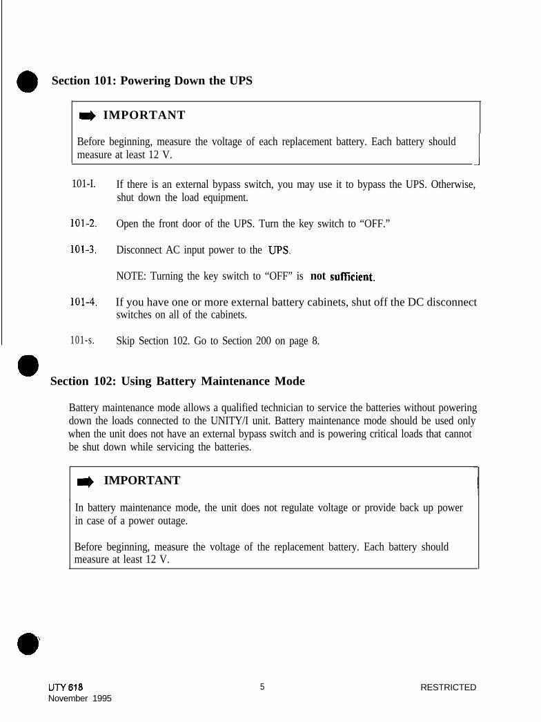
Section 101: Powering Down the UPS
I) IMPORTANT
Before beginning, measure the voltage of each replacement battery. Each battery shouldmeasure at least 12 V. 1
101-I. If there is an external bypass switch, you may use it to bypass the UPS. Otherwise,shut down the load equipment.
101-2. Open the front door of the UPS. Turn the key switch to “OFF.”
101-3. Disconnect AC input power to the UPS.
NOTE: Turning the key switch to “OFF” is not suffxient.
101-4. If you have one or more external battery cabinets, shut off the DC disconnectswitches on all of the cabinets.
101-s. Skip Section 102. Go to Section 200 on page 8.
Section 102: Using Battery Maintenance Mode
Battery maintenance mode allows a qualified technician to service the batteries without poweringdown the loads connected to the UNITY/I unit. Battery maintenance mode should be used onlywhen the unit does not have an external bypass switch and is powering critical loads that cannotbe shut down while servicing the batteries.
I) IMPORTANT
In battery maintenance mode, the unit does not regulate voltage or provide back up powerin case of a power outage.
Before beginning, measure the voltage of the replacement battery. Each battery shouldmeasure at least 12 V.
UTY618November 1995
5 RESTRICTED

eCAUTION
When the unit is in battery maintenance mode (Parameter 63 set to “1”) there is stilllive voltage inside the UPS.
Battery maintenance mode (Parameter 63 set to “1”) should be used during batterymaintenance only. Do not use battery maintenance mode for any other type of UPSservice or maintenance.
102-l. Verify the stability of the AC line. If there are irregularities with the input AC line,BEST recommends that you do not use battery maintenance mode at this time.
l Press the [VLINE] key on the front of the unit. Watch to see if the input voltage isstable.
l You can also check the UPS system log to see if the unit has frequently switchedto battery power (inverter) recently. See the UNITY/I User A4unual forinstructions on viewing the system log. Look for the system event code “in”(inverter).
102-2. Access parameter mode and enter the user password (377) as follows:
NOTE: When the unit is in parameter mode, each of the front panel keys has aspecific function. The label inside the front door of the unit explains theparameter mode key functions. The label also shows a “ProgrammingTemplate” with alternate key names that correspond to the parametermode key functions.
a. Simultaneously hold down the [CANCEL] and [RUNTIME] keys for two seconds.Release them when the display reads P-0 0.
b. Press [CANCEL]. The display should read 0.
c . Use the [%LOA!J] key or the [VOUT] key to change the display reading to 3 7 7.
NOTE: Use the [%LOAD] key to increase the value. Use the [VOUT] key todecrease the value. If you hold down either key, the display begins toscroll more quickly.
d. Press [RUNTIME]. The display should read I. If it does not, repeat steps “c” and“d.”
e. Press [CANCEL]. The display should read P- 0 0. 0
UTY 618November 1995
6 RESTRICTED

102-3. Enter the nominal AC input line voltage in Parameter 62 (Nominal Input Voltage) asfollows:
a . The display should show P-XX (where XX is a parameter number). Use the[%LOAD] key or the [VOUT] key to change the display reading to P- 6 2.
b. Press [CANCEL]
c . Use the [%LOAD] key or the [VOUT] key to change the display reading to thenominal AC input line voltage (200, 208, 220, 230 or 240).
102-4.
NOTE: Ifthe UPS has optional 380-415 VAC input, set the nominal AC inputvoltage value to “240.”
d . Press [RUNTIME] to enter the new value.
e . Press [CANCEL]. The display should read P- 6 2.
Put the unit into battery maintenance mode by setting Parameter 63 (BatteryMaintenance Mode) to “1” as follows:
a. The display should read P-XX, where XX is a parameter number. Use the[%LOAD] key or the [VOUT] key to change the display reading to P- 6 3.
b . Press [CANCEL]. The display should read 0
c . Press the [%LOAD] key to change the display reading to I.
d. Press [RUNTIME]. The display should read 1 .
102-5. Look at the LEDs on the UPS front panel. The LINE, BYPASS, and ALARM LEDsshould be on, and the BATTERY LED should be off, as shown in Figure 1.
IA CAUTIONIf the front panel LEDs are not lighted as shown in Figure 1, the unit is not inbattery maintenance mode and it is not safe to service the batteries. Repeat allof Section 102 or power down the UPS as instructed in Section 101.
NOTE: If, after repeated attempts, the unit does not transfer to batterymaintenance mode, the AC input voltage may be out of tolerance. CallBEST Worldwide Service for technical assistance.
UTY618November 1995
7 RESTRICTED

Section 200: Removing the Batteries0
I) IMPORTANT
The steps in Sections 200 and 300 must be performed in order.
200-l. Remove the screws at the comers of the front ventilation panel and remove the panelfrom the unit. Also, remove the bottom narrow front panel(s). See Figure 2.
NOTE: On a UTSK, also remove the front kick plate (found below the frontventilation panel); slide it upward, then pull it away from the unit
TBatteryTrayHandle
Fuse Board
Note: This drawln s h o w sa UT3K, UT4K or & T5K.
The UTBK Is similar but hasa larger chassis. additional“arrow front panels, anda front kick plate
~ Front Door
DC Connector
/-// Front, <itation
Bottom NarrowFront Panel -
Figure 2: Single-Phase UNITW UPS
200-2. Remove the battery tray handle from the back of the unit (see Figure 2). Keep the twobolts handy to use in step 200-4.
200-3. At the front of the unit, remove the bolt that secures the battery tray to the floor ofthe chassis. To find the bolt, look under the two cables labeled “+” connectedbetween the bottom DC connector and the fuse board (see “Bolt” in Figure 2). 0
UTY618November 1995
8 RESTRICTED

200-4.
e200-S.
200-6.
200-7.
200-S.
200-9. Pull the battery tray out just far enough to expose the first battery.
200-10. Disconnect the negative (-) battery cable from the first battery.Insulate the cable lead with electrical tape or heat shrink tubing.
Figure 3: Battery Tray, Front View
Use the two bolts to attach the battery tray handle to the battery tray at the front ofthe unit (see Figure 3).
Remove the bolt from the top DC connector. See Figure 3 for DC connector location.
Disconnect the top DC connector as shown in Figure 3.
If the unit has external batteries, perform the following steps:
a. Switch off the DC disconnect switch on the external battery cabinet(s).
b. Disconnect the external battery cable (f) from the “+BATT” post at top of thefirse board (see Figure 3). Insulate the cable lead with electrical tape or heatshrink tubing.
In the order listed, disconnect the following from the fuse board. Remove any tiewraps. See Figure 3 for connection locations.
a. Fast-on connector from E5.b. Connector From J3.c. Connector from Jl.
UTY616November 1995
9 RESTRICTED

ACAUTION
The battery tray will drop to the floor if it is completely removed from the unit. Make surethat your feet/hands are not under the battery tray while pulling the tray out of the unit.
200-l 1, Read the CAUTION above. Then, carefully pull the battery tray out of the unit justfar enough to expose all of the battery terminals.
Section 300: Replacing the Batteries
300-l. Replace the old batteries with new ones of the same series and type and rewire in thesame order. See Figure 4.
Figure 4: Battery Tray with Batteries
300-2. Slide the battery tray into the unit until only the front battery is exposed
300-3. Attach the negative (-) battery cable to the first battery.
e CAUTIONWhen pushing the battery tray into the unit, be careml not to pinch your fingers betweenthe batterv trav and the chassis.
300-4. Use the palms of your hands to push the battery drawer all the way into the unit.0
UTY618November 1995
10 RESTRICTED

a 300-5.
300-6.
300-7.
300-8.
300-9.
300-10.
i.’ I0 300-11.
300-12.
\aUN616November 1995
If the unit has external batteries, connect the external battery cable (+) to the“+BATT” post at the top of the fuse board (see Figure 3). Reassemble in this order:cable, flat washer, split lock washer, nut or cable, flat washer, nut with attached starwasher.
Switch on the DC disconnect switch on the external battery cabinet(s), if applicable.
In the order listed, reconnect the following. See Figure 3, on page 9, for connectionlocations.
a . Connector to Jl on the fuse board.b . Connector to J3 on the fuse board.c. DC connector and bolt.d . Fast-on connector to ES on the fuse board. There may be a small spark,e . Replace any tie wraps that were removed.
Remove the handle from the battery drawer and reattach it to the back of the unit.
Replace the bolt that secures the front of the battery tray to the floor of the chassis.
Replace the bottom narrow front panel(s). If you have a UT8K, also replace the frontkick plate.
Replace the front ventilation panel and secure it with the screws.
l If you powered down the UPS:
a. Switch on the DC disconnect switch on the external battery cabinets (ifapplicable).
b . Reapply AC line to the UPS.
c . Turn the UPS key switch to “AUTO.”
d. Reapply the loads,
e. You have completed the battery replacement procedure. The UPS should berunning on line power with all of the load equipment applied. The LINE LEDshould be on, and the BATTERY, BYPASS, and ALARM LEDs should be off.
11 RESTRICTED

l If you used battery maintenance mode:m
a. Access parameter mode and enter the user password (377) as follows:
1. Simultaneously hold down the [CANCEL] and [RUNTIME] keys for twoseconds. Release them when the display reads P- 0 0.
2. Press [CANCEL]. The display should read 0.
3. Use the [%LOAD] key or the [VOUT] key to change the display reading to3 1 1.
4. Press [RUNTIME]. The display should read I.
5. Press [CANCEL]. The display should read P- 0 0.
b. Take the unit out of battery maintenance mode by setting Parameter 63 (BatteryMaintenance Mode) to “0” as follows:
1 . The display should read P- 0 0. Use the [%LOAD] key or the [VOUT] key tochange the display reading to P- 6 3.
2. Press [CANCEL]. The display should read 1 .
3. Press the [VOUT] key. The display should read 0.
4. Press [RUNTIME]. The display should read 0.
I) IMPORTANT
The BYPASS LED should be off and the LINE LED should be on.
If the BYPASS LED is on, the unit is still in battery maintenance mode.Repeat steps “a” and “b” above. If the BYPASS LED remains lit, callBEST Power Worldwide Service for technical assistance.
c . Press [VLINE] twice to escape parameter mode.
d. You have completed the battery replacement procedure. The UPS should berunning on line power with all of the load equipment applied. The LINE LEDshould be on, and the BATTERY, BYPASS, and ALARM LEDs should be off
WY616November 1995
12 RESTRICTED

JNINTERRUPTIELE‘OWER S Y S T E M S UTY 619
IIDecember 5.1997
Replacing the Internal Batteries in UN ITY/IUT3K, UT4K, UTSK, and UT8K (Internal Fuse Board)
This publication describes how to change the internal batteries in UNITY/F” models UT3K, UT4K, UTSK, andUT8K. This procedure is for units with the fuse board mounted inside the chassis; see Best Power publication UTY618 if the fuse board in your unit is mounted below the front ventilation panel.
NOTE: If your UNITY/I UPS has an extended runtime option and has external batteries, refer to UTY 620 forreplacing both external and internal batteries.
Replace batteries with the same series and type of battery.
A qualified service person must perform this procedure. Should questions or problems arise while performingthis procedure, call Best Power Worldwide Service at l-800-356-5737 (U.S.A. and Canada only), l-608-565-2100,or your local Best Power office.
Tools Required - Use Insulated Tools:
Safety Equipment Required by Local Codes ‘%-inch Heat Shrink Tubing or Electrical Tape
DC Voltmeter 7/16-inch and l/4-inch Nut Drivers
7116~inch Box Wrench UNITY/I User Manual
Table of Contents
IMPORTANT SAFETY INSTRUCTIONS - SAVE THESE INSTRUCTIONS! . . . . . . ........Section 100: Before Replacing the Batteries . . . . . . . . . . . . . . . . . . . . . . . . . . . . . ........
Section 101: Powering Down the Loads . . . . . . . . . . . . . . . . . . . . . . . . . . . . . ........
Section 102: Using the Make-Before-Break Bypass Switch. . . . . . . . . . . . . . . . . ........Section 103: Using Battery Maintenance Mode . . . . . . . . . . . . . . . . . . . . . . ........
Section 200: Removing the Batteries . . . . . . . . . . . . . . . . . . . . . . . . . . . . . . . . . . ........Section 300: Replacing the Batteries . . . . . . . . . . . . . . . . . . . . . . . . . . . . . . . . . . ........
UTY-0619ACopyright 1997, Best Power. All rights reserved.
24679
:.131 5
RESTRICTED

IMPORTANT SAFETY INSTRUCTIONS - SA VE THESE INSTRUCTIONS!
ACAUTION! i
This procedure must be performed by a qualified service person only. UNITY/I UPS units are designed to proviepower under a variety of operating conditions. Dangerous voltages may be present even if input AC line or D8voltage is removed. Remove all AC and DC power sources. TEST BEFORE TOUCHING!
Turn offthe UNITY/l UPS according to the procedure describing “Shutting Down the UNITY/I” in the U/V/p/N Us<Manual. Make sure that the UNITY/I batteries and AC input are off or disconnected before you replace the batterie
N-H This unit contains electrostatic sensitive devices (ESD). If you do not follow proper ESD procedures, you mz
(1’ cause severe damage to electronic circuitry.
UNITY/I UPS batteries are high current sources. Shorting battery terminals or DC terminal strip terminals can causevere arcing, equipment damage and injury. A short circuit can cause a battery to explode. Always wear protecticlothing and eye protection and use insulated tools when working near batteries.
Best Power recommends the following for qualified service people servicing the UNITY/I UPS:A) Remove rings, watches, and other jewelry before servicing the UNITY/I UPS.B) Always wear protective clothing and eye protection, and use insulated tools when working near batterieC) Whenever you are servicing an energized unit with the cover removed, electric shock is possible. Folio
all local safety codes.
e CAUTION!
Full voltage and current are always present at the battery terminals.
The batteries used in this system can produce dangerous voltages, extremely high currents, and a risk of electricshock. They may cause severe injury if the terminals are shorted together or to ground (earth). You must bcextremely careful to avoid electric shock and burns caused by contacting battery terminals or shorting terminal!during battery installation. Do not touch uninsulated battery terminals.
A qualified service person who is familiar with battery systems and required precautions must service the batteriesAny battery used with this UPS shall comply with the applicable requirements for batteries in the standard fo:emergency lighting and power equipment, UL 924. Batteries must be replaced with Best Power battery numbe:BAT-XKKX’or equivalent. The installation must conform to national and local codes.
Keep unauthorized personnel away from batteries.
W-Y619 December 5. 1997RESTRICTED
Page 2

The technician or electrician must take these precautions:
1 . Wear protective clothing and eye wear. Batteries contain caustic acids and toxic materials and canrupture or leak if mistreated. Remove rings and metal wristwatches or other metal objects andjewelry. Do not carry metal objects in your pockets where the objects can fall into the batterycabinet.
2. Tools must have insulated handles and must be insulated so that they will not short batteryterminals. Do not allow a tool to short a battery terminal to another battery terminal or to thecabinet at any time. Do not lay tools or metal parts on top of the batteries, and do not lay themwhere they could fall onto the batteries or into the cabinet.
3. When connecting cables, never allow a cable to short across a battery’s terminals, the string ofbatteries, or to the cabinet.
4. Align the cables on the battery terminals so that the cable lug does not contact any part of thecabinet even if the battery is moved. Keep the cable away from any sharp metal edges.
5. Install the battery cables so they cannot be pinched by the battery cabinet door or UPS covers.
6. Make sure the fuse is positioned so that it will not contact any cabinet parts or other battery posts ifthe batteries move. Make sure there is enough clearance when the battery cabinet door closes.
7 . If you are replacing batteries or repairing battery connections, follow the procedure in the UNITY/IUser Manual to shut off the UPS and remove both AC and DC input power, unless you must use“Battery Maintenance Mode.”
8 . If your local or national code requires you to ground either battery terminal, remove the connectionfrom the terminal to ground (earth) before you service the batteries. If any battery terminal isinadvertently grounded, remove the source of the ground. Contacting any part of a groundedbattery can cause a risk of electric shock. An electric shock will be less likely if you disconnect thegrounding connection before you work on the batteries.
9. Assume that old batteries are fully charged. Use the same precautions you would use whenhandling a new battery. Do not short battery terminals or the battery string with a cable or toolwhen you disconnect the batteries.
10. Do not dispose of batteries in a fire because the batteries could explode. Do not open or mutilatebatteries. Released electrolyte is harmful to the skin and eyes. It may be toxic.
Il. Batteries contain lead. Many state and local governments have regulations about disposing of usedbatteries. Please dispose of batteries properly.
Page 3 December 5.1997 U-W619RESTRICTED

Section 100: Before Replacing the Batteries. . .
IMPORTANT: Before beginning, measure the voltage of each replacement battery. Each batteryshould measure at least 12 VDC.
Hardwired or Softwired..... Whenever possible, you should shut down your UPS and remove all AC andDC power to replace the batteries. However you may use “Battery Maintenance Mode” if necessary. To help youselect the best way to change batteries in your UNITY/I System, look at your system’s wiring configuration. MostUNITY0 units are “soft-wired.” This means they have a line cord and plug that connects to utility power at a wallelectrical outlet. The “Protected Loads” are plugged into outlets on the back of the UNITY/I. If your unit issoftwired, go to Table 1, below.
If your UNITY/I was installed so it is wired directly, without an input AC plug or receptacles for the loads, it is“hardwired.” Go to the next page for information regarding hard wired UNITY/I units.
Table 1 - Softwired
0 Do this if your “Protected Loads” can be shutdown:
: 1. Turn off protected loads.
QIfyour] “ P r o t e c t e d
j Loads” cannot be2. Unplug them and then plug them into wall receptacles. Switch them on while you shut down, go to
; replace the batteries. Battery replacement takes up to about eight hours. Section 103,, ~.
3. Turn off the UNITY/I UPS by opening the front door and turning the key switch to’ uUsing Battery
“OFF.”~ Maintenance
:ACAUTION! Turning the key switch to “OFF” is not sufficient. Shut off UPS Mode.”
circuit breaker or remove UPS AC input plug from the wall receptacle.-. - 4
4 . Go to Section 200, “Removing the Batteries” on page 13. Complete steps 5 through8, below, after you complete the battery installation..-
; When battery installation is finished, complete steps 5 through 8 to restart theUPS.5 . Reapply AC line to the UPS.
6 . Turn the UPS key switch to “AUTO.”
7 . Turn off the protected loads and plug them into the UNITY/I UPS receptacles.Switch on the loads.
8 . You have completed the battery replacement procedure. The UPS should berunning on line power with all of the load equipment applied, The LINE LED ~should be on, and the BATTERY, BYPASS, and ALARM LEDs should be off ;
~_A~~..
u-m 619 December $1997RESTRICTED
Page 4
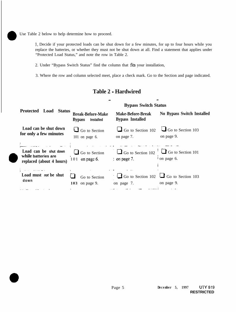
a Use Table 2 below to help determine how to proceed.
1, Decide if your protected loads can be shut down for a few minutes, for up to four hours while youreplace the batteries, or whether they must not be shut down at all. Find a statement that applies under“Protected Load Status,” and note the row in Table 2.
2. Under “Bypass Switch Status” find the column that fits your installation,
3. Where the row and column selected meet, place a check mark. Go to the Section and page indicated.
Table 2 - Hardwired- -
Bypass Switch StatusProtected Load Status
Break-Before-Make Make-Before-Break No Bypass Switch InstalledBypass Installed Bypass Installed
Load can be shut downfor only a few minutes
cl Go to Section 0 Go to Section 102 ’ 0 Go to Section 103
101 on page 6. on page 7. on page 9.
’ Load can be shut down
0
,oGo to Section ‘0 Go to Section 102 ICI Go to Section 101
i while batteries are~ replaced (about 4 hours) 1 0 1 onpage6. : onpage7. 1 on page 6.
I
I Load must not be shutd o w n
0 Go to Section :aGo to Section 102 I 0 Go to Section 103
103 on page 9. on page 7. : on page 9.
Page 5 December 5, 1997 UTY619RESTRICTED

Section 101: Powering Down the Loads
10 l-1. Shut down the load equipment.
10 I-2. If you have an external Break-Before-Make Bypass Switch, and your protected loads can be shutdown for only a few minutes while you replace the batteries, set the BBM Switch to “LINE.” Youcan now switch on the loads and operate on utility line power.
101-3. Open the front door of the LIPS. Turn the key switch to “OFF.”
101-4. Disconnect AC input power to theUPS
e CAUTION! Turning the key switch to “OFF” is not sufficient
101.5. Go to Section 200, “Removing the Batteries” on Page 13. You will complete steps 101-6 through101-10 after you complete the battery installation.
When battery installation is finished, complete steps 101-6 through 101-10 to restart the UPS.
1 0 1 - 6 . Reapply AC line to the UPS
101-7. Turn the UPS key switch to “AUTO.”
101-8. If you have a BBM Switch, shut down the loads, set BBM Switch to “UPS”
101-9. Switch on the loads.
101-10. You have completed the battery replacement procedure. The UPS should be running on linepower with all of the load equipment applied. The LINE LED should be on, and the BATTERY,BYPASS, and ALARM LEDs should be off.
Table 3-Alarm Status Table (table duplicated on page 10)..~ ,. .~~..~_~
1
UNITY/I Model Serial Number
3 K 25098 and below.i
1 .
2 5 0 9 9 a n d a b o v e I.,~4 K 25097 and below
25098 and above :/
S K 20778 and below ’.;20779 and above :
- r /8K 25097 and e
4: 25098 and above
-.- ‘
ALARM LED State-Battery Maintenance Mode
O N
OFF
UN 619 December 5. 1997RESTRICTED
Page 6

Section 102: IJsing the Make-Before-Break Bypass Switch
102-l. If you do not need to operate the protected load while you replace the batteries, you may wantto shut it down. TO connect the protected loads to utility power while you replace the batteries,follow the procedure in steps 102-2 through 102-6.
To switch the MBB bypass switch from “UPS’ to “LINE” (or vice versa) with a UNITY/I single-phase unit, the unit must be operating in BYPASS mode (the BYPASS light must be ON).
To operate the bypass switch, enter the BYPASS mode by following the instructions below:
102-2. Enter the user password (377):a. Hold down the [CANCEL] and [RUNTIME] keys; release the keys when the display shows
“P-00.”b. Press [CANCEL]. The display should show “0.”c. Press and hold the [%LOAD] key until the display shows “377.” (If you go past “377,” press
[VOUT] to scroll backwards.)d. Press [RUNTIME]. The display should show “I.”
102-3. Program parameter 62 (nominal input voltage):a . Press [CANCEL] to toggle to the parameter number. The display should show “P-00.”b. Press [%LOAD] to scroll up to “P-62.” (If you go past “P-62,” press [VOUT] to scroll
backwards.)c . Press [CANCEL] to toggle to the parameter value.d . Set the value to the nominal input voltage (200, 208, 220,230, or 240). Press [%LOAD] to
increase the setting or [VOUT] to decrease the setting.
NOTE: Ifthe UPS has optional 380-415 VAC input, set the nominal AC input voltagevalue to “240.”
e. Press [RUNTIME] to enter the value. The new value should remain on the display.
102-4. Program parameter 63 to “I”:a. Press [CANCEL] to toggle to the parameter number. The display should show “P-62.”b. Press [%LOAD] to go to parameter 63 (P-63).c. Press [CANCEL]. The display should show “0.”d . Press [%LOAD] to change the parameter value to “I.”e. Press [RUNTIME] to enter the new value. The display should still show “I,” and the
BYPASS light should be on. Refer to the Alarm Status Table on the preceding page and seeif ALARM light should be on or off. If either light is incorrect, repeat steps 102-4, d and e.
102-5. If the BYPASS light will not come on: When input line is bad, the UPS will not transfer tobypass mode, and the BYPASS light will not come on. Follow these steps:a. Turn off the load equipment.b. Turn the UPS keyswitch to “OFF.”c . Turn the AC Disconnect switch to “OFF.”d. Turn the MBB bypass switch to “LINE.”e. Turn on the load equipment.
Page 7 December &I997 UTY 619RESTRICTED

102-6. If the BYPASS light came on, you can safely operate the MBB bypass switch. Quickly turn thebypass switch from “UPS” to “LINE.”
Now you can shutdown the UPS to replace the batteries.
1 0 2 - 7 . Open the front door of the UPS. Turn the key switch to “OFF.”
102-8. Disconnect AC input power to the UPS
e CAUTION! Turning the key switch to “OFF” is not sufficient.
102-9. Go to Section 200, “Removing the Batteries” on page 13. Do not do Section 103. You will comeback and complete steps 102-10 through 102-14 after completing the battery installation.
When battery installation is finished, complete steps 102-10 through 102-14 to restart the UPS.
102.10. Before continuing:
;:
C.
Reapply AC line.Turn the UPS key switch to “AUTO.”Look at the UPS front panel lights:
* The ALARM light status is shown in Table 3-Alarm Status. (See page 6 or 10.). The BYPASS light should be ON.* The LINE light should be OFF.
IMPORTANT! If the ALARM light status is wrong or the BYPASS light is OFF, repeatsteps 102-2, 102-3 and 102-4 before continuing.
0
102-l 1. Quickly turn the MBB bypass switch back to “UPS.”
102-12. Enter the user password (377). See step 102-2.
102-13. Program parameter 63 backto “0”:a . Press [CANCEL] to toggle to the parameter number. The display should show “P-00.”b . Press [%LOAD] to scroll to “P-63.” (Use [VOUT] to scroll backwards if you go past “P-
63.“)c. Press [CANCEL]. The display should show “I.”d . Press [VOUT] to change the value to “0.”e. Press [RUNTIME]. The display should show “0,” and the BYPASS and ALARM lights
should now be OFF. The LINE light should be ON.
If the BYPASS light will not turn off: When input line is bad, the UPS will not transfer outof bypass mode, and the BYPASS light will stay ON. If this OCCUTS, you must wait until inputAC line is good. If the BYPASS light stays ON for an extended period of time, have anelectrician check your AC line or call Best Power Worldwide Service at I-800-356-5737 orl-608-565-2100.
102-14. Press [VLINE] twice to exit the parameter mode. The load is once more protected by the UPS.
lUTY 619 December 5,1997RESTRICTED
Page 8

Section 103: Using Battery Maintenance Mode
BatteIy maintenance mode allows a qualified service person to service the batteries without poweringdown the loads connected to the UNITY/I unit. Battery maintenance mode should be used only when theunit does not have an external bypass switch and is powering critical loads that cannot be shut down whileservicing the batteries.
IMPORTANT! In battery maintenance mode, the unit does not regulate voltage or provide back-up power in case of a power outage.
r e CAUTION!
When the unit is in battery maintenance mode (Parameter 63 set to “I”), there is still live voltage inside theUFS
Battery maintenance mode (Parameter 63 set to “I”) should be used during battery maintenance only. DOnot use battery maintenance mode for any other type of UPS service or maintenance.
103-l. Verify the stability of the AC line. If there are irregularities with the input AC line, Best Powerrecommends that you do not use battery maintenance mode at this time.
s Press the [VLINE] key on the front ofthe unit. Watch to see if the input voltage is stable.
. You can also check the UPS system log to see if the unit has frequently switched to batterypower (inverter) recently. See the UNITY/I User Manual for instructions on viewing thesystem log. Look for the system event code “in” (inverter). ,
103-2. Access parameter mode and enter the user password (377) as follows:
NOTE: When the unit is in parameter mode, each of the front panel keys has a specific function.The label inside the front door of the unit explains the parameter mode key functions. Thelabel also shows a “Programming Template” with alternate key names that correspondto the parameter mode key functions.
a . Simultaneously hold down the [CANCEL] and [RUNTIME] keys for two (2) seconds.Release them when the display reads “P-00.”
b . Press [CANCEL]. The display should read “0.”
c . Use the [%LOAD] key or the [VOUT] key to change the display reading to “377.”
NOTE: Use the [%LOAD] key to increase the value. Use the [VOUT] key to decreasethe value. If you hold down either key, the display begins to scroll more quickly.
d . Press [RUNTIME]. The display should read “I,” If it does not, repeat steps “c” and “d.”
e. Press [CANCEL] The display should read “P-00.”
Page 9 December 5, 1997 U-i-Y 619RESTRICTED

103-3. Enter the nominal AC input line voltage in Parameter 62 (Nominal Input Voltage) as follows:
a. The display should show P-xX(whereXYis a parameter number). Use the [%LOAD] key orthe [VOUT] key to change the display reading to “P-62.” 0
b. Press [CANCEL]
c. Use the [%LOAD] key or the [VOUT] key to change the display reading to the nominal ACinput line voltage (200,208, 220, 230 or 240).
NOTE: If the UPS has optional 380-415 VAC input, set the nominal AC input voltagevalue to “240.”
d. Press [RUNTIME] to enter the new value.
e. Press [CANCEL]. The display should read “P-62.”
103-4. Put the unit into battery maintenance mode by setting Parameter 63 (Battery Maintenance Mode)to “I” as follows:
a. The display should read P-Z, where His a parameter number. Use the [%LOAD] key orthe [VOUT] key to change the display reading to “P-63.”
b. Press [CANCEL]. The display should read “0.”
c. Press the [%LOAD] key to change the display reading to “1.”
d . Press [RUNTIME]. The display should read “I.”
103-5. Look at the LEDs on the UPS front panel. The LINE and BYPASS LEDs should be on, and theBATTERY LED should be off, as shown in Figure 1. The ALARM LED state is shown below.
Table 3-Alarm Status Table (table duplicated on page 6)- I. ~.UNITY/I Model
3K
4K
5K
8K
Serial Number
25098 and below
25099andabove
25097 and&&v ON
25098 and above OFF+
ON20778 and below
20779andabove
25097 and below
ALARM LED State-Battery Maintenance Mode.- , -__--
O N _--.~_ -.--.. -aOFF
25098 and above
UP/619 December 5. 1997RESTRICTED
Page 10

See the table on page 10 for Alarm status
e CAUTION!
If the front panel LEDs do not light as shown in Figure 1, the unit is not in battery maintenancemode and it is not safe to service the batteries. Repeat Section 103-I to 103-5 or power down theUPS as instructed in Section 101.
NOTE: If, after repeated attempts, the unit does not transfer to battery maintenance mode, the ACinput voltage may be out of tolerance. Call Best Power Worldwide Service for technicalassistance.
103.6. Once the UPS is in battery maintenance mode, go to Section 200, “Removing the Batteries,” onpage 13. You will complete steps 103-7 through 103-10 after the battery installation is done.
When battery installation is finished, complete steps 103-7 through 103-10 to restart the UPS
103.7. Access parameter mode and enter the user password (377) as follows:
a . Simultaneously hold down the [CANCEL] and [RUNTIME] keys. Release them when the displayreads “P-00.”
b Press [CANCEL]. The display should read “0.”
c. Use the [%LOAD] key or the [VOUT] key to change the display reading to “377.”
d . Press [RUNTIME]. The display should read “I.”
e. Press [CANCEL]. The display should read “P-00.”
103.8. Take the unit out of battery maintenance mode by setting Parameter 63 (Battery MaintenanceMode) to “0” as follows:
a . The display should read P-00. Use the [%LOAD] key or the [VOUT] key to change the displayreading to “P-63.”
b . Press [CANCEL]. The display should read “I.”
Page 11 December 5. 1997 UTY619RESTRICTED

c. Press the [VOUT] key. The display should read “0.”
d . Press [RUNTIME]. The display should read “0.”
IMPORTANT:
The BYPASS LED should be off and the LINE LED should be ON.
If the BYPASS LED is ON, the unit is still in battery maintenance mode. Repeat steps “A” through“D” above. If the BYPASS LED remains lit, call Best Power Worldwide Service for technicalassistance.
103-9. Press [VLINE] twice to escape parameter mode. If you have an “A-l 7 ” alarm, press CANCELfor five (5) seconds to clear alarm.
103-l 0. You have completed the battery replacement procedure. The UPS should be running on line powerwith all of the load equipment applied. The LINE LED should be ON, and the BAlTERY,BYPASS, and ALARM LEDs should be off.
UTY 619 December5,1997RESTRICTED
Page12

Section 200: Removing the Batteries
IMPORTANT: The steps in Sections 200 and 300 must be performed in order.
201. To gain access to the batteries, take the front panel off the UF’S as shown in 201-1, below.
201-l. Remove the screws at the comers of the front ventilation panel and remove the panel from theunit. (See Figure 2. This figure shows the 8K model. There are only two screws in the 3K, 4K and5K models.) Also, remove the bottom narrow front panel. There are two narrow front panels onthe 8K.
On the 8K, remove the front kick plate (found below the front ventilation panel); slide it upward,then pull it away from the unit.
Batteries
Figure 2
201-2. At the front of the unit, remove the bolt that secures the battery tray to the chassis floor. (SeeFigure 3).
1~ I
REMOVE THIS
Figure>
Page 13 December 5, 1997 U-rY 619RESTRICTED

201-3. Disconnect the DC connector by pulling itdown. (See Figure 4.)
SLIDE THEBOTTOM DC
201-4.
201-5.
Disconnect the HRS-370 “quickconnect” connector on the front ofthe battery tray. (See Figure 5.)
Note! The end of the battery traywith the strap will drop to thefloor as you slide out the tray. Donot drop this very heavy hay onyour toes or hands! Take the strapand carefully pull the battery trayout of the unit just far enough toexpose all of the battery terminals.
Note the battery cable wiringorder and the position of thebattery tie down buckles so thatyou can install new batteries in thesame fashion.
Figure 4
Figure 5
/‘QUICKCONNECT
UlY619 December 5. 1997RESTRICTED
Page 14

Section 300: Replacing the Batteries
a 301. Installing batteries and putting the UPS together.
30 1 - 1. Replace the old batteries with new ones of the same series and type and rewire in the same orderSee Figure 6.
Figure 6
ACAUTION!
When pushing the battery tray into the unit, be careful not to pinch your fingers between thebattery tray and the chassis.
301-2. Make sure that the HRS-370 “quick connect” connector is not in the battery cavity. Use the palmsof your hands to push the battery drawer all the way into the unit.
301-3. Precharge and then switch on the DC disconnect switch on the external battery cabinet(s), ifapplicable.
301-4. Reconnect the “quick connect” connector on the front of the battery tray. (See Figure 5 on page14.)
301-5. Replace the bolt that secures the front of the battery tray to the floor of the chassis. (See Figure3 on page 13.)
301-6. Reconnect the DC connector at the bottom of the unit. (See Figure 4 on page 14.)
301-7. Replace the bottom narrow front panel(s). If you have a UTXK, also replace the front kick plate.(See Figure 2 on page 13.)
301-8. Replace the front ventilation panel and secure it with the screws. (See Figure 2 on page 13.)
Page 15 December 5, 1997 UTY 619RESTRICTED
30 l-9. If your UNITY/l is softwired, and you shut down your loads, return to Table 1 on page4, and complete the remaining steps. If you did not shut down your loads and used the“Battery Maintenance Mode,” complete steps 103-7 through 103-10 on page 11.
If your UNITY/I is hard-wired, go to the Section you selected from Table 2 on page 5,and complete the remaining steps to return the UNITY/I UPS to normal operation.
UTY 619 December 5.1997RESTRICTED
Page 16
i ’‘
UTYGOE
llJQ”H 29,1997
Generator Setup for UNITY/IUT3K, UT4K, UTSK, and UTSK
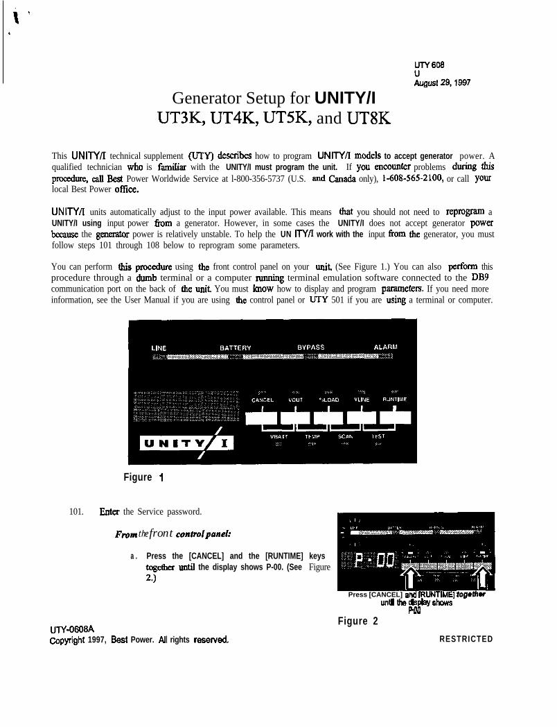
This UNITY/I technical supplement (UTY) describea how to program UNITY/l models to accept generator power. Aqualified technician who is famiIiar with the UNITY/I must program the unit. If you encounter problems during thispromdoze, call Flest Power Worldwide Service at l-800-356-5737 (U.S. and Canada only), 1-608-565-2100, or call yourlocal Best Power office.
UNITY/I units automatically adjust to the input power available. This means that you should not need to reprogram aUNITY/I using input power t?om a generator. However, in some cases the UNITY/I does not accept generator powa
because the generator power is relatively unstable. To help the UN KY/I work with the input from the generator, you mustfollow steps 101 through 108 below to reprogram some parameters.
You can perform this procedure using the front control panel on your unit (See Figure 1.) You can also perform thisprocedure through a dumb terminal or a computer running terminal emulation software connected to the DBYcommunication port on the back of the unit You must koow how to display and program parameters. If you need moreinformation, see the User Manual if you are using the control panel or UTY 501 if you are using a terminal or computer.
Figure 1
101. Enter the Service password.
Fmnt the front eontmIpanel:
a . Press the [CANCEL] and the [RUNTIME] keystog&m until the display shows P-00. (See Figure2.)
u~Y-06OgACopyright 1997, Best Power. All rights reserved.
Press [CANCEL] and IRUNTIMEI h~getbruntl the dqlay shows
Pm
Figure 2RESTRICTED

b .
c.
‘fhen, press [%LOAD] until the unit displays 2639.(See Figure 3.)
Then, press [RUNTIME]. The dispIay should read 2(for password level 2). (See Figure 4.)
a . S&the UNITY/It&.properbaudrate. Ifthe baud& FW* 3needs to be changed:
I .
ii.
111.
i v .
press the [CANCEL] and the [RUNTIME] keystogether until the display shows P-00. (See Figure2 on page. 1.)
Then, press [%LOAD] until the tit displays 22.(See Figure 5.)
Once you reach P-22, press [CANCEL]. Use the Figure 4[%LOAO] key or the [VOUT] key to change thedispIsy to the erect settiog. (See Table 1 below todetermine the correct setting.)
To enter the new setting, press [RUNTIME]. Toescape parameter mode, press [ MINE] twice.
NOTE: To escape wifhouf saving, press the[MINE] or the [CANCEL] key. Figure 5
munication Moda I
I 0-F I Contact mode. Set3 the d&v fii secmds~ cm Din 2. I
II .
10 1 RS232 mode, 1200 baud.I
20 RS232 mode, 24OQ baud30 RS232 mode, 4800 baud40 RS232 mode. 9600 baud
l Parametlz22scningslueinhe%a~.
b . Type P 00 2639 and press <ENTER>. The display should read OK=>.
102. Change parameter #8 (Glitch Limit) to a value of “25.”
From the front controlpanel:
press [CANCEL] to return to the parameter display, then press [%LOAD] or [VOUT] until thedisplay reads P-06. Thea, press [CANCEL] to display the parameter value. Press [%LOAD] orVOUTJ u&I the display reads 25. Ress [RUNTIME] to save the value. The UPS should beep toindicate that you have saved the new value for parameter 8.
UN 606 August 29,1997RESTRICTED
Page 2

Type P 08 = 25, then press <ENTER>. The display should read OK=*.
103. change parameter #86 (Generator) to a value of “1.” This sets the inverta lockout.
From the front controlpanel:
Press [CANCEL] to rehum to the parameter display, then press [%LOAD] or [VOUT] until thedisplay reads P-66. Then, press [CANCEL] to display the parameter value. Press [%LOAD] or[VOUT] until the display reads 1. Press [RUNTIME] to save the value. The UPS should beep toindicate that you have saved the new value for parameter 86.
From (I computer or terminal:
Type P 86 = 1, then press GNTER>. The display should read OK=>.
104. Chge parameter #87 (Invertex Lock Out) to a value of “5.” This sets the number of cycles after a transferto line that line-interactive operation is prohibited.
From the front contmlpam!l:
Press [CANCEL] to r&m to the parameter display, then press [%LOAD] 01 D/OUT] until thedisplay reads P-67. Then, press [CANCEL] to display the parameter value. Press [%LOAD] or[VOUT] until the display reads 5. Press [RUNTIME] to save the value. The UPS should beep toindicate that you have saved the new value for parameter 87.
From (I computer or terminal:
Type P 87 = 5, then press <ENTER>. The display should read OK=>.
105. change parameter #78 (Line Delta Mode) to a value of ‘Y.” This sets the Line Delta to poor line.
From the front controlpanel:
Press [CANCEL] to rehum to the parameter display, then press [%LOAD] or [VOUT] until thedisplay reads P-76. Then, press [CANCEL] to display the parameter value. Press [%LOAD] or[VOLJTI until the display reads 2. Press [RUNTIME] to save the value. The UPS should beep toindicate that you have saved the new value for parameter 78.
From a computer or terminal:
Type P 78 = 2, then press <ENTER>. The display should read OK=>.
Page 3 August 29,1997 UTY 608RESTRICTED

106. Change parameter #9 (Frequency Slew Rate) to a value in the range of “400” to “700.”
From the front controlpanel:
Press [CANCEL] to return to the parameter display, then press [%LOAD] or [VOUT] until thedisplay reads P-OS. Then, press [CANCEL] to display the parameter ~alt~e.. Press [%LOAD] or(VOUTj until the display reads a value between400 and 700. Press [RUNTIME] to save the value.The UPS should beep to indicate that you have saved the new value for parameter 9.
From LI computer or terminal:
Type P OS =, enter a value between 400 and 700, then press <ENTER>. The display should readOK=>.
Adjust this parameter until you find the optimum setting.
107. Change pammeter #85 flap Delay Count) to a value of “4.” This programs the “N” cycle delay for the relayoperate and debounce times.
From the front control panel:
Press [CANCEL] to return to the parameter display, then press [%LOAD] or [VOUT] until thedisplay reads P-85. Then, press [CANCEL] to display the parameter value. Press [%LOAD] ok[VOIJT] until the display reads 4. Press [RUNTIME] to save the value. The UF’S should beep toindicate that you have saved the new value for parameter 85.
From II computer or termind:
Type P 85 = 4, then press <ENTER>. The display should read OK=>.
III
(GlitebLknit) 1 25 Increases number of glitches before tmit goes to inwrter.dtobeset.
87 (lmrter Lockout) 5 Sets the numba of cycles aftex tmsfer to line that line-interactiveoperation is ptibited.
7 8 (LineDeltaMcde) 2 SekthC!LineDeltatopoorliM.9 (hqmcy Slew Rate) 400-700 Maximum ftwmq of slew me of&awe.
a5 f-ran n&l” Chlnt~ 4 Roaams the T cwlt for relav snd debounce times.
108. Exit tiom the parameter mode.
From thefront controlpanel, press [KLINE] twice to exit from the parameter mode.
From a computer or terminal, type P 00 = l .
your UNITY/I UPS should ILOW be set for the generator used in your application. If you still have trouble with the UPSlocking to line, caU Best Power Worldwide Service at I-800-356-5737 (U.S. sod Caoada only), I-608-565-2100, or callyour local Best Power office.
W608 August 29,1997 Page 4RESTRICTED


a

a

100 Introductiona
The following sections provide general information about UNITY/l, including technical supportinformation, warranty information, information on ordering exchange parts, available options, andproduct specifications on standard models. Before using this service manual you should be familiar withthe UNITY/I User Manual and the UN/TY/I Insta~kdion Manual. If the user or installation manual hasbeen misplaced, contact Best Power Worldwide Service or your local BEST oflice for a replacement.
101 GeneralInformation ..,,._._......,,,....,,__._.,.,,._..,.,.._.......... 100-l
102 Technical Support .__,,,_._.,._._.._.._,,,.___..,,.._....,_._.......... 100-2
103 Warranty Information 100-3
104 OrderingExchangeParts ,,__.,,___,...,_..,._.._.,,,_.__..,_._,......... 100-3
105 Options ,__..,___.,.,._..,,__...._...,,__.,,,___._,,_,__.,._..__,.._. 100-4
106 Specifications, Standard Models 100-6
101 General Information
This manual covers the following UNITY/I single-phase units:
a. Models UT3K, UT4K, UTSK and UTSK. The model number is located on a label
inside the unit’s front door.
l Units with versions 1.00 to 1.09 software. To find the software version, viewParameter 128 or look at the label on the EPROM located on the logic board. SeeSection 308 of this manual for instructions on how to check parameters.
BEST product changes ensure that our customers get a competitively priced product thatprovides optimum performance and reliability. There have been three major phases of productsin the UNITY/I line.
PHASE I was the early production UNITY/I product. This included serial numbers O-19999 for3 to 5 KVA models and 0 to 24999 for the 8 KVA model.
PHASE II followed for the 3 to 5 KVA model serial numbers 20000 to 24999 and includedthese changes:
A.
B.C.
External DC connections made standard with a gray DC plug mounted at therear of the UPS, mating to the plug on the fuse box at the external batteryconnection.External battery cabinets became available.Internal battery tray connections changed and the fuse board was moved inside.
Section 100 - Introduction 100-I

PHASE III changes for the 3 to 5 KVA model serial numbers 25000 and up consistedOf :
D. Fuses were removed from the fuse board and the board was moved frombottom to the inside of the front panel.
E. Logic daughterboard was added.F. AC daughterboard was added.G. Default voltage regulation was set to 5%, programmable to 3%.H. Circuit board mountings were improved.I. Wooden packaging was used for shipping.
PHASE II and III changes (listed in A through I) occurred at the same time in the 8KVA model, beginning with serial numbers 25000 and up.
This manual does not cover Customer Purchase Options (CPOs) or changes made in theUNITY/I product after this manual was published.
102 Technical Support
Best Power has an outstanding Service Center. If you have a question about your UNITY/IUPS, write or call BEST Power Worldwide Service. BEST Power Worldwide Service is openevery business day from 7:00 a.m. to 8:30 p.m. (U.S. central time), and a technician is on call toanswer questions 24 hours a day, 365 days a year.
Before contacting Best Power Worldwide Service, please have the following informationavailable for the technical support staff
l The unit serial number, located inside the unit’s front door. BEST uses the serialnumber to track service records and system modifications.
0 A description ofthe question or problem, including any display lights or alarm codes.
Call from a telephone located near the UPS, if possible.
Technical Support Toll-Free: l-800-356-5737 (U.S.A. and Canada)Technical Support Phone: I-608-565-2100 (Worldwide)
Technical Support Fax: l-608-565-2509BBS: l-608-565-7424
Worldwide Web Site: http/www.bestpower.come-mail: [email protected]
100-2 Section 100 - Introduction
UNITY/I’”
l Mailing address: Best Power Worldwide ServiceP.O. Box 280Necedah, Wisconsin 54646 U.S.A.
Outside the U.S.A. and Canada, contact your local BEST office. See the back cover ofthis manual for Best Power offices located worldwide.
The following technical services are also available:
a
.
103
c
104
Field Support: To have your system started up, maintained or repaired by a BEST factory-trained technician, call Best Power Worldwide Service.
Service Training: To arrange factoty training for your in-house service technicians, call l-800-356-5794 (U.S.A. or Canada) or l-608-565-7200 for pricing and workshop information.
Warranty Information
As stated in the Limited Two-Year Warranty in the UNITYL User Manual, the warranty periodis two years from the date of initial retail purchase or delivery, whichever is earlier. If youreturn a defective UNITY/I system, system component @se, transformer, etc.), or a circuitboard to BEST Power Worldwide Service within the warranty period, BEST will repair orreplace it free of charge. Make sure you call for a Return Material Authorization @MA)number (see Section 104). The customer is responsible for all &eight charges.
Besides the standard two year warranty, Best Power offers Warranty Enhancement Plans to meetyour service and maintenance needs. Contact BEST Power Worldwide Service for detailedinformation about these and other warranty enhancement plans
Ordering Exchange Parts
BEST’s products are warranted for two years; see the Limited Two-Year Warranty in theUNITY0 User Manual for details. If a product fails while it is under warranty, you may orderreplacement parts for exchange or you may send in the failed part for repair; you are responsiblefor all shipping costs. After the warranty has expired, you may order exchange parts or send inthe failed parts for repair.
To order exchange parts, call BEST Power Worldwide Service at l-800-356-5737 (U.S.A. andCanada), or l-608-565-2100, or the nearest BEST office. Best Power Worldwide Service willdetermine which parts you need and tell you the cost of the parts. You must then fax or mail aPurchase Order, a MasterCardMSA number, or accept COD delivery, even if the parts to bereplaced may still be under warranty. BEST will ship you the new exchange parts with aninvoice.
Section 100 -Introduction 100-3

After your unit has been repaired, return the old parts for exchange. If the parts are underwarranty, you will receive a credit memo from Best. The exchange parts procedure can varyFor additional information, please call BEST Power Worldwide Service. For more warrantyinformation, see the UNITY/I User Manual.
105 Options
BEST offers a number of options for the UN IT?‘/ I If you would like more information, pleasecontact your local BEST office or dealer.
Bypss Switches:If your UPS does not have an AC input plug, an external bypass switch lets you convenientlytransfer your protected equipment to direct AC input power when it’s time to service the UPS.Your local BEST office can tell you if an external bypass switch is recommended for your UPS.
CkeckUP9 Automatic Shutdown Soffivare:CheckUPS software runs on your computer and enables a computer to communicate with the UPS.CheckUPS does a complete unattended shutdown of your computer if you have an extended poweroutage. CheckUPS II also monitors site power quality and has graphic display capabilities. SomeCheckUPS II contain a resident SNh@ agent to work with selected Network ManagementSoftware. Check with BEST for the application to fit your system.
Environnlental Monitoring:EnviroComm I and II models monitor many UPS and environmental conditions and phones youwhen there is a problem.
Extended Runtime and Faster Charging:If you want extended nmtime, calI BEST for information on adding additional battery or chargercapacity. (See BEST publication FSS-393, in Section 700, for further information.)
Interface Kits:Interface cables and assemblies are available for a number of computer systems. These kits allowyour computer’s software to shut down your protected equipment safely during an extended poweroutage. See the CheckUPS Automatic Shutdown Software option.
100-4 Section 100 - Introduction

UNITY/I”
Plugs:The following input plugs are available for UT3K, UT4K and UTSK units:
PLUG OPTIONS
O@Q@(JQ
L6-30P 6-5OP IEMI9 IEC$3$9* SW$JjKO* L6-2OP*
* IEC-309 (16 A), SCHUKO. and L6-20P plugs available on UT3K only.
Receptacles:The following output receptacles can be ordered on new units:
2 0 0 . 208. 2 2 0 . 2 3 0 . 2 4 0 V O L T
RECEPTACLE OPTIONS100, 110, 115, 120, 127 VOLT
15A 20A
(00)
aaC15R 5.2m
2OA 15A
@ 0
@ 0Canadkn L5-,.5R
5-ZOR
20A 30A
@ @L5-20R L590R
120/240 V O L T *20A 3 0 A
fgg @
L14-20R L143OR
‘L142OR a n d L14-30R wallable f o r 120/240 voiis only.
Section 100 -Introduction 100-S

q !!:Warranties: Besides the standard two-year warranty, BEST offers warranty enhancement plans
to meet your service and maintenance needs. Call the nearest Best Power office formore information.
l i
106 Specifications, Standard Models
Table 106-l: Specifications, Standard Models
Model Number
Capacity (KVAIKW)
Max. Input Current (Amps)200 VAC input208 VAC input220 VAC input230 VAC input240 VAC input
Mar. Output Currentper phase (Amps)
127 VAC outputlOOnO VAC output208 VAC output1 lo/220 VAC output11 S/230 VAC output120/240 VAC output
Audible Noise (dBA)on AC Line at 1 meter
Maximum DC Amps(Nominal Battery)
Nomimd DC Voltage
Ernelenq0on ACLk
Frequency on AC Line
Total Harmonic DistortionTml
Heat Dissipat ionBTU/hour:KWibour:
Noise Reject ion
Operating Temperature
Relative Humidity(non-condensing)
-
UT3K UT4K UTSK UTSK
3 4 5 8
17 2 217 22 27 4316 20 25 4115 2014 I 19
I
I 28 45
24 3923 38
12 16 20 3115 20 2 5 4014 19 24 3 814 18 2 3 3 613 17 22 3513 1 7 2 1 33
40 40 40 40
7 2 9 8 123 196
48 48 48 48
95% 96% 96% 96%
so/60 Hz l 3 Hz 50/60 Hz i3 Hz 50160 Hz l 3 Hz 50/60 Hz *3
5 5% 5 5% < 5% 5 5%
5 3 9 5 6 9 711 11380.158 0.167 0.208 0.333
Up to 90 dR in nonual mode from 100 kHz to 10 MHZ. Up to 50 dB in commonfrom 100 kHz to 10 MHZ.
0” to 40” c 0” to 40” c 0” to 40” c 0” to 40’32” to 104” F 32” to 104” F 32” to 104” F 32” to l@
0 to 95% 0 to 95% 0 to 95% 0 to 95:
100-6 Section 100 -Introduction

UNITY/I”a Model Number
Capacity @VA/KWl
Mar. Input Current (Amps)200 VAC input208 VAC input220 VAC input230 VAC input240 VAC input
Runtime (min.)100% Load:75% Load:50% Load:
Unit Weight (lbskg)with Standard Batteries
Steady State OutputVoltage Regulat ion’
UT3K UT4K UTSK UTSK3 4 5 8
17 22 28 4517 22 27 4316 20 25 4115 20 24 3914 19 23 38
4.5 9 6 1 17 14 9 1713 24 16 27
200191 2801127 2951134 49ol222
* 5% of nominal * 5% of nominal * 5% of * 5% ofnominal nominal
‘Early versions of the UNITY/l product were rated at * 3 % regulation. This includesall models with 1.00 - 1.08 software.
Later models are rated at f 5 % regulation, when changes to reduce unnecessary tapchanging were incorporated in software version ~1.09.
Section 100 -Introduction 100-7


200 System Description and Theory of Operation
The following sections describe the UNITY/l system, the theory of operation, and a description of themajor system components found on each board.
201 System Description 200-l
202 System Theory of Operation 200-3
203 Major System Components, 200-7203-l *AC Board Theo?y of Operation . . . . . . . . . . .203-2 EMI Board Theory of Operation . . . . . . . . . .203-3 DC Fuse and Fuse Board Theory of Operation203-4 Inverter Board Theory of Operation . . . . . . . .203-S Logic Board Theory of Operation . . . . . . . . . .203-6 User Interface Board Theory of Operation . . .203-7 Transformer Theory of Operation . . . . . . . . . .203-S Internal Batteries . . . . . . . . . . . . . . . . . . . . . .203-9 Optional External Battery Packs . . . . . . . . . . .
200-7‘200-10200-l 1200-12200-15200-18200-18200-19200-19
201 System DescriptionThe single-phase UNITY/I UPS protects sensitive electronic equipment from blackouts, brownouts,lightning, spikes, sags, surges, and noise. The UPS provides computer grade power and currentmodels provide f 5% steady state voltage regulation to the loads.
The UNITY/I UPS is line-interactive, modifying and conditioning line power by interacting withAC input (see Figure 201-A). Raw line power passes through the EMI board, which provideselectromagnetic interference filtering and lightning protection. Output voltage is regulated over awide input voltage range using the multi-tap transformer. While the unit is on AC line, themicroprocessor controls the charger to keep the batteries charged to the optimum level.
If AC line fails, ifthere is a power outage, or if AC line is unstable, the UPS switches off AC lineinput and turns on the inverter. The inverter converts DC battery power into pulse-widthmodulated DC. This power is supplied to the transformer and the output filter to create oomputer-grade AC power.
RAWTRANSFORMER ii
POWER ’
e Figure 201-A: UNITY/I Simplified Block Diagram
Section 200 -System Description and Theory of Operation 200-l

Features of the UNITY/I include the following:
l Full Kilowatt Rating: The UNITY/I UPS is rated at unity power factor. This means thatUNITY/I always supplies the same amount of capacity in KVA. As the power factorapproaches unity (I .O), the unit provides more KW. At unity power factor, the unit providesfbll KW capacity.
l Microprocessor Control: An internal microprocessor controls, monitors, and meters the unit’sinternal functions. You can change and calibrate the unit’s parameters from the unit’s frontpanel or from a terminal, computer, or modem connected to the DB9S communication port.
l Universal Input and Output Voltages in Every Unit: The UNITY/I UPS is a universalproduct. A single power transformer per model means that every unit can be configured forany of the possible UNITY/I input/output voltage configurations. Every unit operates over thenominal input voltage range of 200 to 24OVAC, and output frequency can be selected at either50 or 6OHz. Output voltage is dependent on wiring and a software setting. The output can beconfigured for 200, 208, 220, 230, 240, 100, 110, 1 IS, 120, 127 (6OHz only), 100/200,110/220, 115/230, or 120/240. Call BEST for other configuration options.
An optional internal auto-transformer can be factory-installed so that the unit can operate at380/400/415VAC input with the same available output voltage configurations as the standardunit.
l Automatic Frequency Selection: Every UNITY/I UF’S can operate at 5OH.z or 6OHz. Theunit automatically selects a nominal frequency of 5OHz or 6OHz based upon the inputfrequency. When the unit runs on battery power, it provides output voltage at the selectedfrequency. When the unit runs on AC line, the output frequency is the same as the inputfrequency.
l Software-Controlled, Multi-Mode Battery Charger: The battery charger is designed tomaximize battery life. The charger can be programmed according to battery manufacturers’recommendations, or a customer’s preferred method.
l Internal Bypass Switch: The UNITY/I UPS has a built-in internal bypass switch that can beactivated via a software parameter or a key switch. The “Battery Maintenance mode” softwareparameter allows a qualified technician to service the batteries without shutting down the loads.The key switch bypass (break-before-make) allows the loads to be powered directly from ACline if necessary. Although the unit cannot provide backup power or voltage regulation when ininternal bypass mode, it does continue to provide lightning protection, noise protection, andisolated output.
200-2 Section 200 -System Description and Theory of Operation

l PhonTek@: PhonTek enables the UNITY/I to transmit UPS status data, including parametersand system logs, to Best Power Worldwide Service via a telephone line. This informationassists service technicians in remote troubleshooting. The only equipment needed is a telephonewith a detachable handset. Recent production models with VI .09 software were not sold asPhonTek-enabled units.
l Alarms: The UNITY/I UPS has alarms to alert you to conditions which require your attention.If the unit detects an alarm condition, it illuminates a red LED, sounds an audible beep, andshows an alarm code on its front display identifying the alarm. Early production models had 18alarms, while more recent production models have 16 alarms and 2 advisory conditions. SeeSection 503 for more alarm information and details based upon Model and Serial Number.
202 System Theory of OperationThe UNITY/I UPS interacts with incoming AC line, moditj4ng and conditioning the AC input toproduce a specified AC output. The UNITY/I’s control circuits, including the microprocessor,continuously monitor AC input and output voltage and other power conditions.
Figure 202-A: UNITY/I Operation on Line
Section 200 -System Description and Theory of Operation zoo-3

During operation on line (see Figure 202-A), AC line passes through the EM1 filter and staticswitch to the tap-changing circuits on the AC board.
These circuits, controlled by the microprocessor, select the proper taps on the transformer’sprimary to compensate for highs or lows on the AC input line. The AC line is then coupled to thetransformer’s secondary and applied to the monitoring circuits and to the loads. Using this process,the UNITY/I regulates the steady state output voltage to f 5% (default) of nominal and exceedsrecommended CBEMA voltage regulation standards under any line, load, or battery condition.’ Seethe information in Section 106, Specifications. Note the regulation differences in the footnote underTable 106-l.
When there is a power outage or when AC line does not meet the requirements set by theparameters, the control circuits turn off the static switch and open the tap relays. This removes ACline from the transformer’s AC line primary (see Figure 202-B).
Figure 202-B: UNITY/I Operation on lnvetter (Battery Power)
*In bypass mode and on initial restart after a Low Battery shutdown, the unit does notprovide voltage regulation.
200-4 Section 200 -System Description and Theory of Operation

UNITY/I”Before output voltage begins to decrease, the high-frequency H-bridge inverter uses battery powerto provide pulse-width modulated DC to the transformer’s inverter primary. The transformer andoutput capacitors smooth the pulsed DC into high quality sine wave output. The switching processis completed instantaneously, so the loads receive unintermpted power.
If the AC line fault is a glitch, the inverter provides clean power to the loads by acting as a sub-cycle gap filler, filling in the missing portions of the sine wave. When line ghtches becomeexcessively frequent, the unit switches to invetter operation for a minimum of two seconds. If theAC line fault is a high or low voltage condition within the adjustable limits of the tap changer, thecontrol circuits adjust the tap changer and transfer the unit back to AC line. This recess allows theunit to operate on line power over a wide input voltage ran e (147-276VAC) anBprovide superiorsteady state out ut voltage regulation of* S%(default) o
2Fnom&. See Section 106 and Table
106-l along wt the footnote about voltage regulation.
If the AC line voltaon battery power mverter). When the unit runs on battery powef, the BATTERY LEDk
e is not within the adjustable limits of the tap changer, the unit continues to run
illuminates, and the unit beeps once per minute. The control circuits continue to monitor allparameters. Approximately every ten seconds, the microremaining, which can be vlewed by pressing the [RUNTivl
rocessor calculates the estimated nmtimeE] key. If the estimated nmtlme falls
below the Low Runtime Set Point (parameter 07), the unit activates a Low Runtime alarm (A-00),which alerts you to perform an orderly shutdown of the loads.
Ifthe unit continues to run on battery power and the battery voltage drops below a load-dependentvalue calculated by the microprocessor, the unit activates a Low Battery alarm or advisorycondition (A-08), a Low AC Out alarm (A-13), and an Auto B(A-16). If line does not retum,,the unit shuts down. When AC i@
ass alarm or advisoy conditionme does return, the umt
automatically restarts’ and begms to rechar e the batteries. During this initial1provides unregulated out
recharging, the. unit
noise protection, over-vo tage protection, and isolated output. Once the batteries reach 48 voltsPut voltage to the oads while continuing to provide lghtnmg proteblon,‘i r .
(f?om 2 to 5 hours), the unit continues to run in the non-regulating mode for an additional twominutes. The unit then resumes normal line-interactive operation.
If the UPS is running on battery power and acceptable AC line returns before a Low Batteryshutdown occurs, the system matches the inverter’s phase and f?equency to the mcommg AC tineusing a softwareline cycles) of sta
base-locked-loop (PLL) routine. AC line is momtored until two seconds (120fl le AC tine is detected. Control circuits then tfansfer the system !o 4C line ty
turning off the inverter and turning on the static switch. The umt resumes normal he-mteractweoperation and recharges the batteries.
The multi-mode battery charger is software controlled. Charger set points are programmable, sothe charging profile can be tailored to the recommendations of a specific battery manufacturer or toa customer’s preferred method. The battery charger has four charging modes (see Section 203-4.4).
A periodic battery test is done once every seven days (default). During the test, the unit first shutsoff the charger and checks the battery voltage. The unit then switches itself to battery power for aset length of time. If the unit detects a possible battery problem or low battery voltage during thetest, it immediately switches back to AC line power. A Check Battery alarm (A-04) is thenactivated. You can program the time of day that the test occurs, the number of days between tests,the test duration, and the day that the first test should occur.
You can disable the periodic battery test by setting parameter 76 to zero. If parameter 77 isenabled, “test on demand” can be activated via the front panel keys.
* If Auto Restart (parameter 03) is disabled, the unit must be manually restarted
Section 200 -System Description and Theory of Operation 200-S

Internal bypass mode provides power to the loads while replacing batteries, or if the UPS systemfails. A bypass relay is connected in parallel with the static switch. This redundant power path canbe used to bypass the static switch and power the output, provided that Input AC hne voltage isadequate to energize the bypass relay. In internal bypass mode, AC line continue! to be routedthrough the EMI board, thus maintaining lightning and noise protection. AC line IS then routedthrough the main transformer via the bypass relay and the tap changer on the AC board (see Figure202-C).
In internal bypass mode, the unit does not provide voltage regulation and does not charge thebatteries or provide backup power from the batteries. The unit also provides over-voltageprotection, as long as the logic board remains active (see Section 203-l .3).
To activate internal bypass mode, you can put the unit into either “Battery Maintenance Mode” viaparameter 63 or, with loads disconnected, turn the key switch inside the unit’s front door to“Bypass.” The BYPASS LED on the front panel shows that the unit is in internal bypass mode.
Figure 202-C: UNITY/I Operation in Internal Bypass Mode
The UNITY/I is designed to be fault tolerant so that, typically, the loads continue to receivepower even if a UPS fault occurs,
200-6 Section 200 - System Description and Theory of Operation

UNITY/I”
0 Parallel MOSFETs are used in the inverter, and parallel MOVs on the AC board. To improvethe chances of continued run in the event of MOSFET or MOV failure, the failed component isisolated from the remaining components.
The MOVs and the gates of the MOSFETs are fused individually, and the secondarycomponents can handle the load. A MOSFET failure activates a Check Inverter (A-05) alarmMOV failure activates a Check MOVs alarm (A-15).
l The control circuits perform diagnostics on the tap system during every tap change se uence. Ifa tap system fault is found, the unit indicates a Tap Regulator alarm (A-12) and recheca s toverify the fault, If the fault is an open tap relay, the unit identrfies the faulty relay(s) andcontmues to regulate AC line with the functional taps whenever possible. If the unit detects awelded contact in the tap system, the unit remains on battery power to prevent internal damageto the UPS.
l Under normal conditions, the microprocessor generates a “watchdog” signal. In the unlikelyevent of a microprocessor failure, this signal dtsappears, and the bypass relay closes auto-maticall The loads can then receive power from the AC line even If the mnt shuts down. TheBYPA& LED on the front panel indtcates that the unit is in ;nternal bypass mode.
When an alarm condition occurs, the unit illuminates the ALARM LED, sounds an audible alarm(default), and shows an alarm code so you can identify the alarm condition. This information ‘isstored in the unit’s alarm log. (Refer to the alarm tables in Section 500 for more information.)
203 Major System ComponentsThe UNITY/I consists of several major circuit boards: the AC board, the EMI board, the firseboard, the inverter board, the logic board, and the user interface board. The following sectionscontain the theory of operation for each of these boards, the transformer, and the batteries.
203-l AC Board Theory of Operation
The AC board :l selects the proper transformer tap to regulate output voltage to +/- 5%.. opens AC input line for inverter operation, closes it for AC line operation.l keeps loads powered during a UPS failure by bypassing UPS circuitry.l dampens power supply oscillations, detects MOV overcurrent conditions.. supplies +24VDC and +15VDC to UPS circuits.. monitors AC output voltage and current.
These functions are performed by the following: the static switch and static switch driver, thetap-changing circuits, the bypass circuit, the AC snubber and MOV failure detection circuit, thepower supply, and the monitoring circuitry.
203-1.1 Static Switch and Static Switch Driver
The static switch responds to microprocessor signals to open or close the current path betweenAC line input and the main transformer.
Section 200 -System Description and Theory of Operation ZOO-7

The static switch is an Insulated Gate Bipolar Transistor (IGBT). Typically, the static switchopens when the UPS transfers to battery power, and closes when the UPS transfers back toline. The switch is closed during normal operation, and open during inverter or bypassoperation. Whenever a Low Battery alarm or advisory condition (A-08) occurs, the unitoperates in a non-regulating mode employing the static switch.
The ZGBT &tic switch is ON when the microprocessor sends a command via the control lineSSON (Static Switch ON). When the static switch is ON, current flows from line to supplypower to the main transformer and the loads.
The ZGBT smtic switch is turned OFF on command from either the microprocessor or theIGBT conduction limit circuit.
203-1.2 Tap-Changing Circuits
As incoming AC varies, the microprocessor signals the tap changing circuits to switch relays toselect the appropriate transformer taps, The UNITY/I supplies all available voltagecombinations from one linear transformer by changing the tap configuration (see Section 203-7for information on the transformer).
Control signals are sent from the logic board to the AC board where they are decoded. Thedecoding circuitry opens and closes the major tap changing relays and buck/boost relays whilealso preventing illegal relay conIigurations.
During the tap change process, the unit transfers to battery power (inverter). This causes “dry”switching of the relays, which prevents arcing and prolongs relay life and reliability. When thetap change is complete, the unit transfers from battery power to line, and power is applied tothe tap contiguration via the IGBT static switch (see Section 203-1.1).
203-1.3 Bypass Circuit
The bypass circuit provides an alternate path for AC line to keep the loads energized. Bypassmode can be used to power loads when replacing batteries. When the unit is in bypass mode,AC line continues to be routed through the EMI board, providing electromagnetic interferencefiltering and lightning protection. AC line is then routed through the bypass circuit, the tapchangers, and the main transformer, maintaining isolated output, As long as the logic board isactive, the unit protects against over-voltage conditions, The unit does not provide voltageregulation or backup power when it is in bypass mode.
YOU can put the unit into internal bypass mode using the front key switch or the softwareparameter HotSwap (parameter 63). The front key switch is a break-before-make switch;power must be removed from the loads before a key switch bypass. During a key switch bypass,the logic board is not active, During a HotSwap bypass, (make-before-break) the loads remainpowered, and the logic board remains active (unless it becomes de-energized).
200-8 Section 200 -System Description and Theory of Operation

UNITY/I”
The logic board activates alarms if conditions warrant. The system may begin an internal bypassautomatically if a system failure occurs, The disappearance of the watchdog signal activates thebypass circuit (see Section 203-5.2).
203-1.4 AC Snubber Circuit and MOV Failure Detection
The AC snubber circuit dampens power oscillations and protects the IGBT static switch fromover-voltage transients. Transients occur when loads are turned off, or when lightning-inducedtransients or other transients appear on the AC input.
MOVs clamp the short, high-energy pulses when the static switch turns off. Filter capacitorscapture and dissipate transient energy. If the IGBTs are forced to turn off in an overcurrentcondition, the voltage seen across the switch is clamped by the capacitors and MOVs. Thisclamping action brings the voltage across the IGBTs to a safe level, preventing possible damageto the IGBTs.
In the AC snubber circuit, each bank of three parallel MOVs has a series 4-amp mse. If a MOVshorts, the fIrse opens. This causes the control line MOVFLT to go LOW, which activates aCheck MOVs alarm (A-15). Refer to Section 203-2.3.
203-U Power Supply
The main power supply consists of two step-down (buck) converters. One supplies +lSVDC atup to 1.5 amps (3 amps on the UT8K). The other supplies +24VDC at up to 1 amp. Bothconverters operate from the 4%volt DC bus.
The +SVDC power supplies consist of five-volt linear regulators that get their input powerf?om either the +24VDC or +ISVDC power supply. Each printed circuit board in the systemhas one or more five-volt regulators.
Ifeither the +24VDC or +ISVDC is low or fails, a Check Power Supply alarm (A-19)activates. In addition to indicating t-24 or +I5 VDC failures, in Phase III models, ifthe 48 voltDC bus falls below the battery threshold (typically 44 VDC), the A-19 alarm will sound. Referto Section 101 for a listing of UNITY/I model and serial number in relation to Phase I, II andIII units.
203-1.6 Monitoring Circuitry
A step-down transformer rated at 230V primary and 28V secondary monitors AC outputvoltage. The primary is connected to the AC output filter capacitor via the main harness. The28V secondary is fed via a ribbon cable to the logic board, where it is scaled and used formetering.
A current transformer near the terminal blocks and a burden resistor on the AC board (theUT8K has two burden resistors in parallel) monitor AC output current. The burden resistordevelops the signal and sends it tu the logic board to be used for metering.
Section 200 - System Description and Theory of Operation zoo-9

203-2 EMI Board Theory of Operation
The EM1 board provides these functions:
. electromagnetic interference (EMI) filtering.
. lightning protection.
. AC input monitoring.
. MOV failure detection.
. backfeed protection (in models UT3K, UT4K, and UTSK).
203-2.1 EM1 Filtering
An inductor-capacitor circuit filters common mode noise (line-to-chassis ground). Capacitorsfilter differential noise (line-to-line). A resistor-capacitor circuit forms a snubber that dampensringing on the line caused by line inductance oscillating with the line capacitors.
203-2.2 AC Input Monitoring Circuitry
To monitor AC input, a line monitor transformer steps down the AC input voltage signal to alevel that can be used by the control circuitry to monitor and meter line. The monitortransformer also provides electrical isolation from line for the control circuits. The AC inputmonitoring signal is sent via the AC board to the logic board. Control signals from the logicboard are then sent to the tap-changing circuits on the AC board to regulate AC input (seeSection 203-1.2).
203-2.3 Lightning Protection and MOV Failure Detection
A combination of metal oxide varistors (MOVs) and gas-discharge tubes (arrestors) providelightning suppression. The EMI board contains three 220VAC MOVs and two 600V (peak)arrestors. MOVs in series provide line-to-lime suppression. Voltage transients exceeding anominal 622V cause the MOVs to conduct and dissipate power in the transient spike. Thehigher the transient, the more current the MOVs conduct.
MOVs and arrestors in combination control line-to-chassis ground suppression. The MOVs arerated at 220VAC and the arrestors are 600V peak. If the voltage rating ofthe arrestor isexceeded, the voltage across it decreases to as low as 25V, then increases as current increases,During a transient, the MOVs pass enough leakage current to activate the arrestors. When thearrestors activate, the voltage across the arrestors decreases, which causes most of the transientvoltage to be seen across the MOV network, clamping the transient.
The MOVs are protected by fuses. If a MOV shorts, the current increases and blows the fuses.This causes the control line MOVFLT to go LOW, which causes the microprocessor to activatea Check MOVs alarm (A-15).
200-10 Section 200 - System Description and Theory of Operation

UNITY/I”203-2.4 Anti-Backfeed Relays and Relay Drive Circuitry
On UT3K, UT4K, and UTSK units, two anti-backfeed relays open when line is not present,preventing voltage from being backfed onto the line cord while the unit is running on inverter(battery power). Anti-backfeed relays are not required for hardwired units (UTSK).
The relay drive circuit is designed to energize the relays from a low of 147VAC to a high of276VAC. When incoming line falls below 147VAC or rises above 276VAC, the unit switchesto battery power and the relays de-energize. Since the relays have 48VDC coils connected inseries, the incoming AC is rectified to supply the 96VDC required to operate the relays.
203-3 DC Fuse and Fuse Board Theory of Operation
The DC fuses and fuse board performs several functions:
. protect the batteries from overcurrent conditions.
. supplies positive battery voltage to the inverter board for powering loads.
. supplies positive battery voltage to AC board for +24VDC and +ISVDCconverters.
. pre-charges or discharges the main DC filter capacitors when connecting ordisconnecting the batteries.
. monitors the temperature of the battery compartment and the main DC fuses.
The &se board includes the fuses (for Phase I and II models) and interconnection points, theblown-fuse diagnostics, the thermal probe, and the pre-charge and discharge cmxntry asdiscussed in the followmg sections. In Phase III models, the fuses were removed from the“fuse” board and located on the shelf where the fuse board was located in Phase I and IImodels, The “fuse” board in Phase III models is on the back of the front panel near the fuses.
2033.1 DC Fuses and Interconnection Points
The DC fuses protect the battery cables from over-current conditions. The t%e board has theinterconnection points between the positive (+) battery and the mverter board, and supplies (+)DC to the AC board for the +24VDC and +l SVDC power supplies.
203-3.2 Blown Fuse Diagnostics
Blown firse diagnostics are found across the DC fuses. The network is designed to sense eitherpositive current (charging) or negative current (discharging). Current from either directioncauses the LED in an opto-isolator to illuminate, which in turn activates a transistor. The logicboard senses the ON state of the transistor and activates a Check Fuse Board alarm (A-17).
203-3.3 Pre-Charge/Discharge Circuitry
The pre-charge/discharge circuit conditions the main DC filter capacitors on the inverter boardwhen the positive battery terminal is connected or disconnected via the DC connector. Whenconnecting the (+) from the batteries, the circuit provides a low rate of charge to bring thecapacitor voltage up before making the DC connection. When disconnecting the batteries, thecircuit provides a discharge path to bleed the capacitors.
Section 200 -System Description and Theory of Operation zoo-1 1

The pre-charge/discharge is activated by a micro switch foynd behind the DC connector. Whenthe DC connector is connected,,the micro switch closes, chrecting battery @tag! to turn on aMOSFET, which causes a circmt to charge the capacitors. The pre-charge time 1s about one-half second. When the DC connector is disconnected, the micro switch common is connected toground and the capacitors are bled to provide a safe working environment for servicepersonnel. The discharge time is about five minutes.
If a fault occurs during the pre-charge time, such as a short on the inverter board, two positivetemperature coefficient thermistors quickly heat up and become a high impedance, limiting thecurrent and protecting the batteries from the overcurrent condition.
203-3.4 Thermrl Probe
A negative temperature coefficient (NTC) thermistor is used to monitor the temperature of thebattery compartment. This probe is used as a means to provide temperature compensation tothe battery charger. The temperature signal is sent to the logic board to control the chargercurrent. As battery temperature in the battery compartment increases, the charge currentdecreases. If the battery compartment temperature is less than parameter 71 (10°C default), thebattery float voltage is changed to the value of parameter 70 (cold float voltage).
203-4 Inverter Board Theory of Operation
The inverter board (two boards in UTSK) performs the following functions:
. provides power to loads when incoming AC line is unstable or fails,
. charges the batteries.
. provides DC voltage to the cooling fan(s).
These functions are performed by the gate drive circuits, gate fault diagnostics, inverterconduction limit, battery charger, and fan drive diagnostic circuits as discussed in the followingsections.
203-4.1 Gate Drive Circuits
When incoming AC line fails or is unstable, the logic board sends gate drive signals to theinverter board. These signals, pulse-width modulated (PWM) at 19.2kHz rate, control thepolarity and frequency of the output signal. Different banks of MOSFETs are selected by thegate drive signals for the positive and negative half cycles of the AC output. Each bank ofMOSFETs conducts for a time duration determined by these gate drive signals. Using thebattery voltage as a power source, the inverter MOSFETs send a PWM signal to the primary ofthe transformer. The transformer and output capacitors shape the signal into a high quality sinewave.
200-12 Section 200 -System Description and Theory of Operation

UNITY/I"203-4.2 Gate Fault Diagnostics
The gate diagnostics function whenever the unit is running on line or inverter. A failedMOSFET typically shorts gate to drain. If a MOSFET shorts, the voltage on the gate puts ahigh on the INVFLT control line. The logic board detects this and activates a Check Inverteralarm (A-OS). The voltage on the drain also lights a LED on the inverter board (LEDI) to aid introubleshooting, especially in the UT8K, which has two inverter boards. Due to spacelimitations on the board, not all MOSFETs are monitored.
203-4.3 Inverter Conduction Limit
The conduction limit circuits protect the MOSFETs from excessive current flow. The circuitscompare the voltage drop across the inverter MOSFETs to a DC reference level while theMOSFETs are conducting, If the voltage across the MOSFETs exceeds the limit, the MOSFETgate signal is canceled.
A temperature-compensated conduction limit circuit decreases the current allowed to flowthrough a MOSFET as its temperature increases. The circuit contains a 110°C positivetemperature coefficient (PTC) thermistor. If the inverter MOSFET temperature exceeds 1 lO”C,the conduction limit reference decreases to a safe level.
203-4.4 Battery Charger
The battery charger delivers five amps nominal (ten amps in UTBK) at a battery voltage of 48V.Charging current decreases as battery voltage increases. The battery charger’s input power isderived from the inverter windings at the main transformer and is protected by two 20A fuses.A timer chip is used to control the minimum charger frequency, which is set at 2OkHzMinimum tiequency operation keeps the charger from becoming audible and allows themonitoring transformer to be pulsed so that a proper signal develops to control the current inthe charger inductor. The battery charger has both a hardware and software shutoff for highbattery conditions.
The charger operates whenever the system is in line-interactive mode (i.e., running on AC linepower), except brief periods required to measure open circuit voltage of the battery for theruntime algorithms and for other miscellaneous reasons (see Section 203-3.4). When the unit isrunning on battery power, the charger does not operate.
The charger operates in one of four modes: periodic mode, constant current mode, constantvoltage mode, or maintenance mode. The modes can be programmed according to time andvoltage constraints to accommodate a variety of charging profiles (see parameters 64-71).Parameter 72 indicates the current charging mode (see Table 203-4.4).
Table 203-4.4: Charging ModesI.Charger Mode Parameter 72, Displayed Number
Periodic 1Constant Current 2Constant Voltage 3Maintenance 4
Section 200 -System Description and Theory of Operation ZOO-13

l Periodic Mode. The charger brings the batteries to a programmable float voltage of57.6OVDC (default) for 18 hours, every 30 days (default). This “controlled overcharge”allows any batteries that are in a lower state of charge to be brought up to the equivalentcharge of the other batteries. Periodic mode supersedes and terminates any other mode. Thecharger enters this mode when the UPS is installed, when the ROMs are changed, whenEPROM is defaulted, or as the result of certain battery diagnostic test results.
The time interval between charges is programmable. NOTE: During the initial installation,do not turn off the unit until the charging cycle is complete (see parameter 18).
After the initial installation charge is complete, the unit does a periodic charge every thirtydays (programmable). If the unit is turned off while in periodic mode, the unit terminates thecharge cycle, and does not resume the cycle when it is restarted. If the unit switches toinverter during periodic mode, it resumes charging when power is restored.
l Constant Current Mode. In this mode the charger brings the batteries to a programmablefloat voltage of 57.6OVDC (default). If the batteries are brought to float voltage within fourminutes (default), the charger reverts directly to maintenance mode. If the duration ofconstant current mode exceeds four minutes, the charger switches to constant voltagemode. The charger enters this mode after each inverter run. This is actually a constantpower mode since the current tapers off as batteries acquire capacity.
l Constant Voltage Mode. In this mode the charger holds the batteries at the float voltage57.6OVDC (default) for four hours (default). The charger then returns to maintenancemode. If constant current mode persists for more than four minutes (default) after batteryoperation, the constant voltage timer is reset. Once the constant voltage timer of four hourshas expired, the charger enters maintenance mode.
l Maintenance Mode. When the batteries have been filly charged, the charger entersmaintenance mode to maintain battery voltage (default 53.3OVDC). This mode compensatesfor the self-discharge of the batteries.and provides enough charge current for thehousekeeping power supplies. No current is drawn from the batteries for the housekeepingoperation; the batteries essentially remain in a rest state, extending battery life.
203-4.5 Fan Drive Circuit and Fan Diagnostics
The unit uses a +24VDC fan for cooling (two fans in the UTSK). The fan operates at low speedduring line operation and at high speed during inverter operation. Fan speed is controlled bychanging the voltage supplied to the fan: +I SVDC for low speed, +24VDC for high speed. Thefan is off during a key switch bypass and when the battery charger is in constant current mode.
The fan diagnostic circuitry monitors the fan tach signal at pin 3 on 13 on the inverter board. Ifthe fan turns too slowly or stops, the fan tach signal slows or stops. The logic board senses thisand activates a Check Fan alarm (A-09).
200-I 4 Section 200 -System Description and Theory of Operation
UNITY/I”
203-5 Logic Board Theory of Operation
The logic board:
. uses monitored signals, preset parameters, and external commands to regulatethe operation of the unit.
. sets the nominal center frequency of the unit automatically.
. controls switching from line to battery and back, smoothly and in phase.
. controls tap-changing circuitry on the AC board.
. controls inverter regulation and battery charging.
. transmits UPS system status information via the PhonTek jack. Late productionunits with VI .09 software, were not marketed as Phon-Tek enabled.
These functions are performed by the Siemens 8OC166 16-bit microprocessor. The logic boardalso contains two g-bit RAM devices, and two S-bit EPROMS (which contain the controllingsoftware for the microprocessor). The following sections discuss the automatic frequencydetection and phase-locked-loop, tap changing and static switch, inverter regulation, batterycharging, and PhonTek features.
203-5.1 Control Circuits
l Automatic Frequency Detection and Phase-Locked-Loop: With AC input powerapplied, the UNITY/I monitors the AC input signal. The auto-frequency detection system (ifenabled) determines the input frequency and resets the unit center frequency to match theincoming AC line frequency (50 or 60Hz). If no input AC line is present when the UPS ispowered, the center frequency circuit will revert to its most recent setting.
The phase-locked-loop (PLL) circuit allows the UNITY/I to switch from AC line to batterypower and back to line smoothly and in phase. The PLL does this by monitoring the inputAC line signal and changing the phase of the unit’s center frequency to match the phase ofthe AC line frequency.
The rate of phase shift, or “slew rate,” (parameter 9) is usually changed to accommodate anunstable source of AC input such as a generator. Whenever the input frequency is outsideprogrammable limits, the unit switches to battery power and the PLL slews to the unit’scenter frequency.
l Tap Changing: The tap-changing circuitry provides stable AC output by selectingdifferent windings on the input transformer. AC output voltage is monitored to determinethe proper main transformer tap to be used to maintain % steady state output voltageregulation. The microprocessor sends tap setting information to the AC board, where thecorrect transformer tap relays are energized. When tap changes are required, themicroprocessor senses the zero cross point of the AC line and switches to battery power atthis point, reducing voltage distortion. Switching to battery power allows “dry switching”of the relays (without voltage on the relay contacts), reducing relay stress. After the propertap is selected, the unit switches from inverter to line.
Section 200 -System Description and Theory of Operation 200-l 5

Each time the microprocessor selects a new tap configuration, the unit performs diagnosticson the tap-changing circuit. The diagnostic system tests for the presence or absence ofvoltage available to the tap relays. If the diagnostic system senses inappropriate voltageresponses, the microprocessor infers shorted or open windings. If a problem is detected, thesystem responds as follows: (1) the tap change is terminated; (2) the unit uses theinverter-and in some cases any functional taps-to provide output voltage, and (3) theunit activates a Tap Regulator alarm (A-12).
l Static Switch: While operating on AC line, the microprocessor sends a SSON (StaticSwitch ON) signal to the AC board. When the output voltage cannot be kept within * 5%by tap changing, the microprocessor disables the SSON signal to open the static switch.Simultaneously the microprocessor generates an Inverter Enable (INVEN) signal to turn onthe inverter. This (INVEN) signal is always on under normal conditions, allowing theinverter to “gapfill” AC line irregularities.
l Inverter Regulation and Battery Charging: When the microprocessor senses that aswitch to battery power is necessary, it generates control signals feeding the inverter gatedrive circuits on the inverter board to control the conduction of different banks of MOSFETgates. These inverter control signals are Pulse Width Modulated (PWM) at a rate of19.2kHz. These PWM signals determine the polarity and cycle duration of the output signalto maintain * 5% steady state regulation of the output voltage.
The microprocessor monitors battery voltage and the settings of battery chargingparameters to determine the battery charger mode of operation (see Section 203-4.4 forcharger mode descriptions). The battery charger is software-protected against AC inputover-voltage and limits the maximum output current,
l PhonTek: The PhonTek feature provides a way to transmit UPS system data to BestPower Worldwide Service for remote troubleshooting.
Phontek transmits:
. the current status of the unit. all parameters. the taps in use. the status of the programmable contacts. the system and alarm logs. information about the transmission
A standard telephone handset cord connects to the PhonTek jack (found behind the frontdoor of the unit). Initial data transmission and the number of repeat transmissions can beprogrammed via parameter 26. The parameter can also be set for continuous transmissionThe data stream originates on the logic board and is sent to the PhonTek jack.
200-16 Section 200 -System Description and Theory of Operation

-
UNITY/I”
Data transmission is FSK conforming to International Standard CCITT V.23 mode 2operating at 1200 BPS. (See BEST Publication UTY 628, in section 700 of this manual, formore detailed instructions.)
l Power Supplies: The logic board uses +24VDC and +I5VDC from the AC board togenerate internal -12VDC and +SVDC. These voltages are used to provide power to thelogic board circuits.
2034.2 Monitoring Functions
The logic board monitors AC input voltage, AC output voltage, AC output current and batteryvoltage. It also monitors for alarm conditions and many other system conditions. (Refer to theparameter tables in Section 300 and the alarm tables in Section 500 for more information).
0 AC Input Voltage (ACVI): AC input voltage is monitored to determine line quality. If themicroprocessor and other logic control circuits determine line quality is poor, the unitswitches to inverter, either continuously or on a sub-cycle basis, to maintain the requiredRMS output voltage.
ACVI is monitored on the EMI board, scaled down by a monitor transformer, and sent tothe logic board via the AC board. The AC sensing signal is used to establish a reference forthe PLL and the automatic frequency detection system, as well to control the inverter.
0 AC Output Voltage (ACVO): ACVO is monitored at the output capacitors, fed to theAC board where it is scaled down by a monitor transformer, and passed to the logic board.This AC signal determines the proper main transformer taps to be used. ACVO is usedalong with AC output current (ACIO) to calculate output power (watts and VA), and withAC output current and battery voltage (WATT) to calculate estimated remaining runtime.
l AC Output Current (ACIO): AC10 is monitored by a current toroid located below theDIN rail. The AC current passes through this coil and generates the AC10 signal. Thissignal travels to the logic board via the AC board.
AC10 is used to detect unit overload. If there is a system overload, the unit activates anOverload alarm (A-01). If the overload condition continues, the unit activates a CircuitBreaker alarm (A-02) and shuts down.
NOTE: The unit only shuts down if an (A-02) occurs. (A-01) = 115% load, (A-02) =115% load for x amount of time (x based on circuit breaker curve).
AC10 is used with ACVO to calculate output power (watts and VA) and power factor, andwith AC output voltage (ACVO) and battery voltage (VBATT) to calculate estimatedremaining runtime.
0 Battery Voltage (VBATT): Battery voltage is monitored at the fuse board and sent to thelogic board, where it is used to determine the battery charger mode.
Section 200 -System Description and Theory of Operation 200-17

VBATT is also used with ACVO and AC10 to determine estimated remaining runtime andunit shutdown at the Low Battery setpoint.
l Temperature (AMB TEMP) (BATT TEMP): The logic board monitors ambienttemperature and battery temperature signals and compares them with stored parametersettings, Ambient temperature is monitored by a thermistor mounted on the logic boardBattery temperature is monitored by a thermistor mounted on the fuse board. The logicboard uses the battery temperature signal to control charger operation. Ambienttemperature is monitored for a possible alarm condition.
l Watchdog Signal: The microprocessor sends out a watchdog signal that monitors the unitfor microprocessor failure, system power supply failure, and other conditions. If thewatchdog signal disappears, the bypass relay closes automatically and the static switchopens. The incoming line bypasses the static switch and powers the loads, even if the unitshuts down due to the event that caused the watchdog signal to disappear.
203-6 User Interface Board Theory of Operation
The user interface board (UIB) performs the following fimctions:
. displays UPS operating conditions, parameters, and alarm and system logs.
. accepts data input from the user.
The UIB has LED status indicators, a keypad, and a four-digit, seven-segment display. Thecircuitry takes in a serial data stream from the microprocessor and converts it into signals thatdrive the LEDs.
203-7 Transformer Theory of Operation
One linear transformer per model size, provides all available output voltage combinations. Thetransformer isolates the UPS input from the output (see Section 203-1.2 for additionalinformation).
The tap-changing circuits include relay-switched transformer winding taps. Five “major taps”are in series with the main body of the primary winding. Two additional relays are found oneach end of a separate “buck/boost” winding. The buck/boost winding, by means of two relaysat each end, can aid (boost), oppose (buck), or leave the primary winding flux unmodified(bypass*). Steady state output voltage regulation of * 5% is obtained by choosing one of thefive major taps and one of the buck/boost winding configurations (buck, boost, or bypass’). Thevarious combinations create 15 “virtual taps”.
* As used here. “bypass” refers to a state of the buck/boost winding in which the buck/boos~winding is not used to modify the transformer primary turns ratio (and is therefore“bypassed”). In this case, “bypass” does nof refer 10 the bypass circuil discussed in 203-M
200-1 a Section 200 -System Description and Theory of Operation

UNITY/I”
For installation instructions see BEST Publication FSS 393, “Connecting External BatteryPack(s) to the UNITY/I Single Phase UPS,” in Section 700 of this manual.
l Fusing: There are two fuses affiliated with the battery cabinet: one is found inside thebattery cabinet chassis, and one is found in the small connection box at the back of the unit.The &sing is designed to protect the wiring between the cabinet and the unit, in case of ashort circuit in the wiring itself There is no visual indication of a blown fuse. To check afuse, use a true RMS voltmeter or similar device.
.
,*
203-S Internal Batteries
The standard internal batteries are an absorbed glass mat (AGM), sealed lead acid. The AGMbattery has the electrolyte absorbed in a fiberglass material compressed between plates. Thesedo not contain any free-flowing electrolyte and are termed “dry” batteries. This type of batteryis very low-gassing.
Power is stored in a battery bank for use by the inverter. When the UPS detects a condition thatwarrants switching to battery power, the inverter uses the stored power in the batteries toprovide AC power to the protected equipment. The battery bank must be designed for theproper ampere-hour rating of the system. All units have four batteries connected in series togenerate a nominal 48VDC bus. Battery strings can also be connected in parallel to increase thetotal ampere-hour rating and increase runtime. UT8K units have 8 batteries standard, whileUT3K and 5K models have 4 batteries standard.
203-9 Optional External Battery Packs
The UNITY/I may be connected to as many as three optional external battery cabinets. Thesebattery cabinets are designed to complement the UNITY/I systems with a plug-n-playconnection. Each battery cabinet consists OE
. Two fuses for overcurrent protection
. One or two strings of batteries
. A precharge circuit and switch to precharge the inverter
. A DC disconnect switch to isolate the battery cabinet from the UPS
. An ON-LINE indication when the battery pack is on
. Various wiring options to connect to the UPS
Batteries: If only one string of batteries is installed, it is located on the battery shelf. If twostrings are installed, one string is on the battery shelf and the other is in the battery tray. Thebatteries are paralleled together at the main DC switch, therefore, when either string isattached, the battery side of the switch terminals are live. (For additional information seeBest Publication FSS-393 in Section 700 of this manual).
Precharge circuitry and switch: The precharge board in the battery cabinet serves toprecharge the inverter when the precharge switch is pressed. The precharge switch islocated on the front panel of the cabinet, next to the main DC switch.
Section 200 -System Description and Theory of Operation 200-I 9
- -. !

200-20
This switch is used to precharge the inverter capacitors before engaging the main DCswitch. It should be pressed for 5 seconds prior to engaging the main DC switch. If themain DC switch is turned on before precharging the capacitors, fuses inside of the UPS andfuses in the battery cabinet may open. Discharge of the inverter capacitors is not donethrough the battery cabinet.
Main DC switch: The DC switch is an emergency-off type. To turn the switch off, push itin; to turn it on, pull it out. The key locks the switch in the “Off position, not the “On”position, It is removable when in the locked position. To turn the battery cabinet on, turnthe key clockwise and pull out the DC switch. Then, the key may be turnedcounterclockwise and removed, and the battery cabinet will remain on line. The cabinet canstill be shut off by pushing in the DC switch.
The switch is intended for use only when the UPS is off, in battery maintenance.mode, or incase of emergency. Pushing in the switch while the UPS is running on battery power willcompletely shut off the unit, provided the LIPS has no internal batteries, and can cause alow battery and/or battery missing alarm when the unit is powered back up. Pushing in theswitch while the unit is operating on-line can cause a variety of alarms, and the unit mayswitch to BYPASS mode.
ON-LINE indicator: The ON-LINE indicator is on whenever the main DC switch is on.When the UPS is shut off, the battery cabinet should be shut off. The ON-LINE indicatordraws a small current. This may cause the batteries to drain down over time with the batterypack on and no charge current present. Circuitry for the ON-LINE indicator is located onthe precharge board.
Wiring options: Sol-l-wired cabinets have flying tye-wrapped power and ground leadscoming from the battery cabinet leading into a small box. This box contains a fuse and a DCconnector. It is plugged into the DC port on the back ofthe UPS, and the ground lead issecured to the ground bolt on the back of the UPS.
Hardwired cabinets have a conduit containing the power and groundleads leadinginto asmall box. This box is plugged into the DC port on the back of the UPS, and the groundconnection is made through the mounting of the box.
Small battery cabinets can only plug into small units (3-5KVA). Large battery cabinets builtwith a small connector can be connected to small (3-5KVA) units; large cabinets withoutthe small connector are used with large units (SKVA). If more than one cabinet is used onthe 8KVA unit, additional cabinets may have a large connector.
UPS units ordered without internal batteries have a dummy DC connector where theinternal batteries would otherwise connect, and the precharge connector remains empty.This means that an A-17 alarm is avoided, because the internal DC connector isdisconnected, and the inverter discharge path through the fuse board is turned off If thisDC connector is not present, the battery pack batteries will discharge through the fuseboard ifthe Main DC switch is on, even with the UPS shut off.
Section 200 -System Description and Theory of Operation


300 System Operation and Communications
The following sections provide information for operating and communicating with the UPS, including proceduresfor starting the UPS (Startup), discomtecting AC and DC power (Shutdown), operating the front panel keyswitch and the front panel keys, accessing and changing system parameters, and accessing alarm and systemlogs.
See the UN/rY/I Single-Phase User Manual for more detailed startup procedures and for basic operationalinformation.
3 0 1 StartingtheUPS.. . . . . . . . . . . . . . . . . . . . . . . . . . . . . . . . . . . . . . . . . . . . . . . . . . . . . . . . . . ..300- 2
302 Disconnecting AC and DC Power . . . . . . . . . . . . . . . . . . . . . . . . . . . . . . . . . . . . . . . . . . . . . . . . 3004302-l ShutdownProcedures.. . . . . . . . . . . . . . . . . . . . . . . . . . . . . . . . . . . . . . . . . . . . . . . . . . . . ..300 -4302-2 Discharging the Capacitors . . . . . . . . . . . . . . . . . . . . . . . . . . . . . . . . . . . . . . . . . . . . . . . . . . . 300-5
3 0 3 FrontPanelKeySwitch........................................................300- 5
304 Emergency Power Off (EPO) Reset Button . . . . . . . . . . . . . . . . . . . . . . . . . . . . . . . . . . . . . . . . . 300-6
3 0 5 FrontPanelLEDs . . . . . . . . . . . . . . . . . . . . . . . . . . . . . . . . . . . . . . . . . . . . . . . . . . . . . . . . . . ..300- 6
306 Front Panel Keys and Display . . . . . . . . . . . . . . . . . . . . . . . . . . . . . . . . . . . . . . . . . . . . . . . . . . . 300-7
307 Communication via the DB9S Communication Port . . . . . . . . . . . . . . . . . . . . . . . . . . . . . . . . . . . 300-8
308 SystemParameters . . . . . . . . . . . . . . . . . . . . . . . . . . . . . . . . . . . . . . . . . . . . . . . . . . . . . . . . . ..300- 8308-I Passwords . . . . . . . . . . . . . . . . . . . . . . . . . . . . . . . . . . . . . . . . . . . . . . . . . . . . . . . . . . . . . . . 300-8308-2 Key Functions: Parametcr Mode . . . . . . . . . . . . . . . . . . . . . . . . . . . . . . . . . . . . . . . . . . . . . . . 300-S308-3 Viewing Parameters via Front Panel Keys . . . . . . . . . . . . . . . . . . . . . . . . . . . . . . . . . . . . . . . . 300-9308-4 Changing a Parameter Value and PARAMETER TABLE . . . . . . . . . . . . . . . . . . . . . . . . . . . . 300-93085 ParameterN~otes . . . . . . . . . . . . . . . . . . . . . . . . . . . . . . . . . . . . . . . . . . . . . . . . . . . . . . . . . . 300-27
309 AlarmandSystemLogs . . . . . . . . . . . . . . . . . . . . . . . . . . . . . . . . . . . . . . . . . . . . . . . . . . . . ..300-2 9
Section 300 - System Operation
\
300-I

301 Starting the UPS
e CAUTION!
To avoid possible equipment damage or personal injury, assume that there may be AC voltage atthe UPS’s output terminals/receptacles any time AC input power or DC battery voltage isapplied. The UPS can provide output voltage from the batteries even when there is no input linevoltage. When AC input voltage is present, the UPS can provide output voltage even when thebatteries are disconnected.
If you want to be certain there is no UPS output voltage, disconnect the AC input source, turnthe UPS’s key switch to “OFF” AND disconnect DC.
Startup Procedure
1. Make sure that the key switch inside the front door of the UPS is turned to “OFF” (seeFigure 301-1A).
2. If your UNITY/I has an input line cord and plug, plug in the TJPS.
3. If your UNITY/I is hardwired (does not have an input line cord and plug), it should havean external bypass/AC disconnect switch mounted on the wall nearby (see Figure 301-1B).Turn the UPS AC line disconnect switch to “ON” and the UPS BYPASS switch to “OFF.”
Best Power Technolmv. Inc.
Bypass
Figure 301-1A: Front Panel (behind door)
300-2
-~
Section 300 -System Operation

UNITY/I”
A CAUTION!
Never turn the BYPASSswitch while the unit is onbattery power. Output andline current will not be inphase. Figure 301-18: External Bypass
Switch
4. Some units have optional external batteries located in a separate cabinet. On the batterycabinet find the Precharge Switch. Then, press the Precharge switch for 5 seconds. Nextfind the Main DC KeySwitch. Insert the key, turnit to the right and pull theDC switch on (see Figure301-IC).
5 . Turn the key switch insidethe tiont door of the UPS to“AUTO.” The yellowBATTERY LED will flashbriefly, then the green LINELED will turn on. The unit’sfour-digit display will showestimated nmtime in minutesand seconds. Estimatedmntime is bigb when there isno equipment drawingpower from the unit.
Ifthe red ALARMLEDi.9on: See Section 503 beforecontinuing. NOTE: Donot continue until the greenLINT! LED is on.
Main DC Key SwitchFigure 301-IC Battery Pack Front Panel
Once you switch on the unit and the LINE LED comes on, the UPS will begin to charge thebatteries. You may use the UPS right away. The UPS’s battery runtime will be reduceduntil the UPS fully charges the batteries.
6. If your UNITY/I has receptacles on the back: Plug in and switch on the load equipment.
7. If your UNITY/I does not have receptacles on the back: Turn the UPS BYPASS switch(see Figure 301-1B) to “UPS.” Then, switch on the loads.
Section 300 -System Operation 300-3
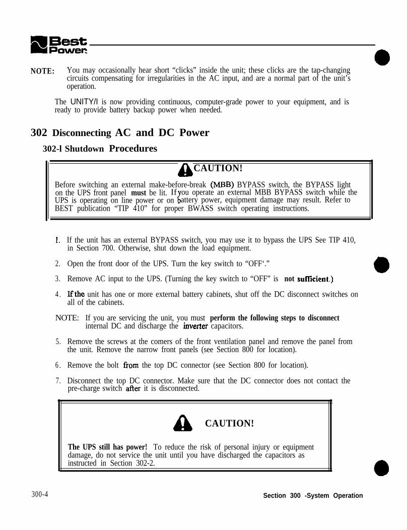
NOTE: You may occasionally hear short “clicks” inside the unit; these clicks are the tap-changingcircuits compensating for irregularities in the AC input, and are a normal part of the unit’soperation.
The UNITY/I is now providing continuous, computer-grade power to your equipment, and isready to provide battery backup power when needed.
302 Disconnecting AC and DC Power302-l Shutdown Procedures
g, CAUTION!
Before switching an external make-before-break (MBB) BYPASS switch, the BYPASS lighton the UPS front panel must be lit. IfUPS is operating on line power or on IT
ou operate an external MBB BYPASS switch while theattery power, equipment damage may result. Refer to
BEST publication “TIP 410” for proper BWASS switch operating instructions.
1. If the unit has an external BYPASS switch, you may use it to bypass the UPS See TIP 410,in Section 700. Otherwise, shut down the load equipment.
2. Open the front door of the UPS. Turn the key switch to “OFF‘.”
3. Remove AC input to the UPS. (Turning the key switch to “OFF” is not suffkient.)
4 . Ifthe unit has one or more external battery cabinets, shut off the DC disconnect switches onall of the cabinets.
NOTE: If you are servicing the unit, you must perform the following steps to disconnectinternal DC and discharge the inverter capacitors.
5. Remove the screws at the comers of the front ventilation panel and remove the panel fromthe unit. Remove the narrow front panels (see Section 800 for location).
6 . Remove the bolt from the top DC connector (see Section 800 for location).
7. Disconnect the top DC connector. Make sure that the DC connector does not contact thepre-charge switch after it is disconnected.
300-4
e CAUTION!
The UPS still has power! To reduce the risk of personal injury or equipmentdamage, do not service the unit until you have discharged the capacitors asinstructed in Section 302-2.
Section 300 -System Operation

UNITY/I”
0 302-2 Discharging the Capacitors
1 .
2.
3.
4.
5.
6.
I.
8.
Remove the seven screws From the side covers. Three screws are found on top of the unit,and two on each side panel.
Lift each side cover straight up, then off.
Remove the two screws in the upper comers of the side door assembly. Open the side doorassembly.
NOTE: Steps 4 and 5 are for units with internal batteries. If your unit.has no internalbatteries, slup steps 4 and 5 and wait five minutes for capacitors to discharge through thefuse board before continuing with step 6.
WM AC and DCpo~er disconnected (see Section 302-l), turn the UPS key switch to“AUTO” for at least five seconds.
Turn the key switch back to “OFF.”
Verify that the capacitors are discharged.Use a DC voltmeter to measure the DCvoltage between the DC bus bar (-) and theoutside heatsink on the inverter board (+)as shown in Figure 302-2A.
(i!Aeasure both
inverter heatsinks in the UT8 .)
If the readin in step 6 is greater than fivevolts,wait me minutes to allow theBcapacitors to discharge. Then, repeat steps6 and 7 before continuing.
Remove the fast-on connector from ES inthe u er right comer of the fbse board.
ke zard.)See ection 800 for the location of the
303 Front Panel Key SwitchFigura 302~2tk Measuring Chargein Capacitors
The UPS k switch is found inside the front door of the UNITY/I. The key switch allows you toplace the UFS mto “AUTO” mode, shut the UPS off, or place the UPS into internal bypass mode.
l AUTO: When the key switch is turned to “AUTO,” the UPS provides computer-grade powerto your equipment. Usually the UPS operates on AC line power, filtering and regulating utilitypower. When necessary, the UPS switches to battery Rower.
a OFF: When the key switch is turned to “OFF,” the UPS is off and does not provide power tothe connected equipment.
ACAUTION!Live AC, DC, and charged capacitors are still inside the unit. If you intend to performservice, maintenance, or repair, see Section 302 for complete shutdown instructions.
Section 300 - System Operation 300-5

l BYPASS: When the key switch is turned to “BYPASS” the unit powers the connectedequipment, but it does not regulate the AC power going to the connected equipment and cannotprovide battery backup power or charge the batteries. The unit does provide lightningprotection, noise protection, isolated output, and over-voltage protection.
304 Emergency Power Off (EPO) Reset Buttonl EPO Reset: The EPO reset button is found on the front panel of the unit near the key switch
(see Figure 301-IA). If a remote EPO shutdown has been activated, use the EPO reset buttonto reset the unit. Before resetting the unit, verify that no actual emergency has occurred, or thatthe emergency is over. The EPO reset button does not serve as a reset button for any otherpurpose.
NOTE: The remote EPO feature allows you to connect your UPS to a remote EmergencyPower Off switch, or “panic button.” For proper installation see the User MunuuI. If theEPO is installed, the UPS will shut down when an EPO signal is sent to itscommunication port. When an EPO shutdown occurs, the unit’s four-digit displayscrolls “EPO.” The EPO reset button will reset the UPS to normal system operation.
305 Front Panel LEDsThe four LEDs at the top of theFront panel give informationabout the operating status of theUPS (see Figure 305-A). Theyare explained below. (The nineLEDs located by the front panelkeys are discussed in Section306.)
l Line LED (Green)
When the LINE LED is on, theunit is receiving AC input line.The UPS is filtering and Figure 305-A: Front Panel LEDsregulating AC line power to provide computer-grade power to your equipment,
When the LINE LED is off, the UPS is not receiving adequate AC input power to run on line (i.e.,if there is a power outage). Usually, when the LliVE LED is off, the BATTERY LED will be on.
l Battery LED (Yellow)
When the BATTERY LED is on, the UPS is providing power from its batteries.
l BYPASS LED (Yellow)
The unit is in internal bypass mode when the BYPASS LED is on. Either the front key switch hasbeen turned to “BYPASS” or Parameter 63 has been enabled (see Table 308-4). When the unit is inbypass mode it continues to power the connected equipment, but it does not regulate the AC powergomg to the connected equipment and will not provide battery backup power. The unit doescontmue to provide Ii htning protection, noise protection, and isolated output. If the logic board ispowered, it will shut own the unit if an over-voltage condition occurs,f
300-6 Section 300 -System Operation

NOTE: If the BYPASS LED is on, the UPS key switch is turned to “AUTO,” and the unit is notshowin laceditself in53
an A-16 alarm or advisory condttion, the unit may have automattcallyYPASS mode (see table 501-l for alarm information, and Section 20 P-5.2 for
information on the watchdog signal).
l Alarm LED (Bed)
When the ALARM LED is on, the UPS is alerting you to an alarm condition (see Section 503).
306 Front Panel Keys and DisplayInformation about the UPS is easily accessed via front anel keword above each key tells you what information the d 4S wtll
s and a four-digit display. The
words below the keys tell you what information the UPS willtsplay if you press that ke . The
displathe two ke s indicated. A small green LED illuminates to tell you wK
if you stmultaneous y pressYat mformatton IS currently
displayed. she information remams on the display until you press another key. Table 306-lexplains what happens whenmore information about the 2
ou press each key or pair of keys. (See Sections 308 and 309 foront panel key fbnctions when the umt IS m parameter mode, and when
viewing alarm and system logs.)
l Silences an audible alarm if one is present. If the UPS subsequently recognizes anew alarm condition, it will reactivate the audible aIarm. NOTE: Silencing analarm does not correct the alarm condition.
0 Cancels a battery test if one is in progress.l Holding the key down for two seconds clears an alarm.
NOTE: The alarm will recur if the condition that caused it still exists.l If the unit has shut down due to an alarm condition, holding the key down for hvo
alarm condition has been corrected and
the estimated rnntime remaining (in minutes and seconds).. The runtirne display is most accurate when the UPS is rnnning on battery
Starts the scan mode. In scan mode the UPS scrolls through a display of VBATI,P, %LOAB, VLINE Each value is displayed for two
tell you which value is currently
NOTE: If Parameter 77 (Test on Demand) is enabled, the unit will also test thebatteries, If Parameter 77 is enabled and Parameter 62 (Nominal Input Voltage) is set,
Section 300 -System Operation

307 Communication via the DB9S Communication PortBEST publication UTY 501, in Section 700, gives instructions on communication via the DB9Sport.
308 System ParametersParameter values are set at the factory and some may be changed in the field by qualified fieldservice personnel. The UPS uses the parameters for meters, counters, alarm set points, acceptablepower quality limits, operation limits, or communication. The system parameters providecomparison set points that the software compares with values acquired in real time.
308-l Passwords
A password is required to program many parameters. i%e password must be entered inParameter 00. See Table 308-l for passwords. See Table 308-4 for the password levelrequired to program specific parameters.
Table 308-l: Passwords for the UNITY/I
Password Level Password
Level 1: User 371
II Level 2: Service I 2639 II
Level 3: Factory 8473
Display only Parameter cannot be changed in the field.
308-2 Key Functions: Parameter Mode
The table below ex@ins what each key does when a parameter number or parameter value ischsplayed. Alternative key names are on the programming template inside the unit’s &ont door.
Key When a ParameterNumber is Displayed
When a Parameter Value is Displayed
%LOAD Steps to the nextparameter number.
Increases the setting of the parameter.
VOUT Steps to the previousparameter number.
Decreases the setting of the parameter.
CANCEL Toggles to the parameter Toggles to the parameter number display.value display.
VLINE Escapes parameter mode. Returns to the parameter number display withoutsaving any changes made to the parameter setting.
RUNnME Key has no function. Enters new parameter setting.
300-8 Section 300 -System Operation

UNITY/I”!
308-3 Viewing Parameters via Front Panel Keys
This section explains how to view parameters using the front panel keys and four-digit displayon the !?ont of the UPS. To view parameters via a terminal connected to the DB9 port, seeBEST Publication UTY 501 in Section 700 of this manual. For more information about eachparameter, see Table 308-4. NOTE: An alternative “programming template” is found on a labelinside the UPS’s front door. This template provides alternative key names that correspond tothe parameter key functions.
1. To access the parameters, simultaneously hold down the [CANCEL] and [RUNTIME] keysfor two seconds. Release the keys when the four-digit display shows “P-00.”
“P-00” is a parameter number. (The first cohunn of the parameter table, Table 308-4, showseach parameter number.)
2. Whenever a parameter number (P-xx) is displayed, you can use the following keys to step tothe parameter you wish to view.
l Step to the next parameter number by pressing [%LOAD].l Step to the previous parameter number by pressing [VOUT].
3, Press [CANCEL] to view the parameter value. For example, with “P-07” on the display,press [CANCEL] to view the UPS’s Low Runtime Alarm Setpoint.
4 . Press [CANCEL] to return to the parameter number (P-xx). Note that the [CANCEL] keyallows you to toggle between the parameter number and actual parameter value.
5. If you wish to view additionai parameters, repeat steps 2 - 4.
6 . To escape parameter mode, press WINE] twice.
308-4 Changing a Parameter Value and PARAMETER TABLE
You can set many of the unit’s parameter values to program certain UPS features. Table 308-4describes the parameters. Make sure that you FULLY understand a parameter beforeattempting to change it! Improper setting of certain parameters may cause the UPS tofunction differently than expected.
1. Hold down the [CANCEL] and BUNTIME] for two seconds, Release the keys when thedisplay shows “P-00.” Then press [CANCEL], The display should read “0.”
2. Use the [%LOAD] (increase setting) or the [VOUT] (decrease setting) keys to change thedisplay reading to the desired password (see Section 308-I). To scroll through the settingquickly, hold down the [%LOAD] or the [VOUT] key.
Section 300 -System Operation 300-9

3. Press [RUNTIME] to enter the password. The display should read “1,” “2,” or “3” forservice or factory password. If the display reads “0,” the unit did not accept thepassword-repeat step 2.
NOTE: If the display is left unattended (no keys are pressed) for five minutes, thepassword reverts to level “0” and you must reenter the password. (In softwarev. 1.00, if the display is let? unattended for one minute the password must bereentered.)
4 . Press [CANCEL] to set the parameter number (P-xx).
5. Press the [%LOAD] or [VOUT] key to scroll to the number of the parameter that you wishto change. Press [CANCEL] to view the parameter value. Note that the [CANCEL] keyallows you to toggle between the parameter number and parameter value.
6. Whenever a parameter value is displayed, use these keys to change the setting:
l To increase the setting press [%LOAD].l To decrease the setting press [VOUT].l To set and enter the oarameter at its factorv default settine. (see the fifth column of the
parameter table), simttltaneously hold down the [%LOAI?j and [VOUT] keys for &JOseconds. \
NOTE: The UPS will not allow you to change a parameter ifit requires a passwordlevel higher than the password entered in step 2.
I. To enter the new value, press [RUNTIME 1. The UPS beeps to indicate that the new valuehas been entered. If you wish nof to save a change that you have made, press [VLINE] andthe value will remain at its original setting.
8. If you wish to change additional parameters, repeat steps 4 - 7.
9 . To escape parameter mode, press /VLINE] twice.
The parameter table (Table 308-4) includes the parameter number, parameter names, thepassword required to change the parameter, the default setting, and a description that includesthe adjustable range. A password of “Display only” means that the parameter value is notprogrammable in the field.
300-I 0
- - -
Section 300 -System Operation

UNITY/I”
able 308-4:ParameterNamePassword
:-Phase UNITYParameter NameSoftware Code
zmetersPassword
None
Serial NumberL o w
SerialNumLow Factory
Serial NumbaHigh
SerialNumHigh Factory
Auto Restart AutoRestartMode User
Model Numb ModelNumber Factory 0
output VoltagReference
NominalVOUT User 240
-Default Description
Allows you to enter a password. Password levels:Level 0: No passwordLevel 1: User Password (377)Level 2: Service Password (2639)Level 3: Factory Password (8473)Password time out is five minutes; if there is no userinput for five minutes, the unit reverts to passwordlevel “0” (no password).Note: In software ~1.00 only, the password time outis one minute.The UNITY/l serial number is formatted as follows:UtxKyzzzz where x is the model number(KW/KVA rating) of the UPS and yuu is a uniquefive-digit unit serial number. Parameter 01 reportsy. Parameter 02 reports iz22.Note: On the UPS front panel, parameter 02 doesnot display leading zeroes. For example, for theserial number UT3K10025, parameter 01 would be“1” and Parameter 02 would be “25.” Range(software VI. 00 lo VI. 03): 0 - FFFF hex.Rome fsofhare ~I.04 to ~1.06): 0 - 9999.
If the UPS shuts down because of a non-latchingalarm or an “OFF’ or “TOFF’ command from atetinal connected to the DB9 port, this parameterdetermines whether the unit will automaticallyrestart. Ifset to “I,” the UPS r&arts itselfwhenconditions allow. If set to “0,” the UPS must bemanuallyrestarted.Choicest 0 (Disable) or 1 (Enable).Reports the model number (KW/KVA mting) of theUPS. Setting does not affect unit operation. Range:fl.9999~
This parameter setting determines the voltagespresent nt fhe output terminals on the WS DIN rail.The output voltage regulation range will be *3%(with ~1.00 to 1.08 software). or tits% (with vl.09software) steady state (default) of this value. Range:180-260VAC.Notes: (1) This value will be the nominal outputbetween UPS DIN rail terminals Xl to X4 or Xl toX5, depending on the contiguration. (2) The outputfo the loads depends upon which output terminalsthe output wires are connected to. (3) See the“Voltage and Phase Check” section in theInstallation Manual for more information on settingthis parameter and for information on outputvoltage/wiring configurations.
Section 300 -System Operation 300-11

mBes;tm Powerr
I
# Parameter Parameter Name in Password Default DescriptionName Software Code
0 6 Full Load Set FullLoadSetpoint Service 4.00 Unit KW/KVA rating. Maximum steady statePnint KW/KVA output. Used in the calculation of the set
II I . -...I I I I 1 point for the dverload alarm (A-01). Range: 2.00 - 11
0 7 Low RuntimeAlsroISet Point
i7.00 KVA.LowRuntimeSetpoin UseI 2 When running on battery power, the UPS indicatest a Low Runtime alarm (A-00) when the estimated
runtime is equal to or less than this value. Range: 1I - 99 minutes.
0 8 1 GlitchLimit I GlitchLimit 1 Service 1 1 2 1Number of glitches that must accumulate for theI I I I UPS to switch to exclusive inverter operation.
II I Range: 1 - 36 glitches.nQ 1 Frequency Slew 1 Fred_ .-qSlewRate user 3 4 7 Sets the rate at which the phase-locked-loop (PLL)
Rate tracks changes in input frequency. Greater value =faster tracking. Default of 347 is about 30HzIsecond.Rmwe: 10 - 780.
“,10
ILine Full Loadcurrent
LineFullLoadCurren Service 17.2 Maximum steady state output current in ampms. Ifthe output current exceeds this value, anaccumulator will activate a Circuit Breaker Warningalarm (A-02). If the accumulator reaches the trippoint CircuitBreakerTripl (parameter 1 l), the UPSactivates a Circuit Breaker Shutdown alarm (A-02)and the UPS output shuts down. Range: 1.0 - 350.0
amns. 1I I
11 Circuit BreakerTrip 1
1 2 High Ambient HighAmbientSetpoi Service 40.0 The UPS activates a High Ambient Temperahue
~ TZEZintnt alarm (A.03) if the UPS internal ambient
temperature is equal to or greater than this value.The ambient temperature sensor is located on thelogic board. Range: 1.0 - 100.0 degrees Celsius.
13 Frequency Frequency Display 0 Displays the frequency of the phase-locked-loop (theOdY UPS output frequency).
Note: A new value is computed automatically ifparameter 05 (NominalVOLlT) or parameter 06(FuIILoadSetpoint) is changed.
CircuitBreakerTripl Senice 4 0 Sets the hit for maximum allowable overload, triptime depends on amount of overload. See alsopeter 10 (LiieFullLoadCuncnt). Range: l-
300-12 Section 300 - System Operation
a 1di

UNITY/I”
k Parameter Parameter Name in Password Default DescriptionName Software Code
14 Frequency Mode FrequencyMode U s e r 2 So/twore ~I.00 - ~1.05: Specifies the PLL center(VI.00 -vl.OS) frequency (i.e. nominal frequency). The UPS
omputs this frequency 10.15Hz when nmning onbattery power. If this parameter is set to “2” (autoselect), the UPS automatically selects the PLL centerfrequency based upon the input frequency.
NominalFrequency(~1.06-09)
FrequencyMode USI
Choices: 0 (5OHz), 1 (6OHz) or 2 (Auto select).Note: If no input line is present when the UPS ispowered up, it will revert to its most recent setting.lf the UPS auto select frequency mode, it will revertto the most recently auto-selected frequency.
1 Software vl.06: I f Parameter 15(AutoFrequencyMode) is set to “l”, this parameterreports the PLL center frequency (i.e. nominalfrequency) that the UPS has auto-selected. IfParameter 15 (AutoFrequencyMode) is set to “o”, thisparameter is used to specify the PLL center frequency.Choicest 0 = 50 Hz, 1=6OHz.
15 Auto Frequency AutoFrequencyMode D i s p l a y 1 SoffwLye v.1.00 - 1.05: When FrequencyModeMode (~1.00 - OdY (parameter 14) is set to auto select, this parameterv1.05) reports the PLL center frequency presently selected.
0=50Hz.,1=60Hz.
DAuto Frequency AntoFrequencyMode User 1 Sofivare ~1.06: Enables or disables auto frequencyMode(v1.06-09) mode. In auto frequency mode, the UPS automatically
selects the nominal fmquency based upon the inputfrequency. See also Parameter 14. Choices: 0(LNsabIe) or I (Enable).
16 Maximum MaxFreq”-=Y USer 65.0* Maximum line frequency to which the PLL willFrequencY’ lock. Ifthe frequency exceeds this value, the UPS
&xvltchestobattery0~ti0”. Thisvaluem”stbegreater than the PLL center besuency (see
17 MhtimumFw=“CY*
MinFmqueucy USer 45.0*
parameters.14aud 15).Rqy: 50.5 -65.OHz.
Minimum frequemy to which the PLL will lock. Ifthe fteqnency drops below this value, the UPSswitches to battery operation. This value most beless than the PLL center frequency (see parameters14 and 15). Range: 45.0 - 593Hz.
* Note for units with ~1.04 or x1.06 software: If the UPS is in auto frequency mode (see Parameter 14 inv.1.04-1.05 or Parameter 15 in v.1.06) the unit selects a nominal frequency of 50 or 60 Hz. The UPS thenautomatically sets *3 Hz frequency rails-in other words, it sets MaxFrequency (F’arameter 16) to the nominalfrequency plus 3 Hz, and it sets MinFrequency (Parameter 17) to the nominal frequency minus 3 Hz.Important: If the unit is in auto frequency mode and the user programs frequency rails into Parameters 16 and17, the user-programmed frequency rails will be overridden if the unit is shut down and re-started (i.e. the unitwill again auto-select the frequency and set frequency rails of l 3 Hz). To prevent this, if you programfrequency rails in Parameters 16 and 17, you should also disable the auto frequency mode (see Parameter 14 inv.1.04 - 1.05 or Parameter 15 in v.1.06).
Section 300 -System Operation 300-13

Description-Default
1
111
4
-
c
-Parameter Name inSoftware Code
ParameterNameInstallationEqualization
Password
Service
19 Phase ClEset phase_offset Service
20
r
21
23
24
2r
-
TransformerResistance
Service
Set Metering for380/400/415VInput
SetVINRange400
COlIUUUlli~tiOn
Mode
Programmablecontact 0
PgmcOnraaO
ProgrammableC o n t a c t 1
PgmContactl
Programmablecontact2
PgmContact2
user
User
USer
U s e r
U s e r
If set to “1,” causes equalization charge of thebatteries at installation or when ROMs are changed.Choices: 0 (Disable) or 1 (Enable).Notes: (1) The duration of the instaIIatiooequalization charge is determined by parameter 67(CHRGDURHOURS). (2) Once the equalizationcharge is complete, the unit automatically resets thisparameter to “0.” (3) If the unit is shut off before theinstall equalization charge is completed, theinstallation charge will begin over again at the nextstart-up because this parameter will still be set to“1.”Used to compensate for the reference phase lag ofthe zero cross discriminator. Calcolated only atsystem start-up (i.e. if this parameter is changed, theunit must be re-started for the change to becomeeffective). Range: 0 - 359 degrees.Scaling factor used to compensate for impedancedrops in the UPS system. Used in the calculation ofa tap setting when transferring from battery to linenewer. Ronee: 0 - 16.
0 Scales the UPS metering for systems with optional (380/400/415 volt input. This setting does not affectUPS output voltage. Choices: 0 (Disable) or 1(Enable).Selects comnmnication mode and sets baud rate orreaction delay. Range: 0 - 50 hex.See BEST publication UTY 501 for moreinformatiolLUsed to program contact 0 @in 5) on theconmmnication port. Range: 0 - 3F24 hex.See BEST publication UTY 501 for moreinformationUsed to program contact 1 (pin 3) on thecommunication port. Range: 0 - 3F24 hex.See BEST publication UTY 501 for moreinfwmation.
1 0
1 3 0 7
1317
3317 Used to program contact 2 (pin 6) on thecommunication port. Range: 0 - 3F24 hex.See BEST publication UTY 501 for moreinformation.
300-14 Section 300 -System Operation

UNITY/I”
Parameter Parameter Name in Password Default DescriptionName Software Code
2 6 Reserved (~1.00 so/huare ~I.00 to ~1.03: Resewed.to I. 03)PhonTek Copies Copies User 0 %~?~are ~I.04 IO ~1.06: Begins PhonTck(VI.04 to v1.06) transmission and specifies how many copies of the
message to transmit.Range: 0 - 98 copies. 99 = continuous transmission.Note: BEST publication UTY 628 contains userinstructions for PhonTck.
2 7 Input Voltage CalibratcdVIN sclvicc 0 Directly metered input voltage. Range: 65 - 300VAC.
28 output Voltage calibratcdVOuT Service 0 Directly metered output voltage. The onit monitorsthe high voltage output (up.3 output terminals Xl tcX5) and extrapolates the nominal output voltage forthe display based on the setting of parameter 5.Range: 10 - 1000 VAC @MS).Caution: Before calibrating parameter 28, removeloads and set parameter 05 (NominaJVOUT) to 240.Then, program parameter 28 based on the mcawedvoltage from UPS output terminals Xl to X5.Parameter 28 will not calibrate properly unlessparameter 05 is set to 240.
b1
29 output currc”t CalihratcdIOUT Service 0 . 0
30 Battery Voltage CalibratedVBAT service 0.00
31 Internal Ambient CalibratcdAh4BTMF’ Service 0 . 0Temperam
(Note: After calibrating parameter 28, remember toreset parameter 05 to its previous setting.) SeeBEST publication UTY 501 for instructions oncalibrating parameter 28.Directly metered RMS output oorrent. Range: 1.0 -350.0 amperes @MS).Dkctly metered battery voltage.Range: 1.00 - 99.99 V.
UPS inter& ambient temperahue. The internalambient temperature sensor is located on the logicboard: Rmge: 0 - 150.0 degrees Celsius.
32 Battery CalibratcdBATTMP service 0 . 0 UPS battery compartment tcmpcratm. The batteryTemperatore temperature sensor is located on tbc fbsc board.
Range: 0 - 150.0 degrees Celsius.33 Runtimc Runtime Display 0o:oo The estimated rontime in minutes and seconds.
OdY Notes: (1) The estimated nmtimc is most aecmatewhen the UF’S is nmning on battery. (2) In s&ware~1.00 tov1.03, a terminal connected to the DB9port displays the runtime in secon& on&.
34 Percent Load PercentLoad Display 0 The percentage of the unit’s total capacity that theOdY load equipment is using.
Percent Load = (VA Load + Max VA Load) x 100.35 power Factor PowerFactor Display 0 . 0 0 Ratio of system real power to system VA.
OdY Power Factor = KW Out + KVA Out.K W O u t DisplayWOUT Display 0 . 0 0 Calculated KW of load.
O”lY
\
Section 300 -System Operation
I
300-15

t
39
41
42
43
-44
DescriptionParameter Parameter Name inName Software Code
KVA Out DisplayVAOUT
Input VoltageCalibrationFactor
CalFactorVIN
Calculated KVA of load.
AID conversion factor for determiningCalibratedVIN (parameter 27). Differs in each unit.Range: 03E8 - FOOO hex.AID conversion factor for determiningCalibratedVOUT @ammeter 28). Each unit differs.Ranw: 03E8 - FOOO hex.
Output VoltageCalibrationFactor
CalFactorVOUT Service lA9C
CalFactorIOUT Service 1309
--I-Service 1775
AID conversion factor for determiningCalibratedIOUT (parameter 29). Differs in eachunit.Range: 03E8 - FOOO hex.
A/D conversion factor for determiningCalibratedVBAT (Dammeter 30). Each unit differs.Range: 03E8 - FOCO hex.
Output CurrentCalibrationFactor
Battery VoltageCalibrationFactorInternalTemperatureCalibrationFactor
CalFactorVBAT
CalFactorAMBTMP
+
Service lC9 A/D conversion factor for determiningCalibratedAMBTMP (oarameter 31). Each unitdiffers.RometO- FOOOhex.
Z.emAhWlXP Setice 1DFZero InternalAmbientTemperature
BatteryTemperahueCalibrationFactor
CalFactorBATTMP
Offset correction for determiningCalibratedAMBTMP (parameter 3 1). Each unitdiffers..Range: 0- FOOOhex.AiD conversion factor for determiningCalibratexiBATTMP (parameter 32). Each unitdiesRange: 0 - FOOO hex.
Offset comctlon for determiningCaIiiratedBAm (parameter 32). Each unitdiEeraRune-: 0 - FOOO hex.
q-G-
Service 1DF
t
Display 0OdY
45 Zero BatteryTemperature
ZeroBAlThJF’
-46 Alarmstahls+o AltUtIlStatus+o
47 Alarm Status + 1 AlarmStatus+
-48 Alarm Mask + 0
(vl.00 tovl.05)AlarnMask+O
Alarm Mask + 0(~1.06)
AlarmMask+O
When an alarm condition existqa bit is set in the32-hit alarm status register. This parameter displaysthe hexadecimal representation of the lower alarmstatas register, which is bits 0 - 15. See BESTpublication UTY 501 for more information.
When an alarm condition exists, a bit is set in the32-bit alarm status register. This parameter displaysthe hexadecimal representation of the upper alarmstates register, which is bits 16 - 31. See BESTpublication UTY 501 for more information.Sofhvare ~I.00 to ~1.05: Causes selected alarms tobe ianored.Ron&:0 -FFFF.Sofhvare ~1.06: Causes selected alarms to beignored.
Displayonly
0
Range:O-FFFF.
300-I 6 Section 300 -System Operation

UNITY/I’”
Nallte Software Code4 9 Alarm Mask + 1 Alarmh4ask+l Display 0 sofhwe VI.00 to VI.05 causes selected alarms to
(VI.00 tovl.os) dy be ignored.Range: 0 - FFFF.
Alarm Mask + 1 AlarmMask+ Factory 0 Sofhyore ~1.06: Causes selected alarms to be(~1.06) ignored.
Range: 0 - F F F F .
S O Beeper Enable BeeperEnable User 1 If set to “0,” silences the beeper in all cases exceptPhonTek operation.Choices: 0 (Silence), 1 (Enable).
5 1 Low Battery LowBatterySetpoint Display 4 0 . 0 8 Battery voltage at which a Low Battery Alarm orAlann Set Point OdY advisory condition (A-OS) and shutdown occor.
Automatically adapts based on BatteryCapacity(parameter 55) and either VAOUT (in soj?worev.1.00-vl.05)orWOLTr(8o~arevl.06).Note: As load increases, LowBatterySetpointvoltage decreases. As BatteryCapacity increases,LowBatterySetpoint voltage increases.
5 2 High Battery HighBattetySetpoint Service 6 0 . 0 0 Battery voltage set point for High Battery alarmAlarm Set Point (A-07) Ranger 10.00 - 90.00 V.
warev1.00 to ~1.03 = 4.7,
Section 300 -System Operation 300-17

-P&WV0r ‘nrameter Parameter Name in i
hme Software Code61 sow Battery LBatlShutDFlag
f1Xsplay
;hutdown Flag c,nlyvl.00 tovl.05)3ypassFlag BypassFlag Xsplayv1.06) )dY
62 %minal Input HSNominalVlN UserJoltage
63 3attery HotSwap Usertiaintenance (v.1.00 -vl.OS)Mode HotSwapAcess
(v. 1.06)
-Description
So/tware ~1.00 to vl.0.Y: Flag for determiningaperating mode at start-up following a low batteryshutdown. 0 = Not in shutdown mode.Softwore ~1.06: Indicates which bypass condition isactive (HotSwap, LowBattery, EPO) and the bypasstap chosen. (Bit 0 = Last tap - 1, bit 1 = HotSwapon, bit 2 = LowBatt on, bit 3 = EPO on).Used to set the nominal input voltage before usingparameter 63 (HotSwap). Range: 200 - 240 VAC.Note: If this parameter is set and parameter 77(TestOnDemand) is enabled, during a front panelkey TEST the UPS will test the BYPASS light bybriefly switching to internal bypass mode.When this parameter is enabled, the internal bypassrelay is used to bypass the static switch. The UPScontinues to power the connected equipment butdoes not regulate voltage and will not providebattery backup power. To enable parameter 63, youmust first set parameter 62 (HSNomina1VR-J).Choices: 0 (Disable), 1 (Enable).Notes: (1) When parameter 63 is enabled, the unitcontinues to provide noise protection, lightningprotection, and isolated output. (2) As long as the ilogic board is energized, the unit will indicate anAuto Bypass (A-16) alarm or advisory conditionwhen parameter 63 is enabled. (3) As long as thelogic board is energized, the UPS alarms will befhCtiOMl.WARNING! Parameter 63 allows a qualifiedtechnician to service or replace the batteries withoulshutting dowathe unitioads. Parameter 63 is foruse during battery maintenance only and must notbensedduring~otbertypeofunitserviceormaintenance because the unit remains ener&ed.-
Vote for parameters 64 - 72: The UNlTYiI battery charger has four charging modes: Periodic, Constant Current, ConstantVoltage, and Maintenance. For more information, see Section 203-4.4 “Charger Modes.”
User 4 If the duration of the “constant current” chargingmode exceeds CCMINUTE S , the unit does a“constant voltage” charge before returning to the“maintenance” charging mode. If the duration of tht“constant current” mode is CCMINUTES or less,the unit proceeds directly to the “maintenance”chareinp. mode.Ran& i - 10 minutes.
300-l 8 Section 300 -System Operation

UNITY/I”
48.00 - 56.00 V .
If CalibratexlBAlTMP eter 3 2 ) is less than or
(parameter 69) is used as the charger float voltage.Range: 0 - 20.0 degrees Celsius.Note: In units with softwm ~1.06, there is a 3” Chysteresis. The unit will use ColdChrgVolts(Parameter 70) when CalibratedBATTMP(Parameter 32) drops to or below the ColdAmbientsetting.TheunitwillresomeuseoftheNormChrgVolts @uameter 69) when
er. 1 = Periodic 2 = Constant Current,
Battery TestTime(~1.06)
BatteryTestTime User Sofhvare ~1.06: lf the pericdic battery test isenabled (see Parameter 76), the battery test beginswhen Time (Parameter 89) equals this value.Range:OO:OO -23:59.Note: The battery charger must be in maintenancemode for the battery test to occur.
Section 300 - System Operation 300-19

ParameterNa”Ie
Battery Test[nterval
Battery TestLength
First Day ofBattery Test[vl.OO to v1.04)
First Date ofBattery Test:v1.05 -v1.06)
rest On Demand
Line Delta Mode
Parameter Name inSoftware Code
BatteryTestInterval
BatTestLength
FirstDateOfTest
FirstDateOffest
restOnDenm”d
LineDeltaMode
Password
User
User
User
User
User
User
aDefa”
7
15
30:oo
30.00
D
3
IDescription
If the periodic battery test is enabled (see parameter76), this is the interval between battery tests,Ranee: 1 - 28 davs.
If the periodic battery test is enabled (see parameter76), this is the length of time the UPS rims onbattery power during the battery test, expressed as apercentage of the LowRuntimeSetpoint (parameter07).Range: 5 - 25%.Note: The default BatTestLength = 15% of 2minutes (LowR”“timeSetpoint default), whichequals 0.3 minutes (18 seconds).Sofhvare ~1.00 to ~1.04: The first battery test willtake place on the day that WeeksDays (parameter91) equals this value.Disables the periodic battery test if set to “0”.Range: 0O:OO (Disable test) or 01:Ol - 04:07(Week/Day of first test).S’oftwrrre ~I.05 to 1.06: The first battery test willtake place on this Date (Parameter 90), fornmttedmonth/day (nun/dd). Disables the periodic batterytest if set to Yo”.Range: 00.00 (Disable test) or 01.01 - 12.31 (Date (of first test). **See note at bottom of oaee.If set to “1,” the UPS performs a battery test whenthe tint panel TEST keys are pressed or when theB command is sent via a terminal conncctcd to theDB9 communication port. Choices: 0 (Disable) or1 (Enable).Note: See the Note for meter 62.
Used to detenni”e.sc”sitivhy to AC line faults.Choices: 1 (Normal mode-uses LINEDELTAvalue in pammeter 81), 2, (Poor line mode--usesleast sensitive fault detection), 3 (Adaptivenmde-UPS adapts sensitivity based on line qualityhistory).
P,
** In software version 1.05 - 1.06, if the battery test time and date (Parameters 73,76) fall prior to the currenttime and date (Parameters 89, 90), the UPS will add the value of BatteryTestInterval (parameter 74) to theFirstDayOf Test (Parameter 76) until the battery test time and date fall after the current tilne and date.Example: The Current Time (Parameter 89) = 13:07, Date (Parameter 90) = 04.28 (i.e. current time/date =1:07 p.m., April 28).The BatteryTestTime (Parameter 74) is programmed to 1:00 and the FirstDateOtTest (Parameter 76) to 04.22(i.e. battery test time/date = 1:00 a.m., April 22). Because the battery test date (April 22) precedes the currentdate (April 28), the UPS will add the value of BatteryTestInterval (Parameter 74, default = 7 days) to the valuefor FirstDayOtTest. Thus, the first battery test will occur on 04.29 at 1:00 (04.22 + 7 days = 04.29).
300-20 Section 300 -System Operation

UNITY/I”=
‘cyI Parameter Parameter Name in Password Default DescriptionName Software Code
19 Glitch Sensitivity GlitchSensitivity User 1 0 When LineDeltahkde fjwameter 78) is set toadaptive mode, this is the number of glitchesallowed to occur per quarter second before line deltais increased (sensitivity to disturbances is
. decreased). Range: 1 - 34.80 Less Delta LessDelta UseI 5 0 0 When LineDeltaMode (parameter 78) is set to
adaptive mode, this is the number of quarter-secondintervals without a glitch before line delta isdecreased (sensitivity to disturbances is increased).Range:4-9999.
81 Line Delta LINEDELTA UsJZ FFDD When LineDeltaMode (parameter 78) is set tonormal mode, this parameter programs the deltalevel. A higher value increases sensitivity todisturbances (decreases delta).RangcFE82 -FiTE hex.
82 Low output Votriplo User 228 The low output voltage tap regulation trip point. AVoltage Trip steady-state calibrated VOUT (parameter 28) lowerPoint than this value causes a tap change. This parameter
and Votriphi parameter 83 set the steady-stateoutput voltage regulation window.
Range: 100 - 300 VAC.-I
83 .HighOutputVoltage Trippoint
votriphi user 252
Notes: (1) If nominal VOUT (parameter 05) ischange4 Votriplo is automatically recalculated to-3%(vLOO-1.08 sofhvare)or-5%(v1.09 software)ofnod. (Nominal VOUT x 0.97) for ~1.00-1.08,or (Nominal VOUT x .95) for v1.09.(2) Default value = NominalVOUT x 0.97 (vl.OO-
1.08), which is -3% of NominalVOUT.Default value = NominalVOUT x 0.95 (vl.O9),which is -5% of NominalVOUT.Tkhigh output voltage tap regulation trip point Asteady-state CalibratedVOUT (parameter 28) higherthan this value causes a tap change. This parameterand Votriplo @ammeter 82) set the steady-stateoutput voltage regulation window.Range: 100 - 300VAC.Notes: (1) If nominal VOUT (parameter 05) ischanged, Votriphi is automatically recalcolated to+3% (~1.00-1.08 software) or +5% (~1.09 so&are)of nominal. (Nominal VOUT x 1.03)(2) Default = NominalVOUT x 1.03 (vl.OO-LOS),which is +3% of NominalVOUT.Default = NomiaalVOUT x 1.05 (vl.O9), which is+5% of NominalVOUT.
Section 300 - System Operation 300-21


400 Scheduled Maintenance*
For years of UPS reliability, follow proper maintenance procedures. Scheduled maintenance. should be performedevery sir months. A qualified service technician should clean and inspect the unit; check alarm and system logsand parameters for abnormal indications; perform a unit self-test; and perform a battery load test. It may benecessary to calibrate the AC and DC meter functions when batteries, parts, or other components have beenreplaced.
eCAUTION
UPS maintenance must be performed by a qualified service technician only.
BEST publication WA’ 604 provides written step-by-step instructions for scheduled maintenance. It includes
e
important questions about the system and provides space for you to record the results for future reference.\,
BEST publication UTY 605 is an abbreviated version of UTY 604 provided for experienced technicians alreadyfamiliar with UNITY/l maintenance procedures.
BEST publications UTY 604 and 605 include a simulated power outage and load test to make sure the UPS canprovide power to the loads during a power outage. This test also helps the service technician identify batteriesthat may need replacing. It is important that the customer is informed that if there are low or faulty batteries inthe system, the loads could lose power.
BEST publication UTY 601 contains calibration procedures.
These publications are found in Section 700 of this manual.
Section 400 - Maintenance 400-l


Ia

500 Troubleshooting
The following sections provide information for troubleshooting conditions external to the UPS andinternal alarm conditions. This information can be used to diagnose external factors such asinstallation errors, uneven load distribution, or equipment overload. Information is also provided toassist in diagnosing alarm conditions such as low batteries or high ambient temperature. A list ofalarm codes can be found inside the front panel of each unit for quick reference.
If, after following the troubleshooting tables in this section, you still cannot operate yourUPS, contact BEST Power Worldwide Service at l-800-356-5737 or l-608-565-2100, oryour local BEST office. Please have your unit’s model number and serial numberavailable when you call.
501 Getting Started . . . . . . . . . . . . . . . . . . . . . . . . . . . . . . . . . . . . . . . . . . . . . . . . . . . . . . . . 500-2
5 0 2 Troubleshooting Problems External to the UPS . . . . . . . . . . . . . . . . . . . . . . . . . . . . . . . 500-5
*5 0 3 Troubleshooting Alarm Conditions . . . . . . . . . . . . . . . . . . . . .
503-I: Low Runtime Alarm (A-00) ?& .%5..*. . . o.c.I++~ ?r . .503-2: Overload Alarm (A-01) . . . . . . . . . . . . . . . . . . . . . . . . .503-3: Circuit Breaker Warning/Shutdown Alarm (A-02) . . . . .503-4: High Ambient Temperature Alarm (A-03) . . . . . . . . . . .503-5: Check Battery Alarm (A-04) . . . . . . . . . . . . . . . . . . . . .503-6: Check Inverter Alann (A-05) . . . . . . . . . . . . . . . . . . . . .503-7: Memory Error Alarm (A-06) . . . . . . . . . . . . . . . . . . . . .503-8: Bigh Battery Alarm (A-07) . . . . . . . . . . . . . . . . . . . . . .503-9: Low Battery Alarm (A-08) . . . . . . . . . . . . . . . . . . . . . . .503-10: Check Fan (A-09) . . . . . . . . . . . . . . . . . . . . . . . . . . . . .503-l 1: Batteries Disconnected Alarm (A-l 1) . . . . . . . . . . . . . . .503-12: Tap Regulator Alarm (A-12) . . . . . . . . . . . . . . . . . . . . .503-13: Low AC Out Alarm (A-13) . . . . . . . . . . . . . . . . . . . . . .503-14: High AC Out Warning/Shutdown Alarm (A-14) . . . . . . .503-15: Check MOVs Alarm (A-15) . . . . . . . . . . . . . . . . . . . . . .503-16: Auto Bypass Alarm (A-16) . . . . . . . . . . . . . . . . . . . . . .503-17: Check Fuse Board Alarm (A-17) . . . . . . . . . . . . . . . . . .503-18: Check Power Supply Alarm (A-19) . . . . . . . . . . . . . . . .
.
.
.. .....
.
.
.
. .. . .. .
. .
500-7: ‘500-10 500-9
500-11500-12500-13
. 500-14
. 500-15500-16500-17500-19500-20500-21500-22500-23500-24500-25500-26500-27
504 Dead Unit Diagnostic Procedure 500-28
\a 505 AC Line Diagnostic Procedure
I\ Section 500 - Troubleshooting
. . . . . .._ 500-29
500-l

501 Getting Started
Based on BEST’s field experience, a majority of service calls are caused by problems outside theUPS cabinet, Improper UPS sizing, improper installation wiring, neglected maintenance, and loadequipment failure are common external problems. These problems may start months or years afterthe UPS has been operating and protecting vital equipment, See Section 502, “TroubleshootingProblems External to the UPS,” for more information.
Ifthe UPS is alarming or shows alarms in the alarm log, refer to the troubleshooting tables inSection SO3 of this manual.
If the system is experiencing problems, but the UPS is not alarming and does not show any alarmsin the alarm log, refer to Table 501-l.
To begin troubleshooting, see the following “Basic Troubleshooting” chart
500-2 Section 500 - Troubleshooting

UNITY/I”
0 l Basic Troubleshooting
Disconnect or bypass the loads. Turn off the UNITY/I keyswitch, turn off AC input, disconnect DC or turn 0the DC switch. Then. reconnect DC or turn on the DC switch. Turn the UPS key switch to mAutO.m
Turn off AC Input for SOseconds; then. turn AC
input on ageIn.on and transfer Go to Section 503.
e
I\
“PS operation seems normal. The problem ma,’ be IntermIttent. Display the alarm log to determine whethet+,e problem caused an alarm. It it did. go to the table ‘or that alar”, h Section 503. If not, the pmblem me
be I” loads o,- the InstallZ3tlOf-G 688 Sections 501 and 502.
Section 500 - Troubleshooting 500-3

Table 501-l: Troubleshooting - Without Alarms
1 Possible cause 1 Suggested Action
UPS is dead.
UPS is not dead, butsome or all of the loadequipment is notreceiving power.
*SeeTable 504-l.
l road equipment is switched off.. Equipment formerly connected
to UPS is no longer connected.* A tripped breaker on back of
unit* “Emergency Power Or has
been activated.* Software activated shutdown.
* See Table 504-l.
. Turn load equipment on.l Check load equipment connections.- Reset breaker.l After verifying there is not an actual
emergency, or if the emergency isover, press the EPO Reset Button.
UPS switches to batterypower for “no reason” orin a predictable sequence(i.e., at the same timeevery day).
* Au automatic battery test isbeing done.
l Input AC is being drawn awayby equipment on the same inputpower circuit as the UPS.
l Unstable input power (i.e.,generator).
l Have an electrician check the inputwiring circuit
l Monitor input voltage to find thepattern of disturbance to help inisolation of the problem.
. Check source of unstable input power.
There are powerinterruptions to the loadequipment
Bypass LED is litalthough the key switchis in “Auto” position andno alarm is present
l External bypass switch is in * Put bypass switch in UPS position.LlNE rather than UPS position. * Make sure loads are connected to
* Fquipment formerly conncctcd UPS.to UPS is no longer connected. . Turn key switch to “Or and then to
* Equipment shutdown was “Auto.” Watch display for alarmsofhvare activated. codes.
l F4 on Fuse Board open or wire l Power down equipment, check F4connections on circuit boards and circuit board conne&ions.open.
Excessive tap changing(lots of clicking).
l Unstable input power (i.e.,generator).
l Track dowuthe source ofuustableinput power.
l Change parameters 82 and 83 to set awider output voltage regulationwindow. This should result in fewertap changes.
Communication: Much of the troubleshooting information in this manual assumes that you cancommunicate with the UPS. Although communication is not required, it greatly improves your abilityto find the cause of a problem in the unit. You can communicate with your UPS by using:
. Front Panel Keys: You can use the keys on the front panel of the UNITY/I to communicatewith the UPS. See Section 306 and BEST’s UTY 501 in Section 700 for more information.
0 Terminal/Computer: By connecting a terminal or computer to the unit’s communication port, ,YOU can send commands to the UPS to display and change parameters. See BEST publication 0
500-4 Section 500 - Troubleshooting

‘i UNITY/I”
UTY 501 in Section 700 for information about communicating via the DB9 communicationport.
. CheckUPS Software: If your computer or network is running optional CheckUPS software,you can communicate with the WS.
502 Troubleshooting Problems External to the UPS
UPS problems are often caused by factors external to the UPS. Such problems can begin at any time,and may occur at the UPS AC input or at the loads,
e CAUTION
Only a qualified service technician should disconnect any cables or connectionsthat may contain voltage or current.
The UPS should be installed on a dedicated circuit. The circuit should provide power to the UPS
a
only. Even if the UPS was initially installed on a dedicated circuit, you may discover that other,I equipment (such as a copier or a laser printer) was installed later, on the same circuit. Copiers and
laser printers can cause sags in the input power that may cause the UPS to run on battery power moreoften.
Loads connected to the UPS can sometimes cause problems. For example, coffee pots or smallelectrical heaters can overload the UPS by drawing excessive current. Other UPS loads can haveinternal problemsthat may cause them to draw excessive current. If you suspect that a load is causingthe problem, try discomwzting or switching off the loads one at a time.
As you do this, check to see if the UPS runs properly. If the UPS runs properly when one or moreloads are off, the problem is probably the load, not the UPS.
If these solutions do not help you find an external problem, an electrician can use Table 502-I tocheck the UPS installation.
l Installation Wiring and Grounding (for Hardwired Units)
e, CAUTIONThis section is for qualified service personnel only.
\
!, Most of the UPS service calls BEST receives are installation-related. These problems could beavoided by using the correct wiring diagram provided by BEST. The National Electrical Code (NEC)
I ‘, Section 500 -Troubleshooting 500-s
I\

requires that listed equipment be installed according to the instructions furnished by the manufacturer.Failure to comply with this is a violation of NEC Article 110-3(b).
If you suspect that UPS problems are caused by an external condition, begin troubleshooting byreviewing the entire installation. Start from the service entrance panel, to the UPS connection panel,through the bypass switch, and out to the receptacle outlets where the load equipment is connected.Compare the installation with the wiring diagram in the UNITY~InsrullutionManuul shipped withthe unit, and note any differences. Make sure all connections are tight and properly secured.
The table below describes common installation errors, ways to correct the errors, and applicableNational Electrical Code Articles.
Table 502-l: Common Installation Errors
Installation Error Correction NEC Article
Switchgear, disconnects, and load breakers are Label all disconnects, bypass switches, 1 IO-22not labeled. load breakers, etc.
The UPS is in a cramped or inaccessible area. Position the UPS so that the clearance 1 lo-16You cannot fully remove the cover and inspect conforms to the specifications in thesystem components. UNITY/I Installation Manual. 1
The UPS neutral is not grounded, not used, or The UNITY/I UPS is a separately- 250-5(d)not switched at the external bypass switch. derived power source, and must be 250-26
installed as such. 250-23
The UPS neutral is fused at the bypass switch. Use a bypass switch that is not fused. .230-90(b)240-22
Local ground to the UPS is missing or supplied Supply a continuous conductor from 250-26(c)by conduit only. the nearest available effectively 250-91(a)
grounded electrode (i.e., building 250-92(a)strucmral steel, or re-bar in concrete). 250-92(b)
The UPS 208VAC output is fed to the loads Never use the 88 VAC leg on the UPS 110-3(b)with a neutral. As a result, the loads are fed output. Call BEST for instructions on208/120/88VAC, and loads on the 88VAC leg properly installing the 120/208 VACmalfunction or are damaged, output combination.
500-6 Section 500 -Troubleshooting

UNITY/I’”
a 503 Troubleshooting Alarm Conditions
The following sections describe most internal UPS problems. If these sections do not describe yourUPS problem, use the schematic diagrams in Section 800 to troubleshoot the problem. If you stillcannot find the cause of the problem, call BEST Power Worldwide Service for assistance.
Alarms alert you to UPS conditions that require immediate attention. While some alarms arewarnings, other alarms indicate that the UPS has shut down to protect the UPS and/or the loadequipment from potential damage, Alarm codes are found inside the unit’s front panel for quickidentification.
Alarms may register immediately, or a short debounce may occur. Debounce is the time period that afault condition exists before an alarm circuit is triggered. Debounce prevents false alarms caused bytransient conditions. If you wish to silence an existing audible alarm, press the [CANCEL] key.Silencing the audible alarm does not correct the condition that caused it. The ALARM LEDremains lit to show that the alarm condition still exists, If a new alarm condition arises, the audiblealarm reactivates, If the UPS has shut down and the alarm condition no longer exists, restart theUPS by turning the key switch to “Off and back to “Auto.”
There are two types of alarms. Non-latching alarms clear automatically when an alarm condition isgone. Latching alarms must be cleared manually, even though the alarm condition no longer exists.
’ If a latching alarm is active and the alarm condition no longer exists, first clear the audible alarm byholding down the [CANCEL] key for two seconds.
Then, if the loads are not connected, you must reset the alarm by turning the key switch to “Offand back to “Auto.”
Ifthe loads are still connected and your unit is equipped with an external bypass switch, check tosee ifit is labeled Make-Before-Break (MBB). If so, switch to external bypass to avoid losing powerto the loads. Then turn the key switch to “OR” and back to “Auto.” This will reset the latching aharm.
NOTE: Never turn the external bypass switch while the unit is on inverter. The BYPASS LED onthe front panel of the UPS must be lit. If it is not lit, battery and line current will not be in phase.
Refer to the table on the next page.
Section 500 -Troubleshooting 500-7

To diagnose an alarm condition, look at the alarm code(s) displayed on the UPS front panel and turnto the description on the page number(s) below.
Alarm
A-00A-O 1A-02A-03A-04A-05A-06A-07A-08’A-09A-11A-12A-13A-14A-15A-162A-17A-19
L o w RuntimeO v e r l o a dCircuit Breaker Warning/ShutdownHigh Ambient TemperatureC h e c k B a t t e r yCheck Inverter .M e m o r y E r r o rHigh BatteryL o w B a t t e r yC h e c k F a nB a t t e r i e s D i s c o n n e c t e dT a p R e g u l a t o r A l a r mLowACOut _._....,...____._.High AC Out Warning/ShutdownC h e c k MOVsA u t o B y p a s sCheck Fuse BoardC h e c k P o w e r S u p p l y
.
Page
500-g500-10
. 500-11500-12500-13500-14500-15500-16500-17500-19500-20500-21500-22500-23500-24500-25500-26500-27
’ See Table 503-9AA
2 See Table 503-16AA
500-a Section 500 -Troubleshooting

503-I: Low Runtime Alarm (A-00)
Table 503-1A: Low Runtime Alarm General InformationAlarm code: A-00
Latching? NO
Dcliounce: NOW
Cause: UPS on inverter AND Runtime < LowRuntimeSetpint (default is two minutes); The UPS is on battery power and the estimated mntime remaining is low.
UPS Action: Activates A-00 alarm, records event in alarm log
eter 07 to the proper setting.
Section 500 -Troubleshooting

503-2: Overload Alarm (A-01)
Debounce: 1 second
1 PercentLoad > 115There IS more than 115% load on the unit.
It TIPS1
Action. A-n1 alarm records event in alarm II
tep Possible Cause What to do Notes- -
I Too much load equipment Press the [%LOAD] key to check the percent load. If the percent More loads may have recently been added to theload is more than 100, remove the load equipment one piece at a UPS. Check especially for coffee pots, lasertime until the %LOAD display reads 100 or less. printers, copiers, or other load equipment with
internal heating elements. This type of load drawssubstantial current and could overload the UPS.
2 Incorrect calibration of Calibrate parameter 29. Use a true RMS ammeter. See Section. 700,CalibratedIOUT (parameter 29) (UTY 601) for calibration procedures.
3 Incorrect setting of FullLoadSetpoint Set parameter 06 to the proper setting. Setting should match KW/KVA rating of UPS(parameter 06) (UT3K = 3.00, UT4K = 4.00, UTSK = 5.00,
UT8K = 8.00).
4 Logic board failure With no load on the unit, parameter 29 (CalibratedIOUT) should See Section 700, (UTY 641).read 0.0. If it does not, replace the logic board.
Section 500 -Troubleshooting 500-10

503-3: Circuit Breaker Warning/Shutdown Alarm (A-02)
‘able 503-3A: Circuit Breaker Warning/Shutdown Alarm General InformationAlarm code: A-02.
Latching?
Dcbounce:
Cause:
Warning: No. Shutdown: Yes.
Warning: 2 seconds. Shutdown: 2 seconds.
Warning: Thermal~Accumulator > 5 * 256.Shutdown: Thermal-Accumulator > (CiiuitEIreakerTripl * 256).Excessive output current triggets “Warning.” Subsequent “Shutdown” may occur, dependingon severity and duration of high output current condition.
UPS Action: Warning: Activates A-02 alarm, records event in alarm log.Shutdown: Activates A-02 alarm, records event in alarm log, and puts UPS into “sleep” mode(unit shuts down, but the logic board remains active).
1-;03-3B: Circuit Breaker WarmPossible Cause
Too much load equipment connectedto the UPS.
Incorrect calibration ofCalibratedIOUT (parameter 29).
Incorrect setting ofLineFullLoadCurrent (parameter10).Nominal VOUT (parameter 5)and/or FullLoadSetpoint(parameter 6)
Logic board failure
&Shutdown Alarm Troubleshooting ProcedureWhat to do
Press the [%LOAD] key. If the display reading is more than 100,rcmovc the load equipment one piece at time until the %LOADdisplay reads 100 or less.
If the unit shut down, after reducing loads, restart the unit byturning the UPS key switch to “Off’ and back to “Auto.”
Calibrate parameter 29.
Set parameter 10 to the proper setting.Set parameter 5 and 6 to the proper setting, then checkparameter 10 to ensure it has the proper reading.
With no load on the onit parameter 29 (CalibratedIOUT) shouldread “0.” If not, replace the logic board.
=
-
More loads may have recently been added to theUPS. Especially check for coffee pots, laserprinters, copiers, or other load equipment withinternal heating elements. This type of load drawssubstantial current and could overload the UPS.
Use a true RhIS ammeter. See Section 700,(UTY 601) for calibration procedure.
Refer to Specifications table (Section 106) forproper reading of parameter 10.
See Section 700, (UTY 641).
Section 500 -Troubleshooting 500-l 1

503-4: High Ambient Temperature Alarm (A-03)
Table 503-4A: High Ambient Temperature Alarm General Information1 Alarm code: t A-03
NO
1 second
Cause: CalibratedAMBTMP > HighAmbientSetpointThe UPS internal temperature is too high.
Action. A-07 alarm
able 503-4B: Hiph Ambient Temperature Alarm Troubleshootine Proceduretep Possible Cause What to do Notes
I UPS vents blocked Make sure that the vents at the front and back of the unit are not Requires a minimum 4” ventilation clearance at tolblocked. and rear of the unit.
2 Room temperature too high Reduce the temperature of the room where the UPS is located. Ambient temperature is 0 - 40’ C or 32 -104’ FBatteries last longer at room temp of less than77-F.
3 Fan failure See the Check Fan alarm (A-09) troubleshooting procedure. An A-09 alarm should also be active.
4 Incorrect setting of Set parameter 12 to the proper setting. Default = 40.HighAmbientSetpoint(parameter 12)
5 Incorrect calibration of Calibrate parameter 31. Insert a nonmetallic thermometer insideCalibratedAMBTMP (parameter 3 1) the unit near the logic board for two minutes and set parameter
3 1 for that temperature in Celsius.
6 Logic board failure Replace logic baard. If all other possible causes are eliminated, replacethe logic board. See Section 700 (UTY 64 1) forlogic board replacement instructions.
Section 500 -Troubleshooting 500-12

Table 503-5A: Check Batten Alarm General InformationAlarm code: A-04
Latching? Yes
Debounce: 1.25 seconds for Cal V BAT to be less than FloatV
cause: Failed battery test OR Cal V BAT c FloatV aAer PatteryCapacity * 3600/ChargerRating] seconds elapsed with charger on.Unit fails battery test or batteries do not reach float voltage quickly enough with the charger on.
UPS Action: Activates A-04 alarm, records event in alarm log.
&:ep1
2
3
4
5
6
=
D3-5B: Check Batterv Alarm Troubleshootine ProcedurePnsihle Cause 1 What to do
3C switch turned to “Off’ or DC‘use blown on external battery:abinetIncorrect calibration ofMbratedVBAT (parameter 30)
h~correct setting of BatteryCapacityLparameter 55)
If there is an external battery cabinet, verify that the DCswitch is “On” and fuses are good.
Calibrate parameter 30.
Set parameter 55 to the proper setting. The setting shouldreflect the amp-how rating of the batteries.
Incorrect setting of ChargerRating Set parameter 60 to the proper setting. The setig should(parameter 60) reflect the total ampere rating of the battery charger(s).
Battery failure Allow the batteries to recharge. Do a battery load test.Replace any failed batteries.
Battery charger failure(Inverter board)
Battery voltages52.5VDC. With unit running on line,press the [VBATTj key. The battery voltage on thedisplay should be increasing. If not, replace the inverterboard.Battery voltage>52SVDC. Run the unit momentarily onbattery by removing AC for 2-3 seconds. Then, with ACreapplied the battery voltage should be increasmg to57.6VDC. If it is not, replace inverter board.
-
-
Notes
Use a hue RMS voltmeter to check fuses. For plug-n-play models, there is one fuse in the cabinet, and one inthe connection box to the UPS.
Use a tie RMS voltmeter. See Section 700 (UTY 601)for calibration procedures.
Default settings for standard units:UT3K = 17, UT4K or UTSK = 33, and UT8K = 90.See Section 700 (UTY 601), and (FSS-393) forinstmctions on setting battery capacity.
Parameter 60 settings:UT3K, UT4K, or UTSK (standard charger only): 5UT3K. UT4K, or UT5K (w/auxiliary charger): 20UTSK (standard charger only): 10UTBK (w/auxiliary charger): 25
See Section 700 (UTY 604) for instructions onperforming a load test.See Section 700 (UTY 618) for battery replacementinstructions.
500-13
See Section 700 (UTY 643 or 647) for invener boardreplacement instructions.
Section 500 -Troubleshooting

503-6: Cneck Inverter Alarm (A-05)
Table 503-6A: Check Inverter Alarm General InformationAlarm code: 1 A-OS
Latching? J Yes
Debounce: 1 second II
IICause: InvFlt High
UPS detects a possible problem with the inverter. IUPS Action: Activates A-OS alarm, records event in alarm log.
p&&?p
1
-2
03-6B: Check Inverter AlarmPossible Cause
lnverter board failure
Logic board failure
Section 500 -Troubleshooting
‘1i
-
:roubleshootbw Procedurewho+ tn IL-IMeasure resistance between one of the outer and one of the innerheatsink fms on the inverter board. (Check both boards onUTBK.) The resistance should be approximately 2 ohms. Ifshorted, replace inverttr board(s).
There is a red LED on the invener board. If the LED is lit: theinverter board failed. (However, if the LED is not lit, the mverterboard still may have failed). If there is SVDC on the LED leads,replace the inverter board. On the 8K unit (hvo iwetter boards)the faulty board is the one with the highest voltage on the LEDles&
If there is 0.0 VDC on the LED leads, on the inverter board,replace the logic board.
Votes
See Section 700 (UTY 643 or 647) for inverterward replacement instructions.
See Section 700 (UTY 641) for logic board:eplacement instructions.
500-14
e

mory Error Alarm (A-06)
Table 503-7A: Memorv Error Alarm General InformationAlarm code: A-06
Latching? NO
Debounce: NotIe
Cause: EEWord does not match between soflvme end EPROM.
UPS Action: Activates A-06 alano, records event in alarm log, defaults all parameters.
Table 503-7B: Memorv Error Alarm Troubleshoothe ProcedureXvL^. l � .I.. runtcarm p r”SSLDlr La”se . . UP, L” “V ..“__I
I Software has been newly replaced If you have just replaced the software on the logic board, turn See Section 700 (UTY64 1) for calibrationthe UPS key switch to “Off’ and back to “Auto,” or reset by procedures.holding down the [CANCEL] key for 2 seconds. Then calibratetitemitesins!nxtedinUTY641.
2 Parameter 128 set incorrectly Check to see if the label on the logic board EPROM chip NolIematches P12g setting.
. . ̂ ” . . -fi,. 1.-r IAS\
Section 500 -Troubleshooting 500-15

503-S: .Ilgh Battery Alarm (A-07)
T a b l e 503-8A: H i e h B a t t e r v A l a r m G e n e r a l I n f o r m a t i o nAlam code: A-07
Lalcbing’? NO
Debounce: I second
Cause: CalibratedVBAT z HighBatterySeQointThe battery voltage is too high
UPS Action: Activates A-07 alarm, records event in alarm log, hum battery charger off.
Tabhstep
1
2
c
3
4
503-8B: High Batterv Alarm Troubleshootine ProcedurePossible Cause 1 Whnttodo
Hi&kmerySetooint (parameter 52) 1 Set parameter 52 to the proper setting.
) Notes
Default = 60is set incorkctly ‘-
Incorrect calibration ofCalibratedVBAT (parameter 30)
Battery charger failure(Inverter board failure)
Logic board failure
Calibrate parameter 30. Use a true RMS voltmeter.See Section 700 (UTY 601).
Measure battery voltage with B DC voltmeter. If battery voltage See Section 700 (LJTY 643 or 647) for inverteris more than 60 VDC, measure anode of CR.53 to DC GND on board replacement procedures.imater board. If greater than 1 volt, replace the inverter board, See Section 700 (UTY641) for logic boardif less than 1 volt, replace the logic board. replacement procedures.
If the measured battery voltage is less than 60 volts and See Section 700 (UTY 641) for logic boardparameter 30 is properly calibrated but the alarm still occurs, replacement procedures.replace the logic board.
Section 500 -Troubleshooting 500-16

Battery Alarm (A-08)
,“,C J”J-7H. L”lv “a,LcLy rsl~L1U ,“I rxU.,O”, . ~“,,“,I,“I,, “C,,\;,P, I,,.“,.I.PL.“,I
,larm code: A-08- -.atching? Yes (until unit returns to line-interactive operation)
kbounce: I second
:ause: CalibratedVBAT < LowBatterySetpoint
JPS Action: Activates A-08 Alarm or Advisory Condition, records event in alarm log, switches to a non-regulatingmode (which activates A-16 alarm or advisory condition), and goes into “sleep” mode (i.e., unit shutsdown, but logic board remains active; logic will shut down if battery voltage drops to 33.00 volts).
If AutoRestartMode (parameter 03) is enabled, when acceptable AC line power returns the UPS willautomatically restart in a non-regulating mode-the static switch turns ON and the inwter and tapchanger are inhibited. The unit runs in this mode (and A-08 and A-16 remain active) until the batteryvoltage reaches 48 volts. The unit stays in non-regulating mode for an additional two minutes beforeautomatically resuming normal line-interactive operation. If AC is lost before batteries recharge to 48volts, the loads will lose power.
T&le_5~3~A: A-08 Alarm Status TableUNITY/l Model Serial Number
3K 25098 and below
25099 and above
4K 25097 and below
25098 and above
5K 20778 and below
20779andabove
ALARM LED State when inLow Battery (A-08) or Battery Maintenance Mode (A-16)
O N
OFF
ON
OFF
ON
OFF
SK 25097 and below
25098 and above
ON
OFF
Section 500 -Troubleshooting 500-17

able 5-,-9B: Lo
(Extended power outage)If AutoRestartMode (parameter 03) is enabled: When theunit restarts , a l low the batter ies to recharge .
If AutoRestartMode (parameter 03) is disabled: Whenacceptable AC power returns, manually restati the “nit byturning the key switch to “Off’ and back to “Auto.” Allow thebatteries to recharge.
If you anticipate an extended power outage: Switch off allload equipment. TIMI the UPS key switch to “Off’ andmanually restart the “nit when power retmns.
Auto Bypass alarm (A-16) should also be present.The A-08 and A-16 alarms automatically clearwhen the unit returns to normal line-interactive
This alarm and shutdown occur when the unit hasnm on battery power for its full runtime and thebatteries have been exhausted. The UPS shutsdown to prevent damage to the batteries.You may wish to switch off all of the loadequipment and switch it back on when the UPS~etums to normal line-interactive operation (i.e.,when the A-08 and A- 16 alar”~s are no longer
Parameter 54 default = EAO hexParameter 55 defaults for standard “nits:UT3K = 17 , UT4K or UTSK = 33, and
Use a true Fats volaneter.
See Section 70
. The battery voltage on the display should belace the invertex board.
503-10: Check Fan (A-09)
Section 500 -Troubleshooting 500-18
e

tep
I;
Possible Cause What to do Notes
Fan blades obstructed Make sure that fan blades are clear of obstructions. N0ll.S- - - -2 ’ Fan disconnected or connected Check J3 on inverter board to make sure fan lead is properly NOlK
backwards on inverter board. connected.
3 Fan failure With the unit tunning, see if the fan is turning (2 fans on See Section 700 (UTY 644) for fan replacementUTgK). instmctions.Fan not turning: Check for a 15 VDC or 24 WC signal onpin 2 of J3 ott the itwetter board.
-- --14 Inverter board failure 1. Signal present: Replace the fan.2. Signal not present: Replace the invertex board. See Section 700 (UTY 643 or 647) for inverter
board replacement instructions.
~~mwning: Check for >5V oo pin 3 of J3 on the inverter
5 Ribbon cable failure 1: Voltage not present: Replace the fan. NOtX2. Voltage present: Check for 5V on pin 14 of US on thehwetter board.
a. Voltage not present: Replace the invetter board.-.~6 Logic board failure b. Voltage present: Check for SV on the right side of
R200 on the logic board.See Section 700 (UTY 641) for logic board
i. Voltage not present: Replace the ribbon cable. replacement procedures.ii. Voltage present: Replace the logic board.
Section 500 -Troubleshooting 500-19

503-l 1. batteries Disconnected Alarm (A-11)
Table S03-11A: Batteries Disconnected Alarm General InformationAlarm code: A-II
Latching? N O
Dcbounce: NOM-Cause: At system start-up, CalibratedVBAT < 32.23V
T iPS Action. Activates A-l 1 alarm. turns battav chamer off. and records event in alarm loa.
arm Troubleshootin roceduretan I r.,nrrihln r..,rn I whattnrln 1 Notes.‘y A “*...“.. -““11 _.-. _- --
I Loose or missing bat tery connect ion check all baaery cables, DC coxmecto~, and connectors on fuse This will give an A-13 and A-17 alarm.board.
2 Fl on fuse board is open. Check Fl on the fuse board. Will also give A-8, A-13, and A-16 alarms.
3 Batteries Disconnected Alarm, Check DC switches and fuses. This will only occur if the UPS has no internalExternal battery cabinet DC switches batter ies .
I turned “Off,” or the fuse blown atexternal DC connection point to theU P S .
4 Batteries deeply discharged Turn the key switch to “Auto” to allow the batteries to charge This may happen if the unit was stored for anfor 24 hours or until the batteries reach float voltage (57.6V extended period of time without recharging or afterdefaul t ) se t brtlatime will L
parameter 69. Loads may be connected, but an extended power outage.reduced if there is a power outage.
5 Battery failure Disconnect the positive battery cable from the fuse board. Then, See Section 700 (UTY 618) for battery replacemenuse a voltmeter to measure the battery voltage. procedure.
a. Ifbattery voltage is < 32.23 VDC, replace the batteries.6 Logic board failure ~oI~attery voltage IS > 32.23 VDC, replace the logic See Section 700 (UTY 641) for logic board
replacement procedure.
t
d
Section 500 -Troubleshooting 500-20

c503-12: p Regulator Alarm (A-12)
Ta’ .5
rI:
c
_^ ̂ -- , . I. -_ .*,-Ible 5U5-ILA: DIED KegwaIor Alarm General m~ormanonJam code: A-12atching? Yes - if welded contact
jebounce: NOM
‘3USC TAP STATUS “on-zeroUnitaetected a possible failure in the tap changer (open or welded relay, etc.).
1.IPS Action: Activates A- 12 alarm, and records event io alarm log. If parameter 88 f I, unit clearsalarm every two minutes and repeats diagnostics. Stores results of diagnostic tests ofthe tap regulator in TAP-STATUS (parameter 124) and OPEN-TAPS (parameter126).
If the detected failure is a static switch failure, bypass relay failure, or a welded majortap relay, the unit switches to exclusive ioverter operation. Otherwise, the unitcontinues line-interactive voltage regulation using the taps that are sttll functional. Thlvoltage regulation window is widened to +3%, -6% of NominalVOUT plus 1 volt(unless Votriplo has been pmgrammed by the user, in which case the user-programmed low voltage trip point will he used). Set parameter 88 to 1 If a welded talis detected.
,
Table 503-12B: Tat, Remlator Alarm Troubleshootine ProcedureStep Possible Cause What to do
I Open DC fuse (Fuse board) If a Check Fuse Board alarm (A-17) is also present, check the DC fuse(s) onthe fuse board. Replace any open fuses.
Notes
NOIE
2 Open fuse on AC board Display parameter 88 (WeldedContact). Ifparameter 88 reads “1,” it must be resetIf parameter 88 reads “I”: Set Parameter 88 to “0.” Turn the key switch to to “0” after the unit is repaired.“Off’ and back to “‘Auto.” If the A-12 alarm recurs, replace the AC board.If parameter 88 reads “0”: Display parameter 124 (TapStatus).
3 AC board failure a . Parameter 124 reads “120”: On the AC board, check fuse F3 (UT3K, See Section 700 (UTY 642) for AC board4K, or 5K) or fuse F4 (UTSK). Replace the fuse if open. If alarm replacement procedure.reams, replace AC board.
b . Parameter 124 does not read “120” or “0”: Replace AC board.
4 Logic board failure. ;;pzdmoter 88 and 124 read “0” and alarm is still present, replace the logic See Section 700 (UTY 641) for logicboard replacement procedures.
5 Very poor input line stability Determine cause of poor line. None(16 tap changes in 2 seconds) Open or widen parameters (i.e., lime delta, frequency rails, glitch limit, glitch
sensitivity, or generator).
Section 500 -Troubleshooting 500-21

503-13: uow AC Out Alarm (A-13)
Alarm code:Latchina? / No
Debounce:
t
Default = 1 second (Software ~1.06, variable set byparamerer 94; no debounce forsoftware v.1 .oo - 1.05)-_
Cause: CalibratedVOLJT < (0.75 * NominalVOW’) AND inverter enabled AND static switchdisabled.
II I Low UPS outout voltaee. II
UPS Action: Activates A-13 alarm, and records event in alarm log (software v.1.06 shuts downUPS if in Hotswap).
Step 1 Possible Cause What to do 1 Notes
11 I / Unit is in bypass mode. Battery Shutdown (A-08) alarm is active, refer to Section
If (A-16) alarm is active and parameter 63 (Hotswap) is set to 1, setparameter 63 to zero. Turn unit to “Off,” then “Auto.”
2 If another alarm is active, go to that alarm’stroubleshootinr! orocedure.
II 3 I Inverter board failure1 inverter board.
If the alarm occurs only while the unit is on battery power, replace the See Section 700 (UTY 643 and 647)Inverter board reolacement orocedure.
4 AC board failure If the alarmoccurs only while on line, replace the AC board See Section 700 (UTY 642) for ACboard replacement procedure
5 Incorrect calibration of Calibrated VOUT Calibrate parameter 28. See Section 700 (UTY 601).(parameter 28)
6 Filter caps failed or have loose wire Check wire connections to filter capacitors. Measure voltage across Use a hue RMS volhneter.connections filter cauacitors. Voltaee should measure ZOO-260VAC.
7 Load equipment Disconnect loads. Does alarm clear? If so, reconnect loads one at atime until unit alarms. The last load connected is faulty or overloadsUPS.
8 Logic board failure Ifall otherpossibilities have been eliminated, replace the logic board. See Section 700 (IJTY 641) for logicboard replacement procedure.
q
500-22
e-

c
4l503-14: _ gh AC Out WarningIShutddwu Alarm (A-14) e
Table 503-14A: Hiph AC Out Warning/Shutdown Alarm General InformationAlarm code: A-14
Latching? YCS- -Debounce: 8 line cycles
Cause: VOUT > 1.08 ’ NotninalVOUT
UPS Act ion: Activates A-14 alarm, records event in alarm log, and goes into “sleep” mode (i.e.,unit shuts down, but logic board remains active).
,ble 503-14B: High AC Out Warning/Shutdown Alarm Troubleshootine Proceduretep Possible Cause What to do Notes
I Uni t i s in Bypass mode. Set parameter 63 to zero, then turn keyswitch to “Off,” then to Alarm occurs because the unit is in bypass and l ine“Auto.” vol tage i s too h igh.
2 Incorrect calibration of Calibrate parameter 28. Parameter 28, Use a hue P&E volhneter. SeeCalibratedVOUT (parameter 28) Section 700 (UTY 601).
3 Invetter board failure If the alarm occurs only while the unit is running on battery See Section 700 (UTY 643 or 647) for inverterpower, replace the invcttcr board. board replacement procedure.
4 AC board failure If the alarm occurs only while the unit is running on line, See Section 700 (UTY 642) for AC boardreplace the AC line board. replacement procedure.
5 Logic board failure Replace the logic board. See Section 700 (UTY 641) for logic boardreplacement procedure.
Section 500 -Troubleshooting 500.23

503-15: check MOVs Alarm (A-15)
Table 503-15A: Check MOVs Alarm General InformationAlarm code: A-15
Latching? NO
Debounce: I second
Cause: MOVStatus non-zeroOne or more failed MOVs on the EMI board and/or AC board
UPS Action: Activates A-15 alarm, records event in alarm log.
““SC .,“J-IdY* b,,LCR l.l.2. ., -1”nn.n L.Y”“...IYVY...IG 1 .“LLYYXU
itep 1 Possible Cause What to do Notes1 I Blown MOV on EM1 board Visually check the MOVs on the EM1 board. If any MOV is blown, See Section 700 (UTY 640) for EM1 board
replace the EMl board. replacement procedures.
.2 Blown MOV on AC board Visually check the MOVs on the AC board. If any MOV is blown, See Section 700 (UTY 642) for AC boardreplace the AC board. replacement procedures.
3 Blown fuse on EM1 board Check fuses Fl, F2, F3 and F4 on the EM1 board. If any fuse is See Section 700 (UTY 640) for EM1 boardblown, replace the EMI board. replacement procedures.
4 Blown fuse on the AC board Check foses Fl and F2 (UTIIK, 4K, and SK) or fixes Fl, F2 and F3 See Section 700 (UTY 640) for EM1 boardfTT;K) on the AC board. If any fuse is blown, replace the AC replacement procedures.
5 EMI board failure 1. With alarm displayed - power down the UPS. See Section 700 (UTY 640 or 642).2. Disconnect 13 from AC line board - power up the UPS.
6 AC board failure a. If alarm disappears, replace the EM1 board.b. If alarm remains, replace the AC board.
7 Ribbon cable failure Inspect the ribbon cable between the AC board and the logic boardfor any cracks, bare spots or worn areas. If any damage is found,replace the ribbon cable.
8 Logic board failure ;faad&er possibilities have been eliminated, replace the logic See Section 700 (UTY 641) for logic boardreplacement procedure.
Section 500 -Troubleshooting
e- l1
500-24

503-ln. .uto Bypass Alarm (A-16) 0
Table 503-16A: Auto Bvoass A larm (or Adv i sorv Condi t ion ) General InformationAlarm code: A-16
Latching? No
Debounce: NOIE
Cause: BYPASS-PWM or HotSwap or LbattShutDFlag enabledParameter 63 (HotSwap) is enabled or a Low Battery alarm (or advisory Condition),A-OS, and shutdown has occurred.
UPS Action: Activates A-16 alarm (or advisory condition), and records event in alarm log.Refer to Table 503-9AA for information on A-16 and A-08 status as an alarm oradvisory condition, based upon the serial number of the UNITY/l unit.
“LC J”.?I”“. rl”L” UIllPJJ rlIP.111 LL”UU.CY”““Llllr I ,“Cb”“Ax.
:ep Possible Cause What to do
I Normal operation See Step 1 of the troubleshooting procedure for A-08, LowLow batteries Battery Aiatm (or Advisory Condition).
Notes
The Low Battery alarm (or advisory condition), A-08, places the unit into a special bypass mode. Thisspecial bypass mode does not use the bypass relay;instead, it inhibits the static switch from switchingoff. In this mode, the AC input travels to the maintransformer AC line primary via the static switch.Inverter activity is prohibited, so the unit will notregulate voltage or provide backup power.However, the unit provides lightning protection,noise protection, and isolated output.
2 Parameter 63 is set to “1.” Set parameter 63 to “0.” Parameter 63 to “1” is HotSwap mode.
3 Fuse is open. C$!z!F;and F4 on fuse board (Ph I & IIF For Phase III, check Fl open will also give A-8, A-l 1, and A-13 alarm.
4 Lost watchdog signal. Other alarms should be present. Refer to that alarm’s NOIEtroubleshooting procedure. If there are no other alarms, replacetbe logic board.
Section 500 -Troubleshooting 500-25

503-l’/. Lheck Fuse Board Alarm (A-17)
Table 503-17A: Check Fuse Board l a rAlarm code: A-17
Latching? NO
Debounce: 1 second
Cause: FUSEBAD = 0. Open fuse
UPS Action: Activates A-17 alarm, and records event in alarm log.
able 503-17B: Check Fuse Board Alarm TIroubleshootine Procedure;tep ( Possible Cause What to do
1 / Blown fuse on fuse board Check the fuses on the fuse board. Replace any open fuses.
Notes
The UT3K and UT4K have one fuse. The UTSKand UT8K have two fuses.
2 1 DC connector disconnected 1 Check that the DC comwctor to the rieht of the fuse board is 1properly connected.
3 Inverter board failure Measure both sides of the invetter heatsinks (from outside See Section 700 (UTY 643 or 647) for inverterheatsink- to inside heatsink). If they are shorted, replace board replacement procedues.inverter board.
4 Fuse board or logic board failure Check voltage on Jl pin 3 of the fuse board. If zero, replace See Section 700 (LJTY 639) for fuse boardfuse board. Anv other voltaee. reolace logic board. replacement procedure. See Section 100 (UTY
641) for logic board replacement procedures.
Section 500 -Troubleshooting

Power Supply Alarm (A-19)
T;thlc 503-l 8A: Check Power Sudv Alarm Gene4 JnformrtionAlam code: A-19
I.*tChillg? Yes
Debounce: 13ms
Cause: Internal +24VDC or +lSVDC attenuated or missing
UPS Action: Activates A-19 alarm, disables ioverter, records events in alarm log.
S t e p Possible Cause
1 Normal operation In tits with software v.l.OO-1.04, if tbe alarm is not active but The unit may briefly display or log a n A- 1 Yappears in the alazm log, check the duration, If the recorded duration is alarm when it is shut off. The umt senses the“--.-‘I (less than 6 seconds), the alarm is probably in the log because drop in power supply voltage before the logicthe unit was shut off. board loses power.
2 Ribbon cable disconnected or Visually inspect the ribbon cable between J8 on the logic board and 14damaged on the AC board. Look for any loose connections, pinches, exposed
wires or damage to the cable. If necessary, reconnect or replace.
3 / Logic board failure On the AC board J2, pin 11 should measure 24V, and pin 12 should See Section 700 (UTY 641) for logic boardmeasure 15V fain 10 and oin 13 are aroundl replacement procedure.
a . If t&voltages ari present, r-qlaceihe logic board.4 lnverter board failure b . If either voltage is not present, disconnect J2 on the inverter See Section 700 (UTY 643 OI 647) for inverter
board and remeasure AC board 12 pins IO and 11. board replacement procedure.1. If voltages are present, replace the inverter board.
5 AC board failure 2. If either voltage is not present, replace the AC board. See Section 700 (UTY 642) for AC boardreplacement procedure.
Section 500 -Troubleshooting 500-27

504 Dead Unit Diagnostic Procedure
ii-- -^.- -
.v...-. . . . ~.aDIe 504-l: Ueaa unit ma nosncre f urn s mat WIII n o t g rr c0 eau ts tep Possible Cause What to do- -
I The UPS key switch turned to “Off Tom tbe UPS key switch to “Auto.”- -2 Internal power supply failure If the UPS key switch is in the “Auto” position and the BYPASS LED is on and there is no visual display,
follow the troubleshooting procedure for the A-19 alarm.
-
-
3 Loose connection or disconnected lead Visually inspect the unit for loose connections OI disconnected leads. Specifically check E-5, J2, and J3 on fuseboard and 11, J2, and J4 of AC board, and J8 of the logic board.
4 Key switch failure With the key switch in auto, measure for 48 VDC at E5 of fuse board.1. Voltage missing at ES of fuse board.
a. check F4 on fuse board and check for battery voltage present at stud 5.b. Voltage missing at stud 5 - check and tighten battery cable connections.
2. Voltage present at ES of fuse board. Measure for 48 VDC at 11 pin 1 of AC board.a. Voltage missing - replace AC board.b. Voltage present - measure for 48 VDC at Jl pin 2 of AC board.
i. Voltage missing at Jl pin 2 - replace front panel key switch.ii. Voltage present at Jl pin 2 - if J3-6 is less than 15V, replace AC board;
if 53-5 is less than J3-6, replace key switch.5 Normal operation Use a voltmeter to check for AC input voltage; measure from Ll to L2 on the input terminal blocks.
6 Battery failureIf AC input voltage is not present:
a . Is there a utility power failure? If so, the unit may have exhausted its batteries and completely-~ shut itself down. Wait for AC power to return.
7 Improper installation b . Check the main circuit breaker that provides AC to the UPS.c. Check the battery voltage. If the battery voltage is less than 32.23VDC, replace the batteries.
8 EMI board failure If AC input voltage is present: Check for AC voltage across the static switch; measure between the twooutside heatsinks on the AC board.
9 AC board failure t.If no voltage is present, replace the EM1 board.If voltage is present, replace the AC board.
Section 500 -Troubleshooting 500-28

he Diagnostic Procedure - (UPS has AC line will not accept it.)
,ble 505-l: AC Line Diagnostic Procedurestep Possible Cause Repair Procedure
I Low or high AC power to the Verify that adequate AC power isUPS reaching the UPS.
Notes
Measure at Lland L2 on input terminal block. The AC line voltagemust be 147-255VAC for the tap changing circuitry to compensate forthe low or high input to keep the output at *3% (sotware ~1.00-1.08) or~5% (software vl.09) of desired output.
2 The UPS will not accept AC line. Check tbe frequency of the AC lie The default setting for frequency rails is +3Hz from center frequency.signal and tbe incoming frequencyrails (parameter 14-17).
3 Poor quality AC line Set parameter 78 to “2” @oar line NOTIemode); if tbe unit works, input linevoltage is poor. Set parameter 78 backto “1” and repair input power problem.
4 Parameter 125 (Contml flags) Examine contents of parameter 125. Parameter 125 can aid in fault detection.showing a fault Check for active flags. See Section
308-5 for B detailed interpretation ofparameter 125.
5 Incorrect calibration of Calibrate parameter 27. Use a hue RMS voltmeter. See Section 700 (UTY 601).CalibratedVIN (parameter 27)
6 The logic board failed Replace the logic board. See Section 700 (UTY 641) for logic board replacement procedures.
Section 500 -Troubleshooting 500-29


600 Parts Listse following tables list the major parts and BEST part numbers for each UNlTYA model. BEST part numbers are
generally formatted as PPP-nnnnX, where PPP is a three-letter prefix identifying the type of part, and nnnn is aspecific part number.
To order parts, call BEST Power Worldwide Service at l-800-356-5737 (U.S.A. and Canada) or l-608-565-2100(Worldwide). For warranty information, see the UNITY// User Manual.
601 PartsListforModelUT3K ,......,.,...,.,.........,................................600-1
602 Parts List for Model UT4K . . . . . 600-4
603 Parts List for Model UTSK . . . . . . 600-7
604 Parts List for Model UT8K . . 600-9
Note: This is not a full parts list.
601 Parts List for Model UT3K
UNITY/I 3K
Part Description Part#
PCP-0395
wt
3
rEkBoard I PCS-0030
Fuse Board (for units with serial number less than 20,000) (includes DC&es for model number ordered) P C P - 0 1 8 5
I Fuse Board (for units with serial number more than 20,000) (must orderDC fuses separately) I
PCP-03 I4
Fuse, DC, (1 per unit); (2 per kit); (125 Let. 125A, 24OV); (for unitswith serial number less than 25,000)
Fuse, DC, (1 per unit); (2 per kit); (125 Let. 125A, 13Ov); (for unitswith serial number more than 25,000)
F U S - 0 2 0 3
F U S - 0 3 6 7
Inverter Board I P C P - 0 1 7 8
1
1
111
1
3
Logic Board; FRW-0014 @IV EPROM) FRW-0015 (LV EPROM) PCL-0165 2
User Interface Board I P C I - 0 0 1 7 1 IAUX Charger Upgrade Kit UT3-SK (for serial number 20,000 and aboveonly)
SSBCGUT3-5 1 3
e
Section 600 - Parts Lists\L.‘1
600-I

Part Description
Battery (12V, 17AH) Qty 4
Battery (12V, 33AH) Qty 4
Bracket (tip stabilizer)
Breaker (main 15A)
Cable, Ribbon (7 in, 34 pin, Jl inverter board to 12 logic board)
Cable, Ribbon (37 in, 9 pin. Jl logic board to DB9 port)
Cable, Ribbon (33 in, 34 pin. J4 AC board to J8 logic board)
Capacitor, filter (45uF, 280VAC)
Casters (back)
Casters (front swivel)
Cover (left side black)
Cover (left side)
Cover (right side black)
Cover (right side)
DmRail
Fan (24VDC w/tach output; secured with four FAS-0228)
Fastener (nylon snap rivet)
Fuse (with external battery cabinets only 125A, 13OV)
Grommet (for line cords)
Label (alarm code; attaches to front door panel; PAN-O 189)
Label (user interface board label for front panel keys and LEDs; attachesto user interface board holder; PAN-0187)
Line Cord (L6-30)
Line Cord (L6-20)
PaIt# w t
BAT-005@ 17
BAT-006S1 2 7
BKT-0594 2
BRC-0261 1
BAA-0433 1
BAA-0436 1
BAA-0459 1
CPR-048 1 1
HWR-0117 1
HWR-0118 1
CAB-1005 12
CAB-0800 1 2
CAB-1003 12
CAB-080 1 1 2
DRA-0013 3
FAN-0043 2
FAS-0228 I
Fus-0351 1
CNF-0034 1
LAB-1170 1
LAB-1146 1
LCA-0257 3
LCA-0256 3
1
8
0\‘Ordering Nate: BAT-OOS8 are used in units with serial numbers less than 20,000. BAT-0065 are ’
used in units with serial numbers greater than 20,000.
Section 600 - Parts Lists
A

UNITY/I”
Section 600 - Parts Lists 600-3
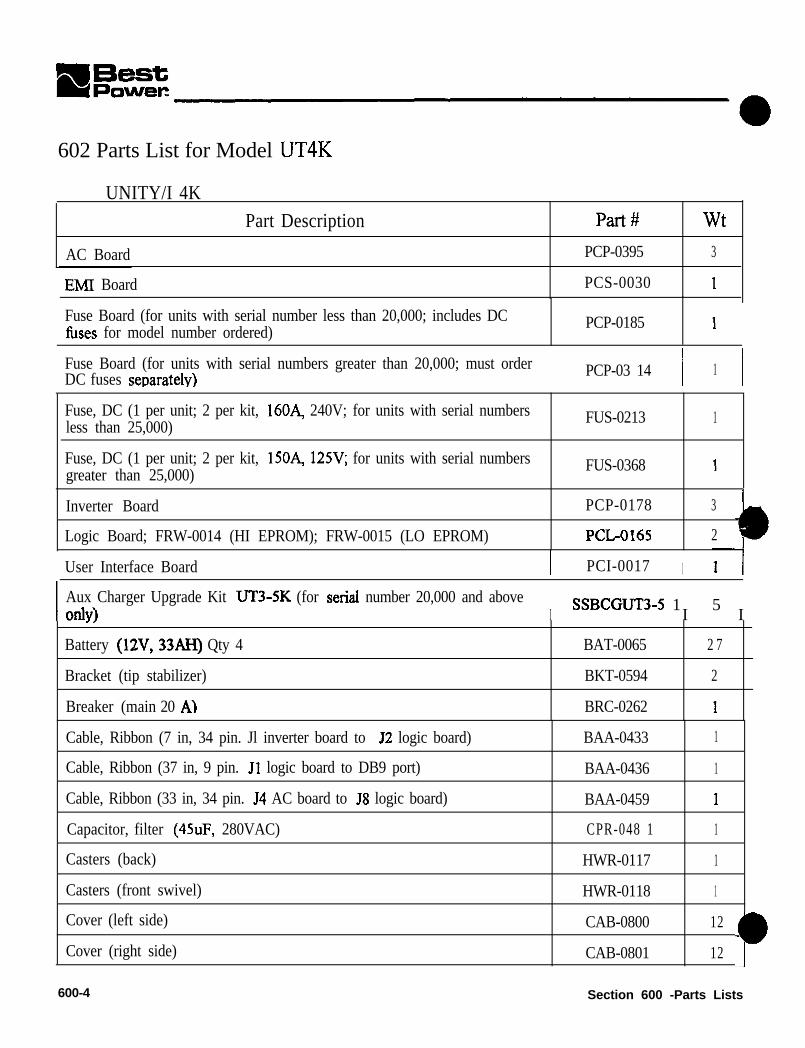
602 Parts List for Model UT4K
UNITY/I 4K
AC Board
Part Description Part# wt
PCP-0395 3
EMl Board PCS-0030 1
Fuse Board (for units with serial number less than 20,000; includes DCfuses for model number ordered) PCP-0185 1
Fuse Board (for units with serial numbers greater than 20,000; must orderDC fuses senaratelv) PCP-03 14 I I
1
Fuse, DC (1 per unit; 2 per kit, 16OA, 240V; for units with serial numbersless than 25,000) FUS-0213 1
Fuse, DC (1 per unit; 2 per kit, 15OA, 125V; for units with serial numbersgreater than 25,000) FUS-0368 1
Inverter Board
Logic Board; FRW-0014 (HI EPROM); FRW-0015 (LO EPROM)
PCP-0178 3
PCL-0165 2
User Interface Board I PCI-0017 I
I Aux Charger Upgrade Kit UT3-5K (for serial number 20,000 and aboveonlv‘) I SSBCGUT3-5 1 5I I.,
Battery (12V, 33AH) Qty 4 BAT-0065 2 7
Bracket (tip stabilizer) BKT-0594 2
Breaker (main 20 A1 BRC-0262 1
Cable, Ribbon (7 in, 34 pin. Jl inverter board to 52 logic board)
Cable, Ribbon (37 in, 9 pin. Jl logic board to DB9 port)
Cable, Ribbon (33 in, 34 pin. 54 AC board to 58 logic board)
Capacitor, filter (45uF, 280VAC)
Casters (back)
Casters (front swivel)
Cover (left side)
Cover (right side)
600-4
BAA-0433 1
BAA-0436 1
BAA-0459 1
CPR-048 1 1
HWR-0117 1
HWR-0118 1
CAB-0800 12
CAB-0801 12
Section 600 -Parts Lists

UNITY/I"
Part Description Pal-# wt
Din Rail DRA-0013 3
Fan (24VDC w/tach output; secured with four FAS-0228) FAN-0043 2
Fastener (nylon snap rivet) FASO228 1
Fuse (with external battery cabinets only 2OOA, 130V) Fus-0004 1
Fuse (with external battery cabinets only lSOA, 130V) FUS-0165 1
Grommet (for line cords) CNF-0034 1
Label (alarm code; attaches to front door panel; (PAN-01 89) LAB-l 170 1
Label (user interface board label for &ont panel keys and LEDs; attaches touser interface board holder; PAN-0187) LAB-l 146 1
Line Cord (L6-30P) I LCA-0257 I 3
Line Cord ($6-20)
Line Cord (IEC-309 32A)
onitor Torroid
Panel (front door)
Panel (front door black)
Panel (front narrow)
Panel (t?ont narrow black)
Panel (kickplate)
Panel (user interface board frame)
Panel (user interface board frame black)
Panel (user interface board holder)
Panel (user interface board holder black)
Panel (ventilation)
LCA-0256 3
SSLCA-0164 3
MT%0005 1
PAN-0189 1
PAN-0222 1
PAN-0190 1
PAN-022 1 1
BKT-0485 2
PAN-0188 1
PAN-0223 1
PAN-0187 1
PAN-0224 1
PAN-0186 2
Panel (ventilation black) I PAN-0225 I 2
Receptacle Panel (blank)
de Door Assembly
PNL-0226 2
CAB-0803 8
Section 600 - Parts Lists 600-5

Part Description
Switch (EPO reset harness)
Switch (main keyswitch, three-position Auto/OtVBypass)
Switch (pre-charge harness)
Transformer
Wire harness @B9 port and wire harness)
Wire harness (EMI to AC board)
Wire harness (input EMI )
Wire harness (logic to fuse board)
Wire (pre-charge)
Part# w t
H R S - 0 2 6 4 1
HRS-0260 1
HRS-0258 1
TRN-0771 7 0
BAA-0436 1
BAA-0453 1
BAA-0454 1
BAA-0451 1
BAA-0452 1
600-6 Section 600 -Parts Lists
a

UNITY/I”
a 03 Parts List for Model UTSK
UNITY/I 5K
Part Description
AC Board
EMI Board
Fuse Board (for units with serial number less than 20,090) (includes DCfuses for model number ordered)
Fuse Board (for units with serial number greater than 20,000) (must orderDC fuses separately)
Fuse, DC (2 per unit, 4 per kit 100 Let, 1004 240V; for units with ser #less than 25,000).
Fuse, DC (1 per unit, 2 per kit 2OOA, 125V; for units with ser # greater thar25,000).
Inverter Board
Logic Board; FRW-00 14 (HI EPROM) FRW-00 15 (LO EPROM)
ser Interface Board
Aux Charger Upgrade Kit UT3-SK (for serial number 20,000 and aboveOdY)
Battery (12V, 33AH) Qty 4
Bracket (tip stabilizer)
Breaker (main 25A)
Cable, Ribbon (7 in, 34 pin. Jl inverter board to J2 logic board)
Cable, Ribbon (37 in, 9 pin. Jl logic board to DB9 port)
Cable, Ribbon (33 in, 34 pin. J4 AC board to 58 logic hoard)
Capacitor, filter (55uF, 370VAC)
Casters (back)
Casters (front swivel)
Cover (left side black)
over (leg side)
Par&#
PCP-0 175
PCS-0030
PCP-0185
PCP-03 14
FUS-0212
FUS-0362
PCP-0193
PCL-0165
PCI-0017
SSBCGUT3-5
BAT-0065
BKT-0594
BRC-0263
BAA-0433
BAA-0436
BAA-0459
CPR-0628
HWR-0117
HWR-0118
CAB-1005
CAB-0800
3
1
2 7
Section 600 -Parts Lists 600-7

Label (user interface board label for front panel keys and LEDs; attaches touser interface board holder; PAN-0187) LAB-1 146 I I1
1 Line Cord (L6-30P) I LCA-0257 I 3 I
Line Cord (L6-20) LCA-0256 3
Line Cord (IEC-309 32 A) SSLCA-0164 3
Monitor Torroid I MTl+ooo5 I 1 I
1 PAN-0189 1 1 1
I PAN-0222 I 1 II PAN-0190 I 1 II PAN-0221 I 1 II PAN-0188 I 1 I
1 Panel (front door)
Panel (front door black)
Panel (t+ont narrow)
Panel (front narrow black)
Panel (user interface board frame)
Panel (user interface board frame black)
Panel (user interface board holder)
Panel (user interface board holder black)
Panel (ventilation)
Panel (ventilation black)
Receptacle Panel (blank)
Side Door Assembly
PAN-0223 1
PAN-0187 1
PAN-0224 1
PAN-0186 1
PAN-0225 1
PNL-0226 1
CAB-0803 8
600-6 Section 600 - Parts Lists

UNITY/I'"witch (EPO reset harness)
Switch (main keyswitch, three-position AutolOtVBypass)
Switch (pre-charge harness)
Transformer
HRS-0264 1
HRS-0260 1
HRS-0258 1
TRN-0778 92
Wire harness (DB9 port and wire harness) BAA-0436 1
Wire harness (EMI to AC board) BAA-0453 1
1 Wire harness (input EMI ) 1 BAA-0454 1 1 1
Wire harness (logic to fuse board)
Wire (me-charge)
BAA-0451 1
BAA-0452 1
604 Parts List for Model UTSK
1 TNTTYII RK- - . - - - . - -- _
Part Description Part# wt
C Board (for serial number below 25,OOOO send BAA-0565 ribbon cable also) PCP-0176 4
EMI Board PCS-0029 1
Fuse Board (units with serial number less than 25,000) (includes DC fuses formodel number ordered) PCP-0185 1
Fuse Board (units with serial numbers greater than 25,OOOl) (must order DCtltses seperately) PCP-0314 1
Fuse, DC (2 per unit)(4 per kit) ( 16OA, 24OV) (for units with serial numberunder 25000.) FUS-0213 1
Fuse, DC (2 per unit); (4 per kit); (lSOA, 125V); (for units with serial numbergreater than 25000.) FUS-0368 1
Inverter Board (2 per unit) PCP-0178 3
Logic Board; FRW-0014 (HI EPROM); FRW-0015 (LO EPROM) PCL-0165 2
User Interface Board PCI-0017 1
Aux Charger Upgrade Kit (for serial number 25,000 and above only) SSBCGUTS 15
Battery (12V, 75AH) Qty 4 BAT-0103 57
racket (tip stabilizer) BKT-0492 2
Section 600 - Parts Lists

Breaker (main 40A) 1 BRC-0201 1 1
Cable, Ribbon (17 in, 34 pin. Jl inverter board to J2 logic board) BAA-0435 1
Cable. Ribbon (37 in, 9 pin. Jl logic board to DB9 port) BAA-0437 1
Cable, Ribbon (33 in, 34 pin. J4 AC board to J8 logic board) for serial numberbelow 25.000 BAA-0459 1
Cable, Ribbon (33 in, 34 pin. 54 AC board to J8 logic board) for serial numberabove 25,000
BAA-0565 1
Capacitor, filter (70uF, 370VAC) ) CPR-0629 1 1
1 HWR-0117 ) 1
1 HWR-0118 ( 1
[ CAB-0780 ( 16
1 CAB-0781 1 16
1 TRB-0399 1 4
FAN-0043 2
FAS-0228 1
FUS-0249 1
Fan; Qty 2 (24VDC w/tach output; secured with four FAS-0228)
Fastener (nylon snap rivet) Qty 4 per fan
Fuse (with external battery cabinets only 35OA, 13OV) Qty 2
Label (aharm code; attaches to~front door panel; (PAN-0189)
Label (user interface board label for f?ont panel keys and LEDs. Attaches touser interface board holder; PAN-O 187) LAB-1146 1I
Casters (back fixed)
Casters (front swivel)
Cover (left side)
Cover (right side)
I LAB-1170 I 1
Monitor Torroid
Panel (front door)
Panel (front narrow)
Panel (kickplate)
Panel (user interface board frame)
Panel (user interface board holder)
Panel (ventilation)
Receptical Panel (blank)
Side Door Assembly
MT%0005 1
PAN-0189 1
PAN-0190 1
BKT-0485 2
PAN-0188 1
PAN-0187 1
PAN-0186 1
Pi%-0226 1
CAB-0783 11
Section 600 - Parts Lists

UNITY/I”
Switch (EPO reset harness)
Switch (main keyswitch, three-position Auto/OfVBypass)
Switch (pre-charge harness)
Transformer
Wire harness (DB9 port and wire harness)
Wire harness (EMI to AC board)
Wire harness (input EMI )
Wire harness (logic to f&e board)
Wire (pre-charge)
HRS-0264 1
HIRS-0257 1
HRS-0258 1
TRIG0779 137
BAA-0437 1
BAA-043 1 1
BAA-0430 1
BAA-0443 1
HRS-0259 I
Section 600 - Parts Lists 600-l 1


700 Technical Information PublicationsUNITY/l technical information publications (UTYs) listed below provide further information about the unit.additional or updated copies of the following publications, call BEST Power at I-800-356-5737 (U.S.A.
d Canada), or l-608-565-2100 (Worldwide).
UTY Number
w 5 0 1
UTY601
lJTY604
UTY605
UTY608
uTY618
UTY619
UTY620
WY627
U T Y 6 2 8
W 639
UTY640
UTY641
UTY642
U-l-Y643
uTY644
U-l-Y646
W641
TIP410
FSS 393
/* U-IY320
UTY Title
Communicating with the UNITY/l via the DB9S Communication Port
Verifying the Basic Operation of the Single-Phase UNITY/l
Scheduled Maintenance for UNITYil Single-Phase Models
Scheduled Maintenance and Service Call Report Formfor UNITY/l Single-Phase Models
Generator Setup for UNITY/l UT3K, UT4K, UTSK, and UT8K
Replacing the Internal Batteries in UNITY/I Models UT3K, UT4K, UTSK, and UTBK
Replacing the Internal Batteries in UNITY/I UT3K, UT4K, UTSK, andUT8K (Internal Fuse Board)
Replacing the External Batteries for UNITY/l UT3K, UT4K, UT5K, and UT8K
Replacing the User Interface Board in UNITY/I Models UT3K, UT4K, UTSK, and UT8K
Using the PhonTek Interface in the Single-Phase UNITY/l
Replacing the Fuse Board on UNITY/I Models UT3K, UT4K, UTSK, and IJT8K
Replacing the EMI Board in UNITY/I Models UT3K, UT4K, UTSK, and UT8K
Replacing the Logic Board in UNITY/I Models Ill%, UT4K, UT5K, and UTSK
Replacing the AC Board in UNITY/I Models UT3K, UT4K, and UTSK
Replacing the Inverter Board in UNITY/l Models UT3K, UT4K, and UTSK
Replacing the Fan in UNITY/l Models UT3K, UT4K, UT5K and UT8K
Replacing the AC Board in UNITY/l Model UT8K
Replacing the Inverter Board in UNITY/I Model UT8K
Operating the Make-Before-Break Bypass Switch on FERRUPS,FORTRESS, and UNITY/l (single-phase) UPS Installation
Connecting External Battery Packs to the UNITY/I Single-Phase UPS, Models UT3K,UT4K, UTSK, and UT8K
Connecting Customer Supplied External Battery Packs to the UNITY/l Single-Phase UT8K
Section 700 - Technical Information Publications 700-I

OWER S Y S T E M SLJTY 501
September 14.1998
Communicating with the Single-PhaseUNITY/P UPS via the DB9 Communication Port
This document provides information about communicating with the single-phase UNITY/I UPSvia the communication port. This document applies to all UNITY/I single-phase models withsoftware versions up to and including 2.01.
You can use the communication port in two ways:
l Choose contact mode to use the available shutdown and inverter contacts
0 Choose RS232 mode to access full duplex communication with the UPS and use theprogrammable contacts available. In RS232 mode, you can send commands to the UPS,view and change parameters, or use optional CheckUPS” software or interface kits.
Contents
Section 100:
Section 200:
Section 300:
1 Appendix A:Appendix B:
Appendix C:I Appendix D:
Choosing a Communication Mode . . . . . . . . . . . . . . . . . . . . . . . . . .1 0 1 : ContactMode . . . . . . . . . . . . . . . . . . . . . . . . . . . . . . . . . . . . . .1 0 2 : RS232Mode . . . . . . . . . . . . . . . . . . . . . . . . . . . . . . . . . . . . . .103: Programming the Communication Mode . . . . . . . . . . . . . . . . .
Connecting a Terminal, Computer, or Modem to the DB9 Port20 1: Connecting Terminal or Computer to the DB9 Port . . . . . . . .202: Connecting a Modem to the DB9 Port . . . . . . . . . . . . . . . . . . .
. 2
. 334
556
RS232 Communication . . . . . . . . . . . . . . . . . . . . . . . . . . . . . . . . . . . I30 1: Entering Commands . . . . . . . . . . . . . . . . . . . . . . . . . . . . . . . . . 7302: Viewing and Changing Parameters connected to the DB9 Port 1 0303: Reading the Alarm and System Logs . . . . . . . . . . . . . . . . . . . . 2 1304: Unsolicited Messages . . . . . . . . . . . . . . . . . . . . . . . . . . . . . . . . .23305: CheckUPS@ and Interface Kit Options. . . . . . . . . . . . . . . . . . . 23
Reading the F String . . . . . . . . . . . . . . . . . . . . . . . . . . . . . . . . . . . . . .Programmable Contacts . . . . . . . . . . . . . . . . . . . . . . . . . . . . . . . . . . . .Bit-Mapped Alarm Status Register . . . . . . . . . . . . . . . . . . . . . . . . . . .System and Alarm Log Event Codes . . . . . . . . . . . . . . . . . . . . . . . . . .-.
. . ...242526
. . ...28
Best Power makes no claim on trade names of application products mentioned in this publication. Best Power’s trademarkownership extends to its own products only.
U-Y-0501 D0 Copyright 1994, 1995, 1996, 1998 Best Power. All rights reserved.

Section 100: Choosing a Communication Mode
Two communication modes are available at the UPScommunication port: contact mode and RS232 mode.Section 101 describes contact mode, Section 102 describesRS232 mode, and Section 103 explains how to program the UPScommunication mode.
Table 1 contains the DB9 communication port pin outs for thesingle-phase UNITY/I. The functions of pins 1 and 2 are deter-mined by the communication mode. The functions of all otherpins are the same in either mode.
Table
I PinPin 1
I
’ Pin2
I Pin 3II - - - -! Pin 4
1r-I-c
ct
c
Figure 1: DB9 Port
: UNITY/I Communication Port Pin Outs~__- - - -Contact mode function ( RS232 mode function~.- ~~~~ --+-___- __~~.__. ~~~ _.__
Shutdown -A +12 VDC signal held for 5 RS232 RD - The UNITY/l receives data at theseconds on this pin while the UPS is on battery programmed baud rate (default 1200), 8 bits, no ;power shuts down the UPS 20 seconds later . , parity, 1 s top bi t , and no handshaking.The UPS will restart after a I5-second delayonce normal input power is restored. I
- - ~. --~~~~~ - -Inverter Status - Produces a +I 2 VDC signal ~ RS232 TD - The UNITY/I transmits data at thewhenever the UPS is on battery power. When programmed baud rate (default 1200), 8 bits, nothe UPS is not on battery power, the pin parity, 1 stop bit, and no handshaking.produces a -8 VDC signal.
~~-~ ! __~~~ ~~~-~~ ~-.
Inserter Normolly Open Contact - Closes* to indicate that the UPS is on battq power (default).Programmable via Parameter 24 (see Appendix B).
Common - Signal ground for all interface signals and contacts.-
Low Runtime NormaNy Open Contact - Closes* to indicate that battery runtime is low (default).Pin 5! Programmable via Parameter 23 (see Appendix B).+----~~-
Pin 6 / Inverter Normally Closed* Contact - Opens to indicate that the UPS is on battery power (default).i Programmable via Parameter 25 (see Appendix B).
I
Pin7 ’-
,.-4
Remote Emergency Power Off (EPO) - Short to pin 4 to shut down the UPS output. See theAppendix to the UNITY/I User Manual for information on connecting a remote EPO switch.--~ i
P i n 8I
Unregulated +18 VDCNominal Source - An unregulated +I 8 VDC nominal source protected by 1I a 1000 ohm source impedance.
; -- __t ~~~__-P i n 9
II Internal Bypass NormoNy Open _ Closes* to indicate that the UPS is in internal bypass mode./ (Note: Does not close for the Auto Bypass alarm condition that occurs after a low battery Ifitdown.) I
--~~~~* Internally tied to pin 4 when closed.
UTY 501 September 14, 1998 Page 2

101: Contact Mode
Contact mode gives you access to shutdown and inverter status. This mode does not allowRS232 communication.
l Selecting Contact Mode
To select contact mode, program Parameter 22 to a one-digit value from 0 - F hexadecimal.This one-digit value sets the delay (in seconds) before changing the status of pin 2 (inverterstatus).
For example, if you programmed Parameter 22 to “5,” the UPS would be in contact mode andwould operate on battery power for at least 5 seconds before changing the status of pin 2(inverter status).
See Section 103 for instructions on programming Parameter 22.
102: RS232 Mode
RS232 mode allows full duplex (two-way) communication with the UPS. This mode allowsyou to send commands to the UPS, receive messages about UPS operating status, view UPS
e
parameters, change UPS parameters, and view UPS status logs and alarm logs.
0 UPS RS232 Technical Specification Summary
As shipped, the UPS is set up for serial communication at 1200 baud using 8 data bits percharacter, one stop bit, and no parity.
The UPS echoes all characters sent to it (default), so the computer or terminal should beoperated full duplex. The UPS is not case sensitive, so commands may be sent in eitheruppercase or lowercase.
Connector: 9 pin D (female) wired as DCE.Format: ASCII 8 data bits, 1 stop bit.Baud Raie: 1200,2400,4800 or 9600 (programmable)Parity: None.Duplex: Full.
l Selecting RS232 Mode
To select RS232 mode, use the UPS front panel keys to program Parameter 22 to “10” for1200 baud, “20” for 2400 baud, “30” for 4800 baud, or “40” for 9600 baud. Set the baud rateto match the baud rate of the cornouter, terminal, or modem that you will connect to the UPS.
0 See Section 103 for instructions in programming Parameter 22.
Page 3 UTY 501 September 14, 1998

103: Programming the Communication Mode
To program the UPS communication mode, use the UPS front panel keys and follow the 0instructions below to set Parameter 22 (Communication Mode).
1 .
2.
3.
4.
5.
6.
7.
8.
9.
Simultaneously hold down the [CANCEL] and [RUNTIME] keys for two seconds. Releasethe keys when the display shows P - 0 0.
Press [CANCEL]. The display should show 0.
Press [%LOAD] until the display shows 3 7 7. If you inadvertently scroll past 3 7 7,press [VOUT] to decrease the display value.
Once the display reads 3 7 7, press [RUNTIME]. The display should show 1.
Press [CANCEL]. The display should show P- 0 0..
Press [%LOAD] until the display reads P- 2 I?. If you inadvertently go past P - 2 2, usethe [VOUT] key to step back.
Once you reach P- 2 2, press [CANCEL].
Use the [%LOAD] key or the [VOUT] key to change the display to the correct setting. Usethe list below to determine the correct setting.
Parameter 22 Setting* Communication Mode
O - F Contact mode. Sets the delay (in seconds) on pin 2.
1 0 RS232 mode, 1200 baud.
20 RS232 mode, 2400 baud.
30 RS232 mode, 4800 baud.
40 RS232 mode, 9600 baud.
* Parameter 22 settings are in hexadecimal.
To enter the new setting, press [RUNTIME].
NOTE: To escape without saving, press the [VLINE] or the [CANCEL] key.
10. To escape parameter mode, press [VLINE] twice.
UTY 501 September 14,1998 Page 4

Section 200: Connecting a Terminal, Computer, or Modem to the DB9 Port
a
201:
0
This section explains how to connect a terminal, computer, or modem to the UPScommunication port.
The standard RS232 connection points are as follows:
Pin 1: RS232 Receive Data. The UPS receives data on this pin.Pin 2: RS232 Transmit Data. The UPS transmits data on this pin.Pin 4: Common (signal ground).
Pins 3, 5,6,7,8 and 9 have the same functions in RS232 mode as they have in contact mode.See Section 100.
Connecting a Terminal or Computer to the DB9 Port
To communicate with the UPS, your terminal or computer must be capable of serialcommunication. A computer must be capable of terminal emulation. Whether you are using aPC and a modem or directly connecting the PC, you may use any standard communicationpackage (such as Smartcom@, CROSSTALKa, or ProCommTM).
To connect a terminal or computer to the UPS communication port, follow the steps below.
1. Set the UPS to the proper baud rate if you have not already done so. See Section 103.
2 . Plug the terminal or computer into an outlet protected by the UNlTYfl UPS.
3 . Construct your own high-quality shielded cable (see Figure 2 or 3 on page 6) or call BestPower to order one. Connect the cable between the UNITY/I and the terminal orcomputer.
4 . Switch on the terminal or computer. If you are using a computer, start the terminalemulation program.
You should now be able to communicate with the UPS. If you cannot communicate, verifythat the baud rate of the UPS matches the baud rate of the connected terminal or computer(see Section 103) and check the cabling and connections (see Figures 2 and 3).
See Section 300 for commands and other information about RS232 communication.
Page 5 UTY 501 September 14, 1998

DE9 TOCOMPUTER
WE)
Figure 2: Computer DB9 to UNITY/I DB9
0625 TOC O M P U T E R
(DE)
D69P [MALETO UNITY/ i
(‘JW
Figure 3: Computer DB25 to UNITYi/I DB9
202: Connecting a Modem to the DB9 Port
Before connecting a modem to the UPS communication port, configure the modem to ignorethe state of all RS232 lines except RxD and TxD. Many modems use Pin 20 as a reset (DTR).Consult your modem documentation.
NOTE: When using a modem, you must disable the sending of result codes-consult your
modem documentation. If you do not disable result codes, communication may beinconsistent.
1 . Set the UPS to the proper baud rate if you have not already done SO (seeSection 103).
2 . Construct your own high-quality shielded cable (see Figure 4), or call Best Power toorder one. Connect the cable between the UNITY/I UPS and the modem.
UTY 501 September 14, 1996 Page 6

0825 TOMODEMWE)
DBSP (MALETO UNITY/ I
WE)
Figure 4: Modem DB25 to UNITY/I DB9
Section 300: RS232 Communication
This section describes RS232 communication.
301: Entering Commands
From a terminal connected to the UPS DB9 port, you can send the commands listed inTable 2 on page 8.
0 Commands may be typed in either uppercase or lowercase. End each command with acarriage return.
l Spaces between commands and values are ignored. For example, DIZ? and D 12 ?cause the same action.
0 If a command is valid, the UPS responds with OK => (OK, carriage return, line feed,prompt).
l If a command is invalid, the data is out of range, or the password level is too low, theUPS responds with ? => (?, carriage retnrn, line feed, prompt) and no action isperformed.
Page 7 UTY 501 September 14, 1998

Table 2: UNITY/I Co+rnzu&_.___ -~~~ -~~- -~Command Description_+__ _.._. _~ ~~~-~~~-~ - - ~. .._~~.~ ib._- - .~.. ~-.. - - -
!a Initiates an immediate battery test unless the unit is running on battery power. If the UPS
/~ detects a possible battery problem, it gives a Check Battery alarm. A Check Battery alann isI indicated by an R - 0 ‘I on the unit’s front display and the unsolicited message [OOOOOI 001 on: a terminal connected to the UPS communication port (for ~1.00-1.03 the message reads: [00000200])._- .,-.. ..~-- ~~.- .,~ .-.~--. ~.~ .
D <number> ? Displays a given piece of information (see Table 3), where <number> is the display number.
E <value> Enables or disables character echo, where <value> is 0 (disable echo) or 1 (enable echo,default). When echo is enabled, you can see characters on screen as you type them.
i - - ~~- .~ -.-
F Displays a formatted string of data. See Appendix A.
I Displays a unit identification message, including the UPS model number, serial number, and‘; s&ware version (VI .06 - 2.01 only).
+.--.. .~-- __- - ~~.
L <number> ? I Displays the contents ofthe selected log, where <number> is 0 (alarm log) or I (system log).: See Section 303 for information on reading the logs.
~-.~ ..-,+ ~.. ~~-- .-. _ ~.~
L <number>= * Clears the contents of the selected log, where <number> is 0 (alarm log) or 1 (system log).-. ~-. ~~.j
OFF <value>
OFFC
I Automatically puts the unit into “sleep” mode (shuts the unit down) +alue> seconds afiw thecommand is entered. This command is intended for use when the UPS is running on batterypower and you want to shut it down. If Parameter 03 (Auto Restart) is enabled, the UPS will
: restart automatically when AC line returns. If Parameter 03 is disabled, you must restart theUPS by turning the UPS key switch to “Off’ and back to “Auto.”
-aCancels the OFF command. Forsoftware vl.OO- vl.OJ’, the OFFC command works only~ you enter it before the OFF command is executed. For software ~1.04 - v2.01’, the OFFC
command works before and @firer the OFF command is executed-if the OFF command has,
P <number> 7
P <number> = <value>
P <number> = *
already been executed, the UPS restarts when the OFFC command is entered.-
Displays the value of a parameter, where <number> is the parameter number. See Section 302for more information about parameters.
Sets aparameter to a specified value, where <number> is the parameter number and <value>is the new setting. To change a parameter setting, the correct password must be entered. Donot change a parameter setting unless youfufly understand what the parameter meansand how the change will affect the operation of the UPS. See Section 302 for moreinformation about parameters.
Sets a parameter to its default value, where <number> is the parameter number. The correctpassword must be entered. Do not default a parameter unless youfully understand what
~ the parameter means, know what the default setting is, and know how the change willaffect the operation of the UPS. See Section 302 for more information about parameters.
TOFF <value I> <value 2> ; Auromatically puts the unit into “sleep” mode (shuts the unit down) <value I> seconds after: the command is entered and restarts the unit <value 2> seconds after the command is entered.The acceptable range for each value is 0 to 16,383 seconds, and <value 22 must be greater
than <value I>.
TOFFC
~. ,_~. -~. ~_~~~,..~ __
Cancels the TOFF command. If the UPS has already shut down, it will restart when theTOFFC command is entered.
UTY 501 September 14, 1998 Page 8
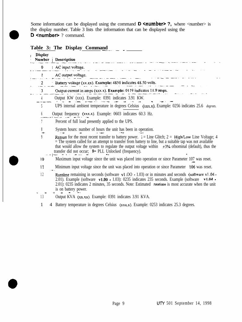
Some information can be displayed using the command D <number> ?, where <number> isthe display number. Table 3 lists the information that can be displayed using theD <number> ? command.
Table 3: The Display Command-~~- -
4 ’ Output KW (xxx). Example: 0391 indicates 3.91 KW._~_- . - - ~_ .~__. ._~_ ~- ~- ~_ ~- _ ._~ ~..5 UPS internal ambient temperature in degrees Celsius (xxx.x). Example: 0256 indicates 25.6 degrees.
6 Output frequency (xxx.x). Example: 0603 indicates 60.3 Hz.-_-+__~.- ~.~ -~-. ~-7 Percent of full load presently applied to the UPS.
I
0
8 System hours: number of hours the unit has been in operation.+ ~~- - .~-- ~-- .-.9 Reaxm for the most recent transfer to battery power. I = Line Glitch; 2 = High/Low Line Voltage; 4
= The system called for an attempt to transfer from battery to line, but a suitable tap was not availablethat would allow the system to regulate the output voltage within +3% ofnominal (default), thus the
i transfer did not occur; 8= PLL Unlocked (frequency).-~-t- ~-~ --~ - _- .~
IO Maximum input voltage since the unit was placed into operation or since Parameter 107 was reset.-11 Minimum input voltage since the unit was placed into operation or since Parameter 106 was reset.~*~1 2 Runtime remaining in seconds (software VI .OO - 1.03) or in minutes and seconds (software VI .04 -
2.01). Example (software ~1.00 - 1.03): 0235 indicates 235 seconds. Example (software ~I.04 -2.01): 0235 indicates 2 minutes, 35 seconds. Note: Estimated runtime is most accurate when the unitis on battery power._ ~., -/ - - ..~~
1 3 Output KVA (xxxx). Example: 0391 indicates 3.91 KVA.
1 4 Battery temperature in degrees Celsius (xxx.x). Example: 0253 indicates 25.3 degrees.
Page 9 UTY 501 September 14, 1998

302: Viewing and Changing Parameters via a Terminal Connected to the DB9
Before attempting to change a parameter, make sure that youfully understand what theparameter means and how the change will affect the operation of the UPS.Improper setting of certain parameters may cause the UPS to function other than expected.If the “Password Required to Change” in Table 4 says “Phone Best Power,” or if you have aquestion, phone Best Power’s Worldwide Service or your local Best Power office forassistance.
To view or change parameters via a terminal, use the commands below:
P <number> ? Displays a parameter setting, where <number> is the parameternumber.
P <number> = <value> Changes a parameter setting, where <number> is the parameternumber and <value> is the new setting. The correct passwordmust be entered in Parameter 00 before you can change aparameter value. The user password is 377.
Table 4 lists the UNITY/I parameters. Some parameters vary depending upon the UPSsoftware version; for these parameters, software versions are specified. To view the softwareversion of your UPS, enter the command P128?. 0
NOTE: On a terminal connected to the UPS DB9 port, decimal points are not displayed.Where applicable, the “Front Panel” sample display in Table 4 shows the numberof decimal places.
Table4: Pa.rameter Table
1 ParameterParam.i # Name
00 Password
/ Password -r -~~-~---- ~--- - ~- ~--~~~~~
iSample Display
- -- -~- -I Required to 1 Parameter Description! Change , Front : T e r m i n a l
; Panel ~ Screen
i None 0 0 0 0 0 Allows you to enter a password. Password levels:Level 0 = No Password
iLevel I = J$r Password (377).~*. ~~_~.
01 Serial Number ) Phone I r 0001 The UNITY/l serial number is formatted as follows:I L o w ’ Best Power ~ I
! , / UTXlQZZZZ
1i where x is the model number (KWIKVA rating) of the
, ~_ -_-~ _02 : Serial Number + ~PG---t~--m -t- - --i UPS and YZZZZ is a unique t&z-digit unit s&i
High: 367 0367
; Best Power ; 1number. Parameter 01 reports y. Parameter 02 reports1 zzzz. Note: On the UPS front panel, Parameter 02
I I / does not display leading zero&/ Range (sofrware ~1.00 - 1.03): 0 - FFFF hex.
I 1 1 Range (spfhuare ~1.04.2.01):0-9999. ___~
WY501 September14,1998 Page10

P a s s w o r d Sample Displayparam. P a r a m e t e r R e q u i r e d t o --~-- - .+ Parameter Description
# Name Change Front TerminalPZilWl SCt-t-l?n.~.__ .____.. _. ~~_.~_. * ..__ ~_ * - ..- _~
03 Auto Restart Use r 1 0 0 0 1 If the UPS shuts itself down, this parameterdetermines whether the UPS restarts automatically. Ifset to “1,” the UPS re&uts itself when conditionsallow. If set to “0,” the UPS must be manuallyrestarted.
,. *. - ~. ...~_ _~ ~- ~-.*04 Model Number Phone 4 0 0 0 4
Best Power~._~~.~ _-+05 Output Voltage Usor 240 0240. -’
Reference
06
0;.
+Full Load Set Phone 4.00- 0400Point Best PowerLow Runtime UStX 2 0002Alarm Set Point
08i. --*
Glitch Limit + Phone I2 0012 -Best Power
_ + ~.. - _~. ~- +09 Frequency Slew u s e r 341 0347
Rate
10 Line Full Load Phone ’ j7.2 +- 0172Current Best Power~..~~ -* ~~ ~_- ~- + -~~
1 1 Circuit Breaker Phone . 40 0040Trip I Best Power
I2i.~-~ -~~.
High Ambient Phone 40.0 0400Temperahue Best PowerAlarm Set Point
1;. * Frequency14’ -. *-
Display Only 60.0- t 0600+ ~’Frequency Mode User 2 0002
(VI .oo - 1.05)
Nominal~_ _ -- * -.~~. +
User 1 0001Frequency(vl.06 -2.01)
Choices: 0 ([)is_able) or 1 (&able).Reports the model number (KVAIKW rating) of the
, ups. l$nge: q,- q999.
Phone BEST before attempting to change thisparameter. This parameter setting determines thenominal voltage present al the oz~pf terminalsblockr. The output fo the loads also depends uponhow the factory or the installing electrician wired theoutput. See the UNITY/I Installation Manual for more
i information.~Ranget 180 - 260 VAC.Unit KW/KVA rating. Maximum steady state
i KWAZVA output. Range: 2.00 - 17.00 KVA.When running on battery power, the UPS activates aLow Runtime alarm (A-00) when the estimatedmntime remaining is equal to or less than this value.Range: 1 - 99 minutes.Number oiglitches that must accumulate for the UPSto switch to exclusive battery operation.Range: 1 - 36 glitches.Rate at which the UPS tracks changes in inputfrequency. The greater the value, the faster thetracking. The default of 347 is about 30 Hz/second.
+ Range: IO - 780.Maximum steady state output current.
+ &nge: 1.0 - 350.0 amps.Sets the limit for maximum allowable overload. Usedin determining when the unit shuts down.
. pylge: I 9999.The UPS sounds a High Ambient Temperature alarm(A-03) if the UPS internal ambient temperature isequal to OT greater than this value.
f +mge: I .O - 100.0 degrees Celsius.f Displays thepresent UPS output frequency (Hz).
Software ~I.00 - 1.05: Sets the nominal frequency. Ifthis parameter is set to “2” (Auto select), the UPSautomatically selects the nominal frequency basedupon input frequency.
i Choices: 0 (50 Hf), I (60 Hz) or 2 (Auto select).Software ~I.06 - 2.01: If auto frequency mode isenabled (see Parameter 15), this parameter reports thenominal frequency that the UPS has auto-selected. Ifauto frequency mode is disabled (see Parameter 15),you can use this parameter to set tbe nominalfrequency. Choices: 0 (50 Hz) or 1 (60 Hz).
Page 11 UTY 501 September 14, 1998

-ii
-17
18
19
20
21
Auto FrequencyMode
Auto FrequencyMode(~1.06 - 2.01)
Display ( 1Only
MaximumFrequency
usw ~- + ii.0 -*0 6 5 0
Minimum User 45.0 0450F r e q u e n c y
~---._~ ~~. --Installation Phone 0 I 0000Equalization Best Power
- ~. -.-Phase Offset Phone IIlL i-0111
Best Power- ~~I _ .Transformer Phone 4 * 0004Resistance Best Power
~.. ~~_+-~ ...~~Set Metering for Use1 0380/400/415V
y oooo-
Input
i Software vl.OO- 1.05: When Parameter 14 is set toauto select. this oarameter reoorts the nominal1 frequency ;resently selected: 0 = 5&H?, 1~~ 6oHz.
Sofhvare ~I.06 - 2.01: Enables or disables autofrequency mode. In auto frequency mode, the UPSautomatically selects the nominal frequency basedupon the input frequency. See also P-14.
-or Cftoices: 0 (Disable) y I (Enable).
: Sets the maximum frequency for operation on ACline. Ifthe input frequency exceeds this value, theUPS switches to battery operation. This value must begreater than the nominal frequency (see Parameters 14
;-and 15). Range: 50.5 - 65.0 Hz.Sets the minimum frequency for operation on AC line.If the input frequency drops below this value, the UPSswitches to battery operation. This value must be lessthan the nominal frequency (see Parameters 14 and
* !~A). Range: 45.0 - 59.5 Hz.If set to “I”, causes equalization charge of thebatteries at installation or when ROMs are changed.Choices: 0 (Disable) or I (Enable),Used to compensate for the reference phase lag if the
I zero cross discriminator. Range: 0 - 359 degrees.Scaling factor used to compensate for impedanc
-~.~~~ -*drops in the UPS system. Used in the calculation othe tap setting when transferring from battery power to
line power. Range: 0 - 16.~+--~~ ~~~~...Scales UPS metering for systems with optional
: 380/400/415 volt input. Note: This setting does not~ affect UPS output voltage.
24 t
Programs contact 0 (pin 5) on the communication ~port. See Appendix B. Range: 0 - 3F24 hexadecimal.~~-~ .-~~_-~ ~~~~__ _ __ ~~~~-Programs contact I (pin 3) on the communication ~
25 Programmable
POIT.
See Appendix B. Range: 0 - 3F24 hex@ec@al.~~: 3017 3317 Programs contact 2 (pin 6) on communicationthe
Contact 2 pt.i--~- .~.~_. .~-~i.. ~~~~ ~~.~.__.~ . ..~~__. ~_
;6See Appendix B. Range: 0 - 3F24 hexadecimal..I _~~__.. ~- ~~~~~-,.~~~~
R e s e r v e d Software vl.OO- 1.03.2.01: Reserved.(v1.00 - 1.03,
L 2.01)PhonTek” U s e r 0 ~ Software ~I.04 - 1.09: Begins PhonTek transmission
Copies~ (v1.04- 1 . 0 9 )
/ Oooo , and specifies how many copies of the message to~_~. -~+_____ i-----~--__ -~--i~ transmit. Rmge: 0 - 98 copies, 99 = continuous.~. ----+ -~-~__~.~.-~27 Input Voltage ’ Phone : 235
Best Power~ 0235 Directly metered RMS input voltage.
~- .~ 1.- ~--___ i---~~,..~_---_-~I_-_~~Ran~~~_l~O~o\lAc-__~~~~
WY501 September14,1998 Page12

Passwordparam. i Parameter Required to ~. . ~. _
TerminalSClWll
2 8 Output Voltage Phone 2 4 0 0240Bes t Power
2 9 output Current Phone 11.9 0119Bes t Power
30 Battery Voltage Phone 48.00 4800Bes t Power
* +31 In te rna l Phone 2 5 . 0 0 2 5 0Ambient Bes t PowerTempera tu re
+3 2 Battery Phone 2 5 . 1 0251
+
Tempera tu re
--
f Best Power
*3 3 Runtime Disp lay Only l5:OO 1500
+- 4
3 4 Percent Load Disp lay Only 7 0 0070
+ + +3 5 Power Fac to r Disp lay Only ~I.00 0100
36 - ** ~... _
KW Out Display Only 4.00 0400 +
+...---.~ +3 7 KVA Out Display Only * 4.00 + 0400 +
3 8
3 9
4 0
41
4 2
4 3
4 4
Input VoltageCal ib ra t ionFac to r
Output VoltageCal ib ra t ion
PhoneBes t Power
PhoneBes t Power
Fac to r
Output CurrentCal ib ra t ion
PhoneBes t Power
Fac to r
Battery Voltage PhoneCal ib ra t ion Bes t PowerFac to r
In te rna l PhoneTempera tu re Bes t PowerCal ib ra t ion
+ Factor
Zero Internal PhoneAmbient Bes t Power
+ Tempera tu re
Battery PhoneTempera tu re Bes t PowerCal ib ra t ion
L Factor
+ dC4 ODC4
* lA9C . lA9C
1309 + 1309
+ 1775 * 1775
_ lC9 . OlC9
_ IdF * OIDF
+ IC9 -* OIC9
Page 13
Parameter Description
Directly metered RMS output voltage.Range: IO - 1000 VAC.
Directly metered RMS output current.Range: 1.0 - 350.0 amperes.
Directly metered battery voltage.Range: 1.00 - 99.99 V.,~UPS in terna l ambient tempera ture .Range: 0 - 150.0 degrees Ce ls ius .
.~ .__. ._ .~UPS ba t te ry compar tment tempera tu re .Range: 0 - 150.0 degrees Ce ls ius .
The estimated runtime in minutes and seconds.Notes: (I) Estimated rontime is most accurate whenthe UPS is running on battery power. (2) In units withsofhvare VI .OO - 1.03, B terminal connected to theDB9 port displays the runtime in seconds only.
The percentagp: ofthe UPS’s total capacity that theload equipment is using.
The difference in the way the load equipment drawsvoltage and current. Power factor is equal to KW Outdivided by KVA Out.
The total pow; in kilowatts (KW) that the loadequipment is drawing from the UPS.
The total apparent power in kilo&eres (KVA)that the load equipment is drawing from the UPS.
AID conversion factor. Do not change.Range: 03E8 FOOO hexadecimal.
AID conversion factor. Do not change.Range: 03E8 - FOOO hexadec ima l .
AID conversion factor. Do not change.Range: 03E8 FOOO hexadecimal.
AID conversion factor. Do not change.Range: 03E8 - FOOO hexadecimal.
AID conversion factor. Do not change.Range: 0 - FOOO hexadecimal.
Offset correction. Do not change.Range: 0 - FOOO hexadecimal.
AID conversion factor. Do not change.Range: 0 - FOOO hexadecimal.
UTY 501 September 14, 1998

Param. ~ FaEreter-7 P a s s w o r d S a m p l e D i s p l a y
R e q u i r e d t o / ~~ ~-- maim--! Parameter Description
# C h a n g e Front ! TerminalP a n e l ! S c r e e n+~ ---~..-.-- -~.,+. .-.-. + ~- ‘---
45 Zero Battery Phone IdF OIDF ~ Offset correction. Do not change.Temperature ! Best Power Range: 0 - FOOO hexadecimal.
4 6 Display -i---t-’ --~Alarm Status + oooo - - - - - : ~-- -Hexadectmal representation of the bit-mapped alum0 Only statlls register. This parameter displays the lower
.-+--------. ~-_~ ~.Display ’ 0
alarm status register (bits 0 - 15). See Appendix C.41 Alarm Status + : 0000 Hexadecimal representation of the bit-mapped alarm
1 Onlv statlls resister. This “arameter disolavs the “““er,, . ._ ~~--.--..i..~- alarm status register’(bits I6 _ 3 1). See Appendix C.
48 Alann Mask + 0 Phone + 0. * ‘0000 : Causes selected alarms to be-ig&ed.Best Power.~ +. Range: 0 - FFFF_ -- i .- -.* ~~ -
49 Alarm Mask + I Phone 0 0000Best Power
50 ’ Beeper Enable User I 0 0 0 1
iI*.~~~~ ~~ I .~ *. - .-/.- ~.
Low Battery Display Only 40.08 4008
52
Shutdown SetPointHieh Batterv Phone
_ -~-.* -,.60.00 6000
Al&n Set Point Best Power+ ~~,~. ~~-- *. ---+ ~~~53 VII0 Phone 1068 1068
Best Power54 i K,l -- +. -... .~ +~~Phone EAO + OEA;
Best Power55 ~+
+ ~~~ .~ -...Battery Capacity User 33.0 0 3 3 0
56
58 Runtime K2
60
Full ChargeOpen Circuit
+ VoltageRuntime KI
+ _ .-*--.--Phone 51.80
+~ 5180
Best Power+ ~-~_
Phone* o~5~- - +-
0 0 5 0.i Best Power
Phone 6B8 ~ 0688Best Power
Causes selected alarms to be ignored.Range: 0 - FFFF.+ .~ ~-- .-.--~.If set to “0,” silences all present and future audible&x”v and the “on battery power” beep.
+ Choices: 0 (Si!ence) and I (Enable).Battery voltage set point for Low Battery alarm (A-08) and shutdown. Automatically adapts based onload and battery capacity (Parameter 55).Battery voltage set point for High Battery alarm
(A-07). Range: 10.00 - 90.00 V.: Used in calculation of low battery shutdown set point
based on load. Range: 03E8 - 4E20 hexadecimalUsed in calculation of low battery shutdown setb
+ based on load. Runget OEAO - 2814 hexadecimal.Amp-Hour capacity of battery string(s).Range (sofware ~1.00 - 1.03): IS.0 - 120.0.
i Range (software vi.04 - 2.01): 15.0 - 999.9.The full charge open circuit battery voltage.
Range: 10.00 - 99.99 V.
Constant used in adaptive runtime calculation.Range: 0 - 99.99.~*~ .~.--__-...~ ~.- --,-~.- ..~
Constant used in adaptive runtime calculation.Range (sofhare ~I.00 - 1.03): 0 - 9999.
Range (software ~I.04 - 2.01): 0 - FFFF hex.* ~~ ----~~ ~~~~. ~~~~~~~~~~~~~ -. ~~~- ---.Constant used in adaptive nmtime calculation.Range: 0 - 9999 .+~ ~~~~~~~~~~~~~~~~~~ ~~~~~. -.- --~.~~ ~~-.~~
~ Ampere rating of system battery charger(s).&@nge: 1.0 - 50.0 amps.
UTY 501 September 14, 1998 Page 14

Password Sam& Displavt Param. Parameter R e q u i r e d t o -- .~ -- - 3 Parameter Description3 # Name Change Front Terminal
PIXIeI Screen
6 1 Low Battery Display Only 0Shutdown Flag
(vl.oo~- 1 . 0 4 ) *
Bypass Flag Display Only *0(VI.05 - 2.01)
0000
0000
62 Nominal Input U s e r ‘0 ~_ 0000Voltage
63_
BatteryMaintenanceMode
User 0 0000
64 Constant USeI 4 0004Current ChargeDuration
65 Constant user 4 0004Voltage Charge
66
Duration _~. -Periodic Charge USeI
67Duration
68 Maintenance USeI 53.30 5330
69
Charge Voltage
Normal Float User 57.60 5760Voltage - .--.- .~ .+ --+ -
User 58.00 5800
-
Software ~1.00 - 1.04: Flag used by UPS t”determine operating mode at start-up following a low
I battery shutdown.
Software ~1.05 - 2.OZ: Indicates which bypasscondition is active and the bypass tap chosen. Bit 0 =Tap -I is active, Bit I = HotSwap (Parameter 63)enabled, Bit 2 = Low Battery alarm/Auto Bypass,
_ Bit 3 =,EPO on.
Used to set the nominal input voltage before “singParameter 63. (Note: If Parameter 62 is set andParameter 77 is enabled, during a front panel keyTEST the UPS will test the BYPASS light by brieflyswitching to internal bypass mode).
i Range: 200 - 240 VAC.
If set to “1.” activates battery maintenance mode. Inbattery maintenance mode, the unit continues topower the load equipment but does not regulatepower andwillnotprovide battery backup power.The unit continues to provide noise protection,lightning protection, and isolated output. In order toenable Parameter 63, you must first set Parameter 62.Choices: 0 (Disable) and 1 (Enable).
This parameter is intended to be used during batterymaintenance. Battery maintenance must he per-formed by qualified service personnel only. Phone
j BEST’s Worldwi$z Service center for assistance.
If the “constant current” charging mode lasts m”rethan x minutes (default 4). the unit does a “constantvoltage” charge before returning to the “maintenance”charging mode. Ifthe wnstant current chargeduration is equal t” or less than x, the unit proceedsdirectly to the maintenance charging mode.
_ Range: I - IO minutes.Duration of constant voltage charge.Range:O-20 hours.
iinterval between periodic float charges.
( Range: 1 - 90 days.
Duration of periodic float charge._ Range:O-50 hours.
When the charger is in maintenance charge mode, itmaintains the battery string at this voltage.Range: 48.00- 56.00 V.+~-~~-- ~~~~~.-.-~--~ -~ -.Ifthe battery temperature is greater than the set pointin Parameter 71, this is the charger float voltage.Range: 55.00- 60.00 V.+~~~-~.~~~ -..-~.~~~ ~~
! Ifthe battery temperature is less than or equal t” theset point in Parameter 71, this is the charger float
voltage. Range: 55.00 - 60.00 V.A~ ~~~.~ ~.~~ _~
Page 15 UTY 501 September 14, 1998

’ -7 ! Password: Parameter : Required to
S a m p l e D i s p l a y iParam.
+ Front? Terminal!Parameter Description
# N a m e Changej. ~.---I--- --~
7 1-+ ~~-~~-f. Panel i .Scre?
~ Cold Ambient ~ User 10.0 , 0100 Battery temperature set point at or below which the ~Cold Float Voltage (Parameter 70) is used.
km -~ ~_I I(ange: 0 - 20.0 degrees Celsius.7 2 Charger Mode
7 3
I
7 4
-75
7 6
7 7
;s
7 9
SO
Battery TestTime(VI.00 - 1.05)
Battely TestTime(~I.06 - 2.01)
Battery TestInterval
Battery TestLength
First Day ofBattery Test(VI.00 - 1.05)
First Day ofBattery Test(v1.06 - 2.01)
Test OnDemand
Line DeltaMode
GlitchSensitivity
iess Delta
~ Phone 4 ~ 0004 Indicates the mode of the multi-mode battery charger,Best Power i 1 = Periodic, 2 = Constant Current, 3 = Constant
Voltage, 4 = Maintenance.~-.--~~~~~ -_,~-+.~~ ~- +~~ ~--.--~ .-~- ~~~--~~- --~ ~~-~-.-~ -~..User 0o:oo ’ 0 0 0 0 : Soffware ~I.00 - 1.05: If the periodic battery test is
enabled (see Parameter 76), the battery test beginsI when Time (Parameter 90) equals this value.
Range: 0O:OO - 23:59 (24-hour time)...__ +_~~ ~~~~~~.-User 00.00 : 0000 Software ~1.06 - 2.01: If the periodic battery test is
enabled (see Parameter 76), the battery test beginsI : when Time (Parameter 89) equals this value.
*~~~~ + ~~~~~~ -1~ __ _ ~_ Range: 0O:OO - 23:59 (24-hour time).User 7 : 0007 If the periodic battery test is enabled (see
~ Parameter 76), this is the interval between battery
-+ ~+ --.c. - - - tests. Range: I - 28 days.User 15 0 0 1 5 I If the periodic battery test is enabled (see Parameter
/ 76), this is the length of time the UPS runs on batterypower during the battery test, expressed as a
percentage of the Low Runtime Alarm Set Point(Parameter 07). The default Battery Test Length is
15% of two minutes (Parameter 07 default), whitequals 0.3 minutes (I 8 seconds). Range: 5 25 o
User t 0o:oo i 0000aSoftware ~I.00 - 1.05: The first battery test will take
place when the Week/Day (Parameter 91) equals this
/: value. Disables the periodic battery test if set to
-+, ---+- “0O:OO.” Range: 0O:OO (Disable test) 01:Ol - 04:07.I - - - - - ---~~-~- ~~~~~~ ~~ .’ -U s e r
+USN
User
00.00
+0
*~3
~.-. -IO
I 0000,
+ oood
0 0 0 3
: 0010
* sob ‘~0500
Software ~1.06 - 2.01: The first battery test will takeplace on this Date (Parameter 90), formatted asmonth.day (mm.dd). Disables the periodic batterytest if set to “0.” Range: 00.00 (Disable test), 01.01 -12.31.
If set to “I”, the UPS performs a battery test when thefront panel TEST keys are pressed.Choices: 0 (Disable) or 1 (Enable).Used to determine sensitivity to AC line faults.Choices: I (Normal mode; see also Parameter 8 I),2 (Poor line mode-uses the least sensitive faultdetection), 3 (Adaptive mode-UPS adapts sensitivitybased-qn line quality history).When in adaptive line delta mode (see Parameter 7X),the number of glitches which can occur per quartersecond before line delta is increased (i.e., sensitivityto disturbances is decreased). Range: 1 - 34.- .--When in adaptive line delta mode (see Parameter 78),the number of quarter-second intervals without a
glitch before line delta is decreased (i.e., sensitidisturbances is increased). Range: 4 - 9999. Q
UTY 501 September 14, 1998 Page 16

Parameter# Name
-.Password Sample DisplayRequired to ‘. b;ont--~ -- ‘m, .; Parameter Description
Termmal
Sl L ine De l ta
Change
8 2 Low outputVoltage TripPoint
8 3 High OutputVoltage TripPoint
8 4 + -<age Limit(VI.00 - v.l.05)
Tap In tegra t ionLimit(~1.06-2.01)
*8 5 Tap Delay
Count
86 + -Generator
8 7 lnverter LockOut
Welded Con tac t PhoneFlag Best Power
+U&
User
PhoneBes t Power
+PhoneBes t Power
I
PhoneBes t Power
Phone+ Best Power
PhoneBes t Power
(VI .06 2.01)
9 0 T i m e User
233 + 0233
2 4 7 * 0247
2 3 3 ’ 0233
122 . 0122
*2 0 0 0 2
0 I 0000.
3 * 0003
0 0000
. 0o:oo * oooo- -.
0:oo *-0000
‘~0o:oo 0000
When in normal line delta mode (see Parameter 78).this parameter programs the delta level. A highervalue increases sensitivity to disturbances (decreasesde l ta ) .
+_Range: FF82 - FFFE hex.
The low output voltage tap regulation trip point. Thisparameter and Parameter 83 set the steady-stateoutput voltage reguIation window.Default = Parameter 05 x 0.97.Range: 10 - 1000 VAC.
The high output voltage tap regulation trip point. Thisparameter and Parameter 82 set the steady-stateoutput voltage regulation window.Default = Parameter 05 x I .03.
+ Rqe: IO- lOIl0 VAC.
Software ~1.00 - 1.05: Used in calculation of tapchanges. Default = Parameter 05 x 0.97.
. Range:lO- lOO0.Sofhvare ~1.06 - 2.01: Controls the amount ofweighting to each under/over voltage sample.Lowering this will decrease the time until tapselection.+The number of line cycles of delay after a lapactivation to allow for tap relay operating time.Setting varies depending on the size of the unit.
+ Range: I - 5 cycles.
Enables lnverter Lock Out (see P-87). Use with poor_ line sources. Choices: 0 (Disable), I (Enable).
Following a transfer to line power, the number ofcycles during which transfers to battery power areprohibited. Parameter 86 must be enabled.Range:0 - lOcycles..,.A non-zero display indicates a welded contact orshun ted s ta t i c sw i t ch . Phone BEST Power Wor ldw ideService if Parameter 88 contains a non-zero value. See
+~ also Parameter 124.
Sofwure vl.OO- 1.05: Minutes and seconds clock.The UPS takes the minutes from Parameter 90.Range(secondssettin~): 00- 59.Sofkm v1.06- 2.01: Time of day (in 24-hour time).Range: 0O:OO -23:59.+~-.~. .-~~Software vI.OO- 1.05: Time ofday (in 24.hour time).Range: 0O:OO -23:59.*+~~~~ ~~_. - .~ ~~~ ~~~Software v1.06- 2.01: Date, formatted as month.day(mm.dd). Range: 1.01 - 12.31.--~~_. ~~--~ - - ,----~
, (vl.OO- 1.05) ~+~
D a t e USeI 1 . 0 1 0101-(~1.06-2.01) . --.. _
* In units with software versions 1.00 to 1.05: When setting Parameters 90 and 9141’ any parameter whichinvolves entering a time or week/day-the values on the UPS display will scroll beyond the allowed range of valuesHowever, once you have entered a value, the UPS will track the value properly.
Page 17 UTY 501 September 14.1998

Param. ; Parameter# Name- ~C
, Required to L .---~‘-~ -J Parameter Description
91 weemay 1.01 0’0’ Software ~I.00 - 1.05: The first digit (front panel! (vl.OO- 1.05)
~, I display) indicates the week of the month (1 - 4) and
I I, the last two digits indicate the day of the week (01 -
- -+---\--.. .A~-- 07). Range: 1.0’ - 4.07.*Year , User 1 9 9 4 ‘ 9 9 4 ~ Software ~I.06 - 2.01: The year. Range: ‘994 - 2’30.
(~1.06-2.0’),... -,- +~__~~-.- +--92 System Hours j Phone
*.;-+ ..- ~~~~~ ~j_
; ooo’Number of hours the unit has been in operation.
Best Power Rolls to “0” every 8760 hours (one year).See also Parameter 93.
9 3 -~~-.~+ ~~~ ~_ - - *._~
System Years Phone 0 5oo-- +-Number of years the unit has been in operation.Best Power~. +- -~ +~ ~___-
94 Reserved/ (v1.00 - 1.04)_-.- ~~ i - - *-.~~-Low ACOut : Phone 1
Alarm Delay I Best Power(VI.05 - 2.0’) I_.. -.-~~ I . - - . , - -
95 Low AC Percent : Phone 85(v1.06 - 2.01) Best Power
96 - ‘0’102
+Reserved
Minimum ’ PhoneOutput Current ~ Best Power
~+ .--.103 Maximum Phone
Output Current Best Power
104 * Minimum PhoneOutput Voltage Best Power
--‘05 Maximum Phone
Output Voltage Best Power I ~ was placed into operation or since this parameter waslast reset.
;06* ~... + ~~~~ ~.__, -
Minimum Input I PhoneVoltage Best Power
0 0000 : The lowest AC input voltage (RMS)Gnck the&Swas placed into operation or since this parameter waslast reset.
‘ 0 7+ ~------
Maximum Input Phone‘Z7 i 0247 --+ ~~~~ --
The highest AC input voltage (RMS) since the UPSVoltage Best Power was placed into operation or since this parameter was
cc
~ See also Parameter 92.~+~ -~~- ..- ~-- ~-~.-.~ ~--- - - -Software ~1.00 - I.04: Reserved.
000’ Software ~1.05 - 2.01: Debounce for Low AC Outalarm (A- 13).
0085Range: 0 - ‘0 seconds..~ ~. ~. .-
Percentage of nominal AC output voltage at whichunit will shut down. (i.e., 85% of 240 = 204).
Range: 50 - 90.* (~1 I&)-l .05 Reserved)Reserved-. _. ~~*_~__~~ _ .--~~~_._-~~~ -. ~_..~_--~ --~
0.0 0 0 0 0 The lowest UPS output current (RMS), in amperes,since the UPS was placed into operation or since
i, ~-.i -~ parameter was last reset. I):‘1.9 0119 The highest UPS output current (RMS), in amperes,
since the UPS was placed into operation or since this.+ t
parameter was last reset.236 0236 The lowest UPS output voltage (&IS) since the UPS
was placed into operation or since this parameter waslast reset.+ .-+ .----~ + ~-- -.
243 I 0243 The highest UPS output &age (RMS) since the-UPS
last reset.,08 -~Min’imum-~ + ~~--. * _-. :
Phone 47.87. i 478; *---The lowest battery voltage since the UPS was placedBattery Voltage__; Be$ Pqwer *~~~~~
109 Maximum Phone 56.00j Battery Voltage Best Power+ --~ ~- ~* --~ -
1 1 0 M i n i m u m Phone 24.9Ambient Best Power
into operation or since this parameter was last reset.r ~~... _. .~5600 The highest battery voltage since the UPS was placed
. .+ ~_~.~~~~ ~~. .~ -. p .~-~ ____ ~-1into operation or since this ammeter was last reset0249 The lowest ambient temperature, in degrees Celsius,
since the UPS was placed into operation or since thisTemperature ; parameter was last ieset.
Ill ~- Maximum ; PhoneAmbient
2 9 . 0ti 0290 The highest ambient temperature, in degrees Ce
, Best Power since the UPS was olaced into ooeration or since
UTY 501 September 14, 1998 Page 18

.
/ Password Sample DisplayParameter R e q u i r e d t o r ~~ ~- - - - - P a r a m e t e r D e s c r i p t i o n
: Name Change Front TerminalPanel Screen Jo
Minimum Phone 25.1 0251 The lowest battery compartment temperature, inBattery Best Power
-+ Temperature113 M a x i m u m - . P h o n e
Battery Best Power
1;4_ T e m p e r a t u r e _
Minimum PhoneOutput Best Power
+ F=pe”c_y115 Maximum Phone
output Best Power+ Frequency
116 Minimum KW I PhoneO u t Best Power*
117 Maximum KW Phone; lout Best Power
118 Minimum KVA * bhone~--O u t
1;9 -Maximum KVA
+ Best PowerPhone
+ Out Best Power120 Minimum . Phone
+- Percent Load Best Poweri21 Maximum Phone
_ +rcent Load I Best Power122 Minimum Power Phone
+ Factor Best Power123 Maximum Phone
Power Factor Best Power
124 Tap&us Display Only
* 2713. 0273
58.8
60.5
1.80
* 2.86
0180 The lowest KW output s ince the UPS was placed into
0286
1.80 0180
2.86 0286
50 0050
0075
0000
0100
0000
75
+ 0.00
1 .oo
0
1;5 - ~+ Control Flags OOIF
126 -‘-b;en TapsDisplay Only * 1F
Display Only 0 0000
-,. -_.- ..~ _127 Transfer Code Display Only *2
0588
0605 ’ The highest output frequency, ins hertz, since the UPS
0002
degrees Celsius, s ince the UPS was placed intooperation or since this parameter was last reset .+-The highest battery comparhnent temperature, indegrees Celsius, s ince the UPS was placed intooperation or since this parameter was last reset ./The lowest output frequency, in hertz, since the UPSwas placed into operation or since this parameter waslast reset .
was placed into operation or since this parameter waslast reset .+
+ operation or since this parameter was last reset .The highest KW output s ince the UPS was placed intooperation or since this parameter was last reset .
. The lowest KVA output since the UPS was placed
+ into operation or since this parameter was last reset .
The highest KVA output s ince the UPS was placed
* into operation or since this parameter was last reset .
The lowest percent load since the UPS was placedinto operation or since this parameter was last reset .The highest percent load since the UPS was placedinto operation or since this parameter was last reset .
_ The lowest power factor since the UPS was placedinto operation or since this parameter was last reset .+The highest power factor since the UPS was placedinto operation or since this parameter was last reset .
Displays the tap status of the l i teral taps. A non-zerodisplay indicates the location of a suspected shorted oropen tap. If this parameter contains a non-zero value,phone BEST Power Worldwide Service. See alsoParameter 126.
Displays UPS stams and control flags.Indicates virtual taps not available. If this parametercontains a non-zero value, phone Best PowerWorldwide Service.
4 .~~ - . ~~~
Displays the reason for the last transfer to batterypower. 1 = Line glitch; 2 = High/low AC line voltage;4 = System called for an attempt to transfer frombattery to l ine, but no suitable tap was available, sothe transfer did not occur; 8 = PLL unlocked
Page 19 UT/ 501 September 14, 1998

Pal%3Kl. i Parameter j Parameter Desuiption
# I Name~--~.~-. --.-. ~-..
129 , Reserved I ~ Software vl.OO- 1.03: Reserved.; (v1.00 - 1.03)Optional~ Charger Set/ Point
’ software ~I.04 - 2.01: The optional auxiliary batterycharger turns on if the battery voltage drops below this
set point. Range: 48.00 - 60.00.~~. I (~~.04-2.01)~~-~-~ +--~ + ~,_~---~--~---.--~ -,.. {
130 ~ Reserved : ; Software ~I.00 - 1.03: Reserved.; _cv_lloo - 1.03) : ~~~-----~ ipm~ ~~~+ ._- ~~~ ~~-- ---__~-~ ~..~ ~.
Contact Select : Display Only 0 : 0000 Software ~1.04 - 2.01: Indicates the taps currently ~; (~1.04-2.01) ’ selected and the contacts on.- - *~-~ _.~._i .*.-~ ~-------~--~~ -----. --~ :
131 ‘F <eserved Reserved.tI -.. - .-,- -~~~~-~~~132 ~ EE Word Phone : SAOC i 5 A O C Software ~I.00 -,1.03: EPROM verification check.
(VI.00 - 1.03) ; B e s t P o w e r DO NOT CHANGE.t-----v-- :R e s e r v e d t ------7Sofwarev1.04-2.01: Reserved.
For a more detailed list of parameters and service procedures see the UNITY/I Service A4unual. Toorder a copy of the Service Manual, call Best Power’s Worldwide Service at l-800-356-5737 (U.S.and Canada), or l-608-565-2100, or call your local Best Power office.
UTY 501 September 14,1998 Page 20

303: Reading the Alarm and System Logs
The UNITY/I UPS stores information in two sets of logs: the alarm log and the system log.The alarm log stores information about alarm events, and the system log stores informationabout certain UPS system events. This section explains how to access and read these logsusing a terminal connected to the unit’s DB9 port. The format of the alarm and system logsvaries depending upon the unit’s software version (to view the software version, type thecommand P128?).
To access the alarm or system log, enter one of the commands below.
L 0 ? displays the alarm log.L 1 ? displays the system log
l Units with Software Versions 1.00 to 1.05
A list of log entries will appear on the screen. Each entry contains four pieces of information:
l Log Number: The most recent event is stored in log 01. In units with software vl .OOto 1.03, the unit stores 10 alarm log entries and 40 system log entries. In units withsoftware ~1.04 to 1 .OS, the unit stores 20 alarm log entries and 30 system log entries.
0 Event Code: A four-digit code indicating the system or alann event. See Appendix D.
l Qsrem Hour: The system hour during which the event began, taken fromParameter 92 (System Hours).
l Duration: The duration of the event, in minutes (with one decimal mace). A displayI I
of ‘<----” indicates that the UPS was unable to record the duration,
Log Entry Examples (for units with software versions 1.00 to 1.05):
0 Alarm log entry:
AL01 A000 0134 0016
“Alarm Log 01: The UPS had an A-00 (Low Runtime) alarm during the 134thsystem hour which lasted 1.6 minutes.”
0 System log entry:
SL20 IN 0134 0196
“System Log 20: The UPS ran on inverter (battery power) during the 134thsystem hour. The event lasted 19.6 minutes.”
Page 21 UTY 501 September 14. 1998

l Units with Software Versions 1.06-2.01
A list of log entries will appear on the screen. Each entry contains five pieces of information incolumns labeled A, B, C, D, and E. An asterisk (*) shows that the event is still active.
l Column A, Log Number: The unit stores 16 alarm log entries and 20 system log entries.The most recent event is stored in log number 0 1.
l Column B, Event Code: A four-digit code indicating the system or alarm event. SeeAppendix D.
l Column C, Date: The date that the event occurred, taken from Parameter 90 (Date) andParameter 91 (Year). Formatted as mm/dd/yyyy (month, day, year).
l Column D, Time: The time that the event occurred, taken from Parameter 89 (Time).Formatted as hh:mm:ss (hour, minute, second).
0 Column E, Duration: The duration of the event. Formatted as hh:mm:ss (hour, minute,second). An asterisk (*) indicates that the event is currently active. A display of “----”indicates that the duration was greater than 18 hours, 12 minutes, 14 seconds.
Log Entry Examples @or units with software versions 1.06-2.01):
0 Alarm log entry:A B C D E
AL01 A015 04/25/1994 04:20:46 00:00:38 *AL02 A017 04/25/1994 04:20:44 00:00:40 *AL03 A000 03/22/1994 19:03:23 00:01:21AL04 A000 03/15/1994 19:00:04 00:00:43
The first row reads as follows: Alarm Log 01: The UPS has an A-15 (CheckMOVs) alarm which began on April 25, 1994 (04/25/1994) at 4:20:46 a.m.The alarm has been active for 38 seconds, and is still active (*).
0 System log entry:A B C D E
SLOl IN 03/22/1<94~ 18:5~1:23 00:13:21SL02 IN 03/15/1994 18:48:04 00:12:47SLO3 tESt 03/14/1994 00:01:00 00:00:18
In this example, the first row reads as follows: System Log 01: The UPS ran oninverter (battery power) beginning on March 22, 1994 (0312211994) at6:51:23 p.m. (l&51:23). The unit ran on inverter for 13 minutes, 21 seconds(00:13:21).
UPI 501 September 14, 1998 Page 22

304: Unsolicited Messages
In RS232 mode, the UPS sends unsolicited messages to the communication port whenevercertain system status or alarm status changes occur. A system status message appears as afour-digit number enclosed in braces { }. An alarm status message appears as an eight-digitnumber enclosed in brackets [ 1. This section explains how to interpret unsolicited messages.
0 System Status Messages
The UNITY/l UPS sends the following unsolicited system status messages:(0001) On AC line or in auto bypass.(0002) On inverter (battery power).(0010) “Sleep” mode (UPS shutdown).
l Alarm Status Messages
An unsolicited alarm status message is displayed as an eight-digit number enclosed inbrackets-for example, [00000004]. This eight-digit number is a hexadecimal represen-tation of a 32-bit alarm status register. For information about the alarm status register seeAppendix C. For more information about alarms and what they mean, see the UN/WI UserManual.
5: CheckUPS@ Software and Interface Kit Options
l CheckUPS Software
CheckUPS software runs on your computer and allows it to communicate with your UPS.During an extended power outage, CheckUPS software initiates an orderly, automaticshutdown of the computer, computers on the connected network, and the UPS before theUPS batteries are exhausted. CheckUPS software is available for many kinds of computersand operating systems.
CheckUPS II software has all of the features of CheckUPS software, and it monitors sitepower quality and has graphic display capabilities. In addition, UNIX-based systems includea resident SNMP agent.
If you did not receive CheckUPS with your UPS, you can download it free of charge fromBest Power’s World Wide Web site at http://www.bestpower.com.
l Interface Kits
If your computer or Local Area Network has its own UPS monitoring or shutdown software,
0
Best Power has interface kits to match your system’s requirements. Interface kits may includeinterface cables, monitoring cards, serial cable adapters, and instructions for interfacingbetween your UPS and your computer system. Contact the local Best Power office for details.
Page 23 UN 501 September 14, 1998

Appendix A: Reading the F String
The F string is an 80-character data string that the UPS returns when you send the Fcommand. The primary purpose of this data string is to communicate with CheckUPSsoftware. The F string header and trailer each consist of a [CR][LF], or (ODh) (OAh),sequence. The information contained in the F string is explained in Figure 5 and Table 5.
vbns Am&+res
Figure 5: F-String Description
Table 5: The F StringCharacter ; Description
; P o s i t i o n.~- ~~ *-~ ~-. _~__~..o-3 i Software vl.OO-l.OSandl.O?*: AlwaysO.
; Software v1.06-Z.OI*: Date, formatted as mm dd (month, day).TV ---~-~~----~~~~~~ ~~~~~ ~~~~~ ~~ ~~~~~~ -------~ ‘-----
:4-9 SoftwarevLOO-I.05 andl.07*: AlwaysO.Software vI.O6-2.01% Time, formatted as hh mm ss (hour, minute, second).
1 ~~~?r -~lo- II I System mode. 00 = “Sleep” mode or shutdown, Ol= AC line power or Battery power,
02 = Auto bypass mode.~_~~~~~ ~~~~_--...-- - - ..- -~~ .--..-- --~ ~~12- 15 Always 0.
1 6 - 1 7 lnverter status. 00 = Off, 01 = On., ..~-.-~ i~~~~~~~~- ~~~~~ .-- .-.18- 19 Charger status. 00 = Off, 01 = On./. .- .~~- +
20-23r
, Lower alarm status register (bits 0 - 15). See Appendix C.
24-27 I AC input volts.28.31 I AC output volts..---+-. .~~~~~~~~~~ ~-. .--~ ~~~~ -~~.32-35 AlwaysO.
36-39 AC output amperes (XXXX). Example: 0012 indicates 1.2 amps.40-45 VA load.
46-49 Always 0.
50-53 Battery voltage (XXXX). Example: 0497 indicates 49.7 volts.
54-57
58-61
Frequency (xxx.x or XXX). Example (software ~I.00 - 1.03*): 0599 indicates 59.9 Hz.Example (software v1.04-2.01*):5990 indicates 59.90 Hz.Runtime remaining in minutes.
Internal ambient temperature in degrees Celsius.
Percent load..~~Upper alarm status register (bits I6 _ 3 I). See Appendix C.
62-65
66-69
70-73
74-71 ~ Sohare version (xx.xx). Example: 0104 indicates version 1.04.-.78-79 Checksum byte.L ~--* To view the software version, enter the command P128? or see characters 74-77 in the F-string.
UTY 501 September 14, 1998

Appendix B: Programmable Contacts
The UNITY/I has three programmable contacts on the communication port. Each of theprogrammable contacts has a configuration parameter.
l Use Parameter 23 (Programmable Contact 0) to program pin 5.l Use Parameter 24 (Programmable Contact 1) to program pin 3.l Use Parameter 25 (Programmable Contact 2) to program pin 6.
To program the contact, you must enter a four-digit code in the appropriate parameter. Todetermine what four-digit code to enter, use the information below.
NOTE: You can program the parameter via the front panel or via a terminal. If you needmore information about programming parameters, see the UNITY/I Ciser Manualand Section 302 in this document,
l The first digit (left most) of the parameter determines whether the contact is usedand the contact’s normal state.
0 = Normally open, not used. 2 = Normally closed, not used.1 = Normally open, in use. 3 = Normally closed, in use.
0 The second digit (from the left) sets the delay in seconds, Range: 0 - Fhexadecimal.
l The third and fourth digits (from the left) determine the event that triggers thecontact.
00 = Any Alarm01 = (Reserved)02 = Check Fan Alarm03 = Tap Regulator Alarm04 = Circuit Breaker Warning Alarm05 = Check Battery Alarm06 = Check lnverter Alarm07 = Low Runtime Alarm08 = Overload Alarm09 = High Ambient Temperature AlarmOA = Check MOVs AlarmOB = Low AC Output AlarmOC = Testing Battery or Front PanelOD = High Battery AlarmOE = Batteries Disconnected AlarmOF = Low Battery Alarm10 = Circuit Breaker Shutdown Alarm1 1 = Check Fuse Board Alarm12 = Auto Bypass and Low Battery Alarms
13 = Check Power Supply Alarm14 = UPS in Sleep Mode15 = EPO Shutdown16 = Battery Maintenance Mode enabled
(see Parameter 63)II= lnverter On18 = lnverter On and Any Alarm19 = +24 AlarmIA = lnverter On and Check Fan AlarmIB = lnverter On and Tap Regulator Alarm1C = lnverter On and Circuit Breaker WarningID = Inverter On and Check Battery Alarm1 E = lnverter On and Check lnvetter Alarm1F = Inverter On and Low Runtime Alarm20 = lnverter On and Overload Alarm21 = lnverter On and High Ambient Temperature22 = Inverter On and Check MOVs Alarm23 = lnverter On and Low AC Output Alarm24 = lnverter On and Testing Battery or Front Panel
Example: If Parameter 23 were programmed to lF00, pin 5 would be in use and normallyopen (1). If any alarm (00) occurred and continued for at least I.5 (F) seconds, thecontact would close.
Page 25 UTY 501 September 14. 1998

Appendix C: Bit-Mapped Alarm Status Register
In the 32-bit alarm status register, each bit is assigned to a given alarm. When the alarm ispresent, the bit is set to “1.”
Figure 6 shows the bit assigned to each alarm for units with software ~1.00 - 1.03.Figure 7 shows the bit assigned to each alarm for units with software ~1.04 - 2.01.
Bit 16: Check Fuse BoardBit 17: Check MOVs
Bit 16: (Reserved)Bit 19: Low AC Output
Bit 20: High AC OutputBit 21: Auto Bypass
- - -’ -- : I
L Bits 22 - 31: Not used ’
0 = False1 = True
j !,
- Bit 15: High Ambient Temperature- Bit 14: Overload
-- Bit 13: Circuit Breaker Shutdownr Bit 12: Low Battery
-~~ Bit 11: Low Runtime
jr-‘-~ ~~ B i t 1 0 : C h e c k lnverter, ) i - - Bi t 9 : Check Battery
II
/ ; Bit 8: Memory ErrorI
0000 0000 0000Bit 7: CircuR Breaker Wamin
Bit 6 : (Reserved 3Bit 5: Tap Regulator Alarm
Bit 4: Battery Disconnected
0 0 0 0 0 0 0 0
1;: ‘lI’J;, ) ‘i
I !S’i :
Bit 3: Check Power Supply 5Bit 2: Check Fan
‘-
Figure 6: Alarm Status Register for Software ~1.00 - 1.03
Bit 16: Check MOVsBit 17: Low AC OutputBit 16: High AC Output
Bit 19: Auto Bypass
Bi ts 20 - 31: Not used 1
0 0 0 0 0 0 0 0 0 0 0 0
-.
Bit 15: Check Fuse BoardBit 14: High Ambient Temperature
‘. -..- Bit 13: OverloadBit 12: Circuit Breaker Shutdown
.’ Bit 11: Low Battery-~ Bit 10: Low Runtime
i~ :
Bit 9: Check lnverterBit 6: Check Battery
0000 0000 0000 0000 0000Bit 7: Memory Error i I
Bit 6: (Resewed)Bit 5: Tap Regulator Alarm
Bit 4: Battery Disconnected
0 = False1 = True
Bti 3: Check Power Supply-sit 2j.Check Fan
j
Bit 1: High tlattery 1B i t 0 : (Reserved) -.~ ~- -
Figure 7: Alarm Status Registerfor Software ~1.04 - 2.01
UTY 501 September 14, 1998

The 32 bits are grouped into eight groups of four bits. When the alarm status register isdisplayed (on the UPS front panel, or on a terminal connected to the DB9 port), each four-bitgroup is converted to a one-digit hexadecimal number. In the example below (Figure 8), bit 2is set to “1,” indicating a Check Fan alarm. The UPS converts the four-bit group “0100” tohexadecimal and displays the hexadecimal number, which in this case is “4.”
LSB
Binary 0 0 0 0 0 0 0 0 0 0 0 0 0 0 0 0 0 0 0 0 0 0 0 0 0 0 0 0 0 1 0 0
4 4 4 4 4 4 4 +
Upper Alarm Status Register Lower Alarm Status RegisterParameter 47 Parameter 46
F string characters 70 73 F string characters 20 - 23
Figure 8: Hexadecimal Representation of 32-Bit Alarm StatusRegister
To read the alarm status register, first convert each non-zero digit in the hexadecimal displayto binary (see Table 6). Then, use Figure 6 or Figure 7 to determine the alarm(s).
Table 6: Hexadecimal-to-Binary ConversionH e x a d e c i m a l i Binary Hexadecimal Binary(displayed)
r0 0000~.~~-- _ ~- 1
(displayed)
8 Gloo ~-.
9 1 0 0 1‘+
A 1010+.--._~B 1011
Page 27 UTY 501 September 14, 1998
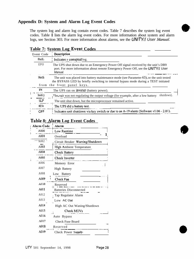
Appendix D: System and Alarm Log Event Codes
The system log and alarm log contain event codes. Table 7 describes the system log event 0i
codes. Table 8 lists the alarm log event codes. For more information about system and alarmlogs, see Section 303. For more information about alarms, see the UNITY/I User A4unual.
Table 7: System Log Evvt CodesEvent Code &Description I
BadL ~!“di~~E33S a corrupter log.
I E P O ’ The UPS shut down due to an Emergency Power Off signal received by the unit’s DB9port. For more information about remote Emergency Power Off, see the UNITY/I UserManual.; ---i------.- ~~.~~__~~~~ --,
HotS ~The unit was placed into battery maintenance mode (see Parameter 63), or the unit testedthe BYPASS LED by briefly switching to internal bypass mode during a TEST initiated
;
i-1 f r o m t h e f r o n t p a n e l k e y s .i IN! ---~
i The UPS ran on inverter (battery power).NrEG 1 The unit was not regulating the output voltage (for example, after a low battery -4shutdown).
,- -.. ~~~ ?~---SLP 1 The unit shut down, but the microprocessor remained active.
--i
Tab!? 8: Alzwm Log Event Codes~.~__
7-.------- ~~~A001 ~ Overload - 1
.--I :A002 , Circuit Breaker Waming/Shutdowni
’ ~~ t-.----*:i
High Ambient Temperature- -
A006 / Memory Error -jA007 i High BatteryA008 Low Battery
A009 ; checkFan~---~--A010 1 Reserved
-~ ~~-::I+ .--~~~~ ~~~-~~~~-~---~~ -;
AOII ~ Batteries Disconnected+.---.---- --~~- -.A012 ; Tap Regulator Alarm /A013 I Low ACOut+AOl4- High AC Out Waning/ShutdownA015
~-I Chc?c!~ -AA016 Auto BypassA017 Check Fuse Board
iA018 Reserved..-..* ~. _~A019 -----1; Check Power Supply 0
UTY 501 September 14, 1998

B e s tPower
~~NTERRUPTIBLE3WER S Y S T E M S UTY 604
September 1995
Scheduled Maintenance for UNITY/I Single-Phase Models
A maintenance check should be performed by a qualified technician every six months. Thispublication provides a detailed description of the scheduled maintenance procedure. It includescleaning and inspection procedures, an alarm and system log check, a battery load test, and aparameter settings check. Use this as a guide as you fill in BEST publication UTY 605. Eachnumbered step in this publication corresponds with the same numbered step in BEST publicationUTY 605.
Tools required (use insulated tools):
Phillips screwdriverNonmetahic brushDigital multimeter
7/16” wrench or nutdriverVacuum cleaner with nonmetallic nozzle
a-0604ACopyright 1995, Best Power, Inc. 1 RESTRICTED
N9246 Highway 80 South, PO. Box 280. Necedah, WI 54646 U.S.A , Web site: wwbestpowercom1-608-565-7200 , 1-800356-5794 I” 5 A, .“d C.“sdsl , FM 1-608~565-2221
sewce: I-SOcG56-5737 , Fex: 1-608-565-2509 , Fax-On-Demand: 1-800-487-6813
eCAUTION
1 . These procedures must be performed by a qualified service technician only.
2. UPS units are designed to provide power under a variety of operating conditions.Dangerous voltages may be present even if AC line and DC voltage is removed.
TEST BEFORE TOUCHING!
3. UPS batteries are high current sources. Shorting battery terminals or DC terminalstrip terminals can cause severe arcing, equipment damage, and injury. A shortcircuit can cause a battery to explode.
XIIThis unit contains components that are sensitive to electrostatic discharge (ESD).If you do not follow proper ESD procedures, severe damage to electroniccomponents may occur.
BEST recommends the following for qualified technicians servicing the UPS:
i:Remove rings, watches, and other jewelry before servicing the UPS.Always wear protective clothing and eye protection, and use insulated tools whenworking near batteries.
C . Whenever you are servicing an energized unit with the cover removed, electricshock is possible. Follow all local safety codes.

You can find the UNITY/I model number and serial number near the key switch inside the frontdoor. If there is an external bypass switch, an identification label on the bypass cabinet will tellyou whether it is break-before-make or make-before-break. l i1 . Authorization to perform maintenance and test the UPS (Contact Signature). Write down
the contact person’s name; then, ask that person to sign in the space provided. Make surethe customer understands that during this procedure you must power down the loadequipment if there is a break-before-make bypass switch or no bypass switch. If there is amake-before-break switch, loads may shut down during transfer under some conditions, ifpossible, shut down loads before switching.
2 . Comments or problems regarding the UPS. Record any comments or problems thecustomer has had with the unit since the last scheduled maintenance.
3. Is the UPS environment clean andfree from dust and dirt? If the unit is not in a safe,clean, dry area, stop and call BEST’s Technical Support Center at l-800-456-5737(U.S.A. and Canada) or l-608-565-2100.
1 Shut down the load equipment or bypass the UPS before continuing with steps 4, 5, and 6.
e CAUTION
Before switching an external make-before-break (MBB) bypass switch, the BYPASS light onthe UF’S front pane1 must be lit. If you operate an external MBB bypass switch while the UPSis operating on line power or on battery power, equipment damage may result. Refer to BESTpublication “TIP 410” for proper bypass switch operating instructions.
Ile WARNING
Risk of electric shock! Before removing cover: shut off the UPS, turn offAC line and DC input power, and discharge the capacitors (as instructedbelow).
Disconnecting AC and DC Power
0 Open the front door of the UPS. Turn the key switch to “Off.”
0 Remove AC input to the UPS. (Turning the key switch “Off’ is not sufficient.)
0 If you have one or more external battery cabinets, shut off the DC disconnectswitches on all of the cabinets.
UN 604September 1995
2 RESTRICTED

e
Figure 1
0
q
q
Remove the screws at thecorners of the frontventilation panel and removethe panel from the unit.
Remove the bolt from the topDC connector (see Figure 1).
Disconnect the top DCconnector (see Figure 1).Make sure that the connectordoes not contact the pre-charge switch after it isdisconnected
lb CAUTION
The DC filter capacitors store a charge, even after AC and DC power are disconnected.Do not service the unit until you have discharged the capacitors.
Discharging the Capacitors
q Remove the seven screws from the side covers. Three screws are located on top ofthe unit, and two on each side panel. Lift each side cover straight up, then off.
q With AC and DC power disconnected, turnthe WS key switch to “Auto” for at least fiveseconds. Note: The fans may come on and A-17 and A-13 alarms may be displayed. This isa normal indication.
q Turn the UPS key switch back to “Off”
q To verify that the capacitors are discharged,use a voltmeter to measure the DC voltagebetween the DC bus bar (-) and one of theoutside heatsinks on each inverter board (f),as shown in Figure 2.
Figure 2q If the reading is greater than S volts, wait
five minutes to allow the capacitors to discharge. Then, repeat the previous stepbefore continuing.
UN 604September 1995
3 RESTRICTED

Cl Remove the fast-on connector from E5 in the upper right corner of the fuse board.The fuse board is located next to the DC connector at the base of the front panel.
4. Perform a visual inspecfion of the UPS.
0 Look for any damage on the boards or any marks inside the unit. Make sure allterminal connections, including battery, AC input, and AC output connections arein good working order and free of corrosion. If a wire is loose, tighten theconnection. Make sure each battery connection is tight. If you find any damage,stop and call BEST’s Technical Support Center.
Cleaning Inside the Chassis
0 Using a nonmetallic brush and a vacuum cleaner with a plastic nozzle, vacuum outany dust or dirt found in the unit. Be careful not to dislodge or damage anycomponents or connections while cleaning the unit.
5 . Are there open fuses, blown MOVs or damaged components on any of the boards? Noteany repairs in step 13. If you find any damage or if fuses are open, stop and call BEST’sTechnical Support Center. If not, continue.
0 Close the door assembly and secure it with the two Phillips screws. Make sure thatno wires are pinched between the door and the chassis.
0 Replace the side covers and secure them with the seven screws. Slide each coverstraight down to secure it on the notches that hold it in place.
q At the front of the unit, reconnect the fast-on connector to E5 on the fUse board.
q At the front of the unit, reconnect the top DC connector and secure it with thebolt.
0 Switch on the DC disconnect switches on the external battery cabinets (ifapplicable).
[I1 Replace the front ventilation panel and secure it with the screws.
q Reapply AC line.
q Turn the key switch inside the unit’s front door to “Auto.”
0 Apply 50% non-essential load to the unit.
UN 604September 1995
4 RESTRICTED

Checking Alarm and System Logs
List thefive most recent alarm andsystem log events. Record the log information (i.e.,alarm code, time, etc.) for the first five alarm and system log entries in BEST PublicationUTY 605. The first entry displayed is the most recent log entry.
0 Hold down the [CANCEL] and [RUNTIMB] keys for two seconds. Release thekeys when display shows “P-00.”
0 Press [VOUT]. The display should show either “P-134” or “P-132.”0 Press [%LOAD]. The display should show “AL 10’ If the UPS has never had an
alarm condition, the display will show “SL 1.”
Use [%LOAD] and [VOUT] keys to step up and down through the log numbers. Thesystem log entries follow the alarm log entries. If you step past the last system log entry(to “P-00”), repeat the above steps to re-access the logs. When finished viewing the logs,press [VLINE] twice.
Viewing System Parameters
List Parameter 92, system Hours. To view parameter 92 follow the instructions below.
0 Hold down the [CANCEL] and [RUNTIMB] for two seconds. Release the keyswhen the display shows “P-00.” Use [%LOAD] and [VOUT] to step up and downthrough the parameters until you reach “P-92.” Then press [CANCEL]. Thedisplay will show the parameter value. Use the [CANCEL] key to toggle betweenparameter number and the parameter value. Record the system hours in the blankprovided. When finished viewing the parameters, press [VLINE] twice.
Is there anything in the logs thut implies the UPS will not sustain the load equipmentduring an outage? Not& the customer that you are going to perform a battery load testand that in the unlikely event of a problem, all equipment should be preparedfor a poweroutage. Look at the entries you recorded in step 6 to find out if there have been anybattery alarms since the last scheduled maintenance that were not caused by a poweroutage. If yes, do not continue. Service the UPS before proceeding with the next step.If necessary, call BEST Service Department for help interpreting log information.
Is customer using the DB9 communication port for a communications link? Take thenecessaryprecautions so that this contact closure will not cause apremature shutdown.If the customer is using a communications link with UPS monitoring software, you mustdisable the software prior to doing a battery test. If there is no data cable attached to theDB9 port on the back of the UPS, no communications link is being used.
I.
8 .
UTY 604September 1995
5 RESTRICTED

eCAUTION
The UPS must be in an operative mode with at least 50% of the non-essential load appliedfor the following tests. To avoid equipment damage, do not use critical loads whileoerforminp. a batterv test.
9 . Perform a battev test. Set Parameter 77 to “1.” Parameter 77 must be set to 1 for thebattery test to be performed. To change this parameter:
0 Hold down the [CANCEL] and [RUNTIME] for two seconds. Release the keyswhen the display shows “P-00.” Then press [CANCEL]. The display will read “0.”
0 Use the [%LOAD] (increase setting) and [VOUT] (decrease setting) keys tochange the display reading to “377.”
0 Press [RUNTIME]. The display should read “1.” If the display reads “0,” the unitdid not accept the password, repeat the previous step.
NOTE: If the display is let? unattended (no keys are pressed) for five minutes, thepassword reverts to level “0” and you must re-enter the password. (In softwarev. 1 .OO, if the display is let? unattended for one minute the password must bereentered.)
0 Press [CANCEL]. The display should read “P-00.”
0 Press [%LOAD] until the display shows “P-77.” Press [CANCEL] to view theparameter value. Note that the [CANCEL] key allows you to toggle between theparameter number and parameter value.
0 Press [%LOAD] to set the value to “1.”
0 Press [RUNTIME]. Then enter the value “1.” The UPS beeps to indicate that thenew value has been entered.
0 Press [VLINE] twice.
Front Panel LED Test
Press the [TEST] keys and hold downfor 2 seconds for the test. Watch the LED statusindicators and display to make sure they work. Did each front panel LED (except bypass)and all segments of the LCD display light? If a low battery or battery problem is detected,an alarm will activate. When test is finished, reset parameter 77 to its original value.
UTY 604September 1995
6 RESTRICTED

0 10,
1 1 .
a
1 2 .
1 3 .
1 4 .
Battery Load Test
Buttery loud test. With at least 50% load applied, remove AC power and run on batterypower for 10 minutes or half of the system’s specified battery nmtime, whichever is less.
After 10 minutes (or half your battery nmtime), use a multimeter to measure the voltageacross each individual battery. Average battery voltage should be approximately 11.5volts. Record the voltages. If any battery is more than 0.5 volt different from the others,that battery has failed. Circle the date code for any failed batteries. If you replace one ormore batteries, note this in step 14. When the unit is running on battery, till out the “OnBattery” column in step 11. Is there anything in these parameters that indicates the UPSwill not sustain loads during a power outage?
When you finish the battery load test, record the time in the “Length of load test” blank,and record the batteries’ “BAT” model number in the blank provided.
Reapply AC line. Put the unit in auto mode andjill in the “On Line” readings listed instep II. Then, reconnect all loads.
Parameter Settings Check
Is there anything in the parameter readings that would indicate the UPS will not sustainthe load equipment? Refer to instructions in step 6 to access parameters. It is notnecessary to enter a password to view the parameters. Compare these parameter readingswith parameter readings from the last maintenance check. If there was not a previousmaintenance check, refer to the Service Manual for parameter settings. Save BESTpublication UTY 605 to use as a reference for the next scheduled maintenance procedure.
Record any repairs or changes that you made. Document any wiring problems and anycorrective action taken. Did you change any parameters to a different setting? List anychanges made and the reason for the change.
List all parts, including batteries, used to repair the system.
For BESTIFS& Fill in the information on the bottom of page two (travel time, time onsite, was the unit operational, is a return trip required, does BEST need to contact thecustomer). Have the form signed by the required individuals and return it to BEST.
File this document so it can be referred to the next time preventive or corrective maintenance isneeded.
UTY 604September 1995
RESTRICTED

ININTERRUPTIBLE‘OWER S Y S T E M S
0September 1995
) Scheduled Maintenance and Service Call Report FormFor UNITY/I Single-Phase Models
Refer to UTY 604 for detailed instructions.Please check one: 0 Maintenance 0 Service
Technician
LOCATION OF SYSTEM Model Number
Company Name
Address
RF.9 Number
Technician ID Number Territory
Serial Number
Phone Number
BypassType: OBBM q MBB Date of service
1. Authoriition to p&cm, maintenance and test UPS (Contact Signature)
2 . Comments or problems regarding the LIPS.
3 . Is the UPS environment clean and free from dust and dirt?
Time of service
-Yes -No*
IBefore removing cover and continuing with steps 4.5, and 6:l&L : Shut down the load equipment or bypass the UPS.
Shut off the UPS. Turn off AC line and DC input power and discharge the capacitors.
4 .
-
6 .
7 .
8 .
Perform a visual inspection of the UPS.Check battery terminal connections; are connections tight, free of corrosion and in good condition?
Are there open fuses, blown MOVs, or damaged components on any of the boards?Note any repairs in step 13.
-Yes -NC*
-Yes*Nc
List the five most recent alarm and system log events below. List Parameter 92 Sys Hrs
Alarm Log Swtem Lag
ALI SL 1
AL2 SL2
AL3 SL3
AL4 SL4
AL5 SL5
Is there anything in the logs that implies the UPS will not sustain the load equipment during an outage?Notify the site that you are going to perform a battery load test and that, in the unlikely event of a problem, all equipment shouldbe prepared for a power outage.
Is customer using the DB9 communicaticn pat for a communications link? Take tix necessary precautions so that this contactclosure will not cause a premature shutdown.
The UPS must be in an operative mode with at least 50% of the nonessential load applied for the following tests.
Perfor,,, a battery test. Record the value of parameter 77 ~. Set parameter 71 to “I” and escape parameter mode. Thenpress the [TEST] keys and hold them down for 2 seconds. Watch the LED status indicators and display to make sure theywork. (The Bypass LED will not light.) The unit will perform a brief battery test. Reset parameter 77 to original value.
UTY-0605BCopyright 1995, Best Power T+r~oloN9246 Highway $IyP
1 RESTRICTEDOuth, PO Box 280. NecedLa WI 54646 u.s.a. , Web site: wwwbestpowercom
1-608-565-7200 , I-Bco-356-5794 ,u S,A, and Canads, , Fax: 1-608-565-2221service: 1-800356-5737 , Fax: 1-608-565-2509, Fax-O”.Oem*nd: 1-800487-6m3

10. Battery load test. Remove AC line from the UPS. With 50% load applied, run on battery power for 10 minutes per batterystring or until average battery voltage is 11.5 volts. Record the voltages below. If any battery is more than 0.5 volt differentfrom the others, that battery has failed. Circle the date code for any failed batteries. If you replace one or more batteries, notethis in step 14. While the unit is running on battery, fill out the “On Battery”column in step 11.
Battery Number 1 2 3 4 S 6 7 8
On Battery with Load
Date Code
Length of battery load test Battery type BAT-
Put the unit back on line in auto mode to do the ‘On Line” readings listed below in step 11
11. Is there anything in these parameters that indicates that the UPS will not sustain the load equipment?
Parameter Number
1 Serial Number Low
2 Serial Number High
5 Nominal V Out
6 Full Load Setpoint
13 Frequency
21 Volt.9 In
28 VoltsOut
29 IOut
30 VBatt
31 Amb Temp
wxxxxxx
xxx
On Battq Parameter Number32 Batt Temp
34 Percent Load
35 Power Factor
36 Watts
37 VAOut
62 Hot Swap V In
89* Hours!Min
w On Bsttq
x x x90*MonthDay xxxPl*Year x x x‘For Software v. 1.05 and below, Parameter 90 = Time andParameter 91= Month/Day.
12. Record any repairs or changes that you made. Document any wiring problems and any corrective action that was taken
13. List all parts, including batteries, used to repair the system.
14. BEST IFSCs: Operational Unit? q Yes ONo Return trip required? 0 Yes ON0
Travel Time Time cm Site
BEST must contact customer in reference to today’s service: -Yes N o Phone l-800-356-5737
P.O. # Authorized by Verified by (BEST employee)
Quoted price (Quoted price does not include shipping or tax, if applicable.)
Site Representative Signature Service Representative Signature
2 U-I-Y 605RESTRICTED

JNlNTERRUPTlSLE‘ O W E R S Y S T E M S
U N 601January 199s
Verifying the Basic Operation of theSingle-Phase UNITY/ITM UPS
This document explains how to verify the basic operation of a single-phase UNITY/I UPS. Thisprocedure can be used after performing maintenance or as a stand-alone procedure. If a completerecalibration is required or if a complete scheduled maintenance procedure is required, call BEST’sTechnical Support Center at l-800-356-5737 (U.S.A. and Canada) or your local BEST office.
Ifthe DB9 port on the back of the UPS is being monitored by automatic shutdown software, take thenecessary precautions so that this procedure does not trigger a shutdown of the load equipment.
Tools required (use insulated tools):
True RMS voltmeter Clamp-on ammeter Pen or pencilPhillips screwdriver UNITY/I User ManualDC voltmeter Personal safety equipment as required by local code
L
eWARNINGThese procedures must be performed by a qualitied service technician only.
UPS units are designed to provide power under a variety of operating conditions.Dangerous voltages may be present even if AC line or DC voltage is removed.
TEST BEFORE TOUCHING!
3. UPS batteries are high current sources. Shorting battery terminals or DC terminal stripterminals can cause severe arcing, equipment damage and injury. A short circuit cancause a battery to explode.
tqYThis unit contains components that are sensitive to electrostatic discharge (ESD). Ifyou do not follow proper ESD procedures, severe damage to electronic componentsmay occur.
BEST recommends the following for qualified technicians servicing the UPS:
;:Remove rings, watches and other jewelry before servicing the UPS.Always wearprotective clothing and eye protection and use insulated tools whenworking near batteries.
C . Whenever you are servicing an energized unit with the cover removed, electric shock ispossible. Follow all local safety codes.
8 Copyright 1995. Best Power Technology, Inc.UT-f-0601A
RESTRICTED

Contents
Section 100: Removing the Covers
Section ZOO: V e r i f y i n g B a s i c U n i t O p e r a t i o n201: Accessing Parameter Mode and Entering a Password202: Calibrating the AC Input Voltage . . .2 0 3 : C a l i b r a t i n g t h e A C O u t p u t V o l t a g e2 0 4 : C a l i b r a t i n g t h e B a t t e r y V o l t a g e2 0 5 : C a l i b r a t i n g t h e O u t p u t C u r r e n t206: Checking Unit Transfers (with Loads) and Battery Charger Operation
.2
.3
.3
.4
.6
.81012
Section 300: Replacing the Covers 12
Section 100: Removing the Covers
e CAUTION
If you use an external bypass switch to bypass the UPS, the loads are powered by directAC line and are not protected by the UPS.
100-l. If there is an external bypass switch, you may use it to bypass the UPS. Otherwise,shut down the load equipment.
100-2. Open the front door of the UPS. Turn the UPS key switch to “Off
WARNING
There is still live voltage inside the UPS.
100-3. Remove the seven screws from the side covers. Three screws are located on top ofthe unit, and two on each side panel.
100-4. Lift each side cover straight up, then off.
UN 601January 1995
RESTRICTED

a E xtior 250: Verifying Basic Unit Operation
NOTE: During start-up and during transfers from battery power to line power, the tapchangers will make clicking sounds. This is normal.
NOTE: If the UPS will not accept a new parameter setting during the procedure, re-enterthe password as instructed in steps 201-3 to 201-7.
If you encounter a problem while performing this procedure:
1, Completely shut down the unit as instructed in the UNITY/I User Mcmuul.
2. Verify all connections/troubleshoot the UPS.
3. Check to see if something external to the UPS may be causing the problem.
4. Start this procedure over.
5. If you encounter the same problem a second time, shut the unit down and phoneBEST’s Technical Support Center or your local BEST office for assistance. Do notcontinue the procedure until the problem is remedied.
If you need assistance, phone BEST’s Technical Support Center at l-800-356-5737(U.S.A. and Canada); elsewhere, phone your local BEST office. Have the UPS serialnumber and UPS model number available when you call.
201: Accessing Parameter Mode and Entering a Password
NOTE: When the unit is in parameter mode, each of the front panel keys has a specificfimction. The label inside the front door of the unit explains the parameter mode keyfunctions. The label also shows a “Programming Template” with alternate keynames which correspond to the parameter mode key functions.
b WARNING
As a safety precaution, stand clear of the UPS whenever reapplying AC input linevoltage to the unit or restarting the unit.
Wear personal safety equipment whenever the UPS covers are removed.
UTY 601January 1995
RESTRICTED
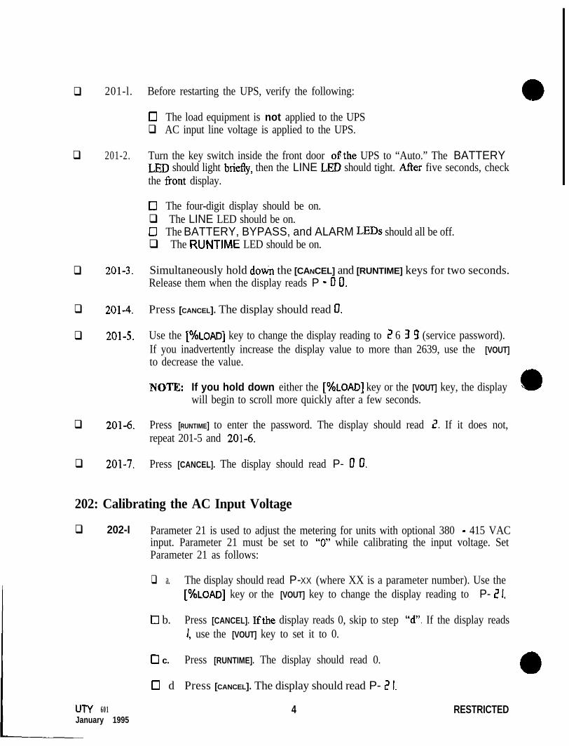
q
q
q
q
q
q
q
201-l. Before restarting the UPS, verify the following:
0 The load equipment is not applied to the UPSq AC input line voltage is applied to the UPS.
201-2. Turn the key switch inside the front door ofthe UPS to “Auto.” The BATTERYLBD should light briefly, then the LINE LED should tight. AtIer five seconds, checkthe front display.
II The four-digit display should be on.q The LINE LED should be on.cl The BATTERY, BYPASS, and ALARM LEDs should all be off.q The RUNTIME LED should be on.
201-3. Simultaneously hold doti the [CANCEL] and [RUNTIME] keys for two seconds.Release them when the display reads P - II 0.
201-4. Press [CANCEL]. The display should read 0.
201-5. Use the [%LOAD] key to change the display reading to 2 6 3 9 (service password).If you inadvertently increase the display value to more than 2639, use the [VOUT]to decrease the value.
NOTE: If you hold down either the [%LOAD] key or the [VOUT] key, the displaywill begin to scroll more quickly after a few seconds.
201-6. Press [RUNTIME] to enter the password. The display should read I?. If it does not,repeat 201-5 and 201-6.
201-7. Press [CANCEL]. The display should read P- 0 0.
202: Calibrating the AC Input Voltage
q 202-I Parameter 21 is used to adjust the metering for units with optional 380 - 415 VACinput. Parameter 21 must be set to “0” while calibrating the input voltage. SetParameter 21 as follows:
UTY 601January 1995
q a. The display should read P-XX (where XX is a parameter number). Use the[%LOAD] key or the [VOUT] key to change the display reading to P- 6’ 1.
0 b. Press [CANCEL]. Ifthe display reads 0, skip to step W’. If the display reads1, use the [VOUT] key to set it to 0.
Cl c. Press [RUNTIME]. The display should read 0.
0 d Press [CANCEL]. The display should read P- 2 I.
4 RESTRICTED

Figure I
0 202-2. Go to Parameter 27 (Input Voltage) as follows:
El a. The display should read P-XX (where XX is a parameter number). Use the[%LOAD] key or the [VOUT] key to change the display reading to P - 2 1.
0 b. Press [CANCEL]. The display should show the UPS input voltage.Displayed input voltage = VAC.
0 202-3. Calibrate Parameter 27 (Input Voltage) as follows:
0 a. Use a true RMS voltmeter to measure the AC input voltage from Ll to L2on the UPS DIN rail (see Figure 1). Measured input voltage =~ VAC.
NOTE: If the displayed voltage is within *2.0 volts of the measuredvoltage, you may skip to step 202-4.
17 b. Use the [%LOAD] key or the [VOUT] key to change the display reading tothe measured voltage.
•i C. Press [RUNTIME] to enter the new value. The displayed voltage should nowbe within i2.0 volts ofthe measured voltage. If it is not, repeat all of 202-3.
0 202-4. Press [CANCEL]. The display should read P- 2 1.
UTY 601January 1995
5 RESTRICTED

cl 202-5. On the label inside the unit’s front door, find the “Input Volts” rating.
0 If the “Input Volts” rating is 200 - 240 VAC, skip to Section 203.
0 If the “Input Volts” rating is 380 - 415 VAC, set Parameter 21 to “1” asfollows:
0 a. The display should read P-XX (where XX is a parameter number). Use the[%LOAD] or [VOUT] key to change the display reading to P- 2 1.
0 b. Press [CANCEL]. Use the [%LOAD] key to change the display reading to 1 .
0 C. Press [RUNTIME]. The display should read 1 .
0 d. Press [CANCEL]. The display should read P-I? 1.
203: Calibrating the AC Output Voltage
The AC output voltage to the loads is dependent upon three main factors:
0 The Parameter 05 setting, which determines what voltages will be present at theoutput terminals on the UPS DIN rail.
0 The connection of the output wires to the correct UPS DIN rail terminals.
0 The calibration of Parameter 28 (Output Voltage).
q 203-l. Check the Output Voltage Reference setting (Parameter 05).
0 a. Use Table 1 to determine the correct Parameter 05 setting for yourapplication. Write the correct Parameter 05 setting here
Table 1: Parameter 05 SettingVoltage required by loads (UPS Output) Correct Parameter 05 setting
100 and/or 200 200
110 and/or 220 220
115 and/or 230 230
120 and/or 240 240
208 208
127 254
1271220 220
0 b. The display should read P-XX (where XX is a parameter number). Use the[%LOAD] key or the [VOUT] key to change the display reading to P- 0 5.
UTY 601 6 RESTRICTEDJanuary 1995

0 c. Press [CANCEL]. The display will show the Parameter 05 setting
0 d. Does the displayed setting (step “c”) match the correct setting (step “a”)?
0 YES Continue with step 203-2.
0 NO For the UPS to provide the desired output voltage to theloads, Parameter 05 must be set properly. Do not continueuntil you are certain of the correct Parameter 05 setting fcryour application. You may wish to refer to the UNITYilZnsfdafion MunuuZ. If vou need assistance. call BEST’sTechnical Support Centetor your local BEST’office.
lb CAUTIONBefore continuing, make sure that no load equipment is applied to the UPS. The next step maychange the unit’s output voltage.
Parameter 28 (Output Voltage) will not calibrate properly unless Parameter 05 is set to “240”as instructed in this section.
0 203-2. Temporarily set Parameter 05 (Output Voltage Reference) to “240” as follows:
0 a. The display should still show the Parameter 05 setting.NOTE: If the setting is already “240”, you may skip to step 203-3.
0 b. Read the CAUTION above. Make sure that IIQ loads are applied.
0 c. Use the [%LOAD] key or [VOUT] key to change th:: display reading to 2 ‘! 0.
0 d. Press [RUNTIME]. You may hear clicking. The display should read 2 9 0.
0 203-3. Press [CANCEL]. The display should read P- 0 5.
0 203-4. Go to Parameter 28 (Output Voltage) as follows:
q a. The display should read P-XX (where XX is a parameter number). Use the[%LOAD] key or the [VOUT] key to change the display reading to P - 2 8.
0 b. Press [CANCEL]. The display should show the UPS output voltage,Displayed output voltage = VAC.
NOTE: The unit uses the highest nominal voltage developed on thetransformer secondary to monitor both the high and lowvoltage outputs. Parameter 28 displays the high outputvoltage only.
U-I-Y 601January 1995
7 RESTRICTED

0 203-5. Calibrate Parameter 28 (Output Voltage) as follows:
Cl a. Use a true RMS voltmeter to measure the AC output voltage fromXl to X5 on the UPS DIN rail (see Figure 1). Measured output = _VAC.
NOTE: If the displayed voltage is within i2.0 volts of the measuredvoltage, you may skip to step 203-6.
q b. Use the [%LOAD] key or the [VOUT] key to change the displayed reading tothe measured voltage.
•I c. Press [RUNTIME] to enter the new value. The displayed voltage should nowbe within i2.0 volts of the measured voltage. If it is not, repeat all of 203-5.
0 203-6. Press [CANCEL]. The display should read P- 2 8
q 203-7. Reset Parameter 05 (Output Voltage Reference) to the correct setting as follows:
0 a. Look back at step 203-la on page 6 and write the correct Parameter 05setting for your application here
NOTE: Ifthe correct Parameter 05 setting for your application is 240, youmay skip to Section 204. Otherwise, follow the steps below.
0 b. The display should read P-XX, where XX is a parameter number. Use the[%LOAD] key or the [VOUT] key to change the display reading to P- 13 5.
•I c. Press [CANCEL]. The display should read 2 Y 0
c] d. Use the [%LOAD] key or the [VOUT] key to change the display reading tothe value recorded in step 203-7a.
0 e. Press [RUNTIME] to enter the value. You may hear clicking.
0 f. Press [CANCEL]. The display should show P- 0 5.
204: Calibrating the Battery Voltage
q 204-I. Go to Parameter 30 (Battery Voltage) as follows:
0 a. The display should read P-XX (where XX is a parameter number). Use the[%LOAD] key or the [VOUT] key to change the display reading to P- 3 0.
0 b. Press [CANCEL]. The display should show the battery voltage.
U-I-Y 601January 1995
a RESTRICTED

204-Z Remove AC input line voltage. The unit should transfer to battery power.
0 The four-digit display should be on.0 The BAl7ERY LED should be on.0 The LINE, BYPASS, and ALARM LEDs should all be offq The fan should be on. You should be able to hear the fan and feel air flowing
out of the top of the unit.
q 204-3. Watch the displayed battery voltage. When the battery voltage stabilizes (about 60seconds), recalibrate Parameter 30 as follows:
NOTE: See Figure 1 for the locations of the DC bus bar (-) and inverter board.
0 a. Place the DC voltmeter so that you can see the voltmeter display and theUPS display at the same time.
0 b. Use the DC voltmeter to measure the battery voltage between the DC busbar (-) and one of the outside heatsiis on the inverter board (+), as shownin Figure 2.
Look at the measured DC voltage and the UPS display at the same time.Is the UPS display within rt0.2 volts of the measured voltage?
q YES Skip to step 204-4.q NO Recalibrate as instructed in steps “c” and “d” below.
lUTY 601January 1995
Figure 2
q c. Use the [%LOAD] or [VOLJT] key to change the UPS display reading to themeasured DC voltage.
0 d. Press [RUNTIME]. The displayed voltage should now be within *0.2 volts ofthe measured voltage. Ifit is not, repeat all of step 204-3.
9 RESTRICTED

q 204-4. Press [CANCEL]. The display should read P- 3 0. lq 204-5. Reapply AC input line voltage. The unit should transfer to line power. After five
seconds, check the front display.
0 The four-digit display should be on.q The LINE LED should be on.0 The BATTERY, BYPASS, and ALARM LEDs should all be off.
205: Calibrating the Output Current
q 205-l Reapply the load equipment.
cl 205-2. Check the Parameter 06 (Full Load Set Point) setting as follows:
q a. Open the Eront door of the unit. Find the model number UTXK, where X isthe KW/KVA rating of the unit. Unit rating = KWIKVA.
0 b. The display should read P-XX, where XX is a parameter number. Use the[%LOAD] key or the [VOUT] key to step to P- 0 6.
q C. Press [CANCEL]. The display should show the Parameter 06 setting. aDisplayed Parameter 06 setting =
0 d. Does the displayed Parameter 06 setting in step “cl’ match the unitKW/KVA rating written in step “a”?
17 YES Continue with step “e” below.
ON0 Use the [%LOAD] key or the [VOUT] key to change thedisplayed readmg to the correct KW/KVA rating. Then, press[RUNTIME] to enter the new value,
IS’ IMPORTANT!
If the Parameter 06 setting was incorrect, a fullrecalibration may be required. After completing thisprocedure contact BEST’s Technical Support Center at
1 B E S T oice f o r a s s i s t a n c e .l-800-356-5737 (U.S.A. and Canada) or your local
0 e. Press [CANCEL]. The display should read P- 0 6. a
UTY 601 10 RESTRICTEDJanuary 1995

0 cl 205-3. Check Parameter 34 (Percent Load) as follows:
0 a. The display should read P-XX, where XX is a parameter number. Use the[%LOAD] key or the [VOIJT] key to change the displayed reading to P- 3 L(.
Cl b. Press [CANCEL]. The display should show the percent of the unit’s ratedcapacity presently being used. Percent load = %.
0 c. Ifthe percent load is over lOO%, remove load until the percent load is lessthan 100%.
0 d. Press [CANCEL]. The display should read P- 3 ‘-I.
q 205-4. Go to Parameter 29 (Output Current) as follows:
q a. The display should read P-XX (where XX is a parameter number). Use the[%LOAD] key or the [VOUT] key to change the display reading to P- 2 9.
0 b. Press [CANCEL]. The display should show the output current in amperes.Displayed output current = amps.
q 205-5. Calibrate Parameter 29 (Output Current) as follows:
0 a. Use a clamp-on ammeter to measure the current of the output wireconnected to Xl on the UPS DIN rail. Xl = amps.
Cl b. Use a clamp-on ammeter to measure the current of either the output wireat X4 or the output wire at X5, whichever is used. X4 or X5 = -amps.
0 c. In the spaces provided below, add the value recorded in step “a” to thevalue recorded in step “b” and divide by 2.
NOTE: If the calculated current is within i0.2 amps of the displayedoutput current, you may skip to step 205-6.
0 d. Use the [%LOAD] key or the [VOUT] key to change the UPS display readingto the correct output current value as calculated in step “c.”
•i e. Press [RUNTIME]. The displayed output current should now be within 50.2amps of the calculated current. If it is not, repeat all of 205-5.
q 205-6. Press [VLINE] twice to escape parameter mode.
UN 601January 1995
1 1 RESTRICTED

206: Checking Unit Transfers (with Loads) and Battery Charger Operation
In Section 204, you transferred the unit from line power to battery power and from batterypower to line power without the loads applied. In this section, you will check these transferswith the loads applied. You will also check for battery charger operatiop.
G5= IMPORTANT!
Unit runtime may be low if the batteries are not fully charged.
206-l. Remove AC input line voltage. The unit should transfer to battery power.
0 The four-digit display should be on.0 The BATTERY LED should be on.0 The LINE, BYPASS, and ALARM LEDs should all be off.0 The fan should be on. You should be able to hear the fan and feel air flowing
out of the top of the unit.
206-2. Reapply AC input line voltage. The unit should transfer to line power. After fiveseconds, check the front display.
0 The four-digit display should be on.0 The LINE LED should be on.0 The BATTERY, BYPASS, and ALARM LEDs should all be off.
206-3. To verify charger operation, simultaneously press the two [WATT] keys to displaythe battery voltage. The charger should be recharging the batteries, so the displayedbattery voltage should be increasing.
Section 300: Replacing the Covers
0 300-l. Ifthere is an external bypass switch, you may use it to bypass the UPS. Otherwise,shut down the load equipment.
0 300-2. Open the front door of the UPS. Turn the UPS key switch to “Off’.
Cl 300-3. Replace the side covers and secure them with the seven screws. Replace the rightcover first, then the left. Slide each cover straight down to secure it on the notchesthat hold it in place.
0 300-4. Turn the UPS key switch to “Auto”.
0 300-5. Reapply the load equipment.
UTY 601 12 RESTRICTEDJanuary 1995

NINTERRUPTIELEOWER S Y S T E M S
Generator Setup for UNITY/IUT3K, UTLFK, UT5K, and UT8K
UN608UAugust 29,1997
fhis UNITY/l technical supplement (UTY) describes how to program UNITY/I models to accept generator power. AIualilied technician who is familiar with the UNITY/l must program the unit. If you encounter problems during thisxoc&re, call Best Power Worldwide Service at l-800-356-5737 (U.S. and Canada only). l-608-565-2100. or call your,ocal Best Power oflice.
JNITY/I units automatically adjust to the input power available. This means that you should not need to reprogram aUNITY/I using input power from a generator. However. in some cases the UNITY/I does not accept generator powerxcause the generator power is relatively unstable. To help the UNITY/I work with the input from the generator. you mustfollow steps 101 through 108 below to reprogram some parameters.
You can perform this procedure using the front control panel on your unit. (See Figure 1.) You can also perform thisprocedure through a dumb terminal or a computer running terminal emulation software connected to the DB9communication port on the back of the unit. You must know how to display and program parameters. If you need moreinformation, see the Liser Manual if you are using the control panel or UTY 50 1 if you are using a terminal or computer.
Figure 1
Enter the Service password.
From the front controlpanel:
a . Press the [CANCEL] and the [RUNTIME] keystogether until the display shows P-00. (See Figure2.)
1997, Best Power. All rights reserved.
Figure 2
RESTRICTED

a . Set the UNITY/I to the proper baud rate. If the baud rate Figure 3needs to be changed:
I.
ii.
ttt.
iv.
press the [CANCEL] and the [RUNTIME] keystogether until the display shows P-00. (See Figure2onpage 1.)
Then, press [%LOAD] until the unit displays 22.(See Figure 5.)
Once you reach p-22, press [CANCEL]. Use the Figure 4[%Lo~o] key or the @OUT] key to change thedisplay to the wrect setting. (See Table 1 below todetermine the correct setting.)
To enter the new setting, press [RUNTIME]. Toescape parameter mode, press [VLINE] twice.
NOTE: To escape without saving, press the._ .[VLlNEj or the ~CANCEL] key. Figure 3
Table 1 Baud Rate Settings
Parameter 22 Setting* Communication M[ode rlO-F. Contact mode. Sets the delay (ii seconds) on pin 2.
tn *s’)1’) mnA* tmn hand II.” _.I--- . .._I _, .I”_ ----. 1
2 0 RS232 mode, 2400 baud.
3 0 RS232 mode, 4800 baud.4 0 RS232 mode, 9600 baud.
* Parameter 22 settings are in hexadecimal.
b . Type P 00 2639 and press <ENTER>. The display should read OK=>.
1 0 2 . Change parameter #8 (Glitch Limit) to a value of “25.”
From thejiiont controlpanel:
Press [CANCEL] to return to the parameter display, then press [%LOAD] or [VOUT] until thedisplay reads P-08. Then. press [CANCEL] to display the parameter value. Press [%LOAD] or
[VOUT] until the display reads 25. Press [RUNTIME] to save the value. The UF’S should beep toindicate that you have saved the new value for parameter 8.
UTY 608 August 29,1997 Page 2RESTRICTED

From a computer or terminal:
c Type P 08 = 25, then press <ENTER>. The display should read OK=>.
103. Change parameter #86 (Generator) to a value of “1.” This sets the inverter lockout.
From the front control panel:
Press [CANCEL] to return to the parameter display. then press [%LOAD] or [VOUT] until thedisplay reads P-86. Then, press [CANCEL] to display the parameter value. Press [%LOAD] or[VOUT] until the display reads 1. Press [RUNTIME] to save the value. The UPS should beep toindicate that you have saved the new value for parameter 86.
From a computer or terminal:
Type P 88 = 1, then press <ENTER>. The display should read OK=>.
104 . Change parameter #87 (Inverter Lock Out) to a value of “5.” This sets the number of cycles after a transferto line that line-interactive operation is prohibited.
From thefront control panel:
Press [CANCEL] to return to the parameter display. then press [%LOAD] or [VOUT] until thedisplay reads P-67. Then_ press [CANCEL] to display the parameter value. Press [%LOAD] or[VOUT] until the display reads 5. Press [RUNTIME] to save the value. The UPS should beep to
0indicate that you have saved the new value for parameter 87.
From II computer or terminal:
Type P 87 = 5, then press <ENTER>. The display should read OK=>.
105. Change parameter #78 (Line Delta Mode) to a value of “2.” This sets the Line Delta to poor line.
From thefront controlpanel:
Press [CANCEL] to return to the parameter display, then press [%LOAD] or [VOUT] until thedisplay reads P-78. Then, press [CANCEL] to display the parameter value. Press [%LOAD] or[VOUT] until the display reads 2. Press [RUNTIME] to save the value. The UPS should beep toindicate that you have saved the new value for parameter 78.
From a computer or terminal:
Type P 78 = 2, then press <ENTER>. The display should read OK=>.
Page 3 August 29,1997 U-I-Y 608RESTRICTED

1 0 6 . Change parameter #9 (Frequency Slew Rate) to a value in the range of “400” to “700.”
From thefkmt control panel:
Press [CANCEL] to return to the parameter display, then press [%LOAD] or [VOUT] until thedisplay reads P-09. Then, press [CANCEL] to display the parameter value. Press [%LOAD] or[VOUT] until the display reads a value between 400 and 700. Press [RUNTIME] to save the value.The UPS should beep to indicate that you have saved the new value for parameter 9.
From a computer or terminal:
Type P OS =, enter a value between 400 and 700, then press <ENTER>. The display should readOK=>.
Adjust this parameter until you find the optimum setting.
107 . Change parameter #85 (Tap Delay Count) to a value of “4.” This programs the ‘N” cycle delay for the relayoperate and debounce times.
Press [CANCEL] to return to the parameter display. then press [%LOAD] or [VOUT] until thedisplay reads P-85. Then. press [CANCEL] to display the parameter value. Press [%LOAD] or[VOUT] until the display reads 4. Press [RUNTIME] to save the value. The UPS should beep toindicate that you have saved the new value for parameter 85.
From a computer or terminal:
Type P 85 = 4. then press <ENTER>. The display should read OK=>.
108 . Exit from the parameter mode.
From thefront controlpanel, press [VLINE] rwice to exit from the parameter mode.
From a computer or terminal, type P 00 = *
Your UNITYA UPS should now be set for the generator used in your application. If you still have trouble with the UPSlocking to line, call Best Power Worldwide Service at I-800-356-5737 (U.S. and Canada only), l-608-565-2100, or callyour local Best Power offke.
UN 608 August 29,1997RESTRICTED
Page 4

\IINTERRuPTIBLE3WEu SYSTEMS UTY 620
u
0
December 51997
Replacing the External Batteries forUNITY/I UT3K, UT4K, UTSK, and UT8K
This publication describes how to change the external batteries in UNITY/P models UT3K, UT4K, UTSK, andUT8K. Since many UNITY/I models with external batteries also have internal batteries, this UTY includesinstructions for replacing them as well. If your UNITY/I has no external batteries, refer to UTY 619, instead.
Replace batteries with the same series and type of battery. A qualified service person must perform thisprocedure. Should questions or problems arise while performing this procedure, call Best Power WorldwideService at l-800-356-5737 (U.S.A. and Canada only), l-608-565-2100, or your local Best Power office.
Tools Required - Use Insulated Tools:
Safety Equipment Required by Local Codes UNITY/I User Manual 7/16-inch and l/4-inch Nut Drivers
‘X-inch Heat Shrink Tubing or Electrical Tape 7/16-inch Box Wrench DC Voltmeter
Phillips Screwdriver Diagonal Cutters
Table of Contents
IMPORTANT SAFETY INSTRUCTIONS - SAVE THESE INSTRUCTIONS!S e c t i o n 1 0 0 : B e f o r e R e p l a c i n g t h e B a t t e r i e s
S e c t i o n 1 0 1 : P o w e r i n g D o w n t h e L o a d sSect ion 102: Using the Make-Before-Break Bypass SwitchSection 103: Using Battery Maintenance Mode
S e c t i o n 2 0 0 : R e m o v i n g t h e I n t e r n a l B a t t e r i e sS e c t i o n 3 0 0 : R e p l a c i n g t h e I n t e r n a l B a t t e r i e sS e c t i o n 4 0 0 : R e m o v i n g t h e E x t e r n a l B a t t e r i e sS e c t i o n 5 0 0 : R e p l a c i n g t h e E x t e r n a l B a t t e r i e s
a‘P/-0620ACopyright 1997. Best Power. All rights reserved
........ 2
. . . . . . . . 4
. . . . . . . . 6
........ /
........ 9. . . . . . . 1 3. . . . . . . 16. . . . . . . 17. . . . . . . 19
RESTRICTED

IMPORTANT SAFETY INSTRUCTIONS - SAVE THESE INSTRUCTIONS!
&CAUTION!
This procedure must be performed by a qualified service person only. UNlTY/l UPS units are designed to provicpower under a variety of operating conditions. Dangerous voltages may be present even if input AC line or Dvoltage is removed. Remove all AC and DC power sources. TEST BEFORE TOUCHfNG!
ieC
Turn off the UNITY/I WS according to the procedure describing “Shutting Down the UNITY/l” in the UN/p//I U..sManual. Make sure that the UNITYA batteries and AC input are off or disconnected before you replace the batterie
rs.
‘Yr-k This unit contains electrostatic sensitive devices (ESD). If you do not follow proper ESD procedures, you mrhJ cause severe damage to electronic circuitry.
UNITY/I UPS batteries are high current sources. Shorting battery terminals or DC terminal strip terminals can caulsevere arcing, equipment damage and injury. A short circuit can cause a battery to explode. Always wear protecticlothing and eye protection and use insulated tools when working near batteries.
s ere
Best Power reeommends the following for qualified service people servicing the UNITY/I UPS:A) Remove rings, watches, and other jewelry before servicing the UNITY/I UPS.B) Always wear protective clothing and eye protection, and use insulated tools when working near batterhC) Whenever you are servicing an energized unit with the cover removed, electric shock is possible. Follo
all local safety codes.1
eCAUTION!
Full voItage and current are always present at the battery terminals.
The batteries used in this system can produce dangerous voltages, extremely high currents, and a risk of electricshock. They may cause severe injury if the terminals are shorted together or to ground (earth). You must beextremely careful to avoid electric shock and bums caused by contacting battery terminals or shorting terminalsduring battery installation. Do not touch uninsulated battery terminals.
A qualified service person who is familiar with battery systems and required precautions must service the batteries.Any battery used with this UPS shall comply with the applicable requirements for batteries in the standard foremergency lighting and power equipment, UL 924. Batteries must be replaced with Best Power battery numberBAT-mar equivalent, The installation must conform to national and local codes.
Keep unauthorized personnel away from batteries.
UTY 620 December 5, 1997RESTRICTED
Page 2

The technician or electrician must take these precautions:
@I. Wear protective clothing and eye wear. Batteries contain caustic acids and toxic materials and canrupture or leak if mistreated. Remove rings and metal wristwatches or other metal objects andjewelry. Do not carry metal objects in your pockets where the objects can fall into the batterycabinet.
2. Tools must have insulated handles and must be insulated so that they will not short batteryterminals. Do not allow a tool to short a battery terminal to another battery terminal or to thecabinet at any time. Do not lay tools or metal parts on top of the batteries, and do not lay themwhere they could fall onto the batteries or into the cabinet.
3 . When connecting cables, never allow a cable to short across a battery’s terminals, the string ofbatteries, or to the cabinet.
4 . Align the cables on the battery terminals so that the cable lug does not contact any part of thecabinet even if the battery is moved. Keep the cable away from any sharp metal edges.
5 . Install the battery cables so they cannot be pinched by the battery cabinet door or UPS covers.
6 . Make sure the fuse is positioned so that it will not contact any cabinet parts or other battery posts ifthe batteries move. Make sure there is enough clearance when the battery cabinet door closes.
a. If you are replacing batteries or repairing battery connections, follow the procedure in the UNITY/IUser Manual to shut off the UPS and remove both AC and DC input power, unless you must use“Battery Maintenance Mode.”
8 . If your local or national code requires you to ground either battery terminal, remove the connectionfrom the terminal to ground (earth) before you service the batteries. If any battery terminal isinadvertently grounded, remove the source of the ground. Contacting any part of a groundedbattery can cause a risk of electric shock. An electric shock will be less likely if you disconnect thegrounding connection before you work on the batteries.
9 . Assume that old batteries are fully charged. Use the same precautions you would use whenhandling a new battery. Do not short battery terminals or the battery string with a cable or toolwhen you disconnect the batteries.
10. Do not dispose of batteries in a fire because the batteries could explode. Do not open or mutilatebatteries. Released electrolyte is harmful to the skin and eyes. It may be toxic.
11. Batteries contain lead. Many state and local governments have regulations about disposing of usedbatteries. Please dispose of batteries properly.
Page 3 December 5, 1997 UTY 620RESTRICTED

Section 100: Before Replacing the Batteries . . .
IMPORTANT: Before beginning, measure the voltage of each replacement battery. Eachshould measure at least 12 VDC.
Hardwired or Softwired..... Whenever possible, you should shut down your UPS and remove all AC andDC power to replace the batteries. However you may use “Battery Maintenance Mode” if necessary. To help youselect the best way to change batteries in your UNITY/l System, look at your system’s wiring configuration. MostUNITY/l units are “soft-wired.” This means they have a line cord and plug that connects to utility power at a wallelectrical outlet. The “Protected Loads” are plugged into outlets on the back of the UNITY/I. If your unit issoftwired, go to Table 1, below.
If your UNITY/I was installed so it is wired directly, without an input AC plug or receptacles for the loads, it is“hardwired.” Go to the next page for information regarding hard wired UNITY/I units.
Table 1 - Softwired-. _ ~_~
~-T---
0 Do this if your “Protected Loads” can be shutdown: / ClIfyour
1. Turn off protected loads.~~~~ “Protected-1 Loads”cannotbe ~
2. Unplug them and then plug them into wall receptacles. Switch them on while you I shut down, go toreplace the batteries. Battery replacement takes up to about eight hours. j Section 103,
3. Turn off the UNITY/I UPS by opening the front door and turning the key switch to-- -I “Using Battery
~“OFF.”
I Maintenance 0
4 CAUTION! Turning the key switch to “OFF” is not sufficient. Shut off UPS Mode.”
circuit breaker or remove UPS AC input plug from the wall receptacle.
4 . Go to Section 200, “Removing the Internal Batteries” on page 13. Complete steps5 through 8, below, after you complete the battery installation.
When battery installation is finished, complete steps 5 through 8 to restart theUPS.5 . Reapply AC line to the UPS.
6 . Turn the UPS key switch to “AUTO.”
7 . Turn off the protected loads and plug them into the UNITY/l UPS receptacles.Switch on the loads.
8 . You have completed the battery replacement procedure. The UPS should berunning on line power with all of the load equipment applied. The LINE LEDshould be on, and the BATTERY, BYPASS, and ALARM LEDs should be off
J
UTY 620 December 5, 1997RESTRICTED
Page 4

Use Table 2 - Hardwired (below), to help determine how to proceed.
1 . Decide if your protected loads can be shut down for a few minutes, for up to eight hours while youreplace the batteries, or whether they must not be shut down at all. Find a statement that applies under“Protected Load Status,” and note the row in Table 2.
2 . Under “Bypass Switch Status” find the column that tits your installation.
3 . Where the row and column selected meet, place a check mark. Go to the Section and page indicated.
Table 2 - Hardwired
Protected Load StatusBypass Switch Status
Break-Before-Make Make-Before-Break No Bypass SwitchBypass Installed Bypass Installed Installed
Load can be shut down for onlya few minutes
0 Go to Section 101 0 Go to Section 102 ‘0 Go to Section 103
on page 6 on page I on page 9
Load can be shut down whilebatteries are replaced (up to 8
0 Go to Section 101 0 Go to Section 102 ,o Go to Section 101on page 6 on page 7 on page 6
Load must not be shut down 0 Go to Section 103 0 Go to Section 102 0 Go to Section 103on page 9 : on page 7 on page 9
Page 5 December 5,1997 UTY 620RESTRICTED

Section 101: Powering Down the Loads
101-l. Shut down the load equipment,
101-2. Ifyou have an external Break-Before-Make Bypass Switch, and your protected loads can be shutdown for only a few minutes while you replace the batteries, set the BBM Switch to “LINE.” Youcan now switch on the loads and operate on utility line power.
1 0 1 - 3 . Open the front door of the UPS. Turn the key switch to “OFF.”
101-4. Disconnect AC input power to the UPS.
e CAUTION! Turning the key switch to “OFF” is not suffkient.
101-S . Go to Section 200, “Removing the Internal Batteries” on page 13. You will complete steps 101-6through 101-10 after you complete internal and external battery installation.
When battery installation is finished, complete steps 101-6 through 101-10 to restart the UPS.
101-6. Reapply AC line to the UPS.
101-7. Turn the UPS key switch to “AUTO.”
101-8. Ifyou have a BBM Switch, shut down the loads, set BBM Switch to “UPS”,
101-9. Switch on the loads.
101-10. You have completed the battery replacement procedure. The UPS should be running on line powerwith all of the load equipment applied. The LINE LED should be on, and the BAlTERY,BYPASS, and ALARM LEDs should be off.
Table 3-Alarm Status Table (table duplicated on page 10)
UNITY/I Model
3 Ki
4 K
5K
Serial Number
25098 and&
25099 and above
25097 and&
25098 and abovef~~20778 and below ;
+ -- -.- -/
ALARM LED State-Battery Maintenance Mode ’_...~~ --~~~.- . . ~~~--.~~- 1
O N
,O N
OFF
UTY 620 December 5, 1997RES T R I C T E D
P a g e 6

Section 102: Using the Make-Before-Break Bypass Switch
102-l If you do not need to operate the protected load while you replace the batteries, you may want toshut it down. To connect the protected loads to utility power while you replace the batteries,follow the procedure in steps 102-2 through 102-6.
To switch the MBB bypass switch from “UPS” to “LINE” (or vice versa) with a UNlTYiI single-phase unit, the unit must be operating in BYPASS mode (the BYPASS light must be ON).
To operate the bypass switch, enter the BYPASS mode by following the inshuctions below:
102-2. Enter the user password (377):a . Hold down the [CANCEL] and [RUNTIME] keys; release the keys when the display shows
“P-00.”b. Press [CANCEL]. The display should show “0.”c. Press and hold the [%LOAD] key until the display shows “377.” (Ifyou go past “377,” press
[VOUT] to scroll backwards.)d . Press [RUNTIME]. The display should show “I.”
102-3. Program parameter 62 (nominal input voltage):a . Press [CANCEL] to toggle to the parameter number. The display should show “P-00.”b. Press [%LOAD] to scroll up to “P-62.” (If you go past “P-62,” press [VOUT] to scroll
backwards.)c . Press [CANCEL] to toggle to the parameter value.d. Set the value to the nominal input voltage (200,208,220,230, or 240). Press [%LOAD] to
increase the setting or [VOUT] to decrease the setting.
NOTE: If the UPS has optional 380-415 VAC input, set the nominal AC input voltagevalue to “240.”
e. Press [RUNTIME] to enter the value. The new value should remain on the display.
102-4. Program parameter 63 to “I”:a. Press [CANCEL] to toggle to the parameter number. The display should show “P-62.”b . Press [%LOAD] to go to parameter 63 (P-63).c. Press [CANCEL]. The display should show “0.”d . Press [%LOAD] to change the parameter value to ‘*I.”e. Press [RUNTIME] to enter the new value. The display should still show “I,” and the
BYPASS light should be on. Refer to the Alarm Status Table on the preceding page and seeifALARM light should be on or off. If either light is incorrect, repeat steps 102-4, d and 5.
102-5. If the BYPASS light will not come on: When input line is bad, the UPS will not transfer tobypass mode, and the BYPASS light will not come on. Follow these steps:a. Turn off the load equipment.b. Turn the UPS keyswitch to “OFF.”c. Turn the AC Disconnect switch to “OFF.”d. Turn the MBB bypass switch to “LINE.”e. Turn on the load equipment.
Page 7 December 5,1997 UTY 620RESTRICTED

102-6. If the BYPASS light came on, you can safely operate the MBB bypass switch. Quickly turn thebypass switch from “UPS” to “LINE.”
Now you can shutdown the UPS to replace the batteries. 0
102-7. Open the front door of the UPS. Turn the key switch to “OFF.”
102-S. Disconnect AC input power to the UPS.
e CAUTION! Turning the key switch to “OFF” is not sufficient.
102-9. Go to Section 200, ‘*Removing the Internal Batteries” on page 13. Do not do Section 103. Youwill come back and complete steps 102-10 through 102-14 after completing the batteryinstallation.
When battery installation is finished, complete steps 102-10 through 102-14 to restart the UPS.
102-10. Befowcontinuing:a. Reapply AC line.b. Turn the UPS key switch to “AUTO.”c . Look at the UPS front panel lights:
- The ALARM light status is shown in Table 3-Alarm Status. (See page 6 or 10.)- The BYPASS light should be ON.* The LINE light should be OFF.
IMPORTANT! If the ALARM light status is wrong or the BYPASS light is OFF, repesteps 102-2, 102-3 and 102-4 before continuing.
102-I 1. Quickly turn the MBB bypass switch back to “UPS.”
102-12. Enter the user password (377). See step 102-2.
102-13. Program parameter 63 back to “0”:a . Press [CANCEL] to toggle to the parameter number. The display should show “P-00.”b. Press [%LOAD] to scroll to “P-63.” (Use [VOUT] to scroll backwards if you go past “P-63.“)c . Press [CANCEL]. The display should show “I.”d. Press [VOUT] to change the value to “0.”e. Press [RUNTIME]. The display should show “0,” and the BYPASS and ALARM lights should
now be OFF. The LINE light should be ON.
If the BYPASS light will not turn off: When input line is bad, the UPS will not transfer outof bypass mode, and the BYPASS light will stay ON. If this occurs, you must wait until inputAC line is good. If the BYPASS light stays ON for an extended period of time, have anelectrician check your AC line OT call Best Power Worldwide Service at I-800-356-5737 orl-608-565-2100.
102-14. Press [VLINE] twice to exit the parameter mode. The load is once more protected by the UPS.
UTY 620 December 5.1997RESTRICTED
Page 8

Section 103: Using Battery Maintenance Mode
Battery maintenance mode allows a qualified service person to service the batteries without powering downthe loads connected to the UNITY/I unit. Battery maintenance mode should be used only when the unitdoes not have an external bypass switch and is powering critical loads that cannot be shut down whileservicing the batteries.
IMPORTANT! In battery maintenance mode, the unit does not regulate voltage or provide back-up power in case of a power outage.
When the unit is in battery maintenance mode (Parameter 63 set to “I”), there is still live voltage inside theUPS.
Battery maintenance mode (Parameter 63 set to “I”) should be used during battery maintenance only. Donot use battery maintenance mode for any other type of UPS service or maintenance.
103-l. Verify the stability of the AC line. If there are irregularities with the input AC line, Best Powerrecommends that you do not use battery maintenance mode at this time.
l Press the [VLINE] key on the front of the unit. Watch to see if the input voltage is stable,
l You can also check the UPS system log to see if the unit has frequently switched to batterypower (inverter) recently. See the UNITY/I User Manual for instructions on viewing thesystem log. Look for the system event code “in” (inverter).
103-2. Access parameter mode and enter the user password (377) as follows:
NOTE: When the unit is in parameter mode, each of the front panel keys has a specific function.The label inside the front door of the unit explains the parameter mode key functions. Thelabel also shows a “Programming Template” with alternate key names that correspondto the parameter mode key functions.
a . Simultaneously hold down the [CANCEL] and [RUNTIME] keys for two (2) seconds. Releasethem when the display reads “P-00.”
b. Press [CANCEL]. The display should read “0.”
c. Use the [%LOAD] key or the [VOUT] key to change the display reading to “377.”
NOTE: Use the [%LOAD] key to increase the value. Use the [VOUT] key to decreasethe value. If you hold down either key, the display begins to scroll more quickly.
d . Press [RUNTIME]. The display should read “I.” If it does not, repeat steps “c” and “d.”
e. Press [CANCEL] The display should read “P-00.”
Page 9 December 5.1997 U-I-Y 620RESTRICTED

103-3. Enter the nominal AC input line voltage in Parameter 62 (Nominal Input Voltage) as follows:
a . The display should show P-m(where XYis a parameter number). Use the [%LOAD] key othe [VOUT] key to change the display reading to “P-62.”
b. Press [CANCEL].
c . Use the [%LOAD] key or the [VOUT] key to change the display reading to the nominal ACinput line voltage (200,208, 220, 230 or 240).
NOTE: If the UPS has optional 380-415 VAC input, set the nominal AC input voltagevalue to “240.”
d . Press [RUNTIME] to enter the new value.
e. Press [CANCEL]. The display should read “P-62.”
103-4. Put the unit into battery maintenance mode by setting Parameter 63 (Battery Maintenance Mode)to “I” as follows:
a . The display should read P-H, where XX’is a parameter number. Use the [%LOAD] key orthe [VOUT] key to change the display reading to “P-63.”
b . Press [CANCEL]. The display should read “0.”
c . Press the [%LOAD] key to change the display reading to “I.” 0
d . Press [RUNTIME]. The display should read “I.”
103-5. Look at the LEDs on the UPS front panel. The LINE and BYPASS LEDs should be on, and theBATTERY LED should be off, as shown in Figure 1. The ALARM LED state is shown below.
Table 3-Alarm Status Table (Table duplicated on page 6.)
UNITY/I Model Serial Number ALARM LED State-Battery Maintenance Mode I-. ‘f *
3 K 25098 and below O N II ~J
25099 and above O F F I+~ ~~- I .~~~ - - .~
4 K 25097 and & ~ O N -~ ---I+ ~~~~~~-~~~ ~~ ~--- - - -
25098 and above OFF 1+ +
5 k 20778 and &
8K+
O N
20779 and above I OFF
25097 and & O N~_--~~ - ~~---&__25098 and above OFF
UTY620 December&1997RESTRICTED
Page10

See table on page 10 for Alarm status
Figure 1: Battery Maintenance Mode LEDs
a CAUTION!
If the front panel LEDs do not light as shown in Figure 1, the unit is not in battery maintenancemode and it is not safe to service the batteries. Repeat Section 103-l to 103-5 or power down
NOTE: If, after repeated attempts, the unit does not transfer to battery maintenance mode, the ACinput voltage may be out of tolerance. Call Best Power Worldwide Service for technicalassistance.
103-6. Once the UPS is in battery maintenance mode, go to Section 200, “Removing the InternalBatteries,” on page 13. You will complete steps 103-7 through 103-10 after the battery installationis done.
When battery installation is finished, complete steps 103-7 through 103-10 to restart the UPS
103-7. Access parameter mode and enter the user password (377) as follows:
a . Simultaneously hold down the [CANCEL] and [RUNTIME] keys. Release them when the displayreads “P-00.”
b. Press [CANCEL]. The display should read “0.”
c. Use the [%LOAD] key or the [VOUT] key to change the display reading to “377.”
d . Press [RUNTIME]. The display should read “I.”
e. Press [CANCEL]. The display should read “P-00.”
103-8. Take the unit out of battery maintenance mode by setting Parameter 63 (Battery MaintenanceMode) to “0” as follows:
a . The display should read P-00. Use the [%LOAD] key or the [VOUT] key to change the displayreading to “P-63.”
Page 11 December 5.1997 UTY 620RESTRICTED

b. Press [CANCEL]. The display should read “I:’
c. Press the [VOUT] key. The display should read “0.”
d . Press [RUNTIME]. The display should read “0.”
IMPORTANT:
The BYPASS LED should be off and the LINE LED should be ON.
If the BYPASS LED is ON, the unit is still in battery maintenance mode. Repeat steps “a” through ‘2”above. If the BYPASS LED remains lit, call Best Power Worldwide Service for technical assistance.
103-9. Press [VLINE] twice to escape parameter mode. If you have an “A-l 7 ” alarm, press CANCEL forfive (5) seconds to clear alarm.
103-10. You have completed the battery replacement procedure. The UPS should be running on line powerwith all of the load equipment applied. The LINE LED should be ON, and the BATTERY,BYPASS, and ALARM LEDs should be off.
UTY 620 December 5,1997RESTRICTED
Page 12

Section 200: Removing the Internal Batteries
IMPORTANT: The steps in Sections 200 and 300 must be performed in order.
201. At each external battery cabinet, shut the DC power OFF by pushing the DC switch in and removingthe key. This locks the DC switch to the “Off’ position. (See Figure 2.)
KEY SWITCH
Figure 2
201-l. Disconnect the battery pack(s) from the UNITY/I UPS by removing the DC connector from theUNITY/I. If you have multiple battery packs, remove the connectors from each battery pack. (SeeFigure 3.)
Figure 3
201-2. Most UNITY/I units with extended runtime options have external batteries and internal batteries.If there are internal batteries in the bottom of the UNITY/I cabinet you must replace them as wellas the external batteries. Figure 4 on the next page shows internal battery location.
201-3. To see if there are internal UPS batteries, remove the screws at the comers of the front ventilationpanel and remove the panel from the unit. There are only two screws in the 3K, 4K and 5K models;Figure 4 shows the 8K model.
If there are batteries in the UPS, go on to step 201-4,
If there are no internal UNITY/I UPS batteries, replace the panel and screws. Then go to Section400, “Removing the External Batteries,” on page 17.
Page 13 December 5, 1997 UTY 620RESTRICTED

201-4. To replace the internal batteries, remove the narrow front panel(s).On the 8K, remove the frontkick plate (below the front ventilation panel); slide it upward, then pull it away from the unit.
‘1Batteries
Narrow Front PanelFront Ventilation Panel
Figure 4
201-S. At the front of the unit, remove the bolt that secures the battery tray to the chassis floor. (SeeFigure 5).
REMOVE TH 1s
Figure 5
UTY 620 December 5, 1997RESTRICTED
Page 14

201-6.
201-7.
201-6.
Disconnect the DC connector bv Dulling it. ’down. (See Figure 6.)
SLIDE THE
Figure 6
Disconnect the HRS-370 “quickconnect” connector on the front ofthe battery tray. (See Figure 7.)
Note! The end of the battery traywith the strap will drop to the flooras you slide out the tray. Do not dropthis very heavy tray on your toes orhands! Take the strap and carefiL(rpull the battery tray out of the unitjust far enough to expose all of thebattery terminals.
Note the battery cable wiring orderand the position of the battery tiedown buckles so that you can installnew batteries in the same fashion.
I>! ,/ QUICKCONNECT
Figure 7
Page 15 December 5.1997 UTY 620RESTRICTED

Section 300: Replacing the Internal Batteries
301. Installing batteries and putting the UPS together.0
301-l. Replace the old batteries with new ones of the same series and type and rewire in the same order.See Figure 8.
Figure 8
&CAUTION!
When pushing the battery tray into the unit, be careful not to pinch your fingers between thbattery tray and the chassis.
301-2. Make sure that the HRS-370 “quick connect” connector is not in the battery cavity. Use the palmsof your hands to push the battery drawer all the way into the unit.
301-3. Reconnect the “quick connect” connector on the front of the battery tray. (See Figure 7 on page15.)
301-4. Replace the bolt that secures the front of the battery tray to the floor of the chassis. (See Figure 5on page 14.)
301-5. Reconnect the DC connector at the bottom ofthe unit. (See Figure 6 on page 15.)
301-6. Replace the bottom narrow front panel(s). If you have a UT8K, also replace the front kick plate(See Figure 4 on page 14.)
301-7. Replace the front ventilation panel and secure it with the screws. (See Figure 4 on page 14.)
301-8. Now go to Section 400 “Removing the External batteries.”
UTY 620 December 5. 1997RESTRICTED
Page 16

Section 400: Removing the External Batteries
400. On the external battery cabinet(s), the DC disconnect switch should be “OFF.“‘Ihe DC connector onthe back of the UNITY/I UPS should be disconnected, as well as DC connectors between batterycabinets.
401-l. Remove the screws from the battery cabinet left side panel. Remove the panel from the batterypack. (See Figure 9.)
Figure 9
401-2. Remove the front ventilation panel at the bottom of the battery pack. On UT8K units, remove thekick plate found below the front ventilation panel. Slide the kick plate up, then pull it away fromthe battery pack. (See Figure 10.)
Remove the Fro:Ventilation Panel (also ~~~Kick Plate on UTBK)
Figure 9
Page 17 December 5.1997 UTY 620RESTRICTED

401-3. At the front of the battery pack, remove the bolt that secures the battery tray to the floor of thechassis. (See Figure 11.)
1 REMOVE THE BOLTHOLDING THE
BATTERY TRAY TOTHE BOTTOM OFTHE BATTERY PACK
Figure 11
401.4. Remove the cable from the DC fuse(s) at the top of the battery pack. Insulate the battery cablelead with heatshrink wrap or electrical tape to prevent shorting. (See Figure 12.)
REMOVE ANDINSULATE CABLESFROM FUSE(S)
/ . ,-I
UN 620 December 5, 1997RESTRICTED
Figure 12
Page 18

401-S. Pull the battery tray out just far enough to expose the first battery.
401-6. Disconnect the negative (-) battery cable from the first battery. Insulate the cable lead withelectrical tape or heat shrink tubing.
e CAUTION!
The battery tray may drop to the floor if it is completely removed from the unit. Make sure thatyour feet and/or hands are not under the battery tray while pulling the tray out of the unit.
401-7. Read the CAUTION! above. Then, carefully pull the battery tray out of the unit just far enoughto expose all of the battery terminals.
Section 500: Replacing the External Batteries
501. Installing the batteries and putting the battery cabinets together.
501-l Replace the old batteries with new ones of the same series and type and rewire in the same order.(See Figure 13.)
Figure 13
501-2. Slide the battery tray into the unit until only the front battery is exposed,
501-3. Attach the negative (-) battery cable to the first battery.
&CAUTION! IIWhen pushing the battery tray into the unit, be careful not to pinch your fingers between thebattery tray and the chassis.
Page 19 December 5. 1997 UTY 620RESTRICTED

501-4. Use the palms of your hands to push the battery drawer all the way into the battery pack. Replacethe bolt that secures the front of the battery tray to the floor of the battery pack chassis.
501-5. Next, replace the batteries on the top shelf with the same series and type and rewire in the sameorder.
501-6. Reconnect the battery cables to the DC fuse(s).
501-7. Replace the bottom narrow front panel(s). If you have a UT8K, also replace the front kick plate.Replace the front ventilation panel and secure it with the screws. (See Figure 10 on page 17.)
501-8. Replace the side panel on the battery pack. (See Figure 9 on page 17.) Repeat steps 400 through501-8 for each additional external battery cabinet.
501-9. Reconnect the DC connector to the UNITY/I UPS. If you have multiple UNITY/I battery cabinets,reconnect each battery cabinet. (See Figure 14.)
RECONNECT THE BATTERY PACK(S) Tq THE UNITY/I UPS (AND EACH OTHER)
Figure 14
501-10. You have completed replacing the batteries in the battery packs. Press the Precharge switch, onthe front of each battery cabinet, for five (5) seconds. (See Figure 15.)
UTY 620 December 5, 1997RESTRICTED
Page 20

PRECHARGE SWITCH-l-.- --..-.
KEY SWITCH /
Figure 15
501-l 1. (a.) Insert the key into the main DC switch on the front of each battery pack. (b.) Turn the keyclockwise, then pull the switch out. (c.) The ON-LINE LED should light up. (See Figure 16.)
,e ., 9.. t
KEY SW&H T”RN KEi’ CLOCKWISE
Figure 16
501-12. If your UNITY/I is softwired, and you shut down your loads, return to Table 1 on page 4, andcomplete the remaining steps. If you did not shut down your loads and used the “BattelyMaintenance Mode,” complete steps 103-7 through 103-10 beginning on page 11.
If your UNITY/I is hard-wired, go to the Section you selected from Table 2 on page 5, andcomplete the remaining steps to return the UNITY/I UPS to normal operation.
Page 21 December 5.1997 u-rt 620RESTRICTED

EestPower
NINTERRUPTISLEOWER S Y S T E M S
uTY627JulylseS
Replacing the User Interface Board in UNITY/FMModels UT3K, UT4K, UTSK, and UTSK
This document explains how to replace the user interface board in UNITY/l models UT3K, UT4K,UTSK, and UTSK. This procedure must be performed by a q&tied service technician only. If youhave any questions while performing this procedure, call BEST’s Technical Support Center atl-800-356-5737 (U.S.A. and Canada) or your local BEST office.
Tools required (use insulated tools):
Phillips screwdriverDC voltmeter
Personal safety equipment required by local codes7/l 6” nut driver
4
eWARNING
1 . These procedures must be performed by a qualified service technician only.
2 . UPS units are designed to provide power under a variety of operating conditions.Dangerous voltages may be present even if input AC hoe or DC voltage is removed.Remove all AC and DC power sources. TEST BEFORE TOUCHING!
3. UPS batteries are high current sources. Shorting battery terminals or DC terminal stripterminals can cause severe arcing, equipment damage and injury. A short circuit cancause a battery to explode. Always wear protective clothing and eye protection anduse insulated tools when working near batteries.
This unit contains components that are sensitive to electrostatic discharge (ESD).173 fy dI ou o not follow proper ESD procedures, severe damage to electronic
components may occur.
BEST recommends the following for qualified service technicians servicing the UPS:a . Remove rings, watches, and other jewelry before servicing the UPS.b. Always wear protective clothing and eye protection, and use insulated tools when
working near batteries.c. Whenever you are servicing an energized unit with the cover removed, electric shock
is possible. Follow all local safety codes.
e Copyright 1995, Best Power Technology, Inc.JTY-06278
RESTRICTED

Contents
Section 100: Disconnecting AC and DC PowerSection 200: Removing the S ide CoversSection 300: Discharg ing the Capac i to r sSection 400: Removing the Fron t Pane l sSection 500: Removing the User Interface BoardSection 600: Replacing the User Interface BoardSection 700: R e s t a r t i n g t h e U P S
.23.4
.:
.67
Section 100: Disconnecting AC and DC Power
0 100-l. Ifthere is an external bypass switch, you may use it to bypass the UPSOtherwise, shut down the load equipment.
0 100-2. Open the front door of the UPS. Turn the key switch to “Off.”
Cl 100-3. Remove AC input to the UPS. (Turning the key switch to “OtY is not suflkient.)
0 100-4. If you have one or more external battery cabinets, shut off the DC disconnect switcheson all of the cabinets.
0 100-S. Remove the screws at the comers of the front ventilation panel and remove the panelfrom the unit (see Figure 1). Remove narrow front panel(s).
Figure 1: Single-Phase UNINL, Covers RemovedUT3K, UT4K, and UT5K pictured. UTSK varies slightly in appearance with two inverter boards, two narrow frontpanels, two fans, and a larger chassis.
UTY 627July 1995
2 RESTRICTED

0 100-6. Remove the bolt fiord the top DC connector (see Figure 2)
17 100-i. Disconnect the top DC connector (see Figure 2). Make sure that the DC connectordoes no? contact the pre-charge switch after it is disconnected.
Se&on >.C3~ Rr;~~p‘&, t;iF Is;& @fJ-vgiy$
0 203-I. Remove the sevez screws f?om the side covers. Three sc.rews are located on top ofthe unit, and two on each side panel.
0 200-2. Lii each side cover straight up, then off.
0 200-3. Remove the two screws in the upper comers of the side door assembly. Open theside door assembly (see Figure 1).
3

Section 300: Discharging the Capacitors
0 3 0 0 - I With AC a&DCpowe~ disconnected (see S&on i SO), turn the UPS key switchto “Auto” for at least Eve seconds. The key switch is found inside the front door.
0 300-2. Turn the UPS key switch back to “Off.”
0 300-3. To verify that the capacitors are discharged, me a CC voltmeter to measure the DCvoltage between the DC bus bar (-) and one o%he o~~~‘:r?r?e heatsinks on the inverterboard (+), as shown in Figure 3. For model LJT8K check the voltage on tcfhinverter boards to make sure the qacitors on each hoad are discharged.
[3 300-4. If the rze<~iq ? s;ep 300-3 L dp m-cater than 5 vol:::. \-:ait 5 minutes IO sue\:! ‘GlZcapacitc :3 ?o i: 3 Grg~, Then, repeat steps 3CO-3 & 330-4 before co&uing.
U 3 0 0 - S . Remove. 5-2 ?z-;n connector ?rom ES in the upper rY$t comer ofthe &.e boa-d.SOS FiD: :‘: ‘8 .“o:- ~.>e !ocation &he &se boark.

ection 400: Removing the Front Panels
Refer tc %igure 1 for panel locations.
q 400-i. Remove the front door from the unit.
0 403-Z. Remove the four Phillips screws located inside the front door.
i! 403-3. Slide the front panel &me uo about % inch to release it, then remove it from thechassis by pull& it away from the unit
3Logic Board
I

Figure J: User &z&face bored connections
Cl 500-5. Disconnect the ground wire from the chassis (s Figure 5).
0 500-6. CarefUlly pull the ribbon cable through the hole on the %ont of the chassis.
Cl 500-7. Slide the PhonTek jack out of the user interface boa-d :lolder (see Figure 5)
0 500-8. Gently Tush up on each of the three tab-~ r releax the user interface boarti (seeFigure 5:.
0 600-l. Put the PTW us,zr interface board into the intelface bozrd holder. Gently p-j&~ up tLhethree tabs w!ti!z ptiing the board into place.
0 600-2. Feed the r&bon cab!e through the hole on the f?oni o,Ythe chassis. lou;e it bchintithe !ogic joarti.
q 600-3. A%ch the ~oxd wire to the chassis in this order: zrcud vl;.re, tooth lock \!,:,?iler,screw.
0 600-4. Slide the ?honTek jack into the user interface board holder (see Figure 5)
Cl 600-5. Attach the user interface board holder to the chas&s.
0 600-6. Connect the ribbon cable to 33 on the logic board. Make sure that the rtid stripe onthe ribbon cable is aligned with pin 1 on 53 (see Figure 4).
El 600-7. Remourzt &e logic board on the mounting notches, EI& secure it with the tool11 !ockwasher and the screw.

wtion 700: Restarting the UPS
0 700-I. Replace the fiont panel frame (with four screws), and then the front door(see Figure 1).
0 700-2. Close the side door assembly and secure it with the two screws. Make sure that nowires are pinched between the door and the chassis.
0 700-3. At the front ofthe unit, reconnect the fast-on connector to ES on the fuse board.
0 700-4. At the front of the unit, reconnect the top DC connector and secure it with the bolt.
Cl 700-S. Replace the narrow front panel(s).
0 700-6. Replace the front ventilation panel and secure it with the screws
0 700-7. Replace the side covers
NOTE: Replace the right cover first, then the left. Slide each cover straight downto secure it on the notches that hold it in place.
0 700-8. Switch on the DC disconnect switches on the external battery cabinets (if applicable).
Cl 700-9. Reapply AC line.
0 700-10. Turn the key switch inside the unit’s front door to “Auto.”
Cl 700-I 1. Perform a system self-test. Simultaneously press the VLINE and RUNTIME keysfor two seconds to verify that the new board is limctioning properly. The unit willtest the front panel lights (except BYPASS) and four-digit display. (See the UserMama/ for specific parameter options.)
NOTE: If you have switched to external bypass, you may now switch to “UPS.”
Cl 700-12. Reapply the loads
UTY 627July 1995
7

JNINTERRUPTIBLE>OWER S Y S T E M S
Using the PhonTekTM Interface in theSingle-Phase U NITY/ITM
The UNITY/I has the ability to transmit its alarm and system logs, UPS status data, and real timedata, to BEST’s Technical Support Center. This information helps BEST’s field service technicianstroubleshoot the UPS. Data is transmitted via a jack located behind the front door of the UPS. Iftransmission of PhonTek data is necessarv, BEST’s field service technician will give you instructions.The basic procedure is explained below.
1 .
\\a
2.
3.
4.
5.
6.
Obtain a phone with a handset cord thatcan reach the front panel of the UPS. Thephone must have a detachable handset.Call BEST’s Technical Support Center.You will be able to speak with the fieldservice technician before transmitting thePhonTek data.
Open the front door of the UPS and locatethe PhonTek jack (see Figure 1).
Simultaneously hold down the [CANCEL]and [RUNTIME] keys for two seconds.Release them when the display readsP-00.
Press the [CANCEL] key. The displayshould read 0.
Enter the password “377.” To do this, usethe [%LOAD] key to increase the value onthe display and the [VOUT] key to de-crease the value on the display.
Once the display reads 3 1 I, press[RUNTIME] to enter the password. Thedisplay should read 1.
PhonTek Jack
0 Copyright 1995, Best Power Technology, Inc.UTY-0628C

7. Press the [CANCEL] key. The display should read P- 0 0.
8. Press the [%LOAD] key until the display reads P-t? 6. If you inadvertently step pastP - I? 6, press the [VOUT] key to step back.
9 . Press the [CANCEL] key. Then, press the [%LOAD] key until the display shows thenumber of copies of PhonTek data that the field service technician requests.
10. When the field service technician requests, unplug the handset cord from the handset of thetelephone and plug it into the PhonTek jack (see Figure 1 for location ofjack),
11. Press the [RUNTIME] key. The unit will beep and the display will count down to 0.
NOTE: If “99” was entered for the number of copies, the unit will continuously transmitdata and the display reading will remain at 9 9. To end the data transmission,hold down the D/OUT] key until the display reads 0, then press [RUNTIME]. (Ifmore than five minutes have passed since the value “99” was entered, you mayneed to re-enter the password before you can reprogram the PhonTek parameterto 0. If this is the case, press [VLINE] twice, then repeat steps 3 - 10, but instep 10 use the [VOUT] key to change the value from 9 9 to 0. Then, press[RUNTIME]).
12. When the beeper is silent and the four-digit display reads 0, unplug the cord from thePhonTek jack and plug it back into the handset. You can now speak with the field servicetechnician again.
13. Press [KLINE] to escape parameter mode.
UTY 628September 1995
2

NINTERRUPTIBLE “T-f 639DWER S Y S T E M S July 1995
0
Replacing the Fuse Board in UNITY/PModels UT3K, UT4K, UTSK, and UTSK
This document describes how to replace the fuse board in UNITY/I models UT3K, UT4K, UTSK,and UTSK. This procedure must be performed by a qualified service technician only. If you have anyquestions or problems while performing this procedure, call BEST’s Technical Support Center atl-800-356-5737 (U.S.A. or Canada) or your local BEST office.
Tools required (use insulated tools):
Phillips screwdriver7116” nut driverl/4” nut driver (optional)
l/2” heat shrink tubing or electrical tapePersonal safety equipment required by local code
eWARNING
1 . These procedures must be performed by a qualified service technician only.
2. UPS units are designed to provide power under a variety of operating conditions.Dangerous voltages may be present even if input AC line or DC voltage is removed.Remove all AC and DC power sources. TEST BEFORE TOUCHING!
3 . UPS batteries are high current sources. Shorting battery terminals or DC terminal stripterminals can cause severe arcing, equipment damage and injury. A short circuit can causea battery to explode. Always wear protective clothing and eye protection, and useinsulated tools when working near batteries.
tyThis unit contains components that are sensitive to electrostatic discharge (ESD). Ifyou do not follow proper ESD procedures, severe damage to electronic componentsmay occur.
BEST recommends the following for qualified service technicians servicing the UPS:a. Remove rings, watches, and other jewelry before servicing the UPS.b . Always wear protective clothing and eye protection, and use insulated tools when
working near batteries.C . Whenever you are servicing an energized unit with the cover removed, electric shock is
possible. Follow all local safety codes.
l 0 Copyright 1995, Best Power Technology, IncUN-0639B RESTRICTED

Contents 10
Section 100: Disconnecting AC and DC Power. . . . . . . . . . . . . . . . . . . . . . . . . . . . . . . . 2Section 200: Removing the Fuse Board . . . . . . . . . . . . . . . . . . . . . . . . . . . . . . . . . . . . . 3Section 300: Replacing the Fuse Board . . . . . . . . . . . . . . . . . . . . . . . . . . . . . . . . . . . . . . 4Section 400: Restarting the UPS . . . . . . . . . . . . . . . . . . . . . . . . . . . . . . . . . . . . . . . . . . . 5
Section 100: Disconnecting AC and DC Power
0 100-l. If there is an external bypass switch, you may use it to bypass the UPSOtherwise, shut down the load equipment.
0 100-2. Open the front door of the UPS. Turn the key switch to “OE”
0 100-3. Remove AC input to the UPS. (Turning the key switch to “Off” is notsufficient.)
0 100-4. If you have one or more external battery cabinets, shut off the DC disconnectswitches on all of the external battery cabinets.
0 100-5. Remove the screws at the comers of the front ventilation panel and remove thepanel from the unit (see Figure 1). Remove the bottom narrow front panel(s).
Figure 1: Single-Phase UNITWI
UTY 639July1995
0
RESTRICTED

0 100-6. At the front of the unit, remove the bolt from the top DC connector. See Figure 1for the location of the DC connector.
0 100-7. Disconnect the top DC connector (see Figure 2).
Section 200: Removing the Fuse Board
w IMPORTANT
Read the WARNINGS on page 1.
Refer to Figure 2 for board connections.
0 200-l. Remove the positive battery cable from the post labeled “+BATT” at the top ofthe board. Insulate the battery cable with a piece of heat shrink tubing orelectrical tape.
For units with external batteries, there may be two positive battery cables, oneconnected to each of the “+BATT” posts. Remove and insulate both cables.
q 200-2. Remove the two cables labeled I’+” from the bottom of the board.
Figure 2: Fuse Board Connections
UTY 639July 1995 3 RESTRICTED

0 200-3. Disconnect the following:
l L-shaped connector from ES- Plug from J3.9 Plug from 12.l Plug from Jl.
0 200-4. Remove the four screws securing the board to the chassis and remove the boardfrom the unit.
Section 300: Replacing the Fuse Board
w IMPORTANT
Read the WARNINGS on page 1.
Refer to Figure 2 for board connections.
0 300-l. Mount the new fuse board so that Jl, J2, and J3 are on the right-hand side.Tighten all four screws.
00 300-2. Reconnect the following:
. Plugto Jl.l Plug to J2.l Plug to J3.* L-shaped connector to ES
0 300-3. Reconnect the two cables labeled “+” to the two posts at the bottom of the boardReassemble in this order:
l Cable lead- Flat washer* Split lock washerl Nut
OR* Cable leadl Flat washerl Nut with attached star washer
0 300-4. Reconnect the positive battery cable to the “+BATT” post in the upper left cornerof the board. Reassemble in the same order as listed in step 300-3.
For units with external batteries, there may be two positive battery cablesConnect one to each of the “+BATT” posts.
UN 639July 1995
-
A RESTRICTED

c Section 400: Restarting the UPS
0 400-l. At the front of the unit, reconnect the top DC connector and replace the bolt.
0 400-2. Replace the bottom narrow front panel(s) and the front ventilation panel
q 400-3. Switch on the DC disconnect switches on the external battery cabinets (ifapplicable).
0 400-4. Reapply AC line.
0 400-5. Turn the UPS key switch inside the unit’s front door to “Auto.”
NOTE: If you have switched to external bypass, you may now switch back to“UPS.”
0 400-6. Reapply the loads
UTY 639July 1995 5 RESTRICTED

l
NINTERRUPTISLEDWER S Y S T E M S
a
Replacing the EM1 Board in UNITY/PModels UT3K, UT4K, UTSK, and UTSK
UTY 640July 1995
This document explains how to replace the EMI board in UNITY/I models UT3K, UT4K, UTSK,and UTSK. This procedure must be performed by a qualified service technician only. If you have anyquestions while performing this procedure, call BEST’s Technical Support Center at l-800-356-5737(U.S.A. or Canada) or your local BEST office.
t&Y IMPORTANT! BEST publication UTY 601 is required as part of this procedure
Tools required (use insulated tools):
Phillips screwdriver7/16” nut driverDC voltmeter
BEST publication UTY 60 1Personal safety equipment required by local codes
eWARNING1 . These procedures must be performed by a qualified service technician only.
2 . UPS units are designed to provide power under a variety of operating conditions.Dangerous voltages may be present even if input AC line or DC voltage is removed.Remove all AC and DC power sources. TEST BEFORE TOUCHING!
3 . UPS batteries are high current sources. Shorting battery terminals or DC terminal stripterminals can cause severe arcing, equipment damage and injury. A short circuit cancause a battery to explode. Always wear protective clothing and eye protection, anduse insulated tools when working near batteries.
This unit contains components that are sensitive to electrostatic discharge (ESD).ty f Y dI ou o not follow proper ESD procedures, severe damage to electronic
components may occur.
BEST recommends the following for qualified service technicians servicing the UPS:a. Remove rings, watches, and other jewelry before servicing the UPS.b . Always wear protective clothing and eye protection, and use insulated tools when
working near batteries.c . Whenever you are servicing an energized unit with the cover removed, electric shock
is possible. Follow all local safetv codes.
0 0 Copyright 1995, Best Power Technology, Inc.UTY-064OB
RESTRICTED

Contents
Section 100: Disconnecting AC and DC Power . . . . . . . . . . . . . . . . . . . . . . . . . . . . . . . . 2Section 200: Removing the Side Covers . . . . . . . . . . . . . . . . . . . . . . . . . . . . . . . . . . . . . 3Section 300: Discharging the Capacitors . . . . . . . . . . . . . . . . . . . . . . . . . . . . . . . . . . . . . 4Section 400: Removing the EMI board . . . . . . . . . . . . . . . . . . . . . . . . . . . . . . . . . . . . . . 5Section 500: Replacing the EMI board . . . . . . . . . . . . . . . . . . . . . . . . . . . . . . . . . . . . . . 6Section 600: Restarting the UPS . . . . . . . . . . . . . . . . . . . . . . . . . . . . . . . . . . . . . . . . . . . 6
Section 100: Disconnecting AC and DC Power
0 100-l. If there is an external bypass switch, you may use it to bypass the UPSOtherwise, shut down the load equipment.
0 100-2. Open the front door of the UPS. Turn the key switch to “Off.”
0 100-3. Remove AC input to the UPS. (Turning the key switch to “Off’ is not suffkient.)
0 100-4. If you have one or more external battery cabinets, shut off the DC disconnectswitches on all of the cabinets.
0 100-5. Remove the screws at the corners of the Front ventilation panel and remove thepanel from the unit (see Figure 1). Remove the bottom narrow front panels onmodel UTSK only. 0
Figure
UT3K, UT4K. and UTSK pictured. UTEK varies slightly in appearance with hw inverter boards, two fans, two narrow frontpanels, and a larger chassis.
UN640July1995
2 RESTRICTED

Cl 100-6. Remove the bolt from the top DC connector (see Figure 2)
Figure 2: DC Connector
0 100-7. Disconnect the top DC connector (see Figure 2). Make sure that the connectordoes not contact the pre-charge switch after it is disconnected.
0e WARNING
II There is still power inside the UPS! Do not service the unit until you have discharged thecaoacitors as instructed in Section 300.
Section 200: Removing the Side Covers
0 200-l. Remove the seven screws from the side covers. Three screws are found on top ofthe unit, and two on each side panel.
17 200-2. Lift each side cover straight up, then off.
0 200-3. Remove the two screws in the upper comers of the side door assembly. Open theside door assembly (see Figure 1).
UN 640July 1995
RESTRICTED

Section 300: Discharging the Capacitors
0 300-l. Wh AC undDCpower disconnected (see Section 100) turn the III’S key switchto “Auto” for at least five seconds.
0 300-2. Turn the UF’S key switch back to “Olf”
0 300-3. To verify that the capacitors are discharged, use a voltmeter to measure the DCvoltage between the DC bus bar (-) and one of the outside heatsinks on theinverter board (f), as shown in Figure 3. For model UTSK, check the voltage onboth inverter boards to make sure the capacitors on each board are discharged.
Figure 3: VerijjGg Capacitor Discharge
0 300-4. If the reading in step 300-3 is greater than 5 volts, wait 5 minutes to allow thecapacitors to discharge. Then, repeat steps 300-3 and 300-4 before continuing.
Cl 300-5. Remove the fast-on connector from E5 in the upper right corner of the fuseboard. See Figure 1 for the location of the mse board.
UTY640July 1995
RESTRICTED

Section 400: Removing the EM1 Board
0AL WARNING
Make sure that AC line is completely removed from the UPS input.
If AC is present at the UPS input, the EMI board will be &lly energized and dangerousvoltages will be present, even if the UPS key switch is turned “Off.”
TEST BEFORE TOUCHING!
Refer to Figure 4 for board connections
0 400-l. Disconnect the following from the EMI board:
NOTE: To release the locking connectors, squeeze the sides of the connectorwhile pulling away from the board.
- Locking connector from J3.l P6 from J2.* Locking connector from Jl.
0 400-2. Remove the Phillips screw from the upper left comer of the board.
0 400-3. Slide the board upward to unseat it from the mounting notches. Remove theboard from the unit.
@ Mounting N o t c h -
UN 640July 1995
FromDIN Rail
Figure 4: EMI board connections*
*Jl has four wires and J3 has six wires on model UT8K.
5
To AC Board (J7)
RESTRICTED

Section 500: Replacing the EM1 Board
Refer to Figure 4 for board connections.
0 500-l. Verify that there is a jumper connected to 14 on the new EMI board. If there is nojumper, remove the jumper from the old board and place it on the new board.
0 500-2. Seat the new board on the mounting notches and replace the Phillips screw in theupper left corner of the board.
0 500-3. Reconnect the following to the EMI board:
- Locking connector to J1l P6 to J2.* Locking connector to 53.
Section 600: Restarting the UPS
0 600-l. Close the side door assembly and secure it with the two screws. Make sure thatno wires are pinched between the side door and the chassis.
0 600-2. At the front of the unit, reconnect the fast-on connector to E5 on the fuse board.
0 600-3. At the front of the unit, reconnect the top DC connector. Secure it with the bolt. 0
0 600-4. Replace the bottom narrow front panels (on UT8K)
0 600-5. Replace the front ventilation panel and secure it with the screws.
0 600-6. Switch on the DC disconnect switches on the external battery cabinets (ifapplicable).
0 600-7. Reapply AC line
NOTE: If you have switched to external bypass, you may now switch to “UPS.”
0 600-8. Perform the entire procedure in BEST publication UTY 601, “Verifying the BasicOperation of the Single-Phase UNITY/I UPS.”
UN 640July 1995
6 RESTRICTED

c

JINTERRUPTIBLE March IS95
lWER SYSTEMS Replacing the Logic Board in UNITY/P0 Models UT3K, UT4K, UTSK and UT8K
This document describes how to change the logic board in UNITY/l models UT3K, UT4K, UT5Kand UTSK. This procedure must be performed by a qualified service technician only. If you have anyquestions while performing this procedure, call BEST’s Technical Support Center at l-800-356-5737(U.S.A. and Canada) or your local BEST office.
Tools Required:
Phillips screwdriver True RMS voltmeter UNITY/I User Manual
7116” nut driver Clamp-on ammeter Pen/pencilDC voltmeter Personal safety equipment as required by local codes
e WARNING!
I. These procedures must be performed by a qualified service technician only.
!. UPS units are designed to provide power under a variety of operating conditions.Dangerous voltages may be present even if input AC line or DC voltage is removed.Remove all AC and DC power sources.
TEST BEFORE TOUCHING!
5. UPS batteries are high current sources. Shorting battery terminals or DC terminal stripterminals can cause severe arcing, equipment damage and injury. A short circuit can causea battery to explode. Always wear protective clothing and eye protection and use insulatedtools when working near batteries.
N,“.,\tJ
This unit contains components that are sensitive to electrostatic discharge (ESD). Ifyou do not follow proper ESD procedures, severe da-=.;ge to electronic componentsmay occur.
BEST recommends the following for qualified technicians servicing the UPS:L. Remove rings, watches, and other jewelry before servicing the UPS.). Always wear protective clothing and eye protection and use insulated tools when working
near batteries.:. Whenever you are servicing an energized unit with the cover removed, electric shock is
oossible. Follow all local safe@ codes.
$3 Copyright 1995, Best Power Technology, Inc,UTY-0641 A
RESTRICTED

Contents I
Section 100:Section 200:Section 300:Section 400:Section 500:Section 600:Section 700:
Section 800:Aouendix:
D i s c o n n e c t i n g A C a n d D C P o w e rR e m o v i n g t h e S i d e C o v e r sD i s c h a r g i n g t h e C a p a c i t o r sR e m o v i n g t h e L o g i c B o a r d . .R e p l a c i n g L o g i c B o a r dR e s t a r t i n g t h e U P SCalibrating the UPS and Verifying Basic Unit Operation701: Accessing Parameter Mode and Entering a Password7 0 2 : C a l i b r a t i n g t h e A C I n p u t V o l t a g e7 0 3 : C a l i b r a t i n g t h e A C O u t p u t V o l t a g e7 0 4 : C a l i b r a t i n g t h e B a t t e r y V o l t a g e7 0 5 : S e t t i n g t h e Unit I d e n t i f i c a t i o n P a r a m e t e r s7 0 6 : S e t t i n g t h e B a t t e r y - R e l a t e d P a r a m e t e r s707: Reapplying the Loads and Calibrating the Output Current708: Checking Unit Transfers and Battery Charger OperationR e p l a c i n g t h e C o v e r sCalculatina Parameters 55.57. and 58 for Units with External Batteries
Section 100: Disconnecting AC and DC Power
100-l. Ifthere is an external bypass switch, you may use it to bypass the UPS. Othetwisshut down the load equipment.
100-2. Open the front door of the UPS. Turn the key switch to “Off’.
100-3.
100-4.
Remove AC input to the UPS. (Turning the key switch “Of?’ is not sufficient.)
If you have one or more external battery cabinets, shut off the DC disconnectswitches on all of the cabinets.
100-s. Remove the screws at the comers of the front ventila?ion panel and remove thepanel from the unit (see Figure 1).
100-6. At the tiont of the unit, remove the bolt from the top DC connector (see Figure 1).
100-7. Disconnect the top DC connector (see Figure 2). Make sure that the connectordoes not contact the precharge switch after it is disconnected.
A WARNING
There is still power inside of the UPS! Do not service the unit until you have discharged thecapacitors as instructed in Section 300.
UN 641March 1995
2 RESTRICTED

has two h”e*er boardsand a larger chassis.
sar (4
m Side Dwr
‘Note: This drawing showsa UT3K, UT4K or UTSK.The UTBK Is similar but
Fuse Board E5
Figure 2: DC Connector
/ 4-/f Front Door
, DCmnnedor(+)
Figure 1: Single-Phase UNINfl UPS
DC Connec to r(both leads posit~e)
Precharge Switch
UTY 641March 1966
RESTRICTED

Section 200: Removing the Side Covers
200-l. Remove the seven screws tiom the side covers. Three of the screws are located ontop of the unit, and two on each side panel.
200-2. Lii each side cover straight up, then off.
200-3. Remove the two screws in the upper comers of the side door assembly. Open theside door assembly (see Figure 1).
Section 300: Discharging the Capacitors
300-l. WXr ACandDCpower disconnecfed(see Section 100) turn the UPS key switchto “Auto” for at least five seconds. The key switch is located inside the front door.
300-2. Turn the UPS key switch back to “OR”.
300-3. To verify that the capacitors are discharged, use a DC voltmeter to measure the DCvoltage between the DC bus bar (-) and one ofthe outside heatsinks on the inverterboard (+), as shown in Figure 3.
NOTE: On a UT%, check each inverter board to make sure that theon each board are discharged.
Figure 3: Verifving Capacitor Discharge
300-4. If the reading in step 300-3 is greater than S volts, wait five minutes to allow thecapacitors to discharge. Then, repeat steps 300-3 and 300-4 before continuing.
300-5. Remove the fast-on connector from E5 in the upper right comer of the fuse boar(see Figure 1).
UlY641March 1995
4 RESTRICTED

Figure 4: Logic Board
Section 400: Removing the Logic Board
Refer to Figure 4 for board connections.
400-l. Disconnect the following from the logic board:
l Ribbon cable from 58.0 Connector from J4.l Ribbon cable from J3.l Ribbon cable from 52.
l Ribbon cable from Jl0 Connector from Jll.l Connector from J9 (if applicable).
400-2. Remove the screw and tooth lock washer from the center of the board.
400-3 Unseat the board from the mounting notches and remove it from the UPS
Section 500: Replacing the Logic Board
Refer to Figure 4 for board connections.
500-l. Reseat the logic board on the mounting notches with 53, J4, and J8 at the bottom
500-2. Replace the screw and tooth lock washer.
500-3. Reconnect the following:
NOTE: Make sure that the red stripe on each ribbon cable lines up with pin 1 onthe board.
l Connector to Jl 1.l Ribbon cable to Jll Ribbon cable to 52.l Ribbon cable to J3.
l Connector to J4.l Ribbon cable to J8.l Connector to 19 (if applicable)
UN 641March1995
5 RESTRICTED

Section 600: Restarting the UPS
600-l. Switch on the DC disconnect switches on the external battery cabinets (ifapplicable).
600-2. At the front of the unit, reconnect the fast-on connector to E5 on the fbse board(see Figure 1).
600-3. At the front of the unit, reconnect the top DC connector and secure it with the bolt
A WARNING
Stand clear of the UPS when reappiying AC input line voltage to the unit or restartingthe unit. Wear personal safety equipment whenever the UPS covers are removed.
600-4. Reapply AC line. Do not reapply the loads yet.
600-5. Turn the key switch inside the front door of the UPS to “Auto.” The BATTERYLED should light briefly, then the LINE LED should light. After five seconds, checkthe front display.
0 The LINE LED should be on.0 The BATTERY, BYPASS, and ALARM LEDs should all be off.
*
Section 700: Calibrating the UPS and Verifying Basic Unit Operation
NOTE: During start-up and during transfers from battery power to line power, the tapchangers will make clicking sounds. This is normal.
NOTE: If the UPS will not accept a new parameter setting during the procedure, re-enterthe password as instructed in Section 701,
701: Accessing Parameter Mode and Entering a Password
NOTE: When the unit is in parameter mode, each of the front panel keys has a specifictlmction. The label inside the front door of the unit explains the parameter mode keyfunctions. The label also shows a “Programming Template” with alternate keynames which correspond to the parameter mode key functions.
701-I. Simultaneously hold down the [CANCEL] and [RUNTIME] keys for two seconds.Release them when the display reads P - II 0.
UTY 641March 1995
6 RESTRICTED

701-2.
701-3.
701-4.
701-5.
Press [CANCEL]. The display should read 0.
Use the [%LOAD] key to change the display reading to I? 6 3 9 (service password).If you inadvertently go past 2639, use the [VOUT] key to decrease the value.
NOTE: If you hold down the [%LOAD] key or the [VOUT] key, the display willbegin to scroll more quickly after a few seconds.
Press [RUNTIME] to enter the password. The display should read 2. If it does not,repeat 701-3 and 701-4.
Press [CANCEL]. The display should read P-00.
702: Calibrating the AC Input Voltage
702-l. In units with the 380 - 415 VAC input option, Parameter 21 tells the UPS to scalethe metered input voltage. While calibrating the input voltage, Pa&meter 21 mustbe set to “0”.
set Parameter 21 as follows:
a. The display should read P-m where XX is a parameter number. Use the[%LOAD] key or the [VOUT] key to change the display reading to P- 2 1.
b. Press [CANCEL].
c . If the display reads 0, skip to step “e.” If the display reads k IEX the iI;rlWJkey to change the display reading to 0.
d. Press [RUNTIME]. The display should read 0.
e . Press [CANCEL]. The display should read P-2 1.
702-2. Go to Parameter 27 (Input Voltage) as follows:
a. The display should read P-XX, where Xx is a parameter number. Use the[%LOAD] key or the [VOUT] key to change the display reading to P - 2 1.
b. Press [CANCEL]. The display should show the UPS input voltage.Displayed input voltage = VAC.
UTY 641March 1995

702-3. Calibrate Parameter 27 (Input Voltage) as follows:
*a. Use a true RMS voltmeter to measure the AC input voltage from Ll to L2 on
the UPS DIN rail. Measured input voltage = VAC.
NOTE: Ifthe displayed voltage is within h2.0 volts of the measured voltage,you may skip to step 702-4.
b. Use the [%LOAD] key or the [VOIJT] key to change the display reading to themeasured voltage.
c. Press [RUNTIME] to enter the new value. The displayed voltage should now bewithin *2.0 volts of the measured voltage. If it is not, repeat all of step 702-3.
702-4. Press [CANCEL]. The display should read P- 2 1.
702-5. On the label inside the unit’s front door, find the “Input Volts” rating.
l Ifthe “Input Volts” rating is 200 - 240 VAC, skip to Section 703
l If the “Input Volts” rating is 380 - 415 VAC, set Parameter 21 to “1” asfollows:
a. The display should read P-XX, where XX is a parameter number. Use the[%LOAD] key or the [VOUT] key to change the display reading to P- 2 1.
b. Press [CANCEL]. The display should read 0.
c . Use the [%LOAD] key to change the display reading to 1 ,
d . Press [RUNTIME]. The display should read I
e . Press [CANCEL]. The display should read P- I? 1.
UN 641March 1995
RESTRICTED

703: Calibrating the AC Output Voltage
To properly calibrate the AC output voltage, you must follow all of the steps in Section 703.
703-l Check the Output Voltage Reference setting (Parameter 05)
a. Use Table 1 to find the correct Parameter 05 setting for your application. Writethe correct setting here
Table 1: Parameter 05 SettingVoltage required by loads (UPS Output)
100 and/or 200
110 and/or 220
115 ador 230
120 and/or 240
208
127
1271220
b. The display should read P-XX, where XX is a parameter number. Use the[%LOAD] key or the [VOUT] key to change the display reading to P- 0 5.
c. Press [CANCEL]. The display will show the Parameter 05 setting
d. Does the displayed setting (step “c”) match the correct setting (step “a”)?
0 Y E S Continue with step 703-2.
0 N O For the UPS to provide the desired output voltage to the loads,Parameter 05 must be set properly. Do not continue until you arecertain of the correct Parameter 05 setting for your application. Youmay wish to refer to the UNITY/I Installation Manual. If you needassistance, call BEST’s Technical Support Center or your localBEST office.
UN 641March 1996
9 RESTRICTED

lb CAUTIONBefore continuing, make sure that no load equipment is applied to the UPS The nextstep may change the unit’s output voltage.
Parameter 28 (Output Voltage) will not calibrate properly unless Parameter 05 is set to“240” as instructed in this section.
703-2. Temporarily reset Parameter 05 (Output Voltage Reference) to “240” as follows:
a. The display should still show the Parameter 05 setting. If the setting is already“240”, you may skip to step 703-3.
b. Read the CAUTION above. Make sure that no loads are applied to the UPS,
c . Use the [%LoAD] key or the [VOUT] key to change the display reading to L’ q Cl.
d. Press [RUNTIME]. You may hear clicking. The display should read 2 ‘lo.
703-3. Press [CANCEL]. The display should read P-U 5.
703-4. Go to Parameter 28 (Output Voltage) as follows:a
a. The display should read P-XX, where XX is a parameter number. Use the[%LOAD] key or the [VOUT] key to change the display reading to P-I? 8
b . Press [CANCEL]. The display should show the UPS output voltage.Displayed output voltage = VAC.
NOTE: The unit uses the highest nominal voltage developed on thetransformer secondary to monitor both the high and low voltageoutputs. Parameter 28 displays the high output voltage only.
703-5. Calibrate Parameter 28 (Output Voltage) as follows:
a. Use a true RMS voltmeter to measure the AC output voltage from Xl to X5 onthe UPS DIN rail. Measured output voltage = VAC.
NOTE: Ifthe displayed voltage is within *2.0 volts of the measured voltage,you may skip to step 703-6.
b. Use the [%LoAD] key or the [VOUT] key to change the displayed reading to themeasured voltage.
UTY 641March 1995
c . Press [RUNTIME] to enter the new value. The displayed voltage should now bwithin *2.0 volts of the measured voltage. If it is not, repeat all of 703-5. Q
IO RESTRICTED

703-6. Press [CANCEL]. The display should read P- 2 8
703-7. Reset Parameter 05 (Output Voltage Reference) to the correct setting as follows:
a. Look back at step 703-la on page 9 and write the correct Parameter 05 settingfor your application here
NOTE: Ifthe correct Parameter 05 setting for your application is 240, youmay skip to Section 704. Otherwise, follow the steps below.
b. The display should read P-XX, where XX is a parameter number. Use the[%LOAD] key or the [VOUT] key to change the display reading to P- 0 5.
C. Press [CANCEL]. The display should read I? ‘I 0.
d. Use the [%LOAD] key or the [VOUT] key to change the display reading to thevalue recorded in step “a.”
e . Press [RUNTIME] to enter the value. You may hear clicking.
f. Press [CANCEL]. The display should show P- 0 5
0 704: Calibrating tbe Battery Voltage
704-I. Go to Parameter 30 (Battery Voltage) as follows:
a. The display should read P-XX, where XX is a parameter number. Use the[%LOAD] key or the [VOUT] key to change the display reading to P- 3 0.
b. Press [CANCEL]. The display should show the battery voltage.
704-2. Remove AC input line voltage. The unit should transfer to battery power.
0 The BATTERY LED should be on.0 The LINE, BYPASS, and ALARM LEDs should all be off.0 The fan should come on. You should be able to hear the fan and feel air flowing
out of the top of the unit.
UN 641March 1996
11

704-3. The display should still show the battery voltage. When the battery voltage stabilizes(about 60 seconds), recalibrate Parameter 30 as follows: la. Place the DC voltmeter so that you can see the voltmeter display and the UPS
display at the same time.
b. Use the DC voltmeter to measure the battery voltage between the DC busbar (-) and one of the outside heatsinks on the inverter board (+), as shown inFigure 5. (On a UTSK, you may use either inverter board).
Look at the measured DC voltage and the UPS display at the same time.Is the UPS display within *0.2 volts of the measured voltage?
0 YES Skip to step 704-4.0 N O Recalibrate as instructed in steps “c” and “d” below.
Figure 5: Measuring Battery Voltage
c. Use the [%LoAD] key or the [vOUT] key to change the UPS display reading tothe measured DC voltage.
d. Press [RUNTIME] to enter the new value. The displayed voltage should now bewithin a.2 volts ofthe measured voltage. If it is not, repeat steps “c” and “d”.
704-4. Press [CANCEL], The display should read P- 3 0.
UTY 641March 1995
12 RESTRICTED

704-5. Reapply AC input line voltage. The unit should transfer to line power. After fiveseconds, check the front display.
0 The LINE LED should be on.0 The BATTERY, BYPASS, and ALARM LEDs should all be off.
705: Setting the Unit Identification Parameters
705-I. Open the front door of the unit and find the unit serial number (SN) label.
Unit serial number = UT KW-W (Fivedisit serial number)
705-2. Enter the first digit of the five-digit serial number into Parameter 01 (SerialNumber Low) as follows:
a. The display should read P-XX, where XX is a parameter number. Use the[%LOAD] key or the [VOUT] key to change the displayed reading to P-0 1.
b. Press [CANCEL].
c . Use the [%LOAD] key to change the displayed reading to the first digit of thefive-digit serial number (see step 705-l).
d. Press [RUNTIME] to enter the new value
e . Press [CANCEL]. The display should read P- 0 I.
705-3. Enter the last four digits of the serial number into Parameter 02 (Serial NumberHigh) as follows:
a. The display should read P-m, where XX is a parameter number. Use the[%LOAD] key or the [VOUT] key to change the displayed reading to P - 0 2.
b. Press [CANCEL]
c. Use the [%LOAD] key or the [VOUT] key to change the displayed reading to thelast four digits ofthe five-digit serial number (see step 705-l).
d. Press [RUNTIME] to enter the new value.
e . Press [CANCEL]. The display should read P- 0 2.
UN 641March 1995
13 RESTRICTED

705-4. Enter the unit model number into Parameter 04 (Model Number) as follows:
a. The display should read P-XX, where XX is a parameter number. Use the 0Yl
[%LOAD] key or the [VOUT] key to change the displayed reading to P- 0 ‘-I.
b. Press [CANCEL].
c. Use the [%LOAD] key or the [VOUT] key to change the displayed reading to theunit model number (see step 705-l).
d. Press [RUNTIME] to enter the new value.
e . Press [CANCEL]. The display should read P- 0 ‘I
706: Setting the Battery-Related Parameters
706-l. Does the UPS have any external battery strings?
0 NO Go to step 706-2.
0 YES Go to the Appendix on page 20 and calculate the correct values forParameters 55, 57, and 58. After you calculate the correct values, recordthem here:
Parameter 55 Parameter 57 Parameter 58
After you calculate the correct values and record them above, continuewith step 706-2.
UTY 641March 1995
14 RESTRICTED

706-2. Enter the proper battery capacity in Parameter 55 (Battery Capacity) as follows:
a. The display should read P-XX, where XX is a parameter number. Use the[%LOAD] key or the [VOUT] key to change the displayed reading to P- 5 5.
b. Press [CANCEL]
c. Use the [%LOAD] key or the [VOUT] key to change the displayed reading to thecorrect amp-hour rating. The list below shows the correct Parameter 55 valuefor units with one string of internal batteries only (no external batteries). Forunits with external batteries, see step 706-l.
l 17.0 for a UT3K with one string of standard (17 AH) internal batteriesonly.
l 33.0 for a UT3K with one string of extended runfime (33 AH) internalbatteries only.
l 33.0 for a UT4K with one string of standard (33 AH) internal batteries only.l 33.0 for a UTSK with one string of standard (33 AH) internal batteries only.l 90.0 for a UTSK with one string of standard (90 AH) internal batteries only.
d. Press [RUNTIME] to enter the new value.
e . Press [CANCEL]. The display should read P- 5 5
706-3. Set Parameter 56 (Full Charge Open Circuit Voltage) as follows:
a. The display should read P-XX, where XX is a parameter number. Use the[%LOAD] key or the [VOUT] key to change the displayed reading to P- 5 6.
b. Press [CANCEL].
c. Use the [%LOAD] key or the [VOUT] key to change the displayed reading to thefollowing value:
l 52.50 for a UT3K, UT4K or UTSKl 51.50 for a UTSK.
d. Press [RUNTIME] to enter the new value.
e . Press [CANCEL]. The display should read P - 5 6
U-W 641March 1995
15 RESTRICTED

706-4. Set Parameter 57 (Runtime Kl) as follows:
a. The display should read P-XX, where XX is a parameter number. Use the I)j
[%LOAD] key or the [VOUT] key to change the displayed reading to P- 5 7.
b. Press [CANCEL].
c. Use the [%LOAD] key or the [VOUT] key to change the displayed reading to thecorrect value. The list below shows the correct Parameter 57 value for unitswith one string of internal bdferies on@ (no external batteries). For units withexternal batteries, see step 706-l.
l 0.65 for a UT3K with one string of standard internal batteries only.l 0.50 for a UT3K with one string of extended runtime (33 AH) internal
batteries only.l 0.50 for a UT4K with one string of standard internal batteries only.l 0.20 for a UTSK with one string of standard internal batteries only.l 0.00 for any UT8K.
d. Press [RUNTIME] to enter the new value.
e . Press [CANCEL]. The display should read P- 5 1.
706-5. Set Parameter 58 (Runtime K2) as follows:
a. The display should read P-XX, where XX is a parameter number. Use the[%LOAD] key or the [VOUT] key to change the displayed reading to P - 5 8.
b. Press [CANCEL].
c. Use the [%LOAD] key or the [VOUT] key to change the displayed reading to thecorrect value. The list below shows the correct value for units with one stringof internal batteries only. For units with external batteries, see step 706-l.
l 99C hex for a UT3K with one string of stun&d internal batteries only.l 6B8 hex for a UT3K with one string of extended runtime (33 AH) internal
batteries only.l 6B8 hex for a UT4K with one string of standard internal batteries only.l 7D0 hex for a UTSK with one string of standard internal batteries only.l 14B4 hex for a UT8K with one string of standard internal batteries only.
d. Press [RUNTIME] to enter the new value,
e . Press [CANCEL]. The display should read P - 5 8.
UTY 641March 1995
16 RESTRICTED

706-6. Enter the battery charger rating in Parameter 60 (Charger Rating) as follows:
a. The display should read P-XX, where XX is a parameter number. Use the[%LOAD] key or the [VOUT] key to change the displayed reading to P- 6 0.
b. Press [CANCEL]
c. Use the [%LOAD] key or the [VOUT] key to change the displayed reading to thevalue below.
NOTE: For units with an optional 15-amp auxiliary battery charger, add15.0 to the value below.
l 5.0 for a UT3K, UT4K or UTSK with standard internal charger only.l 10.0 for a UTSK with standard internal charger only.
d. Press [RUNTIME] to enter the new value.
e . Press [CANCEL]. The display should read P - 6 0.
707: Reapplying the Loads and Calibrating the Output Current
707-l. Reapply all of the load equipment
707-2. Set Parameter 06 (Full Load Set Point) as follows:
a. Open the tiont door ofthe unit. Find the model number UTXK, where X is theKW/KVA rating of the unit. Unit rating = KWIKVA.
b. The display should read P-XX, where XX is a parameter number. Use the[%LOAD] key or the [VOUT] key to change the display to P- 0 6.
C. Press [CANCEL]
d. Use the [%LOAD] key or the [VOUT] key to change the displayed reading to thecorrect KW/KVA rating (see step 707-2a).
e . Press [RUNTIME] to enter the new value
707-3. Press [CANCEL]. The display should read P- 0 6.
UT-f 641March 1995
17 RESTRICTED

707-4. Check Parameter 34 (Percent Load) as follows:
a. The display should read P-XX, where XX is a parameter number. Use the[%LOAD] key or the [VOUT] key to change the displayed reading to P- 3 Y
b. Press [CANCEL]. The display should show the percent of the unit’s ratedcapacity presently being used. Percent load = %.
c. If the percent load is more than lOO%, too much load is applied to the unitRemove load until the percent load is less than 100%.
d. Press [CANCEL]. The display should read P- 3 9.
707-5. Go to Parameter 29 (Output Current) as follows:
a .
b.
The display should read P-XX (where XX is a parameter number). Use the[%LOAD] key or the [VOUT] key to change the display reading to P- 2 9.
Press [CANCEL]. The display should show the output current in amperes.Displayed output current = amps.
707-6. Calibrate Parameter 29 (Output Current) as follows:
a. Use a clamp-on ammeter to measure the current of the output wire connected0
1to Xl on the UPS DIN rail. Measured output current (Xl) = amps.
b. Use a clamp-on ammeter to measure the current of the output wire at X4 or theoutput wire at X5, whichever is used.Measured output Current (X4 or X5) = amps.
c. In the spaces below, add the value recorded in step “a” to the value recordedin step “b” and divide by 2.
( amps + amps) + 2 =Ioutatx,
ampsIoutatX4orx5 C&rated 1 Out (P-. 7.9)
NOTE: If the calculated value is within *0.2 amps of the displayed outputcurrent, you may skip to step 707-7.
d. Use the [%LOAD] key or the [VOUT] key to change the UPS display reading tothe correct output current value as calculated in step “c.”
e . Press [RUNTIME]. The displayed output current should now be within *to.2 amps
ofthe value calculated in step “c.” If it is not, repeat all of step 707-6.
707-7. Press [VLINE] twice to escape parameter mode. l �UTY 641March 1995
1 %

m 708: Checking Unit Transfers and Battery Charger Operation
In Section 704, you transferred the unit from line power to battery power and from batterypower to line power without the loads applied. In this section, you will check the unittransfers with the loads applied. You will also check for battery charger operation.
B IMPORTANT! Unit nmtime may be low if the batteries are not fully charged.
708-l. Remove AC input line voltage. The unit should transfer to battery power,
0 The BATTERY LED should be on.0 The LINE, BYPASS, and ALARM LEDs should all be off.Cl The fan should be on.
708-2. Reapply AC input line voltage. The unit should transfer to line power. After fiveseconds, check the front display.
0 The LINE LED should be on.0 The BATTERY, BYPASS, and ALARM LEDs should all be off,
708-3. To verify battery charger operation, simultaneously press the two [VBATT] keys todisplay the battery voltage. The charger should be recharging the batteries, so thedisplayed battery voltage should be increasing.
Section 800: Replacing the Covers
800-I. Ifthere is an external bypass switch, you may use it to bypass the UPS. Otherwise,shut down the load equipment.
800-2. Open the front door of the UPS. Turn the UPS key switch to “Off’
800-3. Replace the front ventilation panel and secure it with the screws
800-4. Close the side door assembly and secure it with the two screws. When closing thedoor assembly, make sure that no wires are pinched between the door and thechassis.
800-5. Replace the side covers and secure them with the seven screws. Replace the rightcover tirst, then the left. Slide each cover straight down to secure it on the notchesthat hold it in place.
800-6 Turn the UF’S key switch to “Auto”
800-7. Reapply the load equipment
U-I-Y 641March 1995
19 RESTRICTED

Appendix: Calculating Parameters 55,57 and 58 for Units with External Batteries
For a unit with external batteries only or a unit with a combination of internal and external batteries,this appendix tells how to calculate the correct values for Parameter 55 (Battery Capacity),Parameter 57 (Runtime Kl), and Parameter 58 (Runtime K2). After calculating the correct values,go back to step 706-Z and continue the calibration procedure.
You will find two examples on page 21
l Calculating Parameter 55 (Battery Capacity)
Add the amp-hour capacity of all of the battery strings.
Your Parameter 55 value =
l Calculating Parameter 57 (Runtime Kl)
Takeymr Parameter 55 value (calculated above) and divide it by the standard Parameter 55value for your UPS (see Table 2). Then, multiply by the standmdparameter 57 value for yourUPS (see Table 2). Round to two decimal places.
Your Parameter 57 value =
l Calculating Parameter 58 (Runtime K2)
Take your Parameter 55 value (calculated above) and divide it by the standard Parameter 55value for your UPS (see Table 2). Then, multiply by the value listed below:
l 2460 for a UT3K with.ti&d (17 AH) internal batteries or no internal batteries.. 1720 for a UT3K with extended runtime (33 AH) internal batteries.. 1720 for a UT4K.l 2000 for a UT5K.l 5300 for a UT8K.
Convert the answer to hexadecimal,
Your Parameter 58 value =
l Programming the Values
hexadecimal.
Record your Parameter 55, 57 and 58 values in step 706-l on page 14. Then, go step 706-2on page 15 and continue the calibration procedure.
NOTE: When you resume the calibration procedure, if the UPS does not allow you toprogram new values, re-enter the service password (see Section 701).
UTY 641March 1995
20 RESTRICTED

Table 2: Standard Values for Parameters 55 and 57Standard Value for Standard Value for
Your UPS m o d e l Parameter 55 Parameter 57
UT3K ’ 17.0 0.65
lJT3K 33.0 0.50(internal ext. runtime batts) *
UT4K 33.0 0.50
UTSK 33.0 0.20
UTSK 90.0 t-l
!
JUse these values for a UT3K which has 17 AH internal batteries or no internal bat ter ies .
’ Use these values for a UT3K which has 33 AH internal bat ter ies .
Example I: UT4K, no internal batteries, two external strings of 100 AH batteries
l To calculate Parameter 55, add the amp-hour capacities of all of the battery strings.100+100=200.
l To calculate Parameter 57, take your Parameter 55 value (200) and divide it by thesrandard Parameter 55 value in Table 2 (33.0 for a UT4K). Then, multiply by thestanhrd Parameter 57 value in Table 2 (0.50 for a UT4K).(200 + 33.0) x 0.50 = 3.0303= 3.03.
l To calculate Parameter 58, take your Parameter 55 value (200) and divide it by theStrmdadParameter 55 value in Table 2 (33.0 for a UT4K). Then, multiply by the correctvalue listed on page 20 (1720 for a UT4K) and convert the answer to hex.(200 + 33.0) x 1720 = 10424.24242 = 28B8 hex.
Example 2: UT3K internal extended runtime (33 AH) batteries, one string of 100 AH batts.
l To calculate Parameter 55, add the amp-hour capacities of all of the battery strings.33 + 100 = 133.
l To calculate Parameter 57, takeyorrr Parameter 55 value (133) and divide it by thest&dParameter 55 value in Table 2 (33.0 for aUT3K with internal extended runtimebatteries). Then, multiply by the standard Parameter 57 value in Table 2 (0.50 for aUT3K with internal extended runtime batteries). (133 + 33) x 0.50 = 2.0151 = 2.02.
l To calculate Parameter 58, take your Parameter 55 value (133) and divide it by thesrandcadParameter 55 value in Table 2 (33.0 for a UT3K with internal extended runtimebatteries). Then multiply by the correct value listed on page 20 (1720 for a UT3K withinternal extended runtime batteries) and covert the answer to hex.(133 + 33) x 1720 = 6932.121212 = lB14 hex.
UN 641March 1995
21 RESTRICTED


NINTERRUPTIELE UN a420 W E R S Y S T E M S January 1995
a
Replacing the AC Board in UNITY/ITMModels UT3K, UT4K and UTSK
This document explains how to remove and replace the AC board in UNITY/I models UT3K, UT4Kand UTSK. This procedure must be performed by a qua&d service technician only. If you have anyquestions while performing this procedure, call BEST’s Technical Support Center at l-800-356-5737(U.S.A. and Canada) or your local BEST office.
K@C IMPORTANT! BEST publication UTY 601 is required as part of this procedure.
Tools required (use insulated tools):
Phillips screwdriver DC voltmeter Pliers (optional)7116” nut driver BEST publication UTY 601 l/4” nut driver (optional)
Personal safety equipment as required by local code
eWARNING
These procedures must be performed by a qualified service technician only.
!. UPS units are designed to provide power under a variety of operating conditions.Dangerous voltages may be present even if input AC line or DC voltage is removed.Remove all AC and DC power sources. TEST BEFORE TOUCHING!
1. UPS batteries are high current sources. Shorting battery terminals or DC terminal stripterminals can cause severe arcing, equipment damage and injury. A short circuit can causea battery to explode. Always wear protective clothing and eye protection and use insulatedtools when working near batteries.
\q[t/
This unit contains components that are sensitive to electrostatic discharge (ESD). Ifyou do not follow proper ESD procedures, severe damage to electronic componentsmay occur.
BEST recommends the following for qualified technicians servicing the UPS:1 . Remove rings, watches, and other jewelry before servicing the UPS.). Always wear protective clothing and eye protection and use insulated tools when working
near batteries.:. Whenever you are servicing an energized unit with the cover removed, electric shock is
possible. Follow all local safety codes.
@Copyright 1995, Best Power Technology, Inc.U-I-Y-0642A
RESTRICTED

Contents
Section 100: Disconnecting AC and DC Power . . . . . . . . . . . . . . . . . . . . . . . . . . . . . . . . . . 2Section 200: Removing the Side Covers . . . . . . . . . . . . . . . . . . . . . . . . . . . . . . . . . . . . . . . 3Section 300: Discharging the Capacitors . . . . . . . . . . . . . . . . . . . . . . . . . . . . . . . . . . . . . . . 4Section 400: Removing the AC Board . . . . . . . . . . . . . . . . . . . . . . . . . . . . . . . . . . . . . . . . 5Section 500: Replacing the AC Board . . . . . . . . . . . . . . . . . . . . . . . . . . . . . . . . . . . . . . . . . 7Section 600: Restarting the UPS . . . . . . . . . . . . . . . . . . . . . . . . . . . . . . . . . . . . . . . . . . . . . 7
Section 100: Disconnecting AC and DC Power
0 100-l. If there is an external bypass switch, use it to bypass the UPS. Otherwise, shutdown the load equipment.
0 100-2. Open the front door of the UPS. Turn the key switch to “Off
0 100-3. Remove AC input to the UPS. (Turning the key switch “Off’ is not suffkient.)
0 100-4. If you have one or more external battery cabinets, shut off the DC disconnectswitches on all of the cabinets.
Cl 100-5. Remove the screws at the comers of the front ventilation panel and remove panelfrom the unit (see Figure 1).
0
Figure 1
UTY 642January 1995
RESTRICTED

DC Connector -fl(both leads posithre)
\
Precharge Switch
el I -
’ I
Figure 2
q 100-6. Remove the bolt from the top DC comector (see Figure 2).
0 100-7. Disconnect the top DC connector (see Figure 2). Make sure that the connectordoes not contact the precharge switch after it is disconnected.
eWARNING
There is still power inside the UPS! Do not service the unit until you have discharged thecapacitors as instructed in Section 300.
Section 200: Removing the Side Covers
0 200- 1. Remove the seven screws from the side covers. Three scriws are located on top ofthe unit, and two on each side panel.
0 200-2. Lift each side cover straight up, then off.
UTY 642Januaty 1995
3 RESTRICTED

Section 300: Discharging the Capacitors
•1 300-l. With AC and DC power disconnected (see Section 100) turn the UFS key switchto “Auto” for at least five seconds.
0 300-2. Turn the UPS key switch back to “OR.”
0 300-3. To verify that the capacitors are discharged, use a voltmeter to measure the DCvoltage between the DC bus bar (-) and one ofthe outside heatsinks on the inverterboard (+), as shown in Figure 3.
Figure 3
0 300-4. If the reading in step 300-3 is greater than 5 volts, wait five minutes to allow thecapacitors to discharge. Then, repeat steps 300-3 and 300-4 before continuing.
0 300-5. Remove the fast-on connector from E5 in the upper right comer of the fuse board.See Figure 1 for the location of the fuse board.
U-I-Y 642January 1995
RESTRICTED

8
Section 400: Removing the AC Board
e WARNING -1
0 400-l On the side door assembly (see Figure l), remove the two hex head screws thatsecure the AC board’s nylon standoffs to the door (see Figure 4).
q 400-2. Remove the screws tiom the upper corners ofthe side door assembly (see Figure 4).Open the side door assembly.
8Figure 4
UTY 642January 1995
r
e
aL
u noRemove to open side door assembly t
* eB
1a
Remove torelease standoffs T
e
-
RESTRICTED

0 400-3. Remove the following connectors from the AC board (see Figure 5). To release alocking connector, squeeze the sides of the connector while pulling up.
l Pl fromJ1.l P2from J2.l P3fromJ3.l Ribbon cable from J4.
* Locking connector from J5.- Locking connector from J6.l Locking connector from 57.
0 400-4. Remove the screw and tooth lock washer located near the large heatsink.
0 400-5. Carefully slide the board toward the top of the door and unseat it from themounting notches. Remove the board from the unit.
Figure 5
U-W 642January 1995
6 RESTRICTED

Section 500: Replacing the AC Board
Refer to Figure 6 for board connections.
q 500-l. Remove the nylon standoffs from the old board.
0 500-Z. Put the nylon standoffs on the new board
0 500-3. Mount the new board onto the side door. Be careful not to trap any of theconnectors underneath the board.
0 500-4. Replace the tooth lock washer and screw
q 500-5. Reconnect the following:
* Locking connector to J7.l Locking connector with wires labeled 2, 3, 4, 5 to J5.* Locking connector with wires labeled 9, 1, 6, 7 to J6.* Ribbon cable to J4. Align the red stripe on the ribbon cable with pin 1 on 54.l P3toJ3.- P2 to 52.* Pl to Jl.
0 500-6. Close the side door assembly and secure it with the two screws. Make sure that nowires are pinched between the door and the chassis.
0 500-7. Replace the two hex head screws to secure the nylon standoffs to the side door.
Section 600: Restarting the UPS
0 600-l. Switch on the DC disconnect switches on the external battery cabinets (ifapplicable).
0 600-2. At the front of the unit, reconnect the fast-on connector ,to E5 on the fuse board.
0 600-3. At the front of the unit, reconnect the top DC connector and secure it with thebolt.
0 600-4. Replace the front ventilation panel and secure it with the screws.
0 600-5. Reapply AC line
q 600-6. Perform the procedure in BEST publication UTY 601, “Verifying the BasicOperation of the Single-Phase UNITY/I UPS.”
UTY 642 7 RESTRICTEDJanuary 1995

lNiNTERRUPTlSLEO W E R S Y S T E M S Up1644
July 1395
0 Replacing the Fan in UNITY/ITMModels UT3K, UT4K, UTSK, and UTSK
This document explains how to replace the fan in UN ITYlI models UT3K, UT4K, UTSK, andUTBK. This procedure must be performed by a qualified service technician only. If you have anyquestions or problems while performing this procedure, call BEST’s Technical Support Center atl-800-356-5737 (U.S.A. and Canada) or your local BEST office.
Tools required (use insulated tools):
Phillips screwdriver Small standard screwdriver7/l 6” nut driver DC voltmeter3/S” nut driver Personal safety equipment required by local codes
0 I
0 Copyright 1995, Best Power Technology, Inc.UTY-06446 RESTRICTEDN9246 HiQhw” 80 South, PO. BOX 280. Necedah, WI 54646 USA , Web site: www.Llestpower.com
eWARNING
1 . These procedures must be performed by a qualified service technician only.
2. UPS units are designed to provide power under a variety of operating conditions.Dangerous voltages may be present even if input AC line or DC voltage is removed.Remove all AC and DC power sources.
TEST BEFORE TOUCHING!
3 . UPS batteries are high current sources. Shorting battery terminals or DC terminal stripterminals can cause severe arcing, equipment damage and injury. A short circuit cancause a battery to explode. Always wear protective clothing and eye protection, anduse insulated tools when working near batteries.
This unit contains components that are sensitive to electrostatic discharge (ESD).tt f Y dI ou o not follow proper ESD procedures, severe damage to electronic
components may occur.
BEST recommends the following for qualified service technicians servicing the UPS:a. Remove rings, watches, and other jewelry before servicing the UPS.b. Always wear protective clothing and eye protection and use insulated tools when
working near batteries.c. Whenever you are servicing an energized unit with the cover removed, electric shock
is possible. Follow all local safety codes.

Contents
Section 100: Disconnecting AC and DC PowerSection ZOO: Removing the Side CoversSection 300: Discharging the CapacitorsSec t ion 400 : Removing the FanSec t ion 500 : Rep lac ing the FanSection 600: Replacing the Side CoversS e c t i o n 7 0 0 : Restarting t h e U P S
.23.455.6.6
Section 100: Disconnecting AC and DC Power
[3 100-I. If there is an external bypass switch, you may use it to bypass the UPS.Otherwise, shut down the load equipment,
0 100-2. Open the front door of the UPS. Turn the key switch to “Off.”
0 100-3. Remove AC input to the UPS. (Turning the key switch to “OR” is notsuffkient.)
0 100-4. If you have one or more external battery cabinets, shut off the DC disconnectswitches on all of the cabinets.
0 100-S. Remove the screws at the comers of the front ventilation panel and detach thepanel from the unit (see Figure 1). Remove the bottom narrow front panel onmodel UTBK only.
Figure I: Single-Phase UNITWl
UT3K, UT4K, and UTSK pictnred. UT8K varies slightly in appearance with hvo invertex boards. two fans, twoIUITOW hnt panels, and a larger chassis.
UN 644July 1995 2 RESTRICTED

(both leads posMve)\
Figure 2: DC Connector
0 100-6. Remove the bolt from the top DC connector (see Figure 2).
0 100-7. Disconnect the top DC connector (see Figure 2). Make sure that the connectordoes not contact the pre-charge switch after it is disconnected.
II e WARNING
There is still power inside the UPS! Do not service the unit until you have discharged thecapacitors as instructed in Section 300.
Section 200: Removing the Side Covers
0 200-l. Remove the seven screws from the side covers. Three screws are located on topof the unit, and two on each side panel.
0 200-2. Lift each side cover straight up, then off
Cl 200-3. Remove the two screws in the upper comers of the side door assembly. Open theside door assembly (see Figure 1).
UTY 644July 1995 RESTRICTED

Section 300: Discharging the Capacitors
q 300-l. With AC and DCpower disconnected (see Section IOO), turn the UPS key switchlto “Auto” for at least five seconds.
0 300-2. Turn the UPS key switch back to “Off”
0 300-3. To verify that the capacitors are discharged, use a DC voltmeter to measure theDC voltage between the DC bus bar (-) and one of the outside heatsinks on theinverter board (+), as shown in Figure 3. For model UTgK, check the voltage onboth inverter boards to make sure the capacitors on each board are discharged.
Figure 3: VeriJjGng Capacitor Discharge
0 300-4. If the reading in step 300-3 is greater than 5 volts, wait 5 minutes to allow thecapacitors to discharge. Then, repeat steps 300-3 and 300-4 before continuing.
0 300-5. Remove the fast-on connector E5 in the upper right comer of the fuse board. SeeFigure 1 for the location of the fuse board.
UTY 644July 19951 4 RESTRlcTED

a
a
Section 400: Removing the Fan
0 400-l. Remove the nut and flat washer securing the fan shroud to the inverter boardheatsink. Remove the fan shroud from the unit.
0 400-2. Remove the four plastic snap rivets securing the fan to the chassis. Gently prywith a small screwdriver if necessary.
NOTE: The two rivets closest to the inverter board may be difficult to removefrom the top. You can push these rivets out from the bottom. (SeeFigure 4 for location of rivets.)
0 400-3. Unplug the fan lead from 53 on the inverter board
0 400-4. Remove the fan from the unit.
Section 500: Replacing the Fan
0 500-l. Place the fan into the unit with the label and the four fan motor bars facing upThe three fan wires should exit toward the front of the unit (see Figure 4).
0 500-2. Use the four plastic snap rivets to mount the new fan to the chassis
NOTES: The two rivetsfarthesi from the inverter board should be installed fromabove, as shown in Figure 4.
The two rivets closest to the inverter board should be installed frombelow, as shown in Figure 4.
Rivets
0Figure 4: Fan Placement
UTY 644July 1995 5 RESTRlCTED

0 500-3. Connect the fan wire lead to 53 on the inverter board.
q 500-4. Place the fan shroud tabs into the slots in the UPS chassis. Refasten the fanshroud to the inverter board heatsink using the flat washer and nut.
Section 600: Replacing the Side Covers
0 600-l. Close the door assembly and secure it with the two Phillips’ screws. Make surethat no wires are pinched between the door and the chassis.
0 600-2. Replace the right side cover, then the left, and secure with the seven screws.
NOTE: Slide each cover straight down to secure it on the notches that hold itin place.
Section 700: Restarting the UPS
0 700-l. At the front of the unit, reconnect the fast-on connector to E5 on the fuse board.
0 700-Z. At the front of the unit, reconnect the top DC connector and secure it with thebolt.
0 700-3. Replace the bottom narrow front panel (on UT8K only),
0 700-4. Replace the front ventilation panel and secure it with the Phillips screws.
0 700-5. Switch on the DC disconnect switches on the external battery cabinets (ifapplicable).
0 700-6. Reapply AC line.
0 700-7. Turn the key switch inside the unit’s front door to “Auto.”
NOTE: If you have switched to external bypass, you may now switch to “UPS.”
0 700-8. Reapply the loads.
UN 644July 1995 6 RESTRICTED


VINTERRUPTISLE3WER S Y S T E M S
UTY 643January 1995
0 Replacing the Inverter Board in UNITY/PModels UT3K, UT4K and UTSK
This UTY describes how to remove and replace the inverter board in UNITY/I models UT3K, UT4Kand UTSK. This procedure must be performed by a qualified service technician only. If you have anyquestions or problems while performing this procedure, call BEST’s Technical Support Center atl-800-356-5737 (U.S.A. and Canada) or your local BEST office.
m IMPORTANT! BEST publication UTY 601 is required as part of this procedure,
Tools required (use insulated tools):
Phillips screwdriver DC voltmeter706” nut driver Personal safety equipment as required by local code3/S” nut driver 3M 2209 disposable wrist strap (or equivalent)506” nut driver BEST Publication UTY 601
eWARNING
1 . These procedures must be performed by a qualified service technician only!
2 . UPS units are designed to provide power under a variety of operating conditions.Dangerous voltages may be present even if AC line or DC voltage is removed. Removeall AC and DC power sources. TEST BEFORE TOUCHING!
3 . UPS batteries are high current sources. Shorting battery terminals or DC terminal stripterminals can cause severe arcing, equipment damage and injury A short circuit can causea battery to explode.
tyThis unit contains components that are sensitive to electrostatic discharge (ESD). Ifyou do not follow proper ESD procedures, severe damage to electronic componentsmay occur.
BEST recommends the following for the qualified technician servicing the UPS:a. Remove rings, watches and other jewelry before servicing the UPS.b . Always wear protective clothing and eye protection and use insulated tools when working
near batteries.C . Whenever you are servicing an energized unit with the cover removed, electric shock is
possible. Follow all local safety codes.
0 Copyright 1995, Best Power Technology, Inc.UTY-0643A
RESTRICTED

Contents
Section 100: Disconnecting AC and DC Power . . . . . . . . . . . . . . . . . . . . . . . . . . . . . . . . . . 2Section ZOO: Removing the Side Covers . . . . . . . . . . . . . . . . . . . . . . . . . . . . . . . . . . . . . . . . 3Section 300: Discharging the Capacitors . . . . . . . . . . . . . . . . . . . . . . . . . . . . . . . . . . . . . . . . 4Section 400: Removing the Inverter Board . . . . . . . . . . . . . . . . . . . . . . . . . . . . . . . . . . . . . . 5Section 500: Replacing the Inverter Board . . . . . . . . . . . . . . . . . . . . . . . . . . . . . . . . . . . . . . 6Section 600: Restarting the UPS . . . . . . . . . . . . . . . . . . . . . . . . . . . . . . . . . . . . . . . . . . . . . . 7
Section 100: Disconnecting AC and DC Power
Cl 100-l. Ifthere is an external bypass switch, you may use it to bypass the UPS. Otherwise,shut down the load equipment.
0 100-2. Open the front door of the UPS. Turn the key switch to “Off’
0 100-3. Completely remove the AC input to the UPS. (Note: Turning the key switch to“Off’ is not sufficient.)
0 100-4. If you have one or more external battery cabinets, shut off the DC disconnectswitches on all of the cabinets.
0 100-5. Remove the screws at the comers of the front ventilation panel and remove thepanel from the unit (see Figure 1).
Fuse Board E5
Front Ventilation Panel -
Figure 1
WI-Y 643Januaty 1995 2 RESTRICTED

DC Connector(both leads posttiie)
--k
Precharge S w i t c h~-
Figure 2
0 100-6. Remove the bolt from the top DC connector (see Figure 2).
0 100-7. Disconnect the top DC connector (see Figure 2). Make sure that the connectordoes not contact the precharge switch after it is disconnected.
iAWARNINGThere is still power inside the UPS! Do not service the unit until you have discharged the
caoacitors as instructed in Section 300.a -
Removing the Side CoversSection ZOO:
0 200-l.
I I I 200-2.
0 200-3.
Remove the seven screws from the side covers. Three screws are located on topof the unit, and two on each side panel.
Lift each side cover straight up, then off.
Remove the screws in the upper comers of the side door assembly. Open the sidedoor assembly (see Figure 1).
UTY 643January 1995 RESTRICTED

Section 300: Discharging the Capacitors0
q 300-l. With AC and DC power disconnected (see Section loo), turn the UPS keyswitch to “Auto” for at least five seconds.
17 300-2. Turn the UPS key switch back to “Off.”
0 300-3. To verify that the capacitors are discharged, use a voltmeter to measure the DCvoltage between the DC bus bar (-) and one of the outside heatsinks on theinverter board (+), as shown in Figure 3.
Figure 3
0 300-4. If the reading in step 300-3 is greater than 5 volts, wait five minutes to allow thecapacitors to discharge. Then, repeat step 300-3 before continuing.
0 300-5. Remove the fast-on connector Tom E5 in the upper right comer of the fuse boardSee Figure 1 for fuse board location.
UTY 643January 1995 4 RESTRICTED

Section 400: Removing the Inverter Board
Refer to Figure 4 for inverter board connection locations,
0 400-l. Remove the nut and flat washer securing the fan shroud to the inverter boardheatsink. Remove the fan shroud from the unit.
0 400-2. Disconnect the following from the inverter board:
* Ribbon cable from J1l Plug P5 from 52l Plug from J3* Fast-on connector from E5
0 400-3. Remove the nut and flat washer securing transformer lead #16 to W3 (VOSENS-).Remove the transformer lead from the post.
0 400-4. Remove the nut and flat washer securing transformer lead #I5 to W2 (VOSENS+).Remove the transformer lead from the post.
Figure 4
UTY 643January 1995 RESTRICTED

0 400-5. Remove the nut and flat washer securing the two positive (+) battery cables toWl (+BATT). Remove the cables from the post.
q 400-6. Remove the three bolts and flat washers securing the board to the DC bus bar.
e WARNING
Before continuing, make sure that you have discharged the capacitors as instructed inL Section 300. Failure to do so could result in personal injury or component damage. 1
0 400-7. You must wear an ESD wrist strap for the rest of this procedure. Do not continueunless you are wearing an ESD wrist strap.
0 400-8. Unseat the board t?om the mounting notches and grooves. Remove the board fromthe unit,
Section 500: Replacing the Inverter Board
Refer to Figure 4 for connection locations.
0 500-l. On the new board, there is a jumper (RSA-0021) connecting ES and E6 (seeFigure 5). Remove the jumper from the hoard. Then, install the jumper on theold board and place the old board in the ESD-protective bag.
Figure 5
UTY 643January 1995
d E5
6 RESTRICTED

8q 500-2. Seat the bottom of the new board in the mounting grooves and the upper corners
of the board on the mounting notches.
0 500-3. Secure the board to the DC bus bar with the three washers and bolts
0 500-4. Place the two positive (+) battery cables onto the post labeled WI (+BATT) andreplace the washer and nut.
0 500-5. Place transformer lead #I6 onto the post labeled W3 (VOSENS-) and replace thewasher and nut.
0 500-6. Place transformer lead #IS onto the post labeled W2 (VOSENS+) and replace thewasher and nut.
0 500-7. Reconnect the following on the inverter board:
l Fast-on connector to ES. Plug (from fan) to 53l Plug P5 to J2l Ribbon cable to Jl.
0 500-S. Slide the fan shroud tabs into the slots in the UPS chassis. Refasten the fan shroud
8to the inverter board heatsink with the flat washer and nut.
Section 600: Restarting the UPS
0 600- 1. Close the side door assembly and secure it with the two screws. Make sure that nowires are pinched between the door and the chassis.
0 600-2. Switch on the DC switches on the external battery cabinet(s), if applicable,
0 600-3. At the front of the unit, reconnect the fast-on connector to E5 on the fuse board.
0 600-4. At the front of the unit, reconnect the top DC connector and replace the bolt
0 600-5. Reapply AC line.
0 600-6. Perform the procedure in BEST publication UTY 601, “Verifying the BasicOperation of the Single-Phase UNITY/I UPS.”
Before shipping the old inverter board back to BEST (if applicable): (1) Make sure that the jumper(RSA-0021) is installed between E5 and E6 on the old board; (2) Place the old board in the ESD-
bag; and (3) Pack the board properly. Write the RMA number on the outside of the
UTY 643Januaf-y 1995 7 RESTRICTED

NINTERRUPTIBLEOWER S Y S T E M S
Replacing the AC Boardin UNITY/ITM Model UTSK
uTY646May 1995
This document explains how to remove and replace the AC board in UNITY/I model UT8K. Thisprocedure must be performed by a qualified service technician only. If you have any questions whileperforming this procedure, call BEST’s Technical Support Center at l-800-356-5737 (U.S.A. andCanada) or your local BEST ofice.
1~33 IMPORTANT! BEST publication UTY 601 is required as part of this procedure.
Tools required (use insulated tools):
Phillips screwdriver ESD strap Pliers (optional)7/16” and 3/S” nut drivers BEST publication UTY 601 I/4” nut driver (optional)DC voltmeter Personal safety equipment as required by local code’
eWARNING
1 .
2.
These procedures must be performed by a qualified service technician only.
UPS units are designed to provide power under a variety of operating conditions.Dangerous voltages may be present even if input AC line or DC voltage is removed.Remove all AC and DC power sources. TEST BEFORE TOUCHING!
3. UPS batteries are high current sources. Shorting battery terminals or DC terminalblock COMeCtiOnS can cause severe arcing, equipment damage and injury. A shortcircuit can cause a battery to explode. Always wear protective clothing and eyeprotection and use insulated tools when working near batteries.
N,“,t.tJ
This unit contains components that are sensitive to electrostatic discharge (ESD).If you do not follow proper ESD procedures, severe damage tq electroniccomponents may occur.
BEST recommends the following for qualified technicians servicing the UPS:
::Remove rings, watches, and other jewelry before servicing the UPS.Always wear protective clothing and eye protection and use insulated tools whenworking near batteries.
C. Whenever you are servicing an energized unit with the cover removed, electricshock is possible. Follow all local safety codes.i
@Copyright 1995, Best Power Technology, Inc.UTY-0646A
RESTRICTED

I IContents
Section 100: Disconnecting AC and DC Power 2 kSection 200: Removing the Side Covers . . . . . . . . . . . . . . . . . . . . . . . . . . . . . . . . . . . . 3Section 300: Discharging the Capacitors . . . . . . . . . . . . . . . . . . . . . . . . . . . . . . . . . . . . 4Section 400: Removing the AC Board . . . . . . . . . . . . . . . . . . . . . . . . . . . . . . . . . . . . . 5Section 500: Replacing the AC Board . . . . . . . . . . . . . . . . . . . . . . . . . . . . . . . . . . . . . . 6Section 600: Restarting the UPS . . . . . . . . . . . . . . . . . . . . . . . . . . . . . . . . . . . . . . . . . . 7
Section 100: Disconnecting AC and DC Power
0 100-l. If there is an external bypass switch, use it to bypass the UPS. Otherwise, shutdown the load equipment.
0 100-2. Open the t?ont door ofthe UPS. Turn the key switch to “Off
DC Bus Bar (-)?
FlKSe Board-
lnverter BoardrHeatsink
lnverter Boards
Figure 1
UTY 646May 1995
2

0 100-3. Remove AC input to the UPS. (Turning the key switch “OIY is not sufficient.)
0 100-4. If you have one or more external battery cabinets, shut off the DC disconnectswitches on all of the cabinets.
q 100-5. Remove the screws at the comers of the front ventilation panel and remove thepanel from the unit (see Figure 1).
0 100-6. Remove the bolt from the top DC connector (see Figure 2).
0 100-7. Disconnect the top DC connector (see Figure 2). Make sure that the connectordoes not contact the pre-charge switch after it is disconnected.
Figure 2
eWARNING
There is still power inside the UPS! Do not service the unit until you have dischargedthe capacitors as instructed in Section 300.
Section 200: Removing the Side Covers
q 200-l. Remove the seven screws from the side covers. Three screws are located on topof the unit, and two on each side panel.
0 200-2. Lift each side cover straight up, then oE.
RESTRICTED

Section 300: Discharging the Capacitors
q 300-l. With AC and DC power discomrected (see Section loo), turn the UPS key switchto “Auto” for at least five seconds. Note: The fans may come on and A-17 andA-13 alarms may be displayed. This is a normal indication.
0 300-2. Turn the UT’S key switch back to “OtY
q 300-3. To verify that the capacitors are discharged, use a voltmeter to measure the DCvoltage between the DC bus bar (-) and one of the outside heatsinks on eachinverter board (+), as shown in Figure 3. Measure the voltage on both inverterboard heatsinks
Figure 3
0 300-4. Ifthe reading in step 300-3 is greater than 5 volts, wait five minutes to allow thecapacitors to discharge. Then, repeat steps 300-3 and 300-4 before continuing.
q 300-S. Remove the fast-on connector fbom E5 in the upper right comer of the fuse board.(See Figure 1 for the location of the fuse board).
UTY 646May 1995
RESTRICTED 0

Section 400: Removing the AC Boardl ,
IA WARNINGMake sure that AC is completely removed from the UPS input. If AC is present at theUPS input, sections of the AC board will be energized, even if the UPS key switch is turned
TOUCHING!
0 400-I. On the side door assembly, remove the three hex head screws that secure the ACboards nylon standoffs to the door (see Figure 4).
0 400-2. Remove the screws t?om the upper comers of the side door assembly that securethe door. (See Figure 4). Open the side door assembly.
1Figure 4
e CAUTION
Wear an ESD strap to avoid damage to the circuit board!
UN 646May 1995
5 RESTRICTED

0 400-3. Remove and label the following connectors from the AC board (see Figure 5)To release a locking connector, squeeze the sides of the connector whilepulling away from the board.
l Pl fromJ1. l Locking connector from J5.l P2from J2. l Locking connector from J6.. P3fiomJ3. l Locking connector from J7.l Ribbon cable from 54. - Locking connector from J8.
q 400-4. Remove the screw and washer located near the large blue capacitor.
0 400-5. CaretIdly slide the board toward the top of the door and unseat it fromthe mounting notches, Remove the board from the unit.
Section 500: Replacing the AC Board
Refer to Figure 5 for board connections.
Mw”tl”g Nddl
Jl
T O,nvert*r axlard, J2AC caps.current Donut.and Fuse Board
53
54
Figure 5
UTY 646May 1995
6 RESTRICTED 0

0 500-l. Remove the nylon standoffs from the old board
q 500-2. Put the nylon standoffs on the new board
0 500-3. Remove the plexiglass air deflector from the old board
0 500-4. Put the plexiglass air deflector on the new board
q 500-5. Mount the new board onto the side door. Be careful not to trap any of theconnectors underneath the board.
q 500-6. Replace the washer and screw.
Cl 500-7. Reconnect the following:
l Locking connectors to J5,56, J7, and 58.l Ribbon cable to J4. Align the red stripe on the ribbon cable with pin 1 on 54.l P3toJ3.l P2 to 52.l PltoJl.
q 500-S. Close the side door assembly and secure it with the two screws. Make sure thatno wires are pinched between the door and the chassis.
0 500-9. Replace the three hex head screws to secure the nylon standoffs to the side door.
Section 600: Restarting the UPS
0 600- 1. Switch on the DC disconnect switches on the external battery cabinets(if applicable).
0 600-2. At the 6ont ofthe unit, reconnect the fast-on connector to ES on the fuse board.
0 600-3. At the front of the unit, reconnect the top DC connector and secure it with thebolt.
0 600-4. Replace the front ventilation panel and secure it with the screws.
0 600-5. Reapply AC line
•i 600-6. Perform the procedure in BEST publication UTY 601, “Verifying the BasicOperation of the Single-Phase UNITYiI UPS.”
RESTRICTED

NINTERRUPTISLE3WER S Y S T E M S
Replacing the Inverter Boardin the UNITY/ITM UTSK
l
This document describes how to remove and replace the inverter board in the UNITY/I modelUTSK. This procedure should be performed by a qualified service technician only. If you have anyquestions while performing this procedure, call BEST’s Technical Support Center atI-800-356-5737 (U.S.A. and Canada) or your local BEST office.
IMPORTANT! BEST publication UTY 601 is required as part of this procedure
Tools required (use insulated tools):
Phillips screwdriver DC voltmeter7/l 6” nut driver Personal safety equipment as required by local code3/S” nut driver ESD wrist strap506” nut driver BEST publication UTY 601
I’
e WARNING
1 . These procedures should be performed by a qualified service technician only.
2. UPS units are designed to provide power under a variety of operating conditions.Dangerous voltages may be present even if AC line or DC voltage is removed. Removeall AC and DC power sources. TEST BEFORE TOUCHING!
3. UPS batteries are high current sources. Shorting battery terminals or DC terminal stripterminals can cause severe arcing, equipment damage and injury A short circuit can causea battery to explode.
tyThis unit contains components that are sensitive to electrostatic discharge (ESD). Ifyou do not follow proper ESD procedures, severe damage to electronic componentsmay occur.
BEST recommends the following for the qualified technician servicing the UPS:3. Remove rings, watches and other jewelry before servicing the UPS.b. Always wear protective clothing and eye protection and use insulated tools when working
near batteries.c. Whenever you are servicing an energized unit with the cover removed, electric shock is
possible. Follow all local safety codes.
0 Copyright 1995, Best Power Technology, inc.UN-0647A
RESTRICTED

Contents
Section 100: Disconnecting AC and DC Power 2Section 200: Removing the Side Covers 3Section 300: Discharging the Capacitors 4Section 400: Removing the Inverter Board 5Section 500: Replacing the Inverter Board 6Section 600: Restarting the UPS 7
Section 100: Disconnecting AC and DC Power
0 100-l. If there is an external bypass switch, you may use it to bypass the UPS.Otherwise, shut down the load equipment.
0 100-2. Open the front door ofthe UPS. Turn the key switch to “OR”.
0 100-3. Completely remove the AC input to the UPS. (Note: Turning the key switch to“Off’ is not sufficient.)
0 100-4. If you have one or more external battery cabinets, shut off the DC disconnectswitches on all of the cabinets.
Figure 1: UNIN/I Model UTBK, Covers Removed
UTY 647June 1995 2 RESTRICTED

(both leads posttive)I- -1,.., I”“:
Precharge Switch
ia
Figure 2: DC Connector
q 100-5. Remove the screws at the corners of the front ventilation panel and remove thepanel from the unit (see Figure I). Also, remove the bottom narrow frontpanels.
0 100-6. Remove the bolt from the top DC connector (see Figure 2).
0 100-7. Disconnect the top DC connector (see Figure 2). Make sure that the connectordoes not contact the pre-charge switch after it is disconnected.
~AWARNING
1 There is still power inside the UPS! Do not service the unit until you have discharged the! capacitors as instructed in Section 300.
Section 200: Removing the Side Covers
0 200-l. Remove the seven screws from the side covers. Three screws are located on topof the unit, and two on each side panel.
0 200-2. Lift each side cover straight up, then off.
Cl 200-3, Remove the screws in the upper corners of the side door assembly. Open theside door assembly (see Figure 1).
UTY 647June 1995 RESTRICTED

Section 300: Discharging the Capacitors
0 300-l. With AC and DC power disconnected (see Section loo), turn the UPS keyswitch to “Auto” for at least five seconds.
NOTE: The unit will display A-17 and A-13 alarms. This is normal.
El 300-2. Turn the UPS key switch back to “Off.”
q 300-3. To verify that the capacitors are discharged, use a voltmeter to measure the DCvoltage between the DC bus bar (-) and one of the outside heatsinks on theinverter board (f), as shown in Figure 3.
NOTE: Check each inverter board to verify that the capacitors on each boardare discharged.
Cl 300-4.
0 300-5.
UTY 647June 1995
Figure 3: Verifying Capacitor Discharge
Ifthe reading in step 300-3 is greater than 5 volts, wait five minutes to allowthe capacitors to discharge. Then, repeat step 300-3 before continuing.
Remove the fast-on connector from E5 in the upper right comer of the fuseboard. See Figure 1 for fuse board location.
4 RESTRICTED

Section 400: Removing the Inverter Board
sure that you have discharged the inverter board capacitors as instructed ~do so could result in personal injury or component damage.___~~~ -
There are two inverter boards in the UTSK. You can use the instructions below to removeone or both boards. Refer to Figure 4 for inverter board connections
0 400-l. Remove the nut and flat washer securing the fan shroud to the inverter boardheatsink. Remove the fan shroud from the unit.
0 400-2. Disconnect the following from the inverter board:
* Ribbon cable from Jl* Plug P5 from J2 (left-hand inverter board only).l Plug from 53.* Fast-on connector from ES.
Figure 4: Znverter Board Connections
UTY 647June 1995 5 RESTRICTED

0 400-3. Remove the nut, flat washer, and transformer lead #16 from W3 (VOSENS-).
0 400-4. Remove the nut, flat washer, and transformer lead #15 from W2 (VOSENS+).
0 400-5. Remove the nut, flat washer, and battety cable from Wl (+BATT).
0 400-6. Remove the three bolts and flat washers securing the board to the DC bus bar.
0 400-7. You must wear an ESD wrist strap for the rest of this procedure. See the ESDwarning on page 1.
0 400-S. Remove the board from the unit.
Section 500: Replacing the Inverter Board
Refer to Figure 4 for connection locations.
0 500-l. On the new board, there is a jumper connecting E5 to E6 (see Figure 5).Remove the jumper from the board.
0 500-2. Install the jumper (P/N RSA-0021) between E5 and E6 on the old board andplace the old board in the ESD-protective bag. (The jumper keeps the inverterboard capacitors discharged during shipment.)
Q E5 1Figure 5: Jumper MA-0021 (remove before installing board)
UTY 647June 1995 6 RESTRICTED

0 500-3
q 500-4
0 500-5
0 500-6,
0 500-7.
0 500-s.
0 500-9.
0 Section 600:
0 600-I.
0 600-2.
0 600-3.
0 600-4.
0 600-5.
q 600-6.
0 600-7.
Place the bottom edge of the new board in the mounting grooves and the uppercorners of the board on the mounting notches.
Secure the board to the DC bus bar with the three washers and bolts,
Place the battery cable onto Wl (+BATT) and replace the washer and nut.
Place transformer lead #16 onto W3 (VOSENS-) and replace the washer andnut.
Place transformer lead #15 onto W2 (VOSENS+) and replace the washer andnut.
Reconnect the following on the inverter board:
l Fast-on connector to ES.. Plug (from fan) to J3.* Plug P5 to 52 (left-hand inverter board only).* Ribbon cable to Jl.
Slide the fan shroud tabs into the slots in the UPS chassis. Fasten the fan shroudto the inverter board heatsink with the flat washer and nut.
Restarting the UPS
Close the side door assembly and secure it with the two screws. Make sure thatno wires are pinched between the door and the chassis.
Switch on the DC switch(es) on the external battery cabinet(s), if applicable.
At the front of the unit, reconnect the fast-on connector to E5 on the fuseboard.
At the front of the unit, reconnect the top DC connector and replace the bolt.
Replace the bottom narrow front panels and front ventilation panel.
Reapply AC line.
Perform the procedure in BEST publication UTY 6CI, “Verifying the BasicOperation of the Single-Phase UNITY/l UPS."
Before shipping the old inverter board back to BEST (if applicable): (1) Make sure that thejumper (RSA-0021) is installed between E5 and E6 on the old board; (2) Place the old board inthe ESD-protective bag; and (3) Pack the board properly. Write the RMA number on the outsideof the package.
UTY 647June 1995 7 RESTRICTED

-.- ..-I N I N T E R R U P T I B L E 11~41”
‘UWER S Y S T E M S OlUFebruary 3,ZOOO
@E
Operating the Make-Before-Break (MBB) Bypass Switch forRRUPS@, BEST-Lites”, ILS, Fortress@, and UNITY/I’” Installations
e CAUTIONTo avoid equipment damage, follow these instructions EVERY TIME you switch the MBB bypass switchfrom “UPS” to “LINE” or from “LINE” to “UPS.” Equipment damage will result if you do not follow theseinstructions.
Contents
Section 100: FERRUPS, BEST-Lites, or ILS Systems . . . . . . . . . . . . . . . . . . . . . . . . . . . . . . . . . . . . . 1Section200: Fortress . . . . . . . . . . . . . . . . . . . . . . . . . . . . . . . . . . . . . . . . . . . . . . . . . . . . . . . . . . . . . . . 2Section 300: UNITY/I Single-Phase . . . . . . . . . . . . . . . . . . . . . . . . . . . . . . . . . . . . . . . . . . . . . . . . . . . 2Section 400: What to do if a “DO NOT SWITCH” Condition Exists . . . . . . . . . . . . . . . . . . . . . . . . . . 4
Section 100: FERRUPS, BEST-Lites, or ILS Systems
To switch the MBB bypass switch from “UPS” to “LINE” (or vice versa) with a FERRUPS, BEST-Lites,or Integrated Life Safety (ILS) system, the UPS must be operating on AC line, and there mast be UPS
at the front panel lights on your UPS:
DO NOT SWITCH if...- AC LINE light is OFF
iUld/0rl BATTERY POWER light is ON
NOTE: If a “DO NOT SWITCH” condition exists, see Section 400 for instructions.
OK TO SWITCH if...- AC LINE light is ON
andl BAl7ERY POWER light is OFF
andl There is AC output power from the UPS (see note below).
NOTE: To determine if there is AC output power: (1) If the READY light is ON, there is output.(2) If the CHARGING light is ON, there is output. (3) If the unit has a control panel,check the output voltage by pressing [DISPLAY] [2] [ENTER]. (4) If a terminal isconnected to the unit’s communication port, check the output voltage by typing thecommand D 2 <RETURN>.
1995, 2000 Best Power Technology, Inc. All rights reserved.

Section 200: Fortress
To switch the MBB bypass switch from “UPS” to “LINE” (or vice versa) with a Fortress UPS, the UPSbe running on AC line, and there must be UPS output.
Look at the UPS front panel lights:
DO NOT SWITCH if one or more of the following conditions exists:l BATTERY light is ON.l BATTERY light is blinking.l LINE light is OFF.l LINE light is blinking.
NOTE: If a “DO NOT SWITCH” condition exists, see Section 400 for instructions.
OK TO SWITCH if...l AC LINE light is ON (steady, not blinking)
andl BATTERY POWER light is OFF.
Section 300: UNITY/I Single-Phase
To switch the MBB bypass switch from “UPS” to “LINE” (or vice versa) with a UNITY/I single-phase UPS,the UPS must be operating in BYPASS mode (the BYPASS light must be ON).
To operate the bypass switch, enter the BYPASS mode by following the instructions below:0
1. Enter the user password (377):a . Hold down the [CANCEL] and [RUNTIME] keys; release the keys when the display shows “P-
00.”b . Press [CANCEL]. The display should show “0.”c . Press and hold the [%LOAD] key until the display shows “377.” (If you go past “377,” press
[VOUT] to scroll backwards.)d . Press [RUNTIME]. The display should show “1,”
2 . Program parameter 62 (nominal input voltage):Press [CANCEL] to toggle-to the p&meter number. The display should show “P-00.”Press [%LOAD] to scroll up to “P-62.” (If you go past “P-62,” press [VOUT] to scrollbackwards.)
C .
d .
e.
Press [CANCEL] to toggle to the parameter value.Set the value to the nominal input voltage (200, 208, 220, 230, or 240). Press [%LOAD] toincrease the setting or [VOUT] to decrease the setting.Press [RUNTIME] to enter the value. The new value should remain on the display.
3 . Program parameter 63 to “1”:a . Press [CANCEL] to toggle to the parameter number. The display should show “P-62.”b . Press [%LOAD] to go to parameter 63 (P-63).c . Press [CANCEL]. The display should show “0.”d . Press [%LOAD] to change the parameter value to “I .”
TIP 410February 3,200O Page 2

e . Press [RUNTIME] to enter the new value. The display should still show “1,” and the BYPASSlight should be on; if not, repeat steps 1 - 3.
4. If the BYPASS light will not come on: When input line is bad, the UPS will not transfer to bypassmode, and the BYPASS light will not come on. Follow these steps:
a . Turn off the load equipment.b . Turn the UPS keyswitch to “OFF.”c . Turn the AC Disconnect switch to “OFF.”d . Turn the MBB bypass switch to “LINE.”e. Turn on the load equipment.
5 . If the BYPASS light came on, you can safely operate the MBB bypass switch. Quickly turn the bypassswitch from “UPS” to “LINE.”
To switch from “LINE” back to “UPS”:
6. Before continuing:a . If you disconnected AC input, reapply AC line,b . Turn the UPS key switch to “AUTO.”c . Look at the UPS front panel lights:
l The ALARM light should be ON (to indicate an Auto Bypass alarm).l The BYPASS light should be ON.
IMPORTANT! If either the ALARM or BYPASS light is OFF, repeat steps 1 and 3 beforecontinuing.
*7 . Quickly turn the bypass switch back to “UPS.”
8 . Enter the user password (377). (See step 1.)
9 . Program parameter 63 back to “0”:a . Press [CANCEL] to toggle to the parameter number. The display should show “P-00.”b . Press [%LOAD] to scroll to “P-63.” (Use [VOUT] to scroll backwards if you go past “P-63.“)c . Press [CANCEL]. The display should show “1.”d . Press [VOUT] to change the value to “0.”e . Press [RUNTIME]. The display should show “0,” and the BYPASS and ALARM lights should
now be OFF.
If the BYPASS light will not turn off: When input line is bad, the UPS will not transfer out of bypassmode, and the BYPASS light will stay on. If this occurs, you must wait until input AC line is good. Ifthe BYPASS light stays on for an extended period of time, have an electrician check your AC line orcall Best Power Worldwide Service at l-800-356-5737 or l-608-565-2100.
10. Press [VLINE] twice to exit the parameter mode.
The load equipment is now protected by the UPS
Page 3TIP 410
February 3.2000

Section 400: What to do if a “DO NOT SWITCH” Condition Exists
The instructions in this section are for FERRUPS, BEST-Lites, ILS, and Fortress units only.(For UNITY/I Single-Phase UPS, always follow the step-by-step instructions in Section 300.)
If the front panel lights on your UPS indicate a DO NOT SWITCH condition:
l If the bypass switch is presently in the “LINE” position, do not switch the bypass switch. CallWorldwide Service* for assistance to determine the condition of the UPS.
l If the bypass switch is presently in the “UPS” position, follow the instructions below to safely switchfrom “UPS” to “LINE.”
I. Turn off fhe load equipment.
2 . Shut off the UPS. Follow the shutdown procedure in your User Manual.
3 . Turn off the circuit breaker at the main service panel to disconnect AC line input to the bypassswitch and the UPS.
4 . If applicable, turn the AC Disconnect switch OFF.
5 . Turn the bypass switch to “LINE.”
6 . To power the load equipment from the bypass source:a . Turn on the circuit breaker at the main service panel.b . If applicable, turn the AC Disconnect switch ON.c . Turn on the load equipment. e
NOTE: While the load equipment is powered from the bypass source, the UPS does not protectthe loads.
7 . To return from “LINE” to “UPS,” see Section 100 (FERRUPS, BEST-Lites, or ILS System) orSection 200 (Fortress). If a “DO NOT SWITCH” condition still exists, call Worldwide Service* forassistance.
* Best Power Worldwide Service: l-800-356-5737 (U.S.A. or Canada) or 1-608-565-2100Dual-Lite Worldwide Service: l-800-848-6439 (U.S.A. or Canada only).
TIP 410February 3,200O Page 4

Rs0 -I N T E R R U P T I B L Ew E R S Y S T E M S Connecting External Battery Pack(s)
ato the UNITY/I Single-Phase UPS
Models UT3K, UT4K, UTSK and UTSK
IMPORTANT SAFETY INSTRUCTIONSSAVE THESE INSTRUCTIONS
If you have any questions or problems while performing this procedure, call Best Power’sWorldwide Service center at l-800-356-5737 (U.S. and Canada), or l-608-565-2100, or call thenearest Best Power office.
Tools required (use insulated tools):
Wire cutterPhillips screwdriver, l/4-inch nutdriver or wrench7/l 6-inch nutdriver or wrenchUNITY/I User and Installation ManualsPersonal safety equipment as required by local code
AFETY INFORMATION
Follow these important safety instructions when installing external battery packs
e CAUTIONFull voltage and current are always present at the battery terminals.Keep unauthorized personnel away from batteries.
The batteries used in this system can produce dangerous voltages, extremely highcurrents and a risk of electric shock. They may cause severe injury if the terminals areshorted together or to ground (earth). Be extremely careful to avoid contacting batteryterminals during battery installation. Do not touch uninsulated battery terminals.
A qualified service person who is familiar with battery systems and requiredprecautions must service the batteries. Batteries must be replaced with Best Powerbattery number BAT-XXXX or equivalent. Best Power’s batteries come with a one-year warranty. Using batteries not supplied by Best Power invalidates any Best Powerservice agreement.
FSS-0393CCopyright 1995, 1998 Best Power. All rights resewed

e CAUTION1 . Batteries contain caustic acids and toxic materials and can rupture or leak if mistreated. Released
electrolyte is harmful to the skin and eyes. It may be toxic. Wear protective clothing and eye wear.Remove rings and metal wristwatches or other jewelry. Do not carry metal objects in your pockets; theseobjects could fall into the battery cabinet or UPS. Disconnect battery cabinets from each other beforeservicing.
I. Tools must be insulated so that they will not short battery terminals. Do not allow a tool to short a batteryterminal to another battery terminal or to the cabinet. Do not lay tools or metal parts on top of thebatter ies .
3. The grounding bolt on the back ofthe UPS must be connected to the grounding wire from the batterypack. This connects the battery pack’s chassis (ground to earth) to the UPS chassis (ground to earth).Ground additional battery packs to each other.
1. If you are replacing batteries or repairing battery connections, shut off the UPS, and remove both AC andDC input power. Follow the procedures for shutting down power found in the UNITY/I I/ser Manual. Forinformation on battery replacement, call Best Power’s Worldwide Service or the nearest Best Poweroffice.
n The UNITY/l weighs from 215lbs/98kg to 490lbs/222kg depending on model. External batterypacks are also heavy.See Section 500 in the UNITY/I User Manual for UPS weights and dimensions, and ask your salesrepresentative for battery cabinet weights. Make sure that you are prepared for these weights beforeyou unload or move the UPS or batteries.
. The temperature should be below 77’ F (25” C) for the best battery performance.Batteries will be less efficient at temperatures below 65” F (IS” C), and high temperatures willreduce battery life. Typically, at about 95” F (35” C), battery life will be one-half ofwhat it would beat a normal temperature of 77” F (25” C). At about 113” F (45” C), battery life will be one-fourth oftl0rtllal.
Make sure that heaters, sunlight, air conditioners, or outside air vents arc not directed toward thebatteries. These can make temperatures within battery strings vary, which can cause differences in tbebatteries’ voltages. Eventually, this could affect battery performance.
. Use the Same Number and Type of Battery.To ensure continued superior performance of your UPS and to maintain proper battery chargeroperation, you must replace the batteries in the UPS or its battery cabinets with the same number ofbatteries. These batteries must be the same type as the original batteries: valve-regulated, low-maintenance. The replacement batteries should have the same voltage and ampere hour rating as theoriginal batteries. Any battery used with this UPS shall comply with the applicable requirements forbatteries in the standard for emergency lighting and power equipment, UL 924. The installation mustconform to national and local codes.
. Do You Need to Remove Ground from the Battery Terminal?If your local or national code requires you to ground either battery terminal, remove the connectionfrom the terminal to ground (earth) before you service the batteries. If any battery terminal isinadvertently grounded, remove the source of the ground. Contacting any part of a grounded batterycan cause a risk of electric shock. An electric shock will be less likely if you disconnect the groundconnection before you service the batteries
. Dispose of batteries properly.Assume that old batteries are fully charged. Use the same precautions you would use when handling anew battery. Do not dispose of battery or batteries in a fire. The battery may explode. Batteriescontain lead. Many state and local governments have regulations for disposing of batteries.
FSS-0393 2

External Battery Pack Installation
1
02
3
0
BATTERY PACKS
UNITY/l
Figure 1: UNITY/I UPS and Battery Packs
Make sure the key switch inside the front door of the UPS is turned to “OFF.” Plug in theUPS to establish a ground connection. If you have a hardwired unit, see Section 206 ofthe UNITY/I User Manual for proper shutdown procedures.
Place the battery pack(s) next to the UPS (see Figure 1). Leave at least 4 inches (100 mm)of space at the rear and top of the battery pack(s) for ventilation, and 36 inches (910mm)at the front, Leave 4 inches (1 OOmm) between the battery pack and the UPS. Best Poweralso recommends a 36 inch (910mm) service clearance on the right side of the batterypack(s).
Installation of the stabilizer bracket is required to meet TUV requirements, per standardsEN 60 950 and EN 50091-l.
a . Place the battery pack near its permanentlocation. You will need access to the back ofthe unit. The battery pack is easier to movebefore the stabilizer bracket is attached.
b . Place the stabilizer bracket flat againstthe back panel of the battery pack. The base ofthe stabilizer bracket will rest on the floor.
C. Use the bolts that came with your battery packto secure the bracket to the back of the batterypack (see Figure 2). Figure 2: Stabilizer Bracket
d . Repeat for additional battery packs.
FSS-0393 3

4 Attach the ground cable: BATTERY PACKrc, .:
a . The ground cable (green) is tie-wrapped with theDC cables on the back of the UPS. Use a wire cutterto cut the section of tie-wrap which is threadedthrough the ring connector (see Figure 3). The ring _-connector is attached to the end of the ground cable. (7 Jr., , , .
,
NOTE: Be careful not to cut the cables. Donot cut any of the other tie-wraps.
b . Pull the DC box out of the back of the batterypack (see Figure 4). Remove the packingmaterial from behind the box.
Figure 3: Tie-wrap
BAnmY PACK UPS
c . Remove the bolt, labeled with the groundsymbol, from the back of the UPS (seeFigure 5).
d . Put the bolt you removed from the UPS intothe ring connector at the end of the groundingcable.
e . Use the bolt to attach the ground cable to theUPS (see Figure 5).
Figure 4: Remove DC Box
f. If you have more than one battery pack,connect the ground cable of the secondbattery pack to the bolt on the first batterypack. Repeat for additional battery packs (seeFigure 9).
Figure 5: Attach Ground Cable
FSS-0393

5 Connect the DC cable:BATTERYPACK UPS
Remove the two screws holding thea.
b .
c .
d .
e .
f.
metal plate to the back of the UPS(see Figure 6). You may discardthese screws.
Insert the DC box into the back ofthe UPS (see Figure 7).
If your UPS has more than oneexternal battery pack, go to step d(skip step c).
Figure 6: Remove metal plate
If your UPS has one external batterypack, attach the metal plate to the backof the battery cabinet (see Figure 7). Usethe two screws attached at the base ofthe opening where you removed the DCbox (see Figure 8). You are finishedconnecting the cables; go to step 6.
If your UPS has more than one externalbattery pack, put the DC box from thesecond battery pack into the connectoron the back of the first battery pack (see
;;;;m”;py^
Figure 9). Figure 7: Connect DC
Put the DC box from the third battery pack into “SETHESESCRWSTOSEC”REPLATEthe connector on the back of the second batterypack (see Figure 9).
Unscrew the two screws, at the base of theopening where you removed the DC box, on theback of the last battery pack (see Figure 8). Usethese screws to attach the metal plate to the backof the last battery cabinet.
Figure 8: Secure Plate
FSS-0393 5

BAITERYP A C K #3
Figure 9: Connecting Two or Tkree Battery Packs to the UNI7W7 UPS
6 You have finished connectingthe external batteries. PRECHARGE SWITCH
a.
b
c
Hold down the Prechargeswitch on the front of thebattery cabinet for fiveseconds (see Figure 10).
Insert the key into the mainDC switch on the front of thebatterv cabinet. Turn itclockwise. then ~11 the switchout, toward you&elf. The ON-
. .
LINE LED will light on theKEY SWITCH
battery pack cabinet.Figure IO: Battery Pack Front Panel
Turn the key switch inside the front door of the UPS to “AUTO.” The yellow BATTERYlight will turn on briefly, then the green LINE light will turn on.
If the red ALARM light is on: See Section 204 in the UNITY/I User Manual beforecontinuing. Do not continue until the green LINE light has come on.
NOTE: If this is the initial installation of a hardwired unit, turn to the “Voltageand Phase Check” section in the UNlTYN Installation Manual. Then,continue with step 7 of this document to set the UPS parameters forincreased battery capacity.
FSS-0393 6
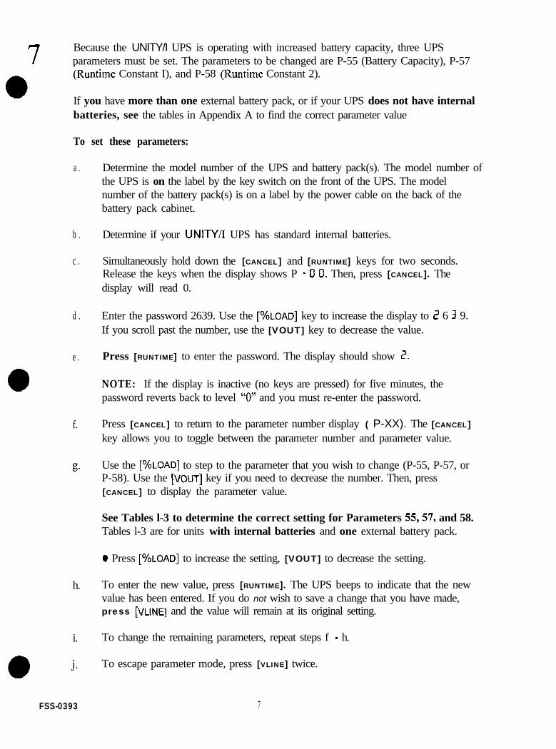
7 Because the UNITY/I UPS is operating with increased battery capacity, three UPSparameters must be set. The parameters to be changed are P-55 (Battery Capacity), P-57;Runtime Constant I), and P-58 (Runtime Constant 2).
If you have more than one external battery pack, or if your UPS does not have internalbatteries, see the tables in Appendix A to find the correct parameter value
To set these parameters:
a . Determine the model number of the UPS and battery pack(s). The model number ofthe UPS is on the label by the key switch on the front of the UPS. The modelnumber of the battery pack(s) is on a label by the power cable on the back of thebattery pack cabinet.
b .
c .
Determine if your UNITY/I UPS has standard internal batteries.
Simultaneously hold down the [CANCEL] and [RUNTIME] keys for two seconds.Release the keys when the display shows P - Cl Cl. Then, press [CANCEL]. Thedisplay will read 0.
d . Enter the password 2639. Use the [%LOAD] key to increase the display to 2 6 3 9.If you scroll past the number, use the [VOUT] key to decrease the value.
e . Press [RUNTIME] to enter the password. The display should show 2.
NOTE: If the display is inactive (no keys are pressed) for five minutes, thepassword reverts back to level “0” and you must re-enter the password.
f. Press [CANCEL] to return to the parameter number display ( P-XX). The [CANCEL]key allows you to toggle between the parameter number and parameter value.
EC Use the [%LOAD] to step to the parameter that you wish to change (P-55, P-57, orP-58). Use the [VOW] key if you need to decrease the number. Then, press[CANCEL] to display the parameter value.
See Tables l-3 to determine the correct setting for Parameters 55,57, and 58.Tables l-3 are for units with internal batteries and one external battery pack.
0 Press [%LOAD] to increase the setting, [VOUT] to decrease the setting.
h. To enter the new value, press [RUNTIME]. The UPS beeps to indicate that the newvalue has been entered. If you do not wish to save a change that you have made,press [VLINE] and the value will remain at its original setting.
i. To change the remaining parameters, repeat steps f - h.
i To escape parameter mode, press [VLINE] twice.
FSS-0393 7

Table 1: Parameter 55 (Battery Capacity)
Battery Pack UT3K UT4K UTSK UT8K
EBPUTl 66 66 66 108
EBPUT2EBPUT2W 99 99 99 141EBPUT3W
EBPUT21 108EBPUT6
*Internal extended runtime.
108 108 150
Table 2: Parameter 57 (Kl)
Battery Pack UT3K
EBPUTI 1.91
EBPUT2EBPUTZW 3.17EBPUT3W
UT4K UTSK UT8K
I .oo 0.40 0.00
I .50 0.60 0.00
EBPUT21 4.09EBPUT6
*Internal extended runtime.
I.86 0.75 0.00
Table 3: Parameter 58 (K2)**
Battery Pack UT3K
EBPUTI IC43
EBPUT2EBPURW 2EEAEBPUT3W
UT4K UT5K UTSK
D70 FAO lC4B
1428 1770 23E2
EBPUTZI 3C7B 190AEBPUT6
*Internal extended runtime.**Parameter 58 is represented as a hexadecimal number.
IDlE 2968
FSS-0393

APPENDIX A: Additional Parameter Tables
0 If you have more than one external battery pack, or if your UPS does not have internalbatteries, use the following tables to determine the correct parameter settings for your systemIf there are more than three battery cabinets in a system, parameters will have to be calculatedindividually; call Best Power Worldwide Service for more information.
Use Table A to add up the amp-hours of each battery pack along with the amp-hours of theinternal batteries to arrive at the total amp-hours for the system. For example, a UTSK withinternal batteries, a EBPUT2, and an EBPUTl, would have a system amp-hour of33 + 66 + 33 = 132A.h.
After determining the system amp-hours, set parameter 55 (Battery capacity) to this value. Forinformation on setting battery parameters, see step 7 of this document.
You can use this value with the following tables to determine the values for parameters 57 (Kl)and 58 (K2). Tables B-D correspond to a particular UPS model. The system amp-hours are in thefirst column. The row shows the values to input for P-57 and P-58.
Table A: Battery Amp-hours for all UNITYA modelsModel number Battery A-h
UT3K without internal batteries 0
UT3K 33
UT4K without internal batteries 0 I
I 33 II
II UTSK without internal batteries I 0 III 33 I I
UT8K without internal batteries3II EBPUR I 66 I III EBPUTZW I 66 IIII EBPUT3W I 66 IIII EBPUT6 I 75 II
FSS-0393 9

To determine P-57 and P-58 for the previous example (a UTSK with internal batteries, anEBPUT2, and an EBPUTI), use the table for a UT5K with 33A*h batteries. Find the system A-h(132) in the first column. The row shows the value for P-57 is 0.80; the value for P-58 is lF40. 0
NOTE: Parameter 58 is shown as a hexadecimal number. If your unit has software vl .OO-v. 1.03,call Best Power Worldwide Service for information on converting hexadecimal to decimalnotation.
able B: UT3K/UT4K with 33A.b batteries or no internal batteries
FSS-0393 10
l

Table C: UT5K with 33A*h batteries or no
198 I .20 2 E E 0
213 I .29 3260
II 222 1 1.35 1 348F
I I 231 1 1.40 1 36B0
2 4 6 I .49 3A3D
ernal batteries
System A-h(cont inued) P-57 P-58
Table D: UTSK with 75A*h batteries or no internal batteries
System A-h P-57 P-58 S y s t e m A-h(cont inued)
P-57 P-58
0 0 .00 0 0 0 0 300 0.00 52DO
7 5 0.00 14B4 375 0.00 6 7 8 4
150 0.00 2968 4 5 0 0.00 7C38
2 2 5 0.00 3ElC 525 0.00 9 0 E C
FSS-0393

PBestI\ Power-iJINTERRUPTISLEIWER S Y S T E M S UlY 320
a
NO”emkr 19.1996
Connecting Customer-Supplied External Battery Packs--
to the Single-Phase UNITY/P UTSK
This document supplements the battery installation instructions in your UNITY/I Installation Manual. The instructionsin the manual explain how to connect Best Power-supplied battery cabinets; this document (UTY 320) provides guidelines forcustomers who are supplying their own battery packs. This procedure must be performed by a qualified service person only. Ifyou have any questions, call Best Power’s Worldwide Service at l-800-356-5737 (U.S.A. or Canada) or l-608-565-2100, orcall the nearest Best Power office.
NOTE: UNITMmodels come with one of two internal chargers: I) the standard charger or 2) the optional auxiliarycharger. Ifyou did not order the auxiliary charger, the UPS cannot charge battery strings of more than 200AHto full capacity. Ifyou are using an external charger, please call Best Powerfor assistance. l7te nominal voltageof your battery system should be 48 WC.
Tools required (use insulated tools):Phillips screwdriverPersonal safety equipment required by local codes
7/16-inch NutdriverDC voltmeter
ACAUTION1. This procedure must only be performed by a qualified service person who is familiar with battery systems and
quired precautions. The installation must conform to national and local codes.
Ri S units are designed to provide power under a variety of operating conditions. Dangerous voltages may be presenteven if input AC line or DC voltage is removed. Remove all AC and DC power sources. TEST BEFORETOUCHING!
3. UPS batteries can produce dangerous voltage, extremely high current, and a risk of electric shock. They maycause severe injury if the terminals are shorted together or to ground (earth). Be extremely careful to avoidelectric shock and burns caused by contacting battery terminals or shorting terminals when you connect thebattery packs. Do not touch uninsulated battery terminals. Shorting battery terminals or DC terminal stripterminals can cause severe arcing, equipment damage, and injury. A short circuit cao cause a battery to explodeWhen working near batteries, always wear protective clothing and eye protection, and use insulated tools.
1. Where conductors may be exposed to physical damage, protect the conductors in accordance with NEC NFPA 70 orlocal or national codes.
Best Power recommends the following for qualified service personnel who are connecting the batteries:8. Remove rings, watches, and other jewelry before connecting the batteries.b. When working near batteries, always wear protective clothing and eye protection, and use insulated tools. Batteries
contain caustic acids and toxic materials aad can rupture or leak if mistreated.:. Do not carry metal objects in your pockets where the objects can fall onto the batteries.1. Whenever you are servicing an energized unit with the cover removed, electric shock is possible. Follow all local safety
codes.
UN-0320A96, Best Power. All rights resewed.

ContentsSection 100: Disconnecting AC Power 2
Section 100: Disconnecting AC Power
Complete AC installation before installing the external batteries. After AC installation, use this section to make sureall AC power to the UF’S is off.
0 100-l. If there is an external bypass switch, you may use it to bypass the UPS. Otherwise, shut down the loadequipment.
0 100-2. Open the front door of the UPS. Turn the key switch to “Off.”
Cl 100-3. Remove AC input to the UPS by shutting off the breaker at the service panel. (Turning the UPS keyswitch to “Off’ is not sufficient.)
0 100-4. Remove the four screws at the comers of the front ventilation panel and remove the panel from the unit(see Figure 1). Then, remove the three narrow front panels shown by sliding them off of the UPS.
Figure 1: UNITY/I, Covers Removed
0 100-5. Remove the bolt corn the top DC connector (see Figure 2 on the next page).
0 100-6. Disconnect the top DC connector (see Figure 2 on the next page). Make sure that the connector does notcontact the pre-charge switch after it is disconnected.
UTY320 November 19.1996 Page 2

Figure 2: DC Connector
Section 200: Removing the Side Covers
0 200-I. Remove the seven screws from the side covers. Three of these screws are on tap of the unit, and two areon each side panel.
0 200-2. Lift each side cover straight up, then off.
0 200-3. Remove the two screws in the upper comers of the side door assembly as shown in Figure 1. Open theside door assembly.
Pection 300: Connecting the External Batteries
0 300-l
0 300-2 Your battery system should be installed and ready to comect to the UPS. Your battery pack should havepositive (+) and negative (-) cables that you can connect to the UPS DIN rail terminals. If your batterypack requires a ground connection to the UPS, you must also have a ground wire fiorn the battery packthat can be connected to the UPS DIN rail terminals. Pull the cables through the knockout you removedfrom the back of the UPS.
q 300-3 Find the DIN rail toward the back of the UPS. (See Figure 1.) Figure 3 shows the DIN rail.
During AC installation, you should have removed a knockout in the back panel of the UPS so you canroute the battery cables into the UPS. (See the Installation Manual.)
Note: Wherever conductors may be exposed to physical damage, you must protect the conductors inaccordance with National Electrical Code NFPA 70 (in the U.S.; in other areas, follow localcodes). This includes battery cables between the UPS and the battery cabinet and cables betweenbattery cabinets
Figure 3: UPS DIN Rail
Page 3 UTY 320 November 19,1996

0 300-4. If your battery pack requires a ground connection to the UPS, connect the ground wire to the ground(earth) DIN rail terminal that is next to the negative (-) DC terminal. The ground (earth) terminal blockhas the ground symbol shown in Figure 3.
0 300-5.
0 300-6.
Strip 0.5 inches (13 mm) of insulation off the UPS end of the positive (+) and negative (-) battery a
Connect the negative (-) battery cable to the negative (-) DC terminal on the UPS DIN rail. Connect thepositive (+) battery cable to the positive (+) DC terminal on the UPS DIN rail.
0 300-7. Use the DC voltmeter to check for the proper nominal DC voltage at the UPS DC terminals. The nominalDC voltage should be 48 VDC. Make sure the polarity agrees with the markings on the UPS DCterminals.
0 300-8. Close the side door assembly and secure it with the two screws. Make sore that no wires are pinchedbetween the side door and the chassis.
0 300-9.
0 300-10
0300-11
0300-12
At the front of the unit, reconnect the top DC connector. Secure it with the bolt.
Reattach the bottom narrow front panel and the narrow side panels to the front of the UPS.
Use the screws you removed to reattach the front ventilation panel.
Now that you have installed the AC wiring and connected the batteries, the installing electrician shouldcomplete the voltage and phase check in the Installation Manual. Then, return to the steps below tocomplete parameter changes.
q 300-13
0300-14
Put each side cover in place by bringing it straight down into position.
aReattach the seven screws that secure the panels: use three of the screws on top of the unit, and twoeach side panel.
0 300-15 Reapply AC line to the UPS. Turn the key switch inside the UPS’ front door to “Auto.” The yellowBATTERY light will tarn on briefly, then the green LINE light will tom on.
0 300-16, If you have used an external bypass switch to bypass the UPS, you may now switch it back to “UPS.”
Section 400: Changing Parameter Values
The UNITY/l has parameters set at the factory for specific battery strings. Since you are using batteries that are notsupplied by Best Power, you must adjust the parameters to prevent calibration ala.rms. For customer-suppliedbatteries, Table 1 on the next page shows the parameters that require changing and the default values. Refer to theUNITY/l User Manual for additional parameter information; see the steps on the next page to program the parametersin Table 1.
WY320 November19,1996 Page4

Table 1: Customer-supplied External Battery Pack Parameter Numbers to Change
Parameter ParameterNumber Name Settings
P-69 Normal Float Voltage Set to 57.60 or to the voltage recommended by your battery manufacturer.P-70 Cold Float Voltage Set to 58.00 or to the voltage recommended by your battery manufacturer.
P-55
P-57
Battery Capacity* Enter the Amp-hours for your battery string(s).(Battery string amp-hours x Number of strings)
Runtime Constant (Kl) This is always set to 0000.
P-58Hexadecimal number. To determine this value, take the value of P-55,
Runtime Constant (K2) divide by 90, and multiply this number by 5300. Convert to hexadecimalnumber and enter this into the uarameter settine.
*If battery capacity is more than 200 AH, the standard UPS charger does not have enough capacity to fully charge the batteries;make sure your UPS has the internal auxiliary charger. If you plan to use an external charger, call Best Power for assistance.
Make sore that you FULLY understand a parameter before attempting to change it. Improper setting ofcertain parameters may cause the UPS to function other than expected.
0 400-l. Simultaneously hold down the [CANCEL] and [RUNTIME] keys for two seconds. Release the keys when thedisplay shows P- 0 0. Then, press [CANCEL]. The display should read 0.
0 400-2. The Service password is 2639. To enter it, follow the steps below.
q a. Use the [%LOAD] or the [VOUT] key to change the display reading to 2 6 3 3
Note: To scroll the display more quickly, hold down the [%LOAD] or [VOUT] key
q b. Press [RUNTIME] to enter the password. The display should read 2 (for password level 2).
Note: If the display is left unattended (no keys are pressed) for five minutes, the password reverts backto level “0” and you must re-enter the password.
0 400-3. Press [CANCEL] to return to t&e parameter number display (P-XX)
Note that the [CANCEL] key allows you to toggle between the parameter number and parameter value
0 400-4. Use the [%LOAD] or the [ VOUT] key to step to the parameter that you wish to change. Then, press[CANCEL] to display the parameter value.
0 400-5. Whenever a parameter value is displayed, you can use these keys to change the setting:
0 Press [%LOAD] to increase the setting.l Press [VOUT] to decrease the setting.
Note: The UPS will not allow you to change a parameter if the parameter requires a password higherthan that entered in step 1.
El 400-6. To enter the new value, press [RUNTIME]. The UPS beeps to indicate that the new value has been entered.If you wish not to save a change that you have made, press [VLINE] and the value will remain at itsoriginal setting.
Page 5 UN 320 November 19,1996

0 400-7. Repeat steps 400-4 to 400-6 to change the other parameters listed in Table 1
0 400-S. To escape parameter mode, press [VLINE] twice.
UTY 320 November 19,1996 Page 6


u N 1 T y/ I@ S I N G L E - P H A S E 3kVAlkW T O SkVAIkW
U N I N T E R R U P T I B L E P O W E R S Y S T E M SSPECIFICATIONS
RatingAC Input Voltage RangeInput Nominal Current at Full Load
147.276V (for nominal 200/208/220/230/24OV output)200V=17A ZOOV=ZZA 200V=28A 200V=45A208V=f7A 208V=22A 208V=27A 208V=43A
I 220V=16AI
220V=ZOA230V=lSA 230V=20A I
220V=25A230V=24A I
220V=41A23OVI9A
Output ConnectionEtficiency (an line)Heat (an line):
Audible NoiseTypical Runtime:(minutes)B a t t e r y C h a r g e rB a t t e r y R e c h a r g eWeight:
(BTUihr.)(kW/hr.)
(Full Load)(Half Load)
lib)
240V=15A 240V=i9A 240V=23A 240V=38AHardwired output is standard. (pre-configured models available -contact factory.)
9 5 % I 9 6 %539 569 711 1138
0.158 0.167 0.208 0.333<40dBA at 1 mete,
1 9 1 2 9 1 343 2 8 2 1 31
5 a m p lOamp2-3 hours
280 I 295 490(kg) 1 1 2 7 1 3 4 222
D i m e n s i o n s : H x W x 0 (inches) 2 9 Y 1 0 . 5 x 25.75 32x13~33imm) 737x267~654 813x330~838
Lightning and Surge Protection:UL1449 listed. 300 joule surges u p p r e s s i o n r a t i n g . M e e t s I E C801-5. Tested to ANSI/IEEEC62.41 Cateoories A3 and 83 test.Zero surge ciamping responsetime. 0.7% LTVIsolation (includes output N-10-Gbond): Complete from line. Ouali-fies as a separately derived powermum u n d e r N E C alticle 250.5d.Noise Rejection: Common Mode- uo to 50dB. Normal Mode - uoto 4OdB.Regulation: *5% of nominal out-put voltage (programmable to *3 % ) . E x c e e d s r e c o m m e n d e dCBEMA and ANSI voltage regula-tion standards for computingequipment under any line. load, orbattery conditions.Continuous Na.Break Power:
Continuous, no-break power dur-ing a complete power outage ormomentary power interruption.S i n e - W a v e P o w e r : S i n e - w a v e .computer-grade power with 5% orless total harmonic distortion(THO) at rated kW load. Meets orexceeds GSA C22.2 No. 107.1 forharmonic distoltion.Load Compatibility: Guaranteedcompatible with all computerloads. including power factor-corrected.Intelligent, Interactive Interface:RS-232 port featuring full-duplexserial communication, alarm con-tacts, inverter contacts, andremote shutdown.
Reliability Engineered: Oual-track Relative Humidity: 0 to 95%
redundant configuration that uti-lizes either line or &welter sourcefor power and is designed 1~ meetor exceed an expected MTBF of150,000 hours.Protection: Overload alarm andmicroprocessor-controlled circuitbreaker. Optional output recepta-cles protecled by fuses or circuitb reake rsOverload: 2 0 0 % s u r g eF r e q u e n c y : ( 5 0 H z o r 60 Hznominal)On line: output frequency tracksinput within adiustabte limits (+3Hz default). On inverter: to.15 Hz.Operating Temperature: 0” to+40” c. storage temperature:F,om -20” to t60” C (-20” to 140”C if battery is not removed)
without condensationVentilation Requirement: Clean.dust-free air, free of corrosivechemicals or other contaminantsmust be available with proper aircirculation.High-Altitude Operation: Maxi-mum ambient operating tempera-ture drops by 1” C per 305 meters(1,000 feet) above sea level, withthe maximum elevation being3,050 meters (10,000 feet).Safefy Compliance: UL 1778, UL1449, CSA (clJL). GS (TUV), CEE M C C o m p l i a n c e : F C C - A , Vtg24311991, Vfg 4611992, CISPR 22T e s t i n g S t a n d a r d s : A N S I / I E E EC62.41 (1980). C62.45 (1987):I E C 8 0 1 - Z . 801-3.801-4.801-5
Best Power offers a complete line of Uninterruptible Power Systems from 28OVA to 220kVA.
PO. Box 280, Necedah, WI 54646 USA U N I N T E R R U P T I B L ETel: l-800-356-5794, Fax-On-Demand: 1-800-487-6813. Internet: wwvbestpawerxom P O W E R S Y S T E M S

U N I N T E R R U P T I B L E P O W E R S Y S T E M S
,!!!!q CheckUPS II softwareand cable providedtar a complete powlermenagament solution.
World-ready, flexible power protection for midrangeand client/server computing.
SMART AND COST-EFFICIENT OPERATIONWith one of power protection’s most advanced microprocessorsin charge, UNITY/I Single-Phase systems need only 4 percentof incoming power to protect critical systems and valuabledata. This 96% efficiency minimizes system temperature,stress on components, and daily cost-to-operate. Credit themicroprocessor for a very small parts count and fewerpotential fault or failure points.
HIGH FAULT-TOLERANCEUNITY/I Single-Phase safeguards include a dual power trackconfiguration: if one power path develops a fault, the secondtakes over to keep UPS protection on-line. Also, an internalbypass sw i t ch ensures your equ ipment con t inues to rece i vepower in the unlikely event of UPS failure.
EXCELLENT POWER CONDITIONINGUNITY/I SinglePhase is a universal system: it automaticallyselects frequency I50 or 60 Hz] and allows you to selectoperating voltages M meet requirements throughout the world
SOPHISTICATED SELF-MONITORINGUNITY/I SinglePhase systems monitor and report 18 separatealarm conditions. Every UNITY/I Single-Phase unit comesbundled with free CheckUPS” II Suite power management andshutdovn software and connecting cable. This software CD-ROM cuh3ins on-line documentation and support for mostmajor operating systems. A Best Power’” SNMP Adapter canbe connected for remote network operations.
COMPACT AND QUIETUNITY/I SinglePhase has the sleek look, small footprint, andwhisperquiet operation that fii in any office environment.In fact, UNITY/I SinglePhase is more than twice as quiet (40decibels at 1 meter] as other UPS models on the market.
UNSURPASSED WARRANTYUNITY/I SinglePhase is covered by cur twoyear limited warrantyagainst factory or workmanship defects. We up the ante withour limited “Double Lifetime” warranty* that repairs or replacesyour UNITY/I Single-Phase if damaged by lightning, and coversup to US!325,ooO for damage to connected equipment. Call thefactory for details on these limited warranties.

u N 1 T v/ I@ S I N G L E - P H A S E 3kVA/kW T O EkVAlkW
IEXTERNAL B A T T E R Y P A C K S
Extend the runtime of your Best Power UPS,
RlJNTlME EXTENSIONBest Power offers six external battery packs to extend yourUNIN/I Single-Phase runtime. One pack can extend full loadruntime up to one hour, 21 minutes while a combination ofthree can supply up to seven hours. 19 minutes.
EASY INSTALLATIONAll battery packs are fully assembled and ready to plug intoyour UPS and each other, eliminating additional labor costfor the significant, increased protection time offered. Nospecial battery connections must be made - they are alreadycomplete. (At present, the UT8K must be hardwired to thefirst battery pack.]
OFFICE-FRIENDLYThe external battery cabinets are designed to visuallycomplement your UPS. They fit office environments withlimited floor space, and require only standard ventilation.
MULTIPLE COMBINATIONSRuntims extension can be tailored with any combination ofup to three battery packs. Four different battery packs areavailable for use with UT3K. UT4K. and UTSK models, andtwo with UTBK.
q AlTERYCHARGERUPGRADEAn auxiliary 15smpsre charger obtained in place of theUPS internal batteries enables faster recharge times withthe external battery packs [most configurations of more thanone external pack require the 15amp charger). Rechargetime to full load protection with external battery packs canbe as little as 3 hours.
UNSURPASSED WARRANTYUNITY/I Single-Phase External Battery Packs are covered byour twoyear limited warranty against factory or workmanshipdefects Call the factory for details on this limited warranty.

u N 1 T v/ I@ SINGLE-PHA8E J 3kVAkW T O 8kVAkW
E X T E R N A L B A T T E R Y P A C K SSPECIFICATIONS
/
1 6 8 1 3 5 0 -
I 1 8 8 1 3 9 0 I -
1 EBPlJTEL+STD - - - 1 5U p g r a d e - - - 8.9
T21tChrgr Upgrade - - - 11.8TUILLT~~IIIYI Upgrade - - - 14.8!cifications subject to change Witho”, notice. ‘Runtimes are baSed on battery size. condition, and discharge-cycle history among Othe‘faCtO‘S.
m B e s t P o w e r o f f e r s a c o m p l e t e l i n e o f U n i n t e r r u p t i b l e P o w e r S y s t e m s f r o m 2 S O V A t o 2 2 0 k V A .