Type IN According with EN 22858 / ISO 2858 / ISO 5199
11
IN CENTRIFUGAL PUMPS Type IN According with EN 22858 / ISO 2858 / ISO 5199 1
-
Upload
khangminh22 -
Category
Documents
-
view
3 -
download
0
Transcript of Type IN According with EN 22858 / ISO 2858 / ISO 5199

IN
CENTRIFUGAL PUMPS
Type IN
According with EN 22858 / ISO 2858 / ISO 5199
1
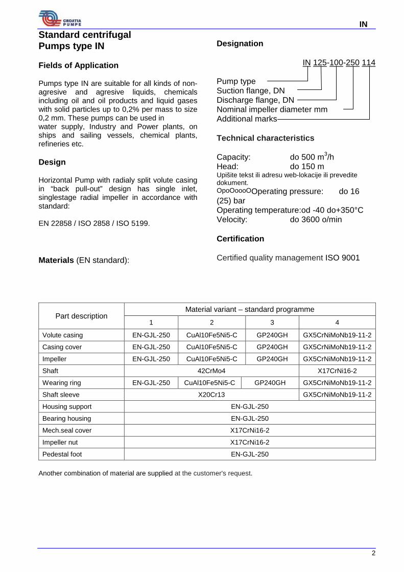
IN Standard centrifugal Pumps type IN Fields of Application Pumps type IN are suitable for all kinds of non-agresive and agresive liquids, chemicals including oil and oil products and liquid gases with solid particles up to 0,2% per mass to size 0,2 mm. These pumps can be used in water supply, Industry and Power plants, on ships and sailing vessels, chemical plants, refineries etc. Design Horizontal Pump with radialy split volute casing in “back pull-out” design has single inlet, singlestage radial impeller in accordance with standard: EN 22858 / ISO 2858 / ISO 5199. Materials (EN standard):
Designation
IN 125-100-250 114 Pump type Suction flange, DN Discharge flange, DN Nominal impeller diameter mm Additional marks Technical characteristics Capacity: do 500 m3/h Head: do 150 m Upišite tekst ili adresu web-lokacije ili prevedite dokument. OpoOoooOOperating pressure: do 16 (25) bar Operating temperature:od -40 do+350°C Velocity: do 3600 o/min Certification Certified quality management ISO 9001
Part description Material variant – standard programme
1 2 3 4
Volute casing EN-GJL-250 CuAl10Fe5Ni5-C GP240GH GX5CrNiMoNb19-11-2
Casing cover EN-GJL-250 CuAl10Fe5Ni5-C GP240GH GX5CrNiMoNb19-11-2
Impeller EN-GJL-250 CuAl10Fe5Ni5-C GP240GH GX5CrNiMoNb19-11-2
Shaft 42CrMo4 X17CrNi16-2
Wearing ring EN-GJL-250 CuAl10Fe5Ni5-C GP240GH GX5CrNiMoNb19-11-2
Shaft sleeve X20Cr13 GX5CrNiMoNb19-11-2
Housing support EN-GJL-250
Bearing housing EN-GJL-250
Mech.seal cover X17CrNi16-2
Impeller nut X17CrNi16-2
Pedestal foot EN-GJL-250 Another combination of material are supplied at the customer's request.
2
IN
3

IN Selection Charts
4

IN
5

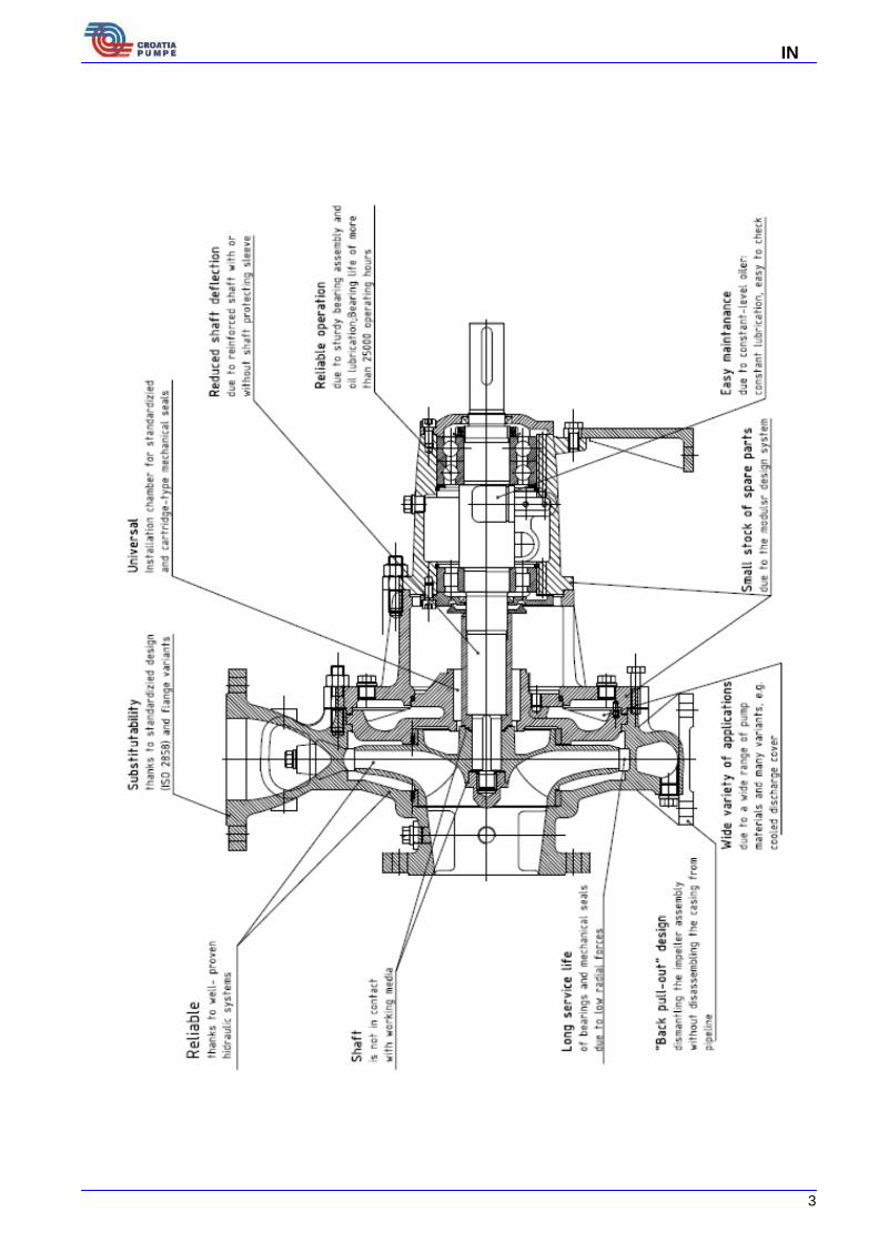
IN IN pumps benefits Technical datas Casing Radially split, consisting of volute casing and casing cover. The casing cover and the bearing bracket lantern form a chamber which can be used for heating and cooling depending of pump purpose. Impeller Impeller is keyed between two support roller bearings. Front support is one cylindrical roller bearing, and back supports are two ball bearings with obliquely contacts facing one to another. Axial force is balanced with unburdening holes and wearing rings. Shaft Seal The shaft seal can be designed as a gland packing or a mechanical seal. Conversion from gland to mechanical seal and vice versa is possible without any rework on the casing cover. Mechanical seal are standard single and double seals according to standard DIN 24960. Recommended Spare Parts Stock for Two years`operation
Acceptance Tests / Guarantees • Material tests
Test report 2.2 on request • Product tests
Inspection certificate 3.1, on request,for: pressure test of complete pump as per EN
10204 • Hydraulic tests
Each pump is subjected to a performance test run, and its duty point is guaranteed according toISO 9906 / 2A. • NPSH test Warranties are given within he scope of valid delivery conditions. Forces and moments IN pumps are designed for handling forces and moments in accordance with ISO 5199 Documentation Delivered documentation with pump: - Sectional drawing whit list of component - Technical data sheet - Installation plan / Measuring sketch - Operating instructions
Pos. Nr.
Part Description Number of pumps (including standby pumps)
2 3 4 5 6+7 8+9 10 and more
Quantity of spare parts Shaft 1 1 1 2 2 2 20% Impeller 1 1 1 2 2 2 20% Bearings with obliquely contact (set) 1 1 2 2 2 3 25% Roller bearing 1 1 2 2 2 3 25% Mechanical seal, set 1 1 2 2 2 3 25% Sealing ring 1 1 2 2 2 3 25% Gland packing 4 4 6 6 6 8 100% Casing wearing ring 2 2 2 3 3 4 50% Shaft sleeve 2 2 2 3 3 4 50% Sealing for pump casing (set) 4 6 8 8 9 12 150% Coupling (set) 1 1 2 2 3 4 30%
Example of Seal Arrangements:
6

IN 1. Gland packing
2. Cylinrical seal chamber
3. Cartridge seal
4. Double-acting mechanical seal
7

IN Pumps section view with part list
IN Pumps Part list
111 Volute casing
112 Wearing ring
114 Screw
119 Casing cover
125 Pin
132 Housing support
133 Screw
134 Nut
135 Screw
140 Seal
141 Seal
150 Mechanical seal cover
151 Mechanical seal
152 Nut
153 Screw
154 Seal
155 Pin
156 Connection
157 Sealing ring
158 Pipe
210 Shaft
211 Impeller
213 Impeller nut
215 Sealing ring
217 Mechanical seal sleeve
219 Shaft key
220 Shaft key
221 Centrifugalni odvajač
222 Bearing
223 Bearing
224 Nut
225 Lock washer
311 Bearing housing
312 Bearing cover
313 Bearing cover
314 Pump foot
315 Shaft seal
316 Shaft seal
317 Distant ring
318 Circlip
320 Seal
321 Oil level regulator 323 Screw
324 Nut
325 Screw
328 Screw
330 Plug
331 Plug
332 Plug
334 O-ring
333 Plug
335 Sealing ring
336 Sealing ring
337 Sealing ring
8
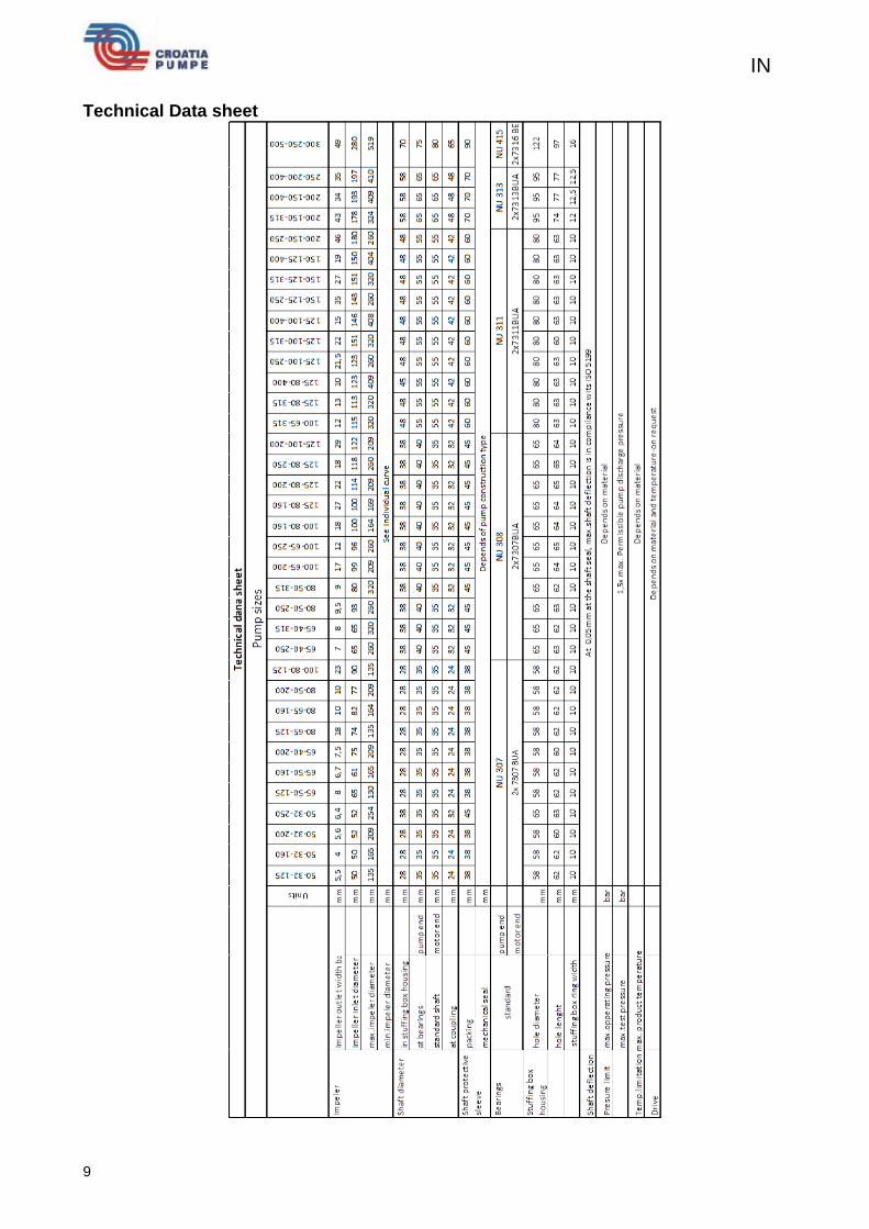
IN Technical Data sheet
9

IN Dimensions and Connections
Dimensions
10

IN
11