EN ISO 2560
35
EUROPEAN STANDARD NORME EUROPÉENNE EUROPÄISCHE NORM EN ISO 2560 October 2009 ICS 25.160.20 Supersedes EN ISO 2560:2005 English Version Welding consumables - Covered electrodes for manual metal arc welding of non-alloy and fine grain steels - Classification (ISO 2560:2009) Produits consommables pour le soudage - Électrodes Schweißzusätze - Umhüllte Stabelektroden zum enrobées pour le soudage manuel à l'arc des aciers non Lichtbogenhandschweißen von unlegierten Stählen und alliés et des aciers à grains fins - Classification (ISO Feinkornstählen - Einteilung (ISO 2560:2009) 2560:2009) This European Standard was approved by CEN on 17 September 2009. CEN members are bound to comply with the CEN/CENELEC Internal Regulations which stipulate the conditions for giving this European Standard the status of a national standard without any alteration. Up-to-date lists and bibliographical references concerning such national standards may be obtained on application to the CEN Management Centre or to any CEN member. This European Standard exists in three official versions (English, French, German). A version in any other language made by translation under the responsibility of a CEN member into its own language and notified to the CEN Management Centre has the same status asthe official versions. CEN members are the national standards bodies of Austria, Belgium, Bulgaria, Cyprus, Czech Republic, Denmark, Estonia, Finland, France, Germany, Greece, Hungary, Iceland, Ireland, Italy, Latvia, Lithuania, Luxembourg, Malta, Netherlands, Norway, Poland, Fbrtugal, Romania, Slovakia, Slovenia, Spain, Sweden, Switzerland and United Kingdom.
-
Upload
khangminh22 -
Category
Documents
-
view
1 -
download
0
Transcript of EN ISO 2560

EUROPEAN STANDARD
NORME EUROPÉENNE
EUROPÄISCHE NORM
EN ISO 2560
October 2009
ICS 25.160.20 Supersedes EN ISO 2560:2005
English Version
Welding consumables - Covered electrodes for manual metal arc welding of non-alloy and fine grain steels - Classification
(ISO 2560:2009)
Produits consommables pour le soudage - Électrodes Schweißzusätze - Umhüllte Stabelektroden zumenrobées pour le soudage manuel à l'arc des aciers non Lichtbogenhandschweißen von unlegierten Stählen und
alliés et des aciers à grains fins - Classification (ISO Feinkornstählen - Einteilung (ISO 2560:2009)2560:2009)
This European Standard was approved by CEN on 17 September 2009.
CEN members are bound to comply with the CEN/CENELEC Internal Regulations which stipulate the conditions for giving this European Standard the status of a national standard without any alteration. Up-to-date lists and bibliographical references concerning such national standards may be obtained on application to the CEN Management Centre or to any CEN member.
This European Standard exists in three official versions (English, French, German). A version in any other language made by translation under the responsibility of a CEN member into its own language and notified to the CEN Management Centre has the same status asthe official versions.
CEN members are the national standards bodies of Austria, Belgium, Bulgaria, Cyprus, Czech Republic, Denmark, Estonia, Finland, France, Germany, Greece, Hungary, Iceland, Ireland, Italy, Latvia, Lithuania, Luxembourg, Malta, Netherlands, Norway, Poland, Fbrtugal, Romania, Slovakia, Slovenia, Spain, Sweden, Switzerland and United Kingdom.

EN ISO 2560:2009 (E)
Contents Page
Foreword..............................................................................................................................................................3
2

! " $%& ' ( ) * + ' * * 9 - ! )
Foreword
This document (EN ISO 2560:2009) has been prepared by Technical Committee ISO/TC 44 "Welding and allied processes" in collaboration with Technical Committee CEN/TC 121 “Welding” the secretariat of which is held by DIN.
This European Standard shall be given the status of a national standard, either by publication of an identical text or by endorsement, at the latest by April 2010, and conflicting national standards shall be withdrawn at the latest by April 2010.
Attention is drawn to the possibility that some of the elements of this document may be the subject of patent rights. CEN [and/or CENELEC] shall not be held responsible for identifying any or all such patent rights.
This document supersedes EN ISO 2560:2005.
According to the CEN/CENELEC Internal Regulations, the national standards organizations of the following countries are bound to implement this European Standard: Austria, Belgium, Bulgaria, Cyprus, Czech Republic, Denmark, Estonia, Finland, France, Germany, Greece, Hungary, Iceland, Ireland, Italy, Latvia, Lithuania, Luxembourg, Malta, Netherlands, Norway, Poland, Portugal, Romania, Slovakia, Slovenia, Spain, Sweden, Switzerland and the United Kingdom.
Endorsement notice
The text of ISO 2560:2009 has been approved by CEN as a EN ISO 2560:2009 without any modification.
3

ISO 2560:2009(E)
Contents Page
Foreword............................................................................................................................................................ ivIntroduction......................................................................................................................................................... v1 Scope...................................................................................................................................................... 12 Normative references............................................................................................................................ 13 Classification......................................................................................................................................... 24 Symbols and requirements.................................................................................................................. 34.1 Symbol for the product/process.......................................................................................................... 34.2 Symbols for strength and elongation of all-weld metal.................................................................... 34.3 Symbol for impact properties of all-weld metal.................................................................................44.4 Symbol for the chemical composition of all-weld metal...................................................................54.5 Symbol for type of electrode covering................................................................................................ 64.6 Symbol for condition of post-weld heat-treatment of all-weld metal...............................................74.7 Symbol for nominal electrode efficiency and type of current.......................................................... 74.8 Symbol for welding position................................................................................................................ 84.9 Symbol for diffusible hydrogen content of deposited metal............................................................85 Mechanical tests.................................................................................................................................... 95.1 Preheating and interpass temperatures.............................................................................................. 95.2 Pass sequence..................................................................................................................................... 136 Chemical analysis ............................................................................................................................... 137 Fillet weld test...................................................................................................................................... 168 Rounding procedure........................................................................................................................... 189 Retests.................................................................................................................................................. 1810 Technical delivery conditions............................................................................................................ 1811 Examples of designation.................................................................................................................... 19Annex A (informative) Classification systems............................................................................................... 20Annex B (informative) Description of types of electrode covering — Classification by yield
strength and 47 J impact energy....................................................................................................... 23Annex C (informative) Description of types of electrode covering — Classification by tensile
strength and 27 J impact energy....................................................................................................... 25Annex D (informative) Notes on diffusible hydrogen and the avoidance of cold cracking......................28Bibliography...................................................................................................................................................... 29
© ISO 2009 - All rights reserved iii
ISO 2560:2009(E)
Foreword
ISO (the International Organization for Standardization) is a worldwide federation of national standards bodies (ISO member bodies). The work of preparing International Standards is normally carried out through ISO technical committees. Each member body interested in a subject for which a technical committee has been established has the right to be represented on that committee. International organizations, governmental and non-governmental, in liaison with ISO, also take part in the work. ISO collaborates closely with the International Electrotechnical Commission (IEC) on all matters of electrotechnical standardization.
International Standards are drafted in accordance with the rules given in the ISO/IEC Directives, Part 2.
The main task of technical committees is to prepare International Standards. Draft International Standards adopted by the technical committees are circulated to the member bodies for voting. Publication as an International Standard requires approval by at least 75 % of the member bodies casting a vote.
Attention is drawn to the possibility that some of the elements of this document may be the subject of patent rights. ISO shall not be held responsible for identifying any or all such patent rights.
ISO 2560 was prepared by Technical Committee ISO/TC 44, Welding and allied processes, Subcommittee SC 3, Welding consumables.
This third edition cancels and replaces the second edition (ISO 2560:2002), which has been technically revised.
Requests for official interpretations of any aspect of this International Standard should be directed to the Secretariat of ISO/TC 44/SC 3 via your national standards body. A complete listing of these bodies can be found at www.iso.org.
iv © ISO 2009 - All rights reserved

ISO 2560:2009(E)
Introduction
T h is In te rn a tio n a l S ta n d a rd re c o g n iz e s th a t th e re a re tw o s o m e w h a t d if fe re n t a p p ro a c h e s in th e g lo b a l m a rk e t to c la s s ify in g a g iv e n e le c tro d e , an d a llo w s fo r e ith e r o r bo th to be use d , to s u it a p a r tic u la r m a rk e t need . A p p lic a t io n o f e ith e r ty p e o f c la s s if ic a tio n d e s ig n a tio n (o r o f bo th , w h e re s u ita b le ) id e n tifie s a p ro d u c t as c la s s if ie d in a c c o rd a n c e w ith th is In te rn a tio n a l S ta n d a rd . T h e c la s s if ic a tio n in a c c o rd a n c e w ith s y s te m A is m a in ly b a se d on E N 4 9 9 :1 9 9 4 t1]. T h e c la s s if ic a tio n in a c c o rd a n c e w ith s y s te m B is m a in ly b a s e d up on s ta n d a rd s u se d a ro u n d th e P a c ific R im .
T h is In te rn a tio n a l S ta n d a rd p ro v id e s a c la s s if ic a tio n in o rd e r to d e s ig n a te c o v e re d e le c tro d e s in te rm s o f th e y ie ld s tre n g th , te n s ile s tre n g th a n d e lo n g a tio n o f th e a ll-w e ld m e ta l. T h e ra tio o f y ie ld s tre n g th to te n s ile s tre n g th o f w e ld m e ta l is g e n e ra lly h ig h e r th a n th a t o f p a re n t m e ta l. U s e rs s h o u ld n o te th a t m a tc h in g w e ld m e ta l y ie ld s tre n g th to p a re n t m e ta l y ie ld s tre n g th d o e s n o t n e c e s s a r ily e n s u re th a t th e w e ld m e ta l te n s ile s tre n g th m a tc h e s th a t o f th e p a re n t m e ta l. T h e re fo re , w h e re th e a p p lic a tio n re q u ire s m a tc h in g te n s ile s tre n g th , s e le c tio n o f th e c o n s u m a b le s h o u ld be m a d e b y re fe re n c e to c o lu m n 3 o f T a b le 1A o r to T a b le 1B and T a b le 8B .
It s h o u ld be n o te d th a t th e m e c h a n ic a l p ro p e r tie s o f a ll-w e ld m e ta l te s t s p e c im e n s u se d to c la s s ify th e e le c tro d e s v a ry fro m th o s e o b ta in e d in p ro d u c tio n jo in ts b e c a u s e o f d iffe re n c e s in w e ld in g p ro c e d u re s u c h as e le c tro d e s ize , w id th o f w e a v e , w e ld in g p o s it io n , w e ld in g c u rre n t, in te rp a s s te m p e ra tu re an d p a re n t m e ta l c o m p o s itio n .
© ISO 2009 - All rights reserved v

INTERNATIONAL STANDARD ISO 2560:2009(E)
Welding consumables — Covered electrodes for manual metal arc welding of non-alloy and fine grain steels — Classification
1 Scope
This International Standard specifies requirements for classification of covered electrodes and deposited metal in the as-welded condition and in the post-weld heat-treated condition for manual metal arc welding of non-alloy and fine grain steels with a minimum yield strength of up to 500 MPa or a minimum tensile strength of up to 570 MPa.
This International Standard is a combined specification providing for classification utilizing a system based upon the yield strength and the average impact energy of 47 J of all-weld metal, or utilizing a system based upon the tensile strength and the average impact energy of 27 J of all-weld metal.
a) Paragraphs and tables which carry the suffix letter “A” are applicable only to covered electrodes classified to the system based upon the yield strength and the average impact energy of 47 J of all-weld metal in this International Standard.
b) Paragraphs and tables which carry the suffix letter “B” are applicable only to covered electrodes classified to the system based upon the tensile strength and the average impact energy of 27 J of all-weld metal in this International Standard.
c) Paragraphs and tables which do not have either the suffix letter “A” or the suffix letter “B” are applicable to all covered electrodes classified in this International Standard.
2 Normative references
The following referenced documents are indispensable for the application of this document. For dated references, only the edition cited applies. For undated references, the latest edition of the referenced document (including any amendments) applies.
ISO 544, Welding consumables — Technical delivery conditions for welding filler materials — Type of product, dimensions, tolerances and markings
ISO 2401, Covered electrodes — Determination of the efficiency, metal recovery and deposition coefficient
ISO 3690, Welding and allied processes — Determination of hydrogen content in ferritic steel arc weld metal
ISO 6847, Welding consumables — Deposition of a weld metal pad for chemical analysis
ISO 6947, Welds — Welding positions
ISO 13916, Welding — Guidance on the measurement of preheating temperature, interpass temperature and preheat maintenance temperature
ISO 14344, Welding and allied processes — Procurement of welding consumables
ISO 15792-1:2000, Welding consumables — Test methods — Part 1: Test methods for all-weld metal test specimens in steel, nickel and nickel alloys
© ISO 2009 - All rights reserved 1
ISO 2560:2009(E)
ISO 15792-3:2000, Welding consumables — Test methods — Part 3: Classification testing of positional capacity and root penetration of welding consumables in a fillet weld (as amended by ISO 15792-3:2000/Cor.1:2006)
ISO 80000-1, Quantities and units — Part 1: General
3 Classification
Classification designations are based upon two approaches to indicate the tensile properties and the impact properties of the all-weld metal obtained with a given electrode. The two designation approaches include additional designators for some other classification requirements, but not all, as is clear from the following subclauses. In most cases, a given commercial product can be classified in both systems. Then either or both classification designations can be used for the product.
The classification includes all-weld metal properties obtained with a covered electrode as given below. The classification is based on an electrode size of 4,0 mm, with the exception of the symbol for welding position, which is based on ISO 15792-3. Where the defined diameter has not been manufactured, the closest diameter to 4,0 mm shall be used for all-weld metal tests.
3A Classification by yield strength and 47 J impact energy
The classification is divided into eight parts:
1) the first part gives a symbol indicating the product/process to be identified;
2) the second part gives a symbol indicating the strength and elongation of all-weld metal (see Table 1A);
3) the third part gives a symbol indicating the impact properties of all-weld metal (see Table 2A);
4) the fourth part gives a symbol indicating the chemical composition of all-weld metal (see Table 3A);
5) the fifth part gives a symbol indicating the type of electrode covering (see 4.5A);
6) the sixth part gives a symbol indicating the nominal electrode efficiency and type of current (see Table 5A);
7) the seventh part gives a symbol indicating the welding position (see Table 6A);
8) the eighth part gives a symbol indicating the diffusible hydrogen content of the deposited metal (see Table 7).
3B Classification by tensile strength and 27 J impact energy
The classification is divided into seven parts:
1) the first part gives a symbol indicating the product/process to be identified;
2) the second part gives a symbol indicating the strength of all-weld metal (see Table 1B);
3) the third part gives a symbol indicating the type of electrode covering, the type of current, and the welding position (see Table 4B);
4) the fourth part gives a symbol indicating the chemical composition of all-weld metal (see Table 3B);
5) the fifth part gives a symbol indicating the condition of post-weld heat treatment under which the all-weld metal test was conducted (see 4.6B);
6) the sixth part gives a symbol indicating that the electrode has satisfied a requirement for 47 J impact energy at the temperature normally used for the 27 J requirement;
7) the seventh part gives a symbol indicating the diffusible hydrogen content of the deposited metal (see Table 7).
2 © ISO 2009 - All rights reserved
ISO 2560:2009(E)
In order to promote the use of this International Standard, the classification is split into two sections:
a) Compulsory section
This section includes the symbols for the type of product, the strength and elongation, the impact properties, the chemical composition and the type of covering, i.e. the symbols defined in 4.1,4.2A, 4.3A, 4.4A and 4.5A.
b) Optional section
This section includes the symbols for the nominal electrode efficiency, the type of current, the welding positions for which the electrode is suitable, and the symbol for diffusible hydrogen content, i.e. the symbols defined in 4.7A, 4.8A and 4.9.
In order to promote the use of this International Standard, the classification is split into two sections:
a) Compulsory section
This section includes the symbols for the type of product, the strength, the type of covering, the type of current, the welding position, the chemical composition and the condition of heat treatment, i.e. the symbols defined in 4.1, 4.2B, 4.4B, 4.5B and 4.6B.
b) Optional section
This section includes the symbol for the optional supplemental designator for 47 J impact energy, i.e. the symbol defined in 4.3B; and the symbol for diffusible hydrogen content, i.e., the symbol defined in 4.9.
The designation (see Clause 11), compulsory section and any chosen elements of the optional section, shall be used on packages and in the manufacturer's literature and data sheets. See Figure A.1 for a schematic representation of the full designation of electrodes classified by yield strength and 47 J impact energy (system A). See Figure A.2 for a schematic representation of the full designation of electrodes classified by tensile strength and 27 J impact energy (system B).
4 Sym bols and requirem ents
4.1 Symbol for the product/process
The symbol for the covered electrode used in the manual metal arc welding process shall be the letter E placed at the beginning of the designation.
4.2 Symbols for strength and elongation of all-weld metal
4.2A Classification by yield strength and 47 J impact energy
The symbols in Table 1A indicate the yield strength, tensile strength, and elongation of the all-weld metal in the as-welded condition, determined in accordance with Clause 5.
4.2B Classification by tensile strength and 27 J impact energy
The symbols in Table 1B indicate the tensile strength of the all-weld metal in the as-welded condition or in the post-weld heat-treated condition, determined in accordance with Clause 5. The yield strength and elongation requirements depend upon the specific chemical composition, heat treatment condition and coating type, as well as upon the tensile strength requirements, as given for the complete classification in Table 8B.
© ISO 2009 - All rights reserved 3

ISO 2560:2009(E)
Table 1A — Symbol for strength and elongation of all-weld metal
(Classification by yield strength and 47 J impact energy)
Symbol
Minimumyield
strength3
Tensilestrength
Minimumelongationb
MPa MPa %
35 355 440 to 570 22
38 380 470 to 600 20
42 420 500 to 640 20
46 460 530 to 680 20
50 500 560 to 720 18
a For yield strength, the lower yield strength (ffeL) shall be used when yielding occurs, otherwise the 0,2 % proof strength (Rp02) shall be used.b The gauge length is equal to five times the specimen diameter.
Table 1B — Symbol for strength of all-weld metal
(Classification by tensile strength and 27 J impact energy)
SymbolMinimum tensile strength
MPa
43 430
49 490
55 550
57 570
4.3 Symbol for impact properties of all-weld metal
4.3A Classification by yield strength and 4.3B Classification by tensile strength and47 J impact energy 27 J impact energy
The symbols in Table 2A indicate the temperature at which an average impact energy of 47 J is achieved under the conditions given in Clause 5. Three specimens shall be tested. Only one individual value may be lower than 47 J but not lower than 32 J. When an all-weld metal has been classified for a certain temperature, it automatically covers any higher temperature in Table 2A.
Table 2A — Symbol for impact properties of all-weld metal
(Classification by yield strength and 47 J impact energy)
SymbolTemperature for minimum average
impact energy of 47 J
°C
Z No requirement
A +20
0 0
2 -20
3 -30
4 -40
5 -50
6 -60
There is no specific symbol for impact properties. The complete classification in Table 8B determines the temperature at which an impact energy of 27 J is achieved in the as-welded condition or in the post-weld heat-treated condition under the conditions given in Clause 5. Five test specimens shall be tested. The lowest and highest values obtained shall be disregarded. Two of the three remaining values shall be greater than the specified 27 J level, one of the three may be lower but shall not be less than 20 J. The average of the three remaining values shall be at least 27 J.
The addition of the optional symbol U, immediately after the symbol for condition of heat treatment, indicates that the supplemental requirement of 47 J impact energy at the normal 27 J impact test temperature has also been satisfied. For the 47 J impact requirement, the number of specimens tested and values obtained shall meet the requirement of 4.3A.
4 © ISO 2009 - All rights reserved

ISO 2560:2009(E)
4.4 Symbol for the chemical composition of all-weld metal
4.4A Classification by yield strength and 47 J impact energy
The symbols in Table 3A indicate the chemical composition of all-weld metal, determined in accordance with Clause 6.
Table 3A — Symbol for chemical composition of all-weld metal
(Classification by yield strength and 47 J impact energy)
Chemical compositionAlloy % (by mass)abc
symbolMn Mo Ni
No symbol 2,0 ! |
Mo 1,4 0,3 to 0,6 |
MnMo 1,4 to 2,0 0,3 to 0,6 |
1 Ni 1,4 | 0,6 to 1,2
MnINi 1,4 to 2,0 | 0,6 to 1,2
2Ni 1,4 | 1,8 to 2,6
Mn2Ni 1,4 to 2,0 | 1,2 to 2,6
3Ni 1,4 | 2,6 to 3,8
INiMo 1,4 0,3 to 0,6 0,6 to 1,2
Zc Any other agreed composition
a If not specified, Mo < 0,2; Ni < 0,3; Cr < 0,2; V < 0,05;Nb < 0,05; Cu < 0,3.
b Single values shown in the table mean maximum values.
c Consumables for which the chemical composition is not listed in the table may be symbolized similarly and prefixed by the letter Z. The chemical composition ranges are not specified and therefore two electrodes with the same Z-classification maynot be interchangeable.
4.4B Classification by tensile strength and 27 J impact energy
The symbols in Table 3B indicate the principal alloying elements, and sometimes the nominal alloy level of the most significant alloy element, of all-weld metal, determined in accordance with Clause 6. The symbol for chemical composition does not immediately follow the symbol for strength, but follows the symbol for coating type. The complete classification, given in Table 10B, determines the exact chemical composition requirements for a particular electrode classification.
Table 3B — Symbol for chemical composition of all-weld metal
(Classification by tensile strength and 27 J impact energy)
Alloy Chemical composition
symbol Principal alloy Nominal levelelement(s) % (by mass)
No symbol, -1, Mn 1,0-P1 o r-P 2
-1M3 Mo 0,5
-3M2 MnMo
1,50,4
-3M3 MnMo
1,50,5
-N1 Ni 0,5
-N2 Ni 1,0
-N3 Ni 1,5
-3N3 MnNi
1.51.5
-N5 Ni 2,5
-N7 Ni 3,5-N13 Ni 6,5
-N2M3 NiMo
1,00,5
-NC NiCu
0,50,4
-CC CrCu
0,50,4
Ni 0,2-NCC Cr 0,6
Cu 0,5Ni 0,6
-NCC1 Cr 0,6Cu 0,5Ni 0,3
-NCC2 Cr 0,2Cu 0,5
-G Any other agreed composition
© ISO 2009 - All rights reserved 5

ISO 2560:2009(E)
4.5A Classification by yield strength and 47 J impact energy
The type of covering of a covered electrode depends substantially on the types of slag-forming components. The symbols indicating the covering type shall be in accordance with Table 4A.
4.5 Symbol for type of electrode covering
The type of covering of a covered electrode depends substantially on the types of slag-forming components. The type of covering also determines the positions suitable for welding and the type of current, in accordance with Table 4B.
4.5B Classification by tensile strength and27 J impact energy
Table 4A — Symbol for type of covering(Classification by yield strength
and 47 J impact energy)
Symbol Type of covering
A Acid covering
C Cellulosic covering
R Rutile covering
RR Rutile thick covering
RC Rutile-cellulosic covering
RA Rutile-acid covering
RB Rutile-basic covering
B Basic covering
NOTE A description of the characteristics of each of the types of covering is given in Annex B.
Table 4B — Symbol for type of covering(Classification by tensile strength
and 27 J impact energy)
Symbol T ype of covering
Weldingpositions3
Type of currentb
03 Rutile basic Allc a.c. and d.c.(±)
10 Cellulosic All d.c. (+)
11 Cellulosic All a.c. and d.c. (+)
12 Rutile Allc a.c. and d.c.(-)
13 Rutile Allc a.c. and d.c.(±)
14 Rutile + iron powder Allc a.c. and d.c.
(±)15 Basic Allc d.c. (+)
16 Basic Allc a.c. and d.c. (+)
18 Basic + iron powder Allc a.c. and d.c.
(+)
19 Ilmenite Allc a.c. and d.c.(±)
20 Iron oxide PA, PB a.c. and d.c.(-)
24 Rutile + iron powder PA, PB a.c. and d.c.
(±)
27 Iron oxide + iron powder PA, PB a.c. and d.c.
(±)
28 Basic + iron powder PA, PB, PC a.c. and d.c.
(+)
40 Not specified Manufacturer'srecommendations
45 Basic All d.c. (+)
48 Basic All a.c. and d.c. (+)
NOTE A description of the characteristics of each of the types of covering is given in Annex C.
a Positions are defined in ISO 6947. PA = flat, PB = horizontal vertical fillet, PC = horizontal, PG = vertical down.
b Alternating current = a.c.; direct current = d.c. c The indication “all positions” may or may not include vertical down welding. This shall be specified in the manufacturer's literature.
6 © ISO 2009 - All rights reserved

ISO 2560:2009(E)
4.6 Symbol for condition of post-weld heat-treatment of all-weld metal
4.6A Classification by yield strength and 47 J impact energy
Classification is based upon mechanical properties of the all-weld metal in the as-welded condition only. There is no symbol for condition of post-weld heat treatment.
4.7
4.7A Classification by yield strength and 47 J impact energy
The symbols in Table 5A indicate nominal electrode efficiency, determined in accordance with ISO 2401 with the type of current shown in Table 5A.
4.6B Classification by tensile strength and 27 J impact energy
If the electrode has been classified in the as-welded condition, the symbol A shall be added to the classification. If the electrode has been classified in the post-weld heat-treated condition, the symbol P shall be added to the classification. When classified in the post-weld heat-treated condition, the temperature of post-weld heat treatment shall be 620 °C ± 15 °C, except for chemical compositions N5 and N7, where the temperature shall be 605 °C ± 15 °C, and chemical composition N13, where the temperature shall be 600 °C ± 15 °C. Post-weld heat treatment time shall be 1h (+ 15min) at temperature. If the electrode has been classified in both conditions, the symbol AP shall be added to the classification.
The furnace shall be at a temperature not higher than 300 °C when the test assembly is placed in it. The heating rate, from that point to the specified holding temperature, shall be 85 °C to 275 °C/h. When the holding time has been completed, the assembly shall be allowed to cool in the furnace to a temperature below 300 °C at a rate not exceeding 200 °C/h. The assembly may be removed from the furnace at any temperature below 300 °C, and allowed to cool in still air to room temperature.
4.7B Classification by tensile strength and 27 J impact energy
There is no specific symbol for nominal electrode efficiency and type of current. Type of current is included in the symbol for type of covering (Table 4B). Nominal electrode efficiency is not addressed.
Symbol for nominal electrode efficiency and type of current
Table 5A — Symbol for nominal electrode efficiency and type of current
(Classification by yield strength and 47 J impact energy)
Symbol Nominal electrode efficiency, n, %
Type of currentab
1 n u 105 a.c. and d.c.2 n u 105 d.c.3 105 < n u 125 a.c. and d.c.4 105 < n u 125 d.c.5 125 < n u 160 a.c. and d.c.6 125 < n u 160 d.c.7 n > 160 a.c. and d.c.8 n > 160 d.c.
a In order to demonstrate operability on a.c., tests shall becarried out with an open circuit voltage no higher than 65 V.b Alternating current = a.c.; direct current = d.c.
© ISO 2009 - All rights reserved 7

ISO 2560:2009(E)
4.8 Symbol for welding position
4.8A Classification by yield strength and 47 J impact energy
The symbols in Table 6A for welding positions indicate the positions for which the electrode is tested in accordance with ISO 15792-3. For testing requirements, see Clause 7.
Table 6A — Symbol for welding position(Classification by yield strength and
47 J impact energy)
Symbol Welding positions in accordance with ISO 6947
1 PA, PB, PC, PD, PE, PF, PG
2 PA, PB, PC, PD, PE, PF
3 PA, PB
4 PA
5 PA, PB, PG
There is no specific symbol for welding position. The welding position requirements are included with the symbol for type of covering (Table 4B).
4.8B Classification by tensile strength and27 J impact energy
4.9 Symbol for diffusible hydrogen content of deposited metal
The symbols in Table 7 indicate diffusible hydrogen content determined in deposited metal from an electrode of size 4 mm in accordance with the method given in ISO 3690. The current used shall be 70 % to 90 % of the maximum value recommended by the manufacturer. Electrodes recommended for use with a.c. and d.c. shall be tested using a.c. Electrodes recommended for d.c. only shall be tested using d.c. with electrode positive.
The manufacturer shall provide information on the recommended type of current and redrying conditions for achieving the diffusible hydrogen levels.
Table 7 — Symbol for diffusible hydrogen content of deposited metal
SymbolDiffusible hydrogen content
max.ml/100 g of deposited weld metal
H5 5
H10 10
H15 15
See Annex D for additional information about diffusible hydrogen.
8 © ISO 2009 - All rights reserved
ISO 2560:2009(E)
5 Mechanical tests
Tensile and impact tests and any required retests shall be carried out in the as-welded condition and/or in the post-weld heat-treated condition, using an all-weld metal test assembly type 1.3 in accordance with ISO 15792-1:2000 and the welding conditions described in 5.1 and 5.2.
When diffusible hydrogen removal treatment is specified by the manufacturer, it shall be carried out in accordance with ISO 15792-1:2000.
5.1 Preheating and interpass temperatures
The preheating and interpass temperatures shall be measured using temperature indicator crayons, surface thermometers or thermocouples (see ISO 13916).
5.1A Classification by yield strength and 47 J impact energy
Preheating is not required; welding may start from room temperature. The interpass temperature shall be in the range 90 °C to 175 °C. If, after any pass, the interpass temperature is exceeded, the test assembly shall be cooled in air to a temperature below that limit.
To reach tensile test requirements and impact properties at the same time, it may be necessary to keep the interpass temperature in a small range.
5B Classification by tensile strength and27 J impact energy
5.1B Classification by tensile strength and 27 J impact energy
Preheating and interpass temperature for electrodes with no chemical composition symbol or with the -1 symbol in Tables 3B and 8B shall be 100 °C to 150 °C. Preheating and interpass temperatures for all other compositions shall be 90 °C to 110 °C.
5A Classification by yield strength and 47 J impact energy
Tensile and impact tests and any required retests shall be carried out in the as-welded condition using an all-weld metal test assembly type 1.3 in accordance with ISO 15792-1:2000 and the welding conditions described in 5.1 and 5.2.
© ISO 2009 - All rights reserved 9
ISO 2560:2009(E)
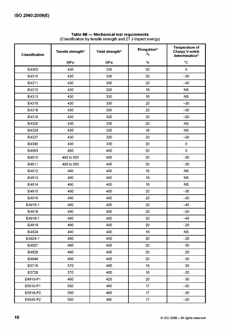
Table 8B — Mechanical test requirements(Classification by tensile strength and 27 J impact energy)
ClassificationTensile strengtha Yield strengtha Elongationa
A5
Temperature of Charpy V-notch determination13
MPa MPa % °C
E4303 430 330 20 0
E4310 430 330 20 -30
E4311 430 330 20 -30
E4312 430 330 16 NS
E4313 430 330 16 NS
E4316 430 330 20 -30
E4318 430 330 20 -30
E4319 430 330 20 -20
E4320 430 330 20 NS
E4324 430 330 16 NS
E4327 430 330 20 -30
E4340 430 330 20 0
E4903 490 400 20 0
E4910 490 to 650 400 20 -30
E4911 490 to 650 400 20 -30
E4912 490 400 16 NS
E4913 490 400 16 NS
E4914 490 400 16 NS
E4915 490 400 20 -30
E4916 490 400 20 -30
E4916-1 490 400 20 -45
E4918 490 400 20 -30
E4918-1 490 400 20 -45
E4919 490 400 20 -20
E4924 490 400 16 NS
E4924-1 490 400 20 -20
E4927 490 400 20 -30
E4928 490 400 20 -20
E4948 490 400 20 -30
E5716 570 490 16 -30
E5728 570 490 16 -20
E4910-P1 490 420 20 -30
E5510-P1 550 460 17 -30
E5518-P2 550 460 17 -30
E5545-P2 550 460 17 -30
10 © ISO 2009 - All rights reserved

ISO 2560:2009(E)
Table 8B (continued)
ClassificationTensile strength3 Yield strength3 Elongation3
A5
Temperature of Charpy V-notch determinationb
MPa MPa % °C
E4910-1M3 490 420 20 NS
E4911-1 M3 490 400 20 NS
E4915-1M3 490 400 20 NS
E4916-1 M3 490 400 20 NS
E4918-1M3 490 400 20 NS
E4919-1M3 490 400 20 NS
E4920-1 M3 490 400 20 NS
E4927-1 M3 490 400 20 NS
E5518-3M2 550 460 17 -50
E5516-3M3 550 460 17 -50
E5518-3M3 550 460 17 -50
E4916-N1 490 390 20 -40
E4928-N1 490 390 20 -40
E5516-N1 550 460 17 -40
E5528-N1 550 460 17 -40
E4916-N2 490 390 20 -40
E4918-N2 490 390 20 -50
E5516-N2 550 470 to 550 20 -40
E5518-N2 550 470 to 550 20 -40
E4916-N3 490 390 20 -40
E5516-N3 550 460 17 -50
E5516-3N3 550 460 17 -50
E5518-N3 550 460 17 -50
E4915-N5 490 390 20 -75
E4916-N5 490 390 20 -75
E4918-N5 490 390 20 -75
E4928-N5 490 390 20 -60
E5516-N5 550 460 17 -60
E5518-N5 550 460 17 -60
E4915-N7 490 390 20 -100
E4916-N7 490 390 20 -100
E4918-N7 490 390 20 -100
E5516-N7 550 460 17 -75
E5518-N7 550 460 17 -75
E5516-N13 550 460 17 -100
E5518-N2M3 550 460 17 -40
© ISO 2009 - All rights reserved 11

ISO 2560:2009(E)
Table 8B (continued)
ClassificationTensile strengtha Yield strengtha Elongationa
A5
Temperature of Charpy V-notch determination13
MPa MPa % °C
E4903-NC 490 390 20 0
E4916-NC 490 390 20 0
E4928-NC 490 390 20 0
E5716-NC 570 490 16 0
E5728-NC 570 490 16 0
E4903-CC 490 390 20 0
E4916-CC 490 390 20 0
E4928-CC 490 390 20 0
E5716-CC 570 490 16 0
E5728-CC 570 490 16 0
E4903-NCC 490 390 20 0
E4916-NCC 490 390 20 0
E4928-NCC 490 390 20 0
E5716-NCC 570 490 16 0
E5728-NCC 570 490 16 0
E4903-NCC1 490 390 20 0
E4916-NCC1 490 390 20 0
E4928-NCC1 490 390 20 0
E5516-NCC1 550 460 17 -20
E5518-NCC1 550 460 17 -20
E5716-NCC1 570 490 16 0
E5728-NCC1 570 490 16 0
E4916-NCC2 490 420 20 -20
E4918-NCC2 490 420 20 -20
E49XX-G 490 400 20 NS
E55XX-G 550 460 17 NS
E57XX-G 570 490 16 NS
a Single values are minimum requirements.
b Not specified = NS.
12 © ISO 2009 - All rights reserved

ISO 2560:2009(E)
5.2 Pass sequence
The pass sequence shall be as indicated in Table 9.
The direction o f welding to complete a pass shall not vary. Each pass shall be executed with a welding current o f 70 % to 90 % o f the maximum current recommended by the manufacturer. Regardless o f the type of covering, welding shall be performed with a.c. when both a.c. or d.c. are applicable and with d.c. using the recommended polarity when only d.c. is claimed.
Table 9 — Pass sequence
Electrode diameter3
mm
Split weave
Layer No. Passes per layer Number of layers
4,0 1 to top 2b 7 to 9
For diameters other than 4,0 mm, the pass sequence is to be specified by the manufacturer.
The top two layers may be completed with 3 passes per layer.
ab
6 Chemical analysis
Chemical analysis may be performed on any suitable test piece, but in cases o f dispute, specimens in accordance with ISO 6847 shall be used. Any analytical technique may be used, but in cases o f dispute, reference shall be made to established published methods.
6A Classification by yield strength and 47 J impact energy
The results o f the chemical analysis shall fulfil the requirements given in Table 3A.
6B Classification by tensile strength and 27 J impact energy
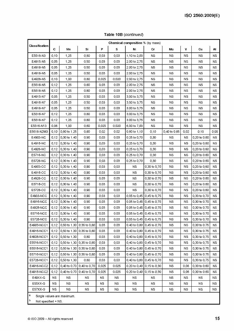
The results o f the chemical analysis shall fulfil the requirements given in Table 10B fo r the classification under test.
Table 10B — All-weld metal deposit composition requirements(Classification by tensile strength and 27 J impact energy)ab
ClassificationC Mn Si P
Chemical c
S
omposition
Ni
% (by mass)
Cr Mo V Cu Al
E4303 0,20 1,20 1,00 NS NS 0,30 0,20 0,30 0,08 NS NS
E4310 0,20 1,20 1,00 NS NS 0,30 0,20 0,30 0,08 NS NS
E4311 0,20 1,20 1,00 NS NS 0,30 0,20 0,30 0,08 NS NS
E4312 0,20 1,20 1,00 NS NS 0,30 0,20 0,30 0,08 NS NS
E4313 0,20 1,20 1,00 NS NS 0,30 0,20 0,30 0,08 NS NS
E4316 0,20 1,20 1,00 NS NS 0,30 0,20 0,30 0,08 NS NS
E4318 0,03 0,60 0,40 0,025 0,015 0,30 0,20 0,30 0,08 NS NS
E4319 0,20 1,20 1,00 NS NS 0,30 0,20 0,30 0,08 NS NS
E4320 0,20 1,20 1,00 NS NS 0,30 0,20 0,30 0,08 NS NS
E4324 0,20 1,20 1,00 NS NS 0,30 0,20 0,30 0,08 NS NS
E4327 0,20 1,20 1,00 NS NS 0,30 0,20 0,30 0,08 NS NS
E4340 NS NS NS NS NS NS NS NS NS NS NS
E4903 0,15 1,25 0,90 NS NS 0,30 0,20 0,30 0,08 NS NS
E4910 0,20 1,25 0,90 0,035 0,035 0,30 0,20 0,30 0,08 NS NS
E4911 0,20 1,25 0,90 0,035 0,035 0,30 0,20 0,30 0,08 NS NS
© ISO 2009 - All rights reserved 13

ISO 2560:2009(E)
Table 10B (continued)
ClassificationC Mn Si P
Chemical c
S
omposition
Ni
% (by mass)
Cr Mo V Cu Al
E4912 0,20 1,20 1,00 NS NS 0,30 0,20 0,30 0,08 NS NS
E4913 0,20 1,20 1,00 NS NS 0,30 0,20 0,30 0,08 NS NS
E4914 0,15 1,25 0,90 0,035 0,035 0,30 0,20 0,30 0,08 NS NS
E4915 0,15 1,25 0,90 0,035 0,035 0,30 0,20 0,30 0,08 NS NS
E4916 0,15 1,60 0,75 0,035 0,035 0,30 0,20 0,30 0,08 NS NS
E4916-1 0,15 1,60 0,75 0,035 0,035 0,30 0,20 0,30 0,08 NS NS
E4918 0,15 1,60 0,90 0,035 0,035 0,30 0,20 0,30 0,08 NS NS
E4918-1 0,15 1,60 0,90 0,035 0,035 0,30 0,20 0,30 0,08 NS NS
E4919 0,15 1,25 0,90 0,035 0,035 0,30 0,20 0,30 0,08 NS NS
E4924 0,15 1,25 0,90 0,035 0,035 0,30 0,20 0,30 0,08 NS NS
E4924-1 0,15 1,25 0,90 0,035 0,035 0,30 0,20 0,30 0,08 NS NS
E4927 0,15 1,60 0,75 0,035 0,035 0,30 0,20 0,30 0,08 NS NS
E4928 0,15 1,60 0,90 0,035 0,035 0,30 0,20 0,30 0,08 NS NS
E4948 0,15 1,60 0,90 0,035 0,035 0,30 0,20 0,30 0,08 NS NS
E5716 0,12 1,60 0,90 0,03 0,03 1,00 0,30 0,35 NS NS NS
E5728 0,12 1,60 0,90 0,03 0,03 1,00 0,30 0,35 NS NS NS
E4910-P1 0,20 1,20 0,60 0,03 0,03 1,00 0,30 0,50 0,10 NS NS
E5510-P1 0,20 1,20 0,60 0,03 0,03 1,00 0,30 0,50 0,10 NS NS
E5518-P2 0,12 0,90 to 1,70 0,80 0,03 0,03 1,00 0,20 0,50 0,05 NS NS
E5545-P2 0,12 0,90 to 1,70 0,80 0,03 0,03 1,00 0,20 0,50 0,05 NS NS
E4910-1 M3 0,12 0,60 0,40 0,03 0,03 NS NS 0,40 to 0,65 NS NS NS
E4911-1 M3 0,12 0,60 0,40 0,03 0,03 NS NS 0,40 to 0,65 NS NS NS
E4915-1 M3 0,12 0,90 0,60 0,03 0,03 NS NS 0,40 to 0,65 NS NS NS
E4916-1 M3 0,12 0,90 0,60 0,03 0,03 NS NS 0,40 to 0,65 NS NS NS
E4918-1 M3 0,12 0,90 0,80 0,03 0,03 NS NS 0,40 to 0,65 NS NS NS
E4919-1 M3 0,12 0,90 0,40 0,03 0,03 NS NS 0,40 to 0,65 NS NS NS
E4920-1 M3 0,12 0,60 0,40 0,03 0,03 NS NS 0,40 to 0,65 NS NS NS
E4927-1 M3 0,12 1,00 0,40 0,03 0,03 NS NS 0,40 to 0,65 NS NS NS
E5518-3M2 0,12 1,00 to 1,75 0,80 0,03 0,03 0,90 NS 0,25 to 0,45 NS NS NS
E5516-3M3 0,12 1,00 to 1,80 0,80 0,03 0,03 0,90 NS 0,40 to 0,65 NS NS NS
E5518-3M3 0,12 1,00 to 1,80 0,80 0,03 0,03 0,90 NS 0,40 to 0,65 NS NS NS
E4916-N1 0,12 0,60 to 1,60 0,90 0,03 0,03 0,30 to 1,00 NS 0,35 0,05 NS NS
E4928-N1 0,12 0,60 to 1,60 0,90 0,03 0,03 0,30 to 1,00 NS 0,35 0,05 NS NS
E5516-N1 0,12 0,60 to 1,60 0,90 0,03 0,03 0,30 to 1,00 NS 0,35 0,05 NS NS
E5528-N1 0,12 0,60 to 1,60 0,90 0,03 0,03 0,30 to 1,00 NS 0,35 0,05 NS NS
E4916-N2 0,08 0,40 to 1,40 0,50 0,03 0,03 0,80 to 1,10 0,15 0,35 0,05 NS NS
E4918-N2 0,08 0,40 to 1,40 0,50 0,03 0,03 0,80 to 1,10 0,15 0,35 0,05 NS NS
E5516-N2 0,12 0,40 to 1,25 0,80 0,03 0,03 0,80 to 1,10 0,15 0,35 0,05 NS NS
E5518-N2 0,12 0,40 to 1,25 0,80 0,03 0,03 0,80 to 1,10 0,15 0,35 0,05 NS NS
E4916-N3 0,10 1,25 0,60 0,03 0,03 1,10 to 2,00 NS 0,35 NS NS NS
E5516-N3 0,10 1,25 0,60 0,03 0,03 1,10 to 2,00 NS 0,35 NS NS NS
E5516-3N3 0,10 1,60 0,60 0,03 0,03 1,10 to 2,00 NS NS NS NS NS
14 © ISO 2009 - All rights reserved
ISO 2560:2009(E)
Table 10B (continued)
ClassificationC Mn Si P
Chemical c
S
omposition
Ni
% (by mass)
Cr Mo V Cu Al
E5518-N3 0,10 1,25 0,80 0,03 0,03 1,10 to 2,00 NS NS NS NS NS
E4915-N5 0,05 1,25 0,50 0,03 0,03 2,00 to 2,75 NS NS NS NS NS
E4916-N5 0,05 1,25 0,50 0,03 0,03 2,00 to 2,75 NS NS NS NS NS
E4918-N5 0,05 1,25 0,50 0,03 0,03 2,00 to 2,75 NS NS NS NS NS
E4928-N5 0,10 1,00 0,80 0,025 0,020 2,00 to 2,75 NS NS NS NS NS
E5516-N5 0,12 1,25 0,60 0,03 0,03 2,00 to 2,75 NS NS NS NS NS
E5518-N5 0,12 1,25 0,80 0,03 0,03 2,00 to 2,75 NS NS NS NS NS
E4915-N7 0,05 1,25 0,50 0,03 0,03 3,00 to 3,75 NS NS NS NS NS
E4916-N7 0,05 1,25 0,50 0,03 0,03 3,00 to 3,75 NS NS NS NS NS
E4918-N7 0,05 1,25 0,50 0,03 0,03 3,00 to 3,75 NS NS NS NS NS
E5516-N7 0,12 1,25 0,80 0,03 0,03 3,00 to 3,75 NS NS NS NS NS
E5518-N7 0,12 1,25 0,80 0,03 0,03 3,00 to 3,75 NS NS NS NS NS
E5516-N13 0,06 1,00 0,60 0,025 0,020 6,00 to 7,00 NS NS NS NS NS
E5518-N2M3 0,10 0,80 to 1,25 0,60 0,02 0,02 0,80 to 1,10 0,10 0,40 to 0,65 0,02 0,10 0,05
E4903-NC 0,12 0,30 to 1,40 0,90 0,03 0,03 0,25 to 0,70 0,30 NS NS 0,20 to 0,60 NS
E4916-NC 0,12 0,30 to 1,40 0,90 0,03 0,03 0,25 to 0,70 0,30 NS NS 0,20 to 0,60 NS
E4928-NC 0,12 0,30 to 1,40 0,90 0,03 0,03 0,25 to 0,70 0,30 NS NS 0,20 to 0,60 NS
E5716-NC 0,12 0,30 to 1,40 0,90 0,03 0,03 0,25 to 0,70 0,30 NS NS 0,20 to 0,60 NS
E5728-NC 0,12 0,30 to 1,40 0,90 0,03 0,03 0,25 to 0,70 0,30 NS NS 0,20 to 0,60 NS
E4903-CC 0,12 0,30 to 1,40 0,90 0,03 0,03 NS 0,30 to 0,70 NS NS 0,20 to 0,60 NS
E4916-CC 0,12 0,30 to 1,40 0,90 0,03 0,03 NS 0,30 to 0,70 NS NS 0,20 to 0,60 NS
E4928-CC 0,12 0,30 to 1,40 0,90 0,03 0,03 NS 0,30 to 0,70 NS NS 0,20 to 0,60 NS
E5716-CC 0,12 0,30 to 1,40 0,90 0,03 0,03 NS 0,30 to 0,70 NS NS 0,20 to 0,60 NS
E5728-CC 0,12 0,30 to 1,40 0,90 0,03 0,03 NS 0,30 to 0,70 NS NS 0,20 to 0,60 NS
E4903-NCC 0,12 0,30 to 1,40 0,90 0,03 0,03 0,05 to 0,45 0,45 to 0,75 NS NS 0,30 to 0,70 NS
E4916-NCC 0,12 0,30 to 1,40 0,90 0,03 0,03 0,05 to 0,45 0,45 to 0,75 NS NS 0,30 to 0,70 NS
E4928-NCC 0,12 0,30 to 1,40 0,90 0,03 0,03 0,05 to 0,45 0,45 to 0,75 NS NS 0,30 to 0,70 NS
E5716-NCC 0,12 0,30 to 1,40 0,90 0,03 0,03 0,05 to 0,45 0,45 to 0,75 NS NS 0,30 to 0,70 NS
E5728-NCC 0,12 0,30 to 1,40 0,90 0,03 0,03 0,05 to 0,45 0,45 to 0,75 NS NS 0,30 to 0,70 NS
E4903-NCC1 0,12 0,50 to 1,30 0,35 to 0,80 0,03 0,03 0,40 to 0,80 0,45 to 0,70 NS NS 0,30 to 0,75 NS
E4916-NCC1 0,12 0,50 to 1,30 0,35 to 0,80 0,03 0,03 0,40 to 0,80 0,45 to 0,70 NS NS 0,30 to 0,75 NS
E4928-NCC1 0,12 0,50 to 1,30 0,80 0,03 0,03 0,40 to 0,80 0,45 to 0,70 NS NS 0,30 to 0,75 NS
E5516-NCC1 0,12 0,50 to 1,30 0,35 to 0,80 0,03 0,03 0,40 to 0,80 0,45 to 0,70 NS NS 0,30 to 0,75 NS
E5518-NCC1 0,12 0,50 to 1,30 0,35 to 0,80 0,03 0,03 0,40 to 0,80 0,45 to 0,70 NS NS 0,30 to 0,75 NS
E5716-NCC1 0,12 0,50 to 1,30 0,35 to 0,80 0,03 0,03 0,40 to 0,80 0,45 to 0,70 NS NS 0,30 to 0,75 NS
E5728-NCC1 0,12 0,50 to 1,30 0,80 0,03 0,03 0,40 to 0,80 0,45 to 0,70 NS NS 0,30 to 0,75 NS
E4916-NCC2 0,12 0,40 to 0,70 0,40 to 0,70 0,025 0,025 0,20 to 0,40 0,15 to 0,30 NS 0,08 0,30 to 0,60 NS
E4918-NCC2 0,12 0,40 to 0,70 0,40 to 0,70 0,025 0,025 0,20 to 0,40 0,15 to 0,30 NS 0,08 0,30 to 0,60 NS
E49XX-G NS NS NS NS NS NS NS NS NS NS NS
E55XX-G NS NS NS NS NS NS NS NS NS NS NS
E57XX-G NS NS NS NS NS NS NS NS NS NS NS
a Single values are maximum.
b Not specified = NS.
© ISO 2009 - All rights reserved 15

ISO 2560:2009(E)
7 Fillet weld test
The fillet weld test assembly shall be as shown in ISO 15792-3:2000, Figure 1.
7A Classification by yield strength and 47 J impact energy
The plate material shall be selected from the range of materials for which the electrode is recommended by the manufacturer. The surface shall be free of scale, rust and other contaminants. The test plate thickness, t, shall be 10 mm to 12 mm, the width, b, shall be 75 mm minimum and the length, l, shall be 300 mm minimum. The electrode sizes to be tested for each coating type, the test positions and the required test results are given in Table 11A.
7B Classification by tensile strength and 27 J impact energy
The plate material shall be unalloyed steel of 0,30 % (by mass) C maximum. The surfaces to be welded shall be clean. The test plate thickness, t, shall be 10 mm to 12 mm in accordance with Table 11B. The width, b, the length, l, the test positions for each coating type, and the required test results are given in Tables 11B and 12B.
Table 11A — Test req u irem en ts fo r f i l le t w e ld s a(Classification by yield strength and 47 J impact energy)
Dimensions in millimetres
Symbol of position for
classification
Coatingtype
Testposition
Electrodesizea
Fillettheoretical
throat
Leg length difference Convexity
C 4,5 min. 1,5 max. 2,5 max.
1 or 2 RXb PB 6,0 5,0 min. 2,0 max. 3,0 max.
B 5,0 min. 2,0 max. 3,0 max.
A3
RRPB 6,0 5,0 min. 2,0 max. 3,0 max.
R 6,05
BPB
5,04,5 min. 1,5 max. 2,5 max.
C 4,5 max.
1 or 2 RXb PF 4,0 4,5 max. — 2,0 max.
B 5,5 max.
C 4,5 max. 1,5 max. 2,5 max.
1 or 2 RXb PD 4,0 4,5 max. 1,5 max. 2,5 max.
B 5,5 max. 2,0 max. 3,0 max.
5 B PG 4,0 5,0 min. — 1,5 max.c
a Where the largest size claimed for positional welding is smaller than that specified, use the largest size and adjust criteria pro rata.Otherwise, electrode sizes not shown are not required to be tested.
b RX includes R, RC, RA and RB
c Maximum concavity.
16 © ISO 2009 - All rights reserved

ISO 2560:2009(E)
Table 11B — Test requirements for fillet welds(Classification by tensile strength and 27 J impact energy)
Dimensions in millimetres
Minimum plate Minimum plate Fillet
Coating type Current and polarity
Electrode sizea Testposition
width
w
length
l
weld size
03 a.c. and 5,0 PF, PD 75 300 10,0 max.d.c. (+) 6,0 PB 400 8,0 min.
10 d c. (+) 5,0 PF, PD 75 300 8,0 max.6,0 PB 400 6,0 min.
11 a.c. and 5,0 PF, PD 75 300 8,0 max.d.c. (+) 6,0 PB 400 6,0 min.
12 a.c. and 5,0 PF, PD 75 300 10,0 max.d.c. (-) 6,0 PB 400 8,0 min.
13 a.c., d.c. (-) 5,0 PF, PD 75 300 10,0 max.and d.c. (+) 6,0 PB 400 8,0 min.
14 a.c., d.c. (-) 4,0 PF, PD 75 300 8,0 max.and d.c. (+) 6,0 PB 400 8,0 min.
15 d.c. (+) 4,0 PF, PD 75 300 8,0 max.6,0 PB 400 8,0 min.
16 a.c. and 4,0 PF, PD 75 300 8,0 max.d.c. (+) 6,0 PB 400 8,0 min.
18 a.c. and 4,0 PF, PD 75 300 8,0 max.d.c. (+) 6,0 PB 400 8,0 min.
19 a.c. and 5,0 PF, PD 75 300 10,0 max.d.c. (+) 6,0 PB 400 8,0 min.
20 a.c. and d.c. (-)
6,0 PB 75 400 8,0 min.
24 a.c., d.c. (-) and d.c. (+) 6,0 PB 75 400 or 650b 8,0 min.
27 a.c. and d.c. (-)
6,0 PB 75 400 or 650b 8,0 min.
28 a.c. and d.c. (+)
6,0 PB 75 400 or 650b 8,0 min.
40 NSc NSc NSc 75 NSc NSc
45 d.c. (+) 4,04,5 PE, PG 75 300 8.0 max.
6.0 min.
48 a.c. and 4,0 PD, PG 75 300 8,0 max.d.c. (+) 5,0 PB, PG 300 or 400d 6,5 min.
a Where the largest size claimed for positional welding is smaller than that specified, use the largest size and adjust criteria pro rata.Otherwise, electrode sizes not shown are not required to be tested.
b For 450 mm electrode length, l shall be 400 minimum; for 700 mm electrode length, l shall be 650 mm minimum.
c Not specified = NS. Requirements shall be agreed between purchaser and supplier.
d For 350 mm electrode length, l shall be 300 mm minimum; for 450 mm or 460 mm electrode length, l shall be 400 mm minimum.
© ISO 2009 - All rights reserved 17

ISO 2560:2009(E)
Table 12B — Allowable leg length difference and maximum convexityDimensions in millimetres
Measured fillet weld size Maximum leg length difference Maximum convexity
4,0 or less 1,0 2,0
4,5 1,5 2,0
5,0 or 5,5 2,0 2,0
6,0 or 6,5 2,5 2,0
7,0, 7,5 or 8,0 3,0 2,5
8,5 3,5 2,5
9,0 or more 4,0 2,5
8 Rounding procedure
For the purposes of determining compliance with the requirements of this International Standard, the actual test values obtained shall be subject to ISO 80000-1, Clause B.3, Rule A. If the measured values are obtained by equipment calibrated in units other than those of this International Standard, the measured values shall be converted to the units of this International Standard before rounding. If an arithmetic average value is to be compared to the requirements of this International Standard, rounding shall be done only after calculating the arithmetic average. If the test method standard cited in Clause 2 contains instructions for rounding that conflict with the instructions of this International Standard, the rounding requirements of the test method standard shall apply. The rounded results shall fulfil the requirements of the appropriate table for the classification under test.
9 Retests
If any test fails to meet requirements, that test shall be repeated twice. The results of both retests shall meet the requirements. Specimens for the retest may be taken from the original test assembly or from a new test assembly. For chemical analysis, retest need be only for those specific elements that failed to meet their test requirement. If the results of one or both retests fail to meet requirements, the material under test shall be considered as not meeting the requirements of this specification for that classification.
In the event that, during preparation or after completion of any test, it is clearly determined that prescribed or proper procedures were not followed in preparing the weld test assembly or test specimen(s), or in conducting the test, the test shall be considered invalid, without regard to whether the test was actually completed, or whether the test results met, or failed to meet, the requirements. That test shall be repeated, following properly prescribed procedures. In this case, the requirement for doubling the number of test specimens does not apply.
10 Technical delivery conditions
Technical delivery conditions shall meet the requirements in ISO 544 and in ISO 14344.
18 © ISO 2009 - All rights reserved
ISO 2560:2009(E)
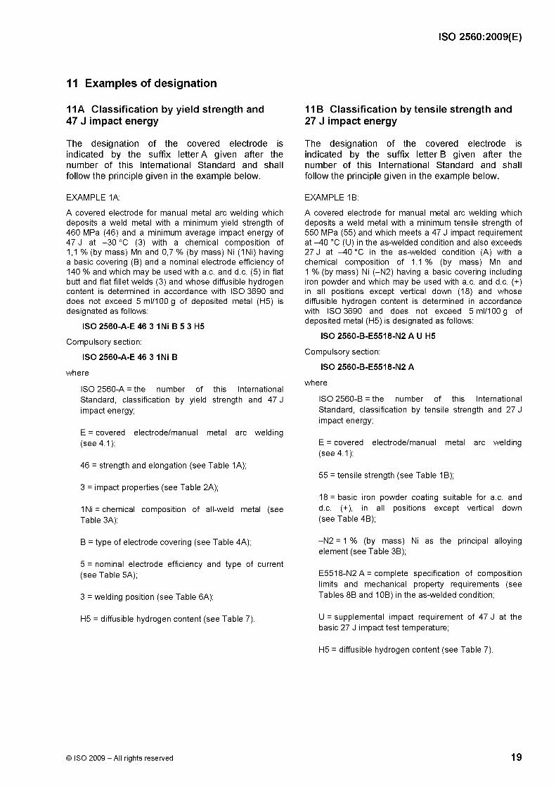
11A Classification by yield strength and 47 J impact energy
The designation of the covered electrode is indicated by the suffix letter A given after the number of this International Standard and shall follow the principle given in the example below.
EXAMPLE 1A:
A covered electrode for manual metal arc welding which deposits a weld metal with a minimum yield strength of 460 MPa (46) and a minimum average impact energy of 47 J at -30 °C (3) with a chemical composition of 1,1 % (by mass) Mn and 0,7 % (by mass) Ni (1Ni) having a basic covering (B) and a nominal electrode efficiency of 140 % and which may be used with a.c. and d.c. (5) in flat butt and flat fillet welds (3) and whose diffusible hydrogen content is determined in accordance with ISO 3690 and does not exceed 5 ml/100 g of deposited metal (H5) is designated as follows:
ISO 2560-A-E 46 3 1Ni B 5 3 H5
Compulsory section:
ISO 2560-A-E 46 3 1Ni B
where
ISO 2560-A = the number of this International Standard, classification by yield strength and 47 J impact energy;
E = covered electrode/manual metal arc welding (see 4.1);
46 = strength and elongation (see Table 1A);
3 = impact properties (see Table 2A);
1 Ni = chemical composition of all-weld metal (see Table 3A);
B = type of electrode covering (see Table 4A);
5 = nominal electrode efficiency and type of current (see Table 5A);
3 = welding position (see Table 6A);
H5 = diffusible hydrogen content (see Table 7).
11 Examples of designation
11B Classification by tensile strength and 27 J impact energy
The designation of the covered electrode is indicated by the suffix letter B given after the number of this International Standard and shall follow the principle given in the example below.
EXAMPLE 1B:
A covered electrode for manual metal arc welding which deposits a weld metal with a minimum tensile strength of 550 MPa (55) and which meets a 47 J impact requirement at -40 °C (U) in the as-welded condition and also exceeds 27 J at -40 °C in the as-welded condition (A) with a chemical composition of 1,1 % (by mass) Mn and 1 % (by mass) Ni (-N2) having a basic covering including iron powder and which may be used with a.c. and d.c. (+) in all positions except vertical down (18) and whose diffusible hydrogen content is determined in accordance with ISO 3690 and does not exceed 5 ml/100 g of deposited metal (H5) is designated as follows:
ISO 2560-B-E5518-N2 A U H5
Compulsory section:
ISO 2560-B-E5518-N2 A
where
ISO 2560-B = the number of this International Standard, classification by tensile strength and 27 J impact energy;
E = covered electrode/manual metal arc welding (see 4.1);
55 = tensile strength (see Table 1B);
18 = basic iron powder coating suitable for a.c. and d.c. (+), in all positions except vertical down (see Table 4B);
-N2 = 1 % (by mass) Ni as the principal alloying element (see Table 3B);
E5518-N2 A = complete specification of composition limits and mechanical property requirements (see Tables 8B and 10B) in the as-welded condition;
U = supplemental impact requirement of 47 J at the basic 27 J impact test temperature;
H5 = diffusible hydrogen content (see Table 7).
© ISO 2009 - All rights reserved 19
ISO 2560:2009(E)
Classification systems
Annex A(informative)
A.1 ISO 2560-A
The ISO 2560-A classification system for covered electrodes for non-alloy and fine grain steels, based upon yield strength and 47 J minimum impact energy, is shown in Figure A.1.
A.2 ISO 2560-B
The ISO 2560-B classification system for covered electrodes for non-alloy and fine grain steels, based upon tensile strength and 27 J minimum impact energy, is shown in Figure A.2.
20 © ISO 2009 - All rights reserved

ISO 2560:2009(E)
Compulsory classification designators3
ISO 2560-A-E XX X XXX X X X HX
Number of this International Standard. The "A" in the final position indicates classification by yield strength and 47 J impact requirement.
Designates a covered electrode.
Yield strength designator. For electrodes suitable for multi-run welding, the symbol "35, 38, 42, 46 or 50" is used to indicate a minimum yield strength of 355 MPa, 380 MPa, 420 MPa, 460 MPa or 500 MPa, respectively.
Charpy V-Notch impact energy designator. Indicates the temperature in degrees Celsius at or above which the impact strength of the weld metal meets or exceeds 47J. The letter "A" is used to indicate a test temperature of + 20 °C. The letter "Z" indicates that there is no impact requirement.
Chemical composition designator. Indicates composition of all-weld metal.
Designator for type of electrode coating. The symbols "A, C, R, RR, RC,RA, RB and B” are used to indicate acid covering, cellulosic covering, rutile covering, rutile thick covering, rutile-cellulosic covering, rutile-acid covering, rutile-basic covering or basic covering, respectively.
Optional supplemental designators13
Optional supplemental diffusible hydrogen designator. "H5, H10 or H15" is used to indicate a maximum diffusible hydrogen content of 5 ml/100 g, 10 ml/100 g or 15 ml/100 g of deposited metal, respectively.
Positionality designator. The symbol "1, 2, 3, 4 or 5" indicates the welding position(s) for which the electrode is suitable.
Metal recovery and type of current indicator. The symbol "1,2, 3, 4, 5, 6, 7 or 8" indicates the weld metal recovery and type of current.
a The combination of these designators constitutes the covered electrode classification. b These designators are optional and do not constitute part of the covered electrode classification.
Figure A.1 — ISO 2560-A designation of electrodes(Classification by yield strength and 47 J impact energy)
© ISO 2009 - All rights reserved 21
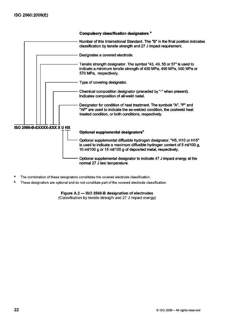
ISO 2560:2009(E)
ISO 2560-B-EXXXX-XXX X U
Number of this International Standard. The "B" in the final position indicates classification by tensile strength and 27 J impact requirement.
Designates a covered electrode.
Tensile strength designator. The symbol "43, 49, 55 or 57" is used to indicate a minimum tensile strength of 430 MPa, 490 MPa, 550 MPa or 570 MPa, respectively.
Type of covering designator.
Chemical composition designator (preceded by when present).Indicates composition of all-weld metal.
Designator for condition of heat treatment. The symbols "A", "P" and "AP" are used to indicate the as-welded condition, the postweld heat treated condition, or both conditions, respectively.
Compulsory classification designators a
Optional supplemental designators*3
Optional supplemental diffusible hydrogen designator. "H5, H10 or H15" is used to indicate a maximum diffusible hydrogen content of 5 ml/100 g, 10 ml/100 g or 15 ml/100 g of deposited metal, respectively.
Optional supplemental designator to indicate 47 J impact energy at the normal 27 J test temperature.
a The combination of these designators constitutes the covered electrode classification. b These designators are optional and do not constitute part of the covered electrode classification.
Figure A.2 — ISO 2560-B designation of electrodes(Classification by tensile strength and 27 J impact energy)
22 © ISO 2009 - All rights reserved
ISO 2560:2009(E)
Description of types of electrode covering — Classification by yield strength and 47 J impact energy
Annex B(informative)
B.1 General
The properties of a covered electrode, i.e. both its welding characteristics and mechanical properties of the weld metal, are decisively influenced by the covering. This homogeneous mixture of substances generally contains the following six main components:
— slag-forming materials;
— deoxidants;
— shielding gas-forming materials;
— ionizing agents;
— binders;
— alloying elements (if necessary).
In addition, iron powder may be added to increase the nominal electrode efficiency (see 4.6A), which may affect the positional welding properties.
In the following, “thick covering” means a diameter ratio of covering to core wire greater than or equal to 1,6.
B.2 Acid-covered electrodes
The covering of this type is characterized by large proportions of iron oxides and, as a result of the high oxygen potential, of deoxidants (ferro-manganese). With a thick covering, the acid slag causes a very fine droplet transfer and produces flat and smooth welds. Electrodes with acid covering only have a limited application for positional welding and are more susceptible to solidification cracking than other types.
B.3 Cellulosic-covered electrodes
Electrodes of this type contain a large quantity of combustible organic substances, particularly cellulose, in the covering. Owing to the intensive arc, such electrodes are especially suitable for welding in the vertical downward position.
B.4 Rutile-covered electrodes
Electrodes of this type give a coarse droplet transfer, which ensures that these electrodes are suitable for welding sheet metal. Rutile type electrodes are suitable for all welding positions, except the vertical downward position.
© ISO 2009 - All rights reserved 23
ISO 2560:2009(E)
B.5 Rutile-thick-covered electrodes
Electrodes of this type have a diameter ratio of covering to core wire greater than or equal to 1,6. Characteristic features are the high rutile content of their covering, their good restriking characteristics and their finely rippled regular welds.
B.6 Rutile-cellulosic-covered electrodes
The composition of the covering of these electrodes is similar to that of rutile-type electrodes, containing, however, larger quantities of cellulose. Electrodes of this type are therefore suitable for welding in the vertical downward position.
B.7 Rutile-acid-covered electrodes
Concerning welding characteristics, electrodes of this mixed type are comparable to electrodes having an acid covering.
However, in the covering of these electrodes, a substantial proportion of iron oxide has been replaced by rutile. Therefore, these electrodes, having mostly a thick covering, are suitable for all positions, except the vertical downward position.
B.8 Rutile-basic-covered electrodes
Characteristic features of this type of covering are a large quantity of rutile and an increased proportion of basic components. These electrodes, having mostly a thick covering, are characterized by good mechanical properties. They possess uniformly good welding properties in all positions, except the vertical downward position.
B.9 Basic-covered electrodes
A characteristic feature of the thick covering of these electrodes is the large quantity of carbonates of the alkaline earth metals, e.g. calcium carbonate (lime), and calcium fluoride (fluorspar). To improve the welding properties, particularly with a.c. welding, higher concentrations of non-basic components (e.g. rutile and/or quartz) may be required.
Basic-covered electrodes have two outstanding properties: a) the impact energy of the weld metal is higher, particularly at low temperatures; b) they are more resistant to cracking than all other types.
Their resistance to solidification cracking results from the high metallurgical purity of the weld metal, whilst the low risk of cold cracking, provided dry electrodes are used, is attributable to the low hydrogen content. It is lower than with all other types and should not exceed an upper permissible limit of HD = 15 ml/100 g of deposited metal.
Generally, electrodes of the basic type are suitable for all welding positions, except the vertical downward position. Basic-type electrodes especially suited for the vertical downward position have a particular slag composition.
24 © ISO 2009 - All rights reserved

ISO 2560:2009(E)
Description of types of electrode covering — Classification by tensile strength and 27 J impact energy
Annex C(informative)
C.1 General
The properties of a covered electrode, i.e. both its welding characteristics and mechanical properties of the weld metal, are decisively influenced by the covering. This homogeneous mixture of substances generally contains the following six main components:
— slag-forming materials;
— deoxidants;
— shielding gas-forming materials;
— ionizing agents;
— binders;
— alloying elements (if necessary).
In addition, iron powder may be added to increase the nominal electrode efficiency (see 4.6A), which may affect the positional welding properties.
Certain electrode designs, while usable on both a.c. and d.c. (either or both polarities), may be optimized by their manufacturer for one particular current type for a particular market need.
C.2 Covering type 03
Electrodes of this type contain a mixture of titanium dioxide (rutile) and calcium carbonate (lime), so they share some characteristics of rutile electrodes with some characteristics of basic electrodes. See Clauses C.6 and C.9.
C.3 Covering type 10
Electrodes of this type contain a large quantity of combustible organic substances, particularly cellulose, in the covering. Owing to the intensive arc, such electrodes are especially suitable for welding in the vertical downward position. Arc stabilization is primarily by sodium, so the electrodes are mainly suitable for d.c. welding, normally with electrode positive.
C.4 Covering type 11
Electrodes of this type contain a large quantity of combustible organic substances, particularly cellulose, in the covering. Owing to the intensive arc, such electrodes are especially suitable for welding in the vertical downward position. Arc stabilization is primarily by potassium, so the electrodes are suitable for both a.c. and d.c., electrode positive, welding.
25

ISO 2560:2009(E)
C.5 Covering type 12
Electrodes of this type contain a large quantity of titanium dioxide (usually in the form of the mineral rutile) in the covering. Their soft arc makes them suitable for bridging wide root gaps under conditions of poor fit.
C.6 Covering type 13
Electrodes of this type contain a large quantity of titanium dioxide (rutile) and are heavily stabilized with potassium. They produce a soft quiet arc at lower currents than electrodes with covering type 12, and are especially suitable for sheet metal.
C.7 Covering type 14
Electrodes of this type have covering similar to types 12 and 13, but with the addition of a small amount of iron powder. The iron powder permits higher current and provides higher deposition rate. Nevertheless, they are suitable for use in all welding positions.
C.8 Covering type 15
Electrodes of this type have a covering that is highly basic, consisting largely of lime and calcium fluoride (fluorspar). Arc stabilization is provided mainly by sodium, and they are generally suitable for use on d.c. electrode positive only. They produce weld metal of high metallurgical quality with low diffusible hydrogen.
C.9 Covering type 16
Electrodes of this type have a covering that is highly basic, consisting largely of lime and calcium fluoride (fluorspar). Arc stabilization with potassium is responsible for their ability to weld with alternating current. They produce weld metal of high metallurgical quality with low diffusible hydrogen.
C.10 Covering type 18
Electrodes of this type are similar to electrodes of covering type 16, except that they have a somewhat thicker coating with the addition of iron powder. The iron powder increases their current-carrying capacity and deposition rate, as compared to electrodes of covering type 16.
C.11 Covering type 19
Electrodes of this type contain oxides of titanium and iron, usually combined in the form of the mineral ilmenite. Although they are not low-hydrogen basic electrodes, they are capable of producing weld metal of relatively high toughness.
C.12 Covering type 20
Electrodes of this type contain large amounts of iron oxide. The slag is very fluid, so that welding is generally suitable only in flat and horizontal positions. They are primarily designed for fillet and lap welds.
26 © ISO 2009 - All rights reserved
ISO 2560:2009(E)
C.13 Covering type 24
Electrodes of this type are similar to electrodes of covering type 14, except that the covering is thicker and contains a higher portion of iron powder. They are generally only suitable for flat and horizontal welding positions. Principal applications are in fillet and lap welds.
C.14 Covering type 27
Electrodes of this type are similar to electrodes of covering type 20, except that the covering is thicker and contains large amounts of iron powder in addition to the iron oxide of covering type 20. Electrodes of covering type 27 are primarily designed for high speed fillet and lap welds.
C.15 Covering type 28
Electrodes of this type are similar to electrodes of covering type 18, except that the covering is thicker and contains more iron powder. As such, they are generally limited to use in the flat and horizontal positions. The resulting weld metal is of high metallurgical quality with low hydrogen content.
C.16 Covering type 40
Electrodes having this type of covering cannot be classified as having any other covering type in this specification. They are manufactured to meet very specific usability or application requirements of the purchaser. Welding position is a matter of agreement between supplier and purchaser. A specific example might be an electrode specially designed for welding inside holes (“plug welding”) or inside slots. Since covering type 40 is non-specific, a given electrode identified as having this covering type might be very different from another electrode identified as having this covering type.
C.17 Covering type 45
Electrodes of this type are similar to electrodes of covering type 15, except that the covering is specifically designed for vertical downward welding.
C.18 Covering type 48
Electrodes of this type are similar to electrodes of covering type 18, except that the covering is specifically designed for vertical downward welding.
© ISO 2009 - All rights reserved 27

ISO 2560:2009(E)
Notes on diffusible hydrogen and the avoidance of cold cracking
Annex D(informative)
Assuming that the external conditions are satisfactory (i.e. weld areas clean and dry), the diffusible hydrogen in the weld metal stems from hydrogen-containing compounds in the consumables and from the ambient air conditions; in the case of basic-covered electrodes, the water taken up by the covering is the main source. The water dissociates in the arc and gives rise to atomic hydrogen, which is absorbed by the weld metal. Under given material and stress conditions, the risk of cold cracking diminishes with decreasing diffusible hydrogen content of the weld metal.
Assuming that appropriate precautions are taken to keep the amount of diffusible hydrogen introduced into the weld to a reasonable minimum, cracking is generally avoided by preheating the joint to an appropriate temperature, and maintaining this as the minimum temperature throughout the welding operation. In practice, the appropriate diffusible hydrogen level depends on the particular application and, to ensure that this is achieved, the relevant handling, storage and drying conditions recommended by the electrode manufacturer should be followed.
Other methods of collection and measurement of diffusible hydrogen may be used for batch testing, provided they possess equal reproducibility with, and are calibrated against, the method given in ISO 3690. The weld metal diffusible hydrogen level is influenced by the type of current.
Cracks in welded joints may be caused or significantly influenced by diffusible hydrogen. Such cracks in general are developed after the joint has become cold, and are therefore commonly called cold cracks. For C-Mn steels, the greatest risk of cracking is generally in the HAZ; such cracks generally lie approximately parallel to the fusion boundary. The risk of diffusible hydrogen-assisted cracking increases with increasing alloy content and stress level. With increasing alloy content, the greater risk of cracking shifts to the weld metal, when the cracks are commonly perpendicular to the welding direction and to the surface of the parent material.
Assuming that the external conditions are satisfactory (i.e. weld areas clean and dry), the hydrogen in the weld metal stems from hydrogen-containing compounds in the consumables and from the ambient air conditions; in the case of basic covered electrodes, the water taken up by the covering is the main source. The water dissociates in the arc and gives rise to atomic hydrogen, which is absorbed by the weld metal. Under given material and stress conditions, the risk of cold cracking diminishes with decreasing hydrogen content of the weld metal.
28 © ISO 2009 - All rights reserved

ISO 2560:2009(E)
Bibliography
[1] EN 499:1994, W e ld in g c o n s u m a b le s — C o v e r e d e le c t r o d e s f o r m a n u a l m e t a l a r c w e ld in g o f n o n a l lo y
a n d f in e g r a in s t e e ls — C la s s i f i c a t io n 1)
1) Withdrawn and superseded by this International Standard.
© ISO 2009 - All rights reserved 29