
ISO 15765-2
42
Reference number ISO 15765-2:2004(E) INTERNATIONAL STANDARD ISO 15765-2 First edition 2004-10-15 Road vehicles — Diagnostics on Controller Area Networks (CAN) — Part 2: Network layer services Véhicules routiers — Diagnostic sur gestionnaire de réseau de communication (CAN) — Partie 2: Services de la couche réseau No reproduction or networking permitted without license from IHS --`,,,,`,-`-`,,`,,`,`,,`---
-
Upload
khangminh22 -
Category
Documents
-
view
3 -
download
0
Transcript of ISO 15765-2

Reference numberISO 15765-2:2004(E)
© ISO 2004
INTERNATIONAL STANDARD
ISO15765-2
First edition2004-10-15
Road vehicles — Diagnostics on Controller Area Networks (CAN) — Part 2: Network layer services
Véhicules routiers — Diagnostic sur gestionnaire de réseau de communication (CAN) —
Partie 2: Services de la couche réseau
Copyright International Organization for Standardization Reproduced by IHS under license with ISO
Not for ResaleNo reproduction or networking permitted without license from IHS
--`,,,,`,-`-`,,`,,`,`,,`---
ISO 15765-2:2004(E)
PDF disclaimer This PDF file may contain embedded typefaces. In accordance with Adobe's licensing policy, this file may be printed or viewed but shall not be edited unless the typefaces which are embedded are licensed to and installed on the computer performing the editing. In downloading this file, parties accept therein the responsibility of not infringing Adobe's licensing policy. The ISO Central Secretariat accepts no liability in this area.
Adobe is a trademark of Adobe Systems Incorporated.
Details of the software products used to create this PDF file can be found in the General Info relative to the file; the PDF-creation parameters were optimized for printing. Every care has been taken to ensure that the file is suitable for use by ISO member bodies. In the unlikely event that a problem relating to it is found, please inform the Central Secretariat at the address given below.
© ISO 2004 All rights reserved. Unless otherwise specified, no part of this publication may be reproduced or utilized in any form or by any means, electronic or mechanical, including photocopying and microfilm, without permission in writing from either ISO at the address below or ISO's member body in the country of the requester.
ISO copyright office Case postale 56 • CH-1211 Geneva 20 Tel. + 41 22 749 01 11 Fax + 41 22 749 09 47 E-mail [email protected] Web www.iso.org
Published in Switzerland
ii © ISO 2004 – All rights reserved
Copyright International Organization for Standardization Reproduced by IHS under license with ISO
Not for ResaleNo reproduction or networking permitted without license from IHS
--`,,,,`,-`-`,,`,,`,`,,`---

ISO 15765-2:2004(E)
© ISO 2004 – All rights reserved iii
Contents Page
Foreword............................................................................................................................................................ iv Introduction ........................................................................................................................................................ v 1 Scope...................................................................................................................................................... 1 2 Normative references ........................................................................................................................... 1 3 Terms, definitions and abbreviated terms.......................................................................................... 1 4 Network layer overview ........................................................................................................................ 3 4.1 General ................................................................................................................................................... 3 4.2 Services provided by network layer to higher layers........................................................................ 3 4.3 Internal operation of network layer ..................................................................................................... 4 5 Network layer services ......................................................................................................................... 5 5.1 General ................................................................................................................................................... 5 5.2 Specification of network layer service primitives ............................................................................. 6 5.3 Service data unit specification ............................................................................................................ 8 6 Network layer protocol ....................................................................................................................... 12 6.1 Protocol functions .............................................................................................................................. 12 6.2 Single frame transmission ................................................................................................................. 12 6.3 Multiple frame transmission .............................................................................................................. 12 6.4 Network layer protocol data units ..................................................................................................... 15 6.5 Protocol control information specification ...................................................................................... 16 6.6 Maximum number of FC.Wait frame transmissions (N_WFTmax) ................................................. 23 6.7 Network layer timing........................................................................................................................... 23 6.8 Interleaving of messages ................................................................................................................... 27 7 Data link layer usage .......................................................................................................................... 27 7.1 Data link layer interface services ...................................................................................................... 27 7.2 Data link layer service parameters.................................................................................................... 28 7.3 Mapping of the N_PDU fields............................................................................................................. 28 7.4 CAN frame Data Length Code (DLC)................................................................................................. 30 Annex A (informative) Use of normal fixed and mixed addressing with data link layer according to
SAE J1939............................................................................................................................................ 32 Bibliography ..................................................................................................................................................... 35
Copyright International Organization for Standardization Reproduced by IHS under license with ISO
Not for ResaleNo reproduction or networking permitted without license from IHS
--`,,,,`,-`-`,,`,,`,`,,`---
19911112
Arrow
19911112
Arrow
19911112
Arrow
19911112
Arrow
19911112
Arrow
19911112
Arrow
19911112
Arrow
19911112
Arrow

ISO 15765-2:2004(E)
iv © ISO 2004 – All rights reserved
Foreword
ISO (the International Organization for Standardization) is a worldwide federation of national standards bodies (ISO member bodies). The work of preparing International Standards is normally carried out through ISO technical committees. Each member body interested in a subject for which a technical committee has been established has the right to be represented on that committee. International organizations, governmental and non-governmental, in liaison with ISO, also take part in the work. ISO collaborates closely with the International Electrotechnical Commission (IEC) on all matters of electrotechnical standardization.
International Standards are drafted in accordance with the rules given in the ISO/IEC Directives, Part 2.
The main task of technical committees is to prepare International Standards. Draft International Standards adopted by the technical committees are circulated to the member bodies for voting. Publication as an International Standard requires approval by at least 75 % of the member bodies casting a vote.
Attention is drawn to the possibility that some of the elements of this document may be the subject of patent rights. ISO shall not be held responsible for identifying any or all such patent rights.
ISO 15765-2 was prepared by Technical Committee ISO/TC 22, Road vehicles, Subcommittee SC 3, Electrical and electronic equipment.
ISO 15765 consists of the following parts, under the general title Road vehicles — Diagnostics on Controller Area Networks (CAN):
Part 1: General information
Part 2: Network layer services
Part 3: Implementation of unified diagnostic services (UDS on CAN)
Part 4: Requirements for emissions-related systems
Copyright International Organization for Standardization Reproduced by IHS under license with ISO
Not for ResaleNo reproduction or networking permitted without license from IHS
--`,,,,`,-`-`,,`,,`,`,,`---

ISO 15765-2:2004(E)
© ISO 2004 – All rights reserved v
Introduction
This part of ISO 15765 has been established in order to define common requirements for vehicle diagnostic systems implemented on a Controller Area Network (CAN) communication link, as specified in ISO 11898. Although primarily intended for diagnostic systems, it also meets requirements from other CAN-based systems needing a network layer protocol.
To achieve this, it is based on the Open Systems Interconnection (OSI) Basic Reference Model specified in ISO/IEC 7498 and ISO/IEC 10731, which structures communication systems into seven layers. When mapped on this model, the services specified by ISO 15765 are divided into
unified diagnostic services (layer 7), specified in ISO 15765-3,
network layer services (layer 3), specified in this part of ISO 15765,
CAN services (layers 1 and 2), specified in ISO 11898,
in accordance with Table 1.
The application layer services covered by ISO 15765-3 have been defined in compliance with diagnostic services established in ISO 14229-1 and ISO 15031-5, but are not limited to use only with them. ISO 15765-3 is also compatible with most diagnostic services defined in national standards or vehicle manufacturer's specifications.
The network layer services covered by this part of ISO 15765 have been defined to be independent of the physical layer implemented, and a physical layer is only specified for legislated OBD.
For other application areas, ISO 15765 can be used with any CAN physical layer.
Table 1 — Enhanced and legislated OBD diagnostic specifications applicable to the OSI layers
Open Systems Interconnection (OSI) layers
Vehicle manufacturer enhanced diagnostics
Legislated on-board diagnostics (OBD)
Diagnostic application User defined ISO 15031-5
Application layer ISO 15765-3 ISO 15031-5
Presentation layer N/A N/A
Session layer ISO 15765-3 N/A
Transport layer N/A N/A
Network layer ISO 15765-2 ISO 15765-4
Data link layer ISO 11898-1 ISO 15765-4
Physical layer User defined ISO 15765-4
Copyright International Organization for Standardization Reproduced by IHS under license with ISO
Not for ResaleNo reproduction or networking permitted without license from IHS
--`,,,,`,-`-`,,`,,`,`,,`---
19911112
Highlight
19911112
Highlight
19911112
Highlight
19911112
Highlight
19911112
Line
19911112
Line
19911112
Line
19911112
Line
19911112
Arrow
19911112
Arrow

Copyright International Organization for Standardization Reproduced by IHS under license with ISO
Not for ResaleNo reproduction or networking permitted without license from IHS
--`,,,,`,-`-`,,`,,`,`,,`---

INTERNATIONAL STANDARD ISO 15765-2:2004(E)
© ISO 2004 – All rights reserved 1
Road vehicles — Diagnostics on Controller Area Networks (CAN) —
Part 2: Network layer services
1 Scope
This part of ISO 15765 specifies a network protocol tailored to meet the requirements of CAN-based vehicle network systems on controller area networks as specified in ISO 11898. It has been defined in accordance with the diagnostic services established in ISO 14229-1 and ISO 15031-5, but is not limited to use with them, and is also compatible with most other communication needs for in-vehicle networks. The protocol specifies an unconfirmed communication.
2 Normative references
The following referenced documents are indispensable for the application of this document. For dated references, only the edition cited applies. For undated references, the latest edition of the referenced document (including any amendments) applies.
ISO 11898-1, Road vehicles — Controller area network (CAN) — Part 1: Data link layer and physical signalling
ISO/IEC 7498 (all parts), Information technology — Open Systems Interconnection — Basic Reference Model
3 Terms, definitions and abbreviated terms
For the purposes of this document, the terms and definitions given in ISO 7498, and the following abbreviated terms, apply.
BS block size
CF consecutive frame
confirm confirmation service primitive
ECU electronic control unit
FC flow control
FF first frame
FF_DL first frame data length
FS flow status
indication indication service primitive
Copyright International Organization for Standardization Reproduced by IHS under license with ISO
Not for ResaleNo reproduction or networking permitted without license from IHS
--`,,,,`,-`-`,,`,,`,`,,`---
19911112
Highlight
19911112
Typewriter
节点网络协议
19911112
Highlight
19911112
Typewriter
未证实的
19911112
Typewriter
标准参考
19911112
Typewriter
这部分ISO 15765协议描述了在ISO 11898定义的控制其局域网中裁剪的网络协议, 用于满足基于CAN的车载网络系统。它是按照ISO 14229-1和ISO 15031-5建立的诊 断服务制定的,但该部分协议不仅适用于上述的诊断服务项,还适用于车载内部 其它的网络通信。该协议描述的是未经最后确认的的通信。
19911112
Sticky Note
下述的参考文档对于该文档的应用是必不可少的。 ISO 11898-1,道路车辆——控制器局域网(CAN)——第一部分——数据链路层及物理信号层 ISO/IEC 7498(所有部分),技术信息——开放互联系统——基本参考模型
19911112
Sticky Note
3 术语,定义和缩略词 为编撰该文档目的,这些术语和定义已在ISO 7498中给出,以下缩略词术语同样适用。

ISO 15765-2:2004(E)
2 © ISO 2004 – All rights reserved
Mtype message type
N_AE network address extension
N_AI address information
N_Ar network layer timing parameter Ar
N_As network layer timing parameter As
N_Br network layer timing parameter Br
N_Bs network layer timing parameter Bs
N_ChangeParameter network layer service name
N_Cr network layer timing parameter Cr
N_Cs network layer timing parameter Cs
N_Data network data
N_PCI network protocol control information
N_PCItype network protocol control information type
N_PDU network protocol data unit
N_SA network source address
N_SDU network service data unit
N_TA network target address
N_TAtype network target address type
N_USData network layer unacknowledged segmented data transfer service name
NWL network layer
request request service primitive
r receiver
s sender
SF single frame
SF_DL single frame data length
SN sequence number
STmin separation time min.
Copyright International Organization for Standardization Reproduced by IHS under license with ISO
Not for ResaleNo reproduction or networking permitted without license from IHS
--`,,,,`,-`-`,,`,,`,`,,`---
19911112
Line
19911112
Line
19911112
Arrow
19911112
Arrow
19911112
Arrow
19911112
Arrow
19911112
Line
ISO 15765-2:2004(E)
© ISO 2004 – All rights reserved 3
4 Network layer overview
4.1 General
This clause describes the overall functionality of the network layer. This part of ISO 15765 specifies an unconfirmed network layer communication protocol for the exchange of data between network nodes, e.g. from ECU to ECU, or between external test equipment and an ECU. If the data to be transferred do not fit into a single CAN frame, a segmentation method is provided.
In order to describe the function of the network layer, services provided to higher layers and the internal operation of the network layer have to be considered.
4.2 Services provided by network layer to higher layers
The service interface defines a set of services that are needed to access the functions offered by the network layer, i.e. transmission/reception of data and setting of protocol parameters.
Two types of services are defined.
a) Communication services
These services, of which the following are defined, enable the transfer of up to 4 095 bytes of data.
1) N_USData.request
This service is used to request the transfer of data. If necessary, the network layer segments the data.
2) N_USData_FF.indication
This service is used to signal the beginning of a segmented message reception to the upper layer.
3) N_USData.indication
This service is used to provide received data to the higher layers.
4) N_USData.confirm
This service confirms to the higher layers that the requested service has been carried out (successfully or not).
b) Protocol parameter setting services
These services, of which the following are defined, enable the dynamic setting of protocol parameters.
1) N_ChangeParameter.request
This service is used to request the dynamic setting of specific internal parameters.
2) N_ChangeParameter.confirm
This service confirms to the upper layer that the request to change a specific protocol has been carried out (successfully or not).
Copyright International Organization for Standardization Reproduced by IHS under license with ISO
Not for ResaleNo reproduction or networking permitted without license from IHS
--`,,,,`,-`-`,,`,,`,`,,`---
张磊
打字机
N_USData: network layer unacknowledged segmented data transfer service name
张磊
线条
张磊
线条
张磊
线条
张磊
线条
张磊
打字机
N_ChangeParameter: network layer service name
zhanglei
线条
Haha
Line
Haha
Line
19911112
Sticky Note
网络层总览 概述 该项主要描述网络层总体的功能。该部分的ISO 15765协议定义了未最后确认的网络层通信协议。该协议用于网络节点之间数据交互,例如从一个ECU到另一个ECU,或外部诊断设备和一个ECU之间的通信。如果要传送的数据超过了单个的CAN帧长度,则需要提供拆分的方法。 为描述网络层的功能,它提供给高层的服务项及内部操作必须予以研究。
19911112
Typewriter
该服务项接口定义了一些由网络层提供使用服务项,例如, 数据发送、数据接收及协议参数设置。 已定义了两种类型的服务:
19911112
Typewriter
该服务项用于通知上层被拆分的信息的首帧的接收
19911112
Typewriter
该服务项用于请求发送数据。如果有必要的话,网络层拆分这些数据。
19911112
Typewriter
该服务项用于提供接收的数据至上层。
19911112
Typewriter
该服务项用于确认应答给上层,表示请求服务项已经被执行(成功 执行或不成功执行)。
19911112
Typewriter
以下定义的服务项,使之能够对协议参数动态设置。
19911112
Typewriter
该项服务用于对特定内部参数的动态设置的请求
19911112
Typewriter
该服务项用于确认应答给上层,表示修改协议特定项的请求已经被执行(成功执行或 不成功执行)。
Sean-Ihr
Typewriter
confirm用来告知上层request是否成功发送出去
Sean-Ihr
Typewriter
注意不同层之间的原语含义不一定相同。

ISO 15765-2:2004(E)
4 © ISO 2004 – All rights reserved
4.3 Internal operation of network layer
The internal operation of the network layer provides methods for segmentation, transmission with flow control, and reassembly. The main purpose of the network layer is to transfer messages that might or might not fit in a single CAN frame. Messages that do not fit into a single CAN frame are segmented into multiple parts, where each can be transmitted in a CAN frame.
Figure 1 shows an example of an unsegmented message transmission.
Figure 1 — Example of unsegmented message
Figure 2 shows an example of a segmented message transmission.
Figure 2 — Example of segmented message
Copyright International Organization for Standardization Reproduced by IHS under license with ISO
Not for ResaleNo reproduction or networking permitted without license from IHS
--`,,,,`,-`-`,,`,,`,`,,`---
张磊
线条
张磊
线条
19911112
Typewriter
网络层的内部操作通信提供了分段、重组、数据传输流控制方法。网络层主要的任 务是传递一帧或大于一帧的数据信息。超过一帧的信息被分成多个部分,每一个部 分都以一个CAN帧的形式被发送。
19911112
Typewriter
图2显示的是被拆分的信息传送的例子
19911112
Typewriter
图1显示的是未被拆分的信息的传送的例子。

ISO 15765-2:2004(E)
© ISO 2004 – All rights reserved 5
Flow control is used to adjust the sender to the network layer capabilities of the receiver. This flow control scheme allows the use of diagnostic gateways and sub-networks.
ISO 15765 specifies three different addressing formats: normal, extended and mixed.
5 Network layer services
5.1 General
All network layer services have the same general structure. To define the services, three types of service primitives are specified:
a service request primitive, used by higher communication layers or the application to pass control information and data required to be transmitted to the network layer;
a service indication primitive, used by the network layer to pass status information and received data to upper communication layers or the application;
a service confirmation primitive used by the network layer to pass status information to higher communication layers or the application.
This service specification does not specify an application programming interface, but only a set of service primitives that are independent of any implementation.
All network layer services have the same general format. Service primitives are written in the form:
service_name.type ( parameter A, parameter B, parameter C, ... )
where “service_name” is the name of the service, e.g. N_USData, “type” indicates the type of the service primitive, and “parameter A, parameter B, parameter C, ...” are the N_SDU as a list of values passed by the service primitive.
The service primitives define how a service user (e.g. diagnostic application) cooperates with a service provider (e.g. network layer). The following service primitives are specified in this International Standard: request, indication and confirm.
Using the service primitive request (service_name.request) a service user requests a service from the service provider.
Using the service primitive indication (service_name.indication), the service provider informs a service user about an internal event of the network layer or the service request of a peer protocol layer entity service user.
With the service primitive confirm (service_name.confirm) the service provider informs the service user about the result of a preceding service request of the service user.
Copyright International Organization for Standardization Reproduced by IHS under license with ISO
Not for ResaleNo reproduction or networking permitted without license from IHS
--`,,,,`,-`-`,,`,,`,`,,`---
张磊
线条
张磊
线条
张磊
线条
张磊
线条
张磊
线条
张磊
线条
Haha
Rectangle
19911112
Typewriter
流控制用来使发送端适应接收端网络层的接收能力。该流控制策略同样适用于诊 断网关和通信子网。
19911112
Typewriter
19911112
Typewriter
所有的网络层服务项有统一的结构。为了定义这些服务项,三类主要的服务项说明如下:
19911112
Typewriter
——请求服务,被更高的通信层或应用层使用或用于向网络层传递控制信息及要发送的数据;
19911112
Typewriter
——指示服务,被网络层使用,用于向更高通信层或应用层传递状态信息及接收到的数据;
19911112
Typewriter
——确认服务,被网络层使用,用于向更高通信层或应用层传递状态信息。
19911112
Typewriter
这些服务说明没有指定具体的应用程序接口,而只是一些独立于具体实施的主要服务项。
19911112
Typewriter
所有的网络层服务项有统一的结构形式,服务项写成如下的形式:
19911112
Typewriter
概要
19911112
Typewriter
这里,“service_name”是指服务项名称,例如,N_SDU,“type”指示了服务项 的类型,“parameter A,parameter B,parameter C,…”则是N_SDU服务项传递的值。
19911112
Typewriter
服务项定义了如何使服务的使用者(例如,诊断应用层)如何与服务的提 供者(例如,网络层)协同运行。以下服务项已在国际标准中说明,请求,指示和确认。
19911112
Typewriter
——使用请求服务项(service_name.request),服务使用者向服务提供者请求一项服务。
19911112
Typewriter
——使用指示服务项(service_name.indication),服务提供者通知服务使用者网络 层的一个内部事件或者一个对等协议层实体服务用户的服务请求。
19911112
Typewriter
19911112
Line
19911112
Line
19911112
Typewriter
——通过确认服务项(service_name.confirm),服务提供者通知服务的使用者,之前服务使 用者请求服务的结果。
19911112
Highlight
Sean-Ihr
Typewriter
三种地址格式:标准,扩展,混合

ISO 15765-2:2004(E)
6 © ISO 2004 – All rights reserved
5.2 Specification of network layer service primitives
5.2.1 N_USData.request
The service primitive requests transmission of <MessageData> with <Length> bytes from the sender to the receiver peer entities identified by the address information in N_SA, N_TA, N_TAtype, and N_AE 1) (see 5.3 for parameter definition).
Each time the N_USData.request service is called, the network layer shall signal the completion (or failure) of the message transmission to the service user by means of the issuing of an N_USData.confirm service call:
N_USData.request ( Mtype N_SA N_TA N_TAtype N_AE 1) <MessageData> <Length> )
5.2.2 N_USData.confirm
The N_USData.confirm service is issued by the network layer. The service primitive confirms the completion of an N_USData.request service identified by the address information in N_SA, N_TA, N_TAtype, and N_AE 1). The parameter <N_Result> provides the status of the service request (see 5.3 for parameter definition).
N_USData.confirm ( Mtype N_SA N_TA N_TAtype N_AE 1) <N_Result> )
5.2.3 N_USData_FF.indication
The N_USData_FF.indication service is issued by the network layer. The service primitive indicates to the adjacent upper layer the arrival of a first frame (FF) of a segmented message received from a peer protocol entity, identified by the address information in N_SA, N_TA, N_TAtype, and N_AE 1) (see 5.3 for parameter definition). This indication shall take place upon reception of the first frame (FF) of a segmented message.
N_USData_FF.indication ( Mtype N_SA N_TA N_TAtype N_AE 1) <Length> )
The N_USData_FF.indication service shall always be followed by an N_USData.indication service call from the network layer, indicating the completion (or failure) of the message reception.
1) Optional.
Copyright International Organization for Standardization Reproduced by IHS under license with ISO
Not for ResaleNo reproduction or networking permitted without license from IHS
--`,,,,`,-`-`,,`,,`,`,,`---
张磊
打字机
源地址
张磊
打字机
目标地址
张磊
打字机
目标地址类型
张磊
打字机
地址扩展
张磊
线条
张磊
线条
张磊
线条
张磊
线条
Haha
Rectangle
19911112
Typewriter
该请求服务项是请求传递<MessageData>数据及<Length>字节数,从发送者到 对等实体接收者,通过在N_SA,N_TA,N_TAtype及N_AE中的地址信息确认。 (参看5.3对参数的定义)。
19911112
Typewriter
N_USData.request服务项每次被启动,网络层应当通过一条 N_USData.confirm服务通知服务使用者信息传递的完成情况。 (成功或失败)
19911112
Typewriter
N_USData.confirm服务项由网络层发送,该服务项用于确定 N_USData.request服务的完成情况,通过在N_SA,N_TA,N_TAtype 及N_AE中的地址信息确认。参数<N_Result>提供请求服务项的状态。 (参看5.3对参数的定义)
19911112
Typewriter
N_USData_FF. indication服务项由网络层发送。该服务项用于 通知相邻上层接收到对等实体首帧数据已经到了。通过在 N_SA,N_TA,N_TAtype及N_AE中的地址信息确认。(参看5.3对参数 的定义)这个指示项发生在接收到拆分数据首帧的时刻。
19911112
Typewriter
N_USData_FF. indication指示服务项,应当总是紧跟着发送来自网络层的一个 N_UDSData.indication服务项,指示信息接收的完成情况。(成功或失败)
Sean-Ihr
Oval

ISO 15765-2:2004(E)
© ISO 2004 – All rights reserved 7
An N_USData_FF.indication service call shall only be issued by the network layer if a correct first frame (FF) message segment has been received.
If the network layer detects any type of error in a first frame (FF), then the message shall be ignored by the network layer and no N_USData_FF.indication shall be issued to the adjacent upper layer.
If the network layer receives a first frame (FF) with a data length value (FF_DL) that is greater than the available receiver buffer size, then this shall be considered as an error condition and no N_USData_FF.indication shall be issued to the adjacent upper layer.
5.2.4 N_USData.indication
The N_USData.indication service is issued by the network layer. The service primitive indicates <N_Result> events and delivers <MessageData> with <Length> bytes received from a peer protocol entity identified by the address information in N_SA, N_TA, N_TAtype, and N_AE 2 ) to the adjacent upper layer (see 5.3 for parameter definition).
The parameters <MessageData> and <Length> are only valid if <N_Result> equals N_OK.
N_USData.indication ( Mtype N_SA N_TA N_TAtype N_AE 2) <MessageData> <Length> <N_Result> )
The N_USData.indication service call is issued after the reception of a single frame (SF) message or as an indication of the completion (or failure) of a segmented message reception.
If the network layer detects any type of error in a single frame (SF), then the message shall be ignored by the network layer and no N_USData.indication shall be issued to the adjacent upper layer.
5.2.5 N_ChangeParameters.request
The service primitive is used to request the change of an internal parameter’s value on the local protocol entity. The <Parameter_Value> is assigned to the <Parameter> (see 5.3 for parameter definition).
A parameter change is always possible, except after reception of the first frame (N_USData_FF.indication) and until the end of the reception of the corresponding message (N_USData.indication).
N_ChangeParameter.request ( Mtype N_SA N_TA N_TAtype N_AE 2) <Parameter> <Parameter_Value> )
This is an optional service that can be replaced by implementation of fixed parameter values.
2) Optional.
Copyright International Organization for Standardization Reproduced by IHS under license with ISO
Not for ResaleNo reproduction or networking permitted without license from IHS
--`,,,,`,-`-`,,`,,`,`,,`---
Haha
Rectangle
19911112
Typewriter
N_USData_FF. indication指示服务项应当只有被网络层发送,如果指示信息段的首帧是否被正确接收。
19911112
Typewriter
如果网络层监测到首帧中任何类型的错误,该信息应当被网络层忽略,并且N_USData_FF. indication指示 服务项不应当被发送至相邻的上层。
19911112
Typewriter
如果网络层接收到首帧中数据长度项的值(FF_DL)大于接收者缓冲区的数据,这应当被认为是一个错误的条件 并且N_USData_FF. indication指示服务项不应当被发送至相邻的上层。
19911112
Typewriter
N_USData.indication服务项由网络层发送。该服务项指示<N_Result>事件并 传递<Length>字节数的<MessageData>至相邻的上层。这些信息通过同等实体 间通过存放于N_SA,N_TA,N_TAtype及N_AE中标识的地址信息接收过来的。
19911112
Typewriter
当<N_Result>值为N_OK时,<MessageDate>及<Length>参数信息 才有效。
19911112
Typewriter
N_USData.indication服务项是在接收到单帧(SF)信息或是指示拆分信息接收的完成时发送。
19911112
Typewriter
如果网络层检查到单帧中任何类型的错误,该条单帧信息应当被忽略并且N_USData_FF. indication指示服 务项不应当被发送至相邻的上层。
19911112
Typewriter
该服务项用于请求本地实体内部参数的修改。<Parameter_Value>参数值分配给<Parameter>参数(参看5.3对参 数的定义)。
19911112
Typewriter
对参数总是可以修改的。特殊情况是在应用层接收到首帧的指示服务项(N_USData_FF.indication) 到接收(N_USData.indication)服务项之间的时刻。
19911112
Typewriter
这是一个可选服务项,可被固定的参数值实施代替。

ISO 15765-2:2004(E)
8 © ISO 2004 – All rights reserved
5.2.6 N_ChangeParameter.confirm
The service primitive confirms the completion of an N_ChangeParameter.Confirmation service applying to a message identified by the address information in N_SA, N_TA, N_TAtype, and N_AE 3) (see 5.3 for parameter definition).
N_ChangeParameter.confirm ( Mtype N_SA N_TA N_TAtype N_AE 3) <Parameter> <Result_ChangeParameter> )
5.3 Service data unit specification
5.3.1 Mtype, Message type
Type: enumeration
Range: diagnostics, remote diagnostics
Description: The parameter Mtype shall be used to identify the type and range of address information parameters included in a service call. This part of ISO 15765 specifies a range of two values for this parameter. The intention is that users of the document can extend the range of values by specifying other types and combinations of address information parameters to be used with the network layer protocol specified in this document. For each such new range of address information, a new value for the Mtype parameter shall be specified to identify the new address information.
If Mtype = diagnostics, then the address information N_AI shall consist of the parameters N_SA, N_TA, and N_TAtype.
If Mtype = remote diagnostics, then the address information N_AI shall consist of the parameters N_SA, N_TA, N_TAtype, and N_AE.
5.3.2 N_AI, Address Information
5.3.2.1 N_AI description
These parameters refer to addressing information. As a whole, the N_AI parameters are used to identify the source address (N_SA), target address (N_TA) of message senders and recipients as well as the communication model for the message (N_TAtype) and the optional address extension (N_AE).
5.3.2.2 N_SA, Network Source Address
Type: 1 byte unsigned integer value
Range: 00-FF hex
Description: The N_SA parameter shall be used to encode the sending network layer protocol entity.
3) Optional.
Copyright International Organization for Standardization Reproduced by IHS under license with ISO
Not for ResaleNo reproduction or networking permitted without license from IHS
--`,,,,`,-`-`,,`,,`,`,,`---
张磊
线条
19911112
Typewriter
该服务项用于确认N_ChangeParameter.Confirmation运用信息的完成情况,这信息通过在 N_SA,N_TA,N_TAtype及N_AE中的地址信息标识。
19911112
Typewriter
类型:枚举类型 范围:诊断,远程诊断 描述:参数Mtype用于确定服务项中信息参数的类型及地址范围。 ISO 15765协议的该部分为该参数指定了两个值的范围。这样做的 目的就是让本文档的使用者可以通过指定其它的类型和将要被使用 到的地址信息参数与本文档指定的网络层协议的组合来扩展值的 范围。对于每一个地址信息的新范围,一个新的Mtype参数值就应 该被指定来确认该新的地址信息。
19911112
Typewriter
——如果Mtype = 诊断,N_AI地址信息应当包含参数N_SA,N_TA,和N_TAtype。
19911112
Typewriter
——如果Mtype = 远程诊断,N_AI地址信息应当包含参数N_SA,N_TA,和N_TAtype,和N_AE。
19911112
Typewriter
该参数指的是地址信息。总的来说,N_AI参数用于确定信息发送者和接收者的源地址(N_SA), 目标地址(N_TA),也包含确定(N_TAtype)和可选择地址扩展(N_AE)的通信模式。
19911112
Typewriter
类型:1字节的无符号整数 范围:00-FF 16进制 描述:N_SA参数代表发送者网络层实体
ISO 15765-2:2004(E)
© ISO 2004 – All rights reserved 9
5.3.2.3 N_TA, Network Target Address
Type: 1 byte unsigned integer value
Range: 00-FF hex
Description: The N_TA parameter shall be used to encode the receiving network layer protocol entity.
5.3.2.4 N_TAtype, Network Target Address type
Type: enumeration
Range: physical, functional
Description: The parameter N_TAtype is an extension to the N_TA parameter. It shall be used to encode the communication model used by the communicating peer entities of the network layer. Two communication models are specified: 1 to 1 communication, called physical addressing, and 1 to n communication, called functional addressing.
Physical addressing (1-to-1 communication) shall be supported for all types of network layer messages.
Functional addressing (1-to-n communication) shall only be supported for Single Frame communication.
5.3.2.5 N_AE, Network Address Extension
Type: 1 byte unsigned integer value
Range: 00-FF hex
Description: The N_AE parameter is used to extend the available address range for large networks, and to encode both sending and receiving network layer entities of subnets other than the local network where the communication takes place. N_AE is only part of the addressing information if Mtype is set to remote diagnostics.
5.3.3 <Length>
Type: 12 bits
Range: 1-4095
Description: This parameter includes the length of data to be transmitted/received.
5.3.4 <MessageData>
Type: string of bytes
Range: not applicable
Description: This parameter includes all data the higher layer entities exchange.
Copyright International Organization for Standardization Reproduced by IHS under license with ISO
Not for ResaleNo reproduction or networking permitted without license from IHS
--`,,,,`,-`-`,,`,,`,`,,`---
Haha
Line
Haha
Line
Haha
Line
19911112
Typewriter
类型:1字节的无符号整数 范围:00-FF 16进制 描述:N_SA参数代表接收者网络层实体
19911112
Typewriter
类型:枚举类型 范围:物理的,功能的 描述:N_TAtype参数是对N_TA参数的扩展。它被网络层对等实体使 用,代表通信模式。两种通信模式说明如下:1对1的通信,称为物 理地址,1对多的通信称为功能地址。
19911112
Typewriter
——物理地址(1对1通信)网络层所有类型的信息都支持。 ——功能地址(1对多通信)仅仅对单帧的通信支持。
19911112
Typewriter
类型:1字节的无符号整数 范围:00-FF 16进制 描述:N_AE参数用于在大的网络上扩展现行的地址范围, 用于子网中发送与接收网络层实体而不是本地网的通信。 若Mtype设置为远程诊断时,N_AE仅仅是地址信息的一部分。
19911112
Typewriter
类型: 12个bit位 范围: 1-4095 描述:该参数包含要发送或接收的数据长度。
19911112
Typewriter
类型:字符串 范围:不固定 描述:该参数包含与上层实体所有交互的数据

ISO 15765-2:2004(E)
10 © ISO 2004 – All rights reserved
5.3.5 <Parameter>
Type: enumeration
Range: STmin, BS
Description: This parameter identifies a parameter of the network layer.
5.3.6 <Parameter_Value>
Type: 1 byte unsigned integer value
Range: 0-255
Description: This parameter is assigned to a protocol parameter <Parameter> as indicated in the service section of this document.
5.3.7 <N_Result>
Type: enumeration
Range: N_OK, N_TIMEOUT_A, N_TIMEOUT_Bs, N_TIMEOUT_Cr, N_WRONG_SN, N_INVALID_FS, N_UNEXP_PDU, N_WFT_OVRN, N_BUFFER_OVFLW, N_ERROR
Description: This parameter contains the status relating to the outcome of a service execution. If two or more errors are discovered at the same time, then the network layer entity shall use the parameter value first found in this list in the error indication to the higher layers.
N_OK
This value means that the service execution has completed successfully; it can be issued to a service user on both the sender and receiver side.
N_TIMEOUT_A
This value is issued to the protocol user when the timer N_Ar/N_As has passed its time-out value N_Asmax/N_Armax; it can be issued to service user on both the sender and receiver side.
N_TIMEOUT_Bs
This value is issued to the service user when the timer N_Bs has passed its time-out value N_Bsmax; it can be issued to the service user on the sender side only.
N_TIMEOUT_Cr
This value is issued to the service user when the timer N_Cr has passed its time-out value N_Crmax; it can be issued to the service user on the receiver side only.
N_WRONG_SN
This value is issued to the service user upon reception of an unexpected sequence number (PCI.SN) value; it can be issued to the service user on the receiver side only.
Copyright International Organization for Standardization Reproduced by IHS under license with ISO
Not for ResaleNo reproduction or networking permitted without license from IHS
--`,,,,`,-`-`,,`,,`,`,,`---
张磊
打字机
STmin: separation time min.
张磊
打字机
BS: block size
张磊
线条
张磊
打字机
发送方CAN报文确认超时
张磊
打字机
接收方CAN报文确认超时
张磊
线条
张磊
线条
张磊
打字机
FC超时
张磊
打字机
CF超时
张磊
线条
19911112
Typewriter
类型:枚举类型 范围:STmin, BS 描述:该参数确定网络层的参数
19911112
Typewriter
类型:1字节无符号整数 范围:0-255 描述:该参数分配给协议参数<Parameter>作为指示服务。
19911112
Typewriter
类型:枚举类型 范围:N_OK, N_TIMEOUT_A, N_TIMEOUT_Bs, N_TIMEOUT_Cr, N_WRONG_SN,N_INVALID_FS, N_UNEXP_PDU, N_WFT_OVRN, N_BUFFER_OVFLW, N_ERROR
19911112
Typewriter
描述:该参数包含与服务项执行的结果状态。如果同时产生了两个或以上的错误,网络层应该 使用下列错误指示中首先找到的参数值,发送给高层。
19911112
Sticky Note
——N_OK 该值表示服务执行完全正确;它可同时由发送者和接收者发送至服务的使用者。 ——N_TIMEOUT_A 该值在定时器N_Ar/N_As超过了定时值N_Asmax/N_Armax,发送给服务的使用者;它可同时由发送者和接收者发送至服务的使用者。 ——N_TIMEOUT_Bs 该值在定时器N_Bs超过了定时值N_Bsmax,发送给服务的使用者;它仅能由发送者发送至服务的使用者。 ——N_TIMEOUT_Cr 该值在定时器N_Bs超过了定时值N_Crmax,发送给服务的使用者;它仅能由接收者发送至服务的使用者。 ——N_WRONG_SN 该值在接收到意外的连续的数值(PCI.SN)时被发送至服务使用者;它仅能由接收者发送至服务的使用者。 ——N_INVALID_FS 该值在从流控(FC)N_PDU接收到无效的或未知的流状态值时发送至服务的使用者;它仅能由发送者发送至服务的使用者。 ——N_UNEXP_PDU 该值在接收到未知协议数据单元时发送给服务使用者,它仅能由接收者发送至服务的使用者。 ——N_WFT_OVRN 该值在接收到流控WAIT帧超过最大计数N_WFTmax时发送至服务使用者。 ——N_BUFFER_OVFLW 该值在接收到流控(FC)N_PDU状态Flow = OVFLW时发送给服务的使用者。它用于指示接收者缓冲区无法存储首帧中数据长度(FF_DL),因此,该拆分数据的传递被丢弃。它仅能由发送者发送至服务的使用者。 ——N_ERROR 这是一个默认的错误值。它是当检测到网络层错误并且没有其它更好的参数描述该项错误时使用发送到服务使用者。它可同时由发送者和接收者发送至服务的使用者。
19911112
Line
19911112
Line
19911112
Line
19911112
Line
19911112
Line
19911112
Line
19911112
Line
Sean-Ihr
Note
STmin?

ISO 15765-2:2004(E)
© ISO 2004 – All rights reserved 11
N_INVALID_FS
This value is issued to the service user when an invalid or unknown FlowStatus value has been received in a flow control (FC) N_PDU; it can be issued to the service user on the sender side only.
N_UNEXP_PDU
This value is issued to the service user upon reception of an unexpected protocol data unit; it can be issued to the service user on the receiver side only.
N_WFT_OVRN
This value is issued to the service user upon reception of flow control WAIT frame that exceeds the maximum counter N_WFTmax.
N_BUFFER_OVFLW
This value is issued to the service user upon reception of a flow control (FC) N_PDU with FlowStatus = OVFLW. It indicates that the buffer on the receiver side of a segmented message transmission cannot store the number of bytes specified by the FirstFrame DataLength (FF_DL) parameter in the FirstFrame and therefore the transmission of the segmented message was aborted. It can be issued to the service user on the sender side only.
N_ERROR
This is the general error value. It shall be issued to the service user when an error has been detected by the network layer and no other parameter value can be used to better describe the error. It can be issued to the service user on both the sender and receiver side.
5.3.8 <Result_ChangeParameter>
Type: enumeration.
Range: N_OK, N_RX_ON, N_WRONG_PARAMETER, N_WRONG_VALUE
Description: This parameter contains the status relating to the outcome of a service execution.
N_OK
This value means that the service execution has completed successfully; it can be issued to a service user on both the sender and receiver side.
N_RX_ON
This value is issued to the service user to indicate that the service did not execute since a reception of the message identified by <AI> was taking place. It can be issued to the service user on the receiver side only.
N_WRONG_PARAMETER
This value is issued to the service user to indicate that the service did not execute due to an undefined <Parameter>; it can be issued to the service user on both the receiver and sender side.
Copyright International Organization for Standardization Reproduced by IHS under license with ISO
Not for ResaleNo reproduction or networking permitted without license from IHS
--`,,,,`,-`-`,,`,,`,`,,`---
张磊
线条
张磊
线条
张磊
线条
张磊
线条
19911112
Line
19911112
Line
19911112
Line
19911112
Line
19911112
Line
19911112
Line
19911112
Line
19911112
Line
19911112
Line
19911112
Line
19911112
Line
19911112
Line
19911112
Line
19911112
Line
19911112
Line
19911112
Line
19911112
Line
19911112
Line
19911112
Line
19911112
Line
19911112
Line
19911112
Line

ISO 15765-2:2004(E)
12 © ISO 2004 – All rights reserved
N_WRONG_VALUE
This value is issued to the service user to indicate that the service did not execute due to an out of range <Parameter_Value>; it can be issued to the service user on both the receiver and sender side.
6 Network layer protocol
6.1 Protocol functions
The network layer protocol performs the following functions:
a) transmission/reception of messages up to 4 095 data bytes;
b) reporting of transmission/reception completion (or failure).
6.2 Single frame transmission
Transmission of messages up to six (6) (in case of extended or mixed addressing) or seven (7) (in case of normal addressing) data bytes is performed via transmission of a unique N_PDU (see 6.4), called SF (see Figure 3).
Reception of messages up to six (6) or seven (7) data bytes is performed via reception of a unique N_PDU.
Figure 3 — Example of unsegmented message
6.3 Multiple frame transmission
Transmission of longer messages is performed via segmentation of the message and transmission of multiple N_PDUs. Reception of longer messages is performed via reception of multiple N_PDUs and reassembly of the received data bytes (concatenation). The multiple N_PDUs are called FirstFrame (for the first N_PDU of the message) and ConsecutiveFrame (for all the following N_PDUs).
The receiver of a multiple N_PDU message has the possibility of adapting the transmission throughput to its capability by means of the flow control mechanism using the FlowControl protocol data units (FC N_PDU).
Messages longer than six (6) or seven (7) data bytes are segmented into
Copyright International Organization for Standardization Reproduced by IHS under license with ISO
Not for ResaleNo reproduction or networking permitted without license from IHS
--`,,,,`,-`-`,,`,,`,`,,`---
Haha
Rectangle
19911112
Line
19911112
Line
19911112
Line

ISO 15765-2:2004(E)
© ISO 2004 – All rights reserved 13
a FirstFrame protocol data unit (FF N_PDU), containing the first five (5) — in the case of extended or mixed addressing — or six (6) — in the case of normal addressing — data bytes, and
one or more ConsecutiveFrame protocol data units (CF N_PDU), containing each six (6) or seven (7) data bytes. The CF N_PDU contains only the remaining data bytes, and may therefore be less than six (6) or seven (7) data bytes long.
Figure 4 shows segmentation at the sender side and reassembly at the receiver side.
NOTE The FC N_PDU issued by the receiver in response to the reception of the FF N_PDU is not shown.
Figure 4 — Segmentation and reassembly
The message length is transmitted in the FF N_PDU. All CF N_PDUs are numbered by the sender to help the receiver re-assemble them in the same order.
The flow control mechanism (see Figure 5) allows the receiver to inform the sender about the receiver’s capabilities. Since different nodes may have different capabilities, the flow control sent by the receiver informs the sender about its capabilities. The sender shall conform to the receiver’s capabilities.
These capabilities are defined as follows.
BlockSize (BS): the maximum number of N_PDUs the receiver allows the sender to send, before waiting for an authorization to continue transmission of the following N_PDUs.
SeparationTimeMin (STmin): the minimum time the sender is to wait between the transmissions of two CF N_PDUs.
Copyright International Organization for Standardization Reproduced by IHS under license with ISO
Not for ResaleNo reproduction or networking permitted without license from IHS
--`,,,,`,-`-`,,`,,`,`,,`---
张磊
线条
张磊
线条
张磊
线条
张磊
线条
张磊
线条
张磊
线条
19911112
Line
19911112
Line
19911112
Line
19911112
Line
19911112
Line
19911112
Typewriter
接收方允许发送方发送的最大数量
19911112
Typewriter
发送方连续两个报文帧之间的最小间隔时间

ISO 15765-2:2004(E)
14 © ISO 2004 – All rights reserved
Figure 5 — Flow Control (FC) mechanism
All blocks, except the last one, will consist of BS N_PDUs. The last one will contain the remaining N_PDUs (1 up to BS).
Each time the sender/receiver waits for an N_PDU from the receiver/sender, a timeout mechanism allows detection of a transmission failure (see 6.7.2).
By means of FC N_PDUs, the receiver has the possibility of authorizing transmission of the following CF N_PDUs, to delay transmission of that authorization or to deny the reception of a segmented message in case the number of bytes to be transferred exceeds the number of bytes that can be stored in the receiver buffer.
FC.CTS: continue to send, the authorization to continue,
FC.WAIT: the request to continue to wait,
FC.OVFLW: buffer overflow, the indication that the number of bytes specified in the FirstFrame of the segmented message exceeds the number of bytes that can be stored in the buffer of the receiver entity.
Copyright International Organization for Standardization Reproduced by IHS under license with ISO
Not for ResaleNo reproduction or networking permitted without license from IHS
--`,,,,`,-`-`,,`,,`,`,,`---
张磊
线条
张磊
线条
19911112
Typewriter
最小间隔时间
19911112
Typewriter
最大接收数量:允许发送方发送的最大 数量。
19911112
Line
19911112
Typewriter
最后一个快将包含N_PDUs的数量。
19911112
Typewriter
网络层 协议数据单元
Sean-Ihr
Typewriter
通过流控制,可以延迟传输,可以杜绝超过接收方缓冲区大小的传输

ISO 15765-2:2004(E)
© ISO 2004 – All rights reserved 15
There is a maximum limit to the number of FC.WAIT a receiver is allowed to send in a row: N_WFTmax. This parameter is a system design constant and is not transmitted in the first FC N_PDU.
6.4 Network layer protocol data units
6.4.1 Protocol data unit types
The communication between the peer protocol entities of the network layer in different nodes is done by means of exchanging N_PDUs.
This part of ISO 15765 specifies four different types of network layer protocol data units — single-frame (SF N_PDU), first-frame (FF N_PDU), consecutive-frame (CF N_PDU) and flow-control (FC N_PDU) — which are used to establish a communication path between the peer network layer entities, to exchange communication parameters, to transmit user data and to release communication resources.
6.4.2 SF N_PDU
The SF N_PDU is identified by the single-frame protocol control information (SF N_PCI). The SF N_PDU shall be sent out by the sending network entity and can be received by one or multiple receiving network entities. It shall be sent out to transfer a service data unit that can be transferred via a single service request to the data link layer, and to transfer unsegmented messages.
6.4.3 FF N_PDU
The FF N_PDU is identified by the first-frame protocol control information (FF N_PCI). The FF N_PDU shall be sent out by the sending network entity and received by a unique receiving network entity for the duration of the segmented message transmission. It identifies the first N_PDU of a segmented message transmitted by a network sending entity and received by a receiving network entity. The receiving network layer entity shall start assembling the segmented message on receipt of an FF N_PDU.
6.4.4 CF N_PDU
The CF N_PDU is identified by the consecutive-frame protocol control information (CF N_PCI). The CF N_PDU transfers segments (N_Data) of the service data unit message data (<MessageData>). All N_PDUs transmitted by the sending entity after the FF N_PDU shall be encoded as CF N_PDUs. The receiving entity shall pass the assembled message to the service user of the network receiving entity after the last CF N_PDU has been received. The CF N_PDU shall be sent out by the sending network entity and received by a unique receiving network entity for the duration of the segmented message transmission.
6.4.5 FC N_PDU
The FC N_PDU is identified by the flow-control protocol control information (FC N_PCI). The FC N_PDU instructs a sending network entity to start, stop or resume transmission of CF N_PDUs. It shall be sent by the receiving network layer entity to the sending network layer entity, when ready to receive more data, after correct reception of
a) an FF N_PDU, or
b) the last CF N_PDU of a block of consecutive frames, if further consecutive frames need to be sent.
The FC N_PDU can also inform a sending network entity to pause transmission of CF N_PDUs during a segmented message transmission or to abort the transmission of a segmented message if the length information (FF_DL) in the FF N_PDU transmitted by the sending entity exceeds the buffer size of the receiving entity.
Copyright International Organization for Standardization Reproduced by IHS under license with ISO
Not for ResaleNo reproduction or networking permitted without license from IHS
--`,,,,`,-`-`,,`,,`,`,,`---
张磊
线条
张磊
线条
张磊
线条
张磊
线条
张磊
线条
张磊
线条
张磊
线条
张磊
线条
张磊
线条
19911112
Typewriter
协议数据单元类型
19911112
Typewriter
交互N_PDUs实现通讯
19911112
Line
19911112
Line
19911112
Line
19911112
Line
19911112
Line
19911112
Line
19911112
Line
19911112
Line
19911112
Line
19911112
Line
19911112
Line
19911112
Line
19911112
Line
19911112
Line
19911112
Line
19911112
Line
19911112
Line

ISO 15765-2:2004(E)
16 © ISO 2004 – All rights reserved
6.4.6 Protocol data unit field description
6.4.6.1 N_PDU format
The protocol data unit (N_PDU) enables the transfer of data between the network layer in one node and the network layer in one or more other nodes (peer protocol entities). All N_PDUs consist of three (3) fields, as given in Table 2.
Table 2 — N_PDU format
Address information Protocol control information Data field
N_AI N_PCI N_Data
6.4.6.2 Address information (N_AI)
The N_AI is used to identify the communicating peer entities of the network layer. The N_AI information received in the N_SDU — N_SA, N_TA, N_TAtype, N_AE 4) — shall be copied and included in the N_PDU. If the message data (<MessageData> and <Length>) received in the N_SDU is so long that segmentation is needed for the network layer to transmit the complete message, the N_AI shall be copied and included (repeated) in every N_PDU that is transmitted.
This field contains address information that identifies the type of message exchanged, and the recipient(s) and sender between whom data exchange takes place. The address information consists of message addresses.
NOTE For a detailed description of address information, see 5.3.2.
6.4.6.3 Protocol control information (N_PCI)
This field identifies the type of N_PDUs exchanged. It is also used to exchange other control parameters between the communicating network layer entities.
NOTE For a detailed specification of all N_PCI parameters, see 6.5.
6.4.6.4 Data Field (N_Data)
The N_Data in the N_PDU is used to transmit the service user data received in the <MessageData> parameter in the N_USData.request service call. The <MessageData>, if needed, is segmented into smaller parts that each fit into the N_PDU data field before they are transmitted over the network.
The size of N_Data depends on the N_PDU type and the address format chosen.
6.5 Protocol control information specification
6.5.1 N_PCI
Each N_PDU is identified by means of an N_PCI. See Tables 3 and 4.
4) Optional.
Copyright International Organization for Standardization Reproduced by IHS under license with ISO
Not for ResaleNo reproduction or networking permitted without license from IHS
--`,,,,`,-`-`,,`,,`,`,,`---
19911112
Line
19911112
Line
19911112
Line
19911112
Line
19911112
Highlight
19911112
Highlight
19911112
Highlight
19911112
Line
19911112
Line
19911112
Highlight
19911112
Line
19911112
Line
19911112
Line
19911112
Line

ISO 15765-2:2004(E)
© ISO 2004 – All rights reserved 17
Table 3 — Summary of N_PCI bytes
N_PCI bytes
Byte #1 Byte #2 Byte #3 N_PDU name
Bits 7 – 4 Bits 3 – 0
SingleFrame (SF) N_PCItype = 0 SF_DL N/A N/A
FirstFrame (FF) N_PCItype = 1 FF_DL N/A
ConsecutiveFrame (CF) N_PCItype = 2 SN N/A N/A
FlowControl (FC) N_PCItype = 3 FS BS STmin
Table 4 — Definition of N_PCItype values
Hex value Description
SingleFrame 0
For unsegmented messages, the network layer protocol provides an optimized implementation of the network protocol with the message length embedded in the PCI byte only. SingleFrame (SF) shall be used to support the transmission of messages that can fit in a single CAN frame.
FirstFrame 1
A FirstFrame (FF) shall only be used to support the transmission of messages that cannot fit in a single CAN frame, i.e. segmented messages. The first frame of a segmented message is encoded as an FF. On receipt of an FF, the receiving network layer entity shall start assembling the segmented message.
ConsecutiveFrame 2
When sending segmented data, all consecutive frames following the FF are encoded as ConsecutiveFrame (CF). On receipt of a CF, the receiving network layer entity shall assemble the received data bytes until the whole message is received. The receiving entity shall pass the assembled message to the adjacent upper protocol layer after the last frame of the message has been received without error.
FlowControl 3
The purpose of FlowControl (FC) is to regulate the rate at which CF N_PDUs are sent to the receiver. Three distinct types of FC protocol control information are specified to support this function. The type is indicated by a field of the protocol control information called FlowStatus (FS), as defined hereafter.
Reserved 4 – F
This range of values is reserved by this part of ISO 15765.
6.5.2 SingleFrame N_PCI parameter definition
6.5.2.1 SF N_PCI byte
Table 5 provides an overview of the SF N_PCI byte.
Table 5 — Overview of SF N_PCI byte
SF N_PCI byte
Byte #1 N_PDU name
7 6 5 4 3 2 1 0
SingleFrame 0 0 0 0 SF_DL
Copyright International Organization for Standardization Reproduced by IHS under license with ISO
Not for ResaleNo reproduction or networking permitted without license from IHS
--`,,,,`,-`-`,,`,,`,`,,`---
19911112
Line
19911112
Line
19911112
Line
19911112
Line
19911112
Line
19911112
Highlight

ISO 15765-2:2004(E)
18 © ISO 2004 – All rights reserved
The parameter SingleFrame DataLength (SF_DL) is used in the SF N_PDU to specify the number of service user data bytes. See Table 6.
Table 6 — Definition of SF_DL values
Hex value Description
0 Reserved
This value is reserved by part of ISO 15765.
1 – 6 SingleFrame DataLength (SF_DL)
The SF_DL is encoded in the low nibble of N_PCI byte #1 value. It shall be assigned the value of the service parameter <Length>.
7 SingleFrame DataLength (SF_DL) with normal addressing
SF_DL = 7 is only allowed with normal addressing.
8 – F Invalid
This range of values is invalid.
6.5.2.2 SF_DL error handling
If the network layer receives an SF with an SF_DL equal to zero (0), then the network layer shall ignore the received SF N_PDU.
If the network layer receives an SF with an SF_DL greater than 7 when using normal addressing, or greater than 6 for extended or mixed addressing, then the network layer shall ignore the received SF N_PDU.
6.5.3 FirstFrame N_PCI parameter definition
6.5.3.1 FF N_PCI bytes
Table 7 provides an overview of the FF N_PCI bytes.
Table 7 — Overview of FF N_PCI bytes
FF N_PCI bytes N_PDU name
Byte #1 Byte #2
7 6 5 4 3 2 1 0 7 – 0
FirstFrame 0 0 0 1 FF_DL
6.5.3.2 FirstFrame DataLength (FF_DL) parameter definition
The parameter FF_DL is used in the FF N_PDU to specify the number of service user data bytes. See Table 8.
Copyright International Organization for Standardization Reproduced by IHS under license with ISO
Not for ResaleNo reproduction or networking permitted without license from IHS
--`,,,,`,-`-`,,`,,`,`,,`---
张磊
线条
19911112
Highlight
19911112
Typewriter
字节
19911112
Highlight
19911112
Typewriter
功能寻址最多6
19911112
Typewriter
正常寻址
19911112
Highlight
19911112
Line
19911112
Line
19911112
Typewriter
忽略接收到的数据:等于0,大于7或扩展、混合寻址大于6

ISO 15765-2:2004(E)
© ISO 2004 – All rights reserved 19
Table 8 — Definition of FF_DL values
Hex value Description
0 – 6 Invalid
This range of values is invalid.
7 FirstFrame DataLength (FF_DL) with extended addressing or mixed addressing
FF_DL = 7 is only allowed with extended or mixed addressing.
8 – FFF FirstFrame DataLength (FF_DL)
The encoding of the segmented message length results in a twelve (12) bit length value (FF_DL) where the least significant bit (LSB) is specified to be bit “0” of the N_PCI byte #2 and the most significant bit (MSB) is bit three (3) of the N_PCI byte #1. The maximum segmented message length supported is equal to 4 095 bytes of user data. It shall be assigned the value of the service parameter <Length>.
6.5.3.3 FF_DL error handling
If the network layer receives an FF with an FF_DL that is greater than the available receiver buffer size, then this shall be considered as an error condition. The network layer shall abort the message reception and send an FC N_PDU with the parameter FlowStatus = Overflow.
If the network layer receives an FF with an FF_DL that is less than (eight) 8 when using normal addressing or less than 7 when using extended or mixed addressing, then the network layer shall ignore the received FF N_PDU and not transmit an FC N_PDU.
6.5.4 ConsecutiveFrame N_PCI parameter definition
6.5.4.1 CF N_PCI byte
Table 9 provides an overview of the CF N_PCI byte.
Table 9 — Overview of CF N_PCI byte
CF N_PCI byte
Byte #1 N_PDU name
7 6 5 4 3 2 1 0
ConsecutiveFrame 0 0 1 0 SN
6.5.4.2 SequenceNumber (SN) parameter definition
The parameter SN is used in the CF N_PDU to specify the order of the consecutive frames.
The SN shall start with zero (0) for all segmented messages. The FF shall be assigned the value zero (0). It does not include an explicit SequenceNumber in the N_PCI field but shall be treated as the segment number zero (0).
The SN of the first CF that immediately follows the FF shall be set to one (1).
The SN shall be incremented by one (1) for each new CF that is transmitted during a segmented message transmission.
The SN value shall not be affected by any FC frame.
When the SN reaches the value of fifteen (15), it shall wraparound and be set to zero (0) for the next CF.
Copyright International Organization for Standardization Reproduced by IHS under license with ISO
Not for ResaleNo reproduction or networking permitted without license from IHS
--`,,,,`,-`-`,,`,,`,`,,`---
张磊
线条
张磊
线条
张磊
线条
张磊
线条
张磊
线条
张磊
线条
张磊
线条
张磊
线条
张磊
线条
张磊
线条
19911112
Line
19911112
Typewriter
扩展或混合寻址
19911112
Line
19911112
Line
19911112
Line
19911112
Line
19911112
Line
19911112
Typewriter
说明连续帧的顺序
19911112
Line
19911112
Typewriter
明确的
19911112
Line
19911112
Typewriter
循环处理
Sean-Ihr
Typewriter
单帧即可传输,不需要多帧
Sean-Ihr
Typewriter
即便FF中没有SN,但默认其SN为0
ISO 15765-2:2004(E)
20 © ISO 2004 – All rights reserved
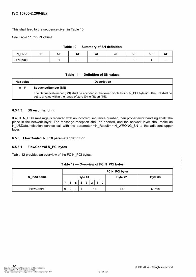
This shall lead to the sequence given in Table 10.
See Table 11 for SN values.
Table 10 — Summary of SN definition
N_PDU FF CF CF CF CF CF CF CF
SN (hex) 0 1 … E F 0 1 …
Table 11 — Definition of SN values
Hex value Description
0 – F SequenceNumber (SN)
The SequenceNumber (SN) shall be encoded in the lower nibble bits of N_PCI byte #1. The SN shall be set to a value within the range of zero (0) to fifteen (15).
6.5.4.3 SN error handling
If a CF N_PDU message is received with an incorrect sequence number, then proper error handling shall take place in the network layer. The message reception shall be aborted, and the network layer shall make an N_USData.indication service call with the parameter <N_Result> = N_WRONG_SN to the adjacent upper layer.
6.5.5 FlowControl N_PCI parameter definition
6.5.5.1 FlowControl N_PCI bytes
Table 12 provides an overview of the FC N_PCI bytes.
Table 12 — Overview of FC N_PCI bytes
FC N_PCI bytes
Byte #1 Byte #2 Byte #3 N_PDU name
7 6 5 4 3 2 1 0
FlowControl 0 0 1 1 FS BS STmin
Copyright International Organization for Standardization Reproduced by IHS under license with ISO
Not for ResaleNo reproduction or networking permitted without license from IHS
--`,,,,`,-`-`,,`,,`,`,,`---
张磊
线条
19911112
Line
19911112
Line
19911112
Line
19911112
Line

ISO 15765-2:2004(E)
© ISO 2004 – All rights reserved 21
6.5.5.2 FlowStatus (FS) parameter definition
The parameter FlowStatus (FS) indicates whether the sending network entity can proceed with the message transmission.
A sending network entity shall support all specified (not reserved) values of the FS parameter.
Table 13 — Definition of FS values
Hex value Description
0 ContinueToSend (CTS)
The FlowControl ContinueToSend parameter shall be encoded by setting the lower nibble of the N_PCI byte #1 to “0”. It shall cause the sender to resume the sending of Consecutive frames. The meaning of this value is that the receiver is ready to receive a maximum of BS number of Consecutive frames.
1 Wait (WT)
The FlowControl Wait parameter shall be encoded by setting the lower nibble of the N_PCI byte #1 to “1”. It shall cause the sender to continue to wait for a new FlowControl N_PDU and to restart its N_BS timer.
2 Overflow (OVFLW)
The FlowControl Overflow parameter shall be encoded by setting the lower nibble of the N_PCI byte #1 to “2”. It shall cause the sender to abort the transmission of a segmented message and make an N_USData.confirm service call with the parameter <N_Result>=N_BUFFER_OVFLW. This N_PCI FlowStatus parameter value is only allowed to be transmitted in the FlowControl N_PDU that follows the FirstFrame N_PDU and shall only be used in case the message length FF_DL of the received FirstFrame N_PDU exceeds the buffer size of the receiving entity.
3 – F Reserved
This range of values is reserved by this part of ISO 15765.
6.5.5.3 FS error handling
If an FC N_PDU message is received with an invalid (reserved) FS parameter value, then proper error handling shall take place in the network layer. The message transmission shall be aborted, and the network layer shall make an N_USData.confirm service call with the parameter <N_Result> = N_INVALID_FS to the adjacent upper layer.
6.5.5.4 BlockSize (BS) parameter definition
The BS parameter shall be encoded in byte #2 of the FC N_PCI.
The units of BS are the absolute number of CF N_PDUs per block.
EXAMPLE If BS is equal to twenty (20) (decimal), then the block will consist of twenty (20) (decimal) CF N_PDUs.
Only the last block of consecutive frames in a segmented data transmission may have less than the BS number of frames.
Table 14 provides an overview of the FC N_PCI byte.
Copyright International Organization for Standardization Reproduced by IHS under license with ISO
Not for ResaleNo reproduction or networking permitted without license from IHS
--`,,,,`,-`-`,,`,,`,`,,`---
张磊
打字机
4位
张磊
线条
张磊
线条
张磊
线条
张磊
线条
张磊
线条
张磊
线条
19911112
Line
19911112
Line
19911112
Line
19911112
Line
19911112
Line
19911112
Line
19911112
Line
19911112
Line
19911112
Line
19911112
Line
Sean-Ihr
Typewriter
已准备后接受至多BS的CF
Sean-Ihr
Typewriter
只能在FF或FF_DL超过缓冲区大小时发送
Sean-Ihr
Typewriter
FF不算在内?

ISO 15765-2:2004(E)
22 © ISO 2004 – All rights reserved
Table 14 — Definition of BS values
Hex value Description
00 BlockSize (BS)
The BS parameter value zero (0) shall be used to indicate to the sender that no more FC frames shall be sent during the transmission of the segmented message. The sending network layer entity shall send all remaining consecutive frames without any stop for further FC frames from the receiving network layer entity.
01 – FF BlockSize (BS)
This range of BS parameter values shall be used to indicate to the sender the maximum number of consecutive frames that can be received without an intermediate FC frame from the receiving network entity.
6.5.5.5 Definition of SeparationTime (STmin) parameter
The STmin parameter shall be encoded in byte #3 of the FC N_PCI.
This time is specified by the receiving entity and shall be kept by the sending network entity for the duration of a segmented message transmission.
The STmin parameter value specifies the minimum time gap allowed between the transmission of consecutive frame network protocol data units. See Table 15.
Table 15 — Definition of STmin values
Hex value Description
00 – 7F SeparationTime (STmin) range: 0 ms – 127 ms
The units of STmin in the range 00 hex – 7F hex are absolute milliseconds (ms).
80 – F0 Reserved
This range of values is reserved by this part of ISO 15765.
F1 – F9 SeparationTime (STmin) range: 100 µs – 900 µs
The units of STmin in the range F1 hex – F9 hex are even 100 microseconds (µs), where parameter value F1 hex represents 100 µs and parameter value F9 hex represents 900 µs.
FA – FF Reserved
This range of values is reserved by this part of ISO 15765.
The measurement of the STmin starts after completion of transmission of a ConsecutiveFrame (CF) and ends at the request for the transmission of the next CF.
EXAMPLE If STmin is equal to ten (10) (decimal), then the minimum ST authorized between consecutive frame network protocol data units is equal to 10 ms.
6.5.5.6 ST error handling
If an FC N_PDU message is received with a reserved ST parameter value, then the sending network entity shall use the longest ST value specified by this part of ISO 15765 (7F hex – 127 ms) instead of the value received from the receiving network entity for the duration of the ongoing segmented message transmission.
Copyright International Organization for Standardization Reproduced by IHS under license with ISO
Not for ResaleNo reproduction or networking permitted without license from IHS
--`,,,,`,-`-`,,`,,`,`,,`---
张磊
线条
张磊
线条
张磊
线条
张磊
线条
张磊
线条
张磊
线条
张磊
线条
19911112
Line
19911112
Line
19911112
Line
19911112
Line
19911112
Line
19911112
Line
19911112
Line
19911112
Line
19911112
Line
19911112
Line
19911112
Line
Sean-Ihr
Typewriter
从CF成功传输开始到下一个CF请求结束的时间。

ISO 15765-2:2004(E)
© ISO 2004 – All rights reserved 23
6.6 Maximum number of FC.Wait frame transmissions (N_WFTmax)
The purpose of this variable is to avoid communication sender nodes being potentially hooked-up in case of a fault condition whereby the latter could be waiting continuously. This parameter is local to communication peers and is not transmitted, and is hence not part of the FC protocol data unit.
The N_WFTmax parameter shall indicate how many FC N_PDU WTs can be transmitted by the receiver in a row.
The N_WFTmax parameter upper limit shall be user defined at system generation time.
The N_WFTmax parameter shall only be used on the receiving network entity during message reception.
If N_WFTmax parameter value is set to zero (0), then flow control shall rely upon flow control continue to send FC N_PDU CTS only. Flow control wait (FC N_PDU WT) shall not be used by that network entity.
6.7 Network layer timing
6.7.1 Timing parameters
Figure 7 shows the network layer timing parameters, while Table 16 defines the network layer timing parameter values and their corresponding start and end positions based on the data link layer services.
Performance requirement values are the binding communication requirements to be met by each communication peer in order to be compliant with the specification. A certain application may define specific performance requirements within the ranges defined in Table 16.
Timeout values are defined to be higher than the values for the performance requirements in order to ensure a working system and to overcome communication conditions where the performance requirement can absolutely not be met (e.g. high bus load). Specified timeout values shall be treated as the lower limit for any given implementation. The real timeout shall occur no later than at the specified timeout value + 50 %.
The network layer shall issue an appropriate service primitive to the network layer service user upon detection of an error condition.
Copyright International Organization for Standardization Reproduced by IHS under license with ISO
Not for ResaleNo reproduction or networking permitted without license from IHS
--`,,,,`,-`-`,,`,,`,`,,`---
张磊
线条
张磊
打字机
接收方最多连续发送多少个等待FC帧个数
张磊
线条
19911112
Line
19911112
Line
19911112
Line
19911112
Line
19911112
Line
19911112
Line
19911112
Line

ISO 15765-2:2004(E)
24 © ISO 2004 – All rights reserved
Key s sender r receiver
Figure 6 — Placement of network layer timing parameters
Copyright International Organization for Standardization Reproduced by IHS under license with ISO
Not for ResaleNo reproduction or networking permitted without license from IHS
--`,,,,`,-`-`,,`,,`,`,,`---
张磊
打字机
发送方CAN报文确认超时
张磊
打字机
网络层FC接收端发送等待时间
张磊
打字机
接收端CAN报文确认时间
张磊
打字机
STmin
张磊
打字机
CF超时

ISO 15765-2:2004(E)
© ISO 2004 – All rights reserved 25
Table 16 — Network layer timing parameter values
Timing Description Data Link Layer service Timeout Performance
Parameter Start End (ms) requirement (ms)
N_As Time for transmission of the CAN frame (any N_PDU) on the sender side
L_Data.request L_Data.confirm 1 000 N/A
N_Ar Time for transmission of the CAN frame (any N_PDU) on the receiver side
L_Data.request L_Data.confirm 1 000 N/A
N_Bs Time until reception of the next FlowControl N_PDU.
L_Data.confirm (FF),L_Data.confirm (CF),
L_Data.indication (FC)L_Data.indication (FC) 1 000 N/A
N_Br Time until transmission of the next FlowControl N_PDU
L_Data.indication (FF),L_Data.confirm (FC) L_Data.request (FC) N/A
(N_Br + N_Ar) <
(0.9 * N_Bs timeout)
N_Cs Time until transmission of the next ConsecutiveFrame N_PDU
L_Data.indication (FC),L_Data.confirm (CF) L_Data.request (CF) N/A
(N_Cs + N_As) <
(0.9 * N_Cr timeout)
N_Cr Time until reception of the next ConsecutiveFrame N_PDU
L_Data.confirm (FC),L_Data.indication (CF) L_Data.indication (CF) 1 000 —
s is the sender of the message. r is the receiver of the message.
6.7.2 Network layer timeouts
Table 17 defines the cause and action in a network layer timeout.
Table 17 — Network layer timeout error handling
Timeout Cause Action
N_As Any N_PDU not transmitted in time on the sender side. Abort message transmission and issue N_USData.confirm with <N_Result> = N_TIMEOUT_A.
N_Ar Any N_PDU not transmitted in time on the receiver side. Abort message reception and issue N_USData.indication with <N_Result> = N_TIMEOUT_A.
N_Bs
FlowControl N_PDU not received (lost, overwritten) on the sender side or preceding FirstFrame N_PDU or ConsecutiveFrame N_PDU not received (lost, overwritten) on the receiver side.
Abort message transmission and issue N_USData.confirm with <N_Result> = N_TIMEOUT_Bs.
N_Cr ConsecutiveFrame N_PDU not received (lost, overwritten) on the receiver side or preceding FC N_PDU not received (lost, overwritten) on the sender side.
Abort message reception and issue N_USData.indication with <N_Result> = N_TIMEOUT_Cr.
Copyright International Organization for Standardization Reproduced by IHS under license with ISO
Not for ResaleNo reproduction or networking permitted without license from IHS
--`,,,,`,-`-`,,`,,`,`,,`---
张磊
线条
张磊
线条
张磊
线条
张磊
线条
张磊
线条
张磊
线条
张磊
线条
张磊
线条
张磊
线条
19911112
Line
19911112
Line
19911112
Line
19911112
Rectangle
19911112
Rectangle
19911112
Rectangle
19911112
Rectangle
19911112
Rectangle

ISO 15765-2:2004(E)
26 © ISO 2004 – All rights reserved
6.7.3 Unexpected arrival of N_PDU
An unexpected N_PDU is defined as one that has been received by a node outside the expected order of N_PDUs. It could be an N_PDU defined by this part of ISO 15765 (SF N_PDU, FF N_PDU, CF N_PDU or FC N_PDU) that is received out of the normal expected order, or else it could be an unknown N_PDU that cannot be interpreted by the definitions given in this document.
Depending on the network layer design decision to support full- or half-duplex communication, the interpretation of “unexpected” differs:
a) with half-duplex, point-to-point communication between two nodes is only possible in one direction at a time;
b) with full-duplex, point-to-point communication between two nodes is possible in both directions at one time.
In addition to the network layer design decision, the possibility has to be considered that a reception or transmission from/to a node with the same address information (N_AI), as contained in the received unexpected N_PDU, is in progress.
As a general rule, arrival of an unexpected N_PDU from any node shall be ignored, with the exception of SF N_PDUs and physically addressed FF N_PDUs; functionally addressed first frames shall be ignored. When the specified action is to ignore an unexpected N_PDU, this means that the network layer shall not notify the upper layers of its arrival.
Table 18 defines the network layer behaviour in the case of the reception of an unexpected N_PDU, in consideration of the actual network layer internal status (NWL status) and the design decision to support half- or full-duplex communication. It has to be understood that the received N_PDU will contain the same N_AI as the reception or transmission that could be in progress at the time the N_PDU is received.
Table 18 — Handling of unexpected arrival of N_PDU
Reception of NWL status
SF N_PDU FF N_PDU CF N_PDU FC N_PDU UnknownN_PDU
Segmented Transmit
in progress
Full-duplex: If a reception is in progress, see corresponding cell below in this table, otherwise process the SF N_PDU as the start of a new reception.
Full-duplex: If a reception is in progress, see corresponding cell below in this table, otherwise process the FF N_PDU as the start of a new reception.
Full-duplex: If a reception is in progress, see corresponding cell below in this table.
If awaited, process the FC N_PDU, otherwise ignore it.
Ignore
Half-duplex: ignore
Half-duplex: ignore
Half-duplex: ignore
Segmented Receive
in progress
Terminate the current reception, report an N_USData.indication, with <N_Result> set to N_UNEXP_PDU, to the upper layer, and process the SF N_PDU as the start of a new reception.
Terminate the current reception, report an N_USData.indication, with <N_Result> set to N_UNEXP_PDU, to the upper layer, and process the FF N_PDU as the start of a new reception.
If awaited, process the CF N_PDU in the on-going reception and perform the required checks (e.g. SN in right order),otherwise ignore it.
Full-duplex: If a transmission is in progress, see corresponding cell above in this table.
Ignore
Half-duplex: Ignore
Idle a Process the SF N_PDU as the start of a new reception.
Process the FF N_PDU as the start of a new reception.
Ignore Ignore Ignore
a Neither a segmented transmission nor segmented reception is in progress.
Copyright International Organization for Standardization Reproduced by IHS under license with ISO
Not for ResaleNo reproduction or networking permitted without license from IHS
--`,,,,`,-`-`,,`,,`,`,,`---
张磊
矩形
张磊
线条
张磊
矩形
张磊
打字机
非预期帧处理
zhanglei
线条
19911112
Line
19911112
Line
19911112
Line
19911112
Line
19911112
Line
19911112
Line
19911112
Line
19911112
Line
19911112
Typewriter
到来
19911112
Highlight
19911112
Highlight
19911112
Highlight
19911112
Line
19911112
Line
19911112
Line
19911112
Line
19911112
Highlight
19911112
Highlight
19911112
Highlight
19911112
Highlight
19911112
Highlight
19911112
Highlight
19911112
Highlight

ISO 15765-2:2004(E)
© ISO 2004 – All rights reserved 27
6.7.4 Wait frame error handling
When the receiver has transmitted N_WFTmax flow control wait network protocol data units (FC N_PDU WT) in a row and following this it cannot meet the performance requirement for the transmission of a flow control clear to send network protocol data unit (FC NPDU CTS), then the receiver side shall abort the message reception and issue an N_USData.indication with <N_Result> set to N_WFT_OVRN to the higher layer.
The sender of the message is informed about the aborted message reception via an N_USData.confirm with <N_Result> set to N_TIMEOUT_Bs (because of the missing FlowControl N_PDU from the receiver an N_Bs timeout occurs in the sender).
6.8 Interleaving of messages
The network layer protocol shall be capable of carrying out parallel transmission of different messages that are not mapped onto the same N_AI. This is necessary to ensure that the receiving peer is able to reassemble in a consistent manner the received network protocol data units. This scheme for example enables gateway operation that needs to handle different message transmissions concurrently across distinct sub-networks.
7 Data link layer usage
7.1 Data link layer interface services
7.1.1 L_Data.request
The service primitive requests transmission of <Data> that shall be mapped within specific attributes of the data link protocol data unit selected by means of <Identifier>.
The <Identifier> shall provide reference to the specific addressing format used to transmit <Data>:
L_Data.request ( <Identifier> <DLC> <Data> )
7.1.2 L_Data.confirm
The service primitive confirms the completion of an L_Data.request service for a specific <Identifier>.
The parameter <TransferStatus> provides the status of the service request:
L_Data.confirm ( <Identifier> <TransferStatus> )
7.1.3 L_Data.indication
The service primitive indicates data link layer event to the adjacent upper layer and delivers <Data> identified by <Identifier>:
L_Data.indication ( <Identifier> <DLC> <Data> )
Copyright International Organization for Standardization Reproduced by IHS under license with ISO
Not for ResaleNo reproduction or networking permitted without license from IHS
--`,,,,`,-`-`,,`,,`,`,,`---
张磊
线条
张磊
线条
19911112
Line
19911112
Line
19911112
Line
19911112
Line
19911112
Line
19911112
Typewriter
数据链路层接口服务
19911112
Typewriter
数据链路层用法
19911112
Rectangle
19911112
Pencil
19911112
Pencil
19911112
Rectangle
19911112
Rectangle
19911112
Pencil
19911112
Typewriter
NWL to DLL
19911112
Typewriter
DLL to NWL
19911112
Typewriter
DLL to NWL

ISO 15765-2:2004(E)
28 © ISO 2004 – All rights reserved
7.2 Data link layer service parameters
The following data link layer service parameters are defined in ISO 11898-1:
<Identifier>: CAN identifier
<DLC>: Data Length Code
<Data>: CAN frame data
<TransferStatus>: Status of a transmission
7.3 Mapping of the N_PDU fields
7.3.1 Addressing formats
The exchange of network layer data is supported by three addressing formats: normal, extended and mixed addressing. Each addressing format requires a different number of CAN frame data bytes to encapsulate the addressing information associated with the data to be exchanged. Consequently, the number of data bytes transported within a single CAN frame depends on the type of addressing format chosen.
The following (7.3.2 to 7.3.5) specifies the mapping mechanisms for each addressing format, based on the data link layer services and service parameters defined in ISO 11898-1.
7.3.2 Normal addressing
For each combination of N_SA, N_TA, N_TAtype and Mtype, a unique CAN identifier is assigned. N_PCI and N_Data is placed in the CAN frame data field. See Table 19.
Table 19 — Mapping of N_PDU parameters into CAN frame — Normal addressing
CAN frame data field N_PDU type CAN Identifier
Byte 1 Byte 2 Byte 3 Byte 4 Byte 5 Byte 6 Byte 7 Byte 8
SingleFrame (SF) N_AI N_PCI N_Data
FirstFrame (FF) N_AI N_PCI N_Data
ConsecutiveFrame (CF) N_AI N_PCI N_Data
FlowControl (FC) N_AI N_PCI N/A
7.3.3 Normal fixed addressing
Normal fixed addressing is a subformat of normal addressing where the mapping of the address information into the CAN identifier is further defined. In the general case of normal addressing, described above, the correspondence between N_AI and the CAN identifier is left open.
For normal fixed addressing, only 29 bit CAN identifiers are allowed. Tables 20 and 21 define the mapping of the address information (N_AI) into the CAN identifier, depending on the target address type (N_TAtype). N_PCI and N_Data is placed in the CAN frame data field.
Copyright International Organization for Standardization Reproduced by IHS under license with ISO
Not for ResaleNo reproduction or networking permitted without license from IHS
--`,,,,`,-`-`,,`,,`,`,,`---
张磊
线条
张磊
线条
张磊
打字机
11位CAN id, 没有填充形式,系统设计
张磊
线条
19911112
Line
19911112
Line
19911112
Line
19911112
Line
19911112
Line
19911112
Highlight
19911112
Typewriter
压缩
19911112
Line
19911112
Line
19911112
Line
19911112
Line
19911112
Typewriter
数据链路层服务参数
19911112
Arrow
19911112
Arrow
19911112
Typewriter
N_PDU区域的映射
19911112
Pencil
19911112
Pencil
19911112
Pencil
19911112
Pencil
19911112
Rectangle
19911112
Typewriter
正常固定寻址
Sean-Ihr
Typewriter
不同地址模式,单个CAN帧数据长度不同

ISO 15765-2:2004(E)
© ISO 2004 – All rights reserved 29
Table 20 — Normal fixed addressing, N_TAtype = physical
29 bit CAN Identifier bit position
CAN frame data field byte position N_PDU type
28 ... 26 25 24 23 ... 16 15 8 7 ... 0 1 2 3 4 5 6 7 8
SingleFrame (SF) 110 (bin) 0 0 218 (dec) N_TA N_SA N_PCI N_Data
FirstFrame (FF) 110 (bin) 0 0 218 (dec) N_TA N_SA N_PCI N_Data
ConsecutiveFrame (CF) 110 (bin) 0 0 218 (dec) N_TA N_SA N_PCI N_Data
FlowControl (FC) 110 (bin) 0 0 218 (dec) N_TA N_SA N_PCI N/A
Table 21 — Normal fixed addressing, N_TAtype = functional
29 bit CAN Identifier bit position
CAN frame data field byte position N_PDU type
28 ... 26 25 24 23 ... 16 15 8 7 ... 0 1 2 3 4 5 6 7 8
SingleFrame (SF) 110 (bin) 0 0 219 (dec) N_TA N_SA N_PCI N_Data
FirstFrame (FF) 110 (bin) 0 0 219 (dec) N_TA N_SA N_PCI N_Data
ConsecutiveFrame (CF) 110 (bin) 0 0 219 (dec) N_TA N_SA N_PCI N_Data
FlowControl (FC) 110 (bin) 0 0 219 (dec) N_TA N_SA N_PCI N/A
7.3.4 Extended addressing
For each combination of N_SA, N_TAtype and Mtype, a unique CAN identifier is assigned. N_TA is placed in the first data byte of the CAN frame data field. N_PCI and N_Data is placed in the remaining bytes of the CAN frame data field.
Table 22 — Mapping of N_PDU parameters into CAN frame — Extended addressing
N_PDU type CAN Identifier Byte 1 Byte 2 Byte 3 Byte 4 Byte 5 Byte 6 Byte 7 Byte 8
SingleFrame (SF) N_AI, except N_TA N_TA N_PCI N_Data
FirstFrame( FF) N_AI, except N_TA N_TA N_PCI N_Data
ConsecutiveFrame (CF) N_AI, except N_TA N_TA N_PCI N_Data
FlowControl (FC) N_AI, except N_TA N_TA N_PCI N/A
7.3.5 Mixed addressing
7.3.5.1 29 bit CAN identifier
Mixed addressing is the addressing format to be used if Mtype is set to remote diagnostics.
Tables 23 and 24 define the mapping of the address information (N_AI) into the 29 bit CAN identifier scheme and the first CAN frame data byte, depending on the target address type (N_TAtype). N_PCI and N_Data are placed in the remaining bytes of the CAN frame data field.
Copyright International Organization for Standardization Reproduced by IHS under license with ISO
Not for ResaleNo reproduction or networking permitted without license from IHS
--`,,,,`,-`-`,,`,,`,`,,`---
张磊
打字机
仅用于11位ID
张磊
线条
19911112
Line
19911112
Line
19911112
Line
19911112
Rectangle
Sean-Ihr
Typewriter

ISO 15765-2:2004(E)
30 © ISO 2004 – All rights reserved
Table 23 — Mixed addressing with 29 bit CAN Identifier, N_TAtype = physical
29 bit CAN Identifier bit position CAN frame data field byte position N_PDU type
28 ... 26 25 24 23 ... 16 15 8 7 ... 0 1 2 3 4 5 6 7 8
SingleFrame (SF) 110 (bin) 0 0 206 (dec) N_TA N_SA N_AE N_PCI N_Data
FirstFrame (FF) 110 (bin) 0 0 206 (dec) N_TA N_SA N_AE N_PCI N_Data
ConsecutiveFrame (CF) 110 (bin) 0 0 206 (dec) N_TA N_SA N_AE N_PCI N_Data
FlowControl (FC) 110 (bin) 0 0 206 (dec) N_TA N_SA N_AE N_PCI N/A
Table 24 — Mixed addressing with 29 bit CAN Identifier, N_TAtype = functional
29 bit CAN Identifier bit position CAN frame data field byte position N_PDU type
28 ... 26 25 24 23 ... 16 15 8 7 ... 0 1 2 3 4 5 6 7 8
SingleFrame (SF) 110 (bin) 0 0 205 (dec) N_TA N_SA N_AE N_PCI N_Data
FirstFrame (FF) 110 (bin) 0 0 205 (dec) N_TA N_SA N_AE N_PCI N_Data
ConsecutiveFrame (CF) 110 (bin) 0 0 205 (dec) N_TA N_SA N_AE N_PCI N_Data
FlowControl (FC) 110 (bin) 0 0 205 (dec) N_TA N_SA N_AE N_PCI N/A
7.3.5.2 11 bit CAN identifier
Mixed addressing is the addressing format to be used if Mtype is set to remote diagnostics.
Table 25 defines the mapping of the address information (N_AI) into the 11 bit CAN identifier scheme. For each combination of N_SA, N_TA and N_TAtype a unique CAN identifier is assigned. N_AE is placed in the first data byte of the CAN frame data field. N_PCI and N_Data is placed in the remaining bytes of the CAN frame data field.
Table 25 — Mixed addressing (11 bit CAN Id)
N_PDU type CAN Identifier
Byte 1 Byte 2 Byte 3 Byte 4 Byte 5 Byte 6 Byte 7 Byte 8
SingleFrame (SF) N_AI N_AE N_PCI N_Data
FirstFrame( FF) N_AI N_AE N_PCI N_Data
ConsecutiveFrame (CF) N_AI N_AE N_PCI N_Data
FlowControl (FC) N_AI N_AE N_PCI N/A
7.4 CAN frame Data Length Code (DLC)
7.4.1 DLC parameter
The DLC parameter specifies the number of data bytes transmitted in a CAN frame. This part of ISO 15765 does not specify any requirements concerning the length of the data field in a CAN frame other than those implied by the size of the network layer protocol data units.
Copyright International Organization for Standardization Reproduced by IHS under license with ISO
Not for ResaleNo reproduction or networking permitted without license from IHS
--`,,,,`,-`-`,,`,,`,`,,`---
张磊
矩形
张磊
矩形
19911112
Line
19911112
Line
19911112
Line

ISO 15765-2:2004(E)
© ISO 2004 – All rights reserved 31
An application that implements the network layer as defined in this document might either pad all CAN frames to their full length (see 7.4.2) or optimize the DLC to the applicable length of the network layer protocol data unit (see 7.4.3).
7.4.2 CAN frame data padding
The DLC is always set to 8. If the N_PDU to be transmitted is shorter than 8 bytes, then the sender has to set the DLC to the maximum value 8 (padding of unused data bytes). In particular this can be the case for an SF, FC frame or last CF of a segmented message.
The DLC parameter of the CAN frame is set by the sender and read by the receiver to determine the number of data bytes per CAN frame to be processed by the network layer. The DLC parameter cannot be used to determine the message length; this information shall be extracted from the N_PCI information in the beginning of a message.
7.4.3 CAN frame data optimization
The DLC does not always need to be 8. If the N_PDU to be transmitted is shorter than 8 bytes, then the sender may optimize the CAN bus load by shortening the CAN frame data to only contain the number of bytes occupied by the N_PDU (no padding of unused data bytes). CAN frame data optimization can only be used for a SF, FC frame or last CF of a segmented message.
The DLC parameter of the CAN frame is set by the sender and read by the receiver to determine the number of data bytes per CAN frame to be processed by the network layer. The DLC parameter cannot be used to determine the message length; this information shall be extracted from the N_PCI information in the beginning of a message.
7.4.4 Data Length Code error handling
Depending on the N_PCI value, the network layer can calculate the smallest expected value for the CAN DLC parameter in a received CAN frame.
The reception of a CAN frame with a DLC value smaller than expected (less than 8 for applications which pad the CAN frames or smaller than implied by the size of the network protocol data unit for optimized implementations) shall be ignored by the network layer without any further action.
Copyright International Organization for Standardization Reproduced by IHS under license with ISO
Not for ResaleNo reproduction or networking permitted without license from IHS
--`,,,,`,-`-`,,`,,`,`,,`---
张磊
线条
张磊
线条
张磊
线条
张磊
线条
19911112
Line
19911112
Typewriter
这个情况尤其是出现在SF,FC或最后一个CF
19911112
Line
19911112
Line
19911112
Typewriter
不能用于确定信息长度,应该从开始信息的PCI中获取
19911112
Highlight
19911112
Highlight
19911112
Line
19911112
Line

ISO 15765-2:2004(E)
32 © ISO 2004 – All rights reserved
Annex A (informative)
Use of normal fixed and mixed addressing with data link layer according
to SAE J1939
A.1 Overview
This annex describes how to map address information parameters, N_AI, into the CAN frame when a data link layer according to SAE J1939 is used.
A.2 Rules
A.2.1 Normal fixed addressing
Table A.1 shows the mapping of address information parameters, N_AI, into the CAN frame when Network Target Address type, N_TAtype, physical addressing is used.
Table A.1 — Normal addressing, physical addressed messages
J1939 name P R DP PF PS SA Data field
Bits 3 1 1 8 8 8 64
Content default 110 (bin) 0 0 218 (dec) N_TA N_SA N_PCI, N_Data
CAN Id Bits 28 – 26 25 24 23 – 16 15 – 8 7 – 0
CAN data byte 1 – 8
CAN Field Identifier Data
Table A.2 shows the mapping of address information parameters, N_AI, into the CAN frame when Network Target Address type, N_TAtype, functional addressing is used.
Table A.2 — Normal addressing, functional addressed messages
J1939 name P R DP PF PS SA Data field
Bits 3 1 1 8 8 8 64
Content default 110 (bin) 0 0 219 (dec) N_TA N_SA N_PCI, N_Data
CAN Id Bits 28 – 26 25 24 23 – 16 15 – 8 7 – 0
CAN data byte 1 – 8
CAN Field Identifier Data
Copyright International Organization for Standardization Reproduced by IHS under license with ISO
Not for ResaleNo reproduction or networking permitted without license from IHS
--`,,,,`,-`-`,,`,,`,`,,`---
19911112
Line
19911112
Line
19911112
Typewriter
协议控制信息 数据
19911112
Line
19911112
Line
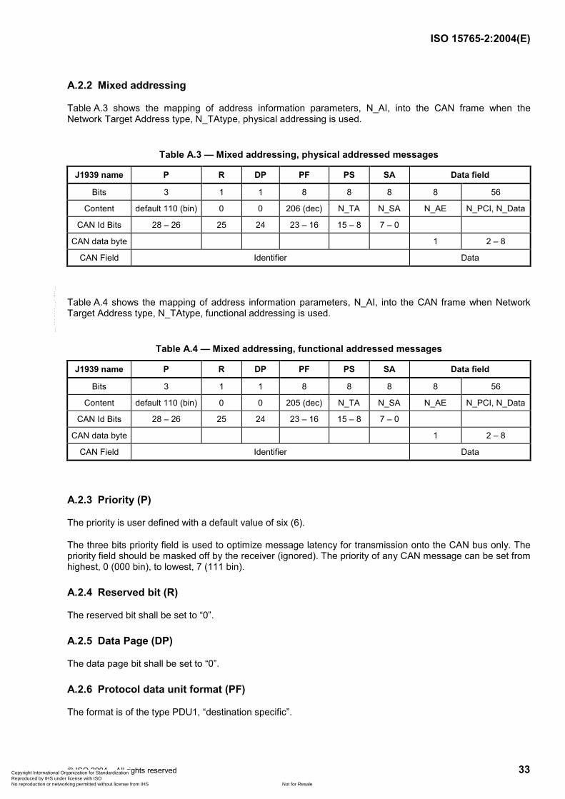
ISO 15765-2:2004(E)
© ISO 2004 – All rights reserved 33
A.2.2 Mixed addressing
Table A.3 shows the mapping of address information parameters, N_AI, into the CAN frame when the Network Target Address type, N_TAtype, physical addressing is used.
Table A.3 — Mixed addressing, physical addressed messages
J1939 name P R DP PF PS SA Data field
Bits 3 1 1 8 8 8 8 56
Content default 110 (bin) 0 0 206 (dec) N_TA N_SA N_AE N_PCI, N_Data
CAN Id Bits 28 – 26 25 24 23 – 16 15 – 8 7 – 0
CAN data byte 1 2 – 8
CAN Field Identifier Data
Table A.4 shows the mapping of address information parameters, N_AI, into the CAN frame when Network Target Address type, N_TAtype, functional addressing is used.
Table A.4 — Mixed addressing, functional addressed messages
J1939 name P R DP PF PS SA Data field
Bits 3 1 1 8 8 8 8 56
Content default 110 (bin) 0 0 205 (dec) N_TA N_SA N_AE N_PCI, N_Data
CAN Id Bits 28 – 26 25 24 23 – 16 15 – 8 7 – 0
CAN data byte 1 2 – 8
CAN Field Identifier Data
A.2.3 Priority (P)
The priority is user defined with a default value of six (6).
The three bits priority field is used to optimize message latency for transmission onto the CAN bus only. The priority field should be masked off by the receiver (ignored). The priority of any CAN message can be set from highest, 0 (000 bin), to lowest, 7 (111 bin).
A.2.4 Reserved bit (R)
The reserved bit shall be set to “0”.
A.2.5 Data Page (DP)
The data page bit shall be set to “0”.
A.2.6 Protocol data unit format (PF)
The format is of the type PDU1, “destination specific”.
Copyright International Organization for Standardization Reproduced by IHS under license with ISO
Not for ResaleNo reproduction or networking permitted without license from IHS
--`,,,,`,-`-`,,`,,`,`,,`---
19911112
Line
19911112
Line
19911112
Line
19911112
Line
19911112
Typewriter
地址信息
19911112
Line
19911112
Line
19911112
Line
19911112
Line
19911112
Typewriter
0
19911112
Typewriter
0
19911112
Line
19911112
Typewriter
目的指定
19911112
Typewriter
目的指定
19911112
Arrow
19911112
Typewriter
混合寻址:物理寻址205(CD);功能寻址206(CE); 正常固定寻址:物理寻址218(DA);功能寻址219(DB);
19911112
Typewriter
目的地址
19911112
Typewriter
源地址
19911112
Typewriter
优先级

ISO 15765-2:2004(E)
34 © ISO 2004 – All rights reserved
Diagnostic messages shall use the following parameter group numbers (PGN).
Mixed addressing: 52480 (dec) for N_TAtype = functional, which gives PF = 205 (dec).
Mixed addressing: 52736 (dec) for N_Tatype = physical, which gives PF = 206 (dec).
Normal fixed addressing: 55808 (dec) for N_TAtype = physical, which gives PF = 218 (dec),
Normal fixed addressing: 56064 (dec) for N_TAtype = functional, which gives PF = 219 (dec).
A.2.7 PDU-specific (PS)
The PDU-specific field shall contain the target address (destination address), N_TA.
A.2.8 Source Address (SA)
The SA field shall contain the source address, N_SA
A.2.9 Update rate
Update rate is according to user requirements.
A.2.10 Data length
Data length shall be eight (8) bytes.
Copyright International Organization for Standardization Reproduced by IHS under license with ISO
Not for ResaleNo reproduction or networking permitted without license from IHS
--`,,,,`,-`-`,,`,,`,`,,`---
19911112
Highlight
19911112
Highlight

ISO 15765-2:2004(E)
© ISO 2004 – All rights reserved 35
Bibliography
[1] ISO/IEC 7498 (all parts), Information technology — Open Systems Interconnection — Basic Reference Model
[2] ISO/IEC 10731, Information technology — Open Systems Interconnection — Basic Reference Model — Conventions for the definition of OSI services
[3] ISO 11898 (all parts), Road vehicles — Controller area network (CAN)
[4] ISO 14229-1, Road vehicles — Unified diagnostic services (UDS) — Part 1: Specification and requirements 5)
[5] ISO 15031-5, Road vehicles — Communication between vehicle and external equipment for emissions-related diagnostics — Part 5: Emissions-related diagnostic services 5)
[6] SAE J1939, Recommended Practice for a Serial Control and Communications Vehicle Network
5) To be published.
Copyright International Organization for Standardization Reproduced by IHS under license with ISO
Not for ResaleNo reproduction or networking permitted without license from IHS
--`,,,,`,-`-`,,`,,`,`,,`---

ISO 15765-2:2004(E)
ICS 43.040.15 Price based on 35 pages
© ISO 2004 – All rights reserved
Copyright International Organization for Standardization Reproduced by IHS under license with ISO
Not for ResaleNo reproduction or networking permitted without license from IHS
--`,,,,`,-`-`,,`,,`,`,,`---