ISO 11898-4 - Rafavi
40
Reference number ISO 11898-4:2004(E) INTERNATIONAL STANDARD ISO 11898-4 First edition 2004-08-01 Road vehicles — Controller area network (CAN) — Part 4: Time-triggered communication Véhicules routiers — Gestionnaire de réseau de communication (CAN) — Partie 4: Déclenchement temporel des communications No reproduction or networking permitted without license from IHS --``````-`-`,,`,,`,`,,`---
-
Upload
khangminh22 -
Category
Documents
-
view
0 -
download
0
Transcript of ISO 11898-4 - Rafavi

Reference numberISO 11898-4:2004(E)
© ISO 2004
INTERNATIONAL STANDARD
ISO11898-4
First edition2004-08-01
Road vehicles — Controller area network (CAN) — Part 4: Time-triggered communication
Véhicules routiers — Gestionnaire de réseau de communication (CAN) —
Partie 4: Déclenchement temporel des communications
Copyright International Organization for Standardization Reproduced by IHS under license with ISO
Not for ResaleNo reproduction or networking permitted without license from IHS
--``````-`-`,,`,,`,`,,`---

ISO 11898-4:2004(E)
PDF disclaimer This PDF file may contain embedded typefaces. In accordance with Adobe's licensing policy, this file may be printed or viewed but shall not be edited unless the typefaces which are embedded are licensed to and installed on the computer performing the editing. In downloading this file, parties accept therein the responsibility of not infringing Adobe's licensing policy. The ISO Central Secretariat accepts no liability in this area.
Adobe is a trademark of Adobe Systems Incorporated.
Details of the SOFtware products used to create this PDF file can be found in the General Info relative to the file; the PDF-creation parameters were optimized for printing. Every care has been taken to ensure that the file is suitable for use by ISO member bodies. In the unlikely event that a problem relating to it is found, please inform the Central Secretariat at the address given below.
© ISO 2004 All rights reserved. Unless otherwise specified, no part of this publication may be reproduced or utilized in any form or by any means, electronic or mechanical, including photocopying and microfilm, without permission in writing from either ISO at the address below or ISO's member body in the country of the requester.
ISO copyright office Case postale 56 • CH-1211 Geneva 20 Tel. + 41 22 749 01 11 Fax + 41 22 749 09 47 E-mail [email protected] Web www.iso.org
Published in Switzerland
ii © ISO 2004 – All rights reserved
Copyright International Organization for Standardization Reproduced by IHS under license with ISO
Not for ResaleNo reproduction or networking permitted without license from IHS
--``````-`-`,,`,,`,`,,`---
ISO 11898-4:2004(E)
© ISO 2004 – All rights reserved iii
Contents Page
Foreword............................................................................................................................................................ iv Introduction ........................................................................................................................................................ v 1 Scope...................................................................................................................................................... 1 2 Normative references ........................................................................................................................... 1 3 Terms and definitions........................................................................................................................... 1 4 Abbreviated terms................................................................................................................................. 6 5 Basic concepts of time-triggered CAN ............................................................................................... 6 5.1 General conventions............................................................................................................................. 6 5.2 General principle of protocol ............................................................................................................... 8 5.3 Reference message ............................................................................................................................ 10 6 Timing and synchronisation features ............................................................................................... 12 6.1 Levels 1 and 2...................................................................................................................................... 12 6.2 Generation of local time ..................................................................................................................... 12 6.3 Cycle_Time parameter........................................................................................................................ 14 6.4 Synchronisation in Level 2................................................................................................................. 14 6.5 Global time in Level 2 (local time + local offset).............................................................................. 14 6.6 External clock synchronisation......................................................................................................... 15 7 Sending and receiving........................................................................................................................ 15 7.1 General ................................................................................................................................................. 15 7.2 Transmission of messages................................................................................................................ 15 7.3 Reception of messages ...................................................................................................................... 17 7.4 Transmission of reference messages............................................................................................... 17 8 Initialisation and fault tolerance of time masters ............................................................................ 18 8.1 General ................................................................................................................................................. 18 8.2 Initialisation procedure....................................................................................................................... 19 8.3 Failure of current time master ........................................................................................................... 20 8.4 Shutdown............................................................................................................................................. 20 9 Failure handling .................................................................................................................................. 21 9.1 General ................................................................................................................................................. 21 9.2 Message status count......................................................................................................................... 22 9.3 Interrupt_Status_Vector ..................................................................................................................... 22 9.4 Master state ......................................................................................................................................... 23 10 Visible interfaces................................................................................................................................. 25 10.1 Configuration interfaces..................................................................................................................... 25 10.2 Application interfaces......................................................................................................................... 28 10.3 Optional interfaces.............................................................................................................................. 30 Bibliography ..................................................................................................................................................... 32
Copyright International Organization for Standardization Reproduced by IHS under license with ISO
Not for ResaleNo reproduction or networking permitted without license from IHS
--``````-`-`,,`,,`,`,,`---

ISO 11898-4:2004(E)
iv © ISO 2004 – All rights reserved
Foreword
ISO (the International Organization for Standardization) is a worldwide federation of national standards bodies (ISO member bodies). The work of preparing International Standards is normally carried out through ISO technical committees. Each member body interested in a subject for which a technical committee has been established has the right to be represented on that committee. International organizations, governmental and non-governmental, in liaison with ISO, also take part in the work. ISO collaborates closely with the International Electrotechnical Commission (IEC) on all matters of electrotechnical standardization.
International Standards are drafted in accordance with the rules given in the ISO/IEC Directives, Part 2.
The main task of technical committees is to prepare International Standards. Draft International Standards adopted by the technical committees are circulated to the member bodies for voting. Publication as an International Standard requires approval by at least 75 % of the member bodies casting a vote.
Attention is drawn to the possibility that some of the elements of this document may be the subject of patent rights. ISO shall not be held responsible for identifying any or all such patent rights.
ISO 11898-4 was prepared by Technical Committee ISO/TC 22, Road vehicles, Subcommittee SC 3, Electrical and electronic equipment.
ISO 11898 consists of the following parts, under the general title Road vehicles — Controller area network (CAN):
Part 1: Data link layer and physical signalling
Part 2: High-speed medium access unit
Part 3: Low-speed fault-tolerant, medium dependent interface
Part 4: Time-triggered communication
Copyright International Organization for Standardization Reproduced by IHS under license with ISO
Not for ResaleNo reproduction or networking permitted without license from IHS
--``````-`-`,,`,,`,`,,`---

ISO 11898-4:2004(E)
© ISO 2004 – All rights reserved v
Introduction
In the classic CAN network, communication is event-triggered; peak loads can occur when the transmission of several messages is requested at the same time. The non-destructive arbitration mechanism of CAN guarantees the sequential transmission of all messages according to their identifier priority. For hard real-time systems, a scheduling analysis of the entire system is done to ensure that all transmission deadlines are met even at peak bus loads.
Some real-time operating systems (RTOS) are based on static cyclic scheduling of all tasks in the application system (control unit). They build a schedule of time slots and place each task in at least one slot. Tasks of high priority appear in more than one slot. All activity in one slot, including interrupt handling, must be completed before the beginning of the next slot.
If such an RTOS is considered for a distributed application system consisting of control units linked by a CAN network, system integration and composability are served when the communication on the CAN network also follows a synchronised schedule.
The time-triggered communication option for CAN-based networks (see ISO 11898-1) gives the prerequisites for the synchronisation of all nodes in the CAN network. When the nodes are synchronised, any message may be transmitted at a specific time slot, without competing with other messages for the bus. Thus the loss of arbitration is avoided; the latency time becomes predictable.
Copyright International Organization for Standardization Reproduced by IHS under license with ISO
Not for ResaleNo reproduction or networking permitted without license from IHS
--``````-`-`,,`,,`,`,,`---

Copyright International Organization for Standardization Reproduced by IHS under license with ISO
Not for ResaleNo reproduction or networking permitted without license from IHS
--``````-`-`,,`,,`,`,,`---

INTERNATIONAL STANDARD ISO 11898-4:2004(E)
© ISO 2004 – All rights reserved 1
Road vehicles — Controller area network (CAN) —
Part 4: Time-triggered communication
1 Scope
This part of ISO 11898 specifies time-triggered communication in the controller area network (CAN): a serial communication protocol that supports distributed real-time control and multiplexing for use within road vehicles. It is applicable to setting up a time-triggered interchange of digital information between electronic control units (ECU) of road vehicles equipped with CAN, and specifies the frame synchronisation entity that coordinates the operation of both logical link and media access controls in accordance with ISO 11898-1, to provide the time-triggered communication schedule.
NOTE Time-triggered CAN is a higher level protocol layer additional to the CAN protocol itself, which remains unchanged within the time-triggered communication. Time-triggered communication keeps the latency time of each message at a specified value independent of the CAN bus load. Time-triggered CAN is implemented on two levels: Level 1 is restricted to the cyclic message transfer, while Level 2, in addition, supports a global system time. Time-triggered CAN’s cyclic, periodical communication is based on reference messages transmitted by a time master. Each period starting with a reference message is called a basic cycle and is subdivided into several time windows. The reference messages are used to synchronise and calibrate the time bases of all nodes to the time master's time base, providing a global time for the network. A mechanism is provided for alternative time masters to substitute for a failing time master.
2 Normative references
The following referenced documents are indispensable for the application of this document. For dated references, only the edition cited applies. For undated references, the latest edition of the referenced document (including any amendments) applies.
ISO 11898-1, Road vehicles — Controller area network (CAN) — Part 1: Data link layer and physical signalling
ISO 11898-2, Road vehicles — Controller area network (CAN) — Part 2: High-speed medium access unit
ISO 11898-3, Road vehicles — Controller area network (CAN) — Part 3: Low-speed fault-tolerant, medium dependant interface
3 Terms and definitions
For the purposes of this document, the terms and definitions given in ISO 11898-1, ISO 11898-2 and ISO 11898-3, and the following apply.
NOTE Parameter terms (Cycle_Time, Cycle_Count, etc.) are given as proper nouns, connected by an underscore where the parameter consists of two or more words.
Copyright International Organization for Standardization Reproduced by IHS under license with ISO
Not for ResaleNo reproduction or networking permitted without license from IHS
--``````-`-`,,`,,`,`,,`---

ISO 11898-4:2004(E)
2 © ISO 2004 – All rights reserved
3.1 application watchdog entity which verifies that the application is operating properly
3.2 arbitrating time window time window assigned to messages that share the same time window
3.3 basic cycle row of the system matrix of several consecutive time windows
3.4 Cycle_Time difference between the local time of an FSE and its Ref_Mark
3.5 Cycle_Count number of the current basic cycle of the matrix cycle
3.6 Cycle_Count_Max value of Cycle_Count of the last basic cycle in the given system matrix of the network
3.7 Cycle_Offset parameter specifying, within a matrix cycle, the first basic cycle for which an Rx_Trigger or Tx_Trigger is valid
3.8 Disc_Bit part of the reference message signalling a discontinuity in global time caused by an external clock correction by the time master
3.9 error severity levels of distinguished severity of an error
3.10 exclusive time window time window assigned to a specific message transmitted periodically without competition for the CAN bus
3.11 Expected_Tx_Trigger local parameter which specifies, for each FSE, the number of Tx_Triggers the FSE is expected to activate between two starts of a matrix cycle
3.12 Frame_Synchronisation pulse, generated in each FSE and for each data frame and remote frame in the CAN network at the sample point of start of frame (SOF) bit, synchronous in the whole network, disregarding signal propagation times, and with an optionally added time offset referencing to the sync_segment of the SOF-Bit, to compensate for variations of bit timing configuration in the system
3.13 frame synchronisation entity FSE part coordinating the operation of logical link control and media access control
NOTE Each CAN controller in a time-triggered CAN network has its own FSE.
Copyright International Organization for Standardization Reproduced by IHS under license with ISO
Not for ResaleNo reproduction or networking permitted without license from IHS
--``````-`-`,,`,,`,`,,`---

ISO 11898-4:2004(E)
© ISO 2004 – All rights reserved 3
3.14 free time window time window free of messages scheduled in the system matrix
3.15 global time node view of the global time of the current time master
3.16 Global_Ref_Mark parameter saved on successful reception of a reference message
3.17 Global_Sync_Mark current value of the node view of global time, saved at the pulse of Frame_Synchronisation
3.18 Init_Watch_Trigger value of the maximum of cycle time
3.19 Initial_Ref_Offset initialisation value that loads the Ref_Trigger_Offset
3.20 level level of implementation of time-triggered CAN in accordance with this part of ISO 11898
NOTE There are two levels, Level 1 and Level 2, with Level 2 an extension of Level 1.
3.21 local time time generated by a cyclic incrementing counter
3.22 Local_Offset difference between Global_Ref_Mark and Ref_Mark, saved at each successful completion of the reference message
3.23 master state vector which combines the FSE states referring to error, synchronisation and master-slave relation, i.e. a triplet (error level, sync_mode, master-slave_mode)
3.24 Master_Ref_Mark MRM parameter transmitted by the time master in the reference message
3.25 matrix cycle cycle of all basic cycles in the system matrix, consecutive from the first to the last basic cycle
NOTE The matrix cycle is the same as the basic cycle if the system matrix consists of one basic cycle only.
3.26 merged arbitrating time window single window into which consecutive arbitrating time windows are merged
Copyright International Organization for Standardization Reproduced by IHS under license with ISO
Not for ResaleNo reproduction or networking permitted without license from IHS
--``````-`-`,,`,,`,`,,`---

ISO 11898-4:2004(E)
4 © ISO 2004 – All rights reserved
3.27 message object buffer providing storage of an LLC frame together with control and status information
3.28 message status count MSC error counter providing means for detecting scheduling errors for messages sent in exclusive time windows
3.29 network time unit NTU unit measuring all times and providing a constant of the whole network
3.30 network view system aspect of network parameter
3.31 node view local aspect of network parameter
3.32 node view of global time integer part of the sum of local time of the node and its Local_Offset
3.33 potential time master frame synchronisation entity that is allowed to send a reference message by system configuration
3.34 Ref_Mark parameter saved on each successful completion of the reference message
3.35 Ref_Trigger_Offset parameter used to modify the time mark within a Tx_Ref_Trigger such that it sends a reference message
3.36 reference message message (data frame) that starts a basic cycle
3.37 Repeat_Factor parameter specifying the repetition rate of a message within a transmission column, being a part of Tx_Trigger or Rx_Trigger parameters
NOTE The unit of the repetition rate is “rows in the system matrix”.
3.38 Rx_Trigger parameter that specifies when the successful reception of a message will be verified
3.39 Sync_Mark current value of the local time saved at the pulse of Frame_Synchronisation
Copyright International Organization for Standardization Reproduced by IHS under license with ISO
Not for ResaleNo reproduction or networking permitted without license from IHS
--``````-`-`,,`,,`,`,,`---

ISO 11898-4:2004(E)
© ISO 2004 – All rights reserved 5
3.40 system matrix form containing all messages of all nodes in the network, organised as components and consisting of time windows organised in basic cycles (rows of the matrix) and transmission columns (columns of the matrix)
NOTE The system matrix specifies the correlation between messages and time windows (type and time mark). The first basic cycle in the system matrix starts with Cycle_Count 0.
3.41 time gap time between the end of a basic cycle and the beginning of the next basic cycle, when the beginning of the next basic cycle is synchronised to an event
3.42 time mark mark within a frame synchronisation entity specifying an instant of Cycle_Time (in NTUs) at which a certain action is expected or planned
3.43 time master frame synchronisation entity sending the reference message
3.44 time window amount of time allocated for a specific transmission column in the system matrix
3.45 transmission column column of the system matrix whose elements correlate to a particular time window repeated in each basic cycle
NOTE Transmission rows are the basic cycles of the system matrix.
3.46 time unit ratio TUR ratio between the length of a NTU and the length of the FSE specific basic time unit (e.g. local oscillator period) used for clock synchronisation
NOTE TUR is, in principle, a non-integer number. The node view of a NTU is implemented by the value of TUR.
3.47 Tx_Count counter that is reset at each start of a matrix cycle, i.e. after identification of the corresponding reference message with Cycle_Count equal to zero
3.48 Tx_Enable time period within which the transmission of a message may be started
3.49 Tx_Overflow status flag set when more Tx_Triggers occur than specified by Expected_Tx_Trigger
3.50 Tx_Ref_Trigger special Tx_Trigger parameter referring only to the triggering of reference messages
Copyright International Organization for Standardization Reproduced by IHS under license with ISO
Not for ResaleNo reproduction or networking permitted without license from IHS
--``````-`-`,,`,,`,`,,`---

ISO 11898-4:2004(E)
6 © ISO 2004 – All rights reserved
3.51 Tx_Trigger parameter specifying when a certain message will be transmitted and which consists of a time mark, the position within the transmission column in respect of the first sending (Cycle_Offset) and the repetition rate (Repeat_Factor) within that transmission column, and a reference to a message object for which the Tx_Trigger is valid
NOTE The Tx_Trigger also contains information about the window type (exclusive, arbitrating, merged).
3.52 Tx_Underflow status flag set when less Tx_Triggers occur than specified by Expected_Tx_Trigger
3.53 Watch_Trigger time mark used to check whether the time since the last valid reference message has been too long
4 Abbreviated terms
CAN controller area network
FSE frame synchronisation entity
LLC logical link control
LSB least significant bit
MAC medium access control
MSB most significant bit
SOF start of frame
5 Basic concepts of time-triggered CAN
5.1 General conventions
For the purposes of this part of ISO 11898, the following conventions apply.
Application watchdog: regularly served by the Host_Alive_Sign parameter.
Arbitrating time window conflicts are resolved by the identifier arbitration of CAN and a CAN node may not start transmission if the bus is not idle. Several CAN nodes in the network may start a transmission within the Tx_Enable window of an arbitrating time window. The immediate automatic retransmission is disabled. Exception: merging of time windows.
Basic cycle elements are several consecutive time windows. The number and length of the different time windows is specified off-line and is the same for the whole network. Each basic cycle of the system matrix consists of the same sequence of time windows, starting with the time window for the reference message.
Cycle_Time is truncated to the most significant 16 bits of the difference between the local time of a FSE and its Ref_Mark, Cycle_Time = most significant 16 bits of (Local_Time – Ref_Mark).
Cycle_Count starts counting at zero.
Cycle_Offset is part of a Tx_Trigger or Rx_Trigger parameter.
Copyright International Organization for Standardization Reproduced by IHS under license with ISO
Not for ResaleNo reproduction or networking permitted without license from IHS
--``````-`-`,,`,,`,`,,`---

ISO 11898-4:2004(E)
© ISO 2004 – All rights reserved 7
Error severity: no error (S0), warning (S1), error (S2), and severe error (S3).
Expected_Tx_Trigger: when Tx_Count reaches Expected_Tx_Trigger, all further Tx_Triggers of this FSE in the current matrix cycle are disabled.
FSE handles the transmission or reception of the time reference messages and provides a status and control interface to the application layer.
Free time windows are reserved for future extensions of the network.
Global_Sync_Mark (Level 2 only) is saved at the pulse of Frame_Synchronisation. This value contains the 16-bit integer part as well as the fractional part of the sum (local time + local offset).
Init_Watch_Trigger has the value of 216−1, the maximum of cycle time.
Local time is generated with a width of 16 bit in Level 1 and at least 19 bit in Level 2. All but the 16 most significant bits in Level 2 give fractional parts of a NTU. The incrementation procedure of local time shall guarantee that the non-fractional part is incremented once each local equivalent of NTU.
EXAMPLE If the fractional part uses 3 bits, local time is incremented eight times in Level 2, each increment being the local equivalent of NTU/8.
Inside a merged arbitrating time window, the retransmission for frames that lost arbitration or were disturbed by an error is enabled.
NTU is a constant of the whole network:
in Level 1, NTU is the nominal CAN bit time;
in Level 2, NTU is a fraction of the physical second.
Node view of global time is the integer part of the sum of local time of the node and its Local_Offset. The fractional part is used for clock synchronisation only. Hence the node view of the global time is the local image of the global time in (local) NTUs. It shall be possible to provide the node view of the global time as a continuous monotonic value to the application.
Ref_Mark: at each successful completion of the reference message, the current Sync_Mark becomes Ref_Mark.
Rx_Trigger: the necessary information for an Rx_Trigger consists of a time mark (point of time after which the reception of the corresponding message is expected to be completed), the position within the transmission column in respect to the first reception (Cycle_Offset) and the repetition rate (Repeat_Factor) within that transmission column, and, of course, a reference to a message object for which the Rx_Trigger is valid. Several Rx_Triggers may be specified for the same message. Rx_Triggers are intended for messages sent in exclusive time windows only.
Time window: the three types of time window are exclusive, arbitrating and free.
TUR (Level 2 only) is used for clock synchronisation.
Tx_Count: each time a Tx_Trigger becomes active, Tx_Count is incremented. Tx_Count is not incremented beyond Expected_Tx_Trigger.
Tx_Enable is opened with Tx_Trigger and closed after a predefined number of nominal CAN bit times specified by the system configuration.
Watch_Trigger parameter value depends on the mode of operation (event synchronised or time-triggered) of Time-triggered CAN.
Copyright International Organization for Standardization Reproduced by IHS under license with ISO
Not for ResaleNo reproduction or networking permitted without license from IHS
--``````-`-`,,`,,`,`,,`---

ISO 11898-4:2004(E)
8 © ISO 2004 – All rights reserved
5.2 General principle of protocol
5.2.1 System matrix — Matrix cycle
In a time-triggered system, all messages of all nodes in the network may be organised as components of a system matrix. The system matrix specifies the correlation between the messages and the time windows in which they shall be sent. In time-triggered CAN, the system matrix shall be organised in basic cycles (rows of the matrix) and transmission columns (columns of the matrix). The number of basic cycles in the system matrix shall be a power of two (2), its minimum value is 1. Each basic cycle starts with a specially characterised message: the reference message (see Figure 1).
Figure 1 — Basic cycle of time-triggered CAN
Within a basic cycle, a message may be assigned to more than one time window, i.e. a specific message may belong to more than one transmission column. The cycle of all basic cycles in the system matrix shall be the matrix cycle. Within a matrix cycle, Cycle_Count shall count the number of the basic cycles. The counting shall start at zero and shall end at Cycle_Count_Max. The current value of Cycle_Count shall be transmitted by the time master as part of the reference message. In particular, it shall be cyclically incremented each basic cycle by the time master. Any FSE receiving a valid reference message shall use the cycle count transmitted in that reference message. The number of basic cycles within a matrix cycle (Cycle_Count_Max+1) shall be an integer power of two (2).
A column of the matrix cycle is called a transmission column. Within a transmission column, a specific message may be transmitted periodically with a period that is a power of two (2) that is not greater than the number of rows in the system matrix. The unit of the period is “rows in the system matrix”. The number (as a value of Cycle_Count) of the basic cycle in which this specific message is transmitted first is called Cycle_Offset; the period is called Repeat_Factor. A specific message may belong to more than one transmission column and may be transmitted in more than one time window of a transmission column.
5.2.2 Time windows
Each message shall be transmitted in a particular time window. Within a time window, the transmission of a message may only be started during the Tx_Enable window (see 7.2.2), i.e. the SOF-bit of the message shall be within the Tx_Enable window.
Copyright International Organization for Standardization Reproduced by IHS under license with ISO
Not for ResaleNo reproduction or networking permitted without license from IHS
--``````-`-`,,`,,`,`,,`---

ISO 11898-4:2004(E)
© ISO 2004 – All rights reserved 9
In time-triggered CAN, three different types of time windows shall be provided:
exclusive time windows;
free time windows;
arbitrating time windows.
A basic cycle may consist of time windows of different type and length. All time windows of a transmission column shall have the same length but may have different types (see Figure 2, which shows a system matrix with Cycle_Count_Max = 3).
Figure 2 — System matrix
Exclusive time windows are assigned to a specific message transmitted periodically without competition for the CAN bus. Only one FSE in the network may start a transmission in an exclusive time window. Arbitrating time windows are assigned to messages that share the same time window. Within arbitrating time windows, bus conflicts are resolved by CAN identifier arbitration. Several FSEs in the network may start a transmission in the arbitrating time window. In case of a lost arbitration, the automatic retransmission shall be disabled (exception: merged arbitrating windows). Consecutive arbitrating time windows may be merged to one single window. Frames that lost arbitration or were disturbed by an error may be retransmitted inside the merged arbitrating time window. Free time windows are reserved for future extensions of the network.
NOTE For details concerning the Tx_Enable windows, see 7.2.2.
Copyright International Organization for Standardization Reproduced by IHS under license with ISO
Not for ResaleNo reproduction or networking permitted without license from IHS
--``````-`-`,,`,,`,`,,`---

ISO 11898-4:2004(E)
10 © ISO 2004 – All rights reserved
5.2.3 Event synchronised start of basic cycle
In a time-triggered system that is not event-synchronised, the reference messages shall be transmitted periodically in equidistant time slots. Time-triggered CAN shall have the option to synchronise the basic cycles to a specific event in the time masters’ nodes. When the communication is to be synchronised, the cyclic message transfer shall be discontinued after the end of a basic cycle and a time gap may appear between the end of the last periodic basic cycle and the beginning of the next, event-synchronised basic cycle. The time gap shall be announced by the current time master in the last basic cycle’s reference message. The time gap ends as soon as the current time master or one of the potential time masters sends a reference message to start the following basic cycle of the matrix cycle. This is shown in Figure 3.
NOTE The event-synchronised start of a basic cycle can be used to synchronise the transmission cycles of two or more time-triggered CAN busses.
Figure 3 — Event-synchronised basic cycle
5.3 Reference message
5.3.1 Description
All time-triggered, periodic communication on the CAN bus shall be based on the reference message. A reference message shall be a data frame characterised by a specific CAN identifier and received and accepted by all FSEs except the time master (sender of the reference message). For Level 1 the data length code shall be at least one (1); for Level 2 the data length shall be at least four (4); otherwise, the message shall not be accepted as reference message. All bits of the identifier except the three (3) LSBs characterise the message as a reference message. The last 3 bits shall specify the priorities of up to 8 potential time masters.
Both in Level 1 and in Level 2, the reference message shall contain the number of the current basic cycle (Cycle_Count) and the status bit, Next_is_Gap, that announces whether the next cycle will begin with the event-synchronised transmission of the reference message. In Level 2, the reference message shall additionally contain the Master_Ref_Mark (measured in global time) and the status bit, Disc_Bit, that announces whether there is a discontinuity in the global time. The time master shall transmit the reference message, usually in equidistant time slots or optionally synchronised to a specific event. If the reference message is disturbed by an error, it shall be possible for it to be retransmitted immediately. Note that, if retransmission is disabled, there might no longer be any communication on the bus. In case of a retransmission, the transmitted Master_Ref_Mark shall be updated. The reference message usually shall be sent periodically, but it is permitted to stop the periodic transmission (Next_is_Gap bit) and to initiate event synchronised at the start of the next basic cycle by the current time master or by one of the other potential time masters.
The time master shall be the FSE transmitting the reference messages. The time master shall be allowed to transmit other messages. If the current time master fails, its function shall be replicated by another FSE
Copyright International Organization for Standardization Reproduced by IHS under license with ISO
Not for ResaleNo reproduction or networking permitted without license from IHS
--``````-`-`,,`,,`,`,,`---

ISO 11898-4:2004(E)
© ISO 2004 – All rights reserved 11
belonging to the potential time masters. Each potential time master shall use a different specific CAN identifier when it transmits a reference message, specified by its time master priority. Each of the specific CAN identifiers shall be recognised by all FSEs in the network as a reference message identifier. FSEs that are neither time master nor potential time master are time-receiving FSEs.
The reference message shall have different formats for Level 1 and Level 2 (see Figures 4 and 5). In both cases, the reference message may be extended by other data up to the sum of eight CAN data bytes. Reserved Bits shall be transmitted as logical 0 and shall be ignored by the receivers.
5.3.2 Level 1
The reference message for Level 1 shall consist of at least one data byte. The first byte contains Next_is_Gap bit and the Cycle_Count. The MSB (bit number seven) is transmitted first. A time-triggered CAN FSE may be able to deal with Cycle_Count values up to 63 (six bits). It is not necessary for a time-triggered CAN FSE to support this.
NOTE FSEs with different value of supported Cycle_Count_Max may be used consistently in a time-triggered CAN network. However it shall be guaranteed that all potential time masters of this network support the maximum value that is used within the network by any of the FSEs.
7 6 5 4 3 2 1 0
Next_is_GapReserved Optional: Cycle_Count (5)
Optional: Cycle_Count (4)
Optional: Cycle_Count (3)
Optional: Cycle_Count (2)
Optional: Cycle_Count (1)
Optional: Cycle_Count (0)
Figure 4 — Format of reference message — Level 1
5.3.3 Level 2
The reference message for Level 2 shall consist of at least four data bytes (see Figure 5). The first byte shall contain Next_is_Gap bit and the Cycle_Count. The MSB (bit 7) of each byte shall be transmitted first.
The second byte shall contain the discontinuity bit (Disc_Bit – see 6.6) and the bits for the network time unit resolution (NTU_Res). These are the fractional parts of Master_Ref_Mark. In Level 2 at least three bits for NTU_Res shall be supported, optionally a FSE may support additional bits up to a resolution of 7 bits. Bits that are not supported shall be sent as logical 0.
The third byte shall contain the low byte of the Master_Ref_Mark (MRM), and the fourth byte the high byte of the Master_Ref_Mark (MRM).
Copyright International Organization for Standardization Reproduced by IHS under license with ISO
Not for ResaleNo reproduction or networking permitted without license from IHS
--``````-`-`,,`,,`,`,,`---

ISO 11898-4:2004(E)
12 © ISO 2004 – All rights reserved
First byte
7 6 5 4 3 2 1 0
Next_is_Gap Reserved Optional: Cycle_Count
(5)
Optional: Cycle_Count
(4)
Optional: Cycle_Count
(3)
Optional: Cycle_Count
(2)
Optional: Cycle_Count
(1)
Optional: Cycle_Count
(0)
Second byte
7 6 5 4 3 2 1 0
NTU_Res (6)
NTU_Res (5)
NTU_Res (4)
Optional: NTU_Res
(3)
Optional: NTU_Res
(2)
Optional: NTU_Res
(1)
Optional: NTU_Res
(0)
Disc_Bit
Third byte
7 6 5 4 3 2 1 0
MRM (7)
MRM (6)
MRM (5)
MRM (4)
MRM (3)
MRM (2)
MRM (1)
MRM (0)
Fourth byte
7 6 5 4 3 2 1 0
MRM (15)
MRM (14)
MRM (13)
MRM (12)
MRM (11)
MRM (10)
MRM (9)
MRM (8)
Figure 5 — Format of reference message — Level 2
6 Timing and synchronisation features
6.1 Levels 1 and 2
There are two possible levels in time-triggered CAN: Level 1 and Level 2. Level 1 only provides time-triggered operation using Cycle_Time. Level 2 shall additionally provide increased synchronisation quality, global time and external clock synchronisation. In both levels, all timing features shall be based on a local time base — the local time. In principle, all FSEs in the network shall measure their local times using the NTU. The node view of the NTU usually differs marginally from the network view, owing to slight differences in the local oscillators (system clocks). In Level 2, the synchronisation procedure shall ensure that these local views of a NTU in different FSEs are very close (see 6.4). In Level 1, the NTU is the nominal CAN bit time; in Level 2, the NTU is a fraction of the physical second.
It is possible to mix Level 1 and 2 FSEs within one time-triggered CAN network if the Level 2 NTU equals the Level 1 NTU (nominal CAN bit time). However, all potential time masters shall be of Level 2 in such a mixed network.
6.2 Generation of local time
In each FSE, local time shall be implemented by a cyclically incrementing counter. In Level 1, the counter shall contain 16 bits, counting in units of a NTU (in Level 1 the nominal CAN bit time). In Level 2, the counter shall contain at least 19 bits where all but the 16 most significant bits give fractional parts of a NTU, i.e. the counter counts in units of NTU/2n if NTU_Res covers n bits. Hence, in Level 1 the counter shall increment once each (local equivalent of an) NTU, while in Level 2 the counter shall increment 2n times each (local equivalent of an) NTU. Apart from incrementing, local time shall be influenced only by hardware reset. In hardware, each FSE shall have access to an oscillator which provides local clock ticks. The implementation of a NTU in Level 2 shall be based on TUR.
Copyright International Organization for Standardization Reproduced by IHS under license with ISO
Not for ResaleNo reproduction or networking permitted without license from IHS
--``````-`-`,,`,,`,`,,`---

ISO 11898-4:2004(E)
© ISO 2004 – All rights reserved 13
NOTE TUR influences the length of a NTU, hence the velocity of the incrementing of local time.
TUR is a FSE-specific (usually non integer) number which gives the ratio between the length of a NTU and the FSE-specific basic time unit. This FSE-specific basic time unit may be for instance the length of the oscillator period. The local generation of an NTU shall be based on the local value of TUR that is currently valid: TUR_Actual. The accuracy of TUR_Actual in the FSEs influences the maximum difference between any two local views of a NTU. The value of TUR shall determine the length of a (local) NTU and thus the velocity of the local time counter. Implementation of TUR as well as data format of TUR is FSE-specific.
NOTE 1 A Level 2 hardware implementation for the generation of a NTU can increment for instance the local time counter 8 times every TUR_Actual clock ticks in (approximately) equidistant intervals. Since TUR is usually not an integer number, the length of consecutive network time units could differ by one local oscillator period.
NOTE 2 In principle, it is possible to distinguish between different interpretations of the NTU, as follows.
a) Nominal NTU is the exact theoretical length of time of the NTU, which can be obtained or measured only by the specified second. In practice, this is not achievable. However, the nominal NTU is of great importance as any time-related specification will be recalculated into nominal NTUs in any application that takes advantage of the common time in the system. The nominal NTU is thus a specification value that cannot be exactly met in reality. To specify the global time, we give the number of nominal NTUs that make up a second.
b) Global NTU: the current time master will generate an internal time tick good enough for the complete system (i.e. the network) to be used for its clock. The clock generates the global time for the system based on the global NTU. Depending on the existence of an external clock synchronisation, the internal time “tick” of the current time master will be replaced or influenced by an external clock source. The global NTU is represented by the current time master’s node view of the NTU which is the network view of the NTU.
c) Local NTU: each node in a time-triggered CAN system has a local clock as a source for generating local time and hence a local replica of the global time. As it receives the global time by the reference message from the time master, this replica will deviate from the global time. How accurately it mirrors the global time is system-dependent; essentially, the precision is given by the precision of TUR. The local NTU is the node view of a NTU.
Figure 6 shows a possible principle for the generation of the node view of a NTU.
The data format of TUR shall be implementation-specific for the FSE. The initialisation value of TUR within a FSE (TUR_Config) is known a priori. FSEs that are not time master and that are synchronised to the time-triggered CAN network shall continuously update their TUR value according to the observed ratio between their local time (system clock) and the master’s global time (see 6.4).
Figure 6 — Generation of node view of NTU in Level 2
Copyright International Organization for Standardization Reproduced by IHS under license with ISO
Not for ResaleNo reproduction or networking permitted without license from IHS
--``````-`-`,,`,,`,`,,`---

ISO 11898-4:2004(E)
14 © ISO 2004 – All rights reserved
6.3 Cycle_Time parameter
A Frame_Synchronisation pulse shall be generated in each FSE for each data frame and remote frame in the CAN network, at the sample point of the start of frame (SOF) bit. This pulse shall be synchronous in the whole network, disregarding of signal propagation times. At the pulse of Frame_Synchronisation, the current value of the local time shall be saved as the Sync_Mark. At each successful completion of the reference message, the current Sync_Mark shall be saved as Ref_Mark.
The Cycle_Time shall be the difference between a FSE's local time and its Ref_Mark, conceptually restarting with zero at each start of a basic cycle (Sync_Mark of the reference message). In fact, the starting point of Cycle_Time may only be identified after completion of the reference message. In Level 2 only the 16 most significant bits of this difference shall contribute to Cycle_Time, i.e. Cycle_Time has no fractional parts and shall be always a 16-bit value both in Level 1 and Level 2. All time marks shall be given in the Cycle_Time parameter.
6.4 Synchronisation in Level 2
In Level 2, an improved synchronisation of the different time counters between reference messages shall be achieved by the adjustment of the TUR value, and TUR shall not usually be an integer number. In FSEs that are not time master, TUR shall be adapted to the master’s view of the global time after each reception of the reference message, compensating for clock drift.
At the pulse of Frame_Synchronisation, the current value of the node view of the sum of local time and local offset shall be saved as the Global_Sync_Mark (node view of the global time including the fractional part). This is a value of at least nineteen (19) bits. The time master shall transmit its current Global_Sync_Mark in the reference message as Master_Ref_Mark. The current Master_Ref_Mark shall be saved, at each successful completion of the reference message, as Global_Ref_Mark.
At each successful completion of the reference message, the difference between the node view of Ref_Mark (in local time) and the Master_Ref_Mark of the reference message shall be saved as Local_Offset (Local_Offset = Global_Ref_Mark – Ref_Mark). The Local_Offset may change due to oscillator drift. The current time master view of Local_Offset shall remain constant; each node of the network shall start with a Local_Offset of zero. When the current time master fails and another FSE (potential time master) becomes time master, the new time master's Local_Offset shall be retained. A FSE that becomes the current time master shall keep its updated TUR value. It may optionally support the feature to gradually return from the TUR_Actual value to its TUR_Config value afterwards.
EXAMPLE Each time a reference message is completed, the current length of the last basic cycle is measured in system clock periods (p_sys) and in global time (q_gt = difference between two Master_Ref_Marks in NTU). The new value of TUR (as in Figure 6) is given by: TUR_Actual = p_sys/q_gt. In order to provide sufficient quality of TUR, q_gt is to be known with a higher resolution than 1 NTU. This means that in the Master_Ref_Marks, time information about the master time will be given with higher resolution than 1 NTU. This is the reason for the fractional part of a NTU in the Master_Ref_Mark.
6.5 Global time in Level 2 (local time + local offset)
The global time of a time-triggered CAN network shall be the sixteen (16) MSBs of (local time + local offset) in the time master. In each FSE, the sixteen (16) MSBs of local time + local offset shall give an approximation of the global time. As this approximation shall not produce continuous values (i.e. two successive values differ by at most one), it shall be possible to provide the sixteen (16) MSBs of monotonic value (local time + local offset) as a continuous monotonic value to the application: the global time. The unit of the global time shall be the NTU. A smoothing procedure may be necessary to maintain monotony and continuity of the global time in case of frequency adjustment by external clock synchronisation (see 6.6), long gaps, or changes in time. If a discontinuity occurs (Disc_Bit is set in the reference message) due to an external clock synchronisation, it shall be signalled (Disc_Flag) to the application.
Copyright International Organization for Standardization Reproduced by IHS under license with ISO
Not for ResaleNo reproduction or networking permitted without license from IHS
--``````-`-`,,`,,`,`,,`---

ISO 11898-4:2004(E)
© ISO 2004 – All rights reserved 15
6.6 External clock synchronisation
Time master of time-triggered CAN may use an external time base to provide the global time of a network. Synchronisation with the external time base shall be maintained using the following means.
Frequency adjustment may be applied by using the external time period as the base for the NTU. This may be done by adapting the TUR value to the length of the external time period. The application of the current master shall write the new TUR value into TUR_Adjust and set the External Clock Synchronisation Command. At the beginning of the next basic cycle, the FSE shall use the new TUR_Adjust value as TUR_Actual.
Phase adjustment may be applied either by continuous frequency adjustment or by inserting a discontinuity in the global time. For this case, the discontinuity bit (Disc_bit) shall be part of the reference message and indicate that such a discontinuous behaviour of the global time is to be expected. The application shall write the difference between the desired global time and the current global time of the network into Global_Time_Preset and set the Set_Time_Command. At the beginning of the next basic cycle this value shall be added to the Local_Offset of the time master, and hence to the global time. The discontinuity bit (Disc_bit) in the reference message shall be set. There shall not be two consecutive reference messages in the network with a set discontinuity bit.
Adjustment of Cycle_Time to a specified external global time value shall be applied by setting the Next_is_Gap bit in the reference message, and starting an event-synchronised basic cycle according to the requested correction.
7 Sending and receiving
7.1 General
In a time-triggered system, all messages of all nodes in the network shall be organised as components of a system matrix. The system matrix specifies the correlation between the messages and the time windows in which they are to be sent. In time-triggered CAN, the system matrix shall be organised in basic cycles (rows of the matrix) and transmission columns (columns of the matrix). Each basic cycle shall start with a specially characterised message, the reference message (see Figure 1). The cycle of all basic cycles in the system matrix shall be the matrix cycle. The sequence of the time windows inside the basic cycle shall be controlled by time marks that are compared to the Cycle_Time. When a particular time window is opened, the point of Cycle_Time shall be as specified by the time mark of that time window. It shall be closed when the following time window is opened. The timing of time-triggered CAN shall be based on the following triggers related to a certain time mark of the system matrix: Tx_Trigger, Rx_Trigger, Tx_Ref_Trigger and Watch_Trigger.
7.2 Transmission of messages
7.2.1 Tx_Trigger
In nodes that are synchronised to the time-triggered CAN network, the transmission of messages shall be controlled by the transmit trigger Tx_Trigger. Thus the Tx_Trigger specifies for the referred message the time window of the matrix cycle at which it is to be transmitted.
A Tx_Trigger shall consist of different parts, in the following sequence:
a) a reference to a message for which it is valid;
b) the time mark when it may be activated (column of the system matrix, transmission column);
c) the position in the transmission column (position given by Cycle_Count, row of the system matrix) at which it shall be first activated;
d) the Repeat_Factor position of the same transmission column at which it shall be next activated.
Copyright International Organization for Standardization Reproduced by IHS under license with ISO
Not for ResaleNo reproduction or networking permitted without license from IHS
--``````-`-`,,`,,`,`,,`---

ISO 11898-4:2004(E)
16 © ISO 2004 – All rights reserved
The Repeat_Factor shall be a power of two (2), greater than Cycle_Offset but not greater than Cycle_Count_Max + 1. In addition, the Tx_Trigger shall contain information as to whether it refers to an arbitrating or an exclusive window. If it refers to an arbitrating window, the information as to whether it is merged with the following window shall also be given (see 5.2.2). Several Tx_Triggers may be specified for the same message.
NOTE A Tx_Trigger becomes active each time its trigger conditions are met, even if the transmission of the corresponding message is disabled — owing to error conditions, for example.
Figure 7 shows an example of a Tx_Trigger for the exclusive message D, which shall be sent in the fifth time window (exclusive time window) at the first and third basic cycles of this system matrix. The Cycle_Offset is configured to 0 and the Repeat_Factor is 2 for this example.
Figure 7 — Example Tx_Trigger for exclusive message
7.2.2 Tx_Enable
The Tx_Trigger specifies the beginning of the message time window. In order that the timing constraints of the offline planned schedule (matrix cycle) be obeyed, the event of starting to send a message shall be restricted to the begin of a message’s time window. The Tx_Enable shall be a window which specifies this time period when a transmission is to be started. It shall be opened at the beginning of the time window and closed after a specified number of nominal CAN bit times (1 ... 16). The length of the Tx_Enable window is specified by the system configuration (see 10.1.3.7) and may vary for the different FSEs in the network.
Although it is allowed, within a time-triggered CAN FSE, to specify a different length of the Tx_Enable window for each time window, this is not required, i.e. the length of Tx_Enable window may be an FSE constant.
Copyright International Organization for Standardization Reproduced by IHS under license with ISO
Not for ResaleNo reproduction or networking permitted without license from IHS
--``````-`-`,,`,,`,`,,`---

ISO 11898-4:2004(E)
© ISO 2004 – All rights reserved 17
All MAC transmission requests shall be set by the message Tx_Trigger (if there is an LLC transmission request) and be reset at the end of the Tx_Enable window.
When a MAC transmission request is reset after the transmission has started, the MAC will not abort the transmission, the transmission will be completed. When a node, which should transmit a message in a particular time window, cannot start the transmission of the message inside the Tx_Enable window (e.g. because the bus is not idle or because the application had transiently disabled the message), the transmission may not be started at all in that time window and shall either be postponed until the next Tx_Trigger for that message or omitted completely. In any case, the message transmission request (the LLC transmission request) is relayed from the LLC to the MAC only at the event of the message's Tx_Trigger, and the MAC transmission request is disabled at the end of the message's Tx_Enable window.
The Tx_Enable window of merged arbitrating windows shall start at the beginning of the first time window and end at the end of the Tx_Enable window of the last merged time window. Accordingly, the length of the last of the time windows to be merged specifies the maximum length of the messages that may be transmitted in the resulting merged arbitrating time window.
The first and the last of the Tx_Triggers within the merged arbitrating time window shall be known at each FSE that can participate in the merged arbitrating time window.
7.2.3 Transmit message object
A message object shall provide storage for one LLC frame (see ISO 11898-1) together with control and status information to be sent when a Tx_Trigger for that message object becomes active. For time-triggered CAN, the message object shall contain the additional status information MSC (see 9.2). The message objects shall be configured during initialisation and may be updated during time-triggered operation.
7.3 Reception of messages
7.3.1 Rx_Trigger
In FSEs synchronised to the time-triggered CAN network, the verification of the message reception shall be controlled by the reception check trigger Rx_Trigger, which shall consist of the same parts as the Tx_Trigger and which specifies when the successful reception of an exclusive message is to be verified. The Rx_Trigger's time mark gives a point of time after which the reception of the corresponding message shall be completed (and its local acceptance filtering done) and before the beginning of the next basic cycle. Several Rx_Triggers may be specified for the same message.
7.3.2 Receive message object
A message object shall provide storage for one LLC frame (see ISO 11898-1), together with control and status information for the received exclusive message to be validated if the time mark of Rx_Trigger matches the current Cycle_Time. For time-triggered CAN, the message object shall contain the additional status information MSC, showing the result of the verification. The message objects shall be configured during initialisation and may be updated during time-triggered operation.
The actual reception of messages shall be independent of the Rx_Triggers. As specified in ISO 11898-1, each controller checks all messages for CAN protocol errors and acknowledges each received valid message.
7.4 Transmission of reference messages
7.4.1 Tx_Ref_Trigger
Tx_Ref_Trigger shall be a special Tx_Trigger which only refers to the triggering of reference messages. Tx_Ref_Triggers shall only be present in potential time masters. In a strictly time-triggered system, only one Tx_Ref_Trigger shall ensure the periodic transmission of reference messages. Whenever a Tx_Ref_Trigger is reached, the FSE shall try to send a reference message.
Copyright International Organization for Standardization Reproduced by IHS under license with ISO
Not for ResaleNo reproduction or networking permitted without license from IHS
--``````-`-`,,`,,`,`,,`---

ISO 11898-4:2004(E)
18 © ISO 2004 – All rights reserved
Two Tx_Ref_Triggers shall be used in a system with event-synchronised basic cycles. One Tx_Ref_Trigger shall be active in the periodic case and shall ensure the periodic transmission of the reference messages until the next time a basic cycle is synchronised to an event (Next_is_Gap bit was set by the active time master). The other Tx_Ref_Trigger shall restart the periodic transmission of reference messages in case the synchronising event does not occur or is missed, hence the Tx_Ref_Trigger for gap case checks the application-specific maximum length of the gap. At a given time, only one of the Tx_Ref_Triggers shall be relevant.
The Tx_Ref_Trigger’s time marks for the periodic case shall be the same in all potential time masters of the network. The size of these time marks shall give the length of the basic cycle.
The time mark in the Tx_Ref_Trigger additionally shall be modified by Ref_Trigger_Offset.
7.4.2 Tx_Ref_Trigger’s message object
Message objects for Tx_Ref_Triggers shall provide storage for the reference message identifier and for the data length code. Parts of the reference message’s data shall be provided by the time-triggered CAN protocol mechanisms (see 5.3). The last three bits of the identifier of the reference message shall specify the time master priority of this FSE.
7.4.3 Ref_Trigger_Offset
Ref_Trigger_Offset shall modify the time mark of Tx_Ref_Trigger to allow initialisation and fault-tolerance of the time masters. The sum of the Tx_Ref_Trigger’s time mark and Ref_Trigger_Offset shall determine the point in time at which the transmission of the reference message is started. The value of Ref_Trigger_Offset shall depend on the master state and the initialisation state. During normal operation for the current master, Ref_Trigger_Offset shall be zero (= 0), and for the other potential time masters, Ref_Trigger_Offset shall be equal to Initial_Ref_Offset, where Initial_Ref_Offset shall be a positive value specified by the configuration. If — for example, during initialisation or after a reset — a potential master has a higher time master priority than the current master, it shall reset Ref_Trigger_Offset to zero (0) (if Ref_Trigger_Offset was positive) and shall decrement Ref_Trigger_Offset every basic cycle by one until it sends a reference message or it receives another reference message with a higher priority. There shall be no decrementation in the gap case. Ref_Trigger_Offset may only take values between –127 and +127. See Clause 8.
7.4.4 Watch_Trigger
In case there is no reference message for a very long time (e.g. after several retries of all potential time masters to send a reference message during a strongly disturbed bus), the FSE-specific Watch_Trigger shall be reached. As for Tx_Ref_Triggers, there shall be two Watch_Triggers. One shall be for the periodic case and one for the event-synchronised case. This even shall hold for time-receiving FSEs. Then an error handling procedure shall be initiated and the application shall be notified (see Clause 8). During initialisation, the Watch_Triggers shall be disabled until successful transmission or reception of a message.
NOTE The complete system matrix information does not have to be known in each FSE. It is sufficient that each FSE knows when to transmit (Tx_Trigger, Tx_Ref_Trigger) its own messages, when to verify the reception (Rx_Trigger) of messages that are locally processed, and when to check for the absence (Watch_Trigger) of a reference message.
8 Initialisation and fault tolerance of time masters
8.1 General
All time-triggered, periodic communication on the CAN bus shall be based on the reference message, usually transmitted by the time master in equidistant time slots. While the function of the time master is required for the normal bus communication, the cases of system start up and replacement of a failed time master shall be considered separately.
Copyright International Organization for Standardization Reproduced by IHS under license with ISO
Not for ResaleNo reproduction or networking permitted without license from IHS
--``````-`-`,,`,,`,`,,`---

ISO 11898-4:2004(E)
© ISO 2004 – All rights reserved 19
For monitoring the time since the last reference message, Tx_Ref_Triggers, Watch_Triggers and the Init_Watch_Trigger shall be used. Only potential time masters may use Tx_Ref_Triggers. Whenever a Tx_Ref_Trigger (modified by Ref_Trigger_Offset) is reached, the FSE tries to send a reference message. It shall continue to do so until it receives a reference message or successfully transmits a reference message. In particular, if the bus is not idle when the Tx_Ref_Trigger is reached, the FSE shall check whether the last message on the bus was a reference message before trying to transmit its own reference message. Within a potential time master there are two Tx_Ref_Triggers: one refers to the periodic case, the other to the event-synchronised case (after a Next_is_Gap bit has been sent in the last reference message).
In case no reference message was transmitted for a very long time, e.g. after several retries of all potential time masters to send a reference message during a strongly disturbed bus, the FSE-specific Watch_Trigger shall be reached. As for Tx_Ref_Triggers, there are two Watch_Triggers: one for the periodic case and the other for the event-synchronised case. This even holds for time-receiving FSEs. Then an error handling procedure shall be initiated and the application shall be notified (see 9.3.8).
8.2 Initialisation procedure
Up to 8 FSEs of a time-triggered CAN network may be potential time masters, but only one of them shall become the current time master once the normal time-triggered bus communication is established. At system start up, after the hardware reset, all potential time masters shall perform the function of time master and shall try to send a reference message — according to a specified priority and waiting time. The FSE with the highest priority shall use the highest CAN identifier priority and shall start its transmission the shortest time after its hardware reset. The reference message priorities of different potential time masters may only differ in the three LSBs (the remaining MSBs of these identifiers are equal). The system designer shall ensure that they are known to any FSE in the network.
Local time, global time, and Cycle_Time shall be at zero after hardware reset is released. Local time shall be started after the configuration of TUR is finished. The FSE (node) shall be initialised and ready to receive messages when Config_Mode is left. Cycle_Time shall be zero when the state “synchronising” (see 9.4.2) is entered. Global time shall be regarded as invalid until the synchronisation to the time-triggered CAN network is completed. The Tx_Ref_Triggers referring to the event-synchronised communication shall cause the transmission of a reference message in the potential time masters. The FSE with the highest priority shall use the Tx_Ref_Trigger with the lowest time mark. FSEs that are only time receivers shall wait a specified time for the first reference message before notifying the application.
When the Config_Mode (see 10.1.2.2) is left, the Watch_Triggers shall be disabled and the Init_Watch_Trigger shall be used to monitor the bus for messages. The value of Init_Watch_Trigger shall be 216−1, the maximum of cycle time. At the first successful reception or transmission of any message before the time mark Init_Watch_Trigger is encountered, the Watch_Triggers shall be enabled and the Init_Watch_Trigger shall be disabled. If the time mark Init_Watch_Trigger is encountered, all transmissions of data frames shall be disabled and the application shall be notified using the Init_Watch_Trigger_Reached signal. After encountering the time mark Init_Watch_Trigger, the CAN node may still receive (and give acknowledge to) CAN messages; however, cycle time and global time shall be regarded as invalid; “synchronising” is restarted by the reception of a reference message or (for potential time masters) by entering and leaving the Config_Mode, and is completed when two successive reference messages have been observed — either received or transmitted (if the last reference message it received did not contain a set Disc_Bit).
NOTE This mechanism is introduced to deal with situations where there are strongly different wake-up times in the network. In this case, it could be a long time before a potential time master finds a partner giving an acknowledge.
Ref_Trigger_Offset modifies the time mark of Tx_Ref_Trigger. The sum of the Tx_Ref_Trigger’s time mark and Ref_Trigger_Offset determines the point in time when the transmission is started. The value of Ref_Trigger_Offset depends on the master state and the initialisation state. During normal operation for the current master, Ref_Trigger_Offset = 0, and for other potential time masters Ref_Trigger_Offset = Initial_Ref_Offset, where Initial_Ref_Offset is a positive value specified by the configuration. Directly after reset, all potential time masters start with Ref_Trigger_Offset = Initial_Ref_Offset, the Tx_Ref_Trigger in use is the Tx_Ref_Trigger for the event-synchronised communication and the master state is backup time master.
Copyright International Organization for Standardization Reproduced by IHS under license with ISO
Not for ResaleNo reproduction or networking permitted without license from IHS
--``````-`-`,,`,,`,`,,`---

ISO 11898-4:2004(E)
20 © ISO 2004 – All rights reserved
If a potential master has a higher time-master priority than the current master and its Ref_Trigger_Offset is positive, it shall reset its Ref_Trigger_Offset to zero (0). If a potential time master is in Sync_Mode In_Schedule, does not have a positive Ref_Trigger_Offset, and receives a reference message with a lower time master priority, it shall decrement the Ref_Trigger_Offset by one until it succeeds in sending a reference message or receives another reference message with a higher priority. Ref_Trigger_Offset may only take values between –127 and 127.
Any time a potential time master receives a reference message with a higher priority than its own, it shall use Ref_Trigger_Offset = Initial_Ref_Offset and shall change its master state to backup time master. If it becomes current time master (by successfully transmitting a reference message), it shall use Ref_Trigger_Offset to zero (0).
When all FSEs have started bus activity, the FSE with the highest priority shall remain as the current time master of the network.
After reset, a FSE shall consider itself synchronised to the network after the occurrence of the second consecutive reference message (if the last reference message it received did not contain a set Disc_Bit). Until a FSE is synchronised to the network, it shall not transmit a message (exception for potential time masters: reference message), it shall not update the MSCs of the message objects, and its global time will be considered invalid.
8.3 Failure of current time master
Whenever a Tx_Ref_Trigger (including modification by Ref_Trigger_Offset) becomes active, the transmission of a reference message shall be requested. The request shall remain active until any reference message is completed (transmitted or received).
As long as the current time master transmits its reference messages in the correct schedule, the bus shall not be idle at the other potential time masters Tx_Ref_Triggers (+Ref_Trigger_Offset) and no other reference message shall be transmitted.
When the current time master fails to send a reference message, the CAN bus shall remain idle and the potential time master with the shortest Initial_Ref_Offset shall transmit a reference message as soon as its Tx_Ref_Trigger (including modification by Ref_Trigger_Offset) is reached, to become the current time master. In case two potential time masters attempt to send a reference message at the same time, the bit arbitration mechanism shall ensure that the one with the highest priority becomes the time master. If, out of two competing potential masters, the one with the lower priority starts earlier with the transmission of the reference message due to imperfect synchronisation, no arbitration shall take place. As during initialisation, the potential time master with the higher priority shall decrement its Ref_Trigger_Offset until it succeeds in sending a reference message (or receives another reference message with higher priority).
When a reference message is disturbed by an error, it shall be repeated as soon as possible with updated Master_Ref_Mark. Each FSE shall provide a Watch_Trigger that becomes active when an expected reference message is missing for too long. At that event, the synchronisation watchdog shall notify the application and initiate an error-handling procedure. When a failed time master reconnects to the system with active time-triggered communication, it shall wait until it is synchronised to the network before attempting to become time master again.
NOTE The observation of two consecutive reference messages with a set Disc_Bit (see 6.6) is considered an error.
8.4 Shutdown
Shutdown of the time-triggered CAN network shall be handled by a higher layer, e.g. application or fault-tolerance layer, and is not covered by this part of ISO 11898.
Copyright International Organization for Standardization Reproduced by IHS under license with ISO
Not for ResaleNo reproduction or networking permitted without license from IHS
--``````-`-`,,`,,`,`,,`---

ISO 11898-4:2004(E)
© ISO 2004 – All rights reserved 21
9 Failure handling
9.1 General
CAN failures are considered in ISO 11898-1. When a FSE detects scheduling errors, implicit error notification shall be prohibited by the CAN protocol specification in accordance with ISO 11898-1. All explicit notifications (error messages) shall be considered in the system matrix. Active fault confinement shall be left to a higher layer or to the application, and the FSE shall provide error detection and fail-silent function.
The following error detection mechanisms (severity S1 to S3) shall at least be covered (missing reference messages are handled as during initialisation, see Clause 8).
Scheduling_Error_1 (S1) is set if within one matrix cycle the difference between the highest message status count (MSC) and the lowest MSC of all messages (of exclusive time windows) of a FSE is larger than two (2), or if one of the MSCs of an exclusive receive message object has reached seven (7). If within one matrix cycle none of these conditions is valid, the bit is reset.
Tx_Underflow (S1) is set when Tx_Count is less than Expected_Tx_Triggers at the start of a new matrix cycle. It is reset when Tx_Count is at least Expected_Tx_Triggers at the start of a new matrix cycle.
Scheduling_Error_2 (S2) is set if for one transmit message object the MSC has reached seven (7). It is reset when no transmit object has an MSC of seven (7).
Tx_Overflow (S2) is equal or higher than the value of Expected_Tx_Triggers and a Tx_Trigger event occurs. It is reset when Tx_Count is no more than Expected_Tx_Triggers at the start of a new matrix cycle.
Application_Watchdog (S3): the application failed to serve the application watchdog. This watchdog shall be reset by the application by setting the Host_Alive_Sign, which shall be served regularly as soon as Time-triggered CAN is set to operating modes (time-triggered or event-synchronised time-triggered operation).
CAN_Bus_Off (S3): the controller went bus off due to CAN-specific errors.
Config_Error (S3): a merged arbitrating time window is not properly closed or there is a Tx_Trigger with a time mark beyond the Tx_Ref_Trigger.
Watch_Trigger_Reached (S3): The Watch_Trigger was reached because the reference message is missing.
The S3 error conditions shall remain active until the application updates the configuration.
Four levels of error severity are specified: no error (S0), warning (S1), error (S2) and severe error (S3). If several errors are detected at the same time, the highest severity shall prevail. The severity level gives the error state (with respect to TT-failures) of the FSE. When an error is detected, the application shall be notified by updating the Interrupt_Status_Vector (see 10.2.2).
a) S0 — no error.
b) S1 — warning: only notification of application; reaction application-specific.
c) S2 — error: notification of application. All transmissions in exclusive or arbitrating time windows are disabled (i.e. no data or remote frames may be started). Potential time masters may still transmit reference messages with the Ref_Trigger_Offset set to the maximum value of 127.
d) S3 — severe error: notification of application. All CAN bus operations are stopped, i.e. transmission of dominant bits is not allowed. Application service is requested. Update of the configuration of the time-triggered CAN FSE is required.
Copyright International Organization for Standardization Reproduced by IHS under license with ISO
Not for ResaleNo reproduction or networking permitted without license from IHS
--``````-`-`,,`,,`,`,,`---

ISO 11898-4:2004(E)
22 © ISO 2004 – All rights reserved
The error level state machine shall be
in state S3 while at least one S3 error detection mechanism is active, or else
in state S2 while at least one S2 error detection mechanism is active, or else
in state S1 while at least one S1 error detection mechanism is active, or else
it shall be in state S0.
9.2 Message status count
MSC — range from zero (0) to seven (7) — shall be an error counter which provides a means of detecting scheduling errors for periodic messages in exclusive time windows. There is no MSC for arbitrating messages. Each message object for an exclusive time window has its own MSC. Incrementing and decrementing MSCs is not allowed beyond the limits. When MSC reaches an error level of seven (7) for any of the messages, an error-handling procedure shall be initiated. A significant difference — i.e. larger than two (2) — between the MSCs of different messages within one matrix cycle indicates a scheduling error, e.g. the message transmitted in the previous time window may be too long or may have started too late. MSC shall be reset to zero during configuration and is not updated before the local FSE is synchronised.
For messages to be received, the MSC shall be updated at the event of Rx_Trigger of the message. At the Rx_Trigger, it shall be checked whether the message has been received since the beginning of the current basic cycle or since the last Rx_Trigger for this message. MSC shall be incremented (by one) if the check is not successful, or else decremented (by one).
For messages to be transmitted, the MSC shall be incremented (by one) if the transmission attempt is not successful. The MSC decrement condition shall be different for the error states S0 and S1 or S2. In S0 and S1, the MSC shall be decremented (by one) when the message has been transmitted successfully. In S2 (all transmissions are disabled) the MSC shall be decremented by one when the FSE detects bus idle during the Tx_Enable window of the time window for this message.
If the bus is disturbed, the MSC of all messages that are to be sent or received during the disturbance shall be incremented.
9.3 Interrupt_Status_Vector
9.3.1 General
For error indication, time-triggered CAN shall use the Interrupt_Status_Vector (see 10.2.2). For each error-detection mechanism, there shall be one bit in the Interrupt_Status_Vector. A set bit means that the corresponding mechanism has detected some error. A given implementation shall provide the error-detection mechanisms indicated below. It may also provide additional error-detection mechanisms. The FSE shall provide at least one interrupt line to the application. Each of the interrupt sources in Interrupt_Status_Vector shall be enabled separately by Interrupt_Enable. Interrupt_Status_Vector shall be updated regardless of Interrupt_Enable. The Interrupt_Enable register shall enable the access of the interrupt source to the interrupt line.
NOTE The severity of each of the error detection mechanisms specified in 9.3.2 to 9.3.9 is given between parentheses in the title of the subclause.
9.3.2 Scheduling_Error_1 (S1)
Scheduling_Error_1 shall be set if, within one matrix cycle, the difference between the highest MSC and the lowest MSC of all messages (of exclusive time windows) of a FSE is larger than two (2), or if one of the MSCs of an exclusive receive message object has reached the value of seven (7).
Copyright International Organization for Standardization Reproduced by IHS under license with ISO
Not for ResaleNo reproduction or networking permitted without license from IHS
--``````-`-`,,`,,`,`,,`---

ISO 11898-4:2004(E)
© ISO 2004 – All rights reserved 23
9.3.3 Tx_Underflow (S1)
Tx_Count is less than Expected_Tx_Triggers at the start of a new matrix cycle.
9.3.4 Scheduling_Error_2 (S2)
Scheduling_Error_2 shall be set if for one transmit message object the MSC has reached seven (7).
9.3.5 Tx_Overflow (S2)
Tx_Count is equal or higher than the value of Expected_Tx_Triggers and a Tx_Trigger event occurs.
9.3.6 Application_Watchdog (S3)
The application failed to serve the application watchdog, which shall be reset by the application by setting the Host_Alive_Sign, which in turn shall be served regularly as soon as Time-triggered CAN is set to operating modes (time-triggered or event-synchronised time-triggered operation).
9.3.7 CAN_Bus_Off (S3)
The controller went bus-off due to CAN-specific errors.
9.3.8 Config_Error (S3)
A merged arbitrating time window is not properly closed or there is a Tx_Trigger with a time mark beyond the Tx_Ref_Trigger.
9.3.9 Watch_Trigger_Reached (S3)
The Watch_Trigger was reached because the reference message is missing.
NOTE In a potential time master, a Watch_Trigger can only be reached if the reference message triggered by the preceding Tx_Ref_Trigger is repeatedly disturbed. In systems with event-synchronised basic cycles, there could be different Watch_Triggers for the two Tx_Ref_Triggers. When one of the Tx_Ref_Triggers is not active, the corresponding Watch_Trigger is not active.
9.4 Master state
9.4.1 General
The master state shall be a 6-bit vector which combines the FSE states referring to error, synchronisation and master-slave relation, i.e. a triplet (error level, sync_mode, master-slave_mode). The error level shall be a two (2) bit vector with the four states S0, S1, S2, S3 according to 9.1. Other components, sync_mode and master-slave_mode, are two (2) bit vectors as well, and are specified in 9.4.2 and 9.4.3. The complete state machine for the master state is the combination of the three state machines.
9.4.2 Sync_Mode
The two (2) bits in Sync_Mode shall describe states with the following meanings.
State Sync_Off: No synchronisation activity in progress.
State synchronising: FSE is in process of synchronisation but not yet synchronised.
State In_Gap: FSE is synchronised, gap expected.
State In_Schedule: FSE is synchronised, no gap expected.
Copyright International Organization for Standardization Reproduced by IHS under license with ISO
Not for ResaleNo reproduction or networking permitted without license from IHS
--``````-`-`,,`,,`,`,,`---
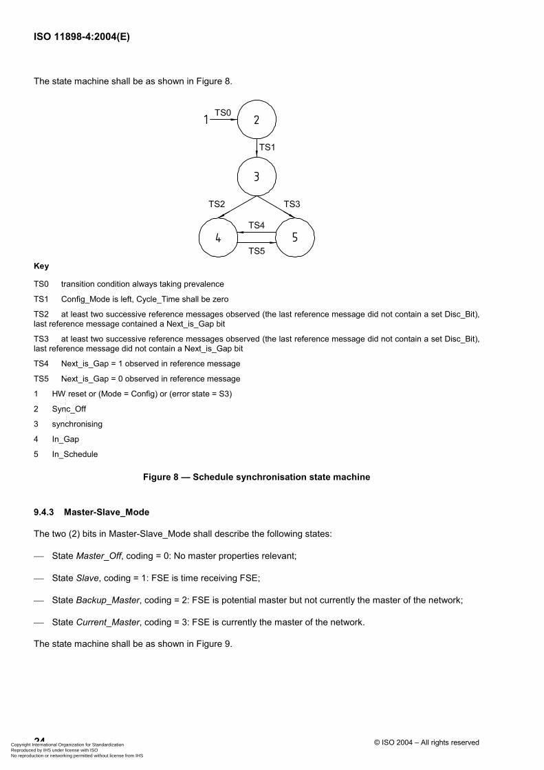
ISO 11898-4:2004(E)
24 © ISO 2004 – All rights reserved
The state machine shall be as shown in Figure 8.
Key
TS0 transition condition always taking prevalence
TS1 Config_Mode is left, Cycle_Time shall be zero
TS2 at least two successive reference messages observed (the last reference message did not contain a set Disc_Bit), last reference message contained a Next_is_Gap bit
TS3 at least two successive reference messages observed (the last reference message did not contain a set Disc_Bit), last reference message did not contain a Next_is_Gap bit
TS4 Next_is_Gap = 1 observed in reference message
TS5 Next_is_Gap = 0 observed in reference message
1 HW reset or (Mode = Config) or (error state = S3)
2 Sync_Off
3 synchronising
4 In_Gap
5 In_Schedule
Figure 8 — Schedule synchronisation state machine
9.4.3 Master-Slave_Mode
The two (2) bits in Master-Slave_Mode shall describe the following states:
State Master_Off, coding = 0: No master properties relevant;
State Slave, coding = 1: FSE is time receiving FSE;
State Backup_Master, coding = 2: FSE is potential master but not currently the master of the network;
State Current_Master, coding = 3: FSE is currently the master of the network.
The state machine shall be as shown in Figure 9.
Copyright International Organization for Standardization Reproduced by IHS under license with ISO
Not for ResaleNo reproduction or networking permitted without license from IHS
--``````-`-`,,`,,`,`,,`---

ISO 11898-4:2004(E)
© ISO 2004 – All rights reserved 25
Key
TM0 transition condition always taking prevalence
TM1 FSE is not potential master and a reference message is observed
TM2 FSE is potential master, error state is not S2 or S3, reference message is observed where master priority is not equal to own master priority
TM3 FSE is potential master, error state is not S2 or S3, reference message is observed where time master priority is equal to own master priority (i.e. reference message was sent by FSE itself)
TM4 FSE changes from backup master to current master when it observes a reference message with its own time master priority
TM5 FSE changes from current master to backup master when it observes a reference message with a time master priority higher than its own
TM6 error state = S2
TM7 error state = S2
1 HW reset or (Mode = Config) or (error state = S3)
2 Master_Off
3 Backup_Master
4 Slave
5 Current_Master
Figure 9 — Master to slave relation
10 Visible interfaces
10.1 Configuration interfaces
10.1.1 General
All configuration interfaces shall be lockable against random changes. Correct initialisation of the configuration interfaces shall be verified. Reading of configuration data is always possible.
Copyright International Organization for Standardization Reproduced by IHS under license with ISO
Not for ResaleNo reproduction or networking permitted without license from IHS
--``````-`-`,,`,,`,`,,`---

ISO 11898-4:2004(E)
26 © ISO 2004 – All rights reserved
10.1.2 General configuration interfaces
10.1.2.1 TUR_Config
There are three register sets for TUR.
a) The first register (TUR_Config) shall be written by the application on initialisation.
b) The second register (TUR_Adjust) shall be used for the external clock synchronisation process.
c) The third register (TUR_Actual) — influenced by the drift correction and read only for the application — shall be used by the FSE internally, loaded from TUR_Config on start-up and from TUR_Adjust on synchronisation command.
All values shall be readable by the application. The format of these registers shall be implementation-specific.
10.1.2.2 Operating_Mode
Possible modes are
Configuration mode,
CAN communication,
time-triggered communication, or
event-synchronised time-triggered communication.
Operating modes may only be changed by first changing to the configuration mode and then changing to the new mode.
10.1.2.3 Time-triggered CAN level
One bit shall be used to distinguish between Level 1 and Level 2.
10.1.2.4 Master/slave
One bit shall be used to distinguish between (potential) time masters and time slaves.
10.1.2.5 External_Clock_Synchronisation
One bit shall be used to configure whether or not external clock synchronisation will be allowed during runtime (only Level 2).
10.1.2.6 Interrupt_Enable register
The Interrupt_Enable register shall contain one enable bit for each interrupt source specified in the application interface (Interrupt_Status_Vector).
10.1.2.7 Appl_Watchdog_Limit
The Appl_Watchdog_Limit shall be an 8-bit value specifying the period for the application watchdog in Appl_Watchdog_Limit times 256 NTUs.
Copyright International Organization for Standardization Reproduced by IHS under license with ISO
Not for ResaleNo reproduction or networking permitted without license from IHS
--``````-`-`,,`,,`,`,,`---

ISO 11898-4:2004(E)
© ISO 2004 – All rights reserved 27
10.1.3 System matrix
10.1.3.1 Description
The system matrix configuration may be read and written by the application during initialisation; it shall be locked during time-triggered communication. The node view of the system matrix shall consist of the different Tx_Triggers, Rx_Triggers and Tx_Ref_Triggers.
10.1.3.2 Trigger
Each configuration data of trigger shall consist of different parts:
a) the first part shall be a reference to a message for which it is valid,
b) the second part shall be the time mark when it may be activated,
c) the third part shall contain data identifying at which position in the transmission column it is to be activated first, and
d) the fourth part shall be the Repeat_Factor.
In addition, the trigger shall contain the information as to whether it refers to an arbitrating or an exclusive window.
10.1.3.3 Merging
For each Tx_Trigger, it shall be specified whether the time window belonging to that trigger shall be merged with the then following window.
10.1.3.4 Watch_Trigger
The Watch_Trigger for a FSE shall consist of a time mark and the coded specifications of the operating mode (event-synchronised or time-triggered) for which the Watch_Trigger is active.
10.1.3.5 Initial_Ref_Offset
The Initial_Ref_Offset shall be an eight (8) bit value for the initialisation of Ref_Trigger_Offset.
10.1.3.6 Expected_Tx_Trigger
The Expected_Tx_Trigger shall be an eight (8) bit value which limits the number of messages the FSE may try to transmit in one matrix cycle.
10.1.3.7 Length of Tx_Enable window
The length of Tx_Enable window shall be a four (4) bit value specifying the length of the time period (1–16 nominal CAN bit times) in which a transmission may be started.
10.1.3.8 Cycle_Count_Max
The Cycle_Count_Max shall be a value specifying the number of the last basic cycle in the system matrix. A FSE may extend (see 5.3.2) the upper limit to 63.
10.1.4 Message objects
There shall be one message object for each Tx_Trigger, Rx_Trigger and Tx_Ref_Trigger. The message objects shall be configured during initialisation and may be updated during time-triggered operation.
Copyright International Organization for Standardization Reproduced by IHS under license with ISO
Not for ResaleNo reproduction or networking permitted without license from IHS
--``````-`-`,,`,,`,`,,`---

ISO 11898-4:2004(E)
28 © ISO 2004 – All rights reserved
Message objects for Tx_Trigger and Rx_Trigger shall provide storage for one LLC frame, in accordance with ISO 11898-1, together with control and status information and 3-bit message status count (MSC).
Message objects for Tx_Ref_Triggers shall provide storage for the reference message identifier and for the data length code. Parts of the reference message data shall be provided by the FSE.
The last three bits of the identifier of the reference message shall specify the time master priority of this FSE.
10.2 Application interfaces
10.2.1 General application interfaces
10.2.1.1 Time master priority
The time master priority shall contain a three (3) bit value for the priority of the current time master (the last three bits of the identifier of the reference message).
10.2.1.2 Master state
The master state shall be a six (6) bit vector which combines the FSE states in the field of error, synchronisation and master-slave relation, i.e. a triplet (error level, sync_mode, master-slave_mode).
10.2.1.3 Global_Time
The Gloal_Time parameter shall contain a sixteen (16) bit value counting the NTUs.
10.2.1.4 Cycle_Time
The Cycle_Time parameter shall contain a sixteen (16) bit value counting the NTUs.
10.2.1.5 Cycle_Count
The Cycle_Count parameter shall be the value giving the number of the current basic cycle (0 to 63).
10.2.1.6 Wait_for_Event
The Wait_for_Event parameters shall be one bit set when a Next_is_Gap bit was received in the last reference message. It shall be reset by the start of the next basic cycle.
10.2.1.7 Ref_Trigger_Offset
The Ref_Trigger_Offset parameter shall contain a read-only eight (8) bit value.
10.2.1.8 TUR_Actual
The TUR_Actual parameter shall contain a read-only value.
10.2.1.9 MSC
MSC shall be used only for messages transmitted in exclusive time windows.
Copyright International Organization for Standardization Reproduced by IHS under license with ISO
Not for ResaleNo reproduction or networking permitted without license from IHS
--``````-`-`,,`,,`,`,,`---

ISO 11898-4:2004(E)
© ISO 2004 – All rights reserved 29
10.2.2 Interrupt_Status_Vector
10.2.2.1 Description
The time-triggered CAN FSE shall provide at least one interrupt line to the application. Several interrupt sources shall be provided: each may be enabled separately (Interrupt_Enable). The Interrupt_Status_Vector will be updated regardless of the Interrupt_Enable register, allowing two types of application programming, i.e. interrupt driven or polling. Every bit of the Interrupt_Status_Vector that has been set will remain set until reset by the application. The Interrupt_Enable register shall enable the access of the interrupt source to the interrupt line.
The interrupt vector shall contain operational as well as error-handling sources of an interrupt. The interrupt sources below shall be provided. A specific implementation may provide additional sources. In such an implementation, the corresponding Interrupt_Enable shall also contain these sources.
10.2.2.2 Operational interrupt sources
Operational interrupt source may contain
Start_of_Basic_Cycle,
Start_of_System_Matrix,
Synch_to_Event (a Next_is_Gap bit was received in the last reference message),
Disc_Flag (a status flag set to show that a discontinuity in the global time has happened),
Change_of_Masterstate (the local FSE changed its master state),
Global_Time_Wrap (the Global_Time had an overflow),
Init_Watch_Trigger (Init_Watch_Trigger was reached).
10.2.2.3 Error detection interrupt sources
The error detection interrupt sources may contain (see 9.3)
Application_Watchdog,
Tx_Overflow,
Tx_Underflow,
Scheduling_Error_1,
Scheduling_Error_2,
Watch_Trigger_Reached,
CAN_Bus_Off.
10.2.3 Application interfaces — Control
10.2.3.1 Host_Alive_Sign
The application shall regularly access the Host_Alive_Sign interface in order to serve the application watchdog of the time-triggered FSE.
Copyright International Organization for Standardization Reproduced by IHS under license with ISO
Not for ResaleNo reproduction or networking permitted without license from IHS
--``````-`-`,,`,,`,`,,`---

ISO 11898-4:2004(E)
30 © ISO 2004 – All rights reserved
10.2.3.2 Set_Next_is_Gap
The application of the current time master may set the Set_Next_is_Gap bit to control the event-synchronised time-triggered communication. The bit shall be automatically reset by the time-triggered CAN FSE after the reference message containing the Next_is_Gap bit is sent. The operational interrupt source Synch_to_Event shall be set also at the time master.
10.2.3.3 End_of_Gap (1-bit)
End_of_Gap contains a one (1) bit value. The application shall start the next basic cycle by setting End_of_Gap. This function shall only be enabled when the basic cycle started by a reference message with a Next_is_Gap bit is completed.
10.2.3.4 Set_Time_Command
The Set_Time_Command shall be used to allow the application of the current time master to change the value of the global time of the network by an amount of Global_Time_Preset (phase adjustment). The command shall be executed at the beginning of the next basic cycle. The discontinuity bit shall be set in the reference message that starts the next basic cycle.
10.2.3.5 Global_Time_Preset
The value of Global_Time_Preset parameter shall contain the difference between the desired global time and the current global time of the network. The content of Global_Time_Preset shall be written by the application. At the beginning of the next basic cycle, this value shall be added to the Local_Offset of the time master — hence to the current global time (phase adjustment).
10.2.3.6 External clock synchronisation command
The external clock synchronisation command shall be used to allow external clock synchronisation by the application of the time master (frequency adjustment). The application shall write the new value for TUR into the TUR_Adjust and shall activate the external clock synchronisation command to initiate the transfer of this new value into TUR_Actual.
10.2.3.7 TUR_Adjust
TUR_Adjust shall be used to adjust the internal clock to an external clock.
10.3 Optional interfaces
10.3.1 Description
The interfaces specified above are requirements for conformance with this part of ISO 11898. However, any implementation may have additional interfaces. Those described below are included in the system, but given here as optional functional content.
10.3.2 Disable_Discontinuity
The Disable_Discontinuity is a configuration interface which disables the usage of the Disc_Bit. Therefore, no discontinuities in global time shall be signalled.
10.3.3 Out_of_Sync
The Out_of_Sync parameter indicates that the FSE is not synchronised to the time master global time.
Copyright International Organization for Standardization Reproduced by IHS under license with ISO
Not for ResaleNo reproduction or networking permitted without license from IHS
--``````-`-`,,`,,`,`,,`---

ISO 11898-4:2004(E)
© ISO 2004 – All rights reserved 31
10.3.4 Synchronisation_Deviation
Synchronisation_Deviation parameter is the maximum tolerated difference between the Global_Sync_Mark of the reference message and the Global_Ref_Mark in the reference message for Level 2 only.
10.3.5 Synchronisation_Quality
Synchronisation_Quality shows whether the Synchronisation_Deviation exceeds a preconfigured value for Level 2 only.
10.3.6 Global_Time_Fraction
Global_Time_Fraction parameter shows the fractional part of the global time for Level 2 only.
10.3.7 Disable_Global_Time_Filtering
Disable_Global_Time_Filtering means that the smoothing of the global time is disabled for Level 2 only.
10.3.8 Enable_TUR_Restore
Enable_TUR_Restore allows the current time master to gradually return to its TUR_Config value for Level 2 only.
Copyright International Organization for Standardization Reproduced by IHS under license with ISO
Not for ResaleNo reproduction or networking permitted without license from IHS
--``````-`-`,,`,,`,`,,`---

ISO 11898-4:2004(E)
32 © ISO 2004 – All rights reserved
Bibliography
[1] ISO/IEC 7498-1, Information processing systems — Open Systems Interconnection — Basic Reference Model: The Basic Model
[2] ISO/IEC 8802-2, Information technology — Telecommunications and information exchange between systems — Local and metropolitan area networks — Specific requirements — Part 2: Logical link control
[3] ISO/IEC 8802-3, Information technology — Local and metropolitan area networks — Part 3: Carrier sense multiple access with collision detection (CSMA/CD) access method and physical layer specifications
Copyright International Organization for Standardization Reproduced by IHS under license with ISO
Not for ResaleNo reproduction or networking permitted without license from IHS
--``````-`-`,,`,,`,`,,`---

Copyright International Organization for Standardization Reproduced by IHS under license with ISO
Not for ResaleNo reproduction or networking permitted without license from IHS
--``````-`-`,,`,,`,`,,`---

ISO 11898-4:2004(E)
ICS 43.040.15 Price based on 32 pages
© ISO 2004 – All rights reserved
Copyright International Organization for Standardization Reproduced by IHS under license with ISO
Not for ResaleNo reproduction or networking permitted without license from IHS
--``````-`-`,,`,,`,`,,`---