ISO 643 - SIS
11
Reference number ISO 643:2003(E) © ISO 2003 INTERNATIONAL STANDARD ISO 643 Second edition 2003-02-15 Steels — Micrographic determination of the apparent grain size Aciers — Détermination micrographique de la grosseur de grain apparente This preview is downloaded from www.sis.se. Buy the entire standard via https://www.sis.se/std-903625
-
Upload
khangminh22 -
Category
Documents
-
view
1 -
download
0
Transcript of ISO 643 - SIS
Reference numberISO 643:2003(E)
© ISO 2003
INTERNATIONAL STANDARD
ISO643
Second edition2003-02-15
Steels — Micrographic determination of the apparent grain size
Aciers — Détermination micrographique de la grosseur de grain apparente
This preview is downloaded from www.sis.se. Buy the entire standard via https://www.sis.se/std-903625
ISO 643:2003(E)
PDF disclaimer This PDF file may contain embedded typefaces. In accordance with Adobe's licensing policy, this file may be printed or viewed but shall not be edited unless the typefaces which are embedded are licensed to and installed on the computer performing the editing. In downloading this file, parties accept therein the responsibility of not infringing Adobe's licensing policy. The ISO Central Secretariat accepts no liability in this area.
Adobe is a trademark of Adobe Systems Incorporated.
Details of the software products used to create this PDF file can be found in the General Info relative to the file; the PDF-creation parameters were optimized for printing. Every care has been taken to ensure that the file is suitable for use by ISO member bodies. In the unlikely event that a problem relating to it is found, please inform the Central Secretariat at the address given below.
© ISO 2003 All rights reserved. Unless otherwise specified, no part of this publication may be reproduced or utilized in any form or by any means, electronic or mechanical, including photocopying and microfilm, without permission in writing from either ISO at the address below or ISO's member body in the country of the requester.
ISO copyright office Case postale 56 • CH-1211 Geneva 20 Tel. + 41 22 749 01 11 Fax + 41 22 749 09 47 E-mail [email protected] Web www.iso.org
Published in Switzerland
ii © ISO 2003 — All rights reserved
This preview is downloaded from www.sis.se. Buy the entire standard via https://www.sis.se/std-903625
ISO 643:2003(E)
© ISO 2003 — All rights reserved iii
Contents Page
Foreword............................................................................................................................................................ iv 1 Scope...................................................................................................................................................... 1 2 Normative references ........................................................................................................................... 1 3 Terms and definitions........................................................................................................................... 1 4 Symbols and abbreviated terms.......................................................................................................... 2 5 Principle ................................................................................................................................................. 2 6 Selection and preparation of the specimen ....................................................................................... 5 6.1 Test location .......................................................................................................................................... 5 6.2 Revealing ferritic grain boundaries..................................................................................................... 5 6.3 Revealing austenitic and prior-austenitic grain boundaries ............................................................ 5 7 Characterization of grain size............................................................................................................ 10 7.1 Characterization by an index ............................................................................................................. 10 7.2 Characterization by the intercept method ........................................................................................ 11 8 Test report............................................................................................................................................ 14 Annex A (informative) Summary of methods for revealing ferritic, austenitic or prior-austenitic
grain boundaries in steels.................................................................................................................. 15 Annex B (normative) Determination of grain size — Standard charts taken from ASTM E112 ............... 16 Annex C (normative) Evaluation method ....................................................................................................... 31
This preview is downloaded from www.sis.se. Buy the entire standard via https://www.sis.se/std-903625

ISO 643:2003(E)
iv © ISO 2003 — All rights reserved
Foreword
ISO (the International Organization for Standardization) is a worldwide federation of national standards bodies (ISO member bodies). The work of preparing International Standards is normally carried out through ISO technical committees. Each member body interested in a subject for which a technical committee has been established has the right to be represented on that committee. International organizations, governmental and non-governmental, in liaison with ISO, also take part in the work. ISO collaborates closely with the International Electrotechnical Commission (IEC) on all matters of electrotechnical standardization.
International Standards are drafted in accordance with the rules given in the ISO/IEC Directives, Part 2.
The main task of technical committees is to prepare International Standards. Draft International Standards adopted by the technical committees are circulated to the member bodies for voting. Publication as an International Standard requires approval by at least 75 % of the member bodies casting a vote.
Attention is drawn to the possibility that some of the elements of this document may be the subject of patent rights. ISO shall not be held responsible for identifying any or all such patent rights.
ISO 643 was prepared by Technical Committee ISO/TC 17, Steel, Subcommittee SC 7, Methods of testing (other than mechanical tests and chemical analysis).
This second edition cancels and replaces the first edition (ISO 643:1983), which has been technically revised.
This preview is downloaded from www.sis.se. Buy the entire standard via https://www.sis.se/std-903625
INTERNATIONAL STANDARD ISO 643:2003(E)
© ISO 2003 — All rights reserved 1
Steels — Micrographic determination of the apparent grain size
1 Scope
This International Standard specifies a micrographic method of determining apparent ferritic or austenitic grain size in steels. It describes the methods of revealing grain boundaries and of estimating the mean grain size of specimens with unimodal size distribution. Although grains are three-dimensional in shape, the metallographic sectioning plane can cut through a grain at any point from a grain corner, to the maximum diameter of the grain, thus producing a range of apparent grain sizes on the two-dimensional plane, even in a sample with a perfectly consistent grain size.
2 Normative references
The following referenced documents are indispensable for the application of this document. For dated references, only the edition cited applies. For undated references, the latest edition of the referenced document (including any amendments) applies.
ISO 3785, Steel — Designation of test piece axes
ISO 14250, Steel — Metallographic characterization of duplex grain size and distributions
ASTM E112, Standard Test Methods for Determining Average Grain Size
3 Terms and definitions
For the purposes of this document, the following terms and definitions apply.
3.1 grain closed polygonal shape with more or less curved sides, which can be revealed on a flat cross-section through the sample, polished and prepared for micrographic examination
A distinction is made between:
3.1.1 austenitic grain crystal with a face-centered cubic crystal structure which may, or may not, contain annealing twins
3.1.2 ferritic grain crystal with a body-centered cubic crystal structure which never contains annealing twins1)
1) Ferritic grain size is generally estimated for non-alloy steels with a carbon content of 0,25 % or less. If pearlite islands of identical dimensions to those of the ferrite grains are present, the islands are then counted as ferrite grains.
This preview is downloaded from www.sis.se. Buy the entire standard via https://www.sis.se/std-903625
ISO 643:2003(E)
2 © ISO 2003 — All rights reserved
3.2 index positive, zero or possibly negative number G which is derived from the mean number m of grains counted in an area of 1 mm2 of the section of the specimen
NOTE By definition, G = 1 where m = 16; the other indices are obtained by the formula
8 2Gm = ×
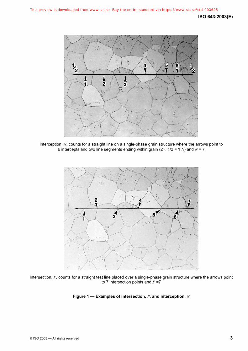
3.3 intercept N number of grains intercepted by a test line, either straight or curved
See Figure 1.
NOTE Straight test lines will normally end within a grain. These end segments are counted as 1/2 an interception. N is the average of a number of counts of the number of grains intercepted by the test line applied randomly at various locations. N is divided by the true line length, T,L usually measured in millimetres, in order to obtain the number of grains intercepted per unit length, .LN
3.4 intersection P number of intersection points between grain boundaries and a test line, either straight or curved
See Figure 1.
NOTE P is the average of a number of counts of the number of grain boundaries intersected by the test line applied randomly at various locations. P is divided by the true line length, T,L usually measured in millimetres, in order to obtain the number of grain boundary intersections per unit length, .LP
4 Symbols and abbreviated terms
The symbols used are given in Table 1.
5 Principle
The grain size is revealed by micrographic examination of a polished section of the specimen prepared by an appropriate method for the type of steel and for the information sought.
NOTE If the order or the International Standard defining the product does not stipulate the method of revealing the grain, the choice of this method is left to the manufacturer.
This average size is characterized either
a) by an index obtained
usually by comparison with standard charts for the measurement of grain size;
or by counting to determine the average number of grains per unit area;
b) or by the mean value of the intercepted segment.
This preview is downloaded from www.sis.se. Buy the entire standard via https://www.sis.se/std-903625
ISO 643:2003(E)
© ISO 2003 — All rights reserved 3
Interception, N, counts for a straight line on a single-phase grain structure where the arrows point to 6 intercepts and two line segments ending within grain (2 × 1/2 = 1 N) and N = 7
Intersection, P, counts for a straight test line placed over a single-phase grain structure where the arrows point to 7 intersection points and P =7
Figure 1 — Examples of intersection, P, and interception, N
This preview is downloaded from www.sis.se. Buy the entire standard via https://www.sis.se/std-903625
ISO 643:2003(E)
4 © ISO 2003 — All rights reserved
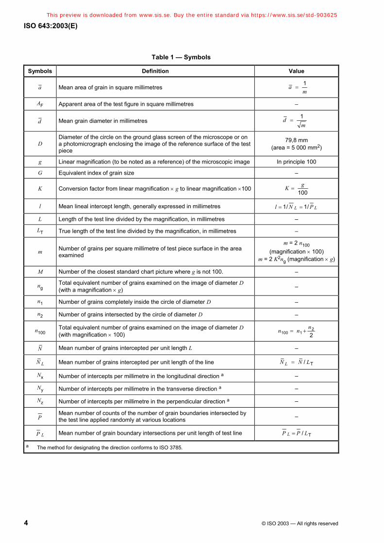
Table 1 — Symbols
Symbols Definition Value
a Mean area of grain in square millimetres 1am
=
AF Apparent area of the test figure in square millimetres –
d Mean grain diameter in millimetres 1dm
=
D Diameter of the circle on the ground glass screen of the microscope or on a photomicrograph enclosing the image of the reference surface of the test piece
79,8 mm (area = 5 000 mm2)
g Linear magnification (to be noted as a reference) of the microscopic image In principle 100
G Equivalent index of grain size –
K Conversion factor from linear magnification × g to linear magnification ×100 100
gK =
l Mean lineal intercept length, generally expressed in millimetres 1/ 1/ LLl N P= =
L Length of the test line divided by the magnification, in millimetres –
LT True length of the test line divided by the magnification, in millimetres –
m Number of grains per square millimetre of test piece surface in the area examined
m = 2 n100 (magnification × 100)
m = 2 K2ng (magnification × g)
M Number of the closest standard chart picture where g is not 100. –
ng Total equivalent number of grains examined on the image of diameter D (with a magnification × g) –
n1 Number of grains completely inside the circle of diameter D –
n2 Number of grains intersected by the circle of diameter D –
n100 Total equivalent number of grains examined on the image of diameter D (with magnification × 100)
2100 1 2
nn n= +
N Mean number of grains intercepted per unit length L –
LN Mean number of grains intercepted per unit length of the line T/LN N L=
Nx Number of intercepts per millimetre in the longitudinal direction a –
Ny Number of intercepts per millimetre in the transverse direction a –
Nz Number of intercepts per millimetre in the perpendicular direction a –
P Mean number of counts of the number of grain boundaries intersected by the test line applied randomly at various locations –
LP Mean number of grain boundary intersections per unit length of test line T/LP P L=
a The method for designating the direction conforms to ISO 3785.
This preview is downloaded from www.sis.se. Buy the entire standard via https://www.sis.se/std-903625
ISO 643:2003(E)
© ISO 2003 — All rights reserved 5
6 Selection and preparation of the specimen
6.1 Test location
If the order, or the International Standard defining the product, does not specify the number of specimens and the point at which they are to be taken from the product, these are left to the manufacturer, although it has been shown that precision of grain size determination increases the higher the number of specimens assessed. Therefore, it is recommended that two or more sections be assessed. Care shall be taken to ensure that the specimens are representative of the bulk of the product (i.e., avoid heavily deformed material such as that found at the extreme end of certain products or where shearing has been used to remove the specimen etc.). The specimens shall be polished in accordance with the usual methods.
Unless otherwise stated by the product standard or by agreement with the customer, the polished face of the specimen shall be longitudinal, i.e., parallel to the principal axis of deformation in wrought products. Measurements of the grain size on a transverse plane will be biased if the grain shape is not equiaxial.
6.2 Revealing ferritic grain boundaries
The ferritic grains shall be revealed by etching with nital (ethanolic 2 % to 3 % nitric acid solution), or with an appropriate reagent.
6.3 Revealing austenitic and prior-austenitic grain boundaries
6.3.1 General
In the case of steels having a single-phase or two-phase austenitic structure (delta ferrite grains in an austenitic matrix) at ambient temperature, the grain shall be revealed by an etching solution. For single phase austenitic stainless steels, the most commonly used chemical etchants are glyceregia, Kalling’s reagent (No. 2) and Marble's reagent. The best electrolytic etch for single or two-phase stainless steels is aqueous 60 % nitric acid at 1,4 V d.c. for 60 s to 120 s, as it reveals the grain boundaries but not the twin boundaries. Aqueous 10 % oxalic acid, 6 V d.c., up to 60 s, is commonly used but is less effective than electrolytic 60 % HNO3.
For other steels, one or other of the methods specified below shall be used depending on the information required.
“Bechet-Beaujard” method by etching with aqueous saturated picric acid solution (see 6.3.2);
“Kohn” method by controlled oxidation (see 6.3.3);
“McQuaid-Ehn” method by carburization (see 6.3.4);
grain boundary sensitization method (see 6.3.7);
other methods specially agreed upon when ordering.
NOTE The first three methods are for prior-austenitic grain boundaries while the others are for austenitic Mn or austenitic stainless, see Annex A.
If comparative tests are carried out for the different methods, it is essential to use the same heat treatment conditions. Results may vary considerably from one method to the other.
This preview is downloaded from www.sis.se. Buy the entire standard via https://www.sis.se/std-903625
ISO 643:2003(E)
6 © ISO 2003 — All rights reserved
6.3.2 “Bechet-Beaujard” method by etching with aqueous saturated picric acid solution
6.3.2.1 Field of application
This method reveals austenitic grains formed during heat treatment of the specimen. It is applicable to specimens which have a martensitic or bainitic structure. For this etch to work, there shall be at least 0,005 % P.
6.3.2.2 Preparation
The Bechet-Beaujard etchant is normally used on a heat-treated steel specimen. Normally, no subsequent heat treatment is necessary if the specimen has a martensitic or bainitic structure. If this is not the case, heat treatment is necessary.
If the conditions for treating the test piece are not provided for by the International Standard defining the product and there is no specification to the contrary, the following conditions shall be applied in the case of heat-treated structural carbon steels and low-alloy steels:
1,5 h at (850 ± 10) °C for steels whose carbon content is greater than 0,35 %;
1,5 h at (880 ± 10) °C for steels whose carbon content is less than or equal to 0,35 %.
After this treatment, the test piece shall be quenched into water or oil.
6.3.2.3 Polishing and etching
A flat specimen surface shall be polished for micrographic examination. It shall be etched for an adequate period of time by means of an aqueous solution saturated with picric acid together with at least 0,5 % sodium alkylsulfonate or another appropriate wetting agent.
NOTE The period of etching may vary from a few minutes to more than one hour. Heating of the solution to 60 °C may improve the etching action and reduce etching time.
Several successive etching and polishing operations are sometimes necessary to ensure a sufficient contrast between the grain boundaries and the general base of the specimen. In the case of through-hardened steel, tempering may be carried out before selecting the specimen.
WARNING: When heating solutions containing picric acid, caution shall be taken to avoid the solution boiling dry as picric acid can become explosive.
6.3.2.4 Result
The prior-austenite grain boundaries shall be immediately apparent on microscopic examination.
6.3.3 “Kohn” method by controlled oxidation
6.3.3.1 Field of application
This method shows up the austenitic grain pattern formed by preferential oxidation of the boundaries during austenization at the temperature of a given heat treatment.
6.3.3.2 Preparation
One surface of the specimen shall be polished. The rest of its surface shall not show any traces of oxide. The specimen shall be placed in a laboratory furnace in which either a vacuum of 1 Pa is attained or an inert gas is circulated (e.g. purified argon). Heat treat the specimen in accordance with the austenitizing procedure specified by the customer, or as defined by the International Standard governing the product.
This preview is downloaded from www.sis.se. Buy the entire standard via https://www.sis.se/std-903625

ISO 643:2003(E)
© ISO 2003 — All rights reserved 7
At the end of this specified heating period, air shall be introduced into the furnace for a period of 10 s to 15 s.
The specimen shall then be water-quenched. The specimen can usually be directly examined using a microscope.
NOTE 1 The oxidation method can be done without the inert atmosphere.
NOTE 2 The oxide adhering to the previously polished surface should be removed by light polishing with a fine abrasive, taking care that the oxide network which has formed on the grain boundaries is retained; then the polishing should be completed by the usual methods. The specimen should then be etched using Vilella's reagent:
picric acid 1 g
hydrochloric acid 5 ml
ethanol 100 ml
6.3.3.3 Result
The preferential oxidation of the boundaries shows up the pattern of austenitic grains.
If the preparation is effected correctly, no oxide globules should appear at the grain boundaries.
In certain cases, it may be necessary to use oblique illumination, or DIC (Differential Interference Contrast) methods, to show up the boundaries in better relief.
6.3.4 “McQuaid-Ehn” method by carburization at 925 °C
6.3.4.1 Field of application
This is a method specifically for carburizing steels and shows up austenitic grain boundaries formed during carburization of these steels. It is not usually suitable for revealing grains actually formed during other heat treatments.
NOTE The “mock carburizing” procedure may also be used. The specimen is subjected to the same thermal treatment but without a carbon-rich atmosphere. It is then heat-treated as the product would be treated. The Bechet-Beaujard reagent is used to reveal the grain boundaries, see 6.3.2.
6.3.4.2 Preparation
The specimens shall be free from any trace of decarburization or of surface oxidation. Any prior treatment, either cold, hot, mechanical, etc., may have an effect on the shape of the grain obtained; the product specification shall state the treatments to be carried out before determination in cases where it is advisable to take into account these considerations.
After carburizing, the specimen must be cooled at a rate slow enough to precipitate cementite at the grain boundaries in the hypereutectoid surface region of the carburized specimen.
Carburization shall be achieved by maintaining the specimen at (925 ± 10) °C for 6 h. This is generally done by keeping the carburizing chamber at (925 ± 10) °C for 8 h, including a pre-heating period. In most cases, a carburized layer of approximately 1 mm is obtained. After carburizing, cool the specimen at a rate slow enough to ensure that the cementite is precipitated at the grain boundaries of the hypereutectoid zone of the carburized layer.
Fresh carburizing compound shall be used each time.
This preview is downloaded from www.sis.se. Buy the entire standard via https://www.sis.se/std-903625