
Two- and three-dimensional numerical models of flow and heat transfer over louvred fin arrays in...
18
\ PERGAMON International Journal of Heat and Mass Transfer 30 "0887# 3952Ð3979 9906Ð8209:87 ,08[99 Þ 0887 Published by Elsevier Science Ltd[ All rights reserved PII]S9906Ð8209"87#99054Ð2 Two! and three!dimensional numerical models of ~ow and heat transfer over louvred _n arrays in compact heat exchangers K[ N[ Atkinson a\ \ R[ Drakulic a \ M[ R[ Heikal a \ T[ A[ Cowell b a Department of Mechanical and Manufacturin` En`ineerin`\ University of Bri`hton\ Cockcroft Buildin`\ Moulsecoomb\ Bri`hton BN1 3GJ\ U[K[ b Delphi Automotive Systems European Technical Centre\ GM Luxembour`\ L!3839 Baschara`e\ G!D Luxembour` Received 4 November 0886^ in _nal form 8 April 0887 Abstract This paper presents a detailed evaluation of two! and three!dimensional numerical models of ~ow and heat transfer over louvred _n arrays in compact heat exchangers[ Two 2!D models are described\ both of which incorporate the e}ects of tube surface area and _n resistance on the overall heat transfer rate[ Both of these features lead to a lowering of the predicted heat transfer rate per unit area compared with the 1!D model and\ as a result\ the 2!D models give predictions of overall heat transfer in better agreement with experimental observations[ All of the models give accurate predictions of pressure losses\ but it is argued that the superior heat transfer predictions of the 2!D models make them much more useful as design tools than 1!D models\ even though they require much greater computing resources Þ 0887 Published by Elsevier Science Ltd[ All rights reserved[ Nomenclature A a heat transfer area A c minimum ~ow area c p speci_c heat at constant pressure D h hydraulic diameter f overall friction factor F p _n pitch G mass velocity "rU# h speci_c enthalpy h c heat transfer coe.cient k thermal conductivity L _n length L p louvre pitch LMTD logarithmic mean temperature di}erence m mass ~ow rate Nu local Nusselt number p pressure Q heat ~ux R speci_c gas constant for air Re Dh Reynolds number based on hydraulic diameter Re Lp Reynolds number based on louvre pitch Corresponding author[ St overall Stanton number t _n thickness T absolute temperature of air T a\i air temperature upstream of _n T a\o air temperature downstream of _n T f absolute temperature of _n T p tube pitch T w tube width u\ v\ w velocity components in x\ y and z coordinate directions\ respectively U mean velocity through minimum ~ow area x\ y\ z Cartesian coordinates[ Greek symbols DT i temperature di}erence T f -T a\i DT o temperature di}erence T f -T a\o l second coe.cient of viscosity " -1:2 m# m dynamic viscosity of air u louvre angle r air density s ij viscous stress[ 0[ Introduction Louvred plate _ns are frequently used on the air side of automotive radiators and other heat exchangers to
Transcript of Two- and three-dimensional numerical models of flow and heat transfer over louvred fin arrays in...
\PERGAMON International Journal of Heat and Mass Transfer 30 "0887# 3952Ð3979
9906Ð8209:87 ,08[99 Þ 0887 Published by Elsevier Science Ltd[ All rights reservedPII ] S 9 9 0 6 Ð 8 2 0 9 " 8 7 # 9 9 0 5 4 Ð 2
Two! and three!dimensional numerical models of ~ow andheat transfer over louvred _n arrays in compact heat exchangers
K[ N[ Atkinsona\�\ R[ Drakulica\ M[ R[ Heikala\ T[ A[ Cowellb
a Department of Mechanical and Manufacturin` En`ineerin`\ University of Bri`hton\ Cockcroft Buildin`\ Moulsecoomb\ Bri`htonBN1 3GJ\ U[K[
b Delphi Automotive Systems European Technical Centre\ GM Luxembour`\ L!3839 Baschara`e\ G!D Luxembour`
Received 4 November 0886^ in _nal form 8 April 0887
Abstract
This paper presents a detailed evaluation of two! and three!dimensional numerical models of ~ow and heat transferover louvred _n arrays in compact heat exchangers[ Two 2!D models are described\ both of which incorporate the e}ectsof tube surface area and _n resistance on the overall heat transfer rate[ Both of these features lead to a lowering of thepredicted heat transfer rate per unit area compared with the 1!D model and\ as a result\ the 2!D models give predictionsof overall heat transfer in better agreement with experimental observations[ All of the models give accurate predictionsof pressure losses\ but it is argued that the superior heat transfer predictions of the 2!D models make them much moreuseful as design tools than 1!D models\ even though they require much greater computing resources Þ 0887 Publishedby Elsevier Science Ltd[ All rights reserved[
Nomenclature
Aa heat transfer areaAc minimum ~ow areacp speci_c heat at constant pressureDh hydraulic diameterf overall friction factorFp _n pitchG mass velocity "�rU#h speci_c enthalpyhc heat transfer coe.cientk thermal conductivityL _n lengthLp louvre pitchLMTD logarithmic mean temperature di}erencem mass ~ow rateNu local Nusselt numberp pressureQ heat ~uxR speci_c gas constant for airReDh Reynolds number based on hydraulic diameterReLp Reynolds number based on louvre pitch
� Corresponding author[
St overall Stanton numbert _n thicknessT absolute temperature of airTa\i air temperature upstream of _nTa\o air temperature downstream of _nTf absolute temperature of _nTp tube pitchTw tube widthu\ v\ w velocity components in x\ y and z coordinatedirections\ respectivelyU mean velocity through minimum ~ow areax\ y\ z Cartesian coordinates[
Greek symbolsDTi temperature di}erence Tf−Ta\i
DTo temperature di}erence Tf−Ta\o
l second coe.cient of viscosity "� −1:2 m#m dynamic viscosity of airu louvre angler air densitysi j viscous stress[
0[ Introduction
Louvred plate _ns are frequently used on the air sideof automotive radiators and other heat exchangers to
K[N[ Atkinson et al[:Int[ J[ Heat Mass Transfer 30 "0887# 3952Ð39793953
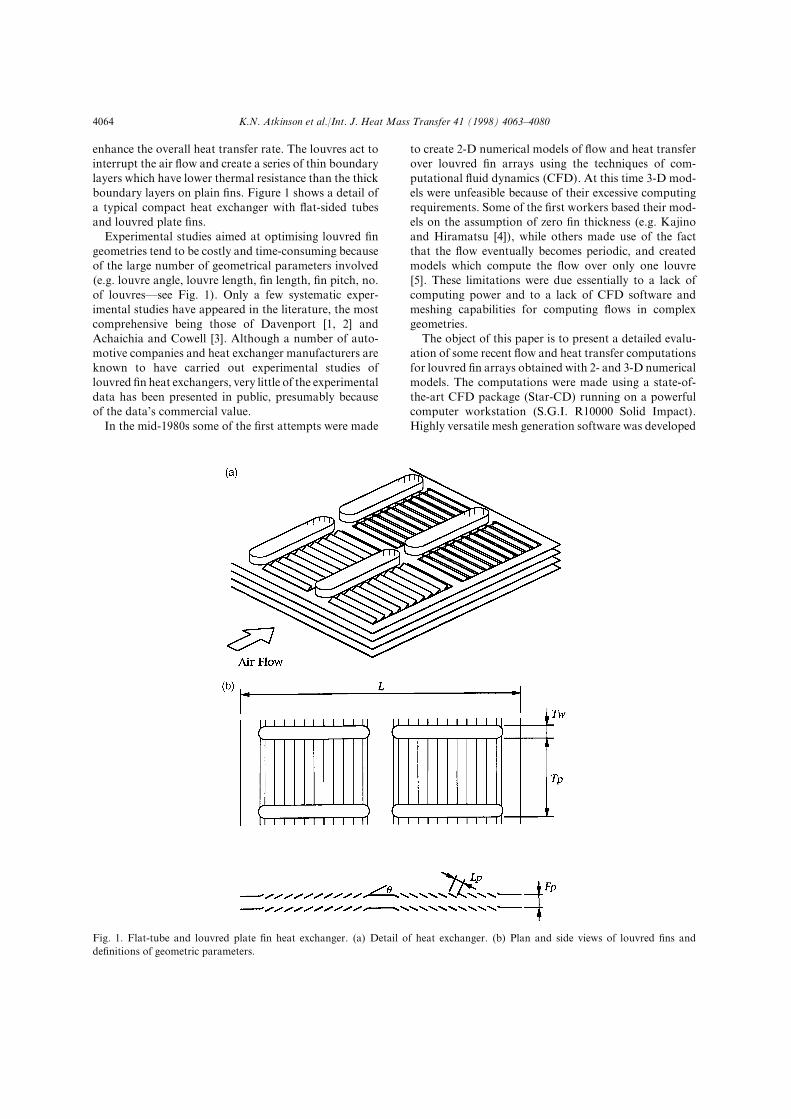
enhance the overall heat transfer rate[ The louvres act tointerrupt the air ~ow and create a series of thin boundarylayers which have lower thermal resistance than the thickboundary layers on plain _ns[ Figure 0 shows a detail ofa typical compact heat exchanger with ~at!sided tubesand louvred plate _ns[
Experimental studies aimed at optimising louvred _ngeometries tend to be costly and time!consuming becauseof the large number of geometrical parameters involved"e[g[ louvre angle\ louvre length\ _n length\ _n pitch\ no[of louvres*see Fig[ 0#[ Only a few systematic exper!imental studies have appeared in the literature\ the mostcomprehensive being those of Davenport ð0\ 1Ł andAchaichia and Cowell ð2Ł[ Although a number of auto!motive companies and heat exchanger manufacturers areknown to have carried out experimental studies oflouvred _n heat exchangers\ very little of the experimentaldata has been presented in public\ presumably becauseof the data|s commercial value[
In the mid!0879s some of the _rst attempts were made
Fig[ 0[ Flat!tube and louvred plate _n heat exchanger[ "a# Detail of heat exchanger[ "b# Plan and side views of louvred _ns andde_nitions of geometric parameters[
to create 1!D numerical models of ~ow and heat transferover louvred _n arrays using the techniques of com!putational ~uid dynamics "CFD#[ At this time 2!D mod!els were unfeasible because of their excessive computingrequirements[ Some of the _rst workers based their mod!els on the assumption of zero _n thickness "e[g[ Kajinoand Hiramatsu ð3Ł#\ while others made use of the factthat the ~ow eventually becomes periodic\ and createdmodels which compute the ~ow over only one louvreð4Ł[ These limitations were due essentially to a lack ofcomputing power and to a lack of CFD software andmeshing capabilities for computing ~ows in complexgeometries[
The object of this paper is to present a detailed evalu!ation of some recent ~ow and heat transfer computationsfor louvred _n arrays obtained with 1! and 2!D numericalmodels[ The computations were made using a state!of!the!art CFD package "Star!CD# running on a powerfulcomputer workstation "S[G[I[ R09999 Solid Impact#[Highly versatile mesh generation software was developed

K[N[ Atkinson et al[:Int[ J[ Heat Mass Transfer 30 "0887# 3952Ð3979 3954
which was capable of creating numerical meshes for most_n geometries of practical interest[ The meshes had ablock structure with mainly rectangular cells formaximum numerical accuracy[ Two 2!D models werecreated\ both of which accounted for the e}ects of tubesurface area and _n resistance on the overall heat transferrate[ It is shown that both of these features lead to asigni_cant lowering of the predicted heat transfer rate perunit area\ and are therefore essential components in thecorrect modelling of louvred!_n ~ows[ Finally\ to evalu!ate the models\ computed values of overall Stanton num!ber and friction factor were obtained for di}erent Rey!nolds numbers and _n geometries and compared withmeasured values obtained on practical louvred _n heatexchangers by Achaichia and Cowell ð2Ł[
1[ Literature review
Experiments on louvred _ns can be divided into studieson actual!size _ns and studies on large!scale models[ Theformer tend to be concerned with the acquisition ofdesign data such as overall friction factor and Stantonnumber\ whereas the latter tend to be concerned morewith understanding the detailed ~ow mechanisms whichlead to heat transfer enhancement[ The _rst person toconduct an experiment on a large!scale model appears tobe Beauvais ð5Ł[ He presents a single photograph of asmoke trace in a ten!times scale model which clearlyillustrates how the ~ow is redirected by the louvres[ Upto that time it had been speculated that the louvres simplyacted as roughness elements\ with the ~ow being directedhorizontally over the _n[
Wong and Smith ð6Ł appear to be the _rst to dem!onstrate the validity of using large!scale models to simu!late the ~ow over actual!size _ns[ They measured theoverall drag coe.cient and Nusselt number for a _ve!times scale model and found that the values agreed withthose for an actual!size heat exchanger operating at thesame Reynolds number[
Davenport ð0Ł carried out smoke trace studies on aten!times scale model of a non!standard variant of thecorrugated louvred _n "the Z _n# and demonstrated thatthe degree of alignment between the ~ow and the louvresis a function of Reynolds number[ At low Reynolds num!ber the ~ow is mainly in the direction of the _n\ whereasat high Reynolds number the ~ow is almost completelyaligned with the louvres[ Davenport conjectured that thechange in alignment was due to the change in boundarylayer thickness on the _n[
Davenport also carried out measurements of overallfriction factor and Stanton number on actual!size louvred_n heat exchangers "Davenport ð0\ 1Ł#[ He found thatwhen the friction factor and Stanton number were plottedagainst Reynolds number on logÐlog axes\ the data hadroughly constant slope of −0:1\ consistent with the idea
of a series of laminar boundary layers[ At low Reynoldsnumber he noticed a ~attening of the Stanton numberdata\ and conjectured that this was due to the change in~ow alignment[
Achaichia and Cowell ð2Ł made a comprehensive studyof the performance characteristics of ~at!sided tube andlouvred plate _n heat exchangers[ Their performancedata encompass variations in all of the important geo!metrical parameters\ including _n pitch\ louvre pitch\louvre angle and tube pitch[ Like Davenport\ they foundtheir data could be correlated more easily when theReynolds number was expressed in terms of the louvrepitch rather than the hydraulic diameter of the air pass!ages\ again consistent with the idea of a series of laminarboundary layers[ Achaichia and Cowell also noticed a~attening of the Stanton number at low Reynolds numberand\ like Davenport\ they attributed it to the change in~ow alignment[
The studies of Davenport ð0\ 1Ł and Achaichia andCowell ð2Ł represent the only major published sources of~ow and heat transfer data on actual!size _ns[ There area far greater number of studies in the literature on large!scale models aimed at investigating the ~ow mechanisms[Kajino and Hiramatsu ð3Ł and Webb and Trauger ð7Ł\for example\ use the dye!line ~ow visualisation techniqueto investigate the relationship between the ~ow alignmentand the geometrical parameters louvre angle\ louvre pitchand _n pitch[ The dye!line technique also serves to indi!cate the conditions under which ~ow unsteadiness canoccur[ The study of Kajino and Hiramatsu ð3Ł\ for exam!ple\ shows that the ~ow remains essentially laminar andsteady for ReLp up to about 0999[ Antoniou et al[ ð8Łpresent hot!wire measurements of mean velocity andr[m[s[ velocity ~uctuation in a 05!times scale model\ andagain show that the ~ow remains laminar and steady forReLp up to about 0999[ For ReLp × 0999\ they detectedvelocity ~uctuations downstream of the _rst one or twolouvres in each bank\ which they attributed to vortexshedding[ Since practical _ns usually contain a large num!ber of louvres "19 or more in the _ns studied by Achaichiaand Cowell#\ these regions of unsteadiness constituteonly a small fraction of the entire ~ow[ Based on theseexperimental observations\ most workers who havedeveloped CFD models have tended to assume that the~ow is entirely laminar and steady[ For automotive appli!cations\ in which the Reynolds number ranges fromabout 199 to 0199\ this assumption appears reasonable[
Baldwin et al[ ð09Ł and Kajino and Hiramatsu ð3Ł wereamongst the _rst workers to publish details of a 1!Dnumerical model of ~ow over louvred _ns[ In both modelsa rectangular solution domain was de_ned around the _nand the domain was divided into rectangular cells[ In themodel of Kajino and Hiramatsu the _n was assumed tohave zero thickness\ whereas in the model of Baldwin etal[ the _n had _nite thickness and was represented byde_ning some cells as solid regions[ This gave the surface
K[N[ Atkinson et al[:Int[ J[ Heat Mass Transfer 30 "0887# 3952Ð39793955
of the louvres the appearance of a series of steps[ Bothmodels were evaluated using the results of studies onlarge!scale ~ow models[ Baldwin et al[ presented com!putations for two geometries with one Reynolds numbereach\ corresponding to the LDA studies of Button et al[ð00Ł and the hydrogen bubble visualisation studies ofHiramatsu and Ota ð01Ł[ The computations were foundto display the same basic ~ow phenomena as in the exper!iments^ in particular\ it was found that ~ow alignmenttook longer to occur in the second louvre bank thanin the _rst bank\ agreeing with the smoke visualisationstudies of Davenport ð0Ł[ Kajino and Hiramatsu ð3Łpresented computed results for one geometry and oneReynolds number[ They found that their computedstreamlines agreed closely with the results of their owndye!line visualisation studies\ and that their computedvelocity pro_les agreed well with their own velocity pro!_les deduced from hydrogen bubble studies[ Kajino andHiramatsu calculated the overall Nusselt number for the_n\ but in neither of the two studies were computed valuesof overall pressure loss and heat transfer compared withmeasurements[
Achiachia and Cowell ð4Ł computed the ~ow over asingle zero!thickness louvre by employing a rectangular~ow domain with uniform rectangular cells and withboundary conditions appropriate to periodic ~ow[ Theyfound that the degree of ~ow alignment increased withReynolds number as observed in the experiments of Dav!enport ð0Ł\ and they again attributed this to the changein boundary layer thickness[ The authors carried outcomputations for a range of di}erent geometrical par!ameter values and Reynolds numbers[ As in the exper!iments of Kajino and Hiramatsu ð3Ł and Webb and Trau!ger ð7Ł\ for example\ they found that the degree of ~owalignment at a given Reynolds number increased as the_n!to!louvre pitch ratio was reduced[ Achiachia andCowell ð4Ł did not compute the heat transfer from the_n\ and although they presented computations of overallfriction factor for the louvre\ they did not compare thesewith any measured values[
Suga et al[ ð02Ł and Suga and Aoki ð03Ł used a rec!tangular ~ow domain _lled with overlapping Cartesianmeshes to compute the ~ow and heat transfer over a_nite!thickness _n[ The Cartesian meshes were arrangedso that mesh lines coincided with the _n surface[ In theoverlap regions values of variables were transferred fromone mesh to another by bilinear interpolation[ Suga et al[ð02Ł compared computed velocity pro_les for onegeometry and Reynolds number with LDA measure!ments in a ten!times scale model and found reasonablyclose agreement[ Also\ for two Reynolds numbers\ theycompared values of Nusselt number averaged over eachlouvre with measurements for an actual!size _n obtainedby uniformly heating each louvre using a nickel!_lm tech!nique[ In this case very close agreement was found[ Sugaand Aoki ð03Ł carried out a computational study of the
e}ect of louvre angle\ _n pitch and _n thickness on overallheat transfer performance and pressure drop[ Amongsttheir _ndings\ they observed that the overall Nusseltnumber reaches a peak when the thermal wake down!stream of each louvre passes down the middle of the gapbetween the louvres downstream\ presumably becausethis maintains the greatest temperature di}erencebetween the air and the louvres[ The authors presentedvalues of overall Nusselt number and pressure drop fora wide range of parameter values and Reynolds numbers\but\ as in other studies\ they did not compare these withany measurements on practical heat exchangers[
In the 0889s several workers developed CFD codesbased on non!orthogonal\ boundary!_tted meshes tocompute the ~ow over louvred _ns ð04\ 05Ł[ Otherworkers used non!orthogonal meshes in conjunction withcommercial CFD codes ð06\ 07Ł[ Hiramatsu et al[ ð04Ł forexample\ used a block!structured mesh with individualblocks for each louvre\ whereas Achaichia et al[ ð06Ł useda novel mesh structure with mesh lines running parallelto the louvres and extending over several _ns[ Hiramatsuet al[ ð04Ł compared computed values of overall Nusseltnumber for one geometry and several Reynolds numberswith measurements for a uniformly heated _n by Shi!nagawa et al[ ð08Ł and found close agreement[ They alsocompared values of computed and measured overall fric!tion coe.cient\ but in this case found only reasonableagreement[ Ikuta et al[ ð05Ł compared computed andmeasured values of overall heat transfer and pressureloss for di}erent inlet louvre designs and found goodagreement[ Achaichia et al[ ð06Ł investigated the variationin ~ow alignment with Reynolds number using the {mean~ow angle| a de_ned by Achaichia and Cowell ð4Ł as ameasure of the local degree of alignment[ They foundthat the maximum value reached by a was always lessthan the louvre angle\ but approached it at high Reynoldsnumber[ Finally\ Ha et al[ ð07Ł computed the overallNusselt number and friction factor for a limited numberof louvre angle\ _n pitch and Reynolds number values[They found that the Nusselt number and friction factorboth increased when the louvre angle was increased orthe _n pitch was reduced\ but they did not attempt tocompare their data with any measured values[
It can be seen that the many experiments on louvred_ns over the last two or three decades have yielded valu!able insight into the ~ow and heat transfer characteristicsof these surfaces[ The experiments on large!scale models\in particular\ have shed much light on the relationshipbetween the ~ow characteristics and the values of geo!metrical parameters[ In developing 1!D CFD models\workers have been quick to take advantage of increasesin computing power and\ in some cases\ the availabilityof commercial CFD software[ With improvements incomputer hardware\ in particular\ it has been possible toovercome restrictions on solution domain size and todevelop advanced meshing arrangements giving
K[N[ Atkinson et al[:Int[ J[ Heat Mass Transfer 30 "0887# 3952Ð3979 3956
increased numerical accuracy[ Most workers have carriedout some testing of their models based on measured ~owand heat transfer data[ However\ there appears to havebeen a tendency to employ data collected on large!scalemodels having essentially 1!D ~ow characteristics[ Infact\ there appears to have been very little testing basedon overall performance data collected on practical heatexchangers[ Consequently\ most models have been testedin the absence of e}ects due to tube surface area and _nresistance[ As the present paper indicates\ theseadditional features can have a major e}ect on overallheat transfer parameters\ with the implication that 1!Dmodels may be inadequate for computing the heat trans!fer performance of practical louvred!_n heat exchangers[On the other hand\ it should be said that it has onlyrecently become possible to create 2!D models\ includingthe e}ects of _n resistance\ because of recent increases incomputing power and the availability of commercialCFD codes capable of computing heat transfer in solidas well as ~uid regions[
2[ Computational models
2[0[ Conservation equations
The ~ow over the louvres is assumed to be laminar andsteady[ In the 2!D models\ variations in ~ow propertiesalong all three coordinate directions are assumed to besigni_cant[ The equations representing the conservationof mass\ momentum and energy "enthalpy# for the three!dimensional models are therefore as follows]
Mass
1ru1x
¦1rv1y
¦1rw1z
� 9\
u!momentum
1ru1
1x¦
1ruv1y
¦1ruw1z
� −1p1x
¦1sxx
1x¦
1sxy
1y¦
1sxz
1z\
v!momentum
1rvu1x
¦1rv1
1y¦
1rvw1z
� −1p1y
¦1syx
1x¦
1syy
1y¦
1syz
1z\
w!momentum
1rwu1x
¦1rwv1y
¦1rw1
1z� −
1p1z
¦1szx
1x¦
1szy
1y¦
1szz
1z\
where the viscous stress terms sij are given by
sxx � 1m1u1x
¦l01u1x
¦1v1y
¦1w1z1\
syy � 1m1v1y
¦l01u1x
¦1v1y
¦1w1z1\
szz � 1m1w1z
¦l01u1x
¦1v1y
¦1w1z1\
sxy � syx � m01u1y
¦1v1x1\
sxz � szx � m01u1z
¦1w1x1\
syz � szy � m01v1z
¦1w1y1\
Enthalpy
1ruh1x
¦1rvh1y
¦1rwh1z
�1
1x0k1T1x1
¦1
1y0k1T1y1¦
1
1z0k1T1z1¦u
1p1x
¦v1p1y
¦w1p1z
¦F\
where the dissipation term F is given by
F � sxx
1u1x
¦sxy
1u1y
¦sxz
1u1z
¦syx
1v1x
¦syy
1v1y
¦syz
1v1z
¦ szx
1w1x
¦szy
1w1y
¦szz
1w1z
[
In the 1!D model\ the w component of momentum andvariations in ~ow properties along the spanwise "z# coor!dinate direction are assumed to be zero[ The conservationequations for the 1!D model are not presented here\ butare obtained simply by omitting the w momentum equa!tion from the preceding set of equations and deleting allterms involving w or derivatives with respect to z fromthe other equations in the set[
To form a closed set of equations\ additional relationsare required linking the thermodynamic and transportproperties of the air "pressure\ density\ temperature\enthalpy and viscosity#[ Since the air can be assumed tobe an ideal gas\ we can make use of the ideal gas law]
pr
� RT[
In addition\ for an ideal gas\ the enthalpy is a functiononly of the temperature\ and the two properties arerelated by
dh � cp"T# dT[
The change in air temperature over the _n is small\ so cp
can be assumed constant and evaluated at the mean airtemperature "Ta\i¦Ta\o#:1[
The viscosity of the air is also a function only of thetemperature\ and is obtained from Sutherland|s law]
m � 0[34×09−5 T2:1
T¦009kg m−0 s−0
2[1[ Solution al`orithm
The preceding set of equations was solved using thecommercial _nite!volume computer program Star!CD[
K[N[ Atkinson et al[:Int[ J[ Heat Mass Transfer 30 "0887# 3952Ð39793957
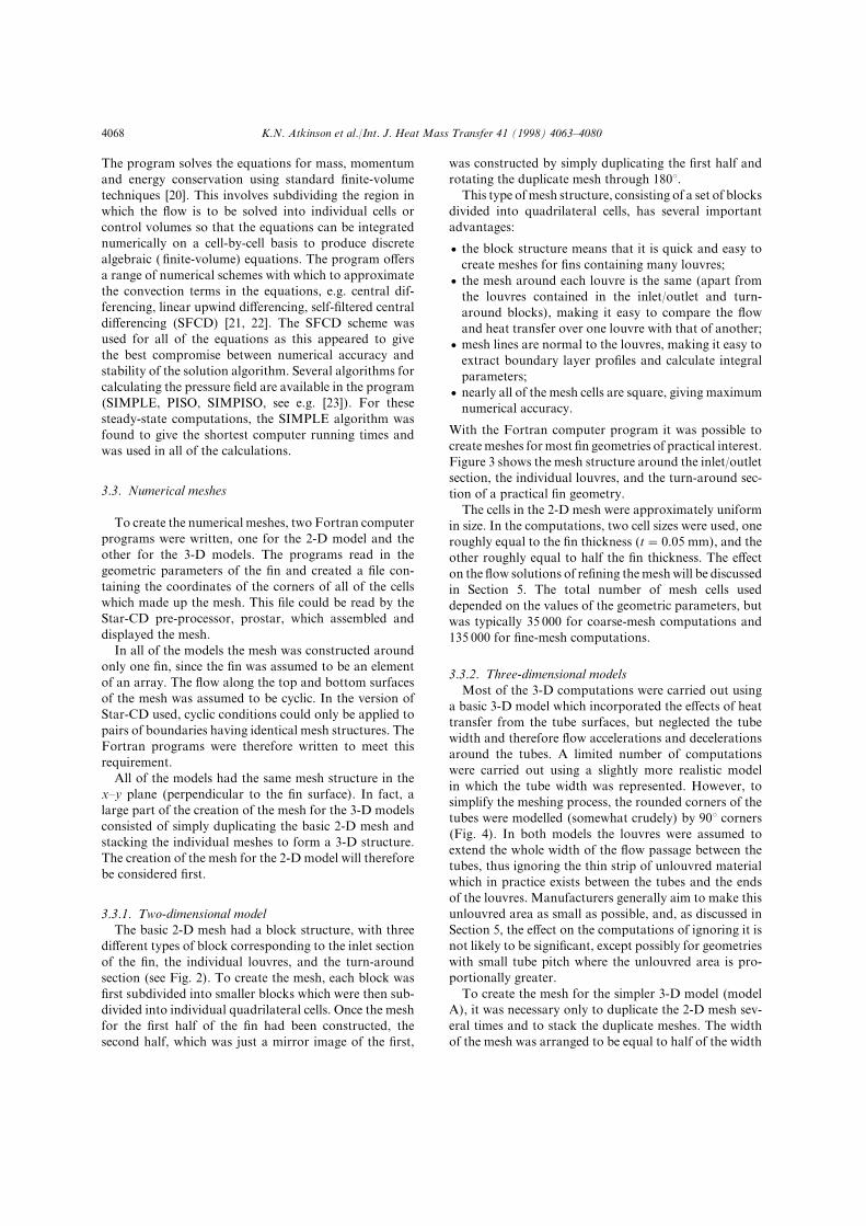
The program solves the equations for mass\ momentumand energy conservation using standard _nite!volumetechniques ð19Ł[ This involves subdividing the region inwhich the ~ow is to be solved into individual cells orcontrol volumes so that the equations can be integratednumerically on a cell!by!cell basis to produce discretealgebraic " _nite!volume# equations[ The program o}ersa range of numerical schemes with which to approximatethe convection terms in the equations\ e[g[ central dif!ferencing\ linear upwind di}erencing\ self!_ltered centraldi}erencing "SFCD# ð10\ 11Ł[ The SFCD scheme wasused for all of the equations as this appeared to givethe best compromise between numerical accuracy andstability of the solution algorithm[ Several algorithms forcalculating the pressure _eld are available in the program"SIMPLE\ PISO\ SIMPISO\ see e[g[ ð12Ł#[ For thesesteady!state computations\ the SIMPLE algorithm wasfound to give the shortest computer running times andwas used in all of the calculations[
2[2[ Numerical meshes
To create the numerical meshes\ two Fortran computerprograms were written\ one for the 1!D model and theother for the 2!D models[ The programs read in thegeometric parameters of the _n and created a _le con!taining the coordinates of the corners of all of the cellswhich made up the mesh[ This _le could be read by theStar!CD pre!processor\ prostar\ which assembled anddisplayed the mesh[
In all of the models the mesh was constructed aroundonly one _n\ since the _n was assumed to be an elementof an array[ The ~ow along the top and bottom surfacesof the mesh was assumed to be cyclic[ In the version ofStar!CD used\ cyclic conditions could only be applied topairs of boundaries having identical mesh structures[ TheFortran programs were therefore written to meet thisrequirement[
All of the models had the same mesh structure in thexÐy plane "perpendicular to the _n surface#[ In fact\ alarge part of the creation of the mesh for the 2!D modelsconsisted of simply duplicating the basic 1!D mesh andstacking the individual meshes to form a 2!D structure[The creation of the mesh for the 1!D model will thereforebe considered _rst[
2[2[0[ Two!dimensional modelThe basic 1!D mesh had a block structure\ with three
di}erent types of block corresponding to the inlet sectionof the _n\ the individual louvres\ and the turn!aroundsection "see Fig[ 1#[ To create the mesh\ each block was_rst subdivided into smaller blocks which were then sub!divided into individual quadrilateral cells[ Once the meshfor the _rst half of the _n had been constructed\ thesecond half\ which was just a mirror image of the _rst\
was constructed by simply duplicating the _rst half androtating the duplicate mesh through 079>[
This type of mesh structure\ consisting of a set of blocksdivided into quadrilateral cells\ has several importantadvantages]
+ the block structure means that it is quick and easy tocreate meshes for _ns containing many louvres^
+ the mesh around each louvre is the same "apart fromthe louvres contained in the inlet:outlet and turn!around blocks#\ making it easy to compare the ~owand heat transfer over one louvre with that of another^
+ mesh lines are normal to the louvres\ making it easy toextract boundary layer pro_les and calculate integralparameters^
+ nearly all of the mesh cells are square\ giving maximumnumerical accuracy[
With the Fortran computer program it was possible tocreate meshes for most _n geometries of practical interest[Figure 2 shows the mesh structure around the inlet:outletsection\ the individual louvres\ and the turn!around sec!tion of a practical _n geometry[
The cells in the 1!D mesh were approximately uniformin size[ In the computations\ two cell sizes were used\ oneroughly equal to the _n thickness "t � 9[94 mm#\ and theother roughly equal to half the _n thickness[ The e}ecton the ~ow solutions of re_ning the mesh will be discussedin Section 4[ The total number of mesh cells useddepended on the values of the geometric parameters\ butwas typically 24 999 for coarse!mesh computations and024 999 for _ne!mesh computations[
2[2[1[ Three!dimensional modelsMost of the 2!D computations were carried out using
a basic 2!D model which incorporated the e}ects of heattransfer from the tube surfaces\ but neglected the tubewidth and therefore ~ow accelerations and decelerationsaround the tubes[ A limited number of computationswere carried out using a slightly more realistic modelin which the tube width was represented[ However\ tosimplify the meshing process\ the rounded corners of thetubes were modelled "somewhat crudely# by 89> corners"Fig[ 3#[ In both models the louvres were assumed toextend the whole width of the ~ow passage between thetubes\ thus ignoring the thin strip of unlouvred materialwhich in practice exists between the tubes and the endsof the louvres[ Manufacturers generally aim to make thisunlouvred area as small as possible\ and\ as discussed inSection 4\ the e}ect on the computations of ignoring it isnot likely to be signi_cant\ except possibly for geometrieswith small tube pitch where the unlouvred area is pro!portionally greater[
To create the mesh for the simpler 2!D model "modelA#\ it was necessary only to duplicate the 1!D mesh sev!eral times and to stack the duplicate meshes[ The widthof the mesh was arranged to be equal to half of the width

K[N[ Atkinson et al[:Int[ J[ Heat Mass Transfer 30 "0887# 3952Ð3979 3958
Fig[ 1[ Block structure of the 1!D mesh[
Fig[ 2[ Typical mesh for the 1!D model^ Fp � 1[943 mm\ Lp �0[3 mm\ u � 14[4>\ t � 9[94 mm[ "a# Inlet section[ "b# Individuallouvres[ "c# Turn!around section[
of the passage between the tubes\ i[e[ "Tp−Tw#:1\ whereTp is the tube pitch and Tw is the tube width[ One side ofthe mesh was de_ned to be a symmetry plane and theside opposite was divided into symmetry planes and solidregions\ as shown in Fig[ 3[ The width of the solid regionswas equal to the distance between the farthest upstreamand downstream points on the outer surfaces of the tubes[
In the computations\ one value of tube width\ equal to1 mm\ and two values of tube pitch\ equal to 7 and 03mm\ were considered[ In each case\ the width of the cell
layer adjacent to the tube wall was set equal to the _nthickness "9[94 mm#\ and the remaining cell layersexpanded in width towards the symmetry plane[ Theexpansion factor was arranged to be no greater than 0[1\giving a total of 04 cell layers for the tube pitch 7 mmand 08 cell layers for the tube pitch 03 mm[
The mesh for the more realistic model "model B# wasdeveloped from the mesh for model A[ The three surfacesde_ned as symmetry planes on one side of model A weredisplaced sideways into the centreplane of the tubes\ andthe spaces in between were _lled by duplicating and stack!ing the adjacent mesh structure[ The spacing between thecell layers was arranged to expand uniformly to the cen!treplane[ With the number of cell layers set to 8\ the expan!sion factor was almost exactly 0[1[ As in the 1!D model\the total number of mesh cells depended on the values ofthe geometric parameters[ For the computations with tubepitch 7 mm the total number of cells was around 499 999for model A and 459 999 for model B[
2[3[ Boundary conditions
Boundary conditions were required for u\ v and T inthe 1! and 2!D models\ and also for w in the 2!D models[At the inlet plane all of the properties were assumed tobe constant\ with v "and w in the 2!D models# beingset to zero and T being set to the ambient atmospherictemperature[
On the _n and tube surfaces\ no!slip "i[e[ zero velocity#conditions were assumed to exist[ In the 1!D model thetemperature of the _n was assumed to be constant and tobe about 69>C above the atmospheric temperature[ Thiscorresponded to the di}erence in air and water!side tem!peratures in the experiments by Achaichia and Cowell ð2Ł[
In the 2!D models the temperature of the tube surfacewas assumed to be 69>C above the atmospheric tem!perature[ The Star!CD program has the facility to com!pute the temperature distribution within both solid and~uid regions\ and in the 2!D models this facility was usedto compute the variation in temperature in the _n withdistance from the tube surface[ The fall in temperatureacross the _n was found to be signi_cant under certain~ow conditions\ and to lead to signi_cantly better agree!ment between the predicted and experimentally deter!

K[N[ Atkinson et al[:Int[ J[ Heat Mass Transfer 30 "0887# 3952Ð39793969
Fig[ 3[ Solution domains for the 2!D models[ "a# Model A[ "b# Model B[
mined heat transfer performance[ The e}ect of the _ntemperature calculation on the ~ow solutions is discussedin more detail in Section 4\ but it may be stated here thatthis facility appears to be an essential component in thecorrect modelling of louvred!_n ~ows[
3[ Determination of performance parameters
The pressure drop and heat transfer performance ofthe louvred _n for a given set of geometric and ~owconditions can be characterised by a friction factor anda Stanton number\ respectively[ The ~ow conditionsthemselves can be characterised by a Reynolds number\
while the geometric conditions can be characterised interms of dimensionless parameters such as _n!to!louvrepitch ratio and louvre angle[
Following the conventions laid down by Kays andLondon ð13Ł\ the friction factor and Stanton number arede_ned in terms of the heat transfer area Aa\ the minimum~ow area Ac\ and the mean velocity through the minimum~ow area U\ as follows]
f �Dp
rU1
1Aa
Ac
\ St �hc
rUcp
[
The heat transfer coe.cient hc appearing in the Stanton

K[N[ Atkinson et al[:Int[ J[ Heat Mass Transfer 30 "0887# 3952Ð3979 3960
Fig[ 4[ Computed velocity and temperature _elds for the 1!D model^ Fp � 1[943 mm\ Lp � 0[3 mm\ u � 14[4>\ t � 9[94 mm[ "a# Velocity\ReLp � 099[ "b# Temperature\ ReLp � 099[ "c# Velocity\ ReLp � 0599[ "d# Temperature\ ReLp � 0599[

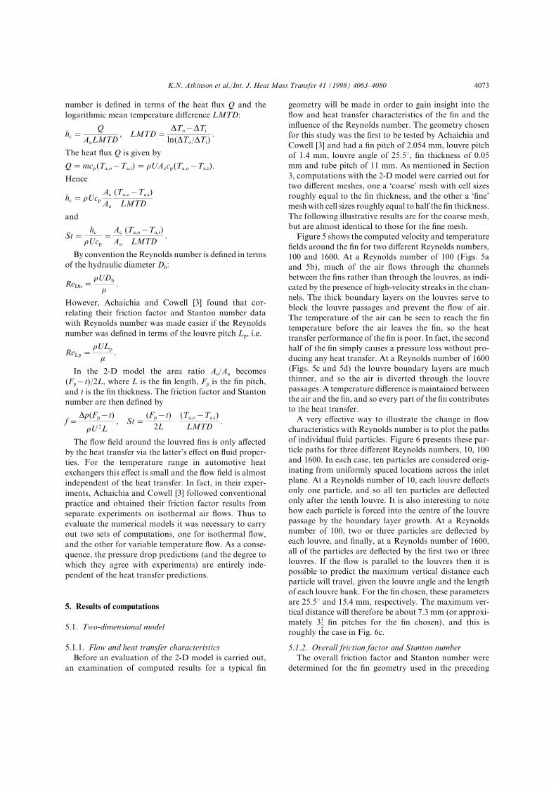
K[N[ Atkinson et al[:Int[ J[ Heat Mass Transfer 30 "0887# 3952Ð3979 3962
number is de_ned in terms of the heat ~ux Q and thelogarithmic mean temperature di}erence LMTD]
hc �Q
AaLMTD\ LMTD �
DTo−DTi
ln"DTo:DTi#[
The heat ~ux Q is given by
Q � mcp"Ta\o−Ta\i# � rUAccp"Ta\o−Ta\i#[
Hence
hc � rUcp
Ac
Aa
"Ta\o−Ta\i#LMTD
and
St �hc
rUcp
�Ac
Aa
"Ta\o−Ta\i#LMTD
[
By convention the Reynolds number is de_ned in termsof the hydraulic diameter Dh]
ReDh �rUDh
m[
However\ Achaichia and Cowell ð2Ł found that cor!relating their friction factor and Stanton number datawith Reynolds number was made easier if the Reynoldsnumber was de_ned in terms of the louvre pitch Lp\ i[e[
ReLp �rULp
m[
In the 1!D model the area ratio Ac:Aa becomes"Fp−t#:1L\ where L is the _n length\ Fp is the _n pitch\and t is the _n thickness[ The friction factor and Stantonnumber are then de_ned by
f �Dp"Fp−t#
rU1L\ St �
"Fp−t#1L
"Ta\o−Ta\i#LMTD
[
The ~ow _eld around the louvred _ns is only a}ectedby the heat transfer via the latter|s e}ect on ~uid proper!ties[ For the temperature range in automotive heatexchangers this e}ect is small and the ~ow _eld is almostindependent of the heat transfer[ In fact\ in their exper!iments\ Achaichia and Cowell ð2Ł followed conventionalpractice and obtained their friction factor results fromseparate experiments on isothermal air ~ows[ Thus toevaluate the numerical models it was necessary to carryout two sets of computations\ one for isothermal ~ow\and the other for variable temperature ~ow[ As a conse!quence\ the pressure drop predictions "and the degree towhich they agree with experiments# are entirely inde!pendent of the heat transfer predictions[
4[ Results of computations
4[0[ Two!dimensional model
4[0[0[ Flow and heat transfer characteristicsBefore an evaluation of the 1!D model is carried out\
an examination of computed results for a typical _n
geometry will be made in order to gain insight into the~ow and heat transfer characteristics of the _n and thein~uence of the Reynolds number[ The geometry chosenfor this study was the _rst to be tested by Achaichia andCowell ð2Ł and had a _n pitch of 1[943 mm\ louvre pitchof 0[3 mm\ louvre angle of 14[4>\ _n thickness of 9[94mm and tube pitch of 00 mm[ As mentioned in Section2\ computations with the 1!D model were carried out fortwo di}erent meshes\ one a {coarse| mesh with cell sizesroughly equal to the _n thickness\ and the other a {_ne|mesh with cell sizes roughly equal to half the _n thickness[The following illustrative results are for the coarse mesh\but are almost identical to those for the _ne mesh[
Figure 4 shows the computed velocity and temperature_elds around the _n for two di}erent Reynolds numbers\099 and 0599[ At a Reynolds number of 099 "Figs[ 4aand 4b#\ much of the air ~ows through the channelsbetween the _ns rather than through the louvres\ as indi!cated by the presence of high!velocity streaks in the chan!nels[ The thick boundary layers on the louvres serve toblock the louvre passages and prevent the ~ow of air[The temperature of the air can be seen to reach the _ntemperature before the air leaves the _n\ so the heattransfer performance of the _n is poor[ In fact\ the secondhalf of the _n simply causes a pressure loss without pro!ducing any heat transfer[ At a Reynolds number of 0599"Figs[ 4c and 4d# the louvre boundary layers are muchthinner\ and so the air is diverted through the louvrepassages[ A temperature di}erence is maintained betweenthe air and the _n\ and so every part of the _n contributesto the heat transfer[
A very e}ective way to illustrate the change in ~owcharacteristics with Reynolds number is to plot the pathsof individual ~uid particles[ Figure 5 presents these par!ticle paths for three di}erent Reynolds numbers\ 09\ 099and 0599[ In each case\ ten particles are considered orig!inating from uniformly spaced locations across the inletplane[ At a Reynolds number of 09\ each louvre de~ectsonly one particle\ and so all ten particles are de~ectedonly after the tenth louvre[ It is also interesting to notehow each particle is forced into the centre of the louvrepassage by the boundary layer growth[ At a Reynoldsnumber of 099\ two or three particles are de~ected byeach louvre\ and _nally\ at a Reynolds number of 0599\all of the particles are de~ected by the _rst two or threelouvres[ If the ~ow is parallel to the louvres then it ispossible to predict the maximum vertical distance eachparticle will travel\ given the louvre angle and the lengthof each louvre bank[ For the _n chosen\ these parametersare 14[4> and 04[3 mm\ respectively[ The maximum ver!tical distance will therefore be about 6[2 mm "or approxi!mately 20
1_n pitches for the _n chosen#\ and this is
roughly the case in Fig[ 5c[
4[0[1[ Overall friction factor and Stanton numberThe overall friction factor and Stanton number were
determined for the _n geometry used in the preceding

K[N[ Atkinson et al[:Int[ J[ Heat Mass Transfer 30 "0887# 3952Ð39793963
Fig[ 5[ Particle paths for a louvred _n[ "a# ReLp � 09[ "b# ReLp � 099[ "c# ReLp � 0599[
computations\ using the equations given in Section 3for the limiting case of two!dimensional ~ow[ Numericalcomputations were made for Reynolds numbers from099 to 2199\ and therefore over a somewhat greater rangethan is typical of automotive heat exchangers"ReLp � 199 to 0199#[ In Fig[ 6a\ the friction factor andStanton number for both the coarse and _ne mesh solu!tions are plotted against Reynolds number\ along withthe experimentally determined values of Achaichia andCowell ð2Ł[ The coarse and _ne mesh results can be seento be very similar\ except for a slight lowering of theStanton number with mesh re_nement at high Reynoldsnumber[ The computed results appear to be relativelyinsensitive to mesh re_nement\ given that a two!foldreduction in the cell size was carried out[ Since the SFCDscheme used in the computations is approximatelysecond!order accurate\ any further changes with meshre_nement can be expected to be small[ It therefore seemsreasonable to suppose that the computed results "at leastfor the _ne mesh# are close to being mesh independent[
From Fig[ 6a it can be seen that the computed frictionfactor and Stanton number follow very similar trendsto the measurements[ The measured friction factor andStanton number have roughly constant slope forReynolds numbers greater than 199\ when plotted on logÐ
log axes\ and this trend is also re~ected in the calculations\with the computed slope being almost exactly the sameas in the measurements[ However\ it is clear from Fig[ 6athat there is a signi_cant o}set between the computedand measured Stanton number[ This o}set is uniformand represents a 69) overprediction of the Stanton num!ber\ and hence the heat transfer rate[ Also evident is thefact that no computed Stanton number data are plottedfor a Reynolds number of less than 199\ even though themeasured data "and the computed friction factor data#continue down to a Reynolds number of 099[ Both theo}set in the Stanton number and the absence of com!puted Stanton number data at low Reynolds numbersare essentially due to the fact that the heat transfer rateis overpredicted[ This overprediction causes the air tem!perature to reach the _n temperature at low Reynoldsnumber\ as seen in Fig[ 4b\ which in turn causes DTo tobecome zero and the LMTD to become indeterminate[
Computations were not made for Reynolds numbersbelow 099\ but it can be seen from Fig[ 6a that the slopeof the measured friction factor data increases signi_cantlyfor lower Reynolds numbers[ Achaichia and Cowell ð2Łattribute this increase in slope to the change in ~owalignment at low Reynolds number[ Consequently\ theslope of the friction factor data ceases to be consistent

K[N[ Atkinson et al[:Int[ J[ Heat Mass Transfer 30 "0887# 3952Ð3979 3964
Fig[ 6[ Computed and measured friction factor and Stanton number[ Computations are for the 1!D model[ Friction factor] r\computed\ coarse mesh^ �\ computed\ _ne mesh^ e\ measured[ Stanton number] R\ computed\ coarse mesh^ Ž\ computed\ _ne mesh^E\ measured[ Data are shown for Lp � 0[3 mm\ Tp � 00 mm\ t � 9[94 mm and "a# Fp � 1[94 mm\ u � 14[4>^ "b# 1[93 mm\ 17[4>^"c# 1[98 mm\ 10[4>^ "d# 0[53 mm\ 14[4>[
with a series of laminar boundary layers and approachesa value more consistent with laminar ~ow in a rectangularchannel[
Further computations were made for some of the other_n geometries investigated by Achaichia and Cowell ð2Ł[The geometries chosen for these computations encom!passed a wide variety of individual geometric parametervalues\ and comparisons of computed and measured fric!tion factor and Stanton number for some for thegeometries are shown in Figs[ 6bÐd[ In all cases the
model|s performance in terms of friction factor and Stan!ton number does not appear to be very di}erent from itsperformance for the _rst geometry "Fig[ 6a#[ The frictionfactor is computed reasonably well for all of thegeometries\ but the Stanton number is always sig!ni_cantly overpredicted\ although\ as with the _rstgeometry\ the slope of the computed Stanton numberdata agrees well with the measured slope[ The size of theo}set was found to vary from one geometry to another\and to reach as high as 099) for some geometries[
K[N[ Atkinson et al[:Int[ J[ Heat Mass Transfer 30 "0887# 3952Ð39793965
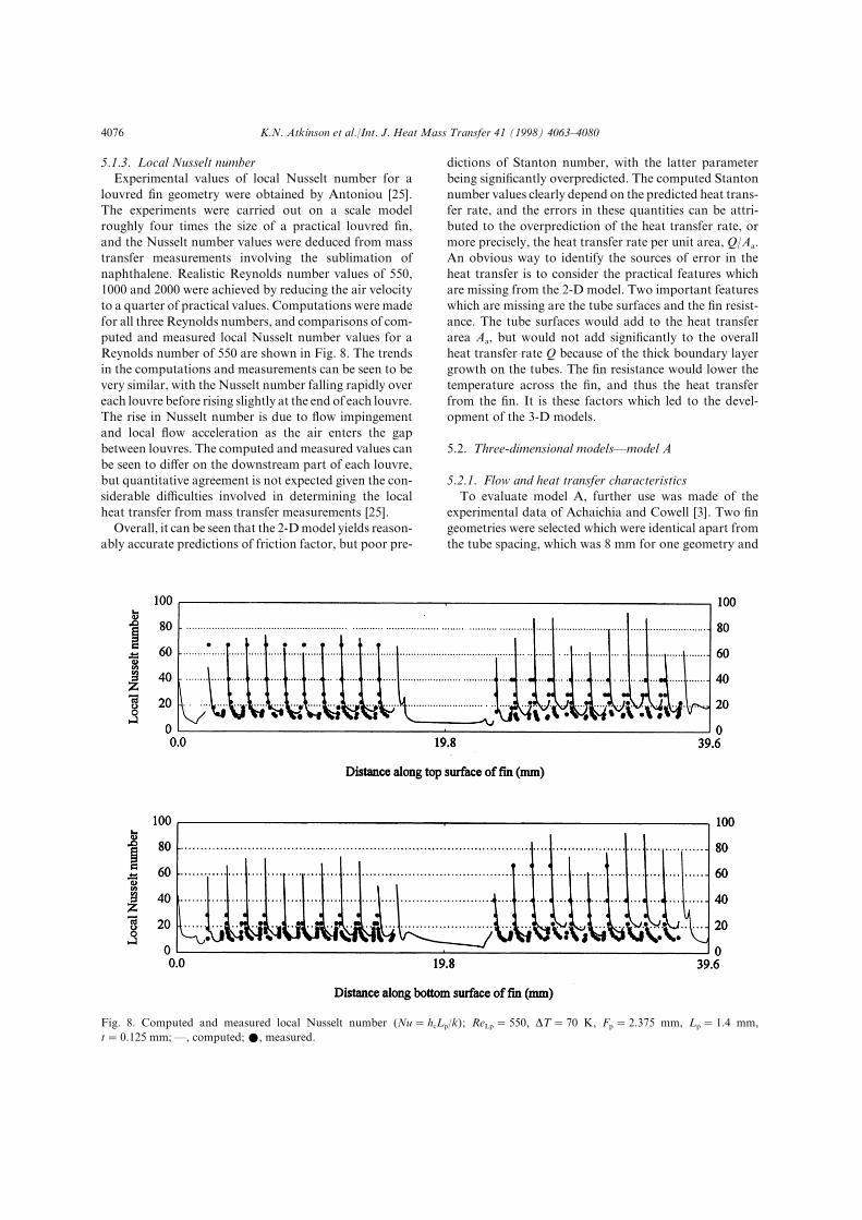
4[0[2[ Local Nusselt numberExperimental values of local Nusselt number for a
louvred _n geometry were obtained by Antoniou ð14Ł[The experiments were carried out on a scale modelroughly four times the size of a practical louvred _n\and the Nusselt number values were deduced from masstransfer measurements involving the sublimation ofnaphthalene[ Realistic Reynolds number values of 449\0999 and 1999 were achieved by reducing the air velocityto a quarter of practical values[ Computations were madefor all three Reynolds numbers\ and comparisons of com!puted and measured local Nusselt number values for aReynolds number of 449 are shown in Fig[ 7[ The trendsin the computations and measurements can be seen to bevery similar\ with the Nusselt number falling rapidly overeach louvre before rising slightly at the end of each louvre[The rise in Nusselt number is due to ~ow impingementand local ~ow acceleration as the air enters the gapbetween louvres[ The computed and measured values canbe seen to di}er on the downstream part of each louvre\but quantitative agreement is not expected given the con!siderable di.culties involved in determining the localheat transfer from mass transfer measurements ð14Ł[
Overall\ it can be seen that the 1!D model yields reason!ably accurate predictions of friction factor\ but poor pre!
Fig[ 7[ Computed and measured local Nusselt number "Nu � hcLp:k#^ ReLp � 449\ DT � 69 K\ Fp � 1[264 mm\ Lp � 0[3 mm\t � 9[014 mm^ *\ computed^ ž\ measured[
dictions of Stanton number\ with the latter parameterbeing signi_cantly overpredicted[ The computed Stantonnumber values clearly depend on the predicted heat trans!fer rate\ and the errors in these quantities can be attri!buted to the overprediction of the heat transfer rate\ ormore precisely\ the heat transfer rate per unit area\ Q:Aa[An obvious way to identify the sources of error in theheat transfer is to consider the practical features whichare missing from the 1!D model[ Two important featureswhich are missing are the tube surfaces and the _n resist!ance[ The tube surfaces would add to the heat transferarea Aa\ but would not add signi_cantly to the overallheat transfer rate Q because of the thick boundary layergrowth on the tubes[ The _n resistance would lower thetemperature across the _n\ and thus the heat transferfrom the _n[ It is these factors which led to the devel!opment of the 2!D models[
4[1[ Three!dimensional models*model A
4[1[0[ Flow and heat transfer characteristicsTo evaluate model A\ further use was made of the
experimental data of Achaichia and Cowell ð2Ł[ Two _ngeometries were selected which were identical apart fromthe tube spacing\ which was 7 mm for one geometry and

K[N[ Atkinson et al[:Int[ J[ Heat Mass Transfer 30 "0887# 3952Ð3979 3966
03 mm for the other[ The other dimensions were] _n pitch1[06 mm\ louvre pitch 0[0 mm\ louvre angle 11>\ and_n thickness 9[94 mm[ Computations were made forReynolds numbers between 099 and 0599[
The velocity and temperature distributions away fromthe tube walls were found to be very similar to those inthe 1!D computations and to vary in the same way withReynolds number[ The velocity _eld was essentially two!dimensional\ except in the boundary layers growing onthe tube walls[ The thickness of these boundary layerswas found to be uneven because of the presence of thelouvres\ but to be essentially independent of the tubespacing\ and to decrease with Reynolds number\ asexpected[ From the computed velocity _eld\ the thicknessof the velocity boundary layer was determined at thedownstream edge of the solid surface representing thesecond "downstream# tube[ The thickness was found todecrease from about 9[8 mm at a Reynolds number of099 to about 9[4 mm at a Reynolds number of 0599[ Thecontributions to the total heat transfer from the tubesand the _n were determined for each Reynolds number\and these values were used to determine the reduction inQ:Aa due to the presence of the tube surfaces[ Thesereductions varied from 03 to 02) with increasingReynolds number for the geometry with tube pitch 7 mm\and from 7 to 5) for the geometry with tube pitch03 mm[
4[1[1[ Fin temperature variationThe temperature of the _n was found to decrease with
distance from the tubes because of the _n resistance\and by an amount which increased signi_cantly withReynolds number[ In Fig[ 8 the variation in _n tem!perature is plotted for two locations along the _n cor!responding to the middle of the two tubes[ The tem!perature falls more at the upstream location because theair temperature is lower\ and as would be expected\ thetemperature in the middle of the _n falls further as thetube spacing is increased[ The rapid fall in temperatureat high Reynolds number can be attributed to the higherheat transfer coe.cient on the _n surface[
4[1[2[ Overall friction factor and Stanton numberIn Fig[ 09 computed and measured values of friction
factor and Stanton number for the two _ns are presented[Computed values for both the 1!D model and the 2!Dmodel are included to indicate the improvement made bythe 2!D model[ Also shown\ for a Reynolds number of399\ is the computed Stanton number when the _n tem!perature is assumed to be uniform "i[e[ the _n resistanceis assumed to be zero#[ This latter value serves to indicatethe improvement in Stanton number due to the inclusionof the _n resistance[
It can be seen that the 2!D model produces even closeragreement between computed and measured frictionfactor\ particularly for the tube pitch of 7 mm[ The results
Fig[ 8[ Computed temperature variation across the _n^ Fp � 1[06mm\ Lp � 0[0 mm\ u � 11>\ t � 9[94 mm[ Middle of upstreamtube] D\ ReLp � 099^ �\ 399^ e\ 0599^ middle of downstreamtube^ R\ ReLp � 099^ Ž\ 399^ E\ 0599[ "a# Tp � 7 mm[ "b#Tp � 03 mm[
for the 1!D model are independent of the tube spacing\and the di}erences between computation and measure!ment for the lower tube pitch are more pronouncedbecause of the in~uence of the tube spacing[ It is note!worthy that the 2!D model produces a greater change infriction factor at the lower tube pitch as required toachieve agreement[

K[N[ Atkinson et al[:Int[ J[ Heat Mass Transfer 30 "0887# 3952Ð39793967
Fig[ 09[ Computed and measured friction factor and Stantonnumber[ Friction factor] r\ computed\ 1!D model^ �\computed\ 2!D model A^ e\ measured[ Stanton number] R\computed\ 1!D model\ Ž\ computed\ 2!D model A^ X\computed\ 2!D model A with uniform _n temperature^ E\measured[ Fp � 1[06 mm\ Lp � 0[0 mm\ u � 11>\ t � 9[94 mm["a# Tp � 7 mm[ "b# Tp � 03 mm[
The use of the 2!D model can be seen to bring about aconsiderable reduction in the o}set in Stanton number[For the tube pitch of 03 mm the o}set is practicallyreduced to zero\ while for the tube pitch of 7 mm it isreduced from a value representing a 89) error to a valuerepresenting a 14) error[ One possible reason for theremaining error is lack of mesh re_nement[ The cell sizesin the x!y plane of the 2!D mesh were the same as thosein the 1!D coarse mesh\ and Fig[ 6a shows that re_ningthe mesh in the x!y plane can produce a further signi_cantreduction in the o}set "around 04)#[ Another possiblereason is that the model ignores the thin strips of un!
louvred material adjacent to the tubes[ It is possible thatignoring these strips might cause the heat transfer to beoverpredicted in rough proportion to the width of thestrips[ According to Achaichia and Cowell ð2Ł the stripswere about 0:3 mm in width[ For the tube pitch of 7 mmthey accounted for about 7) of the width of the ~owpassage "leading to a possible 7) overprediction of theStanton number#\ and for the tube pitch of 03 mm\ about3)[ Achaichia and Cowell estimated that the uncer!tainties in their Stanton number and friction factor datawere about 5[4 and 04)\ respectively\ at the lower endof the Reynolds number range in Fig[ 09\ and about 2[4and 4)\ respectively\ at the upper end of the range[
From Fig[ 09\ it can be seen that the inclusion ofthe _n resistance makes a signi_cant contribution to theimprovement in the computed Stanton number[ For thetube pitch of 7 mm the contribution is 16)\ and for thetube pitch of 03 mm it is 54)[ These results are consistentwith the lower overall _n temperature for the wider tubepitch "Fig[ 8#\ and serve to emphasise the importanceof modelling the _n resistance\ especially for heatexchangers with wide tube spacing[
4[2[ Three!dimensional models*model B
Model B was applied to a single _n geometry\ thisbeing the geometry with tube pitch 7 mm used to evaluatemodel A[ Computations were carried out for Reynoldsnumbers of 099\ 399 and 0599\ but it was found thatconverged solutions could only be obtained for theReynolds numbers 099 and 399[ The computed Stantonnumber values for the two Reynolds numbers were foundto be very close to those for model A "within 3)#\ andthis was thought to be due to the fact that the inclusionof the tube width does not a}ect Q:Aa signi_cantly[ Thecomputed friction factor values were found to be some!what higher than those for model A "by 00) atReLp � 399# and therefore in poorer agreement withmeasurements[ However\ it is thought that much of theincrease was due to the rather crude modelling of thetube corners\ and in fact ignoring the tube width\ as inmodel A\ leads to a more accurate estimation of thepressure loss[
An examination of the velocity _eld around the tubesrevealed regions of separated ~ow at the corners of thetubes[ It was thought that the lack of convergence atReynolds number 0599 was due essentially to the factthat these separation regions become unsteady at highReynolds number[ Solving steady!~ow equations is there!fore no longer appropriate[ It is possible that convergencecould have been achieved if the rounded corners of thetubes had been accurately represented\ but the results forfriction factor and Stanton number would appear to callinto question the value of modelling these corners at all[
In summary\ it can be seen that the 2!D models givesigni_cantly better predictions of performance par!

K[N[ Atkinson et al[:Int[ J[ Heat Mass Transfer 30 "0887# 3952Ð3979 3968
ameters than the 1!D model\ and that predictions of theStanton number in particular are substantially better withthe 2!D models[ For the geometry with tube pitch 7mm\ di}erences were still present between computed andmeasured Stanton number[ Two possible sources of errorin the computations were identi_ed[ Lack of meshre_nement was thought to be a signi_cant source of error\and the fact that the unlouvred area of the _n was ignoredmay also have been signi_cant\ since this area accountsfor a greater proportion of the _n area for geometrieswith small tube pitch[
5[ Conclusions
In this paper 1! and 2!D numerical models have beendescribed for computing the ~ow and heat transfer overlouvred _n arrays in compact heat exchangers[ Two 2!Dmodels were presented\ both of which incorporated thetube surface area and the _n resistance\ and one of whichincorporated the tube width[ The models were evaluatedusing the measurements of overall Stanton number andfriction factor for louvred _n heat exchangers byAchaichia and Cowell ð2Ł[
It was found that the tube surface area and _n resist!ance in the 2!D models led to a considerable lowering ofthe predicted heat transfer rate per unit area "Q:Aa#\ andas a result the 2!D models gave much more accuratepredictions of overall Stanton number than the 1!Dmodel[ All of the models gave satisfactory predictions ofoverall friction factor\ although it was noted that for one_n geometry with small tube pitch the 2!D models gavesigni_cantly better predictions than the 1!D model[ Thee}ect on the Stanton number of modelling the tube widthwas negligible\ and this _nding was thought to be due tothe fact that the inclusion of the tube width does nota}ect Q:Aa signi_cantly[ It was found that the inclusionof the tube width led to slightly poorer predictions ofthe friction factor\ contrary to expectations\ but it wasthought that the slightly poorer results could be at!tributed to the rather crude way in which the tube cornerswere modelled[ For the _n geometry with small tube pitchit was found that signi_cant di}erences were still presentbetween computed and measured Stanton number evenwhen the 2!D models were used[ Apart from measure!ment uncertainties\ two possible sources of error wereidenti_ed[ These were lack of mesh re_nement and thefact that in the computations no account was taken ofthe unlouvred area of the _n adjacent to the tubes[
The computing resources required by the 2!D modelswere considerably greater than those of the 1!D model\with run times for the 2!D models being typically tentimes those of the 1!D model "about 19 hours on theSilicon Graphics computer#[ Nevertheless\ it is arguedthat the superior heat transfer predictions of the 2!D
models makes them much more useful as design toolsthan the 1!D model[ In any case\ if the recent rapidincreases in computing power continue\ there is everylikelihood that the run times of the 2!D models will\within the very near future\ match those of 1!D modelson today|s computers[
References
ð0Ł C[J[ Davenport\ Heat transfer and ~uid ~ow in louvredtriangular ducts] PhD thesis[ CNAA\ Lanchester Poly!technic\ 0879[
ð1Ł C[J[ Davenport[ Heat transfer and ~ow friction charac!teristics of louvred heat exchanger surfaces\ in] J[ Taborek\G[F[ Hewitt\ N[ Afgan\ "Eds#\ Heat Exchangers\ Theoryand Practice\ Hemisphere:MacGraw!Hill\ Washington\DC\ 0872\ pp[ 286Ð301[
ð2Ł A[ Achaichia\ T[A[ Cowell[ Heat transfer and pressure dropcharacteristics of ~at tube and louvred plate _n surfaces[Experimental Thermal and Fluid Science 0 "0877# 036Ð046[
ð3Ł M[ Kajino\ M[ Hiramatsu[ Research and development ofautomotive heat exchangers\ in] W[J[ Yang\ Y[ Mori "Eds[#\Heat Transfer in High Technology and Power Engineering\Hemisphere\ Washington\ DC\ 0876\ pp[ 319Ð321[
ð4Ł A[ Achaichia\ T[ A[ Cowell[ A _nite di}erence analysis offully developed periodic laminar ~ow in inclined louvrearrays[ Proceedings of the Second U[K[ National HeatTransfer Conference\ 0877\ pp[ 772Ð787[
ð5Ł F[N[ Beauvais[ An aerodynamic look at automotive radi!ators[ SAE Paper No[ 549369\ 0854[
ð6Ł L[T[ Wong\ M[C[ Smith[ Air~ow phenomena in thelouvered!_n heat exchanger[ SAE Paper No[ 629126\ 0862[
ð7Ł R[L[ Webb\ P[ Trauger[ Flow structure in the louvered _nheat exchanger geometry[ Experimental Thermal and FluidScience 3 "0880# 194Ð106[
ð8Ł A[A[ Antoniou\ M[R[ Heikal\ T[A[ Cowell[ Measurementsof local velocity and turbulence levels in arrays of louvredplate _ns[ Proceedings of the Ninth International HeatTransfer Conference\ Jerusalem\ 0889\ pp[ 094Ð009[
ð09Ł S[J[ Baldwin\ P[R[S[ White\ A[J[ Al!Daini\ C[J[ Davenport[Investigation of the gas side ~ow _eld in multilouvred ductswith ~ow reversal[ Proceedings of the Fifth InternationalConference on Numerical Methods in Laminar and Tur!bulent Flow\ Montreal\ 0876\ pp[ 371Ð384[
ð00Ł B[L[ Button\ R[ Tura\ C[C[ Wright[ Investigation of theair~ow through louvred rectangular ducts using laserDoppler anemometry[ Proceedings of the Second Inter!national Symposium on Applications of Laser DopplerAnemometry to Fluid Mechanics\ Lisbon\ 0873\ pp[E1ÐE4[
ð01Ł M[ Hiramatsu\ K[ Ota[ Heat transfer analysis for heatexchanger _ns[ Paper B292[ Proceedings of the NineteenthNational Heat Transfer Symposium of Japan\ 0871[
ð02Ł K[ Suga\ H[ Aoki\ T[ Shinagawa[ Numerical analysis ontwo!dimensional ~ow and heat transfer of louvered _nsusing overlaid grids[ JSME International Journal\ Series 122 "0# "0889# 011Ð016[
ð03Ł K[ Suga\ H[ Aoki[ Numerical study on heat transfer andpressure drop in multilouvered _ns[ Proceedings of the

K[N[ Atkinson et al[:Int[ J[ Heat Mass Transfer 30 "0887# 3952Ð39793979
ASME:JSME Thermal Engineering Joint Conference\Reno\ 0880\ pp[ 250Ð257[
ð04Ł M[ Hiramatsu\ T[ Ishimaru\ K[ Matsuzaki[ Research on_ns for air conditioning heat exchangers "0st Report\Numerical analysis of heat transfer on louvered _ns#[ JSMEInternational Journal\ Series II 22 "3# "0889# 638Ð645[
ð05Ł S[ Ikuta\ Y[ Sasaki\ K[ Tanaka\ M[ Takagi\ R[ Himeno[Numerical analysis of heat transfer around louver as!semblies[ SAE Paper No[ 899970\ 0889[
ð06Ł A[ Achaichia\ M[R[ Heikal\ Y[ Sulaiman\ T[A[ Cowell[Numerical investigation of ~ow and friction in louvred_n arrays[ Proceedings of the Tenth International HeatTransfer Conference\ Brighton\ 0883[
ð07Ł M[Y[ Ha\ K[C[ Kim\ S[H[ Koak\ K[H[ Kim\ K[I[ Kim\J[K[ Kang\ T[Y[ Park[ Fluid ~ow and heat transfer charac!teristics in multi!louvered _n heat exchanger[ SAE PaperNo[ 849004\ 0884[
ð08Ł T[ Shinagawa\ H[ Aoki\ K[ Suga[ A study of _nned heatexchanger] 4th report\ a method for measuring the heattransfer coe.cient of the louvers[ Proceedings of the
Twenty!third National Heat Transfer Symposium ofJapan\ 0875\ pp[ 239Ð231[
ð19Ł S[V[ Patankar[ Numerical Heat Transfer and Fluid Flow[Hemisphere Publishing Corporation\ 0879[
ð10Ł M[A[ Leschziner[ Practical evaluation of three _nite di}er!ence schemes for the computation of steady!state recir!culating ~ows[ Computer Methods in Applied Mechanicsand Engineering 12 "0879# 182Ð201[
ð11Ł P[G[ Huang\ B[E[ Launder\ M[A[ Leschziner[ Dis!cretization of non!linear convection processes] a broad!range comparison of four schemes[ Computer Methods inApplied Mechanics and Engineering 37 "0874# 0Ð13[
ð12Ł J[P[ Van Doormal\ G[D[ Raithby[ Enhancements of theSIMPLE method for predicting incompressible ~uid ~ows[Numerical Heat Transfer 6 "0873# 036Ð052[
ð13Ł W[M[ Kays\ A[L[ London[ Compact Heat Exchangers\McGraw!Hill\ New York\ 0873[
ð14Ł A[A[ Antoniou[ Measurements of local heat transfer\ vel!ocity and turbulence intensity values in louvred arrays[ PhDthesis[ CNAA\ Brighton Polytechnic\ 0878[