TUBE-ICE® MACHINE
149
12/2016 P-24AL & P-34AL TUBE-ICE ® MACHINE Service Manual $50 00
-
Upload
khangminh22 -
Category
Documents
-
view
0 -
download
0
Transcript of TUBE-ICE® MACHINE
12/2016
P-24AL
&
P-34AL TUBE-ICE®
MACHINE
Service Manual
$5000
12/2016
NOTICE
This manual is the property of the owner of this particular Tube-Ice®
machine.
Model #____________________ Serial #____________________.
It is to be left on the premises with this machine at all times. After start-up,
it should be stored in a safe place where it can be readily available when
needed for future reference in maintaining troubleshooting or servicing.
Failure to comply with this notice will result in unnecessary inconvenience
and possible additional expenses.
This manual is intended as an informational tool for the installation,
operation, maintenance, troubleshooting, and servicing of this equipment.
If an existing situation calls for additional information not found herein, we
suggest that you contact your distributor first. If further assistance or
information is needed, please feel free to contact the factory at 502-635-
3000 or FAX at 502-635-3024 or 502-634-0479.
IMPORTANT: The Warranty Registration/Start-Up Report found in the
front of this manual is to be completed and returned to the factory promptly
after the official start-up.
Please return to: Vogt Ice, LLC
1000 W. Ormsby, Suite 19
Louisville, KY 40210
Attn. SuperCare Department
12/2016
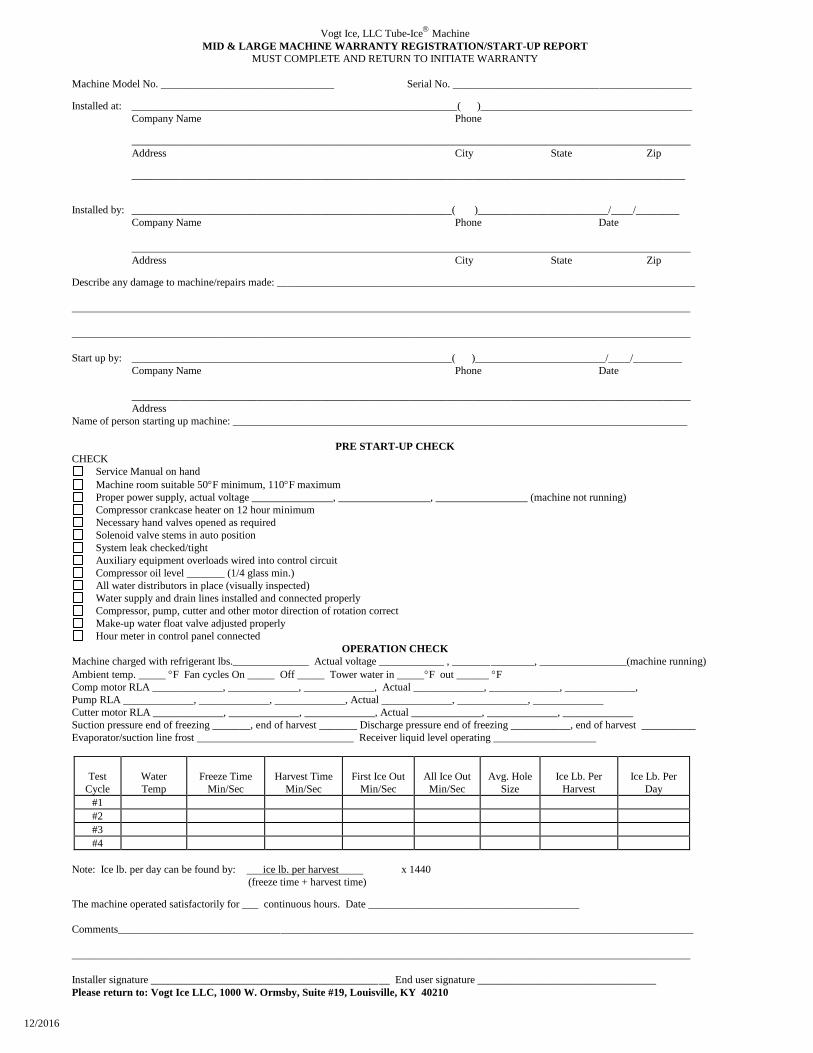
Vogt Ice, LLC Tube-Ice
Machine
MID & LARGE MACHINE WARRANTY REGISTRATION/START-UP REPORT
MUST COMPLETE AND RETURN TO INITIATE WARRANTY
Machine Model No. ________________________________ Serial No. ____________________________________________
Installed at: ____________________________________________________________( )_______________________________________
Company Name Phone
_______________________________________________________________________________________________________
Address City State Zip
______________________________________________________________________________________________________
Installed by: ___________________________________________________________( )________________________/____/________
Company Name Phone Date
_______________________________________________________________________________________________________
Address City State Zip
Describe any damage to machine/repairs made: _____________________________________________________________________________
__________________________________________________________________________________________________________________
__________________________________________________________________________________________________________________
Start up by: ___________________________________________________________( )________________________/____/_________
Company Name Phone Date
_______________________________________________________________________________________________________
Address
Name of person starting up machine: ____________________________________________________________________________________
PRE START-UP CHECK
CHECK
Service Manual on hand
Machine room suitable 50F minimum, 110F maximum
Proper power supply, actual voltage _______________, _________________, _________________ (machine not running)
Compressor crankcase heater on 12 hour minimum
Necessary hand valves opened as required
Solenoid valve stems in auto position
System leak checked/tight
Auxiliary equipment overloads wired into control circuit
Compressor oil level _______ (1/4 glass min.)
All water distributors in place (visually inspected)
Water supply and drain lines installed and connected properly
Compressor, pump, cutter and other motor direction of rotation correct
Make-up water float valve adjusted properly
Hour meter in control panel connected
OPERATION CHECK
Machine charged with refrigerant lbs.______________ Actual voltage ____________ , _______________, ________________(machine running)
Ambient temp. _____ F Fan cycles On _____ Off _____ Tower water in _____F out ______ F
Comp motor RLA _____________, _____________, _____________, Actual _____________, _____________, _____________,
Pump RLA _____________, _____________, _____________, Actual _____________, _____________, _____________
Cutter motor RLA _____________, _____________, _____________, Actual _____________, _____________, _____________
Suction pressure end of freezing _______, end of harvest _______ Discharge pressure end of freezing ___________, end of harvest __________
Evaporator/suction line frost _____________________________ Receiver liquid level operating ___________________
Test
Cycle
Water
Temp
Freeze Time
Min/Sec
Harvest Time
Min/Sec
First Ice Out
Min/Sec
All Ice Out
Min/Sec
Avg. Hole
Size
Ice Lb. Per
Harvest
Ice Lb. Per
Day
#1
#2
#3
#4
Note: Ice lb. per day can be found by: ice lb. per harvest x 1440
(freeze time + harvest time)
The machine operated satisfactorily for ___ continuous hours. Date _______________________________________
Comments__________________________________________________________________________________________________________
__________________________________________________________________________________________________________________
Installer signature ____________________________________________ End user signature _________________________________
Please return to: Vogt Ice LLC, 1000 W. Ormsby, Suite #19, Louisville, KY 40210

12/2016
VOGT
TUBE-ICE® MACHINES
P24AL & P34AL Model
Installation, Service Manual, and Parts Catalog #12A-4171L14
Vogt Ice, LLC
1000 W. Ormsby Avenue, Suite 19
Louisville, Kentucky, 40210
800-853-8648 502-635-3000
Fax: 502-634-0479
P24AL & P34AL Service Manual
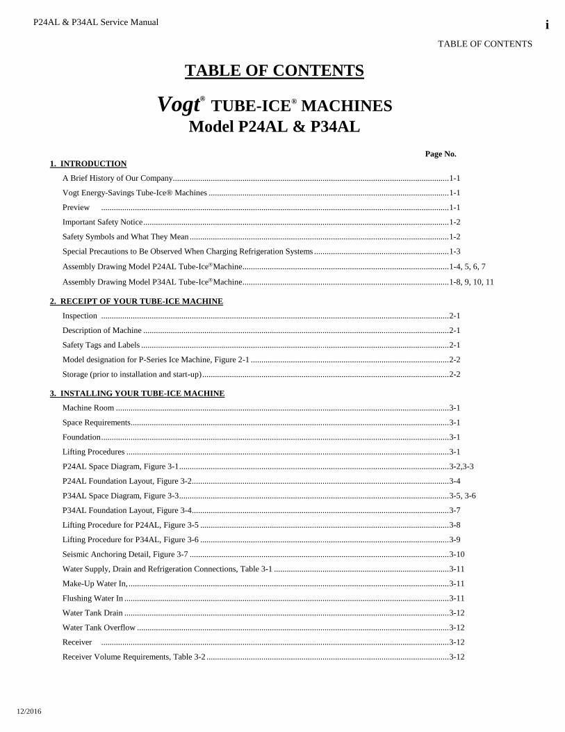
TABLE OF CONTENTS
12/2016
i
TABLE OF CONTENTS
Vogt®
TUBE-ICE® MACHINES
Model P24AL & P34AL
Page No.
1. INTRODUCTION
A Brief History of Our Company ................................................................................................................................... 1-1
Vogt Energy-Savings Tube-Ice® Machines .................................................................................................................. 1-1
Preview ..................................................................................................................................................................... 1-1
Important Safety Notice ................................................................................................................................................. 1-2
Safety Symbols and What They Mean ........................................................................................................................... 1-2
Special Precautions to Be Observed When Charging Refrigeration Systems ................................................................ 1-3
Assembly Drawing Model P24AL Tube-IceMachine .................................................................................................. 1-4, 5, 6, 7
Assembly Drawing Model P34AL Tube-IceMachine .................................................................................................. 1-8, 9, 10, 11
2. RECEIPT OF YOUR TUBE-ICE MACHINE
Inspection ..................................................................................................................................................................... 2-1
Description of Machine ................................................................................................................................................. 2-1
Safety Tags and Labels .................................................................................................................................................. 2-1
Model designation for P-Series Ice Machine, Figure 2-1 .............................................................................................. 2-2
Storage (prior to installation and start-up) ..................................................................................................................... 2-2
3. INSTALLING YOUR TUBE-ICE MACHINE
Machine Room .............................................................................................................................................................. 3-1
Space Requirements ....................................................................................................................................................... 3-1
Foundation ..................................................................................................................................................................... 3-1
Lifting Procedures ......................................................................................................................................................... 3-1
P24AL Space Diagram, Figure 3-1 ................................................................................................................................ 3-2,3-3
P24AL Foundation Layout, Figure 3-2 .......................................................................................................................... 3-4
P34AL Space Diagram, Figure 3-3 ................................................................................................................................ 3-5, 3-6
P34AL Foundation Layout, Figure 3-4 .......................................................................................................................... 3-7
Lifting Procedure for P24AL, Figure 3-5 ...................................................................................................................... 3-8
Lifting Procedure for P34AL, Figure 3-6 ...................................................................................................................... 3-9
Seismic Anchoring Detail, Figure 3-7 ........................................................................................................................... 3-10
Water Supply, Drain and Refrigeration Connections, Table 3-1 ................................................................................... 3-11
Make-Up Water In, ........................................................................................................................................................ 3-11
Flushing Water In .......................................................................................................................................................... 3-11
Water Tank Drain .......................................................................................................................................................... 3-12
Water Tank Overflow .................................................................................................................................................... 3-12
Receiver ..................................................................................................................................................................... 3-12
Receiver Volume Requirements, Table 3-2 ................................................................................................................... 3-12
P24AL & P34AL Service Manual
TABLE OF CONTENTS
12/2016
ii
Page No.
Suction Pressure Regulator ............................................................................................................................................ 3-12
Compressor Unloading .................................................................................................................................................. 3-12
Cooling Tower (optional) .............................................................................................................................................. 3-13
Total Heat Rejection Requirements, Table 3-3 .............................................................................................................. 3-13
Freeze Protection, Figures 3-8, 3-9, 3-10 ...................................................................................................................... 3-14, 3-15
Safety Valves ................................................................................................................................................................ 3-15
Wiring and Electrical Connections ................................................................................................................................ 3-15
Power Supply Connections, Figure 3-11 ....................................................................................................................... 3-16
Voltage Unbalance ........................................................................................................................................................ 3-16
Current Unbalance ......................................................................................................................................................... 3-17
Rotation Check .............................................................................................................................................................. 3-17
Auxiliary Controls or Equipment................................................................................................................................... 3-18
Interconnecting Piping for Vogt P24AL and Vogt 24AHS, Figure 3-12....................................................................... 3-19
Interconnecting Piping for Vogt P24AL and Dedicated High Side, Figure 3-13 .......................................................... 3-20
Interconnecting Piping for Vogt P34AL and Dedicated High Side, Figure 3-14 .......................................................... 3-21
Interconnecting Piping for Vogt P24AL and Central High Side, Figure 3-15 ............................................................... 3-22
Interconnecting Piping for Vogt P34AL and Central High Side, Figure 3-16 ............................................................... 3-23
Interconnecting Piping for 2-Vogt P34AL and Central High Side, Figure 3-17 ........................................................... 3-24
Interconnecting Piping for 3-Vogt P34AL and Central High Side, Figure 3-18 ........................................................... 3-25
Installation Review: A Checklist ................................................................................................................................... 3-26
4. HOW YOUR TUBE-ICE MACHINE WORKS
Operating Features ......................................................................................................................................................... 4-1
Principle of Operation ................................................................................................................................................... 4-1
Freeze Period ................................................................................................................................................................. 4-1
Harvest Period ............................................................................................................................................................... 4-2
Piping Nomenclature ..................................................................................................................................................... 4-2
Piping Schematic for P24AL, Figure 4-1 ...................................................................................................................... 4-3
Piping Schematic for P34AL, Figure 4-2 ...................................................................................................................... 4-4
5. START-UP AND OPERATION
Refrigeration System Review ........................................................................................................................................ 5-1
Start-up Checklist .......................................................................................................................................................... 5-2
Refrigerant Charge ......................................................................................................................................................... 5-2
Ammonia Specification by Grade, Table 5-1 ................................................................................................................. 5-2
Special Precautions to be Observed When Charging Refrigeration Systems ................................................................. 5-2
Charging from Tank Truck (for dedicated high side only) ............................................................................................ 5-3
Charging from Cylinders (for dedicated high side only)................................................................................................ 5-3
Control Panel, Figure 5-1 .............................................................................................................................................. 5-5
Start-Up ..................................................................................................................................................................... 5-5
Adding Refrigerant ........................................................................................................................................................ 5-6
Operating Tips ............................................................................................................................................................... 5-7
Thaw Gas Regulating and Suction Regulating Valve Adjustment ................................................................................. 5-7

P24AL & P34AL Service Manual
TABLE OF CONTENTS
12/2016
iii
Page No.
6. ELECTRICAL CONTROLS & THEIR FUNCTIONS
Bin Level Control .......................................................................................................................................................... 6-1
Safety Switches .............................................................................................................................................................. 6-1
Control Panel (Door Opened), Figure 6-1 ..................................................................................................................... 6-2
Description of Control Panel Parts (Inside), Table 6-1 .................................................................................................. 6-2
Control Panel (Door Closed), Figure 6-2 ...................................................................................................................... 6-3
Description of Control Panel Parts (Outer Door), Table 6-2 ......................................................................................... 6-3
Electrical Schematic All Voltages 50-60 Hz. Across Line Start, Figure 6-3 ................................................................. 6-4
7. MAINTENANCE
Preventive Maintenance ................................................................................................................................................. 7-1
Preventative Maintenance Form .................................................................................................................................... 7-2
Ice-Making Section ........................................................................................................................................................ 7-3
Cleaning Procedure........................................................................................................................................................ 7-3
Water Distributors ......................................................................................................................................................... 7-3
Water Distributors, Table 7-1 ........................................................................................................................................ 7-4
Average Hole Size in Tube-Ice, Table 7-2................................................................................................................... 7-4
Water Tank .................................................................................................................................................................... 7-4
Compressor (optional) ................................................................................................................................................... 7-5
Compressor Maintenance, Table 7-4 ............................................................................................................................. 7-6
Oil Trap .................................................................................................................................................................... 7-6
Cutter Gear Reducer ...................................................................................................................................................... 7-6
8. TROUBLESHOOTING
List of Symptoms ........................................................................................................................................................... 8-1
Machine Stopped ........................................................................................................................................................... 8-2, 8-3
Freeze-Up Due to Extended Freezing Period ................................................................................................................ 8-4
Freeze-Up Due to Ice Failing To Discharge .................................................................................................................. 8-5
Low Ice Capacity ........................................................................................................................................................... 8-6, 8-7
Poor Ice Quality ............................................................................................................................................................. 8-7
High Discharge Pressure ................................................................................................................................................ 8-8
Low Discharge Pressure ................................................................................................................................................ 8-9
High Suction Pressure ................................................................................................................................................... 8-9
Compressor Running Unloaded During Freeze ............................................................................................................. 8-9
Compressor Oil Pressure Low ....................................................................................................................................... 8-10
Compressor Loosing Oil Excessively ............................................................................................................................ 8-10
Machine Short Cycles .................................................................................................................................................... 8-11
High Compressor Discharge Temperature ..................................................................................................................... 8-11
Suction Line Frosting to Compressor ............................................................................................................................ 8-11
9. SERVICING OPERATIONS
Automatic Blow down (Harvest Cycle) ......................................................................................................................... 9-1
Cleaning the Ice Making Section ................................................................................................................................... 9-1
P24AL & P34AL Service Manual
TABLE OF CONTENTS
12/2016
iv
Page No. Float Valve (Make-Up Water) ....................................................................................................................................... 9-1
Float Switch ................................................................................................................................................................... 9-1
P24AL and P34AL Float Height, Figure 9-1 ................................................................................................................. 9-2
Hand Expansion Valve .................................................................................................................................................. 9-2
Freeze Timer .................................................................................................................................................................. 9-2
Miniature Rocker Switch Settings for Freeze Timer, Table 9-1 .................................................................................... 9-3
Entering and Displaying Set points ............................................................................................................................... 9-3
Freeze Timer, Figure 9-2 ............................................................................................................................................... 9-4
Freezer Pressure Switch (optional) ................................................................................................................................ 9-4
Freezer Pressure Switch, Figure 9-3 .............................................................................................................................. 9-5
Control Circuit Protection ............................................................................................................................................. 9-5
Thawing Timer .............................................................................................................................................................. 9-5
Thawing Timer, Figure 9-4 ............................................................................................................................................ 9-6
Suggested Condenser Cleaning ..................................................................................................................................... 9-6
Cutter Gear Reducer ...................................................................................................................................................... 9-7
Drive Gear Replacement ................................................................................................................................................ 9-7
Gear Reducer Replacement ............................................................................................................................................ 9-8
Water Tank and Cutter Parts Weights, Table 9-2 .......................................................................................................... 9-9
Water Tank Removal ..................................................................................................................................................... 9-9
Cutter Assembly Removal and Installation .................................................................................................................... 9-9
Bearing Bracket and Cutter Disc Removal .................................................................................................................... 9-10
Cutter Shaft and Bearing Removal ................................................................................................................................ 9-10
Cutter Shaft and Bearing Installation ............................................................................................................................. 9-10
Cutter Height Adjustment .............................................................................................................................................. 9-11
Water Tank Installation ................................................................................................................................................. 9-12
P24A Cutter Assembly, Figure 9-5A ............................................................................................................................. 9-12
P24A Water Tank Assembly, Figure 9-5B .................................................................................................................... 9-13
P24A and P34A Cutter and Water Tank Part Nos. ........................................................................................................ 9-14
Cutter Ring Gear Replacement ...................................................................................................................................... 9-15
Cutter Blade Replacement ............................................................................................................................................. 9-15
Cutter Blade and Adapter Plate Adjustment, Figure 9-6 ............................................................................................... 9-16
Cutter Adapter Plate Installation.................................................................................................................................... 9-18
Pumpdown ..................................................................................................................................................................... 9-16
Removal of Ammonia Refrigerant from the Machine .................................................................................................... 9-17
Refrigerant Leaks ........................................................................................................................................................... 9-17
Non-Condensable Gases ................................................................................................................................................ 9-18
Purging Non-Condensables ........................................................................................................................................... 9-18
Draining the Oil Trap..................................................................................................................................................... 9-19
Removing Excess Water from Ammonia ....................................................................................................................... 9-19
Circulating Water Pump Motor ..................................................................................................................................... 9-20
The Thaw Gas Solenoid Valve ...................................................................................................................................... 9-20
Thaw Gas Solenoid Valve, Figure 9-7 ........................................................................................................................... 9-21
The Liquid Feed Solenoid Valve ................................................................................................................................... 9-21

P24AL & P34AL Service Manual
TABLE OF CONTENTS
12/2016
v
Page No. The Liquid Feed Solenoid Valve, Figure 9-8 ................................................................................................................ 9-22
The Thaw Chamber Check Valve .................................................................................................................................. 9-22
The Thaw Chamber Check Valve, Figure 9-9 ............................................................................................................... 9-22
Water Flush Solenoid Valve .......................................................................................................................................... 9-22
Compressor Cooling Solenoid Valve (dedicated high side only) .................................................................................. 9-23
Compressor Oil Changing ............................................................................................................................................. 9-23
Compressor Inspection .................................................................................................................................................. 9-23
Belt Tension ................................................................................................................................................................... 9-24
Compressor Servicing .................................................................................................................................................... 9-24
10. OPTIONS AND ACCESSORIES
Crushed Ice Production ................................................................................................................................................ 10-1
Length of Ice ................................................................................................................................................................. 10-1
PLC (Programmable Logic Controller) ......................................................................................................................... 10-1
Mitsubishi E1012 Operator Interface, Figure 10-1 ........................................................................................................ 10-2
Mitsubishi PLC .............................................................................................................................................................. 10-3
Mitsubishi FKIN-24MR PLC and FX2N-8ER-ES/UL, Figure 10-2 ............................................................................. 10-3
Mitsubishi FX3GE-24MR PLC and FX2N-8ER-ES/UL, Figure 10-3 .......................................................................... 10-4
Mitsubishi PLC Input / Outputs, Table 10-1 ................................................................................................................. 10-4
Wiring Schematic – P24AL/P34AL with Mitsubishi PLC, Figure 10-4........................................................................ 10-5
Power Monitor ............................................................................................................................................................... 10-6
Power Monitor, Figure 10-5 .......................................................................................................................................... 10-6
Power Monitor Parameter Limits, Table 10-2 ............................................................................................................... 10-7
Parameter Adjustments .................................................................................................................................................. 10-7
11. TABLES AND CHARTS
P24AL Specifications, Table 11-1 ................................................................................................................................. 11-1
P34AL Specifications, Table 11-2 ................................................................................................................................. 11-2
P24AL Make-up Water Usage, Table 11-3 .................................................................................................................... 11-3
P34A Make-up Water Usage, Table 11-4 ...................................................................................................................... 11-3
P24A Normal Operating Vitals, Table 11-5 .................................................................................................................. 11-4
P34A Normal Operating Vitals, Table 11-6 .................................................................................................................. 11-4
Recommended Spare Parts List ..................................................................................................................................... 11-5
Temperature - Pressure Chart for Common Refrigerants, Table 11-7 ........................................................................... 11-6
Conversion Factors: English to Metric, Table 11-8 ....................................................................................................... 11-7
Constants, Table 11-9 .................................................................................................................................................... 11-7
12. INDEX
APPENDIX A
WARRANTY

P24AL & P34AL Service Manual
TABLE OF CONTENTS
12/2016
vi

P24AL & P34AL Service Manual
INTRODUCTION
12/2016
1-1
1. Introduction
Vogt Ice, LLC
A Brief History of Our Company. Henry Vogt Machine Co. was founded as a small machine shop
in Louisville, Kentucky in 1880. Today, Vogt Ice, LLC is one of the world’s leading producers of
ice-making equipment.
In 1938, Vogt built the first Tube-Ice® machine and revolutionized the ice-making industry. Our first
“sized-ice” machine quickly replaced the old can-ice plants, which required hard labor and large
amounts of floor space for freezing, cutting, and crushing ice by hand.
Vogt Energy-Saving Tube-Ice Machines Are Cost Effective. Today, Vogt Tube-Ice® machines
enjoy a well-earned reputation as the most energy efficient, dependable ice-making equipment in the
world.
Using as little as one-half to one-third the energy required by competitors’ ice makers, Tube-Ice®
machines produce the same amount of ice--in restaurants, sports arenas, packing plants, and
wholesale operations around the globe--at great savings.
In addition, Tube-Ice® machines are renowned for their long life, giving many customers more than
35 years of dependable service. Ask someone who owns one.
Preview. All the skill in engineering and fabrication that we’ve learned in over a century of
experience is reflected in every Tube-Ice® machine. Since Vogt introduced Tube-Ice® machines in
1938, the process of making Tube-Ice® ice has been widely recognized as the most economical
means of production. The machine’s economic and reliable operation has been proven over and over
again, in a network of varied types of installations throughout the world.
This manual is designed to assist you in the installation, start-up, and maintenance of your unit.
Your Tube-Ice® machine will give you a lifetime of service provided you install, maintain, and
service it properly. It is evidence of our desire to deliver to you “the finest ice-making unit ever
made.”
Please read your manual carefully before attempting installation, operation, or servicing of this
professionally-designed piece of equipment. Also, make sure the Warranty Registration/Start-up
Report is completed and returned.
If you have additional questions, please call your distributor. Also, feel free to phone the factory
direct at (502) 635-3000.
P24AL & P34AL Service Manual
INTRODUCTION
12/2016
1-2
Important Safety Notice. This information is intended for use by individuals possessing adequate
backgrounds in electrical, refrigeration and mechanical experience. Any attempt to repair major
equipment may result in personal injury and/or property damage. The manufacturer or seller cannot
be responsible for the interpretation of this information, nor can it assume any liability in connection
with its use. It is important that personnel understand the properties of this refrigerant and that they
be thoroughly trained in safe practices for its use and handling. Refer to the enclosed “Anhydrous
Ammonia Safety” in Appendix A.
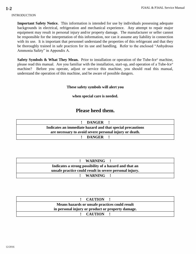
Safety Symbols & What They Mean. Prior to installation or operation of the Tube-Ice® machine,
please read this manual. Are you familiar with the installation, start-up, and operation of a Tube-Ice®
machine? Before you operate, adjust or service this machine, you should read this manual,
understand the operation of this machine, and be aware of possible dangers.
These safety symbols will alert you
when special care is needed.
Please heed them.
! DANGER !
Indicates an immediate hazard and that special precautions
are necessary to avoid severe personal injury or death.
! DANGER !
! WARNING !
Indicates a strong possibility of a hazard and that an
unsafe practice could result in severe personal injury.
! WARNING !
! CAUTION !
Means hazards or unsafe practices could result
in personal injury or product or property damage.
! CAUTION !

P24AL & P34AL Service Manual
INTRODUCTION
12/2016
1-3
Special Precautions to Be Observed When Charging Refrigeration Systems. Only technically-
qualified persons, experienced and knowledgeable in the handling of anhydrous ammonia refrigerant
and operation of refrigeration systems, should perform the operations described in this manual. All
local, federal, and EPA regulations must be strictly adhered to when handling ammonia (R-717)
refrigerant. See “Material Safety Data Sheet”, MSDS Code No. 5B81-83.
If a refrigeration system is being charged from refrigerant cylinders, disconnect each cylinder when
empty or when the system is fully charged. A gage should be installed in the charging line to
indicate refrigerant cylinder pressure. The cylinder may be considered empty of liquid R-717
refrigerant when the gauge pressure is 25 pounds or less, and there is no frost on the cylinder. Close
the refrigerant charging valve and cylinder valve before disconnecting the cylinder. Loosen the
union in the refrigerant charging line--carefully to avoid unnecessary, excessive or illegal release of
refrigerant into the atmosphere.
! CAUTION !
Immediately close system charging valve at commencement of defrost or thawing cycle if
refrigerant cylinder is connected. Never leave a refrigerant cylinder connected to system
except during charging operation. Failure to observe either of these precautions can result in
transferring refrigerant from the system to the refrigerant cylinder, over-filling it, and
possibly causing the cylinder to rupture because of pressure from expansion of the liquid
refrigerant brought on by an increase in temperature.
! CAUTION !
Always store cylinders containing refrigerant in a cool place. They should never be exposed to
temperatures higher than 120F and should be stored in a manner to prevent abnormal mechanical
shocks.
Also, transferring refrigerant from a refrigeration system into a cylinder can be very dangerous and is
not recommended.
! CAUTION !
It is not recommended that refrigerant be transferred from a refrigeration system directly into
a cylinder. If such a transfer is made, the refrigerant cylinder must be an approved, CLEAN
cylinder--free of any contaminants or foreign materials--and must be weighed continuously to
assure contents do not exceed net weight specified by cylinder manufacturer or any applicable
code requirements.
! CAUTION !

P24AL & P34AL Service Manual
INTRODUCTION
12/2016
1-4
Figure 1-1
P24AL 1” Front Side (Control Panel)
P24AL & P34AL Service Manual
INTRODUCTION
12/2016
1-5
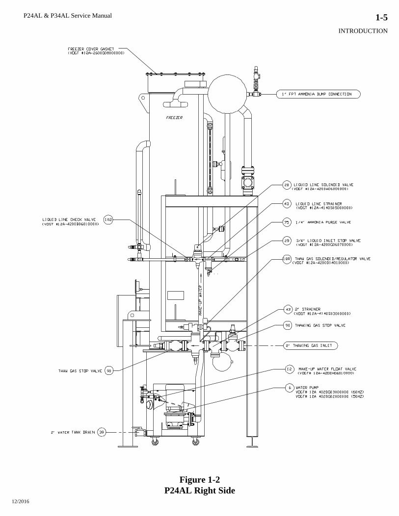
Figure 1-2
P24AL Right Side
P24AL & P34AL Service Manual
INTRODUCTION
12/2016
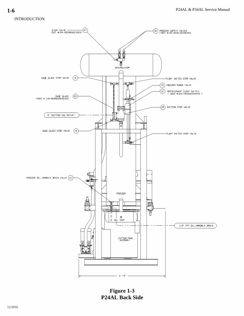
1-6
Figure 1-3
P24AL Back Side
P24AL & P34AL Service Manual
INTRODUCTION
12/2016
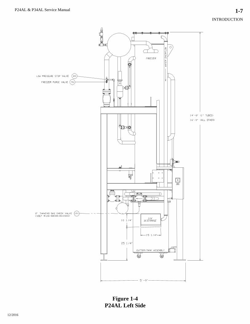
1-7
Figure 1-4
P24AL Left Side

P24AL & P34AL Service Manual
INTRODUCTION
12/2016
1-8
Figure 1-5
P34AL Front Side (Control Panel)

P24AL & P34AL Service Manual
INTRODUCTION
12/2016
1-9
Figure 1-6
P34AL Right Side
P24AL & P34AL Service Manual
INTRODUCTION
12/2016
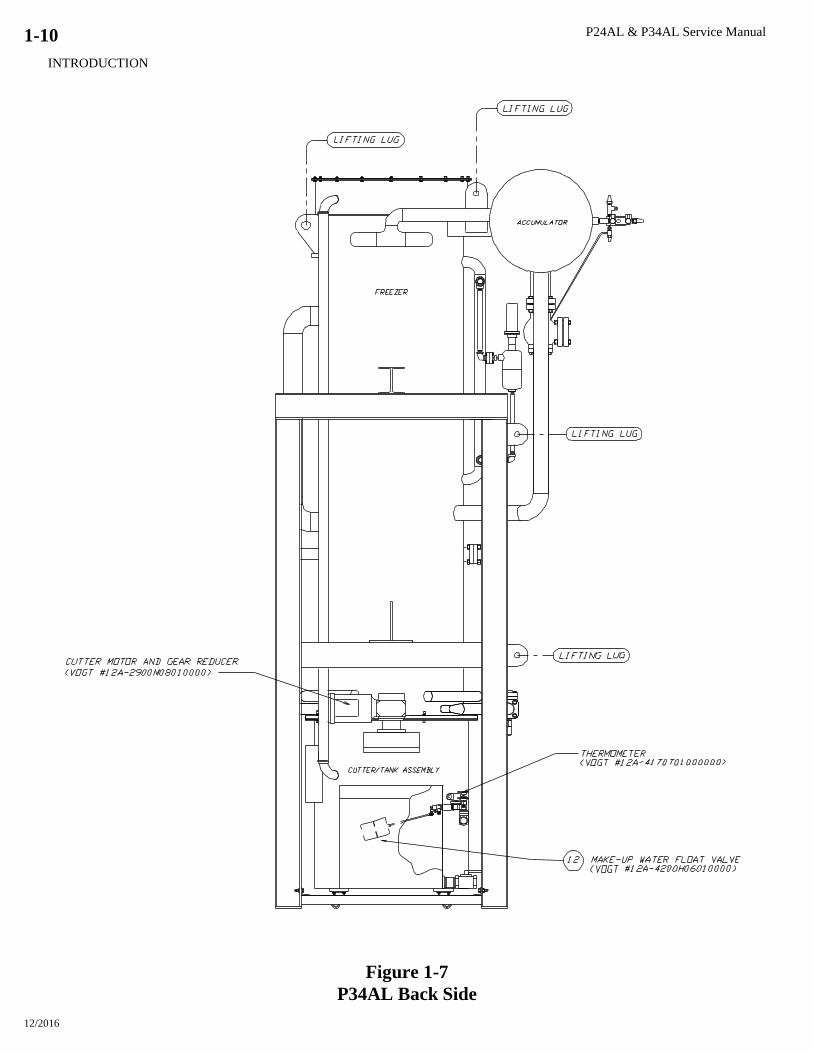
1-10
Figure 1-7
P34AL Back Side
P24AL & P34AL Service Manual
INTRODUCTION
12/2016
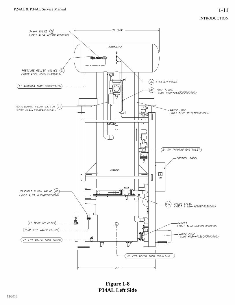
1-11
Figure 1-8
P34AL Left Side

P24AL & P34AL Service Manual
INTRODUCTION
12/2016
1-12
P24AL & P34AL Service Manual
RECEIPT OF YOUR TUBE-ICE MACHINE
12/2016
2-1
2. Receipt of Your Tube-Ice Machine
! CAUTION !
Only service personnel experienced in ammonia refrigeration and
qualified to work on high amperage electrical equipment should
be allowed to install or service this Tube-Ice machine.
Eye protection should be worn by all personnel
working on or around the Tube-Ice machine.
It is very important that you are familiar with and adhere to
all local, state, and federal, etc. ordinances and laws regarding
the handling, storing, and use of anhydrous ammonia.
An approved ammonia mask should be readily available
for use in an emergency and all personnel should be aware
of its location and proper use.
! CAUTION !
Inspection. As soon as you receive your machine, inspect it for any damage. If damage is
suspected, note it on the shipper’s papers (i.e., the trucker’s Bill of Lading). Immediately make a
separate written request for inspection by the freight line’s agent. Any repair work or alteration to
the machine without the permission of the Vogt Ice, LLC can void the machine’s warranty. You
should also notify your Vogt distributor or the factory.
Description of Machine. A low side Tube-Ice machine is a remote ice producing plant requiring
refrigerant suction connection, refrigerant liquid connection, thaw gas connection, make-up water
supply, electrical connection, and the proper refrigerant charge.
The machine has been partially factory tested prior to shipment and will require adjustment to meet
the high side (condensing unit) operating conditions. See “Start-up and Operation” for the correct
setting of the controls.
After factory pressure testing of the machine, the machine is evacuated and charged with nitrogen
gas pressure for shipment. This prevents air or moisture from entering the system during transit.
There should be a positive pressure (20-25 psig) indicated on the control panel gages when the
machine is received. The machine has been cleaned with ice machine cleaner and flushed so that the
machine is ready for ice production.
Safety Tags and Labels. Be sure to read and adhere to all special tags and labels attached to valves
or applied to various areas of the machine. They provide important information necessary for safe
and efficient operation of your equipment.
The machine is available in three different tube sizes for producing ice: 7/8” OD x 1” long, 1 1/8”
OD x 1” long, or 1 3/8” OD x 1” long. The ice is cut to length by a rotating breaker type cutter. Ice
can be produced up to 1 1/2” long by modifying the spacers under the adapter plates (see Chapter 10,
“Ice Length” for modifying instructions). Crushed ice is also available by modifying the cutter and
making minor adjustments to the machine (see Chapter 10, “Crushed Ice”).

P24AL & P34AL Service Manual
RECEIPT OF YOUR TUBE-ICE MACHINE
12/2016
2-2
50T A L A B 5 46 NC 000
Figure 2-1
Model Designation for P-Series Ice
Rated Capacity. Tube-Ice machines are rated to produce a given amount of ice when operating
under the proper conditions as specified in this manual (see Chapter 11 for the operating
specifications). You should be prepared to handle the ice produced as it is discharged from the
machine and move it to your storage or bagging area promptly.
Storage (prior to installation or start-up). The machine must not be stored or installed in an area
that is subject to reach temperatures at or above 110F (43.3C).
Nominal Capacity
(“T” = tons/day)
“25T” – 25 tons/day
“50T” – 50 tons/day
“80T” – 80 tons/day
Product Variation Code
A number or letter designator
assigned to specific variations
within a family series
“000 or Blank” – Standard
Product
Consult factory for specific
code interpretation Model Variation
A letter assigned to indicate
major variations within any one
family series Condenser Type
“WC” – Water Cooled
“NC” – No Condenser
Basic Configuration
“P” – Package
“L” – Lowside
Refrigerant
“F” – R-22
“A” – Ammonia
“H” – R-404a
Type of Ice
“B” – Cylinder
“K” – Crushed
“L” – 1 ½” Long Ice
Electrical Codes
“26” – 208/230-3-60
“46” – 460-3-60
“25” – 200-3-50
“45” – 400-3-50
Tube Size
(In ¼’s of an inch)
“4” – 1”
“5” – 1 ¼”
“6” – 1 ½”
“7” – 1 ¾”
“8” – 2”
P24AL & P34AL Service Manual
INSTALLING YOUR TUBE-ICE MACHINE
12/2016
3-1
3. Installing Your Tube-Ice Machine
Your machine will be shipped to you as one package. You will need to arrange for the handling of
the package as soon as it arrives, see Chapter 11 for shipping and operating weights. Before you
remove the unit from the truck, be certain that any sign of damage, however slight, is noted on the
carrier’s papers.
Note: See “Lifting Procedure” drawing included with this manual, Figures 3-5 and 3-6.
Machine Room. The machine must be located inside a suitable building and must not be subjected
to ambient temperatures below 50F (10C) or above 110F (43.3C). Heat radiation from other
sources (sunlight, furnaces, condenser, etc.) and unusual air current may affect the operation of the
machine and should be avoided. The electrical components of the Tube-Ice® machine are rated
NEMA 1. Therefore, the machine should not be located in a hazardous area or sprayed with
water. The machine should be installed in an area where water will not stand, but will readily drain
away from the machine.
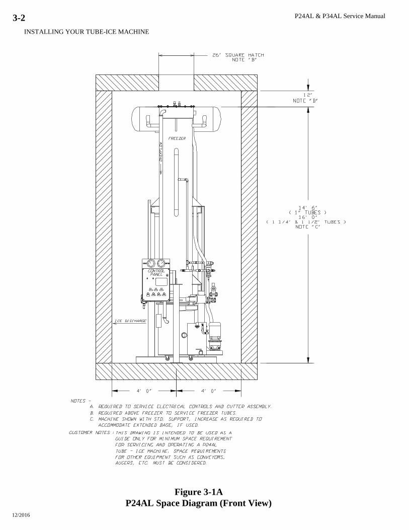
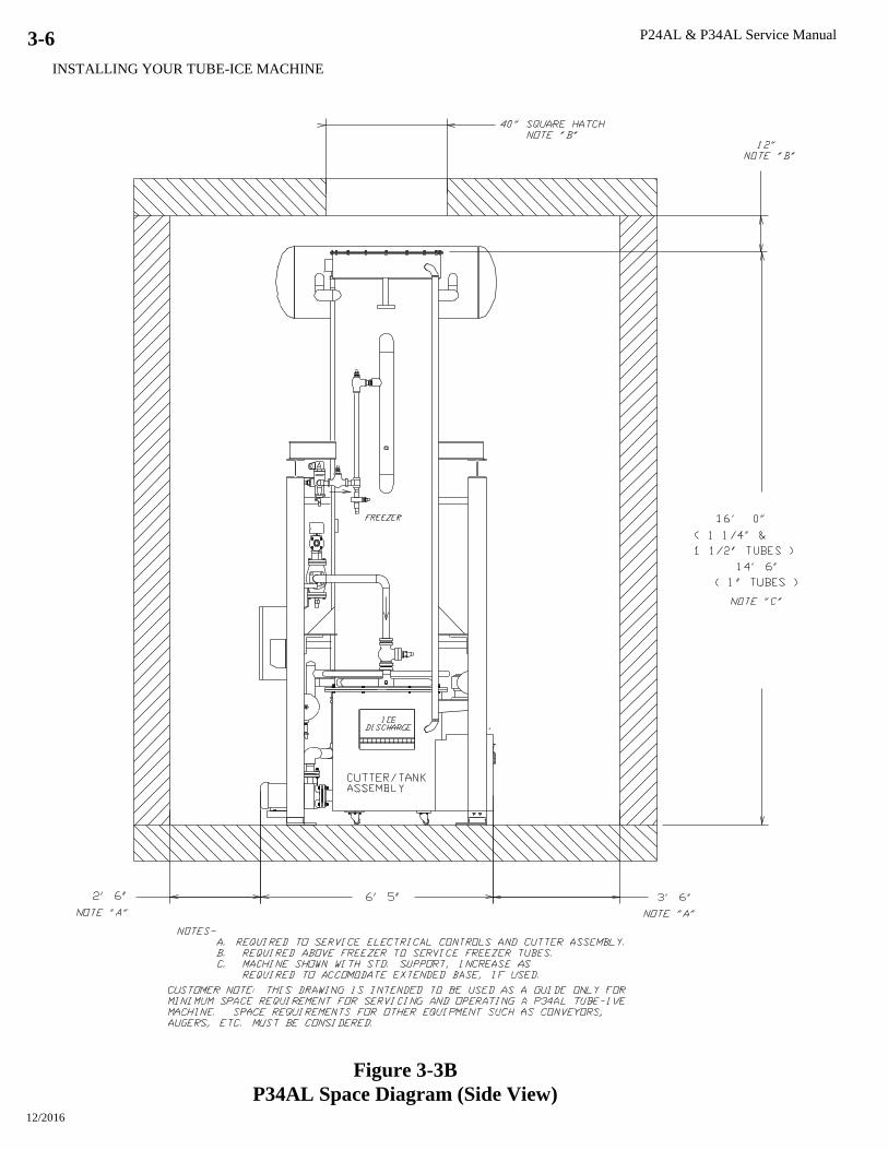
Space Requirements. Refer to the space diagrams, Figures 3-1 and 3-3, for recommended
minimum clearance around the machine for ease of servicing and observation. Pay particular
attention to the additional space required. If it ever becomes necessary to mechanically clean the
condenser tubes, extra space will be required on one end (preferably on the opposite end from the
water inlet and outlet) for the cleaning tools.
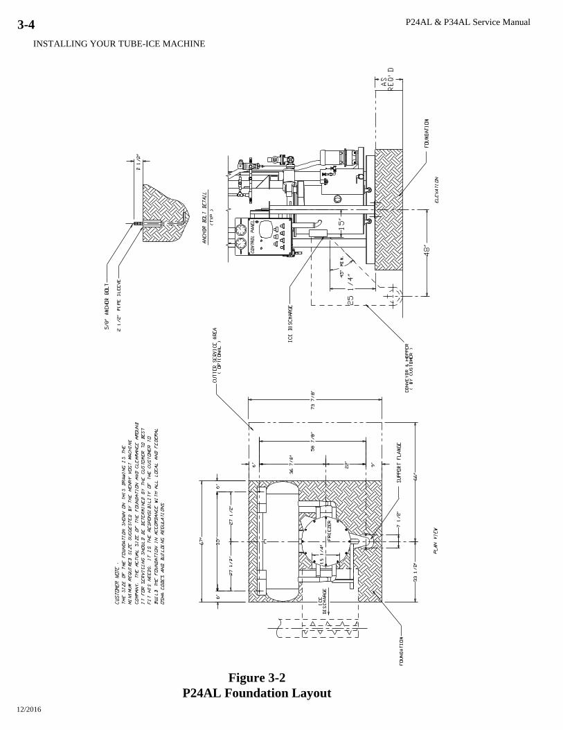
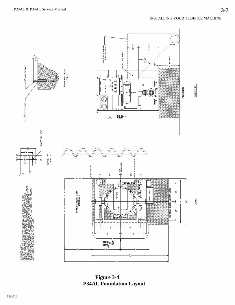
Foundation. Refer to the space diagrams, Figures 3-2 and 3-4, for recommended minimum
foundation requirements. The figures show anchor bolt details and machine anchor hole details.
Contact your local distributor for seismic anchoring requirements in your area.
! WARNING !
Lifting or moving heavy equipment should only be attempted by
competent rigging and hoisting contractors. Never allow personnel
near or under heavy equipment when it is being moved or lifted.
Failure to comply could result in personal injury or loss of life.
! WARNING !
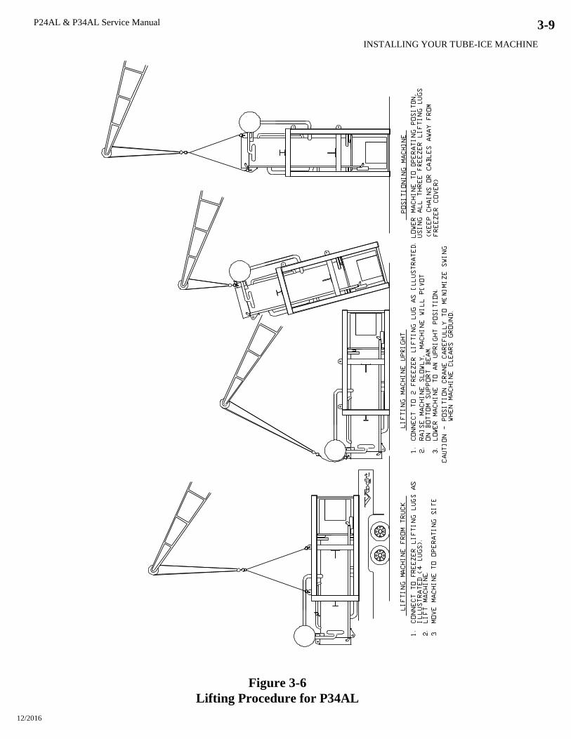
Lifting Procedures. Your Tube-Ice machine is provided with lifting lugs for the purpose of
unloading and moving the machine to its operation location. Refer to the enclosed drawings for
instructions and illustrations of their use.
P24AL - Figure 3-5. Machine weight 6,200 lbs.
P34AL - Figure 3-6. Machine weight 10,000 lbs.
These figures are intended as a guide to unloading and lifting the P24AL and P34AL Tube-Ice®
machine. Vogt Ice, LLC is not responsible for product damage or personnel injury or loss of
life during the loading or lifting process.
P24AL & P34AL Service Manual
INSTALLING YOUR TUBE-ICE MACHINE
12/2016
3-2
Figure 3-1A
P24AL Space Diagram (Front View)

P24AL & P34AL Service Manual
INSTALLING YOUR TUBE-ICE MACHINE
12/2016
3-3
Figure 3-1B
P24AL Space Diagram (Side View)
P24AL & P34AL Service Manual
INSTALLING YOUR TUBE-ICE MACHINE
12/2016
3-4
Figure 3-2
P24AL Foundation Layout

P24AL & P34AL Service Manual
INSTALLING YOUR TUBE-ICE MACHINE
12/2016
3-5
Figure 3-3A
P34AL Space Diagram (Front View)
P24AL & P34AL Service Manual
INSTALLING YOUR TUBE-ICE MACHINE
12/2016
3-6
Figure 3-3B
P34AL Space Diagram (Side View)
P24AL & P34AL Service Manual
INSTALLING YOUR TUBE-ICE MACHINE
12/2016
3-7
Figure 3-4
P34AL Foundation Layout

P24AL & P34AL Service Manual
INSTALLING YOUR TUBE-ICE MACHINE
12/2016
3-8
Figure 3-5
Lifting Procedure for P24AL
P24AL & P34AL Service Manual
INSTALLING YOUR TUBE-ICE MACHINE
12/2016
3-9
Figure 3-6
Lifting Procedure for P34AL
P24AL & P34AL Service Manual
INSTALLING YOUR TUBE-ICE MACHINE
12/2016
3-10
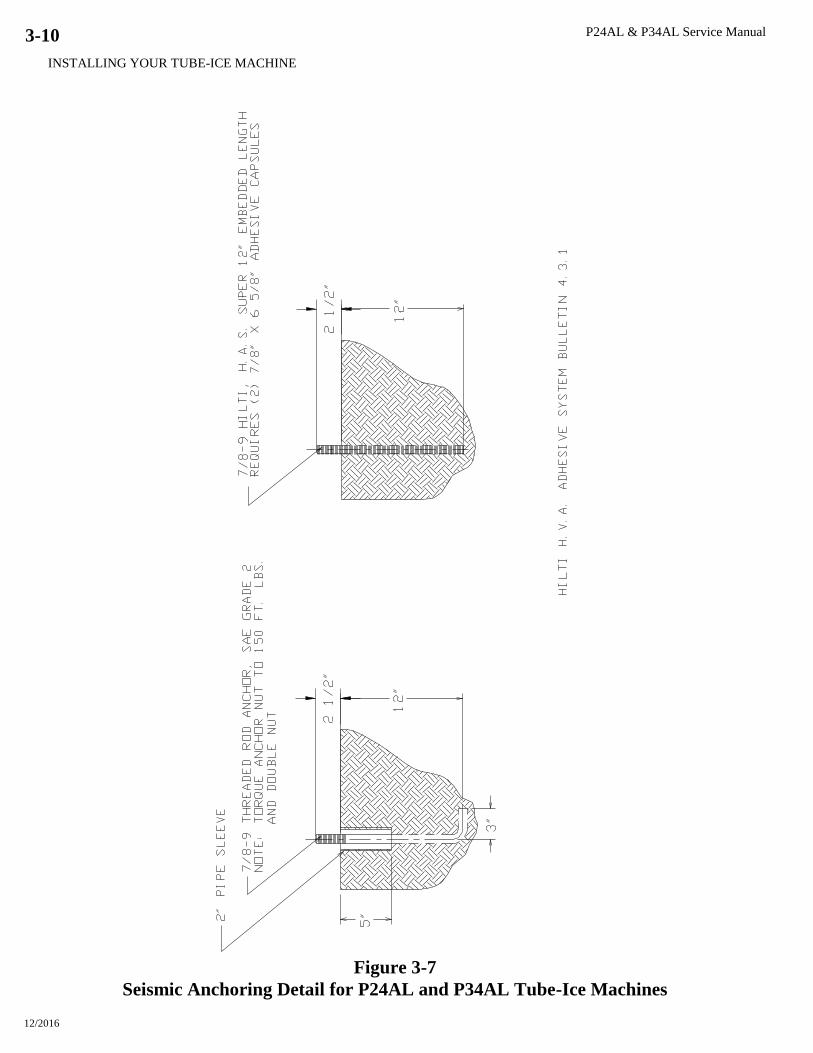
Figure 3-7
Seismic Anchoring Detail for P24AL and P34AL Tube-Ice Machines
P24AL & P34AL Service Manual
INSTALLING YOUR TUBE-ICE MACHINE
12/2016
3-11
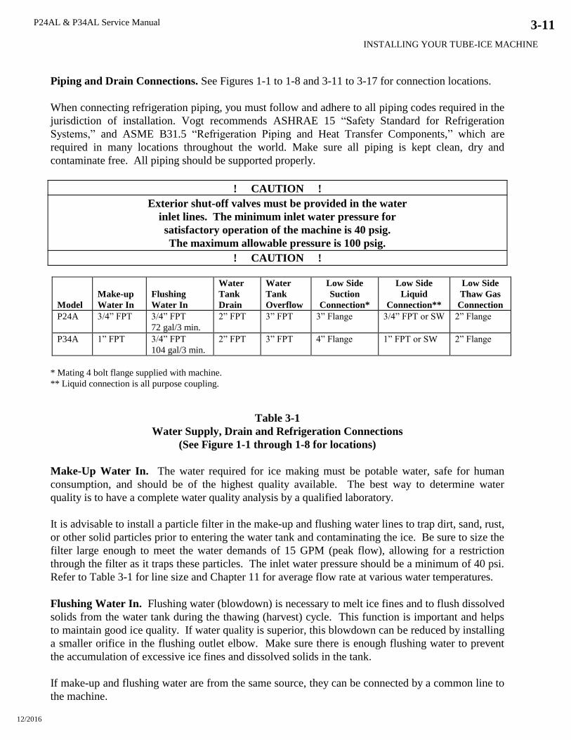
Piping and Drain Connections. See Figures 1-1 to 1-8 and 3-11 to 3-17 for connection locations.
When connecting refrigeration piping, you must follow and adhere to all piping codes required in the
jurisdiction of installation. Vogt recommends ASHRAE 15 “Safety Standard for Refrigeration
Systems,” and ASME B31.5 “Refrigeration Piping and Heat Transfer Components,” which are
required in many locations throughout the world. Make sure all piping is kept clean, dry and
contaminate free. All piping should be supported properly.
! CAUTION !
Exterior shut-off valves must be provided in the water
inlet lines. The minimum inlet water pressure for
satisfactory operation of the machine is 40 psig.
The maximum allowable pressure is 100 psig.
! CAUTION !
Model
Make-up
Water In
Flushing
Water In
Water
Tank
Drain
Water
Tank
Overflow
Low Side
Suction
Connection*
Low Side
Liquid
Connection**
Low Side
Thaw Gas
Connection
P24A 3/4” FPT 3/4” FPT
72 gal/3 min.
2” FPT 3” FPT 3” Flange 3/4” FPT or SW 2” Flange
P34A 1” FPT 3/4” FPT
104 gal/3 min.
2” FPT 3” FPT 4” Flange 1” FPT or SW 2” Flange
* Mating 4 bolt flange supplied with machine.
** Liquid connection is all purpose coupling.
Table 3-1
Water Supply, Drain and Refrigeration Connections
(See Figure 1-1 through 1-8 for locations)
Make-Up Water In. The water required for ice making must be potable water, safe for human
consumption, and should be of the highest quality available. The best way to determine water
quality is to have a complete water quality analysis by a qualified laboratory.
It is advisable to install a particle filter in the make-up and flushing water lines to trap dirt, sand, rust,
or other solid particles prior to entering the water tank and contaminating the ice. Be sure to size the
filter large enough to meet the water demands of 15 GPM (peak flow), allowing for a restriction
through the filter as it traps these particles. The inlet water pressure should be a minimum of 40 psi.
Refer to Table 3-1 for line size and Chapter 11 for average flow rate at various water temperatures.
Flushing Water In. Flushing water (blowdown) is necessary to melt ice fines and to flush dissolved
solids from the water tank during the thawing (harvest) cycle. This function is important and helps
to maintain good ice quality. If water quality is superior, this blowdown can be reduced by installing
a smaller orifice in the flushing outlet elbow. Make sure there is enough flushing water to prevent
the accumulation of excessive ice fines and dissolved solids in the tank.
If make-up and flushing water are from the same source, they can be connected by a common line to
the machine.
P24AL & P34AL Service Manual
INSTALLING YOUR TUBE-ICE MACHINE
12/2016
3-12
Water Tank Drain. This valve and connection is for the purpose of flushing and draining the water
tank of impurities, foreign material and cleaning chemicals used during servicing. It should be piped
to an open drain or sump for visible discharge. It can be tied in with the overflow line but no others.
Water Tank Overflow. A 3” FPT connection on the side of the water tank is provided to carry
away overflow water during the thawing (harvest cycle). This water contains ice fines accumulated
during harvesting and dissolved solids accumulated during the freezing cycle. Do not reduce the
size of this line. Three inches is needed to provide sufficient area for ice fines to be flushed out,
especially if the incoming flushing water is 55F (13C) or below. This overflow line should not tie
in with any other drain line except the water tank drain.
Unless water quality is superior, do not discharge the overflow water to the cooling tower system.
This water contains additional dissolved solids left from the ice making process and can lead to
excessive condenser fouling or cooling tower chemical usage. It is recommended that a heat
exchanger be used in place of direct contact with condenser water.
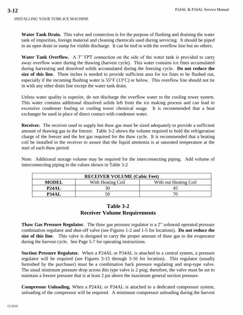
Receiver. The receiver used to supply hot thaw gas must be sized adequately to provide a sufficient
amount of thawing gas to the freezer. Table 3-2 shows the volume required to hold the refrigeration
charge of the freezer and the hot gas required for the thaw cycle. It is recommended that a heating
coil be installed in the receiver to assure that the liquid ammonia is at saturated temperature at the
start of each thaw period.
Note: Additional storage volume may be required for the interconnecting piping. Add volume of
interconnecting piping to the values shown in Table 3-2
RECEIVER VOLUME (Cubic Feet)
MODEL With Heating Coil With out Heating Coil
P24AL 30 45
P34AL 50 70
Table 3-2
Receiver Volume Requirements
Thaw Gas Pressure Regulator. The thaw gas pressure regulator is a 2” solenoid operated pressure
combination regulator and shut-off valve (see Figures 1-2 and 1-5 for locations). Do not reduce the
size of this line. This valve is designed to carry the proper amount of thaw gas to the evaporator
during the harvest cycle. See Page 5-7 for operating instructions.
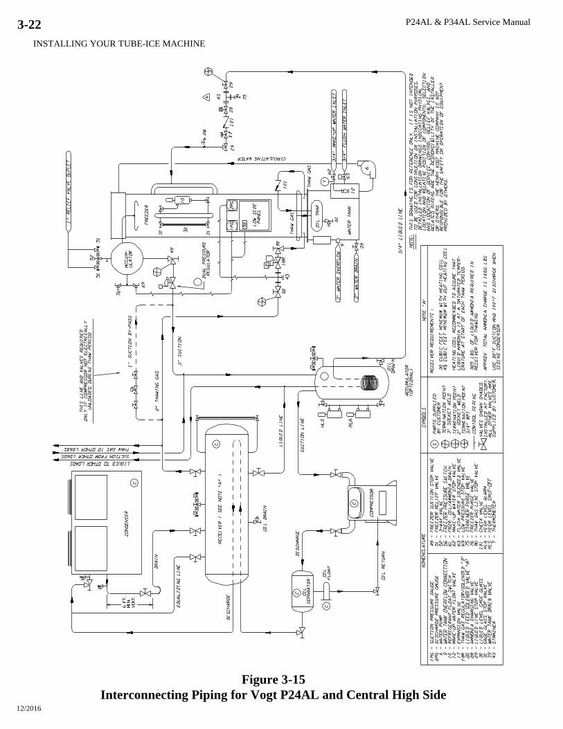
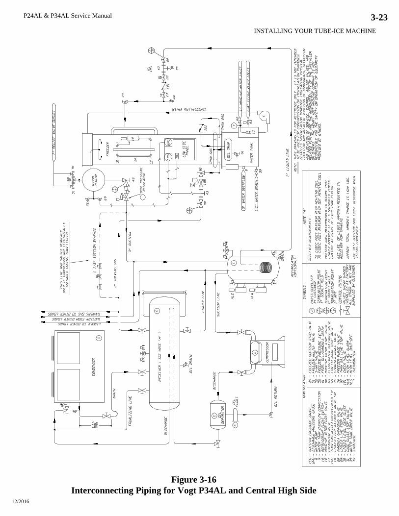
Suction Pressure Regulator. When a P24AL or P34AL is attached to a central system, a pressure
regulator will be required (see Figures 3-15 through 3-16 for location). This regulator (usually
furnished by the purchaser) must be a combination back pressure regulating and stop-type valve.
The usual minimum pressure drop across this type valve is 2 psig; therefore, the valve must be set to
maintain a freezer pressure that is at least 2 psi above the maximum general suction pressure.
Compressor Unloading. When a P24AL or P34AL is attached to a dedicated compressor system,
unloading of the compressor will be required. A minimum compressor unloading during the harvest
P24AL & P34AL Service Manual
INSTALLING YOUR TUBE-ICE MACHINE
12/2016
3-13
cycle is 50%. If the compressor cannot be unloaded, then a hot gas bypass to the suction line must
be installed. See Figures 3-13 through 3-16.
Cooling Tower (optional). When selecting a cooling tower, careful attention must be given to
operating wet bulb conditions. It is advisable to check with your local cooling tower distributor for
their recommendations based on actual operating conditions in your area. An average wet bulb of
78F is typical in the U.S., but many localities have designed wet bulbs as low as 72F or as high as
82F.
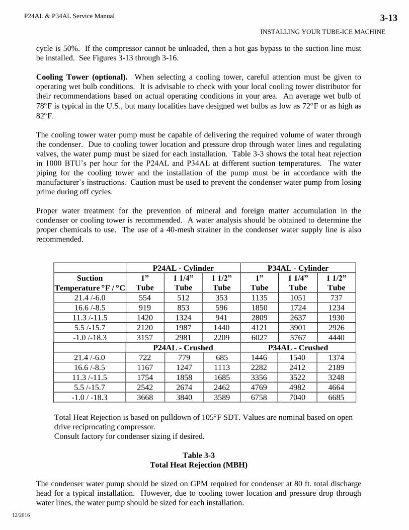
The cooling tower water pump must be capable of delivering the required volume of water through
the condenser. Due to cooling tower location and pressure drop through water lines and regulating
valves, the water pump must be sized for each installation. Table 3-3 shows the total heat rejection
in 1000 BTU’s per hour for the P24AL and P34AL at different suction temperatures. The water
piping for the cooling tower and the installation of the pump must be in accordance with the
manufacturer’s instructions. Caution must be used to prevent the condenser water pump from losing
prime during off cycles.
Proper water treatment for the prevention of mineral and foreign matter accumulation in the
condenser or cooling tower is recommended. A water analysis should be obtained to determine the
proper chemicals to use. The use of a 40-mesh strainer in the condenser water supply line is also
recommended.
P24AL - Cylinder P34AL - Cylinder
Suction
Temperature F / C
1”
Tube
1 1/4”
Tube
1 1/2”
Tube
1”
Tube
1 1/4”
Tube
1 1/2”
Tube
21.4 /-6.0 554 512 353 1135 1051 737
16.6 /-8.5 919 853 596 1850 1724 1234
11.3 /-11.5 1420 1324 941 2809 2637 1930
5.5 /-15.7 2120 1987 1440 4121 3901 2926
-1.0 /-18.3 3157 2981 2209 6027 5767 4440
P24AL - Crushed P34AL - Crushed
21.4 /-6.0 722 779 685 1446 1540 1374
16.6 /-8.5 1167 1247 1113 2282 2412 2189
11.3 /-11.5 1754 1858 1685 3356 3522 3248
5.5 /-15.7 2542 2674 2462 4769 4982 4664
-1.0 / -18.3 3668 3840 3589 6758 7040 6685
Total Heat Rejection is based on pulldown of 105F SDT. Values are nominal based on open
drive reciprocating compressor.
Consult factory for condenser sizing if desired.
Table 3-3
Total Heat Rejection (MBH)
The condenser water pump should be sized on GPM required for condenser at 80 ft. total discharge
head for a typical installation. However, due to cooling tower location and pressure drop through
water lines, the water pump should be sized for each installation.
P24AL & P34AL Service Manual
INSTALLING YOUR TUBE-ICE MACHINE
12/2016
3-14
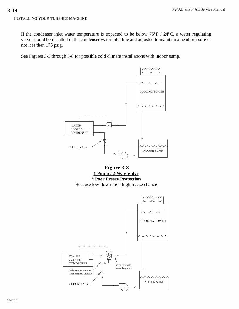
If the condenser inlet water temperature is expected to be below 75F / 24C, a water regulating
valve should be installed in the condenser water inlet line and adjusted to maintain a head pressure of
not less than 175 psig.
See Figures 3-5 through 3-8 for possible cold climate installations with indoor sump.
COOLING TOWER
WATER
COOLED
CONDENSER
INDOOR SUMP
CHECK VALVE
Figure 3-8 1 Pump / 2-Way Valve
* Poor Freeze Protection
Because low flow rate = high freeze chance
COOLING TOWER
WATER
COOLED
CONDENSER
INDOOR SUMPCHECK VALVE
Same flow rate
to cooling towerOnly enough water to
maintain head pressure
P24AL & P34AL Service Manual
INSTALLING YOUR TUBE-ICE MACHINE
12/2016
3-15
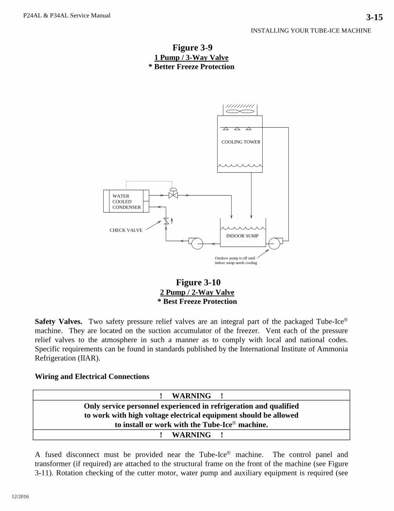
Figure 3-9
1 Pump / 3-Way Valve
* Better Freeze Protection
COOLING TOWER
WATER
COOLED
CONDENSER
INDOOR SUMP
CHECK VALVE
Outdoor pump is off until
indoor sump needs cooling
Figure 3-10 2 Pump / 2-Way Valve
* Best Freeze Protection
Safety Valves. Two safety pressure relief valves are an integral part of the packaged Tube-Ice
machine. They are located on the suction accumulator of the freezer. Vent each of the pressure
relief valves to the atmosphere in such a manner as to comply with local and national codes.
Specific requirements can be found in standards published by the International Institute of Ammonia
Refrigeration (IIAR).
Wiring and Electrical Connections
! WARNING !
Only service personnel experienced in refrigeration and qualified
to work with high voltage electrical equipment should be allowed
to install or work with the Tube-Ice machine.
! WARNING !
A fused disconnect must be provided near the Tube-Ice machine. The control panel and
transformer (if required) are attached to the structural frame on the front of the machine (see Figure
3-11). Rotation checking of the cutter motor, water pump and auxiliary equipment is required (see
P24AL & P34AL Service Manual
INSTALLING YOUR TUBE-ICE MACHINE
12/2016
3-16
Rotation Check). If one leg of the 3 phase power is higher or lower (“wild”), then it should be
connected to terminal L3. Connect the ground wire to the “ground” terminal provided.
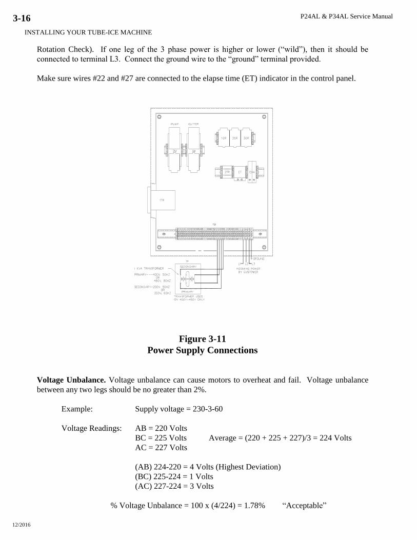
Make sure wires #22 and #27 are connected to the elapse time (ET) indicator in the control panel.
Figure 3-11
Power Supply Connections
Voltage Unbalance. Voltage unbalance can cause motors to overheat and fail. Voltage unbalance
between any two legs should be no greater than 2%.
Example: Supply voltage = 230-3-60
Voltage Readings: AB = 220 Volts
BC = 225 Volts Average = (220 + 225 + 227)/3 = 224 Volts
AC = 227 Volts
(AB) 224-220 = 4 Volts (Highest Deviation)
(BC) 225-224 = 1 Volts
(AC) 227-224 = 3 Volts
% Voltage Unbalance = 100 x (4/224) = 1.78% “Acceptable”
P24AL & P34AL Service Manual
INSTALLING YOUR TUBE-ICE MACHINE
12/2016
3-17
Important: If the supply voltage phase unbalance is more the 2%, contact your local electric
utility company.
Current Unbalance. Voltage unbalance will cause a current unbalance, but a current unbalance does
not necessarily mean that a voltage unbalance exists. A loose terminal connection or a buildup of
dirt or carbon on one set of contacts would cause a higher resistance on that leg than on the other two
legs. Current follows the path of least resistance, therefore if terminal connection L1 is loose or
dirty, L2 and/or L3 will have higher current.
Higher current causes more heat to be generated in the motor windings. The maximum acceptable
current unbalance is 10%.
Example:
Current Readings: L1 = 96 Amps
L2 = 91 Amps Average = (96 + 91 + 98)/3 = 95Amps
L3 = 98 Amps
(L1) 96-95 = 1 Amps
(L2) 95-91 = 4 Amps (Highest Deviation)
(L3) 98-95 = 3 Amps
% Current Unbalance = 100 x (4/95) = 4.2% “Acceptable”
Rotation Check. The compressor, cutter, and pump motor rotation are factory synchronized, but
must be checked at installation. For cylinder ice production, the cutter disc as viewed at the ice
discharge opening should turn from left to right.
Check rotation by the following procedure:
1. Turn the power to the machine on and check voltages.
2. Make sure the water tank is full of clean water.
3. Turn the HAND/AUTO switch (ISS) to HAND position. The water pump will start and the
FREEZING (1LT) and the LIQUID FEED (2LT) pilot lights will illuminate. Check pump
rotation.
4. Push the MANUAL HARVEST button. The water pump will stop, the FREEZING and LIQUID
FEED lights will go out, and after 20-30 seconds, the cutter motor will start. The thawing gas
solenoid valve will open and the THAWING pilot light (3LT) will illuminate.
5. Check the cutter disc rotation. It should be turning from left to right (CCW looking from the
top).
6. Turn the HAND/AUTO switch to AUTO to stop the cutter.
To change rotation, follow this procedure:
1. Disconnect power to the machine and lock it out to make sure it can’t be turned back on.
2. Check for power at L1, L2, L3 with a volt meter to make sure it is off.
3. At the cutter motor circuit breaker (CB3) or at the power disconnect, reverse wires L1 and L2.
4. Make sure these terminals are tight and restore power to the machine.
5. Perform rotation check again to confirm that it is correct.

P24AL & P34AL Service Manual
INSTALLING YOUR TUBE-ICE MACHINE
12/2016
3-18
! CAUTION !
Do not attempt to start the machine until first making sure all
conditions listed in the Installation Review Checklist and all
necessary valves have been opened for operation.
! CAUTION !
Auxiliary Controls or Equipment. When connecting other equipment such as high/low pressure
switch, conveyor motors, bin level control, etc., refer to the control panel wiring drawing for the
proper connecting terminals and instructions. See Figure 6-3.

P24AL & P34AL Service Manual
INSTALLING YOUR TUBE-ICE MACHINE
12/2016
3-19
Figure 3-12
Interconnecting Piping for Vogt P24AL and Vogt 24AHS
P24AL & P34AL Service Manual
INSTALLING YOUR TUBE-ICE MACHINE
12/2016
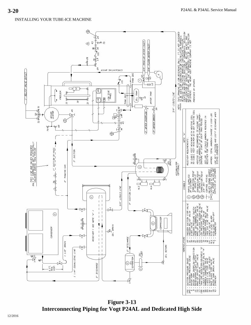
3-20
Figure 3-13
Interconnecting Piping for Vogt P24AL and Dedicated High Side

P24AL & P34AL Service Manual
INSTALLING YOUR TUBE-ICE MACHINE
12/2016
3-21
Figure 3-14
Interconnecting Piping for Vogt P34AL and Dedicated High Side
P24AL & P34AL Service Manual
INSTALLING YOUR TUBE-ICE MACHINE
12/2016
3-22
Figure 3-15
Interconnecting Piping for Vogt P24AL and Central High Side
P24AL & P34AL Service Manual
INSTALLING YOUR TUBE-ICE MACHINE
12/2016
3-23
Figure 3-16
Interconnecting Piping for Vogt P34AL and Central High Side

P24AL & P34AL Service Manual
INSTALLING YOUR TUBE-ICE MACHINE
12/2016
3-24
Figure 3-17
Interconnecting Piping for 2-Vogt P34AL and Central High Side
P24AL & P34AL Service Manual
INSTALLING YOUR TUBE-ICE MACHINE
12/2016
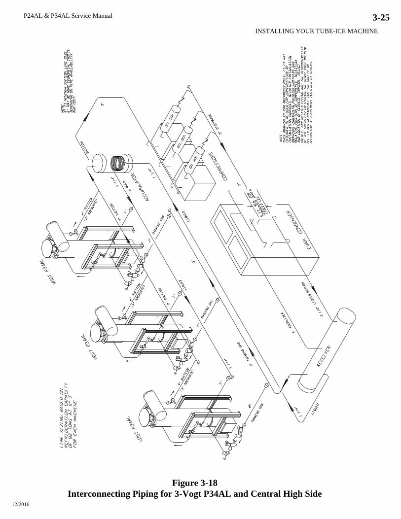
3-25
Figure 3-18
Interconnecting Piping for 3-Vogt P34AL and Central High Side
P24AL & P34AL Service Manual
INSTALLING YOUR TUBE-ICE MACHINE
12/2016
3-26
! IMPORTANT !
Be sure to follow the wiring schematic when incorporating overloads of
conveyor (5 MOL). Also remove jumpers as instructed.
This is necessary to provide proper
protection for the Tube-Ice machine and its component parts.
! IMPORTANT !
Installation Review: A Checklist. Make a visual check to be sure these steps have been taken
BEFORE continuing.
CHECK: _____ PRIOR TO OPENING VALVES, check all joints for leaks which may have
developed during shipment. (NOTE: the machine was shipped with a positive pressure of 20-25
psig, which should be indicated on the suction and discharge gages.)
CHECK: _____ The system is properly evacuated to 500 microns.
CHECK: _____ All refrigerant piping, water supply and drain connections for conformity to
requirements stipulated in this manual and properly connected to inlets and outlets.
CHECK: _____ Electrical supply for proper size of fuses and for compliance to local and national
codes. See the machine nameplate for minimum circuit ampacity and maximum fuse size.
CHECK: _____ All field installed equipment (augers, conveyors, cooling towers, bin level controls,
etc.) for proper installation.
CHECK: _____ The applicable portion of the warranty registration/start-up report for proper
completion.
CHECK: _____ Cutter gear reducer oil level oil should run out of side pipe plug when removed.
CHECK: _____ The water distributors at top of freezer to make sure they are all in position (one
seated firmly in each tube with a vent tube in each distributor).
! CAUTION !
The compressor crankcase heater should be energized for a minimum of
four hours and the oil temperature should be 100-110F
before attempting to start the compressor.
! CAUTION !
P24AL & P34AL Service Manual
HOW YOUR TUBE-ICE MACHINE WORKS
12/2016
4-1
4. How Your Tube-Ice Machine Works
Operating Features. Your low side Tube-Ice machine is an efficient ice producing plant. If
installed and maintained properly, it will give many years of operation with a minimum amount of
repairs. Refer to piping schematics, Figures 4-1 and 4-2, to identify component parts while
following the information and instructions in this manual.
The machine is manually started and stopped by the START and STOP push buttons. The machine
features automatic stop safeties, including cutter and pump motor overloads, as well as other
auxiliary motor overloads. It will also stop automatically due to high head pressure and low suction
pressure conditions (if field wired to the high side). The circulating water pump can be operated
independently for chemically cleaning the freezer tubes and water tank by use of the HAND/AUTO
selector switch. The machine can be manually forced into a harvest cycle with the MANUAL
HARVEST push button.
Principle of Operation. The freezer (2) is a shell-and-tube type vessel. During the freezing period
(cycle), water is constantly recirculated through the vertical tubes of the freezer by a centrifugal
pump (6). Make-up water is maintained by a float valve (12) in the water tank (7). The refrigerant
float switch (10) opens and closes the liquid feed “A” solenoid valve (20) and maintains the desired
refrigerant level in the freezer (2) (evaporator).
Refrigerant gas from the top of the freezer (2) passes through the suction accumulator (88) to the
suction header and back to the compressor. The cool gas from the evaporator is compressed to a high
temperature, high pressure gas which discharges through the oil separator (then through the heat coil
of the receiver, when installed) and to the condenser. In the condenser, heat is removed and the gas
is condensed to a high temperature, high-pressure liquid. The high-pressure liquid passes through
the liquid line through a strainer (43), liquid “A” solenoid valve (20) check valve (101), and hand
expansion valve (17). At the hand expansion valve (17), the refrigerant expands from a saturated
high pressure liquid state to a low pressure, low temperature liquid. This cold liquid enters the
freezer (2) where it absorbs heat from the circulating water in the freezer tubes. Cool gas is again
pulled out of the freezer through the suction outlet, completing the circuit.
The freezing period is completed by action of the freeze timer (1TR) in the control panel. The water
pump (6) stops and the “A” solenoid valve (20) closes. After a delay of 20-30 seconds, the cutter
motor starts, the thawing gas “D” solenoid valve (18R) opens, and the harvest (thawing) timer (2TR)
is activated. Warm gas from the receiver is discharged through the thawing chamber (16), check
valve (101), and into the freezer. There it warms the refrigerant and the outer surface of the freezer
tubes, allowing the ice to release on the inside of the tubes and drop down onto the rotating cutter for
sizing. After sizing, the ice drops on the tines cutter disc and is discharged through the ice discharge
opening.
See “Freeze Period” and “Harvest Period” for additional details.
Freeze Period. Water is frozen inside the stainless steel tubes of the freezer (2) by the direct
application of refrigerant to the shell side of the tubes. Ice is produced from constantly circulating
water down each tube. As the ice thickness increases, the freezer suction pressure decreases. At a
set time, the freeze timer (1TR) energizes the relay (1CR), which stops the water pump, closes the
P24AL & P34AL Service Manual
HOW YOUR TUBE-ICE MACHINE WORKS
12/2016
4-2
“A” liquid feed solenoid valve (20), de-energizes the suction regulator (when installed) and turns out
the two pilot lights, LIQUID FEED and FREEZING.
Harvest Period. About 20-30 seconds after the 1CR relay is energized, the thaw gas valve (18)
opens, the “H” water flush solenoid valve (63) opens, the compressor unloads (when required), the
cutter motor starts, the thaw timer (2TR) is energized, the red thawing gas light illuminates and
auxiliary equipment starts (conveyors, etc.). When the refrigerant in the freezer is warmed
sufficiently, approximately 40F / 5C to allow the ice in the tubes to release and be sized, the ice is
then discharged into the customer’s ice handling equipment. See “Ice Handling” for more
information on this subject. The thaw timer (2TR) is adjustable and should be set for the time
required for all the ice to clear the freezer plus 30 seconds more.
! CAUTION !
Make sure all the ice clears the freezer with at least 30 seconds
to spare before the next freezer period begins. This is to prevent
refreezing and to allow the ice moving augers etc. to clear.
! CAUTION !
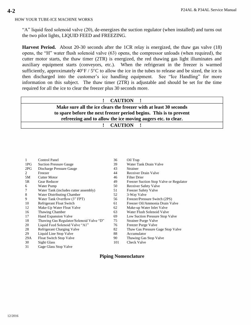
1 Control Panel 36 Oil Trap
1PG Suction Pressure Gauge 39 Water Tank Drain Valve
2PG Discharge Pressure Gauge 43 Strainer
2 Freezer 44 Receiver Drain Valve
5M Cutter Motor 46 Filter Drier
5R Gear Reducer 49 Freezer Suction Stop Valve or Regulator
6 Water Pump 50 Receiver Safety Valve
7 Water Tank (includes cutter assembly) 51 Freezer Safety Valve
8 Water Distributing Chamber 52 3-Way Valve
9 Water Tank Overflow (3” FPT) 56 Freezer/Pressure Switch (2PS)
10 Refrigerant Float Switch 61 Freezer Oil/Ammonia Drain Valve
12 Make-Up Water Float Valve 62 Make-up Water Inlet Valve
16 Thawing Chamber 63 Water Flush Solenoid Valve
17 Hand Expansion Valve 69 Low Suction Pressure Stop Valve
18 Thawing Gas Regulator/Solenoid Valve “D” 75 Strainer Purge Valve
20 Liquid Feed Solenoid Valve “A1” 76 Freezer Purge Valve
28 Refrigerant Charging Valve 82 Thaw Gas Pressure Gage Stop Valve
29 Liquid Line Stop Valve 88 Accumulator
29A Float Switch Stop Valve 90 Thawing Gas Stop Valve
30 Sight Glass 101 Check Valve
31 Gage Glass Stop Valve
Piping Nomenclature

P24AL & P34AL Service Manual
HOW YOUR TUBE-ICE MACHINE WORKS
12/2016
4-3
Figure 4-1
Piping Schematic for P24AL
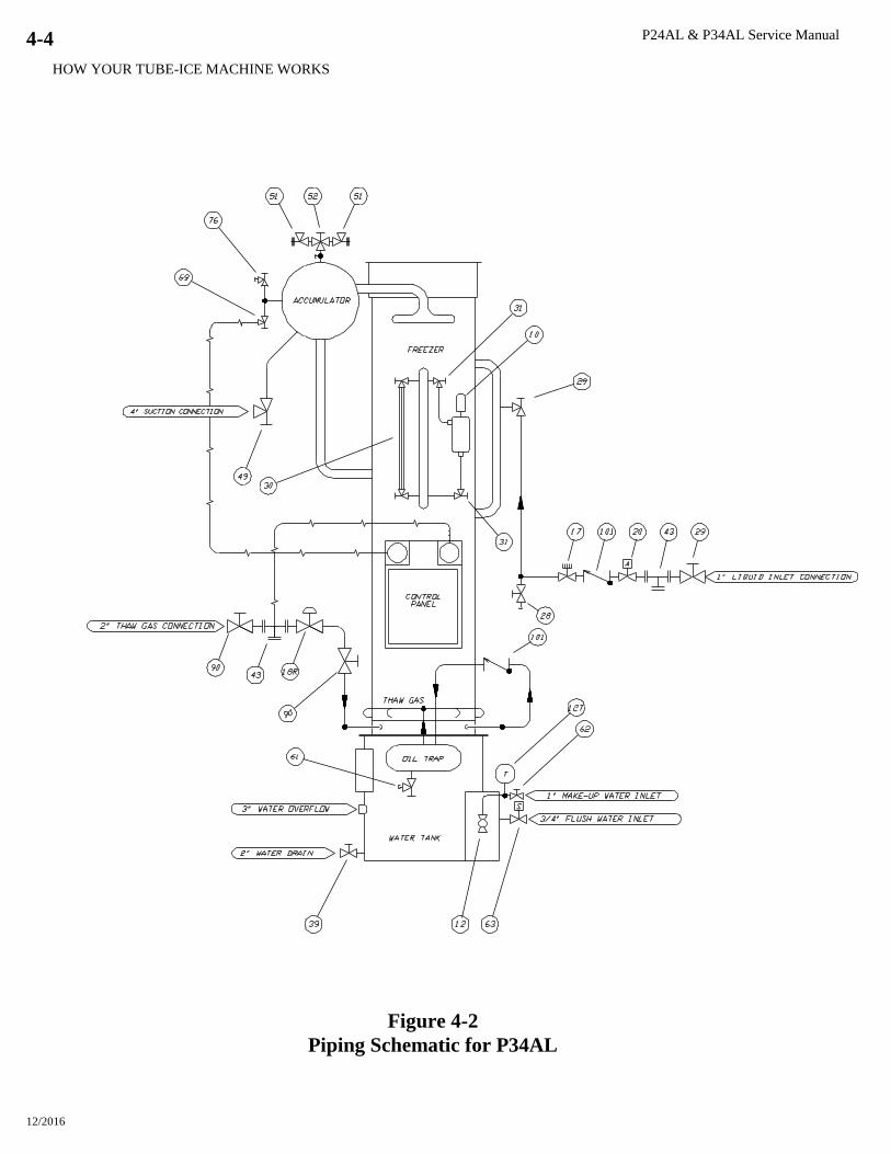
P24AL & P34AL Service Manual
HOW YOUR TUBE-ICE MACHINE WORKS
12/2016
4-4
Figure 4-2
Piping Schematic for P34AL

P24AL & P34AL Service Manual
START-UP & OPERATION
12/2016
5-1
5. Start-Up & Operation
Refrigeration System Review. The refrigeration system uses anhydrous ammonia (R-717)
refrigerant. Following the piping schematic (Figures 3-12 to 3-16 and 4-1 or 4-2), you will see that
during the machine’s freeze cycle, the compressor discharge gas goes through the oil separator to
remove any oil present in the discharge gas and return the oil to the compressor crankcase. It is then
discharged into the condenser and condensed into a liquid by the removal of heat by water passing
through the condenser tubes. A reservoir of liquid R-717 (approximate 325 lbs for P24AL and 625
lbs. for P34AL) is accumulated in the receiver and is required for thawing purposes (see Table 3-2).
Liquid from the receiver flows through the strainer to the “A” solenoid valve (20), which opens and
closes by action of the low side float switch (The liquid is then expanded through the hand expansion
valve (17) and into the evaporator (2) (freezer). The cold, wet R-717 refrigerant floods the
evaporator and is in contact with the outside of the ice making tubes through which water is being
circulated. The heat contained in the water passes through the wall of the tubes, lowering the
temperature of the water, causing it to freeze and to form a long tube of ice that adheres to the inside
of freezer tubes. Since the purest water freezes first, the circulating water continues to wash the
dissolved solids down into the sump area of the water tank. The flushing valve helps to rid the water
tank of increased dissolved solids by flushing them out the overflow during the harvest (thawing)
period.
The wet suction gas leaves the freezer and passes through the suction accumulator (88), where liquid
droplets are removed, and allowing dry gas to enter the suction side of the compressor. The suction
gas is then compressed and discharged once again, completing the cycle. As ice continues to form in
the freezer tubes, the suction pressure steadily decreases, when the freeze timer (1TR) times out the
contact closes, initiating the thaw (harvest) cycle.
Note: Freezing time will vary, depending on make-up water temperature and thickness of ice
produced. The freeze timer (1TR) should be set to provide the correct time to produce ice at the
required thickness under the current operating conditions.
During the harvest period, the “D” thawing gas valve (18) opens and the compressor unloads (when
required), allowing the warm high-pressure gas from the receiver to enter the freezer. As the tubes
warm up to slightly above freezing (approximately 40F / 5C), the ice inside the tubes releases and
falls down onto the rotating cutter for sizing and discharging. Harvesting requires about three
minutes, but can vary depending on ice thickness, suction pressure, discharge pressure (thawing gas
temperature) and distance from the receiver to the freezer.
! IMPORTANT !
It is a good idea and will be profitable for you to observe and
become familiar with the proper operating characteristics of your
Tube-Ice machine. It will help you to recognize and correct minor
irregularities as they occur in order to help prevent major problems.
“An ounce of prevention is worth a pound of cure.”
! IMPORTANT !

P24AL & P34AL Service Manual
START-UP & OPERATION
12/2016
5-2
Start-up Checklist. Be sure to complete and return the “Warranty Registration/Start-up Report”
located in the front of the manual.
1. See that the water-inlet connections are attached properly. The water inlet shutoff valve (62) for
the water tank should be open. The water level in the water tank should be at a height where the
make-up float valve will be closed when the machine is idle and water is not running out of the
overflow (9).
2. Fill the cooling tower sump and check the tower manufacturer’s installation and operation
instructions to make sure it is ready to run.
3. Check condenser cooling water pump rotation.
4. Check rotation of augers or ice handling equipment to make sure they are rotating the proper
direction.
5. Check all tagged valves and make sure they are in their correct operational position (opened,
closed, or automatic). Sight glass valves on the freezer must be closed prior to operation.
6. See that the electrical disconnect is closed and the proper power is supplied to the machine.
7. See that the compressor oil temperature is 100-110F and there is no liquid ammonia in the
crankcase. The oil level should be 1/2-3/4 of the sight glass.
8. Check the elapsed time indicator (ET) and make sure wire #22 and #27 are attached.
9. Reconfirm “Rotation Check” for cutter and water pump (See Section 3).
Refrigerant Charge. Prior to charging the machine with anhydrous ammonia (R-717), make sure
the system is leak tight and free of non-condensibles or other contaminants.
The machine will require a full charge of pure anhydrous ammonia. Make sure it is from a reputable
supplier who can and will furnish quality ammonia of Refrigeration or Federal Technical grade.
Grade
Minimum
Ammonia Content
Maximum
Water Content
Maximum
Oil Content
Maximum Non-
condensable
Fertilizer 99.50% 5000 PPM 5 PPM N/A
Refrigeration 99.98% 150 PPM 3 PPM .2 ml/g
Federal Technical 99.98% 200 PPM 5 PPM None
Metallurgical 99.99% 33 PPM 2 PPM 10 ml/g
Research 99.999% 5 PPM 1 PPM 7 PPM
TABLE 5-1
Ammonia Specification by Grade
(Reference IIAR Ammonia Data Book Chapter 1, General Information)
NOTE: Do not use Fertilizer grade ammonia.
Total ammonia (R717) charge required is approximately:
Dedicated System - P24AL = 1000 lbs. P34AL = 1600 lbs.
Evaporator only - P24AL = 500 lbs. P34AL = 950 lbs.
Special precautions to be observed when charging refrigeration systems. Only technically
qualified persons, experienced and knowledgeable in the handling of anhydrous ammonia refrigerant
and operation of refrigeration systems should perform the operations described in this manual. All
local, federal, and EPA regulations must be strictly adhered to when handling ammonia (R717)
refrigerants. See “Material Safety Data Sheet”, MSDS Code 5B81-83, located in the Appendix A.

P24AL & P34AL Service Manual
START-UP & OPERATION
12/2016
5-3
Charging from Tank Truck (dedicated high side only). The system may be charged by bulk from
a tank truck and be pumped directly into the receiver through the drain valve.
Follow these instructions with caution:
1. Using an ammonia approved charging hose, connect one end to the drain/charging valve in the
bottom of the high pressure receiver.
2. Connect the other end of the charging hose to the tank truck. It is best to have a gage in this line
to indicate pressure.
3. Open the drain/charging valve and the fill valve from the tank truck.
4. While observing the sight glass on the high-pressure receiver, fill the receiver to the proper
volume.
5. Make sure the charging valve is closed and the cylinder valve is closed before attempting to
disconnect the hose. Use caution when disconnecting the charging hose, it will contain liquid
ammonia and should be disposed of in accordance with local, state and federal safety and
environmental rules.
! CAUTION !
Do NOT attempt to bulk charge the machine through the freezer
charging valve (28). The freezer will not hold the full charge
without exposing the compressor to serious damage.
! CAUTION !
Charging from Cylinders (dedicated high side only). The machine may also be charged from
refrigerant cylinders. To charge from cylinders, the compressor will have to operate to transfer the
ammonia from the freezer to the receiver. Again, make sure all the necessary valves are opened for
operation and the compressor crankcase heater has been energized for a minimum for four hours.
Follow these instructions with caution:
1. Using an approved for ammonia charging hose, connect one end to the charging valve (28) in the
liquid line near the freezer.
2. Lay a full cylinder of anhydrous ammonia horizontally with the cylinder valve outlet pointing up
to withdraw liquid and the bottom end raised about 2” higher than the top end.
3. Connect the other end of the charging hose to the cylinder valve. It is recommended that a gage
be attached to this line to indicate cylinder pressure.
4. Close the liquid line stop valve (29) or at the receiver.
5. Open charging valve (28) and carefully purge air from the charging hose.
6. Open the cylinder valve slowly, checking for leaks in the line and allow the suction pressure to
build up to approximately 40 psig and check again for leaks in the system.
7. Set the freeze timer (1TR) to maximum setting. If the machine contains a pressure switch (2PS)
in place of the freeze timer, disconnect and locked out the power, open the control panel door and
disconnect wire #24 from the freezer pressure switch (2PS), then turn the power back on.
8. Check compressor rotation by starting and stopping the compressor momentarily. If the
compressor starter is wire to (3CR) then jog the compressor by using the green START push
button (2PB) and the red STOP push button (1PB). Correct compressor rotation is indicated by
an arrow on the outer rim of the oil pump assembly (opposite the shaft end of the compressor.
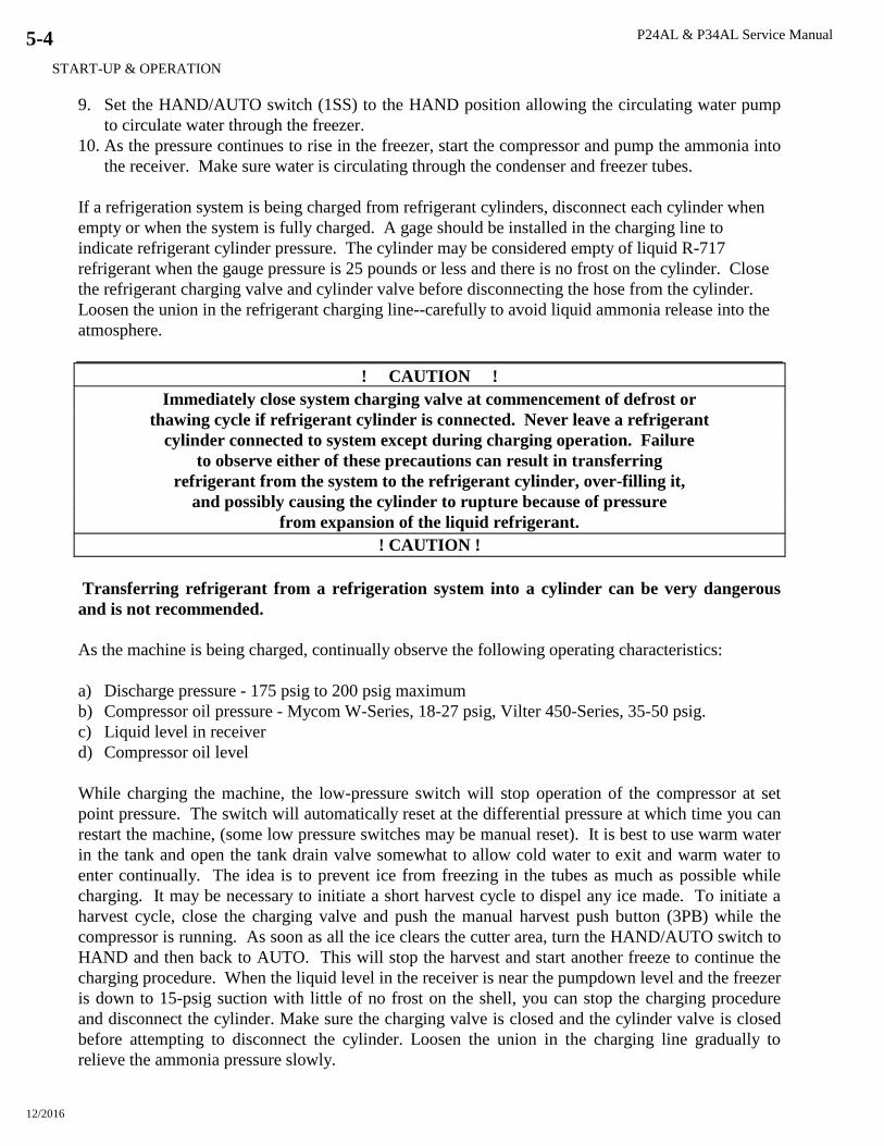
P24AL & P34AL Service Manual
START-UP & OPERATION
12/2016
5-4
9. Set the HAND/AUTO switch (1SS) to the HAND position allowing the circulating water pump
to circulate water through the freezer.
10. As the pressure continues to rise in the freezer, start the compressor and pump the ammonia into
the receiver. Make sure water is circulating through the condenser and freezer tubes.
If a refrigeration system is being charged from refrigerant cylinders, disconnect each cylinder when
empty or when the system is fully charged. A gage should be installed in the charging line to
indicate refrigerant cylinder pressure. The cylinder may be considered empty of liquid R-717
refrigerant when the gauge pressure is 25 pounds or less and there is no frost on the cylinder. Close
the refrigerant charging valve and cylinder valve before disconnecting the hose from the cylinder.
Loosen the union in the refrigerant charging line--carefully to avoid liquid ammonia release into the
atmosphere.
! CAUTION !
Immediately close system charging valve at commencement of defrost or
thawing cycle if refrigerant cylinder is connected. Never leave a refrigerant
cylinder connected to system except during charging operation. Failure
to observe either of these precautions can result in transferring
refrigerant from the system to the refrigerant cylinder, over-filling it,
and possibly causing the cylinder to rupture because of pressure
from expansion of the liquid refrigerant.
! CAUTION !
Transferring refrigerant from a refrigeration system into a cylinder can be very dangerous
and is not recommended.
As the machine is being charged, continually observe the following operating characteristics:
a) Discharge pressure - 175 psig to 200 psig maximum
b) Compressor oil pressure - Mycom W-Series, 18-27 psig, Vilter 450-Series, 35-50 psig.
c) Liquid level in receiver
d) Compressor oil level
While charging the machine, the low-pressure switch will stop operation of the compressor at set
point pressure. The switch will automatically reset at the differential pressure at which time you can
restart the machine, (some low pressure switches may be manual reset). It is best to use warm water
in the tank and open the tank drain valve somewhat to allow cold water to exit and warm water to
enter continually. The idea is to prevent ice from freezing in the tubes as much as possible while
charging. It may be necessary to initiate a short harvest cycle to dispel any ice made. To initiate a
harvest cycle, close the charging valve and push the manual harvest push button (3PB) while the
compressor is running. As soon as all the ice clears the cutter area, turn the HAND/AUTO switch to
HAND and then back to AUTO. This will stop the harvest and start another freeze to continue the
charging procedure. When the liquid level in the receiver is near the pumpdown level and the freezer
is down to 15-psig suction with little of no frost on the shell, you can stop the charging procedure
and disconnect the cylinder. Make sure the charging valve is closed and the cylinder valve is closed
before attempting to disconnect the cylinder. Loosen the union in the charging line gradually to
relieve the ammonia pressure slowly.
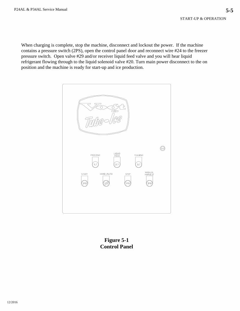
P24AL & P34AL Service Manual
START-UP & OPERATION
12/2016
5-5
When charging is complete, stop the machine, disconnect and lockout the power. If the machine
contains a pressure switch (2PS), open the control panel door and reconnect wire #24 to the freezer
pressure switch. Open valve #29 and/or receiver liquid feed valve and you will hear liquid
refrigerant flowing through to the liquid solenoid valve #20. Turn main power disconnect to the on
position and the machine is ready for start-up and ice production.
Figure 5-1
Control Panel
P24AL & P34AL Service Manual
START-UP & OPERATION
12/2016
5-6
Start-Up. Starting the machine in a freezing cycle can be accomplished as follows:
1. Make sure the crankcase oil temperature is approximately 100F and there is no liquid ammonia
in the compressor crankcase.
2. Turn the HAND/AUTO switch (1SS) to the HAND position and allow the water tank to refill.
MAKE SURE THE DRAIN VALVE IS CLOSED.
3. If the compressor motor starter is wired to the control relay (3CR) then push the green START
push button to start the compressor and immediately observe the oil pressure, the oil level, the
discharge pressure, and listen for any unusual sounds. The compressor should start unloaded and
will load automatically after several seconds of operation.
4. Turn the HAND/AUTO switch to the AUTO position.
5. When the discharge pressure increases to about 170 psig, push the MANUAL HARVEST button
to initiate the harvest cycle. See “Harvest Period”.
6. Set the thaw gas pressure regulator (18R) and the suction regulator (if used). See “Thaw Gas
Regulator” and “Suction Regulator” for instructions.
7. When the suction pressure raises to 50-55 psig, any ice made should release and discharge. After
all of the ice clears the cutter and auger, turn the HAND/AUTO switch to HAND and back to
AUTO. This will interrupt the harvest cycle and start another freeze cycle. See “Freeze Cycle”.
As the machine continues its freezing cycle, the liquid ammonia will feed into the freezer until the
level float switch (10) is satisfied. The float switch will open and close the liquid line solenoid valve
(20) to maintain that level of ammonia in the freezer during the freeze cycle. When the freeze timer
(1TR) times out the switch will close and initiate the harvest cycle. If a freezer pressure switch
(2PS) has been installed, the suction pressure will decrease to the setting of the freezer pressure
switch (2PS), the switch will close and initiate the harvest cycle. See “Harvest Period”.
Be sure to observe several complete cycles of ice production to confirm the satisfactory operation of
the machine.
! IMPORTANT !
Complete the remaining part of the “Warranty/Registration Start-Up Report”
and return it to Vogt Ice, LLC.
! IMPORTANT !
Check the refrigerant level at the receiver liquid gage glass to make sure it is near the operating level
mark.
Adding Refrigerant. Add refrigerant while the machine is running by the following procedure:
1. With a cylinder of anhydrous ammonia laying on its side, cylinder valve outlet pointing up and
bottom end raised two inches higher than the valve end, connect an “approved for ammonia”
charging hose between the freezer charging valve (28) and the cylinder valve.
2. Purge all air from the charging hose and open the cylinder valve gradually to check for possible
leaks around the packing nut or hose fittings. Then open the cylinder valve fully.
3. While the “ammonia feed light is not illuminated, open the charging valve (28) and ammonia
will flow from the cylinder to the freezer.
P24AL & P34AL Service Manual
START-UP & OPERATION
12/2016
5-7
4. Close the cylinder valve immediately when the ammonia feed light comes on and reopen it when
the light goes out. Repeat until properly charged.
! CAUTION !
Do not leave a refrigerant cylinder attached to the machine unattended.
Disconnect it immediately when the machine is charged or the cylinder is empty.
! CAUTION !
Operating Tips.
Make sure the machine is left running in the AUTO position. This will assure a complete
shutdown if a safety or overload is tripped.
To initiate a harvest cycle, simply push the MANUAL HARVEST push button (3PB).
To interrupt the harvest cycle (harvest timer #2TR) and revert to a freeze cycle, turn the
HAND/AUTO switch to HAND and back to AUTO.
The circulating water overflow tubing will show that water is being slightly lifted up the tubing
near the end of the freezing cycle. If this action ceases and water begins overflowing from the
top water box, it is an indication that the tubes are freezing solid and the machine should begin a
harvest cycle. It is best not to freeze the ice solid with no hole.
To cease ice production manually, allow the machine to complete the harvest period and start the
freeze period. When the LIQUID FEED light comes on at the beginning of the freeze period,
push the STOP button to cease ice production.
Thaw Gas Regulating and Suction Regulating Valve Adjustment. The following is the
procedure for regulating valve adjustment. On dedicated compressor systems the suction regulating
valve is not required. However, the compressor must unload by 50% or greater during the harvest or
a hot gas bypass must be installed.
1. Install gauge and gauge valve in gauge port of regulator.
2. Turn high pressure stem (down stream pressure) on suction regulator into the milled flats, do
not turn milled flats into packing nut.
3. Start the machine and initiate a harvest.
4. Adjust the thaw gas regulator to build pressure to 60 - 65 psig. (1 turn is approximately 13 psig)
5. Adjust (downstream) high-pressure stem on suction regulator to begin regulating at 59-64 psig.
(Slightly below the thaw gas regulator)
6. After the machine has completed the harvest cycle and returned to the freeze cycle, adjust the
low pressure (upstream pressure) on the suction regulator to maintain the required freezer
pressure. For clear ice a minimum of 20-psig freezer pressure is required.

P24AL & P34AL Service Manual
START-UP & OPERATION
12/2016
5-8

P24AL & P34AL Service Manual
ELECTRICAL CONTROLS
12/2016
6-1
6. Electrical Controls
Your low side Tube-Ice machine is equipped with a dry contact (3CR) for a compressor motor
starter and a transformer (if required) for the control circuit power. The control panel and
transformer are mounted on the machine front side (see Figures 1-1 or 1-8).
The control panel wiring schematic, Figure 6-3, illustrates these components as well as provisions
for auxiliary equipment that may be incorporated by the customer such as:
(FU1) Main power disconnect
(5M) Conveyor motor starter and overload (5MOL)
(C-SOL) Suction regulating valve
When adding motor starters for auxiliary equipment, be sure to incorporate the overload protection
as indicated between terminals #12 - #13 and remove the jumper wire. This will assure that the
machine will shutdown when any auxiliary equipment fails.
Bin Level Control. Included in the wiring schematic is provision for a bin level control (BLC). The
NC contract of your control should be wired between terminals #8-#9 and the jumper wire removed
as indicated. Installation in this manner will allow the machine to finish the harvest period before
shutdown. However, the machine will still need to be manually started to resume production.
Safety Switches. The machine is not equipped with the following safeties and control switches;
however, they can be wired into the control circuit. Refer to the wiring schematic Figure 6-3 for
their circuitry.
High/Low dual pressure switch (1PS) to stop the machine if the compressor suction pressure
goes too low (15-20 psig) or the compressor discharge pressure goes too high (225-250 psig).
See “High/Low Pressure Switch”.

P24AL & P34AL Service Manual
ELECTRICAL CONTROLS
12/2016
6-2
Figure 6-1
Control Panel (Door Opened)
(3CR) Compressor Motor
Starter contact and
holding relay
Holding relay for safety and bin level control. Auxiliary contact
provides control power to the compressor motor starter.
Continuously energized during freezing and thawing.
(2M) Pump Motor Starter Provides power to the circulating water pump during the freezer
period or when the HAND/AUTO switch is in the HAND position
to circulate water or ice machine cleaner, etc. Provides motor
overload and short circuit protection.
(3M) Cutter Motor Starter Provides power to the cutter during the harvest period. Provides
motor overload and short circuit protection.
(1CR) Control Relay With
Pneumatic Timer
For making and breaking various circuits during freezing and
thawing period with pneumatic timer to delay the actual thawing
process. Energized during thawing.
(2CR) Control Relay For making and breaking circuits during freezing and thawing.
Energized during freezing, thawing, and hand. Momentarily de-
energized at the end of the harvest.
(2TR) Thawing Timer Controls the time of the harvest (thawing) period.
Energized during the harvest period.
(1TR) Freeze Timer Controls the length of time the machine is in the freeze cycle. When
timed out initiates the harvest cycle.
(2PS) optional for
dedicated high side
Freezer Pressure Switch Controls the desired ice thickness (hole size) by sensing the freezer
suction pressure and initiating the harvest period.
(ET) Elapsed Time Indicator Indicates total hours of machine operation. Is powered when the
compressor is running.
(CB4) Circuit Breaker Overload and short circuit protection for crankcase heater and the
control circuit.
(TB) Terminal Block Numbered for multiple wire connections and ease of
troubleshooting.
Table 6-1
Description of Control Panel Parts (Inside)
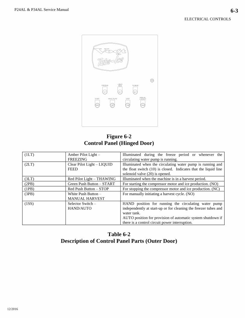
P24AL & P34AL Service Manual
ELECTRICAL CONTROLS
12/2016
6-3
Figure 6-2
Control Panel (Hinged Door)
(1LT) Amber Pilot Light –
FREEZING
Illuminated during the freeze period or whenever the
circulating water pump is running.
(2LT) Clear Pilot Light – LIQUID
FEED
Illuminated when the circulating water pump is running and
the float switch (10) is closed. Indicates that the liquid line
solenoid valve (20) is opened.
(3LT) Red Pilot Light – THAWING Illuminated when the machine is in a harvest period.
(2PB) Green Push Button – START For starting the compressor motor and ice production. (NO)
(1PB) Red Push Button – STOP For stopping the compressor motor and ice production. (NC)
(3PB) White Push Button –
MANUAL HARVEST
For manually initiating a harvest cycle. (NO)
(1SS) Selector Switch –
HAND/AUTO
HAND position for running the circulating water pump
independently at start-up or for cleaning the freezer tubes and
water tank.
AUTO position for provision of automatic system shutdown if
there is a control circuit power interruption.
Table 6-2
Description of Control Panel Parts (Outer Door)

P24AL & P34AL Service Manual
ELECTRICAL CONTROLS
12/2016
6-4
Figure 6-3
Electrical Schematic for P24AL and P34AL all Voltages, 50-60 Hz.

P24AL & P34AL Service Manual 7-1
MAINTENANCE
12/2016
7. Maintenance
Preventative Maintenance. A careful inspection of your Tube-Ice machine for leaks and correct
operational functions at the time of installation and start-up will begin a long, satisfactory life of
service. In order to insure this degree of dependability, a systematic maintenance program is
necessary. Therefore, the following schedule is suggested as a minimum.
A. Daily
1) Check operating pressures (suction, discharge, oil).
2) Check ice quality.
3) Check “ice out” time (maintain 30 seconds of continued harvest after last ice is out).
4) Check compressor oil level.
5) Check refrigerant operation level.
6) Check frost pattern on freezer shell and oil trap.
7) Check make-up water float valve adjustment.
B. Weekly (in addition to daily checks)
1) Check for leaks after 400 hours or four weeks of operation
C. Monthly (in addition to weekly checks)
1) Check calibration and operation of all controls (high and low pressure switches, oil pressure
switch, etc.)
2) Check cooling tower spray nozzles and pump suction screen for scaling and algae (consult
water treatment suppliers for corrective measures).
3) Check water distributors in freezer for scale accumulation.
4) Check water tank for solids to be removed.
5) Check all motor drive units (compressor, cutter and pump motors, cooling tower fan, and
pump, etc) for abnormal noise and/or vibrations.
6) Check oil level in gear reducer.
7) Check one complete freeze/thaw cycle, record data and compare with production check of
Registration/Start-up Report.
D. Yearly (in addition to weekly and monthly)
1) Check entire system for leaks.
2) Drain water from condenser and cooling tower and check condenser tubes. Check closely
for damage by corrosion or scale.
3) Remove all rust from all equipment, clean, and paint.
4) Check all motors for shaft wear and end play.
5) Check operation and general condition of all electrical controls, relays, motor starters, and
solenoid valves.
6) Check freezing time, ice release time, and ice out time.
7) Change oil in gear reducer box once a year.
8) Lubricate compressor motor bearings.

7-2 P24AL & P34AL Service Manual
MAINTENANCE
12/2016
PREVENTATIVE MAINTENANCE FORM
This form can be removed and duplicated for record keeping.
Date: _____________ Model #: ________________________ Serial #: _____________
The following service performed and checked:
Hour meter reading _______________, Ambient temperature (inside)_______ F
Make-Up water float valve adjusted properly
Water distributors clean and in place
All drains freely draining
Cleaned and flushed water tank
Compressor oil changed
Cleaned and inspected inside compressor crankcase
Changed compressor oil filter
Checked/adjusted compressor belt tension or alignment
Lubricate compressor motor bearings
Check/change cutter gear reducer oil
Check/adjust cutter drive gear meshing
Leak check entire system
Check liquid refrigerant level in receiver
Drained oil from oil trap
Compressor crankcase heater working
Compressor net oil pressure (gage reading less suction)
Motor amps: Compressor ________ Cutter ________ Pump ________
Suction psig (end of freeze) __________ Discharge psig (end of freeze) _____________
Suction psig (end of thaw) __________ Discharge psig (end of thaw) _____________
Compressor water out ____F Tower fan cycles ___ On ___ Off
Production Check
Test
Cycle
Make-up
Water
Temp
Freezing
Time
Min/Sec
Harvest
Time
Min/Sec
First
Ice Out
Min/Sec
All
Ice Out
Min/Sec
Avg.
Hole
Size
Ice lb.
Per Harvest
(est)
Ice lb.
Per Day
(est)
#1
#2
#3
#4
Comments: _______________________________________________________________________
_________________________________________________________________________________
_________________________________________________________________________________
Name: __________________________________
P24AL & P34AL Service Manual 7-3
MAINTENANCE
12/2016
Ice Making Section. The ice making section of the Tube-Ice machine should be cleaned at least
twice a year (more often if water conditions cause mineral build-up). Use an approved food-grade
ice machine cleaner. The water pump is used to circulate the cleaner through the system. For
complete instructions, follow the “Cleaning Procedure” below.
Cleaning Procedure
1. Stop the machine at the end of harvest.
2. Shut off make-up water supply.
3. Drain the water tank, flushing out any loose sediment.
4. Close the drain valve and fill the tank with warm water. Warm water promotes faster cleaning.
5. Cover the ice discharge opening to prevent water from splashing out and contaminating any
stored ice.
6. Add sufficient ice machine cleaner to the water tank.
P24 tank = 2.5 gallons of water per inch of water height in tank, 13” = 32.5 gallons
P34 tank = 4.7 gallons of water per inch of water height in tank, 13” = 60.6 gallons
Mix cleaning solution according to manufacturer’s recommendations.
7. Remove top water box cover, inspect distributors, remove any hard particles from orifices, and
make sure all distributors are in place. Replace cover.
8. Turn HAND/AUTO switch to HAND position and circulate the cleaning solution until deposits
are dissolved or the solution is neutralized. After draining, the pump may have to be stopped and
restarted to dispel air.
9. Turn switch to AUTO position to stop the pump. Drain and flush the water tank. Repeat
cleaning as necessary.
10. After cleaning, fill the tank with fresh water, start the pump again, and circulate for 15 minutes.
11. Stop the pump, drain and flush the tank and again refill with fresh water.
12. Remove the cover from the ice discharge opening, and clean any area that may have been
splashed with solution during cleaning.
13. Make sure the make-up water float valve is adjusted properly and the drain valve is closed.
14. Start and stop the pump again to make sure it is circulating water and it is not air bound.
The machine is now ready to produce ice.
Water Distributors. The water distributors are located under the top freezer cover. These
distributors are similar in design to those used in mid-size and small machines (i.e. P18F, P118, etc.)
except they have a small vent tube. It is important that this plastic vent tube remain in place in each
distributor. The distributors may require occasional or periodic cleaning to remove solids, foreign
particles, or mineral deposit accumulated from the circulating make-up (ice making) water. The
frequency of cleaning operation will depend on the characteristics of the water supply. The
distributors need inspection when the inside diameter of a large portion of the ice becomes irregular
(due to channeling of water), if some of the ice is opaque or if there is a noticeable decrease in ice
capacity and quality.
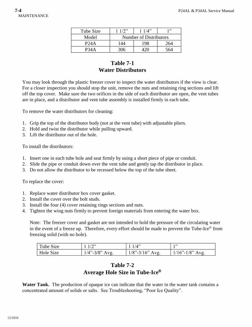
7-4 P24AL & P34AL Service Manual
MAINTENANCE
12/2016
Tube Size 1 1/2” 1 1/4” 1”
Model Number of Distributors
P24A 144 198 264
P34A 306 420 564
Table 7-1
Water Distributors
You may look through the plastic freezer cover to inspect the water distributors if the view is clear.
For a closer inspection you should stop the unit, remove the nuts and retaining ring sections and lift
off the top cover. Make sure the two orifices in the side of each distributor are open, the vent tubes
are in place, and a distributor and vent tube assembly is installed firmly in each tube.
To remove the water distributors for cleaning:
1. Grip the top of the distributor body (not at the vent tube) with adjustable pliers.
2. Hold and twist the distributor while pulling upward.
3. Lift the distributor out of the hole.
To install the distributors:
1. Insert one in each tube hole and seat firmly by using a short piece of pipe or conduit.
2. Slide the pipe or conduit down over the vent tube and gently tap the distributor in place.
3. Do not allow the distributor to be recessed below the top of the tube sheet.
To replace the cover:
1. Replace water distributor box cover gasket.
2. Install the cover over the bolt studs.
3. Install the four (4) cover retaining rings sections and nuts.
4. Tighten the wing nuts firmly to prevent foreign materials from entering the water box.
Note: The freezer cover and gasket are not intended to hold the pressure of the circulating water
in the event of a freeze up. Therefore, every effort should be made to prevent the Tube-Ice from
freezing solid (with no hole).
Tube Size 1 1/2” 1 1/4” 1”
Hole Size 1/4”-3/8” Avg. 1/8”-3/16” Avg. 1/16”-1/8” Avg.
Table 7-2
Average Hole Size in Tube-Ice
Water Tank. The production of opaque ice can indicate that the water in the water tank contains a
concentrated amount of solids or salts. See Troubleshooting, “Poor Ice Quality”.
P24AL & P34AL Service Manual 7-5
MAINTENANCE
12/2016
To clean the water tank:
1. Stop the machine at the end of harvest.
2. Shut off the make-up water supply.
3. Open the drain valve and drain the tank.
4. Remove the water box cover and flush out any loose sediment from the tank. The wire mesh
screen can be removed if necessary.
5. If further cleaning is needed, follow “Cleaning Procedure”.
6. If further cleaning is not needed, close the drain valve and refill the tank with fresh water.
7. Make sure the float valve is adjusted properly and install the water box cover.
8. Start and stop the pump again to make sure it is circulating water and is not air bound.
Compressor (optional). This section is only a guide, please consult the compressor manual for
manufacturers recommended maintenance.
In starting and charging the unit, the oil sight glass should be continually checked to make sure an
adequate oil level is maintained. The oil level should be 1/4-3/4 of the sight glass. If the oil level
drops below 1/4 of the glass, add refrigeration oil as per the compressor manufacturer
recommendations. Never allow the oil level to be out of sight, above or below the sight glass when
the compressor is operating.
! CAUTION !
The crankcase heater should be energized for a minimum of
four hours and the oil temperature should be 100-110F
before attempting to start the compressor.
! CAUTION !
During operation, the specified net oil pressure should be maintained for proper lubrication and
operation of the cylinder unloader mechanism.
Mycom N&W Series net oil pressure: 17-28 psig
Vilter 450 Series net oil pressure: 35-50 psig
Note: Net oil pressure is calculated by subtracting the compressor suction pressure from the oil
pressure gage reading while the compressor is running.
Example: Oil pressure gage reading: 65 psig
Suction pressure gage reading: 40 psig
Net oil pressure: 25 psig
The compressor oil should be changed at close intervals during initial break-in operation and up to
the first 1000 hours (see Table 7-4 below).
Note: It is the owner’s responsibility to make sure normal maintenance is initiated to insure that the
compressor is not subjected to premature wear or failure due to neglect or lack of sufficient
maintenance and care.
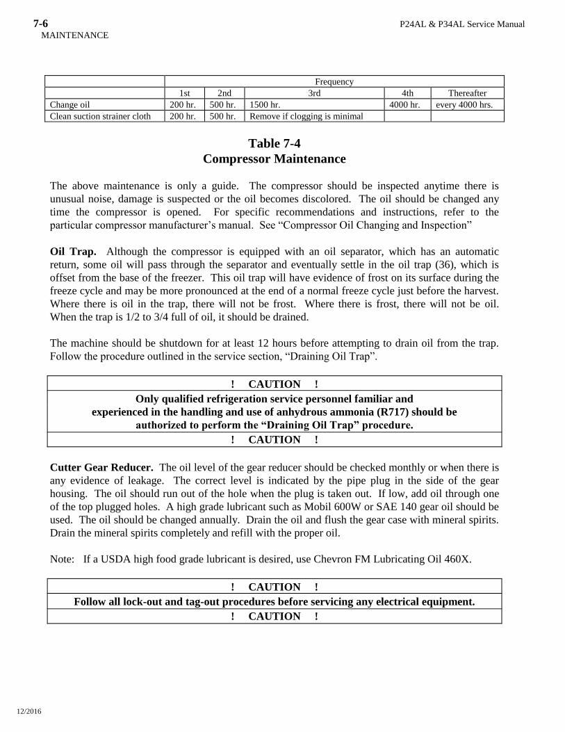
7-6 P24AL & P34AL Service Manual
MAINTENANCE
12/2016
Frequency
1st 2nd 3rd 4th Thereafter
Change oil 200 hr. 500 hr. 1500 hr. 4000 hr. every 4000 hrs.
Clean suction strainer cloth 200 hr. 500 hr. Remove if clogging is minimal
Table 7-4
Compressor Maintenance
The above maintenance is only a guide. The compressor should be inspected anytime there is
unusual noise, damage is suspected or the oil becomes discolored. The oil should be changed any
time the compressor is opened. For specific recommendations and instructions, refer to the
particular compressor manufacturer’s manual. See “Compressor Oil Changing and Inspection”
Oil Trap. Although the compressor is equipped with an oil separator, which has an automatic
return, some oil will pass through the separator and eventually settle in the oil trap (36), which is
offset from the base of the freezer. This oil trap will have evidence of frost on its surface during the
freeze cycle and may be more pronounced at the end of a normal freeze cycle just before the harvest.
Where there is oil in the trap, there will not be frost. Where there is frost, there will not be oil.
When the trap is 1/2 to 3/4 full of oil, it should be drained.
The machine should be shutdown for at least 12 hours before attempting to drain oil from the trap.
Follow the procedure outlined in the service section, “Draining Oil Trap”.
! CAUTION !
Only qualified refrigeration service personnel familiar and
experienced in the handling and use of anhydrous ammonia (R717) should be
authorized to perform the “Draining Oil Trap” procedure.
! CAUTION !
Cutter Gear Reducer. The oil level of the gear reducer should be checked monthly or when there is
any evidence of leakage. The correct level is indicated by the pipe plug in the side of the gear
housing. The oil should run out of the hole when the plug is taken out. If low, add oil through one
of the top plugged holes. A high grade lubricant such as Mobil 600W or SAE 140 gear oil should be
used. The oil should be changed annually. Drain the oil and flush the gear case with mineral spirits.
Drain the mineral spirits completely and refill with the proper oil.
Note: If a USDA high food grade lubricant is desired, use Chevron FM Lubricating Oil 460X.
! CAUTION !
Follow all lock-out and tag-out procedures before servicing any electrical equipment.
! CAUTION !
P24AL & P34AL Service Manual
TROUBLESHOOTING
12/2016
8-1
8. Troubleshooting
Note: Your machine’s electrical system has several built-in safety and overload protection features
to stop operation when a single component fails or if there is a problem from an outside
source such a power supply. Make sure all auxiliary equipment is connected to incorporate
safety and overload circuits and protect all related equipment.
When the machine stops, it must be manually restarted by pushing the START button. If it stopped
while in a freeze cycle, it should be manually harvested to remove all ice from the freezer. This is
done by pushing the white MANUAL HARVEST button.
Always check the machine operation thoroughly after remedying the problem. Be sure to correct the
source or cause of the problem to prevent the problem from occurring again.
Symptom Page
Machine stopped 8-2
Freeze-up due to extended freeze period 8-4
Freeze-up due to ice failing to discharge 8-5
Low ice capacity 8-6
Poor ice quality 8-7
High discharge pressure 8-8
Low discharge pressure 8-9
High suction pressure 8-9
Compressor running unloaded during freeze 8-9
Compressor oil pressure low 8-10
Compressor loosing oil excessively 8-10
Machine short cycles 8-11
High compressor discharge temperature 8-11
Suction line frosting to compressor 8-11
Contact your distributor first for technical service assistance about operation problems not covered in
this manual.
Also feel free to contact the factory for additional service (502) 635-3510
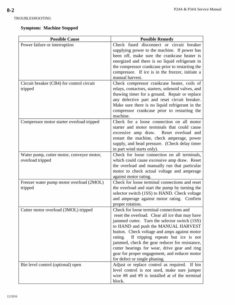
P24A & P34A Service Manual
TROUBLESHOOTING
12/2016
8-2
Symptom: Machine Stopped
Possible Cause Possible Remedy
Power failure or interruption Check fused disconnect or circuit breaker
supplying power to the machine. If power has
been off, make sure the crankcase heater is
energized and there is no liquid refrigerant in
the compressor crankcase prior to restarting the
compressor. If ice is in the freezer, initiate a
manual harvest.
Circuit breaker (CB4) for control circuit
tripped
Check compressor crankcase heater, coils of
relays, contactors, starters, solenoid valves, and
thawing timer for a ground. Repair or replace
any defective part and reset circuit breaker.
Make sure there is no liquid refrigerant in the
compressor crankcase prior to restarting the
machine.
Compressor motor starter overload tripped Check for a loose connection on all motor
starter and motor terminals that could cause
excessive amp draw. Reset overload and
restart the machine, check amperage, power
supply, and head pressure. (Check delay timer
in part wind starts only).
Water pump, cutter motor, conveyor motor,
overload tripped
Check for loose connection on all terminals,
which could cause excessive amp draw. Reset
the overload and manually run that particular
motor to check actual voltage and amperage
against motor rating.
Freezer water pump motor overload (2MOL)
tripped
Check for loose terminal connections and reset
the overload and start the pump by turning the
selector switch (1SS) to HAND. Check voltage
and amperage against motor rating. Confirm
proper rotation.
Cutter motor overload (3MOL) tripped Check for loose terminal connections and
reset the overload. Clear all ice that may have
jammed cutter. Turn the selector switch (1SS)
to HAND and push the MANUAL HARVEST
button. Check voltage and amps against motor
rating. If tripping repeats but ice is not
jammed, check the gear reducer for resistance,
cutter bearings for wear, drive gear and ring
gear for proper engagement, and reducer motor
for defect or single phasing.
Bin level control (optional) open Adjust or replace control as required. If bin
level control is not used, make sure jumper
wire #8 and #9 is installed at of the terminal
block.
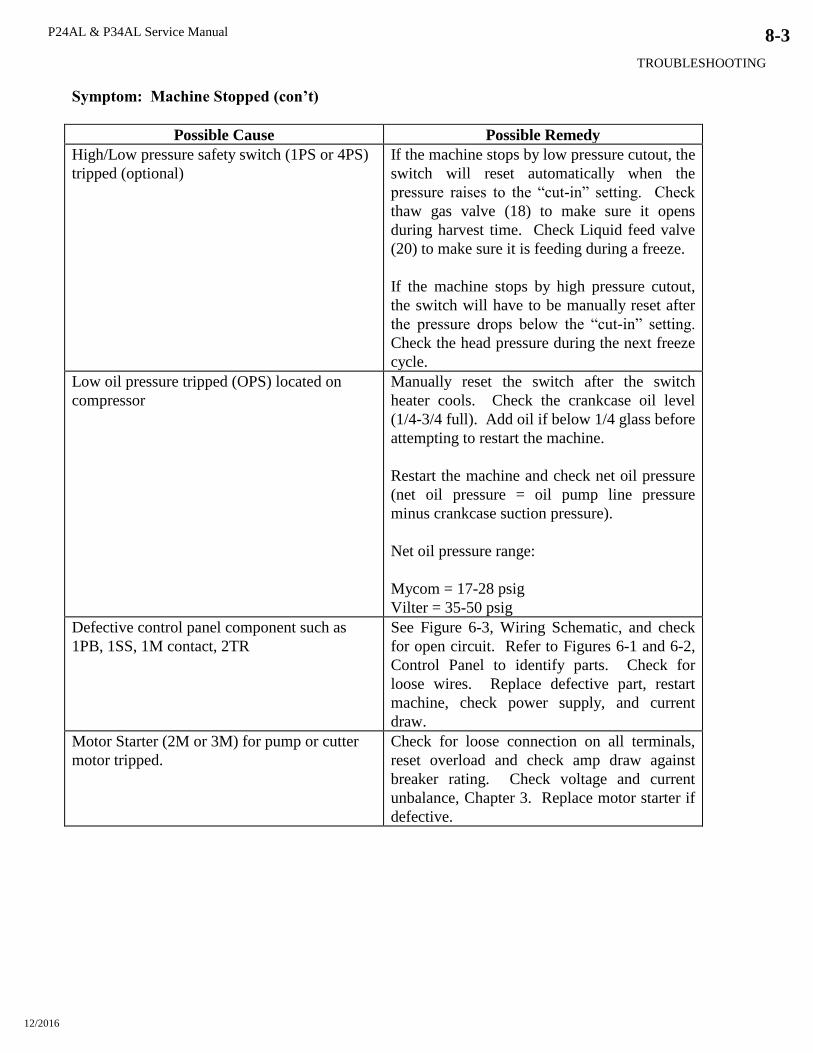
P24AL & P34AL Service Manual
TROUBLESHOOTING
12/2016
8-3
Symptom: Machine Stopped (con’t)
Possible Cause Possible Remedy
High/Low pressure safety switch (1PS or 4PS)
tripped (optional)
If the machine stops by low pressure cutout, the
switch will reset automatically when the
pressure raises to the “cut-in” setting. Check
thaw gas valve (18) to make sure it opens
during harvest time. Check Liquid feed valve
(20) to make sure it is feeding during a freeze.
If the machine stops by high pressure cutout,
the switch will have to be manually reset after
the pressure drops below the “cut-in” setting.
Check the head pressure during the next freeze
cycle.
Low oil pressure tripped (OPS) located on
compressor
Manually reset the switch after the switch
heater cools. Check the crankcase oil level
(1/4-3/4 full). Add oil if below 1/4 glass before
attempting to restart the machine.
Restart the machine and check net oil pressure
(net oil pressure = oil pump line pressure
minus crankcase suction pressure).
Net oil pressure range:
Mycom = 17-28 psig
Vilter = 35-50 psig
Defective control panel component such as
1PB, 1SS, 1M contact, 2TR
See Figure 6-3, Wiring Schematic, and check
for open circuit. Refer to Figures 6-1 and 6-2,
Control Panel to identify parts. Check for
loose wires. Replace defective part, restart
machine, check power supply, and current
draw.
Motor Starter (2M or 3M) for pump or cutter
motor tripped.
Check for loose connection on all terminals,
reset overload and check amp draw against
breaker rating. Check voltage and current
unbalance, Chapter 3. Replace motor starter if
defective.
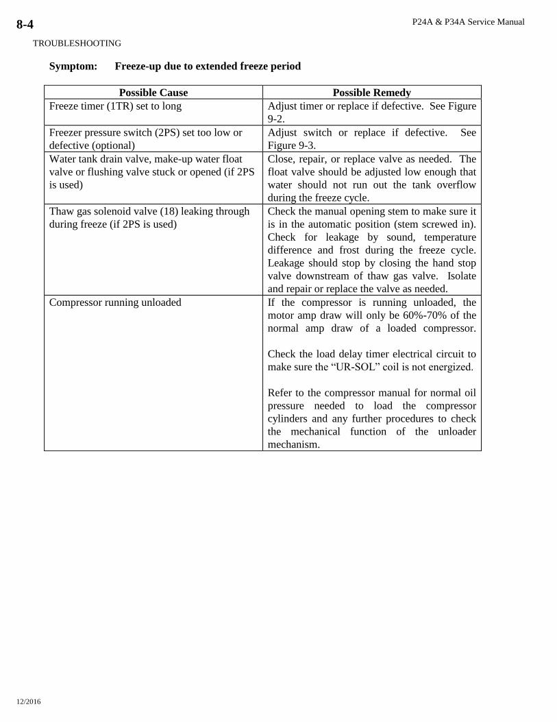
P24A & P34A Service Manual
TROUBLESHOOTING
12/2016
8-4
Symptom: Freeze-up due to extended freeze period
Possible Cause Possible Remedy
Freeze timer (1TR) set to long Adjust timer or replace if defective. See Figure
9-2.
Freezer pressure switch (2PS) set too low or
defective (optional)
Adjust switch or replace if defective. See
Figure 9-3.
Water tank drain valve, make-up water float
valve or flushing valve stuck or opened (if 2PS
is used)
Close, repair, or replace valve as needed. The
float valve should be adjusted low enough that
water should not run out the tank overflow
during the freeze cycle.
Thaw gas solenoid valve (18) leaking through
during freeze (if 2PS is used)
Check the manual opening stem to make sure it
is in the automatic position (stem screwed in).
Check for leakage by sound, temperature
difference and frost during the freeze cycle.
Leakage should stop by closing the hand stop
valve downstream of thaw gas valve. Isolate
and repair or replace the valve as needed.
Compressor running unloaded If the compressor is running unloaded, the
motor amp draw will only be 60%-70% of the
normal amp draw of a loaded compressor.
Check the load delay timer electrical circuit to
make sure the “UR-SOL” coil is not energized.
Refer to the compressor manual for normal oil
pressure needed to load the compressor
cylinders and any further procedures to check
the mechanical function of the unloader
mechanism.
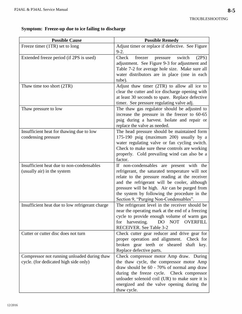
P24AL & P34AL Service Manual
TROUBLESHOOTING
12/2016
8-5
Symptom: Freeze-up due to ice failing to discharge
Possible Cause Possible Remedy
Freeze timer (1TR) set to long Adjust timer or replace if defective. See Figure
9-2.
Extended freeze period (if 2PS is used) Check freezer pressure switch (2PS)
adjustment. See Figure 9-3 for adjustment and
Table 7-2 for average hole size. Make sure all
water distributors are in place (one in each
tube).
Thaw time too short (2TR) Adjust thaw timer (2TR) to allow all ice to
clear the cutter and ice discharge opening with
at least 30 seconds to spare. Replace defective
timer. See pressure regulating valve adj.
Thaw pressure to low The thaw gas regulator should be adjusted to
increase the pressure in the freezer to 60-65
psig during a harvest. Isolate and repair or
replace the valve as needed.
Insufficient heat for thawing due to low
condensing pressure
The head pressure should be maintained form
175-190 psig (maximum 200) usually by a
water regulating valve or fan cycling switch.
Check to make sure these controls are working
properly. Cold prevailing wind can also be a
factor.
Insufficient heat due to non-condensables
(usually air) in the system
If non-condensables are present with the
refrigerant, the saturated temperature will not
relate to the pressure reading at the receiver
and the refrigerant will be cooler, although
pressure will be high. Air can be purged from
the system by following the procedure in the
Section 9, “Purging Non-Condensables”.
Insufficient heat due to low refrigerant charge The refrigerant level in the receiver should be
near the operating mark at the end of a freezing
cycle to provide enough volume of warm gas
for harvesting. DO NOT OVERFILL
RECEIVER. See Table 3-2
Cutter or cutter disc does not turn Check cutter gear reducer and drive gear for
proper operation and alignment. Check for
broken gear teeth or sheared shaft key.
Replace defective parts.
Compressor not running unloaded during thaw
cycle. (for dedicated high side only)
Check compressor motor Amp draw. During
the thaw cycle, the compressor motor Amp
draw should be 60 - 70% of normal amp draw
during the freeze cycle. Check compressor
unloader solenoid coil (UR) to make sure it is
energized and the valve opening during the
thaw cycle.

P24A & P34A Service Manual
TROUBLESHOOTING
12/2016
8-6
Symptom: Low ice capacity.
Suspicions of low ice capacity should be confirmed by accurate calculations of actual ice product.
Much weight can be lost by melting and off fall through augers and other ice handling equipment.
1. Time the total freeze and thaw cycle for the cycle which is to be caught and weighed.
2. Catch all the ice at the ice discharge opening of the machine.
3. Weight the total amount of ice caught.
Lbs. ice per cycle
Cycle time minutes X 1440 = _____ lbs. production per 24 hours
More than one cycle should be caught and weighed to get an accurate average.
Possible Cause Possible Remedy
Inadequate water for ice making Water pressure of 40 psig minimum is required
to assure proper water supply. Check water
pressure. Check for a restriction in the incoming
line or at the make-up water float valve.
Water distributors may be stopped up Check distributors and clean orifices as needed.
Freeze timer, Freezer pressure switch or thaw
timer out of adjustment
Check hole size in Tube-Ice (See Table 7-2).
Crushed ice should be 3/16”-1/4” thick. Check
and adjust thawing time. Thawing should be 30
seconds longer than it takes for all the ice to
clear the freezer.
Excessive ice chips in the water tank, causing
short cycling Check incoming water temperature (45F
minimum). Check flushing valve to make sure
ice chips are being melted and flowing out the
tank overflow during the harvest cycle.
Compressor running unloaded or not pumping
full volume
Check compressor motor amp draw. Check for
belt slippage and tighten as needed. Check for
leaking compressor suction or discharge valves.
Refer to your compressor manual. See other
related symptoms.
Restriction in the refrigerant liquid line or float
switch not operating properly
Check for a partially closed valve or an
obstruction at the strainer, solenoid valve, or
hand expansion valve. The liquid line will
normally have frost on the downstream side of a
restriction, especially as the suction pressure
decreases.
Low refrigerant charge, causing re-freeze Check the receiver gage glass mark for the
proper level. Check for and repair leaks. Add
refrigerant.
Warm make-up water for ice making Capacity of the machine is proportional to ice
making water temperature. Warmer water will
reduce the ice making capacity. Check float
adjustment and water tank drain valve.

P24AL & P34AL Service Manual
TROUBLESHOOTING
12/2016
8-7
Symptom: Low ice capacity (cont.)
Possible Cause Possible Remedy
Excessively high head pressure Check cooling tower or evaporative condenser
to make sure sufficient water is provided for
cooling and the equipment is operational to
cool the water. Also see “Symptom High Head
Pressure”.
Suction regulator out of adjustment or
defective (optional)
Check the freezer pressure and compare to the
main suction pressure. The suction regulator
should regulate the freezer pressure and create
a 2 psig pressure drop across the valve. Adjust
pressure regulator. Repair or replace defective
valve.
Thawing gas solenoid valve (18) leaking
through during freeze cycle
Check the manual opening stem to make sure it
is in the automatic position (stem screwed in).
Check for leak by sound, temperature
difference and frost during a freeze cycle.
Close the stop valve (90) to confirm suspicion
of leakage. Repair or replace the valve.
Symptom: Poor ice quality
Possible Cause Possible Remedy
Excessive concentration of solids in the water
tank usually indicated by a build-up of mineral
deposit on the sides and bottom of the tank and
opaque ice production. Also, water distributors
restricted.
Perform a cleaning procedure as well as
removing the freezer cover and cleaning the
water distributors. Make sure the flushing
valve (63) is functioning and the tank overflow
piping is not restricted.
Insufficient water supply indicated by a low
level in the tank
Check water pressure, 40 psig is recommended
minimum. Check for a water line restriction,
partially closed valve, or defective make-up
water float valve. Make sure the water tank
drain is closed.
Water pump rotation wrong direction Check rotation in relation with arrow on pump
housing and reverse two wires at the motor if
necessary.
Low refrigerant charge, causing an ice out
problem and re-freeze
Check refrigerant level mark on the receiver
and on the painted portion of the gage glass
guard. Be sure to keep the gage glass cocks
closed when finished checking the level.
Suction Pressure to low Adjust suction regulator valve
Restriction in liquid line, causing short freeze
cycle
Check for closed valve, defective solenoid
valve (20), float switch defective or strainer
restricted. The liquid line will normally have
frost on the down-stream side of a restriction,
especially as the suction pressure decreases.
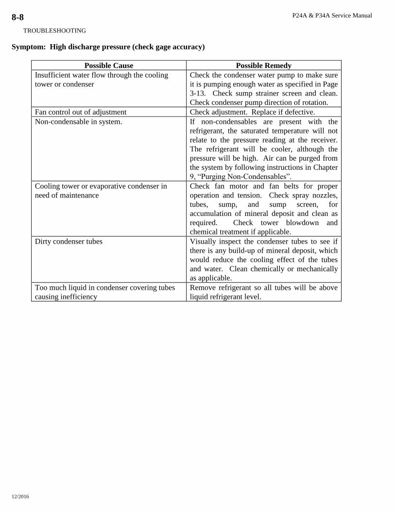
P24A & P34A Service Manual
TROUBLESHOOTING
12/2016
8-8
Symptom: High discharge pressure (check gage accuracy)
Possible Cause Possible Remedy
Insufficient water flow through the cooling
tower or condenser
Check the condenser water pump to make sure
it is pumping enough water as specified in Page
3-13. Check sump strainer screen and clean.
Check condenser pump direction of rotation.
Fan control out of adjustment Check adjustment. Replace if defective.
Non-condensable in system. If non-condensables are present with the
refrigerant, the saturated temperature will not
relate to the pressure reading at the receiver.
The refrigerant will be cooler, although the
pressure will be high. Air can be purged from
the system by following instructions in Chapter
9, “Purging Non-Condensables”.
Cooling tower or evaporative condenser in
need of maintenance
Check fan motor and fan belts for proper
operation and tension. Check spray nozzles,
tubes, sump, and sump screen, for
accumulation of mineral deposit and clean as
required. Check tower blowdown and
chemical treatment if applicable.
Dirty condenser tubes Visually inspect the condenser tubes to see if
there is any build-up of mineral deposit, which
would reduce the cooling effect of the tubes
and water. Clean chemically or mechanically
as applicable.
Too much liquid in condenser covering tubes
causing inefficiency
Remove refrigerant so all tubes will be above
liquid refrigerant level.
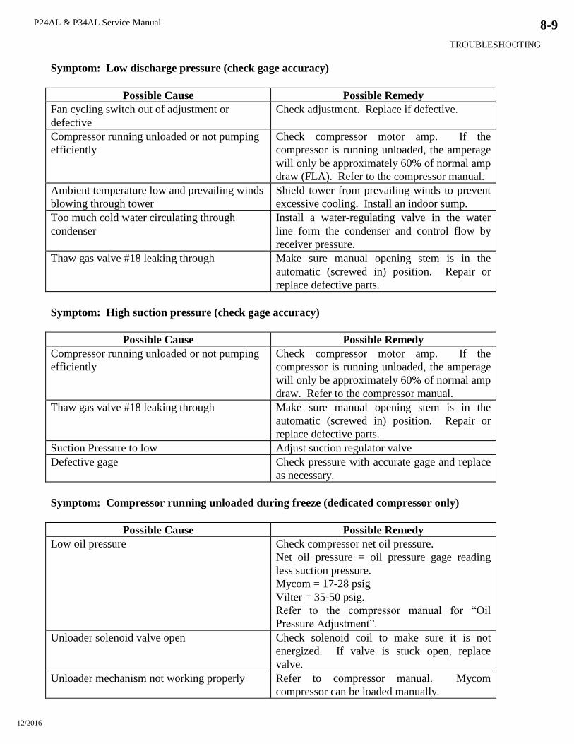
P24AL & P34AL Service Manual
TROUBLESHOOTING
12/2016
8-9
Symptom: Low discharge pressure (check gage accuracy)
Possible Cause Possible Remedy
Fan cycling switch out of adjustment or
defective
Check adjustment. Replace if defective.
Compressor running unloaded or not pumping
efficiently
Check compressor motor amp. If the
compressor is running unloaded, the amperage
will only be approximately 60% of normal amp
draw (FLA). Refer to the compressor manual.
Ambient temperature low and prevailing winds
blowing through tower
Shield tower from prevailing winds to prevent
excessive cooling. Install an indoor sump.
Too much cold water circulating through
condenser
Install a water-regulating valve in the water
line form the condenser and control flow by
receiver pressure.
Thaw gas valve #18 leaking through Make sure manual opening stem is in the
automatic (screwed in) position. Repair or
replace defective parts.
Symptom: High suction pressure (check gage accuracy)
Possible Cause Possible Remedy
Compressor running unloaded or not pumping
efficiently
Check compressor motor amp. If the
compressor is running unloaded, the amperage
will only be approximately 60% of normal amp
draw. Refer to the compressor manual.
Thaw gas valve #18 leaking through Make sure manual opening stem is in the
automatic (screwed in) position. Repair or
replace defective parts.
Suction Pressure to low Adjust suction regulator valve
Defective gage Check pressure with accurate gage and replace
as necessary.
Symptom: Compressor running unloaded during freeze (dedicated compressor only)
Possible Cause Possible Remedy
Low oil pressure Check compressor net oil pressure.
Net oil pressure = oil pressure gage reading
less suction pressure.
Mycom = 17-28 psig
Vilter = 35-50 psig.
Refer to the compressor manual for “Oil
Pressure Adjustment”.
Unloader solenoid valve open Check solenoid coil to make sure it is not
energized. If valve is stuck open, replace
valve.
Unloader mechanism not working properly Refer to compressor manual. Mycom
compressor can be loaded manually.
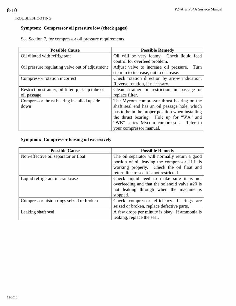
P24A & P34A Service Manual
TROUBLESHOOTING
12/2016
8-10
Symptom: Compressor oil pressure low (check gages)
See Section 7, for compressor oil pressure requirements.
Possible Cause Possible Remedy
Oil diluted with refrigerant Oil will be very foamy. Check liquid feed
control for overfeed problem.
Oil pressure regulating valve out of adjustment Adjust valve to increase oil pressure. Turn
stem in to increase, out to decrease.
Compressor rotation incorrect Check rotation direction by arrow indication.
Reverse rotation, if necessary.
Restriction strainer, oil filter, pick-up tube or
oil passage
Clean strainer or restriction in passage or
replace filter.
Compressor thrust bearing installed upside
down
The Mycom compressor thrust bearing on the
shaft seal end has an oil passage hole, which
has to be in the proper position when installing
the thrust bearing. Hole up for “WA” and
“WB” series Mycom compressor. Refer to
your compressor manual.
Symptom: Compressor loosing oil excessively
Possible Cause Possible Remedy
Non-effective oil separator or float The oil separator will normally return a good
portion of oil leaving the compressor, if it is
working properly. Check the oil float and
return line to see it is not restricted.
Liquid refrigerant in crankcase Check liquid feed to make sure it is not
overfeeding and that the solenoid valve #20 is
not leaking through when the machine is
stopped.
Compressor piston rings seized or broken Check compressor efficiency. If rings are
seized or broken, replace defective parts.
Leaking shaft seal A few drops per minute is okay. If ammonia is
leaking, replace the seal.
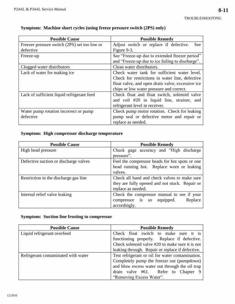
P24AL & P34AL Service Manual
TROUBLESHOOTING
12/2016
8-11
Symptom: Machine short cycles (using freeze pressure switch (2PS) only)
Possible Cause Possible Remedy
Freezer pressure switch (2PS) set too low or
defective
Adjust switch or replace if defective. See
Figure 9-3.
Freeze-up See “Freeze-up due to extended freezer period”
and “Freeze-up due to ice failing to discharge”.
Clogged water distributors Clean water distributors.
Lack of water for making ice Check water tank for sufficient water level.
Check for restrictions in water line, defective
float valve, and open drain valve, excessive ice
chips or low water pressure and correct.
Lack of sufficient liquid refrigerant feed Check float and float switch, solenoid valve
and coil #20 in liquid line, strainer, and
refrigerant level in receiver.
Water pump rotation incorrect or pump
defective
Check pump motor rotation. Check for leaking
pump seal or defective motor and repair or
replace as needed.
Symptom: High compressor discharge temperature
Possible Cause Possible Remedy
High head pressure Check gage accuracy and “High discharge
pressure”.
Defective suction or discharge valves Feel the compressor heads for hot spots or one
head running hot. Replace worn or leaking
valves.
Restriction in the discharge gas line Check all hand and check valves to make sure
they are fully opened and not stuck. Repair or
replace as needed.
Internal relief valve leaking Check the compressor manual to see if your
compressor is so equipped. Replace
accordingly.
Symptom: Suction line frosting to compressor
Possible Cause Possible Remedy
Liquid refrigerant overfeed Check float switch to make sure it is
functioning properly. Replace if defective.
Check solenoid valve #20 to make sure it is not
leaking through. Repair or replace if defective.
Refrigerant contaminated with water Test refrigerant or oil for water contamination.
Completely pump the freezer out (pumpdown)
and blow excess water out through the oil trap
drain valve #61. Refer to Chapter 9
“Removing Excess Water”.

P24A & P34A Service Manual
TROUBLESHOOTING
12/2016
8-12

P24AL & P34AL Service Manual
SERVICING OPERATIONS
12/2016
9-1
9. Servicing Operations
Automatic Blowdown (harvest cycle). A feature of this machine is a solenoid activated flushing
valve (63) which is provided to eliminate or reduce the necessity for frequent flushing or cleaning of
the water tank. This flushing during the harvest cycle helps to remove salts or solids accumulated in
the water as a result of the freezing action. It also helps melt ice chips that fall into the water tank
during harvest. The flushing valve is opened (energized) during each thaw cycle when the water
pump stops and the water in the freezer tubes returns to the water tank. If water quality is superior,
this blowdown can be reduced by installing a smaller reducer bushing in the outlet elbow.
The flushing action carries accumulated salts, solids, and ice chips (fines) out through the water tank
overflow pipe. This overflow should be kept open at all times to allow the water to drain freely and
keep the water level below the cutter disc and ice discharge opening. If the flushing solenoid valve
leaks through during the freeze cycle, it can be disassembled and cleaned, then reassembled.
Cleaning Ice Making Section. Refer to Chapter 7, Maintenance for instructions for cleaning the
circulating water tubes, water distributors, and water tank.
Float valve (make-up water). The make-up water float valve (12) maintains the proper pumping
level in the water tank for ice making. The valve should be set to maintain a water level in the water
tank during the freezing period, so that there will be a quantity of blow down only during the thaw
mode. The water level during the freeze mode should always be below the overflow piping to
prevent excessive waste of cold water, resulting in loss of ice capacity.
If it should become necessary to clean the float valve, close the stop valve in the make-up water line
to the machine and remove the float valve. After the valve has been cleaned and reinstalled, check to
ascertain if the proper water level is being maintained. After the machine is stopped and the water in
the tank seeks its normal level, there should be no water flow through the float valve or out the
overflow.
It is advisable to install a large area strainer in the water supply line to protect the float valve from
dirt or solids in the water which would necessitate frequent cleaning. A strainer of 40-mesh screen is
usually satisfactory.
Float Switch. The float switch is installed on a header assembly that is attached to the freezer shell.
Valves are provided for isolation of the float switch assembly if replacement or servicing is
necessary. The float switch closes as the level of refrigerant in the freezer rises and opens as the
level falls.
The float switch is connected to the “A1” solenoid valve coil. This is the solenoid valve directly
before the hand expansion valve. Therefore, when the refrigerant level in the freezer drops, the float
switch closes, thereby energizing and opening the “A1” liquid feed solenoid until sufficient level has
been reached to open the float switch. The float switch has a fixed 1/2” differential.
The float switch is installed at the correct height at the factory and should not need to be adjusted.
The float switch is installed at the position which provides highest capacity. The correct height will
produce compressor superheat which climbs throughout the freeze cycle to a minimum of 30° F.
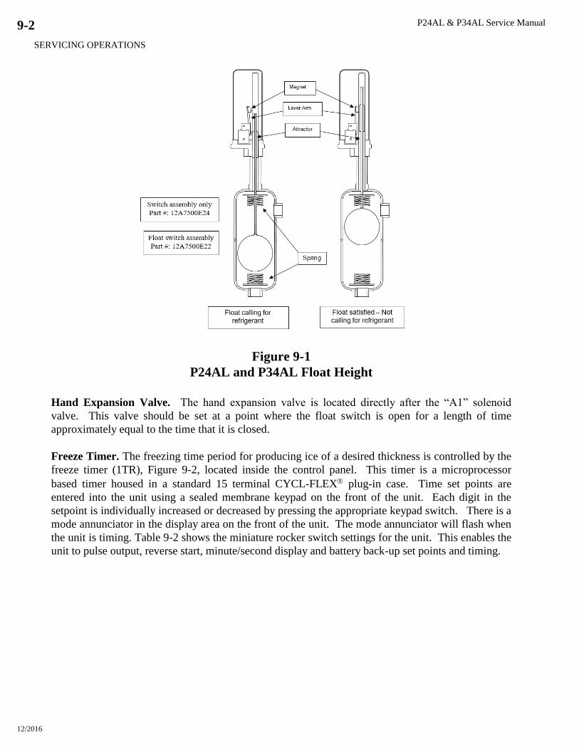
P24AL & P34AL Service Manual
SERVICING OPERATIONS
12/2016
9-2
Figure 9-1
P24AL and P34AL Float Height
Hand Expansion Valve. The hand expansion valve is located directly after the “A1” solenoid
valve. This valve should be set at a point where the float switch is open for a length of time
approximately equal to the time that it is closed.
Freeze Timer. The freezing time period for producing ice of a desired thickness is controlled by the
freeze timer (1TR), Figure 9-2, located inside the control panel. This timer is a microprocessor
based timer housed in a standard 15 terminal CYCL-FLEX plug-in case. Time set points are
entered into the unit using a sealed membrane keypad on the front of the unit. Each digit in the
setpoint is individually increased or decreased by pressing the appropriate keypad switch. There is a
mode annunciator in the display area on the front of the unit. The mode annunciator will flash when
the unit is timing. Table 9-2 shows the miniature rocker switch settings for the unit. This enables the
unit to pulse output, reverse start, minute/second display and battery back-up set points and timing.
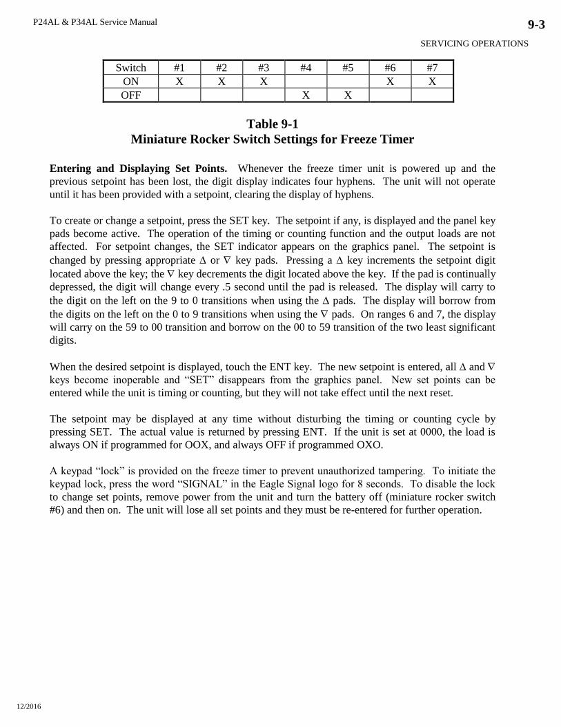
P24AL & P34AL Service Manual
SERVICING OPERATIONS
12/2016
9-3
Switch #1 #2 #3 #4 #5 #6 #7
ON X X X X X
OFF X X
Table 9-1
Miniature Rocker Switch Settings for Freeze Timer
Entering and Displaying Set Points. Whenever the freeze timer unit is powered up and the
previous setpoint has been lost, the digit display indicates four hyphens. The unit will not operate
until it has been provided with a setpoint, clearing the display of hyphens.
To create or change a setpoint, press the SET key. The setpoint if any, is displayed and the panel key
pads become active. The operation of the timing or counting function and the output loads are not
affected. For setpoint changes, the SET indicator appears on the graphics panel. The setpoint is
changed by pressing appropriate or key pads. Pressing a key increments the setpoint digit
located above the key; the key decrements the digit located above the key. If the pad is continually
depressed, the digit will change every .5 second until the pad is released. The display will carry to
the digit on the left on the 9 to 0 transitions when using the pads. The display will borrow from
the digits on the left on the 0 to 9 transitions when using the pads. On ranges 6 and 7, the display
will carry on the 59 to 00 transition and borrow on the 00 to 59 transition of the two least significant
digits.
When the desired setpoint is displayed, touch the ENT key. The new setpoint is entered, all and
keys become inoperable and “SET” disappears from the graphics panel. New set points can be
entered while the unit is timing or counting, but they will not take effect until the next reset.
The setpoint may be displayed at any time without disturbing the timing or counting cycle by
pressing SET. The actual value is returned by pressing ENT. If the unit is set at 0000, the load is
always ON if programmed for OOX, and always OFF if programmed OXO.
A keypad “lock” is provided on the freeze timer to prevent unauthorized tampering. To initiate the
keypad lock, press the word “SIGNAL” in the Eagle Signal logo for 8 seconds. To disable the lock
to change set points, remove power from the unit and turn the battery off (miniature rocker switch
#6) and then on. The unit will lose all set points and they must be re-entered for further operation.

P24AL & P34AL Service Manual
SERVICING OPERATIONS
12/2016
9-4
Figure 9-2
Freeze Timer (1TR)
Freezer Pressure Switch (optional). The freezing time period for producing ice of a desired
thickness is controlled by the freezer pressure switch (2PS), Figure 9-3, located inside the control
panel.
The original switch was set at the factory to produce ice of recommended thickness. Look at the
“Certificate of Test” which was provided with the machine for a sample set of pressure readings with
corresponding time periods and water temperatures. Also see Tables 11-5 or 11-6, Operating Vitals
for typical settings. When making adjustments, allow two ice discharging cycles between
adjustments. Switch adjustment is as follows: See Figure 9-3.
1. Turn the low signal adjustment nut CCW until low signal setting indicator is fully down. Turn
the high signal adjustment nut until high signal setting indicator is slightly beyond the actuation
setting of 55 psig.
2. Starting with the pressure above the actuation pressure, reduce the pressure to desired actuation
pressure of 55 psig, contact opens.
3. Advance the low signal adjusting nut until the switch actuates and contact closes.
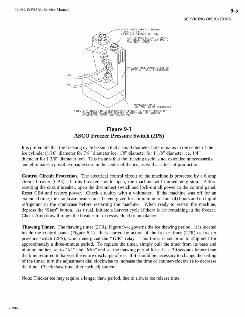
P24AL & P34AL Service Manual
SERVICING OPERATIONS
12/2016
9-5
Figure 9-3
ASCO Freezer Pressure Switch (2PS)
It is preferable that the freezing cycle be such that a small diameter hole remains in the center of the
ice cylinder (1/16” diameter for 7/8” diameter ice, 1/8” diameter for 1 1/8” diameter ice, 1/4”
diameter for 1 3/8” diameter ice). This insures that the freezing cycle is not extended unnecessarily
and eliminates a possible opaque core in the center of the ice, as well as a loss of production.
Control Circuit Protection. The electrical control circuit of the machine is protected by a 6 amp
circuit breaker (CB4). If this breaker should open, the machine will immediately stop. Before
resetting the circuit breaker, open the disconnect switch and lock-out all power to the control panel.
Reset CB4 and restore power. Check circuitry with a voltmeter. If the machine was off for an
extended time, the crankcase heater must be energized for a minimum of four (4) hours and no liquid
refrigerant in the crankcase before restarting the machine. When ready to restart the machine,
depress the “Start” button. As usual, initiate a harvest cycle if there is ice remaining in the freezer.
Check Amp draw through the breaker for excessive load or unbalance.
Thawing Timer. The thawing timer (2TR), Figure 9-4, governs the ice thawing period. It is located
inside the control panel (Figure 6-1). It is started by action of the freeze timer (2TR) or freezer
pressure switch (2PS), which energized the “1CR” relay. This timer is set prior to shipment for
approximately a three-minute period. To replace the timer, simply pull the timer from its base and
plug in another, set to “X1” and “Min” and set the thawing period for at least 30 seconds longer than
the time required to harvest the entire discharge of ice. If it should be necessary to change the setting
of the timer, turn the adjustment dial clockwise to increase the time or counter-clockwise to decrease
the time. Check thaw time after each adjustment.
Note: Thicker ice may require a longer thaw period, due to slower ice release time.
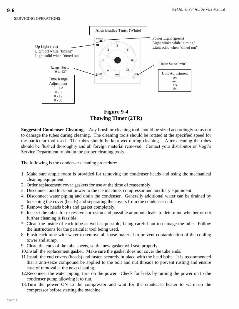
P24AL & P34AL Service Manual
SERVICING OPERATIONS
12/2016
9-6
Figure 9-4
Thawing Timer (2TR)
Suggested Condenser Cleaning. Any brush or cleaning tool should be sized accordingly so as not
to damage the tubes during cleaning. The cleaning tools should be rotated at the specified speed for
the particular tool used. The tubes should be kept wet during cleaning. After cleaning the tubes
should be flushed thoroughly and all foreign material removed. Contact your distributor or Vogt’s
Service Department to obtain the proper cleaning tools.
The following is the condenser cleaning procedure:
1. Make sure ample room is provided for removing the condenser heads and using the mechanical
cleaning equipment.
2. Order replacement cover gaskets for use at the time of reassembly.
3. Disconnect and lock-out power to the ice machine, compressor and auxiliary equipment.
4. Disconnect water piping and drain the condenser. Generally additional water can be drained by
loosening the cover (heads) and separating the covers from the condenser end.
5. Remove the heads bolts and gasket completely.
6. Inspect the tubes for excessive corrosion and possible ammonia leaks to determine whether or not
further cleaning is feasible.
7. Clean the inside of each tube as well as possible, being careful not to damage the tube. Follow
the instructions for the particular tool being used.
8. Flush each tube with water to remove all loose material to prevent contamination of the cooling
tower and sump.
9. Clean the ends of the tube sheets, so the new gasket will seal properly.
10.Install the replacement gasket. Make sure the gasket does not cover the tube ends.
11.Install the end covers (heads) and fasten securely in place with the head bolts. It is recommended
that a anti-seize compound be applied to the bolt and nut threads to prevent rusting and ensure
ease of removal at the next cleaning.
12.Reconnect the water piping, turn on the power. Check for leaks by turning the power on to the
condenser pump allowing it to run.
13.Turn the power ON to the compressor and wait for the crankcase heater to warm-up the
compressor before starting the machine.
Allen Bradley Timer (White)
0
2
4
6
8
10
12
RANGE UNIT
POWER
UP
Min
Power Light (green)
Light blinks while "timing"
Light solid when "timed out"
Unit Adjustment sec
min
hrs 10h
Units: Set to “min” Range: Set to
“0 to 12”
Time Range
Adjustment 0 - 1.2
0 - 3
0 - 12
0 - 30
Up Light (red)
Light off while "timing"
Light solid when "timed out"
P24AL & P34AL Service Manual
SERVICING OPERATIONS
12/2016
9-7
Cutter Gear Reducer. The cutter motor and gear reducer (54), Figure 9-5A, drive the ring gear of
the cutter assembly. It is important that the teeth of the drive gear and the ring gear mesh properly
both vertically and horizontally. The drive gear and hub can be raised or lowered on the gear reducer
shaft to obtain maximum vertical tooth engagement and the reducer assembly can be moved in or out
horizontally to obtain the proper tooth depth for maximum gear life.
Note: The motor and gear reducer are an integral unit. Only qualified personnel should attempt to
disassemble and repair this unit.
Drive Gear Replacement.
1. Disconnect and lock-out all power to the machine.
2. Remove the top and side bolts holding the mounting plate to the support bracket. Lift the plate
and gear reducer from the bracket and rest the assembly on a stable worktable sitting next to the
tank. Leave the electrical conduit connected to the gear reducer motor.
3. Inspect the drive gear teeth for proper vertical alignment and wear pattern.
4. If the wear pattern indicates less than a full width of tooth engagement, measure the difference
and make a note to correct at the time of reassembly.
5. Measure and record the dimension from the drive gear to the bottom side of the mounting plate.
6. Remove the three or four cap screws holding the drive gear to the split taper bushing.
7. Using two of the same cap screws in the threaded holes of the bushing, jack the gear off the
bushing and remove both from the gear reducer shaft.
8. Clean the split bushing and tapered hole of the new drive gear and insert the bushing into the
drive gear making sure the tapers match.
9. Slide the split hub and gear onto the keyed shaft with the key in place, positioning the hub (by
measurement previously recorded) so the full width of the gear teeth will engage when assembled
and tightened.
10. Tighten the cap screws (three or four) progressively and uniformly around the hub and recheck
the location measurement. If it is not correct, loosen the cap screws, hub and gear assembly and
make correction. Then retighten the cap screws.
11. Install the reducer and mounting plate assembly on the water tank bracket and fasten in place
with the side and top cap screws.
12. Rotate the cutter and disc assembly by hand and stop at the point where you feel the least amount
of backlash between the gear teeth.
NOTE: There should be only a slight amount of backlash (more specifically “tooth tip
clearance”). Too much clearance will cause premature wear and possible tooth damage. When
the cutter runs under a no load condition, it should have a smooth uniform sound. For
lubrication, see Chapter 7, Maintenance.
13. If the tooth tip clearance needs adjusting, loosen the four hex nuts holding the reducer to the
mounting plate and move the reducer as required for proper tooth engagement. Tighten the hex
nuts securely and recheck backlash.
P24AL & P34AL Service Manual
SERVICING OPERATIONS
12/2016
9-8
Gear Reducer Replacement.
1. Disconnect and lock out all power to the machine.
2. Disconnect electrical wires and conduit from the motor.
3. Remove the top and side bolts holding the mounting plate to the support bracket and lift the plate
and gear reducer assembly from the tank bracket.
4. Inspect the drive gear teeth for proper vertical alignment and wear pattern. If the wear pattern
indicates less than a full width of tooth engagement, measure the distance so correction can be
made at the time of reassembly.
5. Measure and record either the distance of the drive gear from the mounting plate or the split hub
from the shaft end for future reference when reassembling.
6. Remove the three or four cap screws from the split taper bushing.
7. Use two of the cap screws in the threaded holes of the busing as jacking screws for pushing the
drive gear from the hub.
8. Drive a wedge in the split of the hub (bushing) and slide both the hub and gear from the shaft.
9. Remove the four hex nuts and lock washers from the carriage bolts around the reducer base and
mounting plate and separate the plate and reducer.
10. Install the replacement gear reducer and motor onto the mounting plate using the carriage bolts,
lock washers, and hex nuts. Tighten the nuts snug only for later adjustment.
11. Clean the split hub and drive gear, insert the hub into the gear, making sure the tapers of the two
match and slide the hub and gear onto the shaft.
12. Position the hub on the shaft (note measurements previously taken) so the full width of the gear
teeth will engage when assembled and tightened.
13. Tighten the cap screws (three or four) progressively and uniformly around the hub, checking the
measurements and adjusting as necessary.
14. Install the reducer and mounting plate assembly on the water tank bracket and fasten in place
with the side and top cap screws.
15. Rotate the cutter and disc assembly by hand and stop at the point where you feel the least amount
of backlash between the gear teeth.
16. If the gear tooth tip clearance needs adjusting, loosen the four hex nuts around the reducer base
and move the reducer as required for proper tooth clearance. Tighten the hex nuts securely and
recheck for backlash.
17. Reconnect the electrical wires and conduit to the motor.
18. Check cutter rotation and correct as necessary.
NOTE: When the cutter runs under a “no-load” condition, it should have a smooth uniform
sound.
The weights listed in Table 9-3 will give you an idea of manpower or equipment needed when
servicing and handling the various parts of the water tank and cutter. Be sure to use safe lifting and
handling practices to prevent bodily injury and/or damage to parts. If additional information is
needed, you should contact your distributor or the factory.
To inspect the cutter assembly and make repairs or replace parts, it will be necessary to lower and
remove the water tank from its mounting to the bottom of the freezer. The water tank has metal
casters allowing it to be rolled out from under the freezer for inspection and servicing.
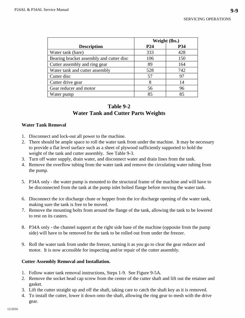
P24AL & P34AL Service Manual
SERVICING OPERATIONS
12/2016
9-9
Weight (lbs.)
Description P24 P34
Water tank (bare) 333 428
Bearing bracket assembly and cutter disc 106 150
Cutter assembly and ring gear 89 164
Water tank and cutter assembly 528 742
Cutter disc 57 97
Cutter drive gear 8 14
Gear reducer and motor 56 96
Water pump 85 85
Table 9-2
Water Tank and Cutter Parts Weights
Water Tank Removal
1. Disconnect and lock-out all power to the machine.
2. There should be ample space to roll the water tank from under the machine. It may be necessary
to provide a flat level surface such as a sheet of plywood sufficiently supported to hold the
weight of the tank and cutter assembly. See Table 9-3.
3. Turn off water supply, drain water, and disconnect water and drain lines from the tank.
4. Remove the overflow tubing from the water tank and remove the circulating water tubing from
the pump.
5. P34A only - the water pump is mounted to the structural frame of the machine and will have to
be disconnected from the tank at the pump inlet bolted flange before moving the water tank.
6. Disconnect the ice discharge chute or hopper from the ice discharge opening of the water tank,
making sure the tank is free to be moved.
7. Remove the mounting bolts from around the flange of the tank, allowing the tank to be lowered
to rest on its casters.
8. P34A only - the channel support at the right side base of the machine (opposite from the pump
side) will have to be removed for the tank to be rolled out from under the freezer.
9. Roll the water tank from under the freezer, turning it as you go to clear the gear reducer and
motor. It is now accessible for inspecting and/or repair of the cutter assembly.
Cutter Assembly Removal and Installation.
1. Follow water tank removal instructions, Steps 1-9. See Figure 9-5A.
2. Remove the socket head cap screw from the center of the cutter shaft and lift out the retainer and
gasket.
3. Lift the cutter straight up and off the shaft, taking care to catch the shaft key as it is removed.
4. To install the cutter, lower it down onto the shaft, allowing the ring gear to mesh with the drive
gear.

P24AL & P34AL Service Manual
SERVICING OPERATIONS
12/2016
9-10
5. Rotate the cutter, aligning the shaft and hub key way and inserting the key to its full depth.
6. Install the gasket, the retainer, and the socket head cap screw and tighten to approximately 15 ft.
lb. torque.
7. Check and adjust the cutter height per “Cutter Height Adjustment” instructions.
Bearing Bracket and Cutter Disc Removal.
1. Remove the cutter assembly per instructions.
2. Match mark the bearing bracket support arms with the water tank for reassembly reference.
3. Remove the splash shield and ice deflector plate from the ice discharge opening.
4. Support the bearing bracket to keep it from falling in the tank. Loosen and remove the four cap
screws and lock washers from the ends of the bearing bracket support arms.
5. Lift the bracket and cutter disc from the tank. Be sure the support arms are match marked for
reassembly. You may have to gently drive the support arms up or down to release them from the
tank walls.
6. With the bracket and disc assembly turned upside down, remove the cotter pin from the shaft.
7. Loosen and remove the slotted hex nut, spring washer, and spacer.
8. Lift the cutter disc from the keyed shaft, being careful not to loose the shaft key.
The cutter shaft and bearings are sealed in the bearing bracket assembly. The cavity between the
bearings has been filled with a food-grade grease to prevent the presence of moisture and prolong the
life of the unit. If there is any vertical or side movement of the shaft or if the bearings feel rough or
tight when turning the shaft, the assembly should be dismantled and rebuilt. Refer to the cutter tank
assembly drawing, Figure 9-5A, for parts location and identification.
Cutter Shaft and Bearing Removal.
Note: Use only a soft mallet or other soft tool for fitting all parts into place.
1. With the bearing bracket assembly removed from the tank, press the shaft out of the housing
from the bottom up.
Note: The two top bearings may come out with the shaft along with the upper seal and excluder.
2. Turn the bracket over and press the bottom bearing out the bottom, along with the lower seal.
3. There are three spacers on the shaft that should be removed and labeled as to their location.
Remove them as they are made accessible.
4. Clean and inspect all parts for wear or damage. Discard all parts showing any indication of
damage.
Cutter Shaft and Bearing Installation.
1. Clean the inside of the bearing housing of grease or foreign matter. Further clean the top bearing
housing with pro-lock cleaner and primer (or a suitable substitute) and remove the pipe plugs
from the side of the housing
2. Apply a thin coat of Loctite RC/609 retainer (or a suitable substitute) to the inner surface and
bearing shoulder of the top of the bearing bracket.
3. Insert a bearing in the top housing and set it in place.
4. Clean the cutter shaft and press the top bearing onto the shaft.
P24AL & P34AL Service Manual
SERVICING OPERATIONS
12/2016
9-11
5. Slide the upper bearing spacer on the shaft and begin driving the shaft down through the middle
bearing of the housing. Do not start the top shaft bearing in the housing.
6. Partially fill the housing with grease (MPG-2 or a USDA approved grease). Use enough to fill
the area between the two upper bearings, forcing some out the pipe plughole when the shaft and
top bearing are seated.
7. Finish driving the shaft and bearing into the housing until it is firmly seated.
8. Turn the bracket and shaft upside down and fill the housing around the shaft with MPG-2 (or
suitable equivalent) grease.
9. Slide the lower bearing spacer over the shaft and into the housing.
10. With the top end of the shaft supported, install the lower bearing on the shaft driving it down into
the housing firmly against the housing shoulder.
11. Slide the seal spacer (ridged end in, flat end out) and seal (open face out) onto the shaft together.
12. Uniformly tap the seal into the housing against its shoulder.
NOTE: The purpose of the seals and excluders are to prevent moisture from entering the
housing area not to hold the grease in.
13. Wipe off excess grease and install the two pipe plugs.
14. Install the largest excluder on the bracket as illustrated by the assembly drawing.
15. Install the tines disc, the 1/4 x 1/4 key, spacer, spring washer, castle nut, and cotter pin.
16. Turn the assembly right side up and install it in the water tank, locating the support arms as they
were match marked when removed and secure in place using the 5/8” stainless steel cap screw
and lock washer maximum torque should be 90 ft. lbs.
17. Install the top seal (open side facing out*), tapping it uniformly into the housing until it seats.
18. Install the top water excluder.
19. Install the splash shield and ice deflector plate in the ice discharge opening.
20. Install the cutter assembly, using the 1/4” X 1/4” X 3 3/16” lg. stainless steel key to align the key
ways and lock the cutter and shaft together.
21. Install the red rubber gasket, retainer, and 3/8” stainless steel socket head cap screw. Tighten to
approximately 15 ft. lbs.
22. Check and adjust the cutter height per “Cutter Height Adjustment” instructions.
Cutter Height Adjustment. The height of the cutter can be adjusted by the four bolts holding the
bearing bracket assembly in place. These bolts are threaded into holes in the end of each arm
through holes in the water tank. The current design has these washers welded in place after the cutter
height is properly adjusted. This helps to insure proper adjustment during servicing. Using a true
straight edge long enough to reach across the top flange of the water tank (30” for P24 and 40” for
P34), the top of the cutter rim and blade should be 1/8” 1/16” below the top of the water tank
flange.
Keep one end of the straight edge at the same point and swing the other end across the tank at
various points to check the clearance.
Also, rotate the cutter to check all points. If adjustment is necessary, loosen the four side bolts and
raise or lower each arm as needed. Tighten the bolts securely to approximately 90 ft. lb.

P24AL & P34AL Service Manual
SERVICING OPERATIONS
12/2016
9-12
Water Tank Installation.
1. Place the 3/16” thick gum rubber gasket on the top of the tank flange. It can be held in place
with narrow strips of tape through the bolt holes.
2. Push the water tank in and under the freezer aligning the boltholes and installing the mounting
bolts around the flange and tightening the nuts securely.
3. Reconnect the discharge chute or hopper to the ice discharge opening.
4. Mount the water pump (P34 only) and attach the circulating water tubing and overflow tubing.
5. Reconnect all water piping such as drain, overflow, and make-up water lines. Turn water on and
check for leaks.
6. Fill the water tank with water and make sure the drain valve is closed.
When ready, turn the power “On” to the machine, but don’t operate the compressor until the oil is
warm and there is no liquid refrigerant in the crankcase.
Figure 9-5A
P24A Cutter Assembly

P24AL & P34AL Service Manual
SERVICING OPERATIONS
12/2016
9-13
Figure 9-5B
P24A Water Tank Assembly
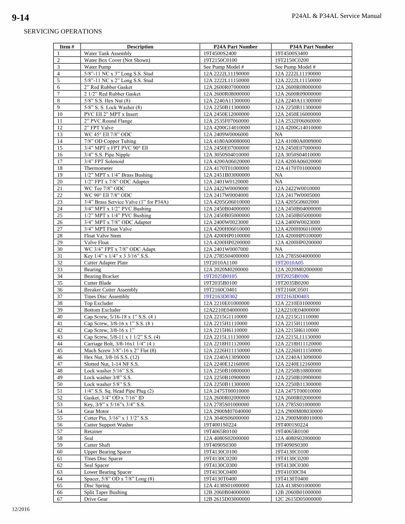
P24AL & P34AL Service Manual
SERVICING OPERATIONS
12/2016
9-14
Item # Description P24A Part Number P34A Part Number
1 Water Tank Assembly 19T4500S2400 19T4500S3400
2 Water Box Cover (Not Shown) 19T2150C0100 19T2150C0200
3 Water Pump See Pump Model # See Pump Model #
4 5/8”-11 NC x 3” Long S.S. Stud 12A 2222L11190000 12A 2222L11190000
5 5/8”-11 NC x 2” Long S.S. Stud 12A 2222L11150000 12A 2222L11150000
6 2” Red Rubber Gasket 12A 2600R07000000 12A 2600R08000000
7 2 1/2” Red Rubber Gasket 12A 2600R08000000 12A 2600R09000000
8 5/8” S.S. Hex Nut (8) 12A 2240A11300000 12A 2240A11300000
9 5/8” S. S. Lock Washer (8) 12A 2250B11300000 12A 2250B11300000
10 PVC Ell 2” MPT x Insert 12A 2450E12000000 12A 2450E16000000
11 2” PVC Round Flange 12A 2535F07060000 12A 2532F06060000
12 2” FPT Valve 12A 4200G14010000 12A 4200G14010000
13 WC 45° Ell 7/8” ODC 12A 2409W0006000 NA
14 7/8” OD Copper Tubing 12A 4180A00080000 12A 41080A0009000
15 3/4” MPT x FPT PVC 90° Ell 12A 2450E07000000 12A 2450E07000000
16 3/4” S.S. Pipe Nipple 12A 3050S04010000 12A 3050S04010000
17 3/4” FPT Solenoid 12A 4200A06020000 12A 4200A06020000
18 Thermometer 12A 4170T01000000 12A 4170T01000000
19 1/2” MPT x 1/4” Brass Bushing 12A 2451B03000000 NA
20 1/2” FPT x 7/8” ODC Adapter 12A 2401W0120000 NA
21 WC Tee 7/8” ODC 12A 2422W0009000 12A 2422W0010000
22 WC 90° Ell 7/8” ODC 12A 2417W0004000 12A 2417W0005000
23 3/4” Brass Service Valve (1” for P34A) 12A 4205G06010000 12A 4205G0602000
24 3/4” MPT x 1/2” PVC Bushing 12A 2450B04000000 12A 2450B04000000
25 1/2” MPT x 1/4” PVC Bushing 12A 2450B05000000 12A 2450B05000000
26 3/4” MPT x 7/8” ODC Adapter 12A 2400W0023000 12A 2400W0023000
27 3/4” MPT Float Valve 12A 4200H06010000 12A 4200H06010000
28 Float Valve Stem 12A 4200HP0100000 12A 4200HP0100000
29 Valve Float 12A 4200HP0200000 12A 4200HP0200000
30 WC 3/4” FPT x 7/8” ODC Adapt. 12A 2401W0007000 NA
31 Key 1/4” x 1/4” x 3 3/16” S.S. 12A 2785S04000000 12A 2785S04000000
32 Cutter Adapter Plate 19T2010A1100 19T2010A05
33 Bearing 12A 2020M0200000 12A 2020M02000000
34 Bearing Bracket 19T2025B0105 19T2025B0106
35 Cutter Blade 19T2035B0100 19T2035B0200
36 Breaker Cutter Assembly 19T2160C0401 19T2160C0501
37 Tines Disc Assembly 19T2163D0302 19T2163D0403
38 Top Excluder 12A 2210E01000000 12A 2210E01000000
39 Bottom Excluder 12A2210E04000000 12A2210E04000000
40 Cap Screw, 5/16-18 x 1” S.S. (4 ) 12A 2215G1110000 12A 2215G1110000
41 Cap Screw, 3/8-16 x 1” S.S. (8 ) 12A 2215H1110000 12A 2215H1110000
42 Cap Screw, 3/8-16 x 1” 12A 2215H6110000 12A 2215H6110000
43 Cap Screw, 5/8-11 x 1 1/2” S.S. (4) 12A 2215L11130000 12A 2215L11130000
44 Carriage Bolt, 3/8-16x1 1/4” (4 ) 12A 2218H11120000 12A 2218H11120000
45 Mach Screw 3/8”-16 x 2” Flat (8) 12A 2226H11150000 12A 2226H11150000
46 Hex Nut, 3/8-16 S.S. (12) 12A 2240A13090000 12A 2240A13090000
47 Slotted Nut, 1-14 NF S.S. 12A 2240E12160000 12A 2240E12160000
48 Lock washer 5/16” S.S. 12A 2250B10800000 12A 2250B10800000
49 Lock washer 3/8” S.S. 12A 2250B10900000 12A 2250B10900000
50 Lock washer 5/8” S.S. 12A 2250B11300000 12A 2250B11300000
51 1/4” S.S. Sq. Head Pipe Plug (2) 12A 2475T00010000 12A 2475T00010000
52 Gasket, 3/4” OD x 7/16” ID 12A 2600R02000000 12A 2600R02000000
53 Key, 3/8” x 5/16”x 3/4” S.S. 12A 2785S01000000 12A 2785S01000000
54 Gear Motor 12A 2900M07040000 12A 2900M08030000
55 Cotter Pin, 3/16” x 1 1/2” S.S. 12A 3040S06000000 12A 2900M08010000
56 Cutter Support Washer 19T4001S0224 19T4001S0224
57 Retainer 19T4065R0100 19T4065R0100
58 Seal 12A 4080S02000000 12A 4080S02000000
59 Cutter Shaft 19T4090S0300 19T4090S0300
60 Upper Bearing Spacer 19T4130C0100 19T4130C0100
61 Tines Disc Spacer 19T4130C0200 19T4130C0200
62 Seal Spacer 19T4130C0300 19T4130C0300
63 Lower Bearing Spacer 19T4130C0400 19T41030C04
64 Spacer, 5/8” OD x 7/8” Long (8) 19T4130T0400 19T4130T0400
65 Disc Spring 12A 4138S01000000 12A 4138S01000000
66 Split Taper Bushing 12B 2060B04000000 12B 2060B01000000
67 Drive Gear 12B 2615D03000000 12C 2615D05000000
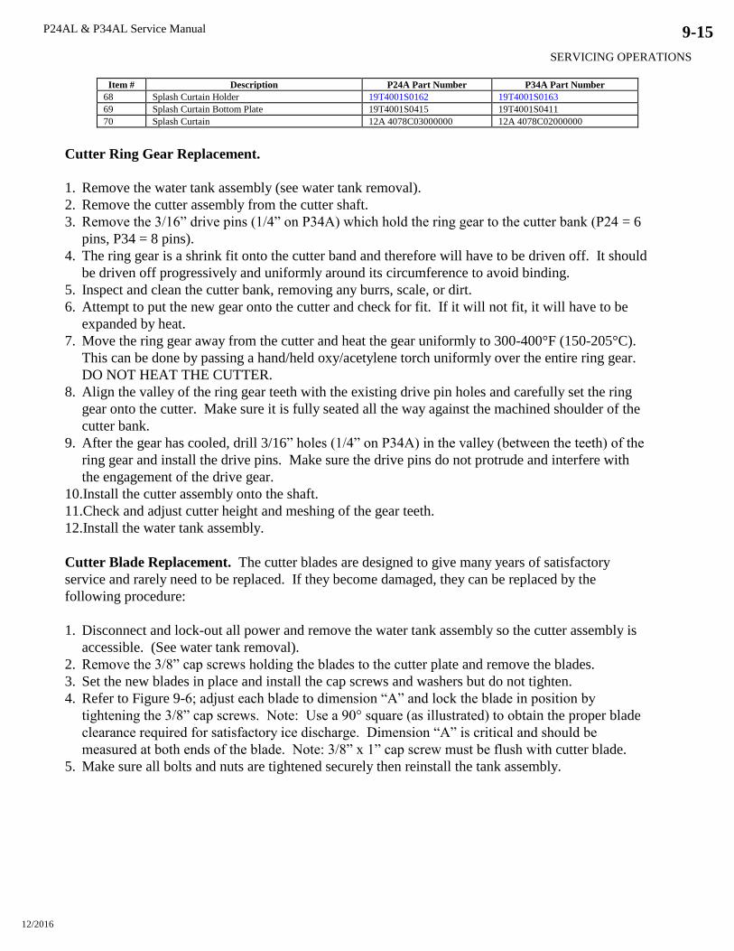
P24AL & P34AL Service Manual
SERVICING OPERATIONS
12/2016
9-15
Item # Description P24A Part Number P34A Part Number
68 Splash Curtain Holder 19T4001S0162 19T4001S0163
69 Splash Curtain Bottom Plate 19T4001S0415 19T4001S0411
70 Splash Curtain 12A 4078C03000000 12A 4078C02000000
Cutter Ring Gear Replacement.
1. Remove the water tank assembly (see water tank removal).
2. Remove the cutter assembly from the cutter shaft.
3. Remove the 3/16” drive pins (1/4” on P34A) which hold the ring gear to the cutter bank (P24 = 6
pins, P34 = 8 pins).
4. The ring gear is a shrink fit onto the cutter band and therefore will have to be driven off. It should
be driven off progressively and uniformly around its circumference to avoid binding.
5. Inspect and clean the cutter bank, removing any burrs, scale, or dirt.
6. Attempt to put the new gear onto the cutter and check for fit. If it will not fit, it will have to be
expanded by heat.
7. Move the ring gear away from the cutter and heat the gear uniformly to 300-400°F (150-205°C).
This can be done by passing a hand/held oxy/acetylene torch uniformly over the entire ring gear.
DO NOT HEAT THE CUTTER.
8. Align the valley of the ring gear teeth with the existing drive pin holes and carefully set the ring
gear onto the cutter. Make sure it is fully seated all the way against the machined shoulder of the
cutter bank.
9. After the gear has cooled, drill 3/16” holes (1/4” on P34A) in the valley (between the teeth) of the
ring gear and install the drive pins. Make sure the drive pins do not protrude and interfere with
the engagement of the drive gear.
10.Install the cutter assembly onto the shaft.
11.Check and adjust cutter height and meshing of the gear teeth.
12.Install the water tank assembly.
Cutter Blade Replacement. The cutter blades are designed to give many years of satisfactory
service and rarely need to be replaced. If they become damaged, they can be replaced by the
following procedure:
1. Disconnect and lock-out all power and remove the water tank assembly so the cutter assembly is
accessible. (See water tank removal).
2. Remove the 3/8” cap screws holding the blades to the cutter plate and remove the blades.
3. Set the new blades in place and install the cap screws and washers but do not tighten.
4. Refer to Figure 9-6; adjust each blade to dimension “A” and lock the blade in position by
tightening the 3/8” cap screws. Note: Use a 90° square (as illustrated) to obtain the proper blade
clearance required for satisfactory ice discharge. Dimension “A” is critical and should be
measured at both ends of the blade. Note: 3/8” x 1” cap screw must be flush with cutter blade.
5. Make sure all bolts and nuts are tightened securely then reinstall the tank assembly.

P24AL & P34AL Service Manual
SERVICING OPERATIONS
12/2016
9-16
Figure 9-6
Cutter Blade and Adapter Plate Adjustment
Cutter Adapter Plate Installation.
1. Disconnect and lock-out all power to the machine and remove the water tank assembly so the
cutter is accessible (see water tank removal).
2. Locate the new adapter plate, holding the correct dimension “A” from the edge of the plate to the
edge of the blade. See Figure 9-6.
3. Using two C-clamps to hold the adapter plate securely in place, drill four 7/16” diameter holes
through the adapter plate and through the cutter plate at the same time so they will adjoin
properly.
4. Countersink the holes in the adapter plate to make the bolt heads flush with the plate.
5. Install bolts and spacers as illustrated and tighten securely. Note: the length of ice is determined
by the spacer length. Refer to “Ice Length” for details.
6. Install the water tank assembly to the machine.
Note: Length of cylinder ice can be changed. See Chapter 10.
Pumpdown. The function of the pumpdown is to transfer all the liquid refrigerant from the freezer
(evaporator) into the receiver. Pumpdown should only be performed when the freezer is clear of ice.
Its main purposes are:
1. To check the total refrigerant charge.
2. To perform service or repair work on the machine.
3. To winterize the machine.
4. To remove excess water from the ammonia.
5. To prepare the machine for disconnection or moving.

P24AL & P34AL Service Manual
SERVICING OPERATIONS
12/2016
9-17
To perform a pumpdown, follow this procedure:
1. With the machine running, close the liquid feed stop valve nearest the receiver.
2. Open the water tank drain valve partially to allow a continuous flow of warm make-up water into
the water tank and still maintain a good level in the tank. An auxiliary supply of warm water (not
to exceed 100°F) may be used if available. Warmer water affords a more complete pumpdown.
3. Allow the machine to operate and complete two freeze and harvest cycles.
4. After the second harvest cycle, stop the machine, throw the electrical disconnect, and lock-out all
power to the machine.
5. Remove wire #17 from the freezer pressure switch (2PS) and insulate the end to prevent a short
circuit.
6. Restore power to the machine and start the water pump only, to circulate warm water through the
freezer.
7. When the suction pressure increases to 70 psig or higher, start the compressor and allow the
machine to stop automatically by the low pressure switch at approximately 15 psig. (Lower
pressure can be obtained by jumping out the pressure switch.) Remove all power from the
machine before opening the control panel cover. With the pressure switch jumped out, the
machine can be manually started and stopped. Do not operate the machine below 2 psig.
8. When the desirable pumpdown is obtained, close the thawing gas stop valve (90), and the
compressor discharge line stop valve. Other valves may also be closed to isolate a particular area
which may require attention.
9. To perform a total pumpdown, it may be necessary to apply heat directly to the oil trap in order to
boil off the liquid ammonia and oil mixture.
Removal of Ammonia Refrigerant from the Machine. Liquid ammonia can be removed from the
machine through the receiver drain valve. Refer to Chapters 1, 2, and Appendix A for special
warnings and instructions regarding the handling of ammonia. Make sure you are familiar with and
technically qualified to handle anhydrous-ammonia refrigerant.
! WARNING !
It is not recommended that refrigerant to be transferred from a refrigeration system directly
into a cylinder. If such a transfer is made, the refrigerant cylinder must be an approved,
CLEAN cylinder--free of any contaminants or foreign materials--and must be weighed
continuously to assure contents do not exceed net weight specified by cylinder manufacturer of
any applicable code requirements.
! WARNING !
If ammonia vapor is released from the machine, it may be purged into water which will absorb it.
Follow the purging instructions. See “Purging Non-Condensables”.
Note: Observe all local codes when handling and discharging anhydrous-ammonia refrigerant.
Refrigerant Leaks. Anhydrous ammonia leaks can be detected by odor, sulfur stick, soap solution,
or test paper. The odor is normally noticed first and the location of the leak is found with soap or
sulfur stick. Soap solution can be purchased from your refrigeration supply house or it can be made
by mixing four parts water, one part liquid soap, and a few drops of Glycerin for better capillary
attraction.

P24AL & P34AL Service Manual
SERVICING OPERATIONS
12/2016
9-18
Apply soap solutions with a narrow brush or spray bottle to all joints, welds, or areas of
suspicion. The solution will form bubbles if there is a leak.
Sulfur sticks and test paper can be obtained from your ammonia supplier.
Light the end of the sulfur stick and pass it around suspected points of leakage. A white cloud
will form where a leak is, even if it is very small.
Moisten a strip of test paper and pass it around the suspected area. If the paper comes in contact
with ammonia, it will turn red. Coils submerged in water, or condenser cooling water may be
tested by dipping a strip directly in the water. If ammonia is present, the paper will turn red.
Always remove refrigerant pressure from the vessel, tubing, or component part before repairs are
attempted.
Non-condensable Gasses. Satisfactory operation of the machine is not possible if non-condensable
gases (usually air) are present in the system. Excessive condensing pressure is an indication of such
gases. Excessive condensing pressure in water-cooled condensers may also be due to the
accumulation of scale in the cooling coil or due to insufficient cooling water or excessive water
temperature. See Chapter 7 “Water-Cooled Condensers”, and Chapter 9 “Condenser Cleaning”.
Purging Non-Condensables. Air and other non-condensable gases in a refrigeration system are not
desirable. Purging air from your Tube-Ice machine will greatly improve system performance and
save money.
Non-condensable gas effects are:
1. Higher condensing pressure than what should match the condensed liquid temperature.
2. Greater electrical power consumption.
3. Reduced refrigeration capacity.
4. Longer than normal compressor running time.
5. Slow ice release and long thaw cycle.
Air collects mostly in high pressure condensers, receivers, and other high-pressure components. It is
most commonly found in the coolest, lowest-velocity area of these components.
Evaporative condensers usually have purge points at the top of the outlet header of each circuit.
Receivers usually have a purge point at the top, away from the inlet, where it is coolest and the gas
velocity is the lowest.
The freezer can be purged through the valve at the top of the suction accumulator, but should be
done only during the thaw cycle or after the system has been idle at least two hours.
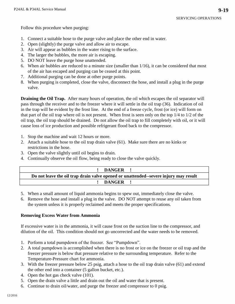
P24AL & P34AL Service Manual
SERVICING OPERATIONS
12/2016
9-19
Follow this procedure when purging:
1. Connect a suitable hose to the purge valve and place the other end in water.
2. Open (slightly) the purge valve and allow air to escape.
3. Air will appear as bubbles in the water rising to the surface.
4. The larger the bubbles, the more air is escaping.
5. DO NOT leave the purge hose unattended.
6. When air bubbles are reduced to a minute size (smaller than 1/16), it can be considered that most
of the air has escaped and purging can be ceased at this point.
7. Additional purging can be done at other purge points.
8. When purging is completed, close the valve, disconnect the hose, and install a plug in the purge
valve.
Draining the Oil Trap. After many hours of operation, the oil which escapes the oil separator will
pass through the receiver and to the freezer where it will settle in the oil trap (36). Indication of oil
in the trap will be evident by the frost line. At the end of a freeze cycle, frost (or ice) will form on
that part of the oil trap where oil is not present. When frost is seen only on the top 1/4 to 1/2 of the
oil trap, the oil trap should be drained. Do not allow the oil trap to fill completely with oil, or it will
cause loss of ice production and possible refrigerant flood back to the compressor.
1. Stop the machine and wait 12 hours or more.
2. Attach a suitable hose to the oil trap drain valve (61). Make sure there are no kinks or
restrictions in the hose.
3. Open the valve slightly until oil begins to drain.
4. Continually observe the oil flow, being ready to close the valve quickly.
! DANGER !
Do not leave the oil trap drain valve opened or unattended--severe injury may result
! DANGER !
5. When a small amount of liquid ammonia begins to spew out, immediately close the valve.
6. Remove the hose and install a plug in the valve. DO NOT attempt to reuse any oil taken from
the system unless it is properly reclaimed and meets the proper specifications.
Removing Excess Water from Ammonia
If excessive water is in the ammonia, it will cause frost on the suction line to the compressor, and
dilution of the oil. This condition should not go uncorrected and the water needs to be removed.
1. Perform a total pumpdown of the freezer. See “Pumpdown”.
2. A total pumpdown is accomplished when there is no frost or ice on the freezer or oil trap and the
freezer pressure is below that pressure relative to the surrounding temperature. Refer to the
Temperature-Pressure chart for ammonia.
3. With the freezer pressure below 25 psig, attach a hose to the oil trap drain valve (61) and extend
the other end into a container (5 gallon bucket, etc.).
4. Open the hot gas check valve (101).
5. Open the drain valve a little and drain out the oil and water that is present.
6. Continue to drain oil/water, and purge the freezer and compressor to 0 psig.
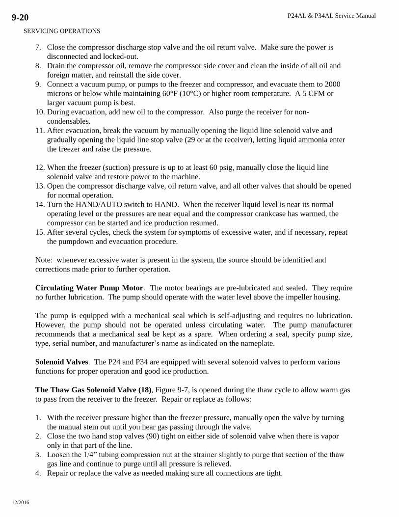
P24AL & P34AL Service Manual
SERVICING OPERATIONS
12/2016
9-20
7. Close the compressor discharge stop valve and the oil return valve. Make sure the power is
disconnected and locked-out.
8. Drain the compressor oil, remove the compressor side cover and clean the inside of all oil and
foreign matter, and reinstall the side cover.
9. Connect a vacuum pump, or pumps to the freezer and compressor, and evacuate them to 2000
microns or below while maintaining 60°F (10°C) or higher room temperature. A 5 CFM or
larger vacuum pump is best.
10. During evacuation, add new oil to the compressor. Also purge the receiver for non-
condensables.
11. After evacuation, break the vacuum by manually opening the liquid line solenoid valve and
gradually opening the liquid line stop valve (29 or at the receiver), letting liquid ammonia enter
the freezer and raise the pressure.
12. When the freezer (suction) pressure is up to at least 60 psig, manually close the liquid line
solenoid valve and restore power to the machine.
13. Open the compressor discharge valve, oil return valve, and all other valves that should be opened
for normal operation.
14. Turn the HAND/AUTO switch to HAND. When the receiver liquid level is near its normal
operating level or the pressures are near equal and the compressor crankcase has warmed, the
compressor can be started and ice production resumed.
15. After several cycles, check the system for symptoms of excessive water, and if necessary, repeat
the pumpdown and evacuation procedure.
Note: whenever excessive water is present in the system, the source should be identified and
corrections made prior to further operation.
Circulating Water Pump Motor. The motor bearings are pre-lubricated and sealed. They require
no further lubrication. The pump should operate with the water level above the impeller housing.
The pump is equipped with a mechanical seal which is self-adjusting and requires no lubrication.
However, the pump should not be operated unless circulating water. The pump manufacturer
recommends that a mechanical seal be kept as a spare. When ordering a seal, specify pump size,
type, serial number, and manufacturer’s name as indicated on the nameplate.
Solenoid Valves. The P24 and P34 are equipped with several solenoid valves to perform various
functions for proper operation and good ice production.
The Thaw Gas Solenoid Valve (18), Figure 9-7, is opened during the thaw cycle to allow warm gas
to pass from the receiver to the freezer. Repair or replace as follows:
1. With the receiver pressure higher than the freezer pressure, manually open the valve by turning
the manual stem out until you hear gas passing through the valve.
2. Close the two hand stop valves (90) tight on either side of solenoid valve when there is vapor
only in that part of the line.
3. Loosen the 1/4” tubing compression nut at the strainer slightly to purge that section of the thaw
gas line and continue to purge until all pressure is relieved.
4. Repair or replace the valve as needed making sure all connections are tight.
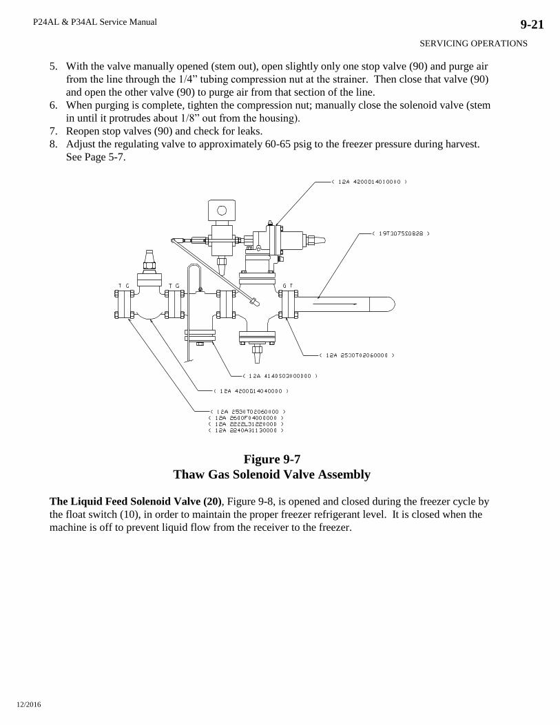
P24AL & P34AL Service Manual
SERVICING OPERATIONS
12/2016
9-21
5. With the valve manually opened (stem out), open slightly only one stop valve (90) and purge air
from the line through the 1/4” tubing compression nut at the strainer. Then close that valve (90)
and open the other valve (90) to purge air from that section of the line.
6. When purging is complete, tighten the compression nut; manually close the solenoid valve (stem
in until it protrudes about 1/8” out from the housing).
7. Reopen stop valves (90) and check for leaks.
8. Adjust the regulating valve to approximately 60-65 psig to the freezer pressure during harvest.
See Page 5-7.
Figure 9-7
Thaw Gas Solenoid Valve Assembly
The Liquid Feed Solenoid Valve (20), Figure 9-8, is opened and closed during the freezer cycle by
the float switch (10), in order to maintain the proper freezer refrigerant level. It is closed when the
machine is off to prevent liquid flow from the receiver to the freezer.

P24AL & P34AL Service Manual
SERVICING OPERATIONS
12/2016
9-22
Repair or replace as follows:
1. With the receiver pressure higher than the freezer pressure close the hand stop valve (58) and
(29) (upstream and downstream) in the liquid line between the receiver and liquid feed solenoid
valve.
2. Manually open (screw stem in until only 1/8” protrudes) and allow the liquid to flow to the
freezer and clear this part of the line of liquid, leaving only vapor.
3. Close the other hand stop valve (29) (downstream). This will isolate the solenoid valve.
4. Purge the remaining ammonia from this line through the strainer purge valve (75).
5. Repair or replace the valve as needed, making sure all connections are tight.
6. Evacuate or purge air from this isolated part of the liquid line through the strainer purge valve.
7. After purging, manually close (screw stem out) the solenoid valve and open stop valves (29) and
(58), check for leaks.
Figure 9-8
Liquid Line Solenoid Valve
Thaw Chamber Check Valve (101) Fig. 9-9. This valve is closed during the freeze cycle to keep
the thaw chamber from filling with liquid ammonia. To manually open simply turn the manually
opening stem inward. Repair or replace as follows:
1. Pump the machine completely down with check valve in the manually open.
2. Shut the thaw gas hand valve (90).
3. Vent additional ammonia vapors from oil trap drain valve (61).
4. Replace or repair valve.
5. Shut oil trap drain valve and open thaw gas hand valve.
6. start machine in normal operating condition.

P24AL & P34AL Service Manual
SERVICING OPERATIONS
12/2016
9-23
Figure 9-9
Thaw Gas Check Valve
Water Flush Solenoid Valve (63) is opened during the thaw (harvest) cycle, to flush out some of
the impurities form the water in the tank, thereby improving the ice quality. Repair or replace as
follows:
1. Turn off the water supply to this valve.
2. Dismantle the valve and inspect for dirt, etc., and wear. Reverse osmosis water can cause
premature wear and erosion of the brass parts of this valve, you may want to consider replacing
the valve with a stainless steel valve.
3. Repair or replace the valve as needed.
4. Turn on the water supply and check for leaks.
Compressor Cooling Solenoid Valve (64) is opened all the time the compressor is running. It
provides water for cooling the compressor oil and heads. There should be no water flow through the
compressor heads when the compressor is not running. Water through the heads (water jackets)
during off times could cause liquid ammonia condensing in the crankcase and dilute the oil or slug
the compressor at start up. Repair or replace this valve by following the same procedure outlined for
the Water Flush Valve (63).
Compressor Oil Changing
See Table 7-4 for frequency recommendations.
1. Turn off power to the machine and make sure the compressor crankcase heater is not energized.
2. Drain the oil through the oil drain valve located at the base of the compressor.
3. When all oil is drained, new oil of the required specifications can be pumped into the crankcase
to the proper level.
4. Turn the power on and allow the crankcase heater to warm the oil prior to start-up. Be sure to
confirm sufficient oil pressure at start-up.
5. Restore power to the crankcase heater allowing time to warm the oil. Be sure to confirm
sufficient oil pressure at start-up.
Compressor Inspection
1. Close the compressor suction valve and allow the machine to stop by low pressure cut-out.
2. Close the compressor discharge valve, oil return stop valve. Disconnect and lock-out all power to
the machine.

P24AL & P34AL Service Manual
SERVICING OPERATIONS
12/2016
9-24
3. Drain the oil through the oil drain valve located at the base of the compressor and purge the
compressor until all pressure is relieved.
4. Remove the compressor side cover (hand-hole cover) being careful to protect the gasket and
surface from damage.
5. Inspect the crankcase inside for foreign material such as sludge, metal flakes, burrs, or anything
which may look unusual, indicating excessive wear or damage.
6. Remove all remaining oil and wipe out the compressor with a lint-free cloth. The extent of
internal inspection should be dependent on the degree of evidence of wear.
7. Inspect and clean the oil strainer. Cleaning can be accomplished with light oil, diesel fuel or
mineral spirits. Make sure excess cleaning agents are removed prior to closing the crankcase.
8. Clean the oil sight glass and install the side cover plate using a new gasket if necessary and
torqueing bolts to the correct specification.
9. Evacuate the compressor and add new oil to the crankcase.
10.Restore power to the crankcase heater allowing time to warm the oil.
11.Open the suction valve, discharge valve, oil return valve, and any other valves which may have
been closed for servicing and check for leaks.
12.Check and confirm sufficient oil pressure as you witness at least one complete cycle when
operation is resumed.
Belt Tension. New belts should be checked after the first day running, after the first week for
tension, then at regular intervals for tension, alignment, and wear
1. Always use matched sets or banded belts for multiple belt applications.
2. Too much tension shortens belt life and motor bearing life.
3. Never use a petroleum base belt dressing.
4. The proper tension is just enough to prevent slipping.
Reasons for premature wear:
1. Pulley misalignment
2. Belts not matched
3. Dirt or foreign material present
4. Excessive slipping (loose tension)
Belt Replacement. Belts which are worn, cracked, frayed, or over stretched should be replaced.
1. Remove the belt guard and loosen motor hold-down bolts.
2. Move the motor and sheave closer to the compressor until there is enough slack to remove the
old belts.
3. Remove the old belts and clean the sheave grove if necessary with non-flammable, non-toxic
degreasing agent or commercial detergent.
4. Install new belts by rotating the belt and sheaves to obtain seating in the grooves.
Note: on drives having more belt grooves in the sheaves than needed, use the grooves closest to
the motor and compressor. Make sure that the belts are all slack on the same side of the drive,
preferably the bottom, prior to tightening.
5. Move the sheaves apart until the belts are snug.
P24AL & P34AL Service Manual
SERVICING OPERATIONS
12/2016
9-25
6. Check the motor and compressor shafts to make sure they are parallel, and check the flywheel
and motor sheave with a straight edge, string, or wire to make sure they are parallel and in the
same plain. Make adjustment as required.
7. Adjust tension following these guidelines:
a) Best tension is the lowest tension at which the belts will not slip under the highest load
condition.
b) Check tension after the first two to four hours and again after 24 to 48 hours of operation,
then periodically thereafter.
c) If a belt slips, tighten it.
8. Retighten motor hold-down bolts after each adjustment.
Compressor Servicing. Refer to your compressor manual for specific instructions regarding repair
and servicing of internal parts. It is important to be familiar with the operation and function of your
equipment so you can provide the best possible service.

P24AL & P34AL Service Manual
SERVICING OPERATIONS
12/2016
9-26

P24AL & P34AL Service Manual
OPTIONS AND ACCESSORIES
12/2016
10-1
10. Options and Accessories
Crushed Ice Production. Your P24 or P34 Tube-Ice machine is capable of producing crushed ice
with no loss of capacity; however, there are certain changes to be made in order to convert to crushed
ice production. The following modifications are required:
1. Remove the existing cutter adapter plate and install new adapter plates for crushed ice.
2. Remove the existing tines disc assembly and install new crushed ice disc assembly.
3. Remove the existing ice shield and scraper and install new shield and scraper.
4. Readjust the freezer pressure switch to produce ice 3/16”-1/4” thick for crushed ice.
To remove and install cutter parts, it will be necessary to first remove the water tank assembly for
unrestricted access. The result is that the ice is approximately 1/2” long and frozen only 3/16 – 1/4”
thick. A modification of this type is not one you would want to make every time a temporary change
to crushed ice was wanted. Contact your distributor for more information and complete details.
Length of Ice. Ice length can be changed by increasing or decreasing the length of the spacer under
the adapter plates. The water tank assembly must be removed for making this modification. When
installing the adapter plates, make sure the horizontal dimension from the cutter blade edge to the
edge of the adapter plate is as follows:
7/8” space for 1” tubes
1 1/8” space for 1 1/4” tubes
1 3/8” space for 1 1/2” tubes
See Figure 9-6 for illustration of this critical adjustment.
! CAUTION !
Always witness several ice making cycles after making conversions or modifications to make
sure all ice clearing during the set thawing time and adjust timer accordingly.
! CAUTION !
PLC (Programmable Logic Controller). Tube-Ice® machines are available with a Mitsubishi
Fx1N 24MR programmable controller, FX2N-8ER expansion module and a Mitsubishi E1012
Operator interface. The E1012 interface contains a real-time clock and 6 programmable function
keys that allow for easy screen navigation and enhanced machine operation over the standard Tube-
Ice® machine mechanical controls.
NOTE: The E1012 interface replaces the E150 and requires a 24VDC power supply to power the
unit, where the E150 was powered by the PLC itself.
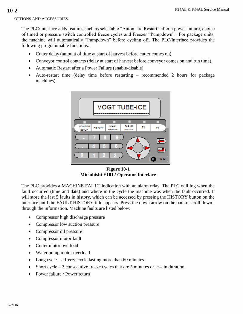
P24AL & P34AL Service Manual
OPTIONS AND ACCESSORIES
12/2016
10-2
The PLC/Interface adds features such as selectable “Automatic Restart” after a power failure, choice
of timed or pressure switch controlled freeze cycles and Freezer “Pumpdown”. For package units,
the machine will automatically “Pumpdown” before cycling off. The PLC/Interface provides the
following programmable functions:
Cutter delay (amount of time at start of harvest before cutter comes on).
Conveyor control contacts (delay at start of harvest before conveyor comes on and run time).
Automatic Restart after a Power Failure (enable/disable)
Auto-restart time (delay time before restarting – recommended 2 hours for package
machines)
Figure 10-1
Mitsubishi E1012 Operator Interface
The PLC provides a MACHINE FAULT indication with an alarm relay. The PLC will log when the
fault occurred (time and date) and where in the cycle the machine was when the fault occurred. It
will store the last 5 faults in history, which can be accessed by pressing the HISTORY button on the
interface until the FAULT HISTORY title appears. Press the down arrow on the pad to scroll down t
through the information. Machine faults are listed below:
Compressor high discharge pressure
Compressor low suction pressure
Compressor oil pressure
Compressor motor fault
Cutter motor overload
Water pump motor overload
Long cycle – a freeze cycle lasting more than 60 minutes
Short cycle – 3 consecutive freeze cycles that are 5 minutes or less in duration
Power failure / Power return
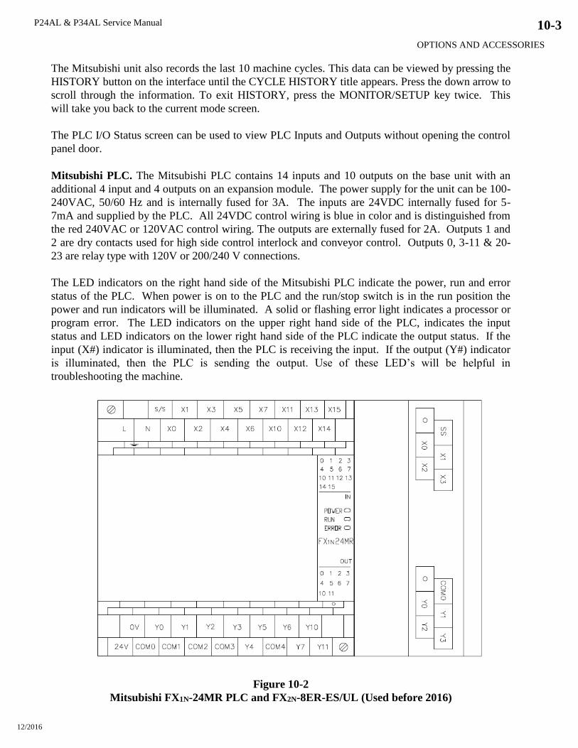
P24AL & P34AL Service Manual
OPTIONS AND ACCESSORIES
12/2016
10-3
The Mitsubishi unit also records the last 10 machine cycles. This data can be viewed by pressing the
HISTORY button on the interface until the CYCLE HISTORY title appears. Press the down arrow to
scroll through the information. To exit HISTORY, press the MONITOR/SETUP key twice. This
will take you back to the current mode screen.
The PLC I/O Status screen can be used to view PLC Inputs and Outputs without opening the control
panel door.
Mitsubishi PLC. The Mitsubishi PLC contains 14 inputs and 10 outputs on the base unit with an
additional 4 input and 4 outputs on an expansion module. The power supply for the unit can be 100-
240VAC, 50/60 Hz and is internally fused for 3A. The inputs are 24VDC internally fused for 5-
7mA and supplied by the PLC. All 24VDC control wiring is blue in color and is distinguished from
the red 240VAC or 120VAC control wiring. The outputs are externally fused for 2A. Outputs 1 and
2 are dry contacts used for high side control interlock and conveyor control. Outputs 0, 3-11 & 20-
23 are relay type with 120V or 200/240 V connections.
The LED indicators on the right hand side of the Mitsubishi PLC indicate the power, run and error
status of the PLC. When power is on to the PLC and the run/stop switch is in the run position the
power and run indicators will be illuminated. A solid or flashing error light indicates a processor or
program error. The LED indicators on the upper right hand side of the PLC, indicates the input
status and LED indicators on the lower right hand side of the PLC indicate the output status. If the
input (X#) indicator is illuminated, then the PLC is receiving the input. If the output (Y#) indicator
is illuminated, then the PLC is sending the output. Use of these LED’s will be helpful in
troubleshooting the machine.
Figure 10-2
Mitsubishi FX1N-24MR PLC and FX2N-8ER-ES/UL (Used before 2016)
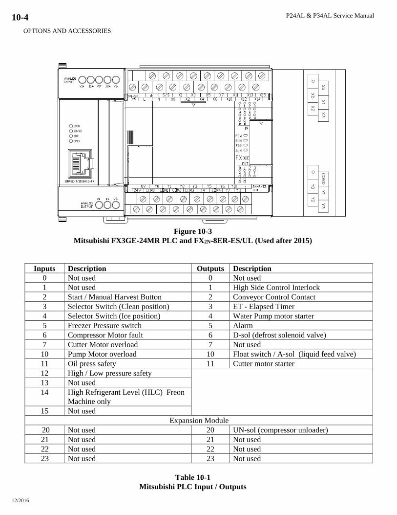
P24AL & P34AL Service Manual
OPTIONS AND ACCESSORIES
12/2016
10-4
Figure 10-3
Mitsubishi FX3GE-24MR PLC and FX2N-8ER-ES/UL (Used after 2015)
Inputs Description Outputs Description
0 Not used 0 Not used
1 Not used 1 High Side Control Interlock
2 Start / Manual Harvest Button 2 Conveyor Control Contact
3 Selector Switch (Clean position) 3 ET - Elapsed Timer
4 Selector Switch (Ice position) 4 Water Pump motor starter
5 Freezer Pressure switch 5 Alarm
6 Compressor Motor fault 6 D-sol (defrost solenoid valve)
7 Cutter Motor overload 7 Not used
10 Pump Motor overload 10 Float switch / A-sol (liquid feed valve)
11 Oil press safety 11 Cutter motor starter
12 High / Low pressure safety
13 Not used
14 High Refrigerant Level (HLC) Freon
Machine only
15 Not used
Expansion Module
20 Not used 20 UN-sol (compressor unloader)
21 Not used 21 Not used
22 Not used 22 Not used
23 Not used 23 Not used
Table 10-1
Mitsubishi PLC Input / Outputs

P24AL & P34AL Service Manual
OPTIONS AND ACCESSORIES
12/2016
10-5
Figure 10-4
Wiring Schematic – P24AL/P34AL with Mitsubishi PLC
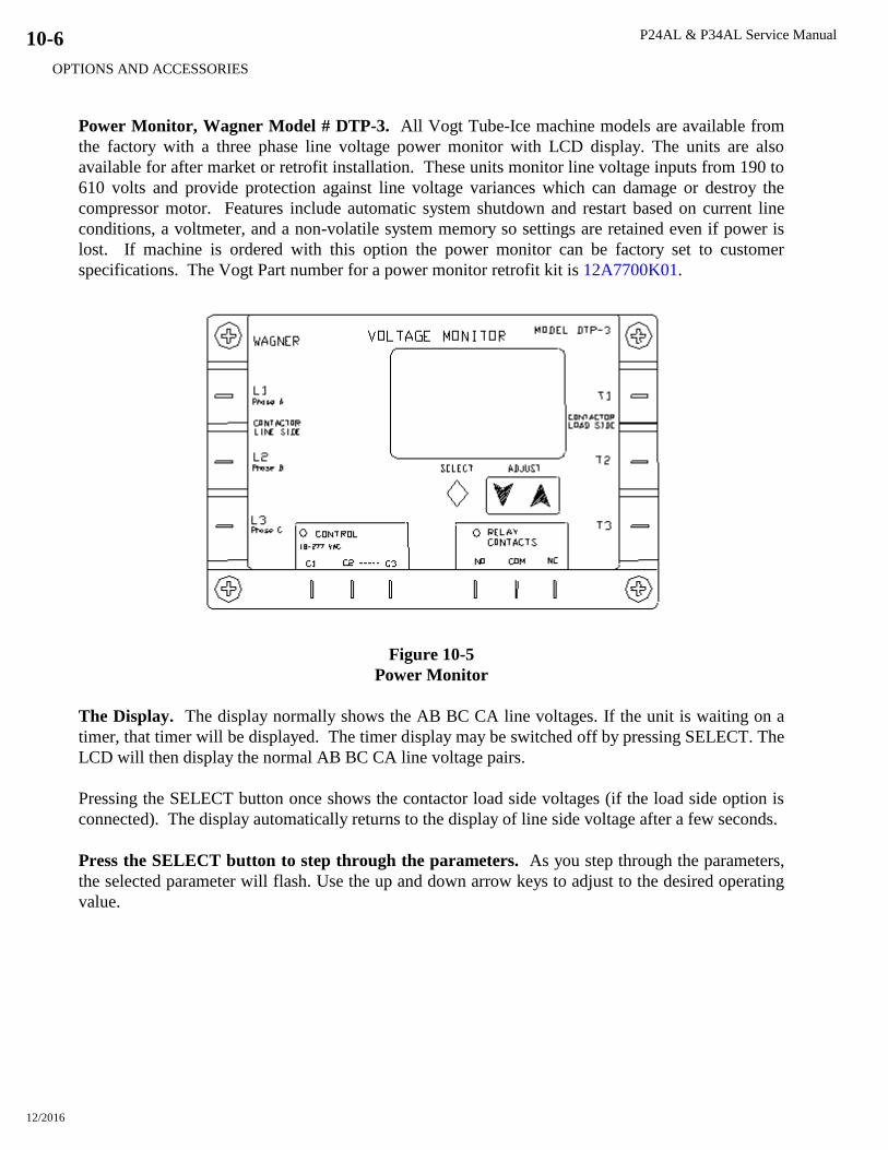
P24AL & P34AL Service Manual
OPTIONS AND ACCESSORIES
12/2016
10-6
Power Monitor, Wagner Model # DTP-3. All Vogt Tube-Ice machine models are available from
the factory with a three phase line voltage power monitor with LCD display. The units are also
available for after market or retrofit installation. These units monitor line voltage inputs from 190 to
610 volts and provide protection against line voltage variances which can damage or destroy the
compressor motor. Features include automatic system shutdown and restart based on current line
conditions, a voltmeter, and a non-volatile system memory so settings are retained even if power is
lost. If machine is ordered with this option the power monitor can be factory set to customer
specifications. The Vogt Part number for a power monitor retrofit kit is 12A7700K01.
Figure 10-5
Power Monitor
The Display. The display normally shows the AB BC CA line voltages. If the unit is waiting on a
timer, that timer will be displayed. The timer display may be switched off by pressing SELECT. The
LCD will then display the normal AB BC CA line voltage pairs.
Pressing the SELECT button once shows the contactor load side voltages (if the load side option is
connected). The display automatically returns to the display of line side voltage after a few seconds.
Press the SELECT button to step through the parameters. As you step through the parameters,
the selected parameter will flash. Use the up and down arrow keys to adjust to the desired operating
value.
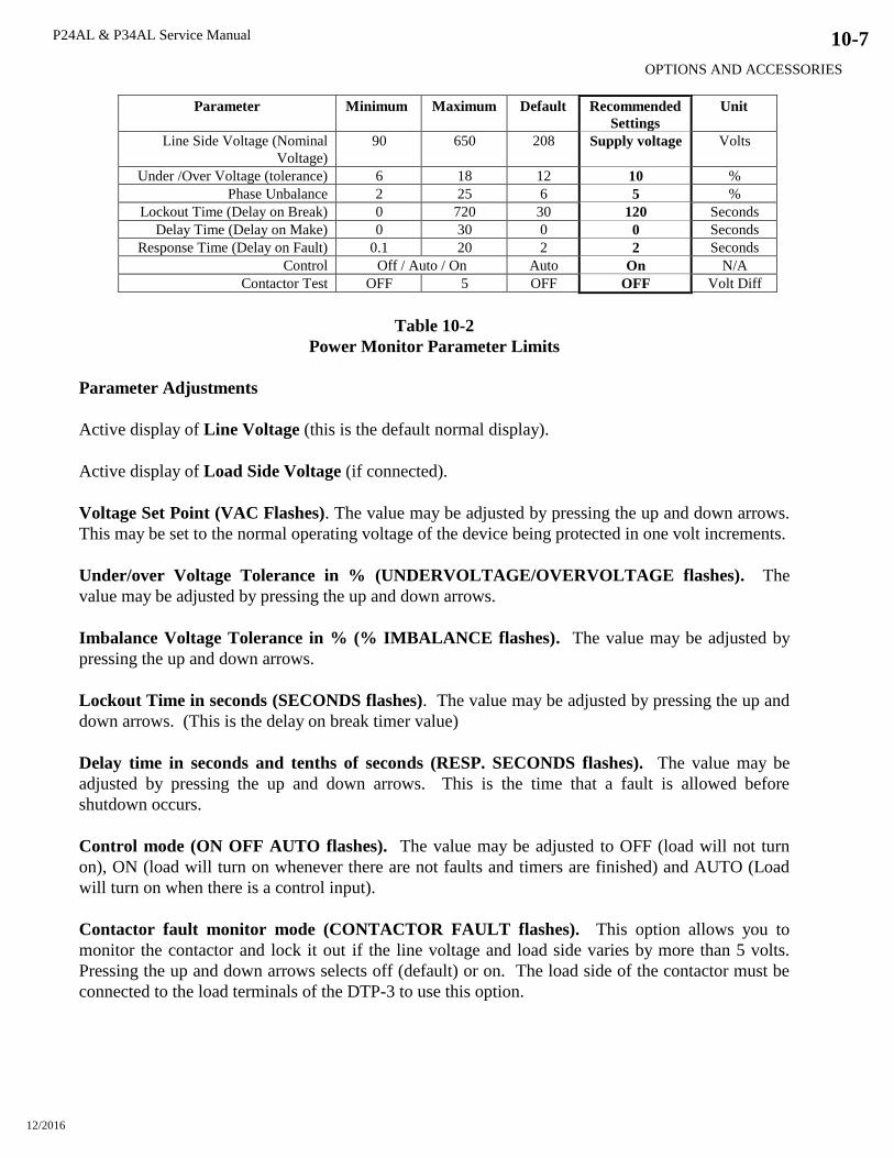
P24AL & P34AL Service Manual
OPTIONS AND ACCESSORIES
12/2016
10-7
Parameter Minimum Maximum Default Recommended
Settings
Unit
Line Side Voltage (Nominal
Voltage)
90 650 208 Supply voltage Volts
Under /Over Voltage (tolerance) 6 18 12 10 %
Phase Unbalance 2 25 6 5 %
Lockout Time (Delay on Break) 0 720 30 120 Seconds
Delay Time (Delay on Make) 0 30 0 0 Seconds
Response Time (Delay on Fault) 0.1 20 2 2 Seconds
Control Off / Auto / On Auto On N/A
Contactor Test OFF 5 OFF OFF Volt Diff
Table 10-2
Power Monitor Parameter Limits
Parameter Adjustments
Active display of Line Voltage (this is the default normal display).
Active display of Load Side Voltage (if connected).
Voltage Set Point (VAC Flashes). The value may be adjusted by pressing the up and down arrows.
This may be set to the normal operating voltage of the device being protected in one volt increments.
Under/over Voltage Tolerance in % (UNDERVOLTAGE/OVERVOLTAGE flashes). The
value may be adjusted by pressing the up and down arrows.
Imbalance Voltage Tolerance in % (% IMBALANCE flashes). The value may be adjusted by
pressing the up and down arrows.
Lockout Time in seconds (SECONDS flashes). The value may be adjusted by pressing the up and
down arrows. (This is the delay on break timer value)
Delay time in seconds and tenths of seconds (RESP. SECONDS flashes). The value may be
adjusted by pressing the up and down arrows. This is the time that a fault is allowed before
shutdown occurs.
Control mode (ON OFF AUTO flashes). The value may be adjusted to OFF (load will not turn
on), ON (load will turn on whenever there are not faults and timers are finished) and AUTO (Load
will turn on when there is a control input).
Contactor fault monitor mode (CONTACTOR FAULT flashes). This option allows you to
monitor the contactor and lock it out if the line voltage and load side varies by more than 5 volts.
Pressing the up and down arrows selects off (default) or on. The load side of the contactor must be
connected to the load terminals of the DTP-3 to use this option.

P24AL & P34AL Service Manual
OPTIONS AND ACCESSORIES
12/2016
10-8
Display of fault memories (MEM flashes). Pressing up or down displays the last fault conditions
that took the unit off line. The first 25 faults are recorded. The top number displayed represents the
fault memory. The middle number represents the total number of faults that have occurred since the
fault memory was cleared. To clear the memory, press and hold the up and down keys until the
display is cleared.
NOTE: If you press SELECT and do not change a parameter by pressing the up or down arrow keys,
the DTP-3 automatically returns to displaying the line voltage in a few seconds.
The new settings are saved in permanent memory when the display returns to displaying the line
voltage. The new settings may be verified by pressing the select button to sequence through the
various parameters.
To prevent tripping on a 1-volt change, the DTP-3 automatically calculates cut-in voltages for the
return from undervoltage conditions. The cut-out voltage is always based on user voltage and
tolerance settings, while the cut-in voltage is 3% closer to the nominal voltage setting. This quality
is sometimes referred to as hysteresis. This is to help reduce oscillation that may occur on weak
power distribution system. When the load is switched off due to undervoltage, the line voltage will
increase. Without the hysteresis, the monitor would switch the load back on, the line voltage would
again drop, and cause a continuous on-off-on cycling.

P24AL & P34AL Service Manual
TABLES & CHARTS
12/16/16
11-1
11. Tables & Charts
P24AL Specifications, 400/460 Volt-3 Phase- 50/60Hz
Tube Size Inches (cm) 1 (2.54) 1 1/4 (3.17) 1 1/2 (3.18)
Nominal Capacity (1) Tons/day (M Tons/day) 21.4 (19.3) 22.4 (20.2) 16.6 (15.0)
Overall Dimensions (LxWxH) Feet (meters) 5x5.5x14.5
(1.5x1.7x4.4)
5x5.5x16 (1.5x1.7x4.8) 5x5.5x16 (1.5x1.7x4.8)
Shipping Weight lbs (Kg) 5,800 (2,630) 6,200 (2,810) 6,000 (2,720)
Operating Weight lbs (Kg) 7,150 (3,240) 7,700 (3,490) 7,500 (3,400)
Refrigerant Charge (R-717)(2) lbs (Kg) 500 (227) 500 (227) 500 (227)
Total FLA (3) 9.1 9.1 9.1
Maximum Fuse 15 15 15
Minimum Ampacity 7.6 7.6 7.6
System Requirements
- Dedicated Compressor (4) Tons (KW) 43.6 (154) 40.5 (143) 28.3 (100)
- Average Refrigeration (4) Tons (KW) 35.0 (123) 34.9 (122) 25.5 (90)
- Peak Refrigeration (4) Tons (KW) 64.8 (228) 68.2 (240) 60.5 (212)
-Makeup (5) gpm (m3/ Hr) 4.71 (1.1) 4.71 (1.1) 4.38 (1.0)
- Blow down per harvest (min) Gallons (L) 19 (72) 19 (72) 19 (72)
Connection Sizes
-Makeup water FPT 3/4” 3/4” 3/4”
-Tank drain FPT 2” 2” 2”
-Tank overflow FPT 3” 3” 3”
-Flush water FPT 3/4” 3/4” 3/4”
-Suction Flanged 3” 3” 3”
-Liquid feed FPT/Socket 3/4” 3/4” 3/4”
-Thaw gas Flanged 2” 2” 2”
Compressor -HP-KW-FLA Dedicated only 60 - 44.7 - 77 60 - 44.7 - 77 60 - 44.7 - 77
Water Pump -HP-KW-FLA 3 - 2.2 - 4.1 3 - 2.2 - 4.1 3 - 2.2 - 4.1
Cutter Motor -HP-KW-FLA 1 - 0.75 - 2.0 1 - 0.75 - 2.0 1 - 0.75 - 2.0
THR at Pull down Btu/hr (kW) 919,000 (269.3) 853,000 (250.0) 596,000 (174.6)
(1) Nominal capacity is based on 70°F makeup water, 16F suction temperature, 100°F condensing temperature, 70°F ambient, and 25% blow down.
(2) For evaporator only. Dedicated system charge is 1,000 lbs., (454Kgs).
(3) FLA for 460 volt models is approximately 1/2 that of 230 volt models. Total FLA does not include cooling tower or auxiliary equipment.
(4) Compressor Requirements is based on 16F suction temperature, 100°F condensing temperature, 70°F ambient, and 25% blow down.
(5) Makeup water is maximum value and includes 25% blow down each cycle.
Vogt reserves the right to change designs and specifications without notice.
Table 11-1
P24AL Specifications
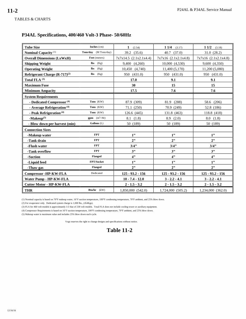
P24AL & P34AL Service Manual
TABLES & CHARTS
12/16/16
11-2
P34AL Specifications, 400/460 Volt-3 Phase- 50/60Hz
Tube Size Inches (cm) 1 (2.54) 1 1/4 (3.17) 1 1/2 (3.18)
Nominal Capacity (1) Tons/day (M Tons/day) 39.2 (35.6) 40.7 (37.0) 31.0 (28.2)
Overall Dimensions (LxWxH) Feet (meters) 7x7x14.5 (2.1x2.1x4.4) 7x7x16 (2.1x2.1x4.8) 7x7x16 (2.1x2.1x4.8)
Shipping Weight lbs (Kg) 9,400 (4,260) 10,000 (4,530) 9,600 (4,350)
Operating Weight lbs (Kg) 10,450 (4,740) 11,400 (5,170) 11,200 (5,080)
Refrigerant Charge (R-717)(2) lbs (Kg) 950 (431.0) 950 (431.0) 950 (431.0)
Total FLA (3) 17.0 9.1 9.1
Maximum Fuse 30 15 15
Minimum Ampacity 17.5 7.6 7.6
System Requirements
- Dedicated Compressor (4) Tons (KW) 87.9 (309) 81.9 (288) 58.6 (206)
- Average Refrigeration (4) Tons (KW) 71.1 (250) 70.9 (249) 52.8 (186)
- Peak Refrigeration (4) Tons (KW) 126.6 (445) 131.8 (463) 118.8 (418)
-Makeup(5) gpm (m3/ Hr) 8.1 (1.8) 8.9 (2.0) 8.0 (1.8)
- Blow down per harvest (min) Gallons (L) 50 (189) 50 (189) 50 (189)
Connection Sizes
-Makeup water FPT 1” 1” 1”
-Tank drain FPT 2” 2” 2”
-Flush water FPT 3/4” 3/4” 3/4”
-Tank overflow FPT 3” 3” 3”
-Suction Flanged 4” 4” 4”
-Liquid feed FPT/Socket 1” 1” 1”
-Thaw gas Flanged 2” 2” 2”
Compressor -HP-KW-FLA Dedicated 125 - 93.2 - 156 125 - 93.2 - 156 125 - 93.2 - 156
Water Pump - HP-KW-FLA 10 - 7.4 - 12.0 3 - 2.2 - 4.1 3 - 2.2 - 4.1
Cutter Motor - HP-KW-FLA 2 - 1.5 - 3.2 2 - 1.5 - 3.2 2 - 1.5 - 3.2
THR Btu/hr (kW) 1,850,000 (542.0) 1,724,000 (505.2) 1,234,000 (362.0)
(1) Nominal capacity is based on 70°F makeup water, 16F suction temperature, 100°F condensing temperature, 70°F ambient, and 25% blow down.
(2) For evaporator only. Dedicated system charge is 1,000 lbs., (454Kgs).
(3) FLA for 460 volt models is approximately 1/2 that of 230 volt models. Total FLA does not include cooling tower or auxiliary equipment.
(4) Compressor Requirements is based on 16F suction temperature, 100°F condensing temperature, 70°F ambient, and 25% blow down.
(5) Makeup water is maximum value and includes 25% blow down each cycle.
Vogt reserves the right to change designs and specifications without notice.
Table 11-2
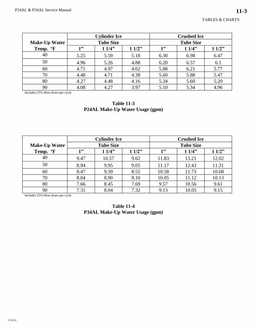
P24AL & P34AL Service Manual
TABLES & CHARTS
12/16/16
11-3
Cylinder Ice Crushed Ice
Make-Up Water Tube Size Tube Size
Temp. °F 1” 1 1/4” 1 1/2” 1” 1 1/4” 1 1/2”
40 5.25 5.59 5.18 6.30 6.98 6.47
50 4.96 5.26 4.88 6.20 6.57 6.1
60 4.71 4.97 4.62 5.88 6.21 5.77
70 4.48 4.71 4.38 5.60 5.88 5.47
80 4.27 4.48 4.16 5.34 5.60 5.20
90 4.08 4.27 3.97 5.10 5.34 4.96 Includes 25% blow down per cycle
Table 11-3
P24AL Make-Up Water Usage (gpm)
Cylinder Ice Crushed Ice
Make-Up Water Tube Size Tube Size
Temp. °F 1” 1 1/4” 1 1/2” 1” 1 1/4” 1 1/2”
40 9.47 10.57 9.62 11.83 13.21 12.02
50 8.94 9.95 9.05 11.17 12.43 11.31
60 8.47 9.39 8.55 10.58 11.73 10.68
70 8.04 8.90 8.10 10.05 11.12 10.13
80 7.66 8.45 7.69 9.57 10.56 9.61
90 7.31 8.04 7.32 9.13 10.05 9.15 Includes 25% blow down per cycle
Table 11-4
P34AL Make-Up Water Usage (gpm)
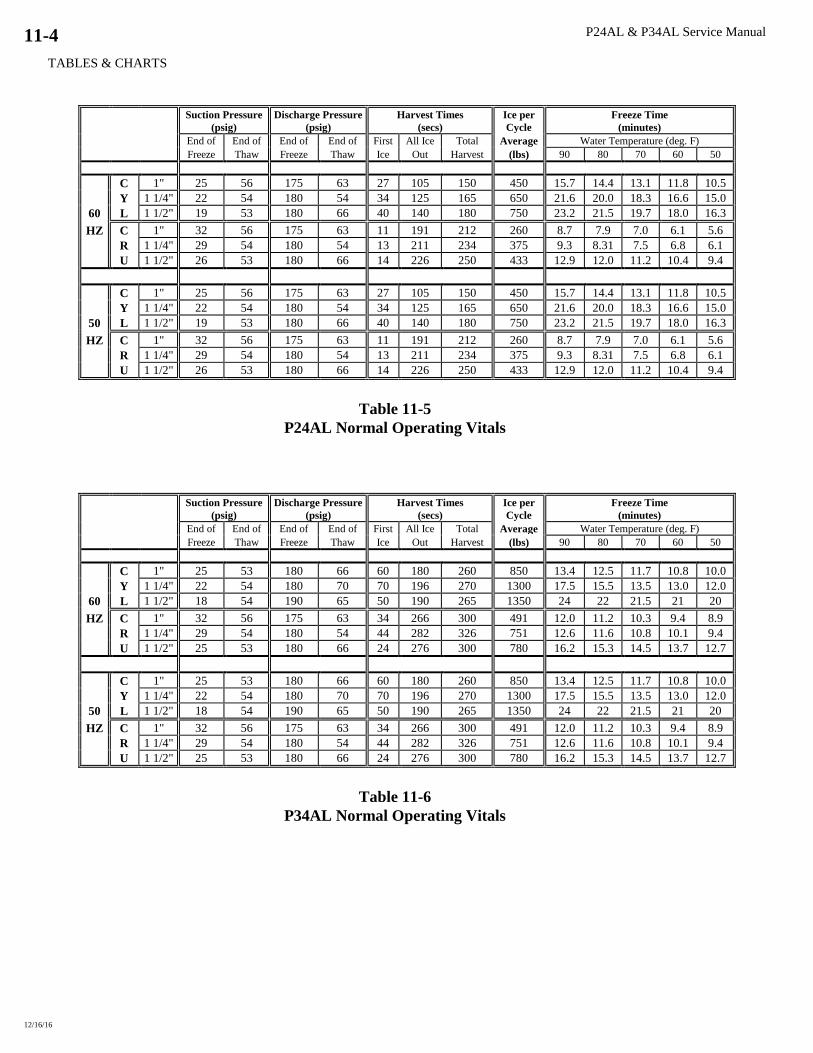
P24AL & P34AL Service Manual
TABLES & CHARTS
12/16/16
11-4
Suction Pressure
(psig)
Discharge Pressure
(psig)
Harvest Times
(secs)
Ice per
Cycle
Freeze Time
(minutes)
End of End of End of End of First All Ice Total Average Water Temperature (deg. F)
Freeze Thaw Freeze Thaw Ice Out Harvest (lbs) 90 80 70 60 50
C 1" 25 56 175 63 27 105 150 450 15.7 14.4 13.1 11.8 10.5
Y 1 1/4" 22 54 180 54 34 125 165 650 21.6 20.0 18.3 16.6 15.0
60 L 1 1/2" 19 53 180 66 40 140 180 750 23.2 21.5 19.7 18.0 16.3
HZ C 1" 32 56 175 63 11 191 212 260 8.7 7.9 7.0 6.1 5.6
R 1 1/4" 29 54 180 54 13 211 234 375 9.3 8.31 7.5 6.8 6.1
U 1 1/2" 26 53 180 66 14 226 250 433 12.9 12.0 11.2 10.4 9.4
C 1" 25 56 175 63 27 105 150 450 15.7 14.4 13.1 11.8 10.5
Y 1 1/4" 22 54 180 54 34 125 165 650 21.6 20.0 18.3 16.6 15.0
50 L 1 1/2" 19 53 180 66 40 140 180 750 23.2 21.5 19.7 18.0 16.3
HZ C 1" 32 56 175 63 11 191 212 260 8.7 7.9 7.0 6.1 5.6
R 1 1/4" 29 54 180 54 13 211 234 375 9.3 8.31 7.5 6.8 6.1
U 1 1/2" 26 53 180 66 14 226 250 433 12.9 12.0 11.2 10.4 9.4
Table 11-5
P24AL Normal Operating Vitals
Suction Pressure
(psig)
Discharge Pressure
(psig)
Harvest Times
(secs)
Ice per
Cycle
Freeze Time
(minutes)
End of End of End of End of First All Ice Total Average Water Temperature (deg. F)
Freeze Thaw Freeze Thaw Ice Out Harvest (lbs) 90 80 70 60 50
C 1" 25 53 180 66 60 180 260 850 13.4 12.5 11.7 10.8 10.0
Y 1 1/4" 22 54 180 70 70 196 270 1300 17.5 15.5 13.5 13.0 12.0
60 L 1 1/2" 18 54 190 65 50 190 265 1350 24 22 21.5 21 20
HZ C 1" 32 56 175 63 34 266 300 491 12.0 11.2 10.3 9.4 8.9
R 1 1/4" 29 54 180 54 44 282 326 751 12.6 11.6 10.8 10.1 9.4
U 1 1/2" 25 53 180 66 24 276 300 780 16.2 15.3 14.5 13.7 12.7
C 1" 25 53 180 66 60 180 260 850 13.4 12.5 11.7 10.8 10.0
Y 1 1/4" 22 54 180 70 70 196 270 1300 17.5 15.5 13.5 13.0 12.0
50 L 1 1/2" 18 54 190 65 50 190 265 1350 24 22 21.5 21 20
HZ C 1" 32 56 175 63 34 266 300 491 12.0 11.2 10.3 9.4 8.9
R 1 1/4" 29 54 180 54 44 282 326 751 12.6 11.6 10.8 10.1 9.4
U 1 1/2" 25 53 180 66 24 276 300 780 16.2 15.3 14.5 13.7 12.7
Table 11-6
P34AL Normal Operating Vitals
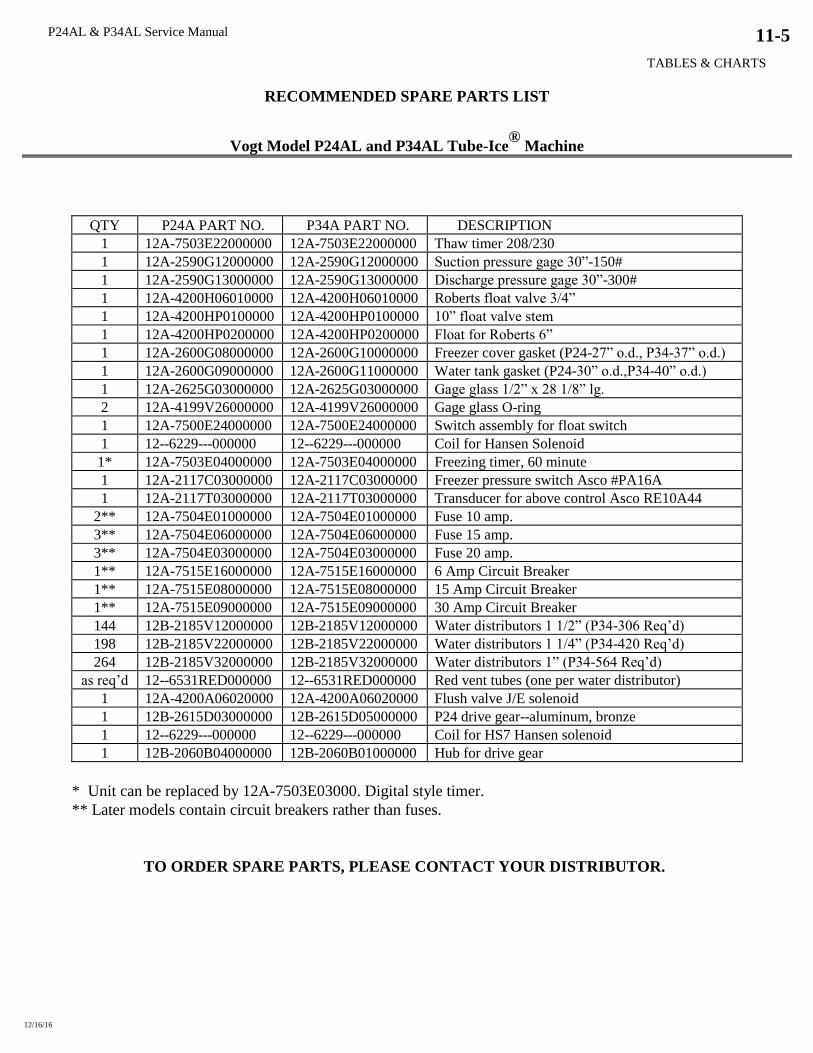
P24AL & P34AL Service Manual
TABLES & CHARTS
12/16/16
11-5
RECOMMENDED SPARE PARTS LIST
Vogt Model P24AL and P34AL Tube-Ice®
Machine
QTY P24A PART NO. P34A PART NO. DESCRIPTION
1 12A-7503E22000000 12A-7503E22000000 Thaw timer 208/230
1 12A-2590G12000000 12A-2590G12000000 Suction pressure gage 30”-150#
1 12A-2590G13000000 12A-2590G13000000 Discharge pressure gage 30”-300#
1 12A-4200H06010000 12A-4200H06010000 Roberts float valve 3/4”
1 12A-4200HP0100000 12A-4200HP0100000 10” float valve stem
1 12A-4200HP0200000 12A-4200HP0200000 Float for Roberts 6”
1 12A-2600G08000000 12A-2600G10000000 Freezer cover gasket (P24-27” o.d., P34-37” o.d.)
1 12A-2600G09000000 12A-2600G11000000 Water tank gasket (P24-30” o.d.,P34-40” o.d.)
1 12A-2625G03000000 12A-2625G03000000 Gage glass 1/2” x 28 1/8” lg.
2 12A-4199V26000000 12A-4199V26000000 Gage glass O-ring
1 12A-7500E24000000 12A-7500E24000000 Switch assembly for float switch
1 12--6229---000000 12--6229---000000 Coil for Hansen Solenoid
1* 12A-7503E04000000 12A-7503E04000000 Freezing timer, 60 minute
1 12A-2117C03000000 12A-2117C03000000 Freezer pressure switch Asco #PA16A
1 12A-2117T03000000 12A-2117T03000000 Transducer for above control Asco RE10A44
2** 12A-7504E01000000 12A-7504E01000000 Fuse 10 amp.
3** 12A-7504E06000000 12A-7504E06000000 Fuse 15 amp.
3** 12A-7504E03000000 12A-7504E03000000 Fuse 20 amp.
1** 12A-7515E16000000 12A-7515E16000000 6 Amp Circuit Breaker
1** 12A-7515E08000000 12A-7515E08000000 15 Amp Circuit Breaker
1** 12A-7515E09000000 12A-7515E09000000 30 Amp Circuit Breaker
144 12B-2185V12000000 12B-2185V12000000 Water distributors 1 1/2” (P34-306 Req’d)
198 12B-2185V22000000 12B-2185V22000000 Water distributors 1 1/4” (P34-420 Req’d)
264 12B-2185V32000000 12B-2185V32000000 Water distributors 1” (P34-564 Req’d)
as req’d 12--6531RED000000 12--6531RED000000 Red vent tubes (one per water distributor)
1 12A-4200A06020000 12A-4200A06020000 Flush valve J/E solenoid
1 12B-2615D03000000 12B-2615D05000000 P24 drive gear--aluminum, bronze
1 12--6229---000000 12--6229---000000 Coil for HS7 Hansen solenoid
1 12B-2060B04000000 12B-2060B01000000 Hub for drive gear
* Unit can be replaced by 12A-7503E03000. Digital style timer.
** Later models contain circuit breakers rather than fuses.
TO ORDER SPARE PARTS, PLEASE CONTACT YOUR DISTRIBUTOR.
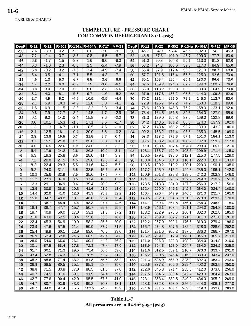
P24AL & P34AL Service Manual
TABLES & CHARTS
12/16/16
11-6
TEMPERATURE - PRESSURE CHART
FOR COMMON REFRIGERANTS (°F-psig)
DegF R-12 R-22 R-502 R-134a R-404A R-717 MP-39 DegF R-12 R-22 R-502 R-134a R-404A R-717 MP-39
-50 -7.6 -3.0 0.2 -9.0 0.0 -7.0 -9.1 50 46.7 84.0 97.4 45.5 102.9 74.2 45.3
-48 -7.2 -2.4 0.7 -8.7 0.8 -6.5 -8.7 52 48.8 87.3 101.0 47.7 109.0 77.7 60.0
-46 -6.8 -1.7 1.5 -8.3 1.6 -6.0 -8.3 54 51.0 90.8 104.8 50.1 113.0 81.3 62.0
-44 -6.3 -1.0 2.3 -8.0 2.5 -5.4 -7.9 56 53.2 94.3 108.6 52.3 117.0 84.9 65.0
-42 -5.8 -0.2 3.2 -7.6 3.4 -4.9 -7.4 58 55.4 97.9 112.4 55.0 121.0 88.7 68.0
-40 -5.4 0.5 4.1 -7.1 5.5 -4.3 -7.1 60 57.7 101.6 116.4 57.5 125.0 92.6 70.0
-38 -4.9 1.3 5.0 -6.7 6.5 -3.6 -6.6 62 60.1 105.4 120.4 60.1 130.0 96.6 73.0
-36 -4.4 2.2 6.0 -6.3 7.5 -3.0 -6.1 64 62.5 109.3 124.6 62.7 134.0 100.7 76.0
-34 -3.8 3.0 7.0 -5.8 8.6 -2.3 -5.6 66 65.0 113.2 128.8 65.5 139.0 104.9 79.0
-32 -3.3 4.0 8.1 -5.3 9.7 -1.6 -5.2 68 67.6 117.3 133.2 68.3 144.0 109.3 82.0
-30 -2.7 4.9 9.2 -4.8 10.8 -0.8 -4.4 70 70.2 121.4 137.6 71.2 148.0 113.7 85.0
-28 -2.1 5.9 10.3 -4.2 12.0 0.0 -4.1 72 72.9 125.7 142.2 74.2 153.0 118.3 89.0
-26 -1.5 6.9 11.5 -3.8 13.2 0.8 -3.4 74 75.6 130.0 146.8 77.2 158.0 123.1 92.0
-24 -0.8 7.9 12.7 -3.0 14.5 1.7 -2.9 76 78.4 134.5 151.5 80.3 164.0 127.9 95.0
-22 -0.1 9.0 14.0 -2.4 15.8 2.6 -2.2 78 81.3 139.0 156.3 83.5 169.0 132.8 99.0
-20 0.6 10.1 15.3 -1.8 17.1 3.5 -1.7 80 84.2 143.6 161.2 86.8 174.0 137.9 102.0
-18 1.3 11.3 16.7 -1.1 18.5 4.5 -1.0 82 87.2 148.4 166.2 90.2 180.0 143.2 106.0
-16 2.1 12.5 18.1 -0.4 20.0 5.6 -0.2 84 90.2 153.2 171.4 93.6 185.0 148.5 109.0
-14 2.8 13.8 19.5 0.3 21.5 6.7 0.4 86 93.3 158.2 176.6 97.1 191.0 154.1 113.0
-12 3.7 15.1 21.0 1.1 23.0 7.8 1.4 88 96.5 163.2 181.9 100.7 197.0 159.7 117.0
-10 4.5 16.5 22.6 1.9 24.6 8.9 2.2 90 99.8 168.4 187.4 104.4 203.0 165.5 121.0
-8 5.4 17.9 24.2 2.8 26.3 10.2 3.1 92 103.1 173.7 192.9 108.2 209.9 171.4 125.0
-6 6.3 19.3 25.8 3.6 28.0 11.4 3.9 94 106.5 179.1 198.6 112.1 215.0 177.5 129.0
-4 7.2 20.8 27.5 4.5 29.8 12.8 4.8 96 110.0 184.6 204.3 116.1 222.0 183.7 133.0
-2 8.2 22.4 29.3 5.5 31.6 14.2 5.7 98 113.5 190.2 210.2 120.1 229.0 190.1 138.0
0 9.2 24.0 31.1 6.5 33.5 15.6 6.7 100 117.2 195.9 216.2 124.3 235.0 196.1 142.0
2 10.2 25.6 32.9 7.5 35.6 17.1 7.7 102 120.9 201.8 222.3 128.5 242.0 203.3 146.0
4 11.2 27.3 34.9 8.5 37.4 18.6 8.8 104 124.7 207.7 228.5 132.9 249.0 210.2 151.0
6 12.3 29.1 36.9 9.6 39.4 20.3 9.9 106 128.5 213.8 234.9 137.3 256.0 217.2 156.0
8 13.5 30.9 38.9 10.8 41.6 21.9 11.0 108 132.4 220.0 241.3 142.8 264.0 224.4 160.0
10 14.6 32.8 41.0 12.0 43.9 23.7 12.2 110 136.4 226.4 247.9 146.5 271.0 231.7 165.0
12 15.8 34.7 43.2 13.1 46.0 25.4 13.4 112 140.5 232.8 254.6 151.3 279.0 239.2 170.0
14 17.1 36.7 45.4 14.4 48.3 27.4 14.6 114 144.7 239.4 261.5 156.1 286.0 246.9 175.0
16 18.4 38.7 47.7 15.7 50.7 29.3 15.9 116 148.9 246.1 268.4 161.1 294.0 254.8 180.0
18 19.7 40.9 50.0 17.0 53.1 31.3 17.2 118 153.2 252.9 275.5 166.1 302.0 262.8 185.0
20 21.0 43.0 52.5 18.4 55.6 33.3 18.6 120 157.7 259.9 282.7 171.3 311.0 271.0 191.0
22 22.4 45.3 54.9 19.9 58.2 35.5 20.0 122 162.2 267.0 290.1 176.6 319.0 279.4 196.0
24 23.9 47.6 57.5 21.4 59.9 37.7 21.5 124 166.7 274.3 297.6 182.0 328.0 288.0 202.0
26 25.4 49.9 60.1 22.9 63.6 40.0 23.0 126 171.4 281.6 305.2 187.5 336.0 296.7 207.0
28 26.9 52.4 62.8 24.5 66.5 42.4 24.6 128 176.2 289.1 312.9 193.1 345.0 305.7 213.0
30 28.5 54.9 65.6 26.1 69.4 44.8 26.2 130 181.0 296.8 320.8 198.9 354.0 314.8 219.0
32 30.1 57.5 68.4 27.8 72.3 47.4 27.9 132 185.9 304.6 328.9 204.7 364.0 324.2 225.0
34 31.7 60.1 71.3 29.5 75.4 50.0 29.6 134 191.0 312.5 337.1 210.7 373.0 333.7 231.0
36 33.4 62.8 74.3 31.3 78.5 52.7 31.3 136 196.2 320.6 345.4 216.8 383.0 343.4 237.0
38 35.2 65.6 77.4 33.2 81.8 55.5 33.2 138 201.3 328.9 353.9 223.0 392.0 353.4 243.0
40 36.9 68.5 80.5 35.1 85.1 58.4 35.0 140 206.6 337.3 362.6 229.4 402.0 363.5 250.0
42 38.8 71.5 83.8 37.0 88.5 61.3 37.0 142 212.0 345.8 371.4 235.8 412.0 373.8 256.0
44 40.7 74.5 87.0 39.1 91.9 64.4 39.0 144 217.5 354.5 380.4 242.4 423.0 384.4 263.0
46 42.7 77.6 90.4 42.0 95.5 67.6 41.0 146 223.1 363.4 389.5 249.2 434.0 395.2 269.0
48 44.7 80.7 93.9 43.3 99.2 70.8 43.1 148 228.8 372.3 398.9 256.0 444.0 406.1 277.0
50 46.7 84.0 97.4 45.5 102.9 74.2 45.3 150 234.6 381.5 408.4 263.0 449.0 432.0 283.0
Table 11-7
All pressures are in lbs/in2 gage (psig).

P24AL & P34AL Service Manual
TABLES & CHARTS
12/16/16
11-7
REFERENCE INFORMATION
CONVERSION FACTORS: English to Metric
To Convert From To Multiply by
Area ft2 m2 9.2903e-2
in2 m2 6.416 e-4
Energy BTU Joule (J) 1054.48
hp BTU/Hr 2546.2
kW hp 1.34
Length ft. m. 0.3048
in. m. 0.0254
Pressure lbf/ft2 Paschals 47.88
lbf/in2 (psi) Paschals 6894.76
in. Hg psi 0.491
in H2O psi 0.03612
Temperature F C TC=5/9*(TF - 32)
C F TF=(9/5*TC) + 32
Volume ft3 m3 2.8317e-2
gal(U.S.) m3 3.7854e-3
ft3 gal(U.S.) 7.48
Table 11-8
CONSTANTS
Specific heat of Water 1 BTU/(lbm F)
Specific heat of Air 4.19 kJ/(kg C)
0.24 BTU/(lbm F)
Tube-Ice Density 32-35 lbs/ft3
Ice Latent Heat 144 BTU/hr
Water Sensible Heat 1 BTU/(lb F)
Ice Melting Effect (IME)
1 Ton Refrigeration 12,000 BTU/hr
Atmospheric pressure 14.7 psia
Weight of Water 62.4 lbs/ft3
8.33 lbs/gal
1 gpm water 12013 lb/day
Weight of air 0.0749 lbs/ft3
0.0100 lbs/gal
1 Horsepower 2545.6 BTU/hr
1 Kilowatt 1.34 horsepower
Gravitational accel. 9.81 m2/sec
Table 11-9

P24AL & P34AL Service Manual
TABLES & CHARTS
12/16/16
11-8
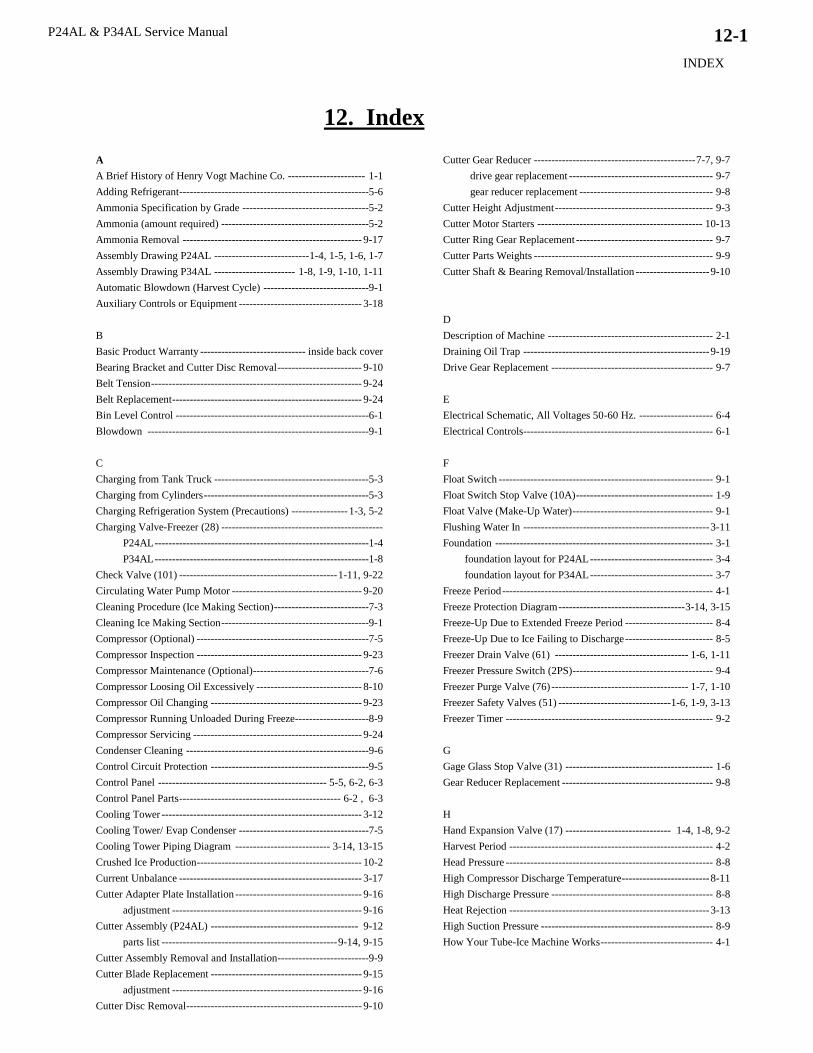
P24AL & P34AL Service Manual
INDEX
12/2016
12-1
12. Index
A
A Brief History of Henry Vogt Machine Co. ---------------------- 1-1
Adding Refrigerant------------------------------------------------------5-6
Ammonia Specification by Grade ------------------------------------5-2
Ammonia (amount required) ------------------------------------------5-2
Ammonia Removal --------------------------------------------------- 9-17
Assembly Drawing P24AL --------------------------- 1-4, 1-5, 1-6, 1-7
Assembly Drawing P34AL ----------------------- 1-8, 1-9, 1-10, 1-11
Automatic Blowdown (Harvest Cycle) ------------------------------9-1
Auxiliary Controls or Equipment ----------------------------------- 3-18
B
Basic Product Warranty ------------------------------ inside back cover
Bearing Bracket and Cutter Disc Removal ------------------------ 9-10
Belt Tension ------------------------------------------------------------ 9-24
Belt Replacement ------------------------------------------------------ 9-24
Bin Level Control -------------------------------------------------------6-1
Blowdown ---------------------------------------------------------------9-1
C
Charging from Tank Truck --------------------------------------------5-3
Charging from Cylinders -----------------------------------------------5-3
Charging Refrigeration System (Precautions) ---------------- 1-3, 5-2
Charging Valve-Freezer (28) ----------------------------------------------
P24AL -------------------------------------------------------------1-4
P34AL -------------------------------------------------------------1-8
Check Valve (101) --------------------------------------------- 1-11, 9-22
Circulating Water Pump Motor ------------------------------------- 9-20
Cleaning Procedure (Ice Making Section) ---------------------------7-3
Cleaning Ice Making Section ------------------------------------------9-1
Compressor (Optional) -------------------------------------------------7-5
Compressor Inspection ----------------------------------------------- 9-23
Compressor Maintenance (Optional) ---------------------------------7-6
Compressor Loosing Oil Excessively ------------------------------ 8-10
Compressor Oil Changing ------------------------------------------- 9-23
Compressor Running Unloaded During Freeze ---------------------8-9
Compressor Servicing ------------------------------------------------ 9-24
Condenser Cleaning ----------------------------------------------------9-6
Control Circuit Protection ---------------------------------------------9-5
Control Panel ------------------------------------------------ 5-5, 6-2, 6-3
Control Panel Parts ---------------------------------------------- 6-2 , 6-3
Cooling Tower --------------------------------------------------------- 3-12
Cooling Tower/ Evap Condenser -------------------------------------7-5
Cooling Tower Piping Diagram --------------------------- 3-14, 13-15
Crushed Ice Production----------------------------------------------- 10-2
Current Unbalance ---------------------------------------------------- 3-17
Cutter Adapter Plate Installation ------------------------------------ 9-16
adjustment ------------------------------------------------------ 9-16
Cutter Assembly (P24AL) ------------------------------------------ 9-12
parts list -------------------------------------------------- 9-14, 9-15
Cutter Assembly Removal and Installation--------------------------9-9
Cutter Blade Replacement ------------------------------------------- 9-15
adjustment ------------------------------------------------------ 9-16
Cutter Disc Removal -------------------------------------------------- 9-10
Cutter Gear Reducer ---------------------------------------------- 7-7, 9-7
drive gear replacement ----------------------------------------- 9-7
gear reducer replacement -------------------------------------- 9-8
Cutter Height Adjustment --------------------------------------------- 9-3
Cutter Motor Starters ----------------------------------------------- 10-13
Cutter Ring Gear Replacement --------------------------------------- 9-7
Cutter Parts Weights --------------------------------------------------- 9-9
Cutter Shaft & Bearing Removal/Installation --------------------- 9-10
D
Description of Machine ----------------------------------------------- 2-1
Draining Oil Trap ----------------------------------------------------- 9-19
Drive Gear Replacement ---------------------------------------------- 9-7
E
Electrical Schematic, All Voltages 50-60 Hz. --------------------- 6-4
Electrical Controls------------------------------------------------------ 6-1
F
Float Switch ------------------------------------------------------------- 9-1
Float Switch Stop Valve (10A) --------------------------------------- 1-9
Float Valve (Make-Up Water) ---------------------------------------- 9-1
Flushing Water In ----------------------------------------------------- 3-11
Foundation -------------------------------------------------------------- 3-1
foundation layout for P24AL ----------------------------------- 3-4
foundation layout for P34AL ----------------------------------- 3-7
Freeze Period ------------------------------------------------------------ 4-1
Freeze Protection Diagram ------------------------------------ 3-14, 3-15
Freeze-Up Due to Extended Freeze Period ------------------------- 8-4
Freeze-Up Due to Ice Failing to Discharge ------------------------- 8-5
Freezer Drain Valve (61) -------------------------------------- 1-6, 1-11
Freezer Pressure Switch (2PS) ---------------------------------------- 9-4
Freezer Purge Valve (76) --------------------------------------- 1-7, 1-10
Freezer Safety Valves (51) -------------------------------- 1-6, 1-9, 3-13
Freezer Timer ----------------------------------------------------------- 9-2
G
Gage Glass Stop Valve (31) ------------------------------------------ 1-6
Gear Reducer Replacement ------------------------------------------- 9-8
H
Hand Expansion Valve (17) ------------------------------ 1-4, 1-8, 9-2
Harvest Period ---------------------------------------------------------- 4-2
Head Pressure ----------------------------------------------------------- 8-8
High Compressor Discharge Temperature ------------------------- 8-11
High Discharge Pressure ---------------------------------------------- 8-8
Heat Rejection --------------------------------------------------------- 3-13
High Suction Pressure ------------------------------------------------- 8-9
How Your Tube-Ice Machine Works -------------------------------- 4-1
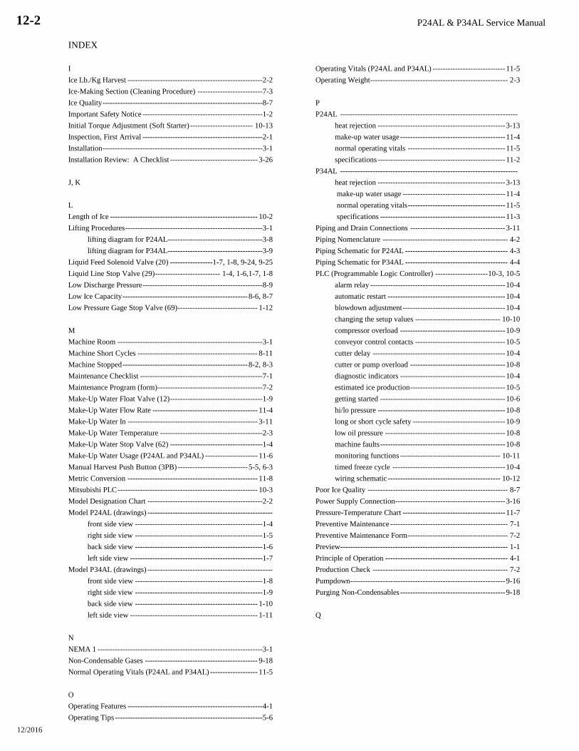
P24AL & P34AL Service Manual
INDEX
12/2016
12-2
I
Ice Lb./Kg Harvest ------------------------------------------------------2-2
Ice-Making Section (Cleaning Procedure) --------------------------7-3
Ice Quality ----------------------------------------------------------------8-7
Important Safety Notice ------------------------------------------------1-2
Initial Torque Adjustment (Soft Starter) ------------------------- 10-13
Inspection, First Arrival ------------------------------------------------2-1
Installation ----------------------------------------------------------------3-1
Installation Review: A Checklist ----------------------------------- 3-26
J, K
L
Length of Ice ----------------------------------------------------------- 10-2
Lifting Procedures -------------------------------------------------------3-1
lifting diagram for P24AL --------------------------------------3-8
lifting diagram for P34AL --------------------------------------3-9
Liquid Feed Solenoid Valve (20) -----------------1-7, 1-8, 9-24, 9-25
Liquid Line Stop Valve (29) -------------------------- 1-4, 1-6,1-7, 1-8
Low Discharge Pressure ------------------------------------------------8-9
Low Ice Capacity -------------------------------------------------- 8-6, 8-7
Low Pressure Gage Stop Valve (69) -------------------------------- 1-12
M
Machine Room ----------------------------------------------------------3-1
Machine Short Cycles ------------------------------------------------ 8-11
Machine Stopped -------------------------------------------------- 8-2, 8-3
Maintenance Checklist -------------------------------------------------7-1
Maintenance Program (form) ------------------------------------------7-2
Make-Up Water Float Valve (12) -------------------------------------1-9
Make-Up Water Flow Rate ------------------------------------------ 11-4
Make-Up Water In ---------------------------------------------------- 3-11
Make-Up Water Temperature -----------------------------------------2-3
Make-Up Water Stop Valve (62) -------------------------------------1-4
Make-Up Water Usage (P24AL and P34AL) --------------------- 11-6
Manual Harvest Push Button (3PB) ---------------------------- 5-5, 6-3
Metric Conversion ---------------------------------------------------- 11-8
Mitsubishi PLC -------------------------------------------------------- 10-3
Model Designation Chart ----------------------------------------------2-2
Model P24AL (drawings) --------------------------------------------------
front side view ---------------------------------------------------1-4
right side view ---------------------------------------------------1-5
back side view ---------------------------------------------------1-6
left side view -----------------------------------------------------1-7
Model P34AL (drawings) --------------------------------------------------
front side view ---------------------------------------------------1-8
right side view ---------------------------------------------------1-9
back side view ------------------------------------------------- 1-10
left side view --------------------------------------------------- 1-11
N
NEMA 1 ------------------------------------------------------------------3-1
Non-Condensable Gases --------------------------------------------- 9-18
Normal Operating Vitals (P24AL and P34AL) ------------------- 11-5
O
Operating Features ------------------------------------------------------4-1
Operating Tips -----------------------------------------------------------5-6
Operating Vitals (P24AL and P34AL) ----------------------------- 11-5
Operating Weight------------------------------------------------------- 2-3
P
P24AL -----------------------------------------------------------------------
heat rejection --------------------------------------------------- 3-13
make-up water usage ------------------------------------------ 11-4
normal operating vitals --------------------------------------- 11-5
specifications --------------------------------------------------- 11-2
P34AL -----------------------------------------------------------------------
heat rejection --------------------------------------------------- 3-13
make-up water usage ----------------------------------------- 11-4
normal operating vitals --------------------------------------- 11-5
specifications -------------------------------------------------- 11-3
Piping and Drain Connections -------------------------------------- 3-11
Piping Nomenclature -------------------------------------------------- 4-2
Piping Schematic for P24AL ----------------------------------------- 4-3
Piping Schematic for P34AL ----------------------------------------- 4-4
PLC (Programmable Logic Controller) --------------------- 10-3, 10-5
alarm relay ------------------------------------------------------ 10-4
automatic restart ----------------------------------------------- 10-4
blowdown adjustment ----------------------------------------- 10-4
changing the setup values ---------------------------------- 10-10
compressor overload ------------------------------------------ 10-9
conveyor control contacts ------------------------------------ 10-5
cutter delay ----------------------------------------------------- 10-4
cutter or pump overload -------------------------------------- 10-8
diagnostic indicators ------------------------------------------ 10-4
estimated ice production -------------------------------------- 10-5
getting started -------------------------------------------------- 10-6
hi/lo pressure --------------------------------------------------- 10-8
long or short cycle safety ------------------------------------- 10-9
low oil pressure ------------------------------------------------ 10-8
machine faults -------------------------------------------------- 10-8
monitoring functions ---------------------------------------- 10-11
timed freeze cycle --------------------------------------------- 10-4
wiring schematic --------------------------------------------- 10-12
Poor Ice Quality -------------------------------------------------------- 8-7
Power Supply Connection-------------------------------------------- 3-16
Pressure-Temperature Chart ----------------------------------------- 11-7
Preventive Maintenance ----------------------------------------------- 7-1
Preventive Maintenance Form ---------------------------------------- 7-2
Preview ------------------------------------------------------------------- 1-1
Principle of Operation ------------------------------------------------- 4-1
Production Check ------------------------------------------------------ 7-2
Pumpdown-------------------------------------------------------------- 9-16
Purging Non-Condensables ------------------------------------------ 9-18
Q

P24AL & P34ALService Manual
INDEX
12/2016
12-3
R
R - 717 (Refrigerant) ---------------------------------------------------5-1
Rated Capacity ----------------------------------------------------------2-3
Receipt of Machine -----------------------------------------------------2-1
inspection ---------------------------------------------------------2-1
description ---------------------------------------------------------2-1
safety tags and labels --------------------------------------------2-2
Receiver Ammonia Drain Valve (44) ------------------------------ 1-11
Receiver Purge Valve (59) ------------------------------------------- 1-10
Refrigerant, Adding -----------------------------------------------------5-6
Refrigerant Leaks ----------------------------------------------------- 9-17
Refrigerant Charge ------------------------------------------------------5-2
Refrigerant, Removal ------------------------------------------------- 9-17
Refrigeration System Review -----------------------------------------5-1
Removing Excess Water from Ammonia -------------------------- 9-19
Rotation Check -------------------------------------------------------- 3-17
S
Safety Notice -------------------------------------------------------------1-2
Safety Switches ----------------------------------------------------------6-1
Safety Symbols and What They Mean -------------------------------1-2
Safety Tags and Labels -------------------------------------------------2-2
Safety Valves ---------------------------------------------------------- 3-13
------------------------------- see figures 1-6 through 1-11 for location
Servicing Operations ---------------------------------------------------9-1
Shipping weight ---------------------------------------------------------2-3
Soft Start Cutter Motor Starters ----------------------------------- 10-13
initial torque adjustment ------------------------------------ 10-13
start time adjustment ---------------------------------------- 10-13
wiring ---------------------------------------------------------- 10-13
Solenoid Valves ---------------------------------------------------------9-3
-------------------------------- see figures 1-1 through 1-9 for location
Space Requirements ----------------------------------------------------3-1
Space Diagram (P24AL) ---------------------------------------- 3-2, 3-3
Space Diagram (P34AL) ---------------------------------------- 3-5, 3-6
Spare Parts List (P24AL and P34AL) ------------------------------ 11-6
Specifications for P24AL -------------------------------------- 2-3, 11-2
Specifications for P34AL -------------------------------------- 2-3, 11-3
Start Push Button (2PB) ----------------------------------------- 5-5, 6-3
Start Time Adjustment (Soft Starter) ----------------------------- 10-13
Start-Up -------------------------------------------------------------------5-5
Start-Up & Operation ---------------------------------------------------5-1
Start-Up Checklist ------------------------------------------------------5-2
Storage (prior to installation and start-up) --------------------------2-3
Stop Push Button (1PB) ------------------------------------------ 5-5, 6-3
Suction Line Frosting to Compressor ------------------------------ 8-12
Suction Regulating Valve -------------------------------------- 3-12, 5-7
T
Temperature-Pressure Chart ----------------------------------------- 11-7
Thaw Gas Check Valve (101) -------------------------------- 1-7, 9-22
Thaw Gas Regulating Valve (18) ---------- 1-5, 1-9, 9-20, 9-21, 5-7
Thaw Gas Stop Valve (90) --------------------------------------- 1-5, 1-9
Thawing Timer (2TR) --------------------------------------------------9-5
Three Way Valve (52) ------------------------------------------ 1-6, 1-10
Troubleshooting ---------------------------------------------------------8-1
U
V
Valves ------------------------------------------------------------------- 9-20
Valves (location) ------------------------- see figures 1-1 through 1-12
Voltage Unbalance --------------------------------------------------- 3-16
W
Warranty (Basic Product) ---------------------------- inside back cover
Water Cooled Condenser Cleaning ---------------------------------- 9-6
Water Distributors ----------------------------------------------------------
chart--------------------------------------------------------------- 7-3
cleaning procedure --------------------------------------------- 7-4
Water Flush Solenoid Valve (63) ----------------------- 1-4, 1-9, 9-22
Water Tank ------------------------------------------------ 7-4, 9-12, 9-13
Water Tank Drain Valve (39) ----------------------------------- 1-4, 1-9
Water Tank and Cutter Parts Weights ------------------------------- 9-9
Water Tank Assembly (P24AL) ------------------------------------- 9-13
parts list --------------------------------------------------------- 9-14
Water Tank Drain ----------------------------------------------------- 3-11
Water Tank Installation ----------------------------------------------- 9-12
Water Tank Overflow ------------------------------------------------- 3-11
Water Tank Removal -------------------------------------------------- 9-9
Wiring and Electrical Connections --------------------------------- 3-15
Wiring (Soft Starter) ------------------------------------------------ 10-13
Wiring Schematic, All Voltages - 50/60 Hz ------------------------ 6-4
X
Y, Z

P24AL & P34AL Service Manual
INDEX
12/2016
12-4

Appendix A

Material Safety Data Sheet # 4001 LAROCHE INDUSTRIES INC.
2/15/96 SECTION 1: CHEMICAL PRODUCT & COMPANY IDENTIFICATION
CHEMICAL NAME: Anhydrous Ammonia TRADE NAMES/SYNONYMS Ammonia
PRODUCT CODE: 5B81-83
MANUFACTURER AND/OR DISTRIBUTOR: EMERGENCY TELEPHONE NUMBERS:
LaRoche Industries Inc. Transportation (CHEMTREC): (800) 424-9300
1100 Johnson Ferry Rd., NE Environmental/Health/Safety: (800) 528-4963
Atlanta, Ga. 30342 Customer Service: (800) 491-7987
SECTION 2: COMPOSITION/INFORMATION ON INGREDIENTS
CHEMICAL FORMULA % BY WEIGHT CAS OSHA PEL NIOSH REL / ACGIH TLV IDLH
C-grade P-grade
Ammonia NH3 99.5 99.995 7664-41-7 50 ppm (TWA) 25 ppm (TWA) 35 ppm (STEL) 300 ppm
Water H2O 0.4 33 ppm 7732-18-5 None None None
Oil ----- 0.1 2 ppm ------------ None None None
SECTION 3: HAZARDS INDENTIFICATION
EMERGENCY OVERVIEW: 1) Colorless gas or compressed liquid with extremely pungent odor 2) Liquid ammonia reacts violently with
water. Vapor cloud is produced 3) Avoid contact with liquid and vapor 4) Stay upwind and use water spray to absorb vapor
5) Not flammable under conditions likely to be encountered outdoors 6) Stop discharge if possible
POTENTIAL HEALTH EFFECTS:
ROUTES OF ENTRY: Inhalation, Skin Contact, Eye Contact, Ingestion TARGET ORGANS: Eyes, skin and respiratory system
EYE CONTACT: Exposure to liquid or high concentrations of vapor can cause painful, instant and possibly irreversible damage to
tissue such as the conjunctiva, cornea and lens.
SKIN CONTACT: Prolonged contact with high concentrations can cause painful tissue damage, frostbite and serious chemical burns.
INHALATION: Depending on exposure concentration and durationís, effects can vary from none or only mild irritation, to obstruction
of breathing from laryngeal and bronchial spasm, to edema and severe damage of the mucous membranes of the respiratory tract with
possible fatal results. Latent edema and residual reduction in pulmonary function may occur.
INGESTION: Tissue damage, chemical burns, nausea and vomiting can occur. Ammonia is a gas under normal atmospheric conditions
and ingestion is unlikely.
CARCINOGENICITY: NTP? No IARC? No OSHA? No
SECTION 4: FIRST AID MEASURES
EYE CONTACT: Flush with large amount of water for at least 15 minutes then immediately seek medical aid.
SKIN CONTACT: Immediately flush with large quantities of water for at least 15 minutes while removing clothing. Clothing frozen to the
skin should be thawed with water before removal. Seek immediate medical aid.
INHALATION: Remove from exposure. If breathing has stopped or is difficult, administer artificial respiration or oxygen as needed.
Seek immediate medical aid.
INGESTION: Do not induce vomiting. Have the victim drink large quantities of water if conscious. Immediately seek medical aid. Never
give anything by mouth to an unconscious person.
SECTION 5: FIRE FIGHTING MEASURES
FLASH POINT(method used): Not Applicable FLAMMABLE LIMITS: 16-25% in air
EXTINGUISHING MEDIA: With a source of ignition, ammonia will burn in the range of 16-25% in air. Stop flow of gas or liquid.
SPECIAL FIRE FIGHTING PROCEDURES: Move containers from fire zone if possible; if not, use water to cool fire exposed
containers. Use water spray to control vapors. Do not put water directly on liquid ammonia. Personnel must be equipped with
appropriate protective clothing and respiratory protection.
NFPA HAZARD CLASSIFICATION: Health: 3 Flammability: 1 Reactivity: 0 (least-0 4-highest)
SECTION 6: ACCIDENTAL RELEASE MEASURES
Release of 100 lbs. or more of ammonia within 24 hours must be immediately (within minutes) reported to the National Response Center at
1-800-424-8802, as well as appropriate local and state agencies. Suggested Local Action: Stop leak if feasible. Avoid breathing ammonia.
Evacuate personnel not equipped with protective clothing and equipment. Use copious amounts of water spray or fog to absorb ammonia
vapor. DO NOT put water on liquid ammonia. Contain run-off to prevent ammonia from entering a stream, lake, sewer, or ditch. Any
release of this material, during the course of loading, transporting, unloading or temporary storage, must be reported to U.S. D.O.T. as
required by CFR 171.15 and 171.16.
SECTION 7: HANDLING AND STORAGE
Refer to the ANSI K61.1 standard for storage and handling information. Protect containers from physical damage and temperatures
exceeding 120∞F. Use only approved storage systems. Zinc, copper, silver, cadmium and their alloys must not be used in ammonia systems
since they can be rapidly corroded by it. Avoid hydrostatic pressure, which can cause equipment rupture, by adhering to proper filling
procedures and the use of hydrostatic pressure relief valves where appropriate.

SECTION 8: EXPOSURE CONTROLS/PERSONAL PROTECTION
RESPIRATORY PROTECTION: Respiratory protection approved by NIOSH/MSHA for ammonia must be used when
exposure limits are exceeded. Whether a chemical cartridge respirator or a self-contained breathing apparatus is sufficient for effective
respiratory protection depends on the type and magnitude of exposure.
EYE PROTECTION: Chemical splash goggles, approved for use with ammonia, must be worn to prevent eye contact with liquid or vapor.
A face shield should be used for increased protection from contact with liquid.
VENTILATION: Local positive pressure and/or exhaust ventilation should be used to reduce vapor concentrations in confined spaces.
Ammonia vapor, being lighter than air, can be expected to dissipate to the upper atmosphere. Ammonia concentrations may also be
reduced by the use of an appropriate absorbent or reactant material.
OTHER EQUIPMENT: Emergency eye wash stations and deluge safety showers must be available in the work area. Post a list of
emergency response contacts and telephone numbers.
SECTION 9: PHYSICAL AND CHEMICAL PROPERTIES
Boiling Point: -28.1F Vapor Pressure: 4802.9 mm Hg @60F Vapor Density: 0.60 @ 32F (Air=1)
Solubility In Water: High Percent Volatile By Volume: 100% pH: Approx. 11.6 for 1 N Soln. in water
Melting Point: -107.9F Specific Gravity: 0.62 @ 60F (water=1) Appearance: Colorless (pungent) gas
SECTION 10: STABILITY AND REACTIVITY
STABILITY: Material generally considered stable. However, heating above ambient temperatures causes the vapor pressure of ammonia
to increase rapidly.
INCOMPATIBILITY (Materials to Avoid): Ammonia can react violently with strong acids. Under certain conditions, ammonia reacts
with bromine, chlorine, fluorine or iodine to form compounds which explode spontaneously. Reactions of ammonia with gold, silver or
mercury to form explosive fulminate-like compounds have been reported.
HAZARDOUS DECOMPOSITION PRODUCTS: Hydrogen on heating to over 850F. The decomposition temperature may be lowered
to 575F by contact with certain metals such as nickel.
HAZARDOUS POLYMERIZATION: Will not occur. CONDITIONS TO AVOID: Not applicable.
SECTION 11: TOXICOLOGICAL INFORMATION
Ammonia is a strong alkali and readily damages all body tissues. Ammonia is not a cumulative metabolic poison.
SECTION 12: ECOLOGICAL INFORMATION
Aquatic Toxicity:2.0-2.5 ppm/1-4 days/goldfish & yellow perch/LC; 60-80 ppm/3 days/crawfish/LC100; 8.2 ppm/96hr/fatheadminnow/TLm
Waterfowl Toxicity: 120 ppm
Biochemical Oxygen Demand: Not pertinent
Food Chain Concentration Potential: None
SECTION 13: DISPOSAL CONSIDERATIONS
Recover ammonia if feasible. Otherwise, let ammonia evaporate if appropriate. Only personnel experienced in ammonia spills should add
water to liquid ammonia. Dispose of diluted ammonia as a fertilizer or in an industrial process. For Hazardous Waste Regulations call
1-800-424-9346, the RCRA Hotline.
SECTION 14: TRANSPORT INFORMATION
Domestic Shipments International Shipments
Proper shipping name: Ammonia, Anhydrous, Liquefied Ammonia, Anhydrous, Liquefied
DOT Hazard Class: 2.2 (nonflammable gas) 2.3 (poison gas)
Identification Number: UN1005 UN1005
Packing Group: None None
SECTION 15: REGULATORY INFORMATION
NOTICE: This product is subject to the reporting requirements of SARA (1986, Section 313 of Title III) and 40 CFR Part 370.
OSHA HAZARD COMMUNICATION RULE, 29 CFR 1910.1200: Ammonia is considered a hazardous chemical.
OSHA HAZARD COMMUNICATION RULE, 29 CFR 1910.1200: Ammonia is considered a hazardous chemical.
EMERGENCY PLANNING AND COMMUNITY RIGHT-TO-KNOW ACT (SARA, TITLE III): Section 302
Extremely Hazardous Substance: Yes; Section 311/312 Hazardous Categories: Immediate (acute) health hazards;
Section 313 Toxic Chemical: Yes
CERCLA/SUPERFUND, 40 CFR 117,302: This product contains ammonia which if released to the environment in quantities of 100 lbs.
or more requires notification to the National Response Center in Washington, DC at 1-800-424-8802.
WHMIS: One Percent (1%) CALIFORNIA PROPOSITION 65: Reproductive: No Carcinogen: No
OSHA PROCESS SAFETY MANAGEMENT, 29 CFR 1910.119: This product is subject to the Process Safety Management requirements
of 29 CFR 1910.119 if maintained on-site in quantities of 10,000 lbs. or greater.
EPA CHEMICAL ACCIDENT RELEASE PREVENTION, 40 CFR PART 68: This product is subject to the Risk Management Plan
requirements of 40 CFR Part 68 if maintained on-site in quantities of 10,000 lbs. or greater.
DRINKING WATER: Maximum use dosage in potable water is 5 mg/l.
This information is taken from sources or based upon data believed to be reliable, however, LaRoche Industries Inc. makes no warranty as to the absolute correctness or
sufficiency of any of the foregoing or that additional or other measures may not be required under particular conditions.


Copyright 1989 by LaRoche Industries Inc.
All rights reserved.
Quotation or production in whole or part without written permission is expressly prohibited.

i
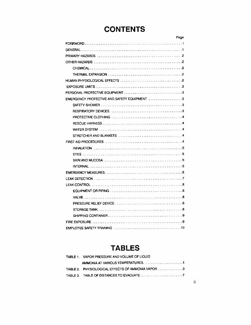
ii
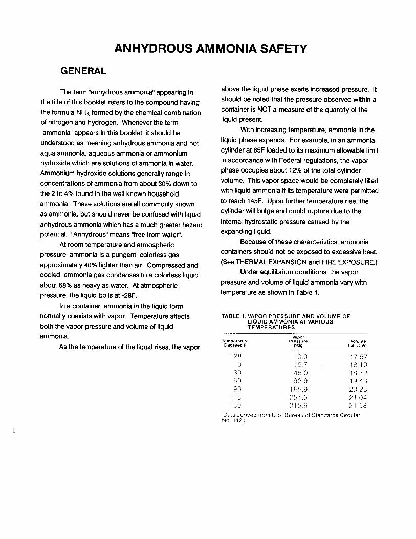
1
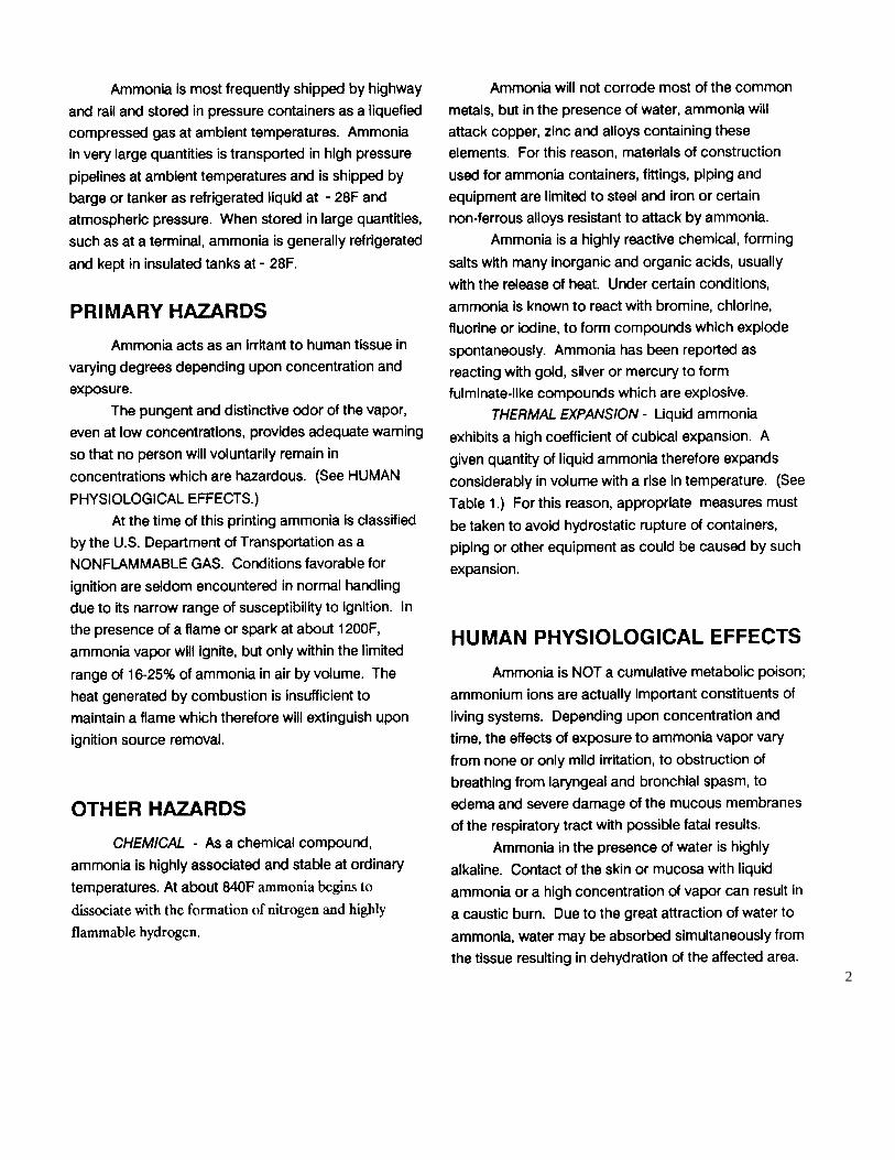
2

3
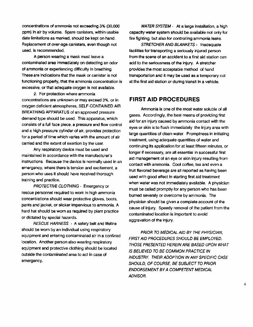
4
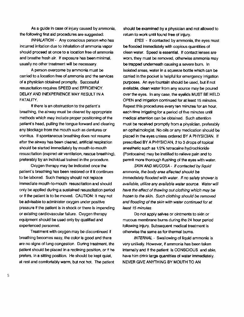
5
6
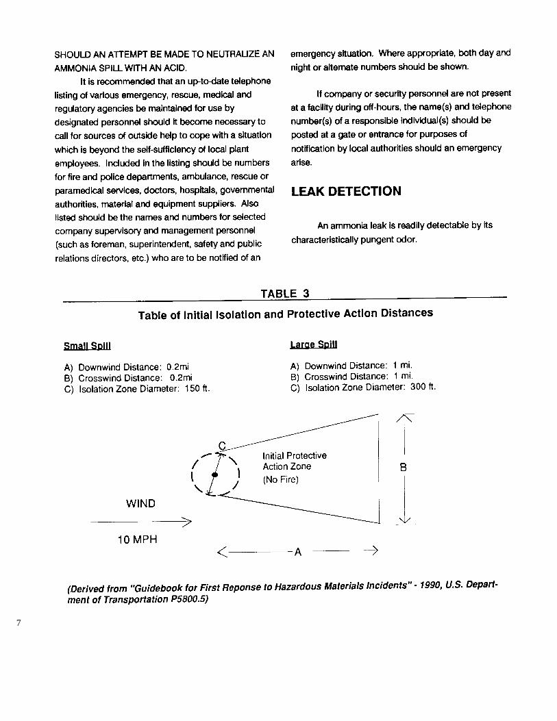
7
8
9
10
11

VOGT® TUBE-ICE® MACHINE
BASIC PRODUCT WARRANTY Vogt Tube Ice LLC, hereinafter referred to as SELLER, warrants to the original Purchaser from SELLER or the original end-user, hereinafter
referred to as PURCHASER, every Vogt® Tube-Ice® Machine Model
P24A, P24F, P24AL, P24ALOF P24FL, P34A, P34F, P34FL, P34AL,
P34ALOF and packaged high side Models P24AHS, P24FHS, P34AHS
and P34FHS to be free from defects in material and workmanship, if properly installed, maintained and operated, for a period of 12 months from date of original installation or 12 months from date of shipment from SELLER’S plant if SELLER does not have an accepted start-up form on file. SELLER’S obligation under this warranty shall be strictly limited, at SELLER’S option, to: (i) repairing or furnishing replacement parts on an exchange basis, F.O.B. Louisville, Kentucky, without charge to PURCHASER those parts proven defective upon examination by SELLER; or (ii) issuing written authorization for PURCHASER or its agents to replace or repair, without charge to PURCHASER, those parts proven defective upon examination by SELLER; or (iii) in discharge of SELLER’S maximum liability herewith, refunding all monies paid by PURCHASER to SELLER for the product and, at discretion of SELLER, having the product removed and returned to SELLER at PURCHASER’S expense. All transportation charges relative to corrective work or defective parts or replacement parts shall be borne by PURCHASER. PURCHASER shall give SELLER immediate notice upon discovery of any defect. The undertaking of repairs or replacement by PURCHASER or its agents without SELLER’S written consent shall relieve SELLER of all responsibility herewith. Any alteration in material or design of SELLER’S product or any component parts thereof by PURCHASER or others without written authorization by SELLER voids all obligations of SELLER regarding the product and any associated warranty herein stated or implied. SELLER’S sole liability shall be exclusively as set forth herein, and SELLER shall not be liable for any incidental or consequential damages due to its breach of any warranty herein contained, or otherwise. Without limitation to the foregoing, in no event shall SELLER be liable for the loss of use of the product or for the loss of use of any other product, process, plant, equipment, or facilities of the PURCHASER whether partially or wholly due to defects in material and/or workmanship and/or design of SELLER’S product, and in no event shall SELLER be liable for removal of appurtenances or incidentals such as connections,
pipework and similar items of obstruction or for any cost brought about by the necessity of removing the product from its point of installation.
SELLER DOES NOT MAKE AND DOES NOT AUTHORIZE ANY
OTHER PERSON TO MAKE ANY WARRANTY OF ANY KIND
WHATSOEVER, EXPRESS OR IMPLIED, ORALLY OR IN WRITING,
OTHER THAN AS SPECIFICALLY STATED HEREIN; AND THERE ARE
NO WARRANTIES OF MERCHANTABILITY AND/OR FITNESS FOR A
PARTICULAR PURPOSE WHICH EXCEED THE OBLIGATIONS AND
WARRANTIES SPECIFICALLY STATED HEREIN. Parts furnished without charge as replacements for original parts under warranty are warranted only for that period of time during which the original parts warranty is effective. Damage to any component due to water quality is specifically excluded from this warranty.
EXTENDED WARRANTY At the termination of the Basic Product Warranty period above, SELLER hereby extends this warranty for one additional year to cover the
CIRCULATING WATER TANK AND CUTTER ASSEMBLY, EXCLUDING
THE CUTTER BEARINGS AND DRIVE TRAINS.
LIFETIME WARRANTY* This component warranty is further extended for the life of the machine to cover the EVAPORATOR (FREEZER). Damage to evaporator tubes as a result of expansion caused by re-freezing of ice or corrosion damage due to water quality is specifically excluded.
The Extended Warranty applies only to VOGT TUBE-ICE MACHINE
MODELS P24A, P24F, P24AL, P24ALOF, P24FL, P34A, P34F, P34FL,
P34AL, and P34ALOF for the exclusive benefit of PURCHASER, as defined above. All other obligations, terms, conditions, exclusions and limitations of the Basic Product Warranty apply to the Extended and Lifetime Warranty.
*“Lifetime” is defined as 25 years. Vogt® and Tube-Ice® are registered
trademarks of Vogt Tube-Ice, LLC, 1000West Ormsby Ave., Louisville, Kentucky 40210
2000