TSS Tool Stand Manual - ati-ia.com
105
Engineered Products for Robotic Productivity Pinnacle Park • 1031 Goodworth Drive • Apex, NC 27539 • Tel: +1‑919.772.0115 • Fax: +1‑919.772.8259 • www.ati‑ia.com TSS Tool Stand Manual Document #: 9610-20-1068
-
Upload
khangminh22 -
Category
Documents
-
view
0 -
download
0
Transcript of TSS Tool Stand Manual - ati-ia.com

Engineered Products for Robotic ProductivityPinnacle Park • 1031 Goodworth Drive • Apex, NC 27539 • Tel: +1‑919.772.0115 • Fax: +1‑919.772.8259 • www.ati‑ia.com
TSS Tool Stand
Manual
Document #: 9610-20-1068

Manual, Tool Stand, TSSDocument #9610-20-1068-17
Pinnacle Park • 1031 Goodworth Drive • Apex, NC 27539 • Tel: 919.772.0115 • Fax: 919.772.8259 • www.ati-ia.com2
ForewordPlease contact ATI Industrial Automation with any questions concerning your particular model.
CAUTION: This manual describes the function, application, and safety considerations of this product. This manual must be read and understood before any attempt is made to install or operate the product, otherwise damage to the product or unsafe conditions may occur.
Information contained in this document is the property of ATI Industrial Automation, Inc (ATI) and shall not be reproduced in whole or in part without prior written approval of ATI. The information herein is subject to change without notice. This manual is periodically revised to reflect and incorporate changes made to the product.
The information contained herein is confidential and reserved exclusively for the customers and authorized agents of ATI Industrial Automation and may not be divulged to any third party without prior written consent from ATI. No warranty including implied warranties is made with regard to accuracy of this document or fitness of this device for a particular application. ATI Industrial Automation shall not be liable for any errors contained in this document or for any incidental or consequential damages caused thereby. ATI Industrial Automation also reserves the right to make changes to this manual at any time without prior notice.
ATI assumes no responsibility for any errors or omissions in this document.
Copyright ©2022 by ATI Industrial Automation. All rights reserved.
How to Reach Us
Sale, Service and Information about ATI products:
ATI Industrial Automation 1031 Goodworth Drive Apex, NC 27539 USA www.ati‑ia.com Tel: 919.772.0115 Fax: 919.772.8259Application Engineering Tel: 919.772.0115 Fax: 919.772.8259 E‑mail: applicationsengineers@ati‑ia.com

Manual, Tool Stand, TSSDocument #9610-20-1068-17
Pinnacle Park • 1031 Goodworth Drive • Apex, NC 27539 • Tel: 919.772.0115 • Fax: 919.772.8259 • www.ati-ia.com3
Table of ContentsForeword .......................................................................................................................................... 2Glossary ........................................................................................................................................... 71. Safety ......................................................................................................................................... 8
1.1 Explanation of Notifications ......................................................................................................... 8
1.2 General Safety Guidelines ............................................................................................................ 8
1.3 Safety Precautions ........................................................................................................................ 9
2. Product Overview ................................................................................................................... 102.1 TSS Pin and Bushing Tool Stands ............................................................................................. 10
2.1.1 Post Modules .................................................................................................................... 11
2.1.2 Horizontal Modules ........................................................................................................... 11
2.1.3 Mounting Modules ............................................................................................................ 11
2.1.4 Proximity Sensor Assembly and Proximity Sensors for Mounting Modules ..................... 11
2.1.5 Tooling Interface Plates .................................................................................................... 12
2.1.6 Vertical Tooling Interface Plates ....................................................................................... 12
2.1.7 Clamp Modules ................................................................................................................ 13
2.2 TSS Tool Stands with Slotted Mounting Modules .................................................................... 142.2.1 Post Modules .................................................................................................................... 15
2.2.2 Horizontal Modules ........................................................................................................... 15
2.2.3 Slotted Mounting Modules ................................................................................................ 16
2.2.4 Barrel‑type Proximity Sensors .......................................................................................... 16
2.2.5 Photoelectric Proximity Sensors ....................................................................................... 16
2.3 TSS Tool Stands with Hook and Hanger Mounting Modules .................................................. 172.3.1 Post Modules .................................................................................................................... 17
2.3.2 Horizontal Modules ........................................................................................................... 18
2.3.3 Post Hanger and Rail Adapter Modules ........................................................................... 18
2.3.4 Proximity Sensors ............................................................................................................ 18
2.3.5 Tool Hook Modules ........................................................................................................... 18
2.4 TSS Pin and Rack Tool Stands .................................................................................................. 192.4.1 Post Modules .................................................................................................................... 20
2.4.2 Tool Bars and Forward Adapter ....................................................................................... 20
2.4.3 Mounting Module .............................................................................................................. 20
2.4.4 Proximity Sensor Assembly and Proximity Sensors ......................................................... 20
2.4.5 Rack Modules, Interface Plate Assemblies, Alignment Pins and Pin Blocks .................... 21
2.5 TSS Tool Stand for the QC-001 .................................................................................................. 222.5.1 Post Module ..................................................................................................................... 22
2.5.2 Horizontal Modules ........................................................................................................... 23
2.5.3 Mounting Module .............................................................................................................. 23

Manual, Tool Stand, TSSDocument #9610-20-1068-17
Pinnacle Park • 1031 Goodworth Drive • Apex, NC 27539 • Tel: 919.772.0115 • Fax: 919.772.8259 • www.ati-ia.com4
2.5.4 Photoelectric Sensor ........................................................................................................ 23
2.6 Post Module Components .......................................................................................................... 242.6.1 Post Modules (Complete Assembly) ................................................................................ 24
2.6.2 Base Assembly ................................................................................................................. 25
2.6.3 Rail Assemblies ................................................................................................................ 25
2.6.4 Gusset Assembly .............................................................................................................. 25
2.7 Determining Tool Stand Configurations ................................................................................... 262.7.1 Configuring a Tool Stand for a QC‑001 Tool Changer ...................................................... 28
2.7.2 Configuring a Pin and Bushing Tool Stand ....................................................................... 28
2.7.3 Configuring TSS Tool Stands with Slotted Mounting Modules ......................................... 29
2.7.4 Configuring QC‑7 TSS Tool Stands with Hook and Hanger Modules............................... 30
2.7.5 Configuring a Pin and Rack Tool Stand ............................................................................ 31
3. Installation .............................................................................................................................. 323.1 Assembling the Post Module ..................................................................................................... 32
3.2 Installing TSS Tool Stands for QC-001 ...................................................................................... 343.2.1 Installing Proximity Sensors for QC‑001 .......................................................................... 35
3.3 Installing TSS Pin and Bushing Tool Stands ............................................................................ 353.3.1 Installing a Proximity Sensor on Mounting Modules ......................................................... 37
3.3.2 Installing Clamp Modules ................................................................................................. 38
3.4 Installing TSS Tool Stands with Slotted Mounting Modules ................................................... 393.4.1 Installing Barrel Sensors on TSS Tool Stands with Slotted Mounting Modules ................ 43
3.4.2 Installing Proximity Sensors for QC‑7 Slotted Mounting Module ..........................................44
3.5 Installing Hook and Hanger Modules ........................................................................................ 453.5.1 (Optional) Install the Post Hanger Module to a Flat Surface ............................................ 46
3.5.2 Installing Proximity Sensors for QC‑7 Hook and Hanger Module .........................................47
3.6 Installing TSS Pin and Rack Tool Stands .................................................................................. 483.6.1 Installing Proximity Sensors for TSS Pin and Rack Tool Stands ...................................... 50
4. Operation ................................................................................................................................ 514.1 TSS Tool Stands for QC-001 Operation ..................................................................................... 51
4.2 TSS Tool Stands for Hook and Hanger Modules (QC-7) .......................................................... 524.2.1 Operation Sequence ........................................................................................................ 52
4.2.1.1 Tool Drop‑Off ..................................................................................................... 52
4.2.2 Payload ............................................................................................................................ 53
4.3 TSS Tool Stands with QC-7 Slotted Mounting Modules .......................................................... 554.3.1 Payload ............................................................................................................................ 55
4.4 TSS Tool Stands with QC-11 Slotted Mounting Modules ........................................................ 57
4.5 TSS Pin and Bushing Tool Stand Operation ............................................................................. 58
4.6 TSS Pin and Rack Tool Stand Operation .................................................................................. 58

Manual, Tool Stand, TSSDocument #9610-20-1068-17
Pinnacle Park • 1031 Goodworth Drive • Apex, NC 27539 • Tel: 919.772.0115 • Fax: 919.772.8259 • www.ati-ia.com5
5. Maintenance ............................................................................................................................ 595.1 All TSS Tool Stands .................................................................................................................... 59
5.2 TSS Pin and Bushing Tool Stands ............................................................................................. 59
5.3 TSS Pin and Rack Tool Stands .................................................................................................. 60
5.4 TSS QC-7 Slotted Mounting Module .......................................................................................... 60
5.5 TSS QC-7 Hook and Hanger Module ......................................................................................... 615.5.1 Lubricate Hook and Hanger Module ................................................................................. 62
6. Troubleshooting ..................................................................................................................... 637. Serviceable Parts ................................................................................................................... 64
7.1 Part Number Cross Reference ................................................................................................... 647.1.1 TSS Pin and Bushing Tool Stands ................................................................................... 64
7.1.2 TSS Pin and Rack Tool Stands ........................................................................................ 65
7.1.3 TSS Tool Stand for the QC‑001, QC‑7, and QC‑11 .......................................................... 65
7.1.4 Post Module Components ................................................................................................ 65
8. Specifications ......................................................................................................................... 668.1 Common TSS Tool Stand Components .................................................................................... 66
8.2 TSS Tool Stand for QC-001 Components .................................................................................. 66
8.3 TSS Tool Stand for QC-7 Slotted Tool Stand Components ..................................................... 66
8.4 Slotted Mounting Module Components .................................................................................... 67
8.5 QC-7 Hook and Hanger Module Components .......................................................................... 67
8.6 TSS Pin and Rack Tool Stand Components ............................................................................. 67
8.7 TSS Pin and Bushing Tool Stand Components ........................................................................ 68
9. Drawings ................................................................................................................................. 699.1 TSS Pin and Bushing Tool Stands ............................................................................................. 69
9.1.1 QC‑5/11 ............................................................................................................................ 69
9.1.2 QC‑20/21 .......................................................................................................................... 70
9.1.3 QC‑29 ............................................................................................................................... 71
9.1.4 QC‑40/41 .......................................................................................................................... 72
9.2 Tooling Interface Plates .............................................................................................................. 739.2.1 QC‑5/11 Tooling Interface Plate ‑ Blank ........................................................................... 73
9.2.2 QC‑20/21 Tooling Interface Plate ‑ Blank ......................................................................... 74
9.2.3 QC‑29 Tooling Interface Plate ‑ Blank .............................................................................. 75
9.2.4 QC‑40 Tooling Interface Plate ‑ Blank .............................................................................. 76
9.2.5 QC‑41 Tooling Interface Plate ‑ Blank .............................................................................. 77

Manual, Tool Stand, TSSDocument #9610-20-1068-17
Pinnacle Park • 1031 Goodworth Drive • Apex, NC 27539 • Tel: 919.772.0115 • Fax: 919.772.8259 • www.ati-ia.com6
9.2.6 QC‑20/21/40/41 Vertical Tooling Interface Plate ‑ Blank .................................................. 78
9.2.7 QC‑40/41 Vertical Tooling Interface Plate J16 Mounting Pattern ..................................... 79
9.3 Clamp Modules ............................................................................................................................ 809.3.1 TSS Clamp Module, Right Hand ...................................................................................... 80
9.3.2 TSS Clamp Module, Left Hand ......................................................................................... 81
9.4 TSS Pin and Rack Tool Stands .................................................................................................. 829.4.1 QC‑5/11 ............................................................................................................................ 82
9.4.2 QC‑20 ............................................................................................................................... 83
9.4.3 QC‑21 ............................................................................................................................... 84
9.4.4 Tool Stand Forward Adapter Kit for QC‑20, 21, and 21E ................................................. 85
9.4.5 5 Position Tool Bar for QC‑5 through 21 .......................................................................... 86
9.4.6 QC‑5 Tool Rack ................................................................................................................ 87
9.4.7 QC‑10 Tool Rack .............................................................................................................. 88
9.4.8 QC‑11 Tool Rack .............................................................................................................. 89
9.4.9 QC‑20 Tool Rack .............................................................................................................. 90
9.4.10 QC‑21 Tool Rack .............................................................................................................. 91
9.4.11 QC‑21 Euro Tool Rack ..................................................................................................... 92
9.5 Post Modules ............................................................................................................................... 939.5.1 Post Modules with 45 x 90 Rail ........................................................................................ 93
9.5.2 Post Modules with 90 x 90 Rail ........................................................................................ 94
9.6 TSS Slotted Mounting Modules ................................................................................................. 959.6.1 TSS Tool Stand for QC‑001 .............................................................................................. 95
9.6.2 TSS Tool Stand for QC‑7 .................................................................................................. 96
9.6.3 TSS Tool Stand for QC‑11 ................................................................................................ 98
9.7 TSS Hook and Hanger Mounting Modules .............................................................................. 1009.7.1 TSS Hook and Hanger Configuration ............................................................................. 100
9.7.2 TSS Tool Hook ............................................................................................................... 102
9.7.3 TSS Post Hanger and Rail Adapter ................................................................................ 103
10. Terms and Conditions of Sale ............................................................................................. 105

Manual, Tool Stand, TSSDocument #9610-20-1068-17
Pinnacle Park • 1031 Goodworth Drive • Apex, NC 27539 • Tel: 919.772.0115 • Fax: 919.772.8259 • www.ati-ia.com7
GlossaryTerm Definition
Alignment Pin Attaches to the interface plate and mounting module to support and position the tooling in the Tool Stand.
Clamp Module A cylinder used to constrain the interface plate against deflection caused by cables and hoses.
End‑Effector A tool or other device attached to the robot arm in order to perform a task.Forward Adapter Provides extra clearance from the Tool Stand to accommodate larger tooling.Horizontal Module A rail that supports multiple tool positions.Interface Plate Assembly Provides mounting for the Tool Changer Tool plate and the customer tooling.Master plate The half of the Tool Changer that is mounted to an interface plate or the robot.
ModuleAn optional component that can be added to the Master and Tool plates to enhance the capabilities of the Tool Changer; for example: fluid/air, electrical, control/signal, servo, or high‑current modules.
Mounting Block Provides a mount for the Tool bar, forward adapter, or rack module for the pin and rack Tool Stand.
Mounting Module Provides a mount on the Tool Stand for the tooling interface plate, or mounts the Tool plate directly for some models.
Pin Block Mounts to a flat on the Tool Changer Tool plate and provides a mount for an alignment pin.
Pin and Bushing Tool Stand
A Tool Stand that uses mounting modules and Tooling interface plates with pins and bushings to support and position the Tool Changer Tool plate and customer tooling.
Pin and Rack Tool Stand A Tool Stand that uses rack assemblies to support and position the Tool Changer Tool plate and customer tooling.
Post Hanger and Rail Adapter
A post hanger has two pins where the Tool hook can rest. The hanger attaches to a rail adapter that mounts to the TSS post module.
Post Module A vertical post for (1) or more mounting modules.Proximity Sensor Provides a signal that indicates the tool is located in the Tool Stand.Proximity Sensor Assembly Provides a mount on the Tool Stand for the proximity sensor.
Rack Module Mounts to the Tool bar, forward adapter, or mounting block to provide support and position the tooling in the Tool Stand.
Tool Bar Provides fixed additional tool mounting positions on the Tool Stand.
Tool Hook A module that attaches to the Tool Changer Tool plate and rests on hanger pins, when placed on the TSS.
Tooling Interface Plate A machined plate that adapts the Tool plate to customer tooling and provides mounting features for a Tool Stand.
Tool Plate The half of the Tool Changer that is mounted to a Tooling interface plate and customer‑supplied tooling.
Tool Stand Small (TSS) Tool Stand
A fixture provided by ATI that holds the Tool plate and attached hardware when not in use.
Vertical Tooling Interface Plate
A machined plate with a vertical surface that adapts the customer end‑effector and provides mounting features for a Tool Stand.

Manual, Tool Stand, TSSDocument #9610-20-1068-17
Pinnacle Park • 1031 Goodworth Drive • Apex, NC 27539 • Tel: 919.772.0115 • Fax: 919.772.8259 • www.ati-ia.com8
1. SafetyThe safety section describes general safety guidelines to be followed with this product, explanations of the notifications found in this manual, and safety precautions that apply to the product. Product specific notifications are imbedded within the sections of this manual (where they apply).
1.1 Explanation of NotificationsThese notifications are used in all of ATI manuals and are not specific to this product. The user should heed all notifications from the robot manufacturer and/or the manufacturers of other components used in the installation.
DANGER: Notification of information or instructions that if not followed will result in death or serious injury. The notification provides information about the nature of the hazardous situation, the consequences of not avoiding the hazard, and the method for avoiding the situation.
WARNING: Notification of information or instructions that if not followed could result in death or serious injury. The notification provides information about the nature of the hazardous situation, the consequences of not avoiding the hazard, and the method for avoiding the situation.
CAUTION: Notification of information or instructions that if not followed could result in moderate injury or will cause damage to equipment. The notification provides information about the nature of the hazardous situation, the consequences of not avoiding the hazard, and the method for avoiding the situation.
NOTICE: Notification of specific information or instructions about maintaining, operating, installing, or setting up the product that if not followed could result in damage to equipment. The notification can emphasize, but is not limited to: specific grease types, best operating practices, and maintenance tips.
1.2 General Safety GuidelinesThis system is intended for use in industrial applications for tool changing and storage in conjunction with a Tool Changer.The customer must select a Tool Changer that is rated for the maximum loads and moments expected during operation. Contact ATI for assistance.
WARNING: The customer is responsible for ensuring that the area between the tool and the Tool Stand and the area between the Master and Tool plates are clear during operation. Failure to do so may result in serious injury to personnel or damage to equipment.
WARNING: The gap between the Master and Tool sides is a pinch point. All personnel should be prevented from placing any part of their body or clothing in the gap, especially during actuation of the locking mechanism.

Manual, Tool Stand, TSSDocument #9610-20-1068-17
Pinnacle Park • 1031 Goodworth Drive • Apex, NC 27539 • Tel: 919.772.0115 • Fax: 919.772.8259 • www.ati-ia.com9
1.3 Safety PrecautionsWARNING: Do not perform maintenance or repair(s) on the Tool Changer or modules unless the Tool is safely supported or placed in the tool stand, all energized circuits (e.g. electrical, air, water, etc.) are turned off, pressurized connections are purged and power is discharged from circuits in accordance with the customer specific safety practices and policies. Injury or equipment damage can occur with the Tool not placed and energized circuits on. Place the Tool in the tool stand, turn off and discharge all energized circuits, purge all pressurized connections, and verify all circuits are de‑energized before performing maintenance or repair(s) on the Tool Changer or modules.
CAUTION: The TSS Tool Stand system is only to be used for intended applications and applications approved by the manufacturer.

Manual, Tool Stand, TSSDocument #9610-20-1068-17
Pinnacle Park • 1031 Goodworth Drive • Apex, NC 27539 • Tel: 919.772.0115 • Fax: 919.772.8259 • www.ati-ia.com10
2. Product OverviewThe ATI TSS system is compatible with ATI Tool Changer sizes QC‑001 through QC‑41. The modular system enables you to customize your tool storage rack based on the number of tools and mounting requirements. The following TSS systems are available:
• Section 2.1—TSS Pin and Bushing Tool Stands• Section 2.2—TSS Tool Stands with Slotted Mounting Modules• Section 2.3—TSS Tool Stands with Hook and Hanger Mounting Modules• Section 2.4—TSS Pin and Rack Tool Stands• Section 2.5—TSS Tool Stand for the QC‑001
2.1 TSS Pin and Bushing Tool StandsThe TSS Pin and Bushing Tool Stand system is compatible with ATI Tool Changer sizes QC‑5 through QC‑41. The Tool Stand can be equipped with horizontal modules and mounting modules that support the Tool Changer Tool plate, tool interface plate, and customer tooling. Mounting modules can be placed anywhere along a horizontal module. For an example of a TSS Pin and Bushing Tool Stand, refer to Figure 2.1. The horizontal module is necessary when accommodating (3) or more tool positions. The mounting module assemblies or single pin mounting module can be mounted to either side of the post module.
Figure 2.1—TSS Pin and Bushing Tool Stand
Post Module
Horizontal Module
Tool Changer Tool Side(QC-21 Shown)
Tooling Interface Plate
Clamp Module(Optional)
Proximity Sensor Holder
Proximity Sensor(Optional)
Mounting Module Assembly(Includes the Proximity Sensor Holder.)
Mounting ModuleAssembly (Includes the
Proximity Sensor Holder)
Vertical Tooling Interface Plate
Tool Changer Tool Side(QC-41 Shown)

Manual, Tool Stand, TSSDocument #9610-20-1068-17
Pinnacle Park • 1031 Goodworth Drive • Apex, NC 27539 • Tel: 919.772.0115 • Fax: 919.772.8259 • www.ati-ia.com11
2.1.1 Post ModulesThe post module is a common component to all TSS Tool Stands. The post module is available in different post heights and consists of a base assembly, rail assembly, and gusset; refer to Section 2.5.1—Post Module.
2.1.2 Horizontal ModulesThe horizontal module mounts to the post module and can be positioned vertically and horizontally. The rail gussets accommodate customer tooling. The rail is an aluminum extrusion (45x90) and comes in 12”, 18”, 24”, 36”, and 48” standard lengths. The rail can accommodate multiple mounting modules, depending on tool spacing requirements, and can be positioned anywhere along the horizontal module.Item Part Number Refer to Drawing in: QC-ModelsHorizontal Module 300 mm (12”)1,2 9120‑TSM‑HM‑3362
Section 9.1.1 ~ Section 9.1.4 QC‑5 ~ QC‑41
Horizontal Module 457 mm (18”)1,2 9120‑TSM‑HM‑3323Horizontal Module 610 mm (24”)1,2 9120‑TSM‑HM‑1020Horizontal Module 914 mm (36”)1,2 9120‑TSM‑HM‑3317Horizontal Module 1220 mm (48”)1,2 9120‑TSM‑HM‑3325Horizontal Module 1520 mm (60”) 9120‑TSM‑HM‑3353
Notes: 1. The horizontal module is used with TSS Pin and Bushing Tool Stands.2. The customer can specify other rail lengths.
2.1.3 Mounting ModulesThe mounting module includes (2) vertical alignment pins and one vertical pin receiver. Mounting hardware is included, and can mount to the horizontal module or to the post module. The mounting module can be positioned anywher e along the rail to accommodate customer tooling. A proximity sensor holder is included with the mounting module. A mounting module is required for each tool position. The mounting module provides mounting holes for optional right and left clamp modules.Item Part Number Refer to Drawing in: QC-Models
Mounting Module1,2 9120‑TSS‑MMB‑7124Section 9.1.1 ~ Section 9.1.4
QC‑5, QC‑119120‑TSS‑MMB‑7130 QC‑20 ~ QC‑41
Notes:1. The mounting module is used with TSS Pin and Bushing Tool Stands.2. The mounting module is used with a proximity sensor assembly 9120‑TSS‑SM‑3315 and
proximity sensors 8590‑9909999‑08 and 8590‑9909999‑09.
2.1.4 Proximity Sensor Assembly and Proximity Sensors for Mounting ModulesProximity sensors provide a signal that indicates the tool is located in the Tool Stand. The proximity sensor assembly mounts proximity sensors to the mounting block, adapter bar, forward adapter, or mounting module. The assembly includes mounting hardware and can accommodate any 8 mm barrel‑type sensor, threaded or unthreaded. Sensor cables are available in various lengths.
Proximity Sensor AssemblyItem Part Number Refer to Drawing in: QC-Models
Proximity Sensor Assembly1, 2 9120‑TSS‑SM‑3315 Section 9.1.1 ~ Section 9.1.4 QC‑5, QC‑10 ~ QC‑41
Proximity SensorsProximity Sensor PNP 3 wire DC 8590‑9909999‑08
Section 9.1.1 ~ Section 9.1.4 QC‑5, QC‑10 ~ QC‑41Proximity Sensor NPN 3 wire DC 8590‑9909999‑09
Notes:1. The proximity sensor holder is only included with the mounting module. The proximity sensor
holder is sold separately for the following: adapter bar, forward adapter, and mounting block.2. The proximity sensor is not included.

Manual, Tool Stand, TSSDocument #9610-20-1068-17
Pinnacle Park • 1031 Goodworth Drive • Apex, NC 27539 • Tel: 919.772.0115 • Fax: 919.772.8259 • www.ati-ia.com12
2.1.5 Tooling Interface PlatesThe tooling interface plate adapts the tool and Tool Changer to the mounting module. The tooling interface plate uses (2) bushings and (1) alignment pin to position the tooling to the mounting module. Custom tooling interface plates with specific mounting patterns are available, contact ATI for details.Item Part Number Refer to Drawing in: QC-ModelsTooling Interface Plate for QC‑5,11‑Blank1,2 9120‑TSS‑HBQ‑7123 Section 9.2.1 QC‑5, QC‑11
Tooling Interface Plate for QC‑20,21‑Blank1,3 9120‑TSS‑HBQ‑9483 Section 9.2.2 QC‑20,
QC‑21Tooling Interface Plate for QC‑29‑Blank1,3 9120‑TSS‑HBQ‑11659 Section 9.2.3 QC‑29
Tooling Interface Plate for QC‑40‑Blank1,3 9120‑TSS‑HBQ‑9400 Section 9.2.4 QC‑40,
QC‑40QTooling Interface Plate for QC‑41‑Blank1,3 9120‑TSS‑HBQ‑7539 Section 9.2.5 QC‑41
Notes: 1. The tooling interface plate is only used with TSS Pin and Bushing Tool Stands.2. Used with mounting module 9120‑TSS‑MMB‑7124.3. Used with mounting module 9120‑TSS‑MMB‑7130.
2.1.6 Vertical Tooling Interface PlatesThe vertical tooling interface plate adapts the tool and Tool Changer to the mounting module. The tooling interface plate attaches to a flat on the Tool Changer and provides mounting for the customer tooling. The tooling interface plate uses (2) bushings and (1) alignment pin to align with the mounting module. Custom vertical tooling interface plates with specific mounting patterns are available, contact ATI for details.Item Part Number Refer to Drawing in: QC-ModelsVertical Tooling Interface Plate‑Blank1, 2 9120‑TSS‑VBB‑7963 Section 9.1.2
Section 9.2.6 QC‑20, QC‑21
Vertical Tooling Interface Plate‑J16 Pattern1, 2
9120‑TSS‑VBQ‑8206 Section 9.1.4 Section 9.2.7 QC‑40, QC‑41
Vertical Tooling Interface, QC‑181, 2 9120‑TSS‑VBQ‑9968 NA QC‑18
Notes: 1. The vertical tooling interface plate is only used with TSS Pin and Bushing Tool Stands.2. Used with mounting module 9120‑TSS‑MM‑7130.

Manual, Tool Stand, TSSDocument #9610-20-1068-17
Pinnacle Park • 1031 Goodworth Drive • Apex, NC 27539 • Tel: 919.772.0115 • Fax: 919.772.8259 • www.ati-ia.com13
2.1.7 Clamp ModulesClamp modules secure the Tooling plate in cases where the customer tooling and utility lines pull the tooling plate to one side. The clamps ensure that the tooling interface plate is properly positioned in the mounting module. Optional clamp modules can be used on one or both sides of the mounting module. The clamp arm consists of a 90o swing, rotary actuator, which has a clamp stroke of 10 mm and rotates clockwise when opening (see Figure 2.2). The hex head screw in the clamp arm of the rotary actuator can be adjusted to contact the Tool plate and is secured with a lock nut (see Section 9—Drawings). M5 elbow air fittings are supplied to clamp and unclamp the arm. A supply pressure in the range of 90 to 145 psi is recommended for operation. The lock/unlock sensors included with the clamp module verify the position of the clamp arm.Item Part Number Refer to Drawing in: QC-ModelsClamp Module Right Hand1 9120‑TSS‑CM‑7335 Section 9.3.1 QC‑5, QC‑10 ~
QC‑21
Clamp Module Left Hand1 9120‑TSS‑CM‑7336 Section 9.3.2 QC‑5, QC‑10 ~ QC‑21
Notes:1. The clamp module is only used with TSS Pin and Bushing Tool Stands.
Figure 2.2—Adjustable Actuator Arm Swing and Stroke
10 mm Clamping Stroke
90o Swing
Manual, Tool Stand, TSSDocument #9610-20-1068-17
Pinnacle Park • 1031 Goodworth Drive • Apex, NC 27539 • Tel: 919.772.0115 • Fax: 919.772.8259 • www.ati-ia.com14
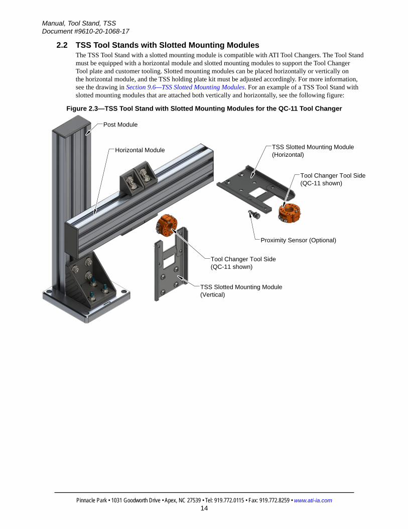
2.2 TSS Tool Stands with Slotted Mounting ModulesThe TSS Tool Stand with a slotted mounting module is compatible with ATI Tool Changers. The Tool Stand must be equipped with a horizontal module and slotted mounting modules to support the Tool Changer Tool plate and customer tooling. Slotted mounting modules can be placed horizontally or vertically on the horizontal module, and the TSS holding plate kit must be adjusted accordingly. For more information, see the drawing in Section 9.6—TSS Slotted Mounting Modules. For an example of a TSS Tool Stand with slotted mounting modules that are attached both vertically and horizontally, see the following figure:
Figure 2.3—TSS Tool Stand with Slotted Mounting Modules for the QC-11 Tool Changer
Post Module
Horizontal Module
Tool Changer Tool Side(QC-11 shown)
Tool Changer Tool Side(QC-11 shown)
Proximity Sensor (Optional)
TSS Slotted Mounting Module(Horizontal)
TSS Slotted Mounting Module(Vertical)

Manual, Tool Stand, TSSDocument #9610-20-1068-17
Pinnacle Park • 1031 Goodworth Drive • Apex, NC 27539 • Tel: 919.772.0115 • Fax: 919.772.8259 • www.ati-ia.com15
Figure 2.4—TSS Tool Stand with Slotted Mounting Modules for the QC-7 Tool Changer
End Cap
Slotted Mounting Module(horizontal position)
QC-7 Tool side
End Cap
QC-7 Tool side
(2) T-nuts
T-slot
Horizontal Module
Post Module
T-bolt
T-slot
Slotted Mounting Module(vertical position)
(2) T-nuts
2.2.1 Post ModulesThe post module is a common component to all TSS Tool Stands. The post module is available in different post heights and consists of a base assembly, rail assembly, and gusset; refer to Section 2.5.1—Post Module.
2.2.2 Horizontal ModulesThe horizontal module mounts to the post module and can be positioned vertically and horizontally using the rail gussets. The rail is an aluminum extrusion (45x90) and comes in 12”, 18”, 24”, 36”, and 48” standard lengths. The rail can accommodate multiple mounting modules, depending on tool spacing requirements, and can be positioned anywhere along the horizontal module.Item Part Number Refer to Drawing in: QC-ModelsHorizontal Module 300 mm (12”)1,2 9120‑TSM‑HM‑3362
Section 9.1.1 ~ Section 9.1.4 QC‑5 ~ QC‑41
Horizontal Module 457 mm (18”)1,2 9120‑TSM‑HM‑3323Horizontal Module 610 mm (24”)1,2 9120‑TSM‑HM‑1020Horizontal Module 914 mm (36”)1,2 9120‑TSM‑HM‑3317Horizontal Module 1220 mm (48”)1,2 9120‑TSM‑HM‑3325
Notes: 1. The horizontal module is used with TSS Pin and Bushing Tool Stands.2. The customer can specify other rail lengths.

Manual, Tool Stand, TSSDocument #9610-20-1068-17
Pinnacle Park • 1031 Goodworth Drive • Apex, NC 27539 • Tel: 919.772.0115 • Fax: 919.772.8259 • www.ati-ia.com16
2.2.3 Slotted Mounting ModulesThe slotted mounting module is compatible with ATI Tool Changers. The module mounts to the horizontal module, and can be positioned vertically or horizontally. For information about torque and required fasteners, see Section 9.6—TSS Slotted Mounting Modules.
NOTE: For QC‑11, if mounting the module horizontally, use the (2) T‑nuts. The TSS holding plate kit must be adjusted accordingly. The module can accommodate any threaded 8 mm barrel‑type proximity sensor.
Item Part Number Refer to Drawing in: QC-Models
Slotted Mounting Module 9120‑TSS‑MMS‑11345 Section 9.6.2 QC‑7
Slotted Mounting Module 9120‑TSS‑MMS‑9589 Section 9.6.3 QC‑11
2.2.4 Barrel-type Proximity SensorsProximity sensors provide a signal that indicates the tool is located in the Tool Stand. The slotted mounting module can accommodate any threaded 8 mm barrel‑type sensor. Sensor cables are available in various lengths. See Figure 2.3.
Proximity SensorsItem Part Number Refer to Drawing in: QC-ModelsProximity Sensor PNP 3 wire DC1 8590‑9909999‑08
Section 9.6.3 QC‑5 ~ QC‑41Proximity Sensor NPN 3 wire DC1 8590‑9909999‑09Notes:
1. Proximity sensors include nuts and washers that attach to the Slotted Mounting Module.
2.2.5 Photoelectric Proximity SensorsProximity sensors provide a signal that indicates the tool is located in the Tool Stand. For the QC‑7 slotted mounting module, the following sensor options are available:
Proximity SensorsItem Part Number Refer to Drawing in: QC-ModelsPNP proximity sensor kit, M8 3‑pin connector with .12 meter cable
9120‑TSS‑SMA‑11345
Section 9.6.2 QC‑7NPN Proximity Sensor Kit, 1 meter cable with flying leads
9120‑TSS‑SMB1‑11345
Notes:1. Proximity sensors include screws for installing the sensor to the slotted mounting module.
Manual, Tool Stand, TSSDocument #9610-20-1068-17
Pinnacle Park • 1031 Goodworth Drive • Apex, NC 27539 • Tel: 919.772.0115 • Fax: 919.772.8259 • www.ati-ia.com17
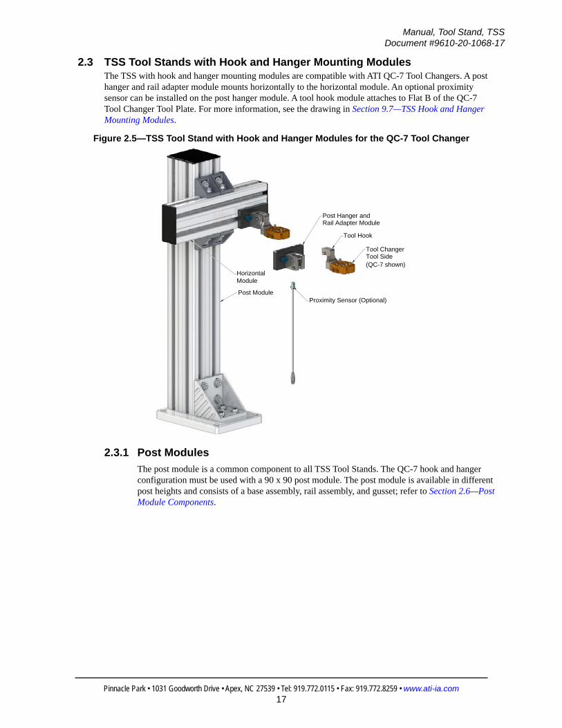
2.3 TSS Tool Stands with Hook and Hanger Mounting ModulesThe TSS with hook and hanger mounting modules are compatible with ATI QC‑7 Tool Changers. A post hanger and rail adapter module mounts horizontally to the horizontal module. An optional proximity sensor can be installed on the post hanger module. A tool hook module attaches to Flat B of the QC‑7 Tool Changer Tool Plate. For more information, see the drawing in Section 9.7—TSS Hook and Hanger Mounting Modules.
Figure 2.5—TSS Tool Stand with Hook and Hanger Modules for the QC-7 Tool Changer
Tool Changer Tool Side
Proximity Sensor (Optional)
Post Hanger andRail Adapter Module
Horizontal
Post Module
Tool Hook
(QC-7 shown)
Module
2.3.1 Post ModulesThe post module is a common component to all TSS Tool Stands. The QC‑7 hook and hanger configuration must be used with a 90 x 90 post module. The post module is available in different post heights and consists of a base assembly, rail assembly, and gusset; refer to Section 2.6—Post Module Components.

Manual, Tool Stand, TSSDocument #9610-20-1068-17
Pinnacle Park • 1031 Goodworth Drive • Apex, NC 27539 • Tel: 919.772.0115 • Fax: 919.772.8259 • www.ati-ia.com18
2.3.2 Horizontal ModulesThe horizontal module mounts to the post module and can be positioned vertically and horizontally using the rail gussets. The rail is an aluminum extrusion (45x90) and comes in 12”, 18”, 24”, 36”, and 48” standard lengths. The rail can accommodate multiple mounting modules, depending on tool spacing requirements, and can be positioned anywhere along the horizontal module.Item Part Number Refer to Drawing in: QC-ModelsHorizontal Module 300 mm (12”)1,2 9120‑TSM‑HM‑3362
Section 9.1.1 ~ Section 9.1.4 QC‑7
Horizontal Module 457 mm (18”)1,2 9120‑TSM‑HM‑3323Horizontal Module 610 mm (24”)1,2 9120‑TSM‑HM‑1020Horizontal Module 914 mm (36”)1,2 9120‑TSM‑HM‑3317Horizontal Module 1220 mm (48”)1,2 9120‑TSM‑HM‑3325
Notes: 1. The horizontal module is used with TSS Pin and Bushing Tool Stands.2. The customer can specify other rail lengths .
2.3.3 Post Hanger and Rail Adapter ModulesThe post hanger and rail adapter mounts to the horizontal module and must be oriented horizontally. For information about torque and required fasteners, see Section 9.7—TSS Hook and Hanger Mounting Modules. Item Part Number Refer to Drawing in: QC-Models
Post Hanger and Rail Adapter Module 9120‑TSS‑MMH‑11392 Section 9.7.3 QC‑7
2.3.4 Proximity SensorsProximity sensors provide a signal that indicates the tool hook is in the post hanger. Sensor options available are listed in the following table:
Proximity SensorsItem Part Number Refer to Drawing in: QC-ModelsPNP proximity sensor kit, M8 3‑pin male connector with 0.2 meter cable
9120‑TSS‑SMA‑11392
Section 9.7.1 QC‑7NPN proximity sensor kit, M8 3‑pin male connector with 0.2 meter cable
9120‑TSS‑SMB‑11392
Notes:1. Proximity sensors include a screw for installing the sensor to the post hanger module.
2.3.5 Tool Hook ModulesThe tool hook module mounts to the QC‑7 Tool. For information about torque and required fasteners, see Section 9.7 Item Part Number Refer to Drawing in: QC-Models
Tool Hook 9120‑TSS‑TH‑11391 Section 9.7.2 QC‑7

Manual, Tool Stand, TSSDocument #9610-20-1068-17
Pinnacle Park • 1031 Goodworth Drive • Apex, NC 27539 • Tel: 919.772.0115 • Fax: 919.772.8259 • www.ati-ia.com19
2.4 TSS Pin and Rack Tool StandsThe TSS Pin and Rack Tool Stand system is compatible with ATI Tool Changer sizes QC‑5 and QC‑10 through QC‑41. The Tool Stand can be equipped with either a forward adapter or an adapter bar with fixed tool spacing. The rack assemblies provide the option to either use interface plates or empty air ports as mounting points for the alignment pins.
Figure 2.6—TSS Pin and Rack Tool Stand

Manual, Tool Stand, TSSDocument #9610-20-1068-17
Pinnacle Park • 1031 Goodworth Drive • Apex, NC 27539 • Tel: 919.772.0115 • Fax: 919.772.8259 • www.ati-ia.com20
2.4.1 Post ModulesThe post module is a common component to all TSS Tool Stands. The post module is available in different post heights and consists of a base assembly, rail assembly, and gusset; refer to Section 2.6—Post Module Components.
2.4.2 Tool Bars and Forward Adapter There is (1) type of forward adapter and (3) types of tool bars. The tool bar mounts to the mounting block and can hold (3) to (5) rack modules, depending on the model. Tool bars also allow for the attachment of a proximity sensor holder for each rack. The forward adapter is used when tooling requires extra clearance from the rail, and also accommodates a proximity sensor holder. Item Part Number Refer to Drawing in: QC-Models
Forward Adapter Assembly* 9120‑TSS‑FA‑3361 Section 9.4.4
QC‑5, QC‑10 ~ QC‑41Tool Bar – 3 Position1 9120‑TSS‑TB‑3308 Section 9.4.1
Tool Bar – 4 Position1 9120‑TSS‑TB‑3431 N/ATool Bar – 5 Position1 9120‑TSS‑TB‑3570 Section 9.4.5Notes:
1. The forward adapter and adapter bars are used with TSS Pin and Rack Tool Stands only.
2.4.3 Mounting ModuleThe mounting module mounts to the post module and can be positioned anywhere along the rail to the desired height. The rack module, forward adapter, or tool bar can mount to the block. The block also can accommodate a proximity sensor holder.Item Part Number Refer to Drawing in: QC-Models
Mounting Block1 9120‑TSS‑MMA‑3306 Section 9.4.1 ~ Section 9.4.5 QC‑5, QC‑10 ~ QC‑41
Notes:1. The forward adapter and adapter bars are only used with TSS Pin and Rack Tool Stands.
2.4.4 Proximity Sensor Assembly and Proximity SensorsThe proximity sensor assembly can be mounted to the mounting block, adapter bar, forward adapter, and mounting module to secure a proximity sensor. The assembly includes mounting hardware and can accommodate any 8 mm barrel‑type sensor, threaded or unthreaded. The proximity sensor provides a signal that indicates the tool is located in the Tool Stand. Sensor cables are available in various lengths. The proximity sensor assembly is not compatible with the Tool Stand for the QC‑001.
Proximity Sensor AssemblyItem Part Number Refer to Drawing in: QC-Models
Proximity Sensor Assembly1, 2 9120‑TSS‑SM‑3315 Section 9.4.1 QC‑5, QC‑10 ~ QC‑41
Proximity SensorsProximity Sensor PNP 3 wire DC 8590‑9909999‑08
Section 9.4.1 QC‑5, QC‑10 ~ QC‑41Proximity Sensor NPN 3 wire DC 8590‑9909999‑09
Notes:1. The proximity sensor holder is only included with the mounting module. For all others: adapter
bar, forward adapter, and mounting block, the proximity sensor holder is sold separately.2. The proximity sensor is not included.

Manual, Tool Stand, TSSDocument #9610-20-1068-17
Pinnacle Park • 1031 Goodworth Drive • Apex, NC 27539 • Tel: 919.772.0115 • Fax: 919.772.8259 • www.ati-ia.com21
2.4.5 Rack Modules, Interface Plate Assemblies, Alignment Pins and Pin BlocksThe rack module consists of a rigid “U”‑shaped plate that supports the Tool Changer and customer tooling. The assembly includes mounting hardware and mounts to the mounting block, adapter bar, and forward adapter. Each rack has V‑grooves that orient the alignment pins. The groove‑pin combination allows for limited compliance in the horizontal plane, and also provides repeatable tool positioning.The Interface plate assembly adapts the customer tooling to the Tool Changer. Interface plates are sized specifically to correspond with the Tool Changer and Rack Module. Interface plate assemblies that are designed for fixed‑tool spacing stands include (3) stainless steel alignment pins. Standard interface plates are sold blank to allow customers to machine their own tooling bolt patterns. ATI can provide specific tooling patterns upon request.
Rack Assemblies That Use an Interface PlateRack Assemblies
Item Quantity Part Number Refer to Drawing in: QC-Models
Rack Module for QC‑5,10,111 1 9120‑TSS‑MMV‑3310
Section 9.4.6 QC‑5Section 9.4.7 QC‑10Section 9.4.8 QC‑11
Rack Module for QC‑21, 21E1 1 9120‑TSS‑MMV‑3313
Section 9.4.9 QC‑20Section 9.4.10 QC‑21Section 9.4.11 QC‑21 (Euro)
Rack Module for QC‑411 1 9120‑TSS‑MMV‑4175 N/A QC‑41
Interface Plates Assemblies
Tool Interface Plate Assembly for QC‑5, 10,11‑Blank1, 2
1 9120‑TSS‑HVQ‑3314Section 9.4.6 QC‑5Section 9.4.7 QC‑10Section 9.4.8 QC‑11
Tool Interface Plate Assembly for QC‑21, 21E‑Blank1,
2
1 9120‑TSS‑HVQ‑3319
Section 9.4.9 QC‑20Section 9.4.10 QC‑21
Section 9.4.11 QC‑21 (Euro)
Tool Interface Plate Assembly for QC‑41‑Blank1, 2
1 9120‑TSS‑HVQ‑4174 N/A QC‑41
Alignment PinAlignment Pin2 3 3700‑20‑3303 Section 9.4.6 ~ Section 9.4.11 ALLNotes:
1. Only used with TSS Tool Stands with fixed tool spacing.2. The adapter plate assembly includes (3) 3700‑20‑3303 alignment pins.

Manual, Tool Stand, TSSDocument #9610-20-1068-17
Pinnacle Park • 1031 Goodworth Drive • Apex, NC 27539 • Tel: 919.772.0115 • Fax: 919.772.8259 • www.ati-ia.com22
2.5 TSS Tool Stand for the QC-001The TSS Tool Stand for the ATI QC‑001 Tool Changer combines the rack‑type mounting module with adjustable tool spacing. The mounting module attaches to the horizontal module and can be positioned anywhere along the rail. An optional photoelectric sensor can attach to the mounting module and indicate if the tool is located in the stand.Horizontal modules can accommodate up to (6) tool positions, depending on the size of the tooling.
Figure 2.7—QC-001 - Complete TSS Tool Stand
2.5.1 Post ModuleThe post module is a common component to all TSS Tool Stands. The post module is available in different post heights and consists of a base assembly, rail assembly, and gusset; refer to Section 2.6—Post Module Components.

Manual, Tool Stand, TSSDocument #9610-20-1068-17
Pinnacle Park • 1031 Goodworth Drive • Apex, NC 27539 • Tel: 919.772.0115 • Fax: 919.772.8259 • www.ati-ia.com23
2.5.2 Horizontal ModulesThe horizontal module mounts to the post module and can be positioned vertically or horizontally using the rail gussets to accommodate customer tooling. The rail is an aluminum extrusion and comes in standard lengths. Multiple tool plate assemblies can be added to the rail depending on tool spacing requirements.The 12” horizontal module can accommodate up to (2) tool positions, the 18” horizontal module can accommodate up to (4) tool positions, and the 24” horizontal module can accommodate up to (6) tool positions, depending on tooling size.Item Part Number Refer to Drawing in: QC-ModelsHorizontal Module 300 mm (12”)1,2 9120‑TSS‑HM‑3362
Section 9.6.1 QC‑001Horizontal Module 457 mm (18”)1,2 9120‑TSS‑HM‑3323
Horizontal Module 610 mm (24”)1,2 9120‑TSS‑HM‑1020
Notes: 1. This Horizontal Module is only used with TSS Tool Stand for QC‑001.2. The customer can specify other rail lengths.
2.5.3 Mounting ModuleQC‑001 mounting module “U” shaped plates adapt the Tool Changer and customer tooling to the TSS Tool Stand. The mounting module includes mounting hardware and attaches to the horizontal module. Item Part Number Refer to Drawing in: QC-ModelsMounting Module1 9120‑TSS‑MM‑7869 Section 9.6.1 QC‑001Notes:
1. The mounting module and photoelectric sensor are only used with TSS Tool Stand for QC‑001.
2.5.4 Photoelectric SensorPhotoelectric sensors mount to the mounting module and indicate if the tool is located in the Tool Stand.Item Part Number Refer to Drawing in: QC-ModelsPhotoelectric Sensor Kit1 9120‑TSS‑SMA‑7869 Section 9.6.1 QC‑001Notes:
1. The mounting module and photoelectric sensor are only used with TSS Tool Stand for QC‑001.

Manual, Tool Stand, TSSDocument #9610-20-1068-17
Pinnacle Park • 1031 Goodworth Drive • Apex, NC 27539 • Tel: 919.772.0115 • Fax: 919.772.8259 • www.ati-ia.com24
2.6 Post Module ComponentsThe post module is a common component to all TSS Tool Stands. The post module is available in different post heights and consists of a base assembly, rail assembly, and gusset.
Figure 2.8—Post Module Components
Rail Assembly
Base Assembly
Gusset Assembly
2.6.1 Post Modules (Complete Assembly)The post module is a common component to all TSS Tool Stands. The post module is available in different post heights and consists of a base assembly, rail assembly, and gusset.
Post ModuleItem Part Number Refer to Drawing in: QC-ModelsPost Module 300 mm (12”)1,2 9120‑TSS‑PM‑3362
Section 9.5
QC‑001Post Module 457 mm (18”)1,2 9120‑TSS‑PM‑3323
QC‑5 ~ QC‑113
Post Module 610 mm (24”)1,2 9120‑TSS‑PM‑1020Post Module 914 mm (36”)1,2 9120‑TSS‑PM‑3317Post Module 1220 mm (48”)1,2 9120‑TSS‑PM‑3325
Post Module 1520 mm (60”)1,2 9120‑TSS‑PM‑3353
Notes: 1. Customer can specify other rail lengths.2. The Post Module is available factory assembled; an assembly charge will apply.3. Use for applications that have light payload/moment.
Post Module with a 90 x 90 BaseItem Part Number Refer to Drawing in: QC-ModelsPost Module 610 mm (24”)1,2 9120‑TSS‑PM‑3442
Section 9.5 QC‑73 ~ QC‑41
Post Module 914 mm (36”)1,2 9120‑TSS‑PM‑3435Post Module 1220 mm (48”)1,2 9120‑TSS‑PM‑3436Post Module 1520 mm (60”)1,2 9120‑TSS‑PM‑3434
Notes: 1. Customer can specify other rail lengths.2. The Post Module is available factory assembled; an assembly charge will apply.3. Only use 90x90 for the QC‑7 hook and hanger configuration.

Manual, Tool Stand, TSSDocument #9610-20-1068-17
Pinnacle Park • 1031 Goodworth Drive • Apex, NC 27539 • Tel: 919.772.0115 • Fax: 919.772.8259 • www.ati-ia.com25
2.6.2 Base AssemblyThe base assembly consists of a square aluminum machined plate and hardware that attaches to the rail and gusset assemblies. The base is the foundation for the Tool Stand system.
Item Part Number Refer to Drawing in: QC-Models
Base Assembly1 9120‑TSS‑BA‑3311 Section 9.5 All
Base Assembly2 9120‑TSS‑BA‑11435 Section 9.5 QC‑5 ~ QC‑41
Note:1. Use with 45 x 90 rail assemblies.2. Use with 90 x 90 rail assemblies.
2.6.3 Rail AssembliesThe rail assembly mounts to the base assembly. The standard rail assembly is an aluminum extrusion (45x90 or 90x90). Customers can request custom lengths when ordering.
Rail Assemblies (45 x 90)Item Part Number Refer to Drawing in: QC-ModelsPost Rail 300 mm (12”)1 9005‑20‑2225
Section 9.5
QC‑001Post Rail 610 mm (24”)1 9005‑20‑2226
QC‑5 ~ QC‑11Post Rail 914 mm (36”)1 9005‑20‑2227Post Rail 1220 mm (48”)1 9005‑20‑2228Post Rail 1520 mm (60”)1 9005‑20‑2229Note:
1. The customer can specify other rail lengths.
Rail Assemblies (90 x 90)Item Part Number Refer to Drawing in: QC-ModelsPost Rail 610 mm (24”)1 9005‑20‑3442
Section 9.5 QC‑72 ~ QC‑41Post Rail 914 mm (36”)1 9005‑20‑3435Post Rail 1220 mm (48”)1 9005‑20‑3436Post Rail 1520 mm (60”)1 9005‑20‑3434Note:
1. The customer can specify other rail lengths.2. Only use 90x90 for the QC‑7 hook and hanger configuration.
2.6.4 Gusset AssemblyThe gusset assembly (90x90) provides additional structural support at the Tool Stand base. The gusset assembly mounts to the base assembly and includes alignment and mounting hardware. Note: Tabs must be removed from the series 90x90 gusset to allow flush contact to the base assembly. For more information, see Section 9.5—Post Modules.
Item Part Number Refer to Drawing in: QC-Models
Gusset 9120‑TSS‑GA‑1030 Section 9.5 All

Manual, Tool Stand, TSSDocument #9610-20-1068-17
Pinnacle Park • 1031 Goodworth Drive • Apex, NC 27539 • Tel: 919.772.0115 • Fax: 919.772.8259 • www.ati-ia.com26
2.7 Determining Tool Stand ConfigurationsSee Figure 2.10.When determining the Tool Stand components, consider the following variables:• The model of the Tool Changer, and if add‑on modules are required
• The dimensions, weight, and number of tools that the stand must accommodate
• The size, reach, and capabilities of the robot being used
• The area available for the Tool Stand
• The area between the tool positions required for pneumatic fittings, hoses, electrical cabling and other utilities
Figure 2.9—Tool Stand and Tool SpacingHorizontal Module length to accomodate
Tools and Tool spacing
Post Module height to accomodate Adapter Plate, Tooling, Pneumatic
Fittings, Pneumatic Hoses and Electrical Cabling.
Height of Tooling, Adapter Plate, Utility Fittings, Hoses, and Cabling
needed to determine the Post Module height and height to set the Horizontal Module.
To determine Tool spacing, the width of the Tool Changer, Tooling Interface Plate, Customer Tooling, Utilities, Pneumatic
Fittings, Pneumatic Hoses, and Electrical Cabling must be considered.
Post Module
Horizontal Module
Adapter Plate
Pneumatic Fittings
and Hoses
Customer Tooling
Tool Changer
Tooling Interface Plate

Manual, Tool Stand, TSSDocument #9610-20-1068-17
Pinnacle Park • 1031 Goodworth Drive • Apex, NC 27539 • Tel: 919.772.0115 • Fax: 919.772.8259 • www.ati-ia.com27
Figure 2.10—Tool Stand Configurations
Depth of the Tooling is limited by the Tooling Interface Plate and the Monting Module. CustomTooling Inerface Plates are available contact ATI for information.
Post Module
Horizontal Module
Adapter Plate
Pneumatic Fittings and Hoses
Customer Tooling
Tool Changer
Optional Utility Modules
Tooling Interface Plate
Mounting Module
Customer Tooling
Adapter Plate
Note: Mounting Module mounted to Post Module
Note: Mounting Module mounted to Horizontal Module
Mounting Module
Tooling Interface Plate

Manual, Tool Stand, TSSDocument #9610-20-1068-17
Pinnacle Park • 1031 Goodworth Drive • Apex, NC 27539 • Tel: 919.772.0115 • Fax: 919.772.8259 • www.ati-ia.com28
2.7.1 Configuring a Tool Stand for a QC-001 Tool ChangerWhen configuring a Tool Stand for the QC‑001 model Tool Changer, consider the quantity and size of the tools required. This information determines the number of mounting modules and the length of the horizontal module. If sensors are required, a photoelectric sensor kit must be added for each tool. Refer to Section 9.6.1—TSS Tool Stand for QC‑001 for detailed information.
Figure 2.11—QC‑001 Tool Stand Configuration
2.7.2 Configuring a Pin and Bushing Tool StandPin and Bushing Tool Stands support multiple tool positioning, sensing, and clamping options for Tool Changer models QC‑5 through QC‑41. The mounting module can mount to the post module for up to (2) tool positions, or mount to an optional horizontal module to accommodate multiple tool positions. Horizontal or vertical tooling interface plates can be used to secure the Tool Changer and tooling to the stand. Refer to Section 9.1—TSS Pin and Bushing Tool Stands for detailed information.
Figure 2.12—Pin and Bushing Tool Stand Configurations

Manual, Tool Stand, TSSDocument #9610-20-1068-17
Pinnacle Park • 1031 Goodworth Drive • Apex, NC 27539 • Tel: 919.772.0115 • Fax: 919.772.8259 • www.ati-ia.com29
2.7.3 Configuring TSS Tool Stands with Slotted Mounting ModulesWhen configuring a Tool Stand with slotted mounting modules, consider the quantity and size of the tools required. This information determines the amount of mounting modules required and the required length of the horizontal module. Slotted mounting modules can mount either horizontally or vertically. If required, sensors can be added for each tool. For detailed information, refer to Section 9.6—TSS Slotted Mounting Modules.
Figure 2.13—TSS Tool Stand with Slotted Mounting Module Configuration

Manual, Tool Stand, TSSDocument #9610-20-1068-17
Pinnacle Park • 1031 Goodworth Drive • Apex, NC 27539 • Tel: 919.772.0115 • Fax: 919.772.8259 • www.ati-ia.com30
2.7.4 Configuring QC-7 TSS Tool Stands with Hook and Hanger ModulesWhen configuring a Tool Stand with hook and hanger mounting modules, consider the quantity and size of the tools required. This information determines the amount of mounting modules required and the required length of the horizontal module. Hook and hanger modules can mount horizontally. If required, sensors can be added for each tool. For detailed information, refer to Section 9.7—TSS Hook and Hanger Mounting Modules.
Figure 2.14—QC‑7 TSS with Hook and Hanger Module Configuration
Manual, Tool Stand, TSSDocument #9610-20-1068-17
Pinnacle Park • 1031 Goodworth Drive • Apex, NC 27539 • Tel: 919.772.0115 • Fax: 919.772.8259 • www.ati-ia.com31
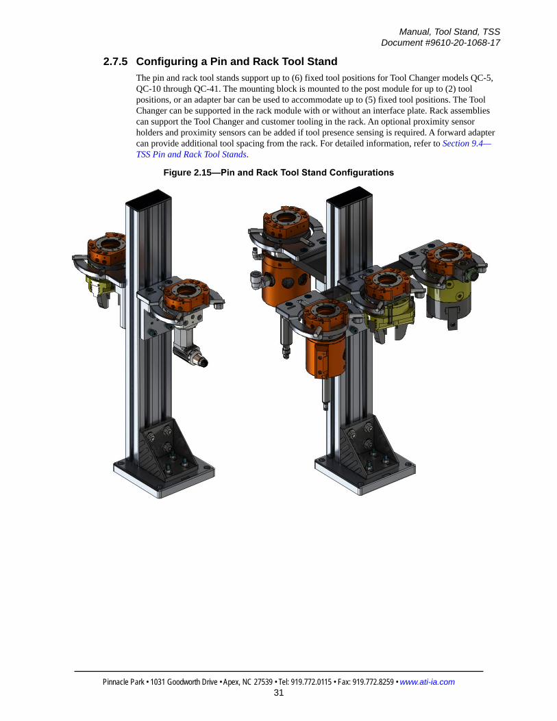
2.7.5 Configuring a Pin and Rack Tool StandThe pin and rack tool stands support up to (6) fixed tool positions for Tool Changer models QC‑5, QC‑10 through QC‑41. The mounting block is mounted to the post module for up to (2) tool positions, or an adapter bar can be used to accommodate up to (5) fixed tool positions. The Tool Changer can be supported in the rack module with or without an interface plate. Rack assemblies can support the Tool Changer and customer tooling in the rack. An optional proximity sensor holders and proximity sensors can be added if tool presence sensing is required. A forward adapter can provide additional tool spacing from the rack. For detailed information, refer to Section 9.4—TSS Pin and Rack Tool Stands.
Figure 2.15—Pin and Rack Tool Stand Configurations

Manual, Tool Stand, TSSDocument #9610-20-1068-17
Pinnacle Park • 1031 Goodworth Drive • Apex, NC 27539 • Tel: 919.772.0115 • Fax: 919.772.8259 • www.ati-ia.com32
3. InstallationThe Tool Stand is shipped unassembled. The customer must perform the final assembly and determine the proper location for the Tool Stand.
CAUTION: Improper cable routing can result in wires and cables being pinched in the joint between the Tool Changer plates and premature failure of the electrical connectors. Properly route and secure all cables, particularly on the Master side.
CAUTION: Thread locker applied to fasteners must not be used more than once. Fasteners might become loose and cause equipment damage. Always apply new thread locker when reusing fasteners.
3.1 Assembling the Post ModuleTools required: 6 mm and 10 mm hex key, 13 mm socket wrench, torque wrench, flat head screwdriverThe post module can be ordered assembled or unassembled. Use the following steps to assemble and mount the post module.
1. Determine the proper location and configuration of your Tool Stand. Assemble the base, rail and gusset assemblies prior to anchoring the TSS base.
2. Assemble the gusset to the rail by inserting the T‑bolts into the T‑Slots in the rail and turning the T‑bolts 90°. Note: Tabs must be removed from the gusset assembly to allow flush contact to base assembly. For more information, see Section 9.5—Post Modules.
NOTICE: 45x90 Rails require (2) M12 socket head screws to fasten to the base. 90x90 Rails require (4) M12 socket head cap screws to fasten to the base.
3. Assemble the rail to the base using a 10 mm hex key and (2) or (4) M12 socket head cap screws. for specific details on torque and thread locking requirements, refer to Section 9.5—Post Modules.
4. Insert the (4) M8 socket head cap screw through the base and gusset. Secure using the M8 flat washer and nut. Tighten the nut on the T‑bolts holding the gusset to the rail. For specific details on torque and thread locking requirements, refer to Section 9.5—Post Modules.

Manual, Tool Stand, TSSDocument #9610-20-1068-17
Pinnacle Park • 1031 Goodworth Drive • Apex, NC 27539 • Tel: 919.772.0115 • Fax: 919.772.8259 • www.ati-ia.com33
Figure 3.1—Installing Base, Rail, and Gusset Assemblies
5. Anchor the base assembly to a smooth flat surface using the (4) 13 mm through‑holes provided (hardware not included).
6. To continue the installation, refer to the following sections: Section 3.2—Installing TSS Tool Stands for QC‑001 Section 3.3—Installing TSS Pin and Bushing Tool Stands Section 3.4—Installing TSS Tool Stands with Slotted Mounting Modules Section 3.5—Installing Hook and Hanger Modules Section 3.6—Installing TSS Pin and Rack Tool Stands

Manual, Tool Stand, TSSDocument #9610-20-1068-17
Pinnacle Park • 1031 Goodworth Drive • Apex, NC 27539 • Tel: 919.772.0115 • Fax: 919.772.8259 • www.ati-ia.com34
3.2 Installing TSS Tool Stands for QC-001Tools required: 2.5 mm and 5 mm hex key, torque wrench
1. Refer to the drawing for the model being assembled in Section 9.6.1—TSS Tool Stand for QC‑001. The drawings will provide torque, thread locking, and other specific requirements.
2. Assemble the horizontal module to the post module by inserting the T‑bolts into the T‑slot in the post module. Turn the T‑bolts 90°.
3. Adjust the height of the horizontal module to accommodate the tooling for the application and tighten the nuts on the T‑bolts to secure the vertical position of the rail.
4. Remove the horizontal module end cap and assemble the mounting module to the horizontal module by sliding the T‑nuts into the horizontal module.
5. Install additional mounting modules if needed.6. Position the horizontal module and the mounting modules to accommodate the tool spacing desired and
tighten the T‑bolts for the horizontal position of the rail. Using a 5 mm hex key, tighten the M8 button head cap screws to secure the mounting modules.
7. Replace the end cap on the horizontal module.8. If equipped, install the optional photoelectric sensor to the mounting module. Refer to Section 3.2.1—
Installing Proximity Sensors for QC‑001.
Figure 3.2—Installing TSS Tool Stand for QC-001

Manual, Tool Stand, TSSDocument #9610-20-1068-17
Pinnacle Park • 1031 Goodworth Drive • Apex, NC 27539 • Tel: 919.772.0115 • Fax: 919.772.8259 • www.ati-ia.com35
3.2.1 Installing Proximity Sensors for QC-001Tools required: 2.5 mm hex keySupplies required: Loctite 222
1. Apply Loctite 222 or similar to the M3 socket head cap screw used to mount the proximity sensor.
2. Attach the sensor cable to the proximity sensor.3. Using a 2.5 mm hex key, tighten the (2) M3 socket head cap screws so that the sensor is loosely
secured to the QC‑001.4. Using a sheet of paper as a guide, position the sensor so that the laser hits the post of the Tool
Changer, as shown in Figure 3.3.5. Tighten the M3 socket head cap screws until contact. Tighten ¼ turn.
CAUTION: Do not over tighten M3 screws. Over tightening the screws can damage the sensor. Tighten the screw until contact. Then tighten ¼ turn.
Figure 3.3—Adjusting QC-001 Proximity Sensors
3.3 Installing TSS Pin and Bushing Tool StandsRefer to Figure 3.4.Tools required: 6 mm hex key, 2.5 mm hex key for the Tool Stand Hanger Module, torque wrench
1. Refer to drawing for the model being assembled in Section 9.1—TSS Pin and Bushing Tool Stands. The drawings provide torque, thread locking, and other specific requirements.
2. Assemble the horizontal module to the post module by inserting the T‑bolts into the T‑slot in the post module. Turn the T‑bolts 90°.
3. Adjust the height of the horizontal module to accommodate the tooling for the application and tighten the nuts on the T‑bolts to secure the vertical position of the rail.
4. Remove the horizontal module end cap and assemble the mounting module or single pin mounting module to the horizontal module by sliding the T‑nuts into the horizontal module.
5. Install additional mounting modules or single pin mounting modules if needed.

Manual, Tool Stand, TSSDocument #9610-20-1068-17
Pinnacle Park • 1031 Goodworth Drive • Apex, NC 27539 • Tel: 919.772.0115 • Fax: 919.772.8259 • www.ati-ia.com36
6. Position the horizontal module and the mounting modules to accommodate the tool spacing desired and tighten the T‑bolts for the horizontal position of the rail. Tighten the M8 socket head cap screws to secure the mounting modules using a 6 mm hex key.
7. Replace the end cap on the horizontal module.
Figure 3.4—Installing TSS Pin and Bushing Tool Stand
8. If equipped, install the optional proximity sensor. • For a mounting module, refer to Section 3.3.1—Installing a Proximity Sensor on Mounting Modules.
9. If equipped, install the optional clamp assembly to the mounting module, Refer to Section 3.3.2—Installing Clamp Modules.
NOTICE: If the tooling interface plate is a blank tool plate, it must be machined with a mounting pattern that matches customer tooling. Refer to the manual for the specific Tool Changer model (http://www.ati-ia.com/products/toolchanger/tool_changer_models.aspx).
10. Assemble the customer tooling and Tool Changer to the tooling interface plate. 11. Place on the mounting module.

Manual, Tool Stand, TSSDocument #9610-20-1068-17
Pinnacle Park • 1031 Goodworth Drive • Apex, NC 27539 • Tel: 919.772.0115 • Fax: 919.772.8259 • www.ati-ia.com37
3.3.1 Installing a Proximity Sensor on Mounting ModulesTools required: 2.5 mm hex keySupplies required: Loctite 222
1. Apply Loctite 222 or similar to the M3 socket head cap screw used to mount the proximity sensor.
2. Attach the sensor cable to the proximity sensor and slide the proximity sensor into the holder as shown in Figure 3.5.
3. Tighten the M3 socket head cap screw using a 2.5 mm hex key until the mount loosely secures the sensor (Sensor should freely move up and down in the holder).
4. Position the sensor so the sensor face is 0.030” below the top surface of the mounting module as shown in Figure 3.5.
5. Tighten the M3 socket head cap screw until contact. Then tighten ¼ turn.
CAUTION: Do not over tighten M3 screw. Over tightening the screw can damage the sensor. Tighten the screw until contact. Then tighten ¼ turn.
Figure 3.5—Proximity Sensor Position
Proximity Sensor
Sensor Cable
Proximity SensorHolder
M3 Socket Head Cap ScrewTop Surface of Mounting Module
Adjust to .030"Below Top Surfaceof Mounting Module

Manual, Tool Stand, TSSDocument #9610-20-1068-17
Pinnacle Park • 1031 Goodworth Drive • Apex, NC 27539 • Tel: 919.772.0115 • Fax: 919.772.8259 • www.ati-ia.com38
3.3.2 Installing Clamp ModulesTools required: 3 mm hex key, small flat screwdriver, torque wrenchThe clamp module is shipped unattached. Some adjustment may be necessary depending on the application. If needed, the clamp module can be mounted on the opposite side to orient the cylinder air supply ports on the inside of the tool stand, the adjustable arm will need to be rotated 180°.
1. Refer to the drawing in Section 9.3.1—TSS Clamp Module, Right Hand or Section 9.3.2—TSS Clamp Module, Left Hand for details on torque, thread locking, and other specific requirements.
2. If needed adjust the clamping screw. With the rotary actuator in the locked position, loosen the lock nut. Adjust the clamping screw until it extends 13 mm (0.51”) from the adjustable arm. Tighten the lock nut. Refer to the drawing for details.
3. Assemble the clamp module to the mounting module, using the (3) M4 socket head cap screws provided and a 3 mm hex key. Tighten to 25 in‑lbs (2.82 Nm).
4. Attach the lock and unlock air supply to the M5 (¼ turn) air connections. Note: It is recommended to appropriately exhaust the cylinder air in order to allow the cylinder piston to spring back.
Figure 3.6—Install Clamp Module
Right HandClamp Module
Left HandClamp Module
(3) M4 Socket Head Cap Screw
(3) M4 Socket Head Cap Screw
Unlock M5 1/4 turn Air Fitting
Lock M5 1/4 turn Air Fitting
Adjustable Arm
Mounting Module
13 mm (0.51")
Clamping ScrewLock Nut
5. Install the actuator sensors, if not already installed. Slide the sensor into the track as shown. Refer to the drawing in Section 9.3.1—TSS Clamp Module, Right Hand or Section 9.3.2—TSS Clamp Module, Left Hand for details on torque, thread locking, and other specific requirements.a. Position the sensors to the reference dimension shown in Figure 3.7.
b. Secure the sensor in the track by tightening the set screw with a small flat head screw driver (jewelers small). Tighten to 1.0 in‑lbs (0.11 Nm). Do not over‑tighten.
c. Label the ends of the sensor cables as shown on the drawing. Route and connect the sensor cables.
d. Cycle the cylinder both extending and retracting a number of times to confirm the correct operation and sensor placement. Adjust the sensor position as desired.

Manual, Tool Stand, TSSDocument #9610-20-1068-17
Pinnacle Park • 1031 Goodworth Drive • Apex, NC 27539 • Tel: 919.772.0115 • Fax: 919.772.8259 • www.ati-ia.com39
Figure 3.7—Clamp Module Sensor Installation
12 mm (0.47") Ref
29.5 mm(1.16") Ref
Unlock Sensor
Set Screw
Lock Sensor
3.4 Installing TSS Tool Stands with Slotted Mounting ModulesTools required: 3 mm and 5 mm hex key, torque wrenchRefer to the drawing for the model being assembled in Section 9.6—TSS Slotted Mounting Modules. The drawings provide torque, thread locking, and other specific requirements.
1. Assemble the horizontal module to the post module by inserting the T‑bolts into the T‑slot in the post module. Turn the T‑bolts 90°.
2. Adjust the height of the horizontal module to accommodate the tooling for the application and tighten the nuts on the T‑bolts to secure the vertical position of the rail.
3. Remove the horizontal module end cap.4. Orient the slotted mounting module either horizontally or vertically. If using the horizontal configuration,
use (2) M8 button head cap screws and T‑nuts. If using the vertical configuration, use either (4) or (2) M8 button head cap screws and T‑nuts, depending on the required sensor configuration. For example, if installing a barrel sensor in the vertical orientation, use (2) M8 button head cap screws and T‑nuts in order to provide adequate clearance for the sensor. See Figure 3.8.
5. Adjust the TSS holding plate kit according to the orientation. See the drawing in Section 9.6—TSS Slotted Mounting Modules.
6. Assemble the slotted mounting module to the horizontal module by sliding the T‑nuts into the horizontal module.
7. Install additional mounting modules if needed.8. Adjust the slotted mounting module to the desired position and tighten the M8 button head cap screws
using a 5 mm hex key.9. Replace the end caps on the post module and horizontal module.

Manual, Tool Stand, TSSDocument #9610-20-1068-17
Pinnacle Park • 1031 Goodworth Drive • Apex, NC 27539 • Tel: 919.772.0115 • Fax: 919.772.8259 • www.ati-ia.com40
10. If equipped, install optional proximity sensors to the slotted mounting module. • For barrel sensors (QC‑11), refer to Section 3.4.1—Installing Barrel Sensors on TSS Tool
Stands with Slotted Mounting Modules. • For photoelectric sensors (QC‑7), refer to Section 3.4.2—Installing Proximity Sensors for
QC‑7 Slotted Mounting Module.11. Assemble the customer tooling and Tool Changer to the tooling interface plate. 12. Place the Tool Changer Tool side on the slotted mounting module.
Figure 3.8—Installing TSS Tool Stands with Slotted Mounting Modules (QC-11 Shown)
End CapEnd Cap
End Cap
Post Module
Horizontal Module
T-Slot
T-Bolt
T-NutSlotted Mounting Module
Slotted MountingModule
Tool Changer Tool Side(QC-11 shown)
Tool Changer Tool Side(QC-11 shown)
Barrel Sensor

Manual, Tool Stand, TSSDocument #9610-20-1068-17
Pinnacle Park • 1031 Goodworth Drive • Apex, NC 27539 • Tel: 919.772.0115 • Fax: 919.772.8259 • www.ati-ia.com41
NOTICE: When working with air fittings, position fittings to avoid contact with the slotted mounting module or the Tool Stand. Refer to Figure 3.9.
Figure 3.9—Tool Changer with Air Fittings routed (QC-11 Shown)
QC-11 Masterand Tool
Slotted Mounting Module
Air Fittings with adequate clearance (9.5 mm between center of fitting and Slotted Mounting Module) and routed to avoid contact with Tool Stand
Figure 3.10—Installing TSS Tool Stands with QC-7 Slotted Mounting Modules
End Cap
Slotted Mounting Module(horizontal position)
QC-7 Tool side
End Cap
QC-7 Tool side
(2) T-nuts
T-slot
Horizontal Module
Post Module
T-bolt
T-slot
Slotted Mounting Module(vertical position)
(2) T-nuts

Manual, Tool Stand, TSSDocument #9610-20-1068-17
Pinnacle Park • 1031 Goodworth Drive • Apex, NC 27539 • Tel: 919.772.0115 • Fax: 919.772.8259 • www.ati-ia.com42
NOTICE: When working with air fittings, position fittings to avoid contact with the slotted mounting module or the Tool Stand (refer to Figure 3.9).
Figure 3.11—QC-7 Tool Changer with Air Fittings routed
QC-7 Master and Tool
Slotted Mounting Module
Air fittings with adequate clearanceand routed to avoid contact with the Tool Stand.

Manual, Tool Stand, TSSDocument #9610-20-1068-17
Pinnacle Park • 1031 Goodworth Drive • Apex, NC 27539 • Tel: 919.772.0115 • Fax: 919.772.8259 • www.ati-ia.com43
3.4.1 Installing Barrel Sensors on TSS Tool Stands with Slotted Mounting ModulesTools required: (2) 24 mm wrenchSlotted mounting modules have sensor mounts that can accommodate most 8 mm barrel sensors. To install barrel sensors to slotted mounting modules, complete the following steps.
1. Mount the slotted mounting module using (2) M8 button head cap screws and T‑nuts. Refer to Section 3.4—Installing TSS Tool Stands with Slotted Mounting Modules.
2. Insert the barrel sensor into the sensor mount on the slotted mounting module, as shown in Figure 3.12.
3. Adjust the barrel sensor face 0.19” (4.5 mm) from the target, as shown in Figure 3.13.4. Tighten the jam nuts finger tight and attach the sensor cable.5. Cycle the Tool pick‑up and drop off, and adjust the sensor position accordingly. 6. Tighten the jam nuts using 24 mm wrenches.
Figure 3.12—Installing Barrel Sensors to Slotted Mounting Modules
Locking Nut
Locking Nut
Washer
Washer
Sensor Mount
8 mm Barrel
Sensor Cable
Sensor
Figure 3.13—Adjusting Barrel Sensors
0.19” (4.5 mm)
QC-11 (Shown)
Barrel Sensor
Slotted MountingModule

Manual, Tool Stand, TSSDocument #9610-20-1068-17
Pinnacle Park • 1031 Goodworth Drive • Apex, NC 27539 • Tel: 919.772.0115 • Fax: 919.772.8259 • www.ati-ia.com44
3.4.2 Installing Proximity Sensors for QC-7 Slotted Mounting Module
Parts required: Refer to Section 2.2.5—Photoelectric Proximity Sensors.Tools required: 2 mm hex key, torque wrench
NOTICE: The proximity sensor can only be installed as shown in Figure 3.14.
1. Position the sensor so that the holes in the sensor align with the holes in slotted mounting module.
2. Use a 2 mm hex key to install the (2) M3 button head cap screws into the sensor and slotted mounting module. Tighten to 0.68 Nm (6 in‑lbs).
3. Connect the sensor connector to the appropriate connection on a control/signal module on the Tool.
4. Safely resume normal operation.
Figure 3.14—Installing Photoelectric Proximity Sensor for QC-7
(2) M3 Button Head Cap Screw
Photoelectric Proximity Sensor
Slotted Mounting Module
(screws included)

Manual, Tool Stand, TSSDocument #9610-20-1068-17
Pinnacle Park • 1031 Goodworth Drive • Apex, NC 27539 • Tel: 919.772.0115 • Fax: 919.772.8259 • www.ati-ia.com45
3.5 Installing Hook and Hanger ModulesTools required: 3 mm and 6 mm hex key, torque wrenchRefer to the drawing for the model being assembled in Section 9.4—TSS Pin and Rack Tool Stands. The drawings provide torque, thread locking, and other specific requirements.
1. Install the tool hook module on Flat B of the QC‑7 tool plate.a. Use a 3 mm hex key to install the (4) M4 socket head cap screws into the Tool hanger and QC‑7
Tool plate.
b. Tighten the fasteners to 5 Nm (44.25 in‑lbs).
Figure 3.15—Install the Tool Hanger Module on the QC-7
Flat B onthe QC-7 Tool Plate
(9120-007DT-0-0 shown)
Hook Module
(4) M4 Socket HeadCap Screw
2. Install the post hanger and rail adapter module on the horizontal module.a. Remove the end cap from one end of the horizontal module.
b. Slide the T‑nuts of the post hanger and rail adapter module through the slot in the horizontal module.
c. Use a 6 mm hex key to tighten the M8 socket head cap screws to secure the rail adapter plate to the horizontal module.
d. Tighten to 21.5 Nm (15.8 ft‑lbs).
Figure 3.16—Install the Post Hanger and Rail Adapter Module
(2) M8 SocketHead Cap Screw
End Cap
Slots in Horizontal Module
(2) T-nut
Rail Adapter plate
Back View Front View

Manual, Tool Stand, TSSDocument #9610-20-1068-17
Pinnacle Park • 1031 Goodworth Drive • Apex, NC 27539 • Tel: 919.772.0115 • Fax: 919.772.8259 • www.ati-ia.com46
3.5.1 (Optional) Install the Post Hanger Module to a Flat SurfaceThe post hanger module can also be mounted on a flat surface, if a Tool Stand is not applicable to the application.Parts required: (2) M5 Dowel pins (refer to Figure 3.17)Tools required: 4 mm hex key, torque wrenchSupplies required: Loctite 242
1. Insert (2) M5 dowel pins in the back of the post hanger module.2. Apply Loctite 242 to the threads of the M5 socket head cap screws.3. Use a 4 mm hex key to install the (4) M5 socket head cap screws and secure the post hanger to
the flat surface. Tighten to 6 Nm (53.1 in‑lbs).
Figure 3.17—Post Hanger Mounting Pattern
4X M5X0.8 11.9
2X 5.0605.034 6.1
for (2) M5 dowel pin
19.1
19.1
9.5
(dowel pins not included)
for (4) M5 socket headcap screw

Manual, Tool Stand, TSSDocument #9610-20-1068-17
Pinnacle Park • 1031 Goodworth Drive • Apex, NC 27539 • Tel: 919.772.0115 • Fax: 919.772.8259 • www.ati-ia.com47
3.5.2 Installing Proximity Sensors for QC-7 Hook and Hanger Module
Parts required: Refer to Section 2.3.4—Proximity Sensors.Tools required: 2 mm hex key, torque wrench
1. Position the sensor so that the sensor M3 hole algin with one of the M3 holes post hanger and rail adapter module.
2. Use a 2 mm hex key to install the M3 flat head cap screw into the sensor and post hanger module. Tighten to 0.68 Nm (6 in‑lbs).
3. Connect the sensor connector to the appropriate connection on a control/signal module on the Tool.
4. Safely resume normal operation.
Figure 3.18—Installing Proximity Sensor for QC-7 Hook and Hanger Module
M3 socket flathead cap screw
Sensor
Hanger
Post
If installing the cable up, install the M3 socket headscrew in the top hole.
If installing the cable down,install the M3 socket headscrew in the bottom hole.

Manual, Tool Stand, TSSDocument #9610-20-1068-17
Pinnacle Park • 1031 Goodworth Drive • Apex, NC 27539 • Tel: 919.772.0115 • Fax: 919.772.8259 • www.ati-ia.com48
3.6 Installing TSS Pin and Rack Tool StandsTools required: 3 mm and 6 mm hex key, torque wrenchRefer to the drawing for the model being assembled in Section 9.4—TSS Pin and Rack Tool Stands. The drawings provide torque, thread locking, and other specific requirements.
1. Remove the post module end cap and slide the T‑nuts out of the T‑Slots. Attach the T‑nuts to the mounting block using the M8 socket head cap screws provided with a 6 mm hex key. Refer to Figure 3.19.
2. Assemble the mounting block to the rail by sliding the T‑nuts into the T‑Slots in the rail. 3. Adjust the height of the mounting block to accommodate the tooling for the application and tighten the
M8 socket head cap screws using a 6 mm hex key. 4. Replace the end cap on the post module.5. Attach the tool bar or forward adapter and the center rack module to the mounting block using the M8
socket head cap screws provided with the adapter bar and a 6 mm hex key.6. If a tool bar is being used, attach the additional rack modules to the adapter bar using the M8 socket head
cap screws provided with the rack modules and a 6 mm hex key.7. Install the mounting to the Tool Changer:• If an interface plate is being used, attach the interface plate to the Tool side of the Tool Changer and
place in the rack.
• If no interface plate is being used, perform the following steps:
a. Attach the alignment pin to the appropriate air ports on the tool side of the Tool Changer.
b. If a pin block is required, attach the pin block to Flat B of the tool side of the Tool Changer using the M4 socket head cap screws provided and a 3 mm hex key.
c. Attach the alignment pin to the pin block.
d. Place the Tool Changer in the rack.

Manual, Tool Stand, TSSDocument #9610-20-1068-17
Pinnacle Park • 1031 Goodworth Drive • Apex, NC 27539 • Tel: 919.772.0115 • Fax: 919.772.8259 • www.ati-ia.com49
Figure 3.19—Installing TSS Pin and Rack Tool Stand
8. If equipped, install the optional sensor holder and proximity sensor; refer to Section 3.6.1—Installing Proximity Sensors for TSS Pin and Rack Tool Stands.

Manual, Tool Stand, TSSDocument #9610-20-1068-17
Pinnacle Park • 1031 Goodworth Drive • Apex, NC 27539 • Tel: 919.772.0115 • Fax: 919.772.8259 • www.ati-ia.com50
3.6.1 Installing Proximity Sensors for TSS Pin and Rack Tool StandsTools required: 2.5 mm hex keySupplies required: Loctite 222
1. Apply Loctite 222 or similar to the (2) M3 socket head cap screws used to mount the proximity sensor holder.
2. Attach the proximity sensor holder to the adapter bar or forward adapter using the (2) M3 socket head cap screws and a 2.5 mm hex key. Tighten to 6 in‑lbs (0.68 Nm).
3. Attach sensor cable to the proximity sensor and slide the proximity sensor into the holder as shown in Figure 3.20.
4. Gently tighten the M3 socket head cap screw (adjustment screw) until the sensor holder loosely secures the sensor (Sensor should still move up and down in holder).
5. Position the sensor so the sensor face is 0.030” above the bottom surface of the “V” groove as shown in Figure 3.20.
6. Tighten the M3 socket head cap screws (adjustment screw) (Contact plus ¼ turn).
CAUTION: Do not over tighten M3 screw. Over tightening the screw can damage the sensor. Tighten the screw until contact. Then tighten ¼ turn.
Figure 3.20—Proximity Sensor Position
Proximity Sensor
Sensor Cable
Proximity Sensor Holder(2) M3 Socket Head Cap Screw
Bottom of "V" Groove
Adjust the sensor face .030" above the bottom of the "V" groove
M3 Socket Head Cap ScrewAdjustment Screw

Manual, Tool Stand, TSSDocument #9610-20-1068-17
Pinnacle Park • 1031 Goodworth Drive • Apex, NC 27539 • Tel: 919.772.0115 • Fax: 919.772.8259 • www.ati-ia.com51
4. OperationThe ATI TSS Tool Stand is intended for use with No‑touch locking Tool Changers only, such as ATI changers QC‑001 through QC‑41.
4.1 TSS Tool Stands for QC-001 OperationCAUTION: Damage will occur if contact is made between the TSS Tool plate assembly and the Tool Changer prior to tool drop‑off.
For proper tool drop‑off, ATI recommends 3.4 mm (.134”) maximum distance from the top surface of the tool plate assembly and the top surface of the tool side of the Tool Changer. See Figure 4.14 for reference.
Figure 4.1—TSS Tool Stand for QC-001 Maximum Clearance for Proper Tool Drop-off

Manual, Tool Stand, TSSDocument #9610-20-1068-17
Pinnacle Park • 1031 Goodworth Drive • Apex, NC 27539 • Tel: 919.772.0115 • Fax: 919.772.8259 • www.ati-ia.com52
4.2 TSS Tool Stands for Hook and Hanger Modules (QC-7)CAUTION: Damage will occur if cables and hoses are not properly secured and routed away from the tool hook module. Route lock/unlock cables, pneumatic hoses, and additional cables away from where the hook rests in the hanger post module so that cables and hoses do not become tangled in the Tool Stand.
4.2.1 Operation SequenceAs the tool hook module approaches the hanger post module, use the vertical and horizontal approach markings to correctly drop off the Tool plate assembly.
Figure 4.2—Approach Alignment Marks on the Tool Hook and Hanger Post
Horizontal ApproachAlignment Marks
Vertical ApproachAlignment Mark
Hanger Post and Rail Adapter Module
Tool Hook
4.2.1.1 Tool Drop-Off1. Move the Tool plate and Tool Hook downward until the vertical alignment mark is
even with the edge of the post hanger module.
Figure 4.3—Align Vertical Approach Alignment Marks
The veritcal approach markaligns with the top edge of thepost hanger module.

Manual, Tool Stand, TSSDocument #9610-20-1068-17
Pinnacle Park • 1031 Goodworth Drive • Apex, NC 27539 • Tel: 919.772.0115 • Fax: 919.772.8259 • www.ati-ia.com53
2. Move the robot so that the horizontal approach marks on the tool hook module align with the marks on the post hanger module.
Figure 4.4—Align Horizontal Approach Alignment Marks
Align the horizontal marks.
3. Lower the tool hook module until the hook rests in the post hanger.
Figure 4.5—Tool Hook Placed in the Post Hanger
4.2.2 PayloadFor a Tool Stand with a hook and hanger module configuration, both the safe zones for different payloads and the distance of their center of gravity from the hook and hanger modules are shown in Figure 4.6 and Figure 4.7. If the center of gravity for the Tool plate, modules, and customer tooling is out side of the zone for the respective payload, then the user should contact ATI for assistance in configuring a Tool Stand.

Manual, Tool Stand, TSSDocument #9610-20-1068-17
Pinnacle Park • 1031 Goodworth Drive • Apex, NC 27539 • Tel: 919.772.0115 • Fax: 919.772.8259 • www.ati-ia.com54
Figure 4.6—Maximum Allowable Offset for QC-7 Hook and Hanger (Imperial Units)
35 lbm
25 lbm
20 lbm
15 lbm
10 lbm
0
1
2
3
4
5
6
0 1 2 3 4 5 6 7 8 9 10 11 12
Ly (in)
Lx (in)
QC‐7 Hook and Hanger Tool Stand, Maximum Allowable Offset for Tooling Center of Gravity
Figure 4.7—Maximum Allowable Offset for QC-7 Hook and Hanger (Metric Units)
16 kg
11 kg9 kg
6.5 kg
4.5 kg
0
20
40
60
80
100
120
140
160
0 50 100 150 200 250 300
Ly (m
m)
Lx (mm)
QC‐7 Hook and Hanger Tool Stand, Maximum Allowable Offset for Tooling Center of Gravity

Manual, Tool Stand, TSSDocument #9610-20-1068-17
Pinnacle Park • 1031 Goodworth Drive • Apex, NC 27539 • Tel: 919.772.0115 • Fax: 919.772.8259 • www.ati-ia.com55
4.3 TSS Tool Stands with QC-7 Slotted Mounting ModulesCAUTION: Damage will occur if contact is made between the TSS slotted mounting module and the Tool Changer prior to tool drop‑off.
For proper tool drop‑off, ATI recommends the distances in the following figure.
Figure 4.8—Slotted Mounting Module Maximum Clearance for Tool Drop-off
0.55 in (1.4 mm) from top surface of the slotted mounting module to the top surface of the Tool Changer.
The surface of the Tool is flush with the slotted plate module.
Tool positioned for storage Tool raised for movement in or out of the slotted mounting module.
When the Tool is in the mounting module, it has the range of movement listed in the following figure or drawing (refer to Section 9.6.2—TSS Tool Stand for QC‑7). Uneven weight distribution can cause the Tool Changer to sit unevenly in the mounting module.
Figure 4.9—Tool Changer Seated Unevenly in Mounting Module
The Tool can rock or leanbecause of uneven loads.
2.1°
The Tool can rock or leanbecause of uneven loads.
1.6°
Side-to-Side Tilt Front-to-Back Tilt
4.3.1 PayloadFor a Tool Stand with a slotted tool nest configuration, both the safe zones for different payloads and the distance of their center of gravity from the slotted mounting module are shown in Figure 4.10 and Figure 4.11. If the center of gravity for the Tool plate, modules, and customer tooling is out side of the zone for the respective payload, then the user should contact ATI for assistance in configuring a Tool Stand.

Manual, Tool Stand, TSSDocument #9610-20-1068-17
Pinnacle Park • 1031 Goodworth Drive • Apex, NC 27539 • Tel: 919.772.0115 • Fax: 919.772.8259 • www.ati-ia.com56
Figure 4.10—Maximum Allowable Offset for QC-7 Slotted Tool Stand (Imperial Units)
15.4 lbm*
11 lbm*
8.8 lbm*
6.6 lbm*
4.4 lbm*
0
0.5
1
1.5
2
2.5
3
3.5
4
4.5
0 1 2 3 4 5 6 7 8 9
Ly (in)
Lx (in)
QC‐7 Slotted Tool Stand, Maximum Allowable Offset for Tooling Center of Gravity
35lbm
* For payloads stored in the horizontal tool stand orientation, the QC Tool will tilt after drop‐off if the tooling's center of gravity is offset greater than 0.375" in the X‐ or Y‐direction.
Figure 4.11—Maximum Allowable Offset for QC-7 Slotted Tool Stand (Metric Units)
7 kg*
5 kg*
4 kg*
3 kg*
2 kg*
0
20
40
60
80
100
120
0 50 100 150 200 250
Ly (m
m)
Lx (mm)
QC‐7 Slotted Tool Stand, Maximum Allowable Offset for Tooling Center of Gravity
* For payloads stored in the horizontal tool stand orientation, the QC Tool will tilt after drop‐off if the tooling's center of gravity is offset greater than 10mm in the X‐ or Y‐direction.
16kg

Manual, Tool Stand, TSSDocument #9610-20-1068-17
Pinnacle Park • 1031 Goodworth Drive • Apex, NC 27539 • Tel: 919.772.0115 • Fax: 919.772.8259 • www.ati-ia.com57
4.4 TSS Tool Stands with QC-11 Slotted Mounting ModulesCAUTION: Damage will occur if contact is made between the TSS slotted mounting module and the Tool Changer prior to tool drop‑off.
For proper tool drop‑off, ATI recommends 3.9 mm (.153”) maximum distance from the top surface of the Tool plate assembly and the top surface of the tool side of the Tool Changer. Refer to the following figure.
Figure 4.12—Slotted Mounting Module Maximum Clearance for Tool Drop-off
Top surface ofSlotted Mounting Module
3.9 mm (0.153”) from top surface of Slotted Mounting Module to
top surface of Tool Changer
Tool raised for movement in orout of the Slotted Mounting Module
Tool positioned for storage
Top surface of Tool Changer
2.54 mm (0.1”) from top surface of Slotted Mounting Module
to top surface of Tool Changer
The Tool Changer has 2° of movement when seated in the mounting module. Uneven weight distribution can cause the Tool Changer to sit unevenly in the mounting module. Refer to the following figure.
Figure 4.13—Tool Changer Seated Unevenly in Mounting Module
°2
Tool Changer can rock or lean due to uneven loads

Manual, Tool Stand, TSSDocument #9610-20-1068-17
Pinnacle Park • 1031 Goodworth Drive • Apex, NC 27539 • Tel: 919.772.0115 • Fax: 919.772.8259 • www.ati-ia.com58
4.5 TSS Pin and Bushing Tool Stand OperationCAUTION: Damage will occur if contact is made between the TSS Pin and Bushing Tooling Plate and the mounting module prior to tool drop‑off.
For proper tool drop‑off, ATI recommends 1 mm maximum clearance between mounting module contact surfaces and the tooling interface plate contact surface. See Figure 4.14 for reference.
Figure 4.14—TSS Pin and Bushing Tool Stands Maximum Clearance for Proper Tool Drop-off
4.6 TSS Pin and Rack Tool Stand Operation
CAUTION: Damage can occur if contact is made between the rack module and alignment pins prior to tool drop‑off.
For proper tool drop‑off, ATI recommends 1 mm maximum clearance gap between rack groove and alignment pins. See the following figure for reference:
Figure 4.15 TSS Pin and Rack Tool Stands Maximum Clearance for Proper Tool Drop-off

Manual, Tool Stand, TSSDocument #9610-20-1068-17
Pinnacle Park • 1031 Goodworth Drive • Apex, NC 27539 • Tel: 919.772.0115 • Fax: 919.772.8259 • www.ati-ia.com59
5. MaintenanceWARNING: Do not perform maintenance or repair(s) on the Tool Changer or modules unless the Tool is safely supported or placed in the tool stand, all energized circuits (e.g. electrical, air, water, etc.) are turned off, pressurized connections are purged and power is discharged from circuits in accordance with the customer’s safety practices and policies. Injury or equipment damage can occur with the Tool not placed and energized circuits on. Place the Tool in the tool stand, turn off and discharge all energized circuits, purge all pressurized connections, and verify all circuits are de‑energized before performing maintenance or repair(s) on the Tool Changer or modules.
It is recommended that the following areas are checked at least once every 100,000 cycles. Earlier intervention may be necessary if a problem is identified prior to the scheduled maintenance checks.
5.1 All TSS Tool StandsDuring regular use, components of the Tool Stand can become loose. Verify regularly that the following components are tight; tighten if necessary: • The Tool Stand base.
• The rail, gusset, and horizontal module(s).
• The mounting block.
• The proximity sensor holder and the proximity sensor.Other maintenance actions:• Inspect sensor cables and all utility lines for wear.
• Inspect and wipe clean all sensor faces to ensure proper function.
• Inspect the Tool Changer slot for signs of wear or damage from misalignment.
5.2 TSS Pin and Bushing Tool StandsDuring regular use, components of the Tool Stand can become loose. Verify regularly that the following components are tight; tighten if necessary:• The alignment pins. For the horizontal shoulder screw, re‑apply Loctite 242, and tighten
to 40 in‑lbs (4.52 Nm). For the center vertical peg, re‑apply Loctite 222 and tighten to 27 in‑lbs (3.05 Nm). For the single pin mounting module, tighten to 62 in‑lbs (7 Nm).
• The mounting modules and single pin nest. Apply Loctite 242 and tighten the M8 socket head cap screw to 150 in‑lbs (16.95 Nm), if required.
• The clamp cylinder. Tighten if necessary.Other maintenance actions:• Inspect sensor cables and all utility lines for wear.
• Inspect and wipe clean all sensor faces to ensure proper function.
• Inspect the alignment pins and bushings for cracks and wear. Replace if necessary.
• Lubricate the mounting module pins and bushing, see Figure 5.1 and Section 9—Drawings for details.
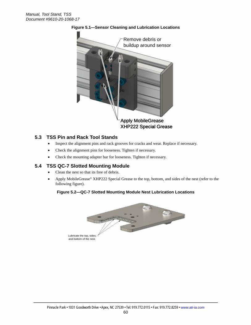
Manual, Tool Stand, TSSDocument #9610-20-1068-17
Pinnacle Park • 1031 Goodworth Drive • Apex, NC 27539 • Tel: 919.772.0115 • Fax: 919.772.8259 • www.ati-ia.com60
Figure 5.1—Sensor Cleaning and Lubrication Locations
Remove debris orbuildup around sensor
Apply MobileGreaseXHP222 Special Grease Apply MobileGreaseXHP222 Special Grease Apply MobileGreaseXHP222 Special Grease
5.3 TSS Pin and Rack Tool Stands• Inspect the alignment pins and rack grooves for cracks and wear. Replace if necessary.
• Check the alignment pins for looseness. Tighten if necessary.
• Check the mounting adapter bar for looseness. Tighten if necessary.
5.4 TSS QC-7 Slotted Mounting Module• Clean the nest so that its free of debris.
• Apply MobileGrease® XHP222 Special Grease to the top, bottom, and sides of the nest (refer to the following figure).
Figure 5.2—QC-7 Slotted Mounting Module Nest Lubrication Locations
Lubricate the top, sides,and bottom of the nest.

Manual, Tool Stand, TSSDocument #9610-20-1068-17
Pinnacle Park • 1031 Goodworth Drive • Apex, NC 27539 • Tel: 919.772.0115 • Fax: 919.772.8259 • www.ati-ia.com61
5.5 TSS QC-7 Hook and Hanger Module• Verify fasteners that secure the tool hook module to the Tool plate and the post hanger/rail
adapter module to the horizontal module are secure (refer to Section 3.5—Installing Hook and Hanger Modules).
• Verify components do not have excessive wear. If worn, replace.
• Verify that Tool Changer cables and hoses are not damaged. If damaged, replace.
• Verify that during operation, the Tool Changer cables and hoses are not becoming caught in the hook and hanger modules or tangling in the Tool Stand.
• Remove debris from and clean with a lint free cloth:
• the hook and hanger modules
• the proximity sensor installed on the post hanger module.
• Every 100, 000 cycles, lubricate the hook and hanger module per Section 5.5.1—Lubricate Hook and Hanger Module.

Manual, Tool Stand, TSSDocument #9610-20-1068-17
Pinnacle Park • 1031 Goodworth Drive • Apex, NC 27539 • Tel: 919.772.0115 • Fax: 919.772.8259 • www.ati-ia.com62
5.5.1 Lubricate Hook and Hanger ModuleParts required: Refer to Section 2.3—TSS Tool Stands with Hook and Hanger Mounting Modules
and Section 7—Serviceable Parts.Tools required: Snap ring pliersSupplies required: MobileGrease® XHP222 Special Grease
1. Apply MobileGrease® XHP22 Special Grease to all surfaces of the hook that contact the post hanger module.
Figure 5.3—Lubricate Hook
Lubricate the surfacesof the hook that contact the post hanger module.
2. Remove the pins from the post hanger module:a. Use snap ring pliers to remove the (4) retaining rings.
b. Remove the (2) pins.
3. Apply MobileGrease® XHP22 Special Grease to the (2) pins.4. Install the pins in the post hanger module:
a. Insert the pins into the post hanger module.
b. Install a retaining ring on each side of the pin.
Figure 5.4—Lubricate Pins and Retaining Rings
(2) pins (lubricate)
(4) retaining rings

Manual, Tool Stand, TSSDocument #9610-20-1068-17
Pinnacle Park • 1031 Goodworth Drive • Apex, NC 27539 • Tel: 919.772.0115 • Fax: 919.772.8259 • www.ati-ia.com63
6. TroubleshootingRefer to the following table for troubleshooting information:
Table 6.1—TroubleshootingSymptom Possible Cause Correction
Tool drop‑off location is not repeatable.
The Tool alignment pin(s) may be loose or missing.
Tighten or replace alignment pin(s), if necessary.
Tool Changer misaligned with mounting module.
Inspect the Tool Changer and slot for damage or signs of wear resulting from misalignment. Recalibrate if needed.
The proximity sensor fails.
Debris build up on the proximity sensor.
Check for debris build up and clean if necessary. Refer to Section 5—Maintenance.
The proximity sensor is loose or not positioned correctly.
Verify that the correct distance between the sensing face and the target is set. Verify that the sensor is aimed properly at the sensor target. Adjust if necessary. Refer to Section 3.2.1—Installing Proximity Sensors for QC-001 Section 3.3.1—Installing a Proximity Sensor on Mounting Modules Section 3.4.1—Installing Barrel Sensors on TSS Tool Stands with Slotted Mounting Modules Section 3.4.2—Installing Proximity Sensors for QC-7 Slotted Mounting Module Section 3.5.2—Installing Proximity Sensors for QC-7 Hook and Hanger Module Section 3.6.1—Installing Proximity Sensors for TSS Pin and Rack Tool Stands.
The sensor cable broken or damaged.
Inspect sensor cable for damage, test continuity, replace if damaged.
The proximity sensor damaged or not functioning.
Inspect the proximity sensor for damage, test sensor.
Tool/End Effector is malfunctioning.
Utility lines and cables are damaged.
Inspect utility lines and cables for damage or wear. Inspect all connections for damage. Test cable continuity. Replace any damaged utility lines and cables.
Tool Changer or utility modules are not functioning properly.
Verify Tool Changer and utility modules for proper function. Refer to the Tool Changer and module manual for troubleshooting.

Manual, Tool Stand, TSSDocument #9610-20-1068-17
Pinnacle Park • 1031 Goodworth Drive • Apex, NC 27539 • Tel: 919.772.0115 • Fax: 919.772.8259 • www.ati-ia.com64
7. Serviceable PartsThe following items are commonly used as spare parts for the TSS Tool Stand.
Other components are available upon request.
Model Part Number Name Used ForCommon TSS Tool Stand Components 9120‑TSS‑SM‑3315 Proximity Sensor
HolderClamp used to hold 8 mm barrel type proximity sensor.
TSS Pin and Bushing Tool Stands
3700‑20‑7130 Mounting Block Interface with TSS Plate.
3500‑2065050‑11
Socket Cap Shoulder Screw, 8 mm x 50 mm, M6 Thread, Steel
Used as alignment Pin for Tooling Plate.
3700‑20‑7124 Alignment Pin Used as alignment Pin for Tooling Plate (Beta Units use 3700‑20‑5056 or 3700‑20‑3303).
8590‑9909999‑75 Rotary Actuator Replacement Sensor
To detect lock or unlock Position (PNP 3‑Wire DC, Normally Open, 10‑30 VDC, comes with 2m cable).
3415‑0021022‑00 Rotary Actuator Clamp cylinder for mounting module (supplied with open/closed sensors).
3700‑20‑5756 Alignment Pin Mounting Module.
TSS Pin and Rack Tool Stands
3700‑20‑3303 Alignment Pin Interface with TSS Rack (M5 Thread)*.
3700‑20‑3316 Alignment Pin Interface with TSS Rack for QC‑21 Mounting Option #2 – Air Ports (NPT Thread).
3700‑20‑3320 Alignment Pin Interface with TSS Rack for QC‑21 Euro Mounting Option #2 – Air Ports (BSPP Thread).
TSS Hook and Hanger Tool Stands
3690‑5503200‑10 Pin (shaft)Used in the post hanger module for the hook module to rest. The post hanger requires (2) pins.
3690‑5400100‑10 Retaining Ring Used to secure the pin in the post hanger. (2) per pin.
7.1 Part Number Cross ReferenceThe TSS Tool Stand Part Numbers and Descriptions have been changed to provide a consistent numbering and naming scheme for all components of the Tool Stand system. The following tables provide a cross reference from the originally used Part Numbers to the current Part Numbers.
7.1.1 TSS Pin and Bushing Tool StandsSection 2.1.3—Mounting Modules
Original Part Number Current Part Number Description9120‑TSS‑MM‑7124 9120‑TSS‑MMB‑7124 Mounting Module
9120‑TSS‑MM‑7130 9120‑TSS‑MMB‑7130 Mounting Module
Section 2.1.5—Tooling Interface Plates9120‑TSS‑TP‑7123 9120‑TSS‑HBQ‑7123 Tooling Interface Plate for QC‑5,11‑Blank
9120‑TSS‑TP‑7851 9120‑TSS‑HBQ‑7851 Tooling Interface Plate for QC‑10‑Blank
9120‑TSS‑TP‑7392 9120‑TSS‑HBQ‑9483 Tooling Interface Plate for QC‑20,21‑Blank
9120‑TSS‑TP‑7539 9120‑TSS‑HBQ‑7539 Tooling Interface Plate for QC‑41‑Blank
Section 2.1.6—Vertical Tooling Interface Plates9120‑TSS‑TP‑7963 9120‑TSS‑VBB‑7963 Vertical Tooling Interface Plate‑Blank
9120‑TSS‑TP‑7190 9120‑TSS‑VBQ‑8026 Vertical Tooling Interface Plate‑J16 Pattern

Manual, Tool Stand, TSSDocument #9610-20-1068-17
Pinnacle Park • 1031 Goodworth Drive • Apex, NC 27539 • Tel: 919.772.0115 • Fax: 919.772.8259 • www.ati-ia.com65
7.1.2 TSS Pin and Rack Tool StandsSection 2.4.2—Tool Bars and Forward Adapter
Original Part Number
Current Part Number Description
9120‑TSS‑3361 9120‑TSS‑FA‑3361 TSS Forward Adapter Assembly
9120‑TSS‑3308 9120‑TSS‑TB‑3308 Tool Bar – 3 Position
9120‑TSS‑3431 9120‑TSS‑TB‑3431 Tool Bar – 4 Position
9120‑TSS‑3570 9120‑TSS‑TB‑3570 Tool Bar – 5 Position
Section 2.4.3—Mounting Module9120‑TSS‑3306 9120‑TSS‑MMA‑3306 Mounting Module
Section 2.4.4—Proximity Sensor Assembly and Proximity Sensors9120‑TSS‑3315 9120‑TSS‑SM‑3315 Proximity Sensor Assembly
Section 2.4.5—Rack Modules, Interface Plate Assemblies, Alignment Pins and Pin Blocks9120‑TSS‑3305 9120‑TSS‑MMV‑3305 Rack Module for QC‑20
9120‑TSS‑3310 9120‑TSS‑MMV‑3310 Rack Module for QC 10,11
9120‑TSS‑3312 9120‑TSS‑MMV‑3312 Rack Module for QC‑5
9120‑TSS‑3313 9120‑TSS‑MMV‑3313 Rack Module for QC 21, 21E
9120‑TSS‑4175 9120‑TSS‑MMV‑4175 Rack Module for QC‑41
9120‑TSS‑3314 9120‑TSS‑HVQ‑3314 Tool Interface Plate Assembly for QC‑5, 10,11
9120‑TSS‑3319 9120‑TSS‑HVQ‑3319 Tool Interface Plate Assembly for QC‑20, 21, 21E
9120‑TSS‑4174 9120‑TSS‑HVQ‑4174 Tool Interface Plate Assembly for QC‑21
7.1.3 TSS Tool Stand for the QC-001, QC-7, and QC-11Section 2.5.2—Horizontal Modules
Original Part Number
Current Part Number Description
9120‑TSS‑3394 9120‑TSS‑HM‑3362 Horizontal Module 300 mm (12”)
7.1.4 Post Module ComponentsSection 2.6.1—Post Modules (Complete Assembly)
Original Part Number
Current Part Number Description
9120‑TSS‑3311 9120‑TSS‑BA‑3311 Base Assembly
Section 2.6.3—Rail Assemblies9120‑TSS‑3362 9005‑20‑2225 Post Rail 300 mm (12”)
9120‑TSS‑1020 9005‑20‑2226 Post Rail 610 mm (24”)
9120‑TSS‑3324 9005‑20‑2227 Post Rail 914 mm (36”)
9120‑TSS‑3325 9005‑20‑2228 Post Rail 1220 mm (48”)
Section 2.6.4—Gusset Assembly9120‑TSS‑1030 9120‑TSS‑GA‑1030 Gusset

Manual, Tool Stand, TSSDocument #9610-20-1068-17
Pinnacle Park • 1031 Goodworth Drive • Apex, NC 27539 • Tel: 919.772.0115 • Fax: 919.772.8259 • www.ati-ia.com66
8. SpecificationsSpecifications for common components are included in the following sections.
8.1 Common TSS Tool Stand ComponentsPart Description Part Number Material Weight-MassTSS Base (for 45 x 90 rail) 9120‑TSS‑BA‑3311 T‑6 Aluminum 1.09 kg (2.4 lb)
TSS Base (for 90 x 90 rail) 9120‑TSS‑BA‑11435 T‑6 Aluminum 1.5 kg (3.3 lb)
TSS Proximity Sensor Holder 9120‑TSS‑SM‑3315 Black Nylon 0.0005 kg (.001 lb) TSS Gusset 9120‑TSS‑GA‑1030 Cast Aluminum, 90 x 90 3.08 kg (6.8 lb)
TSS Post Module Rail (45 x 90)TSS Rail, 300 mm (12”) long 9005‑20‑2225 Anodized T‑6 Extruded
Aluminum 0.91 kg (2.0 lb)
TSS Rail, 610 mm (24”) long 9005‑20‑2226 Anodized T‑6 Extruded Aluminum 1.86 kg (4.1 lb)
TSS Rail, 914 mm (36”) long 9005‑20‑2227 Anodized T‑6 Extruded Aluminum 2.79 kg (6.15 lb)
TSS Rail,1220 mm (48”) long 9005‑20‑2228 Anodized T‑6 Extruded Aluminum 3.72 kg (8.2 lb)
TSS Rail,1520 mm (60”) long 9005‑20‑2229 Anodized T‑6 Extruded Aluminum 4.63 kg (10.2 lb)
TSS Post Module Rail (90 x 90)
TSS Rail, 610 mm (24”) long 9005‑20‑3442 Anodized T‑6 Extruded Aluminum 3.86 kg (8.5 lb)
TSS Rail, 914 mm (36”) long 9005‑20‑3435 Anodized T‑6 Extruded Aluminum 5.81 kg (12.8 lb)
TSS Rail, 1220 mm (48”) long 9005‑20‑3436 Anodized T‑6 Extruded Aluminum 7.76 kg (17.1 lb)
TSS Rail, 1520 mm (60”) long 9005‑20‑3434 Anodized T‑6 Extruded Aluminum 9.66 kg (21.3 lb)
8.2 TSS Tool Stand for QC-001 ComponentsPart Description Part Number Material Weight-MassTSS Horizontal module 300 mm (12”) long 9120‑TSS‑HM‑3362 Anodized T‑6 Aluminum 1.47 kg (2.23 lb)
TSS Horizontal module 457 mm (18”) long 9120‑TSM‑HM‑3323 Anodized T‑6 Aluminum 1.95 kg (4.29 lb)
TSS Horizontal module 610 mm (24”) long 9120‑TSM‑HM‑1020 Anodized T‑6 Aluminum 2.41 kg (5.31 lb)
TSS Tooling Plate Assembly 9120‑TSS‑MM‑7869 18 Ga. Stainless Steel 0.14 kg (0.3 lb)
8.3 TSS Tool Stand for QC-7 Slotted Tool Stand ComponentsPart Description Part Number Material Weight-MassTSS Horizontal module 300 mm (12”) long 9120‑TSS‑HM‑3362 Anodized T‑6 Aluminum 1.01 kg (2.23 lb)
TSS Horizontal module 457 mm (18”) long 9120‑TSM‑HM‑3323 Anodized T‑6 Aluminum 1.95 kg (4.29 lb)
TSS Horizontal module 610 mm (24”) long 9120‑TSM‑HM‑1020 Anodized T‑6 Aluminum 2.41 kg (5.31 lb)
TSS Horizontal module 914 mm (36”) long 9120‑TSM‑HM‑3317 Anodized T‑6 Aluminum 3.33 kg (7.35 lb)
TSS Horizontal module 1220 mm (48”) long 9120‑TSM‑HM‑3325 Anodized T‑6 Aluminum 4.26 kg (9.39 lb)
TSS Tooling Plate Assembly 9120‑TSS‑MMS‑11345 Stainless Steel 0.41 kg (0.90 lb)
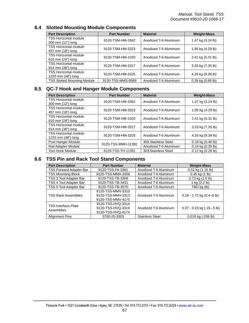
Manual, Tool Stand, TSSDocument #9610-20-1068-17
Pinnacle Park • 1031 Goodworth Drive • Apex, NC 27539 • Tel: 919.772.0115 • Fax: 919.772.8259 • www.ati-ia.com67
8.4 Slotted Mounting Module ComponentsPart Description Part Number Material Weight-MassTSS Horizontal module 300 mm (12”) long 9120‑TSM‑HM‑3362 Anodized T‑6 Aluminum 1.47 kg (3.24 lb)
TSS Horizontal module 457 mm (18”) long 9120‑TSM‑HM‑3323 Anodized T‑6 Aluminum 1.95 kg (4.29 lb)
TSS Horizontal module 610 mm (24”) long 9120‑TSM‑HM‑1020 Anodized T‑6 Aluminum 2.41 kg (5.31 lb)
TSS Horizontal module 914 mm (36”) long 9120‑TSM‑HM‑3317 Anodized T‑6 Aluminum 3.33 kg (7.35 lb)
TSS Horizontal module 1220 mm (48”) long 9120‑TSM‑HM‑3325 Anodized T‑6 Aluminum 4.26 kg (9.39 lb)
TSS Slotted Mounting Module 9120‑TSS‑MMS‑9589 Anodized T‑6 Aluminum 0.39 kg (0.85 lb)
8.5 QC-7 Hook and Hanger Module ComponentsPart Description Part Number Material Weight-MassTSS Horizontal module 300 mm (12”) long 9120‑TSM‑HM‑3362 Anodized T‑6 Aluminum 1.47 kg (3.24 lb)
TSS Horizontal module 457 mm (18”) long 9120‑TSM‑HM‑3323 Anodized T‑6 Aluminum 1.95 kg (4.29 lb)
TSS Horizontal module 610 mm (24”) long 9120‑TSM‑HM‑1020 Anodized T‑6 Aluminum 2.41 kg (5.31 lb)
TSS Horizontal module 914 mm (36”) long 9120‑TSM‑HM‑3317 Anodized T‑6 Aluminum 3.33 kg (7.35 lb)
TSS Horizontal module 1220 mm (48”) long 9120‑TSM‑HM‑3325 Anodized T‑6 Aluminum 4.26 kg (9.39 lb)
Post Hanger Module 9120‑TSS‑MMH‑11392 303 Stainless Steel 0.18 kg (0.40 lb)Rail Adapter Module Anodized T‑6 Aluminum 0.16 kg (0.35 lb)Tool Hook Module 9120‑TSS‑TH‑11391 303 Stainless Steel 0.12 kg (0.26 lb)
8.6 TSS Pin and Rack Tool Stand ComponentsPart Description Part Number Material Weight-MassTSS Forward Adapter Bar 9120‑TSS‑FA‑3361 Anodized T‑6 Aluminum 0.52 kg (1.15 lb)TSS Mounting Block 9120‑TSS‑MMA‑3306 Anodized T‑6 Aluminum 0.45 kg (1 lb)TSS 3 Tool Adapter Bar 9120‑TSS‑TB‑3308 Anodized T‑6 Aluminum 0.73 kg (1.6 lb)TSS 4 Tool Adapter Bar 9120‑TSS‑TB‑3431 Anodized T‑6 Aluminum 1 kg (2.2 lb)TSS 5 Tool Adapter Bar 9120‑TSS‑TB‑3570 Anodized T‑6 Aluminum TBD kg (lb)
TSS Rack Assemblies9120‑TSS‑MMV‑3310 9120‑TSS‑MMV‑3313 9120‑TSS‑MMV‑4175
Anodized T‑6 Aluminum 0.18 ‑ 2.72 kg (0.4–6 lb)
TSS Interface Plate Assemblies
9120‑TSS‑HVQ‑3314 9120‑TSS‑HVQ‑3319 9120‑TSS‑HVQ‑4174
Anodized T‑6 Aluminum 0.07 ‑ 0.23 kg (.15–.5 lb)
Alignment Pins 3700‑20‑3303 Stainless Steel 0.016 kg (.036 lb)

Manual, Tool Stand, TSSDocument #9610-20-1068-17
Pinnacle Park • 1031 Goodworth Drive • Apex, NC 27539 • Tel: 919.772.0115 • Fax: 919.772.8259 • www.ati-ia.com68
8.7 TSS Pin and Bushing Tool Stand ComponentsPart Description Part Number Material Weight-MassAlignment Pins 3700‑20‑7124 Stainless Steel 0.016 kg (.036 lb)TSS Horizontal module 300 mm (12”) long 9120‑TSM‑HM‑3362 Anodized T‑6 Aluminum 1.47 kg (3.24 lb)
TSS Horizontal module 457 mm (18”) long 9120‑TSM‑HM‑3323 Anodized T‑6 Aluminum 1.95 kg (4.29 lb)
TSS Horizontal module 610 mm (24”) long 9120‑TSM‑HM‑1020 Anodized T‑6 Aluminum 2.41 kg (5.31 lb)
TSS Horizontal module 914 mm (36”) long 9120‑TSM‑HM‑3317 Anodized T‑6 Aluminum 3.33 kg (7.35 lb)
TSS Horizontal module 1220 mm (48”) long 9120‑TSM‑HM‑3325 Anodized T‑6 Aluminum 4.26 kg (9.39 lb)
TSS Horizontal module 1520 mm (60”) long 9120‑TSM‑HM‑3353 Anodized T‑6 Aluminum 5.17 kg (11.40 lb)
TSS Mounting Module 9120‑TSS‑MMB‑7124 9120‑TSS‑MMB‑7130 Anodized T‑6 Aluminum 0.91 kg (2 lb)
TSS Tooling Plate Assemblies
9120‑TSS‑HBQ‑7123 9120‑TSS‑HBQ‑9483 9120‑TSS‑HBQ‑11659 9120‑TSS‑HBQ‑9400 9120‑TSS‑HBQ‑7539 9120‑TSS‑VBB‑7963 9120‑TSS‑VBQ‑8206 9120‑TSS‑VBQ‑9968
Anodized T‑6 Aluminum 0.23 ‑ 0.34 kg (0.50–0.75 lb)
TSS Holding Clamp Module
9120‑TSS‑CM‑7335 9120‑TSS‑CM‑7336
Aluminum, SMC Brand, 90 degree rotation 0.18 kg (0.40 lb)

Manual, Tool Stand, TSSDocument #9610-20-1068-17
Pinnacle Park • 1031 Goodworth Drive • Apex, NC 27539 • Tel: 919.772.0115 • Fax: 919.772.8259 • www.ati-ia.com69
9. Drawings9.1 TSS Pin and Bushing Tool Stands
9.1.1 QC-5/11
3rd
AN
GLE
PRO
JEC
TION
1
2
3
9120
-TSS
-HBQ
-712
3TS
S TO
OLI
NG
INTE
RFA
CE
PLAT
E F
OR
QC
-5,1
1 - B
LAN
KN
OTE
2
9120
-011
T-00
0-00
0Q
C-1
1 TO
OL
NO
TE 2
8590
-990
9999
-08
PNP
(NO
) PR
OXI
MIT
Y SE
NSO
RN
OTE
2
936
.2 9
14
743
CU
STO
MER
TO
SET
457
.2
140
.5
4X
13.5
TH
RU
15
2.4
12
7
NO
TES IF O
RD
ERED
AS
9120
-TSS
-ASY
-840
0, T
OO
L ST
AND
WIL
L BE
SH
IPPE
D U
NAS
SEM
BLED
1.
AND
PAC
KAG
ED IN
MU
LTIP
LE B
OXE
S TO
PR
OTE
CT
CO
MPO
NEN
TS.
ITEM
S SH
OW
N F
OR
REF
EREN
CE
ON
LY.
OR
DER
ED A
S SE
PAR
ATE
LIN
E IT
EMS.
2.
Rev.
Des
crip
tion
Initi
ator
Dat
e
02EC
O 1
9202
: Rep
lace
d 8
590-
9909
999-
21 w
ith 8
590-
9909
999-
08.
TBC
8/5/
2020
9120
-TSS
-ASY
-840
0 BO
M
ITEM
NO
.Q
TY.
PAR
T N
UM
BER
DES
CR
IPTI
ON
11
912
0-TS
S-PM
-331
7TS
S Po
st M
odul
e, 0
914m
m (3
6") P
ost H
eigh
t - K
it2
1 9
120-
TSM
-HM
-332
3TS
M H
oriz
onta
l Mod
ule,
045
7mm
(18"
)3
2 9
120-
TSS-
MM
B-71
24TS
S M
ount
ing
Mod
ule
B1:
81
1RE
VISI
ON
NO
TES:
UN
LESS
OTH
ERW
ISE
SPEC
IFIE
D.
DO
NO
T SC
ALE
DRA
WIN
G.
ALL
DIM
ENSI
ON
S A
RE IN
M
ILLIM
ETER
S.
DRA
WN
BY:
CHE
CKE
D B
Y:
J. W
inte
rroth
, 12/
13/1
6
D. N
orto
n, 1
0/27
/17
TITLE SC
ALE
SIZE
DRA
WIN
G N
UMBE
R
PRO
JEC
T #
SHEE
T
O
F 96
30-2
0-TS
S-AS
Y-84
0016
1212
-302
PRO
PERT
Y O
F A
TI IN
DUS
TRIA
L A
UTO
MA
TION
, IN
C. N
OT
TO B
E RE
PRO
DUC
ED IN
AN
Y M
AN
NER
EXC
EPT
ON
ORD
ER O
R W
ITH P
RIO
R W
RITT
EN A
UTHO
RIZA
TION
OF
ATI.
1031
Goo
dwor
th Dr
ive, A
pex,
NC 27
539,
USA
Tel: +
1.919
.772.0
115
Em
ail: in
fo@ati
-ia.co
mFa
x: +1
.919.7
72.82
59
www
.ati-ia
.com
ISO
9001
Reg
ister
ed C
ompa
ny
QC
-11
Pin
& Bu
shin
g

Manual, Tool Stand, TSSDocument #9610-20-1068-17
Pinnacle Park • 1031 Goodworth Drive • Apex, NC 27539 • Tel: 919.772.0115 • Fax: 919.772.8259 • www.ati-ia.com70
9.1.2 QC-20/21
3rd
AN
GLE
PRO
JEC
TION
1
2
3
9120
-TSS
-HBQ
-948
3TS
S TO
OLI
NG
INTE
RFA
CE
PLAT
E F
OR
QC
-20,
21,
22
- BLA
NK
NO
TE 2
9120
-021
T-00
0-00
0Q
C-2
1 TO
OL
NO
TE 2
8590
-990
9999
-08
PNP
(NO
) PR
OXI
MIT
Y SE
NSO
RN
OTE
2
9120
-020
T-00
0-PM
5Q
C-2
0 TO
OL
NO
TE 2
762
CU
STO
MER
TO
SET
914
9
36
457
.2
35
6
33
0.2
4X
13.1
TH
RU
185
.5
NO
TES IF O
RD
ERED
AS
9120
-TSS
-ASY
-840
1, T
OO
L ST
AND
WIL
L BE
SH
IPPE
D U
NAS
SEM
BLED
1.
AND
PAC
KAG
ED IN
MU
LTIP
LE B
OXE
S TO
PR
OTE
CT
CO
MPO
NEN
TS.
ITEM
S SH
OW
N F
OR
REF
EREN
CE
ON
LY.
OR
DER
ED A
S SE
PAR
ATE
LIN
E IT
EMS.
2.
Rev.
Des
crip
tion
Initi
ator
Dat
e
04EC
O 1
9556
: Rep
lace
d 9
120-
020T
-000
-P8
with
912
0-02
0T-0
00-P
M5.
TBC
3/26
/202
1
9120
-TSS
-ASY
-800
1 BO
M
ITEM
NO
.Q
TY.
PAR
T N
UM
BER
DES
CR
IPTI
ON
11
912
0-TS
M-H
M-3
323
TSM
Hor
izon
tal M
odul
e, 0
457m
m (1
8")
22
912
0-TS
S-M
MB-
7130
TSS
and
Man
ual C
oupl
er M
ount
ing
Mod
ule
31
912
0-TS
M-P
M-3
317
TSM
Pos
t Mod
ule,
091
4mm
(36"
) Pos
t Hei
ght -
Kit
B1:
81
1RE
VISI
ON
NO
TES:
UN
LESS
OTH
ERW
ISE
SPEC
IFIE
D.
DO
NO
T SC
ALE
DRA
WIN
G.
ALL
DIM
ENSI
ON
S A
RE IN
M
ILLIM
ETER
S.
DRA
WN
BY:
CHE
CKE
D B
Y:
J. W
inte
rroth
, 12/
13/1
6
D. N
orto
n, 1
0/27
/17
TITLE SC
ALE
SIZE
DRA
WIN
G N
UMBE
R
PRO
JEC
T #
SHEE
T
O
F 96
30-2
0-TS
S-AS
Y-84
0116
1212
-304
PRO
PERT
Y O
F A
TI IN
DUS
TRIA
L A
UTO
MA
TION
, IN
C. N
OT
TO B
E RE
PRO
DUC
ED IN
AN
Y M
AN
NER
EXC
EPT
ON
ORD
ER O
R W
ITH P
RIO
R W
RITT
EN A
UTHO
RIZA
TION
OF
ATI.
QC
-20/
21/2
2 TS
S Pi
n &
Bush
ing
1031
Goo
dwor
th Dr
ive, A
pex,
NC 27
539,
USA
Tel: +
1.919
.772.0
115
w
ww.at
i-ia.co
mFa
x: +1
.919.7
72.82
59
ISO
9001
Reg
ister
ed C
ompa
ny

Manual, Tool Stand, TSSDocument #9610-20-1068-17
Pinnacle Park • 1031 Goodworth Drive • Apex, NC 27539 • Tel: 919.772.0115 • Fax: 919.772.8259 • www.ati-ia.com71
9.1.3 QC-29
3rd
AN
GLE
PRO
JEC
TION
9120
-TSS
-PM
-343
5TS
S PO
ST M
OD
ULE
, 914
mm
(36"
) PO
ST H
EIG
HT
90 X
90
POST
SEE
9630
-20-
TSS-
PM-3
435
FOR
DET
AILS
9120
-TSM
-HM
-332
3TS
M H
OR
IZO
NTA
L M
OD
ULE
, 457
mm
(18"
)SE
E 96
30-2
0-TS
M-H
M-3
323
FOR
DET
AILS
9120
-TSS
-MM
B-71
30TS
S AN
D M
ANU
AL C
OU
PLER
MO
UN
TIN
G M
OD
ULE
SEE
9630
-20-
TSS-
MM
B-71
30 F
OR
DET
AILS
8590
-990
9999
-08
PNP
PRO
XIM
ITY
SEN
SOR
(NO
)
9120
-TSS
-HBQ
-116
59TS
S TO
OLI
NG
INTE
RFA
CE
PLAT
E FO
R Q
C-2
9 - B
LAN
KSE
E 96
30-2
0-TS
S-H
BQ-1
1659
FO
R D
ETAI
LS
9120
-029
ET-0
-0-0
QC
-29
TOO
L BA
SE A
SSEM
BLY
SEE
9630
-20-
029
FOR
DET
AILS
NO
TES:
TOO
L C
HAN
GER
, TO
OL
STAN
D S
UB-
ASSE
MBL
IES,
AN
D T
OO
L ST
AND
SEN
SOR
S1.
ARE
OR
DER
ED A
ND
PAC
KAG
ED S
EPAR
ATEL
Y. C
UST
OM
ER A
SSEM
BLY
REQ
UIR
ED.
EXTR
USI
ON
S AV
AILA
BLE
IN O
THER
LEN
GTH
S, C
ON
TAC
T AT
I FO
R D
ETAI
LS.
2.TO
OL
STAN
D S
ENSO
RS
AVAI
LABL
E IN
PN
P AN
D N
PN, C
ON
TAC
T AT
I FO
R D
ETAI
LS.
3.O
THER
TO
OL
STAN
D S
OLU
TIO
NS
AVAI
LABL
E, C
ON
TAC
T AT
I FO
R D
ETAI
LS.
4.
REV
.D
ESC
RIPT
ION
INITI
ATO
RD
ATE
01IN
ITIA
L D
RAW
ING
MJG
1/31
/202
2
B1:
61
1RE
VISI
ON
NO
TES:
UN
LESS
OTH
ERW
ISE
SPEC
IFIE
D.
DO
NO
T SC
ALE
DRA
WIN
G.
ALL
DIM
ENSI
ON
S A
RE IN
M
ILLIM
ETER
S.
DRA
WN
BY:
CHE
CKE
D B
Y:
M. G
ALA
12/1
6/21
D. T
HO
MAS
1/7
/22
TITLE SC
ALE
SIZE
DRA
WIN
G N
UMBE
R
PRO
JEC
T #
SHEE
T
O
F 96
30-2
0-TS
S-AS
Y-11
659
2104
21-1
01
PRO
PERT
Y O
F A
TI IN
DUS
TRIA
L A
UTO
MA
TION
, IN
C. N
OT
TO B
E RE
PRO
DUC
ED IN
AN
Y M
AN
NER
EXC
EPT
ON
ORD
ER O
R W
ITH P
RIO
R W
RITT
EN A
UTHO
RIZA
TION
OF
ATI.
TSS
TOO
L ST
AND
FO
R Q
C-2
9, E
XAM
PLE
ARR
ANG
EMEN
T
1031
Goo
dwor
th Dr
ive, A
pex,
NC 27
539,
USA
Tel: +
1.919
.772.0
115
w
ww.at
i-ia.co
mFa
x: +1
.919.7
72.82
59
ISO
9001
Reg
ister
ed C
ompa
ny

Manual, Tool Stand, TSSDocument #9610-20-1068-17
Pinnacle Park • 1031 Goodworth Drive • Apex, NC 27539 • Tel: 919.772.0115 • Fax: 919.772.8259 • www.ati-ia.com72
9.1.4 QC-40/41
3rd
AN
GLE
PRO
JEC
TION
1
23
8590
-990
9999
-08
PNP
(NO
) PR
OXI
MIT
Y SE
NSO
RN
OTE
2
9120
-TSS
-VBQ
-820
6TS
S VE
RTI
CAL
TO
OLI
NG
I
NTE
RFA
CE
PLAT
E - J
16 P
ATTE
RN
NO
TE 2
9120
-040
T-00
0-00
0Q
C-4
0 TO
OL
NO
TE 2
9120
-TSS
-HBQ
-940
0TS
S TO
OLI
NG
INTE
RFA
CE
PLA
TE F
OR
QC
-40
- BLA
NK
NO
TE 2
9120
-041
T-00
0-00
0Q
C-4
1 TO
OL
NO
TE 2
9120
-TSS
-HBQ
-753
9TS
S TO
OLI
NG
INTE
RFA
CE
PLA
TE F
OR
QC
-40
- BLA
NK
NO
TE 2
914
9
36
743.
2C
UST
OM
ER T
O S
ET
35
5.6
4X
13.1
TH
RU
33
0.2
457
.2
185
.5
NO
TES IF O
RD
ERED
AS
9120
-TSS
-ASY
-840
3, T
OO
L ST
AND
WIL
L BE
SH
IPPE
D U
NAS
SEM
BLED
1.
AND
PAC
KAG
ED IN
MU
LTIP
LE B
OXE
S TO
PR
OTE
CT
CO
MPO
NEN
TS.
ITEM
S SH
OW
N F
OR
REF
EREN
CE
ON
LY.
OR
DER
ED A
S SE
PAR
ATE
LIN
E IT
EMS.
2.
Rev.
Des
crip
tion
Initi
ator
Dat
e
02EC
O 1
9202
: Rep
lace
d 8
590-
9909
999-
21 w
ith 8
590-
9909
999-
08.
TBC
8/6/
2020
9120
-TSS
-ASY
-840
3 BO
M
ITEM
NO
.Q
TY.
PAR
T N
UM
BER
DES
CR
IPTI
ON
11
912
0-TS
M-P
M-3
317
TSM
Pos
t Mod
ule,
091
4mm
(36"
) Pos
t Hei
ght -
Kit
21
912
0-TS
M-H
M-3
323
TSM
Hor
izon
tal M
odul
e, 0
457m
m (1
8")
33
912
0-TS
S-M
MB-
7130
TSS
and
Man
ual C
oupl
er M
ount
ing
Mod
ule
B1:
81
1RE
VISI
ON
NO
TES:
UN
LESS
OTH
ERW
ISE
SPEC
IFIE
D.
DO
NO
T SC
ALE
DRA
WIN
G.
ALL
DIM
ENSI
ON
S A
RE IN
M
ILLIM
ETER
S.
DRA
WN
BY:
CHE
CKE
D B
Y:
J. W
inte
rroth
, 12/
14/1
6
D. N
orto
n, 1
0/27
/17
TITLE SC
ALE
SIZE
DRA
WIN
G N
UMBE
R
PRO
JEC
T #
SHEE
T
O
F 96
30-2
0-TS
S-AS
Y-84
0216
1212
-302
PRO
PERT
Y O
F A
TI IN
DUS
TRIA
L A
UTO
MA
TION
, IN
C. N
OT
TO B
E RE
PRO
DUC
ED IN
AN
Y M
AN
NER
EXC
EPT
ON
ORD
ER O
R W
ITH P
RIO
R W
RITT
EN A
UTHO
RIZA
TION
OF
ATI.
1031
Goo
dwor
th Dr
ive, A
pex,
NC 27
539,
USA
Tel: +
1.919
.772.0
115
Em
ail: in
fo@ati
-ia.co
mFa
x: +1
.919.7
72.82
59
www
.ati-ia
.com
ISO
9001
Reg
ister
ed C
ompa
ny
QC
-40/
41 T
SS P
in &
Bus
hing

Manual, Tool Stand, TSSDocument #9610-20-1068-17
Pinnacle Park • 1031 Goodworth Drive • Apex, NC 27539 • Tel: 919.772.0115 • Fax: 919.772.8259 • www.ati-ia.com73
9.2 Tooling Interface Plates9.2.1 QC-5/11 Tooling Interface Plate - Blank
3rd
AN
GLE
PRO
JEC
TION
Not
es: Fa
sten
ers
ship
ped
loos
e. C
usto
mer
to u
se L
octit
e or
sim
ilar t
hrea
d lo
cker
and
1.
torq
ue to
list
ed v
alue
.D
owel
shi
pped
loos
e. C
usto
mer
to p
ress
dow
el in
to A
TI T
ool C
hang
er.
2.
3mm
Dow
el, S
FN
ote
2
4X M
5 S
HC
S24
2 / 5
2 in
-lbs
Not
e 1
44
12
4D
owel
4X
7.9
56
67
41
88.
9
89
44
114
Rev.
Des
crip
tion
Initi
ator
Dat
e
01Re
leas
e EC
O 1
0601
: No
Cha
nges
JDB
10/3
1/20
13
ITE
M N
O.
QTY
.P
AR
T N
UM
BE
RD
ES
CR
IPTI
ON
11
9120
-TS
S-H
BQ
-712
3TS
S T
oolin
g In
terfa
ce P
late
for Q
C-5
,11
- B
lank
B2:
31
1RE
VISI
ON
NO
TES:
UN
LESS
OTH
ERW
ISE
SPEC
IFIE
D.
DO
NO
T SC
ALE
DRA
WIN
G.
ALL
DIM
ENSI
ON
S A
RE IN
M
ILLIM
ETER
S.
DRA
WN
BY:
CHE
CKE
D B
Y:
D.B
rew
er, 1
0/30
/13
J. W
inte
rroth
, 11/
18/1
3
TITLE SC
ALE
SIZE
DRA
WIN
G N
UMBE
R
PRO
JEC
T #
SHEE
T
O
F 96
30-2
0-TS
S-H
BQ-7
123
-01
PRO
PERT
Y O
F A
TI IN
DUS
TRIA
L A
UTO
MA
TION
, IN
C. N
OT
TO B
E RE
PRO
DUC
ED IN
AN
Y M
AN
NER
EXC
EPT
ON
ORD
ER O
R W
ITH P
RIO
R W
RITT
EN A
UTHO
RIZA
TION
OF
ATI.
1031
Goo
dwor
th Dr
ive, A
pex,
NC 27
539,
USA
Tel: +
1.919
.772.0
115
Em
ail: in
fo@ati
-ia.co
mFa
x: +1
.919.7
72.82
59
www
.ati-ia
.com
ISO
9001
Reg
ister
ed C
ompa
ny
TSS
Tool
ing
Inte
rface
Pla
te fo
r QC
-5, 1
1

Manual, Tool Stand, TSSDocument #9610-20-1068-17
Pinnacle Park • 1031 Goodworth Drive • Apex, NC 27539 • Tel: 919.772.0115 • Fax: 919.772.8259 • www.ati-ia.com74
9.2.2 QC-20/21 Tooling Interface Plate - Blank
3rd
AN
GLE
PRO
JEC
TION
153
.7 20.
3
4X
9.9
9.8
Dow
el
57.
4 4
5.2
4X M
6 SH
CS
Pre
/ 89
in-lb
sN
ote
1
M6
Dow
elN
ote
2
1
2 3
Not
es:
Cus
tom
er to
inst
all p
re-a
pplie
d fa
sten
ers
and
torq
ue to
list
ed v
alue
.1.
Cus
tom
er to
inst
all d
owel
pin
into
QC
-21E
Too
l Bod
y.2.
Rev.
Des
crip
tion
Initi
ator
Dat
e
03EC
O 1
5016
; Upd
ated
des
crip
tion
(was
"...f
or Q
C-2
1E -
Blan
k")
SZJ
11/3
0/20
16
04Ec
o 17
127;
Ad
ded
QC
-22
to d
raw
ing
title
.LJ
H8/
30/2
018
ITEM
NO
.Q
TYPA
RT
NU
MBE
RD
ESC
RIP
TIO
N1
191
20-T
SS-H
BQ-9
483
Tool
ing
Inte
rface
Pla
te fo
r QC
-20/
21/2
2 - B
lank
Serv
icea
ble
Item
sIT
EM N
O.
QTY
PAR
T N
UM
BER
DES
CR
IPTI
ON
11
3700
-20-
5200
Elon
gate
d D
rill B
ushi
ng 3
/8" d
ia,
5/8
OD
, 1/2
" lon
g
21
3700
-20-
5230
Dril
l Bus
hing
3/8
ID x
5/8
OD
x
1/2
L3
137
00-2
0-90
06TS
S Al
ignm
ent P
in
B1:
21
1RE
VISI
ON
NO
TES:
UN
LESS
OTH
ERW
ISE
SPEC
IFIE
D.
DO
NO
T SC
ALE
DRA
WIN
G.
ALL
DIM
ENSI
ON
S A
RE IN
M
ILLIM
ETER
S.
DRA
WN
BY:
CHE
CKE
D B
Y:
L. S
trahl
er 8
/27/
15
J. W
inte
rroth
9/4
/15
TITLE SC
ALE
SIZE
DRA
WIN
G N
UMBE
R
PRO
JEC
T #
SHEE
T
O
F 96
30-2
0-TS
S-H
BQ-9
483
1508
21-1
04
PRO
PERT
Y O
F A
TI IN
DUS
TRIA
L A
UTO
MA
TION
, IN
C. N
OT
TO B
E RE
PRO
DUC
ED IN
AN
Y M
AN
NER
EXC
EPT
ON
ORD
ER O
R W
ITH P
RIO
R W
RITT
EN A
UTHO
RIZA
TION
OF
ATI.
1031
Goo
dwor
th Dr
ive, A
pex,
NC 27
539,
USA
Tel: +
1.919
.772.0
115
Em
ail: in
fo@ati
-ia.co
mFa
x: +1
.919.7
72.82
59
www
.ati-ia
.com
ISO
9001
Reg
ister
ed C
ompa
ny
TSS
Tool
ing
Inte
rface
Pla
te fo
r QC
-20/
21/2
2 - B
lank

Manual, Tool Stand, TSSDocument #9610-20-1068-17
Pinnacle Park • 1031 Goodworth Drive • Apex, NC 27539 • Tel: 919.772.0115 • Fax: 919.772.8259 • www.ati-ia.com75
9.2.3 QC-29 Tooling Interface Plate - Blank
3rd
AN
GLE
PRO
JEC
TION
2X 6
.4(D
OW
ELS)
4X 9
.9(S
CR
EWS)
89
45.
2 5
7.4
150
12.
4
19.
1
12
3
4X M
6 X
16 S
HC
S24
2 / 1
5 N
mN
OTE
1
2X
6mm
DO
WEL
SN
OTE
2
2X
6 H
7 6
31.5
5231
.526
6
.4
50
45°
4X
6.8
TH
RU
11.
3 6
.4EV
ENLY
SPA
CED
85.
1
20.
3 1
1.4
33
66
23.
5
20
.046
20.0
20 T
HR
U
NO
TES:
FAST
ENER
S SH
IPPE
D L
OO
SE. C
UST
OM
ER T
O U
SE L
OC
TITE
OR
SIM
ILAR
TH
REA
D1.
LOC
KER
AN
D T
OR
QU
E TO
LIS
TED
VAL
UE.
PLAT
E C
OM
ES W
ITH
DO
WEL
PIN
S PR
ESSE
D IN
FO
R E
NG
AGIN
G T
HE
QC
-29
TOO
L.2.
REV
.D
ESC
RIPT
ION
INITI
ATO
RD
ATE
02EC
O 2
0333
; 20
.046
/20.
020
THRU
WA
S 20
.021
/20.
000
H7,
6 H7
WA
S 6.
012/
6 H7
, AN
D
31.5
52/3
1.52
6 W
AS
31.5
25/3
1.50
0 H7
SZJ
9/14
/202
1
SER
VIC
EABL
E IT
EMS
ITEM
NO
.Q
TYPA
RT
NU
MBE
RD
ESC
RIP
TIO
N
11
3700
-20-
5200
ELO
NG
ATED
DR
ILL
BUSH
ING
3/8
" DIA
, 5/8
OD
, 1/
2" L
ON
G2
137
00-2
0-52
30D
RIL
L BU
SHIN
G 3
/8ID
X 5
/8O
D X
1/2
L3
137
00-2
0-90
06TS
S AL
IGN
MEN
T PI
N
ITEM
NO
.Q
TYPA
RT
NU
MBE
RD
ESC
RIP
TIO
N1
191
20-T
SS-H
BQ-1
1659
TSS
TOO
LIN
G IN
TER
FAC
E PL
ATE
FOR
QC
-29
- BLA
NK
B1:
21
1RE
VISI
ON
NO
TES:
UN
LESS
OTH
ERW
ISE
SPEC
IFIE
D.
DO
NO
T SC
ALE
DRA
WIN
G.
ALL
DIM
ENSI
ON
S A
RE IN
M
ILLIM
ETER
S.
DRA
WN
BY:
CHE
CKE
D B
Y:
M. G
ALA
5/17
/21
D. T
HO
MAS
5/2
6/21
TITLE SC
ALE
SIZE
DRA
WIN
G N
UMBE
R
PRO
JEC
T #
SHEE
T
O
F 96
30-2
0-TS
S-H
BQ-1
1659
2104
21-1
02
PRO
PERT
Y O
F A
TI IN
DUS
TRIA
L A
UTO
MA
TION
, IN
C. N
OT
TO B
E RE
PRO
DUC
ED IN
AN
Y M
AN
NER
EXC
EPT
ON
ORD
ER O
R W
ITH P
RIO
R W
RITT
EN A
UTHO
RIZA
TION
OF
ATI.
TSS
TOO
LIN
G IN
TER
FAC
E PL
ATE
FOR
QC
-29
- BLA
NK
1031
Goo
dwor
th Dr
ive, A
pex,
NC 27
539,
USA
Tel: +
1.919
.772.0
115
w
ww.at
i-ia.co
mFa
x: +1
.919.7
72.82
59
ISO
9001
Reg
ister
ed C
ompa
ny

Manual, Tool Stand, TSSDocument #9610-20-1068-17
Pinnacle Park • 1031 Goodworth Drive • Apex, NC 27539 • Tel: 919.772.0115 • Fax: 919.772.8259 • www.ati-ia.com76
9.2.4 QC-40 Tooling Interface Plate - Blank
3rd
AN
GLE
PRO
JEC
TION
20.
3
169
.2
111
.8
6X
11.
7 2X
14.
7D
owel
12.
7 4
6 5
6.1
6X M
8 S
HC
S24
2 / 1
90 in
-lbs
Not
e 1
8mm
Dow
elN
ote
2
2
1
3
Not
es:
Cus
tom
er to
inst
all f
aste
ners
with
sug
gest
ed L
octit
e or
sim
ilar
1. t
hrea
dloc
ker a
nd to
rque
to re
com
men
ded
torq
ue v
alue
.C
usto
mer
to in
stal
l dow
el p
ins
into
QC
-40
Tool
Bod
y.2.
Rev.
Des
crip
tion
Initi
ator
Dat
e
01In
ital d
raw
ing
LCS
1/7/
2016
Serv
icab
le It
ems
ITE
M N
O.
QTY
PA
RT
NU
MB
ER
DE
SC
RIP
TIO
N
11
3700
-20-
5200
Elo
ngat
ed D
rill B
ushi
ng 3
/8"
dia,
5/8
OD
, 1/2
" lon
g
21
3700
-20-
5230
Dril
l Bus
hing
3/8
ID x
5/8
OD
x
1/2
L3
137
00-2
0-90
06TS
S A
lignm
ent P
in
ITE
M N
O.
QTY
PA
RT
NU
MB
ER
DE
SC
RIP
TIO
N1
191
20-T
SS
-HB
Q-9
400
TSS
Too
ling
Inte
rface
Pla
te fo
r QC
-40
- Bla
nk
B1:
21
1RE
VISI
ON
NO
TES:
UN
LESS
OTH
ERW
ISE
SPEC
IFIE
D.
DO
NO
T SC
ALE
DRA
WIN
G.
ALL
DIM
ENSI
ON
S A
RE IN
M
ILLIM
ETER
S.
DRA
WN
BY:
CHE
CKE
D B
Y:
L. S
trahl
er 1
/7/2
016
J. W
inte
rroth
1/7
/201
6
TITLE SC
ALE
SIZE
DRA
WIN
G N
UMBE
R
PRO
JEC
T #
SHEE
T
O
F 96
30-2
0-TS
S-H
BQ-9
400
1506
15-2
01
PRO
PERT
Y O
F A
TI IN
DUS
TRIA
L A
UTO
MA
TION
, IN
C. N
OT
TO B
E RE
PRO
DUC
ED IN
AN
Y M
AN
NER
EXC
EPT
ON
ORD
ER O
R W
ITH P
RIO
R W
RITT
EN A
UTHO
RIZA
TION
OF
ATI.
1031
Goo
dwor
th Dr
ive, A
pex,
NC 27
539,
USA
Tel: +
1.919
.772.0
115
Em
ail: in
fo@ati
-ia.co
mFa
x: +1
.919.7
72.82
59
www
.ati-ia
.com
ISO
9001
Reg
ister
ed C
ompa
ny
TSS
Tool
ing
Inte
rface
Pla
te fo
r QC
-40
- Bla
nk

Manual, Tool Stand, TSSDocument #9610-20-1068-17
Pinnacle Park • 1031 Goodworth Drive • Apex, NC 27539 • Tel: 919.772.0115 • Fax: 919.772.8259 • www.ati-ia.com77
9.2.5 QC-41 Tooling Interface Plate - Blank
3rd
AN
GLE
PRO
JEC
TION
12.
4
44
56
6X
12
9.8
Dow
el
6X M
8 S
HC
S24
2 / 1
90 in
-lbs
Not
e 1
8mm
Dow
el, S
FN
ote
2
2
1
3
66
142
164
8
5
119
129
Not
es: Fa
sten
ers
ship
ped
loos
e. C
usto
mer
to u
se lo
ctite
or s
imila
r thr
ead
lock
er a
nd to
rque
to
1. li
sted
val
ue.
Dow
el s
hipp
ed lo
ose.
Cus
tom
er to
pre
ss d
owel
into
ATI
Too
l Cha
nger
.2.
Rev.
Des
crip
tion
Initi
ator
Dat
e
01Re
leas
e EC
O 1
0601
: No
Cha
nges
JDB
10/3
0/20
13
02EC
O 1
2417
: Ad
ded
'Ser
vice
able
Item
s' Ta
ble
DBo
h7/
24/2
014
ITE
M N
O.
QTY
.P
AR
T N
UM
BE
RD
ES
CR
IPTI
ON
11
9120
-TS
S-H
BQ
-753
9TS
S T
oolin
g In
terfa
ce P
late
for Q
C-4
1 - B
lank
Serv
icea
ble
Item
sIT
EM
NO
.QTY
.PA
RT
NU
MB
ER
DE
SC
RIP
TIO
N
11
3700
-20-
5200
Elo
ngat
ed D
rill B
ushi
ng 3
/8" d
ia, 5
/8
OD
, 1/2
" lon
g2
137
00-2
0-52
30D
rill B
ushi
ng 3
/8ID
x 5
/8O
D x
1/2
L3
137
00-2
0-71
35B
oss
Hex
Loc
atin
g P
in
B1:
21
1RE
VISI
ON
NO
TES:
UN
LESS
OTH
ERW
ISE
SPEC
IFIE
D.
DO
NO
T SC
ALE
DRA
WIN
G.
ALL
DIM
ENSI
ON
S A
RE IN
M
ILLIM
ETER
S.
DRA
WN
BY:
CHE
CKE
D B
Y:
D.B
rew
er. 1
0/30
/13
J. W
inte
rroth
, 11/
07/1
3
TITLE SC
ALE
SIZE
DRA
WIN
G N
UMBE
R
PRO
JEC
T #
SHEE
T
O
F 96
30-2
0-TS
S-H
BQ-7
539
-02
PRO
PERT
Y O
F A
TI IN
DUS
TRIA
L A
UTO
MA
TION
, IN
C. N
OT
TO B
E RE
PRO
DUC
ED IN
AN
Y M
AN
NER
EXC
EPT
ON
ORD
ER O
R W
ITH P
RIO
R W
RITT
EN A
UTHO
RIZA
TION
OF
ATI.
1031
Goo
dwor
th Dr
ive, A
pex,
NC 27
539,
USA
Tel: +
1.919
.772.0
115
Em
ail: in
fo@ati
-ia.co
mFa
x: +1
.919.7
72.82
59
www
.ati-ia
.com
ISO
9001
Reg
ister
ed C
ompa
ny
TSS
Tool
ing
Inte
rface
Pla
te fo
r QC
-41
- Bla
nk

Manual, Tool Stand, TSSDocument #9610-20-1068-17
Pinnacle Park • 1031 Goodworth Drive • Apex, NC 27539 • Tel: 919.772.0115 • Fax: 919.772.8259 • www.ati-ia.com78
9.2.6 QC-20/21/40/41 Vertical Tooling Interface Plate - Blank
3rd
AN
GLE
PRO
JEC
TION
46
58
70
89
29
4
3
1
2
Rev.
Des
crip
tion
Initi
ator
Dat
e
03Ec
o 19
047;
Dim
ensio
n 46
was
50,
dim
58
was
59,
dim
70
was
71
LJH
4/28
/202
0
ITEM
NO
.Q
TY.
PAR
T N
UM
BER
DES
CR
IPTI
ON
11
9120
-TSS
-VBB
-796
3TS
S Ve
rtica
l Too
ling
Inte
rface
Pla
te -
Blan
k
Serv
icea
ble
Item
sIT
EM N
O.Q
TY.P
ART
NU
MBE
RD
ESC
RIP
TIO
N1
137
00-2
0-52
00El
onga
ted
Dril
l Bus
hing
3/8
" dia
, 5/8
OD
, 1/2
" lon
g2
137
00-2
0-52
30D
rill B
ushi
ng 3
/8ID
x 5
/8O
D x
1/2
L3
137
00-2
0-90
06TS
S Al
ignm
ent P
in
B1:
21
1RE
VISI
ON
NO
TES:
UN
LESS
OTH
ERW
ISE
SPEC
IFIE
D.
DO
NO
T SC
ALE
DRA
WIN
G.
ALL
DIM
ENSI
ON
S A
RE IN
M
ILLIM
ETER
S.
DRA
WN
BY:
CHE
CKE
D B
Y:
D.B
rew
er, 9
/20/
13
J. W
inte
rroth
, 11/
18/1
3
TITLE SC
ALE
SIZE
DRA
WIN
G N
UMBE
R
PRO
JEC
T #
SHEE
T
O
F 96
30-2
0-TS
S-VB
B-79
6303
PRO
PERT
Y O
F A
TI IN
DUS
TRIA
L A
UTO
MA
TION
, IN
C. N
OT
TO B
E RE
PRO
DUC
ED IN
AN
Y M
AN
NER
EXC
EPT
ON
ORD
ER O
R W
ITH P
RIO
R W
RITT
EN A
UTHO
RIZA
TION
OF
ATI.
1031
Goo
dwor
th Dr
ive, A
pex,
NC 27
539,
USA
Tel: +
1.919
.772.0
115
Em
ail: in
fo@ati
-ia.co
mFa
x: +1
.919.7
72.82
59
www
.ati-ia
.com
ISO
9001
Reg
ister
ed C
ompa
ny
TSS
Verti
cal T
oolin
g In
terfa
ce P
late
- Bl
ank

Manual, Tool Stand, TSSDocument #9610-20-1068-17
Pinnacle Park • 1031 Goodworth Drive • Apex, NC 27539 • Tel: 919.772.0115 • Fax: 919.772.8259 • www.ati-ia.com79
9.2.7 QC-40/41 Vertical Tooling Interface Plate J16 Mounting Pattern
3rd
AN
GLE
PRO
JEC
TION
17.
4
12.
4
66
89
29.
2
70 5
8
46
7.7
5.1
21
3
4X M
4 S
HC
SP
RE
/ 25
IN-L
BS
NO
TE 1
2X M
4 D
OW
EL
NO
TE 2
NO
TES
:
CU
STO
ME
R T
O IN
STA
LL F
AS
TEN
ER
S A
ND
TO
RQ
UE
TO
LIS
TED
VA
LUE
.1.
CU
STO
ME
R T
O P
RE
SS
DO
WE
LS IF
NE
ED
ED
.2.
REV
.D
ESC
RIPT
ION
INITI
ATO
RD
ATE
01EC
O 1
5412
; IN
ITIA
L D
RAW
ING
JMW
2/22
/201
7
ITE
M N
O.
QTY
.P
AR
T N
UM
BE
RD
ES
CR
IPTI
ON
11
9120
-TS
S-V
BQ
-820
6TS
S P
in a
nd B
ushi
ng V
ertic
al T
oolin
g P
late
w/J
16 P
atte
rn -
notc
hed
SER
VIC
EAB
LE IT
EMS
ITE
M N
O.
QTY
PA
RT
NU
MB
ER
DE
SC
RIP
TIO
N
11
3700
-20-
5200
Elo
ngat
ed D
rill B
ushi
ng 3
/8" d
ia, 5
/8 O
D, 1
/2" l
ong
21
3700
-20-
5230
Dril
l Bus
hing
3/8
ID x
5/8
OD
x 1
/2 L
31
3700
-20-
9006
TSS
Alig
nmen
t Pin
B2:
31
1RE
VISI
ON
NO
TES:
UN
LESS
OTH
ERW
ISE
SPEC
IFIE
D.
DO
NO
T SC
ALE
DRA
WIN
G.
ALL
DIM
ENSI
ON
S A
RE IN
M
ILLIM
ETER
S.
DRA
WN
BY:
CHE
CKE
D B
Y:
J. W
inte
rroth
, 2/2
2/17
D. N
orto
n, 2
/28/
17
TITLE SC
ALE
SIZE
DRA
WIN
G N
UMBE
R
PRO
JEC
T #
SHEE
T
O
F 96
30-2
0-TS
S-VB
Q-8
206
1304
12-1
01
PRO
PERT
Y O
F A
TI IN
DUS
TRIA
L A
UTO
MA
TION
, IN
C. N
OT
TO B
E RE
PRO
DUC
ED IN
AN
Y M
AN
NER
EXC
EPT
ON
ORD
ER O
R W
ITH P
RIO
R W
RITT
EN A
UTHO
RIZA
TION
OF
ATI.
1031
Goo
dwor
th Dr
ive, A
pex,
NC 27
539,
USA
Tel: +
1.919
.772.0
115
Em
ail: in
fo@ati
-ia.co
mFa
x: +1
.919.7
72.82
59
www
.ati-ia
.com
ISO
9001
Reg
ister
ed C
ompa
ny
TSS
Pin
and
Bush
ing
Verti
cal T
oolin
g Pl
ate
w/J
16 P
atte
rn -
Not
ched

Manual, Tool Stand, TSSDocument #9610-20-1068-17
Pinnacle Park • 1031 Goodworth Drive • Apex, NC 27539 • Tel: 919.772.0115 • Fax: 919.772.8259 • www.ati-ia.com80
9.3 Clamp Modules9.3.1 TSS Clamp Module, Right Hand
3rd
AN
GLE
PRO
JEC
TION
Pre
25 in
-lbs
7649
-569
Con
tact
+
1/4
Turn
Pre
/ 25
in-lb
s
Not
e 4
3500
-106
2010
-15A
3X M
4 x
10m
m S
HC
S37
00-2
0-73
35Ac
tuat
or M
ount
ing
Brac
ket
3405
-222
0005
-01
2X A
ir Fi
tting
M5
3415
-002
1022
-00
Rot
ary
Actu
ator
3500
-106
2012
0-15
A4X
M4
x 12
mm
SH
CS
Show
n In
Lo
cked
Pos
ition
9
0° S
win
g
Lock
/UnL
ock
Sens
ors
Show
n in
UnL
ocke
d Po
sitio
n
13
31.5
Ref
Lock
ed
7.5
Clo
sed
Fron
t Vie
w-L
ocke
d
Adju
stab
leAr
m22
2/25
inlb
sN
ote
5
12
29.
5
49.3
Ref
UnL
ocke
d
10m
m S
troke
Lock
Sen
sor
(Mar
k W
ire w
ithG
reen
Tap
e)
UnL
ock
Sens
or(M
ark
Wire
with
Red
Tap
e)
Not
e 1,
2,3
Not
es: Mov
e se
nsor
s to
pos
ition
sho
wn
and
tight
en s
crew
usi
ng fl
at h
ead
scre
w d
river
.1.
Inst
all s
enso
rs o
n pr
oper
sid
e as
sho
wn.
2.W
ire ti
e lo
ose
wire
s.3.
Loos
en S
HC
S to
rota
te a
rm in
to c
orre
ct p
ositi
on, t
orqu
e 25
-31
in-lb
s.4.
Adju
st a
rm to
dim
ensi
on s
how
n. L
ock
in p
lace
with
Loc
k N
ut.
5.
Side
Vie
w-U
nLoc
ked
SEN
SOR
WIR
ING
Rev.
Des
crip
tion
Initi
ator
Dat
e
03EC
O 1
7039
: Rem
oved
"Pro
x W
iring
" vie
w &
ad
ded
"3-w
ire, P
NP"
vie
w.
TBC
7/20
/201
8
B1:
21
1RE
VISI
ON
NO
TES:
UN
LESS
OTH
ERW
ISE
SPEC
IFIE
D.
DO
NO
T SC
ALE
DRA
WIN
G.
ALL
DIM
ENSI
ON
S A
RE IN
M
ILLIM
ETER
S.
DRA
WN
BY:
CHE
CKE
D B
Y:
JDB,
12/
27/1
1
JW
, 4/3
0/12
TITLE SC
ALE
SIZE
DRA
WIN
G N
UMBE
R
PRO
JEC
T #
SHEE
T
O
F 96
30-2
0-TS
S-C
M-7
335
1105
16-1
PRO
PERT
Y O
F A
TI IN
DUS
TRIA
L A
UTO
MA
TION
, IN
C. N
OT
TO B
E RE
PRO
DUC
ED IN
AN
Y M
AN
NER
EXC
EPT
ON
ORD
ER O
R W
ITH P
RIO
R W
RITT
EN A
UTHO
RIZA
TION
OF
ATI.
1031
Goo
dwor
th Dr
ive, A
pex,
NC 27
539,
USA
Tel: +
1.919
.772.0
115
Em
ail: in
fo@ati
-ia.co
mFa
x: +1
.919.7
72.82
59
www
.ati-ia
.com
ISO
9001
Reg
ister
ed C
ompa
ny
C
lam
p M
odul
e, R
H
03

Manual, Tool Stand, TSSDocument #9610-20-1068-17
Pinnacle Park • 1031 Goodworth Drive • Apex, NC 27539 • Tel: 919.772.0115 • Fax: 919.772.8259 • www.ati-ia.com81
9.3.2 TSS Clamp Module, Left Hand
3rd
AN
GLE
PRO
JEC
TION
7649
-569
Con
tact
+
1/4
Turn
Pre
/ 25
in-lb
s
Not
e 4
3500
-106
2010
-15A
3X M
4 x
10m
m S
HC
S
3500
-106
2012
0-15
A4X
M4
x 12
mm
SH
CS
3415
-002
1022
-00
Rot
ary
Actu
ator
3405
-222
0005
-01
2X A
ir Fi
tting
M5
3700
-20-
7335
Actu
ator
Mou
ntin
g Br
acke
tPr
e / 2
5 in
-lbs
Show
n in
Lo
cked
Pos
ition
90°
Sw
ing
Show
n in
U
nLoc
ked
Posi
tion
Lock
/UnL
ock
Sens
ors
13
Ref
31
.5 R
efLo
cked
7.5
Ref
Clo
sed
Fron
t Vie
w-L
ocke
d
222/
25 in
lbs
Not
e 5
Adju
stab
leAr
m
12
29.
5
49.3
Ref
UnL
ocke
d
10m
m S
troke
Lock
Se
nsor
(Mar
k W
ire w
ithG
reen
Tap
e)
UnL
ock
Sens
or(M
ark
Wire
with
Red
Tap
e)
Not
e 1,
2,3
Not
es: Mov
e se
nsor
s to
pos
ition
sho
wn
and
tight
en s
crew
usi
ng fl
at h
ead
scre
w d
river
.1.
Inst
all s
enso
rs o
n pr
oper
sid
e as
sho
wn.
2.W
ire ti
e lo
ose
wire
s.3.
Loos
en S
HC
S to
rota
te a
rm in
to c
orre
ct p
ositi
on, t
orqu
e 25
-31
in-lb
s4.
Adju
st a
rm to
dim
ensi
on s
how
n-Lo
ck in
pla
ce w
ith L
ock
Nut
5.
Side
Vie
w-U
nLoc
ked
SEN
SOR
WIR
ING
Rev.
Des
crip
tion
Initi
ator
Dat
e
04EC
O 1
7039
: Rem
oved
"Pro
x W
iring
" vie
w &
ad
ded
"3-w
ire, P
NP"
vie
w.
TBC
7/20
/201
8
B1:
21
1RE
VISI
ON
NO
TES:
UN
LESS
OTH
ERW
ISE
SPEC
IFIE
D.
DO
NO
T SC
ALE
DRA
WIN
G.
ALL
DIM
ENSI
ON
S A
RE IN
M
ILLIM
ETER
S.
DRA
WN
BY:
CHE
CKE
D B
Y:
JDB,
12/
27/1
1
JW
, 4/3
0/12
TITLE SC
ALE
SIZE
DRA
WIN
G N
UMBE
R
PRO
JEC
T #
SHEE
T
O
F 96
30-2
0-TS
S-C
M-7
336
1105
16-1
04
PRO
PERT
Y O
F A
TI IN
DUS
TRIA
L A
UTO
MA
TION
, IN
C. N
OT
TO B
E RE
PRO
DUC
ED IN
AN
Y M
AN
NER
EXC
EPT
ON
ORD
ER O
R W
ITH P
RIO
R W
RITT
EN A
UTHO
RIZA
TION
OF
ATI.
1031
Goo
dwor
th Dr
ive, A
pex,
NC 27
539,
USA
Tel: +
1.919
.772.0
115
Em
ail: in
fo@ati
-ia.co
mFa
x: +1
.919.7
72.82
59
www
.ati-ia
.com
ISO
9001
Reg
ister
ed C
ompa
ny
Cla
mp
Mod
ule,
LH

Manual, Tool Stand, TSSDocument #9610-20-1068-17
Pinnacle Park • 1031 Goodworth Drive • Apex, NC 27539 • Tel: 919.772.0115 • Fax: 919.772.8259 • www.ati-ia.com82
9.4 TSS Pin and Rack Tool Stands9.4.1 QC-5/11
3rd
ANG
LE P
ROJE
CTIO
N
AA
BB
(4)
9 Th
ruM
8 Bo
lts th
read
into
Rail
Nut
s(S
ee N
ote
3)
632
.2
D
127
127
4X
13.5
152
.4 SE
CTIO
N A-
A
165.
1Di
stanc
e Be
twee
n Ra
cks
SECT
ION
B-B
9120
-TSS
-SM
-331
5Pr
ox S
enso
r Hold
er
(See
Not
e 4)
Prox
Sen
sor
9120
-TSS
-TB-
3308
3 Po
sition
Ad
apte
r Bar
(See
Not
e 2)91
20-T
SS-M
MA-
3306
Mou
nting
Bloc
k(S
ee N
ote
2)
9120
-TSS
-PM
-102
0
(Rac
k Sho
wn fo
rRe
fere
nce
Only)
DETA
IL D
SCAL
E 1
: 391
20-T
SS-M
MV-
3310
Rack
Ass
embly
Sh
own
for R
efer
ence
Prox
Sen
sor T
hru
Hole
NOTE
S:1.
Cus
tom
er ca
n sp
ecify
oth
er ra
il len
gths
2. M
ount
ing B
lock a
nd 3
Pos
ition
Bar a
re
c
ompa
table
with
any
TSS
Rac
k3.
Use
Loc
tite T
hrea
dlock
er 2
42 o
n all
faste
ners
.
Tigh
ten
to 2
21 in
-lbs.
4. S
enso
r Hold
er is
com
pata
ble w
ith
a
ny b
arre
l-typ
e 8m
m S
enso
r.
FRON
T VI
EWSI
DE V
IEW
ISO
VIEW
EXPL
ODED
VIE
W
Rev.
Desc
riptio
nIn
itiato
rDa
te
04Re
draw
nDA
N3/
4/03
05EC
O 1
1556
; Dra
wing
Upd
ate
ERDO
11/1
1/20
13
B1:6
11
REVI
SION
NOTE
S: U
NLES
S OTH
ERW
ISE
SPEC
IFIED
.
DO N
OT S
CALE
DRA
WIN
G.
ALL D
IMEN
SIONS
ARE
IN
MILL
IMET
ERS.
DRAW
N BY
:
CHEC
KED
BY:
Dan
Norto
n, 2
/3/0
3
-
TITLE SC
ALE
SIZE
DRAW
ING
NUM
BER
PRO
JECT
#SH
EET
O
F 92
30-2
0-16
75-
05
PRO
PERT
Y O
F ATI
INDU
STRIA
L AUT
OM
ATIO
N, IN
C. N
OT T
O B
E REP
RODU
CED
IN A
NY
MAN
NER
EXCE
PT O
N O
RDER
OR
WITH
PRIO
R W
RITTE
N AU
THO
RIZAT
ION
OF A
TI.
1031
Goo
dwort
h Driv
e, Ap
ex, N
C 275
39, U
SATe
l: +1.9
19.77
2.011
5
Email:
info@
ati-ia
.com
Fax:
+1.91
9.772
.8259
w
ww.at
i-ia.co
mISO
9001
Regis
tered
Comp
any
Tool
Stan
d Co
mm
on P
arts
for Q
C-10
& Q
C-11

Manual, Tool Stand, TSSDocument #9610-20-1068-17
Pinnacle Park • 1031 Goodworth Drive • Apex, NC 27539 • Tel: 919.772.0115 • Fax: 919.772.8259 • www.ati-ia.com83
9.4.2 QC-20
3rd
AN
GLE
PRO
JEC
TION
12
3
4
9120
-TSS
-SM
-331
5TO
OL
STAN
D P
RO
XIM
ITY
SEN
SOR
ASS
EMBL
Y N
OTE
285
90-9
9099
99-0
8PN
P (N
O) P
RO
XIM
ITY
SEN
SOR
N
OTE
2
4 PI
N -
OPT
ION
1AI
R P
OR
TS -
1, 5
, 8, 1
237
00-2
0-33
03AL
IGN
MEN
T PI
N -
QTY
4N
OTE
2, 3
9120
-020
T-00
0-PM
5Q
C-2
0 TO
OL
NO
TE 2
4 PI
N -
OPT
ION
2AI
R P
OR
TS -
1, 3
, 10,
12
3700
-20-
3303
ALIG
NM
ENT
PIN
- Q
TY 4
NO
TE 2
, 3
3 PI
N O
PTIO
N
AIR
PO
RTS
- 1,
12,
BLA
NK
3700
-20-
3303
ALIG
NM
ENT
PIN
- Q
TY 3
NO
TE 2
9120
-TSS
-HVQ
-331
9TS
S TO
OLI
NG
INTE
RFA
CE
PL
ATE
FOR
QC
-20/
21N
OTE
2
5
762
CU
STO
MER
TO
SET
914
936
457
.2
35
5.6
33
0.2
4X13
.1 T
HR
U
242
.6
NO
TES IF O
RD
ERED
AS
9120
-TSS
-ASY
-840
5, T
OO
L ST
AND
WIL
L BE
SH
IPPE
D U
NAS
SEM
BLED
1.
AND
PAC
KAG
ED IN
MU
LTIP
LE B
OXE
S TO
PR
OTE
CT
CO
MPO
NEN
TS.
ITEM
S SH
OW
N F
OR
REF
EREN
CE
ON
LY.
OR
DER
ED A
S SE
PAR
ATE
LIN
E IT
EMS.
2.TO
OL
STAN
D P
RO
XIM
ITY
SEN
SOR
NO
T C
OM
PATI
BLE
WIT
H 4
PIN
OPT
ION
.3.
Rev.
Des
crip
tion
Initi
ator
Dat
e
02EC
O 1
9202
: Rep
lace
d 8
590-
9909
999-
21 w
ith 8
590-
9909
999-
08.
TBC
8/6/
2020
9120
-TSS
-ASY
-840
5 BO
MIT
EM N
O.
QTY
PAR
T N
UM
BER
DES
CR
IPTI
ON
11
912
0-TS
M-P
M-3
317
TSM
Pos
t Mod
ule,
091
4mm
(36"
) Pos
t Hei
ght -
Kit
21
912
0-TS
S-TB
-343
1TS
S To
ol B
ar -
4 Po
sitio
n 3
1 9
120-
TSS-
MM
A-33
06M
ount
ing
Mod
ule
Asse
mbl
y4
3 9
120-
TSS-
MM
V-33
05TS
S R
ack
Mod
ule
for Q
C-2
05
1 9
120-
TSS-
MM
V-33
13TS
S R
ack
Mod
ule
for Q
C 2
1, 2
1E
B1:
81
1RE
VISI
ON
NO
TES:
UN
LESS
OTH
ERW
ISE
SPEC
IFIE
D.
DO
NO
T SC
ALE
DRA
WIN
G.
ALL
DIM
ENSI
ON
S A
RE IN
M
ILLIM
ETER
S.
DRA
WN
BY:
CHE
CKE
D B
Y:
J. W
inte
rroth
, 12/
16/1
6
D. N
orto
n, 1
0/27
/17
TITLE SC
ALE
SIZE
DRA
WIN
G N
UMBE
R
PRO
JEC
T #
SHEE
T
O
F 96
30-2
0-TS
S-AS
Y-84
0416
1212
-302
PRO
PERT
Y O
F A
TI IN
DUS
TRIA
L A
UTO
MA
TION
, IN
C. N
OT
TO B
E RE
PRO
DUC
ED IN
AN
Y M
AN
NER
EXC
EPT
ON
ORD
ER O
R W
ITH P
RIO
R W
RITT
EN A
UTHO
RIZA
TION
OF
ATI.
1031
Goo
dwor
th Dr
ive, A
pex,
NC 27
539,
USA
Tel: +
1.919
.772.0
115
Em
ail: in
fo@ati
-ia.co
mFa
x: +1
.919.7
72.82
59
www
.ati-ia
.com
ISO
9001
Reg
ister
ed C
ompa
ny
QC
-20
TSS
Pin
& R
ack

Manual, Tool Stand, TSSDocument #9610-20-1068-17
Pinnacle Park • 1031 Goodworth Drive • Apex, NC 27539 • Tel: 919.772.0115 • Fax: 919.772.8259 • www.ati-ia.com84
9.4.3 QC-21
3rd
AN
GLE
PRO
JEC
TION
4
1
2
3
9120
-TSS
-SM
-331
5TO
OL
STAN
D P
RO
XIM
ITY
SEN
SOR
ASS
EMBL
Y N
OTE
2
8590
-990
9999
-08
PNP
(NO
) PR
OXI
MIT
Y SE
NSO
R
NO
TE 2
3700
-20-
3316
ALIG
NM
ENT
PIN
- Q
TY 4
POR
TS -
1, 4
, 5, 8
NO
TE 2
, 3
9120
-021
T-00
0-00
0Q
C-2
1 TO
OL
NO
TE 2
9120
-TSS
-HVQ
-331
9TS
S TO
OLI
NG
INTE
RFA
CE
PLAT
E F
OR
QC
-21
NO
TE 2
9120
-TSS
-331
7PI
N IN
TER
FAC
E BL
OC
K FO
R
QC
-21
TOO
L ST
AND
NO
TE 2
3700
-20-
3316
ALIG
NM
ENT
PIN
- Q
TY 3
POR
TS -
4, 8
, FLA
T B
NO
TE 2
762
(CU
STO
MER
TO
SET
)
936
9
14
35
5.6
33
0.2
13.1
TH
RU
762
242
.6
NO
TES IF O
RD
ERED
AS
9120
-TSS
-ASY
-840
7, T
OO
L ST
AND
WIL
L BE
SH
IPPE
D U
NAS
SEM
BLED
1.
AND
PAC
KAG
ED IN
MU
LTIP
LE B
OXE
S TO
PR
OTE
CT
CO
MPO
NEN
TS.
ITEM
S SH
OW
N F
OR
REF
EREN
CE
ON
LY.
OR
DER
ED A
S SE
PAR
ATE
LIN
E IT
EMS.
2.TO
OL
STAN
D P
RO
XIM
ITY
SEN
SOR
NO
T C
OM
PATI
BLE
WIT
H 4
PIN
OPT
ION
.3.
Rev.
Des
crip
tion
Initi
ator
Dat
e
02EC
O 1
9202
: Rep
lace
d 8
590-
9909
999-
21 w
ith 8
590-
9909
999-
08.
TBC
8/6/
2020
9120
-TSS
-ASY
-840
7 BO
MIT
EM N
O.
QTY
PAR
T N
UM
BER
DES
CR
IPTI
ON
11
912
0-TS
M-P
M-3
317
TSM
Pos
t Mod
ule,
091
4mm
(36"
) Pos
t Hei
ght -
Kit
21
912
0-TS
S-TB
-357
0TS
S To
ol B
ar -
5 Po
sitio
n 3
1 9
120-
TSS-
MM
A-33
06M
ount
ing
Mod
ule
Asse
mbl
y4
4 9
120-
TSS-
MM
V-33
13TS
S R
ack
Mod
ule
for Q
C 2
1, 2
1E
B1:
81
1RE
VISI
ON
NO
TES:
UN
LESS
OTH
ERW
ISE
SPEC
IFIE
D.
DO
NO
T SC
ALE
DRA
WIN
G.
ALL
DIM
ENSI
ON
S A
RE IN
M
ILLIM
ETER
S.
DRA
WN
BY:
CHE
CKE
D B
Y:
J. W
inte
rroth
, 1/0
9/17
D. N
orto
n, 1
0/27
/17
TITLE SC
ALE
SIZE
DRA
WIN
G N
UMBE
R
PRO
JEC
T #
SHEE
T
O
F 96
30-2
0-TS
S-AS
Y-84
0516
1212
-302
PRO
PERT
Y O
F A
TI IN
DUS
TRIA
L A
UTO
MA
TION
, IN
C. N
OT
TO B
E RE
PRO
DUC
ED IN
AN
Y M
AN
NER
EXC
EPT
ON
ORD
ER O
R W
ITH P
RIO
R W
RITT
EN A
UTHO
RIZA
TION
OF
ATI.
1031
Goo
dwor
th Dr
ive, A
pex,
NC 27
539,
USA
Tel: +
1.919
.772.0
115
Em
ail: in
fo@ati
-ia.co
mFa
x: +1
.919.7
72.82
59
www
.ati-ia
.com
ISO
9001
Reg
ister
ed C
ompa
ny
QC
-21
TSS
Pin
& R
ack

Manual, Tool Stand, TSSDocument #9610-20-1068-17
Pinnacle Park • 1031 Goodworth Drive • Apex, NC 27539 • Tel: 919.772.0115 • Fax: 919.772.8259 • www.ati-ia.com85
9.4.4 Tool Stand Forward Adapter Kit for QC-20, 21, and 21E
3rd
AN
GLE
PRO
JEC
TION
632
.2
AA
BB
Tigh
ten
to 1
90 in
-lbto
set
hei
ght o
n ra
il
152
.4
127
127
4
X 13
.5
SEC
TIO
N A
-A
182
.9
120
.7
SEC
TIO
N B
-B
Cus
tom
er M
achi
nes
Mtg
Pat
tern
For
Too
ling
As N
eede
d
C
DET
AIL
C
SCAL
E 1
: 2
3700
-20-
3303
Alig
nmen
t Pin
9120
-TSS
-HVQ
-331
9To
ol In
terfa
ce P
late
Mou
nts
to T
ool S
ide
Of
QC
20,
21 o
r 21E
9120
-TSS
-MM
V-33
13R
ack
Asse
mbl
y fo
rQ
C 2
0,21
,21E
9120
-TSS
-PM
-102
0St
and
Rai
l 610
mm
Lon
g*
9120
-TSS
-MM
A-33
06M
ount
ing
Bloc
k**
9120
-TSS
-SM
-331
5Pr
ox S
enso
r Hol
der
Prox
Sen
sor
8590
-990
9999
-08
9120
-TSS
-FA-
3361
Forw
ard
Adap
ter
ISO
MET
RIC
VIE
WIS
OM
ETR
IC V
IEW
EXPL
OD
ED
NO
TES:
1. *
Cus
tom
er c
an s
peci
fy o
ther
rail
leng
ths
2. *
*Mou
ntin
g Bl
ock
and
Forw
ard
Adap
ter i
s co
mpa
tabl
e w
ith a
ny T
SS R
ack
3. U
se L
octit
e Th
read
lock
er 2
42 o
n al
l fas
tene
rs.
Tigh
ten
to 1
90 in
-lb.
Rev.
Des
crip
tion
Initi
ato
rD
ate
05EC
O 1
9202
: Rep
lace
d 8
590-
9909
999-
21 w
ith 8
590-
9909
999-
08.
TBC
8/4/
2020
B1:
61
1RE
VISI
ON
NO
TES:
UN
LESS
OTH
ERW
ISE
SPEC
IFIE
D.
DO
NO
T SC
ALE
DRA
WIN
G.
ALL
DIM
ENSI
ON
S A
RE IN
M
ILLIM
ETER
S.
DRA
WN
BY:
CHE
CKE
D B
Y:
Dan
Nor
ton,
2/3
/03
D. B
rew
er 7
/15/
12
TITLE SC
ALE
SIZE
DRA
WIN
G N
UMBE
R
PRO
JEC
T #
SHEE
T
O
F 92
30-2
0-16
7901
0730
-305
PRO
PERT
Y O
F A
TI IN
DUS
TRIA
L A
UTO
MA
TION
, IN
C. N
OT
TO B
E RE
PRO
DUC
ED IN
AN
Y M
AN
NER
EXC
EPT
ON
ORD
ER O
R W
ITH P
RIO
R W
RITT
EN A
UTHO
RIZA
TION
OF
ATI.
Tool
Sta
nd F
orw
ard
Adap
ter K
it fo
r QC
20,
21,
21E
1031
Goo
dwor
th Dr
ive, A
pex,
NC 27
539,
USA
Tel: +
1.919
.772.0
115
w
ww.at
i-ia.co
mFa
x: +1
.919.7
72.82
59
ISO
9001
Reg
ister
ed C
ompa
ny

Manual, Tool Stand, TSSDocument #9610-20-1068-17
Pinnacle Park • 1031 Goodworth Drive • Apex, NC 27539 • Tel: 919.772.0115 • Fax: 919.772.8259 • www.ati-ia.com86
9.4.5 5 Position Tool Bar for QC-5 through 21
3rd
AN
GLE
PRO
JEC
TION
AA
BB
4X
9 Th
ruM
8 Bo
lts th
read
into
Rai
l Nut
s(S
ee N
ote
3)
632
.2
D
127
127
152
.4
4X13
.5
SEC
TIO
N A
-A
152.
4D
ista
nce
Betw
een
Rac
ks
SEC
TIO
N B
-B
9120
-TSS
-SM
-331
5Pr
ox S
enso
r Hol
der
(See
Not
e 4)
Prox
Sen
sor
8590
-990
9999
-08
9120
-TSS
-TB-
3570
5 Po
sitio
n Ad
apte
r Bar
(See
Not
e 2)
9120
-TSS
-MM
A-33
06M
ount
ing
Bloc
k(S
ee N
ote
2)
9120
-TSS
-PM
-102
0St
and
Rai
l 61
0mm
Lon
g(S
ee N
ote
1)
(Rac
k Sh
own
for
Ref
eren
ce O
nly)
DET
AIL
DSC
ALE
1 : 3
9120
-TSS
-MM
V-33
10R
ack
Asse
mbl
y Sh
own
for R
efer
ence
Prox
Sen
sor T
hru
Hol
e
NO
TES:
1. C
usto
mer
can
spe
cify
oth
er ra
il le
ngth
s2.
Mou
ntin
g Bl
ock
and
5 Po
sitio
n Ba
r are
com
pata
ble
with
any
TSS
Rac
k3.
Use
Loc
tite
Thre
adlo
cker
242
on
all f
aste
ners
.
Tig
hten
to 1
90 in
-lb.
4. S
enso
r Hol
der i
s co
mpa
tabl
e w
ith
a
ny b
arre
l-typ
e 8m
m S
enso
r.
FRO
NT
VIEW
SID
E VI
EW
ISO
VIE
W
EXPL
OD
ED V
IEW
Rev.
Des
crip
tion
Initi
ator
Dat
e
04EC
O 1
9202
: Rep
lace
d 8
590-
9909
999-
21 w
ith 8
590-
9909
999-
08.
TBC
8/5/
2020
B1:
61
1RE
VISI
ON
NO
TES:
UN
LESS
OTH
ERW
ISE
SPEC
IFIE
D.
DO
NO
T SC
ALE
DRA
WIN
G.
ALL
DIM
ENSI
ON
S A
RE IN
M
ILLIM
ETER
S.
DRA
WN
BY:
CHE
CKE
D B
Y:
Dan
Nor
ton,
2/3
/03
J.W
inte
rroth
, 10/
21/1
4
TITLE SC
ALE
SIZE
DRA
WIN
G N
UMBE
R
PRO
JEC
T #
SHEE
T
O
F 92
30-2
0-19
1401
0730
-304
PRO
PERT
Y O
F A
TI IN
DUS
TRIA
L A
UTO
MA
TION
, IN
C. N
OT
TO B
E RE
PRO
DUC
ED IN
AN
Y M
AN
NER
EXC
EPT
ON
ORD
ER O
R W
ITH P
RIO
R W
RITT
EN A
UTHO
RIZA
TION
OF
ATI.
1031
Goo
dwor
th Dr
ive, A
pex,
NC 27
539,
USA
Tel: +
1.919
.772.0
115
Em
ail: in
fo@ati
-ia.co
mFa
x: +1
.919.7
72.82
59
www
.ati-ia
.com
ISO
9001
Reg
ister
ed C
ompa
ny
Tool
Sta
nd C
omm
on P
arts
for Q
C-5
thru
21

Manual, Tool Stand, TSSDocument #9610-20-1068-17
Pinnacle Park • 1031 Goodworth Drive • Apex, NC 27539 • Tel: 919.772.0115 • Fax: 919.772.8259 • www.ati-ia.com87
9.4.6 QC-5 Tool Rack
3rd
AN
GLE
PRO
JEC
TION
QC
-5 T
ool B
ody
(Sho
wn
for R
efer
ence
)
3700
-20-
3303
Alig
nmen
t Pin
3700
-20-
3303
Alig
nmen
t Pin
9120
-TSS
-MM
V-33
12R
ack
Asse
mbl
y
9120
-TSS
-MM
V-33
10R
ack
Asse
mbl
y
9120
-TSS
-HVQ
-331
4To
ol In
terfa
ce P
late
Asse
mbl
y
2.2
17.2
6.5
10.7
Pla
te T
hick
ness
61.2
60
82.6
50.8
±0.0
10
9 Th
ru(fo
r sen
sor)
(2)
8.00
07.
987
7.
6(P
F 8
Dow
el)
R44
.5
71.9
R44
.5
R24
.5
82.6
B.C
.40
25H
70+0
.021
4
3H
80+0
.014
6
45°
25.
4
12.
7 1
7.8
0.01
0
Cus
tom
er m
achi
nes
mou
ntin
g pa
ttern
for
tool
ing
as n
eede
d
(2)
9 Th
ru15
,8.
4 (o
ther
sid
e)
(4) T
ap M
5x.8
, 10
Equa
lly S
pace
d
OPT
ION
1:
Use
Inte
rfac
e Pl
ate
OPT
ION
2:
Use
QC
Air
Port
s
FRO
NT
VIEW
Both
Opt
ions
BOTT
OM
VIE
WBo
th O
ptio
nsC
usto
mer
Inte
rface
Det
ail
(Mou
ntin
g Pa
ttern
for R
acks
are
iden
tical
)
EXPL
OD
ED V
IEW
Both
Opt
ions
Rev.
Des
crip
tion
Initi
ator
Dat
e
01In
itial
Dra
win
gD
AN
2/3/
03
02EC
O 1
1556
; Dra
win
g Up
dat
eER
DO
11/1
2/20
13
03EC
O 1
1832
: Rep
lace
d 9
120-
TSS-
3314
with
912
0-TS
S-HV
Q-3
314
JMW
02/0
7/20
14
B1:
21
1RE
VISI
ON
NO
TES:
UN
LESS
OTH
ERW
ISE
SPEC
IFIE
D.
DO
NO
T SC
ALE
DRA
WIN
G.
ALL
DIM
ENSI
ON
S A
RE IN
M
ILLIM
ETER
S.
DRA
WN
BY:
CHE
CKE
D B
Y:
Dan
Nor
ton,
3/5
/03
J. W
inte
rroth
, 2/0
7/14
TITLE SC
ALE
SIZE
DRA
WIN
G N
UMBE
R
PRO
JEC
T #
SHEE
T
O
F 92
30-2
0-16
56-
03
PRO
PERT
Y O
F A
TI IN
DUS
TRIA
L A
UTO
MA
TION
, IN
C. N
OT
TO B
E RE
PRO
DUC
ED IN
AN
Y M
AN
NER
EXC
EPT
ON
ORD
ER O
R W
ITH P
RIO
R W
RITT
EN A
UTHO
RIZA
TION
OF
ATI.
1031
Goo
dwor
th Dr
ive, A
pex,
NC 27
539,
USA
Tel: +
1.919
.772.0
115
Em
ail: in
fo@ati
-ia.co
mFa
x: +1
.919.7
72.82
59
www
.ati-ia
.com
ISO
9001
Reg
ister
ed C
ompa
ny
QC
5 T
ool R
ack

Manual, Tool Stand, TSSDocument #9610-20-1068-17
Pinnacle Park • 1031 Goodworth Drive • Apex, NC 27539 • Tel: 919.772.0115 • Fax: 919.772.8259 • www.ati-ia.com88
9.4.7 QC-10 Tool Rack
3rd
AN
GLE
PRO
JEC
TION
QC
-10
Tool
Bod
y(S
how
n fo
r Ref
eren
ce)
3700
-20-
3303
Alig
nmen
t Pin
3700
-20-
3303
Alig
nmen
t Pin
9120
-TSS
-HVQ
-331
4To
ol In
terfa
ce P
late
Asse
mbl
y (B
lank
)
9120
-TSS
-MM
V-33
10R
ack
Asse
mbl
y
9120
-TSS
-MM
V-33
10R
ack
Asse
mbl
y
1.9
6.5
10.7
Pla
te T
hick
ness
17.2
6061
.8
10 T
hru
(for s
enso
r)
(2)
8.00
07.
987
7.6
(PF
8 D
owel
)
82.6
R44
.5R
2571
.9
45°
B.C
.40
82.6
6H
70+0
.015
, 9
50.
80.
010
25.
4
17.
80.
010
25 H
8 + 0.
033
0,
4
Cus
tom
er m
achi
nes
mou
ntin
g pa
ttern
for
tool
ing
as n
eede
d
(4) T
ap M
5 x
.8,
10Eq
ually
Spa
ced
OPT
ION
2:
Use
QC
Air
Port
s(P
rox
Sens
or O
ptio
n no
t ava
ilabl
e)O
PTIO
N 1
:U
se In
terf
ace
Plat
e
FRO
NT
VIEW
Both
Opt
ions
BOTT
OM
VIE
WBo
th O
ptio
nsC
usto
mer
Inte
rface
Det
ail
(Mou
ntin
g Pa
ttern
for R
acks
are
iden
tical
)
EXPL
OD
ED V
IEW
Both
Opt
ions
Rev.
Des
crip
tion
Initi
ator
Dat
e
03EC
O 1
1832
: Rep
lace
d 9
120-
TSS-
3314
with
912
0-TS
S-HV
Q-3
314
JMW
02/0
7/20
14
B1:
21
1RE
VISI
ON
NO
TES:
UN
LESS
OTH
ERW
ISE
SPEC
IFIE
D.
DO
NO
T SC
ALE
DRA
WIN
G.
ALL
DIM
ENSI
ON
S A
RE IN
M
ILLIM
ETER
S.
DRA
WN
BY:
CHE
CKE
D B
Y:
Dan
Nor
ton,
3/7
/03
J. W
inte
rroth
, 2/0
7/14
TITLE SC
ALE
SIZE
DRA
WIN
G N
UMBE
R
PRO
JEC
T #
SHEE
T
O
F 92
30-2
0-16
57-
03
PRO
PERT
Y O
F A
TI IN
DUS
TRIA
L A
UTO
MA
TION
, IN
C. N
OT
TO B
E RE
PRO
DUC
ED IN
AN
Y M
AN
NER
EXC
EPT
ON
ORD
ER O
R W
ITH P
RIO
R W
RITT
EN A
UTHO
RIZA
TION
OF
ATI.
1031
Goo
dwor
th Dr
ive, A
pex,
NC 27
539,
USA
Tel: +
1.919
.772.0
115
Em
ail: in
fo@ati
-ia.co
mFa
x: +1
.919.7
72.82
59
www
.ati-ia
.com
ISO
9001
Reg
ister
ed C
ompa
ny
QC
-10
Tool
Rac
k

Manual, Tool Stand, TSSDocument #9610-20-1068-17
Pinnacle Park • 1031 Goodworth Drive • Apex, NC 27539 • Tel: 919.772.0115 • Fax: 919.772.8259 • www.ati-ia.com89
9.4.8 QC-11 Tool Rack
3rd
AN
GLE
PRO
JEC
TION
3700
-20-
3303
Alig
nmen
t Pin
3700
-20-
3303
Alig
nmen
t Pin
9120
-TSS
-HVQ
-331
4To
ol In
terfa
ce P
late
Asse
mbl
y (B
lank
)
9120
-TSS
-MM
V-33
10R
ack
Asse
mbl
y
9120
-TSS
-MM
V-33
10R
ack
Asse
mbl
y
QC
-11
Tool
Bod
y(S
how
n fo
r Ref
eren
ce)
1.3
17.2
6.5
10.7
Pla
te T
hick
ness
3H
70+0
.010
, 5
25H
80+0
.033
, 5
82.6
71.9
R44
.5
R25
45°
B.C
. 40
61.8
60
82.6
25.4
(2)
8.00
07.
987
7.6
(PF
for
8Dow
el)
10 T
hru
(for s
enso
r)
BC
40
For Q
C M
ount
ing
(4)
10
19.1
Thr
u
(2)
9 T
hru
15,
8.4
(oth
er s
ide)
5
0.8
0.01
0
17.
80.
010
(4) T
ap M
5 x
.8,
10Eq
ually
Spa
ced
Cus
tom
er m
achi
nes
mou
ntin
g pa
ttern
for
tool
ing
as n
eede
dOPT
ION
1:
Use
Inte
rfac
e Pl
ate
OPT
ION
2:
Use
QC
Air
Port
s(P
rox
Sens
or O
ptio
n no
t ava
ilabl
e)
FRO
NT
VIEW
Both
Opt
ions
BOTT
OM
VIE
WBo
th O
ptio
nsC
usto
mer
Inte
rface
Det
ail
(Mou
ntin
g Pa
ttern
for R
acks
are
iden
tical
)
EXPL
OD
ED V
IEW
Both
Opt
ions
Rev.
Des
crip
tion
Initi
ator
Dat
e
02A
dd
ed P
late
QC
Bol
t Pat
tern
DA
N10
/5/0
503
ECO
115
56; D
raw
ing
Upd
ate
ERD
O11
/13/
2013
04EC
O 1
1832
: Rep
lace
d 9
120-
TSS-
3314
with
912
0-TS
S-HV
Q-3
314
JMw
02/0
7/20
14
B1:
21
1RE
VISI
ON
NO
TES:
UN
LESS
OTH
ERW
ISE
SPEC
IFIE
D.
DO
NO
T SC
ALE
DRA
WIN
G.
ALL
DIM
ENSI
ON
S A
RE IN
M
ILLIM
ETER
S.
DRA
WN
BY:
CHE
CKE
D B
Y:
Dan
Nor
ton,
3/7
/03
J. W
inte
rroth
, 2/0
7/14
TITLE SC
ALE
SIZE
DRA
WIN
G N
UMBE
R
PRO
JEC
T #
SHEE
T
O
F 92
30-2
0-16
58-
04
PRO
PERT
Y O
F A
TI IN
DUS
TRIA
L A
UTO
MA
TION
, IN
C. N
OT
TO B
E RE
PRO
DUC
ED IN
AN
Y M
AN
NER
EXC
EPT
ON
ORD
ER O
R W
ITH P
RIO
R W
RITT
EN A
UTHO
RIZA
TION
OF
ATI.
1031
Goo
dwor
th Dr
ive, A
pex,
NC 27
539,
USA
Tel: +
1.919
.772.0
115
Em
ail: in
fo@ati
-ia.co
mFa
x: +1
.919.7
72.82
59
www
.ati-ia
.com
ISO
9001
Reg
ister
ed C
ompa
ny
QC
11
Tool
Rac
k

Manual, Tool Stand, TSSDocument #9610-20-1068-17
Pinnacle Park • 1031 Goodworth Drive • Apex, NC 27539 • Tel: 919.772.0115 • Fax: 919.772.8259 • www.ati-ia.com90
9.4.9 QC-20 Tool Rack
3rd
AN
GLE
PRO
JEC
TION
QC
-20
Tool
Bod
y(S
how
n fo
r Ref
eren
ce)
9120
-TSS
-MM
V-33
13R
ack
Asse
mbl
y
9120
-TSS
-MM
V-33
05R
ack
Asse
mbl
y
9120
-TSS
-HVQ
-331
9To
ol In
terfa
ce P
late
Asse
mbl
y (B
lank
)
3700
-20-
3303
Alig
nmen
t Pin
3700
-20-
3303
Alig
nmen
t Pin
4.9
18.2
5.5
12.7
Pla
te T
hick
ness
B.C
.63
6H
70+0
.015
,10
40H
70+0
.025
,6
45°
85.6
R57
.2
R45
101.
6
9579
.3
10Th
ru(fo
r sen
sor)
101.
6(2
)8.
000
7.98
77.
6(P
F 8
Dow
el)
(2)
9 Th
ru15
,8.
4 (o
ther
side
) 5
0.8
0.01
0 2
5.4
17.
80.
010
(4) T
ap M
6 x
1.0,
10Eq
ually
Spa
ced
Cus
tom
er m
achi
nes
mou
ntin
g pa
ttern
for
tool
ing
as n
eede
d
OPT
ION
1:
Use
Inte
rfac
e Pl
ate
OPT
ION
2:
Use
QC
Air
Port
s
FRO
NT
VIEW
Both
Opt
ions
BOTT
OM
VIE
WBo
th O
ptio
nsC
usto
mer
Inte
rface
Det
ail
(Mou
ntin
g Pa
ttern
for R
acks
are
iden
tical
)
Rev.
Des
crip
tion
Initi
ator
Dat
e
01In
itial
Dra
win
gD
AN
3/7/
03
02EC
O 1
1556
; Dra
win
g Up
dat
eER
DO
11/1
2/20
13
03EC
o 11
832:
Rep
lace
d 9
120-
TSS-
3319
for 9
120-
TSS-
HVQ
-331
9JM
W02
/07/
2014
B1:
21
1RE
VISI
ON
NO
TES:
UN
LESS
OTH
ERW
ISE
SPEC
IFIE
D.
DO
NO
T SC
ALE
DRA
WIN
G.
ALL
DIM
ENSI
ON
S A
RE IN
M
ILLIM
ETER
S.
DRA
WN
BY:
CHE
CKE
D B
Y:
Dan
Nor
ton,
3/7
/03
J. W
inte
rroth
, 2/0
7/14
TITLE SC
ALE
SIZE
DRA
WIN
G N
UMBE
R
PRO
JEC
T #
SHEE
T
O
F 92
30-2
0-16
59-
03
PRO
PERT
Y O
F A
TI IN
DUS
TRIA
L A
UTO
MA
TION
, IN
C. N
OT
TO B
E RE
PRO
DUC
ED IN
AN
Y M
AN
NER
EXC
EPT
ON
ORD
ER O
R W
ITH P
RIO
R W
RITT
EN A
UTHO
RIZA
TION
OF
ATI.
1031
Goo
dwor
th Dr
ive, A
pex,
NC 27
539,
USA
Tel: +
1.919
.772.0
115
Em
ail: in
fo@ati
-ia.co
mFa
x: +1
.919.7
72.82
59
www
.ati-ia
.com
ISO
9001
Reg
ister
ed C
ompa
ny
QC
-20
Tool
Rac
k

Manual, Tool Stand, TSSDocument #9610-20-1068-17
Pinnacle Park • 1031 Goodworth Drive • Apex, NC 27539 • Tel: 919.772.0115 • Fax: 919.772.8259 • www.ati-ia.com91
9.4.10 QC-21 Tool Rack
3rd
AN
GLE
PRO
JEC
TION
4.9
5.5
12.7
Pla
te T
hick
ness
18.2
101.
6
R57
.2
101.
6(2
)8.
000
7.98
77.
6(P
F 8
Dow
el)
10Th
ru(fo
r sen
sor)
85.6
R47
.595
79.3
40H
70+0.0
25,
6
6H
70+0.0
15B
.C.
63
45°
17.
80.
010
25.
4 5
0.8
0.01
0
12.
7
Cus
tom
er m
achi
nes
mou
ntin
g pa
ttern
for
tool
ing
as n
eede
d
(2)
9 Th
ru15
,8.
4 (o
ther
sid
e)
(4) T
appe
d M
6-1,
10
Dp
Equa
lly S
pace
dC
usto
mer
Inte
rface
QC
21
Tool
Bod
y
QC
21
Tool
Bod
y37
00-2
0-33
16Al
ignm
ent P
in
9120
-TSS
-331
7Pi
n Bl
ock
9120
-TSS
-MM
V-33
13R
ack
Asse
mbl
y
9120
-TSS
-MM
V-33
13R
ack
Asse
mbl
y
9120
-TSS
-HVQ
-331
9To
ol In
terfa
ce P
late
As
sem
bly
(Bla
nk)
3700
-20-
3303
Alig
nmen
t Pin
OPT
ION
1:
Use
Inte
rfac
e Pl
ate
OPT
ION
2:
Use
QC
Air
Port
s
BOTT
OM
VIE
WBo
th O
ptio
nsC
usto
mer
Inte
rface
Det
ail
EXPL
OD
ED V
IEW
Both
Opt
ions
FRO
NT
VIEW
Both
Opt
ions
Rev.
Des
crip
tion
Initi
ator
Dat
e
01In
itial
Dra
win
gD
AN
3/4/
03
02EC
O 1
1556
; Dra
win
g Up
dat
eER
DO
11/1
2/20
13
03EC
O 1
1832
: Re
plac
e 37
00-2
0-33
19 w
ith 9
120-
TSS-
HVQ
-331
9JM
W02
/07/
2014
B1:
21
1RE
VISI
ON
NO
TES:
UN
LESS
OTH
ERW
ISE
SPEC
IFIE
D.
DO
NO
T SC
ALE
DRA
WIN
G.
ALL
DIM
ENSI
ON
S A
RE IN
M
ILLIM
ETER
S.
DRA
WN
BY:
CHE
CKE
D B
Y:
Dan
Nor
ton,
3/4
/03
J. W
inte
rroth
, 2/0
7/14
TITLE SC
ALE
SIZE
DRA
WIN
G N
UMBE
R
PRO
JEC
T #
SHEE
T
O
F 92
30-2
0-16
60-
03
PRO
PERT
Y O
F A
TI IN
DUS
TRIA
L A
UTO
MA
TION
, IN
C. N
OT
TO B
E RE
PRO
DUC
ED IN
AN
Y M
AN
NER
EXC
EPT
ON
ORD
ER O
R W
ITH P
RIO
R W
RITT
EN A
UTHO
RIZA
TION
OF
ATI.
1031
Goo
dwor
th Dr
ive, A
pex,
NC 27
539,
USA
Tel: +
1.919
.772.0
115
Em
ail: in
fo@ati
-ia.co
mFa
x: +1
.919.7
72.82
59
www
.ati-ia
.com
ISO
9001
Reg
ister
ed C
ompa
ny
QC
21
Tool
Rac
k

Manual, Tool Stand, TSSDocument #9610-20-1068-17
Pinnacle Park • 1031 Goodworth Drive • Apex, NC 27539 • Tel: 919.772.0115 • Fax: 919.772.8259 • www.ati-ia.com92
9.4.11 QC-21 Euro Tool Rack
3rd
AN
GLE
PRO
JEC
TION
QC
-21
Euro
Too
l Bod
y(S
how
n fo
r Ref
eren
ce)
9120
-TSS
-MM
V-33
13R
ack
Asse
mbl
y
9120
-TSS
-MM
V-33
13R
ack
Asse
mbl
y
9120
-TSS
-HVQ
-331
9To
ol In
terfa
ce P
late
Asse
mbl
y (B
lank
)
3700
-20-
3303
Alig
nmen
t Pin
3700
-20-
3320
Alig
nmen
t Pin
9120
-TSS
-336
0Pi
n Bl
ock
5.1
18.2
5.5
12.7
Pla
te T
hick
ness
6H
70+0
.012
,10
40H
70+0
.025
,6
(4) T
ap M
6 x
1.0,
10
Equ
ally
Spa
ced
B.C
.63
85.6
R57
.2R
47.5
45°
101.
6
95
79.3
10Th
ru(fo
r sen
sor)
101.
6
12.7
(2)
8.00
07.
987
7.6
(PF
8 D
owel
)
(2)
9 T
hru
15,
8.4
(oth
er s
ide)
50.
80.
010
25.
4
17.
80.
010
Cus
tom
er m
achi
nes
mou
ntin
g pa
ttern
for
tool
ing
as n
eede
d
OPT
ION
1:
Use
Inte
rfac
e Pl
ate
OPT
ION
2:
Use
QC
Air
Port
s
FRO
NT
VIEW
Both
Opt
ions
BOTT
OM
VIE
WBo
th O
ptio
nsC
usto
mer
Inte
rface
Det
ail
(Mou
ntin
g Pa
ttern
for R
acks
are
iden
tical
)
EXPL
OD
ED V
IEW
Both
Opt
ions
Rev.
Des
crip
tion
Initi
ator
Dat
e
01In
itial
Dra
win
gD
AN
3/8/
03
02EC
O 1
1556
; Dra
win
g Up
dat
eER
DO
11/1
2/20
13
03EC
O 1
1832
: Rep
lace
d 9
120-
TSS-
3319
with
912
0-TS
S-HV
Q-3
319
JMW
02/0
7/20
14
B1:
21
1RE
VISI
ON
NO
TES:
UN
LESS
OTH
ERW
ISE
SPEC
IFIE
D.
DO
NO
T SC
ALE
DRA
WIN
G.
ALL
DIM
ENSI
ON
S A
RE IN
M
ILLIM
ETER
S.
DRA
WN
BY:
CHE
CKE
D B
Y:
Dan
Nor
ton,
3/8
/03
J. W
inte
rroth
, 2/0
7/14
TITLE SC
ALE
SIZE
DRA
WIN
G N
UMBE
R
PRO
JEC
T #
SHEE
T
O
F 92
30-2
0-16
62-
03
PRO
PERT
Y O
F A
TI IN
DUS
TRIA
L A
UTO
MA
TION
, IN
C. N
OT
TO B
E RE
PRO
DUC
ED IN
AN
Y M
AN
NER
EXC
EPT
ON
ORD
ER O
R W
ITH P
RIO
R W
RITT
EN A
UTHO
RIZA
TION
OF
ATI.
1031
Goo
dwor
th Dr
ive, A
pex,
NC 27
539,
USA
Tel: +
1.919
.772.0
115
Em
ail: in
fo@ati
-ia.co
mFa
x: +1
.919.7
72.82
59
www
.ati-ia
.com
ISO
9001
Reg
ister
ed C
ompa
ny
QC
-21
Euro
Too
l Rac
k

Manual, Tool Stand, TSSDocument #9610-20-1068-17
Pinnacle Park • 1031 Goodworth Drive • Apex, NC 27539 • Tel: 919.772.0115 • Fax: 919.772.8259 • www.ati-ia.com93
9.5 Post Modules9.5.1 Post Modules with 45 x 90 Rail
3rd
AN
GLE
PRO
JEC
TION
48.0
1220
Pos
t Hei
ght
T.O
.P.
19.1
Pla
te T
hick
ness
15
2
127
4X
13
.5 T
hru
4X M
8 T-
Bol
t24
2 / 1
90 in
-lbs
Not
e 2
Not
e 1
4X M
8 S
HC
SP
re /
190
in-lb
sN
ote
3
2X M
12 S
HC
SP
re /
250
in-lb
sN
ote
3
Not
es: Cus
tom
er to
rem
ove
Gus
set t
abs
from
the
mat
ing
surfa
ce th
at c
onta
cts
the
base
ass
embl
y.1.
Cus
tom
er to
use
Loc
tite
or s
imila
r thr
ead
lock
er a
nd to
rque
fast
ener
s to
list
ed to
rque
val
ue.
2.C
usto
mer
to in
stal
l pre
-app
lied
fast
ener
s an
d to
rque
to li
sted
torq
ue v
alue
.3.
Rem
ove
the
tabs
on
the
Gus
set f
ace
that
will
con
tact
th
e B
ase
asse
mbl
y
Pry
up
on a
tab
to
brea
k it
off
Tab
Rem
oval
Inst
ruct
ions
:
Inse
rt a
scre
w d
river
into
the
slot
und
er th
e ta
b.1.
Pry
up
on th
e ta
b to
bre
ak it
off.
2.R
emov
e an
y bu
rrs
that
may
not
allo
w fl
ush
3.co
ntac
t to
the
base
ass
embl
y.
Rev.
Des
crip
tion
Initi
ator
Dat
e
03EC
O 1
3584
: Ad
ded
new
Not
e #
1 an
d re
num
bere
d e
xistin
g N
otes
; Cha
nged
Not
e #
's on
cal
lout
s; A
dd
ed im
ages
& N
otes
d
etai
ling
tab
rem
oval
; "Ki
t" ad
ded
to P
ost M
odul
e d
escr
iptio
n.M
SD9/
28/2
015
ITE
M N
O.
QTY
PA
RT
NU
MB
ER
DE
SC
RIP
TIO
N1
191
20-T
SS
-PM
-332
5TS
S P
ost M
odul
e, 1
220m
m (4
8")
Pos
t Hei
ght -
Kit
B1:
41
1RE
VISI
ON
NO
TES:
UN
LESS
OTH
ERW
ISE
SPEC
IFIE
D.
DO
NO
T SC
ALE
DRA
WIN
G.
ALL
DIM
ENSI
ON
S A
RE IN
M
ILLIM
ETER
S.
DRA
WN
BY:
CHE
CKE
D B
Y:
D.B
rew
er, 1
0/30
/13
J. W
inte
rroth
, 11/
12/1
3
TITLE SC
ALE
SIZE
DRA
WIN
G N
UMBE
R
PRO
JEC
T #
SHEE
T
O
F 96
30-2
0-TS
S-PM
-332
503
PRO
PERT
Y O
F A
TI IN
DUS
TRIA
L A
UTO
MA
TION
, IN
C. N
OT
TO B
E RE
PRO
DUC
ED IN
AN
Y M
AN
NER
EXC
EPT
ON
ORD
ER O
R W
ITH P
RIO
R W
RITT
EN A
UTHO
RIZA
TION
OF
ATI.
1031
Goo
dwor
th Dr
ive, A
pex,
NC 27
539,
USA
Tel: +
1.919
.772.0
115
Em
ail: in
fo@ati
-ia.co
mFa
x: +1
.919.7
72.82
59
www
.ati-ia
.com
ISO
9001
Reg
ister
ed C
ompa
ny
TSS
Post
Mod
ule,
122
0mm
(48"
) Pos
t Hei
ght

Manual, Tool Stand, TSSDocument #9610-20-1068-17
Pinnacle Park • 1031 Goodworth Drive • Apex, NC 27539 • Tel: 919.772.0115 • Fax: 919.772.8259 • www.ati-ia.com94
9.5.2 Post Modules with 90 x 90 Rail
3rd
AN
GLE
PRO
JEC
TION
19.1
PLAT
ETH
ICKN
ESS
48 1220
POST
HEI
GH
TT.
O.P
.
4X
13.
5 TH
RU
NO
TE 4
178
127
203
152
4X M
8 T-
BOLT
7649
-242
/ 19
0 IN
-LBS
NO
TE 2
4X M
8 SH
CS
PRE
/ 190
IN-L
BSN
OTE
3
NO
TE 1
4X M
12 S
HC
SPR
E / 2
50 IN
-LBS
NO
TE 3
NO
TES:
CU
STO
MER
TO
REM
OVE
GU
SSET
TAB
S FR
OM
TH
E M
ATIN
G S
UR
FAC
E TH
AT C
ON
TAC
TS
1.TH
E BA
SE A
SSEM
BLY.
CU
STO
MER
TO
USE
LO
CTI
TE O
R S
IMIL
AR T
HR
EAD
LO
CKE
R A
ND
TO
RQ
UE
FAST
ENER
S 2.
TO L
ISTE
D T
OR
QU
E VA
LUE.
CU
STO
MER
TO
INST
ALL
PRE-
APPL
IED
FAS
TEN
ERS
AND
TO
RQ
UE
TO L
ISTE
D T
OR
QU
E 3.
VALU
E.PR
OVI
DES
CLE
ARAN
CE
FOR
M12
OR
SM
ALLE
R M
ETR
IC B
OLT
S AN
D 1
/2" O
R S
MAL
LER
4.
STAN
DAR
D B
OLT
S.
TAB
REM
OVA
L IN
STR
UC
TIO
NS:
INSE
RT
A SC
REW
DR
IVER
INTO
TH
E SL
OT
1.U
ND
ER T
HE
TAB.
PRY
UP
ON
TH
E TA
B TO
BR
EAK
IT O
FF.
2.R
EMO
VE A
NY
BUR
RS
THAT
MAY
NO
T AL
LOW
3.
FLU
SH C
ON
TAC
T TO
TH
E BA
SE A
SSEM
BLY.
PRY
UP
ON
TA
B TO
BR
EAK
IT O
FF
REM
OVE
TH
E TA
BS O
N
THE
GU
SSET
FAC
E TH
AT
WIL
L C
ON
TAC
T TH
E BA
SE A
SSEM
BLY
REV
.D
ESC
RIPT
ION
INITI
ATO
RD
ATE
01IN
ITIA
L RE
LEA
SEBP
M7/
28/2
020
ITEM
NO
.Q
TYPA
RT
NU
MBE
RD
ESC
RIP
TIO
N1
191
20-T
SS-P
M-3
436
TSS
POST
MO
DU
LE, 1
220m
m (4
8") P
OST
HEI
GH
T, 9
0 X
90 P
OST
B1:
31
1RE
VISI
ON
NO
TES:
UN
LESS
OTH
ERW
ISE
SPEC
IFIE
D.
DO
NO
T SC
ALE
DRA
WIN
G.
ALL
DIM
ENSI
ON
S A
RE IN
M
ILLIM
ETER
S.
DRA
WN
BY:
CHE
CKE
D B
Y:
B. M
cCal
l, 07
/28/
2020
D. T
hom
as, 0
7/29
/202
0
TITLE SC
ALE
SIZE
DRA
WIN
G N
UMBE
R
PRO
JEC
T #
SHEE
T
O
F 96
30-2
0-TS
S-PM
-343
620
0721
-201
PRO
PERT
Y O
F A
TI IN
DUS
TRIA
L A
UTO
MA
TION
, IN
C. N
OT
TO B
E RE
PRO
DUC
ED IN
AN
Y M
AN
NER
EXC
EPT
ON
ORD
ER O
R W
ITH P
RIO
R W
RITT
EN A
UTHO
RIZA
TION
OF
ATI.
TSS
Post
Mod
ule,
122
0mm
(48"
) Pos
t Hei
ght,
90 X
90
Post
D
raw
ing
1031
Goo
dwor
th Dr
ive, A
pex,
NC 27
539,
USA
Tel: +
1.919
.772.0
115
w
ww.at
i-ia.co
mFa
x: +1
.919.7
72.82
59
ISO
9001
Reg
ister
ed C
ompa
ny

Manual, Tool Stand, TSSDocument #9610-20-1068-17
Pinnacle Park • 1031 Goodworth Drive • Apex, NC 27539 • Tel: 919.772.0115 • Fax: 919.772.8259 • www.ati-ia.com95
9.6 TSS Slotted Mounting Modules9.6.1 TSS Tool Stand for QC-001
3rd
AN
GLE
PRO
JEC
TION
M8
T-B
olt
242
/ 140
in-lb
sN
ote
2
M8
Fast
ener
w/ T
-nut
242
/ 25
in-lb
sN
ote
2
9120
-TS
S-P
M-3
362
TSS
Too
l Sta
nd P
ost M
odul
e, 3
00 m
m (1
2") P
ost
9120
-TS
S-H
M-3
362
TSS
Hor
izon
tal M
odul
e, 3
00 m
m (1
2")
9120
-TS
S-M
M-7
869
TSS
Mou
ntin
g M
odul
e fo
r QC
-001
9120
-TS
S-S
MA
-786
9P
hoto
elec
tric
Sen
sor K
it - P
NP
, 8m
m 4
-pin
(Opt
iona
l) N
ote
4
M3
SH
CS
Pre
/ 10
in-lb
s
A
DE
TAIL
A
SC
ALE
1 :
2
Har
dene
d st
eel d
owel
pin
enga
ges
reta
inin
g sl
ot.
QC
-001
tool
reta
inin
g sl
ots
B
3.4
1
.3
DE
TAIL
B
SC
ALE
1 :
2
Tool
pos
ition
ed fo
r sto
rage
.To
ol ra
ised
for m
ovem
ent
in a
nd o
ut o
f the
mou
ntin
gm
odul
e.
101
.6
16.
5
80
41
73
127
1
52.4
127
152
.4
4X13
.5 T
hru
238.
6R
ef
Not
es:
Tool
sta
nd s
hipp
ed u
nass
embl
ed, c
usto
mer
to p
erfo
rm fi
nal a
ssem
bly.
1.D
ry fa
sten
ers
prov
ided
on
Tool
Sta
nd, c
usto
mer
to s
et fi
nal p
lace
men
t and
Loc
tite
2.w
ith s
ugge
sted
or s
imila
r thr
eadl
ocke
r and
torq
ue to
reco
mm
ende
d to
rque
val
ue.
Tool
ass
embl
ies
show
n fo
r cla
rity
only
. Too
l ass
embl
ies
are
orde
red
and
ship
ped
sepa
rate
ly.
3.S
enso
r kit
show
n fo
r cla
rity
only
. S
enso
r kit
orde
red
and
ship
ped
sepa
rate
ly.
4.
Rev.
Des
crip
tion
Initi
ator
Dat
e
01In
itial
Dra
win
gJM
W10
/12/
2012
02EC
O 1
1556
; Dra
win
g Up
dat
eER
DO
10/3
0/20
13
B1:
41
1RE
VISI
ON
NO
TES:
UN
LESS
OTH
ERW
ISE
SPEC
IFIE
D.
DO
NO
T SC
ALE
DRA
WIN
G.
ALL
DIM
ENSI
ON
S A
RE IN
M
ILLIM
ETER
S.
DRA
WN
BY:
CHE
CKE
D B
Y:
J. W
inte
rroth
, 10/
11/1
2
D. S
wan
son,
10/
12/1
2
TITLE SC
ALE
SIZE
DRA
WIN
G N
UMBE
R
PRO
JEC
T #
SHEE
T
O
F 92
30-2
0-39
0512
0601
-402
PRO
PERT
Y O
F A
TI IN
DUS
TRIA
L A
UTO
MA
TION
, IN
C. N
OT
TO B
E RE
PRO
DUC
ED IN
AN
Y M
AN
NER
EXC
EPT
ON
ORD
ER O
R W
ITH P
RIO
R W
RITT
EN A
UTHO
RIZA
TION
OF
ATI.
1031
Goo
dwor
th Dr
ive, A
pex,
NC 27
539,
USA
Tel: +
1.919
.772.0
115
Em
ail: in
fo@ati
-ia.co
mFa
x: +1
.919.7
72.82
59
www
.ati-ia
.com
ISO
9001
Reg
ister
ed C
ompa
ny
TSS
Tool
Sta
nd fo
r QC
-001

Manual, Tool Stand, TSSDocument #9610-20-1068-17
Pinnacle Park • 1031 Goodworth Drive • Apex, NC 27539 • Tel: 919.772.0115 • Fax: 919.772.8259 • www.ati-ia.com96
9.6.2 TSS Tool Stand for QC-7
3rd
AN
GLE
PRO
JEC
TION
4.8
45
127
101
.6
92.
6
17.
9
QC
CEN
TER
SHO
WN
WIT
H Q
C-7
9120
-007
ST-0
00-0
00N
OTE
3
(A) N
OTE
1
1.6°
TILT
AN
GLE
NO
TE 4
A A B B
0.4
MAX
SLO
TC
LEAR
ANC
E
C C
2.1°
TILT
AN
GLE
NO
TE 4
OPT
ION
AL P
HO
TOEL
ECTR
IC
PRO
XIM
ITY
SEN
SOR
KIT
,"T
OO
L IN
NES
T" C
ON
DIT
ION
NO
TE 2
DO
WEL
PIN
LIM
ITS
SEN
SOR
INST
ALLA
TIO
NTO
OR
IEN
TATI
ON
SH
OW
N
M3
BHC
SPR
E / .
68 N
m (6
IN-L
B)
NO
TES:
MAT
ERIA
L: S
TAIN
LESS
STE
EL.
1.O
PTIO
NAL
SEN
SOR
KIT
AVA
ILAB
LE F
OR
"TO
OL
IN N
EST"
CO
ND
ITIO
N, O
RD
ERED
2.
SEPA
RAT
ELY
(INC
LUD
ES M
OU
NTI
NG
HAR
DW
ARE)
, PH
OTO
ELEC
TRIC
PR
OX
SEN
SOR
WIT
H
LED
N.O
., C
UST
OM
ER T
O IN
STAL
L.
9120
-TSS
-SM
A-11
345
PNP
PRO
X SE
NSO
R K
IT, M
8 3-
PIN
CO
NN
ECTO
R W
ITH
.12M
CAB
LE•
9120
-TSS
-SM
B1-1
1345
NPN
PR
OX
SEN
SOR
KIT
, 1 M
ETER
CAB
LE W
ITH
FLY
ING
LEA
DS
• SHO
WN
FO
R R
EFER
ENC
E O
NLY
, SO
LD S
EPAR
ATEL
Y.3.
TILT
AN
GLE
S PR
OVI
DED
AR
E N
OM
INAL
AN
D A
PPLY
TO
BO
TH H
OR
IZO
NTA
L AN
D V
ERTI
CAL
4.
MO
UN
TIN
G C
ON
FIG
UR
ATIO
NS.
AC
TUAL
TIL
T M
AY V
ARY
BASE
D O
N A
PPLI
CAT
ION
.C
UST
OM
ER T
O U
SE L
OC
TITE
OR
SIM
ILAR
TH
REA
D L
OC
KER
AN
D T
OR
QU
E TO
LIS
TED
5.
TOR
QU
E VA
LUE.
CO
NTA
CT
ATI E
NG
INEE
RIN
G F
OR
INFO
RM
ATIO
N O
N C
OM
PLET
E TO
OL
STAN
D S
YSTE
MS
6.(IN
CLU
DIN
G P
OST
MO
DU
LES,
EXT
RU
SIO
NS)
.
DO
NO
T D
ELET
E TH
ESE
VIEW
S
PAR
T N
UM
BER
S:(A
) 912
0-TS
S-M
MS-
1134
5
REV
.D
ESC
RIPT
ION
INITI
ATO
RD
ATE
01IN
ITIA
L RE
LEA
SEBP
F4/
10/2
020
B1:
21
2RE
VISI
ON
NO
TES:
UN
LESS
OTH
ERW
ISE
SPEC
IFIE
D.
DO
NO
T SC
ALE
DRA
WIN
G.
ALL
DIM
ENSI
ON
S A
RE IN
M
ILLIM
ETER
S.
DRA
WN
BY:
CHE
CKE
D B
Y:
B. F
itzPa
trick
, 03/
19/2
0
D. T
hom
as, 0
4/10
/20
TITLE SC
ALE
SIZE
DRA
WIN
G N
UMBE
R
PRO
JEC
T #
SHEE
T
O
F 96
30-2
0-TS
S-M
MS-
1134
520
0302
-701
PRO
PERT
Y O
F A
TI IN
DUS
TRIA
L A
UTO
MA
TION
, IN
C. N
OT
TO B
E RE
PRO
DUC
ED IN
AN
Y M
AN
NER
EXC
EPT
ON
ORD
ER O
R W
ITH P
RIO
R W
RITT
EN A
UTHO
RIZA
TION
OF
ATI.
1031
Goo
dwor
th Dr
ive, A
pex,
NC 27
539,
USA
Tel: +
1.919
.772.0
115
Em
ail: in
fo@ati
-ia.co
mFa
x: +1
.919.7
72.82
59
www
.ati-ia
.com
ISO
9001
Reg
ister
ed C
ompa
ny
TSS
Slot
ted
Tool
Nes
t for
QC
-7

Manual, Tool Stand, TSSDocument #9610-20-1068-17
Pinnacle Park • 1031 Goodworth Drive • Apex, NC 27539 • Tel: 919.772.0115 • Fax: 919.772.8259 • www.ati-ia.com97
3rd
AN
GLE
PRO
JEC
TION
HO
RIZ
ON
TAL
CO
NFI
GU
RA
TIO
N
M8
T-N
UT
M8
SHC
SLO
CTI
TE 7
649-
242
/ 130
IN-L
BSN
OTE
5
OPT
ION
AL
TOP
OR
BO
TTO
M M
OU
NT
70.
2 7
7.7
VER
TIC
AL
CO
NFI
GU
RA
TIO
N
OPT
ION
AL
FRO
NT
OR
REA
R M
OU
NT
M8
T-N
UT
M8
SHC
SLO
CTI
TE 7
649-
242
/ 15
Nm
(130
IN-L
BS)
NO
TE 5
70.
2
32.
7 OR
IEN
T Q
C A
S SH
OW
NQ
C C
ENTE
R
B1:
32
2RE
VISI
ON
NO
TES:
UN
LESS
OTH
ERW
ISE
SPEC
IFIE
D.
DO
NO
T SC
ALE
DRA
WIN
G.
ALL
DIM
ENSI
ON
S A
RE IN
M
ILLIM
ETER
S.
DRA
WN
BY:
CHE
CKE
D B
Y:
B. F
itzPa
trick
, 03/
19/2
0
D. T
hom
as, 0
4/10
/20
TITLE SC
ALE
SIZE
DRA
WIN
G N
UMBE
R
PRO
JEC
T #
SHEE
T
O
F 96
30-2
0-TS
S-M
MS-
1134
520
0302
-701
PRO
PERT
Y O
F A
TI IN
DUS
TRIA
L A
UTO
MA
TION
, IN
C. N
OT
TO B
E RE
PRO
DUC
ED IN
AN
Y M
AN
NER
EXC
EPT
ON
ORD
ER O
R W
ITH P
RIO
R W
RITT
EN A
UTHO
RIZA
TION
OF
ATI.
1031
Goo
dwor
th Dr
ive, A
pex,
NC 27
539,
USA
Tel: +
1.919
.772.0
115
Em
ail: in
fo@ati
-ia.co
mFa
x: +1
.919.7
72.82
59
www
.ati-ia
.com
ISO
9001
Reg
ister
ed C
ompa
ny
TSS
Slot
ted
Tool
Nes
t for
QC
-7

Manual, Tool Stand, TSSDocument #9610-20-1068-17
Pinnacle Park • 1031 Goodworth Drive • Apex, NC 27539 • Tel: 919.772.0115 • Fax: 919.772.8259 • www.ati-ia.com98
9.6.3 TSS Tool Stand for QC-11
3rd
AN
GLE
PRO
JEC
TION
96
15.
2
45
91.
8
44.
2
18.
1
165
.1
OPT
ION
AL 8
mm
BAR
REL
PR
OXI
MIT
Y SE
NSO
R.
NO
TE 5
SHO
WN
WIT
H Q
C-1
191
20-0
11TZ
K4W
14-0
00-0
00N
OTE
5
MAX
2°
CO
CKI
NG
AN
GLE
A A
B B
0.4
SLO
TC
LEAR
ANC
E
C C
MAX
2.4
°C
OC
KIN
G A
NG
LE
NO
TES:
MO
UN
TIN
G M
OD
ULE
SH
IPPE
D U
NAS
SEM
BLED
.1.
CU
STO
MER
TO
USE
LO
CTI
TE O
R S
IMIL
AR T
HR
EAD
LO
CKE
R A
ND
TO
RQ
UE
TO
2.LI
STED
TO
RQ
UE
VALU
EH
OLD
ING
PLA
TES
SHIP
PED
IN H
OR
IZO
NTA
L C
ON
FIG
UR
ATIO
N.
IF V
ERTI
CAL
3.
CO
NFI
GU
RAT
ION
IS N
EED
CU
STO
MER
TO
REO
RIE
NT.
SEE
SH
EET
2.M
ATER
IAL:
4. -
STA
INLE
SS S
TEEL
ITEM
S SH
OW
N F
OR
REF
EREN
CE
ON
LY.
5.PR
OG
RAM
MIN
G F
OR
SLO
TTED
TO
OL
STAN
DS
IS M
OR
E C
OM
PLIC
ATED
TH
AN
6.O
THER
TO
OL
STAN
D S
OLU
TIO
NS.
NO
T A
GO
OD
FIT
FO
R N
ON
-6 A
XIS
RO
BOTS
.
DO
NO
T D
ELET
E TH
ESE
VIEW
S
Rev.
Des
crip
tion
Initi
ator
Dat
e
03EC
O 1
7741
: Upd
ated
for c
hang
es to
loca
tions
of P
EM n
uts &
re
mov
al o
f ben
d ta
b.TB
C4/
11/2
019
ITEM
NO
.Q
TY.
PAR
T N
UM
BER
DES
CR
IPTI
ON
11
9120
-TSS
-MM
S-95
89TS
S Sl
otte
d M
ount
ing
Mod
ule
for Q
C-1
1
B1:
21
2RE
VISI
ON
NO
TES:
UN
LESS
OTH
ERW
ISE
SPEC
IFIE
D.
DO
NO
T SC
ALE
DRA
WIN
G.
ALL
DIM
ENSI
ON
S A
RE IN
M
ILLIM
ETER
S.
DRA
WN
BY:
CHE
CKE
D B
Y:
J. W
inte
rroth
, 1/1
0/17
D. N
orto
n, 1
/13/
17
TITLE SC
ALE
SIZE
DRA
WIN
G N
UMBE
R
PRO
JEC
T #
SHEE
T
O
F 96
30-2
0-TS
S-M
MS-
9589
1509
17-2
03
PRO
PERT
Y O
F A
TI IN
DUS
TRIA
L A
UTO
MA
TION
, IN
C. N
OT
TO B
E RE
PRO
DUC
ED IN
AN
Y M
AN
NER
EXC
EPT
ON
ORD
ER O
R W
ITH P
RIO
R W
RITT
EN A
UTHO
RIZA
TION
OF
ATI.
1031
Goo
dwor
th Dr
ive, A
pex,
NC 27
539,
USA
Tel: +
1.919
.772.0
115
Em
ail: in
fo@ati
-ia.co
mFa
x: +1
.919.7
72.82
59
www
.ati-ia
.com
ISO
9001
Reg
ister
ed C
ompa
ny
TSS
Slot
ted
Mou
ntin
g M
odul
e fo
r QC
-11

Manual, Tool Stand, TSSDocument #9610-20-1068-17
Pinnacle Park • 1031 Goodworth Drive • Apex, NC 27539 • Tel: 919.772.0115 • Fax: 919.772.8259 • www.ati-ia.com99
3rd
AN
GLE
PRO
JEC
TION
HO
RIZ
ON
TAL
CO
NFI
GU
RA
TIO
N(O
PTIO
NA
L FA
STEN
ERS
NO
T SH
OW
N)
M8
T-N
UT
NO
TE 2
.
M4
SHC
S76
49-2
22 /
20 IN
-LBS
NO
TE2.
NO
TCH
TO
TH
E FR
ON
TN
OTE
3M
8 SH
CS
7649
-242
/ 19
0 IN
-LBS
NO
TE 2
.
CU
STO
MER
TO
AD
JUST
SE
NSO
R D
ISTA
NC
E.
VER
TIC
AL
CO
NFI
GU
RA
TIO
N(O
PTIO
NA
L FA
STEN
ERS
SHO
WN
)
NO
TCH
TO
TH
E R
EAR
NO
TE 3
OPT
ION
AL F
ASTE
NER
SN
OTE
2.
M8
T-N
UT
NO
TE 2
.
M4
SHC
S76
49-2
22 /
20 IN
-LBS
NO
TE2.
M8
SHC
S76
49-2
42 /
190
IN-L
BSN
OTE
2.
9005
-20-
2524
TSS
HO
LDIN
G P
LATE
KIT
FO
R Q
C-1
1
OR
IEN
T Q
C A
S SH
OW
N.
OPT
ION
AL F
ASTE
NER
S U
SED
.
IF U
SIN
G O
PTIO
NAL
FAS
TEN
ERS
A R
IGH
T AN
GLE
CO
NN
ECTO
R IS
REQ
UIR
ED.
B1:
32
2RE
VISI
ON
NO
TES:
UN
LESS
OTH
ERW
ISE
SPEC
IFIE
D.
DO
NO
T SC
ALE
DRA
WIN
G.
ALL
DIM
ENSI
ON
S A
RE IN
M
ILLIM
ETER
S.
DRA
WN
BY:
CHE
CKE
D B
Y:
J. W
inte
rroth
, 1/1
0/17
D. N
orto
n, 1
/13/
17
TITLE SC
ALE
SIZE
DRA
WIN
G N
UMBE
R
PRO
JEC
T #
SHEE
T
O
F 96
30-2
0-TS
S-M
MS-
9589
1509
17-2
03
PRO
PERT
Y O
F A
TI IN
DUS
TRIA
L A
UTO
MA
TION
, IN
C. N
OT
TO B
E RE
PRO
DUC
ED IN
AN
Y M
AN
NER
EXC
EPT
ON
ORD
ER O
R W
ITH P
RIO
R W
RITT
EN A
UTHO
RIZA
TION
OF
ATI.
1031
Goo
dwor
th Dr
ive, A
pex,
NC 27
539,
USA
Tel: +
1.919
.772.0
115
Em
ail: in
fo@ati
-ia.co
mFa
x: +1
.919.7
72.82
59
www
.ati-ia
.com
ISO
9001
Reg
ister
ed C
ompa
ny
TSS
Slot
ted
Mou
ntin
g M
odul
e fo
r QC
-11

Manual, Tool Stand, TSSDocument #9610-20-1068-17
Pinnacle Park • 1031 Goodworth Drive • Apex, NC 27539 • Tel: 919.772.0115 • Fax: 919.772.8259 • www.ati-ia.com100
9.7 TSS Hook and Hanger Mounting Modules9.7.1 TSS Hook and Hanger Configuration
3rd
AN
GLE
PRO
JEC
TION
9120
-TSS
-PM
-344
2TS
S PO
ST M
OD
ULE
, 610
mm
(24"
)
9120
-TSM
-HM
-336
2TS
M H
OR
IZO
NTA
L M
OD
ULE
, 300
mm
(12"
)
9120
-007
DT-
0-H
1Q
C-7
TO
OL
ASSE
MBL
YW
ITH
TO
OL
HO
OK
9120
-TSS
-TH
-113
91
9120
-TSS
-MM
H-1
1392
QC
-7 P
OST
HAN
GER
AND
RAI
L AD
APTE
R M
OD
ULE
9120
-TSS
-SM
A-11
392
TSS
SEN
SOR
MO
DU
LE, P
NP
NO
TES:
TOO
L C
HAN
GER
, TO
OL
STAN
D S
UB-
ASSE
MBL
IES,
AN
D T
OO
L ST
AND
SEN
SOR
S 1.
ARE
OR
DER
ED A
ND
PAC
KAG
ED S
EPAR
ATEL
Y. C
UST
OM
ER A
SSEM
BLY
REQ
UIR
ED.
EXTR
UST
ION
S AV
AILA
BLE
IN O
THER
LEN
GTH
S, C
ON
TAC
T AT
I FO
R D
ETAI
LS2.
TOO
L ST
AND
SEN
SOR
AVA
ILAB
LE IN
PN
P AN
D N
PN, C
ON
TAC
T AT
I FO
R D
ETAI
LS3.
OTH
ER T
OO
L ST
AND
SO
LUTI
ON
S AV
AILA
BLE,
CO
NTA
CT
ATI F
OR
DET
AILS
.4.
REV
.D
ESC
RIPT
ION
INITI
ATO
RD
ATE
01IN
ITIA
L RE
LEA
SED
CT
09/1
6/20
20
B1:
101
2RE
VISI
ON
NO
TES:
UN
LESS
OTH
ERW
ISE
SPEC
IFIE
D.
DO
NO
T SC
ALE
DRA
WIN
G.
ALL
DIM
ENSI
ON
S A
RE IN
M
ILLIM
ETER
S.
DRA
WN
BY:
CHE
CKE
D B
Y:
D. T
HO
MAS
, 07/
30/2
0
M. G
ALA,
08/
03/2
0
TITLE SC
ALE
SIZE
DRA
WIN
G N
UMBE
R
PRO
JEC
T #
SHEE
T
O
F 96
30-2
0-TS
S-AS
Y-11
391
2001
16-1
01
PRO
PERT
Y O
F A
TI IN
DUS
TRIA
L A
UTO
MA
TION
, IN
C. N
OT
TO B
E RE
PRO
DUC
ED IN
AN
Y M
AN
NER
EXC
EPT
ON
ORD
ER O
R W
ITH P
RIO
R W
RITT
EN A
UTHO
RIZA
TION
OF
ATI.
1031
Goo
dwor
th Dr
ive, A
pex,
NC 27
539,
USA
Tel: +
1.919
.772.0
115
Em
ail: in
fo@ati
-ia.co
mFa
x: +1
.919.7
72.82
59
www
.ati-ia
.com
ISO
9001
Reg
ister
ed C
ompa
ny
TSS
Tool
Sta
nd fo
r QC
-7 w
ith M
MH
and
TH

Manual, Tool Stand, TSSDocument #9610-20-1068-17
Pinnacle Park • 1031 Goodworth Drive • Apex, NC 27539 • Tel: 919.772.0115 • Fax: 919.772.8259 • www.ati-ia.com101
3rd
AN
GLE
PRO
JEC
TION
49.
5
74.
9
90
45.
5
QC
CEN
TER
50.
8 61
33.
8
22.
9 3
5
45.
1
113
.7
A
DET
AIL
ASC
ALE
2 : 1
VER
TIC
AL A
PPR
OAC
HAL
IGN
MEN
T FE
ATU
RE
BB
HO
RIZ
ON
TAL
APPR
OAC
HAL
IGN
MEN
T FE
ATU
RE 1
.5
1.5
SEC
TIO
N B
-B
B2:
32
2RE
VISI
ON
NO
TES:
UN
LESS
OTH
ERW
ISE
SPEC
IFIE
D.
DO
NO
T SC
ALE
DRA
WIN
G.
ALL
DIM
ENSI
ON
S A
RE IN
M
ILLIM
ETER
S.
DRA
WN
BY:
CHE
CKE
D B
Y:
D. T
HO
MAS
, 07/
30/2
0
M. G
ALA,
08/
03/2
0
TITLE SC
ALE
SIZE
DRA
WIN
G N
UMBE
R
PRO
JEC
T #
SHEE
T
O
F 96
30-2
0-TS
S-AS
Y-11
391
2001
16-1
01
PRO
PERT
Y O
F A
TI IN
DUS
TRIA
L A
UTO
MA
TION
, IN
C. N
OT
TO B
E RE
PRO
DUC
ED IN
AN
Y M
AN
NER
EXC
EPT
ON
ORD
ER O
R W
ITH P
RIO
R W
RITT
EN A
UTHO
RIZA
TION
OF
ATI.
1031
Goo
dwor
th Dr
ive, A
pex,
NC 27
539,
USA
Tel: +
1.919
.772.0
115
Em
ail: in
fo@ati
-ia.co
mFa
x: +1
.919.7
72.82
59
www
.ati-ia
.com
ISO
9001
Reg
ister
ed C
ompa
ny
TSS
Tool
Sta
nd fo
r QC
-7 w
ith M
MH
and
TH

Manual, Tool Stand, TSSDocument #9610-20-1068-17
Pinnacle Park • 1031 Goodworth Drive • Apex, NC 27539 • Tel: 919.772.0115 • Fax: 919.772.8259 • www.ati-ia.com102
9.7.2 TSS Tool Hook
3rd
AN
GLE
PRO
JEC
TION
44.
6
29.
7
(A)
50.
8
17.
8 4
5.1
28
61
NO
TE 2
4X M
4 SH
CS
222
/ 45
in-lb
sN
OTE
1
NO
TE 2
1
4X
6.9
2X 4
.8D
OW
EL
7.6
35.
6
NO
TES:
FAST
ENER
S SH
IPPE
D L
OO
SE. C
UST
OM
ER T
O U
SE L
OC
TITE
OR
1.
SIM
ILAR
TH
REA
D L
OC
KER
AN
D T
OR
QU
E TO
LIS
TED
VAL
UE.
SHO
WN
WIT
H Q
C-7
TO
OL,
TYP
E 91
20-0
07D
T -x.
NO
T IN
CLU
DED
.2.PA
RT
NU
MBE
RS:
(A) 9
120-
TSS-
TH-1
1391
REV
.D
ESC
RIPT
ION
INITI
ATO
RD
ATE
01IN
ITIA
L D
RAW
ING
DC
T09
/16/
2020
SER
VIC
ABLE
ITEM
SIT
EM N
O.
QTY
.PA
RT
NU
MBE
RD
ESC
RIP
TIO
N1
435
00-1
0620
16-1
5M
4-0.
7 X
16m
m S
HC
S, B
LUE
B1:
11
1RE
VISI
ON
NO
TES:
UN
LESS
OTH
ERW
ISE
SPEC
IFIE
D.
DO
NO
T SC
ALE
DRA
WIN
G.
ALL
DIM
ENSI
ON
S A
RE IN
M
ILLIM
ETER
S.
DRA
WN
BY:
CHE
CKE
D B
Y:
D. T
HO
MAS
, 07/
28/2
020
B. K
END
RIC
K, 0
7/28
/202
0
TITLE SC
ALE
SIZE
DRA
WIN
G N
UMBE
R
PRO
JEC
T #
SHEE
T
O
F 96
30-2
0-TS
S-TH
-113
9120
0116
-101
PRO
PERT
Y O
F A
TI IN
DUS
TRIA
L A
UTO
MA
TION
, IN
C. N
OT
TO B
E RE
PRO
DUC
ED IN
AN
Y M
AN
NER
EXC
EPT
ON
ORD
ER O
R W
ITH P
RIO
R W
RITT
EN A
UTHO
RIZA
TION
OF
ATI.
QC
-7 T
ool H
ook
1031
Goo
dwor
th Dr
ive, A
pex,
NC 27
539,
USA
Tel: +
1.919
.772.0
115
w
ww.at
i-ia.co
mFa
x: +1
.919.7
72.82
59
ISO
9001
Reg
ister
ed C
ompa
ny
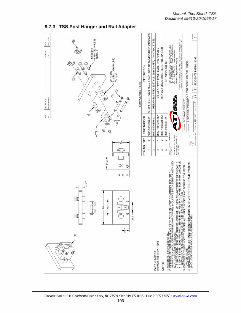
Manual, Tool Stand, TSSDocument #9610-20-1068-17
Pinnacle Park • 1031 Goodworth Drive • Apex, NC 27539 • Tel: 919.772.0115 • Fax: 919.772.8259 • www.ati-ia.com103
9.7.3 TSS Post Hanger and Rail Adapter
3rd
AN
GLE
PRO
JEC
TION
22.
5
45
90
29.
2
(A)
9.7
45
33
34.
3
M8
SHC
S21
.5 N
m (1
90 IN
-LBS
)N
OTE
3
M5
SHC
S6
Nm
(52
IN-L
BS)
NO
TE 3
12
4
35
NO
TE 1
NO
TES:
MAT
ERIA
L: S
TAIN
LESS
STE
EL.
1.O
PTIO
NAL
SEN
SOR
KIT
AVA
ILAB
LE F
OR
"TO
OL
IN N
EST"
CO
ND
ITIO
N, O
RD
ERED
2.
SEPA
RAT
ELY
(INC
LUD
ES M
OU
NTI
NG
HAR
DW
ARE)
, IN
DU
CTI
VE P
RO
X SE
NSO
R W
ITH
LED
N
.O.,
CU
STO
MER
TO
INST
ALL.
91
20-T
SS-S
MA-
1139
2 PN
P PR
OX
SEN
SOR
KIT
, M8
3-PI
N C
ON
NEC
TOR
WIT
H .2
M C
ABLE
•91
20-T
SS-S
MB-
1139
2 N
PN P
RO
X SE
NSO
R K
IT, M
8 3-
PIN
CO
NN
ECTO
R W
ITH
.2M
CAB
LE•
CO
NTA
CT
ATI E
NG
INEE
RIN
G F
OR
OTH
ER S
ENSO
R O
PTIO
NS
• CU
STO
MER
TO
USE
LO
CTI
TE O
R S
IMIL
AR T
HR
EAD
LO
CKE
R A
ND
TO
RQ
UE
TO L
ISTE
D
3.TO
RQ
UE
VALU
E.C
ON
TAC
T AT
I EN
GIN
EER
ING
FO
R IN
FOR
MAT
ION
ON
CO
MPL
ETE
TOO
L ST
AND
SYS
TEM
S 4.
(INC
LUD
ING
PO
ST M
OD
ULE
S, E
XTR
USI
ON
S).
PAR
T N
UM
BER
S:(A
) 912
0-TS
S-M
MH
-113
92
REV
.D
ESC
RIPT
ION
INITI
ATO
RD
ATE
01IN
ITIA
L RE
LEA
SED
CT
09/1
6/20
20
SER
VIC
EABL
E IT
EMS
ITEM
NO
.Q
TY.
PAR
T N
UM
BER
DES
CR
IPTI
ON
12
3690
-550
3200
-10
SHAF
T, 5
mm
(G6)
X 3
2mm
LO
NG
, TW
O R
ETAI
NIN
G R
ING
GR
OO
VES
24
3690
-540
0100
-10
RET
AIN
ING
RIN
G, E
-STY
LE, 5
mm
SH
AFT,
.7m
m T
HK,
STE
EL
34
3500
-106
4016
-15A
M5-
0.8
X 16
mm
SH
CS,
BLU
E, P
RE-
APPL
IED
42
3500
-106
8020
-15A
M8-
1.25
X 2
0mm
SH
CS,
BLU
E, P
RE-
APPL
IED
52
3505
-996
8001
-21
T-N
UT,
10m
m, M
8, S
S
B2:
31
2RE
VISI
ON
NO
TES:
UN
LESS
OTH
ERW
ISE
SPEC
IFIE
D.
DO
NO
T SC
ALE
DRA
WIN
G.
ALL
DIM
ENSI
ON
S A
RE IN
M
ILLIM
ETER
S.
DRA
WN
BY:
CHE
CKE
D B
Y:
D. T
HO
MAS
, 05/
05/2
020
B. K
END
RIC
K, 0
7/28
/202
0TITLE SC
ALE
SIZE
DRA
WIN
G N
UMBE
R
PRO
JEC
T #
SHEE
T
O
F 96
30-2
0-TS
S-M
MH
-113
9220
0116
-101
PRO
PERT
Y O
F A
TI IN
DUS
TRIA
L A
UTO
MA
TION
, IN
C. N
OT
TO B
E RE
PRO
DUC
ED IN
AN
Y M
AN
NER
EXC
EPT
ON
ORD
ER O
R W
ITH P
RIO
R W
RITT
EN A
UTHO
RIZA
TION
OF
ATI.
1031
Goo
dwor
th Dr
ive, A
pex,
NC 27
539,
USA
Tel: +
1.919
.772.0
115
Em
ail: in
fo@ati
-ia.co
mFa
x: +1
.919.7
72.82
59
www
.ati-ia
.com
ISO
9001
Reg
ister
ed C
ompa
ny
QC
-7 P
ost H
ange
r and
Rai
l Ada
pter

Manual, Tool Stand, TSSDocument #9610-20-1068-17
Pinnacle Park • 1031 Goodworth Drive • Apex, NC 27539 • Tel: 919.772.0115 • Fax: 919.772.8259 • www.ati-ia.com104
3rd
AN
GLE
PRO
JEC
TION
SEN
SOR
CAB
LE U
P
MU
ST U
SE U
PPER
THR
EAD
ED H
OLE
OPT
ION
AL IN
DU
CTI
VE
PRO
XIM
ITY
SEN
SOR
KIT
,"T
OO
L IN
NES
T" C
ON
DIT
ION
NO
TE 2
MU
ST U
SE L
OW
ERTH
REA
DED
HO
LEM
3 SF
HC
SPR
E / 6
in-lb
sN
OTE
3
SEN
SOR
CAB
LE D
OW
N
B2:
32
2RE
VISI
ON
NO
TES:
UN
LESS
OTH
ERW
ISE
SPEC
IFIE
D.
DO
NO
T SC
ALE
DRA
WIN
G.
ALL
DIM
ENSI
ON
S A
RE IN
M
ILLIM
ETER
S.
DRA
WN
BY:
CHE
CKE
D B
Y:
D. T
HO
MAS
, 05/
05/2
020
B. K
END
RIC
K, 0
7/28
/202
0TITLE SC
ALE
SIZE
DRA
WIN
G N
UMBE
R
PRO
JEC
T #
SHEE
T
O
F 96
30-2
0-TS
S-M
MH
-113
9220
0116
-101
PRO
PERT
Y O
F A
TI IN
DUS
TRIA
L A
UTO
MA
TION
, IN
C. N
OT
TO B
E RE
PRO
DUC
ED IN
AN
Y M
AN
NER
EXC
EPT
ON
ORD
ER O
R W
ITH P
RIO
R W
RITT
EN A
UTHO
RIZA
TION
OF
ATI.
1031
Goo
dwor
th Dr
ive, A
pex,
NC 27
539,
USA
Tel: +
1.919
.772.0
115
Em
ail: in
fo@ati
-ia.co
mFa
x: +1
.919.7
72.82
59
www
.ati-ia
.com
ISO
9001
Reg
ister
ed C
ompa
ny
QC
-7 P
ost H
ange
r and
Rai
l Ada
pter

Manual, Tool Stand, TSSDocument #9610-20-1068-17
Pinnacle Park • 1031 Goodworth Drive • Apex, NC 27539 • Tel: 919.772.0115 • Fax: 919.772.8259 • www.ati-ia.com105
10. Terms and Conditions of SaleThe following Terms and Conditions are a supplement to and include a portion of ATI’s Standard Terms and Conditions, which are on file at ATI and available upon request.
ATI warrants to Purchaser that robotic Tool Changer products purchased hereunder will be free from defects in material and workmanship under normal use for a period of three (3) years from the date of shipment. This warranty does not cover components subject to wear and tear under normal usage or those requiring periodic replacement. ATI will have no liability under this warranty unless: (a) ATI is given written notice of the claimed defect and a Description thereof within thirty (30) days after Purchaser discovers the defect and in any event not later than the last day of the warranty period; and (b) the defective item is received by ATI not later ten (10) days after the last day of the warranty period. ATI’s entire liability and Purchaser’s sole remedy under this warranty is limited to repair or replacement, at ATI’s election, of the defective part or item or, at ATI’s election, refund of the price paid for the item. The foregoing warranty does not apply to any defect or failure resulting from improper installation, operation, maintenance or repair by anyone other than ATI.
ATI will in no event be liable for incidental, consequential or special damages of any kind, even if ATI has been advised of the possibility of such damages. ATI’s aggregate liability will in no event exceed the amount paid by purchaser for the item which is the subject of claim or dispute. ATI will have no liability of any kind for failure of any equipment or other items not supplied by ATI.
No action against ATI, regardless of form, arising out of or in any way connected with products or services supplied hereunder may be brought more than one (1) year after the cause of action accrued.
No representation or agreement varying or extending the warranty and limitation of remedy provisions contained herein is authorized by ATI, and may not be relied upon as having been authorized by ATI, unless in writing and signed by an executive officer of ATI.
Unless otherwise agreed in writing by ATI, all designs, drawings, data, inventions, software and other technology made or developed by ATI in the course of providing products and services hereunder, and all rights therein under any patent, copyright or other law protecting intellectual property, shall be and remain ATI’s property. The sale of products or services hereunder does not convey any express or implied license under any patent, copyright or other intellectual property right owned or controlled by ATI, whether relating to the products sold or any other matter, except for the license expressly granted below.
In the course of supplying products and services hereunder, ATI may provide or disclose to Purchaser confidential and proprietary information of ATI relating to the design, operation or other aspects of ATI’s products. As between ATI and Purchaser, ownership of such information, including without limitation any computer software provided to Purchaser by ATI, shall remain in ATI and such information is licensed to Purchaser only for Purchaser’s use in operating the products supplied by ATI hereunder in Purchaser’s internal business operations.
Without ATI’s prior written permission, Purchaser will not use such information for any other purpose or provide or otherwise make such information available to any third party. Purchaser agrees to take all reasonable precautions to prevent any unauthorized use or disclosure of such information.
Purchaser will not be liable hereunder with respect to disclosure or use of information which: (a) is in the public domain when received from ATI; (b) is thereafter published or otherwise enters the public domain through no fault of Purchaser; (c) is in Purchaser’s possession prior to receipt from ATI; (d) is lawfully obtained by Purchaser from a third party entitled to disclose it; or (f) is required to be disclosed by judicial order or other governmental authority, provided that, with respect to such required disclosures, Purchaser gives ATI prior notice thereof and uses all legally available means to maintain the confidentiality of such information.